Embed Size (px)
Citation preview
ME
Ra
b
c
a
ARRA
KFSMA
1
tttww
cataufiflflc
eads
0d
Materials Science and Engineering A 498 (2008) 384–391
Contents lists available at ScienceDirect
Materials Science and Engineering A
journa l homepage: www.e lsev ier .com/ locate /msea
aterial flow in heterogeneous friction stir welding of thin aluminium sheets:ffect of shoulder geometry
.M. Leala,b, C. Leitãoa, A. Loureiroa, D.M. Rodriguesa,∗, P. Vilacac
CEMUC, Department of Mechanical Engineering, University of Coimbra, PortugalESAD.CR, Polytechnic Institute of Leiria, Caldas da Rainha, PortugalDEM-IST, Technical University of Lisbon, Portugal
r t i c l e i n f o
rticle history:eceived 13 June 2008eceived in revised form 12 August 2008
a b s t r a c t
The aim of this investigation was to study the influence of tool geometry on material flow during hetero-geneous friction stir welding in 1 mm thick plates of AA 5182-H111 and AA 6016-T4 aluminium alloys. Two
ccepted 14 August 2008
eywords:riction stir weldinghoulder geometryaterial flow
types of tool shoulders were used: a shoulder with a conical cavity and a scrolled shoulder. Pin-driven flowwas predominant in welds produced with the conical cavity shoulder, which are characterized by an onionring structure. The interaction between pin-driven and shoulder-driven flow is restricted to the crown ofthe weld, at the trailing side of the tool, and extends throughout the weld thickness, at the leading side.Although no onion ring structure was formed in welds done with the scrolled shoulder, extensive mixingof the base materials occurred in a plasticized layer flowing through the thickness around the rotating
is int
amtmmtnttawmmaflp
nt
luminium alloys pin. Shoulder-driven flow
. Introduction
When compared with conventional fusion welding processes,he friction stir welding (FSW) process has many technical advan-ages for joining soft materials, such as aluminium alloys, beyondhe evident environmental benefits. In fact, FSW is a solid stateelding process that allows similar or dissimilar materials to beelded together without emission of radiation or dangerous fumes.
However, as for any other welding processes, FSW requires aareful choice of process parameters in order for microstructuralnd mechanical characteristics and defect free welds to be consis-ently reproducible. Defects in FS welds have already been classifieds flow or geometric related [1]. The geometric related defects aresually associated with lack of penetration and occur due to insuf-cient pin penetration depth and/or improper seam tracking. Theow related defects, which are much more difficult to avoid, includeash formation, surface galling, lack of fill, wormholes, and nuggetollapse or lack of consolidation [1–7].
According to the literature, the main process parameters influ-
ncing material flow and weld quality include tool geometry (pinnd shoulder design and relative dimensions of pin and shoul-er), welding parameters (tool rotation rate and direction, traversepeed, plunge depth, tilt angle), base material flow stress behaviour∗ Corresponding author. Tel.: +351 239 790 700; fax: +351 239 790 701.E-mail address: [email protected] (D.M. Rodrigues).
psttrIdo
921-5093/$ – see front matter © 2008 Elsevier B.V. All rights reserved.oi:10.1016/j.msea.2008.08.018
ense and continuous around the tool.© 2008 Elsevier B.V. All rights reserved.
nd temperature as well as the interaction between the workpieceaterial and the various weld tool features [2,8–11]. Experimen-
al flow visualization studies have been conducted by introducingarker materials into the weld line [9–15] by welding dissimilaraterials [14,16,17] or by simply using etching contrast to enhance
he flow patterns in the weld [1,6,18–21]. However, all these tech-iques have well known limitations. The insertion of markers inhe weld line may influence material flow during welding due tohe different flow characteristics of the base and marker materi-ls and the introduction of additional interfaces [22]. In the sameay, it is not clear if the material flow during welding of dissimilaraterials, having different flow properties, can be compared withaterial flow in friction stir welding of similar materials. Finally,
ll these techniques are limited to speculation about real materialow during FSW since they are based on the simple observation ofre- and post-welding material positions.
Despite current limitations of metal flow visualization tech-iques, it is commonly agreed that the flow of material aroundhe tool is not symmetric about the weld centreline and dis-lays significant differences between the advancing and retreatingides [1,6,9–11,13]. According to several authors, vertical, straight-hrough and rotational flows of plasticized material take place inhe vicinity or around the tool, dragging the bulk of the stirred mate-
ial to a final position behind its original position [6,11,13,14,20,23].n the wake of the weld, behind the travelling tool, materialeposition takes place layer-by-layer resulting in the formationf a zone with a banded structure commonly referred to as the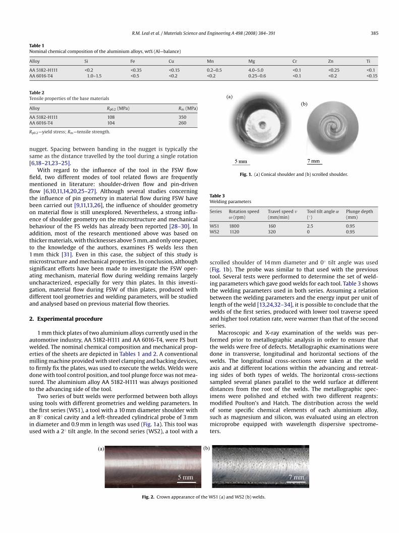
R.M. Leal et al. / Materials Science and Engineering A 498 (2008) 384–391 385
Table 1Nominal chemical composition of the aluminium alloys, wt% (Al—balance)
Alloy Si Fe Cu Mn Mg Cr Zn Ti
AA 5182-H111 <0.2 <0.35 <0.15 0.2–0.5 4.0–5.0 <0.1 <0.25 <0.1AA 6016-T4 1.0–1.5 <0.5 <0.2 <0.2 0.25–0.6 <0.1 <0.2 <0.15
Table 2Tensile properties of the base materials
Alloy Rp0.2 (MPa) Rm (MPa)
AA
R
ns[
fimfltboebatt1msaugda
2
awemtdst
utaiu
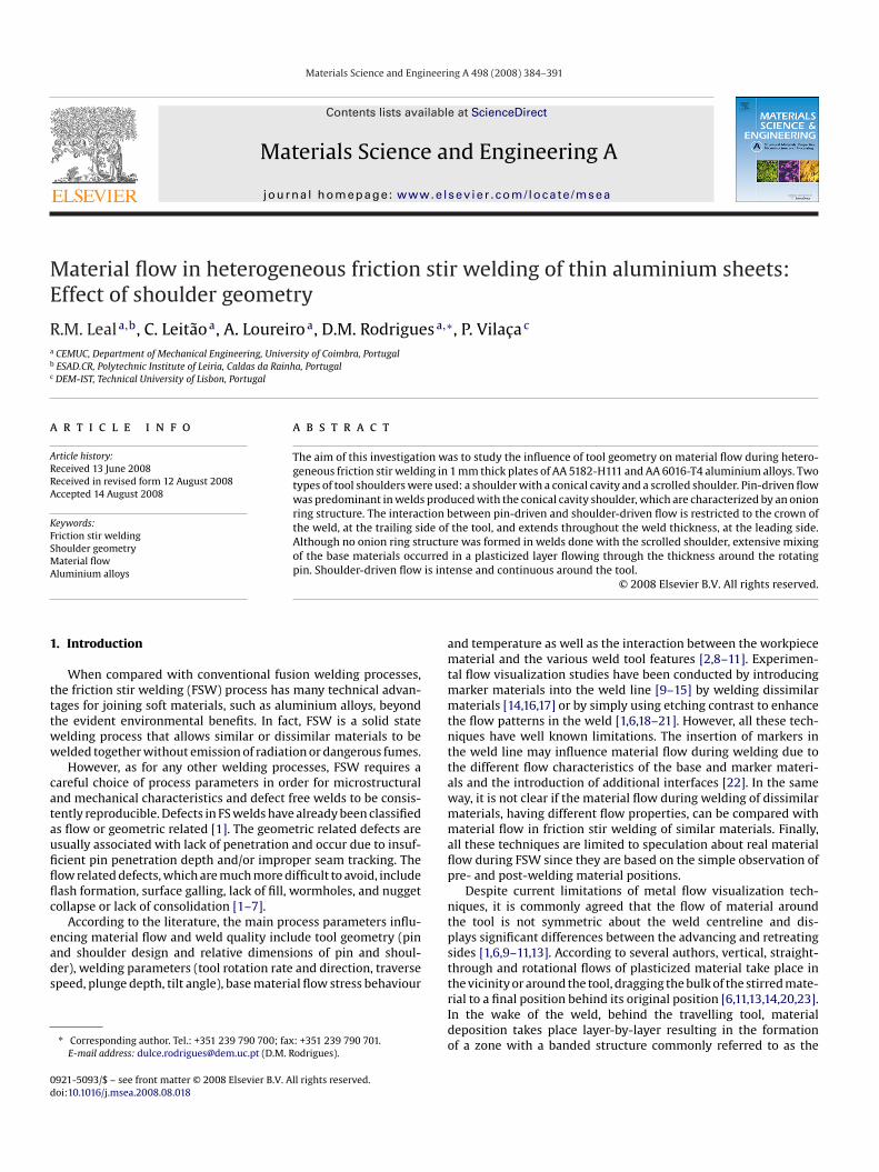
Fig. 1. (a) Conical shoulder and (b) scrolled shoulder.
Table 3Welding parameters
Series Rotation speedω (rpm)
Travel speed �(mm/min)
Tool tilt angle ˛(◦)
Plunge depth(mm)
WS1 1800 160 2.5 0.95W
s(titblwas
ftdwaisdi
A 5182-H111 108 350A 6016-T4 104 260
p0.2—yield stress; Rm—tensile strength.
ugget. Spacing between banding in the nugget is typically theame as the distance travelled by the tool during a single rotation6,18–21,23–25].
With regard to the influence of the tool in the FSW floweld, two different modes of tool related flows are frequentlyentioned in literature: shoulder-driven flow and pin-driven
ow [6,10,11,14,20,25–27]. Although several studies concerninghe influence of pin geometry in material flow during FSW haveeen carried out [9,11,13,26], the influence of shoulder geometryn material flow is still unexplored. Nevertheless, a strong influ-nce of shoulder geometry on the microstructure and mechanicalehaviour of the FS welds has already been reported [28–30]. Inddition, most of the research mentioned above was based onhicker materials, with thicknesses above 5 mm, and only one paper,o the knowledge of the authors, examines FS welds less thenmm thick [31]. Even in this case, the subject of this study isicrostructure and mechanical properties. In conclusion, although
ignificant efforts have been made to investigate the FSW oper-ting mechanism, material flow during welding remains largelyncharacterized, especially for very thin plates. In this investi-ation, material flow during FSW of thin plates, produced withifferent tool geometries and welding parameters, will be studiednd analysed based on previous material flow theories.
. Experimental procedure
1 mm thick plates of two aluminium alloys currently used in theutomotive industry, AA 5182-H111 and AA 6016-T4, were FS buttelded. The nominal chemical composition and mechanical prop-
rties of the sheets are depicted in Tables 1 and 2. A conventionalilling machine provided with steel clamping and backing devices,
o firmly fix the plates, was used to execute the welds. Welds wereone with tool control position, and tool plunge force was not mea-ured. The aluminium alloy AA 5182-H111 was always positionedo the advancing side of the tool.
Two series of butt welds were performed between both alloys
sing tools with different geometries and welding parameters. Inhe first series (WS1), a tool with a 10 mm diameter shoulder withn 8◦ conical cavity and a left-threaded cylindrical probe of 3 mmn diameter and 0.9 mm in length was used (Fig. 1a). This tool wassed with a 2◦ tilt angle. In the second series (WS2), a tool with amosmt
Fig. 2. Crown appearance of the W
S2 1120 320 0 0.95
crolled shoulder of 14 mm diameter and 0◦ tilt angle was usedFig. 1b). The probe was similar to that used with the previousool. Several tests were performed to determine the set of weld-ng parameters which gave good welds for each tool. Table 3 showshe welding parameters used in both series. Assuming a relationetween the welding parameters and the energy input per unit of
ength of the weld [13,24,32–34], it is possible to conclude that theelds of the first series, produced with lower tool traverse speed
nd higher tool rotation rate, were warmer than that of the seconderies.
Macroscopic and X-ray examination of the welds was per-ormed prior to metallographic analysis in order to ensure thathe welds were free of defects. Metallographic examinations wereone in transverse, longitudinal and horizontal sections of theelds. The longitudinal cross-sections were taken at the weld
xis and at different locations within the advancing and retreat-ng sides of both types of welds. The horizontal cross-sectionsampled several planes parallel to the weld surface at differentistances from the root of the welds. The metallographic spec-
mens were polished and etched with two different reagents:odified Poulton’s and Hatch. The distribution across the weld
f some specific chemical elements of each aluminium alloy,uch as magnesium and silicon, was evaluated using an electron
icroprobe equipped with wavelength dispersive spectrome-ers.
S1 (a) and WS2 (b) welds.
386 R.M. Leal et al. / Materials Science and Engineering A 498 (2008) 384–391
F oultos
3
3
fivi[a
wIttTewsshuit[
i
itcsatatai
ztmbbtteaoa
F3
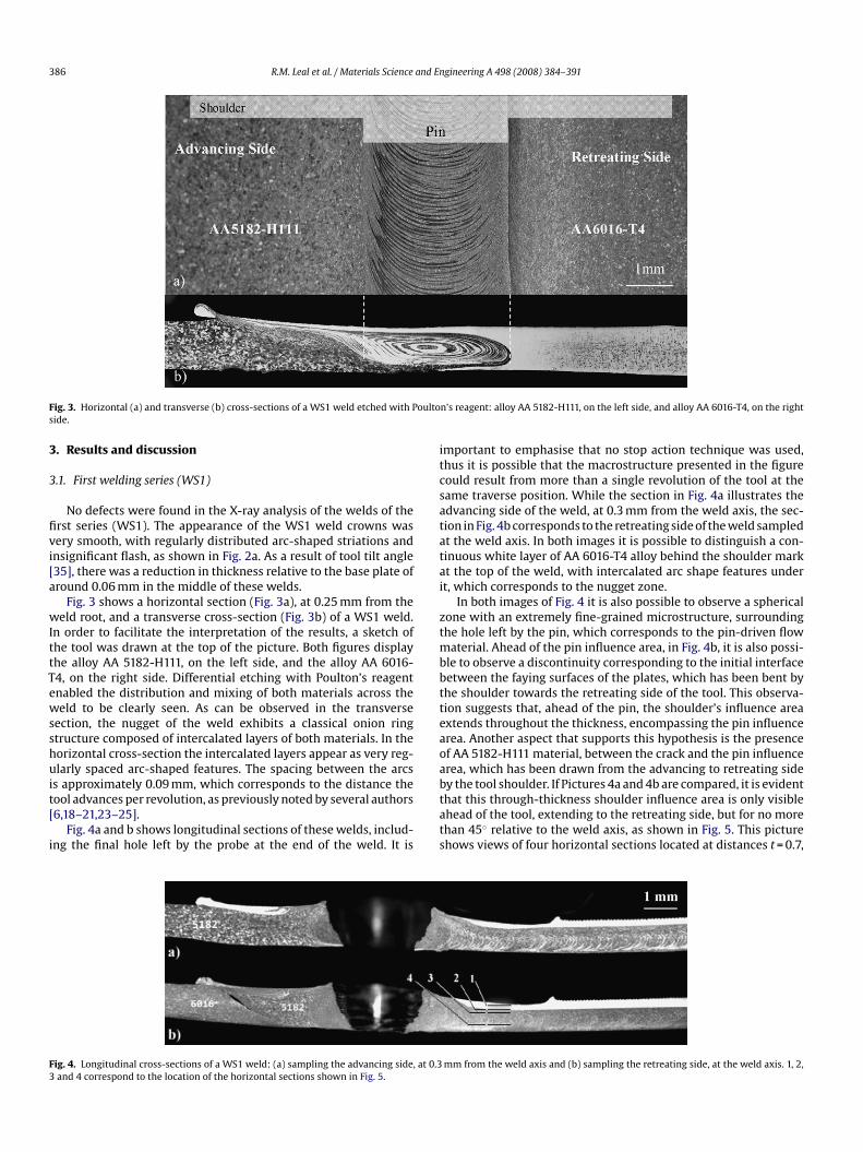
ig. 3. Horizontal (a) and transverse (b) cross-sections of a WS1 weld etched with Pide.
. Results and discussion
.1. First welding series (WS1)
No defects were found in the X-ray analysis of the welds of therst series (WS1). The appearance of the WS1 weld crowns wasery smooth, with regularly distributed arc-shaped striations andnsignificant flash, as shown in Fig. 2a. As a result of tool tilt angle35], there was a reduction in thickness relative to the base plate ofround 0.06 mm in the middle of these welds.
Fig. 3 shows a horizontal section (Fig. 3a), at 0.25 mm from theeld root, and a transverse cross-section (Fig. 3b) of a WS1 weld.
n order to facilitate the interpretation of the results, a sketch ofhe tool was drawn at the top of the picture. Both figures displayhe alloy AA 5182-H111, on the left side, and the alloy AA 6016-4, on the right side. Differential etching with Poulton’s reagentnabled the distribution and mixing of both materials across theeld to be clearly seen. As can be observed in the transverse
ection, the nugget of the weld exhibits a classical onion ringtructure composed of intercalated layers of both materials. In theorizontal cross-section the intercalated layers appear as very reg-larly spaced arc-shaped features. The spacing between the arcs
s approximately 0.09 mm, which corresponds to the distance theool advances per revolution, as previously noted by several authors6,18–21,23–25].
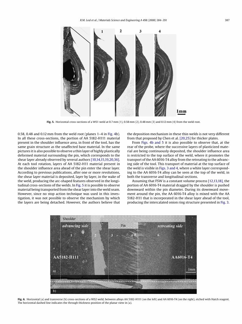
Fig. 4a and b shows longitudinal sections of these welds, includ-ng the final hole left by the probe at the end of the weld. It is
btats
ig. 4. Longitudinal cross-sections of a WS1 weld: (a) sampling the advancing side, at 0.3and 4 correspond to the location of the horizontal sections shown in Fig. 5.
n’s reagent: alloy AA 5182-H111, on the left side, and alloy AA 6016-T4, on the right
mportant to emphasise that no stop action technique was used,hus it is possible that the macrostructure presented in the figureould result from more than a single revolution of the tool at theame traverse position. While the section in Fig. 4a illustrates thedvancing side of the weld, at 0.3 mm from the weld axis, the sec-ion in Fig. 4b corresponds to the retreating side of the weld sampledt the weld axis. In both images it is possible to distinguish a con-inuous white layer of AA 6016-T4 alloy behind the shoulder markt the top of the weld, with intercalated arc shape features undert, which corresponds to the nugget zone.
In both images of Fig. 4 it is also possible to observe a sphericalone with an extremely fine-grained microstructure, surroundinghe hole left by the pin, which corresponds to the pin-driven flow
aterial. Ahead of the pin influence area, in Fig. 4b, it is also possi-le to observe a discontinuity corresponding to the initial interfaceetween the faying surfaces of the plates, which has been bent byhe shoulder towards the retreating side of the tool. This observa-ion suggests that, ahead of the pin, the shoulder’s influence areaxtends throughout the thickness, encompassing the pin influencerea. Another aspect that supports this hypothesis is the presencef AA 5182-H111 material, between the crack and the pin influencerea, which has been drawn from the advancing to retreating side
y the tool shoulder. If Pictures 4a and 4b are compared, it is evidenthat this through-thickness shoulder influence area is only visiblehead of the tool, extending to the retreating side, but for no morehan 45◦ relative to the weld axis, as shown in Fig. 5. This picturehows views of four horizontal sections located at distances t = 0.7,mm from the weld axis and (b) sampling the retreating side, at the weld axis. 1, 2,
R.M. Leal et al. / Materials Science and Engineering A 498 (2008) 384–391 387
), 0.5
0IpspdsAtAtttmHtt
tf
rrititib
FT
Fig. 5. Horizontal cross-sections of a WS1 weld at 0.7 mm (1
.58, 0.48 and 0.12 mm from the weld root (planes 1–4 in Fig. 4b).n all these cross-sections, the portion of AA 5182-H111 materialresent in the shoulder influence area, in front of the tool, has theame grain structure as the unaffected base material. In the sameictures it is also possible to observe a thin layer of highly plasticallyeformed material surrounding the pin, which corresponds to thehear layer already observed by several authors [10,14,15,19,20,36].t each tool rotation, layers of AA 5182-H11 material present in
he shoulder influence area ahead of the pin enter the shear layer.ccording to previous publications, after one or more revolutions,
he shear layer material is deposited, layer by layer, in the wake ofhe weld, producing the arc-shaped features observed in the longi-
udinal cross-sections of the welds. In Fig. 5 it is possible to observeaterial being transported from the shear layer into the weld seam.owever, since no stop action technique was used in this inves-
igation, it was not possible to observe the mechanism by whichhe layers are being detached. However, the authors believe that
pdm5p
ig. 6. Horizontal (a) and transverse (b) cross-sections of a WS2 weld, between alloys AAhe horizontal dashed line indicates the through thickness position of the planar view in
8 mm (2), 0.48 mm (3) and 0.12 mm (4) from the weld root.
he deposition mechanism in these thin welds is not very differentrom that proposed by Chen et al. [20,25] for thicker plates.
From Figs. 4b and 5 it is also possible to observe that, at theear of the probe, where the successive layers of plasticized mate-ial are being continuously deposited, the shoulder influence areas restricted to the top surface of the weld, where it promotes theransport of the AA 6016-T4 alloy from the retreating to the advanc-ng side of the tool. This transport of material at the top surface ofhe weld is visible in Figs. 3 and 4, where a white layer correspond-ng to the AA 6016-T4 alloy can be seen at the top of the weld, inoth the transverse and longitudinal sections.
Assuming that FSW is a constant volume process [12,13,18], the
ortion of AA 6016-T4 material dragged by the shoulder is pushedownward within the pin diameter. During its downward move-ent around the pin, the AA 6016-T4 alloy is mixed with the AA182-H11 that is incorporated in the shear layer ahead of the tool,roducing the intercalated onion ring structure presented in Fig. 3.
5182-H111 (on the left) and AA 6016-T4 (on the right), etched with Hatch reagent.(a).
388 R.M. Leal et al. / Materials Science and En
Table 4Chemical composition of several regions of a WS2 weld (wt%)
5182-H11 6016-T4 Nugget zones
MS
H6atr
3
ittr
twawpav
ttanesaiavwz
istrT
zioTtm
apde0tldmtAtimctht
F(iftstAStmatrswg
1 2 3 4 5 6 7
g 4–5 0.25–0.6 4.35 1.36 4.3 4.19 0.34 0.34 0.36i Max. 0.2 1–1.5 0.05 0.74 0.05 0.04 0.84 0.81 0.79
owever, at the top of the weld, there is always some portion of AA016-T4 material that is not transported by the downward flow fieldnd is expelled from the weld zone as flash at the advancing side ofhe tool (see Fig. 3), giving rise to the reduction in weld thicknesselative to the base plate that was registered for these welds.
.2. Second welding series (WS2)
The crown appearance of the welds of the second series (WS2)s shown in Fig. 2b. From this picture it is possible to observe thathe crown of the WS2 welds is rougher than that of the welds ofhe first series. However, due to the absence of tool tilt angle, noeduction in thickness was observed for these welds.
Fig. 6 shows a horizontal section of a WS2 weld (Fig. 6a) and aransverse cross-section of the same weld (Fig. 6b). Both samplesere etched with Hatch reagent, which enables the AA 5182-H111
lloy on the left side and the AA 6016-T4 alloy on the right side of theeld to be distinguished. As can be concluded by observing bothictures, no onion ring structure was formed in the pin influencerea. In fact, as discussed below, material flow for these welds wasery different from that of the welds of the first series.
From a purely metallographic analysis of Fig. 6, it is apparenthat the materials in the weld nugget are mixed in a complex pat-ern with a tongue of white material going upwards through thedvancing side into a matrix of AA 5182-H111 material. Since it isot possible to identify the nature of the materials in the differ-nt weld features from simple etching contrast, the metallographictudy was complemented with a chemical analysis performed afterslight polishing in the plane parallel to the weld surface shown
n Fig. 6a. As illustrated in this figure, seven different regions werenalysed. Since both base materials are aluminium alloys, but withery different magnesium and silicon contents, these elementsere selected to identify the materials present in the different
ones under analysis.Table 4 shows the chemical composition of the different regions
dentified in Fig. 6 together with the nominal content of magne-ium and silicon of the parent materials. Comparing the results inhe table, it is possible to confirm that zones 1 and 7 correspond,espectively, to the base materials AA 5182-H111 and AA 6016-T4.he magnesium and silicon contents of region 2 suggest that this
wdi
0
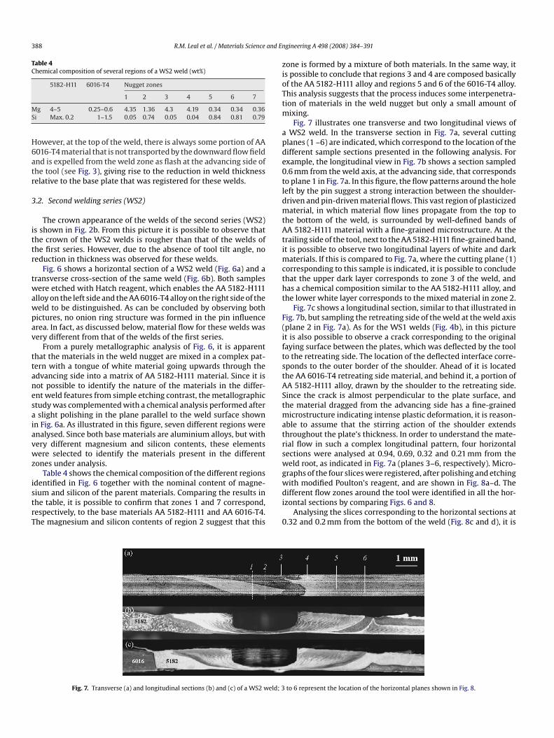
Fig. 7. Transverse (a) and longitudinal sections (b) and (c) of a WS2 weld; 3
gineering A 498 (2008) 384–391
one is formed by a mixture of both materials. In the same way, its possible to conclude that regions 3 and 4 are composed basicallyf the AA 5182-H111 alloy and regions 5 and 6 of the 6016-T4 alloy.his analysis suggests that the process induces some interpenetra-ion of materials in the weld nugget but only a small amount of
ixing.Fig. 7 illustrates one transverse and two longitudinal views of
WS2 weld. In the transverse section in Fig. 7a, several cuttinglanes (1 –6) are indicated, which correspond to the location of theifferent sample sections presented in the following analysis. Forxample, the longitudinal view in Fig. 7b shows a section sampled.6 mm from the weld axis, at the advancing side, that correspondso plane 1 in Fig. 7a. In this figure, the flow patterns around the holeeft by the pin suggest a strong interaction between the shoulder-riven and pin-driven material flows. This vast region of plasticizedaterial, in which material flow lines propagate from the top to
he bottom of the weld, is surrounded by well-defined bands ofA 5182-H111 material with a fine-grained microstructure. At the
railing side of the tool, next to the AA 5182-H111 fine-grained band,t is possible to observe two longitudinal layers of white and dark
aterials. If this is compared to Fig. 7a, where the cutting plane (1)orresponding to this sample is indicated, it is possible to concludehat the upper dark layer corresponds to zone 3 of the weld, andas a chemical composition similar to the AA 5182-H111 alloy, andhe lower white layer corresponds to the mixed material in zone 2.
Fig. 7c shows a longitudinal section, similar to that illustrated inig. 7b, but sampling the retreating side of the weld at the weld axisplane 2 in Fig. 7a). As for the WS1 welds (Fig. 4b), in this picturet is also possible to observe a crack corresponding to the originalaying surface between the plates, which was deflected by the toolo the retreating side. The location of the deflected interface corre-ponds to the outer border of the shoulder. Ahead of it is locatedhe AA 6016-T4 retreating side material, and behind it, a portion ofA 5182-H111 alloy, drawn by the shoulder to the retreating side.ince the crack is almost perpendicular to the plate surface, andhe material dragged from the advancing side has a fine-grained
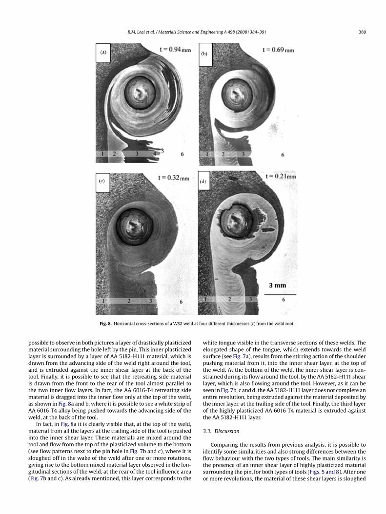
icrostructure indicating intense plastic deformation, it is reason-ble to assume that the stirring action of the shoulder extendshroughout the plate’s thickness. In order to understand the mate-ial flow in such a complex longitudinal pattern, four horizontalections were analysed at 0.94, 0.69, 0.32 and 0.21 mm from theeld root, as indicated in Fig. 7a (planes 3–6, respectively). Micro-
raphs of the four slices were registered, after polishing and etching
ith modified Poulton’s reagent, and are shown in Fig. 8a–d. Theifferent flow zones around the tool were identified in all the hor-zontal sections by comparing Figs. 6 and 8.Analysing the slices corresponding to the horizontal sections at
.32 and 0.2 mm from the bottom of the weld (Fig. 8c and d), it is
to 6 represent the location of the horizontal planes shown in Fig. 8.
R.M. Leal et al. / Materials Science and Engineering A 498 (2008) 384–391 389
at fou
pmldatitmaAw
mit(sgg(
wesptslsetot
3
Fig. 8. Horizontal cross-sections of a WS2 weld
ossible to observe in both pictures a layer of drastically plasticizedaterial surrounding the hole left by the pin. This inner plasticized
ayer is surrounded by a layer of AA 5182-H111 material, which israwn from the advancing side of the weld right around the tool,nd is extruded against the inner shear layer at the back of theool. Finally, it is possible to see that the retreating side materials drawn from the front to the rear of the tool almost parallel tohe two inner flow layers. In fact, the AA 6016-T4 retreating side
aterial is dragged into the inner flow only at the top of the weld,s shown in Fig. 8a and b, where it is possible to see a white strip ofA 6016-T4 alloy being pushed towards the advancing side of theeld, at the back of the tool.
In fact, in Fig. 8a it is clearly visible that, at the top of the weld,aterial from all the layers at the trailing side of the tool is pushed
nto the inner shear layer. These materials are mixed around theool and flow from the top of the plasticized volume to the bottom
see flow patterns next to the pin hole in Fig. 7b and c), where it isloughed off in the wake of the weld after one or more rotations,iving rise to the bottom mixed material layer observed in the lon-itudinal sections of the weld, at the rear of the tool influence areaFig. 7b and c). As already mentioned, this layer corresponds to theifltso
r different thicknesses (t) from the weld root.
hite tongue visible in the transverse sections of these welds. Thelongated shape of the tongue, which extends towards the weldurface (see Fig. 7a), results from the stirring action of the shoulderushing material from it, into the inner shear layer, at the top ofhe weld. At the bottom of the weld, the inner shear layer is con-trained during its flow around the tool, by the AA 5182-H111 shearayer, which is also flowing around the tool. However, as it can beeen in Fig. 7b, c and d, the AA 5182-H111 layer does not complete anntire revolution, being extruded against the material deposited byhe inner layer, at the trailing side of the tool. Finally, the third layerf the highly plasticized AA 6016-T4 material is extruded againsthe AA 5182-H111 layer.
.3. Discussion
Comparing the results from previous analysis, it is possible to
dentify some similarities and also strong differences between theow behaviour with the two types of tools. The main similarity ishe presence of an inner shear layer of highly plasticized materialurrounding the pin, for both types of tools (Figs. 5 and 8). After oner more revolutions, the material of these shear layers is sloughed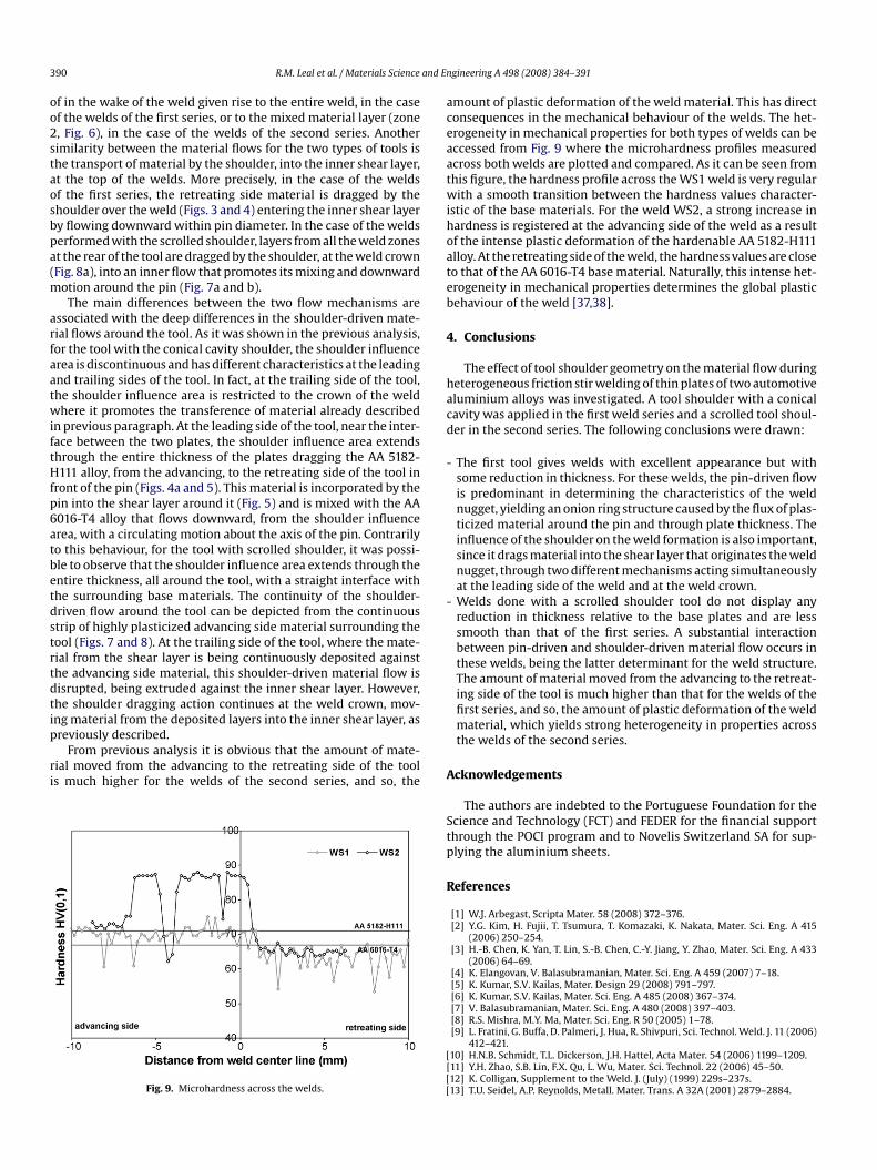
3 and En
oo2staosbpa(m
arfaatwiftHfp6atbetdstrtdtip
ri
aceaatwihoateb
4
hacd
-
-
90 R.M. Leal et al. / Materials Science
f in the wake of the weld given rise to the entire weld, in the casef the welds of the first series, or to the mixed material layer (zone, Fig. 6), in the case of the welds of the second series. Anotherimilarity between the material flows for the two types of tools ishe transport of material by the shoulder, into the inner shear layer,t the top of the welds. More precisely, in the case of the weldsf the first series, the retreating side material is dragged by thehoulder over the weld (Figs. 3 and 4) entering the inner shear layery flowing downward within pin diameter. In the case of the weldserformed with the scrolled shoulder, layers from all the weld zonest the rear of the tool are dragged by the shoulder, at the weld crownFig. 8a), into an inner flow that promotes its mixing and downward
otion around the pin (Fig. 7a and b).The main differences between the two flow mechanisms are
ssociated with the deep differences in the shoulder-driven mate-ial flows around the tool. As it was shown in the previous analysis,or the tool with the conical cavity shoulder, the shoulder influencerea is discontinuous and has different characteristics at the leadingnd trailing sides of the tool. In fact, at the trailing side of the tool,he shoulder influence area is restricted to the crown of the weldhere it promotes the transference of material already described
n previous paragraph. At the leading side of the tool, near the inter-ace between the two plates, the shoulder influence area extendshrough the entire thickness of the plates dragging the AA 5182-111 alloy, from the advancing, to the retreating side of the tool in
ront of the pin (Figs. 4a and 5). This material is incorporated by thein into the shear layer around it (Fig. 5) and is mixed with the AA016-T4 alloy that flows downward, from the shoulder influencerea, with a circulating motion about the axis of the pin. Contrarilyo this behaviour, for the tool with scrolled shoulder, it was possi-le to observe that the shoulder influence area extends through thentire thickness, all around the tool, with a straight interface withhe surrounding base materials. The continuity of the shoulder-riven flow around the tool can be depicted from the continuoustrip of highly plasticized advancing side material surrounding theool (Figs. 7 and 8). At the trailing side of the tool, where the mate-ial from the shear layer is being continuously deposited againsthe advancing side material, this shoulder-driven material flow isisrupted, being extruded against the inner shear layer. However,he shoulder dragging action continues at the weld crown, mov-ng material from the deposited layers into the inner shear layer, as
reviously described.From previous analysis it is obvious that the amount of mate-ial moved from the advancing to the retreating side of the tools much higher for the welds of the second series, and so, the
Fig. 9. Microhardness across the welds.
A
Stp
R
[[[[
gineering A 498 (2008) 384–391
mount of plastic deformation of the weld material. This has directonsequences in the mechanical behaviour of the welds. The het-rogeneity in mechanical properties for both types of welds can beccessed from Fig. 9 where the microhardness profiles measuredcross both welds are plotted and compared. As it can be seen fromhis figure, the hardness profile across the WS1 weld is very regularith a smooth transition between the hardness values character-
stic of the base materials. For the weld WS2, a strong increase inardness is registered at the advancing side of the weld as a resultf the intense plastic deformation of the hardenable AA 5182-H111lloy. At the retreating side of the weld, the hardness values are closeo that of the AA 6016-T4 base material. Naturally, this intense het-rogeneity in mechanical properties determines the global plasticehaviour of the weld [37,38].
. Conclusions
The effect of tool shoulder geometry on the material flow duringeterogeneous friction stir welding of thin plates of two automotiveluminium alloys was investigated. A tool shoulder with a conicalavity was applied in the first weld series and a scrolled tool shoul-er in the second series. The following conclusions were drawn:
The first tool gives welds with excellent appearance but withsome reduction in thickness. For these welds, the pin-driven flowis predominant in determining the characteristics of the weldnugget, yielding an onion ring structure caused by the flux of plas-ticized material around the pin and through plate thickness. Theinfluence of the shoulder on the weld formation is also important,since it drags material into the shear layer that originates the weldnugget, through two different mechanisms acting simultaneouslyat the leading side of the weld and at the weld crown.Welds done with a scrolled shoulder tool do not display anyreduction in thickness relative to the base plates and are lesssmooth than that of the first series. A substantial interactionbetween pin-driven and shoulder-driven material flow occurs inthese welds, being the latter determinant for the weld structure.The amount of material moved from the advancing to the retreat-ing side of the tool is much higher than that for the welds of thefirst series, and so, the amount of plastic deformation of the weldmaterial, which yields strong heterogeneity in properties acrossthe welds of the second series.
cknowledgements
The authors are indebted to the Portuguese Foundation for thecience and Technology (FCT) and FEDER for the financial supporthrough the POCI program and to Novelis Switzerland SA for sup-lying the aluminium sheets.
eferences
[1] W.J. Arbegast, Scripta Mater. 58 (2008) 372–376.[2] Y.G. Kim, H. Fujii, T. Tsumura, T. Komazaki, K. Nakata, Mater. Sci. Eng. A 415
(2006) 250–254.[3] H.-B. Chen, K. Yan, T. Lin, S.-B. Chen, C.-Y. Jiang, Y. Zhao, Mater. Sci. Eng. A 433
(2006) 64–69.[4] K. Elangovan, V. Balasubramanian, Mater. Sci. Eng. A 459 (2007) 7–18.[5] K. Kumar, S.V. Kailas, Mater. Design 29 (2008) 791–797.[6] K. Kumar, S.V. Kailas, Mater. Sci. Eng. A 485 (2008) 367–374.[7] V. Balasubramanian, Mater. Sci. Eng. A 480 (2008) 397–403.[8] R.S. Mishra, M.Y. Ma, Mater. Sci. Eng. R 50 (2005) 1–78.
[9] L. Fratini, G. Buffa, D. Palmeri, J. Hua, R. Shivpuri, Sci. Technol. Weld. J. 11 (2006)412–421.10] H.N.B. Schmidt, T.L. Dickerson, J.H. Hattel, Acta Mater. 54 (2006) 1199–1209.11] Y.H. Zhao, S.B. Lin, F.X. Qu, L. Wu, Mater. Sci. Technol. 22 (2006) 45–50.12] K. Colligan, Supplement to the Weld. J. (July) (1999) 229s–237s.13] T.U. Seidel, A.P. Reynolds, Metall. Mater. Trans. A 32A (2001) 2879–2884.

and En
[
[
[[[[[[[[[[[[
[[[
[
[
[[
R.M. Leal et al. / Materials Science
14] M. Guerra, C. Schmidt, J.C. McClure, L.E. Murr, A.C. Nunes, Mater. Charact. 49(2003) 95–101.
15] J. Schneider, R. Beshears, J.A.C. Nunes, Mater. Sci. Eng. A 435-436 (2008)297–304.
16] Y. Li, L.E. Murr, J.C. McClure, Scripta Mater. 40 (1999) 1041–1046.17] Y. Li, L.E. Murr, J.C. McClure, Mater. Sci. Eng. A 271 (1999) 213–223.18] K.N. Krishnan, Mater. Sci. Eng. A 327 (2002) 241–251.19] J.A. Schneider, A.C. Nunes, J. Metall. Mater. Trans. B 35B (2004) 777–783.20] Z.W. Chen, T. Pasang, Y. Qi, Mater. Sci. Eng. A 474 (2008) 312–316.21] S. Xu, X. Deng, Acta Mater. 56 (2008) 1326–1341.22] H. Zhang, S.B. Lin, L. Wu, J.C. Feng, S.L. Ma, Mater. Design 27 (2006) 805–809.
23] A.P. Reynolds, Scripta Mater. 58 (2008) 338–342.24] B. Yang, J. Yan, M.A. Sutton, A.P. Reynolds, Mater. Sci. Eng. A 364 (2004) 55–65.25] Z.W. Chen, S. Cui, Scripta Mater. 58 (2008) 417–420.26] S. Muthukumaran, S.K. Mukherjee, Sci. Technol. Weld. J. 11 (2006) 337–340.27] S. Muthukumaran, S.K. Mukherjee, Int. J. Adv. Manuf. Technol. 38 (2008)68–73.
[[[
[
gineering A 498 (2008) 384–391 391
28] A. Scialpi, L.A.C. De Filippis, P. Cavaliere, Mater. Design 28 (2007) 1124–1129.29] K. Elangovan, V. Balasubramanian, Mater. Design 29 (2008) 362–373.30] K. Kumar, S.V. Kailas, T.S. Srivatsan, Mater. Manuf. Process. 23 (2008)
188–194.31] A. Scialpi, M. De Giorgi, L.A.C. De Filippis, R. Nobile, F.W. Panella, Mater. Design
29 (2008) 928–936.32] M.J. Peel, A. Steuwer, P.J. Withers, T. Dickerson, Q. Shi, H. Shercliff, Metall. Mater.
Trans. A 37A (2006) 2183–2193.33] A. Gerlich, P. Su, M. Yamamoto, T.H. North, J. Mater. Sci. 42 (2007) 5589–5601.34] H. Lombard, D.G. Hattingh, A. Steuwer, M.N. James, Eng. Fract. Mech. 75 (2008)
341–354.
35] A. Arici, S. Selale, Sci. Technol. Weld. J. 12 (2007) 536–539.36] R. Nandan, G.G. Roy, T.J. Lienert, T. Debroy, Acta Mater. 55 (2007) 883–895.37] C. Leitao, R.M. Leal, D.M. Rodrigues, A. Loureiro, P. Vilaca, Mater. Design 30(2009) 101–108.38] R.M. Leal, B.M. Chaparro, J.M. Antunes, P. Vilaca, D.M. Rodrigues, A. Loureiro,
Mater. Sci. Forum 587–588 (2008) 961–965.


![Common sheets[6]](https://img.pdfslide.net/doc/110x75/63577c0b5108319c8703cb30/common-sheets6.jpg)


