Embed Size (px)
Citation preview

Send documenta t ion comments to mdsfeedback -doc@c i sco .com
Cisco MDS 9000 Family SwOL-8400-02
C H A P T E R 6
MDS 9000 Core with Brocade 3900/12000 Edge TopologyThis chapter describes how to set up a basic core-edge topology with one MDS 9000 switch configured for interop mode 1 at the core and two Brocade switches at the edge. All devices are connected to the edge switches. However, all traffic must flow through the core switch to reach its destination.
This chapter includes the following sections:
• Specifications, page 6-1
• Expected Topology Behavior, page 6-2
• Configuration, page 6-3
• Verification, page 6-6
• Zoning, page 6-15
SpecificationsThe following switches and code levels were used for this example configuration:
• MDS 9216 running MDS SAN-OS Release 1.1(1)
• Brocade 3900 Version 04.0.2d
• Brocade 12000 Version 4.0.2c
Figure 6-1 shows the topology used for this example configuration.
6-1itch-to-Switch Interoperability Configuration Guide

Send documenta t ion comments to mdsfeedback -doc@c i sco .com
Chapter 6 MDS 9000 Core with Brocade 3900/12000 Edge Topology Expected Topology Behavior
Figure 6-1 MDS 9000 Switch Core Switch with Brocade 3900 and 12000 Edge Switch Topology
Expected Topology BehaviorThis section covers the Fibre Channel services and features that act differently in this topology (Figure 6-1) as compared to a homogeneous, single-vendor implementation.
This section contains the following topics:
• Zoning, page 6-2
• FSPF, page 6-3
• Trunking and PortChannels, page 6-3
• Domain IDs, page 6-3
ZoningIn the core-edge topology (using standard interop mode), zone members are all pWWNs because the Brocade domain/port nomenclature is not a valid form according to the FC standard. When a zone set (or configuration, in Brocade terminology) activation is made at the core switch, the zone set activation reaches all switches at the same time because they are all the same distance from the core.
The Brocade edge switches provide all of the zone security because the MDS 9000 switch does not check the source and destination of the frame when traversing E ports. Brocade switches only check the zoning information on the egress port of the fabric.
Note After two active zone sets successfully merge, always copy the active zone set to the full zone set database prior to modifying it on the MDS 9000 switch.
6-2Cisco MDS 9000 Family Switch-to-Switch Interoperability Configuration Guide
OL-8400-02

Send documenta t ion comments to mdsfeedback -doc@c i sco .com
Chapter 6 MDS 9000 Core with Brocade 3900/12000 Edge Topology Configuration
FSPFAll links within the topology show the link cost of 500.
Because the Brocade switches load balance their routes using source and destination, the ingress edge switch uses the same core switch for all traffic that has the same source and destination pair. If the Brocade switch could load balance using source/destination/ox-id, then it could choose either of the two core switches for the route through the fabric.
Trunking and PortChannelsThe lack of MDS 9000 switch-to-MDS 9000-switch connections prohibits the topology from containing TE ports or PortChannels. While in interop mode, the Brocade switches do not support trunked ports of any type. Only standard E ports are used for the ISLs.
Domain IDsThe domain IDs are limited to the 97 to 127 range due to a restriction imposed by McData's inability to handle IDs outside of that range. While Brocade switches and MDS 9000 switches can handle domain IDs outside of this range, their implementation of interoperability mode includes this limitation.
Domain ID modifications can be handled in two ways, disruptively or nondisruptively:
• Disruptive—This event impacts the entire switch. When changing domain IDs, Brocade requires the entire switch to be taken offline and/or rebooted.
• Nondisruptive—This event is limited to the VSAN where the event is taking place. Only the MDS 9000 switch can perform this action, as the domain manager process for this VSAN is restarted and not the entire switch. This restart requires any device logged into the VSAN to log into the fabric again to obtain a new FC ID.
Configuration This section describes the configuration process and includes the following topics:
• Configuring the MDS 9000 Switch, page 6-3
• Configuring the Brocade 3900 Switch, page 6-4
• Configuring the Brocade 12000 Switch, page 6-5
Configuring the MDS 9000 SwitchFollow these steps to configure the MDS 9000 switch.
Step 1 Place the VSAN of the E ports(s) that connect to the OEM switch in interoperability mode.
MDS9000# config tMDS9000(config)# vsan databaseMDS9000(config-vsan-db)# vsan 1 interop
6-3Cisco MDS 9000 Family Switch-to-Switch Interoperability Configuration Guide
OL-8400-02

Send documenta t ion comments to mdsfeedback -doc@c i sco .com
Chapter 6 MDS 9000 Core with Brocade 3900/12000 Edge Topology Configuration
Step 2 Assign a domain ID in the range of 97 (0x61) through 127 (0x7F). This interop mode limitation restricts the fabric to a total of 31 switches.
In the MDS 9000 switch, the default is to request an ID from the principal switch. If the preferred keyword is used, the MDS 9000 switch requests a specific ID, but still joins the fabric if the principal switch assigns a different ID. If the static keyword is used, the MDS 9000 switch will not join the fabric unless the principal switch agrees, and assigns the requested ID.
MDS9000# config tMDS9000(config)# fcdomain domain 120 preferred vsan 1
Step 3 Change the Fibre Channel timers if they have been changed from the system defaults. The FC error Detect (ED_TOV) and Resource Allocation (RA_TOV) timers on the MDS 9000 switch and Brocade switches default to the same values. The RA_TOV defaults to 10 seconds, and the ED_TOV defaults to 2 seconds. These values can be changed. According to the FC-SW2 standard, these values must be the same on each switch in the fabric.
MDS9000# config tMDS9000(config)# fctimer e_d_tov ? <1000-100000> E_D_TOV in milliseconds(1000-100000)
MDS9000(config)# fctimer r_a_tov ? <5000-100000> R_A_TOV in milliseconds(5000-100000)
Step 4 After making changes to the domain, restart the MDS 9000 switch domain manager function for the altered VSAN. To do this, suspend and then resume the VSAN.
MDS9509(config)# vsan databaseMDS9509(config-vsan-db)# vsan 1 suspendMDS9509(config-vsan-db)# no vsan 1 suspend
Configuring the Brocade 3900 SwitchFollow these steps to configure the Brocade 3900 switch in interoperability mode.
Step 1 Disable the switch. This is a disruptive process.
CA3900:admin> switchdisable
Step 2 Enter the configuration dialog.
CA3900:admin> configure
Configure...
Fabric parameters (yes, y, no, n): [no] y
Domain: (97..239) [98] 98 <==== Assign domain id in the 97-127 range R_A_TOV: (4000..120000) [10000] <==== Must match other switches in the fabric E_D_TOV: (1000..5000) [2000] <==== Must match other switches in the fabric Data field size: (256..2112) [2112] Sequence Level Switching: (0..1) [0] Disable Device Probing: (0..1) [0] Suppress Class F Traffic: (0..1) [0] VC Encoded Address Mode: (0..1) [0] Per-frame Route Priority: (0..1) [0] BB credit: (1..16) [16]
6-4Cisco MDS 9000 Family Switch-to-Switch Interoperability Configuration Guide
OL-8400-02

Send documenta t ion comments to mdsfeedback -doc@c i sco .com
Chapter 6 MDS 9000 Core with Brocade 3900/12000 Edge Topology Configuration
Virtual Channel parameters (yes, y, no, n): [no] Zoning Operation parameters (yes, y, no, n): [no] RSCN Transmission Mode (yes, y, no, n): [no] NS Operation Parameters (yes, y, no, n): [no] Arbitrated Loop parameters (yes, y, no, n): [no] System services (yes, y, no, n): [no] Portlog events enable (yes, y, no, n): [no]
Step 3 Disable platform management services. Failure to do this will isolate any E ports that connect to non-Brocade switches.
CA3900:admin> msPlMgmtDeactivateThis will erase all Platform entries. Are you sure? (yes, y, no, n): [no] yCommitting configuration...done.Request Fabric to Deactivate Platform Management services....Done.
Step 4 Configure interoperability mode, and then reboot.
CA3900:admin> interopmode 1 Set interop mode onCommitting configuration...done.interopMode is 1
NOTE: It is recommended that you reboot the switch to make this change take effect
Note Do not ignore the warning message. Anomalies were experienced that required a switch reboot.
CA3900:admin> fastboot
To return to non-interop mode, you must disable the switch. Reconfigure the switch, set the interoperability mode to 0, and then reboot.
Configuring the Brocade 12000 SwitchFollow these steps to configure the Brocade 12000 switch in interoperability mode.
Step 1 Disable the switch. This is a disruptive process.
CA12000:admin> switchdisable
Step 2 Enter the configuration dialog.
CA12000:admin> configure
Configure...
Fabric parameters (yes, y, no, n): [no] y
Domain: (97..239) [110] 110 <==== Assign domain id in the 97-127 range R_A_TOV: (4000..120000) [10000] <==== Must match other switches in the fabric E_D_TOV: (1000..5000) [2000] <==== Must match other switches in the fabric Data field size: (256..2112) [2112] Sequence Level Switching: (0..1) [0] Disable Device Probing: (0..1) [0] Suppress Class F Traffic: (0..1) [0]
6-5Cisco MDS 9000 Family Switch-to-Switch Interoperability Configuration Guide
OL-8400-02

Send documenta t ion comments to mdsfeedback -doc@c i sco .com
Chapter 6 MDS 9000 Core with Brocade 3900/12000 Edge Topology Verification
VC Encoded Address Mode: (0..1) [0] Per-frame Route Priority: (0..1) [0] BB credit: (1..16) [16]
Virtual Channel parameters (yes, y, no, n): [no Zoning Operation parameters (yes, y, no, n): [n RSCN Transmission Mode (yes, y, no, n): [no] NS Operation Parameters (yes, y, no, n): [no] Arbitrated Loop parameters (yes, y, no, n): [no System services (yes, y, no, n): [no] Portlog events enable (yes, y, no, n): [no]
Step 3 Disable platform management services. Failure to do this will isolate E ports that connect to non-Brocade switches.
CA12000:admin> msPlMgmtDeactivateThis will erase all Platform entries. Are you sure? (yes, y, no, n): [no] yCommitting configuration...done.Request Fabric to Deactivate Platform Management services....Done.
Step 4 Configure interoperability mode at the command line, and then reboot.
CA12000:admin> interopmode 1 Set interop mode onCommitting configuration...done.interopMode is 1NOTE: It is recommended that you boot this switch to make this change take effect
Note Do not ignore the above warning message. Anomalies were experienced that required a switch reboot.
CA12000:admin> fastboot
To return to non-interop mode, disable the switch. Reconfigure the switch, set interoperability mode to 0, and then reboot.
VerificationThe following section highlights the commands used to verify that the fabric is up and running in interoperability mode.
In this example topology, there are only single ISLs. If there were multiple ISLs connecting the edge Brocade switches to the core MDS 9000 switch, the Brocade switches would load balance their routes using source and destination, and the ingress edge switch would use the same ISL for all traffic that has the same source and destination pair. The MDS 9000 switch would continue to load balance across ISLs using the source/destination/ox-id of the frame. This principle is illustrated in Figure 5-12.
6-6Cisco MDS 9000 Family Switch-to-Switch Interoperability Configuration Guide
OL-8400-02

Send documenta t ion comments to mdsfeedback -doc@c i sco .com
Chapter 6 MDS 9000 Core with Brocade 3900/12000 Edge Topology Verification
Verifying the MDS 9000 SwitchThe following examples show verification of the MDS 9000 switch.
MDS9000# show versionCisco Storage Area Networking Operating System (SAN-OS) SoftwareTAC support: http://www.cisco.com/tacCopyright (c) 2002-2003 by Cisco Systems, Inc. All rights reserved.The copyright for certain works contained herein are owned byAndiamo Systems, Inc. and/or other third parties and are used anddistributed under license.
Software BIOS: version 1.0.7 loader: version 1.0(3a) [last : 1.0(4)] kickstart: version 1.1(1) system: version 1.1(1)
BIOS compile time: 03/20/03 kickstart image file is: bootflash:/m9200-ek9-kickstart-mz.1.1.1.bin kickstart compile time: 5/23/2003 0:00:00 system image file is: bootflash:/m9200-ek9-mz.1.1.1.bin system compile time: 5/23/2003 0:00:00
Hardware RAM 963116 kB
bootflash: 500736 blocks (block size 512b) slot0: 0 blocks (block size 512b)
MDS9000 uptime is 1 days 21 hours 38 minute(s) 3 second(s)
Last reset at 412363 usecs after Wed Jul 2 02:40:38 2003 Reason: Reset Requested by management application System version: 1.1(1)
MDS9000# show interface brief
----------------------------------------------------------------------------Interface Vsan Admin Admin Status Oper Oper Port-channel Mode Trunk Mode Speed Mode (Gbps)----------------------------------------------------------------------------fc1/1 1 auto on notConnected -- --fc1/2 1 auto on notConnected -- --fc1/3 1 auto on down -- --fc1/4 1 auto on down -- --fc1/5 1 auto on down -- --fc1/6 1 auto on down -- --fc1/7 1 auto on down -- --fc1/8 1 auto on down -- --fc1/9 1 auto on down -- --fc1/10 1 auto on down -- --fc1/11 1 auto on down -- --fc1/12 1 auto on down -- --fc1/13 1 auto on down -- --fc1/14 1 auto on down -- --fc1/15 1 auto on up E 2 --fc1/16 1 E on up E 2 --
6-7Cisco MDS 9000 Family Switch-to-Switch Interoperability Configuration Guide
OL-8400-02

Send documenta t ion comments to mdsfeedback -doc@c i sco .com
Chapter 6 MDS 9000 Core with Brocade 3900/12000 Edge Topology Verification
----------------------------------------------------------------------------Interface Status Speed (Gbps)----------------------------------------------------------------------------sup-fc0 up 1
----------------------------------------------------------------------------Interface Status IP Address Speed MTU----------------------------------------------------------------------------mgmt0 up 172.22.36.255/23 100 Mbps 1500
----------------------------------------------------------------------------Interface Status IP Address Speed MTU----------------------------------------------------------------------------vsan1 up -- 1 Gbps 1500
MDS9000# show running-config
Building Configuration ...vsan databasevsan 1 interop
interface vsan1
snmp-server community public rwsnmp-server user admin network-admin auth md5 0xe649424ae4a77d12a40f7dd86f55965 localizedkeysnmp-server host 10.10.3.20 traps version 1 publicsnmp-server host 171.69.122.33 traps version 2c public udp-port 2162snmp-server host 171.71.188.65 traps version 2c public udp-port 4058
boot system bootflash:/m9200-ek9-mz.1.1.1.binboot kickstart bootflash:/m9200-ek9-kickstart-mz.1.1.1.bin
ip default-gateway 172.22.36.1kernel core module 1 level ramkernel core module 2 level ramkernel core module 3 level ramkernel core module 4 level ramkernel core module 5 level ramkernel core module 6 level ramkernel core module 7 level ramkernel core module 8 level ramkernel core module 9 level ramkernel core module 10 level ramkernel core module 11 level ramkernel core module 12 level ramkernel core module 13 level ramkernel core module 14 level ramkernel core module 15 level ram
switchname MDS9000username admin password 5 AOpL5dCXKyzng role network-adminzone name Bro12000 vsan 1 member pwwn 21:01:00:e0:8b:29:8b:3e member pwwn 21:00:00:e0:8b:09:8b:3e member pwwn 50:06:0e:80:03:4e:95:32
6-8Cisco MDS 9000 Family Switch-to-Switch Interoperability Configuration Guide
OL-8400-02

Send documenta t ion comments to mdsfeedback -doc@c i sco .com
Chapter 6 MDS 9000 Core with Brocade 3900/12000 Edge Topology Verification
zone default-zone permit vsan 2-4
zoneset name BrocadeZoneSet vsan 1 member Bro12000
zoneset activate name BrocadeZoneSet vsan 1
interface fc1/1no shutdown
interface fc1/2no shutdown
interface fc1/3
interface fc1/4
interface fc1/5
interface fc1/6
interface fc1/7
interface fc1/8
interface fc1/9
interface fc1/10
interface fc1/11
interface fc1/12
interface fc1/13
interface fc1/14
interface fc1/15no shutdown
interface fc1/16switchport mode Eno shutdown
interface mgmt0ip address 172.22.36.255 255.255.254.0
6-9Cisco MDS 9000 Family Switch-to-Switch Interoperability Configuration Guide
OL-8400-02
Send documenta t ion comments to mdsfeedback -doc@c i sco .com
Chapter 6 MDS 9000 Core with Brocade 3900/12000 Edge Topology Verification
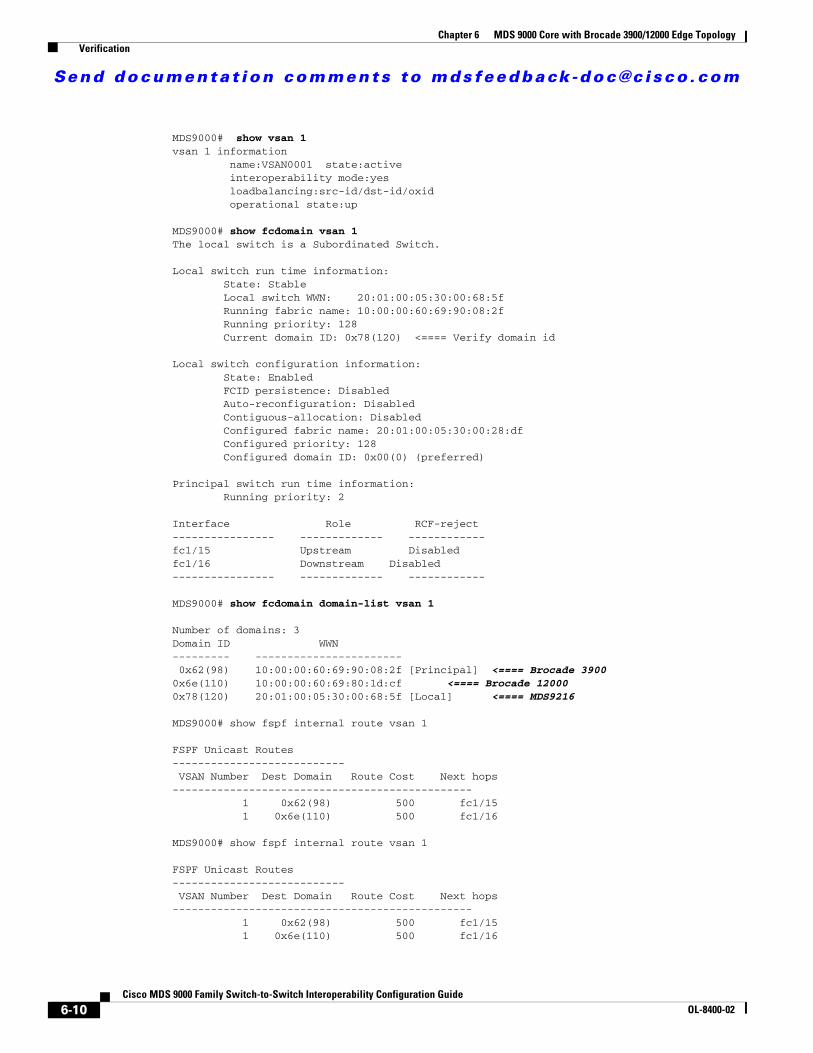
MDS9000# show vsan 1vsan 1 information name:VSAN0001 state:active interoperability mode:yes loadbalancing:src-id/dst-id/oxid operational state:up
MDS9000# show fcdomain vsan 1The local switch is a Subordinated Switch.
Local switch run time information: State: Stable Local switch WWN: 20:01:00:05:30:00:68:5f Running fabric name: 10:00:00:60:69:90:08:2f Running priority: 128 Current domain ID: 0x78(120) <==== Verify domain id
Local switch configuration information: State: Enabled FCID persistence: Disabled Auto-reconfiguration: Disabled Contiguous-allocation: Disabled Configured fabric name: 20:01:00:05:30:00:28:df Configured priority: 128 Configured domain ID: 0x00(0) (preferred)
Principal switch run time information: Running priority: 2
Interface Role RCF-reject---------------- ------------- ------------fc1/15 Upstream Disabledfc1/16 Downstream Disabled---------------- ------------- ------------
MDS9000# show fcdomain domain-list vsan 1
Number of domains: 3Domain ID WWN--------- ----------------------- 0x62(98) 10:00:00:60:69:90:08:2f [Principal] <==== Brocade 39000x6e(110) 10:00:00:60:69:80:1d:cf <==== Brocade 120000x78(120) 20:01:00:05:30:00:68:5f [Local] <==== MDS9216
MDS9000# show fspf internal route vsan 1
FSPF Unicast Routes--------------------------- VSAN Number Dest Domain Route Cost Next hops----------------------------------------------- 1 0x62(98) 500 fc1/15 1 0x6e(110) 500 fc1/16
MDS9000# show fspf internal route vsan 1
FSPF Unicast Routes--------------------------- VSAN Number Dest Domain Route Cost Next hops----------------------------------------------- 1 0x62(98) 500 fc1/15 1 0x6e(110) 500 fc1/16
6-10Cisco MDS 9000 Family Switch-to-Switch Interoperability Configuration Guide
OL-8400-02

Send documenta t ion comments to mdsfeedback -doc@c i sco .com
Chapter 6 MDS 9000 Core with Brocade 3900/12000 Edge Topology Verification
MDS9000# show fcns database vsan 1
VSAN 1:--------------------------------------------------------------------------FCID TYPE PWWN (VENDOR) FC4-TYPE:FEATURE--------------------------------------------------------------------------0x621c00 N 21:01:00:e0:8b:29:8b:3e (QLogic)0x621d00 N 21:00:00:e0:8b:09:8b:3e (QLogic)0x6e0e00 N 50:06:0e:80:03:4e:95:32 scsi-fcp
Total number of entries = 3
Note The MDS name server shows both local and remote entries, and it does not time out the entries.
Verifying the Brocade 3900 SwitchThe following examples show verification of the Brocade 3900 switch.
CA3900:admin> versionKernel: 2.4.2 Fabric OS: v4.0.2dMade on: Sat Apr 5 00:22:58 2003Flash: Mon Jun 23 18:49:49 2003BootProm: 3.1.18
CA3900:admin> licenseshowedcczbyc9pedd0X: Web license Zoning license Fabric license Fabric Watch license Trunking license
CA3900:admin> switchshowswitchName: CA3900switchType: 12.1switchState: Online switchRole: PrincipalswitchDomain: 98switchId: fffc62switchWwn: 10:00:00:60:69:90:08:2fswitchBeacon: OFF
Port Gbic Speed State ========================= 0 -- N2 No_Module 1 -- N2 No_Module 2 -- N2 No_Module 3 -- N2 No_Module 4 -- N2 No_Module 5 -- N2 No_Module 6 -- N2 No_Module 7 -- N2 No_Module 8 -- N2 No_Module 9 -- N2 No_Module 10 -- N2 No_Module 11 -- N2 No_Module 12 -- N2 No_Module 13 -- N2 No_Module
6-11Cisco MDS 9000 Family Switch-to-Switch Interoperability Configuration Guide
OL-8400-02

Send documenta t ion comments to mdsfeedback -doc@c i sco .com
Chapter 6 MDS 9000 Core with Brocade 3900/12000 Edge Topology Verification
14 -- N2 No_Module 15 id N2 No_Light 16 id N2 Online E-Port 20:01:00:05:30:00:68:5f (downstream) 17 -- N2 No_Module 18 -- N2 No_Module 19 -- N2 No_Module 20 -- N2 No_Module 21 -- N2 No_Module 22 -- N2 No_Module 23 -- N2 No_Module 24 -- N2 No_Module 25 -- N2 No_Module 26 -- N2 No_Module 27 -- N2 No_Module 28 id N2 Online F-Port 21:01:00:e0:8b:29:8b:3e 29 id N2 Online F-Port 21:00:00:e0:8b:09:8b:3e 30 id N2 No_Light 31 id N2 No_Light
CA3900:admin> topologyshow
3 domains in the fabric; Local Domain ID: 98
Domain: 110Metric: 1000Name: CA12000Path Count: 1
Hops: 2 Out Port: 16 In Ports: 28 29 Total Bandwidth: 2 Gbps Bandwidth Demand: 200 % Flags: D
Domain: 120Metric: 500Name: UnknownPath Count: 1
Hops: 1 Out Port: 16 In Ports: 28 29 Total Bandwidth: 2 Gbps Bandwidth Demand: 200 % Flags: D
CA3900:admin> interopmodeInteropMode: On
Usage: InteropMode 0|1 0: to turn it off 1: to turn it on
CA3900:admin> nsallshow3 Nx_Ports in the Fabric { 621c00 621d00 6e0e00 }
Note The Brocade switch remote name server entries time out of the cache after 900 seconds (15 minutes).
6-12Cisco MDS 9000 Family Switch-to-Switch Interoperability Configuration Guide
OL-8400-02

Send documenta t ion comments to mdsfeedback -doc@c i sco .com
Chapter 6 MDS 9000 Core with Brocade 3900/12000 Edge Topology Verification
CA3900:admin> urouteshow
Local Domain ID: 98
In Port Domain Out Port Metric Hops Flags Next (Dom, Port)---------------------------------------------------------------------------- 28 110 16 1000 2 D 120,65550 120 16 500 1 D 120,65550
Verifying the Brocade 12000 SwitchThe following examples show the commands used to verify the configuration of the Brocade 12000 switch.
CA12000:admin> versionKernel: 2.4.2 Fabric OS: v4.0.2cMade on: Wed Jan 22 04:17:49 2003Flash: Thu Mar 20 23:48:04 2003BootProm: 3.1.18
CA12000:admin> licenseshowSQeRRcyyRzdRfSSz: Web license Zoning license Fabric Watch license Trunking licenseRzb9SzQc99S0cATc: Fabric license
CA12000:admin> switchshowswitchName: CA12000switchType: 10.1switchState: Online switchRole: SubordinateswitchDomain: 110switchId: fffc6eswitchWwn: 10:00:00:60:69:80:1d:cfswitchBeacon: OFFblade7 Beacon: OFF
Area Slot Port Gbic Speed State ===================================== 0 7 0 id N2 No_Light 1 7 1 id N2 No_Light 2 7 2 id N2 No_Light 3 7 3 id N2 No_Light 4 7 4 id N2 No_Light 5 7 5 id N2 No_Light 6 7 6 id N2 No_Light 7 7 7 id N2 No_Light 8 7 8 id N2 No_Light 9 7 9 id N2 No_Light 10 7 10 id N2 No_Light 11 7 11 id N2 No_Light 12 7 12 id N2 No_Light 13 7 13 id N2 No_Light 14 7 14 id N2 Online F-Port 50:06:0e:80:03:4e:95:32 15 7 15 id N2 Online E-Port 20:01:00:05:30:00:68:5f (upstream)
6-13Cisco MDS 9000 Family Switch-to-Switch Interoperability Configuration Guide
OL-8400-02

Send documenta t ion comments to mdsfeedback -doc@c i sco .com
Chapter 6 MDS 9000 Core with Brocade 3900/12000 Edge Topology Verification
CA12000:admin> topologyshow
3 domains in the fabric; Local Domain ID: 110
Domain: 98Metric: 1000Name: CA3900Path Count: 1
Hops: 2 Out Port: 7/15 In Ports: 7/14 Total Bandwidth: 2 Gbps Bandwidth Demand: 100 % Flags: D
Domain: 120Metric: 500Name: UnknownPath Count: 1
Hops: 1 Out Port: 7/15 In Ports: 7/14 Total Bandwidth: 2 Gbps Bandwidth Demand: 100 % Flags: D
CA12000:admin> interopmodeInteropMode: On
Usage: InteropMode 0|1 0: to turn it off 1: to turn it on
CA12000:admin> nsshowThe Local Name Server has 1 entry { Type Pid COS PortName NodeName TTL(sec) N 6e0e00; 3;50:06:0e:80:03:4e:95:32;50:06:0e:80:03:4e:95:32; na FC4s: FCP [HITACHI OPEN-3 2105] Fabric Port Name: 20:0e:00:60:69:80:1d:cf
}CA12000:admin> nsallshow3 Nx_Ports in the Fabric { 621c00 621d00 6e0e00 }
Note The Brocade switch remote name server entries time out of the cache after 900 seconds (15 minutes).
CA12000:admin> urouteshow
Local Domain ID: 110
In Port Domain Out Port Metric Hops Flags Next (Dom, Port)---------------------------------------------------------------------------- 14 98 15 1000 2 D 120,65551 120 15 500 1 D 120,65551
6-14Cisco MDS 9000 Family Switch-to-Switch Interoperability Configuration Guide
OL-8400-02
Send documenta t ion comments to mdsfeedback -doc@c i sco .com
Chapter 6 MDS 9000 Core with Brocade 3900/12000 Edge Topology Zoning
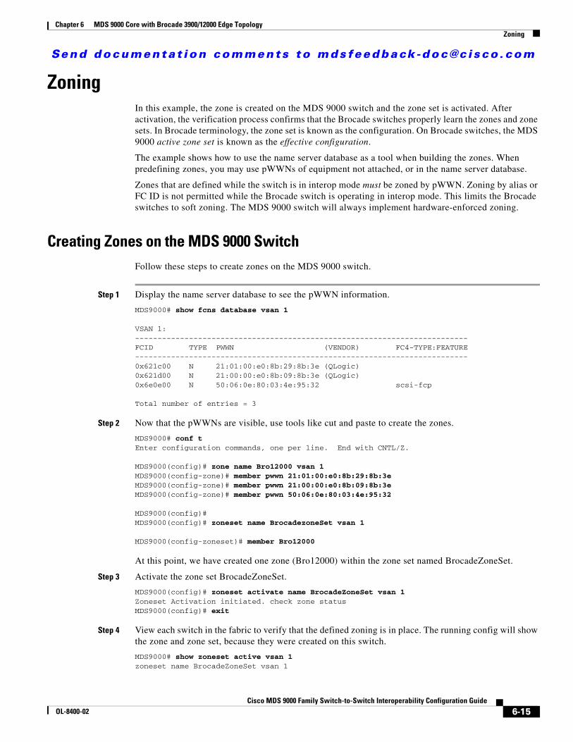
ZoningIn this example, the zone is created on the MDS 9000 switch and the zone set is activated. After activation, the verification process confirms that the Brocade switches properly learn the zones and zone sets. In Brocade terminology, the zone set is known as the configuration. On Brocade switches, the MDS 9000 active zone set is known as the effective configuration.
The example shows how to use the name server database as a tool when building the zones. When predefining zones, you may use pWWNs of equipment not attached, or in the name server database.
Zones that are defined while the switch is in interop mode must be zoned by pWWN. Zoning by alias or FC ID is not permitted while the Brocade switch is operating in interop mode. This limits the Brocade switches to soft zoning. The MDS 9000 switch will always implement hardware-enforced zoning.
Creating Zones on the MDS 9000 SwitchFollow these steps to create zones on the MDS 9000 switch.
Step 1 Display the name server database to see the pWWN information.
MDS9000# show fcns database vsan 1
VSAN 1:--------------------------------------------------------------------------FCID TYPE PWWN (VENDOR) FC4-TYPE:FEATURE--------------------------------------------------------------------------0x621c00 N 21:01:00:e0:8b:29:8b:3e (QLogic) 0x621d00 N 21:00:00:e0:8b:09:8b:3e (QLogic) 0x6e0e00 N 50:06:0e:80:03:4e:95:32 scsi-fcp
Total number of entries = 3
Step 2 Now that the pWWNs are visible, use tools like cut and paste to create the zones.
MDS9000# conf tEnter configuration commands, one per line. End with CNTL/Z.
MDS9000(config)# zone name Bro12000 vsan 1MDS9000(config-zone)# member pwwn 21:01:00:e0:8b:29:8b:3eMDS9000(config-zone)# member pwwn 21:00:00:e0:8b:09:8b:3eMDS9000(config-zone)# member pwwn 50:06:0e:80:03:4e:95:32
MDS9000(config)# MDS9000(config)# zoneset name BrocadezoneSet vsan 1
MDS9000(config-zoneset)# member Bro12000
At this point, we have created one zone (Bro12000) within the zone set named BrocadeZoneSet.
Step 3 Activate the zone set BrocadeZoneSet.
MDS9000(config)# zoneset activate name BrocadeZoneSet vsan 1Zoneset Activation initiated. check zone statusMDS9000(config)# exit
Step 4 View each switch in the fabric to verify that the defined zoning is in place. The running config will show the zone and zone set, because they were created on this switch.
MDS9000# show zoneset active vsan 1zoneset name BrocadeZoneSet vsan 1
6-15Cisco MDS 9000 Family Switch-to-Switch Interoperability Configuration Guide
OL-8400-02

Send documenta t ion comments to mdsfeedback -doc@c i sco .com
Chapter 6 MDS 9000 Core with Brocade 3900/12000 Edge Topology Zoning
zone name Bro12000 vsan 1* fcid 0x621c00 [pwwn 21:01:00:e0:8b:29:8b:3e]* fcid 0x621d00 [pwwn 21:00:00:e0:8b:09:8b:3e]* fcid 0x6e0e00 [pwwn 50:06:0e:80:03:4e:95:32]
Verifying Zoning on the Brocade 12000 SwitchThe Brocade 12000 switch does not have a defined configuration, but it does contain an effective configuration. The effective configuration was passed to it by the MDS 9000 switch when the MDS 9000 switch full zone set was activated.
CA12000:admin> cfgshow Defined configuration: no configuration defined
Effective configuration: cfg: BrocadeZoneSet zone: Bro12000 21:01:00:e0:8b:29:8b:3e 21:00:00:e0:8b:09:8b:3e 50:06:0e:80:03:4e:95:32
Verifying Zoning on the Brocade 3900 SwitchThe following example shows commands used to verify the configuration of the Brocade 3900 switch.
CA3900:admin> cfgshow Defined configuration: no configuration defined
Effective configuration: cfg: BrocadeZoneSet zone: Bro12000 21:01:00:e0:8b:29:8b:3e 21:00:00:e0:8b:09:8b:3e 50:06:0e:80:03:4e:95:32
Note The zones created in the MDS 9000 switch are propagated to the Brocade switches. Although the cfgshow command does not show these zones as the defined configuration, if the switch is isolated and rebooted, the correct zone configuration is effective.
On the MDS 9000 switch, the active zone configuration is always saved to memory. It will not display in the running configuration. If the switch is isolated and rebooted, the last active zone set is reinstated as the current active zone set.
Any changes to the zones or zone set while the switch is isolated will need to pass a zone merge validation when the ISLs are activated.
6-16Cisco MDS 9000 Family Switch-to-Switch Interoperability Configuration Guide
OL-8400-02


