Embed Size (px)
Citation preview
MALLA REDDY COLLEGE OF ENGINEERING & TECHNOLOGY
DEPARTMENT OF MECHANICAL ENGINEERING (Autonomous Institution-UGC, Govt. of India) Secunderabad-500100, Telangana State, India.
www.mrcet.ac.in
COURSE MATERIAL
IV Year B. Tech I- Semester
MECHANICAL ENGINEERING
MECHANICAL MEASUREMENTS
AND INSTRUMENTATION
R17A0328
www.mrcet.ac.in
MALLA REDDY COLLEGE OF ENGINEERING & TECHNOLOGY
(Autonomous Institution – UGC, Govt. of India)
DEPARTMENT OF MECHANICAL ENGINEERING
CONTENTS
1. Vision, Mission & Quality Policy
2. Pos, PSOs & PEOs
3. Blooms Taxonomy
4. Course Syllabus
5. Lecture Notes (Unit wise)
a. Objectives and outcomes
b. Notes
c. Presentation Material (PPT Slides/ Videos)
d. Industry applications relevant to the concepts covered
e. Question Bank for Assignments
f. Tutorial Questions
6. Previous Question Papers

MALLA REDDY COLLEGE OF ENGINEERING & TECHNOLOGY
(Autonomous Institution – UGC, Govt. of India)
VISION
To establish a pedestal for the integral innovation, team spirit, originality and
competence in the students, expose them to face the global challenges and become
technology leaders of Indian vision of modern society.
MISSION
To become a model institution in the fields of Engineering, Technology and
Management.
To impart holistic education to the students to render them as industry ready
engineers.
To ensure synchronization of MRCET ideologies with challenging demands of
International Pioneering Organizations.
QUALITY POLICY
To implement best practices in Teaching and Learning process for both UG and PG
courses meticulously.
To provide state of art infrastructure and expertise to impart quality education.
To groom the students to become intellectually creative and professionally
competitive.
To channelize the activities and tune them in heights of commitment and sincerity,
the requisites to claim the never - ending ladder of SUCCESS year after year.
For more information: www.mrcet.ac.in

MALLA REDDY COLLEGE OF ENGINEERING & TECHNOLOGY
(Autonomous Institution – UGC, Govt. of India)
www.mrcet.ac.in Department of Mechanical Engineering
VISION
To become an innovative knowledge center in mechanical engineering through state-of-
the-art teaching-learning and research practices, promoting creative thinking
professionals.
MISSION
The Department of Mechanical Engineering is dedicated for transforming the students
into highly competent Mechanical engineers to meet the needs of the industry, in a
changing and challenging technical environment, by strongly focusing in the
fundamentals of engineering sciences for achieving excellent results in their professional
pursuits.
Quality Policy
To pursuit global Standards of excellence in all our endeavors namely teaching,
research and continuing education and to remain accountable in our core and
support functions, through processes of self-evaluation and continuous
improvement.
To create a midst of excellence for imparting state of art education, industry-
oriented training research in the field of technical education.

MALLA REDDY COLLEGE OF ENGINEERING & TECHNOLOGY
(Autonomous Institution – UGC, Govt. of India)
www.mrcet.ac.in Department of Mechanical Engineering
PROGRAM OUTCOMES
Engineering Graduates will be able to:
1. Engineering knowledge: Apply the knowledge of mathematics, science, engineering
fundamentals, and an engineering specialization to the solution of complex engineering
problems.
2. Problem analysis: Identify, formulate, review research literature, and analyze complex
engineering problems reaching substantiated conclusions using first principles of
mathematics, natural sciences, and engineering sciences.
3. Design/development of solutions: Design solutions for complex engineering problems
and design system components or processes that meet the specified needs with
appropriate consideration for the public health and safety, and the cultural, societal, and
environmental considerations.
4. Conduct investigations of complex problems: Use research-based knowledge and
research methods including design of experiments, analysis and interpretation of data,
and synthesis of the information to provide valid conclusions.
5. Modern tool usage: Create, select, and apply appropriate techniques, resources, and
modern engineering and IT tools including prediction and modeling to complex
engineering activities with an understanding of the limitations.
6. The engineer and society: Apply reasoning informed by the contextual knowledge to
assess societal, health, safety, legal and cultural issues and the consequent
responsibilities relevant to the professional engineering practice.
7. Environment and sustainability: Understand the impact of the professional engineering
solutions in societal and environmental contexts, and demonstrate the knowledge of, and
need for sustainable development.
8. Ethics: Apply ethical principles and commit to professional ethics and responsibilities and
norms of the engineering practice.
9. Individual and teamwork: Function effectively as an individual, and as a member or
leader in diverse teams, and in multidisciplinary settings.
10. Communication: Communicate effectively on complex engineering activities with the
engineering community and with society at large, such as, being able to comprehend and
write effective reports and design documentation, make effective presentations, and give
and receive clear instructions.
11. Project management and finance: Demonstrate knowledge and understanding of the
engineering and management principles and apply these to one’s own work, as a member
and leader in a team, to manage projects and in multidisciplinary environments.

MALLA REDDY COLLEGE OF ENGINEERING & TECHNOLOGY
(Autonomous Institution – UGC, Govt. of India)
www.mrcet.ac.in Department of Mechanical Engineering
12. Life-long learning: Recognize the need for and have the preparation and ability to
engage in independent and life-long learning in the broadest context of technological
change.
PROGRAM SPECIFIC OUTCOMES (PSOs)
PSO1 Ability to analyze, design and develop Mechanical systems to solve the
Engineering problems by integrating thermal, design and manufacturing Domains.
PSO2 Ability to succeed in competitive examinations or to pursue higher studies or
research.
PSO3 Ability to apply the learned Mechanical Engineering knowledge for the
Development of society and self.
Program Educational Objectives (PEOs)
The Program Educational Objectives of the program offered by the department are broadly
listed below:
PEO1: PREPARATION
To provide sound foundation in mathematical, scientific and engineering fundamentals
necessary to analyze, formulate and solve engineering problems.
PEO2: CORE COMPETANCE
To provide thorough knowledge in Mechanical Engineering subjects including theoretical
knowledge and practical training for preparing physical models pertaining to Thermodynamics,
Hydraulics, Heat and Mass Transfer, Dynamics of Machinery, Jet Propulsion, Automobile
Engineering, Element Analysis, Production Technology, Mechatronics etc.
PEO3: INVENTION, INNOVATION AND CREATIVITY
To make the students to design, experiment, analyze, interpret in the core field with the help of
other inter disciplinary concepts wherever applicable.
PEO4: CAREER DEVELOPMENT
To inculcate the habit of lifelong learning for career development through successful completion
of advanced degrees, professional development courses, industrial training etc.

MALLA REDDY COLLEGE OF ENGINEERING & TECHNOLOGY
(Autonomous Institution – UGC, Govt. of India)
www.mrcet.ac.in Department of Mechanical Engineering
PEO5: PROFESSIONALISM
To impart technical knowledge, ethical values for professional development of the student to
solve complex problems and to work in multi-disciplinary ambience, whose solutions lead to
significant societal benefits.
MALLA REDDY COLLEGE OF ENGINEERING & TECHNOLOGY (Autonomous Institution – UGC, Govt. of India)
www.mrcet.ac.in Department of Mechanical Engineering
Blooms Taxonomy
Bloom’s Taxonomy is a classification of the different objectives and skills that educators set for
their students (learning objectives). The terminology has been updated to include the following
six levels of learning. These 6 levels can be used to structure the learning objectives, lessons,
and assessments of a course.
1. Remembering: Retrieving, recognizing, and recalling relevant knowledge from long‐ term
memory.
2. Understanding: Constructing meaning from oral, written, and graphic messages through
interpreting, exemplifying, classifying, summarizing, inferring, comparing, and explaining.
3. Applying: Carrying out or using a procedure for executing or implementing.
4. Analyzing: Breaking material into constituent parts, determining how the parts relate to
one another and to an overall structure or purpose through differentiating, organizing, and
attributing.
5. Evaluating: Making judgments based on criteria and standard through checking and
critiquing.
6. Creating: Putting elements together to form a coherent or functional whole; reorganizing
elements into a new pattern or structure through generating, planning, or producing.

MALLA REDDY COLLEGE OF ENGINEERING & TECHNOLOGY (Autonomous Institution – UGC, Govt. of India)
www.mrcet.ac.in Department of Mechanical Engineering
MRCET Campus (UGC Autonomous)
190
MALLA REDDY COLLEGE OF ENGINEERING &TECHNOLOGY
IV Year B. Tech, ME-I Sem
(R17A0328) MECHANICAL MEASUREMENTS AND INSTRUMENATION
Course Objectives:
To study concept of architecture of the measurementsystem.
To deliver working principle of mechanical measurementsystem.
Toimpartknowledgeofmathematicalmodelingofthecontrolsystemandcontrol
system under different timedomain.
To analyze the stress and strain measurements and humiditymeasurements
TounderstandtheMeasurementofForce,TorqueandPowerElementsofControl
Systems
UNIT –I
Definition – Basic principles of measurement – Measurement systems, generalized
configuration and functional descriptions of measuring instruments – examples. Dynamic
performance characteristics – sources of error, Classification and elimination oferror.
Measurement of Displacement: Theory and construction of various transducers to measure
displacement – Piezo electric, Inductive, capacitance, resistance, ionization and Photo electric
transducers, Calibration procedures.
UNIT –II
Measurement of Temperature: Classification – Ranges – Various Principles of measurement –
Expansion, Electrical Resistance – Thermistor – Thermocouple – Pyrometers – Temperature
Indicators.
Measurement of Pressure: Units – classification – different principles used. Manometers,
Piston, Bourdon pressure gauges, Bellows – Diaphragm gauges. Low pressure measurement –
Thermal conductivity gauges – ionization pressure gauges, Mcleod pressuregauge.
Measurement of Level: Direct method – Indirect methods – capacitative, ultrasonic,
magnetic, cryogenic fuel level indicators – Bubler level indicators.
UNIT –III
Flow Measurement: Rotameter, magnetic, Ultrasonic, Turbine flow meter, Hot – wire
anemometer, Laser Doppler Anemometer (LDA).
Measurement of Speed: Mechanical Tachometers – Electrical tachometers – Stroboscope,
Noncontact type of tachometer
Measurement of Acceleration and Vibration: Different simple instruments – Principles of
Seismic instruments – Vibrometer and accelerometer using this principle.
UNIT –IV
Stress Strain Measurements: Various types of stress and strain measurements – electrical strain
gauge – gauge factor – method of usage of resistance strain gauge for bending compressive
and tensile strains – usage for measuring torque, Strain gaugeRosettes.
Measurement of Humidity – Moisture content of gases, sling psychrometer, Absorption
psychrometer, Dew point meter.
L T/P/D C 3 0 3
MRCET Campus (UGC Autonomous)
191
UNIT –V
MeasurementofForce,TorqueAndPower-Elasticforcemeters,loadcells,Torsionmeters,
Dynamometers.
Elements of Control Systems: Introduction, Importance – Classification – Open and closed
systemsServomechanisms–Exampleswithblockdiagrams–Temperature,speed&position
controlsystems.
TEXT BOOKS:
1. Mechanical Measurements / Beck With, Marangoni, Linehar/ PHIPublisher 2. Measurement Systems: Applications & design / D.S Kumar/McGraw HillPublishers
3. Mechanical Measurements /Shawney/McGraw HillPublishers
REFERENCE BOOKS:
1. Experimental Methods for Engineers / Holman/ McGraw-HillEducation
2. Mechanical and Industrial Measurements / R.K. Jain/ KhannaPublishers. 3. InstrumentationandMechanicalMeasurements/A.K.Tayal/GalgotiaPublications.
Course Outcomes:
LearnershouldbeabletoIdentifyandselectpropermeasuringinstrumentforspecific application Illustrate working principle of measuringinstruments.
Explaincalibrationmethodologyanderroranalysisrelatedtomeasuringinstruments
Mathematically model and analyze for differentmeasuments.
AcquireknowledgeinstressandstrainmeasurementsandHumiditymeasurement.
Identify,analysis,andsolvemechanicalengineeringproblemsusefultothesociety
UNIT 1
DEFINITION &
MEASUREMENT OF DISPLACEMENT
DEPARTMENT OF MECHANICAL ENGINEERING
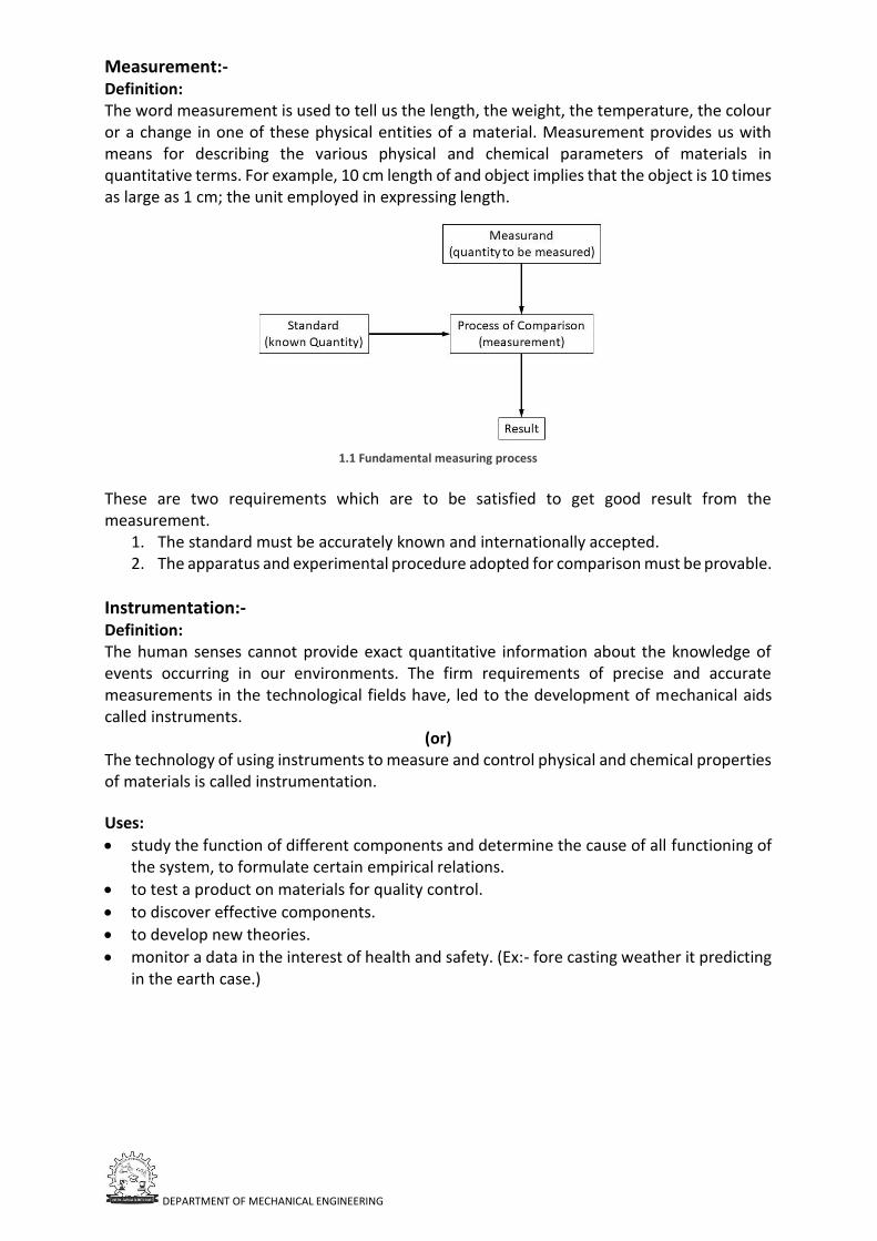
Measurement:- Definition: The word measurement is used to tell us the length, the weight, the temperature, the colour or a change in one of these physical entities of a material. Measurement provides us with means for describing the various physical and chemical parameters of materials in quantitative terms. For example, 10 cm length of and object implies that the object is 10 times as large as 1 cm; the unit employed in expressing length.
1.1 Fundamental measuring process
These are two requirements which are to be satisfied to get good result from the measurement.
1. The standard must be accurately known and internationally accepted. 2. The apparatus and experimental procedure adopted for comparison must be provable.
Instrumentation:- Definition: The human senses cannot provide exact quantitative information about the knowledge of events occurring in our environments. The firm requirements of precise and accurate measurements in the technological fields have, led to the development of mechanical aids called instruments.
(or) The technology of using instruments to measure and control physical and chemical properties of materials is called instrumentation.
Uses:
• study the function of different components and determine the cause of all functioning of the system, to formulate certain empirical relations.
• to test a product on materials for quality control.
• to discover effective components.
• to develop new theories.
• monitor a data in the interest of health and safety. (Ex:- fore casting weather it predicting in the earth case.)
DEPARTMENT OF MECHANICAL ENGINEERING
Methods of measurement:- 1. Direct and indirect measurement. 2. Primary and secondary & tertiary measurement. 3. Contact and non-contact type of measurement.
1. Direct and indirect measurement: Measurement is a process of comparison of the physical quantity with a standard depending upon requirement and based upon the standard employed, these are the two basic methods of measurement. Direct measurement: The value of the physical parameter is determined by comparing it directly with different standards. The physical standards like mass, length and time are measured by direct measurement. Indirect measurement: The value of the physical parameter is more generally determined by indirect comparison with the secondary standards through calibration. The measurement is converting into an analogous signal which subsequently process and fed to the end device at present the result of measurement.
2. Primary and secondary & tertiary measurement: The complexity of an instrument system depending upon measurement being made and upon the accuracy level to which the measurement is needed. Based upon the complexity of the measurement systems, the measurement is generally grouped into three categories. i. Primary ii. Secondary
iii. Tertiary.
In the primary mode, the sought value of physical parameter is determined by comparing it directly with reference standards the required information is obtained to sense of side and touch.
Examples are: a) Matching of two lengths is determining the length of a object with ruler. b) Estimation the temperature difference between the components of the container by
inserting fingers. c) Use of bean balance measure masses. d) Measurement of time by counting a number of strokes of a block.
Secondary and tertiary measurement are the indirect measurements involving one transmission are called secondary measurements and those involving two convergent are called tertiary measurements
Examples:
a) The convergent of pressure into displacement by means of be allows and the convergent of force into displacement.
b) Pressure measurement by manometer and the temperature measurement by mercury in glass tube thermometer.
DEPARTMENT OF MECHANICAL ENGINEERING
The measurement of static pressure by boundary tube pressure gauge is a typical example of tertiary measurement.
3. Contact and non-contact type of measurements: Contact type:
Where the sensing element of measuring device as a contact with medium whose characteristics are being measured.
Non-contact type: Where the sense doesn't communicate physically with the medium.
Example: The optical, radioactive and some of the electrical/electronic measurement belong to this category.
Objectives of instrumentation:- 1. The major objective of instrumentation is to measure and control the field parameters to
increase safety and efficiency of the process. 2. To achieve good quality. 3. To achieve auto machine and automatic control of process there by reducing human. 4. To maintain the operation of the plan within the design exportations and to achieve good
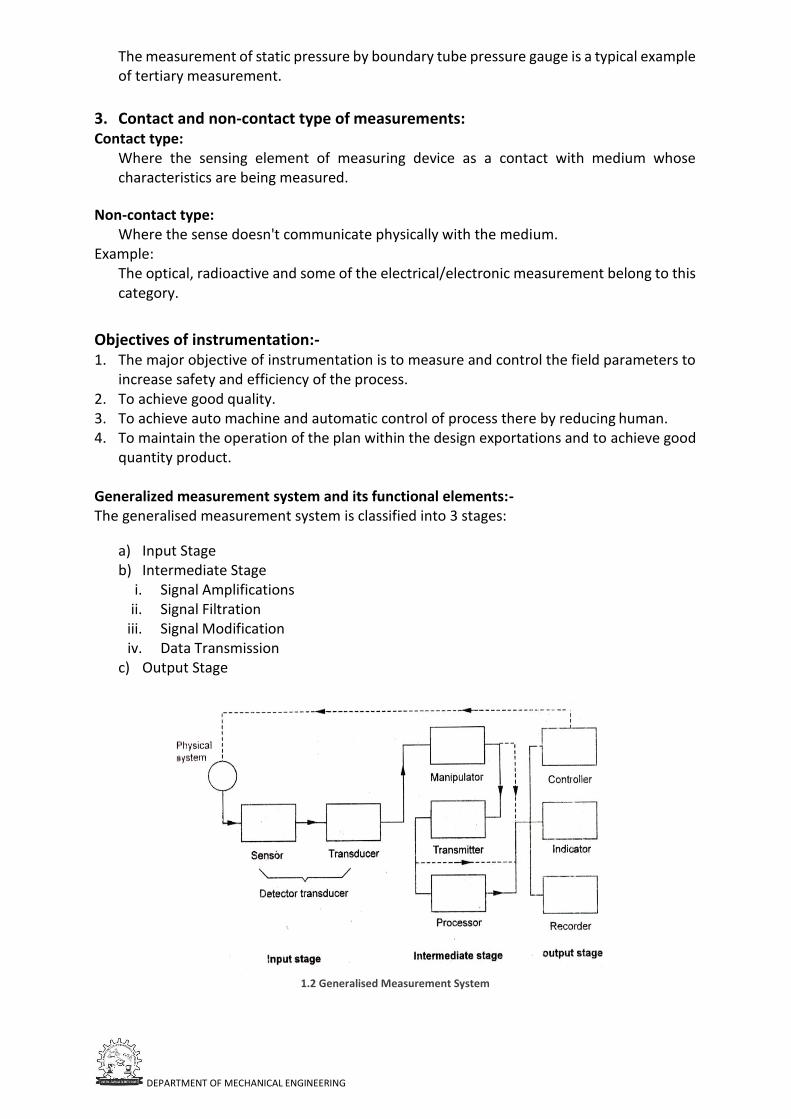
quantity product. Generalized measurement system and its functional elements:- The generalised measurement system is classified into 3 stages:
a) Input Stage b) Intermediate Stage
i. Signal Amplifications ii. Signal Filtration
iii. Signal Modification iv. Data Transmission
c) Output Stage
1.2 Generalised Measurement System
DEPARTMENT OF MECHANICAL ENGINEERING
Input Stage: Input stage (Detector-transducer) which is acted upon by the input signal (a variable to be measured) such as length, pressure, temperature, angle etc. and which transforms this signal in some other physical form. When the dimensional units for the input and output signals are same, this functional element/stage is referred to as the transformer.
Intermediate Stage: i. signal amplification to increase the power or amplitude of the signal without affecting
its waveform. The output from the detector-transducer element' is generally too small to operate an indicator or a recorder and its amplification is necessary. Depending upon the type of transducer signal, the amplification device may be of mechanical, hydraulic/pneumatic, optical and electrical type.
ii. Signal filtration to extract the desired information from extraneous data. Signal filtration removes the unwanted noise signals that tend to obscure the transducer signal. Depending upon nature of the signal and situation, one may use mechanical, pneumatic or electrical filters.
iii. Signal modification to provide a digital signal from an analog signal or vice versa, or change the form of output from voltage to frequency or from voltage to current.
iv. Data transmission to telemeter the data for remote reading and recording.
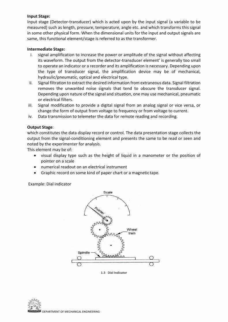
Output Stage: which constitutes the data display record or control. The data presentation stage collects the output from the signal-conditioning element and presents the same to be read or seen and noted by the experimenter for analysis. This element may be of:
• visual display type such as the height of liquid in a manometer or the position of pointer on a scale
• numerical readout on an electrical instrument
• Graphic record on some kind of paper chart or a magnetic tape. Example: Dial indicator
1.3 Dial Indicator
DEPARTMENT OF MECHANICAL ENGINEERING
(Second Explanation)
1. Primary sensing element. 2. Variable conversion (or) Transducer element. 3. Manipulation of element. 4. Data transmission element. 5. Data processing element. 6. Data presentation element.
1. Primary Sensing Element:
An element that is sensitive to the measured variable .The sensing element sense the condition , state (or) value of the process variable by extracting a small part of energy from the measurement and produces an output which is proportional to the input. Because of the energy expansion, the measured quantity is always disturb. Good instruments are designed to minimise this loading effect.
2. Variable conversion (or) Transducer Element:
An element that converts the signal from one physical for to Another without changing the information content of the signal. Example:
• Bourdon tube and bellows which transfer pressure into displacement.
• Proving ring and other elastic members which converts force into displacement.
• Rack and Pinion: It converts rotary to linear and vice versa.
• Thermo couple which converts information about temperature difference to information in the form of E.M.F.
3. Manipulation Element: It modifies the direct signal by amplification, filtering etc., so that a desired output is produced. [input]× constant = Output
4. Data Transmission Element: An element that transmits the signal from one location to another without changing the information content. Data may by transmitted over long distances (from one location to another) or short distances (from a test centre to a nearby computer).
5. Data Processing Element: An element that modifies data before it is displayed or finally recorded. Data processing may be used for such purposes as:
• Corrections to the measured physical variables to compensate for scaling, non- linearity, zero offset, temperature error etc.
• Covert the data into useful form, e.g., calculation of engine efficiency from speed, power input and torque developed.
• Collect information regarding average, statistical and logarithmic values.
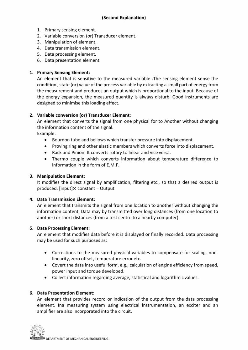
6. Data Presentation Element: An element that provides record or indication of the output from the data processing element. Ina measuring system using electrical instrumentation, an exciter and an amplifier are also incorporated into the circuit.
DEPARTMENT OF MECHANICAL ENGINEERING
The display unit may be required to serve the following functions.
• Transmitting
• Signaling
• Registering
• Indicating
• Recording
1.4 Electro-mechanical measurement system
CLASSIFICATION OF INSTRUMENTS:
1. Automatic and Manual instruments: 2. Self-generating and power operated 3. Self-contact and remote indicating instruments 4. Deflection and null type 5. Analog and digital types 6. Contact and non-contact type
1. Automatic and manual instruments:
The manual instruments require the services of an operator while the automatic types donot. For example, the temperature measurement by mercury-in-glass thermometer is automatic as the instrument indicates the temperature without requiring any manual assistance. However, the measurement of temperature by a resistance thermometer incorporating; Wheatstone brigde in its circuit is manual in operation as it needs an operator for obtaining the null position.
2. Self-generating and power operated Self-generated instruments are the output is supplied entirely by the input signal. The instrument does not require any outside power in performing its function Example: mercury in glass thermometer, bourdon pressure gauge, pitot tube for measuring velocity So, instruments require same auxiliary source of power such as compound air, electricity, hydraulic supply for these operations and hence are called externally powered instruments (or) passive instruments.
DEPARTMENT OF MECHANICAL ENGINEERING
Example:
• L.V.D.T(Linear Variable Differential Transducer)
• Strain gauge load cell
• Resistance thermometer and the mister.
• Self-contained remote indicator.
3. Self-contact and remote indicating instruments: The different elements of a self-contained instrument are contained in one physical assembly. In a remote indicating instrument, the primary sensing element may be located at a sufficiently long distance from the secondary indicating element. In the modern instrumentation technology, there is a trend to install remote indicating instruments where the important indications can be displayed in the central control rooms.
4. Deflection and null output instruments:
In null-type instruments, the physical effect caused by the quantity being measured is nullified (deflection maintained at zero) by generating an equivalent opposing effect. The equivalent null causing effect then provides a measure of the unknown quantity. A deflection type instrument is that in which the physical effect generated by the measuring quantity (measurand) is noted and correlated to the measurand.
5. Analog and digital instruments: The signals of an analog unit vary in a continuous fashion and can take on infinite number of values in a given range. Wrist watch speedometer of an automobile, fuel gauge, ammeters and voltmeters are examples of analog instruments.
Instruments basically perform two functions: i. Collection of data and
ii. Control of plant and process
Accordingly based upon the service rendered, the instruments may also be classified as indicating instruments, recording instruments and controlling instruments
Performance characteristics of a measuring instrument:
1. Static characteristics 2. Dynamic characteristics
The performance characteristics of an instrument system is conclusion by low accurately the system measures the requires input and how absolutely it reject the undesirable inputs.
Error = measured value ( ) – true value (( ) Correction = ( - ).
1. Static characteristics:
a) Range and span, b) Accuracy, error, correction, c) Calibration, d) Repeatability, e) Reproducibility f) Precision, g) Sensitivity, h) Threshold, i) Resolution, j) Drift, k) Hysteresis, dead zone.
a) Range and span The region between the limits with in which as instrument is designed to operate for measuring, indicating (or) recording a physical quantity is called the range of instrument.
DEPARTMENT OF MECHANICAL ENGINEERING
The range is expressed by standing the lower and upper values. Span represents the algebraic difference between the upper and lower range values of the instruments.
Ex: -
Range : 10 Co to 80 Co Span=90oc
Range : 5 bar to 100 bar Span=100-5=95bar
Range : 0 v to 75v Span=75volts
b) Accuracy, error, correction: No instrument gives an exact value of what is being measured, there is always some uncertainty in the measured values. This uncertainty express in terms of accuracy and error.
Accuracy of an indicated value (measured) may be defined as closeness to an accepted standard value (true value). The difference between measured value ( ) and true value ( ) of the quantity is expressed as instrument error.
= -
Static correction is defined as-
= -
c) Calibration:
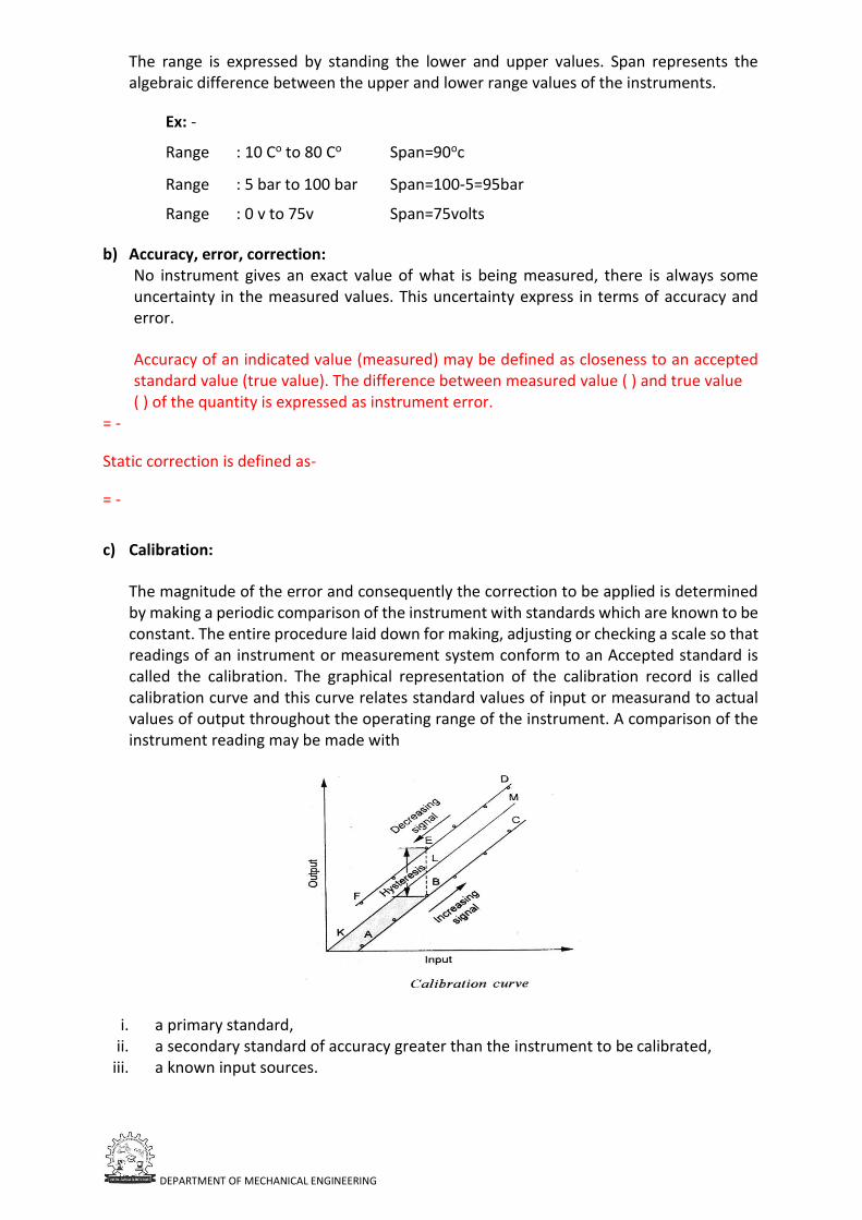
The magnitude of the error and consequently the correction to be applied is determined by making a periodic comparison of the instrument with standards which are known to be constant. The entire procedure laid down for making, adjusting or checking a scale so that readings of an instrument or measurement system conform to an Accepted standard is called the calibration. The graphical representation of the calibration record is called calibration curve and this curve relates standard values of input or measurand to actual values of output throughout the operating range of the instrument. A comparison of the instrument reading may be made with
i. a primary standard,
ii. a secondary standard of accuracy greater than the instrument to be calibrated, iii. a known input sources.
DEPARTMENT OF MECHANICAL ENGINEERING
The following points and observations need consideration while calibrating an instrument:-
a) Calibration of the instrument is out with the instrument in the same (upright, horizontal etc.) and subjected same temperature and other environmental conditions under which it is to operate while in service.
b) The instrument is calibrated with values of the measuring impressed both in the increasing and in the decreasing order. The results are then expressed graphically, typically the output is plotted as the ordinate and the input or measuring as the abscissa.
c) Output readings for a series of impressed values going up the scale may not agree with the output readings for the same input values when going down.
d) Lines or curves plotted in the graphs may not close to form a loop.
d) Repeatability: Repeatability describes the closeness of the output readings, when the same input is applied repeatability over a short period of time with the same measurement conditions, same instrument and observer, same location and same conditions of use maintained throughout.
e) Reproductability: Reproductability describes the closeness of output readings for the same input. When are changes in the method of measurement, observer, measuring instrument, location, conditions of use and time of measurement. f) Precision: The instrument ability to reproduce a certain group of the readings with a given accuracy is known as precision i.e., if a no of measurements are made on the same true value then the degree of closeness of these measurements is called precision.
It refers to the ability of an instrument to give its readings again and again in the same manner for constant input signals.
g) Sensitivity: Sensitivity of an instrument is the ratio of magnitude of response (output signal) to the magnitude of the quantity being measured (input signal) i.e., h) Threshold: Threshold defines the minimum value of input which is necessary to cause detectable change from zero output.
When the input to an instrument is gradually increased from zero, then the input must reach to a certain minimum value, so that the change in the output can be detected. The minimum value of input refers to threshold.
i) Resolution: It is defines as the increment in the input of the instrument for which input remains constant i.e., when the input given to the instrument is slowly increased for which the output remains same until the increment exceeds a different value.
j) Drift: The slow variation of the output signal of a measuring instrument is known as draft.
The variation of the output signal is not due to any changes in the input quantity, but to the changes in the working conditions of the components inside the measuring instruments.
DEPARTMENT OF MECHANICAL ENGINEERING
k) Hysteresis, Dead zone: Hysteresis is the maximum difference for the same measuring quantity (input signal) between the up scale and down scale reading during a full range measure in each direction.
Dead zone is the largest range through which an input signal can be varied without initiating any response from the indicating instrument it is due to the friction.
Dynamic characteristics: a) Speed of response and measuring lag, b) Fidelity and dynamic error, c) Over shoot, d) Dead time and dead zone, e) Frequency response.
a) Speed of response and measuring lag: In a measuring instrument the speed of response (or) responsiveness is defined as the rapidity with which an instrument responds to a change in the value of the quantity being measured.
Measuring lag refers to delay in the responds of an instrument to a change in the input signal. The lag is caused by conditions such as inertia, or resistance.
b) Fidelity and dynamic errors: Fidelity of an instrumentation system is defined as the degree of closeness with which the system indicates (or) records the signal which is upon its. It refers to the ability of the system to reproduce the output in the same form as the input. If the input is a sine wave then for 100% fidelity the output should also be a sine wave.
The difference between the indicated quantity and the true value of the time quantity is the dynamic error. Here the static error of instrument is assumed to be zero.
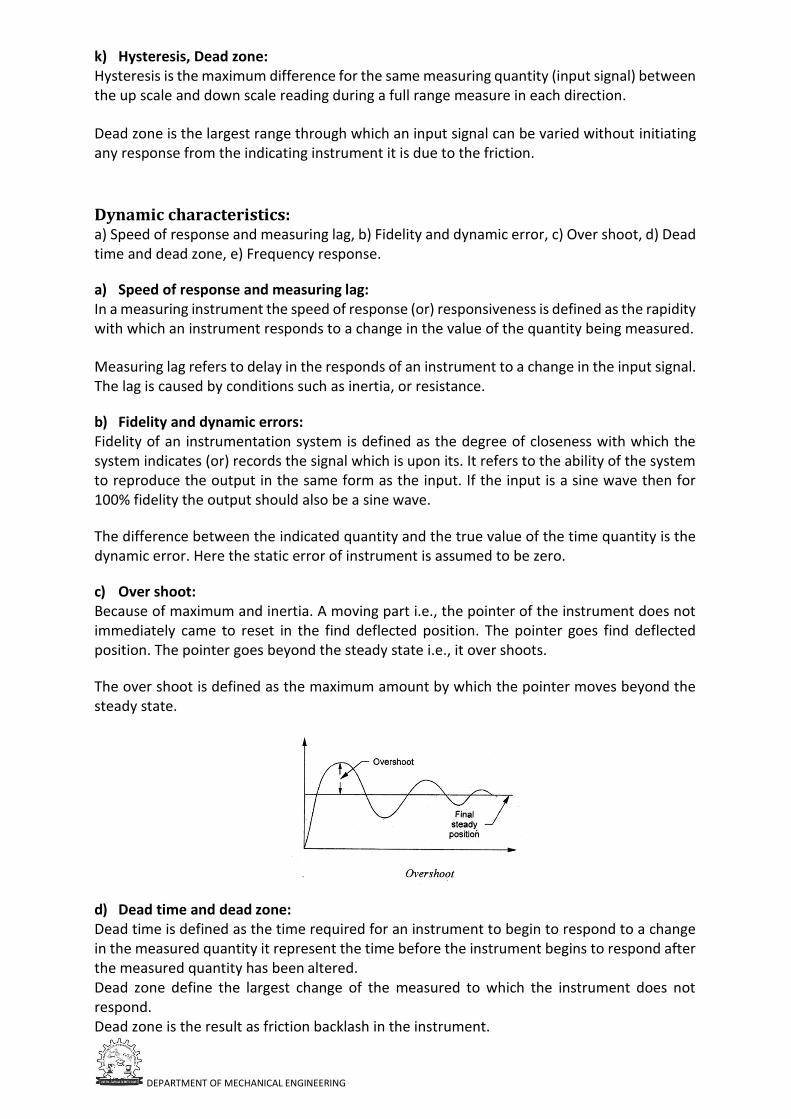
c) Over shoot: Because of maximum and inertia. A moving part i.e., the pointer of the instrument does not immediately came to reset in the find deflected position. The pointer goes find deflected position. The pointer goes beyond the steady state i.e., it over shoots.
The over shoot is defined as the maximum amount by which the pointer moves beyond the steady state.
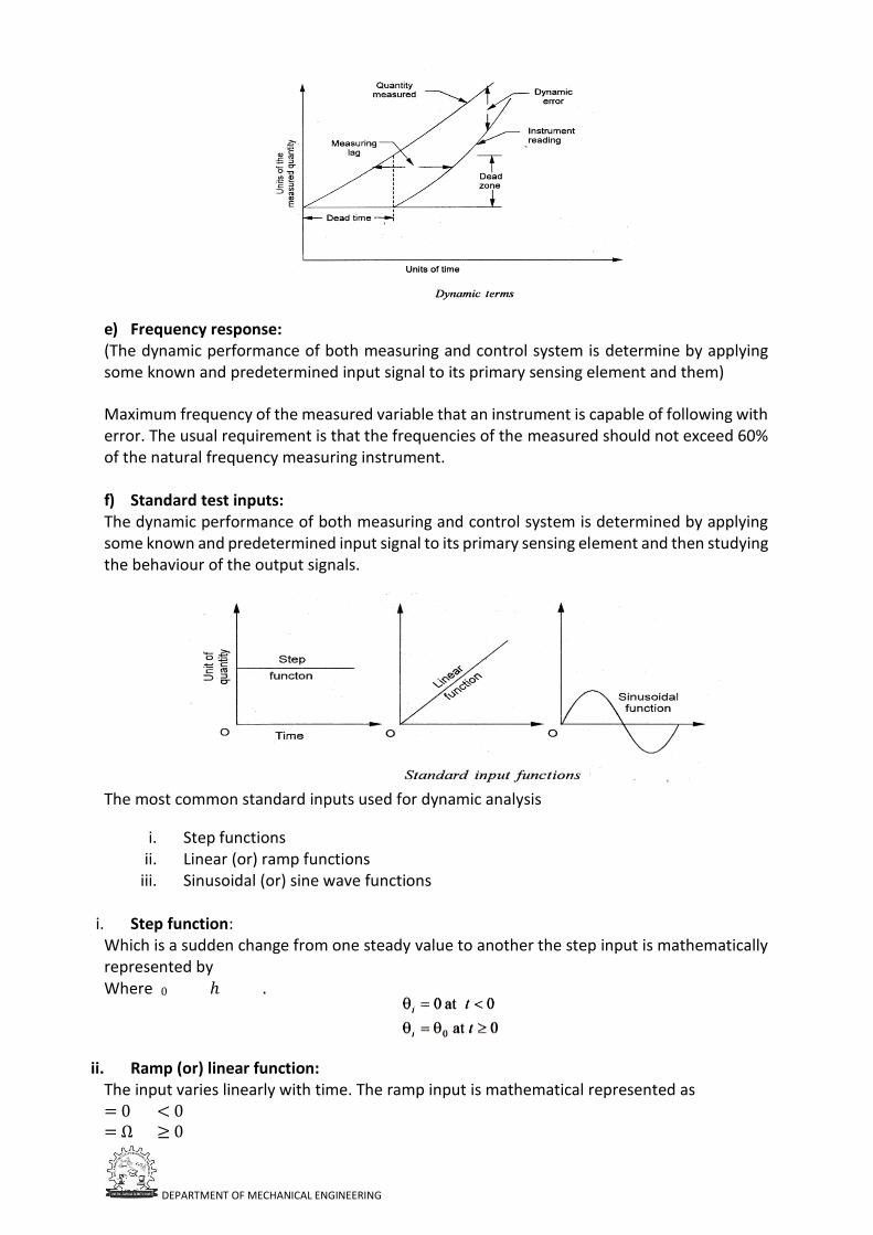
d) Dead time and dead zone: Dead time is defined as the time required for an instrument to begin to respond to a change in the measured quantity it represent the time before the instrument begins to respond after the measured quantity has been altered. Dead zone define the largest change of the measured to which the instrument does not respond. Dead zone is the result as friction backlash in the instrument.
DEPARTMENT OF MECHANICAL ENGINEERING
e) Frequency response: (The dynamic performance of both measuring and control system is determine by applying some known and predetermined input signal to its primary sensing element and them)
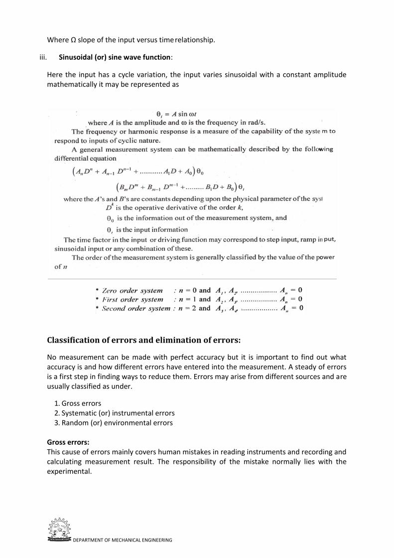
Maximum frequency of the measured variable that an instrument is capable of following with error. The usual requirement is that the frequencies of the measured should not exceed 60% of the natural frequency measuring instrument. f) Standard test inputs: The dynamic performance of both measuring and control system is determined by applying some known and predetermined input signal to its primary sensing element and then studying the behaviour of the output signals.
The most common standard inputs used for dynamic analysis
i. Step functions ii. Linear (or) ramp functions
iii. Sinusoidal (or) sine wave functions
i. Step function: Which is a sudden change from one steady value to another the step input is mathematically represented by Where 0 ℎ .
ii. Ramp (or) linear function: The input varies linearly with time. The ramp input is mathematical represented as = 0 < 0 = Ω ≥ 0
DEPARTMENT OF MECHANICAL ENGINEERING
Where Ω slope of the input versus time relationship.
iii. Sinusoidal (or) sine wave function:
Here the input has a cycle variation, the input varies sinusoidal with a constant amplitude mathematically it may be represented as
Classification of errors and elimination of errors:
No measurement can be made with perfect accuracy but it is important to find out what accuracy is and how different errors have entered into the measurement. A steady of errors is a first step in finding ways to reduce them. Errors may arise from different sources and are usually classified as under.
1. Gross errors 2. Systematic (or) instrumental errors 3. Random (or) environmental errors
Gross errors: This cause of errors mainly covers human mistakes in reading instruments and recording and calculating measurement result. The responsibility of the mistake normally lies with the experimental.
DEPARTMENT OF MECHANICAL ENGINEERING
Ex: The temperature is 31.50c, but it will write as 21.50c it is an error however they can be avoided by adopting two means
• Great care should be taken in reading and recording the data.
• Two, three (or) even more readings should be taken for quantity under measurement
Systematic errors:
These type of errors are divided into three categories.
i. Instrumental errors These errors occurs due to three main reasons.
• Due to inherent short comings of the instrument
• Due to misuse of instruments
• Due to loading effects of instruments.
ii. Environmental errors These errors are caused due to changes in the environmental conditions in the area surrounding the instrument, that may affect the instrument characteristics, such as the affects of changes in temperature, humidity, barometric pressure or if magnetic field or electrostatic field.
These undesirable errors can be reduced by the following ways. a) Arrangement must be made to keep the conditions approximately constant. b) Employing hermetically sealing to certain components in the instrument, which
eliminate the effects of the humidity dust, etc. c) Magnetic or electrostatic shields must be provided.
iii. Observational errors These errors are produced by the experiment. Enter. The most frequent error is the parallax error introduced in reading a meter scale. These errors are caused by the habits of individual observers To minimize parallax errors modern electrical instruments have digital display of output
Random (or) accidental errors:
The causes of such errors is unknown (or) not determinable in the ordinary process making measurements. Such errors are normally small and follow the law of chance. Random errors they may be treated mathematically according to the law of probability.
• Certain human errors
• Errors caused due to the disturbances to the equipment’s
• Errors caused by fluctuating experimental conditions.
Certain human errors: These errors occur due to inconsistency in estimating successive readings from the instrument by an experimenter. To reduce these errors it is necessary to exercise extreme care with mature and considered judgement in recording the observations.
DEPARTMENT OF MECHANICAL ENGINEERING
Errors caused due to the disturbances to the equipment: Precision errors in the instrument may arise from the outside disturbances to the measuring system. These disturbances may be variations or mechanical vibrations. Poorly controlled processes also lead to random errors.
Errors caused by fluctuating experimental conditions: These errors are caused due to some uncontrolled, disturbances which influence the instrument output. Line voltage fluctuations, vibrations of the instrument supports, etc., are common examples of this type.
DEPARTMENT OF MECHANICAL ENGINEERING
Measurement of displacement
Introduction:
The direct measurements of displacement, force, torque and speed are very important in industrial processes. Also. Many other quantities such as pressure, temperature, level, flow, etc. are often measured by transducers them to displacement. Motion, or force, and then measuring these parameters which give the required value of a particular quantity. In this chapter some of the methods for measuring displacement, force, torque and speed have been discussed. Measurement of displacement: Generally, displacement is thought of in terms of motion of a few millimeters (mm) or less. The measurement of displacement is made frequently to relate to some other measurement and hence displacement transducers are fundamental components of any instrumentation system Displacement is closely associated with motion (from one point to another) and position (i.e. a change from one position to the next). Displacement can be measured by both mechanical and electrical methods, but only electrical methods which are common in industrial use will be described here.
Definition of a Transducer:
Strain gauge is a positive-type resistance transducer which converts a mechanical displacement into a change of resistance. It is the most commonly used transducer for the measurement of displacement. The resistance gauge is essentially a fine wire which changes its resistance, when mechanically strained.
Due to physical effects. Its length and cross-sectional area vary and a change of electrical resistivity also occurs.
A transducer perform the following functions: i. detects or senses the present and changes in physical quantity being measured.
ii. Provided a proportional output signal.
The strain Range is mounted to the measured surface so that it elongates or contracts with that surface. This deformation of the sensing materials causes it to undergo a change in resistance.
Classification of transducers:-
Transducers are broadly classified into two groups as follows:
1. Active transducers (self-generating type) 2. Passive transducers (Externally powered)
Active transducers (self-generating type): Active transducers are self-generating type. They do not require electric energy. They work on the principle of conservation of energy. The energy required for production of an output signal is obtained from the input or physical phenomenon being measured.
DEPARTMENT OF MECHANICAL ENGINEERING
Examples: Thermo couples, Thermoelectric and Piezo-electric devices….etc. Passive transducers (Externally powered): Passive transducers are externally powered type. Passive transducers are based on principle of energy controlling and they required a secondary electrical source for operation.
Examples: LVDT (Linear variable differential transformer), Thermistors, resistance thermometers, strain gauge devices. Classification based on the type of output:
i. Analog Transducer: These transducers convert the input physical phenomenon into an analog output (analog form) which is continuous function of time. Examples: Thermistor, Thermocouple, strain gauge, LVDT
ii. Digital Transducer: These transducers convert the input physical phenomenon into an electrical output (digital form) which may be in the form of pulses. Examples: Turbine flow meter.
Classification based on the electrical principle involved:
Variable resistance type Strain and pressure gauge Thermistors, resistance thermo meters Photo conductive cell
Variable inductance type
LVDT Reluctance pickup Eddy current type
Variable capacitance type
Capacitor micro phase Pressure gauge Di electric gauge
Voltage generating type
Thermo couple Photo voltaic cell Rotational motion tachometer Piezo- electric pickup
Voltage divider type
Potentiometer position sensor Pressure actuated voltage divider
DEPARTMENT OF MECHANICAL ENGINEERING
According to the principle of operation, transducer for the measurement of displacement: Variable resistance transducer Variable inductance transducer Variable capacitance transducer Piezo electric transducer Photo electric or light detecting transducer
Photo conductive Photo voltaic Photo emissive
Ionization transducers. Advantages of electrical transducers over other transducers:
Mass and inertia effects are minimized Amplification or attenuation is minimized Effect of friction is minimized They are compact in size Remote indication is possible Power consumption is less and loading errors are minimized.
Limitations: They need external power supply, High cost Instrument electrical properties may change the actual reading of the variable which is to be measured
UNIT 2
MEASUREMENT OF
TEMPERATURE, PRESSURE & LEVEL
41
UNIT-II Measurement of Temperature
Temperature is probably, most widely measured and frequently controlled variable
encountered in industrial processing of all kinds measurement of temperature is involved in
thermo dynamics, heat transfer and many chemical operations. Basically all the properties of
matter such as size, colour, electrical and magnetic characteristics and the physical states
(solid, liquid, gas) change with changing temperature. Definition: Temperature may be defined as the degree of hotness and coldness of a body are an environmental measured on a definite scale.
The temperature of a substance is a measure of the hotness, or coldness, of that substance. It is the thermal site of a body or a substance which determines whether it will give heat to, or receive heat from, other bodies. If two bodies are placed in contact then heat tends to flow from a body at a higher temperature to a body at a lower temperature, just as water flows from higher to lower levels.
The terms, heat and temperature, are closely related Temperature may be defined as "degree
of heat" but heat is usually taken to mean "quantity of heat” Temperature and heat f low are
related quantitatively by the second law of thermodynamics, which states that heat flows. Of
its own accord, from a body at a higher temperature to a body at a lower temperature. It is
therefore important to remember that in temperature measurement, two bodies in intimate
contact are at the same temperature only if there is no heat flow between them. Temperature scales: Temperature scales are based upon some recognized fixed points. At least two fixed points are required which are constant in temperature and can be easily reproduced as:
(i) Centrigrade and fahren heat scales:
On both these scales the freezing point and boiling point of water are used as fixed point. The freezing point. The centigrade scale abbreviated as 0c, assigns 0 0c to the ice point and 1000c to the steam point and the intervals between these points is divided into 100 equal points. The corresponding values of the Fahrenheit scale deviated 0F are 32 0F and 2120F with the interval divided into 180 equal parts. (ii) kelvin and rankine absolute scales:- On the kelvin and rankine scales the absloute and hypothetically placed at -273.2° and -459.7° . (iii) Thermo dynamic scale:- The efficiency of an ideal engine operating up on the control cycle between any two temperatures is given by
43
4. International temperature scale:-
This scale has been established and adopted provide an experimental basis for the calibration
of specific thermometers to indicate temperatures as close as possible to the Kelvin
thermodynamic scale. The International temperature scale covers the range from the boiling
point of oxygen to the highest temperatures of incandescent bodies and names. The main
features of this scale, adopted in 1948 at the Ninth General Conference on Weights and
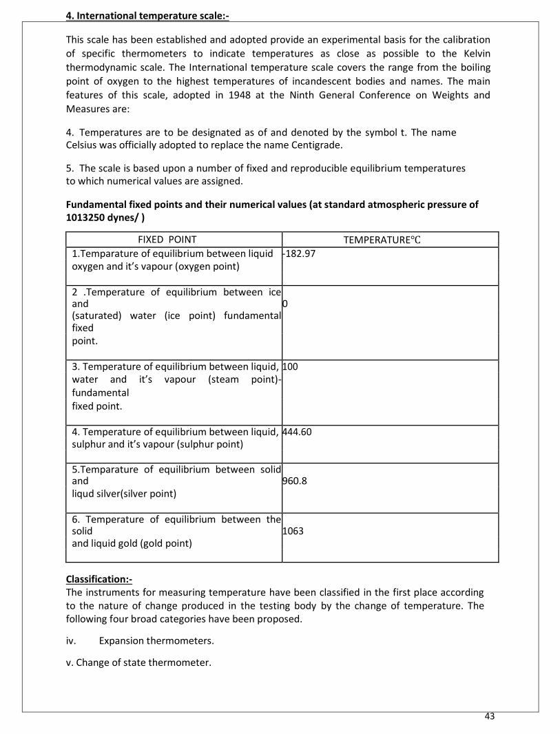
Measures are: 4. Temperatures are to be designated as of and denoted by the symbol t. The name Celsius was officially adopted to replace the name Centigrade. 5. The scale is based upon a number of fixed and reproducible equilibrium temperatures to which numerical values are assigned. Fundamental fixed points and their numerical values (at standard atmospheric pressure of 1013250 dynes/ )
FIXED POINT TEMPERATURE 1.Temparature of equilibrium between liquid -182.97 oxygen and it’s vapour (oxygen point)
2 .Temperature of equilibrium between ice and 0 (saturated) water (ice point) fundamental fixed
point.
3. Temperature of equilibrium between liquid, 100 water and it’s vapour (steam point)-fundamental
fixed point.
4. Temperature of equilibrium between liquid, 444.60 sulphur and it’s vapour (sulphur point)
5.Temparature of equilibrium between solid and 960.8 liqud silver(silver point)
6. Temperature of equilibrium between the solid 1063 and liquid gold (gold point)
Classification:- The instruments for measuring temperature have been classified in the first place according to the nature of change produced in the testing body by the change of temperature. The following four broad categories have been proposed. iv. Expansion thermometers. v. Change of state thermometer.
44
vi. Electrical methods of measuring temperature. 4. Radiation and optical pyrometer.
e) EXPANSIONTHERMOMETER:
a)Expansion of solids
Bimetaliic thermometer
Solid rod thermometer
Expansion of liquids
liquid in glass thermometer
liquid in metal thermometer (C) Expansion of gases-gas thermometer f) Change of state thermometers:- Liquid in metal thermometers (or) vapour pressure thermometers. 5. Electrical methods of measuring temperature:-
Electrical resistances bulbs.
Thermistors.
Thermo couples and thermopiles. 6. Radiation and optical pyrometers:- Optical pyrometers (total radiation pyrometer). Ranges:-
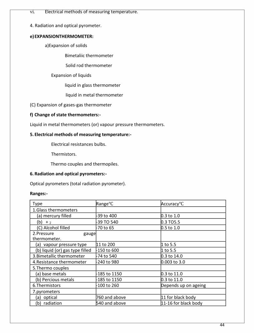
Type Range Accuracy 1.Glass thermometers
(a) mercury filled -39 to 400 0.3 to 1.0 (b) + 2 -39 TO 540 0.3 TO5.5 (C) Alcohol filled -70 to 65 0.5 to 1.0
2.Pressure gauge thermometer.
(a) vapour pressure type 11 to 200 1 to 5.5 (b) liquid (or) gas type filled -150 to 600 1 to 5.5
3.Bimetallic thermometer -74 to 540 0.3 to 14.0 4.Resistance thermometer -240 to 980 0.003 to 3.0 5.Thermo couples
(a) base metals -185 to 1150 0.3 to 11.0 (b) Percious metals -185 to 1150 0.3 to 11.0
6.Thermistors -100 to 260 Depends up on ageing 7.pyrometers
(a) optical 760 and above 11 for black body (b) radiation 540 and above 11-16 for black body
45
8.fusion 590 to 3600 As low as 20-30 under optimum conditions.
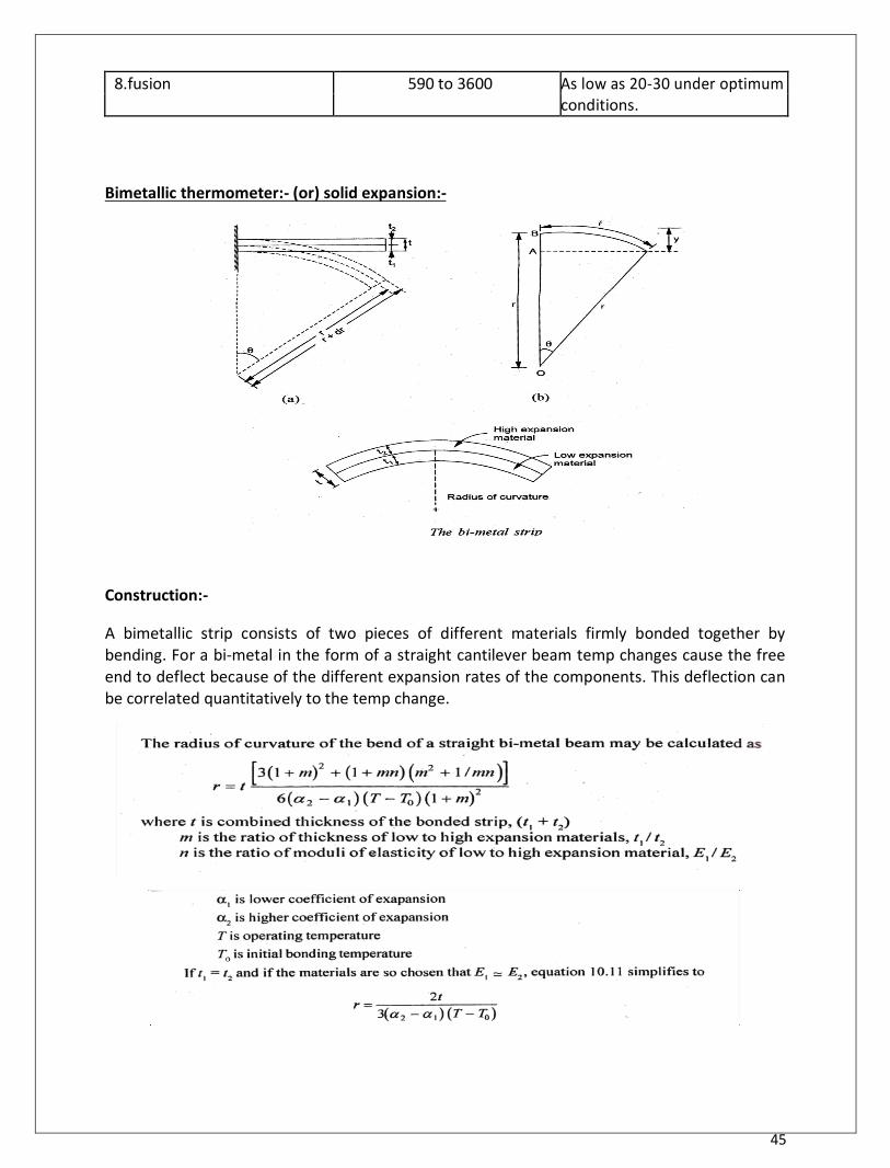
Bimetallic thermometer:- (or) solid expansion:-
Construction:-
A bimetallic strip consists of two pieces of different materials firmly bonded together by bending. For a bi-metal in the form of a straight cantilever beam temp changes cause the free end to deflect because of the different expansion rates of the components. This deflection can be correlated quantitatively to the temp change.
46
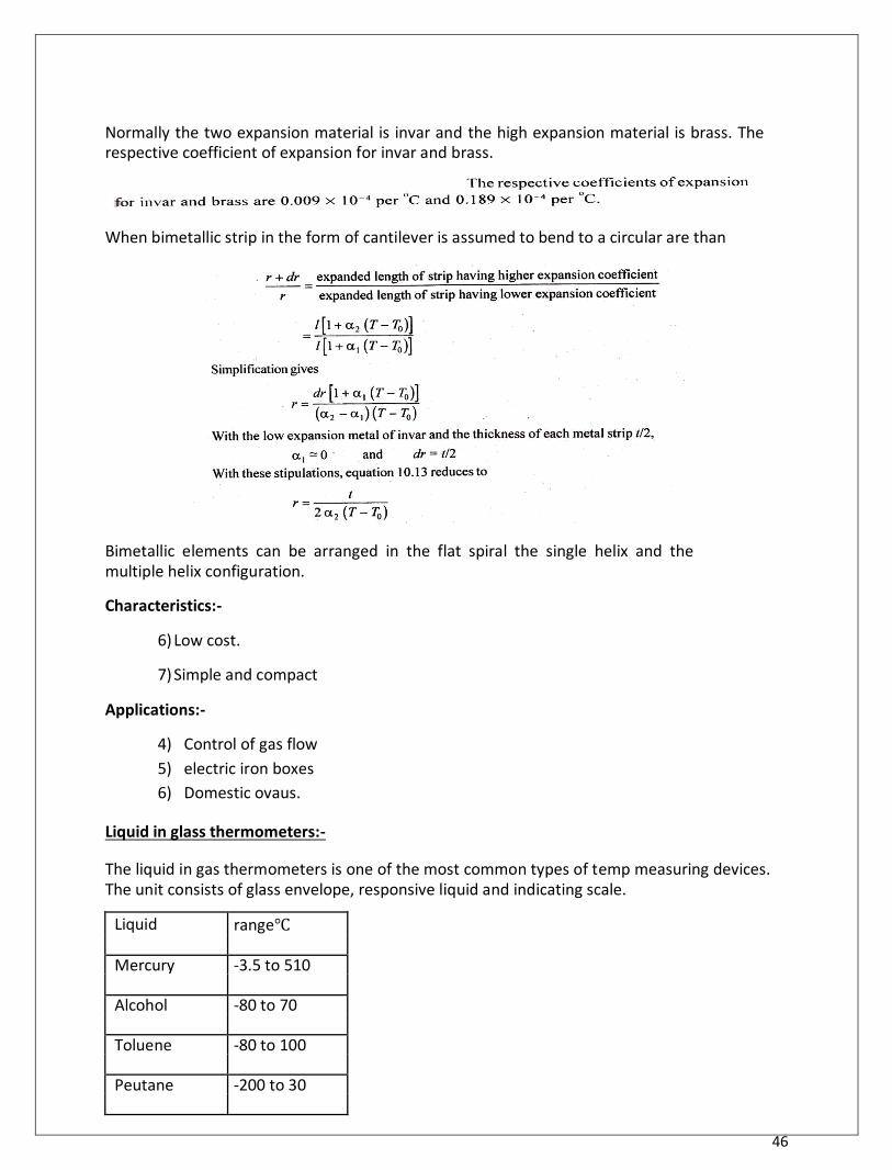
Normally the two expansion material is invar and the high expansion material is brass. The respective coefficient of expansion for invar and brass.
When bimetallic strip in the form of cantilever is assumed to bend to a circular are than
Bimetallic elements can be arranged in the flat spiral the single helix and the multiple helix configuration. Characteristics:-
6) Low cost.
7) Simple and compact Applications:-
4) Control of gas flow 5) electric iron boxes 6) Domestic ovaus.
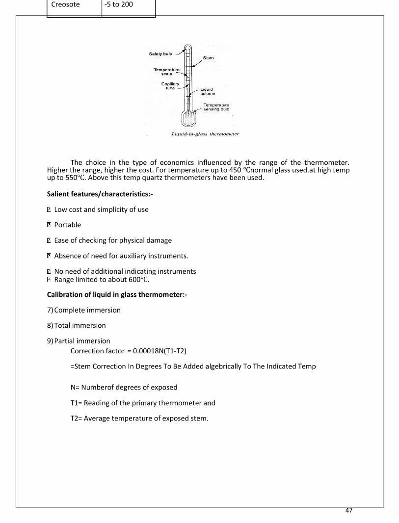
Liquid in glass thermometers:- The liquid in gas thermometers is one of the most common types of temp measuring devices. The unit consists of glass envelope, responsive liquid and indicating scale.
Liquid range
Mercury -3.5 to 510
Alcohol -80 to 70
Toluene -80 to 100
Peutane -200 to 30
47
Creosote -5 to 200
The choice in the type of economics influenced by the range of the thermometer. Higher the range, higher the cost. For temperature up to 450 normal glass used.at high temp up to 550. Above this temp quartz thermometers have been used.
Salient features/characteristics:- Low cost and simplicity of use
Portable
Ease of checking for physical damage
Absence of need for auxiliary instruments.
No need of additional indicating instruments Range limited to about 600.
Calibration of liquid in glass thermometer:- 7) Complete immersion 8) Total immersion 9) Partial immersion
Correction factor = 0.00018N(T1-T2)
=Stem Correction In Degrees To Be Added algebrically To The Indicated Temp
N= Numberof degrees of exposed
T1= Reading of the primary thermometer and
T2= Average temperature of exposed stem.
48
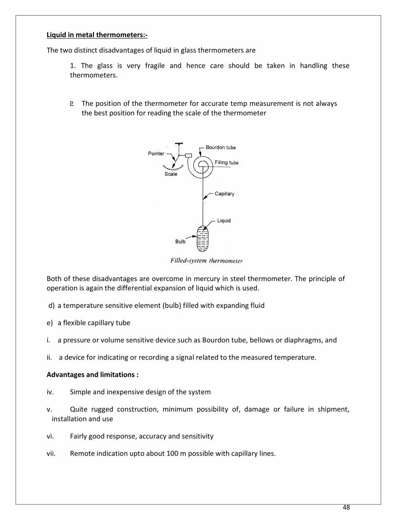
Liquid in metal thermometers:- The two distinct disadvantages of liquid in glass thermometers are
1. The glass is very fragile and hence care should be taken in handling these thermometers.
The position of the thermometer for accurate temp measurement is not always
the best position for reading the scale of the thermometer
Both of these disadvantages are overcome in mercury in steel thermometer. The principle of operation is again the differential expansion of liquid which is used.
d) a temperature sensitive element (bulb) filled with expanding fluid e) a flexible capillary tube i. a pressure or volume sensitive device such as Bourdon tube, bellows or diaphragms, and ii. a device for indicating or recording a signal related to the measured temperature.
Advantages and limitations :
iv. Simple and inexpensive design of the system v. Quite rugged construction, minimum possibility of, damage or failure in shipment,
installation and use vi. Fairly good response, accuracy and sensitivity vii. Remote indication upto about 100 m possible with capillary lines.
49
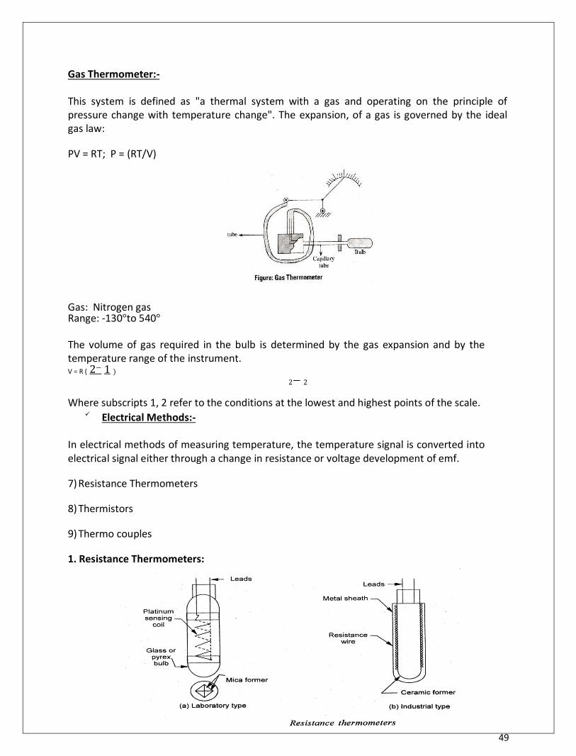
Gas Thermometer:-
This system is defined as "a thermal system with a gas and operating on the principle of pressure change with temperature change". The expansion, of a gas is governed by the ideal gas law:
PV = RT; P = (RT/V) Gas: Nitrogen gas Range: -130°to 540°
The volume of gas required in the bulb is determined by the gas expansion and by the temperature range of the instrument. V = R ( 2− 1 )
2− 2 Where subscripts 1, 2 refer to the conditions at the lowest and highest points of the scale.
Electrical Methods:-
In electrical methods of measuring temperature, the temperature signal is converted into electrical signal either through a change in resistance or voltage development of emf.
7) Resistance Thermometers 8) Thermistors 9) Thermo couples
1. Resistance Thermometers:
50
The thermometer comprises a resistance element or bulb, suitable electrical leads and an
indicating - recording or resistance measuring instrument. The resistance element is, usually in
the form of a coil of very fine platinum, nickel or copper wound non -conductively. Onto an
insulating ceramic former which is protected externally by a metal sheath. A laboratory type of
resistance thermometer is often wound on a crossed mica former and enclosed in a pyrex
tube. The tube may be evacuated or filled with an inert gas to protect the metal wire. Care is
to be taken to ensure that the resistance wire is free from m mechanical stresses. A metal
which has been strained will suffer a change in the resistance characteristics; the metal is
therefore usually annealed at a temperature higher than that at which it is so operate. Platinum is preferred because,
4) Physically stable (i.e., relatively indifferent to its environment, resists corrosion and chemical attack and is not readily oxidised) and has high electrical resistance characteristics.
5) Accuracy attainable with a platinum resistance thermometer is of the order of ± 0.01 of upto 500° and within ± 0. 1° of upto 1200 ° .
Advantages:-
(iv) Simplicity and accuracy of operation (v) Possibility of easy installation and replacement of sensitive bulb
51
B) Easy check on the accuracy of the measuring circuit 'by substituting a standard resistance for the resistance element.
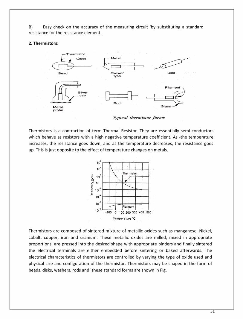
2. Thermistors:
Thermistors is a contraction of term Thermal Resistor. They are essentially semi-conductors
which behave as resistors with a high negative temperature coefficient. As -the temperature
increases, the resistance goes down, and as the temperature decreases, the resistance goes
up. This is just opposite to the effect of temperature changes on metals.
Thermistors are composed of sintered mixture of metallic oxides such as manganese. Nickel,
cobalt, copper, iron and uranium. These metallic oxides are milled, mixed in appropriate
proportions, are pressed into the desired shape with appropriate binders and finally sintered
the electrical terminals are either embedded before sintering or baked afterwards. The
electrical characteristics of thermistors are controlled by varying the type of oxide used and
physical size and configuration of the thermistor. Thermistors may be shaped in the form of
beads, disks, washers, rods and `these standard forms are shown in Fig.
52
The mathematical expression for the relation- ship between the resistance of a thermistor and absolute temperature of thermistor is
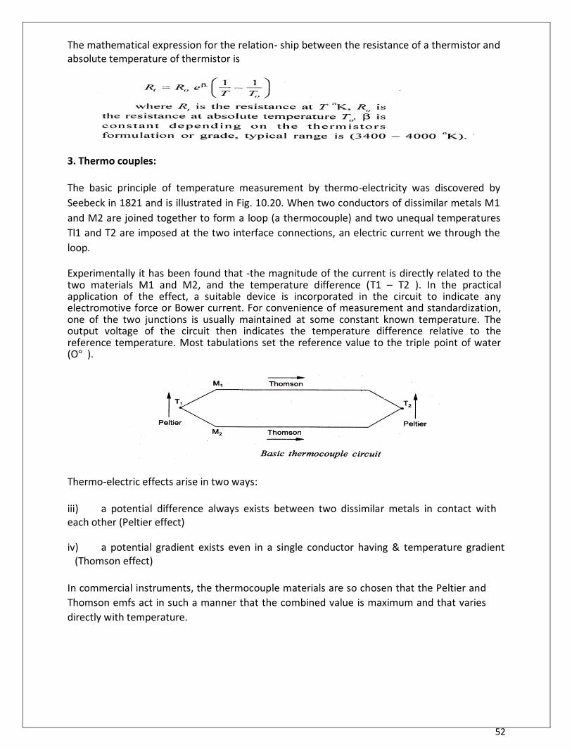
3. Thermo couples:
The basic principle of temperature measurement by thermo-electricity was discovered by
Seebeck in 1821 and is illustrated in Fig. 10.20. When two conductors of dissimilar metals M1
and M2 are joined together to form a loop (a thermocouple) and two unequal temperatures
Tl1 and T2 are imposed at the two interface connections, an electric current we through the
loop. Experimentally it has been found that -the magnitude of the current is directly related to the two materials M1 and M2, and the temperature difference (T1 – T2 ). In the practical application of the effect, a suitable device is incorporated in the circuit to indicate any electromotive force or Bower current. For convenience of measurement and standardization, one of the two junctions is usually maintained at some constant known temperature. The output voltage of the circuit then indicates the temperature difference relative to the reference temperature. Most tabulations set the reference value to the triple point of water (O° ).
Thermo-electric effects arise in two ways:
iii) a potential difference always exists between two dissimilar metals in contact with each other (Peltier effect) iv) a potential gradient exists even in a single conductor having & temperature gradient
(Thomson effect)
In commercial instruments, the thermocouple materials are so chosen that the Peltier and
Thomson emfs act in such a manner that the combined value is maximum and that varies
directly with temperature.
53
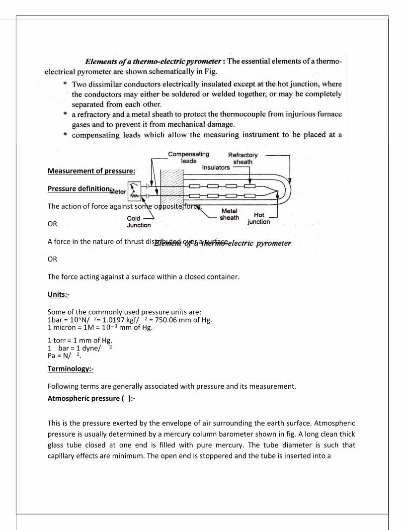
Measurement of pressure:
Pressure definition:-
The action of force against some opposite force.
OR
A force in the nature of thrust distributed over a surface.
OR
The force acting against a surface within a closed container.
Units:-
Some of the commonly used pressure units are: 1bar = 105N/ 2= 1.0197 kgf/ 2 = 750.06 mm of Hg. 1 micron = 1M = 10−3 mm of Hg. 1 torr = 1 mm of Hg. 1 bar = 1 dyne/ 2
Pa = N/ 2. Terminology:-
Following terms are generally associated with pressure and its measurement. Atmospheric pressure ( ):-
This is the pressure exerted by the envelope of air surrounding the earth surface. Atmospheric
pressure is usually determined by a mercury column barometer shown in fig. A long clean thick
glass tube closed at one end is filled with pure mercury. The tube diameter is such that
capillary effects are minimum. The open end is stoppered and the tube is inserted into a
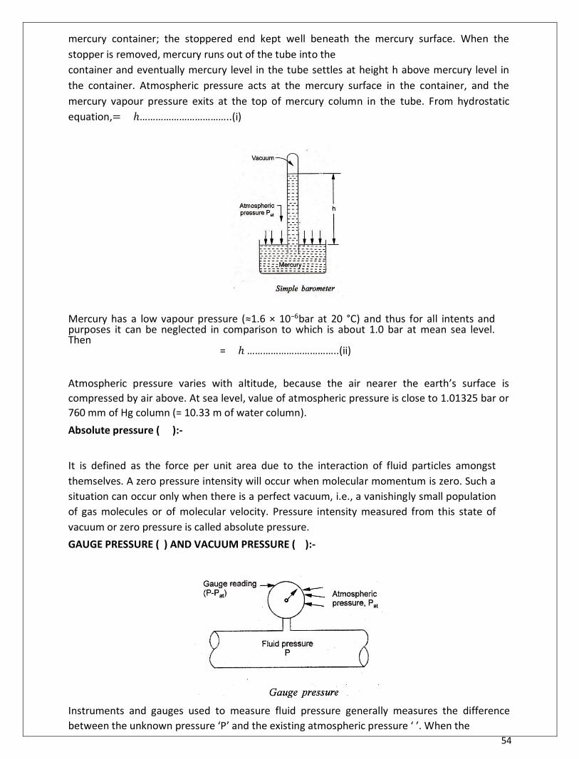
54
mercury container; the stoppered end kept well beneath the mercury surface. When the
stopper is removed, mercury runs out of the tube into the
container and eventually mercury level in the tube settles at height h above mercury level in
the container. Atmospheric pressure acts at the mercury surface in the container, and the
mercury vapour pressure exits at the top of mercury column in the tube. From hydrostatic
equation,= ℎ……………………………..(i)
Mercury has a low vapour pressure (≈1.6 × 10⁻⁶bar at 20 °C) and thus for all intents and purposes it can be neglected in comparison to which is about 1.0 bar at mean sea level. Then
= ℎ ……………………………..(ii)
Atmospheric pressure varies with altitude, because the air nearer the earth’s surface is
compressed by air above. At sea level, value of atmospheric pressure is close to 1.01325 bar or
760 mm of Hg column (= 10.33 m of water column). Absolute pressure ( ):-
It is defined as the force per unit area due to the interaction of fluid particles amongst
themselves. A zero pressure intensity will occur when molecular momentum is zero. Such a
situation can occur only when there is a perfect vacuum, i.e., a vanishingly small population
of gas molecules or of molecular velocity. Pressure intensity measured from this state of
vacuum or zero pressure is called absolute pressure. GAUGE PRESSURE ( ) AND VACUUM PRESSURE ( ):- Instruments and gauges used to measure fluid pressure generally measures the difference
between the unknown pressure ‘P’ and the existing atmospheric pressure ‘ ’. When the
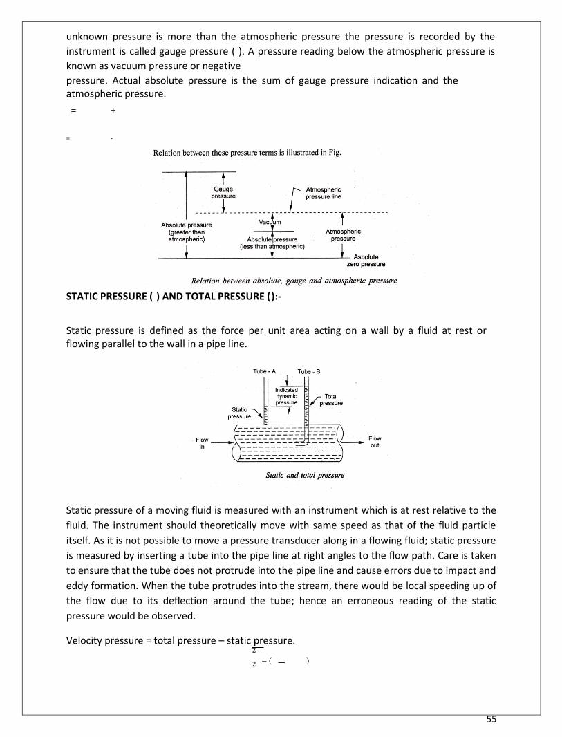
55
unknown pressure is more than the atmospheric pressure the pressure is recorded by the
instrument is called gauge pressure ( ). A pressure reading below the atmospheric pressure is
known as vacuum pressure or negative
pressure. Actual absolute pressure is the sum of gauge pressure indication and the atmospheric pressure. = +
= -
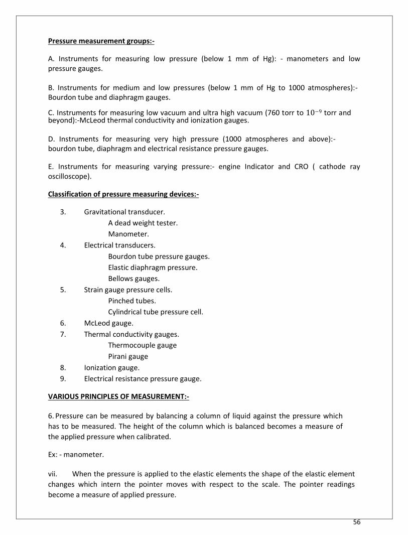
STATIC PRESSURE ( ) AND TOTAL PRESSURE ( ):-
Static pressure is defined as the force per unit area acting on a wall by a fluid at rest or flowing parallel to the wall in a pipe line.
Static pressure of a moving fluid is measured with an instrument which is at rest relative to the
fluid. The instrument should theoretically move with same speed as that of the fluid particle
itself. As it is not possible to move a pressure transducer along in a flowing fluid; static pressure
is measured by inserting a tube into the pipe line at right angles to the flow path. Care is taken
to ensure that the tube does not protrude into the pipe line and cause errors due to impact and
eddy formation. When the tube protrudes into the stream, there would be local speeding up of
the flow due to its deflection around the tube; hence an erroneous reading of the static
pressure would be observed. Velocity pressure = total pressure – static pressure.
2
2 = ( − )
56
Pressure measurement groups:-
A. Instruments for measuring low pressure (below 1 mm of Hg): - manometers and low pressure gauges.
B. Instruments for medium and low pressures (below 1 mm of Hg to 1000 atmospheres):- Bourdon tube and diaphragm gauges. C. Instruments for measuring low vacuum and ultra high vacuum (760 torr to 10−9 torr and beyond):-McLeod thermal conductivity and ionization gauges.
D. Instruments for measuring very high pressure (1000 atmospheres and above):- bourdon tube, diaphragm and electrical resistance pressure gauges.
E. Instruments for measuring varying pressure:- engine Indicator and CRO ( cathode ray oscilloscope).
Classification of pressure measuring devices:-
3. Gravitational transducer. A dead weight tester. Manometer.
4. Electrical transducers. Bourdon tube pressure gauges. Elastic diaphragm pressure. Bellows gauges.
5. Strain gauge pressure cells. Pinched tubes. Cylindrical tube pressure cell.
6. McLeod gauge. 7. Thermal conductivity gauges.
Thermocouple gauge Pirani gauge
8. Ionization gauge. 9. Electrical resistance pressure gauge.
VARIOUS PRINCIPLES OF MEASUREMENT:-
6. Pressure can be measured by balancing a column of liquid against the pressure which
has to be measured. The height of the column which is balanced becomes a measure of
the applied pressure when calibrated.
Ex: - manometer.
vii. When the pressure is applied to the elastic elements the shape of the elastic element
changes which intern the pointer moves with respect to the scale. The pointer readings
become a measure of applied pressure.
57
Ex: - bourdon tube pressure gauge, diaphragm, bellows.
g) When electric current flows through a conducting wire it gets heated. Depending up on
the conductivity of the surrounding media the heat is dissipated from the wire. The rate of
change in the temperature of the wire becomes a measure of the pressure.
Ex:- Pirani gauge, ionization gauge, thermal conductivity gauges.
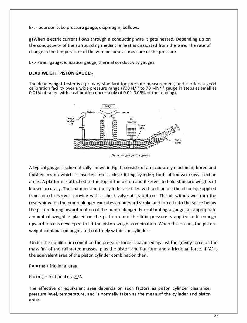
DEAD WEIGHT PISTON GAUGE:- The dead weight tester is a primary standard for pressure measurement, and it offers a good calibration facility over a wide pressure range (700 N/ 2 to 70 MN/ 2 gauge in steps as small as 0.01% of range with a calibration uncertainly of 0.01-0.05% of the reading).
A typical gauge is schematically shown in Fig. It consists of an accurately machined, bored and
finished piston which is inserted into a close fitting cylinder; both of known cross- section
areas. A platform is attached to the top of the piston and it serves to hold standard weights of
known accuracy. The chamber and the cylinder are filled with a clean oil; the oil being supplied
from an oil reservoir provide with a check valve at its bottom. The oil withdrawn from the
reservoir when the pump plunger executes an outward stroke and forced into the space below
the piston during inward motion of the pump plunger. For calibrating a gauge, an appropriate
amount of weight is placed on the platform and the fluid pressure is applied until enough
upward force is developed to lift the piston-weight combination. When this occurs, the piston-
weight combination begins to float freely within the cylinder.
Under the equilibrium condition the pressure force is balanced against the gravity force on the
mass ‘m’ of the calibrated masses, plus the piston and flat form and a frictional force. If ‘A’ is
the equivalent area of the piston cylinder combination then:
PA = mg + frictional drag.
P = (mg + frictional drag)/A
The effective or equivalent area depends on such factors as piston cylinder clearance, pressure level, temperature, and is normally taken as the mean of the cylinder and piston areas.
58
Manometers:-
Manometers measure pressure by balancing a column of liquid against the pressure to
measured. Height of column so balanced is noted and then converted to the desired units.
Manometers may be vertical, inclined, open, differential or compound. Choice of any type
depends on its sensitivity of measurement, ease of operation and the magnitude of pressure
being measured. Manometers can be used to measure gauge, differential, atmospheric, and
absolute pressure.
i. Piezo meter
7. U- tube manometer 8. Single column manometer
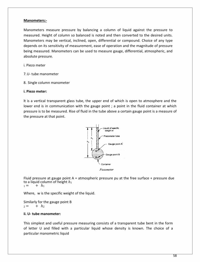
i. Piezo meter:
lt is a vertical transparent glass tube, the upper end of which is open to atmosphere and the
lower end is in communication with the gauge point ; a point in the fluid container at which
pressure is to be measured. Rise of fluid in the tube above a certain gauge point is a measure of
the pressure at that point. Fluid pressure at gauge point A = atmospheric pressure pu at the free surface + pressure due to a liquid column of height ℎ1
1 = + ℎ1 Where, w is the specific weight of the liquid.
Similarly for the gauge point B 2 = + ℎ2 ii. U- tube manometer:
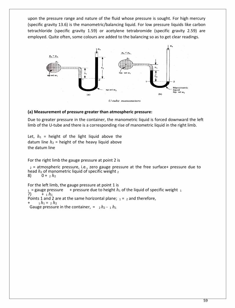
This simplest and useful pressure measuring consists of a transparent tube bent in the form
of letter U and filled with a particular liquid whose density is known. The choice of a
particular manometric liquid
59
upon the pressure range and nature of the fluid whose pressure is sought. For high mercury
(specific gravity 13.6) is the manometric/balancing liquid. For low pressure liquids like carbon
tetrachloride (specific gravity 1.59) or acetylene tetrabromide (specific gravity 2.59) are
employed. Quite often, some colours are added to the balancing so as to get clear readings.
(a) Measurement of pressure greater than atmospheric pressure: Due to greater pressure in the container, the manometric liquid is forced downward the left limb of the U-tube and there is a corresponding rise of manometric liquid in the right limb.
Let, ℎ1 = height of the light liquid above the datum line ℎ2 = height of the heavy liquid above the datum line
For the right limb the gauge pressure at point 2 is
2 = atmospheric pressure, i.e., zero gauge pressure at the free surface+ pressure due to head ℎ2 of manometric liquid of specific weight 2
8) 0 + 2 ℎ2
For the left limb, the gauge pressure at point 1 is 1 = gauge pressure + pressure due to height ℎ1 of the liquid of specific weight 1
7) + 1 ℎ1 Points 1 and 2 are at the same horizontal plane; 1 = 2 and therefore, + 1 ℎ1 = 2 ℎ2
Gauge pressure in the container, = 2 ℎ2 - 1 ℎ1
60
(b) Measurement of pressure less than atmospheric pressure: Due to negative pressure in the container, the manometric liquid is sucked upwards in the left limb of the U-tube and there is a corresponding fall of manometric liquid in the right limb. Pressure in the two legs at the same level 1 and 2 are equal; 1 = 2 and therefore, Gauge pressure in the container, = −( 1 ℎ1 = 2 ℎ2)
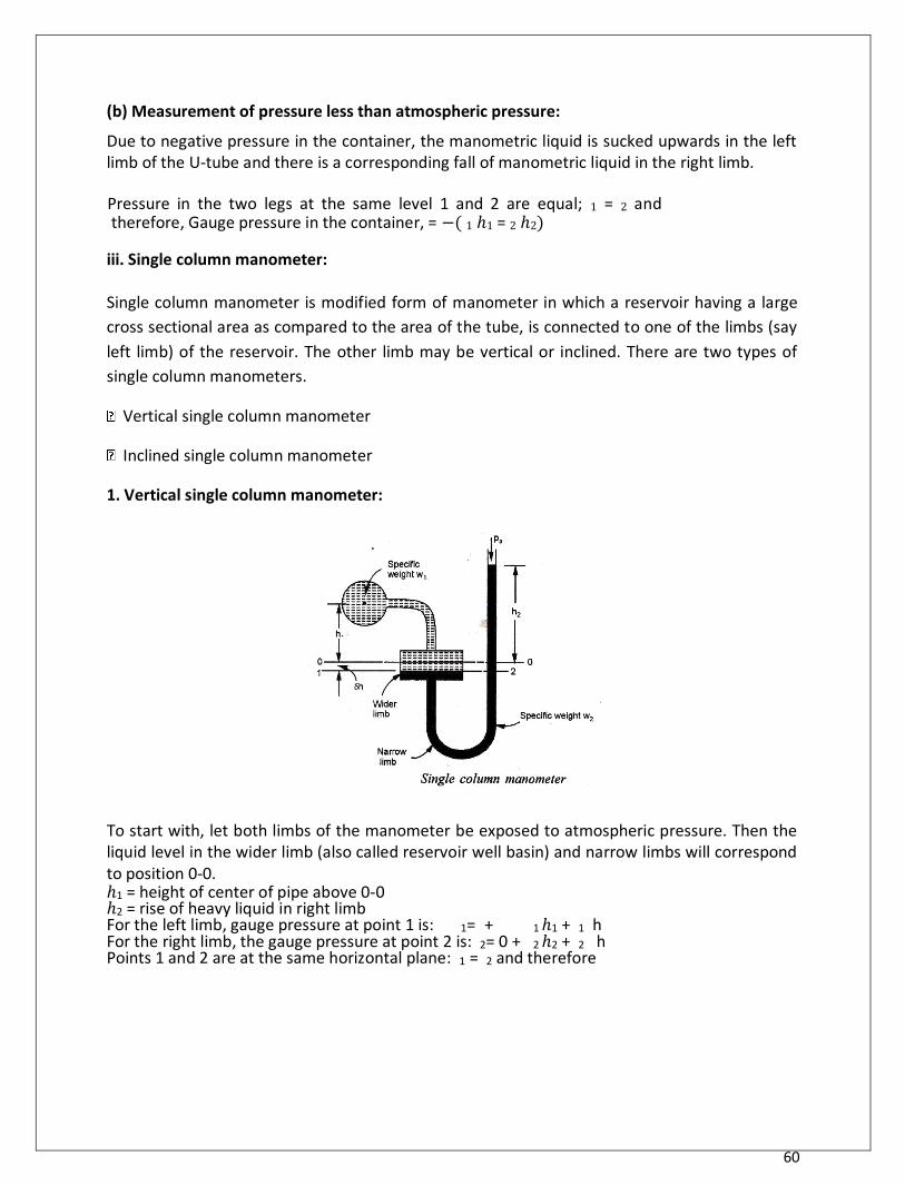
iii. Single column manometer:
Single column manometer is modified form of manometer in which a reservoir having a large
cross sectional area as compared to the area of the tube, is connected to one of the limbs (say
left limb) of the reservoir. The other limb may be vertical or inclined. There are two types of
single column manometers. Vertical single column manometer
Inclined single column manometer
1. Vertical single column manometer: To start with, let both limbs of the manometer be exposed to atmospheric pressure. Then the liquid level in the wider limb (also called reservoir well basin) and narrow limbs will correspond to position 0-0. ℎ1 = height of center of pipe above 0-0 ℎ2 = rise of heavy liquid in right limb For the left limb, gauge pressure at point 1 is: 1= + 1 ℎ1 + 1 h For the right limb, the gauge pressure at point 2 is: 2= 0 + 2 ℎ2 + 2 h Points 1 and 2 are at the same horizontal plane: 1 = 2 and therefore
61
Gauge pressure in the container is: = ( 2 ℎ2 - 1 ℎ1) + h ( 2 - 1)
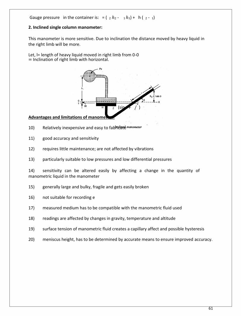
2. Inclined single column manometer:
This manometer is more sensitive. Due to inclination the distance moved by heavy liquid in the right limb will be more.
Let, l= length of heavy liquid moved in right limb from 0-0 = Inclination of right limb with horizontal.
= 2 (sin + / )
Advantages and limitations of manometers:
10) Relatively inexpensive and easy to fabricate 11) good accuracy and sensitivity 12) requires little maintenance; are not affected by vibrations 13) particularly suitable to low pressures and low differential pressures 14) sensitivity can be altered easily by affecting a change in the quantity of manometric liquid in the manometer 15) generally large and bulky, fragile and gets easily broken 16) not suitable for recording e 17) measured medium has to be compatible with the manometric fluid used 18) readings are affected by changes in gravity, temperature and altitude 19) surface tension of manometric fluid creates a capillary affect and possible hysteresis 20) meniscus height, has to be determined by accurate means to ensure improved accuracy.
62
Mechanical Gauges: - Elastic Pressure Transducer:-
For measuring pressures in excess of two atmosphere elastic mechanical type transducers are
used. The actions of these gauges are based on the deflection of the hollow tube, diaphragm
and bellows caused by the applied pressure difference. The resulting deflection made directly
accurate a pointer. Scale read out through suitable linkages and gears are the motion may be
transmitted through and electrical signal. Bellows and diaphragm gauges are generally suitable
up to 28 to 56 bars. Where as bourdon tubes are very high pressure gauges.
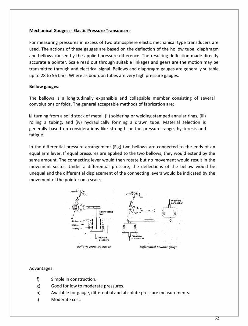
Bellow gauges:
The bellows is a longitudinally expansible and collapsible member consisting of several convolutions or folds. The general acceptable methods of fabrication are:
turning from a solid stock of metal, (ii) soldering or welding stamped annular rings, (iii)
rolling a tubing, and (iv) hydraulically forming a drawn tube. Material selection is
generally based on considerations like strength or the pressure range, hysteresis and
fatigue.
In the differential pressure arrangement (Fig) two bellows are connected to the ends of an
equal arm lever. If equal pressures are applied to the two bellows, they would extend by the
same amount. The connecting lever would then rotate but no movement would result in the
movement sector. Under a differential pressure, the deflections of the bellow would be
unequal and the differential displacement of the connecting levers would be indicated by the
movement of the pointer on a scale.
Advantages:
f) Simple in construction. g) Good for low to moderate pressures. h) Available for gauge, differential and absolute pressure measurements. i) Moderate cost.
63
Limitations:
viii. Zero shift problems. ix. Needs spring for accurate characterization. x. Requires compensation for temperature ambient changes.
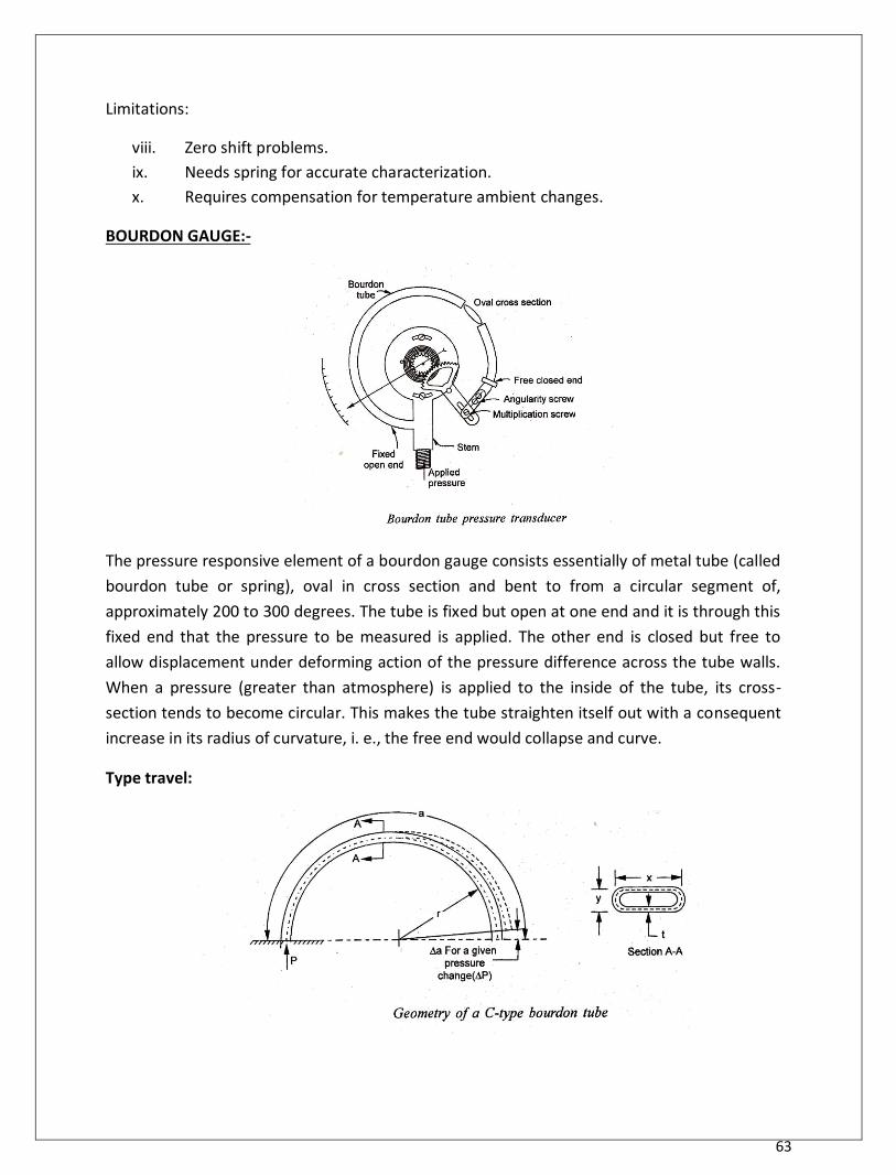
BOURDON GAUGE:-
The pressure responsive element of a bourdon gauge consists essentially of metal tube (called
bourdon tube or spring), oval in cross section and bent to from a circular segment of,
approximately 200 to 300 degrees. The tube is fixed but open at one end and it is through this
fixed end that the pressure to be measured is applied. The other end is closed but free to
allow displacement under deforming action of the pressure difference across the tube walls.
When a pressure (greater than atmosphere) is applied to the inside of the tube, its cross-
section tends to become circular. This makes the tube straighten itself out with a consequent
increase in its radius of curvature, i. e., the free end would collapse and curve. Type travel:
64
The motion of the free end commonly called tip travel is a function of tube length wall thickness, cross sectional geometry and modulus of the tube material. For a bourdon tube a deflection ∆a of the elemental tip can be expressed as
0.2
0.0
3 3.0 ∆a = 0.05
(
) (
) (
)
Where ‘a’ is the total angle subtended by the tube before pressurization, P is the applied pressure difference and ‘E’ is the modulus of elasticity of the tube material.
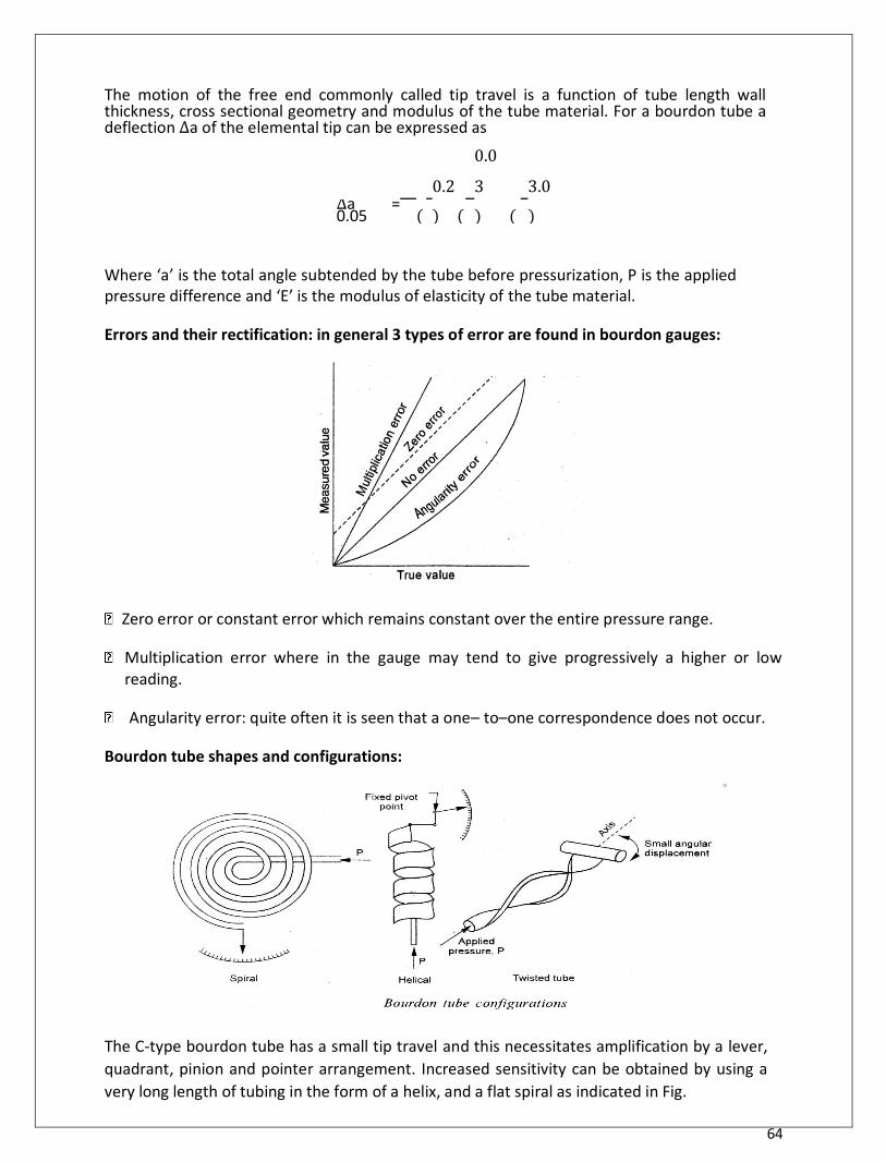
Errors and their rectification: in general 3 types of error are found in bourdon gauges: Zero error or constant error which remains constant over the entire pressure range.
Multiplication error where in the gauge may tend to give progressively a higher or low
reading. Angularity error: quite often it is seen that a one– to–one correspondence does not occur.
Bourdon tube shapes and configurations:
The C-type bourdon tube has a small tip travel and this necessitates amplification by a lever,
quadrant, pinion and pointer arrangement. Increased sensitivity can be obtained by using a
very long length of tubing in the form of a helix, and a flat spiral as indicated in Fig.
65
Materials:
10) Pressure 100 to 700 KN/m2(tubes are made of phosphor bronze) 11) For high pressure P=7000 to 63000 KN/m2 (tubes are made of alloy steel or k-monel)
Advantages:
6) Low cost and simple in construction. 7) Capability to measure gauge absolute and differential pressure. 8) Availability in several ranges.
Limitations:
(vi) So response. (vii) Susceptibility to sharp and vibration. (viii) Mutually required geared movement for application.
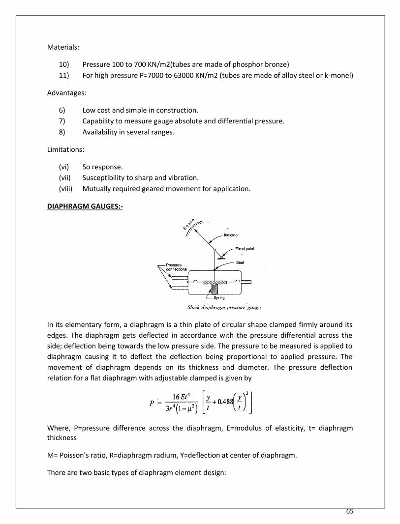
DIAPHRAGM GAUGES:-
In its elementary form, a diaphragm is a thin plate of circular shape clamped firmly around its
edges. The diaphragm gets deflected in accordance with the pressure differential across the
side; deflection being towards the low pressure side. The pressure to be measured is applied to
diaphragm causing it to deflect the deflection being proportional to applied pressure. The
movement of diaphragm depends on its thickness and diameter. The pressure deflection
relation for a flat diaphragm with adjustable clamped is given by
Where, P=pressure difference across the diaphragm, E=modulus of elasticity, t= diaphragm thickness
M= Poisson’s ratio, R=diaphragm radium, Y=deflection at center of diaphragm.
There are two basic types of diaphragm element design:
66
C) Metallic diaphragm which depends upon its own resilience for its operation. D) Non-metallic or slack diaphragm which employs a soft, flexible material with no elastic
characteristic.
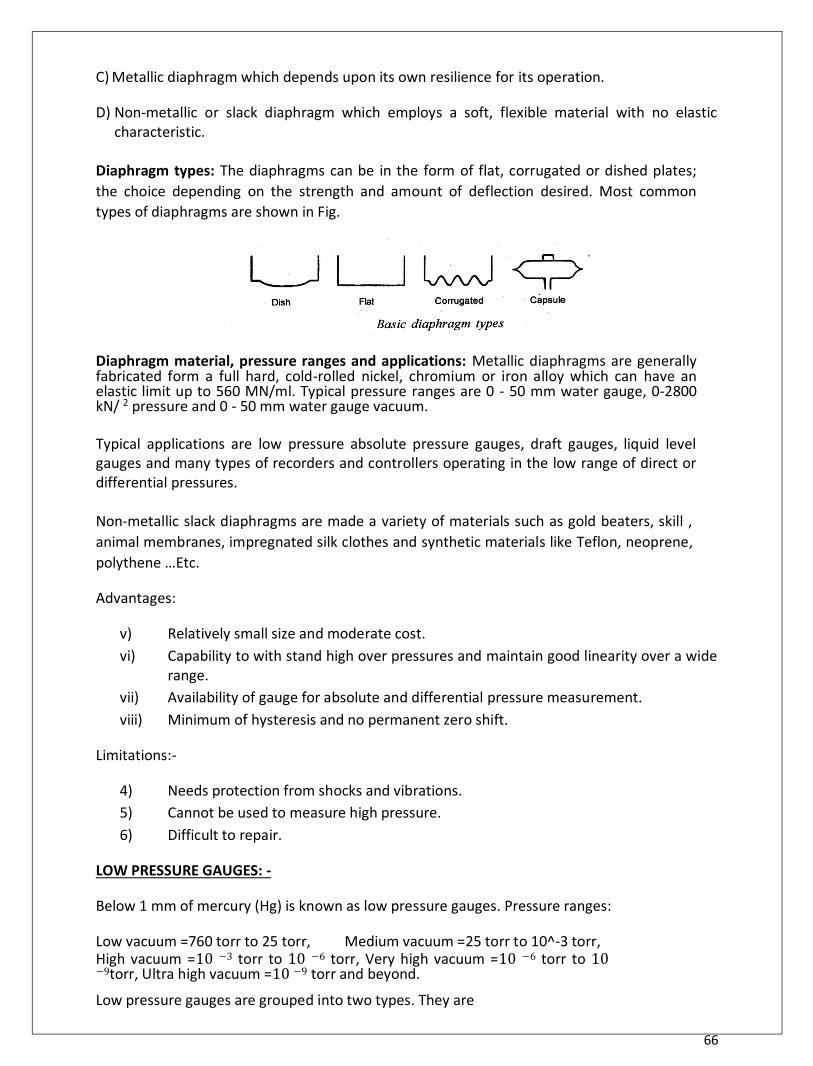
Diaphragm types: The diaphragms can be in the form of flat, corrugated or dished plates;
the choice depending on the strength and amount of deflection desired. Most common
types of diaphragms are shown in Fig.
Diaphragm material, pressure ranges and applications: Metallic diaphragms are generally fabricated form a full hard, cold-rolled nickel, chromium or iron alloy which can have an elastic limit up to 560 MN/ml. Typical pressure ranges are 0 - 50 mm water gauge, 0-2800 kN/ 2 pressure and 0 - 50 mm water gauge vacuum. Typical applications are low pressure absolute pressure gauges, draft gauges, liquid level gauges and many types of recorders and controllers operating in the low range of direct or differential pressures.
Non-metallic slack diaphragms are made a variety of materials such as gold beaters, skill ,
animal membranes, impregnated silk clothes and synthetic materials like Teflon, neoprene,
polythene …Etc.
Advantages:
v) Relatively small size and moderate cost. vi) Capability to with stand high over pressures and maintain good linearity over a wide
range. vii) Availability of gauge for absolute and differential pressure measurement. viii) Minimum of hysteresis and no permanent zero shift.
Limitations:-
4) Needs protection from shocks and vibrations. 5) Cannot be used to measure high pressure. 6) Difficult to repair.
LOW PRESSURE GAUGES: -
Below 1 mm of mercury (Hg) is known as low pressure gauges. Pressure ranges:
Low vacuum =760 torr to 25 torr, Medium vacuum =25 torr to 10^-3 torr, High vacuum =10 −3 torr to 10 −6 torr, Very high vacuum =10 −6 torr to 10 −9torr, Ultra high vacuum =10 −9 torr and beyond. Low pressure gauges are grouped into two types. They are
67
5. Direct measurement: wherein displacement deflection caused by the pressure is measured and is
correlated to the applied pressure. This principle is incorporated in bellows, diaphragm, bourdon tube, manometer. 6. Indirect type measurements: wherein the low pressure is detected through measurement
of a pressure controlled property such as volume, thermal conductivity etc. the inferential
gauges include Thermal conductivity gauges, Ionization gauge, McLeod gauge.
THERMAL CONDUCTIVITY GAUGES: -
These gauges measure pressure through a change in the thermal conductivity of the gas. Their
operation is based on the thermodynamic principle that “at low pressures there is a
relationship between the pressure and thermal conductivity i.e., the heat conductivity
decreases with decrease in pressure”. There are two types of thermal gauges.
d) Thermocouple gauge. e) Pirani gauge.
1. Thermocouple gauge:
The schematic diagram of a thermocouple type conductivity gauge is shown in figure (1). The
pressure to be measured admitted to a chamber. A constant current is passed through the
thin metal strip in the chamber.
Due to this current, the metal strip gets heated and acts as hot surface. The temperature of this
hot surface is sensed by a thermocouple which is attached to the metal strip. The glass tube
acts as the cold surface. Whose temperature is nearly equal room temperature. The
conductivity of the metal strip changes due to the applied pressure. This change in conductivity
causes a change in the temperature, which is sensed by the thermocouple. The thermocouple

68
produces current corresponding to the thermocouple output which is then indicated by a mm.
This indicated current becomes a measure of the applied pressure when calibrated.
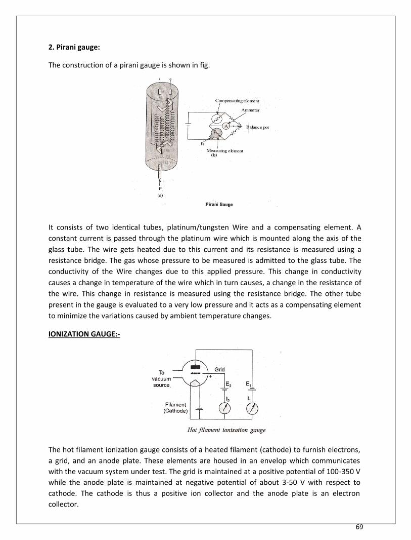
69
2. Pirani gauge:
The construction of a pirani gauge is shown in fig.
It consists of two identical tubes, platinum/tungsten Wire and a compensating element. A
constant current is passed through the platinum wire which is mounted along the axis of the
glass tube. The wire gets heated due to this current and its resistance is measured using a
resistance bridge. The gas whose pressure to be measured is admitted to the glass tube. The
conductivity of the Wire changes due to this applied pressure. This change in conductivity
causes a change in temperature of the wire which in turn causes, a change in the resistance of
the wire. This change in resistance is measured using the resistance bridge. The other tube
present in the gauge is evaluated to a very low pressure and it acts as a compensating element
to minimize the variations caused by ambient temperature changes.
IONIZATION GAUGE:-
The hot filament ionization gauge consists of a heated filament (cathode) to furnish electrons,
a grid, and an anode plate. These elements are housed in an envelop which communicates
with the vacuum system under test. The grid is maintained at a positive potential of 100-350 V
while the anode plate is maintained at negative potential of about 3-50 V with respect to
cathode. The cathode is thus a positive ion collector and the anode plate is an electron
collector.
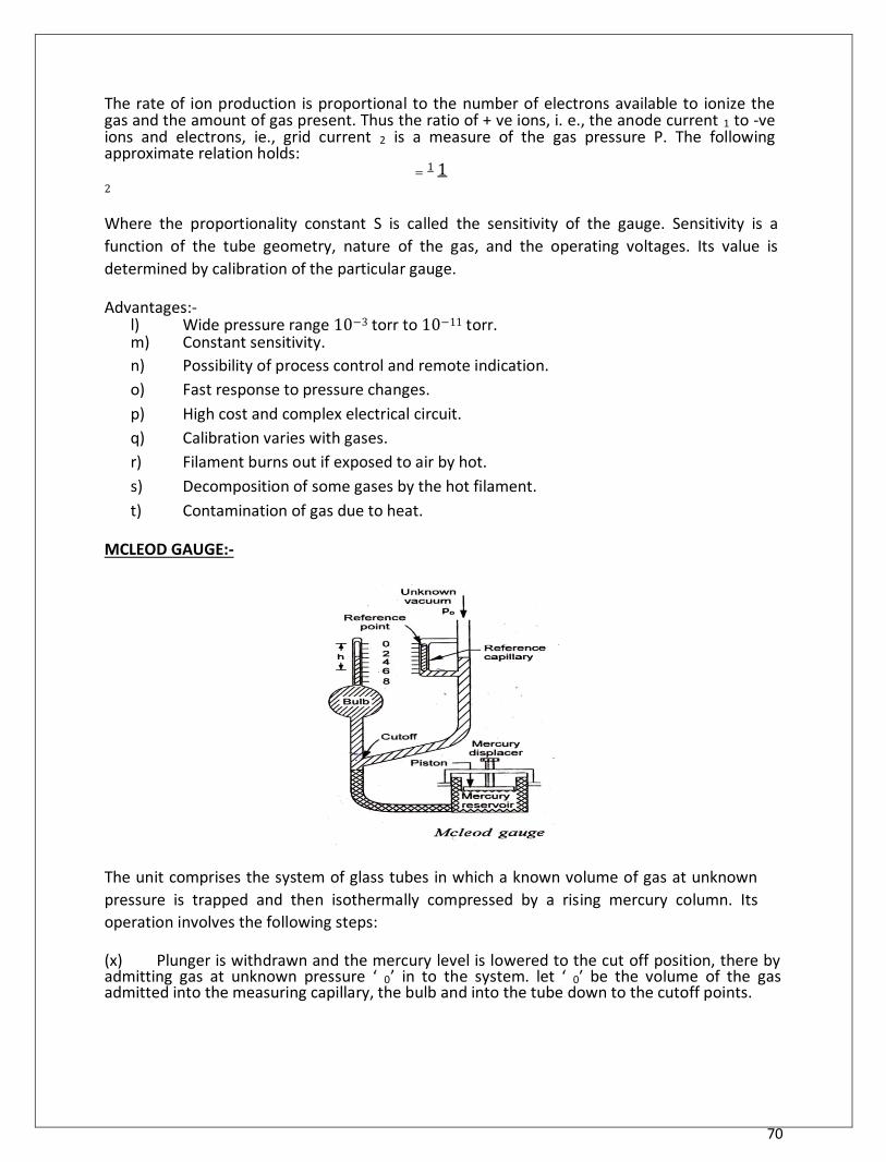
70
The rate of ion production is proportional to the number of electrons available to ionize the gas and the amount of gas present. Thus the ratio of + ve ions, i. e., the anode current 1 to -ve ions and electrons, ie., grid current 2 is a measure of the gas pressure P. The following approximate relation holds:
= 1 1 2
Where the proportionality constant S is called the sensitivity of the gauge. Sensitivity is a
function of the tube geometry, nature of the gas, and the operating voltages. Its value is
determined by calibration of the particular gauge.
Advantages:- l) Wide pressure range 10−3 torr to 10−11 torr. m) Constant sensitivity. n) Possibility of process control and remote indication. o) Fast response to pressure changes. p) High cost and complex electrical circuit. q) Calibration varies with gases. r) Filament burns out if exposed to air by hot. s) Decomposition of some gases by the hot filament. t) Contamination of gas due to heat.
MCLEOD GAUGE:- The unit comprises the system of glass tubes in which a known volume of gas at unknown
pressure is trapped and then isothermally compressed by a rising mercury column. Its
operation involves the following steps:
(x) Plunger is withdrawn and the mercury level is lowered to the cut off position, there by admitting gas at unknown pressure ‘ 0’ in to the system. let ‘ 0′ be the volume of the gas admitted into the measuring capillary, the bulb and into the tube down to the cutoff points.
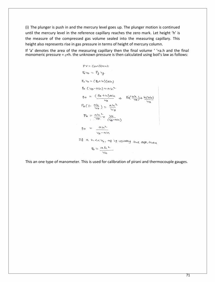
71
(i) The plunger is push in and the mercury level goes up. The plunger motion is continued
until the mercury level in the reference capillary reaches the zero mark. Let height ‘h’ is
the measure of the compressed gas volume sealed into the measuring capillary. This
height also represents rise in gas pressure in terms of height of mercury column. If ‘a’ denotes the area of the measuring capillary then the final volume ‘ ′=a.h and the final monomeric pressure = 0+h. the unknown pressure is then calculated using boil’s law as follows:
This an one type of manometer. This is used for calibration of pirani and thermocouple gauges.
UNIT 3
MEASUREMENT OF FLOW, SPEED, ACCELERATION & VIBRATION
DEPARTMENT OF MECHANICAL ENGINEERING
Measurement of Liquid and Flow
Measurement of Liquid Level:-
Liquid level refers to the position or height of a liquid surface above a datum line.
Level measurements are made to a certain quantity of the liquid held with in a container.
Level offers both the pressure and rate of flow in and out of the container and as such its measurement
and control is an important function in a variety of processes. The task of liquid level measurement may be
accomplished by direct methods and indirect methods.
(1) Direct methods (2) Indirect methods
(1) Direct methods:-
This is the simplest method of measuring liquid level. In this method, the level of liquid is measured
directly by means of the following level indicators:
1. Hook-type Level Indicator
2. Sight Glass
3. Float-type
4. Float and shaft liquid level gauge.
(i) Hook-type Level Indicator:
When the level of liquid in an open tank is measured directly on a scale (the scale may be in the liquid or
outside it), it is sometimes difficult to read the level accurately because of parallax error. In this case a
hook type of level indicator is used.
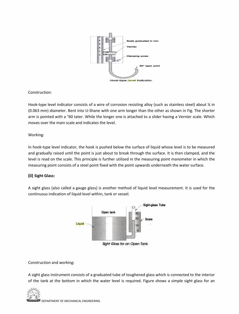
DEPARTMENT OF MECHANICAL ENGINEERING
Construction:
Hook-type level indicator consists of a wire of corrosion resisting alloy (such as stainless steel) about ¼ in
(0.063 mm) diameter. Bent into U-Shane with one arm longer than the other as shown in Fig. The shorter
arm is pointed with a °60 tater. While the longer one is attached to a slider having a Vernier scale. Which
moves over the main scale and indicates the level.
Working:
In hook-type level indicator, the hook is pushed below the surface of liquid whose level is to be measured
and gradually raised until the point is just about to break through the surface. It is then clamped, and the
level is read on the scale. This principle is further utilized in the measuring point manometer in which the
measuring point consists of a steel point fixed with the point upwards underneath the water surface.
(ii) Sight Glass:
A sight glass (also called a gauge glass) is another method of liquid level measurement. It is used for the
continuous indication of liquid level within, tank or vessel.
Construction and working:
A sight glass instrument consists of a graduated tube of toughened glass which is connected to the interior
of the tank at the bottom in which the water level is required. Figure shows a simple sight glass for an
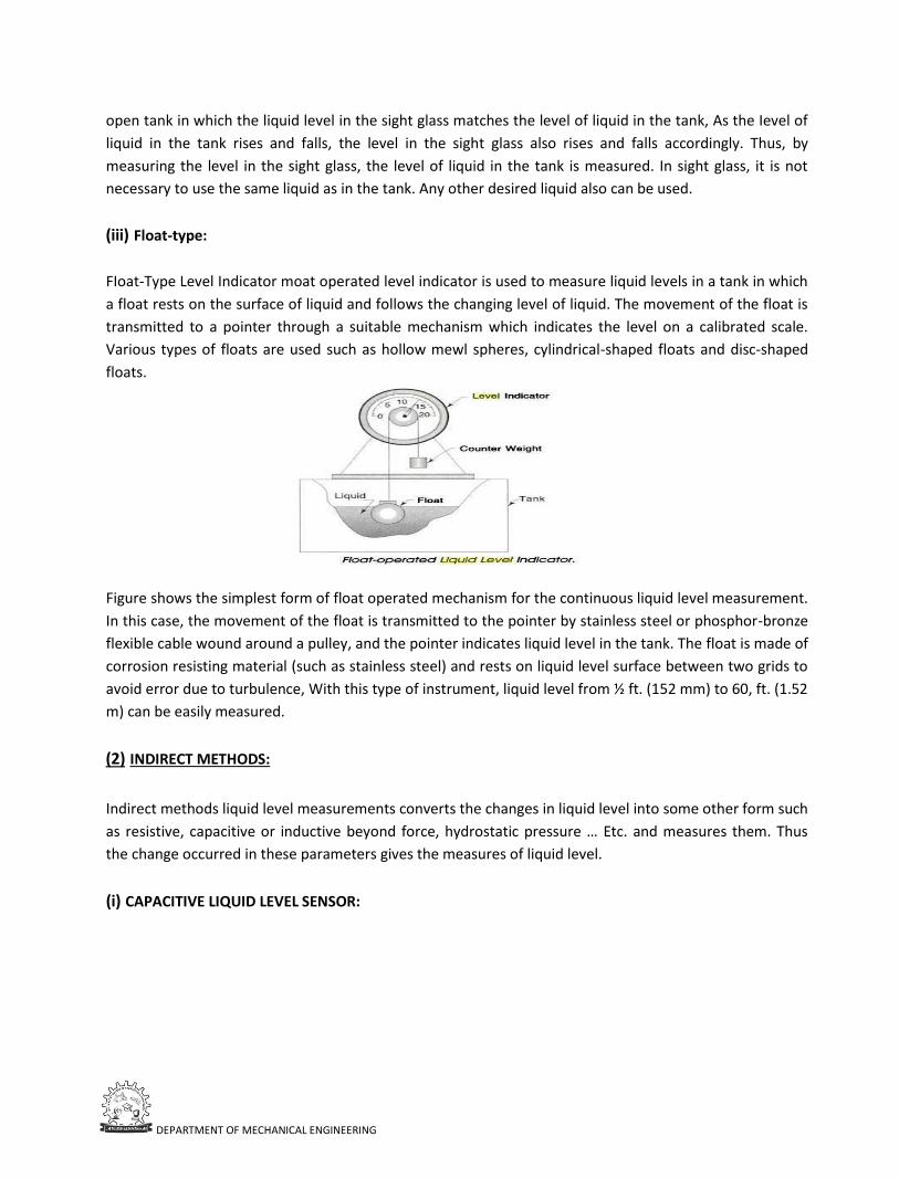
DEPARTMENT OF MECHANICAL ENGINEERING
open tank in which the liquid level in the sight glass matches the level of liquid in the tank, As the Ievel of
liquid in the tank rises and falls, the level in the sight glass also rises and falls accordingly. Thus, by
measuring the level in the sight glass, the level of liquid in the tank is measured. In sight glass, it is not
necessary to use the same liquid as in the tank. Any other desired liquid also can be used.
(iii) Float-type:
FIoat-Type Level Indicator moat operated level indicator is used to measure liquid levels in a tank in which
a float rests on the surface of liquid and follows the changing level of liquid. The movement of the float is
transmitted to a pointer through a suitable mechanism which indicates the level on a calibrated scale.
Various types of floats are used such as hollow mewl spheres, cylindrical-shaped floats and disc-shaped
floats.
Figure shows the simplest form of float operated mechanism for the continuous liquid level measurement.
In this case, the movement of the float is transmitted to the pointer by stainless steel or phosphor-bronze
flexible cable wound around a pulley, and the pointer indicates liquid level in the tank. The float is made of
corrosion resisting material (such as stainless steel) and rests on liquid level surface between two grids to
avoid error due to turbulence, With this type of instrument, liquid level from ½ ft. (152 mm) to 60, ft. (1.52
m) can be easily measured.
(2) INDIRECT METHODS:
Indirect methods liquid level measurements converts the changes in liquid level into some other form such
as resistive, capacitive or inductive beyond force, hydrostatic pressure … Etc. and measures them. Thus
the change occurred in these parameters gives the measures of liquid level.
(i) CAPACITIVE LIQUID LEVEL SENSOR:
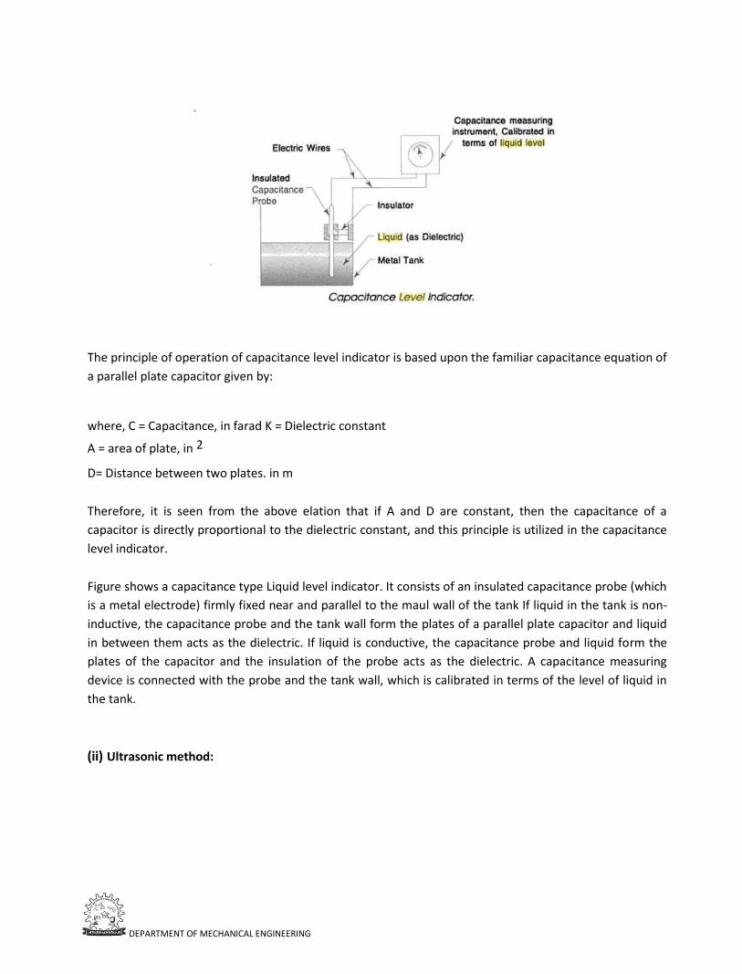
DEPARTMENT OF MECHANICAL ENGINEERING
The principle of operation of capacitance level indicator is based upon the familiar capacitance equation of
a parallel plate capacitor given by:
where, C = Capacitance, in farad K = Dielectric constant
A = area of plate, in 2
D= Distance between two plates. in m
Therefore, it is seen from the above elation that if A and D are constant, then the capacitance of a
capacitor is directly proportional to the dielectric constant, and this principle is utilized in the capacitance
level indicator.
Figure shows a capacitance type Liquid level indicator. It consists of an insulated capacitance probe (which
is a metal electrode) firmly fixed near and parallel to the maul wall of the tank If liquid in the tank is non-
inductive, the capacitance probe and the tank wall form the plates of a parallel plate capacitor and liquid
in between them acts as the dielectric. If liquid is conductive, the capacitance probe and liquid form the
plates of the capacitor and the insulation of the probe acts as the dielectric. A capacitance measuring
device is connected with the probe and the tank wall, which is calibrated in terms of the level of liquid in
the tank.
(ii) Ultrasonic method:
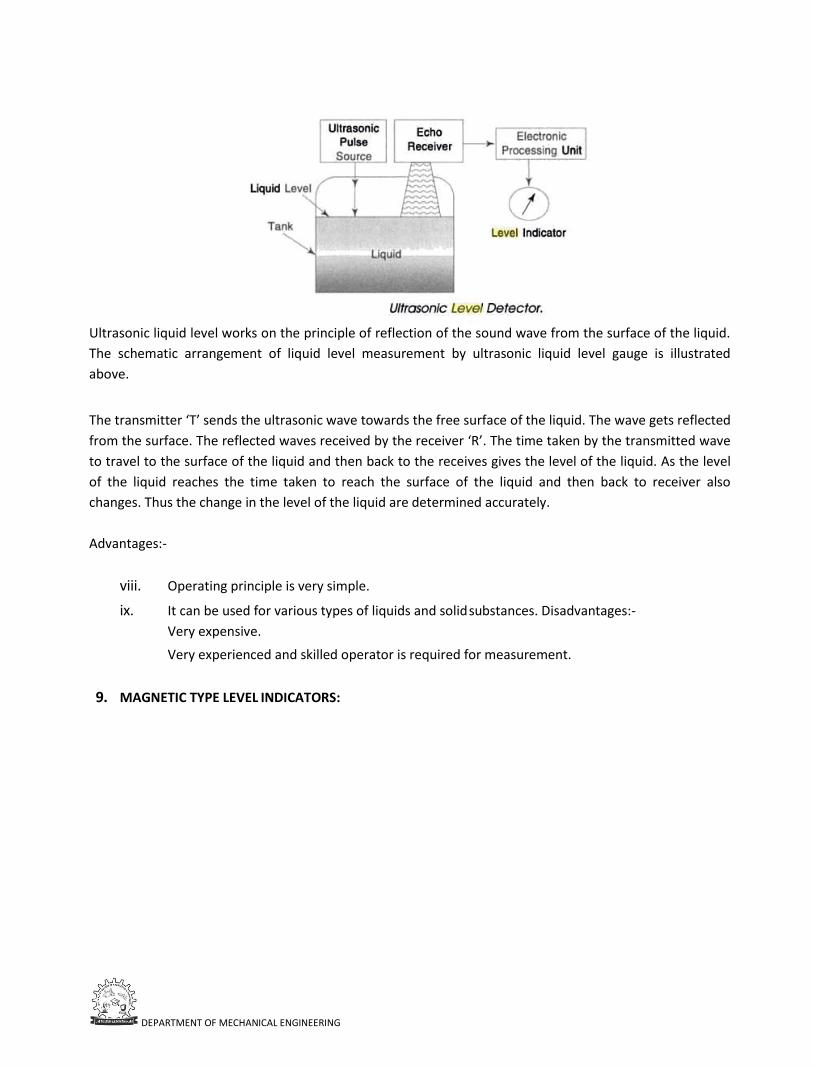
DEPARTMENT OF MECHANICAL ENGINEERING
Ultrasonic liquid level works on the principle of reflection of the sound wave from the surface of the liquid.
The schematic arrangement of liquid level measurement by ultrasonic liquid level gauge is illustrated
above.
The transmitter ‘T’ sends the ultrasonic wave towards the free surface of the liquid. The wave gets reflected
from the surface. The reflected waves received by the receiver ‘R’. The time taken by the transmitted wave
to travel to the surface of the liquid and then back to the receives gives the level of the liquid. As the level
of the liquid reaches the time taken to reach the surface of the liquid and then back to receiver also
changes. Thus the change in the level of the liquid are determined accurately.
Advantages:-
viii. Operating principle is very simple.
ix. It can be used for various types of liquids and solid substances. Disadvantages:-
Very expensive.
Very experienced and skilled operator is required for measurement.
9. MAGNETIC TYPE LEVEL INDICATORS:
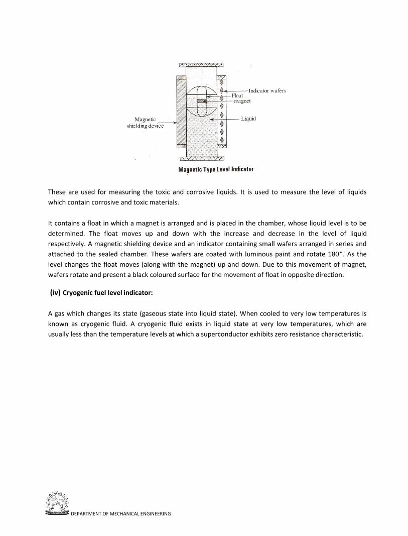
DEPARTMENT OF MECHANICAL ENGINEERING
These are used for measuring the toxic and corrosive liquids. It is used to measure the level of liquids
which contain corrosive and toxic materials.
It contains a float in which a magnet is arranged and is placed in the chamber, whose liquid level is to be
determined. The float moves up and down with the increase and decrease in the level of liquid
respectively. A magnetic shielding device and an indicator containing small wafers arranged in series and
attached to the sealed chamber. These wafers are coated with luminous paint and rotate 180*. As the
level changes the float moves (along with the magnet) up and down. Due to this movement of magnet,
wafers rotate and present a black coloured surface for the movement of float in opposite direction.
(iv) Cryogenic fuel level indicator:
A gas which changes its state (gaseous state into liquid state). When cooled to very low temperatures is
known as cryogenic fluid. A cryogenic fluid exists in liquid state at very low temperatures, which are
usually less than the temperature levels at which a superconductor exhibits zero resistance characteristic.
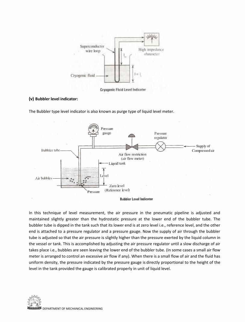
DEPARTMENT OF MECHANICAL ENGINEERING
(v) Bubbler level indicator:
The Bubbler type level indicator is also known as purge type of liquid level meter.
In this technique of level measurement, the air pressure in the pneumatic pipeline is adjusted and
maintained slightly greater than the hydrostatic pressure at the lower end of the bubbler tube. The
bubbler tube is dipped in the tank such that its lower end is at zero level i.e., reference level, and the other
end is attached to a pressure regulator and a pressure gauge. Now the supply of air through the bubbler
tube is adjusted so that the air pressure is slightly higher than the pressure exerted by the liquid column in
the vessel or tank. This is accomplished by adjusting the air pressure regulator until a slow discharge of air
takes place i.e., bubbles are seen leaving the lower end of the bubbler tube. (In some cases a small air flow
meter is arranged to control an excessive air flow if any). When there is a small flow of air and the fluid has
uniform density, the pressure indicated by the pressure gauge is directly proportional to the height of the
level in the tank provided the gauge is calibrated properly in unit of liquid level.
DEPARTMENT OF MECHANICAL ENGINEERING
FLOW MEASUREMENT:-
Introduction: Measurement of fluid velocity, flow rate and flow quantity with varying degree of accuracy or
a fundamental necessity in almost all the flow situations of engineering. Studying ocean or air currents,
monitoring gas input into a vacuum chamber, measuring blood movement in a vein. The scientist or
engineer is faced with choosing a method to measure flow. For experiment procedures, it may be necessary
to measure the rates of flow either into or out of the engines. “Pumps, compressors and turbines”. In
industrial organizations flow measurement is needed for providing the basis for controlling processes and
operations. That is for determining the proportions of materials entering or leaving, a continuous
manufacturing process. Flow measurements are also made for the purpose of cost accounting in
distribution of water and gas to domestic consumers, and in the gasoline pumping stations.
TYPES OF FLOW MEASURING INSTRUMENTS:-
8) Quantity meters.
9) Flow meters.
Quantity meters:-
In this class of instruments actual flow rate is measured. Flow rate measurement devices frequently
required accurate. Pressure and temperature measurements in order to calculate the output of the
instrument. The overall accuracy of the instrument depends upon the accuracy of pressure and
temperature measurements.
Quantity meters are used for the calibration of flow meters:
1) Quantity meters.
• Weight or volume tanks.
• Positive displacement or semi-positive displacement meters.
2) Flow meters.
• Obstruction meters.
• Orifice Nozzle Venture
• Variable-area meters.
• Velocity probes.
• Static pressure probes.
• Total pressure probes.
• Special methods.
• Turbine type meters.
• Magnetic flow meters.
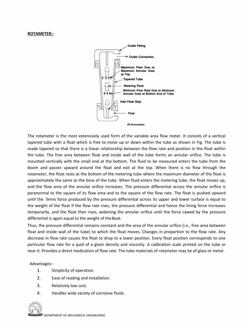
DEPARTMENT OF MECHANICAL ENGINEERING
ROTAMETER:-
The rotameter is the most extensively used form of the variable area flow meter. It consists of a vertical
tapered tube with a float which is free to move up or down within the tube as shown in Fig. The tube is
made tapered so that there is a linear relationship between the flow rate and position in the float within
the tube. The free area between float and inside wall of the tube forms an annular orifice. The tube is
mounted vertically with the small end at the bottom. The fluid to be measured enters the tube from the
boom and passes upward around the float and exit at the top. When there is no flow through the
rotameter, the float rests at the bottom of the metering tube where the maximum diameter of the float is
approximately the same as the bore of the tube. When fluid enters the metering tube, the float moves up,
and the flow area of the annular orifice increases. The pressure differential across the annular orifice is
paranormal to the square of its flow area and to the square of the flow rate. The float is pushed upward
until the `limns force produced by the pressure differential across its upper and lower surface is equal to
the weight of the float If the flow rate rises, the pressure differential and hence the lining force increases
temporarily, and the float then rises, widening the annular orifice until the force cawed by the pressure
differential is again equal to the weight of the Boat.
Thus, the pressure differential remains constant and the area of the annular orifice (i.e., free area between
float and inside wall of the tube) to which the float moves. Changes in proportion to the flow rate. Any
decrease in flow rate causes the float to drop to a lower position. Every float position corresponds to one
particular flow rate for a quid of a given density and viscosity. A calibration scale printed on the tube or
near it. Provides a direct medication of flow rate. The tube materials of rotameter may be of glass or metal.
Advantages:-
1. Simplicity of operation.
2. Ease of reading and installation.
3. Relatively low cost.
4. Handles wide variety of corrosive fluids.
DEPARTMENT OF MECHANICAL ENGINEERING
5. Easily equipped with data transmission, indicating and recording devices. Disadvantages:-
6. Glass tube subject to breakage.
7. Limited to small pipe sizes and capacities.
8. Less accurate compared to venture and orifice meters.
9. Must be mounted vertically.
10. Subject to oscillations.
TURBINE FLOW METER:-
Principle: - the permanent magnet attached to the body of rotor is polarized at 90° to the axis of rotation.
When the rotor rotates due to the velocity of the fluid (V), the permanent magnet also rotates along with
the rotor. Therefore, a rotating magnetic field will be generated which is then cut by the pickup coil. Due
to this ac-voltage pulses are generated whose frequency is directly proportional to the flow rate.
Q=
Where, f= total number of pulse, V= volume flow rate, k = flow coefficient
By minimizing the bearing friction and other losses that device can be designed to give linear output.
Advantages:-
• Good accuracy and repeatability. Easy to install and maintain.
• Low pressure drop. Electrical output is available. Good transient response.
Disadvantages:-
• High cost.
• The bearing of the rotor may subject to corrosion.
• Wear and tear problems. Applications:-
• Used to determine the fluid flow in pipes and tubes.
• Flow of water in rivers.
• Used to determine wind velocity in weather situations or conditions.
HOT WIRE ANEMOMETER:-
Principle:- When a fluid flows over an electrically heated surface, heat transfer takes place from the
surface or wire to the fluid. Hence, the temperature of the heated wire decreases which causes variations
in the resistance. The change that occurred in the resistance of the wire is related to the flow rate.
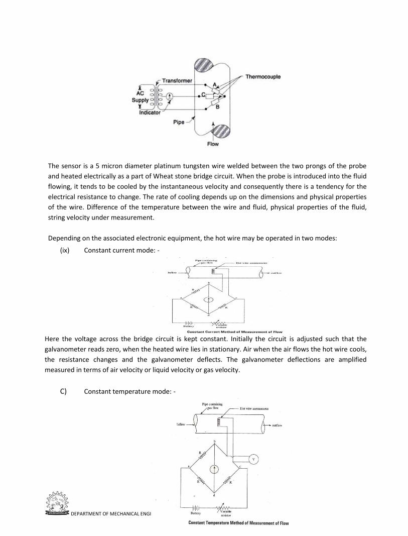
DEPARTMENT OF MECHANICAL ENGINEERING
The sensor is a 5 micron diameter platinum tungsten wire welded between the two prongs of the probe
and heated electrically as a part of Wheat stone bridge circuit. When the probe is introduced into the fluid
flowing, it tends to be cooled by the instantaneous velocity and consequently there is a tendency for the
electrical resistance to change. The rate of cooling depends up on the dimensions and physical properties
of the wire. Difference of the temperature between the wire and fluid, physical properties of the fluid,
string velocity under measurement.
Depending on the associated electronic equipment, the hot wire may be operated in two modes:
(ix) Constant current mode: -
Here the voltage across the bridge circuit is kept constant. Initially the circuit is adjusted such that the
galvanometer reads zero, when the heated wire lies in stationary. Air when the air flows the hot wire cools,
the resistance changes and the galvanometer deflects. The galvanometer deflections are amplified
measured in terms of air velocity or liquid velocity or gas velocity.
C) Constant temperature mode: -
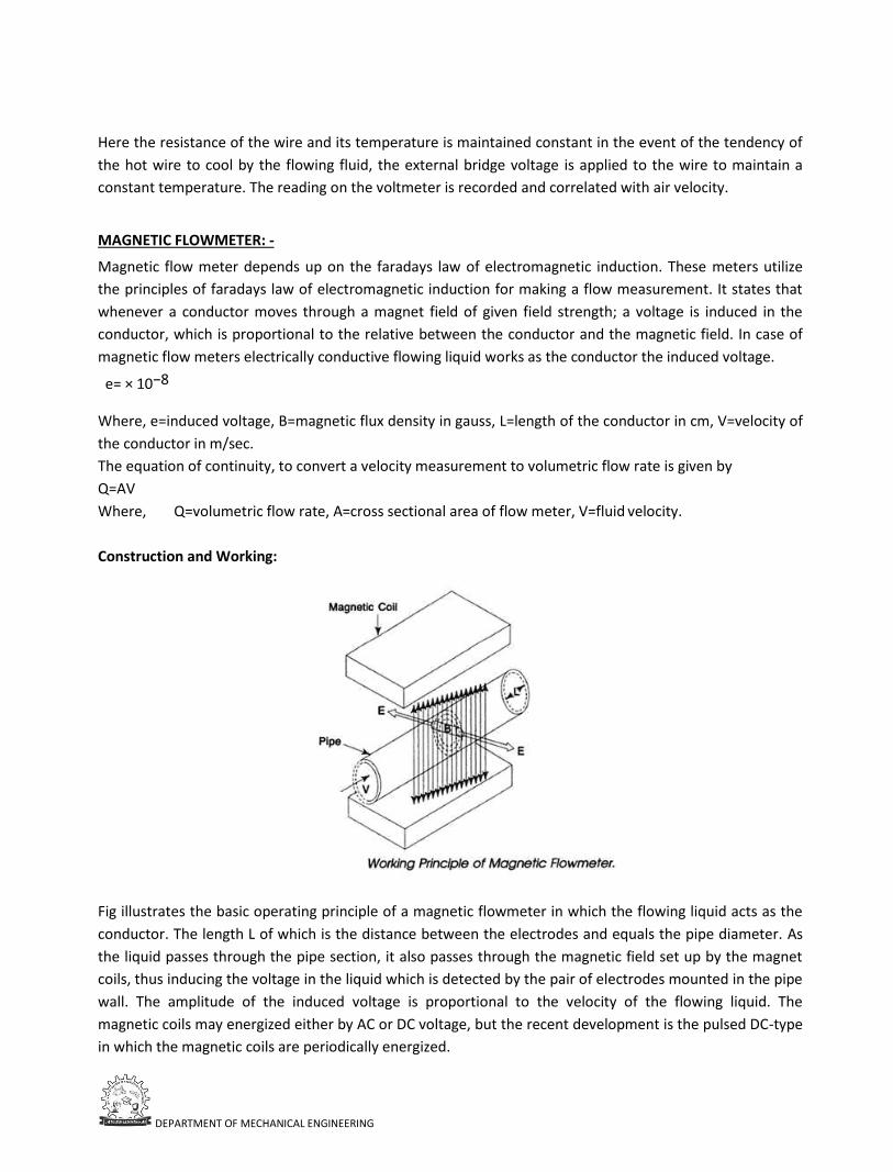
DEPARTMENT OF MECHANICAL ENGINEERING
Here the resistance of the wire and its temperature is maintained constant in the event of the tendency of
the hot wire to cool by the flowing fluid, the external bridge voltage is applied to the wire to maintain a
constant temperature. The reading on the voltmeter is recorded and correlated with air velocity.
MAGNETIC FLOWMETER: -
Magnetic flow meter depends up on the faradays law of electromagnetic induction. These meters utilize
the principles of faradays law of electromagnetic induction for making a flow measurement. It states that
whenever a conductor moves through a magnet field of given field strength; a voltage is induced in the
conductor, which is proportional to the relative between the conductor and the magnetic field. In case of
magnetic flow meters electrically conductive flowing liquid works as the conductor the induced voltage.
e= × 10−8
Where, e=induced voltage, B=magnetic flux density in gauss, L=length of the conductor in cm, V=velocity of
the conductor in m/sec.
The equation of continuity, to convert a velocity measurement to volumetric flow rate is given by
Q=AV
Where, Q=volumetric flow rate, A=cross sectional area of flow meter, V=fluid velocity.
Construction and Working:
Fig illustrates the basic operating principle of a magnetic flowmeter in which the flowing liquid acts as the
conductor. The length L of which is the distance between the electrodes and equals the pipe diameter. As
the liquid passes through the pipe section, it also passes through the magnetic field set up by the magnet
coils, thus inducing the voltage in the liquid which is detected by the pair of electrodes mounted in the pipe
wall. The amplitude of the induced voltage is proportional to the velocity of the flowing liquid. The
magnetic coils may energized either by AC or DC voltage, but the recent development is the pulsed DC-type
in which the magnetic coils are periodically energized.
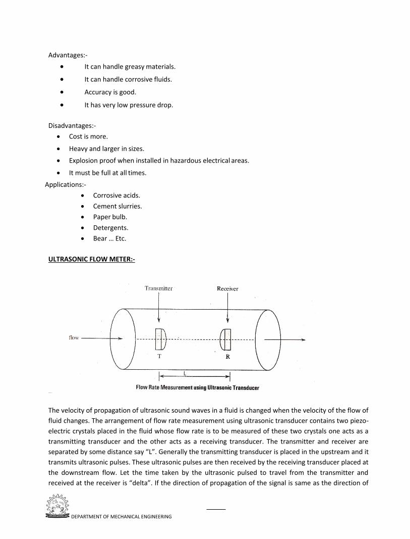
DEPARTMENT OF MECHANICAL ENGINEERING
Advantages:-
• It can handle greasy materials.
• It can handle corrosive fluids.
• Accuracy is good.
• It has very low pressure drop.
Disadvantages:-
• Cost is more.
• Heavy and larger in sizes.
• Explosion proof when installed in hazardous electrical areas.
• It must be full at all times.
Applications:-
• Corrosive acids.
• Cement slurries.
• Paper bulb.
• Detergents.
• Bear … Etc.
ULTRASONIC FLOW METER:-
The velocity of propagation of ultrasonic sound waves in a fluid is changed when the velocity of the flow of
fluid changes. The arrangement of flow rate measurement using ultrasonic transducer contains two piezo-
electric crystals placed in the fluid whose flow rate is to be measured of these two crystals one acts as a
transmitting transducer and the other acts as a receiving transducer. The transmitter and receiver are
separated by some distance say “L”. Generally the transmitting transducer is placed in the upstream and it
transmits ultrasonic pulses. These ultrasonic pulses are then received by the receiving transducer placed at
the downstream flow. Let the time taken by the ultrasonic pulsed to travel from the transmitter and
received at the receiver is “delta”. If the direction of propagation of the signal is same as the direction of
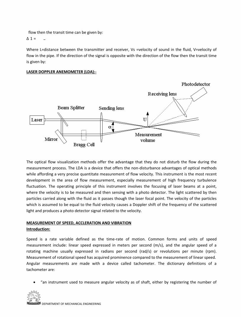
DEPARTMENT OF MECHANICAL ENGINEERING
flow then the transit time can be given by:
∆ 1 = −
Where L=distance between the transmitter and receiver, Vs =velocity of sound in the fluid, V=velocity of
flow in the pipe. If the direction of the signal is opposite with the direction of the flow then the transit time
is given by:
LASER DOPPLER ANEMOMETER (LDA):-
The optical flow visualization methods offer the advantage that they do not disturb the flow during the
measurement process. The LDA is a device that offers the non-disturbance advantages of optical methods
while affording a very precise quantitate measurement of flow velocity. This instrument is the most recent
development in the area of flow measurement, especially measurement of high frequency turbulence
fluctuation. The operating principle of this instrument involves the focusing of laser beams at a point,
where the velocity is to be measured and then sensing with a photo detector. The light scattered by then
particles carried along with the fluid as it passes though the laser focal point. The velocity of the particles
which is assumed to be equal to the fluid velocity causes a Doppler shift of the frequency of the scattered
light and produces a photo detector signal related to the velocity.
MEASUREMENT OF SPEED, ACCLERATION AND VIBRATION
Introduction:
Speed is a rate variable defined as the time-rate of motion. Common forms and units of speed
measurement include: linear speed expressed in meters per second (m/s), and the angular speed of a
rotating machine usually expressed in radians per second (rad/s) or revolutions per minute (rpm).
Measurement of rotational speed has acquired prominence compared to the measurement of linear speed.
Angular measurements are made with a device called tachometer. The dictionary definitions of a
tachometer are:
• “an instrument used to measure angular velocity as of shaft, either by registering the number of
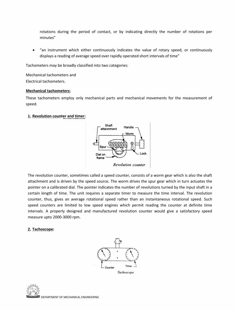
DEPARTMENT OF MECHANICAL ENGINEERING
rotations during the period of contact, or by indicating directly the number of rotations per
minutes”
• “an instrument which either continuously indicates the value of rotary speed, or continuously
displays a reading of average speed over rapidly operated short intervals of time”
Tachometers may be broadly classified into two categories:
Mechanical tachometers and
Electrical tachometers.
Mechanical tachometers:
These tachometers employ only mechanical parts and mechanical movements for the measurement of
speed.
1. Revolution counter and timer:
The revolution counter, sometimes called a speed counter, consists of a worm gear which is also the shaft
attachment and is driven by the speed source. The worm drives the spur gear which in turn actuates the
pointer on a calibrated dial. The pointer indicates the number of revolutions turned by the input shaft in a
certain length of time. The unit requires a separate timer to measure the time interval. The revolution
counter, thus, gives an average rotational speed rather than an instantaneous rotational speed. Such
speed counters are limited to low speed engines which permit reading the counter at definite time
intervals. A properly designed and manufactured revolution counter would give a satisfactory speed
measure upto 2000-3000 rpm.
2. Tachoscope:
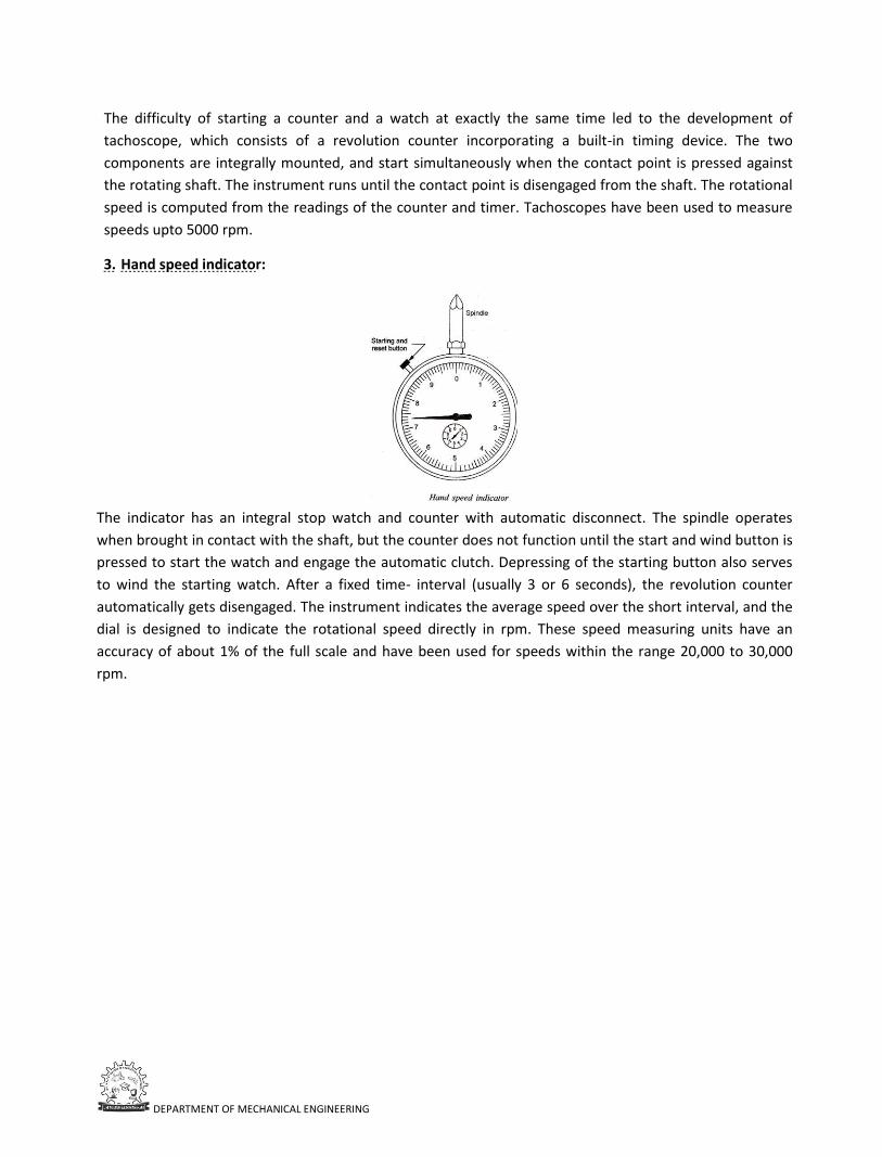
DEPARTMENT OF MECHANICAL ENGINEERING
The difficulty of starting a counter and a watch at exactly the same time led to the development of
tachoscope, which consists of a revolution counter incorporating a built-in timing device. The two
components are integrally mounted, and start simultaneously when the contact point is pressed against
the rotating shaft. The instrument runs until the contact point is disengaged from the shaft. The rotational
speed is computed from the readings of the counter and timer. Tachoscopes have been used to measure
speeds upto 5000 rpm.
3. Hand speed indicator:
The indicator has an integral stop watch and counter with automatic disconnect. The spindle operates
when brought in contact with the shaft, but the counter does not function until the start and wind button is
pressed to start the watch and engage the automatic clutch. Depressing of the starting button also serves
to wind the starting watch. After a fixed time- interval (usually 3 or 6 seconds), the revolution counter
automatically gets disengaged. The instrument indicates the average speed over the short interval, and the
dial is designed to indicate the rotational speed directly in rpm. These speed measuring units have an
accuracy of about 1% of the full scale and have been used for speeds within the range 20,000 to 30,000
rpm.
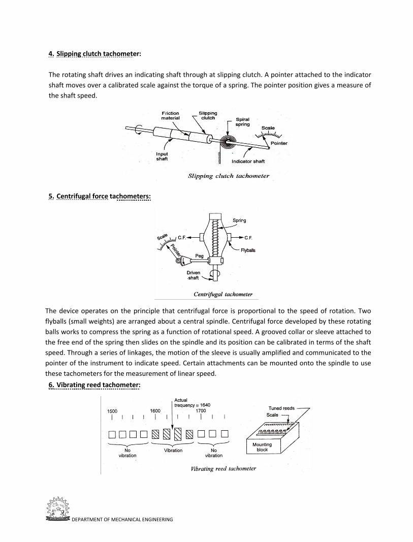
DEPARTMENT OF MECHANICAL ENGINEERING
4. Slipping clutch tachometer:
The rotating shaft drives an indicating shaft through at slipping clutch. A pointer attached to the indicator
shaft moves over a calibrated scale against the torque of a spring. The pointer position gives a measure of
the shaft speed.
5. Centrifugal force tachometers:
The device operates on the principle that centrifugal force is proportional to the speed of rotation. Two
flyballs (small weights) are arranged about a central spindle. Centrifugal force developed by these rotating
balls works to compress the spring as a function of rotational speed. A grooved collar or sleeve attached to
the free end of the spring then slides on the spindle and its position can be calibrated in terms of the shaft
speed. Through a series of linkages, the motion of the sleeve is usually amplified and communicated to the
pointer of the instrument to indicate speed. Certain attachments can be mounted onto the spindle to use
these tachometers for the measurement of linear speed.
6. Vibrating reed tachometer:
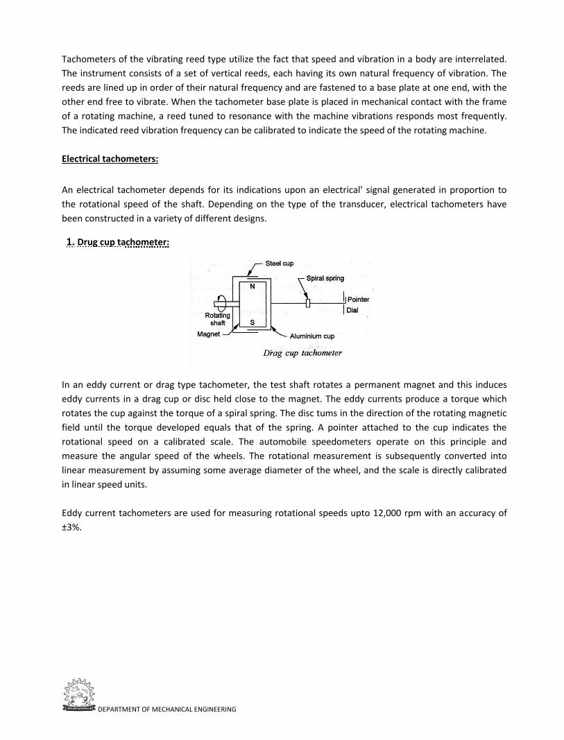
DEPARTMENT OF MECHANICAL ENGINEERING
Tachometers of the vibrating reed type utilize the fact that speed and vibration in a body are interrelated.
The instrument consists of a set of vertical reeds, each having its own natural frequency of vibration. The
reeds are lined up in order of their natural frequency and are fastened to a base plate at one end, with the
other end free to vibrate. When the tachometer base plate is placed in mechanical contact with the frame
of a rotating machine, a reed tuned to resonance with the machine vibrations responds most frequently.
The indicated reed vibration frequency can be calibrated to indicate the speed of the rotating machine.
Electrical tachometers:
An electrical tachometer depends for its indications upon an electrical' signal generated in proportion to
the rotational speed of the shaft. Depending on the type of the transducer, electrical tachometers have
been constructed in a variety of different designs.
1. Drug cup tachometer:
In an eddy current or drag type tachometer, the test shaft rotates a permanent magnet and this induces
eddy currents in a drag cup or disc held close to the magnet. The eddy currents produce a torque which
rotates the cup against the torque of a spiral spring. The disc tums in the direction of the rotating magnetic
field until the torque developed equals that of the spring. A pointer attached to the cup indicates the
rotational speed on a calibrated scale. The automobile speedometers operate on this principle and
measure the angular speed of the wheels. The rotational measurement is subsequently converted into
linear measurement by assuming some average diameter of the wheel, and the scale is directly calibrated
in linear speed units.
Eddy current tachometers are used for measuring rotational speeds upto 12,000 rpm with an accuracy of
±3%.
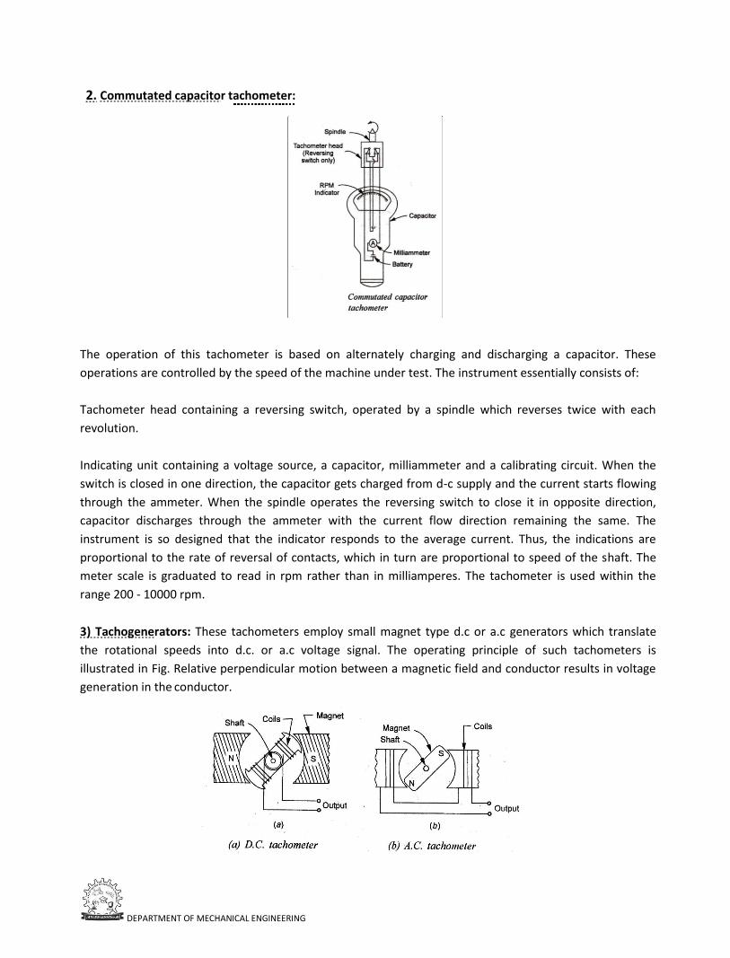
DEPARTMENT OF MECHANICAL ENGINEERING
2. Commutated capacitor tachometer:
The operation of this tachometer is based on alternately charging and discharging a capacitor. These
operations are controlled by the speed of the machine under test. The instrument essentially consists of:
Tachometer head containing a reversing switch, operated by a spindle which reverses twice with each
revolution.
Indicating unit containing a voltage source, a capacitor, milliammeter and a calibrating circuit. When the
switch is closed in one direction, the capacitor gets charged from d-c supply and the current starts flowing
through the ammeter. When the spindle operates the reversing switch to close it in opposite direction,
capacitor discharges through the ammeter with the current flow direction remaining the same. The
instrument is so designed that the indicator responds to the average current. Thus, the indications are
proportional to the rate of reversal of contacts, which in turn are proportional to speed of the shaft. The
meter scale is graduated to read in rpm rather than in milliamperes. The tachometer is used within the
range 200 - 10000 rpm.
3) Tachogenerators: These tachometers employ small magnet type d.c or a.c generators which translate
the rotational speeds into d.c. or a.c voltage signal. The operating principle of such tachometers is
illustrated in Fig. Relative perpendicular motion between a magnetic field and conductor results in voltage
generation in the conductor.
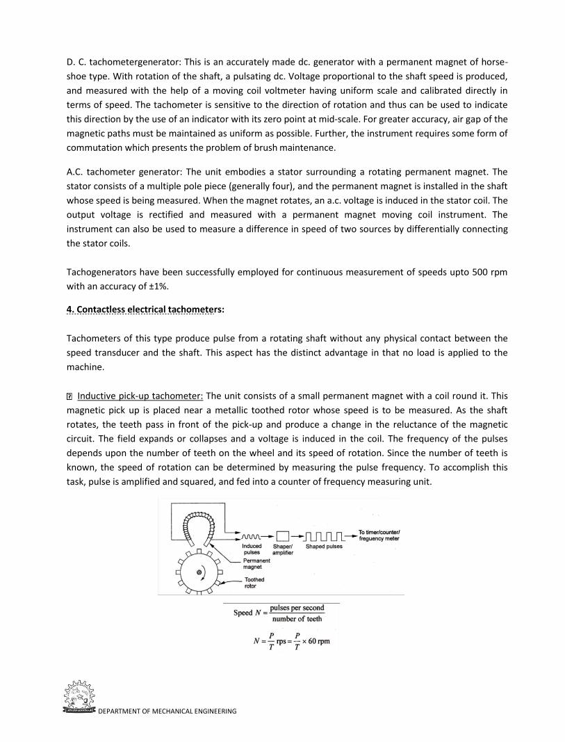
DEPARTMENT OF MECHANICAL ENGINEERING
D. C. tachometergenerator: This is an accurately made dc. generator with a permanent magnet of horse-
shoe type. With rotation of the shaft, a pulsating dc. Voltage proportional to the shaft speed is produced,
and measured with the help of a moving coil voltmeter having uniform scale and calibrated directly in
terms of speed. The tachometer is sensitive to the direction of rotation and thus can be used to indicate
this direction by the use of an indicator with its zero point at mid-scale. For greater accuracy, air gap of the
magnetic paths must be maintained as uniform as possible. Further, the instrument requires some form of
commutation which presents the problem of brush maintenance.
A.C. tachometer generator: The unit embodies a stator surrounding a rotating permanent magnet. The
stator consists of a multiple pole piece (generally four), and the permanent magnet is installed in the shaft
whose speed is being measured. When the magnet rotates, an a.c. voltage is induced in the stator coil. The
output voltage is rectified and measured with a permanent magnet moving coil instrument. The
instrument can also be used to measure a difference in speed of two sources by differentially connecting
the stator coils.
Tachogenerators have been successfully employed for continuous measurement of speeds upto 500 rpm
with an accuracy of ±1%.
4. Contactless electrical tachometers:
Tachometers of this type produce pulse from a rotating shaft without any physical contact between the
speed transducer and the shaft. This aspect has the distinct advantage in that no load is applied to the
machine.
Inductive pick-up tachometer: The unit consists of a small permanent magnet with a coil round it. This
magnetic pick up is placed near a metallic toothed rotor whose speed is to be measured. As the shaft
rotates, the teeth pass in front of the pick-up and produce a change in the reluctance of the magnetic
circuit. The field expands or collapses and a voltage is induced in the coil. The frequency of the pulses
depends upon the number of teeth on the wheel and its speed of rotation. Since the number of teeth is
known, the speed of rotation can be determined by measuring the pulse frequency. To accomplish this
task, pulse is amplified and squared, and fed into a counter of frequency measuring unit.
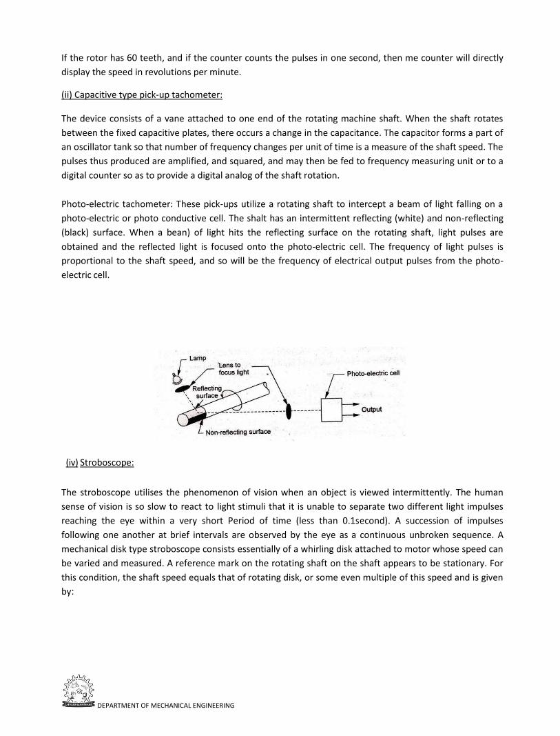
DEPARTMENT OF MECHANICAL ENGINEERING
If the rotor has 60 teeth, and if the counter counts the pulses in one second, then me counter will directly
display the speed in revolutions per minute.
(ii) Capacitive type pick-up tachometer:
The device consists of a vane attached to one end of the rotating machine shaft. When the shaft rotates
between the fixed capacitive plates, there occurs a change in the capacitance. The capacitor forms a part of
an oscillator tank so that number of frequency changes per unit of time is a measure of the shaft speed. The
pulses thus produced are amplified, and squared, and may then be fed to frequency measuring unit or to a
digital counter so as to provide a digital analog of the shaft rotation.
Photo-electric tachometer: These pick-ups utilize a rotating shaft to intercept a beam of light falling on a
photo-electric or photo conductive cell. The shalt has an intermittent reflecting (white) and non-reflecting
(black) surface. When a bean) of light hits the reflecting surface on the rotating shaft, light pulses are
obtained and the reflected light is focused onto the photo-electric cell. The frequency of light pulses is
proportional to the shaft speed, and so will be the frequency of electrical output pulses from the photo-
electric cell.
(iv) Stroboscope:
The stroboscope utilises the phenomenon of vision when an object is viewed intermittently. The human
sense of vision is so slow to react to light stimuli that it is unable to separate two different light impulses
reaching the eye within a very short Period of time (less than 0.1second). A succession of impulses
following one another at brief intervals are observed by the eye as a continuous unbroken sequence. A
mechanical disk type stroboscope consists essentially of a whirling disk attached to motor whose speed can
be varied and measured. A reference mark on the rotating shaft on the shaft appears to be stationary. For
this condition, the shaft speed equals that of rotating disk, or some even multiple of this speed and is given
by:
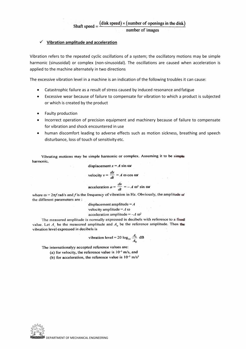
DEPARTMENT OF MECHANICAL ENGINEERING
Vibration amplitude and acceleration
Vibration refers to the repeated cyclic oscillations of a system; the oscillatory motions may be simple
harmonic (sinusoidal) or complex (non-sinusoidal). The oscillations are caused when acceleration is
applied to the machine alternately in two directions
The excessive vibration level in a machine is an indication of the following troubles it can cause:
• Catastrophic failure as a result of stress caused by induced resonance and fatigue
• Excessive wear because of failure to compensate for vibration to which a product is subjected
or which is created by the product
• Faulty production
• Incorrect operation of precision equipment and machinery because of failure to compensate
for vibration and shock encountered in use
• human discomfort leading to adverse effects such as motion sickness, breathing and speech
disturbance, loss of touch of sensitivity etc.
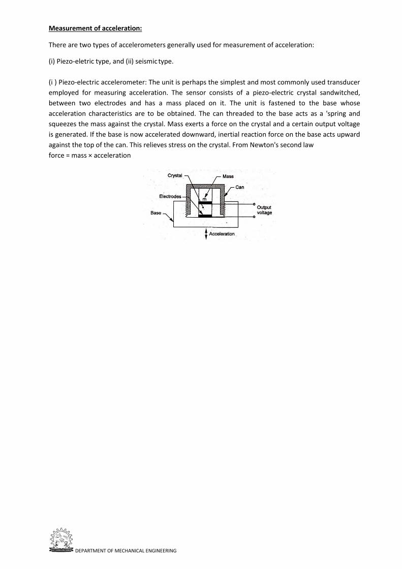
DEPARTMENT OF MECHANICAL ENGINEERING
Measurement of acceleration:
There are two types of accelerometers generally used for measurement of acceleration:
(i) Piezo-eletric type, and (ii) seismic type.
(i ) Piezo-electric accelerometer: The unit is perhaps the simplest and most commonly used transducer
employed for measuring acceleration. The sensor consists of a piezo-electric crystal sandwitched,
between two electrodes and has a mass placed on it. The unit is fastened to the base whose
acceleration characteristics are to be obtained. The can threaded to the base acts as a 'spring and
squeezes the mass against the crystal. Mass exerts a force on the crystal and a certain output voltage
is generated. If the base is now accelerated downward, inertial reaction force on the base acts upward
against the top of the can. This relieves stress on the crystal. From Newton's second law
force = mass × acceleration
UNIT 4
STRESS STRAIN MEASUREMENT & MEASUREMENT OF HUMIDITY
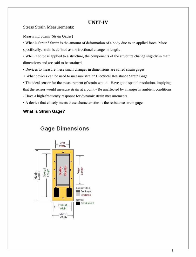
1
UNIT-IV Stress Strain Measurements: Measuring Strain (Strain Gages)
• What is Strain? Strain is the amount of deformation of a body due to an applied force. More
specifically, strain is defined as the fractional change in length.
• When a force is applied to a structure, the components of the structure change slightly in their
dimensions and are said to be strained.
• Devices to measure these small changes in dimensions are called strain gages.
• What devices can be used to measure strain? Electrical Resistance Strain Gage
• The ideal sensor for the measurement of strain would - Have good spatial resolution, implying
that the sensor would measure strain at a point - Be unaffected by changes in ambient conditions
- Have a high-frequency response for dynamic strain measurements.
• A device that closely meets these characteristics is the resistance strain gage.
What is Strain Gage?
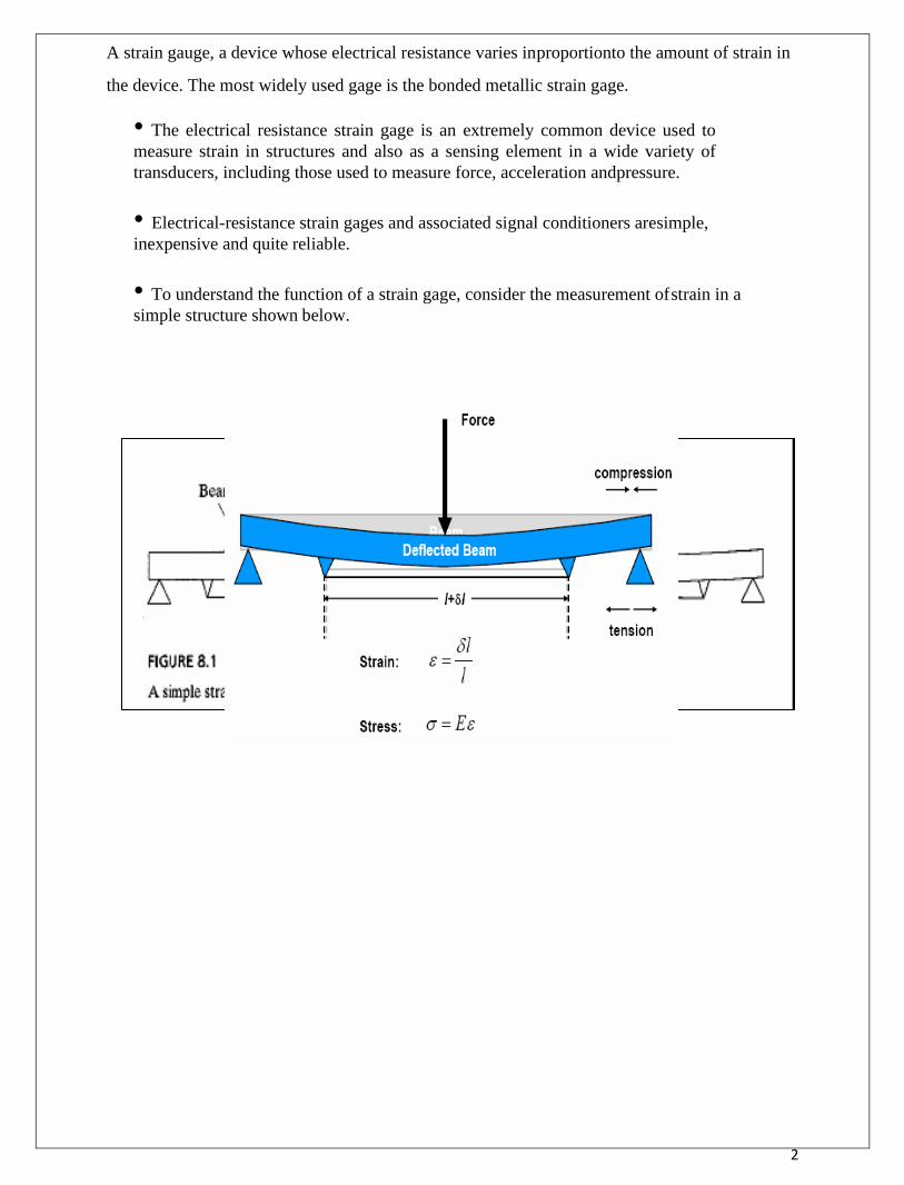
2
A strain gauge, a device whose electrical resistance varies in proportionto the amount of strain in
the device. The most widely used gage is the bonded metallic strain gage.
• The electrical resistance strain gage is an extremely common device used to
measure strain in structures and also as a sensing element in a wide variety of
transducers, including those used to measure force, acceleration and pressure.
• Electrical-resistance strain gages and associated signal conditioners are simple,
inexpensive and quite reliable.
• To understand the function of a strain gage, consider the measurement of strain in a
simple structure shown below.
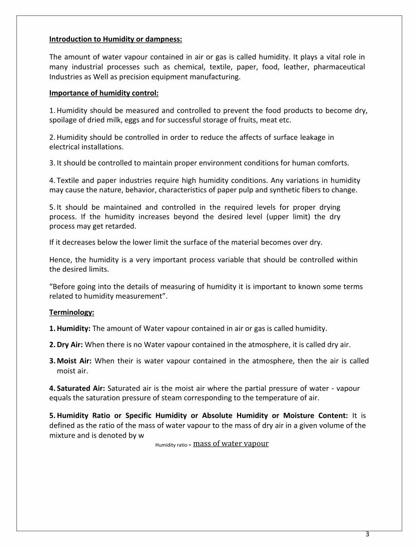
3
Introduction to Humidity or dampness:
The amount of water vapour contained in air or gas is called humidity. It plays a vital role in many industrial processes such as chemical, textile, paper, food, leather, pharmaceutical Industries as Well as precision equipment manufacturing. Importance of humidity control: 1. Humidity should be measured and controlled to prevent the food products to become dry, spoilage of dried milk, eggs and for successful storage of fruits, meat etc. 2. Humidity should be controlled in order to reduce the affects of surface leakage in electrical installations. 3. It should be controlled to maintain proper environment conditions for human comforts. 4. Textile and paper industries require high humidity conditions. Any variations in humidity may cause the nature, behavior, characteristics of paper pulp and synthetic fibers to change. 5. It should be maintained and controlled in the required levels for proper drying process. If the humidity increases beyond the desired level (upper limit) the dry process may get retarded. If it decreases below the lower limit the surface of the material becomes over dry. Hence, the humidity is a very important process variable that should be controlled within the desired limits. “Before going into the details of measuring of humidity it is important to known some terms related to humidity measurement”. Terminology: 1. Humidity: The amount of Water vapour contained in air or gas is called humidity. 2. Dry Air: When there is no Water vapour contained in the atmosphere, it is called dry air. 3. Moist Air: When their is water vapour contained in the atmosphere, then the air is called
moist air. 4. Saturated Air: Saturated air is the moist air where the partial pressure of water - vapour equals the saturation pressure of steam corresponding to the temperature of air. 5. Humidity Ratio or Specific Humidity or Absolute Humidity or Moisture Content: It is defined as the ratio of the mass of water vapour to the mass of dry air in a given volume of the mixture and is denoted by w
Humidity ratio = mass of water vapour
4
i. Relative Humidity: It is defined as the ratio of the mass of water vapour in a certain volume of moist
air at a given temperature to the mass of water vapour in the same volume of saturated air at the same temperature and is denoted by RH or ∅.
Relative humidity =
(Water vapour actually
present) (At a given temperature)
(Water vapour required for saturation)
Here a comparison is made between the humidity of air and the humidity of saturated air at the same temperature and pressure. It is to be noted that if relative humidity is 100 % it is saturated air, i.e., the air contains all the moisture it can hold. It should also be noted that the degree of saturation (percentage of relative humidity ) of air keeps on changing with temperature. a) Dew Point Temperature: By continuous cooling at constant pressure if the temperature of air is reduced, the water - vapour in the air will start to condense at; particular temperature. The temperature at which the water vapour starts condensing is called as dew point temperature. b) Dry Bulb Temperature: When a thermometer bulb is directly exposed to an air -water vapour mixture, the temperature indicated by the thermometer is the dry –bull temperature. This dry- bulb temperate is not affected by the moisture present in the air i.e. the temperature of air is measured in a normal way by the thermometer.
1. Wet Bulb Temperature: When a thermometer bulb is covered by a wet wick, and if the bulb
covered by the wet wick is exposed to air, water vapour mixture, the temperature indicated by
the thermometer is the wet bulb temperature. When air passed on the wet wick present on
the bulb of the thermometer, the moisture present in the wick starts evaporating and this
creates a cooling effect at the bulb. The bulb now measures the thermodynamic equilibrium
temperature reached between then cooling affected by the evaporation of water and heating
by convection. 2. Wet - Bulb Depression: Wet - bulb depression = (Dry - bulb temperature) - (Wet bulb
temperature ) Always dry - bulb temperature is higher than the wet bulb temperature. i.e., (Dry - bulb temperature > Wet bulb temperature) 3. Percentage Humidity: It is defined as ratio of weight of water vapour in a unit weight of air to weight of water vapour in the same weight of air if the air were completely saturated at the same temperature. (Weight of water vapour in a unit weight of air)
Percentage humidity = Weight of water vapour in the same weight of air if the air were completely saturated at the same temperature.
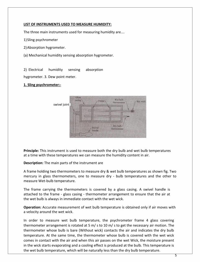
5
LIST OF INSTRUMENTS USED TO MEASURE HUMIDITY: The three main instruments used for measuring humidity are…. 1) Sling psychrometer 2) Absorption hygrometer. (a) Mechanical humidity sensing absorption hygrometer. 2) Electrical humidity sensing absorption
hygrometer. 3. Dew point meter. 1. Sling psychrometer:-
Principle: This instrument is used to measure both the dry bulb and wet bulb temperatures at a time with these temperatures we can measure the humidity content in air. Description: The main parts of the instrument are A frame holding two thermometers to measure dry & wet bulb temperatures as shown fig. Two mercury in glass thermometers, one to measure dry - bulb temperatures and the other to measure Wet-bulb temperature. The frame carrying the thermometers is covered by a glass casing. A swivel handle is attached to the frame - glass casing - thermometer arrangement to ensure that the air at the wet bulb is always in immediate contact with the wet wick. Operation: Accurate measurement of wet bulb temperature is obtained only if air moves with a velocity around the wet wick.
In order to measure wet bulb temperature, the psychrometer frame 4 glass covering
thermometer arrangement is rotated at 5 m/ s to 10 m/ s to get the necessary air motion. The
thermometer whose bulb is bare (Without wick) contacts the air and indicates the dry bulb
temperature. At the same time, the thermometer whose bulb is covered with the wet wick
comes in contact with the air and when this air passes on the wet Wick, the moisture present
in the wick starts evaporating and a cooling effect is produced at the bulb. This temperature is
the wet bulb temperature, which will be naturally less than the dry bulb temperature.
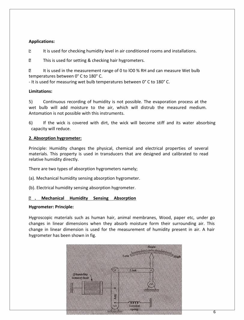
6
Applications: It is used for checking humidity level in air conditioned rooms and installations.
This is used for setting & checking hair hygrometers.
It is used in the measurement range of 0 to lO0 % RH and can measure Wet bulb
temperatures between 0° C to 180° C. - It is used for measuring wet bulb temperatures between 0° C to 180° C. Limitations: 5) Continuous recording of humidity is not possible. The evaporation process at the wet bulb will add moisture to the air, which will distrub the measured medium. Antomation is not possible with this instruments. 6) If the wick is covered with dirt, the wick will become stiff and its water absorbing
capacity will reduce. 2. Absorption hygrometer: Principle: Humidity changes the physical, chemical and electrical properties of several materials. This property is used in transducers that are designed and calibrated to read relative humidity directly. There are two types of absorption hygrometers namely; (a). Mechanical humidity sensing absorption hygrometer. (b). Electrical humidity sensing absorption hygrometer.
. Mechanical Humidity Sensing Absorption
Hygrometer: Principle: Hygroscopic materials such as human hair, animal membranes, Wood, paper etc, under go changes in linear dimensions when they absorb moisture form their surrounding air. This change in linear dimension is used for the measurement of humidity present in air. A hair hygrometer has been shown in fig.
7
Description: The main parts of the mechanical hair hygrometer type are: a) Human hair as the humidity sensor. The hair is arranged in parallel beam and they are separated from one another to expose them to the surrounding air. Number of hairs are placed in parallel to increase mechanical strength as shown in fig. ii. The hair arrangement is subjected to light tension by the use of a tension spring to ensure proper functioning. iii. The hair arrangement is connected to an arm and a link arrangement and link in turn is attached to a pointer, pivoted at one end. The pointer sweeps on a humidity calibrated scale. Operation: When the humidity of air is to be measured, the hair arrangement is exposed to the air medium and this absorbs the humidity from the surrounding air and expands or contracts in the linear direction. This expansion or contraction of the arrangement moves the arm & link and thus the pointer on the calibrated scale, indicating the humidity present in the atmosphere. These hygrometers are called membrance hygrometers when the sensing element is a membrance. Applications: Temperature range of these hygrometers is 0 to 75°C
RH (Relative humidity) range is 30 to 95 %.
Limitations: 1) Response time is slow 2) Calibration tends to change if is it used continuously
2) . Electrical Humidity sensing Absorption
Hygrometer: Principle: Humidity changes the resistance of some material. This change in resistance is taker as a measure of humidity Description: The main parts of this arrangement are: (i) The two metal electrodes, which are coated and separated by a humidity sensing hygroscopic salt (lithium chloride) as shown in fig. (ii) The leads of the electrodes are connected to a null balance Wheatstone bridge
8
Operation: The electrodes coated with lithium chloride are exposed to atmosphere, whose humidity is to be measured. Humidity variation causes the resistance of lithium chloride to change. i.e., the chemical absorbs or loses moisture and causes a change in resistance. Higher the humidity ( RH) in the atmosphere, more will be the humidity absorbed by lithium chloride and lower will be the resistance and higher will be the resistance in case of lesser humidity. The change in resistance is measured using a Wheatstone bridge which becomes a measure of humidity (RH) present in the atmosphere. Applications: -These are used under constant temperature conditions. -The accuracy of this instrument is ± 25% -The response is very fast, of the order of few seconds. Limitations: This instrument should not be exposed to 100 % humidity as this makes chemical absorb all the humidity and damage the instrument. Temperature corrections must be made if they are not used at constant temperature conditions. 3. Dew point meter:- Principle: At constant pressure if the temperature of air is reduced, the water vapour in the will start to condense at a particular temperature. This temperature is called dew point temperature. Description: The main parts of the arrangement are: A) A shiny mirror surface fixed with a thermocouple as shown in fig. B) A nozzle to provide a jet of air on the mirror. C) A light source focused constantly on the mirror. D) A photo cell to detect the amount of light reflected from the mirror.

9
Operation: -The mirror is constantly cooled by a cooling medium, which is maintained at a constant temperature. -A thermocouple is attached to this mirror, whose leads are connected, to a milli voltmeter. -Constantly a light is made to fall at an angle on the mirror and the amount of reflected light is sensed by a photo cell as shown in fig.
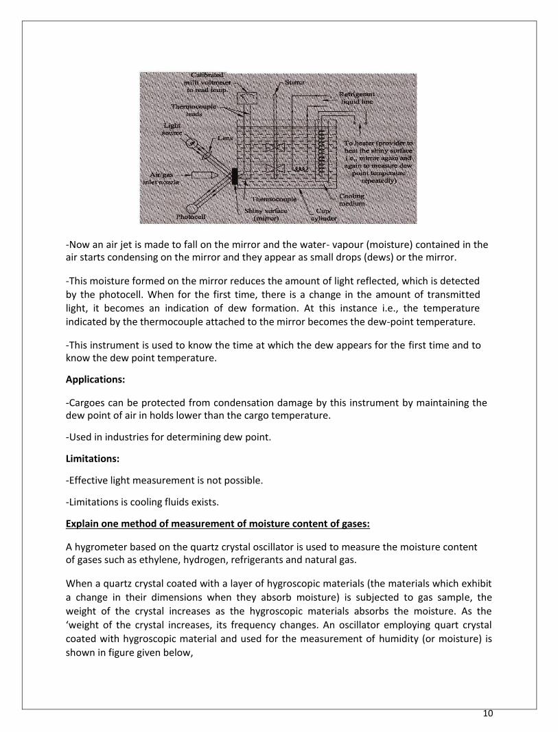
10
-Now an air jet is made to fall on the mirror and the water- vapour (moisture) contained in the air starts condensing on the mirror and they appear as small drops (dews) or the mirror.
-This moisture formed on the mirror reduces the amount of light reflected, which is detected by the photocell. When for the first time, there is a change in the amount of transmitted light, it becomes an indication of dew formation. At this instance i.e., the temperature indicated by the thermocouple attached to the mirror becomes the dew-point temperature. -This instrument is used to know the time at which the dew appears for the first time and to know the dew point temperature. Applications: -Cargoes can be protected from condensation damage by this instrument by maintaining the dew point of air in holds lower than the cargo temperature. -Used in industries for determining dew point. Limitations: -Effective light measurement is not possible. -Limitations is cooling fluids exists. Explain one method of measurement of moisture content of gases: A hygrometer based on the quartz crystal oscillator is used to measure the moisture content of gases such as ethylene, hydrogen, refrigerants and natural gas.
When a quartz crystal coated with a layer of hygroscopic materials (the materials which exhibit
a change in their dimensions when they absorb moisture) is subjected to gas sample, the
weight of the crystal increases as the hygroscopic materials absorbs the moisture. As the
‘weight of the crystal increases, its frequency changes. An oscillator employing quart crystal
coated with hygroscopic material and used for the measurement of humidity (or moisture) is
shown in figure given below,
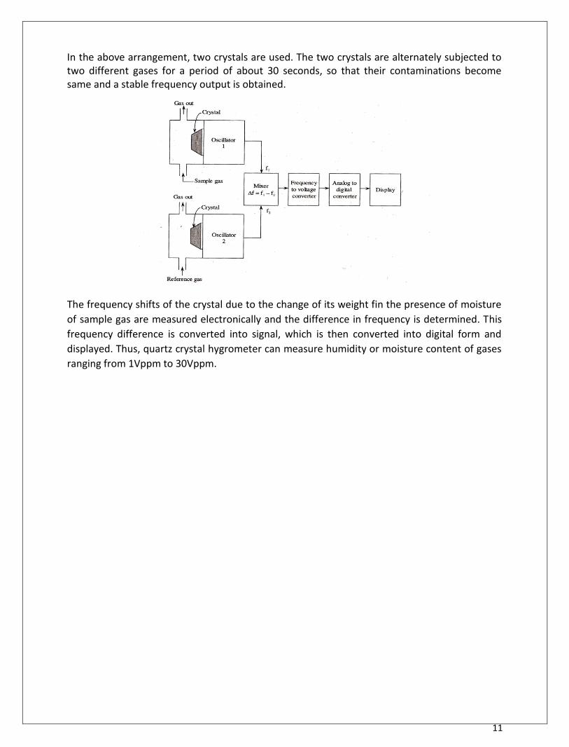
11
In the above arrangement, two crystals are used. The two crystals are alternately subjected to two different gases for a period of about 30 seconds, so that their contaminations become same and a stable frequency output is obtained. The frequency shifts of the crystal due to the change of its weight fin the presence of moisture
of sample gas are measured electronically and the difference in frequency is determined. This
frequency difference is converted into signal, which is then converted into digital form and
displayed. Thus, quartz crystal hygrometer can measure humidity or moisture content of gases
ranging from 1Vppm to 30Vppm.
UNIT 5
MEASUREMENT OF FORCE, TORQUE & POWER
ELEMENTS OF CONTROL SYSTEMS
12
UNIT-V
MEASUREMENT OF FORCE, TORQUE AND POWER An engineer is concerned not only with the generation of power by a prime-mover but is also required to measure the useful output. That helps the engineer to know how well prime-mover is doing its job in relation to the energy supplied to it. The terms related to engine output are: i) Force: Force represents the mechanical quantity which changes or tends to change the relative motion or shape of the body on which it acts. Force is vector quantity specified completely by its magnitude, point of application, line of action and direction. The relationship between motion and force is provided by the laws of dynamics. Newton’s second low of motion states that force is proportional to the rate of change of momentum. That is
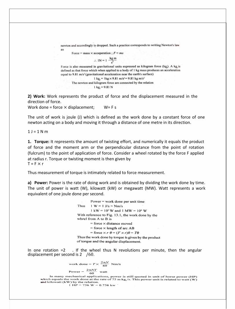
13
2) Work: Work represents the product of force and the displacement measured in the direction of force. Work done = force × displacement; W= F s The unit of work is joule (J) which is defined as the work done by a constant force of one newton acting on a body and moving it through a distance of one metre in its direction. 1 J = 1 N m
1. Torque: It represents the amount of twisting effort, and numerically it equals the product of force and the moment arm or the perpendicular distance from the point of rotation (fulcrum) to the point of application of force. Consider a wheel rotated by the force F applied at radius r. Torque or twisting moment is then given by T = F × r Thus measurement of torque is intimately related to force measurement. a) Power: Power is the rate of doing work and is obtained by dividing the work done by time. The unit of power is watt (W), kilowatt (kW) or megawatt (MW). Watt represents a work equivalent of one joule done per second. In one rotation =2 . If the wheel thus N revolutions per minute, then the angular displacement per second is 2 /60.
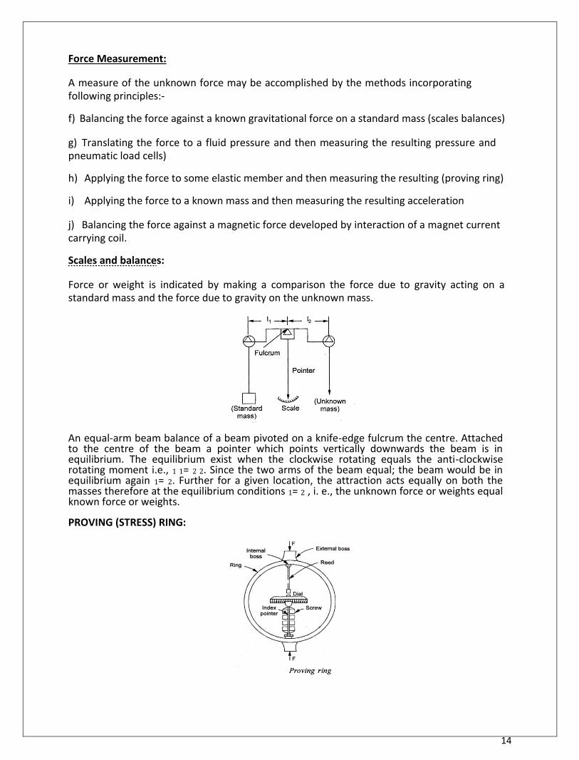
14
Force Measurement: A measure of the unknown force may be accomplished by the methods incorporating following principles:- f) Balancing the force against a known gravitational force on a standard mass (scales balances) g) Translating the force to a fluid pressure and then measuring the resulting pressure and pneumatic load cells) h) Applying the force to some elastic member and then measuring the resulting (proving ring) i) Applying the force to a known mass and then measuring the resulting acceleration j) Balancing the force against a magnetic force developed by interaction of a magnet current carrying coil. Scales and balances: Force or weight is indicated by making a comparison the force due to gravity acting on a standard mass and the force due to gravity on the unknown mass.
An equal-arm beam balance of a beam pivoted on a knife-edge fulcrum the centre. Attached to the centre of the beam a pointer which points vertically downwards the beam is in equilibrium. The equilibrium exist when the clockwise rotating equals the anti-clockwise rotating moment i.e., 1 1= 2 2. Since the two arms of the beam equal; the beam would be in equilibrium again 1= 2. Further for a given location, the attraction acts equally on both the masses therefore at the equilibrium conditions 1= 2 , i. e., the unknown force or weights equal known force or weights. PROVING (STRESS) RING:
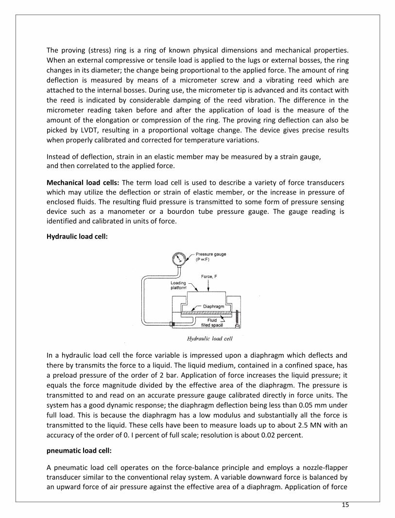
15
The proving (stress) ring is a ring of known physical dimensions and mechanical properties.
When an external compressive or tensile load is applied to the lugs or external bosses, the ring
changes in its diameter; the change being proportional to the applied force. The amount of ring
deflection is measured by means of a micrometer screw and a vibrating reed which are
attached to the internal bosses. During use, the micrometer tip is advanced and its contact with
the reed is indicated by considerable damping of the reed vibration. The difference in the
micrometer reading taken before and after the application of load is the measure of the
amount of the elongation or compression of the ring. The proving ring deflection can also be
picked by LVDT, resulting in a proportional voltage change. The device gives precise results
when properly calibrated and corrected for temperature variations. Instead of deflection, strain in an elastic member may be measured by a strain gauge, and then correlated to the applied force.
Mechanical load cells: The term load cell is used to describe a variety of force transducers which may utilize the deflection or strain of elastic member, or the increase in pressure of enclosed fluids. The resulting fluid pressure is transmitted to some form of pressure sensing device such as a manometer or a bourdon tube pressure gauge. The gauge reading is identified and calibrated in units of force. Hydraulic load cell:
In a hydraulic load cell the force variable is impressed upon a diaphragm which deflects and
there by transmits the force to a liquid. The liquid medium, contained in a confined space, has
a preload pressure of the order of 2 bar. Application of force increases the liquid pressure; it
equals the force magnitude divided by the effective area of the diaphragm. The pressure is
transmitted to and read on an accurate pressure gauge calibrated directly in force units. The
system has a good dynamic response; the diaphragm deflection being less than 0.05 mm under
full load. This is because the diaphragm has a low modulus and substantially all the force is
transmitted to the liquid. These cells have been to measure loads up to about 2.5 MN with an
accuracy of the order of 0. I percent of full scale; resolution is about 0.02 percent. pneumatic load cell:
A pneumatic load cell operates on the force-balance principle and employs a nozzle-flapper transducer similar to the conventional relay system. A variable downward force is balanced by an upward force of air pressure against the effective area of a diaphragm. Application of force

16
causes the flapper to come closer to the nozzle, and the diaphragm to deflect downwards. The nozzle opening is nearly shut-off and
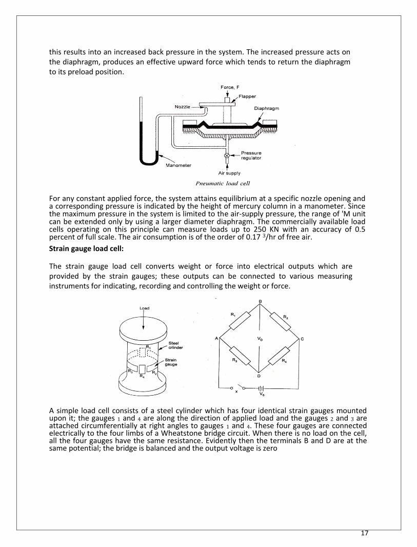
17
this results into an increased back pressure in the system. The increased pressure acts on the diaphragm, produces an effective upward force which tends to return the diaphragm to its preload position. For any constant applied force, the system attains equilibrium at a specific nozzle opening and a corresponding pressure is indicated by the height of mercury column in a manometer. Since the maximum pressure in the system is limited to the air-supply pressure, the range of 'M unit can be extended only by using a larger diameter diaphragm. The commercially available load cells operating on this principle can measure loads up to 250 KN with an accuracy of 0.5 percent of full scale. The air consumption is of the order of 0.17 3/hr of free air. Strain gauge load cell: The strain gauge load cell converts weight or force into electrical outputs which are provided by the strain gauges; these outputs can be connected to various measuring instruments for indicating, recording and controlling the weight or force.
A simple load cell consists of a steel cylinder which has four identical strain gauges mounted upon it; the gauges 1 and 4 are along the direction of applied load and the gauges 2 and 3 are attached circumferentially at right angles to gauges 1 and 4. These four gauges are connected electrically to the four limbs of a Wheatstone bridge circuit. When there is no load on the cell, all the four gauges have the same resistance. Evidently then the terminals B and D are at the same potential; the bridge is balanced and the output voltage is zero
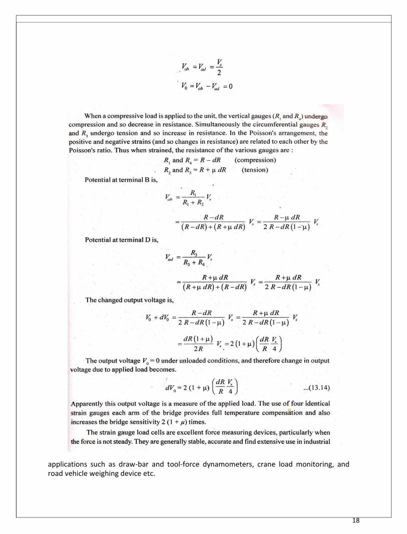
18
applications such as draw-bar and tool-force dynamometers, crane load monitoring, and road vehicle weighing device etc.
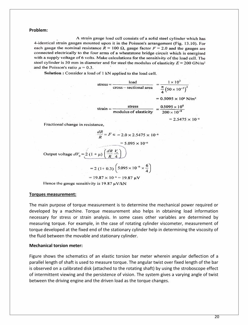
20
Problem:
Torques measurement:
The main purpose of torque measurement is to determine the mechanical power required or
developed by a machine. Torque measurement also helps in obtaining load information
necessary for stress or strain analysis. In some cases other variables are determined by
measuring torque. For example, in the case of rotating cylinder viscometer, measurement of
torque developed at the fixed end of the stationary cylinder help in determining the viscosity of
the fluid between the movable and stationary cylinder. Mechanical torsion meter:
Figure shows the schematics of an elastic torsion bar meter wherein angular deflection of a
parallel length of shaft is used to measure torque. The angular twist over fixed length of the bar
is observed on a calibrated disk (attached to the rotating shaft) by using the stroboscope effect
of intermittent viewing and the persistence of vision. The system gives a varying angle of twist
between the driving engine and the driven load as the torque changes.
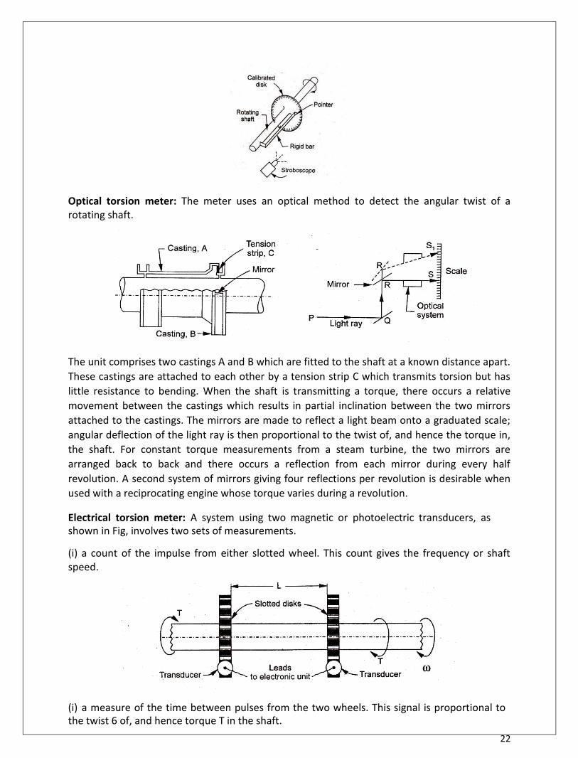
22
Optical torsion meter: The meter uses an optical method to detect the angular twist of a rotating shaft.
The unit comprises two castings A and B which are fitted to the shaft at a known distance apart.
These castings are attached to each other by a tension strip C which transmits torsion but has
little resistance to bending. When the shaft is transmitting a torque, there occurs a relative
movement between the castings which results in partial inclination between the two mirrors
attached to the castings. The mirrors are made to reflect a light beam onto a graduated scale;
angular deflection of the light ray is then proportional to the twist of, and hence the torque in,
the shaft. For constant torque measurements from a steam turbine, the two mirrors are
arranged back to back and there occurs a reflection from each mirror during every half
revolution. A second system of mirrors giving four reflections per revolution is desirable when
used with a reciprocating engine whose torque varies during a revolution. Electrical torsion meter: A system using two magnetic or photoelectric transducers, as shown in Fig, involves two sets of measurements. (i) a count of the impulse from either slotted wheel. This count gives the frequency or shaft speed. (i) a measure of the time between pulses from the two wheels. This signal is proportional to the twist 6 of, and hence torque T in the shaft.
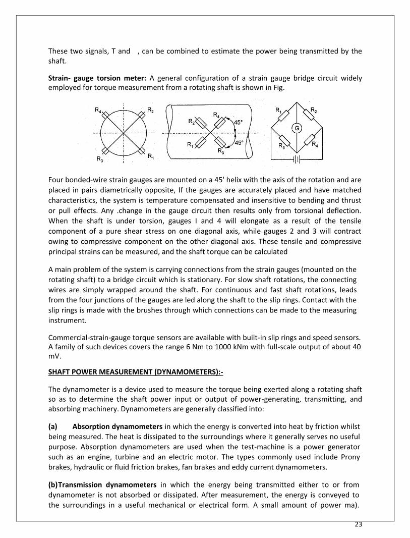
23
These two signals, T and , can be combined to estimate the power being transmitted by the shaft. Strain- gauge torsion meter: A general configuration of a strain gauge bridge circuit widely employed for torque measurement from a rotating shaft is shown in Fig.
Four bonded-wire strain gauges are mounted on a 45' helix with the axis of the rotation and are
placed in pairs diametrically opposite, If the gauges are accurately placed and have matched
characteristics, the system is temperature compensated and insensitive to bending and thrust
or pull effects. Any .change in the gauge circuit then results only from torsional deflection.
When the shaft is under torsion, gauges I and 4 will elongate as a result of the tensile
component of a pure shear stress on one diagonal axis, while gauges 2 and 3 will contract
owing to compressive component on the other diagonal axis. These tensile and compressive
principal strains can be measured, and the shaft torque can be calculated
A main problem of the system is carrying connections from the strain gauges (mounted on the
rotating shaft) to a bridge circuit which is stationary. For slow shaft rotations, the connecting
wires are simply wrapped around the shaft. For continuous and fast shaft rotations, leads
from the four junctions of the gauges are led along the shaft to the slip rings. Contact with the
slip rings is made with the brushes through which connections can be made to the measuring
instrument. Commercial-strain-gauge torque sensors are available with built-in slip rings and speed sensors. A family of such devices covers the range 6 Nm to 1000 kNm with full-scale output of about 40 mV. SHAFT POWER MEASUREMENT (DYNAMOMETERS):- The dynamometer is a device used to measure the torque being exerted along a rotating shaft so as to determine the shaft power input or output of power-generating, transmitting, and absorbing machinery. Dynamometers are generally classified into:
(a) Absorption dynamometers in which the energy is converted into heat by friction whilst
being measured. The heat is dissipated to the surroundings where it generally serves no useful
purpose. Absorption dynamometers are used when the test-machine is a power generator
such as an engine, turbine and an electric motor. The types commonly used include Prony
brakes, hydraulic or fluid friction brakes, fan brakes and eddy current dynamometers. (b) Transmission dynamometers in which the energy being transmitted either to or from
dynamometer is not absorbed or dissipated. After measurement, the energy is conveyed to
the surroundings in a useful mechanical or electrical form. A small amount of power ma).

24
However, be lost by friction at the joints of the dynamometer. The type includes torsion and
belt dynamometers, and strain gauge dynamometers.
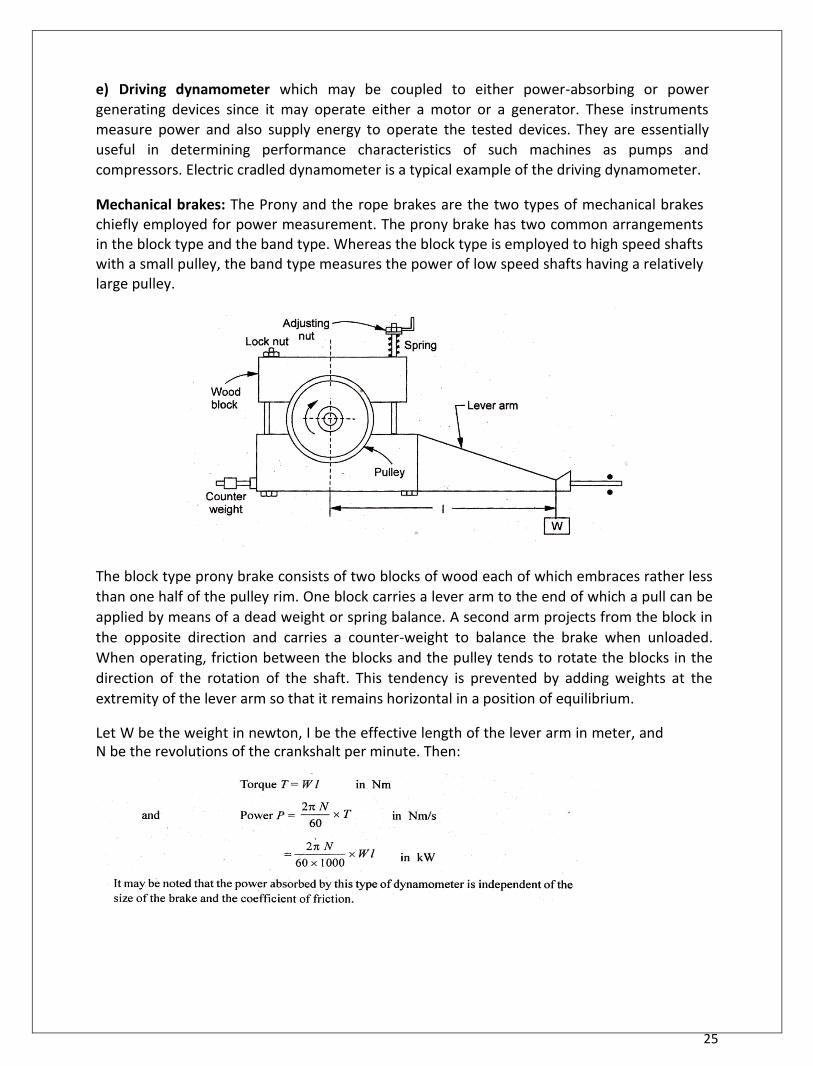
25
e) Driving dynamometer which may be coupled to either power-absorbing or power
generating devices since it may operate either a motor or a generator. These instruments
measure power and also supply energy to operate the tested devices. They are essentially
useful in determining performance characteristics of such machines as pumps and
compressors. Electric cradled dynamometer is a typical example of the driving dynamometer. Mechanical brakes: The Prony and the rope brakes are the two types of mechanical brakes chiefly employed for power measurement. The prony brake has two common arrangements in the block type and the band type. Whereas the block type is employed to high speed shafts with a small pulley, the band type measures the power of low speed shafts having a relatively large pulley.
The block type prony brake consists of two blocks of wood each of which embraces rather less
than one half of the pulley rim. One block carries a lever arm to the end of which a pull can be
applied by means of a dead weight or spring balance. A second arm projects from the block in
the opposite direction and carries a counter-weight to balance the brake when unloaded.
When operating, friction between the blocks and the pulley tends to rotate the blocks in the
direction of the rotation of the shaft. This tendency is prevented by adding weights at the
extremity of the lever arm so that it remains horizontal in a position of equilibrium. Let W be the weight in newton, I be the effective length of the lever arm in meter, and N be the revolutions of the crankshalt per minute. Then:
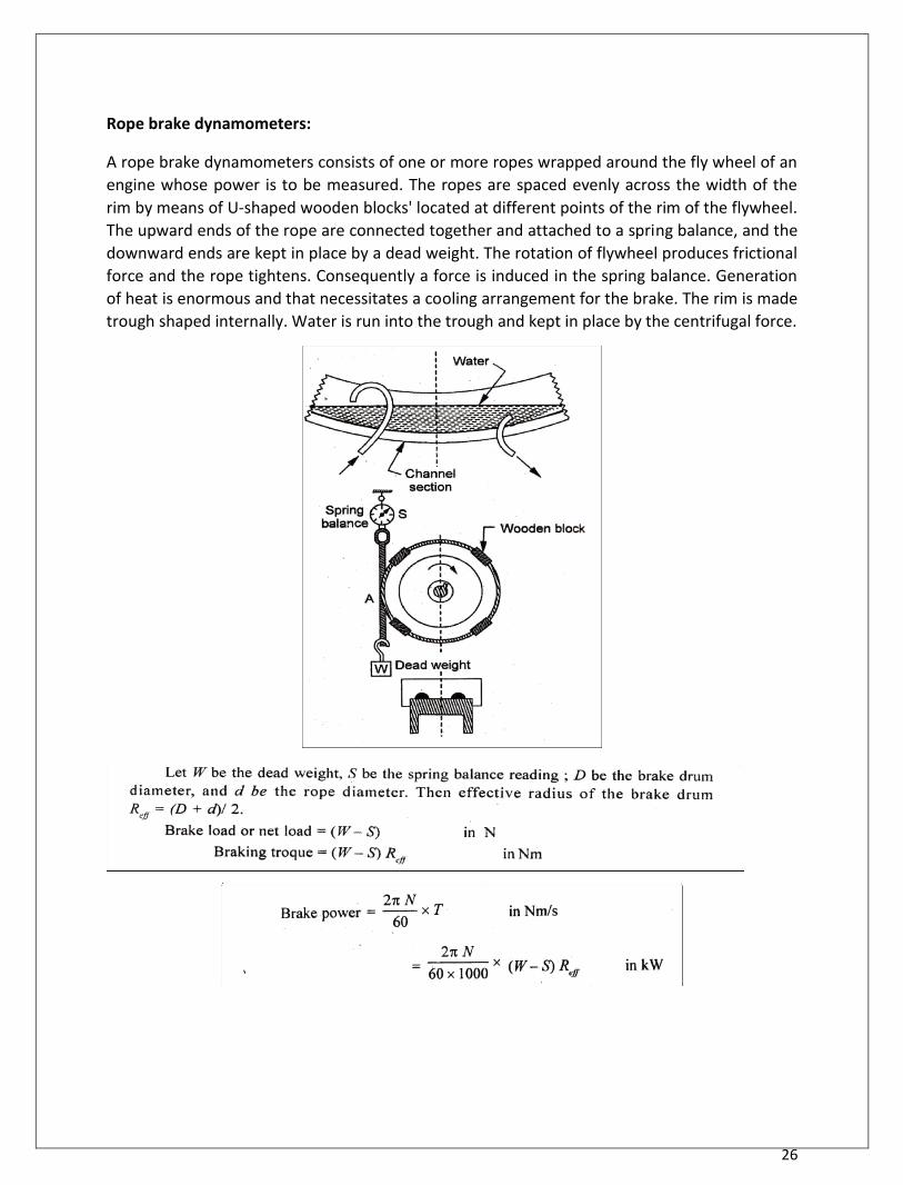
26
Rope brake dynamometers:
A rope brake dynamometers consists of one or more ropes wrapped around the fly wheel of an
engine whose power is to be measured. The ropes are spaced evenly across the width of the
rim by means of U-shaped wooden blocks' located at different points of the rim of the flywheel.
The upward ends of the rope are connected together and attached to a spring balance, and the
downward ends are kept in place by a dead weight. The rotation of flywheel produces frictional
force and the rope tightens. Consequently a force is induced in the spring balance. Generation
of heat is enormous and that necessitates a cooling arrangement for the brake. The rim is made
trough shaped internally. Water is run into the trough and kept in place by the centrifugal force.

27
Hydraulic dynamometer:-
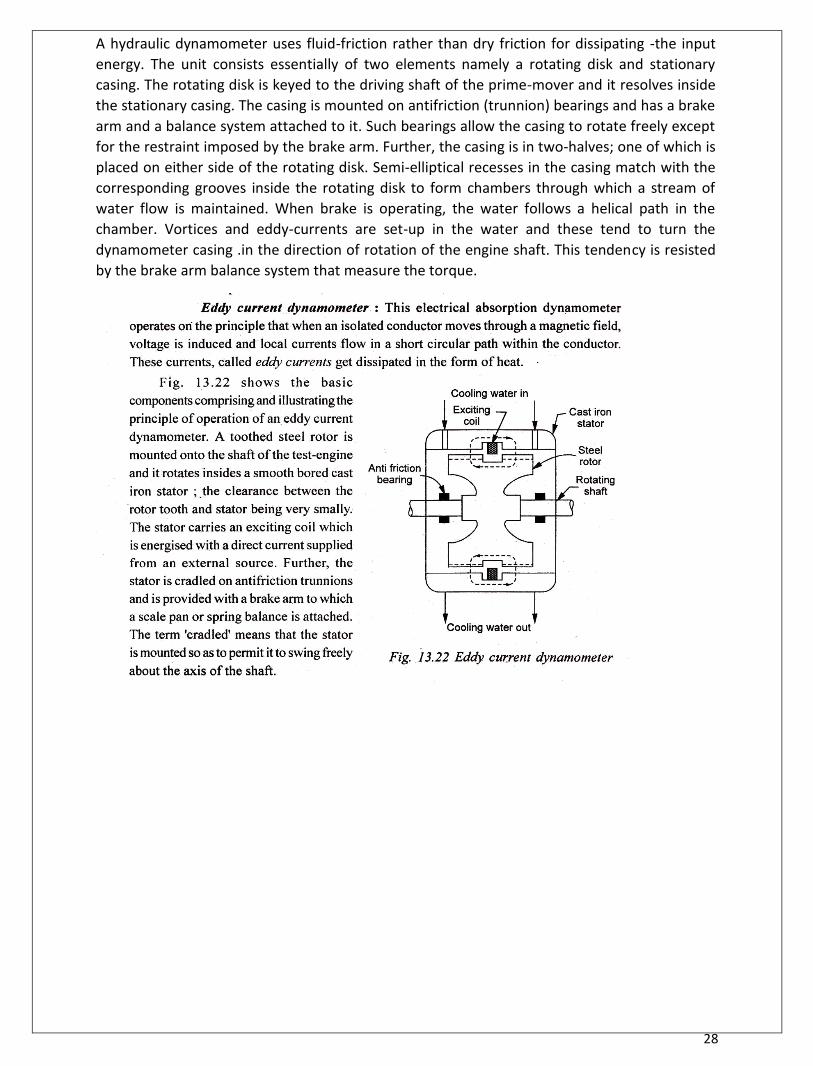
28
A hydraulic dynamometer uses fluid-friction rather than dry friction for dissipating -the input
energy. The unit consists essentially of two elements namely a rotating disk and stationary
casing. The rotating disk is keyed to the driving shaft of the prime-mover and it resolves inside
the stationary casing. The casing is mounted on antifriction (trunnion) bearings and has a brake
arm and a balance system attached to it. Such bearings allow the casing to rotate freely except
for the restraint imposed by the brake arm. Further, the casing is in two-halves; one of which is
placed on either side of the rotating disk. Semi-elliptical recesses in the casing match with the
corresponding grooves inside the rotating disk to form chambers through which a stream of
water flow is maintained. When brake is operating, the water follows a helical path in the
chamber. Vortices and eddy-currents are set-up in the water and these tend to turn the
dynamometer casing .in the direction of rotation of the engine shaft. This tendency is resisted
by the brake arm balance system that measure the torque.
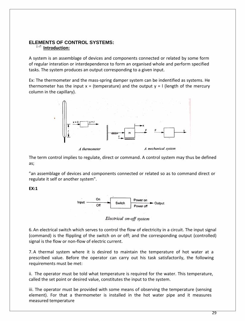
29
ELEMENTS OF CONTROL SYSTEMS: Introduction:
A system is an assemblage of devices and components connected or related by some form of regular interation or interdependence to form an organised whole and perform specified tasks. The system produces an output corresponding to a given input. Ex: The thermometer and the mass-spring damper system can be indentified as systems. He thermometer has the input x = (temperature) and the output y = l (length of the mercury column in the capillary).
The term control implies to regulate, direct or command. A control system may thus be defined as; ”an assemblage of devices and components connected or related so as to command direct or regulate it self or another system". EX:1
6. An electrical switch which serves to control the flow of electricity in a circuit. The input signal (command) is the flippling of the switch on or off; and the corresponding output (controlled) signal is the flow or non-flow of electric current. 7. A thermal system where it is desired to maintain the temperature of hot water at a prescribed value. Before the operator can carry out his task satisfactorily, the following requirements must be met: ii. The operator must be told what temperature is required for the water. This temperature, called the set point or desired value, constitutes the input to the system. iii. The operator must be provided with some means of observing the temperature (sensing element). For that a thermometer is installed in the hot water pipe and it measures measured temperature
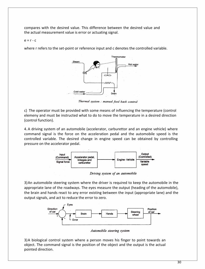
30
compares with the desired value. This difference between the desired value and the actual measurement value is error or actuating signal. e = r - c where r refers to the set-point or reference input and c denotes the controlled variable.
c) The operator must be provided with some means of influencing the temperature (control elemeny and must be instructed what to do to move the temperature in a desired direction (control function). 4. A driving system of an automobile (accelerator, carburettor and an engine vehicle) where command signal is the force on the acceleration pedal and the automobile speed is the controlled variable. The desired change in engine speed can be obtained by controlling pressure on the accelerator pedal. 3) An automobile steering system where the driver is required to keep the automobile in the appropriate lane of the roadways. The eyes measure the output (heading of the automobile), the brain and hands react to any error existing between the input (appropriate lane) and the output signals, and act to reduce the error to zero. 3) A biological control system where a person moves his finger to point towards an object. The command signal is the position of the object and the output is the actual pointed direction.
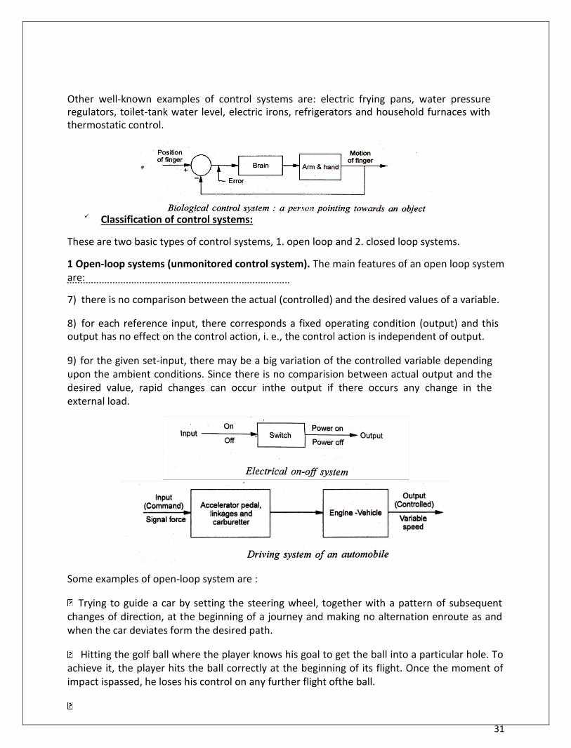
31
Other well-known examples of control systems are: electric frying pans, water pressure regulators, toilet-tank water level, electric irons, refrigerators and household furnaces with thermostatic control.
Classification of control systems:
These are two basic types of control systems, 1. open loop and 2. closed loop systems. 1 Open-loop systems (unmonitored control system). The main features of an open loop system are: 7) there is no comparison between the actual (controlled) and the desired values of a variable. 8) for each reference input, there corresponds a fixed operating condition (output) and this output has no effect on the control action, i. e., the control action is independent of output. 9) for the given set-input, there may be a big variation of the controlled variable depending upon the ambient conditions. Since there is no comparision between actual output and the desired value, rapid changes can occur inthe output if there occurs any change in the external load.
Some examples of open-loop system are : Trying to guide a car by setting the steering wheel, together with a pattern of subsequent
changes of direction, at the beginning of a journey and making no alternation enroute as and when the car deviates form the desired path. Hitting the golf ball where the player knows his goal to get the ball into a particular hole. To
achieve it, the player hits the ball correctly at the beginning of its flight. Once the moment of impact ispassed, he loses his control on any further flight ofthe ball.
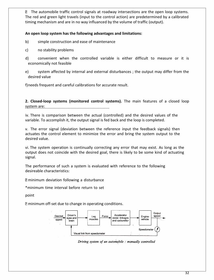
32
The automobile traffic control signals at roadway intersections are the open loop systems. The red and green light travels (input to the control action) are predetermined by a calibrated timing mechanism and are in no way influanced by the volume of traffic (output).
An open loop system has the following advantages and limitations: b) simple construction and ease of maintenance c) no stability problems d) convenient when the controlled variable is either difficult to measure or it is
economically not feasible e) system affected by internal and external disturbances ; the output may differ from the
desired value f) needs frequent and careful calibrations for accurate result.
2. Closed-loop systems (monitored control systems). The main features of a closed loop system are: iv. There is comparison between the actual (controlled) and the desired values of the variable. To accomplish it, the output signal is fed back and the loop is completed. v. The error signal (deviation between the reference input the feedback signals) then actuates the control element to minimize the error and bring the system output to the desired value. vi. The system operation is continually correcting any error that may exist. As long as the output does not coincide with the desired goal, there is likely to be some kind of actuating signal. The performance of such a system is evaluated with reference to the following desireable characteristics:
minimum deviation following a disturbance
*minimum time interval before return to set
point minimum off-set due to change in operating conditions.
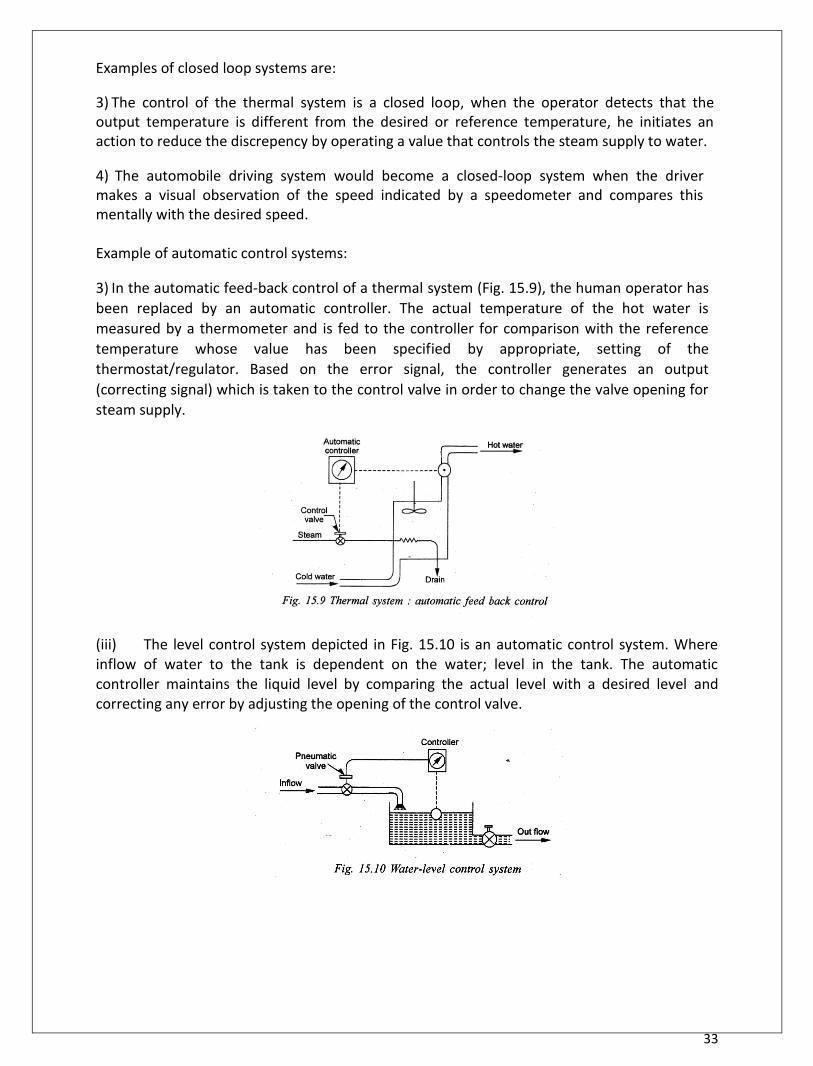
33
Examples of closed loop systems are: 3) The control of the thermal system is a closed loop, when the operator detects that the output temperature is different from the desired or reference temperature, he initiates an action to reduce the discrepency by operating a value that controls the steam supply to water. 4) The automobile driving system would become a closed-loop system when the driver makes a visual observation of the speed indicated by a speedometer and compares this mentally with the desired speed. Example of automatic control systems:
3) In the automatic feed-back control of a thermal system (Fig. 15.9), the human operator has
been replaced by an automatic controller. The actual temperature of the hot water is
measured by a thermometer and is fed to the controller for comparison with the reference
temperature whose value has been specified by appropriate, setting of the
thermostat/regulator. Based on the error signal, the controller generates an output
(correcting signal) which is taken to the control valve in order to change the valve opening for
steam supply. (iii) The level control system depicted in Fig. 15.10 is an automatic control system. Where inflow of water to the tank is dependent on the water; level in the tank. The automatic controller maintains the liquid level by comparing the actual level with a desired level and correcting any error by adjusting the opening of the control valve.
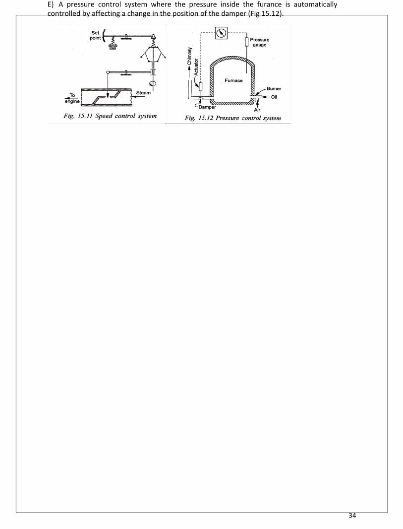
34
E) A pressure control system where the pressure inside the furance is automatically controlled by affecting a change in the position of the damper (Fig 15.12).
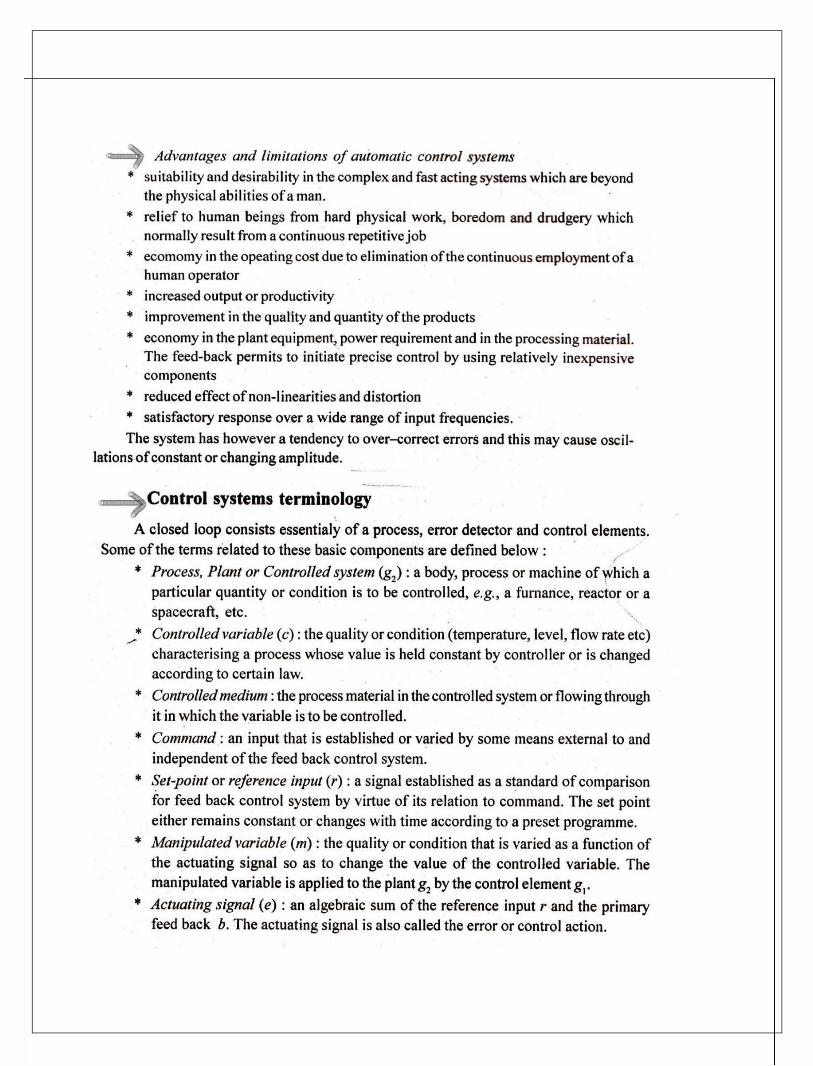
35
36