Embed Size (px)
Citation preview

J O U R N A L O F M A T E R I A L S S C I E N C E 4 0 (2 0 0 5 ) 3669 – 3676
Mechanical response of 2024-7075 aluminium
alloys joined by Friction Stir Welding
P. CAVALIERE∗, E. CERRIDepartment of “Ingegneria dell’Innovazione,” Engineering Faculty, University of Lecce, ItalyE-mail: [email protected]
A. SQUILLACEDepartment of Materials and Production Engineering, Engineering Faculty,University of Naples Federico II, Italy
The mechanical and microstructural properties of 2024 and 7075 aluminium alloys joinedtogether by friction stir welding were analysed in the present study. The two materials werewelded with perpendicular rolling direction and after were tested in tension at roomtemperature in order to analyse the mechanical response and to observe the differenceswith the parent materials, the tensile response of the material in longitudinal directionrevealed an increase in strength respect to the transverse one. The cyclic fatigue tests wereconducted in the axial direction with R = σmin/σmax = 0.1). The microstructure resultingfrom the FSW process was studied by employing optical and scanning electron microscopy.C© 2005 Springer Science + Business Media, Inc.
1. IntroductionFriction Stir Welding (FSW) is being targeted by theindustry for structurally demanding applications to pro-vide high-performance benefits. FSW is shown not tocause severe distortion and residual stresses generatedare low compared to the traditional welding processes[1–3].
From a microstructural point of view the weld’s veryfine and equiaxed grain structure produces a higher me-chanical strength and ductility [4–6]. Jata and Semiatin[7] showed that the microstructure in the weld nuggetzone evolves through a continuous dynamical recrys-tallization process.
This new technology can join difficult to weld alu-minium alloys by traditional fusion techniques, for ex-ample alloys belonging to the 2XXX series with limitedweldability and the 7XXX series generally not recom-mended for welding, even if they are the more used alu-minium alloys in aerospace applications [8–11]. Con-ventional welding, results in a dendritic structure inthe fusion zone which lead to a drastic decrease of the
Figure 1 Optical micrograph of the cross-section of the studied joints.
∗Author to whom all correspondence should be addressed.
mechanical properties [11]. The FSW process is a solidstate process and therefore solidification structure is ab-sent in the weld and the problem related to the presenceof brittle intrer-dendritic and eutectic phases is elimi-nated [12].
In addition, in FSW the surface oxide is not deterrentfor the process; no particular cleaning operations areneeded prior to welding.
Actually, Friction Stir Welding is mainly usedfor joining similar materials, even if few system-atic studies have been performed to observe the ef-fect of combination of alloys with different compo-sition [13–15]. This is a core demand of AircraftIndustries to substitute the traditional joining tech-nologies with low costs and high efficiency onessuch as Friction Stir Welding in the future advanceddesign.
Another important aspect is the possibility to jointmaterials with very different mechanical and physicalproperties such as Aluminium-Steel [16], Aluminium-Magnesium [17], Aluminium-Silver [18].
0022–2461 C© 2005 Springer Science + Business Media, Inc. 3669
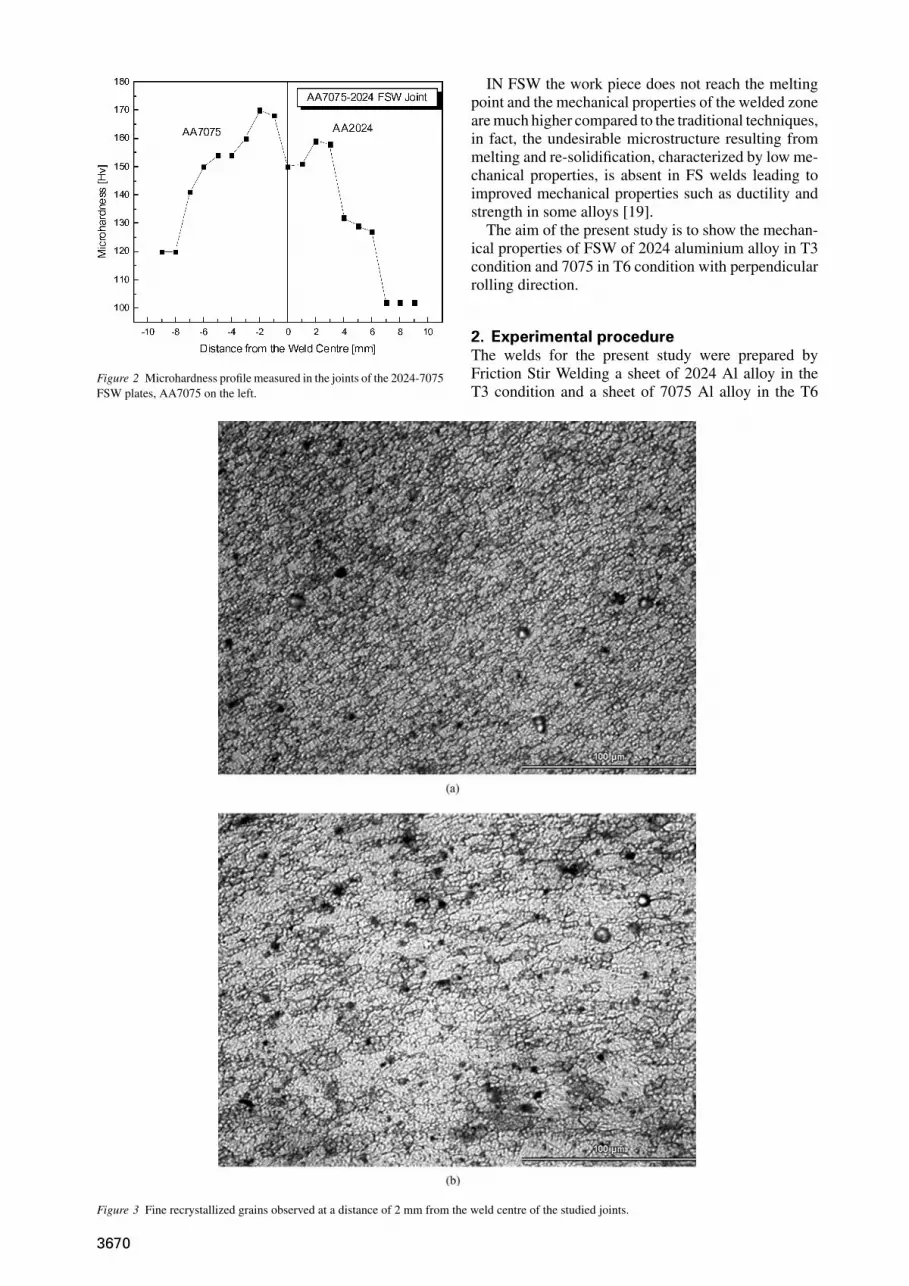
Figure 2 Microhardness profile measured in the joints of the 2024-7075FSW plates, AA7075 on the left.
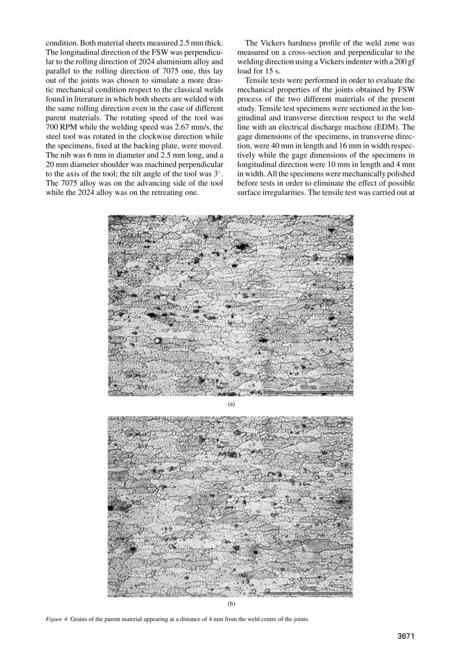
Figure 3 Fine recrystallized grains observed at a distance of 2 mm from the weld centre of the studied joints.
IN FSW the work piece does not reach the meltingpoint and the mechanical properties of the welded zoneare much higher compared to the traditional techniques,in fact, the undesirable microstructure resulting frommelting and re-solidification, characterized by low me-chanical properties, is absent in FS welds leading toimproved mechanical properties such as ductility andstrength in some alloys [19].
The aim of the present study is to show the mechan-ical properties of FSW of 2024 aluminium alloy in T3condition and 7075 in T6 condition with perpendicularrolling direction.
2. Experimental procedureThe welds for the present study were prepared byFriction Stir Welding a sheet of 2024 Al alloy in theT3 condition and a sheet of 7075 Al alloy in the T6
3670
condition. Both material sheets measured 2.5 mm thick.The longitudinal direction of the FSW was perpendicu-lar to the rolling direction of 2024 aluminium alloy andparallel to the rolling direction of 7075 one, this layout of the joints was chosen to simulate a more dras-tic mechanical condition respect to the classical weldsfound in literature in which both sheets are welded withthe same rolling direction even in the case of differentparent materials. The rotating speed of the tool was700 RPM while the welding speed was 2.67 mm/s, thesteel tool was rotated in the clockwise direction whilethe specimens, fixed at the backing plate, were moved.The nib was 6 mm in diameter and 2.5 mm long, and a20 mm diameter shoulder was machined perpendicularto the axis of the tool; the tilt angle of the tool was 3◦.The 7075 alloy was on the advancing side of the toolwhile the 2024 alloy was on the retreating one.
Figure 4 Grains of the parent material appearing at a distance of 4 mm from the weld centre of the joints.
The Vickers hardness profile of the weld zone wasmeasured on a cross-section and perpendicular to thewelding direction using a Vickers indenter with a 200 gfload for 15 s.
Tensile tests were performed in order to evaluate themechanical properties of the joints obtained by FSWprocess of the two different materials of the presentstudy. Tensile test specimens were sectioned in the lon-gitudinal and transverse direction respect to the weldline with an electrical discharge machine (EDM). Thegage dimensions of the specimens, in transverse direc-tion, were 40 mm in length and 16 mm in width respec-tively while the gage dimensions of the specimens inlongitudinal direction were 10 mm in length and 4 mmin width. All the specimens were mechanically polishedbefore tests in order to eliminate the effect of possiblesurface irregularities. The tensile test was carried out at
3671

room temperature using an MTS 810 testing machinewith initial strain rate of 10−3 s−1.
Endurance fatigue tests were performed on a res-onant electro-mechanical testing machine under con-stant loading control up to 250 Hz sine wave loadingTESTRONICTM 50 ± 25 KN, produced by RUMUL(SUI). The cyclic fatigue tests were conducted in theaxial total stress-amplitude control mode under fully-reversed, push-pull, tension loading (R = σmin/σmax =0.1). All mechanical tests were performed up to fail-ure. Surfaces were prepared by standard metallographictechniques and etched with Keller’s reagent and grainstructure of the weld zone was characterized by opticalmicroscopy. A scanning electron microscope equippedwith field emission gun (JEOL-JSM 6500 F) was em-ployed for the observation of the fracture surfaces ofthe specimens tested in monothonic and cyclic loading
Figure 5 TMZ zone grains (a) and parent material grains (b): the grains dimensions difference is clearly distinguished in the studied joints.
in order to study the microscopic defects of the jointsand the mechanisms involved during deformation.
3. Results and discussionIn the present study dissimilar materials, 2024 and 7075aluminium alloy were successfully joined by FSW andno superficial porosity or defects were observed in bothweld top and rear surface.
Light microscopy observations were widely per-formed on the transverse cross-sections of the spec-imens, the FSW process of the 2024 and 7075 alu-minium alloys revealed the classical formation of theelliptical “onion” structure in the centre of the weld; thisis a structure characterized by fine recrystallized grains.The thermo-mechanical effected zone (TMAZ) is evi-dent from optical microscopy observations (Fig. 1). The
3672

micro hardness profile along the FSW joint is shown inFig. 2, the micro hardness reaches a value of 150 Hvin the centre of the weld and after increasing in boththe 2024 and 7075 sides it starts to decrease after 2 mmfrom the centre until reaching a plateau correspond-ing to the hardness values of the parent materials. Thehardness of the joint reaches lower values in the HAZrespect to the parent material in both 2024 and 7075sides, this is a classical behaviour in the aluminiumalloys welded by FSW, in the HAZ and TMAZ, infact, the competing mechanisms of work hardening andover-ageing produce a strength decreasing respect tothe stirred zone and the base metal. The micrograph,shown in Fig. 3 represents a section perpendicular tothe welding direction, the “nugget” zone that consistsof very fine grains. The higher temperature and severeplastic deformation results in grains smaller than thebase metal. In all the FSW literature on aluminium al-
Figure 6 Optical micrograph at a distance from the weld centre of 2 mm (a) and 3 mm (b) in the 2024 side of the joints.
loys, the initial elongated grains of the parent materialsare converted to a new equiaxed fine grain structure. Athigher magnifications the optical micrographs showedvery fine equiaxed grains in the recrystallized zones(Fig. 3). These photomicrographs were taken at 2 mmin the zone of the higher micro hardness value mea-sured from the AA7075 side. By moving away fromthe weld centre, the grains dimensions increase and thegrains begin to result less equiaxed than those closer tothe weld centre (Fig. 4). At a distance of 4 mm fromthe weld centre many of the prior grains of the parentmaterial start to appear. This region corresponds to theheat affected zone as the hardness is low compared tothe base metal. The hardness drops here because theprecipitates are coarsened as discussed by Jata et al.[3]. In the region adjacent to the nugget, i.e. TMAZno recrystallization is observed because the tempera-ture derived from the friction stir processing is not high
3673

Figure 7 Grains from the TMZ zone in the 2024 side.
Figure 8 True Stress vs. True Strain curve of the studied joints tested intension.
enough and the deformation is not so severe to causerecrystallization. Fig. 5a, shows the deformed grains inthe TMAZ and the regions adjacent to the TMAZ is theHAZ, Fig. 5b, where the grain size is similar to the basemetal. However the hardness in the HAZ is low. Simi-lar microstructural observations were made in the FSWzone of the 2024 side of the weld. Photographs shownin Fig. 6 and correspond to the grains in the nugget at adistance of 2 mm from the weld center line and 6b cor-responds to the grains 3 mm away from the center line.Fig. 7 shows the grains in the TMAZ where the grainsare severely bent from deformation but recrystallizationwas absent.
The tensile response, transverse to the welding direc-tion, of the 2024 and 7075 AA joined by FSW is shownin Fig. 8. The curve exhibits a classical behaviour andthe mechanical properties, compared to the parent met-als, are reported in Table I. The joint exhibits very goodproperties of yielding, UTS and ductility from a globalpoint of view even if the weld has lower 0.2% proofstress and elongations respect to the base metals, the
Figure 9 True Stress vs. True Strain tensile behaviour of the FSW jointsparallel to the welding direction.
Figure 10 Endurance Fatigue curves (S-N) of the 2024-7075 platesjoined by Friction Stir Welding compared with the Friction Stir WeldedAA2024 T3 and AA7075 T6.
3674

Figure 11 Tensile specimen fracture surface of the studied joint showing voids population.
mechanical results are very good considering the drasticconditions to which the materials are subjected duringthe Friction Stir Welding process, the elastic modulusresults very different respect to the parent materials.The specimens fractured in the HAZ zones of the welds,always close to the 2024 material. This demonstratesthe classical behaviour of these kind of joints in which,from a microstructural point of view, the mechanicalresponse of the centre of the weld results higher andhigher respect to the parent material and the HAZ be-cause of the large grains dimensions differences. In thiszone, in fact, the mean grain equivalent diameter mea-sured by optical images resulted 2.5 µm.
The room temperature tensile behaviour of the mate-rial of the nugget zone is shown in Fig. 9. The strengthand ductility of the material results strongly increased inthe nugget zone respect to the material in the transversedirection thanks to the uniform and very fine structureconsequent to the friction Stir process.
The curve representing the stress amplitude-fatiguelife response of the welded material and of the 2024parent alloy is reported in Fig. 10, the curve shows aclassical behaviour for the aluminium alloys, revealinga trend of increasing fatigue life with decreasing cyclicstress amplitude.
A fatigue life of 3 × 10⁶ cycles at 73 MPa wasrecorded for the weld joints of the present study. The fa-tigue curve shows very good results compared with thestress levels reached by the parent unwelded materialat the same test frequency, considering the critical sit-
TABL E I Mechanical properties of the 2024-7075 joints comparedwith those proper of the parent materials
Material σy (MPa) UTS (MPa) Elomgation (%)
AA2024 380 490 17AA7075 503 572 112024-7075 FSW 325 424 6
uation exhibited by welded joints in aluminium alloyssubjected to cyclic loading [20], in particular, if com-pared with the 2024 T3 and the 7075 T6 alloys afterFriction Stir Welding, the 2024–7075 joints show a de-crease in fatigue life respect the FSW 7075 T6 oneswhile show a net increase in fatigue life respect to the2024 T3 FSW joints in the High Cycle Regime.
In the understanding of microstructural effects onfracture properties, the observation of fractured sur-faces results fundamental.
The fracture surface of the 2024–7075 joints testedin tension was covered with a broad population of mi-croscopic voids of different size and shape (Fig. 11), atroom temperature the material showed ductility withfracture, the observations performed by employingFEGSEM revealed locally ductile mechanisms.
4. ConclusionsThe 2024 and 7075 aluminium alloys were success-fully joined together by friction stir welding 2.5 mmthick sheets. The resulting microstructure was widelyinvestigated by optical microscopy putting in evidencethe grain structure differences resulting by the process.The mechanical properties of the joints were evaluatedby tensile showing a net increase in strength in longi-tudinal direction respect to the transverse one; fatiguetests showed an increase in fatigue life in the High Cy-cle Regime respect to the FSW 2024 T3 joints and adecrease in fatigue life respect to the FSW 7075 T6ones.
References1. G . B U S S U and P . E . I R V I N G , Intern. J. Fatigue 25 (2003) 77.2. R . J O H N, K. V. J A T A and K. S A D A N A N D A , ibid. 25 (2003)
939.3. K . V . J A T A, K. K. S A N K A R A N and J . R U S C H A U , Metall.
Mater. Trans. 31A (2000) 2181.
3675

4. I . C H A R I T , R . S . M I S H R A and M. W. M A H O N E Y , ScriptaMaterialia 47 (2002) 631.
5. H . G . S A L E M, A. P . R E Y N O L D S and J . S . L Y O N S , ibid.46 (2002) 337.
6. C . G . R H O D E S, M. W. M A H O N E Y, W. H. B I N G E L andM. C A L A B R E S E , ibid. 48 (2003) 1451.
7. K . V . J A T A and S . L . S E M I A T I N , ibid. 43(8) (2000) 743.8. W. D. L O C K W O O D, B. T O M A Z and A. P . R E Y N O L D S ,
Mater. Sci. Engng. A323 (2002) 348.9. M. G U E R R A, C. S C H M I D T, J . C . M C C L U R E, L . E .
M U R R and A. C . N U N E S , Mater Character. 49 (2003) 95.10. P . U L Y S S E , Intern. J. Machine. Tools Manuf. 42 (2002) 1549.11. J . -Q . S U, T . W. N E L S O N, R . M I S H R A and M.
M A H O N E Y , Acta. Materialia 51 (2003) 713.12. C . G . R H O D E S, M. W. M A H O N E Y and W. H. B I N G E L ,
Scripta Mater. 36 (1997) 69.13. (a) I . S H I G E M A T S U, Y. J . K W O N, K. S U Z U K I , T . I M A I
and N. S A I T O , J. Mater. Sci. Lett. 22 (2003) 353; (b) Y I N G L I ,L . E . M U R R and J . C . M C C L U R E , Mater. Sci. Engng. A271(1999) 213.
14. (a) Y U T A K A S. S A T O, M I T S U N O R I U R A T A, H I R O Y U K I
K O K A W A and K E I S U K E I K E D A , ibid. A354 (2003) 298; (b)
P A T R I C K B. B E R B O N, W I L L I A M H. B I N G E L, R A J I V
S . M I S H R A, C L I F F O R D C. B A M P T O N and M U R R A Y W.M A H O N E Y , Scripta Mater. 44 (2001) 61.
15. W O N-B A E L E E, Y U N-M O Y E O N and S E U N G-B O O
J U N G , ibid. 49 (2003) 423.16. H U S E Y I N U Z U N, C L A U D I O D A L L E D O N N E,
A L B E R T O A R G A G N O T T O, T O M M A S O G H I D I N I
and C A R L A G A M B E R O , Mater. Des. 26 (2005) 41.17. Y U T A K A S. S A T O, S E U N G H W A N C. P A R K, M A S A T O
M I C H I U C H I and H I R O Y U K I K O K A W A , Scripta Mater. 50(2004) 1233.
18. W. B . L E E , Y. M. Y E O N and S . B . J U N G , Mater. Sci.Engng. A355 (2003) 154.
19. Y I N G L I , E . A . T R I L L O and L . E . M U R R , J. Mater. Sci.Lett. 19 (2000) 1047.
20. S . L O M O L I N O, R . T O V O and J . D O S S A N T O S , Inter. J.Fatig. 27 (2005) 305.
Received 12 October 2004and accepted 11 February 2005
3676


