Embed Size (px)
Citation preview
International Journal of Solids and Structures 50 (2013) 1164–1176
Contents lists available at SciVerse ScienceDirect
International Journal of Solids and Structures
journal homepage: www.elsevier .com/locate / i jsolst r
Metallic sandwich panels subjected to multiple intense shocks
Hamid Ebrahimi, Ashkan Vaziri ⇑Department of Mechanical and Industrial Engineering, Northeastern University, Boston, MA, United States
a r t i c l e i n f o
Article history:Received 14 May 2012Received in revised form 7 December 2012Available online 11 January 2013
Keywords:Sandwich panelsHoneycomb coreFolded plate coreMultiple shocksDuctilityDynamic response
0020-7683/$ - see front matter � 2013 Elsevier Ltd. Ahttp://dx.doi.org/10.1016/j.ijsolstr.2012.12.013
⇑ Corresponding author. Tel.: +1 (617) 373 3474; faE-mail address: [email protected] (A. Vaziri).
a b s t r a c t
The mechanical response and fracture of metal sandwich panels subjected to multiple impulsive pressureloads (shocks) were investigated for panels with honeycomb and folded plate core constructions. Thestructural performance of panels with specific core configurations under multiple impulsive pressureloads is quantified by the maximum transverse deflection of the face sheets and the core crushing strainat mid-span of the panels. A limited set of simulations was carried out to find the optimum core densityof a square honeycomb core sandwich panels under two shocks. The panels with a relative core density of4%–5% are shown to have minimum face sheet deflection for the loading conditions considered here. Thiswas consistent with the findings related to the sandwich panel response subjected to a single intenseshock. Comparison of these results showed that optimized sandwich panels outperform solid platesunder shock loading. An empirical method for prediction of the deflection and fracture of sandwich pan-els under two consecutive shocks – based on finding an effective peak over-pressure – was provided.Moreover, a limited number of simulations related to response and fracture of sandwich panels undermultiple shocks with different material properties were performed to highlight the role of metal strengthand ductility. In this set of simulations, square honeycomb sandwich panels made of four steels repre-senting a relatively wide range of strength, strain hardening and ductility values were studied. For panelsclamped at their edge, the observed failure mechanisms are core failure, top face failure and tearing at orclose to the clamped edge. Failure diagrams for sandwich panels were constructed which reveal the frac-ture and failure mechanisms under various shock intensities for panels subjected to up to three consec-utive shocks. The results complement previous studies on the behavior and fracture of these panels underhigh intensity dynamic loading and further highlights the potential of these panels for development ofthreat-resistant structural systems.
� 2013 Elsevier Ltd. All rights reserved.
1. Introduction
Threat-resistant structures that can withstand extreme loadingconditions (e.g. impact, blast, thermal shock) and sustain theirfunctionality are critical in both military and industrial settings.Development of such systems requires innovative design and man-ufacturing approaches to create high performance multifunctionalmaterials and structural systems (Ajdari et al., 2012; Chen andPugno, 2012; Fan et al., 2008; Latourte et al., 2012; Xiong et al.,2012b; Qiao et al., 2008). Examples of such developments are cel-lular structures with functionally graded and hierarchical struc-tural organization, which are shown to have superior mechanicalbehavior compared to engineered cellular structures at the sameoverall mass (Ajdari et al., 2012; Ajdari et al., 2011). Another exam-ple is the ongoing efforts in development of sandwich panels withlow density core constructions (Evans et al., 2010; Kishimoto andShinya, 2001; Wadley et al., 2010, 2003; Xiong et al., 2011a,
ll rights reserved.
x: +1 (617) 495 9837.
2010). These panels are considered as promising candidates fordevelopment of impact- and explosion resistant structures (Cuiet al., 2012; Dharmasena et al., 2008; Mori et al., 2007; Qin andWang, 2009; Qiu et al., 2004; Rathbun et al., 2006; Xue and Hutch-inson, 2004b). In fact, well-designed sandwich panels generally un-dergo smaller deflection under shock loading and also sustainhigher intensity of shock prior to failure compared to solid platesof the same mass (Dharmasena et al., 2011; Hutchinson and Xue,2005; Rabczuk et al., 2004; Vaziri and Hutchinson, 2007). Thedesirable mechanical performance of metal sandwich panels, com-bined with their multifunctional advantages (Evans et al., 2001;Wadley, 2006), makes them a unique candidate for developmentof low weight multifunctional structural systems.
The current studies related to impact mechanics and blast resis-tant sandwich panels all consider a single impulsive pressure load-ing (shock) or single projectile loading impinged on the panel.However, the application of sandwich panels in critical structuresrequires consideration of other possible events and loading scenar-ios. Examples of such scenarios are: (i) impingement of multipleshocks, (ii) shock loading followed by projectile impact (for
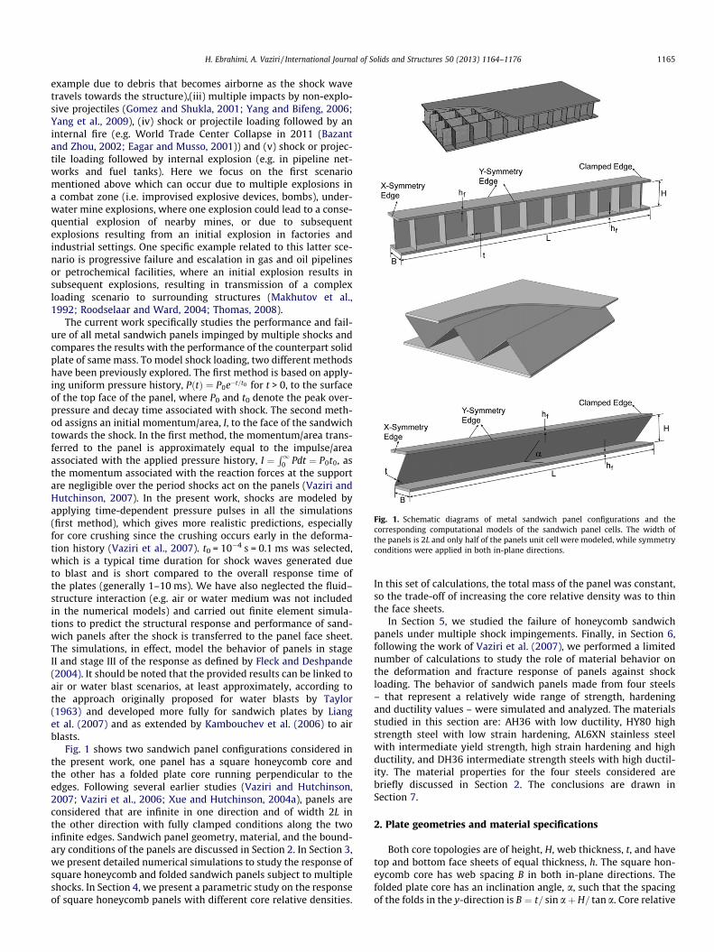
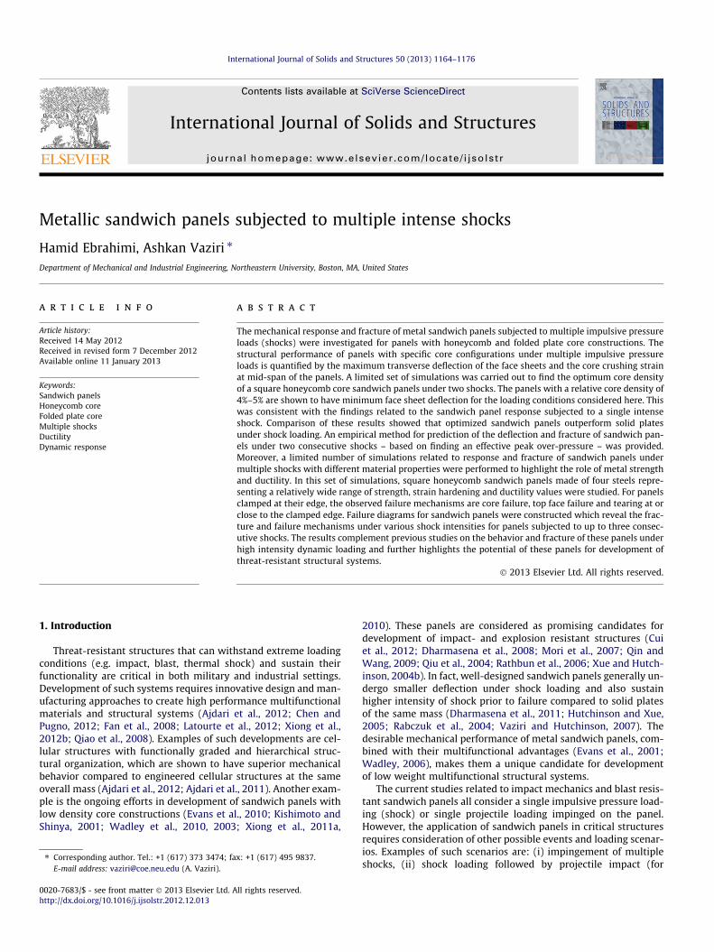
Fig. 1. Schematic diagrams of metal sandwich panel configurations and thecorresponding computational models of the sandwich panel cells. The width ofthe panels is 2L and only half of the panels unit cell were modeled, while symmetryconditions were applied in both in-plane directions.
H. Ebrahimi, A. Vaziri / International Journal of Solids and Structures 50 (2013) 1164–1176 1165
example due to debris that becomes airborne as the shock wavetravels towards the structure),(iii) multiple impacts by non-explo-sive projectiles (Gomez and Shukla, 2001; Yang and Bifeng, 2006;Yang et al., 2009), (iv) shock or projectile loading followed by aninternal fire (e.g. World Trade Center Collapse in 2011 (Bazantand Zhou, 2002; Eagar and Musso, 2001)) and (v) shock or projec-tile loading followed by internal explosion (e.g. in pipeline net-works and fuel tanks). Here we focus on the first scenariomentioned above which can occur due to multiple explosions ina combat zone (i.e. improvised explosive devices, bombs), under-water mine explosions, where one explosion could lead to a conse-quential explosion of nearby mines, or due to subsequentexplosions resulting from an initial explosion in factories andindustrial settings. One specific example related to this latter sce-nario is progressive failure and escalation in gas and oil pipelinesor petrochemical facilities, where an initial explosion results insubsequent explosions, resulting in transmission of a complexloading scenario to surrounding structures (Makhutov et al.,1992; Roodselaar and Ward, 2004; Thomas, 2008).
The current work specifically studies the performance and fail-ure of all metal sandwich panels impinged by multiple shocks andcompares the results with the performance of the counterpart solidplate of same mass. To model shock loading, two different methodshave been previously explored. The first method is based on apply-ing uniform pressure history, PðtÞ ¼ P0e�t=t0 for t > 0, to the surfaceof the top face of the panel, where P0 and t0 denote the peak over-pressure and decay time associated with shock. The second meth-od assigns an initial momentum/area, I, to the face of the sandwichtowards the shock. In the first method, the momentum/area trans-ferred to the panel is approximately equal to the impulse/areaassociated with the applied pressure history, I ¼
R10 Pdt ¼ P0t0, as
the momentum associated with the reaction forces at the supportare negligible over the period shocks act on the panels (Vaziri andHutchinson, 2007). In the present work, shocks are modeled byapplying time-dependent pressure pulses in all the simulations(first method), which gives more realistic predictions, especiallyfor core crushing since the crushing occurs early in the deforma-tion history (Vaziri et al., 2007). t0 = 10�4 s = 0.1 ms was selected,which is a typical time duration for shock waves generated dueto blast and is short compared to the overall response time ofthe plates (generally 1–10 ms). We have also neglected the fluid–structure interaction (e.g. air or water medium was not includedin the numerical models) and carried out finite element simula-tions to predict the structural response and performance of sand-wich panels after the shock is transferred to the panel face sheet.The simulations, in effect, model the behavior of panels in stageII and stage III of the response as defined by Fleck and Deshpande(2004). It should be noted that the provided results can be linked toair or water blast scenarios, at least approximately, according tothe approach originally proposed for water blasts by Taylor(1963) and developed more fully for sandwich plates by Lianget al. (2007) and as extended by Kambouchev et al. (2006) to airblasts.
Fig. 1 shows two sandwich panel configurations considered inthe present work, one panel has a square honeycomb core andthe other has a folded plate core running perpendicular to theedges. Following several earlier studies (Vaziri and Hutchinson,2007; Vaziri et al., 2006; Xue and Hutchinson, 2004a), panels areconsidered that are infinite in one direction and of width 2L inthe other direction with fully clamped conditions along the twoinfinite edges. Sandwich panel geometry, material, and the bound-ary conditions of the panels are discussed in Section 2. In Section 3,we present detailed numerical simulations to study the response ofsquare honeycomb and folded sandwich panels subject to multipleshocks. In Section 4, we present a parametric study on the responseof square honeycomb panels with different core relative densities.
In this set of calculations, the total mass of the panel was constant,so the trade-off of increasing the core relative density was to thinthe face sheets.
In Section 5, we studied the failure of honeycomb sandwichpanels under multiple shock impingements. Finally, in Section 6,following the work of Vaziri et al. (2007), we performed a limitednumber of calculations to study the role of material behavior onthe deformation and fracture response of panels against shockloading. The behavior of sandwich panels made from four steels– that represent a relatively wide range of strength, hardeningand ductility values – were simulated and analyzed. The materialsstudied in this section are: AH36 with low ductility, HY80 highstrength steel with low strain hardening, AL6XN stainless steelwith intermediate yield strength, high strain hardening and highductility, and DH36 intermediate strength steels with high ductil-ity. The material properties for the four steels considered arebriefly discussed in Section 2. The conclusions are drawn inSection 7.
2. Plate geometries and material specifications
Both core topologies are of height, H, web thickness, t, and havetop and bottom face sheets of equal thickness, h. The square hon-eycomb core has web spacing B in both in-plane directions. Thefolded plate core has an inclination angle, a, such that the spacingof the folds in the y-direction is B ¼ t= sin aþ H= tan a. Core relative
1166 H. Ebrahimi, A. Vaziri / International Journal of Solids and Structures 50 (2013) 1164–1176
density is defined as the volume fraction of the core that is occu-pied by the webs and is denoted by qc, where
qc ¼ 2tB� t
B
� �2
for the square honeycomb core ð1Þ
qc ¼t
t þ H cos afor the folded plate core ð2Þ
The mass/area of the sandwich panel is M ¼ q 2hþ qcHð Þ. Byspecifying L, M and q, the geometry of honeycomb sandwich pan-els is fully determined by qc, H/L, B/H and L and the geometry of thefolded plate core sandwich panels is fully determined by qc, H/L, aand L. In our simulations, all panels have half-width, L = 1 m, andmass/area, M = 156 kg m�2, which is the same mass/area of solidplate with thickness equal to 20 mm. The core thickness of bothtypes of sandwich plates is fixed at H/L = 0.1, and the web spacingof the square honeycomb is fixed at B/H = 1 while the folded platecores have a = 45� such that B=H ffi 1. Because of symmetry,numerical simulations of the response are based on models ofone unit cell of the sandwich panel with periodic boundary condi-tion (as depicted in Fig. 1). Full three-dimensional models wereconstructed with detailed meshing of the core as reported in Xueand Hutchinson (2004a) and Vaziri et al. (2006). At least four 8-node brick elements were employed through the thickness of eachface sheet, which captures early stages of necking with acceptablefidelity (Vaziri et al., 2006).
In Section 3, we studied the mechanical response of square hon-eycomb and folded plate core sandwich panels made of HY80 steel– which is a high strength steel with low strain hardening withYoung’s modulus, E = 200 GPa, Poisson’s ratio v = 0.3 and densityq = 7800 kg m�3 under multiple shocks. The true stress-plasticstrain response displayed in Fig. 2A for HY80 is representative ofthe material response at a tensile strain rate of 100/s as adoptedfrom Meyer et al. (2000). Material strain rate dependence is not in-cluded for metal sandwich panels made of HY80, since sufficientdata does not exist in the literature. In Section 4, we studied therole of core density on the response of square honeycomb madeof HY80 steel to obtain the optimized configuration of sandwichpanels. In Section 5, we studied failure mechanisms of sandwichpanels under multiple shocks. Panels with square honeycombcores are known to have higher damage tolerance under highintensity dynamic loading than those with folded plate cores inthat they can withstand loads much larger than those at whichthe first signs of fracture appear. Here, we study the failure of
Fig. 2. (A) True stress-plastic strain response of the four steels considered in this study. (Bthe literature.
square honeycomb panels under multiple shock loading madefrom four steels (AH36, HY80, AL6XN, DH36) that represent a rel-atively wide range strength, hardening and ductility behavior.Young’s modulus, Poisson’s ratio and the density of all the steelmaterials are the same and have the value as stated above.Fig. 2A presents tensile true stress-logarithmic strain curves ofthe four materials. Fig. 2B presents the effective plastic strain atfailure, ep
eff
� �c, plotted as a function of the triaxiality ratio, rm=re,
where rm ¼ rkk=3 is the mean stress, re ¼ 3sijsij=2 is the effectivestress and sij is the stress deviator for all materials other thanHY80, since to our best knowledge data for HY80’s ductility isnot available in the open literature. In Section 5, a parametric studywill be presented for sandwich panels made of HY80 using thefracture strain as a variable to investigate the role of material duc-tility on the fracture of sandwich panels made of this material.
For AH36, the true stress-plastic strain response and the frac-ture locus are taken from Lee and Wierzbicki (2005). The tensiledata for AL6XN is provided by Nahshon et al. (2007) and is similarto data given by Nemat-Nasser et al. (2001). For DH36, the (John-son and Cook, 1983) plasticity model is employed for representingthe stress–strain response of the material, as provided by Nemat-Nasser and Guo (2003). Temperature variations are neglected androom temperature properties are used yielding the following rela-tion between the effective stress and effective plastic strain:
re ¼ 470 1þ 1:5 ePeff
� �0:4� �
ð1þ 0:015 ln _ePeff =1s�1
� �Þðin MPaÞ, at
the effective strain rate of _ePeff . The plot shown in Fig. 2A for
DH36 is at the effective strain rate _ePeff ¼ 100 s�1. Material strain
rate dependence is accounted in calculations for DH36, if not men-tioned otherwise. The failure locus data for both DH36 and AL6XNare based on fitting experimental data to the Johnson–Cook shearfailure model (Vaziri et al., 2007). As will be discussed in the fol-lowing sections, no failure was observed in the sandwich panelsmade of AL6XN and DH36, for the range of shock intensities con-sidered in this study.
3. Numerical analysis of sandwich panels subjected to multipleintense shocks
In this section, detailed results on the deformation of honey-comb and folded plate core sandwich panels are presented forplates made of HY80 steel. The panel geometry was constructed di-rectly in the graphical user interface of the software and theboundary conditions were applied. To model loading of multiple
) Failure locus for three of the four steels. The failure data for HY80 is not available in
H. Ebrahimi, A. Vaziri / International Journal of Solids and Structures 50 (2013) 1164–1176 1167
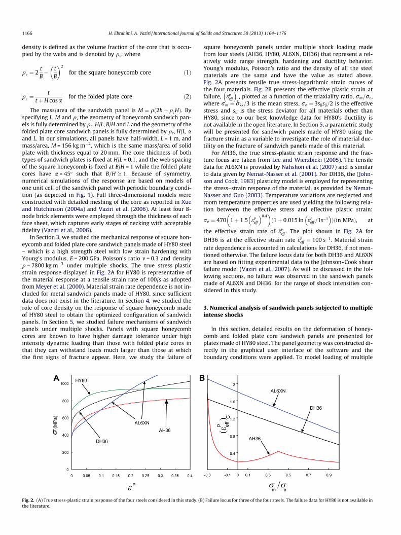
shocks, we need to also define the separation time between theloading from different shocks (e.g. time between two peak pres-sures). Fig. 3A shows the schematic diagram of half of a sandwichpanel subjected to two consecutive shocks with peak over-pres-sures for the first and second shocks denoted by P1 and P2, respec-tively. The separation time between the two peak over-pressure isdenoted by ts. In the numerical model, the pressure loading for dif-ferent values of P1, P2 and ts was then added manually to the inputfile prior to the analysis. The material failure and panel fracturewere not considered here and will be studied in Section 5. All re-sults have been determined with fully clamped boundary condi-tions and the panel geometry as discussed in Section 2. Thesimulations were carried out using ABAQUS/Explicit 6.10.
3.1. Role of separation time between consecutive shock events
As the first step, we carried out a systematic study on the role ofts (the separation time between two consecutive shocks) on the re-sponse and deformation of solid and sandwich panels. In the calcu-lations presented in this section, P1 = 50 MPa, t0 ¼ 10�4 s, while ts
and P2 were systematically varied. In each calculation, we mea-sured the time history of the deflection of the bottom face sheetof the sandwich panels under two shock impingements. Fig. 3Bshows the maximum normalized deflections of the bottom facesheet, dmax
bot =L, of the honeycomb sandwich panel with �qc = 0.04made of HY80 versus the normalized time between the two shocks,�ts ¼ ts=ðL=
ffiffiffiffiffiffiffiffiffiffiffiffiffiffiffiðrY=qÞ
pÞ (Vaziri and Hutchinson, 2007; Xue and
Hutchinson, 2004a). The results for the maximum deflection ofthe counterpart solid panel are also plotted for comparison. In this
Fig. 3. (A) Schematic diagram of a square honeycomb sandwich panel subjected totwo shocks with peak over pressures of P1 and P2. (B) Normalized maximumdeflection of the bottom face of the square honeycomb sandwich panel with �qc =0.04 made of HY80 (dashed lines) and the counterpart solid plate of same mass/area(solid lines) versus normalized shock time subjected to two shocks. No failurecriterion is incorporated and the square honeycomb core panel has M = 156 kg/m2,L = 1 m and �qc = 0.04.
relation rY and q are yield strength and density of the panel mate-rial, respectively. For a panel made from HY80 withL ¼ 1m; L=
ffiffiffiffiffiffirYp
=q ffi 3.4 ms.The results show that for loading with �ts > 1, the response of
both sandwich and solid panels is approximately independent ofthe value of �ts. In this case, the response of the panel to two shocksis effectively uncoupled and the two shocks can be treated as twoisolated loadings or events (i.e. the second shock impinges the pa-nel after it has come nearly to rest after the first shock impinge-ment). It should be noted that this finding appears to beindependent of the panel configuration, and only depends on thematerial behavior, namely the yield strength and density of the pa-nel material.
For �ts < 1, the maximum deflection of the panel increases as theduration between two shocks becomes shorter. When �ts ap-proaches zero, the maximum deflection of the panel under twoshocks becomes equal to the maximum deflection of a panel sub-jected to one shock with over-pressure equal to P1 + P2, as ex-pected. It should be noted that for all loading conditions, thehoneycomb panel undergoes smaller deformation compared toits solid panel counterpart.
3.2. Time-response of sandwich panels impinged by two shocks
In the calculations presented in this section, we chose ts = 8 mswhich corresponds to �ts ffi 2:3. While ts = 8 ms is a short time lagbetween the two shocks, based on the results presented inFig. 3B and discussed in Section 3.1, this insures that panels areat rest (except for low amplitude elastic vibrations) before the sec-ond shock impinges on the structure. It should be noted that hav-ing very short time difference between two shocks with �ts < 1 isperhaps not a common scenario and thus is not considered furtherin this work.
Fig. 4 shows normalized deflection of the bottom face (denotedby dbot=L), of both honeycomb and folded sandwich panels withqc = 0.04 and made from HY80 subjected to two shocks as a func-tion of dimensionless time, t=ðL=
ffiffiffiffiffiffiffiffiffiffiffiffiffiffiðrY=q
pÞÞ. Here, t was measured
from the time that the first shock impinges the panel (i.e. t = 0 atthe occurrence of the first over-peak pressure, P1). Also shown isthe time history of core crushing strain at the mid-span of thesandwich panels, defined as the ratio of core height in the de-formed configuration to the original height, and denoted by ec.By eliminating the local bending of the top and bottom face sheet,core crushing strain can be estimated from �c ffi ðdtop � dbotÞ=H,where dtop is the top face displacement.
For each core type, the figure presents results for three sets ofloadings. For honeycomb panels, P1 = 100 MPa and constant in allcalculations, and P2 was selected as 80,100, and 130 MPa in thethree simulations. For folded panels, P1 = 80 MPa and P2 was se-lected as 60, 80, and 100 MPa. In our simulations, we generallyused lower intensity of loading for folded panels compared to theirhoneycomb panel counterpart. The reason is that folded panels ingeneral sustain lower loading intensity prior to failure comparedto their honeycomb panel counterpart, as discussed in details inour previous publication (Vaziri et al., 2007). For example, for thefolded panel considered here, the loading of P1 = 100 MPa andP2 = 100 MPa, leads to significant necking at the clamped edgesof the panels, thus, making the simulation results inaccurate.
The deflection induced by the second shock is considerablysmaller than the deflection due to the first shock with the sameover-pressure intensity for both core types. For instance, the nor-malized maximum deflection of bottom face of honeycomb sand-wich panel in the first shock subjected to load with P1 = 100 MPais dmax
botL ffi 0:16, whereas the second shock with P2 = 100 MPa adds
only 0.04 to the maximum deflection value. The folded core
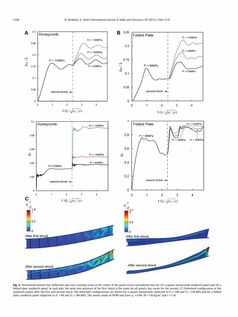
Fig. 4. Normalized bottom face deflection and core crushing strain at the center of the panel versus normalized time for (A) a square honeycomb sandwich panel and (B) afolded plate sandwich panel. In each plot, the peak over-pressure of the first shock is the same for all panels, but varies for the second. (C) Deformed configuration of thesandwich panels after the first and second shock. The deformed configurations are shown for a square honeycomb subjected to P1 = 100 and P2 = 130 MPa and for a foldedplate sandwich panel subjected to P1 = 80 and P2 = 100 MPa. The panels made of HY80 and have �qc = 0.04, M = 156 kg/m2 and L = 1 m.
1168 H. Ebrahimi, A. Vaziri / International Journal of Solids and Structures 50 (2013) 1164–1176
H. Ebrahimi, A. Vaziri / International Journal of Solids and Structures 50 (2013) 1164–1176 1169
sandwich panel subjected to P1 = P2 = 80 MPa, has dmaxbot =L of 0.12
and 0.18 after the first and second shock impingement, respec-tively. One reason is that the maximum deflection plotted here islarger than the residual displacement of the sandwich panels, ascan be seen in Fig. 4A for a honeycomb sandwich panel and inFig. 4B for a folded plate sandwich panel. The deformed configura-tion of sandwich panels after the first and second shock, as well asthe distribution of the effective plastic strain in face sheets andcores are shown in Fig. 4C. For both sandwich panels, local neckingof the top face sheet is observed after the second shock – for fur-ther discussion on dynamic necking, see Xue et al. (2008). Notethat for the folded sandwich panel, the final core crushing strainfor all three sets of loading is close to 1 as the core undergoesnear-total crushing after the impingement of the second shock.
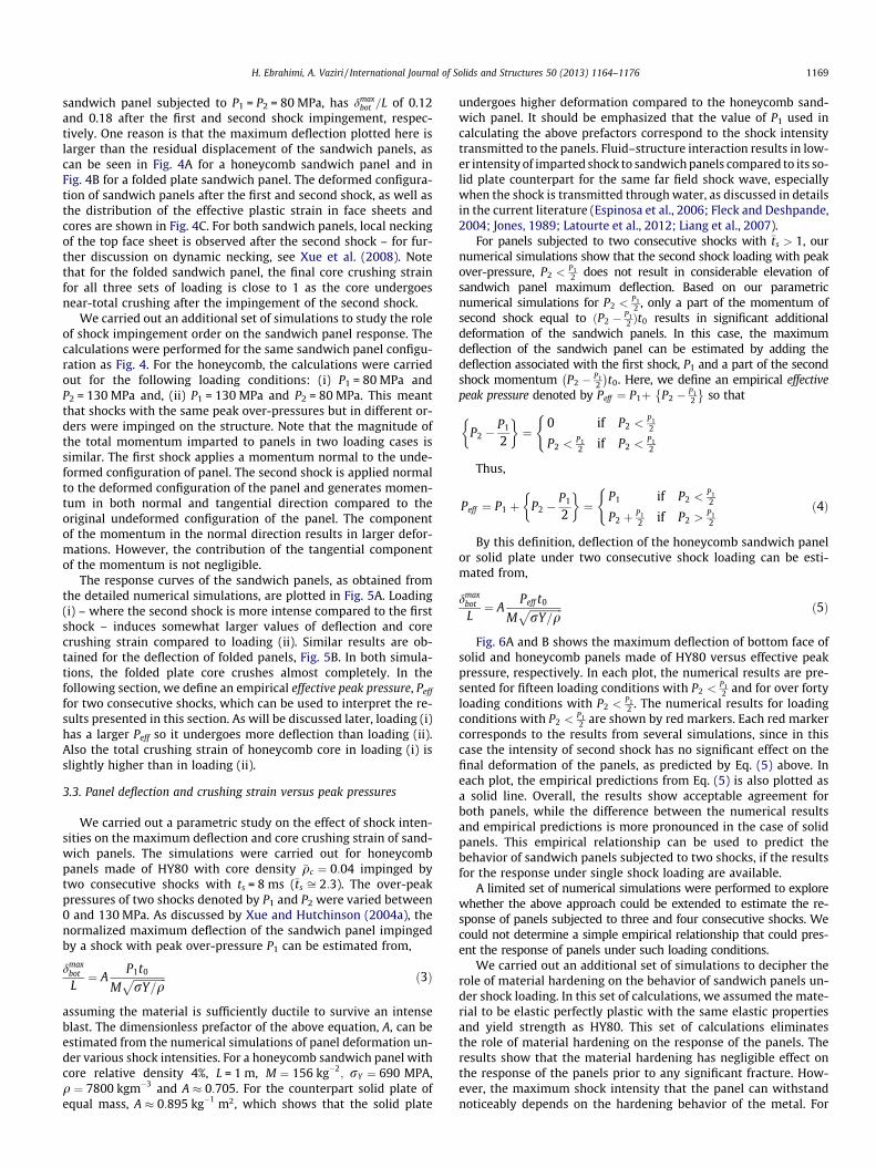
We carried out an additional set of simulations to study the roleof shock impingement order on the sandwich panel response. Thecalculations were performed for the same sandwich panel configu-ration as Fig. 4. For the honeycomb, the calculations were carriedout for the following loading conditions: (i) P1 = 80 MPa andP2 = 130 MPa and, (ii) P1 = 130 MPa and P2 = 80 MPa. This meantthat shocks with the same peak over-pressures but in different or-ders were impinged on the structure. Note that the magnitude ofthe total momentum imparted to panels in two loading cases issimilar. The first shock applies a momentum normal to the unde-formed configuration of panel. The second shock is applied normalto the deformed configuration of the panel and generates momen-tum in both normal and tangential direction compared to theoriginal undeformed configuration of the panel. The componentof the momentum in the normal direction results in larger defor-mations. However, the contribution of the tangential componentof the momentum is not negligible.
The response curves of the sandwich panels, as obtained fromthe detailed numerical simulations, are plotted in Fig. 5A. Loading(i) – where the second shock is more intense compared to the firstshock – induces somewhat larger values of deflection and corecrushing strain compared to loading (ii). Similar results are ob-tained for the deflection of folded panels, Fig. 5B. In both simula-tions, the folded plate core crushes almost completely. In thefollowing section, we define an empirical effective peak pressure, Peff
for two consecutive shocks, which can be used to interpret the re-sults presented in this section. As will be discussed later, loading (i)has a larger Peff so it undergoes more deflection than loading (ii).Also the total crushing strain of honeycomb core in loading (i) isslightly higher than in loading (ii).
3.3. Panel deflection and crushing strain versus peak pressures
We carried out a parametric study on the effect of shock inten-sities on the maximum deflection and core crushing strain of sand-wich panels. The simulations were carried out for honeycombpanels made of HY80 with core density �qc ¼ 0:04 impinged bytwo consecutive shocks with ts = 8 ms (�ts ffi 2:3). The over-peakpressures of two shocks denoted by P1 and P2 were varied between0 and 130 MPa. As discussed by Xue and Hutchinson (2004a), thenormalized maximum deflection of the sandwich panel impingedby a shock with peak over-pressure P1 can be estimated from,
dmaxbot
L¼ A
P1t0
MffiffiffiffiffiffiffiffiffiffiffiffiffirY=q
p ð3Þ
assuming the material is sufficiently ductile to survive an intenseblast. The dimensionless prefactor of the above equation, A, can beestimated from the numerical simulations of panel deformation un-der various shock intensities. For a honeycomb sandwich panel withcore relative density 4%, L = 1 m, M ¼ 156 kg�2
; rY ¼ 690 MPA,q ¼ 7800 kgm�3 and A � 0:705. For the counterpart solid plate ofequal mass, A � 0:895 kg�1 m2, which shows that the solid plate
undergoes higher deformation compared to the honeycomb sand-wich panel. It should be emphasized that the value of P1 used incalculating the above prefactors correspond to the shock intensitytransmitted to the panels. Fluid–structure interaction results in low-er intensity of imparted shock to sandwich panels compared to its so-lid plate counterpart for the same far field shock wave, especiallywhen the shock is transmitted through water, as discussed in detailsin the current literature (Espinosa et al., 2006; Fleck and Deshpande,2004; Jones, 1989; Latourte et al., 2012; Liang et al., 2007).
For panels subjected to two consecutive shocks with �ts > 1, ournumerical simulations show that the second shock loading with peakover-pressure, P2 <
P12 does not result in considerable elevation of
sandwich panel maximum deflection. Based on our parametricnumerical simulations for P2 <
P12 , only a part of the momentum of
second shock equal to ðP2 � P12 Þt0 results in significant additional
deformation of the sandwich panels. In this case, the maximumdeflection of the sandwich panel can be estimated by adding thedeflection associated with the first shock, P1 and a part of the secondshock momentum P2 � P1
2
� �t0. Here, we define an empirical effective
peak pressure denoted by Peff ¼ P1þ P2 � P12
so that
P2 �P1
2
� �¼
0 if P2 <P12
P2 <P12 if P2 <
P12
(
Thus,
Peff ¼ P1 þ P2 �P1
2
� �¼
P1 if P2 <P12
P2 þ P12 if P2 >
P12
(ð4Þ
By this definition, deflection of the honeycomb sandwich panelor solid plate under two consecutive shock loading can be esti-mated from,
dmaxbot
L¼ A
Peff t0
MffiffiffiffiffiffiffiffiffiffiffiffiffirY=q
p ð5Þ
Fig. 6A and B shows the maximum deflection of bottom face ofsolid and honeycomb panels made of HY80 versus effective peakpressure, respectively. In each plot, the numerical results are pre-sented for fifteen loading conditions with P2 <
P12 and for over forty
loading conditions with P2 <P12 . The numerical results for loading
conditions with P2 <P12 are shown by red markers. Each red marker
corresponds to the results from several simulations, since in thiscase the intensity of second shock has no significant effect on thefinal deformation of the panels, as predicted by Eq. (5) above. Ineach plot, the empirical predictions from Eq. (5) is also plotted asa solid line. Overall, the results show acceptable agreement forboth panels, while the difference between the numerical resultsand empirical predictions is more pronounced in the case of solidpanels. This empirical relationship can be used to predict thebehavior of sandwich panels subjected to two shocks, if the resultsfor the response under single shock loading are available.
A limited set of numerical simulations were performed to explorewhether the above approach could be extended to estimate the re-sponse of panels subjected to three and four consecutive shocks. Wecould not determine a simple empirical relationship that could pres-ent the response of panels under such loading conditions.
We carried out an additional set of simulations to decipher therole of material hardening on the behavior of sandwich panels un-der shock loading. In this set of calculations, we assumed the mate-rial to be elastic perfectly plastic with the same elastic propertiesand yield strength as HY80. This set of calculations eliminatesthe role of material hardening on the response of the panels. Theresults show that the material hardening has negligible effect onthe response of the panels prior to any significant fracture. How-ever, the maximum shock intensity that the panel can withstandnoticeably depends on the hardening behavior of the metal. For
Fig. 5. Normalized bottom face deflection and core crushing strain at the center of the panel versus normalized time for (A) the square honeycomb sandwich panel and (B)folded plate sandwich panel. The panels made of HY80 and have �qc = 0.04, M = 156 kg/m2 and L = 1 m.
Fig. 6. Comparison between the numerical simulation results and the prediction from Eq. (5) for normalized maximum deflection (A) a solid plate and (B) the bottom face ofsquare honeycomb sandwich panel subjected to two shocks. Both sandwich panel and solid plate are made of HY80 and have M = 156 kg/m2 and L = 1 m. The squarehoneycomb sandwich panel has core relative density �qc = 0.04. Solid lines show the theory results and markers indicate simulation outcomes. Results are presented for twoloading cases, P2 <
P12 and P2 <
P12 . For loading case, P2 <
P12 , each marker represents several simulation data points. The total number of data points in each figure is about sixty.
1170 H. Ebrahimi, A. Vaziri / International Journal of Solids and Structures 50 (2013) 1164–1176
H. Ebrahimi, A. Vaziri / International Journal of Solids and Structures 50 (2013) 1164–1176 1171
panels with no hardening, necking of the face sheets at low shockintensities was observed, which results in premature failure of thepanels.
4. Optimized sandwich configuration
In this section, we carried out a parametric study of the effect ofpanel geometrical configuration on its response under two consec-utive shocks. More specifically, we systematically varied the rela-tive distribution of the face sheet’s mass and core relativedensity and explored the role of core relative density on the overallresponse of the sandwich panels. The total mass of the panels waskept constant. This means that, for example, the trade-off inincreasing the thickness of the face sheets is thinning of the corewebs and thus, lowering the core relative density. The responseof the panels under one high intensity shock and two consecutiveshocks was obtained using detailed numerical simulations andcompared to the response of the counterpart solid plate of equalmass. Previous optimization studies on the performance of metalsandwich panels with a similar configuration as the current studyshowed that honeycomb and folded plate sandwich panels with acore relative density of 4%–5% generally undergo minimum facesheet deflections under high intensity dynamic loading (Hutchin-son and Xue, 2005; Xue and Hutchinson, 2004a). In this case,20%–25% of the overall mass of the panel is distributed in the core.Core crushing, face sheet stretching and deformation, and localbending of the face sheets are the main deformation mechanismsof the sandwich panels which contribute to their overall deforma-tion and response. For sandwich panels with very low core relativedensity (1%–2%), core crushing is significant. For sandwich panelswith high core relative density (>6%), the face sheets undergosignificant bending and stretching, while the core crushing is min-imal. For panels with core relative density of 4%–5%, the contribu-tion of all the mechanisms is relatively moderate, resulting inlower overall deformation of the panels (Vaziri et al., 2006). Thispanels are also shown to have maximum failure tolerance underhigh intensity dynamic loading (Vaziri et al., 2007).
In this section, we extend these investigations to sandwich pan-els subjected to two consecutive intense shocks. In our simulations,we consider square honeycomb sandwich panels with relative coredensity of 1%–8% made from HY80 steel. Similar to the previoussection, material failure and fluid–structure interaction were notconsidered in the simulations and the calculations were carriedout by keeping the total mass/area of the panels constant,M = 156 kg m�2. Fig. 7A displays the normalized maximum deflec-tion of the top face of the square honeycomb sandwich panels as afunction of core relative density, �qc . The first shock over-pressurewas set at P1 = 100 MPa, and the simulations were carried out forP2 = 0,80,100 and 130 MPa. The set denoted by P2 = 0 refers tosandwich panels subjected to a single shock with P1 = 100 MPa.The maximum deflections of counterpart solid panels are alsoshown by a straight solid lines under each loading other than thehighest shock intensity, P2 = 130 MPa. A solid plate subjected toP2 = 130 MPa undergoes significant necking close to their bound-ary, which makes the numerical results inaccurate.
Honeycomb sandwich panels with core relative density of 4%–5% have the minimum top face deflection under all loading condi-tions. When the panels are subjected to two shocks, the influenceof core relative density becomes somewhat more significant. Forinstance, the maximum top face deflection of a panel with corerelative density 4% is approximately 15% less than the maximumdeflection of a panel with core relative density 1%, under singleshock with P1 = 100 MPa. This difference is 25%, when the panelsare subjected to two consecutive shocks, P1 = 100 MPa andP2 = 130 MPa. It is noteworthy that the panels with moderate corerelative density of 4%–5% noticeably outperform their counterpart
solid panels. However, sandwich panels with very low or very highcore relative densities undergo slightly larger deformations com-pared to their solid panel counterpart. Fig. 7B shows the corecrushing strain at the mid span of the honeycomb sandwich panelsas a function of core relative density for the same loading conditiondiscussed above. As expected, for panels with a low core relativedensity, the core crushes significantly. Panels with core relativedensity above 4% have almost identical core crushing strain forall loadings.
Final deformed configurations of the square honeycomb sand-wich panels with three core relative densities under two consecu-tive shocks, P1 = 100 and P2 = 80 MPa, are shown in Fig. 7C. For thepanel with core relative density 1%, the core webs undergo signif-icant crushing. For panels with the thinnest face sheets (�qc ¼ 8%),top face undergoes extensive plastic bending into the core whilethe core webs undergo very little deformation. For the optimizedconfiguration with �qc ¼ 4% the panel undergoes modest amountof face sheet bending and core crushing, leading to superior perfor-mance of the panels under shock loading. This is discussed in moredetail in Vaziri et al. (2006).
5. Fracture and overall failure of honeycomb sandwich panelsunder multiple shocks
Vaziri et al. (2007) studied the failure mechanisms of all-metalfolded and honeycomb sandwich panels subjected to an intenseshock and provided fracture-shock intensity maps for clampedsandwich panels. The analogous study for composite sandwichpanels was presented by Andrews and Moussa (2009), Latourteet al. (2011). Here, we expand these results to the case of all-metalhoneycomb sandwich panels subjected to multiple consecutiveshocks. As the first step, we studied the fracture behavior of honey-combs panels with �qc ¼ 0:04 made of HY80 subjected to up tothree intense shocks. As discussed before the failure criterion forthis steel alloy is not available and was modeled in this study byassuming that the local failure occurs if the effective plastic strainreaches a critical value, ðeP
eff Þc . This is the simplest form of fracturecriterion for the purpose of numerical analysis. In the calculations,failed elements were removed using the approach available inABAQUS/Explicit 6.10 (SIMULIA, Providence, RI). Additional setsof simulations were carried out for sandwich panels made ofAH36, Al6XN and DH36, which represent a range of ductility andmaterial properties, as described in Section 2. The failure criteriaas presented in Section 2 for these steel alloys was used in theseset of calculations.
It should be emphasized that as HY80 is a high-strength steel,its fracture strain is likely to be dependent on stress triaxiality(as for AH36, where fracture strain and mode strongly dependson the triaxiality – see Fig. 2), which is not considered here. An-other limitation of this study is ignoring the failure of joints andconnections (e.g. welding for metal panels), which was not mod-eled in the simulations. Joint strength is known to be a limiting fac-tor for performance and strength of sandwich panels (Wadleyet al., in press; Mori et al., 2009; Xiong et al., 2012a; Xiong et al.,2011b) and thus, further studies are required to address the roleof connection and joint failure on the overall performance of panelsunder shock loading.
Fig. 8A shows the deformed configuration of the sandwich panelimpinged by three consecutive shocks of equal peak over-pressure,80 MPa, after it comes to rest following each shock event. In thisset of simulations, ðeP
eff Þc = 0.4, representing relatively moderateductility. The contour map displays the effective plastic strain dis-tribution in the panel. After the first shock, the panel undergoesrelatively little core crushing and no apparent failure and cracking.The second shock results in cracking of the core webs close to theclamped boundary condition. Impingement of the third shock
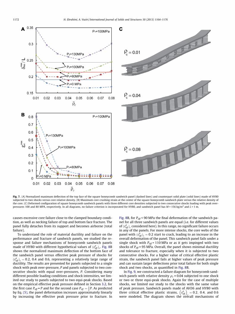
Fig. 7. (A) Normalized maximum deflection of the top face of the square honeycomb sandwich panel (dashed lines) and counterpart solid plate (solid lines) made of HY80subjected to two shocks versus core relative density. (B) Maximum core crushing strain at the center of the square honeycomb sandwich plate versus the relative density ofthe core. (C) Deformed configuration of square honeycomb sandwich panels with three different core densities subjected to two consecutive shocks loading with peak over-pressures 100 and 80 MPA, respectively. In all diagrams, no failure criterion is incorporated for HY80, and sandwich panel has M = 156 kg/m2 and L = 1 m.
1172 H. Ebrahimi, A. Vaziri / International Journal of Solids and Structures 50 (2013) 1164–1176
causes excessive core failure close to the clamped boundary condi-tion, as well as necking failure of top and bottom face fracture. Thepanel fully detaches from its support and becomes airborne (totalfailure).
To understand the role of material ductility and failure on theperformance and fracture of sandwich panels, we studied the re-sponse and failure mechanisms of honeycomb sandwich panelsmade of HY80 with different hypothetical values of ðeP
eff Þc. Fig. 8Bshows the normalized maximum deflection of the bottom face ofthe sandwich panel versus effective peak pressure of shocks forðeP
eff Þc ¼ 0:2, 0.4 and 0.6, representing a relatively large range ofductility. The results are presented for panels subjected to a singleshock with peak over-pressure, P and panels subjected to two con-secutive shocks with equal over-pressures, P. Considering manydifferent possible loading conditions and shock intensities, we lim-ited our study to panels subjected to two equi-peak shocks. Basedon the empirical effective peak pressure defined in Section 3.2, forthe first case Peff = P and for the second case Peff ¼ 3
2 P. As predictedby Eq. (5), the panel deformation increases approximately linearlyby increasing the effective peak pressure prior to fracture. In
Fig. 8B, for Peff < 90 MPa the final deformation of the sandwich pa-nel for all three sandwich panels are equal (i.e. for different valuesof ðeP
eff Þc considered here). In this range, no significant failure occursin any of the panels. For more intense shocks, the core webs of thepanel with ðeP
eff Þc ¼ 0:2 start to crack, leading to an increase in theoverall deformation of the panel. This sandwich panel fails under asingle shock with Peff = 110 MPa or as it gets impinged with twoshocks of Peff = 95 MPa. Overall, the panel shows minimal ductilityand tolerance to fracture, especially when it is subjected to twoconsecutive shocks. For a higher value of critical effective plasticstrain, the sandwich panel fails at higher values of peak pressureand can sustain larger deflections prior total failure for both singleshock and two shocks, as quantified in Fig. 8B.
In Fig. 9, we constructed a failure diagram for honeycomb sand-wich panels with relative density qc = 0.04 subjected to one shockor two or three equi-peak shocks. Again for the case of multipleshocks, we limited our study to the shocks with the same valueof peak pressure. Sandwich panels made of AH36 and HY80 withthree critical effective plastic strains, eP
eff
� �c¼ 0:2; 0:4; and 0:6
were modeled. The diagram shows the overall mechanisms of
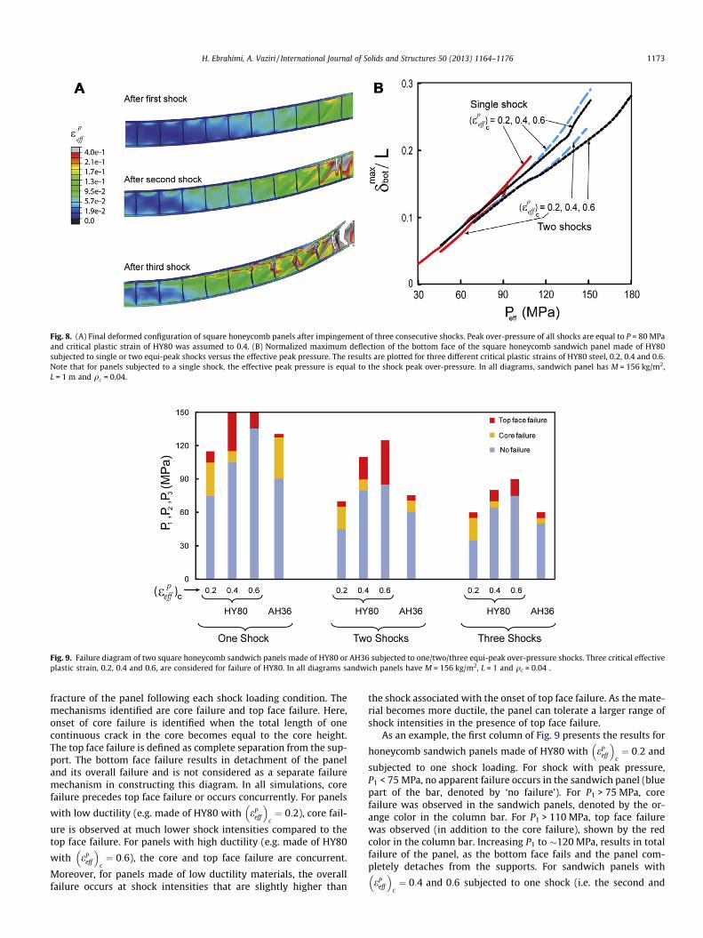
Fig. 9. Failure diagram of two square honeycomb sandwich panels made of HY80 or AH36 subjected to one/two/three equi-peak over-pressure shocks. Three critical effectiveplastic strain, 0.2, 0.4 and 0.6, are considered for failure of HY80. In all diagrams sandwich panels have M = 156 kg/m2, L = 1 and qc = 0.04 .
Fig. 8. (A) Final deformed configuration of square honeycomb panels after impingement of three consecutive shocks. Peak over-pressure of all shocks are equal to P = 80 MPaand critical plastic strain of HY80 was assumed to 0.4. (B) Normalized maximum deflection of the bottom face of the square honeycomb sandwich panel made of HY80subjected to single or two equi-peak shocks versus the effective peak pressure. The results are plotted for three different critical plastic strains of HY80 steel, 0.2, 0.4 and 0.6.Note that for panels subjected to a single shock, the effective peak pressure is equal to the shock peak over-pressure. In all diagrams, sandwich panel has M = 156 kg/m2,L = 1 m and qc = 0.04.
H. Ebrahimi, A. Vaziri / International Journal of Solids and Structures 50 (2013) 1164–1176 1173
fracture of the panel following each shock loading condition. Themechanisms identified are core failure and top face failure. Here,onset of core failure is identified when the total length of onecontinuous crack in the core becomes equal to the core height.The top face failure is defined as complete separation from the sup-port. The bottom face failure results in detachment of the paneland its overall failure and is not considered as a separate failuremechanism in constructing this diagram. In all simulations, corefailure precedes top face failure or occurs concurrently. For panels
with low ductility (e.g. made of HY80 with ePeff
� �c¼ 0:2), core fail-
ure is observed at much lower shock intensities compared to thetop face failure. For panels with high ductility (e.g. made of HY80
with ePeff
� �c¼ 0:6), the core and top face failure are concurrent.
Moreover, for panels made of low ductility materials, the overallfailure occurs at shock intensities that are slightly higher than
the shock associated with the onset of top face failure. As the mate-rial becomes more ductile, the panel can tolerate a larger range ofshock intensities in the presence of top face failure.
As an example, the first column of Fig. 9 presents the results for
honeycomb sandwich panels made of HY80 with ePeff
� �c¼ 0:2 and
subjected to one shock loading. For shock with peak pressure,P1 < 75 MPa, no apparent failure occurs in the sandwich panel (bluepart of the bar, denoted by ‘no failure’). For P1 > 75 MPa, corefailure was observed in the sandwich panels, denoted by the or-ange color in the column bar. For P1 > 110 MPa, top face failurewas observed (in addition to the core failure), shown by the redcolor in the column bar. Increasing P1 to �120 MPa, results in totalfailure of the panel, as the bottom face fails and the panel com-pletely detaches from the supports. For sandwich panels with
ePeff
� �c¼ 0:4 and 0:6 subjected to one shock (i.e. the second and
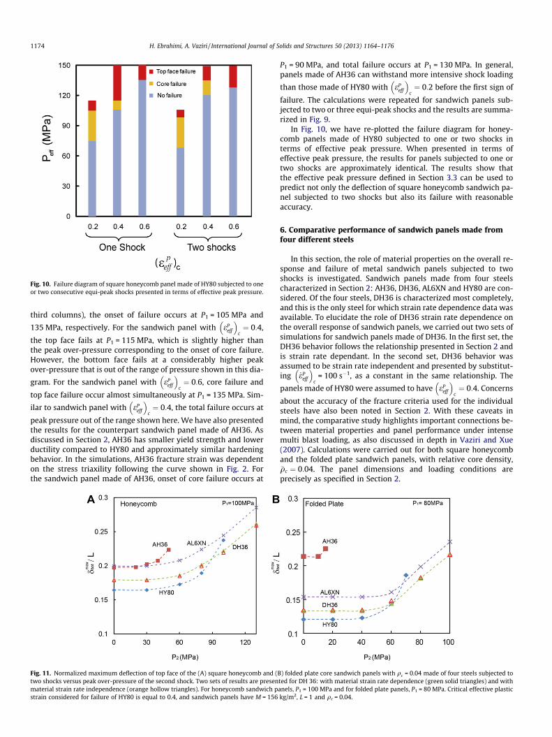
Fig. 10. Failure diagram of square honeycomb panel made of HY80 subjected to oneor two consecutive equi-peak shocks presented in terms of effective peak pressure.
1174 H. Ebrahimi, A. Vaziri / International Journal of Solids and Structures 50 (2013) 1164–1176
third columns), the onset of failure occurs at P1 = 105 MPa and
135 MPa, respectively. For the sandwich panel with ePeff
� �c¼ 0:4,
the top face fails at P1 = 115 MPa, which is slightly higher thanthe peak over-pressure corresponding to the onset of core failure.However, the bottom face fails at a considerably higher peakover-pressure that is out of the range of pressure shown in this dia-
gram. For the sandwich panel with ePeff
� �c¼ 0:6, core failure and
top face failure occur almost simultaneously at P1 = 135 MPa. Sim-
ilar to sandwich panel with ePeff
� �c¼ 0:4, the total failure occurs at
peak pressure out of the range shown here. We have also presentedthe results for the counterpart sandwich panel made of AH36. Asdiscussed in Section 2, AH36 has smaller yield strength and lowerductility compared to HY80 and approximately similar hardeningbehavior. In the simulations, AH36 fracture strain was dependenton the stress triaxility following the curve shown in Fig. 2. Forthe sandwich panel made of AH36, onset of core failure occurs at
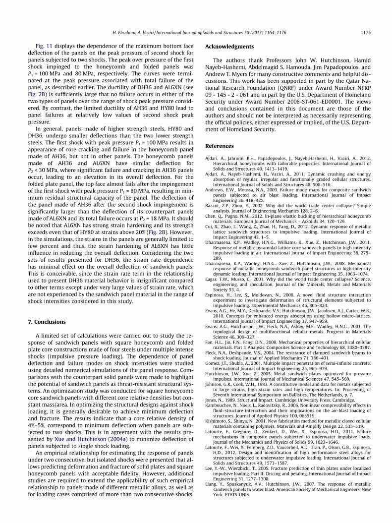
Fig. 11. Normalized maximum deflection of top face of the (A) square honeycomb and (Btwo shocks versus peak over-pressure of the second shock. Two sets of results are presenmaterial strain rate independence (orange hollow triangles). For honeycomb sandwich pstrain considered for failure of HY80 is equal to 0.4, and sandwich panels have M = 156
P1 = 90 MPa, and total failure occurs at P1 = 130 MPa. In general,panels made of AH36 can withstand more intensive shock loading
than those made of HY80 with ePeff
� �c¼ 0:2 before the first sign of
failure. The calculations were repeated for sandwich panels sub-jected to two or three equi-peak shocks and the results are summa-rized in Fig. 9.
In Fig. 10, we have re-plotted the failure diagram for honey-comb panels made of HY80 subjected to one or two shocks interms of effective peak pressure. When presented in terms ofeffective peak pressure, the results for panels subjected to one ortwo shocks are approximately identical. The results show thatthe effective peak pressure defined in Section 3.3 can be used topredict not only the deflection of square honeycomb sandwich pa-nel subjected to two shocks but also its failure with reasonableaccuracy.
6. Comparative performance of sandwich panels made fromfour different steels
In this section, the role of material properties on the overall re-sponse and failure of metal sandwich panels subjected to twoshocks is investigated. Sandwich panels made from four steelscharacterized in Section 2: AH36, DH36, AL6XN and HY80 are con-sidered. Of the four steels, DH36 is characterized most completely,and this is the only steel for which strain rate dependence data wasavailable. To elucidate the role of DH36 strain rate dependence onthe overall response of sandwich panels, we carried out two sets ofsimulations for sandwich panels made of DH36. In the first set, theDH36 behavior follows the relationship presented in Section 2 andis strain rate dependant. In the second set, DH36 behavior wasassumed to be strain rate independent and presented by substitut-ing _eP
eff
� �c
= 100 s�1, as a constant in the same relationship. The
panels made of HY80 were assumed to have ePeff
� �c¼ 0:4. Concerns
about the accuracy of the fracture criteria used for the individualsteels have also been noted in Section 2. With these caveats inmind, the comparative study highlights important connections be-tween material properties and panel performance under intensemulti blast loading, as also discussed in depth in Vaziri and Xue(2007). Calculations were carried out for both square honeycomband the folded plate sandwich panels, with relative core density,�qc ¼ 0:04. The panel dimensions and loading conditions areprecisely as specified in Section 2.
) folded plate core sandwich panels with qc = 0.04 made of four steels subjected toted for DH 36: with material strain rate dependence (green solid triangles) and withanels, P1 = 100 MPa and for folded plate panels, P1 = 80 MPa. Critical effective plastickg/m2, L = 1 and qc = 0.04.
H. Ebrahimi, A. Vaziri / International Journal of Solids and Structures 50 (2013) 1164–1176 1175
Fig. 11 displays the dependence of the maximum bottom facedeflection of the panels on the peak pressure of second shock forpanels subjected to two shocks. The peak over pressure of the firstshock impinged to the honeycomb and folded panels wasP1 = 100 MPa and 80 MPa, respectively. The curves were termi-nated at the peak pressure associated with total failure of thepanel, as described earlier. The ductility of DH36 and AL6XN (seeFig. 2B) is sufficiently large that no failure occurs in either of thetwo types of panels over the range of shock peak pressure consid-ered. By contrast, the limited ductility of AH36 and HY80 lead topanel failures at relatively low values of second shock peakpressure.
In general, panels made of higher strength steels, HY80 andDH36, undergo smaller deflections than the two lower strengthsteels. The first shock with peak pressure P1 = 100 MPa results inappearance of core cracking and failure in the honeycomb panelmade of AH36, but not in other panels. The honeycomb panelsmade of AH36 and AL6XN have similar deflection forP2 < 30 MPa, where significant failure and cracking in AH36 panelsoccur, leading to an elevation in its overall deflection. For thefolded plate panel, the top face almost fails after the impingementof the first shock with peak pressure P1 = 80 MPa, resulting in min-imum residual structural capacity of the panel. The deflection ofthe panel made of AH36 after the second shock impingement issignificantly larger than the deflection of its counterpart panelsmade of AL6XN and its total failure occurs at P2 = 18 MPa. It shouldbe noted that AL6XN has strong strain hardening and its strengthexceeds even that of HY80 at strains above 20% (Fig. 2B). However,in the simulations, the strains in the panels are generally limited tofew percent and thus, the strain hardening of AL6XN has littleinfluence in reducing the overall deflection. Considering the twosets of results presented for DH36, the strain rate dependencehas minimal effect on the overall deflection of sandwich panels.This is conceivable, since the strain rate term in the relationshipused to present DH36 material behavior is insignificant comparedto other terms except under very large values of strain rate, whichare not experienced by the sandwich panel material in the range ofshock intensities considered in this study.
7. Conclusions
A limited set of calculations were carried out to study the re-sponse of sandwich panels with square honeycomb and foldedplate core constructions made of four steels under multiple intenseshocks (impulsive pressure loading). The dependence of paneldeflection and failure modes on shock intensities were studiedusing detailed numerical simulations of the panel response. Com-parisons with the counterpart solid panels were made to highlightthe potential of sandwich panels as threat-resistant structural sys-tems. An optimization study was conducted for square honeycombcore sandwich panels with different core relative densities but con-stant mass/area. In optimizing the structural designs against shockloading, it is generally desirable to achieve minimum deflectionand fracture. The results indicate that a core relative density of4%–5%, correspond to minimum deflection when panels are sub-jected to two shocks. This is in agreement with the results pre-sented by Xue and Hutchinson (2004a) to minimize deflection ofpanels subjected to single shock loading.
An empirical relationship for estimating the response of panelsunder two consecutive, but isolated shocks were presented that al-lows predicting deformation and fracture of solid plates and squarehoneycomb panels with acceptable fidelity. However, additionalstudies are required to extend the applicability of such empiricalrelationship to panels made of different metallic alloys, as well asfor loading cases comprised of more than two consecutive shocks.
Acknowledgments
The authors thank Professors John W. Hutchinson, HamidNayeb-Hashemi, Abdelmagid S. Hamouda, Jim Papadopoulos, andAndrew T. Myers for many constructive comments and helpful dis-cussions. This work has been supported in part by the Qatar Na-tional Research Foundation (QNRF) under Award Number NPRP09 - 145 - 2 - 061 and in part by the U.S. Department of HomelandSecurity under Award Number 2008-ST-061-ED0001. The viewsand conclusions contained in this document are those of theauthors and should not be interpreted as necessarily representingthe official policies, either expressed or implied, of the U.S. Depart-ment of Homeland Security.
References
Ajdari, A., Jahromi, B.H., Papadopoulos, J., Nayeb-Hashemi, H., Vaziri, A., 2012.Hierarchical honeycombs with tailorable properties. International Journal ofSolids and Structures 49, 1413–1419.
Ajdari, A., Nayeb-Hashemi, H., Vaziri, A., 2011. Dynamic crushing and energyabsorption of regular, irregular and functionally graded cellular structures.International Journal of Solids and Structures 48, 506–516.
Andrews, E.W., Moussa, N.A., 2009. Failure mode maps for composite sandwichpanels subjected to air blast loading. International Journal of ImpactEngineering 36, 418–425.
Bazant, Z.P., Zhou, Y., 2002. Why did the world trade center collapse? Simpleanalysis. Journal of Engineering Mechanics 128, 2–6.
Chen, Q., Pugno, N.M., 2012. In-plane elastic buckling of hierarchical honeycombmaterials. European Journal of Mechanics – A/Solids 34, 120–129.
Cui, X., Zhao, L., Wang, Z., Zhao, H., Fang, D., 2012. Dynamic response of metalliclattice sandwich structures to impulsive loading. International Journal ofImpact Engineering 43, 1–5.
Dharmasena, K.P., Wadley, H.N.G., Williams, K., Xue, Z., Hutchinson, J.W., 2011.Response of metallic pyramidal lattice core sandwich panels to high intensityimpulsive loading in air. International Journal of Impact Engineering 38, 275–289.
Dharmasena, K.P., Wadley, H.N.G., Xue, Z., Hutchinson, J.W., 2008. Mechanicalresponse of metallic honeycomb sandwich panel structures to high-intensitydynamic loading. International Journal of Impact Engineering 35, 1063–1074.
Eagar, T.W., Musso, C., 2001. Why did the world trade center collapse? Science,engineering, and speculation. Journal of the Minerals, Metals and MaterialsSociety 53, 4.
Espinosa, H., Lee, S., Moldovan, N., 2006. A novel fluid structure interactionexperiment to investigate deformation of structural elements subjected toimpulsive loading. Experimental Mechanics 46, 805–824.
Evans, A.G., He, M.Y., Deshpande, V.S., Hutchinson, J.W., Jacobsen, A.J., Carter, W.B.,2010. Concepts for enhanced energy absorption using hollow micro-lattices.International Journal of Impact Engineering 37, 947–959.
Evans, A.G., Hutchinson, J.W., Fleck, N.A., Ashby, M.F., Wadley, H.N.G., 2001. Thetopological design of multifunctional cellular metals. Progress in MaterialsScience 46, 309–327.
Fan, H.L., Jin, F.N., Fang, D.N., 2008. Mechanical properties of hierarchical cellularmaterials. Part I: Analysis. Composites Science and Technology 68, 3380–3387.
Fleck, N.A., Deshpande, V.S., 2004. The resistance of clamped sandwich beams toshock loading. Journal of Applied Mechanics 71, 386–401.
Gomez, J.T., Shukla, A., 2001. Multiple impact penetration of semi-infinite concrete.International Journal of Impact Engineering 25, 965–979.
Hutchinson, J.W., Xue, Z., 2005. Metal sandwich plates optimized for pressureimpulses. International Journal of Mechanical Sciences 47, 545–569.
Johnson, G.R., Cook, W.H., 1983. A constitutive model and data for metals subjectedto large strains, high strain rates and high temperatures. In: Proceeding ofSeventh International Symposium on Ballistics, The Netherlands, p. 7.
Jones, N., 1989. Structural Impact. Cambridge University Press, Cambridge.Kambouchev, N., Noels, L., Radovitzky, R., 2006. Nonlinear compressibility effects in
fluid–structure interaction and their implications on the air-blast loading ofstructures. Journal of Applied Physics 100, 063519.
Kishimoto, S., Shinya, N., 2001. New fabrication method for metallic closed cellularmaterials containing polymers. Materials and Amplify Design 22, 535–539.
Latourte, F., Grégoire, D., Zenkert, D., Wei, X., Espinosa, H.D., 2011. Failuremechanisms in composite panels subjected to underwater impulsive loads.Journal of the Mechanics and Physics of Solids 59, 1623–1646.
Latourte, F., Wei, X., Feinberg, Z.D., Vaucorbeil, A.D., Tran, P., Olson, G.B., Espinosa,H.D., 2012. Design and identification of high performance steel alloys forstructures subjected to underwater impulsive loading. International Journal ofSolids and Structures 49, 1573–1587.
Lee, Y.-W., Wierzbicki, T., 2005. Fracture prediction of thin plates under localizedimpulsive loading. Part II: Discing and petaling. International Journal of ImpactEngineering 31, 1277–1308.
Liang, Y., Spuskanyuk, A.V., Hutchinson, J.W., 2007. The response of metallicsandwich panels to water blast, American Society of Mechanical Engineers, NewYork, ETATS-UNIS.
1176 H. Ebrahimi, A. Vaziri / International Journal of Solids and Structures 50 (2013) 1164–1176
Makhutov, N.A., Serikov, S.V., Kotousov, A.G., 1992. Escalation failure of pipelines.Strength of Materials 24, 711–715.
Meyer, L.W., Krüger, L., Hahn, F.F., 2000. Influence of pre-deformation and strainrate on the flow behavior of HY80 steel. Emerging Technologies in Fluids,Structures and Fluid/Structure Interactions 1 (414), 295–300.
Mori, L., Queheillalt, D., Wadley, H., Espinosa, H., 2009. Deformation and failuremodes of I-core sandwich structures subjected to underwater impulsive loads.Experimental Mechanics 49, 257–275.
Mori, L.F., Lee, S., Xue, Z.Y., Vaziri, A., Queheillalt, D.T., Wadley, K.P.D.H.N.G.,Hutchinson, J.W., Espinosa, H.D., 2007. Deformation and fracture modes ofsandwich structures subjected to underwater impulsive loads. Journal ofMechanics of Materials and Structures 2, 26.
Nahshon, K., Pontin, M.G., Evans, A.G., Hutchinson, J.W., Zok, F.W., 2007. Dynamicshear rupture of steel plates. Journal of Mechanics of Materials and Structures 2,2049–2066.
Nemat-Nasser, S., Guo, W.-G., 2003. Thermomechanical response of DH-36structural steel over a wide range of strain rates and temperatures.Mechanics of Materials 35, 1023–1047.
Nemat-Nasser, S., Guo, W.-G., Kihl, D.P., 2001. Thermomechanical response of AL-6XN stainless steel over a wide range of strain rates and temperatures. Journalof the Mechanics and Physics of Solids 49, 1823–1846.
Qiao, P., Yang, M., Bobaru, F., 2008. Impact mechanics and high-energy absorbingmaterials: review. Journal of Aerospace Engineering 21, 14.
Qin, Q.H., Wang, T.J., 2009. A theoretical analysis of the dynamic response ofmetallic sandwich beam under impulsive loading. European Journal ofMechanics – A/Solids 28, 1014–1025.
Qiu, X., Deshpande, V.S., Fleck, N.A., 2004. Dynamic response of a clamped circularsandwich plate subject to shock loading. Journal of Applied Mechanics 71, 637–645.
Rabczuk, T., Kim, J.Y., Samaniego, E., Belytschko, T., 2004. Homogenization ofsandwich structures. International Journal for Numerical Methods inEngineering 61, 1009–1027.
Rathbun, H.J., Radford, D.D., Xue, Z., He, M.Y., Yang, J., Deshpande, V., Fleck, N.A.,Hutchinson, J.W., Zok, F.W., Evans, A.G., 2006. Performance of metallichoneycomb-core sandwich beams under shock loading. International Journalof Solids and Structures 43, 1746–1763.
Roodselaar, A.V., Ward, J.W. 2004. Pipeline Risk Assessment Efforts in UpstreamOperations – Results and Lessons Learned, CORROSION 2004, NACEInternational, New Orleans, LA.
Taylor, G.I., 1963. The pressure and impulse of submarine explosion waves onplates. In: Batchelor, G.K. (Ed.), The Scientific Papers of Sir Geoffrey IngramTaylor, Volume III: Aerodynamics and the Mechanics of Projectiles andExplosions. Cambridge University Press, pp. 287–303.
Thomas, G.O., 2008. Some observations on explosion development in processpipelines and implications for the selection and testing of explosion protectiondevices. Process Safety and Environmental Protection 86, 153–162.
Vaziri, A., Hutchinson, J.W., 2007. Metal sandwich plates subject to intense airshocks. International Journal of Solids and Structures 44, 2021–2035.
Vaziri, A., Xue, Z., 2007. Mechanical behavior and constitutive modeling of metalcores. Journal of Mechanics of Materials and Structures 2, 1743–1761.
Vaziri, A., Xue, Z., Hutchinson, J.W., 2006. Metal sandwich plates with polymericfoam-filled cores. Journal of Mechanics of Materials and Structures 1, 95–128.
Vaziri, A., Xue, Z., Hutchinson, J.W., 2007. Performance and failure of metalsandwich plates subject to shock loading. Journal of Mechanics and Materials 2,1947–1964.
Wadley, H.N.G., Børvik, T., Olovsson, L., Wetzel, J.J., Dharmasena, K.P., Hopperstad,O.S., Deshpande, V.S., Hutchinson, J.W., 2013. Deformation and fracture ofimpulsively loaded sandwich panels. Journal of the Mechanics and Physics ofSolids 61, 674–699.
Wadley, H.N.G., 2006. Multifunctional periodic cellular metals. PhilosophicalTransactions of the Royal Society A: Mathematical, Physical and EngineeringSciences 364, 31–68.
Wadley, H.N.G., Dharmasena, K.P., He, M.Y., McMeeking, R.M., Evans, A.G., Bui-Thanh, T., Radovitzky, R., 2010. An active concept for limiting injuries caused byair blasts. International Journal of Impact Engineering 37, 317–323.
Wadley, H.N.G., Fleck, N.A., Evans, A.G., 2003. Fabrication and structuralperformance of periodic cellular metal sandwich structures. CompositesScience and Technology 63, 2331–2343.
Xiong, J., Ma, L., Pan, S., Wu, L., Papadopoulos, J., Vaziri, A., 2012a. Shear and bendingperformance of carbon fiber composite sandwich panels with pyramidal trusscores. Acta Materialia 60, 1455–1466.
Xiong, J., Ma, L., Vaziri, A., Yang, J., Wu, L., 2012b. Mechanical behavior of carbonfiber composite lattice core sandwich panels fabricated by laser cutting. ActaMaterialia 60, 5322–5334.
Xiong, J., Ma, L., Wu, L., Li, M., Vaziri, A., 2011a. Mechanical behavior of sandwichpanels with hollow Al–Si tubes core construction. Materials and Design 32,592–597.
Xiong, J., Ma, L., Wu, L., Liu, J., Vaziri, A., 2011b. Mechanical behavior and failure ofcomposite pyramidal truss core sandwich columns. Composites Part B:Engineering 42, 938–945.
Xiong, J., Ma, L., Wu, L., Wang, B., Vaziri, A., 2010. Fabrication and crushing behaviorof low density carbon fiber composite pyramidal truss structures. CompositeStructures 92, 2695–2702.
Xue, Z., Hutchinson, J.W., 2004a. A comparative study of impulse-resistant metalsandwich plates. International Journal of Impact Engineering 30, 1283–1305.
Xue, Z., Hutchinson, J.W., 2004b. Constitutive model for quasi-static deformation ofmetallic sandwich cores. International Journal for Numerical Methods inEngineering 61, 2205–2238.
Xue, Z., Vaziri, A., Hutchinson, J.W., 2008. Material aspects of dynamic neckretardation. Journal of the Mechanics and Physics of Solids 56, 93–113.
Yang, P., Bifeng, S., 2006. Solving the combinatorial explosion problem whencalculating the multiple-hit vulnerability of aircraft. Journal of aircraft 43, 5.
Yang, P., Bifeng, S., Qing, H., Baiyu, O., 2009. A direct simulation method forcalculating multiple-hit vulnerability of aircraft with overlapping components.Chinese Journal of Aeronautics 22, 612–619.


