Embed Size (px)
Citation preview
0349 300 080 Valid for serial no.740,743,741,744,742,745,801,802,803,804,806,805--xxx--xxxx
101229
Mig 4002cw, Mig 4002c
Mig 5002cw, Mig 5002c
Mig 6502cw, Mig 6502c
Origo
Service manual
-- 2 --TOCe
READ THIS FIRST 4. . . . . . . . . . . . . . . . . . . . . . . . . . . . . . . . . . . . . . . . . . . . . . . . . . . . . . . . . . . . . . . . .INTRODUCTION 4. . . . . . . . . . . . . . . . . . . . . . . . . . . . . . . . . . . . . . . . . . . . . . . . . . . . . . . . . . . . . . . . . . .TECHNICAL DATA 5. . . . . . . . . . . . . . . . . . . . . . . . . . . . . . . . . . . . . . . . . . . . . . . . . . . . . . . . . . . . . . . . .WIRING DIAGRAM 8. . . . . . . . . . . . . . . . . . . . . . . . . . . . . . . . . . . . . . . . . . . . . . . . . . . . . . . . . . . . . . . . .Component description 8. . . . . . . . . . . . . . . . . . . . . . . . . . . . . . . . . . . . . . . . . . . . . . . . . . . . . . . . . .OrigoTM Mig 4002c / 5002c / 6502c block diagram 9. . . . . . . . . . . . . . . . . . . . . . . . . . . . . . . . .? 230V / 400--415V / 440--460V / 500V ? 18. . . . . . . . . . . . . . . . . . . . . . . . . . . . . . . . . . . . . . . . . . . .Burndy 23 <--> Amphenol 19 19. . . . . . . . . . . . . . . . . . . . . . . . . . . . . . . . . . . . . . . . . . . . . . . . . . . .
DESCRIPTION OF OPERATION 20. . . . . . . . . . . . . . . . . . . . . . . . . . . . . . . . . . . . . . . . . . . . . . . . . . . . .CB0 Control circuit board 20. . . . . . . . . . . . . . . . . . . . . . . . . . . . . . . . . . . . . . . . . . . . . . . . . . . . . . . .CB0:1 Circuit board identity 20. . . . . . . . . . . . . . . . . . . . . . . . . . . . . . . . . . . . . . . . . . . . . . . . . . . . . . . .CB0:2 Power supply 20. . . . . . . . . . . . . . . . . . . . . . . . . . . . . . . . . . . . . . . . . . . . . . . . . . . . . . . . . . . . . .CB0:3 The CAN bus 21. . . . . . . . . . . . . . . . . . . . . . . . . . . . . . . . . . . . . . . . . . . . . . . . . . . . . . . . . . . . . .Terminating resistors 22. . . . . . . . . . . . . . . . . . . . . . . . . . . . . . . . . . . . . . . . . . . . . . . . . . . . . . . . . . . . . .CB0:4 Temperature monitoring 22. . . . . . . . . . . . . . . . . . . . . . . . . . . . . . . . . . . . . . . . . . . . . . . . . . . . .CB0:5 Current sensor 23. . . . . . . . . . . . . . . . . . . . . . . . . . . . . . . . . . . . . . . . . . . . . . . . . . . . . . . . . . . . .CB0:5.1 Calibrating the current sensor signal 24. . . . . . . . . . . . . . . . . . . . . . . . . . . . . . . . . . . . . . . . .CB0:6 Arc voltage input Mig/Mag 25. . . . . . . . . . . . . . . . . . . . . . . . . . . . . . . . . . . . . . . . . . . . . . . . . . .CB0:6.1 Calibration of the arc voltage feedback 26. . . . . . . . . . . . . . . . . . . . . . . . . . . . . . . . . . . . . .CB0:7 Arc voltage input in MMA process 28. . . . . . . . . . . . . . . . . . . . . . . . . . . . . . . . . . . . . . . . . . . .CB0 Components positions 29. . . . . . . . . . . . . . . . . . . . . . . . . . . . . . . . . . . . . . . . . . . . . . . . . . . . . . . .ACH10 Driver/relays board 30. . . . . . . . . . . . . . . . . . . . . . . . . . . . . . . . . . . . . . . . . . . . . . . . . . . . . . .ACH10:1 Circuit diagram 30. . . . . . . . . . . . . . . . . . . . . . . . . . . . . . . . . . . . . . . . . . . . . . . . . . . . . . . . . .ACH10:2 Power supply 30. . . . . . . . . . . . . . . . . . . . . . . . . . . . . . . . . . . . . . . . . . . . . . . . . . . . . . . . . . . .ACH10:3 PWM driver 31. . . . . . . . . . . . . . . . . . . . . . . . . . . . . . . . . . . . . . . . . . . . . . . . . . . . . . . . . . . . .ACH10:4 Pre charging voltage sense 32. . . . . . . . . . . . . . . . . . . . . . . . . . . . . . . . . . . . . . . . . . . . . . .ACH10:5 Mains contactor circuit, energy saving 33. . . . . . . . . . . . . . . . . . . . . . . . . . . . . . . . . . . . . .ACH10:6 Cooling fan 33. . . . . . . . . . . . . . . . . . . . . . . . . . . . . . . . . . . . . . . . . . . . . . . . . . . . . . . . . . . . .ACH10:7 Cooling liquid pump 34. . . . . . . . . . . . . . . . . . . . . . . . . . . . . . . . . . . . . . . . . . . . . . . . . . . . . .ACH10:8 Flow guard 34. . . . . . . . . . . . . . . . . . . . . . . . . . . . . . . . . . . . . . . . . . . . . . . . . . . . . . . . . . . . . .ACH10 Components positions 35. . . . . . . . . . . . . . . . . . . . . . . . . . . . . . . . . . . . . . . . . . . . . . . . . . . . .PF20 Suppression circuit board 36. . . . . . . . . . . . . . . . . . . . . . . . . . . . . . . . . . . . . . . . . . . . . . . . . .PF20:1 Circuit diagram 36. . . . . . . . . . . . . . . . . . . . . . . . . . . . . . . . . . . . . . . . . . . . . . . . . . . . . . . . . . . .PF20:2 Components positions 36. . . . . . . . . . . . . . . . . . . . . . . . . . . . . . . . . . . . . . . . . . . . . . . . . . . . .
REMOTE CONTROLS 36. . . . . . . . . . . . . . . . . . . . . . . . . . . . . . . . . . . . . . . . . . . . . . . . . . . . . . . . . . . . . .FAULT CODES 37. . . . . . . . . . . . . . . . . . . . . . . . . . . . . . . . . . . . . . . . . . . . . . . . . . . . . . . . . . . . . . . . . . . .
Fault log 37. . . . . . . . . . . . . . . . . . . . . . . . . . . . . . . . . . . . . . . . . . . . . . . . . . . . . . . . . . . . . . . . . . . . . . . .Fault code description, power source 38. . . . . . . . . . . . . . . . . . . . . . . . . . . . . . . . . . . . . . . . . . . . . . . .
SERVICE INSTRUCTIONS 41. . . . . . . . . . . . . . . . . . . . . . . . . . . . . . . . . . . . . . . . . . . . . . . . . . . . . . . . . .What is ESD? 41. . . . . . . . . . . . . . . . . . . . . . . . . . . . . . . . . . . . . . . . . . . . . . . . . . . . . . . . . . . . . . . . . . .Service aid 42. . . . . . . . . . . . . . . . . . . . . . . . . . . . . . . . . . . . . . . . . . . . . . . . . . . . . . . . . . . . . . . . . . . . . .ESAB Administration Tool (ESAT) 42. . . . . . . . . . . . . . . . . . . . . . . . . . . . . . . . . . . . . . . . . . . . . . . . . .CAN supply service kit 42. . . . . . . . . . . . . . . . . . . . . . . . . . . . . . . . . . . . . . . . . . . . . . . . . . . . . . . . . . . .Antistatic service kit 43. . . . . . . . . . . . . . . . . . . . . . . . . . . . . . . . . . . . . . . . . . . . . . . . . . . . . . . . . . . . . . .Checking PWM signal 43. . . . . . . . . . . . . . . . . . . . . . . . . . . . . . . . . . . . . . . . . . . . . . . . . . . . . . . . . . . . .Checking thermal cutout 46. . . . . . . . . . . . . . . . . . . . . . . . . . . . . . . . . . . . . . . . . . . . . . . . . . . . . . . . . . .Checking Flow guard(only machines with Flow Guard sensor) 47. . . . . . . . . . . . . . . . . . . . . . . . . . . . . . . . . . . . . . . . . . . . .Checking pre charging circuit 48. . . . . . . . . . . . . . . . . . . . . . . . . . . . . . . . . . . . . . . . . . . . . . . . . . . . . .Checking Fan Circuit 48. . . . . . . . . . . . . . . . . . . . . . . . . . . . . . . . . . . . . . . . . . . . . . . . . . . . . . . . . . . . . .Checking liquid pump circuit 49. . . . . . . . . . . . . . . . . . . . . . . . . . . . . . . . . . . . . . . . . . . . . . . . . . . . . . .Checking the LED Indicators on board CB0 50. . . . . . . . . . . . . . . . . . . . . . . . . . . . . . . . . . . . . . . . . .Checking chopper block V0 51. . . . . . . . . . . . . . . . . . . . . . . . . . . . . . . . . . . . . . . . . . . . . . . . . . . . . . . .Overview test 53. . . . . . . . . . . . . . . . . . . . . . . . . . . . . . . . . . . . . . . . . . . . . . . . . . . . . . . . . . . . . . . . . . . .Rectifier test 53. . . . . . . . . . . . . . . . . . . . . . . . . . . . . . . . . . . . . . . . . . . . . . . . . . . . . . . . . . . . . . . . . . . . .Checking of output stage 54. . . . . . . . . . . . . . . . . . . . . . . . . . . . . . . . . . . . . . . . . . . . . . . . . . . . . . . . . .Replacing of damaged transistors 55. . . . . . . . . . . . . . . . . . . . . . . . . . . . . . . . . . . . . . . . . . . . . . . . . .High current aluminum leads maintenance 55. . . . . . . . . . . . . . . . . . . . . . . . . . . . . . . . . . . . . . . .
-- 3 --TOCe
INSTRUCTIONS 56. . . . . . . . . . . . . . . . . . . . . . . . . . . . . . . . . . . . . . . . . . . . . . . . . . . . . . . . . . . . . . . . . . .SAFETY 56. . . . . . . . . . . . . . . . . . . . . . . . . . . . . . . . . . . . . . . . . . . . . . . . . . . . . . . . . . . . . . . . . . . . . . . . . .INSTALLATION 57. . . . . . . . . . . . . . . . . . . . . . . . . . . . . . . . . . . . . . . . . . . . . . . . . . . . . . . . . . . . . . . . . . . .Placing 57. . . . . . . . . . . . . . . . . . . . . . . . . . . . . . . . . . . . . . . . . . . . . . . . . . . . . . . . . . . . . . . . . . . . . . . . .Assembly of components 58. . . . . . . . . . . . . . . . . . . . . . . . . . . . . . . . . . . . . . . . . . . . . . . . . . . . . . . .Mains power supply 59. . . . . . . . . . . . . . . . . . . . . . . . . . . . . . . . . . . . . . . . . . . . . . . . . . . . . . . . . . . . .
OPERATION 60. . . . . . . . . . . . . . . . . . . . . . . . . . . . . . . . . . . . . . . . . . . . . . . . . . . . . . . . . . . . . . . . . . . . . . .Connections and control devices 60. . . . . . . . . . . . . . . . . . . . . . . . . . . . . . . . . . . . . . . . . . . . . . . . .Overheating protection 60. . . . . . . . . . . . . . . . . . . . . . . . . . . . . . . . . . . . . . . . . . . . . . . . . . . . . . . . . .Water connection 61. . . . . . . . . . . . . . . . . . . . . . . . . . . . . . . . . . . . . . . . . . . . . . . . . . . . . . . . . . . . . . .Water flow guard 61. . . . . . . . . . . . . . . . . . . . . . . . . . . . . . . . . . . . . . . . . . . . . . . . . . . . . . . . . . . . . . . .
MAINTENANCE 61. . . . . . . . . . . . . . . . . . . . . . . . . . . . . . . . . . . . . . . . . . . . . . . . . . . . . . . . . . . . . . . . . . . .Inspection and cleaning 61. . . . . . . . . . . . . . . . . . . . . . . . . . . . . . . . . . . . . . . . . . . . . . . . . . . . . . . . .Topping up the coolant 61. . . . . . . . . . . . . . . . . . . . . . . . . . . . . . . . . . . . . . . . . . . . . . . . . . . . . . . . . .
FAULT TRACING 62. . . . . . . . . . . . . . . . . . . . . . . . . . . . . . . . . . . . . . . . . . . . . . . . . . . . . . . . . . . . . . . . . .ORDERING OF SPARE PARTS 62. . . . . . . . . . . . . . . . . . . . . . . . . . . . . . . . . . . . . . . . . . . . . . . . . . . . . .NOTES 63. . . . . . . . . . . . . . . . . . . . . . . . . . . . . . . . . . . . . . . . . . . . . . . . . . . . . . . . . . . . . . . . . . . . . . . . . . .
-- 4 --1sxx02cw
READ THIS FIRST
Maintenance and repair work should be performed by an experienced person, andelectrical work only by a trained electrician. Use only recommended replacement parts.
This service manual is intended for use by technicians with electrical/electronic training forhelp in connection with fault--tracing and repair.
Use the wiring diagram as a form of index for the description of operation. The circuitboard is divided into numbered blocks, which are described individually in more detail inthe description of operation. All component names in the wiring diagram are listed in thecomponent description.
This manual contains details of all design changes that have been made up to andincluding December 2010.
The OrigoTM Mig 4002cw, Mig 4002c, Mig 5002cw, Mig 5002c, Mig 6502cw, Mig 6502care designed and tested in accordance with European standard EN 60974--1 and EN60974--10.On completion of service or repair work, it is the responsibility of the person(s) etc.performing the work to ensure that the product does not depart from the requirementsof the above standard.
WARNING
Many parts of the power unit are at mains voltage.
INTRODUCTION
The OrigoTM Mig 4002cw, Mig 5002cw, Mig 6502cw are MIG/MAG welding powersources, which can also be used for MMA welding.
There are two variants of the power sources:
� OrigoTM Mig xx02c without cooling unit
� OrigoTM Mig xx02cw with cooling unit
The power sources are intended for use with the AristoTM Feed 3004 or AristoTM
Feed 4804 wire feed units.
All the settings are made from the wire feed unit.
-- 5 --1sxx02cw
TECHNICAL DATA
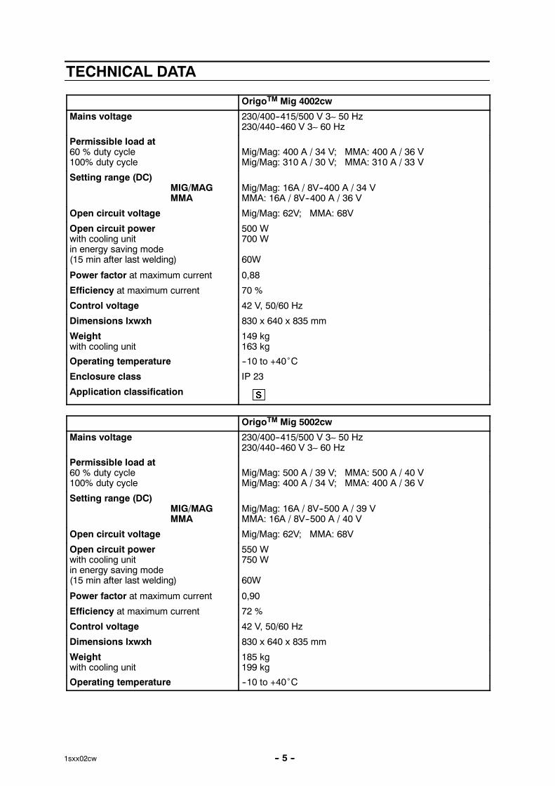
OrigoTM Mig 4002cw
Mains voltage 230/400--415/500 V 3∼ 50 Hz230/440--460 V 3∼ 60 Hz
Permissible load at60 % duty cycle100% duty cycle
Mig/Mag: 400 A / 34 V; MMA: 400 A / 36 VMig/Mag: 310 A / 30 V; MMA: 310 A / 33 V
Setting range (DC)MIG/MAGMMA
Mig/Mag: 16A / 8V--400 A / 34 VMMA: 16A / 8V--400 A / 36 V
Open circuit voltage Mig/Mag: 62V; MMA: 68V
Open circuit powerwith cooling unitin energy saving mode(15 min after last welding)
500 W700 W
60W
Power factor at maximum current 0,88
Efficiency at maximum current 70 %
Control voltage 42 V, 50/60 Hz
Dimensions lxwxh 830 x 640 x 835 mm
Weightwith cooling unit
149 kg163 kg
Operating temperature --10 to +40˚C
Enclosure class IP 23
Application classification
OrigoTM Mig 5002cw
Mains voltage 230/400--415/500 V 3∼ 50 Hz230/440--460 V 3∼ 60 Hz
Permissible load at60 % duty cycle100% duty cycle
Mig/Mag: 500 A / 39 V; MMA: 500 A / 40 VMig/Mag: 400 A / 34 V; MMA: 400 A / 36 V
Setting range (DC)MIG/MAGMMA
Mig/Mag: 16A / 8V--500 A / 39 VMMA: 16A / 8V--500 A / 40 V
Open circuit voltage Mig/Mag: 62V; MMA: 68V
Open circuit powerwith cooling unitin energy saving mode(15 min after last welding)
550 W750 W
60W
Power factor at maximum current 0,90
Efficiency at maximum current 72 %
Control voltage 42 V, 50/60 Hz
Dimensions lxwxh 830 x 640 x 835 mm
Weightwith cooling unit
185 kg199 kg
Operating temperature --10 to +40˚C
-- 6 --1sxx02cw
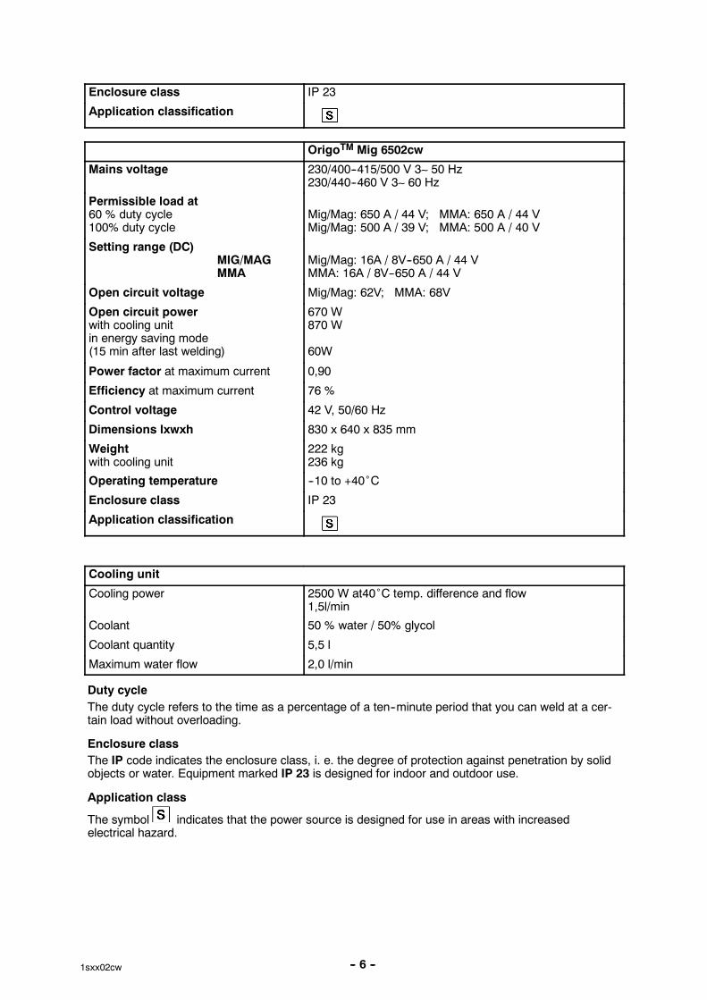
Enclosure class IP 23
Application classification
OrigoTM Mig 6502cw
Mains voltage 230/400--415/500 V 3∼ 50 Hz230/440--460 V 3∼ 60 Hz
Permissible load at60 % duty cycle100% duty cycle
Mig/Mag: 650 A / 44 V; MMA: 650 A / 44 VMig/Mag: 500 A / 39 V; MMA: 500 A / 40 V
Setting range (DC)MIG/MAGMMA
Mig/Mag: 16A / 8V--650 A / 44 VMMA: 16A / 8V--650 A / 44 V
Open circuit voltage Mig/Mag: 62V; MMA: 68V
Open circuit powerwith cooling unitin energy saving mode(15 min after last welding)
670 W870 W
60W
Power factor at maximum current 0,90
Efficiency at maximum current 76 %
Control voltage 42 V, 50/60 Hz
Dimensions lxwxh 830 x 640 x 835 mm
Weightwith cooling unit
222 kg236 kg
Operating temperature --10 to +40˚C
Enclosure class IP 23
Application classification
Cooling unit
Cooling power 2500 W at40˚C temp. difference and flow1,5l/min
Coolant 50 % water / 50% glycol
Coolant quantity 5,5 l
Maximum water flow 2,0 l/min
Duty cycleThe duty cycle refers to the time as a percentage of a ten--minute period that you can weld at a cer-tain load without overloading.
Enclosure classThe IP code indicates the enclosure class, i. e. the degree of protection against penetration by solidobjects or water. Equipment marked IP 23 is designed for indoor and outdoor use.
Application class
The symbol indicates that the power source is designed for use in areas with increasedelectrical hazard.

-- 7 --1sxx02cw
This page is left blank intentionally.

-- 8 --1sxx02cw
WIRING DIAGRAM
WARNING !STATIC ELECTRICITY can damage circuitboards and electronic components.���� Observe precautions for handling electrostatic
sensitive devices.
���� Use proper static--proof bags and boxes.ESD
Component description
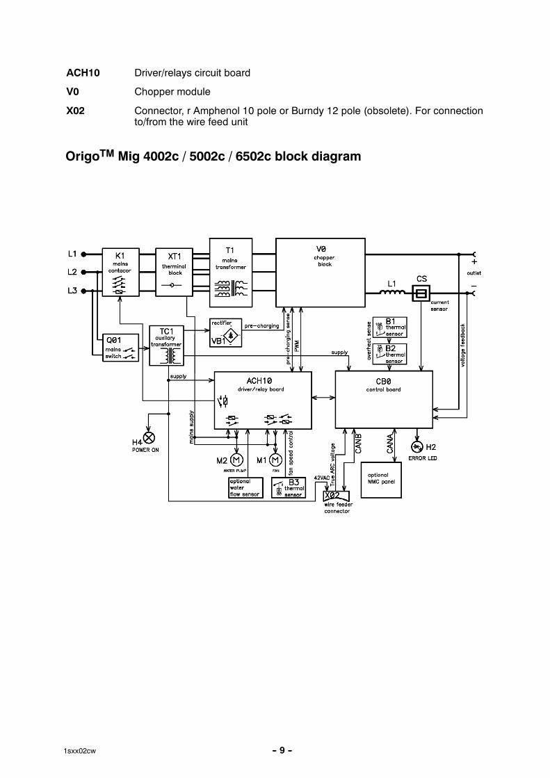
XT1 9 pole terminal block
PF20 Suppression circuit board
Q01 Main ON/OFF switch
K1 Main contactor
M1 Fan 230V 50Hz
M2 Pump motor, 230V 50Hz 0.2kW. Only machines with water cooler
C1 Capacitor, 6uF 250V, for reducing the speed of fan motor M1
C2 Capacitor, 3uF 400V. Start and run capacitor for fan motor M1
C3 -- C7 Suppression capacitors, 0,1uF 250V
C8 Snubber for K1 coil
H2 Orange indicating lamp, Error,overheating
H4 White indicating lamp, power supply ON
T1 Main transformer
TC1 Control power transformer
TC2 Transformer for CO2 heater. (an accessory, see an accessories listed inuser manual)
VB1 Rectifier
B1 Thermal switch. Protects the main transformer against excessivetemperature
B2 Thermal switch. Protects the chopper block against excessive temperature
B3 Thermal switch. Controls the speed of fan motor M1
CS Current sensor
R1 Resistor (pre--charging)
L1 Inductor
CB0 Control circuit board
-- 9 --1sxx02cw
ACH10 Driver/relays circuit board
V0 Chopper module
X02 Connector, r Amphenol 10 pole or Burndy 12 pole (obsolete). For connectionto/from the wire feed unit
OrigoTM Mig 4002c / 5002c / 6502c block diagram
-- 10 --1sxx02cw
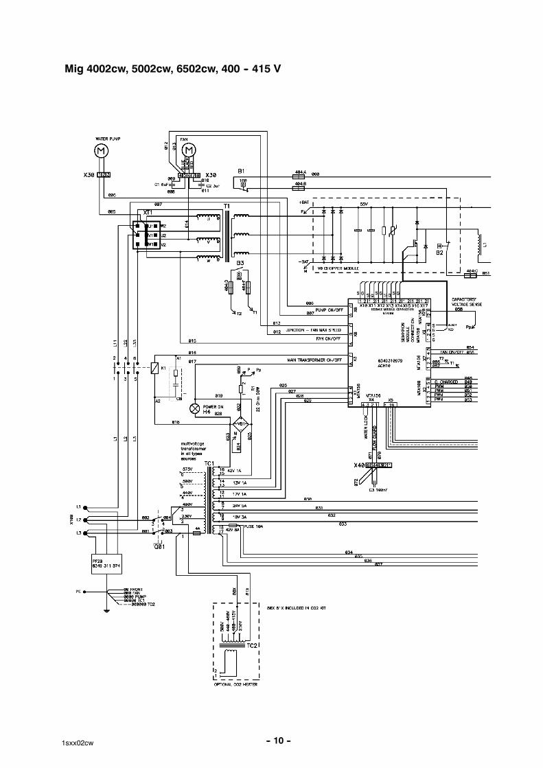
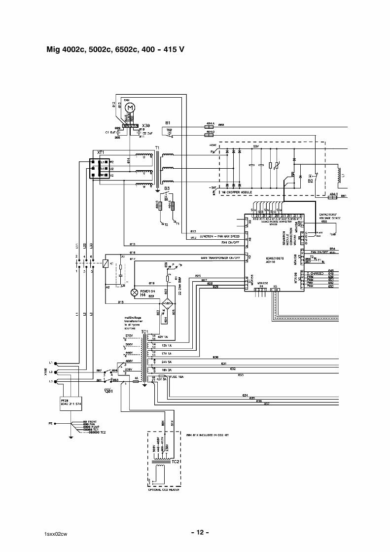
Mig 4002cw, 5002cw, 6502cw, 400 -- 415 V
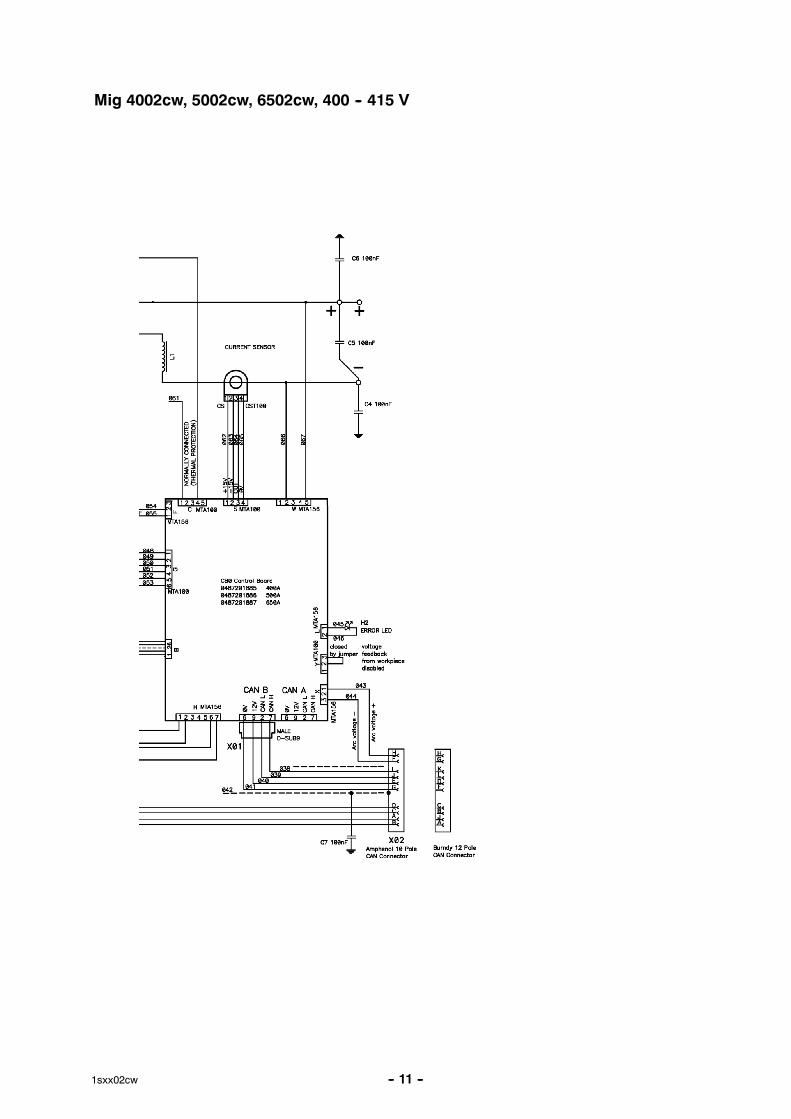
-- 11 --1sxx02cw
Mig 4002cw, 5002cw, 6502cw, 400 -- 415 V
-- 12 --1sxx02cw
Mig 4002c, 5002c, 6502c, 400 -- 415 V
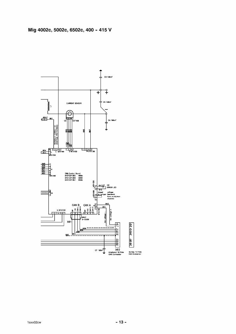
-- 13 --1sxx02cw
Mig 4002c, 5002c, 6502c, 400 -- 415 V
-- 14 --1sxx02cw
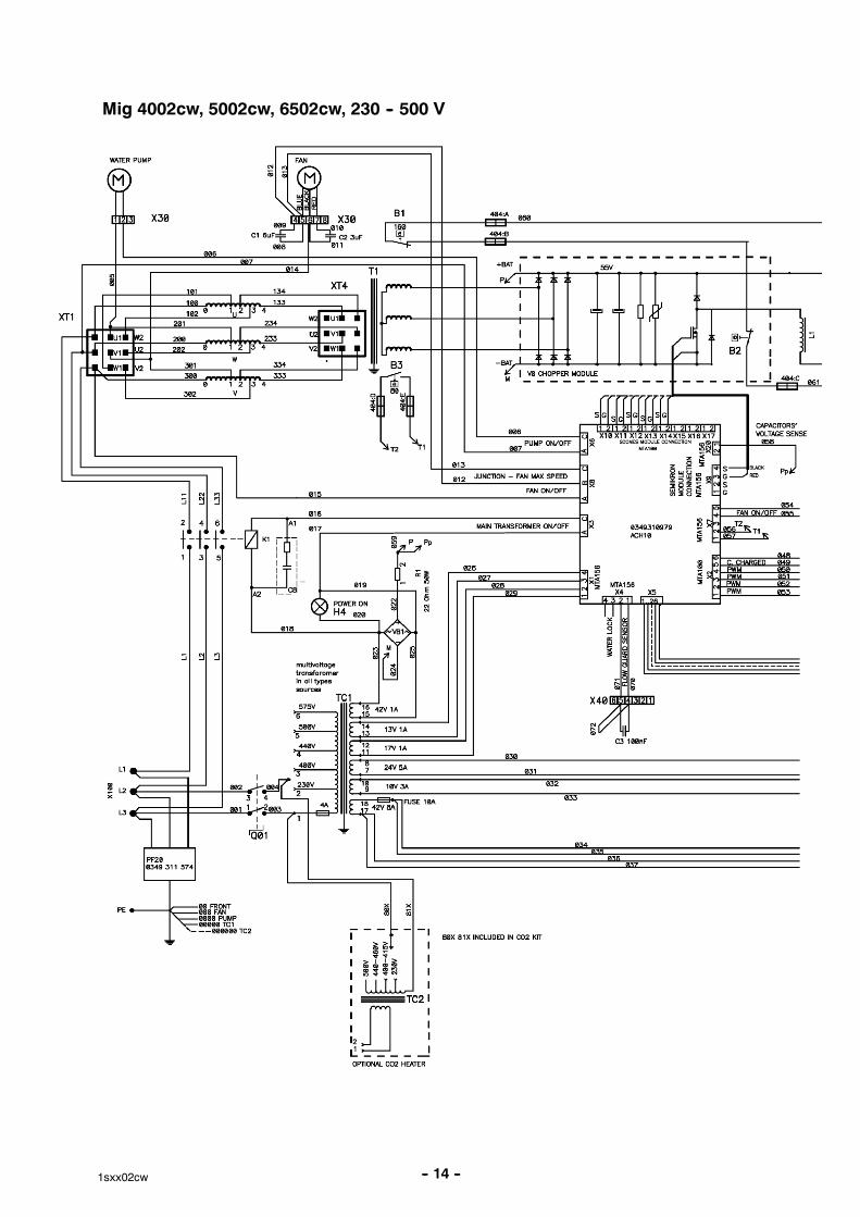
Mig 4002cw, 5002cw, 6502cw, 230 -- 500 V
-- 15 --1sxx02cw
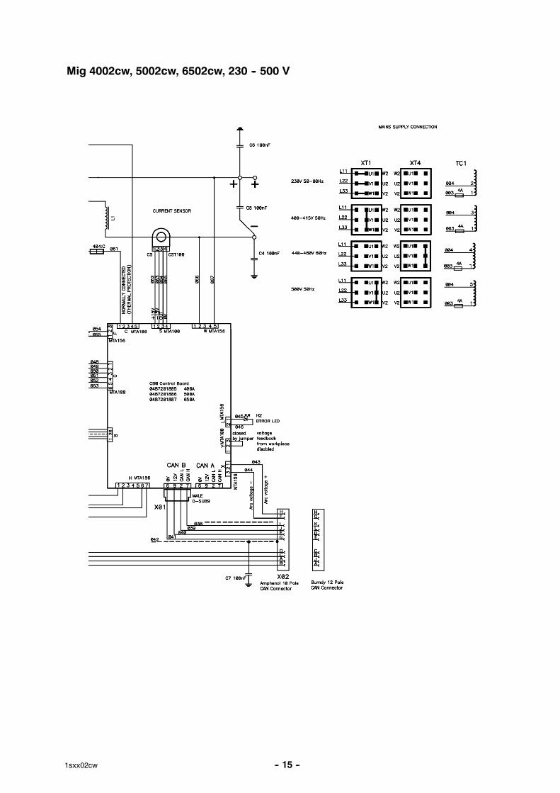
Mig 4002cw, 5002cw, 6502cw, 230 -- 500 V

-- 16 --1sxx02cw
Mig 4002c, 5002c, 6502c, 230 -- 500 V
-- 17 --1sxx02cw
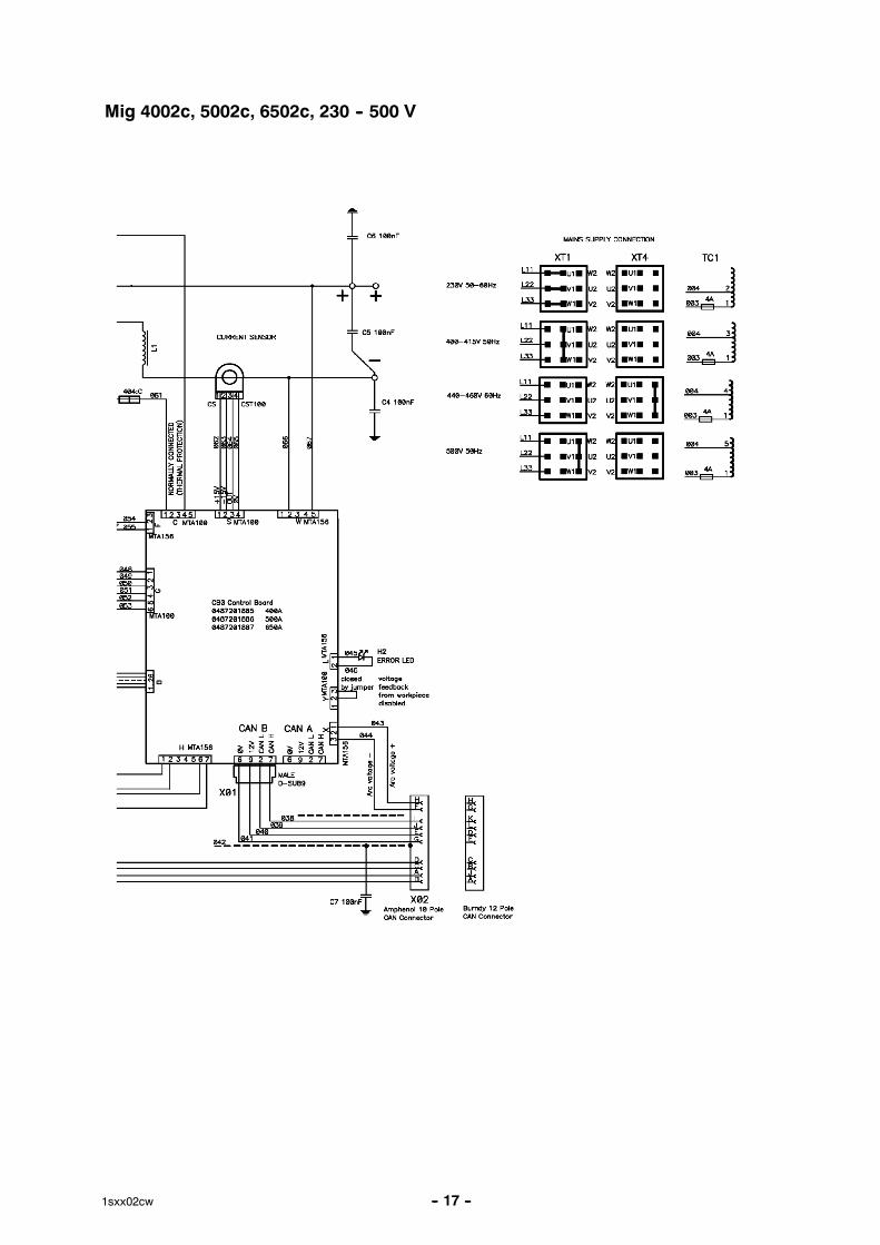
Mig 4002c, 5002c, 6502c, 230 -- 500 V
-- 18 --1sxx02cw
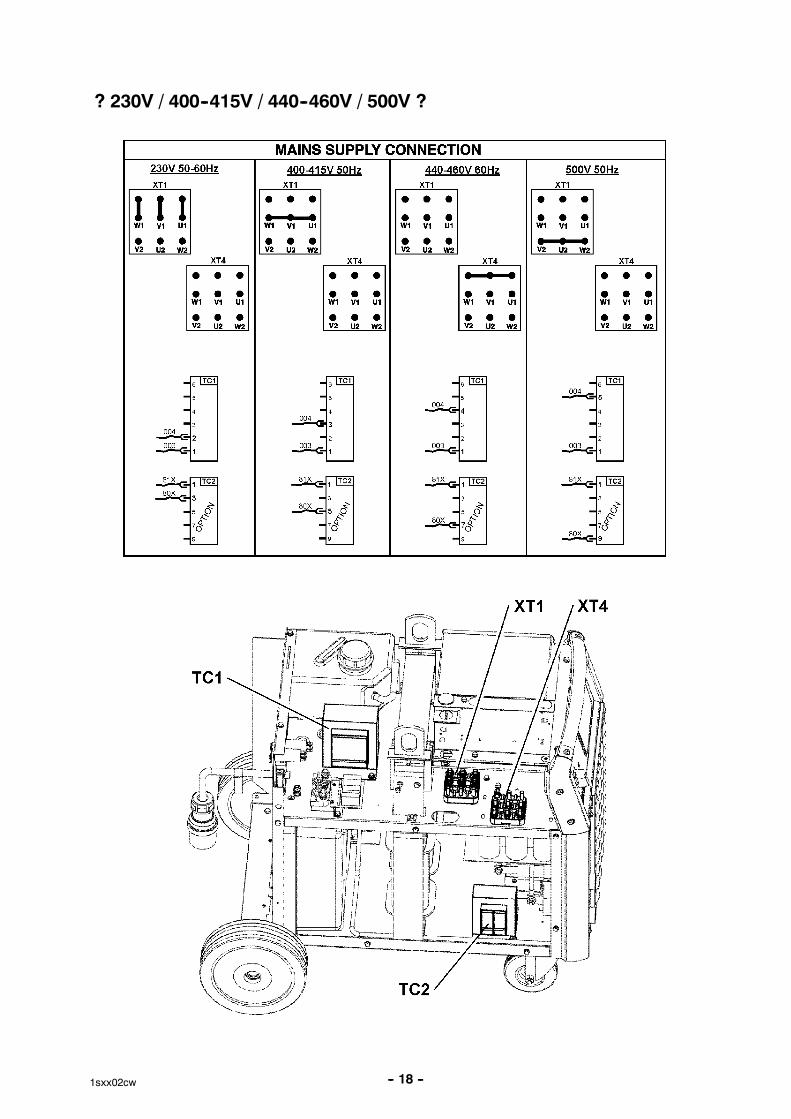
? 230V / 400--415V / 440--460V / 500V ?
-- 19 --1sxx02cw
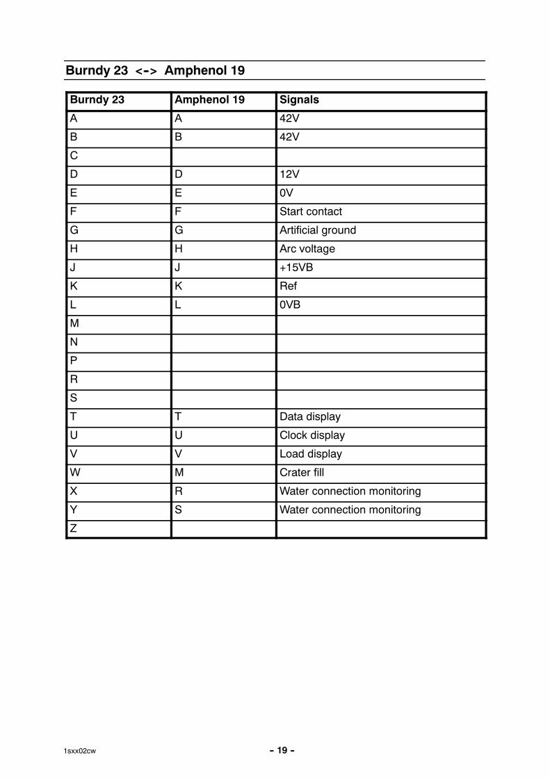
Burndy 23 <--> Amphenol 19
Burndy 23 Amphenol 19 Signals
A A 42V
B B 42V
C
D D 12V
E E 0V
F F Start contact
G G Artificial ground
H H Arc voltage
J J +15VB
K K Ref
L L 0VB
M
N
P
R
S
T T Data display
U U Clock display
V V Load display
W M Crater fill
X R Water connection monitoring
Y S Water connection monitoring
Z
-- 20 --1sxx02cw
DESCRIPTION OF OPERATION
CB0 Control circuit board
The processor on the control board monitors and controls the various functions of the powersource. It obtains information on welding data and welding processes from the welding databoard in the MMC control panel.
CB0:1 Circuit board identity
The control board has a machine ID, a hardware ID and a unit type number. Toread this you need the ESAT service kit. The machine ID defines which type ofpower source the board is intended for. The hardware ID shows design and type ofcircuit board. The unit type is used for identification on the CAN bus.
The ID numbers of the machines :
� OrigoTM Mig 4002c/cw: 38
� OrigoTM Mig 5002c/cw: 39
� OrigoTM Mig 6502c/cw: 40
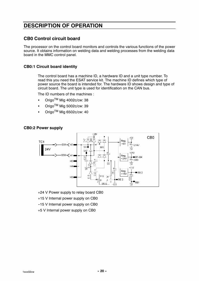
CB0:2 Power supply
+24 V Power supply to relay board CB0
+15 V Internal power supply on CB0
--15 V Internal power supply on CB0
+5 V Internal power supply on CB0
-- 21 --1sxx02cw
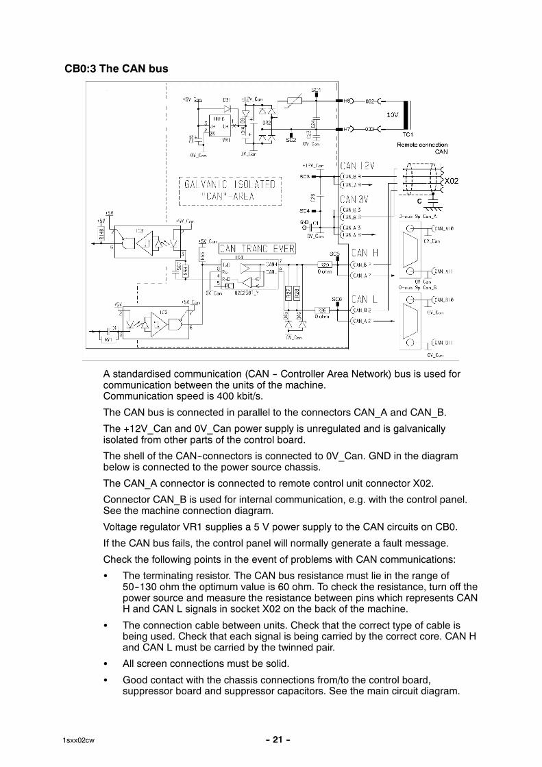
CB0:3 The CAN bus
A standardised communication (CAN -- Controller Area Network) bus is used forcommunication between the units of the machine.Communication speed is 400 kbit/s.
The CAN bus is connected in parallel to the connectors CAN_A and CAN_B.
The +12V_Can and 0V_Can power supply is unregulated and is galvanicallyisolated from other parts of the control board.
The shell of the CAN--connectors is connected to 0V_Can. GND in the diagrambelow is connected to the power source chassis.
The CAN_A connector is connected to remote control unit connector X02.
Connector CAN_B is used for internal communication, e.g. with the control panel.See the machine connection diagram.
Voltage regulator VR1 supplies a 5 V power supply to the CAN circuits on CB0.
If the CAN bus fails, the control panel will normally generate a fault message.
Check the following points in the event of problems with CAN communications:
� The terminating resistor. The CAN bus resistance must lie in the range of50--130 ohm the optimum value is 60 ohm. To check the resistance, turn off thepower source and measure the resistance between pins which represents CANH and CAN L signals in socket X02 on the back of the machine.
� The connection cable between units. Check that the correct type of cable isbeing used. Check that each signal is being carried by the correct core. CAN Hand CAN L must be carried by the twinned pair.
� All screen connections must be solid.
� Good contact with the chassis connections from/to the control board,suppressor board and suppressor capacitors. See the main circuit diagram.
-- 22 --1sxx02cw
Terminating resistors
In order to avoid communication interference, the ends of the CAN bus must beterminated by resistive loads.
One end of the CAN bus is at the control panel, which incorporates a terminatingresistor. The other end is in the power source and it must be fitted with aterminating resistor. If a CAN remote control with terminating resistor is connectedto the power source, the terminating resistor must be removed from the powersource.
The CAN remote controls and CAN adapters have a built--in terminating resistor.This resistor can be disconnected or connected by moving a jumper (See theservice manual for the CAN based remote controls, filename 0740 800 170).
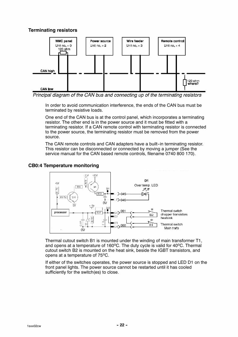
CB0:4 Temperature monitoring
Thermal cutout switch B1 is mounted under the winding of main transformer T1,and opens at a temperature of 160oC. The duty cycle is valid for 40oC. Thermalcutout switch B2 is mounted on the heat sink, beside the IGBT transistors, andopens at a temperature of 75oC.
If either of the switches operates, the power source is stopped and LED D1 on thefront panel lights. The power source cannot be restarted until it has cooledsufficiently for the switch(es) to close.
-- 23 --1sxx02cw
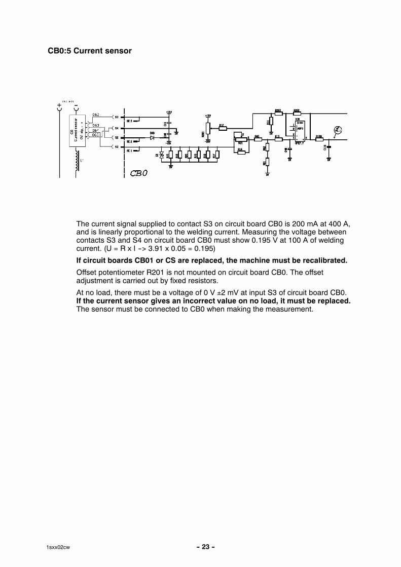
CB0:5 Current sensor
The current signal supplied to contact S3 on circuit board CB0 is 200 mA at 400 A,and is linearly proportional to the welding current. Measuring the voltage betweencontacts S3 and S4 on circuit board CB0 must show 0.195 V at 100 A of weldingcurrent. (U = R x I --> 3.91 x 0.05 = 0.195)
If circuit boards CB01 or CS are replaced, the machine must be recalibrated.
Offset potentiometer R201 is not mounted on circuit board CB0. The offsetadjustment is carried out by fixed resistors.
At no load, there must be a voltage of 0 V ±2 mV at input S3 of circuit board CB0.If the current sensor gives an incorrect value on no load, it must be replaced.The sensor must be connected to CB0 when making the measurement.
-- 24 --1sxx02cw
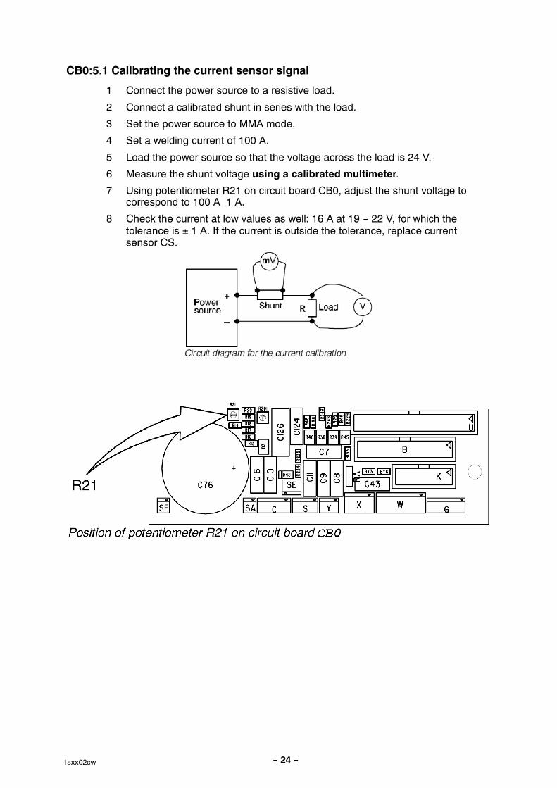
CB0:5.1 Calibrating the current sensor signal
1 Connect the power source to a resistive load.
2 Connect a calibrated shunt in series with the load.
3 Set the power source to MMA mode.
4 Set a welding current of 100 A.
5 Load the power source so that the voltage across the load is 24 V.
6 Measure the shunt voltage using a calibrated multimeter.
7 Using potentiometer R21 on circuit board CB0, adjust the shunt voltage tocorrespond to 100 A 1 A.
8 Check the current at low values as well: 16 A at 19 -- 22 V, for which thetolerance is ± 1 A. If the current is outside the tolerance, replace currentsensor CS.
-- 25 --1sxx02cw
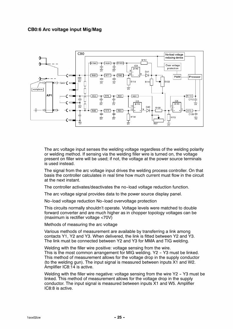
CB0:6 Arc voltage input Mig/Mag
The arc voltage input senses the welding voltage regardless of the welding polarityor welding method. If sensing via the welding filler wire is turned on, the voltagepresent on filler wire will be used; if not, the voltage at the power source terminalsis used instead.
The signal from the arc voltage input drives the welding process controller. On thatbasis the controller calculates in real time how much current must flow in the circuitat the next instant.
The controller activates/deactivates the no--load voltage reduction function.
The arc voltage signal provides data to the power source display panel.
No--load voltage reduction No--load overvoltage protection
This circuits normally shouldn’t operate. Voltage levels were matched to doubleforward converter and are much higher as in chopper topology voltages can be(maximum is rectifier voltage <70V)
Methods of measuring the arc voltage
Various methods of measurement are available by transferring a link amongcontacts Y1, Y2 and Y3. When delivered, the link is fitted between Y2 and Y3.The link must be connected between Y2 and Y3 for MMA and TIG welding.
Welding with the filler wire positive: voltage sensing from the wire.This is the most common arrangement for MIG welding. Y2 -- Y3 must be linked.This method of measurement allows for the voltage drop in the supply conductor(to the welding gun). The input signal is measured between inputs X1 and W2.Amplifier IC8:14 is active.
Welding with the filler wire negative: voltage sensing from the wire Y2 -- Y3 must belinked. This method of measurement allows for the voltage drop in the supplyconductor. The input signal is measured between inputs X1 and W5. AmplifierIC8:8 is active.
-- 26 --1sxx02cw
Welding with the filler wire positive or negative, without external sensing from thewire or workpiece. Y2 -- Y3 must be linked. The input signal is measured betweeninputs W5 and W2 (the voltage at the power source terminals), as there is noconnection to X1. Amplifier IC8:14 is active.
Welding with the filler wire positive: voltage sensing from the wire and workpiece.Y1 and Y2 must be linked. This method allows for the voltage drop on both thesupply and return conductors. The input signal is measured between X1 and X3.Amplifier IC8:14 is active.
Note: If the voltage signal connection to X3 is lost, the power source losescontrol of the arc voltage.
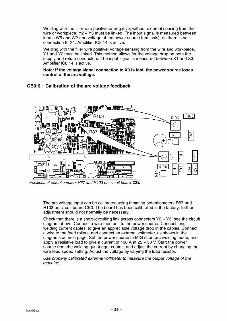
CB0:6.1 Calibration of the arc voltage feedback
The arc voltage input can be calibrated using trimming potentiometers R87 andR103 on circuit board CB0. The board has been calibrated in the factory: furtheradjustment should not normally be necessary.
Check that there is a short--circuiting link across connectors Y2 -- Y3: see the circuitdiagram above. Connect a wire feed unit to the power source. Connect longwelding current cables, to give an appreciable voltage drop in the cables. Connecta wire to the feed rollers, and connect an external voltmeter, as shown in thediagrams on next page. Set the power source to MIG short arc welding mode, andapply a resistive load to give a current of 100 A at 25 -- 30 V. Start the powersource from the welding gun trigger contact and adjust the current by changing thewire feed speed setting. Adjust the voltage by varying the load resistor.
Use properly calibrated external voltmeter to measure the output voltage of themachine.
-- 27 --1sxx02cw
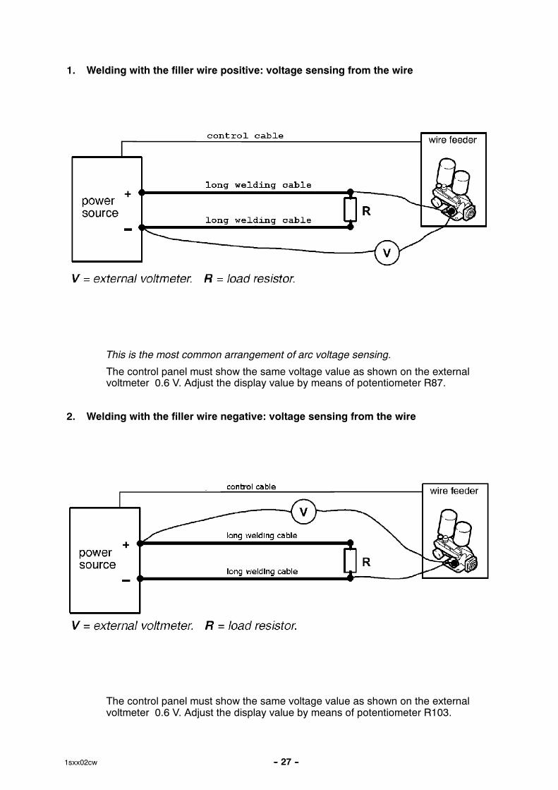
1. Welding with the filler wire positive: voltage sensing from the wire
This is the most common arrangement of arc voltage sensing.
The control panel must show the same voltage value as shown on the externalvoltmeter 0.6 V. Adjust the display value by means of potentiometer R87.
2. Welding with the filler wire negative: voltage sensing from the wire
The control panel must show the same voltage value as shown on the externalvoltmeter 0.6 V. Adjust the display value by means of potentiometer R103.
-- 28 --1sxx02cw
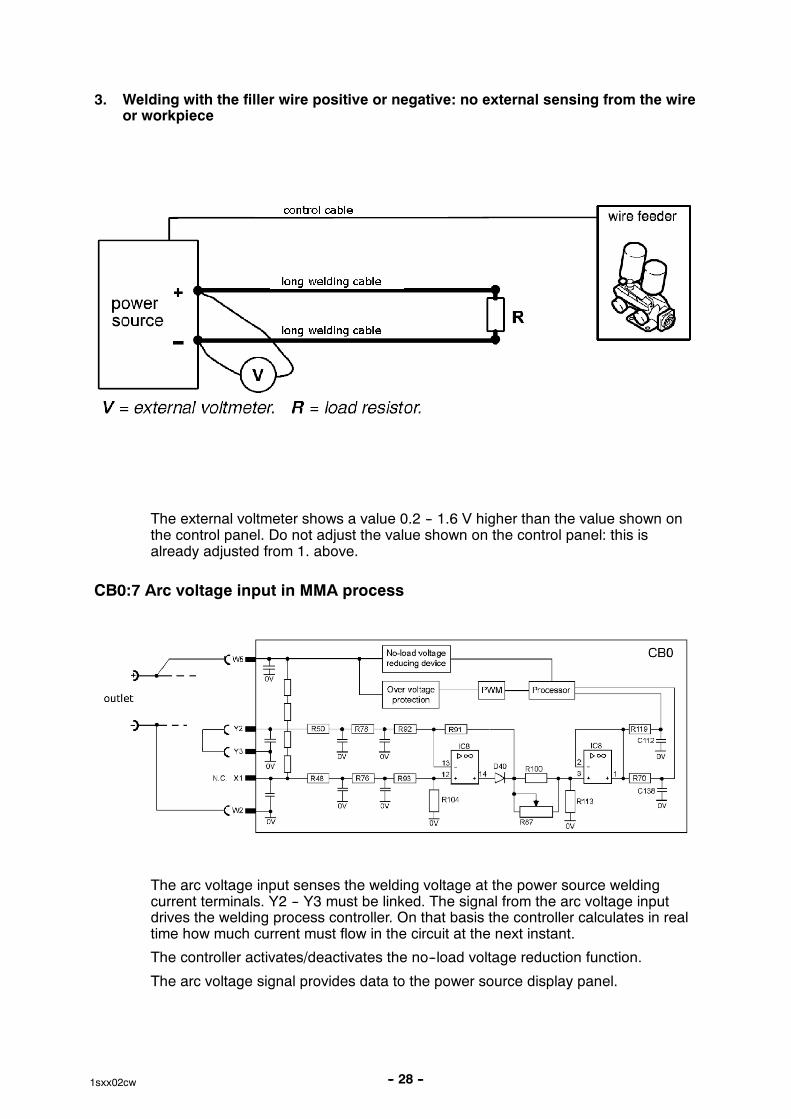
3. Welding with the filler wire positive or negative: no external sensing from the wireor workpiece
The external voltmeter shows a value 0.2 -- 1.6 V higher than the value shown onthe control panel. Do not adjust the value shown on the control panel: this isalready adjusted from 1. above.
CB0:7 Arc voltage input in MMA process
The arc voltage input senses the welding voltage at the power source weldingcurrent terminals. Y2 -- Y3 must be linked. The signal from the arc voltage inputdrives the welding process controller. On that basis the controller calculates in realtime how much current must flow in the circuit at the next instant.
The controller activates/deactivates the no--load voltage reduction function.
The arc voltage signal provides data to the power source display panel.
-- 29 --1sxx02cw
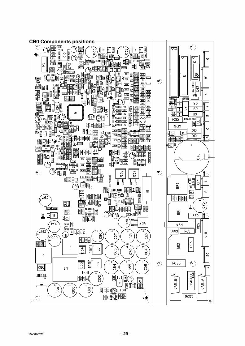
CB0 Components positions
-- 30 --1sxx02cw
ACH10 Driver/relays board
That board co--operates with CB0 and realises following functions:
� driving transistors in chopper module
� monitoring of voltage across capacitors in chopper module
� driving cooling fan, water pump, and mains relay.
All function units are described below.
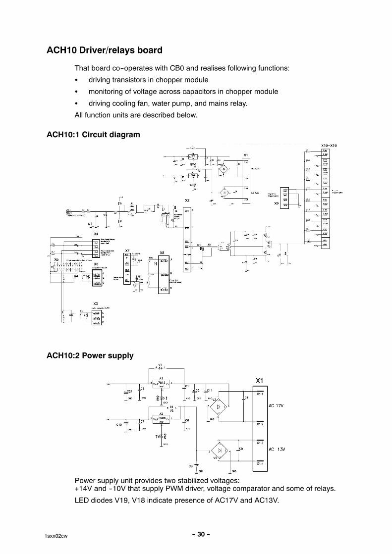
ACH10:1 Circuit diagram
ACH10:2 Power supply
Power supply unit provides two stabilized voltages:+14V and --10V that supply PWM driver, voltage comparator and some of relays.
LED diodes V19, V18 indicate presence of AC17V and AC13V.
-- 31 --1sxx02cw
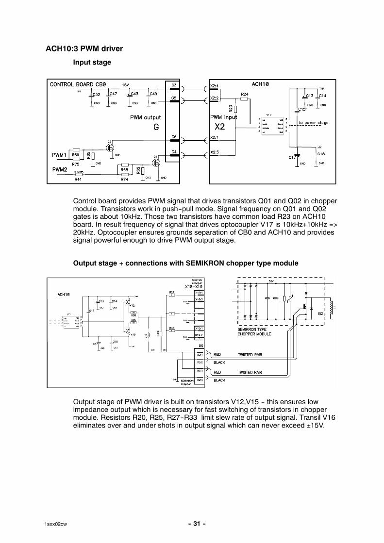
ACH10:3 PWM driver
Input stage
Control board provides PWM signal that drives transistors Q01 and Q02 in choppermodule. Transistors work in push--pull mode. Signal frequency on Q01 and Q02gates is about 10kHz. Those two transistors have common load R23 on ACH10board. In result frequency of signal that drives optocoupler V17 is 10kHz+10kHz =>20kHz. Optocoupler ensures grounds separation of CB0 and ACH10 and providessignal powerful enough to drive PWM output stage.
Output stage + connections with SEMIKRON chopper type module
Output stage of PWM driver is built on transistors V12,V15 -- this ensures lowimpedance output which is necessary for fast switching of transistors in choppermodule. Resistors R20, R25, R27--R33 limit slew rate of output signal. Transil V16eliminates over and under shots in output signal which can never exceed ±15V.
-- 32 --1sxx02cw
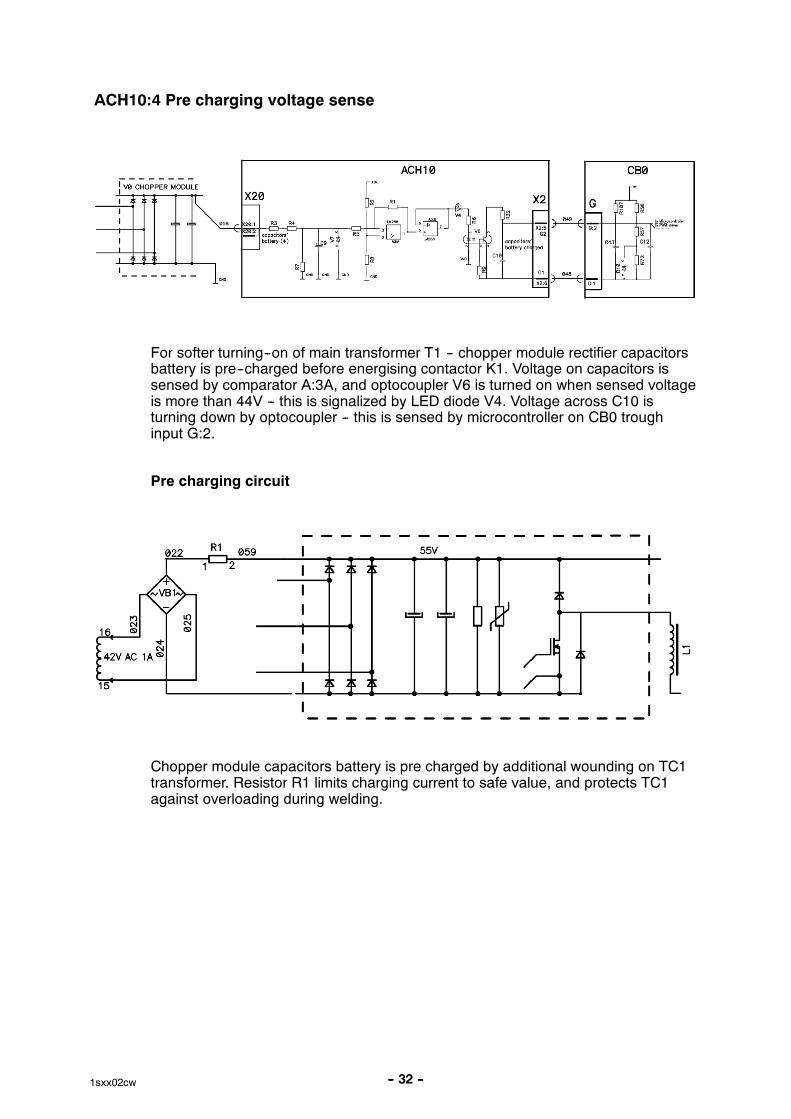
ACH10:4 Pre charging voltage sense
For softer turning--on of main transformer T1 -- chopper module rectifier capacitorsbattery is pre--charged before energising contactor K1. Voltage on capacitors issensed by comparator A:3A, and optocoupler V6 is turned on when sensed voltageis more than 44V -- this is signalized by LED diode V4. Voltage across C10 isturning down by optocoupler -- this is sensed by microcontroller on CB0 troughinput G:2.
Pre charging circuit
Chopper module capacitors battery is pre charged by additional wounding on TC1transformer. Resistor R1 limits charging current to safe value, and protects TC1against overloading during welding.
-- 33 --1sxx02cw
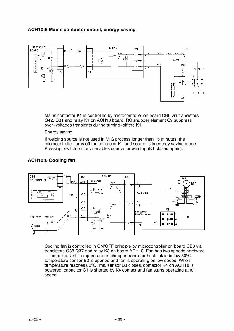
ACH10:5 Mains contactor circuit, energy saving
Mains contactor K1 is controlled by microcontroller on board CB0 via transistorsQ42, Q31 and relay K1 on ACH10 board. RC snubber element C9 suppressover--voltages transients during turning--off the K1.
Energy saving
If welding source is not used in MIG process longer than 15 minutes, themicrocontroller turns off the contactor K1 and source is in energy saving mode.Pressing switch on torch enables source for welding (K1 closed again).
ACH10:6 Cooling fan
Cooling fan is controlled in ON/OFF principle by microcontroller on board CB0 viatransistors Q38,Q37 and relay K3 on board ACH10. Fan has two speeds hardware-- controlled. Until temperature on chopper transistor heatsink is below 80oCtemperature sensor B3 is opened and fan is operating on low speed. Whentemperature reaches 80oC limit, sensor B3 closes, contactor K4 on ACH10 ispowered, capacitor C1 is shorted by K4 contact and fan starts operating at fullspeed.
-- 34 --1sxx02cw
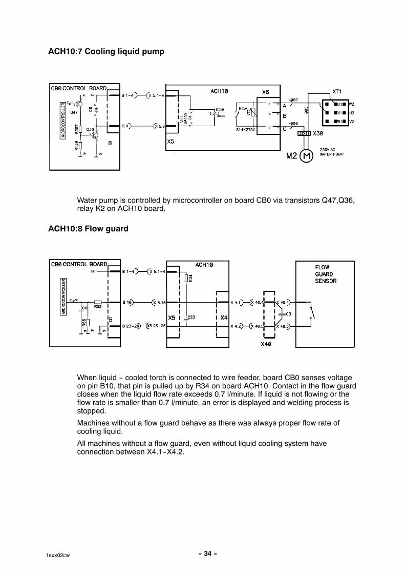
ACH10:7 Cooling liquid pump
Water pump is controlled by microcontroller on board CB0 via transistors Q47,Q36,relay K2 on ACH10 board.
ACH10:8 Flow guard
When liquid -- cooled torch is connected to wire feeder, board CB0 senses voltageon pin B10, that pin is pulled up by R34 on board ACH10. Contact in the flow guardcloses when the liquid flow rate exceeds 0.7 l/minute. If liquid is not flowing or theflow rate is smaller than 0.7 l/minute, an error is displayed and welding process isstopped.
Machines without a flow guard behave as there was always proper flow rate ofcooling liquid.
All machines without a flow guard, even without liquid cooling system haveconnection between X4.1--X4.2.
-- 35 --1sxx02cw
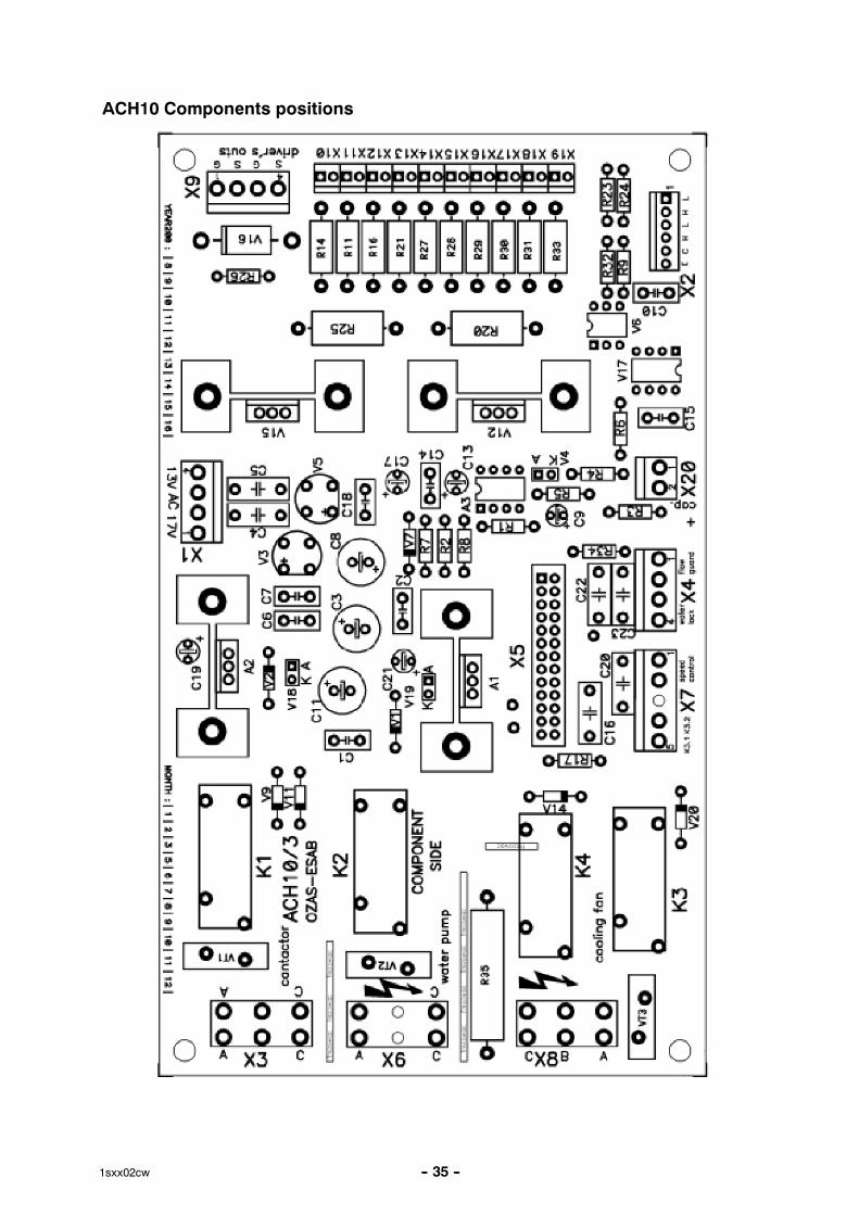
ACH10 Components positions
-- 36 --1sxx02cw
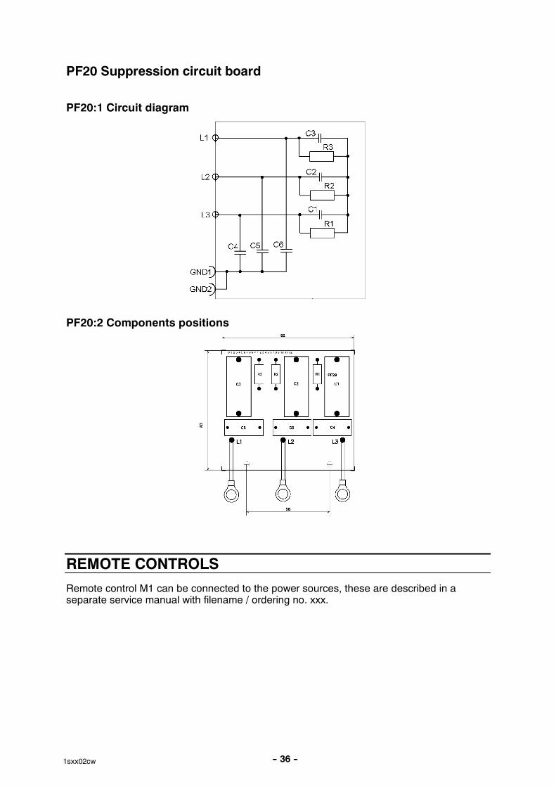
PF20 Suppression circuit board
PF20:1 Circuit diagram
PF20:2 Components positions
REMOTE CONTROLS
Remote control M1 can be connected to the power sources, these are described in aseparate service manual with filename / ordering no. xxx.
-- 37 --1sxx02cw
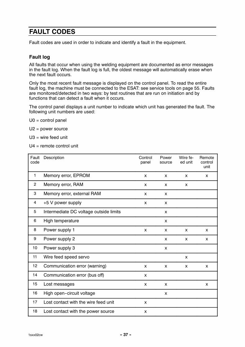
FAULT CODES
Fault codes are used in order to indicate and identify a fault in the equipment.
Fault log
All faults that occur when using the welding equipment are documented as error messagesin the fault log. When the fault log is full, the oldest message will automatically erase whenthe next fault occurs.
Only the most recent fault message is displayed on the control panel. To read the entirefault log, the machine must be connected to the ESAT: see service tools on page 55. Faultsare monitored/detected in two ways: by test routines that are run on initiation and byfunctions that can detect a fault when it occurs.
The control panel displays a unit number to indicate which unit has generated the fault. Thefollowing unit numbers are used:
U0 = control panel
U2 = power source
U3 = wire feed unit
U4 = remote control unit
Faultcode
Description Controlpanel
Powersource
Wire fe-ed unit
Remotecontrolunit
1 Memory error, EPROM x x x x
2 Memory error, RAM x x x
3 Memory error, external RAM x x
4 +5 V power supply x x
5 Intermediate DC voltage outside limits x
6 High temperature x
8 Power supply 1 x x x x
9 Power supply 2 x x x
10 Power supply 3 x
11 Wire feed speed servo x
12 Communication error (warning) x x x x
14 Communication error (bus off) x
15 Lost messages x x x
16 High open--circuit voltage x
17 Lost contact with the wire feed unit x
18 Lost contact with the power source x
-- 38 --1sxx02cw
Faultcode
Remotecontrolunit
Wire fe-ed unit
Powersource
Controlpanel
Description
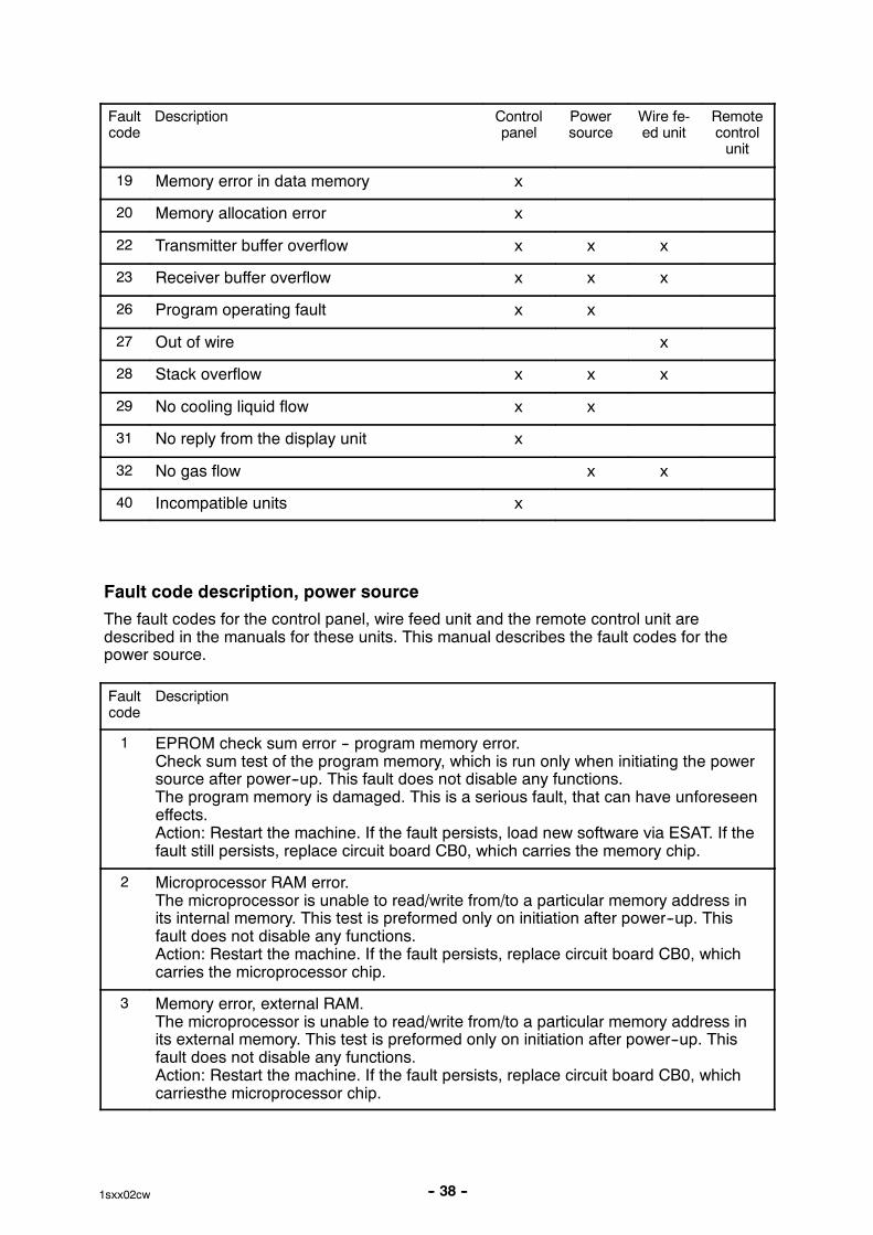
19 Memory error in data memory x
20 Memory allocation error x
22 Transmitter buffer overflow x x x
23 Receiver buffer overflow x x x
26 Program operating fault x x
27 Out of wire x
28 Stack overflow x x x
29 No cooling liquid flow x x
31 No reply from the display unit x
32 No gas flow x x
40 Incompatible units x
Fault code description, power source
The fault codes for the control panel, wire feed unit and the remote control unit aredescribed in the manuals for these units. This manual describes the fault codes for thepower source.
Faultcode
Description
1 EPROM check sum error -- program memory error.Check sum test of the program memory, which is run only when initiating the powersource after power--up. This fault does not disable any functions.The program memory is damaged. This is a serious fault, that can have unforeseeneffects.Action: Restart the machine. If the fault persists, load new software via ESAT. If thefault still persists, replace circuit board CB0, which carries the memory chip.
2 Microprocessor RAM error.The microprocessor is unable to read/write from/to a particular memory address inits internal memory. This test is preformed only on initiation after power--up. Thisfault does not disable any functions.Action: Restart the machine. If the fault persists, replace circuit board CB0, whichcarries the microprocessor chip.
3 Memory error, external RAM.The microprocessor is unable to read/write from/to a particular memory address inits external memory. This test is preformed only on initiation after power--up. Thisfault does not disable any functions.Action: Restart the machine. If the fault persists, replace circuit board CB0, whichcarriesthe microprocessor chip.
-- 39 --1sxx02cw
Faultcode
Description
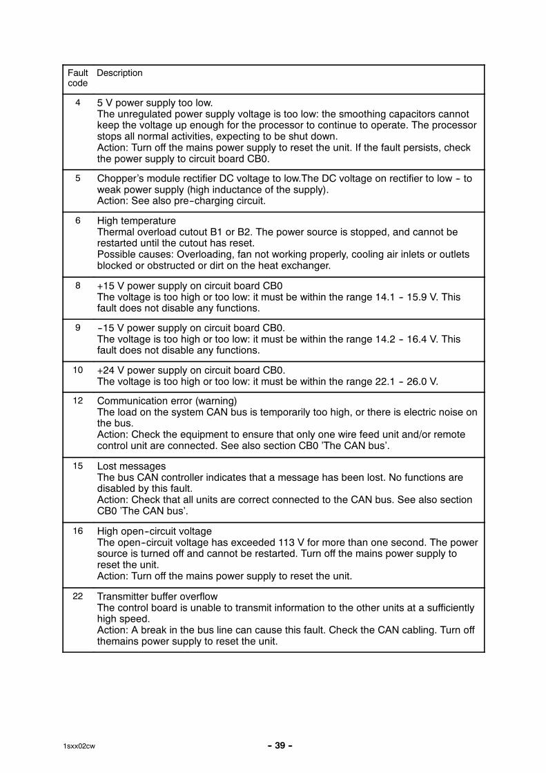
4 5 V power supply too low.The unregulated power supply voltage is too low: the smoothing capacitors cannotkeep the voltage up enough for the processor to continue to operate. The processorstops all normal activities, expecting to be shut down.Action: Turn off the mains power supply to reset the unit. If the fault persists, checkthe power supply to circuit board CB0.
5 Chopper’s module rectifier DC voltage to low.The DC voltage on rectifier to low -- toweak power supply (high inductance of the supply).Action: See also pre--charging circuit.
6 High temperatureThermal overload cutout B1 or B2. The power source is stopped, and cannot berestarted until the cutout has reset.Possible causes: Overloading, fan not working properly, cooling air inlets or outletsblocked or obstructed or dirt on the heat exchanger.
8 +15 V power supply on circuit board CB0The voltage is too high or too low: it must be within the range 14.1 -- 15.9 V. Thisfault does not disable any functions.
9 --15 V power supply on circuit board CB0.The voltage is too high or too low: it must be within the range 14.2 -- 16.4 V. Thisfault does not disable any functions.
10 +24 V power supply on circuit board CB0.The voltage is too high or too low: it must be within the range 22.1 -- 26.0 V.
12 Communication error (warning)The load on the system CAN bus is temporarily too high, or there is electric noise onthe bus.Action: Check the equipment to ensure that only one wire feed unit and/or remotecontrol unit are connected. See also section CB0 ’The CAN bus’.
15 Lost messagesThe bus CAN controller indicates that a message has been lost. No functions aredisabled by this fault.Action: Check that all units are correct connected to the CAN bus. See also sectionCB0 ’The CAN bus’.
16 High open--circuit voltageThe open--circuit voltage has exceeded 113 V for more than one second. The powersource is turned off and cannot be restarted. Turn off the mains power supply toreset the unit.Action: Turn off the mains power supply to reset the unit.
22 Transmitter buffer overflowThe control board is unable to transmit information to the other units at a sufficientlyhigh speed.Action: A break in the bus line can cause this fault. Check the CAN cabling. Turn offthemains power supply to reset the unit.
-- 40 --1sxx02cw
Faultcode
Description
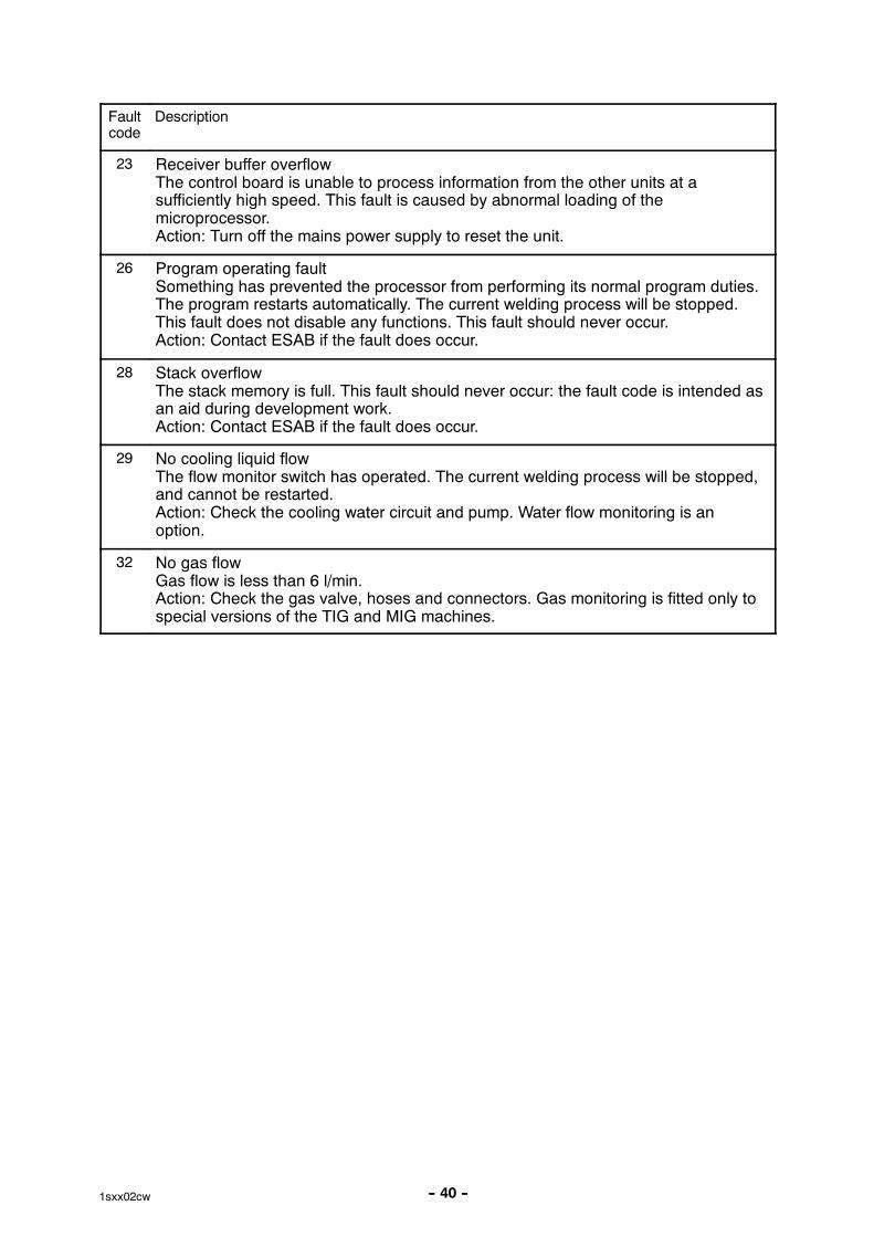
23 Receiver buffer overflowThe control board is unable to process information from the other units at asufficiently high speed. This fault is caused by abnormal loading of themicroprocessor.Action: Turn off the mains power supply to reset the unit.
26 Program operating faultSomething has prevented the processor from performing its normal program duties.The program restarts automatically. The current welding process will be stopped.This fault does not disable any functions. This fault should never occur.Action: Contact ESAB if the fault does occur.
28 Stack overflowThe stack memory is full. This fault should never occur: the fault code is intended asan aid during development work.Action: Contact ESAB if the fault does occur.
29 No cooling liquid flowThe flow monitor switch has operated. The current welding process will be stopped,and cannot be restarted.Action: Check the cooling water circuit and pump. Water flow monitoring is anoption.
32 No gas flowGas flow is less than 6 l/min.Action: Check the gas valve, hoses and connectors. Gas monitoring is fitted only tospecial versions of the TIG and MIG machines.

-- 41 --1sxx02cw
SERVICE INSTRUCTIONS
What is ESD?
A sudden transfer or discharge of static electricity from one object to another. ESD stands forElectrostatic Discharge.
How does ESD damage occur?
ESD can cause damage to sensitive electrical components, but is not dangerous to people.ESD damage occurs when an ungrounded person or object with a static charge comes intocontact with a component or assembly that is grounded. A rapid discharge can occur,causing damage. This damage can take the form of immediate failure, but it is more likelythat system performance will be affected and the component will fail prematurely.
How do we prevent ESD damage?
ESD damage can be prevented by awareness. If static electricity is prevented from buildingup on you or on anything at your work station, then there cannot be any static discharges.Nonconductive materials (e.g. fabrics), or insulators (e.g. plastics) generate and hold staticcharge, so you should not bring unnecessary nonconductive items into the work area.It is obviously difficult to avoid all such items, so various means are used to drain off anystatic discharge from persons to prevent the risk of ESD damage. This is done by simpledevices: wrist straps, connected to ground, and conductive shoes.
Work surfaces, carts and containers must be conductive and grounded, use only antistaticpackaging materials. Overall, handling of ESD--sensitive devices should be minimized toprevent damage.
WARNING !STATIC ELECTRICITY can damage circuitboards and electronic components.���� Observe precautions for handling electrostatic
sensitive devices.
���� Use proper static--proof bags and boxes.ESD
-- 42 --1sxx02cw
Service aid
We can offer a number of service tools that will simplify the service.
ESAB Administration Tool (ESAT)
Ordering no. 0458 847 880
ESAB Administration Tool (ESAT) is software that provides possibility of updating thesoftware in power source. ESAT contains also service functions by which it is possible tocontrol, change or read the different functions in the equipment.
For the installation and use of ESAT a computer with operating system Windows 9x, NT4,2000 or XP is needed.
Contents:
� CAN adapter MECEL PPCAN
� Connection Cable between CAN adapter and power source
� CAN adapter software
� ESAT software
� Instruction manual for Esat
CAN supply service kit
Ordering no. 0349 310 369
As the OrigoTM Mig 400t/500t don’t have external CAN connector and the CAN interface isnot internally supplied, the CAN supply service kit is needed.
Contents:
� transformer 230V/9V,
� cable 9 DSUB male--female
To make an update of the system, you will also need an application program upgrade. Thisprogram will be sent to registered ESAT users by e--mail or be downloaded from ESAB website. ESAT has it’s own instruction manual 0458 885 174.
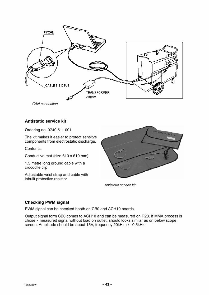
Assuming previous installation of ESAT software in the computer, disconnect the machinefrom mains and remove the left side cover to achieve connectors on the PC boards (seedrawing). Connect the CAN supplying transformer to W socket and connect the 9--9 DSUBcable to CAN_A or CAN_B DSUB connector. Connect the other side of cable to the parallelport of the PC via PPCAN adapter.
-- 43 --1sxx02cw
CAN connection
Antistatic service kit
Ordering no. 0740 511 001
The kit makes it easier to protect sensitvecomponents from electrostatic discharge.
Contents:
Conductive mat (size 610 x 610 mm)
1.5 metre long ground cable with acrocodile clip
Adjustable wrist strap and cable withinbuilt protective resistor
Antistatic service kit
Checking PWM signal
PWM signal can be checked booth on CB0 and ACH10 boards.
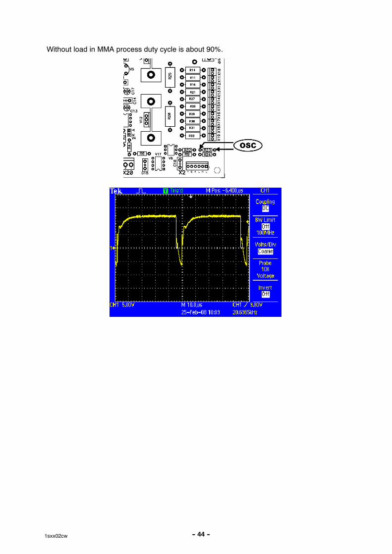
Output signal form CB0 comes to ACH10 and can be measured on R23. If MMA process ischose -- measured signal without load on outlet, should looks similar as on below scopescreen. Amplitude should be about 15V, frequency 20kHz +/ --0,5kHz.
-- 44 --1sxx02cw
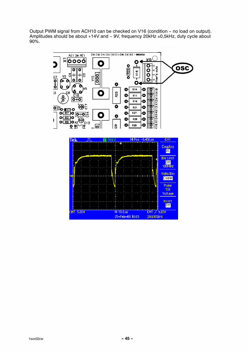
Without load in MMA process duty cycle is about 90%.
-- 45 --1sxx02cw
Output PWM signal from ACH10 can be checked on V16 (condition -- no load on output).Amplitudes should be about +14V and -- 9V, frequency 20kHz ±0,5kHz, duty cycle about90%.
-- 46 --1sxx02cw
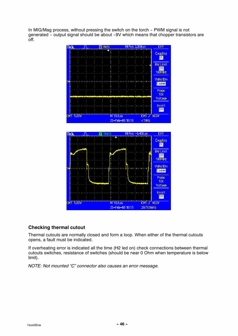
In MIG/Mag process, without pressing the switch on the torch -- PWM signal is notgenerated -- output signal should be about --9V which means that chopper transistors areoff.
Checking thermal cutout
Thermal cutouts are normally closed and form a loop. When either of the thermal cutoutsopens, a fault must be indicated.
If overheating error is indicated all the time (H2 led on) check connections between thermalcutouts switches, resistance of switches (should be near 0 Ohm when temperature is belowlimit).
NOTE: Not mounted “C” connector also causes an error message.
-- 47 --1sxx02cw
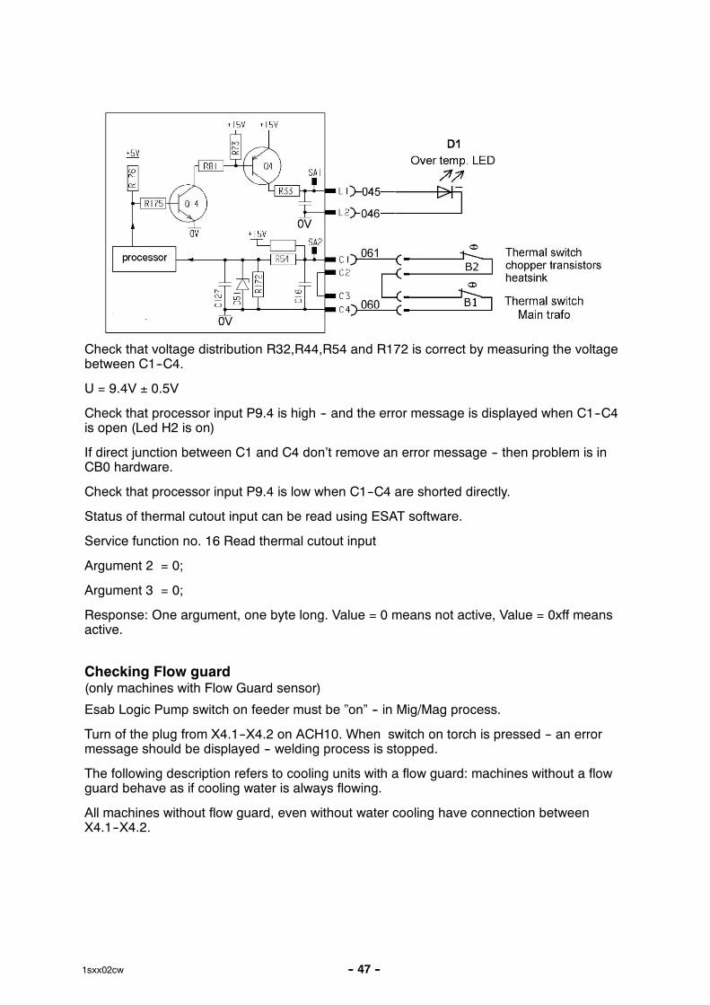
Check that voltage distribution R32,R44,R54 and R172 is correct by measuring the voltagebetween C1--C4.
U = 9.4V ± 0.5V
Check that processor input P9.4 is high -- and the error message is displayed when C1--C4is open (Led H2 is on)
If direct junction between C1 and C4 don’t remove an error message -- then problem is inCB0 hardware.
Check that processor input P9.4 is low when C1--C4 are shorted directly.
Status of thermal cutout input can be read using ESAT software.
Service function no. 16 Read thermal cutout input
Argument 2 = 0;
Argument 3 = 0;
Response: One argument, one byte long. Value = 0 means not active, Value = 0xff meansactive.
Checking Flow guard(only machines with Flow Guard sensor)
Esab Logic Pump switch on feeder must be ”on” -- in Mig/Mag process.
Turn of the plug from X4.1--X4.2 on ACH10. When switch on torch is pressed -- an errormessage should be displayed -- welding process is stopped.
The following description refers to cooling units with a flow guard: machines without a flowguard behave as if cooling water is always flowing.
All machines without flow guard, even without water cooling have connection betweenX4.1--X4.2.

-- 48 --1sxx02cw
Checking pre charging circuit
After few second from turning the power on led diode V4 should light up, and contactor K1should switch on.
If not, an error message should be displayed (error nr 5). Check the pre--charging circuit , Ifvoltage on chopper capacitors is more than 45V V4 should light on. Check voltage on pinA3:A in reference to GND -- should be more than 7.5V. If V4 led light on, but error is stilldisplayed check voltage between X2.5--X2.6, should be less than 1V.
Checking Fan Circuit
Fan should operates during all processes. Turning on also can be done by ESAT software:
Service function 13.
Argument 2 = 0, Fan off
Argument 2 = 0xFF, Fan full speed
If fan is on the voltage between X7:4 and X7:2 should be about 24V.
Be Careful! High Mains Voltage is on X8 connector.
When fan is off voltage between X8:A -- X8:B should be about 230V
When on -- 0V
High speed is on when temperature sensor B3 closes -- working of that circuit can bechecked by shorting X7:2--X7:1 -- then K4 closes and fan operates on high speed. When
-- 49 --1sxx02cw
speed is low, temperature sensor B3 is open -- voltage between X7:2--X7:1 should beabout 13V.
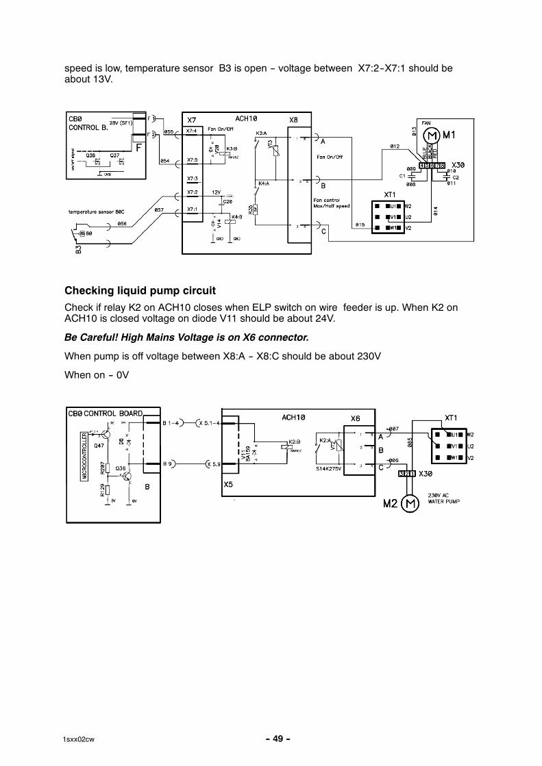
Checking liquid pump circuit
Check if relay K2 on ACH10 closes when ELP switch on wire feeder is up. When K2 onACH10 is closed voltage on diode V11 should be about 24V.
Be Careful! High Mains Voltage is on X6 connector.
When pump is off voltage between X8:A -- X8:C should be about 230V
When on -- 0V
-- 50 --1sxx02cw
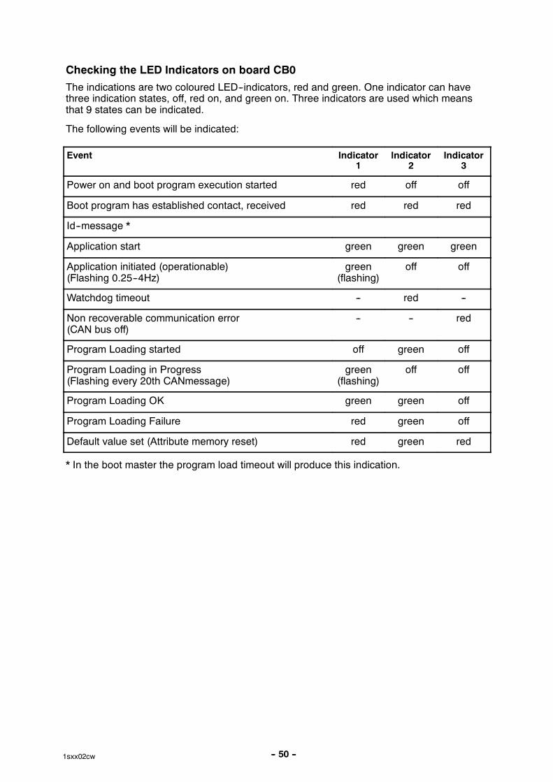
Checking the LED Indicators on board CB0
The indications are two coloured LED--indicators, red and green. One indicator can havethree indication states, off, red on, and green on. Three indicators are used which meansthat 9 states can be indicated.
The following events will be indicated:
Event Indicator1
Indicator2
Indicator3
Power on and boot program execution started red off off
Boot program has established contact, received red red red
Id--message *
Application start green green green
Application initiated (operationable)(Flashing 0.25--4Hz)
green(flashing)
off off
Watchdog timeout -- red --
Non recoverable communication error(CAN bus off)
-- -- red
Program Loading started off green off
Program Loading in Progress(Flashing every 20th CANmessage)
green(flashing)
off off
Program Loading OK green green off
Program Loading Failure red green off
Default value set (Attribute memory reset) red green red
* In the boot master the program load timeout will produce this indication.
-- 51 --1sxx02cw
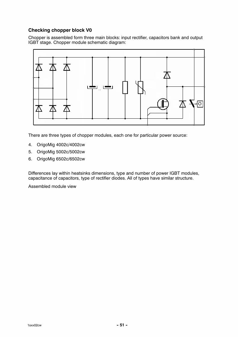
Checking chopper block V0
Chopper is assembled form three main blocks: input rectifier, capacitors bank and outputIGBT stage. Chopper module schematic diagram:
There are three types of chopper modules, each one for particular power source:
4. OrigoMig 4002c/4002cw
5. OrigoMig 5002c/5002cw
6. OrigoMig 6502c/6502cw
Differences lay within heatsinks dimensions, type and number of power IGBT modules,capacitance of capacitors, type of rectifier diodes. All of types have similar structure.
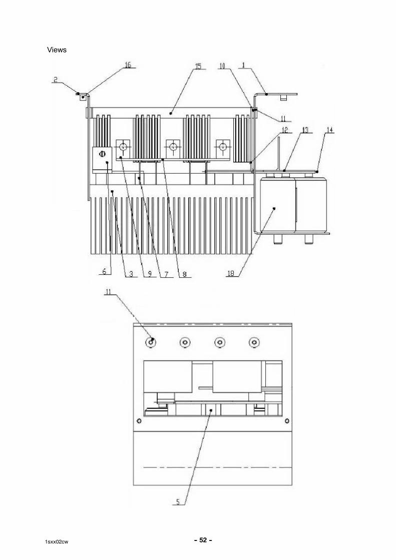
Assembled module view
-- 52 --1sxx02cw
Views
-- 53 --1sxx02cw
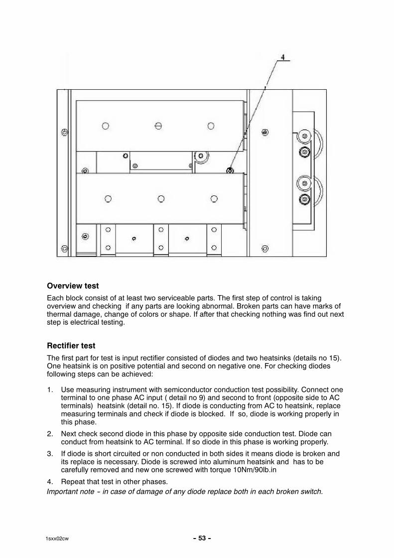
Overview test
Each block consist of at least two serviceable parts. The first step of control is takingoverview and checking if any parts are looking abnormal. Broken parts can have marks ofthermal damage, change of colors or shape. If after that checking nothing was find out nextstep is electrical testing.
Rectifier test
The first part for test is input rectifier consisted of diodes and two heatsinks (details no 15).One heatsink is on positive potential and second on negative one. For checking diodesfollowing steps can be achieved:
1. Use measuring instrument with semiconductor conduction test possibility. Connect oneterminal to one phase AC input ( detail no 9) and second to front (opposite side to ACterminals) heatsink (detail no. 15). If diode is conducting from AC to heatsink, replacemeasuring terminals and check if diode is blocked. If so, diode is working properly inthis phase.
2. Next check second diode in this phase by opposite side conduction test. Diode canconduct from heatsink to AC terminal. If so diode in this phase is working properly.
3. If diode is short circuited or non conducted in both sides it means diode is broken andits replace is necessary. Diode is screwed into aluminum heatsink and has to becarefully removed and new one screwed with torque 10Nm/90lb.in
4. Repeat that test in other phases.
Important note -- in case of damage of any diode replace both in each broken switch.
-- 54 --1sxx02cw
For easy disassembly unscrew both rectifier heatsinks from capacitors side and plastic shelfwith AC terminals and disassemble two M6 screws down the heatsink on opposite side.
Important note -- all diode threads have to be covered with very thin layer of No. 2 ElectroJoint Compound before replacing. Also heatsink side which is connected to DC--link has tobe covered with No.2 EJC.
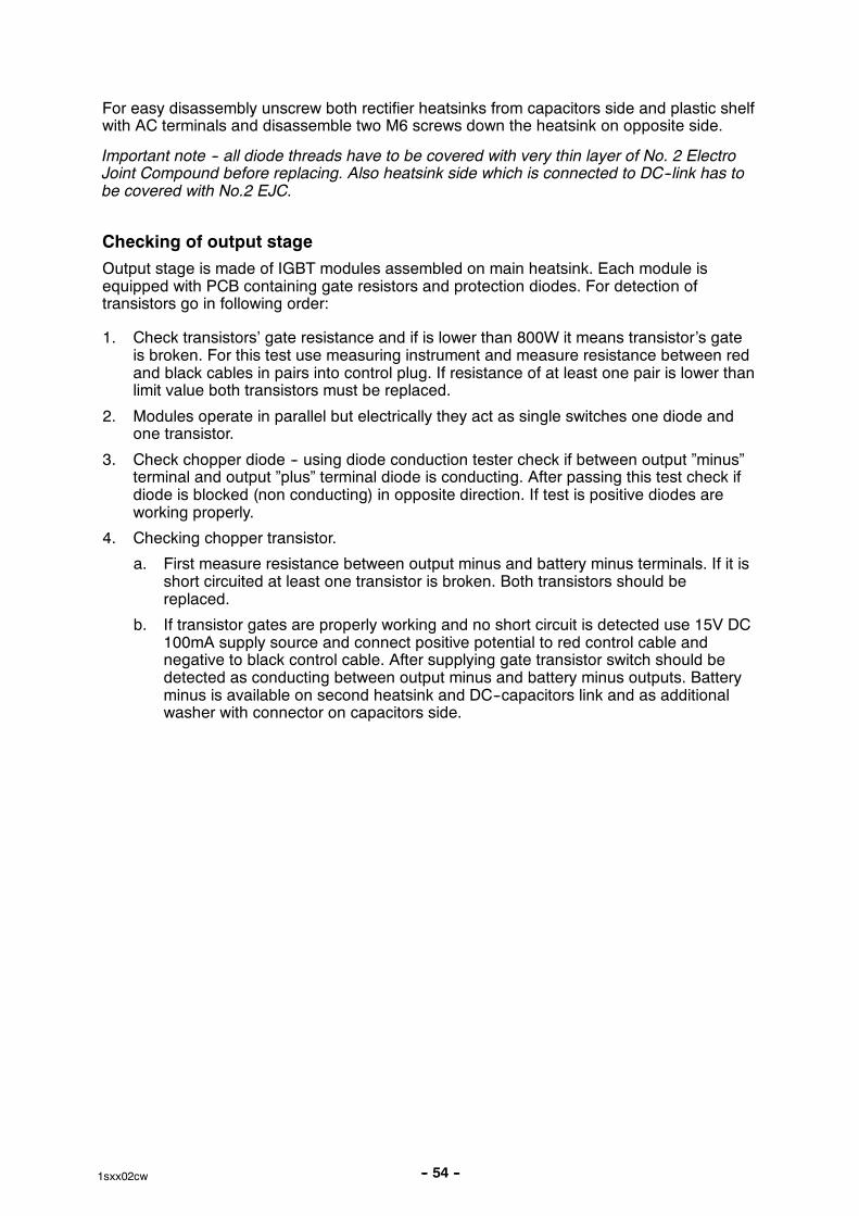
Checking of output stage
Output stage is made of IGBT modules assembled on main heatsink. Each module isequipped with PCB containing gate resistors and protection diodes. For detection oftransistors go in following order:
1. Check transistors’ gate resistance and if is lower than 800W it means transistor’s gateis broken. For this test use measuring instrument and measure resistance between redand black cables in pairs into control plug. If resistance of at least one pair is lower thanlimit value both transistors must be replaced.
2. Modules operate in parallel but electrically they act as single switches one diode andone transistor.
3. Check chopper diode -- using diode conduction tester check if between output ”minus”terminal and output ”plus” terminal diode is conducting. After passing this test check ifdiode is blocked (non conducting) in opposite direction. If test is positive diodes areworking properly.
4. Checking chopper transistor.
a. First measure resistance between output minus and battery minus terminals. If it isshort circuited at least one transistor is broken. Both transistors should bereplaced.
b. If transistor gates are properly working and no short circuit is detected use 15V DC100mA supply source and connect positive potential to red control cable andnegative to black control cable. After supplying gate transistor switch should bedetected as conducting between output minus and battery minus outputs. Batteryminus is available on second heatsink and DC--capacitors link and as additionalwasher with connector on capacitors side.

-- 55 --1sxx02cw
Replacing of damaged transistors
In order to replace damaged transistor following items have to be disassembled:
� diode rectifiers
� output terminal
� DC--link terminals unconnected from modules
Important note -- IGBT module is symmetrical except two plastic pins for positioning PCB.During replacement check if ”+” ”--” marked side of module is placed on capacitors side andant the end is connected to DC--link terminals.
Before placing new module its base plate has to be covered by thin layer of thermalconducing silicon paste.
Fixing torques:
� module to heatsink, screw M5x18 T=3--5Nm
� terminal, screw M6x16 T=3--5Nm
NOTE: Always replace all modules.
High current aluminum leads maintenance
NOTE: In case of disconnecting the high current aluminum leads of main transformer orrectifier bridge, the service technician must perform following actions prior to re--connecting:
� mechanically remove the oxides from the contact surfaces
� cover the contact surfaces with thin layer of electro--conducting paste EL/5--846(140g tube -- Ordering No.: 0349 312 885)
� re--connect the lead and tighten with torque of 10Nm
-- 56 --2sxx02cw
INSTRUCTIONS
This chapter is an extract from the instructions for the OrigoTM Mig 4002c/4002cw,5002c/5002cw and 6502c/6502cw.
SAFETY
Users of ESAB welding equipment have the ultimate responsibility for ensuring that anyone whoworks on or near the equipment observes all the relevant safety precautions. Safety precautionsmust meet the requirements that apply to this type of welding equipment. The following recommen-dations should be observed in addition to the standard regulations that apply to the workplace.
All work must be carried out by trained personnel well--acquainted with the operation of the weldingequipment. Incorrect operation of the equipment may lead to hazardous situations which can resultin injury to the operator and damage to the equipment.
1. Anyone who uses the welding equipment must be familiar with:� its operation� location of emergency stops� its function� relevant safety precautions� welding
2. The operator must ensure that:� no unauthorised person is stationed within the working area of the equipment when it is
started up.� no--one is unprotected when the arc is struck
3. The workplace must:� be suitable for the purpose� be free from draughts
4. Personal safety equipment� Always wear recommended personal safety equipment, such as safety glasses, flame--proof
clothing, safety gloves.� Do not wear loose--fitting items, such as scarves, bracelets, rings, etc., which could become
trapped or cause burns.
5. General precautions� Make sure the return cable is connected securely.� Work on high voltage equipment may only be carried out by a qualified electrician.� Appropriate fire extinquishing equipment must be clearly marked and close at hand.� Lubrication and maintenance must not be carried out on the equipment during operation.
WARNING!
Read and understand the instruction manualbefore installing or operating.
-- 57 --2sxx02cw
INSTALLATION
The installation must be executed by a professional.
WARNING!This product is intended for industrial use. In a domestic environment this product may cause radiointerference. It is the user’s responsibility to take adequate precautions.
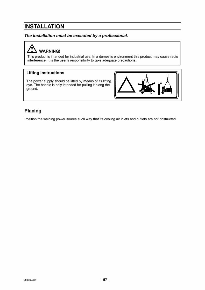
The power supply should be lifted by means of its liftingeye. The handle is only intended for pulling it along theground.
Lifting instructions
Placing
Position the welding power source such way that its cooling air inlets and outlets are not obstructed.
-- 58 --2sxx02cw
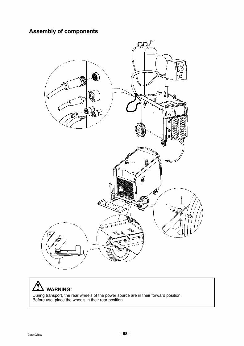
Assembly of components
During transport, the rear wheels of the power source are in their forward position.Before use, place the wheels in their rear position.
WARNING!
-- 59 --2sxx02cw
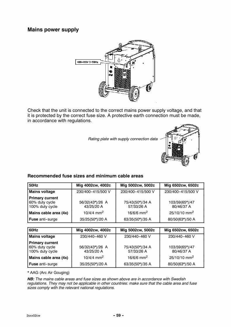
Mains power supply
Check that the unit is connected to the correct mains power supply voltage, and thatit is protected by the correct fuse size. A protective earth connection must be made,in accordance with regulations.
Rating plate with supply connection data
Recommended fuse sizes and minimum cable areas
50Hz Mig 4002cw, 4002c Mig 5002cw, 5002c Mig 6502cw, 6502c
Mains voltage 230/400--415/500 V 230/400--415/500 V 230/400--415/500 V
Primary current60% duty cycle100% duty cycle
56/32(43*)/26 A43/25/20 A
75/43(50*)/34 A57/33/26 A
103/59(65*)/4780/46/37 A
Mains cable area (4x) 10/4/4 mm2 16/6/6 mm2 25/10/10 mm2
Fuse anti--surge 35/25(50*)/20 A 63/35(50*)/35 A 80/50(63*)/50 A
60Hz Mig 4002cw, 4002c Mig 5002cw, 5002c Mig 6502cw, 6502c
Mains voltage 230/440--460 V 230/440--460 V 230/440--460 V
Primary current60% duty cycle100% duty cycle
56/32(43*)/26 A43/25/20 A
75/43(50*)/34 A57/33/26 A
103/59(65*)/4780/46/37 A
Mains cable area (4x) 10/4/4 mm2 16/6/6 mm2 25/10/10 mm2
Fuse anti--surge 35/25(50*)/20 A 63/35(50*)/35 A 80/50(63*)/50 A
* AAG (Arc Air Gouging)
NB: The mains cable areas and fuse sizes as shown above are in accordance with Swedishregulations. They may not be applicable in other countries: make sure that the cable area and fusesizes comply with the relevant national regulations.
-- 60 --2sxx02cw
OPERATION
General safety regulations for the handling of the equipment appear from page56. Read through before you start using the equipment!
WARNING -- TIPPING RISK!
Fasten the equipment -- particularly if the ground is uneven or sloping.
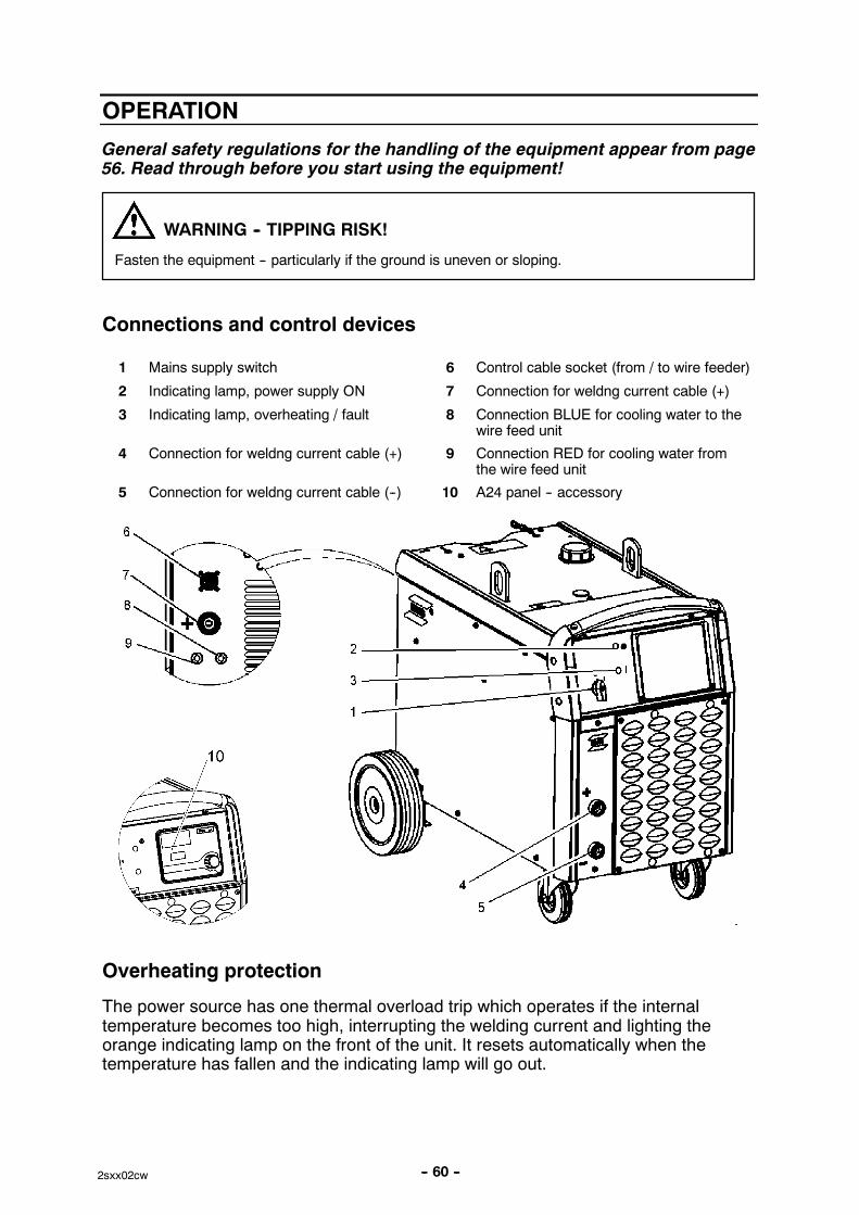
Connections and control devices
1 Mains supply switch 6 Control cable socket (from / to wire feeder)
2 Indicating lamp, power supply ON 7 Connection for weldng current cable (+)
3 Indicating lamp, overheating / fault 8 Connection BLUE for cooling water to thewire feed unit
4 Connection for weldng current cable (+) 9 Connection RED for cooling water fromthe wire feed unit
5 Connection for weldng current cable (--) 10 A24 panel -- accessory
Overheating protection
The power source has one thermal overload trip which operates if the internaltemperature becomes too high, interrupting the welding current and lighting theorange indicating lamp on the front of the unit. It resets automatically when thetemperature has fallen and the indicating lamp will go out.
-- 61 --2sxx02cw
Water connection
The AristoTM/OrigoTM Feed has a sensor ELP, ESAB Logic Pump, that senses if thewater hoses of the welding gun are connected. When a water cooled welding gun isconnected, the water pump starts.
When connecting the cooling water hoses to/from the Feed wire feed unit, the mainsON/OFF switch of the Mig must be in the OFF position.
Note, if a water cooled welding gun is used when the pump is inactive, the weldinggun might be damaged, therefore it is not recommended to use wire feeders notequipped with ELP.
Water flow guard
The water flow guard interrupts the welding current in the event of loss of coolantand an orange indicating lamp on the front of the power source lights up.
The water flow guard is an accessory. Ordering number see in user manual.
MAINTENANCE
Regular maintenance is important for safe, reliable operation.
Maintenance must be executed by a professional.Only those persons who have appropriate electrical knowledge (authorisedpersonnel) may remove the safety plates.
Note!All guarantee undertakings from the supplier cease to apply if the customer himselfattempts any work in the product during the guarantee period in order to rectify anyfaults.
Inspection and cleaning
Check regularly that the power source is free from dirt.
The power source should be regularly blown clean using dry compressed air atreduced pressure. More frequently in dirty environments.
Otherwise the air inlet/outlet may become blocked and cause overheating. To avoidthis you can use an airfilter.The airfilter is an accessory. Ordering number in user manual.
Topping up the coolant
ESAB ready mixed coolant is recommended for use. See accessories in usermanual.
� Fill with coolant.(The fluid level must not exceed the upper marking but neither must it be belowthe lower marking).
-- 62 --2sxx02cw
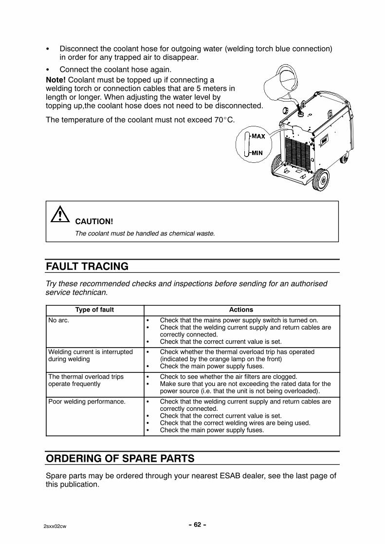
� Disconnect the coolant hose for outgoing water (welding torch blue connection)in order for any trapped air to disappear.
� Connect the coolant hose again.
Note! Coolant must be topped up if connecting awelding torch or connection cables that are 5 meters inlength or longer. When adjusting the water level bytopping up,the coolant hose does not need to be disconnected.
The temperature of the coolant must not exceed 70�C.
CAUTION!
The coolant must be handled as chemical waste.
FAULT TRACING
Try these recommended checks and inspections before sending for an authorisedservice technican.
Type of fault Actions
No arc. � Check that the mains power supply switch is turned on.� Check that the welding current supply and return cables are
correctly connected.� Check that the correct current value is set.
Welding current is interruptedduring welding
� Check whether the thermal overload trip has operated(indicated by the orange lamp on the front)
� Check the main power supply fuses.
The thermal overload tripsoperate frequently
� Check to see whether the air filters are clogged.� Make sure that you are not exceeding the rated data for the
power source (i.e. that the unit is not being overloaded).
Poor welding performance. � Check that the welding current supply and return cables arecorrectly connected.
� Check that the correct current value is set.� Check that the correct welding wires are being used.� Check the main power supply fuses.
ORDERING OF SPARE PARTS
Spare parts may be ordered through your nearest ESAB dealer, see the last page ofthis publication.

-- 63 --notes
NOTES
ESAB ABSE--695 81 LAXÅSWEDENPhone +46 584 81 000
www.esab.com
081016
ESAB subsidiaries and representative offices
EuropeAUSTRIAESAB Ges.m.b.HVienna--LiesingTel: +43 1 888 25 11Fax: +43 1 888 25 11 85
BELGIUMS.A. ESAB N.V.BrusselsTel: +32 2 745 11 00Fax: +32 2 745 11 28
THE CZECH REPUBLICESAB VAMBERK s.r.o.VamberkTel: +420 2 819 40 885Fax: +420 2 819 40 120
DENMARKAktieselskabet ESABHerlevTel: +45 36 30 01 11Fax: +45 36 30 40 03
FINLANDESAB OyHelsinkiTel: +358 9 547 761Fax: +358 9 547 77 71
FRANCEESAB France S.A.Cergy PontoiseTel: +33 1 30 75 55 00Fax: +33 1 30 75 55 24
GERMANYESAB GmbHSolingenTel: +49 212 298 0Fax: +49 212 298 218
GREAT BRITAINESAB Group (UK) LtdWaltham CrossTel: +44 1992 76 85 15Fax: +44 1992 71 58 03
ESAB Automation LtdAndoverTel: +44 1264 33 22 33Fax: +44 1264 33 20 74
HUNGARYESAB KftBudapestTel: +36 1 20 44 182Fax: +36 1 20 44 186
ITALYESAB Saldatura S.p.A.Mesero (Mi)Tel: +39 02 97 96 81Fax: +39 02 97 28 91 81
THE NETHERLANDSESAB Nederland B.V.AmersfoortTel: +31 33 422 35 55Fax: +31 33 422 35 44
NORWAYAS ESABLarvikTel: +47 33 12 10 00Fax: +47 33 11 52 03
POLANDESAB Sp.zo.o.KatowiceTel: +48 32 351 11 00Fax: +48 32 351 11 20
PORTUGALESAB LdaLisbonTel: +351 8 310 960Fax: +351 1 859 1277
SLOVAKIAESAB Slovakia s.r.o.BratislavaTel: +421 7 44 88 24 26Fax: +421 7 44 88 87 41
SPAINESAB Ibérica S.A.Alcalá de Henares (MADRID)Tel: +34 91 878 3600Fax: +34 91 802 3461
SWEDENESAB Sverige ABGothenburgTel: +46 31 50 95 00Fax: +46 31 50 92 22
ESAB international ABGothenburgTel: +46 31 50 90 00Fax: +46 31 50 93 60
SWITZERLANDESAB AGDietikonTel: +41 1 741 25 25Fax: +41 1 740 30 55
North and South AmericaARGENTINACONARCOBuenos AiresTel: +54 11 4 753 4039Fax: +54 11 4 753 6313
BRAZILESAB S.A.Contagem--MGTel: +55 31 2191 4333Fax: +55 31 2191 4440
CANADAESAB Group Canada Inc.Missisauga, OntarioTel: +1 905 670 02 20Fax: +1 905 670 48 79
MEXICOESAB Mexico S.A.MonterreyTel: +52 8 350 5959Fax: +52 8 350 7554
USAESAB Welding & Cutting ProductsFlorence, SCTel: +1 843 669 44 11Fax: +1 843 664 57 48
Asia/PacificCHINAShanghai ESAB A/PShanghaiTel: +86 21 2326 3000Fax: +86 21 6566 6622
INDIAESAB India LtdCalcuttaTel: +91 33 478 45 17Fax: +91 33 468 18 80
INDONESIAP.T. ESABindo PratamaJakartaTel: +62 21 460 0188Fax: +62 21 461 2929
JAPANESAB JapanTokyoTel: +81 45 670 7073Fax: +81 45 670 7001
MALAYSIAESAB (Malaysia) Snd BhdUSJTel: +603 8023 7835Fax: +603 8023 0225
SINGAPOREESAB Asia/Pacific Pte LtdSingaporeTel: +65 6861 43 22Fax: +65 6861 31 95
SOUTH KOREAESAB SeAH CorporationKyungnamTel: +82 55 269 8170Fax: +82 55 289 8864
UNITED ARAB EMIRATESESAB Middle East FZEDubaiTel: +971 4 887 21 11Fax: +971 4 887 22 63
Representative officesBULGARIAESAB Representative OfficeSofiaTel/Fax: +359 2 974 42 88
EGYPTESAB EgyptDokki--CairoTel: +20 2 390 96 69Fax: +20 2 393 32 13
ROMANIAESAB Representative OfficeBucharestTel/Fax: +40 1 322 36 74
RUSSIALLC ESABMoscowTel: +7 095 543 9281Fax: +7 095 543 9280
LLC ESABSt PetersburgTel: +7 812 336 7080Fax: +7 812 336 7060
DistributorsFor addresses and phonenumbers to our distributors inother countries, please visit ourhome page
www.esab.com


