Embed Size (px)
Citation preview
INCH-POUND
MIL-STD-1791C W/Change 1 29 December 2017
SUPERSEDING MIL-STD-1791C 23 October 2017
DEPARTMENT OF DEFENSE INTERFACE STANDARD
DESIGNING FOR INTERNAL AERIAL DELIVERY IN FIXED WING AIRCRAFT
AMSC N/A FSC 1510 DISTRIBUTION STATEMENT A: Approved for public release; distribution is unlimited.
Source: https://assist.dla.mil -- Downloaded: 2018-12-14T17:20ZCheck the source to verify that this is the current version before use.
MIL-STD-1791C w/Change 1
ii
FOREWORD 1. This standard is approved for use by all Departments and Agencies of the Department of Defense. 2. This standard establishes general design and performance requirements that items have to comply with in order to be safely transported onboard USAF fixed wing cargo aircraft. The standard covers the USAF prime mission cargo aircraft (e.g., C-130E/H/J, C-130J-30, C-17, and C-5), cargo carrying systems of the tanker fleet (KC-10 and KC-135) as well as the cargo aircraft in the long-range, international segment of the Civil Reserve Air Fleet (CRAF) (e.g., B747, DC-10, and B767). The structural and dimensional criteria for other cargo aircraft are documented in specific manuals for each aircraft. 3. The definition of an air transportability problem item and what does or does not need to be certified for air transport is provided in 1.3. 4. General and detailed requirements with associated verification criteria are found in sections 4 and 5. Section 6 provides guidance for applying the requirements. 5. For Personnel-Occupied cargo, such as personnel modules and seat pallets, many interface requirements are contained in this document. Due to safety of personnel, the approval authority rests within the individual aircraft offices and the USAF Airworthiness Authority (see A.8.4). 6. For patient care equipment, such as litters and instruments, Safe-to-Fly requirements can be obtained from Headquarters Air Mobility Command’s Medical Modernization Division (HQ AMC/SGR), Scott AFB, IL and Aeromedical Systems Branch’s (AFLCMC/WNUP) Aeromedical Test Laboratory (ATL), Wright-Patterson AFB, OH. This document can provide many of the aircraft interface requirements. 7. This document can be used for guidance when personnel module and patient care equipment are interfaced with aircraft cargo systems. 8. Appendix A explains how the requirements may apply to four common types of cargo and how those types of cargo are air transported. It also includes lessons learned and describes operations common to the standard mission: load planning, loading, restraining cargo, flight, jettison, and combat offloading. Appendix A also gives an overview of the 463L air cargo system. Appendix B provides detailed data on specific aircraft limits to supplement the requirements stated in sections 4 and 5. Data on military aircraft can also be found in that aircraft's Technical Order (T.O.) 1C-XXX-9 cargo loading manual. NOTE: Information on CRAF aircraft are not shown in this document but can be obtained by contacting the Air Transportability Test Loading Activity (ATTLA). 9. Comments, suggestions, or questions on this document should be addressed to AFLCMC/EZFC (ATTN: ATTLA), Building 28, 2145 Monahan Way, Wright-Patterson Air Force Base OH, 45433-7017 or emailed to [email protected]. Since contact information can change, you may want to verify the currency of this address information using the ASSIST online database at https://assist.dla.mil.
Source: https://assist.dla.mil -- Downloaded: 2018-12-14T17:20ZCheck the source to verify that this is the current version before use.
MIL-STD-1791C w/Change 1
iii
SUMMARY OF CHANGE MODIFICATIONS
1. The following modifications were made to this standard.
PARAGRAPH MODIFICATION 1.3 Added 1.3.1 Added 1.3.2 Added 2.3 Added 3 Added 4.3.8.1 Added 4.3.8.2 Added 4.3.8.3 Added 5.3.1.2 Added 5.3.2.1 Added 5.3.2.2 Added 5.3.2.3 Added 5.3.2.4 Added 5.3.2.5 Added 5.3.2.6 Added 5.3.2.7 Added 5.3.2.8 Added 5.3.2.9 Added 5.3.2.10 Added 5.3.2.11 Added 5.3.2.12 Added 5.3.2.14 Added 5.3.2.15 Added 5.3.3.1 Added 5.3.3.5 Added 5.3.4.1 Added 5.3.4.2 Added 5.3.4.3 Added 5.3.4.4 Added
Source: https://assist.dla.mil -- Downloaded: 2018-12-14T17:20ZCheck the source to verify that this is the current version before use.
MIL-STD-1791C w/Change 1
iv
PARAGRAPH MODIFICATION 5.3.4.5 Added 5.3.5.1 Added 5.3.5.1.1 Added 5.3.5.2 Added 5.3.5.2.1 Added 5.3.5.3 Added 5.3.5.3.1 Added 5.3.5.4 Added 5.3.5.4.1 Added 5.3.5.5 Added 5.3.5.5.1 Added 5.3.6.2.1 Added 5.3.6.4.1 Added 5.3.6.5 Added 6.1 Added 6.4.3 Added A.3.3.2.2 Added A.3.4.1 Added A.3.4.5 Added A.3.4.13.1 Added A.4.1.3 Added A.4.1.6 Added A.4.1.8 Added A.4.2.1 Added A.4.2.2 Added A.4.3.1 Added A.4.3.2 Added A.4.3.3 Added A.4.3.3.1 Added A.4.3.3.2 Added A.4.3.3.3 Added A.4.3.3.3.1 Added A.4.3.3.3.2 Added
Source: https://assist.dla.mil -- Downloaded: 2018-12-14T17:20ZCheck the source to verify that this is the current version before use.
MIL-STD-1791C w/Change 1
v
PARAGRAPH MODIFICATION A.4.3.3.3.3 Added A.4.3.3.4 Added A.4.3.3.5 Added A.4.3.3.6 Added A.6.4 Added A.6.10 Added A.7.1 Added A.7.1.1 Added A.7.2.1 Added A.9.6.1 Added A.9.6.3.2 Added A.9.6.4 Added B.3.2.1 Added B.3.2.1.1 Added B.3.4.1 Added B.3.4.1.1 Added B.3.4.2 Added B.3.4.3 Added B.3.4.4 Added B.3.4.5 Added B.4.1.1.1 Added B.4.1.1.3 Added B.4.2.1.3 Added B.4.2.2.2.1 Added B.4.4.3 Added B.4.4.4 Added B.5.2.1.1 Added B.5.2.1.2 Added B.5.2.1.3 Added B.5.4.1 Added B.5.4.1.1 Added B.5.4.1.2 Added B.5.4.1.3 Added
Source: https://assist.dla.mil -- Downloaded: 2018-12-14T17:20ZCheck the source to verify that this is the current version before use.
MIL-STD-1791C w/Change 1
vi
PARAGRAPH MODIFICATION B.5.4.1.4 Added B.5.4.1.5 Added B.5.4.2 Added B.5.4.2.1 Added B.5.4.2.2 Added B.5.4.2.3 Added B.5.4.2.4 Added B.5.4.3 Added B.6.2.1.1 Added FIGURES MODIFICATION FIGURE 5 Changed FIGURE A-2 Changed FIGURE A-23 Changed FIGURE A-27 Changed FIGURE A-28 Changed FIGURE A-29 Changed FIGURE A-32 Changed FIGURE A-33 Changed FIGURE A-34 Changed FIGURE A-35 Changed FIGURE A-40 Changed FIGURE B-7 Changed FIGURE B-8 Changed FIGURE B-9 Changed FIGURE B-32 Changed FIGURE B-33 Changed FIGURE B-35 Changed FIGURE B-37 Changed FIGURE B-39 Changed FIGURE B-41 Changed FIGURE B-43 Changed FIGURE B-52 Changed FIGURE B-53 Changed
Source: https://assist.dla.mil -- Downloaded: 2018-12-14T17:20ZCheck the source to verify that this is the current version before use.
MIL-STD-1791C w/Change 1
vii
FIGURES MODIFICATION FIGURE B-57 Changed FIGURE B-59 Changed FIGURE B-60 Changed FIGURE B-61 Changed FIGURE B-62 Changed FIGURE B-64 Changed FIGURE B-65 Changed FIGURE B-66 Changed FIGURE B-67 sheet 2 Added FIGURE B-77 Changed FIGURE B-90 Changed FIGURE B-91 Changed FIGURE B-92 Changed FIGURE B-94 Changed FIGURE B-101 Changed FIGURE B-114 Changed FIGURE B-115 Changed FIGURE B-116 Changed FIGURE B-117 Changed FIGURE B-118 Changed TABLES MODIFICATION TABLE I Changed TABLE III Changed TABLE IV Changed TABLE XVII Changed TABLE A-I Changed TABLE B-XIV Changed TABLE B-XIX Changed TABLE B-XVI Changed TABLE B-XXI Changed
Source: https://assist.dla.mil -- Downloaded: 2018-12-14T17:20ZCheck the source to verify that this is the current version before use.
MIL-STD-1791C w/Change 1
viii
TABLE OF CONTENTS 1. SCOPE .................................................................................................... 1 1.1 Purpose. ................................................................................................. 1 1.2 General. .................................................................................................. 1 1.2.1 Appendices. ............................................................................................. 1 1.3 Applicability. .......................................................................................... 1 1.3.1 Air transportability problem items. ............................................................ 1 1.3.2 Internal air transport certification. ............................................................. 2 1.3.3 Certification not required. ......................................................................... 3 2. APPLICABLE DOCUMENTS .................................................................. 3 2.1 General. .................................................................................................. 3 2.2 Government documents. ....................................................................... 3 2.2.1 Specifications, standards, and handbooks. .............................................. 3 2.2.2 Other Government documents, drawings, and publications. .................... 4 2.3 Order of precedence. ............................................................................. 6 3. DEFINITIONS .......................................................................................... 6 4. GENERAL REQUIREMENTS ................................................................ 15 4.1 Scope of general requirements. .......................................................... 15 4.2 Verification methods............................................................................ 16 4.3 Requirements. ...................................................................................... 16 4.3.5 Restraint requirements. .......................................................................... 17 4.3.6 Markings. ............................................................................................... 17 4.3.9 Special loading, unloading, and flight procedures. ................................. 19 5. DETAILED REQUIREMENTS ............................................................... 19 5.1 Scope of detailed requirements. ......................................................... 19 5.2 Air transport requirements and verification methods. ...................... 19 5.2.1 Requirements layout. ............................................................................. 19 5.2.2 Verification methods. ............................................................................. 20 5.3 Detailed requirements. ........................................................................ 20 5.3.1 Size requirements. ................................................................................. 20 5.3.2 Weight limits. ......................................................................................... 22 5.3.3 Restraint requirements. .......................................................................... 32 5.3.4 Markings. ............................................................................................... 36 5.3.5 Air transport environment. ...................................................................... 37 5.3.6 Special consideration cargo. .................................................................. 41 5.3.7 Special loading, unloading, and flight procedures. ................................. 47 6. NOTES .................................................................................................. 49 6.1 Intended use. ........................................................................................ 49 6.2 Acquisition requirements. ................................................................... 49 6.3 Tailoring instructions. ......................................................................... 49 6.3.1 Applicability of requirements. ................................................................. 50 6.3.2 Example. ................................................................................................ 55 6.4 Air transport certification process. ..................................................... 56 6.4.2 Other certifications. ................................................................................ 59
Source: https://assist.dla.mil -- Downloaded: 2018-12-14T17:20ZCheck the source to verify that this is the current version before use.
MIL-STD-1791C w/Change 1
ix
6.5 Subject term (key word) listing. .......................................................... 60 6.6 Changes from the previous issue. ...................................................... 61 A.1 SCOPE .................................................................................................. 62 A.2 DEFINITIONS ........................................................................................ 62 A.3 SIZE AND WEIGHT BY CARGO TYPE ................................................. 63 A.3.1 Size........................................................................................................ 63 A.3.1.1 Size requirements. ................................................................................. 65 A.3.2 Weight limits. ......................................................................................... 71 A.3.3. Rolling stock. ......................................................................................... 75 A.3.4 Palletized cargo. .................................................................................... 85 A.3.4.6 Rail systems. ........................................................................................ 94 A.3.5 Bulk cargo. ......................................................................................... 104 A.4 RESTRAINING CARGO ...................................................................... 107 A.4.1 General. ............................................................................................... 107 A.4.1.3 Tiedown devices. ................................................................................. 108 A.4.2 Restraint principles. ............................................................................. 115 A.4.3 Tiedown pattern development. ............................................................. 118 A.4.4 Bulk cargo. ........................................................................................... 136 A.5 MARKINGS ......................................................................................... 137 A.6 SHORING ............................................................................................ 138 A.6.1 Approach shoring. ................................................................................ 140 A.6.2 Pedestal shoring. ................................................................................. 141 A.6.3 Cresting shoring. .................................................................................. 142 A.6.5 Rolling shoring. .................................................................................... 144 A.6.6 Parking shoring. ................................................................................... 144 A.6.7 Sleeper shoring. ................................................................................... 145 A.6.8 Support shoring. .................................................................................. 146 A.6.9 Bridge shoring. ..................................................................................... 147 A.6.10 Protection shoring. ............................................................................... 147 A.7 AIR TRANSPORT ENVIRONMENT .................................................... 148 A.7.1 Shock and vibration. ............................................................................ 148 A.7.2 Pressure change. ................................................................................. 149 A.7.3 Temperature change. ........................................................................... 153 A.7.4 Explosive atmosphere. ......................................................................... 153 A.7.5 Electromagnetic environment. .............................................................. 154 A.7.6 Secondary structural considerations. ................................................... 154 A.8 SPECIAL CONSIDERATION CARGO ................................................ 155 A.8.1 Hazardous material. ............................................................................. 155 A.8.2 Aircraft electrical and data interface. .................................................... 155 A.8.3 Bulk fluid tanks. .................................................................................... 156 A.8.4 Personnel occupied systems. .............................................................. 156 A.9 SPECIAL LOADING AND FLIGHT PROCEDURES ............................ 156 A.9.1 Special tools and transport equipment. ................................................ 156 A.9.2 Material handling equipment (MHE). .................................................... 157
Source: https://assist.dla.mil -- Downloaded: 2018-12-14T17:20ZCheck the source to verify that this is the current version before use.
MIL-STD-1791C w/Change 1
x
A.9.3 Self-adjustment. ................................................................................... 159 A.9.4 Lowering tire pressure.......................................................................... 159 A.9.5 Straight-in loading. ............................................................................... 159 A.9.6 Winching. ............................................................................................. 159 A.9.7 Secondary cargo. ................................................................................. 165 A.10 LOAD PLANNING ............................................................................... 166 A.10.1 Access to aircraft systems. .................................................................. 166 A.10.2 Aircraft CG limits. ................................................................................. 166 A.10.3 Aircraft cargo payload. ......................................................................... 168 A.10.4 Availability of tiedowns. ........................................................................ 168 A.10.5 Compartment size limit......................................................................... 168 A.10.6 Compartment weight limits. .................................................................. 169 A.10.7 Interference with other cargo................................................................ 169 A.10.8 Ramp contact. ...................................................................................... 170 A.10.9 Sensitive areas. ................................................................................... 170 A.11 CARGO JETTISON ............................................................................. 170 A.11.1 General. ............................................................................................... 170 A.11.2 How to read a tip-off curve. .................................................................. 170 B.1 SCOPE ................................................................................................ 172 B.1.1 Scope. ................................................................................................. 172 B.1.2 Applicability. ......................................................................................... 172 B.1.3 Organization. ....................................................................................... 172 B.1.4 Order of precedence. ........................................................................... 172 B.2 DEFINITIONS ...................................................................................... 172 B.3 C-5 GALAXY ....................................................................................... 173 B.3.1 Geometry. ............................................................................................ 174 B.3.2 Strength. .............................................................................................. 209 B.3.3 Restraint. ............................................................................................. 224 B.3.3.3 Lock layout. ........................................................................................ 228 B.3.4 Additional information. ......................................................................... 229 B.4 C-17 GLOBEMASTER III .................................................................... 235 B.4.1 Geometry. ............................................................................................ 236 B.4.2 Strength. .............................................................................................. 269 B.4.3 Restraint. ............................................................................................. 295 B.4.4 Additional information. ......................................................................... 296 B.5.1 Geometry. ............................................................................................ 304 B.5.2 Strength. .............................................................................................. 317 B.5.2.2 Ramp. .................................................................................................. 332 B.5.3 Restraint. ............................................................................................. 335 B.5.4 Additional information. ......................................................................... 338 B.6 KC-10 EXTENDER .............................................................................. 345 B.6.1 Geometry. ............................................................................................ 345 B.6.1.3 Cargo door. ........................................................................................ 351 B.6.2 Strength. .............................................................................................. 352
Source: https://assist.dla.mil -- Downloaded: 2018-12-14T17:20ZCheck the source to verify that this is the current version before use.
MIL-STD-1791C w/Change 1
xi
B.6.3 Restraint. ............................................................................................. 359 B.6.4 Additional information. ......................................................................... 361 B.7 KC-135 STRATOTANKER .................................................................. 365 B.7.1 Geometry. ............................................................................................ 366 B.7.2 Strength. .............................................................................................. 368 B.7.3 Restraint. ............................................................................................. 377 B.7.4 Additional information. ......................................................................... 378 B.8 CIVIL RESERVE AIR FLEET (CRAF) ................................................. 380
TABLE OF FIGURES FIGURE 1. Maximum projected height. ....................................................................................20 FIGURE 2. Tiedown rings. .......................................................................................................35 FIGURE 3. Example tiedown provisions. ..................................................................................35 FIGURE 4. Pallet/roller interface. .............................................................................................45 FIGURE 5. Pallet rail exterior profile. .......................................................................................46 FIGURE 6. Example system. ...................................................................................................56 FIGURE 7. ATTLA certification process. ..................................................................................58 FIGURE A-1. 17 Degree angle .................................................................................................67 FIGURE A-2. Problematic areas for cresting ............................................................................68 FIGURE A-3. Loading issues. ..................................................................................................77 FIGURE A-4. Tire contact area. ...............................................................................................81 FIGURE A-5. Jackstand support. .............................................................................................84 FIGURE A-6. Single and triple pallet loads. ..............................................................................85 FIGURE A-7. Top and side netting. ..........................................................................................87 FIGURE A-8. Pallet and side rail. .............................................................................................88 FIGURE A-9. Pallet size and weight limits with net restraint. ....................................................91 FIGURE A-10. Palletized cargo restrained to aircraft floor rings. ..............................................92 FIGURE A-11. Logistics rail/roller interface with type V airdrop platform. .................................93 FIGURE A-12. Aircraft rail and pallet side rail interface. ...........................................................95 FIGURE A-13. Pallet locked into aircraft rails. ..........................................................................96 FIGURE A-14. Palletized cargo height. ....................................................................................97 FIGURE A-15. Non-uniform pallet loading. ............................................................................. 100 FIGURE A-16. Pallet/roller weight distribution. ....................................................................... 101 FIGURE A-17. Standard pallets and containers. .................................................................... 103 FIGURE A-18. Examples of bulk cargo. ................................................................................. 104 FIGURE A-19. Projection of bulk cargo. ................................................................................. 105 FIGURE A-20. Floor loading calculation. ................................................................................ 106 FIGURE A-21. Forklift loading bulk cargo. .............................................................................. 107 FIGURE A-22. Restraint for various situations. ...................................................................... 108 FIGURE A-23. Tiedown devices............................................................................................. 109 FIGURE A-24. Applied force curves. ...................................................................................... 114 FIGURE A-25. Chain angle 1. ................................................................................................ 116 FIGURE A-26. Chain angle 2. ................................................................................................ 116 FIGURE A-27. Tiedown angles 1. .......................................................................................... 117 FIGURE A-28. Tiedown angles 2. .......................................................................................... 117 FIGURE A-29. Chain gate and chain bridle. ........................................................................... 121 FIGURE A-30. CG location for effective restraint. .................................................................. 121 FIGURE A-31. Sample tiedown pattern. ................................................................................. 122 FIGURE A-32. Dimensions for tiedown analysis. ................................................................... 127
Source: https://assist.dla.mil -- Downloaded: 2018-12-14T17:20ZCheck the source to verify that this is the current version before use.
MIL-STD-1791C w/Change 1
xii
FIGURE A-33. Multiple chain restraint.................................................................................... 128 FIGURE A-34. Example complex tiedown. ............................................................................. 131 FIGURE A-35. Unsatisfactory bulk cargo restraint. ................................................................ 134 FIGURE A-36. Vertical cargo shift. ......................................................................................... 137 FIGURE A-37. Longitudinal/lateral cargo shift. ....................................................................... 137 FIGURE A-38. Sample approach shoring stack. .................................................................... 140 FIGURE A-39. C-5 approach shoring ramp toe support. ........................................................ 141 FIGURE A-40. Pedestal shoring. ........................................................................................... 142 FIGURE A-41. Cresting shoring. ............................................................................................ 143 FIGURE A-42. Shoring to spread weight. ............................................................................... 143 FIGURE A-43. Parking shoring. ............................................................................................. 144 FIGURE A-44. Shoring for large gapped tires. ....................................................................... 145 FIGURE A-45. Sleeper shoring. ............................................................................................. 146 FIGURE A-46. Bridge shoring. ............................................................................................... 147 FIGURE A-47. Vibration spectrum. ........................................................................................ 148 FIGURE A-48. Potential problem areas.................................................................................. 154 FIGURE A-49. Winching cargo. ............................................................................................. 160 FIGURE A-50. Winching with snatch blocks. .......................................................................... 163 FIGURE A-51. Self-winching using snatch blocks. ................................................................. 164 FIGURE A-52. Multiple loads in aircraft. ................................................................................. 167 FIGURE A-53. Allowable CG locations................................................................................... 168 FIGURE A-54. Compartment limit chart. ................................................................................ 169 FIGURE A-55. Ramp cargo placement. ................................................................................. 169 FIGURE A-56. Tip-off curve. .................................................................................................. 171 FIGURE B-1. C-5 Aircraft. ...................................................................................................... 173 FIGURE B-2. Cargo compartment envelope. ......................................................................... 174 FIGURE B-3. Forward cargo opening dimension. .................................................................. 175 FIGURE B-4. Aft cargo opening dimensions. ......................................................................... 176 FIGURE B-5. Allowable cargo height. .................................................................................... 177 FIGURE B-6. Airplane kneeling loading position (on/off loading). ........................................... 178 FIGURE B-7. Crated cargo projection limits (forward and aft end loading-palletized). ............ 180 FIGURE B-8. Forward and aft end loading – vehicle projection limits. .................................... 183 FIGURE B-9. Forward and aft end loading – vehicle projection. ............................................. 186 FIGURE B-10. Forward and aft end loading – vehicle projection limits. .................................. 187 FIGURE B-11. Forward and aft end loading – vehicle projection limits. .................................. 188 FIGURE B-12. Forward and aft end loading – vehicle projection limits. .................................. 189 FIGURE B-13. Forward and aft end loading – vehicle projection limits. .................................. 190 FIGURE B-14. Forward and aft end loading – vehicle projection limits. .................................. 191 FIGURE B-15. Forward and aft end loading – vehicle projection limits. .................................. 192 FIGURE B-16. Forward and aft end loading – vehicle projection limits. .................................. 193 FIGURE B-17. Forward and aft end loading – vehicle projection limits. .................................. 194 FIGURE B-18. Forward and aft end loading – vehicle projection limits. .................................. 195 FIGURE B-19. Forward and aft end loading – vehicle projection limits. .................................. 196 FIGURE B-20. Forward and aft end loading – vehicle projection limits. .................................. 200 FIGURE B-21. Forward and aft end loading – vehicle projection limits. .................................. 201 FIGURE B-22. Forward and aft ramp crest limits. .................................................................. 202 FIGURE B-23. Forward and aft ramp crest limits. .................................................................. 203 FIGURE B-24. Forward and aft ramp crest limits. .................................................................. 204 FIGURE B-25. Parking overhang limits. ................................................................................. 205 FIGURE B-26. Forward and aft cargo ramp vehicle overhang limits. ...................................... 206 FIGURE B-27. Forward and aft cargo ramp vehicle overhang limits. ...................................... 207
Source: https://assist.dla.mil -- Downloaded: 2018-12-14T17:20ZCheck the source to verify that this is the current version before use.
MIL-STD-1791C w/Change 1
xiii
FIGURE B-28. Parking overhang limits. ................................................................................. 208 FIGURE B-29. C-5 minimum approach shoring width under forward ramp toes. .................... 209 FIGURE B-30. Portable loading ramp extension. ................................................................... 210 FIGURE B-31. Portable loading ramp extension assembly sequence. ................................... 211 FIGURE B-32. Cargo floor loading limitations. ....................................................................... 209 FIGURE B-33. Cargo maximum allowable lateral CG location. .............................................. 210 FIGURE B-34. Concentrated cargo maximum allowable floor loads . ..................................... 213 FIGURE B-35. Calculating on/off load limits for tires. ............................................................. 217 FIGURE B-36. Calculating flight load limits for tires. ............................................................... 218 FIGURE B-37. Calculating flight load limits for hard rubber or steel wheels. .......................... 219 FIGURE B-38. Calculating load limits for track pad. ............................................................... 220 FIGURE B-39. C-5 roller system weight limitations. ............................................................... 222 FIGURE B-40. Forward and aft cargo ramp on/off loading limitations. ................................... 223 FIGURE B-41. Cargo floor tiedown rings and ABS receptacles. ............................................. 224 FIGURE B-42. Cargo floor configuration (logistics cargo). ..................................................... 226 FIGURE B-43. Cargo floor configuration (ADS cargo). ........................................................... 227 FIGURE B-44. Inboard and outboard restraint rail mechanism detent locations. .................... 228 FIGURE B-45. C-5 overboard vents. ...................................................................................... 230 FIGURE B-46. Cargo compartment electrical outlets. ............................................................ 232 FIGURE B-47. C-17 aircraft. .................................................................................................. 235 FIGURE B-48. Cargo compartment loading envelope. ........................................................... 236 FIGURE B-49. Electrical bracket. ........................................................................................... 237 FIGURE B-50. C-17 straight-in loading envelope, end view. .................................................. 238 FIGURE B-51. C-17 straight-in loading envelope, side view. .................................................. 239 FIGURE B-52. Cargo projection limits. ................................................................................... 240 FIGURE B-53. Vehicle dimensional limits. ............................................................................. 245 FIGURE B-54. Vehicle projection limits. ................................................................................. 246 FIGURE B-55. Vehicle ramp crest limit. ................................................................................. 259 FIGURE B-56. Vehicle ramp crest clearance limit. ................................................................. 260 FIGURE B-57. Parking overhang limits. ................................................................................. 262 FIGURE B-58. Allowable in-flight ramp loadable height. ........................................................ 263 FIGURE B-59. C-17 minimum approach shoring width under ramp toes. ............................... 265 FIGURE B-60. Floor limitations. ............................................................................................. 269 FIGURE B-61. Concentrated floor loads – calculations. ......................................................... 270 FIGURE B-62. C-17 high pressure pneumatic tire limitations. ................................................ 272 FIGURE B-63. Cargo weight loading envelope (non-E/R). ..................................................... 279 FIGURE B-64. Cargo weight loading envelope (E/R). ............................................................ 280 FIGURE B-65. Tracked vehicle articulated suspension. ......................................................... 281 FIGURE B-66. C-17 Rollers and limitations. ........................................................................... 282 FIGURE B-67. C-17 ADS system. .......................................................................................... 283 FIGURE B-68. C-17 logistic rail system. ................................................................................. 285 FIGURE B-69. Ramp toes. ..................................................................................................... 286 FIGURE B-70. Allowable in-flight ramp payload. .................................................................... 289 FIGURE B-71. Ramp Lifting Limits. ........................................................................................ 290 FIGURE B-72. C-17 ramp crest teeter limitations. .................................................................. 291 FIGURE B-73. C-17 ramp and ramp toes configured for dual row logistics system loading. ... 292 FIGURE B-74. Cargo tiedown rings/location. ......................................................................... 295 FIGURE B-75. Cargo compartment vents. ............................................................................. 296 FIGURE B-76. Cargo compartment electrical receptacles. ..................................................... 300 FIGURE B-77. C-17 tip off curve. ........................................................................................... 302 FIGURE B-78. C-17 aeromedical litter stations. ..................................................................... 303
Source: https://assist.dla.mil -- Downloaded: 2018-12-14T17:20ZCheck the source to verify that this is the current version before use.
MIL-STD-1791C w/Change 1
xiv
FIGURE B-79. C-130 aircraft. ................................................................................................ 304 FIGURE B-80.a C-130 E/H cargo compartment dimensions .................................................. 306 FIGURE B-80.b C-130J and C-130J-30 cargo compartment dimensions. .............................. 307 FIGURE B-81. C-130 safety aisle (all variants) ...................................................................... 309 FIGURE B-82.a C-130A thru H cargo compartment dimensions ............................................ 310 FIGURE B-82.b. C-130J and C-130J-30 cargo compartment dimensions. ............................. 311 FIGURE B-83. C-130E/H cargo compartments. ..................................................................... 312 FIGURE B-84. Overhang and projection limits (cargo) ........................................................... 313 FIGURE B-85. Overhang and projection limits (vehicle) ......................................................... 315 FIGURE B-86. Overhang and projection limits (vehicle). ........................................................ 316 FIGURE B-87. Overhang and projection limits (vehicle). ........................................................ 317 FIGURE B-88. C-130 ramp loadable height. .......................................................................... 318 FIGURE B-89 C-130 E/H compartments and pallet centroids. ............................................... 317 FIGURE B-90. Floor loading capacity – concentrated or pneumatic tire loads........................ 318 FIGURE B-91. Treadways...................................................................................................... 320 FIGURE B-92. C-130J ground and flight limits. ...................................................................... 321 FIGURE B-93. C-130J and -30 compartments, treadways and pallet centroids. ..................... 324 FIGURE B-94. C-130J-30 ground and flight limits. ................................................................. 325 FIGURE B-95. Cargo door and ramp. .................................................................................... 332 FIGURE B-96. Auxiliary truck loading ramp loads. ................................................................. 334 FIGURE B-97. Ramp height. .................................................................................................. 334 FIGURE B-98. Cargo tiedown, seat, and litter fitting locations. ............................................... 335 FIGURE B-99. C-130J tiedown fittings locations. ................................................................... 336 FIGURE B-100. C-130J-30 tiedown fittings locations. ............................................................ 336 FIGURE B-101. Minimum vertical restraint requirements. ...................................................... 341 FIGURE B-102. C-130E/H electrical outlets. .......................................................................... 341 FIGURE B-103. C-130 tip off or jettison height limit curve (all variants). ................................. 341 FIGURE B-104. Litter arrangement. ....................................................................................... 343 FIGURE B-105. KC-10 loading envelope. .............................................................................. 345 FIGURE B-106. Pallet contours and aisle configurations. ...................................................... 346 FIGURE B-107. Cargo compartment envelope. ..................................................................... 347 FIGURE B-108. Mixed cargo/personnel configuration. ........................................................... 347 FIGURE B-109. Mixed cargo/personnel configuration. ........................................................... 348 FIGURE B-110. Mixed cargo/personnel configuration. ........................................................... 349 FIGURE B-111. Mixed cargo/personnel configuration. ........................................................... 350 FIGURE B-112. Cargo door. .................................................................................................. 351 FIGURE B-113. All-cargo configuration. ................................................................................. 352 FIGURE B-114. Pallet load limitations. ................................................................................... 353 FIGURE B-115. Loading data – 25 pallet all-cargo configuration............................................ 354 FIGURE B-116. Loading data – lateral loading (left side of aircraft). ...................................... 355 FIGURE B-117. Concentrated load limitations – 25-pallet all-cargo configuration. ................. 356 FIGURE B-118. Concentrated load limitations – lateral loading (left side of aircraft). ............. 357 FIGURE B-119. Vehicle axle weight limitations. ..................................................................... 358 FIGURE B-120. A-7000 vertical tiedown allowables. .............................................................. 359 FIGURE B-121. HCU-6/E pallet ring vertical allowables. ........................................................ 360 FIGURE B-122. Cargo compartment cryogenic vent. ............................................................. 361 FIGURE B-123. Cargo compartment electrical outlets. .......................................................... 362 FIGURE B-124. Winching arrangements. ............................................................................... 363 FIGURE B-125. Maximum capability of cargo winch on sloped aircraft floor. ......................... 364 FIGURE B-126. Aircraft diagram (typical). .............................................................................. 365 FIGURE B-127. KC-135 R/T cargo compartment. .................................................................. 366
Source: https://assist.dla.mil -- Downloaded: 2018-12-14T17:20ZCheck the source to verify that this is the current version before use.
MIL-STD-1791C w/Change 1
xv
FIGURE B-128. Cargo roller handling system (six pallets installed). ...................................... 367 FIGURE B-129. Cargo contour. ............................................................................................. 367 FIGURE B-130. KC-135 loading envelope. ............................................................................ 368 FIGURE B-131. Large area loads (greater than 1.5 square feet). .......................................... 371 FIGURE B-132. Allowable axle loads for pneumatic tires. ...................................................... 372 FIGURE B-133. Allowable load for hard rubber and steel wheels. .......................................... 374 FIGURE B-134. KC-135 pallet CG requirements. ................................................................... 376 FIGURE B-135. Installation of tiedown shackles 5,000 and 10,000 pound capacity. .............. 377 FIGURE B-136. Allowable tiedown ring load rating (per ring). ................................................ 378 FIGURE B-137. KC-135 cryogenic vents. .............................................................................. 379
LIST OF TABLES TABLE I. Cargo compartment design box ................................................................................21 TABLE II. Pallet and platform limits. .........................................................................................26 TABLE III. Aircraft limits. ..........................................................................................................27 TABLE IV. Restraint load factors. .............................................................................................32 TABLE V. Restraint velocity changes. ......................................................................................33 TABLE VI. EMI/EMC test requirements. ...................................................................................40 TABLE VII. Fuel in tank guidelines. ..........................................................................................41 TABLE VIII. Requirement applicability by loading method. .......................................................51 TABLE IX. Requirement applicability based on typical loads. ...................................................52 TABLE A-I. Summary restraint levels for cargo. ..................................................................... 109 TABLE A-II. Example dimensions and angles. ........................................................................ 131 TABLE A-III. Example forces. ................................................................................................. 131 TABLE A-IV. Example load cases. ......................................................................................... 134 TABLE A-V. Example load cases. .......................................................................................... 136 TABLE A-VI. Shoring minimum size. ...................................................................................... 142 TABLE A-VII. Winch cable force, various surfaces. ................................................................ 162 TABLE B-I. Allowable Cargo Floor Load. ............................................................................... 216 TABLE B-II. Vertical restraint – tiedown rings. ........................................................................ 225 TABLE B-III. Electrical outlets and power supply. ................................................................... 231 TABLE B-IV. Cargo projection limits inboard of X = ± 82. ....................................................... 241 TABLE B-V. Cargo projection limits inboard of X = ± 82. ........................................................ 242 TABLE B-VI. Cargo projection limits outboard of X = ± 82. ..................................................... 243 TABLE B-VII. Cargo projection limits outboard of X = ± 82. .................................................... 244 TABLE B-VIII. Vehicle projection limits inboard of X = ± 82 – wheelbase less than 257 inches. ............................................................................................................................................... 247 TABLE B-IX. Vehicle projection limits inboard of X = ± 82 – wheelbase 257 to 339 inches. ... 249 TABLE B-X. Vehicle projection limits inboard of X = ± 82 – wheelbase 340 inches +. ............ 251 TABLE B-XI. Vehicle projection limits outboard of X = ± 82 – wheelbase less than 257 inches. ............................................................................................................................................... 253 TABLE B-XII. Vehicle projection limits outboard of X = ± 82 – wheelbase 257 to 339 inches. 255 TABLE B-XIII. Vehicle projection limits outboard of X = ± 82 – wheelbase 340 inches +. ....... 257 TABLE B-XIV. Vehicle ramp crest clearance limits. ................................................................ 261 TABLE B-XV. Vehicle ground contact limits. .......................................................................... 264 TABLE B-XVI. Steel and hard rubber wheel – allowable floor load limitations. ....................... 274 TABLE B-XVII. Ramp toe loading limitation chart. .................................................................. 287 TABLE B-XVIII. ADS ramp platform weight limitations. .......................................................... 293 TABLE B-XIX. ADS pallet weight limitations. .......................................................................... 294
Source: https://assist.dla.mil -- Downloaded: 2018-12-14T17:20ZCheck the source to verify that this is the current version before use.
MIL-STD-1791C w/Change 1
xvi
TABLE B-XX. Tiedown ring ratings. ....................................................................................... 295 TABLE B-XXI. Floor loading capacity (solid tires). .................................................................. 328 TABLE B-XXII. Palletized cargo weight limitations for all C-130s. .......................................... 330 TABLE B-XXIII. KC-135 Compartment Structural Limits. ........................................................ 370
Source: https://assist.dla.mil -- Downloaded: 2018-12-14T17:20ZCheck the source to verify that this is the current version before use.
MIL-STD-1791C w/Change 1
1
1. SCOPE
1.1 Purpose. This standard provides design and performance requirements to assure the airworthiness of USAF fixed wing aircraft during safe and effective cargo transportation missions. It presents design requirements and operating limits from the basic aircraft loading manuals and technical publications and is supplemented by additional useful air transport data. The process for approval or certification of cargo for air transport in USAF fixed wing aircraft is described in 6.4. This section presents the format for submitting a request for certification and provides examples of the type of data to submit.
1.2 General. This standard covers general design and performance requirements of U.S. Government developed or purchased off-the-shelf cargo for internal air transport in military prime mission cargo aircraft and the long-range, international segment of the Civil Reserve Air Fleet (CRAF). The complete air transportability requirements for an item of equipment not specified herein will be specified in the individual equipment specification. This standard also describes the procedure to certify outsized or unusual cargo for air transport.
1.2.1 Appendices. The appendices to this standard explain air transport concepts and detailed aircraft systems and limits. Basic air transport concepts and common types of cargo and how the requirements apply are described in Appendix A. Detailed aircraft information for C-130 (and C-130J-30), C-17, C-5, KC-10, and KC-135 are given in Appendix B. Details on CRAF aircraft can be obtained through AMC/A3B; ATTLA can review items for transport on CRAF. However, final approval of the airlift of the item ultimately rests with the individual contractor. Information on other aircraft, such as C-21 and C-40, are not shown in this document because the Air Transportability and Test Loading Activity (ATTLA) does not certify these aircraft.
1.3 Applicability. The requirements and tests contained in this standard apply to the internal air transportability aspects of all items intended for aerial delivery in CRAF or USAF aircraft. They represent the minimum acceptable transportability features. When it is known that the equipment requires features that are more restrictive than those stated herein, those features should be specified in the individual equipment specification.
1.3.1 Air transportability problem items. An air transportability problem item is any item of equipment in its proposed shipping configuration which may be denied transport aboard US Air Force prime mission cargo aircraft or the cargo carrying segment of the Civil Reserve Air Fleet (CRAF). The item may be refused due to excessive size, weight, fragile or hazardous characteristics, lack of adequate means for handling, restraint, or a requirement for special support equipment. An item is considered a potential problem item when its design requirement includes transportability in such aircraft and the item exceeds any one of the general conditions imposed by paragraphs E1.1.14.3, E1.1.14.4, and E1.1.14.5 in DODI 4540.07.
Source: https://assist.dla.mil -- Downloaded: 2018-12-14T17:20ZCheck the source to verify that this is the current version before use.
MIL-STD-1791C w/Change 1
2
The potential problem item criteria requiring cargo to be evaluated are summarized and clarified as follows:
Length greater than 240 inches (20 feet). a. Width greater than 96 inches (8 feet).
a. Height greater than 96 inches (8 feet).
b. Weight greater than 10,000 pounds.
c. Weight distribution greater than aircraft limits, nominally based on the C-130:
1. 5,000 pound axle.
2. 2,500 pound wheel.
3. 1,600 pounds per linear foot running load.
4. 50 pounds per square inch of floor contact pressure.
d. Requires special handing for one or more of the following reasons:
1. Item characteristics are such that the aircraft or Air Force materials handling environment poses a problem.
2. Requires usage of aircraft electrical power or electronic system.
3. Cargo has electronic components that are powered on (electronically active) or are used while in the aircraft other than during on/offload from/to the ground.
4. Susceptible to potential aircraft environment: high altitude, rapid decompression, electromagnetic environment, vibration, or extreme temperature.
5. Susceptibility to explosive atmosphere environment (specific tanker aircraft and aircraft with midair refueling capability only).
6. Cargo item requires maintenance of special in-flight conditions such as venting of hazardous materials, auxiliary power or controlled cargo compartment temperatures.
7. Inadequate ramp clearance for ramp inclines of 15 degrees.
e. Requires special loading/unloading procedures for any other reason.
1.3.2 Internal air transport certification. Any item to be airlifted by USAF cargo transport aircraft, categorized as an air transportability problem item must be reviewed by ATTLA. In many cases, this results in an internal air transport certification being issued. The federal sponsor (office, agency, or person that represents the U.S. Government and develops, procures, owns, or transports the item) must send a memo requesting that ATTLA approve the item for airlift aboard USAF cargo aircraft.
Source: https://assist.dla.mil -- Downloaded: 2018-12-14T17:20ZCheck the source to verify that this is the current version before use.
MIL-STD-1791C w/Change 1
3
The air transport certification process is laid out with a detailed description in documents posted to the ATTLA website at https://intelshare.intelink.gov/sites/attla/. Those who are unable to access the site may request them by contacting ATTLA. A simplified description of the process is in 6.4.
1.3.3 Certification not required. Cargo that is not an air transportability problem item (does not meet any of the criteria stated in 1.3.1 above) will not require certification and can be transported with minimal risk at the discretion of the aircrew and their applicable MAJCOM.
2. APPLICABLE DOCUMENTS
2.1 General. The documents listed in this section are specified in sections 3, 4, or 5 of this standard. This section does not include documents cited in other sections of this standard or recommended for additional information or as examples. While every effort has been made to ensure the completeness of this list, document users are cautioned that they must meet all specified requirements of documents cited in sections 3, 4, or 5 of this standard, whether or not they are listed. 2.2 Government documents. 2.2.1 Specifications, standards, and handbooks. The following specifications, standards, and handbooks form a part of this document to the extent specified herein. Unless otherwise specified, the issues of these documents are those cited in the solicitation or contract. INTERNATIONAL STANDARDIZATION AGREEMENTS
NATO STANAG 3548 Tie-Down Fittings on Air Transported and Air-Dropped Equipment and Cargo Carried Internally by Fixed Wing Aircraft
DEPARTMENT OF DEFENSE SPECIFICATIONS
MIL-DTL-6458 Chain Assemblies, Single Leg, Aircraft Cargo Tie Down MIL-DTL-25959 Tie Down, Tensioners, Cargo, Aircraft MIL-PRF-27260 Tie Down, Cargo, Aircraft, CGU-1/B MIL-DTL-27443 Pallets, Cargo, Aircraft, Type HCU-6/E, HCU-12/E MIL-N-27444 Net, Cargo Tie Down, Aircraft Pallet HCU-7/E, HCU-7 A/E, HCU-
15/C
Source: https://assist.dla.mil -- Downloaded: 2018-12-14T17:20ZCheck the source to verify that this is the current version before use.
MIL-STD-1791C w/Change 1
4
DEPARTMENT OF DEFENSE STANDARDS MIL-STD-129 Military Marking for Shipment and Storage MIL-STD-130 Identification Marking of U.S. Military Property MIL-STD-209 Lifting and Tie Down Provisions MIL-STD-461 Requirements for the Control of Electromagnetic Interference
Characteristics of Subsystems and Equipment MIL-STD-464 Electromagnetic Environmental Effects Requirements for
Systems MIL-STD-648 Specialized Shipping Containers MIL-STD-810 Environmental Engineering Considerations and Laboratory Tests
DEPARTMENT OF DEFENSE HANDBOOKS
MIL-HDBK-516 Airworthiness Certification Criteria (Copies of these documents are available online at http://quicksearch.dla.mil.) DRAWINGS - AIR FORCE
7133042 Extrusion, Pallet Rail - Airborne Cargo (Copies of these drawings are available online at https://jedmics.af.mil/webjedmics/index.jsp, for users with approved access rights granted through the Joint Engineering Data Management Information and Control System (JEDMICS). Users not located on a *.mil network may contact the JEDMICS Help Desk via email at [email protected] for instructions on obtaining and completing the necessary forms.) 2.2.2 Other Government documents, drawings, and publications. The following other Government documents, drawings, and publications form a part of this document to the extent specified herein. Unless otherwise specified, the issues of these documents are those cited in the solicitation or contract. AIR FORCE INSTRUCTION (AFI)
AFI 11-202, Volume 3 Flying Operations, General Flight Rules AFI 91-107 Safety, Design, Evaluation, Troubleshooting, and Maintenance
Criteria for Nuclear Weapon Systems AIR FORCE PAMPHLET (AFPAM)
AFPAM 10-1403 Operations, Air Mobility Planning Factors AIR MOBILITY COMMAND PAMPHLET (AMCPAM)
AMCPAM 24-2 Transportation, Civil Reserve Air Fleet Load Planning Guide, Vol 1-10
Source: https://assist.dla.mil -- Downloaded: 2018-12-14T17:20ZCheck the source to verify that this is the current version before use.
MIL-STD-1791C w/Change 1
5
(Copies of these documents are available online at http://www.e-publishing.af.mil.) FIELD MANUALS (FMs) / TECHNICAL ORDERS (TOs)
TO 1C-130J-1 Flight Manual -- USAF Series 1C-130J Aircraft TO 1C-XXX-9 Cargo Loading Manual (XXX signifies A/C type number
designation) (For specific documents, search the Enhanced Technical Information Management System, ETIMS, online through the Air Force Portal https://www.my.af.mil/etims/ETIMS/index.jsp.)
Contractors can obtain T.O.s through their government contract monitor or from Oklahoma City Air Logistics Center, Tinker AFB; (405) 736-5468 or DSN 336-5468; fax (405) 736-5013 or DSN 336-5013.
JOINT REGULATIONS AFI 24-203 Preparation and Movement of Air Force Cargo AFMAN 24-204(I)/ TM38-250/ NAVSUP PUB 505/ MCO P4030.19/ DLAM 4145.3
Preparation of Hazardous Materials for Military Air Shipment
AFLCR 800-29/AFSCR 800-29/DARCOM-R 700-103/NAVMATINST 4030.11A/
Policies and Procedures for Hazardous Materials
DLAR 4145.37 Package Certification DoDI 4540.07 Operation of DoD Engineering for Transportability
and Deployability Program TECHNICAL REPORTS Air Force Flight Dynamics Laboratory Technical Report 74-144 (AD B003792), C-5A Cargo Deck Low-Frequency Vibration Environment, February 1975 (limited access). ASD-TR-76-30, “Cargo Aircraft and Spacecraft Forward Restraint Criteria”, Aeronautical Systems Division (now Air Force Life Cycle Management Center), Wright-Patterson AFB, OH, Dec 1977. DTIC Report Number, AD-A179 084, U.S. Army Test and Evaluation Command Report Number: Test Operations Procedure 1-1-010, “Vehicle Test Course Severity:”, U.S. Army Combat Systems Test Activity/STECS-AD, Aberdeen proving Grounds, MD, 6 April 1987. DTIC Report Number, AD A043447, U.S. Army Engineer Waterways, Experiment Station, Instruction Report S-77-1, Procedures for Development of CBR Design Curves, A. Taboza Pereira, June 1977. The Goodyear Tire and Rubber Company, Truck Tire Types and Road Contact Pressures, Pedro Yap, Senior Design Engineer, June 1989. Boeing Airport Compatibility, Calculating Tire Contact Area, 4 February 2014.
Source: https://assist.dla.mil -- Downloaded: 2018-12-14T17:20ZCheck the source to verify that this is the current version before use.
MIL-STD-1791C w/Change 1
6
U.S. Army Test and Evaluation Command Report Number: Test Operations Procedure TOP 1-1-011, “Vehicle Test Facilities at Aberdeen Proving Ground”, U.S. Army Combat Systems Test Activity/STEAP-MT-M, Aberdeen Proving Grounds, MD, 6 July 1981.
Department of Defense publications are available online at http://www.dtic.mil/whs/directives; Air Force publications at http://www.e-publishing.af.mil; other departments and agencies at http://www.dtic.mil/whs/directives/links.html, except where noted. (Copies of other Government documents required by contractors in connection with specific acquisition functions should be obtained from the contracting activity or as directed by the contracting activity.)
2.3 Order of precedence. Unless otherwise noted herein or in the contract, in the event of a conflict between the text of this document and the references cited herein, unless otherwise stated, the references take precedence. This document does not supersede applicable laws and regulations unless a specific exemption has been obtained.
3. DEFINITIONS
463L Air cargo system The designation for the USAF system of materials handling equipment. The 463L system consists of separate but interdependent equipment families: the terminal family, cargo preparation family (including the “463L pallet”), ground handling family, and aircraft systems family. A complete description can be found in Appendix A.
Aerial delivery The act or process of delivering cargo or personnel by air transport or airdrop.
Air cargo Any goods or materiel shipped or consigned by air.
Air Force Life Cycle Management Center (AFLCMC)
AFLCMC is one of the five centers under Air Force Materiel Command (AFMC). The AFLCMC is the single center responsible for total life cycle management of the Air Force weapon systems.
Air Mobility Command (AMC)
A unified command of the US Air Force which operates a fleet of transport aircraft for both strategic and tactical support of DOD. In addition to military aircraft, AMC operates civilian aircraft under charter, contract, or lease.
AMCI Air Mobility Command Instruction
Air transport Delivery of personnel or cargo from point-to-point in which the cargo is offloaded after landing the aircraft.
Air Transport The process of moving cargo (including cargo carrying personnel) using aircraft.
Source: https://assist.dla.mil -- Downloaded: 2018-12-14T17:20ZCheck the source to verify that this is the current version before use.
MIL-STD-1791C w/Change 1
7
Air transportability problem item
An item of equipment in its proposed shipping configuration which, because of its size, weight, fragile or hazardous characteristics, lack of adequate means for handling or tiedown, or requirement for special support equipment, may be denied transport aboard US Air Force prime mission cargo aircraft or the long range international segment of the Civil Reserve Air Fleet (CRAF). An item is considered a potential problem item when its design requirement includes transportability in such aircraft and the item exceeds any one of the conditions imposed in 1.3.1.
Air Transportability Test Loading Activity (ATTLA)
USAF organization responsible for providing transportability engineering and design assistance and safety of flight airworthiness certification as related to transportability problem items to be airlifted onboard USAF prime mission cargo aircraft and Civil Reserve Air Fleet (CRAF) aircraft.
Air transportable Denotes equipment and cargo items which are certified by ATTLA that they can be safely carried in an aircraft.
Airdrop Delivery of personnel or cargo from point-to-point in which the cargo is offloaded prior to landing the aircraft.
Airdrop item The equipment in its reduced configuration for airdrop, including external or internal loads such as fuel, ammunition, field gear, or rations.
Airdrop systems Aircraft equipment used to perform personnel and cargo airdrop operations.
ATTLA parking tire loads
This is the tire weight when the cargo is in its final position in the aircraft. The weight limit for flight is lower than for ground loading because the tire can put more than 1 G on the aircraft during flight due to air turbulence and crash. This flight weight may also be different than the ground loading weight if the cargo configuration changes for flight (e.g. deploying support jackstands or repositioning/removing equipment).
Bulk cargo General cargo capable of being stacked on the floor of an aircraft.
Buttock line (butt line, BL)
The distance from the longitudinal centerline of the aircraft measured in inches in an outboard direction. RBL or LBL is used to designate right and left hand side of aircraft when facing forward from aft end of the airplane.
C/B Center of Balance. The longitudinal location of the center of gravity along the length of the item. Its distance from a reference point on the item. For example, the C/B is 50 inches forward of the front axle.
Cargo Equipment or material transported in the aircraft. Cargo may be inert (e.g. rice and beans), active (e.g. a refrigerator) and/or carry living things (e.g. animal cage or patient in a stretcher).
Civil Reserve Air Fleet (CRAF)
A group of commercial transport aircraft with crews, which is allocated in time of emergency, under the emergency war plan, for exclusive use by DOD to augment the AMC fleet.
Source: https://assist.dla.mil -- Downloaded: 2018-12-14T17:20ZCheck the source to verify that this is the current version before use.
MIL-STD-1791C w/Change 1
8
Clearance limits The dimensions beyond which the size of, or projection of, a shipment may not extend in order to clear obstructions which restrict the handling or transportation of such shipment. Such limits may be actual or prescribed by law or regulation.
Compartment The entire cargo carrying volume of the aircraft is commonly referred to as the cargo compartment. However, each airframe has designated sections with weight/size limitations specifically referred to as “compartments”. These are named by letter (e.g. Compartment A). Usually a compartment is between structural members or there is a need to distribute weight for balance.
Configuration A defined arrangement of the parts or elements of a cargo item, aircraft or equipment that is unique. For cargo, an M998 HMMWV with a smoke generator is a configuration of HMMWV. For aircraft, a C-5 in the forward kneel mode is a configuration of the C-5. For equipment, a forklift with rollerized tines is a configuration of a forklift.
Deployment The movement of strategic or tactical aircraft and units to an overseas location. This includes emergency movements, scheduled rotations of aircraft from CONUS bases to overseas bases, and related exercises.
DTR Defense Transportation Regulation
Dunnage (1) Shoring. See shoring definitions below. (2) Material used to spread weight, to protect sensitive material or help with loading cargo. See “Shoring”.
Electrical outlets Electrical sockets/receptacles in the cargo compartment for supplying electricity to cargo.
Electromagnetic Compatibility (EMC)
(1) The capability of electrical and electronic systems, equipment, and devices to operate in their intended electromagnetic environment within a defined margin of safety, and at design levels of performance without suffering or causing unacceptable degradation as a result of electromagnetic interference (NATO).
(2) The ability of a device, equipment, or system to function satisfactorily in its electromagnetic environment without introducing intolerable electromagnetic disturbances to anything in that environment (IEEE Std. 100-1996).
Electromagnetic Interference (EMI)
(1) Any electromagnetic disturbance, whether intentional or not, that interrupts, obstructs, or otherwise degrades or limits the effective performance of electronic or electrical equipment (NATO). (2) Degradation of the performance of an equipment, transmission channel, or system caused by an electromagnetic disturbance [IEC 60050-161 (1990-09)].
Envelope Boundaries shown in a manual or design standard that defines limits which, when exceeded, can cause damage or harm.
Source: https://assist.dla.mil -- Downloaded: 2018-12-14T17:20ZCheck the source to verify that this is the current version before use.
MIL-STD-1791C w/Change 1
9
Federal Sponsor The federal sponsor (office, agency, or person that represents the U.S. Government and develops, procures, owns, or transports the item) must send a memo requesting that ATTLA approve the item for airlift aboard USAF cargo aircraft.
Field Manual (FM) The Army version of the Air Force technical order (T.O.).
Forward, aft, and lateral movement
Movement of cargo is movement relative to the aircraft. Any movement towards the aircraft nose is “forward”. Movement to the aircraft tail is “aft”. Movement to the left or right side is “lateral”. Even when a vehicle is backed into the aircraft, it is still moving “forward”. “Forward” restraint means the cargo is tied down to prevent it from moving forward.
Field Manual/Tech Order (FM/T.O.)
Series of instruction manuals for airdrop published by the US Army Quartermaster School, Ft Lee Va.
Fuselage station (FUS STA, FS)
A longitudinal point in the aircraft designated in inches from a fixed reference point forward of the aircraft nose. For C-130J-30, see “Load Station”.
G-force The resultant force exerted on an object by gravity or by reaction to acceleration or deceleration. G is an acceleration ratio (a/g) of the item's acceleration (a) to the acceleration of gravity (g). When multiplied by an item's weight, the ratio gives the force experienced by the item due to acceleration/deceleration (also called G).
Hazardous material Substance or material which has been determined and designated by the Secretary of Transportation or the services to be capable of posing an unreasonable risk to health, safety, and property when transported. Included are explosives, articles such as flammable liquids and solids, and other dangerous oxidizing materials, corrosive materials, compressed gases, poisons and irritating materials, etiologic agents and radioactive materials. (See provisions of Title 49 of the Code of Federal Regulations and AFMAN 24-204(I)/TM 38-250/NAVSUP PUB 505/MCO P4030.19(I)/DLAI 4145.3 for a complete listing of hazardous materials and certification requirements.)
Internal Air Transport Certification
Documentation issued by ATTLA showing that the cargo is certified for air transport. Limitations and special procedures are included in the letter.
K-loader Operational term for cargo loading vehicles used by the DOD. These vehicles are part of the 463L materials handling system. The number designation in front of the K (kips) represents the usual approximate working capacity of the vehicle, in 1000 pound units. For example, a 25K loader would have a capacity of 25,000 pounds.
Limit load The maximum load which will not produce permanent deformation of the tiedown provision or cargo support system (frame, axles, suspension, etc.).
Limits Restriction on an amount of something, such as size and weight, that is permissible or possible (also see Envelope).
Source: https://assist.dla.mil -- Downloaded: 2018-12-14T17:20ZCheck the source to verify that this is the current version before use.
MIL-STD-1791C w/Change 1
10
Load (1) Cargo.
(2) Weight or force on structure.
Load Station (LS) A longitudinal point in the C-130J-30 (long fuselage C-130J) cargo compartment designated in inches from a fixed reference point forward of the aircraft nose. The C-130J-30 cargo compartment does not reference fuselage stations (FS) for loading cargo, Load Stations (LS) are used instead.
Loadmaster Member of the air crew. Supervises cargo activities and related functions, including aircraft loading and offloading activities, cargo handling, and restraint. Performs pre-flight inspections and post-flight inspections of aircraft and aircraft systems. Computes weight and balance and performs other mission specific duties. Provides for safety and comfort of passengers and troops, and security of cargo, mail, and baggage during flight. Conducts cargo and personnel airdrops.
Medevac Medical evacuation by airlift. Transporting patients by air.
Nonstandard pallet Pallet that has not been certified for airlift by the US Air Force.
Outsized cargo Outsized cargo exceeds the capabilities of C-130 aircraft and requires use of C-17 or C-5.
Overhang The distance, measured along the road surface between the centerline of the extreme end axles and the end of a vehicle. There can be a front and rear overhang.
Oversize cargo Oversize cargo is a single item that exceeds the usable dimensions of a 463L pallet (104 in. length × 84 in. width × 96 in. height for military aircraft).
Pallet A unit load device used for consolidation of cargo items for efficient handling. USAF standard pallets fall into two groups: (1) Warehouse pallet. Generally a wood pallet 40 × 48 × 6 in., weighing 75 to 100 pounds, with a capacity of 2000 pounds.
(2) 463L pallet. A pallet designed as part of the 463L material handling system. They are compatible with military and commercial air cargo systems.
Palletized cargo Cargo transported on cargo pallet(s) or platform(s).
Pounds per Inch of Width (PIW)
This is a measure of lateral running load.
Platform A unit load device similar to the pallet but specifically designed for airdrop. It is 108-inches wide with lengths ranging from 8 to 32 feet, in 4-foot increments.
Pounds per Linear Foot (PLF)
This is a measure of longitudinal running load.
Source: https://assist.dla.mil -- Downloaded: 2018-12-14T17:20ZCheck the source to verify that this is the current version before use.
MIL-STD-1791C w/Change 1
11
Pneumatic tire Tire filled with inert gas such as air or nitrogen.
Pneumatic tire loads Weight put on the aircraft floor by a tire that is filled with air (pneumatic). This is NOT the internal air pressure of the tire.
Pounds per Square Inch (PSI)
For air transport, this is a measure of floor contact pressure or tire inflation pressure.
Pounds per Square Inch Differential (PSID)
It is the difference between the cargo’s internal pressure and the air pressure outside the cargo when there is sudden loss of air pressure inside the airplane. The cargo retains an internal air pressure equivalent to 8,000 feet pushing out against the aircraft cabin pressure equivalent to a high altitude pressure at 40,000 feet. While flying at cruise altitude, the normal cabin air pressure the airplane maintains is 8,000 feet. This difference in pressure is 8.3 psi.
Ramp An aircraft structure that allows cargo to transverse into the aircraft cargo compartment from the ground
Ramp crest The crest of the ramp is the point where the inclined ramp joins the aircraft cargo floor at the hinge line. It is the critical point with respect to underside clearances of items being loaded from the ground up the aircraft ramp.
Ramp crest Ramp crest is the location where the cargo floor ends and the ramp or the ramp hinge begins. Ramp cresting is when the underside of the vehicle contacts the ramp crest.
Ramp toe loading Weight on the ramp toe (or ramp extension) during loading and unloading of cargo. The ramp toe is a structure that bridges the end of the aircraft cargo ramp to the ground.
Restraint The method of keeping cargo and any part of cargo from moving during air transport (also tiedown, tied down).
Roller systems (roller conveyor)
Cylindrical devices on the aircraft floor that allows palletized cargo to move throughout the aircraft cargo/ramp compartment.
Secondary Cargo Systems or cargo attached to or carried internally or externally on the primary cargo item, and rely on it for restraint, is classified as secondary cargo. Examples are air conditioning units on an ISO container, bulk supplies on a trailer bed, computers on equipment shelves, and personal gear in a vehicle.
Replaces the term “accompanying loads” used in the original version of MIL-STD-1791 to eliminate confusion. Aircraft cargo loading manuals use the term “accompanying loads” for separate cargo items carried on the same aircraft at the same time, with individual restraint to the aircraft.
Source: https://assist.dla.mil -- Downloaded: 2018-12-14T17:20ZCheck the source to verify that this is the current version before use.
MIL-STD-1791C w/Change 1
12
Shipper A Service or agency activity (including the contract administration or purchasing office for vendors) or vendor that originates shipments. The function performed includes planning, assembling, consolidating, documenting, and arranging material movement (see DTR 4500.9-R, Part II and AMCI 24-101, Vol 11). The shipper is the owner of the equipment, the party that requires the item to be airlifted. It can be the acquisition office or the transportation agent. The aircrew and aerial port personnel are not the shippers.
Shoring Shoring is material used for a variety of purposes to facilitate cargo loading and to protect the aircraft. Plywood and dimensioned lumber are commonly used.
(1) Approach shoring (step-up shoring). Used to reduce the ramp angle that a vehicle must traverse during aircraft on/offloading.
(2) Parking shoring. Required during flight under the wheels or tracks of vehicular cargo to distribute loads or protect the cargo floor. (3) Rolling shoring. Required during on/off loading under the wheels or tracks of vehicular cargo to distribute loads or protect the cargo floor. (4) Sleeper shoring. Used to protect heavily loaded suspensions during hard landings.
(5) Bridge shoring. Used to spread heavy loads to more than one cargo compartment.
(6) Support shoring. Used to fully support an item or section of an item.
(7) Cresting shoring. Used to increase ground clearance at the ramp crest for loading.
Shoring Cushioning material placed under weighted structure of the cargo that is used to alleviate weight on the aircraft or provide support to the cargo structure to help it withstand aircraft flight loads. Another term is “dunnage”.
Skid A flat, weight bearing surface which is used as the primary means of ground contact for an item.
Skidboard Plywood boards used as a base for airdrop bundles and container delivery systems.
Solid tire There are several types of tires or wheels that are defined as solid. The tire pressure exceeds definition for each aircraft type. For example 100 psi for the C-130 and 300 psi for the C-5. The tire is filled with foam or other solid material. It can be made of hard rubber or metal (e.g. steel-wheel). It can be airless (non-pneumatic). A caster and vibratory roller are also treated as solid tires.
Solid Wheel Refers to solid steel wheels, solid hard-rubber wheels, metal wheels with solid polymer “tires”, foam filled tires with minimal deflection characteristics, or any other wheel with line/ribbon ground contact.
Source: https://assist.dla.mil -- Downloaded: 2018-12-14T17:20ZCheck the source to verify that this is the current version before use.
MIL-STD-1791C w/Change 1
13
Special Assignment Airlift Mission (SAAM)
Mechanism whereby government offices “rent” a USAF aircraft and crew for cargo transport or test purposes. To request a mission, prepare and submit DOD Form 1249 in accordance with Appendix Q of the Defense Travel Regulation (DTR) Part II, to request a SAAM mission. The DTR will identify current office to submit the request.
Special Consideration Cargo
All cargo that may require special handling procedures; contains hazardous material, operates during flight, or interfaces with aircraft non-cargo systems, is designated special consideration cargo. Non-standard cargo handling system interfaces and secondary cargo are also classified as special consideration cargo. Systems occupied by personnel and carried in the aircraft cargo compartment are listed here as well.
Surface Deployment and Distribution Command, Transportation Engineering Agency (SDDCTEA)
Army agency responsible for developing and evaluating cargo for all other modes of transport. Transportability Engineers work closely with requirements writers and equipment developers, including defense contractors, program managers and other government organizations, throughout the acquisition life cycle, to influence the design of systems in favor of efficient transportability.
Supplemental Alternative way of restraining the item when the primary method or provision is not available. Supplemental restraints can be used for multiple directions and must be for the entire weight of the item. For example a pallet lacks enough forward restraint because an aircraft lock is broken. The amount of supplemental restraint is as if there were no locks used. The supplemental restraint cannot just make up for the one broken lock.
Supplemental Restraint Restraint or tiedown provisions used in air transport or airdrop as substitute for forward and rear primary tiedown provisions. Usually the supplemental tiedowns are located on the sides of the item. Each supplemental provision does not have to be equal to each primary tiedown but their combined restraint capability must meet the restraint requirement for air transport.
Strategic airlift Airlift which can be applied to affect a strategic advantage and is characterized by the continuous or sustained air movement of units, personnel, and logistic support between the CONUS and overseas areas and between area commands. Strategic airlift forces will, when required for augmentation of tactical airlift forces, effect delivery of forces into objective areas employing airland or airdrop delivery as far forward as the tactical situation permits.
Tactical airlift The means by which personnel, supplies, and equipment are delivered by air on a sustained, selective, or emergency basis to dispersed sites at any level of conflict throughout a wide spectrum of climate, terrain, and conditions of combat. Air Force tactical airlift forces enhance the battlefield mobility of the Joint Forces in ground combat operations by providing a capability to airland or airdrop combat elements and providing these forces with sustained logistical support.
Source: https://assist.dla.mil -- Downloaded: 2018-12-14T17:20ZCheck the source to verify that this is the current version before use.
MIL-STD-1791C w/Change 1
14
Technical order (T.O., TO)
An AF publication that gives specific technical directives and information with respect to the inspection, storage, operation, modification, and maintenance on given AF items and equipment.
Where this standard references “T.O. 1C-XXX-9” substitute the appropriate aircraft nomenclature for XXX, e.g. 1C-17A-9.
Test loading A trial aircraft loading of an item(s) being evaluated for air transportability certification. Test loadings are limited to cases in which the characteristics of items prevent analytical means alone from determining an item's air transport eligibility. Because of the expense and manpower involved, test loadings are usually only performed based on ATTLA’s recommendation with the approval and support of AMC. Generally, test loadings require the development and documentation of special procedures for handling and restraint.
Tiedown (tiedown) Equipment used to restrain cargo to the aircraft, pallet or to other parts of the cargo.
Tiedown device Hook and tensioning mechanism used with chains or straps to restrain cargo by being connected between the item tiedown provisions and the aircraft floor or platform/pallet (see MIL-DTL-25959 or MIL-PRF-27260).
Tiedown provision (also referred to as tiedown fitting, ring, or shackle)
(1) An integral fitting or part of an item for restraining the item to the aircraft floor or an airdrop platform using tiedown devices. (2) A part of the aircraft cargo restraint system, O-ring or D-ring shaped, on the cargo floor.
Transportability report A report submitted on a transportability problem item during development/acquisition with all information necessary for a comprehensive transportability review (all modes of transport). The report identifies transportability characteristics of proposed, newly designed, modified or off-the-shelf items and components thereof and will contain, to the extent available and pertinent, the information contained in DI-PACK 80880D.
Transportability review An evaluation of the transportability characteristics of an equipment item and its components to assess its ability to be transported by the mode(s) of transportation specified in the materiel requirements documents.
Treadway The high strength areas of the aircraft cargo floor specifically designed to support vehicle loads. Refer to Appendix B for treadway location, strength, and applicable aircraft.
Ultimate strength The maximum force which a provision must withstand before breaking failure occurs. Ultimate load should be at least 1.5 times limit load.
Unitary integrity The ability of an item, in its shipping configuration, to remain in one piece without any components becoming detached, including secondary cargo and/or stowed equipment, during and after experiencing the conditions encountered in air transport.
Source: https://assist.dla.mil -- Downloaded: 2018-12-14T17:20ZCheck the source to verify that this is the current version before use.
MIL-STD-1791C w/Change 1
15
Unitized load Assembly into a single load of more than one package of one or more different line items of supply to allow the load to be moved in an unbroken state from source to distribution point or user as far forward in the supply system as practical. Thus, containerization and palletization facilitate transportability of supplies with compatible properties enabling transport using materials handling equipment.
United States Transportation Command (US TRANSCOM)
Unifying joint service command responsible for coordinating all types of transport for materiel and development of transportation systems.
Validation loading A loading performed at the time of an item's first planned shipment to verify handling and tiedown procedures. Validation loadings are recommended when an item is judged by ATTLA to be air transportable, but where circumstances exist which make close observation advisable during loading for first shipment. Validation loadings normally verify that standard handling and restraint procedures can be applied to the item.
Vehicular cargo Cargo that can roll on and off the aircraft such as a car, truck, tank and trailer.
Vents Provisions along the side wall of the aircraft cargo compartment that allows hazardous or cryogenic vapors to exit the aircraft.
Waterline (WL) The vertical reference distance for an aircraft measured in inches from a fixed point below the aircraft.
Weight Limits The maximum weight that can be placed on a particular area of the airplane, aerial delivery equipment (e.g. pallet or K-loader), or the cargo itself (e.g. truck bed).
Wheel A circular object that revolves on an axle and is fixed below a vehicle or other object to enable it to move.
Winch A mechanical device for pulling cargo in and, sometimes, out of the aircraft. The winch may be permanently mounted to the aircraft or portable. A retriever winch is used for pulling in parachute deployment bags and static lines and, in an emergency, pull in hungup paratroopers.
Yield strength The force at which a provision exhibits a permanent deformation or set of 0.002 inch per inch, in the direction of force application.
4. GENERAL REQUIREMENTS
4.1 Scope of general requirements. The requirements stated in this section represent those areas that shall be considered when designing items to be delivered by fixed-wing cargo aircraft. Because of differences in the physical characteristics of items to be shipped, the manner in which they are configured or packaged during shipment, their concept of operations (ConOps) in relation to air transport, or the aircraft used to transport them, not all requirements apply in every case. While some overlap
Source: https://assist.dla.mil -- Downloaded: 2018-12-14T17:20ZCheck the source to verify that this is the current version before use.
MIL-STD-1791C w/Change 1
16
of requirements may exist, this standard categorizes the information presented by the type of requirement (see 6.3). Contact ATTLA via email at [email protected] if there are questions on design criteria and guidance. Compliance with the requirements of this standard constitutes a portion of the DOD Engineering for Transportability program. DODI 4540.07, Operation of the DOD Engineering for Transportability and Deployability Program, designates the transportability agencies, promulgates policy, assigns responsibilities, and outlines procedures for conducting this program within the Army, Navy, Air Force, Marine Corps, and Defense Logistics Agency. This section contains general requirements that identify overall critical parameters and methods of verification. Section 5 contains detailed requirements based on aircraft operating limits, current practices/policies and applicable standards. Further information on air transport is shown in Appendix A. Specific aircraft limits referenced in section 5 are shown in Appendix B. The method for sorting and applying requirements is detailed in 6.3.
4.2 Verification methods. Compliance with any requirements shall be shown by analysis, demonstration, test, or similarity. Additional sources of data for verification may be certification from other agencies or compliance with equivalent federal or commercial standards.
4.3 Requirements. 4.3.1 Size requirements. Any required disassembly of cargo for transport shall not exceed the user's capability to reassemble the item within a specified time period under field conditions. Whenever possible, items intended for transport as cargo should be designed to be loaded/unloaded and flown aboard aircraft in their operational configuration. When necessary, removable sections or partial disassembly of items may be specified within the constraints of this requirement. The dimensional and structural limits of candidate transport aircraft are summarized in Appendix B.
4.3.2 Loading/unloading. Variations in aircraft cargo floor height shall be considered when evaluating an item for loading. During the load/unload process, size and maneuverability of the item shall be such that it maintains no less than 6 inches of clearance with the walls and ceiling of the airframe. Wheeled vehicles shall maintain no less than 2 inches of clearance when cresting the ramp hinge. Cargo that can be adjusted to facilitate loading and unloading is acceptable (Examples are vehicles with adjustable suspension, an adjustable fifth wheel, or articulated axles). Use of special equipment or material handling equipment is an acceptable practice. The weight and size of external equipment in combination with the cargo load must be within the aircraft loading/unloading limits and the limits of the special equipment. Use of special procedures or equipment is discouraged since such equipment and personnel may have to be transported with the load or may require additional aircraft.
4.3.3 Flight. Cargo shall maintain a 6-inch clearance from the aircraft ceiling or overhanging conduit and aircraft interior sidewalls/insulation/equipment once parked/positioned for flight. Cargo shall not block passage of personnel for routine or emergency access. Cargo shall distribute weight to
Source: https://assist.dla.mil -- Downloaded: 2018-12-14T17:20ZCheck the source to verify that this is the current version before use.
MIL-STD-1791C w/Change 1
17
meet flight limits. Emergency access requirements for CRAF aircraft shall be satisfied in accordance with Federal Aviation Regulation (FAR), Part 25. Emergency access requirements for USAF aircraft (particularly C-130) shall also be met.
4.3.4 Weight limits. In all possible shipping configurations, item gross weight and weight distribution shall meet loading and flight weight requirements shown in section 5 and applicable aircraft limits shown in Appendix B. Cargo items may meet flight limits by being able to redistribute weight (either internally or with additional support) after the item is parked.
The following are types of weight limits affecting the different methods of loading cargo (also see Table III) with references to the relevant, detailed requirement paragraph:
Gross weight/center of gravity 5.3.2.1 Aircraft compartment limits 5.3.2.2 Aircraft roller conveyor limits (palletized cargo) 5.3.2.3 Concentrated loads/surface contact loads (bulk cargo) 5.3.2.4 Longitudinal loads, also known as running loads (all cargo types)
5.3.2.5
Lateral floor loads (all cargo types) 5.3.2.6 Jackstand and tongue loads 5.3.2.7 Axle loads and axle spacing limits (rolling stock) 5.3.2.8 Pneumatic wheel/tire loads (rolling stock) 5.3.2.9 Solid wheel loads (rolling stock) 5.3.2.10 Tracked vehicles (rolling stock) 5.3.2.11 Vehicle suspension limits (rolling stock) 5.3.2.12 Ramp hinge limits (rolling stock and bulk cargo) 5.3.2.13 Palletized cargo 5.3.2.14
4.3.5 Restraint requirements. Cargo items, in their shipping configuration(s), shall be capable of being restrained during all flight conditions and survivable crash landing conditions. After an encounter with such conditions, the cargo item shall maintain its unitary integrity, not pose a hazard to the aircraft or aircrew, nor prevent egress or rescue from a crashed aircraft.
4.3.6 Markings. Equipment shall be marked in accordance with the provisions of MIL-STD-129 and MIL-STD-209, as appropriate, to provide the information necessary to facilitate loading, restraining, or handling the item in the aircraft. Weight, size, and quantity limits for air transport shall also be identified. Unless otherwise specified, the marking shall be stenciled in an appropriate location or provided on the vehicle’s data plate in accordance with MIL-STD-130.
Source: https://assist.dla.mil -- Downloaded: 2018-12-14T17:20ZCheck the source to verify that this is the current version before use.
MIL-STD-1791C w/Change 1
18
4.3.7 Air transport environment. Cargo items shall be designed and configured or packaged for transport to withstand, without loss of performance or unitary integrity, the shock and vibration environment encountered in aircraft flight and ground maneuvering operations or during cargo on/off loading. Cargo shall be packaged for shipment to prevent loss of functionality if loss of functionality will result in a hazard to aircraft or personnel in the aircraft. The cargo shall be packaged to withstand, as applicable, extreme temperatures, rapid decompression, explosive vapor, and the electromagnetic environment, without presenting a hazard to the aircraft or personnel (see section 5 for details).
Acceleration, shock, and vibration requirements 5.3.5.1 Rapid decompression 5.3.5.2 Explosive atmosphere (tanker transport) 5.3.5.3 Extreme temperature 5.3.5.4 EMI/EMC 5.3.5.5
4.3.8 Special consideration cargo. Special consideration cargo shall meet the requirements pertinent to the deviation(s) from routine procedures. Some items may require a separate certification/approval from the applicable agency or organization (see section 5 for details, as listed below).
HAZMAT 5.3.6.1 Venting 5.3.6.2 Electrical and data transmission physical interface 5.3.6.3 Bulk fluid tanks 5.3.6.4 Nuclear cargo 5.3.6.6
4.3.8.1 Interfacing with aircraft systems other than cargo handling systems. Where cargo items require maintenance of special in-flight conditions such as venting of hazardous materials, auxiliary power, sharing flight data, or controlled cargo compartment temperatures, their design shall incorporate the necessary hardware to interface properly with the aircraft installed facilities. The various aircraft have a number of different electrical outlets for power and venting ports for the release of hazardous vapor. Detailed interface data can be found in Appendix B or obtained from the aircraft program office (see section 5).
4.3.8.2 Non-standard pallet or skid loads interfacing USAF 463L MHE. If a custom-built container or other item is intended to be loaded, carried, and unloaded using the USAF 463L cargo handling system, the following shall apply. The item shall have sufficient surface area to distribute its weight to meet the roller and floor limits of both aircraft and Material Handling Equipment (MHE). If the item is to be restrained with chains, tiedown locations sufficient in number and capacity shall be supplied. If the item is to be restrained by the aircraft rail systems then: 1) the side rail profile shall be designed in accordance with the current USAF HCU-6/E specification/drawing (see Figure 5 as a current example), 2) the side rail shall be large enough to distribute upward load to the aircraft restraint rails, 3) indents for engaging the aircraft locks shall be provided in the side rail, and 4) the side rail and supporting structure shall possess sufficient strength to hold the item in place alone, otherwise tiedown locations sufficient in number and capacity to restrain the entire weight of the item shall be provided. See MIL-STD-648 for additional information on designing containers.
Source: https://assist.dla.mil -- Downloaded: 2018-12-14T17:20ZCheck the source to verify that this is the current version before use.
MIL-STD-1791C w/Change 1
19
4.3.8.3 Secondary cargo. a. Size: The combined size of the cargo item(s), with secondary cargo mounted on the
primary cargo item shall not exceed the size constraints of the aircraft. For example, on a C-130, a 100-inch tall truck should not carry cargo that results in increasing the overall cargo height to more than 102 inches.
b. Restraint: Secondary cargo items shall be restrained or encased on the primary cargo to not less than the same levels of the acceleration, shock, and vibration levels of the primary cargo. The forces imposed on the secondary cargo may be greater at the attached location than the forces from the airplane to the primary cargo item due to dynamic characteristics of the primary cargo item. If the primary cargo item cannot meet the requirement to restrain the secondary cargo, secondary cargo shall have restraint provisions to allow it to be secured to the aircraft.
4.3.9 Special loading, unloading, and flight procedures. a. Military equipment: New wheeled or tracked military equipment designs intended for
routine transport shall be loadable without loading aids such as approach shoring or special loading equipment. Examples of routine items are: M-series vehicles, other federal department/agency vehicles, presidential transport.
b. Commercial/non-routine: Commercial equipment purchases and non-routine cargo shall minimize or avoid the use of loading aids. Examples of non-routine items are: humanitarian cargo, space cargo, animal transporters.
c. Tipoff: New equipment designs and commercial equipment purchases intended for use on pallets or platforms and with a combat offload or jettison requirement shall conform to the appropriate aircraft tipoff curve(s).
d. Special tools/equipment: Use of special tools and support equipment shall not degrade the user's mission capability, involve equipment not normally available at the deployment site (unless transported with the item), or compromise the safety of the aircraft or operating personnel.
e. If dunnage (shoring) is required, the user or shipper is responsible for providing dunnage material.
5. DETAILED REQUIREMENTS
5.1 Scope of detailed requirements. This section contains detailed requirements as derived from current aircraft operating limits, historical data, and current practices. This section is organized by type of requirement - size, weight, restraint, marking, air transport environment, special consideration cargo, and special loading and flight procedures. Verification methods and references to appendices are provided within each.
5.2 Air transport requirements and verification methods.
5.2.1 Requirements layout. Detailed requirements for safe loading, handling, and flight in the following sections are in the same sequence as section 4. Each section contains sub-requirements, as necessary, for specific types of cargo or for parameters relating to a particular feature within a type of cargo. Limitations specific to a type of aircraft are shown in Appendix B and are summarized, where possible, on
Source: https://assist.dla.mil -- Downloaded: 2018-12-14T17:20ZCheck the source to verify that this is the current version before use.
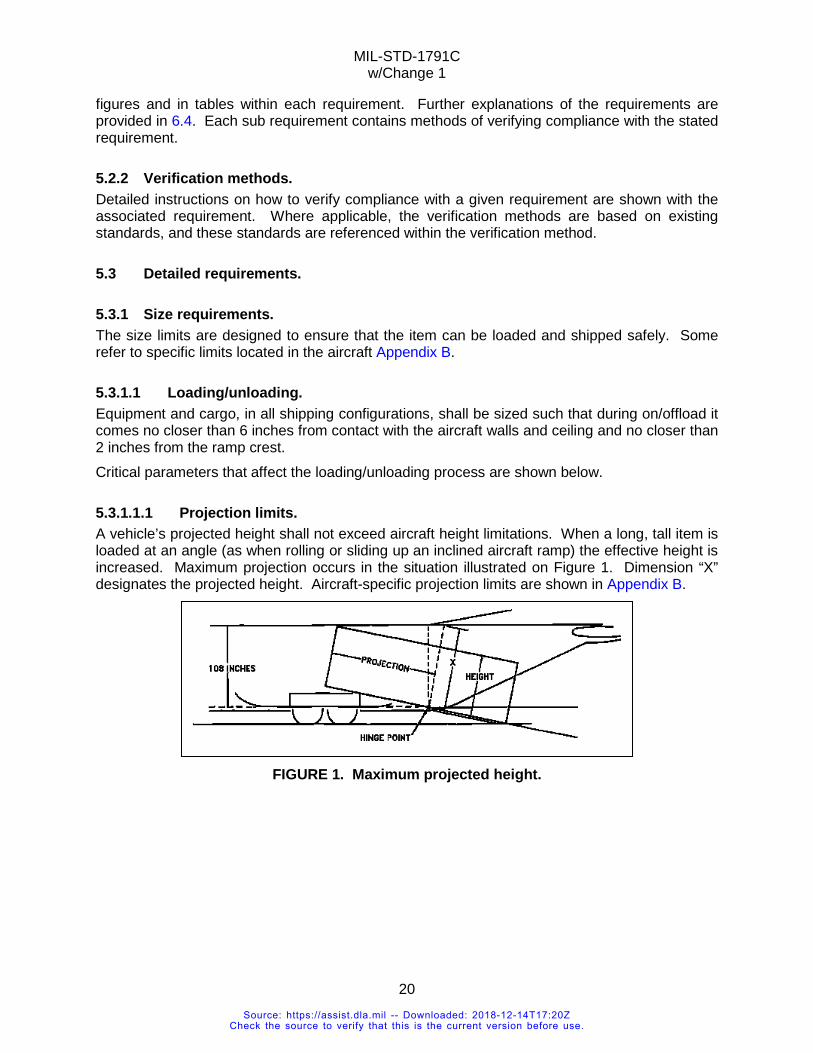
MIL-STD-1791C w/Change 1
20
figures and in tables within each requirement. Further explanations of the requirements are provided in 6.4. Each sub requirement contains methods of verifying compliance with the stated requirement.
5.2.2 Verification methods. Detailed instructions on how to verify compliance with a given requirement are shown with the associated requirement. Where applicable, the verification methods are based on existing standards, and these standards are referenced within the verification method.
5.3 Detailed requirements.
5.3.1 Size requirements. The size limits are designed to ensure that the item can be loaded and shipped safely. Some refer to specific limits located in the aircraft Appendix B.
5.3.1.1 Loading/unloading. Equipment and cargo, in all shipping configurations, shall be sized such that during on/offload it comes no closer than 6 inches from contact with the aircraft walls and ceiling and no closer than 2 inches from the ramp crest. Critical parameters that affect the loading/unloading process are shown below.
5.3.1.1.1 Projection limits. A vehicle’s projected height shall not exceed aircraft height limitations. When a long, tall item is loaded at an angle (as when rolling or sliding up an inclined aircraft ramp) the effective height is increased. Maximum projection occurs in the situation illustrated on Figure 1. Dimension “X” designates the projected height. Aircraft-specific projection limits are shown in Appendix B.
FIGURE 1. Maximum projected height.
Source: https://assist.dla.mil -- Downloaded: 2018-12-14T17:20ZCheck the source to verify that this is the current version before use.
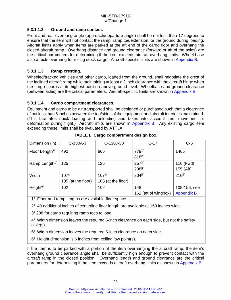
MIL-STD-1791C w/Change 1
21
5.3.1.1.2 Ground and ramp contact. Front and rear overhang angle (approach/departure angle) shall be not less than 17 degrees to ensure that the item will not contact the ramp, ramp toe/extension, or the ground during loading. Aircraft limits apply when items are parked at the aft end of the cargo floor and overhang the closed aircraft ramp. Overhang distance and ground clearance (forward or aft of the axles) are the critical parameters for determining if the item exceeds aircraft overhang limits. Wheel base also affects overhang for rolling stock cargo. Aircraft-specific limits are shown in Appendix B.
5.3.1.1.3 Ramp cresting. Wheeled/tracked vehicles and other cargo, loaded from the ground, shall negotiate the crest of the inclined aircraft ramp while maintaining at least a 2 inch clearance with the aircraft hinge when the cargo floor is at its highest position above ground level. Wheelbase and ground clearance (between axles) are the critical parameters. Aircraft-specific limits are shown in Appendix B.
5.3.1.1.4 Cargo compartment clearances. Equipment and cargo to be air transported shall be designed or purchased such that a clearance of not less than 6 inches between the top/sides of the equipment and aircraft interior is maintained. (This facilitates quick loading and unloading and takes into account item movement or deformation during flight.) Aircraft limits are shown in Appendix B. Any existing cargo item exceeding these limits shall be evaluated by ATTLA.
TABLE I. Cargo compartment design box.
Dimension (in) C-130A-J C-130J-30 C-17 C-5
Floor Length1/ 492 666 7782/
8182/ 1465
Ramp Length1/ 125 125
2573/
2383/ 116 (Fwd) 155 (Aft)
Width 1074/
105 (at the floor) 1074/
105 (at the floor) 2045/ 2165/
Height6/ 102 102 148 162 (aft of wingbox)
108-156, see Appendix B
1/ Floor and ramp lengths are available floor space. 2/ 40 additional inches of centerline floor length are available at 150 inches wide. 3/ 238 for cargo requiring ramp toes to load. 4/ Width dimension leaves the required 6-inch clearance on each side, but not the safety aisle(s). 5/ Width dimension leaves the required 6-inch clearance on each side. 6/ Height dimension is 6 inches from ceiling low point(s).
If the item is to be parked with a portion of the item overhanging the aircraft ramp, the item’s overhang ground clearance angle shall be sufficiently high enough to prevent contact with the aircraft ramp in the closed position. Overhang length and ground clearance are the critical parameters for determining if the item exceeds aircraft overhang limits as shown in Appendix B.
Source: https://assist.dla.mil -- Downloaded: 2018-12-14T17:20ZCheck the source to verify that this is the current version before use.
MIL-STD-1791C w/Change 1
22
5.3.1.1.5 Emergency access and safety aisle. The item’s length, width, and height should allow a safe passageway for crew members and, in some cases, passengers, around the item. The passage is available on most cargo aircraft if the cargo is placed within the cargo envelope, except for C-130 in the wheel well area. The safe passageway for C-130 is defined in Appendix B. Emergency access requirements for CRAF aircraft should be satisfied in accordance with FAR, Part 25, paragraph 25.803.
5.3.1.2 Size verification methods. Compliance with the requirements of 5.3.1 shall be met when compliance can be shown by measurement, engineering analysis, validation loading, or formal test loading.
5.3.2 Weight limits. When in shipping configuration, item gross weight and weight distribution shall meet the requirements of the following subparagraphs as appropriate to the type of item under consideration. The limits for the following parameters are shown in Table III. More detailed limits are shown in Appendix B.
5.3.2.1 Gross weight/center of gravity. The gross weight of items in their shipping configurations shall not exceed the aircraft limits specified in Appendix B for the mission/aircraft combination under consideration. The center of gravity of the total load may not cause the aircraft to be outside its flight stability limits when the load is positioned longitudinally or laterally inside the aircraft. The aircraft limits are shown in the aircraft’s cargo weight loading envelope chart.
5.3.2.2 Aircraft compartment limits. The weight distribution of the item(s) shall not exceed individual cargo compartment weight limits as shown for each aircraft in Table III and Appendix B for specific aircraft.
5.3.2.3 Aircraft roller conveyor limits. The weight distribution of the item(s) shall not exceed individual aircraft roller conveyor limits for loading and during flight. The detailed limits are shown in Table III and Appendix B for specific aircraft. Appendix A describes a method for computing roller loads.
5.3.2.4 Concentrated loads/surface contact loads. Concentrated loads shall not exceed the rated values of the aircraft compartment where they are located. This requirement applies to non-rolling contact with the aircraft floor during loading or flight (treads/tracks have separate limits). The detailed limits are shown in Table III and Appendix B. Cargo shall not have metal-to-metal contact with the aircraft floor. Padding (wood or plastic) may be built into the base or achieved by placing shoring between the base and cargo floor.
Source: https://assist.dla.mil -- Downloaded: 2018-12-14T17:20ZCheck the source to verify that this is the current version before use.
MIL-STD-1791C w/Change 1
23
5.3.2.5 Longitudinal floor (running) loads. Cargo shall not exceed aircraft longitudinal running load limits for loading or flight. The detailed limits are shown in Table III and Appendix B for specific aircraft.
5.3.2.6 Lateral floor loads. Cargo shall not exceed aircraft lateral running load limits for loading or flight. The detailed limits are shown in Table III and Appendix B.
5.3.2.7 Jackstand and tongue loads. Loads imposed on the aircraft floor/ramp by vehicle tongues shall not exceed their maximum rated capacity, when specified. Jackstands and other types of support structure shall withstand 6.75G (4.5G down × 1.5 safety factor) times the intended carrying weight (to meet the 4.5G × 1.5 download requirement in 5.3.3.1, Table I, Down). The stand shall have a locking mechanism that prevents inadvertent collapse or “backing off” due to vibration. Pneumatic and hydraulic stands shall not be used for flight without a mechanical lock because they can leak and lose pressure. Different aircraft floor limits apply if the jackstand is fitted with a foot or a wheel. For a foot or plate, concentrated load limits, lateral load limits, and longitudinal load limits apply. For a wheel, axle load limits and wheel/tire limits or solid wheel limits apply. The detailed limits are shown in Table III and Appendix B for specific aircraft.
5.3.2.8 Axle loads and axle spacing limits. Vehicle axle loads shall not exceed the aircraft compartment loading/flight load limits at the appropriate axle spacing shown in Table III and Appendix B. Axle spacing requirements vary by aircraft and two axles may be treated as a single axle whose weight is the combined weight of both axles when they are too close together. Axles, of any spacing, can be parked to straddle the boundary between compartments. Each axle is subjected to requirements defined for the aircraft compartment(s) in which it may be carried.
5.3.2.9 Pneumatic wheel/tire loads. Vehicles and other wheeled cargo shall not impose pneumatic tire loads in excess of the aircraft compartment limitations for both flight and loading conditions. This is in addition to the requirements for axle loads and axle spacing. Tires with a run flat core not based on reinforced sidewalls, or with internal pressure exceeding 100 psi, are restricted to the solid wheel floor limitations. However, on the C-5 tires up to 300-psi may use pneumatic wheel limits and the C-17 imposes contact-pressure requirements wherein high pressure tires may be treated as pneumatic. (ATTLA reserves the right to examine run-flat tires on a case-by-case basis.) Off-road, agricultural, or industrial tires with deep treads may necessitate rolling and parking shoring due to load concentration by the tread pattern. Foam-filled tires are nominally treated as solid but may be treated as pneumatic depending on individual tire/fill characteristics. Reducing tire pressure to meet limits is not an acceptable practice. Any such procedure shall be certified for air transport use by ATTLA. The method for computing tire load on the aircraft vary by aircraft (see Appendix B) for the methods and limits for each aircraft.
Source: https://assist.dla.mil -- Downloaded: 2018-12-14T17:20ZCheck the source to verify that this is the current version before use.
MIL-STD-1791C w/Change 1
24
5.3.2.10 Solid wheel loads. Vehicles and other wheeled cargo shall not impose steel/hard rubber wheel loads in excess of the aircraft compartment limitations for both flight and loading conditions. This is in addition to the requirements for axle loads and axle spacing. Tires with a run flat core not based on reinforced sidewalls, solid, or with internal pressure exceeding 100 psi, are restricted to the solid wheel floor limitations. Foam-and liquid filled tires are nominally treated as solid wheels but may be treated as pneumatic depending on individual tire/fill characteristics (see Appendix B for individual aircraft limits).
5.3.2.11 Tracked vehicles. Vehicles and other tracked cargo shall not impose track loads in excess of the aircraft compartment limitations for both flight and loading conditions. Grousers or cleats, such as on bulldozers, require rolling shoring from the end of the ramp to the parking location to protect the cargo floor. Shoring thickness shall be the depth of the track pad/cleat, plus 0.5 inch. The minimum thickness is 0.5 inch thick for C-17/C-5 and 0.75 inch for all C-130 variants. Tracked vehicles with worn track pads shall also meet this requirement. Additional shoring may be required to distribute the weight within aircraft limits as shown in Appendix B.
5.3.2.12 Vehicle suspension limits. All vehicle suspension systems shall be capable of supporting a 4.5G static load condition. Military rated equipment may weigh up to the rated military tactical (cross-country) limits, if the testing substantiates that the suspension can support 4.5Gs. Commercially rated loads may carry up to the commercial equivalent of the military tactical (cross-country) limits. If the equivalent limits are unknown, the item may weigh up to 80 percent of the commercial axle rating without being supported. If 80 percent of the rated axle capacity is exceeded, the item may be supported by built-in auxiliary support stands, sleeper shoring, or equivalent systems. Alternatively, test or complete analysis is required to verify that the item can withstand the downward load factor. The support system shall not exceed the aircraft floor contact limits for flight and shall be able to withstand a 4.5G down load. Section A.4.1.8 describes methods to verify compliance with 4.5G download. Special use vehicles weighing over 20,000 pounds, with wide base, off-road tires not designed for highway use, and without a suspension system shall be sleeper shored for flight. (Examples are road graders, forklifts, and wheel loaders.) The aircraft manual, however, directs the aircrew to sleeper shore this type of vehicle if it weighs more than 20,000 pounds, regardless of tire pressure. Air ride suspension shall be fully retracted for flight. This is to prevent collapse of the suspension if a leak occurs. If the suspension collapses then tiedowns will loosen, compromising restraint. Items, built into the cargo, for supporting weight, such as jackstands, are reduced (derated) for flight by dividing the manufacturer’s rating by 6.75 (4.5G down × 1.5 safety factor). This ensures that the structure can sustain the 4.5G down load. The additional 1.5 safety factor is used as added precaution when the ultimate strength is not known. Full manufacturer’s rating may be allowed if the requester or manufacturer can show that the item can support 6.75 times its rating.
Source: https://assist.dla.mil -- Downloaded: 2018-12-14T17:20ZCheck the source to verify that this is the current version before use.
MIL-STD-1791C w/Change 1
25
5.3.2.13 Ramp hinge limits. In addition to the clearance requirements for ramp cresting, cargo items designed to be loaded from the ground up the inclined aircraft ramp shall not impose cresting loads in excess of the ramp hinge limits shown in Appendix B.
5.3.2.14 Palletized cargo. Where equipment can be delivered secured to a pallet that locks into an integral aircraft rail system, the entire unit load shall meet the requirements for restraint. Where such equipment can be secured to the pallet with approved nets and straps, the equipment need not meet the requirements for restraint. All other equipment shall be provided with tiedown provisions in accordance with applicable requirements. In all cases, palletized loads shall not exceed the limits shown in Table II.
Source: https://assist.dla.mil -- Downloaded: 2018-12-14T17:20ZCheck the source to verify that this is the current version before use.
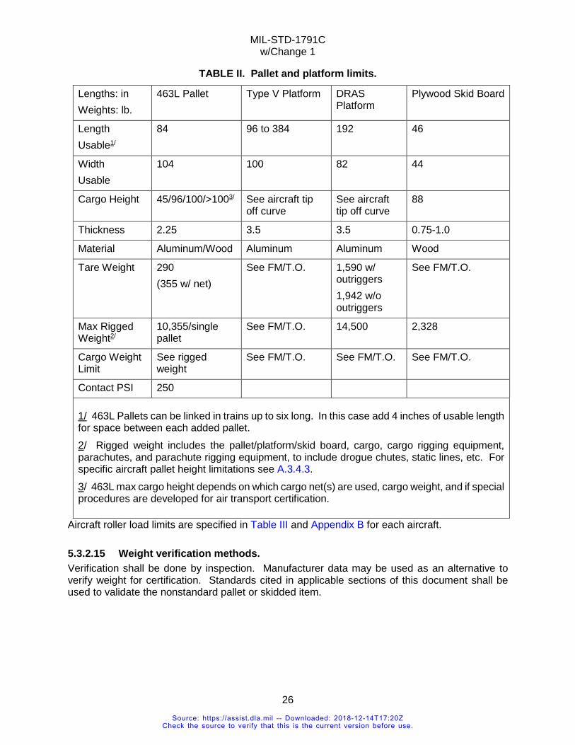
MIL-STD-1791C w/Change 1
26
TABLE II. Pallet and platform limits.
Lengths: in Weights: lb.
463L Pallet Type V Platform DRAS Platform
Plywood Skid Board
Length Usable1/
84 96 to 384 192 46
Width Usable
104 100 82 44
Cargo Height 45/96/100/>1003/ See aircraft tip off curve
See aircraft tip off curve
88
Thickness 2.25 3.5 3.5 0.75-1.0
Material Aluminum/Wood Aluminum Aluminum Wood
Tare Weight 290 (355 w/ net)
See FM/T.O. 1,590 w/ outriggers 1,942 w/o outriggers
See FM/T.O.
Max Rigged Weight2/
10,355/single pallet
See FM/T.O. 14,500 2,328
Cargo Weight Limit
See rigged weight
See FM/T.O. See FM/T.O. See FM/T.O.
Contact PSI 250
1/ 463L Pallets can be linked in trains up to six long. In this case add 4 inches of usable length for space between each added pallet. 2/ Rigged weight includes the pallet/platform/skid board, cargo, cargo rigging equipment, parachutes, and parachute rigging equipment, to include drogue chutes, static lines, etc. For specific aircraft pallet height limitations see A.3.4.3. 3/ 463L max cargo height depends on which cargo net(s) are used, cargo weight, and if special procedures are developed for air transport certification.
Aircraft roller load limits are specified in Table III and Appendix B for each aircraft.
5.3.2.15 Weight verification methods. Verification shall be done by inspection. Manufacturer data may be used as an alternative to verify weight for certification. Standards cited in applicable sections of this document shall be used to validate the nonstandard pallet or skidded item.
Source: https://assist.dla.mil -- Downloaded: 2018-12-14T17:20ZCheck the source to verify that this is the current version before use.
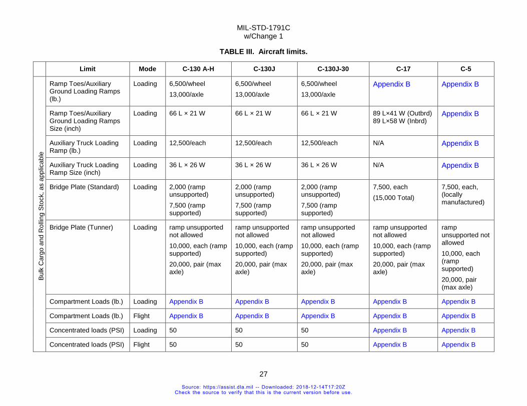
MIL-STD-1791C w/Change 1
27
TABLE III. Aircraft limits. Limit Mode C-130 A-H C-130J C-130J-30 C-17 C-5
Bulk
Car
go a
nd R
ollin
g St
ock,
as
appl
icab
le
Ramp Toes/Auxiliary Ground Loading Ramps (lb.)
Loading 6,500/wheel 13,000/axle
6,500/wheel 13,000/axle
6,500/wheel 13,000/axle
Appendix B Appendix B
Ramp Toes/Auxiliary Ground Loading Ramps Size (inch)
Loading 66 L × 21 W 66 L × 21 W 66 L × 21 W 89 L×41 W (Outbrd) 89 L×58 W (Inbrd)
Appendix B
Auxiliary Truck Loading Ramp (lb.)
Loading 12,500/each 12,500/each 12,500/each N/A Appendix B
Auxiliary Truck Loading Ramp Size (inch)
Loading 36 L × 26 W 36 L × 26 W 36 L × 26 W N/A Appendix B
Bridge Plate (Standard) Loading 2,000 (ramp unsupported) 7,500 (ramp supported)
2,000 (ramp unsupported) 7,500 (ramp supported)
2,000 (ramp unsupported) 7,500 (ramp supported)
7,500, each (15,000 Total)
7,500, each, (locally manufactured)
Bridge Plate (Tunner) Loading ramp unsupported not allowed 10,000, each (ramp supported) 20,000, pair (max axle)
ramp unsupported not allowed 10,000, each (ramp supported) 20,000, pair (max axle)
ramp unsupported not allowed 10,000, each (ramp supported) 20,000, pair (max axle)
ramp unsupported not allowed 10,000, each (ramp supported) 20,000, pair (max axle)
ramp unsupported not allowed 10,000, each (ramp supported) 20,000, pair (max axle)
Compartment Loads (lb.) Loading Appendix B Appendix B Appendix B Appendix B Appendix B
Compartment Loads (lb.) Flight Appendix B Appendix B Appendix B Appendix B Appendix B
Concentrated loads (PSI) Loading 50 50 50 Appendix B Appendix B
Concentrated loads (PSI) Flight 50 50 50 Appendix B Appendix B
Source: https://assist.dla.mil -- Downloaded: 2018-12-14T17:20ZCheck the source to verify that this is the current version before use.
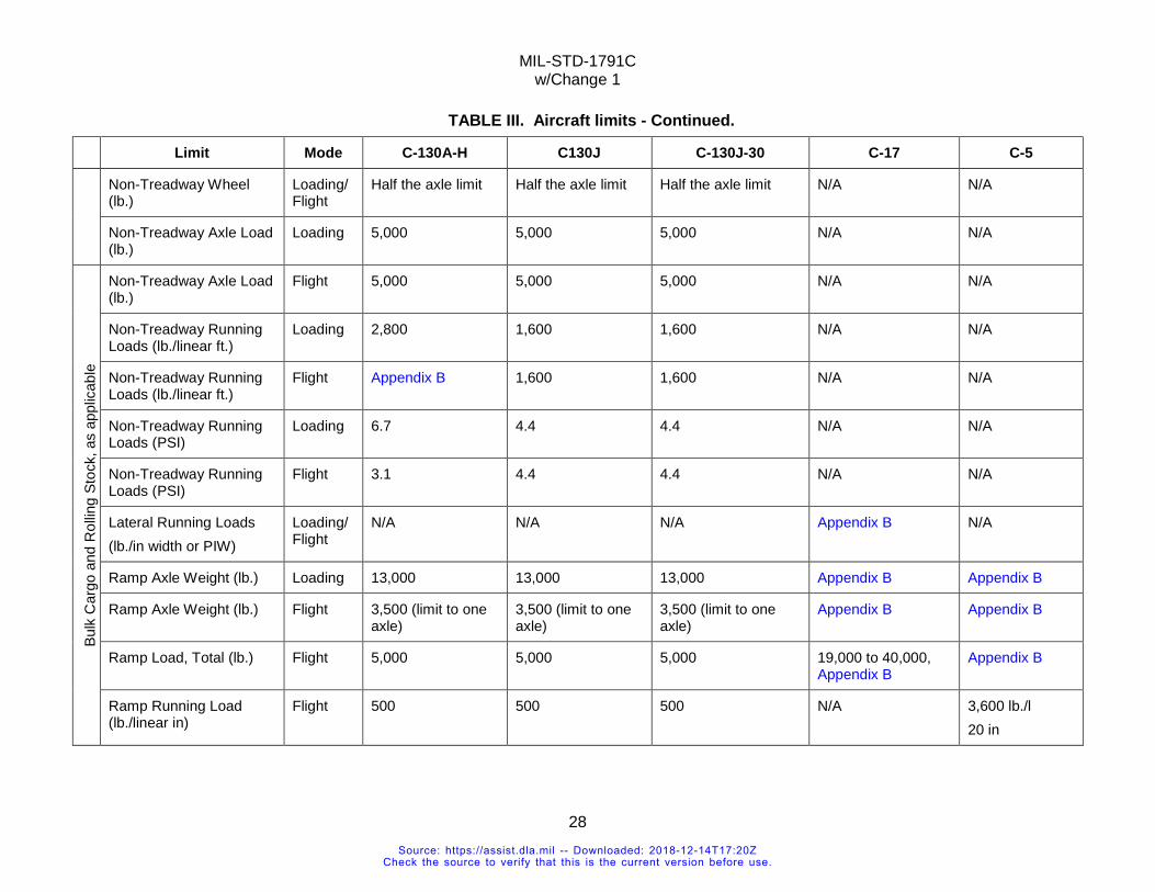
MIL-STD-1791C w/Change 1
28
TABLE III. Aircraft limits - Continued. Limit Mode C-130A-H C130J C-130J-30 C-17 C-5
Non-Treadway Wheel (lb.)
Loading/Flight
Half the axle limit Half the axle limit Half the axle limit N/A N/A
Non-Treadway Axle Load (lb.)
Loading 5,000 5,000 5,000 N/A N/A
Bulk
Car
go a
nd R
ollin
g St
ock,
as
appl
icab
le
Non-Treadway Axle Load (lb.)
Flight 5,000 5,000 5,000 N/A N/A
Non-Treadway Running Loads (lb./linear ft.)
Loading 2,800 1,600 1,600 N/A N/A
Non-Treadway Running Loads (lb./linear ft.)
Flight Appendix B 1,600 1,600 N/A N/A
Non-Treadway Running Loads (PSI)
Loading 6.7 4.4 4.4 N/A N/A
Non-Treadway Running Loads (PSI)
Flight 3.1 4.4 4.4 N/A N/A
Lateral Running Loads (lb./in width or PIW)
Loading/Flight
N/A N/A N/A Appendix B N/A
Ramp Axle Weight (lb.) Loading 13,000 13,000 13,000 Appendix B Appendix B
Ramp Axle Weight (lb.) Flight 3,500 (limit to one axle)
3,500 (limit to one axle)
3,500 (limit to one axle)
Appendix B Appendix B
Ramp Load, Total (lb.) Flight 5,000 5,000 5,000 19,000 to 40,000, Appendix B
Appendix B
Ramp Running Load (lb./linear in)
Flight 500 500 500 N/A 3,600 lb./l 20 in
Source: https://assist.dla.mil -- Downloaded: 2018-12-14T17:20ZCheck the source to verify that this is the current version before use.
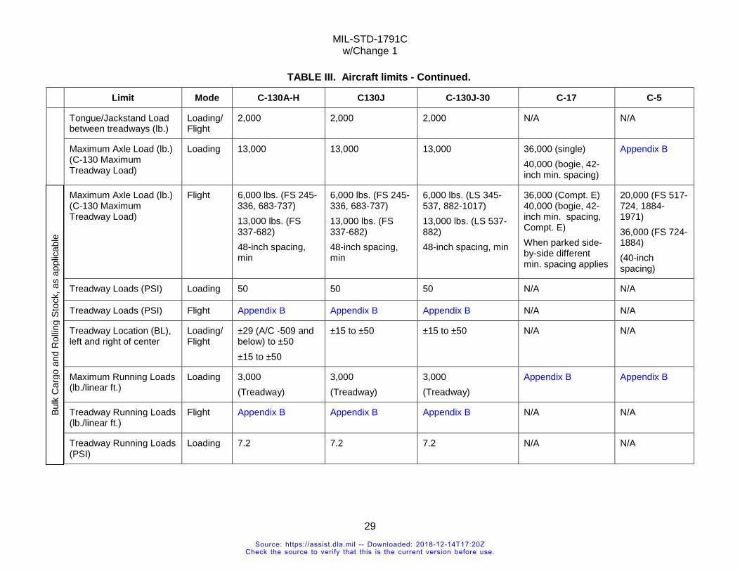
MIL-STD-1791C w/Change 1
29
TABLE III. Aircraft limits - Continued. Limit Mode C-130A-H C130J C-130J-30 C-17 C-5
Tongue/Jackstand Load between treadways (lb.)
Loading/Flight
2,000 2,000 2,000 N/A N/A
Maximum Axle Load (lb.) (C-130 Maximum Treadway Load)
Loading 13,000 13,000 13,000 36,000 (single) 40,000 (bogie, 42-inch min. spacing)
Appendix B
Maximum Axle Load (lb.) (C-130 Maximum Treadway Load)
Flight 6,000 lbs. (FS 245-336, 683-737) 13,000 lbs. (FS 337-682) 48-inch spacing, min
6,000 lbs. (FS 245-336, 683-737) 13,000 lbs. (FS 337-682) 48-inch spacing, min
6,000 lbs. (LS 345-537, 882-1017) 13,000 lbs. (LS 537-882) 48-inch spacing, min
36,000 (Compt. E) 40,000 (bogie, 42-inch min. spacing, Compt. E) When parked side-by-side different min. spacing applies
20,000 (FS 517-724, 1884-1971) 36,000 (FS 724-1884) (40-inch spacing)
Treadway Loads (PSI) Loading 50 50 50 N/A N/A
Treadway Loads (PSI) Flight Appendix B Appendix B Appendix B N/A N/A
Treadway Location (BL), left and right of center
Loading/ Flight
±29 (A/C -509 and below) to ±50 ±15 to ±50
±15 to ±50 ±15 to ±50 N/A N/A
Maximum Running Loads (lb./linear ft.)
Loading 3,000 (Treadway)
3,000 (Treadway)
3,000 (Treadway)
Appendix B Appendix B
Treadway Running Loads (lb./linear ft.)
Flight Appendix B Appendix B Appendix B N/A N/A
Treadway Running Loads (PSI)
Loading 7.2 7.2 7.2 N/A N/A
Bulk
Car
go a
nd R
ollin
g St
ock,
as
appl
icab
le
Source: https://assist.dla.mil -- Downloaded: 2018-12-14T17:20ZCheck the source to verify that this is the current version before use.
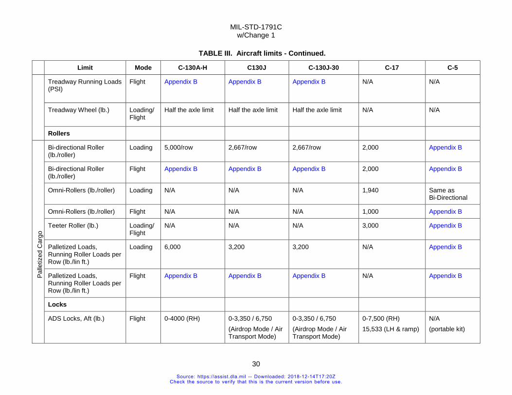
MIL-STD-1791C w/Change 1
30
TABLE III. Aircraft limits - Continued. Limit Mode C-130A-H C130J C-130J-30 C-17 C-5
Treadway Running Loads (PSI)
Flight Appendix B Appendix B Appendix B N/A N/A
Treadway Wheel (lb.) Loading/Flight
Half the axle limit Half the axle limit Half the axle limit N/A N/A
Rollers
Bi-directional Roller (lb./roller)
Loading 5,000/row 2,667/row 2,667/row 2,000 Appendix B
Palle
tized
Car
go
Bi-directional Roller (lb./roller)
Flight Appendix B Appendix B Appendix B 2,000 Appendix B
Omni-Rollers (lb./roller) Loading N/A N/A N/A 1,940 Same as Bi-Directional
Omni-Rollers (lb./roller) Flight N/A N/A N/A 1,000 Appendix B
Teeter Roller (lb.) Loading/Flight
N/A N/A N/A 3,000 Appendix B
Palletized Loads, Running Roller Loads per Row (lb./lin ft.)
Loading 6,000 3,200 3,200 N/A Appendix B
Palletized Loads, Running Roller Loads per Row (lb./lin ft.)
Flight Appendix B Appendix B Appendix B N/A Appendix B
Locks
ADS Locks, Aft (lb.) Flight 0-4000 (RH) 0-3,350 / 6,750 (Airdrop Mode / Air Transport Mode)
0-3,350 / 6,750 (Airdrop Mode / Air Transport Mode)
0-7,500 (RH) 15,533 (LH & ramp)
N/A (portable kit)
Source: https://assist.dla.mil -- Downloaded: 2018-12-14T17:20ZCheck the source to verify that this is the current version before use.
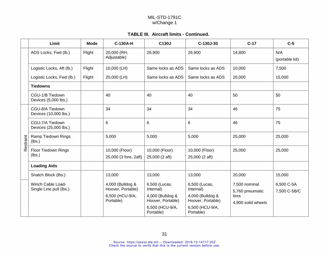
MIL-STD-1791C w/Change 1
31
TABLE III. Aircraft limits - Continued. Limit Mode C-130A-H C130J C-130J-30 C-17 C-5
ADS Locks, Fwd (lb.) Flight 20,000 (RH, Adjustable)
26,900 26,900 14,800 N/A (portable kit)
Logistic Locks, Aft (lb.) Flight 10,000 (LH) Same locks as ADS Same locks as ADS 10,000 7,500
Logistic Locks, Fwd (lb.) Flight 20,000 (LH) Same locks as ADS Same locks as ADS 20,000 15,000
Tiedowns
CGU-1/B Tiedown Devices (5,000 lbs.)
40 40 40 50 50
Res
train
t
CGU-8/A Tiedown Devices (10,000 lbs.)
34 34 34 46 75
CGU-7/A Tiedown Devices (25,000 lbs.)
6 6 6 46 75
Ramp Tiedown Rings (lbs.)
5,000 5,000 5,000 25,000 25,000
Floor Tiedown Rings (lbs.)
10,000 (Floor) 25,000 (3 fore, 2aft)
10,000 (Floor) 25,000 (2 aft)
10,000 (Floor) 25,000 (2 aft)
25,000 25,000
Loading Aids
Snatch Block (lbs.) 13,000 13,000 13,000 20,000 15,000
Winch Cable Load- Single Line pull (lbs.)
4,000 (Bulldog & Hoover, Portable) 6,500 (HCU-9/A, Portable)
6,500 (Lucas, Internal) 4,000 (Bulldog & Hoover, Portable) 6,500 (HCU-9/A, Portable)
6,500 (Lucas, Internal) 4,000 (Bulldog & Hoover, Portable) 6,500 (HCU-9/A, Portable)
7,500 nominal 5,760 pneumatic tires 4,900 solid wheels
6,500 C-5A 7,500 C-5B/C
Source: https://assist.dla.mil -- Downloaded: 2018-12-14T17:20ZCheck the source to verify that this is the current version before use.
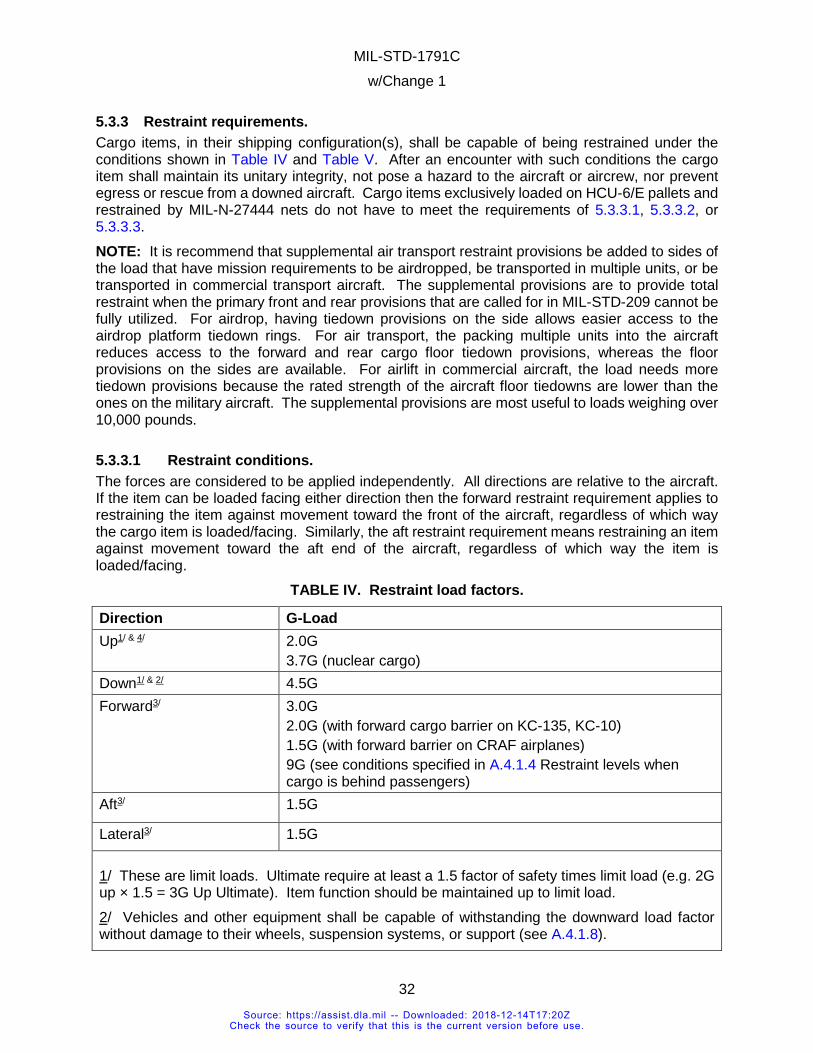
MIL-STD-1791C w/Change 1
32
5.3.3 Restraint requirements. Cargo items, in their shipping configuration(s), shall be capable of being restrained under the conditions shown in Table IV and Table V. After an encounter with such conditions the cargo item shall maintain its unitary integrity, not pose a hazard to the aircraft or aircrew, nor prevent egress or rescue from a downed aircraft. Cargo items exclusively loaded on HCU-6/E pallets and restrained by MIL-N-27444 nets do not have to meet the requirements of 5.3.3.1, 5.3.3.2, or 5.3.3.3. NOTE: It is recommend that supplemental air transport restraint provisions be added to sides of the load that have mission requirements to be airdropped, be transported in multiple units, or be transported in commercial transport aircraft. The supplemental provisions are to provide total restraint when the primary front and rear provisions that are called for in MIL-STD-209 cannot be fully utilized. For airdrop, having tiedown provisions on the side allows easier access to the airdrop platform tiedown rings. For air transport, the packing multiple units into the aircraft reduces access to the forward and rear cargo floor tiedown provisions, whereas the floor provisions on the sides are available. For airlift in commercial aircraft, the load needs more tiedown provisions because the rated strength of the aircraft floor tiedowns are lower than the ones on the military aircraft. The supplemental provisions are most useful to loads weighing over 10,000 pounds.
5.3.3.1 Restraint conditions. The forces are considered to be applied independently. All directions are relative to the aircraft. If the item can be loaded facing either direction then the forward restraint requirement applies to restraining the item against movement toward the front of the aircraft, regardless of which way the cargo item is loaded/facing. Similarly, the aft restraint requirement means restraining an item against movement toward the aft end of the aircraft, regardless of which way the item is loaded/facing.
TABLE IV. Restraint load factors.
Direction G-Load Up1/ & 4/ 2.0G
3.7G (nuclear cargo) Down1/ & 2/ 4.5G Forward3/ 3.0G
2.0G (with forward cargo barrier on KC-135, KC-10) 1.5G (with forward barrier on CRAF airplanes) 9G (see conditions specified in A.4.1.4 Restraint levels when cargo is behind passengers)
Aft3/ 1.5G
Lateral3/ 1.5G
1/ These are limit loads. Ultimate require at least a 1.5 factor of safety times limit load (e.g. 2G up × 1.5 = 3G Up Ultimate). Item function should be maintained up to limit load.
2/ Vehicles and other equipment shall be capable of withstanding the downward load factor without damage to their wheels, suspension systems, or support (see A.4.1.8).
Source: https://assist.dla.mil -- Downloaded: 2018-12-14T17:20ZCheck the source to verify that this is the current version before use.
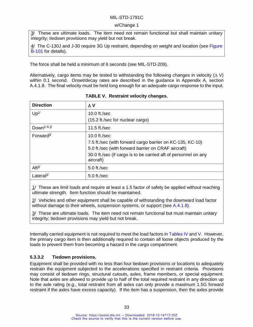
MIL-STD-1791C w/Change 1
33
3/ These are ultimate loads. The item need not remain functional but shall maintain unitary integrity; tiedown provisions may yield but not break. 4/ The C-130J and J-30 require 3G Up restraint, depending on weight and location (see Figure B-101 for details).
The force shall be held a minimum of 6 seconds (see MIL-STD-209). Alternatively, cargo items may be tested to withstanding the following changes in velocity (∆ V) within 0.1 second. Onset/decay rates are described in the guidance in Appendix A, section A.4.1.8. The final velocity must be held long enough for an adequate cargo response to the input.
TABLE V. Restraint velocity changes.
Direction ∆ V Up1/ 10.0 ft./sec
(15.2 ft./sec for nuclear cargo)
Down1/ & 2/ 11.5 ft./sec
Forward3/ 10.0 ft./sec 7.5 ft./sec (with forward cargo barrier on KC-135, KC-10) 5.0 ft./sec (with forward barrier on CRAF aircraft) 30.0 ft./sec (if cargo is to be carried aft of personnel on any aircraft)
Aft3/ 5.0 ft./sec
Lateral3/ 5.0 ft./sec
1/ These are limit loads and require at least a 1.5 factor of safety be applied without reaching ultimate strength. Item function should be maintained. 2/ Vehicles and other equipment shall be capable of withstanding the downward load factor without damage to their wheels, suspension systems, or support (see A.4.1.8). 3/ These are ultimate loads. The item need not remain functional but must maintain unitary integrity; tiedown provisions may yield but not break.
Internally carried equipment is not required to meet the load factors in Tables IV and V. However, the primary cargo item is then additionally required to contain all loose objects produced by the loads to prevent them from becoming a hazard in the cargo compartment.
5.3.3.2 Tiedown provisions. Equipment shall be provided with no less than four tiedown provisions or locations to adequately restrain the equipment subjected to the accelerations specified in restraint criteria. Provisions may consist of tiedown rings, structural cutouts, axles, frame members, or special equipment. Note that axles are allowed to provide up to half of the total required restraint in any direction up to the axle rating (e.g., total restraint from all axles can only provide a maximum 1.5G forward restraint if the axles have excess capacity). If the item has a suspension, then the axles provide
Source: https://assist.dla.mil -- Downloaded: 2018-12-14T17:20ZCheck the source to verify that this is the current version before use.
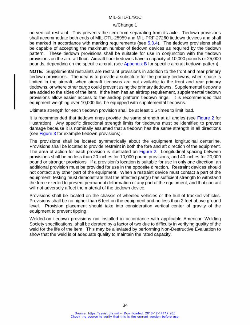
MIL-STD-1791C w/Change 1
34
no vertical restraint. This prevents the item from separating from its axle. Tiedown provisions shall accommodate both ends of MIL-DTL-25959 and MIL-PRF-27260 tiedown devices and shall be marked in accordance with marking requirements (see 5.3.4). The tiedown provisions shall be capable of accepting the maximum number of tiedown devices as required by the tiedown pattern. These tiedown provisions shall be suitable for use in conjunction with the tiedown provisions on the aircraft floor. Aircraft floor tiedowns have a capacity of 10,000 pounds or 25,000 pounds, depending on the specific aircraft (see Appendix B for specific aircraft tiedown pattern). NOTE: Supplemental restraints are restraint provisions in addition to the front and rear primary tiedown provisions. The idea is to provide a substitute for the primary tiedowns, when space is limited in the aircraft, when aircraft tiedowns are not available to the front and rear primary tiedowns, or where other cargo could prevent using the primary tiedowns. Supplemental tiedowns are added to the sides of the item. If the item has an airdrop requirement, supplemental tiedown provisions allow easier access to the airdrop platform tiedown rings. It is recommended that equipment weighing over 10,000 lbs. be equipped with supplemental tiedowns. Ultimate strength for each tiedown provision shall be at least 1.5 times to limit load. It is recommended that tiedown rings provide the same strength at all angles (see Figure 2 for illustration). Any specific directional strength limits for tiedowns must be identified to prevent damage because it is nominally assumed that a tiedown has the same strength in all directions (see Figure 3 for example tiedown provisions). The provisions shall be located symmetrically about the equipment longitudinal centerline. Provisions shall be located to provide restraint in both the fore and aft direction of the equipment. The area of action for each provision is illustrated on Figure 2. Longitudinal spacing between provisions shall be no less than 20 inches for 10,000 pound provisions, and 40 inches for 20,000 pound or stronger provisions. If a provision’s location is suitable for use in only one direction, an additional provision must be provided for use in the opposite direction. Restraint devices should not contact any other part of the equipment. When a restraint device must contact a part of the equipment, testing must demonstrate that the affected part(s) has sufficient strength to withstand the force exerted to prevent permanent deformation of any part of the equipment, and that contact will not adversely affect the material of the tiedown device. Provisions shall be located on the chassis of wheeled vehicles or the hull of tracked vehicles. Provisions shall be no higher than 6 feet on the equipment and no less than 2 feet above ground level. Provision placement should take into consideration vertical center of gravity of the equipment to prevent tipping. Welded-on tiedown provisions not installed in accordance with applicable American Welding Society specifications, shall be derated by a factor of two due to difficulty in verifying quality of the weld for the life of the item. This may be alleviated by performing Non-Destructive Evaluation to show that the weld is of adequate quality to maintain the rated capacity.
Source: https://assist.dla.mil -- Downloaded: 2018-12-14T17:20ZCheck the source to verify that this is the current version before use.
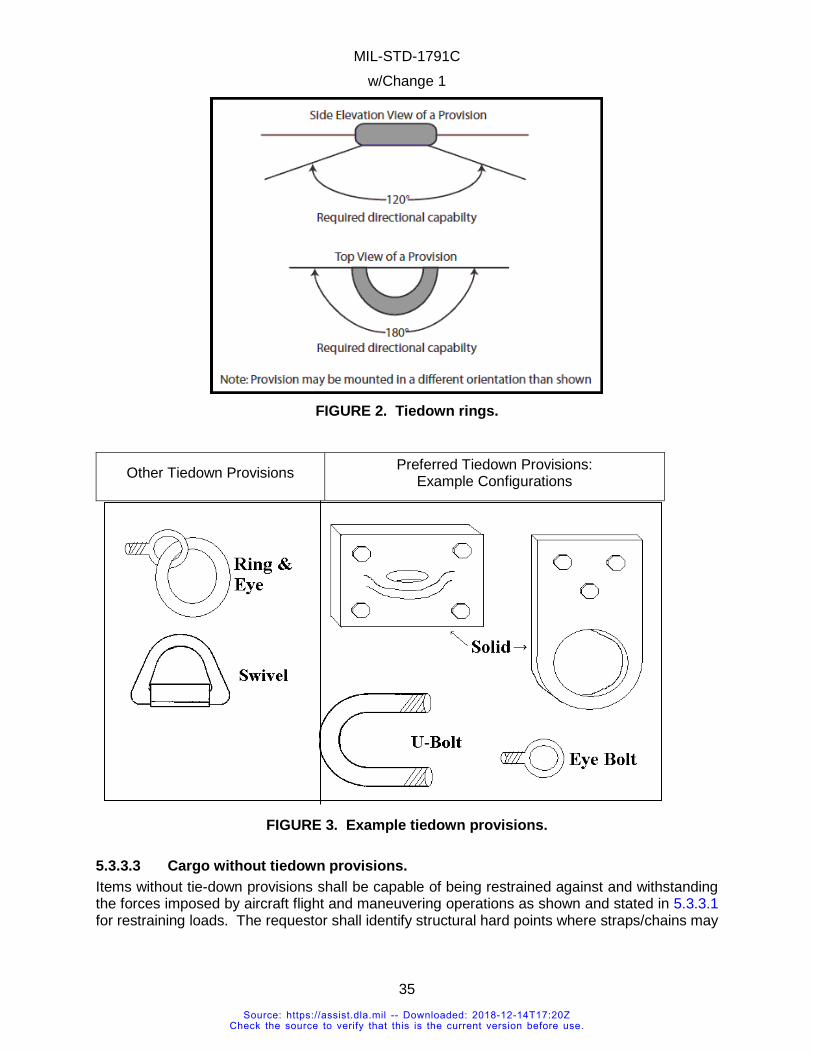
MIL-STD-1791C w/Change 1
35
FIGURE 2. Tiedown rings.
Other Tiedown Provisions Preferred Tiedown Provisions: Example Configurations
FIGURE 3. Example tiedown provisions.
5.3.3.3 Cargo without tiedown provisions. Items without tie-down provisions shall be capable of being restrained against and withstanding the forces imposed by aircraft flight and maneuvering operations as shown and stated in 5.3.3.1 for restraining loads. The requestor shall identify structural hard points where straps/chains may
Source: https://assist.dla.mil -- Downloaded: 2018-12-14T17:20ZCheck the source to verify that this is the current version before use.
MIL-STD-1791C w/Change 1
36
be wrapped around the item and pulled tight. The hard points shall be marked as tiedown points and marked with rated capacities (see 5.3.4.1).
5.3.3.4 Structure. The item shall remain in one piece (unitary integrity) and be capable of being unloaded in the same manner in which it was loaded (maintain loadability), unless otherwise detailed in the loading plan (e.g., a palletized item shall not crush or penetrate the pallet and render it immobile, thus requiring removal via forklift. A wheeled or tracked vehicle shall not crush its own suspension and render itself immobile. A self-propelled vehicle shall remain capable of driving off, if it was driven on, etc.). Military rolling stock gross weight shall not exceed the vehicle’s tactical (cross-country) rating. If the tactical rating is exceeded, test or complete analysis shall be conducted to verify that the item can withstand the load factors and velocity changes. Commercial rolling stock weight shall not exceed 80 percent of the manufacturer’s gross vehicle weight rating (GVWR). If 80 percent of the GVWR is exceeded, test or complete analysis is required to verify that the item can withstand the load factors and velocity changes.
5.3.3.5 Verification methods. Compliance with the restraint requirements shall be assured when it can be demonstrated by engineering analysis or actual test that the item in its shipping configuration and restrained in a manner representative of how it would be restrained for flight can be subjected to the stated static and dynamic loads without loss of structural or unitary integrity of the item and without incurring damage to the aircraft. Loss of structural or unitary integrity during analysis or test shall be cause for rejection of the load for airlift. Loss of loadability during verification of the vertical up or vertical down restraint criteria requirement shall be sufficient to cause rejection of the load for airlift. For palletized items in which the item is restrained to the pallet, the item’s center of gravity location shall be verified by analysis or test. If a vehicle does not have a cross-country weight rating and its weight or axle/suspension loading exceeds 80 percent of its highway gross vehicle rating, test or complete analysis is required to verify that the item can withstand the downward load factor. The vehicle suspension can also be demonstrated using the U.S. Army cross-country test at Aberdeen Proving Ground, MD (see A.4.1.8). The requirements of 5.3.3.2 shall be met when it can be shown by engineering analysis or actual test that the proposed tiedown provisions are adequate in strength, location, size, and number to accept the required MIL-DTL-25959 and MIL-PRF-27260 tiedown devices and provide the restraint required in 5.3.3.1. Cargo without tiedown provisions must be similarly verified using proposed tiedown locations instead of provisions.
5.3.4 Markings. Equipment shall be marked in accordance with the provisions of MIL-STD-129 and MIL-STD-209, as appropriate, to provide the information necessary to facilitate loading and restraining the item in the aircraft. Unless otherwise specified, the marking shall be stenciled in an appropriate location and/or provided on the vehicle data plate in accordance with MIL-STD-130. Markings shall include at least those defined below:
Source: https://assist.dla.mil -- Downloaded: 2018-12-14T17:20ZCheck the source to verify that this is the current version before use.
MIL-STD-1791C w/Change 1
37
5.3.4.1 Tiedown provisions. Tiedown provisions shall be identified, the allowable load shall be indicated, and a representative tiedown grid pattern shall be proposed as defined in the order or contract.
5.3.4.2 Shipping weight and center-of-gravity location. The shipping weight of the equipment in an air transportable condition shall be marked in a conspicuous location. The center of gravity along each axis influencing the method of loading and tiedown shall be marked on the item. This information allows the loadmaster to place the cargo in the proper location on the aircraft.
5.3.4.3 Hoist fittings & forklift tines. When equipment or cargo is to be hoisted onto a K-loader or flatbed trailer or onto a pallet or platform, the hoisting fittings shall be identified and the hoisting capacity shall be marked. Hoist fittings not suitable for use as tiedown provisions shall be marked accordingly. The locations where forklift tines may be applied shall also be identified.
5.3.4.4 Other markings. Other markings shall be provided to address the following, where applicable:
a. Instructions for retraction of wheels or casters to provide greater bearing surface or clearance.
b. Installation of special struts or braces to meet flight loads. c. Orientation(s) in aircraft when critical. d. Instructions for special servicing or other preparation for air shipment. e. Other precautions to be observed during on/offloading and flight.
5.3.4.5 Verification methods. Verification shall be conducted by inspection or manufacturer’s data (e.g., drawings/photographs).
5.3.5 Air transport environment. The air transport environment that the item, in its shipping configuration, shall withstand, and applicable verification methods, is defined below.
5.3.5.1 Acceleration, shock, and vibration requirements. Cargo items shall be designed or configured for transport to withstand, without damage or loss of performance, the shock and vibration environment encountered in aircraft flight and ground maneuvering operations or during cargo on/offloading. The item, in shipping configuration, shall withstand acceleration and shock levels equivalent to the restraint requirements for each aircraft as shown in 5.3.3. In addition, cargo with suspension frequency modes between 0 and 20 Hz shall have sufficient damping to prevent resonance. Vibration environments for each aircraft can be obtained from an aircraft’s Environmental Criteria Document (ECD). In case of unavailability of an ECD or measured data, aircraft general vibration environments described in MIL-STD-810, Environmental Test Methods shall be used.
Source: https://assist.dla.mil -- Downloaded: 2018-12-14T17:20ZCheck the source to verify that this is the current version before use.
MIL-STD-1791C w/Change 1
38
5.3.5.1.1 Verification methods. Tolerance to acceleration, shock, and vibration shall be provided by analysis, demonstration, or formal testing. The item, in its transport configuration, may be subjected to the actual environment or tested to methods described in MIL-STD-810, Environmental Test Methods, or equivalent. In addition, cargo with suspension frequency modes between 0 and 20 Hz shall have sufficient damping as verified by test, analysis, or demonstration.
5.3.5.2 Rapid decompression. The item, including critical subcomponents, shall withstand an internal pressure differential of 8.3 psi developed in 0.5 sec or less without any part of the item becoming a hazard. The aircraft system automatically maintains a maximum of 8.3 psi cabin pressure differential with the atmospheric air pressure.
5.3.5.2.1 Verification methods. Compliance with this requirement shall be verified by analysis or formal testing which confirms that the test item can withstand an internal pressure differential of 8.3 psi developed in 0.5 sec or less without loss of unitary integrity (e.g., any part of the item becoming a missile). A sample calculation for analytical verification of venting area(s) is included in Appendix A.
5.3.5.3 Explosive vapor. This requirement applies to tanker refueling aircraft which have a potential to create a flammable vapor zone inside the cargo compartment. Aircraft equipped with double or redundant fuel leakage barriers do not create a flammable vapor zone and are exempted from this requirement. Any cargo that is transported in flammable vapor or explosive atmosphere zone, or cargo aircraft with midair refueling capability (e.g., KC-10, KC-135, KC-130, and C-17) that has the potential to cause a fire or explosion if the item fails or operates in the aircraft shall be tested. (Cargo with electronic components, that is metallic and carries explosives, or which carries material under high pressure should be tested or analyzed.)
5.3.5.3.1 Verification methods. The item shall be tested to methods described in MIL-STD-810, Method 511.6 or equivalent.
5.3.5.4 Extreme temperature. Applicability of this requirement will be determined by the item’s concept of operations. The cargo shall be packaged to withstand temperature extremes of -40 °F (-40 °C) to 120 °F (49 °C) without posing a hazard to the aircraft and aircrew. Extreme low temperature may be caused by a prolonged cold soak in an arctic location or if a hatch blows (see rapid decompression) at high altitude. Extreme high temperatures can occur when the aircraft is heat soaked in a high-temperature location.
5.3.5.4.1 Verification methods. If applicable, the users or manufacturer shall provide assurance that the item can withstand these conditions or the item shall undergo testing.
Source: https://assist.dla.mil -- Downloaded: 2018-12-14T17:20ZCheck the source to verify that this is the current version before use.
MIL-STD-1791C w/Change 1
39
5.3.5.5. Electromagnetic environment. This section shall apply to electronic devices, materials, and munitions/explosives (which have electrical or electronic integrated initiators that are installed) and transported on the aircraft to ensure safety of flight and mission capability, and to prevent hazards to aircraft and aircrew. Such items shall meet or exceed the criteria shown in Table VI.
5.3.5.5.1 Electromagnetic interference and electromagnetic compatibility (EMI/EMC) requirements. The item, in its air transport configuration, shall meet the requirements of MIL-STD-461 or an equivalent standard (see Table VI). Passive or electrical/electronic equipment/subsystems that will not be operated while on aircraft, including loading/unloading, do not need to be tested unless failure of the item or subsystem is hazardous to the aircraft and aircrew. Safety Critical as used in Table VI (and MIL-STD-461) is defined as a category of subsystems and equipment whose degraded performance could result in loss of life or loss of vehicle or platform.
Source: https://assist.dla.mil -- Downloaded: 2018-12-14T17:20ZCheck the source to verify that this is the current version before use.
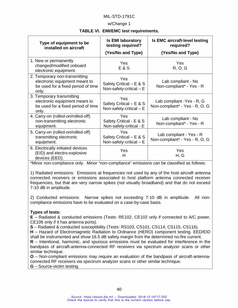
MIL-STD-1791C w/Change 1
40
TABLE VI. EMI/EMC test requirements.
Type of equipment to be installed on aircraft
Is EMI laboratory testing required? (Yes/No and Type)
Is EMC aircraft-level testing required?
(Yes/No and Type)
1. New or permanently changed/modified onboard electronic equipment.
Yes E & S
Yes R, O, G
2. Temporary non-transmitting electronic equipment meant to be used for a fixed period of time only.
Yes Safety Critical – E & S Non-safety-critical – E
Lab compliant - No Non-compliant* - Yes - R
3. Temporary transmitting electronic equipment meant to be used for a fixed period of time only.
Yes Safety Critical – E & S Non-safety-critical – E
Lab compliant -Yes - R, G Non-compliant* - Yes - R, O, G
4. Carry-on (rolled-on/rolled-off) non-transmitting electronic equipment.
Yes Safety Critical - E & S Non-safety-critical - E
Lab compliant - No Non-compliant* - Yes - R
5. Carry-on (rolled-on/rolled-off) transmitting electronic equipment.
Yes Safety Critical – E & S Non-safety-critical – E
Lab compliant - Yes - R Non-compliant* - Yes - R, O, G
6. Electrically initiated devices (EID) and electro-explosive devices (EED).
Yes H
Yes H, G
*Minor non-compliance only. Minor “non-compliance” emissions can be classified as follows: 1) Radiated emissions: Emissions at frequencies not used by any of the host aircraft antenna connected receivers or emissions associated to host platform antenna connected receiver frequencies, but that are very narrow spikes (not visually broadband) and that do not exceed 7-10 dB in amplitude. 2) Conducted emissions: Narrow spikes not exceeding 7-10 dB in amplitude. All non-compliance emissions have to be evaluated on a case-by-case basis. Types of tests: E – Radiated & conducted emissions (Tests: RE102, CE102 only if connected to A/C power, CE106 only if it has antenna ports). S – Radiated & conducted susceptibility (Tests: RS103, CS101, CS114, CS115, CS116). H – Hazard of Electromagnetic Radiation to Ordnance (HERO) component testing. EED/EID shall be instrumented and show 16.5 dB safety margin from the determined no-fire current. R – Intentional, harmonic, and spurious emissions must be evaluated for interference in the bandpass of aircraft-antenna-connected RF receivers via spectrum analyzer scans or other similar technique. O – Non-compliant emissions may require an evaluation of the bandpass of aircraft-antenna-connected RF receivers via spectrum analyzer scans or other similar technique. G – Source-victim testing.
Source: https://assist.dla.mil -- Downloaded: 2018-12-14T17:20ZCheck the source to verify that this is the current version before use.
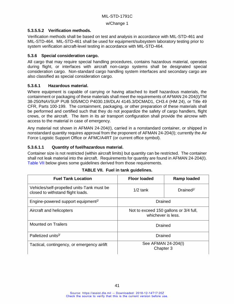
MIL-STD-1791C w/Change 1
41
5.3.5.5.2 Verification methods. Verification methods shall be based on test and analysis in accordance with MIL-STD-461 and MIL-STD-464. MIL-STD-461 shall be used for equipment/subsystem laboratory testing prior to system verification aircraft-level testing in accordance with MIL-STD-464.
5.3.6 Special consideration cargo. All cargo that may require special handling procedures, contains hazardous material, operates during flight, or interfaces with aircraft non-cargo systems shall be designated special consideration cargo. Non-standard cargo handling system interfaces and secondary cargo are also classified as special consideration cargo.
5.3.6.1 Hazardous material. Where equipment is capable of carrying or having attached to itself hazardous materials, the containment or packaging of these materials shall meet the requirements of AFMAN 24-204(I)/TM 38-250/NAVSUP PUB 505/MCO P4030.19I/DLAI 4145.3/DCMAD1, CH3.4 (HM 24), or Title 49 CFR, Parts 100-199. The containment, packaging, or other preparation of these materials shall be performed and certified such that they do not jeopardize the safety of cargo handlers, flight crews, or the aircraft. The item in its air transport configuration shall provide the aircrew with access to the material in case of emergency. Any material not shown in AFMAN 24-204(I), carried in a nonstandard container, or shipped in nonstandard quantity requires approval from the proponent of AFMAN 24-204(I); currently the Air Force Logistic Support Office or AFMC/A4RT (or current office symbol).
5.3.6.1.1 Quantity of fuel/hazardous material. Container size is not restricted (within aircraft limits) but quantity can be restricted. The container shall not leak material into the aircraft. Requirements for quantity are found in AFMAN 24-204(I). Table VII below gives some guidelines derived from those requirements.
TABLE VII. Fuel in tank guidelines.
Fuel Tank Location Floor loaded Ramp loaded
Vehicles/self-propelled units-Tank must be closed to withstand flight loads. 1/2 tank Drained1/
Engine-powered support equipment2/ Drained
Aircraft and helicopters Not to exceed 150 gallons or 3/4 full, whichever is less.
Mounted on Trailers Drained
Palletized units3/ Drained
Tactical, contingency, or emergency airlift See AFMAN 24-204(I) Chapter 3
Source: https://assist.dla.mil -- Downloaded: 2018-12-14T17:20ZCheck the source to verify that this is the current version before use.
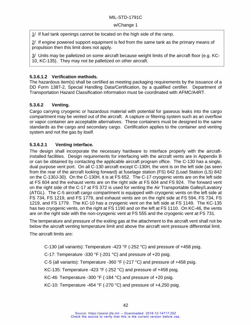
MIL-STD-1791C w/Change 1
42
1/ If fuel tank openings cannot be located on the high side of the ramp.
2/ If engine powered support equipment is fed from the same tank as the primary means of propulsion then this limit does not apply.
3/ Units may be palletized on some aircraft because weight limits of the aircraft floor (e.g. KC-10, KC-135). They may not be palletized on other aircraft.
5.3.6.1.2 Verification methods. The hazardous item(s) shall be certified as meeting packaging requirements by the issuance of a DD Form 1387-2, Special Handling Data/Certification, by a qualified certifier. Department of Transportation Hazard Classification information must be coordinated with AFMC/A4RT.
5.3.6.2 Venting. Cargo carrying cryogenic or hazardous material with potential for gaseous leaks into the cargo compartment may be vented out of the aircraft. A capture or filtering system such as an overflow or vapor container are acceptable alternatives. These containers must be designed to the same standards as the cargo and secondary cargo. Certification applies to the container and venting system and not the gas by itself.
5.3.6.2.1 Venting interface. The design shall incorporate the necessary hardware to interface properly with the aircraft-installed facilities. Design requirements for interfacing with the aircraft vents are in Appendix B or can be obtained by contacting the applicable aircraft program office. The C-130 has a single, dual purpose vent port. On all C-130 aircraft except C-130H, the vent is on the left side (as seen from the rear of the aircraft looking forward) at fuselage station (FS) 642 (Load Station (LS) 842 on the C-130J-30). On the C-130H, it is at FS 652. The C-17 cryogenic vents are on the left side at FS 604 and the exhaust vents are on the right side at FS 604 and FS 924. The forward vent on the right side of the C-17 at FS 372 is used for venting the Air Transportable Galley/Lavatory (ATGL). The C-5 aircraft cargo compartment is equipped with cryogenic vents on the left side at FS 734, FS 1219, and FS 1779, and exhaust vents are on the right side at FS 594, FS 734, FS 1219, and FS 1779. The KC-10 has a cryogenic vent on the left side at FS 1149. The KC-135 has two cryogenic vents, on the right at FS 1190 and on the left at FS 1110. On KC-46, the vents are on the right side with the non-cryogenic vent at FS 555 and the cryogenic vent at FS 731. The temperature and pressure of the exiting gas at the attachment to the aircraft vent shall not be below the aircraft venting temperature limit and above the aircraft vent pressure differential limit. The aircraft limits are: C-130 (all variants): Temperature -423 °F (-252 °C) and pressure of +458 psig. C-17: Temperature -330 °F (-201 °C) and pressure of +20 psig. C-5 (all variants): Temperature -360 °F (-217 °C) and pressure of +458 psig. KC-135: Temperature -423 °F (-252 °C) and pressure of +458 psig. KC-46: Temperature -300 °F (-184 °C) and pressure of +20 psig. KC-10: Temperature -454 °F (-270 °C) and pressure of +4,250 psig.
Source: https://assist.dla.mil -- Downloaded: 2018-12-14T17:20ZCheck the source to verify that this is the current version before use.
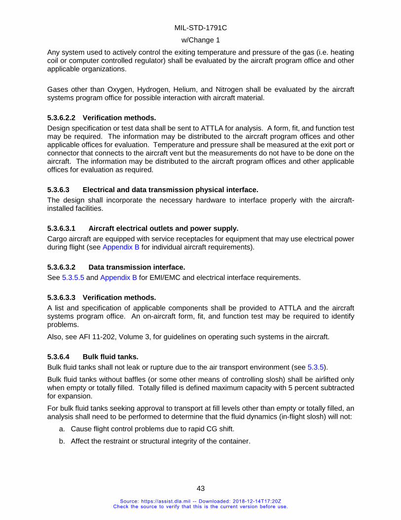
MIL-STD-1791C w/Change 1
43
Any system used to actively control the exiting temperature and pressure of the gas (i.e. heating coil or computer controlled regulator) shall be evaluated by the aircraft program office and other applicable organizations. Gases other than Oxygen, Hydrogen, Helium, and Nitrogen shall be evaluated by the aircraft systems program office for possible interaction with aircraft material.
5.3.6.2.2 Verification methods. Design specification or test data shall be sent to ATTLA for analysis. A form, fit, and function test may be required. The information may be distributed to the aircraft program offices and other applicable offices for evaluation. Temperature and pressure shall be measured at the exit port or connector that connects to the aircraft vent but the measurements do not have to be done on the aircraft. The information may be distributed to the aircraft program offices and other applicable offices for evaluation as required.
5.3.6.3 Electrical and data transmission physical interface. The design shall incorporate the necessary hardware to interface properly with the aircraft-installed facilities.
5.3.6.3.1 Aircraft electrical outlets and power supply. Cargo aircraft are equipped with service receptacles for equipment that may use electrical power during flight (see Appendix B for individual aircraft requirements).
5.3.6.3.2 Data transmission interface. See 5.3.5.5 and Appendix B for EMI/EMC and electrical interface requirements.
5.3.6.3.3 Verification methods. A list and specification of applicable components shall be provided to ATTLA and the aircraft systems program office. An on-aircraft form, fit, and function test may be required to identify problems. Also, see AFI 11-202, Volume 3, for guidelines on operating such systems in the aircraft.
5.3.6.4 Bulk fluid tanks. Bulk fluid tanks shall not leak or rupture due to the air transport environment (see 5.3.5). Bulk fluid tanks without baffles (or some other means of controlling slosh) shall be airlifted only when empty or totally filled. Totally filled is defined maximum capacity with 5 percent subtracted for expansion. For bulk fluid tanks seeking approval to transport at fill levels other than empty or totally filled, an analysis shall need to be performed to determine that the fluid dynamics (in-flight slosh) will not:
a. Cause flight control problems due to rapid CG shift. b. Affect the restraint or structural integrity of the container.
Source: https://assist.dla.mil -- Downloaded: 2018-12-14T17:20ZCheck the source to verify that this is the current version before use.
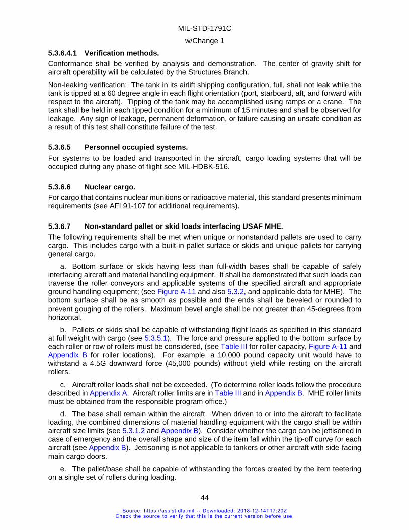
MIL-STD-1791C w/Change 1
44
5.3.6.4.1 Verification methods. Conformance shall be verified by analysis and demonstration. The center of gravity shift for aircraft operability will be calculated by the Structures Branch. Non-leaking verification: The tank in its airlift shipping configuration, full, shall not leak while the tank is tipped at a 60 degree angle in each flight orientation (port, starboard, aft, and forward with respect to the aircraft). Tipping of the tank may be accomplished using ramps or a crane. The tank shall be held in each tipped condition for a minimum of 15 minutes and shall be observed for leakage. Any sign of leakage, permanent deformation, or failure causing an unsafe condition as a result of this test shall constitute failure of the test.
5.3.6.5 Personnel occupied systems. For systems to be loaded and transported in the aircraft, cargo loading systems that will be occupied during any phase of flight see MIL-HDBK-516.
5.3.6.6 Nuclear cargo. For cargo that contains nuclear munitions or radioactive material, this standard presents minimum requirements (see AFI 91-107 for additional requirements).
5.3.6.7 Non-standard pallet or skid loads interfacing USAF MHE. The following requirements shall be met when unique or nonstandard pallets are used to carry cargo. This includes cargo with a built-in pallet surface or skids and unique pallets for carrying general cargo.
a. Bottom surface or skids having less than full-width bases shall be capable of safely interfacing aircraft and material handling equipment. It shall be demonstrated that such loads can traverse the roller conveyors and applicable systems of the specified aircraft and appropriate ground handling equipment; (see Figure A-11 and also 5.3.2, and applicable data for MHE). The bottom surface shall be as smooth as possible and the ends shall be beveled or rounded to prevent gouging of the rollers. Maximum bevel angle shall be not greater than 45-degrees from horizontal.
b. Pallets or skids shall be capable of withstanding flight loads as specified in this standard at full weight with cargo (see 5.3.5.1). The force and pressure applied to the bottom surface by each roller or row of rollers must be considered, (see Table III for roller capacity, Figure A-11 and Appendix B for roller locations). For example, a 10,000 pound capacity unit would have to withstand a 4.5G downward force (45,000 pounds) without yield while resting on the aircraft rollers.
c. Aircraft roller loads shall not be exceeded. (To determine roller loads follow the procedure described in Appendix A. Aircraft roller limits are in Table III and in Appendix B. MHE roller limits must be obtained from the responsible program office.)
d. The base shall remain within the aircraft. When driven to or into the aircraft to facilitate loading, the combined dimensions of material handling equipment with the cargo shall be within aircraft size limits (see 5.3.1.2 and Appendix B). Consider whether the cargo can be jettisoned in case of emergency and the overall shape and size of the item fall within the tip-off curve for each aircraft (see Appendix B). Jettisoning is not applicable to tankers or other aircraft with side-facing main cargo doors.
e. The pallet/base shall be capable of withstanding the forces created by the item teetering on a single set of rollers during loading.
Source: https://assist.dla.mil -- Downloaded: 2018-12-14T17:20ZCheck the source to verify that this is the current version before use.
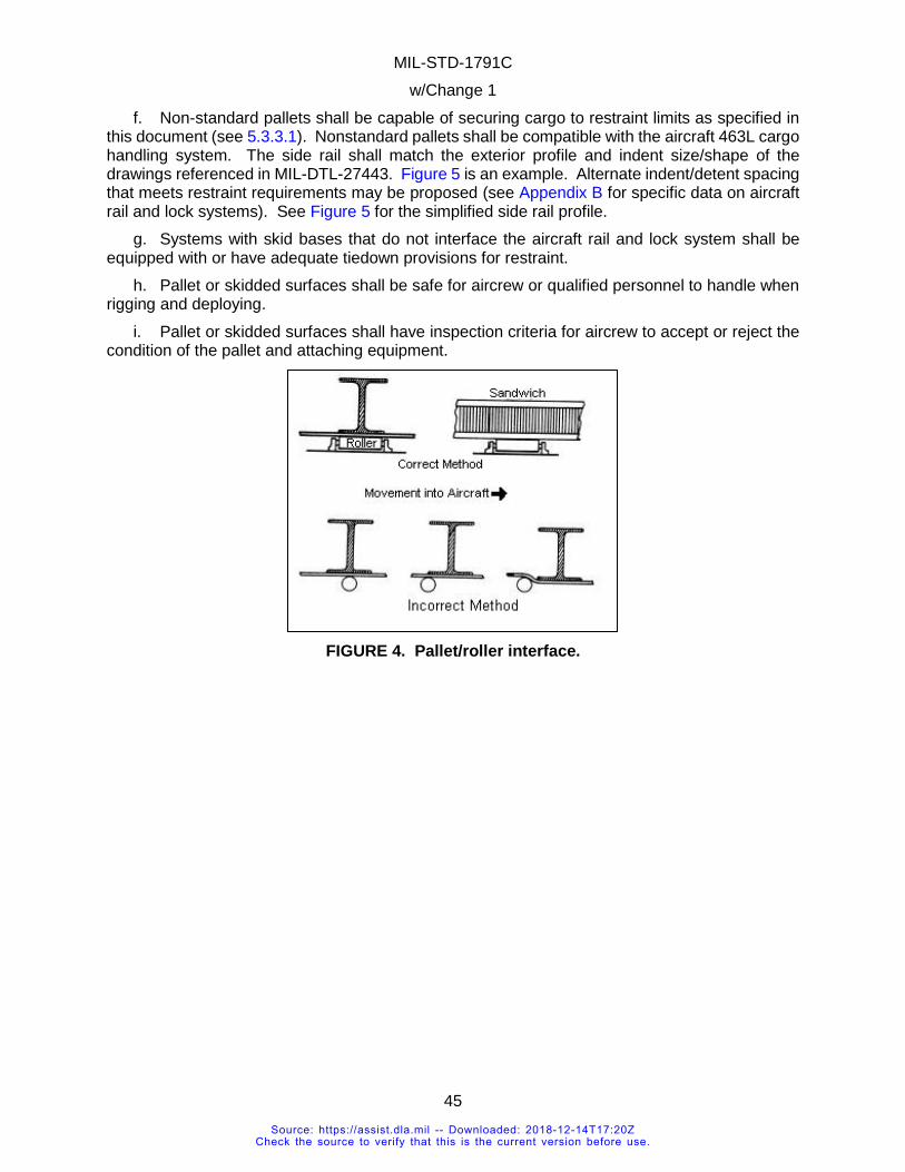
MIL-STD-1791C w/Change 1
45
f. Non-standard pallets shall be capable of securing cargo to restraint limits as specified in this document (see 5.3.3.1). Nonstandard pallets shall be compatible with the aircraft 463L cargo handling system. The side rail shall match the exterior profile and indent size/shape of the drawings referenced in MIL-DTL-27443. Figure 5 is an example. Alternate indent/detent spacing that meets restraint requirements may be proposed (see Appendix B for specific data on aircraft rail and lock systems). See Figure 5 for the simplified side rail profile.
g. Systems with skid bases that do not interface the aircraft rail and lock system shall be equipped with or have adequate tiedown provisions for restraint.
h. Pallet or skidded surfaces shall be safe for aircrew or qualified personnel to handle when rigging and deploying.
i. Pallet or skidded surfaces shall have inspection criteria for aircrew to accept or reject the condition of the pallet and attaching equipment.
FIGURE 4. Pallet/roller interface.
Source: https://assist.dla.mil -- Downloaded: 2018-12-14T17:20ZCheck the source to verify that this is the current version before use.
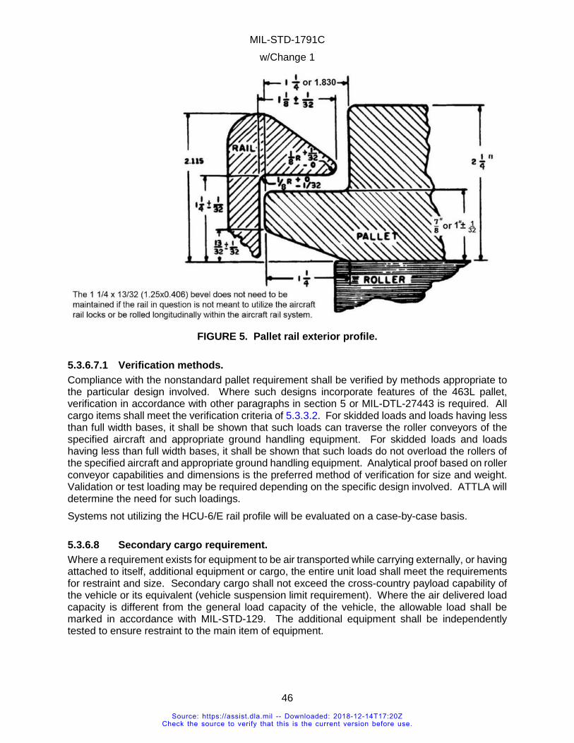
MIL-STD-1791C w/Change 1
46
FIGURE 5. Pallet rail exterior profile.
5.3.6.7.1 Verification methods. Compliance with the nonstandard pallet requirement shall be verified by methods appropriate to the particular design involved. Where such designs incorporate features of the 463L pallet, verification in accordance with other paragraphs in section 5 or MIL-DTL-27443 is required. All cargo items shall meet the verification criteria of 5.3.3.2. For skidded loads and loads having less than full width bases, it shall be shown that such loads can traverse the roller conveyors of the specified aircraft and appropriate ground handling equipment. For skidded loads and loads having less than full width bases, it shall be shown that such loads do not overload the rollers of the specified aircraft and appropriate ground handling equipment. Analytical proof based on roller conveyor capabilities and dimensions is the preferred method of verification for size and weight. Validation or test loading may be required depending on the specific design involved. ATTLA will determine the need for such loadings. Systems not utilizing the HCU-6/E rail profile will be evaluated on a case-by-case basis.
5.3.6.8 Secondary cargo requirement. Where a requirement exists for equipment to be air transported while carrying externally, or having attached to itself, additional equipment or cargo, the entire unit load shall meet the requirements for restraint and size. Secondary cargo shall not exceed the cross-country payload capability of the vehicle or its equivalent (vehicle suspension limit requirement). Where the air delivered load capacity is different from the general load capacity of the vehicle, the allowable load shall be marked in accordance with MIL-STD-129. The additional equipment shall be independently tested to ensure restraint to the main item of equipment.
Source: https://assist.dla.mil -- Downloaded: 2018-12-14T17:20ZCheck the source to verify that this is the current version before use.
MIL-STD-1791C w/Change 1
47
5.3.6.8.1 Verification methods. Same as primary cargo item.
5.3.7 Special loading, unloading, and flight procedures. To facilitate handling, the equipment should be as compact and lightweight as practical. However, reliability and maintainability shall not be substantially impaired in meeting this requirement. Any projected design compromise for the sake of air transportability shall be brought to the attention of the procuring activity. Using a minimum amount of handling equipment, it shall be possible to load the equipment into the aircraft and readily position the equipment without damage to the aircraft.
5.3.7.1 Shoring. The item should be designed to avoid using shoring whenever possible. Shoring is used to spread weight, support structure or aid in loading and unloading (see 5.3.1.1) the item. If any type of shoring is necessary, the user shall provide all shoring material. Approach shoring should, but not required to, be transported with the item for convenience to unload the item. If all or part of the shoring is transported on the item, the weight (see 5.3.2) of the shoring must not cause the item to exceed its weight limits or aircraft limits for flight. If all or part of the shoring is carried on the aircraft separate from the item, the shoring weight and location must not exceed aircraft flight limits. Shoring shall be able to withstand the forces imparted during loading and unloading. The material shall not cause damage to any aircraft part with which it interfaces. The shoring shall be stable during the load transfer process. It is recommended that shoring be solid, without internal spaces. ATTLA must approve shoring that is not solid or shoring that is not made of wood. For pedestal type approach shoring, the minimum length of the top layer, to support the ramp toe/extension or ground loading ramp, shall be 11 inches for C-17/C-5 and 12 inches for all C-130 variants. Minimum width is 1.5 times the items track or wheel width to allow for maneuvering. Also for C-130, the minimum width for over top and pedestal approach shoring shall be 24 inches. Additional shoring may also be required by the specific aircraft limits. If approach shoring is laid on top of the aircraft ramp or ramp extensions, the minimum contact area shall not exceed the aircraft loading limits. If the approach shoring is used on soft ground, semi-prepared runway or unpaved surfaces, the ground contact area shall not exceed 50 psi (including weight of the shoring) to prevent shoring from sinking into the ground during loading and unloading. 50 psi is roughly the inflation pressure of the C-130 tire, which lands on soft, unpaved ground. The tire pressure equates to the average ground contact pressure (see DTIC Report Number AD A043447, The Goodyear Tire and Rubber Company, Truck Tire Types and Road Contact Pressures, June 1989, and Boeing Airport Compatibility, Calculating Tire Contact Area, 4 February 2014). Shoring shall be able to withstand the forces imparted during use. Sleeper or support shoring, if it is other than solid wood, shall withstand vertical force 4.5G down (limit) and 6.75 G down (Ultimate). For approach shoring, or ramp, that is not solid wood, the shoring shall be able to withstand the maximum forces imparted during loading and unloading operations. If a static test is conducted, the ramp shall be able to withstand the force for a minimum of five minutes without deformation, to simulate a vehicle stopped on the ramp. For more information on shoring and its applications, see Appendix A.
Source: https://assist.dla.mil -- Downloaded: 2018-12-14T17:20ZCheck the source to verify that this is the current version before use.
MIL-STD-1791C w/Change 1
48
5.3.7.1.1 Load spreading shoring limitations. New equipment designs which impose unacceptable floor loadings under flight conditions shall incorporate integral devices to function as sleeper shoring. An example of an integral device is a jackstand. Normally, such devices do not relieve excess on/offload forces.
5.3.7.1.2 Load spreading shoring verification methods. Weight-measurements such as gross weight, axle weights, and floor contact weights shall be within acceptable limits per data. Weights on critical areas during the on/offloading process and flight shall also be provided because weight distribution may differ from the loaded position sufficiently to exceed item and aircraft limits.
5.3.7.2 Winching. If the item requires winching in and out of the aircraft, the item shall have a sufficient number of provisions so as to not exceed the winch cable limit. The minimum strength of each winching provision shall withstand the maximum calculated winching force, for that location, times 1.5 safety factor (winching force per point × 1.5) and be large enough to attach a winch cable hook or route a chain bridle through (see MIL-STD-209 for size). Winching aboard may be accomplished using the aircraft winch or vehicle-installed winch from the ground or from a K-loader. See Appendix A for details on winching operations. A tow bar, bridle, or load spreader may be utilized to prevent damage to the winch cable or cargo.
5.3.7.3 Combat offload. New equipment designs and commercial equipment purchases intended for use on pallets or platforms with a combat offload requirement shall conform to the aircraft(s) tipoff curve(s).
5.3.7.4 Special tools and support equipment. Use of special tools and support equipment shall not degrade the user's mission capability, involve equipment not normally available at the deployment site, or compromise the safety of the aircraft or operating personnel.
5.3.7.4.1 Material handling equipment (MHE). If the other requirements of this standard cannot be met, material handling equipment (MHE) shall be used to assist in loading/unloading the item. The item’s physical characteristics and loading/unloading procedures shall meet the requirements for the current MHE. Other equipment such as pallets and mobilizers may be used to facilitate movement in and out of the aircraft. Specialty built material handling equipment shall meet interface requirements of the standard MHE, pallets, or the aircraft depending on the transport procedures.
5.3.7.4.2 Reduced configuration. To facilitate loading and unloading or to meet weight limitations, vehicles may be partially disassembled. Most commonly this involves removing cabs, counterweights, or tools (e.g. wide bulldozer blades). The reduced configuration shall not necessitate use of equipment not normally available at the deployment site; nor shall it compromise the safety of the aircraft or operating personnel.
Source: https://assist.dla.mil -- Downloaded: 2018-12-14T17:20ZCheck the source to verify that this is the current version before use.
MIL-STD-1791C w/Change 1
49
5.3.7.4.3 Self-adjustment. In order to meet weight and dimensional requirements, a cargo item’s inherent adjustability may be employed to prevent contact with the aircraft during loading/unloading (e.g., raising bulldozer blades) or to redistribute weight during loading/unloading or for flight.
5.3.7.5 Verification methods. The item’s critical dimensions, as identified above, shall be provided to ATTLA using the ATTLA data sheet, drawings, CAD files, or other acceptable means for analysis. ATTLA reserves the right to request a validation loading or a test loading if there is risk of contact with the aircraft, if additional data is required, or if the loading procedure is complex.
6. NOTES (This section contains information of a general or explanatory nature that may be helpful, but is not mandatory.)
6.1 Intended use. The information in this standard covers everything necessary to adequately design or modify a cargo item to be safely and successfully transported aboard USAF cargo aircraft. The air transport certification is military unique because there are no similarly configured commercial aircraft and no government or commercial group with adequate expertise. The standard for designing airdropping cargo and interfacing with standard airdrop systems is in MIL-STD-1791-1, Criteria for Nonstandard Airdrop Equipment and Payloads. Any cargo configured for airdrop is considered to be approved air transport without requiring a separate air transport certificate.
6.2 Acquisition requirements. Acquisition documents should specify the following:
a. Title, number, and date of this standard.
b. Use of the ATTLA data sheet for submission of data to ATTLA.
6.3 Tailoring instructions. Some requirements, such as size limitations and vibration spectrum, apply to all cargo being transported by air. Other requirements, such as winching and axle limitations, apply only to cargo that cannot be loaded under its own power and which, for example, is wheeled. In order to identify the requirements pertinent to a given system, the following steps are recommended:
a. First, start with the requirements that apply to all cargo. b. Second, sort size and weight requirements to match the method in which the cargo will be
loaded. c. Third, add requirements for special considerations based on the contents/intended use of
the cargo. d. Fourth, add requirements that apply to special loading or unloading procedures.
Requirements stemming from an item’s concept of operations do occasionally impose additional restrictions on a cargo item. However, due to the wide variability in these situations, such CONOPs restrictions are best reviewed in consultation with an ATTLA agent.
Source: https://assist.dla.mil -- Downloaded: 2018-12-14T17:20ZCheck the source to verify that this is the current version before use.
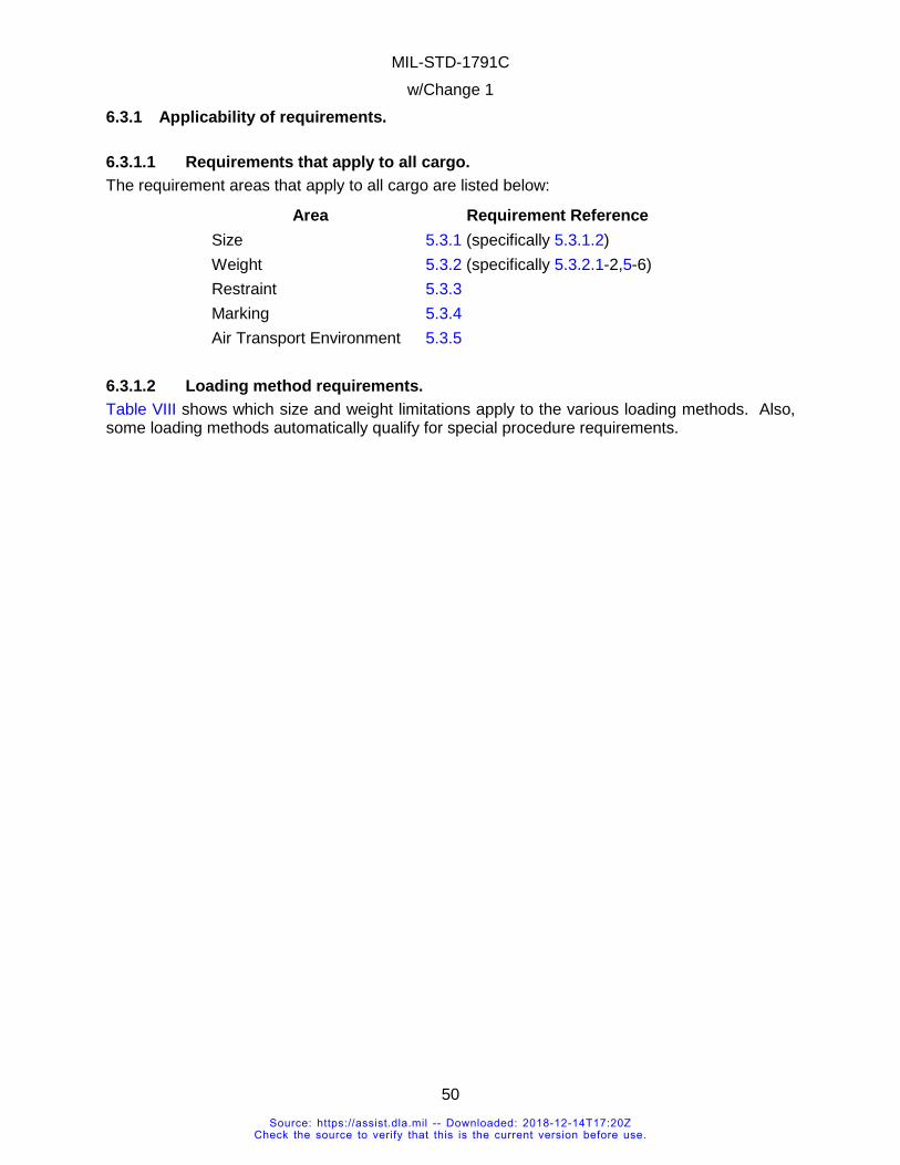
MIL-STD-1791C w/Change 1
50
6.3.1 Applicability of requirements.
6.3.1.1 Requirements that apply to all cargo. The requirement areas that apply to all cargo are listed below:
Area Requirement Reference Size 5.3.1 (specifically 5.3.1.2) Weight 5.3.2 (specifically 5.3.2.1-2,5-6) Restraint 5.3.3 Marking 5.3.4 Air Transport Environment 5.3.5
6.3.1.2 Loading method requirements. Table VIII shows which size and weight limitations apply to the various loading methods. Also, some loading methods automatically qualify for special procedure requirements.
Source: https://assist.dla.mil -- Downloaded: 2018-12-14T17:20ZCheck the source to verify that this is the current version before use.
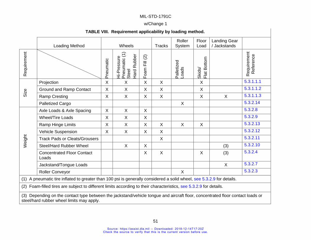
MIL-STD-1791C w/Change 1
51
TABLE VIII. Requirement applicability by loading method.
Loading Method Wheels Tracks
Roller System
Floor Load
Landing Gear / Jackstands
Req
uire
men
t
Pneu
mat
ic
Hi-P
ress
ure
Pneu
mat
ic (1
) St
eel
Har
d R
ubbe
r
Foam
Fill
(2)
Palle
tized
Lo
ads
Skid
s/
Flat
Bot
tom
Req
uire
men
t R
efer
ence
Size
Projection X X X X X 5.3.1.1.1
Ground and Ramp Contact X X X X X 5.3.1.1.2
Ramp Cresting X X X X X X 5.3.1.1.3
Palletized Cargo X 5.3.2.14
Wei
ght
Axle Loads & Axle Spacing X X X 5.3.2.8
Wheel/Tire Loads X X X 5.3.2.9
Ramp Hinge Limits X X X X X X 5.3.2.13
Vehicle Suspension X X X X 5.3.2.12
Track Pads or Cleats/Grousers X 5.3.2.11
Steel/Hard Rubber Wheel X X (3) 5.3.2.10
Concentrated Floor Contact Loads
X X X (3) 5.3.2.4
Jackstand/Tongue Loads X 5.3.2.7
Roller Conveyor X 5.3.2.3
(1) A pneumatic tire inflated to greater than 100 psi is generally considered a solid wheel, see 5.3.2.9 for details.
(2) Foam-filled tires are subject to different limits according to their characteristics, see 5.3.2.9 for details.
(3) Depending on the contact type between the jackstand/vehicle tongue and aircraft floor, concentrated floor contact loads or steel/hard rubber wheel limits may apply.
Source: https://assist.dla.mil -- Downloaded: 2018-12-14T17:20ZCheck the source to verify that this is the current version before use.
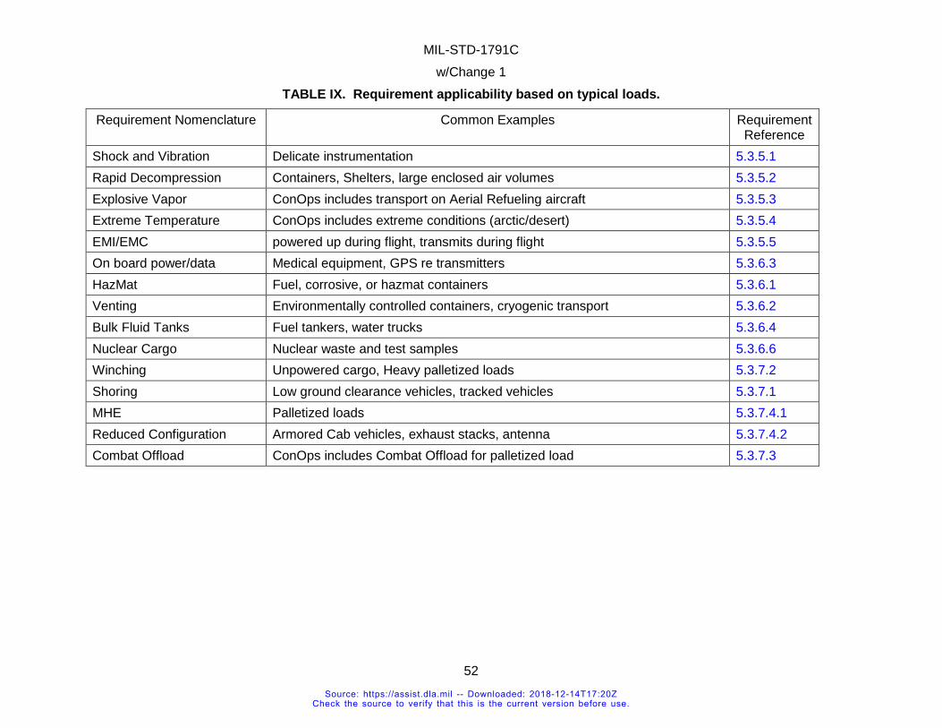
MIL-STD-1791C w/Change 1
52
TABLE IX. Requirement applicability based on typical loads.
Requirement Nomenclature Common Examples Requirement Reference
Shock and Vibration Delicate instrumentation 5.3.5.1 Rapid Decompression Containers, Shelters, large enclosed air volumes 5.3.5.2 Explosive Vapor ConOps includes transport on Aerial Refueling aircraft 5.3.5.3 Extreme Temperature ConOps includes extreme conditions (arctic/desert) 5.3.5.4 EMI/EMC powered up during flight, transmits during flight 5.3.5.5 On board power/data Medical equipment, GPS re transmitters 5.3.6.3 HazMat Fuel, corrosive, or hazmat containers 5.3.6.1 Venting Environmentally controlled containers, cryogenic transport 5.3.6.2 Bulk Fluid Tanks Fuel tankers, water trucks 5.3.6.4 Nuclear Cargo Nuclear waste and test samples 5.3.6.6 Winching Unpowered cargo, Heavy palletized loads 5.3.7.2 Shoring Low ground clearance vehicles, tracked vehicles 5.3.7.1 MHE Palletized loads 5.3.7.4.1 Reduced Configuration Armored Cab vehicles, exhaust stacks, antenna 5.3.7.4.2 Combat Offload ConOps includes Combat Offload for palletized load 5.3.7.3
Source: https://assist.dla.mil -- Downloaded: 2018-12-14T17:20ZCheck the source to verify that this is the current version before use.
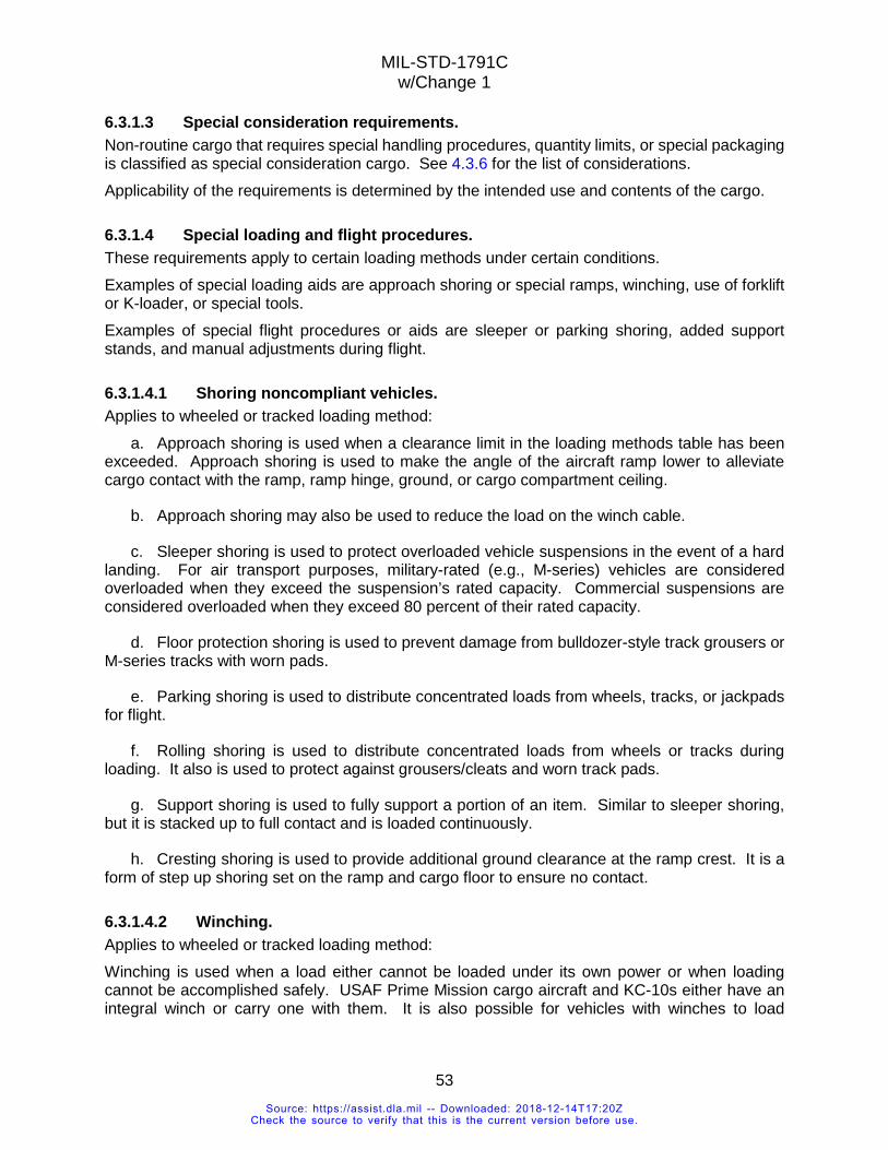
MIL-STD-1791C w/Change 1
53
6.3.1.3 Special consideration requirements. Non-routine cargo that requires special handling procedures, quantity limits, or special packaging is classified as special consideration cargo. See 4.3.6 for the list of considerations. Applicability of the requirements is determined by the intended use and contents of the cargo.
6.3.1.4 Special loading and flight procedures. These requirements apply to certain loading methods under certain conditions. Examples of special loading aids are approach shoring or special ramps, winching, use of forklift or K-loader, or special tools. Examples of special flight procedures or aids are sleeper or parking shoring, added support stands, and manual adjustments during flight.
6.3.1.4.1 Shoring noncompliant vehicles. Applies to wheeled or tracked loading method:
a. Approach shoring is used when a clearance limit in the loading methods table has been exceeded. Approach shoring is used to make the angle of the aircraft ramp lower to alleviate cargo contact with the ramp, ramp hinge, ground, or cargo compartment ceiling.
b. Approach shoring may also be used to reduce the load on the winch cable.
c. Sleeper shoring is used to protect overloaded vehicle suspensions in the event of a hard landing. For air transport purposes, military-rated (e.g., M-series) vehicles are considered overloaded when they exceed the suspension’s rated capacity. Commercial suspensions are considered overloaded when they exceed 80 percent of their rated capacity.
d. Floor protection shoring is used to prevent damage from bulldozer-style track grousers or M-series tracks with worn pads.
e. Parking shoring is used to distribute concentrated loads from wheels, tracks, or jackpads for flight.
f. Rolling shoring is used to distribute concentrated loads from wheels or tracks during loading. It also is used to protect against grousers/cleats and worn track pads.
g. Support shoring is used to fully support a portion of an item. Similar to sleeper shoring, but it is stacked up to full contact and is loaded continuously.
h. Cresting shoring is used to provide additional ground clearance at the ramp crest. It is a form of step up shoring set on the ramp and cargo floor to ensure no contact.
6.3.1.4.2 Winching. Applies to wheeled or tracked loading method: Winching is used when a load either cannot be loaded under its own power or when loading cannot be accomplished safely. USAF Prime Mission cargo aircraft and KC-10s either have an integral winch or carry one with them. It is also possible for vehicles with winches to load
Source: https://assist.dla.mil -- Downloaded: 2018-12-14T17:20ZCheck the source to verify that this is the current version before use.
MIL-STD-1791C w/Change 1
54
themselves. The aircraft have snatch blocks (pulleys) to create a “block and tackle” arrangement if sufficient winch line is available.
6.3.1.4.3 Jettison. Applies to roller system loading method: In the event of an in-flight emergency, the aircrew may opt to jettison any or all possible cargo. Arrangements for this should be made prior to take-off. This primarily applies to palletized cargo. For this reason, palletized loads are required to fit under the “tip-off curve” for the aircraft on which they will be flying. Jettisoning is not applicable to tankers or other cargo aircraft with side-opening main cargo doors. This is not a mandatory requirement in the design of the cargo.
6.3.1.4.4 Combat offload. Applies to roller system loading method: This is essentially cargo jettison while taxiing. Combat offload is used when appropriate material handling equipment is unavailable at the destination airfield or when conditions dictate leaving the cargo and taking off as rapidly as possible. Jettisoning is not applicable to tankers or other cargo aircraft with side-opening main cargo doors.
6.3.1.4.5 Special tools and support equipment. Applies to any loading method: If the other requirements of this standard cannot be met, material handling equipment (MHE) may be used to assist in loading/unloading the item. The item’s physical characteristics and loading/unloading procedures should meet the requirements for the current MHE. Other equipment such as pallets and mobilizers may be used to facilitate movement in and out of the aircraft. Special material handling equipment should meet interface requirements of the standard MHE, pallets or the aircraft depending on the transport procedures.
6.3.1.5 Concept of operations. The proposed cargo item’s concept of operations should be reviewed to determine whether the item can be reconfigured or if it can be certified for airlift at all. Most cargo can be certified based on physical characteristics alone, but there are instances in which the item’s mission or mission concept may be limited by the aircraft’s capabilities.
Requirement Guidance
Examples of operational restrictions due to cargo design: (1) A large, heavy piece of cargo’s concept of operation dictates that it would be transported to a high altitude, short runway geographical location. The item’s size restricts it to being parked only in the aft cargo compartment. The cargo’s weight at the parked location puts the aircraft out of balance. The support equipment or loading equipment adds additional weight that exceeds the aircraft’s payload capability to land and take off from the desired location. (2) The item may have other accompanying equipment that requires additional aircraft to transport the entire system. (3) A vehicle too heavy to be airlifted fully assembled needs all the pieces to perform its mission. Some of the pieces may have to be transported on a pallet or even in a second aircraft to meet weight requirements.
Source: https://assist.dla.mil -- Downloaded: 2018-12-14T17:20ZCheck the source to verify that this is the current version before use.
MIL-STD-1791C w/Change 1
55
(4) Vehicle packages are not certified as packages; each individual item is certified. Thus, a small, lightweight trailer towed behind a heavy prime mover may be certified with the trailer as C-130 transportable but operationally restricted to C-17 or C-5 with its dedicated prime mover.
6.3.2 Example. An example of how design requirements are selected is shown on Figure 6. The cargo item is a mobile command center with wheels and tracks. There is an antenna dish that can be folded up or down. It has jackstands that are deployed in the aircraft. The illustration shows how the various pieces of the item must meet the listed requirements. Besides the elements described in the previous paragraph, the item has an air conditioning unit that must be mounted to withstand flight accelerations, shock loads and vibration, and restraint limits to prevent the unit from breaking loose from the item. The antenna dish and support structure must also meet accelerations, shock loads and vibration, and restraint limits. The trailer roof must be able to support the antenna if the aircraft experiences a 4.5G download. The following dimensions are verified to determine if the item can fit inside the aircraft and whether it can be loaded/unloaded: The location of axles and front and rear ends relative to each other, the ground clearances beneath the item and the item’s width and height. These requirements are shown in sections 4 and 5 and in Appendix B for each type of aircraft. Further explanations of the various types of cargo and how they are handled are given in Appendix A.
Source: https://assist.dla.mil -- Downloaded: 2018-12-14T17:20ZCheck the source to verify that this is the current version before use.
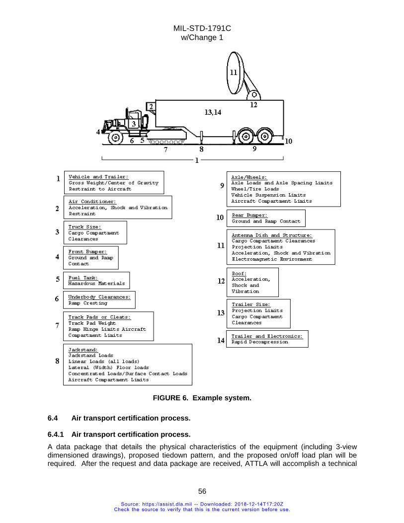
MIL-STD-1791C w/Change 1
56
FIGURE 6. Example system.
6.4 Air transport certification process.
6.4.1 Air transport certification process. A data package that details the physical characteristics of the equipment (including 3-view dimensioned drawings), proposed tiedown pattern, and the proposed on/off load plan will be required. After the request and data package are received, ATTLA will accomplish a technical
Source: https://assist.dla.mil -- Downloaded: 2018-12-14T17:20ZCheck the source to verify that this is the current version before use.
MIL-STD-1791C w/Change 1
57
analysis of the item with respect to internal air transportability and return an Air Transportability Certification memo for approved items or recommend changes to items which do not meet the requirements. Data may be provided at a later date from the initial air transport certification request, provided that ATTLA has at least 45-60 days to review the data. The data package should include physical characteristics of the equipment, structural strength with substantiating information (for analysis of tiedown capability), proposed tiedown pattern, and the proposed on/off load plan. Dimensions may be submitted using drawings, certain CAD files, the ATTLA data sheet, or annotated photographs. The ATTLA data sheet is available in various electronic formats upon request to [email protected]. The structural analysis should list assumptions, material properties, and force diagrams in addition to calculations and conclusions. ATTLA reserves the right to request additional analysis or testing. For items in development, ATTLA will provide design assistance through the applicable procurement office to ensure that the vendor produces an item that ultimately meets all airlift objectives. Because developmental items are subject to continual changes, ATTLA personnel can participate in design reviews and other technical interchanges during the evolution of a design. However, funding must be provided for ATTLA personnel to attend these activities; teleconference and video teleconference capability is also available. ATTLA will conduct an analysis at no cost to the requesting federal office to assess the loading and transportability characteristics of a designated item. Some of the areas examined include fit and projection of the cargo, weight distribution of structural loads on the aircraft, aircrew in-flight access, aircraft weight and balance after loading, interface with material handling equipment, shoring requirements, and required loading methodology. Also considered in this analysis are the structural integrity of the cargo, the capability of sealed systems to survive rapid decompression, inclusion of any hazardous materials, in-flight operation of transported equipment, and the capability of identified restraint provisions, suspension systems, and axles to withstand the dynamics of takeoffs, landings, and flight. If analysis alone cannot positively determine that the item can be safely loaded and airlifted, ATTLA will recommend that either a validation load (see 6.4.1.1) or a test load (see 6.4.1.2) be conducted. ATTLA may certify the item as-is or may require changes to the item in order to meet aircraft and operational limits prior to certification. Historically, only about 5 percent of cargo items presented to ATTLA could not be certified. Upon certification, the owner, the developing agency, or the procuring agency (or all three) will receive a signed Air Transportability Certification memo from ATTLA for each item certified for airlift. In addition, a copy of the memo is forwarded to HQ AMC/A3V and another copy is maintained permanently in the item's project file at ATTLA. ATTLA maintains a database of items that have been certified since 1974. A copy of the memo should accompany the item whenever it is presented for airlift.
Source: https://assist.dla.mil -- Downloaded: 2018-12-14T17:20ZCheck the source to verify that this is the current version before use.
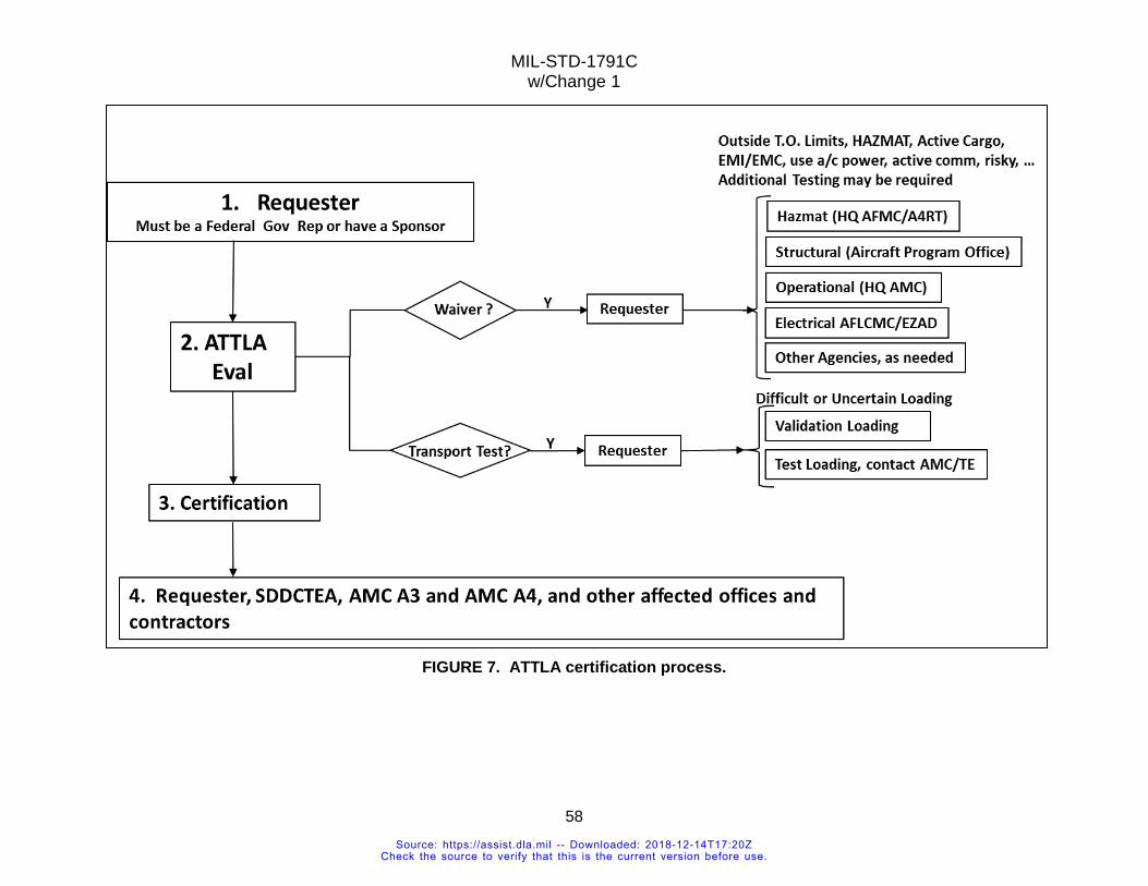
MIL-STD-1791C w/Change 1
58
FIGURE 7. ATTLA certification process.
Source: https://assist.dla.mil -- Downloaded: 2018-12-14T17:20ZCheck the source to verify that this is the current version before use.
MIL-STD-1791C w/Change 1
59
6.4.1.1 Validation loading. Validation loadings are recommended in medium risk cargo situations to verify loading, unloading, and restraint in accordance with published procedures. The capability of the item itself to be transported usually is not in question; the problem is how to get the item safely on and off the aircraft. Validation loads may also be performed to determine whether multiple items can be loaded together. Validation loadings are often performed in conjunction with an item’s first airlift. Whether the procedure requires the presence of ATTLA personnel is determined by assessing the anticipated risk. If ATTLA presence is required, the requestor must pay the ATTLA representative’s travel cost.
6.4.1.2 Test loading. Test loadings are conducted in cargo situations considered high risk. An analysis of the item indicates it cannot be transported without developing new procedures or equipment or that there is the possibility of exceeding one or more aircraft limitations during loading, offloading, or transport. Test loadings are usually conducted as Special Assignment Airlift Mission (SAAM) requests and are managed by Headquarters Air Mobility Command, Test and Evaluation Directorate (HQ AMC/TEA), Scott AFB, IL in conjunction with the 33rd Flight Test Squadron at McGuire AFB, NJ, which is responsible for test execution. The requesting office is responsible for making the arrangements with HQ AMC/TEA to conduct the test loading. A formal test load results in the generation of a test report that outlines the test criteria, results, and the details of any specific procedures or preparations that were needed to load the item. ATTLA will usually approve an item for airlift based upon a successful test load, but because of the test nature positive results are not always obtained. Since test loadings usually involve very detailed instructions, items which have been successfully test loaded usually require publication in the "special procedures" section of the applicable aircraft loading manual. The cost of conducting a test loading is borne by the requesting agency.
6.4.2 Other certifications. The following situations require an airworthiness approval from the aircraft program office for each type of aircraft on which the specified cargo is intended to be transported. ATTLA provides an airworthiness assessment to the aircraft program offices on the item shipped as cargo. Each aircraft office will perform an internal review of the request and ATTLA’s recommendation and issue an airworthiness certificate for the aircraft.
a. Requires interface with aircraft electrical systems: electrical power or aircraft communications systems. b. Cargo is electronically active or is used while in the aircraft. c. Systems occupied by personnel. d. Susceptibility to explosive atmosphere environment (certain aerial tanker and receiver cargo aircraft only).
6.4.2.1 Nuclear. The certifying authority for air transport of nuclear material is the Air Force Nuclear Weapons and Counterproliferation Agency (AFNWCA) at Kirtland AFB, NM.
Source: https://assist.dla.mil -- Downloaded: 2018-12-14T17:20ZCheck the source to verify that this is the current version before use.
MIL-STD-1791C w/Change 1
60
The air transport environment for transporting nuclear cargo is the same as for other cargo and is addressed in this document. Contact AFNWCA for other transport requirements and special protection for stowage of radioactive material. ATTLA can provide technical assistance. 6.4.3 Recertification of previously certified item. For previously certified items, modifications that do not affect the item’s exterior dimensions, weight, or ability to meet a requirement in this specification do not warrant a new or re-certification. Examples include an upgraded radio, new paint scheme (without affecting markings), or a new engine (without weight increase). New tires of the same class will not require a new certification, but changing from highway to off-road or vice versa may affect floor contact pressure. Contact ATTLA for an evaluation if there is any question as to whether a modification will affect air transportability.
6.5 Subject term (key word) listing. 3G ADS Rails Aeromed or Aeromedical AFMAN 24-204 Air transportability Air Transportability Test Loading Activity (ATTLA) Air transportable ATTLA Certification letter Civil Reserve Air Fleet (CRAF) DoDI 4530.07 Forward restraint Internal Air Transport Certification Logistic rails MIL-STD-1366 Nonstandard pallet Outsized cargo Palletized cargo Personnel module Rolling stock Roll-on/Roll-off cargo Seat pallets Special consideration cargo Test loading Tip off or Tipoff
Source: https://assist.dla.mil -- Downloaded: 2018-12-14T17:20ZCheck the source to verify that this is the current version before use.
MIL-STD-1791C w/Change 1
61
Validation loading
6.6 Changes from the previous issue. Marginal notations are not used in this revision to identify changes with respect to the previous issue due to the extent of the changes.
Source: https://assist.dla.mil -- Downloaded: 2018-12-14T17:20ZCheck the source to verify that this is the current version before use.
MIL-STD-1791C w/Change 1
APPENDIX A
62
APPENDIX A SUPPLEMENTAL AIRLIFT CONCEPTS AND PROCEDURES
A.1 SCOPE This appendix contains both mandatory requirements and guidance to ensure safe air transport. The information contained herein is intended to be followed in the context in which they are written.
A.1.1 Scope. This appendix provides supplemental information regarding air transport concepts and procedures. This includes equations, calculation methods, and in depth rationale for specific concepts. A discussion of the three general categories of cargo, rolling stock, palletized, and bulk, elaborate on air transportability issues specific to these categories. Portions of this appendix that are mandatory are preceded by "shall". The information contained herein is intended for compliance.
A.1.2 Applicability. The concepts herein apply to all cargo items. The examples are not exhaustive, but are given for guidance.
A.2 DEFINITIONS Active
These are cargo that do not always interact with personnel but are operating in all phases of flight. Examples are an air conditioner for satellite container, meat freezer, and a GPS relay system. Aside from being active, the item may have physical and aircraft interface characteristics of bulk, palletized or rolling stock cargo. The active cargo may utilize aircraft power or have independent power sources. Even though the item uses aircraft power, it is not considered aircraft equipment because it does not perform operations to the aircraft.
Bulk Cargo Cargo that does not have any equipment to facilitate its movement such as wheels or pallets. (Cargo that utilizes the roller conveyor system is considered palletized cargo even if it is not carried on a standard pallet.) Bulk cargo can be loaded from the ground, or hand carried, and/or it can utilize special handling equipment. An instrumentation crate is an example of bulk cargo (see Figure A-18).
Medical Equipment These are systems used to treat patients during all flight. Aside from interacting with patients, the item may have physical and aircraft interface characteristics of bulk, palletized or rolling stock cargo.
Palletized Cargo These are loads that are rigged on standard 463L cargo pallets, Type V or Type VI (aka DRAS) airdrop platforms, container delivery system (CDS) skid board, or nonstandard pallets. Pallet examples on Figure A-6 and Figure A-9 show loads palletized on a single 463L pallet or multiple pallets. Loads with flat surfaces or skids that interface with the roller conveyor system are also considered palletized cargo because the same
Source: https://assist.dla.mil -- Downloaded: 2018-12-14T17:20ZCheck the source to verify that this is the current version before use.
MIL-STD-1791C w/Change 1
APPENDIX A
63
requirements for interfacing with the aircraft and MHE roller and rail systems apply.
Personnel-Occupied System
These are systems that are used to carry personnel during all phases of flight. Aside from being occupied by personnel, the item may have physical and aircraft interface characteristics of bulk, palletized or rolling stock cargo.
Rolling Stock Cargo that is loaded on any type of wheel or tread whether self-propelled, towed, or winched aboard. Aircraft loaded on landing gear also fall under this category.
A.3 SIZE AND WEIGHT BY CARGO TYPE This section provides guidance relating to the size and weight of cargo. There is a detailed discussion of the three major cargo types, rolling stock, palletized, and bulk cargo and the restrictions specific to each.
A.3.1 Size. REQUIREMENT RATIONALE
The objective of the size requirement is to influence equipment design, consistent with operational needs, to enhance the item's aerial delivery characteristics. Because airlift resources are limited, using them most effectively is mandatory, particularly in contingency situations. Several design considerations impact the efficient use of both aircraft and personnel:
a. Equipment designed to be transported in its operational configuration eliminates the need for time-consuming operations such as breaking the item into sections (e.g. dismounting secondary cargo) or partial disassembly.
b. Operational equipment can generally be on/offloaded with fewer problems and less need for supporting equipment.
c. Items whose design satisfies the worst case or most restrictive combinations of criteria have the greatest chance of being transported in periods of airlift shortfall. This results from the item having physical characteristics compatible with the widest range of available aircraft.
REQUIREMENT GUIDANCE All cargo aircraft have structural limitations which affect the size and configuration of cargo items which can be safely loaded and air delivered. Limitations common to these aircraft include axle loads, axle spacing, roller conveyor loads, bulk cargo linear loadings, cargo compartment zone weight limits, and ramp crest angles, among others. The magnitude of these limits can vary widely between aircraft due to both aircraft design and operational factors. By designing equipment to the most restrictive combination of criteria, the chances of air delivery of the item are greatly improved because the item will be eligible for movement in the widest range of available aircraft.
REQUIREMENT LESSONS LEARNED Item sizing and configuration should be established with the following experience factors in mind:
a. Items specifically designed to be air delivered in their operational configuration often require no special support equipment for on/offloading. This is particularly important where these operations are carried out in austere locations where the availability of any support equipment is likely to be marginal.
Source: https://assist.dla.mil -- Downloaded: 2018-12-14T17:20ZCheck the source to verify that this is the current version before use.
MIL-STD-1791C w/Change 1
APPENDIX A
64
b. Where item functional requirements prevent designing to the conditions of (a) above, design alternatives should consider breaking the item into sections or use of reduction techniques. Exercise caution where breaking the item into sections or reduction is implemented to assure that tool and support equipment requirements are within the organic capability of the using organization or are built into the items to be air delivered.
c. Normally, only two auxiliary ramps are carried aboard C-130 aircraft. Where item design incorporates a tricycle wheel configuration, a fabricated auxiliary ramp is needed to accommodate the centerline wheels during on/offloading. Centerline axles should not exceed axle loads for nontreadway applications.
d. The use of shoring should be avoided whenever possible. Wood shoring is very often unavailable in remote locations and its use is time-consuming as well as labor-intensive. Most importantly each pound of shoring used reduces the aircraft payload by an equal amount. Support devices, designed as an integral part of the equipment can sometimes modify the need for shoring. Strategically positioned auxiliary landing gear, for instance, can eliminate the need for sleeper shoring.
e. Each aircraft has its unique structural limitations. Designing equipment for airlift in the smallest aircraft will not necessarily qualify the item for airlift in larger aircraft. Design should be based on the most restrictive combination of aircraft limits.
VERIFICATION RATIONALE Verification of size requirements can usually be accomplished through analysis of equipment dimensional and weight data. Comparison of the equipment in its shipping configuration with the characteristic loading envelope of the aircraft involved is the least costly and quickest method of determining the aerial delivery eligibility. Where critical clearances exist, or special loading equipment/procedures are involved, a validation or test loading may be required to verify the acceptability of the item for aerial delivery. This method of verification should be a last option because of the high cost of manpower and airlift resources required.
VERIFICATION GUIDANCE Though some latitude is permissible in the configuration of equipment in order to facilitate an item's air transport eligibility, extreme care shall be exercised so that unacceptable limitations are not imposed by certain configurations. While every reasonable effort should be made to ensure the air transportability of an item, the capability of the using unit to make the item operationally ready in the field is often the limiting factor. Special tools and sophisticated support equipment necessary for handling and reassembling the item will probably not be available at most overseas sites. The manpower necessary to perform these operations is also a major factor shall be considered. A third element of major importance is the time required to achieve operational readiness of the item after aerial delivery. The data shown in Appendix B provides the necessary information to assist the designer to set acceptable limits on item configuration. A review of the limiting factors for the various aircraft reveals a variation in aircraft structural capability shall be recognized in the design process. Such factors as linear loading limits and axle weights vary widely between aircraft. Good design practice is that which satisfies the most restrictive combination of requirements. This will assure that the item is eligible for aerial delivery in the maximum number of available aircraft and enhances the probability of the item being airlifted.
Source: https://assist.dla.mil -- Downloaded: 2018-12-14T17:20ZCheck the source to verify that this is the current version before use.
MIL-STD-1791C w/Change 1
APPENDIX A
65
A.3.1.1 Size requirements. Use section 5 and the aircraft appendices to identify whether the item might have loading problems. Keep in mind that cargo may be loadable forward end first but not aft end first, or vice versa. While not required by this standard, the emergency egress requirement is as follows: “The aircrew and passenger area shall have emergency means to allow complete abandonment in 90 seconds during ground egress or ditching of the air vehicle with half of the exits blocked, with the landing gear extended as well as retracted, considering the possibility of the air vehicle being on fire, and at maximum seating capacity” (see MIL-HDBK-516).
A.3.1.2 Loading/unloading. For ground loading, the aircraft cargo door is opened and the ramp is lowered to the ground. The cargo door is rotated up and locked to the ceiling of the cargo compartment. The ramp angle varies with the height of the cargo floor above the ground. (Cargo floor height is determined by how much weight is already on the aircraft, cargo and fuel combined as well as adjustments that the aircraft can make.) The higher the cargo floor is from the ground, the steeper the ramp angle. A steep ramp angle can cause loads with lower ground clearance to contact the ramp or the ramp hinge. Loads with a tall projected height can contact the ceiling. To prevent contact with the aircraft and prevent overloading of aircraft components, shoring may be necessary. Approach shoring decreases the ramp angle by degrees sufficient to prevent the item from contacting the ground, aircraft ramp toes, ramp, ramp hinge, and/or ceiling (see 5.3.1.1). A ramp extension or ramp toe is attached to the lower end of the ramp to bridge the ramp top surface with the ground. The C-5 forward ramp has ramp extensions and ramp toes to bridge this gap (see Appendix B). The angle for each subsequent segment differs from the ramp angle.
A.3.1.2.1 Projection limits. REQUIREMENT RATIONALE
Mission requirements often necessitate loading general cargo and wheeled/tracked vehicles from the ground by winching or driving them directly into the aircraft cargo compartment. Any item loaded in this manner shall be designed so that its height and length do not cause the item to contact the upper structural members of the aircraft or the undercarriage to contact the ramp crest area as shown in Appendix B. In addition, the item should not contact the ground.
REQUIREMENT GUIDANCE The allowable item projection is determined by three factors:
a. The height of the load.
b. The distance of the high point measured behind rear axle (when backed in).
c. The height of the cargo compartment floor at the hinge line of the ramp.
The allowable projection is measured from the centerline of the ramp hinge. Charts are used in determining the acceptable dimensions of vehicles/wheeled cargo whose inclined ramp loading may approach a projection limit. The vehicle projection charts for each aircraft present height-projection limits for wheeled vehicles being on-loaded from the ground using the aircraft ramps. These charts give the critical vehicle height-projection values to
Source: https://assist.dla.mil -- Downloaded: 2018-12-14T17:20ZCheck the source to verify that this is the current version before use.
MIL-STD-1791C w/Change 1
APPENDIX A
66
determine the suitability of loading a given vehicle. Whenever possible, vehicles should be backed into the aircraft. Projection theory: Projection length depends on where the item pivots at the ramp hinge to cause the longest projection length. If the item is two axle rolling stock, the pivot point occurs at the rear axle. If the item has multiple axles, the pivot point depends on whether the axles are tandem or independent. Tandem axles or bogies may articulate sufficiently (15-deg or greater) so that the pivot point is between the axles. If there are multiple axles with no articulation, the worst-case pivot point is at the rearmost (with respect to the aircraft) axle. For loads that are box shaped, refer to charts in the individual aircraft appendix.
REQUIREMENT LESSONS LEARNED Loading vehicles in the aircraft with their aft end facing forward permits more rapid offload. This is particularly important when offloading occurs in combat areas.
VERIFICATION RATIONALE Whenever possible, satisfaction of this requirement should be verified by comparing the item's critical dimensions with the limiting values shown on the appropriate charts for the aircraft involved. This is the fastest and least costly method of verification. Alternate methods of establishing conformance with this requirement are:
a. Demonstration loading using a scale mock-up of the aircraft ramp and cargo compartment envelope.
b. Validation loading to occur at the time of the first actual airlift of the item. c. Formal test loading involving the actual aircraft.
Experience has shown that the analysis method of verification can be applied in most cases. Formal test loadings are required only in extremely critical situations and shall be recommended as necessary by ATTLA before they will be approved. Validation loadings at the time of first shipment are commonly used to establish loading qualifications without incurring the cost involved in a formal test loading.
VERIFICATION GUIDANCE Each chart has instructions to aid the designer in determining analytically if a proposed design or actual item qualifies for ground loading up the aircraft ramp. In some cases, the item's critical dimensions may so closely approach the limiting values that an analytical judgment may not be possible. In all cases, the final determination of an item's certification in this requirement area rests with ATTLA, who will determine if any form of loading demonstration is required.
VERIFICATION LESSONS LEARNED Because of the scale involved, graphical determination of an item's up-the-ramp loadability cannot be made with extreme precision. Except for very critical items, formal test loading is seldom needed to determine an item's qualifications.
A.3.1.2.2 Ground and ramp contact. REQUIREMENT RATIONALE
Vehicles which have structures with long extensions past the front or rear axles may have difficulty in loading up the inclined ramp from the ground. This is especially critical on vehicles which have
Source: https://assist.dla.mil -- Downloaded: 2018-12-14T17:20ZCheck the source to verify that this is the current version before use.
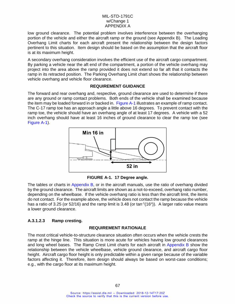
MIL-STD-1791C w/Change 1
APPENDIX A
67
low ground clearance. The potential problem involves interference between the overhanging portion of the vehicle and either the aircraft ramp or the ground (see Appendix B). The Loading Overhang Limit charts for each aircraft present the relationship between the design factors pertinent to this situation. Item design should be based on the assumption that the aircraft floor is at its maximum height. A secondary overhang consideration involves the efficient use of the aircraft cargo compartment. By parking a vehicle near the aft end of the compartment, a portion of the vehicle overhang may project into the area above the ramp provided it does not extend so far aft that it contacts the ramp in its retracted position. The Parking Overhang Limit chart shows the relationship between vehicle overhang and vehicle floor clearance.
REQUIREMENT GUIDANCE The forward and rear overhang and, respective, ground clearance are used to determine if there are any ground or ramp contact problems. Both ends of the vehicle shall be examined because the item may be loaded forward in or backed in. Figure A-1 illustrates an example of ramp contact. The C-17 ramp toe has an approach angle a little above 16 degrees. To prevent contact with the ramp toe, the vehicle should have an overhang angle of at least 17 degrees. A vehicle with a 52 inch overhang should have at least 16 inches of ground clearance to clear the ramp toe (see Figure A-1).
FIGURE A-1. 17 Degree angle.
The tables or charts in Appendix B, or in the aircraft manuals, use the ratio of overhang divided by the ground clearance. The aircraft limits are shown as a not-to-exceed, overhang ratio number, depending on the wheelbase. If the vehicle overhang ratio is less than the aircraft limit, the items do not contact. For the example above, the vehicle does not contact the ramp because the vehicle has a ratio of 3.25 (or 52/16) and the ramp limit is 3.48 (or tan-1(16o)). A larger ratio value means a lower ground clearance.
A.3.1.2.3 Ramp cresting. REQUIREMENT RATIONALE
The most critical vehicle-to-structure clearance situation often occurs when the vehicle crests the ramp at the hinge line. This situation is more acute for vehicles having low ground clearances and long wheel bases. The Ramp Crest Limit charts for each aircraft in Appendix B show the relationship between the vehicle wheelbase, vehicle ground clearance, and aircraft cargo floor height. Aircraft cargo floor height is only predictable within a given range because of the variable factors affecting it. Therefore, item design should always be based on worst-case conditions; e.g., with the cargo floor at its maximum height.
Source: https://assist.dla.mil -- Downloaded: 2018-12-14T17:20ZCheck the source to verify that this is the current version before use.
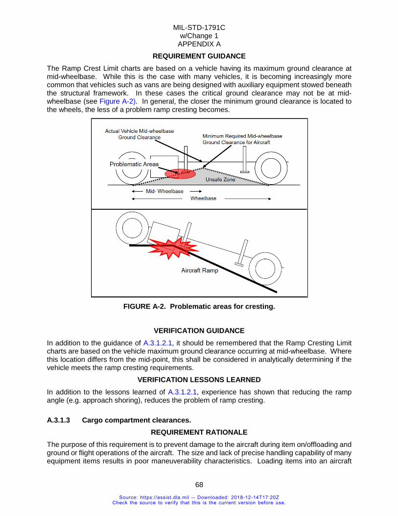
MIL-STD-1791C w/Change 1
APPENDIX A
68
REQUIREMENT GUIDANCE The Ramp Crest Limit charts are based on a vehicle having its maximum ground clearance at mid-wheelbase. While this is the case with many vehicles, it is becoming increasingly more common that vehicles such as vans are being designed with auxiliary equipment stowed beneath the structural framework. In these cases the critical ground clearance may not be at mid-wheelbase (see Figure A-2). In general, the closer the minimum ground clearance is located to the wheels, the less of a problem ramp cresting becomes.
FIGURE A-2. Problematic areas for cresting.
VERIFICATION GUIDANCE
In addition to the guidance of A.3.1.2.1, it should be remembered that the Ramp Cresting Limit charts are based on the vehicle maximum ground clearance occurring at mid-wheelbase. Where this location differs from the mid-point, this shall be considered in analytically determining if the vehicle meets the ramp cresting requirements.
VERIFICATION LESSONS LEARNED In addition to the lessons learned of A.3.1.2.1, experience has shown that reducing the ramp angle (e.g. approach shoring), reduces the problem of ramp cresting.
A.3.1.3 Cargo compartment clearances. REQUIREMENT RATIONALE
The purpose of this requirement is to prevent damage to the aircraft during item on/offloading and ground or flight operations of the aircraft. The size and lack of precise handling capability of many equipment items results in poor maneuverability characteristics. Loading items into an aircraft
Source: https://assist.dla.mil -- Downloaded: 2018-12-14T17:20ZCheck the source to verify that this is the current version before use.
MIL-STD-1791C w/Change 1
APPENDIX A
69
requires sufficient clearance to allow for the difficulty of accurately maneuvering the item into and within the aircraft. Items restrained on-board the aircraft will be subjected to accelerations during both ground and flight operations. These accelerations will result in movement of the item relative to the aircraft. This movement can be caused by deflection of the aircraft, deflection of tiedown chains or straps, deflection of the item itself, or any combination of these conditions.
REQUIREMENT GUIDANCE The clearance available during loading influences the amount of time necessary to load an item. The minimum clearance between the item and the aircraft structure during ground maneuvering and flight operations is influenced by the loading on tiedown devices, cargo item, and aircraft structure. These loads cause deflections to varying degrees and in varying directions. Nylon webbing tiedowns, for example, can elongate up to 20 percent under full load conditions. Full loading occurs only rarely. However, large deflections coupled with minimal clearances could result in the movement of an item to impact the aircraft structure. The dimensions shown in Appendix B represent the cargo design limits for items to be transported in the designated aircraft. These values are derived by reducing the basic rectangular box size of the aircraft cargo compartment to account for the required overhead and side clearances. The C-5 has an irregular cargo compartment cross section which can be described as a rectangle topped by a trapezoid whose base is common with the upper long side of the rectangle. Height dimensions are measured from the load surface of the aircraft floor and do not include any provision for 463L pallets, roller conveyors, or shoring. Designing to these limits will insure that items will meet the aircraft dimensional criteria for straight-in loading. Other aspects of air transportability, such as ramp cresting, projection clearances, axle and wheel loads, and floor and roller loading shall be addressed separately to assure compliance with all requirements. Existing equipment which exceeds these design limits may still be eligible for air transportability certification. However, a detailed review of the item's physical characteristics shall be accomplished before this determination can be made. Special equipment or procedures may be required to permit air transport of certain equipment. The dimensions of the Air Force prime mission cargo aircraft (C-130, C-17, and C-5) are contained in Appendix B.
REQUIREMENT LESSONS LEARNED Equipment on-board the aircraft can decrease the available clearance for loading cargo items. The following situations should be considered:
a. If equipment is to be loaded on the roller conveyor system, the value for the cargo compartment height should be reduced by the height of the rollers and pallet, if used.
b. The C-130 rail restraint system is not removable from the aircraft and limits available loading space.
VERIFICATION RATIONALE The preferred method of verifying this requirement is by engineering analysis of the physical characteristics of the item. Experience has shown that this is the fastest, least costly procedure and can be used in the majority of cases. Where an item has such critical characteristics that analytical methods cannot positively determine if the item can be safely loaded and delivered, an actual test loading of the item may be necessary. Such loadings are the basis for the determination and formal documentation of loading and restraint procedures. Test loadings are expensive and are utilized only when absolutely necessary. Exceeding these limits does not necessarily prevent the item from being air delivered. However, such a situation does require a
Source: https://assist.dla.mil -- Downloaded: 2018-12-14T17:20ZCheck the source to verify that this is the current version before use.
MIL-STD-1791C w/Change 1
APPENDIX A
70
more critical analysis, often requires an expensive and time consuming test loading, and may require unusual loading procedures, the use of auxiliary support equipment, and highly skilled loading crews. Cargo carried in an aircraft will be loaded by (1) straight-in loading over the horizontally positioned ramp from a truck or cargo loader, or (2) ramp loaded from the ground using the auxiliary loading ramps. Straight-in loading presents fewer cargo-aircraft interference problems, but requires ground support equipment which may not be readily available, particularly at austere off-load sites. Ramp loading, while less restrictive from a support equipment standpoint, is more critical with respect to cargo-aircraft interference. Appendix B presents pictorial and graphic data on cargo compartment clearance and cargo-aircraft interference parameters. All load profiles shall conform to dimensional envelope constraints. Additional limitations shall be considered for ramp loaded items. These considerations include ramp cresting, parking overhang, loading overhang and projection limitations. Detailed knowledge of the dimensions and operational characteristics of equipment items is required to determine the acceptability of an item for aerial delivery by use of the Appendix B data.
VERIFICATION GUIDANCE The determination of an item's dimensional acceptability for aerial delivery is made by comparing the item in its shipping configuration with the aircraft dimensional data presented in the appendices to this document. The data presented in these appendices represent design limits which, if not exceeded, should assure that the item can be transported in the aircraft under consideration.
VERIFICATION LESSONS LEARNED The dimensional acceptability of an item shall be determined with the item in its shipping configuration. In addition to the dimensions of the item itself, consideration shall be given to any cargo compartment space taken up by such ancillary items as shoring, pallets, roller conveyors, if these are required. Partial disassembly of equipment to meet the cargo compartment dimensional limits is an acceptable option only when the following conditions are met:
a. The item's reduced configuration shall be such that it can be made operationally ready under field conditions within the specified mission ready response time using only the unit's organic capability.
b. The item in its reduced shipping configuration shall not require the use of on/offloading support equipment which would not be available at the field site.
A.3.1.3.1 Emergency access and safety aisle. REQUIREMENT RATIONALE
On military aircraft, a requirement exists for an aisle in the cargo compartment for crew transit from the flight station to the rear of the aircraft for firefighting, checking and resecuring loads, and scanning engines or landing gear. When passengers are carried, a similar requirement exists in order to provide safe egress. The C-17 and C-5 have walkways. While these walkways satisfy this requirement, they shall be kept clear at all times of cargo or protrusions. On aircraft such as the C-130, a minimum clear space on the left-hand side (when facing forward) shall exist at all times.
Source: https://assist.dla.mil -- Downloaded: 2018-12-14T17:20ZCheck the source to verify that this is the current version before use.
MIL-STD-1791C w/Change 1
APPENDIX A
71
REQUIREMENT GUIDANCE Appendix B shows a cross-section of the C-130 fuselage and highlights two clear space options relative to the cargo compartment envelope. Safety aisle "A" is 14 inches wide by 72 inches high, while safety aisle "B" is 30 inches wide by 48 inches high. Experience has shown that the "A" space will permit an aircrew member to walk with a slight crouch through the cargo compartment. Similarly, the "B" space is adequate to allow a crew member to crawl atop the cargo. The clear spaces are shown in the extreme upper left position of the cargo envelope. This utilizes the maximum cargo widths and heights in this area while still accommodating a walking or crawling person. Other locations of the clear spaces may be acceptable, as are combinations of walkways and crawlways, as long as a continuous passageway exists on the left side of the aircraft. In designing to meet these criteria, remember that the basic requirement is for a person wearing a parachute to be able to get from the forward end of the aircraft to the rear troop doors.
VERIFICATION RATIONALE In the majority of cases, knowledge of the item's dimensions is adequate to make a determination of the acceptability of the clear space. This is the quickest and least costly method of verification. Where complex load configurations are involved, or where multiple units comprise the load, a demonstration of aircrew member access may be necessary. Because of the time and manpower involved, this verification method should be avoided whenever possible.
VERIFICATION GUIDANCE
The configuration of cargo loads seldom will present a uniform rectangular aisle way. Judgment shall be used in many cases in evaluating the acceptability of a load where clear spaces vary from the requirement criteria. Many individual items shall be evaluated in the absence of knowledge of the total aircraft load configuration. The overall load configuration can have an impact on clear space available at an individual item location. Experience has shown, however, that sufficient flexibility in load planning generally exists such that, if an individual item meets access criteria, it can be located in the overall load without adversely affecting the emergency access path. ATTLA is available to provide advice in this area.
A.3.2 Weight limits. REQUIREMENT RATIONALE
Aircraft loading/unloading weight limits are greater than flight limits because there are no additional vertical gust loads while the aircraft is on the ground.
REQUIREMENT GUIDANCE Weight and weight distribution applies throughout the airlift process. The item should be able to load, park, and unload without exceeding aircraft structural limits and the cargo’s structural limits. For example, a tractor/trailer should be able to traverse up the aircraft ramp with all axles in contact with the aircraft ramp and floor. If one axle lifts up, the increased weight on the other axles may exceed the axle capacity or aircraft limits.
Source: https://assist.dla.mil -- Downloaded: 2018-12-14T17:20ZCheck the source to verify that this is the current version before use.
MIL-STD-1791C w/Change 1
APPENDIX A
72
A.3.2.1 Weight requirements. REQUIREMENT RATIONALE
In general, the allowable cargo capacity is dependent on the aircraft floor strength, which varies from one location to another and is dependent on aircraft structural design. Variations in item design impose different types of loads on the aircraft structure. These aircraft structural limits are treated in detail in Appendix B. In addition to unique aircraft structure loading, item weight and center-of-gravity affects aircraft weight and balance considerations as well as aircraft operational range.
REQUIREMENT LESSONS LEARNED A trailer weighing 25,000 pounds on two axles, with an axle separation of about 36 feet had a C-130 transportability requirement. The ground loading limit for the C-130 floor is 13,000 pounds for the entire length but the flight limit of 13,000 pounds only encompasses about 28 feet in the middle of the cargo compartment. The solution was to roll the trailer on board; position eight stacks of shoring underneath the frame, then completely deflate the tires so that the shoring verifiably carried the entire weight of the trailer. Keep in mind that this trailer had no time restrictions on loading/unloading and was required to carry tire inflation/deflation equipment as part of the transportation package. Such a scheme, while a creative exploitation of aircraft limits, would not be appropriate for combat vehicles or others with time-sensitive deployment requirements.
A.3.2.2 Gross weight/center of gravity. REQUIREMENT RATIONALE
Assuming all other load parameters are met, the maximum single item weight which can be carried in an aircraft is dependent on its payload-distance characteristics. Without considering the other factors which influence range, the heavier the payload, the shorter the range. In all cases there is a maximum payload which cannot be exceeded under any circumstances. The aircraft center of gravity (CG) is the point around which the aircraft will balance. The flight performance of the aircraft is dependent on the location of this point which can vary within limits. If the CG is outside this limit the aircraft cannot be flown. The aircraft CG is affected by the location of each individual item CG. In most cases the location of an item's CG is the natural result of its configuration. A preferred location is at or near the geometric center of the item.
REQUIREMENT GUIDANCE Payload-distance information is presented in Appendix B. CRAF payload-range data is published in AMCPAM 24-2. Contact the appropriate program office for more up-to-date information. Center of gravity limit data are presented in the appendix for each aircraft. Use of these curves will determine if proposed loads will meet these requirements. The ability to tailor CG is, admittedly, limited. However, this factor should be recognized in item design. The areas which may provide the greatest potential for doing this are selective location of accompanying loads and CG shifts resulting from item reconfiguration to meet weight or dimensional restrictions.
REQUIREMENT LESSONS LEARNED People tend to associate CG with the geometric center of items. For this reason it is important to assure adequate marking of CG location so that aircraft CG may be computed accurately. An advantage of a central CG location is that it offers more flexible loading options.
Source: https://assist.dla.mil -- Downloaded: 2018-12-14T17:20ZCheck the source to verify that this is the current version before use.
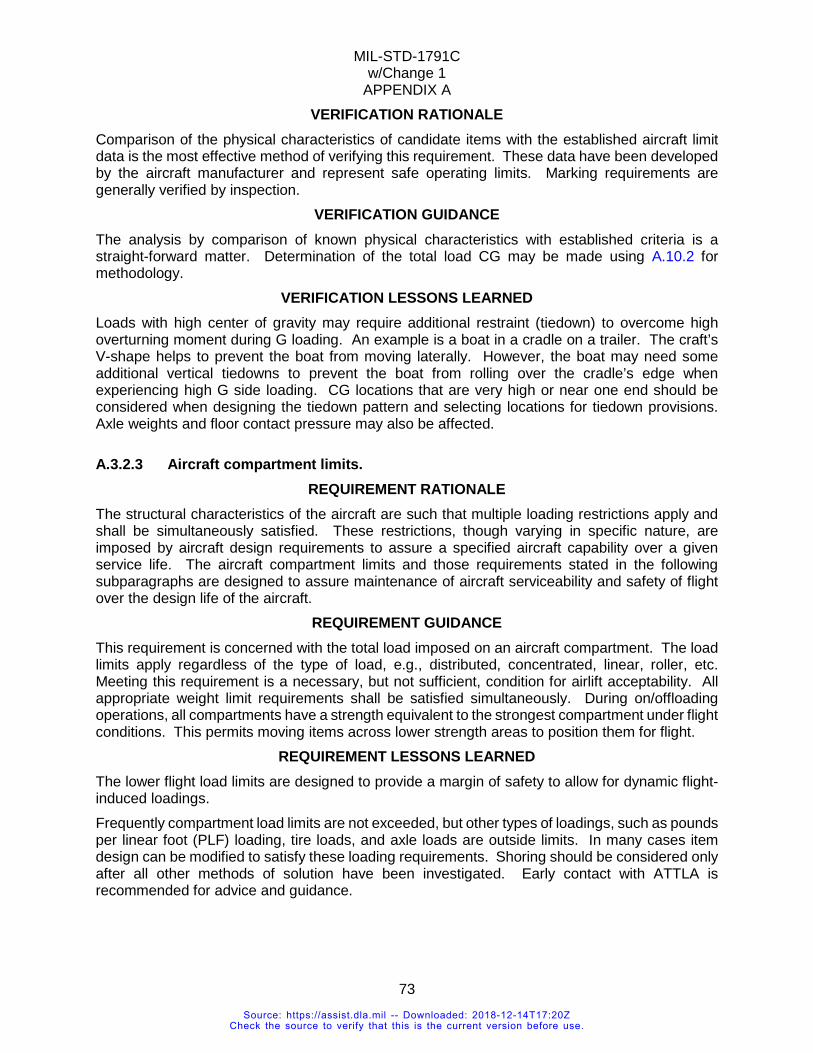
MIL-STD-1791C w/Change 1
APPENDIX A
73
VERIFICATION RATIONALE Comparison of the physical characteristics of candidate items with the established aircraft limit data is the most effective method of verifying this requirement. These data have been developed by the aircraft manufacturer and represent safe operating limits. Marking requirements are generally verified by inspection.
VERIFICATION GUIDANCE The analysis by comparison of known physical characteristics with established criteria is a straight-forward matter. Determination of the total load CG may be made using A.10.2 for methodology.
VERIFICATION LESSONS LEARNED Loads with high center of gravity may require additional restraint (tiedown) to overcome high overturning moment during G loading. An example is a boat in a cradle on a trailer. The craft’s V-shape helps to prevent the boat from moving laterally. However, the boat may need some additional vertical tiedowns to prevent the boat from rolling over the cradle’s edge when experiencing high G side loading. CG locations that are very high or near one end should be considered when designing the tiedown pattern and selecting locations for tiedown provisions. Axle weights and floor contact pressure may also be affected.
A.3.2.3 Aircraft compartment limits. REQUIREMENT RATIONALE
The structural characteristics of the aircraft are such that multiple loading restrictions apply and shall be simultaneously satisfied. These restrictions, though varying in specific nature, are imposed by aircraft design requirements to assure a specified aircraft capability over a given service life. The aircraft compartment limits and those requirements stated in the following subparagraphs are designed to assure maintenance of aircraft serviceability and safety of flight over the design life of the aircraft.
REQUIREMENT GUIDANCE This requirement is concerned with the total load imposed on an aircraft compartment. The load limits apply regardless of the type of load, e.g., distributed, concentrated, linear, roller, etc. Meeting this requirement is a necessary, but not sufficient, condition for airlift acceptability. All appropriate weight limit requirements shall be satisfied simultaneously. During on/offloading operations, all compartments have a strength equivalent to the strongest compartment under flight conditions. This permits moving items across lower strength areas to position them for flight.
REQUIREMENT LESSONS LEARNED The lower flight load limits are designed to provide a margin of safety to allow for dynamic flight-induced loadings. Frequently compartment load limits are not exceeded, but other types of loadings, such as pounds per linear foot (PLF) loading, tire loads, and axle loads are outside limits. In many cases item design can be modified to satisfy these loading requirements. Shoring should be considered only after all other methods of solution have been investigated. Early contact with ATTLA is recommended for advice and guidance.
Source: https://assist.dla.mil -- Downloaded: 2018-12-14T17:20ZCheck the source to verify that this is the current version before use.
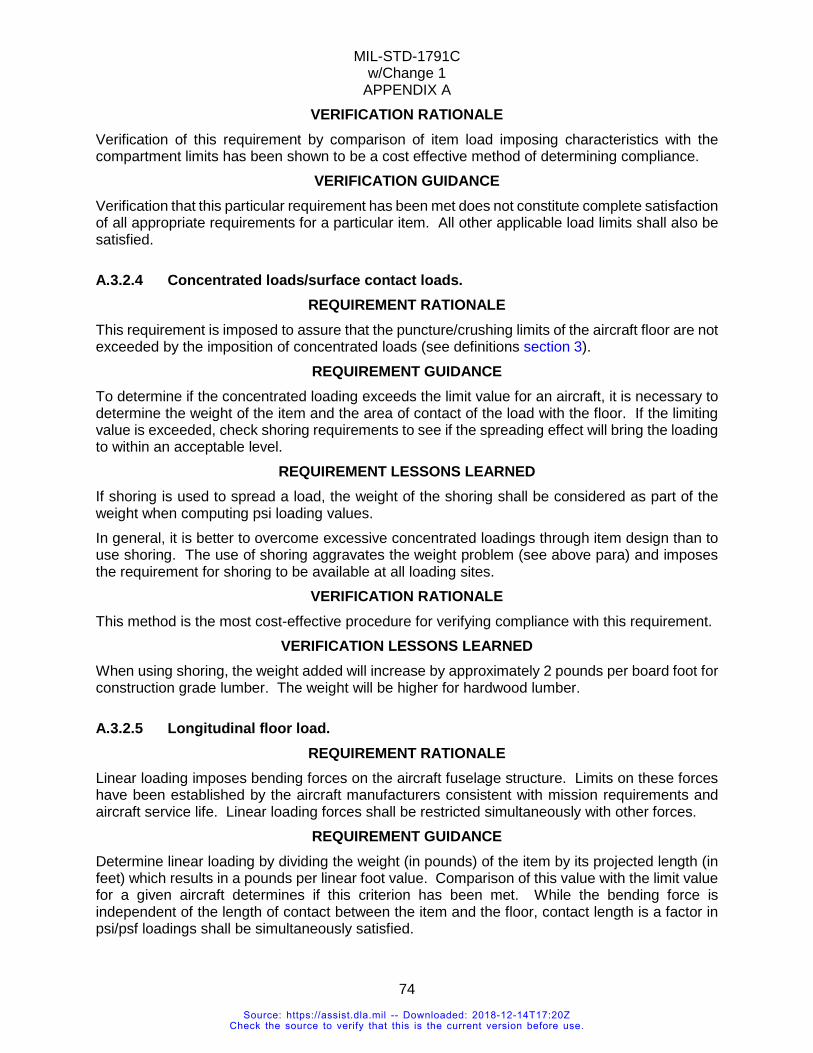
MIL-STD-1791C w/Change 1
APPENDIX A
74
VERIFICATION RATIONALE Verification of this requirement by comparison of item load imposing characteristics with the compartment limits has been shown to be a cost effective method of determining compliance.
VERIFICATION GUIDANCE Verification that this particular requirement has been met does not constitute complete satisfaction of all appropriate requirements for a particular item. All other applicable load limits shall also be satisfied.
A.3.2.4 Concentrated loads/surface contact loads. REQUIREMENT RATIONALE
This requirement is imposed to assure that the puncture/crushing limits of the aircraft floor are not exceeded by the imposition of concentrated loads (see definitions section 3).
REQUIREMENT GUIDANCE To determine if the concentrated loading exceeds the limit value for an aircraft, it is necessary to determine the weight of the item and the area of contact of the load with the floor. If the limiting value is exceeded, check shoring requirements to see if the spreading effect will bring the loading to within an acceptable level.
REQUIREMENT LESSONS LEARNED If shoring is used to spread a load, the weight of the shoring shall be considered as part of the weight when computing psi loading values. In general, it is better to overcome excessive concentrated loadings through item design than to use shoring. The use of shoring aggravates the weight problem (see above para) and imposes the requirement for shoring to be available at all loading sites.
VERIFICATION RATIONALE This method is the most cost-effective procedure for verifying compliance with this requirement.
VERIFICATION LESSONS LEARNED When using shoring, the weight added will increase by approximately 2 pounds per board foot for construction grade lumber. The weight will be higher for hardwood lumber.
A.3.2.5 Longitudinal floor load. REQUIREMENT RATIONALE
Linear loading imposes bending forces on the aircraft fuselage structure. Limits on these forces have been established by the aircraft manufacturers consistent with mission requirements and aircraft service life. Linear loading forces shall be restricted simultaneously with other forces.
REQUIREMENT GUIDANCE Determine linear loading by dividing the weight (in pounds) of the item by its projected length (in feet) which results in a pounds per linear foot value. Comparison of this value with the limit value for a given aircraft determines if this criterion has been met. While the bending force is independent of the length of contact between the item and the floor, contact length is a factor in psi/psf loadings shall be simultaneously satisfied.
Source: https://assist.dla.mil -- Downloaded: 2018-12-14T17:20ZCheck the source to verify that this is the current version before use.
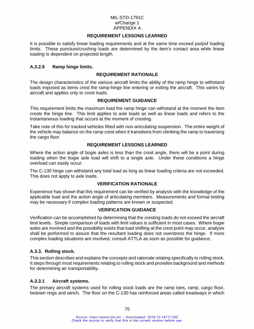
MIL-STD-1791C w/Change 1
APPENDIX A
75
REQUIREMENT LESSONS LEARNED It is possible to satisfy linear loading requirements and at the same time exceed psi/psf loading limits. These puncture/crushing loads are determined by the item's contact area while linear loading is dependent on projected length.
A.3.2.6 Ramp hinge limits. REQUIREMENT RATIONALE
The design characteristics of the various aircraft limits the ability of the ramp hinge to withstand loads imposed as items crest the ramp-hinge line entering or exiting the aircraft. This varies by aircraft and applies only to crest loads.
REQUIREMENT GUIDANCE This requirement limits the maximum load the ramp hinge can withstand at the moment the item crests the hinge line. This limit applies to axle loads as well as linear loads and refers to the instantaneous loading that occurs at the moment of cresting. Take note of this for tracked vehicles fitted with non-articulating suspension. The entire weight of the vehicle may balance on the ramp crest when it transitions from climbing the ramp to traversing the cargo floor.
REQUIREMENT LESSONS LEARNED Where the action angle of bogie axles is less than the crest angle, there will be a point during loading when the bogie axle load will shift to a single axle. Under these conditions a hinge overload can easily occur. The C-130 hinge can withstand any total load as long as linear loading criteria are not exceeded. This does not apply to axle loads.
VERIFICATION RATIONALE Experience has shown that this requirement can be verified by analysis with the knowledge of the applicable load and the action angle of articulating members. Measurements and formal testing may be necessary if complex loading patterns are known or suspected.
VERIFICATION GUIDANCE Verification can be accomplished by determining that the cresting loads do not exceed the aircraft limit levels. Simple comparison of loads with limit values is sufficient in most cases. Where bogie axles are involved and the possibility exists that load shifting at the crest point may occur, analysis shall be performed to assure that the resultant loading does not overstress the hinge. If more complex loading situations are involved, consult ATTLA as soon as possible for guidance.
A.3.3. Rolling stock. This section describes and explains the concepts and rationale relating specifically to rolling stock. It steps through most requirements relating to rolling stock and provides background and methods for determining air transportability.
A.3.3.1 Aircraft systems. The primary aircraft systems used for rolling stock loads are the ramp toes, ramp, cargo floor, tiedown rings and winch. The floor on the C-130 has reinforced areas called treadways in which
Source: https://assist.dla.mil -- Downloaded: 2018-12-14T17:20ZCheck the source to verify that this is the current version before use.
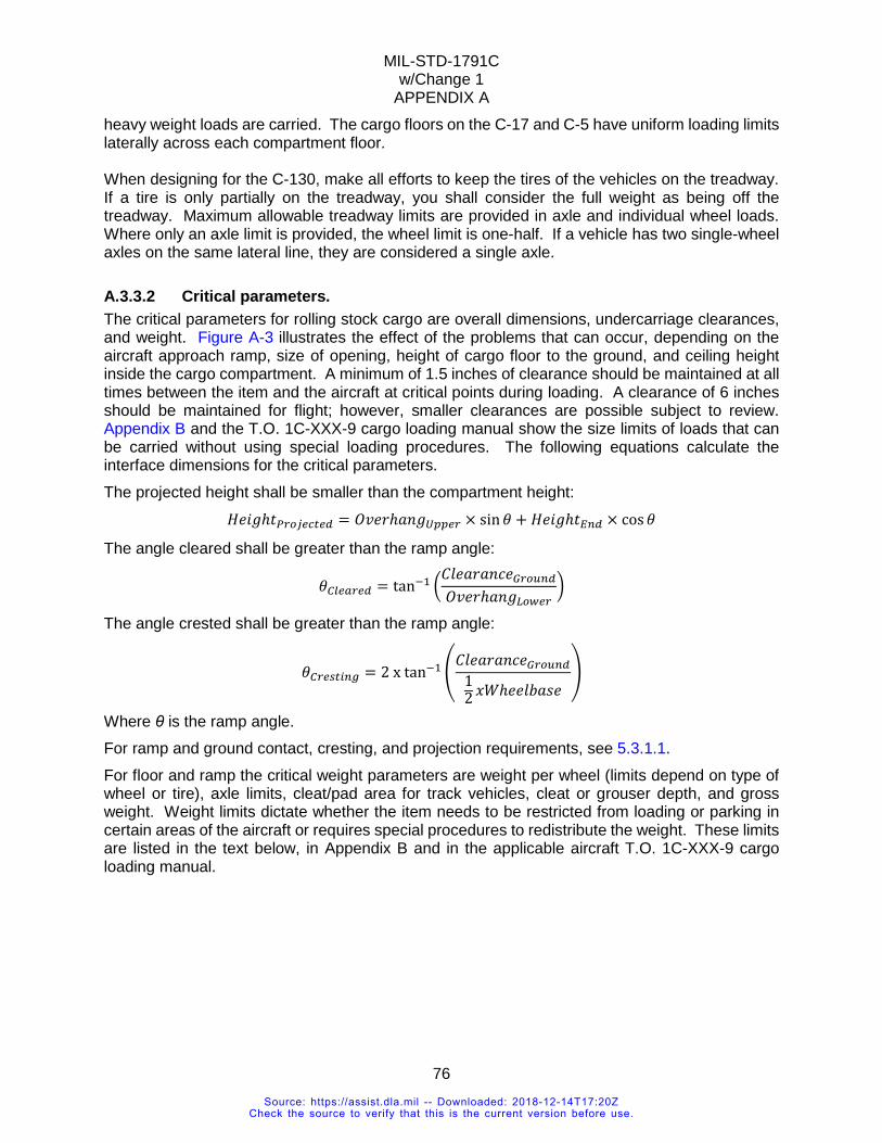
MIL-STD-1791C w/Change 1
APPENDIX A
76
heavy weight loads are carried. The cargo floors on the C-17 and C-5 have uniform loading limits laterally across each compartment floor. When designing for the C-130, make all efforts to keep the tires of the vehicles on the treadway. If a tire is only partially on the treadway, you shall consider the full weight as being off the treadway. Maximum allowable treadway limits are provided in axle and individual wheel loads. Where only an axle limit is provided, the wheel limit is one-half. If a vehicle has two single-wheel axles on the same lateral line, they are considered a single axle.
A.3.3.2 Critical parameters. The critical parameters for rolling stock cargo are overall dimensions, undercarriage clearances, and weight. Figure A-3 illustrates the effect of the problems that can occur, depending on the aircraft approach ramp, size of opening, height of cargo floor to the ground, and ceiling height inside the cargo compartment. A minimum of 1.5 inches of clearance should be maintained at all times between the item and the aircraft at critical points during loading. A clearance of 6 inches should be maintained for flight; however, smaller clearances are possible subject to review. Appendix B and the T.O. 1C-XXX-9 cargo loading manual show the size limits of loads that can be carried without using special loading procedures. The following equations calculate the interface dimensions for the critical parameters. The projected height shall be smaller than the compartment height: 𝐻𝐻𝐻𝐻𝐻𝐻𝐻𝐻ℎ𝑡𝑡𝑃𝑃𝑃𝑃𝑃𝑃𝑃𝑃𝑃𝑃𝑃𝑃𝑃𝑃𝑃𝑃𝑃𝑃 = 𝑂𝑂𝑂𝑂𝐻𝐻𝑂𝑂ℎ𝑎𝑎𝑎𝑎𝐻𝐻𝑈𝑈𝑈𝑈𝑈𝑈𝑃𝑃𝑃𝑃 × sin𝜃𝜃 + 𝐻𝐻𝐻𝐻𝐻𝐻𝐻𝐻ℎ𝑡𝑡𝐸𝐸𝐸𝐸𝑃𝑃 × cos𝜃𝜃
The angle cleared shall be greater than the ramp angle: 𝜃𝜃𝐶𝐶𝐶𝐶𝑃𝑃𝐶𝐶𝑃𝑃𝑃𝑃𝑃𝑃 = tan−1 �
𝐶𝐶𝐶𝐶𝐻𝐻𝑎𝑎𝑂𝑂𝑎𝑎𝑎𝑎𝐶𝐶𝐻𝐻𝐺𝐺𝑃𝑃𝑃𝑃𝐺𝐺𝐸𝐸𝑃𝑃𝑂𝑂𝑂𝑂𝐻𝐻𝑂𝑂ℎ𝑎𝑎𝑎𝑎𝐻𝐻𝐿𝐿𝑃𝑃𝐿𝐿𝑃𝑃𝑃𝑃
�
The angle crested shall be greater than the ramp angle:
𝜃𝜃𝐶𝐶𝑃𝑃𝑃𝑃𝐶𝐶𝑃𝑃𝐶𝐶𝐸𝐸𝐶𝐶 = 2 x tan−1 �𝐶𝐶𝐶𝐶𝐻𝐻𝑎𝑎𝑂𝑂𝑎𝑎𝑎𝑎𝐶𝐶𝐻𝐻𝐺𝐺𝑃𝑃𝑃𝑃𝐺𝐺𝐸𝐸𝑃𝑃
12 𝑥𝑥𝑥𝑥ℎ𝐻𝐻𝐻𝐻𝐶𝐶𝑒𝑒𝑎𝑎𝑒𝑒𝐻𝐻
�
Where θ is the ramp angle. For ramp and ground contact, cresting, and projection requirements, see 5.3.1.1. For floor and ramp the critical weight parameters are weight per wheel (limits depend on type of wheel or tire), axle limits, cleat/pad area for track vehicles, cleat or grouser depth, and gross weight. Weight limits dictate whether the item needs to be restricted from loading or parking in certain areas of the aircraft or requires special procedures to redistribute the weight. These limits are listed in the text below, in Appendix B and in the applicable aircraft T.O. 1C-XXX-9 cargo loading manual.
Source: https://assist.dla.mil -- Downloaded: 2018-12-14T17:20ZCheck the source to verify that this is the current version before use.
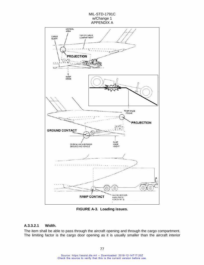
MIL-STD-1791C w/Change 1
APPENDIX A
77
FIGURE A-3. Loading issues.
A.3.3.2.1 Width. The item shall be able to pass through the aircraft opening and through the cargo compartment. The limiting factor is the cargo door opening as it is usually smaller than the aircraft interior
Source: https://assist.dla.mil -- Downloaded: 2018-12-14T17:20ZCheck the source to verify that this is the current version before use.
MIL-STD-1791C w/Change 1
APPENDIX A
78
dimensions. As the item moves into the cargo compartment, the available floor spacing, sidewall clearance or width at various heights should be considered. Aircraft lateral clearances and lateral center of gravity limits should also be observed. For C-130 aircraft, there is a requirement to maintain a safety aisle for the aircrew member to pass through for inspection and emergency movement. If passengers are onboard, the C-130 also has a different aisle way requirement (see 5.3.1.1.5 and Appendix B). Depending on its location, the item may be wider than the floor width due to fuselage curvature, if the item does not block any potential exits.
A.3.3.2.2 Height. Height is critical for projection, straight-in loading, and movement inside the cargo compartment. For straight-in loading, the cargo door opening in the limiting factor. For movement inside the cargo compartment, the combination of height and width may restrict the loads location inside the aircraft. For example, the C-17 wing box limits the height to 148 inches underneath it. Taller loads have to be stationed aft of the wing box. For the C-5, the cargo compartment gets narrower with increasing height (see Appendix B).
A.3.3.3 Weight distribution.
A.3.3.3.1 Axles, tires, and wheels. The critical weight parameters are axle weights, wheels/tire weights, wheel/tire contact length, width and diameter, tire type and contact surface pattern.
A.3.3.3.1.1 Axle weight. The aircraft has axle limits for loading and for flight as shown in Appendix B. The longitudinal spacing between support beams under the aircraft ramp and cargo floor dictate that the distance between axles shall be at least 48 inches to be considered as individual axles. Any axles less than 48 inches will be considered as a single axle with the combined weight of both axles. Many types of commercial rolling stock do not have axles that can withstand the 4.5G down requirement. Rolling stock without a cross-country axle rating is limited to 80 percent of their highway rating. If the vehicle exceeds 80 percent, it will be sleeper shored for flight.
A.3.3.3.1.2 Pneumatic tires. Road tires or highway tires have an internal pressure of no more than 100 psi. The tires’ pads are spaced close together so the tire contact area is mostly covered within the contact length and width.
A.3.3.3.1.3 Off-road tires. Off-road tires, such as those found on construction or farm equipment, have deep grooves and large gaps between tire pads. The gaps increase floor pressure and may require rolling and parking shoring to meet aircraft limits. A guideline for shoring dimensions is to have the thickness at half the distance between the gaps and at least one gap distance more than the overall floor contact length and width of the tire. For example, if the floor contact length is 12 inches and the width is 10 inches but the gap between pads is 2 inches, the shoring size will be 14 inches long by 12 inches wide by 1 inch thick (see Figure A-44). Additional shoring is required depending on the aircraft limits and actual tire pad contact area.
Source: https://assist.dla.mil -- Downloaded: 2018-12-14T17:20ZCheck the source to verify that this is the current version before use.
MIL-STD-1791C w/Change 1
APPENDIX A
79
NOTE: Special use vehicles weighing over 20,000 pounds, with off-road tires, and without a suspension system should be sleeper shored for flight. Examples are road graders, forklifts, and scoop loaders.
A.3.3.3.1.4 Solid wheels. These types of tire include pneumatic over 100 psi (over 300 psi on C-5), hard rubber tires, single piece wheels (rubber, wooden, plastic or metal), and casters. These wheels do not flex during flight. They produce a line or ribbon contact which results in higher contact pressures. The limits for these wheels are laid out in Appendix B and are different for each aircraft.
A.3.3.3.1.5 Computing tire contact area. Tire or wheel contact area is computed differently for each aircraft. In general it can be found by adding the areas of individual contact surfaces inside the length and width of the tire, then multiply by an effective factor for the type of tire. The factor can be found in Appendix B for each type of aircraft. For example, the effective road or highway tire area on the C-5, it is the length times width (L × W) times 0.78. For off-road tires with large gaps between the contact pads, contact surfaces are individually computed, and then added together (see Figure A-4). If actual area is unknown, see methods for each aircraft in Appendix B. A solid tire is a tire with the pressure exceeding the aircraft limit (see Appendix B), is filled with foam or other solid material, hard rubber or airless (non-pneumatic). The reason airless tires are classified in this standard as solid tires, even though they are designed to behave like pneumatic tires, is that there is not enough data to show they behave similarly under flight and crash conditions as pneumatic tires. Other types of solid tire are solid caster, metal wheel, and vibratory roller.
Source: https://assist.dla.mil -- Downloaded: 2018-12-14T17:20ZCheck the source to verify that this is the current version before use.
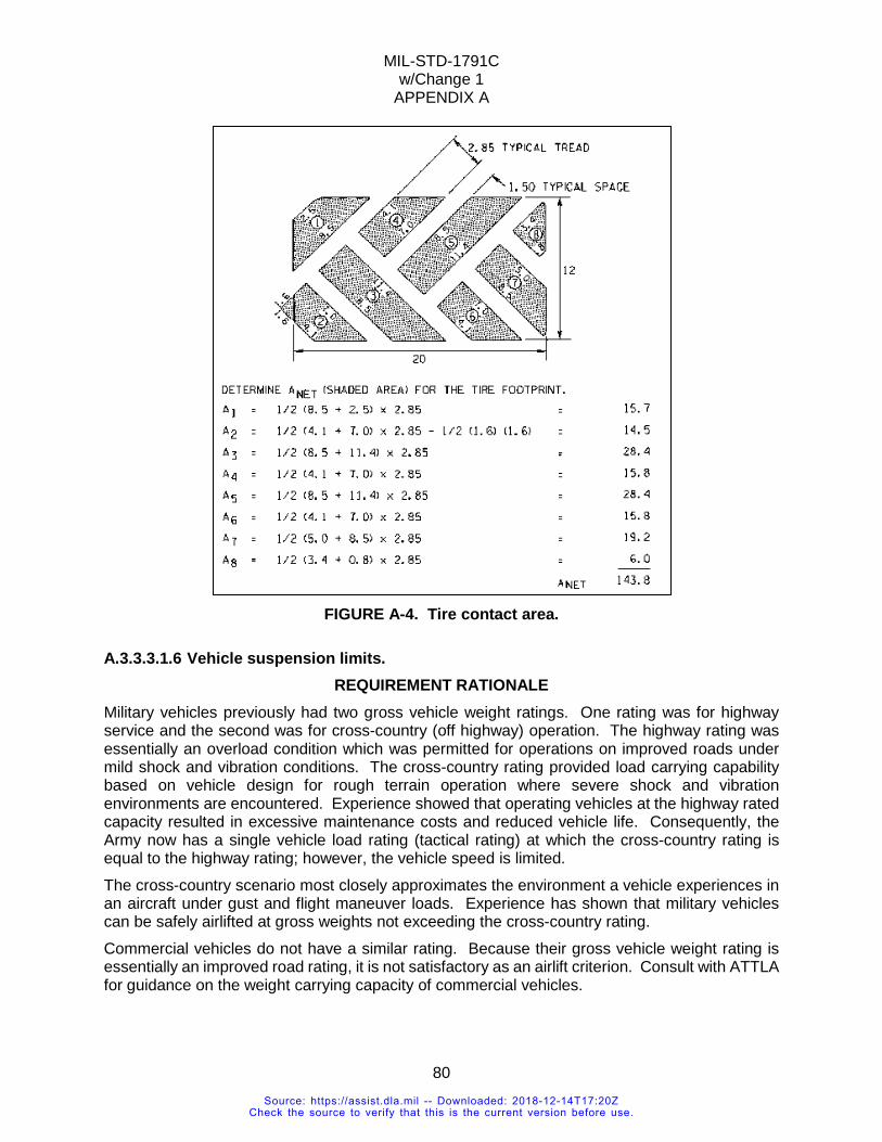
MIL-STD-1791C w/Change 1
APPENDIX A
80
FIGURE A-4. Tire contact area.
A.3.3.3.1.6 Vehicle suspension limits. REQUIREMENT RATIONALE
Military vehicles previously had two gross vehicle weight ratings. One rating was for highway service and the second was for cross-country (off highway) operation. The highway rating was essentially an overload condition which was permitted for operations on improved roads under mild shock and vibration conditions. The cross-country rating provided load carrying capability based on vehicle design for rough terrain operation where severe shock and vibration environments are encountered. Experience showed that operating vehicles at the highway rated capacity resulted in excessive maintenance costs and reduced vehicle life. Consequently, the Army now has a single vehicle load rating (tactical rating) at which the cross-country rating is equal to the highway rating; however, the vehicle speed is limited. The cross-country scenario most closely approximates the environment a vehicle experiences in an aircraft under gust and flight maneuver loads. Experience has shown that military vehicles can be safely airlifted at gross weights not exceeding the cross-country rating. Commercial vehicles do not have a similar rating. Because their gross vehicle weight rating is essentially an improved road rating, it is not satisfactory as an airlift criterion. Consult with ATTLA for guidance on the weight carrying capacity of commercial vehicles.
Source: https://assist.dla.mil -- Downloaded: 2018-12-14T17:20ZCheck the source to verify that this is the current version before use.
MIL-STD-1791C w/Change 1
APPENDIX A
81
REQUIREMENT GUIDANCE A military vehicle which has an established tactical/cross-country rating can be carried safely in all aircraft at gross vehicle weights (GVWs) not exceeding this value provided all other aircraft limitations are met. ATTLA will determine the acceptable GVW of all other vehicles including all commercial vehicles.
REQUIREMENT LESSONS LEARNED Commercial vehicles generally have lighter duty suspension systems than military vehicles which are designed for more rugged service environments. This not only means that they are more subject to failure under flight load conditions with a high potential for aircraft damage, but they are also more prone to uncontrolled random movement which places greater stresses on tiedown devices. Commercial vehicles are increasingly being used for military applications. Because these vehicles are not designed to have the inherent ruggedness the military environment requires, it would be prudent to procure these vehicles with as rugged a suspension package as possible. The initial cost can be recovered many times over through the increased capability of the vehicle and reduced problems associated with aerial delivery. An option is to include load bearing, stabilizing devices which function as sleeper shoring (see 5.3.7.1.2). The earliest possible contact with ATTLA is advised when commercial vehicles are being considered for use. This can often result in problem avoidance.
VERIFICATION RATIONALE Assurance that the actual GVW does not exceed the published value or that determined by cognizant authority is sufficient verification for this requirement. Maximum GVW values are set at levels which will assure safe loading and flight for the vehicles.
VERIFICATION GUIDANCE Cross-country/tactical ratings are shown in the field manual or technical order for each military vehicle. Where no cross-country/ tactical rating for a vehicle has been established, 80 percent of the manufacturer's GVW rating should be used to determine the maximum airlift weight of a vehicle. In addition, the CG of the vehicle should be so located that no axle weight exceeds 80 percent of its maximum rated capacity.
A.3.3.3.1.7 Wheel/tire loads. REQUIREMENT RATIONALE
Pneumatic tires impose a crushing load on the aircraft floor. Steel wheels, in theory, provide only line contact with the supporting area. Slight flexibility of both floor and wheel makes the contact a ribbon rather than a line, but the weight on a steel wheel is still concentrated. Solid rubber wheels also often concentrate the load on a small area. Because steel and solid rubber wheels are essentially unyielding, high concentrated loads can easily be developed. A second consideration applies to pneumatic tires. Tires loaded beyond their rated capacity are subject to failure. Tires filled with a core material no longer spread the load under flight conditions as well as pneumatic tires due to smaller tire deflections.
REQUIREMENT GUIDANCE Appendix B presents data for pneumatic tires as well as charts for steel and hard rubber wheels. Direct comparison of the loads and physical dimensions of the steel/hard rubber wheels with the
Source: https://assist.dla.mil -- Downloaded: 2018-12-14T17:20ZCheck the source to verify that this is the current version before use.
MIL-STD-1791C w/Change 1
APPENDIX A
82
appropriate limit data from the charts will indicate acceptability of the wheels at shipment load values. Tire loads should not only fall within limits imposed by the aircraft manufacturer and shown in tables for each aircraft, but should also adhere to tire manufacturers' load limits as well. If it can be verified that the core filled tires adequately distribute the load for the load factors in 5.3.3.1, relief from this requirement is possible.
REQUIREMENT LESSONS LEARNED Tires have tread which effectively reduces contact area. In cases of construction and rough terrain vehicles, this reduction can be significant. To insure full floor contact, shoring equal in thickness to at least one-half of the tire groove width will be used. For example, if the tire has a groove between tread of two inches, any shoring used shall have a thickness of at least one inch. Tire pressure will be maintained within the manufacturer's operating pressure range. At pressures lower than this, a danger exists that the tire-to-rim seal may be broken with the possibility of sudden tire failure and damage to the aircraft.
VERIFICATION RATIONALE The method of verifying compliance with this requirement by direct comparison of loads and tire/wheel characteristics with published limit data is both adequate and cost effective.
VERIFICATION LESSONS LEARNED For the C-130 aircraft explicitly and as a guideline for other aircraft, pneumatic tires having an air pressure in excess of 100 psi shall be considered hard rubber wheels and verification of acceptability shall be based on these criteria.
A.3.3.3.1.8 Axle loads and axle spacing limits. REQUIREMENT RATIONALE
Vehicle axle loads impose bending forces on the aircraft fuselage. Axle spacing requirements are set to assure that forces are distributed so that major fuselage structural members do not experience overload conditions. Both limits are set by the airframe manufacturer based on design utilization of the aircraft over a specified service life. Aircraft loading limits are equal to or higher than flight limits because no gust or flight maneuver forces are secondarily imposed during the loading/unloading process. Thus, in some instances it may be possible to load an out-of-limit axle if provision can be made through the use of shoring or other means to bring the axle within flight limits once the vehicle is on-board the aircraft.
REQUIREMENT GUIDANCE Appendix B specifies the axle load and axle spacing limits. Knowledge of the axle configuration (number of wheels per axle), axle weight and spacing will permit determination of the acceptability of the vehicle for loading and flight.
REQUIREMENT LESSONS LEARNED Axle loads and wheel loads shall be satisfied simultaneously. Often axle/wheel configuration will be such that the wheel load becomes the more restrictive criteria (see 5.3.2.9). It is important to ensure that, where the axle/wheel configuration permits a given load, the tires are of the appropriate load-bearing range so that tire failure will not occur under either loading or flight conditions. Use of a better grade tire than required for operational purposes may prove to be cost effective if extensive precautions need otherwise be taken in order to airlift the vehicle.
Source: https://assist.dla.mil -- Downloaded: 2018-12-14T17:20ZCheck the source to verify that this is the current version before use.
MIL-STD-1791C w/Change 1
APPENDIX A
83
VERIFICATION RATIONALE Experience has shown that this requirement can generally be verified by comparison of axle/wheel configurations, axle loads, and axle spacing with aircraft limit data. Analysis may be required for loading procedures which involve ramp cresting where axle loads may be instantaneously transferred with possible overloads resulting.
VERIFICATION GUIDANCE Comparison of the vehicle physical characteristics with the limit data presented in Appendix B is the initial step in the verification process. This establishes if the vehicle can be loaded straight in across the horizontally positioned ramp. Loading from the ground up the inclined ramp involves cresting at the hinge line. Without sufficient axle articulation, axle loads can shift at the crest point and cause an overloaded condition to exist until all axles are supported by the aircraft floor. If this condition exists, ATTLA should be contacted immediately for advice.
A.3.3.3.1.9 Lateral weight and axle limit. Placement of cargo to one side or multiple loads side-by-side shall not exceed the aircraft lateral load limits.
A.3.3.3.2 Tracks. Tracked vehicles are governed by the same axle limits as wheeled cargo. There are additional limitations for tracked vehicles with non-articulated suspension. Non-articulated tracks teeter at the ramp crest, balancing their entire weight at the top of the ramp and then rotate down once the CG moves forward. When non-articulated tracks transition to and from the ramp toes the entire weight of the track is supported at the ends, changing the distributed load to a concentrated load. Tracks with pads (usually military) are treated similarly to calculating tire contact area. Tracks with grousers (bulldozers) always require shoring. To prevent damage to the aircraft, a layer of rolling and parking shoring shall be used. The shoring shall be at least 0.5 inch thick for C-17/C-5 and 0.75 inch for C-130 variants. Shoring should be as thick as the cleat or grouser depth plus 0.5 inch. Shoring thickness and width are also predicated on the weight of each track pad.
A.3.3.3.2.1 Tracked pads or cleats. LESSONS LEARNED
Rolling shoring is specified for tracks with grousers to the depth of the cleat plus at least 0.5 inch. It is possible for the vehicle to damage the shoring during loading to the point that it is unusable for offload and a second set may be required. The minimum recommended width is 1.5 times the width of the track to account for minor steering adjustments during on/offload. This may be required for tracks with pads if the pads are worn and present a danger to the aircraft floor.
A.3.3.3.3 Pads or stands. The pressure per pad should not exceed the aircraft floor pressure limits. Supports such as jackstands shall have a locking mechanism to prevent the stand from collapsing. Hydraulic stands are not acceptable as support inside the aircraft because hydraulic fluid can leak and reduce the stand’s carrying capability. The bottom of the pad shall be padded or shored to prevent metal-to-metal contact with the cargo floor (see Figure A-5).
Source: https://assist.dla.mil -- Downloaded: 2018-12-14T17:20ZCheck the source to verify that this is the current version before use.
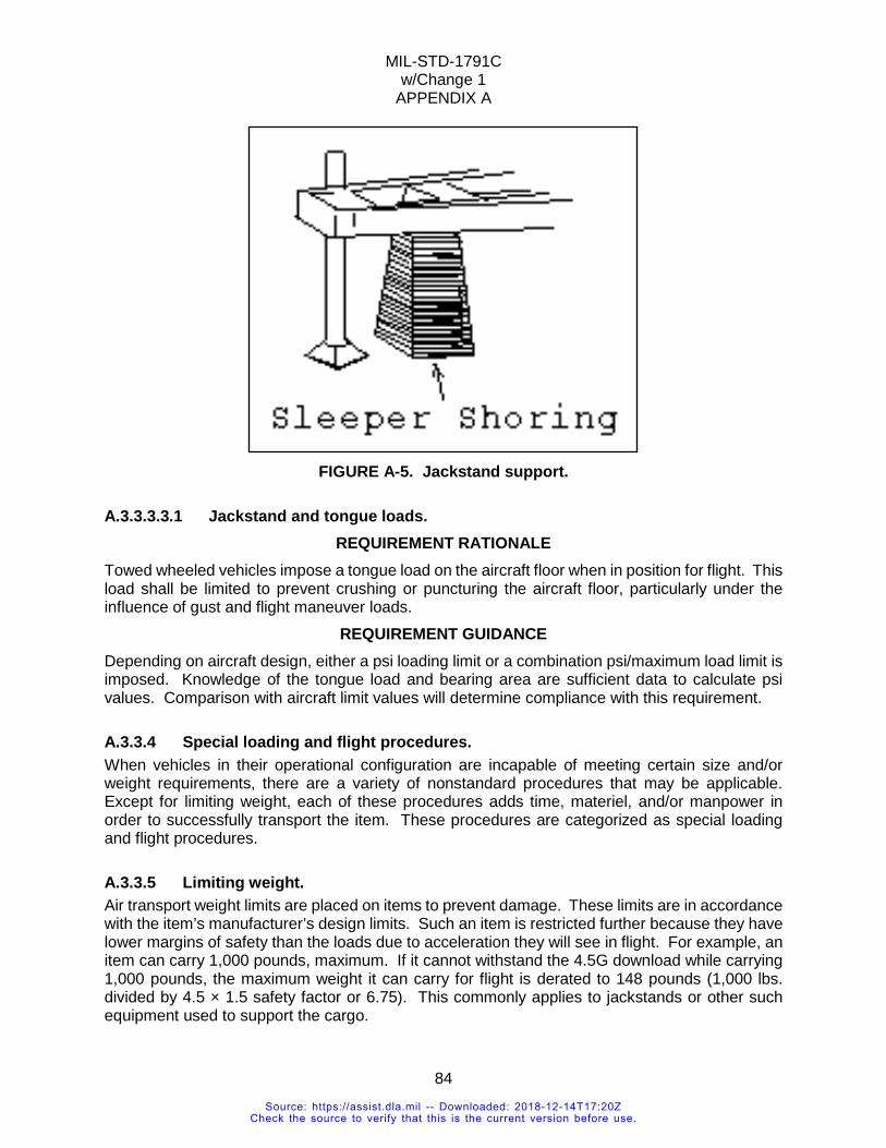
MIL-STD-1791C w/Change 1
APPENDIX A
84
FIGURE A-5. Jackstand support.
A.3.3.3.3.1 Jackstand and tongue loads. REQUIREMENT RATIONALE
Towed wheeled vehicles impose a tongue load on the aircraft floor when in position for flight. This load shall be limited to prevent crushing or puncturing the aircraft floor, particularly under the influence of gust and flight maneuver loads.
REQUIREMENT GUIDANCE Depending on aircraft design, either a psi loading limit or a combination psi/maximum load limit is imposed. Knowledge of the tongue load and bearing area are sufficient data to calculate psi values. Comparison with aircraft limit values will determine compliance with this requirement.
A.3.3.4 Special loading and flight procedures. When vehicles in their operational configuration are incapable of meeting certain size and/or weight requirements, there are a variety of nonstandard procedures that may be applicable. Except for limiting weight, each of these procedures adds time, materiel, and/or manpower in order to successfully transport the item. These procedures are categorized as special loading and flight procedures.
A.3.3.5 Limiting weight. Air transport weight limits are placed on items to prevent damage. These limits are in accordance with the item’s manufacturer’s design limits. Such an item is restricted further because they have lower margins of safety than the loads due to acceleration they will see in flight. For example, an item can carry 1,000 pounds, maximum. If it cannot withstand the 4.5G download while carrying 1,000 pounds, the maximum weight it can carry for flight is derated to 148 pounds (1,000 lbs. divided by 4.5 × 1.5 safety factor or 6.75). This commonly applies to jackstands or other such equipment used to support the cargo.
Source: https://assist.dla.mil -- Downloaded: 2018-12-14T17:20ZCheck the source to verify that this is the current version before use.
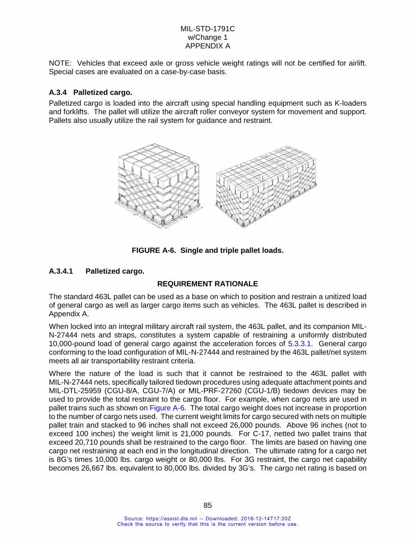
MIL-STD-1791C w/Change 1
APPENDIX A
85
NOTE: Vehicles that exceed axle or gross vehicle weight ratings will not be certified for airlift. Special cases are evaluated on a case-by-case basis.
A.3.4 Palletized cargo. Palletized cargo is loaded into the aircraft using special handling equipment such as K-loaders and forklifts. The pallet will utilize the aircraft roller conveyor system for movement and support. Pallets also usually utilize the rail system for guidance and restraint.
FIGURE A-6. Single and triple pallet loads.
A.3.4.1 Palletized cargo. REQUIREMENT RATIONALE
The standard 463L pallet can be used as a base on which to position and restrain a unitized load of general cargo as well as larger cargo items such as vehicles. The 463L pallet is described in Appendix A. When locked into an integral military aircraft rail system, the 463L pallet, and its companion MIL-N-27444 nets and straps, constitutes a system capable of restraining a uniformly distributed 10,000-pound load of general cargo against the acceleration forces of 5.3.3.1. General cargo conforming to the load configuration of MIL-N-27444 and restrained by the 463L pallet/net system meets all air transportability restraint criteria. Where the nature of the load is such that it cannot be restrained to the 463L pallet with MIL-N-27444 nets, specifically tailored tiedown procedures using adequate attachment points and MIL-DTL-25959 (CGU-8/A, CGU-7/A) or MIL-PRF-27260 (CGU-1/B) tiedown devices may be used to provide the total restraint to the cargo floor. For example, when cargo nets are used in pallet trains such as shown on Figure A-6. The total cargo weight does not increase in proportion to the number of cargo nets used. The current weight limits for cargo secured with nets on multiple pallet train and stacked to 96 inches shall not exceed 26,000 pounds. Above 96 inches (not to exceed 100 inches) the weight limit is 21,000 pounds. For C-17, netted two pallet trains that exceed 20,710 pounds shall be restrained to the cargo floor. The limits are based on having one cargo net restraining at each end in the longitudinal direction. The ultimate rating for a cargo net is 8G’s times 10,000 lbs. cargo weight or 80,000 lbs. For 3G restraint, the cargo net capability becomes 26,667 lbs. equivalent to 80,000 lbs. divided by 3G’s. The cargo net rating is based on
Source: https://assist.dla.mil -- Downloaded: 2018-12-14T17:20ZCheck the source to verify that this is the current version before use.
MIL-STD-1791C w/Change 1
APPENDIX A
86
a 96 inch high load and the weight limits for taller loads it is reduced to 21,000 lbs. Alternative restraint methods shall be used if the cargo weight exceeds the netted cargo limit. 463L pallets are load-limited in two respects. First, concentrated loads on the surface of these devices can cause puncturing of the pallet skin. Secondly, loads carried by these devices are transmitted to and reacted by the aircraft rollers which also have structural limits. Thus, the cargo shall not impose loads which exceed either the roller limits shown in Table III or the pallet puncture load limits of 250 pounds per square inch (psi).
REQUIREMENT GUIDANCE To determine if a palletized object is suitable for air transport, it is necessary to compute the loads which will be imposed on the rollers of the aircraft under consideration. This loading is a function of the object's contact length on the pallet which determines the number of roller stations contacted. Two important considerations shall be kept in mind when determining the acceptability of pallet loads. First, no load spreading capability is assumed to exist with the 463L pallet. Therefore, to determine the longitudinal roller loads for palletized cargo, use only the object's actual contact length per longitudinal contact station on the pallet. If load spreading is necessary to meet roller load limits, wood shoring may be used employing the principle of geometric weight distribution. A note of caution, for cargo that have small surfaces in contact with the pallet surface, such as wheels or landing gear/jackstands/foot pads, weight may still be transmitted directly on to individual rollers through the pallet even when the item is shored. Wheel and landing gear weights can exceed the roller’s limits. Shoring, or load spreading, shall be high enough to lift wheels or landing gears off the pallet surface to ensure weight is distributed on the shoring. The wheels or landing gear may be shimmed afterwards to keep them from bouncing during flight. The second factor is the number of roller conveyors (longitudinal trays of rollers) contacted. Differing roller load limits apply depending on the number of conveyors under load.
VERIFICATION RATIONALE Except where complex weight distributions are involved, analytical means have proven adequate to verify the acceptability of palletized loads. In those cases where complex loading exists, instrumented tests may be necessary to assure that the forces imposed on the roller system or the pallets themselves do not exceed established limits.
VERIFICATION GUIDANCE The basic data required to compute the loads on the aircraft roller system are the dimensions of the base of the cargo item and the item's weight distribution. Both footprint pressure and load placement on the pallet shall be considered. Footprint pressure shall not exceed 250 psi. Load placement directly affects the loading imposed on the rollers. Analysis will permit determination of the number of roller conveyors under load as well as the number of roller stations contacted.
VERIFICATION LESSONS LEARNED Design of palletized loads shall take into account the weight of the pallet, required restraint hardware, and any additional equipment. An airdrop program lost cargo capability when the upgraded airdrop system increased in weight over the old one. The capacity of a unitized load system (pallet, airdrop platform, skidboard, etc.) cannot be increased to accommodate the same cargo capacity because the support equipment increases in weight.
Source: https://assist.dla.mil -- Downloaded: 2018-12-14T17:20ZCheck the source to verify that this is the current version before use.
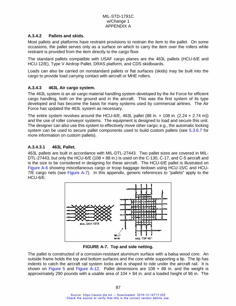
MIL-STD-1791C w/Change 1
APPENDIX A
87
A.3.4.2 Pallets and skids. Most pallets and platforms have restraint provisions to restrain the item to the pallet. On some occasions, the pallet serves only as a surface on which to carry the item over the rollers while restraint is provided from the item directly to the cargo floor. The standard pallets compatible with USAF cargo planes are the 463L pallets (HCU-6/E and HCU-12/E), Type V Airdrop Pallet, DRAS platform, and CDS skidboards. Loads can also be carried on nonstandard pallets or flat surfaces (skids) may be built into the cargo to provide load carrying contact with aircraft or MHE rollers.
A.3.4.3 463L Air cargo system. The 463L system is an air cargo material handling system developed by the Air Force for efficient cargo handling, both on the ground and in the aircraft. This was the first system of its type developed and has become the basis for many systems used by commercial airlines. The Air Force has updated the 463L system as necessary. The entire system revolves around the HCU-6/E, 463L pallet (88 in. × 108 in. (2.24 × 2.74 m)) and the use of roller conveyor systems. The equipment is designed to load and secure this unit. The designer can also use this system to effectively move other cargo; e.g., the automatic locking system can be used to secure pallet components used to build custom pallets (see 5.3.6.7 for more information on custom pallets).
A.3.4.3.1 463L Pallet. 463L pallets are built in accordance with MIL-DTL-27443. Two pallet sizes are covered in MIL-DTL-27443, but only the HCU-6/E (108 × 88 in.) is used on the C-130, C-17, and C-5 aircraft and is the size to be considered in designing for these aircraft. The HCU-6/E pallet is illustrated on Figure A-6 showing miscellaneous cargo or troop baggage tiedown using HCU-15/C and HCU-7/E cargo nets (see Figure A-7). In this appendix, generic references to “pallets” apply to the HCU-6/E.
FIGURE A-7. Top and side netting.
The pallet is constructed of a corrosion-resistant aluminum surface with a balsa wood core. An outside frame holds the top and bottom surfaces and the core while supporting a lip. The lip has indents to catch the aircraft rail system locks and is shaped to ride under the aircraft rail. It is shown on Figure 5 and Figure A-12. Pallet dimensions are 108 × 88 in. and the weight is approximately 290 pounds with a usable area of 104 × 84 in. and a loaded height of 96 in. The
Source: https://assist.dla.mil -- Downloaded: 2018-12-14T17:20ZCheck the source to verify that this is the current version before use.
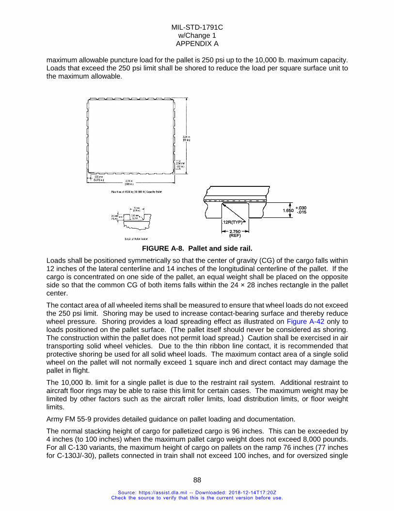
MIL-STD-1791C w/Change 1
APPENDIX A
88
maximum allowable puncture load for the pallet is 250 psi up to the 10,000 lb. maximum capacity. Loads that exceed the 250 psi limit shall be shored to reduce the load per square surface unit to the maximum allowable.
FIGURE A-8. Pallet and side rail.
Loads shall be positioned symmetrically so that the center of gravity (CG) of the cargo falls within 12 inches of the lateral centerline and 14 inches of the longitudinal centerline of the pallet. If the cargo is concentrated on one side of the pallet, an equal weight shall be placed on the opposite side so that the common CG of both items falls within the 24 × 28 inches rectangle in the pallet center. The contact area of all wheeled items shall be measured to ensure that wheel loads do not exceed the 250 psi limit. Shoring may be used to increase contact-bearing surface and thereby reduce wheel pressure. Shoring provides a load spreading effect as illustrated on Figure A-42 only to loads positioned on the pallet surface. (The pallet itself should never be considered as shoring. The construction within the pallet does not permit load spread.) Caution shall be exercised in air transporting solid wheel vehicles. Due to the thin ribbon line contact, it is recommended that protective shoring be used for all solid wheel loads. The maximum contact area of a single solid wheel on the pallet will not normally exceed 1 square inch and direct contact may damage the pallet in flight. The 10,000 lb. limit for a single pallet is due to the restraint rail system. Additional restraint to aircraft floor rings may be able to raise this limit for certain cases. The maximum weight may be limited by other factors such as the aircraft roller limits, load distribution limits, or floor weight limits. Army FM 55-9 provides detailed guidance on pallet loading and documentation. The normal stacking height of cargo for palletized cargo is 96 inches. This can be exceeded by 4 inches (to 100 inches) when the maximum pallet cargo weight does not exceed 8,000 pounds. For all C-130 variants, the maximum height of cargo on pallets on the ramp 76 inches (77 inches for C-130J/-30), pallets connected in train shall not exceed 100 inches, and for oversized single
Source: https://assist.dla.mil -- Downloaded: 2018-12-14T17:20ZCheck the source to verify that this is the current version before use.
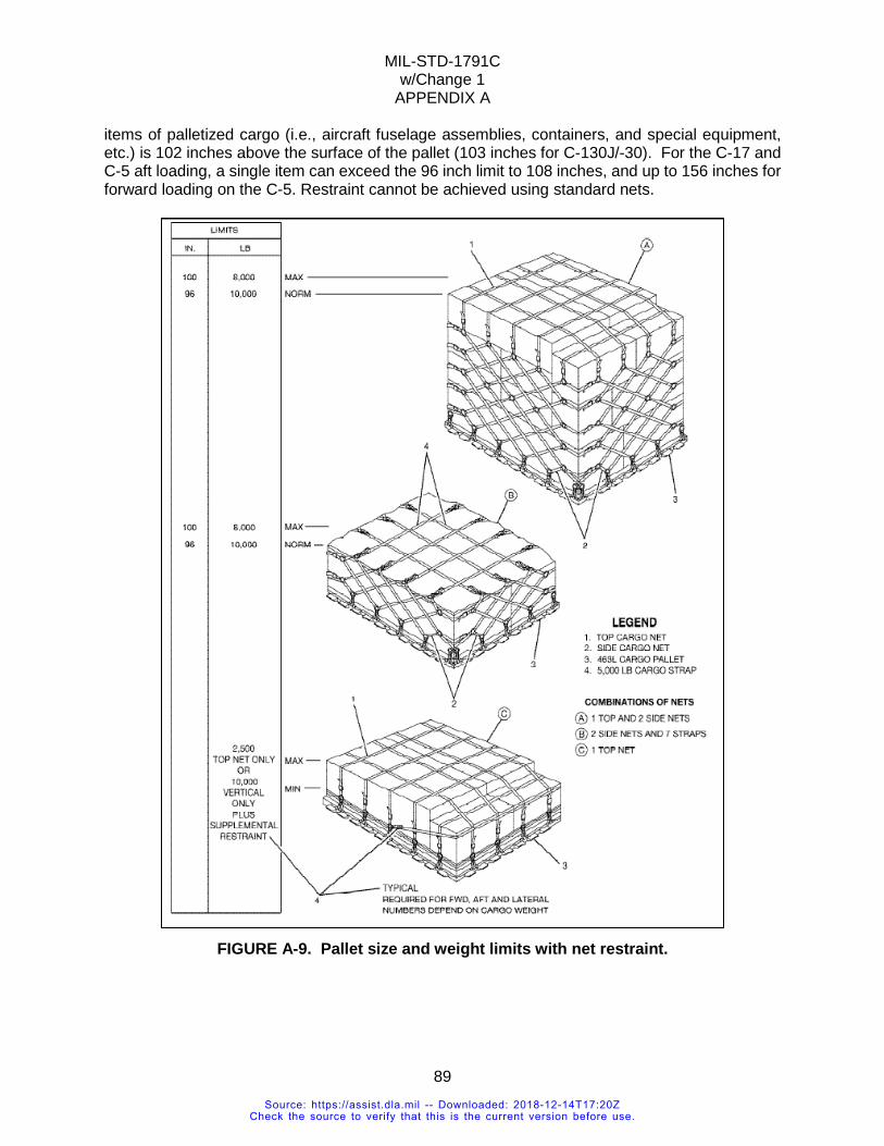
MIL-STD-1791C w/Change 1
APPENDIX A
89
items of palletized cargo (i.e., aircraft fuselage assemblies, containers, and special equipment, etc.) is 102 inches above the surface of the pallet (103 inches for C-130J/-30). For the C-17 and C-5 aft loading, a single item can exceed the 96 inch limit to 108 inches, and up to 156 inches for forward loading on the C-5. Restraint cannot be achieved using standard nets.
FIGURE A-9. Pallet size and weight limits with net restraint.
Source: https://assist.dla.mil -- Downloaded: 2018-12-14T17:20ZCheck the source to verify that this is the current version before use.
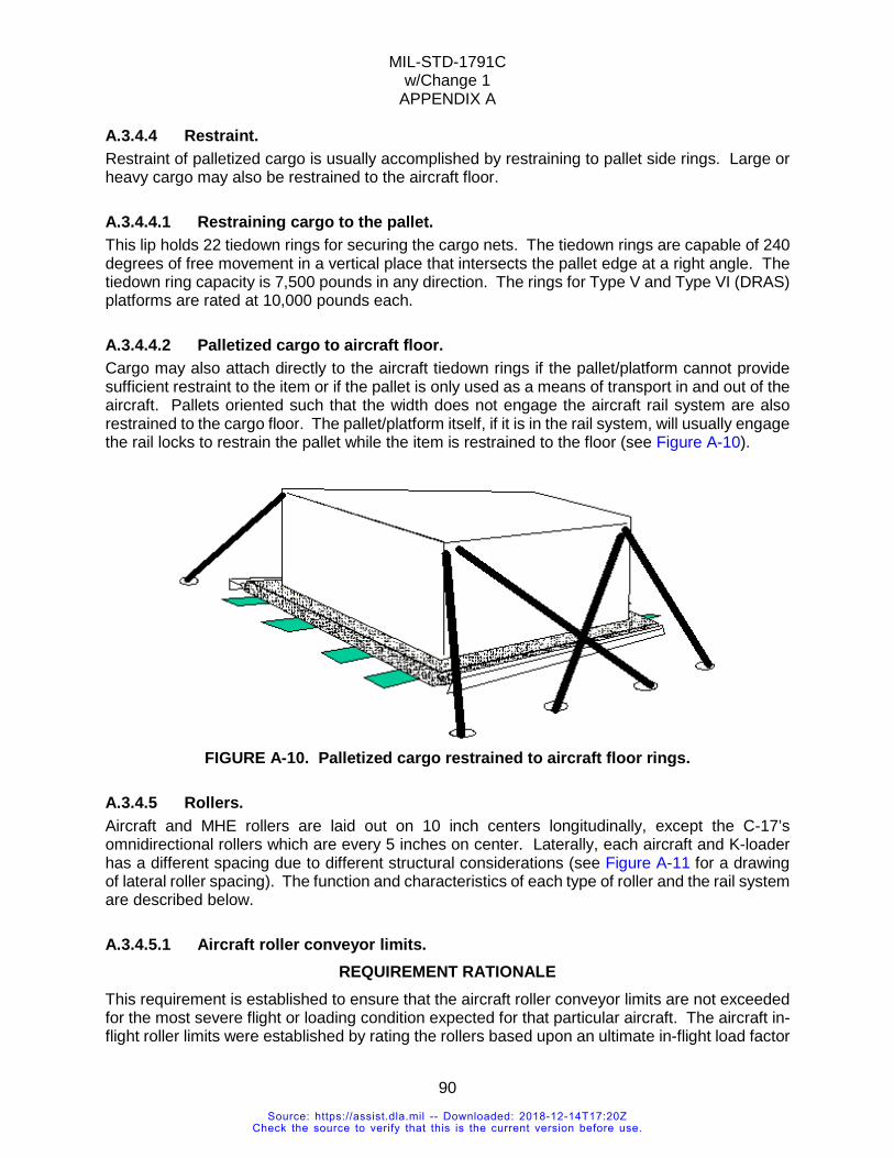
MIL-STD-1791C w/Change 1
APPENDIX A
90
A.3.4.4 Restraint. Restraint of palletized cargo is usually accomplished by restraining to pallet side rings. Large or heavy cargo may also be restrained to the aircraft floor.
A.3.4.4.1 Restraining cargo to the pallet. This lip holds 22 tiedown rings for securing the cargo nets. The tiedown rings are capable of 240 degrees of free movement in a vertical place that intersects the pallet edge at a right angle. The tiedown ring capacity is 7,500 pounds in any direction. The rings for Type V and Type VI (DRAS) platforms are rated at 10,000 pounds each.
A.3.4.4.2 Palletized cargo to aircraft floor. Cargo may also attach directly to the aircraft tiedown rings if the pallet/platform cannot provide sufficient restraint to the item or if the pallet is only used as a means of transport in and out of the aircraft. Pallets oriented such that the width does not engage the aircraft rail system are also restrained to the cargo floor. The pallet/platform itself, if it is in the rail system, will usually engage the rail locks to restrain the pallet while the item is restrained to the floor (see Figure A-10).
FIGURE A-10. Palletized cargo restrained to aircraft floor rings.
A.3.4.5 Rollers. Aircraft and MHE rollers are laid out on 10 inch centers longitudinally, except the C-17’s omnidirectional rollers which are every 5 inches on center. Laterally, each aircraft and K-loader has a different spacing due to different structural considerations (see Figure A-11 for a drawing of lateral roller spacing). The function and characteristics of each type of roller and the rail system are described below.
A.3.4.5.1 Aircraft roller conveyor limits. REQUIREMENT RATIONALE
This requirement is established to ensure that the aircraft roller conveyor limits are not exceeded for the most severe flight or loading condition expected for that particular aircraft. The aircraft in-flight roller limits were established by rating the rollers based upon an ultimate in-flight load factor
Source: https://assist.dla.mil -- Downloaded: 2018-12-14T17:20ZCheck the source to verify that this is the current version before use.
MIL-STD-1791C w/Change 1
APPENDIX A
91
for the particular aircraft. The ultimate load factor for the C-141 was 6.6G and for the C-5 aircraft is 6.15G. Additional limits ensure that loads imposed on the roller do not exceed the cargo compartment floor limits. These limits are normally established by dividing the longitudinal floor loading limits by the longitudinal distance between the rollers. These requirements were established by the aircraft manufacturer.
REQUIREMENT GUIDANCE Each aircraft has a specific procedure for determining limits on the rollers. In all cases, however, the determination of roller loading is accomplished by analysis using the item's contact with the rollers or pallet/platform, and the contact location with respect to the roller locations. HCU-6/E (463L) pallets, airdrop platforms, and energy dissipating material do not provide any load spreading. This premise generally applies to special bases, runners, and skids for items so equipped unless the design specifically provides for load spreading. Load contact patterns should be designed to provide the best load distribution; longitudinal load distribution is generally much preferred to lateral distribution. Note that for items rigged for airdrop, the energy dissipating material stacks are primarily arranged for impact survivability and that some stacks or section of stacks may not transfer loads to the rollers.
REQUIREMENT LESSONS LEARNED Loads moving on/off the aircraft roller conveyor system shall be kept coplanar with the roller surface to prevent excessive forces from being applied to individual rollers. The load distribution between item’s bases, skids, or runners and the roller conveyor is critical in the design of these item-to-roller interfacing devices. These devices shall have continuous strength in the areas that interface with the roller conveyor system to prevent damage to the rollers or the item base. Because of the variable lateral roller conveyor spacing between the different aircraft and the cargo loaders (K-loaders), make sure item runners and skids are wide enough to operate on all intended aircraft and loader roller systems. In the C-5, the teeter rollers are a different width than the basic roller. There are a number of vehicles certified for airdrop from the C-130 aircraft which were not certified from the C-141 because of the different roller limits in the aircraft. A pallet stop on the C-130 A/A32H-4A rail prevents positioning the rigged item forward of FS 262. A pallet stop on the C-17 aircraft rail prevents positioning the rigged item forward of FS 337 in the ADS system or FS 379 in the logistics system.
VERIFICATION RATIONALE Experience has shown that most air transport loads are adequately distributed so that the forces imposed on the roller systems are well within limits. Under these conditions, it is sufficient to satisfy this requirement to compare calculated load values against the limit values for the aircraft under consideration. Complex items often exhibit non-uniformly distributed load patterns. Analytical verification of compliance with this requirement is still the preferred method because of cost and time considerations involved in instrumented roller testing. However, such tests are acceptable in all cases and may, in fact, be necessary where loading/unloading involves possible non-coplanar orientation of the load with respect to the roller surface.
VERIFICATION GUIDANCE Prior to 2007 there was no permanent C-130 or C-5 instrumented roller test beds constructed. A C-141 instrumented roller test bed was located at USA Natick Research and Development Center,
Source: https://assist.dla.mil -- Downloaded: 2018-12-14T17:20ZCheck the source to verify that this is the current version before use.
MIL-STD-1791C w/Change 1
APPENDIX A
92
Natick MA 01760. Data from the C-141 instrumented roller test bed had been used in evaluating airdrop rigged item loadings on lateral rows of rollers for the C-130 aircraft. The new instrumented roller test bed at Natick is adjustable and capable of simulating all present airdrop aircraft.
VERIFICATION LESSONS LEARNED Excessive roller loads and possible damage to both rollers and the item base can result from the impact of the edge of skids, runners, and special bases on the roller as the base device rides up and over the roller. A beveled edge similar to that on the 463L pallet should overcome this potential problem. Testing conducted on an instrumented roller test bed, have shown items with an apparent uniformly loaded test weight, do not transmit weight evenly over each aircraft roller. Also shown by testing, placing the item solely on pallets or airdrop platform does not spread the weight over the entire area pallet/platform. In order to redistribute loads, weight spreading material, such as wood, rubber, or foam, shall be used between the item and the pallet/platform.
Source: https://assist.dla.mil -- Downloaded: 2018-12-14T17:20ZCheck the source to verify that this is the current version before use.
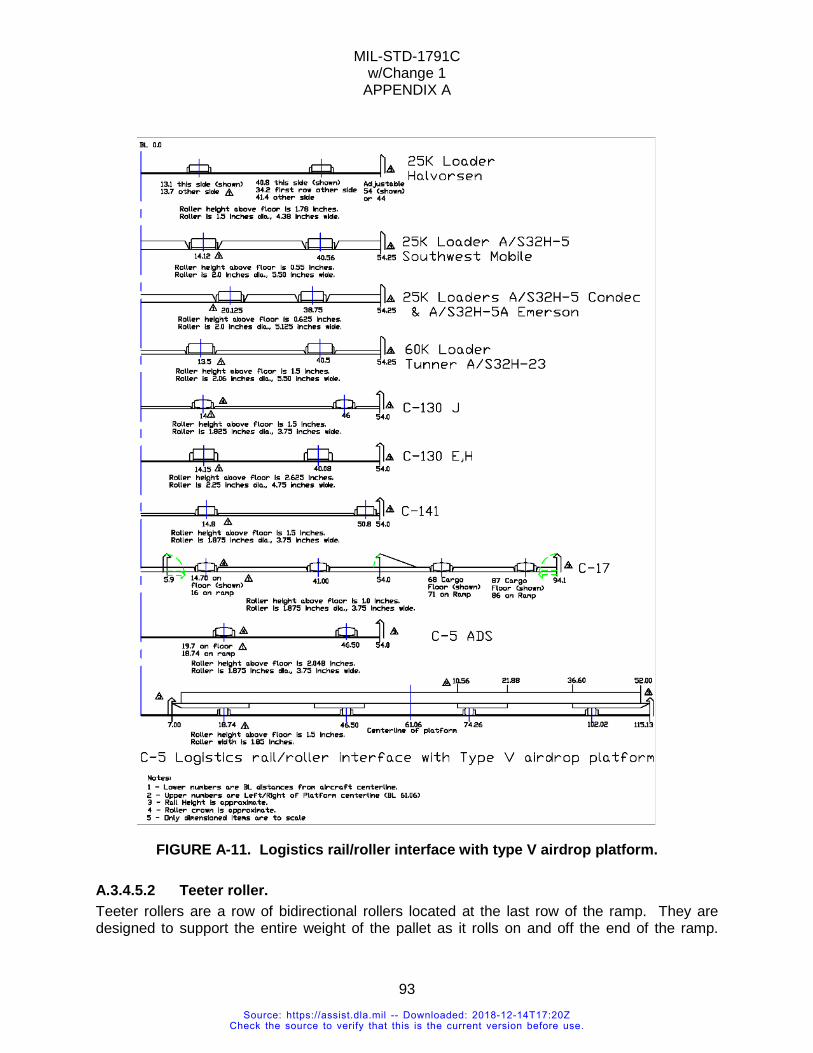
MIL-STD-1791C w/Change 1
APPENDIX A
93
FIGURE A-11. Logistics rail/roller interface with type V airdrop platform.
A.3.4.5.2 Teeter roller. Teeter rollers are a row of bidirectional rollers located at the last row of the ramp. They are designed to support the entire weight of the pallet as it rolls on and off the end of the ramp.
Source: https://assist.dla.mil -- Downloaded: 2018-12-14T17:20ZCheck the source to verify that this is the current version before use.
MIL-STD-1791C w/Change 1
APPENDIX A
94
Teetering occurs during transfer from the loader to the aircraft and vice versa. It also occurs during jettison or airdrop.
A.3.4.5.3 Omnidirectional roller. Omnidirectional rollers allow the pallet to roll forward and back, spin, and move sideways. They are on KC-135, KC-10, C-17, and C-5 aircraft, and on some K-loaders, in specific areas.
A.3.4.5.4 Bidirectional rollers. Bidirectional rollers allow the pallet to only move forward and backward. The majority of rollers on the aircraft and K-loaders are bidirectional rollers.
A.3.4.5.4.1 Roller limits. The pallet/platform loaded item shall engage a sufficient number of rollers to prevent damage to the rollers. These limits are shown in several parameters such as weight (lbs.) per foot, pounds per roller row, or pounds per roller. Each aircraft dictates its own critical roller parameters and method for computing these parameters (see 5.3.2.3 or Appendix B for details). A.3.4.6 Rail systems. Pallets and platforms have side rails with an “L” shaped cross section. The pallet rails slide into slots in restraint rails along each side of the roller system. The restraint rails’ sidewalls and horizontal lips provide lateral and vertical restraint to the pallet. Locks built into the rails extend into the pallet side rail notches, or indents, to provide forward and aft restraint. The C-17 and C-5 have Logistics rails and locks that allow pallets to be loaded side by side; the C-17 has an additional Airdrop System (ADS) that loads pallets down the centerline. The logistic rails are 108 inches wide on C-5, and 88 inches wide on the C-17 (and are also used with the Type VI airdrop platforms). Logistic rails are used primarily to carry pallets. The locks are not adjustable. ADS rails and locks carry pallets and Type V airdrop platforms. The ADS rails are 108 inches wide. On C-17 the ADS variable restraint locks are mounted in the right-hand restraint rail. The aft restraint values of the ADS locks can be adjusted to release at various force levels. When the lock(s) senses that the extraction force is at a desired level, the lock(s) releases to airdrop cargo out of the aircraft. On the opposite side are the ADS logistic locks. The ADS rail logistic locks are not adjustable. During transport, both sets of locks are engaged into the platform. Prior to airdrop the logistic locks are retracted. The C-130 A-H has ADS variable locks on the right-hand side and logistic locks on the left. The C-130J and C-130J-30 aircraft have ADS variable locks on both sides for airdrop and air transport. Airdrop and logistic systems are not available at the same time on C-17. The location of these rail systems is shown in Appendix B. The distance between the locks vary with aircraft, see Appendix B. These locks are designed specifically to engage the 463L type side rail. The same side rail dimensions are used on the Type V and Type VI airdrop platforms, and other pallets that utilize the USAF cargo rail system. The locks are sized to provide sufficient contact area with the side rail indents to restrain the pallet.
Source: https://assist.dla.mil -- Downloaded: 2018-12-14T17:20ZCheck the source to verify that this is the current version before use.
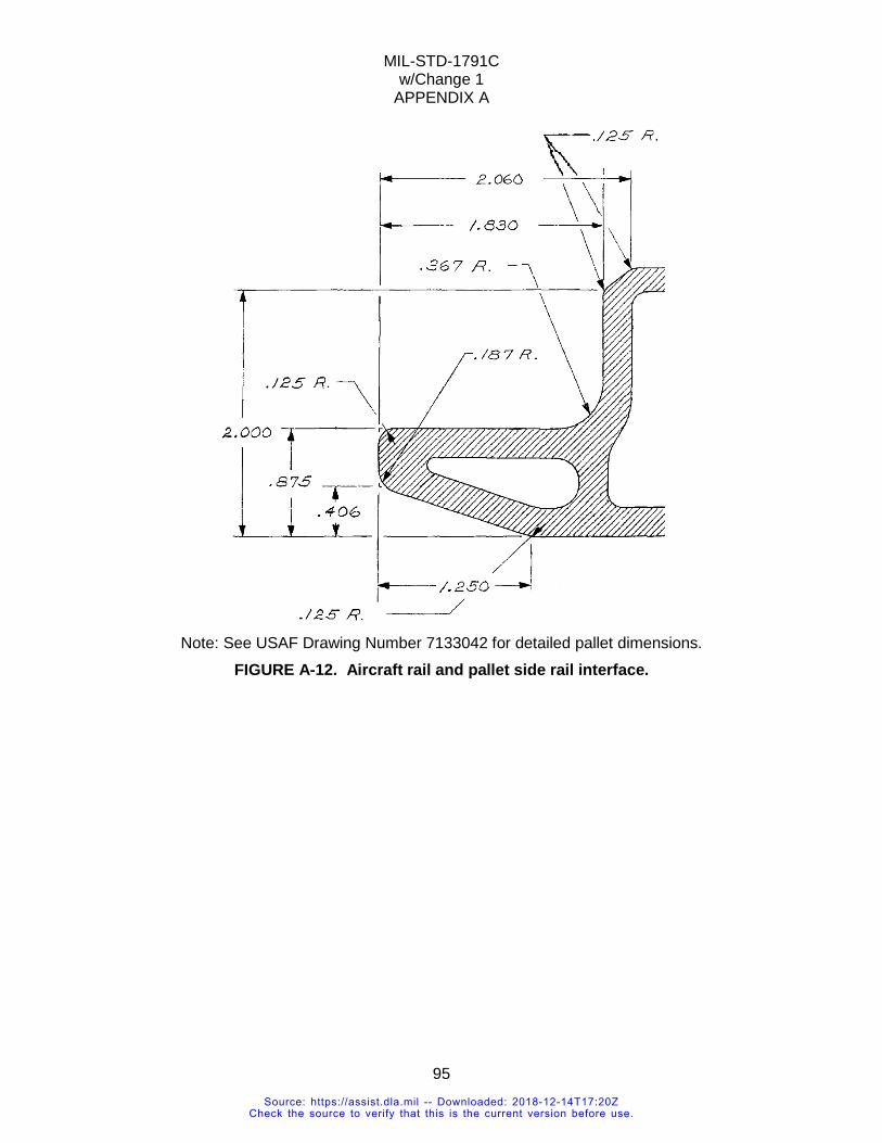
MIL-STD-1791C w/Change 1
APPENDIX A
95
Note: See USAF Drawing Number 7133042 for detailed pallet dimensions.
FIGURE A-12. Aircraft rail and pallet side rail interface.
Source: https://assist.dla.mil -- Downloaded: 2018-12-14T17:20ZCheck the source to verify that this is the current version before use.
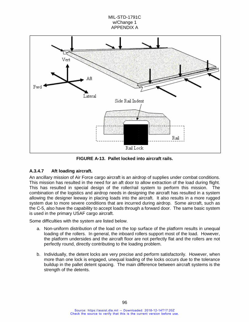
MIL-STD-1791C w/Change 1
APPENDIX A
96
FIGURE A-13. Pallet locked into aircraft rails.
A.3.4.7 Aft loading aircraft. An ancillary mission of Air Force cargo aircraft is an airdrop of supplies under combat conditions. This mission has resulted in the need for an aft door to allow extraction of the load during flight. This has resulted in special design of the roller/rail system to perform this mission. The combination of the logistics and airdrop needs in designing the aircraft has resulted in a system allowing the designer leeway in placing loads into the aircraft. It also results in a more rugged system due to more severe conditions that are incurred during airdrop. Some aircraft, such as the C-5, also have the capability to accept loads through a forward door. The same basic system is used in the primary USAF cargo aircraft. Some difficulties with the system are listed below.
a. Non-uniform distribution of the load on the top surface of the platform results in unequal loading of the rollers. In general, the inboard rollers support most of the load. However, the platform undersides and the aircraft floor are not perfectly flat and the rollers are not perfectly round, directly contributing to the loading problem.
b. Individually, the detent locks are very precise and perform satisfactorily. However, when more than one lock is engaged, unequal loading of the locks occurs due to the tolerance buildup in the pallet detent spacing. The main difference between aircraft systems is the strength of the detents.
Source: https://assist.dla.mil -- Downloaded: 2018-12-14T17:20ZCheck the source to verify that this is the current version before use.
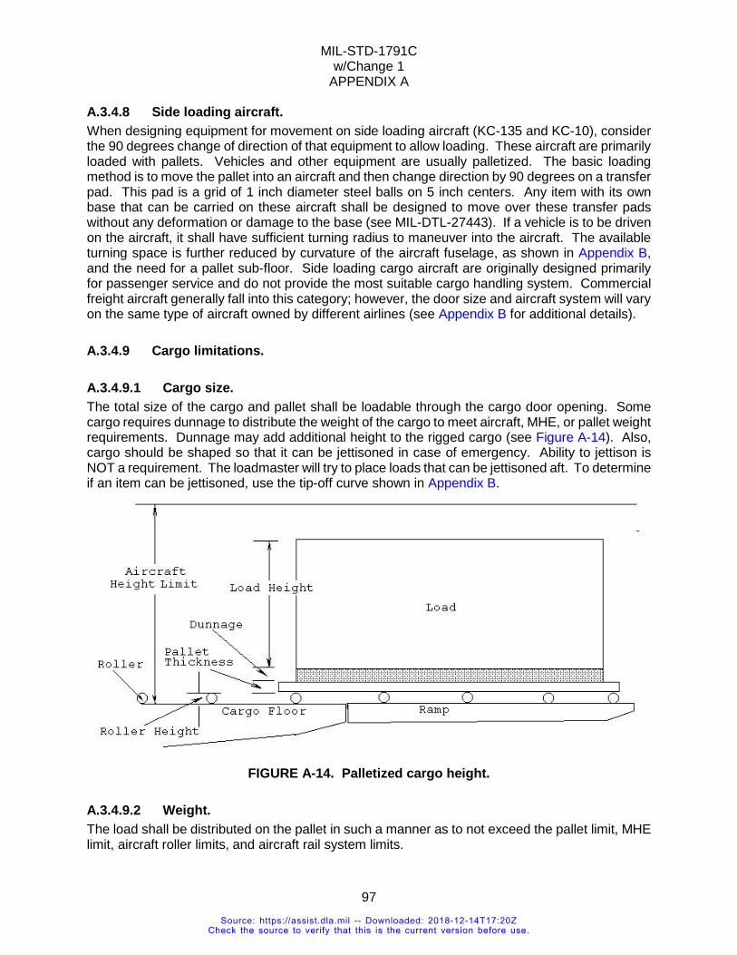
MIL-STD-1791C w/Change 1
APPENDIX A
97
A.3.4.8 Side loading aircraft. When designing equipment for movement on side loading aircraft (KC-135 and KC-10), consider the 90 degrees change of direction of that equipment to allow loading. These aircraft are primarily loaded with pallets. Vehicles and other equipment are usually palletized. The basic loading method is to move the pallet into an aircraft and then change direction by 90 degrees on a transfer pad. This pad is a grid of 1 inch diameter steel balls on 5 inch centers. Any item with its own base that can be carried on these aircraft shall be designed to move over these transfer pads without any deformation or damage to the base (see MIL-DTL-27443). If a vehicle is to be driven on the aircraft, it shall have sufficient turning radius to maneuver into the aircraft. The available turning space is further reduced by curvature of the aircraft fuselage, as shown in Appendix B, and the need for a pallet sub-floor. Side loading cargo aircraft are originally designed primarily for passenger service and do not provide the most suitable cargo handling system. Commercial freight aircraft generally fall into this category; however, the door size and aircraft system will vary on the same type of aircraft owned by different airlines (see Appendix B for additional details).
A.3.4.9 Cargo limitations.
A.3.4.9.1 Cargo size. The total size of the cargo and pallet shall be loadable through the cargo door opening. Some cargo requires dunnage to distribute the weight of the cargo to meet aircraft, MHE, or pallet weight requirements. Dunnage may add additional height to the rigged cargo (see Figure A-14). Also, cargo should be shaped so that it can be jettisoned in case of emergency. Ability to jettison is NOT a requirement. The loadmaster will try to place loads that can be jettisoned aft. To determine if an item can be jettisoned, use the tip-off curve shown in Appendix B.
FIGURE A-14. Palletized cargo height.
A.3.4.9.2 Weight. The load shall be distributed on the pallet in such a manner as to not exceed the pallet limit, MHE limit, aircraft roller limits, and aircraft rail system limits.
Source: https://assist.dla.mil -- Downloaded: 2018-12-14T17:20ZCheck the source to verify that this is the current version before use.
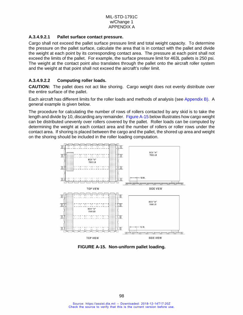
MIL-STD-1791C w/Change 1
APPENDIX A
98
A.3.4.9.2.1 Pallet surface contact pressure. Cargo shall not exceed the pallet surface pressure limit and total weight capacity. To determine the pressure on the pallet surface, calculate the area that is in contact with the pallet and divide the weight at each point by its corresponding contact area. The pressure at each point shall not exceed the limits of the pallet. For example, the surface pressure limit for 463L pallets is 250 psi. The weight at the contact point also translates through the pallet onto the aircraft roller system and the weight at that point shall not exceed the aircraft’s roller limit.
A.3.4.9.2.2 Computing roller loads. CAUTION: The pallet does not act like shoring. Cargo weight does not evenly distribute over the entire surface of the pallet. Each aircraft has different limits for the roller loads and methods of analysis (see Appendix B). A general example is given below. The procedure for calculating the number of rows of rollers contacted by any skid is to take the length and divide by 10, discarding any remainder. Figure A-15 below illustrates how cargo weight can be distributed unevenly over rollers covered by the pallet. Roller loads can be computed by determining the weight at each contact area and the number of rollers or roller rows under the contact area. If shoring is placed between the cargo and the pallet, the shored up area and weight on the shoring should be included in the roller loading computation.
FIGURE A-15. Non-uniform pallet loading.
Source: https://assist.dla.mil -- Downloaded: 2018-12-14T17:20ZCheck the source to verify that this is the current version before use.
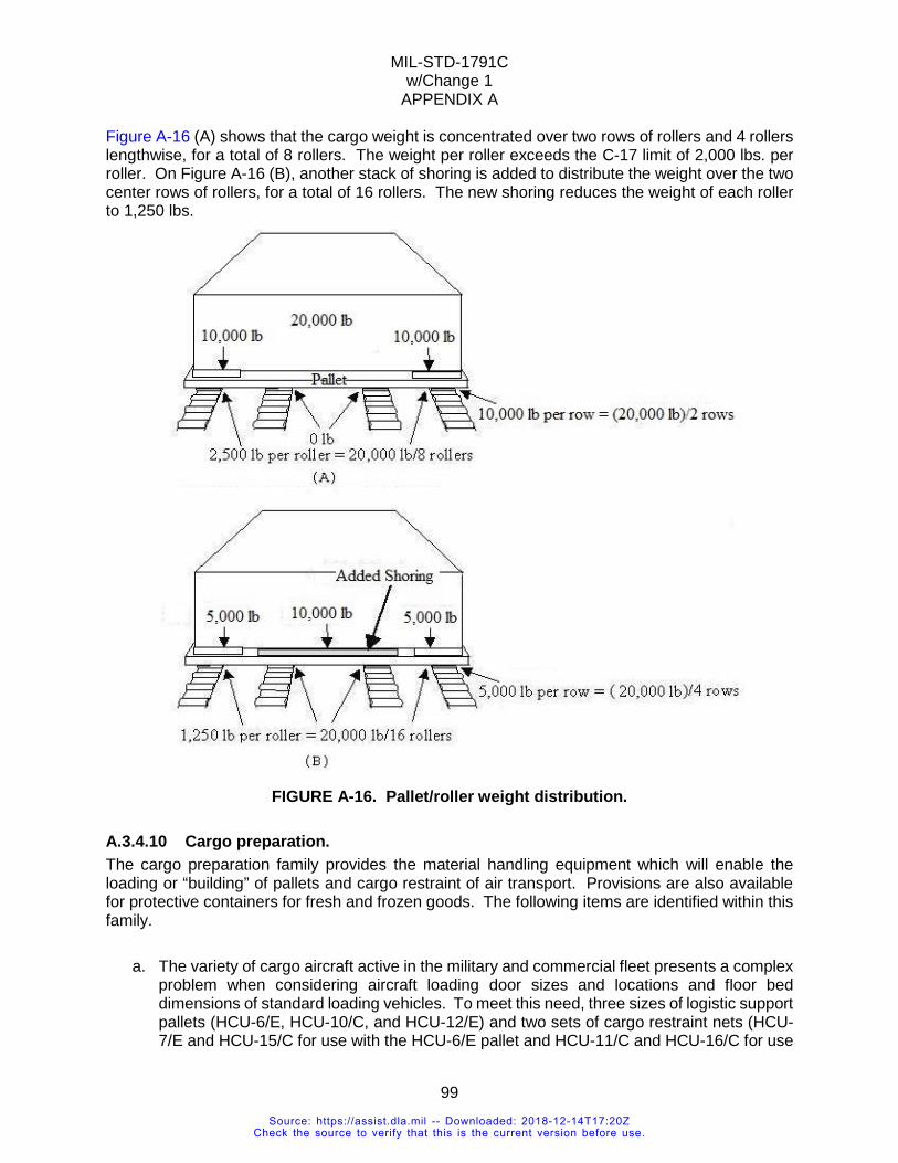
MIL-STD-1791C w/Change 1
APPENDIX A
99
Figure A-16 (A) shows that the cargo weight is concentrated over two rows of rollers and 4 rollers lengthwise, for a total of 8 rollers. The weight per roller exceeds the C-17 limit of 2,000 lbs. per roller. On Figure A-16 (B), another stack of shoring is added to distribute the weight over the two center rows of rollers, for a total of 16 rollers. The new shoring reduces the weight of each roller to 1,250 lbs.
FIGURE A-16. Pallet/roller weight distribution.
A.3.4.10 Cargo preparation. The cargo preparation family provides the material handling equipment which will enable the loading or “building” of pallets and cargo restraint of air transport. Provisions are also available for protective containers for fresh and frozen goods. The following items are identified within this family.
a. The variety of cargo aircraft active in the military and commercial fleet presents a complex problem when considering aircraft loading door sizes and locations and floor bed dimensions of standard loading vehicles. To meet this need, three sizes of logistic support pallets (HCU-6/E, HCU-10/C, and HCU-12/E) and two sets of cargo restraint nets (HCU-7/E and HCU-15/C for use with the HCU-6/E pallet and HCU-11/C and HCU-16/C for use
Source: https://assist.dla.mil -- Downloaded: 2018-12-14T17:20ZCheck the source to verify that this is the current version before use.
MIL-STD-1791C w/Change 1
APPENDIX A
100
with HCU-10/C and HCU-12/E pallets) were standardized. Presently the Air Force only utilizes the HCU-6/E and its associated nets. The HCU-12/E is used by other services and the HCU-10/E is no longer produced.
b. Pallet coupling devices. When cargo is too large to be placed on one 108 x 88 inches
HCU-6/E pallet, two or more pallets (up to a maximum of six) may be joined together. Depending on the airframe, a 2-inch (NSN-1670-01-061-0990CT) coupler or a 1.5-inch (NSN 1670-01-487-8743CT) coupler is required between pallets to ensure the married pallets will mate with the aircraft restraint locks.
A.3.4.11 Ground handling systems. This family is concerned with the movement of palletized cargo between the air cargo terminal and the aircraft. The family is made up of mobile loading equipment of various types and sizes which have been designed to provide the versatility and efficiency required to effectively load/unload various types of aircraft. In addition, each is capable of being air transported to remote sites. Colloquially they are referred to as K-Loaders. The elements of this family are:
a. Truck, Aircraft Cargo Loading/Unloading, 60,000 pound Capacity, A/S32H-23. The common name is Tunner 60K loader. This truck is used primarily at major command terminals for mechanized loading, unloading, and ground transport of air cargo. It services low and high floor aircraft. The capability exists to handle palletized cargo and skidded and wheeled loads in a method resulting in minimum aircraft turnaround time.
b. Truck, Aircraft Cargo Loading/Unloading, 25,000 pound Capability. The common name
is Halvorsen 25K loader. This truck is a lightweight, air transportable vehicle for use at intermediate class terminals to load and unload low and high floor cargo aircraft.
c. Truck, Aircraft Cargo Loading/Unloading, 25,000 pound Capacity, A/S32H-5. The
common name is 25K loader. This truck is a lightweight, air transportable vehicle for use at intermediate class terminals to load and unload military and commercial aircraft. (There are several manufacturers for this model. See Appendix B for variations in lateral roller spacing.)
d. Forklifts: A variety of commercial and military forklifts and wheel loaders (fitted with fork
tines) are presently used to fill this roll instead of just 463L specific equipment.
A.3.4.12 Other platforms. There are several other platforms that can use the 463L systems or can be used for air transport of cargo. They are not a prevalent, but are viable options for consideration (see Figure A-17).
Source: https://assist.dla.mil -- Downloaded: 2018-12-14T17:20ZCheck the source to verify that this is the current version before use.
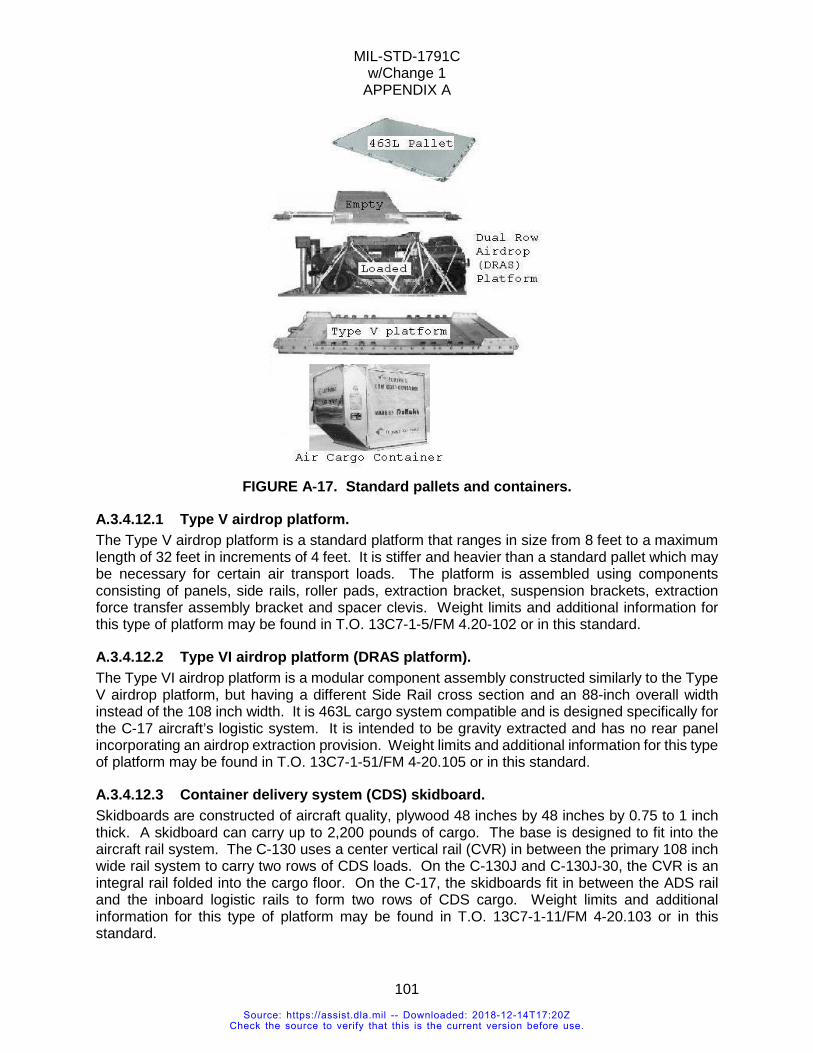
MIL-STD-1791C w/Change 1
APPENDIX A
101
FIGURE A-17. Standard pallets and containers.
A.3.4.12.1 Type V airdrop platform. The Type V airdrop platform is a standard platform that ranges in size from 8 feet to a maximum length of 32 feet in increments of 4 feet. It is stiffer and heavier than a standard pallet which may be necessary for certain air transport loads. The platform is assembled using components consisting of panels, side rails, roller pads, extraction bracket, suspension brackets, extraction force transfer assembly bracket and spacer clevis. Weight limits and additional information for this type of platform may be found in T.O. 13C7-1-5/FM 4.20-102 or in this standard.
A.3.4.12.2 Type VI airdrop platform (DRAS platform). The Type VI airdrop platform is a modular component assembly constructed similarly to the Type V airdrop platform, but having a different Side Rail cross section and an 88-inch overall width instead of the 108 inch width. It is 463L cargo system compatible and is designed specifically for the C-17 aircraft’s logistic system. It is intended to be gravity extracted and has no rear panel incorporating an airdrop extraction provision. Weight limits and additional information for this type of platform may be found in T.O. 13C7-1-51/FM 4-20.105 or in this standard.
A.3.4.12.3 Container delivery system (CDS) skidboard. Skidboards are constructed of aircraft quality, plywood 48 inches by 48 inches by 0.75 to 1 inch thick. A skidboard can carry up to 2,200 pounds of cargo. The base is designed to fit into the aircraft rail system. The C-130 uses a center vertical rail (CVR) in between the primary 108 inch wide rail system to carry two rows of CDS loads. On the C-130J and C-130J-30, the CVR is an integral rail folded into the cargo floor. On the C-17, the skidboards fit in between the ADS rail and the inboard logistic rails to form two rows of CDS cargo. Weight limits and additional information for this type of platform may be found in T.O. 13C7-1-11/FM 4-20.103 or in this standard.
Source: https://assist.dla.mil -- Downloaded: 2018-12-14T17:20ZCheck the source to verify that this is the current version before use.
MIL-STD-1791C w/Change 1
APPENDIX A
102
A.3.4.12.4 Warehouse pallets. These pallets are 6 inch-thick, plywood constructed pallets. They are rated to carry up to 2,000 pounds.
A.3.4.12.5 Commercial containers. Commercial containers are shown on Figure A-17. They are used to carry small packages. They are the primary cargo carrying platform on commercial freighter aircraft and CRAF aircraft.
A.3.4.12.6 Non-standard pallet or skid loads interfacing USAF MHE. REQUIREMENT RATIONALE
Often it is advantageous and, in some cases, necessary to design equipment for air transport with an integral base or pallet. The interface with the aircraft system requires special design considerations. The integral base/pallet design shall be designed to be compatible with the aircraft and materials handling equipment roller conveyor systems, but depending upon the specific equipment design, it may or may not be compatible with the aircraft guide rails and restraint lock systems. A design which incorporates 463L system compatibility offers increased potential for aerial delivery. At the same time it imposes different requirements that shall be satisfied.
REQUIREMENT GUIDANCE A flat bottom is highly desirable, but is only required in the areas and directions where the pallet will contact the rollers or ball casters of the aircraft and material handling equipment. Skids may be used on pallet or equipment bottoms if they are located and sized to mate with the roller conveyor systems and are strong enough to withstand the flight load requirements. The pallet/base shall also be capable of withstanding the forces created by the item teetering on a single set of rollers. Equipment with an integral base/pallet that shall mate with the aircraft guide rail and restraint lock system shall have a lip along the side that interfaces with the aircraft systems. Refer to Figure A-14 for illustration of aircraft rail/pallet interface. Equipment/pallets that do not mate with the aircraft restraint lock system shall have tiedown provisions in accordance with 5.3.3.2 so that it can be secured in the aircraft to the required restraint levels by means of approved tiedown devices.
REQUIREMENT LESSONS LEARNED For efficient use of the aircraft, the base/pallet should lock into the aircraft rail system. This will permit the equipment to be secured to the pallet for the required restraint and then the pallet/equipment assembly can be locked into the aircraft to the required restraint level. However long (exceeding 30 feet) or heavy (exceeding 30,000 pounds), equipment items are difficult to align with the aircraft guide rail system. Load distribution between the pallet and the roller conveyor systems is critical in the design of specialized pallets or integral base designs. Skids and flat bottom pallets shall have continuous strength in the areas that interface with the roller conveyor systems. Sometimes, due to misalignment between cargo loaders and the aircraft, the roller conveyor systems are not coplanar; therefore, a pallet/base can contact only a single set of rollers during the transition or cresting process. The underside of the pallet or skid base shall be as flat as possible and supported adequately to avoid a "washboard" or "wavy" shape while traversing the roller system. In addition, there should
Source: https://assist.dla.mil -- Downloaded: 2018-12-14T17:20ZCheck the source to verify that this is the current version before use.
MIL-STD-1791C w/Change 1
APPENDIX A
103
be no sharp edges, discontinuities, or projections which could damage the rollers. The leading and trailing edges of the pallet or skids should be beveled at a 45 degree angle or be rounded to ease the transition as the edge moves onto the rollers. One HCU-6/E size design was able to meet roller limit and restraint rail requirements with two longitudinal skids along the outboard edges of the container. However, the container bottom was then raised above the pallet end stops on K-loaders and indoor aerial port cargo handling systems, which are on centerline. This forced a system redesign to meet MHE requirements, by putting a bar across the gap at each end. Lowering the container was not possible. It is strongly recommended to have a full-length side rail/pallet lip when interfacing the aircraft rails for restraint. The aircraft rails are designed to provide vertical restraint to running loads, not point loads. For example, a 100 inch pallet with four 10 inch lip sections will be limited in weight to what 40 inches of aircraft rail can restrain. If the rail weight limit is exceeded, the item shall accommodate supplemental restraint to the aircraft floor.
VERIFICATION RATIONALE The method of requirements verification depends to a large extent on the final item configuration. For instance, with a full pallet base, compliance with the appropriate MIL-DTL-27443 requirements is adequate verification for this requirement. In other designs, analysis of the item from both dimensional and structural standpoints may be all that is required to prove acceptability. Where large or heavy items or otherwise complex loading situations are involved, formal test loadings or other demonstration techniques may be required.
VERIFICATION GUIDANCE As in all verification procedures, the method chosen should be the simplest one which will provide assurance that the requirements have been met. Judgment as to the proper procedure shall be made on a case-by-case basis. The assistance of ATTLA is available to both the program office and the designer to determine the feasibility of proposed designs and appropriate verification procedures. In many cases, the experience ATTLA has had with similar designs may prove valuable in avoiding problem areas and may improve item characteristics. The earliest possible contact with ATTLA is advised.
VERIFICATION LESSONS LEARNED The increasing emphasis on on/offloading items with minimal MHE has made this requirement more generally applicable. Where the base/pallet is fully compatible with the 463L roller conveyor system (including restraint provisions), the entire unit load should be structurally capable of being restrained by the rail restraint devices. Unless the base of the item can be maintained coplanar with the surface of the aircraft and MHE rollers during on/offloading, roller overloading and possible failure may result. Intensive consideration of the method of handling the item during on/offloading should be a part of any decision process relative to 463L system compatibility. On/offloading conditions at remote sites should always be considered to be the limiting factor in judging the acceptability of items in terms of 463L compatibility. Aircraft and MHE roller crowns are not perfectly coplanar. At transport weights, the aluminum and balsa HCU-6/E is a flexible structure. The net result is that the calculated roller contact (based on the load, see A.3.4.9.2.2) is achieved. One proposed skid was so stiff that although it had sufficient calculated roller contact, in practice the entire weight of the skid was carried by the highest roller.
Source: https://assist.dla.mil -- Downloaded: 2018-12-14T17:20ZCheck the source to verify that this is the current version before use.
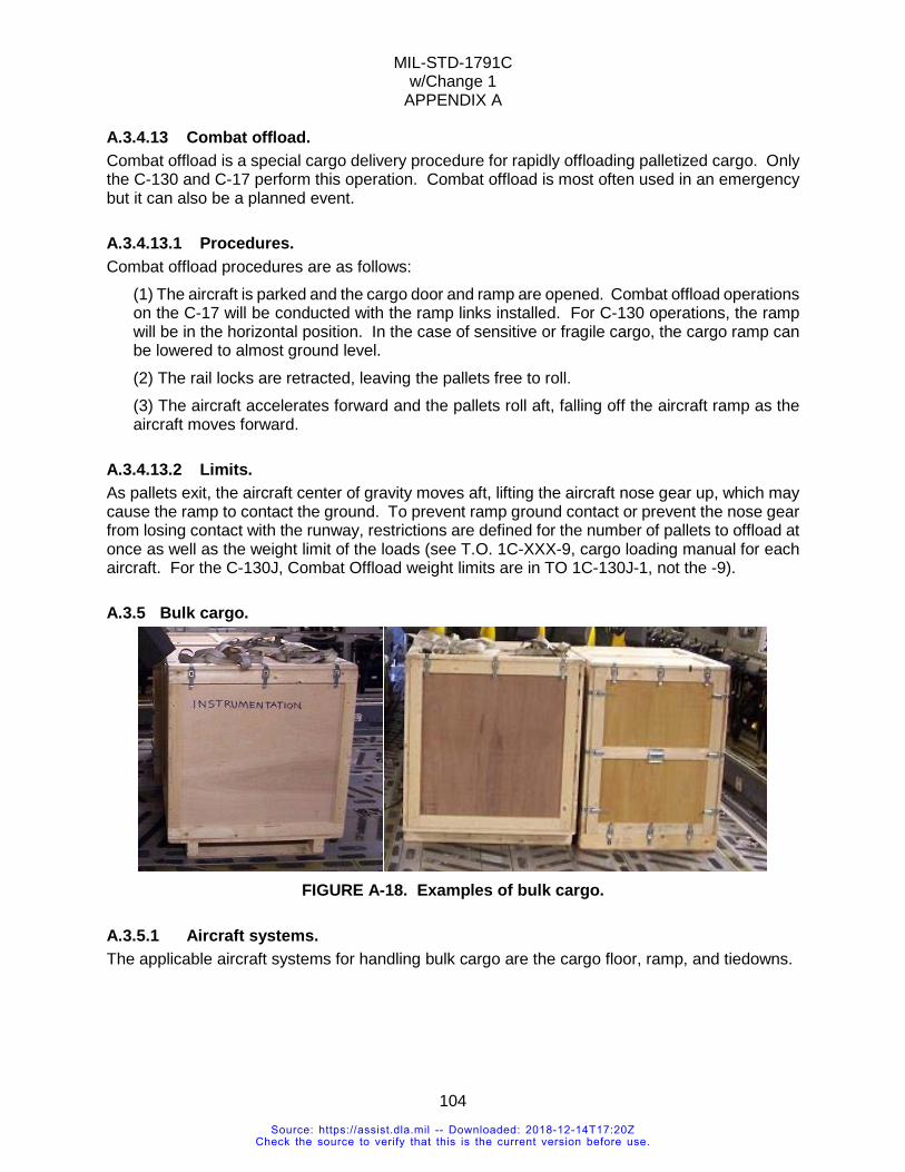
MIL-STD-1791C w/Change 1
APPENDIX A
104
A.3.4.13 Combat offload. Combat offload is a special cargo delivery procedure for rapidly offloading palletized cargo. Only the C-130 and C-17 perform this operation. Combat offload is most often used in an emergency but it can also be a planned event.
A.3.4.13.1 Procedures. Combat offload procedures are as follows:
(1) The aircraft is parked and the cargo door and ramp are opened. Combat offload operations on the C-17 will be conducted with the ramp links installed. For C-130 operations, the ramp will be in the horizontal position. In the case of sensitive or fragile cargo, the cargo ramp can be lowered to almost ground level. (2) The rail locks are retracted, leaving the pallets free to roll. (3) The aircraft accelerates forward and the pallets roll aft, falling off the aircraft ramp as the aircraft moves forward.
A.3.4.13.2 Limits. As pallets exit, the aircraft center of gravity moves aft, lifting the aircraft nose gear up, which may cause the ramp to contact the ground. To prevent ramp ground contact or prevent the nose gear from losing contact with the runway, restrictions are defined for the number of pallets to offload at once as well as the weight limit of the loads (see T.O. 1C-XXX-9, cargo loading manual for each aircraft. For the C-130J, Combat Offload weight limits are in TO 1C-130J-1, not the -9).
A.3.5 Bulk cargo.
FIGURE A-18. Examples of bulk cargo.
A.3.5.1 Aircraft systems. The applicable aircraft systems for handling bulk cargo are the cargo floor, ramp, and tiedowns.
Source: https://assist.dla.mil -- Downloaded: 2018-12-14T17:20ZCheck the source to verify that this is the current version before use.
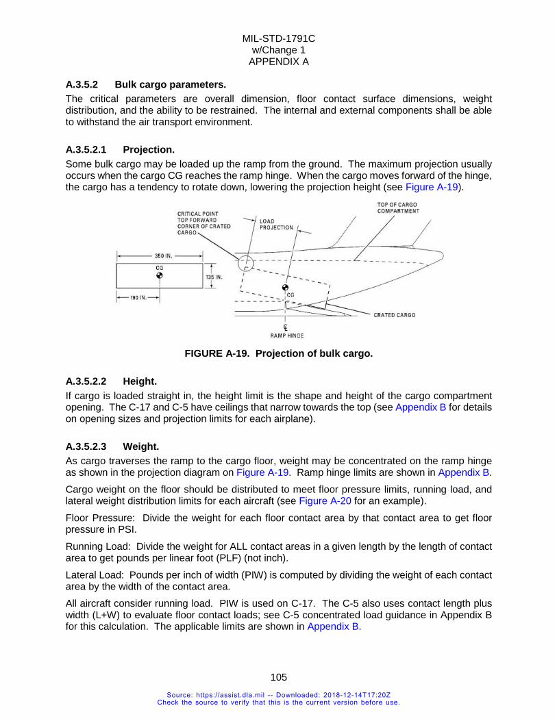
MIL-STD-1791C w/Change 1
APPENDIX A
105
A.3.5.2 Bulk cargo parameters. The critical parameters are overall dimension, floor contact surface dimensions, weight distribution, and the ability to be restrained. The internal and external components shall be able to withstand the air transport environment.
A.3.5.2.1 Projection. Some bulk cargo may be loaded up the ramp from the ground. The maximum projection usually occurs when the cargo CG reaches the ramp hinge. When the cargo moves forward of the hinge, the cargo has a tendency to rotate down, lowering the projection height (see Figure A-19).
FIGURE A-19. Projection of bulk cargo.
A.3.5.2.2 Height. If cargo is loaded straight in, the height limit is the shape and height of the cargo compartment opening. The C-17 and C-5 have ceilings that narrow towards the top (see Appendix B for details on opening sizes and projection limits for each airplane).
A.3.5.2.3 Weight. As cargo traverses the ramp to the cargo floor, weight may be concentrated on the ramp hinge as shown in the projection diagram on Figure A-19. Ramp hinge limits are shown in Appendix B. Cargo weight on the floor should be distributed to meet floor pressure limits, running load, and lateral weight distribution limits for each aircraft (see Figure A-20 for an example). Floor Pressure: Divide the weight for each floor contact area by that contact area to get floor pressure in PSI. Running Load: Divide the weight for ALL contact areas in a given length by the length of contact area to get pounds per linear foot (PLF) (not inch). Lateral Load: Pounds per inch of width (PIW) is computed by dividing the weight of each contact area by the width of the contact area. All aircraft consider running load. PIW is used on C-17. The C-5 also uses contact length plus width (L+W) to evaluate floor contact loads; see C-5 concentrated load guidance in Appendix B for this calculation. The applicable limits are shown in Appendix B.
Source: https://assist.dla.mil -- Downloaded: 2018-12-14T17:20ZCheck the source to verify that this is the current version before use.
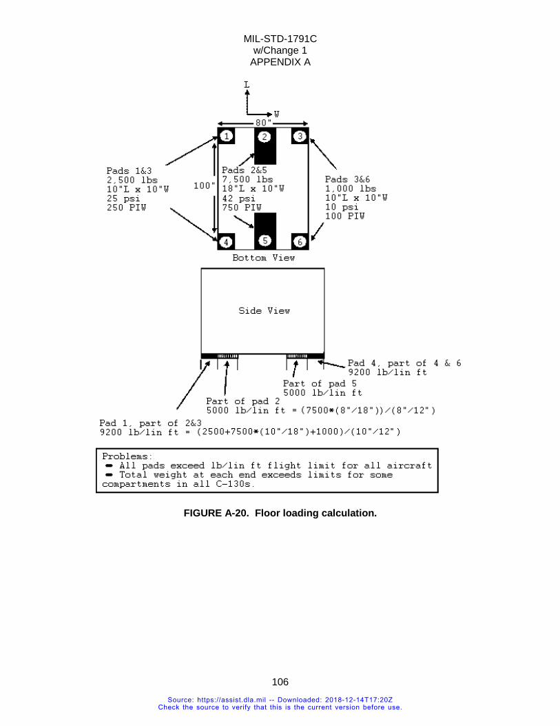
MIL-STD-1791C w/Change 1
APPENDIX A
106
FIGURE A-20. Floor loading calculation.
Source: https://assist.dla.mil -- Downloaded: 2018-12-14T17:20ZCheck the source to verify that this is the current version before use.
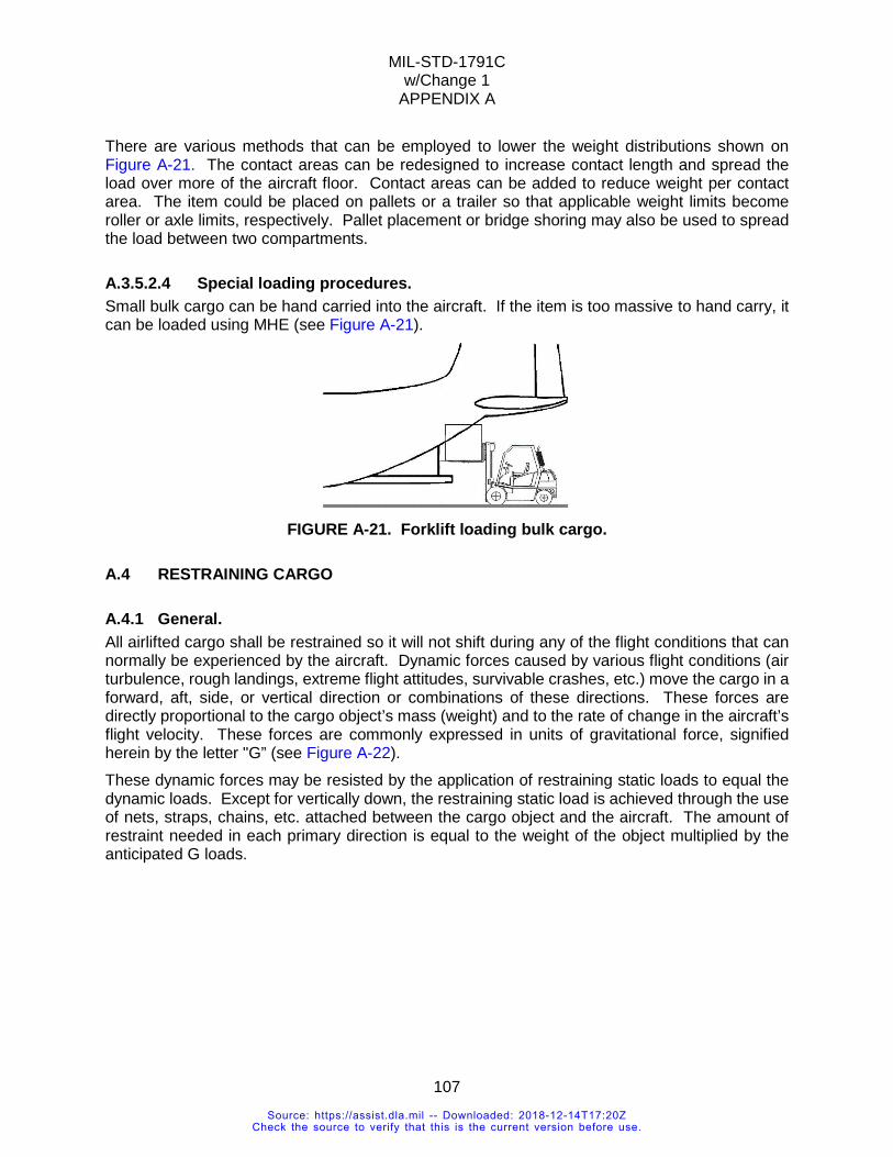
MIL-STD-1791C w/Change 1
APPENDIX A
107
There are various methods that can be employed to lower the weight distributions shown on Figure A-21. The contact areas can be redesigned to increase contact length and spread the load over more of the aircraft floor. Contact areas can be added to reduce weight per contact area. The item could be placed on pallets or a trailer so that applicable weight limits become roller or axle limits, respectively. Pallet placement or bridge shoring may also be used to spread the load between two compartments.
A.3.5.2.4 Special loading procedures. Small bulk cargo can be hand carried into the aircraft. If the item is too massive to hand carry, it can be loaded using MHE (see Figure A-21).
FIGURE A-21. Forklift loading bulk cargo.
A.4 RESTRAINING CARGO
A.4.1 General. All airlifted cargo shall be restrained so it will not shift during any of the flight conditions that can normally be experienced by the aircraft. Dynamic forces caused by various flight conditions (air turbulence, rough landings, extreme flight attitudes, survivable crashes, etc.) move the cargo in a forward, aft, side, or vertical direction or combinations of these directions. These forces are directly proportional to the cargo object’s mass (weight) and to the rate of change in the aircraft’s flight velocity. These forces are commonly expressed in units of gravitational force, signified herein by the letter "G” (see Figure A-22). These dynamic forces may be resisted by the application of restraining static loads to equal the dynamic loads. Except for vertically down, the restraining static load is achieved through the use of nets, straps, chains, etc. attached between the cargo object and the aircraft. The amount of restraint needed in each primary direction is equal to the weight of the object multiplied by the anticipated G loads.
Source: https://assist.dla.mil -- Downloaded: 2018-12-14T17:20ZCheck the source to verify that this is the current version before use.
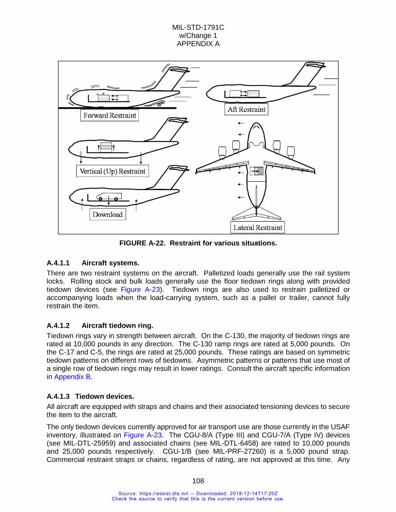
MIL-STD-1791C w/Change 1
APPENDIX A
108
FIGURE A-22. Restraint for various situations.
A.4.1.1 Aircraft systems. There are two restraint systems on the aircraft. Palletized loads generally use the rail system locks. Rolling stock and bulk loads generally use the floor tiedown rings along with provided tiedown devices (see Figure A-23). Tiedown rings are also used to restrain palletized or accompanying loads when the load-carrying system, such as a pallet or trailer, cannot fully restrain the item.
A.4.1.2 Aircraft tiedown ring. Tiedown rings vary in strength between aircraft. On the C-130, the majority of tiedown rings are rated at 10,000 pounds in any direction. The C-130 ramp rings are rated at 5,000 pounds. On the C-17 and C-5, the rings are rated at 25,000 pounds. These ratings are based on symmetric tiedown patterns on different rows of tiedowns. Asymmetric patterns or patterns that use most of a single row of tiedown rings may result in lower ratings. Consult the aircraft specific information in Appendix B.
A.4.1.3 Tiedown devices. All aircraft are equipped with straps and chains and their associated tensioning devices to secure the item to the aircraft. The only tiedown devices currently approved for air transport use are those currently in the USAF inventory, illustrated on Figure A-23. The CGU-8/A (Type III) and CGU-7/A (Type IV) devices (see MIL-DTL-25959) and associated chains (see MIL-DTL-6458) are rated to 10,000 pounds and 25,000 pounds respectively. CGU-1/B (see MIL-PRF-27260) is a 5,000 pound strap. Commercial restraint straps or chains, regardless of rating, are not approved at this time. Any
Source: https://assist.dla.mil -- Downloaded: 2018-12-14T17:20ZCheck the source to verify that this is the current version before use.
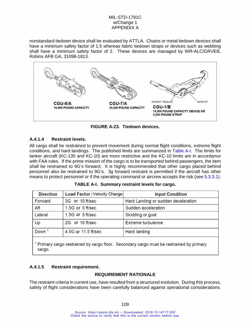
MIL-STD-1791C w/Change 1
APPENDIX A
109
nonstandard tiedown device shall be evaluated by ATTLA. Chains or metal tiedown devices shall have a minimum safety factor of 1.5 whereas fabric tiedown straps or devices such as webbing shall have a minimum safety factor of 2. These devices are managed by WR-ALC/GRVEB, Robins AFB GA, 31098-1813.
FIGURE A-23. Tiedown devices.
A.4.1.4 Restraint levels. All cargo shall be restrained to prevent movement during normal flight conditions, extreme flight conditions, and hard landings. The published limits are summarized in Table A-I. The limits for tanker aircraft (KC-135 and KC-10) are more restrictive and the KC-10 limits are in accordance with FAA rules. If the prime mission of the cargo is to be transported behind passengers, the item shall be restrained to 9G’s forward. It is highly recommended that other cargo placed behind personnel also be restrained to 9G’s. 3g forward restraint is permitted if the aircraft has other means to protect personnel or if the operating command or aircrew accepts the risk (see 5.3.3.1).
TABLE A-I. Summary restraint levels for cargo.
A.4.1.5 Restraint requirement. REQUIREMENT RATIONALE
The restraint criteria in current use, have resulted from a structured evolution. During this process, safety of flight considerations have been carefully balanced against operational considerations.
Source: https://assist.dla.mil -- Downloaded: 2018-12-14T17:20ZCheck the source to verify that this is the current version before use.
MIL-STD-1791C w/Change 1
APPENDIX A
110
The result is a set of criteria which provide a high probability of safety under expected flight conditions and, at the same time, impose reasonable operational requirements. The restraint levels specified are based on a statistical analysis of cargo aircraft accident data coupled with years of successful cargo flight experience at reduced restraint levels. Both static and dynamic conditions are required due to the nature of the actual air transport environment (e.g., the factors are derived from maneuver, gust, and crash loads). The change in velocity within a specified time is designed to give latitude for verification of the dynamic conditions by testing.
REQUIREMENT GUIDANCE The following factors should be considered when designing equipment to meet the specific restraint criteria:
a. When equipment is of such size or configuration that it can be loaded into cargo aircraft with either end facing forward (e.g., a truck that can be driven forward or backed into the aircraft), the highest load factor applies, both fore and aft. When the loading direction is fixed or specified, the 3 g requirement applies in the forward direction and the aft load factor requirement applies in the rearward direction.
b. Vehicles and other equipment should be capable of withstanding, without loss of unitary integrity or loadability, the vertical downward load factor imposed on the wheels, suspension systems, or support.
c. MIL-STD-209 and 5.3.3.2 provide criteria for tiedown provisions on the item which can interface with the aircraft tiedowns.
d. The procuring agency may wish to levy load requirements in excess of those stated herein due to other mission requirements. Chains and straps cannot be used together when restraining cargo to the aircraft. Straps stretch further than chains under the same load and can produce uneven tension of the tiedowns. Likewise, tiedown attachment points on the item cannot be made of material that may stretch more than other attachment points on the item. For example, a nylon loop should not be used as a tiedown on one part of the item while other parts are made of metal, unless the nylon is of the same stiffness and has the same elongation properties as the metal.
REQUIREMENT LESSONS LEARNED The amount of restraint afforded by a tiedown (strap, chains, etc.) in a specific direction will be less than the capacity of the tiedown due to the angle at which the tiedown is attached. Wheeled vehicles are usually self-limiting in their ability to withstand vertical downward forces. The limiting factor is the ability of the suspension system and wheels to resist down loads without failure that would cause aircraft damage. For this reason, suspension loads are limited to the vehicle's cross-country rated load or its equivalent commercial rating. Where this rating is exceeded for flight, but not for loading, devices should be incorporated in the design of the vehicle to limit the load experienced by the suspension system to safe levels. Vehicles with only a commercial highway gross vehicle weight rating are generally limited to 80 percent of the highway gross vehicle rating and 80 percent of the individual highway axle/suspension rating. Analysis or test would be required to upgrade the vehicle weight above 80 percent of the highway rating.
Source: https://assist.dla.mil -- Downloaded: 2018-12-14T17:20ZCheck the source to verify that this is the current version before use.
MIL-STD-1791C w/Change 1
APPENDIX A
111
The M-149 water trailer was not designed to withstand the air transport load factors with a full complement of water in the tank. Evaluations are now required to attempt to qualify the trailer in this configuration. The forward restraint criteria were lowered from 4G to 3G in July 1974 (see ASTR-73-17, Final Report - Air Cargo Restraint Criteria, April 1973, and ASTR-76-30, Cargo Aircraft and Spacecraft Forward Restraint Criteria). An item that might not receive attention with regard to restraint is the wood-frame trailer. Camping, travel, and mobile home sized trailers modified to hold test or command and control equipment have become commonplace. (ATTLA even saw one modified as a mobile kitchen.) With the addition of heavy equipment racks the original design parameters of the trailer will be quickly exceeded. If analysis of the modified frame and equipment installation is not provided, structural reinforcements will be required. Tiedown rings mounted in wood are unacceptable without analysis.
A.4.1.6 Tiedown provisions. REQUIREMENT RATIONALE
Any item of equipment shall have a suitable number of tiedown provisions to allow restraint to the aircraft, using available, on-board tiedown devices. Three such devices: Type CGU-1/B for nylon straps and Types CGU-8/A and CGU-7/A for chains are currently in use. Any tiedown provision should be designed to allow either end of the tiedown device to be used. The other end of the device is secured to a tiedown filling in the aircraft floor. In general, the aircraft has a tiedown point grid pattern on 20 inch centers. C-130 tiedown provisions have a rated strength of 10,000 pounds. A few have a capacity of 25,000 pounds. The C-17 has 25,000 pound attachment points on 25 inch centers; and the C-5 has 25,000 pound attachment points on 40 inch centers. Because all loads are reacted at the tiedown provisions, these shall be of sufficient size and strength to accept the number and type of tiedown devices necessary to meet fore, aft, lateral, and vertical upward restraint criteria of 5.3.3.1. For most items, at least four tiedown provisions are necessary to restrain an item along its three principal geometric axes. The tiedown provisions shall be sized to accept at least two tiedown devices oriented at 90 degrees to each other or a single device of sufficient strength and properly positioned to accept the equivalent resultant load of the dual chain configuration.
REQUIREMENT GUIDANCE Tiedown provisions are usually considered to be specifically designed for the purpose. Such items as lifting and tiedown rings and clevises are commonly used as tiedown provisions. However, tiedown provisions which naturally result from item configuration are acceptable for use provided their strength is adequate to provide the required restraint. Examples of such tiedown provisions are vehicle frames, axles and cross members, pintle hooks, and cut-outs or other openings in structural members. NOTE: Open hooks shall have keeper to prevent tiedown chain or straps from slipping off.
All vehicles shall be restrained by using tiedown provisions on the frame. However, up to one-half of the tiedown devices may be attached to the vehicle axles. The designer shall insure that the through structure to the axles can withstand the loads when the vehicle is secured in this manner.
Source: https://assist.dla.mil -- Downloaded: 2018-12-14T17:20ZCheck the source to verify that this is the current version before use.
MIL-STD-1791C w/Change 1
APPENDIX A
112
Since a load can move in any direction, at least four tiedowns 90 degrees apart shall be secured to an item. The total number is determined by the weight of the item. However, all tiedown provisions should, whenever possible, be symmetrical to allow even loading. The tiedown provisions may be designed to accommodate as many tiedown devices as necessary to achieve the required restraint. MIL-STD-209 provides design information on tiedown provisions.
REQUIREMENT LESSONS LEARNED The following items shall be taken into consideration when determining tiedown provisions type and quantity:
a. When computing the number of tiedown provisions, consider restraint capability degradation incurred when applying tiedown devices at an angle.
b. If possible, position tiedown provisions around the horizontal periphery of the equipment. Also, locate these points so that they are accessible to the equipment on the aircraft. (Installation of a tiedown ring on the vehicle frame and subsequently hanging a fuel tank outboard of that tiedown ring will severely limit or prevent application of restraining devices.) If the equipment needs servicing during flight, the tiedown provisions should be located so as not to block these areas.
The following items shall be taken into consideration when determining the number and type of tiedown devices:
a. Do not intermix chain and webbing tiedowns. Use either all chains or all webbing. The difference in elongation between the two types of tiedowns creates unsymmetrical loading and increases the potential for restraint device overload and failure.
b. Selection of tiedown devices should be based on the appropriate strength rating to provide adequate restraint with the minimum number of devices.
c. Tiedown device strength rating shall not exceed the strength rating of available tiedown provisions or points of attachment to the cargo.
d. Use steel tiedown devices on heavy objects which have attachment lugs or a hard surface for the chains to go around.
e. Attach tiedowns in a symmetrical pattern by using corresponding provisions on each side of the cargo floor centerline.
VERIFICATION RATIONALE The complete restraint system consists of tiedown provisions on the item, CGU-1/B, CGU-8/A, and CGU-7/A tiedown devices and cargo floor tiedown provisions and receptacles. All components except the tiedown provisions on the items have previously been qualified at their rated capacities. The number and strength of the tiedown provisions is the only remaining unknown requiring verification. Verification of these requirements can be accomplished in two ways. Proof of capability can be determined through engineering analysis with the knowledge of tiedown pattern geometry and materials characteristics. Because tiedown patterns may change due to aircraft differences, equipment availability, and aircraft load characteristics, proof of capability shall be predicated on worst-case conditions. The second method of proof is actual testing of the tiedown provisions by subjecting them to appropriate worst-case loads and angles of application.
Source: https://assist.dla.mil -- Downloaded: 2018-12-14T17:20ZCheck the source to verify that this is the current version before use.
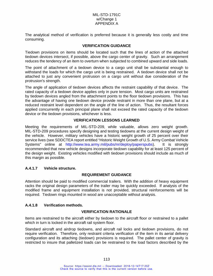
MIL-STD-1791C w/Change 1
APPENDIX A
113
The analytical method of verification is preferred because it is generally less costly and time consuming.
VERIFICATION GUIDANCE Tiedown provisions on items should be located such that the lines of action of the attached tiedown devices intersect, if possible, above the cargo center of gravity. Such an arrangement reduces the tendency of an item to overturn when subjected to combined upward and side loads. The point of attachment of a tiedown device to a cargo unit shall be substantial enough to withstand the loads for which the cargo unit is being restrained. A tiedown device shall not be attached to just any convenient protrusion on a cargo unit without due consideration of the protrusion's strength. The angle of application of tiedown devices affects the restraint capability of that device. The rated capacity of a tiedown device applies only in pure tension. Most cargo units are restrained by tiedown devices angled from the attachment points to the floor tiedown provisions. This has the advantage of having one tiedown device provide restraint in more than one plane, but at a reduced restraint level dependent on the angle of the line of action. Thus, the resultant forces applied concurrently in each principal plane shall not exceed the rated capacity of the tiedown device or the tiedown provisions, whichever is less.
VERIFICATION LESSONS LEARNED Meeting the requirements of MIL-STD-209, while valuable, allows zero weight growth. MIL-STD-209 procedures specify designing and testing tiedowns at the current design weight of the vehicle. However, military vehicles have a historic weight growth of 25 percent over their service lives (see SDDCTEA report entitled “Historic Weight Growth of U.S. Army Combat Vehicle Systems” online at http://www.tea.army.mil/pubs/nr/deploy/paperspubs). It is strongly recommended that new vehicle designs incorporate tiedown capability for at least 125 percent of the design weight. Existing vehicles modified with tiedown provisions should include as much of this margin as possible.
A.4.1.7 Vehicle structure. REQUIREMENT GUIDANCE
Attention should be paid to modified commercial trailers. With the addition of heavy equipment racks the original design parameters of the trailer may be quickly exceeded. If analysis of the modified frame and equipment installation is not provided, structural reinforcements will be required. Tiedown rings mounted in wood are unacceptable without analysis.
A.4.1.8 Verification methods. VERIFICATION RATIONALE
Items are restrained to the aircraft either by tiedown to the aircraft floor or restrained to a pallet which in turn is locked in the aircraft rail system floor. Standard aircraft and airdrop tiedowns, and aircraft rail locks and tiedown provisions, do not require verification. Therefore, only restraint criteria verification of the item in its aerial delivery configuration and its attaching (tiedown) provisions is required. The pallet center of gravity is restricted to insure that palletized loads can be restrained to the load factors described by the
Source: https://assist.dla.mil -- Downloaded: 2018-12-14T17:20ZCheck the source to verify that this is the current version before use.
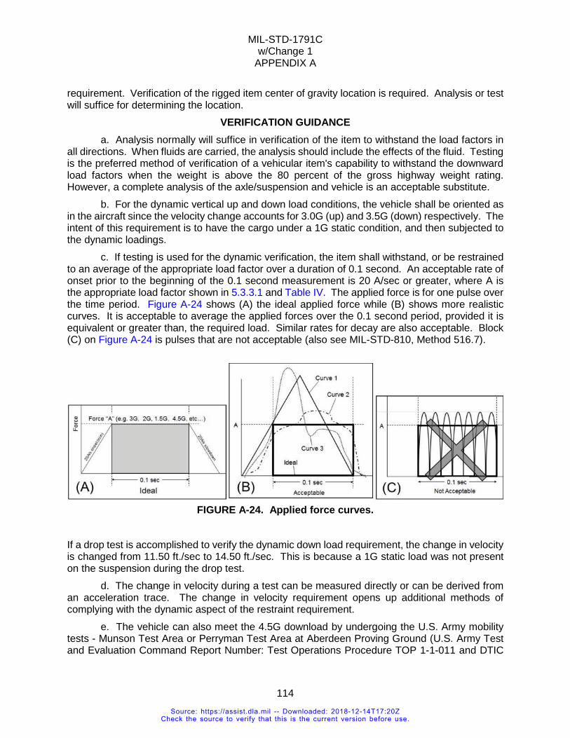
MIL-STD-1791C w/Change 1
APPENDIX A
114
requirement. Verification of the rigged item center of gravity location is required. Analysis or test will suffice for determining the location.
VERIFICATION GUIDANCE a. Analysis normally will suffice in verification of the item to withstand the load factors in
all directions. When fluids are carried, the analysis should include the effects of the fluid. Testing is the preferred method of verification of a vehicular item's capability to withstand the downward load factors when the weight is above the 80 percent of the gross highway weight rating. However, a complete analysis of the axle/suspension and vehicle is an acceptable substitute.
b. For the dynamic vertical up and down load conditions, the vehicle shall be oriented as in the aircraft since the velocity change accounts for 3.0G (up) and 3.5G (down) respectively. The intent of this requirement is to have the cargo under a 1G static condition, and then subjected to the dynamic loadings.
c. If testing is used for the dynamic verification, the item shall withstand, or be restrained to an average of the appropriate load factor over a duration of 0.1 second. An acceptable rate of onset prior to the beginning of the 0.1 second measurement is 20 A/sec or greater, where A is the appropriate load factor shown in 5.3.3.1 and Table IV. The applied force is for one pulse over the time period. Figure A-24 shows (A) the ideal applied force while (B) shows more realistic curves. It is acceptable to average the applied forces over the 0.1 second period, provided it is equivalent or greater than, the required load. Similar rates for decay are also acceptable. Block (C) on Figure A-24 is pulses that are not acceptable (also see MIL-STD-810, Method 516.7).
FIGURE A-24. Applied force curves.
If a drop test is accomplished to verify the dynamic down load requirement, the change in velocity is changed from 11.50 ft./sec to 14.50 ft./sec. This is because a 1G static load was not present on the suspension during the drop test.
d. The change in velocity during a test can be measured directly or can be derived from an acceleration trace. The change in velocity requirement opens up additional methods of complying with the dynamic aspect of the restraint requirement.
e. The vehicle can also meet the 4.5G download by undergoing the U.S. Army mobility tests - Munson Test Area or Perryman Test Area at Aberdeen Proving Ground (U.S. Army Test and Evaluation Command Report Number: Test Operations Procedure TOP 1-1-011 and DTIC
Source: https://assist.dla.mil -- Downloaded: 2018-12-14T17:20ZCheck the source to verify that this is the current version before use.
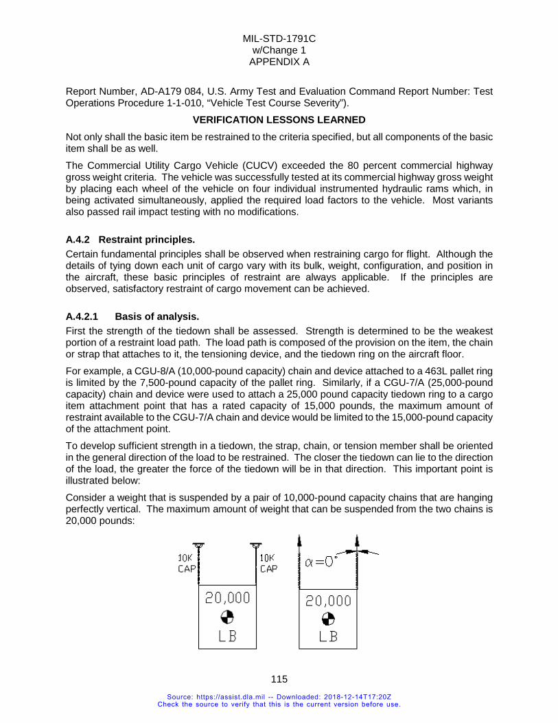
MIL-STD-1791C w/Change 1
APPENDIX A
115
Report Number, AD-A179 084, U.S. Army Test and Evaluation Command Report Number: Test Operations Procedure 1-1-010, “Vehicle Test Course Severity”).
VERIFICATION LESSONS LEARNED Not only shall the basic item be restrained to the criteria specified, but all components of the basic item shall be as well. The Commercial Utility Cargo Vehicle (CUCV) exceeded the 80 percent commercial highway gross weight criteria. The vehicle was successfully tested at its commercial highway gross weight by placing each wheel of the vehicle on four individual instrumented hydraulic rams which, in being activated simultaneously, applied the required load factors to the vehicle. Most variants also passed rail impact testing with no modifications.
A.4.2 Restraint principles. Certain fundamental principles shall be observed when restraining cargo for flight. Although the details of tying down each unit of cargo vary with its bulk, weight, configuration, and position in the aircraft, these basic principles of restraint are always applicable. If the principles are observed, satisfactory restraint of cargo movement can be achieved.
A.4.2.1 Basis of analysis. First the strength of the tiedown shall be assessed. Strength is determined to be the weakest portion of a restraint load path. The load path is composed of the provision on the item, the chain or strap that attaches to it, the tensioning device, and the tiedown ring on the aircraft floor. For example, a CGU-8/A (10,000-pound capacity) chain and device attached to a 463L pallet ring is limited by the 7,500-pound capacity of the pallet ring. Similarly, if a CGU-7/A (25,000-pound capacity) chain and device were used to attach a 25,000 pound capacity tiedown ring to a cargo item attachment point that has a rated capacity of 15,000 pounds, the maximum amount of restraint available to the CGU-7/A chain and device would be limited to the 15,000-pound capacity of the attachment point. To develop sufficient strength in a tiedown, the strap, chain, or tension member shall be oriented in the general direction of the load to be restrained. The closer the tiedown can lie to the direction of the load, the greater the force of the tiedown will be in that direction. This important point is illustrated below: Consider a weight that is suspended by a pair of 10,000-pound capacity chains that are hanging perfectly vertical. The maximum amount of weight that can be suspended from the two chains is 20,000 pounds:
Source: https://assist.dla.mil -- Downloaded: 2018-12-14T17:20ZCheck the source to verify that this is the current version before use.
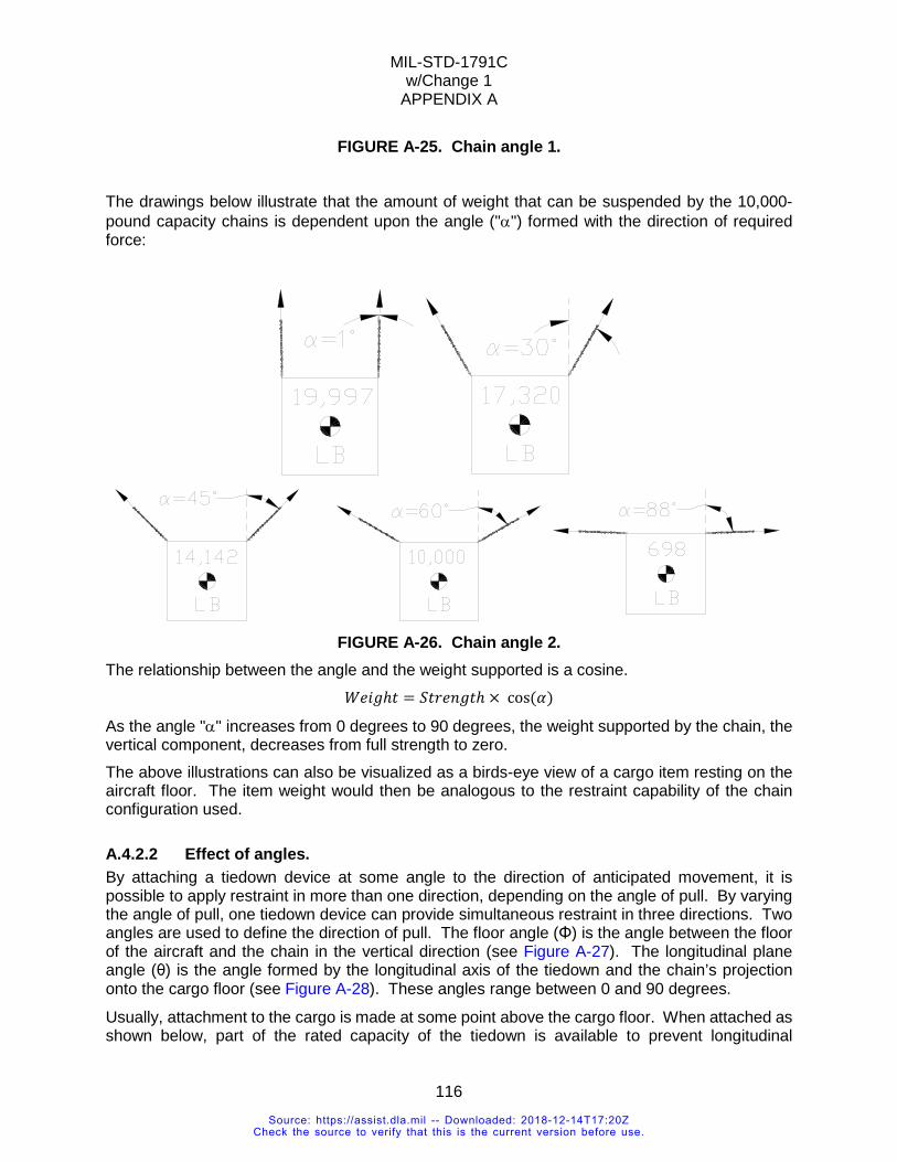
MIL-STD-1791C w/Change 1
APPENDIX A
116
FIGURE A-25. Chain angle 1.
The drawings below illustrate that the amount of weight that can be suspended by the 10,000-pound capacity chains is dependent upon the angle ("α") formed with the direction of required force:
FIGURE A-26. Chain angle 2.
The relationship between the angle and the weight supported is a cosine. 𝑥𝑥𝐻𝐻𝐻𝐻𝐻𝐻ℎ𝑡𝑡 = 𝑆𝑆𝑡𝑡𝑂𝑂𝐻𝐻𝑎𝑎𝐻𝐻𝑡𝑡ℎ × cos(𝛼𝛼)
As the angle "α" increases from 0 degrees to 90 degrees, the weight supported by the chain, the vertical component, decreases from full strength to zero. The above illustrations can also be visualized as a birds-eye view of a cargo item resting on the aircraft floor. The item weight would then be analogous to the restraint capability of the chain configuration used.
A.4.2.2 Effect of angles. By attaching a tiedown device at some angle to the direction of anticipated movement, it is possible to apply restraint in more than one direction, depending on the angle of pull. By varying the angle of pull, one tiedown device can provide simultaneous restraint in three directions. Two angles are used to define the direction of pull. The floor angle (Φ) is the angle between the floor of the aircraft and the chain in the vertical direction (see Figure A-27). The longitudinal plane angle (θ) is the angle formed by the longitudinal axis of the tiedown and the chain’s projection onto the cargo floor (see Figure A-28). These angles range between 0 and 90 degrees.
Usually, attachment to the cargo is made at some point above the cargo floor. When attached as shown below, part of the rated capacity of the tiedown is available to prevent longitudinal
Source: https://assist.dla.mil -- Downloaded: 2018-12-14T17:20ZCheck the source to verify that this is the current version before use.
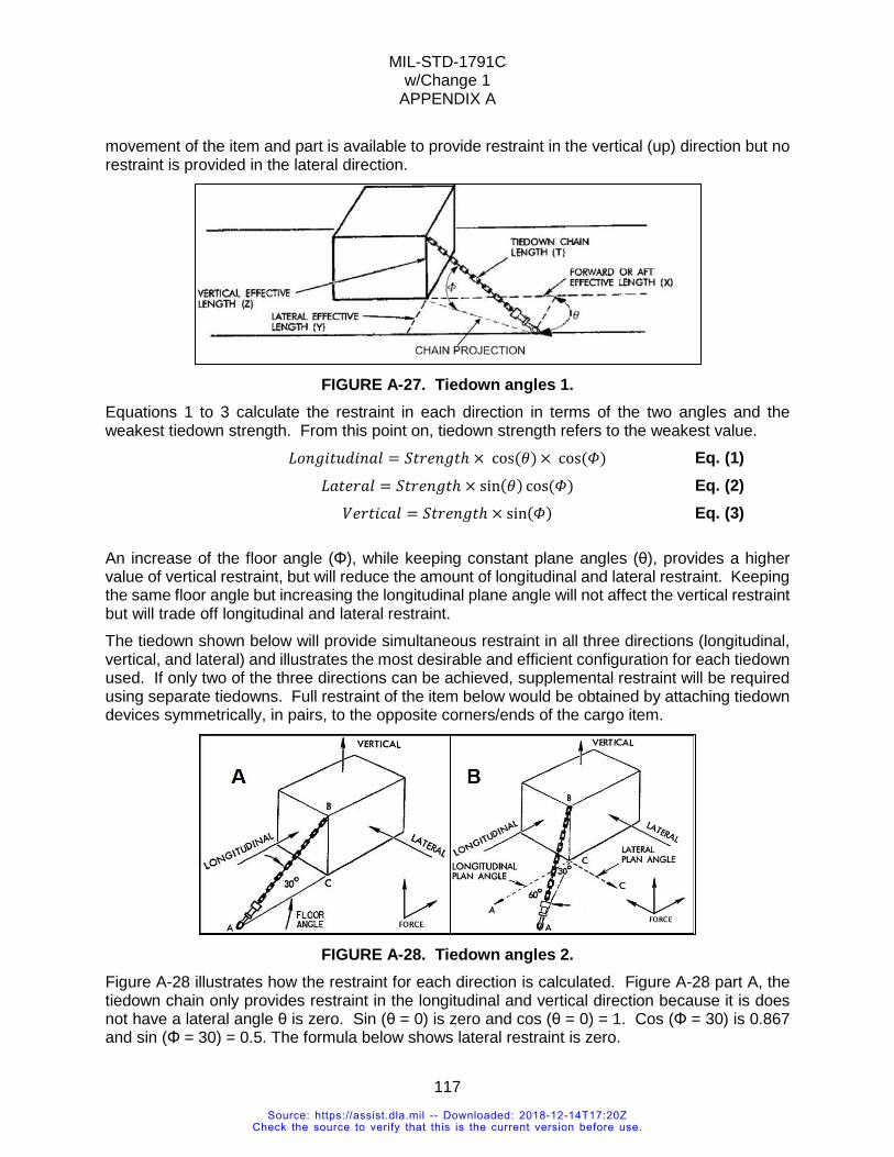
MIL-STD-1791C w/Change 1
APPENDIX A
117
movement of the item and part is available to provide restraint in the vertical (up) direction but no restraint is provided in the lateral direction.
FIGURE A-27. Tiedown angles 1.
Equations 1 to 3 calculate the restraint in each direction in terms of the two angles and the weakest tiedown strength. From this point on, tiedown strength refers to the weakest value. 𝐿𝐿𝐿𝐿𝑎𝑎𝐻𝐻𝐻𝐻𝑡𝑡𝐿𝐿𝐿𝐿𝐻𝐻𝑎𝑎𝑎𝑎𝐶𝐶 = 𝑆𝑆𝑡𝑡𝑂𝑂𝐻𝐻𝑎𝑎𝐻𝐻𝑡𝑡ℎ × cos(𝜃𝜃) × cos(𝛷𝛷) Eq. (1) 𝐿𝐿𝑎𝑎𝑡𝑡𝐻𝐻𝑂𝑂𝑎𝑎𝐶𝐶 = 𝑆𝑆𝑡𝑡𝑂𝑂𝐻𝐻𝑎𝑎𝐻𝐻𝑡𝑡ℎ × sin(𝜃𝜃) cos(𝛷𝛷) Eq. (2) 𝑉𝑉𝐻𝐻𝑂𝑂𝑡𝑡𝐻𝐻𝐶𝐶𝑎𝑎𝐶𝐶 = 𝑆𝑆𝑡𝑡𝑂𝑂𝐻𝐻𝑎𝑎𝐻𝐻𝑡𝑡ℎ × sin(𝛷𝛷) Eq. (3)
An increase of the floor angle (Φ), while keeping constant plane angles (θ), provides a higher value of vertical restraint, but will reduce the amount of longitudinal and lateral restraint. Keeping the same floor angle but increasing the longitudinal plane angle will not affect the vertical restraint but will trade off longitudinal and lateral restraint. The tiedown shown below will provide simultaneous restraint in all three directions (longitudinal, vertical, and lateral) and illustrates the most desirable and efficient configuration for each tiedown used. If only two of the three directions can be achieved, supplemental restraint will be required using separate tiedowns. Full restraint of the item below would be obtained by attaching tiedown devices symmetrically, in pairs, to the opposite corners/ends of the cargo item.
FIGURE A-28. Tiedown angles 2.
Figure A-28 illustrates how the restraint for each direction is calculated. Figure A-28 part A, the tiedown chain only provides restraint in the longitudinal and vertical direction because it is does not have a lateral angle θ is zero. Sin (θ = 0) is zero and cos (θ = 0) = 1. Cos (Φ = 30) is 0.867 and sin (Φ = 30) = 0.5. The formula below shows lateral restraint is zero.
Source: https://assist.dla.mil -- Downloaded: 2018-12-14T17:20ZCheck the source to verify that this is the current version before use.
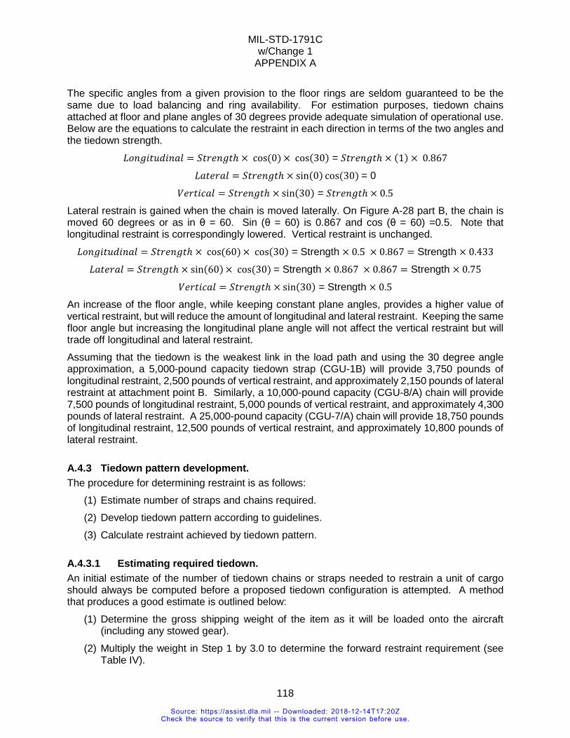
MIL-STD-1791C w/Change 1
APPENDIX A
118
The specific angles from a given provision to the floor rings are seldom guaranteed to be the same due to load balancing and ring availability. For estimation purposes, tiedown chains attached at floor and plane angles of 30 degrees provide adequate simulation of operational use. Below are the equations to calculate the restraint in each direction in terms of the two angles and the tiedown strength.
𝐿𝐿𝐿𝐿𝑎𝑎𝐻𝐻𝐻𝐻𝑡𝑡𝐿𝐿𝐿𝐿𝐻𝐻𝑎𝑎𝑎𝑎𝐶𝐶 = 𝑆𝑆𝑡𝑡𝑂𝑂𝐻𝐻𝑎𝑎𝐻𝐻𝑡𝑡ℎ × cos(0) × cos(30) = 𝑆𝑆𝑡𝑡𝑂𝑂𝐻𝐻𝑎𝑎𝐻𝐻𝑡𝑡ℎ × (1) × 0.867
𝐿𝐿𝑎𝑎𝑡𝑡𝐻𝐻𝑂𝑂𝑎𝑎𝐶𝐶 = 𝑆𝑆𝑡𝑡𝑂𝑂𝐻𝐻𝑎𝑎𝐻𝐻𝑡𝑡ℎ × sin(0) cos(30) = 0
𝑉𝑉𝐻𝐻𝑂𝑂𝑡𝑡𝐻𝐻𝐶𝐶𝑎𝑎𝐶𝐶 = 𝑆𝑆𝑡𝑡𝑂𝑂𝐻𝐻𝑎𝑎𝐻𝐻𝑡𝑡ℎ × sin(30) = 𝑆𝑆𝑡𝑡𝑂𝑂𝐻𝐻𝑎𝑎𝐻𝐻𝑡𝑡ℎ × 0.5
Lateral restrain is gained when the chain is moved laterally. On Figure A-28 part B, the chain is moved 60 degrees or as in θ = 60. Sin (θ = 60) is 0.867 and cos (θ = 60) =0.5. Note that longitudinal restraint is correspondingly lowered. Vertical restraint is unchanged.
𝐿𝐿𝐿𝐿𝑎𝑎𝐻𝐻𝐻𝐻𝑡𝑡𝐿𝐿𝐿𝐿𝐻𝐻𝑎𝑎𝑎𝑎𝐶𝐶 = 𝑆𝑆𝑡𝑡𝑂𝑂𝐻𝐻𝑎𝑎𝐻𝐻𝑡𝑡ℎ × cos(60) × cos(30) = Strength × 0.5 × 0.867 = Strength × 0.433
𝐿𝐿𝑎𝑎𝑡𝑡𝐻𝐻𝑂𝑂𝑎𝑎𝐶𝐶 = 𝑆𝑆𝑡𝑡𝑂𝑂𝐻𝐻𝑎𝑎𝐻𝐻𝑡𝑡ℎ × sin(60) × cos(30) = Strength × 0.867 × 0.867 = Strength × 0.75
𝑉𝑉𝐻𝐻𝑂𝑂𝑡𝑡𝐻𝐻𝐶𝐶𝑎𝑎𝐶𝐶 = 𝑆𝑆𝑡𝑡𝑂𝑂𝐻𝐻𝑎𝑎𝐻𝐻𝑡𝑡ℎ × sin(30) = Strength × 0.5 An increase of the floor angle, while keeping constant plane angles, provides a higher value of vertical restraint, but will reduce the amount of longitudinal and lateral restraint. Keeping the same floor angle but increasing the longitudinal plane angle will not affect the vertical restraint but will trade off longitudinal and lateral restraint. Assuming that the tiedown is the weakest link in the load path and using the 30 degree angle approximation, a 5,000-pound capacity tiedown strap (CGU-1B) will provide 3,750 pounds of longitudinal restraint, 2,500 pounds of vertical restraint, and approximately 2,150 pounds of lateral restraint at attachment point B. Similarly, a 10,000-pound capacity (CGU-8/A) chain will provide 7,500 pounds of longitudinal restraint, 5,000 pounds of vertical restraint, and approximately 4,300 pounds of lateral restraint. A 25,000-pound capacity (CGU-7/A) chain will provide 18,750 pounds of longitudinal restraint, 12,500 pounds of vertical restraint, and approximately 10,800 pounds of lateral restraint.
A.4.3 Tiedown pattern development. The procedure for determining restraint is as follows:
(1) Estimate number of straps and chains required. (2) Develop tiedown pattern according to guidelines. (3) Calculate restraint achieved by tiedown pattern.
A.4.3.1 Estimating required tiedown. An initial estimate of the number of tiedown chains or straps needed to restrain a unit of cargo should always be computed before a proposed tiedown configuration is attempted. A method that produces a good estimate is outlined below:
(1) Determine the gross shipping weight of the item as it will be loaded onto the aircraft (including any stowed gear).
(2) Multiply the weight in Step 1 by 3.0 to determine the forward restraint requirement (see Table IV).
Source: https://assist.dla.mil -- Downloaded: 2018-12-14T17:20ZCheck the source to verify that this is the current version before use.
MIL-STD-1791C w/Change 1
APPENDIX A
119
(3) Divide the result in Step 2 by the longitudinal restraint from 30 degree angle of restraint (see Eq. (1)): 3,750 if 5,000-pound capacity straps will be used, 7,500 if 10,000-pound capacity chains will be used or by 18,750 if 25,000-pound capacity chains will be used. If the attachment points on the cargo item or the floor tiedown rings on the aircraft are weaker than the capacity of the chain that is being used, divide the result in Step 2 by the weakest longitudinal capacity.
(4) Round up the result from Step 3 to the next EVEN whole number (chains should always be attached in pairs). The result will be an estimate of the number of chains that will be needed to restrain the cargo item to 3.0Gs forward.
(5) Repeat from steps 2-4 for aft restraint (1.5Gs). Usually between the forward and aft requirements the lateral and vertical are exceeded. Example: A 30,000-pound vehicle is to be airlifted on a C-17. An additional 2,375 pounds of crew gear will be stowed inside the vehicle prior to loading. There are 2 attachment points on each end of the vehicle, plus 2 additional points down each side of the vehicle, for a total of 8 points, each rated at 65,000 pounds capacity.
Step 1: 30,000 + 2,375 = 32,375 lbs. (gross shipping weight) Step 2: 32,375 × 3.0 G = 97,125 lbs. (restrain to 3.0Gs forward)
Step 3: 97,125 ÷ 18,750 = 5.2 Step 4: Rounding up to the next even number gives a total of 6 (3 pairs) 25,000-pound capacity chains that will be required for forward restraint.
Step 5: (32,375 × 1.5) ÷ 18,750 = 2.6. Rounded up to 4. Use the initial estimate to determine a proposed tiedown configuration.
A.4.3.2 Determining tiedown pattern. Tiedown device attachment generally follows similar patterns because of cargo floor tiedown ring layout and symmetrical restraint requirements. (All references are to Figure A-31.)
(1) Always secure cargo for the required amount of restraint with the minimum number of tiedown devices.
(2) The maximum available restraint for any tiedown is determined by using the weakest rating of the load path: the tiedown attachment points on the cargo item, the effective strength of the tiedown device used, and the tiedown (floor) fittings used. The point of attachment and supporting structure, of a tiedown device to a cargo unit shall be substantial enough to withstand the loads for which the cargo unit is being restrained. A tiedown device cannot be secured to any convenient protrusion on a cargo unit without due consideration of the protrusion's strength.
(3) Chains and straps shall have an unimpeded, straight line of action from the floor to the item’s provision. Chains and straps that are run from a provision around a corner or otherwise impeded from making a straight line place load on the corner and the corner becomes the structural member, not the provision. Routing restraint in this manner can wear on both the vehicle and strap/chain; failure of the impediment introduces slack in the chain which can result
Source: https://assist.dla.mil -- Downloaded: 2018-12-14T17:20ZCheck the source to verify that this is the current version before use.
MIL-STD-1791C w/Change 1
APPENDIX A
120
in restraint failure. This consideration applies to everything, from vehicles with frame mounted tool boxes and fuel tanks, to ship propellers with provisions between blades.
(4) Straps and chains shall not be mixed to restrain cargo in the same direction, on separate load paths (due to different elongation characteristics). However, 10,000 and 25,000-pound rated devices with the appropriate chains may be used for a given direction of restraint. Although all materials stretch in direct proportion to the applied load, materials have varying rates of stretch. Under tension, nylon devices stretch more readily than steel and permit the steel device to assume the majority of the load. Therefore, when two or more tiedown devices are used in the same direction, on separate load paths, the devices shall be of similar material and equally tensioned to ensure the load is evenly distributed. Within the same load path straps and chains can be mixed as long as the same mix is used for restraint in all directions. A strap attached to a chain is providing restraint in the forward direction is allowed if all restraint load paths are the same mix.
(5) Tiedowns should be attached in a symmetrical pattern. Asymmetrical tiedowns permit load distributions that may ultimately result in tiedown device failure. Such a failure would result from the different load-deflection rates of dissimilar materials or of identical materials of different length. Any material subjected to a tension load will stretch. A longer length tiedown has more stretch potential than a shorter length tiedown. If two tiedowns of the same type and capacity are used to restrain a load in a given direction and one is longer than the other, the longer tiedown, with its greater stretch potential, will permit the shorter tiedown to assume the majority of any load that may develop. If the shorter tied own becomes overstressed and fails, the longer tiedown would then be subjected to the full load and it, too, would likely fail. Therefore, symmetrical tiedowns should be as close to the same length as possible.
(6) When multiple tiedowns are attached to floor rings that are in the same lateral row (i.e. pulling on the same floor bulkhead), the amount of vertical restraint may be limited. See Tables B-II for C-5 limits and B-XX for C-17 limits. Example: four CGU-8/A devices attached to floor fittings in the same lateral row may each provide forward and aft restraint to their maximum capacity, but the amount of vertical restraint available per floor ring may be limited. The vertical restraint reduction varies depending on the aircraft, and depending on the number of other devices attached to the same lateral tiedown row.
(7) Primarily attach straps/chains to items. Use of gates and bridles is discouraged and should only be used if attachment is not possible. Restraint straps or chains that are simply passed over or around a unit of cargo (instead of being attached directly to it) can provide double the strength of a single restraint, provided the capacity of the floor fittings is equal to or greater than the strap or chain capacity. Commonly called a strap or chain gate, this type of tiedown configuration can only provide restraint in a single direction. To increase the utility of this concept, a chain bridle may be used to obtain restraint in more than one direction (see Figure A-29):
Source: https://assist.dla.mil -- Downloaded: 2018-12-14T17:20ZCheck the source to verify that this is the current version before use.
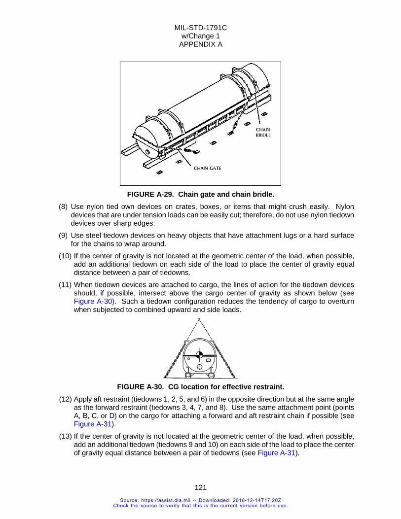
MIL-STD-1791C w/Change 1
APPENDIX A
121
FIGURE A-29. Chain gate and chain bridle.
(8) Use nylon tied own devices on crates, boxes, or items that might crush easily. Nylon devices that are under tension loads can be easily cut; therefore, do not use nylon tiedown devices over sharp edges.
(9) Use steel tiedown devices on heavy objects that have attachment lugs or a hard surface for the chains to wrap around.
(10) If the center of gravity is not located at the geometric center of the load, when possible, add an additional tiedown on each side of the load to place the center of gravity equal distance between a pair of tiedowns.
(11) When tiedown devices are attached to cargo, the lines of action for the tiedown devices should, if possible, intersect above the cargo center of gravity as shown below (see Figure A-30). Such a tiedown configuration reduces the tendency of cargo to overturn when subjected to combined upward and side loads.
FIGURE A-30. CG location for effective restraint.
(12) Apply aft restraint (tiedowns 1, 2, 5, and 6) in the opposite direction but at the same angle as the forward restraint (tiedowns 3, 4, 7, and 8). Use the same attachment point (points A, B, C, or D) on the cargo for attaching a forward and aft restraint chain if possible (see Figure A-31).
(13) If the center of gravity is not located at the geometric center of the load, when possible, add an additional tiedown (tiedowns 9 and 10) on each side of the load to place the center of gravity equal distance between a pair of tiedowns (see Figure A-31).
Source: https://assist.dla.mil -- Downloaded: 2018-12-14T17:20ZCheck the source to verify that this is the current version before use.
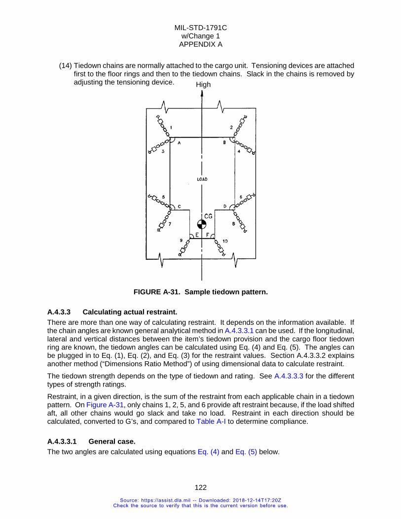
MIL-STD-1791C w/Change 1
APPENDIX A
122
(14) Tiedown chains are normally attached to the cargo unit. Tensioning devices are attached first to the floor rings and then to the tiedown chains. Slack in the chains is removed by adjusting the tensioning device.
FIGURE A-31. Sample tiedown pattern.
A.4.3.3 Calculating actual restraint. There are more than one way of calculating restraint. It depends on the information available. If the chain angles are known general analytical method in A.4.3.3.1 can be used. If the longitudinal, lateral and vertical distances between the item’s tiedown provision and the cargo floor tiedown ring are known, the tiedown angles can be calculated using Eq. (4) and Eq. (5). The angles can be plugged in to Eq. (1), Eq. (2), and Eq. (3) for the restraint values. Section A.4.3.3.2 explains another method (“Dimensions Ratio Method”) of using dimensional data to calculate restraint. The tiedown strength depends on the type of tiedown and rating. See A.4.3.3.3 for the different types of strength ratings. Restraint, in a given direction, is the sum of the restraint from each applicable chain in a tiedown pattern. On Figure A-31, only chains 1, 2, 5, and 6 provide aft restraint because, if the load shifted aft, all other chains would go slack and take no load. Restraint in each direction should be calculated, converted to G’s, and compared to Table A-I to determine compliance.
A.4.3.3.1 General case. The two angles are calculated using equations Eq. (4) and Eq. (5) below.
High
Source: https://assist.dla.mil -- Downloaded: 2018-12-14T17:20ZCheck the source to verify that this is the current version before use.
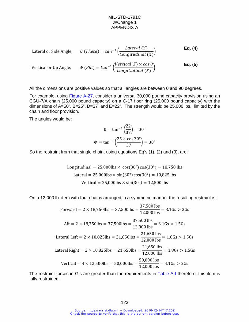
MIL-STD-1791C w/Change 1
APPENDIX A
123
Lateral or Side Angle, 𝜃𝜃 (𝑇𝑇ℎ𝐻𝐻𝑡𝑡𝑎𝑎) = 𝑡𝑡𝑎𝑎𝑎𝑎−1 �𝐿𝐿𝑎𝑎𝑡𝑡𝐻𝐻𝑂𝑂𝑎𝑎𝐶𝐶 (𝑌𝑌)
𝐿𝐿𝐿𝐿𝑎𝑎𝐻𝐻𝐻𝐻𝑡𝑡𝐿𝐿𝐿𝐿𝐻𝐻𝑎𝑎𝑎𝑎𝐶𝐶 (𝑋𝑋)� Eq. (4)
Vertical or Up Angle, 𝛷𝛷 (𝑃𝑃ℎ𝐻𝐻) = 𝑡𝑡𝑎𝑎𝑎𝑎−1 �𝑉𝑉𝐻𝐻𝑂𝑂𝑡𝑡𝐻𝐻𝐶𝐶𝑎𝑎𝐶𝐶(𝑍𝑍) × 𝐶𝐶𝐿𝐿𝑒𝑒 𝜃𝜃𝐿𝐿𝐿𝐿𝑎𝑎𝐻𝐻𝐻𝐻𝑡𝑡𝐿𝐿𝐿𝐿𝐻𝐻𝑎𝑎𝑎𝑎𝐶𝐶 (𝑋𝑋)
� Eq. (5)
All the dimensions are positive values so that all angles are between 0 and 90 degrees. For example, using Figure A-27, consider a universal 30,000 pound capacity provision using an CGU-7/A chain (25,000 pound capacity) on a C-17 floor ring (25,000 pound capacity) with the dimensions of A=50”, B=25”, D=37” and E=22”. The strength would be 25,000 lbs., limited by the chain and floor provision. The angles would be: θ = tan−1 �
2237� = 30°
Φ = tan−1 �25 × cos 30°
37� = 30°
So the restraint from that single chain, using equations Eq’s (1), (2) and (3), are: Longitudinal = 25,000lbs × cos(30°) cos(30°) = 18,750 lbs Lateral = 25,000lbs × sin(30°) cos(30°) = 10,825 lbs Vertical = 25,000lbs × sin(30°) = 12,500 lbs
On a 12,000 lb. item with four chains arranged in a symmetric manner the resulting restraint is:
Forward = 2 × 18,750lbs = 37,500lbs =37,500 lbs12,000 lbs
= 3.1Gs > 3Gs
Aft = 2 × 18,750lbs = 37,500lbs =37,500 lbs12,000 lbs
= 3.1Gs > 1.5Gs
Lateral Left = 2 × 10,825lbs = 21,650lbs =21,650 lbs12,000 lbs
= 1.8Gs > 1.5Gs
Lateral Right = 2 × 10,825lbs = 21,650lbs =21,650 lbs12,000 lbs
= 1.8Gs > 1.5Gs
Vertical = 4 × 12,500lbs = 50,000lbs =50,000 lbs12,000 lbs
= 4.1Gs > 2Gs
The restraint forces in G’s are greater than the requirements in Table A-I therefore, this item is fully restrained.
Source: https://assist.dla.mil -- Downloaded: 2018-12-14T17:20ZCheck the source to verify that this is the current version before use.
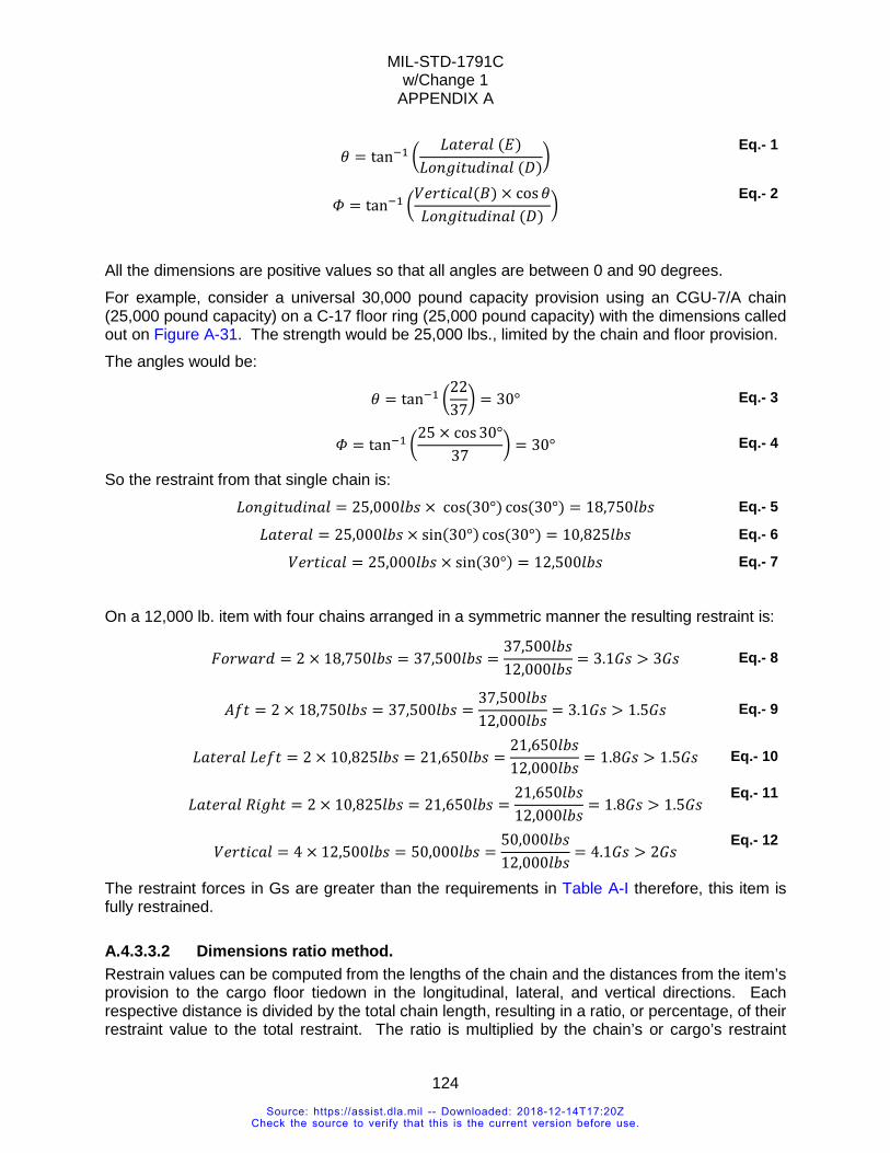
MIL-STD-1791C w/Change 1
APPENDIX A
124
𝜃𝜃 = tan−1 �
𝐿𝐿𝑎𝑎𝑡𝑡𝐻𝐻𝑂𝑂𝑎𝑎𝐶𝐶 (𝐸𝐸)𝐿𝐿𝐿𝐿𝑎𝑎𝐻𝐻𝐻𝐻𝑡𝑡𝐿𝐿𝐿𝐿𝐻𝐻𝑎𝑎𝑎𝑎𝐶𝐶 (𝐷𝐷)
� Eq.- 1
𝛷𝛷 = tan−1 �
𝑉𝑉𝐻𝐻𝑂𝑂𝑡𝑡𝐻𝐻𝐶𝐶𝑎𝑎𝐶𝐶(𝐵𝐵) × cos𝜃𝜃𝐿𝐿𝐿𝐿𝑎𝑎𝐻𝐻𝐻𝐻𝑡𝑡𝐿𝐿𝐿𝐿𝐻𝐻𝑎𝑎𝑎𝑎𝐶𝐶 (𝐷𝐷)
� Eq.- 2
All the dimensions are positive values so that all angles are between 0 and 90 degrees. For example, consider a universal 30,000 pound capacity provision using an CGU-7/A chain (25,000 pound capacity) on a C-17 floor ring (25,000 pound capacity) with the dimensions called out on Figure A-31. The strength would be 25,000 lbs., limited by the chain and floor provision. The angles would be: 𝜃𝜃 = tan−1 �
2237� = 30° Eq.- 3
𝛷𝛷 = tan−1 �25 × cos 30°
37� = 30° Eq.- 4
So the restraint from that single chain is: 𝐿𝐿𝐿𝐿𝑎𝑎𝐻𝐻𝐻𝐻𝑡𝑡𝐿𝐿𝐿𝐿𝐻𝐻𝑎𝑎𝑎𝑎𝐶𝐶 = 25,000𝐶𝐶𝑒𝑒𝑒𝑒 × cos(30°) cos(30°) = 18,750𝐶𝐶𝑒𝑒𝑒𝑒 Eq.- 5
𝐿𝐿𝑎𝑎𝑡𝑡𝐻𝐻𝑂𝑂𝑎𝑎𝐶𝐶 = 25,000𝐶𝐶𝑒𝑒𝑒𝑒 × sin(30°) cos(30°) = 10,825𝐶𝐶𝑒𝑒𝑒𝑒 Eq.- 6
𝑉𝑉𝐻𝐻𝑂𝑂𝑡𝑡𝐻𝐻𝐶𝐶𝑎𝑎𝐶𝐶 = 25,000𝐶𝐶𝑒𝑒𝑒𝑒 × sin(30°) = 12,500𝐶𝐶𝑒𝑒𝑒𝑒 Eq.- 7
On a 12,000 lb. item with four chains arranged in a symmetric manner the resulting restraint is:
𝐹𝐹𝐿𝐿𝑂𝑂𝐹𝐹𝑎𝑎𝑂𝑂𝐿𝐿 = 2 × 18,750𝐶𝐶𝑒𝑒𝑒𝑒 = 37,500𝐶𝐶𝑒𝑒𝑒𝑒 =37,500𝐶𝐶𝑒𝑒𝑒𝑒12,000𝐶𝐶𝑒𝑒𝑒𝑒
= 3.1𝐺𝐺𝑒𝑒 > 3𝐺𝐺𝑒𝑒 Eq.- 8
𝐴𝐴𝐴𝐴𝑡𝑡 = 2 × 18,750𝐶𝐶𝑒𝑒𝑒𝑒 = 37,500𝐶𝐶𝑒𝑒𝑒𝑒 =37,500𝐶𝐶𝑒𝑒𝑒𝑒12,000𝐶𝐶𝑒𝑒𝑒𝑒
= 3.1𝐺𝐺𝑒𝑒 > 1.5𝐺𝐺𝑒𝑒 Eq.- 9
𝐿𝐿𝑎𝑎𝑡𝑡𝐻𝐻𝑂𝑂𝑎𝑎𝐶𝐶 𝐿𝐿𝐻𝐻𝐴𝐴𝑡𝑡 = 2 × 10,825𝐶𝐶𝑒𝑒𝑒𝑒 = 21,650𝐶𝐶𝑒𝑒𝑒𝑒 =21,650𝐶𝐶𝑒𝑒𝑒𝑒12,000𝐶𝐶𝑒𝑒𝑒𝑒
= 1.8𝐺𝐺𝑒𝑒 > 1.5𝐺𝐺𝑒𝑒 Eq.- 10
𝐿𝐿𝑎𝑎𝑡𝑡𝐻𝐻𝑂𝑂𝑎𝑎𝐶𝐶 𝑅𝑅𝐻𝐻𝐻𝐻ℎ𝑡𝑡 = 2 × 10,825𝐶𝐶𝑒𝑒𝑒𝑒 = 21,650𝐶𝐶𝑒𝑒𝑒𝑒 =21,650𝐶𝐶𝑒𝑒𝑒𝑒12,000𝐶𝐶𝑒𝑒𝑒𝑒
= 1.8𝐺𝐺𝑒𝑒 > 1.5𝐺𝐺𝑒𝑒 Eq.- 11
𝑉𝑉𝐻𝐻𝑂𝑂𝑡𝑡𝐻𝐻𝐶𝐶𝑎𝑎𝐶𝐶 = 4 × 12,500𝐶𝐶𝑒𝑒𝑒𝑒 = 50,000𝐶𝐶𝑒𝑒𝑒𝑒 =50,000𝐶𝐶𝑒𝑒𝑒𝑒12,000𝐶𝐶𝑒𝑒𝑒𝑒
= 4.1𝐺𝐺𝑒𝑒 > 2𝐺𝐺𝑒𝑒 Eq.- 12
The restraint forces in Gs are greater than the requirements in Table A-I therefore, this item is fully restrained.
A.4.3.3.2 Dimensions ratio method. Restrain values can be computed from the lengths of the chain and the distances from the item’s provision to the cargo floor tiedown in the longitudinal, lateral, and vertical directions. Each respective distance is divided by the total chain length, resulting in a ratio, or percentage, of their restraint value to the total restraint. The ratio is multiplied by the chain’s or cargo’s restraint
Source: https://assist.dla.mil -- Downloaded: 2018-12-14T17:20ZCheck the source to verify that this is the current version before use.
MIL-STD-1791C w/Change 1
APPENDIX A
125
provision, whichever is weakest, to obtain the restraint force in each direction. This method is the same as using Eq’s (1) through (3) except distances are used instead of angles.
Ratio X,Y or Z = (𝐷𝐷𝐶𝐶𝐶𝐶𝑃𝑃𝐶𝐶𝐸𝐸𝑃𝑃𝑃𝑃 𝑃𝑃𝑃𝑃 𝐹𝐹𝐶𝐶𝑃𝑃𝑃𝑃𝑃𝑃 𝑅𝑅𝐶𝐶𝐸𝐸𝐶𝐶 𝐶𝐶𝐸𝐸 𝑋𝑋,𝑌𝑌 𝑃𝑃𝑃𝑃 𝑍𝑍)
(𝑇𝑇𝑃𝑃𝑃𝑃𝐶𝐶𝐶𝐶 𝐷𝐷𝐶𝐶𝐶𝐶𝑃𝑃𝐶𝐶𝐸𝐸𝑃𝑃𝑃𝑃 𝑃𝑃𝑃𝑃 𝐹𝐹𝐶𝐶𝑃𝑃𝑃𝑃𝑃𝑃 𝑅𝑅𝐶𝐶𝐸𝐸𝐶𝐶 𝑃𝑃𝑃𝑃 𝑇𝑇𝑃𝑃𝑃𝑃𝐶𝐶𝐶𝐶 𝐶𝐶ℎ𝐶𝐶𝐶𝐶𝐸𝐸 𝐿𝐿𝑃𝑃𝐸𝐸𝐶𝐶𝑃𝑃ℎ) Eq. (6)
Restraint X,Y or Z = 𝑅𝑅𝑎𝑎𝑡𝑡𝐻𝐻𝐿𝐿 X,Y or Z 𝑥𝑥 𝑥𝑥𝐻𝐻𝑎𝑎𝑊𝑊𝐻𝐻𝑒𝑒𝑡𝑡 𝑆𝑆𝑡𝑡𝑂𝑂𝐻𝐻𝑎𝑎𝐻𝐻𝑡𝑡ℎ Eq. (7) EXAMPLE The tiedown chain shown on Figure A-27 has the following measurements Total Length (T) = 50 inches Longitudinal (Forward or Aft) Effective Length (X) = 37 inches Lateral Effective Length (Y) = 22 inches Vertical Effective Length (Z) = 25 inches The restraint values are:
VERTICAL RESTRAINT RECEIVED FROM TIEDOWN (1) First, measure the tiedown chain length (T) from the attachment point on the cargo to the
tiedown fitting on the cargo floor (50 inches). You will use this measurement in each calculation.
(2) CALCULATING THE VERTICAL RESTRAINT: a) For determining vertical restraint, measure the vertical dimension (B) from the attachment
point on the cargo to a point directly beneath it on the cargo floor (25 inches). b) Using Eq-6, divide the vertical dimension (B) by the tiedown chain length (A) to determine
a ratio: 25in
50in= 0.5 Ratio
c) Using Eq-7, multiply this ratio by the rated strength of the tiedown chain or the rated strength of the tiedown fitting on the cargo in the appropriate direction or the rated strength of the tiedown floor fitting, whichever is less:
0.5 × 10,000 lbs = 5,000 lbs
FWD OR AFT RESTRAINT RECEIVED FROM TIEDOWN (3) CALCULATING THE FORWARD OR AFT RESTRAINT:
a) For determining forward or aft restraint, obtain a forward or aft dimension (D) by measuring from a point directly beneath the attachment point on the cargo along a longitudinal axis to a point lateral to the tiedown fitting being used on the cargo floor (37 inches).
b) Divide the forward or aft dimension (D) by the tiedown chain length (A) to determine a ratio:
Source: https://assist.dla.mil -- Downloaded: 2018-12-14T17:20ZCheck the source to verify that this is the current version before use.
MIL-STD-1791C w/Change 1
APPENDIX A
126
37in50in
= 0.74 Ratio
c) Multiply this ratio by the rated strength of the tiedown chain or the rated strength of the tiedown fitting on the cargo in the appropriate direction or the rated strength of the tiedown floor fitting, whichever is less:
0.74 × 10,000lbs = 7,400lbs
LATERAL RESTRAINT RECEIVED FROM TIEDOWN
(4) CALCULATING THE LATERAL RESTRAINT: a) For determining lateral restraint, obtain a lateral dimension (E) by measuring from a point
directly beneath the attachment point on the cargo, along the cargo floor, to the row of tiedown fittings being used (22 inches).
b) Divide the lateral dimension (E) by the tiedown chain length (A) to determine a ratio: 22in
50in= 0.44 Ratio
c) Multiply this ratio by the rated strength of the tiedown chain or the rated strength of the tiedown fitting on the cargo or the rated strength of the tiedown floor fitting, whichever is less:
0.44 × 10,000lbs = 4,400lbs
A.4.3.3.3 Orientation specific ratings. Restraint provisions may be stronger in one orientation than another. The designer should select strength ratings that ensures the tiedown will withstand the forces associated with the restraint criteria, potential weight growth of the item, and forces as a result of more than one tiedown configurations. Limiting the load to a specific tiedown pattern is not practical. The USAF loadmaster may have to vary tiedown patterns to suit the mission. The typical ranges of tiedown angles are shown on Figure 2.Typical ways of citing provision limits are:
A.4.3.3.3.1 Universal rating: The provision has the same strength no matter what angle it is pulled at in a hemispherical range of angles starting at the base of the provision (see Figure A-32). Longitudinal, lateral and vertical restraints are computed using the rated strength and the tiedown angle.
Source: https://assist.dla.mil -- Downloaded: 2018-12-14T17:20ZCheck the source to verify that this is the current version before use.
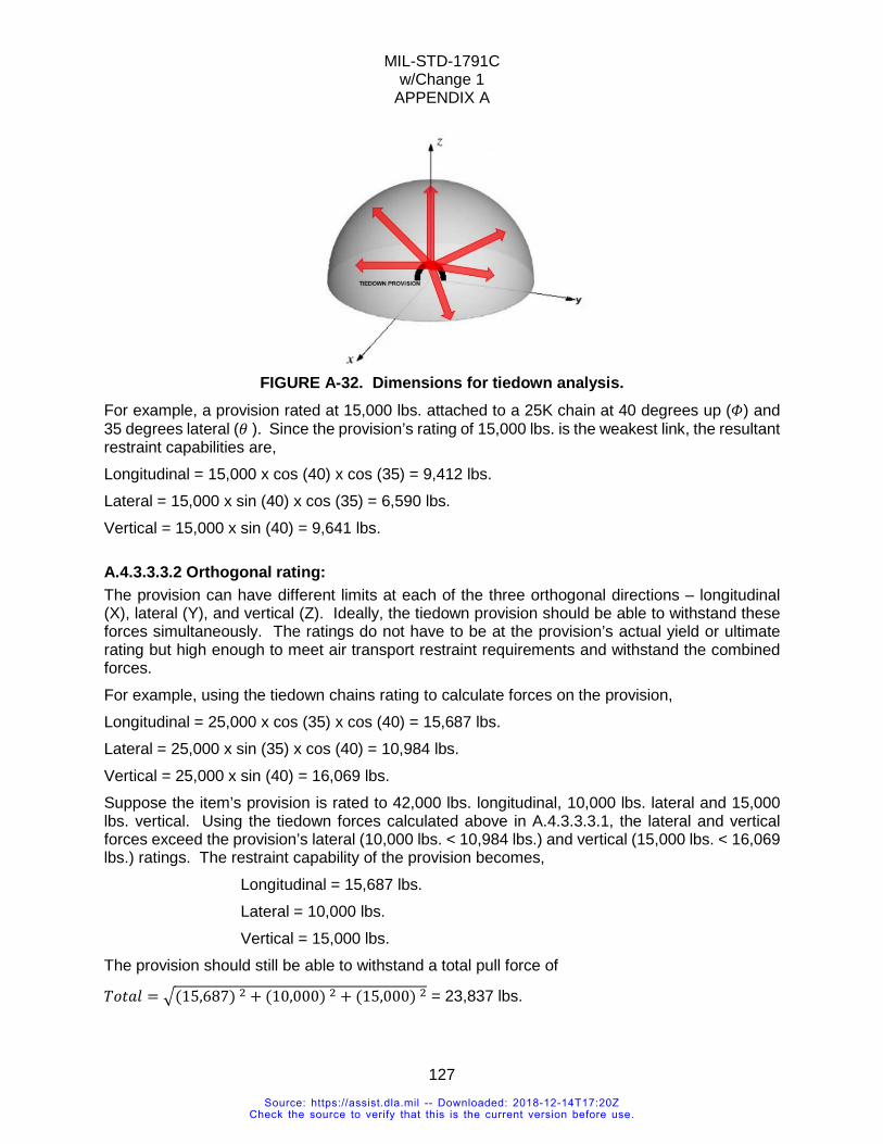
MIL-STD-1791C w/Change 1
APPENDIX A
127
FIGURE A-32. Dimensions for tiedown analysis.
For example, a provision rated at 15,000 lbs. attached to a 25K chain at 40 degrees up (𝛷𝛷) and 35 degrees lateral (𝜃𝜃 ). Since the provision’s rating of 15,000 lbs. is the weakest link, the resultant restraint capabilities are, Longitudinal = 15,000 x cos (40) x cos (35) = 9,412 lbs. Lateral = 15,000 x sin (40) x cos (35) = 6,590 lbs. Vertical = 15,000 x sin (40) = 9,641 lbs.
A.4.3.3.3.2 Orthogonal rating: The provision can have different limits at each of the three orthogonal directions – longitudinal (X), lateral (Y), and vertical (Z). Ideally, the tiedown provision should be able to withstand these forces simultaneously. The ratings do not have to be at the provision’s actual yield or ultimate rating but high enough to meet air transport restraint requirements and withstand the combined forces. For example, using the tiedown chains rating to calculate forces on the provision, Longitudinal = 25,000 x cos (35) x cos (40) = 15,687 lbs. Lateral = 25,000 x sin (35) x cos (40) = 10,984 lbs. Vertical = 25,000 x sin (40) = 16,069 lbs. Suppose the item’s provision is rated to 42,000 lbs. longitudinal, 10,000 lbs. lateral and 15,000 lbs. vertical. Using the tiedown forces calculated above in A.4.3.3.3.1, the lateral and vertical forces exceed the provision’s lateral (10,000 lbs. < 10,984 lbs.) and vertical (15,000 lbs. < 16,069 lbs.) ratings. The restraint capability of the provision becomes,
Longitudinal = 15,687 lbs. Lateral = 10,000 lbs. Vertical = 15,000 lbs.
The provision should still be able to withstand a total pull force of
𝑇𝑇𝐿𝐿𝑡𝑡𝑎𝑎𝐶𝐶 = �(15,687) 2 + (10,000) 2 + (15,000) 2 = 23,837 lbs.
Source: https://assist.dla.mil -- Downloaded: 2018-12-14T17:20ZCheck the source to verify that this is the current version before use.
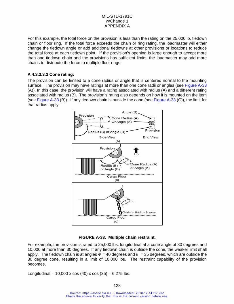
MIL-STD-1791C w/Change 1
APPENDIX A
128
For this example, the total force on the provision is less than the rating on the 25,000 lb. tiedown chain or floor ring. If the total force exceeds the chain or ring rating, the loadmaster will either change the tiedown angle or add additional tiedowns at other provisions or locations to reduce the total force at each tiedown point. If the provision’s opening is large enough to accept more than one tiedown chain and the provisions has sufficient limits, the loadmaster may add more chains to distribute the force to multiple floor rings.
A.4.3.3.3.3 Cone rating: The provision can be limited to a cone radius or angle that is centered normal to the mounting surface. The provision may have ratings at more than one cone radii or angles (see Figure A-33 (A)). In this case, the provision will have a rating associated with radius (A) and a different rating associated with radius (B). The provision’s rating also depends on how it is mounted on the item (see Figure A-33 (B)). If any tiedown chain is outside the cone (see Figure A-33 (C)), the limit for that radius apply.
FIGURE A-33. Multiple chain restraint. For example, the provision is rated to 25,000 lbs. longitudinal at a cone angle of 30 degrees and 10,000 at more than 30 degrees. If any tiedown chain is outside the cone, the weaker limit shall apply. The tiedown chain is at angles 𝛷𝛷 = 40 degrees and 𝜃𝜃 = 35 degrees, which are outside the 30 degree cone, resulting in a limit of 10,000 lbs. The restraint capability of the provision becomes,
Longitudinal = 10,000 x cos (40) x cos (35) = 6,275 lbs.
Source: https://assist.dla.mil -- Downloaded: 2018-12-14T17:20ZCheck the source to verify that this is the current version before use.
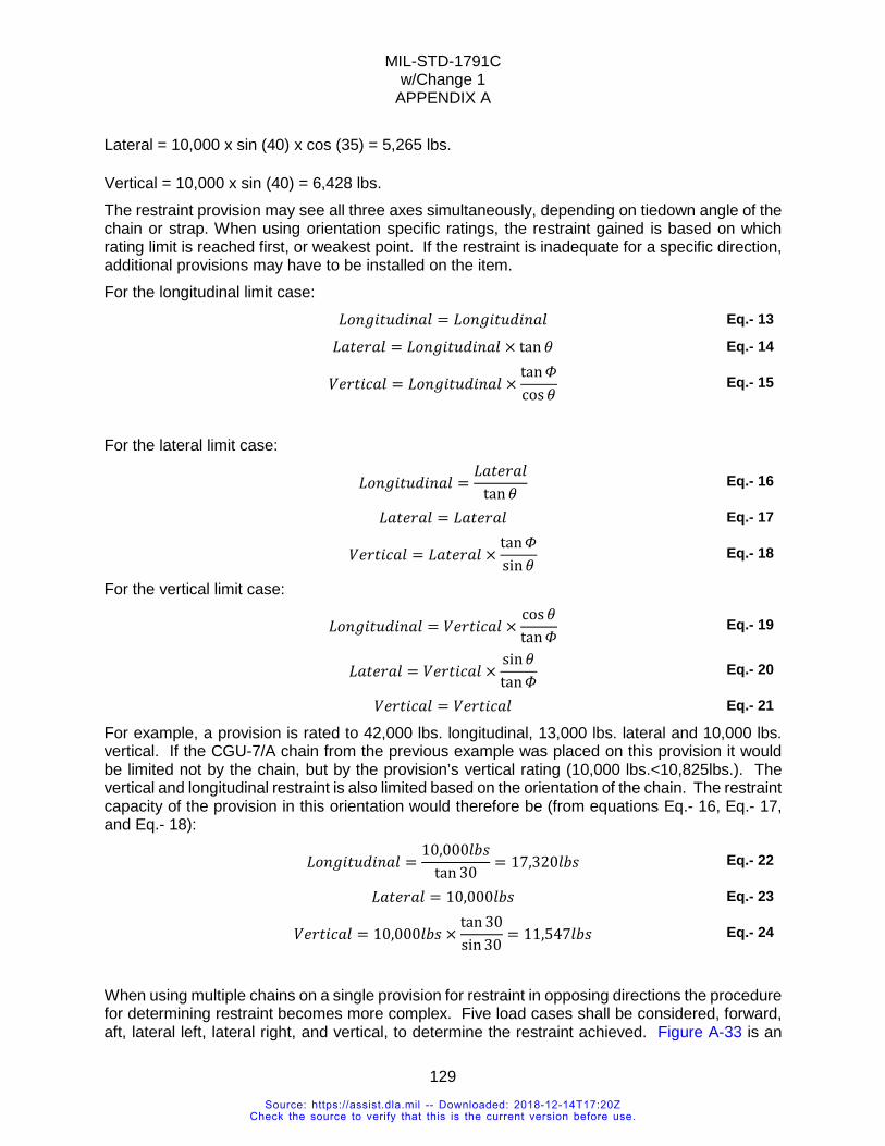
MIL-STD-1791C w/Change 1
APPENDIX A
129
Lateral = 10,000 x sin (40) x cos (35) = 5,265 lbs.
Vertical = 10,000 x sin (40) = 6,428 lbs. The restraint provision may see all three axes simultaneously, depending on tiedown angle of the chain or strap. When using orientation specific ratings, the restraint gained is based on which rating limit is reached first, or weakest point. If the restraint is inadequate for a specific direction, additional provisions may have to be installed on the item. For the longitudinal limit case: 𝐿𝐿𝐿𝐿𝑎𝑎𝐻𝐻𝐻𝐻𝑡𝑡𝐿𝐿𝐿𝐿𝐻𝐻𝑎𝑎𝑎𝑎𝐶𝐶 = 𝐿𝐿𝐿𝐿𝑎𝑎𝐻𝐻𝐻𝐻𝑡𝑡𝐿𝐿𝐿𝐿𝐻𝐻𝑎𝑎𝑎𝑎𝐶𝐶 Eq.- 13
𝐿𝐿𝑎𝑎𝑡𝑡𝐻𝐻𝑂𝑂𝑎𝑎𝐶𝐶 = 𝐿𝐿𝐿𝐿𝑎𝑎𝐻𝐻𝐻𝐻𝑡𝑡𝐿𝐿𝐿𝐿𝐻𝐻𝑎𝑎𝑎𝑎𝐶𝐶 × tan 𝜃𝜃 Eq.- 14
𝑉𝑉𝐻𝐻𝑂𝑂𝑡𝑡𝐻𝐻𝐶𝐶𝑎𝑎𝐶𝐶 = 𝐿𝐿𝐿𝐿𝑎𝑎𝐻𝐻𝐻𝐻𝑡𝑡𝐿𝐿𝐿𝐿𝐻𝐻𝑎𝑎𝑎𝑎𝐶𝐶 ×tan𝛷𝛷cos𝜃𝜃
Eq.- 15
For the lateral limit case: 𝐿𝐿𝐿𝐿𝑎𝑎𝐻𝐻𝐻𝐻𝑡𝑡𝐿𝐿𝐿𝐿𝐻𝐻𝑎𝑎𝑎𝑎𝐶𝐶 =
𝐿𝐿𝑎𝑎𝑡𝑡𝐻𝐻𝑂𝑂𝑎𝑎𝐶𝐶tan𝜃𝜃
Eq.- 16
𝐿𝐿𝑎𝑎𝑡𝑡𝐻𝐻𝑂𝑂𝑎𝑎𝐶𝐶 = 𝐿𝐿𝑎𝑎𝑡𝑡𝐻𝐻𝑂𝑂𝑎𝑎𝐶𝐶 Eq.- 17
𝑉𝑉𝐻𝐻𝑂𝑂𝑡𝑡𝐻𝐻𝐶𝐶𝑎𝑎𝐶𝐶 = 𝐿𝐿𝑎𝑎𝑡𝑡𝐻𝐻𝑂𝑂𝑎𝑎𝐶𝐶 ×tan𝛷𝛷sin𝜃𝜃
Eq.- 18
For the vertical limit case: 𝐿𝐿𝐿𝐿𝑎𝑎𝐻𝐻𝐻𝐻𝑡𝑡𝐿𝐿𝐿𝐿𝐻𝐻𝑎𝑎𝑎𝑎𝐶𝐶 = 𝑉𝑉𝐻𝐻𝑂𝑂𝑡𝑡𝐻𝐻𝐶𝐶𝑎𝑎𝐶𝐶 ×
cos𝜃𝜃tan𝛷𝛷
Eq.- 19
𝐿𝐿𝑎𝑎𝑡𝑡𝐻𝐻𝑂𝑂𝑎𝑎𝐶𝐶 = 𝑉𝑉𝐻𝐻𝑂𝑂𝑡𝑡𝐻𝐻𝐶𝐶𝑎𝑎𝐶𝐶 ×sin𝜃𝜃tan𝛷𝛷
Eq.- 20
𝑉𝑉𝐻𝐻𝑂𝑂𝑡𝑡𝐻𝐻𝐶𝐶𝑎𝑎𝐶𝐶 = 𝑉𝑉𝐻𝐻𝑂𝑂𝑡𝑡𝐻𝐻𝐶𝐶𝑎𝑎𝐶𝐶 Eq.- 21
For example, a provision is rated to 42,000 lbs. longitudinal, 13,000 lbs. lateral and 10,000 lbs. vertical. If the CGU-7/A chain from the previous example was placed on this provision it would be limited not by the chain, but by the provision’s vertical rating (10,000 lbs.<10,825lbs.). The vertical and longitudinal restraint is also limited based on the orientation of the chain. The restraint capacity of the provision in this orientation would therefore be (from equations Eq.- 16, Eq.- 17, and Eq.- 18): 𝐿𝐿𝐿𝐿𝑎𝑎𝐻𝐻𝐻𝐻𝑡𝑡𝐿𝐿𝐿𝐿𝐻𝐻𝑎𝑎𝑎𝑎𝐶𝐶 =
10,000𝐶𝐶𝑒𝑒𝑒𝑒tan 30
= 17,320𝐶𝐶𝑒𝑒𝑒𝑒 Eq.- 22
𝐿𝐿𝑎𝑎𝑡𝑡𝐻𝐻𝑂𝑂𝑎𝑎𝐶𝐶 = 10,000𝐶𝐶𝑒𝑒𝑒𝑒 Eq.- 23
𝑉𝑉𝐻𝐻𝑂𝑂𝑡𝑡𝐻𝐻𝐶𝐶𝑎𝑎𝐶𝐶 = 10,000𝐶𝐶𝑒𝑒𝑒𝑒 ×tan 30sin 30
= 11,547𝐶𝐶𝑒𝑒𝑒𝑒 Eq.- 24
When using multiple chains on a single provision for restraint in opposing directions the procedure for determining restraint becomes more complex. Five load cases shall be considered, forward, aft, lateral left, lateral right, and vertical, to determine the restraint achieved. Figure A-33 is an
Source: https://assist.dla.mil -- Downloaded: 2018-12-14T17:20ZCheck the source to verify that this is the current version before use.
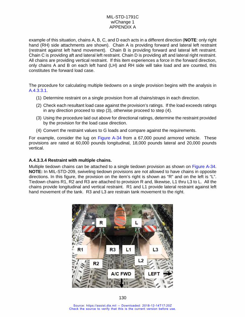
MIL-STD-1791C w/Change 1
APPENDIX A
130
example of this situation, chains A, B, C, and D each acts in a different direction (NOTE: only right hand (RH) side attachments are shown). Chain A is providing forward and lateral left restraint (restraint against left hand movement). Chain B is providing forward and lateral left restraint. Chain C is providing aft and lateral left restraint. Chain D is providing aft and lateral right restraint. All chains are providing vertical restraint. If this item experiences a force in the forward direction, only chains A and B on each left hand (LH) and RH side will take load and are counted, this constitutes the forward load case.
The procedure for calculating multiple tiedowns on a single provision begins with the analysis in A.4.3.3.1.
(1) Determine restraint on a single provision from all chains/straps in each direction. (2) Check each resultant load case against the provision’s ratings. If the load exceeds ratings
in any direction proceed to step (3), otherwise proceed to step (4). (3) Using the procedure laid out above for directional ratings, determine the restraint provided
by the provision for the load case direction. (4) Convert the restraint values to G loads and compare against the requirements.
For example, consider the lug on Figure A-34 from a 67,000 pound armored vehicle. These provisions are rated at 60,000 pounds longitudinal, 18,000 pounds lateral and 20,000 pounds vertical.
A.4.3.3.4 Restraint with multiple chains. Multiple tiedown chains can be attached to a single tiedown provision as shown on Figure A-34. NOTE: In MIL-STD-209, swiveling tiedown provisions are not allowed to have chains in opposite directions. In this figure, the provision on the item’s right is shown as “R” and on the left is “L”. Tiedown chains R1, R2 and R3 are attached to provision R and, likewise, L1 thru L3 to L. All the chains provide longitudinal and vertical restraint. R1 and L1 provide lateral restraint against left hand movement of the tank. R3 and L3 are restrain tank movement to the right.
Source: https://assist.dla.mil -- Downloaded: 2018-12-14T17:20ZCheck the source to verify that this is the current version before use.
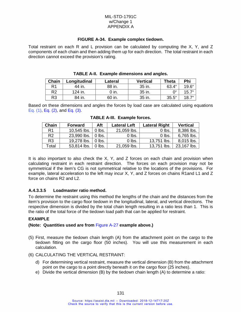
MIL-STD-1791C w/Change 1
APPENDIX A
131
FIGURE A-34. Example complex tiedown. Total restraint on each R and L provision can be calculated by computing the X, Y, and Z components of each chain and then adding them up for each direction. The total restraint in each direction cannot exceed the provision’s rating.
TABLE A-II. Example dimensions and angles.
Chain Longitudinal Lateral Vertical Theta Phi R1 44 in. 88 in. 35 in. 63.4° 19.6° R2 124 in. 0 in. 35 in. 0° 15.7° R3 84 in. 60 in. 35 in. 35.5° 18.7°
Based on these dimensions and angles the forces by load case are calculated using equations Eq. (1), Eq. (2), and Eq. (3).
TABLE A-III. Example forces. Chain Forward Aft Lateral Left Lateral Right Vertical
R1 10,545 lbs. 0 lbs. 21,059 lbs. 0 lbs. 8,386 lbs. R2 23,990 lbs. 0 lbs. 0 lbs. 0 lbs. 6,765 lbs. R3 19,278 lbs. 0 lbs. 0 lbs. 13,751 lbs. 8,015 lbs.
Total 53,814 lbs. 0 lbs. 21,059 lbs. 13,751 lbs. 23,167 lbs. It is also important to also check the X, Y, and Z forces on each chain and provision when calculating restraint in each restraint direction. The forces on each provision may not be symmetrical if the item’s CG is not symmetrical relative to the locations of the provisions. For example, lateral acceleration to the left may incur X, Y, and Z forces on chains R1and L1 and Z force on chains R2 and L2.
A.4.3.3.5 Loadmaster ratio method. To determine the restraint using this method the lengths of the chain and the distances from the item’s provision to the cargo floor tiedown in the longitudinal, lateral, and vertical directions. The respective dimension is divided by the total chain length resulting in a ratio less than 1. This is the ratio of the total force of the tiedown load path that can be applied for restraint. EXAMPLE (Note: Quantities used are from Figure A-27 example above.) (5) First, measure the tiedown chain length (A) from the attachment point on the cargo to the
tiedown fitting on the cargo floor (50 inches). You will use this measurement in each calculation.
(6) CALCULATING THE VERTICAL RESTRAINT: d) For determining vertical restraint, measure the vertical dimension (B) from the attachment
point on the cargo to a point directly beneath it on the cargo floor (25 inches). e) Divide the vertical dimension (B) by the tiedown chain length (A) to determine a ratio:
Source: https://assist.dla.mil -- Downloaded: 2018-12-14T17:20ZCheck the source to verify that this is the current version before use.
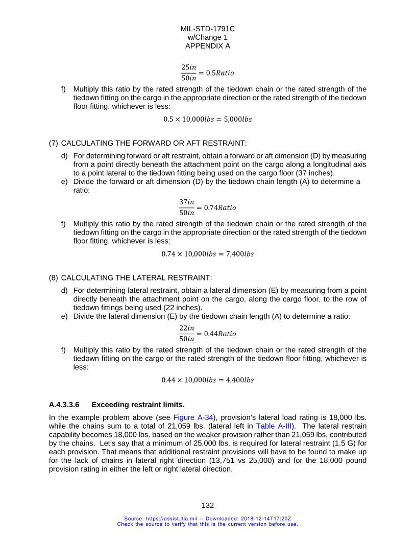
MIL-STD-1791C w/Change 1
APPENDIX A
132
25𝐻𝐻𝑎𝑎50𝐻𝐻𝑎𝑎
= 0.5𝑅𝑅𝑎𝑎𝑡𝑡𝐻𝐻𝐿𝐿
f) Multiply this ratio by the rated strength of the tiedown chain or the rated strength of the tiedown fitting on the cargo in the appropriate direction or the rated strength of the tiedown floor fitting, whichever is less:
0.5 × 10,000𝐶𝐶𝑒𝑒𝑒𝑒 = 5,000𝐶𝐶𝑒𝑒𝑒𝑒
(7) CALCULATING THE FORWARD OR AFT RESTRAINT:
d) For determining forward or aft restraint, obtain a forward or aft dimension (D) by measuring from a point directly beneath the attachment point on the cargo along a longitudinal axis to a point lateral to the tiedown fitting being used on the cargo floor (37 inches).
e) Divide the forward or aft dimension (D) by the tiedown chain length (A) to determine a ratio:
37𝐻𝐻𝑎𝑎50𝐻𝐻𝑎𝑎
= 0.74𝑅𝑅𝑎𝑎𝑡𝑡𝐻𝐻𝐿𝐿
f) Multiply this ratio by the rated strength of the tiedown chain or the rated strength of the tiedown fitting on the cargo in the appropriate direction or the rated strength of the tiedown floor fitting, whichever is less:
0.74 × 10,000𝐶𝐶𝑒𝑒𝑒𝑒 = 7,400𝐶𝐶𝑒𝑒𝑒𝑒
(8) CALCULATING THE LATERAL RESTRAINT:
d) For determining lateral restraint, obtain a lateral dimension (E) by measuring from a point directly beneath the attachment point on the cargo, along the cargo floor, to the row of tiedown fittings being used (22 inches).
e) Divide the lateral dimension (E) by the tiedown chain length (A) to determine a ratio: 22𝐻𝐻𝑎𝑎
50𝐻𝐻𝑎𝑎= 0.44𝑅𝑅𝑎𝑎𝑡𝑡𝐻𝐻𝐿𝐿
f) Multiply this ratio by the rated strength of the tiedown chain or the rated strength of the tiedown fitting on the cargo or the rated strength of the tiedown floor fitting, whichever is less:
0.44 × 10,000𝐶𝐶𝑒𝑒𝑒𝑒 = 4,400𝐶𝐶𝑒𝑒𝑒𝑒
A.4.3.3.6 Exceeding restraint limits. In the example problem above (see Figure A-34), provision’s lateral load rating is 18,000 lbs. while the chains sum to a total of 21,059 lbs. (lateral left in Table A-III). The lateral restrain capability becomes 18,000 lbs. based on the weaker provision rather than 21,059 lbs. contributed by the chains. Let’s say that a minimum of 25,000 lbs. is required for lateral restraint (1.5 G) for each provision. That means that additional restraint provisions will have to be found to make up for the lack of chains in lateral right direction (13,751 vs 25,000) and for the 18,000 pound provision rating in either the left or right lateral direction.
Source: https://assist.dla.mil -- Downloaded: 2018-12-14T17:20ZCheck the source to verify that this is the current version before use.
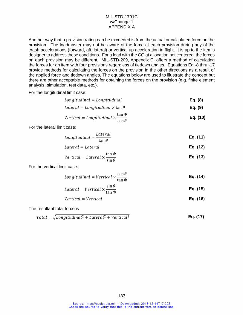
MIL-STD-1791C w/Change 1
APPENDIX A
133
Another way that a provision rating can be exceeded is from the actual or calculated force on the provision. The loadmaster may not be aware of the force at each provision during any of the crash accelerations (forward, aft, lateral) or vertical up acceleration in flight. It is up to the item’s designer to address these conditions. For a load with the CG at a location not centered, the forces on each provision may be different. MIL-STD-209, Appendix C, offers a method of calculating the forces for an item with four provisions regardless of tiedown angles. Equations Eq.-8 thru -17 provide methods for calculating the forces on the provision in the other directions as a result of the applied force and tiedown angles. The equations below are used to illustrate the concept but there are other acceptable methods for obtaining the forces on the provision (e.g. finite element analysis, simulation, test data, etc.). For the longitudinal limit case: 𝐿𝐿𝐿𝐿𝑎𝑎𝐻𝐻𝐻𝐻𝑡𝑡𝐿𝐿𝐿𝐿𝐻𝐻𝑎𝑎𝑎𝑎𝐶𝐶 = 𝐿𝐿𝐿𝐿𝑎𝑎𝐻𝐻𝐻𝐻𝑡𝑡𝐿𝐿𝐿𝐿𝐻𝐻𝑎𝑎𝑎𝑎𝐶𝐶 Eq. (8) 𝐿𝐿𝑎𝑎𝑡𝑡𝐻𝐻𝑂𝑂𝑎𝑎𝐶𝐶 = 𝐿𝐿𝐿𝐿𝑎𝑎𝐻𝐻𝐻𝐻𝑡𝑡𝐿𝐿𝐿𝐿𝐻𝐻𝑎𝑎𝑎𝑎𝐶𝐶 × tan 𝜃𝜃 Eq. (9) 𝑉𝑉𝐻𝐻𝑂𝑂𝑡𝑡𝐻𝐻𝐶𝐶𝑎𝑎𝐶𝐶 = 𝐿𝐿𝐿𝐿𝑎𝑎𝐻𝐻𝐻𝐻𝑡𝑡𝐿𝐿𝐿𝐿𝐻𝐻𝑎𝑎𝑎𝑎𝐶𝐶 ×
tan𝛷𝛷cos𝜃𝜃
Eq. (10)
For the lateral limit case: 𝐿𝐿𝐿𝐿𝑎𝑎𝐻𝐻𝐻𝐻𝑡𝑡𝐿𝐿𝐿𝐿𝐻𝐻𝑎𝑎𝑎𝑎𝐶𝐶 =
𝐿𝐿𝑎𝑎𝑡𝑡𝐻𝐻𝑂𝑂𝑎𝑎𝐶𝐶tan𝜃𝜃
Eq. (11)
𝐿𝐿𝑎𝑎𝑡𝑡𝐻𝐻𝑂𝑂𝑎𝑎𝐶𝐶 = 𝐿𝐿𝑎𝑎𝑡𝑡𝐻𝐻𝑂𝑂𝑎𝑎𝐶𝐶 Eq. (12) 𝑉𝑉𝐻𝐻𝑂𝑂𝑡𝑡𝐻𝐻𝐶𝐶𝑎𝑎𝐶𝐶 = 𝐿𝐿𝑎𝑎𝑡𝑡𝐻𝐻𝑂𝑂𝑎𝑎𝐶𝐶 ×
tan𝛷𝛷sin𝜃𝜃
Eq. (13)
For the vertical limit case: 𝐿𝐿𝐿𝐿𝑎𝑎𝐻𝐻𝐻𝐻𝑡𝑡𝐿𝐿𝐿𝐿𝐻𝐻𝑎𝑎𝑎𝑎𝐶𝐶 = 𝑉𝑉𝐻𝐻𝑂𝑂𝑡𝑡𝐻𝐻𝐶𝐶𝑎𝑎𝐶𝐶 ×
cos𝜃𝜃tan𝛷𝛷
Eq. (14)
𝐿𝐿𝑎𝑎𝑡𝑡𝐻𝐻𝑂𝑂𝑎𝑎𝐶𝐶 = 𝑉𝑉𝐻𝐻𝑂𝑂𝑡𝑡𝐻𝐻𝐶𝐶𝑎𝑎𝐶𝐶 ×sin𝜃𝜃tan𝛷𝛷
Eq. (15)
𝑉𝑉𝐻𝐻𝑂𝑂𝑡𝑡𝐻𝐻𝐶𝐶𝑎𝑎𝐶𝐶 = 𝑉𝑉𝐻𝐻𝑂𝑂𝑡𝑡𝐻𝐻𝐶𝐶𝑎𝑎𝐶𝐶 Eq. (16)
The resultant total force is
𝑇𝑇𝐿𝐿𝑡𝑡𝑎𝑎𝐶𝐶 = �𝐿𝐿𝐿𝐿𝑎𝑎𝐻𝐻𝐻𝐻𝑡𝑡𝐿𝐿𝐿𝐿𝐻𝐻𝑎𝑎𝑎𝑎𝐶𝐶2 + 𝐿𝐿𝑎𝑎𝑡𝑡𝐻𝐻𝑂𝑂𝑎𝑎𝐶𝐶2 + 𝑉𝑉𝐻𝐻𝑂𝑂𝑡𝑡𝐻𝐻𝐶𝐶𝑎𝑎𝐶𝐶2 Eq. (17)
Source: https://assist.dla.mil -- Downloaded: 2018-12-14T17:20ZCheck the source to verify that this is the current version before use.
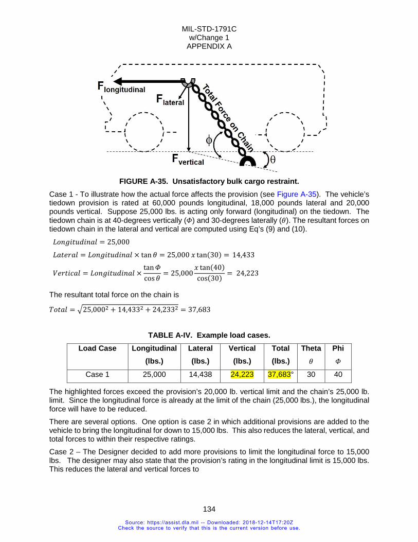
MIL-STD-1791C w/Change 1
APPENDIX A
134
FIGURE A-35. Unsatisfactory bulk cargo restraint.
Case 1 - To illustrate how the actual force affects the provision (see Figure A-35). The vehicle’s tiedown provision is rated at 60,000 pounds longitudinal, 18,000 pounds lateral and 20,000 pounds vertical. Suppose 25,000 lbs. is acting only forward (longitudinal) on the tiedown. The tiedown chain is at 40-degrees vertically (𝛷𝛷) and 30-degrees laterally (𝜃𝜃). The resultant forces on tiedown chain in the lateral and vertical are computed using Eq’s (9) and (10).
𝐿𝐿𝐿𝐿𝑎𝑎𝐻𝐻𝐻𝐻𝑡𝑡𝐿𝐿𝐿𝐿𝐻𝐻𝑎𝑎𝑎𝑎𝐶𝐶 = 25,000 𝐿𝐿𝑎𝑎𝑡𝑡𝐻𝐻𝑂𝑂𝑎𝑎𝐶𝐶 = 𝐿𝐿𝐿𝐿𝑎𝑎𝐻𝐻𝐻𝐻𝑡𝑡𝐿𝐿𝐿𝐿𝐻𝐻𝑎𝑎𝑎𝑎𝐶𝐶 × tan 𝜃𝜃 = 25,000 𝑥𝑥 tan(30) = 14,433
𝑉𝑉𝐻𝐻𝑂𝑂𝑡𝑡𝐻𝐻𝐶𝐶𝑎𝑎𝐶𝐶 = 𝐿𝐿𝐿𝐿𝑎𝑎𝐻𝐻𝐻𝐻𝑡𝑡𝐿𝐿𝐿𝐿𝐻𝐻𝑎𝑎𝑎𝑎𝐶𝐶 ×tan𝛷𝛷cos𝜃𝜃
= 25,000𝑥𝑥 tan(40)cos(30) = 24,223
The resultant total force on the chain is
𝑇𝑇𝐿𝐿𝑡𝑡𝑎𝑎𝐶𝐶 = �25,0002 + 14,4332 + 24,2332 = 37,683
TABLE A-IV. Example load cases. Load Case Longitudinal
(lbs.) Lateral (lbs.)
Vertical (lbs.)
Total (lbs.)
Theta 𝜃𝜃
Phi 𝛷𝛷
Case 1 25,000 14,438 24,223 37,683° 30 40
The highlighted forces exceed the provision’s 20,000 lb. vertical limit and the chain’s 25,000 lb. limit. Since the longitudinal force is already at the limit of the chain (25,000 lbs.), the longitudinal force will have to be reduced. There are several options. One option is case 2 in which additional provisions are added to the vehicle to bring the longitudinal for down to 15,000 lbs. This also reduces the lateral, vertical, and total forces to within their respective ratings. Case 2 – The Designer decided to add more provisions to limit the longitudinal force to 15,000 lbs. The designer may also state that the provision’s rating in the longitudinal limit is 15,000 lbs. This reduces the lateral and vertical forces to
Source: https://assist.dla.mil -- Downloaded: 2018-12-14T17:20ZCheck the source to verify that this is the current version before use.
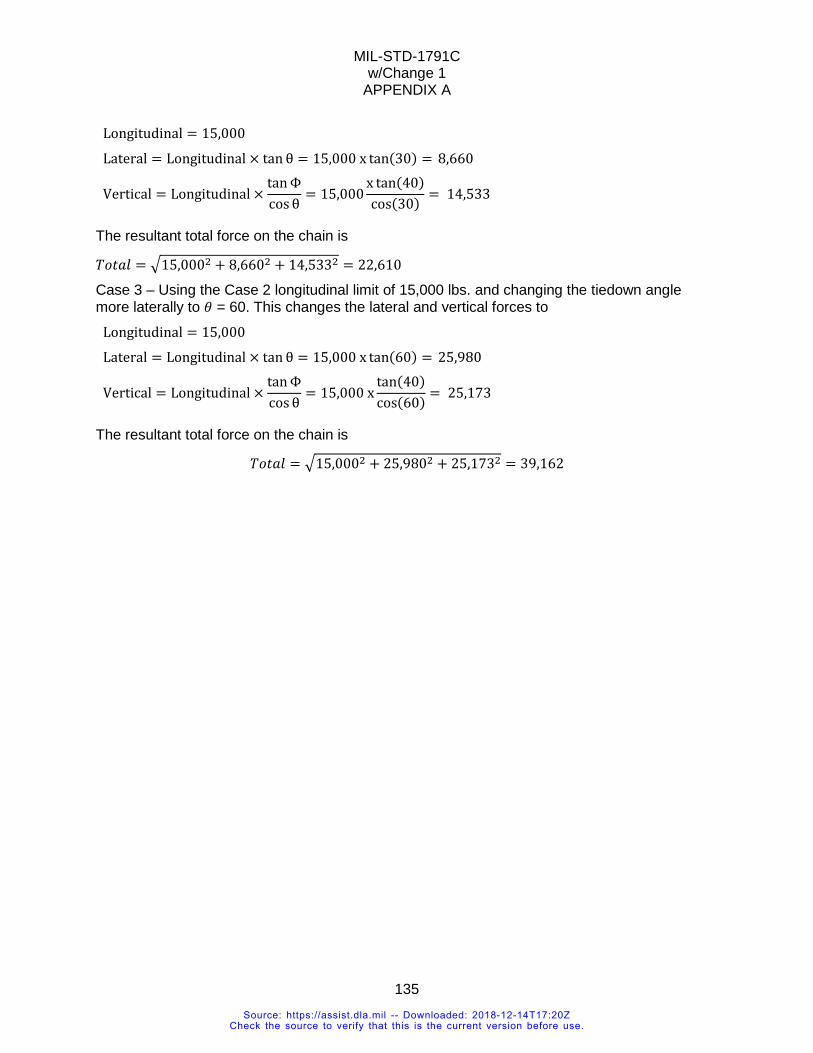
MIL-STD-1791C w/Change 1
APPENDIX A
135
Longitudinal = 15,000 Lateral = Longitudinal × tan θ = 15,000 x tan(30) = 8,660
Vertical = Longitudinal ×tanΦcosθ
= 15,000x tan(40)cos(30) = 14,533
The resultant total force on the chain is
𝑇𝑇𝐿𝐿𝑡𝑡𝑎𝑎𝐶𝐶 = �15,0002 + 8,6602 + 14,5332 = 22,610
Case 3 – Using the Case 2 longitudinal limit of 15,000 lbs. and changing the tiedown angle more laterally to 𝜃𝜃 = 60. This changes the lateral and vertical forces to
Longitudinal = 15,000 Lateral = Longitudinal × tan θ = 15,000 x tan(60) = 25,980
Vertical = Longitudinal ×tanΦcosθ
= 15,000 xtan(40)cos(60) = 25,173
The resultant total force on the chain is
𝑇𝑇𝐿𝐿𝑡𝑡𝑎𝑎𝐶𝐶 = �15,0002 + 25,9802 + 25,1732 = 39,162
Source: https://assist.dla.mil -- Downloaded: 2018-12-14T17:20ZCheck the source to verify that this is the current version before use.
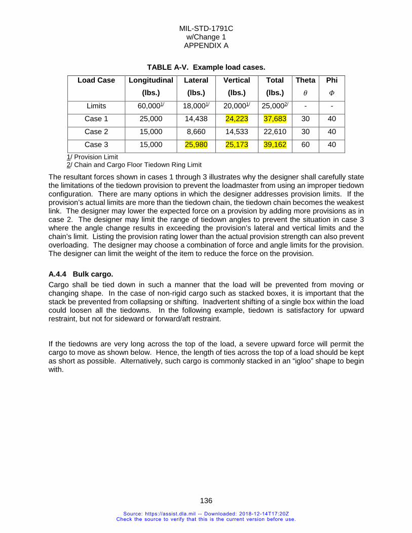
MIL-STD-1791C w/Change 1
APPENDIX A
136
TABLE A-V. Example load cases. Load Case Longitudinal
(lbs.) Lateral (lbs.)
Vertical (lbs.)
Total (lbs.)
Theta 𝜃𝜃
Phi 𝛷𝛷
Limits 60,0001/ 18,0001/ 20,0001/ 25,0002/ - -
Case 1 25,000 14,438 24,223 37,683 30 40
Case 2 15,000 8,660 14,533 22,610 30 40
Case 3 15,000 25,980 25,173 39,162 60 40 1/ Provision Limit 2/ Chain and Cargo Floor Tiedown Ring Limit
The resultant forces shown in cases 1 through 3 illustrates why the designer shall carefully state the limitations of the tiedown provision to prevent the loadmaster from using an improper tiedown configuration. There are many options in which the designer addresses provision limits. If the provision’s actual limits are more than the tiedown chain, the tiedown chain becomes the weakest link. The designer may lower the expected force on a provision by adding more provisions as in case 2. The designer may limit the range of tiedown angles to prevent the situation in case 3 where the angle change results in exceeding the provision’s lateral and vertical limits and the chain’s limit. Listing the provision rating lower than the actual provision strength can also prevent overloading. The designer may choose a combination of force and angle limits for the provision. The designer can limit the weight of the item to reduce the force on the provision.
A.4.4 Bulk cargo. Cargo shall be tied down in such a manner that the load will be prevented from moving or changing shape. In the case of non-rigid cargo such as stacked boxes, it is important that the stack be prevented from collapsing or shifting. Inadvertent shifting of a single box within the load could loosen all the tiedowns. In the following example, tiedown is satisfactory for upward restraint, but not for sideward or forward/aft restraint.
If the tiedowns are very long across the top of the load, a severe upward force will permit the cargo to move as shown below. Hence, the length of ties across the top of a load should be kept as short as possible. Alternatively, such cargo is commonly stacked in an “igloo” shape to begin with.
Source: https://assist.dla.mil -- Downloaded: 2018-12-14T17:20ZCheck the source to verify that this is the current version before use.
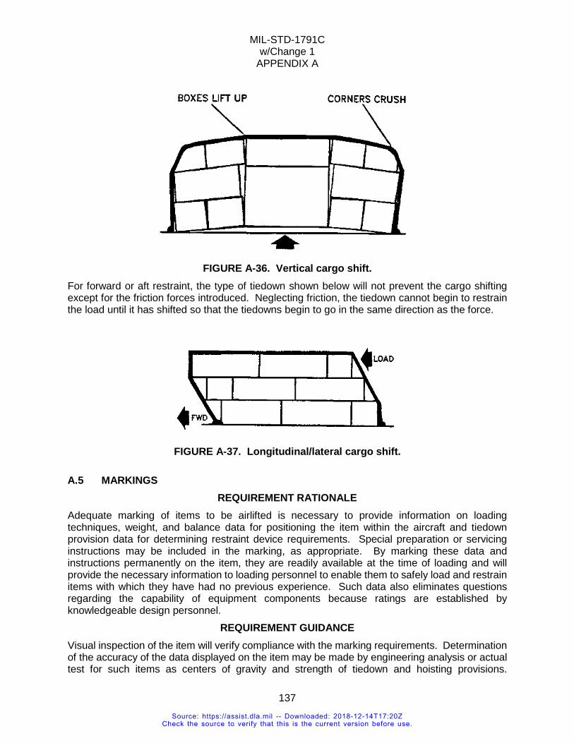
MIL-STD-1791C w/Change 1
APPENDIX A
137
FIGURE A-36. Vertical cargo shift.
For forward or aft restraint, the type of tiedown shown below will not prevent the cargo shifting except for the friction forces introduced. Neglecting friction, the tiedown cannot begin to restrain the load until it has shifted so that the tiedowns begin to go in the same direction as the force.
FIGURE A-37. Longitudinal/lateral cargo shift.
A.5 MARKINGS REQUIREMENT RATIONALE
Adequate marking of items to be airlifted is necessary to provide information on loading techniques, weight, and balance data for positioning the item within the aircraft and tiedown provision data for determining restraint device requirements. Special preparation or servicing instructions may be included in the marking, as appropriate. By marking these data and instructions permanently on the item, they are readily available at the time of loading and will provide the necessary information to loading personnel to enable them to safely load and restrain items with which they have had no previous experience. Such data also eliminates questions regarding the capability of equipment components because ratings are established by knowledgeable design personnel.
REQUIREMENT GUIDANCE Visual inspection of the item will verify compliance with the marking requirements. Determination of the accuracy of the data displayed on the item may be made by engineering analysis or actual test for such items as centers of gravity and strength of tiedown and hoisting provisions.
Source: https://assist.dla.mil -- Downloaded: 2018-12-14T17:20ZCheck the source to verify that this is the current version before use.
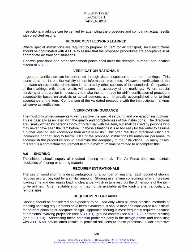
MIL-STD-1791C w/Change 1
APPENDIX A
138
Instructional markings can be verified by attempting the procedure and comparing actual results with predicted results.
REQUIREMENT LESSONS LEARNED Where special instructions are required to prepare an item for air transport, such instructions should be coordinated with ATTLA to assure that the proposed procedures are acceptable in all appropriate air transport situations. Tiedown provisions and other attachment points shall meet the strength, number, and location criteria of 5.3.3.2.
VERIFICATION RATIONALE In general, verification can be performed through visual inspection of the item markings. This alone does not insure the validity of the information presented. However, verification of the hardware characteristics of the item is required by other sections of this standard. Comparison of the markings with these results will assure the accuracy of the markings. Where special servicing or preparation is necessary to make the item ready for airlift, certification of procedure acceptability based on analysis or actual demonstration is usually accomplished prior to final acceptance of the item. Comparison of the validated procedure with the instructional markings will serve as verification.
VERIFICATION GUIDANCE The most difficult requirements to verify involve the special servicing and preparation instructions. This is basically associated with the quality and completeness of the instructions. The directions are usually written by persons thoroughly familiar with the item, but shall be used by persons who may never have seen the item before. In these situations it is all too easy for the writer to assume a higher level of user knowledge than actually exists. This often results in directions which are incomplete or confusing to follow. Use of the proposed instructions by unfamiliar personnel to accomplish the procedure should determine the adequacy of the instructions. In many cases, this step is a contractual requirement tied to a maximum time permitted to accomplish this.
A.6 SHORING The shipper should supply all required shoring material. The Air Force does not maintain stockpiles of shoring or shoring material.
REQUIREMENT RATIONALE The use of wood shoring is disadvantageous for a number of reasons. Each pound of shoring reduces aircraft payload by a similar amount. Shoring use is time consuming, which increases loading time and decreases loading clearance, which in turn restricts the dimensions of the item to be airlifted. Often, suitable shoring may not be available at the loading site, particularly at remote sites.
REQUIREMENT GUIDANCE Shoring should be considered an expedient to be used only when all other practical methods of meeting handling requirements have been exhausted. It should never be considered a substitute for prudent planning or adequate design. Approach shoring is most frequently required because of problems involving projection (see 5.3.1.1.1), ground contact (see 5.3.1.1.2), or ramp cresting (see 5.3.1.1.3). Addressing these potential problems early in the design phase and consulting with ATTLA for advice often results in practical solutions to these problems. Floor protective
Source: https://assist.dla.mil -- Downloaded: 2018-12-14T17:20ZCheck the source to verify that this is the current version before use.
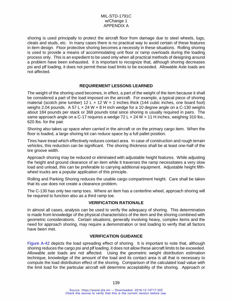
MIL-STD-1791C w/Change 1
APPENDIX A
139
shoring is used principally to protect the aircraft floor from damage due to steel wheels, lugs, cleats and studs, etc. In many cases there is no practical way to avoid certain of these features in item design. Floor protective shoring becomes a necessity in these situations. Rolling shoring is used to provide a means of accommodating unit floor or ramp overloads during the loading process only. This is an expedient to be used only when all practical methods of designing around a problem have been exhausted. It is important to recognize that, although shoring decreases psi and plf loading, it does not permit these load limits to be exceeded. Allowable Axle loads are not affected.
REQUIREMENT LESSONS LEARNED The weight of the shoring used becomes, in effect, a part of the weight of the item because it shall be considered a part of the load imposed on the aircraft. For example, a typical piece of shoring material (scotch pine lumber) 12 L × 12 W × 1 inches thick (144 cubic inches, one board foot) weighs 2.04 pounds. A 57 L × 24 W × 8 H inch wedge for a 10 degree angle on a C-130 weighs about 184 pounds per stack or 368 pounds total since shoring is usually required in pairs. The same approach angle on a C-17 requires a wedge 72 L × 24 W × 11 H inches, weighing 310 lbs., 620 lbs. for the pair. Shoring also takes up space when carried in the aircraft or on the primary cargo item. When the floor is loaded, a large shoring kit can reduce space by a full pallet position. Tires have tread which effectively reduces contact area. In case of construction and rough terrain vehicles, this reduction can be significant. The shoring thickness shall be at least one-half of the tire groove width. Approach shoring may be reduced or eliminated with adjustable height features. While adjusting the height and ground clearance of an item while it traverses the ramp necessitates a very slow load and unload, this can be preferable to carrying additional equipment. Adjustable height fifth-wheel trucks are a popular application of this principle. Rolling and Parking Shoring reduces the usable cargo compartment height. Care shall be taken that its use does not create a clearance problem. The C-130 has only two ramp toes. Where an item has a centerline wheel, approach shoring will be required to function also as a third ramp toe.
VERIFICATION RATIONALE In almost all cases, analysis can be used to verify the adequacy of shoring. This determination is made from knowledge of the physical characteristics of the item and the shoring combined with geometric considerations. Certain situations, generally involving heavy, complex items and the need for approach shoring, may require a demonstration or test loading to verify that all factors have been met.
VERIFICATION GUIDANCE Figure A-42 depicts the load spreading effect of shoring. It is important to note that, although shoring reduces the cargo psi and plf loading, it does not allow these aircraft limits to be exceeded. Allowable axle loads are not affected. Using the geometric weight distribution estimation technique, knowledge of the amount of the load and its contact area is all that is necessary to compute the load distribution effect of the shoring. Comparison of the calculated load value with the limit load for the particular aircraft will determine acceptability of the shoring. Approach or
Source: https://assist.dla.mil -- Downloaded: 2018-12-14T17:20ZCheck the source to verify that this is the current version before use.
MIL-STD-1791C w/Change 1
APPENDIX A
140
"step-up" shoring primarily serves to decrease the ramp angle making it possible to load certain items which would otherwise have cresting, projection, or overhang problems. Acceptability of approach shoring can be shown by analysis in many cases. In more complex loading situations, it may be necessary to perform a demonstration or test loading during which the exact configuration of the shoring is established and documented.
A.6.1 Approach shoring. Approach shoring changes the approach angle into the aircraft to prevent contact with the ground, aircraft ramp, or aircraft ceiling in keeping with the requirements for ground contact, cresting, and projection (see 5.3.1.1.1 and 5.3.1.1.2). Usually approach shoring reduces the approach angle for a segment of the ramp, the entire ramp or in an area along the loading path. Approach shoring can be constructed from any material compatible with aircraft aluminum, able to withstand the forces associated with the on/offloading operation and able to withstand all operational environments (flight and ground). Approach shoring should be provided as assembled kits. Ease of handling, assembly, and storage space and weight should be considered. Typical shoring material is lumber. If metal is used, it shall be padded to prevent metal-to-metal contact with the aircraft surface. Approach shoring may also be used to keep all axles in contact with the aircraft ramp. Particularly for trailers with more than two axles, the suspension frequently does not have enough travel to keep all axles in contact with the aircraft ramp. Two conditions may result: either an axle may become overloaded or aircraft limits may be exceeded.
FIGURE A-38. Sample approach shoring stack.
The C-17 has weight-based requirements for approach shoring width under the ramp toes (see Appendix B). C-5 approach shoring shall be wide enough to completely support the intended ramp toe. The required width under the toe is either 36 inches if an outboard toe is traversed or 28 inches if one of the inboard toes is traversed (see Appendix B).
Source: https://assist.dla.mil -- Downloaded: 2018-12-14T17:20ZCheck the source to verify that this is the current version before use.
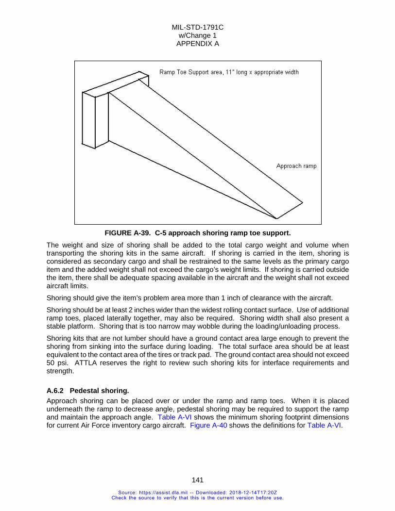
MIL-STD-1791C w/Change 1
APPENDIX A
141
FIGURE A-39. C-5 approach shoring ramp toe support.
The weight and size of shoring shall be added to the total cargo weight and volume when transporting the shoring kits in the same aircraft. If shoring is carried in the item, shoring is considered as secondary cargo and shall be restrained to the same levels as the primary cargo item and the added weight shall not exceed the cargo’s weight limits. If shoring is carried outside the item, there shall be adequate spacing available in the aircraft and the weight shall not exceed aircraft limits. Shoring should give the item’s problem area more than 1 inch of clearance with the aircraft. Shoring should be at least 2 inches wider than the widest rolling contact surface. Use of additional ramp toes, placed laterally together, may also be required. Shoring width shall also present a stable platform. Shoring that is too narrow may wobble during the loading/unloading process. Shoring kits that are not lumber should have a ground contact area large enough to prevent the shoring from sinking into the surface during loading. The total surface area should be at least equivalent to the contact area of the tires or track pad. The ground contact area should not exceed 50 psi. ATTLA reserves the right to review such shoring kits for interface requirements and strength.
A.6.2 Pedestal shoring. Approach shoring can be placed over or under the ramp and ramp toes. When it is placed underneath the ramp to decrease angle, pedestal shoring may be required to support the ramp and maintain the approach angle. Table A-VI shows the minimum shoring footprint dimensions for current Air Force inventory cargo aircraft. Figure A-40 shows the definitions for Table A-VI.
Source: https://assist.dla.mil -- Downloaded: 2018-12-14T17:20ZCheck the source to verify that this is the current version before use.
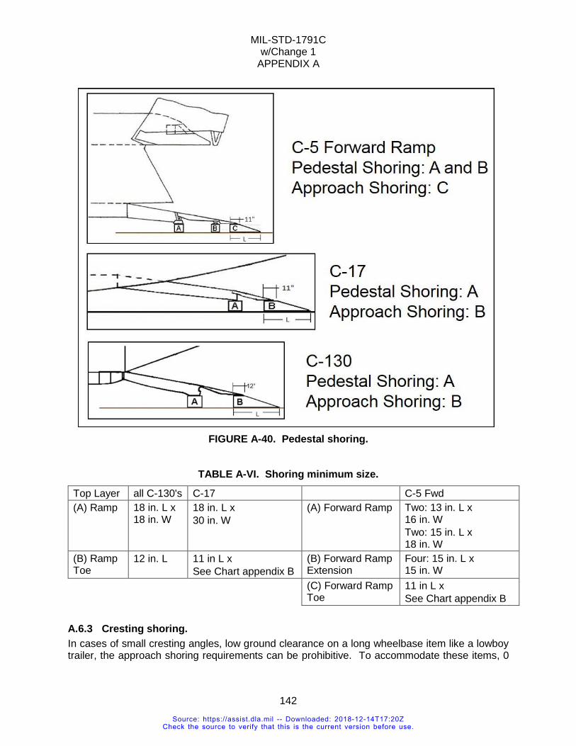
MIL-STD-1791C w/Change 1
APPENDIX A
142
FIGURE A-40. Pedestal shoring.
TABLE A-VI. Shoring minimum size.
Top Layer all C-130's C-17 C-5 Fwd (A) Ramp 18 in. L x
18 in. W 18 in. L x 30 in. W
(A) Forward Ramp Two: 13 in. L x 16 in. W Two: 15 in. L x 18 in. W
(B) Ramp Toe
12 in. L 11 in L x See Chart appendix B
(B) Forward Ramp Extension
Four: 15 in. L x 15 in. W
(C) Forward Ramp Toe
11 in L x See Chart appendix B
A.6.3 Cresting shoring. In cases of small cresting angles, low ground clearance on a long wheelbase item like a lowboy trailer, the approach shoring requirements can be prohibitive. To accommodate these items, 0
Source: https://assist.dla.mil -- Downloaded: 2018-12-14T17:20ZCheck the source to verify that this is the current version before use.
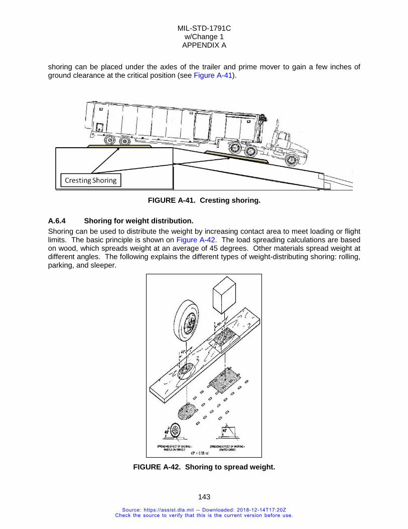
MIL-STD-1791C w/Change 1
APPENDIX A
143
shoring can be placed under the axles of the trailer and prime mover to gain a few inches of ground clearance at the critical position (see Figure A-41).
FIGURE A-41. Cresting shoring.
A.6.4 Shoring for weight distribution. Shoring can be used to distribute the weight by increasing contact area to meet loading or flight limits. The basic principle is shown on Figure A-42. The load spreading calculations are based on wood, which spreads weight at an average of 45 degrees. Other materials spread weight at different angles. The following explains the different types of weight-distributing shoring: rolling, parking, and sleeper.
FIGURE A-42. Shoring to spread weight.
Source: https://assist.dla.mil -- Downloaded: 2018-12-14T17:20ZCheck the source to verify that this is the current version before use.
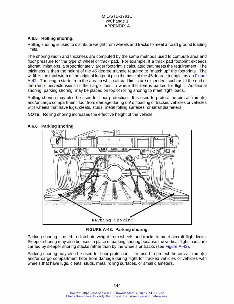
MIL-STD-1791C w/Change 1
APPENDIX A
144
A.6.5 Rolling shoring. Rolling shoring is used to distribute weight from wheels and tracks to meet aircraft ground loading limits. The shoring width and thickness are computed by the same methods used to compute area and floor pressure for the type of wheel or track pad. For example, if a track pad footprint exceeds aircraft limitations, a proportionately larger footprint is calculated that meets the requirement. The thickness is then the height of the 45 degree triangle required to “match up” the footprints. The width is the total width of the original footprint plus the base of the 45 degree triangle, as on Figure A-42. The length starts from the area in which aircraft limits are exceeded, such as at the end of the ramp toes/extensions or the cargo floor, to where the item is parked for flight. Additional shoring, parking shoring, may be placed on top of rolling shoring to meet flight loads. Rolling shoring may also be used for floor protection. It is used to protect the aircraft ramp(s) and/or cargo compartment floor from damage during on/ offloading of tracked vehicles or vehicles with wheels that have lugs, cleats, studs, metal rolling surfaces, or small diameters. NOTE: Rolling shoring increases the effective height of the vehicle.
A.6.6 Parking shoring.
FIGURE A-43. Parking shoring.
Parking shoring is used to distribute weight from wheels and tracks to meet aircraft flight limits. Sleeper shoring may also be used in place of parking shoring because the vertical flight loads are carried by sleeper shoring stacks rather than by the wheels or tracks (see Figure A-43). Parking shoring may also be used for floor protection. It is used to protect the aircraft ramp(s) and/or cargo compartment floor from damage during flight for tracked vehicles or vehicles with wheels that have lugs, cleats, studs, metal rolling surfaces, or small diameters.
Source: https://assist.dla.mil -- Downloaded: 2018-12-14T17:20ZCheck the source to verify that this is the current version before use.
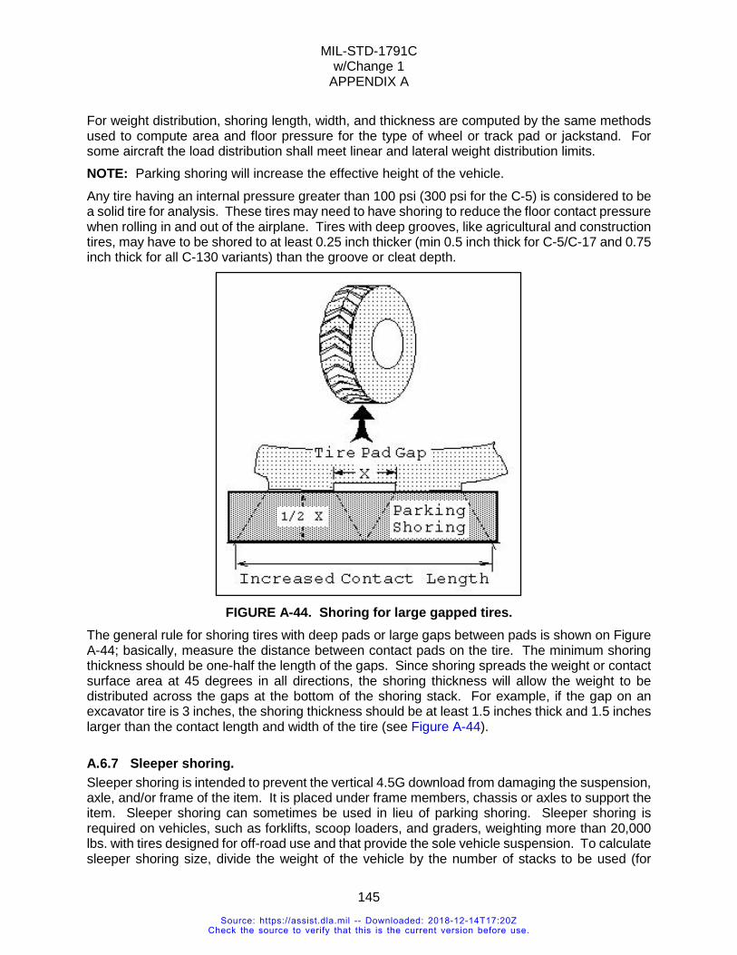
MIL-STD-1791C w/Change 1
APPENDIX A
145
For weight distribution, shoring length, width, and thickness are computed by the same methods used to compute area and floor pressure for the type of wheel or track pad or jackstand. For some aircraft the load distribution shall meet linear and lateral weight distribution limits. NOTE: Parking shoring will increase the effective height of the vehicle.
Any tire having an internal pressure greater than 100 psi (300 psi for the C-5) is considered to be a solid tire for analysis. These tires may need to have shoring to reduce the floor contact pressure when rolling in and out of the airplane. Tires with deep grooves, like agricultural and construction tires, may have to be shored to at least 0.25 inch thicker (min 0.5 inch thick for C-5/C-17 and 0.75 inch thick for all C-130 variants) than the groove or cleat depth.
FIGURE A-44. Shoring for large gapped tires.
The general rule for shoring tires with deep pads or large gaps between pads is shown on Figure A-44; basically, measure the distance between contact pads on the tire. The minimum shoring thickness should be one-half the length of the gaps. Since shoring spreads the weight or contact surface area at 45 degrees in all directions, the shoring thickness will allow the weight to be distributed across the gaps at the bottom of the shoring stack. For example, if the gap on an excavator tire is 3 inches, the shoring thickness should be at least 1.5 inches thick and 1.5 inches larger than the contact length and width of the tire (see Figure A-44).
A.6.7 Sleeper shoring. Sleeper shoring is intended to prevent the vertical 4.5G download from damaging the suspension, axle, and/or frame of the item. It is placed under frame members, chassis or axles to support the item. Sleeper shoring can sometimes be used in lieu of parking shoring. Sleeper shoring is required on vehicles, such as forklifts, scoop loaders, and graders, weighting more than 20,000 lbs. with tires designed for off-road use and that provide the sole vehicle suspension. To calculate sleeper shoring size, divide the weight of the vehicle by the number of stacks to be used (for
Source: https://assist.dla.mil -- Downloaded: 2018-12-14T17:20ZCheck the source to verify that this is the current version before use.
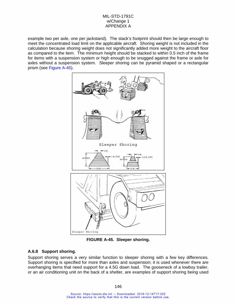
MIL-STD-1791C w/Change 1
APPENDIX A
146
example two per axle, one per jackstand). The stack’s footprint should then be large enough to meet the concentrated load limit on the applicable aircraft. Shoring weight is not included in the calculation because shoring weight does not significantly added more weight to the aircraft floor as compared to the item. The minimum height should be stacked to within 0.5 inch of the frame for items with a suspension system or high enough to be snugged against the frame or axle for axles without a suspension system. Sleeper shoring can be pyramid shaped or a rectangular prism (see Figure A-45).
FIGURE A-45. Sleeper shoring.
A.6.8 Support shoring. Support shoring serves a very similar function to sleeper shoring with a few key differences. Support shoring is specified for more than axles and suspension; it is used whenever there are overhanging items that need support for a 4.5G down load. The gooseneck of a lowboy trailer, or an air conditioning unit on the back of a shelter, are examples of support shoring being used
Source: https://assist.dla.mil -- Downloaded: 2018-12-14T17:20ZCheck the source to verify that this is the current version before use.
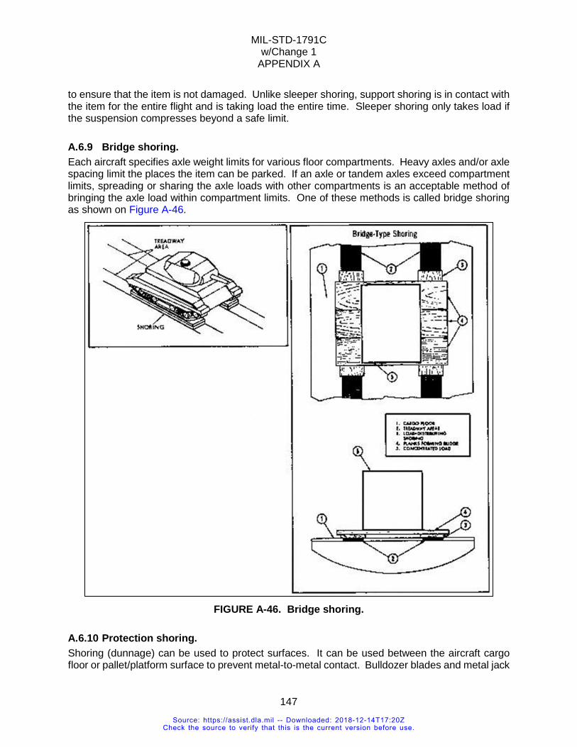
MIL-STD-1791C w/Change 1
APPENDIX A
147
to ensure that the item is not damaged. Unlike sleeper shoring, support shoring is in contact with the item for the entire flight and is taking load the entire time. Sleeper shoring only takes load if the suspension compresses beyond a safe limit.
A.6.9 Bridge shoring. Each aircraft specifies axle weight limits for various floor compartments. Heavy axles and/or axle spacing limit the places the item can be parked. If an axle or tandem axles exceed compartment limits, spreading or sharing the axle loads with other compartments is an acceptable method of bringing the axle load within compartment limits. One of these methods is called bridge shoring as shown on Figure A-46.
FIGURE A-46. Bridge shoring.
A.6.10 Protection shoring. Shoring (dunnage) can be used to protect surfaces. It can be used between the aircraft cargo floor or pallet/platform surface to prevent metal-to-metal contact. Bulldozer blades and metal jack
Source: https://assist.dla.mil -- Downloaded: 2018-12-14T17:20ZCheck the source to verify that this is the current version before use.
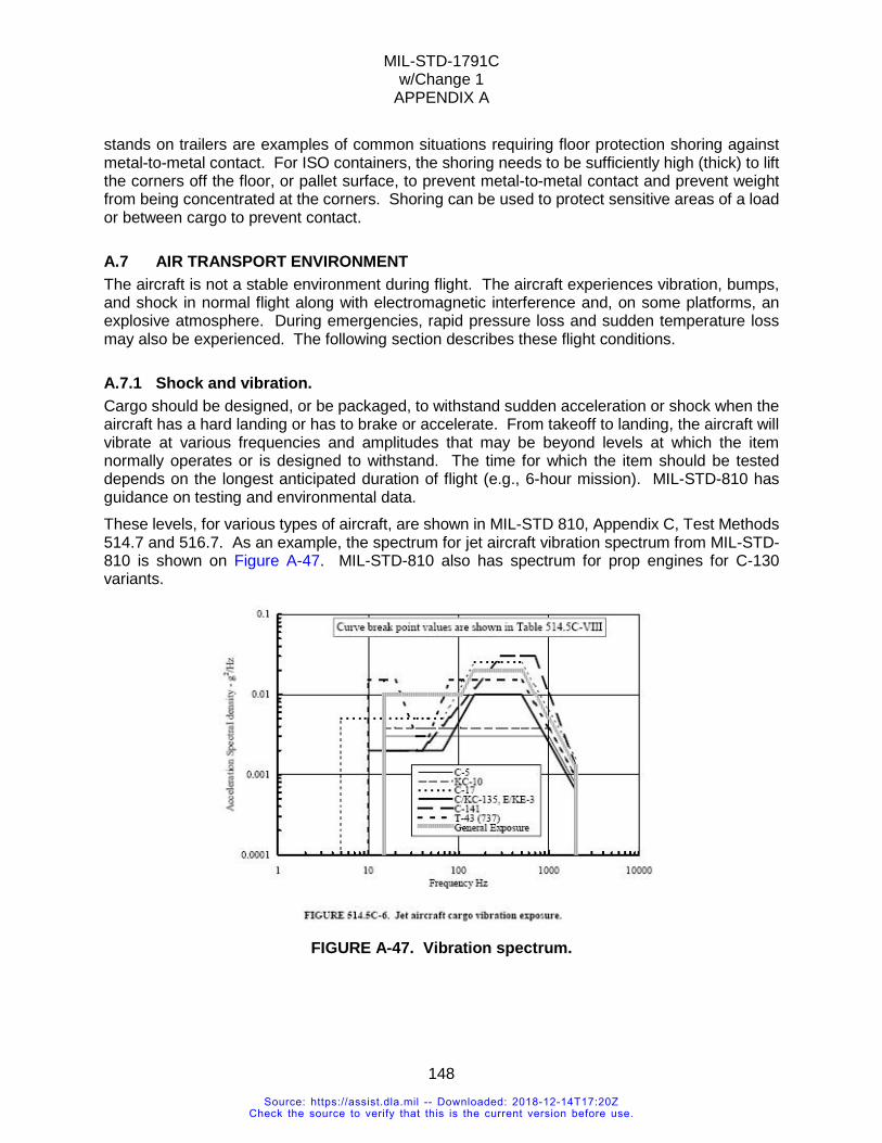
MIL-STD-1791C w/Change 1
APPENDIX A
148
stands on trailers are examples of common situations requiring floor protection shoring against metal-to-metal contact. For ISO containers, the shoring needs to be sufficiently high (thick) to lift the corners off the floor, or pallet surface, to prevent metal-to-metal contact and prevent weight from being concentrated at the corners. Shoring can be used to protect sensitive areas of a load or between cargo to prevent contact.
A.7 AIR TRANSPORT ENVIRONMENT The aircraft is not a stable environment during flight. The aircraft experiences vibration, bumps, and shock in normal flight along with electromagnetic interference and, on some platforms, an explosive atmosphere. During emergencies, rapid pressure loss and sudden temperature loss may also be experienced. The following section describes these flight conditions.
A.7.1 Shock and vibration. Cargo should be designed, or be packaged, to withstand sudden acceleration or shock when the aircraft has a hard landing or has to brake or accelerate. From takeoff to landing, the aircraft will vibrate at various frequencies and amplitudes that may be beyond levels at which the item normally operates or is designed to withstand. The time for which the item should be tested depends on the longest anticipated duration of flight (e.g., 6-hour mission). MIL-STD-810 has guidance on testing and environmental data. These levels, for various types of aircraft, are shown in MIL-STD 810, Appendix C, Test Methods 514.7 and 516.7. As an example, the spectrum for jet aircraft vibration spectrum from MIL-STD-810 is shown on Figure A-47. MIL-STD-810 also has spectrum for prop engines for C-130 variants.
FIGURE A-47. Vibration spectrum.
Source: https://assist.dla.mil -- Downloaded: 2018-12-14T17:20ZCheck the source to verify that this is the current version before use.
MIL-STD-1791C w/Change 1
APPENDIX A
149
A.7.1.1 Acceleration, shock, and vibration. REQUIREMENT RATIONALE
This requirement is imposed to assure that functional damage to the item due to the flight environment is avoided to the maximum extent. Only the designer has knowledge of the structural ruggedness of the item and what shock and vibration levels the unprotected item can tolerate and still function satisfactorily. The purpose of this requirement is to make the designer aware of the airlift operations shock and vibration environment so that necessary protective measures can be applied to the item.
REQUIREMENT GUIDANCE This requirement is intended to define the shock and vibration environment an item may experience during on/offloading and flight. Failure to provide item protection against these potential conditions could cause safety of flight problems. Another adverse effect expected would be failure of the item to function properly. With knowledge of the shock and vibration environment, the item designer would work with packaging personnel to assure item protection.
REQUIREMENT LESSONS LEARNED Air Force Flight Dynamics Laboratory Technical Report 74-144 (AD B003792), C-5A Cargo Deck Low-Frequency Vibration Environment, February 1975 (limited access) provides data on levels of vibration - induced accelerations experienced on the flight deck during all phases of C-5A aircraft operations.
VERIFICATION RATIONALE This standard establishes uniform environmental test methods for determining the resistance of equipment to the effects of natural and induced environments peculiar to military operations. It provides environmental test methods in order to obtain, as much as possible, reproducible test results.
VERIFICATION GUIDANCE MIL-STD-810 Method No 514.7 for Vibration and Method No 516.7 for Shock are the appropriate test methods to determine compliance with the serviceability/performance portion of this requirement. The acceleration forces are shown in 5.3.3.1 and Table IV.
A.7.2 Pressure change.
A.7.2.1 Rapid decompression. REQUIREMENT RATIONALE
The shipment of cargo by air presents a special potential problem not encountered during surface transport. That is the problem of rapid decompression of the cargo compartment. The three USAF prime mission cargo aircraft have automatically controlled cargo compartment pressurization systems which maintain compartment pressure at approximately 8.3 psi differential above outside air pressure when at flight altitude. If extremely rapid pressure loss should occur due to aircraft structural failure, it is possible that sealed items could explode under the influence of reduced external pressure. Parts of these items could become projectiles endangering aircrew members as well as the aircraft.
Source: https://assist.dla.mil -- Downloaded: 2018-12-14T17:20ZCheck the source to verify that this is the current version before use.
MIL-STD-1791C w/Change 1
APPENDIX A
150
REQUIREMENT GUIDANCE This problem is associated principally with well-sealed containers which enclose large volumes of air such as vans, ISO containers, and shelters configured as shops, repair, and test facilities, etc. The effects of rapid decompression on the item can be mitigated by providing for controlled breathing to accommodate air flow due to pressure changes or the use of devices to permit safe relief of an 8.3 psi pressure build-up within 0.5 sec. The intent of this requirement is to assure that this potential problem is considered in item design and provisions made to accommodate rapid decompression if the item will be adversely affected by it. There are two distinct methods of meeting this requirement. The item can be strong enough that the pressure differential can be survived with no effect, such as with the on-board fire extinguisher. Alternately, vent areas of sufficient size to equalize the air pressure fast enough to prevent structural failure (or other hazard) may be used. The venting need not be accomplished in 0.5 sec, but fast enough for the structure to survive. Commercially available “burst panels” are available to assist in meeting this requirement.
REQUIREMENT LESSONS LEARNED Most commercial vans, containers, and shelters are designed for surface movement where rapid decompression is not a factor. When such containers are used for military purposes where airlift is anticipated, provisions for attenuation of the potential damage due to decompression shall be made. Some commercial containers are designed to permit air to enter/exit the interior due to pressure changes. In general, these passages are not designed to accommodate rapid decompression. Small food packets have been known to expand and damage larger containers that carry multiple packets, and each other, as the aircraft ascends to higher altitude. One solution is to not fill a container to maximum capacity to allow the small packets to expand safely. Flexible containers are to be evaluated on a case-by-case basis. Vented and unvented containers of fluid shall also be able to contain the fluid and prevent the lid/cap from opening if the fluid expands under low ambient pressure. An expansion or overflow tank is allowed. Flexible containers are allowed to expand in flight, but not break. The expansion volume shall not cause a loss of restraint, damage other items in the vicinity, or block required access/egress routes
VERIFICATION RATIONALE
The inherent design features and ruggedness of some items may be sufficient to withstand the effects of rapid decompression without modification. Where it can be shown by engineering analysis that this is the case, such analytical proof should be adequate to verify compliance with this requirement. The alternative is dynamic testing of the item in its shipping configuration under the worst-case conditions stated above and inspection of the item to determine no parts have become a missile.
VERIFICATION GUIDANCE Where it can be shown analytically, using accepted engineering practices, that the subject item can withstand rapid decompression under the conditions of 5.3.5.2.1 this constitutes compliance with the requirements of 5.3.5.2. In all other cases formal testing should be accomplished to verify compliance.
Source: https://assist.dla.mil -- Downloaded: 2018-12-14T17:20ZCheck the source to verify that this is the current version before use.
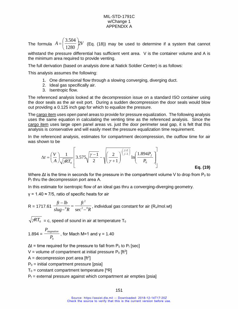
MIL-STD-1791C w/Change 1
APPENDIX A
151
The formula VA 21280
504.3
= (Eq. (18)) may be used to determine if a system that cannot
withstand the pressure differential has sufficient vent area. V is the container volume and A is the minimum area required to provide venting. The full derivation (based on analysis done at Natick Soldier Center) is as follows: This analysis assumes the following:
1. One dimensional flow through a slowing converging, diverging duct. 2. Ideal gas specifically air. 3. Isentropic flow.
The referenced analysis looked at the decompression issue on a standard ISO container using the door seals as the air exit port. During a sudden decompression the door seals would blow out providing a 0.125 inch gap for which to equalize the pressure. The cargo item uses open panel areas to provide for pressure equalization. The following analysis uses the same equation in calculating the venting time as the referenced analysis. Since the cargo item uses large open panel areas vs. just the door perimeter seal gap, it is felt that this analysis is conservative and will easily meet the pressure equalization time requirement. In the referenced analysis, estimates for compartment decompression, the outflow time for air was shown to be
+
−−
=∆
−+
−
0
11
0
894.1ln
12
21575.31
PP
RTAVt fγ
γ
γγ
γ Eq. (19)
Where Δt is the time in seconds for the pressure in the compartment volume V to drop from P0 to Pf thru the decompression port area A. In this estimate for isentropic flow of an ideal gas thru a converging-diverging geometry. γ = 1.40 ≈ 7/5, ratio of specific heats for air
R = 1717.61 R
ftRslug
lbft02
2
0 sec −=
−−
, individual gas constant for air (Ru/mol.wt)
0RTγ = c, speed of sound in air at temperature T0
1.894 = 0P
Pstagnation, for Mach M=1 and γ = 1.40
Δt = time required for the pressure to fall from P0 to Pf [sec] V = volume of compartment at initial pressure P0 [ft3] A = decompression port area [ft2] P0 = initial compartment pressure [psia] T0 = constant compartment temperature [ºR] Pf = external pressure against which compartment air empties [psia]
Source: https://assist.dla.mil -- Downloaded: 2018-12-14T17:20ZCheck the source to verify that this is the current version before use.
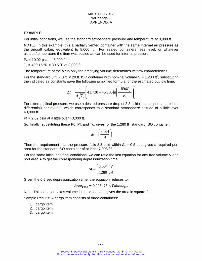
MIL-STD-1791C w/Change 1
APPENDIX A
152
EXAMPLE: For initial conditions, we use the standard atmosphere pressure and temperature at 8,000 ft. NOTE: In this example, this a partially vented container with the same internal air pressure as the aircraft cabin; equivalent to 8,000 ft. For sealed containers, sea level, or whatever altitude/temperature the item was sealed at, can be used for internal pressure. P0 = 10.92 psia at 8,000 ft. T0 = 490.16 ºR = 30.5 ºF at 8,000 ft. The temperature of the air in only the emptying volume determines its flow characteristics. For the standard 8 ft. × 8 ft. × 20 ft. ISO container with nominal volume V = 1,280 ft3, substituting the indicated air constants gave the following simplified formula for the estimated outflow time.
−=∆
00
894.1ln105.45738.411
PP
TAt f
For external, final pressure, we use a desired pressure drop of 8.3 psid (pounds per square inch differential) per 5.3.5.3, which corresponds to a standard atmosphere altitude of a little over 40,000 ft. Pf = 2.62 psia at a little over 40,000 ft. So, finally, substituting these Po, Pf, and To, gives for the 1,280 ft3 standard ISO container.
=∆
At 504.3
Then the requirement that the pressure falls 8.3 psid within Δt = 0.5 sec, gives a required port area for the standard ISO container of at least 7.008 ft2. For the same initial and final conditions, we can ratio the last equation for any free volume V and port area A to get the corresponding depressurization time.
AVt
=∆
1280504.3
Given the 0.5 sec depressurization time, the equation reduces to: 𝐴𝐴𝑂𝑂𝐻𝐻𝑎𝑎𝑣𝑣𝑃𝑃𝐸𝐸𝑃𝑃 = 0.005475 × 𝑉𝑉𝐿𝐿𝐶𝐶𝐿𝐿𝑉𝑉𝐻𝐻𝐶𝐶𝐶𝐶𝑃𝑃
Note: This equation takes volume in cubic-feet and gives the area in square-feet Sample Results: A cargo item consists of three containers:
1. cargo item 2. cargo item 3. cargo item
Source: https://assist.dla.mil -- Downloaded: 2018-12-14T17:20ZCheck the source to verify that this is the current version before use.
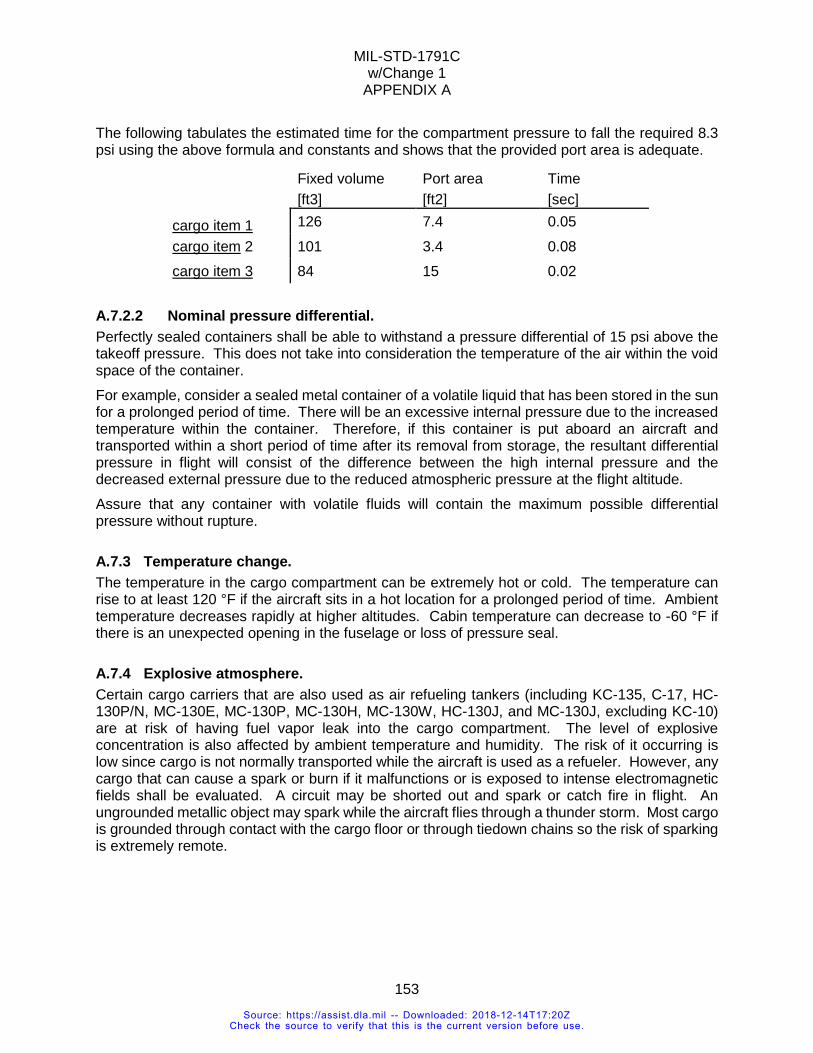
MIL-STD-1791C w/Change 1
APPENDIX A
153
The following tabulates the estimated time for the compartment pressure to fall the required 8.3 psi using the above formula and constants and shows that the provided port area is adequate.
Fixed volume Port area Time [ft3] [ft2] [sec]
cargo item 1 126 7.4 0.05 cargo item 2 101 3.4 0.08 cargo item 3 84 15 0.02
A.7.2.2 Nominal pressure differential. Perfectly sealed containers shall be able to withstand a pressure differential of 15 psi above the takeoff pressure. This does not take into consideration the temperature of the air within the void space of the container. For example, consider a sealed metal container of a volatile liquid that has been stored in the sun for a prolonged period of time. There will be an excessive internal pressure due to the increased temperature within the container. Therefore, if this container is put aboard an aircraft and transported within a short period of time after its removal from storage, the resultant differential pressure in flight will consist of the difference between the high internal pressure and the decreased external pressure due to the reduced atmospheric pressure at the flight altitude. Assure that any container with volatile fluids will contain the maximum possible differential pressure without rupture.
A.7.3 Temperature change. The temperature in the cargo compartment can be extremely hot or cold. The temperature can rise to at least 120 °F if the aircraft sits in a hot location for a prolonged period of time. Ambient temperature decreases rapidly at higher altitudes. Cabin temperature can decrease to -60 °F if there is an unexpected opening in the fuselage or loss of pressure seal.
A.7.4 Explosive atmosphere. Certain cargo carriers that are also used as air refueling tankers (including KC-135, C-17, HC-130P/N, MC-130E, MC-130P, MC-130H, MC-130W, HC-130J, and MC-130J, excluding KC-10) are at risk of having fuel vapor leak into the cargo compartment. The level of explosive concentration is also affected by ambient temperature and humidity. The risk of it occurring is low since cargo is not normally transported while the aircraft is used as a refueler. However, any cargo that can cause a spark or burn if it malfunctions or is exposed to intense electromagnetic fields shall be evaluated. A circuit may be shorted out and spark or catch fire in flight. An ungrounded metallic object may spark while the aircraft flies through a thunder storm. Most cargo is grounded through contact with the cargo floor or through tiedown chains so the risk of sparking is extremely remote.
Source: https://assist.dla.mil -- Downloaded: 2018-12-14T17:20ZCheck the source to verify that this is the current version before use.
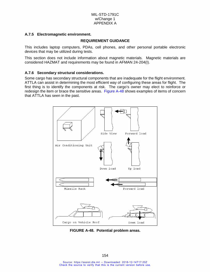
MIL-STD-1791C w/Change 1
APPENDIX A
154
A.7.5 Electromagnetic environment. REQUIREMENT GUIDANCE
This includes laptop computers, PDAs, cell phones, and other personal portable electronic devices that may be utilized during tests. This section does not include information about magnetic materials. Magnetic materials are considered HAZMAT and requirements may be found in AFMAN 24-204(I).
A.7.6 Secondary structural considerations. Some cargo has secondary structural components that are inadequate for the flight environment. ATTLA can assist in determining the most efficient way of configuring these areas for flight. The first thing is to identify the components at risk. The cargo’s owner may elect to reinforce or redesign the item or brace the sensitive areas. Figure A-48 shows examples of items of concern that ATTLA has seen in the past.
FIGURE A-48. Potential problem areas.
Source: https://assist.dla.mil -- Downloaded: 2018-12-14T17:20ZCheck the source to verify that this is the current version before use.
MIL-STD-1791C w/Change 1
APPENDIX A
155
A.8 SPECIAL CONSIDERATION CARGO
A.8.1 Hazardous material. REQUIREMENT RATIONALE
Certain materials which make up components of equipment items, are used in support of equipment operations, or can be carried aboard equipment as an accompanying load represent potential safety hazards to flight personnel and aircraft. In order to reduce the risk of air transporting these materials to an acceptable level, consistent with operational needs, specific preparation procedures have been developed. These required procedures and the conditions governing their application are detailed in Joint Service Publication AFMAN 24-204(I)/TM 38-250/NAVSUP PUB 505/MCO P4030.19H/DLAI 4145.3/DCMA1, CH3.4.
REQUIREMENT GUIDANCE All pertinent requirements of AFMAN 24-204(I) shall be met in air transportability situations. Detailed information regarding procedures to be followed for each hazard is provided in this publication. No deviations from these procedures are acceptable unless specifically authorized by official waiver.
VERIFICATION RATIONALE Because of the complex nature of and potential danger in hazardous materials, verification of their proper preparation for air shipment shall be accomplished by personnel qualified under the provisions of AFMAN 24-204(I). Normally, specialists familiar with specific items will prepare them for shipment and certify that they meet the requirements for air transport. The advantage of this is that such specialists are more knowledgeable about the characteristics of the item and its potentially hazardous elements. Of primary importance are the qualifications of the certifying personnel to assure that the required air transport safety standards have been met. Air terminal personnel, also qualified under AFMAN 24-204(I) standards, will inspect the load prior to its acceptance for air transport, thus providing a secondary check on the unit's proper preparation for shipment.
VERIFICATION GUIDANCE This requirement has been met when a qualified certifier attests to the adequacy of hazardous materials preparation by executing DD Form 1387-2, Special Handling Data/Certification. The provisions of AFMAN 24-204(I) pertinent to the hazard shall be complied with unless an official deviation/waiver is obtained.
A.8.2 Aircraft electrical and data interface. REQUIREMENT GUIDANCE
It is recommended that the users meet with the aircraft program office early in the design process to define interface requirements that may be unique to each type of aircraft. Unless equipment has been specifically electrically isolated, static discharge is not ordinarily encountered. Vehicles and equipment are normally grounded through contact with the aircraft floor, tiedown chains, or the pallet.
Source: https://assist.dla.mil -- Downloaded: 2018-12-14T17:20ZCheck the source to verify that this is the current version before use.
MIL-STD-1791C w/Change 1
APPENDIX A
156
A.8.3 Bulk fluid tanks. REQUIREMENT RATIONALE
Movement of large quantities of liquids can severely shift the aircraft’s center of gravity, putting the aircraft out of limits.
A.8.4 Personnel occupied systems. REQUIREMENT RATIONALE
Equipment installed in the aircraft cargo system intended to be occupied by personnel during flight and may be during takeoff/landing. These are carried in the aircraft cargo compartment and utilize the cargo handling system. They are required to meet many of the same interface requirements as cargo. If the item is not occupied during takeoff/landing, the restraint requirements are the same as cargo. Requirements for restraint during takeoff/landing and other personnel accommodations (e.g. emergency oxygen, alarm systems, ventilation, etc.) are being developed and are not included in this document. Check with ATTLA for details.
REQUIREMENT GUIDANCE In recent years there have been efforts to produce a variety of these systems. Airline-style seats mounted to pallets, VIP seats mounted to pallets, and in-flight test equipment with operator seats are a few examples. All efforts to date revolve around pallet-mounted equipment, thus the information in 5.3.6.7 and 6.3 is recommended as a starting point for interface requirements.
A.9 SPECIAL LOADING AND FLIGHT PROCEDURES
A.9.1 Special tools and transport equipment. SPECIAL TOOLS REQUIREMENT RATIONALE
In most cases, items requiring aerial delivery capabilities are destined for rapid deployment in austere environments. Under these conditions little, if any, support equipment is likely to be available to assist in offloading reassembly operations. Additionally, mission readiness requirements may not allow time for any but minor item reassembly operations. Special tools, even those which are small and easily carried with the item, represent a major problem in remote areas if replacement is needed because of loss or damage. While total avoidance of special tools may not be possible, requiring their use shall be minimized.
SPECIAL TOOLS REQUIREMENT GUIDANCE Item design should be tailored to permit loading and air movement of the item in its operational configuration whenever possible. This not only eliminates the time and effort to prepare the item for transport at the origin and restore it to operational readiness at the destination, but also eliminates the need for supporting equipment and special tools at both locations. The designer should keep in mind that field conditions are vastly different than shop conditions both in terms of manpower and facilities availability. Design should be predicated on the worst-case situation which is the combat field environment. While air transport of items in their operational configuration is a desired goal, many situations exist where this cannot be accomplished. In these cases, every effort should be made to eliminate the need for extensive item modification to make it ready for aerial delivery. In many cases, program requirements may limit the amount of time and resources available to prepare the item for operation once it is delivered to the user.
Source: https://assist.dla.mil -- Downloaded: 2018-12-14T17:20ZCheck the source to verify that this is the current version before use.
MIL-STD-1791C w/Change 1
APPENDIX A
157
SPECIAL TOOLS REQUIREMENT LESSONS LEARNED The more special tools and equipment necessary to support an item, the greater the potential for malfunction and loss of use of that item. Mission requirements often severely limit the allowable time to make equipment operationally ready from its air transport configuration. A factor which is easily overlooked is that combat field conditions can considerably extend the time required to perform a given operation.
SPECIAL TOOLS VERIFICATION RATIONALE Verification of the acceptability of proposed procedures is seldom entirely objective. However, because mission-ready status can be defined in terms of elapsed time from aircraft offload, these criteria are reasonable to establish if make-ready procedures are satisfactory. The acceptability of special tools and equipment is often a matter of subjective judgment. Guidelines shall be established by the program office on a case-by-case basis. Comparison of the characteristics of the special tools/equipment with the established criteria should be the determinant of whether these items are acceptable.
SPECIAL TOOLS VERIFICATION GUIDANCE Where this requirement applies, the program office responsible for the equipment development will specify acceptance criteria. Planning factors for various operational scenarios will determine the allowable time and other conditions for making the equipment ready for use once it is air delivered to the user. The skill level of the personnel readying the equipment shall be considered in verifying the satisfaction of this requirement. In most cases these personnel will be unskilled and unfamiliar with the items requiring assembly/disassembly.
SPECIAL TOOLS VERIFICATION LESSONS LEARNED Demonstrations to prove the acceptability of proposed special tools and procedures may not be representative of actual user circumstances. Care should be taken to make demonstrations as realistic as possible. Factors that should be considered include the user's skill level, training, familiarity with both equipment and procedures, and the physical and environmental conditions under which the operations shall take place.
A.9.2 Material handling equipment (MHE). Cargo can be loaded using material handling equipment (MHE). MHE are forklifts, K-loaders, mobilizers, or special handling tools. Forklifts carry the item into the aircraft, push the item into the aircraft, and/or pick up part of the item to help the item overcome obstacles. If the item is carried into the aircraft on MHE, the entire system of cargo and MHE should be considered as rolling stock. For example, if a forklift is used to pick up the item, the combined weight of the item and forklift weight should be considered. The added weight on the forklift axles or tires should not exceed aircraft limits and the forklift’s ratings. The added dimension(s) of the item on the forklift shall also be considered. The forklift does not necessarily have to be transported with or attached to the item. K-loaders are specialized roller beds mounted on a mobile lift that can raise the item to be level with the cargo ramp and load the cargo straight into the aircraft. This is limited by the carrying capability of the K-loader, availability of equipment to place the item on the K-loader, the straight-in loading limits of the aircraft, and the opening size of the aircraft. KC-10, KC-135 and the CRAF aircraft have side cargo doors for loading cargo. Cargo is palletized and carried up to the door by a K-loader.
Source: https://assist.dla.mil -- Downloaded: 2018-12-14T17:20ZCheck the source to verify that this is the current version before use.
MIL-STD-1791C w/Change 1
APPENDIX A
158
Mobilizers are wheeled frames that attach to bulk cargo and convert the item into rolling stock. Special handling tools are specifically designed to load and unload unusual cargo. Adjustments to any of the MHE during the loading process are allowed. However, the procedure may need to be evaluated if there is anticipated risk of damage or loss of control.
MHE REQUIREMENT RATIONALE The less reliance on supporting MHE, the greater the ability to load/offload items even in the austere environments in which many operations shall take place. In many cases, the required MHE will not be available at the destination unless it also is air transported to the offload site. This not only delays the offloading of the item, but denies valuable aircraft space to other airlift cargo.
MHE REQUIREMENT GUIDANCE With the trend to procurement of commercial-off-the-shelf equipment, less latitude is available in the area of wheeled and tracked vehicles to exercise design judgment to implement this requirement. However, these factors should be recognized in the source selection process and every effort should be made to avoid items with inherent transportability problems. More design freedom exists in the area of initial item design. This is a particularly important time for consideration of this and all air transportability requirements for two reasons. First, within item functional limits, the design has not been frozen and may still accommodate features which enhance the item's handling characteristics. Second, initial item design is often perpetuated through extended use of the item or with the basic item modified to function in other mission roles. This means that designed-in problems are perpetuated if they are permitted in the initial design.
MHE REQUIREMENT LESSONS LEARNED Most standard containers and shelters can be loaded with the aircraft cargo winch from the ground if they have mobilizers attached. This also has the advantage of providing ground mobility. One disadvantage is that the mobilizer sets require approximately 10 additional feet of cargo floor for storage. In this mode, containers/shelters need not be placed on pallet trains and loaded into the aircraft from K-loaders. Many instances can be cited where vehicles fully qualified for air transport have been progressively modified to the point where they no longer can be handled without supporting MHE. While these modifications may not prevent the vehicles from being air transported, they severely restrict the on/offloading options. One of the greatest problems in designing handling provisions of items is the failure to recognize the degree to which an item's maneuverability is limited by narrow aircraft ramps and small interior clearances. Generally only small directional corrections can be made because of these restrictions.
MHE VERIFICATION RATIONALE Experience has shown that analytical methods of verifying this requirement can be effectively used in many cases. However, where sophisticated handling features are employed, actual demonstration of the item's capabilities is the preferred method of verification. This not only verifies the acceptability of the item's features, but also identifies the procedures necessary for successful handling.
Source: https://assist.dla.mil -- Downloaded: 2018-12-14T17:20ZCheck the source to verify that this is the current version before use.
MIL-STD-1791C w/Change 1
APPENDIX A
159
MHE VERIFICATION GUIDANCE To the extent possible, analytical verification should be used because it is faster and the least costly. ATTLA, as final approval authority, has the expertise to provide assistance in this area. Handling demonstrations, using a mock-up of the aircraft ramps and cargo compartment envelope, are the next desirable option. Test loading using an actual aircraft should be resorted to only after all other options have been thoroughly investigated. Test loadings, while providing an absolute check of an item's handling characteristics, are very expensive and require ATTLA approval before being performed.
MHE VERIFICATION LESSONS LEARNED Historically, early consideration of air transport, supported by accurate technical data for on/offloading analysis, has eliminated the requirement for actual test loading in all but a few special cases.
A.9.3 Self-adjustment. Cargo may also have the capability to adjust its clearances to avoid the problems areas. Examples are 1) a pintle that can vary height can be used to avoid ramp cresting; 2) an axle that rises to clear the ramp hinge; and 3) an excavator with the capability to move its scoop to avoid aircraft ramp and ceiling. Cargo may lack the power to climb the ramp or roll into the aircraft. Each of the Prime Mission cargo planes have a winch to help with pulling cargo items into the aircraft.
A.9.4 Lowering tire pressure. Lowering tire pressure to reduce item height is not an acceptable practice. The loadmaster is prohibited from using this technique because a reduction in tire pressure reduces tire capability and may also cause the item to ride on the tire rims. Having the rim roll on the aircraft floor or impact the floor during turbulence may damage the floor and the item’s wheel, tire, and/or axle. A few items which have undergone a thorough analysis for this procedure are allowed to reduce tire pressure to reduce height for loading or to avoid having the tire categorized as a solid wheel. It is a means of last resort. The lower pressure shall be within the range in which the tire capability is not degraded beyond usable limits such as weight carrying capacity. Approval to lower the tire pressure shall be obtained from ATTLA.
A.9.5 Straight-in loading. Some items such as palletized cargo or cargo with extremely low ground clearance have to be loaded with the ramp in the coplanar position with the cargo floor. The cargo is carried by MHE, such as a K-loader or forklift. If the item cannot be pushed or driven in from the MHE, it may be winched in.
A.9.6 Winching. The aircraft cargo winch may be required to assist the loading process. Winching is a method of on/offloading extremely heavy cargo units such as large, skidded boxes, palletized cargo, or vehicles when it is not practical to drive them on or off the aircraft using their own power. Winching is also used to pull palletized or skidded loads that have become stuck during the loading and offloading process. Winching can also be used as a safety to prevent loads from moving too
Source: https://assist.dla.mil -- Downloaded: 2018-12-14T17:20ZCheck the source to verify that this is the current version before use.
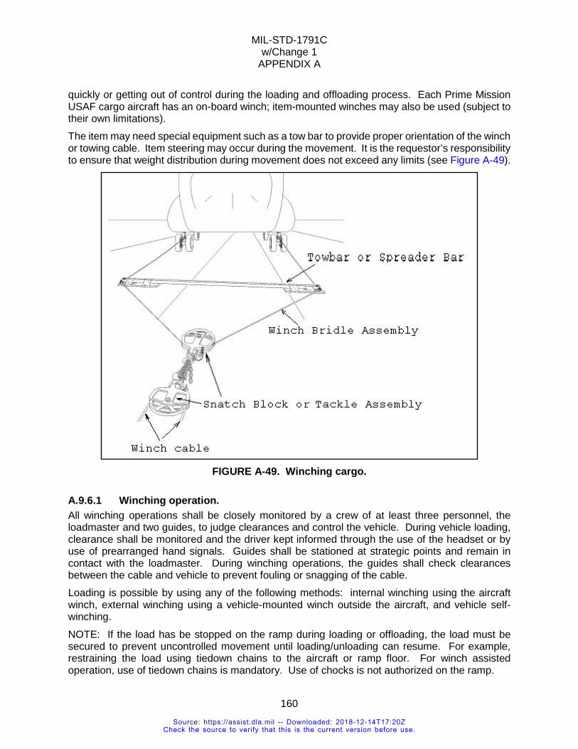
MIL-STD-1791C w/Change 1
APPENDIX A
160
quickly or getting out of control during the loading and offloading process. Each Prime Mission USAF cargo aircraft has an on-board winch; item-mounted winches may also be used (subject to their own limitations). The item may need special equipment such as a tow bar to provide proper orientation of the winch or towing cable. Item steering may occur during the movement. It is the requestor’s responsibility to ensure that weight distribution during movement does not exceed any limits (see Figure A-49).
FIGURE A-49. Winching cargo.
A.9.6.1 Winching operation. All winching operations shall be closely monitored by a crew of at least three personnel, the loadmaster and two guides, to judge clearances and control the vehicle. During vehicle loading, clearance shall be monitored and the driver kept informed through the use of the headset or by use of prearranged hand signals. Guides shall be stationed at strategic points and remain in contact with the loadmaster. During winching operations, the guides shall check clearances between the cable and vehicle to prevent fouling or snagging of the cable. Loading is possible by using any of the following methods: internal winching using the aircraft winch, external winching using a vehicle-mounted winch outside the aircraft, and vehicle self-winching. NOTE: If the load has be stopped on the ramp during loading or offloading, the load must be secured to prevent uncontrolled movement until loading/unloading can resume. For example, restraining the load using tiedown chains to the aircraft or ramp floor. For winch assisted operation, use of tiedown chains is mandatory. Use of chocks is not authorized on the ramp.
Source: https://assist.dla.mil -- Downloaded: 2018-12-14T17:20ZCheck the source to verify that this is the current version before use.
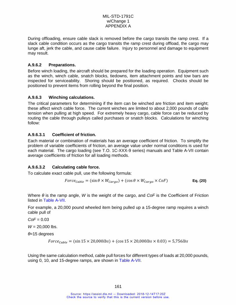
MIL-STD-1791C w/Change 1
APPENDIX A
161
During offloading, ensure cable slack is removed before the cargo transits the ramp crest. If a slack cable condition occurs as the cargo transits the ramp crest during offload, the cargo may lunge aft, jerk the cable, and cause cable failure. Injury to personnel and damage to equipment may result.
A.9.6.2 Preparations. Before winch loading, the aircraft should be prepared for the loading operation. Equipment such as the winch, winch cable, snatch blocks, tiedowns, item attachment points and tow bars are inspected for serviceability. Shoring should be positioned, as required. Chocks should be positioned to prevent items from rolling beyond the final position.
A.9.6.3 Winching calculations. The critical parameters for determining if the item can be winched are friction and item weight; these affect winch cable force. The current winches are limited to about 2,000 pounds of cable tension when pulling at high speed. For extremely heavy cargo, cable force can be reduced by routing the cable through pulleys called purchases or snatch blocks. Calculations for winching follow:
A.9.6.3.1 Coefficient of friction. Each material or combination of materials has an average coefficient of friction. To simplify the problem of variable coefficients of friction, an average value under normal conditions is used for each material. The cargo loading (see T.O. 1C-XXX-9 series) manuals and Table A-VII contain average coefficients of friction for all loading methods.
A.9.6.3.2 Calculating cable force. To calculate exact cable pull, use the following formula: 𝐹𝐹𝐿𝐿𝑂𝑂𝐶𝐶𝐻𝐻𝐶𝐶𝐶𝐶𝐶𝐶𝐶𝐶𝑃𝑃 = (sin𝜃𝜃 × 𝑥𝑥𝐶𝐶𝐶𝐶𝑃𝑃𝐶𝐶𝑃𝑃) + (cos𝜃𝜃 × 𝑥𝑥𝐶𝐶𝐶𝐶𝑃𝑃𝐶𝐶𝑃𝑃 × 𝐶𝐶𝐿𝐿𝐹𝐹) Eq. (20)
Where θ is the ramp angle, W is the weight of the cargo, and CoF is the Coefficient of Friction listed in Table A-VII. For example, a 20,000 pound wheeled item being pulled up a 15-degree ramp requires a winch cable pull of CoF = 0.03 W = 20,000 lbs. θ=15 degrees 𝐹𝐹𝐿𝐿𝑂𝑂𝐶𝐶𝐻𝐻𝐶𝐶𝐶𝐶𝐶𝐶𝐶𝐶𝑃𝑃 = (sin 15 × 20,000𝐶𝐶𝑒𝑒𝑒𝑒) + (cos 15 × 20,000𝐶𝐶𝑒𝑒𝑒𝑒 × 0.03) = 5,756𝐶𝐶𝑒𝑒𝑒𝑒
Using the same calculation method, cable pull forces for different types of loads at 20,000 pounds, using 0, 10, and 15-degree ramps, are shown in Table A-VII.
Source: https://assist.dla.mil -- Downloaded: 2018-12-14T17:20ZCheck the source to verify that this is the current version before use.
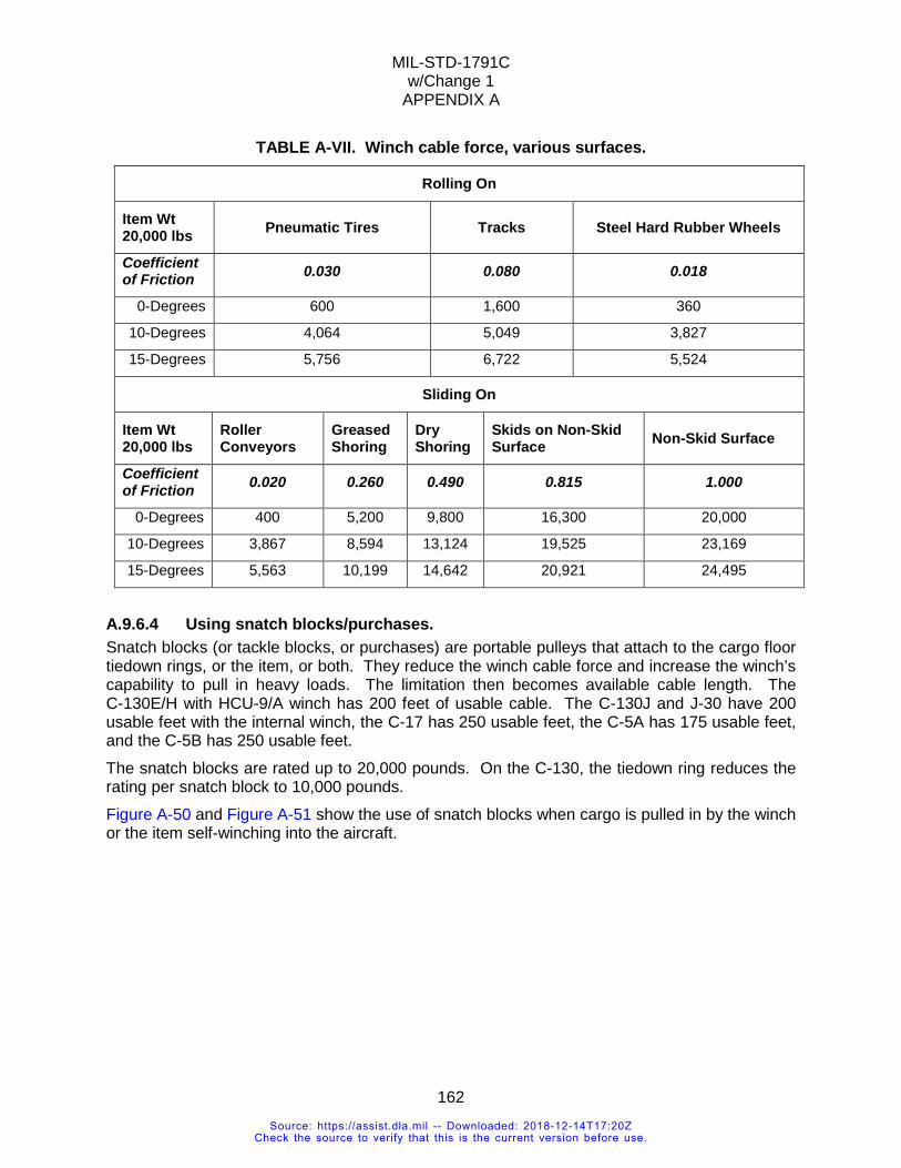
MIL-STD-1791C w/Change 1
APPENDIX A
162
TABLE A-VII. Winch cable force, various surfaces.
Rolling On
Item Wt 20,000 lbs Pneumatic Tires Tracks Steel Hard Rubber Wheels
Coefficient of Friction 0.030 0.080 0.018
0-Degrees 600 1,600 360
10-Degrees 4,064 5,049 3,827
15-Degrees 5,756 6,722 5,524
Sliding On
Item Wt 20,000 lbs
Roller Conveyors
Greased Shoring
Dry Shoring
Skids on Non-Skid Surface Non-Skid Surface
Coefficient of Friction 0.020 0.260 0.490 0.815 1.000
0-Degrees 400 5,200 9,800 16,300 20,000
10-Degrees 3,867 8,594 13,124 19,525 23,169
15-Degrees 5,563 10,199 14,642 20,921 24,495
A.9.6.4 Using snatch blocks/purchases. Snatch blocks (or tackle blocks, or purchases) are portable pulleys that attach to the cargo floor tiedown rings, or the item, or both. They reduce the winch cable force and increase the winch’s capability to pull in heavy loads. The limitation then becomes available cable length. The C-130E/H with HCU-9/A winch has 200 feet of usable cable. The C-130J and J-30 have 200 usable feet with the internal winch, the C-17 has 250 usable feet, the C-5A has 175 usable feet, and the C-5B has 250 usable feet. The snatch blocks are rated up to 20,000 pounds. On the C-130, the tiedown ring reduces the rating per snatch block to 10,000 pounds. Figure A-50 and Figure A-51 show the use of snatch blocks when cargo is pulled in by the winch or the item self-winching into the aircraft.
Source: https://assist.dla.mil -- Downloaded: 2018-12-14T17:20ZCheck the source to verify that this is the current version before use.
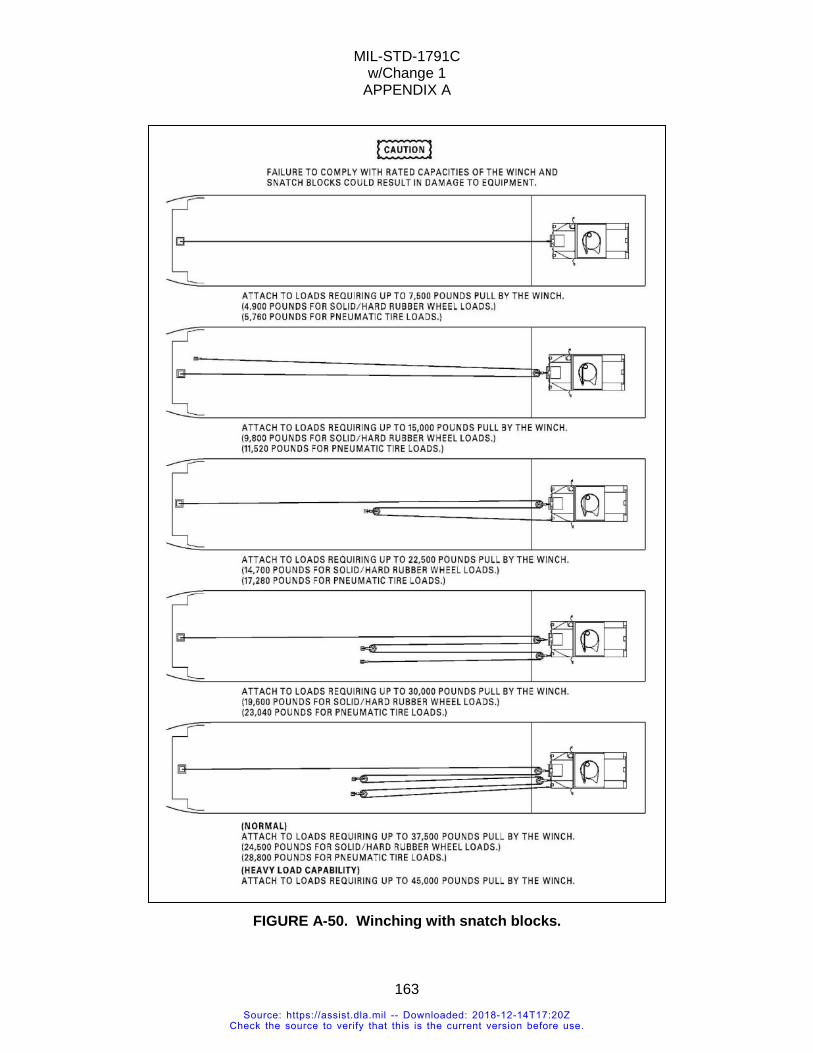
MIL-STD-1791C w/Change 1
APPENDIX A
163
FIGURE A-50. Winching with snatch blocks.
Source: https://assist.dla.mil -- Downloaded: 2018-12-14T17:20ZCheck the source to verify that this is the current version before use.
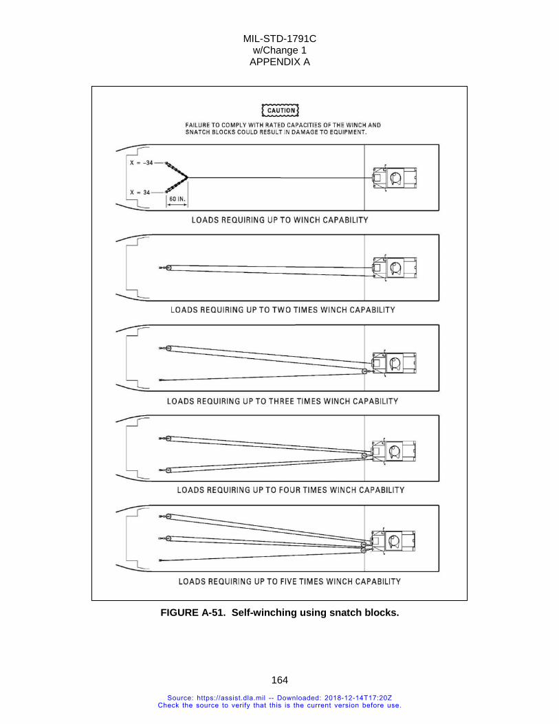
MIL-STD-1791C w/Change 1
APPENDIX A
164
FIGURE A-51. Self-winching using snatch blocks.
Source: https://assist.dla.mil -- Downloaded: 2018-12-14T17:20ZCheck the source to verify that this is the current version before use.
MIL-STD-1791C w/Change 1
APPENDIX A
165
A.9.7 Secondary cargo. REQUIREMENT RATIONALE
In many cargo aircraft the available cargo compartment volume is effectively filled before the weight carrying capability of the aircraft is reached. This is particularly true where high volume-to-weight ratio items such as vehicles are involved. In an effort to more effectively utilize the aircraft payload capability, it is often practical to use the load compartment of vehicles to carry additional cargo. This would be an obvious example of an item with secondary cargo. More subtle examples of secondary cargo are situations involving certain vehicles whose design incorporates components which can become disengaged under flight load conditions. An example is the truck-mounted crane. The crane is mounted on the truck chassis using a large diameter kingpin with no provisions to prevent the kingpin from becoming disengaged during vertical accelerations. Because secondary cargo is subjected to all the same acceleration forces as the basic item, it shall be independently restrained to the same levels. The restraint criteria to be met are shown in 5.3.3.1. Because it is impractical to tiedown individual components of items such as trucks or helicopters, these components should be designed with sufficient inherent strength to withstand the acceleration forces of 5.3.3.1. The entire vehicle, including any additional cargo, shall be fully restrained at its gross transported weight. Loose items such as those listed below should have provisions to be secured to the frame of the vehicle:
a. Spare wheels, tools and tool boxes, towing chains, pinch bars, etc. b. Bulldozer blades and push arms. c. Cranes or booms on wrecking trucks, etc. d. Dump truck bodies and other hydraulic or mechanical lift mechanisms. e. Machines and tools in shop trucks, shelters, and containers.
REQUIREMENT GUIDANCE Where secondary cargo is involved in the shipping configuration of an item, the following factors shall be considered. First, where equipment can carry additional load or is moved in a configuration where its weight is increased, the restraint system shall be developed at the highest possible gross weight. Second, all loose loads or equipment components which are not inherently restrained to withstand the acceleration loads of 5.3.3.1 shall be separately restrained to these levels. Third, the additional loads placed on vehicles shall not cause the vehicle to exceed its cross-country weight rating, axle load limits, or other air transportability criteria. The common method of restraining secondary cargo is to tie it down to a structurally sound member of the principal item such as a vehicle frame. If this mode is used, restraint design can be based on the weight of the secondary cargo. The principal item shall be restrained to the maximum weight of the item plus the secondary cargo. If the principal item and the secondary cargo are each restrained to the aircraft floor, restraint design can be based on the highest weight of each load. All requirements of 5.3.3.1 shall be complied with.
VERIFICATION RATIONALE The restraint criteria in current use have resulted from a structured evolution. During this process, safety of flight considerations have been carefully balanced against operational considerations.
Source: https://assist.dla.mil -- Downloaded: 2018-12-14T17:20ZCheck the source to verify that this is the current version before use.
MIL-STD-1791C w/Change 1
APPENDIX A
166
The result is a set of criteria which provide a high probability of safety under expected flight conditions and, at the same time, impose reasonable operational requirements. The restraint levels specified are based on a statistical analysis of cargo aircraft accident data coupled with years of successful cargo flight experience at reduced restraint levels.
VERIFICATION GUIDANCE Because secondary cargo is generally secured to the basic vehicle or item rather than the aircraft floor, it will be necessary to determine that the attachment points on both the load and the carrying structure are adequate in accordance with the provisions of 5.3.3.1. Where the secondary cargo is restrained to the aircraft floor, only the load attachment points need to be verified for compliance.
A.10 LOAD PLANNING Load planning is the process of identifying possible locations to park the item in the aircraft. Cargo should be parked at locations that meet aircraft flight weight limits, size limits, and any location affected by special considerations (such as venting) or special procedures (such as parking shoring). The item’s proximity to other cargo and the loadmaster’s ability to route tiedown chains/straps and have in-flight access are also considerations. Not all limits defined below apply to all aircraft. Consult the T.O. 1C-XXX-9 cargo loading manuals or Appendix B for details.
A.10.1 Access to aircraft systems. Consideration should be given to positioning cargo near vent ports when necessary to discharge hazardous vapor, near access to aircraft communication systems if necessary, near electrical outlets if necessary, away from oxygen masks if necessary, or away from any other location identified by the loadmaster.
A.10.2 Aircraft CG limits. Cargo shall be positioned within the aircraft’s allowable CG limits. Figure A-52 is an example of multiple loads in the aircraft. The location of all the loads shall result in an overall center of gravity with the aircraft limits. Figure A-53 shows a typical aircraft cargo loading center of gravity (CG) limit. The overall CG location shall fall under the curve to keep the aircraft in balance. The overall CG shall be computed as follows: Multiply the item’s CG fuselage or load station position by its weight. Sum the values and divide by the sum of weights for all cargo in the cargo compartment. The result is the location of the CG, in terms of fuselage station. The calculation is shown on Figure A-52. The result of the calculation for the loads shown on Figure A-52 is fuselage station 891. Weights of baggage, fuel, and personnel should be included for actual missions.
Source: https://assist.dla.mil -- Downloaded: 2018-12-14T17:20ZCheck the source to verify that this is the current version before use.
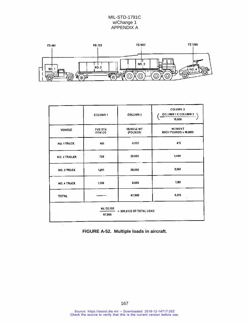
MIL-STD-1791C w/Change 1
APPENDIX A
167
FIGURE A-52. Multiple loads in aircraft.
Source: https://assist.dla.mil -- Downloaded: 2018-12-14T17:20ZCheck the source to verify that this is the current version before use.
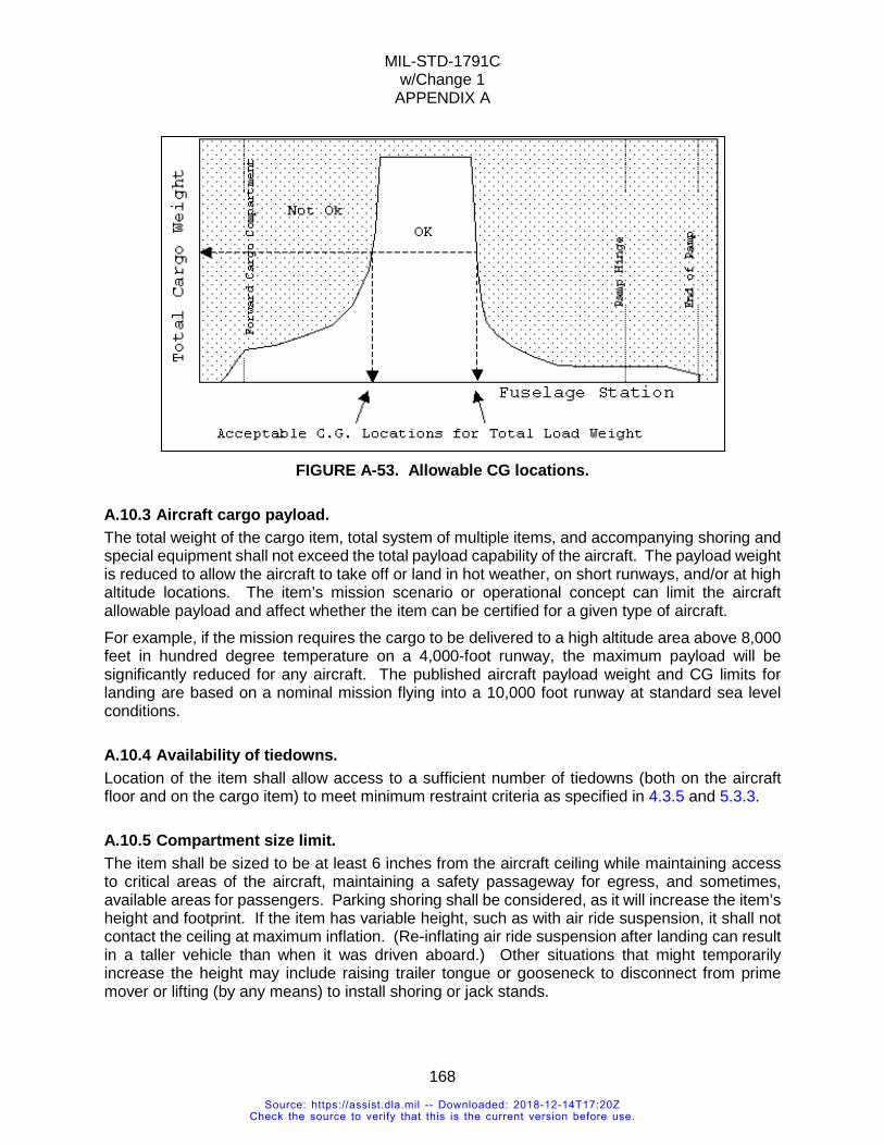
MIL-STD-1791C w/Change 1
APPENDIX A
168
FIGURE A-53. Allowable CG locations.
A.10.3 Aircraft cargo payload. The total weight of the cargo item, total system of multiple items, and accompanying shoring and special equipment shall not exceed the total payload capability of the aircraft. The payload weight is reduced to allow the aircraft to take off or land in hot weather, on short runways, and/or at high altitude locations. The item’s mission scenario or operational concept can limit the aircraft allowable payload and affect whether the item can be certified for a given type of aircraft. For example, if the mission requires the cargo to be delivered to a high altitude area above 8,000 feet in hundred degree temperature on a 4,000-foot runway, the maximum payload will be significantly reduced for any aircraft. The published aircraft payload weight and CG limits for landing are based on a nominal mission flying into a 10,000 foot runway at standard sea level conditions.
A.10.4 Availability of tiedowns. Location of the item shall allow access to a sufficient number of tiedowns (both on the aircraft floor and on the cargo item) to meet minimum restraint criteria as specified in 4.3.5 and 5.3.3.
A.10.5 Compartment size limit. The item shall be sized to be at least 6 inches from the aircraft ceiling while maintaining access to critical areas of the aircraft, maintaining a safety passageway for egress, and sometimes, available areas for passengers. Parking shoring shall be considered, as it will increase the item’s height and footprint. If the item has variable height, such as with air ride suspension, it shall not contact the ceiling at maximum inflation. (Re-inflating air ride suspension after landing can result in a taller vehicle than when it was driven aboard.) Other situations that might temporarily increase the height may include raising trailer tongue or gooseneck to disconnect from prime mover or lifting (by any means) to install shoring or jack stands.
Source: https://assist.dla.mil -- Downloaded: 2018-12-14T17:20ZCheck the source to verify that this is the current version before use.
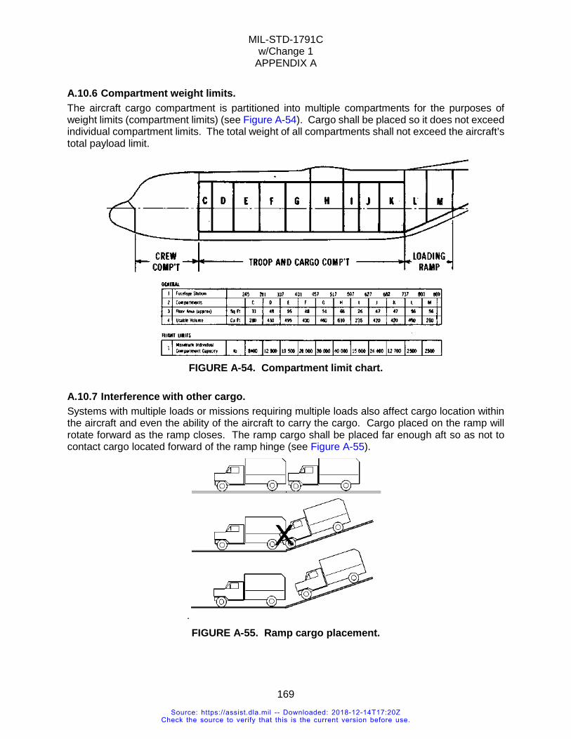
MIL-STD-1791C w/Change 1
APPENDIX A
169
A.10.6 Compartment weight limits. The aircraft cargo compartment is partitioned into multiple compartments for the purposes of weight limits (compartment limits) (see Figure A-54). Cargo shall be placed so it does not exceed individual compartment limits. The total weight of all compartments shall not exceed the aircraft’s total payload limit.
FIGURE A-54. Compartment limit chart.
A.10.7 Interference with other cargo. Systems with multiple loads or missions requiring multiple loads also affect cargo location within the aircraft and even the ability of the aircraft to carry the cargo. Cargo placed on the ramp will rotate forward as the ramp closes. The ramp cargo shall be placed far enough aft so as not to contact cargo located forward of the ramp hinge (see Figure A-55).
. FIGURE A-55. Ramp cargo placement.
Source: https://assist.dla.mil -- Downloaded: 2018-12-14T17:20ZCheck the source to verify that this is the current version before use.
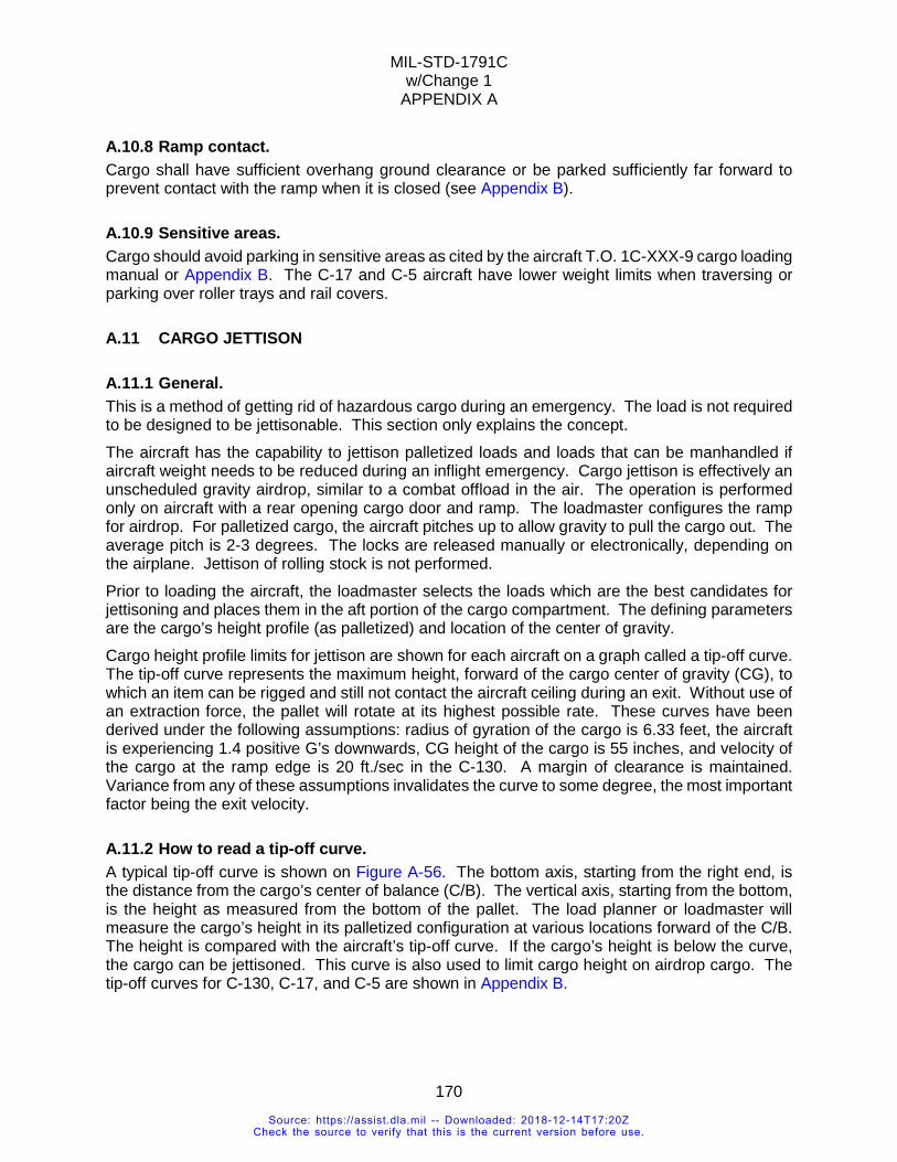
MIL-STD-1791C w/Change 1
APPENDIX A
170
A.10.8 Ramp contact. Cargo shall have sufficient overhang ground clearance or be parked sufficiently far forward to prevent contact with the ramp when it is closed (see Appendix B).
A.10.9 Sensitive areas. Cargo should avoid parking in sensitive areas as cited by the aircraft T.O. 1C-XXX-9 cargo loading manual or Appendix B. The C-17 and C-5 aircraft have lower weight limits when traversing or parking over roller trays and rail covers.
A.11 CARGO JETTISON
A.11.1 General. This is a method of getting rid of hazardous cargo during an emergency. The load is not required to be designed to be jettisonable. This section only explains the concept. The aircraft has the capability to jettison palletized loads and loads that can be manhandled if aircraft weight needs to be reduced during an inflight emergency. Cargo jettison is effectively an unscheduled gravity airdrop, similar to a combat offload in the air. The operation is performed only on aircraft with a rear opening cargo door and ramp. The loadmaster configures the ramp for airdrop. For palletized cargo, the aircraft pitches up to allow gravity to pull the cargo out. The average pitch is 2-3 degrees. The locks are released manually or electronically, depending on the airplane. Jettison of rolling stock is not performed. Prior to loading the aircraft, the loadmaster selects the loads which are the best candidates for jettisoning and places them in the aft portion of the cargo compartment. The defining parameters are the cargo’s height profile (as palletized) and location of the center of gravity. Cargo height profile limits for jettison are shown for each aircraft on a graph called a tip-off curve. The tip-off curve represents the maximum height, forward of the cargo center of gravity (CG), to which an item can be rigged and still not contact the aircraft ceiling during an exit. Without use of an extraction force, the pallet will rotate at its highest possible rate. These curves have been derived under the following assumptions: radius of gyration of the cargo is 6.33 feet, the aircraft is experiencing 1.4 positive G’s downwards, CG height of the cargo is 55 inches, and velocity of the cargo at the ramp edge is 20 ft./sec in the C-130. A margin of clearance is maintained. Variance from any of these assumptions invalidates the curve to some degree, the most important factor being the exit velocity.
A.11.2 How to read a tip-off curve. A typical tip-off curve is shown on Figure A-56. The bottom axis, starting from the right end, is the distance from the cargo’s center of balance (C/B). The vertical axis, starting from the bottom, is the height as measured from the bottom of the pallet. The load planner or loadmaster will measure the cargo’s height in its palletized configuration at various locations forward of the C/B. The height is compared with the aircraft’s tip-off curve. If the cargo’s height is below the curve, the cargo can be jettisoned. This curve is also used to limit cargo height on airdrop cargo. The tip-off curves for C-130, C-17, and C-5 are shown in Appendix B.
Source: https://assist.dla.mil -- Downloaded: 2018-12-14T17:20ZCheck the source to verify that this is the current version before use.
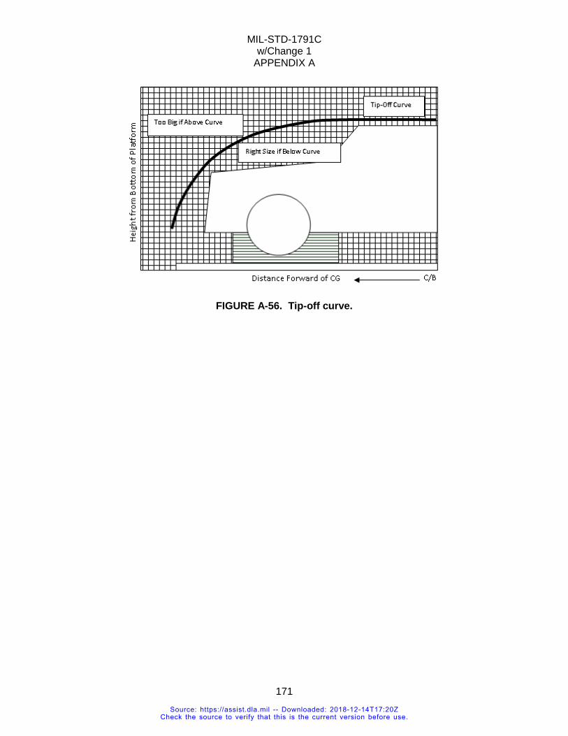
MIL-STD-1791C w/Change 1
APPENDIX A
171
FIGURE A-56. Tip-off curve.
Source: https://assist.dla.mil -- Downloaded: 2018-12-14T17:20ZCheck the source to verify that this is the current version before use.
MIL-STD-1791C w/Change 1
APPENDIX B
172
APPENDIX B AIRCRAFT DATA
B.1 SCOPE
B.1.1 Scope. This appendix provides data on specific aircraft limitations and procedures to determine whether an item exceeds those limits. It is derived from the basic aircraft loading manuals and technical publications. This Appendix is a mandatory part of this standard. The information contained herein is intended for compliance.
B.1.2 Applicability. The limitations contained in this appendix are specific to individual aircraft. The applicability of a given limit to a specific cargo item is determined according to the guidelines in 6.1.
B.1.3 Organization. This appendix is laid out by aircraft and then by size, strength, and restraint data. It is meant to follow the organization of the standard to facilitate data look up. Please note that no single aircraft defines the limiting case for all aircraft. If the designer only accounts for the limitations of the C-130, the item may have transportability issues on the C-17 or C-5. Contact ATTLA if there is confusion regarding the specific limits found herein.
B.1.4 Order of precedence. Unless otherwise noted herein, in the event of a conflict between the text of Appendix B and the TO 1C-XXX-9 or TO 1C-XXX-1, unless otherwise stated, the text of the TO’s takes precedence. This document does not supersede applicable laws and regulations unless a specific exemption has been obtained.
B.2 DEFINITIONS The names of some of the vehicle measurements called out in the different aircraft loading manuals are not consistent. The measurement locations indicated and referred to as "Critical Dimension," "Wheelbase," "Projection," and "Overhang" are not consistent between aircraft, or even between different graph/table sets for each aircraft, particularly the "Critical Dimension.” In the weight limits charts, take note that “steel wheel,” “hard rubber wheel,” and “solid tire” are interchangeable with “solid wheel” as defined in section 3. The loading manuals have been written by different companies over the last 60 years (the YC-130 first flight was in 1954) and are unique to their specific aircraft, both in dimensions and nomenclature.
Source: https://assist.dla.mil -- Downloaded: 2018-12-14T17:20ZCheck the source to verify that this is the current version before use.
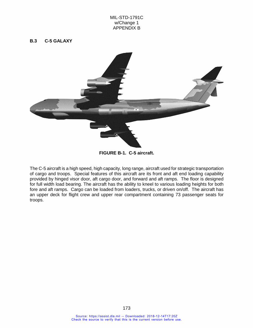
MIL-STD-1791C w/Change 1
APPENDIX B
173
B.3 C-5 GALAXY
FIGURE B-1. C-5 aircraft.
The C-5 aircraft is a high speed, high capacity, long range, aircraft used for strategic transportation of cargo and troops. Special features of this aircraft are its front and aft end loading capability provided by hinged visor door, aft cargo door, and forward and aft ramps. The floor is designed for full width load bearing. The aircraft has the ability to kneel to various loading heights for both fore and aft ramps. Cargo can be loaded from loaders, trucks, or driven on/off. The aircraft has an upper deck for flight crew and upper rear compartment containing 73 passenger seats for troops.
Source: https://assist.dla.mil -- Downloaded: 2018-12-14T17:20ZCheck the source to verify that this is the current version before use.
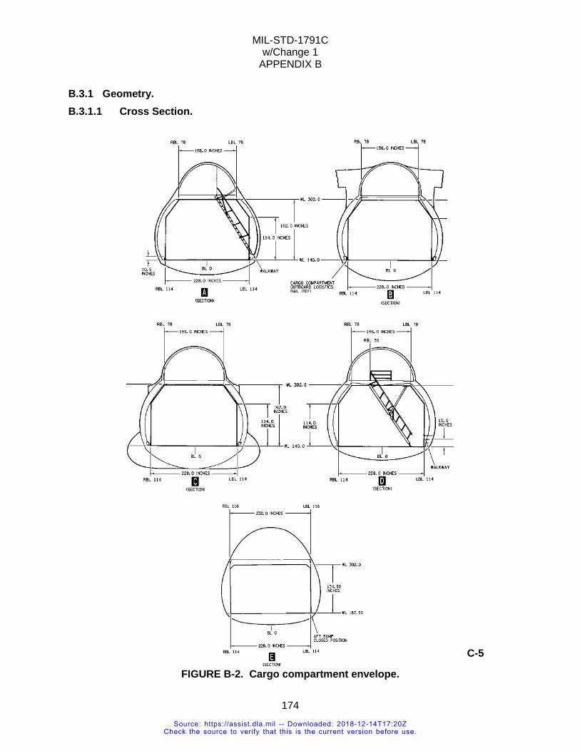
MIL-STD-1791C w/Change 1
APPENDIX B
174
B.3.1 Geometry. B.3.1.1 Cross Section.
FIGURE B-2. Cargo compartment envelope.
C-5
Source: https://assist.dla.mil -- Downloaded: 2018-12-14T17:20ZCheck the source to verify that this is the current version before use.
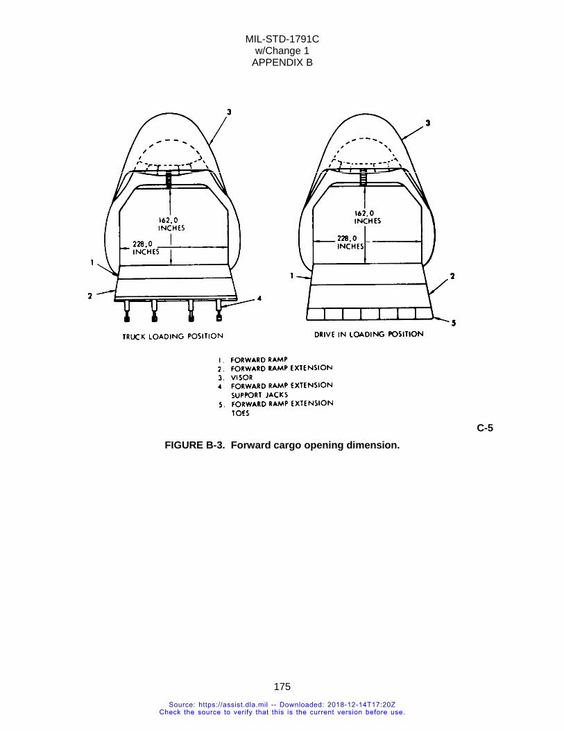
MIL-STD-1791C w/Change 1
APPENDIX B
175
C-5 FIGURE B-3. Forward cargo opening dimension.
Source: https://assist.dla.mil -- Downloaded: 2018-12-14T17:20ZCheck the source to verify that this is the current version before use.
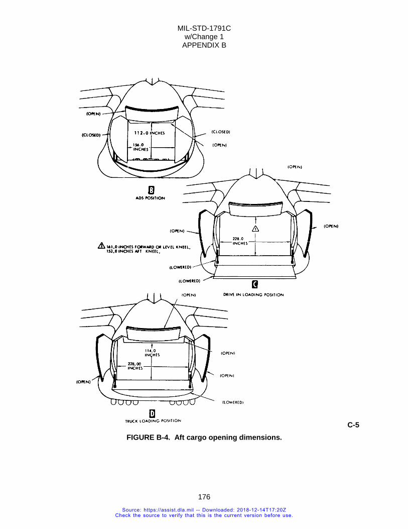
MIL-STD-1791C w/Change 1
APPENDIX B
176
C-5 FIGURE B-4. Aft cargo opening dimensions.
Source: https://assist.dla.mil -- Downloaded: 2018-12-14T17:20ZCheck the source to verify that this is the current version before use.
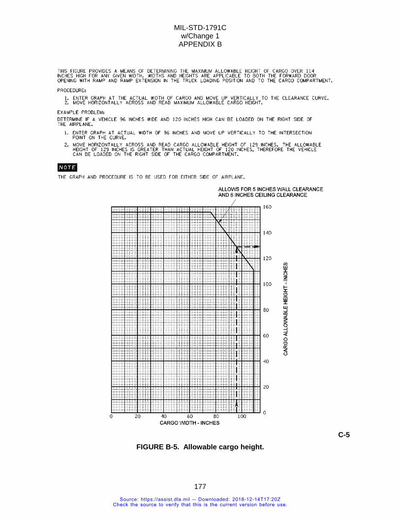
MIL-STD-1791C w/Change 1
APPENDIX B
177
C-5 FIGURE B-5. Allowable cargo height.
Source: https://assist.dla.mil -- Downloaded: 2018-12-14T17:20ZCheck the source to verify that this is the current version before use.
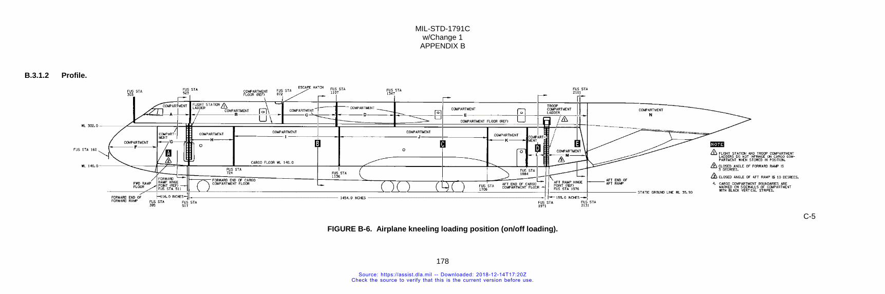
MIL-STD-1791C w/Change 1
APPENDIX B
178
B.3.1.2 Profile.
C-5 FIGURE B-6. Airplane kneeling loading position (on/off loading).
Source: https://assist.dla.mil -- Downloaded: 2018-12-14T17:20ZCheck the source to verify that this is the current version before use.
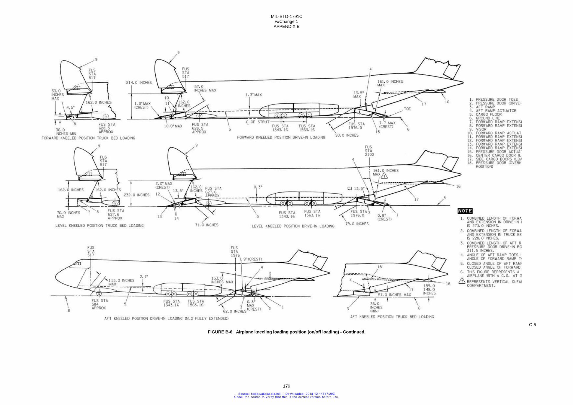
MIL-STD-1791C w/Change 1
APPENDIX B
179
C-5 FIGURE B-6. Airplane kneeling loading position (on/off loading) - Continued.
Source: https://assist.dla.mil -- Downloaded: 2018-12-14T17:20ZCheck the source to verify that this is the current version before use.
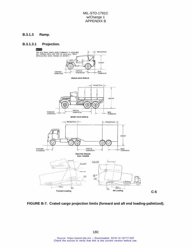
MIL-STD-1791C w/Change 1
APPENDIX B
180
B.3.1.3 Ramp.
B.3.1.3.1 Projection.
C-5
FIGURE B-7. Crated cargo projection limits (forward and aft end loading-palletized).
Source: https://assist.dla.mil -- Downloaded: 2018-12-14T17:20ZCheck the source to verify that this is the current version before use.
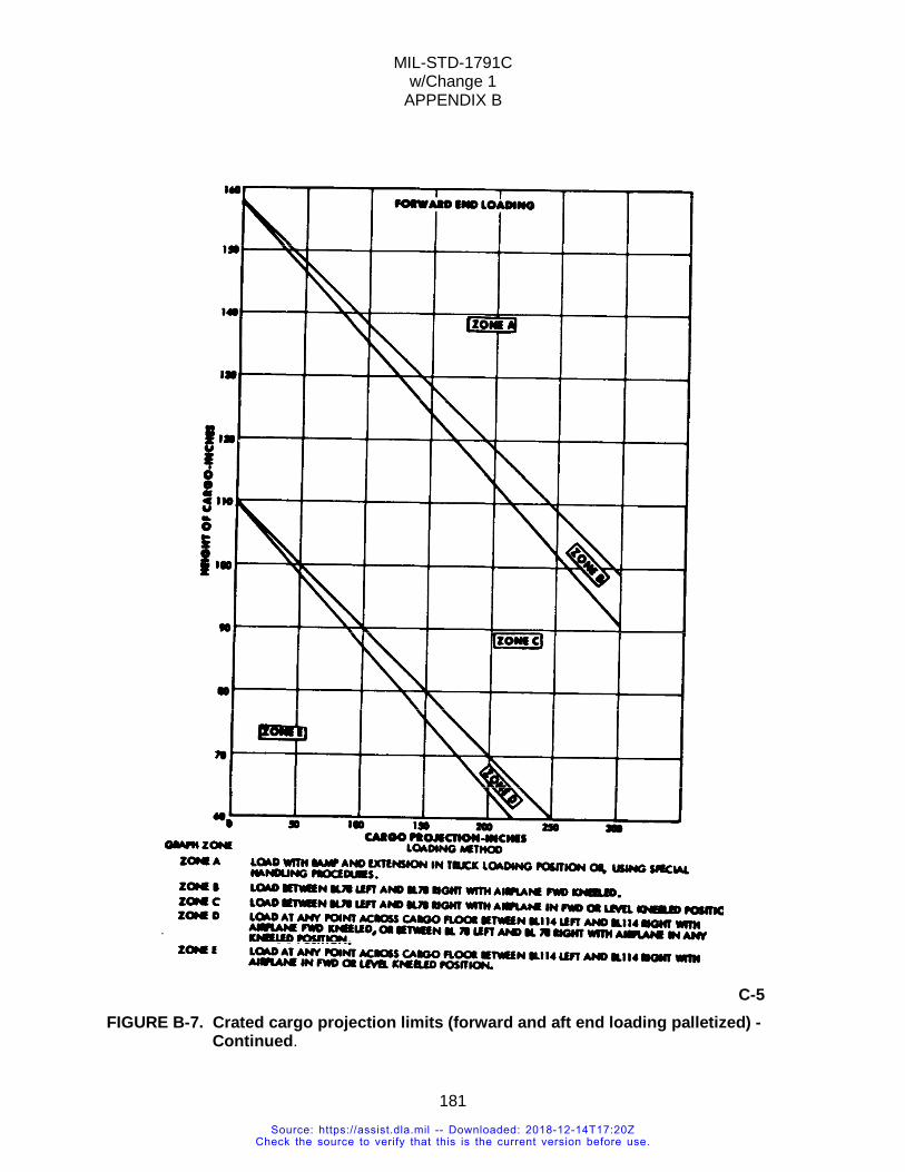
MIL-STD-1791C w/Change 1
APPENDIX B
181
C-5 FIGURE B-7. Crated cargo projection limits (forward and aft end loading palletized) -
Continued.
Source: https://assist.dla.mil -- Downloaded: 2018-12-14T17:20ZCheck the source to verify that this is the current version before use.
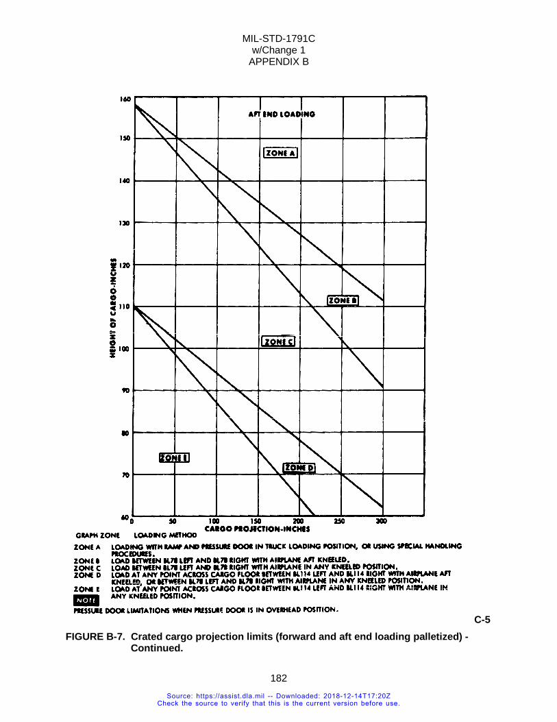
MIL-STD-1791C w/Change 1
APPENDIX B
182
C-5 FIGURE B-7. Crated cargo projection limits (forward and aft end loading palletized) -
Continued.
Source: https://assist.dla.mil -- Downloaded: 2018-12-14T17:20ZCheck the source to verify that this is the current version before use.
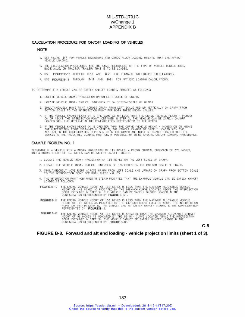
MIL-STD-1791C w/Change 1
APPENDIX B
183
C-5 FIGURE B-8. Forward and aft end loading - vehicle projection limits (sheet 1 of 3).
Source: https://assist.dla.mil -- Downloaded: 2018-12-14T17:20ZCheck the source to verify that this is the current version before use.

MIL-STD-1791C w/Change 1
APPENDIX B
184
C-5 FIGURE B-8. Forward and aft end loading - vehicle projection limits (sheet 2 of 3).
Source: https://assist.dla.mil -- Downloaded: 2018-12-14T17:20ZCheck the source to verify that this is the current version before use.
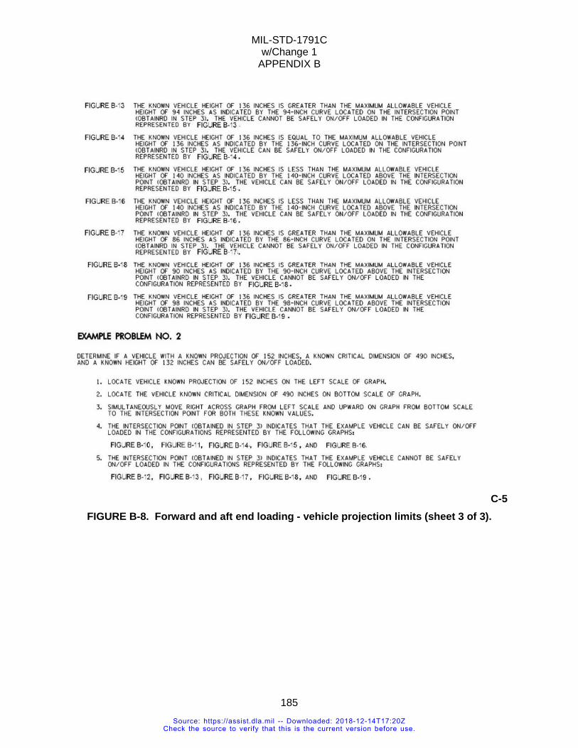
MIL-STD-1791C w/Change 1
APPENDIX B
185
C-5 FIGURE B-8. Forward and aft end loading - vehicle projection limits (sheet 3 of 3).
Source: https://assist.dla.mil -- Downloaded: 2018-12-14T17:20ZCheck the source to verify that this is the current version before use.
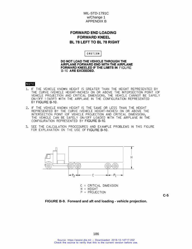
MIL-STD-1791C w/Change 1
APPENDIX B
186
C-5 FIGURE B-9. Forward and aft end loading - vehicle projection.
Source: https://assist.dla.mil -- Downloaded: 2018-12-14T17:20ZCheck the source to verify that this is the current version before use.
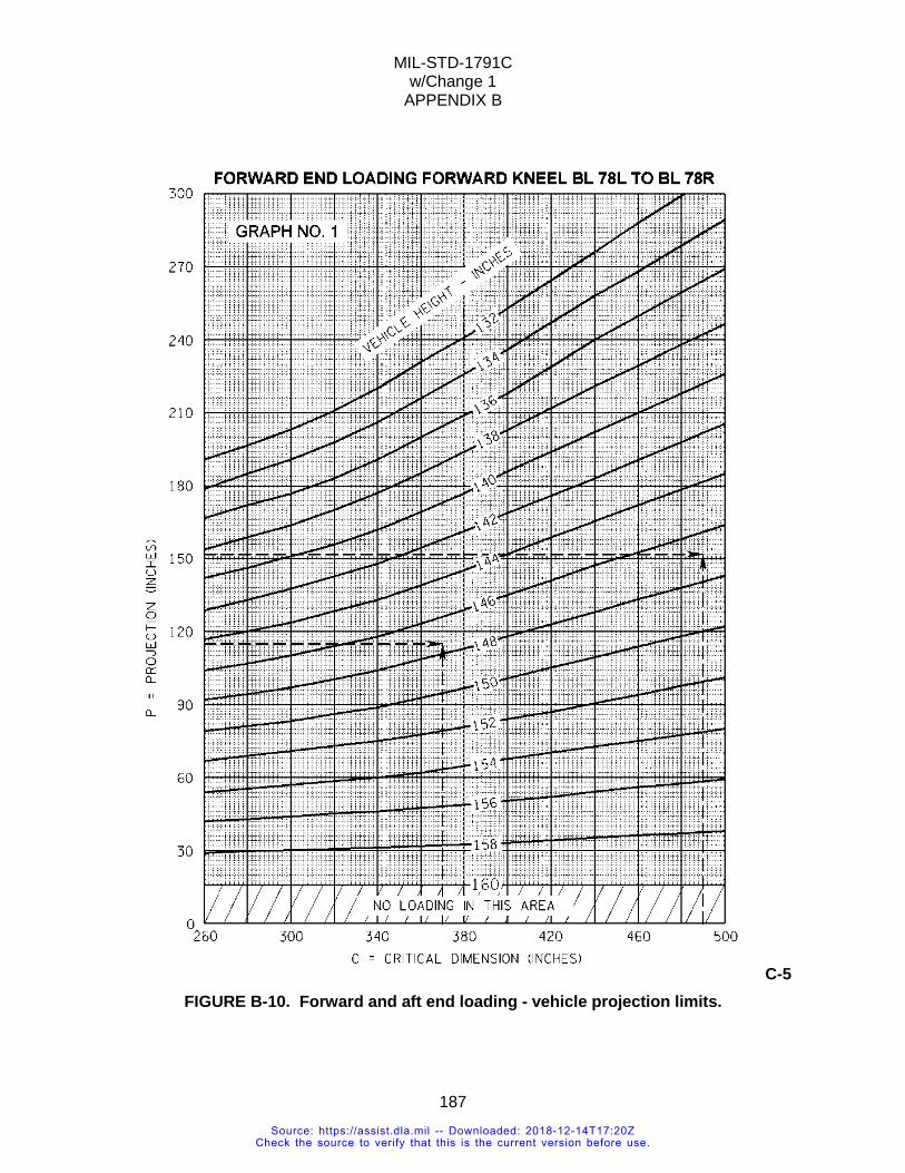
MIL-STD-1791C w/Change 1
APPENDIX B
187
C-5 FIGURE B-10. Forward and aft end loading - vehicle projection limits.
Source: https://assist.dla.mil -- Downloaded: 2018-12-14T17:20ZCheck the source to verify that this is the current version before use.
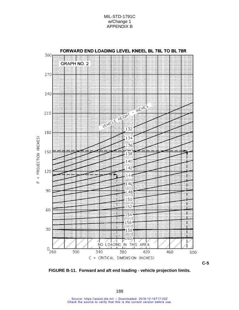
MIL-STD-1791C w/Change 1
APPENDIX B
188
C-5 FIGURE B-11. Forward and aft end loading - vehicle projection limits.
Source: https://assist.dla.mil -- Downloaded: 2018-12-14T17:20ZCheck the source to verify that this is the current version before use.
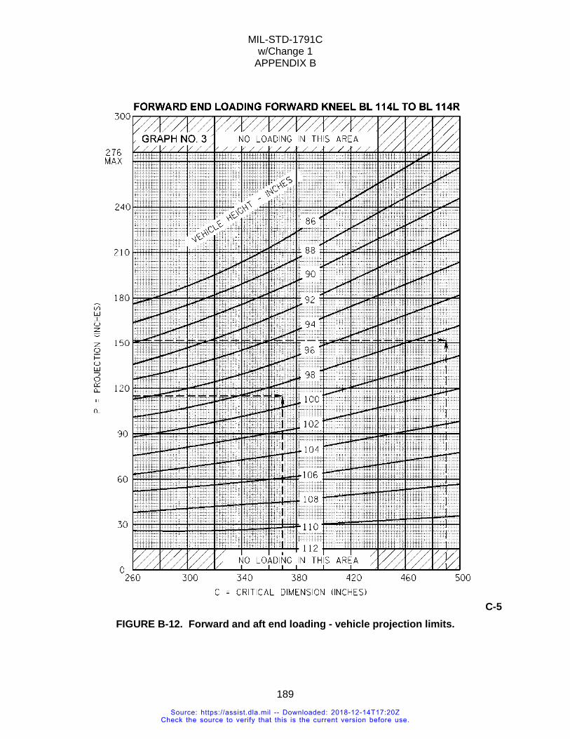
MIL-STD-1791C w/Change 1
APPENDIX B
189
C-5 FIGURE B-12. Forward and aft end loading - vehicle projection limits.
Source: https://assist.dla.mil -- Downloaded: 2018-12-14T17:20ZCheck the source to verify that this is the current version before use.
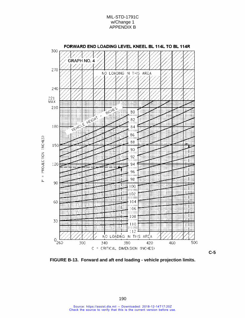
MIL-STD-1791C w/Change 1
APPENDIX B
190
C-5 FIGURE B-13. Forward and aft end loading - vehicle projection limits.
Source: https://assist.dla.mil -- Downloaded: 2018-12-14T17:20ZCheck the source to verify that this is the current version before use.
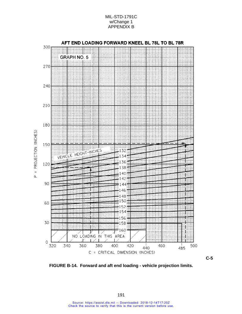
MIL-STD-1791C w/Change 1
APPENDIX B
191
C-5 FIGURE B-14. Forward and aft end loading - vehicle projection limits.
Source: https://assist.dla.mil -- Downloaded: 2018-12-14T17:20ZCheck the source to verify that this is the current version before use.
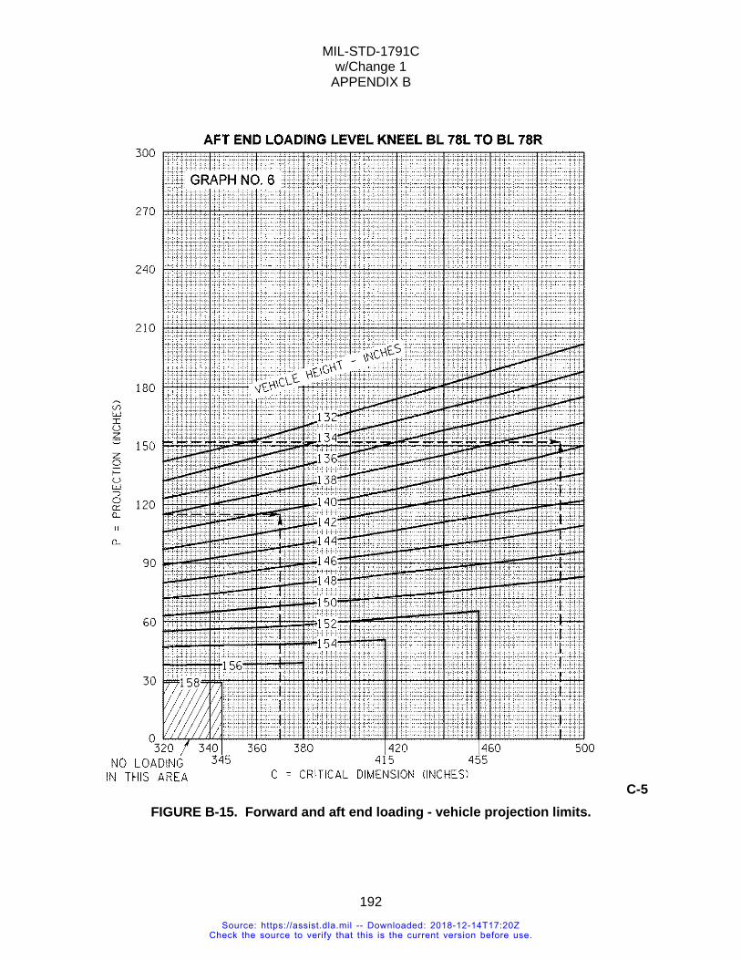
MIL-STD-1791C w/Change 1
APPENDIX B
192
C-5 FIGURE B-15. Forward and aft end loading - vehicle projection limits.
Source: https://assist.dla.mil -- Downloaded: 2018-12-14T17:20ZCheck the source to verify that this is the current version before use.

MIL-STD-1791C w/Change 1
APPENDIX B
193
C-5 FIGURE B-16. Forward and aft end loading - vehicle projection limits.
Source: https://assist.dla.mil -- Downloaded: 2018-12-14T17:20ZCheck the source to verify that this is the current version before use.
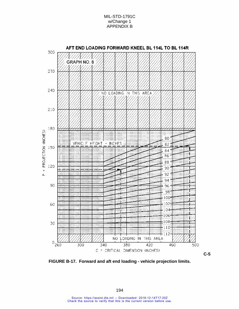
MIL-STD-1791C w/Change 1
APPENDIX B
194
C-5 FIGURE B-17. Forward and aft end loading - vehicle projection limits.
Source: https://assist.dla.mil -- Downloaded: 2018-12-14T17:20ZCheck the source to verify that this is the current version before use.
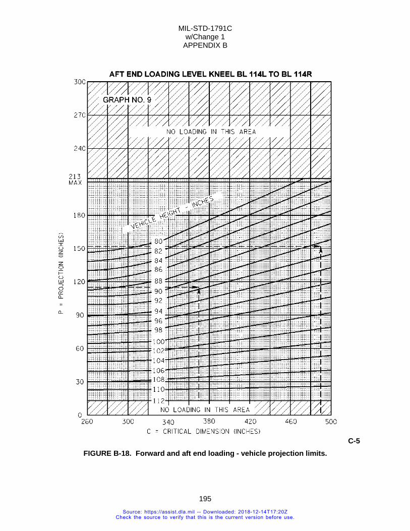
MIL-STD-1791C w/Change 1
APPENDIX B
195
C-5 FIGURE B-18. Forward and aft end loading - vehicle projection limits.
Source: https://assist.dla.mil -- Downloaded: 2018-12-14T17:20ZCheck the source to verify that this is the current version before use.
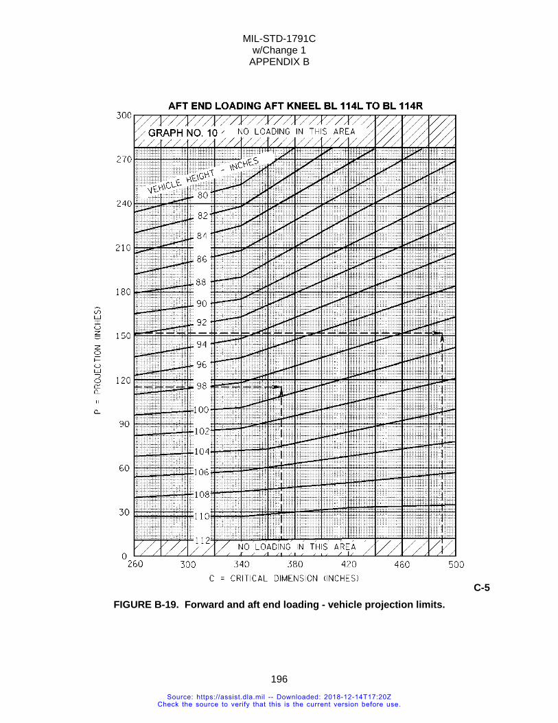
MIL-STD-1791C w/Change 1
APPENDIX B
196
C-5 FIGURE B-19. Forward and aft end loading - vehicle projection limits.
Source: https://assist.dla.mil -- Downloaded: 2018-12-14T17:20ZCheck the source to verify that this is the current version before use.
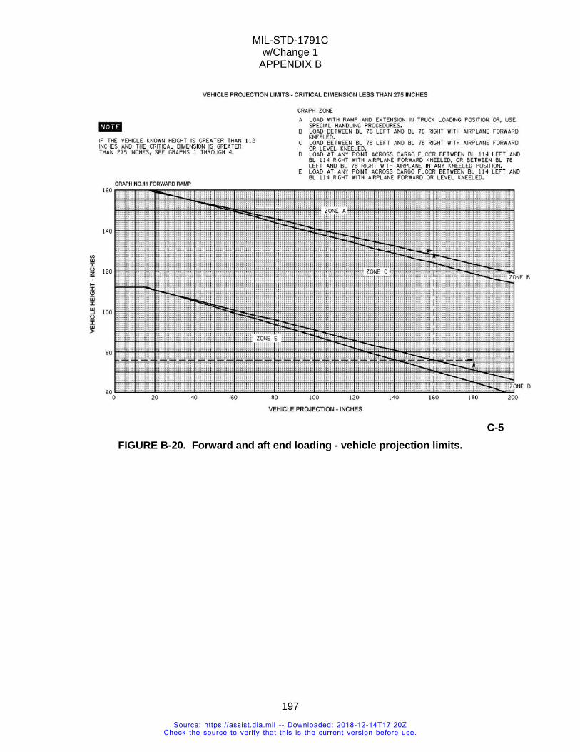
MIL-STD-1791C w/Change 1
APPENDIX B
197
C-5
FIGURE B-20. Forward and aft end loading - vehicle projection limits.
Source: https://assist.dla.mil -- Downloaded: 2018-12-14T17:20ZCheck the source to verify that this is the current version before use.
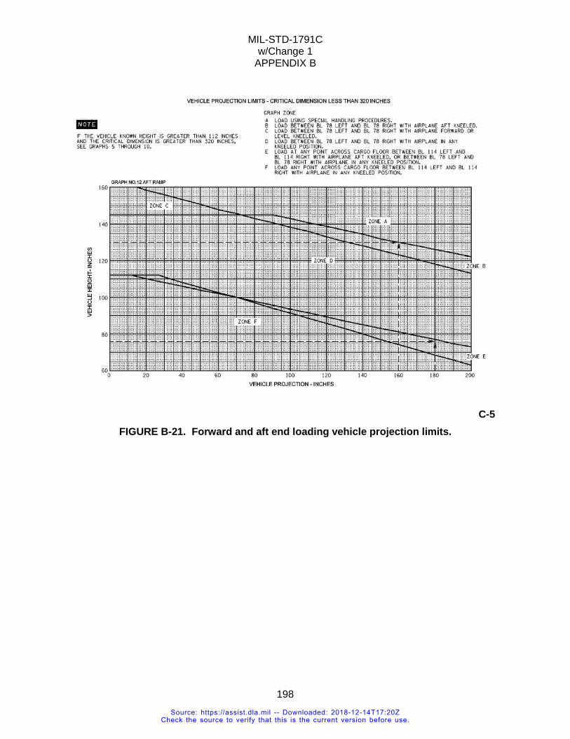
MIL-STD-1791C w/Change 1
APPENDIX B
198
C-5
FIGURE B-21. Forward and aft end loading vehicle projection limits.
Source: https://assist.dla.mil -- Downloaded: 2018-12-14T17:20ZCheck the source to verify that this is the current version before use.
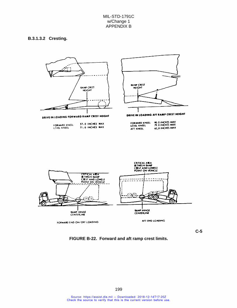
MIL-STD-1791C w/Change 1
APPENDIX B
199
B.3.1.3.2 Cresting.
C-5 FIGURE B-22. Forward and aft ramp crest limits.
Source: https://assist.dla.mil -- Downloaded: 2018-12-14T17:20ZCheck the source to verify that this is the current version before use.
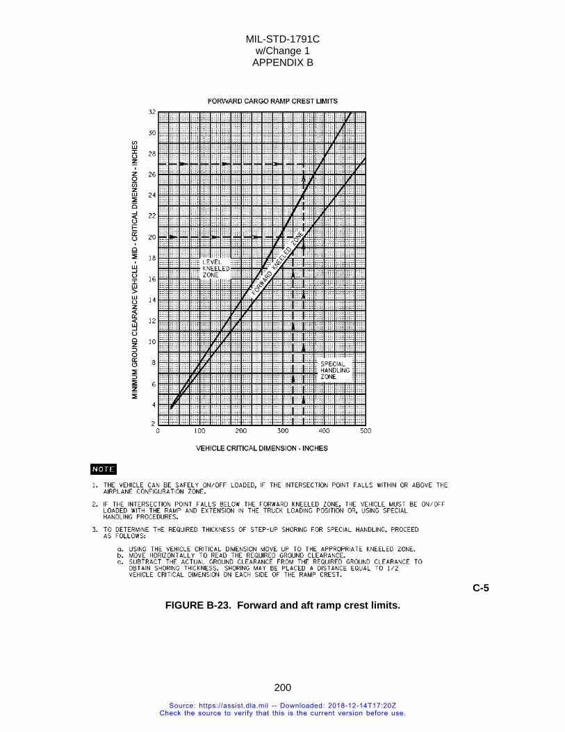
MIL-STD-1791C w/Change 1
APPENDIX B
200
C-5 FIGURE B-23. Forward and aft ramp crest limits.
Source: https://assist.dla.mil -- Downloaded: 2018-12-14T17:20ZCheck the source to verify that this is the current version before use.
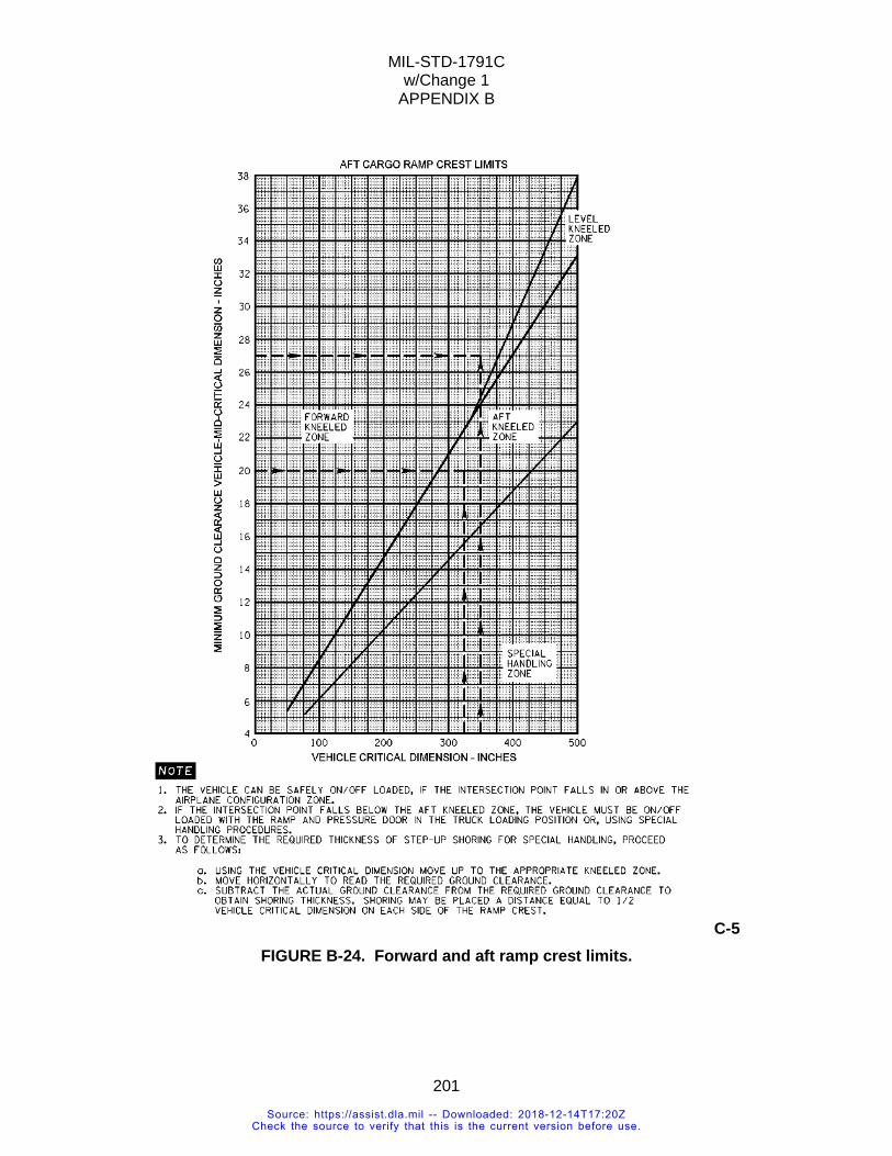
MIL-STD-1791C w/Change 1
APPENDIX B
201
C-5 FIGURE B-24. Forward and aft ramp crest limits.
Source: https://assist.dla.mil -- Downloaded: 2018-12-14T17:20ZCheck the source to verify that this is the current version before use.
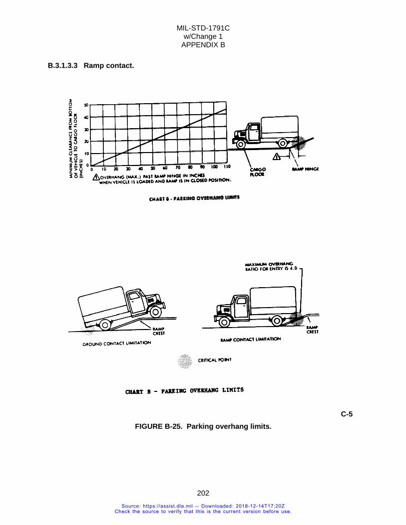
MIL-STD-1791C w/Change 1
APPENDIX B
202
B.3.1.3.3 Ramp contact.
C-5
FIGURE B-25. Parking overhang limits.
Source: https://assist.dla.mil -- Downloaded: 2018-12-14T17:20ZCheck the source to verify that this is the current version before use.
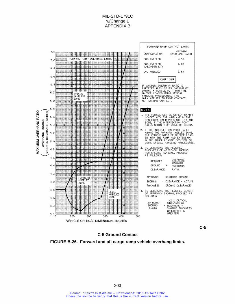
MIL-STD-1791C w/Change 1
APPENDIX B
203
C-5 C-5 Ground Contact
FIGURE B-26. Forward and aft cargo ramp vehicle overhang limits.
Source: https://assist.dla.mil -- Downloaded: 2018-12-14T17:20ZCheck the source to verify that this is the current version before use.
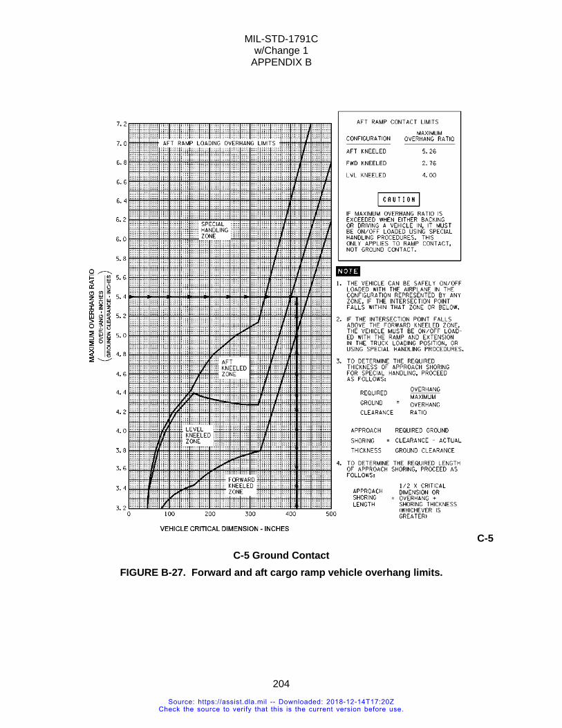
MIL-STD-1791C w/Change 1
APPENDIX B
204
C-5 C-5 Ground Contact
FIGURE B-27. Forward and aft cargo ramp vehicle overhang limits.
Source: https://assist.dla.mil -- Downloaded: 2018-12-14T17:20ZCheck the source to verify that this is the current version before use.
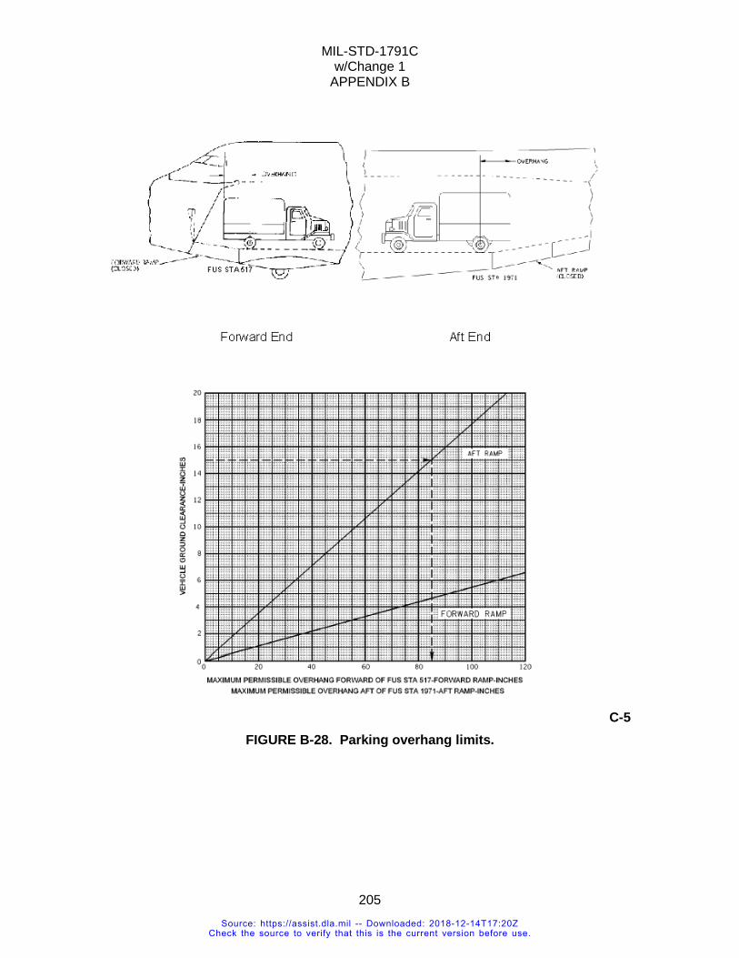
MIL-STD-1791C w/Change 1
APPENDIX B
205
C-5 FIGURE B-28. Parking overhang limits.
Source: https://assist.dla.mil -- Downloaded: 2018-12-14T17:20ZCheck the source to verify that this is the current version before use.
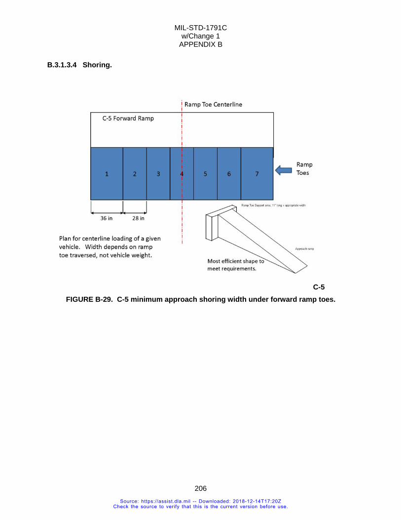
MIL-STD-1791C w/Change 1
APPENDIX B
206
B.3.1.3.4 Shoring.
C-5
FIGURE B-29. C-5 minimum approach shoring width under forward ramp toes.
Source: https://assist.dla.mil -- Downloaded: 2018-12-14T17:20ZCheck the source to verify that this is the current version before use.
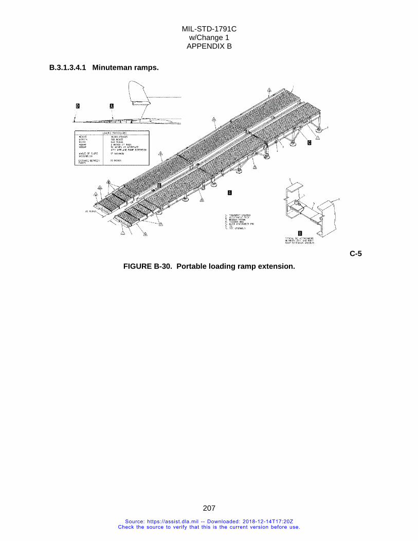
MIL-STD-1791C w/Change 1
APPENDIX B
207
B.3.1.3.4.1 Minuteman ramps.
C-5 FIGURE B-30. Portable loading ramp extension.
Source: https://assist.dla.mil -- Downloaded: 2018-12-14T17:20ZCheck the source to verify that this is the current version before use.
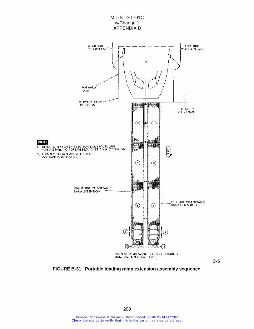
MIL-STD-1791C w/Change 1
APPENDIX B
208
C-5 FIGURE B-31. Portable loading ramp extension assembly sequence.
Source: https://assist.dla.mil -- Downloaded: 2018-12-14T17:20ZCheck the source to verify that this is the current version before use.
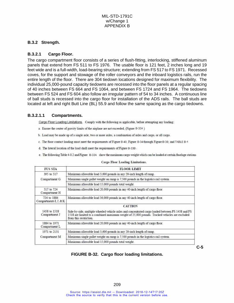
MIL-STD-1791C w/Change 1
APPENDIX B
209
B.3.2 Strength.
B.3.2.1 Cargo Floor. The cargo compartment floor consists of a series of flush-fitting, interlocking, stiffened aluminum panels that extend from FS 511 to FS 1976. The usable floor is 121 feet, 2 inches long and 19 feet wide and is a full-width, load-bearing structure; extending from FS 517 to FS 1971. Recessed coves, for the support and stowage of the roller conveyors and the inboard logistics rails, run the entire length of the floor. There are 304 tiedown locations designed for maximum flexibility. The individual 25,000-pound capacity tiedowns are recessed into the floor panels at a regular spacing of 40 inches between FS 664 and FS 1064, and between FS 1724 and FS 1964. The tiedowns between FS 524 and FS 604 also follow an irregular pattern of 54 to 34 inches. A continuous line of ball studs is recessed into the cargo floor for installation of the ADS rails. The ball studs are located at left and right Butt Line (BL) 55.9 and follow the same spacing as the cargo tiedowns.
B.3.2.1.1 Compartments.
C-5 FIGURE B-32. Cargo floor loading limitations.
Source: https://assist.dla.mil -- Downloaded: 2018-12-14T17:20ZCheck the source to verify that this is the current version before use.
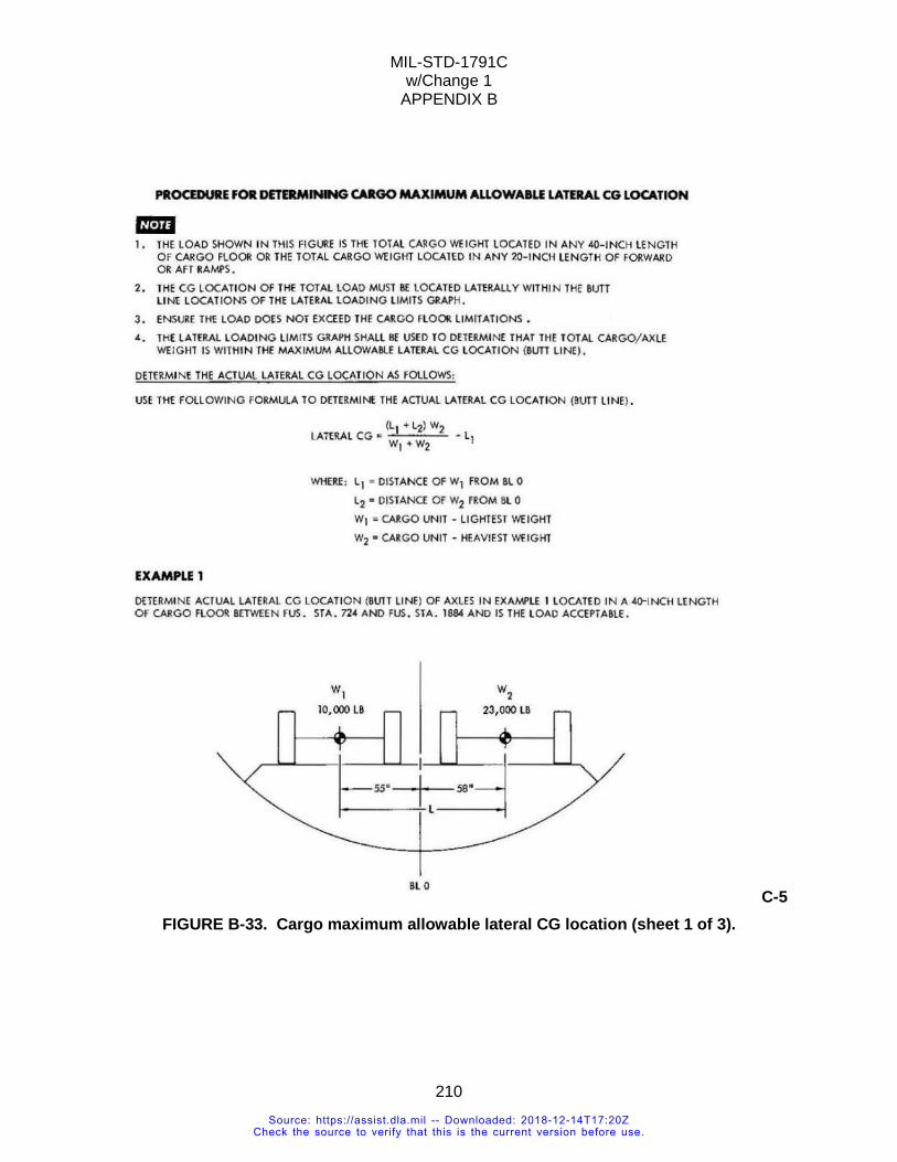
MIL-STD-1791C w/Change 1
APPENDIX B
210
C-5 FIGURE B-33. Cargo maximum allowable lateral CG location (sheet 1 of 3).
Source: https://assist.dla.mil -- Downloaded: 2018-12-14T17:20ZCheck the source to verify that this is the current version before use.
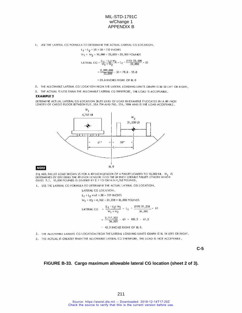
MIL-STD-1791C w/Change 1
APPENDIX B
211
C-5
FIGURE B-33. Cargo maximum allowable lateral CG location (sheet 2 of 3).
Source: https://assist.dla.mil -- Downloaded: 2018-12-14T17:20ZCheck the source to verify that this is the current version before use.
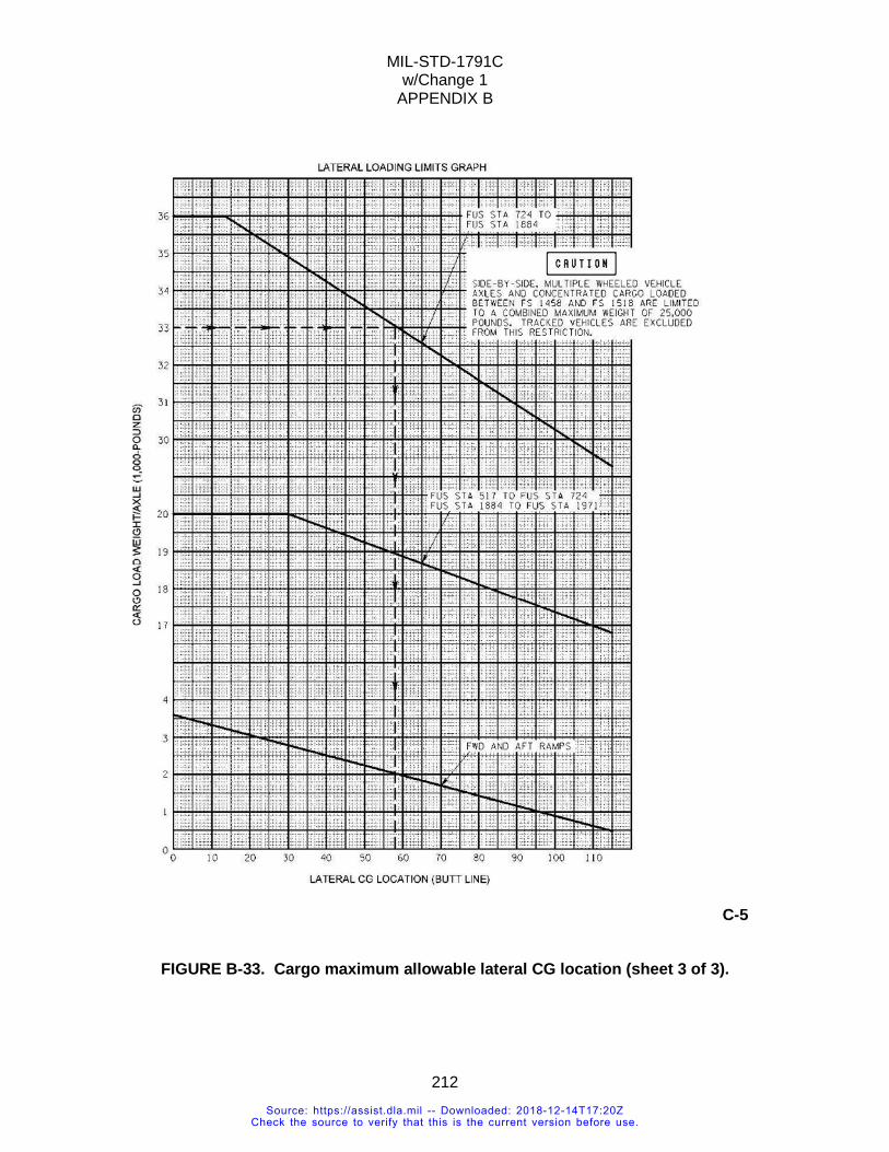
MIL-STD-1791C w/Change 1
APPENDIX B
212
C-5
FIGURE B-33. Cargo maximum allowable lateral CG location (sheet 3 of 3).
Source: https://assist.dla.mil -- Downloaded: 2018-12-14T17:20ZCheck the source to verify that this is the current version before use.
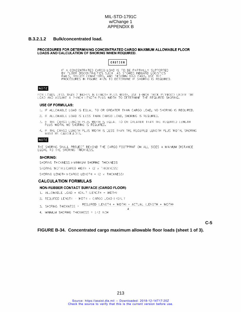
MIL-STD-1791C w/Change 1
APPENDIX B
213
B.3.2.1.2 Bulk/concentrated load.
C-5 FIGURE B-34. Concentrated cargo maximum allowable floor loads (sheet 1 of 3).
Source: https://assist.dla.mil -- Downloaded: 2018-12-14T17:20ZCheck the source to verify that this is the current version before use.
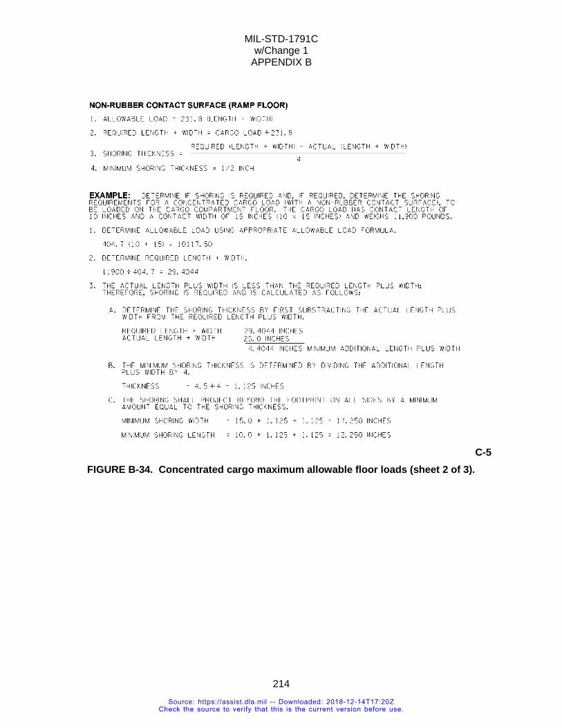
MIL-STD-1791C w/Change 1
APPENDIX B
214
C-5 FIGURE B-34. Concentrated cargo maximum allowable floor loads (sheet 2 of 3).
Source: https://assist.dla.mil -- Downloaded: 2018-12-14T17:20ZCheck the source to verify that this is the current version before use.
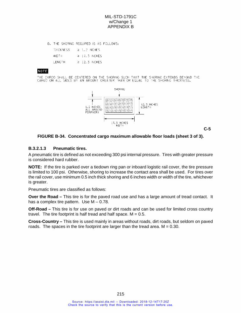
MIL-STD-1791C w/Change 1
APPENDIX B
215
C-5 FIGURE B-34. Concentrated cargo maximum allowable floor loads (sheet 3 of 3).
B.3.2.1.3 Pneumatic tires. A pneumatic tire is defined as not exceeding 300 psi internal pressure. Tires with greater pressure is considered hard rubber. NOTE: If the tire is parked over a tiedown ring pan or inboard logistic rail cover, the tire pressure is limited to 100 psi. Otherwise, shoring to increase the contact area shall be used. For tires over the rail cover, use minimum 0.5 inch thick shoring and 6 inches width or width of the tire, whichever is greater. Pneumatic tires are classified as follows: Over the Road – This tire is for the paved road use and has a large amount of tread contact. It has a complex tire pattern. Use M – 0.78. Off-Road – This tire is for use on paved or dirt roads and can be used for limited cross country travel. The tire footprint is half tread and half space. M = 0.5. Cross-Country – This tire is used mainly in areas without roads, dirt roads, but seldom on paved roads. The spaces in the tire footprint are larger than the tread area. M = 0.30.
Source: https://assist.dla.mil -- Downloaded: 2018-12-14T17:20ZCheck the source to verify that this is the current version before use.
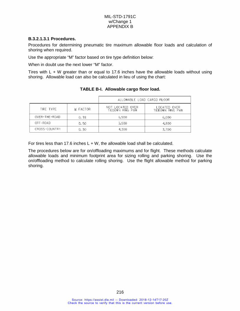
MIL-STD-1791C w/Change 1
APPENDIX B
216
B.3.2.1.3.1 Procedures. Procedures for determining pneumatic tire maximum allowable floor loads and calculation of shoring when required. Use the appropriate “M” factor based on tire type definition below: When in doubt use the next lower “M” factor. Tires with L + W greater than or equal to 17.6 inches have the allowable loads without using shoring. Allowable load can also be calculated in lieu of using the chart:
TABLE B-I. Allowable cargo floor load.
For tires less than 17.6 inches L + W, the allowable load shall be calculated. The procedures below are for on/offloading maximums and for flight. These methods calculate allowable loads and minimum footprint area for sizing rolling and parking shoring. Use the on/offloading method to calculate rolling shoring. Use the flight allowable method for parking shoring.
Source: https://assist.dla.mil -- Downloaded: 2018-12-14T17:20ZCheck the source to verify that this is the current version before use.
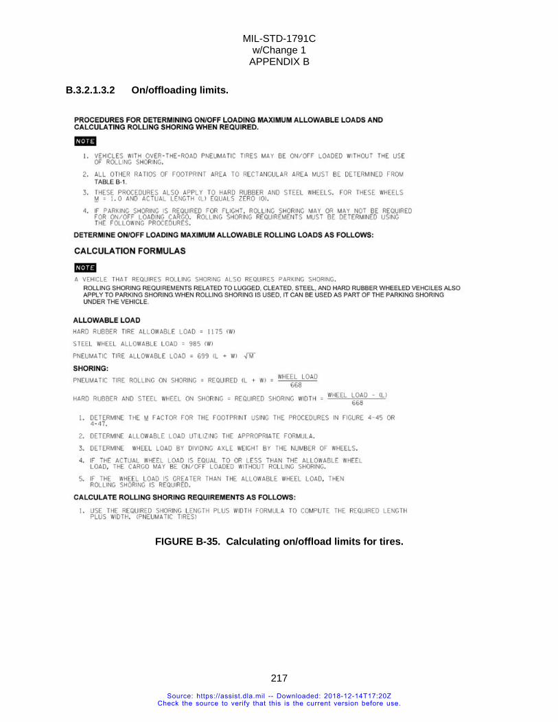
MIL-STD-1791C w/Change 1
APPENDIX B
217
B.3.2.1.3.2 On/offloading limits.
FIGURE B-35. Calculating on/offload limits for tires.
Source: https://assist.dla.mil -- Downloaded: 2018-12-14T17:20ZCheck the source to verify that this is the current version before use.
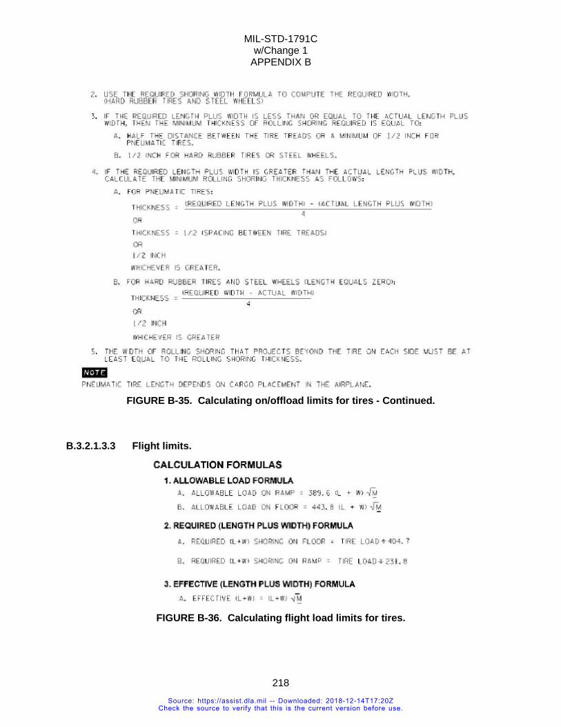
MIL-STD-1791C w/Change 1
APPENDIX B
218
FIGURE B-35. Calculating on/offload limits for tires - Continued.
B.3.2.1.3.3 Flight limits.
FIGURE B-36. Calculating flight load limits for tires.
Source: https://assist.dla.mil -- Downloaded: 2018-12-14T17:20ZCheck the source to verify that this is the current version before use.
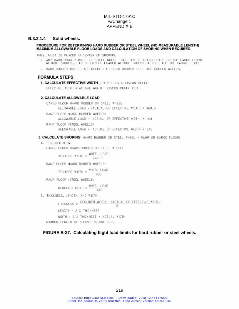
MIL-STD-1791C w/Change 1
APPENDIX B
219
B.3.2.1.4 Solid wheels.
FIGURE B-37. Calculating flight load limits for hard rubber or steel wheels.
Source: https://assist.dla.mil -- Downloaded: 2018-12-14T17:20ZCheck the source to verify that this is the current version before use.
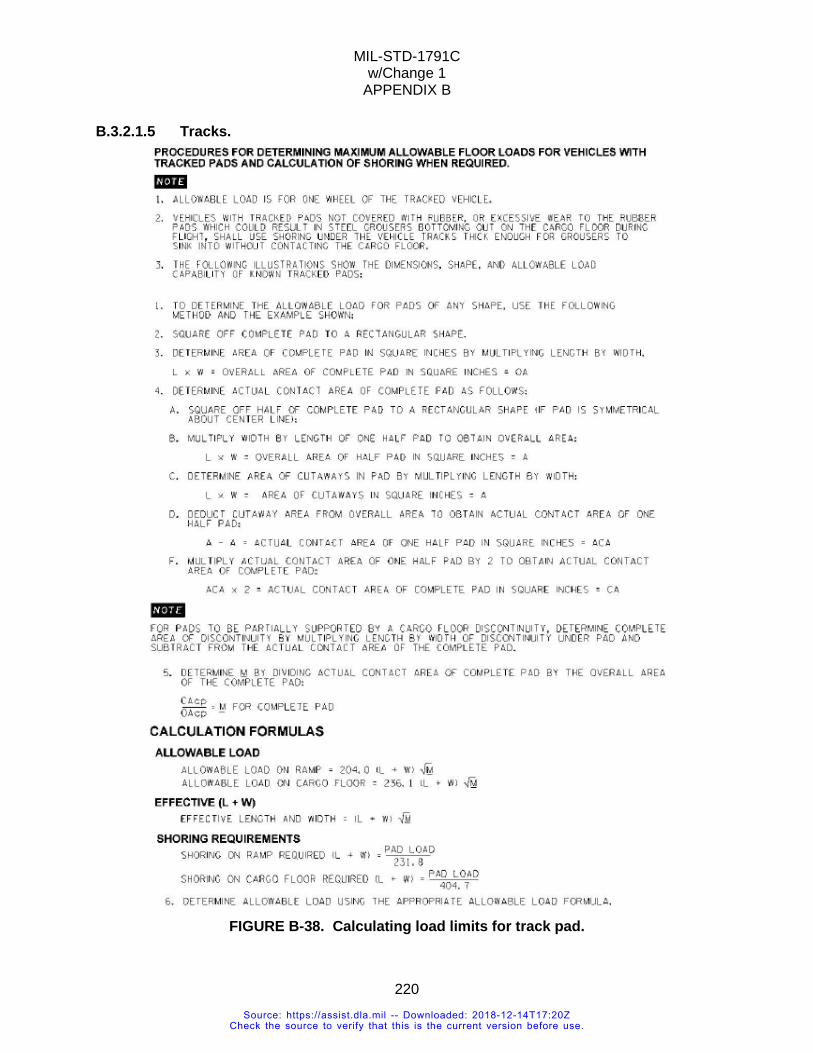
MIL-STD-1791C w/Change 1
APPENDIX B
220
B.3.2.1.5 Tracks.
FIGURE B-38. Calculating load limits for track pad.
Source: https://assist.dla.mil -- Downloaded: 2018-12-14T17:20ZCheck the source to verify that this is the current version before use.
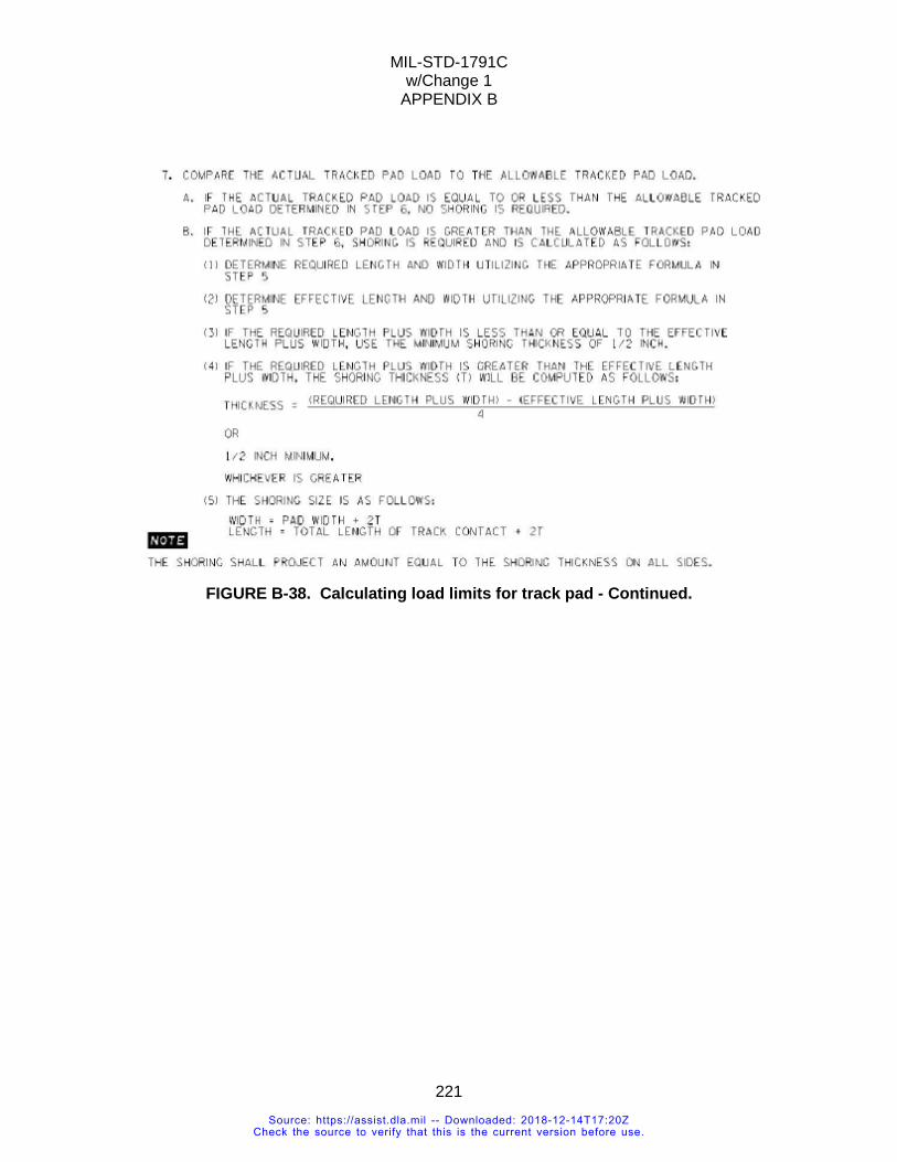
MIL-STD-1791C w/Change 1
APPENDIX B
221
FIGURE B-38. Calculating load limits for track pad - Continued.
Source: https://assist.dla.mil -- Downloaded: 2018-12-14T17:20ZCheck the source to verify that this is the current version before use.
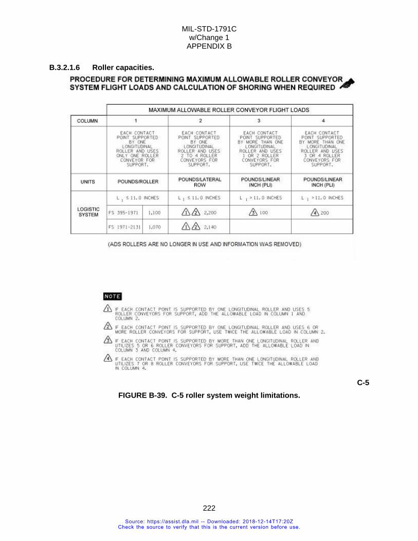
MIL-STD-1791C w/Change 1
APPENDIX B
222
B.3.2.1.6 Roller capacities.
C-5
FIGURE B-39. C-5 roller system weight limitations.
Source: https://assist.dla.mil -- Downloaded: 2018-12-14T17:20ZCheck the source to verify that this is the current version before use.
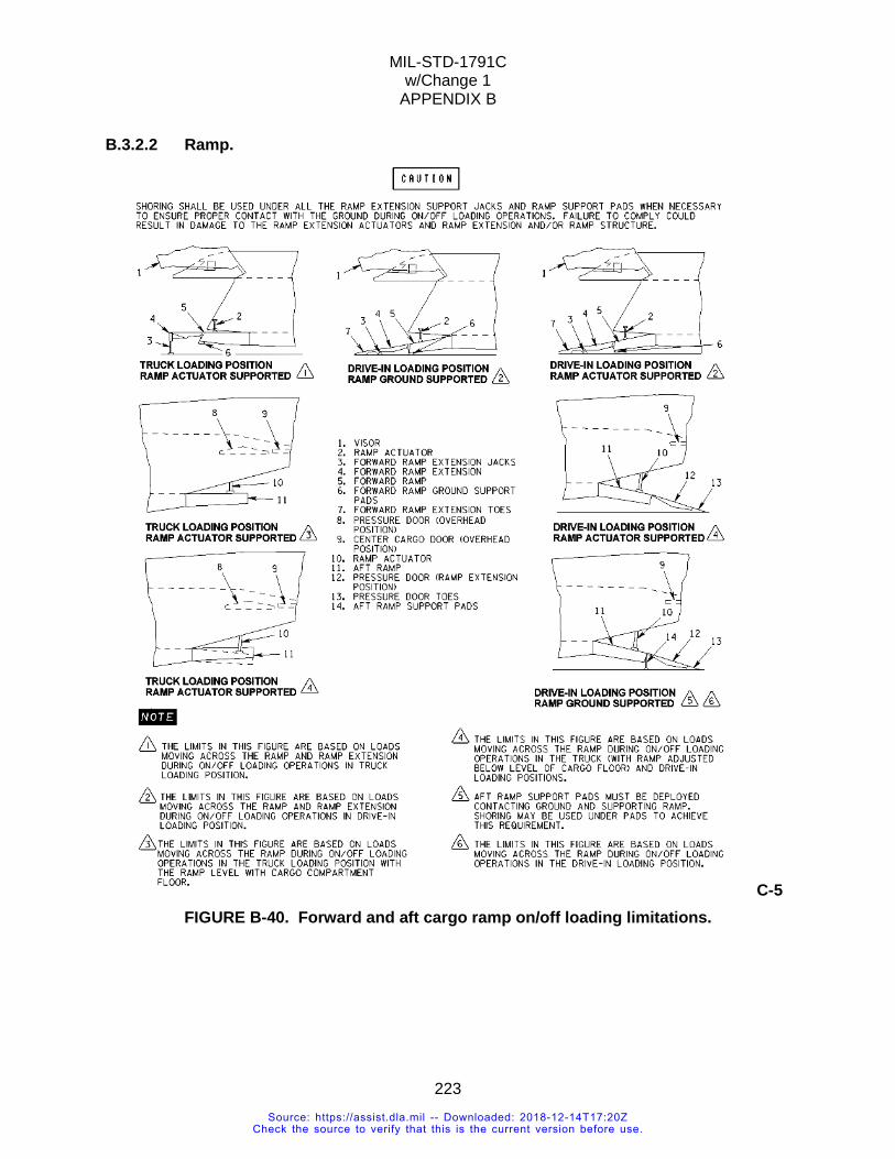
MIL-STD-1791C w/Change 1
APPENDIX B
223
B.3.2.2 Ramp.
C-5 FIGURE B-40. Forward and aft cargo ramp on/off loading limitations.
Source: https://assist.dla.mil -- Downloaded: 2018-12-14T17:20ZCheck the source to verify that this is the current version before use.
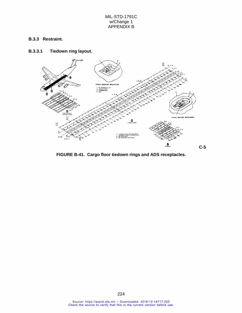
MIL-STD-1791C w/Change 1
APPENDIX B
224
B.3.3 Restraint.
B.3.3.1 Tiedown ring layout.
C-5 FIGURE B-41. Cargo floor tiedown rings and ADS receptacles.
Source: https://assist.dla.mil -- Downloaded: 2018-12-14T17:20ZCheck the source to verify that this is the current version before use.
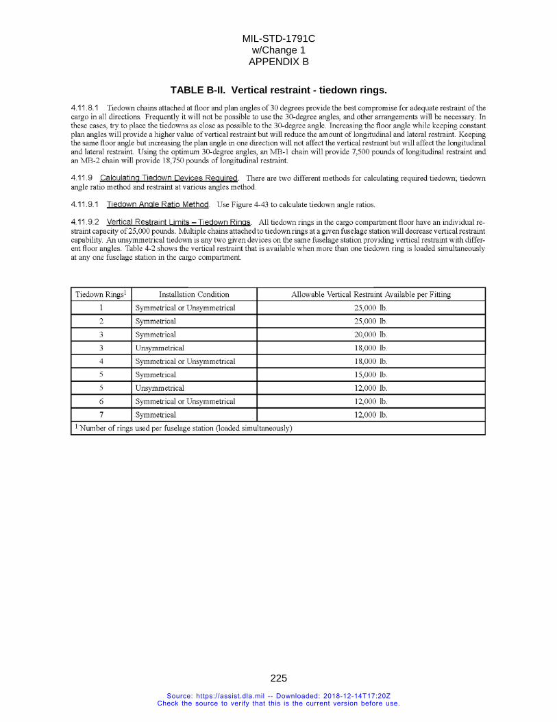
MIL-STD-1791C w/Change 1
APPENDIX B
225
TABLE B-II. Vertical restraint - tiedown rings.
Source: https://assist.dla.mil -- Downloaded: 2018-12-14T17:20ZCheck the source to verify that this is the current version before use.
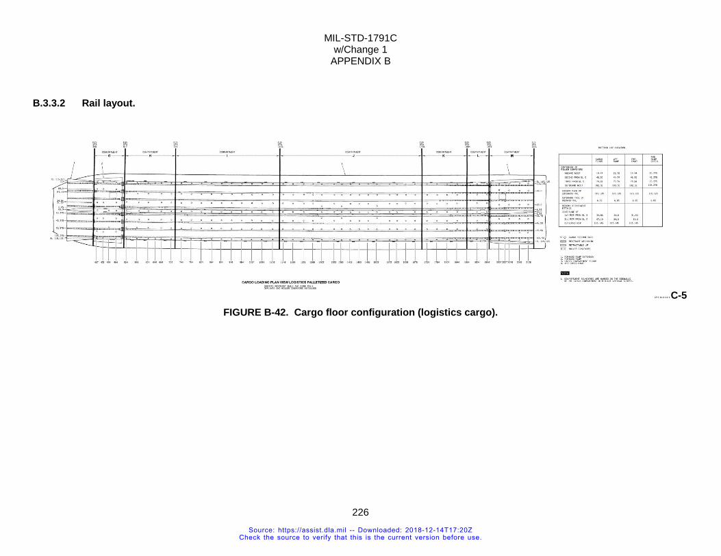
MIL-STD-1791C w/Change 1
APPENDIX B
226
B.3.3.2 Rail layout.
C-5 FIGURE B-42. Cargo floor configuration (logistics cargo).
Source: https://assist.dla.mil -- Downloaded: 2018-12-14T17:20ZCheck the source to verify that this is the current version before use.
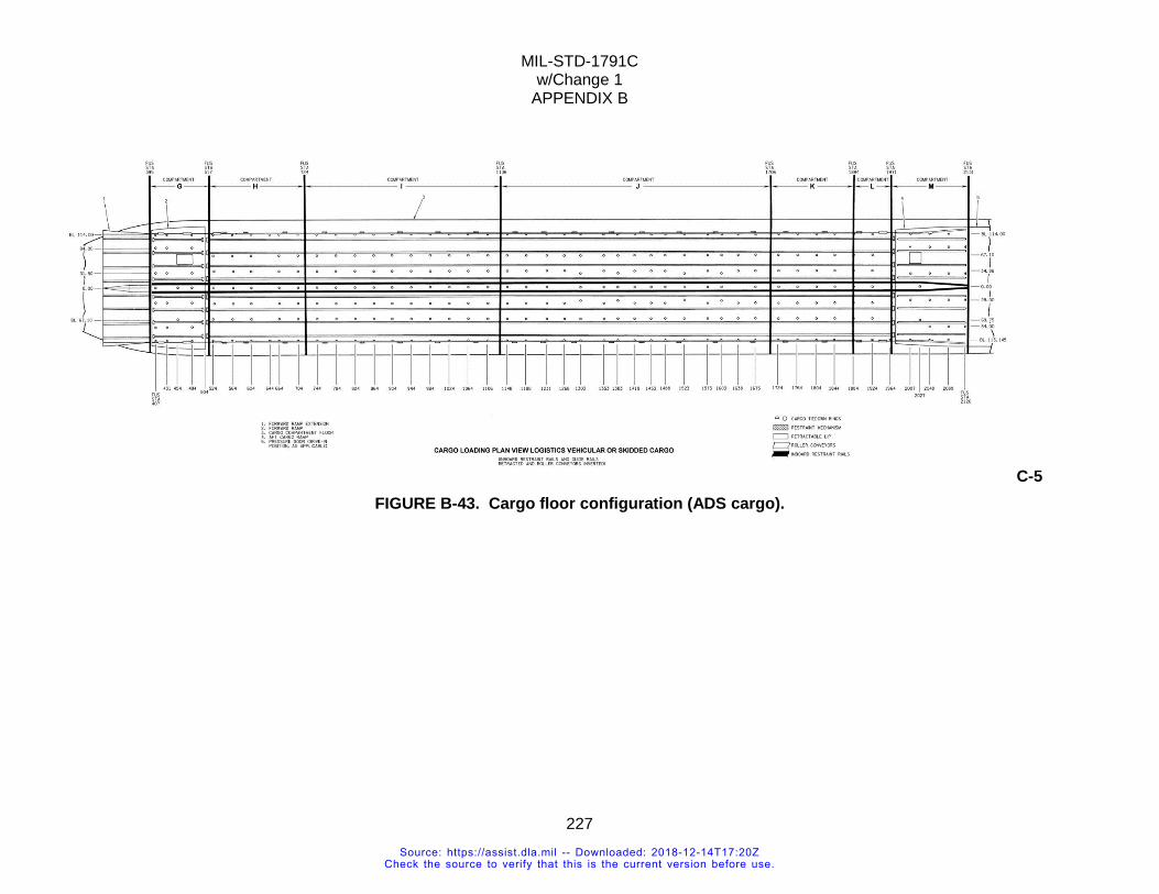
MIL-STD-1791C w/Change 1
APPENDIX B
227
C-5 FIGURE B-43. Cargo floor configuration (ADS cargo).
Source: https://assist.dla.mil -- Downloaded: 2018-12-14T17:20ZCheck the source to verify that this is the current version before use.
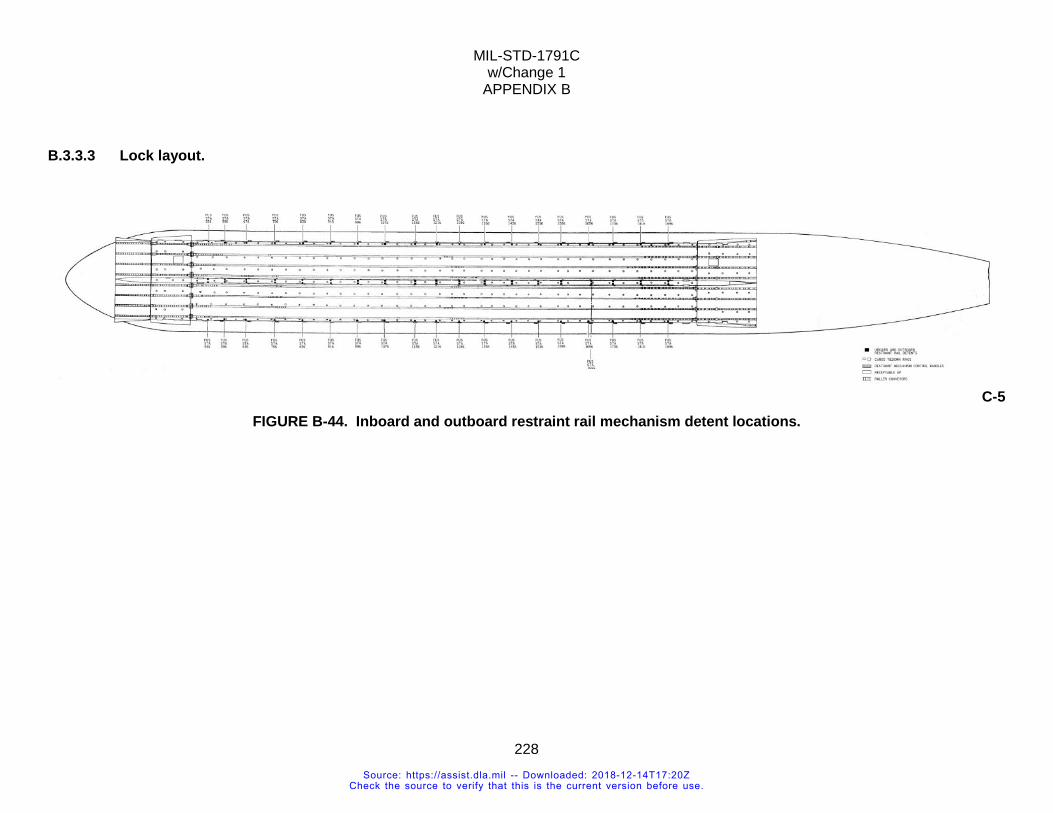
MIL-STD-1791C w/Change 1
APPENDIX B
228
B.3.3.3 Lock layout.
C-5 FIGURE B-44. Inboard and outboard restraint rail mechanism detent locations.
Source: https://assist.dla.mil -- Downloaded: 2018-12-14T17:20ZCheck the source to verify that this is the current version before use.
MIL-STD-1791C w/Change 1
APPENDIX B
229
B.3.4 Additional information.
B.3.4.1 Venting. Seven overboard vents are provided in the cargo compartment for overboard venting of fumes and vapors. The vents are for connection to items of cargo carried in the aircraft requiring cryogenic venting, or to exhausts of vehicles or internal combustion engines that may be operating in the cargo compartment. The cryogenic vents are on the left side of the cargo compartment at FS 734, 1219, and 1779, all at WL 200. The exhaust vents are on the right side of the cargo compartment at FS 594, 734, 1219, and 1779, all at WL 200. Each vent consists of a tube extending through the sidewall of the cargo compartment, a sealing plug, and a coupling. In use, the sealing plug is removed from the vent tube and the coupling is used to secure a cryogenic vent nozzle to the vent tube. When not in use, the coupling secures the sealing plug inside the vent tube to prevent loss of air during pressurized flight. The sealing plug is attached to a chain at each vent for easy accessibility. When not in use, the three cryogenic vent nozzles are stored in the LH stowage box at FS 1774. An exhaust nozzle, which can be inserted through the right side vent tube, is stowed at each of the right side vents. When installed, the nozzles direct the exhaust of engines into the airstream away from the side of the fuselage.
Source: https://assist.dla.mil -- Downloaded: 2018-12-14T17:20ZCheck the source to verify that this is the current version before use.
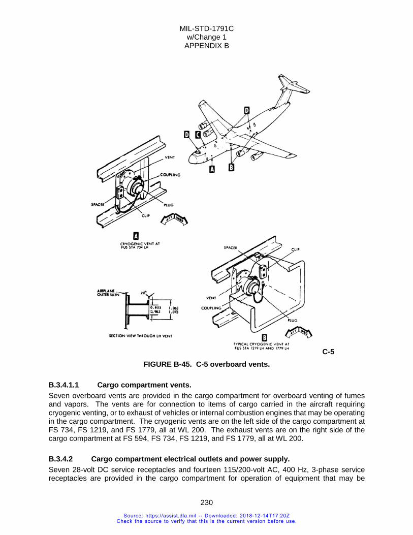
MIL-STD-1791C w/Change 1
APPENDIX B
230
C-5 FIGURE B-45. C-5 overboard vents.
B.3.4.1.1 Cargo compartment vents. Seven overboard vents are provided in the cargo compartment for overboard venting of fumes and vapors. The vents are for connection to items of cargo carried in the aircraft requiring cryogenic venting, or to exhaust of vehicles or internal combustion engines that may be operating in the cargo compartment. The cryogenic vents are on the left side of the cargo compartment at FS 734, FS 1219, and FS 1779, all at WL 200. The exhaust vents are on the right side of the cargo compartment at FS 594, FS 734, FS 1219, and FS 1779, all at WL 200.
B.3.4.2 Cargo compartment electrical outlets and power supply. Seven 28-volt DC service receptacles and fourteen 115/200-volt AC, 400 Hz, 3-phase service receptacles are provided in the cargo compartment for operation of equipment that may be
Source: https://assist.dla.mil -- Downloaded: 2018-12-14T17:20ZCheck the source to verify that this is the current version before use.
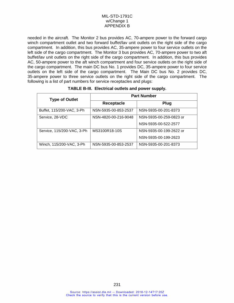
MIL-STD-1791C w/Change 1
APPENDIX B
231
needed in the aircraft. The Monitor 2 bus provides AC, 70-ampere power to the forward cargo winch compartment outlet and two forward buffet/lav unit outlets on the right side of the cargo compartment. In addition, this bus provides AC, 35-ampere power to four service outlets on the left side of the cargo compartment. The Monitor 3 bus provides AC, 70-ampere power to two aft buffet/lav unit outlets on the right side of the cargo compartment. In addition, this bus provides AC, 50-ampere power to the aft winch compartment and four service outlets on the right side of the cargo compartment. The main DC bus No. 1 provides DC, 35-ampere power to four service outlets on the left side of the cargo compartment. The Main DC bus No. 2 provides DC, 35-ampere power to three service outlets on the right side of the cargo compartment. The following is a list of part numbers for service receptacles and plugs:
TABLE B-III. Electrical outlets and power supply.
Type of Outlet Part Number
Receptacle Plug Buffet, 115/200-VAC, 3-Ph NSN-5935-00-853-2537 NSN-5935-00-201-8373
Service, 28-VDC NSN-4820-00-216-9048 NSN-5935-00-259-0823 or
NSN-5935-00-522-2577
Service, 115/200-VAC, 3-Ph MS3100R18-10S NSN-5935-00-199-2622 or
NSN-5935-00-199-2623
Winch, 115/200-VAC, 3-Ph NSN-5935-00-853-2537 NSN-5935-00-201-8373
Source: https://assist.dla.mil -- Downloaded: 2018-12-14T17:20ZCheck the source to verify that this is the current version before use.
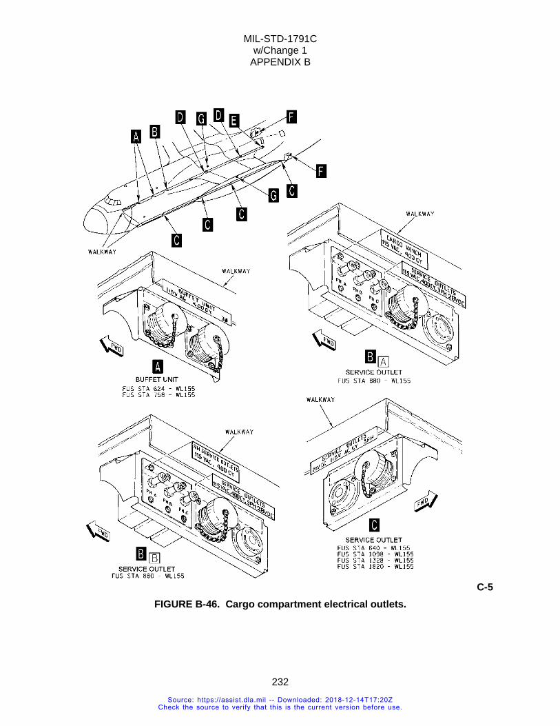
MIL-STD-1791C w/Change 1
APPENDIX B
232
C-5 FIGURE B-46. Cargo compartment electrical outlets.
Source: https://assist.dla.mil -- Downloaded: 2018-12-14T17:20ZCheck the source to verify that this is the current version before use.
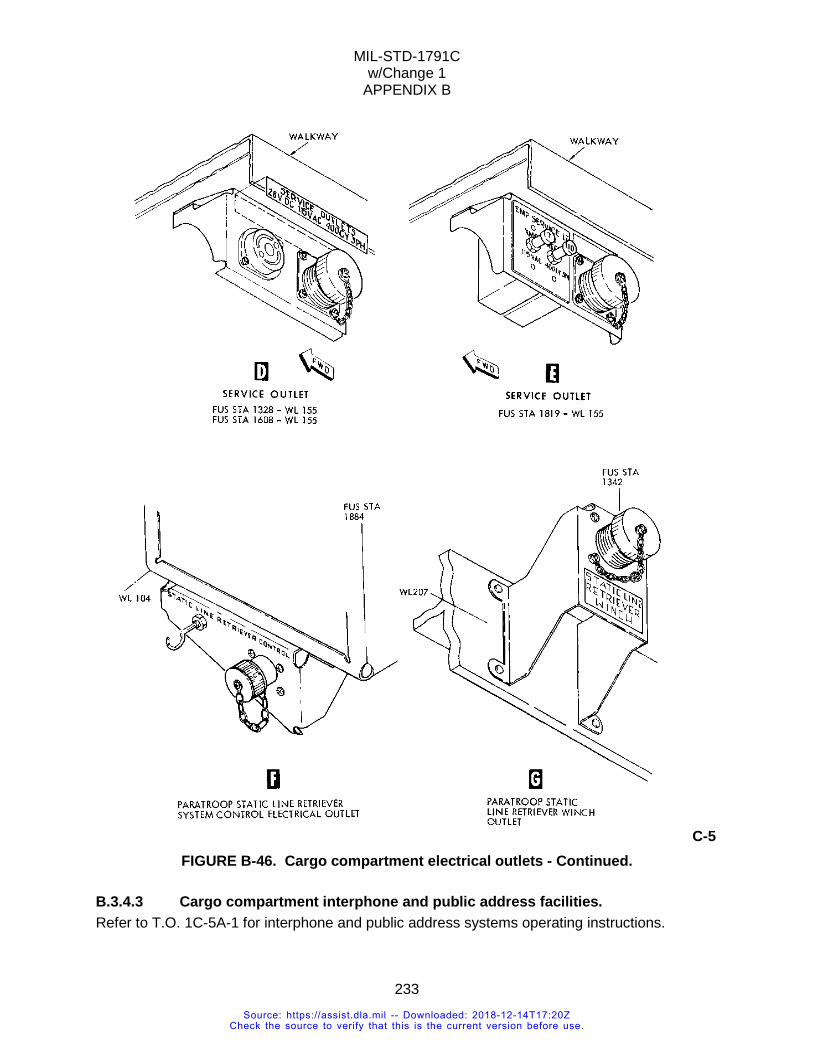
MIL-STD-1791C w/Change 1
APPENDIX B
233
C-5 FIGURE B-46. Cargo compartment electrical outlets - Continued.
B.3.4.3 Cargo compartment interphone and public address facilities. Refer to T.O. 1C-5A-1 for interphone and public address systems operating instructions.
Source: https://assist.dla.mil -- Downloaded: 2018-12-14T17:20ZCheck the source to verify that this is the current version before use.
MIL-STD-1791C w/Change 1
APPENDIX B
234
B.3.4.4 Troop jump signal lights. Troop jump signal lights, consisting of a red and a green light, are installed on the left and the right side of the cargo compartment at the left and right troop door areas. There are two sets of lights on each side of the cargo compartment; one set is located at FS 1844 and Water Line (WL) 195 and the other at FS 1844 and WL 220. The lights are controlled by two JUMP SIGNAL switches on the navigator Aerial Delivery System (ADS) control panel and by two JUMP SIGNAL switches on the copilot’s side console. Light brilliance is controlled by a TROOP JUMP, DIM-BRT toggle switch on the loadmaster’s aft control panel on the left side of the cargo compartment.
B.3.4.5 Cargo compartment lighting. The cargo compartment is provided with lights for general illumination, floodlighting of the forward and aft ramp areas, and emergency exit. The lights (except emergency exit) are controlled from the loadmaster forward and aft control panels.
Source: https://assist.dla.mil -- Downloaded: 2018-12-14T17:20ZCheck the source to verify that this is the current version before use.
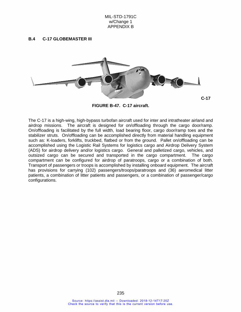
MIL-STD-1791C w/Change 1
APPENDIX B
235
B.4 C-17 GLOBEMASTER III
C-17 FIGURE B-47. C-17 aircraft.
The C-17 is a high-wing, high-bypass turbofan aircraft used for inter and intratheater airland and airdrop missions. The aircraft is designed for on/offloading through the cargo door/ramp. On/offloading is facilitated by the full width, load bearing floor, cargo door/ramp toes and the stabilizer struts. On/offloading can be accomplished directly from material handling equipment such as: K-loaders, forklifts, truckbed, flatbed or from the ground. Pallet on/offloading can be accomplished using the Logistic Rail Systems for logistics cargo and Airdrop Delivery System (ADS) for airdrop delivery and/or logistics cargo. General and palletized cargo, vehicles, and outsized cargo can be secured and transported in the cargo compartment. The cargo compartment can be configured for airdrop of paratroops, cargo or a combination of both. Transport of passengers or troops is accomplished by installing onboard equipment. The aircraft has provisions for carrying (102) passengers/troops/paratroops and (36) aeromedical litter patients, a combination of litter patients and passengers, or a combination of passenger/cargo configurations.
Source: https://assist.dla.mil -- Downloaded: 2018-12-14T17:20ZCheck the source to verify that this is the current version before use.
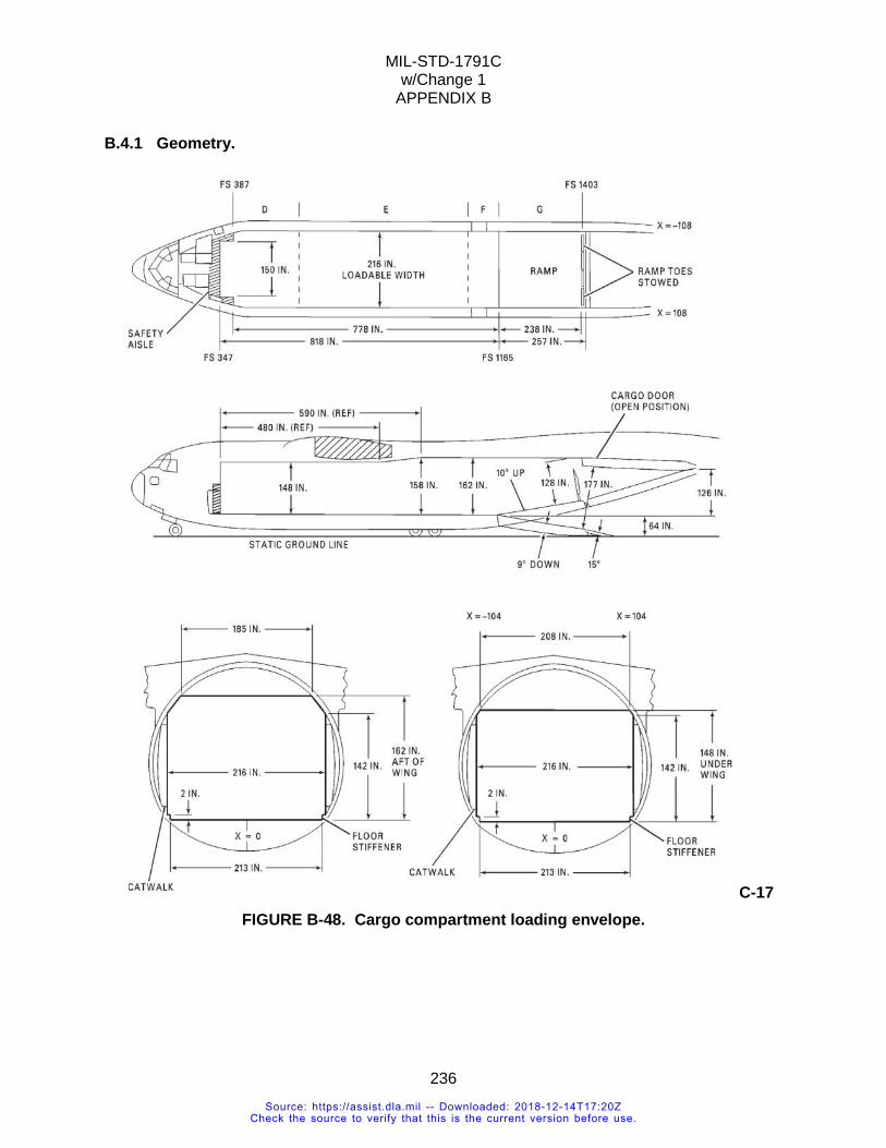
MIL-STD-1791C w/Change 1
APPENDIX B
236
B.4.1 Geometry.
C-17 FIGURE B-48. Cargo compartment loading envelope.
Source: https://assist.dla.mil -- Downloaded: 2018-12-14T17:20ZCheck the source to verify that this is the current version before use.
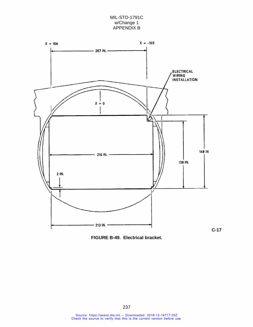
MIL-STD-1791C w/Change 1
APPENDIX B
237
C-17 FIGURE B-49. Electrical bracket.
Source: https://assist.dla.mil -- Downloaded: 2018-12-14T17:20ZCheck the source to verify that this is the current version before use.
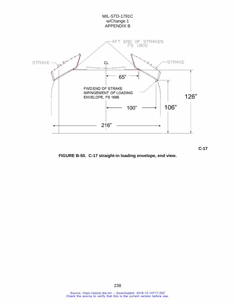
MIL-STD-1791C w/Change 1
APPENDIX B
238
C-17 FIGURE B-50. C-17 straight-in loading envelope, end view.
Source: https://assist.dla.mil -- Downloaded: 2018-12-14T17:20ZCheck the source to verify that this is the current version before use.
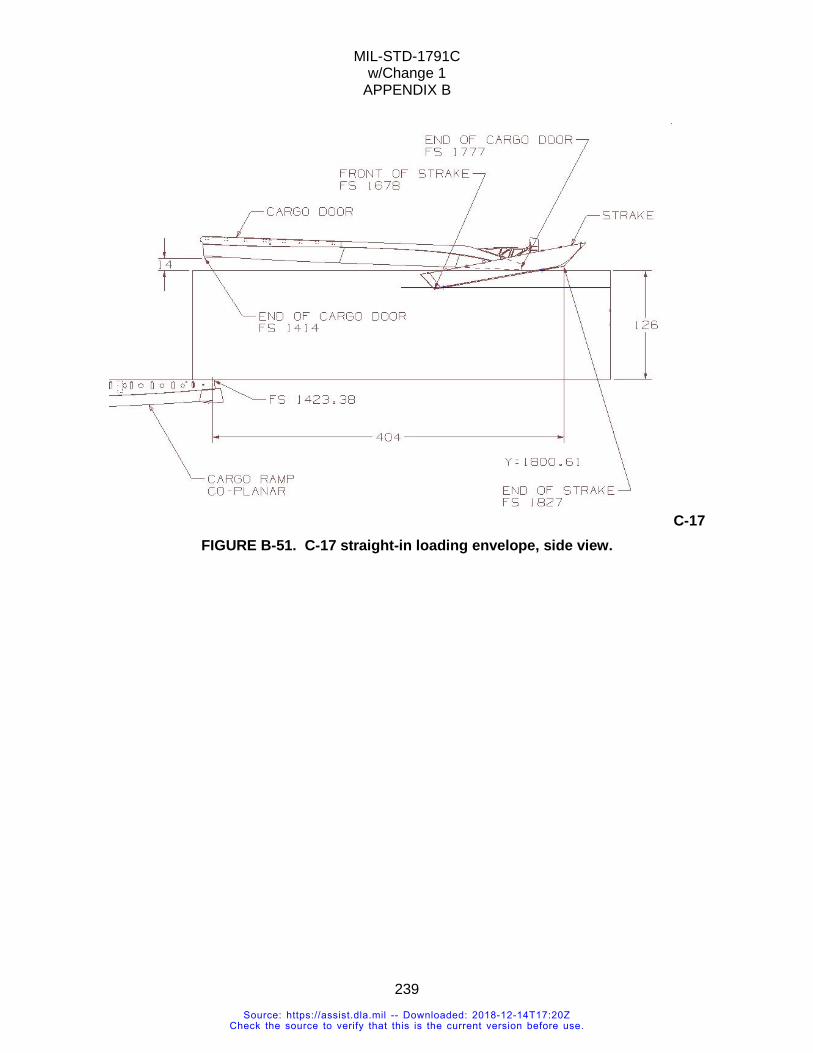
MIL-STD-1791C w/Change 1
APPENDIX B
239
C-17 FIGURE B-51. C-17 straight-in loading envelope, side view.
Source: https://assist.dla.mil -- Downloaded: 2018-12-14T17:20ZCheck the source to verify that this is the current version before use.
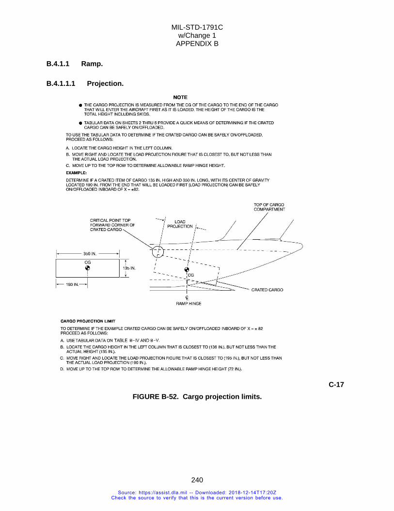
MIL-STD-1791C w/Change 1
APPENDIX B
240
B.4.1.1 Ramp.
B.4.1.1.1 Projection.
C-17 FIGURE B-52. Cargo projection limits.
Source: https://assist.dla.mil -- Downloaded: 2018-12-14T17:20ZCheck the source to verify that this is the current version before use.
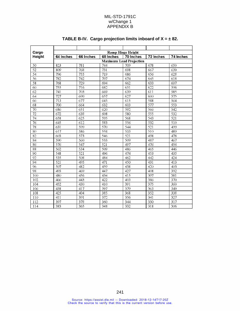
MIL-STD-1791C w/Change 1
APPENDIX B
241
TABLE B-IV. Cargo projection limits inboard of X = ± 82.
Source: https://assist.dla.mil -- Downloaded: 2018-12-14T17:20ZCheck the source to verify that this is the current version before use.
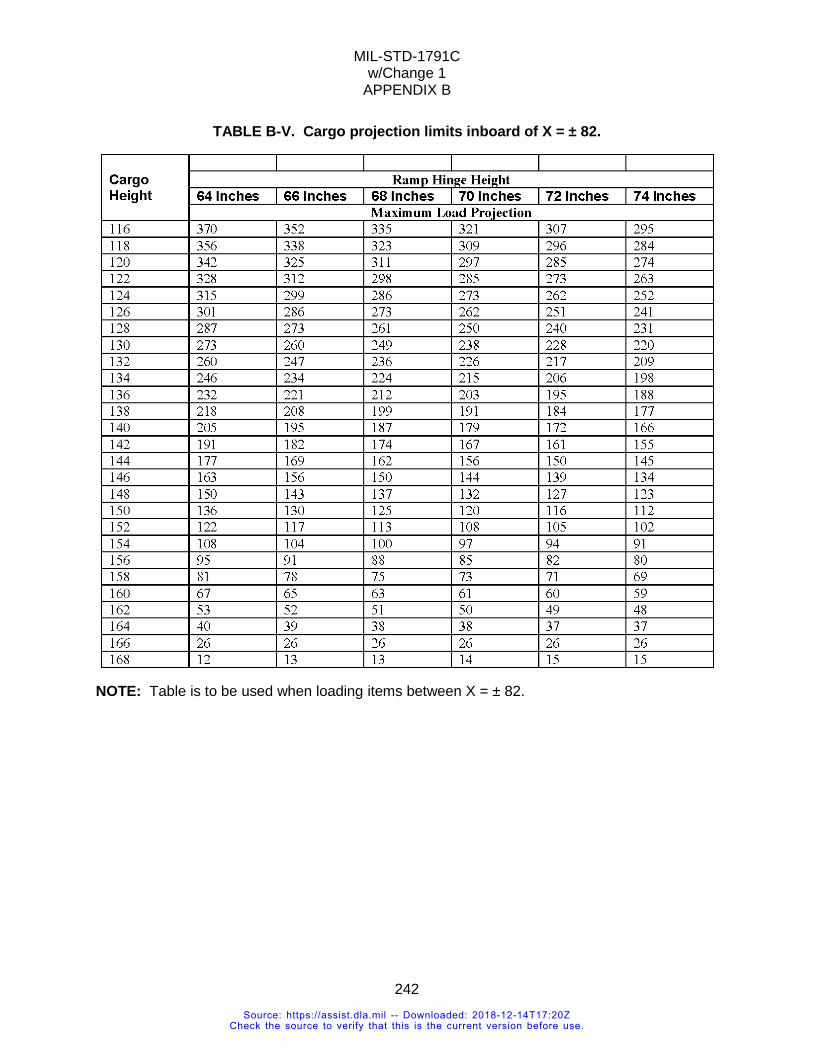
MIL-STD-1791C w/Change 1
APPENDIX B
242
TABLE B-V. Cargo projection limits inboard of X = ± 82.
NOTE: Table is to be used when loading items between X = ± 82.
Source: https://assist.dla.mil -- Downloaded: 2018-12-14T17:20ZCheck the source to verify that this is the current version before use.
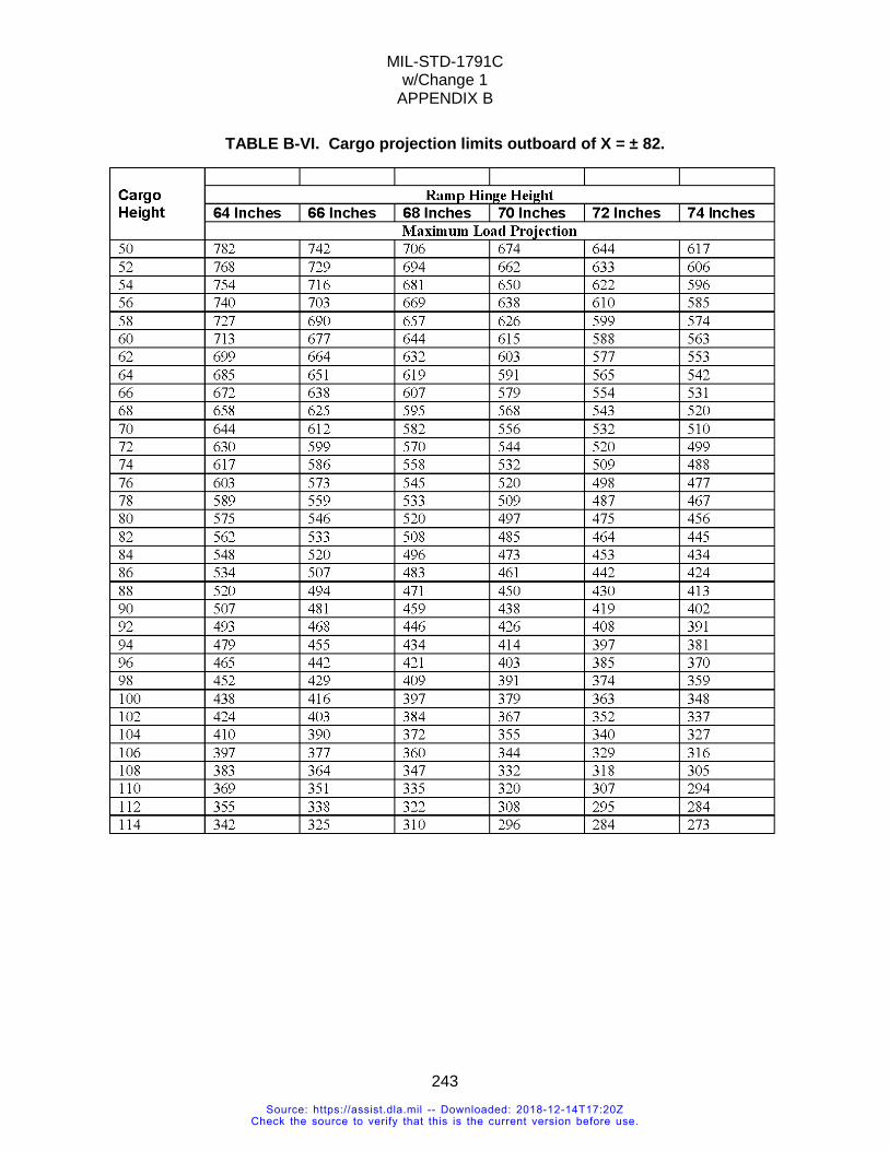
MIL-STD-1791C w/Change 1
APPENDIX B
243
TABLE B-VI. Cargo projection limits outboard of X = ± 82.
Source: https://assist.dla.mil -- Downloaded: 2018-12-14T17:20ZCheck the source to verify that this is the current version before use.
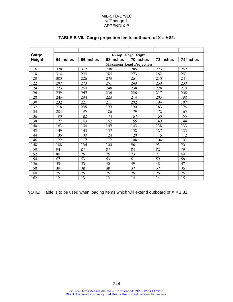
MIL-STD-1791C w/Change 1
APPENDIX B
244
TABLE B-VII. Cargo projection limits outboard of X = ± 82.
NOTE: Table is to be used when loading items which will extend outboard of X = ± 82.
Source: https://assist.dla.mil -- Downloaded: 2018-12-14T17:20ZCheck the source to verify that this is the current version before use.
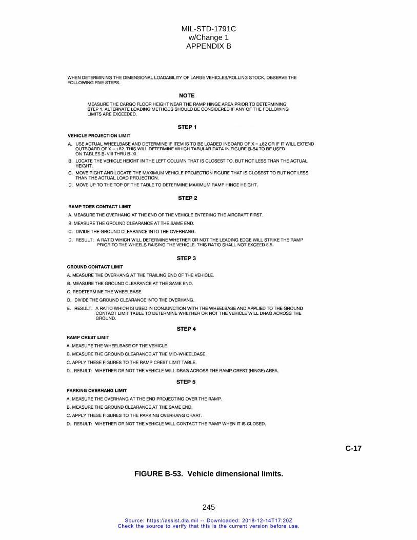
MIL-STD-1791C w/Change 1
APPENDIX B
245
C-17
FIGURE B-53. Vehicle dimensional limits.
Source: https://assist.dla.mil -- Downloaded: 2018-12-14T17:20ZCheck the source to verify that this is the current version before use.
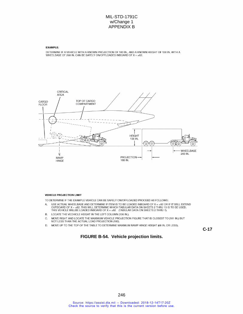
MIL-STD-1791C w/Change 1
APPENDIX B
246
C-17 FIGURE B-54. Vehicle projection limits.
Source: https://assist.dla.mil -- Downloaded: 2018-12-14T17:20ZCheck the source to verify that this is the current version before use.

MIL-STD-1791C w/Change 1
APPENDIX B
247
TABLE B-VIII. Vehicle projection limits inboard of X = ± 82 - wheelbase less than 257 inches.
Source: https://assist.dla.mil -- Downloaded: 2018-12-14T17:20ZCheck the source to verify that this is the current version before use.
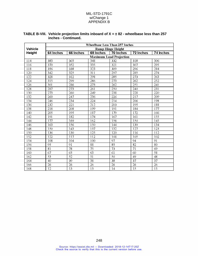
MIL-STD-1791C w/Change 1
APPENDIX B
248
TABLE B-VIII. Vehicle projection limits inboard of X = ± 82 - wheelbase less than 257 inches - Continued.
Source: https://assist.dla.mil -- Downloaded: 2018-12-14T17:20ZCheck the source to verify that this is the current version before use.
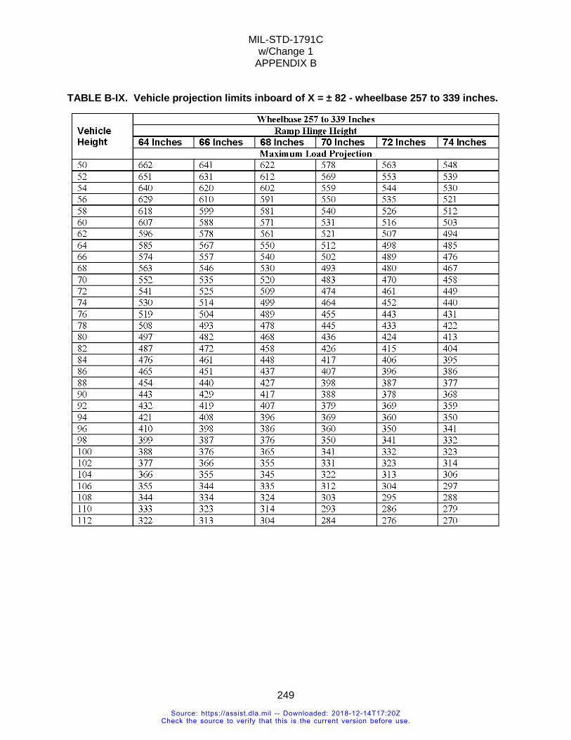
MIL-STD-1791C w/Change 1
APPENDIX B
249
TABLE B-IX. Vehicle projection limits inboard of X = ± 82 - wheelbase 257 to 339 inches.
Source: https://assist.dla.mil -- Downloaded: 2018-12-14T17:20ZCheck the source to verify that this is the current version before use.
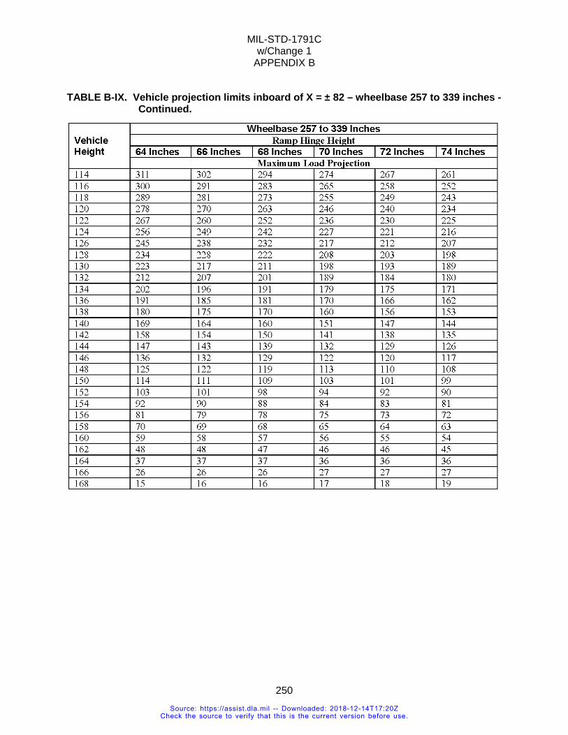
MIL-STD-1791C w/Change 1
APPENDIX B
250
TABLE B-IX. Vehicle projection limits inboard of X = ± 82 – wheelbase 257 to 339 inches - Continued.
Source: https://assist.dla.mil -- Downloaded: 2018-12-14T17:20ZCheck the source to verify that this is the current version before use.
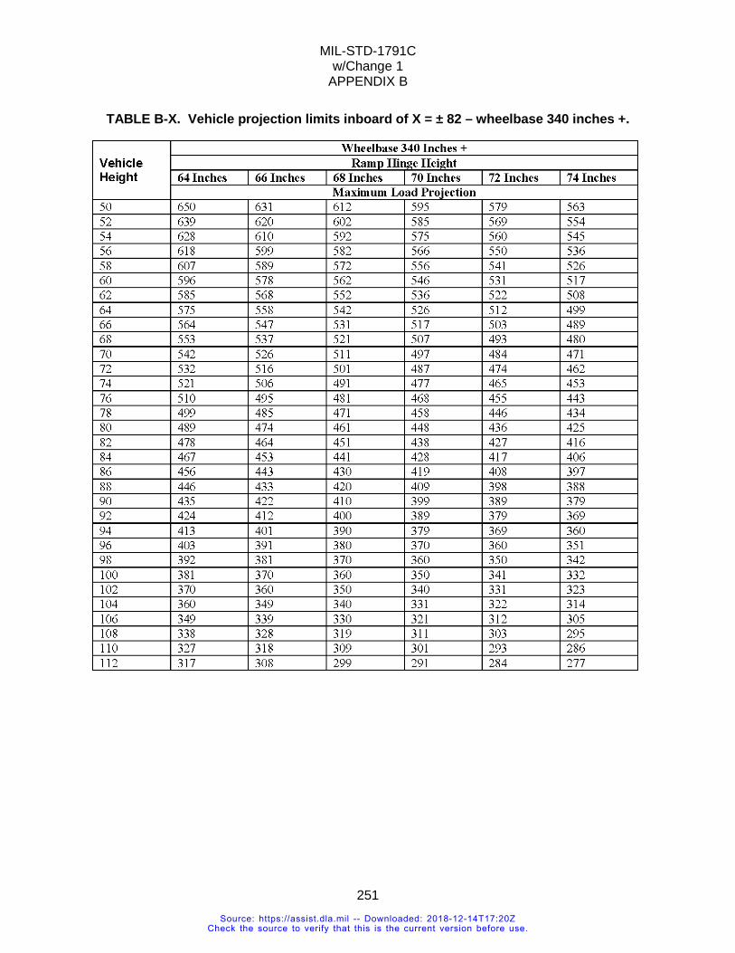
MIL-STD-1791C w/Change 1
APPENDIX B
251
TABLE B-X. Vehicle projection limits inboard of X = ± 82 – wheelbase 340 inches +.
Source: https://assist.dla.mil -- Downloaded: 2018-12-14T17:20ZCheck the source to verify that this is the current version before use.
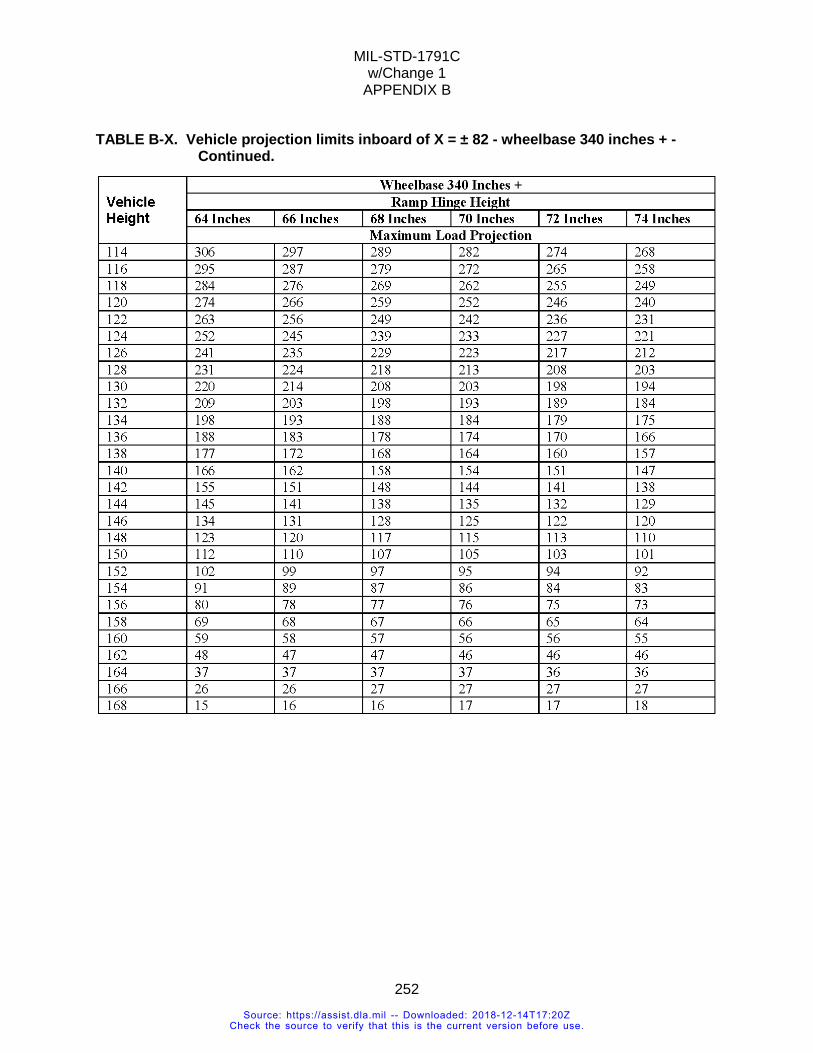
MIL-STD-1791C w/Change 1
APPENDIX B
252
TABLE B-X. Vehicle projection limits inboard of X = ± 82 - wheelbase 340 inches + - Continued.
Source: https://assist.dla.mil -- Downloaded: 2018-12-14T17:20ZCheck the source to verify that this is the current version before use.
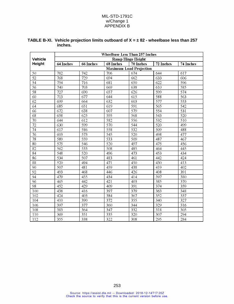
MIL-STD-1791C w/Change 1
APPENDIX B
253
TABLE B-XI. Vehicle projection limits outboard of X = ± 82 - wheelbase less than 257 inches.
Source: https://assist.dla.mil -- Downloaded: 2018-12-14T17:20ZCheck the source to verify that this is the current version before use.
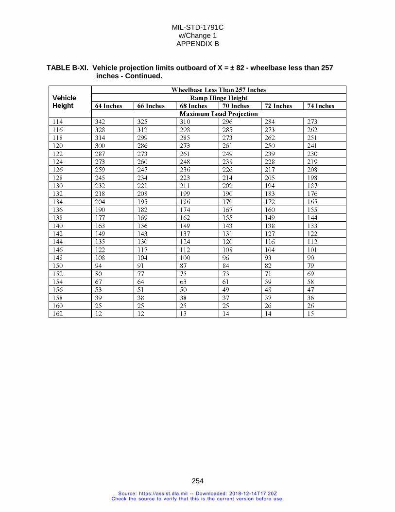
MIL-STD-1791C w/Change 1
APPENDIX B
254
TABLE B-XI. Vehicle projection limits outboard of X = ± 82 - wheelbase less than 257 inches - Continued.
Source: https://assist.dla.mil -- Downloaded: 2018-12-14T17:20ZCheck the source to verify that this is the current version before use.
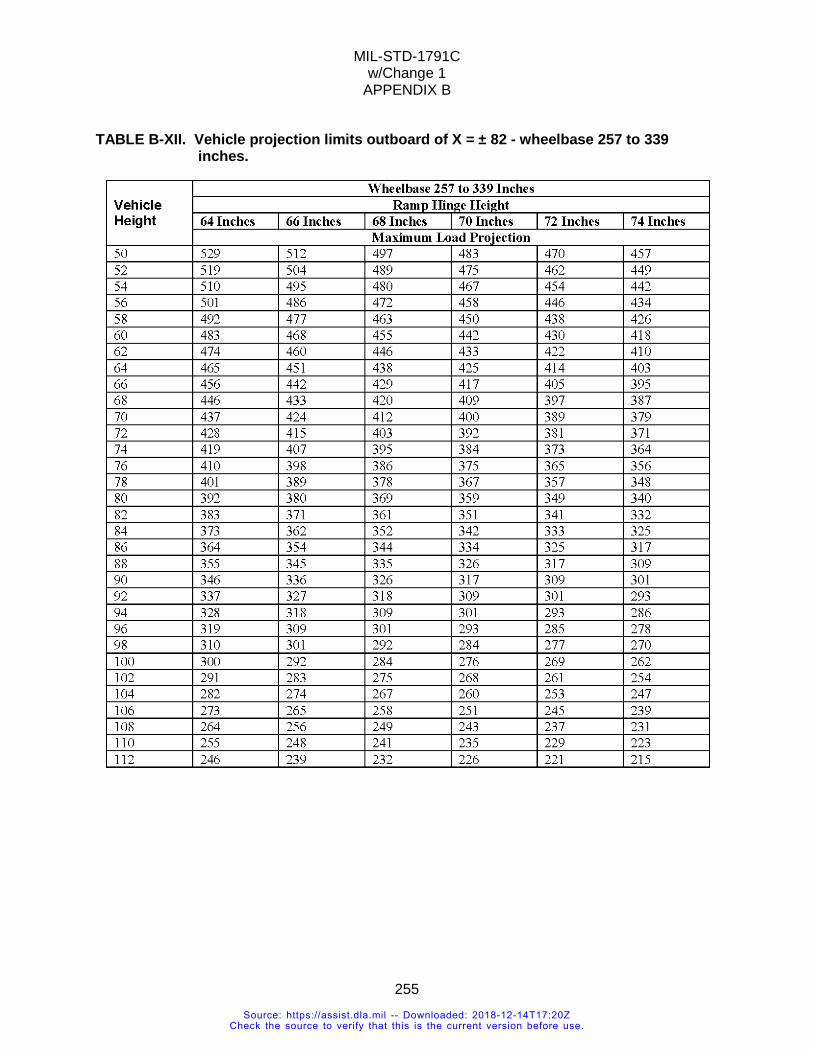
MIL-STD-1791C w/Change 1
APPENDIX B
255
TABLE B-XII. Vehicle projection limits outboard of X = ± 82 - wheelbase 257 to 339 inches.
Source: https://assist.dla.mil -- Downloaded: 2018-12-14T17:20ZCheck the source to verify that this is the current version before use.
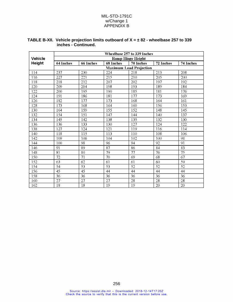
MIL-STD-1791C w/Change 1
APPENDIX B
256
TABLE B-XII. Vehicle projection limits outboard of X = ± 82 - wheelbase 257 to 339 inches - Continued.
Source: https://assist.dla.mil -- Downloaded: 2018-12-14T17:20ZCheck the source to verify that this is the current version before use.
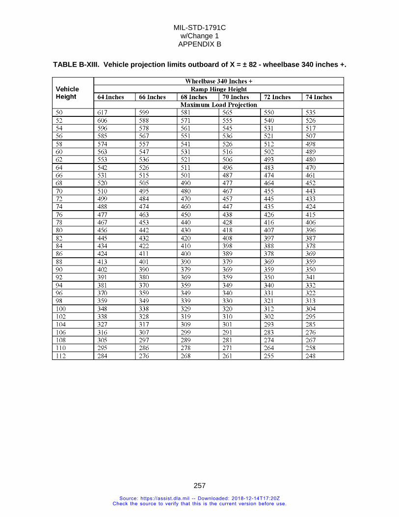
MIL-STD-1791C w/Change 1
APPENDIX B
257
TABLE B-XIII. Vehicle projection limits outboard of X = ± 82 - wheelbase 340 inches +.
Source: https://assist.dla.mil -- Downloaded: 2018-12-14T17:20ZCheck the source to verify that this is the current version before use.
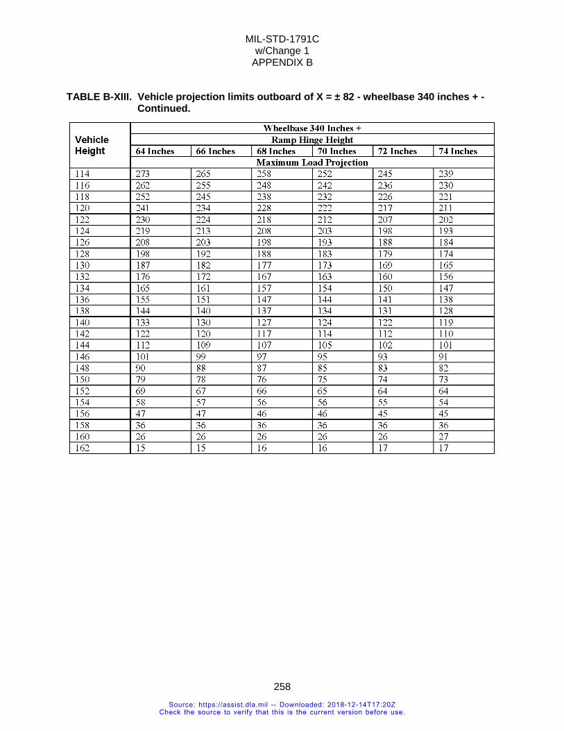
MIL-STD-1791C w/Change 1
APPENDIX B
258
TABLE B-XIII. Vehicle projection limits outboard of X = ± 82 - wheelbase 340 inches + - Continued.
Source: https://assist.dla.mil -- Downloaded: 2018-12-14T17:20ZCheck the source to verify that this is the current version before use.
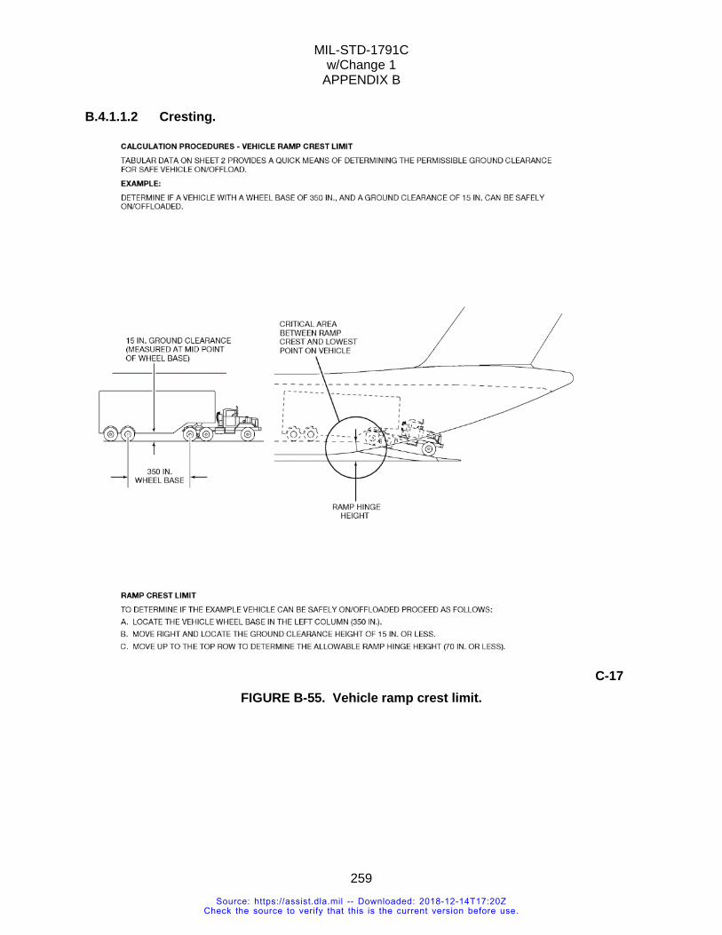
MIL-STD-1791C w/Change 1
APPENDIX B
259
B.4.1.1.2 Cresting.
C-17 FIGURE B-55. Vehicle ramp crest limit.
Source: https://assist.dla.mil -- Downloaded: 2018-12-14T17:20ZCheck the source to verify that this is the current version before use.
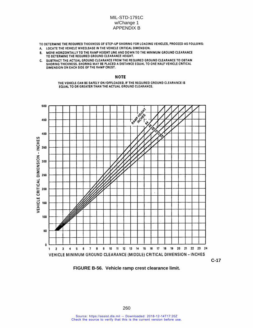
MIL-STD-1791C w/Change 1
APPENDIX B
260
C-17 FIGURE B-56. Vehicle ramp crest clearance limit.
Source: https://assist.dla.mil -- Downloaded: 2018-12-14T17:20ZCheck the source to verify that this is the current version before use.
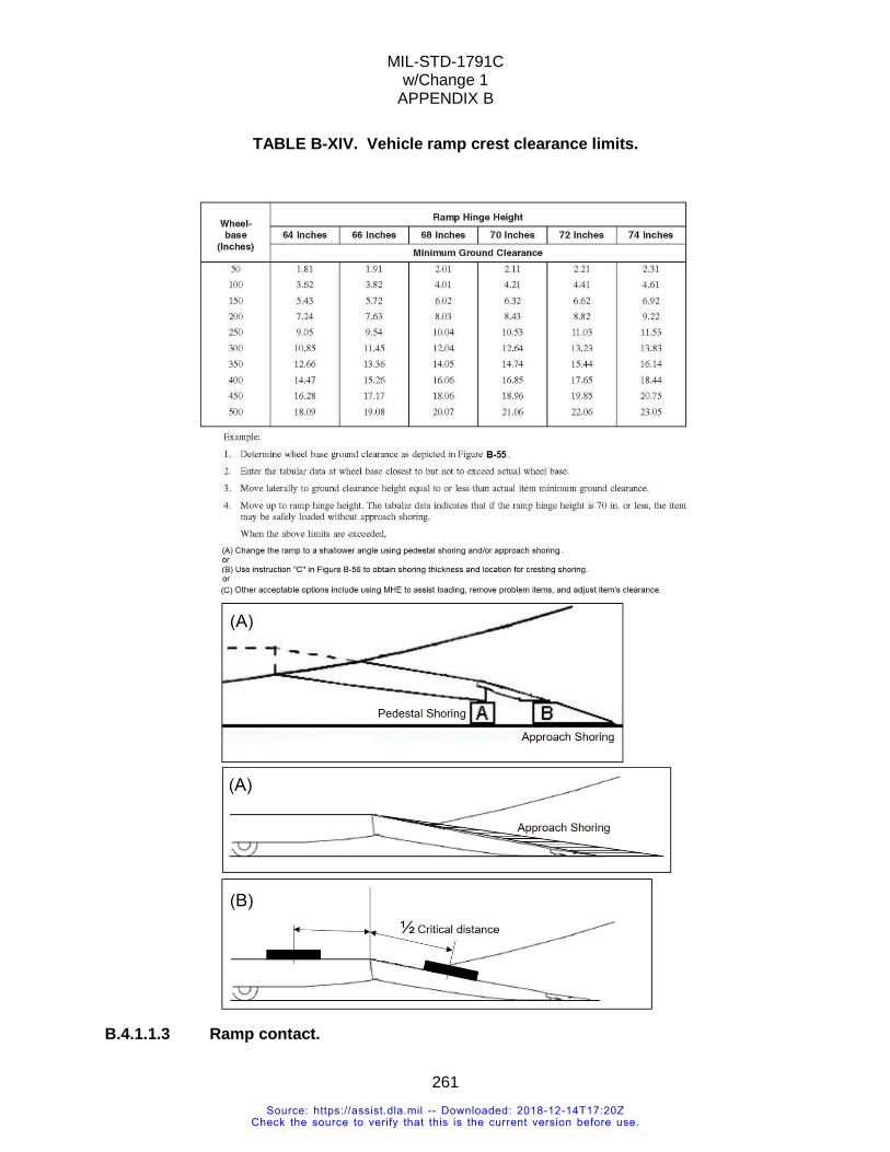
MIL-STD-1791C w/Change 1
APPENDIX B
261
TABLE B-XIV. Vehicle ramp crest clearance limits.
B.4.1.1.3 Ramp contact.
Source: https://assist.dla.mil -- Downloaded: 2018-12-14T17:20ZCheck the source to verify that this is the current version before use.
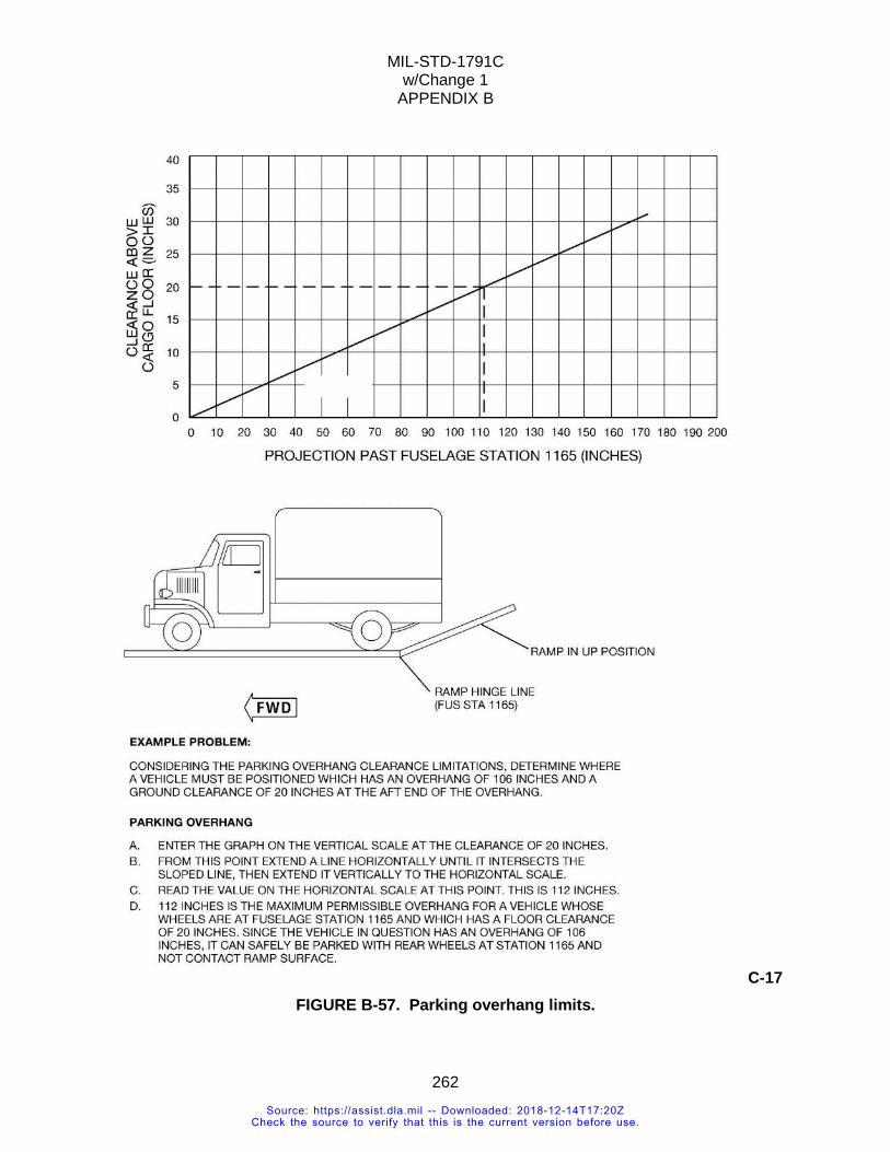
MIL-STD-1791C w/Change 1
APPENDIX B
262
C-17 FIGURE B-57. Parking overhang limits.
Source: https://assist.dla.mil -- Downloaded: 2018-12-14T17:20ZCheck the source to verify that this is the current version before use.
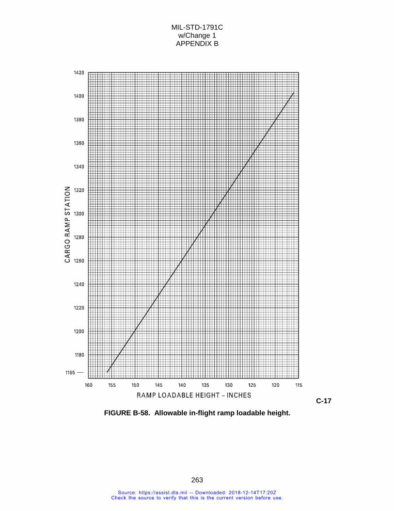
MIL-STD-1791C w/Change 1
APPENDIX B
263
C-17 FIGURE B-58. Allowable in-flight ramp loadable height.
Source: https://assist.dla.mil -- Downloaded: 2018-12-14T17:20ZCheck the source to verify that this is the current version before use.
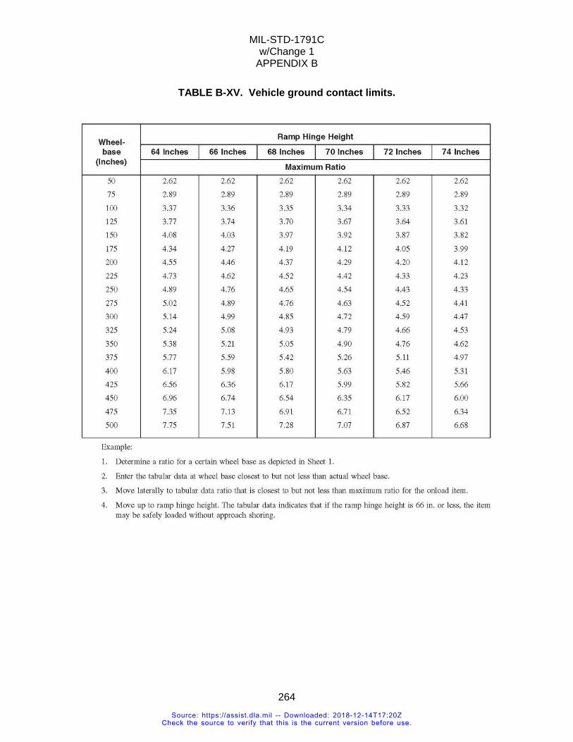
MIL-STD-1791C w/Change 1
APPENDIX B
264
TABLE B-XV. Vehicle ground contact limits.
Source: https://assist.dla.mil -- Downloaded: 2018-12-14T17:20ZCheck the source to verify that this is the current version before use.
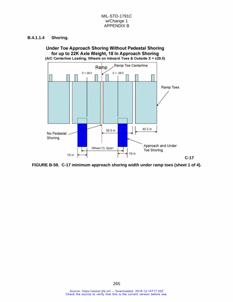
MIL-STD-1791C w/Change 1
APPENDIX B
265
B.4.1.1.4 Shoring.
C-17 FIGURE B-59. C-17 minimum approach shoring width under ramp toes (sheet 1 of 4).
Source: https://assist.dla.mil -- Downloaded: 2018-12-14T17:20ZCheck the source to verify that this is the current version before use.
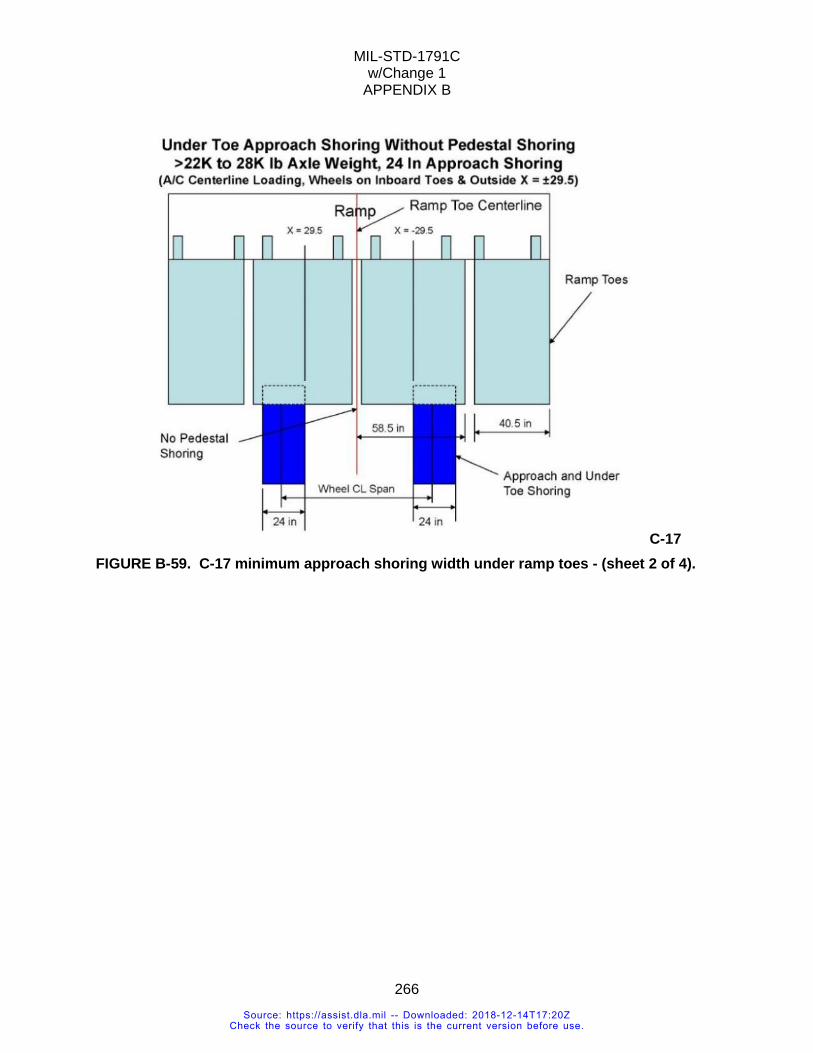
MIL-STD-1791C w/Change 1
APPENDIX B
266
C-17 FIGURE B-59. C-17 minimum approach shoring width under ramp toes - (sheet 2 of 4).
Source: https://assist.dla.mil -- Downloaded: 2018-12-14T17:20ZCheck the source to verify that this is the current version before use.
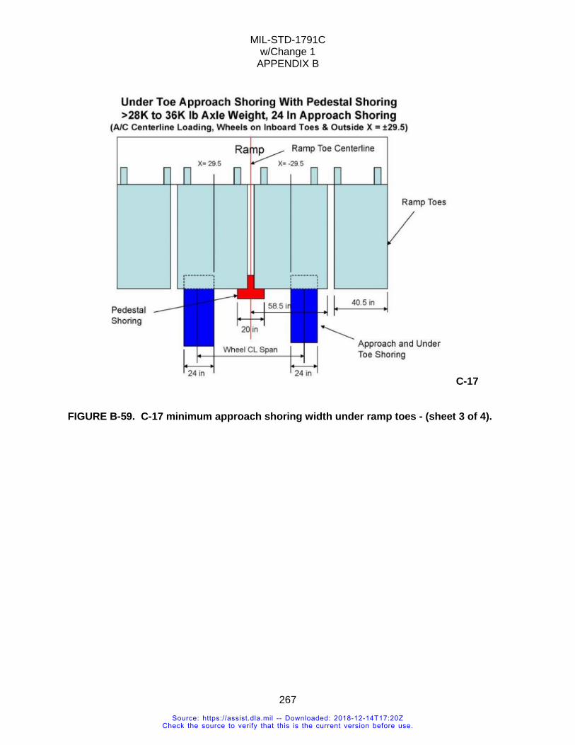
MIL-STD-1791C w/Change 1
APPENDIX B
267
C-17 FIGURE B-59. C-17 minimum approach shoring width under ramp toes - (sheet 3 of 4).
Source: https://assist.dla.mil -- Downloaded: 2018-12-14T17:20ZCheck the source to verify that this is the current version before use.
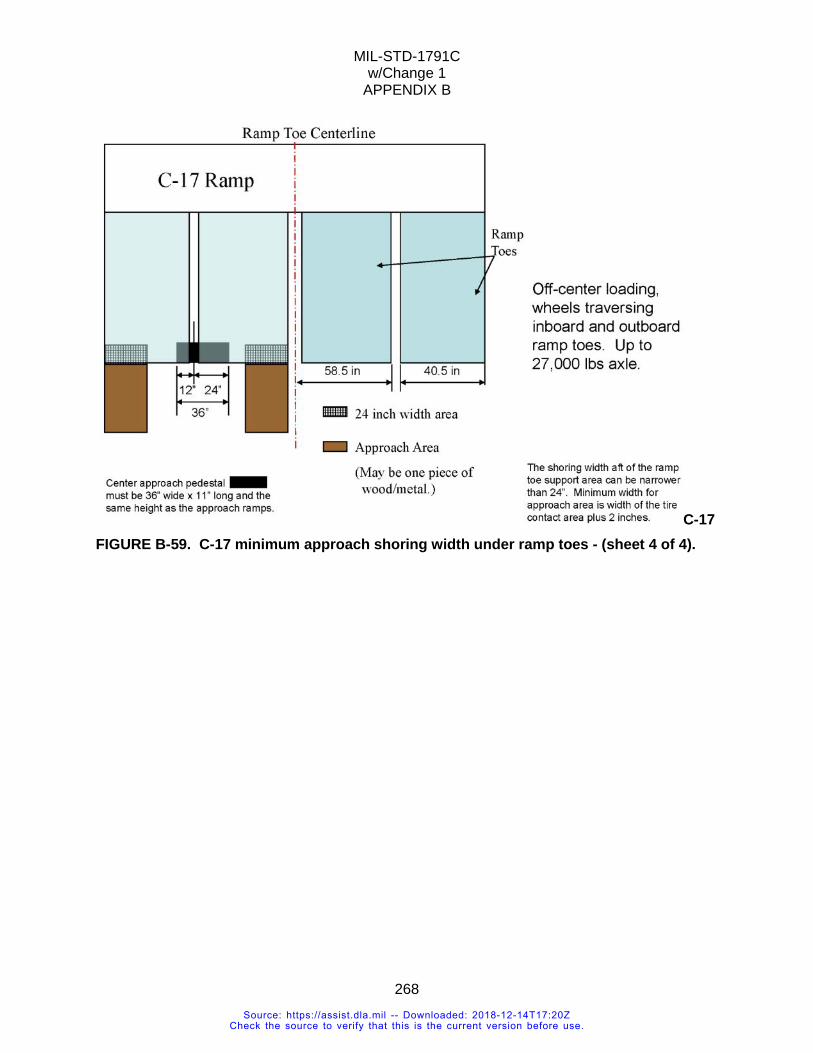
MIL-STD-1791C w/Change 1
APPENDIX B
268
C-17 FIGURE B-59. C-17 minimum approach shoring width under ramp toes - (sheet 4 of 4).
Source: https://assist.dla.mil -- Downloaded: 2018-12-14T17:20ZCheck the source to verify that this is the current version before use.
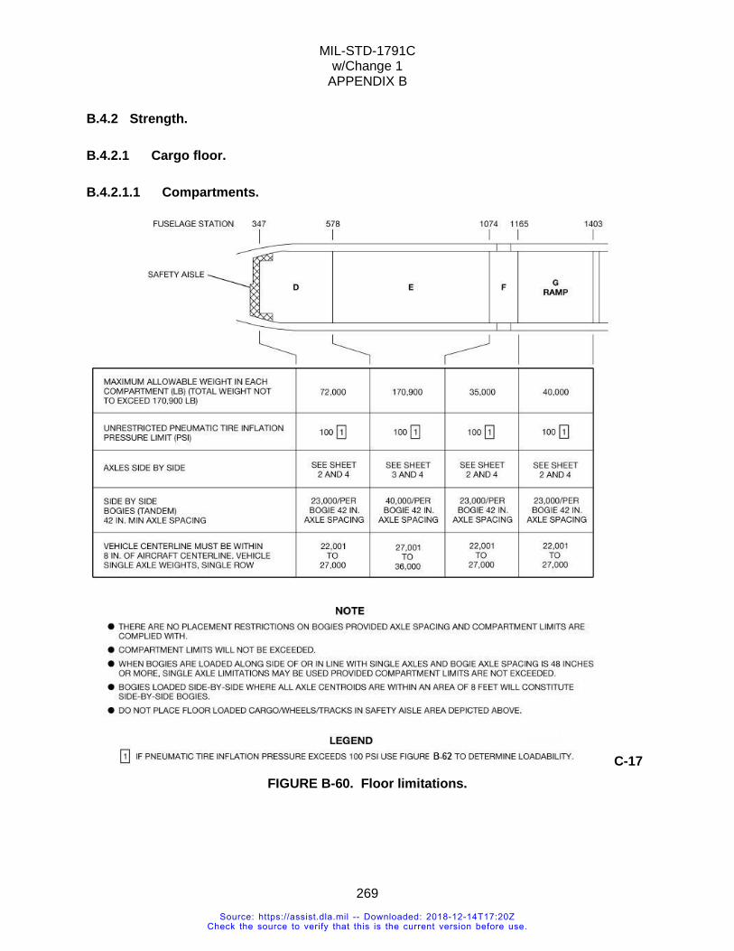
MIL-STD-1791C w/Change 1
APPENDIX B
269
B.4.2 Strength.
B.4.2.1 Cargo floor.
B.4.2.1.1 Compartments.
C-17 FIGURE B-60. Floor limitations.
Source: https://assist.dla.mil -- Downloaded: 2018-12-14T17:20ZCheck the source to verify that this is the current version before use.
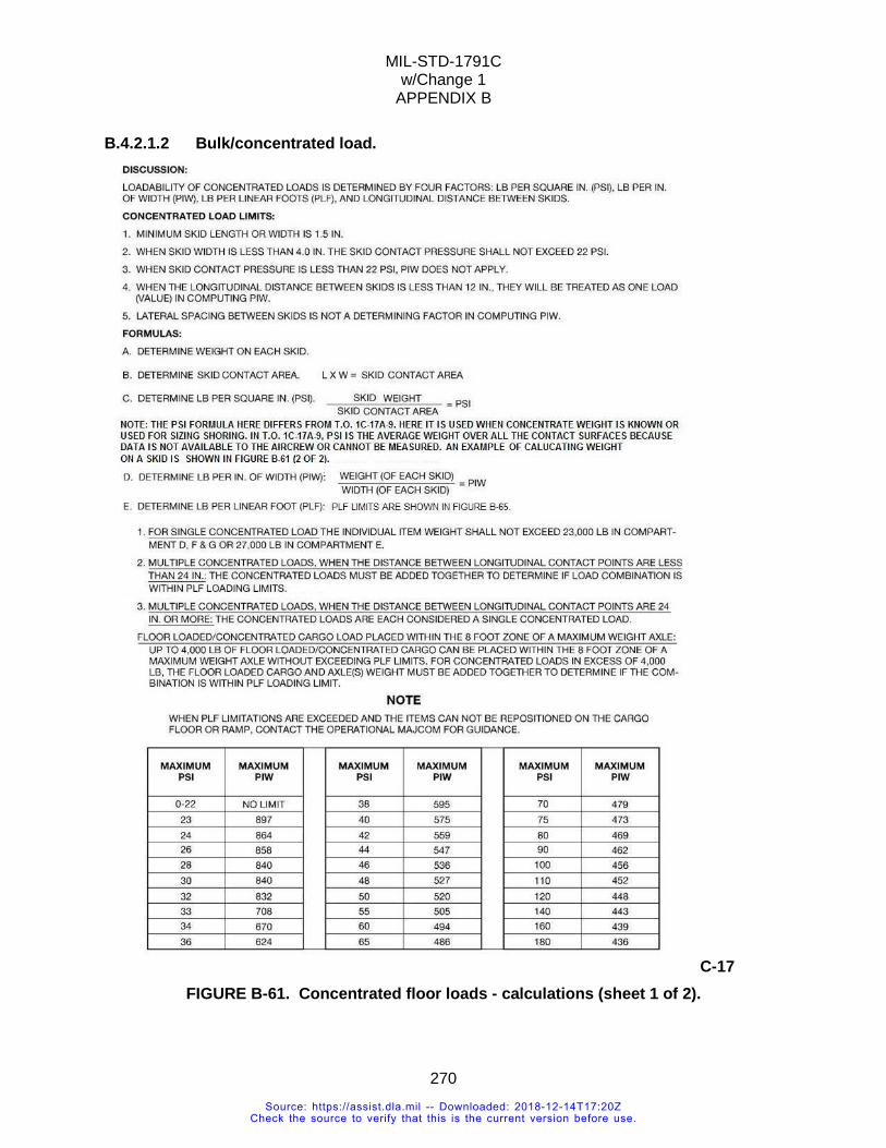
MIL-STD-1791C w/Change 1
APPENDIX B
270
B.4.2.1.2 Bulk/concentrated load.
C-17 FIGURE B-61. Concentrated floor loads - calculations (sheet 1 of 2).
Source: https://assist.dla.mil -- Downloaded: 2018-12-14T17:20ZCheck the source to verify that this is the current version before use.
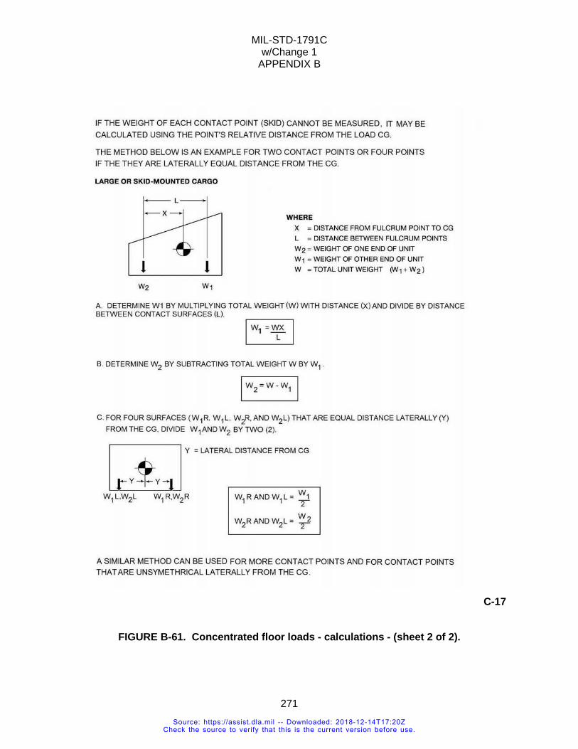
MIL-STD-1791C w/Change 1
APPENDIX B
271
C-17
FIGURE B-61. Concentrated floor loads - calculations - (sheet 2 of 2).
Source: https://assist.dla.mil -- Downloaded: 2018-12-14T17:20ZCheck the source to verify that this is the current version before use.
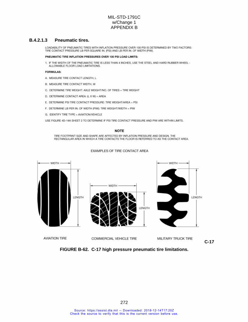
MIL-STD-1791C w/Change 1
APPENDIX B
272
B.4.2.1.3 Pneumatic tires.
C-17 FIGURE B-62. C-17 high pressure pneumatic tire limitations.
Source: https://assist.dla.mil -- Downloaded: 2018-12-14T17:20ZCheck the source to verify that this is the current version before use.
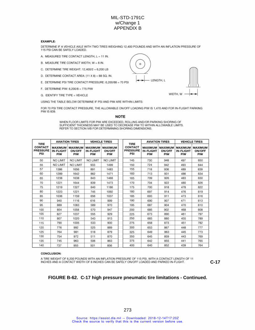
MIL-STD-1791C w/Change 1
APPENDIX B
273
C-17
FIGURE B-62. C-17 high pressure pneumatic tire limitations - Continued.
Source: https://assist.dla.mil -- Downloaded: 2018-12-14T17:20ZCheck the source to verify that this is the current version before use.
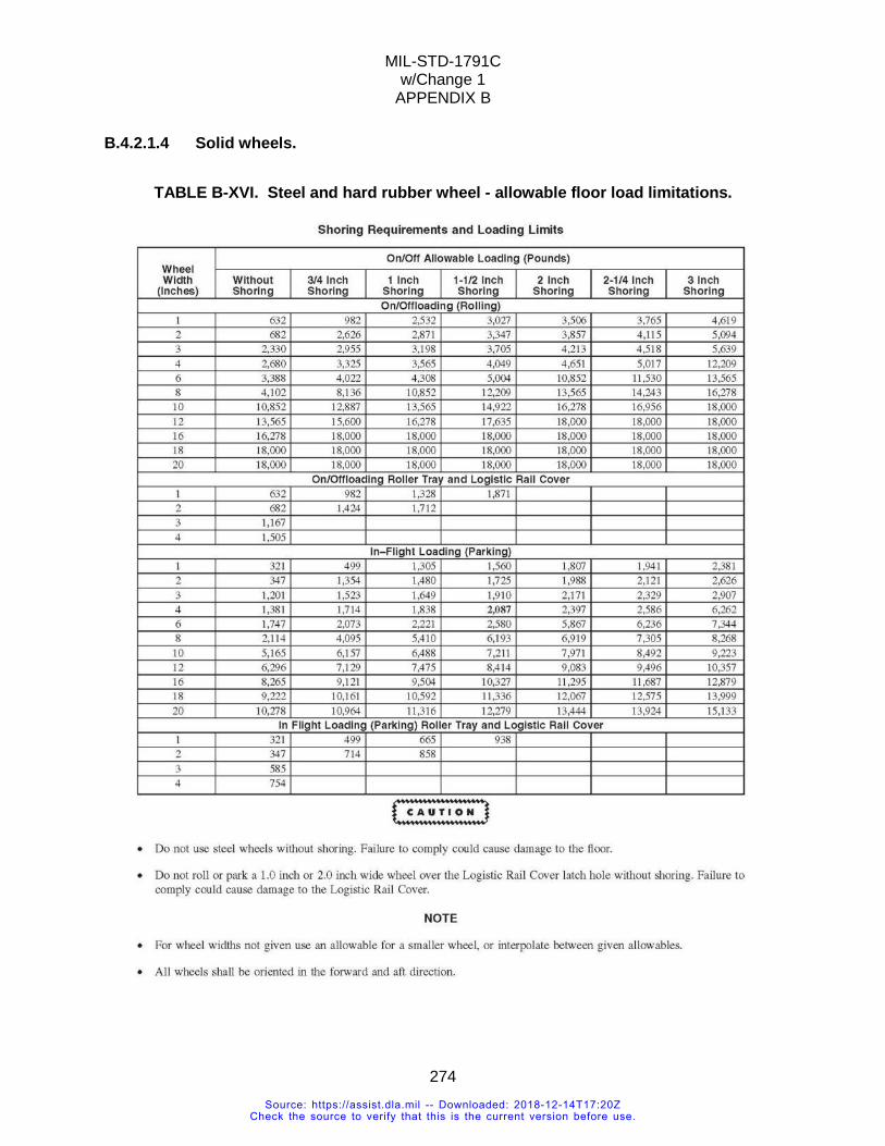
MIL-STD-1791C w/Change 1
APPENDIX B
274
B.4.2.1.4 Solid wheels.
TABLE B-XVI. Steel and hard rubber wheel - allowable floor load limitations.
Source: https://assist.dla.mil -- Downloaded: 2018-12-14T17:20ZCheck the source to verify that this is the current version before use.
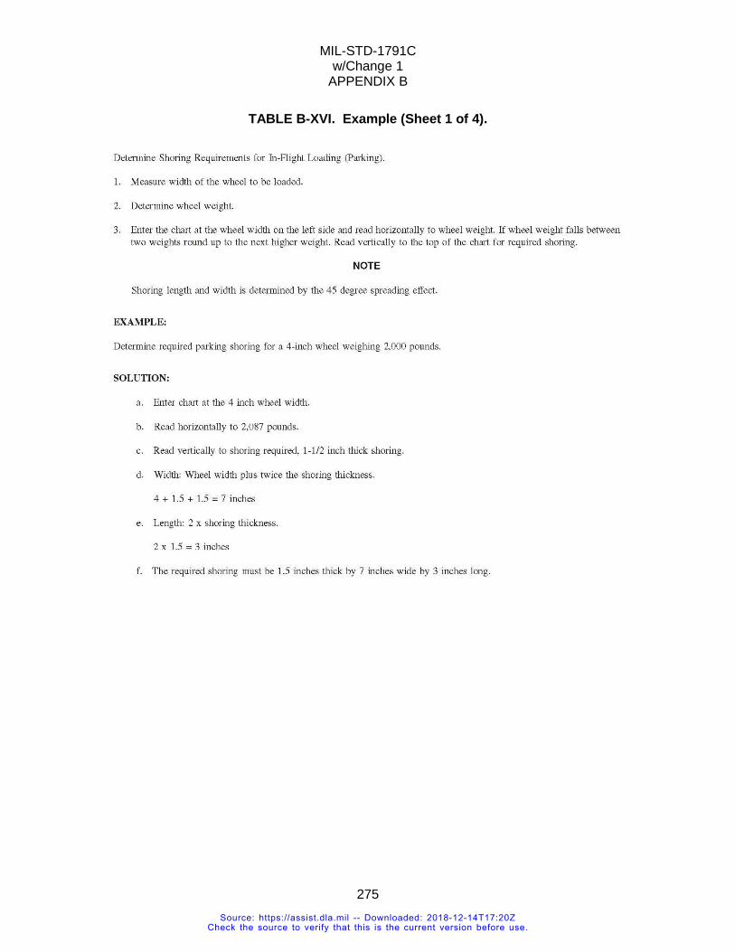
MIL-STD-1791C w/Change 1
APPENDIX B
275
TABLE B-XVI. Example (Sheet 1 of 4).
Source: https://assist.dla.mil -- Downloaded: 2018-12-14T17:20ZCheck the source to verify that this is the current version before use.
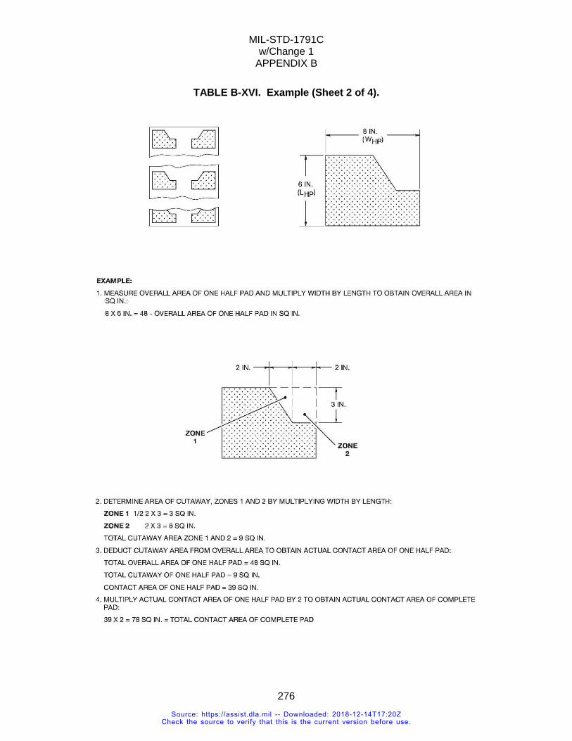
MIL-STD-1791C w/Change 1
APPENDIX B
276
TABLE B-XVI. Example (Sheet 2 of 4).
Source: https://assist.dla.mil -- Downloaded: 2018-12-14T17:20ZCheck the source to verify that this is the current version before use.
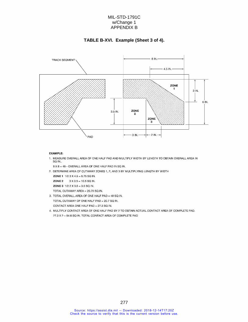
MIL-STD-1791C w/Change 1
APPENDIX B
277
TABLE B-XVI. Example (Sheet 3 of 4).
Source: https://assist.dla.mil -- Downloaded: 2018-12-14T17:20ZCheck the source to verify that this is the current version before use.
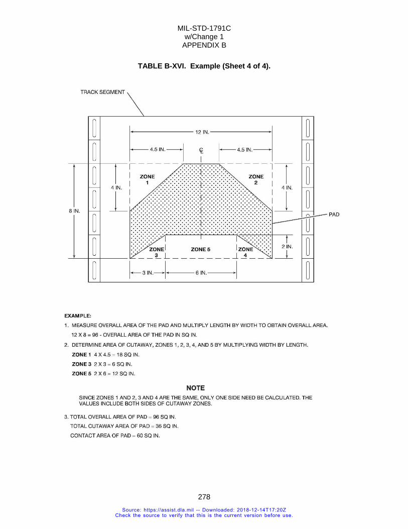
MIL-STD-1791C w/Change 1
APPENDIX B
278
TABLE B-XVI. Example (Sheet 4 of 4).
Source: https://assist.dla.mil -- Downloaded: 2018-12-14T17:20ZCheck the source to verify that this is the current version before use.
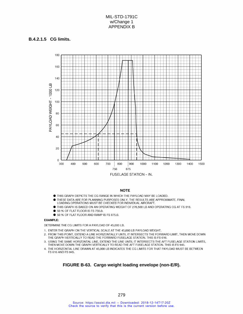
MIL-STD-1791C w/Change 1
APPENDIX B
279
B.4.2.1.5 CG limits.
FIGURE B-63. Cargo weight loading envelope (non-E/R).
Source: https://assist.dla.mil -- Downloaded: 2018-12-14T17:20ZCheck the source to verify that this is the current version before use.
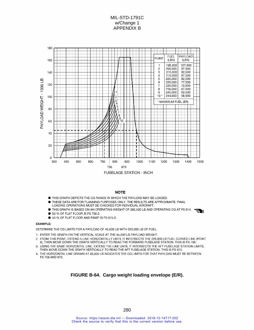
MIL-STD-1791C w/Change 1
APPENDIX B
280
FIGURE B-64. Cargo weight loading envelope (E/R).
Source: https://assist.dla.mil -- Downloaded: 2018-12-14T17:20ZCheck the source to verify that this is the current version before use.
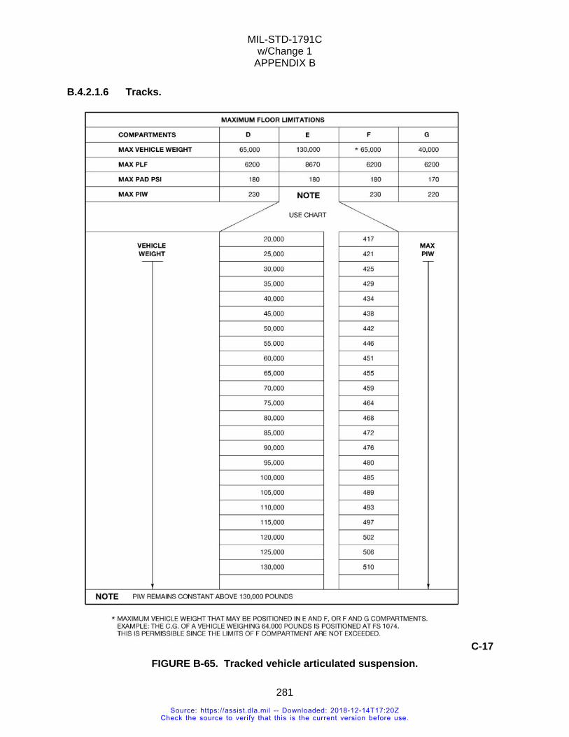
MIL-STD-1791C w/Change 1
APPENDIX B
281
B.4.2.1.6 Tracks.
C-17 FIGURE B-65. Tracked vehicle articulated suspension.
Source: https://assist.dla.mil -- Downloaded: 2018-12-14T17:20ZCheck the source to verify that this is the current version before use.
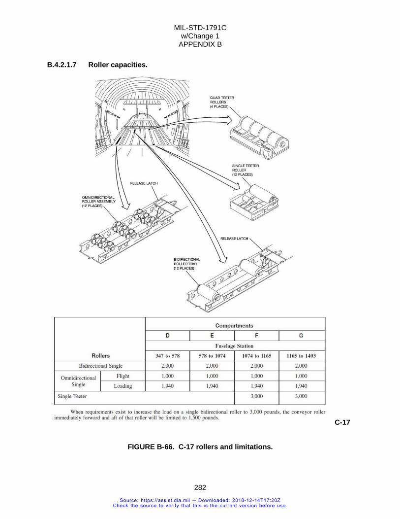
MIL-STD-1791C w/Change 1
APPENDIX B
282
B.4.2.1.7 Roller capacities.
C-17
FIGURE B-66. C-17 rollers and limitations.
Source: https://assist.dla.mil -- Downloaded: 2018-12-14T17:20ZCheck the source to verify that this is the current version before use.
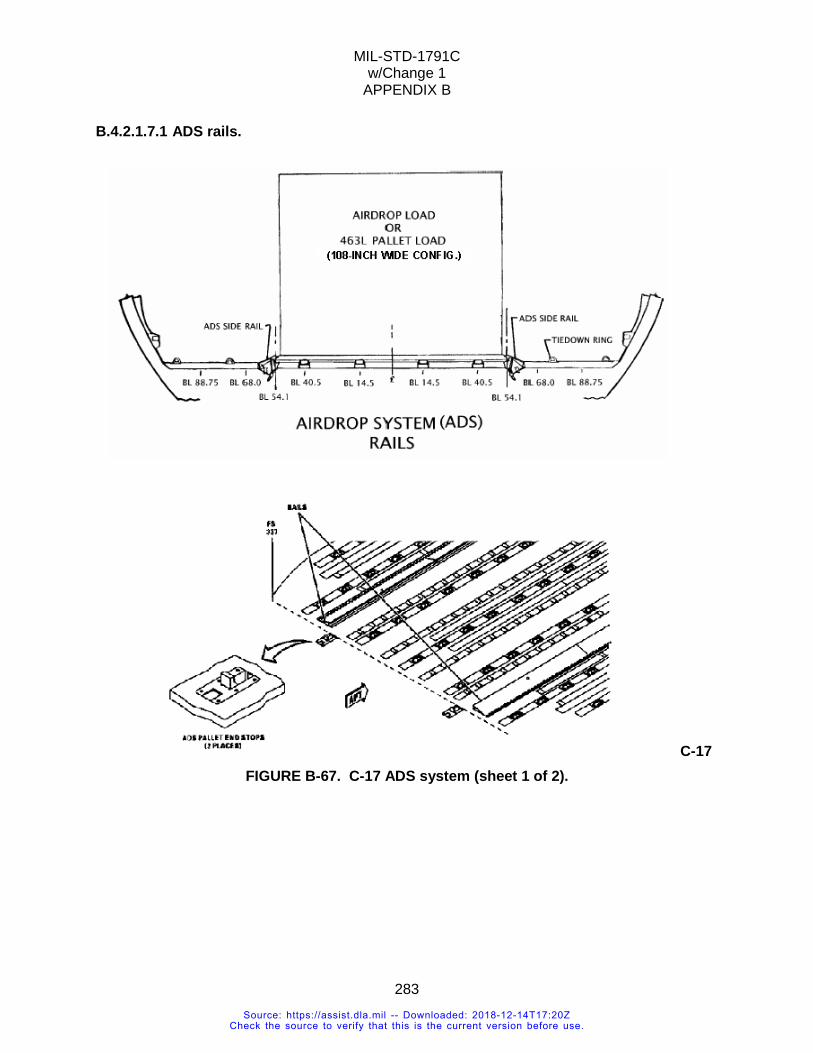
MIL-STD-1791C w/Change 1
APPENDIX B
283
B.4.2.1.7.1 ADS rails.
C-17 FIGURE B-67. C-17 ADS system (sheet 1 of 2).
Source: https://assist.dla.mil -- Downloaded: 2018-12-14T17:20ZCheck the source to verify that this is the current version before use.
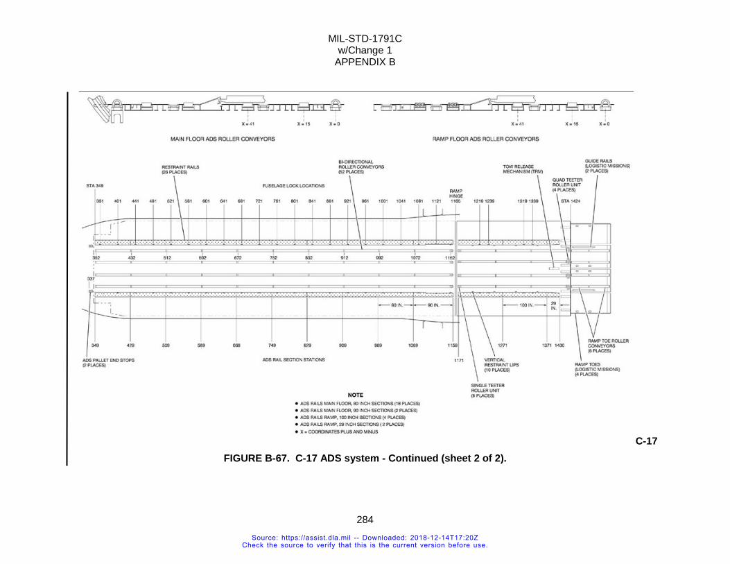
MIL-STD-1791C w/Change 1
APPENDIX B
284
C-17 FIGURE B-67. C-17 ADS system - Continued (sheet 2 of 2).
Source: https://assist.dla.mil -- Downloaded: 2018-12-14T17:20ZCheck the source to verify that this is the current version before use.
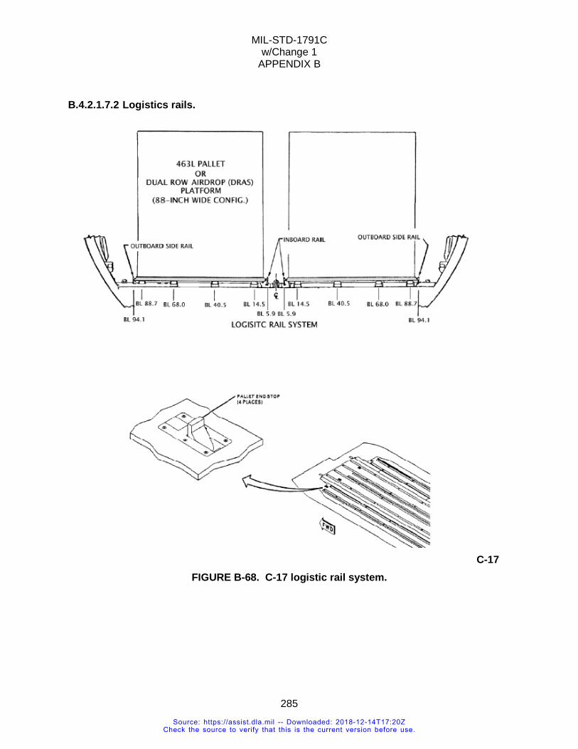
MIL-STD-1791C w/Change 1
APPENDIX B
285
B.4.2.1.7.2 Logistics rails.
C-17 FIGURE B-68. C-17 logistic rail system.
Source: https://assist.dla.mil -- Downloaded: 2018-12-14T17:20ZCheck the source to verify that this is the current version before use.
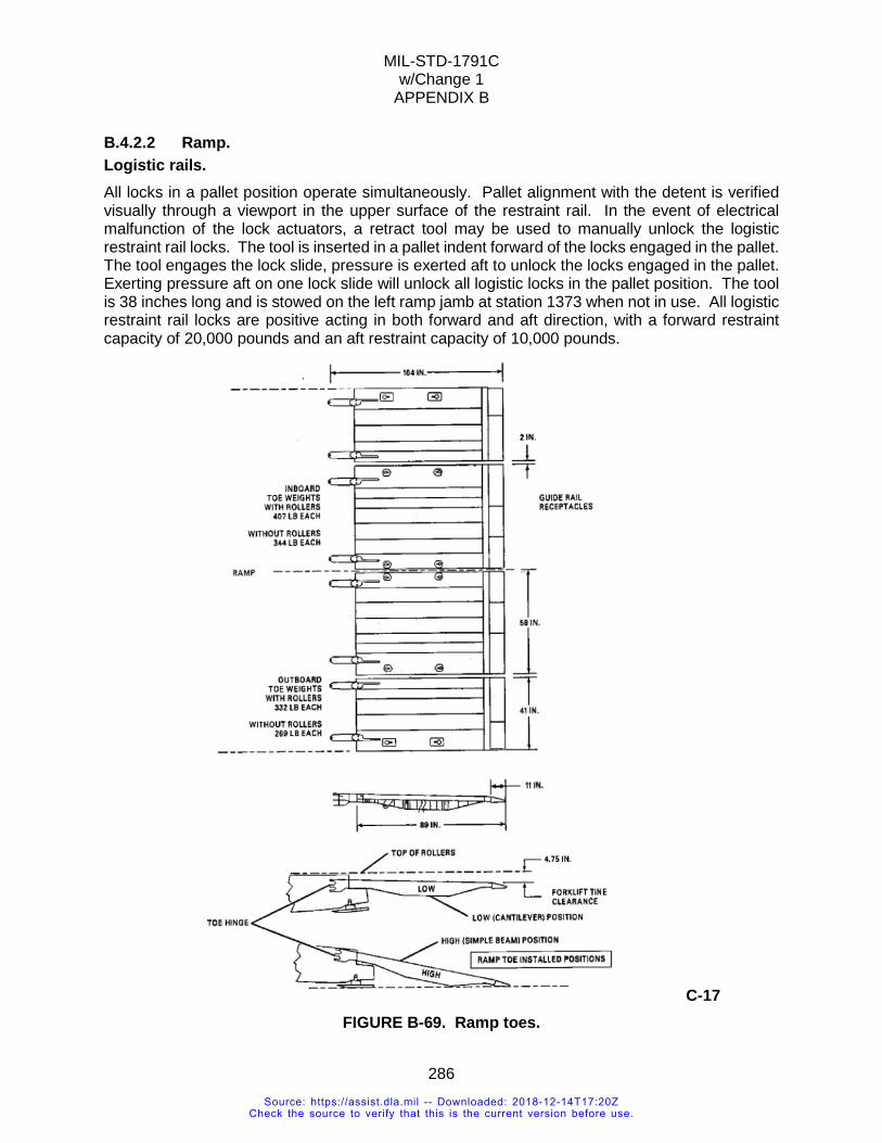
MIL-STD-1791C w/Change 1
APPENDIX B
286
B.4.2.2 Ramp. Logistic rails. All locks in a pallet position operate simultaneously. Pallet alignment with the detent is verified visually through a viewport in the upper surface of the restraint rail. In the event of electrical malfunction of the lock actuators, a retract tool may be used to manually unlock the logistic restraint rail locks. The tool is inserted in a pallet indent forward of the locks engaged in the pallet. The tool engages the lock slide, pressure is exerted aft to unlock the locks engaged in the pallet. Exerting pressure aft on one lock slide will unlock all logistic locks in the pallet position. The tool is 38 inches long and is stowed on the left ramp jamb at station 1373 when not in use. All logistic restraint rail locks are positive acting in both forward and aft direction, with a forward restraint capacity of 20,000 pounds and an aft restraint capacity of 10,000 pounds.
C-17 FIGURE B-69. Ramp toes.
Source: https://assist.dla.mil -- Downloaded: 2018-12-14T17:20ZCheck the source to verify that this is the current version before use.
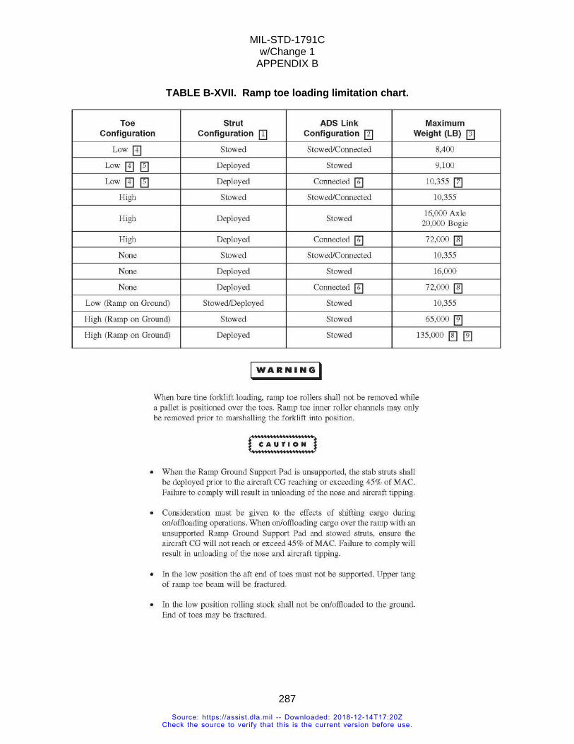
MIL-STD-1791C w/Change 1
APPENDIX B
287
TABLE B-XVII. Ramp toe loading limitation chart.
Source: https://assist.dla.mil -- Downloaded: 2018-12-14T17:20ZCheck the source to verify that this is the current version before use.
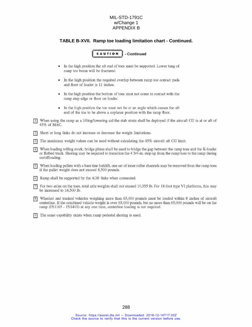
MIL-STD-1791C w/Change 1
APPENDIX B
288
TABLE B-XVII. Ramp toe loading limitation chart - Continued.
Source: https://assist.dla.mil -- Downloaded: 2018-12-14T17:20ZCheck the source to verify that this is the current version before use.
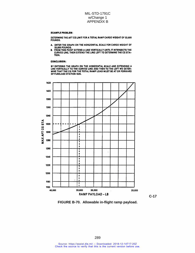
MIL-STD-1791C w/Change 1
APPENDIX B
289
C-17 FIGURE B-70. Allowable in-flight ramp payload.
Source: https://assist.dla.mil -- Downloaded: 2018-12-14T17:20ZCheck the source to verify that this is the current version before use.
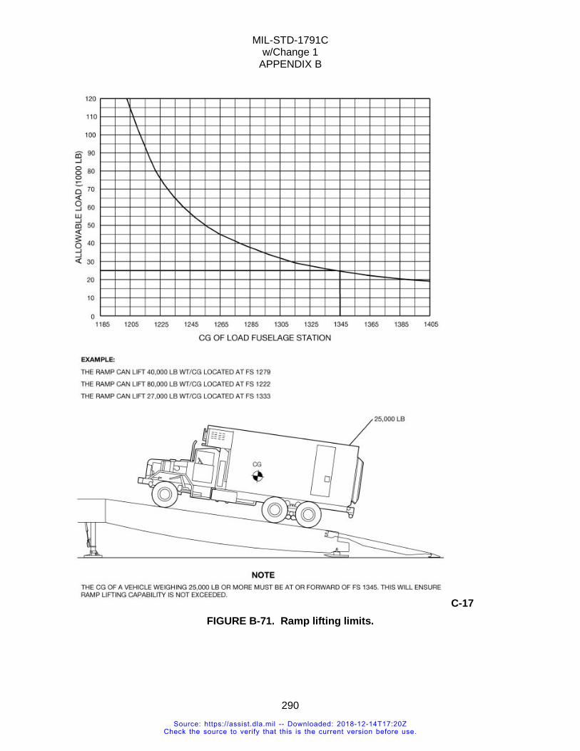
MIL-STD-1791C w/Change 1
APPENDIX B
290
C-17 FIGURE B-71. Ramp lifting limits.
Source: https://assist.dla.mil -- Downloaded: 2018-12-14T17:20ZCheck the source to verify that this is the current version before use.
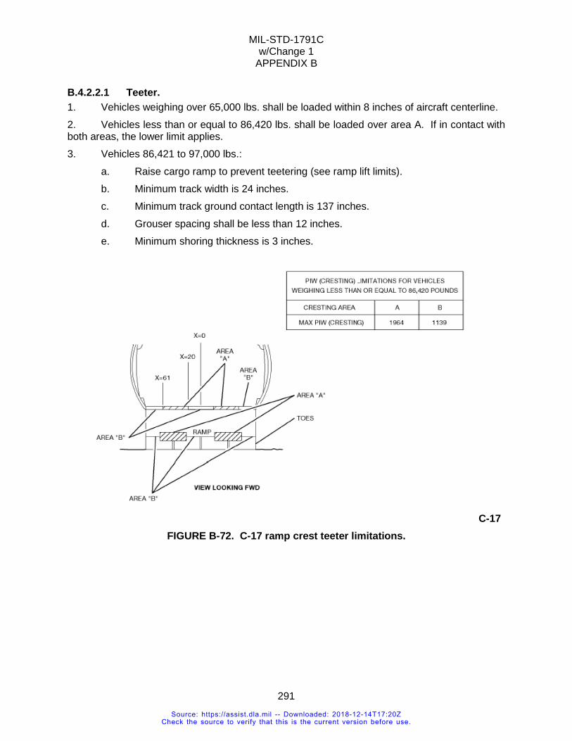
MIL-STD-1791C w/Change 1
APPENDIX B
291
B.4.2.2.1 Teeter. 1. Vehicles weighing over 65,000 lbs. shall be loaded within 8 inches of aircraft centerline. 2. Vehicles less than or equal to 86,420 lbs. shall be loaded over area A. If in contact with both areas, the lower limit applies. 3. Vehicles 86,421 to 97,000 lbs.: a. Raise cargo ramp to prevent teetering (see ramp lift limits). b. Minimum track width is 24 inches. c. Minimum track ground contact length is 137 inches. d. Grouser spacing shall be less than 12 inches. e. Minimum shoring thickness is 3 inches.
C-17 FIGURE B-72. C-17 ramp crest teeter limitations.
Source: https://assist.dla.mil -- Downloaded: 2018-12-14T17:20ZCheck the source to verify that this is the current version before use.
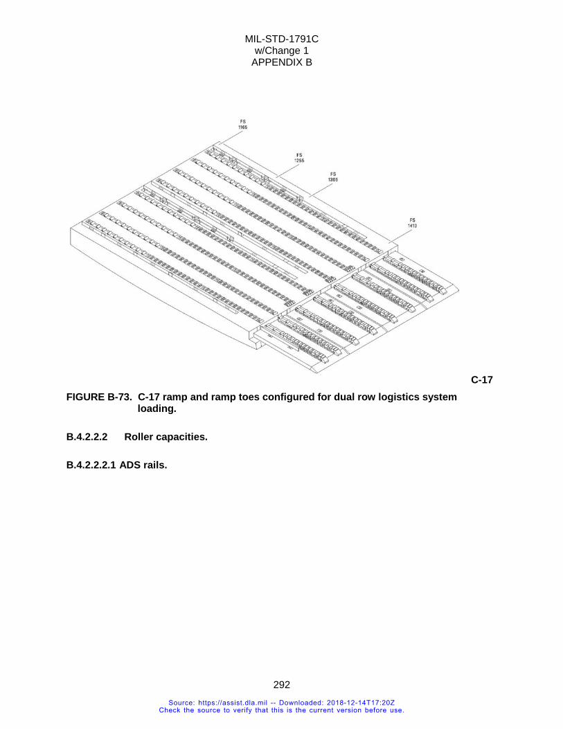
MIL-STD-1791C w/Change 1
APPENDIX B
292
C-17 FIGURE B-73. C-17 ramp and ramp toes configured for dual row logistics system
loading.
B.4.2.2.2 Roller capacities.
B.4.2.2.2.1 ADS rails.
Source: https://assist.dla.mil -- Downloaded: 2018-12-14T17:20ZCheck the source to verify that this is the current version before use.
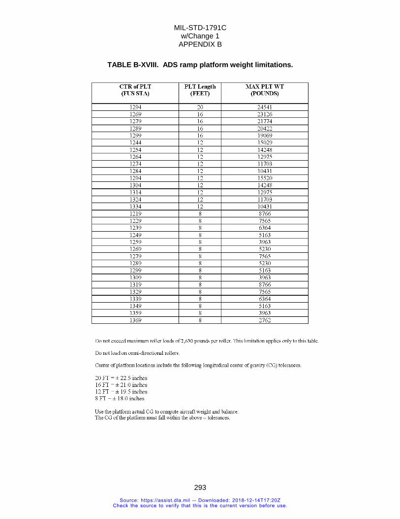
MIL-STD-1791C w/Change 1
APPENDIX B
293
TABLE B-XVIII. ADS ramp platform weight limitations.
Source: https://assist.dla.mil -- Downloaded: 2018-12-14T17:20ZCheck the source to verify that this is the current version before use.
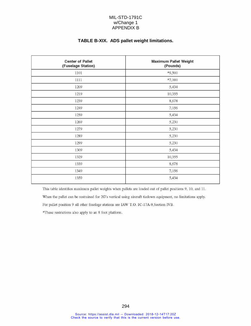
MIL-STD-1791C w/Change 1
APPENDIX B
294
TABLE B-XIX. ADS pallet weight limitations.
Source: https://assist.dla.mil -- Downloaded: 2018-12-14T17:20ZCheck the source to verify that this is the current version before use.
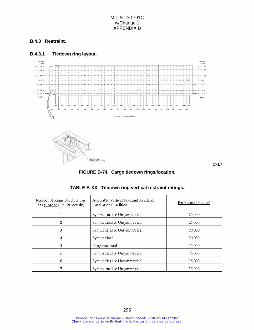
MIL-STD-1791C w/Change 1
APPENDIX B
295
B.4.3 Restraint.
B.4.3.1 Tiedown ring layout.
C-17 FIGURE B-74. Cargo tiedown rings/location.
TABLE B-XX. Tiedown ring vertical restraint ratings.
Source: https://assist.dla.mil -- Downloaded: 2018-12-14T17:20ZCheck the source to verify that this is the current version before use.
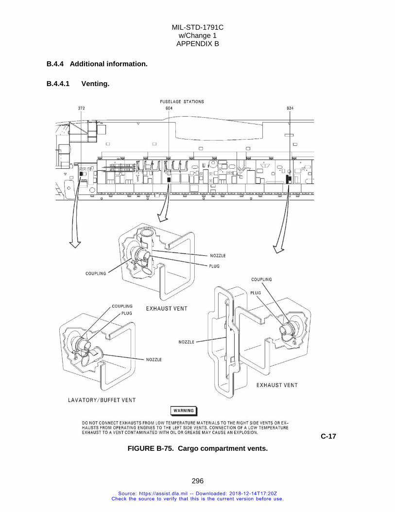
MIL-STD-1791C w/Change 1
APPENDIX B
296
B.4.4 Additional information.
B.4.4.1 Venting.
C-17 FIGURE B-75. Cargo compartment vents.
Source: https://assist.dla.mil -- Downloaded: 2018-12-14T17:20ZCheck the source to verify that this is the current version before use.
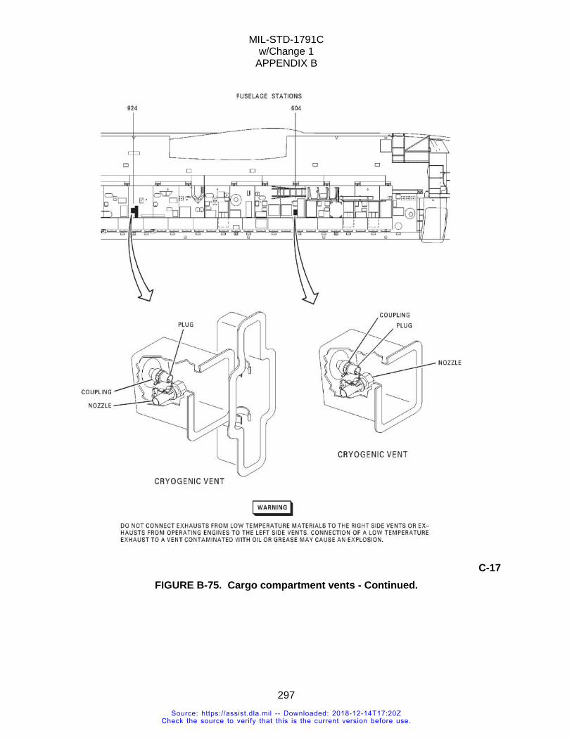
MIL-STD-1791C w/Change 1
APPENDIX B
297
C-17 FIGURE B-75. Cargo compartment vents - Continued.
Source: https://assist.dla.mil -- Downloaded: 2018-12-14T17:20ZCheck the source to verify that this is the current version before use.
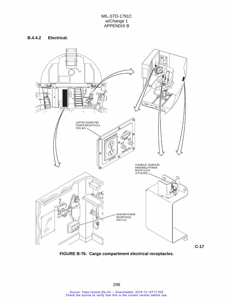
MIL-STD-1791C w/Change 1
APPENDIX B
298
B.4.4.2 Electrical.
C-17 FIGURE B-76. Cargo compartment electrical receptacles.
Source: https://assist.dla.mil -- Downloaded: 2018-12-14T17:20ZCheck the source to verify that this is the current version before use.

MIL-STD-1791C w/Change 1
APPENDIX B
299
C-17 FIGURE B-76. Cargo compartment electrical receptacle - Continued.
B.4.4.3 Tip off.
Source: https://assist.dla.mil -- Downloaded: 2018-12-14T17:20ZCheck the source to verify that this is the current version before use.
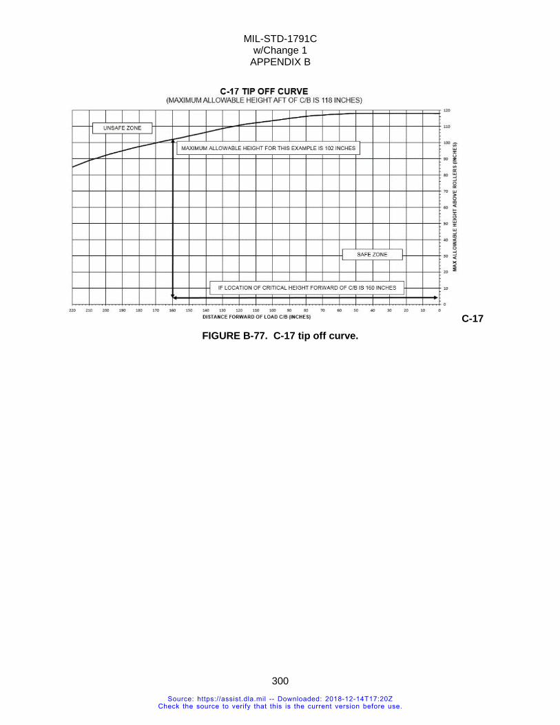
MIL-STD-1791C w/Change 1
APPENDIX B
300
C-17 FIGURE B-77. C-17 tip off curve.
Source: https://assist.dla.mil -- Downloaded: 2018-12-14T17:20ZCheck the source to verify that this is the current version before use.
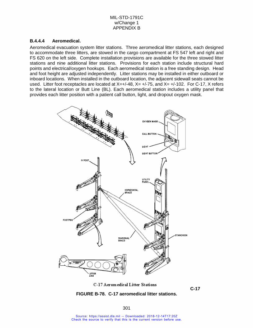
MIL-STD-1791C w/Change 1
APPENDIX B
301
B.4.4.4 Aeromedical. Aeromedical evacuation system litter stations. Three aeromedical litter stations, each designed to accommodate three litters, are stowed in the cargo compartment at FS 547 left and right and FS 620 on the left side. Complete installation provisions are available for the three stowed litter stations and nine additional litter stations. Provisions for each station include structural hard points and electrical/oxygen hookups. Each aeromedical station is a free standing design. Head and foot height are adjusted independently. Litter stations may be installed in either outboard or inboard locations. When installed in the outboard location, the adjacent sidewall seats cannot be used. Litter foot receptacles are located at X=+/-48, X= +/-75, and X= +/-102. For C-17, X refers to the lateral location or Butt Line (BL). Each aeromedical station includes a utility panel that provides each litter position with a patient call button, light, and dropout oxygen mask.
C-17 FIGURE B-78. C-17 aeromedical litter stations.
Source: https://assist.dla.mil -- Downloaded: 2018-12-14T17:20ZCheck the source to verify that this is the current version before use.
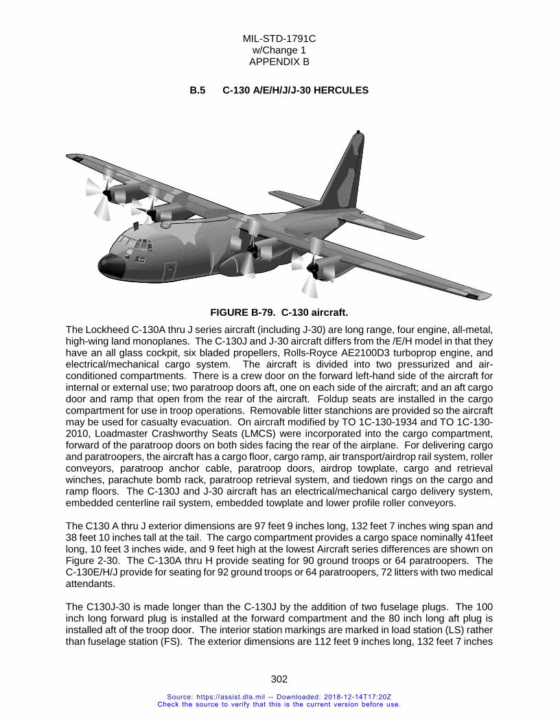
MIL-STD-1791C w/Change 1
APPENDIX B
302
B.5 C-130 A/E/H/J/J-30 HERCULES
FIGURE B-79. C-130 aircraft.
The Lockheed C-130A thru J series aircraft (including J-30) are long range, four engine, all-metal, high-wing land monoplanes. The C-130J and J-30 aircraft differs from the /E/H model in that they have an all glass cockpit, six bladed propellers, Rolls-Royce AE2100D3 turboprop engine, and electrical/mechanical cargo system. The aircraft is divided into two pressurized and air-conditioned compartments. There is a crew door on the forward left-hand side of the aircraft for internal or external use; two paratroop doors aft, one on each side of the aircraft; and an aft cargo door and ramp that open from the rear of the aircraft. Foldup seats are installed in the cargo compartment for use in troop operations. Removable litter stanchions are provided so the aircraft may be used for casualty evacuation. On aircraft modified by TO 1C-130-1934 and TO 1C-130-2010, Loadmaster Crashworthy Seats (LMCS) were incorporated into the cargo compartment, forward of the paratroop doors on both sides facing the rear of the airplane. For delivering cargo and paratroopers, the aircraft has a cargo floor, cargo ramp, air transport/airdrop rail system, roller conveyors, paratroop anchor cable, paratroop doors, airdrop towplate, cargo and retrieval winches, parachute bomb rack, paratroop retrieval system, and tiedown rings on the cargo and ramp floors. The C-130J and J-30 aircraft has an electrical/mechanical cargo delivery system, embedded centerline rail system, embedded towplate and lower profile roller conveyors. The C130 A thru J exterior dimensions are 97 feet 9 inches long, 132 feet 7 inches wing span and 38 feet 10 inches tall at the tail. The cargo compartment provides a cargo space nominally 41feet long, 10 feet 3 inches wide, and 9 feet high at the lowest Aircraft series differences are shown on Figure 2-30. The C-130A thru H provide seating for 90 ground troops or 64 paratroopers. The C-130E/H/J provide for seating for 92 ground troops or 64 paratroopers, 72 litters with two medical attendants. The C130J-30 is made longer than the C-130J by the addition of two fuselage plugs. The 100 inch long forward plug is installed at the forward compartment and the 80 inch long aft plug is installed aft of the troop door. The interior station markings are marked in load station (LS) rather than fuselage station (FS). The exterior dimensions are 112 feet 9 inches long, 132 feet 7 inches
Source: https://assist.dla.mil -- Downloaded: 2018-12-14T17:20ZCheck the source to verify that this is the current version before use.
MIL-STD-1791C w/Change 1
APPENDIX B
303
wing span and 38 feet 10 inches tall at the tail. The cargo compartment provides a cargo space nominally 56 feet long, 10 feet 3 inches wide, and 9 feet high at the lowest. Aircraft series differences are shown on Figure 2-30. The C-130J-30 provide seating for 128 ground troops or 92 paratroopers. 97 litters with four medical attendants.
Source: https://assist.dla.mil -- Downloaded: 2018-12-14T17:20ZCheck the source to verify that this is the current version before use.
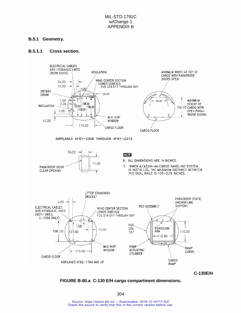
MIL-STD-1791C w/Change 1
APPENDIX B
304
B.5.1 Geometry.
B.5.1.1 Cross section.
C-130E/H
FIGURE B-80.a C-130 E/H cargo compartment dimensions.
Source: https://assist.dla.mil -- Downloaded: 2018-12-14T17:20ZCheck the source to verify that this is the current version before use.
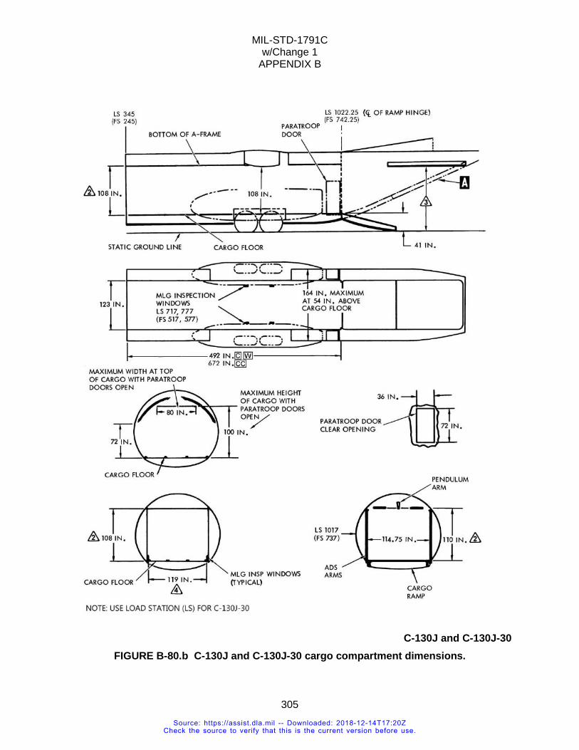
MIL-STD-1791C w/Change 1
APPENDIX B
305
C-130J and C-130J-30
FIGURE B-80.b C-130J and C-130J-30 cargo compartment dimensions.
Source: https://assist.dla.mil -- Downloaded: 2018-12-14T17:20ZCheck the source to verify that this is the current version before use.
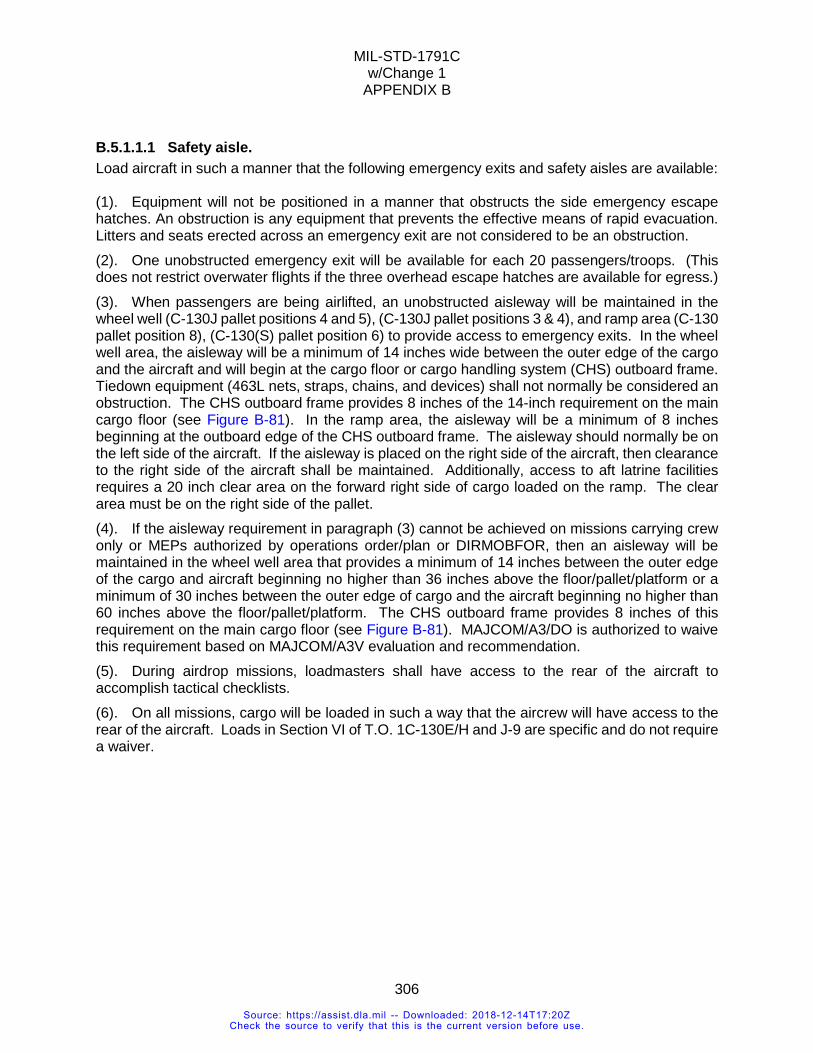
MIL-STD-1791C w/Change 1
APPENDIX B
306
B.5.1.1.1 Safety aisle. Load aircraft in such a manner that the following emergency exits and safety aisles are available: (1). Equipment will not be positioned in a manner that obstructs the side emergency escape hatches. An obstruction is any equipment that prevents the effective means of rapid evacuation. Litters and seats erected across an emergency exit are not considered to be an obstruction. (2). One unobstructed emergency exit will be available for each 20 passengers/troops. (This does not restrict overwater flights if the three overhead escape hatches are available for egress.) (3). When passengers are being airlifted, an unobstructed aisleway will be maintained in the wheel well (C-130J pallet positions 4 and 5), (C-130J pallet positions 3 & 4), and ramp area (C-130 pallet position 8), (C-130(S) pallet position 6) to provide access to emergency exits. In the wheel well area, the aisleway will be a minimum of 14 inches wide between the outer edge of the cargo and the aircraft and will begin at the cargo floor or cargo handling system (CHS) outboard frame. Tiedown equipment (463L nets, straps, chains, and devices) shall not normally be considered an obstruction. The CHS outboard frame provides 8 inches of the 14-inch requirement on the main cargo floor (see Figure B-81). In the ramp area, the aisleway will be a minimum of 8 inches beginning at the outboard edge of the CHS outboard frame. The aisleway should normally be on the left side of the aircraft. If the aisleway is placed on the right side of the aircraft, then clearance to the right side of the aircraft shall be maintained. Additionally, access to aft latrine facilities requires a 20 inch clear area on the forward right side of cargo loaded on the ramp. The clear area must be on the right side of the pallet. (4). If the aisleway requirement in paragraph (3) cannot be achieved on missions carrying crew only or MEPs authorized by operations order/plan or DIRMOBFOR, then an aisleway will be maintained in the wheel well area that provides a minimum of 14 inches between the outer edge of the cargo and aircraft beginning no higher than 36 inches above the floor/pallet/platform or a minimum of 30 inches between the outer edge of cargo and the aircraft beginning no higher than 60 inches above the floor/pallet/platform. The CHS outboard frame provides 8 inches of this requirement on the main cargo floor (see Figure B-81). MAJCOM/A3/DO is authorized to waive this requirement based on MAJCOM/A3V evaluation and recommendation. (5). During airdrop missions, loadmasters shall have access to the rear of the aircraft to accomplish tactical checklists. (6). On all missions, cargo will be loaded in such a way that the aircrew will have access to the rear of the aircraft. Loads in Section VI of T.O. 1C-130E/H and J-9 are specific and do not require a waiver.
Source: https://assist.dla.mil -- Downloaded: 2018-12-14T17:20ZCheck the source to verify that this is the current version before use.
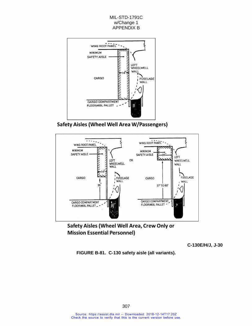
MIL-STD-1791C w/Change 1
APPENDIX B
307
C-130E/H/J, J-30
FIGURE B-81. C-130 safety aisle (all variants).
Source: https://assist.dla.mil -- Downloaded: 2018-12-14T17:20ZCheck the source to verify that this is the current version before use.
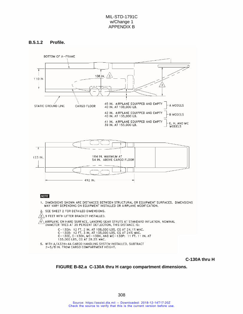
MIL-STD-1791C w/Change 1
APPENDIX B
308
B.5.1.2 Profile.
C-130A thru H
FIGURE B-82.a C-130A thru H cargo compartment dimensions.
Source: https://assist.dla.mil -- Downloaded: 2018-12-14T17:20ZCheck the source to verify that this is the current version before use.
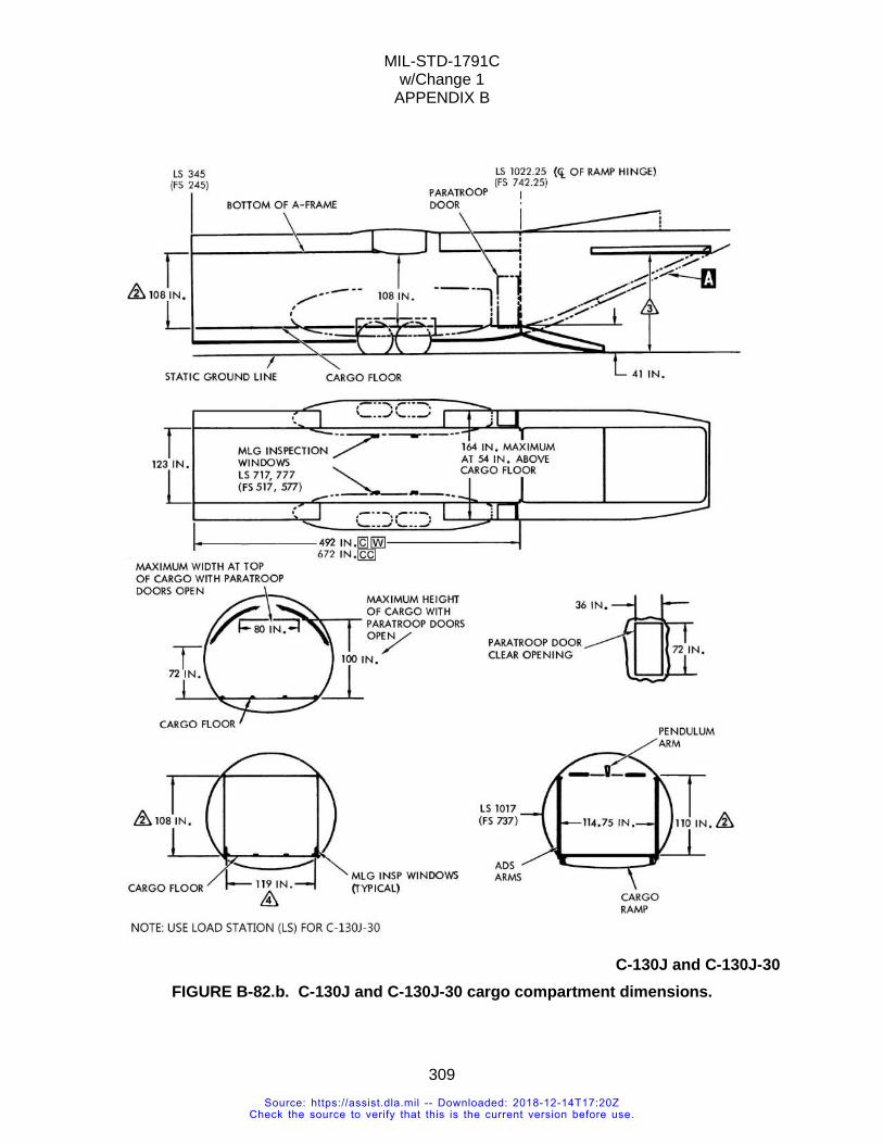
MIL-STD-1791C w/Change 1
APPENDIX B
309
C-130J and C-130J-30 FIGURE B-82.b. C-130J and C-130J-30 cargo compartment dimensions.
Source: https://assist.dla.mil -- Downloaded: 2018-12-14T17:20ZCheck the source to verify that this is the current version before use.
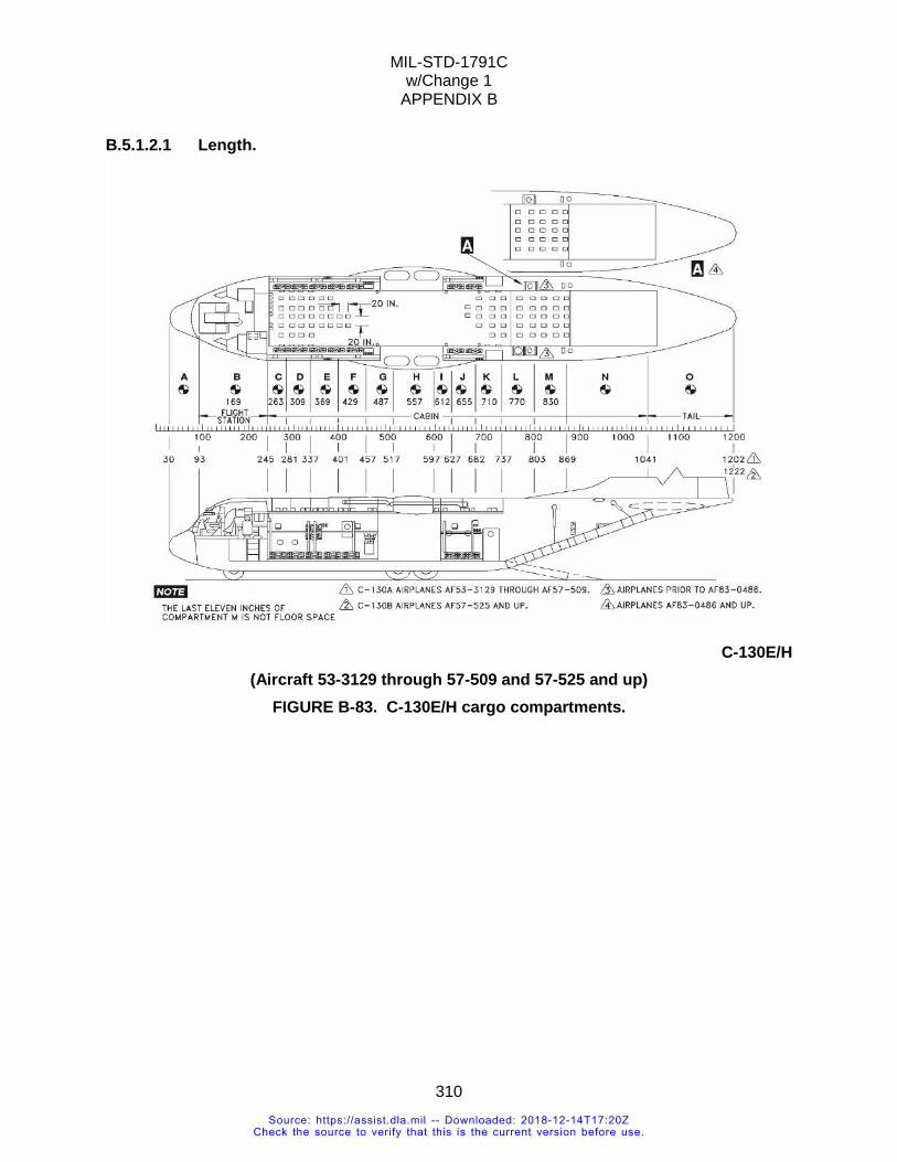
MIL-STD-1791C w/Change 1
APPENDIX B
310
B.5.1.2.1 Length.
C-130E/H
(Aircraft 53-3129 through 57-509 and 57-525 and up) FIGURE B-83. C-130E/H cargo compartments.
Source: https://assist.dla.mil -- Downloaded: 2018-12-14T17:20ZCheck the source to verify that this is the current version before use.
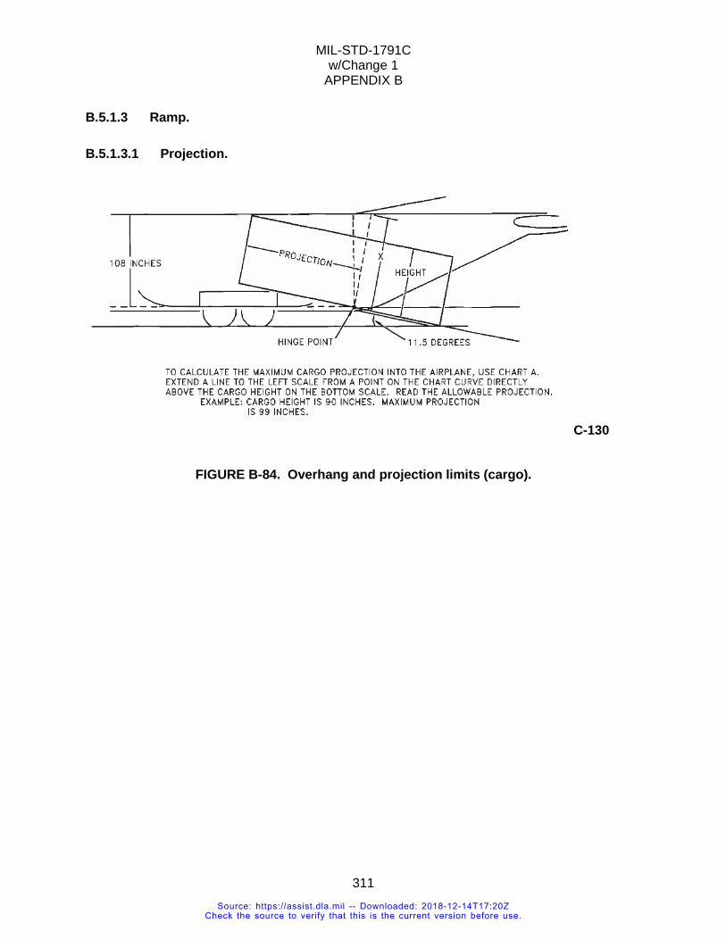
MIL-STD-1791C w/Change 1
APPENDIX B
311
B.5.1.3 Ramp.
B.5.1.3.1 Projection.
C-130
FIGURE B-84. Overhang and projection limits (cargo).
Source: https://assist.dla.mil -- Downloaded: 2018-12-14T17:20ZCheck the source to verify that this is the current version before use.
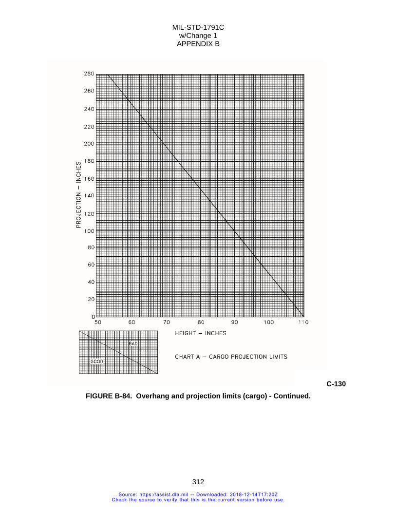
MIL-STD-1791C w/Change 1
APPENDIX B
312
C-130 FIGURE B-84. Overhang and projection limits (cargo) - Continued.
Source: https://assist.dla.mil -- Downloaded: 2018-12-14T17:20ZCheck the source to verify that this is the current version before use.
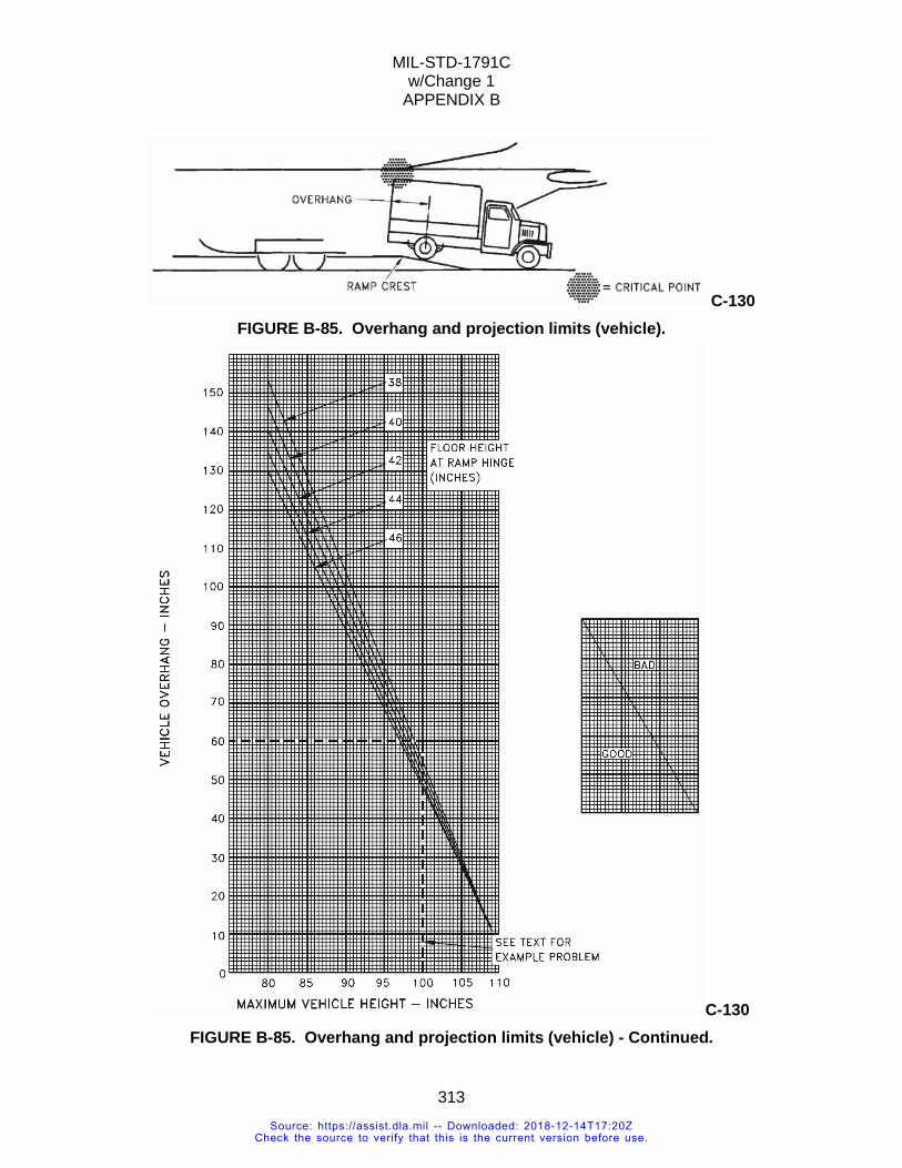
MIL-STD-1791C w/Change 1
APPENDIX B
313
C-130 FIGURE B-85. Overhang and projection limits (vehicle).
C-130 FIGURE B-85. Overhang and projection limits (vehicle) - Continued.
Source: https://assist.dla.mil -- Downloaded: 2018-12-14T17:20ZCheck the source to verify that this is the current version before use.
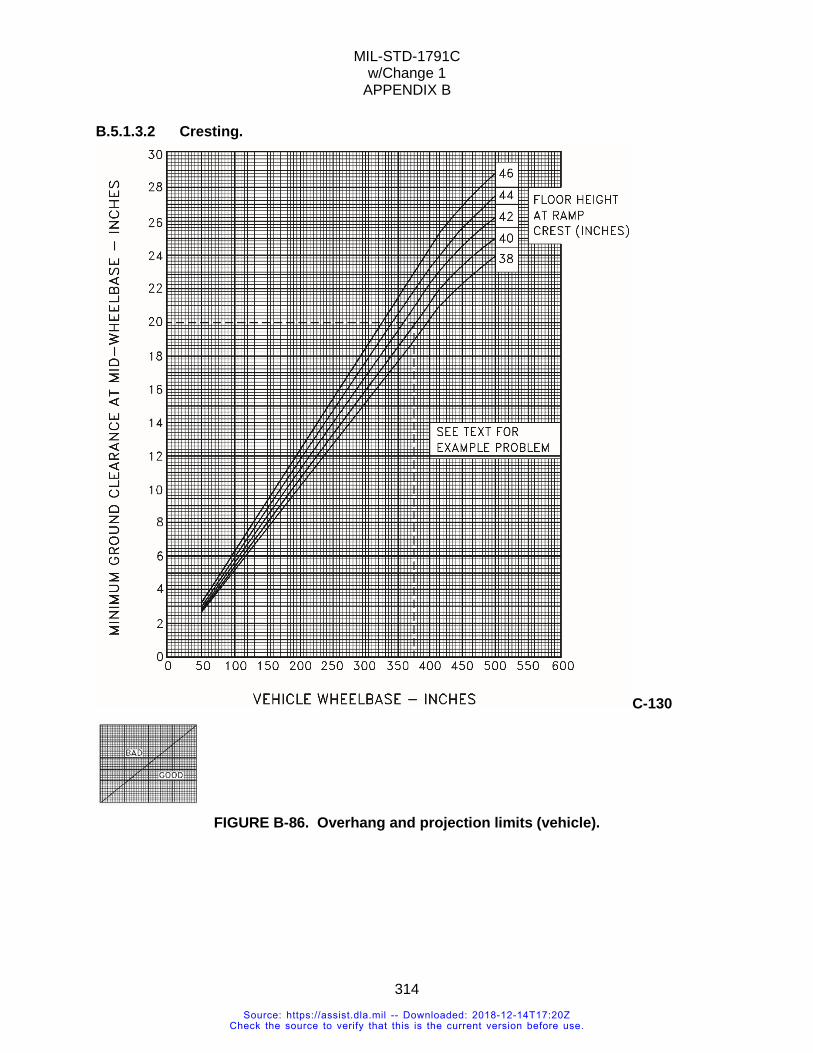
MIL-STD-1791C w/Change 1
APPENDIX B
314
B.5.1.3.2 Cresting.
C-130
FIGURE B-86. Overhang and projection limits (vehicle).
Source: https://assist.dla.mil -- Downloaded: 2018-12-14T17:20ZCheck the source to verify that this is the current version before use.
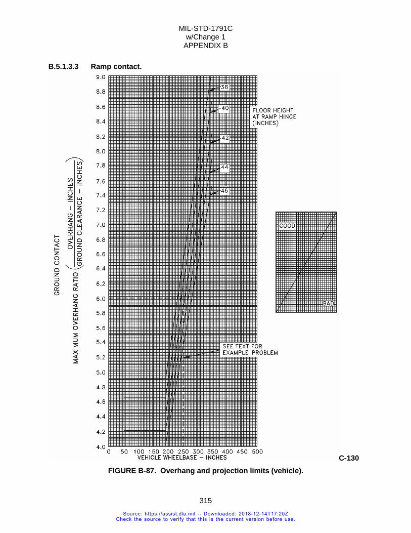
MIL-STD-1791C w/Change 1
APPENDIX B
315
B.5.1.3.3 Ramp contact.
C-130 FIGURE B-87. Overhang and projection limits (vehicle).
Source: https://assist.dla.mil -- Downloaded: 2018-12-14T17:20ZCheck the source to verify that this is the current version before use.
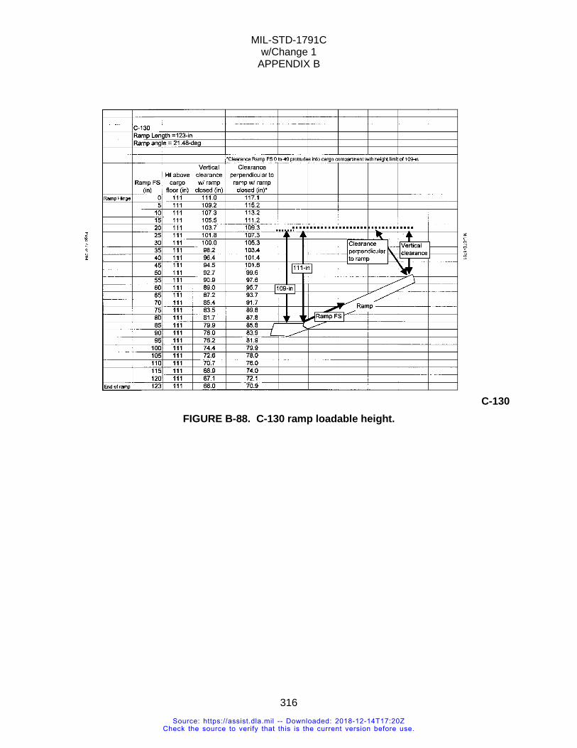
MIL-STD-1791C w/Change 1
APPENDIX B
316
C-130 FIGURE B-88. C-130 ramp loadable height.
Source: https://assist.dla.mil -- Downloaded: 2018-12-14T17:20ZCheck the source to verify that this is the current version before use.
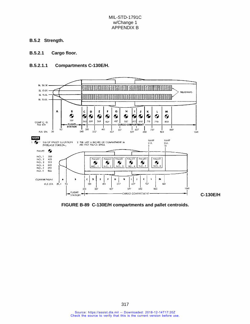
MIL-STD-1791C w/Change 1
APPENDIX B
317
B.5.2 Strength.
B.5.2.1 Cargo floor.
B.5.2.1.1 Compartments C-130E/H.
C-130E/H
FIGURE B-89 C-130E/H compartments and pallet centroids.
Source: https://assist.dla.mil -- Downloaded: 2018-12-14T17:20ZCheck the source to verify that this is the current version before use.
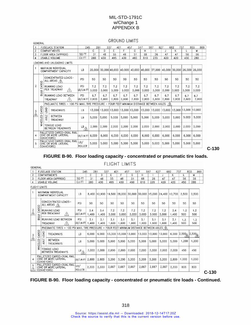
MIL-STD-1791C w/Change 1
APPENDIX B
318
C-130 FIGURE B-90. Floor loading capacity - concentrated or pneumatic tire loads.
C-130 FIGURE B-90. Floor loading capacity - concentrated or pneumatic tire loads - Continued.
Source: https://assist.dla.mil -- Downloaded: 2018-12-14T17:20ZCheck the source to verify that this is the current version before use.
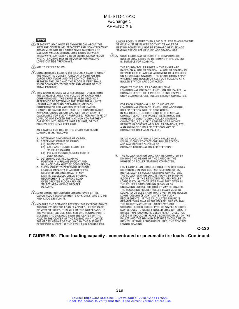
MIL-STD-1791C w/Change 1
APPENDIX B
319
C-130 FIGURE B-90. Floor loading capacity - concentrated or pneumatic tire loads - Continued.
Source: https://assist.dla.mil -- Downloaded: 2018-12-14T17:20ZCheck the source to verify that this is the current version before use.
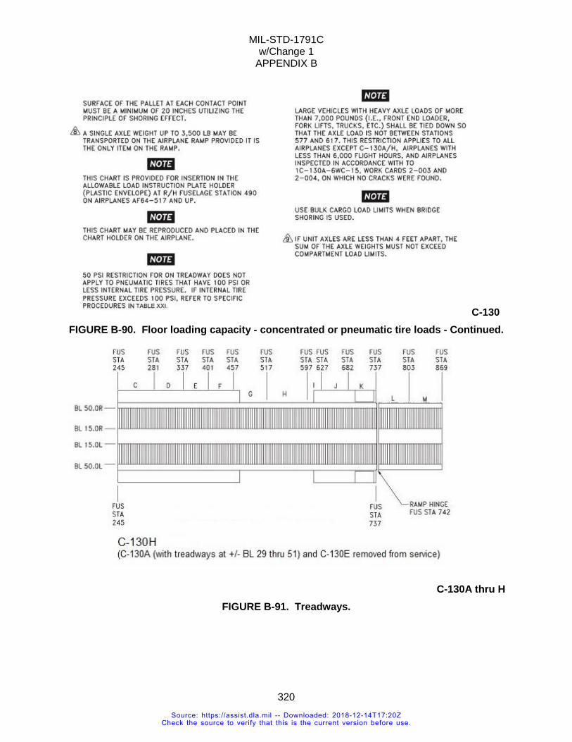
MIL-STD-1791C w/Change 1
APPENDIX B
320
C-130 FIGURE B-90. Floor loading capacity - concentrated or pneumatic tire loads - Continued.
C-130A thru H
FIGURE B-91. Treadways.
Source: https://assist.dla.mil -- Downloaded: 2018-12-14T17:20ZCheck the source to verify that this is the current version before use.
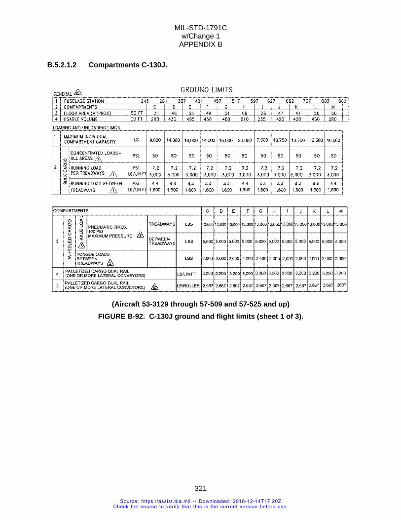
MIL-STD-1791C w/Change 1
APPENDIX B
321
B.5.2.1.2 Compartments C-130J.
(Aircraft 53-3129 through 57-509 and 57-525 and up)
FIGURE B-92. C-130J ground and flight limits (sheet 1 of 3).
Source: https://assist.dla.mil -- Downloaded: 2018-12-14T17:20ZCheck the source to verify that this is the current version before use.
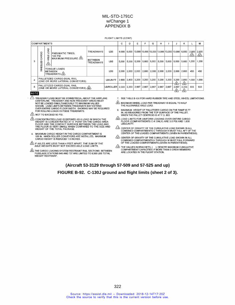
MIL-STD-1791C w/Change 1
APPENDIX B
322
(Aircraft 53-3129 through 57-509 and 57-525 and up)
FIGURE B-92. C-130J ground and flight limits (sheet 2 of 3).
Source: https://assist.dla.mil -- Downloaded: 2018-12-14T17:20ZCheck the source to verify that this is the current version before use.
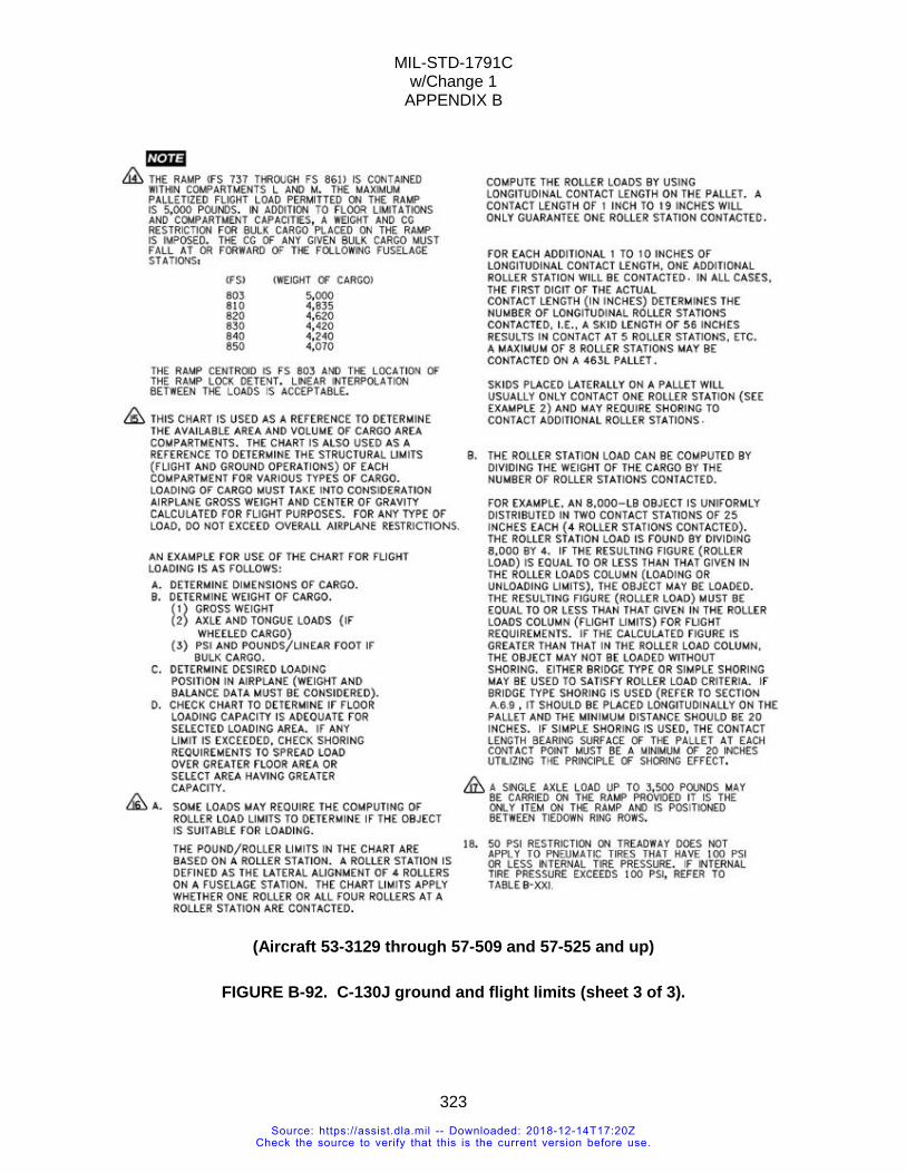
MIL-STD-1791C w/Change 1
APPENDIX B
323
(Aircraft 53-3129 through 57-509 and 57-525 and up)
FIGURE B-92. C-130J ground and flight limits (sheet 3 of 3).
Source: https://assist.dla.mil -- Downloaded: 2018-12-14T17:20ZCheck the source to verify that this is the current version before use.
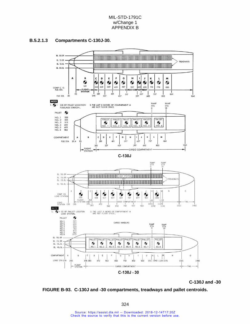
MIL-STD-1791C w/Change 1
APPENDIX B
324
B.5.2.1.3 Compartments C-130J-30.
C-130J and -30
FIGURE B-93. C-130J and -30 compartments, treadways and pallet centroids.
Source: https://assist.dla.mil -- Downloaded: 2018-12-14T17:20ZCheck the source to verify that this is the current version before use.
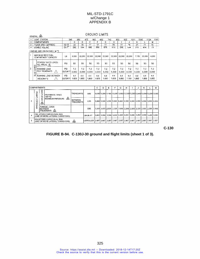
MIL-STD-1791C w/Change 1
APPENDIX B
325
C-130 FIGURE B-94. C-130J-30 ground and flight limits (sheet 1 of 3).
Source: https://assist.dla.mil -- Downloaded: 2018-12-14T17:20ZCheck the source to verify that this is the current version before use.
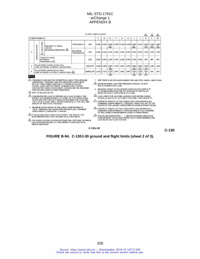
MIL-STD-1791C w/Change 1
APPENDIX B
326
C-130 FIGURE B-94. C-130J-30 ground and flight limits (sheet 2 of 3).
Source: https://assist.dla.mil -- Downloaded: 2018-12-14T17:20ZCheck the source to verify that this is the current version before use.
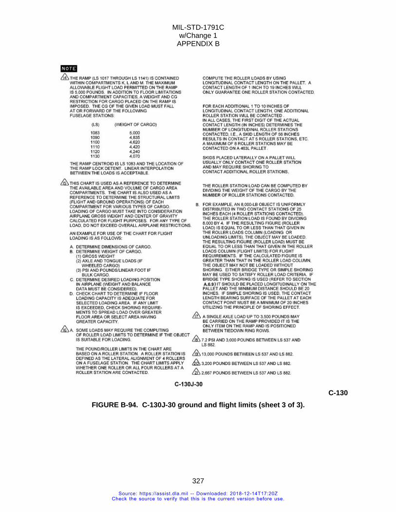
MIL-STD-1791C w/Change 1
APPENDIX B
327
C-130 FIGURE B-94. C-130J-30 ground and flight limits (sheet 3 of 3).
Source: https://assist.dla.mil -- Downloaded: 2018-12-14T17:20ZCheck the source to verify that this is the current version before use.
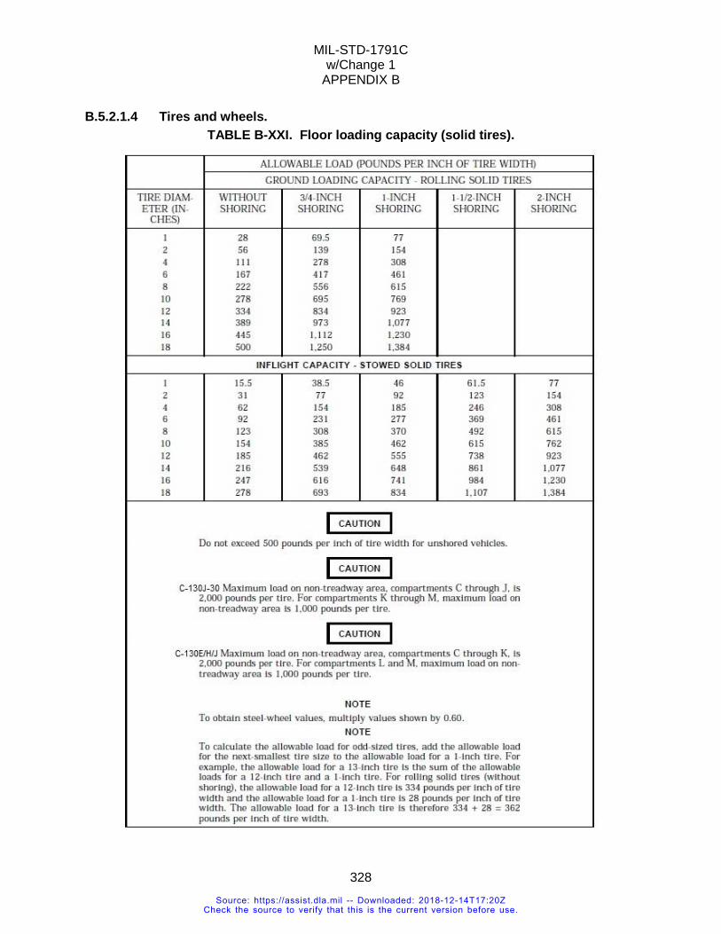
MIL-STD-1791C w/Change 1
APPENDIX B
328
B.5.2.1.4 Tires and wheels. TABLE B-XXI. Floor loading capacity (solid tires).
Source: https://assist.dla.mil -- Downloaded: 2018-12-14T17:20ZCheck the source to verify that this is the current version before use.
MIL-STD-1791C w/Change 1
APPENDIX B
329
B.5.2.1.4.1 Pneumatic tires. For all types of C-130’s, a tire with internal gas pressure of no more than 100 psi is considered pneumatic. A tire with internal pressure exceeding 100 psi is considered as a solid tire. The pneumatic tire contact area (A) is computed by multiplying the ground contact length times contact width (not tire rim) times an effective factor of 0.785.
A = L x W x 0.785 NOTE: Actual tire contact area can vary with weight. Tire contact pressure (PSI) on the aircraft floor is 𝑃𝑃𝑆𝑆𝑃𝑃 = 𝑇𝑇𝐶𝐶𝑃𝑃𝑃𝑃 𝑊𝑊𝑃𝑃𝐶𝐶𝐶𝐶ℎ𝑃𝑃
𝐴𝐴
B.5.2.1.4.2 Solid tires. For the C-130, there are several types of tires or wheels that are defined as solid. The pressure exceeding 100 psi. The tire is filled with foam or other solid material. It can be made of hard rubber or metal (e.g. steel-wheel). It can be airless (non-pneumatic). A caster and vibratory roller are also treated as solid tires (see Table B-XXI for limits).
Source: https://assist.dla.mil -- Downloaded: 2018-12-14T17:20ZCheck the source to verify that this is the current version before use.
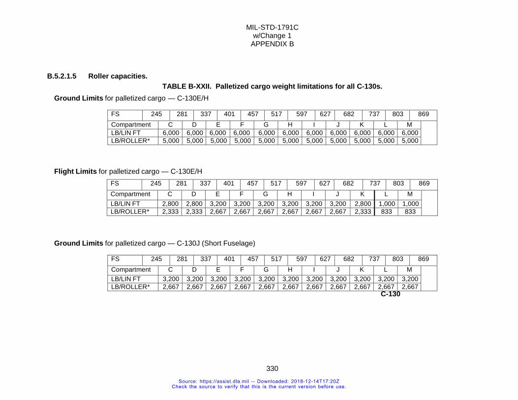
MIL-STD-1791C w/Change 1
APPENDIX B
330
B.5.2.1.5 Roller capacities. TABLE B-XXII. Palletized cargo weight limitations for all C-130s.
Ground Limits for palletized cargo — C-130E/H
FS 245 281 337 401 457 517 597 627 682 737 803 869 Compartment C D E F G H I J K L M LB/LIN FT 6,000 6,000 6,000 6,000 6,000 6,000 6,000 6,000 6,000 6,000 6,000 LB/ROLLER* 5,000 5,000 5,000 5,000 5,000 5,000 5,000 5,000 5,000 5,000 5,000
Flight Limits for palletized cargo — C-130E/H FS 245 281 337 401 457 517 597 627 682 737 803 869 Compartment C D E F G H I J K L M LB/LIN FT 2,800 2,800 3,200 3,200 3,200 3,200 3,200 3,200 2,800 1,000 1,000 LB/ROLLER* 2,333 2,333 2,667 2,667 2,667 2,667 2,667 2,667 2,333 833 833
Ground Limits for palletized cargo — C-130J (Short Fuselage)
FS 245 281 337 401 457 517 597 627 682 737 803 869 Compartment C D E F G H I J K L M LB/LIN FT 3,200 3,200 3,200 3,200 3,200 3,200 3,200 3,200 3,200 3,200 3,200 LB/ROLLER* 2,667 2,667 2,667 2,667 2,667 2,667 2,667 2,667 2,667 2,667 2,667
C-130
Source: https://assist.dla.mil -- Downloaded: 2018-12-14T17:20ZCheck the source to verify that this is the current version before use.
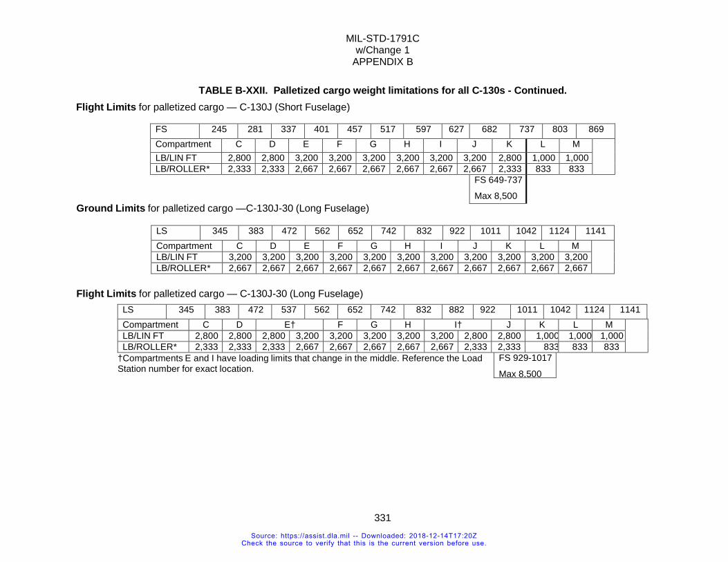
MIL-STD-1791C w/Change 1
APPENDIX B
331
TABLE B-XXII. Palletized cargo weight limitations for all C-130s - Continued. Flight Limits for palletized cargo — C-130J (Short Fuselage)
FS 245 281 337 401 457 517 597 627 682 737 803 869 Compartment C D E F G H I J K L M LB/LIN FT 2,800 2,800 3,200 3,200 3,200 3,200 3,200 3,200 2,800 1,000 1,000 LB/ROLLER* 2,333 2,333 2,667 2,667 2,667 2,667 2,667 2,667 2,333 833 833
FS 649-737
Max 8,500
Ground Limits for palletized cargo —C-130J-30 (Long Fuselage)
LS 345 383 472 562 652 742 832 922 1011 1042 1124 1141 Compartment C D E F G H I J K L M LB/LIN FT 3,200 3,200 3,200 3,200 3,200 3,200 3,200 3,200 3,200 3,200 3,200 LB/ROLLER* 2,667 2,667 2,667 2,667 2,667 2,667 2,667 2,667 2,667 2,667 2,667
Flight Limits for palletized cargo — C-130J-30 (Long Fuselage) LS 345 383 472 537 562 652 742 832 882 922 1011 1042 1124 1141 Compartment C D E† F G H I† J K L M LB/LIN FT 2,800 2,800 2,800 3,200 3,200 3,200 3,200 3,200 2,800 2,800 1,000 1,000 1,000 LB/ROLLER* 2,333 2,333 2,333 2,667 2,667 2,667 2,667 2,667 2,333 2,333 833 833 833
†Compartments E and I have loading limits that change in the middle. Reference the Load Station number for exact location.
FS 929-1017
Max 8,500
Source: https://assist.dla.mil -- Downloaded: 2018-12-14T17:20ZCheck the source to verify that this is the current version before use.
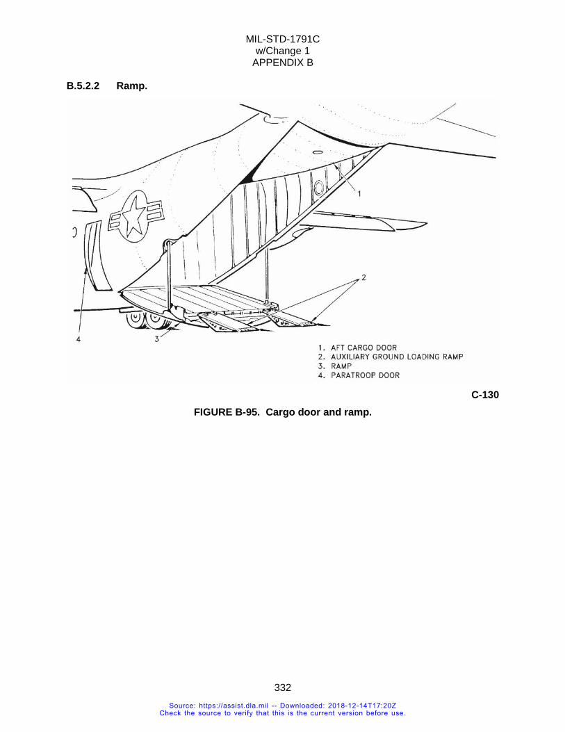
MIL-STD-1791C w/Change 1
APPENDIX B
332
B.5.2.2 Ramp.
C-130
FIGURE B-95. Cargo door and ramp.
Source: https://assist.dla.mil -- Downloaded: 2018-12-14T17:20ZCheck the source to verify that this is the current version before use.
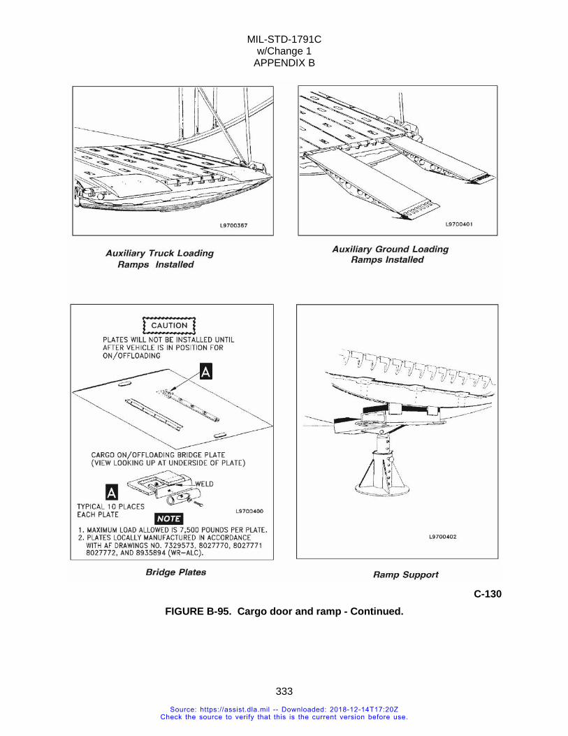
MIL-STD-1791C w/Change 1
APPENDIX B
333
C-130
FIGURE B-95. Cargo door and ramp - Continued.
Source: https://assist.dla.mil -- Downloaded: 2018-12-14T17:20ZCheck the source to verify that this is the current version before use.
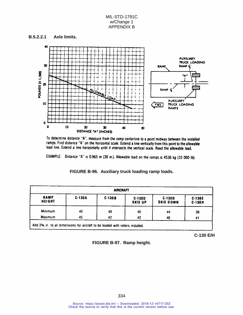
MIL-STD-1791C w/Change 1
APPENDIX B
334
B.5.2.2.1 Axle limits.
FIGURE B-96. Auxiliary truck loading ramp loads.
C-130 E/H FIGURE B-97. Ramp height.
Source: https://assist.dla.mil -- Downloaded: 2018-12-14T17:20ZCheck the source to verify that this is the current version before use.
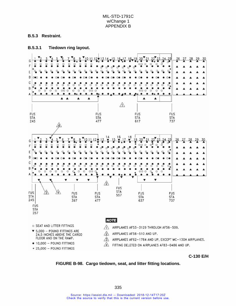
MIL-STD-1791C w/Change 1
APPENDIX B
335
B.5.3 Restraint.
B.5.3.1 Tiedown ring layout.
C-130 E/H
FIGURE B-98. Cargo tiedown, seat, and litter fitting locations.
Source: https://assist.dla.mil -- Downloaded: 2018-12-14T17:20ZCheck the source to verify that this is the current version before use.
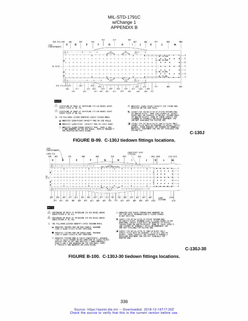
MIL-STD-1791C w/Change 1
APPENDIX B
336
C-130J FIGURE B-99. C-130J tiedown fittings locations.
C-130J-30 FIGURE B-100. C-130J-30 tiedown fittings locations.
Source: https://assist.dla.mil -- Downloaded: 2018-12-14T17:20ZCheck the source to verify that this is the current version before use.
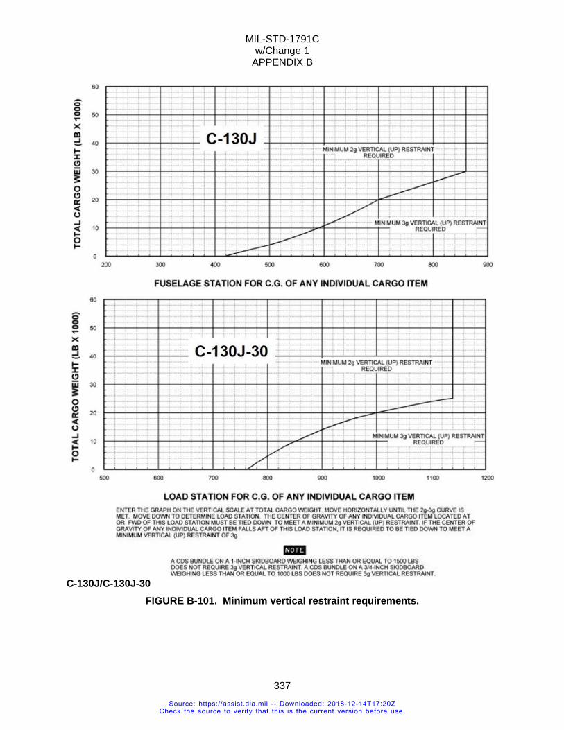
MIL-STD-1791C w/Change 1
APPENDIX B
337
C-130J/C-130J-30 FIGURE B-101. Minimum vertical restraint requirements.
Source: https://assist.dla.mil -- Downloaded: 2018-12-14T17:20ZCheck the source to verify that this is the current version before use.
MIL-STD-1791C w/Change 1
APPENDIX B
338
B.5.4 Additional information.
B.5.4.1 Rail locks. a. The second position (NORM) is the normal or locked position this position locks the right-hand detent latches to provide both forward and aft restraint. b. The third position (EMERG) eliminates the aft restraining force by removing the spring loaded force applied to the detents. c. The fourth position (LOAD) completely retracts the detents, thereby removing all restraining forces in both forward and aft directions. This position is used for cargo loading.
B.5.4.1.1 Ramp detent assemblies and retractable flanges. There are three retractable flanges each in sections 7 and 8 to provide vertical restraint. Normally, these spring-loaded devices stay retracted outboard to prevent them from being engaged inadvertently. For use, they are pushed into position manually and held by latches. For release, the latches are removed simultaneously (in each section) by ramp emergency release handles. The ramp detents will restrain up to 5,000 pounds. NOTE: A maximum of 5,000 pounds may be carried on the cargo ramp. With dual rails and roller conveyors installed, a maximum of 4,664 pounds may be carried on the ramp. With dual rails installed and roller conveyors removed, a total of 4,824 pounds may be carried. NOTE: On MC-130 aircraft, a maximum of 5,000 pounds may be carried on the cargo ramp. With dual rails, roller conveyors, and air deflectors installed, a maximum of 4,527 pounds may be carried on the ramp. With dual rails and air deflectors installed and roller conveyors removed, a total of 4,687 pounds may be carried.
B.5.4.1.2 C-130A/E/H rail guard assemblies. The system includes seven left and seven right guard assemblies. The guard assembly protects latches and control mechanisms. The door can be folded back to permit inspection of the system without removal of guards. The maximum weight that may be placed on the guard assemblies is 250 pounds. CAUTION: Ensure that No. 11 lock cover doors are closed prior to operating paratroop doors.
B.5.4.1.3 Rail-mounted cargo tiedown rings (cargo compartment and ramp). Cargo tiedown rings spaced approximately every 20 inches are mounted on the upper surface of the rail sections. With the addition of the 10,000-pound capacity rings on sections 1 through 6B and the 5,000-pound capacity rings on sections 7 and 8, a full complement of cargo rings is provided for tiedown of rolling stock or special cargo. When not in use, the rings fold flush with the upper surface of the guard assemblies.
B.5.4.1.4 Rail-mounted seat studs. Seat studs are provided on the upper surface of the restraint rail lip corresponding to the floor-mounted studs for attachment of side troop seats. The troop seat legs are attached to these studs in a similar manner, permitting passenger seating with sufficient leg room when used with built-up pallets. There are no seat studs available aft of FS 677.
Source: https://assist.dla.mil -- Downloaded: 2018-12-14T17:20ZCheck the source to verify that this is the current version before use.
MIL-STD-1791C w/Change 1
APPENDIX B
339
B.5.4.1.5 Overboard vent. On aircraft except MC-130H, an overboard vent is located at FS 642 on the left side of the aircraft, approximately 36 inches above the floor. On MC-130H aircraft, the overboard vent is located at FS 652, left side, approximately 26 inches above the floor. To gain access, unsnap and fold back the side wall insulation in the area of the vent. Items requiring venting shall be in accordance with T.O. 37C2-8-1-127. WARNING: When the overboard vent is used to vent fuel, a write-up shall be entered in the form 781A, “Overboard vent at FS 642 is contaminated by fuel. Do not use to vent liquid oxygen until cleaned in accordance with T.O. 37C2-8-1-127”.
B.5.4.2 Electrical systems. Electric power for the aircraft is supplied either by the engine generators, the APU generator, or an external power source. Whenever possible, external power should be used as the source of electrical power. Refer to the applicable maintenance manual for connecting external power to the aircraft. If external power is not available, the APU generator or engine generators can be used to supply electrical power.
B.5.4.2.1 External power receptacle. On the left side of the fuselage, just aft of the battery compartment, is the access door to the external power receptacle. The six prongs make up the plug-in point for an external source of AC allowing an external generator to be plugged in here. CAUTION: External Power must not be plugged into the internal power receptacle.
B.5.4.2.2 Missile support capabilities. Three 20-ampere, 115-volt, 3-phase, AC power outlets equip the aircraft electrically for missile support capabilities. Each power outlet is mounted in a metal box and is provided with a dust cap. The relative location of the outlets is forward right, left, center, and right aft of the cargo compartment. The right forward outlet is located aft of and slightly above the iron lung and galley electrical power outlets. The left center outlet is located immediately below the forward edge of the drip pan for the utility system hydraulic panel. The right aft outlet is located just aft of the main landing gear wheel well bulkhead. Power for the left center and forward right outlet is supplied by the essential AC bus through the MISSILE SUPPORT POWER circuit breaker located on the lower AC distribution circuit breaker panel. Power for the right aft outlet is supplied by the main AC bus through the MISSILE SPRT PWR circuit breaker located on the lower AC distribution circuit breaker panel. Closely monitor the loading of the essential and main AC buses when the missile support system is in use and when any of the following conditions prevail:
a. A 40-KVA ground power supply is in use. b. Only one engine-driven generator or the APU generator is operating. c. Generators 1 and 2 are both out. d. Generators 3 and 4 are both out.
Source: https://assist.dla.mil -- Downloaded: 2018-12-14T17:20ZCheck the source to verify that this is the current version before use.
MIL-STD-1791C w/Change 1
APPENDIX B
340
CAUTION: The rated capacity of the generators available will be exceeded in each of the above cases.
B.5.4.2.3 Service outlets. Seven DC and six AC service outlets are installed throughout the cargo compartment to provide power for work lights, fans, and other electrical equipment. Circuit protection for these outlets are through the CARGO OUTLET RH and CARGO OUTLET LH circuit breakers located on both the lower AC and right hand main avionics DC distribution aft panels and the CARGO OUTLETS AFT located on the aft junction box. Two iron lung and two galley outlets are located together in the cargo compartment, one on the right sidewall aft of the forward bulkhead and the other forward of the left paratroop door. Circuit protection for the iron lung outlets are through the IRON LUNG circuit breakers located on the right main avionics DC distribution panel located in the cargo compartment on the forward bulkhead. Circuit protection for the galley outlets are through the GALLEY PWR CARGO AREA circuit breaker located on the lower AC distribution panel aft on the forward bulkhead.
B.5.4.2.4 Cargo winch power outlets. Two cargo winch power outlets installed on the left side of the cargo compartment, forward bulkhead provide electrical power for operation of AC or DC cargo winches. The AC connector is a four-pin, plug type connector. The DC connector is a three prong type connector and faces outboard.
B.5.4.3 Public address system. The public address system operates on 28 VDC and is used to address personnel in the cargo compartment, either from the flight station or from the cargo compartment Intercommunication System (ICS). The system uses the ICS control panels, loudspeakers, and Headset Interface Units (HIU) with extension cords. By using this equipment, it is possible to speak over the public address system from any ICS panel on the aircraft.
Source: https://assist.dla.mil -- Downloaded: 2018-12-14T17:20ZCheck the source to verify that this is the current version before use.
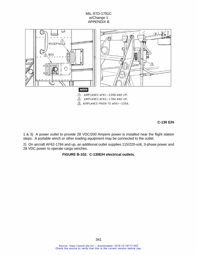
MIL-STD-1791C w/Change 1
APPENDIX B
341
C-130 E/H
1 & 3) A power outlet to provide 28 VDC/200 Ampere power is installed near the flight station steps. A portable winch or other loading equipment may be connected to the outlet. 2) On aircraft AF62-1784 and up, an additional outlet supplies 115/220-volt, 3-phase power and 28 VDC power to operate cargo winches.
FIGURE B-102. C-130E/H electrical outlets.
Source: https://assist.dla.mil -- Downloaded: 2018-12-14T17:20ZCheck the source to verify that this is the current version before use.
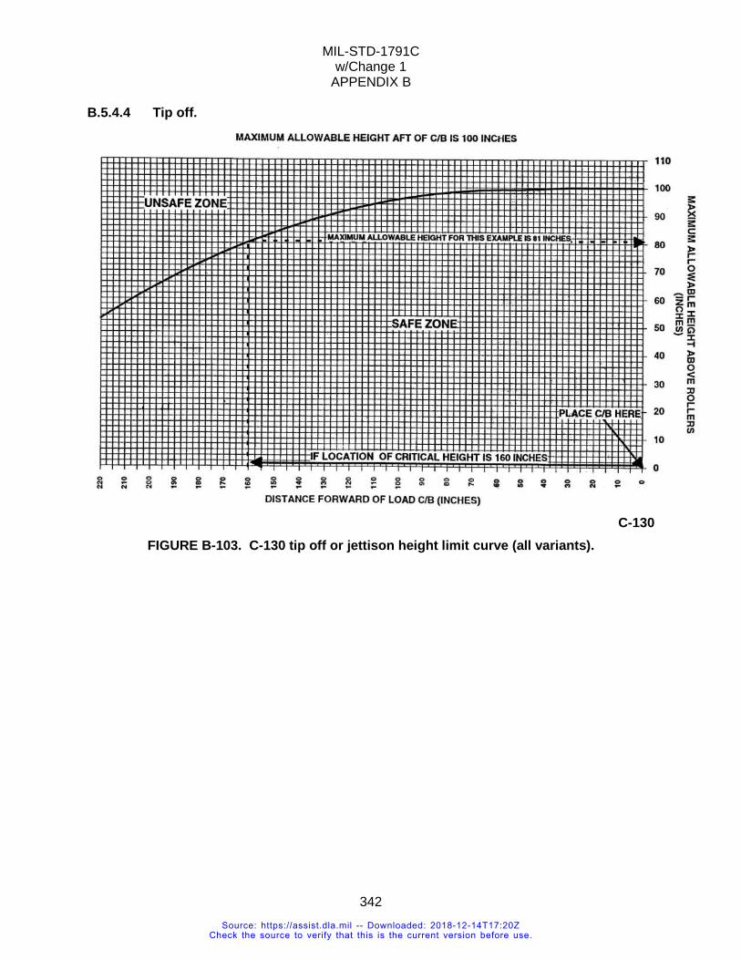
MIL-STD-1791C w/Change 1
APPENDIX B
342
B.5.4.4 Tip off.
C-130
FIGURE B-103. C-130 tip off or jettison height limit curve (all variants).
Source: https://assist.dla.mil -- Downloaded: 2018-12-14T17:20ZCheck the source to verify that this is the current version before use.
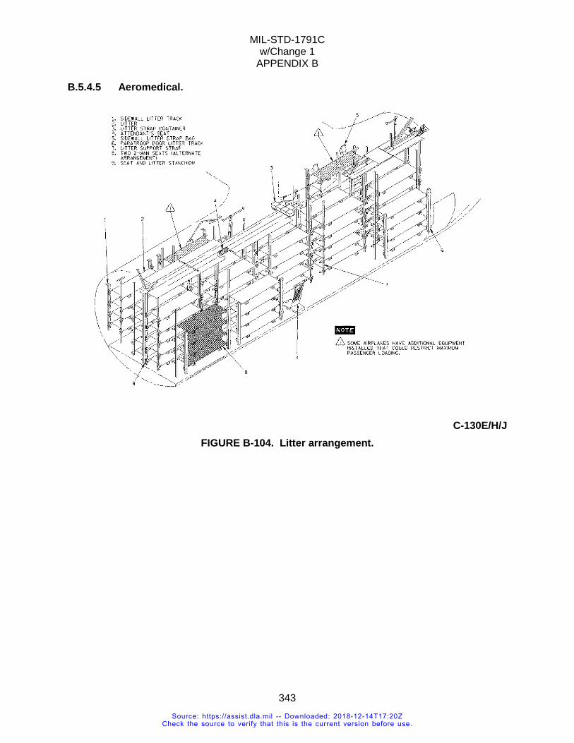
MIL-STD-1791C w/Change 1
APPENDIX B
343
B.5.4.5 Aeromedical.
C-130E/H/J
FIGURE B-104. Litter arrangement.
Source: https://assist.dla.mil -- Downloaded: 2018-12-14T17:20ZCheck the source to verify that this is the current version before use.
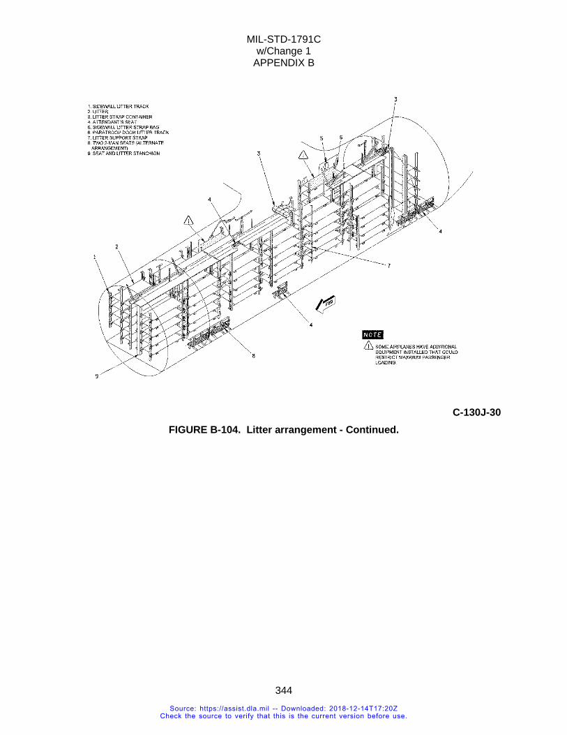
MIL-STD-1791C w/Change 1
APPENDIX B
344
C-130J-30
FIGURE B-104. Litter arrangement - Continued.
Source: https://assist.dla.mil -- Downloaded: 2018-12-14T17:20ZCheck the source to verify that this is the current version before use.
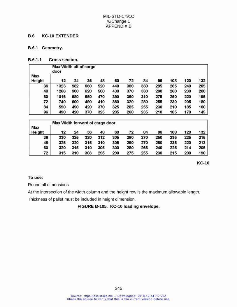
MIL-STD-1791C w/Change 1
APPENDIX B
345
B.6 KC-10 EXTENDER
B.6.1 Geometry.
B.6.1.1 Cross section.
KC-10
To use: Round all dimensions. At the intersection of the width column and the height row is the maximum allowable length. Thickness of pallet must be included in height dimension.
FIGURE B-105. KC-10 loading envelope.
Source: https://assist.dla.mil -- Downloaded: 2018-12-14T17:20ZCheck the source to verify that this is the current version before use.
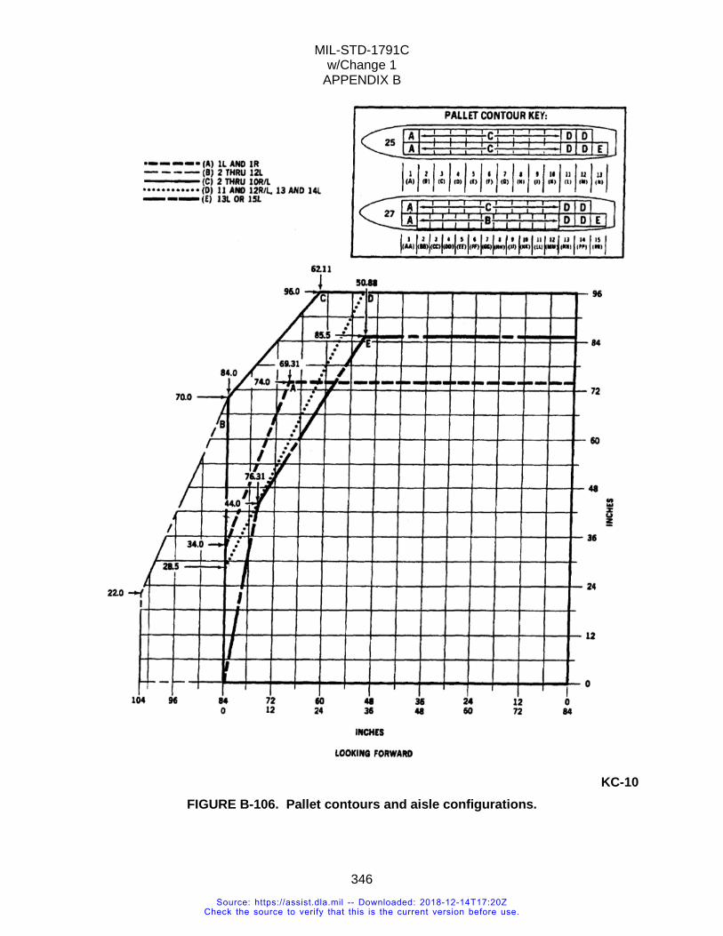
MIL-STD-1791C w/Change 1
APPENDIX B
346
KC-10
FIGURE B-106. Pallet contours and aisle configurations.
Source: https://assist.dla.mil -- Downloaded: 2018-12-14T17:20ZCheck the source to verify that this is the current version before use.
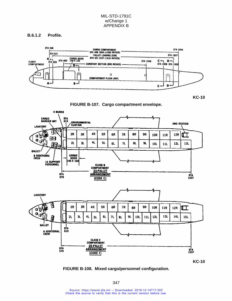
MIL-STD-1791C w/Change 1
APPENDIX B
347
B.6.1.2 Profile.
KC-10
FIGURE B-107. Cargo compartment envelope.
KC-10
FIGURE B-108. Mixed cargo/personnel configuration.
Source: https://assist.dla.mil -- Downloaded: 2018-12-14T17:20ZCheck the source to verify that this is the current version before use.
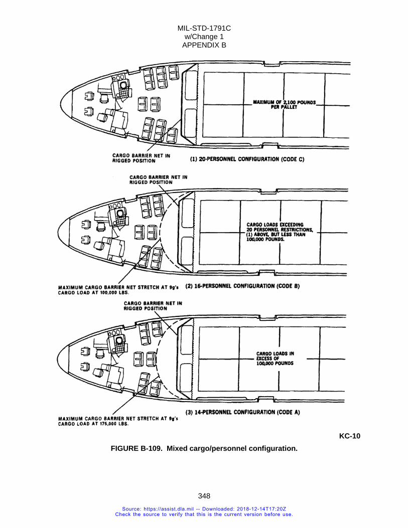
MIL-STD-1791C w/Change 1
APPENDIX B
348
KC-10
FIGURE B-109. Mixed cargo/personnel configuration.
Source: https://assist.dla.mil -- Downloaded: 2018-12-14T17:20ZCheck the source to verify that this is the current version before use.
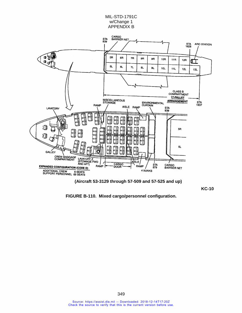
MIL-STD-1791C w/Change 1
APPENDIX B
349
(Aircraft 53-3129 through 57-509 and 57-525 and up)
KC-10 FIGURE B-110. Mixed cargo/personnel configuration.
Source: https://assist.dla.mil -- Downloaded: 2018-12-14T17:20ZCheck the source to verify that this is the current version before use.
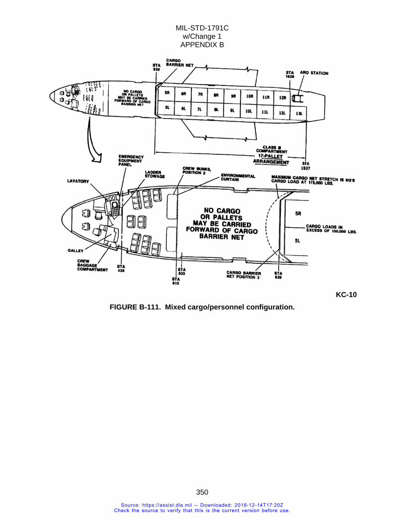
MIL-STD-1791C w/Change 1
APPENDIX B
350
KC-10
FIGURE B-111. Mixed cargo/personnel configuration.
Source: https://assist.dla.mil -- Downloaded: 2018-12-14T17:20ZCheck the source to verify that this is the current version before use.
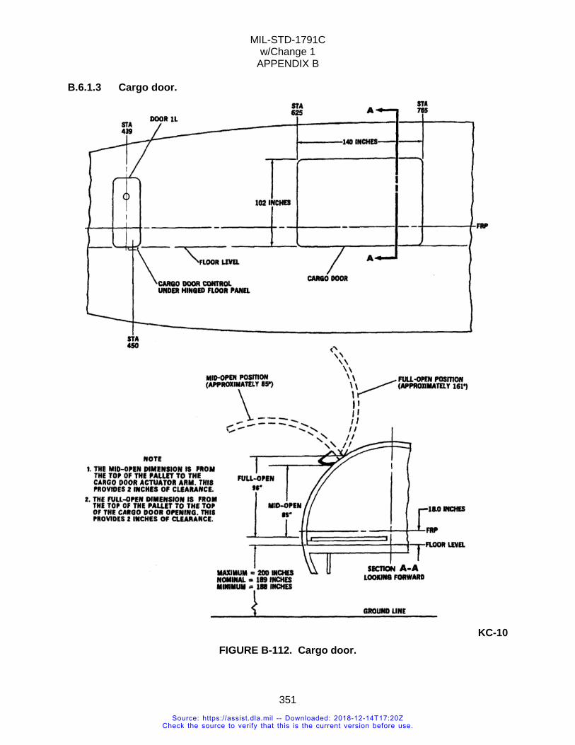
MIL-STD-1791C w/Change 1
APPENDIX B
351
B.6.1.3 Cargo door.
KC-10
FIGURE B-112. Cargo door.
Source: https://assist.dla.mil -- Downloaded: 2018-12-14T17:20ZCheck the source to verify that this is the current version before use.
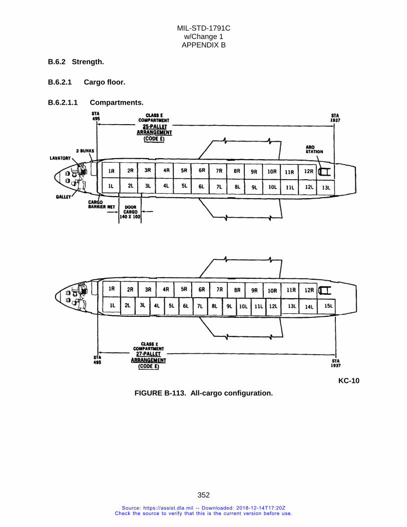
MIL-STD-1791C w/Change 1
APPENDIX B
352
B.6.2 Strength.
B.6.2.1 Cargo floor.
B.6.2.1.1 Compartments.
KC-10
FIGURE B-113. All-cargo configuration.
Source: https://assist.dla.mil -- Downloaded: 2018-12-14T17:20ZCheck the source to verify that this is the current version before use.
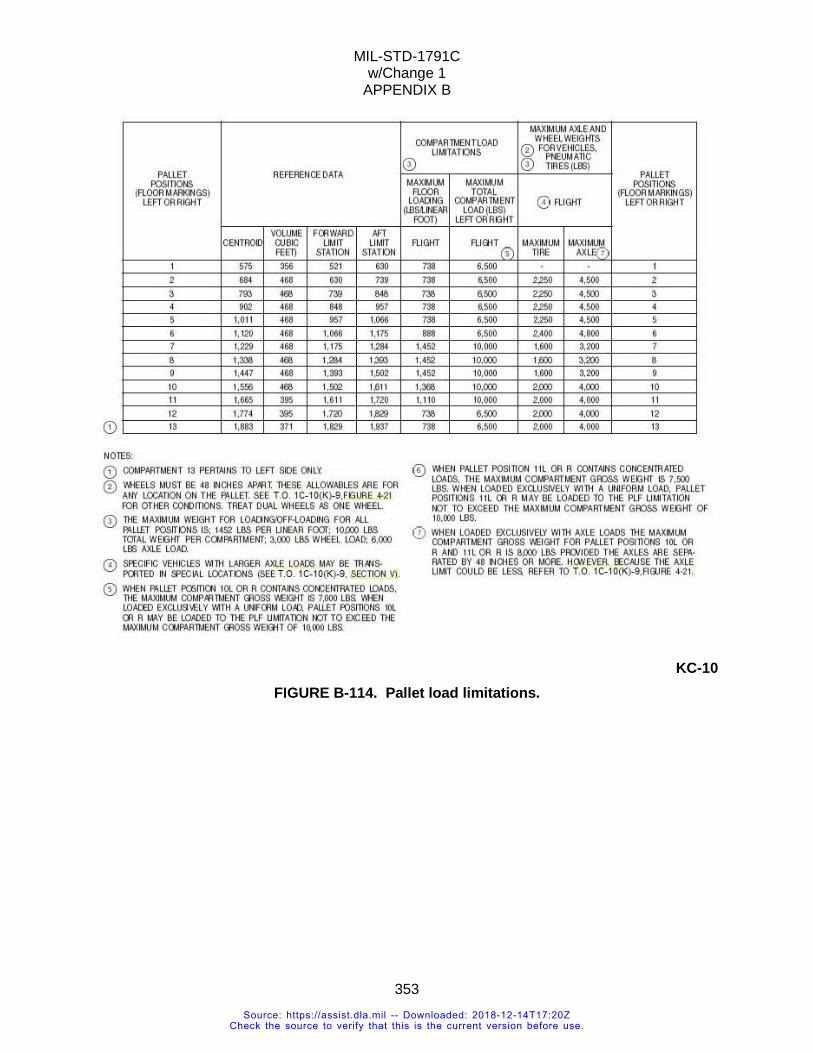
MIL-STD-1791C w/Change 1
APPENDIX B
353
KC-10
FIGURE B-114. Pallet load limitations.
Source: https://assist.dla.mil -- Downloaded: 2018-12-14T17:20ZCheck the source to verify that this is the current version before use.
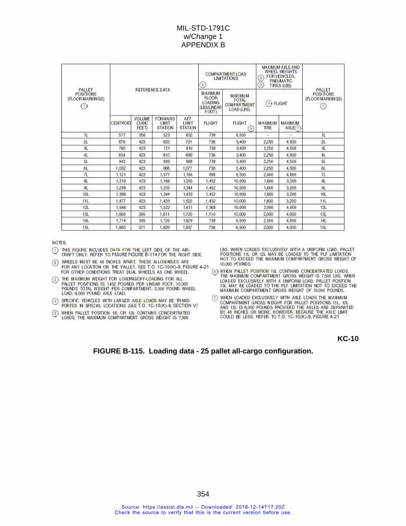
MIL-STD-1791C w/Change 1
APPENDIX B
354
KC-10
FIGURE B-115. Loading data - 25 pallet all-cargo configuration.
Source: https://assist.dla.mil -- Downloaded: 2018-12-14T17:20ZCheck the source to verify that this is the current version before use.
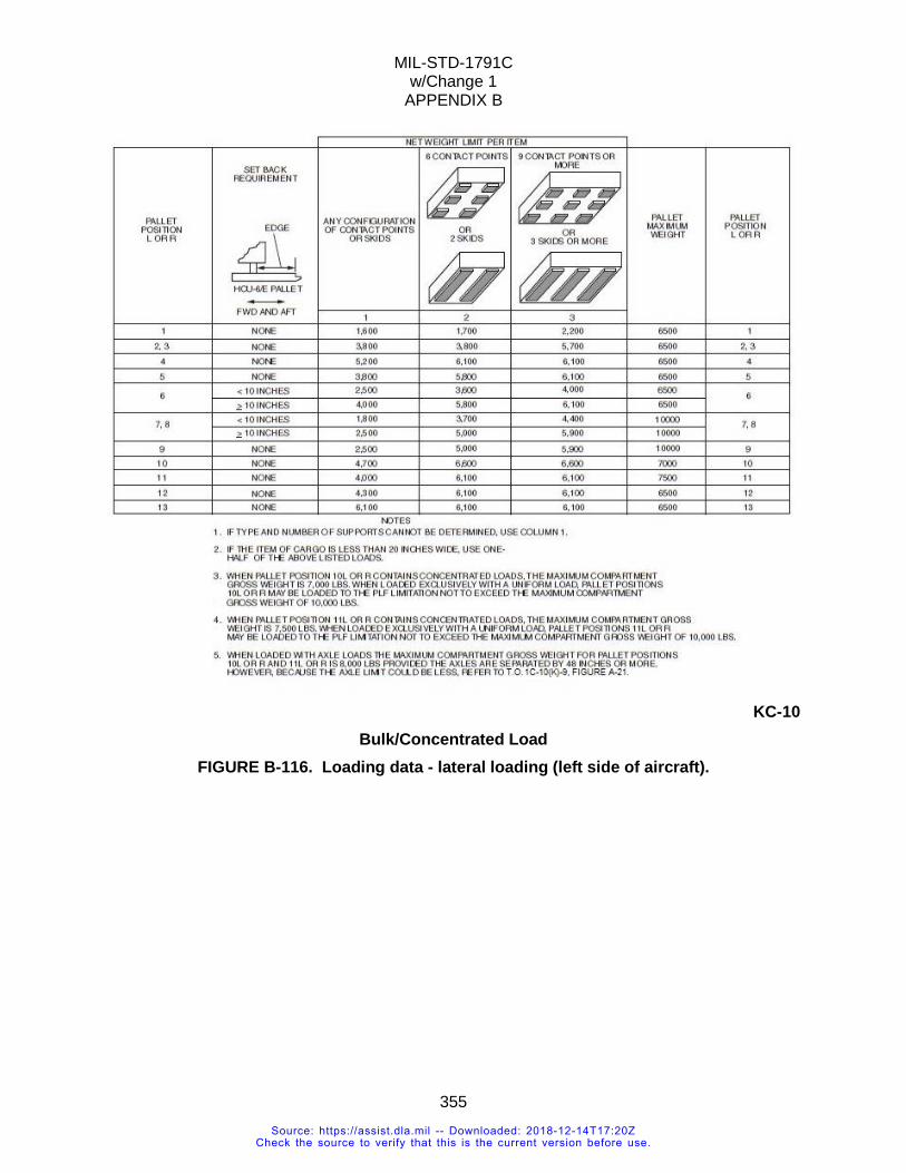
MIL-STD-1791C w/Change 1
APPENDIX B
355
KC-10
Bulk/Concentrated Load FIGURE B-116. Loading data - lateral loading (left side of aircraft).
Source: https://assist.dla.mil -- Downloaded: 2018-12-14T17:20ZCheck the source to verify that this is the current version before use.
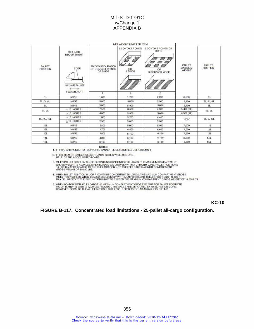
MIL-STD-1791C w/Change 1
APPENDIX B
356
KC-10
FIGURE B-117. Concentrated load limitations - 25-pallet all-cargo configuration.
Source: https://assist.dla.mil -- Downloaded: 2018-12-14T17:20ZCheck the source to verify that this is the current version before use.
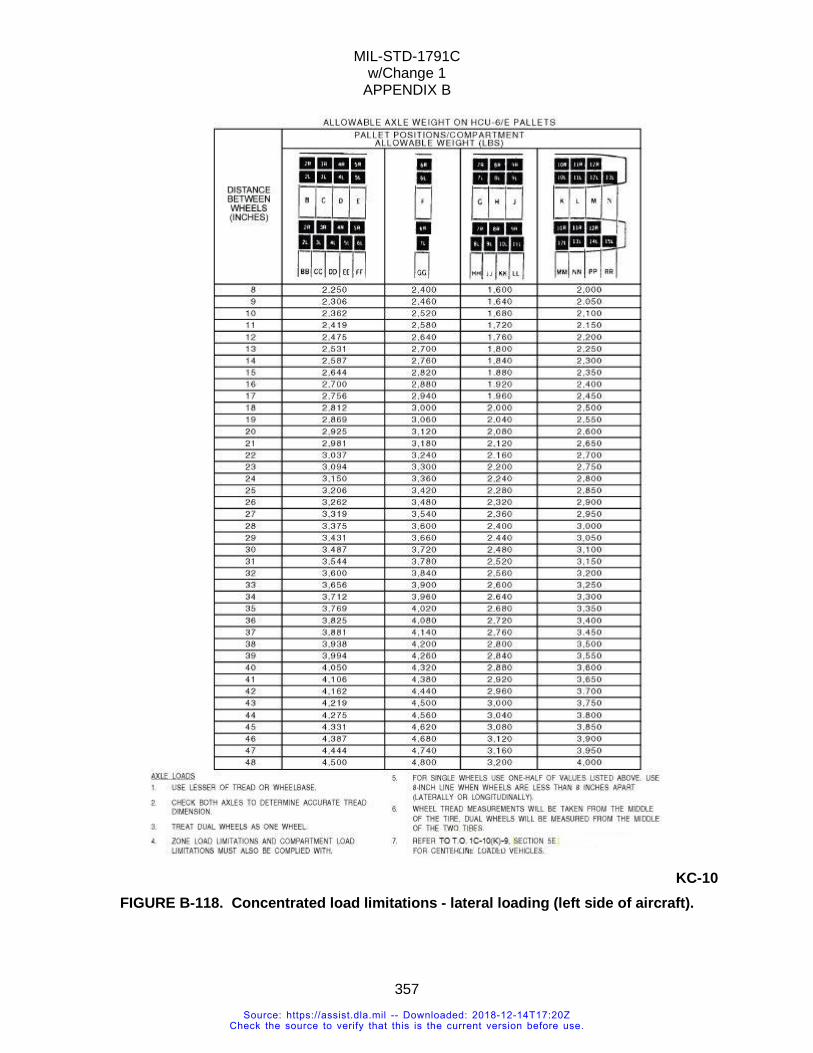
MIL-STD-1791C w/Change 1
APPENDIX B
357
KC-10
FIGURE B-118. Concentrated load limitations - lateral loading (left side of aircraft).
Source: https://assist.dla.mil -- Downloaded: 2018-12-14T17:20ZCheck the source to verify that this is the current version before use.
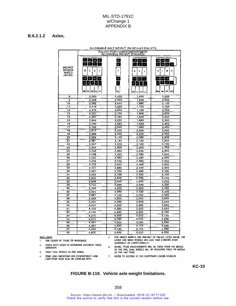
MIL-STD-1791C w/Change 1
APPENDIX B
358
B.6.2.1.2 Axles.
KC-10 FIGURE B-119. Vehicle axle weight limitations.
Source: https://assist.dla.mil -- Downloaded: 2018-12-14T17:20ZCheck the source to verify that this is the current version before use.
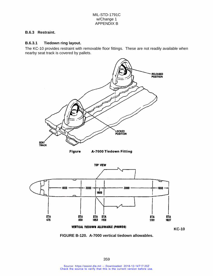
MIL-STD-1791C w/Change 1
APPENDIX B
359
B.6.3 Restraint.
B.6.3.1 Tiedown ring layout. The KC-10 provides restraint with removable floor fittings. These are not readily available when nearby seat track is covered by pallets.
KC-10 FIGURE B-120. A-7000 vertical tiedown allowables.
Source: https://assist.dla.mil -- Downloaded: 2018-12-14T17:20ZCheck the source to verify that this is the current version before use.
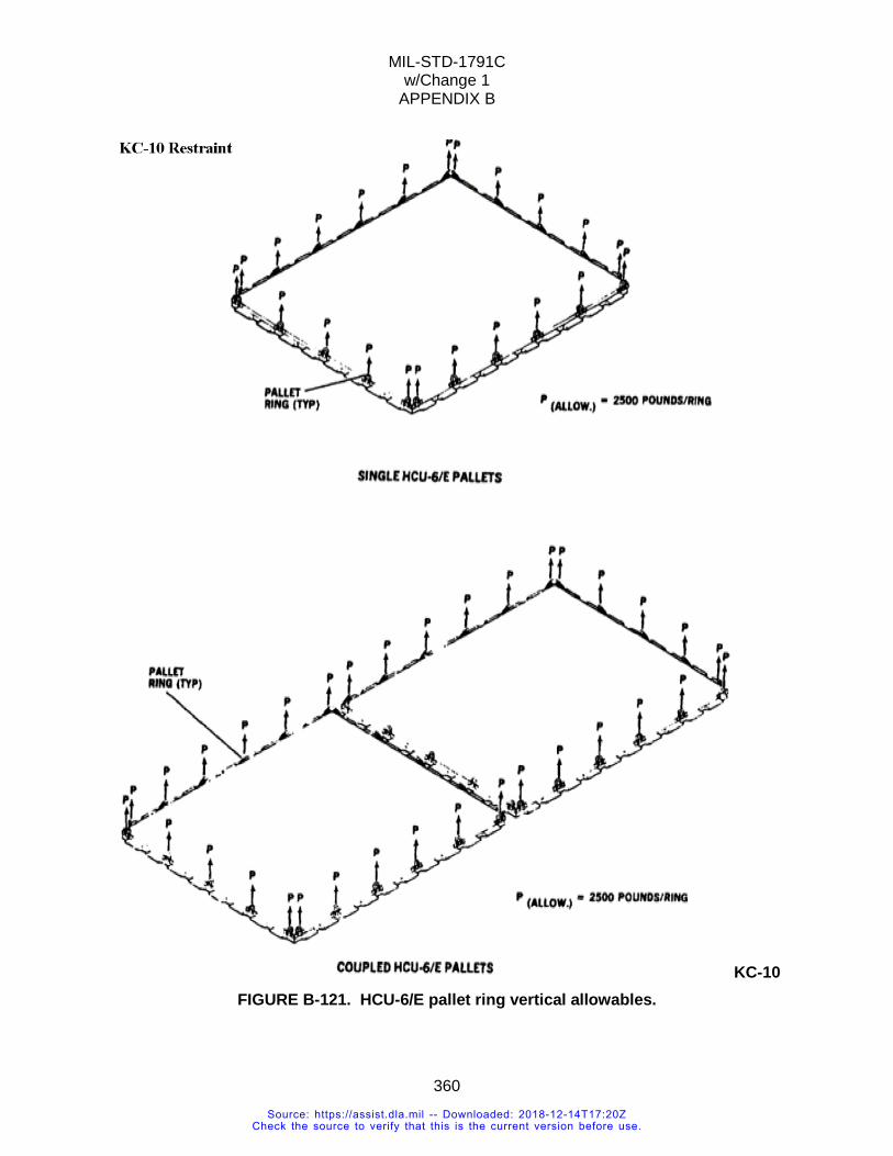
MIL-STD-1791C w/Change 1
APPENDIX B
360
KC-10 FIGURE B-121. HCU-6/E pallet ring vertical allowables.
Source: https://assist.dla.mil -- Downloaded: 2018-12-14T17:20ZCheck the source to verify that this is the current version before use.
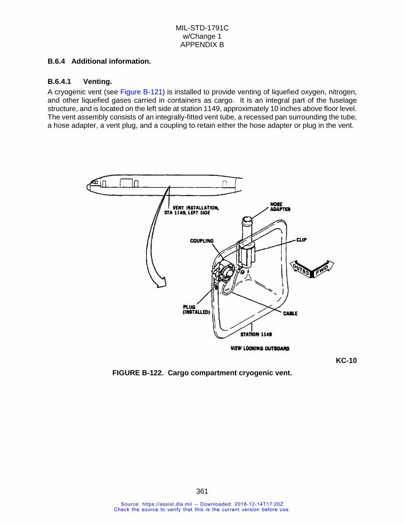
MIL-STD-1791C w/Change 1
APPENDIX B
361
B.6.4 Additional information.
B.6.4.1 Venting. A cryogenic vent (see Figure B-121) is installed to provide venting of liquefied oxygen, nitrogen, and other liquefied gases carried in containers as cargo. It is an integral part of the fuselage structure, and is located on the left side at station 1149, approximately 10 inches above floor level. The vent assembly consists of an integrally-fitted vent tube, a recessed pan surrounding the tube, a hose adapter, a vent plug, and a coupling to retain either the hose adapter or plug in the vent.
KC-10
FIGURE B-122. Cargo compartment cryogenic vent.
Source: https://assist.dla.mil -- Downloaded: 2018-12-14T17:20ZCheck the source to verify that this is the current version before use.
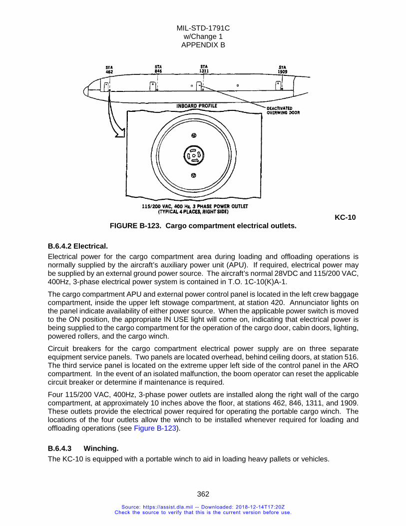
MIL-STD-1791C w/Change 1
APPENDIX B
362
KC-10 FIGURE B-123. Cargo compartment electrical outlets.
B.6.4.2 Electrical. Electrical power for the cargo compartment area during loading and offloading operations is normally supplied by the aircraft’s auxiliary power unit (APU). If required, electrical power may be supplied by an external ground power source. The aircraft’s normal 28VDC and 115/200 VAC, 400Hz, 3-phase electrical power system is contained in T.O. 1C-10(K)A-1. The cargo compartment APU and external power control panel is located in the left crew baggage compartment, inside the upper left stowage compartment, at station 420. Annunciator lights on the panel indicate availability of either power source. When the applicable power switch is moved to the ON position, the appropriate IN USE light will come on, indicating that electrical power is being supplied to the cargo compartment for the operation of the cargo door, cabin doors, lighting, powered rollers, and the cargo winch. Circuit breakers for the cargo compartment electrical power supply are on three separate equipment service panels. Two panels are located overhead, behind ceiling doors, at station 516. The third service panel is located on the extreme upper left side of the control panel in the ARO compartment. In the event of an isolated malfunction, the boom operator can reset the applicable circuit breaker or determine if maintenance is required. Four 115/200 VAC, 400Hz, 3-phase power outlets are installed along the right wall of the cargo compartment, at approximately 10 inches above the floor, at stations 462, 846, 1311, and 1909. These outlets provide the electrical power required for operating the portable cargo winch. The locations of the four outlets allow the winch to be installed whenever required for loading and offloading operations (see Figure B-123).
B.6.4.3 Winching. The KC-10 is equipped with a portable winch to aid in loading heavy pallets or vehicles.
Source: https://assist.dla.mil -- Downloaded: 2018-12-14T17:20ZCheck the source to verify that this is the current version before use.
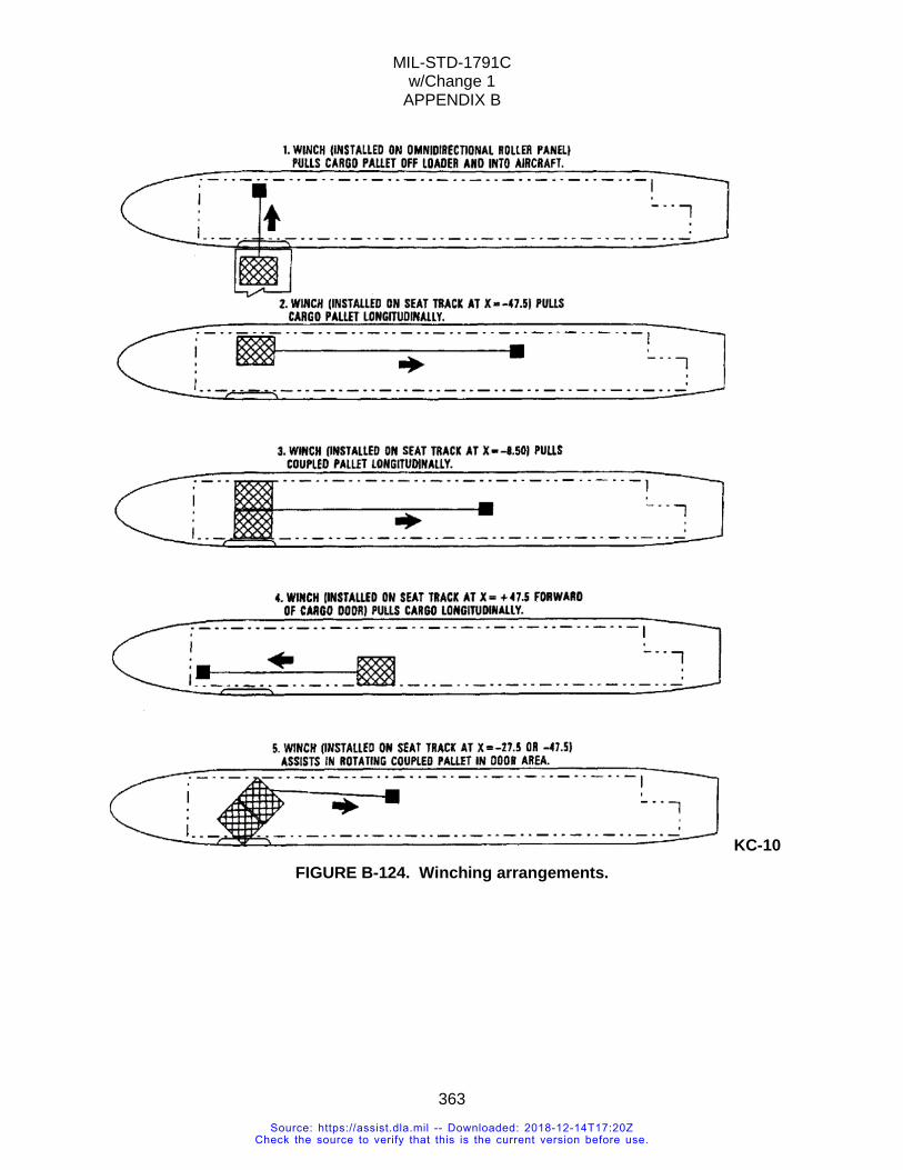
MIL-STD-1791C w/Change 1
APPENDIX B
363
KC-10 FIGURE B-124. Winching arrangements.
Source: https://assist.dla.mil -- Downloaded: 2018-12-14T17:20ZCheck the source to verify that this is the current version before use.
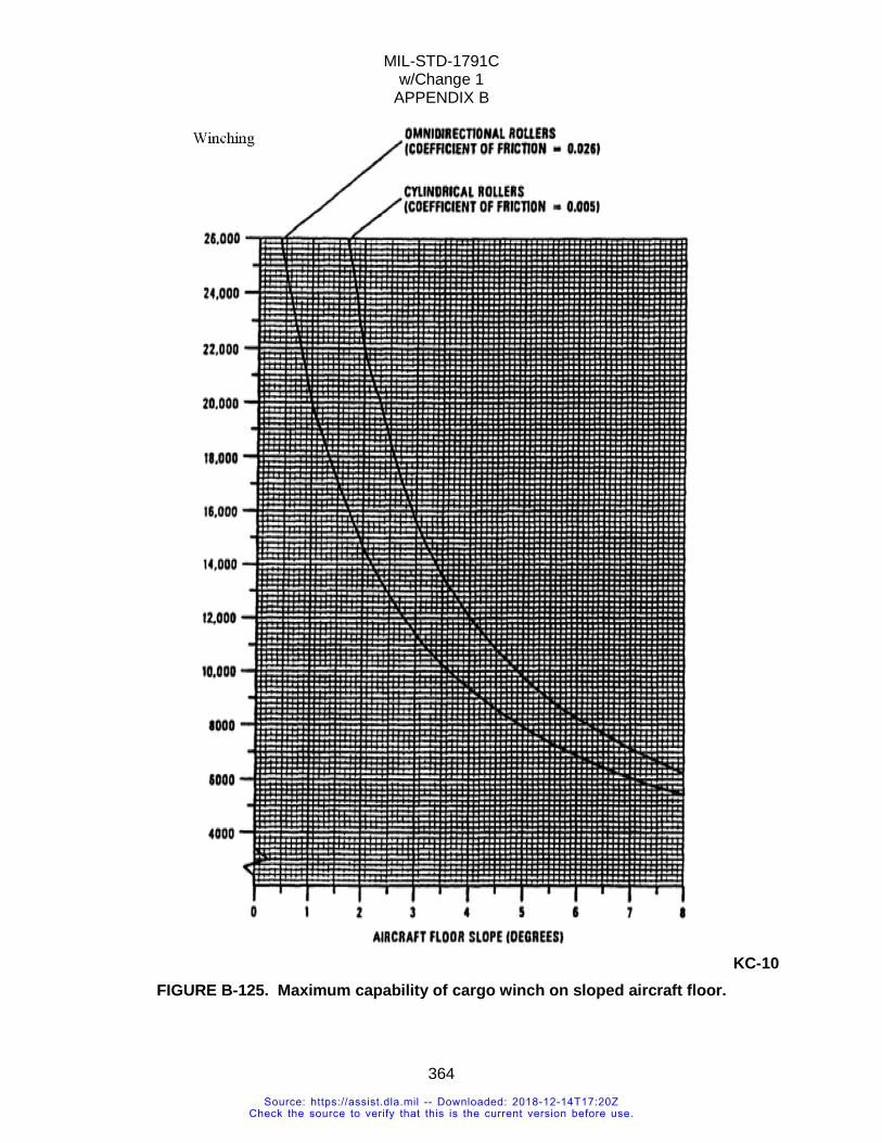
MIL-STD-1791C w/Change 1
APPENDIX B
364
KC-10
FIGURE B-125. Maximum capability of cargo winch on sloped aircraft floor.
Source: https://assist.dla.mil -- Downloaded: 2018-12-14T17:20ZCheck the source to verify that this is the current version before use.
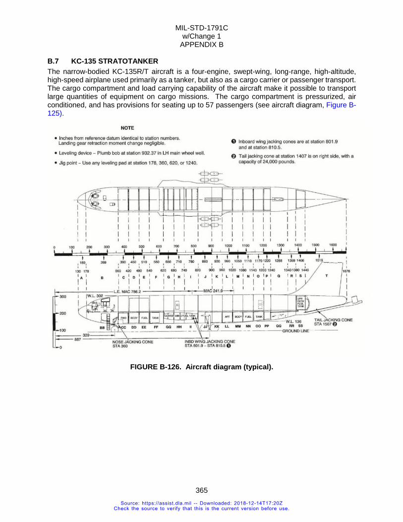
MIL-STD-1791C w/Change 1
APPENDIX B
365
B.7 KC-135 STRATOTANKER The narrow-bodied KC-135R/T aircraft is a four-engine, swept-wing, long-range, high-altitude, high-speed airplane used primarily as a tanker, but also as a cargo carrier or passenger transport. The cargo compartment and load carrying capability of the aircraft make it possible to transport large quantities of equipment on cargo missions. The cargo compartment is pressurized, air conditioned, and has provisions for seating up to 57 passengers (see aircraft diagram, Figure B-125).
FIGURE B-126. Aircraft diagram (typical).
Source: https://assist.dla.mil -- Downloaded: 2018-12-14T17:20ZCheck the source to verify that this is the current version before use.
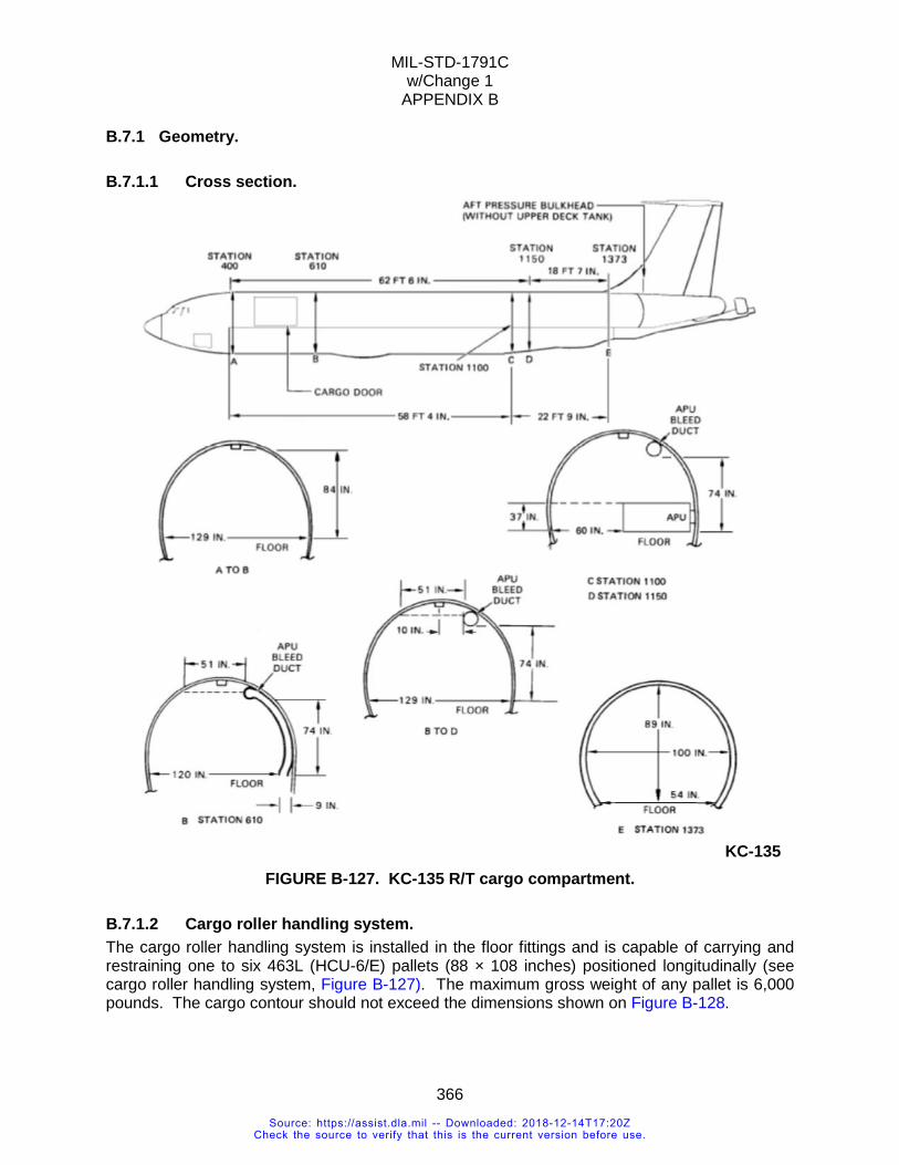
MIL-STD-1791C w/Change 1
APPENDIX B
366
B.7.1 Geometry.
B.7.1.1 Cross section.
KC-135
FIGURE B-127. KC-135 R/T cargo compartment.
B.7.1.2 Cargo roller handling system. The cargo roller handling system is installed in the floor fittings and is capable of carrying and restraining one to six 463L (HCU-6/E) pallets (88 × 108 inches) positioned longitudinally (see cargo roller handling system, Figure B-127). The maximum gross weight of any pallet is 6,000 pounds. The cargo contour should not exceed the dimensions shown on Figure B-128.
Source: https://assist.dla.mil -- Downloaded: 2018-12-14T17:20ZCheck the source to verify that this is the current version before use.
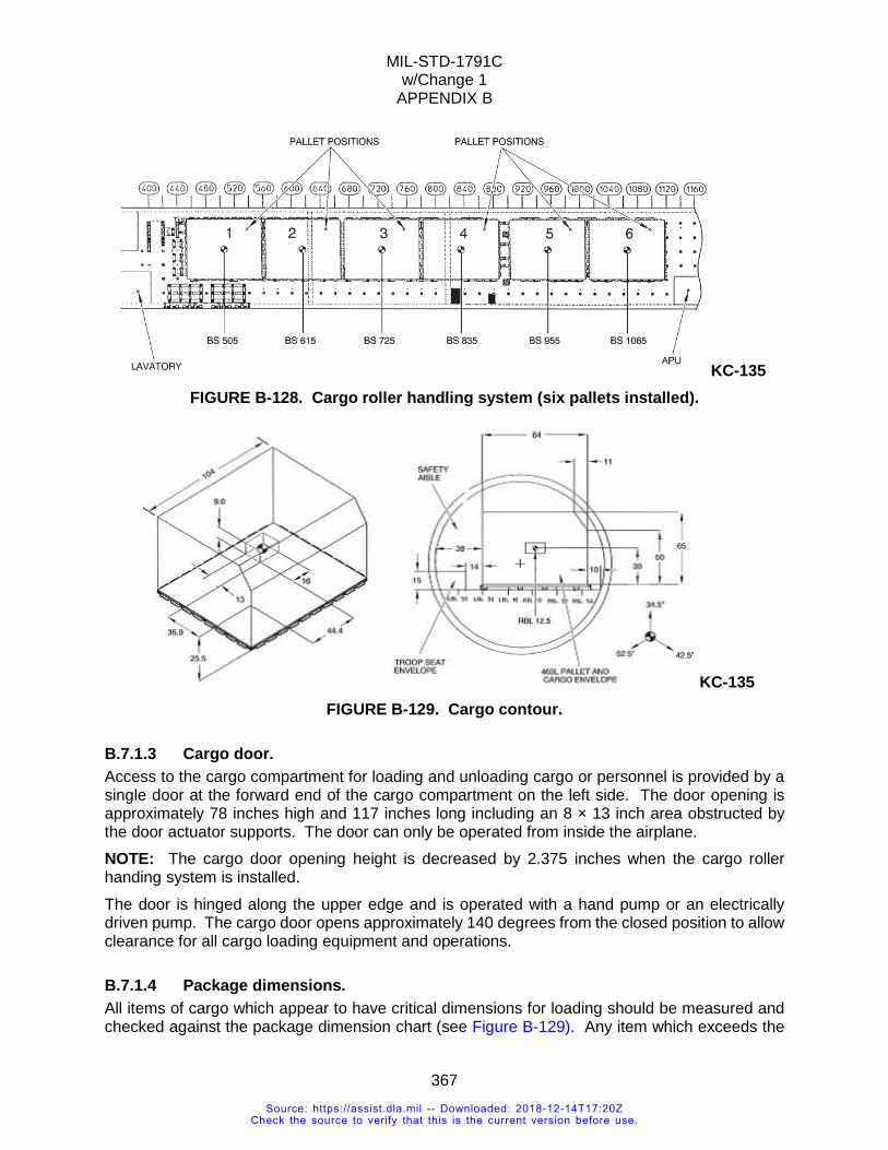
MIL-STD-1791C w/Change 1
APPENDIX B
367
KC-135 FIGURE B-128. Cargo roller handling system (six pallets installed).
KC-135 FIGURE B-129. Cargo contour.
B.7.1.3 Cargo door. Access to the cargo compartment for loading and unloading cargo or personnel is provided by a single door at the forward end of the cargo compartment on the left side. The door opening is approximately 78 inches high and 117 inches long including an 8 × 13 inch area obstructed by the door actuator supports. The door can only be operated from inside the airplane. NOTE: The cargo door opening height is decreased by 2.375 inches when the cargo roller handing system is installed. The door is hinged along the upper edge and is operated with a hand pump or an electrically driven pump. The cargo door opens approximately 140 degrees from the closed position to allow clearance for all cargo loading equipment and operations.
B.7.1.4 Package dimensions. All items of cargo which appear to have critical dimensions for loading should be measured and checked against the package dimension chart (see Figure B-129). Any item which exceeds the
Source: https://assist.dla.mil -- Downloaded: 2018-12-14T17:20ZCheck the source to verify that this is the current version before use.
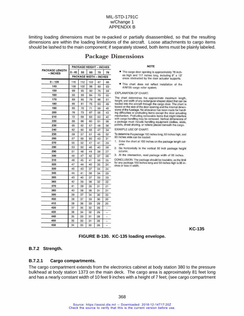
MIL-STD-1791C w/Change 1
APPENDIX B
368
limiting loading dimensions must be re-packed or partially disassembled, so that the resulting dimensions are within the loading limitations of the aircraft. Loose attachments to cargo items should be lashed to the main component; if separately stowed, both items must be plainly labeled.
KC-135 FIGURE B-130. KC-135 loading envelope.
B.7.2 Strength.
B.7.2.1 Cargo compartments. The cargo compartment extends from the electronics cabinet at body station 380 to the pressure bulkhead at body station 1373 on the main deck. The cargo area is approximately 81 feet long and has a nearly constant width of 10 feet 9 inches with a height of 7 feet; (see cargo compartment
Source: https://assist.dla.mil -- Downloaded: 2018-12-14T17:20ZCheck the source to verify that this is the current version before use.
MIL-STD-1791C w/Change 1
APPENDIX B
369
dimensions, Figure B-126). Total cargo compartment volume is approximately 5,300 cubic feet. The floor has tiedown fittings of 5,000 and 10,000 pound capacity.
B.7.2.1.1 Cargo compartment markings. Painted markings on the lining of the cargo compartment identify the limits of each subdivision of the cargo compartment by body station number, and also identify each subdivision by letter, (see Figure B-135). Additional markings identify the centroid of each subdivision of the cargo compartment and also give the maximum load that may be carried in that area. The loads given on these markings apply to loading single compartments only.
B.7.2.1.2 Cargo floor. The cargo floor is made up of two load carrying systems, the floor beams used to support loads over large areas and the 0.375 inch thick plywood floor to support concentrated loads between beams. The plywood panels are supported by beams spaced approximately 10 to 12 inches center-to-center. Structural capacity/strength capability data and physical limitation information for the cargo area floor are provided to support load planning; see compartment structural limits, Table B-XXIII.
B.7.2.1.2.1 Cargo floor loading. When loading general cargo, the load arrangement should be planned so that:
1. The weight is uniformly distributed over the cargo floor, and
2. The weight distribution does not exceed 200 pounds per square foot for flight conditions or 1,600 pounds per square foot for ground loading conditions. Such a load distribution can be obtained readily when loading boxed, crated, or stacked cargo. Other cargo items which are of small size but are heavy may be placed on warehouse pallets or on sheets of 0.75 inch thick plywood to provide a suitable weight distribution.
Source: https://assist.dla.mil -- Downloaded: 2018-12-14T17:20ZCheck the source to verify that this is the current version before use.
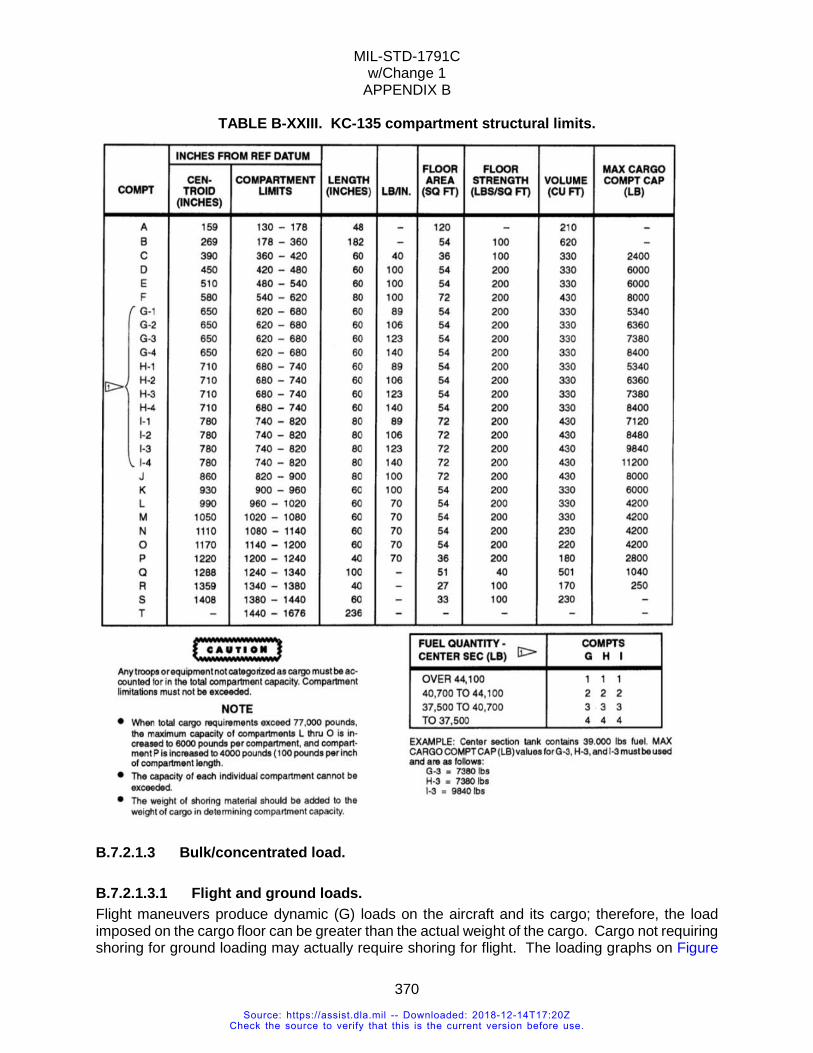
MIL-STD-1791C w/Change 1
APPENDIX B
370
TABLE B-XXIII. KC-135 compartment structural limits.
B.7.2.1.3 Bulk/concentrated load.
B.7.2.1.3.1 Flight and ground loads. Flight maneuvers produce dynamic (G) loads on the aircraft and its cargo; therefore, the load imposed on the cargo floor can be greater than the actual weight of the cargo. Cargo not requiring shoring for ground loading may actually require shoring for flight. The loading graphs on Figure
Source: https://assist.dla.mil -- Downloaded: 2018-12-14T17:20ZCheck the source to verify that this is the current version before use.
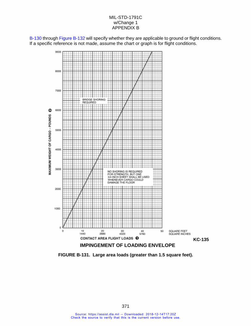
MIL-STD-1791C w/Change 1
APPENDIX B
371
B-130 through Figure B-132 will specify whether they are applicable to ground or flight conditions. If a specific reference is not made, assume the chart or graph is for flight conditions.
KC-135
FIGURE B-131. Large area loads (greater than 1.5 square feet).
IMPINGEMENT OF LOADING ENVELOPE
Source: https://assist.dla.mil -- Downloaded: 2018-12-14T17:20ZCheck the source to verify that this is the current version before use.
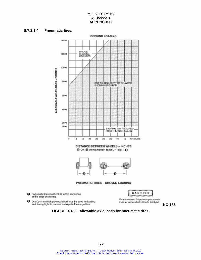
MIL-STD-1791C w/Change 1
APPENDIX B
372
B.7.2.1.4 Pneumatic tires.
KC-135 FIGURE B-132. Allowable axle loads for pneumatic tires.
Source: https://assist.dla.mil -- Downloaded: 2018-12-14T17:20ZCheck the source to verify that this is the current version before use.
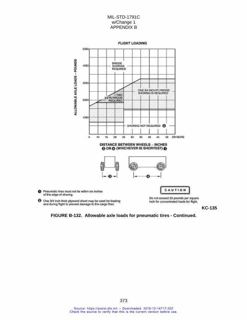
MIL-STD-1791C w/Change 1
APPENDIX B
373
KC-135 FIGURE B-132. Allowable axle loads for pneumatic tires - Continued.
Source: https://assist.dla.mil -- Downloaded: 2018-12-14T17:20ZCheck the source to verify that this is the current version before use.
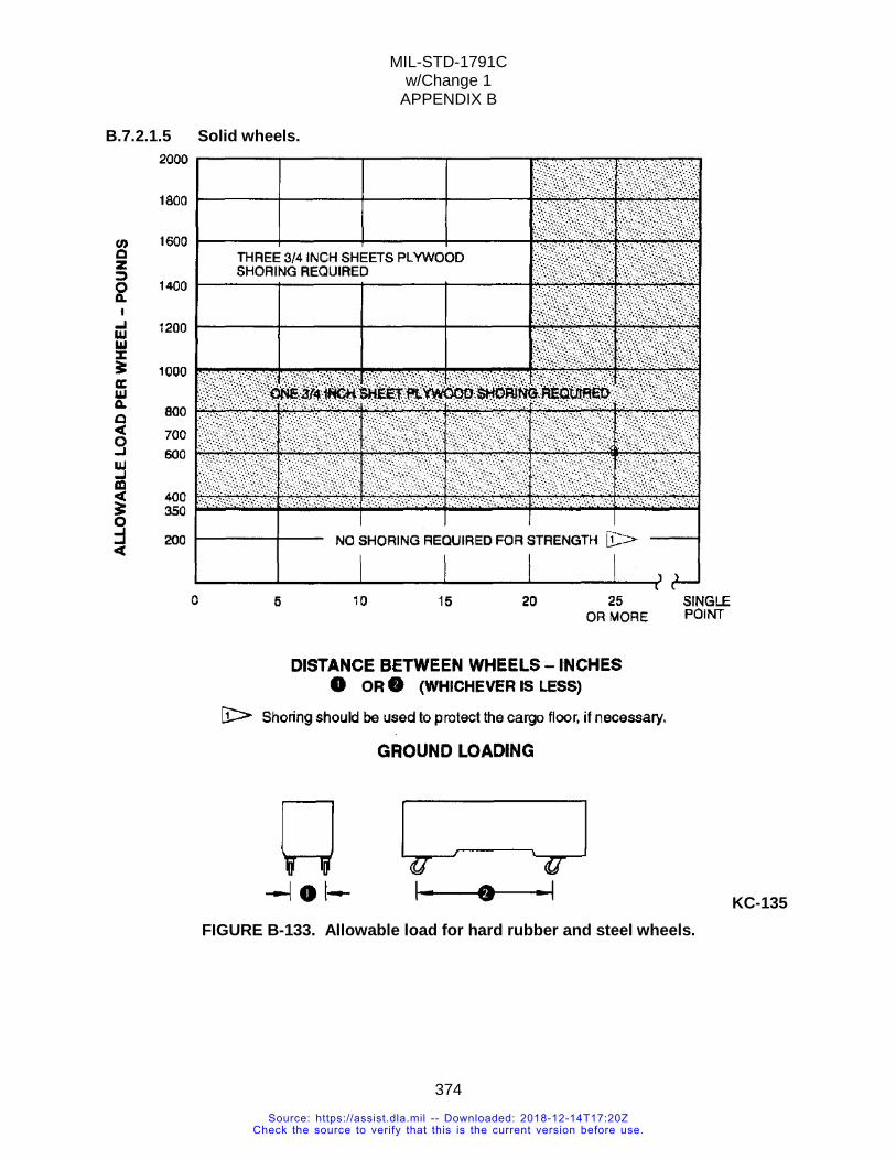
MIL-STD-1791C w/Change 1
APPENDIX B
374
B.7.2.1.5 Solid wheels.
KC-135 FIGURE B-133. Allowable load for hard rubber and steel wheels.
Source: https://assist.dla.mil -- Downloaded: 2018-12-14T17:20ZCheck the source to verify that this is the current version before use.
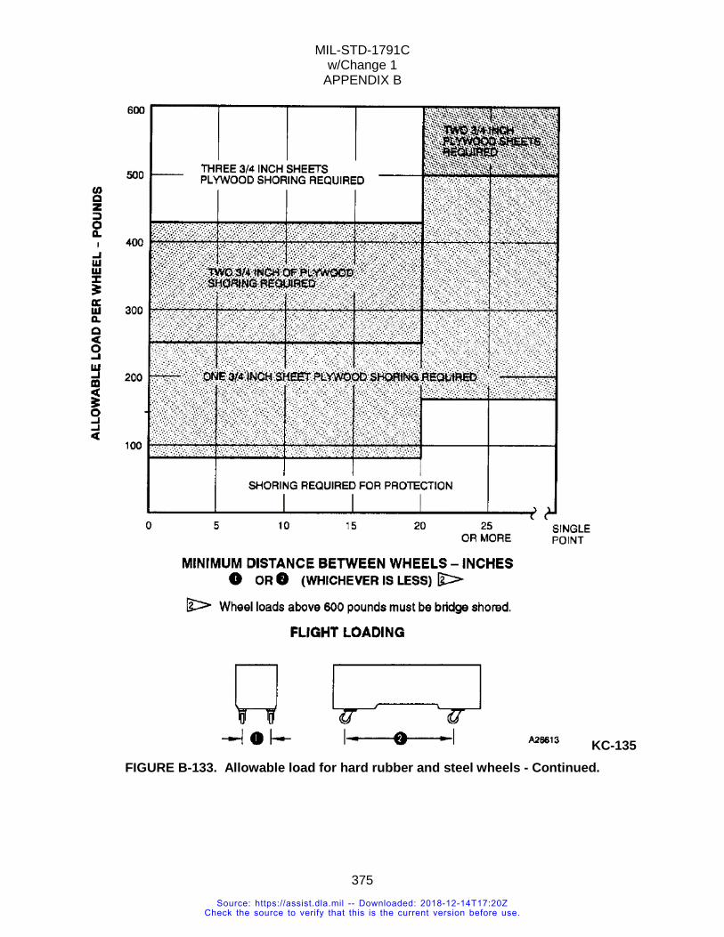
MIL-STD-1791C w/Change 1
APPENDIX B
375
KC-135 FIGURE B-133. Allowable load for hard rubber and steel wheels - Continued.
Source: https://assist.dla.mil -- Downloaded: 2018-12-14T17:20ZCheck the source to verify that this is the current version before use.
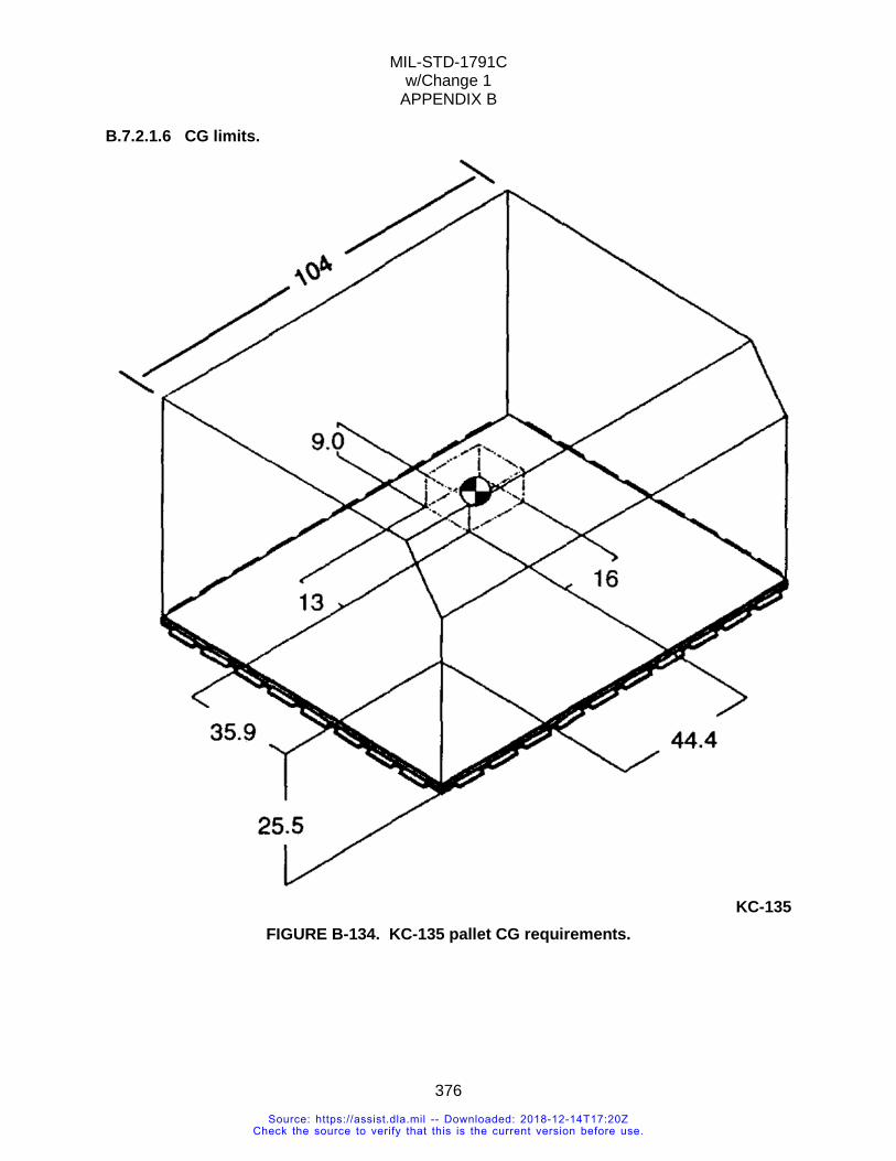
MIL-STD-1791C w/Change 1
APPENDIX B
376
B.7.2.1.6 CG limits.
KC-135
FIGURE B-134. KC-135 pallet CG requirements.
Source: https://assist.dla.mil -- Downloaded: 2018-12-14T17:20ZCheck the source to verify that this is the current version before use.
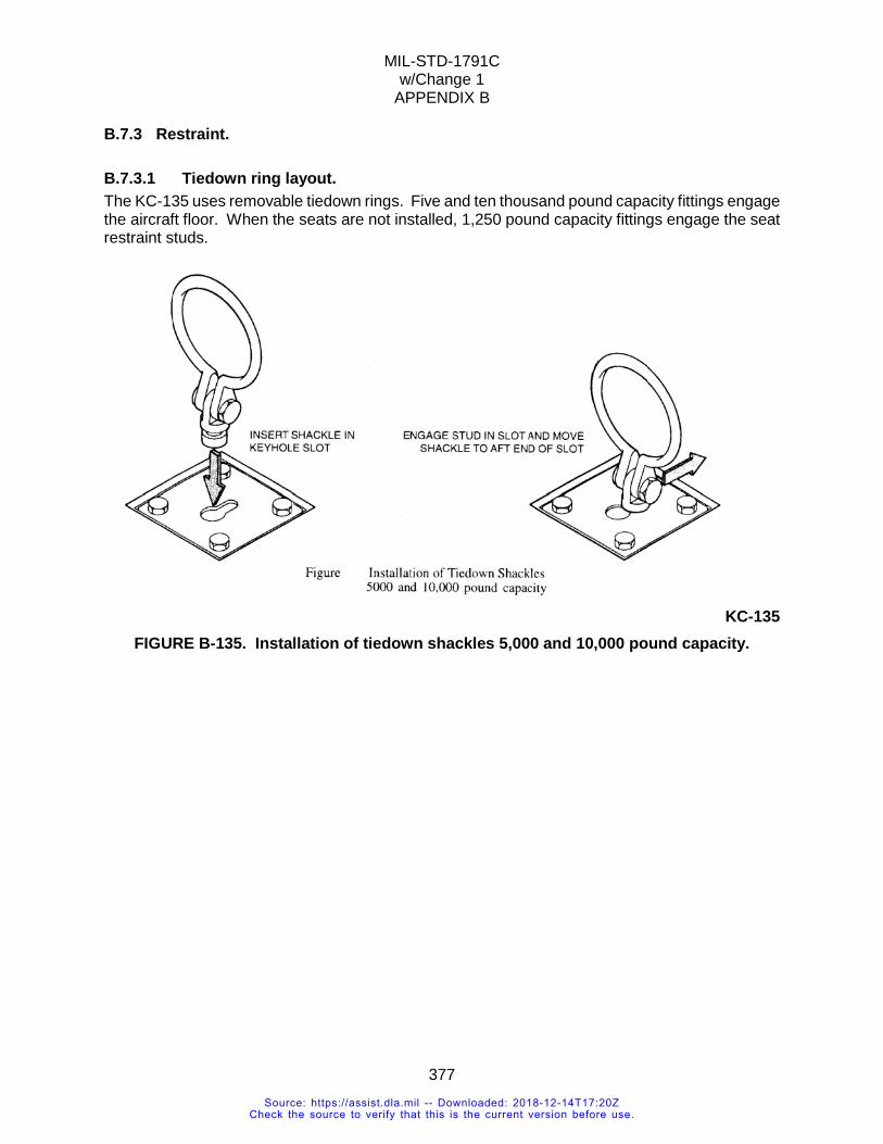
MIL-STD-1791C w/Change 1
APPENDIX B
377
B.7.3 Restraint.
B.7.3.1 Tiedown ring layout. The KC-135 uses removable tiedown rings. Five and ten thousand pound capacity fittings engage the aircraft floor. When the seats are not installed, 1,250 pound capacity fittings engage the seat restraint studs.
KC-135
FIGURE B-135. Installation of tiedown shackles 5,000 and 10,000 pound capacity.
Source: https://assist.dla.mil -- Downloaded: 2018-12-14T17:20ZCheck the source to verify that this is the current version before use.
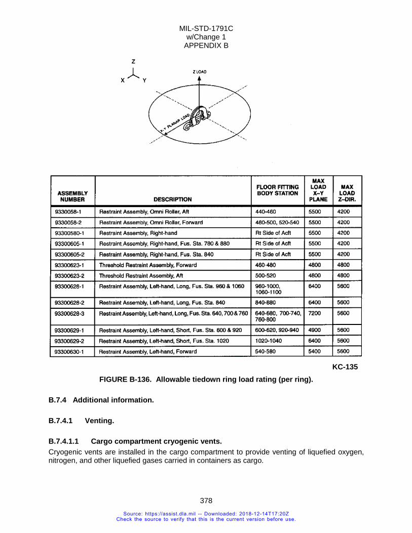
MIL-STD-1791C w/Change 1
APPENDIX B
378
KC-135
FIGURE B-136. Allowable tiedown ring load rating (per ring).
B.7.4 Additional information.
B.7.4.1 Venting.
B.7.4.1.1 Cargo compartment cryogenic vents. Cryogenic vents are installed in the cargo compartment to provide venting of liquefied oxygen, nitrogen, and other liquefied gases carried in containers as cargo.
Source: https://assist.dla.mil -- Downloaded: 2018-12-14T17:20ZCheck the source to verify that this is the current version before use.
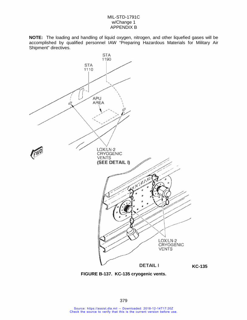
MIL-STD-1791C w/Change 1
APPENDIX B
379
NOTE: The loading and handling of liquid oxygen, nitrogen, and other liquefied gases will be accomplished by qualified personnel IAW “Preparing Hazardous Materials for Military Air Shipment” directives.
KC-135 FIGURE B-137. KC-135 cryogenic vents.
Source: https://assist.dla.mil -- Downloaded: 2018-12-14T17:20ZCheck the source to verify that this is the current version before use.
MIL-STD-1791C w/Change 1
APPENDIX B
380
B.8 CIVIL RESERVE AIR FLEET (CRAF) ATTLA recommends the designer consult with the carriers themselves, TRANSCOM, or Civil Reserve Air Fleet Load Planning Guide, Volume 1-10 because interface requirements are not controlled by the USAF and limits can vary between commercial carriers. ATTLA can perform an evaluation but defer to the individual commercial carrier for final approval.
CONCLUDING MATERIAL Custodians: Preparing activity:
Army - AV Air Force - 11 Navy - AS Air Force - 11 (Project 1510-2018-001)
NOTE: The activities listed above were interested in this document as of the date of this document. Since organizations and responsibilities can change, you should verify the currency of the information above using the ASSIST Online database at https://assist.dla.mil/.
Source: https://assist.dla.mil -- Downloaded: 2018-12-14T17:20ZCheck the source to verify that this is the current version before use.


