Embed Size (px)
Citation preview
MCOTS-C-270H-28-FPSingle Output
Full-brick
Product # MCOTS-C-270H-28-FP Phone 1-888-567-9596 www.synqor.com Doc.# 005-0006311 Rev. C 05/23/2016 Page 1
MCOTS-C-270H-28-FP-N-M
-F
DC/DC CONVERTER
240-425(475)V IN 28V OUT
@ 28.6A
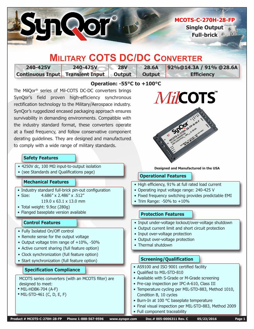
240-425V 240-475V 28V 28.6A 92%@14.3A / 91% @28.6AContinuous Input Transient Input Output Output Efficiency
Operation: -55°C to +100°C
MILITARY COTS DC/DC CONVERTER
Designed and Manufactured in the USA
The MilQor® series of Mil-COTS DC-DC converters brings SynQor’s field proven high-efficiency synchronous rectification technology to the Military/Aerospace industry. SynQor’s ruggedized encased packaging approach ensures survivability in demanding environments. Compatible with the industry standard format, these converters operate at a fixed frequency, and follow conservative component derating guidelines. They are designed and manufactured to comply with a wide range of military standards.
Protection Features
• Input under-voltage lockout/over-voltage shutdown• Output current limit and short circuit protection• Input over-voltage protection• Output over-voltage protection• Thermal shutdown
Screening/Qualification
• AS9100 and ISO 9001 certified facility• Qualified to MIL-STD-810• Available with S-Grade or M-Grade screening• Pre-cap inspection per IPC-A-610, Class III• Temperature cycling per MIL-STD-883, Method 1010,
Condition B, 10 cycles• Burn-In at 100 °C baseplate temperature• Final visual inspection per MIL-STD-883, Method 2009• Full component traceability
Operational Features
• High efficiency, 91% at full rated load current• Operating input voltage range: 240-425 V• Fixed frequency switching provides predictable EMI• Trim Range: -50% to +10%
Safety Features
• 4250V dc, 100 MΩ input-to-output isolation• (see Standards and Qualifications page)
Mechanical Features
• Industry standard full-brick pin-out configuration• Size: 4.686” x 2.486” x .512”
119.0 x 63.1 x 13.0 mm• Total weight: 9.9oz (280g)• Flanged baseplate version available
Control Features
• Fully Isolated On/Off control• Remote sense for the output voltage• Output voltage trim range of +10%, -50%• Active current sharing (full feature option)• Clock synchronization (full feature option)• Start synchronization (full feature option)
Specification Compliance
MCOTS series converters (with an MCOTS filter) are designed to meet:• MIL-HDBK-704 (A-F)• MIL-STD-461 (C, D, E, F)
Technical Specification
MCOTS-C-270H-28-FPOutput: 28V
Current: 28.6A
Product # MCOTS-C-270H-28-FP Phone 1-888-567-9596 www.synqor.com Doc.# 005-0006311 Rev. C 05/23/2016 Page 2
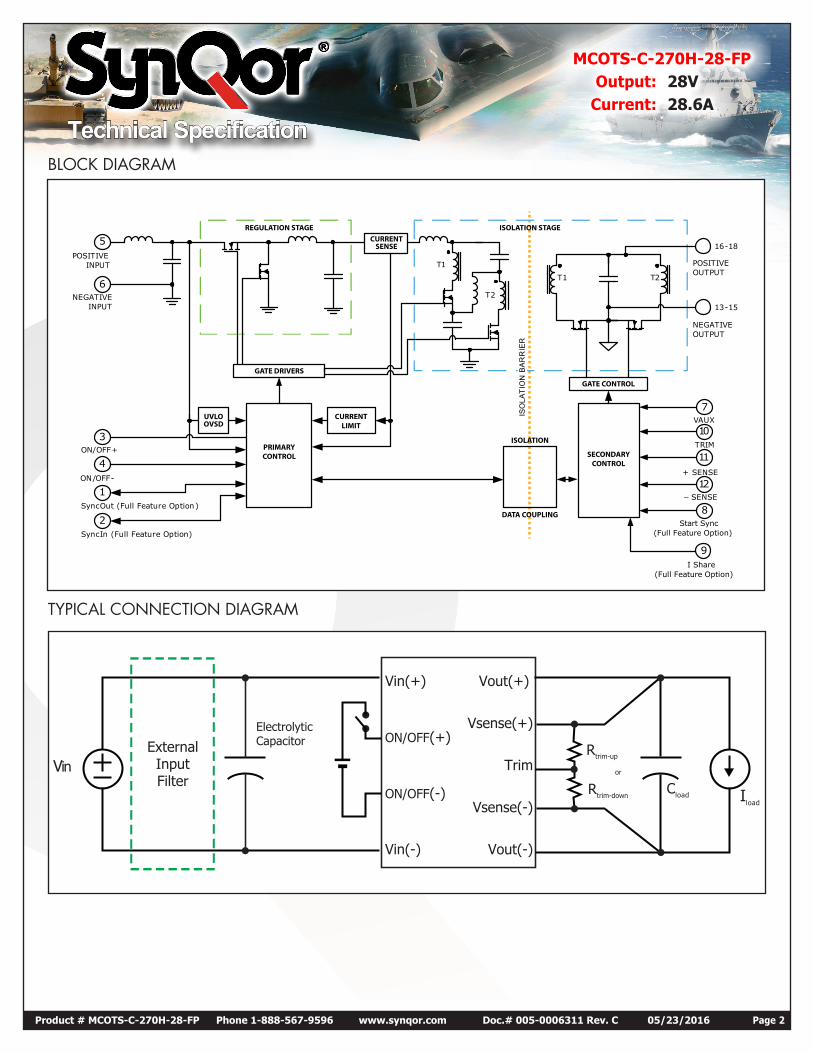
BLOCK DIAGRAM
TYPICAL CONNECTION DIAGRAM
VinExternalInputFilter
Iload
Cload
Rtrim-up
or
Rtrim-down
ElectrolyticCapacitor
Vin(+) Vout(+)
Vout(-)
Vsense(-)
Vsense(+)
Trim
Vin(-)
ON/OFF(-)
ON/OFF(+)
− SENSE
POSITIVEINPUT
NEGATIVEINPUT
ON/OFF+
10
11
5
6
3
POSITIVEOUTPUT
NEGATIVEOUTPUT
TRIM
+ SENSE
ISO
LAT
ION
BA
RR
IER
T1
T1
T2
T2
4
1
2SyncIn (Full Feature Option)
ON/OFF-
SyncOut (Full Feature Option)
16-18
13-15
12
7VAUX
8Start Sync
(Full Feature Option)
I Share(Full Feature Option)
9
ISOLATION
ISOLATION STAGEREGULATION STAGE
CURRENTLIMIT
CURRENTSENSE
DATA COUPLING
SECONDARYCONTROL
PRIMARYCONTROL
GATE CONTROL
GATE DRIVERS
UVLOOVSD
Technical Specification
MCOTS-C-270H-28-FPOutput: 28V
Current: 28.6A
Product # MCOTS-C-270H-28-FP Phone 1-888-567-9596 www.synqor.com Doc.# 005-0006311 Rev. C 05/23/2016 Page 3
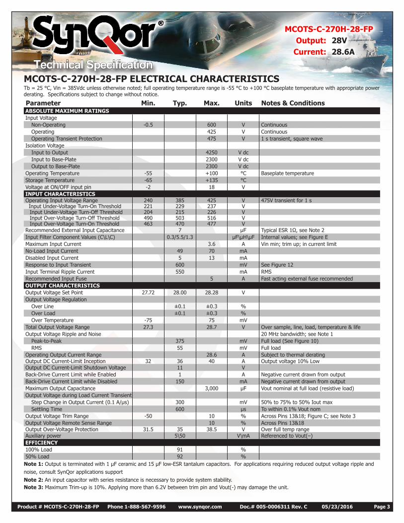
MCOTS-C-270H-28-FP ELECTRICAL CHARACTERISTICSTb = 25 °C, Vin = 385Vdc unless otherwise noted; full operating temperature range is -55 °C to +100 °C baseplate temperature with appropriate power derating. Specifications subject to change without notice.
Parameter Min. Typ. Max. Units Notes & Conditions ABSOLUTE MAXIMUM RATINGS Input Voltage
Non-Operating -0.5 600 V Continuous Operating 425 V Continuous Operating Transient Protection 475 V 1 s transient, square wave
Isolation Voltage Input to Output 4250 V dc Input to Base-Plate 2300 V dc Output to Base-Plate 2300 V dc
Operating Temperature -55 +100 °C Baseplate temperature Storage Temperature -65 +135 °C Voltage at ON/OFF input pin -2 18 V INPUT CHARACTERISTICS Operating Input Voltage Range 240 385 425 V 475V transient for 1 s Input Under-Voltage Turn-On Threshold 221 229 237 V
Input Under-Voltage Turn-Off Threshold 204 215 226 V Input Over-Voltage Turn-Off Threshold 490 503 516 V Input Over-Voltage Turn-On Threshold 463 470 477 V
Recommended External Input Capacitance 7 µF Typical ESR 1Ω, see Note 2 Input Filter Component Values (C\L\C) 0.3/5.5/1.3 µF\µH\µF Internal values; see Figure E Maximum Input Current 3.6 A Vin min; trim up; in current limit No-Load Input Current 49 70 mA Disabled Input Current 5 13 mA Response to Input Transient 600 mV See Figure 12 Input Terminal Ripple Current 550 mA RMS Recommended Input Fuse 5 A Fast acting external fuse recommended OUTPUT CHARACTERISTICS Output Voltage Set Point 27.72 28.00 28.28 V Output Voltage Regulation
Over Line ±0.1 ±0.3 % Over Load ±0.1 ±0.3 % Over Temperature -75 75 mV
Total Output Voltage Range 27.3 28.7 V Over sample, line, load, temperature & life Output Voltage Ripple and Noise 20 MHz bandwidth; see Note 1
Peak-to-Peak 375 mV Full load (See Figure 10) RMS 55 mV Full load
Operating Output Current Range 28.6 A Subject to thermal derating Output DC Current-Limit Inception 32 36 40 A Output voltage 10% Low Output DC Current-Limit Shutdown Voltage 11 V Back-Drive Current Limit while Enabled 1 A Negative current drawn from output Back-Drive Current Limit while Disabled 150 mA Negative current drawn from output Maximum Output Capacitance 3,000 µF Vout nominal at full load (resistive load) Output Voltage during Load Current Transient
Step Change in Output Current (0.1 A/µs) 300 mV 50% to 75% to 50% Iout max Settling Time 600 µs To within 0.1% Vout nom
Output Voltage Trim Range -50 10 % Across Pins 13&18; Figure C; see Note 3 Output Voltage Remote Sense Range 10 % Across Pins 13&18 Output Over-Voltage Protection 31.5 35 38.5 V Over full temp range Auxiliary power 5\50 V\mA Referenced to Vout(–) EFFICIENCY 100% Load 91 % 50% Load 92 %Note 1: Output is terminated with 1 µF ceramic and 15 µF low-ESR tantalum capacitors. For applications requiring reduced output voltage ripple andnoise, consult SynQor applications support Note 2: An input capacitor with series resistance is necessary to provide system stability.Note 3: Maximum Trim-up is 10%. Applying more than 6.2V between trim pin and Vout(-) may damage the unit.
Technical Specification
MCOTS-C-270H-28-FPOutput: 28V
Current: 28.6A
Product # MCOTS-C-270H-28-FP Phone 1-888-567-9596 www.synqor.com Doc.# 005-0006311 Rev. C 05/23/2016 Page 4
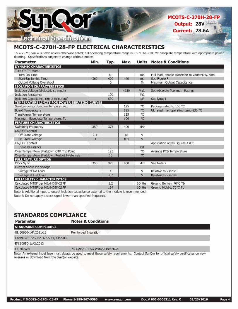
MCOTS-C-270H-28-FP ELECTRICAL CHARACTERISTICSTb = 25 °C, Vin = 385Vdc unless otherwise noted; full operating temperature range is -55 °C to +100 °C baseplate temperature with appropriate power derating. Specifications subject to change without notice.
Parameter Min. Typ. Max. Units Notes & Conditions DYNAMIC CHARACTERISTICS Turn-On Transient
Turn-On Time 60 ms Full load, Enable Transition to Vout=90% nom. Start-Up Inhibit Time 360 400 440 ms See Figure F Output Voltage Overshoot 0 % Maximum Output Capacitance
ISOLATION CHARACTERISTICS Isolation Voltage (dielectric strength) 4250 V dc See Absolute Maximum Ratings Isolation Resistance 100 MΩ Isolation Capacitance (input to output) 500 pF See Note 1 TEMPERATURE LIMITS FOR POWER DERATING CURVES Semiconductor Junction Temperature 125 °C Package rated to 150 °C Board Temperature 125 °C UL rated max operating temp 130 °C Transformer Temperature 125 °C Maximum Baseplate Temperature, Tb 100 °C FEATURE CHARACTERISTICS Switching Frequency 350 375 400 kHz ON/OFF Control
Off-State Voltage 2.4 18 V On-State Voltage -1 0.8 V
ON/OFF Control Application notes Figures A & B Input Resistance 3 kΩ
Over-Temperature Shutdown OTP Trip Point 125 °C Average PCB Temperature Over-Temperature Shutdown Restart Hysteresis 10 °C FULL FEATURE OPTION Clock Sync 350 375 400 kHz See Note 2 Current Share Pin Voltage
Voltage at No Load 1 V Relative to Vsense- Voltage at Full Load 2.2 V Relative to Vsense-
RELIABILITY CHARACTERISTICS Calculated MTBF per MIL-HDBK-217F 1.2 106 Hrs. Ground Benign, 70°C Tb Calculated MTBF per MIL-HDBK-217F 154 103 Hrs. Ground Mobile, 70°C TbNote 1: Additional input to output isolation capacitance external to the module is recommended.Note 2: Do not apply a clock signal lower than specified frequency.
STANDARDS COMPLIANCE Parameter Notes & Conditions STANDARDS COMPLIANCE
UL 60950-1/R:2011-12 Reinforced Insulation
CAN/CSA-C22.2 No. 60950-1/A1:2011
EN 60950-1/A2:2013
CE Marked 2006/95/EC Low Voltage DirectiveNote: An external input fuse must always be used to meet these safety requirements. Contact SynQor for official safety certificates on new releases or download from the SynQor website.
Technical Specification
MCOTS-C-270H-28-FPOutput: 28V
Current: 28.6A
Product # MCOTS-C-270H-28-FP Phone 1-888-567-9596 www.synqor.com Doc.# 005-0006311 Rev. C 05/23/2016 Page 5
82
83
84
85
86
87
88
89
90
91
92
93
5 10 15 20 25 30
Effic
ienc
y (%
)
Load Current (A)
240 Vin
385 Vin
425 Vin82
83
84
85
86
87
88
89
90
91
92
93
-55ºC 25ºC 100ºC
Effic
ienc
y (%
)
Case Temperature (ºC)
240 Vin
385 Vin
425 Vin
20
25
30
35
40
45
50
55
60
-55ºC 25ºC 100ºC
Pow
er D
issi
patio
n (W
)
Case Temperature (ºC)
240 Vin
385 Vin
425 Vin
0
10
20
30
40
50
60
70
80
90
0 5 10 15 20 25 30
Pow
er D
issi
patio
n (W
)
Load Current (A)
425 Vin
385 Vin
240 Vin
0.0
5.0
10.0
15.0
20.0
25.0
30.0
0 5 10 15 20 25 30 35 40 45
Outp
ut V
olta
ge (V
)
Load Current (A)
240 Vin
385Vin
425 Vin
0
5
10
15
20
25
30
35
50 60 70 80 90 100 110
Iout
(A)
Base Plate Temperature (°C)
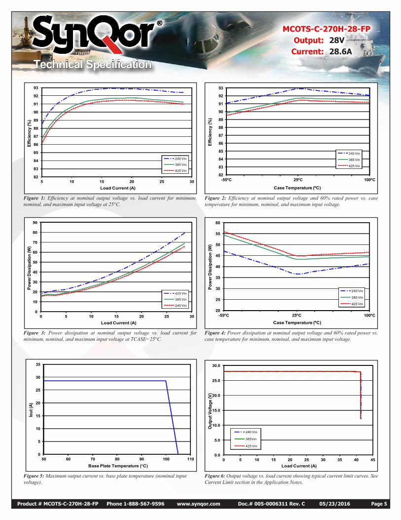
Figure 1: Efficiency at nominal output voltage vs. load current for minimum, nominal, and maximum input voltage at 25°C.
Figure 2: Efficiency at nominal output voltage and 60% rated power vs. case temperature for minimum, nominal, and maximum input voltage.
Figure 3: Power dissipation at nominal output voltage vs. load current for minimum, nominal, and maximum input voltage at TCASE=25°C.
Figure 4: Power dissipation at nominal output voltage and 60% rated power vs. case temperature for minimum, nominal, and maximum input voltage.
Figure 5: Maximum output current vs. base plate temperature (nominal input voltage).
Figure 6: Output voltage vs. load current showing typical current limit curves. See Current Limit section in the Application Notes.
Technical Specification
MCOTS-C-270H-28-FPOutput: 28V
Current: 28.6A
Product # MCOTS-C-270H-28-FP Phone 1-888-567-9596 www.synqor.com Doc.# 005-0006311 Rev. C 05/23/2016 Page 6
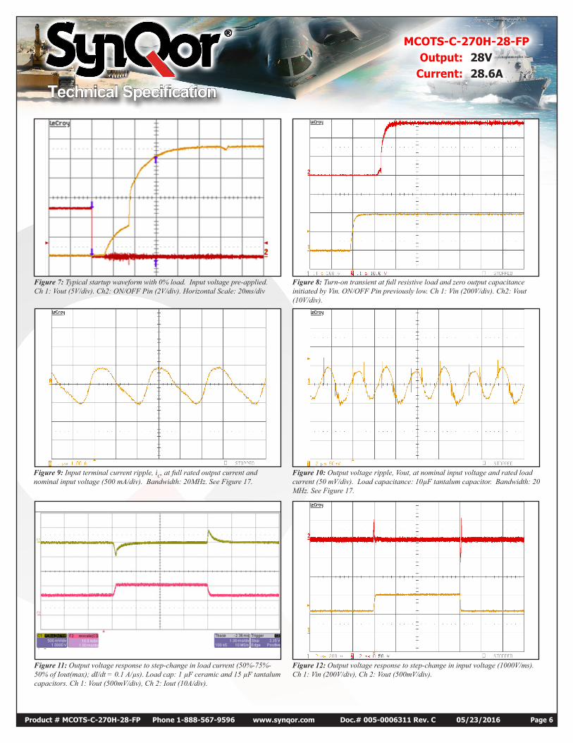
Figure 7: Typical startup waveform with 0% load. Input voltage pre-applied. Ch 1: Vout (5V/div). Ch2: ON/OFF Pin (2V/div). Horizontal Scale: 20ms/div
Figure 8: Turn-on transient at full resistive load and zero output capacitance initiated by Vin. ON/OFF Pin previously low. Ch 1: Vin (200V/div). Ch2: Vout (10V/div).
Figure 9: Input terminal current ripple, iC, at full rated output current and nominal input voltage (500 mA/div). Bandwidth: 20MHz. See Figure 17.
Figure 10: Output voltage ripple, Vout, at nominal input voltage and rated load current (50 mV/div). Load capacitance: 10µF tantalum capacitor. Bandwidth: 20 MHz. See Figure 17.
Figure 11: Output voltage response to step-change in load current (50%-75%-50% of Iout(max); dI/dt = 0.1 A/µs). Load cap: 1 µF ceramic and 15 µF tantalum capacitors. Ch 1: Vout (500mV/div), Ch 2: Iout (10A/div).
Figure 12: Output voltage response to step-change in input voltage (1000V/ms). Ch 1: Vin (200V/div), Ch 2: Vout (500mV/div).
Technical Specification
MCOTS-C-270H-28-FPOutput: 28V
Current: 28.6A
Product # MCOTS-C-270H-28-FP Phone 1-888-567-9596 www.synqor.com Doc.# 005-0006311 Rev. C 05/23/2016 Page 7
DC/DCConverter
VSOURCE
iC
VOUT
0.0001
0.001
0.01
0.1
1
10 100 1,000 10,000 100,000
Outp
ut Im
peda
nce
(ohm
s)
Hz
385Vin
425Vin
240Vin
1
10
100
1000
10 100 1,000 10,000 100,000
Inpu
t Im
peda
nce
(Ohm
s)
Hz
385Vin
425Vin
240Vin
-120
-100
-80
-60
-40
-20
0
100 1,000 10,000 100,000
Forw
ard
Tran
smis
sion
(dB
)
Hz
385Vin
425Vin
240Vin
-50
-40
-30
-20
-10
10 100 1,000 10,000 100,000
Rev
erse
Tra
nsm
issi
on (d
B)
Hz
385Vin
425Vin
240Vin
4.5 µHsource impedance
7 µF,ceramic capacitorin sereis with 1Ω Resistor
10 µF,100mΩ ESR
tantalum capacitor
1 µFceramic capacitor
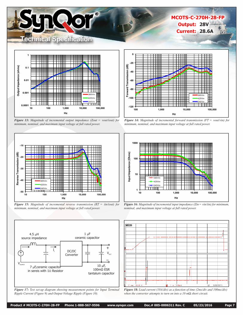
Figure 13: Magnitude of incremental output impedance (Zout = vout/iout) for minimum, nominal, and maximum input voltage at full rated power.
Figure 14: Magnitude of incremental forward transmission (FT = vout/vin) for minimum, nominal, and maximum input voltage at full rated power.
Figure 15: Magnitude of incremental reverse transmission (RT = iin/iout) for minimum, nominal, and maximum input voltage at full rated power.
Figure 16: Magnitude of incremental input impedance (Zin = vin/iin) for minimum, nominal, and maximum input voltage at full rated power.
Figure 17: Test set-up diagram showing measurement points for Input Terminal Ripple Current (Figure 9) and Output Voltage Ripple (Figure 10).
Figure 18: Load current (10A/div) as a function of time (2ms/div and 100ms/div) when the converter attempts to turn on into a 10 mΩ short circuit.
Technical Specification
MCOTS-C-270H-28-FPOutput: 28V
Current: 28.6A
Product # MCOTS-C-270H-28-FP Phone 1-888-567-9596 www.synqor.com Doc.# 005-0006311 Rev. C 05/23/2016 Page 8
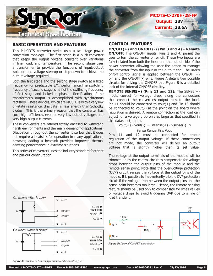
BASIC OPERATION AND FEATURESThis Mil-COTS converter series uses a two-stage power conversion topology. The first stage is a buck-converter that keeps the output voltage constant over variations in line, load, and temperature. The second stage uses a transformer to provide the functions of input/output isolation and voltage step-up or step-down to achieve the output voltage required.Both the first stage and the second stage switch at a fixed frequency for predictable EMI performance.The switching frequency of second stage is half of the swithcing frequency of first stage and locked in phase. Rectification of the transformer’s output is accomplished with synchronous rectifiers. These devices, which are MOSFETs with a very low on-state resistance, dissipate far less energy than Schottky diodes. This is the primary reason that the converter has such high efficiency, even at very low output voltages and very high output currents.These converters are offered totally encased to withstand harsh environments and thermally demanding applications. Dissipation throughout the converter is so low that it does not require a heatsink for operation in many applications; however, adding a heatsink provides improved thermal derating performance in extreme situations.
This series of converters uses the industry standard footprint and pin-out configuration.
Figure A: Example of two configurations for the enable signal
VIN
IN
(+)
+ON/OFF
-ON/OFF
5V
5V
V (-)
VOUT (+)
SENSE (+)
SENSE (-)
VOUT (-)
VIN
IN
(+)
+ON/OFF
-ON/OFF
V (-)
VOUT (+)
SENSE (+)
SENSE (-)
VOUT (-)
On when switch is open
On when switch is closed
CONTROL FEATURESON/OFF(+) and ON/OFF(-) (Pin 3 and 4) - Remote ON/OFF: The ON/OFF inputs, Pins 3 and 4, permit the user to turn the converter on or off. These two inputs are fully isolated from both the input and the output side of the power converter, allowing the user the option to manage the converter from the input or the output end. The user’s on/off control signal is applied between the ON/OFF(+) pin and the ON/OFF(-) pins. Figure A details two possible circuits for driving the ON/OFF pin. Figure B is a detailed look of the internal ON/OFF circuitry.REMOTE SENSE(+) (Pins 11 and 12): The SENSE(+) inputs correct for voltage drops along the conductors that connect the converter’s output pins to the load. Pin 11 should be connected to Vout(+) and Pin 12 should be connected to Vout(-) at the point on the board where regulation is desired. A remote connection at the load can adjust for a voltage drop only as large as that specified in this datasheet, that is
[Vout(+) - Vout(-)] – [Vsense(+) - Vsense(-)] ≤ Sense Range % x Vout
Pins 11 and 12 must be connected for proper regulation of the output voltage. If these connections are not made, the converter will deliver an output voltage that is slightly higher than its set value. The voltage at the output terminals of the module will be trimmed up by the control circuit to compensate for voltage drops between the output pins of the module and the remote sense point. Note that the over-voltage protection (OVP) circuit senses the voltage at the output pins of the module. It is possible to inadvertently trip the OVP protection circuit if the voltage drop between the output pins and the sense point becomes too large. Hence, the remote sensing feature should be used only to compensate for small values of voltage drops to avoid triggering OVP due to a line or load transient.
Figure B: Internal ON/OFF pin circuitry
C1
100p
D1R1
3.01k
Pin 3
Pin 4
OptoU1
Technical Specification
MCOTS-C-270H-28-FPOutput: 28V
Current: 28.6A
Product # MCOTS-C-270H-28-FP Phone 1-888-567-9596 www.synqor.com Doc.# 005-0006311 Rev. C 05/23/2016 Page 9
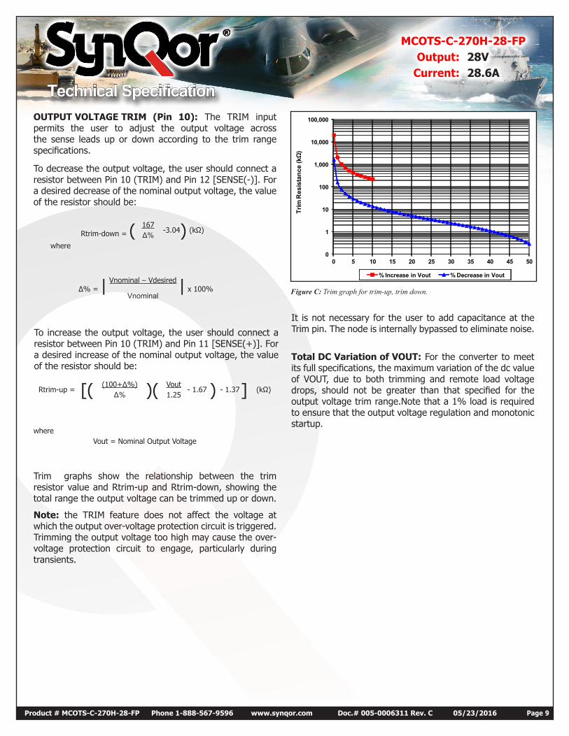
Rtrim-down = ( 167-3.04) (kΩ)
Δ%where
To increase the output voltage, the user should connect a resistor between Pin 10 (TRIM) and Pin 11 [SENSE(+)]. For a desired increase of the nominal output voltage, the value of the resistor should be:
Rtrim-up = [( (100+Δ%) )( Vout- 1.67 ) - 1.37] (kΩ)
Δ% 1.25
It is not necessary for the user to add capacitance at the Trim pin. The node is internally bypassed to eliminate noise.
Total DC Variation of VOUT: For the converter to meet its full specifications, the maximum variation of the dc value of VOUT, due to both trimming and remote load voltage drops, should not be greater than that specified for the output voltage trim range.Note that a 1% load is required to ensure that the output voltage regulation and monotonic startup.
Trim graphs show the relationship between the trim resistor value and Rtrim-up and Rtrim-down, showing the total range the output voltage can be trimmed up or down.
Note: the TRIM feature does not affect the voltage at which the output over-voltage protection circuit is triggered. Trimming the output voltage too high may cause the over-voltage protection circuit to engage, particularly during transients.
Δ% = | Vnominal – Vdesired | x 100%Vnominal
whereVout = Nominal Output Voltage
0
1
10
100
1,000
10,000
100,000
0 5 10 15 20 25 30 35 40 45 50
Trim
Res
ista
nce
(kΩ)
% Increase in Vout % Decrease in Vout
Figure C: Trim graph for trim-up, trim down.
OUTPUT VOLTAGE TRIM (Pin 10): The TRIM input permits the user to adjust the output voltage across the sense leads up or down according to the trim range specifications.
To decrease the output voltage, the user should connect a resistor between Pin 10 (TRIM) and Pin 12 [SENSE(-)]. For a desired decrease of the nominal output voltage, the value of the resistor should be:

Technical Specification
MCOTS-C-270H-28-FPOutput: 28V
Current: 28.6A
Product # MCOTS-C-270H-28-FP Phone 1-888-567-9596 www.synqor.com Doc.# 005-0006311 Rev. C 05/23/2016 Page 10
Protection FeaturesInput Under-Voltage Lockout: The converter is designed to turn off when the input voltage is too low, helping avoid an input system instability problem, described in more detail in the application note titled “Input System Instability” available on www.SynQor.com . The lockout circuitry is a comparator with DC hysteresis. When the input voltage is rising, it must exceed the typical Turn-On Voltage Threshold value (listed on the specification page) before the converter will turn on. Once the converter is on, the input voltage must fall below the typical Turn-Off Voltage Threshold value before the converter will turn off.
Output Over-Voltage Limit: If the voltage across the output pins exceeds the Output Over-Voltage Protection threshold, the converter will immediately stop switching. This prevents damage to the load circuit due to 1) excessive series resistance in output current path from converter output pins to sense point, 2) a release of a short-circuit condition, or 3) a release of a current limit condition. Load capacitance determines exactly how high the output voltage will rise in response to these conditions. After 400 ms the converter will automatically restart.
Over-Temperature Shutdown: A temperature sensor on the converter senses the average temperature of the module. The thermal shutdown circuit is designed to turn the converter off when the temperature at the sensed location reaches the Over-Temperature Shutdown value. It will allow the converter to turn on again when the temperature of the sensed location falls by the amount of the Over-Temperature Shutdown Restart Hysteresis value.
Output Current Limit: The output current remains constant as the output voltage drops. However, once the impedance of the load across the output is small enough to make the output voltage drop below the specified Output DC Current-Limit Shutdown Voltage, the converter turns off.
The converter then enters a “auto-restart” mode where it repeatedly turns on and off at a 2.5 Hz (nominal) frequency until the overload condition is removed. This prevents excessive heating of the converter or the load board.
Technical Specification
MCOTS-C-270H-28-FPOutput: 28V
Current: 28.6A
Product # MCOTS-C-270H-28-FP Phone 1-888-567-9596 www.synqor.com Doc.# 005-0006311 Rev. C 05/23/2016 Page 11
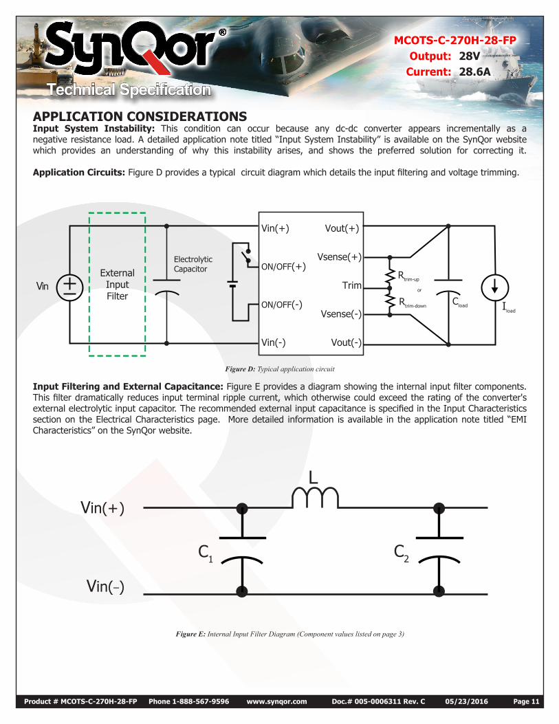
APPLICATION CONSIDERATIONSInput System Instability: This condition can occur because any dc-dc converter appears incrementally as a negative resistance load. A detailed application note titled “Input System Instability” is available on the SynQor website which provides an understanding of why this instability arises, and shows the preferred solution for correcting it. Application Circuits: Figure D provides a typical circuit diagram which details the input filtering and voltage trimming.
Figure D: Typical application circuit
Input Filtering and External Capacitance: Figure E provides a diagram showing the internal input filter components. This filter dramatically reduces input terminal ripple current, which otherwise could exceed the rating of the converter's external electrolytic input capacitor. The recommended external input capacitance is specified in the Input Characteristics section on the Electrical Characteristics page. More detailed information is available in the application note titled “EMI Characteristics” on the SynQor website.
Figure E: Internal Input Filter Diagram (Component values listed on page 3)
VinExternalInputFilter
Iload
Cload
Rtrim-up
or
Rtrim-down
ElectrolyticCapacitor
Vin(+) Vout(+)
Vout(-)
Vsense(-)
Vsense(+)
Trim
Vin(-)
ON/OFF(-)
ON/OFF(+)
C2C1
LVin(+)
Vin(_)

Technical Specification
MCOTS-C-270H-28-FPOutput: 28V
Current: 28.6A
Product # MCOTS-C-270H-28-FP Phone 1-888-567-9596 www.synqor.com Doc.# 005-0006311 Rev. C 05/23/2016 Page 12
Under-Voltage Lockout Turn-On
Threshold
ON/OFF (Negative
logic)
Vout
Vin
(typical start-up inhibit period)
(initial start-up inhibit period)
t0 t1 t2 t
(typical turn on time)
ON ON ONOFF OFF
140ms 400ms 400ms
60ms
Figure F: Startup Inhibit Period (turn-on time not to scale)
Startup Inhibit Period: The Startup Inhibit Period ensures that the converter will remain off for approximately 400 ms when it is shut down for any reason. When an output short is present, this generates a 2.5 Hz “hiccup” mode, which prevents the converter from overheating. In all, there are seven ways that the converter can be shut down, initiating a Startup Inhibit Period:
• Input Under-Voltage Lockout• Input Over-Voltage Lockout• Output Over-Voltage Protection• Over Temperature Shutdown• Current Limit• Short Circuit Protection• Turned off by the ON/OFF inputFigure F shows three turn-on scenarios, where a Startup Inhibit Period is initiated at t0, t1, and t2:Before time t0, when the input voltage is below the UVL threshold, the unit is disabled by the Input Under-Voltage Lockout feature. When the input voltage rises above the UVL threshold, the Input Under-Voltage lockout is released, and a Startup Inhibit Period is initiated. At the end of this delay, the ON/OFF pin is evaluated, and since it is active, the unit turns on.
At time t1, the unit is disabled by the ON/OFF pin, and it cannot be enabled again until the Startup Inhibit Period has elapsed.
When the ON/OFF pin goes high after t2, the Startup Inhibit Period has elapsed, and the output turns on within the typical Turn-On Time.
Thermal Considerations: The maximum operating base-plate temperature, TB, is 100 ºC. Refer to the thermal derating curve, Figure 5, to see the available output current at baseplate temperatures below 100 ºC. A power derating curve can be calculated for any heatsink that is attached to the base-plate of the converter. It is only necessary to determine the thermal resistance, RTHBA, of the chosen heatsink between the base-plate and the ambient air for a given airflow rate. This information is usually available from the heatsink vendor. The following formula can then be used to determine the maximum power the converter can dissipate for a given thermal condition:
Pmax
=TB - TA
diss RTHBA
This value of power dissipation can then be used in conjunction with the data shown in Figure 3 to determine the maximum load current (and power) that the converter can deliver in the given thermal condition.
Technical Specification
MCOTS-C-270H-28-FPOutput: 28V
Current: 28.6A
Product # MCOTS-C-270H-28-FP Phone 1-888-567-9596 www.synqor.com Doc.# 005-0006311 Rev. C 05/23/2016 Page 13
Full-Featured Application NotesThis section provides some basic application information for the full-feature version of the MCOTS series converter.
All units in this product family include back-drive protection to simplify the use of multiple converters in a parallel or sequencing application. However, any voltage applied to the output of the converter should be kept below the rated output voltage of the converter.
In addition to back-drive protection, these units include the following features (pins):
I Share (pin 9)-Active Current Share: Some applications benefit from connecting the outputs of multiple converters in parallel. Typical applications include systems that require power levels higher than the rated power of one converter, or systems that require N+1(less than 30) redundancy for increased reliability and availability. The active current share feature of this converter is a secondary side referenced circuit that ensures that modules configured to operate in parallel will share load current to a significant degree (±5% typical at full rated current). This feature is implemented by directly connecting the I share pins and the Start Sync pins of multiple units together. Note also that it is important to connect the SENSE(+) and SENSE(-) pins of each of the parallel modules in the same physical location to ensure the most accurate level of current sharing. The voltage at the I Share pin will range from approximately 1volt (at no load) to 2.2 volts (at full rated current), referenced to the secondary-side ground, VSENSE(-). For best performance in current shared mode,the following connections must be implemented:
• I share pins of multiple units must be connected together.
• Start Sync pins of multiple units must be connected together (see details below) • SENSE(+) and SENSE(-) pins of each module must be tied together at the same physical location, preferably at the end of power out cable or trace.Start Sync (pin 8) - Start Synchronization:The Start Synchronization feature is a secondary side referenced circuit that will allow a more consistent start-up sequence when the output of multiple modules are connected in parallel. To operate this feature, connect together the Start-Sync pins of multiple current-sharing units. This will permit immediate start-up with loads greater than the current limit of a single unit. Without this connection, any set of converters attempting to asynchronously start (or re-start) with a load greater than the current limit of a single unit will go into an auto-restart mode of operation that will continue until one converter attempts a start at the same time as the minimum number of additional units necessary to sustain the load condition.
For example, three 50 amp units starting into a 90 amp load would require two units to simultaneously attempt a start. The Start Sync connection synchronizes these starting attempts and provides a more consistent and reliable start-up sequence. For details about the auto-restart mode or repeated startup attempts, please see the “Startup Inhibit Period” note in the Technical Specification.
SyncIn (pin 1) – External Clock Synchronization: The Clock Synchronization is a primary side referenced feature which allows the user to control the EMI signature and synchronize sensitive circuitry to quiet periods in the converter operation. With this option, the converter can be synchronized to an external clock signal whose frequency is within the limits specified in the Electrical Characteristics Table. Note that increasing the converter’s frequency will tend to reduce efficiency.
The Clock Synchronization feature allows the user the following choices:
• Change the switching frequency of the converter from the factory pre-set value to any other value in the specified range.• Synchronize the switching of all converters in a current shared mode to a common external frequency.
• Synchronize the switching frequency of each module to an external frequency.
• Improve susceptibility of an adjacent sensitive circuit by moving the converter frequency away from its most sensitive frequency.All the above are also effective means of designing and managing EMI filtering to comply with the specified EMC standards.• All synchronization signals (including an external clock) should be referenced to the negative terminal of input voltage, Vin(-)• The high level of the signal should be between 3.5V and 5.0V
• The low level should be between -0.5V and +1.2V
• The duty cycle of a signal applied to the SyncIn pin should be between 20% and 80%
SyncOut (pin 2) - Synchronization Output: The Synchronization Output is a primary side referenced feature which provides the ability for a user to access a waveform switching synchronously with the pulse width modulator (pwm) clock of the module. The SyncOut signal of one module can be used as the input to multiple other modules.
Technical Specification
MCOTS-C-270H-28-FPOutput: 28V
Current: 28.6A
Product # MCOTS-C-270H-28-FP Phone 1-888-567-9596 www.synqor.com Doc.# 005-0006311 Rev. C 05/23/2016 Page 14
171615141312
18
1110987
123456
0.050 [1.27]0.300 [7.62]0.550 [13.97]
1.450 [36.83]1.200 [30.48]0.950 [24.13]
1.800 [45.72]
4.200[106.68]
0.150 [3.81]0.300 [7.62]0.450 [11.43]0.850 [21.59]1.250 [31.75]
0.243 0.0206.17 ][ 05.0
0.250 0.020 6.35 ][ 05.0 0.493 0.020 12.52 0.50[ ]
2.486 0.020 63.14 0.50[ ]2.00 [50.8]
1
4.686 0.020119.02 0.50[ ]
4.20[106.7]
OVERALL HEIGHT
0.512+0.002-0.005
13.00+0.05[ ]
M3 STANDOFFx4SEE NOTE 8
-0.12
0.010 [0.25]
0.151[3.84]
BOTTOMSIDE CLEARANCE
0.017+0.007-0.010
0.43+0.17-0.25[ ]
3.900[99.06]
3.750[95.25]
3.600[91.44]
3.450[87.63]
3.150
3.300[83.82]
[80.01]
NOTES
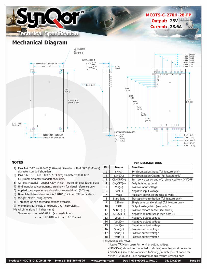
1) Pins 1-4, 7-12 are 0.040” (1.02mm) diameter, with 0.080” (2.03mm) diameter standoff shoulders.
2) Pins 5-6, 13-18 are 0.080” (2.03 mm) diameter with 0.125” (3.18mm) diameter standoff shoulders.
3) All Pins: Material - Copper Alloy; Finish - Matte Tin over Nickel plate4) Undimensioned components are shown for visual reference only.5) Applied torque per screw should not exceed 6in-lb (0.7Nm).6) Baseplate flatness tolerance is 0.010” (0.25mm) TIR for surface.7) Weight: 9.9oz (280g) typical8) Threaded or non-threaded options available.9) Workmanship: Meets or exceeds IPC-A-610 Class II
10) All dimensions in inches (mm)Tolerances: x.xx +/-0.02 in. (x.x +/-0.5mm) x.xxx +/-0.010 in. (x.xx +/-0.25mm)
PIN DESIGNATIONS
Pin Name Function
1 SyncIn Synchronization Input (full feature only)2 SyncOut Synchronization Output (full feature only)3 ON/OFF(+) Turn converter on and off, referenced to – ON/OFF4 ON/OFF(–) Fully isolated ground5 Vin(+) Positive input voltage6 Vin(–) Negative input voltage7 Vaux Auxiliary power, referenced to Vout(–)8 Start Sync Startup synchronization (full feature only)9 I Share Single wire parallel signal (full feature only)10 TRIM Output voltage trim (see note 1)11 SENSE(+) Positive remote sense (see note 2)12 SENSE(–) Negative remote sense (see note 3)13 Vout(–) Negative output voltage14 Vout(–) Negative output voltage15 Vout(–) Negative output voltage16 Vout(+) Positive output voltage17 Vout(+) Positive output voltage18 Vout(+) Positive output voltage
Pin Designations Notes:1 Leave TRIM pin open for nominal output voltage.2 SENSE(+) should be connected to Vout(+) remotely or at converter.3 SENSE(–) should be connected to Vout(–) remotely or at converter.4 Pins 1, 2, 8, and 9 are populated on full feature versions only.
Mechanical Diagram
Technical Specification
MCOTS-C-270H-28-FPOutput: 28V
Current: 28.6A
Product # MCOTS-C-270H-28-FP Phone 1-888-567-9596 www.synqor.com Doc.# 005-0006311 Rev. C 05/23/2016 Page 15
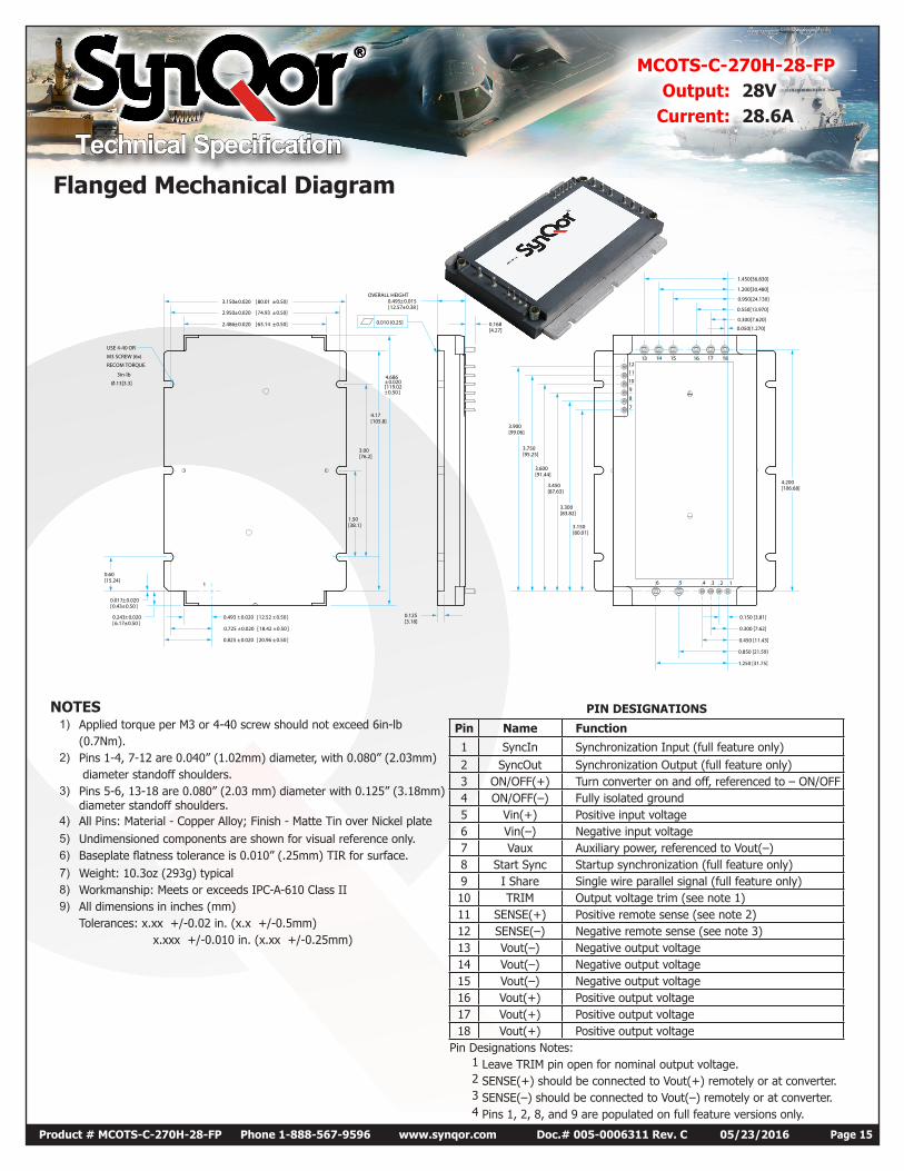
NOTES1) Applied torque per M3 or 4-40 screw should not exceed 6in-lb
(0.7Nm).2) Pins 1-4, 7-12 are 0.040” (1.02mm) diameter, with 0.080” (2.03mm)
diameter standoff shoulders.3) Pins 5-6, 13-18 are 0.080” (2.03 mm) diameter with 0.125” (3.18mm)
diameter standoff shoulders.4) All Pins: Material - Copper Alloy; Finish - Matte Tin over Nickel plate5) Undimensioned components are shown for visual reference only.6) Baseplate flatness tolerance is 0.010” (.25mm) TIR for surface.7) Weight: 10.3oz (293g) typical8) Workmanship: Meets or exceeds IPC-A-610 Class II9) All dimensions in inches (mm)
Tolerances: x.xx +/-0.02 in. (x.x +/-0.5mm) x.xxx +/-0.010 in. (x.xx +/-0.25mm)
PIN DESIGNATIONS
Pin Name Function
1 SyncIn Synchronization Input (full feature only)2 SyncOut Synchronization Output (full feature only)3 ON/OFF(+) Turn converter on and off, referenced to – ON/OFF4 ON/OFF(–) Fully isolated ground5 Vin(+) Positive input voltage6 Vin(–) Negative input voltage7 Vaux Auxiliary power, referenced to Vout(–)8 Start Sync Startup synchronization (full feature only)9 I Share Single wire parallel signal (full feature only)10 TRIM Output voltage trim (see note 1)11 SENSE(+) Positive remote sense (see note 2)12 SENSE(–) Negative remote sense (see note 3)13 Vout(–) Negative output voltage14 Vout(–) Negative output voltage15 Vout(–) Negative output voltage16 Vout(+) Positive output voltage17 Vout(+) Positive output voltage18 Vout(+) Positive output voltage
Pin Designations Notes:1 Leave TRIM pin open for nominal output voltage.2 SENSE(+) should be connected to Vout(+) remotely or at converter.3 SENSE(–) should be connected to Vout(–) remotely or at converter.4 Pins 1, 2, 8, and 9 are populated on full feature versions only.
123456
1716151413 181211
10
9
8
7
1
0.050[1.270]
0.300[7.620]
0.550[13.970]
0.950[24.130]
1.200[30.480]
1.450[36.830]
4.200[106.68]
0.150 [3.81]
0.300 [7.62]
0.450 [11.43]
0.850 [21.59]
1.250 [31.75]
2.486±0.020 63.14 ±0.50][
3.150±0.020 80.01 ±0.50][
2.950±0.020 74.93 ±0.50][
OVERALL HEIGHT0.495±0.01512.57±0.38[ ]
0.168[4.27]
USE 4-40 OR
M3 SCREW (6x)
RECOM TORQUE
3in-lb
Ø.13[3.3]
0.020
±0.50 ]
0.125[3.18]
0.493 ±0.020 12.52 ±0.50[ ]
0.725 ±0.020 18.42 ±0.50[ ]
0.825 ±0.020 20.96 ±0.50[ ]
0.60[15.24]
0.017±0.0200.43±0.50[ ]
0.243±0.0206.17±0.50[ ]
1.50[38.1]
3.00[76.2]
4.17[105.8]
4.686±119.02[
3.150[80.01]
3.300[83.82]
3.450[87.63]
3.600[91.44]
3.750[95.25]
3.900[99.06]
0.010 [0.25]
Flanged Mechanical Diagram
Technical Specification
MCOTS-C-270H-28-FPOutput: 28V
Current: 28.6A
Product # MCOTS-C-270H-28-FP Phone 1-888-567-9596 www.synqor.com Doc.# 005-0006311 Rev. C 05/23/2016 Page 16
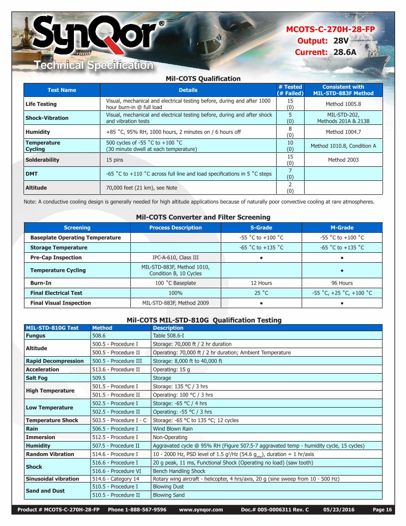
Mil-COTS Converter and Filter ScreeningScreening Process Description S-Grade M-Grade
Baseplate Operating Temperature -55 ˚C to +100 ˚C -55 ˚C to +100 ˚C
Storage Temperature -65 ˚C to +135 ˚C -65 ˚C to +135 ˚C
Pre-Cap Inspection IPC-A-610, Class III
Temperature Cycling MIL-STD-883F, Method 1010, Condition B, 10 Cycles
Burn-In 100 ˚C Baseplate 12 Hours 96 Hours
Final Electrical Test 100% 25 ˚C -55 ˚C, +25 ˚C, +100 ˚C
Final Visual Inspection MIL-STD-883F, Method 2009
Mil-COTS Qualification
Test Name Details # Tested (# Failed)
Consistent with MIL-STD-883F Method
Life Testing Visual, mechanical and electrical testing before, during and after 1000 hour burn-in @ full load
15 (0) Method 1005.8
Shock-Vibration Visual, mechanical and electrical testing before, during and after shock and vibration tests
5 (0)
MIL-STD-202, Methods 201A & 213B
Humidity +85 ˚C, 95% RH, 1000 hours, 2 minutes on / 6 hours off 8 (0) Method 1004.7
Temperature Cycling
500 cycles of -55 ˚C to +100 ˚C (30 minute dwell at each temperature)
10 (0) Method 1010.8, Condition A
Solderability 15 pins 15 (0) Method 2003
DMT -65 ˚C to +110 ˚C across full line and load specifications in 5 ˚C steps 7 (0)
Altitude 70,000 feet (21 km), see Note 2 (0)
Note: A conductive cooling design is generally needed for high altitude applications because of naturally poor convective cooling at rare atmospheres.
Mil-COTS MIL-STD-810G Qualification Testing MIL-STD-810G Test Method Description Fungus 508.6 Table 508.6-I
Altitude 500.5 - Procedure I Storage: 70,000 ft / 2 hr duration
500.5 - Procedure II Operating: 70,000 ft / 2 hr duration; Ambient Temperature
Rapid Decompression 500.5 - Procedure III Storage: 8,000 ft to 40,000 ft
Acceleration 513.6 - Procedure II Operating: 15 g
Salt Fog 509.5 Storage
High Temperature 501.5 - Procedure I Storage: 135 °C / 3 hrs
501.5 - Procedure II Operating: 100 °C / 3 hrs
Low Temperature 502.5 - Procedure I Storage: -65 °C / 4 hrs
502.5 - Procedure II Operating: -55 °C / 3 hrs
Temperature Shock 503.5 - Procedure I - C Storage: -65 °C to 135 °C; 12 cycles
Rain 506.5 - Procedure I Wind Blown Rain
Immersion 512.5 - Procedure I Non-Operating
Humidity 507.5 - Procedure II Aggravated cycle @ 95% RH (Figure 507.5-7 aggravated temp - humidity cycle, 15 cycles)
Random Vibration 514.6 - Procedure I 10 - 2000 Hz, PSD level of 1.5 g2/Hz (54.6 grms), duration = 1 hr/axis
Shock 516.6 - Procedure I 20 g peak, 11 ms, Functional Shock (Operating no load) (saw tooth)
516.6 - Procedure VI Bench Handling Shock Sinusoidal vibration 514.6 - Category 14 Rotary wing aircraft - helicopter, 4 hrs/axis, 20 g (sine sweep from 10 - 500 Hz)
Sand and Dust 510.5 - Procedure I Blowing Dust
510.5 - Procedure II Blowing Sand
Technical Specification
MCOTS-C-270H-28-FPOutput: 28V
Current: 28.6A
Product # MCOTS-C-270H-28-FP Phone 1-888-567-9596 www.synqor.com Doc.# 005-0006311 Rev. C 05/23/2016 Page 17
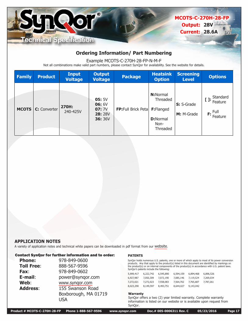
Example MCOTS-C-270H-28-FP-N-M-FNot all combinations make valid part numbers, please contact SynQor for availability. See the website for details.
APPLICATION NOTESA variety of application notes and technical white papers can be downloaded in pdf format from our website.
Ordering Information/ Part Numbering
Family Product Input Voltage
Output Voltage Package Heatsink
OptionScreening
Level Options
MCOTS C: Converter 270H: 240-425V
05: 06: 07: 28: 36:
5V 6V 7V 28V 36V
FP:Full Brick Peta
N:
F:
D:
Normal Threaded Flanged Normal Non-Threaded
S: S-Grade M: M-Grade
[ ]:
F:
Standard Feature Full Feature
WarrantySynQor offers a two (2) year limited warranty. Complete warranty information is listed on our website or is available upon request from SynQor.
Contact SynQor for further information and to order: Phone: 978-849-0600 Toll Free: 888-567-9596 Fax: 978-849-0602 E-mail: [email protected] Web: www.synqor.com Address: 155 Swanson Road Boxborough, MA 01719 USA
PATENTS SynQor holds numerous U.S. patents, one or more of which apply to most of its power conversion products. Any that apply to the product(s) listed in this document are identified by markings on the product(s) or on internal components of the product(s) in accordance with U.S. patent laws. SynQor’s patents include the following:
5,999,417 6,222,742 6,545,890 6,594,159 6,894,468 6,896,526
6,927,987 7,050,309 7,072,190 7,085,146 7,119,524 7,269,034
7,272,021 7,272,023 7,558,083 7,564,702 7,765,687 7,787,261
8,023,290 8,149,597 8,493,751 8,644,027 9,143,042


