Embed Size (px)
Citation preview

Fakultat fur Elektrotechnik und InformationstechnikTechnische Universitat Munchen
Mitigating and Resolving Performance Isolation Issuesof PCIe Passthrough and SR-IOV in
Multi-Core Virtualization
Andre Oliver Richter
Vollstandiger Abdruck der von der Fakultat fur Elektrotechnik und Informationstechnikder Technischen Universitat Munchen zur Erlangung des akademischen Grades eines
Doktor-Ingenieurs (Dr.-Ing.)
genehmigten Dissertation.
Vorsitzender:Prof. Dr.-Ing. Wolfgang Kellerer
Prufende der Dissertation:1. Prof. Dr. sc. techn. Andreas Herkersdorf2. Prof. Dr.-Ing. Dr. h. c. Jurgen Becker,
Karlsruher Institut fur Technologie (KIT)
Die Dissertation wurde am 24.04.2017 bei der Technischen Universitat Muncheneingereicht und durch die Fakultat fur Elektrotechnik und Informationstechnik am27.10.2017 angenommen.


Danksagung
Zuallererst mochte ich meinem Doktorvater Prof. Dr. sc. techn. Andreas Herkersdorffur die Betreuung dieser Arbeit danken. Er hat es mir ermoglicht an einem spannen-den und fur die weitere Zukunft sehr relevanten Thema zu forschen und damit denGrundstein fur diese Arbeit gelegt. Seine Ideen in technischen Meetings halfen mir, sehrschnell ein passendes Gebiet zu identifizieren, auf dem ich forschen konnte. Hervorhebenmochte ich auch Prof. Herkersdorfs menschliche Fuhrung, die seinen Lehrstuhl zu einemangenehmen und vertrauensvollen Arbeitsumfeld fur mich machte.
Besonderer Dank gilt auch Prof. Dr.-Ing. Dr. h. c. Jurgen Becker als Zweitprufer dieserArbeit und Prof. Dr.-Ing. Wolfgang Kellerer fur den Vorsitz der Prufungskommission.
Weiterer Dank gilt:
Dr.-Ing. Thomas Wild fur seinen Input in technischen Meetings und seine Hilfe beiorganisatorischen Dingen aller Art, vor allem im ARAMiS Projekt. Außerdem fur dieMoglichkeit der Tutorentatigkeit im Praktikum VHDL und die dortige Betreuung, durchdie ich den Lehrstuhl schon als Student kennen lernen konnte.
Christian Herber, mit dem ich uber die Jahre stets effektiv zusammen an diversen Pub-likationen und im ARAMiS Projekt gearbeitet habe und bei unseren Dienstreisen immereine gute Zeit hatte.
Holm Rauchfuss, der beigetragen hat, dass der Lehrstuhl Partner im ARAMiS Projektwurde. Dadurch konnte die Stelle geschaffen werden, auf der ich eingestellt wurde. DesWeiteren fur die Betreuung wahrend meiner Werkstudententatigkeit, welche meine ersteArbeitsstelle am Lehrstuhl war.
Allen anderen Kollegen fur die gute Zeit, die lockere Atmosphare, den guten Umgang,die vielen Dart Matches und naturlich die hitzigen Debatten (nicht zwangsweise immernur uber Forschung).
Meiner Frau Susanne, die mich immer aufs Neue motiviert hat, und vor allem gegen Endeeine große Unterstutzung in jeglicher Hinsicht war. Zu guter Letzt meinen Eltern, fur ihreGeduld und ihr Vertrauen wahrend der Schulzeit und die bedingungslose Unterstutzungwahrend dem Studium. Ihr habt diesen Weg geebnet.
iii

Zusammenfassung
Leistungsisolierung ist eine zentrale Herausforderung in virtualisierten Multicore Syste-men. Sie beschreibt die Fahigkeit eines Wirtsystems zur Verhinderung oder Limitierungvon Leistungsinterferenzen zwischen mehreren Virtuellen Maschinen (VMs), welche aufeinem Wirtsystem ausgefuhrt werden und sich dessen Hardware-Ressourcen teilen. Istnur unzureichende Isolierung geboten, wird es moglich, dass bosartige oder defekteVMs Leistung von nebenlaufigen VMs oder dem Wirtsystem selbst stehlen oder ver-mindern. In der Cloud-Computing Domane, in der virtualisierte Multicore Server demaktuellen Stand der Technik entsprechen, kann dies zu Vertragsverletzungen zwischenKunden und Anbieter fuhren. In der Domane fur eingebettete Systeme, in welchervirtualisierte Multicore Systeme in naher Zukunft auftauchen werden, konnen Prob-leme mit der Leistungsisolierung sogar zur Verletzung von Realzeitanforderungen fuhren,was letztendlich die Systemsicherheit gefahrden konnte. Da virtualisierte Systeme vielegemeinsam-benutzte Ressourcen verwenden, z.B. CPU-Kerne, Caches oder I/O Gerate,muss Leistungsisolierung immer individuell bewertet werden.
Diese Arbeit prasentiert Forschungsbeitrage zur Leistungsisolierung der neusten Gen-eration von I/O Virtualisierungstechnologie, namentlich PCIe passthrough und SingleRoot I/O Virtualization (SR-IOV). Diese Virtualisierungstechnologie ermoglicht niedrigeLatenzen und hohe Leistung, und ist bereits in kommerziellen Geraten erhaltlich. DieArbeit zeigt auf, dass die Leistungsisolierung von PCIe passthrough und SR-IOV durchDenial-of-Service (DoS) Angriffe bosartiger oder defekter VMs gebrochen werden kann,indem passthrough und SR-IOV Hardware mit sinnlosen PCIe Paketen uberflutet wird.Zum Beispiel fuhrt ein DoS-Angriff auf einen SR-IOV-fahigen Zweiport Gigabit Eth-ernet Adapter zu einer Verminderung des Durchsatzes von 941 Mbit/s zu 615 Mbit/s(-35%) Derselbe Angriff fuhrt zu einer Verminderung der SSD-Leistung des Wirtsys-tems um 77%. Diese Arbeit untersucht diesen Angriffsvektor grundlich, steuert eineKlassifikation verschiedener DoS-Angriffstypen bei und prasentiert ein Modell, welchesdie architekturellen Probleme in aktueller Hardware beschreibt, die die DoS-Angriffeermoglichen.
Des Weiteren werden zwei domanenspezifische Losungen prasentiert, welche die ent-deckten Isolierungsprobleme abschwachen oder losen. Die Losung fur die Cloud Domaneverwendet schlanke Hardware-Monitoring Erweiterungen in passthrough Geraten, umDoS-Angriffe zu entdecken und mit Software-Scheduling abzuschwachen. Zum Beispielermoglicht sie die Leistung einer Apache Webserver VM von 51.3% wahrend eines DoS-Angriffs zuruck auf 97% zu heben. Als Losung fur Embedded Systeme werden zwei in-tegrierte Hardware-Architekturen vorgeschlagen. Diese funktionieren optionale und bisdato vernachlassigte QoS Erweiterungen der PCIe Spezifikation so um, dass der DoS-Angriffsvektor geschlossen wird und Angriffe komplett verhindert werden. Die erste Ar-
v

Zusammenfassung
chitektur ist fur Scheduling-Freiheit optimiert, die zweite fur minimale Hardwarekosten.Die Vor- und Nachteile der beiden Architekturen werden anhand von Evaluierungsergeb-nissen diskutiert.
Nach meinem Wissen sind die Beitrage, welche in dieser Arbeit prasentiert werden, dieersten die eine umfassende Untersuchung von DoS-Angriffen auf PCIe passthrough undSR-IOV anstellen, und Beitrage zur Losung der entdeckten Leistungsisolierungsproblemeleisten.
vi
Abstract
Performance isolation is a key challenge in virtualized multi-core systems. It describesa host system’s capability to prevent or limit performance interference between multipleVirtual Machines (VMs) that execute on it and share its hardware resources. If ahost system provides insufficient performance isolation, it is possible for malicious ormalfunctioning VMs to degrade or steal performance from concurrent VMs or the hostitself. In the cloud computing domain, where virtualized multi-core servers are state-of-the-art, performance interference could result in broken service level agreements betweenproviders and customers. In the embedded computing domain, where virtualized multi-core systems will surface in the near future, performance isolation issues might evenresult in violation of real-time requirements and therefore compromise system safety.As virtualized systems employ many shared resources, e.g. CPU cores, caches or I/Odevices, performance isolation must be assessed individually.
This thesis contributes research on performance isolation of PCIe passthrough andSingle Root I/O Virtualization (SR-IOV), which is the latest generation of I/O virtual-ization technology. It enables low latency, high performance virtual I/O and is alreadyimplemented in commercial off-the-shelf devices. The thesis shows that performanceisolation of PCIe passthrough and SR-IOV can be broken with Denial-of-Service (DoS)attacks from malicious or malfunctioning VMs that flood passthrough and SR-IOV hard-ware with spurious PCIe packets. For example, DoS attacks on an SR-IOV capable dual-port gigabit Ethernet adapter cause a throughput degradation from 941 Mbit/s down to615 Mbit/s (-35%). The same attack causes a 77% performance degradation of the hostsystem’s SSD storage. The thesis thoroughly investigates this attack vector, contributesa classification of different DoS attack types and presents a model that explains thearchitectural shortcomings in current hardware that enable the attacks.
Additionally, two domain specific solutions for cloud and embedded systems are pre-sented, which mitigate and resolve the discovered performance isolation issues. The cloudsolution utilizes lightweight hardware monitoring extensions within passthrough I/O de-vices to detect attacker VMs and mitigate their DoS attacks with software scheduling.For instance, performance of an Apache webserver VM is restored from 51.3% duringDoS attacks back to 97%. The solution for embedded systems proposes two integratedhardware architectures that repurpose optional and neglected QoS extensions of the PCIespecification in order to close the attack vector and completely prevent DoS attacks. Thefirst architecture is optimized for scheduling freedom, the second for minimal hardwarecosts. Results of an evaluation are used to discuss pros and cons of both architectures.
To the best of my knowledge, work presented in this thesis is the first that compre-hensively investigates DoS attacks on PCIe passthrough and SR-IOV, and contributestowards solving the resulting performance isolation issues.
vii

Contents
Danksagung iii
Zusammenfassung v
Abstract vii
Contents ix
List of Figures xiii
List of Tables xv
Acronyms xvii
1 Introduction 11.1 Problem Statement . . . . . . . . . . . . . . . . . . . . . . . . . . . . . . . 2
1.2 Contributions . . . . . . . . . . . . . . . . . . . . . . . . . . . . . . . . . . 3
1.3 Outline . . . . . . . . . . . . . . . . . . . . . . . . . . . . . . . . . . . . . 5
2 State of the Art 72.1 Platform Virtualization . . . . . . . . . . . . . . . . . . . . . . . . . . . . 7
2.1.1 Spatial Isolation . . . . . . . . . . . . . . . . . . . . . . . . . . . . 8
2.1.2 Performance Isolation . . . . . . . . . . . . . . . . . . . . . . . . . 9
2.1.3 Cloud Computing . . . . . . . . . . . . . . . . . . . . . . . . . . . 9
2.1.4 Embedded Virtualization . . . . . . . . . . . . . . . . . . . . . . . 10
2.2 Software-based I/O Virtualization . . . . . . . . . . . . . . . . . . . . . . 11
2.2.1 Emulation . . . . . . . . . . . . . . . . . . . . . . . . . . . . . . . . 11
2.2.2 Paravirtualization . . . . . . . . . . . . . . . . . . . . . . . . . . . 13
2.2.3 Performance, Pros and Cons . . . . . . . . . . . . . . . . . . . . . 14
2.2.4 Performance Isolation Approaches . . . . . . . . . . . . . . . . . . 15
2.3 Hardware-based I/O Virtualization: Passthrough I/O with PCIe and SR-IOV . . . . . . . . . . . . . . . . . . . . . . . . . . . . . . . . . . . . . . . 16
2.3.1 PCI Express (PCIe) . . . . . . . . . . . . . . . . . . . . . . . . . . 17
2.3.1.1 Topology . . . . . . . . . . . . . . . . . . . . . . . . . . . 17
2.3.1.2 Link Parameters and Bit Rates . . . . . . . . . . . . . . . 18
2.3.1.3 PCIe Functions, Memory Mapped I/O and Drivers . . . . 18
2.3.1.4 Transaction Characteristics and Flow Control . . . . . . 20
ix
Contents
2.3.2 PCIe Single Root I/O Virtulization (SR-IOV) . . . . . . . . . . . . 20
2.3.2.1 Physical and Virtual Functions . . . . . . . . . . . . . . . 20
2.3.2.2 Adoption . . . . . . . . . . . . . . . . . . . . . . . . . . . 22
2.3.3 Performance, Pros and Cons . . . . . . . . . . . . . . . . . . . . . 23
2.3.4 Performance Isolation Approaches . . . . . . . . . . . . . . . . . . 23
3 Investigation of PCIe Passthrough and SR-IOV Performance Isolation Issues 27
3.1 Threat Model . . . . . . . . . . . . . . . . . . . . . . . . . . . . . . . . . . 27
3.2 Implementation of DoS Attacks . . . . . . . . . . . . . . . . . . . . . . . . 28
3.3 Evaluation Platform . . . . . . . . . . . . . . . . . . . . . . . . . . . . . . 29
3.4 Evaluation Methodology . . . . . . . . . . . . . . . . . . . . . . . . . . . . 31
3.4.1 Latencies of 32 bit PCIe Read Transactions . . . . . . . . . . . . . 31
3.4.2 Network Performance – TCP and UDP Throughput . . . . . . . . 33
3.4.3 Storage Performance – SSD Throughput . . . . . . . . . . . . . . . 33
3.5 Experiments and Results . . . . . . . . . . . . . . . . . . . . . . . . . . . . 33
3.5.1 Experiment 1: Attacking SR-IOV Virtual Functions . . . . . . . . 34
3.5.1.1 Baseline Performance . . . . . . . . . . . . . . . . . . . . 34
3.5.1.2 Experimental Setup and Results . . . . . . . . . . . . . . 34
3.5.1.3 Second-Order Effects . . . . . . . . . . . . . . . . . . . . 36
3.5.1.4 Summary . . . . . . . . . . . . . . . . . . . . . . . . . . . 37
3.5.2 Experiment 2: Influence of the DoS Victim’s Processing Speed . . 37
3.5.2.1 Fine-Grained Runtime-Configurable Processing Speedsvia FPGA . . . . . . . . . . . . . . . . . . . . . . . . . . 38
3.5.2.2 Experimental Setup and Results . . . . . . . . . . . . . . 38
3.5.2.3 Processing Speed Variations in COTS Devices . . . . . . 41
3.5.2.4 Summary . . . . . . . . . . . . . . . . . . . . . . . . . . . 42
3.5.3 Experiment 3: Influence of Switching Intermediaries . . . . . . . . 43
3.5.3.1 Experimental Setup and Results . . . . . . . . . . . . . . 43
3.5.3.2 Summary . . . . . . . . . . . . . . . . . . . . . . . . . . . 43
3.5.4 Experiment 4: Degradation of Chipset Disk I/O . . . . . . . . . . 45
3.5.4.1 Experimental Setup and Results . . . . . . . . . . . . . . 45
3.5.4.2 Summary . . . . . . . . . . . . . . . . . . . . . . . . . . . 46
3.6 System Model for PCIe DoS Attacks on Ethernet NICs . . . . . . . . . . 47
3.7 DoS Attack Classification . . . . . . . . . . . . . . . . . . . . . . . . . . . 49
3.7.1 Inter-Device Attack . . . . . . . . . . . . . . . . . . . . . . . . . . 50
3.7.2 Intra-Device Attacks . . . . . . . . . . . . . . . . . . . . . . . . . . 51
3.7.2.1 Inter-Function Attack . . . . . . . . . . . . . . . . . . . . 51
3.7.2.2 Intra-PF Attack . . . . . . . . . . . . . . . . . . . . . . . 51
3.7.2.3 Inter-PF Attack . . . . . . . . . . . . . . . . . . . . . . . 52
3.7.3 Combinations . . . . . . . . . . . . . . . . . . . . . . . . . . . . . . 53
3.8 Summary . . . . . . . . . . . . . . . . . . . . . . . . . . . . . . . . . . . . 53
x
Contents
4 Mitigating Performance Isolation Issues Through Monitoring and Scheduling 554.1 Goals and Requirements . . . . . . . . . . . . . . . . . . . . . . . . . . . . 55
4.1.1 Goals . . . . . . . . . . . . . . . . . . . . . . . . . . . . . . . . . . 554.1.2 Requirements . . . . . . . . . . . . . . . . . . . . . . . . . . . . . . 56
4.2 Design and Exploration . . . . . . . . . . . . . . . . . . . . . . . . . . . . 574.2.1 Monitoring and DoS Attack Detection . . . . . . . . . . . . . . . . 574.2.2 Exploration of Monitoring Alternatives . . . . . . . . . . . . . . . 58
4.2.2.1 Monitoring in CPUs . . . . . . . . . . . . . . . . . . . . . 584.2.2.2 Monitoring in I/O Devices . . . . . . . . . . . . . . . . . 604.2.2.3 Monitoring in Intermediaries . . . . . . . . . . . . . . . . 61
4.2.3 Mitigation . . . . . . . . . . . . . . . . . . . . . . . . . . . . . . . . 614.2.3.1 Isolation via Freeze or Migration . . . . . . . . . . . . . . 614.2.3.2 Attack Throttling via Scheduling . . . . . . . . . . . . . . 62
4.3 Implementation . . . . . . . . . . . . . . . . . . . . . . . . . . . . . . . . . 634.3.1 Overview . . . . . . . . . . . . . . . . . . . . . . . . . . . . . . . . 634.3.2 Monitoring and DoS Detection on FPGA . . . . . . . . . . . . . . 644.3.3 VC709 PF Driver and DoS Protect Process . . . . . . . . . . . . . 654.3.4 System Software and Emulation of Monitoring in the 82576 . . . . 66
4.4 Evaluation . . . . . . . . . . . . . . . . . . . . . . . . . . . . . . . . . . . . 674.4.1 Benchmarks . . . . . . . . . . . . . . . . . . . . . . . . . . . . . . . 684.4.2 DoS Attack Parameters . . . . . . . . . . . . . . . . . . . . . . . . 684.4.3 DoS Detection Threshold . . . . . . . . . . . . . . . . . . . . . . . 694.4.4 Memcached and Apache Results . . . . . . . . . . . . . . . . . . . 704.4.5 Netperf Results . . . . . . . . . . . . . . . . . . . . . . . . . . . . . 724.4.6 Trace of DoS Detection and Attacker Freeze . . . . . . . . . . . . . 74
4.4.6.1 Baseline Trace . . . . . . . . . . . . . . . . . . . . . . . . 744.4.6.2 Mitigation Trace . . . . . . . . . . . . . . . . . . . . . . . 764.4.6.3 Optimization Tradeoffs . . . . . . . . . . . . . . . . . . . 76
4.4.7 Mirroring Overhead . . . . . . . . . . . . . . . . . . . . . . . . . . 764.4.7.1 Benchmark Overhead . . . . . . . . . . . . . . . . . . . . 774.4.7.2 DoS Attack Overhead . . . . . . . . . . . . . . . . . . . . 77
4.5 Summary . . . . . . . . . . . . . . . . . . . . . . . . . . . . . . . . . . . . 78
5 Resolving Performance Isolation Issues Through PCIe QoS Extensions 815.1 Goals and Requirements . . . . . . . . . . . . . . . . . . . . . . . . . . . . 82
5.1.1 Goals . . . . . . . . . . . . . . . . . . . . . . . . . . . . . . . . . . 825.1.2 Requirements . . . . . . . . . . . . . . . . . . . . . . . . . . . . . . 82
5.2 Quality-of-Service Extensions in the PCIe Specification . . . . . . . . . . . 835.2.1 Contribution of this Thesis . . . . . . . . . . . . . . . . . . . . . . 835.2.2 Overview of the PCIe Specification’s QoS Extensions . . . . . . . . 84
5.2.2.1 TC/VC Mapping . . . . . . . . . . . . . . . . . . . . . . 855.2.2.2 Arbitration . . . . . . . . . . . . . . . . . . . . . . . . . . 86
5.3 SystemC TLM 2.0 Model of QoS-enabled PCIe Components . . . . . . . . 875.3.1 Model Verification Approach . . . . . . . . . . . . . . . . . . . . . 90
xi
Contents
5.3.2 Verification Results . . . . . . . . . . . . . . . . . . . . . . . . . . . 905.4 Multi-VC Architecture . . . . . . . . . . . . . . . . . . . . . . . . . . . . . 93
5.4.1 Architecture . . . . . . . . . . . . . . . . . . . . . . . . . . . . . . 935.4.2 Evaluation . . . . . . . . . . . . . . . . . . . . . . . . . . . . . . . 955.4.3 Multi-VC Architecture Summary . . . . . . . . . . . . . . . . . . . 97
5.5 Time-based Weighted Round-Robin Architecture . . . . . . . . . . . . . . 985.5.1 Architecture . . . . . . . . . . . . . . . . . . . . . . . . . . . . . . 985.5.2 Evaluation . . . . . . . . . . . . . . . . . . . . . . . . . . . . . . . 1005.5.3 TBWRR Architecture Summary . . . . . . . . . . . . . . . . . . . 102
5.6 Summary . . . . . . . . . . . . . . . . . . . . . . . . . . . . . . . . . . . . 102
6 Conclusion and Outlook 1056.1 Conclusion . . . . . . . . . . . . . . . . . . . . . . . . . . . . . . . . . . . 1056.2 Outlook . . . . . . . . . . . . . . . . . . . . . . . . . . . . . . . . . . . . . 108
Bibliography 111
A Approximating Packet Processing Times of COTS PCIe Devices 123
xii

List of Figures
1.1 Overview of contributions . . . . . . . . . . . . . . . . . . . . . . . . . . . 4
2.1 Comparison of classic hypervisor types . . . . . . . . . . . . . . . . . . . . 82.2 I/O device emulation in a type 1 hypervisor . . . . . . . . . . . . . . . . . 112.3 I/O device emulation with type 1 hypervisor and trusted VM . . . . . . . 122.4 I/O device emulation in hosted hypervisors . . . . . . . . . . . . . . . . . 132.5 Paravirtualized I/O with trusted VM . . . . . . . . . . . . . . . . . . . . . 142.6 Example of passthrough I/O . . . . . . . . . . . . . . . . . . . . . . . . . 162.7 Example PCIe topology . . . . . . . . . . . . . . . . . . . . . . . . . . . . 172.8 PCIe multi-function Endpoint . . . . . . . . . . . . . . . . . . . . . . . . . 192.9 Virtualized system with SR-IOV device . . . . . . . . . . . . . . . . . . . 212.10 Dependency between interconnect and I/O functionality . . . . . . . . . . 24
3.1 Block diagram of passthrough/SR-IOV evaluation platform . . . . . . . . 303.2 TSC virtualization side effects . . . . . . . . . . . . . . . . . . . . . . . . 323.3 Impact of DoS attacks on VF0.0 . . . . . . . . . . . . . . . . . . . . . . . 353.4 Influence of PCIe speed on performance degradation . . . . . . . . . . . . 363.5 Influence of packet processing speed on latency during DoS . . . . . . . . 393.6 Perf. degradation depending on DoS victim’s processing speed . . . . . . 403.7 PCIe device multiple processing speeds . . . . . . . . . . . . . . . . . . . . 413.8 Influence of switching intermediaries on performance degradation . . . . 443.9 Impact of DoS attacks on chipset disk I/O . . . . . . . . . . . . . . . . . 463.10 System model for legal software-NIC communication . . . . . . . . . . . . 473.11 System model for software-NIC communication with a malicious VM . . . 493.12 Inter-device attack . . . . . . . . . . . . . . . . . . . . . . . . . . . . . . . 503.13 Inter-function attack . . . . . . . . . . . . . . . . . . . . . . . . . . . . . . 513.14 Intra-PF attack . . . . . . . . . . . . . . . . . . . . . . . . . . . . . . . . . 523.15 Inter-PF attack . . . . . . . . . . . . . . . . . . . . . . . . . . . . . . . . . 523.16 DoS attack combinations . . . . . . . . . . . . . . . . . . . . . . . . . . . . 53
4.1 High-level design of HW/SW monitoring/mitigation design . . . . . . . . 574.2 Overview of x86 performance monitoring facilities . . . . . . . . . . . . . . 594.3 Design for DoS detection in I/O devices . . . . . . . . . . . . . . . . . . . 604.4 Throttling malicious VMs via scheduling . . . . . . . . . . . . . . . . . . . 624.5 Prototype implementation for mitigating DoS attacks . . . . . . . . . . . 634.6 Implementation of hardware monitoring and DoS detection on the Virtex-
7 FPGA . . . . . . . . . . . . . . . . . . . . . . . . . . . . . . . . . . . . . 644.7 PCIe transaction rates – Legal vs. DoS . . . . . . . . . . . . . . . . . . . 70
xiii
List of Figures
4.8 Memcached results . . . . . . . . . . . . . . . . . . . . . . . . . . . . . . . 714.9 Apache results . . . . . . . . . . . . . . . . . . . . . . . . . . . . . . . . . 714.10 Netperf results for TCP and UDP . . . . . . . . . . . . . . . . . . . . . . 734.11 A trace of DoS attack mitigation by freezing the attacker . . . . . . . . . 75
5.1 Relationship between PCIe, its optional QoS extensions and SR-IOV . . . 845.2 PCIe QoS extensions . . . . . . . . . . . . . . . . . . . . . . . . . . . . . . 855.3 TBWRR arbitration table example . . . . . . . . . . . . . . . . . . . . . . 865.4 Block diagram of the real-world lab-setup . . . . . . . . . . . . . . . . . . 885.5 The PCIe hierarchy of the SystemC model . . . . . . . . . . . . . . . . . . 895.6 Comparison: Lab-setup vs. SystemC model . . . . . . . . . . . . . . . . . 915.7 Multi-VC architecture . . . . . . . . . . . . . . . . . . . . . . . . . . . . . 945.8 UDP results for multiple, concurrent DoS attacks . . . . . . . . . . . . . 965.9 Comparison of processing engine designs for SR-IOV devices . . . . . . . . 975.10 TBWRR architecture . . . . . . . . . . . . . . . . . . . . . . . . . . . . . 995.11 TBWRR table tailored to the 82576 NIC . . . . . . . . . . . . . . . . . . 995.12 TBWRR vs. best effort arbitration . . . . . . . . . . . . . . . . . . . . . 1005.13 TBWRR table with idle cores . . . . . . . . . . . . . . . . . . . . . . . . . 1015.14 TBWRR table with two stage arbitraion . . . . . . . . . . . . . . . . . . . 102
6.1 Characteristics of the cloud computing solution . . . . . . . . . . . . . . . 1076.2 Characteristics of the solutions for embedded virtualization . . . . . . . . 107
A.1 Three phases of a DoS attack. . . . . . . . . . . . . . . . . . . . . . . . . . 123
xiv
List of Tables
2.1 Performance parameters by PCIe version. . . . . . . . . . . . . . . . . . . 18
3.1 Transfer times for a 1500 byte Ethernet payload. . . . . . . . . . . . . . . 37
4.1 Latencies for reading from a 82576 NIC VF with and without concurrentDoS attack on VF0.0. . . . . . . . . . . . . . . . . . . . . . . . . . . . . . 69
4.2 Times for executing a for-loop (DoS attack) with 108 consecutive PCIewrite transactions, depending on device. . . . . . . . . . . . . . . . . . . 77
5.1 Two examples for TC/VC mapping for a port with two VCs. . . . . . . . 855.2 Downstream PCIe packet sources classified by trust. . . . . . . . . . . . . 93
xv

Acronyms
API Application Programming Interface.ARI Alternative Routing-ID Interpretation.ARINC Aeronautical Radio, Incorporated.ASIC Application-Specific Integrated Circuit.
BAR Base Address Register.BIOS Basic Input/Output System.
CAN Controller Area Network.COTS Commercial off-the-shelf.CPU Central Processing Unit.
DMA Direct Memory Access.DMI Direct Media Interface.
ECU Electronic Control Unit.EPT Extended Page Tables.
FPGA Field-Programmable Gate Array.
GPU Graphics Processing Unit.
I/O Input/Output.IDD Integrated Driver Domain.IOMMU Input/Output Memory Management Unit.IP Internet Protocol.IRQ Interrupt Request.
KVM Kernel Virtual Machine.
LLC Last Level Cache.
MDD Malicious Driver Detection.MMIO Memory Mapped I/O.MMU Memory Management Unit.MTU Maximum Transmission Unit.
xvii

Acronyms
NIC Network Interface Card.NUMA Non-Uniform Memory Access.
OS Operating System.
PCH Platform Controller Hub - The chipset of a computer.PCI Peripheral Component Interconnect.PCI-SIG PCI Special Interest Group.PCIe PCI Express.PF Physical Function.PID Process ID.PMC Performance Monitoring Counter.PMU Performance Monitoring Unit.
QEMU Short for Quick Emulator - An open-source hypervisor.
RAM Random Access Memory.RR Round-Robin.
SR-IOV Single Root I/O Virtualization.SSD Solid-State Drive.
TBWRR Time-based Weighted Round-Robin.TC Traffic Class.TCP Transmission Control Protocol.TSC Time-Stamp Counter.
UDP User Datagram Protocol.UIO Userspace I/O.
VC Virtual Channel.VF Virtual Function.VHDL Very High Speed Integrated Circuit Hardware Description Language.VM Virtual Machine.
WCET Worst-Case Execution Time.WRR Weighted Round-Robin.
xviii


1 Introduction
Virtualization of multi-core server systems is a key enablement technology for the mod-ern cloud computing landscape [1]. Using the virtualization capabilities of modernCPUs [2, 3], it is possible to encapsulate whole Operating Systems (OSs), togetherwith user-applications that run on top of these OSs, into so-called Virtual Machines(VMs). Multiple VMs can execute concurrently on the same physical server and shareits hardware, therefore making virtualization an effective method for increasing the uti-lization of today’s multi-core servers. As VMs can be generated, destroyed and migratedon demand, they also introduce flexibility to datacenter operators. These features arealso important from an economic perspective. On the one hand, they enable cloud com-puting providers to boost the efficiency of their expensive hardware by consolidatingVMs of multiple customers on a single physical machine. On the other hand, they allowproviders to introduce fine-grained and flexible pricing models, which are attractive tocustomers. For instance, customers can lease virtual servers in the form of access toVMs, which are guaranteed certain shares of a physical server’s hardware, e.g. a specificnumber of cores of a multi-core CPU or a specific share of the server’s main memory(RAM). Two prominent cloud computing services offering these pricing models are theAmazon Elastic Compute Cloud (EC2) and Microsoft Azure.
However, this multi-tenancy model can only work if strong inter-VM isolation in twodimensions is in place. First of all, VMs must be isolated in the spatial domain. Onconsolidated servers, VMs from unknown origins execute concurrently, which means thatthey cannot trust each other. Even the cloud computing provider cannot trust the VMs itis hosting, because the customers are free to execute whatever software they want insidetheir VMs. Hence, it must be guaranteed that potentially malicious VMs cannot (1) spyon memory that belongs to another customer’s VM or the host and (2) it is impossiblefor VMs to overwrite foreign memory locations in order to provoke crashes of other VMsor even the server’s control software that hosts the VMs. Nowadays, modern CPUs fulfillthis requirement with hardware-assist for virtualization in their memory managementsubsystems [4, 5]. This also facilitates fault isolation, which means that failures thatcrash one VM do not propagate to other concurrent VMs, and the underlying hardwareremains operational.
The second domain that must be covered by inter-VM isolation is the temporal do-main. Temporal isolation, or performance isolation, has to guarantee that time-sharing of shared resources between VMs results in performance that is in accordancewith the expectations of the tenants. It should be avoided that one VM executes mali-cious or uncooperative workloads that impair or steal performance from other concurrentVMs. If performance isolation is implemented poorly, the system becomes prone to per-formance interference. For instance, if a tenant leases a VM with 1 Gbit/s Ethernet
1
1 Introduction
connectivity, it should not be possible for other VMs to steal or degrade bandwidthfrom this tenant’s VM. Hence, strong performance isolation is important to cloud com-puting providers in order to offer good service level agreements, which in turn attractcustomers. In research, performance isolation has been a topic of study since the earlydays of virtualization [6, 7].
Although starting out as a server technology, the spatial and performance isolationproperties of virtualization recently also caught attention in the embedded computingdomain. Here, the technology promises to enable multi-core embedded systems thatconsolidate different sub-systems in isolated environments while reducing overall costsat the same time [8]. For example, in the automotive domain, Electronic Control Units(ECUs) could use virtualization to share multi-core hardware between mixed-criticalityfunctions [9, 10, 11], e.g. infotainment and instrument cluster applications [12]. Besidescosts, this approach would also reduce weight and cabling, and save installation space.The same goals could be achieved by consolidating multiple legacy functions, whichhistorically run on their own ECUs, into a single but powerful virtualized multi-coreECU. Similar considerations are made for embedded systems in the avionics domain [13,14, 15]. In contrast to the server and cloud computing landscape, inter-VM isolationrequirements for embedded systems are even more strict due to additional real-time andsafety requirements.
1.1 Problem Statement
While the problem of spatial isolation in virtualized systems can be considered as solvedsince the introduction of respective hardware-assist [4, 5], performance isolation is stillwork in progress. In contrast to spatial isolation, which describes a single problem for asingle shared resource (restricting processes from accessing certain memory locations),performance isolation is a multi-dimensional problem. This is because modern multi-coresystems inherently employ multiple shared resources, for example CPU cores, caches,interconnects or I/O devices. For each of these resources, there are multiple architecturalmechanisms that can affect performance isolation [16], which aggravates the complexityof the overall problem. For some resources, solutions have significantly advanced in themeantime. For example, performance isolation issues regarding CPU caches have beenrecognized and acknowledged by hardware manufacturers, which resulted in the recentintroduction of hardware-assist for CPU cache monitoring and allocation [17]. With itshelp, cache-related performance interference between multiple concurrent CPU processeslike VMs can now be prevented.
Performance isolation for I/O devices, in contrast, is still a field of active research.Additionally, it is a particularly diverse problem, because there are multiple approachesand implementations for virtualizing I/O. With emulation and paravirtualization, twolegacy, software-based approaches exist, which utilize a trusted software layer for re-laying and multiplexing I/O of VMs to physical hardware. The latest generation ofI/O virtualization is PCIe passthrough and Single Root I/O Virtualization (SR-IOV).It uses hardware-assist to self-virtualize I/O devices (SR-IOV) and directly connect
2
1.2 Contributions
the virtual I/O device instances to VMs (passthrough). This removes the computa-tional overhead of the software-based relaying and multiplexing layers in the host, whichmakes PCIe passthrough and SR-IOV the currently best-performing solution for I/Ovirtualization [18, 19, 20], and therefore superior to emulation and paravirtualization.
In literature, research on performance isolation of both software-based I/O virtualiza-tion approaches is plentiful, and can be categorized into three types. Studies of the firsttype collected data on performance isolation issues of certain virtualization solutions.This was achieved by running multiple diverse workloads or benchmarks in VMs andquantifying performance interference effects between them [6, 7, 21, 22]. Others focusedon specific I/O resources like storage [23] or networking [24]. Studies of the second typecontain approaches for improving isolation, mostly by enhancing different aspects of VMscheduling. For example, by fairly accounting for VM-demand of CPU cycles [25, 26],adapting to the communication behavior and need of VMs [27, 28, 29], or by optimizingplacement of tasks or VMs in the virtualized server or datacenter [30, 31, 32]. The thirdtype investigates means to deliberately degrade performance of concurrent VMs [33, 34].
However, until now, little work exists on performance isolation for the latest generationof I/O virtualization, PCIe passthrough and SR-IOV. Research on this topic is impor-tant, because the technology has already been deployed by cloud computing providerslike Amazon, and it is also considered for future embedded systems in the automotivedomain [12].
1.2 Contributions
The goals of this thesis are to (1) provide a comprehensive investigation about perfor-mance isolation issues of PCIe passthrough and SR-IOV, and to (2) introduce domain-specific solutions for cloud computing and embedded systems that mitigate and resolveperformance isolation shortcomings of current implementations.
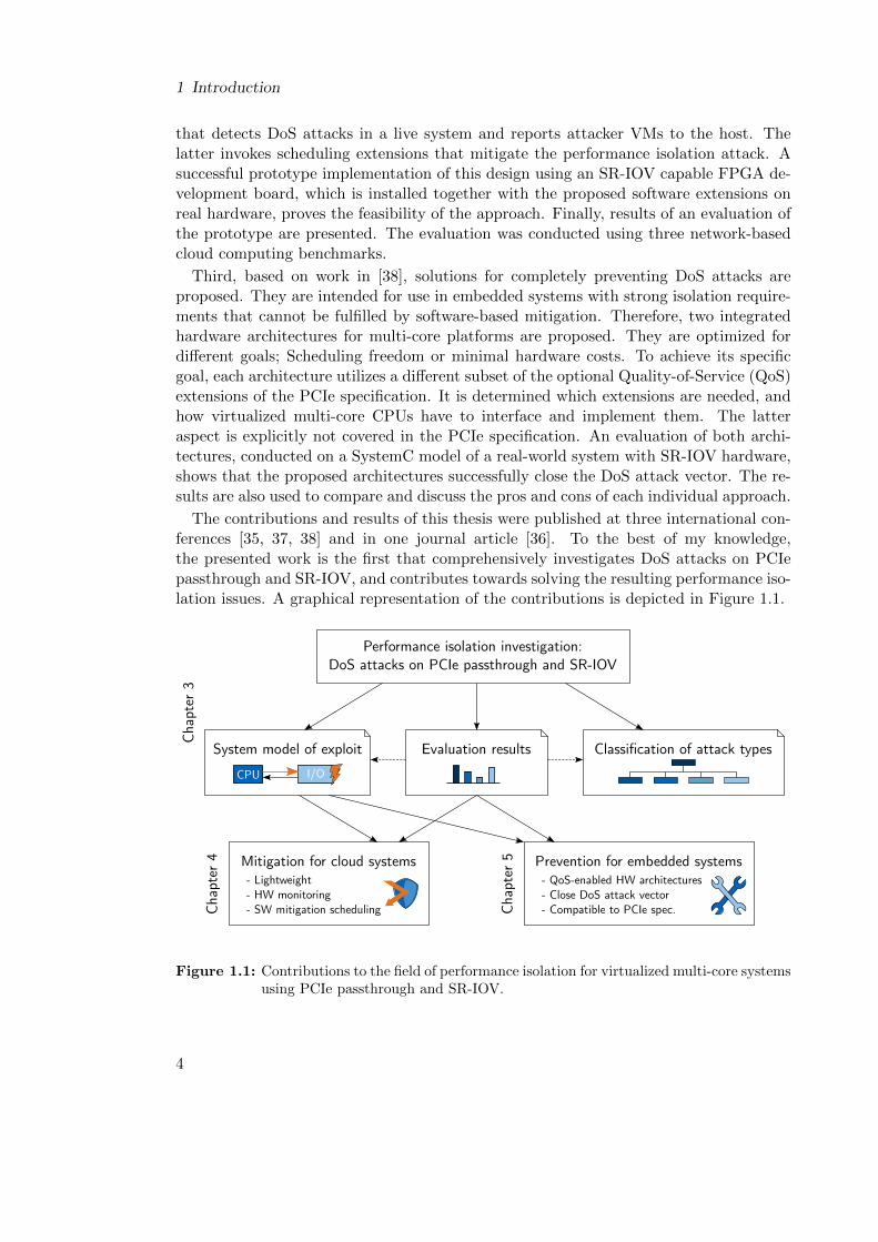
First, based on work in [35, 36], it is introduced that performance isolation of PCIepassthrough and SR-IOV can be broken with Denial-of-Service (DoS) attacks from ma-licious or buggy VMs, which flood passthrough and SR-IOV hardware with spuriousPCIe packets. Accordingly, a threat model is formulated and a sample implementationof a DoS attack is presented. Results from four experiments on a system comprised ofcommercial-off-the-shelf hardware are presented. They demonstrate that latencies andthroughput of different shared resources degrade significantly during DoS attacks onan SR-IOV capable 1 Gbit/s Ethernet NIC. Insights from the experiments are used toconstruct an abstract system model that gives a concise overview of architectural issueswithin PCIe passthrough and SR-IOV, which enable the DoS attack exploit. Further-more, a classification of DoS attacks into four types is presented, which can be used infuture work to communicate the impact and severeness of a specific DoS attack.
Second, based on work in [37], a lightweight solution that mitigates performance iso-lation attacks in cloud computing systems is proposed. The decision to follow a miti-gation approach is motivated with domain-specific requirements. A design is presentedthat extends current cloud computing systems with lightweight hardware monitoring
3
1 Introduction
that detects DoS attacks in a live system and reports attacker VMs to the host. Thelatter invokes scheduling extensions that mitigate the performance isolation attack. Asuccessful prototype implementation of this design using an SR-IOV capable FPGA de-velopment board, which is installed together with the proposed software extensions onreal hardware, proves the feasibility of the approach. Finally, results of an evaluation ofthe prototype are presented. The evaluation was conducted using three network-basedcloud computing benchmarks.
Third, based on work in [38], solutions for completely preventing DoS attacks areproposed. They are intended for use in embedded systems with strong isolation require-ments that cannot be fulfilled by software-based mitigation. Therefore, two integratedhardware architectures for multi-core platforms are proposed. They are optimized fordifferent goals; Scheduling freedom or minimal hardware costs. To achieve its specificgoal, each architecture utilizes a different subset of the optional Quality-of-Service (QoS)extensions of the PCIe specification. It is determined which extensions are needed, andhow virtualized multi-core CPUs have to interface and implement them. The latteraspect is explicitly not covered in the PCIe specification. An evaluation of both archi-tectures, conducted on a SystemC model of a real-world system with SR-IOV hardware,shows that the proposed architectures successfully close the DoS attack vector. The re-sults are also used to compare and discuss the pros and cons of each individual approach.
The contributions and results of this thesis were published at three international con-ferences [35, 37, 38] and in one journal article [36]. To the best of my knowledge,the presented work is the first that comprehensively investigates DoS attacks on PCIepassthrough and SR-IOV, and contributes towards solving the resulting performance iso-lation issues. A graphical representation of the contributions is depicted in Figure 1.1.
Performance isolation investigation:DoS attacks on PCIe passthrough and SR-IOV
Classification of attack typesEvaluation resultsSystem model of exploit
CPU I/O
Mitigation for cloud systems- Lightweight- HW monitoring- SW mitigation scheduling
Prevention for embedded systems- QoS-enabled HW architectures- Close DoS attack vector- Compatible to PCIe spec.
Cha
pter
3
Cha
pter
4
Cha
pter
5
Figure 1.1: Contributions to the field of performance isolation for virtualized multi-core systemsusing PCIe passthrough and SR-IOV.
4
1.3 Outline
1.3 Outline
The remaining part of this thesis is structured as follows: Chapter 2 provides state-of-the-art on relevant technologies and computing domains. The investigation of performanceisolation issues of PCIe passthrough and SR-IOV is presented in Chapter 3. Chapter 4introduces the lightweight hardware/software approach for mitigating performance isola-tion attacks in cloud computing systems. Performance isolation solutions for virtualizedembedded systems are presented in Chapter 5. Finally, Chapter 6 concludes this thesisby comparing and discussing all presented solutions and giving an outlook on futurework on this topic.
5

2 State of the Art
This chapter introduces the state of the art in platform virtualization and I/O perfor-mance isolation. It is structured in a top-down fashion. First, Section 2.1 presents howplatform virtualization in general enables sharing of modern multi-core hardware be-tween multiple Virtual Machines. Next, spatial isolation and performance isolation areintroduced, and the computing domains that have adopted virtualization technology arepresented. Afterwards, virtualization technologies for I/O are introduced in Sections 2.2and 2.3, together with current approaches and research results that investigate and/orimprove their performance isolation. The I/O virtualization technologies are presentedin the chronological order they surfaced: Emulation, paravirtualization and passthroughI/O with Single Root I/O Virtualization (SR-IOV).
As this thesis contributes to the latter approach (passthrough I/O), it is the mostextensively covered part in this chapter. At the time of writing, commercial off-the-shelf (COTS) passthrough I/O devices are mainly provided for the PCIe interconnect.This is a result of x86, which traditionally employs PCIe, being the dominant processorarchitecture in cloud computing, a domain in which platform virtualization was a keyenabling technology [1]. For these reasons, this thesis primarily focuses the x86 familyof processor architectures and PCIe-based I/O devices and virtualization technology.
2.1 Platform Virtualization
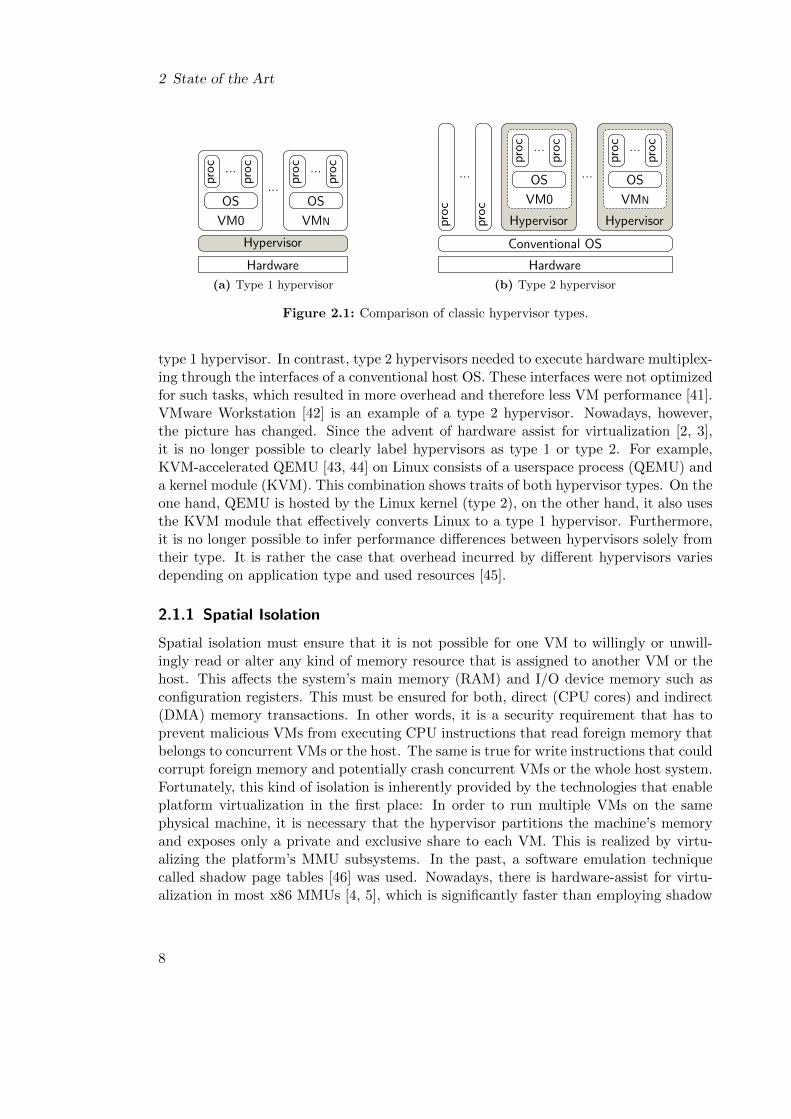
Platform virtualization enables the generation of simulated environments of real com-puter hardware. These environments are called Virtual Machines (VMs). VMs can bedynamically created and destroyed during runtime by a trusted software layer that isusually called hypervisor, or simply the host (both terms are used interchangeably in thefollowing). Correspondingly, VMs may also be called guests or guest software. InsideVMs, it is possible to execute any kind of software, including whole Operating Systems(OSs), and it is possible to host multiple VMs on the same physical hardware. Virtual-ization also offers fault isolation: Critical faults inside VMs only crash the software thatis running encapsulated inside the faulting VM; Other VMs or the host are not affected.The concept of virtualization has been around since the 1970s. At the beginning, hyper-visors were categorized into two types [39]. Type 1 hypervisors (bare metal) run directlyon physical hardware, while type 2 hypervisors (hosted) execute as userspace processeswithin a conventional OS. A block diagram of both types is depicted in Figure 2.1.
In the past, type 1 hypervisors had better overall performance because the hypervisorsoftware layer executes in kernel mode and could be specifically designed to multiplexhardware access between multiple VMs with low overhead. Xen [40] is an example of a
7
2 State of the Art
Hardware
Hypervisor
VM0
OSproc
proc...
VMN
OS
proc
proc...
...
(a) Type 1 hypervisor
Hardware
Hypervisor
VM0
OS
proc
proc...
...
proc
proc
...
Conventional OS
Hypervisor
VMN
OS
proc
proc...
(b) Type 2 hypervisor
Figure 2.1: Comparison of classic hypervisor types.
type 1 hypervisor. In contrast, type 2 hypervisors needed to execute hardware multiplex-ing through the interfaces of a conventional host OS. These interfaces were not optimizedfor such tasks, which resulted in more overhead and therefore less VM performance [41].VMware Workstation [42] is an example of a type 2 hypervisor. Nowadays, however,the picture has changed. Since the advent of hardware assist for virtualization [2, 3],it is no longer possible to clearly label hypervisors as type 1 or type 2. For example,KVM-accelerated QEMU [43, 44] on Linux consists of a userspace process (QEMU) anda kernel module (KVM). This combination shows traits of both hypervisor types. On theone hand, QEMU is hosted by the Linux kernel (type 2), on the other hand, it also usesthe KVM module that effectively converts Linux to a type 1 hypervisor. Furthermore,it is no longer possible to infer performance differences between hypervisors solely fromtheir type. It is rather the case that overhead incurred by different hypervisors variesdepending on application type and used resources [45].
2.1.1 Spatial Isolation
Spatial isolation must ensure that it is not possible for one VM to willingly or unwill-ingly read or alter any kind of memory resource that is assigned to another VM or thehost. This affects the system’s main memory (RAM) and I/O device memory such asconfiguration registers. This must be ensured for both, direct (CPU cores) and indirect(DMA) memory transactions. In other words, it is a security requirement that has toprevent malicious VMs from executing CPU instructions that read foreign memory thatbelongs to concurrent VMs or the host. The same is true for write instructions that couldcorrupt foreign memory and potentially crash concurrent VMs or the whole host system.Fortunately, this kind of isolation is inherently provided by the technologies that enableplatform virtualization in the first place: In order to run multiple VMs on the samephysical machine, it is necessary that the hypervisor partitions the machine’s memoryand exposes only a private and exclusive share to each VM. This is realized by virtu-alizing the platform’s MMU subsystems. In the past, a software emulation techniquecalled shadow page tables [46] was used. Nowadays, there is hardware-assist for virtu-alization in most x86 MMUs [4, 5], which is significantly faster than employing shadow
8
2.1 Platform Virtualization
page tables in most cases [47]. Virtualized MMUs in recent server CPUs using modernhypervisors almost reach bare metal performance, incurring less than 5% overhead [48].Hardware-assist for I/O virtualization has also been introduced for IOMMUs [49, 50].These VM-isolation properties made virtualization “the primary security mechanism intoday’s clouds“, according to [51].
2.1.2 Performance Isolation
Temporal isolation, also called performance isolation, describes the capability of a hostsystem to prevent or limit performance interference amongst VMs. It is naturally causedby time-sharing of shared resources between multiple VMs. If the sharing implemen-tation of the host lacks proper isolation or partitioning capabilities, it is possible thatthe performance of one VM degrades due to uncooperative or malicious usage of sharedresources in another VM. A prominent example is sharing the last level cache (LLC)of multi-core CPUs. If two VMs concurrently run memory intensive workloads, datafrom one VM is constantly evicted by the other, and vice versa, which results in perfor-mance interference [52, 53, 54, 55]. The problem has been solved recently by integratinghardware-assist for cache monitoring and partitioning into CPUs [17]. Similar interfer-ence effects can surface for virtualized I/O. Here, the state-of-the-art in performanceisolation will be reviewed in detail in the following Sections 2.2 and 2.3.
2.1.3 Cloud Computing
Platform virtualization was, and still is, an important enablement technology for CloudComputing [1], especially, but not exclusively, for the Infrastructure-as-a-Service (IaaS)service model. This becomes apparent from The National Institute of Standards andTechnology (NIST) definition of cloud computing [56], which defines IaaS as follows:
“ The capability provided to the consumer is to provision processing, storage,networks, and other fundamental computing resources where the consumeris able to deploy and run arbitrary software, which can include operatingsystems and applications. The consumer does not manage or control the un-derlying cloud infrastructure but has control over operating systems, storage,and deployed applications; [...] ”
Additionally, the NIST definition demands that provisioning must feature dynamic andon-demand characteristics. All of this can be conveniently realized with virtualization.Hypervisors of the cloud computing providers can dynamically generate VMs that pro-vide the consumer’s requested hardware resources (number of CPU cores, amount ofstorage, etc.), and consumer software can then be executed inside the VMs.
This model is also beneficial to the cloud computing provider itself. It enables multi-tenancy by consolidating multiple VMs onto the same physical machine through parti-tioning and sharing of hardware resources. This results in high utilization of hardware,which significantly improves efficiency. Additionally, the option to perform VM livemigration [57] facilitates fault management, load balancing and hardware maintenance,while downtimes for customers are reduced.
9
2 State of the Art
2.1.4 Embedded Virtualization
Platform virtualization technology is also seeing more and more adoption in the embed-ded computing domain. In [8], Gernot Heiser argues that the technology will help toenable future embedded systems where different sub-systems can co-exist in isolated envi-ronments, while overall system costs are reduced at the same time. He presents three usecases for embedded virtualization: (1) Consumer-electronics devices, like smartphones,where real-time environments (e.g. baseband software) are co-located with rich OSs (e.g.Android or iOS). (2) Devices with isolated environments for safety- or security-criticalcomponents, e.g. secure communication devices or medical devices. (3) Cars, where info-tainment software and automotive control and convenience functionality is consolidatedon a single Electronic Control Unit (ECU).
In fact, a virtualized phone has already been launched by Motorola [58]. Frameworksfor smartphone virtualization were also presented by VMware [59] and Lang et al. [60]. Inthe automotive domain, recent research suggests that the isolation properties of virtual-ization are a reasonable means to exploit the power of multi-core CPUs by consolidatingmultiple functions of mixed-criticalities on a shared multi-core ECU [9, 10, 11]. For in-stance, work in [12] presents the consolidation of a virtualized general purpose Androidinfotainment application and a virtualized instrument cluster application on a sharedx86 automotive ECU. Here, virtualization isolates potential faults from the untrustedAndroid application from the trusted code of the car manufacturer, which runs in the in-strument cluster application. Consolidation could also be realized with legacy functionsthat historically run on their own ECUs. In both cases, installation space, weight andcabling are reduced, and therefore overall costs are reduced and efficiency is increasedat the same time. In [61], additional benefits of virtualization for automotive embeddedsystems, besides isolated consolidation, are presented. In the avionics domain, virtual-ization is seen as a suitable approach to implement the spatial and temporal isolationrequirements of the ARINC 653 standard. Virtualization based implementations arepresented in [13, 14, 15].
In contrast to hypervisors that are employed in the server and cloud computing do-main, additional real-time and safety requirements are in place for embedded hyper-visors, which motivates the development of more specialized or extended solutions. Acomprehensive and detailed collection on the state of the art of real-time issues in em-bedded virtualization is presented by Gu et al. in [62]. The paper contains informationon the availability of commercial hypervisors for hard real-time virtualization in safety-critical systems, e.g. OpenSynergy Coqos1 or SYSGO PikeOS2, as well as work thatimproves the real-time behavior of general purpose hypervisors like Xen and KVM, e.g.RT-Xen [63]. As this thesis has a clear focus on I/O, techniques for virtualizing I/Odevices and related work on enforcing performance isolation for virtualized I/O will bepresented in the following sections.
1http://www.opensynergy.com/en/products/coqos/2https://www.sysgo.com/products/pikeos-hypervisor/
10
2.2 Software-based I/O Virtualization
2.2 Software-based I/O Virtualization
All software-based I/O virtualization techniques share the common characteristic thatI/O of VMs is, in one form or another, relayed via trusted host software. This softwareexecutes the requested I/O operations on the physical hardware on behalf of the VMs,and returns eventual results to the respective requesters. Due to the relay, the host canensure that spatial isolation is enforced, because it can check and verify each VM access.The host is also responsible for multiplexing requests from multiple VMs if a device isto be shared. In the following, the two concepts of emulation and paravirtualization forI/O are presented.
2.2.1 Emulation
Using emulation, the host is able to create a VM that emulates the existence of a certainI/O device. Generally, it is beneficial to emulate a device that is wide-spread and popularin the real-world, so that there is a high chance for out-of-the-box support by many OSsthat come into question for running as guests inside VMs. Typical examples for emulateddevices are the popular Intel e1000 or the Realtek RTL8139 family of Ethernet adapters.If the guest OS is then executed inside the VM, no further modifications are needed toenable I/O, because it already possesses a driver for this emulated version of a physicalI/O device.
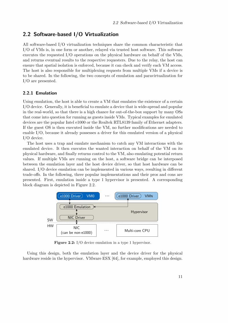
The host uses a trap and emulate mechanism to catch any VM interactions with theemulated device. It then executes the wanted interaction on behalf of the VM on itsphysical hardware, and finally returns control to the VM, also emulating potential returnvalues. If multiple VMs are running on the host, a software bridge can be interposedbetween the emulation layer and the host device driver, so that host hardware can beshared. I/O device emulation can be implemented in various ways, resulting in differenttrade-offs. In the following, three popular implementations and their pros and cons arepresented. First, emulation inside a type 1 hypervisor is presented. A correspondingblock diagram is depicted in Figure 2.2.
Hypervisor
VM0
SW
HW
...
Multi-core CPUNIC
(can be non-e1000)
e1000 Emulation
e1000 Driver VMNe1000 Driver
NIC Driver
...
Figure 2.2: I/O device emulation in a type 1 hypervisor.
Using this design, both the emulation layer and the device driver for the physicalhardware reside in the hypervisor. VMware ESX [64], for example, employed this design.
11
2 State of the Art
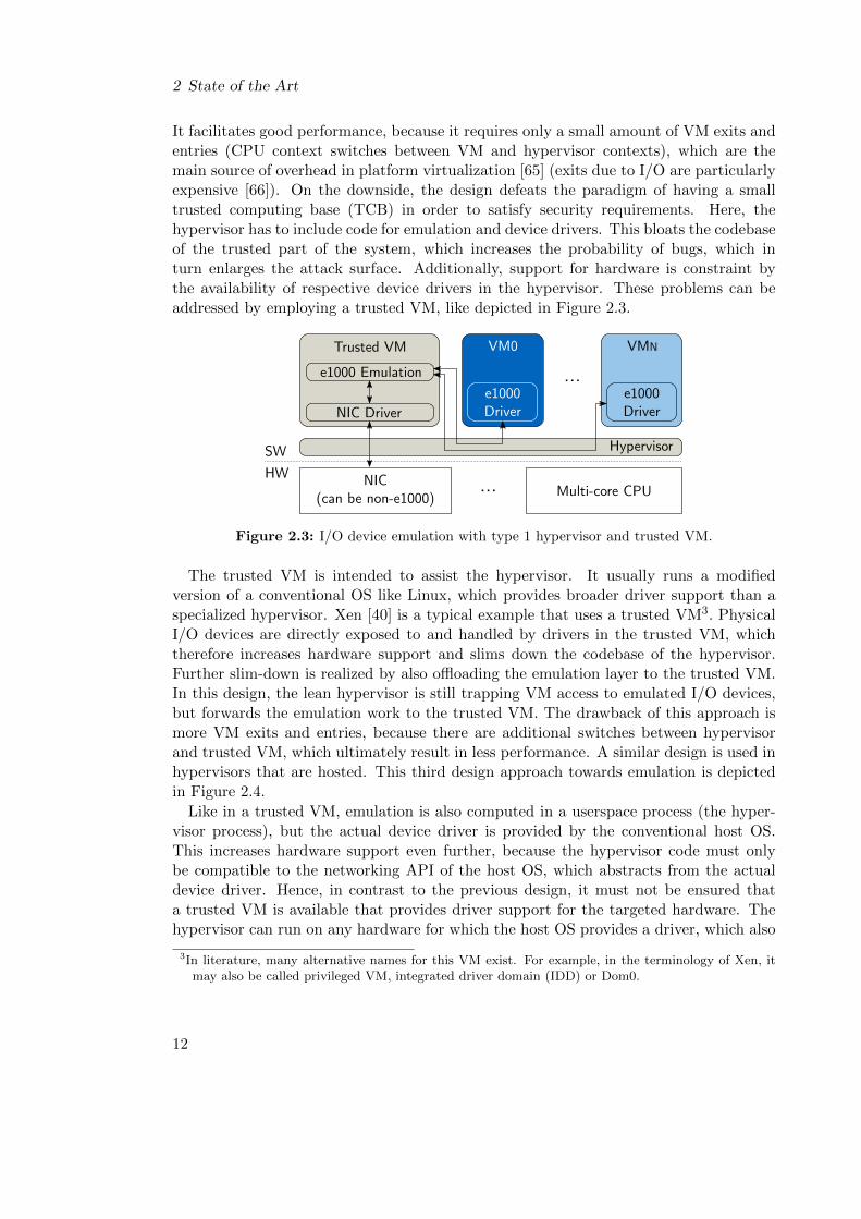
It facilitates good performance, because it requires only a small amount of VM exits andentries (CPU context switches between VM and hypervisor contexts), which are themain source of overhead in platform virtualization [65] (exits due to I/O are particularlyexpensive [66]). On the downside, the design defeats the paradigm of having a smalltrusted computing base (TCB) in order to satisfy security requirements. Here, thehypervisor has to include code for emulation and device drivers. This bloats the codebaseof the trusted part of the system, which increases the probability of bugs, which inturn enlarges the attack surface. Additionally, support for hardware is constraint bythe availability of respective device drivers in the hypervisor. These problems can beaddressed by employing a trusted VM, like depicted in Figure 2.3.
VM0
SW
HW
...
Multi-core CPUNIC
(can be non-e1000)
e1000Driver
...
Hypervisor
e1000 Emulation
NIC Driver
Trusted VM VMN
e1000Driver
Figure 2.3: I/O device emulation with type 1 hypervisor and trusted VM.
The trusted VM is intended to assist the hypervisor. It usually runs a modifiedversion of a conventional OS like Linux, which provides broader driver support than aspecialized hypervisor. Xen [40] is a typical example that uses a trusted VM3. PhysicalI/O devices are directly exposed to and handled by drivers in the trusted VM, whichtherefore increases hardware support and slims down the codebase of the hypervisor.Further slim-down is realized by also offloading the emulation layer to the trusted VM.In this design, the lean hypervisor is still trapping VM access to emulated I/O devices,but forwards the emulation work to the trusted VM. The drawback of this approach ismore VM exits and entries, because there are additional switches between hypervisorand trusted VM, which ultimately result in less performance. A similar design is used inhypervisors that are hosted. This third design approach towards emulation is depictedin Figure 2.4.
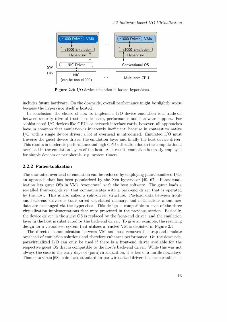
Like in a trusted VM, emulation is also computed in a userspace process (the hyper-visor process), but the actual device driver is provided by the conventional host OS.This increases hardware support even further, because the hypervisor code must onlybe compatible to the networking API of the host OS, which abstracts from the actualdevice driver. Hence, in contrast to the previous design, it must not be ensured thata trusted VM is available that provides driver support for the targeted hardware. Thehypervisor can run on any hardware for which the host OS provides a driver, which also
3In literature, many alternative names for this VM exist. For example, in the terminology of Xen, itmay also be called privileged VM, integrated driver domain (IDD) or Dom0.
12
2.2 Software-based I/O Virtualization
Conventional OSSW
HW
...
Multi-core CPUNIC
(can be non-e1000)
NIC Driver
...
Hypervisor
e1000 Emulation
VMNe1000 Driver
Hypervisor
e1000 Emulation
VM0e1000 Driver
Figure 2.4: I/O device emulation in hosted hypervisors.
includes future hardware. On the downside, overall performance might be slightly worsebecause the hypervisor itself is hosted.
In conclusion, the choice of how to implement I/O device emulation is a trade-offbetween security (size of trusted code base), performance and hardware support. Forsophisticated I/O devices like GPUs or network interface cards, however, all approacheshave in common that emulation is inherently inefficient, because in contrast to nativeI/O with a single device driver, a lot of overhead is introduced. Emulated I/O musttraverse the guest device driver, the emulation layer and finally the host device driver.This results in moderate performance and high CPU utilization due to the computationaloverhead in the emulation layers of the host. As a result, emulation is mostly employedfor simple devices or peripherals, e.g. system timers.
2.2.2 Paravirtualization
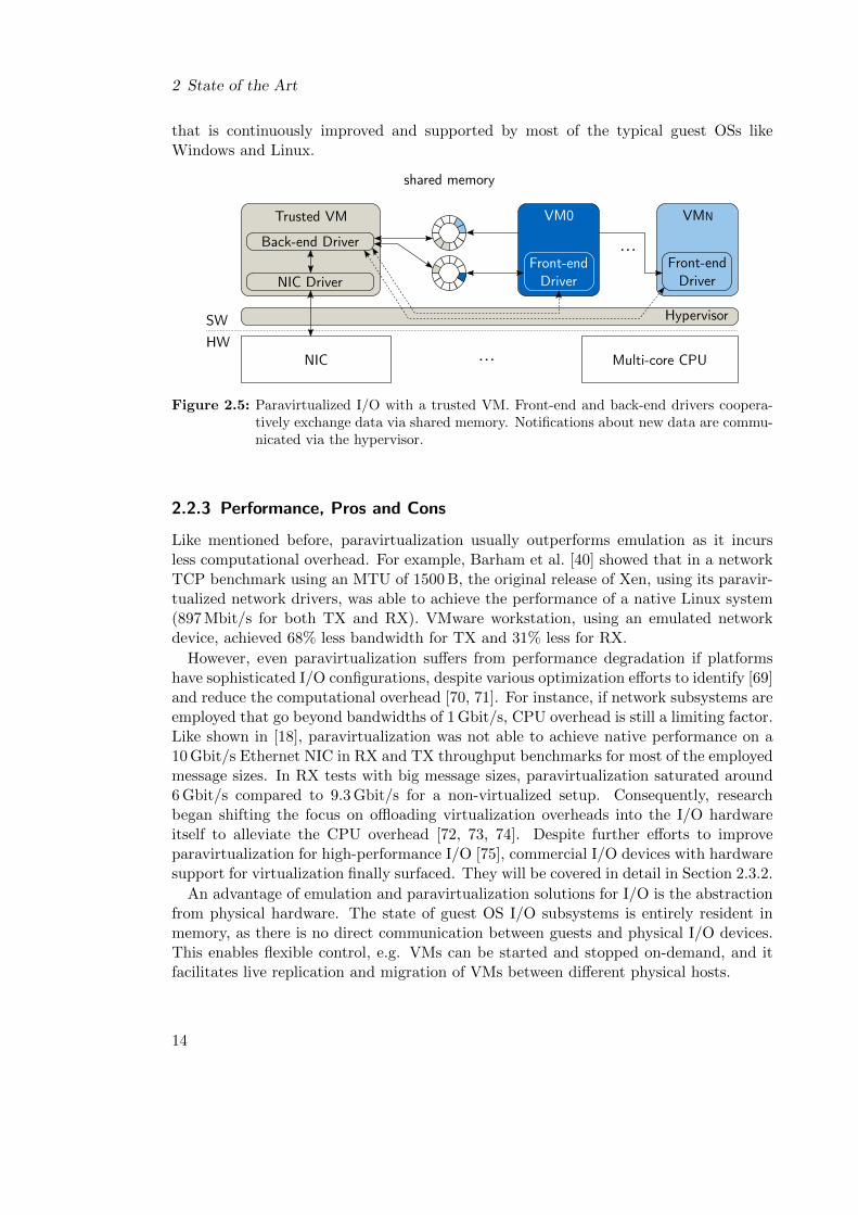
The unwanted overhead of emulation can be reduced by employing paravirtualized I/O,an approach that has been popularized by the Xen hypervisor [40, 67]. Paravirtual-ization lets guest OSs in VMs “cooperate” with the host software. The guest loads aso-called front-end driver that communicates with a back-end driver that is operatedby the host. This is also called a split-driver structure. Payload data between front-and back-end drivers is transported via shared memory, and notifications about newdata are exchanged via the hypervisor. This design is compatible to each of the threevirtualization implementations that were presented in the previous section. Basically,the device driver in the guest OS is replaced by the front-end driver, and the emulationlayer in the host is substituted by the back-end driver. To give an example, the resultingdesign for a virtualized system that utilizes a trusted VM is depicted in Figure 2.5.
The directed communication between VM and host removes the trap-and-emulateoverhead of emulation solutions and therefore enhances performance. On the downside,paravirtualized I/O can only be used if there is a front-end driver available for therespective guest OS that is compatible to the host’s back-end driver. While this was notalways the case in the early days of (para)virtualization, it is less of a hurdle nowadays.Thanks to virtio [68], a de-facto standard for paravirtualized drivers has been established
13
2 State of the Art
that is continuously improved and supported by most of the typical guest OSs likeWindows and Linux.
SW
HW
...
Multi-core CPUNIC ...
Hypervisor
Back-end Driver
NIC Driver
Trusted VM VMN
Front-endDriver
shared memory
VM0
Front-endDriver
Figure 2.5: Paravirtualized I/O with a trusted VM. Front-end and back-end drivers coopera-tively exchange data via shared memory. Notifications about new data are commu-nicated via the hypervisor.
2.2.3 Performance, Pros and Cons
Like mentioned before, paravirtualization usually outperforms emulation as it incursless computational overhead. For example, Barham et al. [40] showed that in a networkTCP benchmark using an MTU of 1500 B, the original release of Xen, using its paravir-tualized network drivers, was able to achieve the performance of a native Linux system(897 Mbit/s for both TX and RX). VMware workstation, using an emulated networkdevice, achieved 68% less bandwidth for TX and 31% less for RX.
However, even paravirtualization suffers from performance degradation if platformshave sophisticated I/O configurations, despite various optimization efforts to identify [69]and reduce the computational overhead [70, 71]. For instance, if network subsystems areemployed that go beyond bandwidths of 1 Gbit/s, CPU overhead is still a limiting factor.Like shown in [18], paravirtualization was not able to achieve native performance on a10 Gbit/s Ethernet NIC in RX and TX throughput benchmarks for most of the employedmessage sizes. In RX tests with big message sizes, paravirtualization saturated around6 Gbit/s compared to 9.3 Gbit/s for a non-virtualized setup. Consequently, researchbegan shifting the focus on offloading virtualization overheads into the I/O hardwareitself to alleviate the CPU overhead [72, 73, 74]. Despite further efforts to improveparavirtualization for high-performance I/O [75], commercial I/O devices with hardwaresupport for virtualization finally surfaced. They will be covered in detail in Section 2.3.2.
An advantage of emulation and paravirtualization solutions for I/O is the abstractionfrom physical hardware. The state of guest OS I/O subsystems is entirely resident inmemory, as there is no direct communication between guests and physical I/O devices.This enables flexible control, e.g. VMs can be started and stopped on-demand, and itfacilitates live replication and migration of VMs between different physical hosts.
14
2.2 Software-based I/O Virtualization
2.2.4 Performance Isolation Approaches
Performance isolation for software-based I/O virtualization has been an active field ofresearch ever since. Many studies focused on investigating performance interference ef-fects between VMs that were running multiple diverse workloads or benchmarks, andtherefore covered software-based I/O virtualization at least partially. Koh et al. [6] uti-lized an instrumented Xen to run a range of benchmarks, i.a. disk I/O workloads, in twoVMs and collected performance metrics and runtime characteristics. They used the datato clusterize applications that generate certain performance interferences and developedmathematical models that predict application performance. Matthews et al. [7] designeda performance isolation benchmark that measures the impact of misbehaving VMs onconcurrent VMs. The benchmark stresses different components like CPU, memory, diskand network I/O. They conducted their benchmarks on multiple virtualization solutionsthat also contained Xen and VMware Workstation. Further studies that cover perfor-mance isolation of software-based I/O virtualization can be found in [21, 22, 23, 24].
Effort also went into enhancing scheduling of the host or developing VM placementstrategies in order to improve performance isolation of VMs. Gupta et al. [25, 26] wereamong the first to investigate this topic. They extended Xen such that it was possibleto measure CPU time that is spent in the host for processing I/O on behalf of a guest.This time is added to the actual CPU time that a guest is consuming. The overalltime is then accounted for by a new VM scheduler, which resulted in enhanced I/Ofairness and better overall performance isolation. Govindan et al. [27] developed a CPUscheduling algorithm for the host that takes the I/O behavior of VMs into accountfor its decision-making. Using their scheduling extensions, a streaming media serverwas enabled to serve 3.5 times more clients than before, and response times could beboosted by 35%. Additional work on host scheduling optimizations and VM placementis presented in [30, 28, 29, 31, 32].
There is also previous work that researched malicious workloads inside VMs, whichis one of the main topics of this thesis. Malicious workloads differ from “standard”workloads in the sense that they do not necessarily try to get the best performance forthemselves by disregarding others, but deliberately try to degrade the performance fromother concurrent VMs without any benefits of their own. Yang et al. [33] presented aperformance measurement and analysis framework for virtualized I/O. It can be usedto gain insight about hypervisor I/O scheduling and leverage the information to carryout disk I/O performance degradation attacks on concurrent VMs. The attacks weresuccessful on local testbeds as well as on Amazon EC2 cloud instances. Chiang et al. [34]demonstrated a similar attacker framework for EC2 that targets network I/O instead.
Although this thesis covers performance isolation issues, the presented approaches toincrease isolation could not be transferred. This is because this thesis covers hardware-instead of software-based I/O virtualization. In hardware-based I/O virtualization, VMsdirectly communicate with I/O hardware, and go unnoticed by the host. Hence, thereis no relaying layer in the host (emulation software or back-end driver) that can beleveraged for insight into I/O consumption, attack detection or fairer scheduling. In thefollowing section, these differences will be introduced in detail.
15
2 State of the Art
2.3 Hardware-based I/O Virtualization: Passthrough I/O withPCIe and SR-IOV
Passthrough I/O, in contrast to emulation and paravirtualization, directly assigns phys-ical I/O devices to VMs. Direct assignment means that memory regions of I/O devicesand VMs are directly exposed to each other, so that both communicate in a directmanner and not via software-based emulation- or paravirtualization-interfaces. In otherwords, the I/O device passes through the host and directly connects to a VM. Removingthe emulation- and paravirtualization software layers results in near-native I/O perfor-mance, e.g. for 1 Gbit/s Ethernet NICs [76], while significantly cutting CPU overheadat the same time. In conclusion, passthrough provides superior I/O performance withrespect to emulation and paravirtualization by giving VMs direct access to dedicatedphysical I/O devices.
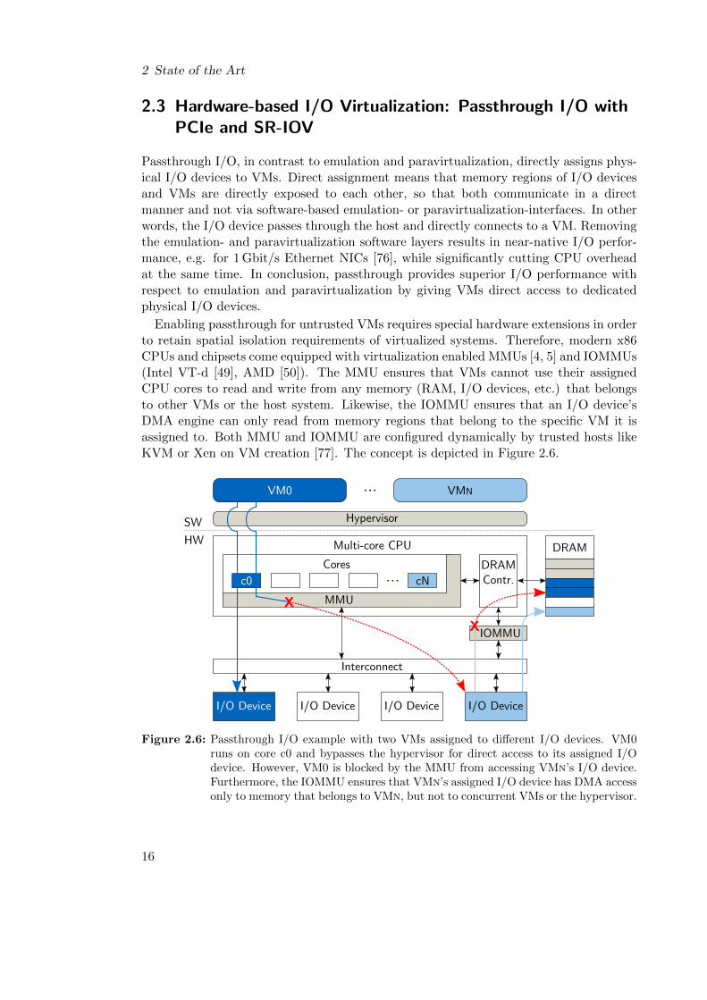
Enabling passthrough for untrusted VMs requires special hardware extensions in orderto retain spatial isolation requirements of virtualized systems. Therefore, modern x86CPUs and chipsets come equipped with virtualization enabled MMUs [4, 5] and IOMMUs(Intel VT-d [49], AMD [50]). The MMU ensures that VMs cannot use their assignedCPU cores to read and write from any memory (RAM, I/O devices, etc.) that belongsto other VMs or the host system. Likewise, the IOMMU ensures that an I/O device’sDMA engine can only read from memory regions that belong to the specific VM it isassigned to. Both MMU and IOMMU are configured dynamically by trusted hosts likeKVM or Xen on VM creation [77]. The concept is depicted in Figure 2.6.
Hypervisor
VM0 VMN
SW
HW
Coresc0 C1 C2 cN
Interconnect
DRAMContr.
MMU
Multi-core CPU DRAM
IOMMU
I/O Device I/O DeviceI/O Device I/O Device
X
X
...C2
...
Figure 2.6: Passthrough I/O example with two VMs assigned to different I/O devices. VM0runs on core c0 and bypasses the hypervisor for direct access to its assigned I/Odevice. However, VM0 is blocked by the MMU from accessing VMn’s I/O device.Furthermore, the IOMMU ensures that VMn’s assigned I/O device has DMA accessonly to memory that belongs to VMn, but not to concurrent VMs or the hypervisor.
16
2.3 Hardware-based I/O Virtualization: Passthrough I/O with PCIe and SR-IOV
As mentioned initially in this chapter, COTS passthrough I/O devices are mainlyprovided for x86 architecture platforms that utilize the PCIe interconnect. For thisreason, the PCIe characteristics that are relevant to this thesis shall be briefly introducedin the following.
2.3.1 PCI Express (PCIe)
PCIe [78] is a high-speed serial interconnect that replaced the older PCI [79] andPCI-X [80] busses. The PCIe specifications comprise hundreds of pages describing thecore technology, as well as optional extensions and concepts for achieving backward com-patibility with legacy PCI. As a consequence, the following introduction will only coverthe respective parts that are necessary for understanding the PCIe related parts of thisthesis. Also, sometimes an abstracted high-level view is presented if a focus on conceptsis more important than actual details of the technical specification.
2.3.1.1 Topology
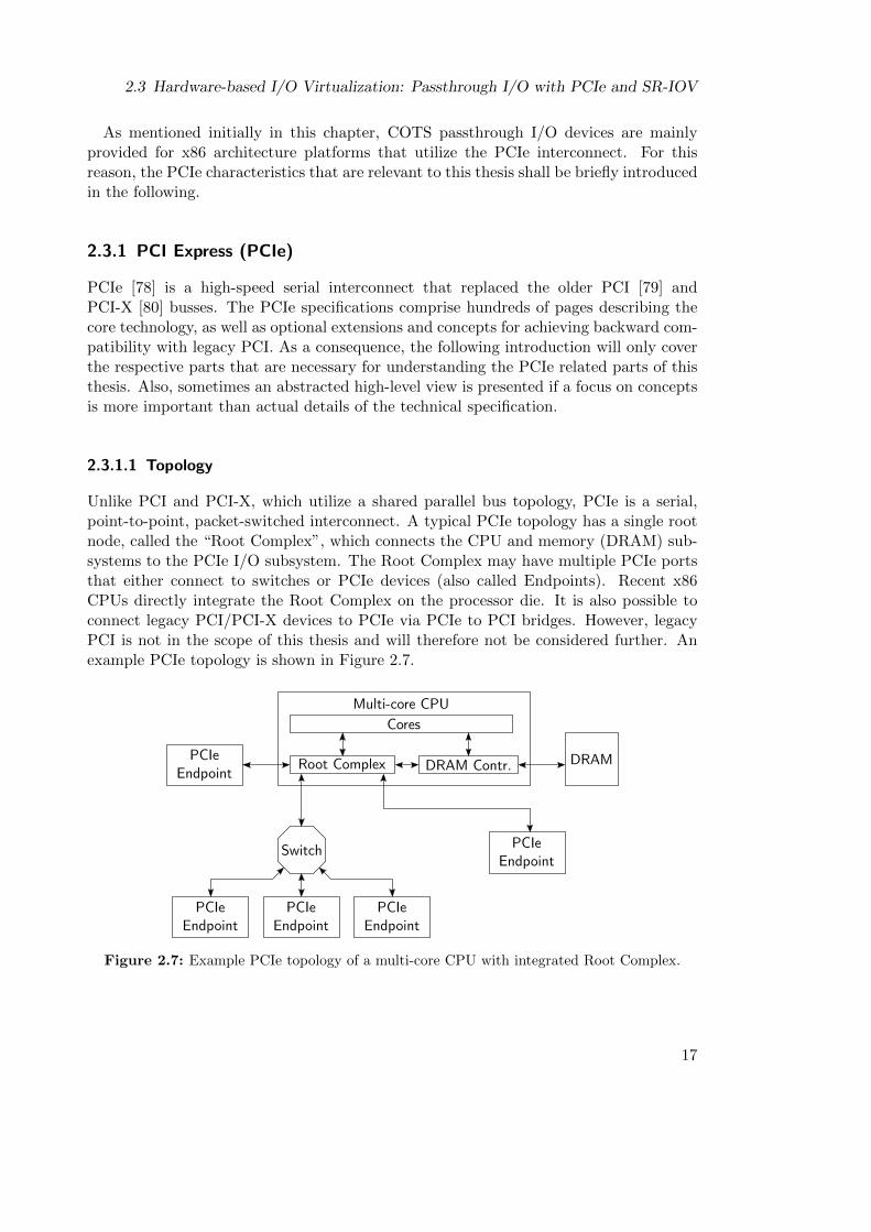
Unlike PCI and PCI-X, which utilize a shared parallel bus topology, PCIe is a serial,point-to-point, packet-switched interconnect. A typical PCIe topology has a single rootnode, called the “Root Complex”, which connects the CPU and memory (DRAM) sub-systems to the PCIe I/O subsystem. The Root Complex may have multiple PCIe portsthat either connect to switches or PCIe devices (also called Endpoints). Recent x86CPUs directly integrate the Root Complex on the processor die. It is also possible toconnect legacy PCI/PCI-X devices to PCIe via PCIe to PCI bridges. However, legacyPCI is not in the scope of this thesis and will therefore not be considered further. Anexample PCIe topology is shown in Figure 2.7.
Root Complex DRAM Contr.
Multi-core CPU
DRAMPCIeEndpoint
Cores
PCIeEndpoint
PCIeEndpoint
Switch
PCIeEndpoint
PCIeEndpoint
Figure 2.7: Example PCIe topology of a multi-core CPU with integrated Root Complex.
17
2 State of the Art
2.3.1.2 Link Parameters and Bit Rates
The communications channel between two PCIe components is called a link. A link hasthree parameters that define its actual net bit rate. First, each link has a number oflanes, which indicate the number of physical signal pairs between two PCIe components.The PCIe specification denotes the number of lanes by xN. For example, x16 means thelink supports 16 lanes. Second, each lane has a physical layer gross bit rate (Rb), whichis given in so-called GigaTransfers per second (GT/s). The supported bit rate dependson the PCIe version that the respective hardware implements. Third, each PCIe versionuses a specific encoding for transfers on the physical layer. An overview of supportedparameters depending on PCIe version is given in Table 2.1.
Table 2.1: Performance parameters by PCIe version.
PCIe version Rb (GT/s) Encoding
1.0 2.5 8b/10b
2.0 5 8b/10b
3.0 8 128b/130b
Please note that newer PCIe versions are backwards compatible in terms of speed.For example, a PCIe 3.0 slot can still operate at 2.5 GT/s with an encoding of 8b/10b ifa PCIe 1.0 device is installed in it. Given all three parameters, it is possible to calculatethe physical layer net bit rate (Rnet). For instance, Rnet of an x16 link with 8 GT/susing 128b/130b encoding is computed as follows:
Rnet = 16 · 8 GT
s· 128
130= 126
Gbit
s= 15.75
GB
s.
2.3.1.3 PCIe Functions, Memory Mapped I/O and Drivers
Although physical PCIe components like Endpoints are connected by a single link, thestandard allows to partition components into multiple so-called PCIe functions. Eachindividual function is independently addressable by other system components like CPUcores. Therefore, each function must first be mapped into the system’s memory map, atask that is usually executed during system boot by firmware or the OS. For instance, inx86 based systems, memory mapping is done by the BIOS. Each PCIe function requestsmemory resources from the BIOS, which reserves a respective address range in the sys-tem’s memory map. Afterwards, the BIOS reports back to each function and notifiesit which address range it got. This way, it is possible for a function to determine if itis the destination of an inbound PCIe packet by comparing the packet’s target addresswith its assigned address range.
As soon as all PCIe functions are mapped, they are ready to receive CPU-to-PCIetransactions. If the destination address of a CPU core’s machine instruction translatesto a PCIe function address, a respective packet is compiled and put on the PCIe in-terconnect. This method for performing I/O operations is called Memory Mapped I/O
18
2.3 Hardware-based I/O Virtualization: Passthrough I/O with PCIe and SR-IOV
(MMIO). It enables the system to consolidate both DRAM and I/O device addressesinto a single memory map. As a consequence, the CPU can use the same machine in-structions for both MMIO and DRAM transactions, which speeds up I/O transactionsand simplifies device driver writing. PCIe devices that support Direct Memory Access(DMA) utilize the same system memory map, which means they can read from DRAMas well as other PCIe devices that are mapped via MMIO.
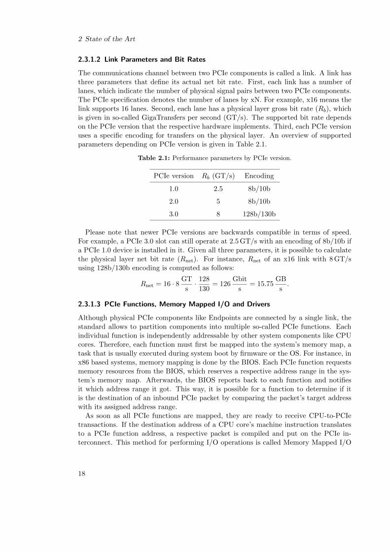
Common examples for real-world multi-function PCIe devices are multi-port NICs,e.g. Ethernet or InfiniBand NICs. Such a NIC’s function address range is used bysystem software to interface to the hardware resources needed for operating a singlephysical NIC port. Usually, it is an OS device driver that interfaces to PCIe functions.The device driver first requests the function’s base address, aka the first address of thefunction in the system memory map. Afterwards, it can access different resources ofthe function (e.g. registers, FIFOs, etc.) by adding an offset to the base address. Aper-function assignment of offsets to resources is known to the programmer of the devicedriver, usually by consulting the device’s datasheet. Most of the time, device driversare written for single PCIe functions, not for the whole device. For example, if a deviceprovides multiple identical functions, Linux loads multiple instances of the same driver,but supplies different base addresses (aka PCIe functions) to each driver instance.
The PCIe specification allows for up to eight functions per PCIe device, except for de-vices supporting an optional PCIe capability called Alternative Routing-ID Interpreation(ARI), which adds support for up to 256 functions. Of course it is in the responsibilityof the PCIe device designers and engineers to choose link parameters that satisfy thecombined net bit rate demands of all provided PCIe functions (see Section 2.3.1.2). Asummary of this section using the example of a multi-port Ethernet NIC is depicted inFigure 2.8.
eth0
func0 funcN...
... ethN
PCIe Port
Mul
ti-p
ort
NIC
Upstream PCIe PortSystem Memory Map
func0
funcN
0x0...1000
0x0...1000 + N · 0x2000
......
...
0x0...2000
Figure 2.8: A multi-function PCIe Endpoint using the example of a multi-port Ethernet NIC.Each device function requests 8 KiB of memory and is assigned a respective addressrange in the system’s memory map.
Thanks to the representation of PCIe functions as address ranges in the system mem-ory map, it is possible to do passthrough I/O at function granularity. The host realizesthis by directly mapping PCIe function address ranges into a VM’s virtual address space.
19
2 State of the Art
2.3.1.4 Transaction Characteristics and Flow Control
As mentioned in 2.3.1, single PCIe transactions are sent via packets. Read transactionsare so called non-posted requests, which means that the reader has to wait for a com-pletion packet from the target that contains the requested data word. For instance, aCPU core would block on the machine instruction that reads from a PCIe device untilthe completion is received. In contrast, write transactions are classified as posted re-quests. Here, program execution can continue as soon as the write packet has been sentto its first downstream stop; write packets are not completed, aka acknowledged, by thereceiver.
PCIe also incorporates hardware flow control mechanisms, which ensure that PCIepackets are sent out only if a free downstream buffer slot is available. For instance, if aCPU core wants to execute a write instruction to PCIe memory, but backpressure fromflow control signals zero available buffers, the core would block on the write instructionuntil a downstream buffer slot is freed.
2.3.2 PCIe Single Root I/O Virtulization (SR-IOV)
While passthrough I/O offers near-native performance, it has limitations in terms ofscalability. Even on machines with moderate VM count, hardware costs quickly getexpensive if one full-blown passthrough device per VM is needed. However, in contrastto emulation or paravirtualization, there is no possibility to share a physical I/O devicebetween multiple VMs with passthrough. This is because a trusted software intermediarylike a hypervisor, that would be able to multiplex single I/O devices between multipleVMs, has deliberately been removed in the first place in order to enable the performancebenefits of passthrough.
For combining both traits, (1) the performance of direct access via passthrough and(2) sharing a device’s physical function, research has suggested self-virtualizing I/Odevices [73, 74]. The idea was to overcome the performance penalties of software-basedI/O virtualization and sharing routines [69] by offloading them into the I/O devicehardware. This way, self-virtualizing devices can offer multiple virtual interfaces perphysical device function, which are enabled by hardware-accelerated I/O virtualizationand sharing.
In line with these ideas, the Single Root I/O Virtualization and Sharing Specification(SR-IOV) [81] was released by the PCI Special Interest Group (PCI-SIG). It is specifiedfor PCIe topologies that utilize a single Root Complex. There is also MR-IOV, a speci-fication for topologies with multiple Root Complexes [82]. However, this thesis will notspecifically cover MR-IOV, because the technology is not widely used yet and the topicsaddressed in this thesis are mostly agnostic of the topology being single or multi-root.
2.3.2.1 Physical and Virtual Functions
Devices supporting SR-IOV provide at least one PCIe function (see 2.3.1.3) that supportsthe SR-IOV capability. Such functions are called Physical Functions (PFs) and they areintended to be controlled by the trusted host. Through the PF interface, it is possible
20

2.3 Hardware-based I/O Virtualization: Passthrough I/O with PCIe and SR-IOV
to dynamically spawn multiple “light-weight” PCIe functions, called Virtual Functions(VFs) in SR-IOV terms. VFs share physical resources with their co-created VFs andthe PF. The maximum number of supported VFs per PF depends on the capabilitiesand hardware implementation of the actual PCIe device.
From the system’s point of view, there is no difference between classic PCIe functions,PFs and VFs. Just like classic functions, there is a reserved address range in the sys-tem’s memory map for each VF (compare Figure 2.8). Hence, VFs are automaticallycompatible with PCIe passthrough and are therefore protected by hardware-enforcedspatial isolation via MMU and IOMMU. Manufacturers or vendors of SR-IOV devicesusually supply special VF drivers for usage in VMs. VF drivers are more light-weightthan classic drivers, because they can spare most control plane functionality for admin-istering the physical hardware, a task which is reserved to host and its PF driver. Thehost also decides which VMs share physical hardware by attaching VMs to VFs that areassociated with the same PF. A summary of the concepts described in this section isdepicted in the block diagram in Figure 2.9.
HypervisorSW
HW
Cores DRAMContr.
MMU
Multi-core CPU
DRAM
port0PCIe Root Complex
IOMMUport1 portN...
VM0 VMN
c0 cN...
eth0
Dua
l-por
tSR
-IO
V N
IC VF0.0
VF0.X
...
PF0
VF1.0
VF1.X
...
PF1
eth1
VM1 ...
c1
... LegacyPCIe
Device
func0
Figure 2.9: SR-IOV enables virtualization and sharing of physical resources like Ethernet portsbetween multiple VMs. In this example, VM0 and VM1 share NIC port eth0.
This example shows an SR-IOV capable dual-port Ethernet NIC. The physical portseth0 and eth1 are associated with PF0 and PF1, respectively. They are administered bythe hypervisor and used to spawn up to X VFs per PF. VM0, which runs on core c0, haspassthrough access to VF0.0, the first VF of PF0. VM1, which runs on a separate core,is attached to VF0.X, which means that VM1 shares Ethernet port eth0 with VM0. Forinstance, if VM0 and VM1 would both execute the same networking benchmark with the
21

2 State of the Art
same parameters at the same time, then each VM would achieve 50% of eth0’s maximumperformance, respectively. VMn, in contrast, is attached to VF1.0, which is associatedwith a different PF. It is therefore not affected by the network usage of concurrent VM0or VM1.
2.3.2.2 Adoption
Being an extension to PCIe, the prevalent interconnect in x86 systems, SR-IOV has beenendorsed quickly by hardware manufacturers. Thus, commercial off-the-shelf (COTS)devices supporting the technology were available after only a short period of time. Atthe time of writing, Ethernet adapters made up a large part of available SR-IOV hard-ware. However, other I/O classes or subclasses are catching up recently: In [83], anInfiniBand adapter supporting SR-IOV is evaluated. Recent revisions of the NVM Ex-press specification [84], which specifies a PCIe based interface to non-volatile storagelike Solid-State Drives (SSDs), includes support for SR-IOV; Implementation details arepresented in [85]. Additionally, the first Graphics Processing Unit (GPU) with SR-IOVsupport has been announced recently [86].
SR-IOV hardware has already been adopted by cloud computing providers. For exam-ple, Amazon offers optional SR-IOV networking for their Elastic Compute Cloud (EC2)instances, where it is termed as “enhanced networking”. On Amazon’s website, SR-IOVis advertised for providing “higher bandwidth, higher packet per second (PPS) perfor-mance, and consistently lower inter-instance latencies” [87]. The Oracle Exalogic ElasticCloud incorporates SR-IOV capable InfiniBand adapters, which can be shared by up to63 VMs [88]. Additionally, SR-IOV is considered as an enabler for virtualization in HighPerformance Computing (HPC) [89, 90].
Recently, SR-IOV also started getting attention in the embedded virtualization do-main. Herber et al. [91] presented a self-virtualizing CAN controller based on SR-IOV. Itis intended for use in future automotive ECUs, which consolidate the software of multiplelegacy single-core ECUs on a single multi-core ECU using virtualization. In [92, 93, 94],concepts are presented that leverage SR-IOV’s partitioning and isolation capabilities toshare and separate access to FPGA-based reconfigurable coprocessors in heterogeneousmixed-criticality multi-core systems. Using SR-IOV for the coprocessors also provideslower overhead than software based virtualization solutions [95]. Both concepts, SR-IOV enabled CAN controllers and coprocessors, were also consolidated into a virtualizedautomotive ECU demonstrator platform [12]. The ECU was running a general pur-pose Android infotainment application and an instrument cluster application, with bothhaving access to SR-IOV enabled CAN and coprocessors.
For the avionics domain, Munch et al. [96] evaluated SR-IOV for mixed-criticality real-time systems, and concluded that SR-IOV is a promising approach for future systems ifcertain criteria are met. Their utilized evaluation platform, a Freescale P4080, however,did not meet the criteria to distinguish PCIe devices at function granularity, but theproblem can be solved by an approach that is presented [97].
22
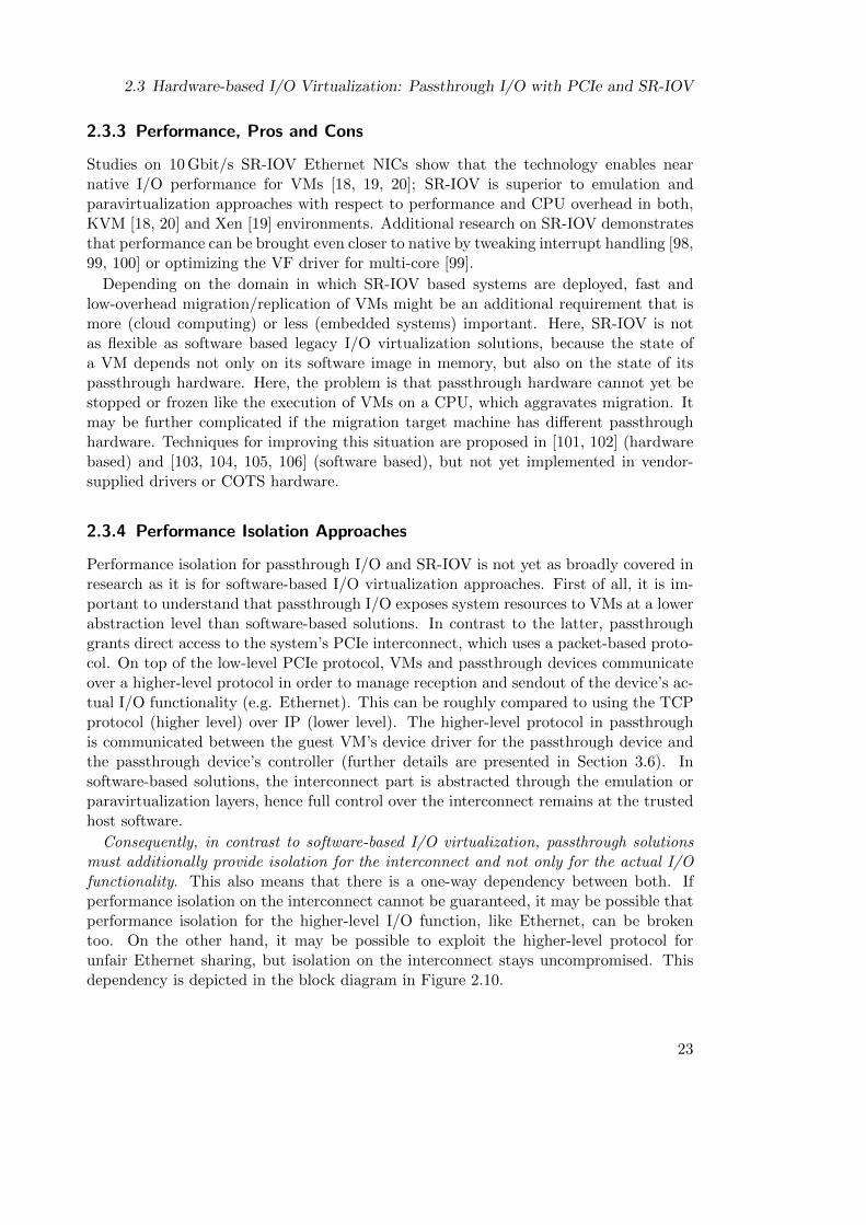
2.3 Hardware-based I/O Virtualization: Passthrough I/O with PCIe and SR-IOV
2.3.3 Performance, Pros and Cons
Studies on 10 Gbit/s SR-IOV Ethernet NICs show that the technology enables nearnative I/O performance for VMs [18, 19, 20]; SR-IOV is superior to emulation andparavirtualization approaches with respect to performance and CPU overhead in both,KVM [18, 20] and Xen [19] environments. Additional research on SR-IOV demonstratesthat performance can be brought even closer to native by tweaking interrupt handling [98,99, 100] or optimizing the VF driver for multi-core [99].
Depending on the domain in which SR-IOV based systems are deployed, fast andlow-overhead migration/replication of VMs might be an additional requirement that ismore (cloud computing) or less (embedded systems) important. Here, SR-IOV is notas flexible as software based legacy I/O virtualization solutions, because the state ofa VM depends not only on its software image in memory, but also on the state of itspassthrough hardware. Here, the problem is that passthrough hardware cannot yet bestopped or frozen like the execution of VMs on a CPU, which aggravates migration. Itmay be further complicated if the migration target machine has different passthroughhardware. Techniques for improving this situation are proposed in [101, 102] (hardwarebased) and [103, 104, 105, 106] (software based), but not yet implemented in vendor-supplied drivers or COTS hardware.
2.3.4 Performance Isolation Approaches
Performance isolation for passthrough I/O and SR-IOV is not yet as broadly covered inresearch as it is for software-based I/O virtualization approaches. First of all, it is im-portant to understand that passthrough I/O exposes system resources to VMs at a lowerabstraction level than software-based solutions. In contrast to the latter, passthroughgrants direct access to the system’s PCIe interconnect, which uses a packet-based proto-col. On top of the low-level PCIe protocol, VMs and passthrough devices communicateover a higher-level protocol in order to manage reception and sendout of the device’s ac-tual I/O functionality (e.g. Ethernet). This can be roughly compared to using the TCPprotocol (higher level) over IP (lower level). The higher-level protocol in passthroughis communicated between the guest VM’s device driver for the passthrough device andthe passthrough device’s controller (further details are presented in Section 3.6). Insoftware-based solutions, the interconnect part is abstracted through the emulation orparavirtualization layers, hence full control over the interconnect remains at the trustedhost software.
Consequently, in contrast to software-based I/O virtualization, passthrough solutionsmust additionally provide isolation for the interconnect and not only for the actual I/Ofunctionality. This also means that there is a one-way dependency between both. Ifperformance isolation on the interconnect cannot be guaranteed, it may be possible thatperformance isolation for the higher-level I/O function, like Ethernet, can be brokentoo. On the other hand, it may be possible to exploit the higher-level protocol forunfair Ethernet sharing, but isolation on the interconnect stays uncompromised. Thisdependency is depicted in the block diagram in Figure 2.10.
23
2 State of the Art
eth0
PCIe Port
buffers
SR-IOV Controller
Upstream
Interconnect part
I/O functionality part
Figure 2.10: Dependency between interconnect and actual I/O functionality. If performanceisolation on the interconnect cannot be guaranteed, it may be possible that isola-tion for the higher level I/O function, like Ethernet, can be broken too.
In one of the first papers about an SR-IOV capable COTS Ethernet NIC, Dong etal. [107] listed an outlook of possible attack types on VFs by malicious VMs, among themDenial-of-Service attacks with spurious messages. However, they only mentioned theirtheoretical possibility. They did not explicitly define what kind of messages would have tobe used. They provided first thoughts of how countermeasures could be designed, but nofurther insights like an actual architecture or evaluation on real hardware were provided.In this thesis, DoS attacks are for the first time implemented, thoroughly investigatedon COTS SR-IOV hardware, evaluated, and mitigation and protection approaches arepresented.
For their actual I/O functionality, controllers in COTS SR-IOV devices usually imple-ment QoS features that that enforce performance isolation. For instance, the 82576 [108]and i350 [109] 1 Gbit/s SR-IOV capable Ethernet controllers provide QoS for servicingthe TX path of their Ethernet ports. Multiple VMs are either fairly arbitrated usinga (weighted) round-robin scheme, or bandwidth can be partitioned arbitrarily betweendifferent VMs through the PF driver of the host. Similar functionality was presented forthe self-virtualized SR-IOV CAN controller of Herber et al. [110]. They use a time-basedweighted round-robin scheme for arbitration between different virtual CAN controllers.Work in this thesis instead focuses on performance isolation for the interconnect part.The results can be combined with the before mentioned approaches to provide perva-sive performance isolation for both the interconnect and the actual I/O functionality ofpassthrough I/O devices.
Previous work on performance isolation for cache and memory subsystems focused onutilizing CPU-resident hardware performance counters to monitor access of individualcores or processes to the shared resources. On misuse or overextension, specifically de-signed scheduling mechanisms are responsible for enforcing isolation. Research was con-ducted for systems of the cloud computing [52, 53, 54] and real-time [111, 112] domain.Work presented in this thesis investigated if this approach is transferable to performanceisolation for passthrough I/O and SR-IOV. The thesis will conclude that scheduling canbe used to mitigate DoS attacks on passthrough I/O and SR-IOV. However, counters in
24
2.3 Hardware-based I/O Virtualization: Passthrough I/O with PCIe and SR-IOV
current CPUs lack needed granularity. They must therefore either be extended accord-ingly, or future passthrough I/O devices must employ respective monitoring facilities inthe I/O devices themselves.
In [113], Bettie et al. present FPGA-based hardware real-time bridges, which areinterposed between the host system’s CPU and the I/O device. Performance isolation isenforced by a real-time scheduler that is connected to the bridges. The approach couldbe compatible to SR-IOV, but it was not implemented with support for it. In contrast,work in this thesis presents solutions that can be integrated into existing CPUs and I/Odevices, enabling solutions that do not need physical hardware that is interposed.
Munch et al. [114] developed a performance isolation concept for mixed-criticalityembedded real-time systems in avionics that employ SR-IOV devices. The main ideais to block CPU cores from sending any MMIO transactions at all to the I/O devices.Instead, communication with the host is realized solely through DMA transactions thatare initiated by the trusted SR-IOV device. DMA transactions for the VFs are arbi-trated by a static arbitration table, which enables performance isolation. This conceptneeds purpose-built SR-IOV devices and specific PF and VF drivers and software thatis compatible to the DMA-only communication model. Solutions presented in this thesisare compatible to existing COTS device drivers and programming models that utilizehost-initiated MMIO transactions.
25

3 Investigation of PCIe Passthrough andSR-IOV Performance Isolation Issues
This chapter presents and investigates a major finding of the thesis: Denial-of-Serviceattacks on PCIe passthrough and SR-IOV devices cause major performance isolationissues. As a result, malicious VMs or buggy device drivers are able to cause performanceinterference with concurrent VMs as well as the host.
The chapter starts by defining a general threat model in Section 3.1, and continueswith Section 3.2, which explains how DoS attacks can be implemented. Subsequently,the test platform for investigating and evaluating the performance isolation issues is in-troduced in Section 3.3. Among other things, hardware and software configurations ofthe platform are presented. Section 3.4 continues by describing the evaluation method-ology used on the test platform. Afterwards, Section 3.5 presents results of four distinctexperiments that evaluate and investigate DoS attacks. Using the results of these exper-iments, Section 3.6 continues by presenting a system level model for PCIe DoS attackson Ethernet devices that abstracts from specific hardware and software. The subsequentSection 3.7 then introduces a classification of different DoS attack types that were found.Finally, a summary of the whole chapter is presented in Section 3.8.
3.1 Threat Model
Software that performs DoS attacks on PCIe passthrough devices has a single require-ment. It must have the respective access permissions for writing to the passthroughdevice’s memory resources. In virtualized systems, there are multiple scenarios in whichthis requirement is either inherently fulfilled or can be fulfilled by force.
For instance, Infrastructure-as-a-Service (IaaS) cloud computing provides computinginfrastructure to the customer, which means he has direct access to virtualized andpassthrough hardware from the start. The customer must install and administer its ownguest OS and hardware drivers inside the provided VM, which means he is also ableto do as he wants with potential passthrough devices. Other service models in cloudcomputing abstract more from the underlying hardware. For example, Platform-as-a-Service (PaaS) offers computing platforms to the customer. Usually, they come in theform of user accounts for an OS that comes equipped with certain pre-installed executionenvironments and developer tools. Here, the customer does not have write permissionsfor potential passthrough hardware, but if he is of malicious nature, he could obtainelevated access by utilizing privilege escalation exploits in the supplied OS. Of course,it is itself already a major problem if an attacker obtains root privileges in a PaaSenvironment, because it enables tampering with other customer accounts that share the
27
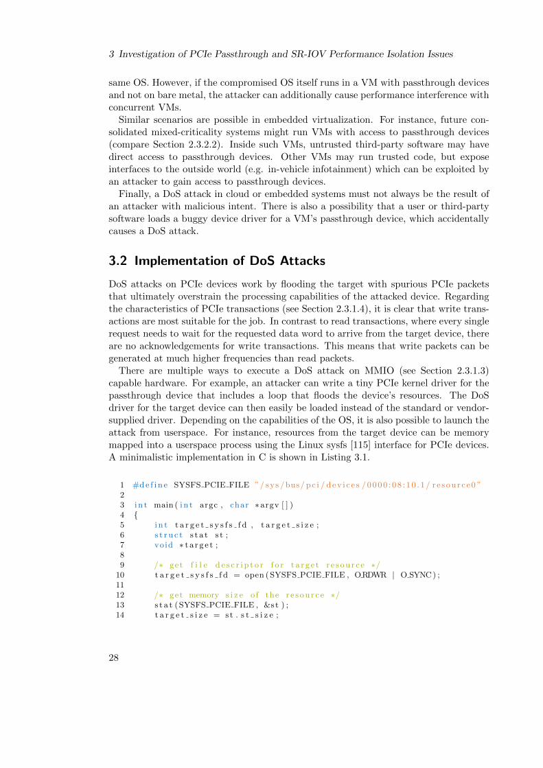
3 Investigation of PCIe Passthrough and SR-IOV Performance Isolation Issues
same OS. However, if the compromised OS itself runs in a VM with passthrough devicesand not on bare metal, the attacker can additionally cause performance interference withconcurrent VMs.
Similar scenarios are possible in embedded virtualization. For instance, future con-solidated mixed-criticality systems might run VMs with access to passthrough devices(compare Section 2.3.2.2). Inside such VMs, untrusted third-party software may havedirect access to passthrough devices. Other VMs may run trusted code, but exposeinterfaces to the outside world (e.g. in-vehicle infotainment) which can be exploited byan attacker to gain access to passthrough devices.
Finally, a DoS attack in cloud or embedded systems must not always be the result ofan attacker with malicious intent. There is also a possibility that a user or third-partysoftware loads a buggy device driver for a VM’s passthrough device, which accidentallycauses a DoS attack.
3.2 Implementation of DoS Attacks
DoS attacks on PCIe devices work by flooding the target with spurious PCIe packetsthat ultimately overstrain the processing capabilities of the attacked device. Regardingthe characteristics of PCIe transactions (see Section 2.3.1.4), it is clear that write trans-actions are most suitable for the job. In contrast to read transactions, where every singlerequest needs to wait for the requested data word to arrive from the target device, thereare no acknowledgements for write transactions. This means that write packets can begenerated at much higher frequencies than read packets.
There are multiple ways to execute a DoS attack on MMIO (see Section 2.3.1.3)capable hardware. For example, an attacker can write a tiny PCIe kernel driver for thepassthrough device that includes a loop that floods the device’s resources. The DoSdriver for the target device can then easily be loaded instead of the standard or vendor-supplied driver. Depending on the capabilities of the OS, it is also possible to launch theattack from userspace. For instance, resources from the target device can be memorymapped into a userspace process using the Linux sysfs [115] interface for PCIe devices.A minimalistic implementation in C is shown in Listing 3.1.
1 #d e f i n e SYSFS PCIE FILE ”/ sys /bus/ pc i / d ev i c e s /0000 : 08 : 10 . 1/ r e source0 ”23 i n t main ( i n t argc , char ∗argv [ ] )4 {5 i n t t a r g e t s y s f s f d , t a r g e t s i z e ;6 s t r u c t s t a t s t ;7 void ∗ t a r g e t ;89 /∗ get f i l e d e s c r i p t o r f o r t a r g e t r e s ou r c e ∗/
10 t a r g e t s y s f s f d = open (SYSFS PCIE FILE , ORDWR | O SYNC) ;1112 /∗ get memory s i z e o f the r e s ou r c e ∗/13 s t a t (SYSFS PCIE FILE , &s t ) ;14 t a r g e t s i z e = s t . s t s i z e ;
28

3.3 Evaluation Platform
1516 /∗ memory map the r e sou r c e ∗/17 t a r g e t = mmap(0 , t a r g e t s i z e , PROT READ | PROT WRITE,18 MAP SHARED, t a r g e t s y s f s f d , 0 ) ;1920 /∗ the ac tua l DoS loop ∗/21 f o r ( ; ; )22 ∗( v o l a t i l e u i n t 3 2 t ∗) t a r g e t = 0xD05 ; /∗ 32 b i t PCIe pkts ∗/23 }
Listing 3.1: A minimalistic C implementation of a DoS attack using the Linux sysfsinterface. Error handling and include files omitted for brevity.
The targeted PCIe device is defined in line one, lines 10–18 map the device’s memoryresources into the address space of the process, and lines 21–22 finally flood the targetdevice with 32 bit PCIe write packets. Error handling code and include files are omittedfor brevity. The DoS attack targets the address that is stored in the pointer variablecalled target. This address points at the first address of the whole address range thatis reserved for the targeted PCIe device (compare Figure 2.8). What kind of I/O-deviceresource actually hides behind this address must be looked up in the device’s data sheet.It could be a register, FIFO memory, or something else. Targeting a different resourceof the device can be achieved by adding an offset to the address stored in target. Therelevance of the actual target resource inside the PCIe device will be discussed later inSection 3.5. Flooding with PCIe packets of other sizes is achieved by casting target tothe respective type, e.g. uint64 t or uint16 t. In the rest of this thesis, the attackedPCIe device will interchangeably be called the DoS target or DoS victim.
3.3 Evaluation Platform
The evaluation platform is based on the x86 architecture and uses a CPU and moth-erboard combination that was selected for building an automotive demonstrator withinthe ARAMiS project [116]. The goal of the demonstrator was to show that virtualizationin multi-core systems is a key-enabler for consolidating different software functions ontoa single physical ECU [12]. The demonstrator also utilized SR-IOV for hardware-basedvirtualization of a coprocessor and a CAN controller. Thus, it is a suitable choice as abase system for evaluating performance isolation issues of SR-IOV.
Figure 3.1 depicts an overview of the evaluation platform. The CPU is an Intel Corei7-3770T (3rd generation) that runs at 2.5 GHz and has four physical cores (or eightlogical cores if HyperThreading is enabled). It also has a single integrated PCIe 3.0port, which is primarily intended to house a graphics card. The CPU is mounted onan Intel DQ77MK motherboard, which provides a Q77 Platform-Controller-Hub (PCH),aka the chipset. PCH and CPU are connected by the proprietary Direct Media Interface(DMI) 2.0, which is very similar to PCIe (serial communication, point-to-point links withmultiple lanes). The DMI on this motherboard is capable of 20 Gbit/s. CPU and PCHsupport VT-x and VT-d hardware virtualization extensions, so that PCIe passthroughis supported. The system is equipped with 32 GB of RAM.
29
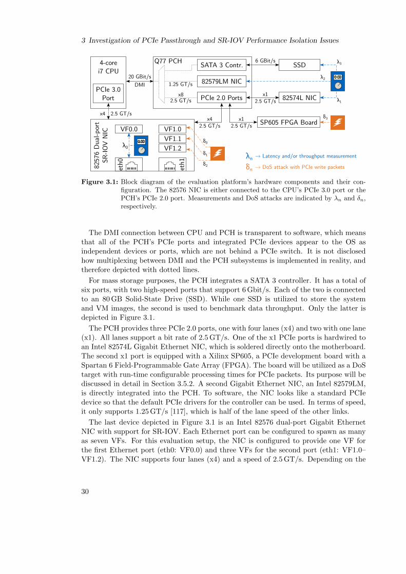
3 Investigation of PCIe Passthrough and SR-IOV Performance Isolation Issues
4-core i7 CPU
PCIe 3.0Port
1.25 GT/s
2.5 GT/sx8
Q77 PCHSATA 3 Contr.
82579LM NIC
PCIe 2.0 Ports
SSD
82574L NIC
SP605 FPGA Boardet
h08257
6 D
ual-p
ort
SR-IO
V N
IC VF0.0 VF1.0
VF1.2
eth1
VF1.1
6 GBit/s
VF1.1
x12.5 GT/s
x12.5 GT/s
x42.5 GT/s
x4 2.5 GT/s
0.00
λ3
λ0
δ3
λ2
λ1
δ0
δ2
δ1 → Latency and/or throughput measurement
→ DoS attack with PCIe write packets
λn
δn
20 GBit/s
DMI
0.00
Figure 3.1: Block diagram of the evaluation platform’s hardware components and their con-figuration. The 82576 NIC is either connected to the CPU’s PCIe 3.0 port or thePCH’s PCIe 2.0 port. Measurements and DoS attacks are indicated by λn and δn,respectively.
The DMI connection between CPU and PCH is transparent to software, which meansthat all of the PCH’s PCIe ports and integrated PCIe devices appear to the OS asindependent devices or ports, which are not behind a PCIe switch. It is not disclosedhow multiplexing between DMI and the PCH subsystems is implemented in reality, andtherefore depicted with dotted lines.
For mass storage purposes, the PCH integrates a SATA 3 controller. It has a total ofsix ports, with two high-speed ports that support 6 Gbit/s. Each of the two is connectedto an 80 GB Solid-State Drive (SSD). While one SSD is utilized to store the systemand VM images, the second is used to benchmark data throughput. Only the latter isdepicted in Figure 3.1.
The PCH provides three PCIe 2.0 ports, one with four lanes (x4) and two with one lane(x1). All lanes support a bit rate of 2.5 GT/s. One of the x1 PCIe ports is hardwired toan Intel 82574L Gigabit Ethernet NIC, which is soldered directly onto the motherboard.The second x1 port is equipped with a Xilinx SP605, a PCIe development board with aSpartan 6 Field-Programmable Gate Array (FPGA). The board will be utilized as a DoStarget with run-time configurable processing times for PCIe packets. Its purpose will bediscussed in detail in Section 3.5.2. A second Gigabit Ethernet NIC, an Intel 82579LM,is directly integrated into the PCH. To software, the NIC looks like a standard PCIedevice so that the default PCIe drivers for the controller can be used. In terms of speed,it only supports 1.25 GT/s [117], which is half of the lane speed of the other links.
The last device depicted in Figure 3.1 is an Intel 82576 dual-port Gigabit EthernetNIC with support for SR-IOV. Each Ethernet port can be configured to spawn as manyas seven VFs. For this evaluation setup, the NIC is configured to provide one VF forthe first Ethernet port (eth0: VF0.0) and three VFs for the second port (eth1: VF1.0–VF1.2). The NIC supports four lanes (x4) and a speed of 2.5 GT/s. Depending on the
30
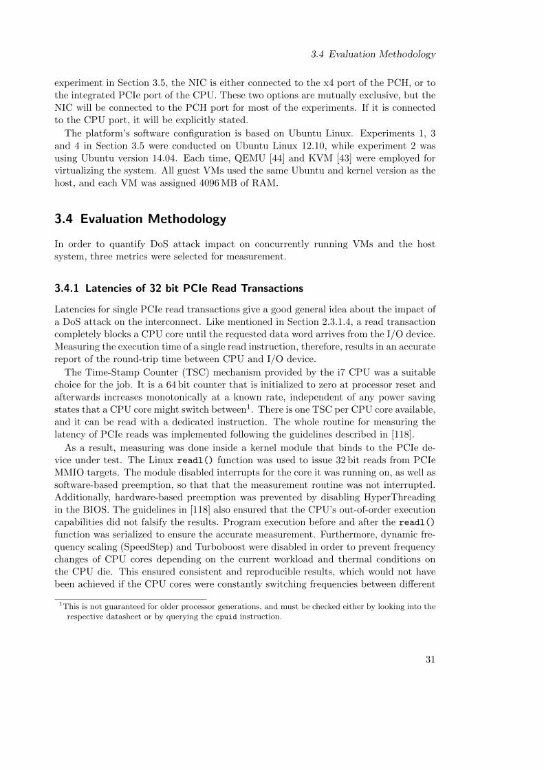
3.4 Evaluation Methodology
experiment in Section 3.5, the NIC is either connected to the x4 port of the PCH, or tothe integrated PCIe port of the CPU. These two options are mutually exclusive, but theNIC will be connected to the PCH port for most of the experiments. If it is connectedto the CPU port, it will be explicitly stated.
The platform’s software configuration is based on Ubuntu Linux. Experiments 1, 3and 4 in Section 3.5 were conducted on Ubuntu Linux 12.10, while experiment 2 wasusing Ubuntu version 14.04. Each time, QEMU [44] and KVM [43] were employed forvirtualizing the system. All guest VMs used the same Ubuntu and kernel version as thehost, and each VM was assigned 4096 MB of RAM.
3.4 Evaluation Methodology
In order to quantify DoS attack impact on concurrently running VMs and the hostsystem, three metrics were selected for measurement.
3.4.1 Latencies of 32 bit PCIe Read Transactions
Latencies for single PCIe read transactions give a good general idea about the impact ofa DoS attack on the interconnect. Like mentioned in Section 2.3.1.4, a read transactioncompletely blocks a CPU core until the requested data word arrives from the I/O device.Measuring the execution time of a single read instruction, therefore, results in an accuratereport of the round-trip time between CPU and I/O device.
The Time-Stamp Counter (TSC) mechanism provided by the i7 CPU was a suitablechoice for the job. It is a 64 bit counter that is initialized to zero at processor reset andafterwards increases monotonically at a known rate, independent of any power savingstates that a CPU core might switch between1. There is one TSC per CPU core available,and it can be read with a dedicated instruction. The whole routine for measuring thelatency of PCIe reads was implemented following the guidelines described in [118].
As a result, measuring was done inside a kernel module that binds to the PCIe de-vice under test. The Linux readl() function was used to issue 32 bit reads from PCIeMMIO targets. The module disabled interrupts for the core it was running on, as well assoftware-based preemption, so that that the measurement routine was not interrupted.Additionally, hardware-based preemption was prevented by disabling HyperThreadingin the BIOS. The guidelines in [118] also ensured that the CPU’s out-of-order executioncapabilities did not falsify the results. Program execution before and after the readl()
function was serialized to ensure the accurate measurement. Furthermore, dynamic fre-quency scaling (SpeedStep) and Turboboost were disabled in order to prevent frequencychanges of CPU cores depending on the current workload and thermal conditions onthe CPU die. This ensured consistent and reproducible results, which would not havebeen achieved if the CPU cores were constantly switching frequencies between different
1This is not guaranteed for older processor generations, and must be checked either by looking into therespective datasheet or by querying the cpuid instruction.
31

3 Investigation of PCIe Passthrough and SR-IOV Performance Isolation Issues
measurement runs. All latency results presented in this chapter are the average of onemillion consecutive samples.
Evaluation of the latency measurement module showed that measurements from withinthe host OS yielded reasonable and expected results. However, it did not work asintended when run within a VM. One of the problems was that hypervisors virtualize theTSC itself due to various reasons [119, 120]. To give an example: Virtualized operatingsystems within VMs may use the TSC for internal time-keeping tasks. If these VMsare fully virtualized, they assume to run on the physical CPU for 100% of the time,while in reality, they might be preempted by the host without knowing. Virtualizing theTSC, e.g. by maintaining virtual per-VM copies, can therefore help to prevent errorsthat may result from this assumption. Additionally, the previously stated feature ofthe measurement module of turning off interrupts und software preemption to guaranteeprecise measurements only applies to the virtualized kernel of the VM. If scheduling fromthe host or arrival of a real interrupt preempts the whole VM, the measurement routinewithin it is halted as well, and measurements lose accuracy. For the evaluation platform,the effects of TSC virtualization can be demonstrated by measuring the latency of VF0.0(see Figure 3.1, λ0) from the host and from a VM with passthrough access to VF0.0.The results are depicted in Figure 3.2.
host VM0
0.5
1
1.5
2
2.5
1.55 1.
57
Lat
ency
(µs)
TSC virtualization side effects
Figure 3.2: The side effects of Time Stamp Counter (TSC) virtualization: Measuring readlatencies of VF0.0 from the host yields better results than from inside a VM.
On average, the inaccuracies that are introduced by TSC virtualization cancel eachother out. Measurement results from the host and from within the VM show a latencyof about 1.5 µs. However, the latter shows a standard deviation drift of 0.75 µs in bothdirections. In order to circumvent this phenomenon, all latencies within this chapter weremeasured from the host. The measurement process was always pinned to a dedicatedcore, so that interferences with VMs were avoided, and a precise measurement of thestate of the interconnect was guaranteed.
32
3.5 Experiments and Results
3.4.2 Network Performance – TCP and UDP Throughput
Network performance in the form of TCP und UDP throughputs is the second metric thatwas used to measure DoS attack impact in the following experiments. Each of the threeNICs of the evaluation platform was incorporated at least once for these tests. Althoughthere is a dependency on the previous metric (latencies for single PCIe packets), theachievable throughputs of the NICs give a better idea of the impact of DoS attacks onreal-world I/O workloads.
Throughputs were measured with the netperf benchmark [121], which was alwaysexecuted from within a VM that had passthrough access to either VF0.0 or one of thetwo other NICs (see Figure 3.1, λ0, λ1, λ2). The respective NIC under test was connectedto a dedicated remote machine which acted as sink for the streams. Standard parameterswere utilized for both streams, TCP and UDP, which used the default message sizes of16 KiB and 64 KiB, respectively. Each benchmark was conducted for a period of tenseconds, and all presented results are the average of multiple iterations. No jumboframes were used, and the Maximum Transmission Unit (MTU) was set to its defaultsize of 1500 bytes.
3.4.3 Storage Performance – SSD Throughput
The third and last metric of the experiments is the storage performance of the host-assigned SSD, which was connected to the evaluation platform’s PCH. Therefore, thestandard Unix tool dd was used to measure the throughput while writing large files tothe SSD. These storage performance tests complete the evaluation by adding a secondclass of real-world I/O that differs from network throughput tests. This helps to furtherput the impact of PCIe DoS attacks into context.
The results will also emphasize the problems that might arise if future chipsets, whichtraditionally integrate a platform’s storage controllers, start to integrate SR-IOV capablestorage controllers. Some server-grade chipsets already do that2, and next generationstorage technologies like NVMe, which is PCIe based, are specifically designed to leveragethe opportunities of SR-IOV [84, 85].
3.5 Experiments and Results
This section presents four different experiments that were conducted in order to learnmultiple things about DoS attacks on PCIe passthrough: Experiments one and twoquantify DoS attack impact by means of PCIe latencies and real-world benchmarks. Thisis followed by experiments three and four, which investigate parameters that influenceDoS attack impact.
2Intel C600 series. However, at the time of writing, SR-IOV features of the controller were not yetusable due to missing support in the drivers.
33
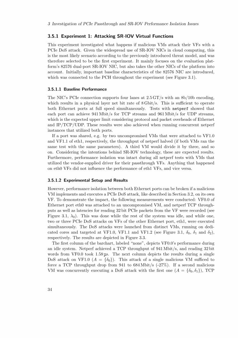
3 Investigation of PCIe Passthrough and SR-IOV Performance Isolation Issues
3.5.1 Experiment 1: Attacking SR-IOV Virtual Functions
This experiment investigated what happens if malicious VMs attack their VFs with aPCIe DoS attack. Given the widespread use of SR-IOV NICs in cloud computing, thisis the most likely scenario according to the previously introduced threat model, and wastherefore selected to be the first experiment. It mainly focuses on the evaluation plat-form’s 82576 dual-port SR-IOV NIC, but also takes the other NICs of the platform intoaccount. Initially, important baseline characteristics of the 82576 NIC are introduced,which was connected to the PCH throughout the experiment (see Figure 3.1).
3.5.1.1 Baseline Performance
The NIC’s PCIe connection supports four lanes at 2.5 GT/s with an 8b/10b encoding,which results in a physical layer net bit rate of 8 Gbit/s. This is sufficient to operateboth Ethernet ports at full speed simultaneously. Tests with netperf showed thateach port can achieve 941 Mbit/s for TCP streams and 961 Mbit/s for UDP streams,which is the expected upper limit considering protocol and packet overheads of Ethernetand IP/TCP/UDP. These results were also achieved when running concurrent netperfinstances that utilized both ports.
If a port was shared, e.g. by two uncompromised VMs that were attached to VF1.0and VF1.1 of eth1, respectively, the throughput of netperf halved (if both VMs ran thesame test with the same parameters). A third VM would divide it by three, and soon. Considering the intentions behind SR-IOV technology, these are expected results.Furthermore, performance isolation was intact during all netperf tests with VMs thatutilized the vendor-supplied driver for their passthrough VFs. Anything that happenedon eth0 VFs did not influence the performance of eth1 VFs, and vice versa.
3.5.1.2 Experimental Setup and Results
However, performance isolation between both Ethernet ports can be broken if a maliciousVM implements and executes a PCIe DoS attack, like described in Section 3.2, on its ownVF. To demonstrate the impact, the following measurements were conducted: VF0.0 ofEthernet port eth0 was attached to an uncompromised VM, and netperf TCP through-puts as well as latencies for reading 32 bit PCIe packets from the VF were recorded (seeFigure 3.1, λ0). This was done while the rest of the system was idle, and while one,two or three PCIe DoS attacks on VFs of the other Ethernet port, eth1, were executedsimultaneously. The DoS attacks were launched from distinct VMs, running on dedi-cated cores and targeted at VF1.0, VF1.1 and VF1.2 (see Figure 3.1, δ0, δ1 and δ2),respectively. The results are depicted in Figure 3.3.
The first column of the barchart, labeled “none”, depicts VF0.0’s performance duringan idle system. Netperf achieved a TCP throughput of 941 Mbit/s, and reading 32 bitwords from VF0.0 took 1.58 µs. The next column depicts the results during a singleDoS attack on VF1.0 (A = {δ0}). This attack of a single malicious VM sufficed toforce a TCP throughput drop from 941 to 684 Mbit/s (-27%). If a second maliciousVM was concurrently executing a DoS attack with the first one (A = {δ0, δ1}), TCP
34
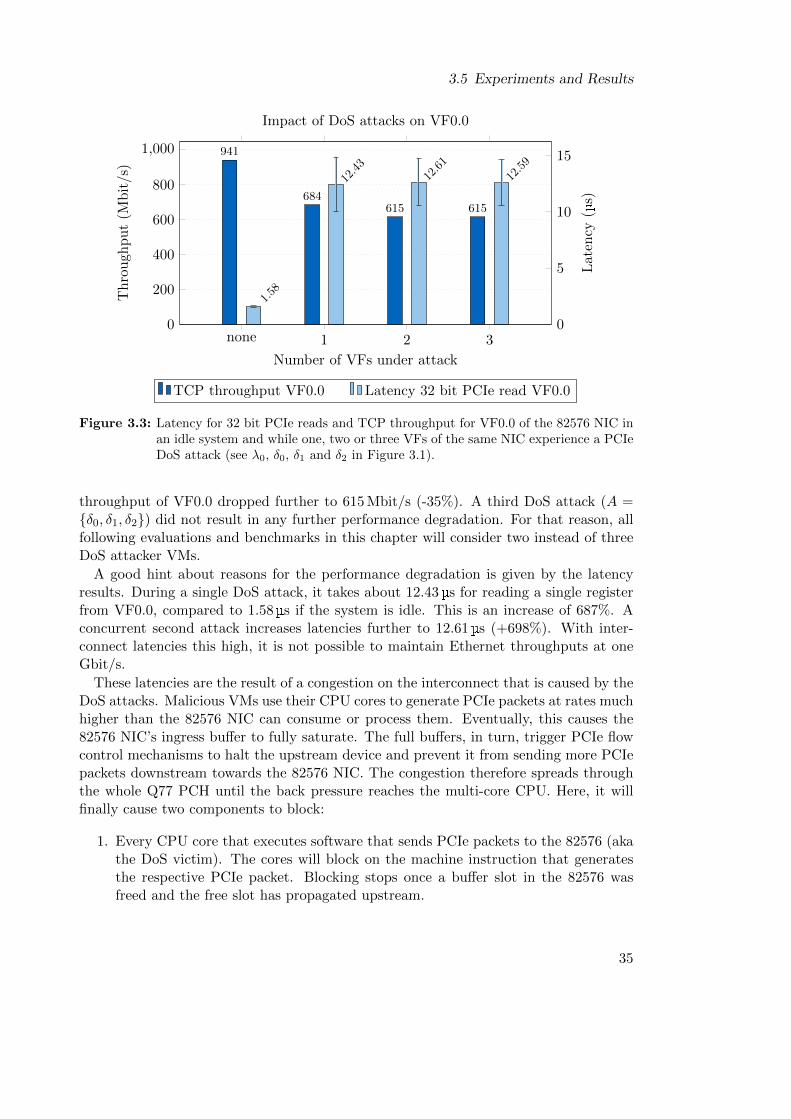
3.5 Experiments and Results
0
200
400
600
800
1,000 941
684615 615
Th
rou
ghp
ut
(Mb
it/s
)
none 1 2 30
5
10
15
1.58
12.43
12.61
12.59
Number of VFs under attack
Late
ncy
(µs)
Impact of DoS attacks on VF0.0
TCP throughput VF0.0 Latency 32 bit PCIe read VF0.0
Figure 3.3: Latency for 32 bit PCIe reads and TCP throughput for VF0.0 of the 82576 NIC inan idle system and while one, two or three VFs of the same NIC experience a PCIeDoS attack (see λ0, δ0, δ1 and δ2 in Figure 3.1).
throughput of VF0.0 dropped further to 615 Mbit/s (-35%). A third DoS attack (A ={δ0, δ1, δ2}) did not result in any further performance degradation. For that reason, allfollowing evaluations and benchmarks in this chapter will consider two instead of threeDoS attacker VMs.
A good hint about reasons for the performance degradation is given by the latencyresults. During a single DoS attack, it takes about 12.43 µs for reading a single registerfrom VF0.0, compared to 1.58 µs if the system is idle. This is an increase of 687%. Aconcurrent second attack increases latencies further to 12.61 µs (+698%). With inter-connect latencies this high, it is not possible to maintain Ethernet throughputs at oneGbit/s.
These latencies are the result of a congestion on the interconnect that is caused by theDoS attacks. Malicious VMs use their CPU cores to generate PCIe packets at rates muchhigher than the 82576 NIC can consume or process them. Eventually, this causes the82576 NIC’s ingress buffer to fully saturate. The full buffers, in turn, trigger PCIe flowcontrol mechanisms to halt the upstream device and prevent it from sending more PCIepackets downstream towards the 82576 NIC. The congestion therefore spreads throughthe whole Q77 PCH until the back pressure reaches the multi-core CPU. Here, it willfinally cause two components to block:
1. Every CPU core that executes software that sends PCIe packets to the 82576 (akathe DoS victim). The cores will block on the machine instruction that generatesthe respective PCIe packet. Blocking stops once a buffer slot in the 82576 wasfreed and the free slot has propagated upstream.
35
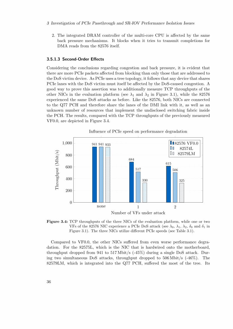
3 Investigation of PCIe Passthrough and SR-IOV Performance Isolation Issues
2. The integrated DRAM controller of the multi-core CPU is affected by the sameback pressure mechanisms. It blocks when it tries to transmit completions forDMA reads from the 82576 itself.
3.5.1.3 Second-Order Effects
Considering the conclusions regarding congestion and back pressure, it is evident thatthere are more PCIe packets affected from blocking than only those that are addressed tothe DoS victim device. As PCIe uses a tree topology, it follows that any device that sharesPCIe lanes with the DoS victim must itself be affected by the DoS-caused congestion. Agood way to prove this assertion was to additionally measure TCP throughputs of theother NICs in the evaluation platform (see λ1 and λ2 in Figure 3.1), while the 82576experienced the same DoS attacks as before. Like the 82576, both NICs are connectedto the Q77 PCH and therefore share the lanes of the DMI link with it, as well as anunknown number of resources that implement the undisclosed switching fabric insidethe PCH. The results, compared with the TCP throughputs of the previously measuredVF0.0, are depicted in Figure 3.4.
none 1 20
200
400
600
800
1,000 941
684615
941
517 506
933
330 325
Number of VFs under attack
Th
rou
ghp
ut
(Mb
it/s
)
Influence of PCIe speed on performance degradation
82576 VF0.082574L
82579LM
Figure 3.4: TCP throughputs of the three NICs of the evaluation platform, while one or twoVFs of the 82576 NIC experience a PCIe DoS attack (see λ0, λ1, λ2, δ0 and δ1 inFigure 3.1). The three NICs utilize different PCIe speeds (see Table 3.1).
Compared to VF0.0, the other NICs suffered from even worse performance degra-dation. For the 82575L, which is the NIC that is hardwired onto the motherboard,throughput dropped from 941 to 517 Mbit/s (-45%) during a single DoS attack. Dur-ing two simultaneous DoS attacks, throughput dropped to 506 Mbit/s (-46%). The82579LM, which is integrated into the Q77 PCH, suffered the most of the tree. Its
36
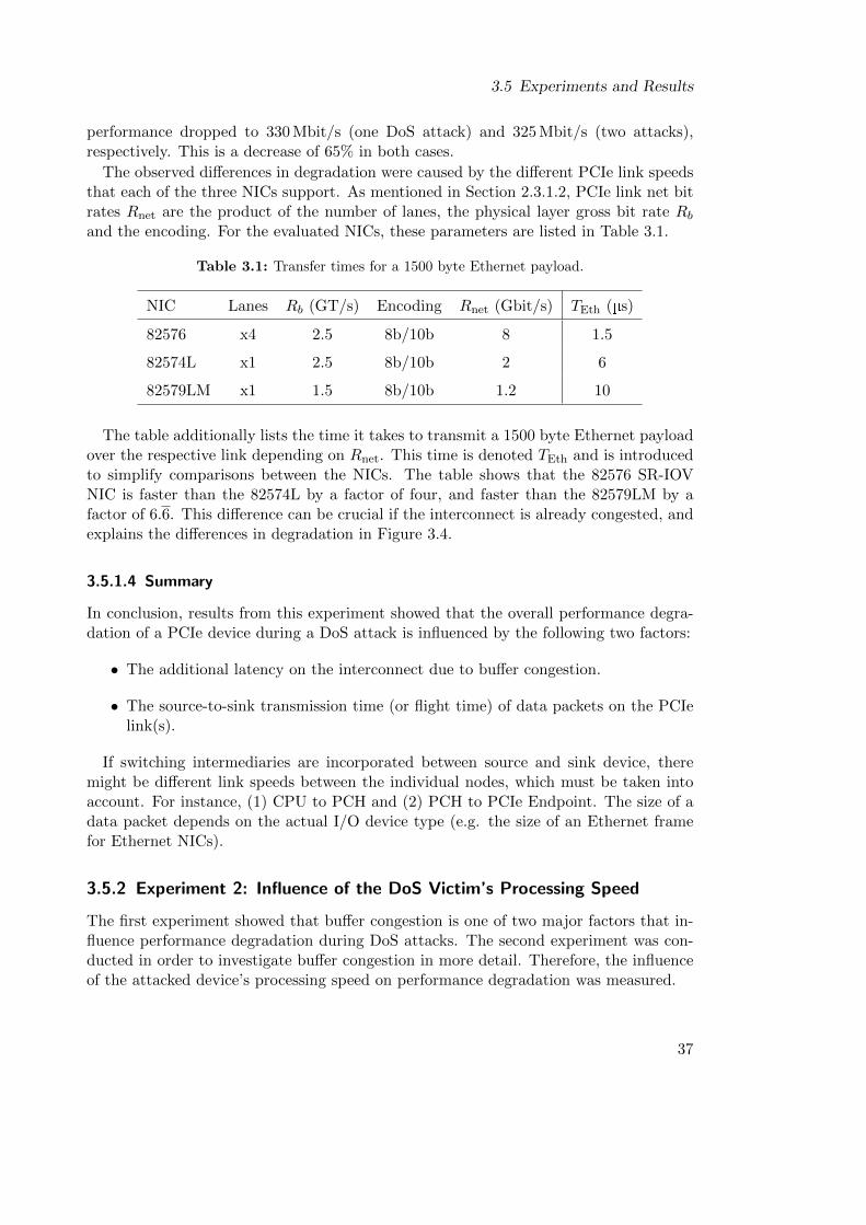
3.5 Experiments and Results
performance dropped to 330 Mbit/s (one DoS attack) and 325 Mbit/s (two attacks),respectively. This is a decrease of 65% in both cases.
The observed differences in degradation were caused by the different PCIe link speedsthat each of the three NICs support. As mentioned in Section 2.3.1.2, PCIe link net bitrates Rnet are the product of the number of lanes, the physical layer gross bit rate Rb
and the encoding. For the evaluated NICs, these parameters are listed in Table 3.1.
Table 3.1: Transfer times for a 1500 byte Ethernet payload.
NIC Lanes Rb (GT/s) Encoding Rnet (Gbit/s) TEth (µs)
82576 x4 2.5 8b/10b 8 1.5
82574L x1 2.5 8b/10b 2 6
82579LM x1 1.5 8b/10b 1.2 10
The table additionally lists the time it takes to transmit a 1500 byte Ethernet payloadover the respective link depending on Rnet. This time is denoted TEth and is introducedto simplify comparisons between the NICs. The table shows that the 82576 SR-IOVNIC is faster than the 82574L by a factor of four, and faster than the 82579LM by afactor of 6.6. This difference can be crucial if the interconnect is already congested, andexplains the differences in degradation in Figure 3.4.
3.5.1.4 Summary
In conclusion, results from this experiment showed that the overall performance degra-dation of a PCIe device during a DoS attack is influenced by the following two factors:
• The additional latency on the interconnect due to buffer congestion.
• The source-to-sink transmission time (or flight time) of data packets on the PCIelink(s).
If switching intermediaries are incorporated between source and sink device, theremight be different link speeds between the individual nodes, which must be taken intoaccount. For instance, (1) CPU to PCH and (2) PCH to PCIe Endpoint. The size of adata packet depends on the actual I/O device type (e.g. the size of an Ethernet framefor Ethernet NICs).
3.5.2 Experiment 2: Influence of the DoS Victim’s Processing Speed
The first experiment showed that buffer congestion is one of two major factors that in-fluence performance degradation during DoS attacks. The second experiment was con-ducted in order to investigate buffer congestion in more detail. Therefore, the influenceof the attacked device’s processing speed on performance degradation was measured.
37
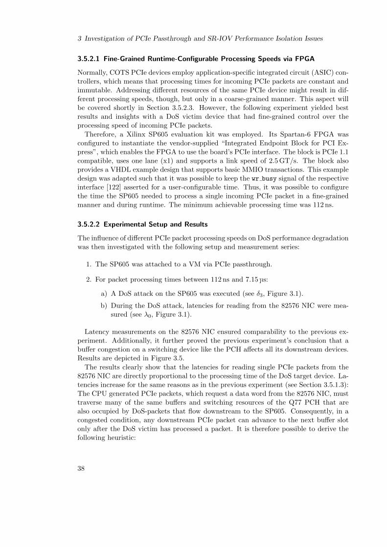
3 Investigation of PCIe Passthrough and SR-IOV Performance Isolation Issues
3.5.2.1 Fine-Grained Runtime-Configurable Processing Speeds via FPGA
Normally, COTS PCIe devices employ application-specific integrated circuit (ASIC) con-trollers, which means that processing times for incoming PCIe packets are constant andimmutable. Addressing different resources of the same PCIe device might result in dif-ferent processing speeds, though, but only in a coarse-grained manner. This aspect willbe covered shortly in Section 3.5.2.3. However, the following experiment yielded bestresults and insights with a DoS victim device that had fine-grained control over theprocessing speed of incoming PCIe packets.
Therefore, a Xilinx SP605 evaluation kit was employed. Its Spartan-6 FPGA wasconfigured to instantiate the vendor-supplied “Integrated Endpoint Block for PCI Ex-press”, which enables the FPGA to use the board’s PCIe interface. The block is PCIe 1.1compatible, uses one lane (x1) and supports a link speed of 2.5 GT/s. The block alsoprovides a VHDL example design that supports basic MMIO transactions. This exampledesign was adapted such that it was possible to keep the wr busy signal of the respectiveinterface [122] asserted for a user-configurable time. Thus, it was possible to configurethe time the SP605 needed to process a single incoming PCIe packet in a fine-grainedmanner and during runtime. The minimum achievable processing time was 112 ns.
3.5.2.2 Experimental Setup and Results
The influence of different PCIe packet processing speeds on DoS performance degradationwas then investigated with the following setup and measurement series:
1. The SP605 was attached to a VM via PCIe passthrough.
2. For packet processing times between 112 ns and 7.15 µs:
a) A DoS attack on the SP605 was executed (see δ3, Figure 3.1).
b) During the DoS attack, latencies for reading from the 82576 NIC were mea-sured (see λ0, Figure 3.1).
Latency measurements on the 82576 NIC ensured comparability to the previous ex-periment. Additionally, it further proved the previous experiment’s conclusion that abuffer congestion on a switching device like the PCH affects all its downstream devices.Results are depicted in Figure 3.5.
The results clearly show that the latencies for reading single PCIe packets from the82576 NIC are directly proportional to the processing time of the DoS target device. La-tencies increase for the same reasons as in the previous experiment (see Section 3.5.1.3):The CPU generated PCIe packets, which request a data word from the 82576 NIC, musttraverse many of the same buffers and switching resources of the Q77 PCH that arealso occupied by DoS-packets that flow downstream to the SP605. Consequently, in acongested condition, any downstream PCIe packet can advance to the next buffer slotonly after the DoS victim has processed a packet. It is therefore possible to derive thefollowing heuristic:
38
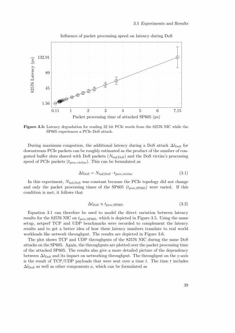
3.5 Experiments and Results
0.11 1 2 3 4 5 6 7.15
1.56
45
89
132.91
Packet processing time of attacked SP605 (µs)
8257
6L
aten
cy(µ
s)Influence of packet processing speed on latency during DoS
Figure 3.5: Latency degradation for reading 32 bit PCIe words from the 82576 NIC while theSP605 experiences a PCIe DoS attack.
During maximum congestion, the additional latency during a DoS attack ∆lDoS fordownstream PCIe packets can be roughly estimated as the product of the number of con-gested buffer slots shared with DoS packets (Nbuf,DoS) and the DoS victim’s processingspeed of PCIe packets (tproc,victim). This can be formulated as
∆lDoS = Nbuf,DoS · tproc,victim. (3.1)
In this experiment, Nbuf,DoS was constant because the PCIe topology did not changeand only the packet processing times of the SP605 (tproc,SP605) were varied. If thiscondition is met, it follows that
∆lDoS ∝ tproc,SP605. (3.2)
Equation 3.1 can therefore be used to model the direct variation between latencyresults for the 82576 NIC on tproc,SP605, which is depicted in Figure 3.5. Using the samesetup, netperf TCP and UDP benchmarks were recorded to complement the latencyresults and to get a better idea of how these latency numbers translate to real worldworkloads like network throughput. The results are depicted in Figure 3.6.
The plot shows TCP and UDP throughputs of the 82576 NIC during the same DoSattacks on the SP605. Again, the throughputs are plotted over the packet processing timeof the attacked SP605. The results also give a more detailed picture of the dependencybetween ∆lDoS and its impact on networking throughput. The throughput on the y-axisis the result of TCP/UDP payloads that were sent over a time t. The time t includes∆lDoS as well as other components a, which can be formulated as
39
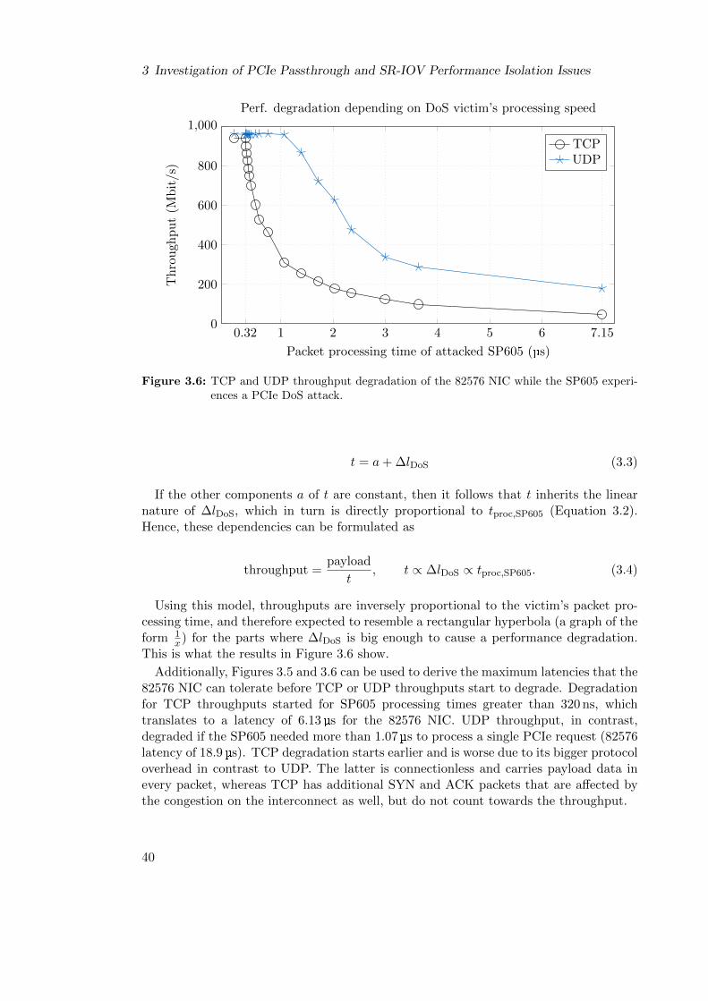
3 Investigation of PCIe Passthrough and SR-IOV Performance Isolation Issues
0.32 1 2 3 4 5 6 7.150
200
400
600
800
1,000
Packet processing time of attacked SP605 (µs)
Th
rou
ghp
ut
(Mb
it/s
)
Perf. degradation depending on DoS victim’s processing speed
TCPUDP
Figure 3.6: TCP and UDP throughput degradation of the 82576 NIC while the SP605 experi-ences a PCIe DoS attack.
t = a+ ∆lDoS (3.3)
If the other components a of t are constant, then it follows that t inherits the linearnature of ∆lDoS, which in turn is directly proportional to tproc,SP605 (Equation 3.2).Hence, these dependencies can be formulated as
throughput =payload
t, t ∝ ∆lDoS ∝ tproc,SP605. (3.4)
Using this model, throughputs are inversely proportional to the victim’s packet pro-cessing time, and therefore expected to resemble a rectangular hyperbola (a graph of theform 1
x) for the parts where ∆lDoS is big enough to cause a performance degradation.This is what the results in Figure 3.6 show.
Additionally, Figures 3.5 and 3.6 can be used to derive the maximum latencies that the82576 NIC can tolerate before TCP or UDP throughputs start to degrade. Degradationfor TCP throughputs started for SP605 processing times greater than 320 ns, whichtranslates to a latency of 6.13 µs for the 82576 NIC. UDP throughput, in contrast,degraded if the SP605 needed more than 1.07 µs to process a single PCIe request (82576latency of 18.9 µs). TCP degradation starts earlier and is worse due to its bigger protocoloverhead in contrast to UDP. The latter is connectionless and carries payload data inevery packet, whereas TCP has additional SYN and ACK packets that are affected bythe congestion on the interconnect as well, but do not count towards the throughput.
40
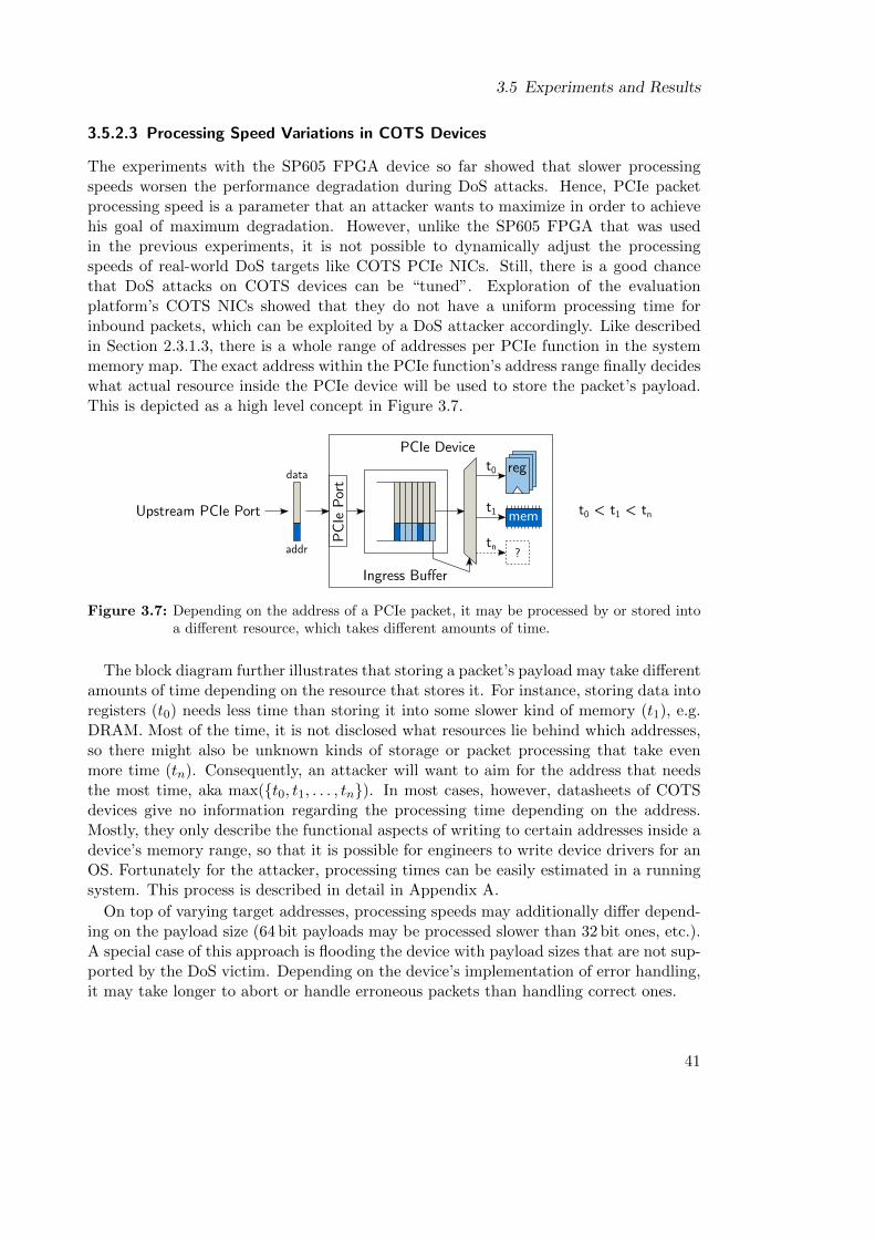
3.5 Experiments and Results
3.5.2.3 Processing Speed Variations in COTS Devices
The experiments with the SP605 FPGA device so far showed that slower processingspeeds worsen the performance degradation during DoS attacks. Hence, PCIe packetprocessing speed is a parameter that an attacker wants to maximize in order to achievehis goal of maximum degradation. However, unlike the SP605 FPGA that was usedin the previous experiments, it is not possible to dynamically adjust the processingspeeds of real-world DoS targets like COTS PCIe NICs. Still, there is a good chancethat DoS attacks on COTS devices can be “tuned”. Exploration of the evaluationplatform’s COTS NICs showed that they do not have a uniform processing time forinbound packets, which can be exploited by a DoS attacker accordingly. Like describedin Section 2.3.1.3, there is a whole range of addresses per PCIe function in the systemmemory map. The exact address within the PCIe function’s address range finally decideswhat actual resource inside the PCIe device will be used to store the packet’s payload.This is depicted as a high level concept in Figure 3.7.
PCIe
Por
t
Ingress Buffer
reg
mem
t0
t1
tn?
t0 < t1 < tnUpstream PCIe Port
PCIe Device
data
addr
Figure 3.7: Depending on the address of a PCIe packet, it may be processed by or stored intoa different resource, which takes different amounts of time.
The block diagram further illustrates that storing a packet’s payload may take differentamounts of time depending on the resource that stores it. For instance, storing data intoregisters (t0) needs less time than storing it into some slower kind of memory (t1), e.g.DRAM. Most of the time, it is not disclosed what resources lie behind which addresses,so there might also be unknown kinds of storage or packet processing that take evenmore time (tn). Consequently, an attacker will want to aim for the address that needsthe most time, aka max({t0, t1, . . . , tn}). In most cases, however, datasheets of COTSdevices give no information regarding the processing time depending on the address.Mostly, they only describe the functional aspects of writing to certain addresses inside adevice’s memory range, so that it is possible for engineers to write device drivers for anOS. Fortunately for the attacker, processing times can be easily estimated in a runningsystem. This process is described in detail in Appendix A.
On top of varying target addresses, processing speeds may additionally differ depend-ing on the payload size (64 bit payloads may be processed slower than 32 bit ones, etc.).A special case of this approach is flooding the device with payload sizes that are not sup-ported by the DoS victim. Depending on the device’s implementation of error handling,it may take longer to abort or handle erroneous packets than handling correct ones.
41
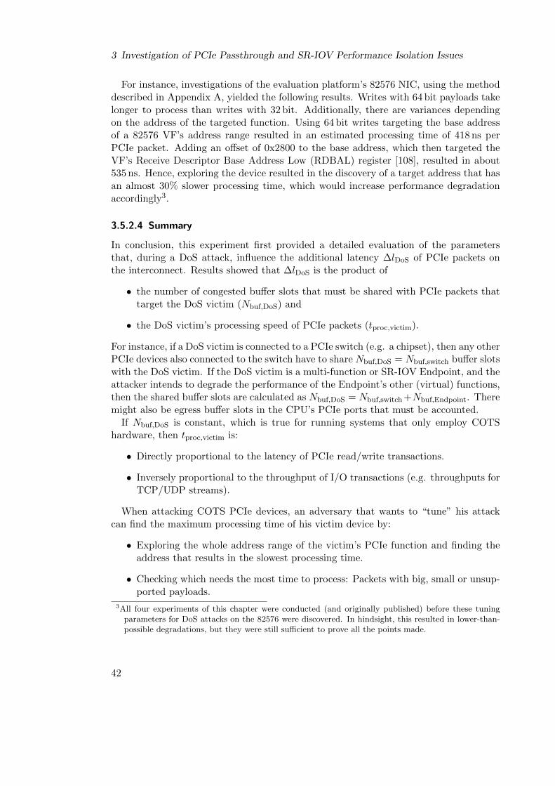
3 Investigation of PCIe Passthrough and SR-IOV Performance Isolation Issues
For instance, investigations of the evaluation platform’s 82576 NIC, using the methoddescribed in Appendix A, yielded the following results. Writes with 64 bit payloads takelonger to process than writes with 32 bit. Additionally, there are variances dependingon the address of the targeted function. Using 64 bit writes targeting the base addressof a 82576 VF’s address range resulted in an estimated processing time of 418 ns perPCIe packet. Adding an offset of 0x2800 to the base address, which then targeted theVF’s Receive Descriptor Base Address Low (RDBAL) register [108], resulted in about535 ns. Hence, exploring the device resulted in the discovery of a target address that hasan almost 30% slower processing time, which would increase performance degradationaccordingly3.
3.5.2.4 Summary
In conclusion, this experiment first provided a detailed evaluation of the parametersthat, during a DoS attack, influence the additional latency ∆lDoS of PCIe packets onthe interconnect. Results showed that ∆lDoS is the product of
• the number of congested buffer slots that must be shared with PCIe packets thattarget the DoS victim (Nbuf,DoS) and
• the DoS victim’s processing speed of PCIe packets (tproc,victim).
For instance, if a DoS victim is connected to a PCIe switch (e.g. a chipset), then any otherPCIe devices also connected to the switch have to share Nbuf,DoS = Nbuf,switch buffer slotswith the DoS victim. If the DoS victim is a multi-function or SR-IOV Endpoint, and theattacker intends to degrade the performance of the Endpoint’s other (virtual) functions,then the shared buffer slots are calculated as Nbuf,DoS = Nbuf,switch+Nbuf,Endpoint. Theremight also be egress buffer slots in the CPU’s PCIe ports that must be accounted.
If Nbuf,DoS is constant, which is true for running systems that only employ COTShardware, then tproc,victim is:
• Directly proportional to the latency of PCIe read/write transactions.
• Inversely proportional to the throughput of I/O transactions (e.g. throughputs forTCP/UDP streams).
When attacking COTS PCIe devices, an adversary that wants to “tune” his attackcan find the maximum processing time of his victim device by:
• Exploring the whole address range of the victim’s PCIe function and finding theaddress that results in the slowest processing time.
• Checking which needs the most time to process: Packets with big, small or unsup-ported payloads.
3All four experiments of this chapter were conducted (and originally published) before these tuningparameters for DoS attacks on the 82576 were discovered. In hindsight, this resulted in lower-than-possible degradations, but they were still sufficient to prove all the points made.
42
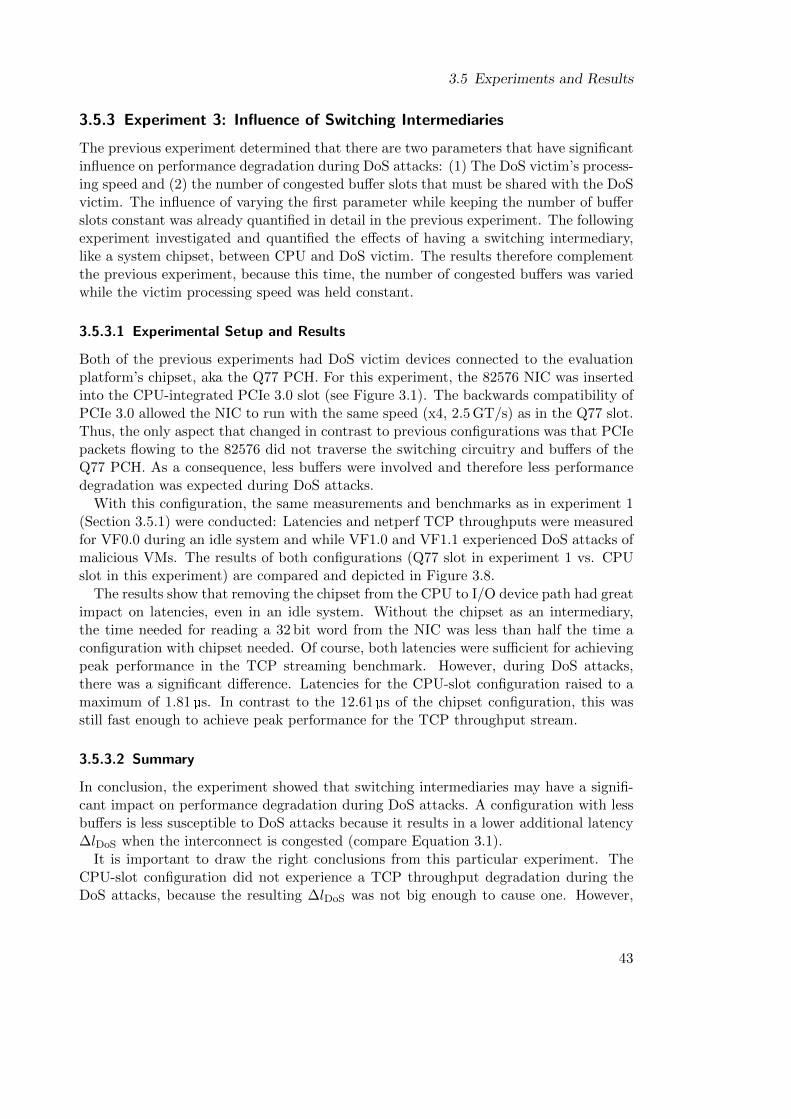
3.5 Experiments and Results
3.5.3 Experiment 3: Influence of Switching Intermediaries
The previous experiment determined that there are two parameters that have significantinfluence on performance degradation during DoS attacks: (1) The DoS victim’s process-ing speed and (2) the number of congested buffer slots that must be shared with the DoSvictim. The influence of varying the first parameter while keeping the number of bufferslots constant was already quantified in detail in the previous experiment. The followingexperiment investigated and quantified the effects of having a switching intermediary,like a system chipset, between CPU and DoS victim. The results therefore complementthe previous experiment, because this time, the number of congested buffers was variedwhile the victim processing speed was held constant.
3.5.3.1 Experimental Setup and Results
Both of the previous experiments had DoS victim devices connected to the evaluationplatform’s chipset, aka the Q77 PCH. For this experiment, the 82576 NIC was insertedinto the CPU-integrated PCIe 3.0 slot (see Figure 3.1). The backwards compatibility ofPCIe 3.0 allowed the NIC to run with the same speed (x4, 2.5 GT/s) as in the Q77 slot.Thus, the only aspect that changed in contrast to previous configurations was that PCIepackets flowing to the 82576 did not traverse the switching circuitry and buffers of theQ77 PCH. As a consequence, less buffers were involved and therefore less performancedegradation was expected during DoS attacks.
With this configuration, the same measurements and benchmarks as in experiment 1(Section 3.5.1) were conducted: Latencies and netperf TCP throughputs were measuredfor VF0.0 during an idle system and while VF1.0 and VF1.1 experienced DoS attacks ofmalicious VMs. The results of both configurations (Q77 slot in experiment 1 vs. CPUslot in this experiment) are compared and depicted in Figure 3.8.
The results show that removing the chipset from the CPU to I/O device path had greatimpact on latencies, even in an idle system. Without the chipset as an intermediary,the time needed for reading a 32 bit word from the NIC was less than half the time aconfiguration with chipset needed. Of course, both latencies were sufficient for achievingpeak performance in the TCP streaming benchmark. However, during DoS attacks,there was a significant difference. Latencies for the CPU-slot configuration raised to amaximum of 1.81 µs. In contrast to the 12.61 µs of the chipset configuration, this wasstill fast enough to achieve peak performance for the TCP throughput stream.
3.5.3.2 Summary
In conclusion, the experiment showed that switching intermediaries may have a signifi-cant impact on performance degradation during DoS attacks. A configuration with lessbuffers is less susceptible to DoS attacks because it results in a lower additional latency∆lDoS when the interconnect is congested (compare Equation 3.1).
It is important to draw the right conclusions from this particular experiment. TheCPU-slot configuration did not experience a TCP throughput degradation during theDoS attacks, because the resulting ∆lDoS was not big enough to cause one. However,
43
3 Investigation of PCIe Passthrough and SR-IOV Performance Isolation Issues
none 1 20
5
10
15
1.58
12.43
12.61
0.7 1.
791.81
Number of VFs under attack
Lat
ency
(µs)
Influence of switching intermediaries on performance degradation
Q77 slotCPU slot
(a) Latency
none 1 20
200
400
600
800
1,000 941
684615
942 942 942
Number of VFs under attack
Th
rou
ghp
ut
(Mb
it/s)
(b) TCP throughput
Figure 3.8: Latency for 32 bit PCIe reads and TCP throughput for VF0.0 of the 82576 NIC inan idle system and while one or two VFs of the same NIC experience a PCIe DoSattack (see λ0, δ0 and δ1 in Figure 3.1); Distinguished by PCIe slot (Q77 or CPU).
44
3.5 Experiments and Results
it cannot be generalized that a CPU-slot configuration automatically prevents perfor-mance degradation during DoS attacks by only looking at this particular benchmark.There were numerous parameters involved that, if changed, can also cause a CPU-slotconfiguration to suffer from performance degradation:
Different hardware Other SR-IOV hardware may have higher maximum processingtimes for PCIe packets than the 82576 NIC used in this experiment, so that∆lDoS might reach critical dimensions even in a CPU-slot configuration. Addi-tionally, other hardware might provide lower PCIe link speeds, which also impactthe amount of degradation.
Different benchmark parameters Netperf was configured to use a large message size(see Section 3.4.2), so that the benchmark was I/O-bound and not CPU-bound.Therefore, blocking of the CPU due to buffer congestion did not steal precious CPUtime from the benchmark. Operating netperf with parameters that make it CPU-bound introduces an additional variable that worsens performance degradation.This will be addressed in more detail in Chapter 4.
Different I/O protocols or classes While TCP over Ethernet was unaffected in theCPU-slot configuration of this experiment, there was still a 157% increase in la-tency. Other transport layer protocols might be more susceptible to additionallatency. Furthermore, other classes of I/O than 1 Gbit Ethernet could be em-ployed, which might be less tolerant of additional latencies, e.g. 10 or 40 GbitEthernet, Infiniband or disk storage.
3.5.4 Experiment 4: Degradation of Chipset Disk I/O
The three previous experiments demonstrated that TCP/UDP over Ethernet can besusceptible to PCIe DoS attacks. However, network I/O is not the only class of I/Oin modern multi-core architectures. In this experiment, the last one of this chapter,both the class of I/O and therefore the benchmark tool that was used were changed.The experiment investigated the effects of DoS attacks on storage I/O, specifically theperformance of the host’s SSDs, which, among others, store the host OS and all the VMimages of the system.
3.5.4.1 Experimental Setup and Results
During the experiment, the 82576 NIC was connected to the Q77 chipset’s PCIe slot,where it again functioned as a DoS victim. Thus, the chipset’s SATA 3 controller wasalso affected by interconnect congestion during the DoS attacks (see Figure 3.1). Usingthe standard Unix tool dd, the write throughput that the host can achieve during anidle system and during DoS attacks on the 82576 VFs was measured. In one benchmarkrun, a total of 1 GiB was copied to the SSD, utilizing four different block sizes that covermost everyday workloads: 512 B, 1 KiB, 512 KiB and 1 MiB. The source data for dd wascaptured from the kernel’s /dev/zero pseudo file, so that the SATA controller was onlyutilized as a sink and not as a source. Results are depicted in Figure 3.9.
45
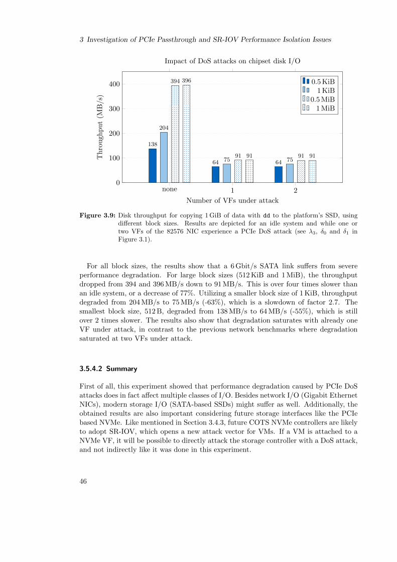
3 Investigation of PCIe Passthrough and SR-IOV Performance Isolation Issues
none 1 20
100
200
300
400
138
64 64
204
75 75
394
91 91
396
91 91
Number of VFs under attack
Th
rou
ghp
ut
(MB/s
)
Impact of DoS attacks on chipset disk I/O
0.5 KiB1 KiB
0.5 MiB1 MiB
Figure 3.9: Disk throughput for copying 1 GiB of data with dd to the platform’s SSD, usingdifferent block sizes. Results are depicted for an idle system and while one ortwo VFs of the 82576 NIC experience a PCIe DoS attack (see λ3, δ0 and δ1 inFigure 3.1).
For all block sizes, the results show that a 6 Gbit/s SATA link suffers from severeperformance degradation. For large block sizes (512 KiB and 1 MiB), the throughputdropped from 394 and 396 MB/s down to 91 MB/s. This is over four times slower thanan idle system, or a decrease of 77%. Utilizing a smaller block size of 1 KiB, throughputdegraded from 204 MB/s to 75 MB/s (-63%), which is a slowdown of factor 2.7. Thesmallest block size, 512 B, degraded from 138 MB/s to 64 MB/s (-55%), which is stillover 2 times slower. The results also show that degradation saturates with already oneVF under attack, in contrast to the previous network benchmarks where degradationsaturated at two VFs under attack.
3.5.4.2 Summary
First of all, this experiment showed that performance degradation caused by PCIe DoSattacks does in fact affect multiple classes of I/O. Besides network I/O (Gigabit EthernetNICs), modern storage I/O (SATA-based SSDs) might suffer as well. Additionally, theobtained results are also important considering future storage interfaces like the PCIebased NVMe. Like mentioned in Section 3.4.3, future COTS NVMe controllers are likelyto adopt SR-IOV, which opens a new attack vector for VMs. If a VM is attached to aNVMe VF, it will be possible to directly attack the storage controller with a DoS attack,and not indirectly like it was done in this experiment.
46
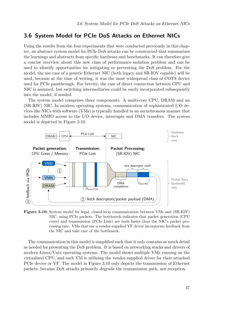
3.6 System Model for PCIe DoS Attacks on Ethernet NICs
3.6 System Model for PCIe DoS Attacks on Ethernet NICs
Using the results from the four experiments that were conducted previously in this chap-ter, an abstract system model for PCIe DoS attacks can be constructed that summarizesthe learnings and abstracts from specific hardware and benchmarks. It can therefore givea concise overview about this new class of performance isolation problem and can beused to identify opportunities for mitigating or preventing the DoS problem. For themodel, the use case of a generic Ethernet NIC (both legacy and SR-IOV capable) will beused, because at the time of writing, it was the most widespread class of COTS deviceused for PCIe passthrough. For brevity, the case of direct connection between CPU andNIC is assumed, but switching intermediaries could be easily incorporated subsequentlyinto the model, if needed.
The system model comprises three components: A multi-core CPU, DRAM and an(SR-IOV) NIC. In modern operating systems, communication of sophisticated I/O de-vices like NICs with software (VMs) is typically handled in an asynchronous manner thatincludes MMIO access to the I/O device, interrupts and DMA transfers. The systemmodel is depicted in Figure 3.10.
VM0
...
VMN
DRAM
Packet generation:CPU Cores / Memory
Transmission:PCIe Link
Packet Processing:(SR-IOV) NIC
NICCPUPCIe Link
DRAM
fetch descriptors/packet payload (DMA)feed
back
via
IRQ
s
23
1
ttrans,PCIe
tproc,NIC
new descriptor notif.
DMAcompletion
Hardwareblockview
Packet flow/bandwidthview
Figure 3.10: System model for legal, closed-loop communication between VMs and (SR-IOV)NIC, using PCIe packets. The bottleneck indicates that packet generation (CPUcores) and transmission (PCIe Link) are both faster than the NIC’s packet pro-cessing rate. VMs that use a vendor-supplied VF driver incorporate feedback fromthe NIC and take care of the bottleneck.
The communication in this model is simplified such that it only contains as much detailas needed for presenting the DoS problem. It is based on networking stacks and drivers ofmodern Linux/Unix operating systems. The model shows multiple VMs running on thevirtualized CPU, and each VM is utilizing the vendor-supplied driver for their attachedPCIe device or VF. The model in Figure 3.10 only depicts the transmission of Ethernetpackets, because DoS attacks primarily degrade the transmission path, not reception.
47
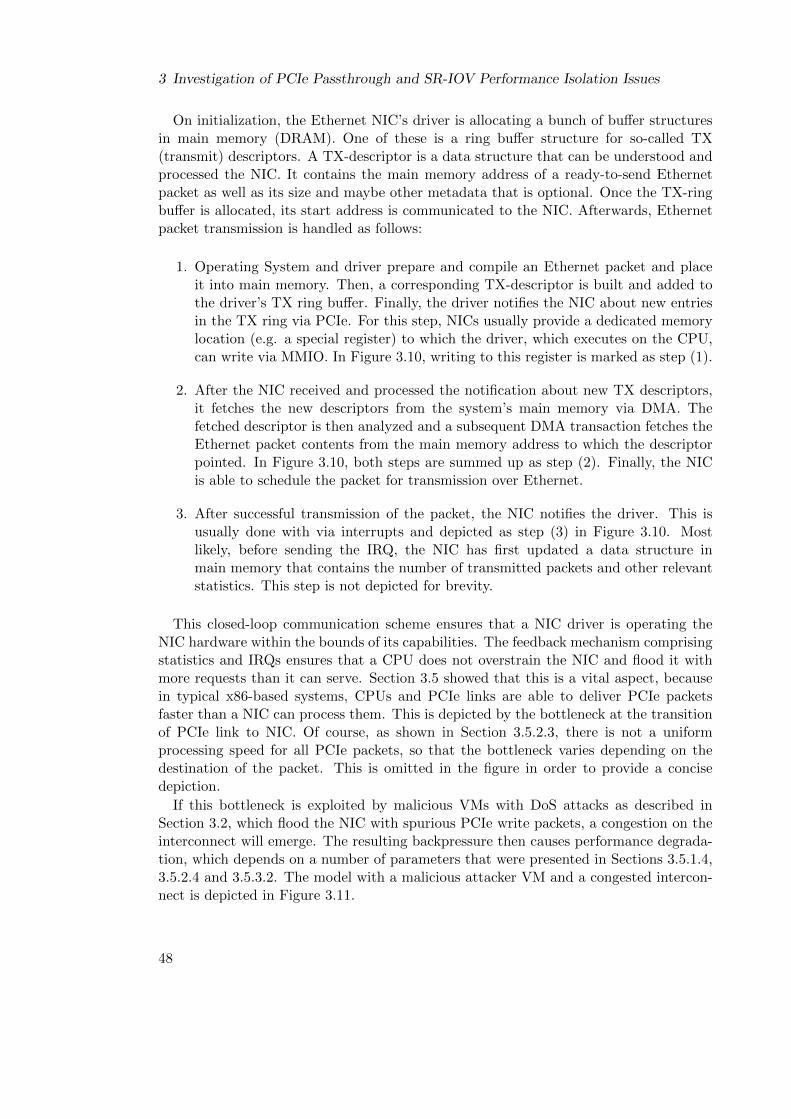
3 Investigation of PCIe Passthrough and SR-IOV Performance Isolation Issues
On initialization, the Ethernet NIC’s driver is allocating a bunch of buffer structuresin main memory (DRAM). One of these is a ring buffer structure for so-called TX(transmit) descriptors. A TX-descriptor is a data structure that can be understood andprocessed the NIC. It contains the main memory address of a ready-to-send Ethernetpacket as well as its size and maybe other metadata that is optional. Once the TX-ringbuffer is allocated, its start address is communicated to the NIC. Afterwards, Ethernetpacket transmission is handled as follows:
1. Operating System and driver prepare and compile an Ethernet packet and placeit into main memory. Then, a corresponding TX-descriptor is built and added tothe driver’s TX ring buffer. Finally, the driver notifies the NIC about new entriesin the TX ring via PCIe. For this step, NICs usually provide a dedicated memorylocation (e.g. a special register) to which the driver, which executes on the CPU,can write via MMIO. In Figure 3.10, writing to this register is marked as step (1).
2. After the NIC received and processed the notification about new TX descriptors,it fetches the new descriptors from the system’s main memory via DMA. Thefetched descriptor is then analyzed and a subsequent DMA transaction fetches theEthernet packet contents from the main memory address to which the descriptorpointed. In Figure 3.10, both steps are summed up as step (2). Finally, the NICis able to schedule the packet for transmission over Ethernet.
3. After successful transmission of the packet, the NIC notifies the driver. This isusually done with via interrupts and depicted as step (3) in Figure 3.10. Mostlikely, before sending the IRQ, the NIC has first updated a data structure inmain memory that contains the number of transmitted packets and other relevantstatistics. This step is not depicted for brevity.
This closed-loop communication scheme ensures that a NIC driver is operating theNIC hardware within the bounds of its capabilities. The feedback mechanism comprisingstatistics and IRQs ensures that a CPU does not overstrain the NIC and flood it withmore requests than it can serve. Section 3.5 showed that this is a vital aspect, becausein typical x86-based systems, CPUs and PCIe links are able to deliver PCIe packetsfaster than a NIC can process them. This is depicted by the bottleneck at the transitionof PCIe link to NIC. Of course, as shown in Section 3.5.2.3, there is not a uniformprocessing speed for all PCIe packets, so that the bottleneck varies depending on thedestination of the packet. This is omitted in the figure in order to provide a concisedepiction.
If this bottleneck is exploited by malicious VMs with DoS attacks as described inSection 3.2, which flood the NIC with spurious PCIe write packets, a congestion on theinterconnect will emerge. The resulting backpressure then causes performance degrada-tion, which depends on a number of parameters that were presented in Sections 3.5.1.4,3.5.2.4 and 3.5.3.2. The model with a malicious attacker VM and a congested intercon-nect is depicted in Figure 3.11.
48
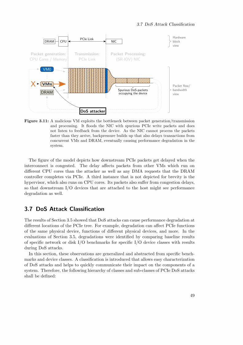
3.7 DoS Attack Classification
VM0
...
DRAM
Packet generation:CPU Cores / Memory
Transmission:PCIe Link
Packet Processing:(SR-IOV) NIC
Spurious DoS-packetsoccupying the device
X
DoS attacker
VMN
NICCPUPCIe Link
DRAMHardwareblockview
Packet flow/bandwidthview
Figure 3.11: A malicious VM exploits the bottleneck between packet generation/transmissionand processing. It floods the NIC with spurious PCIe write packets and doesnot listen to feedback from the device. As the NIC cannot process the packetsfaster than they arrive, backpressure builds up that also delays transactions fromconcurrent VMs and DRAM, eventually causing performance degradation in thesystem.
The figure of the model depicts how downstream PCIe packets get delayed when theinterconnect is congested. The delay affects packets from other VMs which run ondifferent CPU cores than the attacker as well as any DMA requests that the DRAMcontroller completes via PCIe. A third instance that is not depicted for brevity is thehypervisor, which also runs on CPU cores. Its packets also suffer from congestion delays,so that downstream I/O devices that are attached to the host might see performancedegradation as well.
3.7 DoS Attack Classification
The results of Section 3.5 showed that DoS attacks can cause performance degradation atdifferent locations of the PCIe tree. For example, degradation can affect PCIe functionsof the same physical device, functions of different physical devices, and more. In theevaluations of Section 3.5, degradations were identified by comparing baseline resultsof specific network or disk I/O benchmarks for specific I/O device classes with resultsduring DoS attacks.
In this section, these observations are generalized and abstracted from specific bench-marks and device classes. A classification is introduced that allows easy characterizationof DoS attacks and helps to quickly communicate their impact on the components of asystem. Therefore, the following hierarchy of classes and sub-classes of PCIe DoS attacksshall be defined:
49
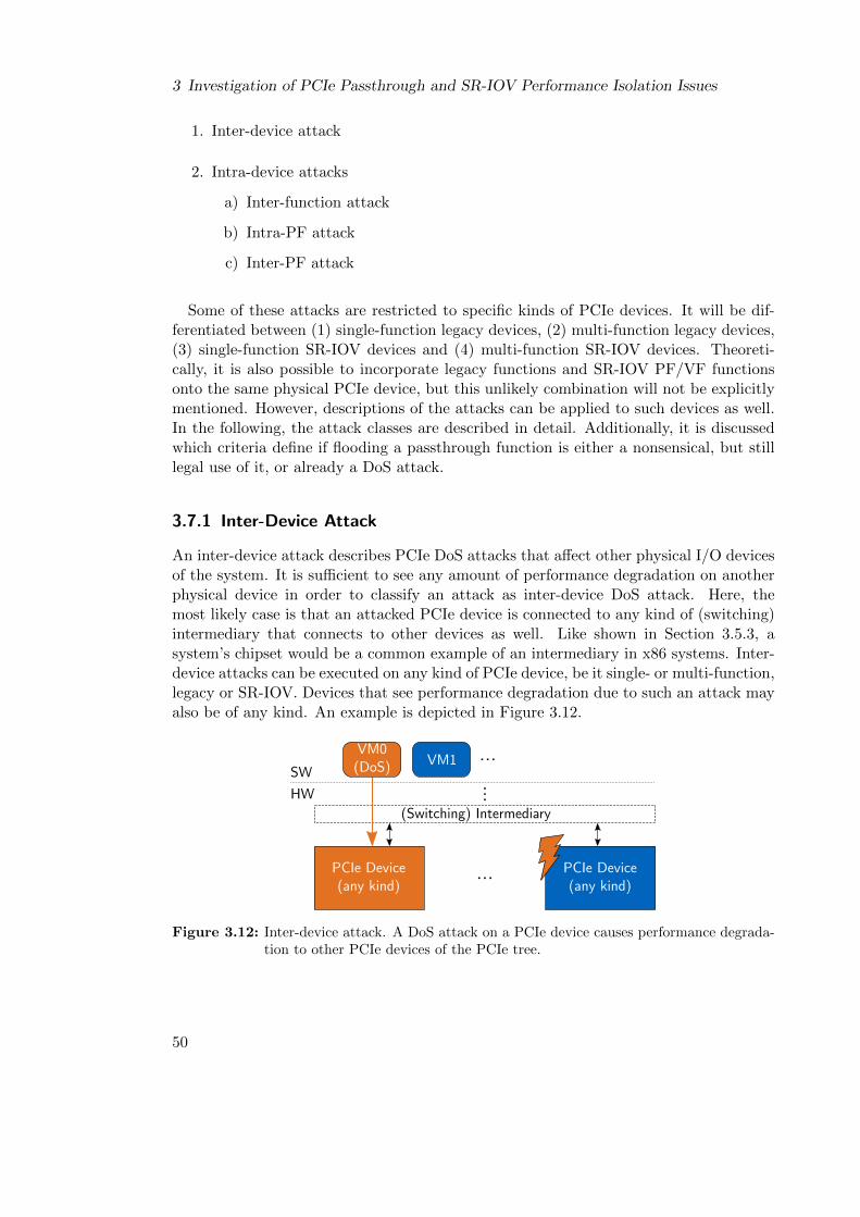
3 Investigation of PCIe Passthrough and SR-IOV Performance Isolation Issues
1. Inter-device attack
2. Intra-device attacks
a) Inter-function attack
b) Intra-PF attack
c) Inter-PF attack
Some of these attacks are restricted to specific kinds of PCIe devices. It will be dif-ferentiated between (1) single-function legacy devices, (2) multi-function legacy devices,(3) single-function SR-IOV devices and (4) multi-function SR-IOV devices. Theoreti-cally, it is also possible to incorporate legacy functions and SR-IOV PF/VF functionsonto the same physical PCIe device, but this unlikely combination will not be explicitlymentioned. However, descriptions of the attacks can be applied to such devices as well.In the following, the attack classes are described in detail. Additionally, it is discussedwhich criteria define if flooding a passthrough function is either a nonsensical, but stilllegal use of it, or already a DoS attack.
3.7.1 Inter-Device Attack
An inter-device attack describes PCIe DoS attacks that affect other physical I/O devicesof the system. It is sufficient to see any amount of performance degradation on anotherphysical device in order to classify an attack as inter-device DoS attack. Here, themost likely case is that an attacked PCIe device is connected to any kind of (switching)intermediary that connects to other devices as well. Like shown in Section 3.5.3, asystem’s chipset would be a common example of an intermediary in x86 systems. Inter-device attacks can be executed on any kind of PCIe device, be it single- or multi-function,legacy or SR-IOV. Devices that see performance degradation due to such an attack mayalso be of any kind. An example is depicted in Figure 3.12.
...
(Switching) Intermediary
PCIe Device(any kind)
...
...VM1SW
HW
PCIe Device(any kind)
VM0(DoS)
Figure 3.12: Inter-device attack. A DoS attack on a PCIe device causes performance degrada-tion to other PCIe devices of the PCIe tree.
50
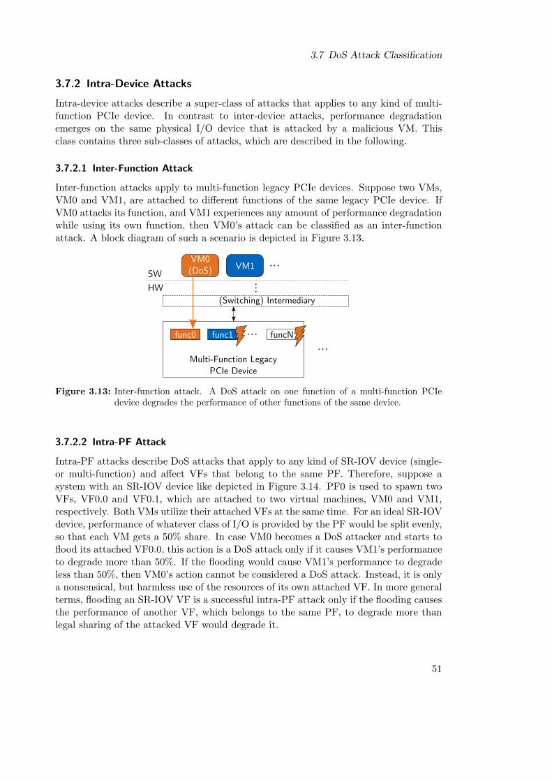
3.7 DoS Attack Classification
3.7.2 Intra-Device Attacks
Intra-device attacks describe a super-class of attacks that applies to any kind of multi-function PCIe device. In contrast to inter-device attacks, performance degradationemerges on the same physical I/O device that is attacked by a malicious VM. Thisclass contains three sub-classes of attacks, which are described in the following.
3.7.2.1 Inter-Function Attack
Inter-function attacks apply to multi-function legacy PCIe devices. Suppose two VMs,VM0 and VM1, are attached to different functions of the same legacy PCIe device. IfVM0 attacks its function, and VM1 experiences any amount of performance degradationwhile using its own function, then VM0’s attack can be classified as an inter-functionattack. A block diagram of such a scenario is depicted in Figure 3.13.
(Switching) Intermediary
Multi-Function LegacyPCIe Device
...
VM0(DoS)
...VM1SW
HW
func0 func1 funcN......
Figure 3.13: Inter-function attack. A DoS attack on one function of a multi-function PCIedevice degrades the performance of other functions of the same device.
3.7.2.2 Intra-PF Attack
Intra-PF attacks describe DoS attacks that apply to any kind of SR-IOV device (single-or multi-function) and affect VFs that belong to the same PF. Therefore, suppose asystem with an SR-IOV device like depicted in Figure 3.14. PF0 is used to spawn twoVFs, VF0.0 and VF0.1, which are attached to two virtual machines, VM0 and VM1,respectively. Both VMs utilize their attached VFs at the same time. For an ideal SR-IOVdevice, performance of whatever class of I/O is provided by the PF would be split evenly,so that each VM gets a 50% share. In case VM0 becomes a DoS attacker and starts toflood its attached VF0.0, this action is a DoS attack only if it causes VM1’s performanceto degrade more than 50%. If the flooding would cause VM1’s performance to degradeless than 50%, then VM0’s action cannot be considered a DoS attack. Instead, it is onlya nonsensical, but harmless use of the resources of its own attached VF. In more generalterms, flooding an SR-IOV VF is a successful intra-PF attack only if the flooding causesthe performance of another VF, which belongs to the same PF, to degrade more thanlegal sharing of the attacked VF would degrade it.
51

3 Investigation of PCIe Passthrough and SR-IOV Performance Isolation Issues
VF0.0
VF0.1
PF0
(Switching) Intermediary
SR-IOV PCIeDevice
...
VM0(DoS)
...VM1SW
HW
...
Figure 3.14: Intra-PF attack. A DoS attack on one VF of a PF degrades the performance ofother VFs of the same PF more than legal sharing of the attacked VF would do.
3.7.2.3 Inter-PF Attack
Inter-PF attacks describe DoS attacks that affect VFs that belong to different PFs. Togive an example, suppose a system like depicted in Figure 3.15. VM0 is again attached toVF0.0, but this time, VM1 is attached to VF1.0. In this setup, simultaneous operationof both VFs would yield 100% of PF performance for each VM, because only a single VFis instantiated per PF. Here, performance isolation requirements demand that VF0.0 ofPF0 cannot have any performance impact on VF1.0 of PF1, because the VFs belongto physically disjunct I/O resources. In general terms, flooding an SR-IOV VF is asuccessful inter-PF attack if the flooding causes any amount of performance degradationfor VFs that belong to different PFs. A block diagram for this example is depicted inFigure 3.15.
VF0.0PF0
VF1.0 PF1 ...
(Switching) Intermediary
Multi-Function SR-IOVPCIe Device
VM0(DoS)
...VM1SW
HW
...
Figure 3.15: Inter-PF attack. A DoS attack on a VF of PF0 degrades the performance of a VFof PF1.
52
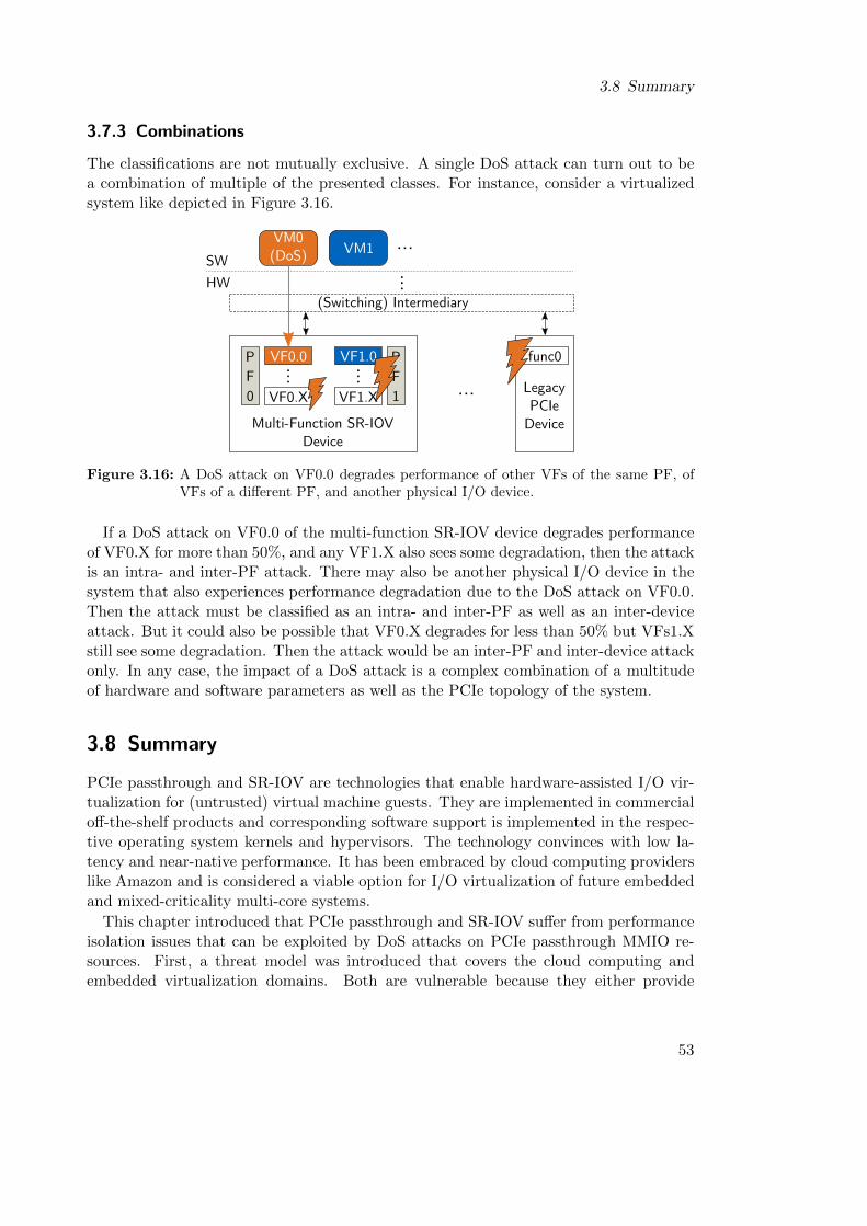
3.8 Summary
3.7.3 Combinations
The classifications are not mutually exclusive. A single DoS attack can turn out to bea combination of multiple of the presented classes. For instance, consider a virtualizedsystem like depicted in Figure 3.16.
VF0.0
VF0.X
...
PF0
VF1.0
VF1.X
...
PF1 ...
(Switching) Intermediary
Multi-Function SR-IOVDevice
...
VM0(DoS)
...VM1
LegacyPCIe
Device
func0
SW
HW
Figure 3.16: A DoS attack on VF0.0 degrades performance of other VFs of the same PF, ofVFs of a different PF, and another physical I/O device.
If a DoS attack on VF0.0 of the multi-function SR-IOV device degrades performanceof VF0.X for more than 50%, and any VF1.X also sees some degradation, then the attackis an intra- and inter-PF attack. There may also be another physical I/O device in thesystem that also experiences performance degradation due to the DoS attack on VF0.0.Then the attack must be classified as an intra- and inter-PF as well as an inter-deviceattack. But it could also be possible that VF0.X degrades for less than 50% but VFs1.Xstill see some degradation. Then the attack would be an inter-PF and inter-device attackonly. In any case, the impact of a DoS attack is a complex combination of a multitudeof hardware and software parameters as well as the PCIe topology of the system.
3.8 Summary
PCIe passthrough and SR-IOV are technologies that enable hardware-assisted I/O vir-tualization for (untrusted) virtual machine guests. They are implemented in commercialoff-the-shelf products and corresponding software support is implemented in the respec-tive operating system kernels and hypervisors. The technology convinces with low la-tency and near-native performance. It has been embraced by cloud computing providerslike Amazon and is considered a viable option for I/O virtualization of future embeddedand mixed-criticality multi-core systems.
This chapter introduced that PCIe passthrough and SR-IOV suffer from performanceisolation issues that can be exploited by DoS attacks on PCIe passthrough MMIO re-sources. First, a threat model was introduced that covers the cloud computing andembedded virtualization domains. Both are vulnerable because they either provide
53
3 Investigation of PCIe Passthrough and SR-IOV Performance Isolation Issues
passthrough access to untrusted users as part of the business model (cloud: IaaS) orby exposing potentially exploitable interfaces to untrusted users (cloud: PaaS, embed-ded: Infotainment). Subsequently, the implementation of DoS attacks is discussed andan exemplary implementation in the C language is presented.
In order to investigate and evaluate performance isolation issues of PCIe passthroughand SR-IOV, an evaluation platform was compiled. The platform is an x86 based systemcomprising a dual-port SR-IOV capable Gigabit Ethernet adapter, two single-port non-SR-IOV Ethernet adapters, an SSD disk and an FPGA board with custom logic designto aid the evaluation. On this platform, four different experiments were conductedwhich provided results that contributed to a thorough understanding of the isolationissues during PCIe DoS attacks. The utilized benchmarks included network streamingbenchmarks for TCP and UDP protocols, latencies for single PCIe reads and storagethroughput for SSDs.
Results showed that DoS attacks can significantly degrade the performance of SR-IOV devices as well as other PCIe devices on the interconnect. For instance, experi-ment 1 demonstrated that, during DoS attacks, Ethernet throughputs for the SR-IOVadapter drop by up to 35% and latencies increase up to 698%; Experiment 4 additionallydemonstrated that disk storage throughput drops by up to 77%. The actual amount ofdegradation always depends on a multitude of hardware- and software parameters of thesystem, as well as the PCIe topology. The two most influential parameters are (1) thePCIe packet processing speed of the device that is targeted by the DoS attack, becauseit influences the additional latency caused by buffer congestion, and (2) the number ofPCIe packet buffers that an affected device must share with the DoS victim device.
In conclusion, the results of the experiments were used to introduce an abstract systemmodel for PCIe DoS attacks on Ethernet devices. The model abstracted from the specifichardware and benchmarks used in the experiments and therefore provided a genericpresentation SR-IOV’s performance isolation issues. Finally, the chapter was closed withthe presentation of a classification of DoS attacks. The classes that were introduced aredistinguished by their reach inside the system and create new vocabulary that helps tocharacterize PCIe DoS attacks in future research.
54
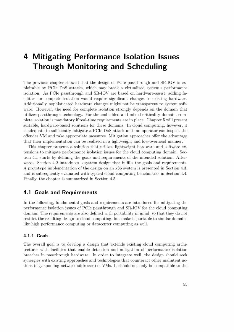
4 Mitigating Performance Isolation IssuesThrough Monitoring and Scheduling
The previous chapter showed that the design of PCIe passthrough and SR-IOV is ex-ploitable by PCIe DoS attacks, which may break a virtualized system’s performanceisolation. As PCIe passthrough and SR-IOV are based on hardware-assist, adding fa-cilities for complete isolation would require significant changes to existing hardware.Additionally, sophisticated hardware changes might not be transparent to system soft-ware. However, the need for complete isolation strongly depends on the domain thatutilizes passthrough technology. For the embedded and mixed-criticality domain, com-plete isolation is mandatory if real-time requirements are in place. Chapter 5 will presentsuitable, hardware-based solutions for these domains. In cloud computing, however, itis adequate to sufficiently mitigate a PCIe DoS attack until an operator can inspect theoffender VM and take appropriate measures. Mitigation approaches offer the advantagethat their implementation can be realized in a lightweight and low-overhead manner.
This chapter presents a solution that utilizes lightweight hardware and software ex-tensions to mitigate performance isolation issues for the cloud computing domain. Sec-tion 4.1 starts by defining the goals and requirements of the intended solution. After-wards, Section 4.2 introduces a system design that fulfills the goals and requirements.A prototype implementation of the design on an x86 system is presented in Section 4.3,and is subsequently evaluated with typical cloud computing benchmarks in Section 4.4.Finally, the chapter is summarized in Section 4.5.
4.1 Goals and Requirements
In the following, fundamental goals and requirements are introduced for mitigating theperformance isolation issues of PCIe passthrough and SR-IOV for the cloud computingdomain. The requirements are also defined with portability in mind, so that they do notrestrict the resulting design to cloud computing, but make it portable to similar domainslike high performance computing or datacenter computing as well.
4.1.1 Goals
The overall goal is to develop a design that extends existing cloud computing archi-tectures with facilities that enable detection and mitigation of performance isolationbreaches in passthrough hardware. In order to integrate well, the design should seeksynergies with existing approaches and technologies that counteract other malintent ac-tions (e.g. spoofing network addresses) of VMs. It should not only be compatible to the
55
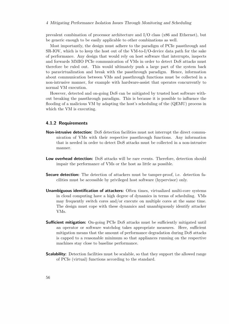
4 Mitigating Performance Isolation Issues Through Monitoring and Scheduling
prevalent combination of processor architecture and I/O class (x86 and Ethernet), butbe generic enough to be easily applicable to other combinations as well.
Most importantly, the design must adhere to the paradigm of PCIe passthrough andSR-IOV, which is to keep the host out of the VM-to-I/O-device data path for the sakeof performance. Any design that would rely on host software that interrupts, inspectsand forwards MMIO PCIe communication of VMs in order to detect DoS attacks musttherefore be ruled out. This would ultimately push a large part of the system backto paravirtualization and break with the passthrough paradigm. Hence, informationabout communication between VMs and passthrough functions must be collected in anon-intrusive manner, for example with hardware-assist that operates concurrently tonormal VM execution.
However, detected and on-going DoS can be mitigated by trusted host software with-out breaking the passthrough paradigm. This is because it is possible to influence theflooding of a malicious VM by adapting the host’s scheduling of the (QEMU) process inwhich the VM is executing.
4.1.2 Requirements
Non-intrusive detection: DoS detection facilities must not interrupt the direct commu-nication of VMs with their respective passthrough functions. Any informationthat is needed in order to detect DoS attacks must be collected in a non-intrusivemanner.
Low overhead detection: DoS attacks will be rare events. Therefore, detection shouldimpair the performance of VMs or the host as little as possible.
Secure detection: The detection of attackers must be tamper-proof, i.e. detection fa-cilities must be accessible by privileged host software (hypervisor) only.
Unambiguous identification of attackers: Often times, virtualized multi-core systemsin cloud computing have a high degree of dynamics in terms of scheduling. VMsmay frequently switch cores and/or execute on multiple cores at the same time.The design must cope with these dynamics and unambiguously identify attackerVMs.
Sufficient mitigation: On-going PCIe DoS attacks must be sufficiently mitigated untilan operator or software watchdog takes appropriate measures. Here, sufficientmitigation means that the amount of performance degradation during DoS attacksis capped to a reasonable minimum so that appliances running on the respectivemachines stay close to baseline performance.
Scalability: Detection facilities must be scalable, so that they support the allowed rangeof PCIe (virtual) functions according to the standard.
56
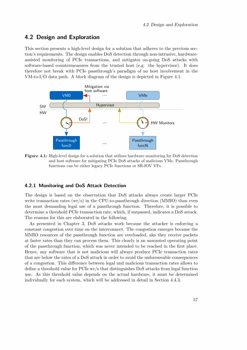
4.2 Design and Exploration
4.2 Design and Exploration
This section presents a high-level design for a solution that adheres to the previous sec-tion’s requirements. The design enables DoS detection through non-intrusive, hardware-assisted monitoring of PCIe transactions, and mitigates on-going DoS attacks withsoftware-based countermeasures from the trusted host (e.g. the hypervisor). It doestherefore not break with PCIe passthrough’s paradigm of no host involvement in theVM-to-I/O data path. A block diagram of the design is depicted in Figure 4.1.
Hypervisor
VM0
SW
HW
... VMN
DoS!
Mitigation viahost software
HW Monitors
Passthroughfunc0
... PassthroughfuncN
...
Figure 4.1: High-level design for a solution that utilizes hardware monitoring for DoS detectionand host software for mitigating PCIe DoS attacks of malicious VMs. Passthroughfunctions can be either legacy PCIe functions or SR-IOV VFs.
4.2.1 Monitoring and DoS Attack Detection
The design is based on the observation that DoS attacks always create larger PCIewrite transaction rates (wr/s) in the CPU-to-passthrough direction (MMIO) than eventhe most demanding legal use of a passthrough function. Therefore, it is possible todetermine a threshold PCIe transaction rate, which, if surpassed, indicates a DoS attack.The reasons for this are elaborated in the following.
As presented in Chapter 3, DoS attacks work because the attacker is enforcing aconstant congestion over time on the interconnect. The congestion emerges because theMMIO resources of the passthrough function are overloaded, aka they receive packetsat faster rates than they can process them. This clearly is an unwanted operating pointof the passthrough function, which was never intended to be reached in the first place.Hence, any software that is not malicious will always produce PCIe transaction ratesthat are below the rates of a DoS attack in order to avoid the unforeseeable consequencesof a congestion. This difference between legal and malicious transaction rates allows todefine a threshold value for PCIe wr/s that distinguishes DoS attacks from legal functionuse. As this threshold value depends on the actual hardware, it must be determinedindividually for each system, which will be addressed in detail in Section 4.4.3.
57

4 Mitigating Performance Isolation Issues Through Monitoring and Scheduling
In order to realize this approach towards DoS detection, hardware monitoring facilitiesare needed that satisfy the following requirements.
1. Monitors must be able to detect and count CPU-to-passthrough PCIe transactions(MMIO) at passthrough function granularity. Here, a passthrough function meanseither a classic function of a legacy PCIe device or a VF of an SR-IOV capabledevice.
2. To satisfy the requirement for secure detection, any access to monitoring facilities(setting parameters, reading out values, etc.) must be restricted to privileged hostsoftware.
DoS detection can then be implemented by sampling the monitor’s counter value forMMIO transactions, calculate the transaction rate, and compare it to the threshold valuefor DoS attacks. Ideally, monitoring facilities already support programmable samplingand comparison features so that this task can be offloaded to hardware, which reducesCPU overhead. However, this is not a strict requirement as long as the CPU overheadfor these routines is acceptable.
4.2.2 Exploration of Monitoring Alternatives
In a PCIe network, it is possible to realize hardware monitoring in three different kindsof components. (1) The CPU cores, which are the sources of the PCIe packets, (2) theI/O device that provides the passthrough function(s) or, if existent, (3) an intermediarydevice like a chipset or switch that is interposed between CPU and I/O device. In thefollowing, all three possibilities are explored and checked against the requirements thatwere proposed in the previous sections.
4.2.2.1 Monitoring in CPUs
Nowadays, common CPU architectures and their respective processors already provideso-called Performance Monitoring Units (PMUs), which enable monitoring of numerousarchitectural events in a CPU. For example, they are available in IBM POWER8 [123],ARM Cortex [124] and most Intel processors [4]. The following exploration will onlycover Intel processors, because at the time of writing, cloud computing providers pairedPCIe passthrough technology almost exclusively with Intel (Xeon) processors.
In each CPU core, there is one PMU, which is a collection of registers that enableperformance monitoring. Each PMU provides a set of Performance Monitoring Counter(PMC) registers (IA32 PMCx), which count events that are selected via correspondingselection registers (IA32 PERFEVTSELx). The bulk of supported events provides insight tothe cache and memory subsystem. Certain complex events also need further specificationvia associated configuration registers. For instance, if IA32 PERFEVTSEL0 is configuredto select so-called offcore events for counting, MSR OFFCORE RSP0 must further specify theexact offcore event that shall be counted by IA32 PMC0. Offcore events include, amongothers, I/O and MMIO transactions. A short overview of PMUs is given in Figure 4.2.
58
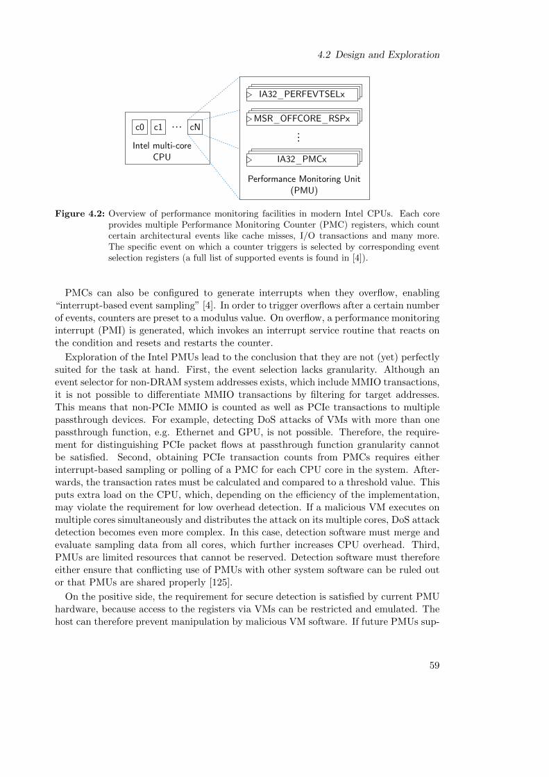
4.2 Design and Exploration
Intel multi-coreCPU
c1 cN... MSR_OFFCORE_RSPx
IA32_PERFEVTSELx
...
IA32_PMCx
Performance Monitoring Unit(PMU)
c0
Figure 4.2: Overview of performance monitoring facilities in modern Intel CPUs. Each coreprovides multiple Performance Monitoring Counter (PMC) registers, which countcertain architectural events like cache misses, I/O transactions and many more.The specific event on which a counter triggers is selected by corresponding eventselection registers (a full list of supported events is found in [4]).
PMCs can also be configured to generate interrupts when they overflow, enabling“interrupt-based event sampling” [4]. In order to trigger overflows after a certain numberof events, counters are preset to a modulus value. On overflow, a performance monitoringinterrupt (PMI) is generated, which invokes an interrupt service routine that reacts onthe condition and resets and restarts the counter.
Exploration of the Intel PMUs lead to the conclusion that they are not (yet) perfectlysuited for the task at hand. First, the event selection lacks granularity. Although anevent selector for non-DRAM system addresses exists, which include MMIO transactions,it is not possible to differentiate MMIO transactions by filtering for target addresses.This means that non-PCIe MMIO is counted as well as PCIe transactions to multiplepassthrough devices. For example, detecting DoS attacks of VMs with more than onepassthrough function, e.g. Ethernet and GPU, is not possible. Therefore, the require-ment for distinguishing PCIe packet flows at passthrough function granularity cannotbe satisfied. Second, obtaining PCIe transaction counts from PMCs requires eitherinterrupt-based sampling or polling of a PMC for each CPU core in the system. After-wards, the transaction rates must be calculated and compared to a threshold value. Thisputs extra load on the CPU, which, depending on the efficiency of the implementation,may violate the requirement for low overhead detection. If a malicious VM executes onmultiple cores simultaneously and distributes the attack on its multiple cores, DoS attackdetection becomes even more complex. In this case, detection software must merge andevaluate sampling data from all cores, which further increases CPU overhead. Third,PMUs are limited resources that cannot be reserved. Detection software must thereforeeither ensure that conflicting use of PMUs with other system software can be ruled outor that PMUs are shared properly [125].
On the positive side, the requirement for secure detection is satisfied by current PMUhardware, because access to the registers via VMs can be restricted and emulated. Thehost can therefore prevent manipulation by malicious VM software. If future PMUs sup-
59
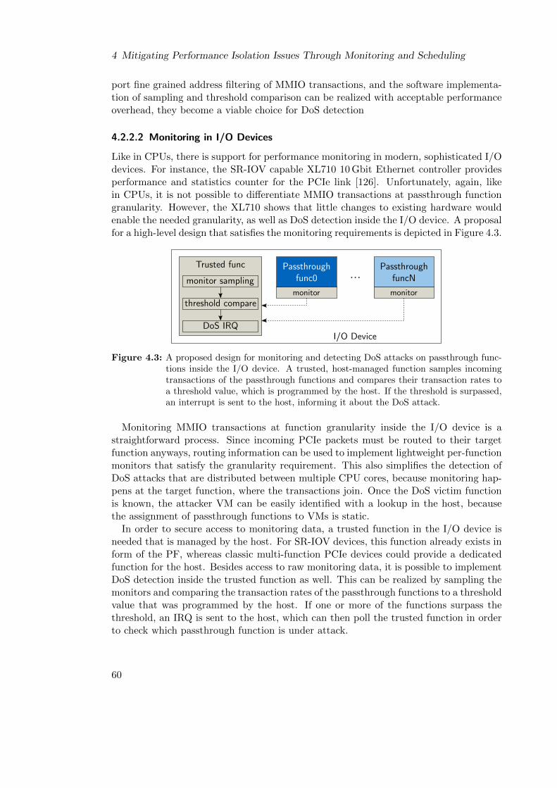
4 Mitigating Performance Isolation Issues Through Monitoring and Scheduling
port fine grained address filtering of MMIO transactions, and the software implementa-tion of sampling and threshold comparison can be realized with acceptable performanceoverhead, they become a viable choice for DoS detection
4.2.2.2 Monitoring in I/O Devices
Like in CPUs, there is support for performance monitoring in modern, sophisticated I/Odevices. For instance, the SR-IOV capable XL710 10 Gbit Ethernet controller providesperformance and statistics counter for the PCIe link [126]. Unfortunately, again, likein CPUs, it is not possible to differentiate MMIO transactions at passthrough functiongranularity. However, the XL710 shows that little changes to existing hardware wouldenable the needed granularity, as well as DoS detection inside the I/O device. A proposalfor a high-level design that satisfies the monitoring requirements is depicted in Figure 4.3.
monitor
Passthroughfunc0
Trusted func
I/O Device
monitor
PassthroughfuncN...
monitor sampling
threshold compare
DoS IRQ
Figure 4.3: A proposed design for monitoring and detecting DoS attacks on passthrough func-tions inside the I/O device. A trusted, host-managed function samples incomingtransactions of the passthrough functions and compares their transaction rates toa threshold value, which is programmed by the host. If the threshold is surpassed,an interrupt is sent to the host, informing it about the DoS attack.
Monitoring MMIO transactions at function granularity inside the I/O device is astraightforward process. Since incoming PCIe packets must be routed to their targetfunction anyways, routing information can be used to implement lightweight per-functionmonitors that satisfy the granularity requirement. This also simplifies the detection ofDoS attacks that are distributed between multiple CPU cores, because monitoring hap-pens at the target function, where the transactions join. Once the DoS victim functionis known, the attacker VM can be easily identified with a lookup in the host, becausethe assignment of passthrough functions to VMs is static.
In order to secure access to monitoring data, a trusted function in the I/O device isneeded that is managed by the host. For SR-IOV devices, this function already exists inform of the PF, whereas classic multi-function PCIe devices could provide a dedicatedfunction for the host. Besides access to raw monitoring data, it is possible to implementDoS detection inside the trusted function as well. This can be realized by sampling themonitors and comparing the transaction rates of the passthrough functions to a thresholdvalue that was programmed by the host. If one or more of the functions surpass thethreshold, an IRQ is sent to the host, which can then poll the trusted function in orderto check which passthrough function is under attack.
60
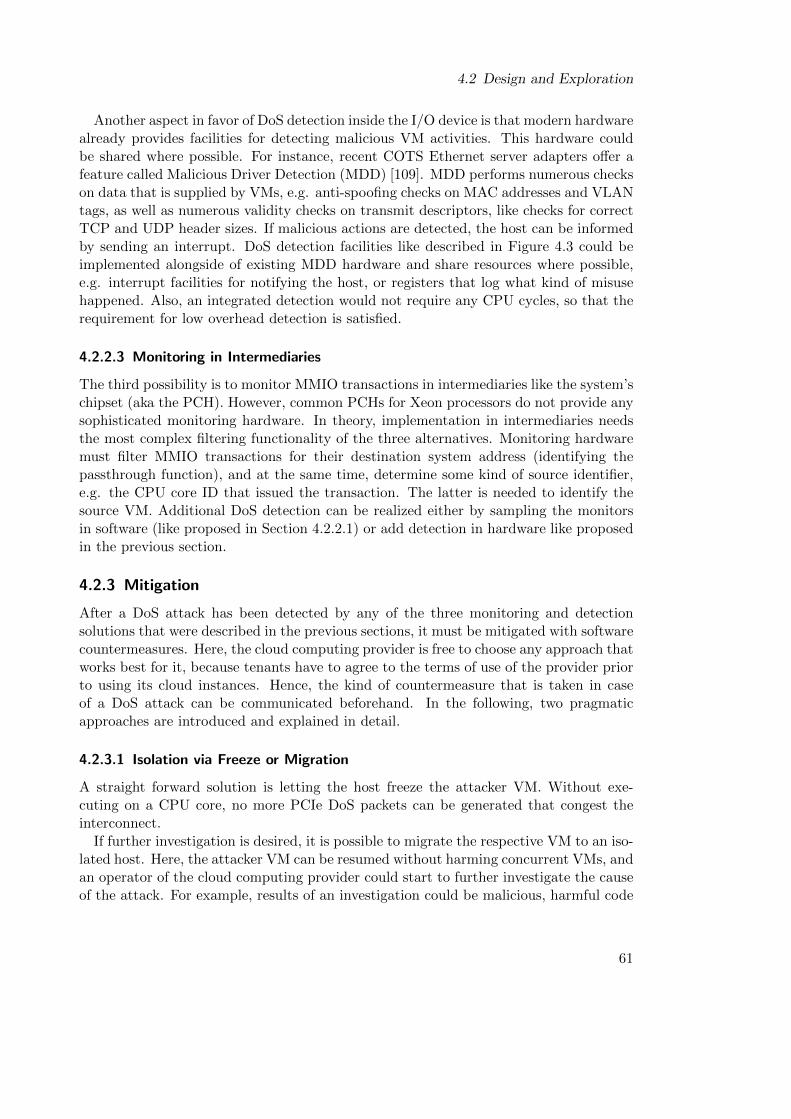
4.2 Design and Exploration
Another aspect in favor of DoS detection inside the I/O device is that modern hardwarealready provides facilities for detecting malicious VM activities. This hardware couldbe shared where possible. For instance, recent COTS Ethernet server adapters offer afeature called Malicious Driver Detection (MDD) [109]. MDD performs numerous checkson data that is supplied by VMs, e.g. anti-spoofing checks on MAC addresses and VLANtags, as well as numerous validity checks on transmit descriptors, like checks for correctTCP and UDP header sizes. If malicious actions are detected, the host can be informedby sending an interrupt. DoS detection facilities like described in Figure 4.3 could beimplemented alongside of existing MDD hardware and share resources where possible,e.g. interrupt facilities for notifying the host, or registers that log what kind of misusehappened. Also, an integrated detection would not require any CPU cycles, so that therequirement for low overhead detection is satisfied.
4.2.2.3 Monitoring in Intermediaries
The third possibility is to monitor MMIO transactions in intermediaries like the system’schipset (aka the PCH). However, common PCHs for Xeon processors do not provide anysophisticated monitoring hardware. In theory, implementation in intermediaries needsthe most complex filtering functionality of the three alternatives. Monitoring hardwaremust filter MMIO transactions for their destination system address (identifying thepassthrough function), and at the same time, determine some kind of source identifier,e.g. the CPU core ID that issued the transaction. The latter is needed to identify thesource VM. Additional DoS detection can be realized either by sampling the monitorsin software (like proposed in Section 4.2.2.1) or add detection in hardware like proposedin the previous section.
4.2.3 Mitigation
After a DoS attack has been detected by any of the three monitoring and detectionsolutions that were described in the previous sections, it must be mitigated with softwarecountermeasures. Here, the cloud computing provider is free to choose any approach thatworks best for it, because tenants have to agree to the terms of use of the provider priorto using its cloud instances. Hence, the kind of countermeasure that is taken in caseof a DoS attack can be communicated beforehand. In the following, two pragmaticapproaches are introduced and explained in detail.
4.2.3.1 Isolation via Freeze or Migration
A straight forward solution is letting the host freeze the attacker VM. Without exe-cuting on a CPU core, no more PCIe DoS packets can be generated that congest theinterconnect.
If further investigation is desired, it is possible to migrate the respective VM to an iso-lated host. Here, the attacker VM can be resumed without harming concurrent VMs, andan operator of the cloud computing provider could start to further investigate the causeof the attack. For example, results of an investigation could be malicious, harmful code
61
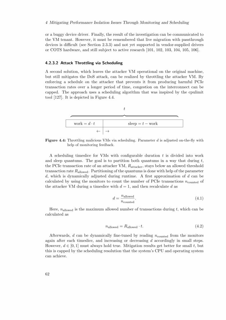
4 Mitigating Performance Isolation Issues Through Monitoring and Scheduling
or a buggy device driver. Finally, the result of the investigation can be communicated tothe VM tenant. However, it must be remembered that live migration with passthroughdevices is difficult (see Section 2.3.3) and not yet supported in vendor-supplied driversor COTS hardware, and still subject to active research [101, 102, 103, 104, 105, 106].
4.2.3.2 Attack Throttling via Scheduling
A second solution, which leaves the attacker VM operational on the original machine,but still mitigates the DoS attack, can be realized by throttling the attacker VM. Byenforcing a schedule on the attacker that prevents it from producing harmful PCIetransaction rates over a longer period of time, congestion on the interconnect can becapped. The approach uses a scheduling algorithm that was inspired by the cpulimittool [127]. It is depicted in Figure 4.4.
t︷ ︸︸ ︷work = d · t sleep = t− work
← →
Figure 4.4: Throttling malicious VMs via scheduling. Parameter d is adjusted on-the-fly withhelp of monitoring feedback.
A scheduling timeslice for VMs with configurable duration t is divided into workand sleep quantums. The goal is to partition both quantums in a way that during t,the PCIe transaction rate of an attacker VM, Rattacker, stays below an allowed thresholdtransaction rateRallowed. Partitioning of the quantums is done with help of the parameterd, which is dynamically adjusted during runtime. A first approximation of d can becalculated by using the monitors to count the number of PCIe transactions ncounted ofthe attacker VM during a timeslice with d = 1, and then recalculate d as
d =nallowedncounted
. (4.1)
Here, nallowed is the maximum allowed number of transactions during t, which can becalculated as
nallowed = Rallowed · t. (4.2)
Afterwards, d can be dynamically fine-tuned by reading ncounted from the monitorsagain after each timeslice, and increasing or decreasing d accordingly in small steps.However, d ∈ [0, 1] must always hold true. Mitigation results get better for small t, butthis is capped by the scheduling resolution that the system’s CPU and operating systemcan achieve.
62
4.3 Implementation
4.3 Implementation
This section presents a proof-of-concept prototype implementation of the design ideas ofthe previous section. The prototype was developed on a cloud-grade x86 Xeon machinefeaturing the same 82576 dual-port Gigabit Ethernet NIC with SR-IOV support thatwas used in Chapter 3. As exploration results in the previous section showed, PCIetransaction monitoring lacks the needed granularity in current hardware. Therefore,monitoring and hardware-assisted DoS detection were implemented on a PCIe-capableXilinx VC709 FPGA board, which then emulated these features for the 82576 NIC.
The decision to build a prototype that works as if monitoring takes place inside theI/O device was made due to the results of the exploration in Section 4.2.2. It showed that(1) existing COTS I/O devices already provide hardware facilities to detect maliciousdrivers and (2) DoS detection is less ambiguous inside the I/O device. Both reasonsmake I/O devices likely candidates for future incorporation of the presented concepts.
4.3.1 Overview
Figure 4.5 depicts a block diagram of the prototype. It used an Intel S2600COE dual-socket Motherboard that features a C602 chipset as the Platform-Controller-Hub (PCH).The first socket was populated with a 2.3 GHz Xeon E5-2630v1 six-core CPU. In orderto minimize measurement variances and guarantee reproducible results without loss ofgenerality, some precautions were taken. First, Hyperthreading was disabled, so thatVMs could be pinned to physical cores without logically sharing them with other thread-s/VMs. Second, SpeedStep and TurboBoost technologies were disabled in the BIOS inorder to prevent variations due to non-deterministic frequency scaling. Third, the secondsocket of the Motherboard was unpopulated. This prevented influencing the measure-ments due to non-uniform memory accesses (NUMA) and other latencies that emergewhen a socket must be crossed.
8257
6 D
ual-p
ort
SR-IO
V N
IC
eth0
VF0.0PF0
VF1.0 PF1
eth1V
C70
9 FP
GA VF2.0P
F2
VF3.0 PF3monitor monitor
6-coreXeonCPU
PCH
PCIe PCIe
USB
SATA
SW
HW
Linux/KVMPF Driver
DoSprotect
VM0(DoS)
VM1(bench.)
mirrored normal use
DoS
normal use
mirrored DoS
monitoring
and IRQs
Figure 4.5: Block diagram of the prototype implementation. VMs run on dedicated cores.
63
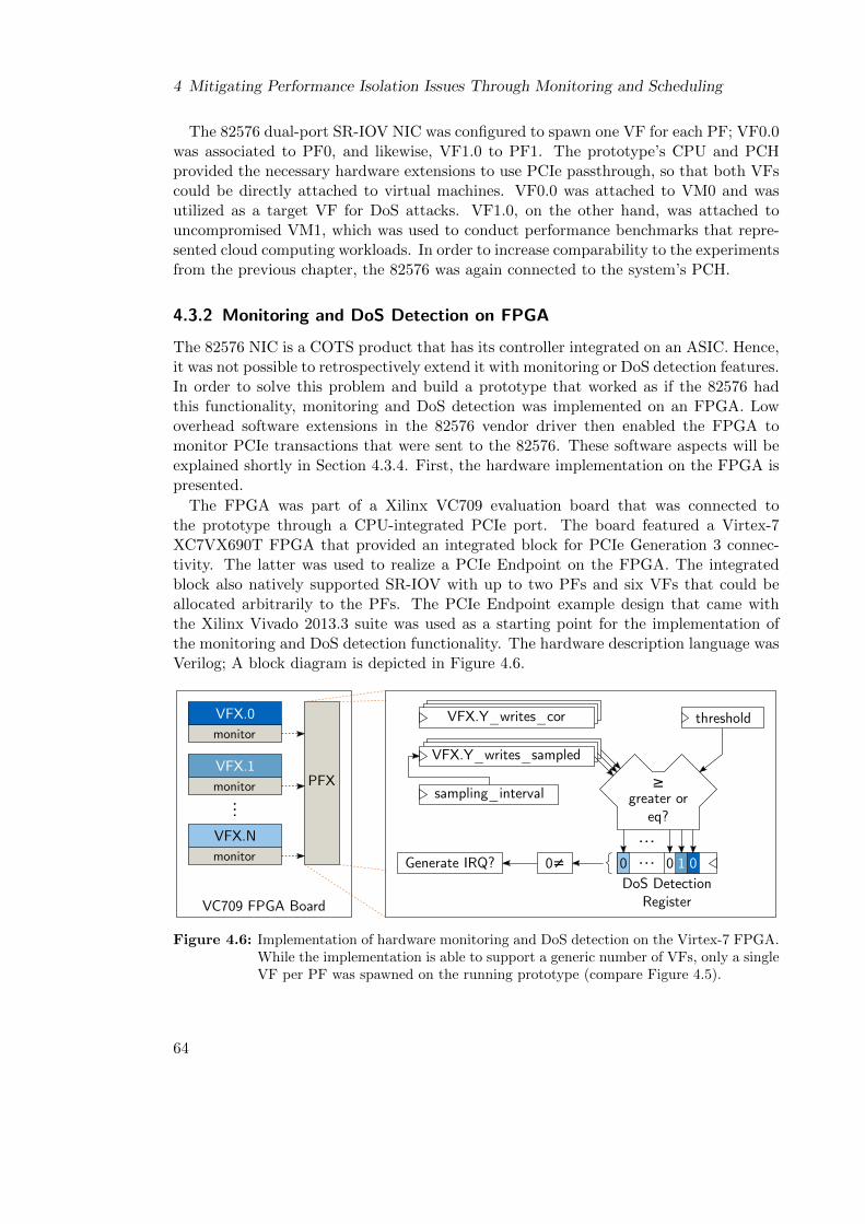
4 Mitigating Performance Isolation Issues Through Monitoring and Scheduling
The 82576 dual-port SR-IOV NIC was configured to spawn one VF for each PF; VF0.0was associated to PF0, and likewise, VF1.0 to PF1. The prototype’s CPU and PCHprovided the necessary hardware extensions to use PCIe passthrough, so that both VFscould be directly attached to virtual machines. VF0.0 was attached to VM0 and wasutilized as a target VF for DoS attacks. VF1.0, on the other hand, was attached touncompromised VM1, which was used to conduct performance benchmarks that repre-sented cloud computing workloads. In order to increase comparability to the experimentsfrom the previous chapter, the 82576 was again connected to the system’s PCH.
4.3.2 Monitoring and DoS Detection on FPGA
The 82576 NIC is a COTS product that has its controller integrated on an ASIC. Hence,it was not possible to retrospectively extend it with monitoring or DoS detection features.In order to solve this problem and build a prototype that worked as if the 82576 hadthis functionality, monitoring and DoS detection was implemented on an FPGA. Lowoverhead software extensions in the 82576 vendor driver then enabled the FPGA tomonitor PCIe transactions that were sent to the 82576. These software aspects will beexplained shortly in Section 4.3.4. First, the hardware implementation on the FPGA ispresented.
The FPGA was part of a Xilinx VC709 evaluation board that was connected tothe prototype through a CPU-integrated PCIe port. The board featured a Virtex-7XC7VX690T FPGA that provided an integrated block for PCIe Generation 3 connec-tivity. The latter was used to realize a PCIe Endpoint on the FPGA. The integratedblock also natively supported SR-IOV with up to two PFs and six VFs that could beallocated arbitrarily to the PFs. The PCIe Endpoint example design that came withthe Xilinx Vivado 2013.3 suite was used as a starting point for the implementation ofthe monitoring and DoS detection functionality. The hardware description language wasVerilog; A block diagram is depicted in Figure 4.6.
monitor
VFX.0
PFX
VC709 FPGA Board
VFX.Y_writes_sampled
VFX.Y_writes_cor threshold
≥greater or
eq?
...DoS Detection
Register
0
sampling_interval
0≠Generate IRQ? 0 0
monitor
VFX.1
monitor
VFX.N ...
...
1
Figure 4.6: Implementation of hardware monitoring and DoS detection on the Virtex-7 FPGA.While the implementation is able to support a generic number of VFs, only a singleVF per PF was spawned on the running prototype (compare Figure 4.5).
64
4.3 Implementation
The block diagram shows one register set per VF that counts every incoming PCIeMMIO write transaction. The counters work in a clear-on-read fashion, which is indi-cated by cor in Figure 4.6. This ensures low overhead read-out or sampling via hostsoftware. Each counter can be independently read from trusted host software throughthe PF to which the respective VF belongs. These counters are primarily used by hostsoftware to throttle an attacker VM, which will be presented in detail in Section 4.3.3.
The remaining blocks describe how hardware-assisted DoS detection on the FPGAworks. Two parameters must be provided by the host for correct functionality: Asampling interval and a threshold value for PCIe transactions per sampling interval.Hardware then periodically compares each VF’s sampled value (VFX.Y writes sampled)to the threshold, and if it is equal or greater to the threshold, set a bit in the DoSDetection Register. The latter is accessible to host software and uses the respective bitpositions to encode which VF has been detected as an attacker. For instance, Figure 4.6shows that bit position one stores a ’1’, which indicates that VFX.1 has been identifiedas a DoS attacker. After detection of a DoS attack, sampling is paused, which freezesthe current state of the detection register, and a PF interrupt is sent to the host. Hostsoftware can then fetch the detection register’s contents, identify the attacker VM andtake appropriate measures. DoS detection in the FPGA is resumed by clearing thedetection register from the host.
4.3.3 VC709 PF Driver and DoS Protect Process
Interfacing the VC709 monitoring and DoS detection facilities was done with a hostkernel driver for the VC709 PFs (compare Figure 4.5). It was used to read the countervalues of the respective VF monitors and to set the DoS detection parameters (thresholdand sampling interval for transactions). Additionally, the driver was responsible for han-dling VC709 IRQs that were generated on DoS attack detection. IRQs were forwardedto a userspace process, which was ultimately responsible for mitigating DoS attacks. InFigure 4.5, it is named DoS protect.
Interrupt delivery was realized in a fashion similar to the Linux userspace I/O (UIO)model [128]. The PF driver generated a character device file that blocked on read()
syscalls until a PF interrupt arrived. On interrupt arrival, the PF’s interrupt service rou-tine acknowledged the IRQ, fetched the contents of the DoS Detection Register (DDR)and returned its content to the DoS protect userspace process that was blocked on theread(). Writing to the same character device file cleared the DDR, which re-enabledinterrupts from the VC709.
On interrupt arrival, DoS protect used the DDR contents returned by the read()
syscall to determine the PCI(e) Bus:Device:Function (BDF) notation of the VF underDoS attack. This was realized via information exported from the kernel’s sysfs. After-wards, DoS protect searched for the process ID (PID) of the QEMU process to whichthe attacked VF is assigned. For the prototype, this task was realized by parsing thekernel’s process tree, looking for QEMU processes and inspecting their command linearguments. One of the arguments contained the BDF notation of the attacked VF, whichrevealed the attacker QEMU process ID and therefore the attacker VM.
65
4 Mitigating Performance Isolation Issues Through Monitoring and Scheduling
Knowing the PID, DoS protect could start freezing or throttling the attacker VM.For the latter, the algorithm presented in Section 4.2.3.2 was used with a timeslice oft = 500 µs. Recalculation of the work/sleep ratio after each timeslice was realized withthe counter values of the clear-on-read registers. DoS protect could also back off andreturn the VM to normal system scheduling if no more flooding was detected for a certainperiod of time.
During active throttling of an attacker VM, the CPU overhead of DoS protect wasmeasured at 5%. In systems with static pinning of VMs to CPU cores, DoS protect
can be dynamically pinned to the same core than the attacker VM, which preventsstealing CPU cycles from concurrent VMs. If there are no DoS attacks in the system,DoS protect sleeps while waiting for an interrupt from the VC709, and therefore doesnot produce any CPU overhead at all.
4.3.4 System Software and Emulation of Monitoring in the 82576
For system software, Ubuntu 14.04 with a Linux 3.13 kernel was used. QEMU [44] andthe KVM [43] hypervisor were used for virtualization. Two fully virtualized Linux guestVMs were spawned and ran the same OS and kernel as the host. Each VM was assigned4 GB of RAM (total 32 GB) and pinned to its own dedicated core. Like mentioned inSection 4.3.1, each VM was attached to one VF of the 82576 NIC (VM0→ VF0.0, VM1→ VF1.0). Vendor drivers for the 82576 VFs were already provided by the 13.3 Linuxkernel under the name of igbvf, so that the VFs could be used out of the box.
Small software modifications in the igbvf driver and the DoS attack code finallyenabled emulation of a system where the transaction monitoring and DoS detectionfacilities of the VC709 were used to monitor MMIO transactions that were sent to the82576. This was realized in the following way:
1. The VC709 board was configured to “clone” the 82576 configuration, so that therewas one VF per PF. VF2.0 was spawned by PF2, and VF3.0 was spawned by PF3.
2. The VFs were attached to VM0 and VM1 respectively, so that VM0 had concurrentaccess to VF0.0 of the 82576 and to VF2.0 of the VC709. Likewise, VM1 had accessto VF1.0 (82576) and VF3.0 (VC709).
3. The original igbvf driver was modified so that each instruction that generateda PCIe MMIO write transaction to a 82576 VF was executed twice. The secondtime, however, the PCIe transaction was sent to the complementary VC709 VFinstead of the 82576 VF. The transactions were basically mirrored.
4. The same mirroring was also implemented for the DoS attack code that was exe-cuted in VM1.
This mirroring concept is also depicted in the block diagram in Figure 4.5. Mosttransactions could be conveniently mirrored by modifying the regs.h file of the igbvf
driver, because it defined macros for writing to the 82576 MMIO registers. These macros
66
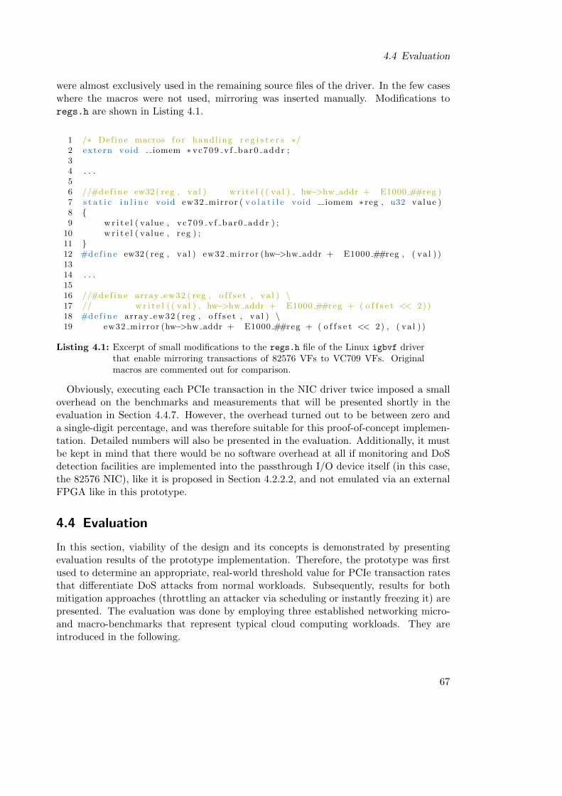
4.4 Evaluation
were almost exclusively used in the remaining source files of the driver. In the few caseswhere the macros were not used, mirroring was inserted manually. Modifications toregs.h are shown in Listing 4.1.
1 /∗ Def ine macros f o r handl ing r e g i s t e r s ∗/2 extern void iomem ∗ vc709 v f bar0 addr ;34 . . .56 //#d e f i n e ew32 ( reg , va l ) w r i t e l ( ( va l ) , hw−>hw addr + E1000 ##reg )7 s t a t i c i n l i n e void ew32 mirror ( v o l a t i l e void iomem ∗ reg , u32 value )8 {9 w r i t e l ( value , vc709 v f bar0 addr ) ;
10 w r i t e l ( value , reg ) ;11 }12 #d e f i n e ew32 ( reg , va l ) ew32 mirror (hw−>hw addr + E1000 ##reg , ( va l ) )1314 . . .1516 //#d e f i n e array ew32 ( reg , o f f s e t , va l ) \17 // w r i t e l ( ( va l ) , hw−>hw addr + E1000 ##reg + ( o f f s e t << 2) )18 #d e f i n e array ew32 ( reg , o f f s e t , va l ) \19 ew32 mirror (hw−>hw addr + E1000 ##reg + ( o f f s e t << 2) , ( va l ) )
Listing 4.1: Excerpt of small modifications to the regs.h file of the Linux igbvf driverthat enable mirroring transactions of 82576 VFs to VC709 VFs. Originalmacros are commented out for comparison.
Obviously, executing each PCIe transaction in the NIC driver twice imposed a smalloverhead on the benchmarks and measurements that will be presented shortly in theevaluation in Section 4.4.7. However, the overhead turned out to be between zero anda single-digit percentage, and was therefore suitable for this proof-of-concept implemen-tation. Detailed numbers will also be presented in the evaluation. Additionally, it mustbe kept in mind that there would be no software overhead at all if monitoring and DoSdetection facilities are implemented into the passthrough I/O device itself (in this case,the 82576 NIC), like it is proposed in Section 4.2.2.2, and not emulated via an externalFPGA like in this prototype.
4.4 Evaluation
In this section, viability of the design and its concepts is demonstrated by presentingevaluation results of the prototype implementation. Therefore, the prototype was firstused to determine an appropriate, real-world threshold value for PCIe transaction ratesthat differentiate DoS attacks from normal workloads. Subsequently, results for bothmitigation approaches (throttling an attacker via scheduling or instantly freezing it) arepresented. The evaluation was done by employing three established networking micro-and macro-benchmarks that represent typical cloud computing workloads. They areintroduced in the following.
67
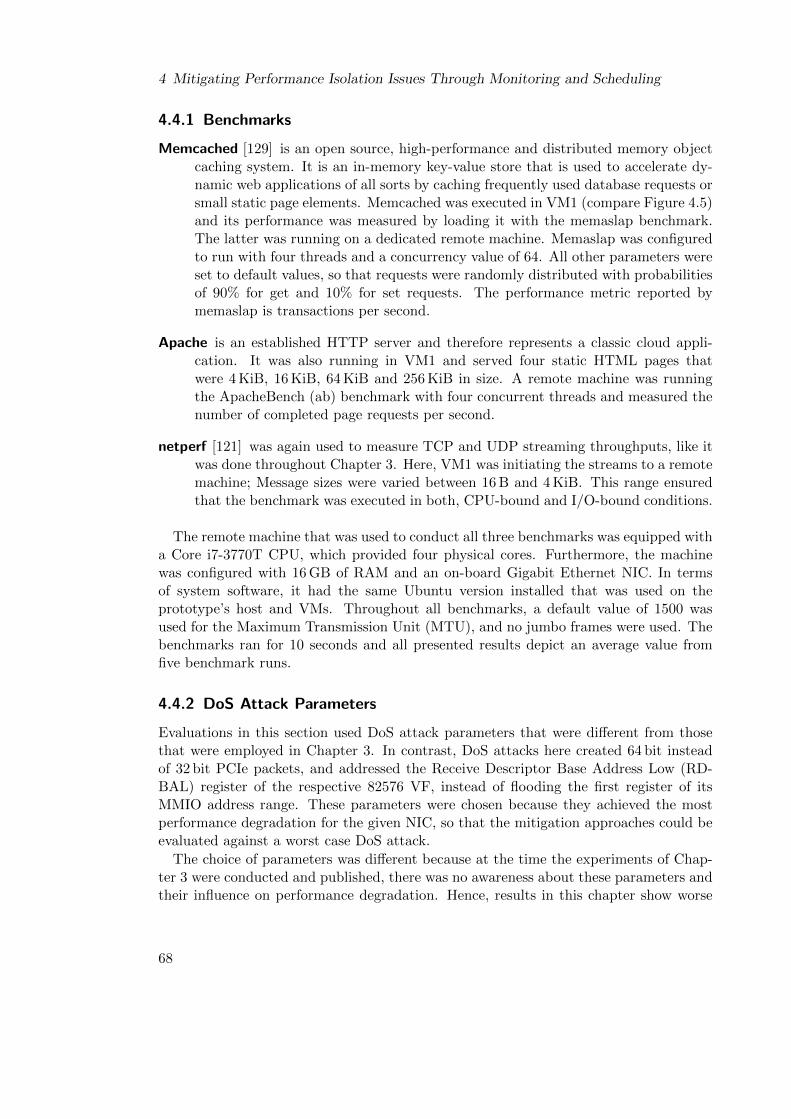
4 Mitigating Performance Isolation Issues Through Monitoring and Scheduling
4.4.1 Benchmarks
Memcached [129] is an open source, high-performance and distributed memory objectcaching system. It is an in-memory key-value store that is used to accelerate dy-namic web applications of all sorts by caching frequently used database requests orsmall static page elements. Memcached was executed in VM1 (compare Figure 4.5)and its performance was measured by loading it with the memaslap benchmark.The latter was running on a dedicated remote machine. Memaslap was configuredto run with four threads and a concurrency value of 64. All other parameters wereset to default values, so that requests were randomly distributed with probabilitiesof 90% for get and 10% for set requests. The performance metric reported bymemaslap is transactions per second.
Apache is an established HTTP server and therefore represents a classic cloud appli-cation. It was also running in VM1 and served four static HTML pages thatwere 4 KiB, 16 KiB, 64 KiB and 256 KiB in size. A remote machine was runningthe ApacheBench (ab) benchmark with four concurrent threads and measured thenumber of completed page requests per second.
netperf [121] was again used to measure TCP and UDP streaming throughputs, like itwas done throughout Chapter 3. Here, VM1 was initiating the streams to a remotemachine; Message sizes were varied between 16 B and 4 KiB. This range ensuredthat the benchmark was executed in both, CPU-bound and I/O-bound conditions.
The remote machine that was used to conduct all three benchmarks was equipped witha Core i7-3770T CPU, which provided four physical cores. Furthermore, the machinewas configured with 16 GB of RAM and an on-board Gigabit Ethernet NIC. In termsof system software, it had the same Ubuntu version installed that was used on theprototype’s host and VMs. Throughout all benchmarks, a default value of 1500 wasused for the Maximum Transmission Unit (MTU), and no jumbo frames were used. Thebenchmarks ran for 10 seconds and all presented results depict an average value fromfive benchmark runs.
4.4.2 DoS Attack Parameters
Evaluations in this section used DoS attack parameters that were different from thosethat were employed in Chapter 3. In contrast, DoS attacks here created 64 bit insteadof 32 bit PCIe packets, and addressed the Receive Descriptor Base Address Low (RD-BAL) register of the respective 82576 VF, instead of flooding the first register of itsMMIO address range. These parameters were chosen because they achieved the mostperformance degradation for the given NIC, so that the mitigation approaches could beevaluated against a worst case DoS attack.
The choice of parameters was different because at the time the experiments of Chap-ter 3 were conducted and published, there was no awareness about these parameters andtheir influence on performance degradation. Hence, results in this chapter show worse
68
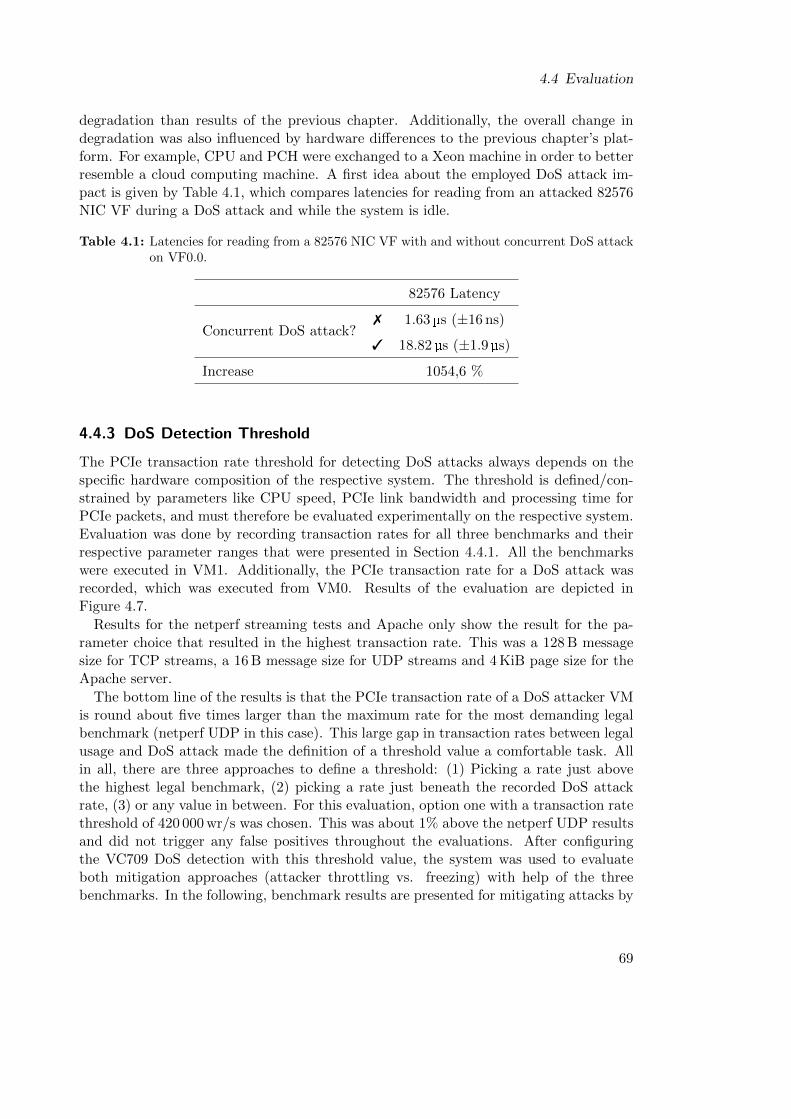
4.4 Evaluation
degradation than results of the previous chapter. Additionally, the overall change indegradation was also influenced by hardware differences to the previous chapter’s plat-form. For example, CPU and PCH were exchanged to a Xeon machine in order to betterresemble a cloud computing machine. A first idea about the employed DoS attack im-pact is given by Table 4.1, which compares latencies for reading from an attacked 82576NIC VF during a DoS attack and while the system is idle.
Table 4.1: Latencies for reading from a 82576 NIC VF with and without concurrent DoS attackon VF0.0.
82576 Latency
Concurrent DoS attack?7 1.63 µs (±16 ns)
3 18.82 µs (±1.9 µs)
Increase 1054,6 %
4.4.3 DoS Detection Threshold
The PCIe transaction rate threshold for detecting DoS attacks always depends on thespecific hardware composition of the respective system. The threshold is defined/con-strained by parameters like CPU speed, PCIe link bandwidth and processing time forPCIe packets, and must therefore be evaluated experimentally on the respective system.Evaluation was done by recording transaction rates for all three benchmarks and theirrespective parameter ranges that were presented in Section 4.4.1. All the benchmarkswere executed in VM1. Additionally, the PCIe transaction rate for a DoS attack wasrecorded, which was executed from VM0. Results of the evaluation are depicted inFigure 4.7.
Results for the netperf streaming tests and Apache only show the result for the pa-rameter choice that resulted in the highest transaction rate. This was a 128 B messagesize for TCP streams, a 16 B message size for UDP streams and 4 KiB page size for theApache server.
The bottom line of the results is that the PCIe transaction rate of a DoS attacker VMis round about five times larger than the maximum rate for the most demanding legalbenchmark (netperf UDP in this case). This large gap in transaction rates between legalusage and DoS attack made the definition of a threshold value a comfortable task. Allin all, there are three approaches to define a threshold: (1) Picking a rate just abovethe highest legal benchmark, (2) picking a rate just beneath the recorded DoS attackrate, (3) or any value in between. For this evaluation, option one with a transaction ratethreshold of 420 000 wr/s was chosen. This was about 1% above the netperf UDP resultsand did not trigger any false positives throughout the evaluations. After configuringthe VC709 DoS detection with this threshold value, the system was used to evaluateboth mitigation approaches (attacker throttling vs. freezing) with help of the threebenchmarks. In the following, benchmark results are presented for mitigating attacks by
69
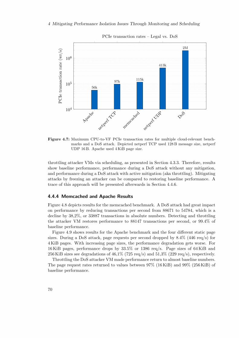
4 Mitigating Performance Isolation Issues Through Monitoring and Scheduling
Apa
che
netp
erf T
CP
mem
cach
ed
netp
erf U
DP
DoS
104
105
106
56k
97k115k
413k
2M
PC
Ietr
an
sact
ion
rate
(wr/
s)
PCIe transaction rates – Legal vs. DoS
Figure 4.7: Maximum CPU-to-VF PCIe transaction rates for multiple cloud-relevant bench-marks and a DoS attack. Depicted netperf TCP used 128 B message size, netperfUDP 16 B. Apache used 4 KiB page size.
throttling attacker VMs via scheduling, as presented in Section 4.3.3. Therefore, resultsshow baseline performance, performance during a DoS attack without any mitigation,and performance during a DoS attack with active mitigation (aka throttling). Mitigatingattacks by freezing an attacker can be compared to restoring baseline performance. Atrace of this approach will be presented afterwards in Section 4.4.6.
4.4.4 Memcached and Apache Results
Figure 4.8 depicts results for the memcached benchmark. A DoS attack had great impacton performance by reducing transactions per second from 88671 to 54784, which is adecline by 38,2%, or 33887 transactions in absolute numbers. Detecting and throttlingthe attacker VM restores performance to 88147 transactions per second, or 99.4% ofbaseline performance.
Figure 4.9 shows results for the Apache benchmark and the four different static pagesizes. During a DoS attack, page requests per second dropped by 8.4% (446 req/s) for4 KiB pages. With increasing page sizes, the performance degradation gets worse. For16 KiB pages, performance drops by 33.5% or 1386 req/s. Page sizes of 64 KiB and256 KiB sizes see degradations of 46,1% (725 req/s) and 51,3% (229 req/s), respectively.
Throttling the DoS attacker VM made performance return to almost baseline numbers.The page request rates returned to values between 97% (16 KiB) and 99% (256 KiB) ofbaseline performance.
70

4.4 Evaluation
Baseline During DoS During DoSw/ mitigation
0
2
4
6
8
10·104
100%
61.8%
99.4%
VM
1T
ran
sact
ion
s/s
Memcached results
Figure 4.8: Results for the memcached benchmark. Mitigating the DoS attack by throttlingthe attacker VM restores 99.4% of baseline performance.
4 16 64 2560
1
2
3
4
5
6·103
Page size (KiB)
VM
1P
age
Req
ues
ts/s
Apache results
BaselineDuring DoS
During DoS w/ mitigation
Figure 4.9: Apache results for four page sizes. Mitigation restores between between 97%(16 KiB) and 99% (256 KiB) of baseline performance. The x axis has logarithmicscaling.
71

4 Mitigating Performance Isolation Issues Through Monitoring and Scheduling
4.4.5 Netperf Results
Figure 4.10 depicts results for netperf TCP and UDP streaming benchmarks and therespective message sizes. In summary, both protocols see performance degradation dur-ing DoS attacks if mitigation was not activated, but the actual degradation dependedon message size. For UDP streams, performance degradations between 37.8% (4096 Bmessage size) and round about 70% (256 B - 16 B message size) were observed. Miti-gating the DoS attack by throttling the attacker VM restored baseline performance formessage sizes between 4096 B - 512 B. For the remaining range of message sizes (256 B -16 B), performance was restored to about 90% of baseline performance by the throttlingapproach.
Results for streams using the TCP protocol showed similar behavior. Performancedegradation during DoS attacks for the message size range of 4096 B - 256 B was mea-sured at 51%. For the same range, throttling the attacker resulted in a return to fullbaseline performance. For the remaining range of message sizes, performance degrada-tion during DoS attacks decreased with smaller message size. At 128 B, a 47% degra-dation was measured, while it was only 1% for 16 B message sizes. In the same range,mitigation via throttling restored between 86.5% (128 B) and 93.7% (16 B) of baselineperformance.
The results for both protocols, UDP and TCP, showed that mitigation of DoS attacksby throttling the attacker VM yielded different results depending on the message sizeof the netperf streams. In conclusion, baseline performance could be restored for allmessage sizes where the netperf benchmark was not CPU-bound. This was the casefor message sizes of 512 B and greater for UDP streams and 256 B or greater for TCPstreams.
For respective smaller message sizes, DoS attacks were still able to cause some degra-dation despite being actively throttled. As described in Section 4.2.3.2, throttling meansthat attacker VMs are scheduled only for very small time slices. The size of a time slice,however, is bounded by CPU speed and the performance of the host operating system’sscheduling code. Evaluations found that even for the smallest possible time slices, at-tacker VMs were still able to cause a short lasting congestion on the PCIe interconnect.These short lasting congestions had no impact if netperf was I/O-bound, aka operatedwith big message sizes and the CPU needed to wait for the I/O device most of the time.However, if the netperf benchmark was CPU-bound, which means that a VM’s CPUcore was fully loaded because it needed to prepare large numbers of small UDP or TCPpackets during small amounts of time, the mini congestions were still enough to degradesome performance. Performance, in this case, was lost when a fully loaded CPU core,which executed the legal netperf benchmark, needed to wait for a few additional cyclesin order to send a PCIe packet downstream, because another CPU core, running theDoS attack, caused a mini congestion on the interconnect that delayed packet sendout.
However, the throttling approach worked fine for both macro-benchmarks (Memcachedand Apache) that represented real-world workloads, and therefore the requirement forsufficient mitigation was satisfied. Further optimizations of the scheduling algorithmwere therefore not investigated.
72
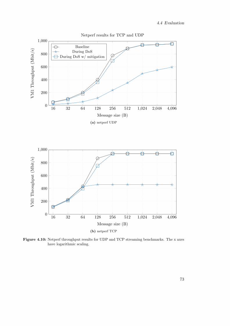
4.4 Evaluation
16 32 64 128 256 512 1,024 2,048 4,0960
200
400
600
800
1,000
Message size (B)
VM
1T
hro
ugh
pu
t(M
bit
/s)
Netperf results for TCP and UDP
BaselineDuring DoS
During DoS w/ mitigation
(a) netperf UDP
16 32 64 128 256 512 1,024 2,048 4,0960
200
400
600
800
1,000
Message size (B)
VM
1T
hro
ugh
pu
t(M
bit
/s)
(b) netperf TCP
Figure 4.10: Netperf throughput results for UDP and TCP streaming benchmarks. The x axeshave logarithmic scaling.
73
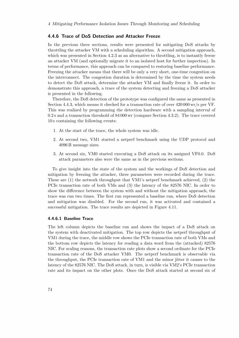
4 Mitigating Performance Isolation Issues Through Monitoring and Scheduling
4.4.6 Trace of DoS Detection and Attacker Freeze
In the previous three sections, results were presented for mitigating DoS attacks bythrottling the attacker VM with a scheduling algorithm. A second mitigation approach,which was presented in Section 4.2.3 as an alternative to throttling, is to instantly freezean attacker VM (and optionally migrate it to an isolated host for further inspection). Interms of performance, this approach can be compared to restoring baseline performance.Freezing the attacker means that there will be only a very short, one-time congestion onthe interconnect. The congestion duration is determined by the time the system needsto detect the DoS attack, determine the attacker VM and finally freeze it. In order todemonstrate this approach, a trace of the system detecting and freezing a DoS attackeris presented in the following.
Therefore, the DoS detection of the prototype was configured the same as presented inSection 4.4.3, which means it checked for a transaction rate of over 420 000 wr/s per VF.This was realized by programming the detection hardware with a sampling interval of0.2 s and a transaction threshold of 84 000 wr (compare Section 4.3.2). The trace covered10 s containing the following events:
1. At the start of the trace, the whole system was idle.
2. At second two, VM1 started a netperf benchmark using the UDP protocol and4096 B message sizes.
3. At second six, VM0 started executing a DoS attack on its assigned VF0.0. DoSattack parameters also were the same as in the previous sections.
To give insight into the state of the system and the workings of DoS detection andmitigation by freezing the attacker, three parameters were recorded during the trace.These are (1) the network throughput that VM1’s netperf benchmark achieved, (2) thePCIe transaction rate of both VMs and (3) the latency of the 82576 NIC. In order toshow the difference between the system with and without the mitigation approach, thetrace was run two times. The first run represented a baseline run, where DoS detectionand mitigation was disabled. For the second run, it was activated and contained asuccessful mitigation. The trace results are depicted in Figure 4.11.
4.4.6.1 Baseline Trace
The left column depicts the baseline run and shows the impact of a DoS attack onthe system with deactivated mitigation. The top row depicts the netperf throughput ofVM1 during the trace, the middle row shows the PCIe transaction rate of both VMs andthe bottom row depicts the latency for reading a data word from the (attacked) 82576NIC. For scaling reasons, the transaction rate plots show a second ordinate for the PCIetransaction rate of the DoS attacker VM0. The netperf benchmark is observable viathe throughput, the PCIe transaction rate of VM1 and the minor jitter it causes to thelatency of the 82576 NIC. The DoS attack, in turn, is visible via VM2’s PCIe transactionrate and its impact on the other plots. Once the DoS attack started at second six of
74
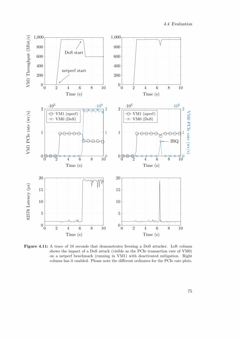
4.4 Evaluation
0 2 4 6 8 100
200
400
600
800
1,000
netperf start
DoS start
Time (s)
VM
1T
hro
ugh
pu
t(M
bit/s
)
0 2 4 6 8 100
200
400
600
800
1,000
Time (s)
0 2 4 6 8 100
1
2·105
Time (s)
VM
1P
CIe
rate
(wr/
s) VM1 (nperf)
VM0 (DoS)
0
1
2·106
0 2 4 6 8 100
1
2·105
Time (s)
VM1 (nperf)
VM0 (DoS)
0
1
2·106
IRQ
VM
0P
CIe
rate(w
r/s)
0 2 4 6 8 100
5
10
15
20
Time (s)
8257
6L
aten
cy(µ
s)
0 2 4 6 8 100
5
10
15
20
Time (s)
Figure 4.11: A trace of 10 seconds that demonstrates freezing a DoS attacker. Left columnshows the impact of a DoS attack (visible as the PCIe transaction rate of VM0)on a netperf benchmark (running in VM1) with deactivated mitigation. Rightcolumn has it enabled. Please note the different ordinates for the PCIe rate plots.
75
4 Mitigating Performance Isolation Issues Through Monitoring and Scheduling
the trace, netperf throughput instantly dropped from 960 Mbit/s to 600 Mbit/s. Thisperformance degradation correlates to a reduced PCIe transaction rate of VM1. Thecause for this degradation was the DoS-caused congestion on the interconnect, whichwas discussed in Chapter 3. The congestion is made visible by the latency plot, whichshows a steep jump once the DoS attack was executing1.
4.4.6.2 Mitigation Trace
The right column shows results for enabled mitigation. Here, the VC709’s DoS detectionidentified the attack after it was started and reported VM0 via interrupt. The DoSprotect process in the host received the interrupt shortly after and instantly froze VM0.As a result, the DoS attack in this trace only caused a small dip in VM1’s throughput andperformance was recovered to 100% of baseline shortly after the attacker was identifiedand frozen.
4.4.6.3 Optimization Tradeoffs
It is also possible to detect DoS attacks faster than in the depicted trace, which wouldhave further reduced the temporary performance drop. Therefore, other parametersmust be chosen for the sampling rate and the transaction threshold of the DoS detectionhardware in the FPGA. The FPGA design runs at 125 MHz, which theoretically enablesit to check for the transaction threshold value at smaller sampling rates than the 0.2 sthat were used, allowing faster detection and freezing of the attacker. On the otherhand, greater sampling rates provide more confident detection. In cloud computingenvironments, the latter is most likely more important, because while a tiny performancedrop is annoying, it is still preferable to having more false alarms.
4.4.7 Mirroring Overhead
In the following, the overhead that transaction mirroring introduced to the conductedevaluations and benchmarks will be discussed. Of course, all findings within this sectionneed only be considered for the prototype implementation, because transaction mirroringwas only used to enable evaluation of the original design idea. If respective monitoringhardware would be implemented directly into hardware, like it is proposed by the design,no mirroring would be needed and therefore no overhead would be introduced.
Transaction mirroring causes CPU cores to duplicate each PCIe transaction that issent to the 82576 NIC. This translates to (1) a tiny CPU overhead for generating theadditional PCIe transaction and (2) a doubling of the volume of PCIe transactions. Thelatter is neglectable due to two reasons. First, the prototype (compare Figure 4.5) isassembled such that the VC709 FPGA and the 82576 NIC PCIe cards do not share anyPCIe lanes. Therefore, mirroring introduced no interferences in this part of the PCIesubsystem. Second, the CPU internal ring structure, which must be traversed by the
1Compare to results that were presented in Section 3.5, where huge latency increases were identified asan indicator of DoS-caused congestion on the interconnect.
76
4.4 Evaluation
original and the mirrored PCIe packets, is capable of much larger transactions volumesthan those introduced by two PCIe devices.
The impact of the CPU overhead introduced by the mirroring approach is discussedin the following.
4.4.7.1 Benchmark Overhead
VM1, which executed the benchmarks, had transaction mirroring enabled only for theevaluation of the maximum PCIe transaction rates per benchmark in Section 4.4.3, andthe system trace for evaluating the freezing approach that was presented in Section 4.4.6.Here, the CPU overhead of mirroring introduced variations in the benchmark results ofat most 7%, but only when the benchmarks itself was CPU-bound. Therefore, in bothcases, this overhead was neglectable. In the first case, mirroring was used to determinethe difference in PCIe transaction rates between DoS attacks and legal benchmarks. Asthe DoS rate was round about five times larger than the next best legal benchmark,a 7% overhead for the latter was acceptable. Considering the results of the systemtrace in Section 4.4.6, netperf was not operated in the CPU-bound region (using 4096 Bmessage sizes), so that CPU overhead of mirroring had no effect. All benchmark resultsin Sections 4.4.4 and 4.4.5 were obtained without active mirroring in the benchmark VMand thus contained no overhead.
4.4.7.2 DoS Attack Overhead
The DoS attack code had transaction mirroring enabled during the whole evaluation.However, no overhead was introduced because the VC709 FPGA was able to processPCIe transactions faster than the 82576 NIC. This is shown in Table 4.1.
Table 4.2: Times for executing a for-loop (DoS attack) with 108 consecutive PCIe write trans-actions, depending on device.
Device total time time/write
82576 NIC 36.138 s 361.38 ns
VC709 FPGA 8.812 s 88.12 ns
While the 82576 NIC needs 361 ns to process a single PCIe packet, the VC709 onlyneeds 88 ns. Due to this difference in processing speeds, DoS-caused congestion on thePCIe subsystem first emerged on the PCIe lanes that connected to the 82576 NIC. Thismeans that during congestion, when all buffers were filled, the CPU core running themirrored DoS attack code would block for 361 ns while waiting for the 82576 NIC toprocess a PCIe transaction that frees a downstream buffer slot. Hence, this waiting timethat existed anyways could be used by the CPU to send the respective mirrored packetto the VC709 without generating any overhead.
77
4 Mitigating Performance Isolation Issues Through Monitoring and Scheduling
4.5 Summary
The cloud computing domain is the most prominent adopter of SR-IOV and PCIepassthrough technology. Cloud computing providers like Amazon use the technologyto provide VMs that offer high performance networking I/O that is superior to legacyI/O virtualization options like paravirtualization. As a consequence, servers that hostSR-IOV VMs are vulnerable to PCIe DoS attacks and may therefore become victimsof unwanted, significant performance degradation (attacks and degradation were thor-oughly investigated in Chapter 3).
This chapter presented research on detecting DoS attacks on PCIe passthrough hard-ware in live systems and mitigating the resulting performance degradation. The overallgoal was to develop lightweight hardware and software extensions that work together inorder to fulfill these tasks. In a first step, domain-specific goals and requirements werecollected. The design of the hardware and software extensions should seek synergieswith existing technology that counteracts other classes of VM misbehavior (e.g networkaddress spoofing) and be compatible to existing and future hardware architectures andI/O classes. Most importantly, the design must keep the host out of the VM-to-I/O-device data path, which is the most important paradigm of PCIe passthrough. Also,the design had to satisfy requirements for non-intrusive, low overhead and secure DoSattacker detection. Additionally, attackers must be identified unambiguously, their at-tacks must be sufficiently mitigated and the overall design must scale to modern cloudcomputing requirements.
In the next step, these goals and requirements were used to develop a high-level designfor the hardware and software extensions. The design was based on the observation thatDoS attacks always create larger PCIe transaction rates than legal (cloud computing)workloads. Therefore, the design was partitioned to utilize hardware-based monitoringof PCIe transaction rates for DoS detection and host software extensions for mitigation.Exploration of hardware monitoring possibilities in PCIe networks yielded three results:(1) Monitoring inside the CPU, (2) in an intermediary like a switch, or (3) inside theI/O device. Each possibility provided its unique pros and cons, but all three wouldbe suitable for implementation in future hardware. In terms of software extensions forDoS attack mitigation, two approaches were presented: (1) A scheduling algorithm thatthrottles the attacker VM so that the DoS attack weakens significantly, or (2) freez-ing and subsequently migrating the attacker VM to an isolated host, where it can beinspected by an operator of the cloud computing provider.
In order to evaluate the high level design, it was implemented on cloud computinggrade, real hardware. An FPGA prototyping board was utilized to emulate hardware-based PCIe transaction monitoring and DoS detection for a commercial-off-the-shelfSR-IOV NIC. Using this hardware prototype, a threshold value for PCIe transactionsrates was determined that differentiates legal usage of an SR-IOV VF from a DoS attack.
Finally, this threshold value and the hardware prototype were used to evaluate theDoS detection and software-based mitigation of DoS attacks in the live system. Thistask was realized by using three cloud computing benchmarks (one micro- and two mac-robenchmarks). Results of the macro-benchmarks showed that the throttling algorithm
78
4.5 Summary
successfully mitigates performance degradation due to DoS attacks. For example, thememcached benchmark saw a drop in performance to 61.8% of baseline performanceduring a DoS attack. Throttling the DoS attacker with the proposed scheduling algo-rithm restored 99.4% of baseline performance for memcached. Results for the approachof freezing DoS attacker VMs showed that DoS detection is fast enough to only leave asub-second dip in network performance until full baseline performance is restored.
79

5 Resolving Performance Isolation IssuesThrough PCIe QoS Extensions
The previous chapter presented approaches for mitigating performance isolation issueswith PCIe passthrough in a running system. Mitigation approaches have a low footprintregarding costs, because they can be enabled with very small monitoring add-ons toexisting hardware. These monitors detect PCIe DoS attacks, which are then mitigatedby software. Although mitigation is able to restore close to baseline system perfor-mance, there still might be small temporary performance fluctuations, which are causedby delays in DoS attack detection and the effectiveness of the mitigation software. Thesecharacteristics make mitigation approaches well-suited for the cloud and datacenter com-puting domains. Here, detection of attackers is the most important aspect, because anoperator (or software watchdog) of the cloud computing provider can shut down or fixdetected attacker VMs from remote. In the short meantime between DoS attack detec-tion and reaction from the operator, it is perfectly acceptable to sacrifice a few percent ofperformance and therefore save money due to an affordable and lightweight implemen-tation. In other words, DoS detection and mitigation are a reactive solution, because itcounters on-going attacks.
There are also other computing domains, where a reactive solution is not the pre-ferred way. For example, in future embedded and mixed-criticality systems that usePCIe passthrough, performance fluctuations during DoS attacks and DoS mitigationwould need to be accounted for in worst case execution time (WCET) calculations. Con-sidering the many hardware and software parameters that influence these performancefluctuations, and the significant increase of latencies that is caused by DoS attacks, thiswould result in a very pessimistic approach that also introduces a high element of un-certainty. Even if these fluctuations would be accounted for in WCET calculations, itis a lot more difficult to fix a compromised VM in embedded systems than in cloudsystems, because instant (remote-) maintenance by experts/operators might not be pos-sible. Hence, in this domain, extra costs regarding hardware would be acceptable ifthey completely close this attack vector and enable usage of PCIe passthrough hardwarewithout the need to calculate with any kind of interference. In other words, a proactivesolution is preferred.
This chapter presents two integrated hardware architectures that achieve this goal.Therefore, Section 5.1 first defines overall goals and domain-specific requirements forthe hardware architectures. As a foundation for both architectures, Quality-of-Service(QoS) extensions from the PCIe specification [78] were employed. The extensions arethoroughly introduced in Section 5.2. Unfortunately, at the time of writing, these QoSextensions were almost completely absent in COTS PCIe hardware, because they are
81
5 Resolving Performance Isolation Issues Through PCIe QoS Extensions
defined optional in the specification and lack use cases in the real world. In order toenable development and evaluation of the proposed hardware architectures despite theabsence of PCIe QoS hardware, a SystemC TLM 2.0 simulation model of a real-worldlab-setup was developed and extended with these PCIe QoS features. The model ispresented in Section 5.3. Afterwards, Sections 5.4 and 5.5 present the two proactivehardware architectures for DoS prevention. They were optimized for different goals:Scheduling freedom and minimal hardware costs. In both sections, it is determinedwhich QoS features are needed, and how virtualized hardware like multi-core CPUsand SR-IOV devices need to implement, interface1and program these features in orderto prevent DoS attacks. Afterwards, evaluation results of each architecture using theSystemC model are presented and a short summary for each respective architecture isgiven. Finally, this chapter is concluded in Section 5.6.
5.1 Goals and Requirements
In order to enable hardware-assisted full performance isolation for systems using PCIepassthrough, certain goals and requirements must be met and satisfied. Both are for-mulated in the following. The goals and requirements are agnostic of specific multi-coreprocessor architectures, PCIe intermediaries or I/O devices, so that they are applicableto any kind of common hardware as long as it implements standardized PCIe interfaces.
5.1.1 Goals
The overall goal is to develop hardware architectures that enable proactive, full perfor-mance isolation for PCIe passthrough. This goal shall not be achieved with any kindof help by software, e.g. introspection or monitoring mechanisms from a trusted host,but enforced solely by hardware. The only allowed exception shall be configuration ofhardware via trusted host software at boot time, prior to VM instantiation. Addition-ally, the hardware architectures shall stay fully compatible to the PCIe and SR-IOVspecifications. This ensures compatibility to existing legacy hardware, and simplifiesintegration of the developed solutions into future hardware, because they build on topof a common base.
5.1.2 Requirements
Proactive, full isolation: The hardware architectures must provide full performance iso-lation, which means that there must be zero I/O performance degradation fornon-attacker VMs during DoS attacks. Also, isolation must be guaranteed perma-nently. It cannot be activated with a short delay after a DoS attack emerged, likein the DoS detection and mitigation approach in the previous chapter, but mustbe there from the start.
1These are aspects that are explicitly not covered in the PCIe specification.
82
5.2 Quality-of-Service Extensions in the PCIe Specification
Secure configuration: Any configuration facilities of the hardware architectures mustbe secured from access by VMs. Only trusted host software, e.g. a hypervisor, isallowed to access and alter the respective configuration.
Scalability: The hardware architectures must be scalable to a reasonable number of VMsand passthrough functions.
Low overhead: The hardware architectures must not introduce performance overheadto other, non-PCIe parts of the system.
5.2 Quality-of-Service Extensions in the PCIe Specification
Exploration of the PCIe specifications [78] found that they include modular hardwareQoS extensions for generic PCIe components. Unfortunately, all of these QoS extensionsare explicitly defined optional. At the date of writing, there seems to be a lack of usecases for QoS extensions in PCIe passthrough-capable hardware. Especially in the caseof x86-based hardware, where PCIe passthrough found adoption in the form of SR-IOVbased networking for virtualized cloud computing, the author is not aware of any COTSPCIe hardware2 that provides QoS facilities as described in the PCIe specifications.
Performance isolation issues of PCIe passthrough and SR-IOV, however, qualify as ause case for these extensions. Closing the existing attack vector for PCIe DoS attackswith help of the specification’s QoS extensions would have two advantages. First, com-patibility to legacy PCIe hardware is increased, and second, integration into existingPCIe hardware is simplified. For these reasons, the QoS extensions were utilized asbuilding blocks in the hardware architectures that are presented later in this chapter,and they help enabling full performance isolation for PCIe passthrough.
5.2.1 Contribution of this Thesis
Before this section continues with background on the specification’s QoS extensions,it shall be first differentiated where this thesis leverages existing concepts from thePCIe specifications, where it transfers and adapts them to new use cases and where itcontributes new work that is needed to enable full performance isolation.
PCIe’s QoS extensions are included since the very first revision (1.0) of the PCI ExpressBase Specification from the year 2002 [130]. The first commercial IOMMUs for x86hardware, which enabled PCIe passthrough, were introduced around the year 2006 [49].The first revision of SR-IOV was introduced a year later in 2007 [131]. SR-IOV extendedthe PCIe base specifications, hence becoming a superset of them, but it did not alter,update or change specifications regarding the QoS extensions. Therefore, it is possibleto design both legacy and SR-IOV capable PCIe devices that include or exclude QoSextensions. The whole relationship is depicted in Figure 5.1.
2For QoS to work, it must be supported pervasively by all components in the hierarchy of a PCIe tree.This results in at least one CPU and one Endpoint, if they are directly connected to each other. Anyintermediaries between CPU and Endpoint, e.g. a chipset (PCH), must also provide matching QoScapabilities.
83
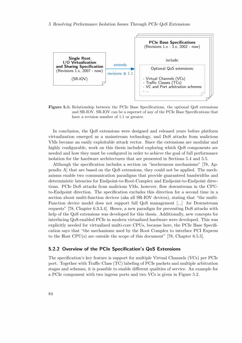
5 Resolving Performance Isolation Issues Through PCIe QoS Extensions
Single RootI/O Virtualization
and Sharing Specification(Revisions 1.x, 2007 - now)
(SR-IOV)
extends
revisions ≥ 1.1- Virtual Channels (VCs)- Traffic Classes (TCs)- VC and Port arbitration schemes- ...
PCIe Base Specifications(Revisions 1.x - 3.x, 2002 - now)
include:
Optional QoS extensions:
Figure 5.1: Relationship between the PCIe Base Specifications, the optional QoS extensionsand SR-IOV. SR-IOV can be a superset of any of the PCIe Base Specifications thathave a revision number of 1.1 or greater.
In conclusion, the QoS extensions were designed and released years before platformvirtualization emerged as a mainstream technology, and DoS attacks from maliciousVMs became an easily exploitable attack vector. Since the extensions are modular andhighly configurable, work on this thesis included exploring which QoS components areneeded and how they must be configured in order to achieve the goal of full performanceisolation for the hardware architectures that are presented in Sections 5.4 and 5.5.
Although the specification includes a section on “isochronous mechanisms” [78, Ap-pendix A] that are based on the QoS extensions, they could not be applied. The mech-anisms enable two communication paradigms that provide guaranteed bandwidths anddeterministic latencies for Endpoint-to-Root-Complex and Endpoint-to-Endpoint direc-tions. PCIe DoS attacks from malicious VMs, however, flow downstream in the CPU-to-Endpoint direction. The specification excludes this direction for a second time in asection about multi-function devices (aka all SR-IOV devices), stating that “the multi-Function device model does not support full QoS management [...] for Downstreamrequests” [78, Chapter 6.3.3.4]. Hence, a new paradigm for preventing DoS attacks withhelp of the QoS extensions was developed for this thesis. Additionally, new concepts forinterfacing QoS-enabled PCIe in modern virtualized hardware were developed. This wasexplicitly needed for virtualized multi-core CPUs, because here, the PCIe Base Specifi-cation says that “the mechanisms used by the Root Complex to interface PCI Expressto the Host CPU(s) are outside the scope of this document” [78, Chapter 6.5.5].
5.2.2 Overview of the PCIe Specification’s QoS Extensions
The specification’s key feature is support for multiple Virtual Channels (VCs) per PCIeport. Together with Traffic Class (TC) labeling of PCIe packets and multiple arbitrationstages and schemes, it is possible to enable different qualities of service. An example fora PCIe component with two ingress ports and two VCs is given in Figure 5.2.
84
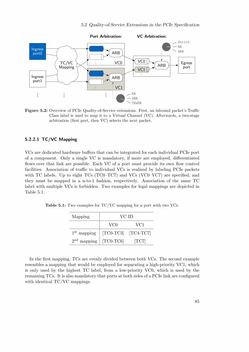
5.2 Quality-of-Service Extensions in the PCIe Specification
Ingressport0
Egressport
Ingressport1
TC/VCMapping
VC0
VC1
ARB
ARB
VC1
VC0
Port Arbitration: VC Arbitration:
RR
ARB
WRRTBWRR
StrictRRWRR
......
...
...
......
Figure 5.2: Overview of PCIe Quality-of-Service extensions. First, an inbound packet’s TrafficClass label is used to map it to a Virtual Channel (VC). Afterwards, a two-stagearbitration (first port, then VC) selects the next packet.
5.2.2.1 TC/VC Mapping
VCs are dedicated hardware buffers that can be integrated for each individual PCIe portof a component. Only a single VC is mandatory, if more are employed, differentiatedflows over that link are possible. Each VC of a port must provide its own flow controlfacilities. Association of traffic to individual VCs is realized by labeling PCIe packetswith TC labels. Up to eight TCs (TC0–TC7) and VCs (VC0–VC7) are specified, andthey must be mapped in a n-to-1 fashion, respectively. Association of the same TClabel with multiple VCs is forbidden. Two examples for legal mappings are depicted inTable 5.1.
Table 5.1: Two examples for TC/VC mapping for a port with two VCs.
Mapping VC ID
VC0 VC1
1st mapping [TC0-TC3] [TC4-TC7]
2nd mapping [TC0-TC6] [TC7]
In the first mapping, TCs are evenly divided between both VCs. The second exampleresembles a mapping that would be employed for separating a high-priority VC1, whichis only used by the highest TC label, from a low-priority VC0, which is used by theremaining TCs. It is also mandatory that ports at both sides of a PCIe link are configuredwith identical TC/VC mappings.
85
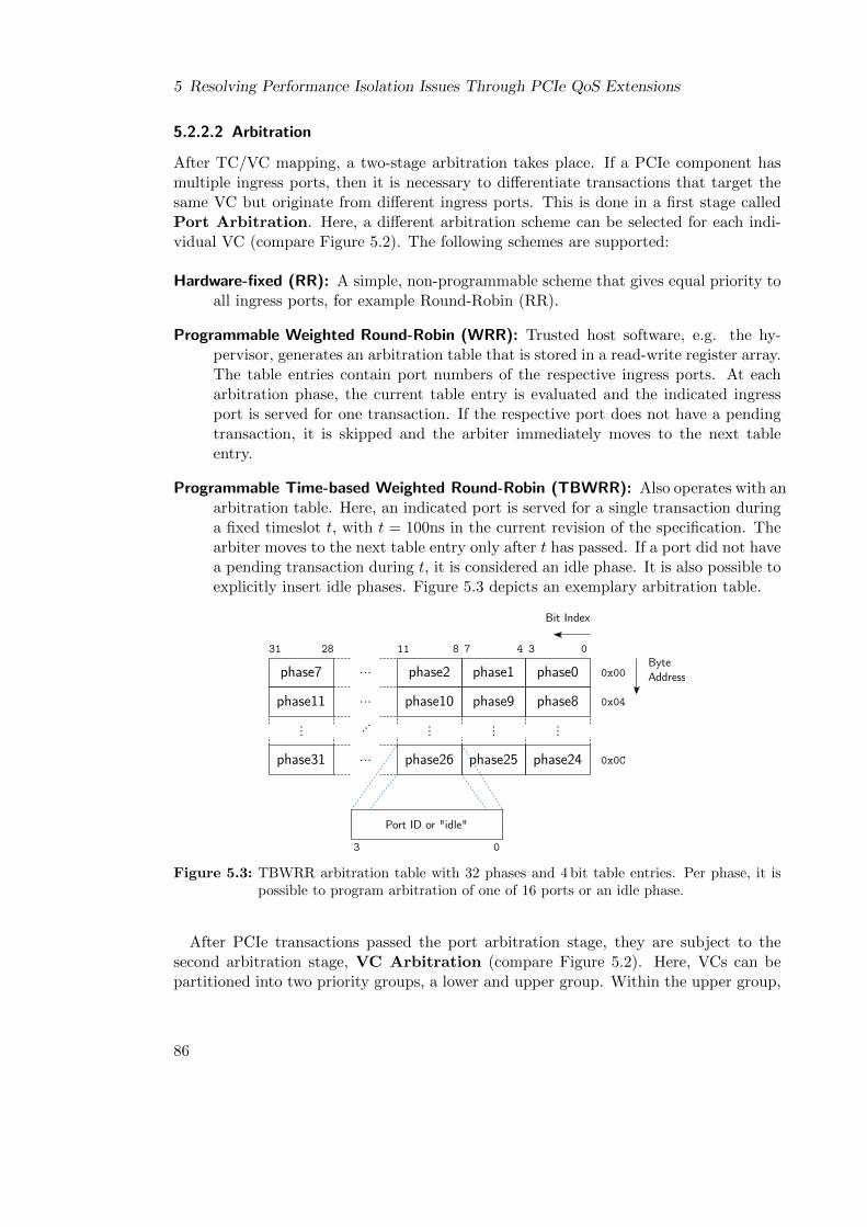
5 Resolving Performance Isolation Issues Through PCIe QoS Extensions
5.2.2.2 Arbitration
After TC/VC mapping, a two-stage arbitration takes place. If a PCIe component hasmultiple ingress ports, then it is necessary to differentiate transactions that target thesame VC but originate from different ingress ports. This is done in a first stage calledPort Arbitration. Here, a different arbitration scheme can be selected for each indi-vidual VC (compare Figure 5.2). The following schemes are supported:
Hardware-fixed (RR): A simple, non-programmable scheme that gives equal priority toall ingress ports, for example Round-Robin (RR).
Programmable Weighted Round-Robin (WRR): Trusted host software, e.g. the hy-pervisor, generates an arbitration table that is stored in a read-write register array.The table entries contain port numbers of the respective ingress ports. At eacharbitration phase, the current table entry is evaluated and the indicated ingressport is served for one transaction. If the respective port does not have a pendingtransaction, it is skipped and the arbiter immediately moves to the next tableentry.
Programmable Time-based Weighted Round-Robin (TBWRR): Also operates with anarbitration table. Here, an indicated port is served for a single transaction duringa fixed timeslot t, with t = 100ns in the current revision of the specification. Thearbiter moves to the next table entry only after t has passed. If a port did not havea pending transaction during t, it is considered an idle phase. It is also possible toexplicitly insert idle phases. Figure 5.3 depicts an exemplary arbitration table.
phase7 phase1phase2 phase0
phase11 phase9phase10 phase8
phase31 phase25phase26 phase24
... ...
...
... ... ...
...
...
ByteAddress0x00
0x04
0x0C
Bit Index
03478112831
Port ID or "idle"
3 0
Figure 5.3: TBWRR arbitration table with 32 phases and 4 bit table entries. Per phase, it ispossible to program arbitration of one of 16 ports or an idle phase.
After PCIe transactions passed the port arbitration stage, they are subject to thesecond arbitration stage, VC Arbitration (compare Figure 5.2). Here, VCs can bepartitioned into two priority groups, a lower and upper group. Within the upper group,
86
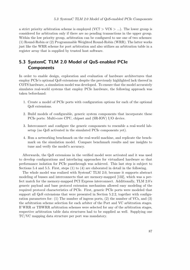
5.3 SystemC TLM 2.0 Model of QoS-enabled PCIe Components
a strict priority arbitration scheme is employed (VC7 > VC6 > ...). The lower group isconsidered for arbitration only if there are no pending transactions in the upper group.Within the low priority group, arbitration can be configured to use one of two schemes:(1) Round-Robin or (2) Programmable Weighted Round-Robin (WRR). The latter worksjust like the WRR scheme for port arbitration and also utilizes an arbitration table in aregister array that is supplied by trusted host software.
5.3 SystemC TLM 2.0 Model of QoS-enabled PCIeComponents
In order to enable design, exploration and evaluation of hardware architectures thatemploy PCIe’s optional QoS extensions despite the previously highlighted lack thereof inCOTS hardware, a simulation model was developed. To ensure that the model accuratelysimulates real-world systems that employ PCIe hardware, the following approach wastaken beforehand:
1. Create a model of PCIe ports with configuration options for each of the optionalQoS extensions.
2. Build models of configurable, generic system components that incorporate thesePCIe ports: Multi-core CPU, chipset and (SR-IOV) I/O device.
3. Interconnect and configure the generic components to resemble a real-world lab-setup (no QoS activated in the simulated PCIe components yet).
4. Run a networking benchmark on the real-world machine, and replicate the bench-mark on the simulation model. Compare benchmark results and use insights totune and verify the model’s accuracy.
Afterwards, the QoS extensions in the verified model were activated and it was usedto develop configurations and interfacing approaches for virtualized hardware so thatperformance isolation for PCIe passthrough was achieved. This last step is subject toSections 5.4 and 5.5. First, steps (1) to (4) are elaborated in detail in the following.
The whole model was realized with SystemC TLM 2.0, because it supports abstractmodeling of busses and interconnects that are memory-mapped [132], which was a per-fect match for the memory-mapped PCI Express interconnect. Additionally, TLM 2.0’sgeneric payload and base protocol extension mechanism allowed easy modeling of therequired protocol characteristics of PCIe. First, generic PCIe ports were modeled thatsupport all QoS extensions that were presented in Section 5.2.2, together with configu-ration parameters for: (1) The number of ingress ports, (2) the number of VCs, and (3)the arbitration scheme selection for each arbiter of the Port and VC arbitration stages.If WRR or TBWRR arbitration schemes were selected for any of the arbitration stages,respective arbitration table data structures had to be supplied as well. Supplying oneTC/VC mapping data structure per port was mandatory.
87
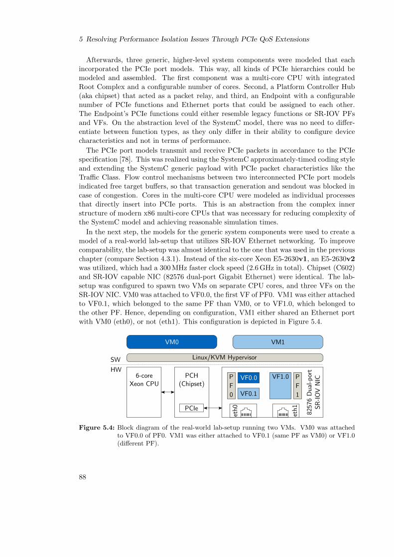
5 Resolving Performance Isolation Issues Through PCIe QoS Extensions
Afterwards, three generic, higher-level system components were modeled that eachincorporated the PCIe port models. This way, all kinds of PCIe hierarchies could bemodeled and assembled. The first component was a multi-core CPU with integratedRoot Complex and a configurable number of cores. Second, a Platform Controller Hub(aka chipset) that acted as a packet relay, and third, an Endpoint with a configurablenumber of PCIe functions and Ethernet ports that could be assigned to each other.The Endpoint’s PCIe functions could either resemble legacy functions or SR-IOV PFsand VFs. On the abstraction level of the SystemC model, there was no need to differ-entiate between function types, as they only differ in their ability to configure devicecharacteristics and not in terms of performance.
The PCIe port models transmit and receive PCIe packets in accordance to the PCIespecification [78]. This was realized using the SystemC approximately-timed coding styleand extending the SystemC generic payload with PCIe packet characteristics like theTraffic Class. Flow control mechanisms between two interconnected PCIe port modelsindicated free target buffers, so that transaction generation and sendout was blocked incase of congestion. Cores in the multi-core CPU were modeled as individual processesthat directly insert into PCIe ports. This is an abstraction from the complex innerstructure of modern x86 multi-core CPUs that was necessary for reducing complexity ofthe SystemC model and achieving reasonable simulation times.
In the next step, the models for the generic system components were used to create amodel of a real-world lab-setup that utilizes SR-IOV Ethernet networking. To improvecomparability, the lab-setup was almost identical to the one that was used in the previouschapter (compare Section 4.3.1). Instead of the six-core Xeon E5-2630v1, an E5-2630v2was utilized, which had a 300 MHz faster clock speed (2.6 GHz in total). Chipset (C602)and SR-IOV capable NIC (82576 dual-port Gigabit Ethernet) were identical. The lab-setup was configured to spawn two VMs on separate CPU cores, and three VFs on theSR-IOV NIC. VM0 was attached to VF0.0, the first VF of PF0. VM1 was either attachedto VF0.1, which belonged to the same PF than VM0, or to VF1.0, which belonged tothe other PF. Hence, depending on configuration, VM1 either shared an Ethernet portwith VM0 (eth0), or not (eth1). This configuration is depicted in Figure 5.4.
Linux/KVM HypervisorSW
HW6-core
Xeon CPU
VM0 VM1
eth0
VF0.0
VF0.1
PF0
VF1.0 PF1
eth1
PCH(Chipset)
8257
6 D
ual-p
ort
SR-IO
V N
IC
PCIe
Figure 5.4: Block diagram of the real-world lab-setup running two VMs. VM0 was attachedto VF0.0 of PF0. VM1 was either attached to VF0.1 (same PF as VM0) or VF1.0(different PF).
88
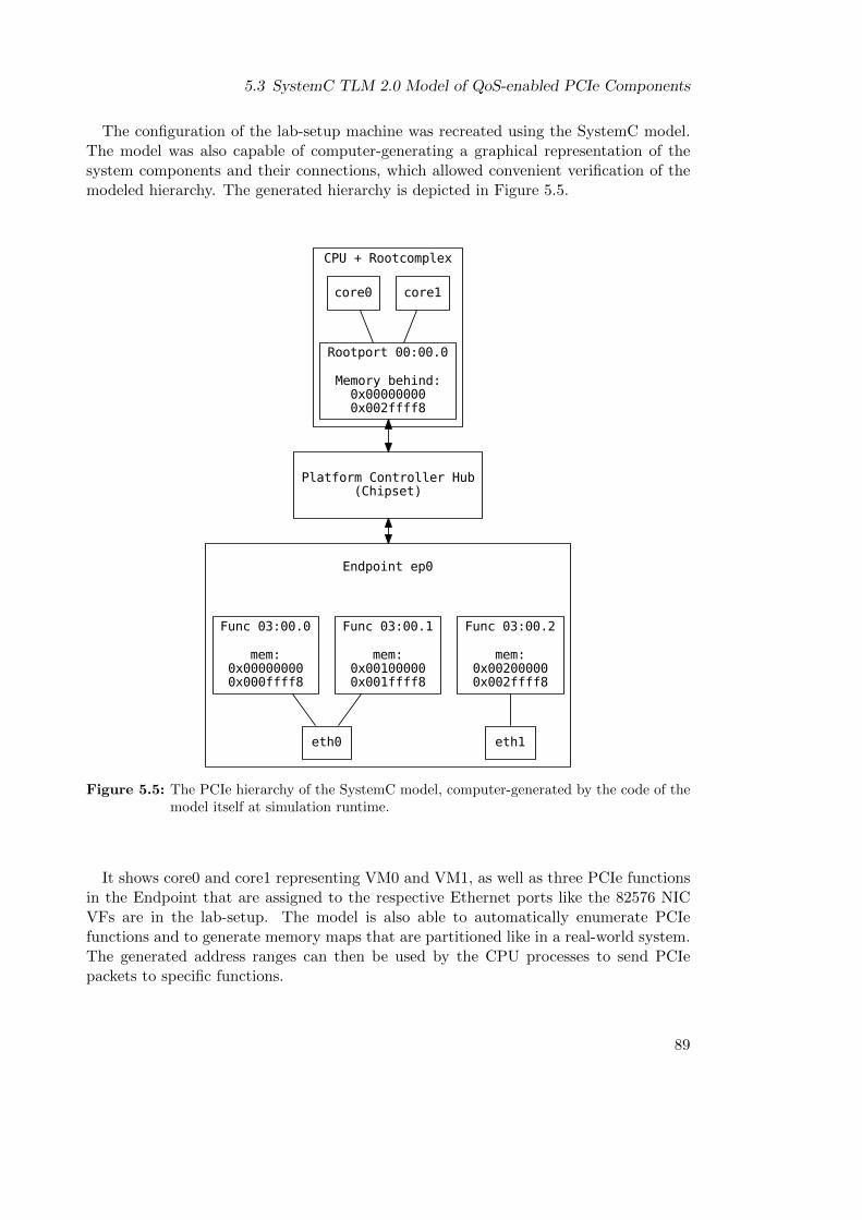
5.3 SystemC TLM 2.0 Model of QoS-enabled PCIe Components
The configuration of the lab-setup machine was recreated using the SystemC model.The model was also capable of computer-generating a graphical representation of thesystem components and their connections, which allowed convenient verification of themodeled hierarchy. The generated hierarchy is depicted in Figure 5.5.
CPU + Rootcomplex
core1
Rootport 00:00.0
Memory behind:0x000000000x002ffff8
core0
Platform Controller Hub(Chipset)
Endpoint ep0
Func 03:00.0
mem:0x000000000x000ffff8
Func 03:00.1
mem:0x001000000x001ffff8
Func 03:00.2
mem:0x002000000x002ffff8
eth0 eth1
Figure 5.5: The PCIe hierarchy of the SystemC model, computer-generated by the code of themodel itself at simulation runtime.
It shows core0 and core1 representing VM0 and VM1, as well as three PCIe functionsin the Endpoint that are assigned to the respective Ethernet ports like the 82576 NICVFs are in the lab-setup. The model is also able to automatically enumerate PCIefunctions and to generate memory maps that are partitioned like in a real-world system.The generated address ranges can then be used by the CPU processes to send PCIepackets to specific functions.
89
5 Resolving Performance Isolation Issues Through PCIe QoS Extensions
5.3.1 Model Verification Approach
For the SystemC model to become a viable research platform for PCIe DoS attacks, ithad to be able to accurately simulate the respective effects. Therefore, the goal wasto simulate execution of DoS attacks and UDP streaming benchmarks on core0 andcore1. On the model, UDP streaming was simulated by letting the model’s cores andtheir attached PCIe functions communicate using the protocol that was described inSection 3.6. On the lab-setup, UDP streaming was benchmarked using netperf, just likein the previous chapters of this thesis. Measurements on the lab-setup were then used toannotate the timings for packet generation and processing delays in the SystemC model(using mean values from multiple runs).
Finally, UDP throughput results on both, lab-setup and SystemC model, were com-pared to verify the accuracy of the simulation. To avoid confusion, the following de-scriptions will only use names as depicted in the block diagram of the lab-setup (seeFigure 5.4), but they can be substituted ad libitum with the respective names fromthe SystemC model hierarchy3(compare Figure 5.5). The following three scenarios wereevaluated:
Baseline: VM1 was completely idle and neither executing a benchmark nor a DoS at-tack. VM0 was the only user of Ethernet port eth0 and was executing the UDPthroughput benchmark.
Shared eth0: VM1 was attached to the second PCIe function of eth0 (VF0.1), and wasconcurrently executing the same benchmark as VM0. Hence, eth0 was shared byboth VM0 and VM1 simultaneously.
During DoS: VM1 was either attached to VF0.1 (same eth port than VM0) or VF1.0(different eth port) and was executing a PCIe DoS attack. Both configurationsyielded the same results and are therefore presented as a single result in the fol-lowing. This behavior is an expected result for a COTS SR-IOV device that, mostlikely, uses the same input buffers (VC0 only in this case) for all its PCIe functions(PFs and VFs). It might therefore only have a single processing engine for allincoming MMIO write transactions, regardless of PCIe function type or number.This was modeled accordingly in the SystemC model.
5.3.2 Verification Results
Figure 5.6 depicts results for UDP throughputs for the lab-setup and the SystemC modelfor a common range of message sizes (16 B – 1024 B). Additionally, the correspondingrate of generated UDP packets per second is depicted for both. This metric helps tofurther verify that the netperf benchmark was modeled accurately in the SystemC model.
3VM0 ↔ core0VM1 ↔ core1VF0.0 ↔ Func 03:00.0VF0.1 ↔ Func 03:00.1VF1.0 ↔ Func 03:00.2
90
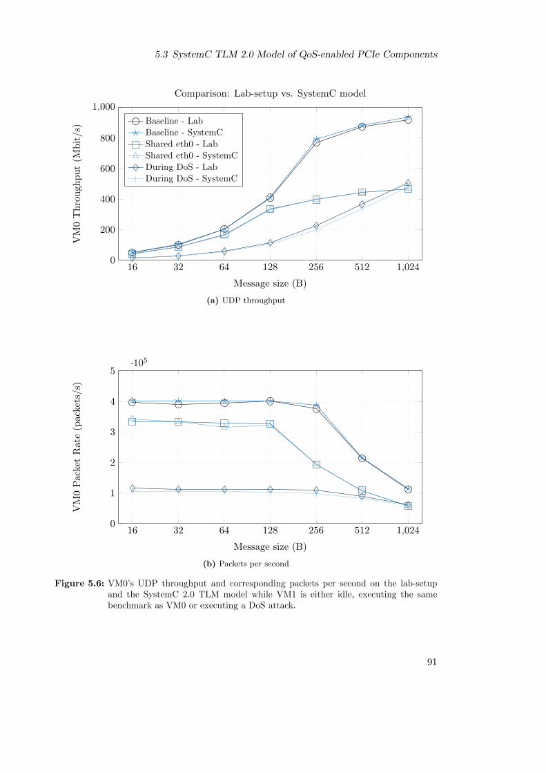
5.3 SystemC TLM 2.0 Model of QoS-enabled PCIe Components
16 32 64 128 256 512 1,0240
200
400
600
800
1,000
Message size (B)
VM
0T
hro
ugh
pu
t(M
bit/s
)
Comparison: Lab-setup vs. SystemC model
Baseline - Lab
Baseline - SystemC
Shared eth0 - Lab
Shared eth0 - SystemC
During DoS - LabDuring DoS - SystemC
(a) UDP throughput
16 32 64 128 256 512 1,0240
1
2
3
4
5·105
Message size (B)
VM
0P
acke
tR
ate
(pac
kets
/s)
(b) Packets per second
Figure 5.6: VM0’s UDP throughput and corresponding packets per second on the lab-setupand the SystemC 2.0 TLM model while VM1 is either idle, executing the samebenchmark as VM0 or executing a DoS attack.
91

5 Resolving Performance Isolation Issues Through PCIe QoS Extensions
Data points for results of the SystemC model each represent a one-time simulation run.Evaluation showed that a statistical distribution of single PCIe packet generation ratesdid not have a significant impact on the results. This was due to the communicationprotocol between CPU cores and I/O device, which involved a lot of blocking dependingon the UDP message size. This resulted in the system converging into one of twopossible states, in which either state produced blocking times that were much largerthan variances in the PCIe packet generation of CPU cores. Both states are explainedas follows:
I/O bound: UDP packets had large payload sizes. A CPU core needed less time togenerate an UDP packet with a large payload than the I/O device needed to sendout the respective packet. Hence, CPU cores were blocked and idle most of thetime, waiting for the I/O device to finish sending the current packet before thenext one could be generated.
CPU bound: UDP messages had small payload sizes. Creating large volumes of smallpackets incurred significant overhead for CPU cores. In consequence, a CPU coreneeded more time to generate an UDP packet with a small payload than the I/Odevice needed to send out the respective packet. Hence, the I/O device was blockedand idle most of the time, waiting for the CPU cores to deliver the next packet.
Results for the lab-setup show that DoS attacks caused UDP throughput drops be-tween 45% (1024 B) and 72% (128 B). UDP throughput during a DoS attack was evenworse than sharing the same Ethernet port (eth0 in this case) with another VM. Accord-ing to the classification of DoS attacks that was presented in Section 3.7, the attack wastherefore both an intra- and inter-PF DoS attack. Comparing these results to the re-spective results of the SystemC model shows that there is an average percentage error of1.9% between both in the baseline case. It is 1% for the case where the Ethernet port isshared (VM0 and VM1 simultaneously utilized eth0), and 7.7% for the case where VM1was executing a DoS attack. The errors can be attributed to the high-level abstractionsin the model that were highlighted previously. Nonetheless, the SystemC model resultswere very close to those of the real-world lab-setup, so that the it provided a good basisfor developing and exploring hardware architectures that employ PCIe’s QoS extensionsto prevent DoS attacks.
Two such hardware architectures will be presented in the following two sections. Thefirst architecture is optimized for full scheduling freedom, the second for minimal hard-ware costs. Both architectures were thoroughly evaluated with help of the SystemCmodel, and the results will be discussed together with the pros and cons of each ap-proach. In order to make evaluation results comparable, each architecture incorporatedthe SR-IOV two-port Gigabit Ethernet NIC that has been presented in previous sec-tions of this thesis. However, the concepts are not limited to this special device or I/Ocategory, but can be applied to any kind of passthrough hardware, e.g. a legacy PCIedevice with multiple functions.
92
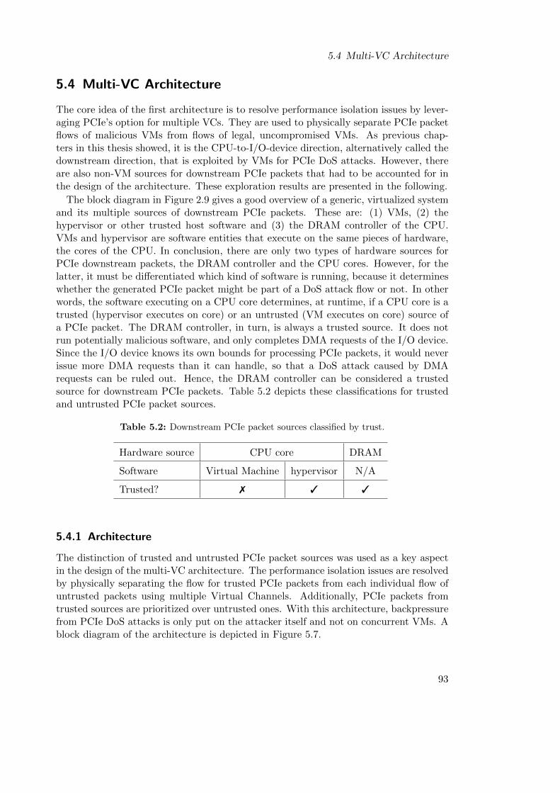
5.4 Multi-VC Architecture
5.4 Multi-VC Architecture
The core idea of the first architecture is to resolve performance isolation issues by lever-aging PCIe’s option for multiple VCs. They are used to physically separate PCIe packetflows of malicious VMs from flows of legal, uncompromised VMs. As previous chap-ters in this thesis showed, it is the CPU-to-I/O-device direction, alternatively called thedownstream direction, that is exploited by VMs for PCIe DoS attacks. However, thereare also non-VM sources for downstream PCIe packets that had to be accounted for inthe design of the architecture. These exploration results are presented in the following.
The block diagram in Figure 2.9 gives a good overview of a generic, virtualized systemand its multiple sources of downstream PCIe packets. These are: (1) VMs, (2) thehypervisor or other trusted host software and (3) the DRAM controller of the CPU.VMs and hypervisor are software entities that execute on the same pieces of hardware,the cores of the CPU. In conclusion, there are only two types of hardware sources forPCIe downstream packets, the DRAM controller and the CPU cores. However, for thelatter, it must be differentiated which kind of software is running, because it determineswhether the generated PCIe packet might be part of a DoS attack flow or not. In otherwords, the software executing on a CPU core determines, at runtime, if a CPU core is atrusted (hypervisor executes on core) or an untrusted (VM executes on core) source ofa PCIe packet. The DRAM controller, in turn, is always a trusted source. It does notrun potentially malicious software, and only completes DMA requests of the I/O device.Since the I/O device knows its own bounds for processing PCIe packets, it would neverissue more DMA requests than it can handle, so that a DoS attack caused by DMArequests can be ruled out. Hence, the DRAM controller can be considered a trustedsource for downstream PCIe packets. Table 5.2 depicts these classifications for trustedand untrusted PCIe packet sources.
Table 5.2: Downstream PCIe packet sources classified by trust.
Hardware source CPU core DRAM
Software Virtual Machine hypervisor N/A
Trusted? 7 3 3
5.4.1 Architecture
The distinction of trusted and untrusted PCIe packet sources was used as a key aspectin the design of the multi-VC architecture. The performance isolation issues are resolvedby physically separating the flow for trusted PCIe packets from each individual flow ofuntrusted packets using multiple Virtual Channels. Additionally, PCIe packets fromtrusted sources are prioritized over untrusted ones. With this architecture, backpressurefrom PCIe DoS attacks is only put on the attacker itself and not on concurrent VMs. Ablock diagram of the architecture is depicted in Figure 5.7.
93
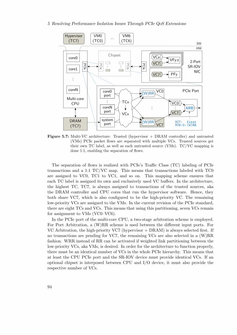
5 Resolving Performance Isolation Issues Through PCIe QoS Extensions
core0
Multi-coreCPU
DRAM(TC7)
VM0(TC0)
VM6(TC6)
...Hypervisor(TC7)
SW
HW
...
coreN
PCIe
Chipset
PCIe
PCIe
... ...
VCx
VC7VFy.z
VC7 PFy
2-PortSR-IOV
NIC
PCIe
(W)RRVC7
...
core0port
coreNport
...
systemport VC7:
VC6-0:first(W)RR
(W)RR VC0
VC0ARB
...
VC7
core1
PCIe Port
TCx
VCx
Figure 5.7: Multi-VC architecture: Trusted (hypervisor + DRAM controller) and untrusted(VMs) PCIe packet flows are separated with multiple VCs. Trusted sources gettheir own TC label, as well as each untrusted source (VMs). TC/VC mapping isdone 1:1, enabling the separation of flows.
The separation of flows is realized with PCIe’s Traffic Class (TC) labeling of PCIetransactions and a 1:1 TC/VC map. This means that transactions labeled with TC0are assigned to VC0, TC1 to VC1, and so on. This mapping scheme ensures thateach TC label is assigned its own and exclusively used VC buffers. In the architecture,the highest TC, TC7, is always assigned to transactions of the trusted sources, akathe DRAM controller and CPU cores that run the hypervisor software. Hence, theyboth share VC7, which is also configured to be the high-priority VC. The remaininglow-priority VCs are assigned to the VMs. In the current revision of the PCIe standard,there are eight TCs and VCs. This means that using this partitioning, seven VCs remainfor assignment to VMs (VC0–VC6).
In the PCIe port of the multi-core CPU, a two-stage arbitration scheme is employed.For Port Arbitration, a (W)RR scheme is used between the different input ports. ForVC Arbitration, the high-priority VC7 (hypervisor + DRAM) is always selected first. Ifno transactions are pending for VC7, the remaining VCs are also selected in a (W)RRfashion. WRR instead of RR can be activated if weighted link partitioning between thelow-priority VCs, aka VMs, is desired. In order for the architecture to function properly,there must be an identical number of VCs in the whole PCIe hierarchy. This means thatat least the CPU PCIe port and the SR-IOV device must provide identical VCs. If anoptional chipset is interposed between CPU and I/O device, it must also provide therespective number of VCs.
94
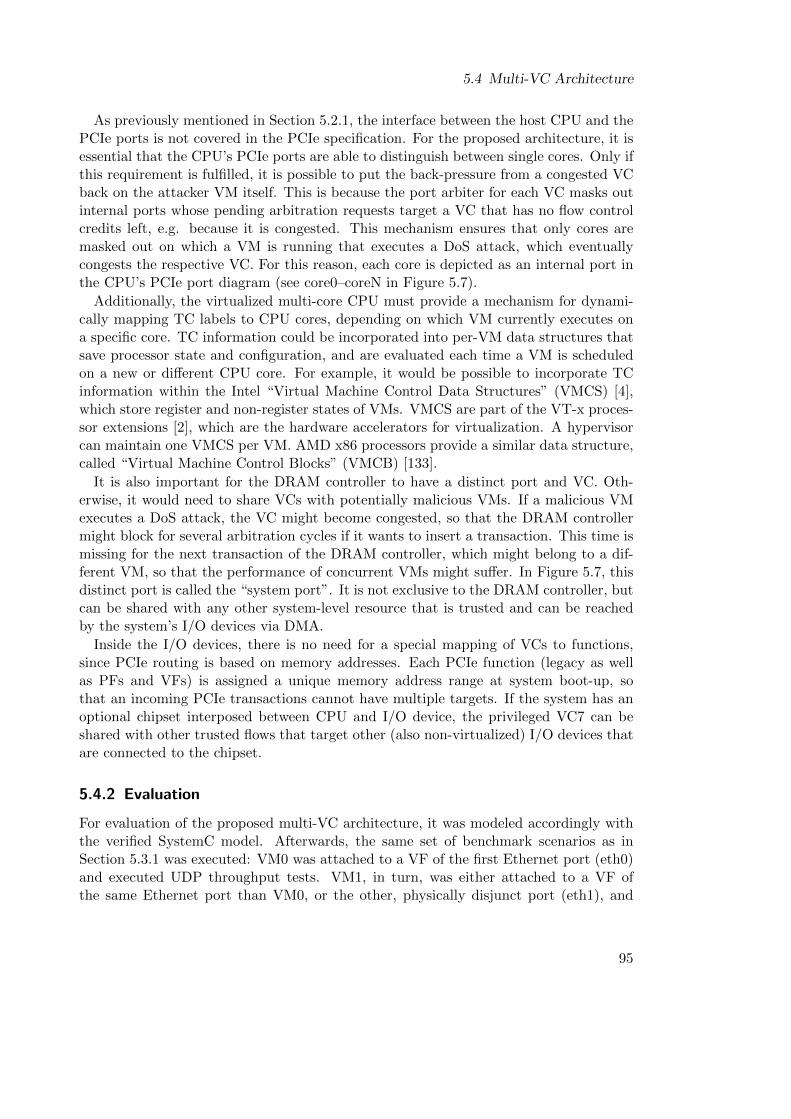
5.4 Multi-VC Architecture
As previously mentioned in Section 5.2.1, the interface between the host CPU and thePCIe ports is not covered in the PCIe specification. For the proposed architecture, it isessential that the CPU’s PCIe ports are able to distinguish between single cores. Only ifthis requirement is fulfilled, it is possible to put the back-pressure from a congested VCback on the attacker VM itself. This is because the port arbiter for each VC masks outinternal ports whose pending arbitration requests target a VC that has no flow controlcredits left, e.g. because it is congested. This mechanism ensures that only cores aremasked out on which a VM is running that executes a DoS attack, which eventuallycongests the respective VC. For this reason, each core is depicted as an internal port inthe CPU’s PCIe port diagram (see core0–coreN in Figure 5.7).
Additionally, the virtualized multi-core CPU must provide a mechanism for dynami-cally mapping TC labels to CPU cores, depending on which VM currently executes ona specific core. TC information could be incorporated into per-VM data structures thatsave processor state and configuration, and are evaluated each time a VM is scheduledon a new or different CPU core. For example, it would be possible to incorporate TCinformation within the Intel “Virtual Machine Control Data Structures” (VMCS) [4],which store register and non-register states of VMs. VMCS are part of the VT-x proces-sor extensions [2], which are the hardware accelerators for virtualization. A hypervisorcan maintain one VMCS per VM. AMD x86 processors provide a similar data structure,called “Virtual Machine Control Blocks” (VMCB) [133].
It is also important for the DRAM controller to have a distinct port and VC. Oth-erwise, it would need to share VCs with potentially malicious VMs. If a malicious VMexecutes a DoS attack, the VC might become congested, so that the DRAM controllermight block for several arbitration cycles if it wants to insert a transaction. This time ismissing for the next transaction of the DRAM controller, which might belong to a dif-ferent VM, so that the performance of concurrent VMs might suffer. In Figure 5.7, thisdistinct port is called the “system port”. It is not exclusive to the DRAM controller, butcan be shared with any other system-level resource that is trusted and can be reachedby the system’s I/O devices via DMA.
Inside the I/O devices, there is no need for a special mapping of VCs to functions,since PCIe routing is based on memory addresses. Each PCIe function (legacy as wellas PFs and VFs) is assigned a unique memory address range at system boot-up, sothat an incoming PCIe transactions cannot have multiple targets. If the system has anoptional chipset interposed between CPU and I/O device, the privileged VC7 can beshared with other trusted flows that target other (also non-virtualized) I/O devices thatare connected to the chipset.
5.4.2 Evaluation
For evaluation of the proposed multi-VC architecture, it was modeled accordingly withthe verified SystemC model. Afterwards, the same set of benchmark scenarios as inSection 5.3.1 was executed: VM0 was attached to a VF of the first Ethernet port (eth0)and executed UDP throughput tests. VM1, in turn, was either attached to a VF ofthe same Ethernet port than VM0, or the other, physically disjunct port (eth1), and
95
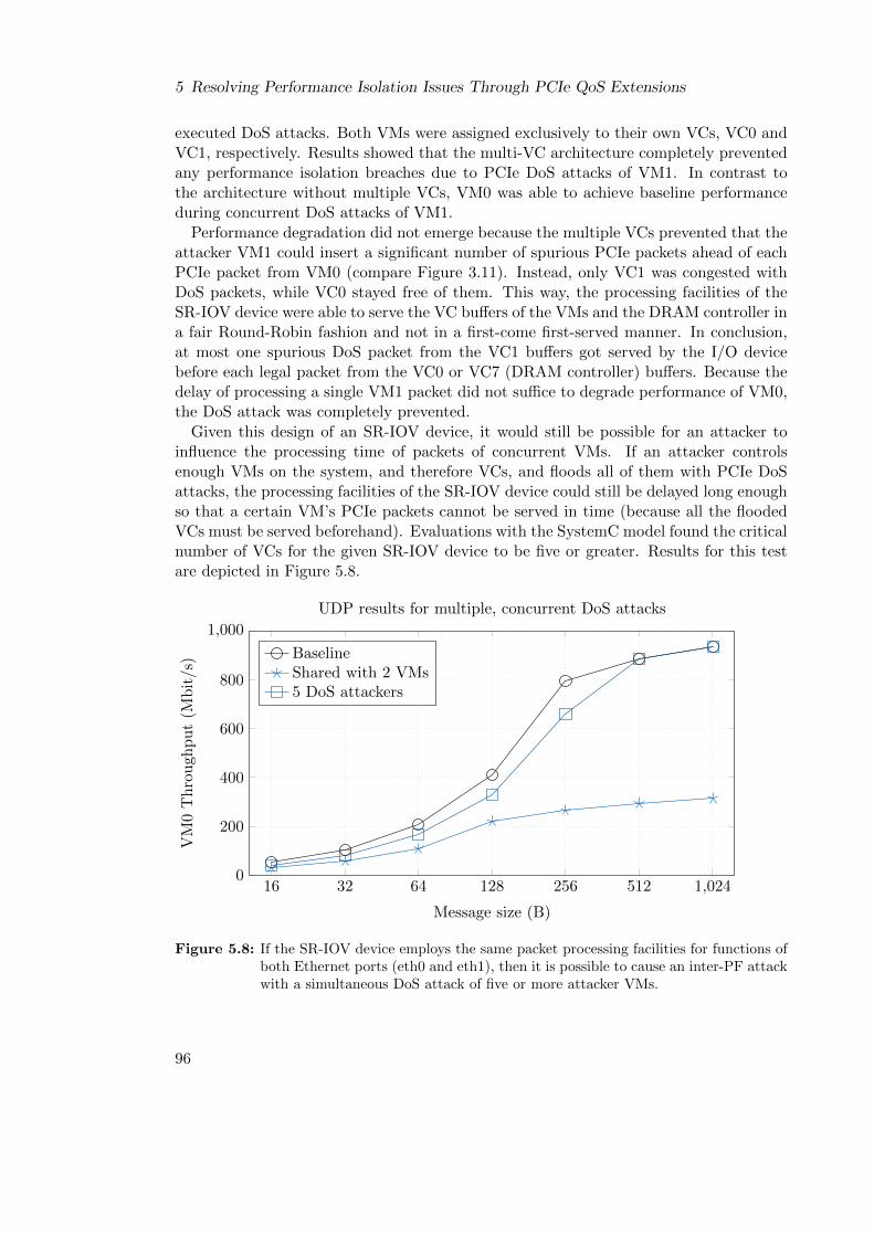
5 Resolving Performance Isolation Issues Through PCIe QoS Extensions
executed DoS attacks. Both VMs were assigned exclusively to their own VCs, VC0 andVC1, respectively. Results showed that the multi-VC architecture completely preventedany performance isolation breaches due to PCIe DoS attacks of VM1. In contrast tothe architecture without multiple VCs, VM0 was able to achieve baseline performanceduring concurrent DoS attacks of VM1.
Performance degradation did not emerge because the multiple VCs prevented that theattacker VM1 could insert a significant number of spurious PCIe packets ahead of eachPCIe packet from VM0 (compare Figure 3.11). Instead, only VC1 was congested withDoS packets, while VC0 stayed free of them. This way, the processing facilities of theSR-IOV device were able to serve the VC buffers of the VMs and the DRAM controller ina fair Round-Robin fashion and not in a first-come first-served manner. In conclusion,at most one spurious DoS packet from the VC1 buffers got served by the I/O devicebefore each legal packet from the VC0 or VC7 (DRAM controller) buffers. Because thedelay of processing a single VM1 packet did not suffice to degrade performance of VM0,the DoS attack was completely prevented.
Given this design of an SR-IOV device, it would still be possible for an attacker toinfluence the processing time of packets of concurrent VMs. If an attacker controlsenough VMs on the system, and therefore VCs, and floods all of them with PCIe DoSattacks, the processing facilities of the SR-IOV device could still be delayed long enoughso that a certain VM’s PCIe packets cannot be served in time (because all the floodedVCs must be served beforehand). Evaluations with the SystemC model found the criticalnumber of VCs for the given SR-IOV device to be five or greater. Results for this testare depicted in Figure 5.8.
16 32 64 128 256 512 1,0240
200
400
600
800
1,000
Message size (B)
VM
0T
hro
ugh
pu
t(M
bit/s)
UDP results for multiple, concurrent DoS attacks
BaselineShared with 2 VMs5 DoS attackers
Figure 5.8: If the SR-IOV device employs the same packet processing facilities for functions ofboth Ethernet ports (eth0 and eth1), then it is possible to cause an inter-PF attackwith a simultaneous DoS attack of five or more attacker VMs.
96
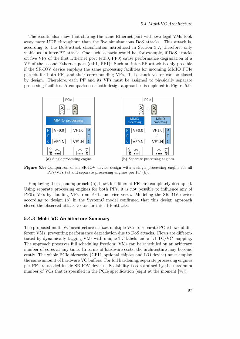
5.4 Multi-VC Architecture
The results also show that sharing the same Ethernet port with two legal VMs tookaway more UDP throughput than the five simultaneous DoS attacks. This attack is,according to the DoS attack classification introduced in Section 3.7, therefore, onlyviable as an inter-PF attack. One such scenario would be, for example, if DoS attackson five VFs of the first Ethernet port (eth0, PF0) cause performance degradation of aVF of the second Ethernet port (eth1, PF1). Such an inter-PF attack is only possibleif the SR-IOV device employs the same processing facilities for incoming MMIO PCIepackets for both PFs and their corresponding VFs. This attack vector can be closedby design. Therefore, each PF and its VFs must be assigned to physically separateprocessing facilities. A comparison of both design approaches is depicted in Figure 5.9.
eth0
VF0.0
VF0.N
PF0
PF1
eth1
VC7
VC0 ...
PCIe
MMIO processing
...
VF1.0
VF1.N
...
(a) Single processing engine
eth0
eth1
VC7
VC0 ...
PCIe
MMIOprocessing
MMIOprocessing
PF0
PF1
VF0.0
VF0.N...
VF1.0
VF1.N
...(b) Separate processing engines
Figure 5.9: Comparison of an SR-IOV device design with a single processing engine for allPFs/VFs (a) and separate processing engines per PF (b).
Employing the second approach (b), flows for different PFs are completely decoupled.Using separate processing engines for both PFs, it is not possible to influence any ofPF0’s VFs by flooding VFs from PF1, and vice versa. Modeling the SR-IOV deviceaccording to design (b) in the SystemC model confirmed that this design approachclosed the observed attack vector for inter-PF attacks.
5.4.3 Multi-VC Architecture Summary
The proposed multi-VC architecture utilizes multiple VCs to separate PCIe flows of dif-ferent VMs, preventing performance degradation due to DoS attacks. Flows are differen-tiated by dynamically tagging VMs with unique TC labels and a 1:1 TC/VC mapping.The approach preserves full scheduling freedom: VMs can be scheduled on an arbitrarynumber of cores at any time. In terms of hardware costs, the architecture may becomecostly. The whole PCIe hierarchy (CPU, optional chipset and I/O device) must employthe same amount of hardware VC buffers. For full hardening, separate processing enginesper PF are needed inside SR-IOV devices. Scalability is constrained by the maximumnumber of VCs that is specified in the PCIe specification (eight at the moment [78]).
97

5 Resolving Performance Isolation Issues Through PCIe QoS Extensions
5.5 Time-based Weighted Round-Robin Architecture
The second architecture proposed in this chapter is called the Time-based WeightedRound-Robin (TBWRR) architecture. It was developed as an alternative to the pre-viously introduced multi-VC architecture. In contrast to the latter, less resources areneeded for the TBWRR architecture, making it more light-weight. Additionally, onlythe virtualized multi-core CPU needs changes to hardware and the architecture utilizesonly a single VC, which makes it compatible to legacy chipsets and passthrough I/O de-vices. The architecture leverages a TBWRR arbitration table for Port Arbitration thatis tailored to the respective passthrough I/O device in order to prevent performancedegradation due to PCIe DoS attacks. For the arbitration scheme to work properly,some constraints must be put on VM scheduling. The core idea of the architecture willbe elaborated in the following.
Recalling Figure 3.11, performance degradation due to PCIe DoS attacks emergesbecause the I/O device is overstrained: The source (CPU cores) is sending PCIe packetsat a rate that is higher than the processing rate of the packets at the sink (I/O device).This eventually leads to a congestion on the interconnect that degrades performancefor concurrent VMs and the host. In current virtualized passthrough systems, there isno possibility to constrain the sending rate at the source. If the source rate could beconstrained such that RSource ≤ RSink, then the DoS attack vector would be eliminated.RSink for real-world hardware can be found either by looking at the respective device’sdatasheet or experimentally measured by trusted host software (see Appendix A) beforethe VMs are instantiated. For example, the I/O device that was used in this chapter, the82576 dual-port SR-IOV capable Gigabit Ethernet NIC, was targeted by DoS attacksat a VF memory address that took 534 ns to process a single packet. To leverage thisinformation, a virtualized multi-core CPU architecture is needed that is able to constrainits cores so that their packet rate is slower than 534 ns per packet.
5.5.1 Architecture
This can be achieved with the TBWRR Arbitration scheme that is defined in the QoSextensions of the PCIe standard [78]. It is the only arbitration scheme that enablesfine-grained temporal control of single PCIe transactions. TBWRR is only available forthe Port Arbitration stage (see Figure 5.2). However, this is an advantage, because itenables the whole architecture to work with only a single VC, VC0, which makes thearchitecture compatible to legacy chipsets and I/O devices. A block diagram of theproposed architecture is depicted in Figure 5.10.
The considerations about trusted and untrusted PCIe packet sources from the previ-ous section were reused for the design of this architecture. Internal ports for CPU coreswere considered untrusted, because they issue PCIe packets on behalf of potentiallymalicious VMs. This means that the time between the arbitration of CPU cores mustbe greater than the 534 ns that are needed for the SR-IOV device to process a PCIepacket. According to the standard, the duration of a TBWRR timeslot is 100 ns [78].Hence, every sixth timeslot in the TBWRR arbitration table may be used by a CPU
98

5.5 Time-based Weighted Round-Robin Architecture
core0
Multi-coreCPU
DRAM
VM0(core0)
VMN
(coreN)
...Hypervisor(core[0-N])
SW
HW
...
coreN
PCIe
Chipset
PCIe
PCIe VC0
VFy.z 2-PortSR-IOV
NIC
PCIe
core0port
coreNport
...
systemport
Time-based WeightedRound-Robin (TBWRR)
ARBVC0
core1
PCIe Port
PFy
TCx
VC0
VC0 ARB
t
Figure 5.10: The TBWRR architecture. DoS attacks are eliminated by a Port Arbitrationtable that prevents CPU cores from sending PCIe packets at rates that are higherthan the packet processing rate of the SR-IOV device.
core. As TBWRR arbitration works with internal ports, it must differentiate the coresof a multi-core CPU using one port per core. Fair allocation of resources can thereforeonly be guaranteed if VMs are statically pinned to certain cores. The remaining five ar-bitration timeslots between two CPU core slots are used for transactions of other systemcomponents. For example, for transactions of the DRAM controller that complete DMArequests from I/O devices. The hypervisor does not need special treatment, because itexecutes on any core that also executes VMs. It can therefore utilize the arbitration slotsof the respective VM. An exemplary TBWRR arbitration table is shown in Figure 5.11.
coreN
...... ............
core0
core1
systemsystem
systemsystem
systemsystem
systemsystemsystem
systemsystem
systemsystem
system
system
100 ns
PCIe packet proc. time of SR-IOV NIC (534 ns)
Figure 5.11: TBWRR arbitration table, tailored for preventing DoS attacks on the 82576 NIC.
99
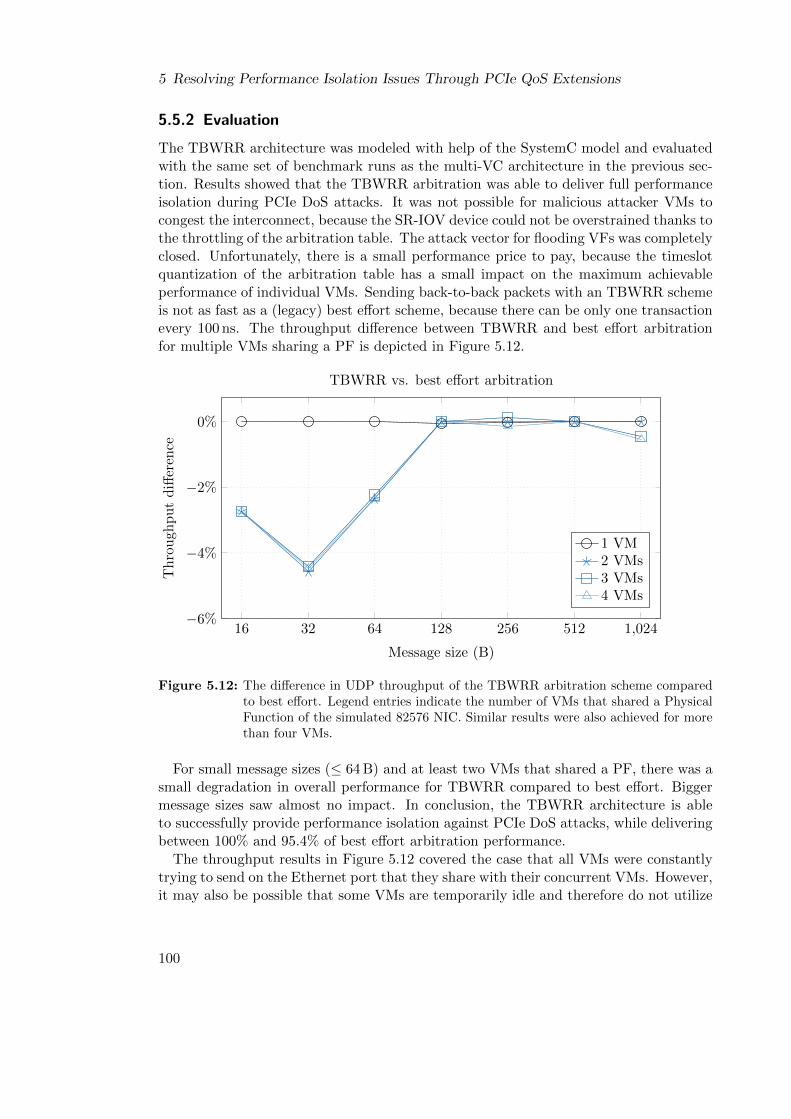
5 Resolving Performance Isolation Issues Through PCIe QoS Extensions
5.5.2 Evaluation
The TBWRR architecture was modeled with help of the SystemC model and evaluatedwith the same set of benchmark runs as the multi-VC architecture in the previous sec-tion. Results showed that the TBWRR arbitration was able to deliver full performanceisolation during PCIe DoS attacks. It was not possible for malicious attacker VMs tocongest the interconnect, because the SR-IOV device could not be overstrained thanks tothe throttling of the arbitration table. The attack vector for flooding VFs was completelyclosed. Unfortunately, there is a small performance price to pay, because the timeslotquantization of the arbitration table has a small impact on the maximum achievableperformance of individual VMs. Sending back-to-back packets with an TBWRR schemeis not as fast as a (legacy) best effort scheme, because there can be only one transactionevery 100 ns. The throughput difference between TBWRR and best effort arbitrationfor multiple VMs sharing a PF is depicted in Figure 5.12.
16 32 64 128 256 512 1,024−6%
−4%
−2%
0%
Message size (B)
Th
rou
ghp
ut
diff
eren
ce
TBWRR vs. best effort arbitration
1 VM2 VMs3 VMs4 VMs
Figure 5.12: The difference in UDP throughput of the TBWRR arbitration scheme comparedto best effort. Legend entries indicate the number of VMs that shared a PhysicalFunction of the simulated 82576 NIC. Similar results were also achieved for morethan four VMs.
For small message sizes (≤ 64 B) and at least two VMs that shared a PF, there was asmall degradation in overall performance for TBWRR compared to best effort. Biggermessage sizes saw almost no impact. In conclusion, the TBWRR architecture is ableto successfully provide performance isolation against PCIe DoS attacks, while deliveringbetween 100% and 95.4% of best effort arbitration performance.
The throughput results in Figure 5.12 covered the case that all VMs were constantlytrying to send on the Ethernet port that they share with their concurrent VMs. However,it may also be possible that some VMs are temporarily idle and therefore do not utilize
100
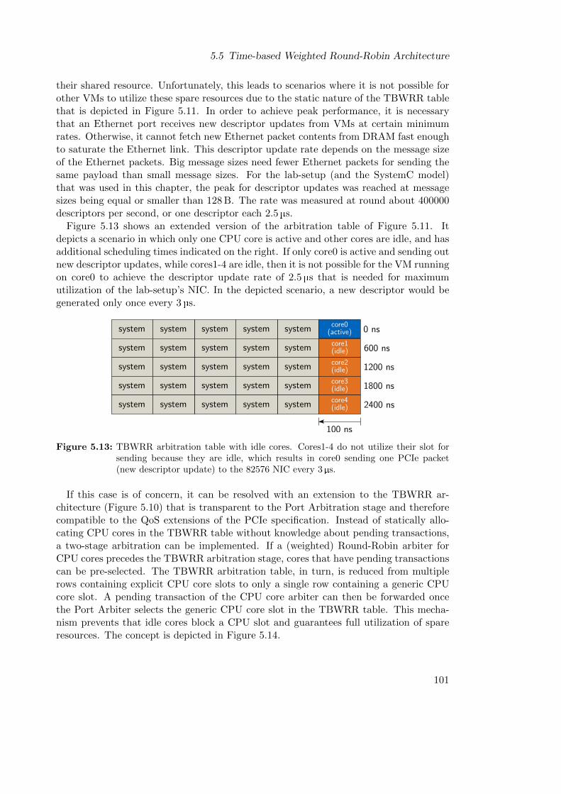
5.5 Time-based Weighted Round-Robin Architecture
their shared resource. Unfortunately, this leads to scenarios where it is not possible forother VMs to utilize these spare resources due to the static nature of the TBWRR tablethat is depicted in Figure 5.11. In order to achieve peak performance, it is necessarythat an Ethernet port receives new descriptor updates from VMs at certain minimumrates. Otherwise, it cannot fetch new Ethernet packet contents from DRAM fast enoughto saturate the Ethernet link. This descriptor update rate depends on the message sizeof the Ethernet packets. Big message sizes need fewer Ethernet packets for sending thesame payload than small message sizes. For the lab-setup (and the SystemC model)that was used in this chapter, the peak for descriptor updates was reached at messagesizes being equal or smaller than 128 B. The rate was measured at round about 400000descriptors per second, or one descriptor each 2.5 µs.
Figure 5.13 shows an extended version of the arbitration table of Figure 5.11. Itdepicts a scenario in which only one CPU core is active and other cores are idle, and hasadditional scheduling times indicated on the right. If only core0 is active and sending outnew descriptor updates, while cores1-4 are idle, then it is not possible for the VM runningon core0 to achieve the descriptor update rate of 2.5 µs that is needed for maximumutilization of the lab-setup’s NIC. In the depicted scenario, a new descriptor would begenerated only once every 3 µs.
core0(active)
core1(idle)
systemsystem
systemsystem
systemsystemsystem
systemsystemsystem
100 ns
systemsystem
systemsystem
systemsystemsystem
systemsystemsystem
systemsystemsystemsystemsystem
0 ns
600 ns
1200 ns
1800 ns
2400 ns
core2(idle)
core3(idle)
core4(idle)
Figure 5.13: TBWRR arbitration table with idle cores. Cores1-4 do not utilize their slot forsending because they are idle, which results in core0 sending one PCIe packet(new descriptor update) to the 82576 NIC every 3µs.
If this case is of concern, it can be resolved with an extension to the TBWRR ar-chitecture (Figure 5.10) that is transparent to the Port Arbitration stage and thereforecompatible to the QoS extensions of the PCIe specification. Instead of statically allo-cating CPU cores in the TBWRR table without knowledge about pending transactions,a two-stage arbitration can be implemented. If a (weighted) Round-Robin arbiter forCPU cores precedes the TBWRR arbitration stage, cores that have pending transactionscan be pre-selected. The TBWRR arbitration table, in turn, is reduced from multiplerows containing explicit CPU core slots to only a single row containing a generic CPUcore slot. A pending transaction of the CPU core arbiter can then be forwarded oncethe Port Arbiter selects the generic CPU core slot in the TBWRR table. This mecha-nism prevents that idle cores block a CPU slot and guarantees full utilization of spareresources. The concept is depicted in Figure 5.14.
101
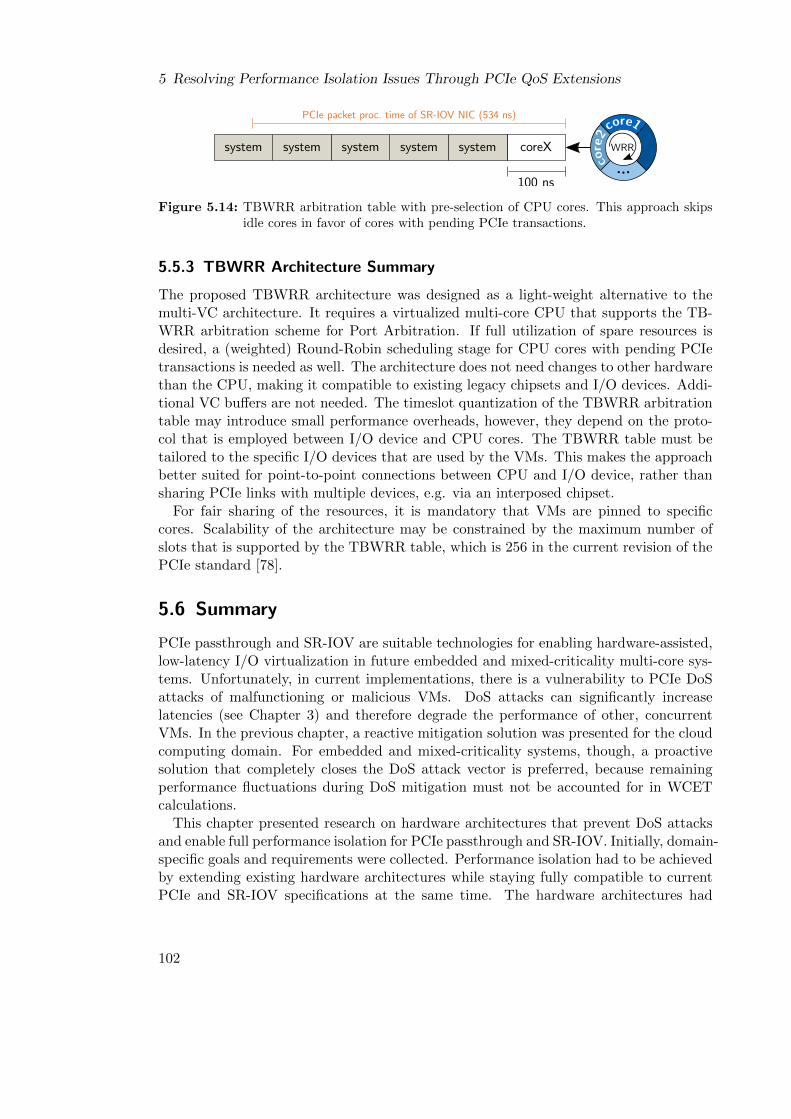
5 Resolving Performance Isolation Issues Through PCIe QoS Extensions
core1
core2
...
WRRcoreXsystemsystemsystemsystemsystem
100 ns
PCIe packet proc. time of SR-IOV NIC (534 ns)
Figure 5.14: TBWRR arbitration table with pre-selection of CPU cores. This approach skipsidle cores in favor of cores with pending PCIe transactions.
5.5.3 TBWRR Architecture Summary
The proposed TBWRR architecture was designed as a light-weight alternative to themulti-VC architecture. It requires a virtualized multi-core CPU that supports the TB-WRR arbitration scheme for Port Arbitration. If full utilization of spare resources isdesired, a (weighted) Round-Robin scheduling stage for CPU cores with pending PCIetransactions is needed as well. The architecture does not need changes to other hardwarethan the CPU, making it compatible to existing legacy chipsets and I/O devices. Addi-tional VC buffers are not needed. The timeslot quantization of the TBWRR arbitrationtable may introduce small performance overheads, however, they depend on the proto-col that is employed between I/O device and CPU cores. The TBWRR table must betailored to the specific I/O devices that are used by the VMs. This makes the approachbetter suited for point-to-point connections between CPU and I/O device, rather thansharing PCIe links with multiple devices, e.g. via an interposed chipset.
For fair sharing of the resources, it is mandatory that VMs are pinned to specificcores. Scalability of the architecture may be constrained by the maximum number ofslots that is supported by the TBWRR table, which is 256 in the current revision of thePCIe standard [78].
5.6 Summary
PCIe passthrough and SR-IOV are suitable technologies for enabling hardware-assisted,low-latency I/O virtualization in future embedded and mixed-criticality multi-core sys-tems. Unfortunately, in current implementations, there is a vulnerability to PCIe DoSattacks of malfunctioning or malicious VMs. DoS attacks can significantly increaselatencies (see Chapter 3) and therefore degrade the performance of other, concurrentVMs. In the previous chapter, a reactive mitigation solution was presented for the cloudcomputing domain. For embedded and mixed-criticality systems, though, a proactivesolution that completely closes the DoS attack vector is preferred, because remainingperformance fluctuations during DoS mitigation must not be accounted for in WCETcalculations.
This chapter presented research on hardware architectures that prevent DoS attacksand enable full performance isolation for PCIe passthrough and SR-IOV. Initially, domain-specific goals and requirements were collected. Performance isolation had to be achievedby extending existing hardware architectures while staying fully compatible to currentPCIe and SR-IOV specifications at the same time. The hardware architectures had
102
5.6 Summary
to satisfy requirements for proactive, full isolation, secure configuration by a trustedsoftware entity like the hypervisor, scalability to a reasonable number of passthroughfunctions and low overhead regarding non-PCIe parts of the system.
The developed architectures were built around optional QoS extensions of the PCIespecification, which facilitated compatibility. During exploration and review of the QoSextensions, it was found that certain hardware building blocks (Virtual Channel buffers,Port and VC arbiters and corresponding arbitration schemes) could be directly em-ployed. On the other hand, paradigms for using these building blocks for preventionof downstream congestion (due to DoS attacks) were missing as well as mechanisms forinterfacing the QoS hardware from a virtualized multi-core CPU. Both aspects weredeveloped from scratch in this chapter.
Since current COTS PCIe hardware did not provide any QoS extensions (defined op-tional in the specification and lack of use cases in the real world), a SystemC TLM 2.0simulation model of a real-world lab-setup was developed and extended with configurablePCIe QoS extensions. The SystemC model’s accuracy was verified by replicating vari-ous UDP throughput benchmarks on it that were also run on the real-world machine.Comparison of the results showed that the average percentage error between softwaremodel and real-world hardware was between 1% and 7.7%.
Afterwards, the SystemC model was used to design and evaluate two hardware archi-tectures that close the PCIe DoS attack vector. Evaluations showed that both architec-tures succeeded in completely preventing PCIe DoS attacks, while being optimized fordifferent goals. The multi-VC architecture provides full scheduling freedom, but needsto implement multiple Virtual Channels in all PCIe devices of the hierarchy (multi-coreCPU, optional chipset, I/O device). The lightweight TBWRR architecture, on the otherhand, only needs hardware changes to the multi-core CPU, but VMs must be pinnedto specific cores. Detailed reviews of both architectures can be found in Sections 5.4.3and 5.5.3, respectively.
103

6 Conclusion and Outlook
Work presented in this thesis contributes to the field of performance isolation for PCIepassthrough and Single Root I/O Virtualization (SR-IOV), the latest generation of I/Ovirtualization technology. Specifically, performance isolation issues that arise from PCIeDenial-of-Service (DoS) attacks on passthrough and SR-IOV hardware were addressed.The focus was laid on the cloud computing domain, where the technology has beenembraced and deployed already, and the embedded virtualization domain, where thetechnology is seen as an enabler for future, virtualized multi-core systems.
6.1 Conclusion
Initial work on this thesis was motivated by the sparse presence of literature on per-formance isolation of PCIe passthrough and SR-IOV. It quickly led to the discoverythat PCIe DoS attacks of malicious or buggy Virtual Machines (VMs) are able to breakperformance isolation in current commercial-off-the-shelf (COTS) hardware that im-plements the technology. This attack vector was investigated with four experimentson a state-of-the-art x86 system comprised of COTS hardware, including a dual-port1 Gbit/s SR-IOV capable Ethernet adapter. Results showed that DoS attacker VMswere able to significantly degrade the I/O performance of concurrent VMs in configura-tions where the victims should have been 100% isolated from the attacker. For example,PCIe DoS attacks on the Ethernet adapter increased latencies for accessing the devicefrom 1.58 µs up to 12.61 µs (+698%). This translated to an Ethernet throughput dropfrom 941 Mbit/s down to 615 Mbit/s (-35%). The same attacks caused the system’s diskstorage throughput to drop by up to 77%.
Learnings from the experiments were used to identify the key architectural issueswithin the design of PCIe passthrough and SR-IOV: First, CPU cores, on which po-tentially malicious VMs execute, are usually faster at generating PCIe packets thanpassthrough I/O devices are at consuming them. Second, in current implementations,there is no mechanism for passthrough devices to prevent VMs from sending packets.The resulting congestion on the shared PCIe interconnect causes performance interfer-ence between otherwise unrelated VMs. The gained insights were used to constructan abstract system model that presents a concise representation of these issues. Fur-thermore, four different DoS attack types were identified and classified according tothe system components that suffer from the attack. For instance, it is differentiated ifdegradation of an attack affects only the shared device that is attacked, or also unrelateddevices on the same interconnect.
In order to solve the performance isolation issues, two domain specific solutions wereproposed. The first solution targets the cloud computing domain and proposes a
105
6 Conclusion and Outlook
combined hardware/software approach. It was experimentally verified that lightweighthardware monitoring facilities within the passthrough I/O device are able to unam-biguously detect DoS attacks and identify attacker VMs using a threshold value fortransaction rates of PCIe packets. Additionally, two countermeasures that mitigate anattack were presented and evaluated. First, freezing attacker VMs showed that baselineperformance for victim VMs is instantly restored, but the approach might also kill other,unrelated processes within the attacker VM. Second, attacker VMs can be throttled byscheduling them only for small timeslices that do not suffice to maintain a constantcongestion on the interconnect. The latter approach keeps the VM alive and is ableto restore close to baseline performance for victim VMs. For instance, performance oftypical cloud applications like Apache and Memcached could be restored from 51.3%during DoS attacks to 97% and from 61.8% to 99.4%, respectively; Streaming-basedmicro-benchmarks performed only slightly worse.
The mitigation approach does not reach 100% of native performance for two reasons.(1) It is a reactive approach that can be invoked only after an attack has been detected,and (2) throttling via software scheduling could not reach granularities that were fine-grained enough to completely prevent congestion on the interconnect. However, thisdesign decision was made on purpose in light of cloud computing requirements. Here,real-time capabilities are not needed, so that small interferences are tolerable. Evenmore so because cloud computing providers can migrate attacker VMs to isolated hostsshortly after a DoS attack was detected and mitigated. On the other hand, using amonitoring approach enables the proposed solution to be scalable and low-cost, whichincreases the chance of manufacturers adopting the idea.
The second solution targets the embedded virtualization domain and pro-poses two integrated hardware architectures that completely prevent DoS attacks onPCIe passthrough and SR-IOV. This way, performance interference of passthrough de-vices need not be considered at all in worst case execution time calculations of real-timesystems. In order to stay compatible to PCIe, both architectures were designed toemploy optional Quality-of-Service (QoS) extensions from the PCIe specification as afoundation. The QoS extensions originate from a time long before PCIe passthrough,SR-IOV and platform virtualization surfaced in datacenters and COTS devices, and DoSattacks on PCIe devices became a valid attack vector. Hence, this thesis shows a wayto repurpose the QoS extensions in order to prevent DoS attacks.
The first proposed architecture, called multi-VC, maps individual VMs to dedicatedVirtual Channels (VCs), which are implemented in CPUs, switches and I/O devices.This separation approach ensures that malicious VMs cannot congest the shared inter-connect. Evaluation with a SystemC model verified full prevention of DoS attacks. ThePCIe interconnect stays congestion free, and performance remains unaffected. However,hardware VCs might be expensive, and scalability is capped by the number of VCs thatthe PCIe specification supports (eight VCs). The second proposed architecture, calledTBWRR, employs hardware-enforced time-based weighted round robin (TBWRR) ar-bitration for admission of VMs to the interconnect. The thesis shows that arbitrationrules can be compiled that completely prevent congestion on the interconnect if VMsare statically pinned to CPU cores. Evaluation with SystemC showed that the approach
106
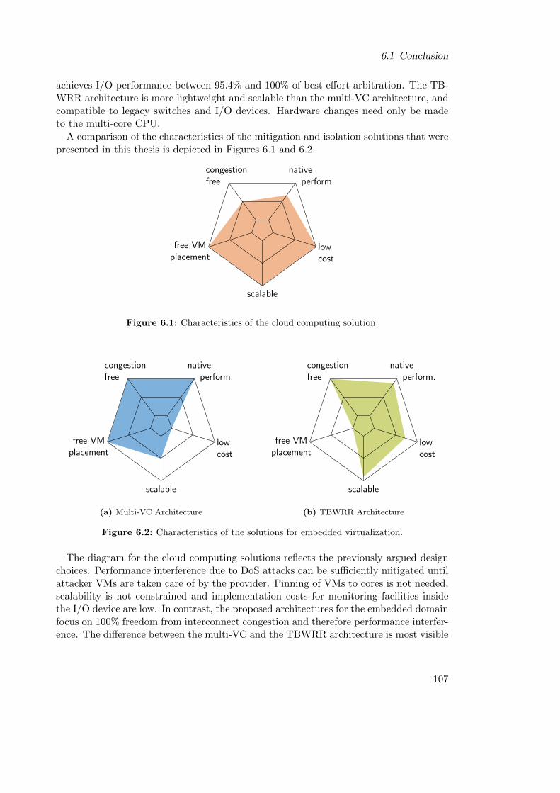
6.1 Conclusion
achieves I/O performance between 95.4% and 100% of best effort arbitration. The TB-WRR architecture is more lightweight and scalable than the multi-VC architecture, andcompatible to legacy switches and I/O devices. Hardware changes need only be madeto the multi-core CPU.
A comparison of the characteristics of the mitigation and isolation solutions that werepresented in this thesis is depicted in Figures 6.1 and 6.2.
scalable
lowcost
free VMplacement
congestionfree
native perform.
Figure 6.1: Characteristics of the cloud computing solution.
scalable
native perform.
congestionfree
lowcost
free VMplacement
(a) Multi-VC Architecture
scalable
native perform.
congestionfree
lowcost
free VMplacement
(b) TBWRR Architecture
Figure 6.2: Characteristics of the solutions for embedded virtualization.
The diagram for the cloud computing solutions reflects the previously argued designchoices. Performance interference due to DoS attacks can be sufficiently mitigated untilattacker VMs are taken care of by the provider. Pinning of VMs to cores is not needed,scalability is not constrained and implementation costs for monitoring facilities insidethe I/O device are low. In contrast, the proposed architectures for the embedded domainfocus on 100% freedom from interconnect congestion and therefore performance interfer-ence. The difference between the multi-VC and the TBWRR architecture is most visible
107
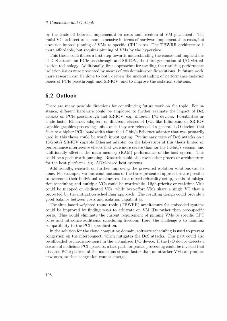
6 Conclusion and Outlook
by the trade-off between implementation costs and freedom of VM placement. Themulti-VC architecture is more expensive in terms of hardware implementation costs, butdoes not impose pinning of VMs to specific CPU cores. The TBWRR architecture ismore affordable, but requires pinning of VMs by the hypervisor.
This thesis contributes a first step towards understanding the causes and implicationsof DoS attacks on PCIe passthrough and SR-IOV, the third generation of I/O virtual-ization technology. Additionally, first approaches for tackling the resulting performanceisolation issues were presented by means of two domain-specific solutions. In future work,more research can be done to both deepen the understanding of performance isolationissues of PCIe passthrough and SR-IOV, and to improve the isolation solutions.
6.2 Outlook
There are many possible directions for contributing future work on the topic. For in-stance, different hardware could be employed to further evaluate the impact of DoSattacks on PCIe passthrough and SR-IOV, e.g. different I/O devices. Possibilities in-clude faster Ethernet adapters or different classes of I/O, like Infiniband or SR-IOVcapable graphics processing units, once they are released. In general, I/O devices thatfeature a higher PCIe bandwidth than the 1 Gbit/s Ethernet adapter that was primarilyused in this thesis could be worth investigating. Preliminary tests of DoS attacks on a10 Gbit/s SR-IOV capable Ethernet adapter on the lab-setups of this thesis hinted onperformance interference effects that were more severe than for the 1 Gbit/s version, andadditionally affected the main memory (RAM) performance of the host system. Thiscould be a path worth pursuing. Research could also cover other processor architecturesfor the host platforms, e.g. ARM-based host systems.
Additionally, research on further improving the presented isolation solutions can bedone. For example, various combinations of the three presented approaches are possibleto overcome their individual weaknesses. In a mixed-criticality setup, a mix of mitiga-tion scheduling and multiple VCs could be worthwhile. High-priority or real-time VMscould be mapped on dedicated VCs, while best-effort VMs share a single VC that isprotected by the mitigation scheduling approach. The resulting design could provide agood balance between costs and isolation capabilities.
The time-based weighted round-robin (TBWRR) architecture for embedded systemscould be improved by finding ways to arbitrate on VM IDs rather than core-specificports. This would eliminate the current requirement of pinning VMs to specific CPUcores and introduce additional scheduling freedom. Here, the challenge is to maintaincompatibility to the PCIe specification.
In the solution for the cloud computing domain, software scheduling is used to preventcongestion on the interconnect, which mitigates the DoS attacks. This part could alsobe offloaded to hardware-assist in the virtualized I/O device. If the I/O device detects astream of malicious PCIe packets, a fast-path for packet processing could be invoked thatdiscards PCIe packets of the malicious stream faster than an attacker VM can producenew ones, so that congestion cannot emerge.
108

6.2 Outlook
Direct access to I/O devices or peripherals for VMs is also possible in virtualizedplatforms that do not employ PCIe as interconnect. Embedded systems often employ amultitude of different interconnects. Here, an evaluation of DoS attacks could contributevaluable insights, as well as research on transferring concepts of the presented solutions.
109

Bibliography
[1] L. Wang, G. Von Laszewski, A. Younge, X. He, M. Kunze, J. Tao, and C. Fu. Cloudcomputing: a perspective study. New Generation Computing, 28(2):137–146, 2010.
[2] R. Uhlig, G. Neiger, D. Rodgers, A. L. Santoni, F. C. Martins, A. V. Anderson,S. M. Bennett, A. Kagi, F. H. Leung, and L. Smith. Intel virtualization technology.Computer, 38(5):48–56, 2005.
[3] Advanced Micro Devices, Inc. AMD64 Virtualization Technology Secure VirtualMachine Architecture Reference Manual, 3.02 edition, December 2005.
[4] Intel Corporation. Intel 64 and IA-32 Architectures Software Developer’s Manual,December 2016. Combined Volumes: 1, 2A, 2B, 2C, 2D, 3A, 3B, 3C and 3D.
[5] R. Bhargava, B. Serebrin, F. Spadini, and S. Manne. Accelerating two-dimensionalpage walks for virtualized systems. In Proceedings of the 13th InternationalConference on Architectural Support for Programming Languages and Operat-ing Systems, ASPLOS XIII, pages 26–35, New York, NY, USA, 2008. ACM.doi:10.1145/1346281.1346286.
[6] Y. Koh, R. Knauerhase, P. Brett, M. Bowman, Z. Wen, and C. Pu. An analysis ofperformance interference effects in virtual environments. In 2007 IEEE Interna-tional Symposium on Performance Analysis of Systems Software, pages 200–209,April 2007. doi:10.1109/ISPASS.2007.363750.
[7] J. N. Matthews, W. Hu, M. Hapuarachchi, T. Deshane, D. Dimatos, G. Hamilton,M. McCabe, and J. Owens. Quantifying the Performance Isolation Properties ofVirtualization Systems. In Proceedings of the 2007 Workshop on ExperimentalComputer Science, ExpCS ’07, New York, NY, USA, 2007. ACM. doi:10.1145/
1281700.1281706.
[8] G. Heiser. Virtualizing embedded systems - why bother? In 2011 48thACM/EDAC/IEEE Design Automation Conference (DAC), pages 901–905, June2011.
[9] D. Reinhardt, D. Kaule, and M. Kucera. Achieving a scalable e/e-architectureusing autosar and virtualization. SAE Int. J. Passeng. Cars – Electron. Electr.Syst., 6:489–497, 04 2013. doi:10.4271/2013-01-1399.
111
Bibliography
[10] D. Reinhardt and G. Morgan. An embedded hypervisor for safety-relevant au-tomotive e/e-systems. In Proceedings of the 9th IEEE International Sympo-sium on Industrial Embedded Systems (SIES 2014), pages 189–198, June 2014.doi:10.1109/SIES.2014.6871203.
[11] D. Juergens, D. Reinhardt, R. Schneider, G. Hofstetter, U. Dannebaum, andA. Graf. Implementing mixed criticality software integration on multicore - acost model and the lessons learned. In SAE Technical Paper. SAE International,04 2015. doi:10.4271/2015-01-0266.
[12] O. Sander, T. Sandmann, V. V. Duy, S. Bahr, F. Bapp, J. Becker, H. U. Michel,D. Kaule, D. Adam, E. Lubbers, J. Hairbucher, A. Richter, C. Herber, and A. Herk-ersdorf. Hardware virtualization support for shared resources in mixed-criticalitymulticore systems. In Design, Automation and Test in Europe Conference and Ex-hibition (DATE), Dresden, Germany, March 2014. doi:10.7873/DATE.2014.081.
[13] D. Kleidermacher and M. Wolf. Mils virtualization for integrated modular avionics.In 2008 IEEE/AIAA 27th Digital Avionics Systems Conference, pages 1.C.3–1–1.C.3–8, Oct 2008. doi:10.1109/DASC.2008.4702759.
[14] S. H. VanderLeest. Arinc 653 hypervisor. In 29th Digital Avionics Systems Con-ference, pages 5.E.2–1–5.E.2–20, Oct 2010. doi:10.1109/DASC.2010.5655298.
[15] S. Han and H. W. Jin. Full virtualization based arinc 653 partitioning. In 2011IEEE/AIAA 30th Digital Avionics Systems Conference, pages 7E1–1–7E1–11, Oct2011. doi:10.1109/DASC.2011.6096132.
[16] O. Kotaba, J. Nowotsch, M. Paulitsch, S. M. Petters, and H. Theiling. Multi-core in real-time systems–temporal isolation challenges due to shared resources.In Workshop on Industry-Driven Approaches for Cost-effective Certification ofSafety-Critical, Mixed-Criticality Systems, 2014.
[17] A. Herdrich, E. Verplanke, P. Autee, R. Illikkal, C. Gianos, R. Singhal, andR. Iyer. Cache qos: From concept to reality in the intel xeon processor e5-2600 v3 product family. In 2016 IEEE International Symposium on High Per-formance Computer Architecture (HPCA), pages 657–668, March 2016. doi:
10.1109/HPCA.2016.7446102.
[18] J. Liu. Evaluating standard-based self-virtualizing devices: A performance studyon 10 gbe nics with sr-iov support. In Parallel Distributed Processing (IPDPS),2010 IEEE International Symposium on, pages 1–12, April 2010. doi:10.1109/
IPDPS.2010.5470365.
[19] Y. Dong, X. Yang, J. Li, G. Liao, K. Tian, and H. Guan. High performancenetwork virtualization with SR-IOV. Journal of Parallel and Distributed Comput-ing, 72(11):1471 – 1480, 2012. Communication Architectures for Scalable Systems.doi:10.1016/j.jpdc.2012.01.020.
112
Bibliography
[20] S. Huang and I. Baldine. Performance evaluation of 10ge nics with sr-iov sup-port: I/o virtualization and network stack optimizations. In Measurement, Mod-elling, and Evaluation of Computing Systems and Dependability and Fault Tol-erance: 16th International GI/ITG Conference, pages 197–205. Springer BerlinHeidelberg, march 2012. doi:10.1007/978-3-642-28540-0_14.
[21] G. Somani and S. Chaudhary. Application performance isolation in virtualization.In 2009 IEEE International Conference on Cloud Computing, pages 41–48, Sept2009. doi:10.1109/CLOUD.2009.78.
[22] X. Pu, L. Liu, Y. Mei, S. Sivathanu, Y. Koh, and C. Pu. Understanding per-formance interference of i/o workload in virtualized cloud environments. In 2010IEEE 3rd International Conference on Cloud Computing, pages 51–58, July 2010.doi:10.1109/CLOUD.2010.65.
[23] G. Casale, S. Kraft, and D. Krishnamurthy. A model of storage i/o perfor-mance interference in virtualized systems. In 2011 31st International Confer-ence on Distributed Computing Systems Workshops, pages 34–39, June 2011.doi:10.1109/ICDCSW.2011.46.
[24] X. Pu, L. Liu, Y. Mei, S. Sivathanu, Y. Koh, C. Pu, and Y. Cao. Who is yourneighbor: Net i/o performance interference in virtualized clouds. IEEE Transac-tions on Services Computing, 6(3):314–329, July 2013. doi:10.1109/TSC.2012.2.
[25] D. Gupta, R. Gardner, and L. Cherkasova. Xenmon: Qos monitoring and perfor-mance profiling tool. Technical report, Hewlett-Packard Labs, 2005.
[26] D. Gupta, L. Cherkasova, R. Gardner, and A. Vahdat. Enforcing performanceisolation across virtual machines in xen. In Proceedings of the ACM/IFIP/USENIX2006 International Conference on Middleware, Middleware ’06, pages 342–362,New York, NY, USA, 2006. Springer-Verlag New York, Inc.
[27] S. Govindan, A. R. Nath, A. Das, B. Urgaonkar, and A. Sivasubramaniam. Xenand co.: Communication-aware cpu scheduling for consolidated xen-based hostingplatforms. In Proceedings of the 3rd International Conference on Virtual ExecutionEnvironments, VEE ’07, pages 126–136, New York, NY, USA, 2007. ACM. doi:
10.1145/1254810.1254828.
[28] H. Kim, H. Lim, J. Jeong, H. Jo, and J. Lee. Task-aware virtual machine schedulingfor i/o performance. In Proceedings of the 2009 ACM SIGPLAN/SIGOPS Inter-national Conference on Virtual Execution Environments, VEE ’09, pages 101–110,New York, NY, USA, 2009. ACM. doi:10.1145/1508293.1508308.
[29] A. Gulati, A. Merchant, and P. J. Varman. mclock: Handling throughput variabil-ity for hypervisor io scheduling. In Proceedings of the 9th USENIX Conference onOperating Systems Design and Implementation, OSDI’10, pages 437–450, Berkeley,CA, USA, 2010. USENIX Association.
113
Bibliography
[30] D. Ongaro, A. L. Cox, and S. Rixner. Scheduling i/o in virtual machine monitors.In Proceedings of the Fourth ACM SIGPLAN/SIGOPS International Conferenceon Virtual Execution Environments, VEE ’08, pages 1–10, New York, NY, USA,2008. ACM. doi:10.1145/1346256.1346258.
[31] Y. Mei, L. Liu, X. Pu, and S. Sivathanu. Performance measurements and analysisof network i/o applications in virtualized cloud. In 2010 IEEE 3rd InternationalConference on Cloud Computing, pages 59–66, July 2010. doi:10.1109/CLOUD.
2010.74.
[32] I. S. Moreno, R. Yang, J. Xu, and T. Wo. Improved energy-efficiency in clouddatacenters with interference-aware virtual machine placement. In AutonomousDecentralized Systems (ISADS), 2013 IEEE Eleventh International Symposiumon, pages 1–8. IEEE, 2013.
[33] Z. Yang, H. Fang, Y. Wu, C. Li, B. Zhao, and H. H. Huang. Understandingthe effects of hypervisor i/o scheduling for virtual machine performance interfer-ence. In Cloud Computing Technology and Science (CloudCom), 2012 IEEE 4thInternational Conference on, pages 34–41. IEEE, 2012.
[34] R. C. Chiang, S. Rajasekaran, N. Zhang, and H. H. Huang. Swiper: Exploit-ing virtual machine vulnerability in third-party clouds with competition for i/oresources. IEEE Transactions on Parallel and Distributed Systems, 26(6):1732–1742, June 2015. doi:10.1109/TPDS.2014.2325564.
[35] A. Richter, C. Herber, H. Rauchfuss, T. Wild, and A. Herkersdorf. Performanceisolation exposure in virtualized platforms with pci passthrough i/o sharing. InARCS 2014 – International Conference on Architecture of Computing Systems,pages 171–182, Lubeck, Germany, February 2014. Springer International Publish-ing. doi:10.1007/978-3-319-04891-8_15.
[36] A. Richter, C. Herber, T. Wild, and A. Herkersdorf. Denial-of-service attacks onpci passthrough devices: Demonstrating the impact on network- and storage-i/operformance. Journal of Systems Architecture, 61(10):592 – 599, November 2015.doi:http://dx.doi.org/10.1016/j.sysarc.2015.07.003.
[37] A. Richter, C. Herber, S. Wallentowitz, T. Wild, and A. Herkersdorf. A hard-ware/software approach for mitigating performance interference effects in virtu-alized environments using sr-iov. In 2015 IEEE 8th International Conferenceon Cloud Computing (CLOUD), pages 950–957, New York, USA, June 2015.doi:10.1109/CLOUD.2015.129.
[38] A. Richter, C. Herber, T. Wild, and A. Herkersdorf. Resolving performance inter-ference in sr-iov setups with pcie quality-of-service extensions. In 19th EUROMI-CRO Conference on Digital System Design (DSD’16), pages 454–462, Limassol,Cyprus, August 2016. doi:10.1109/DSD.2016.41.
114
Bibliography
[39] R. P. Goldberg. Architectural principles for virtual computer systems. Technicalreport, DTIC Document, 1973.
[40] P. Barham, B. Dragovic, K. Fraser, S. Hand, T. Harris, A. Ho, R. Neugebauer,I. Pratt, and A. Warfield. Xen and the art of virtualization. ACM SIGOPSOperating Systems Review, 37(5):164–177, 2003.
[41] S. T. King, G. W. Dunlap, and P. M. Chen. Operating system support for virtualmachines. In Proceedings of the Annual Conference on USENIX Annual TechnicalConference, ATEC ’03, pages 6–6, Berkeley, CA, USA, 2003. USENIX Association.
[42] E. Bugnion, S. Devine, M. Rosenblum, J. Sugerman, and E. Y. Wang. Bringingvirtualization to the x86 architecture with the original vmware workstation. ACMTransactions on Computer Systems (TOCS), 30(4):12, 2012.
[43] A. Kivity, Y. Kamay, D. Laor, U. Lublin, and A. Liguori. kvm: the Linux VirtualMachine Monitor. In Proceedings of the 2007 Ottawa Linux Symposium, volume 1,pages 225–230, 2007.
[44] F. Bellard. QEMU, a fast and portable dynamic translator. In USENIX AnnualTechnical Conference, FREENIX Track, pages 41–46, 2005.
[45] J. Hwang, S. Zeng, F. y Wu, and T. Wood. A component-based performancecomparison of four hypervisors. In 2013 IFIP/IEEE International Symposium onIntegrated Network Management (IM 2013), pages 269–276. IEEE, 2013.
[46] Virtualization: Architectural Considerations and Other Evaluation Criteria.White paper, VMware, Inc., 2005. URL: http://www.vmware.com/pdf/
virtualization_considerations.pdf [last checked 2017-04-16].
[47] N. Bhatia. Performance Evaluation of Intel EPT Hardware Assist. Technicalreport, VMware, Inc., 2009. URL: https://www.vmware.com/pdf/Perf_ESX_
Intel-EPT-eval.pdf [last checked 2017-04-16].
[48] T. Merrifield and H. R. Taheri. Performance implications of extended page tableson virtualized x86 processors. In Proceedings of the 12th ACM SIGPLAN/SIGOPSInternational Conference on Virtual Execution Environments, VEE ’16, pages 25–35, New York, NY, USA, 2016. ACM. doi:10.1145/2892242.2892258.
[49] D. Abramson, J. Jackson, S. Muthrasanallur, G. Neiger, G. Regnier, R. Sankaran,I. Schoinas, R. Uhlig, B. Vembu, and J. Wiegert. Intel virtualization technologyfor directed I/O. Intel Technology Journal, 10(3), 2006.
[50] Advanced Micro Devices, Inc. AMD I/O Virtualization Technology (IOMMU)Specification, 2.62 edition, February 2015.
[51] M. Armbrust, A. Fox, R. Griffith, A. D. Joseph, R. Katz, A. Konwinski, G. Lee,D. Patterson, A. Rabkin, I. Stoica, and M. Zaharia. A view of cloud computing.Commun. ACM, 53(4):50–58, April 2010. doi:10.1145/1721654.1721672.
115
Bibliography
[52] A. Fedorova, M. Seltzer, and M. D. Smith. Improving performance isolation onchip multiprocessors via an operating system scheduler. In Proceedings of the 16thInternational Conference on Parallel Architecture and Compilation Techniques,PACT ’07, pages 25–38, Washington, DC, USA, 2007. IEEE Computer Society.doi:10.1109/PACT.2007.40.
[53] S. Zhuravlev, S. Blagodurov, and A. Fedorova. Addressing shared resource con-tention in multicore processors via scheduling. In Proceedings of the FifteenthEdition of ASPLOS on Architectural Support for Programming Languages and Op-erating Systems, ASPLOS XV, pages 129–142, New York, NY, USA, 2010. ACM.doi:10.1145/1736020.1736036.
[54] L. Tang, J. Mars, N. Vachharajani, R. Hundt, and M. L. Soffa. The impactof memory subsystem resource sharing on datacenter applications. In 2011 38thAnnual International Symposium on Computer Architecture (ISCA), pages 283–294, June 2011.
[55] S. Govindan, J. Liu, A. Kansal, and A. Sivasubramaniam. Cuanta: Quantifyingeffects of shared on-chip resource interference for consolidated virtual machines. InProceedings of the 2Nd ACM Symposium on Cloud Computing, SOCC ’11, pages22:1–22:14, New York, NY, USA, 2011. ACM. doi:10.1145/2038916.2038938.
[56] P. Mell and T. Grance. The NIST definition of cloud computing. Computer Secu-rity Division, Information Technology Laboratory, National Institute of Standardsand Technology Gaithersburg, 2011.
[57] C. Clark, K. Fraser, S. Hand, J. G. Hansen, E. Jul, C. Limpach, I. Pratt, andA. Warfield. Live migration of virtual machines. In Proceedings of the 2nd confer-ence on Symposium on Networked Systems Design & Implementation-Volume 2,pages 273–286. USENIX Association, 2005.
[58] G. Heiser. The Motorola Evoke QA4-A Case Study in Mobile Virtualization. Whitepaper, Open Kernel Labs, Inc., July 2009. URL: https://ssrg.nicta.com.au/publications/papers/Heiser_09:WP:evoke.pdf [last checked 2017-04-16].
[59] K. Barr, P. Bungale, S. Deasy, V. Gyuris, P. Hung, C. Newell, H. Tuch, andB. Zoppis. The vmware mobile virtualization platform: Is that a hypervisor inyour pocket? SIGOPS Oper. Syst. Rev., 44(4):124–135, December 2010. doi:
10.1145/1899928.1899945.
[60] M. Lange, S. Liebergeld, A. Lackorzynski, A. Warg, and M. Peter. L4android:A generic operating system framework for secure smartphones. In Proceedingsof the 1st ACM Workshop on Security and Privacy in Smartphones and MobileDevices, SPSM ’11, pages 39–50, New York, NY, USA, 2011. ACM. doi:10.1145/2046614.2046623.
116
Bibliography
[61] M. Strobl, M. Kucera, A. Foeldi, T. Waas, N. Balbierer, and C. Hilbert. Towardsautomotive virtualization. In 2013 International Conference on Applied Electron-ics, pages 1–6, Sept 2013.
[62] Z. Gu and Q. Zhao. A state-of-the-art survey on real-time issues in embeddedsystems virtualization. Journal of Software Engineering and Applications, pages277–290, 2012. doi:10.4236/jsea.2012.54033.
[63] S. Xi, J. Wilson, C. Lu, and C. Gill. Rt-xen: Towards real-time hypervisor schedul-ing in xen. In 2011 Proceedings of the Ninth ACM International Conference onEmbedded Software (EMSOFT), pages 39–48, Oct 2011.
[64] I. Ahmad, J. M. Anderson, A. M. Holler, R. Kambo, and V. Makhija. An analysisof disk performance in vmware esx server virtual machines. In 2003 IEEE Inter-national Conference on Communications (Cat. No.03CH37441), pages 65–76, Oct2003. doi:10.1109/WWC.2003.1249058.
[65] K. Adams and O. Agesen. A comparison of software and hardware techniquesfor x86 virtualization. SIGOPS Oper. Syst. Rev., 40(5):2–13, October 2006. doi:10.1145/1168917.1168860.
[66] A. Landau, M. Ben-Yehuda, and A. Gordon. Splitx: Split guest/hypervisor exe-cution on multi-core. In Proceedings of the 3rd Conference on I/O Virtualization,WIOV’11, pages 1–1, Berkeley, CA, USA, 2011. USENIX Association.
[67] K. Fraser, S. H, R. Neugebauer, I. Pratt, and M. Williamson. Safe hardware accesswith the xen virtual machine monitor. In In Workshop on Operating System andArchitectural Support for the On-Demand IT Infrastructure, 2004.
[68] R. Russell. Virtio: Towards a de-facto standard for virtual i/o devices. SIGOPSOper. Syst. Rev., 42(5):95–103, July 2008. doi:10.1145/1400097.1400108.
[69] A. Menon, J. R. Santos, Y. Turner, G. J. Janakiraman, and W. Zwaenepoel.Diagnosing performance overheads in the xen virtual machine environment. InProceedings of the 1st ACM/USENIX International Conference on Virtual Exe-cution Environments, VEE ’05, pages 13–23, New York, NY, USA, 2005. ACM.doi:10.1145/1064979.1064984.
[70] A. Menon, A. L. Cox, and W. Zwaenepoel. Optimizing network virtualization inxen. In Proceedings of the Annual Conference on USENIX ’06 Annual TechnicalConference, ATEC ’06, pages 2–2, Berkeley, CA, USA, 2006. USENIX Association.
[71] J. R. Santos, Y. Turner, G. Janakiraman, and I. Pratt. Bridging the gap betweensoftware and hardware techniques for i/o virtualization. In USENIX 2008 AnnualTechnical Conference, ATC’08, pages 29–42, Berkeley, CA, USA, 2008. USENIXAssociation.
117
Bibliography
[72] S. Chinni and R. Hiremane. Virtual machine device queues. White paper, IntelCorporation, September 2007.
[73] H. Raj and K. Schwan. High performance and scalable i/o virtualization via self-virtualized devices. In Proceedings of the 16th International Symposium on HighPerformance Distributed Computing, HPDC ’07, pages 179–188, New York, NY,USA, 2007. ACM. doi:10.1145/1272366.1272390.
[74] J. Shafer, D. Carr, A. Menon, S. Rixner, A. L. Cox, W. Zwaenepoel, and P. Will-mann. Concurrent direct network access for virtual machine monitors. In 2007IEEE 13th International Symposium on High Performance Computer Architecture,pages 306–317, Feb 2007. doi:10.1109/HPCA.2007.346208.
[75] K. K. Ram, J. R. Santos, Y. Turner, A. L. Cox, and S. Rixner. Achieving 10 gb/susing safe and transparent network interface virtualization. In Proceedings of the2009 ACM SIGPLAN/SIGOPS International Conference on Virtual ExecutionEnvironments, VEE ’09, pages 61–70, New York, NY, USA, 2009. ACM. doi:
10.1145/1508293.1508303.
[76] B.-A. Yassour, M. Ben-Yehuda, and O. Wasserman. Direct device assignmentfor untrusted fully-virtualized virtual machines. Technical report, IBM ResearchReport H-0263, 2008.
[77] M. Ben-Yehuda, J. Mason, J. Xenidis, O. Krieger, L. Van Doorn, J. Nakajima,A. Mallick, and E. Wahlig. Utilizing iommus for virtualization in linux and xen.In OLS’06: The 2006 Ottawa Linux Symposium, pages 71–86, 2006.
[78] PCI-SIG. PCI Express Base Specification Revision 3.0, November 2010.
[79] PCI-SIG. PCI Local Bus Specification Revision 3.0, February 2004.
[80] PCI-SIG. PCI-X Addendum to the PCI Local Bus Specification, Revision 2.0, July2002.
[81] PCI-SIG. Single Root I/O Virtualization and Sharing Specification, Revision 1.1,January 2010.
[82] PCI-SIG. Multi-Root I/O Virtualization and Sharing Specification, Revision 1.0,May 2008.
[83] J. Jose, M. Li, X. Lu, K. C. Kandalla, M. D. Arnold, and D. K. Panda. Sr-iov sup-port for virtualization on infiniband clusters: Early experience. In Cluster, Cloudand Grid Computing (CCGrid), 2013 13th IEEE/ACM International Symposiumon, pages 385–392, May 2013. doi:10.1109/CCGrid.2013.76.
[84] NVM Express, Inc. NVM Express Specification, Revision 1.2.1, June 2016.
[85] Z. Ding. I/O Virtualization in Enterprise SSDs. In Storage Developer Conference,Santa Clara, California, USA, 2015.
118
Bibliography
[86] T. Wong. AMD Multiuser GPU: Hardware-enabled GPU virtualization for a trueworkstation experience. White paper, Advanced Micro Devices, Inc., January2016.
[87] Amazon AWS Documentation - Enhanced Networking on Linux [on-line]. 2017. URL: http://docs.aws.amazon.com/AWSEC2/latest/UserGuide/
enhanced-networking.html [last checked 2017-04-16].
[88] A. Hawley and Y. Eilat. Oracle Exalogic Elastic Cloud: Advanced I/O Virtualiza-tion Architecture for Consolidating High-Performance Workloads. White paper,Oracle Corporation, November 2012.
[89] M. Musleh, V. Pai, J. P. Walters, A. Younge, and S. Crago. Bridging the vir-tualization performance gap for hpc using sr-iov for infiniband. In 2014 IEEE7th International Conference on Cloud Computing, pages 627–635, June 2014.doi:10.1109/CLOUD.2014.89.
[90] G. K. Lockwood, M. Tatineni, and R. Wagner. Sr-iov: Performance benefits for vir-tualized interconnects. In Proceedings of the 2014 Annual Conference on ExtremeScience and Engineering Discovery Environment, XSEDE ’14, pages 47:1–47:7,New York, NY, USA, 2014. ACM. doi:10.1145/2616498.2616537.
[91] C. Herber, A. Richter, H. Rauchfuss, and A. Herkersdorf. Self-virtualized cancontroller for multi-core processors in real-time applications. In ARCS 2013 –International Conference on Architecture of Computing Systems, pages 244–255,Prague, Czech Republic, February 2013. Springer Berlin Heidelberg. doi:10.
1007/978-3-642-36424-2_21.
[92] D. V. Vu, O. Sander, T. Sandmann, S. Baehr, J. Heidelberger, and J. Becker.Enabling partial reconfiguration for coprocessors in mixed criticality multicoresystems using pci express single-root i/o virtualization. In 2014 InternationalConference on ReConFigurable Computing and FPGAs (ReConFig14), pages 1–6,Dec 2014. doi:10.1109/ReConFig.2014.7032516.
[93] O. Sander, S. Baehr, E. Luebbers, T. Sandmann, V. V. Duy, and J. Becker. Aflexible interface architecture for reconfigurable coprocessors in embedded mul-ticore systems using pcie single-root i/o virtualization. In 2014 InternationalConference on Field-Programmable Technology (FPT), pages 223–226, Dec 2014.doi:10.1109/FPT.2014.7082780.
[94] D. V. Vu, O. Sander, T. Sandmann, J. Heidelberger, S. Baehr, and J. Becker. On-demand reconfiguration for coprocessors in mixed criticality multicore systems.In 2015 International Conference on High Performance Computing Simulation(HPCS), pages 569–576, July 2015. doi:10.1109/HPCSim.2015.7237094.
[95] D. V. Vu, T. Sandmann, S. Baehr, O. Sander, and J. Becker. Virtualizationsupport for fpga-based coprocessors connected via pci express to an intel multicore
119
Bibliography
platform. In 2014 IEEE International Parallel Distributed Processing SymposiumWorkshops, pages 305–310, May 2014. doi:10.1109/IPDPSW.2014.42.
[96] D. Muench, O. Isfort, K. Mueller, M. Paulitsch, and A. Herkersdorf. Hardware-based i/o virtualization for mixed criticality real-time systems using pcie sr-iov.In 2013 IEEE 16th International Conference on Computational Science and En-gineering, pages 706–713, Dec 2013. doi:10.1109/CSE.2013.109.
[97] D. Muench, M. Paulitsch, and A. Herkersdorf. Iompu: Spatial separation forhardware-based i/o virtualization for mixed-criticality embedded real-time systemsusing non-transparent bridges. In 2015 IEEE 17th International Conference onHigh Performance Computing and Communications, 2015 IEEE 7th InternationalSymposium on Cyberspace Safety and Security, and 2015 IEEE 12th InternationalConference on Embedded Software and Systems, pages 1037–1044, Aug 2015. doi:10.1109/HPCC-CSS-ICESS.2015.221.
[98] A. Gordon, N. Amit, N. Har’El, M. Ben-Yehuda, A. Landau, A. Schuster, andD. Tsafrir. Eli: Bare-metal performance for i/o virtualization. SIGPLAN Not.,47(4):411–422, March 2012. doi:10.1145/2248487.2151020.
[99] Z. Huang, R. Ma, J. Li, Z. Chang, and H. Guan. Adaptive and scalable opti-mizations for high performance sr-iov. In 2012 IEEE International Conference onCluster Computing, pages 459–467, Sept 2012. doi:10.1109/CLUSTER.2012.28.
[100] H. Guan, Y. Dong, K. Tian, and J. Li. Sr-iov based network interrupt-free virtu-alization with event based polling. IEEE Journal on Selected Areas in Communi-cations, 31(12):2596–2609, December 2013. doi:10.1109/JSAC.2013.131202.
[101] Y. Dong, Y. Chen, Z. Pan, J. Dai, and Y. Jiang. Renic: Architectural extension tosr-iov i/o virtualization for efficient replication. ACM Trans. Archit. Code Optim.,8(4):40:1–40:22, January 2012. doi:10.1145/2086696.2086719.
[102] W. L. Guay, S.-A. Reinemo, B. D. Johnsen, C.-H. Yen, T. Skeie, O. Lysne, andO. Tørudbakken. Early experiences with live migration of sr-iov enabled infiniband.Journal of Parallel and Distributed Computing, 78:39 – 52, 2015. doi:10.1016/
j.jpdc.2015.01.004.
[103] E. Zhai, G. D. Cummings, and Y. Dong. Live migration with pass-through devicefor Linux VM. In OLS’08: The 2008 Ottawa Linux Symposium, pages 261–268,2008.
[104] A. Kadav and M. M. Swift. Live migration of direct-access devices. ACM SIGOPSOperating Systems Review, 43(3):95–104, 2009.
[105] Z. Pan, Y. Dong, Y. Chen, L. Zhang, and Z. Zhang. Compsc: Live migrationwith pass-through devices. SIGPLAN Not., 47(7):109–120, March 2012. doi:
10.1145/2365864.2151040.
120
Bibliography
[106] X. Xu and B. Davda. Srvm: Hypervisor support for live migration withpassthrough sr-iov network devices. In Proceedings of the 12th ACM SIG-PLAN/SIGOPS International Conference on Virtual Execution Environments,VEE ’16, pages 65–77, New York, NY, USA, 2016. ACM. doi:10.1145/2892242.2892256.
[107] Y. Dong, Z. Yu, and G. Rose. Sr-iov networking in xen: Architecture, design andimplementation. In Proceedings of the First Conference on I/O Virtualization,WIOV’08, pages 10–10, Berkeley, CA, USA, 2008. USENIX Association.
[108] Intel Corporation. Intel 82576EB Gigabit Ethernet Controller Datasheet, 2011.
[109] Intel Corporation. Intel Ethernet Controller I350 Datasheet, 2.4 edition, 2016.
[110] C. Herber, A. Richter, H. Rauchfuss, and A. Herkersdorf. Spatial and temporalisolation of virtual can controllers. In Workshop on Virtualization for Real-TimeEmbedded Systems (VtRES), Taipei, Taiwan, August 2013.
[111] W. Jing. Performance isolation for mixed criticality real-time system on multicorewith xen hypervisor. Master’s thesis, Uppsala University, Department of Informa-tion Technology, 2013.
[112] J. Nowotsch, M. Paulitsch, D. Buhler, H. Theiling, S. Wegener, and M. Schmidt.Multi-core interference-sensitive wcet analysis leveraging runtime resource capacityenforcement. In 2014 26th Euromicro Conference on Real-Time Systems, pages109–118, July 2014. doi:10.1109/ECRTS.2014.20.
[113] E. Betti, S. Bak, R. Pellizzoni, M. Caccamo, and L. Sha. Real-time i/o managementsystem with cots peripherals. IEEE Transactions on Computers, 62(1):45–58, Jan2013. doi:10.1109/TC.2011.202.
[114] D. Muench, M. Paulitsch, and A. Herkersdorf. Temporal separation for hardware-based i/o virtualization for mixed-criticality embedded real-time systems using pciesr-iov. In ARCS 2014; 2014 Workshop Proceedings on Architecture of ComputingSystems, pages 1–7, Feb 2014.
[115] P. Mochel. The sysfs filesystem. In Proceedings of the Linux Symposium, volume 1,page 313, Ottawa, Ontario, Canada, July 2005.
[116] Automotive, Railway and Avionics Multicore Systems (ARAMiS) [online]. 2011.URL: http://www.projekt-aramis.de/ [last checked 2017-04-16].
[117] Intel Corporation. Intel 7 Series / C216 Chipset Family Platform Controller Hub(PCH) Datasheet, Revision 003, June 2012.
[118] G. Paoloni. How to benchmark code execution times on Intel IA-32 and IA-64instruction set architectures. White paper, Intel Corporation, September 2010.
121
Bibliography
[119] Z. Amsden. Timekeeping Virtualization for X86-Based Architectures,2010. URL: https://www.kernel.org/doc/Documentation/virtual/kvm/
timekeeping.txt [last checked 2017-04-16].
[120] VMware, Inc. Timekeeping in VMware Virtual Machines, 2011. URL:http://www.vmware.com/content/dam/digitalmarketing/vmware/en/pdf/
techpaper/Timekeeping-In-VirtualMachines.pdf [last checked 2017-04-16].
[121] R. Jones. Care and Feeding of Netperf. Hewlett-Packard Company, 2013.
[122] Xilinx Corporation. Spartan-6 FPGA Integrated Endpoint Block for PCI Express,October 2010.
[123] International Business Machines Corporation. POWER8 Processor User’s Manualfor the Single-Chip Module, 1.3 edition, March 2016.
[124] International Business Machines Corporation. ARM Cortex-A72 MPCore Proces-sor Technical Reference Manual, r0p1 edition, February 2015.
[125] P. Irelan and S. Kuo. Performance Monitoring Unit Sharing Guide. White paper,Intel Corporation, 2009.
[126] Intel Corporation. Intel Ethernet Controller XL710 Datasheet, 2.5 edition, 2016.
[127] A. Marletta. cpulimit [online]. URL: https://github.com/opsengine/cpulimit[last checked 2017-04-16].
[128] H. J. Koch. Userspace i/o drivers in a realtime context. In The 13th RealtimeLinux Workshop, 2011.
[129] B. Fitzpatrick. Distributed caching with memcached. Linux journal, 2004(124):5,2004.
[130] PCI-SIG. PCI Express Base Specification Revision 1.0, April 2002.
[131] PCI-SIG. Single Root I/O Virtualization and Sharing Specification, Revision 1.0,September 2007.
[132] J. Aynsley. OSCI TLM-2.0 language reference manual, 2009.
[133] Advanced Micro Devices, Inc. AMD64 Architecture Programmer’s Manual Volume2: System Programming, June 2015.
122
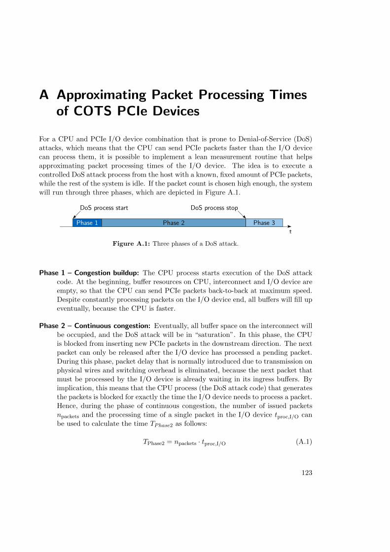
A Approximating Packet Processing Timesof COTS PCIe Devices
For a CPU and PCIe I/O device combination that is prone to Denial-of-Service (DoS)attacks, which means that the CPU can send PCIe packets faster than the I/O devicecan process them, it is possible to implement a lean measurement routine that helpsapproximating packet processing times of the I/O device. The idea is to execute acontrolled DoS attack process from the host with a known, fixed amount of PCIe packets,while the rest of the system is idle. If the packet count is chosen high enough, the systemwill run through three phases, which are depicted in Figure A.1.
Phase 1
DoS process start
Phase 2 Phase 3t
DoS process stop
Figure A.1: Three phases of a DoS attack.
Phase 1 – Congestion buildup: The CPU process starts execution of the DoS attackcode. At the beginning, buffer resources on CPU, interconnect and I/O device areempty, so that the CPU can send PCIe packets back-to-back at maximum speed.Despite constantly processing packets on the I/O device end, all buffers will fill upeventually, because the CPU is faster.
Phase 2 – Continuous congestion: Eventually, all buffer space on the interconnect willbe occupied, and the DoS attack will be in “saturation”. In this phase, the CPUis blocked from inserting new PCIe packets in the downstream direction. The nextpacket can only be released after the I/O device has processed a pending packet.During this phase, packet delay that is normally introduced due to transmission onphysical wires and switching overhead is eliminated, because the next packet thatmust be processed by the I/O device is already waiting in its ingress buffers. Byimplication, this means that the CPU process (the DoS attack code) that generatesthe packets is blocked for exactly the time the I/O device needs to process a packet.Hence, during the phase of continuous congestion, the number of issued packetsnpackets and the processing time of a single packet in the I/O device tproc,I/O canbe used to calculate the time TPhase2 as follows:
TPhase2 = npackets · tproc,I/O (A.1)
123
A Approximating Packet Processing Times of COTS PCIe Devices
Phase 3 – Congestion decay: After the CPU placed the last of its fixed amount of PCIepackets in its downstream buffers, process execution of the DoS attack terminates.The congestion on the interconnect will slowly decay until the last packet is pro-cessed. This phase can be neglected for packet processing time approximation.
The overall execution time of the DoS process is therefore TPhase1 +TPhase2, which canbe measured by the operating system. Unfortunately, there is no straightforward way ofmeasuring TPhase1 or TPhase2 individually. However, if npackets is chosen large enough sothat TPhase2 >> TPhase1, it is possible to get a good approximation of tproc,I/O by simplycalculating
tproc,I/O ≈TPhase1 + TPhase2
npackets. (A.2)
In the following, two examples for the host system that was presented in Section 4.3.1are given. In the first example, 30 000 000 PCIe packets with 64 bit payloads are sentto the first address of the first BAR of the 82576 NIC’s address space. This numberwas found to be high enough so that Phase 1 had no significant impact anymore. Thetime to execute the attacker process was measured with the standard Unix time tool.Output of the controlled DoS process and time is given as follows:
target: /sys/bus/pci/devices/0000:08:10.1/resource0
offset: 0
loops: 30000000
target BAR size: 16 KiB
target addr: 0xBAA81000
13.21 user 0.00 system 0:13.21 elapsed 100% CPU
Overall, the controlled DoS process took 13.21 s to execute. Hence, the time forprocessing a single packet approximately equals
tproc,I/O ≈13.21 s
30000000≈ 440 ns. (A.3)
In the second example, the offset into the device’s BAR is set to 10240, thereforeaddressing a different memory location within the I/O device than in the first example.Output was as follows:
target: /sys/bus/pci/devices/0000:08:10.1/resource0
offset: 10240
loops: 30000000
target BAR size: 16 KiB
target addr: 0xFC524800
16.01 user 0.00 system 0:16.01 elapsed 100% CPU
124
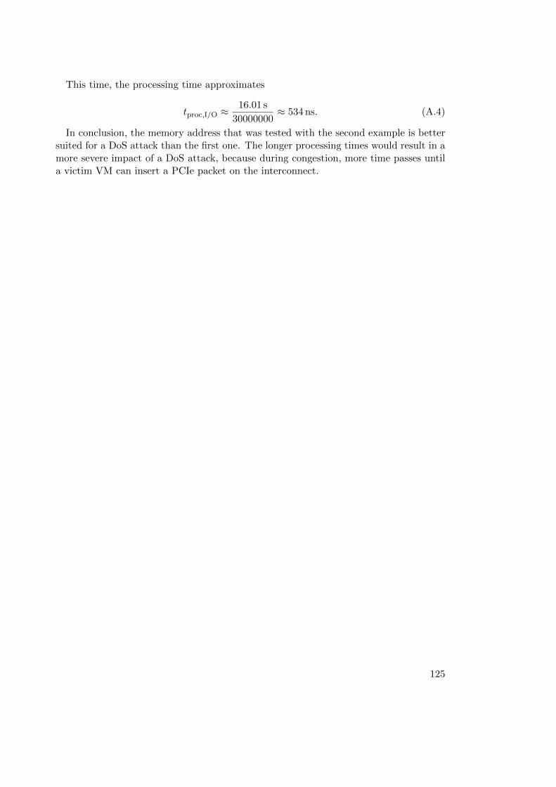
This time, the processing time approximates
tproc,I/O ≈16.01 s
30000000≈ 534 ns. (A.4)
In conclusion, the memory address that was tested with the second example is bettersuited for a DoS attack than the first one. The longer processing times would result in amore severe impact of a DoS attack, because during congestion, more time passes untila victim VM can insert a PCIe packet on the interconnect.
125


