Embed Size (px)
Citation preview
sustainability
Article
Mitigating Polluted Runoff from Industrial Estates by SUDSRetrofits: Case Studies of Problems and Solutions Co-Designedwith a Participatory Approach
Vladimir Krivtsov 1,2,3,*, Brian J. D’Arcy 4, Alejandro Escribano Sevilla 5, Scott Arthur 6 and Chris Semple 6
�����������������
Citation: Krivtsov, V.; D’Arcy, B.J.;
Sevilla, A.E.; Arthur, S.; Semple, C.
Mitigating Polluted Runoff from
Industrial Estates by SUDS Retrofits:
Case Studies of Problems and
Solutions Co-Designed with a
Participatory Approach. Sustainability
2021, 13, 12357. https://doi.org/
10.3390/su132212357
Academic Editors: Amparo López
Jiménez and Modesto Pérez-Sánchez
Received: 30 May 2021
Accepted: 2 September 2021
Published: 9 November 2021
Publisher’s Note: MDPI stays neutral
with regard to jurisdictional claims in
published maps and institutional affil-
iations.
Copyright: © 2021 by the authors.
Licensee MDPI, Basel, Switzerland.
This article is an open access article
distributed under the terms and
conditions of the Creative Commons
Attribution (CC BY) license (https://
creativecommons.org/licenses/by/
4.0/).
1 South Kensington Campus, Imperial College, London SW7 2AZ, UK2 Royal Botanic Garden Edinburgh, 20A Inverleith Row, Edinburgh EH3 5LR, UK3 Rutherford Building, Kings Buildings, The University of Edinburgh, Edinburgh EH9 3BF, UK4 Independent Researcher, Kinross KY13 9JR, UK; [email protected] Mott MacDonald Limited, 22 Station Rd, Cambridge CB1 2JD, UK; [email protected] EGIS, Heriot Watt-University, Edinburgh EH14 4AS, UK; [email protected] (S.A.);
[email protected] (C.S.)* Correspondence: [email protected]
Abstract: Contaminated runoff from industrial estates is a significant cause of poor quality inreceiving watercourses. Pollution risk begins at each of the industrial premises, presenting differentenvironmental risks which require individual treatment and contingency plans. This is best achievedusing SUDS technology, which adds green infrastructure with passive drainage features to theexisting drainage and treatment systems, designed to capture the pollutants present in runoff atsource on individual sites, for conveyance and on a regional basis serving the whole estate. Here, wedevelop a multistage investigative framework structured to facilitate the search for relevant solutionsand optimization of their design. This paper presents the results of the awareness survey, identifiesbarriers and opportunities, and reports on case studies dealing with potential SUDS retrofits atindustrial facilities, assessing the existing control measures and the scope for new ones with the aimof improving pollution management. The feasibility of SUDS components was assessed with respectto their functional characteristics, economic costs, and logistical constraints. Lack of knowledgerelated to SUDS and pollution prevention legislation was identified as the major barrier to retrofits,which should be addressed through educational measures. Although comprehensive SUDS retrofitscould be prohibitive in cost for small and medium-sized companies, partial and affordable retrofitsolutions can be easily implemented to achieve the environmental benefits sought. In addition tothe improvements in water quality and alleviation of flood risk, the introduction of Blue-GreenInfrastructure will bring about further multiple benefits related to such ecosystem services as theamelioration of the local climate, reduction of noise, improvements in air quality, enhancement of thelocal biodiversity, and positive effects for the human well-being and mental health.
Keywords: optimization; industrial design; resilience; sustainable drainage; BGI; contingency planning
1. Introduction
Chronic diffuse pollution is a major problem affecting water security issues world-wide [1–4]. Sustainable Urban Drainage Systems (SUDS) represent an important tool capa-ble of mitigating water pollution risk [5,6]. However, their practical applications remainunderused and present considerable challenges, particularly with respect to retrofitting onalready existing developments [7]. Case studies combining the analysis of technologicaldetails and technical feasibility with the economic costs and considerations of logisticalconstraints are essential to closing the existing gaps between the underpinning science andknowledge transfer. Developing and sharing information on practical examples has beenidentified as an important tool for tackling the barriers related to SUDS and Blue-GreenInfrastructure (BGI) installations [8,9].
Sustainability 2021, 13, 12357. https://doi.org/10.3390/su132212357 https://www.mdpi.com/journal/sustainability
Sustainability 2021, 13, 12357 2 of 24
Combining SUDS assets with Green Infrastructure (GI) in a well-developed BGI net-work is essential for alleviating the risk of pollution damage and is therefore an importantprerequisite for sustainable water management in the context of the Blue-Green Cities(BGC) theoretical and practical framework [5,7,9–14]. SUDS are a statutory requirementfor new developments in Scotland [15]. From its inception in 1996, the Scottish Environ-ment Protection Agency (SEPA) policy [16] has been to seek the provision of SUDS onindustrial estates: at source on individual premises, for conveyance, and on a regionalbasis serving the whole estate or a part thereof. That approach reflects the importance ofindustrial estates as significant causes of poor quality in watercourses [17–19]. The aimof the SUDS technology is to incorporate passive drainage features which can capturethe pollutants present in runoff from urban landscapes to produce river-quality water.The sustainability aspects implicit in the term include no pumping (energy demand) andminimal concrete or other high-CO2-releasing (during production) construction materials.Ideally, the features should facilitate the degradation of biodegradable contaminants insitu in the surface vegetation and soils by the actions of UV light and microbial activity,respectively, as demonstrated in evaluation studies in Scotland [20]. Sustainability of thewater environment requires the quality of the runoff from landscapes of the catchment to begood river quality, and the same applies to infiltration water and groundwater resources.
The application of SUDS technology at each spatial level of the development is consis-tent with the polluter pays principle. Pollution risk begins at each of the premises (as doesthe generation of runoff flow, which may contribute to flood risks). Individual businessespresent different environmental risks, which require individual contingency plans. A SUDSsystem should be integrated with those considerations for each of the premises. Even afterthe treatment of each individual site on an estate, as well as the treatment of the runoff fromthe service roads, a final treatment feature is necessary to address the collective impactof the multiple and variable quality sources in an industrial estate to attempt to produceriver quality drainage from that tract of landscape [1,21]. That final treatment and flowmanagement feature on an industrial estate is also an important contingency measure foraccidents and fires. Optimization of industrial design, resource efficiency, and resiliencecan therefore be enhanced by recognizing the scope for integrating contingency planningfunctions with SUDS on industrial estates. That must also look beyond the individualpremises, as well as the road network. A major incident can overwhelm the resources ofthe site experiencing the crisis and may present risks for the general public, as well asfor other business premises and the environment. An end of the system ‘regional’ SUDSfeature, such as a retention pond or extended detention basin, may easily be designed forflood risk management, with the capacity to add a level of flood water across that surfacearea for the exceptional storm events. Such features could also serve as temporary storagefor a high-risk pollution incident, such as a major fire at a chemical plant, if the regionalpond or detention basin is located at a safe distance. Indeed, factory fires are a majorpollution risk at industrial premises [22–24]. A flood risk design for a pond might planfor a one in 100-year rainstorm, and a major chemical fire with copious volume of toxicfire water runoff might have a similar probability. Thus, the odds of both events occurringsimultaneously would be 1 in 10,000. A safe multi-issue contingency plan can be based onone safely distant SUDS pond.
The focus of the research presented here was an industrial estate in Scotland servedby an undersized treatment wetland, which needs more at-source measures across theindustrial estate to deliver a higher degree of protection for the receiving watercourse [25].Runoff from the estate is polluted and discharges into a local watercourse via a smallwetland, which is known to have water quality problems. The aim of this work was tounderstand how to engage with industrial estate businesses to manage the water qualityissues resulting from their operations. The research objectives were to:
(i) develop a multistage methodological framework capable of revealing and subse-quently obviating the barriers to retrofits, as well as optimizing the proposed retrofitsusing innovative solutions;
Sustainability 2021, 13, 12357 3 of 24
(ii) engage with the industrial estate proprietors to understand their awareness of SUDSand related pollution prevention legislation, and quantify the extent to which SUDSwere already deployed;
(iii) co-develop with proprietors SUDS retrofit designs for two key industrial estate busi-nesses, which highlight the key challenges at play and potential solutions.
2. Methodological Framework
This section describes a methodological framework specifically developed to addressthe aims of the study. This methodology was structured to facilitate the search for effectivesolutions which can be optimized by effective design.
The participating companies were identified by preliminary studies involving screen-ing using a postal survey and interviews with staff. This was followed by detailed inves-tigations involving multiple site visits, observations of environmental settings, and theanalysis of technical details. This paper provides a detailed insight into possibilities ofretrofitting SUDS at these example premises. All the suggested retrofits were designedin partnership with the participating companies. Consequently, the proposed measuresconsider the logistical and technical constraints and present a set of workable solutions.The names of the commercial companies participating in these case studies are not revealedfor confidentiality reasons.
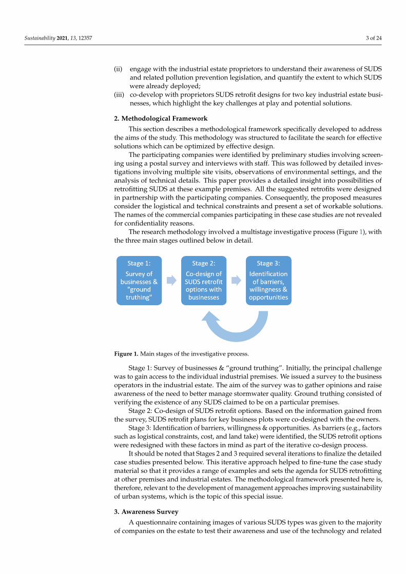
The research methodology involved a multistage investigative process (Figure 1), withthe three main stages outlined below in detail.
Sustainability 2021, 13, x FOR PEER REVIEW 3 of 25
understand how to engage with industrial estate businesses to manage the water quality issues resulting from their operations. The research objectives were to: (i) develop a multistage methodological framework capable of revealing and
subsequently obviating the barriers to retrofits, as well as optimizing the proposed retrofits using innovative solutions;
(ii) engage with the industrial estate proprietors to understand their awareness of SUDS and related pollution prevention legislation, and quantify the extent to which SUDS were already deployed;
(iii) co-develop with proprietors SUDS retrofit designs for two key industrial estate businesses, which highlight the key challenges at play and potential solutions.
2. Methodological Framework This section describes a methodological framework specifically developed to address
the aims of the study. This methodology was structured to facilitate the search for effective solutions which can be optimized by effective design.
The participating companies were identified by preliminary studies involving screening using a postal survey and interviews with staff. This was followed by detailed investigations involving multiple site visits, observations of environmental settings, and the analysis of technical details. This paper provides a detailed insight into possibilities of retrofitting SUDS at these example premises. All the suggested retrofits were designed in partnership with the participating companies. Consequently, the proposed measures consider the logistical and technical constraints and present a set of workable solutions. The names of the commercial companies participating in these case studies are not revealed for confidentiality reasons.
The research methodology involved a multistage investigative process (Figure 1), with the three main stages outlined below in detail.
Figure 1. Main stages of the investigative process.
Stage 1: Survey of businesses & “ground truthing”. Initially, the principal challenge was to gain access to the individual industrial premises. We issued a survey to the business operators in the industrial estate. The aim of the survey was to gather opinions and raise awareness of the need to better manage stormwater quality. Ground truthing consisted of verifying the existence of any SUDS claimed to be on a particular premises.
Stage 2: Co-design of SUDS retrofit options. Based on the information gained from the survey, SUDS retrofit plans for key business plots were co-designed with the owners.
Stage 3: Identification of barriers, willingness & opportunities. As barriers (e.g., factors such as logistical constraints, cost, and land take) were identified, the SUDS retrofit options were redesigned with these factors in mind as part of the iterative co-design process.
It should be noted that Stages 2 and 3 required several iterations to finalize the detailed case studies presented below. This iterative approach helped to fine-tune the case study material so that it provides a range of examples and sets the agenda for SUDS
Figure 1. Main stages of the investigative process.
Stage 1: Survey of businesses & “ground truthing”. Initially, the principal challengewas to gain access to the individual industrial premises. We issued a survey to the businessoperators in the industrial estate. The aim of the survey was to gather opinions and raiseawareness of the need to better manage stormwater quality. Ground truthing consisted ofverifying the existence of any SUDS claimed to be on a particular premises.
Stage 2: Co-design of SUDS retrofit options. Based on the information gained fromthe survey, SUDS retrofit plans for key business plots were co-designed with the owners.
Stage 3: Identification of barriers, willingness & opportunities. As barriers (e.g., factorssuch as logistical constraints, cost, and land take) were identified, the SUDS retrofit optionswere redesigned with these factors in mind as part of the iterative co-design process.
It should be noted that Stages 2 and 3 required several iterations to finalize the detailedcase studies presented below. This iterative approach helped to fine-tune the case studymaterial so that it provides a range of examples and sets the agenda for SUDS retrofittingat other premises and industrial estates. The methodological framework presented here is,therefore, relevant to the development of management approaches improving sustainabilityof urban systems, which is the topic of this special issue.
3. Awareness Survey
A questionnaire containing images of various SUDS types was given to the majorityof companies on the estate to test their awareness and use of the technology and related
Sustainability 2021, 13, 12357 4 of 24
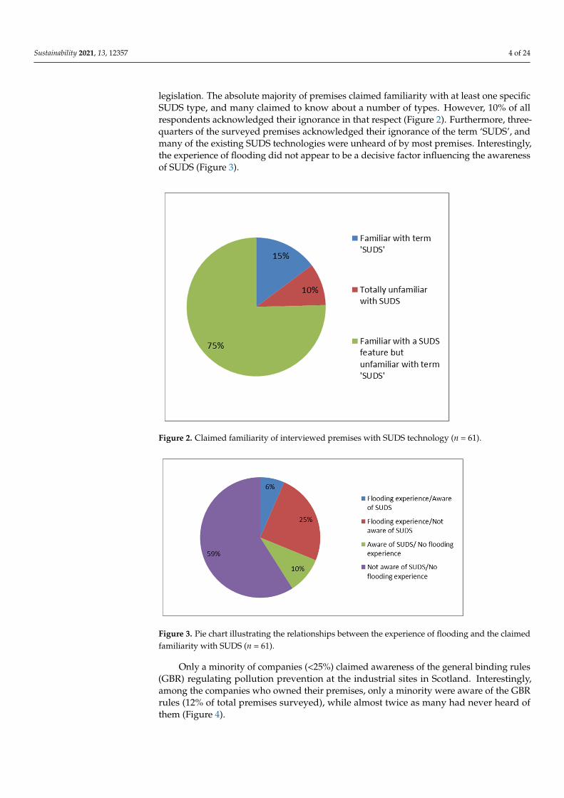
legislation. The absolute majority of premises claimed familiarity with at least one specificSUDS type, and many claimed to know about a number of types. However, 10% of allrespondents acknowledged their ignorance in that respect (Figure 2). Furthermore, three-quarters of the surveyed premises acknowledged their ignorance of the term ‘SUDS’, andmany of the existing SUDS technologies were unheard of by most premises. Interestingly,the experience of flooding did not appear to be a decisive factor influencing the awarenessof SUDS (Figure 3).
Sustainability 2021, 13, x FOR PEER REVIEW 4 of 25
retrofitting at other premises and industrial estates. The methodological framework presented here is, therefore, relevant to the development of management approaches improving sustainability of urban systems, which is the topic of this special issue.
3. Awareness Survey A questionnaire containing images of various SUDS types was given to the majority
of companies on the estate to test their awareness and use of the technology and related legislation. The absolute majority of premises claimed familiarity with at least one specific SUDS type, and many claimed to know about a number of types. However, 10% of all respondents acknowledged their ignorance in that respect (Figure 2). Furthermore, three-quarters of the surveyed premises acknowledged their ignorance of the term ‘SUDS’, and many of the existing SUDS technologies were unheard of by most premises. Interestingly, the experience of flooding did not appear to be a decisive factor influencing the awareness of SUDS (Figure 3).
Figure 2. Claimed familiarity of interviewed premises with SUDS technology (n = 61).
Figure 3. Pie chart illustrating the relationships between the experience of flooding and the claimed familiarity with SUDS (n = 61).
Figure 2. Claimed familiarity of interviewed premises with SUDS technology (n = 61).
Sustainability 2021, 13, x FOR PEER REVIEW 4 of 25
retrofitting at other premises and industrial estates. The methodological framework presented here is, therefore, relevant to the development of management approaches improving sustainability of urban systems, which is the topic of this special issue.
3. Awareness Survey A questionnaire containing images of various SUDS types was given to the majority
of companies on the estate to test their awareness and use of the technology and related legislation. The absolute majority of premises claimed familiarity with at least one specific SUDS type, and many claimed to know about a number of types. However, 10% of all respondents acknowledged their ignorance in that respect (Figure 2). Furthermore, three-quarters of the surveyed premises acknowledged their ignorance of the term ‘SUDS’, and many of the existing SUDS technologies were unheard of by most premises. Interestingly, the experience of flooding did not appear to be a decisive factor influencing the awareness of SUDS (Figure 3).
Figure 2. Claimed familiarity of interviewed premises with SUDS technology (n = 61).
Figure 3. Pie chart illustrating the relationships between the experience of flooding and the claimed familiarity with SUDS (n = 61). Figure 3. Pie chart illustrating the relationships between the experience of flooding and the claimed
familiarity with SUDS (n = 61).
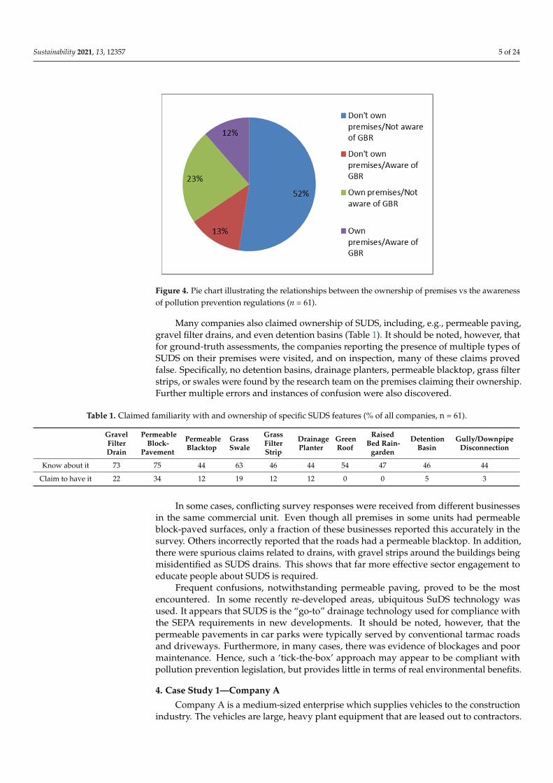
Only a minority of companies (<25%) claimed awareness of the general binding rules(GBR) regulating pollution prevention at the industrial sites in Scotland. Interestingly,among the companies who owned their premises, only a minority were aware of the GBRrules (12% of total premises surveyed), while almost twice as many had never heard ofthem (Figure 4).
Sustainability 2021, 13, 12357 5 of 24
Sustainability 2021, 13, x FOR PEER REVIEW 5 of 25
Only a minority of companies (<25%) claimed awareness of the general binding rules (GBR) regulating pollution prevention at the industrial sites in Scotland. Interestingly, among the companies who owned their premises, only a minority were aware of the GBR rules (12% of total premises surveyed), while almost twice as many had never heard of them (Figure 4).
Figure 4. Pie chart illustrating the relationships between the ownership of premises vs the awareness of pollution prevention regulations (n = 61).
Many companies also claimed ownership of SUDS, including, e.g., permeable paving, gravel filter drains, and even detention basins (Table 1). It should be noted, however, that for ground-truth assessments, the companies reporting the presence of multiple types of SUDS on their premises were visited, and on inspection, many of these claims proved false. Specifically, no detention basins, drainage planters, permeable blacktop, grass filter strips, or swales were found by the research team on the premises claiming their ownership. Further multiple errors and instances of confusion were also discovered.
Table 1. Claimed familiarity with and ownership of specific SUDS features (% of all companies, n = 61).
Gravel Filter Drain
Permeable Block-
Pavement
Permeable Blacktop
Grass Swale
Grass Filter Strip
Drainage Planter
Green Roof
Raised bed Raingarden
Detention Basin
Gully/Downpipe
Disconnection
Know about it 73 75 44 63 46 44 54 47 46 44
Claim to have it 22 34 12 19 12 12 0 0 5 3
In some cases, conflicting survey responses were received from different businesses in the same commercial unit. Even though all premises in some units had permeable block-paved surfaces, only a fraction of these businesses reported this accurately in the survey. Others incorrectly reported that the roads had a permeable blacktop. In addition, there were spurious claims related to drains, with gravel strips around the buildings being misidentified as SUDS drains. This shows that far more effective sector engagement to educate people about SUDS is required.
Frequent confusions, notwithstanding permeable paving, proved to be the most encountered. In some recently re-developed areas, ubiquitous SuDS technology was used. It appears that SUDS is the “go-to” drainage technology used for compliance with the
Figure 4. Pie chart illustrating the relationships between the ownership of premises vs the awarenessof pollution prevention regulations (n = 61).
Many companies also claimed ownership of SUDS, including, e.g., permeable paving,gravel filter drains, and even detention basins (Table 1). It should be noted, however, thatfor ground-truth assessments, the companies reporting the presence of multiple types ofSUDS on their premises were visited, and on inspection, many of these claims provedfalse. Specifically, no detention basins, drainage planters, permeable blacktop, grass filterstrips, or swales were found by the research team on the premises claiming their ownership.Further multiple errors and instances of confusion were also discovered.
Table 1. Claimed familiarity with and ownership of specific SUDS features (% of all companies, n = 61).
GravelFilterDrain
PermeableBlock-
Pavement
PermeableBlacktop
GrassSwale
GrassFilterStrip
DrainagePlanter
GreenRoof
RaisedBed Rain-
garden
DetentionBasin
Gully/DownpipeDisconnection
Know about it 73 75 44 63 46 44 54 47 46 44
Claim to have it 22 34 12 19 12 12 0 0 5 3
In some cases, conflicting survey responses were received from different businessesin the same commercial unit. Even though all premises in some units had permeableblock-paved surfaces, only a fraction of these businesses reported this accurately in thesurvey. Others incorrectly reported that the roads had a permeable blacktop. In addition,there were spurious claims related to drains, with gravel strips around the buildings beingmisidentified as SUDS drains. This shows that far more effective sector engagement toeducate people about SUDS is required.
Frequent confusions, notwithstanding permeable paving, proved to be the mostencountered. In some recently re-developed areas, ubiquitous SuDS technology wasused. It appears that SUDS is the “go-to” drainage technology used for compliance withthe SEPA requirements in new developments. It should be noted, however, that thepermeable pavements in car parks were typically served by conventional tarmac roadsand driveways. Furthermore, in many cases, there was evidence of blockages and poormaintenance. Hence, such a ‘tick-the-box’ approach may appear to be compliant withpollution prevention legislation, but provides little in terms of real environmental benefits.
4. Case Study 1—Company A
Company A is a medium-sized enterprise which supplies vehicles to the constructionindustry. The vehicles are large, heavy plant equipment that are leased out to contractors.
Sustainability 2021, 13, 12357 6 of 24
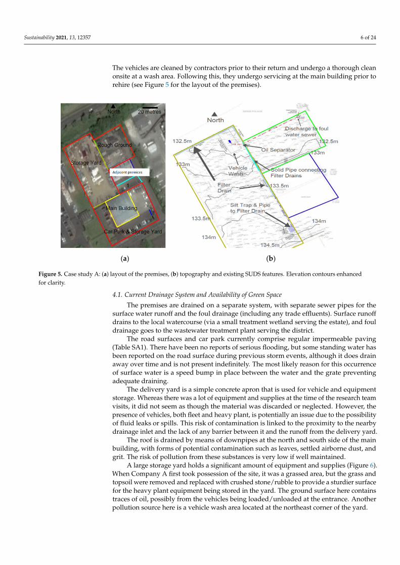
The vehicles are cleaned by contractors prior to their return and undergo a thorough cleanonsite at a wash area. Following this, they undergo servicing at the main building prior torehire (see Figure 5 for the layout of the premises).
Sustainability 2021, 13, x FOR PEER REVIEW 6 of 25
SEPA requirements in new developments. It should be noted, however, that the permeable pavements in car parks were typically served by conventional tarmac roads and driveways. Furthermore, in many cases, there was evidence of blockages and poor maintenance. Hence, such a ‘tick-the-box’ approach may appear to be compliant with pollution prevention legislation, but provides little in terms of real environmental benefits.
4. Case Study 1—Company A Company A is a medium-sized enterprise which supplies vehicles to the construction
industry. The vehicles are large, heavy plant equipment that are leased out to contractors. The vehicles are cleaned by contractors prior to their return and undergo a thorough clean onsite at a wash area. Following this, they undergo servicing at the main building prior to rehire (see Figure 5 for the layout of the premises).
(a) (b)
Figure 5. Case study A: (a) layout of the premises, (b) topography and existing SUDS features. Elevation contours enhanced for clarity.
4.1. Current Drainage System and Availability of Green Space The premises are drained on a separate system, with separate sewer pipes for the
surface water runoff and the foul drainage (including any trade effluents). Surface runoff drains to the local watercourse (via a small treatment wetland serving the estate), and foul drainage goes to the wastewater treatment plant serving the district.
The road surfaces and car park currently comprise regular impermeable paving (Table SA1). There have been no reports of serious flooding, but some standing water has been reported on the road surface during previous storm events, although it does drain away over time and is not present indefinitely. The most likely reason for this occurrence of surface water is a speed bump in place between the water and the grate preventing adequate draining.
The delivery yard is a simple concrete apron that is used for vehicle and equipment storage. Whereas there was a lot of equipment and supplies at the time of the research team visits, it did not seem as though the material was discarded or neglected. However, the presence of vehicles, both fleet and heavy plant, is potentially an issue due to the possibility of fluid leaks or spills. This risk of contamination is linked to the proximity to the nearby drainage inlet and the lack of any barrier between it and the runoff from the delivery yard.
Figure 5. Case study A: (a) layout of the premises, (b) topography and existing SUDS features. Elevation contours enhancedfor clarity.
4.1. Current Drainage System and Availability of Green Space
The premises are drained on a separate system, with separate sewer pipes for thesurface water runoff and the foul drainage (including any trade effluents). Surface runoffdrains to the local watercourse (via a small treatment wetland serving the estate), and fouldrainage goes to the wastewater treatment plant serving the district.
The road surfaces and car park currently comprise regular impermeable paving(Table SA1). There have been no reports of serious flooding, but some standing water hasbeen reported on the road surface during previous storm events, although it does drainaway over time and is not present indefinitely. The most likely reason for this occurrenceof surface water is a speed bump in place between the water and the grate preventingadequate draining.
The delivery yard is a simple concrete apron that is used for vehicle and equipmentstorage. Whereas there was a lot of equipment and supplies at the time of the research teamvisits, it did not seem as though the material was discarded or neglected. However, thepresence of vehicles, both fleet and heavy plant, is potentially an issue due to the possibilityof fluid leaks or spills. This risk of contamination is linked to the proximity to the nearbydrainage inlet and the lack of any barrier between it and the runoff from the delivery yard.
The roof is drained by means of downpipes at the north and south side of the mainbuilding, with forms of potential contamination such as leaves, settled airborne dust, andgrit. The risk of pollution from these substances is very low if well maintained.
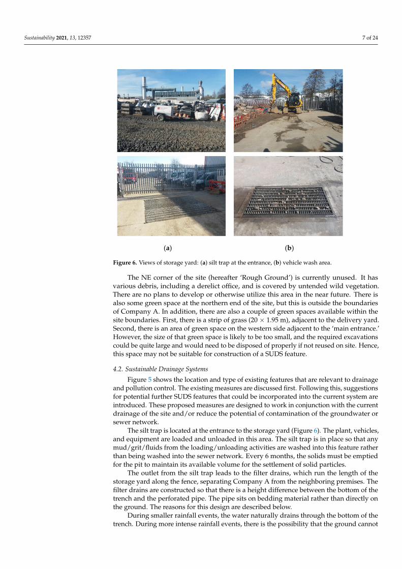
A large storage yard holds a significant amount of equipment and supplies (Figure 6).When Company A first took possession of the site, it was a grassed area, but the grass andtopsoil were removed and replaced with crushed stone/rubble to provide a sturdier surfacefor the heavy plant equipment being stored in the yard. The ground surface here containstraces of oil, possibly from the vehicles being loaded/unloaded at the entrance. Anotherpollution source here is a vehicle wash area located at the northeast corner of the yard.
Sustainability 2021, 13, 12357 7 of 24
Sustainability 2021, 13, x FOR PEER REVIEW 7 of 25
The roof is drained by means of downpipes at the north and south side of the main building, with forms of potential contamination such as leaves, settled airborne dust, and grit. The risk of pollution from these substances is very low if well maintained.
A large storage yard holds a significant amount of equipment and supplies (Figure 6). When Company A first took possession of the site, it was a grassed area, but the grass and topsoil were removed and replaced with crushed stone/rubble to provide a sturdier surface for the heavy plant equipment being stored in the yard. The ground surface here contains traces of oil, possibly from the vehicles being loaded/unloaded at the entrance. Another pollution source here is a vehicle wash area located at the northeast corner of the yard.
(a) (b)
Figure 6. Views of storage yard: (a) silt trap at the entrance, (b) vehicle wash area.
The NE corner of the site (hereafter ‘Rough Ground’) is currently unused. It has various debris, including a derelict office, and is covered by untended wild vegetation. There are no plans to develop or otherwise utilize this area in the near future. There is also some green space at the northern end of the site, but this is outside the boundaries of Company A. In addition, there are also a couple of green spaces available within the site boundaries. First, there is a strip of grass (20 × 1.95 m), adjacent to the delivery yard. Second, there is an area of green space on the western side adjacent to the ‘main entrance.’ However, the size of that green space is likely to be too small, and the required excavations could be quite large and would need to be disposed of properly if not reused on site. Hence, this space may not be suitable for construction of a SUDS feature.
4.2. Sustainable Drainage Systems Figure 5 shows the location and type of existing features that are relevant to drainage
and pollution control. The existing measures are discussed first. Following this, suggestions for potential further SUDS features that could be incorporated into the current system are introduced. These proposed measures are designed to work in conjunction with the current drainage of the site and/or reduce the potential of contamination of the groundwater or sewer network.
The silt trap is located at the entrance to the storage yard (Figure 6). The plant, vehicles, and equipment are loaded and unloaded in this area. The silt trap is in place so
Figure 6. Views of storage yard: (a) silt trap at the entrance, (b) vehicle wash area.
The NE corner of the site (hereafter ‘Rough Ground’) is currently unused. It hasvarious debris, including a derelict office, and is covered by untended wild vegetation.There are no plans to develop or otherwise utilize this area in the near future. There isalso some green space at the northern end of the site, but this is outside the boundariesof Company A. In addition, there are also a couple of green spaces available within thesite boundaries. First, there is a strip of grass (20 × 1.95 m), adjacent to the delivery yard.Second, there is an area of green space on the western side adjacent to the ‘main entrance.’However, the size of that green space is likely to be too small, and the required excavationscould be quite large and would need to be disposed of properly if not reused on site. Hence,this space may not be suitable for construction of a SUDS feature.
4.2. Sustainable Drainage Systems
Figure 5 shows the location and type of existing features that are relevant to drainageand pollution control. The existing measures are discussed first. Following this, suggestionsfor potential further SUDS features that could be incorporated into the current system areintroduced. These proposed measures are designed to work in conjunction with the currentdrainage of the site and/or reduce the potential of contamination of the groundwater orsewer network.
The silt trap is located at the entrance to the storage yard (Figure 6). The plant, vehicles,and equipment are loaded and unloaded in this area. The silt trap is in place so that anymud/grit/fluids from the loading/unloading activities are washed into this feature ratherthan being washed into the sewer network. Every 6 months, the solids must be emptiedfor the pit to maintain its available volume for the settlement of solid particles.
The outlet from the silt trap leads to the filter drains, which run the length of thestorage yard along the fence, separating Company A from the neighboring premises. Thefilter drains are constructed so that there is a height difference between the bottom of thetrench and the perforated pipe. The pipe sits on bedding material rather than directly onthe ground. The reasons for this design are described below.
During smaller rainfall events, the water naturally drains through the bottom of thetrench. During more intense rainfall events, there is the possibility that the ground cannot
Sustainability 2021, 13, 12357 8 of 24
drain quickly enough. In this case, the water rises higher in the trench. Upon reaching thepipe, water will enter via perforations in the base and travel along its length to where itcan drain.
When the filter drains were initially constructed, there was a gap in the drain. Thisgap occurred where the rough ground met the storage yard. This was remedied by theinstallation of a solid pipe connecting the two filter drains together. This connection isshown by the turquoise line in Figure 5.
The vehicle wash area (Figure 6) is a concrete slab that slopes toward a drain in thecenter. This prevents water contaminated by detergents from running onto the naturalground. This drain leads to an oil separator where any detergents are contained, allowingthe water to discharge to the foul sewer shared by the neighboring company.
4.2.1. Potential Solutions
The techniques considered for retrofitting were a function of the space available andincluded grass swales, permeable pavement, a grass filter strip, a small detention basin,rainwater attenuation tanks, a raised bed raingarden, and simple measures, such as oilabsorbent bags in manhole chambers.
Road Surfaces and Car Park
The road surface could be replaced with permeable paving, or porous asphalt (PA),but the new surface may be susceptible to crushing from heavy vehicles (in which case, thesurface could not be used). Permeable block paving (PBP) could be used on the car parkingspaces. A percolation test would be advisable to ensure adequate rates of drainage beforethe construction of a replacement surface of PA. The analysis below considers three pavingoptions involving different combinations of permeable asphalt (PA) and permeable blockpaving (PBP) used in our previous studies [26].
Delivery Yard
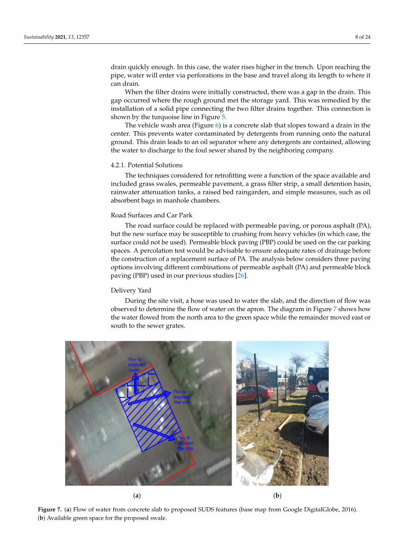
During the site visit, a hose was used to water the slab, and the direction of flow wasobserved to determine the flow of water on the apron. The diagram in Figure 7 shows howthe water flowed from the north area to the green space while the remainder moved east orsouth to the sewer grates.
Sustainability 2021, 13, x FOR PEER REVIEW 9 of 25
(a) (b)
Figure 7. (a) Flow of water from concrete slab to proposed SUDS features (base map from Google DigitalGlobe, 2016). (b) Available green space for the proposed swale.
This simple test shows that it would be useful to create a swale on the green space. The delivery yard has a kerb along its length that would have to be removed or modified in such a way to provide entry points for the water. Figure 7 shows the strip of green space which could be modified into a swale. It would also be prudent to create a filter strip (total length of 36 m) along the east and south side of the delivery yard to contain contaminants before water enters the sewer network. The costs of the filter strip would be around GBP 2–GBP 4/m2 according to 2007 values [27].
For filter strips, the SUDS Manual [6] specifies a minimum topsoil depth of 0.15 m and a minimum engineered soil depth of 0.3 m for a minimum depth of 0.45 m. However, excavation may be needed to reach a subsurface level with sufficient infiltration rates. Because of this, the construction costs of an excavation [28] were added for a depth of 1.5 m. This depth would be subject to change following a full assessment of the ground conditions and effects on road performance. Hence, the resulting costings are rather approximate.
Roof The roof has been split into two halves that have three downpipes leading from each
side. As recommended in similar situations by a previous study [26], the use of attenuation tanks and raised rain gardens would provide a method of runoff attenuation.
For Company A, using raised raingardens on the south side of the building could provide an aesthetic feature. Attenuation tanks are recommended on the north side of the building, where the downpipes are placed behind a barrier which would need to be removed. The tanks require less maintenance due to self-regulation by means of an outflow regulator, thus reducing the need for access in the case that the barrier needs to be reinstalled.
Storage Yard The storage yard is the largest section of the site. When looking at this area, the point
of highest elevation will be looked at first before moving downhill. The silt trap, as described previously, is at storage yard entrance. One suggestion for
this feature is the addition of an absorbent oil sock. This would absorb any oil that is
Figure 7. (a) Flow of water from concrete slab to proposed SUDS features (base map from Google DigitalGlobe, 2016).(b) Available green space for the proposed swale.
Sustainability 2021, 13, 12357 9 of 24
This simple test shows that it would be useful to create a swale on the green space.The delivery yard has a kerb along its length that would have to be removed or modifiedin such a way to provide entry points for the water. Figure 7 shows the strip of green spacewhich could be modified into a swale. It would also be prudent to create a filter strip (totallength of 36 m) along the east and south side of the delivery yard to contain contaminantsbefore water enters the sewer network. The costs of the filter strip would be around GBP2–GBP 4/m2 according to 2007 values [27].
For filter strips, the SUDS Manual [6] specifies a minimum topsoil depth of 0.15 mand a minimum engineered soil depth of 0.3 m for a minimum depth of 0.45 m. However,excavation may be needed to reach a subsurface level with sufficient infiltration rates.Because of this, the construction costs of an excavation [28] were added for a depth of 1.5 m.This depth would be subject to change following a full assessment of the ground conditionsand effects on road performance. Hence, the resulting costings are rather approximate.
Roof
The roof has been split into two halves that have three downpipes leading from eachside. As recommended in similar situations by a previous study [26], the use of attenuationtanks and raised rain gardens would provide a method of runoff attenuation.
For Company A, using raised raingardens on the south side of the building couldprovide an aesthetic feature. Attenuation tanks are recommended on the north side ofthe building, where the downpipes are placed behind a barrier which would need tobe removed. The tanks require less maintenance due to self-regulation by means of anoutflow regulator, thus reducing the need for access in the case that the barrier needsto be reinstalled.
Storage Yard
The storage yard is the largest section of the site. When looking at this area, the pointof highest elevation will be looked at first before moving downhill.
The silt trap, as described previously, is at storage yard entrance. One suggestionfor this feature is the addition of an absorbent oil sock. This would absorb any oil that iswashed into the silt trap, as it likely currently flows into the filter drains and down intothe ground.
The filter drain runs along the east and north side of the storage yard. Because of thedifference in elevation, it is suggested that oil may infiltrate the ground and travel downtoward the filter drains. Because of this possibility, it would be prudent to construct theinspection chambers equipped with oil booms. This would allow a quick inspection of theboom to see if any oil has infiltrated from further up the site. Three places were suggestedfor the inspection chambers, as shown in Figure 8.
These inspection chambers will be 0.6 m deep, as this is the reported depth of the filterdrains onsite. This will allow the oil boom to reach the bottom of both sides of the filterdrain without interference from the perforated pipe.
To deal with any contamination that may result from the oil drums, a collapsible oilbund should be used if the drums cannot be taken directly into the main building. Thecollapsible bund can be stored away securely when not needed. Hence, there would be nointerruption in the day-to-day vehicle operations at the yard entrance, and the containmentof possible oil spills and leaks would be ensured.
Runoff from the vehicle wash at the bottom of the site is dealt with by the oil separator.However, the discharge from a vehicle wash may emulsify the contaminants in the oil in-terceptor. Research has shown that oil/detergent mixes are more toxic than each substanceseparately [29,30]. Hence, ideally, the vehicle wash should be drained to the foul sewer,subject to an agreement with the water utility and any conditions they may require.
Sustainability 2021, 13, 12357 10 of 24
Sustainability 2021, 13, x FOR PEER REVIEW 10 of 25
washed into the silt trap, as it likely currently flows into the filter drains and down into the ground.
The filter drain runs along the east and north side of the storage yard. Because of the difference in elevation, it is suggested that oil may infiltrate the ground and travel down toward the filter drains. Because of this possibility, it would be prudent to construct the inspection chambers equipped with oil booms. This would allow a quick inspection of the boom to see if any oil has infiltrated from further up the site. Three places were suggested for the inspection chambers, as shown in Figure 8.
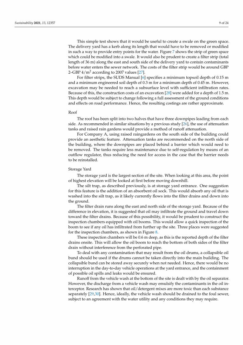
Figure 8. Layout of proposed SUDS features at the Company A site (Google DigitalGlobe, 2016). Inspection chambers shown in yellow on image for clarity. The area indicated with red hatching covers the additional catchment from the adjacent public road.
These inspection chambers will be 0.6 m deep, as this is the reported depth of the filter drains onsite. This will allow the oil boom to reach the bottom of both sides of the filter drain without interference from the perforated pipe.
To deal with any contamination that may result from the oil drums, a collapsible oil bund should be used if the drums cannot be taken directly into the main building. The collapsible bund can be stored away securely when not needed. Hence, there would be no interruption in the day-to-day vehicle operations at the yard entrance, and the containment of possible oil spills and leaks would be ensured.
Runoff from the vehicle wash at the bottom of the site is dealt with by the oil separator. However, the discharge from a vehicle wash may emulsify the contaminants in the oil interceptor. Research has shown that oil/detergent mixes are more toxic than each substance separately [29,30]. Hence, ideally, the vehicle wash should be drained to the foul sewer, subject to an agreement with the water utility and any conditions they may require.
4.2.2. Additional Considerations The green space available on Company A’s property is quite small, limiting what can
be constructed. As mentioned above, a small swale with optional filter strips could be created to serve the delivery yard. It should also be noted that the rough ground has not been fully developed. Preserving the land next to the current filter drain for a swale could provide additional mitigation should the rough ground ever be developed. This could be used to future proof the site for further development.
There is a large area of green space to the north of the site between Company A and the main road through the industrial estate. The local council or developer may provide funding for some of this scheme if a detention basin on this space was proposed. It is
Figure 8. Layout of proposed SUDS features at the Company A site (Google DigitalGlobe, 2016).Inspection chambers shown in yellow on image for clarity. The area indicated with red hatchingcovers the additional catchment from the adjacent public road.
4.2.2. Additional Considerations
The green space available on Company A’s property is quite small, limiting what canbe constructed. As mentioned above, a small swale with optional filter strips could becreated to serve the delivery yard. It should also be noted that the rough ground has notbeen fully developed. Preserving the land next to the current filter drain for a swale couldprovide additional mitigation should the rough ground ever be developed. This could beused to future proof the site for further development.
There is a large area of green space to the north of the site between Company A andthe main road through the industrial estate. The local council or developer may providefunding for some of this scheme if a detention basin on this space was proposed. It ispossible that a detention basin on the green space that would serve solely Company Awould not be given permission for construction. This basin would, therefore, have to servethe public road in addition to the Company A site.
The detention basin would provide attenuation and trap contaminants from a busymain road through the industrial estate, as well as the potential contamination from theheavy vehicles and material storage on Company A’s property. That would be particularlyuseful during high-precipitation events. Figure 8 shows the additional catchment for theproposed detention basin, which is approximately 3110m2. This catchment size was chosento double the area of the Company A storage yard. This will provide an estimate for thebasin included in the final costs. It is assumed that the water will run into the detentionbasin from the road and some of the permeable area. This size is an approximation, and asurvey of the area to determine the fall of the road would be needed to delineate a moreaccurate catchment.
4.3. Size and Cost of SUDS Retrofits
The site plan with all the recommended options is given in Figure 8. Technical detailsof the proposed SUDS retrofits and the associated logistics are given in SupplementaryMaterials A (SA). The comparison of the available and required storage volumes, and theestimates of the resulting costs are presented below.
Sustainability 2021, 13, 12357 11 of 24
4.3.1. Storage Volumes
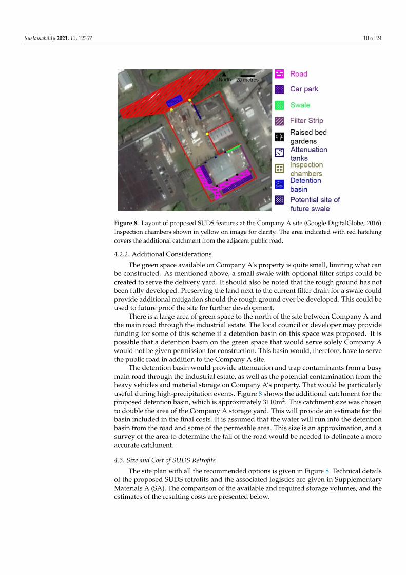
The total available attenuation storage for the Company A site is given in Table 2,which demonstrates the storage for the specific features including a new detention basinserving Company A and the adjacent road.
Table 2. Attenuation storage for all SUDS features proposed for Company A.
Feature Available Storage (m3) withoutAdditional Catchment
Available Storage (m3) withAdditional Catchment
Attenuation tanks 4.5 4.5Raised bed planters 1.15 1.15
Swale 11.6 11.6Detention basin N/A 131.4
Filter drain 39.9 39.9
Total (m3) 57.2 188.5
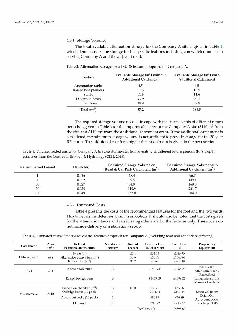
The required storage volume needed to cope with the storm events of different returnperiods is given in Table 3 for the impermeable area of the Company A site (3110 m2 fromthe site and 3110 m2 from the additional catchment area). If the additional catchment isconsidered, the minimum storage volume is not sufficient to provide storage for the 30-yearRP storm. The additional cost for a bigger detention basin is given in the next section.
Table 3. Volume needed onsite for Company A to store stormwater from events with different return periods (RP). Depthestimates from the Centre for Ecology & Hydrology (CEH, 2018).
Return Period (Years) Depth (m) Required Storage Volume onRoad & Car Park Catchment (m3)
Required Storage Volume withAdditional Catchment (m3)
1 0.016 48.4 96.74 0.022 69.5 139.1
10 0.027 84.9 169.830 0.036 110.9 221.7100 0.049 152.0 304.0
4.3.2. Estimated Costs
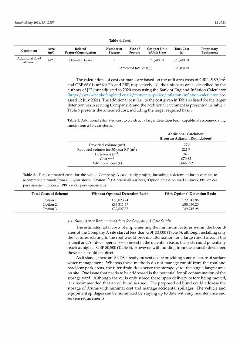
Table 4 presents the costs of the recommended features for the roof and the two yards.This table has the detention basin as an option. It should also be noted that the costs givenfor the attenuation tanks and raised raingardens are for the features only. These costs donot include delivery or installation/set-up.
Table 4. Estimated costs of the source control features proposed for Company A (excluding road and car park resurfacing).
Catchment Area(m2)
RelatedFeature/Construction
Number ofFeature
Size ofFeature
Cost per Unit(£/Unit Size)
Total Cost(£)
ProprietaryEquipment
Delivery yard 686Swale (m) 20.1 £32.13 £646.50
Filter strips excavation (m3) 53.6 £30.76 £1648.61Filter strips (m2) 35.7 £5.68 £202.98
Roof 480Attenuation tanks 3 £762.74 £2288.23 1500l SUDS
Attenuation Tank
Raised bed gardens 3 £1463.09 £4389.26Raised bed
raingardens fromMarmax Products
Storage yard 3110
Inspection chamber (m3) 3 0.60 £30.76 £55.36Oil bilge boom (10 pack) 1 £101.34 £101.34 Drizit Oil Boom
Absorbent socks (20 pack) 1 £50.89 £50.89 Drizit OilAbsorbent Socks
Oil bund 1 £215.72 £215.72 Eccotarp ET 06
Total cost (£) £9598.89
Sustainability 2021, 13, 12357 12 of 24
Table 4. Cont.
Catchment Area(m2)
RelatedFeature/Construction
Number ofFeature
Size ofFeature
Cost per Unit(£/Unit Size)
Total Cost(£)
ProprietaryEquipment
Additional Roadcatchment 6220 Detention basin 1 £10,449.89 £10,449.89
Amended total cost (£) £20,048.79
The calculations of cost estimates are based on the unit area costs of GBP 45.89/m2
and GBP 68.01/m2 for PA and PBP, respectively. All the unit costs are as described by theauthors of [27] but adjusted to 2020 costs using the Bank of England Inflation Calculator(https://www.bankofengland.co.uk/monetary-policy/inflation/inflation-calculator, acc-essed 12 July 2021). The additional cost (i.e., to the cost given in Table 4) listed for the largerdetention basin serving Company A and the additional catchment is presented in Table 5.Table 6 presents the amended cost, including the larger required basin.
Table 5. Additional estimated cost to construct a larger detention basin capable of accommodatingrunoff from a 30-year storm.
Additional Catchment(from an Adjacent Roundabout)
Provided volume (m3) 127.6Required volume for 30-year RP (m3) 221.7
Difference (m3) 94.2Cost/m3 £70.82
Additional cost (£) £6668.72
Table 6. Total estimated costs for the whole Company A case study project, including a detention basin capable toaccommodate runoff from a 30-year storm. ‘Option 1′: PA across all surfaces; ‘Option 2 ’: PA on road surfaces, PBP on carpark spaces; ‘Option 3′: PBP on car park spaces only.
Total Costs of Scheme Without Optional Detention Basin With Optional Detention Basin
Option 1 £55,823.24 £72,941.86Option 2 £63,311.57 £80,430.20Option 3 £32,627.37 £49,745.98
4.4. Summary of Recommendations for Company A Case Study
The estimated total costs of implementing the minimum features within the bound-aries of the Company A site start at less than GBP 33,000 (Table 6), although installing onlythe features relating to the roof would provide attenuation for a large runoff area. If thecouncil and/or developer chose to invest in the detention basin, the costs could potentiallyreach as high as GBP 80,500 (Table 6). However, with funding from the council/developer,these costs could be offset.
As it stands, there are SUDS already present onsite providing some measure of surfacewater management. Whereas these methods do not manage runoff from the roof androad/car park areas, the filter drain does serve the storage yard, the single largest areaon site. One issue that needs to be addressed is the potential for oil contamination of thestorage yard. Although the oil is only stored there upon delivery before being moved,it is recommended that an oil bund is used. The proposed oil bund could address thestorage of drums with minimal cost and manage accidental spillages. The vehicle andequipment spillages can be minimized by staying up to date with any maintenance andservice requirements.
Sustainability 2021, 13, 12357 13 of 24
5. Case Study 2—Company B
The business operations in this case study site forge metal components for the petro-chemical and aeronautical industries. The range of products produced onsite includes jetengine shafts, valves able to function under pressure for oil and gas industries, seamlessextruded metal pipes, and other high-specification products. Forging is by heat and pres-sure. The site has the largest multi-ram hydraulic press in Europe (30,000 tones), as well asa smaller unit (9000 tones).
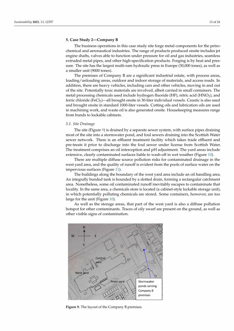
The premises of Company B are a significant industrial estate, with process areas,loading/unloading areas, outdoor and indoor storage of materials, and access roads. Inaddition, there are heavy vehicles, including cars and other vehicles, moving in and outof the site. Potentially toxic materials are involved, albeit carried in small containers. Themetal processing chemicals used include hydrogen fluoride (HF), nitric acid (HNO3), andferric chloride (FeCl3)—all brought onsite in 30-liter individual vessels. Caustic is also usedand brought onsite in standard 1000-liter vessels. Cutting oils and lubrication oils are usedin machining work, and waste oil is also generated onsite. Housekeeping measures rangefrom bunds to lockable cabinets.
5.1. Site Drainage
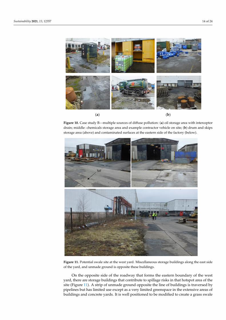
The site (Figure 9) is drained by a separate sewer system, with surface pipes drainingmost of the site into a stormwater pond, and foul sewers draining into the Scottish Watersewer network. There is an effluent treatment facility which takes trade effluent andpre-treats it prior to discharge into the foul sewer under license from Scottish Water.The treatment comprises an oil interception and pH adjustment. The yard areas includeextensive, clearly contaminated surfaces liable to wash-off in wet weather (Figure 10).
There are multiple diffuse source pollution risks for contaminated drainage in thewest yard area, and the quality of runoff is evident from the pools of surface water on theimpervious surfaces (Figure 11).
The buildings along the boundary of the west yard area include an oil handling area.An integrally bunded tank is bounded by a slotted drain, forming a rectangular catchmentarea. Nonetheless, some oil contaminated runoff inevitably escapes to contaminate thatlocality. In the same area, a chemicals store is located (a cabinet-style lockable storage unit),in which potentially polluting chemicals are stored. Some containers, however, are toolarge for the unit (Figure 10).
As well as the storage areas, that part of the west yard is also a diffuse pollutionhotspot for other contaminants. Traces of oily swarf are present on the ground, as well asother visible signs of contamination.
Sustainability 2021, 13, x FOR PEER REVIEW 14 of 25
are used in machining work, and waste oil is also generated onsite. Housekeeping measures range from bunds to lockable cabinets.
5.1. Site Drainage The site (Figure 9) is drained by a separate sewer system, with surface pipes draining
most of the site into a stormwater pond, and foul sewers draining into the Scottish Water sewer network. There is an effluent treatment facility which takes trade effluent and pre-treats it prior to discharge into the foul sewer under license from Scottish Water. The treatment comprises an oil interception and pH adjustment. The yard areas include extensive, clearly contaminated surfaces liable to wash-off in wet weather (Figure 10).
Figure 9. The layout of the Company B premises.
(a) (b)
Figure 10. Case study B—multiple sources of diffuse pollution: (a) oil storage area with interceptor drain; middle: chemicals storage area and example contractor vehicle on site; (b) drum and skips storage area (above) and contaminated surfaces at the eastern side of the factory (below).
There are multiple diffuse source pollution risks for contaminated drainage in the west yard area, and the quality of runoff is evident from the pools of surface water on the impervious surfaces (Figure 11).
Figure 9. The layout of the Company B premises.
Sustainability 2021, 13, 12357 14 of 24
Sustainability 2021, 13, x FOR PEER REVIEW 14 of 25
are used in machining work, and waste oil is also generated onsite. Housekeeping measures range from bunds to lockable cabinets.
5.1. Site Drainage The site (Figure 9) is drained by a separate sewer system, with surface pipes draining
most of the site into a stormwater pond, and foul sewers draining into the Scottish Water sewer network. There is an effluent treatment facility which takes trade effluent and pre-treats it prior to discharge into the foul sewer under license from Scottish Water. The treatment comprises an oil interception and pH adjustment. The yard areas include extensive, clearly contaminated surfaces liable to wash-off in wet weather (Figure 10).
Figure 9. The layout of the Company B premises.
(a) (b)
Figure 10. Case study B—multiple sources of diffuse pollution: (a) oil storage area with interceptor drain; middle: chemicals storage area and example contractor vehicle on site; (b) drum and skips storage area (above) and contaminated surfaces at the eastern side of the factory (below).
There are multiple diffuse source pollution risks for contaminated drainage in the west yard area, and the quality of runoff is evident from the pools of surface water on the impervious surfaces (Figure 11).
Figure 10. Case study B—multiple sources of diffuse pollution: (a) oil storage area with interceptordrain; middle: chemicals storage area and example contractor vehicle on site; (b) drum and skipsstorage area (above) and contaminated surfaces at the eastern side of the factory (below).
1
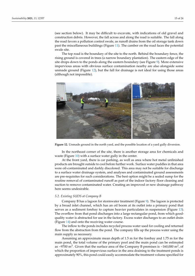
Figure 11. Potential swale site at the west yard. Miscellaneous storage buildings along the east sideof the yard, and unmade ground is opposite these buildings.
On the opposite side of the roadway that forms the eastern boundary of the westyard, there are storage buildings that contribute to spillage risks in that hotspot area of thesite (Figure 11). A strip of unmade ground opposite the line of buildings is traversed bypipelines but has limited use except as a very limited greenspace in the extensive areas ofbuildings and concrete yards. It is well positioned to be modified to create a grass swale
Sustainability 2021, 13, 12357 15 of 24
(see section below). It may be difficult to excavate, with indications of old gravel andconstruction debris. However, the fall across and along the road is suitable. The fall alongthe road favors a pollution control swale, as runoff drains from the oil storage tank downpast the miscellaneous buildings (Figure 11). The camber on the road faces the potentialswale site.
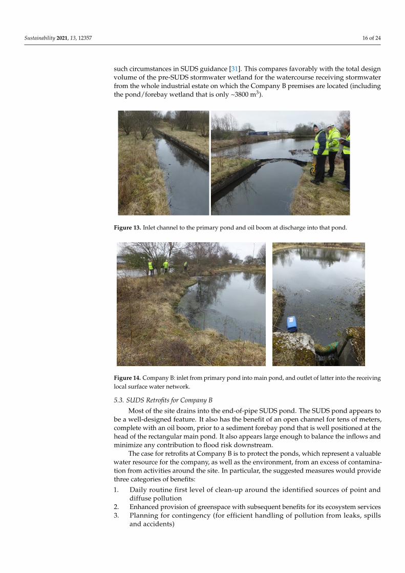
The top road is the boundary of the site to the north. Behind the boundary fence, therising ground is covered in trees (a narrow boundary plantation). The eastern edge of thesite drops down to the ponds along the eastern boundary (see Figure 9). More extensiveimpervious areas with obvious surface contamination nearby are also alongside someunmade ground (Figure 12), but the fall for drainage is not ideal for using those areas(although not impossible).
Sustainability 2021, 13, x FOR PEER REVIEW 16 of 25
Figure 12. Unmade ground in the north yard, and the possible location of a yard gully diversion.
In the northeast corner of the site, there is another storage area for chemicals and waste (Figure 10) with a surface water gully in the center.
At the front yard, there is car parking, as well as area where hot metal unfinished products are brought outside to cool before further work. Surface water puddles in that area were oil-contaminated and darkly discolored. This area may not be suitable for discharge to a surface water drainage system, and analyses and contaminated ground assessments are pre-requisites for such considerations. The best option might be a sealed sump for the routine removal of contaminated runoff as part of the indoor factory floor cleaning and suction to remove contaminated water. Creating an improved or new drainage pathway here seems undesirable.
5.2. Existing SUDS at Company B Company B has a lagoon for stormwater treatment (Figure 9). The lagoon is protected
by a broad inlet channel, which has an oil boom at its outlet into a primary pond that serves as a sediment forebay to capture heavier particulates in suspension (Figure 13). The overflow from that pond discharges into a large rectangular pond, from which good-quality water is abstracted for use in the factory. Excess water discharges to an outlet drain (Figure 14) and onto the receiving water course.
Figure 13. Inlet channel to the primary pond and oil boom at discharge into that pond.
Figure 12. Unmade ground in the north yard, and the possible location of a yard gully diversion.
In the northeast corner of the site, there is another storage area for chemicals andwaste (Figure 10) with a surface water gully in the center.
At the front yard, there is car parking, as well as area where hot metal unfinishedproducts are brought outside to cool before further work. Surface water puddles in that areawere oil-contaminated and darkly discolored. This area may not be suitable for dischargeto a surface water drainage system, and analyses and contaminated ground assessmentsare pre-requisites for such considerations. The best option might be a sealed sump for theroutine removal of contaminated runoff as part of the indoor factory floor cleaning andsuction to remove contaminated water. Creating an improved or new drainage pathwayhere seems undesirable.
5.2. Existing SUDS at Company B
Company B has a lagoon for stormwater treatment (Figure 9). The lagoon is protectedby a broad inlet channel, which has an oil boom at its outlet into a primary pond thatserves as a sediment forebay to capture heavier particulates in suspension (Figure 13).The overflow from that pond discharges into a large rectangular pond, from which good-quality water is abstracted for use in the factory. Excess water discharges to an outlet drain(Figure 14) and onto the receiving water course.
The inflow to the ponds includes recycled process water used for cooling and returnedflow from the abstraction from the pond. The company fills up the process water using themain supply as necessary.
Assuming an approximate mean depth of 1.5 m for the forebay and 1.75 m for themain pond, the total volume of the primary pool and the main pond can be estimatedas ~9700 m3. Given that the surface area of the Company B premises is ~160,000 m2, ofwhich the proportion of impervious surface in the area draining to the treatment ponds isapproximately 90%, this pond could easily accommodate the treatment volume specified for
Sustainability 2021, 13, 12357 16 of 24
such circumstances in SUDS guidance [31]. This compares favorably with the total designvolume of the pre-SUDS stormwater wetland for the watercourse receiving stormwaterfrom the whole industrial estate on which the Company B premises are located (includingthe pond/forebay wetland that is only ~3800 m3).
Sustainability 2021, 13, x FOR PEER REVIEW 16 of 25
Figure 12. Unmade ground in the north yard, and the possible location of a yard gully diversion.
In the northeast corner of the site, there is another storage area for chemicals and waste (Figure 10) with a surface water gully in the center.
At the front yard, there is car parking, as well as area where hot metal unfinished products are brought outside to cool before further work. Surface water puddles in that area were oil-contaminated and darkly discolored. This area may not be suitable for discharge to a surface water drainage system, and analyses and contaminated ground assessments are pre-requisites for such considerations. The best option might be a sealed sump for the routine removal of contaminated runoff as part of the indoor factory floor cleaning and suction to remove contaminated water. Creating an improved or new drainage pathway here seems undesirable.
5.2. Existing SUDS at Company B Company B has a lagoon for stormwater treatment (Figure 9). The lagoon is protected
by a broad inlet channel, which has an oil boom at its outlet into a primary pond that serves as a sediment forebay to capture heavier particulates in suspension (Figure 13). The overflow from that pond discharges into a large rectangular pond, from which good-quality water is abstracted for use in the factory. Excess water discharges to an outlet drain (Figure 14) and onto the receiving water course.
Figure 13. Inlet channel to the primary pond and oil boom at discharge into that pond. Figure 13. Inlet channel to the primary pond and oil boom at discharge into that pond.
Sustainability 2021, 13, x FOR PEER REVIEW 17 of 25
Figure 14. Company B: inlet from primary pond into main pond, and outlet of latter into the receiving local surface water network.
The inflow to the ponds includes recycled process water used for cooling and returned flow from the abstraction from the pond. The company fills up the process water using the main supply as necessary.
Assuming an approximate mean depth of 1.5 m for the forebay and 1.75 m for the main pond, the total volume of the primary pool and the main pond can be estimated as ~9700 m3. Given that the surface area of the Company B premises is ~160,000 m2, of which the proportion of impervious surface in the area draining to the treatment ponds is approximately 90%, this pond could easily accommodate the treatment volume specified for such circumstances in SUDS guidance [31]. This compares favorably with the total design volume of the pre-SUDS stormwater wetland for the watercourse receiving stormwater from the whole industrial estate on which the Company B premises are located (including the pond/forebay wetland that is only ~3800 m3).
5.3. SUDS Retrofits for Company B Most of the site drains into the end-of-pipe SUDS pond. The SUDS pond appears to
be a well-designed feature. It also has the benefit of an open channel for tens of meters, complete with an oil boom, prior to a sediment forebay pond that is well positioned at the head of the rectangular main pond. It also appears large enough to balance the inflows and minimize any contribution to flood risk downstream.
The case for retrofits at Company B is to protect the ponds, which represent a valuable water resource for the company, as well as the environment, from an excess of contamination from activities around the site. In particular, the suggested measures would provide three categories of benefits: 1. Daily routine first level of clean-up around the identified sources of point and diffuse
pollution 2. Enhanced provision of greenspace with subsequent benefits for its ecosystem
services 3. Planning for contingency (for efficient handling of pollution from leaks, spills and
accidents) In respect of the latter benefit, there is an important approach road (typically only
modestly contaminated, but a potential hazard nonetheless) which does not drain to the ponds. Therefore, this road would be the environmental priority for a retrofit.
Figure 14. Company B: inlet from primary pond into main pond, and outlet of latter into the receivinglocal surface water network.
5.3. SUDS Retrofits for Company B
Most of the site drains into the end-of-pipe SUDS pond. The SUDS pond appears tobe a well-designed feature. It also has the benefit of an open channel for tens of meters,complete with an oil boom, prior to a sediment forebay pond that is well positioned at thehead of the rectangular main pond. It also appears large enough to balance the inflows andminimize any contribution to flood risk downstream.
The case for retrofits at Company B is to protect the ponds, which represent a valuablewater resource for the company, as well as the environment, from an excess of contamina-tion from activities around the site. In particular, the suggested measures would providethree categories of benefits:
1. Daily routine first level of clean-up around the identified sources of point anddiffuse pollution
2. Enhanced provision of greenspace with subsequent benefits for its ecosystem services3. Planning for contingency (for efficient handling of pollution from leaks, spills
and accidents)
Sustainability 2021, 13, 12357 17 of 24
In respect of the latter benefit, there is an important approach road (typically onlymodestly contaminated, but a potential hazard nonetheless) which does not drain to theponds. Therefore, this road would be the environmental priority for a retrofit.
5.3.1. Grass Swale for Approach Road
Surface water drainage from the approach road and the adjacent extensive visitorcar park discharges via a limited number of road gullies into a different branch of thedrainage network serving the estate. It does not drain into the Company B ponds (seeFigure SB1). Thus, there is currently no treatment or pollution risk management provisionfor any accidents in that area. All access to the site is along that road. An inflow of lorriescarries containers of acid and caustic, detergents, and other materials (as well as dieselfuel—the ubiquitous pollutant for every lorry irrespective of payload). A SUDS retrofit asa contingency planning provision to allow quick and easy intervention in the event of anaccident is desirable.
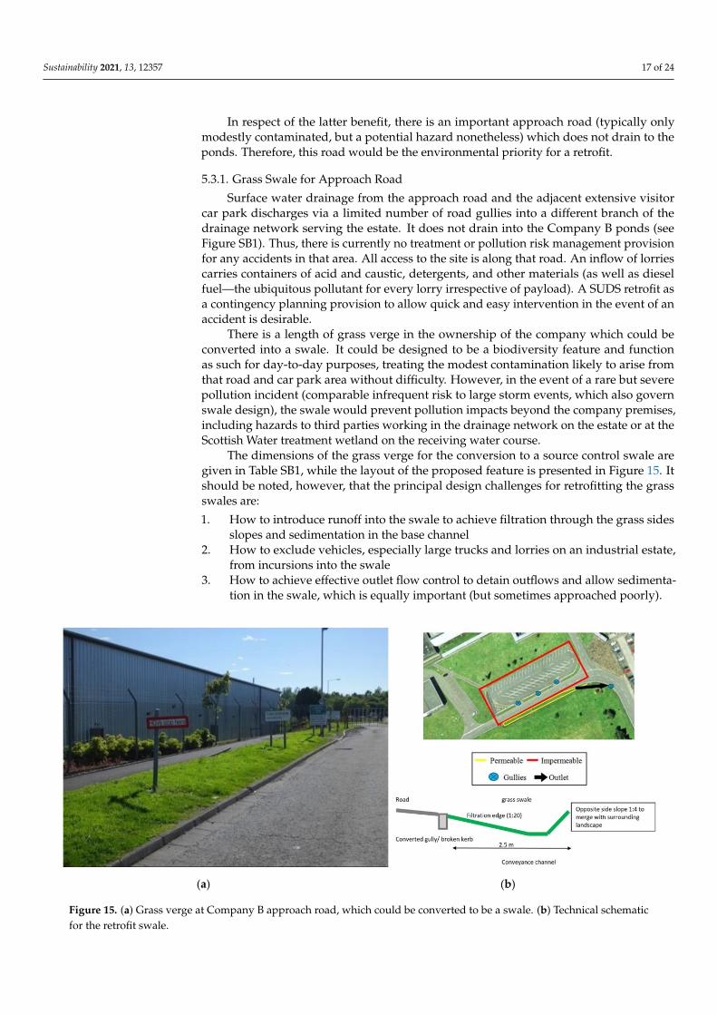
There is a length of grass verge in the ownership of the company which could beconverted into a swale. It could be designed to be a biodiversity feature and functionas such for day-to-day purposes, treating the modest contamination likely to arise fromthat road and car park area without difficulty. However, in the event of a rare but severepollution incident (comparable infrequent risk to large storm events, which also governswale design), the swale would prevent pollution impacts beyond the company premises,including hazards to third parties working in the drainage network on the estate or at theScottish Water treatment wetland on the receiving water course.
The dimensions of the grass verge for the conversion to a source control swale aregiven in Table SB1, while the layout of the proposed feature is presented in Figure 15. Itshould be noted, however, that the principal design challenges for retrofitting the grassswales are:
1. How to introduce runoff into the swale to achieve filtration through the grass sidesslopes and sedimentation in the base channel
2. How to exclude vehicles, especially large trucks and lorries on an industrial estate,from incursions into the swale
3. How to achieve effective outlet flow control to detain outflows and allow sedimenta-tion in the swale, which is equally important (but sometimes approached poorly).
Sustainability 2021, 13, x FOR PEER REVIEW 18 of 25
5.3.1. Grass Swale for Approach Road Surface water drainage from the approach road and the adjacent extensive visitor car
park discharges via a limited number of road gullies into a different branch of the drainage network serving the estate. It does not drain into the Company B ponds (see Figure SB1). Thus, there is currently no treatment or pollution risk management provision for any accidents in that area. All access to the site is along that road. An inflow of lorries carries containers of acid and caustic, detergents, and other materials (as well as diesel fuel—the ubiquitous pollutant for every lorry irrespective of payload). A SUDS retrofit as a contingency planning provision to allow quick and easy intervention in the event of an accident is desirable.
There is a length of grass verge in the ownership of the company which could be converted into a swale. It could be designed to be a biodiversity feature and function as such for day-to-day purposes, treating the modest contamination likely to arise from that road and car park area without difficulty. However, in the event of a rare but severe pollution incident (comparable infrequent risk to large storm events, which also govern swale design), the swale would prevent pollution impacts beyond the company premises, including hazards to third parties working in the drainage network on the estate or at the Scottish Water treatment wetland on the receiving water course.
The dimensions of the grass verge for the conversion to a source control swale are given in Table SB1, while the layout of the proposed feature is presented in Figure 15. It should be noted, however, that the principal design challenges for retrofitting the grass swales are: 1. How to introduce runoff into the swale to achieve filtration through the grass sides
slopes and sedimentation in the base channel 2. How to exclude vehicles, especially large trucks and lorries on an industrial estate,
from incursions into the swale 3. How to achieve effective outlet flow control to detain outflows and allow
sedimentation in the swale, which is equally important (but sometimes approached poorly).
(a) (b)
Figure 15. (a) Grass verge at Company B approach road, which could be converted to be a swale. (b) Technical schematic for the retrofit swale.
The recommended design involves removing the kerbs and laying them flat at a 45-degree angle to meet the grass surface at a new lower soil and grass level. This would
Figure 15. (a) Grass verge at Company B approach road, which could be converted to be a swale. (b) Technical schematicfor the retrofit swale.
Sustainability 2021, 13, 12357 18 of 24
The recommended design involves removing the kerbs and laying them flat at a45-degree angle to meet the grass surface at a new lower soil and grass level. This wouldovercome the downfall of many swales in not preventing the grass levels from growinghigher than road surface level (see the case study of Pittner et al. in [7]).
Vehicle exclusion would be by large intermittent barriers such as posts or rocks. Thereare already several large signs, so the verge is already a recognized, prominent feature bydrivers. An alternative barrier would be a low evergreen hedge (a linear drainage planterusing free-draining soil) to serve the same purpose of the conventional road-edge kerb, butalso enhance biofiltration [32]. Whereas this alternative barrier would work for cars andvans, it may not be effective for larger vehicles.
Outflow should be a two-stage structure at the lower end of the swale: a high-levelhorizontal grill in the event of a major rainstorm, covering an outlet chamber with a base-level entry from the swale which can easily be blocked by a piece of turf in the event of a rarebut serious incident. Routine maintenance would be required to keep that restricted flowpath clear in normal circumstances. Periodic grass cutting would be the only other requiredroutine maintenance (but less frequent than that needed for the existing grass verge).
5.3.2. Grass Swales for Areas within the Factory
Two areas were identified as secondary priorities for retrofits: inside the factory fencedarea and draining to the SUDS ponds. The potential swale to help manage pollution risksat the road and oil/chemical handling areas would assist in protecting the valuable waterresource of the ponds at the factory by achieving capture and treatment at the source. It mayalso help improve the day-to-day practices and care in handling the potential pollutants.The other suitable area is along the western boundary serving the road trafficked by allthe large vehicles bringing chemicals into the factory. It should be noted that soil andvegetation removed from the grass verge while constructing the swale for the approachroad (see above) could be efficiently used in both situations. Tables SB2 and SB3 andFigure SB2 demonstrate appropriate design details and dimensions for this type of swalebased on the measurements at the site.
5.3.3. Other Possibilities at Company B
The visitor car park (Figure SB3) is served by several road gullies located in the tarmacat the downhill part of the car park. They are close to some crash barriers, which demarcatethe car park from the road. It should be possible to retrofit some biofiltration planters(in-ground raingardens, e.g., tree-pits) to divert the flows from the gullies. The planterscould be drained in a new pipe back into the drainage system after providing treatmentand attenuation. This would provide treatment for an additional area of 2306 m2, whichcurrently drains to the local watercourse without abatement.
Alternatively, a carefully designed swale (see above) may be able to accept runofffrom that car parking area and simply seal off the gullies. The fall is in the correct directionto reach the swale, but the impervious area draining to it is large.
Similarly, there are extensive (but relatively uncontaminated or lightly contaminated)areas with grass margins within the catchment area of the surface water drains which donot pass to the ponds. There are two options for retrofitting these areas:
1. Collect and redirect to the ponds for use (it is relatively clean)2. Retrofit swales or raingardens to provide attenuation and treatment prior to overflow
into existing drains
Option 2 would provide treatment for an additional area of 2306 m2, which currentlydrains to the local water course without treatment (see Figure 15, left-hand side of the plan).
It should also be noted that there are extensive grass landscapes beyond the imper-vious front strip, sloping down to the approach road outside the boundary fence. If andwhen the company has sufficient resources and other reasons to regrade and restore thecondition of the front access perimeter road and car parking, then it would be sensible todetermine if such a project could divert the runoff into those grass areas, perhaps with a
Sustainability 2021, 13, 12357 19 of 24
collection drain to collect excess runoff for slower seepage rate into the existing drainagenetwork. Strictly horizontal levels, for even flow distribution, are essential for a grass filterstrip. If it is difficult to achieve horizontal levels, then it might be better to drain parts ofthe area to in-ground rain gardens within the grass space (Figure SB4).
6. Discussion
The need to address the pollution problems in rivers and respond to the climateemergency comes with significant challenges. Green and Blue-Green Infrastructure will beat the heart of the response, and there are already many initiatives showing how it can beretrofitted to residential and commercial developments [33]. However, little considerationhas been given to industrial areas. Industrial areas pose challenges due to the potentiallyhigher pollutant loads and increased complexity regarding who receives the multiplebenefits derived from the Green Infrastructure [34].
6.1. Importance of Different Approaches
It is widely acknowledged that decentralized SUDS and BGI solutions provide goodoptions for the treatment of stormwater runoff [35]. Previous studies have shown how‘end-of-pipe’ pollution control measures, such as wetlands [25,36], can be complementedby ‘source-control’ measures, such as swales and permeable pavement [37]. Such specificmeasures are often considered in isolation but would best function in concert. The currentpaper also provides practical examples in that respect and considers a range of variousavailable options and their feasibility. Crucially, the costs for case study A are providedalongside the logistics, technical feasibility, and the resulting environmental benefits. Theseestimates should be treated as approximate, but are nevertheless indicative of the potentialcosts likely to arise from the retrofitting of the considered SUDS features.
It should be noted that the traditional ‘containment’ measures are indispensable, andoften effective and practicable. They should, therefore, be the first line of defense whereverchemical handling operations occur, which is exemplified here in both case studies andwas particularly relevant for Company B. However, the contamination of surface runoffby diffuse pollution is inevitable. Hence, the application of measures such as filter drains,swales, grass filter strips, and SUDS ponds, should become routine, and the case studiespresented here provide a number of practical recommendations in that regard.
6.2. Importance of the Participatory Co-Design Process
The importance of participatory processes and accounting for the local conditionsis generally accepted both in relation to urban water management, particularly the mit-igation of the potential consequences of flooding, and surface water pollution [9,38–41].Involvement of stakeholder practitioners in the design processes is crucial, as without it,the prospective retrofits are unlikely to succeed. In particular, co-designing the solutionstogether with the stakeholders helps to identify, and subsequently obviate, a range ofpotential logistical constraints related, e.g., to local conditions, peculiarities of technologi-cal processes, the availability of infrastructure, future plans, and the views of the seniormanagement. Techniques such as discussion forums, focus groups, and learning and actionalliances (LAAs) have been used to promote stakeholder participation in finding workablesolutions for difficult problems related to flooding and water quality issues [9,42,43].
To be viable, the proposed solutions should strive to overcome the challenges ofaccessibility vs complexity tradeoff [40]. The prospective retrofit techniques must beaffordable, understandable, and reasonably implementable for specific stakeholders whileretaining sufficient sophistication to provide sufficient improvements and the benefitssought. This study applied a participatory approach involving iterative consultations forco-designing pollution prevention and innovative mitigation solutions, thus striving tooptimize the outcome with respect to affordability, effectiveness, and logistical constraints.
Sustainability 2021, 13, 12357 20 of 24
6.3. Applicability of the Methodological Framework to Other Premises and Industrial Estates
Methodologies and case studies concerning the optimization of industrial processesand functioning of urban systems by improving the resilience of infrastructure are amongthe major themes for this special issue. The presented research has sought to designmethodology to address the knowledge gap of practical implementation of ‘source-control’measures for mitigating polluted runoff from industrial premises by working with busi-nesses in one of Scotland’s largest industrial estates, an area known to contribute tonontrivial water quality problems in a nearby watercourse. It is noteworthy that the settingof the industrial estate, the layout of the premises, and the proposed solutions are typical formany other industrial estates both in the UK and worldwide. The names of the participat-ing companies are not revealed, but the approach used to identify potential SUDS retrofits,assess the logistical feasibility of the proposed solutions, and estimate approximate costs istransferrable to other industrial estates and commercial premises. Hence, the approachand the methodology used in this study are easily applicable elsewhere. In general, themethodological framework developed and applied by this study is directly relevant tothe further development of management approaches aiming to improve sustainability inurban systems, which is the topic of this special issue.
6.4. Barriers to Retrofits
The results of our study are broadly in line with previous general research on potentialbarriers related to the development of BGI and SUDS installations [8] and provide furtherimportant insight in the industrial estate context. Lack of awareness was previouslyreported to be among the major barriers for the installation of BGI assets in residentialareas [9,44]. In our research, lack of knowledge related both to SUDS technology andpollution prevention legislation was identified as a major barrier to retrofits in industrialestates. This needs to be tackled urgently by education campaigns.
The very limited awareness of either the legislation or the technology surroundingSUDS suggests that a retrofit program or initiative without the associated education andengagement would, at best, create features destined to be neglected subsequently. It alsohas implications for the new build and the general use of SUDS. Thus, there is a majorneed for a sustained engagement and education efforts by all the organizations involved indriving SUDS into routine business.
In addition to the lack of knowledge, this study identified three broad classes ofbarriers to retrofits: cost, time, and space. More detailed comments and views wereidentified in the one-to-one dialogue during the initial survey and follow-up visits, in thedialogue with the case study businesses, and through the discussion with the focus group.
It should be noted that industrial estates tend to host companies with widely differingsizes and activities, ranging from office-type work to heavy industrial operations. Thisstudy and the previous work [26] highlighted that businesses were open to consideringretrofitting Green Infrastructure once the benefits were explained, and that viable technicalsolutions are available. Typically, larger businesses who owned their lot were more likelyto engage constructively than small operators which rented their facility. Smaller operatorsunderstood the benefits, but often saw it as a matter for their landlord. It was noted thatsome sizable operations had little local capacity to develop or maintain their real estate,and they often deferred to a manager elsewhere where these issues were concerned.
The case studies presented herein deal with a medium-sized company (CompanyA) and a large company (Company B). Larger businesses appeared more likely to have acorporate policy in place to mitigate the impact of their operations on the environment.These businesses were also more likely to have space within their lot to allocate to retrofits.However, concerns were raised that such an investment would act as a barrier to the busi-ness being able to use that space for the future expansion of their operations. It is thereforeimportant that any proposed retrofits should be realistic and take this kind of considerationinto account, providing various options such as those proposed in this research.
Sustainability 2021, 13, 12357 21 of 24
A detailed survey and extensive communication with businesses demonstrated thatthe fragmented land ownership in the wider industrial estate was a barrier to some retrofitapproaches, particularly the ones which drained more than one lot. A further issue wasthat many businesses felt that they worked within the guidance set by the environmentalregulator and that they paid the water services provider to resolve any drainage issues.Nonetheless, the case studies presented in detail here clearly show that while there arebarriers to retrofitting, installing SUDS and Green Infrastructure features is technically andeconomically feasible. This suggests that progress can be made with the correct incentives.
6.5. Relevance to the BGC Conceptual Framework
Achieving the mitigation of polluted runoff from industrial and housing develop-ments is a prerequisite of sustainable urban growth. It should be noted that most practicalactions are often focused on flooding at housing estates, while industrial pollution is mainlyaddressed in relation to the incidents of acute illegal discharge. It is, however, paramountthat chronic diffuse pollution and planning the contingency measures for potential acci-dents become part of routine management both in the residential and industrial areas. Thissafeguarding of the runoff quality is one of the central themes for the developing conceptualframework of urban flood management (UFR) in Blue-Green and Sponge Cities [10,14,33].Our study is very relevant in that respect.
In addition to the improvements in water quality and alleviation of flood risk, theintroduction of Green and Blue-Green Infrastructure will lead to further benefits relatedto such ecosystem services as the amelioration of the local climate, reduction of noise,improvements in air quality, enhancement of the local biodiversity, and positive effects forthe human well-being and mental health (see, e.g., [9] and references therein). In industrialsettings, it may also have an indirect positive influence on the employees’ productivity.SUDS/BGI features considered in this paper, such as biodiversity swales [6], raingar-dens [11], and retention ponds [12,13,45], are particularly relevant in that respect. Theexisting SUDS ponds at Company B provide a valuable example of how BGI installationscan be used effectively not only to alleviate the flood risk and mitigate polluted runoff, butalso to provide efficient grey water reuse (GWR) and optimize the supply of valuable waterresources for technological processes. Further studies should examine the contributionof these ponds to the local biodiversity value, which is expected to be significant basedon studies of BGI ponds elsewhere [11–13,46]. Further research should also address thepossibilities of increasing GWR through economic and policy instruments using participa-tory system dynamics modelling [38,39], and should examine potential tradeoffs betweenspecific retrofits [45]. Approaches such as comparative theoretical ecosystem analysis [47]and tools comparing multiple benefits based on changes in natural capital [48,49] will beparticularly relevant in that respect.
7. Conclusions
SUDS technology, combining Green Infrastructure with the passive drainage ofstormwater, helps to overcome the challenges related to the pollution problems in riversand respond to the climate emergency by capturing the pollutants present in runoff fromthe industrial landscape. This paper developed a methodological framework, presentedthe results of the awareness survey, examined barriers and opportunities, and providedtwo detailed case studies dealing with potential SUDS retrofits at industrial facilities, as-sessing the existing control measures and the scope for new ones with the aim to improvepollution management.
First, this study developed a multistage investigative framework structured to facili-tate the search for relevant solutions and optimization of their design.
Second, the lack of knowledge related to SUDS and pollution prevention legislationwas identified as the major barrier to retrofits, which should be addressed through educa-tional measures. Many proprietors were not familiar with SUDS, and the majority were
Sustainability 2021, 13, 12357 22 of 24
ignorant of the relevant legislation. Among those who claimed familiarity or ownership ofSUDS, many were found to be mistaking.
Third, the co-design approach used to create SUDS retrofit solutions demonstratedthat it was possible to work with proprietors to sustainably improve water quality. Whereasmany of the design elements consumed space, none impacted the operation of the business.
This study exemplified the potential of SUDS retrofitting to improve pollution man-agement on complex industrial premises. The approach used to identify potential SUDSretrofits, assess the logistical feasibility of the proposed solutions, and estimate approximatecosts is transferrable to other industrial and commercial areas. Adaptive, inclusive, andinnovative design is key to overcoming physical retrofitting barriers, such as landscapelimitations and combining the “end-of-pipe” solution with an effective runoff treatment atthe source.
It is recognized that the diversity of business in size, activities, land ownership, andresponsibilities in industrial estates may entail a barrier to SUDS retrofitting that needs tobe addressed by an awareness campaign, range of solutions, and incentives. Nonetheless,the case studies presented here clearly show that while there are barriers to retrofitting,installing SUDS and Green Infrastructure features is technically and economically feasible.In addition to the improvements in water quality and alleviation of flood risk, a developedBlue-Green Infrastructure network will also contribute a range of further benefits relatedto the increased biodiversity and amenity values, as well as other ecosystem services.
Supplementary Materials: The following are available online at https://www.mdpi.com/article/10.3390/su132212357/s1, Supplementary materials—a single file including Supplement A (SA) andSupplement B (SB).
Author Contributions: All authors provided significant contributions to this work. All authors haveread and agreed to the published version of the manuscript.
Funding: This work was supported by CREW and EPSRC funding.
Institutional Review Board Statement: Not applicable.
Informed Consent Statement: Not applicable.
Data Availability Statement: Data sharing not applicable.
Acknowledgments: The comments of three anonymous reviewers helped to improve the manuscript.
Conflicts of Interest: The authors declare no conflict of interest.
References1. Campbell, N.; D’Arcy, B.; Frost, A.; Novotny, V.; Sansom, A. Diffuse Pollution—An Introduction to the Problems and Solutions; Iwa
Publishing: London, UK, 2004.2. Garrick, D.; Hall, J.W. Water security and society: Risks, metrics, and pathways. Annu. Rev. Environ. Resour. 2014, 39, 611–639.
[CrossRef]3. Novotny, V. Water Quality: Diffuse Pollution and Watershed Management; John Wiley & Sons: Hoboken, NJ, USA, 2003.4. OECD. Diffuse Pollution, Degraded Waters: Emerging Policy Solutions; OECD Publishing: Paris, France, 2017.5. CIRIA. Blue-Green Infrastructure—Perspectives on Water Quality Benefits; CIRIA: London, UK, 2019.6. Woods-Ballard, B.; Kellagher, R.; Martin, R.; Jefferies, C.; Bray, R.; Shaffer, P. The SuDS Manual; CIRIA: London, UK, 2007.7. D’Arcy, B.J.; Kim, L.-H.; Maniquiz-Redillas, M. Wealth Creation without Pollution. Designing for Industry, Ecobusiness Parks and
Industrial Estates; IWAP: London, UK, 2018.8. O’Donnell, E.C.; Lamond, J.E.; Thorne, C.R. Recognising barriers to implementation of Blue-Green Infrastructure: A Newcastle
case study. Urban Water J. 2017, 14, 964–971. [CrossRef]9. CIRIA. Blue-Green Infrastructure—Perspectives on Planning, Evaluation and Collaboration; CIRIA: London, UK, 2019.10. O’Donnell, E.; Thorne, C.; Ahilan, S.; Arthur, S.; Birkinshaw, S.; Butler, D.; Dawson, D.; Everett, G.; Fenner, R.; Glenis, V.; et al. The
blue-green path to urban flood resilience. Blue-Green Syst. 2020, 2, 28–45. [CrossRef]11. Krivtsov, V.; Birkinshaw, S.; Arthur, S.; Knott, D.; Monfries, R.; Wilson, K.; Christie, D.; Chamberlain, D.; Brownless, P.; Kelly,
D. Flood resilience, amenity and biodiversity benefits of an historic urban pond. Philos. Trans. R. Soc. A 2020, 378, 20190389.[CrossRef]
Sustainability 2021, 13, 12357 23 of 24
12. Krivtsov, V.; Birkinshaw, S.; Forbes, H.; Olive, V.; Chamberlain, D.; Lomax, J.; Buckman, J.; Yahr, R.; Arthur, S.; Takezawa, K.; et al.Hydrology, ecology and water chemistry of two SuDS ponds: Detailed analysis of ecosystem services provided by Blue GreenInfrastructure. WIT Trans. Built Environ. 2020, 194, 167–178.
13. Krivtsov, V.; Birkinshaw, S.; Lomax, J.; Christie, D.; Arthur, S. Multiple benefits of blue-green infrastructure and the reduction ofenvironmental risks: Case study of ecosystem services provided by a suds pond. In Civil Engineering for Disaster Risk Reduction;Springer: Berlin/Heidelberg, Germany, 2021; in press.
14. Fenner, R.; O’Donnell, E.; Ahilan, S.; Dawson, D.; Kapetas, L.; Krivtsov, V.; Ncube, S.; Vercruysse, K. Achieving Urban FloodResilience in an Uncertain Future. Water 2019, 11, 1082. [CrossRef]
15. D’Arcy, B.J.; Hemingway, A. The regulatory regime for bringing SUDS into routine use for industrial estates and business parksin Scotland, UK. In Wealth Creation without Pollution-Designing for Industry, Ecobusiness Parks and Industrial Estates; D’Arcy, B., Kim,L.H., Maniquiz-Redillas, M., Eds.; Iwa Publishing: London, UK, 2018.
16. SEPA. State of the Environment Report 1996; Scottish Environment Protection Agency: Stirling, UK, 1996.17. Kim, L.-H.; D’Arcy, B.; Ibanez, M.; Maniquiz-Redillas, M. Industrial estates as sources of water pollution. In Wealth Creation
without Pollution-Designing for Industry, Ecobusiness Parks and Industrial Estates; D’Arcy, B., Kim, L.H., Maniquiz-Redillas, M., Eds.;Iwa Publishing: London, UK, 2018.
18. SEPA. Improving Scotland’s Water Environment, SEPA State of the Environment Report; Scottish Environment Protection Agency:Stirling, UK, 1999.
19. D’Arcy, B.; Ellis, J.B.; Ferrier, R.; Jenkins, A.; Dils, R. Diffuse Pollution Impacts: The Environmental and Economic Impacts of DiffusePollution in the UK; Terence Dalton Publishers: Lavenham, Suffolk, UK, 2000.
20. Napier, F.; Jefferies, C.; Heal, K.V.; Fogg, P.; Arcy, B.J.D.; Clarke, R. Evidence of traffic-related pollutant control in soil-basedSustainable Urban Drainage Systems (SUDS). Water Sci. Technol. 2009, 60, 221–230. [CrossRef]
21. McNeil, A. Best Management Practices and Contingency Planning for Spillage Emergencies, 1998, Surveyor. Available online:https://ww2.eagle.org/en/news/publications/surveyor-archive.html (accessed on 15 October 2021).
22. Dowson, P.; Chem, C.; Biol, C.; Scrimshaw, M.D.; Nasir, J.M.; Bubb, J.N.; Lester, J.N. The Environmental Impact of a ChemicalSpill from a Timber-Treatment Works on a Lowland River System. Water Environ. J. 1996, 10, 235–244. [CrossRef]
23. Salzmann, J. “Schweizerhalle” and its consequences. In Fires involving Pesticides—The Rhine Incident; The British AgrochemicalsAssociation: Henderson, NV, USA, 1987.
24. Abas, M.R.B.; Omar, N.Y.M.J.; Maah, M.J. An assessment of the concentrations of particulate polycyclic aromatic hydrocarbons(PAHs) in the aftermath of a chemical store fire incident. J. Environ. Sci. 2004, 16, 751–754.
25. Heal, K.; Scholz, M.; Willby, N.; Homer, B. The Caw Burn SUDS: Performance of a settlement pond/wetland SUDS retrofit. InProceedings of the Third National Conference on Sustainable Drainage, Coventry, UK, 20–21 June 2005; pp. 19–29.
26. Krivtsov, V.; Arthur, S.; Semple, C.; Sevilla, A.E.; D’Arcy, B.J. Retrofitting SUDS at Industrial Premises. In Proceedings of the 2ndInternational Conference on Natural Hazards & Infrastructure (ICONHIC), Chania, Greece, 23–26 June 2019. Available online:http://www.urbanfloodresilience.ac.uk/documents/krivtsov-et-al.-iconhic-2019.pdf (accessed on 24 September 2021).
27. Stovin, V.R.; Swan, A.D. Retrofit SuDS—Cost estimates and decision-support tools. Proc. Inst. Civ. Eng. Water Manag. 2007, 160,207–214. [CrossRef]
28. Langdon, D. Spon’s Civil Engineering and Highway Works Price Book 2014; CRC Press: Boca Raton, FL, USA, 2014.29. Samuel, O.; Suleiman, O.; Odiete, W. Synergistic Evaluation of Oil-Dispersant and Oil-Detergent Mixtures Using African Catfish,
Clarias gariepinus Fry. J. Fish. Aquat. Sci. 2008, 3, 280–290. [CrossRef]30. Schein, A.; Scott, J.A.; Mos, L.; Hodson, P.V. Oil dispersion increases the apparent bioavailability and toxicity of diesel to rainbow
trout (Oncorhynchus mykiss). Environ. Toxicol. Chem. 2009, 28, 595–602. [CrossRef]31. Woods-Ballard, B.; Wilson, S.; Udale-Clarke, H.; Illman, S.; Scott, T.; Ashley, R.; Kellagher, R. The SUDS Manual; CIRIA: London,
UK, 2015.32. Leroy, M.C.; Marcotte, S.; Legras, M.; Moncond’huy, V.; Le Derf, F.; Portet-Koltalo, F. Influence of the vegetative cover on the fate
of trace metals in retention systems simulating roadside infiltration swales. Sci. Total Environ. 2017, 580, 482–490. [CrossRef]33. Lashford, C.; Rubinato, M.; Cai, Y.; Hou, J.; Abolfathi, S.; Coupe, S.; Charlesworth, S.; Tait, S. SuDS & Sponge Cities: A
Comparative Analysis of the Implementation of Pluvial Flood Management in the UK and China. Sustainability 2019, 11, 213.34. Jarvie, J.; Arthur, S.; Beevers, L. Valuing multiple benefits, and the public perception of SUDS ponds. Water 2017, 9, 128. [CrossRef]35. Dierkes, C.; Lucke, T.; Helmreich, B. General Technical Approvals for Decentralised Sustainable Urban Drainage Systems
(SUDS)—The Current Situation in Germany. Sustainability 2015, 7, 3031. [CrossRef]36. D’Arcy, B.; McLean, N.; Heal, K.; Kay, D. Riparian wetlands for enhancing the self-purification capacity of streams. Water Sci.
Technol. 2007, 56, 49–57. [CrossRef]37. Bastien, N.; Arthur, S.; Wallis, S.; Scholz, M. The best management of SuDS treatment trains: A holistic approach. Water Sci.
Technol. 2010, 61, 263–272. [CrossRef]38. Krivtsov, V.; Pagano, A.; Ahilan, S.; O’Donnell, E.; Pluchinotta, I. Further Developments of the Ebbsfleet water management
system dynamics model: Adjusting representation of processes and system boundaries, insentivising stakeholder re-engagement,and exploring potential for the use in university teaching. WIT Trans. Ecol. Environ. 2021. [CrossRef]
Sustainability 2021, 13, 12357 24 of 24
39. Pluchinotta, I.; Pagano, A.; Vilcan, T.; Ahilan, S.; Kapetas, L.; Maskrey, S.; Krivtsov, V.; Thorne, C.; O’Donnell, E. A participatorysystem dynamics model to investigate sustainable urban water management in Ebbsfleet Garden City. Sustain. Cities Soc. 2021,67, 102709. [CrossRef]
40. Maskrey, S.A.; Mount, N.J.; Thorne, C.R. Doing flood risk modelling differently: Evaluating the potential for participatorytechniques to broaden flood risk management decision-making. J. Flood Risk Manag. 2021, e12757. Available online: https://onlinelibrary.wiley.com/doi/full/10.1111/jfr3.12757 (accessed on 1 September 2021).
41. Few, R. Flooding, vulnerability and coping strategies: Local responses to a global threat. Prog. Dev. Stud. 2003, 3, 43–58. [CrossRef]42. van Herk, S.; Zevenbergen, C.; Ashley, R.; Rijke, J. Learning and Action Alliances for the integration of flood risk management
into urban planning: A new framework from empirical evidence from The Netherlands. Environ. Sci. Policy 2011, 14, 543–554.[CrossRef]
43. Ashley, R.M.; Blanskby, J.; Newman, R.; Gersonius, B.; Poole, A.; Lindley, G.; Smith, S.; Ogden, S.; Nowell, R. Learning and ActionAlliances to build capacity for flood resilience. J. Flood Risk Manag. 2012, 5, 14–22. [CrossRef]
44. Everett, G.; Lamond, J.; Morzillo, A.T.; Chan, F.K.S.; Matsler, A.M. Sustainable drainage systems: Helping people live with water.Proc. ICE Water Manag. 2016, 169, 94–104. [CrossRef]
45. Krivtsov, V.; Birkinshaw, S.; Yahr, R.; Olive, V. Comparative ecosystem analysis of urban ponds: Implications for synergisticbenefits and potential trade-offs resulting from retrofitting of green roofs in their catchments. Int. J. Environ. Impacts 2021, in press.
46. Krivtsov, V.; Arthur, S.; Buckman, J.; Bischoff, J.; Christie, D.; Birkinshaw, S.; Takezawa, K.; Chamberlain, D.; Pereira, R. Monitoringand Modelling SUDS Retention Ponds: Case Studies from Scotland. In Proceedings of the 2nd International Conference on NaturalHazards & Infrastructure (ICONHIC), Chania, Greece, 23–26 June 2019. Available online: http://www.urbanfloodresilience.ac.uk/documents/krivtsov-et-al.-iconhic-2019b.pdf (accessed on 24 September 2021).
47. Krivtsov, V. Investigations of indirect relationships in ecology and environmental sciences: A review and the implications forcomparative theoretical ecosystem analysis. Ecol. Model. 2004, 174, 37–54. [CrossRef]
48. Morgan, M.; Fenner, R. Spatial evaluation of the multiple benefits of sustainable drainage systems. Proc. Inst. Civ. Eng. WaterManag. 2019, 172, 39–52. [CrossRef]
49. Ncube, S.; Arthur, S. Influence of Blue-Green and Grey Infrastructure Combinations on Natural and Human-Derived Capital inUrban Drainage Planning. Sustainability 2021, 13, 2571. [CrossRef]


