Embed Size (px)
Citation preview
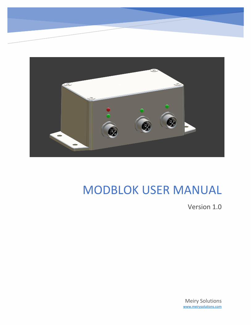
MODBLOK USER MANUAL Version 1.0
Meiry Solutions www.meirysolutions.com
Modblok User Manual
1
Contents Introduction .................................................................................................................................................. 3
Modblok Multiplexing Discussion ................................................................................................................. 3
Modblok Components .................................................................................................................................. 4
DeltaV System Setup ..................................................................................................................................... 4
Graphics .................................................................................................................................................... 5
Hamilton Probe Spreadsheet (csv file)...................................................................................................... 5
Composite Templates ............................................................................................................................... 5
DeltaV System Configuration ........................................................................................................................ 5
Serial Card/Port configuration .................................................................................................................. 5
Read Register Set configuration................................................................................................................ 8
Write Register Set configuration .............................................................................................................. 9
DeltaV Module Creation ......................................................................................................................... 10
Modblok Installation ................................................................................................................................... 18
Port and LED Indicator Overview – Front Face ....................................................................................... 18
Port Overview – Right Face ..................................................................................................................... 19
Master (DCS) Port Cable ......................................................................................................................... 19
Probe Port Cables.................................................................................................................................... 19
Pressure Port Cables ............................................................................................................................... 20
Graphic Overview - Faceplate ..................................................................................................................... 20
Modblok Device Status ........................................................................................................................... 20
Modblok Commission ............................................................................................................................. 21
Probe Status and Value ........................................................................................................................... 22
Probe Selection ....................................................................................................................................... 22
Probe Commissioning ............................................................................................................................. 22
Probe Scan .............................................................................................................................................. 23
Probe Write Register Set ......................................................................................................................... 25
Probe Calibrate ....................................................................................................................................... 27
Hide/Show details ................................................................................................................................... 28
Graphic Overview - Detail ........................................................................................................................... 29
Termination Active .................................................................................................................................. 29
Raw Counts ............................................................................................................................................. 29
Modblok User Manual
2
Pressure (psi)........................................................................................................................................... 29
Gain ......................................................................................................................................................... 30
Tare ......................................................................................................................................................... 30
Module Integration ..................................................................................................................................... 30
Probe Calibration ........................................................................................................................................ 30
Calibration Overview .............................................................................................................................. 30
Standard Calibration ........................................................................................................................... 30
Product Calibration ............................................................................................................................. 30
VisiFerm DO SU (Single Use) Procedure.................................................................................................. 30
Standard Calibration ........................................................................................................................... 30
Product Calibration ............................................................................................................................. 34
VisiFerm DO ECS (Re-Usable) Procedure ................................................................................................ 36
Standard Calibration ........................................................................................................................... 36
Product Calibration ............................................................................................................................. 42
OneFerm pH SU (Single Use) Procedure ................................................................................................. 46
Standard Calibration ........................................................................................................................... 46
Product Calibration ............................................................................................................................. 49
EasyFerm pH ARC (Re-Usable) Procedure .............................................................................................. 54
Standard Calibration ........................................................................................................................... 54
Product Calibration ............................................................................................................................. 63
Modblok User Manual
3
Introduction This document details how to install and commission your Modblok digital solution.
Modblok allows for simple interfacing of Hamilton ARC style probes into a DeltaV control system. All
probe parameters are brought into the DeltaV system while utilizing few resources (DST and serial
dataset).
Modblok acts as a Modbus RTU data collector for dual Hamilton probes. As of this document version, pH
and DO probes are supported, but in the near future, the full portfolio of Hamilton probes will be
supported.
Although all Hamilton ARC probes support Modbus RTU, the data mapping is not easily managed by
Emerson DeltaV Modbus RTU master implementation. The reason why is the Hamilton Modbus map is
fragmented, and each register set mixes data of different type. DeltaV Modbus implementation requires
a Modbus operation to act on a contiguous set of registers with a consistent type and direction. For
example, a multiple register read requires that all registers be contiguous, of the same type (Integer or
Floating Point), and direction (read or write). When a slave device has data that is fragmented, this can
require many small register sets (data sets) and associated operations resulting in excessive resource
usage (both DST and serial port hardware in the case of DeltaV) and segment performance issues.
Modblok implements two features that alleviate any resource usage issues while still allowing full access
to the entire probe data set. These features are:
1) Data aggregation – Modblok reads data continuously from both probes, and arranges the data
in a manner compatible with DeltaV requirements
2) Data multiplexing – Modblok does not demand a DeltaV register per probe parameter. Instead,
lower priority data that is not used for control is slowly periodically collected in parts as opposed
to each module or Modbus segment cycle.
The end result of the above is full access to all probe parameters with total 2 DST consumption.
Modblok has been designed foremost with ease of use, as such configuration of Modblok and associated
probes is largely plug and play.
In addition to supporting Hamilton ARC style probes, the Modblok is available with a pressure sensor
(Pendotech) input option.
Modblok Multiplexing Discussion Every Hamilton probe possesses a myriad of operating parameters. The total parameter count for all
the probe types is approximately 200 to 300. This huge number of parameters is not practical to
continuously read each module scan, nor is this operationally beneficial. Most of these parameters are
either static, only change on a probe write, or very slowly change.
Bearing in mind the nature of the probe data, Modblok characterizes each register access into one of
the following categories:
Modblok User Manual
4
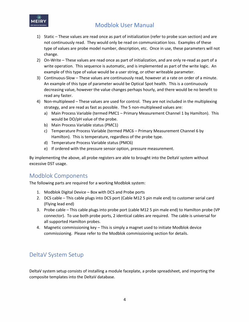
1) Static – These values are read once as part of initialization (refer to probe scan section) and are
not continuously read. They would only be read on communication loss. Examples of these
type of values are probe model number, description, etc. Once in use, these parameters will not
change.
2) On-Write – These values are read once as part of initialization, and are only re-read as part of a
write operation. This sequence is automatic, and is implemented as part of the write logic. An
example of this type of value would be a user string, or other writeable parameter.
3) Continuous-Slow – These values are continuously read, however at a rate on order of a minute.
An example of this type of parameter would be Optical Spot health. This is a continuously
decreasing value, however the value changes perhaps hourly, and there would be no benefit to
read any faster.
4) Non-multiplexed – These values are used for control. They are not included in the multiplexing
strategy, and are read as fast as possible. The 5 non-multiplexed values are:
a) Main Process Variable (termed PMC1 – Primary Measurement Channel 1 by Hamilton). This
would be DO/pH value of the probe.
b) Main Process Variable status (PMC1)
c) Temperature Process Variable (termed PMC6 – Primary Measurement Channel 6 by
Hamilton). This is temperature, regardless of the probe type.
d) Temperature Process Variable status (PMC6)
e) If ordered with the pressure sensor option, pressure measurement.
By implementing the above, all probe registers are able to brought into the DeltaV system without
excessive DST usage.
Modblok Components The following parts are required for a working Modblok system:
1. Modblok Digital Device – Box with DCS and Probe ports
2. DCS cable – This cable plugs into DCS port (Cable M12 5 pin male end) to customer serial card
(Flying lead end)
3. Probe cable – This cable plugs into probe port (cable M12 5 pin male end) to Hamilton probe (VP
connector). To use both probe ports, 2 identical cables are required. The cable is universal for
all supported Hamilton probes.
4. Magnetic commissioning key – This is simply a magnet used to initiate Modblok device
commissioning. Please refer to the Modblok commissioning section for details.
DeltaV System Setup
DeltaV system setup consists of installing a module faceplate, a probe spreadsheet, and importing the
composite templates into the DeltaV database.
Modblok User Manual
5
Graphics For each operator station, Pro and ProPlus computer, copy the Modblk_fp.grf file to the DeltaV
faceplate picture folder. This is typically either:
C:\DeltaV\DVData\Graphics-iFix\PIC\Faceplates
OR
D:\DeltaV\DVData\Graphics-iFix\PIC\Faceplates
Hamilton Probe Spreadsheet (csv file) For each operator station, Pro and ProPlus computer, create a probes folder inside the DeltaV picture
folder. Similar to the faceplate graphics, this new folder should be either:
C:\DeltaV\DVData\Graphics-iFix\PIC\probes
OR
D:\DeltaV\DVData\Graphics-iFix\PIC\probes
In the above folder, copy the RegisterMap5.csv file. Do this for all the above operator, Pro and ProPlus
computers.
Composite Templates From the ProPlus computer, import the MBLK_2_V5.fhx file by:
1) In DeltaV explorer, select File Menu -> Import -> Standard DeltaV Format
2) In file open dialog, select MBLK_2_V5.fhx
After doing the above steps, the import should be successful. If there are errors, please contact us for
assistance.
DeltaV System Configuration DeltaV system configuration consists of adding a serial device (the Modblok device), configuring the
device register set, creating a Modblok device DeltaV control module, and assigning the control module
external references to device registers.
Serial Card/Port configuration In general, a Modblok device will co-exist with other devices on the RS-485 bus. In DeltaV explorer,
expand the appropriate serial card and port. Under this port, add a new device, choosing an unused
address. Note that port settings such as baud rate, number of stop bits, and parity do not need to be
changed. The Modblok device can communicate with any valid Modbus RTU setting.
For the particular serial card, configure the port if required.
NOTE: Modblok comes default with the below settings. It is recommended that if possible to
configure the DeltaV serial device with these settings. Otherwise, any Modbus RTU compatible
settings may be selected, however this will necessitate a Modblok commissioning procedure to be
performed.
Modblok User Manual
6
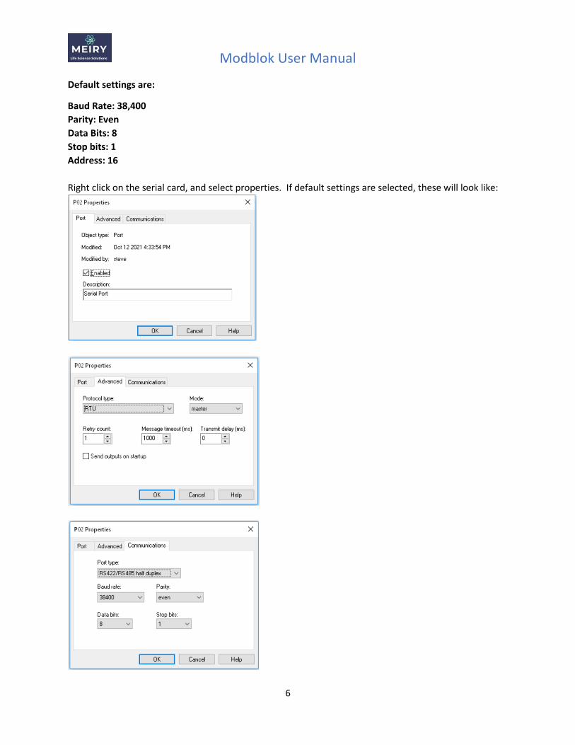
Default settings are:
Baud Rate: 38,400
Parity: Even
Data Bits: 8
Stop bits: 1
Address: 16
Right click on the serial card, and select properties. If default settings are selected, these will look like:
Modblok User Manual
7
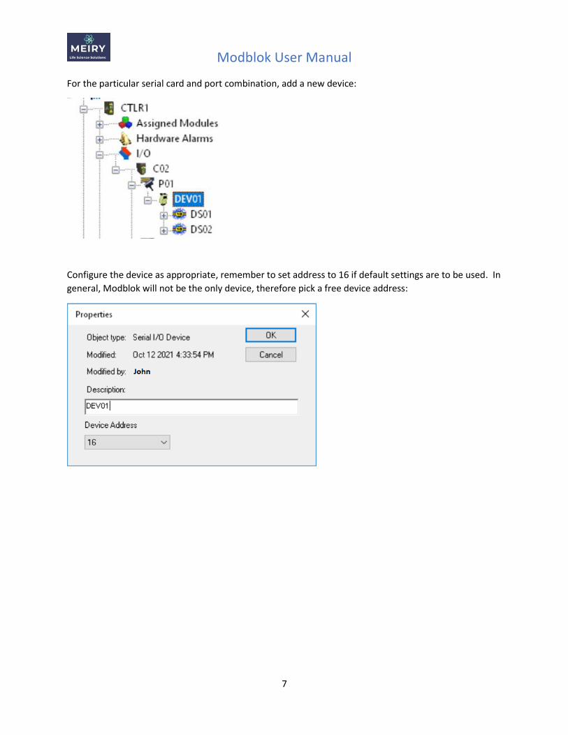
For the particular serial card and port combination, add a new device:
Configure the device as appropriate, remember to set address to 16 if default settings are to be used. In
general, Modblok will not be the only device, therefore pick a free device address:
Modblok User Manual
8
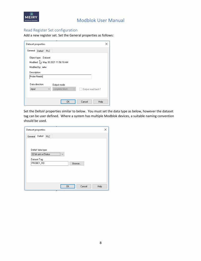
Read Register Set configuration Add a new register set. Set the General properties as follows:
Set the DeltaV properties similar to below. You must set the data type as below, however the dataset
tag can be user defined. Where a system has multiple Modblok devices, a suitable naming convention
should be used.
Modblok User Manual
9
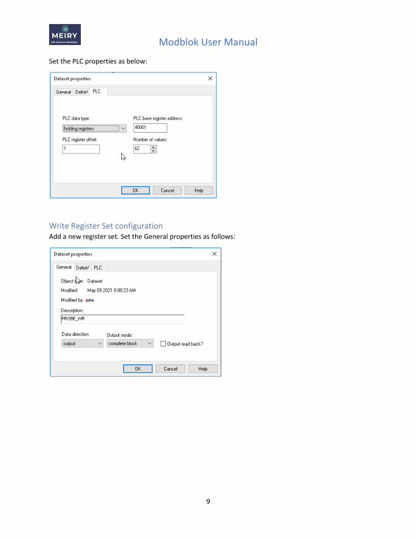
Set the PLC properties as below:
Write Register Set configuration Add a new register set. Set the General properties as follows:
Modblok User Manual
10
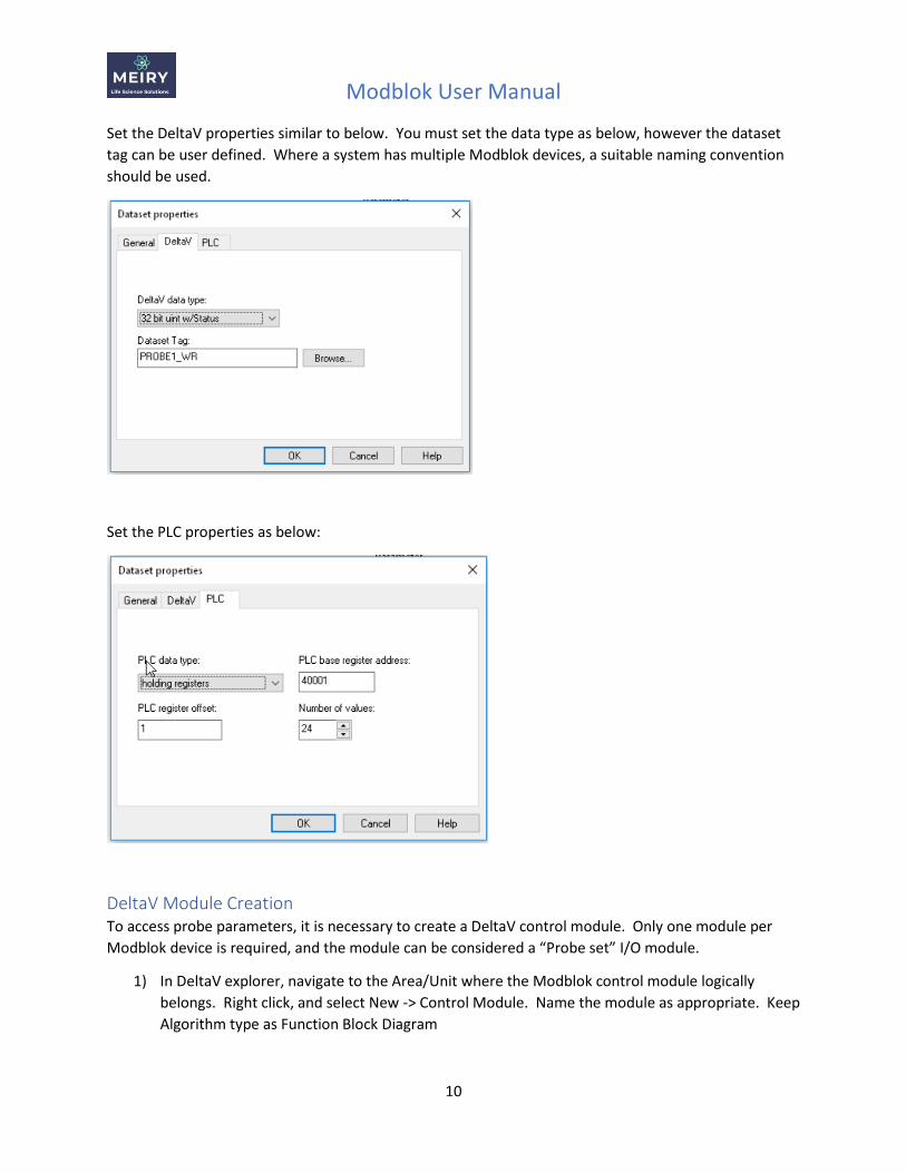
Set the DeltaV properties similar to below. You must set the data type as below, however the dataset
tag can be user defined. Where a system has multiple Modblok devices, a suitable naming convention
should be used.
Set the PLC properties as below:
DeltaV Module Creation To access probe parameters, it is necessary to create a DeltaV control module. Only one module per
Modblok device is required, and the module can be considered a “Probe set” I/O module.
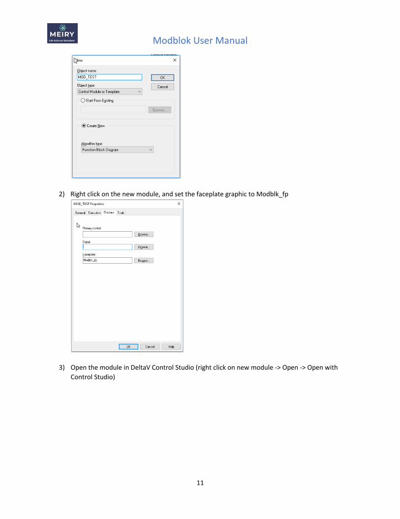
1) In DeltaV explorer, navigate to the Area/Unit where the Modblok control module logically
belongs. Right click, and select New -> Control Module. Name the module as appropriate. Keep
Algorithm type as Function Block Diagram
Modblok User Manual
11
2) Right click on the new module, and set the faceplate graphic to Modblk_fp
3) Open the module in DeltaV Control Studio (right click on new module -> Open -> Open with
Control Studio)
Modblok User Manual
12
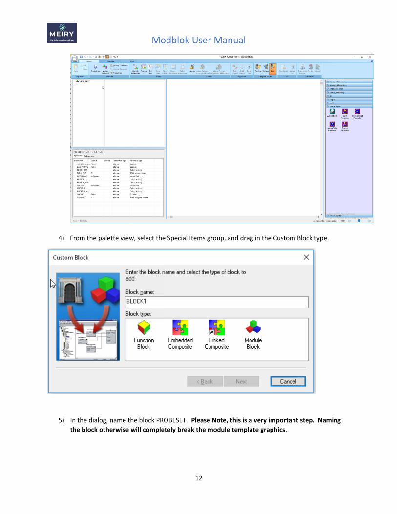
4) From the palette view, select the Special Items group, and drag in the Custom Block type.
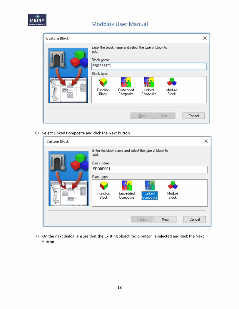
5) In the dialog, name the block PROBESET. Please Note, this is a very important step. Naming
the block otherwise will completely break the module template graphics.
Modblok User Manual
13
6) Select Linked Composite and click the Next button
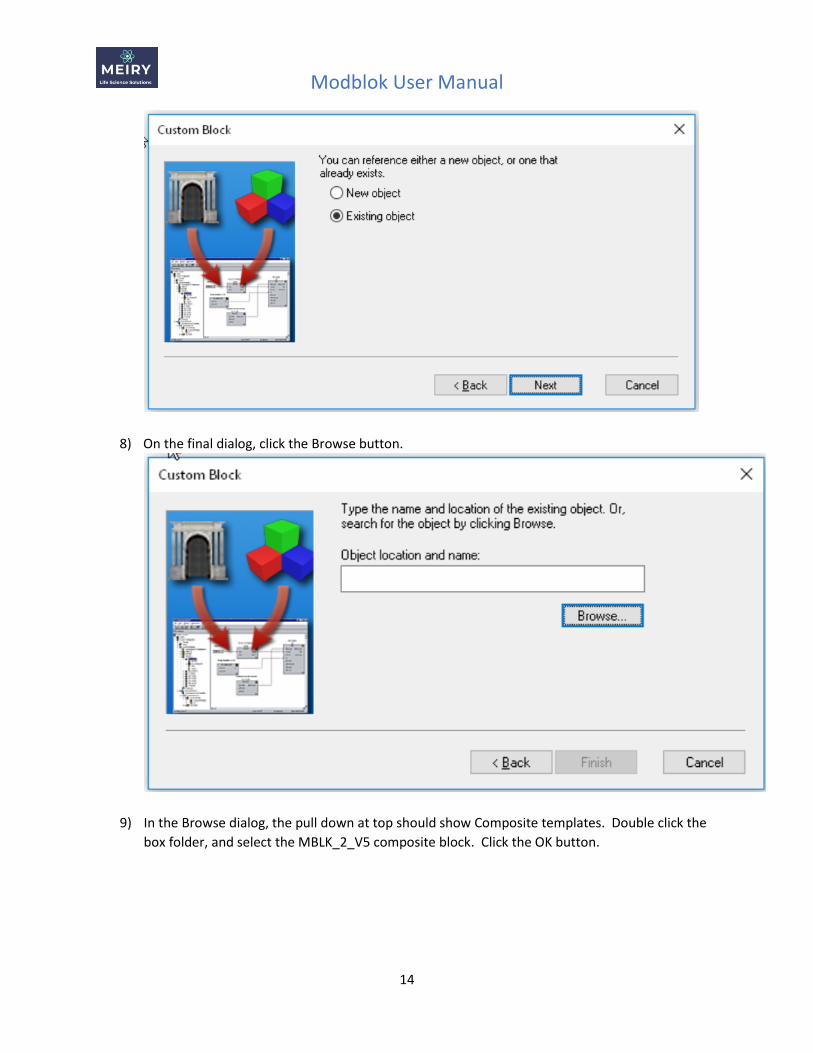
7) On the next dialog, ensure that the Existing object radio button is selected and click the Next
button.
Modblok User Manual
14
8) On the final dialog, click the Browse button.
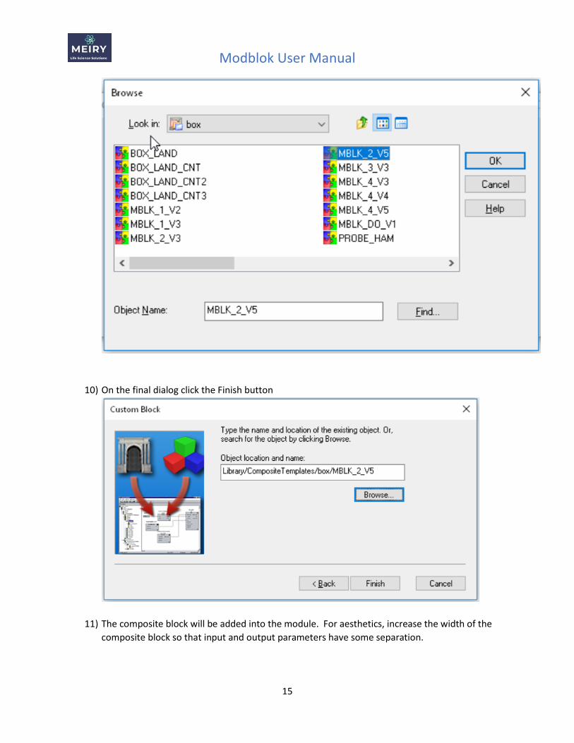
9) In the Browse dialog, the pull down at top should show Composite templates. Double click the
box folder, and select the MBLK_2_V5 composite block. Click the OK button.
Modblok User Manual
15
10) On the final dialog click the Finish button
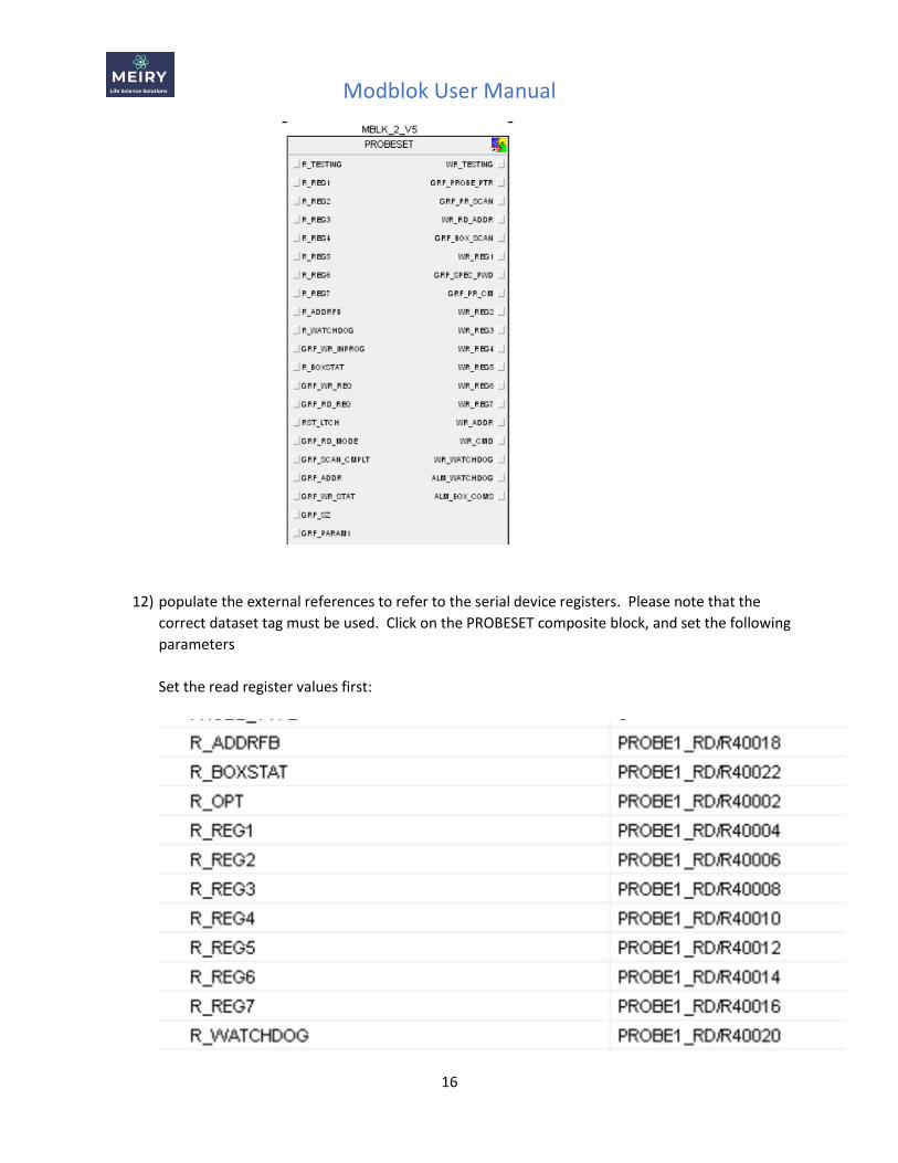
11) The composite block will be added into the module. For aesthetics, increase the width of the
composite block so that input and output parameters have some separation.
Modblok User Manual
16
12) populate the external references to refer to the serial device registers. Please note that the
correct dataset tag must be used. Click on the PROBESET composite block, and set the following
parameters
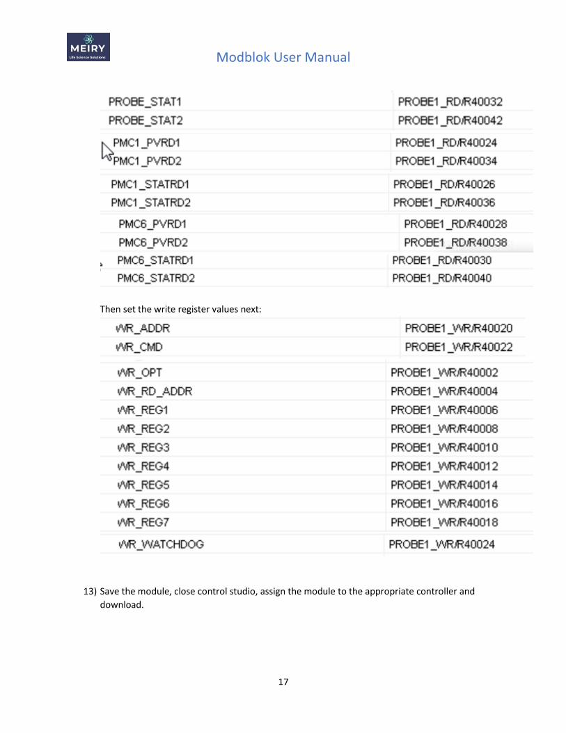
Set the read register values first:
Modblok User Manual
17
Then set the write register values next:
13) Save the module, close control studio, assign the module to the appropriate controller and
download.
Modblok User Manual
18
Modblok Installation
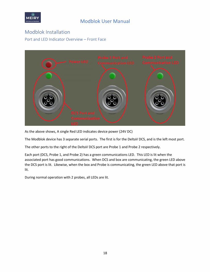
Port and LED Indicator Overview – Front Face
As the above shows, A single Red LED indicates device power (24V DC)
The Modblok device has 3 separate serial ports. The first is for the DeltaV DCS, and is the left most port.
The other ports to the right of the DeltaV DCS port are Probe 1 and Probe 2 respectively.
Each port (DCS, Probe 1, and Probe 2) has a green communications LED. This LED is lit when the
associated port has good communications. When DCS and box are communicating, the green LED above
the DCS port is lit. Likewise, when the box and Probe is communicating, the green LED above that port is
lit.
During normal operation with 2 probes, all LEDs are lit.
Modblok User Manual
19
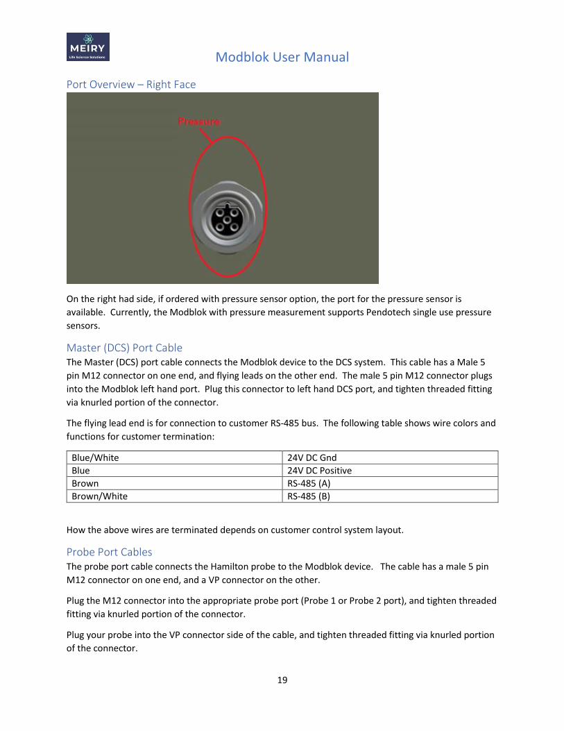
Port Overview – Right Face
On the right had side, if ordered with pressure sensor option, the port for the pressure sensor is
available. Currently, the Modblok with pressure measurement supports Pendotech single use pressure
sensors.
Master (DCS) Port Cable The Master (DCS) port cable connects the Modblok device to the DCS system. This cable has a Male 5
pin M12 connector on one end, and flying leads on the other end. The male 5 pin M12 connector plugs
into the Modblok left hand port. Plug this connector to left hand DCS port, and tighten threaded fitting
via knurled portion of the connector.
The flying lead end is for connection to customer RS-485 bus. The following table shows wire colors and
functions for customer termination:
Blue/White 24V DC Gnd
Blue 24V DC Positive
Brown RS-485 (A)
Brown/White RS-485 (B)
How the above wires are terminated depends on customer control system layout.
Probe Port Cables The probe port cable connects the Hamilton probe to the Modblok device. The cable has a male 5 pin
M12 connector on one end, and a VP connector on the other.
Plug the M12 connector into the appropriate probe port (Probe 1 or Probe 2 port), and tighten threaded
fitting via knurled portion of the connector.
Plug your probe into the VP connector side of the cable, and tighten threaded fitting via knurled portion
of the connector.
Modblok User Manual
20
Please note that each probe port is “Agnostic” with respect to the probe type. Provided the probe is a
supported Hamilton probe, the Modblok device will automatically be able to determine the type and
read the appropriate parameters. Also, please note that the probe cable is “universal” for all supported
probe types.
Pressure Port Cables If the pressure sensor option is ordered, a pressure port cable is required. This has a M12 connector on
one side which plugs into the Modblok device, and a Pendotech 4 pin connector on the other end which
the single use sensor is plugged into.
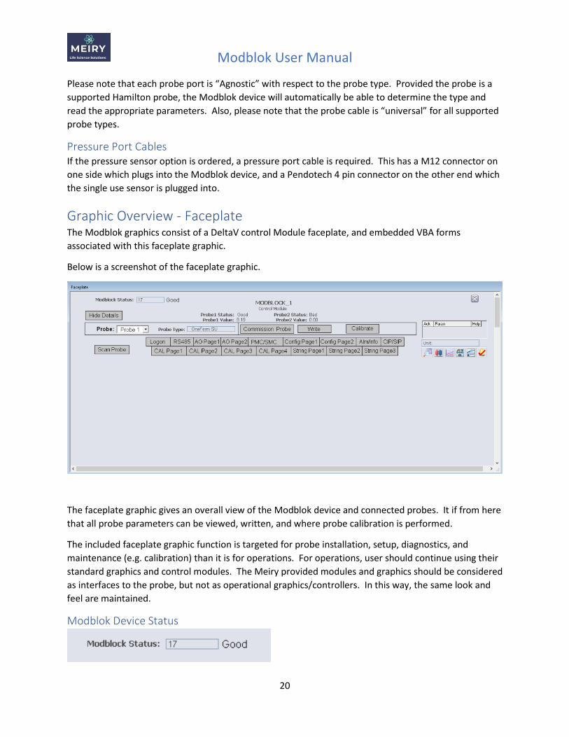
Graphic Overview - Faceplate The Modblok graphics consist of a DeltaV control Module faceplate, and embedded VBA forms
associated with this faceplate graphic.
Below is a screenshot of the faceplate graphic.
The faceplate graphic gives an overall view of the Modblok device and connected probes. It if from here
that all probe parameters can be viewed, written, and where probe calibration is performed.
The included faceplate graphic function is targeted for probe installation, setup, diagnostics, and
maintenance (e.g. calibration) than it is for operations. For operations, user should continue using their
standard graphics and control modules. The Meiry provided modules and graphics should be considered
as interfaces to the probe, but not as operational graphics/controllers. In this way, the same look and
feel are maintained.
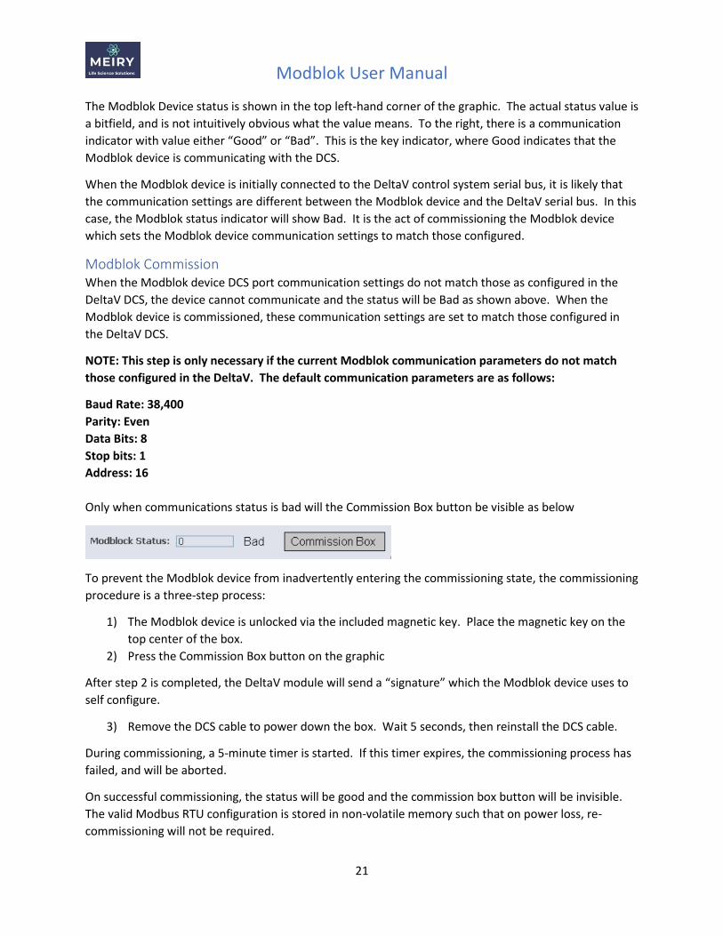
Modblok Device Status
Modblok User Manual
21
The Modblok Device status is shown in the top left-hand corner of the graphic. The actual status value is
a bitfield, and is not intuitively obvious what the value means. To the right, there is a communication
indicator with value either “Good” or “Bad”. This is the key indicator, where Good indicates that the
Modblok device is communicating with the DCS.
When the Modblok device is initially connected to the DeltaV control system serial bus, it is likely that
the communication settings are different between the Modblok device and the DeltaV serial bus. In this
case, the Modblok status indicator will show Bad. It is the act of commissioning the Modblok device
which sets the Modblok device communication settings to match those configured.
Modblok Commission When the Modblok device DCS port communication settings do not match those as configured in the
DeltaV DCS, the device cannot communicate and the status will be Bad as shown above. When the
Modblok device is commissioned, these communication settings are set to match those configured in
the DeltaV DCS.
NOTE: This step is only necessary if the current Modblok communication parameters do not match
those configured in the DeltaV. The default communication parameters are as follows:
Baud Rate: 38,400
Parity: Even
Data Bits: 8
Stop bits: 1
Address: 16
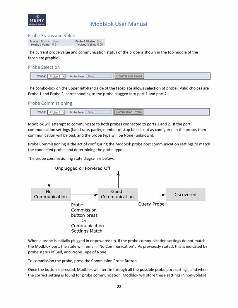
Only when communications status is bad will the Commission Box button be visible as below
To prevent the Modblok device from inadvertently entering the commissioning state, the commissioning
procedure is a three-step process:
1) The Modblok device is unlocked via the included magnetic key. Place the magnetic key on the
top center of the box.
2) Press the Commission Box button on the graphic
After step 2 is completed, the DeltaV module will send a “signature” which the Modblok device uses to
self configure.
3) Remove the DCS cable to power down the box. Wait 5 seconds, then reinstall the DCS cable.
During commissioning, a 5-minute timer is started. If this timer expires, the commissioning process has
failed, and will be aborted.
On successful commissioning, the status will be good and the commission box button will be invisible.
The valid Modbus RTU configuration is stored in non-volatile memory such that on power loss, re-
commissioning will not be required.
Modblok User Manual
22
Probe Status and Value
The current probe value and communication status of the probe is shown in the top middle of the
faceplate graphic.
Probe Selection
The combo-box on the upper left-hand side of the faceplate allows selection of probe. Valid choices are
Probe 1 and Probe 2, corresponding to the probe plugged into port 1 and port 2.
Probe Commissioning
Modblok will attempt to communicate to both probes connected to ports 1 and 2. If the port
communication settings (baud rate, parity, number of stop bits) is not as configured in the probe, then
communication will be bad, and the probe type will be None (unknown).
Probe Commissioning is the act of configuring the Modblok probe port communication settings to match
the connected probe, and determining the probe type.
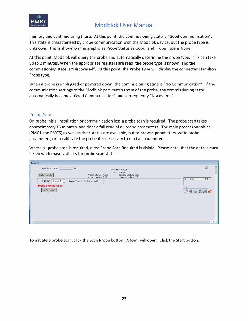
The probe commissioning state diagram is below.
When a probe is initially plugged in or powered up, if the probe communication settings do not match
the Modblok port, the state will remain “No Communication”. As previously stated, this is indicated by
probe status of Bad, and Probe Type of None.
To commission the probe, press the Commission Probe Button
Once the button is pressed, Modblok will iterate through all the possible probe port settings, and when
the correct setting is found for probe communication, Modblok will store these settings in non-volatile
Modblok User Manual
23
memory and continue using these. At this point, the commissioning state is “Good Communication”.
This state is characterized by probe communication with the Modblok device, but the probe type is
unknown. This is shown on the graphic as Probe Status as Good, and Probe Type is None.
At this point, Modblok will query the probe and automatically determine the probe type. This can take
up to 2 minutes. When the appropriate registers are read, the probe type is known, and the
commissioning state is “Discovered”. At this point, the Probe Type will display the connected Hamilton
Probe type.
When a probe is unplugged or powered down, the commissioning state is “No Communication”. If the
communication settings of the Modblok port match those of the probe, the commissioning state
automatically becomes “Good Communication” and subsequently “Discovered”
Probe Scan On probe initial installation or communication loss a probe scan is required. The probe scan takes
approximately 15 minutes, and does a full read of all probe parameters. The main process variables
(PMC1 and PMC6) as well as their status are available, but to browse parameters, write probe
parameters, or to calibrate the probe it is necessary to read all parameters.
Where a probe scan is required, a red Probe Scan Required is visible. Please note, that the details must
be shown to have visibility for probe scan status.
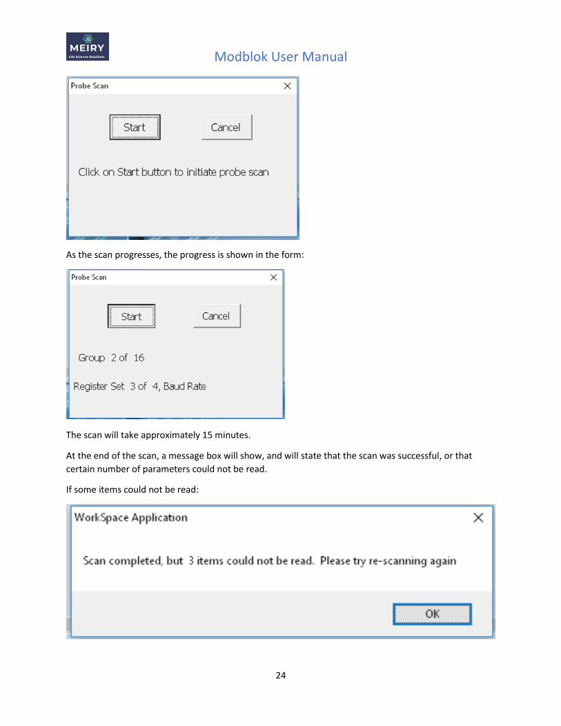
To initiate a probe scan, click the Scan Probe button. A form will open. Click the Start button.
Modblok User Manual
24
As the scan progresses, the progress is shown in the form:
The scan will take approximately 15 minutes.
At the end of the scan, a message box will show, and will state that the scan was successful, or that
certain number of parameters could not be read.
If some items could not be read:
Modblok User Manual
25
If some parameters could not be read, please re-initiate the probe scan.
To cancel the scan, click the Cancel button. The current read completes, and therefore it can take 5
seconds to respond.
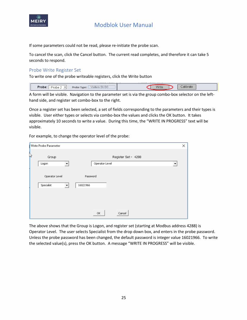
Probe Write Register Set To write one of the probe writeable registers, click the Write button
A form will be visible. Navigation to the parameter set is via the group combo-box selector on the left-
hand side, and register set combo-box to the right.
Once a register set has been selected, a set of fields corresponding to the parameters and their types is
visible. User either types or selects via combo-box the values and clicks the OK button. It takes
approximately 10 seconds to write a value. During this time, the “WRITE IN PROGRESS” text will be
visible.
For example, to change the operator level of the probe:
The above shows that the Group is Logon, and register set (starting at Modbus address 4288) is
Operator Level. The user selects Specialist from the drop down box, and enters in the probe password.
Unless the probe password has been changed, the default password is integer value 16021966. To write
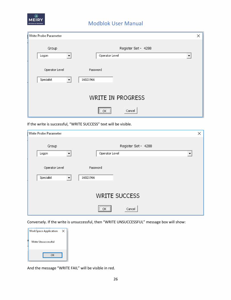
the selected value(s), press the OK button. A message “WRITE IN PROGRESS” will be visible.
Modblok User Manual
26
If the write is successful, “WRITE SUCCESS” text will be visible.
Conversely. If the write is unsuccessful, then “WRITE UNSUCCESSFUL” message box will show:
And the message “WRITE FAIL” will be visible in red.
Modblok User Manual
27
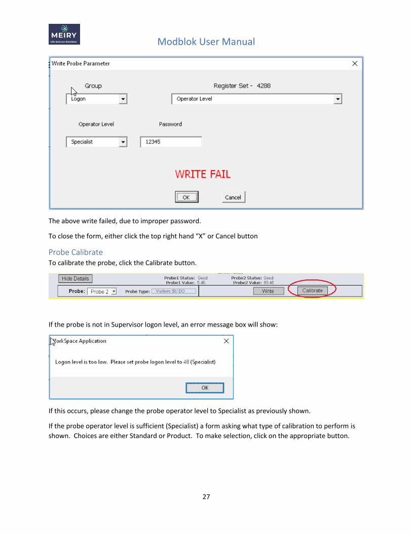
The above write failed, due to improper password.
To close the form, either click the top right hand “X” or Cancel button
Probe Calibrate To calibrate the probe, click the Calibrate button.
If the probe is not in Supervisor logon level, an error message box will show:
If this occurs, please change the probe operator level to Specialist as previously shown.
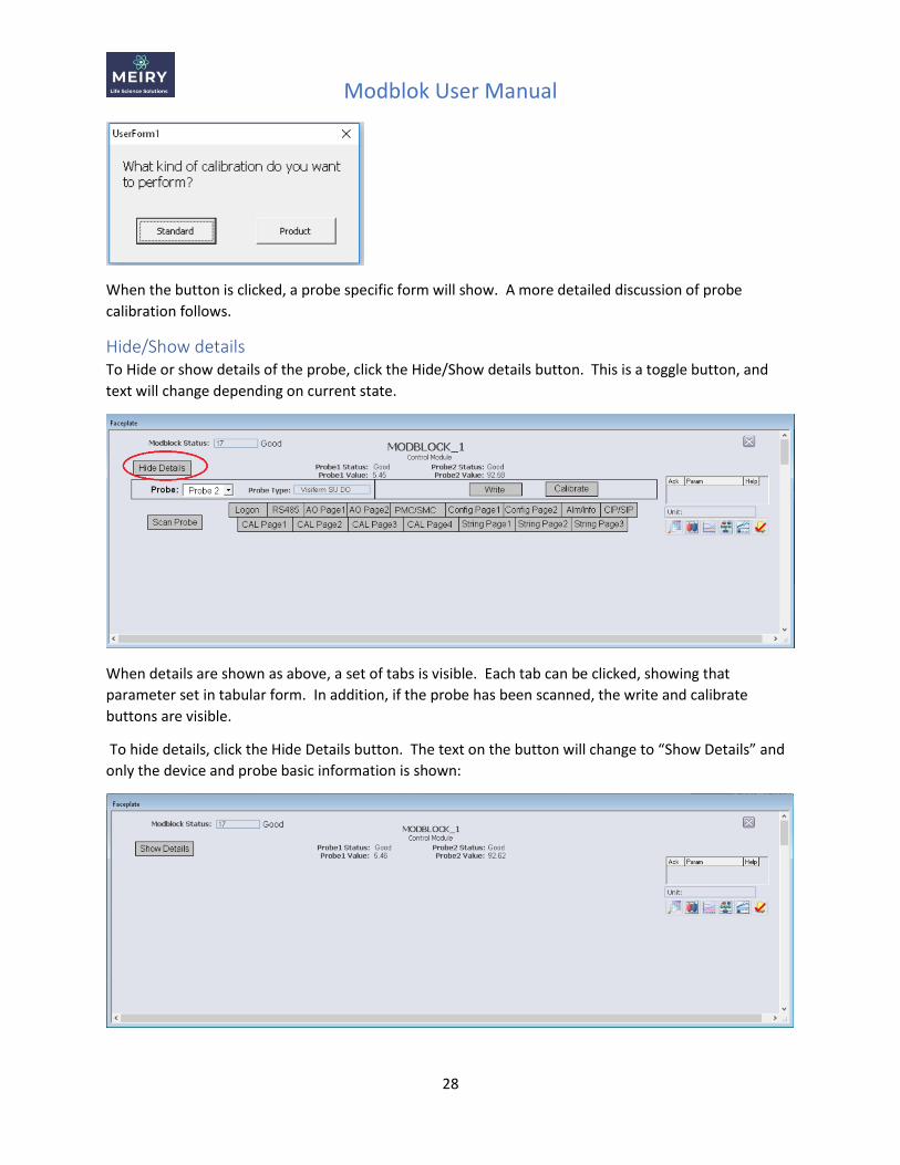
If the probe operator level is sufficient (Specialist) a form asking what type of calibration to perform is
shown. Choices are either Standard or Product. To make selection, click on the appropriate button.
Modblok User Manual
28
When the button is clicked, a probe specific form will show. A more detailed discussion of probe
calibration follows.
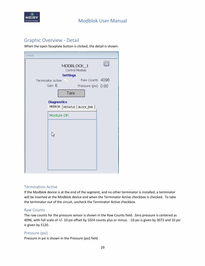
Hide/Show details To Hide or show details of the probe, click the Hide/Show details button. This is a toggle button, and
text will change depending on current state.
When details are shown as above, a set of tabs is visible. Each tab can be clicked, showing that
parameter set in tabular form. In addition, if the probe has been scanned, the write and calibrate
buttons are visible.
To hide details, click the Hide Details button. The text on the button will change to “Show Details” and
only the device and probe basic information is shown:
Modblok User Manual
29
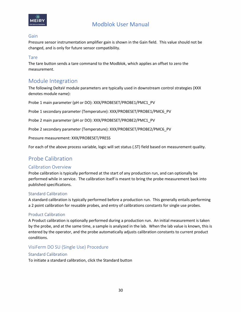
Graphic Overview - Detail When the open faceplate button is clicked, the detail is shown:
Termination Active If the Modblok device is at the end of the segment, and no other terminator is installed, a terminator
will be inserted at the Modblok device end when the Terminator Active checkbox is checked. To take
the terminator out of the circuit, uncheck the Terminator Active checkbox.
Raw Counts The raw counts for the pressure sensor is shown in the Raw Counts field. Zero pressure is centered as
4096, with full scale of +/- 10 psi offset by 1024 counts plus or minus. -10 psi is given by 3072 and 10 psi
is given by 5120.
Pressure (psi) Pressure in psi is shown in the Pressure (psi) field
Modblok User Manual
30
Gain Pressure sensor instrumentation amplifier gain is shown in the Gain field. This value should not be
changed, and is only for future sensor compatibility.
Tare The tare button sends a tare command to the Modblok, which applies an offset to zero the
measurement.
Module Integration The following DeltaV module parameters are typically used in downstream control strategies (XXX
denotes module name):
Probe 1 main parameter (pH or DO): XXX/PROBESET/PROBE1/PMC1_PV
Probe 1 secondary parameter (Temperature): XXX/PROBESET/PROBE1/PMC6_PV
Probe 2 main parameter (pH or DO): XXX/PROBESET/PROBE2/PMC1_PV
Probe 2 secondary parameter (Temperature): XXX/PROBESET/PROBE2/PMC6_PV
Pressure measurement: XXX/PROBESET/PRESS
For each of the above process variable, logic will set status (.ST) field based on measurement quality.
Probe Calibration
Calibration Overview Probe calibration is typically performed at the start of any production run, and can optionally be
performed while in service. The calibration itself is meant to bring the probe measurement back into
published specifications.
Standard Calibration A standard calibration is typically performed before a production run. This generally entails performing
a 2 point calibration for reusable probes, and entry of calibrations constants for single use probes.
Product Calibration A Product calibration is optionally performed during a production run. An initial measurement is taken
by the probe, and at the same time, a sample is analyzed in the lab. When the lab value is known, this is
entered by the operator, and the probe automatically adjusts calibration constants to current product
conditions.
VisiFerm DO SU (Single Use) Procedure
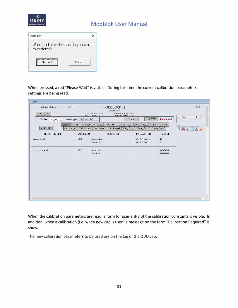
Standard Calibration To initiate a standard calibration, click the Standard button
Modblok User Manual
31
When pressed, a red “Please Wait” is visible. During this time the current calibration parameters
settings are being read.
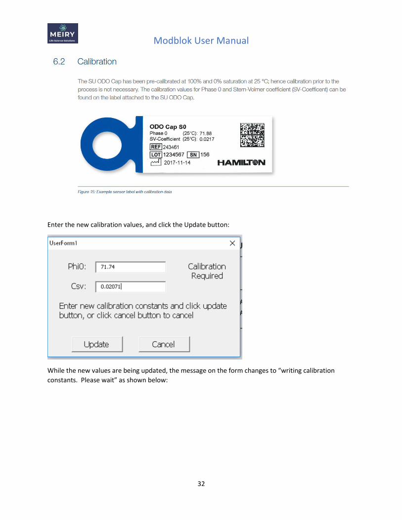
When the calibration parameters are read, a form for user entry of the calibration constants is visible. In
addition, when a calibration (i.e. when new cap is used) a message on the form “Calibration Required” is
shown.
The new calibration parameters to be used are on the tag of the ODO cap:
Modblok User Manual
32
Enter the new calibration values, and click the Update button:
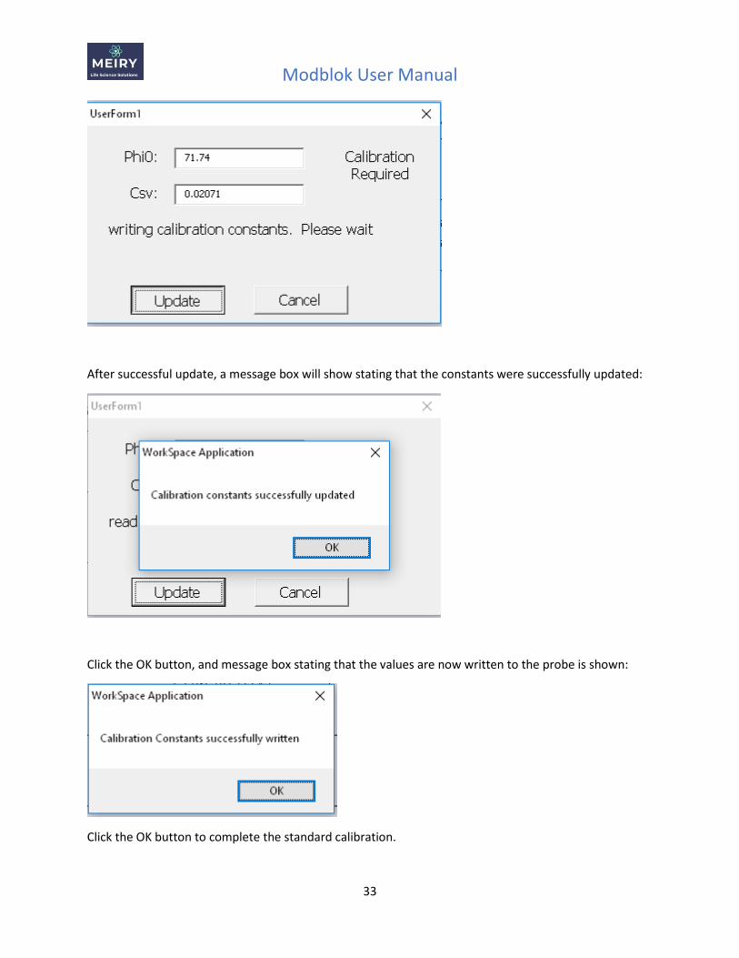
While the new values are being updated, the message on the form changes to “writing calibration
constants. Please wait” as shown below:
Modblok User Manual
33
After successful update, a message box will show stating that the constants were successfully updated:
Click the OK button, and message box stating that the values are now written to the probe is shown:
Click the OK button to complete the standard calibration.
Modblok User Manual
34
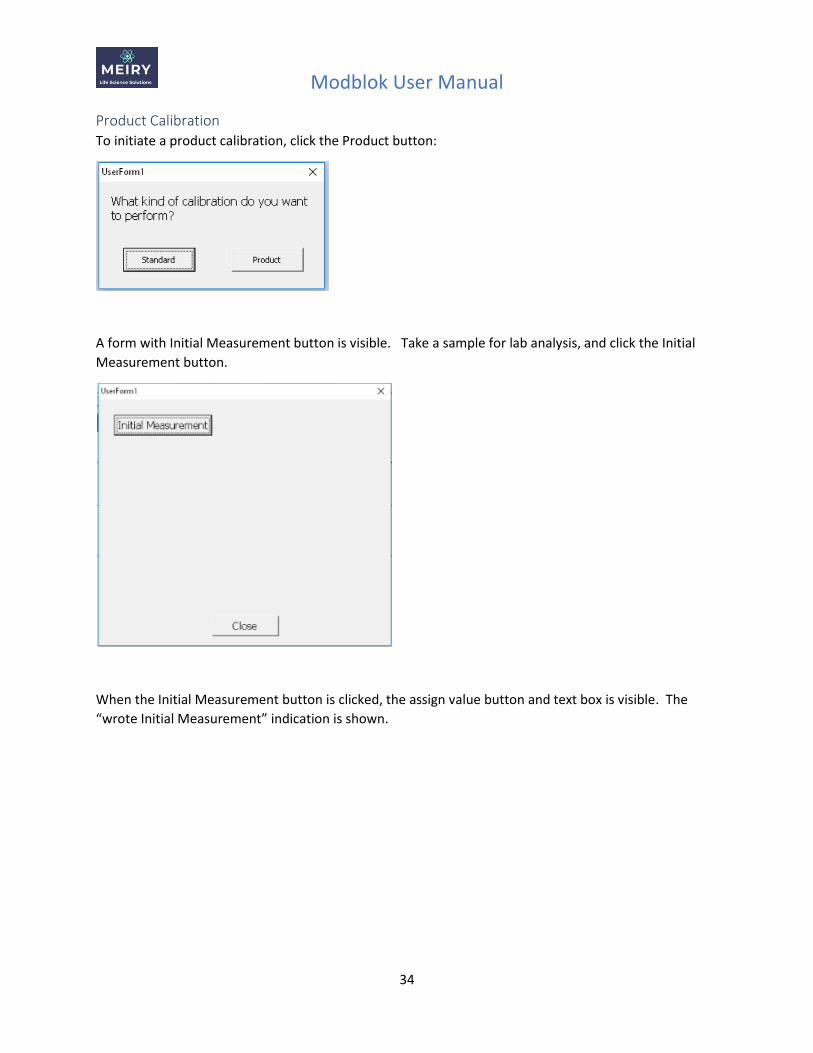
Product Calibration To initiate a product calibration, click the Product button:
A form with Initial Measurement button is visible. Take a sample for lab analysis, and click the Initial
Measurement button.
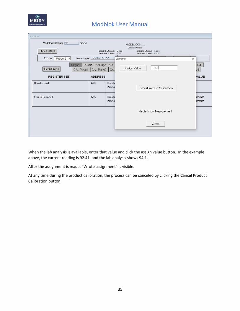
When the Initial Measurement button is clicked, the assign value button and text box is visible. The
“wrote Initial Measurement” indication is shown.
Modblok User Manual
35
When the lab analysis is available, enter that value and click the assign value button. In the example
above, the current reading is 92.41, and the lab analysis shows 94.1.
After the assignment is made, “Wrote assignment” is visible.
At any time during the product calibration, the process can be canceled by clicking the Cancel Product
Calibration button.
Modblok User Manual
36
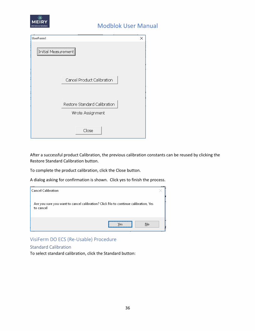
After a successful product Calibration, the previous calibration constants can be reused by clicking the
Restore Standard Calibration button.
To complete the product calibration, click the Close button.
A dialog asking for confirmation is shown. Click yes to finish the process.
VisiFerm DO ECS (Re-Usable) Procedure
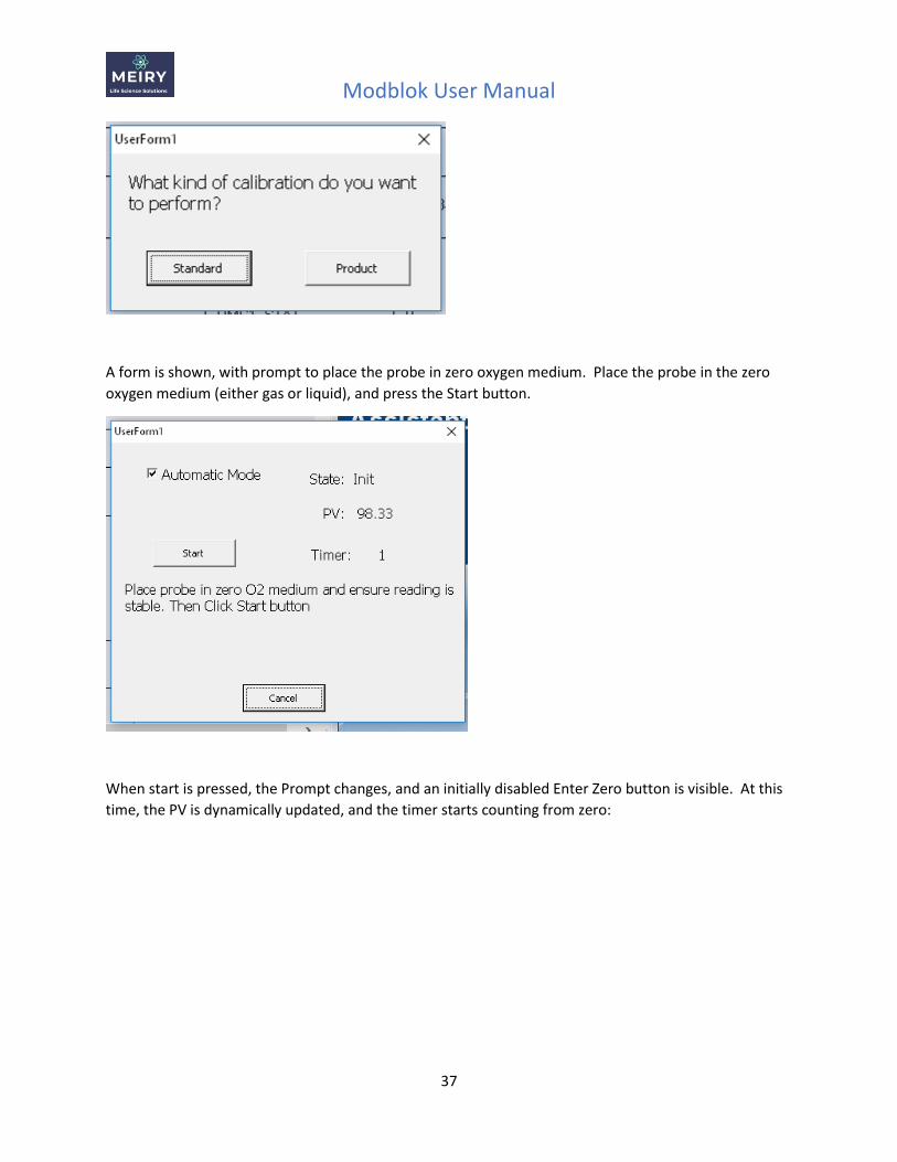
Standard Calibration To select standard calibration, click the Standard button:
Modblok User Manual
37
A form is shown, with prompt to place the probe in zero oxygen medium. Place the probe in the zero
oxygen medium (either gas or liquid), and press the Start button.
When start is pressed, the Prompt changes, and an initially disabled Enter Zero button is visible. At this
time, the PV is dynamically updated, and the timer starts counting from zero:
Modblok User Manual
38
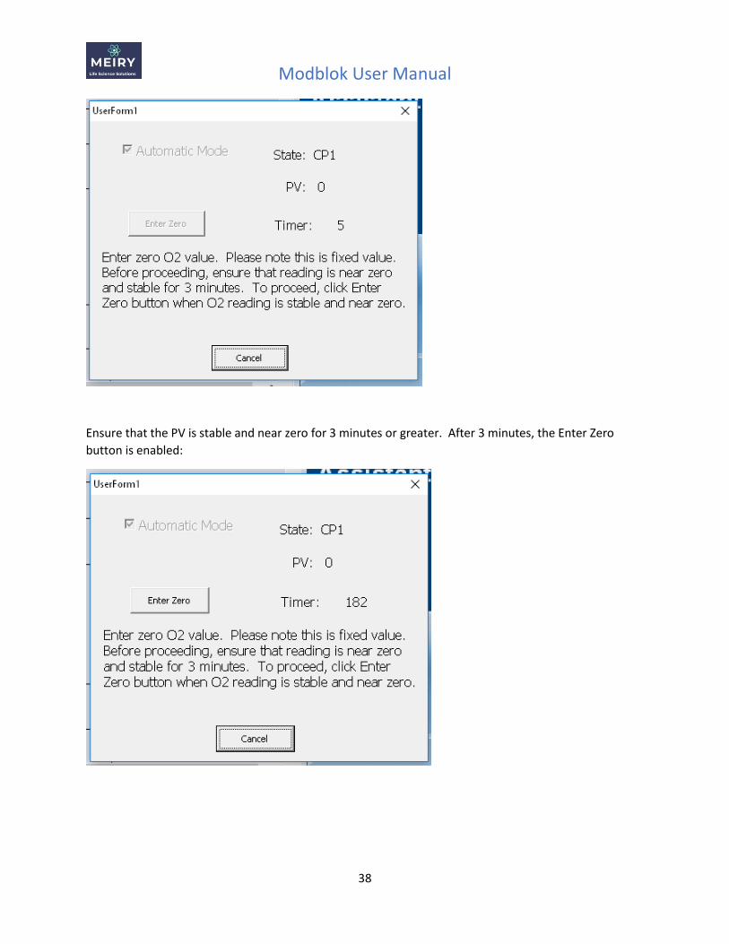
Ensure that the PV is stable and near zero for 3 minutes or greater. After 3 minutes, the Enter Zero
button is enabled:
Modblok User Manual
39
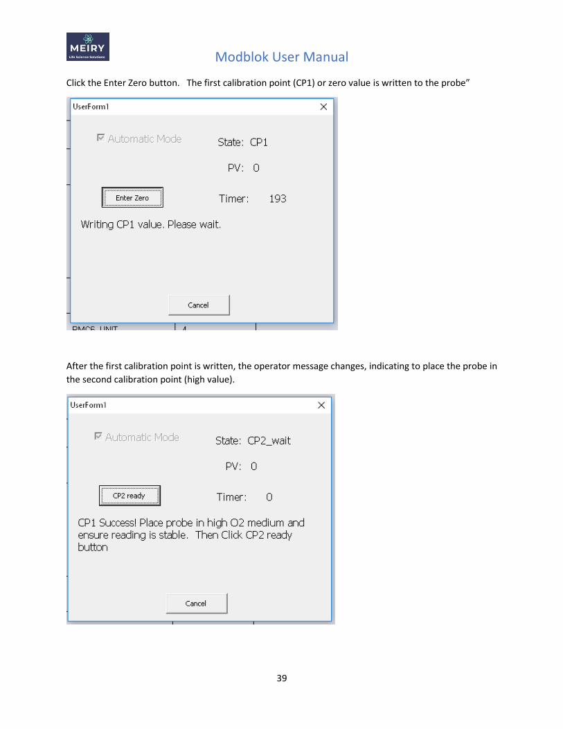
Click the Enter Zero button. The first calibration point (CP1) or zero value is written to the probe”
After the first calibration point is written, the operator message changes, indicating to place the probe in
the second calibration point (high value).
Modblok User Manual
40
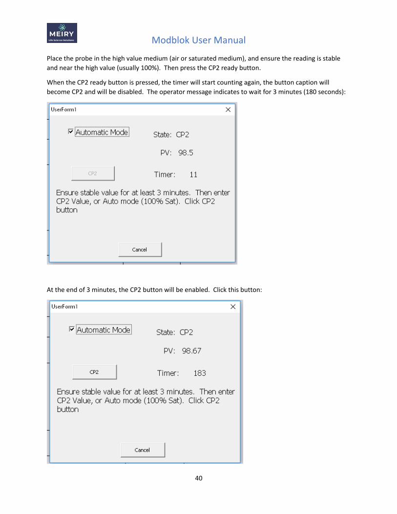
Place the probe in the high value medium (air or saturated medium), and ensure the reading is stable
and near the high value (usually 100%). Then press the CP2 ready button.
When the CP2 ready button is pressed, the timer will start counting again, the button caption will
become CP2 and will be disabled. The operator message indicates to wait for 3 minutes (180 seconds):
At the end of 3 minutes, the CP2 button will be enabled. Click this button:
Modblok User Manual
41
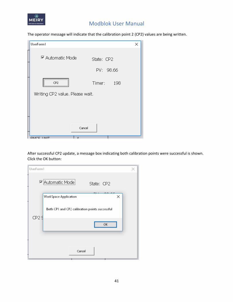
The operator message will indicate that the calibration point 2 (CP2) values are being written.
After successful CP2 update, a message box indicating both calibration points were successful is shown.
Click the OK button:
Modblok User Manual
42
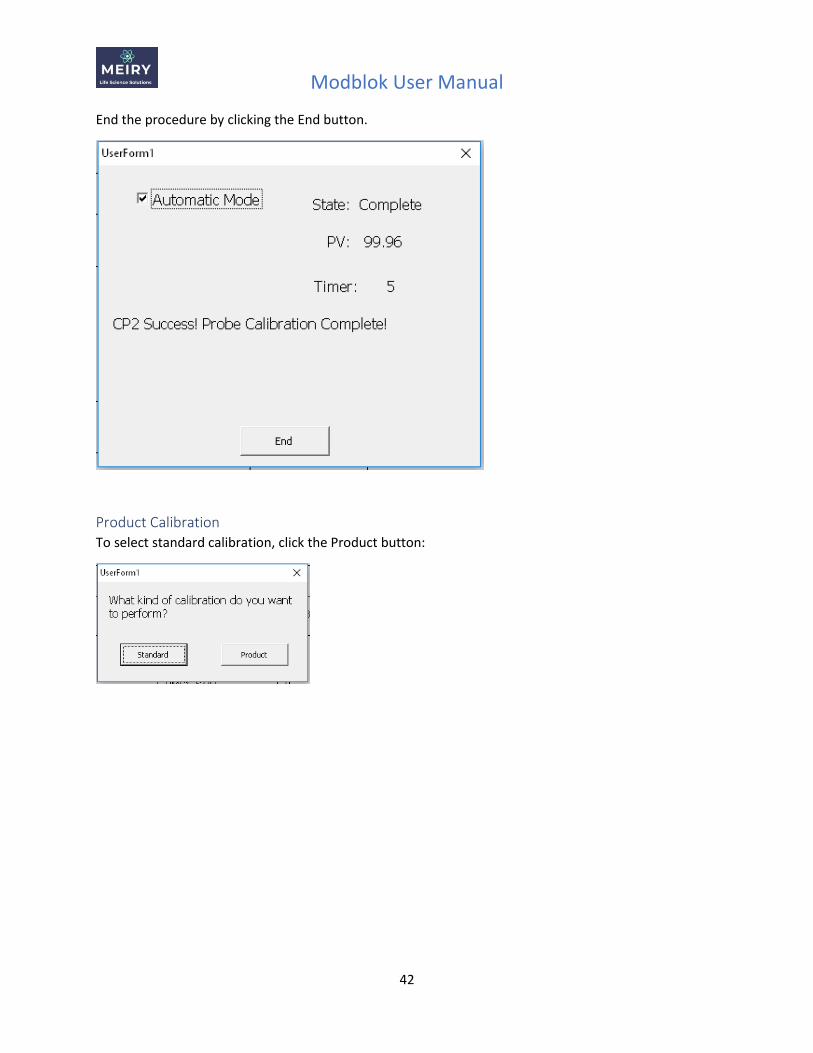
End the procedure by clicking the End button.
Product Calibration To select standard calibration, click the Product button:
Modblok User Manual
43
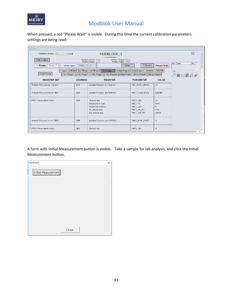
When pressed, a red “Please Wait” is visible. During this time the current calibration parameters
settings are being read:
A form with Initial Measurement button is visible. Take a sample for lab analysis, and click the Initial
Measurement button.
Modblok User Manual
44
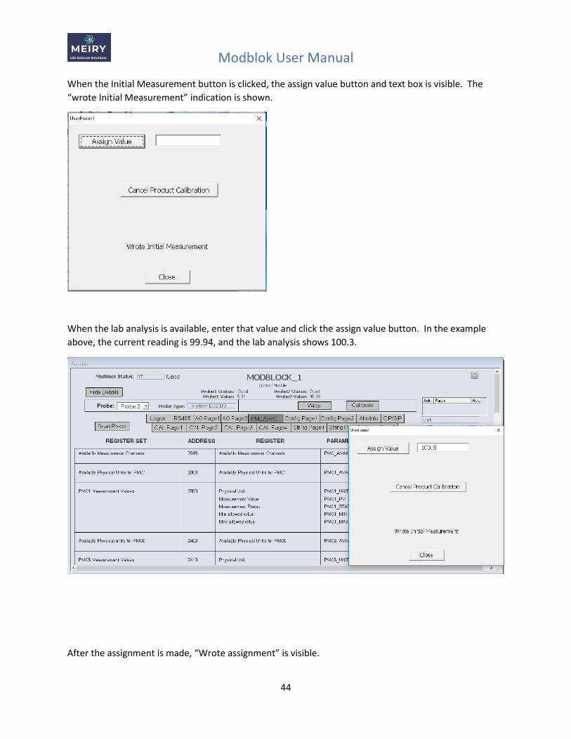
When the Initial Measurement button is clicked, the assign value button and text box is visible. The
“wrote Initial Measurement” indication is shown.
When the lab analysis is available, enter that value and click the assign value button. In the example
above, the current reading is 99.94, and the lab analysis shows 100.3.
After the assignment is made, “Wrote assignment” is visible.
Modblok User Manual
45
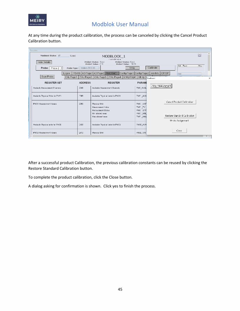
At any time during the product calibration, the process can be canceled by clicking the Cancel Product
Calibration button.
After a successful product Calibration, the previous calibration constants can be reused by clicking the
Restore Standard Calibration button.
To complete the product calibration, click the Close button.
A dialog asking for confirmation is shown. Click yes to finish the process.
Modblok User Manual
46
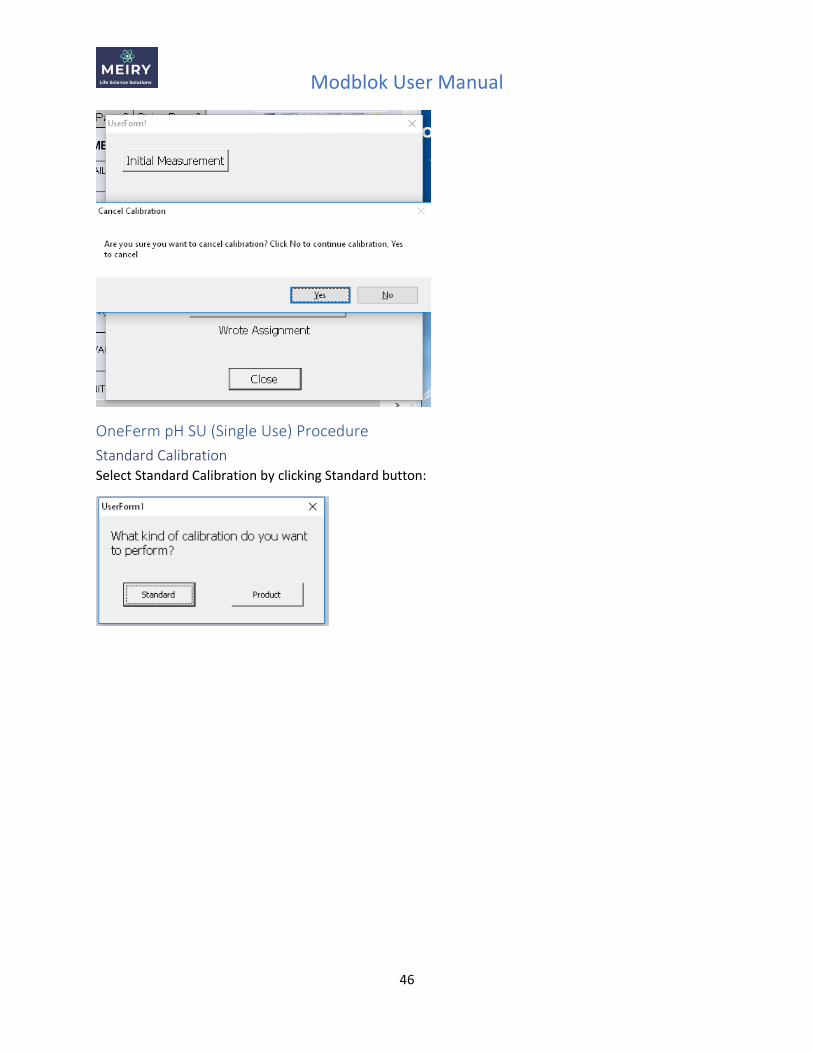
OneFerm pH SU (Single Use) Procedure
Standard Calibration Select Standard Calibration by clicking Standard button:
Modblok User Manual
47
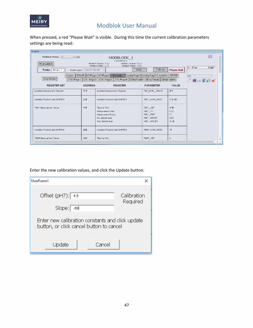
When pressed, a red “Please Wait” is visible. During this time the current calibration parameters
settings are being read:
Enter the new calibration values, and click the Update button:
Modblok User Manual
48
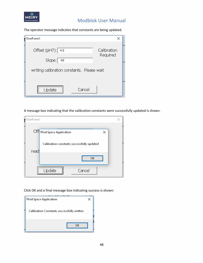
The operator message indicates that constants are being updated.
A message box indicating that the calibration constants were successfully updated is shown.
Click OK and a final message box indicating success is shown:

Modblok User Manual
49
Click OK to complete the process.
Product Calibration To initiate product calibration, click the Product button:
When pressed, a red “Please Wait” is visible. During this time the current calibration parameters
settings are being read:
Modblok User Manual
50
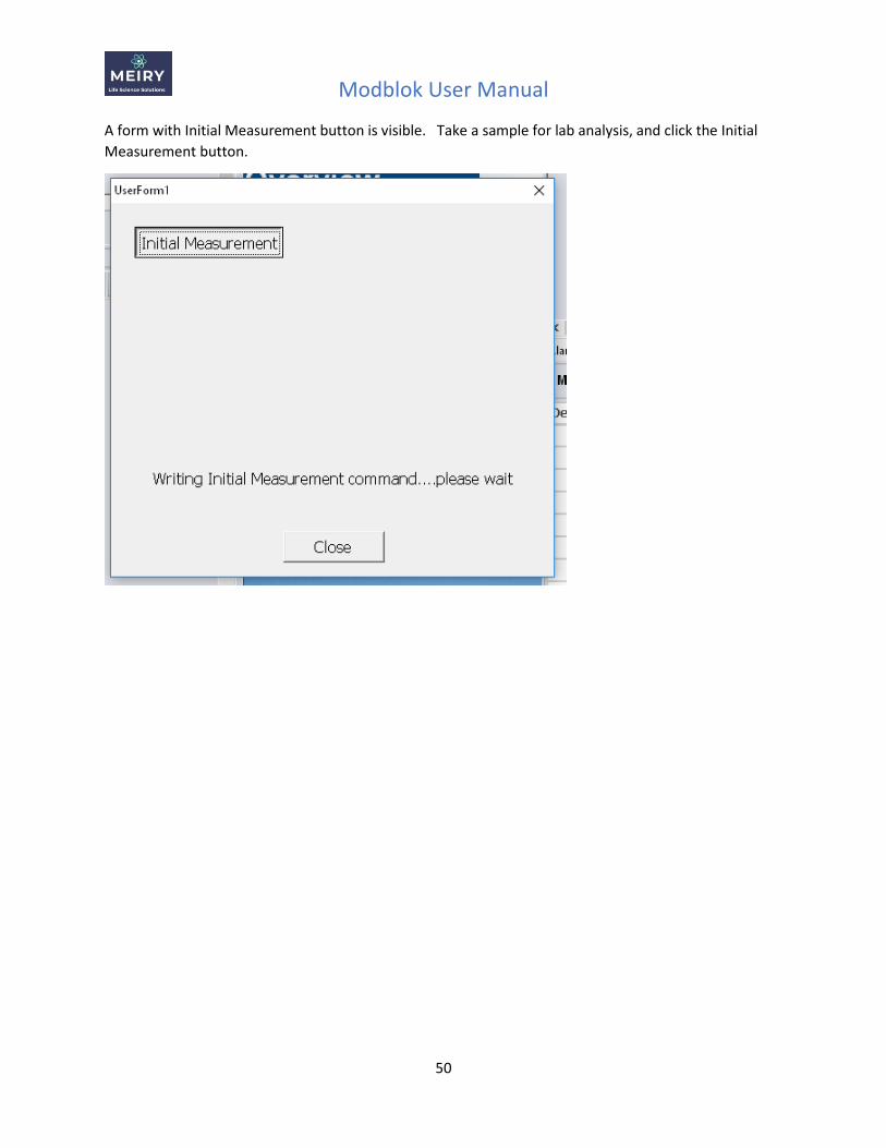
A form with Initial Measurement button is visible. Take a sample for lab analysis, and click the Initial
Measurement button.
Modblok User Manual
51
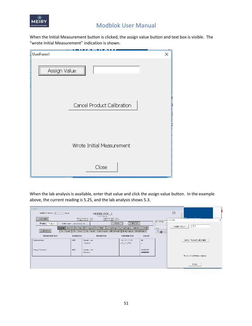
When the Initial Measurement button is clicked, the assign value button and text box is visible. The
“wrote Initial Measurement” indication is shown.
When the lab analysis is available, enter that value and click the assign value button. In the example
above, the current reading is 5.25, and the lab analysis shows 5.3.
Modblok User Manual
52
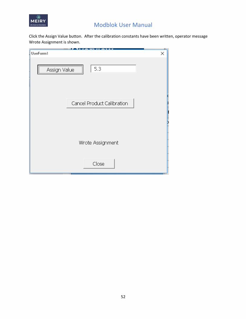
Click the Assign Value button. After the calibration constants have been written, operator message
Wrote Assignment is shown.
Modblok User Manual
53
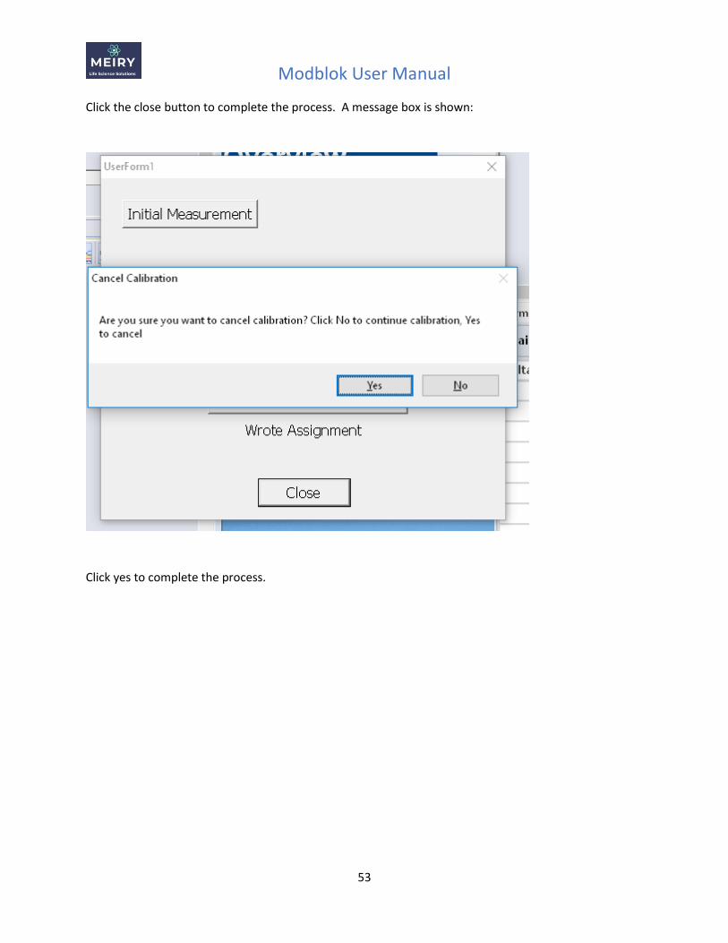
Click the close button to complete the process. A message box is shown:
Click yes to complete the process.
Modblok User Manual
54
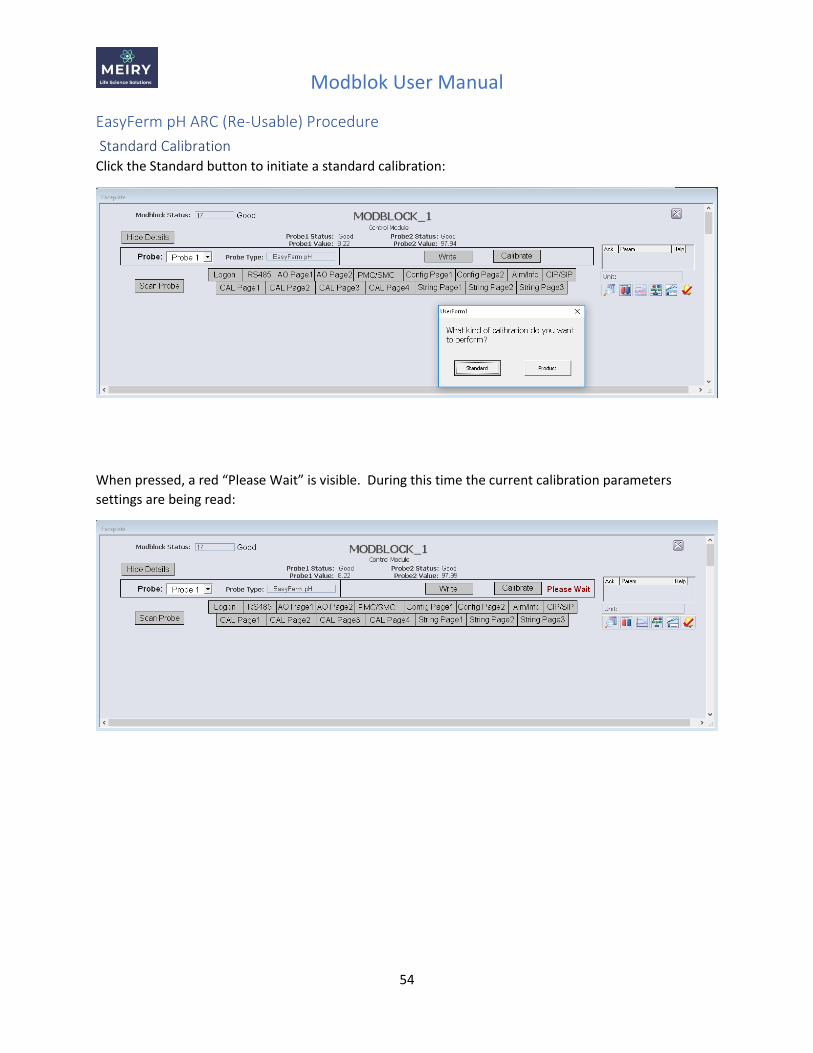
EasyFerm pH ARC (Re-Usable) Procedure
Standard Calibration Click the Standard button to initiate a standard calibration:
When pressed, a red “Please Wait” is visible. During this time the current calibration parameters
settings are being read:
Modblok User Manual
55
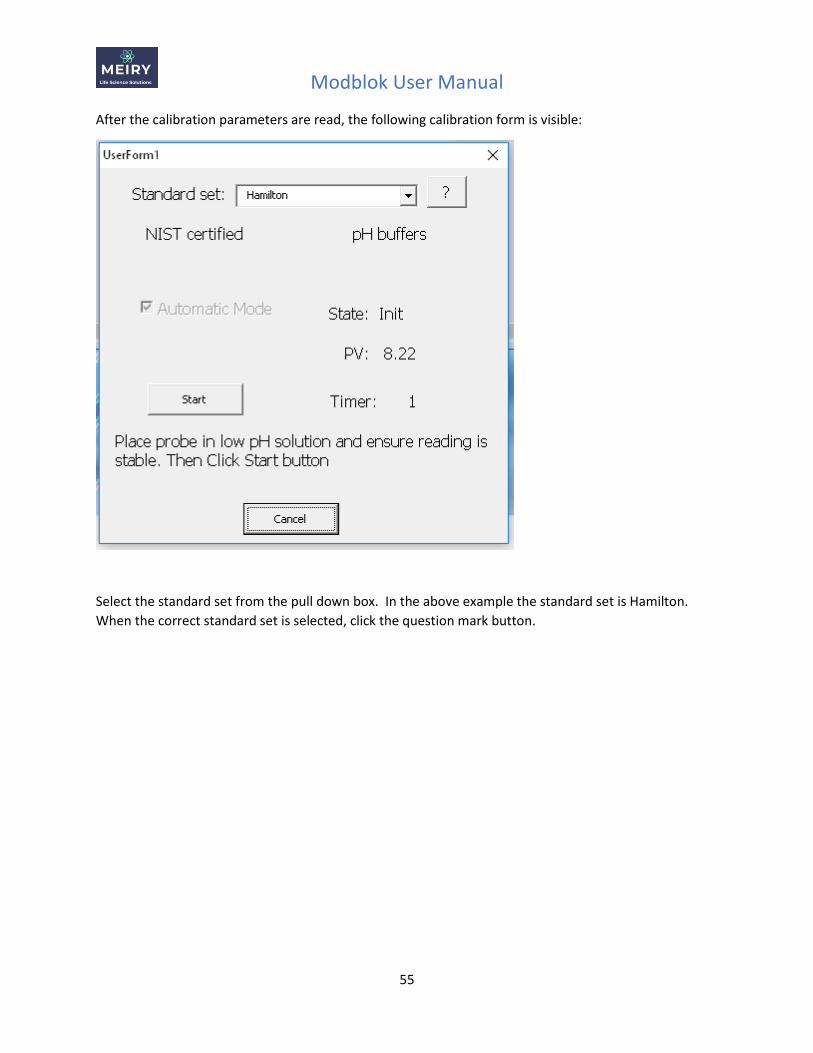
After the calibration parameters are read, the following calibration form is visible:
Select the standard set from the pull down box. In the above example the standard set is Hamilton.
When the correct standard set is selected, click the question mark button.
Modblok User Manual
56
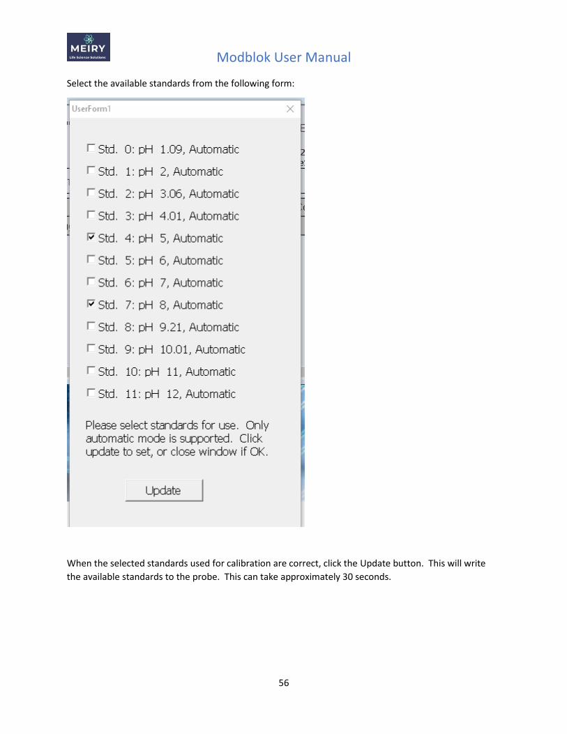
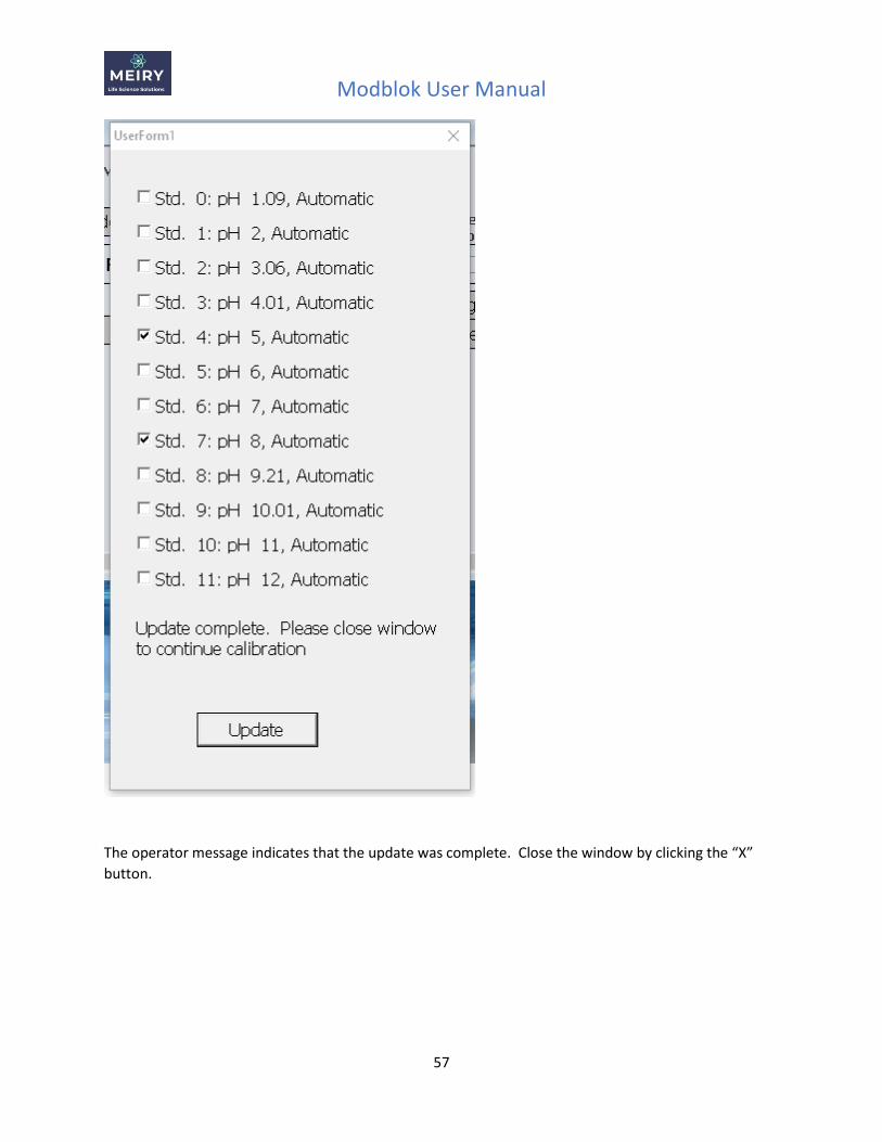
Select the available standards from the following form:
When the selected standards used for calibration are correct, click the Update button. This will write
the available standards to the probe. This can take approximately 30 seconds.
Modblok User Manual
57
The operator message indicates that the update was complete. Close the window by clicking the “X”
button.
Modblok User Manual
58
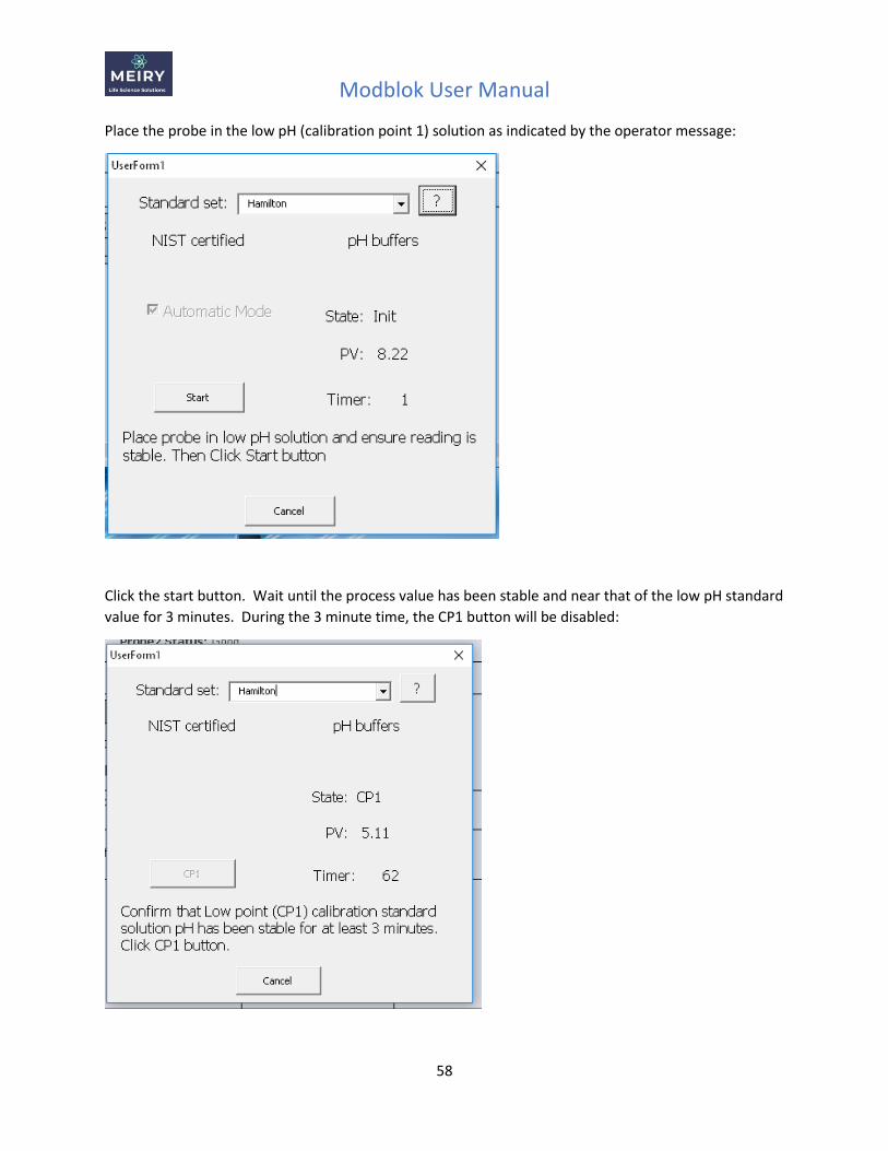
Place the probe in the low pH (calibration point 1) solution as indicated by the operator message:
Click the start button. Wait until the process value has been stable and near that of the low pH standard
value for 3 minutes. During the 3 minute time, the CP1 button will be disabled:
Modblok User Manual
59
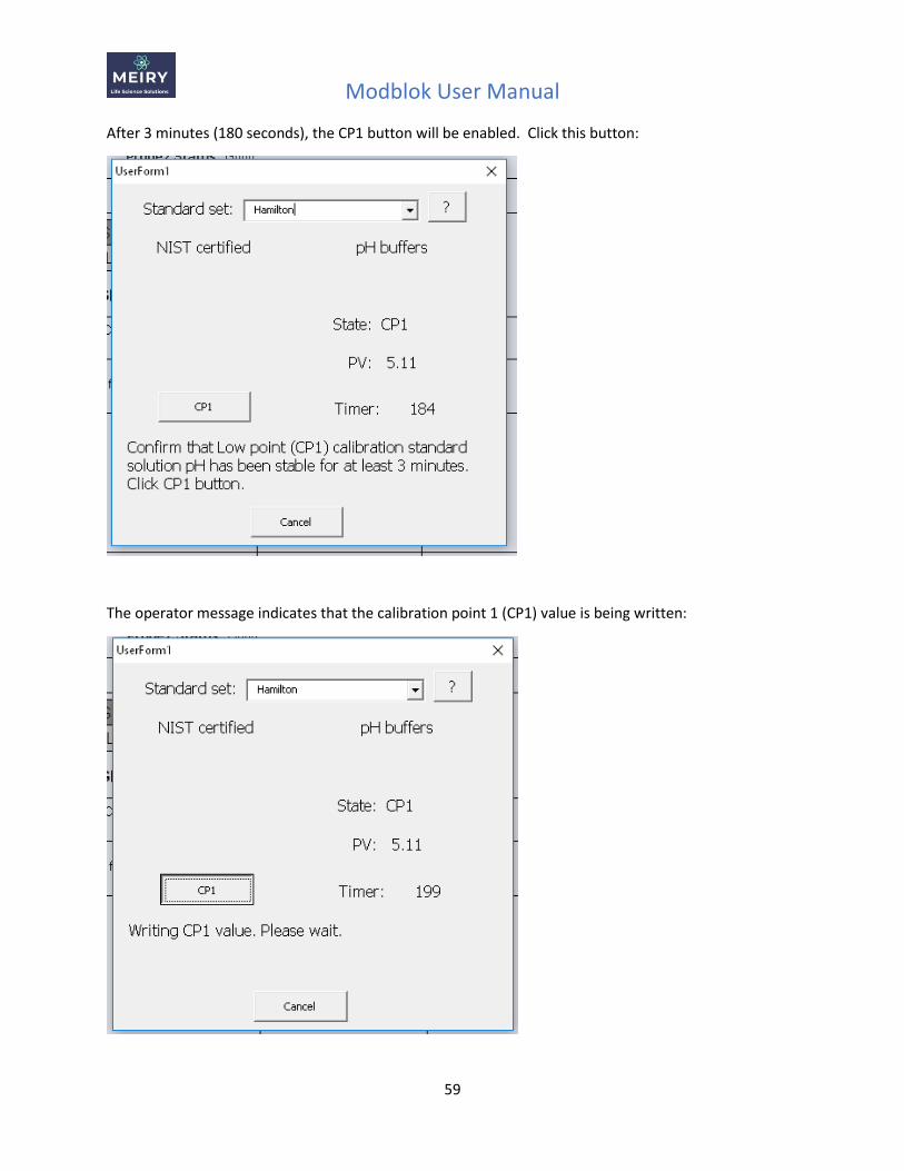
After 3 minutes (180 seconds), the CP1 button will be enabled. Click this button:
The operator message indicates that the calibration point 1 (CP1) value is being written:
Modblok User Manual
60
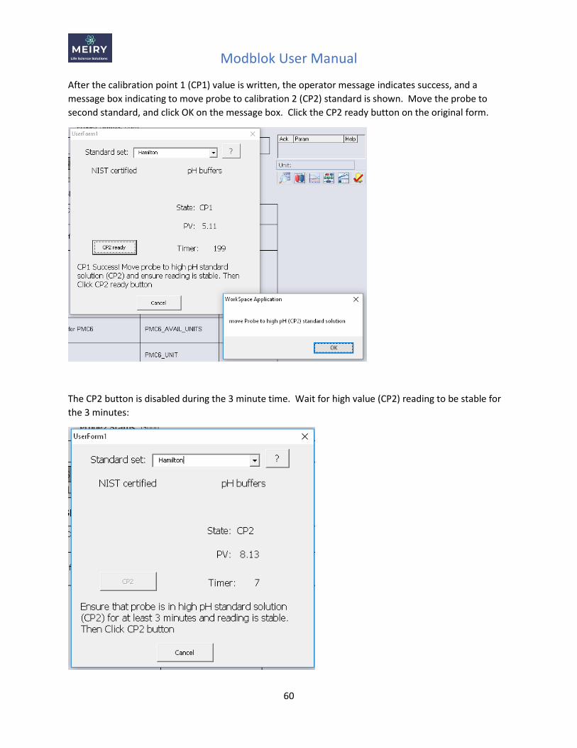
After the calibration point 1 (CP1) value is written, the operator message indicates success, and a
message box indicating to move probe to calibration 2 (CP2) standard is shown. Move the probe to
second standard, and click OK on the message box. Click the CP2 ready button on the original form.
The CP2 button is disabled during the 3 minute time. Wait for high value (CP2) reading to be stable for
the 3 minutes:
Modblok User Manual
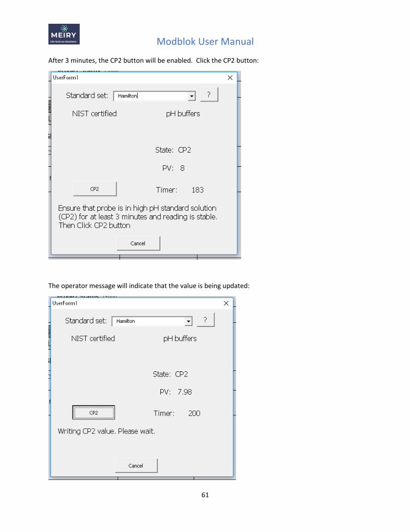
61
After 3 minutes, the CP2 button will be enabled. Click the CP2 button:
The operator message will indicate that the value is being updated:
Modblok User Manual
62
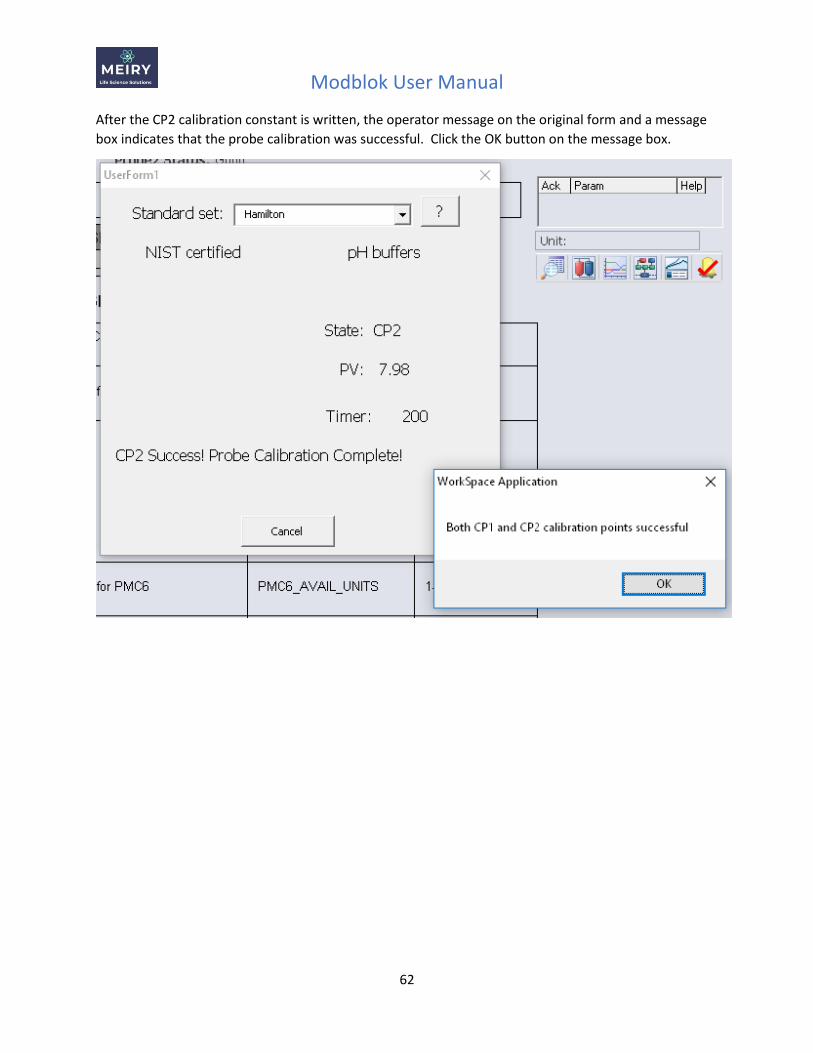
After the CP2 calibration constant is written, the operator message on the original form and a message
box indicates that the probe calibration was successful. Click the OK button on the message box.
Modblok User Manual
63
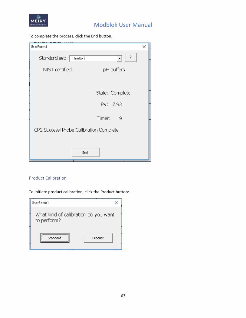
To complete the process, click the End button.
Product Calibration
To initiate product calibration, click the Product button:
Modblok User Manual
64
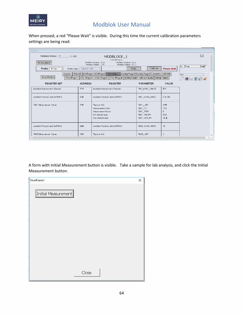
When pressed, a red “Please Wait” is visible. During this time the current calibration parameters
settings are being read:
A form with Initial Measurement button is visible. Take a sample for lab analysis, and click the Initial
Measurement button.
Modblok User Manual
65
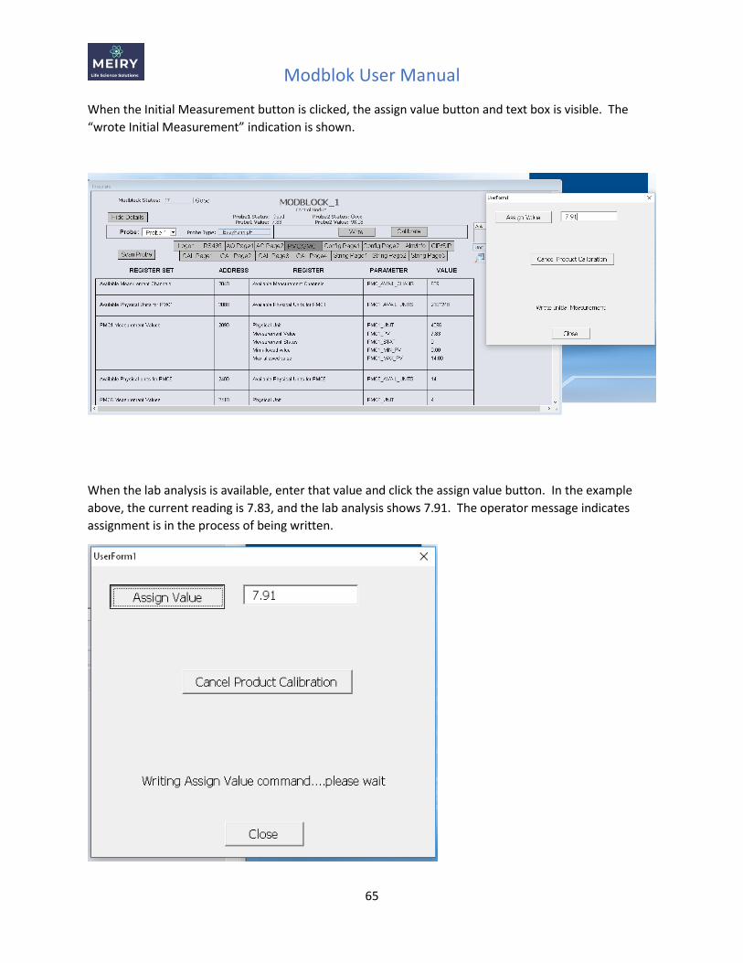
When the Initial Measurement button is clicked, the assign value button and text box is visible. The
“wrote Initial Measurement” indication is shown.
When the lab analysis is available, enter that value and click the assign value button. In the example
above, the current reading is 7.83, and the lab analysis shows 7.91. The operator message indicates
assignment is in the process of being written.
Modblok User Manual
66
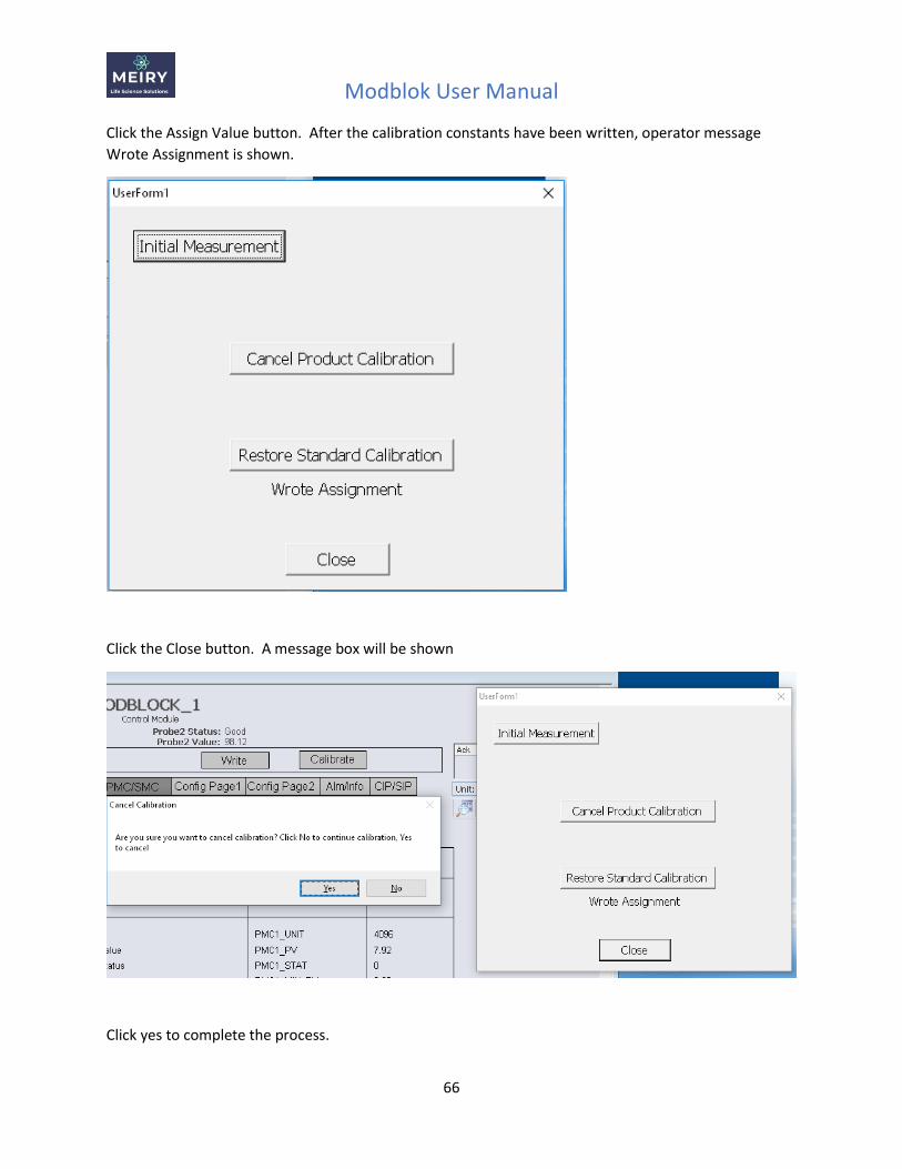
Click the Assign Value button. After the calibration constants have been written, operator message
Wrote Assignment is shown.
Click the Close button. A message box will be shown
Click yes to complete the process.