Embed Size (px)
Citation preview

Model-Based Design of Embedded Control Systems by means of a SynchronousIntermediate Model
Mouaiad Alras, Paul Caspi, Alain Girault, and Pascal RaymondVerimag-CNRS and University of Grenoble – France
INRIA Grenoble Rhone-Alpes – France
Abstract
Model-based design (MBD) involves designing a modelof a control system, simulating and debugging it with dedi-cated tools, and finally generating automatically code cor-responding to this model. In the domain of embedded sys-tems, it offers the huge advantage of avoiding the time-consuming and error-prone final coding phase. The main is-sue raised by MBD is the faithfulness of the generated codewith respect to the initial model, the latter being defined bythe simulation semantics. To bridge the gap between thehigh-level model and the low-level implementation, we usethe synchronous programming language Lustre as an inter-mediate formal model. Concretely, starting from a high-level model specified in the de-facto standard Simulink, wefirst generate Lustre code along with some structured “gluecode”, and then we generate embedded real-time code forthe Xenomai RTOS. Thanks to Lustre’s clean mathematicalsemantics, we are able to guarantee the faithfulness of thegenerated multi-tasked real-time code.
1 Introduction
1.1 Overview
A classical automatic control application consists of asoftware controller interacting with the physical device/en-vironment via dedicated input and output drivers. Ac-cordingly, engineers use a design environment both tomodel the physical environment, using continuous domainparadigms (e.g., differential equations), and to design thecontroller, using sampled discrete time paradigms (e.g., pe-riodic clocks, multi-tasking, priorities). They simulate anddebug their application and, once satisfied with it, they im-plement it over a target architecture consisting of a dis-tributed hardware platform and a real-time operating sys-tem (RTOS). One of the most popular such design environ-ment is Simulink, a de-facto standard in industry (automo-
tive, robotics and automation, consumer electronics,...), andour work is based on it.
For lack of adequate tools, past common practice in in-dustry was to implement manually the controller, an opera-tion that is both time-consuming and error-prone. Model-based design (MBD) precisely attempts at replacing themanual coding phase by an automatic code generation one.MBD is a very active area of research, both in academia andin private companies. The main assumptions it relies on arethat the designer is satisfied with his/her controller (thanksto simulation and testing), that the software paradigms canbe implemented on the architecture, and that the librariesof drivers are consistent with the physical device. SomeMBD solutions exist today, for instance in avionics withSCADE [4], in automotive with Simulink-RTW [14], andin robotics with Orccad [3, 13].
The core principle of MBD is that the designer wants toobtain code that is faithful to his/her design; in other words,what he/she simulates under Simulink must execute exactlyin the same manner on the target architecture. As a con-sequence, MBD must derive as automatically as possiblecode that is faithful to the design of the controller, and thatcan be implemented on the target architecture. Of course,since Simulink does not have a denotational semantics, it isimpossible to prove formally this faithfulness.
The main issue that stems from the faithfulness re-quirement is that the semantics of a Simulink model de-pends on the chosen simulation parameters. For instance,some Simulink models may be accepted if one choosesdiscrete-step simulation, and rejected if one choosesvariable-step, auto, or multi-threaded simulation. Wecall those simulation artifacts.
This is why we propose to use an intermediate formalmodel, to bridge the gap between the high-level Simulinkmodel (i.e., the automatic control world) and the low-levelimplementation (i.e., the computer science world). Wechoose Lustre [10] to express formally the intermediatemodel, because both Lustre and Simulink are data-flow lan-guage that implement the synchronous model of computa-tion, and because Lustre is equipped with a clean mathe-
2009 International Conferences on Embedded Software and Systems
978-0-7695-3678-1/09 $25.00 © 2009 IEEE
DOI 10.1109/ICESS.2009.36
3
2009 International Conferences on Embedded Software and Systems
978-0-7695-3678-1/09 $25.00 © 2009 IEEE
DOI 10.1109/ICESS.2009.36
3
2009 International Conferences on Embedded Software and Systems
978-0-7695-3678-1/09 $25.00 © 2009 IEEE
DOI 10.1109/ICESS.2009.36
3
2009 International Conferences on Embedded Software and Systems
978-0-7695-3678-1/09 $25.00 © 2009 IEEE
DOI 10.1109/ICESS.2009.36
3
2009 International Conferences on Embedded Software and Systems
978-0-7695-3678-1/09 $25.00 © 2009 IEEE
DOI 10.1109/ICESS.2009.36
3
2009 International Conferences on Embedded Software and Systems
978-0-7695-3678-1/09 $25.00 © 2009 IEEE
DOI 10.1109/ICESS.2009.36
3
2009 International Conference on Embedded Software and Systems
978-0-7695-3678-1/09 $25.00 © 2009 IEEE
DOI 10.1109/ICESS.2009.36
3
2009 International Conference on Embedded Software and Systems
978-0-7695-3678-1/09 $25.00 © 2009 IEEE
DOI 10.1109/ICESS.2009.36
3

matical semantics. Our workflow is therefore:
Simulink → Lustre → multiple tasks over a RTOS
Our target RTOS is Xenomai, chosen for usability, main-tainability, and portability reasons.
We also generate some structured “glue code”, necessaryto express features of Simulink that do not exist in Lustre.This is the case, for instance, of periodic clocks and spo-radic events.
1.2 Contribution
Our goal is to develop a complete multi-tier MBD toolthat goes from a high-level Simulink model to a low-levelreal-time implementation for the Xenomai RTOS. We in-volve as well an early conformity analyzing stage.
We extend existing MBD methods also based onSimulink and Lustre [6, 7, 11, 15] to integrate more fea-tures of the high-level model. We extend Lustre with spe-cific meta-operators, which are used to subsume these fea-tures on the one hand, and to incarnate on the other handthe real-time and system-level items of the Xenomai library.We call the extended language Lustre++.
In addition to high-level restrictions that prevent un-safe behaviors of Simulink, and in order to produce bettercode, we propose some confinements and user guidelines intwo directions: Grouping tasks to generate the minimumnumber of RTOS tasks, and using exclusive modes withdata sharing to generate more efficient and better structuredcode.
Our translation is modular and preserves the hierarchicalstructure of the Simulink model. It is implemented in a pro-totype tool consisting of two steps. First, our tool translatesthe Simulink model into our intermediate model Lustre++.Then, this intermediate model can be used in two ways (seeSection 4): On the one hand it can be compiled into em-bedded RTOS code, and on the other hand it can translatedinto pure Lustre code for the simulation and validation ofthe behavioral part of the system.
Some existing approaches in industry only handle themono-processor and mono-task case [14, 15]. Extensionshave been proposed for the multi-task case [5, 12], but theyare limited to periodic tasks where all the periods are a mul-tiple of the smallest period. The method we present hereextends [15] in two directions: on the one hand we han-dle sporadic tasks and arbitrary periodic tasks, and on theother hand we generate embedded real-time code while [15]stopped at the Lustre level. We use previously developedtheoretical results for the inter-task communication proto-cols [7, 11].
2 The Intermediate Model
2.1 From a Simulink model to a synchronous pro-gram
Between the high-level Simulink model and the actualimplementation, we use an intermediate model, based onthe synchronous programming language Lustre [10]. Thistranslation is hierarchical, that is, the structure of the re-sulting synchronous model reflects the one of the Simulinkmodel. In order to obtain this structure, we must extractfrom the Simulink model the following information:
• Subsystems involving features related to asynchronousconcepts, such as multi-tasking, periodic clocks, prior-ities etc. We call this part of the hierarchy the asyn-chronous architecture, and it is intended to be imple-mented by using features of the target RTOS. This partcorresponds to the tree-like structure of the intermedi-ate model.
• Subsystems that can be considered as “functional”:they correspond to synchronous tasks, which can bestraightforwardly translated into Lustre, and then intoclassical sequential programs using the Lustre codegenerator. Those subsystems are considered as atomicin our framwork: they are the leaves of the intermedi-ate model structure.
Figure ?? shows an example of a hierachical Simulinkmodel, together with the corresponding intermediate modelstructure. In this example, the top-level is made of threeconcurrent subsystems: the H and G blocks have been iden-tified as “functional” (typically because they only involvesimple computations, not detailed here). On the contrary,the F block contains non-purely functional features: a DataStore, and two subsystems triggered by a clock-enable con-dition: F is then identified as a non-functional node in theintermediate structure. Finally, F is itself made of two sys-tems that are identified as atomic.
Indeed, the distinction between atomic and non-atomicsubsystems is not always obvious, this is why we proposeguidelines for the design of Simulink models: those guide-lines, presented in Sections 2.3 and 2.4 are intended to helpthe extraction of the intermediate structure. If the Simulinkmodel does not obey the guidelines, we are still able to gen-erate faithful, but less efficient, code.
Since Lustre is notsuited to the expression of the asyn-chronous features of Simulink (clocks, priorities, and soon), we introduce a set of meta-operators to keep trackof these informations in the intermediary nodes of the treestructure. In previous solutions, we used to encode thsesfeatures with non-structured annotations (e.g., pragmas);we find the meta-operators solution better structured andmore elegant.
44444444

1
2
3
out
1
1
out
1
in
in out
F2
A
Data StoreMemory
in
inH
H T=20
Atomic subsystem
+
+
+
Sum
in
inG
G T=40
in
inF
out
out
out
F
in>0
elsein
if out
F1
Merge
Figure 1. A hierarchical Simulink model.
2.2 Meta-operators
Meta-operators are introduced in order to extend the Lus-tre language with the most common features one can findin a classical RTOS: triggered tasks, triggers, data buffers.Each meta-operator has a set of static parameters (given be-tween << and >>) for expressing extra-functional informa-tion. We call Lustre++ the language extended with meta-operators.
Figure 3 shows the Lustre++ nodes generated for the ex-ample of Figure 1. It uses three different meta-operators:
• clock has two static parameters called p and h; it cre-ates a periodic clock of period p and phase h.
• condact has three static parameters called f, c, and d;it invokes the function f at each tick of the clock c; theparameter d is the default value of f’s output
• switch is a structured collection of condact opera-tors, where the clocks are guaranteed to be exclusive.
The meta-operators are designed in order to allow thegeneration of RTOS code. They can also be translated intopure Lustre code as shown in Figure 4: this program corre-sponds to the node main of the example in Figure 3. Thepure Lustre code is not used for embedded code generationbecause it abstracts away the real-time features. We onlyuse it for testing and model-checking purpose.
H G F
main
F1 F2
Figure 2. The intermediate model structurecorresponding to the Simulink model of Fig-ure 1.
node main (inH,inG,inF:int)
returns (out:int);
var
ck_20, ck_40: alarm;let
ck_20 = clock<<20,0>>(_);ck_40 = clock<<40,0>>(_);out = condact<<H,ck_20,1>>(inH)
+ condact<<G,ck_40,1>>(inG)+ F(inF);
tel
node F(in:int) returns(out:int);
constmem_A: int ref = ref 0;
let
out = if (in > 0)
then F1<<mem_A>>(_)
else F2<<mem_A>>(in);
tel
Figure 3. Lustre++ code for the model of Fig-ure 1.
55555555

node main (inH, inG, inF:int)
returns (out:int);
var
cnt_20, cnt_40 : int;
ck_20, ck_40 : bool;
let
cnt_20 = (0 -> pre(cnt_20) + 1) mod 20;
ck_20 = ( 0 = cnt_20 );
cnt_40 = (0 -> pre(cnt_40) + 1) mod 40;
ck_40 = ( 0 = cnt_40 );
outH = if(ck_20)
then current( H(inH when ck_20) )
else 1 -> pre (outH);
outG = if(ck_40)
then current( G(inG when ck_40) )
else 1 -> pre (outG);
out = outH + outG + F(inF);
tel
Figure 4. Lustre code for the model of Fig-ure 3.
2.3 Atomic subsystem guideline
The default heuristic is to consider that a Simulink sub-system triggered by a clock-enable condition must be im-plemented by an RTOS task. However, this is not always agood solution, since it may lead to a large number of contextswitches during the execution that may dramatically slowdown the system.
However, we also propose a guideline that allows theuser to choose how to regroup computation into a singleRTOS task. This is achieved by labeling a block as aSimulink Atomic Subsystem. For instance in Figure 1, thesubsystem H is marked as an Atomic Subsystem: this willenforce the code generator to group all hierarchical subsys-tems contained in H into single RTOS task.
2.4 Exclusive modes guideline
The notion of multi-modes is particularly important incontrol system design: it corresponds to the case where astate variable is computed according to different control-laws (called the modes) depending on the state of the sys-tem.
Muli-mode programming is not a built-in paradigm inSimulink, but rather an (expected) consequence of the de-sign. The system F in Figure 1 is a typical example of multi-modes design: F1 and F2 are triggered by exclusive condi-tions, and their outputs are merged into a single variable“out”.
Recognizing this kind of organization in the simulink
model is very important in our approach, since it allows toproduce better implementation:
• it is not necessary to protect the access to shared vari-ables, since these accesses are guaranteed to be exclu-sive,
• instead of generating a system task for each mode, wecan produce a single task that dynamically select theright mode.
We propose a guideline that guarantees efficient gener-ated code; a set of n blocks are recognized as exclusivemodes of computation if:
1. Each block is triggered by an activation condition andthe n activation conditions are produced by a singleswitch block.
2. Each output of these n block that is common to at leasttwo blocks must be common to the n blocks and mustbe combined into a merge block.
We illustrate this guideline in the next section by a completeexample.
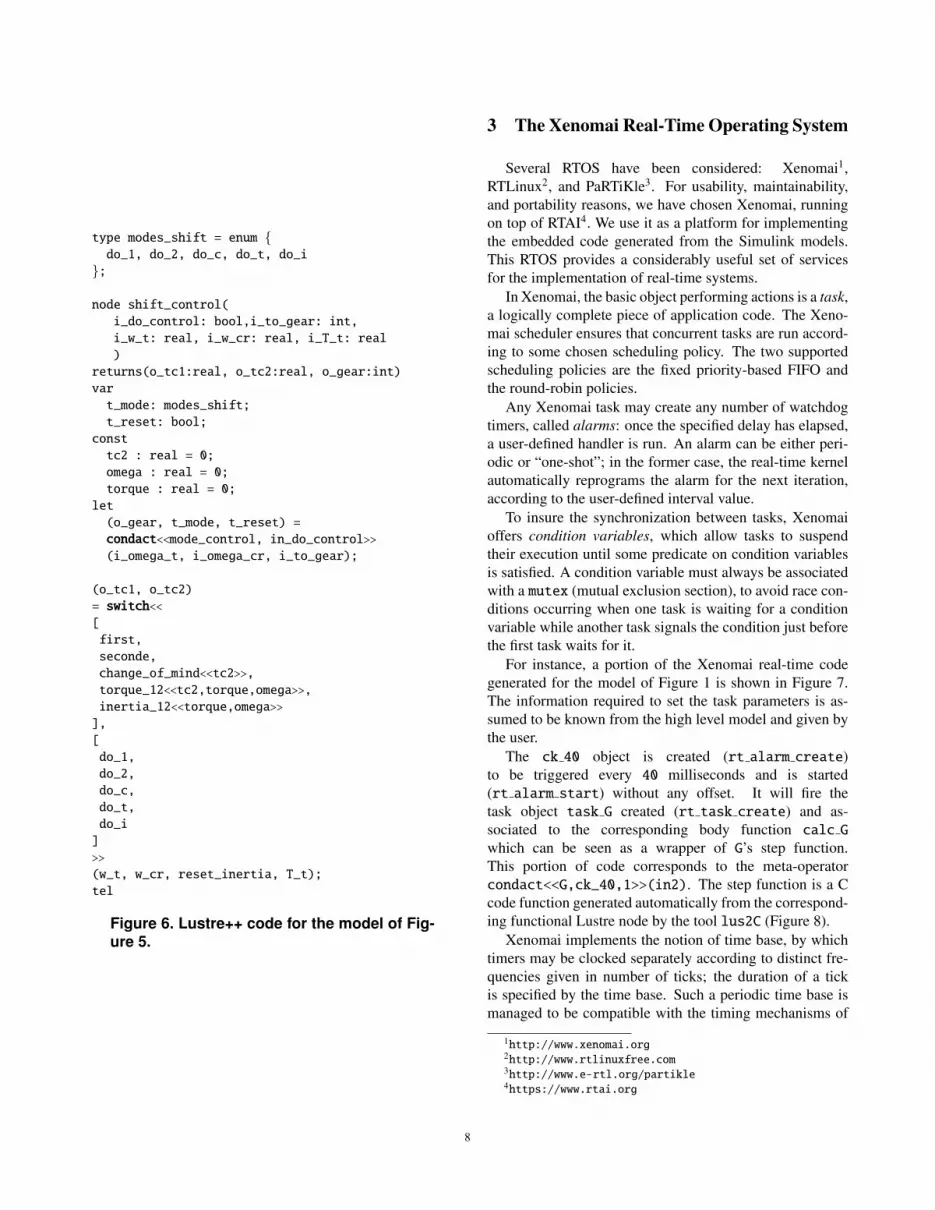
2.5 Example
The example in Figure 5 is based on the controller part ofthe automotive power train model designed at Ford MotorsCompany [9, 8] to study the 1-2 gearshift. This Simulinkmodel contains five triggered subsystems (first, second,change of mind, torque 12, and inertia 12) witch allread the same input T t to calculate differently the sameoutputs tc1 and tc2. Some subsystems need additional in-puts and may also be connected internally to other subsys-tems. For instance, the inertia 12 subsystem receives itslast torque and last omega inputs from torque 12.
The merge operator is used in Simulink when the samevariable is computed by different modes of computation.We restrict the usage of the merge operator to exlusivemodes of computation (Section 2.4).
Goto/From Tags are used in Simulink as connectors toavoid crossing signal lines . For instance in Figure 5,this is the case of the reset inertia output of blockmode control that is connected to the inertia 12 block.We restrict the use of such tags to be scoped only locally(in other words, Goto/From Tags that span over hierarchylevels are forbidden). Figure 6 shows the Lustre++ codecorresponding to this example.
Another way to share variables between subsystemscould be achieved by the use of Data Stores. We chose totake into account only local Data Stores declared explicitlyusing the Memory Block of the Simulink Library (see, e.g,the Data Store A in Figure 1, block F).
66666666

2
3
4
[w_t]
[w_cr]
1
[reset]
3
[do_t]
[tc2_t]
[tc1_i]
[tc2_i]
[do_i]
[w_t]
[w_cr]
[reset]
[do_1]
[tc1_1]
[tc2_1]
[do_2]
[tc1_2]
[tc2_2]
[do_c]
[tc1_c]
[tc2_c]
[tc1_t]
[do_1]
[do_2]
[do_c]
[do_t]
[do_i]
case[2]
case[3]
case[4]
case[5]
case[1]
switch mode
5[w_t]
[l_tc2]
[l_tc2]
to_gear
w_cr
w_t
to_gear
w_cr
w_t
mode_control
gear
do_control
to_gear
tc1
tc2
tc2
tc1
T_t
w_cr
reset_inertia
torque_12
inertia_12
torque
omega
tc1
tc2
T_t
second
tc1
tc2
T_t
tc1
tc2
w_t
change_of_mind
first
T_t
Merge_tc2
Mergetc2
omega
torqueMerge_tc1
Mergetc1
T_t
w_t
T_t
last_tc2
last_tc2
do
do
do
do
do
mode
do_control
reset_inertia
[tc1_i]
[tc2_t]
[tc2_i]
[tc1_2]
[tc1_1]
[tc1_c]
[tc1_t]
[tc2_1]
[tc2_2]
[tc2_c]
[l_tc2]
1
2
Figure 5. Gear Shift Control Example.
77777777
type modes_shift = enum {do_1, do_2, do_c, do_t, do_i
};
node shift_control(
i_do_control: bool,i_to_gear: int,
i_w_t: real, i_w_cr: real, i_T_t: real
)
returns(o_tc1:real, o_tc2:real, o_gear:int)
var
t_mode: modes_shift;
t_reset: bool;
const
tc2 : real = 0;
omega : real = 0;
torque : real = 0;
let
(o_gear, t_mode, t_reset) =
condact<<mode_control, in_do_control>>(i_omega_t, i_omega_cr, i_to_gear);
(o_tc1, o_tc2)
= switch<<[
first,
seconde,
change_of_mind<<tc2>>,
torque_12<<tc2,torque,omega>>,
inertia_12<<torque,omega>>
],
[
do_1,
do_2,
do_c,
do_t,
do_i
]
>>
(w_t, w_cr, reset_inertia, T_t);
tel
Figure 6. Lustre++ code for the model of Fig-ure 5.
3 The Xenomai Real-Time Operating System
Several RTOS have been considered: Xenomai1,RTLinux2, and PaRTiKle3. For usability, maintainability,and portability reasons, we have chosen Xenomai, runningon top of RTAI4. We use it as a platform for implementingthe embedded code generated from the Simulink models.This RTOS provides a considerably useful set of servicesfor the implementation of real-time systems.
In Xenomai, the basic object performing actions is a task,a logically complete piece of application code. The Xeno-mai scheduler ensures that concurrent tasks are run accord-ing to some chosen scheduling policy. The two supportedscheduling policies are the fixed priority-based FIFO andthe round-robin policies.
Any Xenomai task may create any number of watchdogtimers, called alarms: once the specified delay has elapsed,a user-defined handler is run. An alarm can be either peri-odic or “one-shot”; in the former case, the real-time kernelautomatically reprograms the alarm for the next iteration,according to the user-defined interval value.
To insure the synchronization between tasks, Xenomaioffers condition variables, which allow tasks to suspendtheir execution until some predicate on condition variablesis satisfied. A condition variable must always be associatedwith a mutex (mutual exclusion section), to avoid race con-ditions occurring when one task is waiting for a conditionvariable while another task signals the condition just beforethe first task waits for it.
For instance, a portion of the Xenomai real-time codegenerated for the model of Figure 1 is shown in Figure 7.The information required to set the task parameters is as-sumed to be known from the high level model and given bythe user.
The ck 40 object is created (rt alarm create)to be triggered every 40 milliseconds and is started(rt alarm start) without any offset. It will fire thetask object task G created (rt task create) and as-sociated to the corresponding body function calc Gwhich can be seen as a wrapper of G’s step function.This portion of code corresponds to the meta-operatorcondact<<G,ck_40,1>>(in2). The step function is a Ccode function generated automatically from the correspond-ing functional Lustre node by the tool lus2C (Figure 8).
Xenomai implements the notion of time base, by whichtimers may be clocked separately according to distinct fre-quencies given in number of ticks; the duration of a tickis specified by the time base. Such a periodic time base ismanaged to be compatible with the timing mechanisms of
1http://www.xenomai.org2http://www.rtlinuxfree.com3http://www.e-rtl.org/partikle4https://www.rtai.org
88888888

rt_task task_G;
rt_alarm ck_40;
rt_alarm_create(&ck_40,"ck_40");
rt_alram_start(&ck_40, 0, ns2ticks(40 * TICK));
rt_task_create(&task_G, "task_G", SIZE, PRIO, MODE);
ctx->out1 = 1; //initial value
rt_task_start(&task_G, &calc_G, ctx);
void calc_G(void* ctx){
while(1){
rt_alarm_wait(&ck_40);
...
call_step(ctx);
...
}
}
Figure 7. Xenomai code for the Simulinkmodel of Figure 1.
alarm task
step
nodeclockLus2C
callwait
xenomai
Lustre
Figure 8. From Lustre to Xenomai example.
simulation in Lustre.When generating real-time code for automatic control
systems, one of the difficult issues concerns blocks thathave different periods and that communicate together. Ac-cordingly, there are three cases for a given pair of com-municating tasks: high to low priority, high to low prior-ity with unit delay, and low to high priority with unit de-lay5 [11]. The difficulty is to guarantee the zero-delay se-mantics of Simulink. This is achieved thanks to a set ofbuffers and pointers to these buffers [7]. The principle isthat the pointers to the buffers are manipulated upon the ar-rival of the events triggering the tasks instead of during theexecution of the tasks. In that way, the order of arrivals canbe memorized and the original Simulink semantics can bepreserved [11].
5The low to high priority without unit delay is impossible.
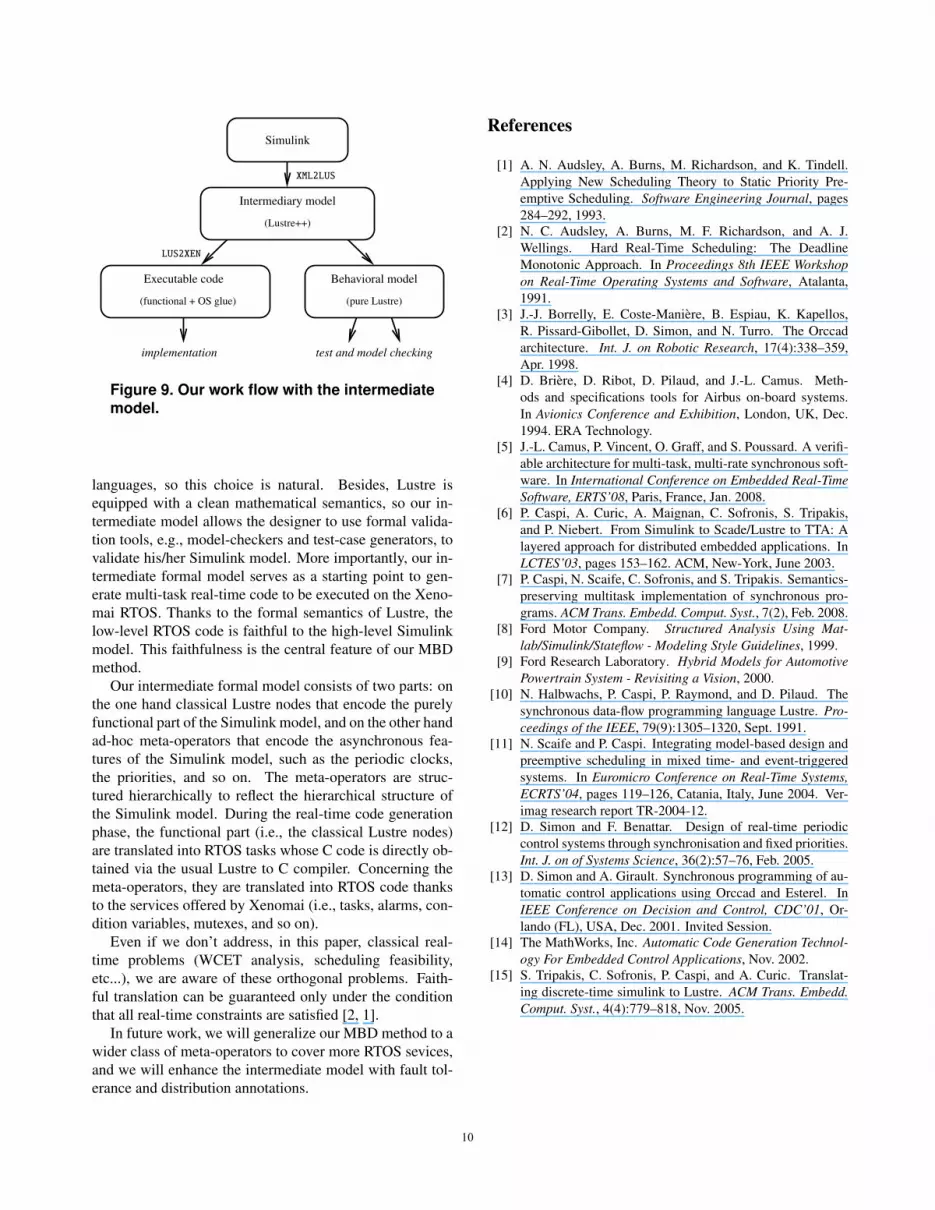
4 Work flow
Our MBD approach is based on a three-phase process.First, Simulink models are parsed thanks to the transla-tor MDL2XML. It extends the existing similar compiler fromSofronis [15] to handle periodic clocks, data stores, atomicsubsystems, and exclusive modes of computation.
The MDL2XML translator first involves a filtering andchecking stage. Models that contain global data stores orglobal connectors will be rejected. The output of this stageis a transformed XML file, which is the entry point of thebackend code generation.
Second, this XML-encoded Simulink model is trans-lated into an intermediate formal model thanks to thetool XML2LUS. It performs the clock inference, type infer-ence, and conformity analysis. The purpose of this anal-ysis is twofold: to detect combinatorial loops and non-deterministic behaviors (non exclusive data sharing), and torecognize patterns respecting the guidelines in order to gen-erate more efficient code (exclusive modes and tasks group-ing).
The XML2LUS tool then generates, for each Simulinkblock and subsystem, the corresponding Lustre node, andexternal function code for every “unknown” and “user-defined” block. In addition, glue-code is generated forthe meta-operators by retrieving information from the high-level model.
Third, the intermediate model is compiled into actualRTOS code thanks to the tool LUS2XEN. It generates, foreach Lustre node, the corresponding real-time task or sys-tem call, and for each meta-operator the corresponding real-time object from the native library of Xenomai. Periodictasks are triggered by alarm objects, sporadic tasks are trig-gered by event objects, buffers are implemented by con-dition variables and mutex services. Additional Xenomaiglue code is generated to manage the master time base,which serves as the specification basis for delays and time-outs. Moreover, the intermediate model can also be trans-lated into a purely functional model that can be used forformal validation (model-checking, test case generation ...).This is a distinctive feature of our approach and wouldnot be achievable with a direct C code generation such asSimulink-RTW [14].
5 Conclusion and Future Work
We have presented a Model-Based Design (MBD)method for embedded control systems specified inSimulink. Once the model has been simulated and thedesigner is satisfied with it, we transform it into an in-termediate formal model, for which we have chosen thesynchronous programming language Lustre. Lustre andSimulink are both synchronous data-flow programming
99999999
Behavioral model
Intermediary model
Simulink
(pure Lustre)
(Lustre++)
test and model checking
LUS2XEN
XML2LUS
Executable code
(functional + OS glue)
implementation
Figure 9. Our work flow with the intermediatemodel.
languages, so this choice is natural. Besides, Lustre isequipped with a clean mathematical semantics, so our in-termediate model allows the designer to use formal valida-tion tools, e.g., model-checkers and test-case generators, tovalidate his/her Simulink model. More importantly, our in-termediate formal model serves as a starting point to gen-erate multi-task real-time code to be executed on the Xeno-mai RTOS. Thanks to the formal semantics of Lustre, thelow-level RTOS code is faithful to the high-level Simulinkmodel. This faithfulness is the central feature of our MBDmethod.
Our intermediate formal model consists of two parts: onthe one hand classical Lustre nodes that encode the purelyfunctional part of the Simulink model, and on the other handad-hoc meta-operators that encode the asynchronous fea-tures of the Simulink model, such as the periodic clocks,the priorities, and so on. The meta-operators are struc-tured hierarchically to reflect the hierarchical structure ofthe Simulink model. During the real-time code generationphase, the functional part (i.e., the classical Lustre nodes)are translated into RTOS tasks whose C code is directly ob-tained via the usual Lustre to C compiler. Concerning themeta-operators, they are translated into RTOS code thanksto the services offered by Xenomai (i.e., tasks, alarms, con-dition variables, mutexes, and so on).
Even if we don’t address, in this paper, classical real-time problems (WCET analysis, scheduling feasibility,etc...), we are aware of these orthogonal problems. Faith-ful translation can be guaranteed only under the conditionthat all real-time constraints are satisfied [2, 1].
In future work, we will generalize our MBD method to awider class of meta-operators to cover more RTOS sevices,and we will enhance the intermediate model with fault tol-erance and distribution annotations.
References
[1] A. N. Audsley, A. Burns, M. Richardson, and K. Tindell.Applying New Scheduling Theory to Static Priority Pre-emptive Scheduling. Software Engineering Journal, pages284–292, 1993.
[2] N. C. Audsley, A. Burns, M. F. Richardson, and A. J.Wellings. Hard Real-Time Scheduling: The DeadlineMonotonic Approach. In Proceedings 8th IEEE Workshopon Real-Time Operating Systems and Software, Atalanta,1991.
[3] J.-J. Borrelly, E. Coste-Maniere, B. Espiau, K. Kapellos,R. Pissard-Gibollet, D. Simon, and N. Turro. The Orccadarchitecture. Int. J. on Robotic Research, 17(4):338–359,Apr. 1998.
[4] D. Briere, D. Ribot, D. Pilaud, and J.-L. Camus. Meth-ods and specifications tools for Airbus on-board systems.In Avionics Conference and Exhibition, London, UK, Dec.1994. ERA Technology.
[5] J.-L. Camus, P. Vincent, O. Graff, and S. Poussard. A verifi-able architecture for multi-task, multi-rate synchronous soft-ware. In International Conference on Embedded Real-TimeSoftware, ERTS’08, Paris, France, Jan. 2008.
[6] P. Caspi, A. Curic, A. Maignan, C. Sofronis, S. Tripakis,and P. Niebert. From Simulink to Scade/Lustre to TTA: Alayered approach for distributed embedded applications. InLCTES’03, pages 153–162. ACM, New-York, June 2003.
[7] P. Caspi, N. Scaife, C. Sofronis, and S. Tripakis. Semantics-preserving multitask implementation of synchronous pro-grams. ACM Trans. Embedd. Comput. Syst., 7(2), Feb. 2008.
[8] Ford Motor Company. Structured Analysis Using Mat-lab/Simulink/Stateflow - Modeling Style Guidelines, 1999.
[9] Ford Research Laboratory. Hybrid Models for AutomotivePowertrain System - Revisiting a Vision, 2000.
[10] N. Halbwachs, P. Caspi, P. Raymond, and D. Pilaud. Thesynchronous data-flow programming language Lustre. Pro-ceedings of the IEEE, 79(9):1305–1320, Sept. 1991.
[11] N. Scaife and P. Caspi. Integrating model-based design andpreemptive scheduling in mixed time- and event-triggeredsystems. In Euromicro Conference on Real-Time Systems,ECRTS’04, pages 119–126, Catania, Italy, June 2004. Ver-imag research report TR-2004-12.
[12] D. Simon and F. Benattar. Design of real-time periodiccontrol systems through synchronisation and fixed priorities.Int. J. on of Systems Science, 36(2):57–76, Feb. 2005.
[13] D. Simon and A. Girault. Synchronous programming of au-tomatic control applications using Orccad and Esterel. InIEEE Conference on Decision and Control, CDC’01, Or-lando (FL), USA, Dec. 2001. Invited Session.
[14] The MathWorks, Inc. Automatic Code Generation Technol-ogy For Embedded Control Applications, Nov. 2002.
[15] S. Tripakis, C. Sofronis, P. Caspi, and A. Curic. Translat-ing discrete-time simulink to Lustre. ACM Trans. Embedd.Comput. Syst., 4(4):779–818, Nov. 2005.
1010101010101010


