Embed Size (px)
Citation preview
Model characterization of impulse response for diffuse optical indoor wireless channels
Adrian Mihaescu, Marius Otesteanu
Universitatea Politehnica Timişoara
Facultatea de Electronică şi Telecomunicaţii, Dept.Comunicaţii Bd. V. Pârvan Nr. 2, 300223 Timişoara,
Abstract – Characterization of the impulse response for real optical wireless channels states the acces bandwidth of communication. In the case of diffuse infrared wireless channel the impulse response varies abruptly with changes in receiver/emitter position and furniture composition of non-empty rooms, so the development of tools capable of estimating this response in real circumstances is important. In this paper we present a new method for estimating the impulse response using a reduced-model of the actual indoor environment. Both simulation and experiments shows a good agreement for the a impulse response function at the 1550nm wavelength for indoor transmissions in a reduced model room. Keywords: wireless optical communications, diffuse indoor channel, impulse response characterization, reduced-model simulation
I. INTRODUCTION
Radio wireless dominates the market nowadays with a variety of systems such as WiFi, Bluetooth, UWB. However optical infrared, especially indoor, remains very practical in certain applications, either as an alternative to radio or as a complement. Optical wireless users enjoy better privacy since, contrary to microwaves, light does not pass through walls. Optical security is the only medical issue that these networks pose, unlike microwave, which rise more and more concern. Electromagnetic compatibility is no longer a problem, making indoor infrared communications viable even in such environments as hospitals.
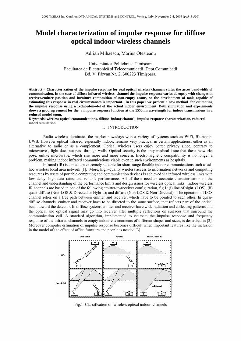
Infrared (IR) is a medium extremely suitable for short-range flexible indoor communications such as ad-hoc wireless local area network [1]. More, high–quality wireless access to information networks and computing resources by users of portable computing and communication devices is achieved via infrared wireless links with low delay, high data rates, and reliable performance. All of these need an accurate characterization of the channel and understanding of the performance limits and design issues for wireless optical links. Indoor wireless IR channels are based in one of the following emitter-to-receiver configuration, fig.1: (i) line of sight. (LOS); (ii) quasi-diffuse (Non-LOS & Directed or Hybrid); and diffuse (Non-LOS & Non-Directed). The operation of LOS channel relies on a free path between emitter and receiver, which have to be pointed to each other. In quasi-diffuse channels, emitter and receiver have to be directed to the same surface, that reflects part of the optical beam toward the detector. In diffuse systems emitter and receiver have wide radiation and collecting patterns and the optical and optical signal may go into receiver after multiple reflections on surfaces that surround the communication cell. A standard algorithm, implemented to estimate the impulse response and frequency response of the infrared channels in empty indoor environments of different shapes and sizes, is described in [2]. Moreover computer estimation of impulse response becomes difficult when important features like the inclusion in the model of the effect of office furniture and people is needed [3].
F
Fig.1 Classification of wireless optical indoor channels
2005 WSEAS Int. Conf. on DYNAMICAL SYSTEMS and CONTROL, Venice, Italy, November 2-4, 2005 (pp545-550)
II. CHANNEL MODEL: METHODS TO GET CHANNEL IMPULSE RESPONSE.
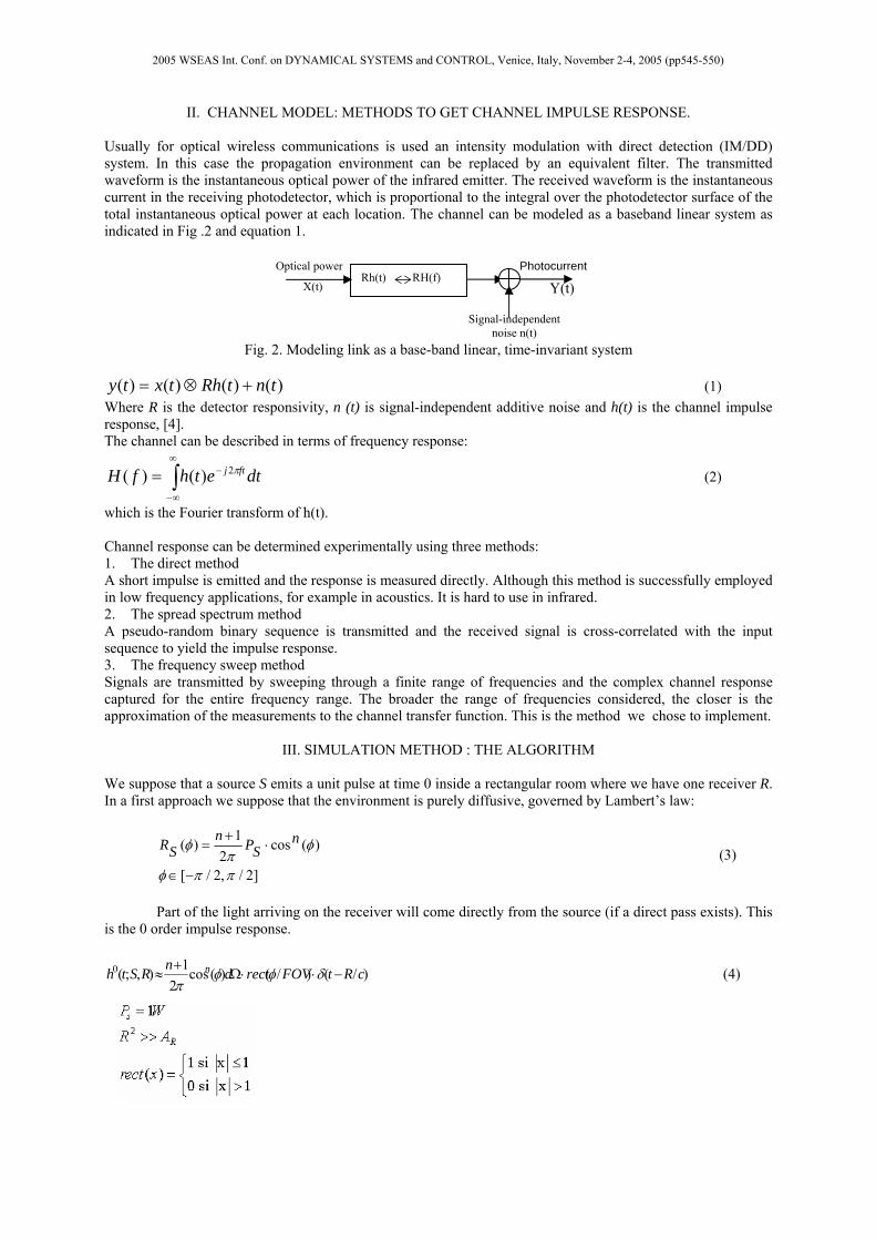
Usually for optical wireless communications is used an intensity modulation with direct detection (IM/DD) system. In this case the propagation environment can be replaced by an equivalent filter. The transmitted waveform is the instantaneous optical power of the infrared emitter. The received waveform is the instantaneous current in the receiving photodetector, which is proportional to the integral over the photodetector surface of the total instantaneous optical power at each location. The channel can be modeled as a baseband linear system as indicated in Fig .2 and equation 1.
Fig. 2. Modeling link as a base-band linear, time-invariant system
)()()()( tntRhtxty +⊗= (1) Where R is the detector responsivity, n (t) is signal-independent additive noise and h(t) is the channel impulse response, [4]. The channel can be described in terms of frequency response:
∫∞
∞−
−= dtethfH ftj π2)()( (2)
which is the Fourier transform of h(t). Channel response can be determined experimentally using three methods: 1. The direct method A short impulse is emitted and the response is measured directly. Although this method is successfully employed in low frequency applications, for example in acoustics. It is hard to use in infrared. 2. The spread spectrum method A pseudo-random binary sequence is transmitted and the received signal is cross-correlated with the input sequence to yield the impulse response. 3. The frequency sweep method Signals are transmitted by sweeping through a finite range of frequencies and the complex channel response captured for the entire frequency range. The broader the range of frequencies considered, the closer is the approximation of the measurements to the channel transfer function. This is the method we chose to implement.
III. SIMULATION METHOD : THE ALGORITHM We suppose that a source S emits a unit pulse at time 0 inside a rectangular room where we have one receiver R. In a first approach we suppose that the environment is purely diffusive, governed by Lambert’s law:
]2/,2/[
)(cos2
1)(
ππφ
φπ
φ
−∈
⋅+
= nSPn
SR (3)
Part of the light arriving on the receiver will come directly from the source (if a direct pass exists). This is the 0 order impulse response.
)/()/()(cos2
1),;(0 cRtFOVrectdnRSth n −⋅⋅Ω+
≈ δφφπ
(4)
Rh(t) RH(f) Optical power
X(t)
Signal-independent noise n(t)
Photocurrent
Y(t)
2005 WSEAS Int. Conf. on DYNAMICAL SYSTEMS and CONTROL, Venice, Italy, November 2-4, 2005 (pp545-550)
The rest will be reflected on the walls of the room so that the total impulse response will be:
∑∞
=
=0
),;(),;(k
k RSthRSth (5)
where each term hk represents the pulse response given by the light arriving on the receiver after a number of k bounces.
∫ −⊗=
=
S
k
k
RnrthdrFOVnrSth
RSth
),1,,;(),,,,;(
),;()1(2)0(
)(
(6)
But, following John Barry’s method, if we consider the walls discrete, made up of N indivisible elementary surfaces the function becomes:
∑ −⊗≈ ),;(),;(),;( )1()0()( RthSthRSth ik
ik εε (7)
and more explicitly:
)),1,,;/(
)/()cos()(cos(
21),;(
)1(1
2
)(
ARnrcdth
FOVrectd
nRSth
k
N
i
nr
k
∆−⋅
⋅⋅
⋅+
≈
−=∑ φθφρ
π
(8)
where ∆A is the area of the receiver and the rectangular function is defined above.
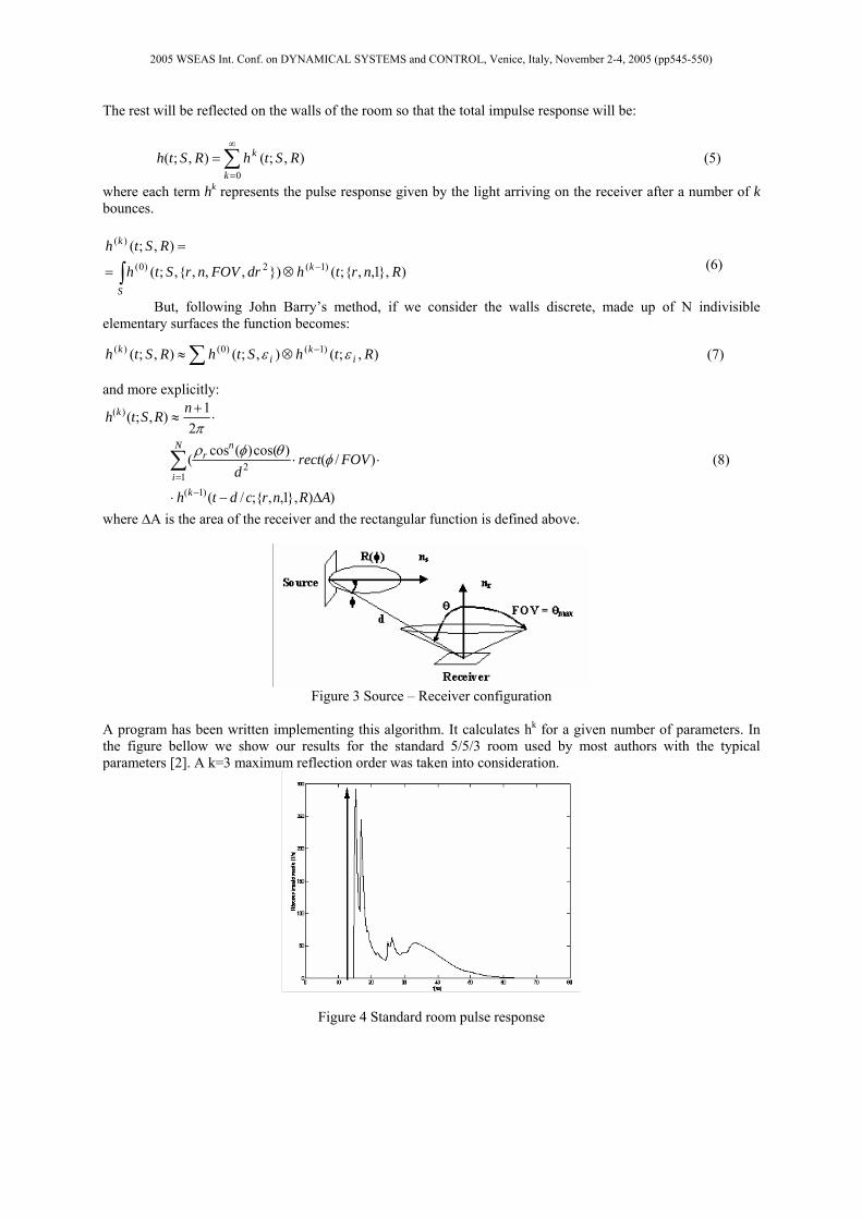
Figure 3 Source – Receiver configuration
A program has been written implementing this algorithm. It calculates hk for a given number of parameters. In the figure bellow we show our results for the standard 5/5/3 room used by most authors with the typical parameters [2]. A k=3 maximum reflection order was taken into consideration.
Figure 4 Standard room pulse response
2005 WSEAS Int. Conf. on DYNAMICAL SYSTEMS and CONTROL, Venice, Italy, November 2-4, 2005 (pp545-550)
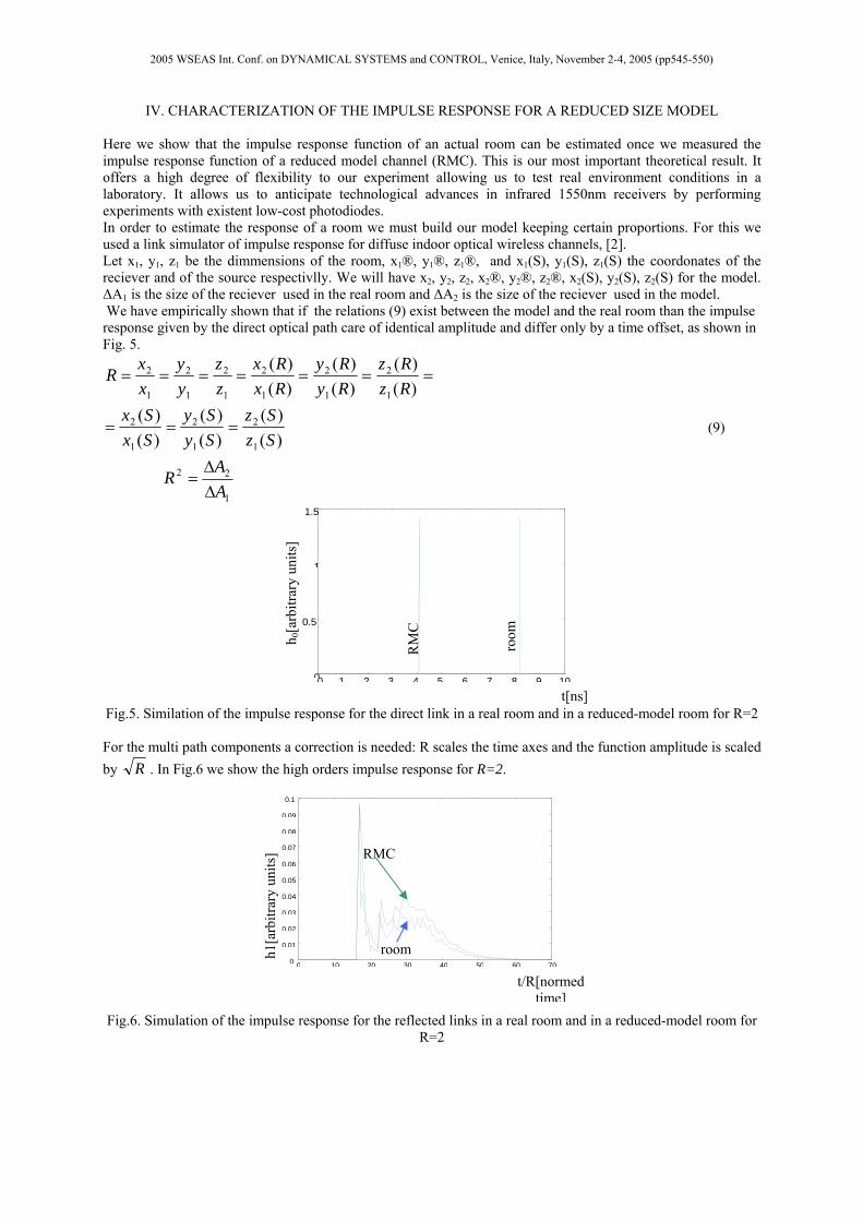
IV. CHARACTERIZATION OF THE IMPULSE RESPONSE FOR A REDUCED SIZE MODEL Here we show that the impulse response function of an actual room can be estimated once we measured the impulse response function of a reduced model channel (RMC). This is our most important theoretical result. It offers a high degree of flexibility to our experiment allowing us to test real environment conditions in a laboratory. It allows us to anticipate technological advances in infrared 1550nm receivers by performing experiments with existent low-cost photodiodes. In order to estimate the response of a room we must build our model keeping certain proportions. For this we used a link simulator of impulse response for diffuse indoor optical wireless channels, [2]. Let x1, y1, z1 be the dimmensions of the room, x1®, y1®, z1®, and x1(S), y1(S), z1(S) the coordonates of the reciever and of the source respectivlly. We will have x2, y2, z2, x2®, y2®, z2®, x2(S), y2(S), z2(S) for the model. ∆A1 is the size of the reciever used in the real room and ∆A2 is the size of the reciever used in the model. We have empirically shown that if the relations (9) exist between the model and the real room than the impulse response given by the direct optical path care of identical amplitude and differ only by a time offset, as shown in Fig. 5.
1
22
1
2
1
2
1
2
1
2
1
2
1
2
1
2
1
2
1
2
)()(
)()(
)()(
)()(
)()(
)()(
AAR
SzSz
SySy
SxSx
RzRz
RyRy
RxRx
zz
yy
xxR
∆∆
=
===
=======
(9)
Fig.5. Similation of the impulse response for the direct link in a real room and in a reduced-model room for R=2 For the multi path components a correction is needed: R scales the time axes and the function amplitude is scaled by R . In Fig.6 we show the high orders impulse response for R=2. Fig.6. Simulation of the impulse response for the reflected links in a real room and in a reduced-model room for
R=2
0 10 20 30 40 50 60 700
0.01
0.02
0.03
0.04
0.05
0.06
0.07
0.08
0.09
0.1
t/R[normed time]
h1[a
rbitr
ary
units
] RMC
room
0 1 2 3 4 5 6 7 8 9 100
0.5
1
1.5
t[ns]
h 0[a
rbitr
ary
units
]
RM
C
room
2005 WSEAS Int. Conf. on DYNAMICAL SYSTEMS and CONTROL, Venice, Italy, November 2-4, 2005 (pp545-550)
The measurement resolution If we reduce the room dimensions we reduce both spread distance and time, so we need a wider band for the measurement system.
max
max
33 fcdx
dcf
⋅=
∆=∆
∆=
We find the relationship between the spread distance (∆d) and the band with of the measurement system (fmax) in equation (10 a), where c is the speed of light. Consequently the spatial resolution (∆x) of the model is given by equation (10 b). For example in a 1mx1mx0.60m model for 1ns temporal resolution one needs 30cm of spread distance, which corresponds to a spatial resolution of 17.3 cm and needs 1 GHz of the band with of the measurement system. Other values are shown in Table 1.It’s obviously that a smaller temporal of resolution is demanded than a greater measurement frequency is needed. Table 1
Measurement frequency
[GHz]
Temporal resolution
[ns]
Spatial resolution [cm]
1 1 17.3 2 0.5 8.66
2.5 0.75 13 10 0.1 1.73
V. EXPERIMENTAL SET-UP
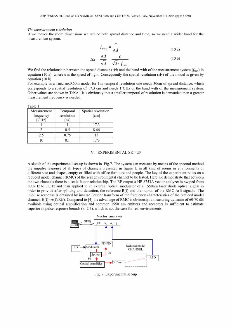
A sketch of the experimental set-up is shown in Fig.7. The system can measure by means of the spectral method the impulse response of all types of channels presented in figure 1, in all kind of rooms or environments of different size and shapes, empty or filled with office furniture and people. The key of the experiment relies on a reduced model channel (RMC) of the real environmental channel to be tested. Here we demonstrate that between the two channels there is a scale factor relationship. The RF output a HP 8753A vector analyzer is swiped from 300kHz to 3GHz and than applied to an external optical modulator of a 1550nm laser diode optical signal in order to provide after splitting and detection, the reference R(f) and the output of the RMC A(f) signals. The impulse response is obtained by inverse Fourier transform of the frequency characteristics of the reduced model channel: H(f)=A(f)/R(f). Compared to [4] the advantage of RMC is obviously: a measuring dynamic of 60-70 dB available using optical amplification and common 1550 nm emitters and receptors is sufficient to estimate superior impulse response bounds (k=2.3), which is not the case for real environments.
Fig. 7. Experimental set-up
Vector analyzer
RF R A B
ModulatorLD PD-PIN
Optical Amplifier
APD Diffuser
GPIB
80
20
Reduced model CHANNEL
Splitter
(10 a) (10 b)
2005 WSEAS Int. Conf. on DYNAMICAL SYSTEMS and CONTROL, Venice, Italy, November 2-4, 2005 (pp545-550)
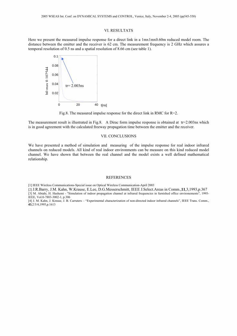
VI. RESULTATS Here we present the measured impulse response for a direct link in a 1mx1mx0.60m reduced model room. The distance between the emitter and the receiver is 62 cm. The measurement frequency is 2 GHz which assures a temporal resolution of 0.5 ns and a spatial resolution of 8.66 cm (see table 1).
Fig.8. The measured impulse response for the direct link in RMC for R=2. The measurement result is illustrated in Fig.8. A Dirac form impulse response is obtained at tr=2.003ns which is in good agreement with the calculated freeway propagation time between the emitter and the receiver.
VII. CONCLUSIONS
We have presented a method of simulation and measuring of the impulse response for real indoor infrared channels on reduced models. All kind of real indoor environments can be measure on this kind reduced model channel. We have shown that between the real channel and the model exists a well defined mathematical relationship.
REFERENCES [1] IEEE Wireless Communications-Special issue on Optical Wireless Communication-April 2003 [2] J.R.Barry, J.M. Kahn, W.Krause, E.Lee, D.G.Messerschmitt, IEEE J.Select.Areas in Comm.,11,3,1993,p.367 [3] M. Abtahi, H. Hashemi - "Simulation of indoor propagation channel at infrared frequencies in furnished office environements", 1995-IEEE, Vol.0-7803-3002-1, p.306 [4] J. M. Kahn, J. Kreuse, J. B. Carruters – “Experimental characterization of non-directed indoor infrared channels”, IEEE Trans. Comm., 43,2/3/4,1995,p.1613
t[ns]0 20 40
0.02
0.04
0.06
0.08
0.1
tr= 2.003ns
h0m
ax0.
1025
44
2005 WSEAS Int. Conf. on DYNAMICAL SYSTEMS and CONTROL, Venice, Italy, November 2-4, 2005 (pp545-550)


