Embed Size (px)
Citation preview
Model-Driven Performance Analysis
Gabriel A. Moreno and Paulo Merson
Software Engineering InstituteCarnegie Mellon University
Pittsburgh, PA, USA{gmoreno,pfm}@sei.cmu.edu
Abstract. Model-Driven Engineering (MDE) is an approach to developsoftware systems by creating models and applying automated transfor-mations to them to ultimately generate the implementation for a targetplatform. Although the main focus of MDE is on the generation of code,it is also necessary to support the analysis of the designs with respectto quality attributes such as performance. To complement the model-to-implementation path of MDE approaches, an MDE tool infrastructureshould provide what we call model-driven analysis. This paper describesan approach to model-driven analysis based on reasoning frameworks.In particular, it describes a performance reasoning framework that cantransform a design into a model suitable for analysis of real-time per-formance properties with different evaluation procedures including ratemonotonic analysis and simulation. The concepts presented in this pa-per have been implemented in the PACC Starter Kit, a developmentenvironment that supports code generation and analysis from the samemodels.
1 Introduction
Model-Driven Engineering (MDE) is an approach to create software systemsthat involves creating models and applying automated transformations to them.The models are expressed in modeling languages (e.g., UML) that describe thestructure and behavior of the system. MDE tools successively apply pre-definedtransformations to the input model created by the developer and ultimately gen-erate as output the source code for the application. MDE tools typically imposedomain-specific constraints and generate output that maps onto specific middle-ware platforms and frameworks [1]. MDE is often indistinctively associated toOMG’s Model-Driven Architecture and Model-Driven Development.
The ability to create a software design and apply automated transformationsto generate the implementation helps to avoid the complexity of today’s im-plementation platforms, component technologies and frameworks. Many MDEsolutions focus on the generation of code that partially or entirely implementsthe functional requirements. However, these solutions often overlook runtimequality attribute requirements, such as performance or reliability. Fixing qualityattribute problems once the implementation is in place has a high cost and oftenrequires structural changes and refactoring. Avoiding these problems is the main
To appear in proceedings of the Fourth International Conference on the Quality of Software Architectures (QoSA 2008). Germany, October 14-17, 2008
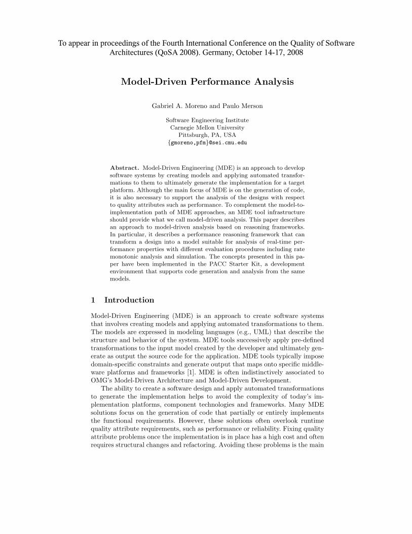
motivation to perform analysis early in the design process. To complement themodel-to-implementation path of MDE approaches, an MDE tool infrastructureshould provide what we call model-driven analysis. The model to code path andthe model-driven analysis path are notionally represented in Figure 1. The goalof model-driven analysis is to verify the ability of the input design model to meetquality requirements.
Fig. 1. Model-Driven Engineering and Model-Driven Analysis
The Software Engineering Institute has developed an MDE tool infrastruc-ture that offers code generation along with various analytic capabilities. Thistool infrastructure is called the PACC Starter Kit (PSK) [2]. It uses the conceptof reasoning frameworks [3] to implement analytic capabilities. Several reasoningframeworks have been developed and applied to industry problems. This paperfocuses on our performance reasoning framework, which analyzes timing proper-ties of component-based real-time systems. The paper describes the model-drivenapproach used in the implementation of the reasoning framework.
The remainder of the paper is organized as follows. Section 2 introduces theconcept of a reasoning framework and then describes the elements of our perfor-mance reasoning framework. Section 3 describes the intermediate constructivemodel, which is the first model created when analyzing an input design. Section 4explains the performance model and how it is generated from the intermediateconstructive model through a transformation called interpretation. Section 5briefly describes how the performance model is used by different evaluation pro-cedures to generate performance predictions. Section 6 shows an example of theapplication of the concepts described in the paper. Section 7 discusses relatedwork and Section 8 has our concluding remarks.
2 Performance Reasoning Framework
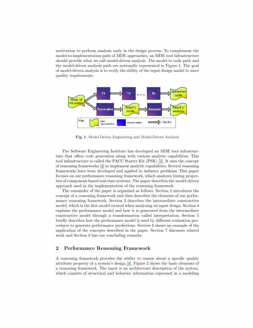
A reasoning framework provides the ability to reason about a specific qualityattribute property of a system’s design [3]. Figure 2 shows the basic elements ofa reasoning framework. The input is an architecture description of the system,which consists of structural and behavior information expressed in a modeling
language or any formally defined design language. Reasoning frameworks can-not analyze any arbitrary design. Furthermore, there is a tradeoff between theanalytic power of a reasoning framework and the space of designs it can analyze.Reasoning frameworks restrict that space by imposing analytic constraints onthe input architecture description. The analytic constraints restrict the designin different ways (e.g., topological constraints) and also specify what propertiesof elements and relations are required in the design.
Fig. 2. Basic elements of a generic reasoning framework
The architecture description is submitted to a transformation called inter-pretation. If the architecture description is well-formed with respect to the con-straints and hence analyzable, the interpretation generates an analytic modelrepresentation. This model is an abstraction of the system capturing only theinformation relevant to the analysis being performed. The types of elements, re-lations and properties found in an analytic model are specific to each reasoningframework. The analytic model is the input to an evaluation procedure, whichis a computable algorithm implemented based on a sound analytic theory. Theimplementation of the evaluation procedure may be purely analytic, simulation-based or a combination of both.
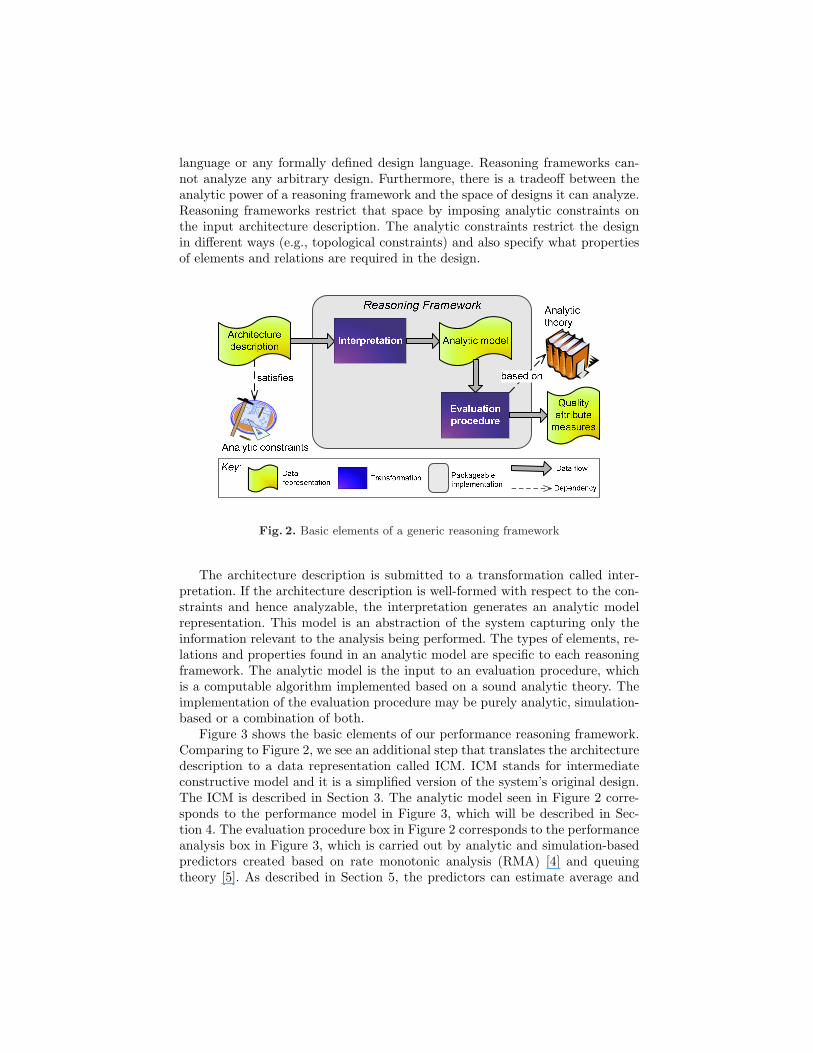
Figure 3 shows the basic elements of our performance reasoning framework.Comparing to Figure 2, we see an additional step that translates the architecturedescription to a data representation called ICM. ICM stands for intermediateconstructive model and it is a simplified version of the system’s original design.The ICM is described in Section 3. The analytic model seen in Figure 2 corre-sponds to the performance model in Figure 3, which will be described in Sec-tion 4. The evaluation procedure box in Figure 2 corresponds to the performanceanalysis box in Figure 3, which is carried out by analytic and simulation-basedpredictors created based on rate monotonic analysis (RMA) [4] and queuingtheory [5]. As described in Section 5, the predictors can estimate average and
worst-case latency of concurrent tasks in a system that runs on a fixed priorityscheduling environment.
Fig. 3. Performance Reasoning Framework
The performance reasoning framework is packaged and independently de-ployed as an Eclipse plug-in [6]. Thus any Eclipsed-based tool used to modelsoftware systems in a parseable design notation could benefit from the perfor-mance reasoning framework by exporting their designs to ICM. Examples of suchtools include: IBM Rational Software Architect, OSATE tool for the AADL lan-guage, Eclipse Model Development Tools (MDT) UML2, and AcmeStudio. Whenadding the performance reasoning framework plug-in to a modeling tool, the onlything one has to do is to create a class that implements the following method:
AssemblyInstance translateDesignToIcm(IFile designFile);
As expected, the implementation of this method is entirely specific to the designlanguage representation used by the tool. We have implemented this method forthe CCL design language [7] that is used in the PSK. An explanation of CCL orhow to translate it to ICM is beyond the scope of this paper. But we should notethat the design language used as input for the performance reasoning frameworkshall support the following elements and relations:
– components with input and output ports1. If the design language were UML,for example, UML components with required and provided interfaces couldbe used.
– special components called environment services (or simply services) that rep-resent external elements of the runtime environment that the system inter-acts with. Clocks, keyboards, consoles, and network interfaces are examples
1 In CCL, an input port is called “sink pin” and an output port is called “sourcepin”—these are the terms used in this paper.
of services. Like regular components, services may have sink and source pins.In UML, they could be represented as stereotyped UML components.
– a way to wire the components together, that is, to connect a source pin to asink pin. In UML, a simple UML assembly connector could be used.
– a way to differentiate between synchronous and asynchronous interactions,as well as threaded and unthreaded interactions. In UML, stereotypes couldbe used to indicate these characteristics.
– a way to annotate any element with specific pairs of key and value. These an-notations are used for properties required by the reasoning framework (e.g.,the performance reasoning framework requires the priority of each compo-nent to be specified). In UML, annotations could be done with tagged values.
3 Intermediate Constructive Model
The architecture description that is the input to a reasoning framework (seeFigure 2) is itself a constructive model of the system. However, it often containsmany details that are not used in the performance analysis. For example, thestate machine of a component may be used for code generation but is not neededby the performance reasoning framework. To remove details specific to the inputdesign language and hence simplify the interpretation translation, we createdthe intermediate constructive model (ICM). The design-to-ICM translation (seeFigure 3) abstracts the elements of the architecture description that are relevantto performance analysis to create the ICM.
Figure 4 shows the ICM metamodel. A complete description of the elements,properties and associations in the ICM metamodel is beyond the objectives ofthis paper. Here, we present the information pieces that are key to the perfor-mance analysis discussion in subsequent sections. The entry point to navigate anICM is AssemblyInstance, which is the return type of the translateDesignToIcmmethod mentioned earlier. The system being analyzed is an assembly of com-ponents. In the ICM metamodel, a component is generically called ElementIn-stance. The use of the suffix “instance” avoids confusion when the input designlanguage allows the definition of types of components. For example, in CCLone can define a component type called AxisController. Then a given assemblymay contain two components (e.g., axisX and axisY ) that are instances of thatcomponent type. The ICM for that assembly would show two ElementInstanceobjects with the same type (AxisController) but different names.
An ElementInstance object (i.e., a component) has zero or more pins (PinIn-stance objects in the metamodel). Each pin is either a SinkPinInstance or aSourcePinInstance object. A sink pin is an input port and when it is activatedit performs some computation. The performance analysis is oblivious to mostdetails of that computation. However, it is necessary to know what source pins(output ports) are triggered during the computation and in what order—that isgiven by the reactSources association between SinkPinInstance and SourcePinIn-stance. It is also necessary to specify the priority that the sink pin computationwill have at runtime. Another important property of a sink pin is the execution
time for the corresponding computation, which is shown in the ICM metamodelas the execTimeDistribution association between SinkPinInstance and Distribu-tion. A sink pin can be synchronous or asynchronous. If it is synchronous, itmay allow concurrent invocations (reentrant code) or enforce mutual exclusionon the sink pin’s computation.
Real-time systems, especially ones with aperiodic threads, sometimes exhibitdifferent behavior depending on certain conditions of the environment or differ-ent pre-set configurations. For example, a system can be operating with limitedcapacity due to a failure condition, or a system can have optional “pluggable”components. These kinds of variability are represented in the ICM as Scenarioobjects. A scenario can be represented in the architecture description as anno-tations to the assembly and the sink pins that are active under that scenario.
Once the ICM for a given architecture description is created, the performancereasoning framework can perform the interpretation translation to generate theperformance model, which is used as input to the performance analysis. Thesesteps are described in the following sections.
4 Performance Model Generation
An important component of a reasoning framework is the interpretation processthat transforms an architecture description into an analytic model. Section 2showed that the architecture description is translated to an intermediate rep-resentation (ICM) in our performance reasoning framework. In this reasoningframework, interpretation starts with an ICM model and produces a perfor-mance model that can then be analyzed by different evaluation procedures.
4.1 Performance Metamodel
The performance metamodel (Figure 5) is based on the method for analyzingthe schedulability of tasks with varying priority developed by Gonzalez Harbouret al. [8]. In this method, a task is a unit of concurrency such as a process ora thread. Tasks are decomposed into a sequence of serially executed subtasks,each of which has a specific priority level and execution time.
The root element of a performance model in our reasoning framework isPerformanceModel, which contains one or more Tasks. Unlike in the method byGonzalez Habour et al., where all tasks are periodic, in our metamodel a task iseither a PeriodicTask or an AperiodicTask. Periodic tasks are characterized bya period and an offset that is used to model different task phasings at startup.Aperiodic tasks, on the other hand, are tasks that respond to events that do nothave a periodic nature. For that reason, they have an interarrivalDistributionto describe the event arrival distribution. For example, the events may followan exponential distribution where the mean interarrival interval is 10ms. TheSSTask models aperiodic tasks scheduled using the sporadic server algorithm [9],which allows scheduling aperiodic tasks at a given priority while limiting theirimpact on the schedulability of other tasks.
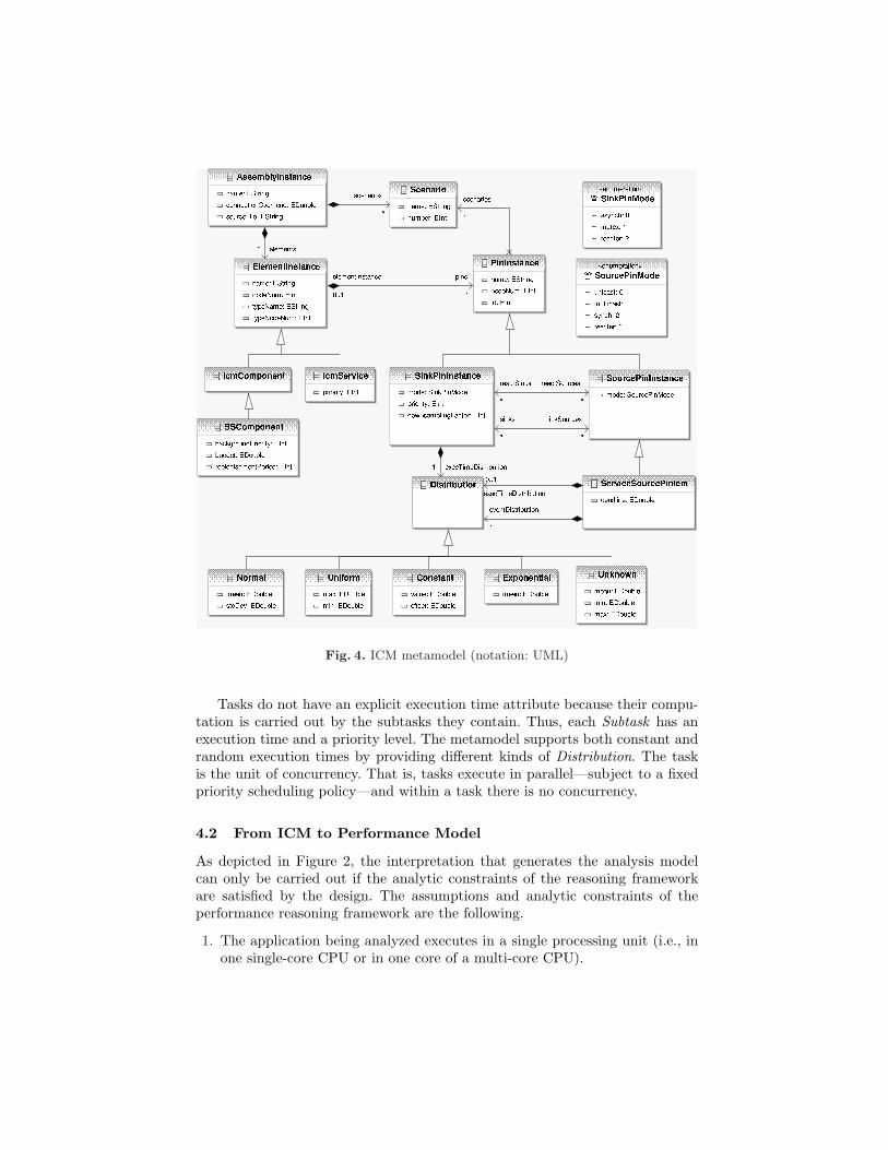
Fig. 4. ICM metamodel (notation: UML)
Tasks do not have an explicit execution time attribute because their compu-tation is carried out by the subtasks they contain. Thus, each Subtask has anexecution time and a priority level. The metamodel supports both constant andrandom execution times by providing different kinds of Distribution. The taskis the unit of concurrency. That is, tasks execute in parallel—subject to a fixedpriority scheduling policy—and within a task there is no concurrency.
4.2 From ICM to Performance Model
As depicted in Figure 2, the interpretation that generates the analysis modelcan only be carried out if the analytic constraints of the reasoning frameworkare satisfied by the design. The assumptions and analytic constraints of theperformance reasoning framework are the following.
1. The application being analyzed executes in a single processing unit (i.e., inone single-core CPU or in one core of a multi-core CPU).
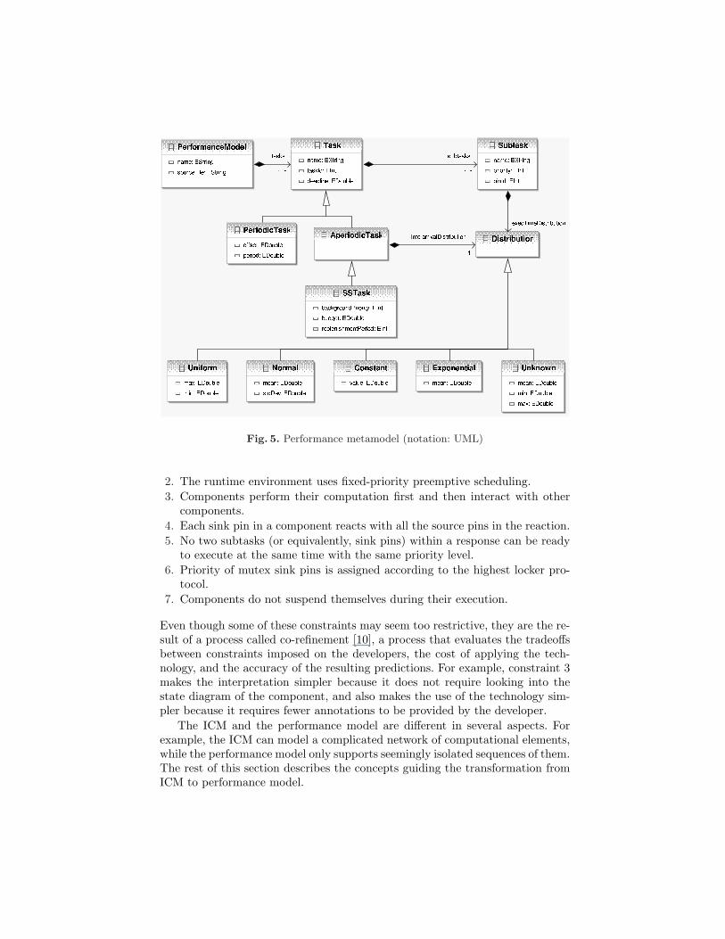
Fig. 5. Performance metamodel (notation: UML)
2. The runtime environment uses fixed-priority preemptive scheduling.3. Components perform their computation first and then interact with other
components.4. Each sink pin in a component reacts with all the source pins in the reaction.5. No two subtasks (or equivalently, sink pins) within a response can be ready
to execute at the same time with the same priority level.6. Priority of mutex sink pins is assigned according to the highest locker pro-
tocol.7. Components do not suspend themselves during their execution.
Even though some of these constraints may seem too restrictive, they are the re-sult of a process called co-refinement [10], a process that evaluates the tradeoffsbetween constraints imposed on the developers, the cost of applying the tech-nology, and the accuracy of the resulting predictions. For example, constraint 3makes the interpretation simpler because it does not require looking into thestate diagram of the component, and also makes the use of the technology sim-pler because it requires fewer annotations to be provided by the developer.
The ICM and the performance model are different in several aspects. Forexample, the ICM can model a complicated network of computational elements,while the performance model only supports seemingly isolated sequences of them.The rest of this section describes the concepts guiding the transformation fromICM to performance model.
An event is an occurrence the system has to respond to. The tick of an internalclock and the arrival of a data packet are examples of events. A response is thecomputational work that must be carried out upon the arrival of an event [4].The main goal of the performance reasoning framework is to predict the latencyof the response to an event, taking into account the preemption and blockingeffects of other tasks. In an ICM, a source of events is represented as a sourcepin in a service (i.e., a ServiceSourcePinIcm). Therefore, the goal translatesinto predicting the latency of all the components that are connected directly orindirectly to that service source pin. Since the response to an event is modeled asa task in the performance model, it follows that for each ServiceSourcePinIcmin the ICM, a Task needs to be created. Depending on the event interarrivaldistribution of the service source pin, the task will be a PeriodicTask or anAperiodicTask.
The next step, and the most complex one, is transforming a possibly multi-threaded response involving several components into a sequence of serially ex-ecuted subtasks. This transformation deals with two main issues: the internalconcurrency within a response, and the blocking effects between responses.
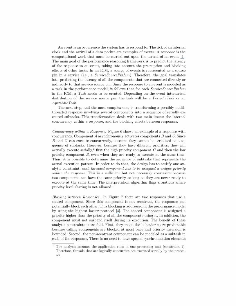
Concurrency within a Response. Figure 6 shows an example of a response withconcurrency. Component A asynchronously activates components B and C. SinceB and C can execute concurrently, it seems they cannot be serialized as a se-quence of subtasks. However, because they have different priorities, they willactually execute serially,2 first the high priority component C and then the lowpriority component B, even when they are ready to execute at the same time.Thus, it is possible to determine the sequence of subtasks that represents theactual execution pattern. In order to do that, the design has to satisfy one an-alytic constraint: each threaded component has to be assigned a unique prioritywithin the response. This is a sufficient but not necessary constraint becausetwo components can have the same priority as long as they are never ready toexecute at the same time. The interpretation algorithm flags situations wherepriority level sharing is not allowed.
Blocking between Responses. In Figure 7 there are two responses that use ashared component. Since this component is not reentrant, the responses canpotentially block each other. This blocking is addressed in the performance modelby using the highest locker protocol [4]. The shared component is assigned apriority higher than the priority of all the components using it. In addition, thecomponent must not suspend itself during its execution. The benefit of theseanalytic constraints is twofold. First, they make the behavior more predictablebecause calling components are blocked at most once and priority inversion isbounded. Second, the non-reentrant component can be modeled as a subtask ineach of the responses. There is no need to have special synchronization elements
2 The analysis assumes the application runs in one processing unit (constraint 1).Therefore, threads that are logically concurrent are executed serially by the proces-sor.
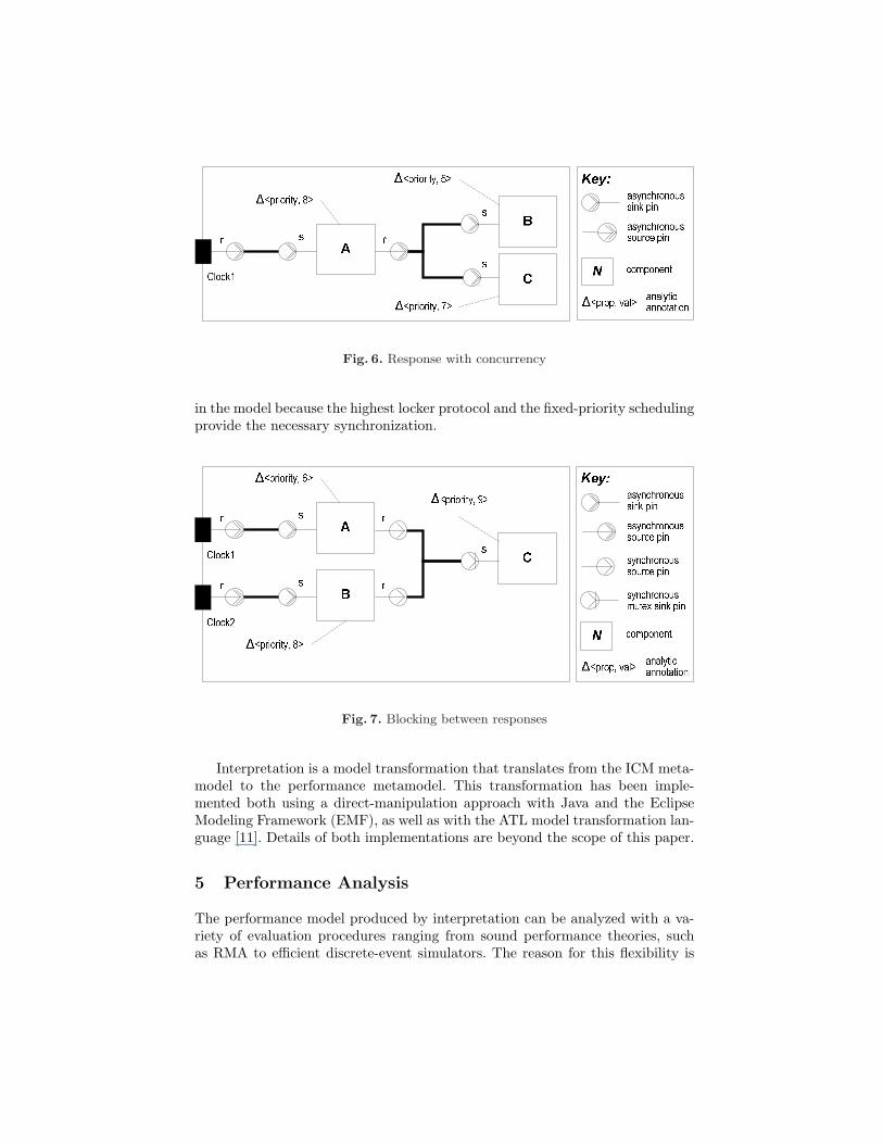
Fig. 6. Response with concurrency
in the model because the highest locker protocol and the fixed-priority schedulingprovide the necessary synchronization.
Fig. 7. Blocking between responses
Interpretation is a model transformation that translates from the ICM meta-model to the performance metamodel. This transformation has been imple-mented both using a direct-manipulation approach with Java and the EclipseModeling Framework (EMF), as well as with the ATL model transformation lan-guage [11]. Details of both implementations are beyond the scope of this paper.
5 Performance Analysis
The performance model produced by interpretation can be analyzed with a va-riety of evaluation procedures ranging from sound performance theories, suchas RMA to efficient discrete-event simulators. The reason for this flexibility is
twofold. First, the evaluation procedures need neither be able to handle asyn-chronous calls nor keep track of call stacks because interpretation translatesresponses involving both into a sequence of serially executed subtasks. Second,evaluation procedures do not need an explicit notion of synchronization betweentasks other than that resulting by virtue of the fixed priority scheduling.
Depending on its characteristics, a given performance model can be ana-lyzed by some evaluation procedures and not by others. For example, modelswith unbounded execution or interarrival time distributions can be handled bya simulation-based evaluation, but not by worst-case analysis like RMA. Forthis reason, different evaluation procedures may dictate adhering to additionalanalytic constraints. In most cases, this is not a limiting constraint, but ratheran enabler for predictability. For instance, when developing a system with hardreal-time requirements where RMA will be used to predict worst-case responsetime, one should avoid designing responses with unbounded execution time.
The rest of this section describes the different evaluation procedures used inour performance reasoning framework. Some of them are third-party tools andhave their own input format. In such cases, the performance model is translatedto the particular format before it is fed to the tool for evaluation.
5.1 Worst-case Analysis
Worst-case analysis predicts the worst-case response time to an event in thesystem by considering the maximum execution time of the components and theworst preemption and blocking effects. Worst-case analysis in the performancereasoning framework is carried out with MAST, a modeling and analysis suite forreal-time applications [12]. Among other techniques, MAST implements RMAwith varying priorities [8].
5.2 Average-case Analysis
Average-case analysis computes the average response time to an event. Althoughthis is achieved by discrete-event simulation in most cases, the performancereasoning framework also includes an analytic average-case analysis.
Simulation-based average-case analyses simulate the execution of a systemtaking into account the statistical distribution of interarrival and executiontimes. By collecting the simulated response time to thousands of arrivals, theycan compute the average response time. In addition, they keep track of the bestand worst cases observed during the simulation.
The performance reasoning framework supports three different simulation-based average case latency predictions. One of them is with Extend, a commercialgeneral-purpose simulation tool that supports discrete-event simulation [13]. Thesimulation model is built out of custom blocks for Extend that represent theconcepts in the performance model (i.e., tasks, subtasks, etc.). The Extend-basedsimulation can model several interarrival distributions and is able to simulatesporadic server tasks. Another simulation analysis is based on a discrete-eventsimulator called qsim. Being a special-purpose simulator, qsim is very efficient
and is able to run much longer simulations in less time. The last of the simulation-based analyses uses Sim MAST, a simulator that is part of the MAST suite.Sim MAST can simulate a performance model providing statistical informationabout the response time to different events.
The analytic average case analysis in the performance reasoning frameworkuses queuing and renewal theory to compute the average latency of a task sched-uled by a sporadic server [5]. Although this method requires specific constraintssuch as exponential interarrival distribution, it provides an envelope for the av-erage latency without the need to run long simulations.
6 Example
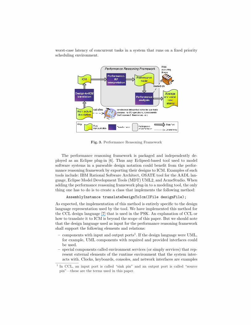
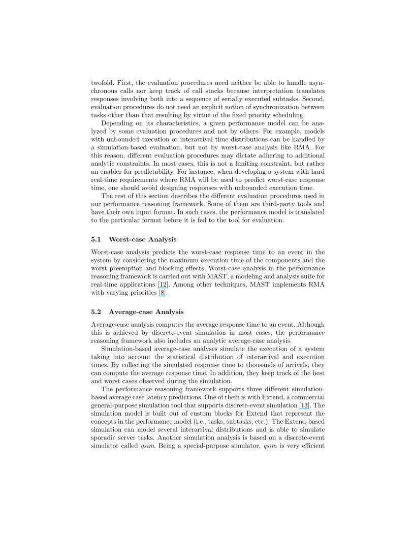
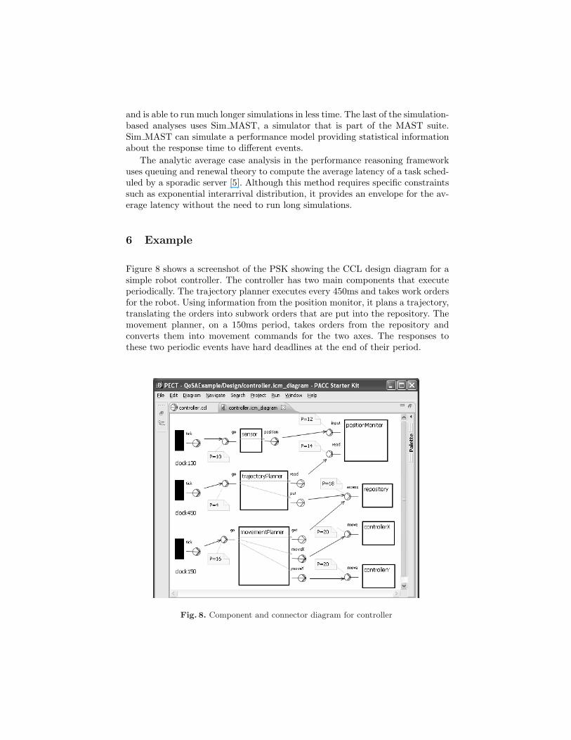
Figure 8 shows a screenshot of the PSK showing the CCL design diagram for asimple robot controller. The controller has two main components that executeperiodically. The trajectory planner executes every 450ms and takes work ordersfor the robot. Using information from the position monitor, it plans a trajectory,translating the orders into subwork orders that are put into the repository. Themovement planner, on a 150ms period, takes orders from the repository andconverts them into movement commands for the two axes. The responses tothese two periodic events have hard deadlines at the end of their period.
Fig. 8. Component and connector diagram for controller
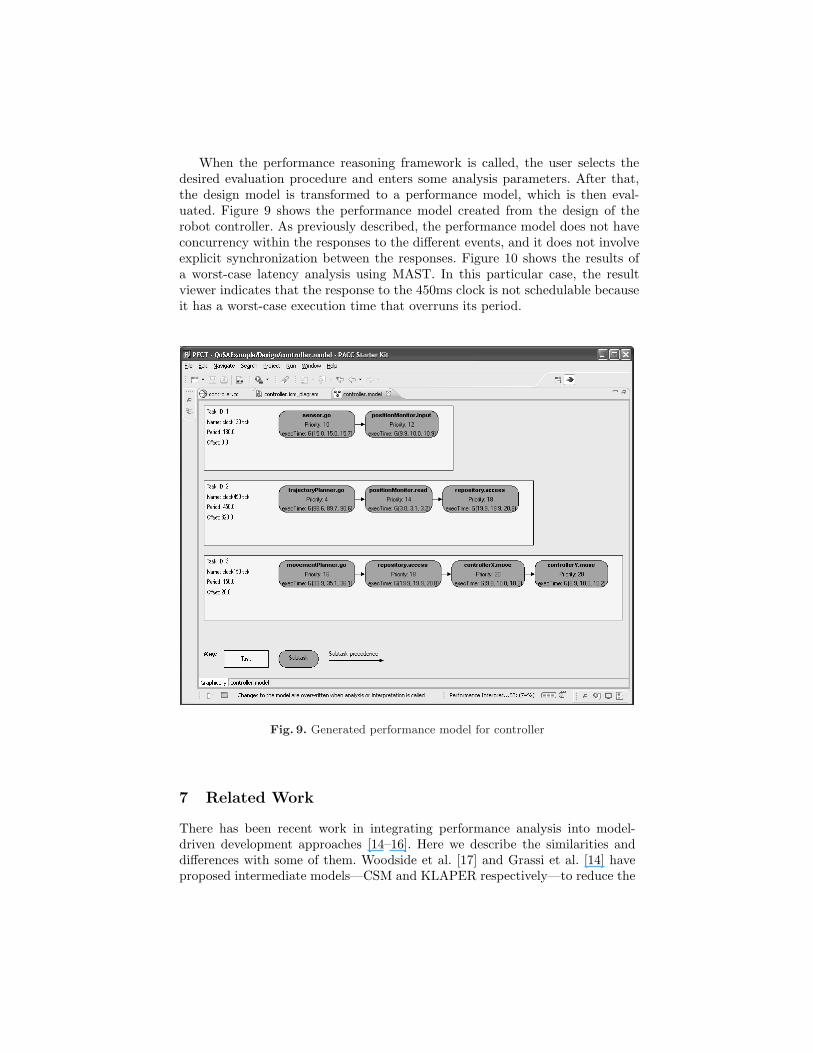
When the performance reasoning framework is called, the user selects thedesired evaluation procedure and enters some analysis parameters. After that,the design model is transformed to a performance model, which is then eval-uated. Figure 9 shows the performance model created from the design of therobot controller. As previously described, the performance model does not haveconcurrency within the responses to the different events, and it does not involveexplicit synchronization between the responses. Figure 10 shows the results ofa worst-case latency analysis using MAST. In this particular case, the resultviewer indicates that the response to the 450ms clock is not schedulable becauseit has a worst-case execution time that overruns its period.
Fig. 9. Generated performance model for controller
7 Related Work
There has been recent work in integrating performance analysis into model-driven development approaches [14–16]. Here we describe the similarities anddifferences with some of them. Woodside et al. [17] and Grassi et al. [14] haveproposed intermediate models—CSM and KLAPER respectively—to reduce the
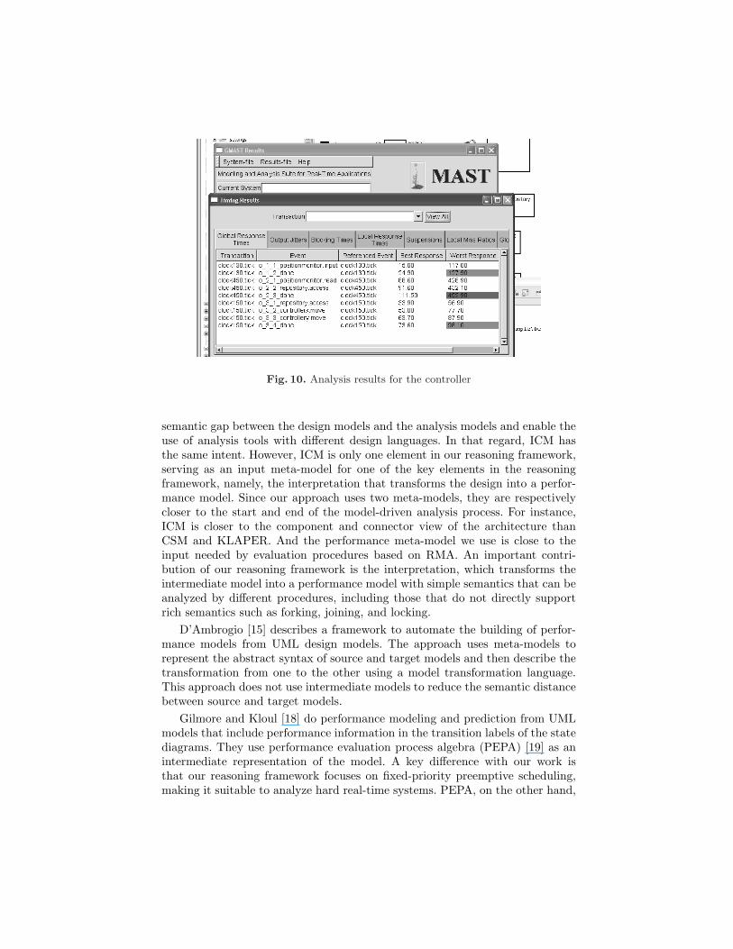
Fig. 10. Analysis results for the controller
semantic gap between the design models and the analysis models and enable theuse of analysis tools with different design languages. In that regard, ICM hasthe same intent. However, ICM is only one element in our reasoning framework,serving as an input meta-model for one of the key elements in the reasoningframework, namely, the interpretation that transforms the design into a perfor-mance model. Since our approach uses two meta-models, they are respectivelycloser to the start and end of the model-driven analysis process. For instance,ICM is closer to the component and connector view of the architecture thanCSM and KLAPER. And the performance meta-model we use is close to theinput needed by evaluation procedures based on RMA. An important contri-bution of our reasoning framework is the interpretation, which transforms theintermediate model into a performance model with simple semantics that can beanalyzed by different procedures, including those that do not directly supportrich semantics such as forking, joining, and locking.
D’Ambrogio [15] describes a framework to automate the building of perfor-mance models from UML design models. The approach uses meta-models torepresent the abstract syntax of source and target models and then describe thetransformation from one to the other using a model transformation language.This approach does not use intermediate models to reduce the semantic distancebetween source and target models.
Gilmore and Kloul [18] do performance modeling and prediction from UMLmodels that include performance information in the transition labels of the statediagrams. They use performance evaluation process algebra (PEPA) [19] as anintermediate representation of the model. A key difference with our work isthat our reasoning framework focuses on fixed-priority preemptive scheduling,making it suitable to analyze hard real-time systems. PEPA, on the other hand,
assumes activities with exponentially distributed duration, whose memorylessproperty allows to treat preemption-resume scenarios as preemption-restart withresampling [20]. This approach is not suitable for real-time systems where moredeterminism is required.
Becker et al. [21] use the Palladio Component Model (PCM) to model component-based architectures including the information necessary for performance predic-tion. PCM is much more detailed than the ICM. For instance, component inter-faces are first-class elements of the metamodel because they are used to checkwhether the connections between components through required and provided in-terfaces are valid. The elements closest to interfaces in ICM are sink and sourcepins. They are not associated with a type or service signature because it is as-sumed that the validity of the connection has already been established at thearchitecture description level–the CCL specification in our case. PCM also allowsmodeling the behavior of the component as far as necessary–an approach calledgray-box–to determine the way required services and resources are used. Thisincludes modeling parameter dependencies, loops, and branching probabilities.In ICM all the required services are assumed to be used exactly once for every in-vocation of the component. Certainly, compared to ICM, PCM allows modelingmore details, that in turn means making fewer assumptions. However, to the bestof our knowledge, the complete details in PCM models cannot be automaticallygenerated and PCM models can only be evaluated by simulation. In contrastICM models are automatically generated from architecture descriptions and canbe analyzed not only by simulation but also by a sound performance theoryfor worst-case response time and schedulability. Also, the simulation frameworkused with PCM does not support priority-based preemptive scheduling.
Analytic constraints play an important role in our approach because theydefine the space of designs that are analyzable by the reasoning framework. Thischaracteristic is also present in the work of Gherbi and Khendek [16] where OCLis used to specify the constraints and assumptions of the schedulability analysis.
8 Conclusions
We began to work in the performance reasoning framework circa 2001. Theinitial versions had limited analysis capability, but successful validation of thepredictions revealed great potential. More recently, we have expanded the spaceof analyzable systems by incorporating and adapting performance theories anddiversifying the set of tools used in the evaluation procedure. In this processwe found that creating metamodels and model transformations greatly reducedcomplexity in the reasoning framework implementation.
The performance reasoning framework has been applied successfully in sev-eral industry scenarios [22–24] and has proven to be very useful for early adoptersof this technology. In maintenance scenarios, model-driven analysis is also useful.The performance annotations of the components in the architecture descriptioncan be changed to reflect the intended modifications and a new run of the anal-ysis can verify whether the modifications will yield the required performance.
The performance reasoning framework is packaged as an Eclipse plug-in andcan be used with different design languages thanks to the ICM metamodel anddesign-to-ICM adapters. A simple architecture description with structural infor-mation (wiring of components and connectors through synchronous and asyn-chronous ports) and performance annotations (e.g., priority, execution time) isthe input for performance analysis. ArchE [25], an architecture expert tool, isan example of an Eclipse-based tool that has been adapted to use the reasoningframework. The PSK is a fully automated solution that includes the perfor-mance reasoning framework and uses CCL as the design language, providing acomprehensive MDE solution: the same architecture description enhanced withbehavior information can also be used as input for code generation. An impor-tant consequence is that conformance between the code, the architecture andthe analysis results is maintained.
Architecture description languages that have explicitly considered the charac-teristics of an application domain or the business needs of adopting organizationshave been more successful [26]. The CCL language was designed to support thedevelopment of component-based safety-critical real-time systems, and its se-mantics are close to the target runtime environment. As a result, annotationsthat express the properties of components and connectors are simpler—by con-trast, a UML generic component or assembly connector would require extensivestereotyping and far more annotations to express the same things.
The performance reasoning framework continues to evolve. Working withacademic and industry collaborators, we plan to extend the space of analyzablesystems by relaxing some of the current analytic constraints. Integration withother performance analysis tools is also a goal. A limitation of our performancereasoning framework is that execution time variations caused by branching areonly represented by the resulting execution time distributions. Since CCL andother design languages can express the behavior inside components, future workintends to overcome that limitation by having the interpretation look inside thestate machine of the components, perhaps using a gray-box approach as in PCM,but trying not to hinder the automation or ability to analyze the model by meansother than simulation.
References
1. Schmidt, D.: Model-driven engineering. IEEE Computer Magazine 39(2) (2006)2. Ivers, J., Moreno, G.A.: Model-driven development with predictable quality. In:
Companion to the OOPSLA’07 Conference. (2007)3. Bass, L., Ivers, J., Klein, M., Merson, P.: Reasoning frameworks. Technical Report
CMU/SEI-2005-TR-007, Software Engineering Institute (2005)4. Klein, M.H., Ralya, T., Pollak, B., Obenza, R., Gonzalez Harbour, M.: A practi-
tioner’s handbook for real-time analysis. Kluwer Academic Publishers (1993)5. Hissam, S., Klein, M., Lehoczky, J., Merson, P., Moreno, G., Wallnau, K.: Per-
formance property theories for predictable assembly from certifiable components(PACC). Technical Report CMU/SEI-2004-TR-017, Software Engineering Insti-tute (2004)
6. Gamma, E., Beck, K.: Contributing to Eclipse: Principles, Patterns, and Plug-Ins.Addison Wesley (2003)
7. Wallnau, K., Ivers, J.: Snapshot of CCL: A language for predictable assembly.Technical Note CMU/SEI-2003-TN-025, Software Engineering Institute (2003)
8. Gonzalez Harbour, M., Klein, M., Lehoczky, J.: Timing analysis for fixed-priorityscheduling of hard real-time systems. IEEE Trans. Softw. Eng. 20(1) (1994)
9. Sprunt, B., Sha, L., Lehoczky, J.: Aperiodic task scheduling for hard real-timesystems. Real-Time Systems 1(1) (1989)
10. Hissam, S., Moreno, G., Stafford, J., Wallnau, K.: Enabling predictable assembly.Journal of Systems and Software 65(3) (2003) 185–198
11. Jouault, F., Kurtev, I.: Transforming models with ATL. In: Proceedings of theModel Transformations in Practice Workshop at MoDELS 2005. (2005)
12. Gonzalez Harbour, M., Gutierrez Garcia, J.J., Palencia Gutierrez, J.C.,Drake Moyano, J.M.: MAST: Modeling and analysis suite for real time appli-cations. In: The 13th Euromicro Conference on Real-Time Systems. (2001)
13. Krahl, D.: Extend: the Extend simulation environment. In: WSC ’02: Proceedingsof the 34th Winter Simulation Conference. (2002)
14. Grassi, V., Mirandola, R., Sabetta, A.: From design to analysis models: a kernellanguage for performance and reliability analysis of component-based systems. In:5th International Workshop on Software and Performance. (2005)
15. D’Ambrogio, A.: A model transformation framework for the automated buildingof performance models from UML models. In: 5th International Workshop onSoftware and Performance. (2005)
16. Gherbi, A., Khendek, F.: From UML/SPT models to schedulability analysis: ametamodel-based transformation. In: Ninth IEEE International Symposium onObject and Component-Oriented Real-Time Distributed Computing. (2006)
17. Woodside, M., Petriu, D., Petriu, D., Shen, H., Israr, T., Merseguer, J.: Perfor-mance by unified model analysis (PUMA). In: 5th International Workshop onSoftware and Performance. (2005)
18. Gilmore, S., Leila, K.: A unified tool for performance modelling and prediction.Reliability Engineering and System Safety 89(1) (Jan 2005) 17–32
19. Hillston, J.: Tuning systems: From composition to performance. The ComputerJournal 48(4) (May 2005) 385–400 The Needham Lecture paper.
20. Gilmore, S., Hillston, J.: The PEPA Workbench: A Tool to Support a ProcessAlgebra-based Approach to Performance Modelling. In: Proceedings of the Sev-enth International Conference on Modelling Techniques and Tools for ComputerPerformance Evaluation. Number 794 in Lecture Notes in Computer Science, Vi-enna, Springer-Verlag (May 1994) 353–368
21. Becker, S., Koziolek, H., Reussner, R.: Model-based performance prediction withthe palladio component model. In: WOSP ’07: Proceedings of the 6th InternationalWorkshop on Software and Performance, New York, NY, USA, ACM (2007) 54–65
22. Hissam, S., Hudak, J., Ivers, J., Klein, M., Larsson, M., Moreno, G., Northrop,L., Plakosh, D., Stafford, J., Wallnau, K., Wood, W.: Predictable assembly ofsubstation automation systems: An experiment report, second edition. TechnicalReport CMU/SEI-2002-TR-031, Software Engineering Institute (2003)
23. Larsson, M., Wall, A., Wallnau, K.: Predictable assembly: The crystal ball tosoftware. ABB Review (2) (2005) 49–54
24. Hissam, S., Moreno, G.A., Plakosh, D., Savo, I., Stelmarczyk, M.: Predicting thebehavior of a highly configurable component based real- time system. In: ECRTS’08: Proceedings of the 20th Euromicro Conference on Real-Time Systems, IEEEComputer Society (2008)

25. Bachmann, F., Bass, L.J., Klein, M., Shelton, C.P.: Experience using an expert sys-tem to assist an architect in designing for modifiability. In: 4th Working IEEE/IFIPConference on Software Architecture (WICSA). (2004)
26. Medvidovic, N.: Moving architectural description from under the technology lamp-post. In: 32nd Euromicro Conference on Software Engineering and Advanced Ap-plications. (2006)


