Embed Size (px)
Citation preview

Modeling Approaches for Electroactive Polymers
Kaal W.a, Herold S.b and Melz T.c
a,b,cFraunhofer Institute for Structural Durability and System Reliability, Germany
ABSTRACT
The focus of this paper is on the modeling of dielectric elastomer actuators and generators. One of the effectsthat is rarely considered in modeling of these systems is the influence of the materials’ specific resistance on theperformance. The non-ideal electrical properties of both elastomer and electrode material will cause undesiredparasitic effects. Although for most laboratory scale prototypes these effects are hardly recognizable, theymay however play an important role for larger structures and especially for dynamic applications. Therefore,an analytical model is developed and presented in this paper which can give helpful instructions for the designand fabrication process of EAP-systems. It is proven to be valid by means of the finite element method andsubsequently extended for more complex systems.
Keywords: dielectric elastomers, electroactive polymers, actuators, modeling, simulation, smart systems,finite elements
1. INTRODUCTION
EAP materials respond to external electrical stimulation with high deformations and can therefore outperformother smart materials in some applications. They can be used to design actuators which are capable of muchhigher displacements, e.g. compared to piezoelectric actuators. They can also be utilized to build generatorsfor energy harvesting applications by exploiting the change in capacitance at large deformations.1–3
In order to properly design and optimize robust and efficient systems reliable models are required thattake into account the various relevant physical effects. Up to now there have been only a few publicationson modeling of EAP material,4–7 and hardly any work has been done to investigate the influence of theelectrical material properties on the performance of EAP actuators. Especially the electric resistivity of boththe elastomer and the electrode material can however have a significant effect on the actuator’s efficiency.The effects investigated in this study are especially critical for large EAP systems and higher frequencies likein applications of structural dynamics. Since most EAP actuators have not exceeded laboratory scale or haveprimarily been used for static and quasi-static applications, this subject has not been paid much attention yet.As will be shown the effects are minimized for electrodes with excellent conductivity properties like graphitepowder8 electrodes or thin-film metallized electrodes. However, for large stroke actuators and also for EAPenergy harvesting devices, where large strains are indispensable, non-metallic electrodes with naturally muchworse conductivity properties will have to be used. In these cases the results presented in this work willcontribute valuable instructions for the proper selection of a material in question and the right dimensioningof the electrode geometry.
2. PHYSICAL PHENOMENON
A sketch of a single elastomer film with electrodes on both sides and a voltage source attached at one endis shown in Figure 1, with an ideal potential distribution (left: without influences of resistances) and with aqualitative potential distribution due to inner resistances (right).
The reason for the inhomogenous distribution is that the specific volume resistivity of the electrode materialis not zero (ρEl > 0) and the insulating resistivity ρIs is finite (ρIs < ∞).
Further author information: (Send correspondence to a)a.: E-mail: [email protected], Telephone: +49 6151 705440b.: E-mail: [email protected], Telephone: +49 6151 705259b.: E-mail: [email protected], Telephone: +49 6151 705252
Electroactive Polymer Actuators and Devices (EAPAD) 2010, edited by Yoseph Bar-Cohen, Proc. of SPIE Vol. 7642, 764211 · © 2010 SPIE · CCC code: 0277-786X/10/$18 · doi: 10.1117/12.848756
Proc. of SPIE Vol. 7642 764211-1

Figure 1. Simple EAP-structure with ideal and non-ideal potential distribution.
To analyze and specify these effects a simple geometrical model is set up, shown in Figure 2. The arrowsindicate the direction of current flow.
l
bdEl
dIs
dEl
electrode
elastomer
Figure 2. Sketch of a film of dielectric elastomer.
In a real EAP device the thin elastomer will have a certain conductivity and the electrodes will show anon-zero resistance. The overall resistances of both elements can be calculated assuming conductors withuniform cross sections according to equations 1. Effects in lateral directions will not be considered, for inmost practical applications l � b will hold true, reducing the investigation to a two-dimensional problem.
REl = ρEl2l
b dEl, RIs = ρIs
dIs
b l. (1)
For parametric studies it is helpful to define a dimensionless resistance ratio η:
η =REl
RIs=
ρEl
ρIs
2l2
dEldIs. (2)
electrode material elastomer material
Y [MPa] ρ [Ωm] ρ [Ωm] εr [-]
silver 83 · 103 1.6·10−8 RT 625 1 · 1013 3.2
Neuhaus K682 ≈ 5 8 · 10−4 3M VHBTM4941 2 · 1012 2.3
Neuhaus K80 ≈ 5 1 · 10−3 3M VHBTM4910 3 · 1013 3.2
conducting polymer PEDOT ≈ 2 · 103 5 · 10−1 Silicone Nusil CF19-2186 1 · 1012 2.8
Table 1. Some physical properties of materials for EAP actuators∗.
∗K682/K80: silicone adhesive with conductive particles (Ag/Cu,Ni), www.neuhaus-elektronik.de,conducting polymer: Oligotron tetramethacrylateTM, 0.5% dispersion in propylene carbonate, for characterization see9
VHBTMproducts: www.3m.com
Proc. of SPIE Vol. 7642 764211-2
Depending on the geometric dimensions and values for material resistivities η can take values in a widerange of magnitudes. For rolled actuators with long unwrapped films the term 2l2
dEldIsis likely to become very
large, especially since research activities aim at maxing out the potential of EAP actuators by reducing thefilm thickness to technological limits, and may even outweigh the extremely small ratio of resistivities ρEl
ρIs.
Table 1 gives an overview over some physical properties of potential materials for the electrode and for theelastomer.
As many have pointed out the development of compliant electrodes is one of the main challenges in thefield of EAP devices10–12 because of the trade-off between good electrical conductivity and sufficiently smallmechanical stiffness. Furthermore the manufacturing process and requests for size, elasticity and reliabilitybring about other boundary conditions for the design of the electrode. In this study the focus will be only onthe electrical properties, though other effects may not be neglected in the design process of EAP devices.
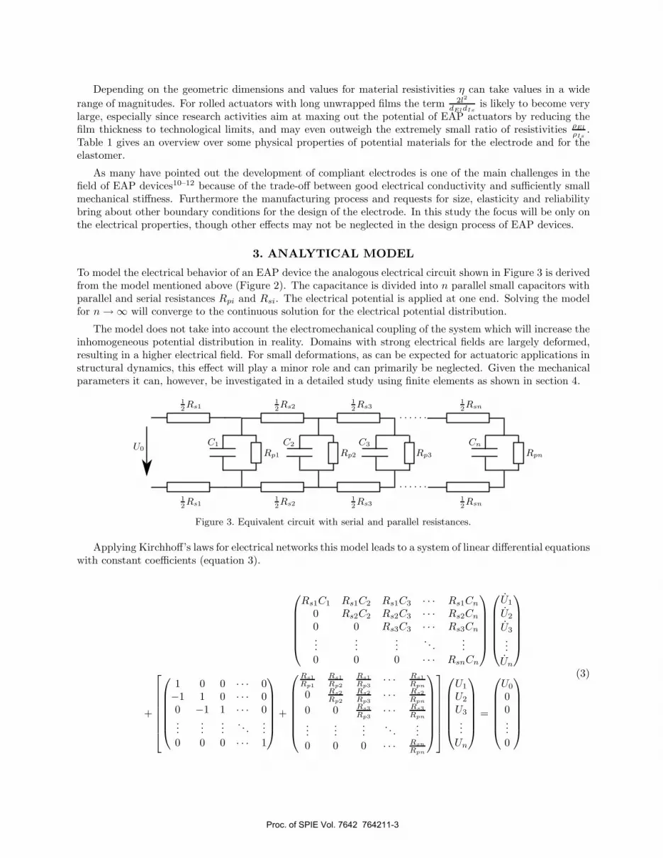
3. ANALYTICAL MODEL
To model the electrical behavior of an EAP device the analogous electrical circuit shown in Figure 3 is derivedfrom the model mentioned above (Figure 2). The capacitance is divided into n parallel small capacitors withparallel and serial resistances Rpi and Rsi. The electrical potential is applied at one end. Solving the modelfor n → ∞ will converge to the continuous solution for the electrical potential distribution.
The model does not take into account the electromechanical coupling of the system which will increase theinhomogeneous potential distribution in reality. Domains with strong electrical fields are largely deformed,resulting in a higher electrical field. For small deformations, as can be expected for actuatoric applications instructural dynamics, this effect will play a minor role and can primarily be neglected. Given the mechanicalparameters it can, however, be investigated in a detailed study using finite elements as shown in section 4.
U0
12Rs1
12Rs1
C1
Rp1
12Rs2
12Rs2
C2
Rp2
12Rs3
12Rs3
C3
Rp3
12Rsn
12Rsn
Cn
Rpn
Figure 3. Equivalent circuit with serial and parallel resistances.
Applying Kirchhoff’s laws for electrical networks this model leads to a system of linear differential equationswith constant coefficients (equation 3).
⎛⎜⎜⎜⎜⎜⎝
Rs1C1 Rs1C2 Rs1C3 · · · Rs1Cn
0 Rs2C2 Rs2C3 · · · Rs2Cn
0 0 Rs3C3 · · · Rs3Cn
......
.... . .
...0 0 0 · · · RsnCn
⎞⎟⎟⎟⎟⎟⎠
⎛⎜⎜⎜⎜⎜⎝
U1
U2
U3
...Un
⎞⎟⎟⎟⎟⎟⎠
+
⎡⎢⎢⎢⎢⎢⎢⎣
⎛⎜⎜⎜⎜⎜⎝
1 0 0 · · · 0−1 1 0 · · · 00 −1 1 · · · 0...
......
. . ....
0 0 0 · · · 1
⎞⎟⎟⎟⎟⎟⎠
+
⎛⎜⎜⎜⎜⎜⎜⎝
Rs1Rp1
Rs1Rp2
Rs1Rp3
· · · Rs1Rpn
0 Rs2Rp2
Rs2Rp3
· · · Rs2Rpn
0 0 Rs3Rp3
· · · Rs3Rpn
......
.... . .
...0 0 0 · · · Rsn
Rpn
⎞⎟⎟⎟⎟⎟⎟⎠
⎤⎥⎥⎥⎥⎥⎥⎦
⎛⎜⎜⎜⎜⎜⎝
U1
U2
U3
...Un
⎞⎟⎟⎟⎟⎟⎠
=
⎛⎜⎜⎜⎜⎜⎝
U0
00...0
⎞⎟⎟⎟⎟⎟⎠
(3)
Proc. of SPIE Vol. 7642 764211-3

The model can, depending on the values for Ci, Rsi and Rpi, represent any geometric configuration; thesimplest and most common case however is the long rectangular film as used in rolled actuators for example.For this case the film is divided into n equal capacitances and resistors:
Rsi =1n
REl = const. (4)
Rpi = n RIs = const. (5)
Ci =1n
Cges = const. (6)
In matrix notation equation 3 can be written as
C U + (B1 + B2) U = U0 (7)
with
U =
⎛⎜⎜⎜⎜⎜⎝
U1(t)U2(t)U3(t)
...Un(t)
⎞⎟⎟⎟⎟⎟⎠
U0 =
⎛⎜⎜⎜⎜⎜⎝
U0(t)00...0
⎞⎟⎟⎟⎟⎟⎠
(8)
and subsequently be transferred to the normalized form for ODEs
U = AU + R(t) (9)
withA = −C−1 (B1 + B2) and R(t) = C−1 U0 . (10)
The characteristic equation|A − λI| = 0 (11)
leads to n eigenvalues λi and n corresponding eigenvectors vn. The general solution of the ODE system iscomposed of n basic solutions
U(t) =n∑
j=0
mj vjeλjt . (12)
The model was set up in a mathematical programming environment with automatically generated matrices.For n = 100 the discretization is fine enough to justify a continuous solution and yet small enough to resultin passable calculation times.
3.1 Initial Charging
First of all the initial charging process shall be considered. The constants mj can be solved with a giveninitial condition, here Ui(t = 0) = 0 for all i and a constant right side U0(t) = U0.
The results are then compared to the charging of a discrete model with a single capacitance C, two serialresistances Ri and one parallel resistance Rp as shown in Figure 4.
The analytical solution for this system is
Udiscr(t) =(
1 − e−Rp+Rs
RpRsC t)
Rp
Rp + RsU0 (13)
Proc. of SPIE Vol. 7642 764211-4

U0
12Rs
12Rs
Cges
Rp
Figure 4. Discrete equivalent circuit.
0 1 2 3 4 50
0.1
0.2
0.3
0.4
0.5
0.6
0.7
0.8
0.9
1
time t/RC
norm
aliz
ed v
olta
ge
discretecontinuous
1
10
100
a)
0 0.05 0.1 0.15 0.20
0.02
0.04
0.06
0.08
0.1
0.12
0.14
0.16
0.18
0.2
0 1 2 3 4 50
0.1
0.2
0.3
0.4
0.5
0.6
0.7
0.8
0.9
1
time t/RC
norm
aliz
ed e
nerg
y
discretecontinuous
n∑1
12CiU
2i
b)
Figure 5. Charging of the capacitor (a) voltage rise over time b) energy storage).
Figure 5 shows the voltage rise at different regions of the capacitor with an ideally insulating elastomer(RIs → ∞). The comparison between the two models makes clear that the discrete model underestimates thedynamic potential of the continuous capacitor. The overall energy content of the capacitor (Figure 5b) andtherefore the stroke and force of the actuator lead the discrete equivalent circuit in time.
If the volume resistance of the elastomer is not infinite (RIs � ∞) the capacitor is not charged completelydue to inner leakage currents. The rearmost regions are charged least, Figure 6b illustrates the potentialdistribution for the steady state.
0 0.5 1 1.5 20
0.2
0.4
0.6
0.8
1
time t/RC
norm
aliz
ed v
olta
ge
discrete without Rp
discrete without Rp
continuous
1
25
50
75
100
a)
0 0.2 0.4 0.6 0.8 10
0.2
0.4
0.6
0.8
1
norm
aliz
ed v
olta
ge
normalized length
discrete without Rp
discrete with Rp
continuous
1
25
50
75100
b)
Figure 6. Incomplete charging for Rp � ∞, both contact points at one end (a) time dependence and b) final stateacross the length).
Proc. of SPIE Vol. 7642 764211-5

3.2 Different Contact Configurations
To enhance the performance of the actuator even simple changes of the construction can be purposeful. Withthe analytical model the effect of different contact configurations can be studied. Applying the electricalcontacts on opposite directions (Figure 7) changes the matrices of the differential equation, the solutionalgorithm remains the same. As depicted in Figure 8 the potential is homogenized over the length, thoughnowhere reaching the maximum voltage. The average voltage is only increased slightly compared to the firstdesign, the quality of the distribution however is increased and the deformation is much more uniform.
U0
C1
Rp1
12Rs2
12Rs2
C2
Rp2
12Rs3
12Rs3
C2
Rp3
12Rs4
12Rs4
C4
Rp4
12Rsn
12Rsn
Cn
Rpn
Figure 7. Analytical model with opposite contact points.
0 1 2 3 4 50
0.2
0.4
0.6
0.8
1
time t/RC
norm
aliz
ed v
olta
ge
discrete without Rp
discrete without Rp
continuous
1/100
25/75
50
a)
0 0.2 0.4 0.6 0.8 10
0.2
0.4
0.6
0.8
1
norm
aliz
ed v
olta
ge
normalized length
discrete without Rp
discrete with Rp
continuous
1
25 50 75
100
b)
Figure 8. Incomplete charging for Rp < ∞, both contacts at opposite ends (a) time dependence and b) final stateacross the length).
Other contact set-ups can further increase the potential distribution. Again the analytical model is usedto estimate the optimization potential (see Appendix A for corresponding equations). Applying two pairs ofcontact points at both ends of the capacitor again rises the mean voltage, adding supporting contact points inbetween pushes the saturation level further up (Figure 9). If possible a long film of EAP material must havemultiple contacts applied to increase the performance, not to mention the benefits gained regarding systemreliability.
Proc. of SPIE Vol. 7642 764211-6

0 0.2 0.4 0.6 0.8 10
0.2
0.4
0.6
0.8
1
rela
tive
volta
ge
relative length
one pair of contactstwo pairs of contactsthree pairs of contactsfour pairs of contacts
0
10
20
30
40
50
60
70
80
90
100
1 2 3 4 5number of connections
ener
gy s
tora
ge [%
]
Figure 9. Enhancement of the saturation level by increasing the number of contact points.
3.3 Dynamic Behavior
As can be seen by a parameter study the aforementioned problems in the static case only arise for sufficientlygreat values of the resistance ratio η which will for most practical set-ups stay far below the critical region.In the dynamic case however the resistance ratio at which a performance loss can be detected sinks to valueswhich are easily achieved with practical actuator designs. If a harmonic signal (U0(t) = sin (ωt)) is appliedthe capacitor will not be charged completely within one period even for an ideally insulating elastomer dueto the electrode resistance. The solution for the complex voltage vector is derived by
U =(jωI + A−1B
)−1A−1U0 . (14)
Figure 10a demonstrates the incomplete charging of the capacitor in the static case and for higher frequenciesfor the exemplary case of η = 0.1. Figure 10b shows the relative charging potential for different frequenciesand resistance ratios. The smaller the resistance ratio, the higher the frequency threshold unto which theactuator can sufficiently be driven. It must however be stressed that the results obtained here do not takeinto account the dynamic potential of the amplifier which will also constrain the frequency range due to thelimited maximum current it can provide.
0 0.2 0.4 0.6 0.8 10
0.1
0.2
0.3
0.4
0.5
0.6
0.7
0.8
0.9
1
norm
aliz
ed v
olta
ge
normalized length
ωC(Rp+R
s) = 0
ωC(Rp+R
s) = 5
ωC(Rp+R
s) = 10
ωC(Rp+R
s) = 50
a)
10−3
10−2
10−1
100
101
0
0.1
0.2
0.3
0.4
0.5
0.6
0.7
0.8
0.9
1
resistance ratio η
ener
gy s
tora
ge
ωC(R
p+R
s) = 0
ωC(Rp+R
s) = 1
ωC(Rp+R
s) = 10
ωC(Rp+R
s) = 100
ωC(Rp+R
s) = 1000
b)
Figure 10. Performance loss for higher frequencies.
Proc. of SPIE Vol. 7642 764211-7

3.4 Self-Discharge and Dissipation Loss
Another advantage of the described modeling approach is that the self-discharge of the capacitor can besimulated which is especially obstructive for EAP energy harvesting devices because it decreases the amountof transformed energy that can be used electrically. Again the system matrices changed slightly (for details seeappendix A) and the initial condition of the ODE is now the final solution of the previous charging analysis.Figure 11a shows the charge and discharge process over time and its spatial distribution qualitatively. Afterdisconnecting the voltage source the potential distribution homogenizes across the capacitor and decreaseswith time (Figure 11b).
0 0.5 1 1.5 2 2.5 3 3.5 40
0.1
0.2
0.3
0.4
0.5
0.6
0.7
0.8
0.9
1
time t/RCp
norm
aliz
ed v
olta
ge
0 0.02 0.04 0.06 0.08 0.10.5
0.55
0.6
0.65
0.7
0.75
0.8
0.85
0.9
0.95
1
�����1
25
50
75
100
a)
0 0.2 0.4 0.6 0.8 10
0.1
0.2
0.3
0.4
0.5
0.6
0.7
0.8
0.9
1
normalized length
norm
aliz
ed v
olta
ge
t=0
t=0.01RCp
t=0.08RCp
t=0.8RCp
b)
Figure 11. Charging and self-discharging of a capacitor with inhomogeneous potential distribution.
The analytical model can also be used to estimate the thermal dissipation loss due to the current flow bysumming up the transformed power of all single resistors:
Pdiss =n∑
i=1
U2i
Rp,i+
n∑i=1
(U2i − U(i−1))2
Rp,i. (15)
4. FINITE ELEMENT MODELING
To fully investigate the behavior of a special EAP device a finite element (FE) model is indispensable becausethe electromechanical coupling and mechanical nonlinearities and boundary-conditions can well be takeninto account. Modeling the aforementioned electrical effects is also possible but requires a special approachbecause standard finite element programs can not solve both for current flows and electrostatic forces in onesolution process. Therefore the simulation is split into two steps. First, the potential distribution due toinner resistances is calculated by solving for the current flow through the system. Here only the electricalproperties of the materials are taken into account. In the second step the mechanical deformation arising fromthis potential distribution is solved for. For small deformations this will already result in a reliable output,for larger deformation both steps have to be repeated in an iteration loop to account for electromechanicalinteraction and higher-order effects. The small FE model (Figure 12) shows that the effects mentioned abovecan all be validated in principle. Therefore, a full FE model is required for complex systems. In order to keepthe number of elements reasonable and the calculation time short enough it will however take advantage ofsymmetry boundary conditions or work with homogenized material properties.
In order to reduce the number of elements and thus keep the simulation time reasonably short a rolledactuator can be modeled with homogenized layers. To make both the electrical and the mechanical behaviorremain identical to the full model the material properties have to be adapted. If k layers are merged into onelayer with k-fold thickness the following equivalent material properties and constraints (labeled with˜) must
Proc. of SPIE Vol. 7642 764211-8

a)
b)
c)
d)
Figure 12. FEM model: potential distribution (left) and resulting mechanical deformation (right).a) contact points at one end, b) contact points at opposite ends, c) two contact pairs, d) three contact pairs
a) b)
Figure 13. FE-Model of the cross-section of a rolled actuator (a) element mesh, b) potential distribution.
be implemented, otherwise the conductivity of the electrode and the insulating properties of the elastomerare overestimated.
U = kU , εr = k2εr , ρIs =1k2
ρIs , ρEl = k2ρEl . (16)
Figure 14 depicts a section of a finite element model of a rolled actuator with single-layer model strategy (left)and with homogenized layers (k = 3) with adapted material properties (right).
Figure 14. Modeling a rolled multilayer actuator with homogenized material parameters.
Proc. of SPIE Vol. 7642 764211-9

5. CONCLUSION
Developing large EAP devices is a complex task and demands preceding simulations since all the designparameters interact and various physical effects arise. In this study the focus was on the significance ofthe electrical properties of the materials used as dielectric elastomer and compliant electrode, especially forconfigurations with rolled films. Disadvantageous combinations of electrode and elastomer material and sizelead to a decreasing performance in the static and especially in the dynamic case. The analytical resultspresented in the first part can be used to predict whether electrical losses will be critical for a given set-upand frequency range. Conversely, it can be stated whether a certain material is suitable, what the criticalthickness from an electrical point of view is and what the maximum frequency for a certain actuator designwill be. Based on the analytical model it has been shown that several actions can be taken in order to improvethe performance and to minimize parasitic effects. Rolled actuators with very long films can be provided withmultiple contact points, for example one per winding, or even a continuous electrical contact on either side.The model was furthermore used to estimate the dissipation losses and to investigate the self-dischargingbehavior. The finite element model presented in the second part has verified the analytical results and hasbeen proven to be valuable in extending the investigation to mechanical and geometrical effects. It is capableof taking into account the electromechanical coupling and the boundary conditions for a certain design. Sinceit can easily become extremely complex and time-consuming, it should only be consulted after making use ofthe analytical guidelines.
APPENDIX A. EQUATIONS
ODE for contacts at opposites ends
⎛⎜⎜⎜⎜⎜⎜⎜⎜⎜⎜⎝
− 12R2C1 + 1
2R2C2 + 12R2C3 · · · + 1
2R2Cn
− 12R3C1 − 1
2R3C2 + 12R3C3 · · · + 1
2R3Cn
− 12R4C1 − 1
2R4C2 − 12R4C3 · · · + 1
2R4Cn
......
.... . .
...− 1
2Rn−1C1 − 12Rn−1C2 − 1
2Rn−1C3 · · · 12Rn−1Cn
02∑
i=2
12RiC2
3∑i=2
12RiC3 · · ·
n∑i=2
12RiCn
⎞⎟⎟⎟⎟⎟⎟⎟⎟⎟⎟⎠
⎛⎜⎜⎜⎜⎜⎜⎜⎝
U1
U2
U3
...Un−1
Un
⎞⎟⎟⎟⎟⎟⎟⎟⎠
+
⎡⎢⎢⎢⎢⎢⎢⎢⎢⎢⎢⎢⎣
⎛⎜⎜⎜⎜⎜⎜⎜⎝
−1 1 0 · · · 00 −1 1 · · · 00 0 −1 · · · 0...
......
. . ....
0 0 0 · · · 10 0 0 · · · 1
⎞⎟⎟⎟⎟⎟⎟⎟⎠
+
⎛⎜⎜⎜⎜⎜⎜⎜⎜⎜⎜⎜⎝
− R22Rp1
+ R22Rp2
+ R22Rp3
· · · + R22Rpn
− R32Rp1
− R32Rp2
+ R32Rp3
· · · + R32Rpn
− R42Rp1
− R42Rp2
− R42Rp3
· · · + R42Rpn
......
.... . .
...−Rn−1
2Rp1−Rn−1
2Rp2−Rn−1
2Rp3· · · Rn−1
2Rpn
02∑
i=2
Ri
2Rp2
3∑i=2
Ri
2Rp3· · ·
n∑i=2
Ri
2Rpn
⎞⎟⎟⎟⎟⎟⎟⎟⎟⎟⎟⎟⎠
⎤⎥⎥⎥⎥⎥⎥⎥⎥⎥⎥⎥⎦
⎛⎜⎜⎜⎜⎜⎜⎜⎝
U1
U2
U3
...Un−1
Un
⎞⎟⎟⎟⎟⎟⎟⎟⎠
=
⎛⎜⎜⎜⎜⎜⎜⎜⎝
000...0U0
⎞⎟⎟⎟⎟⎟⎟⎟⎠
(17)
Proc. of SPIE Vol. 7642 764211-10

ODE for two pairs of contacts at both ends
⎛⎜⎜⎜⎜⎜⎝
Rs1C1 Rs1C2 Rs1C3 · · · Rs1Cn
0 Rs2C2 Rs2C3 · · · Rs2Cn
0 0 Rs3C3 · · · Rs3Cn
......
.... . .
...0 0 0 · · · RsnCn
⎞⎟⎟⎟⎟⎟⎠
⎛⎜⎜⎜⎜⎜⎝
U1
U2
U3
...Un
⎞⎟⎟⎟⎟⎟⎠
+
⎡⎢⎢⎢⎢⎢⎢⎣
⎛⎜⎜⎜⎜⎜⎝
1 0 0 · · · 1−1 1 0 · · · 10 −1 1 · · · 1...
......
. . ....
0 0 0 · · · 2
⎞⎟⎟⎟⎟⎟⎠
+
⎛⎜⎜⎜⎜⎜⎜⎝
Rs1Rp1
Rs1Rp2
Rs1Rp3
· · · Rs1Rpn
0 Rs2Rp2
Rs2Rp3
· · · Rs2Rpn
0 0 Rs3Rp3
· · · Rs3Rpn
......
.... . .
...0 0 0 · · · Rsn
Rpn
⎞⎟⎟⎟⎟⎟⎟⎠
⎤⎥⎥⎥⎥⎥⎥⎦
⎛⎜⎜⎜⎜⎜⎝
U1
U2
U3
...Un
⎞⎟⎟⎟⎟⎟⎠
=
⎛⎜⎜⎜⎜⎜⎜⎝
1 + Rs1Rsm
Rs2RsmRs3Rsm
...Rsn
Rsm
⎞⎟⎟⎟⎟⎟⎟⎠
U0
(18)
REFERENCES
[1] Pelrine, R., Kornbluh, R., and Joseph, J., “Electrostriction of polymer dielectrics with compliant elec-trodes as a means of actuation: Tenth IEEE international workshop on micro electro mechanical systems,”Sensors and Actuators A: Physical 64(1), 77–85 (1998/1/1).
[2] Carpi, F., [Dielectric elastomers as electromechanical transducers: Fundamentals, materials, de-vices, models and applications of an emerging electroactive polymer technology ], Elsevier, Amsterdam,reprinted. ed. (2008).
[3] Bar-Cohen, Y., ed., [Smart structures and materials 2002 - Electroactive polymer actuators and devices(EAPAD): 18 - 21 March 2002, San Diego, USA ], SPIE proceedings series 4695, SPIE, Bellingham,Wash. (2002).
[4] Pelrine, R., Kornbluh, R., and Kofod, G., “High-strain actuator materials based on dielectric elastomers,”Advanced Materials 12(16), 1223–1225 (2000).
[5] Wissler, M. and Mazza, E., “Electromechanical coupling in dielectric elastomer actuators,” Sensors andActuators A: Physical 138(2), 384–393 (2007).
[6] Wissler, M. and Mazza, E., “Modeling and simulation of dielectric elastomer actuators,” Smart Materialsand Structures 14(6), 1396–1402 (2005).
[7] Wissler, M. and Mazza, E., “Modeling of a pre-strained circular actuator made of dielectric elastomers,”Sensors and Actuators A: Physical 120(1), 184–192 (2005).
[8] Pelrine, R., Kornbluh, R., Joseph, J., Heydt, R., Pei, Q., and Chiba, S., “High-field deformation ofelastomeric dielectrics for actuators,” Materials Science and Engineering: C 11(2), 89–100 (2000/11/28).
[9] Lang, U., Naujoks, N., and Dual, J., “Mechanical characterization of PEDOT:PSS thin films,” SyntheticMetals 159(5-6), 473 – 479 (2009).
[10] Kofod, G. and Sommer-Larsen, P., “Compliant electrodes: solutions, materials and technologies,” in [Di-electric Elastomers as Electromechanical Transducers ], Federico Carpi, Danilo De Rossi, Roy Kornbluh,Ronald Pelrine, and Peter Sommer-Larsen, eds., 69–76, Elsevier, Amsterdam (2008).
[11] Niklaus, M., Rosset, S., Dubois, P., and Shea, H., “Ion-implanted compliant electrodes used in dielectricelectroactive polymer actuators with large displacement: Proceedings of the eurosensors XXIII confer-ence,” Procedia Chemistry 1(1), 702–705 (2009).
[12] Urdaneta, M., Delille, E., and Smela, R., “Stretchable electrodes with high conductivity and photo-patternability,” Advanced Materials 19(18), 2629–2633 (2007).
Proc. of SPIE Vol. 7642 764211-11


