Embed Size (px)
Citation preview

Acta Mech 201, 313–339 (2008)DOI 10.1007/s00707-008-0065-z
F. Pesavento · D. Gawin · B. A. Schrefler
Modeling cementitious materials as multiphase porousmedia: theoretical framework and applications
Dedicated to Professor Wilhelm Schneider on the occasion of his 70th birthday
Received: 4 February 2008 / Revised: 20 May 2008 / Published online: 6 August 2008© Springer-Verlag 2008
Abstract In this paper a general model for the analysis of concrete as multiphase porous material, based on theso-called Hybrid Mixture Theory, is presented. The development of the model equations, taking into accountboth bulk phases and interfaces of the multiphase system is described, starting from the microscopic scale. Anexploration of the second law of thermodynamics is also presented: it allows defining several quantities usedin the model, like capillary pressure, disjoining pressure or effective stress, and to obtain some thermodynamicrestrictions imposed on the evolution equations describing the material deterioration. Then, two specific formsof the general model adapted to the case of concrete at early ages and beyond and to the case of concrete struc-tures under fire are shown. Some numerical simulations aimed to prove the validity of the approach adoptedalso are presented and discussed.
List of symbols
aαβ area of αβ interface per averaging volumeAα specific Helmholtz free energy for the bulk phase α (J kg−1)Aαβ specific Helmholtz free energy for the interface αβ (J kg−1)aαβ specific surface of the αβ-interface (m−1)Cp effective specific heat of porous medium (J kg−1 K−1)Cg
p specific heat of gas mixture (J kg−1 K−1)Cw
p specific heat of liquid phase (J kg−1 K−1)D total damage parameter (–)d mechanical damage parameter (–)dα strain rate tensor of the bulk phase α (s−1)
F. Pesavento (B) · B. A. SchreflerDepartment of Structural and Transportation Engineering,University of Padua, via Marzolo 9, 35-131 Padua, ItalyE-mail: [email protected]
B. A. SchreflerE-mail: [email protected]
D. GawinDepartment of Building Physics and Building Materials,Technical University of Łódz, Al. Politechniki 6, 93-590 Łódz, PolandE-mail: [email protected]

314 F. Pesavento et al.
Dgwd effective diffusivity tensor of water vapor in dry air (m2 s−1)
E Young’s modulus (Pa)E0 Young’s modulus of mechanically undamaged material (Pa)Es strain tensor for the solid phase (finite strain) (–)Eα internal energy of bulk phase α (J kg−1)Eαβ internal energy of interface αβ (J kg−1)eααβ rate of mass transfer to the bulk phase α from interface αβ (kg m−3 s−1)
eαβαβγ rate of mass transfer to the interface αβ from the contact line αβγ (kg m−3 s−1)
es elastic strain for the solid phase (infinitesimal deformations) (–)g gravity acceleration (m s−2)gαβ acceleration of the αβ interface (m s−2)Hα enthalpy of the bulk phase α (J kg−1)Hαβ enthalpy of the interface αβ (J kg−1)hα heat source in the bulk phase α (W kg−1)hαβ heat source on the interface αβ (W kg−1)I unit tensor (–)Jααβ curvature of the αβ interface with respect to the bulk phase α (m−1)
Jgwd diffusive flux of vapor (kg m−2 s−1)
Jgad diffusive flux of dry air (kg m−2 s−1)
k absolute permeability tensor (m2)k absolute permeability (scalar) (m2)krπ relative permeability of π-phase (π = g,w) (–)mdehydr rate of mass due to dehydration (kg m−3 s−1)mvap rate of mass due to phase change (kg m−3 s−1)n total porosity (pore volume/total volume) (–)pc capillary pressure (Pa)pg pressure of gas phase (Pa)pw pressure of liquid water (Pa)ps solid skeleton pressure (Pa)pga dry air partial pressure (Pa)pgw water vapor partial pressure (Pa)qα heat flux vector for the bulk phase α (W m−2)qαβ heat flux vector for the interface αβ (W m−2)Qα
αβ body supply of the heat to the bulk phase α from the interface αβ (W m−3)
Qαβαβγ body supply of the heat to the interface αβ from the contact line αβγ (W m−3)
Q fourth order tensor for the definition of transient thermal strain (–)Sw liquid phase volumetric saturation (liquid volume/pore volume) (–)Sαβ
αβγ body supply of momentum to the αβ-interfaces from the αβγ -contact line (kg m−2 s−2)sαβ stress tensor for the αβ-interface (Pa m)T absolute temperature (K)T α absolute temperature of the α-phase (K)T αβ absolute temperature of the αβ-interface (K)Tcr critical temperature of water (K)Tmax maximum temperature attained during dehydration process (K)t time (s)ts Cauchy stress tensor of the solid phase (Pa)tα partial stress tensor of the α-phase (Pa)tTotal total stress tensor of the multiphase system (Pa)Tα
αβ Body supply of momentum to the bulk phases from the interfaces (kg m−2 s−2)u displacement vector of solid matrix (m)V thermo-chemical damage parameter (–)

Modeling cementitious materials as multiphase porous media: theoretical framework and applications 315
vα velocity of the α-phase (m s−1)vα,s relative velocity of the α-phase (with respect to the solid phase “s”) (m s−1)vα,αβ relative velocity of the α-phase (with respect to αβ-interface) (m s−1)vgs relative velocity of gaseous phase (m s−1)vws relative velocity of liquid phase (m s−1)wαβ velocity of the interface αβ (m s−1)wαβ,s relative velocity of the αβ-interface (with respect to the solid phase “s”) (m s−1)xws
s solid surface fraction in contact with the wetting phase (water) (–)xgs
s solid surface fraction in contact with the non-wetting phase (gas) (–)
Greek symbols
α generic bulk phaseα Biot’s constant (–)αc convective heat transfer coefficient (W m−2 K−1)αβ generic interface of α- and β-phasesβtchem thermo-chemical strain coefficient (K−1)βc convective mass transfer coefficient (m s−1)βs cubic thermal expansion coefficient of solid (K−1)βswg combine (solid + liquid + gas) cubic thermal expansion coefficient (K−1)βsw combine (solid + liquid) cubic thermal expansion coefficient (K−1)βtr normalized transient thermal strain coefficient (K−1 s)βw thermal expansion coefficient of liquid water (K−1)χeff effective thermal conductivity (W m−1 K−1)�Hvap enthalpy of vaporization per unit mass (J kg−1)�Hdehydr enthalpy of dehydration per unit mass (J kg−1)εsh shrinkage strain tensor (–)εtchem thermo-chemical strain tensor (–)εth thermal strain tensor (–)εtot total strain tensor (–)εtr transient thermal strain tensor (–)εtr normalized transient thermal strain (–)ε equivalent strain in damage theory of Mazars (–)�αβ surface excess mass density of αβ-interface (kg m−2)�hydr degree of hydration (or dehydration) (–)γ αβ macroscopic interfacial tension of the αβ-interface (J m−2)ηα volumetric fraction of the α phase (–)µπ dynamic viscosity of the constituent π-phase (π = g, w) (Pa s)λα specific entropy of the α-phase (J kg−1 K−1)λαβ specific entropy of the αβ-interface (J kg−1 K−1)�α rate of net production of entropy of the α-phase (W m−3 K−1)�αβ rate of net production of entropy of the αβ-interface (W m−3 K−1)� stiffness matrix of damaged material (Pa)�o stiffness matrix of undamaged material (Pa)�w disjoining pressure (Pa)ρ apparent density of porous medium (kg m−3)ρα density of the α phase (kg m−3)ρg gas phase density (kg m−3)ρw liquid phase density (kg m−3)ρs solid phase density (kg m−3)ρga mass concentration of dry air in gas phase (kg m−3)ρgw mass concentration of water vapor in gas phase (kg m−3)�α
αβ body entropy supply to the bulk phase α from the interfaceαβ (W m−3 K−1)

316 F. Pesavento et al.
�αβαβγ body entropy supply to the interface
αβ from the contact line αβγ (W m−3 K−1)τ s Bishop effective stress tensor of the skeleton (Pa)τ s “net” effective stress tensor of the skeleton (Pa)
Operators and averaged values∂∂t partial time derivativegrad gradient operator (spatial description)div divergence operator (spatial description)
1 Introduction
In this work a general theoretical framework for the analysis of cementitious materials as multiphase porousmedia is presented and applied for solving some relevant engineering problems. By definition, a porous mate-rial is made of a solid phase and closed and open pores. The case where the open pores are filled with one ormore fluids (e.g., water vapor, liquid water, dry air, bound water, etc.) is considered herein.
In several situations it is necessary to model concrete-like materials in such a way. Typical cases deal withconcrete performance in the high-temperature range, e.g., during fire, with early stages of maturing of massiveconcrete structures, with shotcrete in tunneling, and with durability (e.g., concrete affected by leaching process,degradation due to chlorides attack, etc.).
In modeling such a class of problems, usually two different approaches have been used in the past: theclassical phenomenological approach and the mechanistic one. The general model for chemo-hygro-thermo-mechanical analysis of concrete described in the following has been developed using a mechanistic approach.Such an approach leads to governing equations that are usually more complicated formally, but their coef-ficients have clear physical meaning and often are related to classical material parameters, like for exampleporosity, intrinsic permeability, diffusivity of vapor in air, etc. When some relations between structure param-eters and transport properties are found (e.g., the effect of water degree of saturation on relative permeabilityfor water flow), usually they are valid for a class of similar materials, e.g., cellular concrete, ceramic materi-als, etc. Models of this group are generally obtained from microscopic balance equations written for specificconstituents of the medium (i.e., at microscopic level), which are then averaged in space, e.g., by means ofmixture theories [1,2], volume averaging technique [3–6], or homogenization theory [7,8]. Mass and energyfluxes are usually expressed by means of gradients of the related thermodynamic potentials, e.g., temperature,capillary pressure, water vapor concentration etc. Phase changes and the related mass and energy sources(sinks) are also taken into account. Moreover, some additional couplings, e.g., effect of material damagingon intrinsic permeability or capillary and vapor pressures (moisture content) on skeleton stresses, can beconsidered.
In the present work the general model will be formulated by using the so-called Hybrid Mixture Theory [9]in which the governing equations at macroscopic level are obtained by averaging the corresponding equationsin local form, while the constitutive laws are defined directly at the upper scale. Thus, in this paper, we presentthe development of the model equations, taking into account both bulk phases and interfaces of the multiphasesystem, and exploration of the second law of thermodynamics, which allows us to define several quantities usedin the model, like capillary pressure, disjoining pressure or effective stress, and obtain some thermodynamicrestrictions imposed on the evolution equations describing material deterioration. The consistent applicationof the second law of thermodynamics to the whole model is shown for the first time. Then, we present twospecific forms of the general model adapted to the case of concrete at early ages and beyond and to the case ofconcrete structures under fire. Some numerical simulations aimed to show the validity of the approach adopted,will also be presented and discussed.
2 Mathematical model of concrete considered as a multiphase porous material
The multiphase porous system, used for writing the governing equations of the model, is assumed initiallyfar from the thermodynamic equilibrium state. It is treated within the framework of averaging theories by

Modeling cementitious materials as multiphase porous media: theoretical framework and applications 317
Hassanizadeh and Gray [9], starting from the microscopic level and applying the mass-, area- and volumeaveraging operators to the local form of balance equations. For the sake of brevity, the microscopic balanceequations for the constituents of the porous medium are omitted here as well as the kinematics description: theycan be found in [11]. It is simply recalled that the fluid phases and the solid are separated at microscopic levelby interfaces and the latter ones by contact lines. As outlined in [10], the interfaces between the constituentsand their thermodynamic properties are of importance to consider properly constitutive relationships; thusthey are taken into account in defining the general form of the model and in the exploitation of the second lawof thermodynamics. The contact lines are supposed to not possess any thermodynamic property, even if theyallow for exchange of properties between interfaces.
More specifically, in the present case the solid skeleton voids are filled partly by liquid water (thewetting phase) and partly by a gas phase (the non-wetting phase). Below the critical temperature ofwater, Tcr, the liquid phase consists of physically bound water and capillary water, which appears whenthe degree of water saturation exceeds the upper limit of the hygroscopic region, Sssp. Above the tem-perature Tcr, the liquid phase consists of bound water only. In the whole temperature range the gas phaseis a mixture of dry air and water vapor, which is a condensable gas constituent for temperaturesT < Tcr.
The constituents are assumed to be chemically non-reacting except for the solid phase which is formed bythe aggregates and the products of cement hydration (C-S-H gel and calcium hydroxide, mainly). It is affectedby a hydration process during concrete maturing and dehydration process for temperatures exceeding about105◦C. The solid phase is assumed to be in contact with all fluids in the pores. In the following the bulk phasesare indicated with Greek letters (α, β = w,g,s), while for the interfaces and contact lines some combinationsof two and three Greek letters have been used, respectively, (αβ = ws,wg,gs and αβγ = wgs). All symbols areexplained in the list of symbols.
The set of governing equations at macroscopic level is as follows (for a detailed description of the proceduresee [10]):− Mass balance equation for bulk phases and interfaces:
Dαηαρα
Dt+ ηαραdivvα =
∑
β
eααβ, (1)
Dαβaαβ�αβ
Dt+ aαβ�αβdivwαβ = −eα
αβ − eβαβ + eαβ
αβγ (2)
where α, β = s, w, g and αβ = sw, sg, wg and αβγ = swg.The mass source terms on the RHS of Eq. (1) correspond to exchange of mass with interfaces sepa-
rating individual phases (phase changes) and couple these equations with the corresponding balance equa-tions written for the interfaces. The last term in Eq. (2) describes mass exchange of the interfaces withtheir contact line. Since we have three phases composing the medium, there is only one contact line (whichdoes not have any thermodynamic property). In Eq. (2) �αβ represents the macroscopic excess mass ofthe interface αβ, that can be used for taking into account the transition in density from one phase toanother.− Momentum balance equations for the bulk phases and interfaces:
ηαρα Dαvα
Dt− div
(ηαtα
)− ηαραg =∑
β
Tααβ, (3)
aαβ�αβ Dαβwαβ
Dt− div
(aαβsαβ
)− aαβ�αβgαβ
= −(
Tααβ + eα
αβvα,s)
−(
Tβαβ + eβ
αβvβ,s)
+(
eααβ + eβ
αβ
)wαβ,s + sαβ
αβγ .
(4)
The RHS terms in Eq. (3) describe the supply of momentum from the interfaces, i.e., related to phasechanges, while the last RHS term in Eq. (4) corresponds to momentum supply from the contact line wgs to theαβ interface. In this equation, sαβ is the surface stress tensor, which is symmetric.

318 F. Pesavento et al.
− Energy balance equations for the bulk phases and the interfaces:
ηαρα Dα Eα
Dt− ηαtα : grad vα − div
(ηαqα
)− ηαραhα =∑
β
Qααβ, (5)
aαβ�αβ Dαβ Eαβ
Dt− aαβsαβ : grad wαβ − div
(aαβqαβ
)− aαβ�αβhαβ
= −[
Qααβ + Tα
αβ · vα,αβ + eααβ
(Eα,αβ + 1/2
(vα,αβ
)2)]
−[
Qβαβ + Tβ
αβ · vβ,αβ + eβαβ
(Eβ,αβ + 1/2
(vβ,αβ
)2)]+ Qαβαβγ ,
(6)
where Eα,αβ = Eα − Eαβ .The source terms in Eq. (5) describe supply of heat to the bulk phase from the interfaces, related to phase
changes. The terms in square brackets in Eq. (6) describe the energy supply from the bulk phase to the interface,energy associated with momentum supply and energy related to mass supply because of phase changes. Thelast RHS term is supply of heat to the interface from the contact line.− Entropy balance equations for the bulk phases and for the interfaces:
The entropy fluxes are defined here as heat fluxes divided by temperature (otherwise a constitutive rela-tionship is needed), and the entropy external supply due solely to external energy sources is considered, i.e.,assuming the hypothesis of a simple thermodynamic processes. Thus, the entropy balance for the bulk phasesand interfaces may be expressed as follows [10]:
ηαρα Dαλα
Dt− div
(ηα qα
T α
)− ηαρα hα
T α=∑
β
�ααβ + �α, (7)
aαβ�αβ Dαβλαβ
Dt− div
(aαβ qαβ
T αβ
)− aαβ�αβ hαβ
T αβ
= −(�α
αβ + eααβλα,αβ
)−(�
βαβ + eβ
αβλβ,αβ)
+ �αβαβγ + �αβ
(8)
where λα,αβ = λα − λαβ .The two first terms in RHS of Eq. (7) describe the entropy supply to the bulk phases from the interfaces,
while the last one is the rate of net production of entropy in the bulk phase. The terms in parentheses in theRHS of Eq. (8) describe the supply of entropy from the interfaces and the one resulting from the mass supply(phase change), the last but one accounts for entropy supply to the interface from the contact line and the lastone is the rate of net production of entropy in the interface.
The terms related to exchange of mass, momentum, energy and entropy between interfaces via the contactlines must satisfy some restrictions, because the contact lines do not possess any thermodynamic properties asalready stated. Thus, the following relations hold (for further details see [10]):
∑αβ
eαβwgs = 0,
∑αβ
(sαβ
wgs + eαβwgswαβ
)= 0,
∑αβ
[Qαβ
wgs + sαβwgs · wαβ + eαβ
wgs
(Eαβ + 1/2
(wαβ
)2)] = 0,
∑αβ
(�
αβwgs + eαβ
wgsλαβ)
= 0.
(9)
3 Results from the exploitation of the second law of Thermodynamics and constitutive relationships
In the following subsections, results concerning some important properties and/or quantities coming out fromthe exploitation of the second law of Thermodynamics will be presented and discussed. The procedure leadingto a stationary condition of the net production of entropy, is presented in the Appendix. In the next sectionwe apply the results of such a procedure under thermodynamic equilibrium conditions and for infinitesimaldeformations.

Modeling cementitious materials as multiphase porous media: theoretical framework and applications 319
3.1 Solid pressure, effective stress principle and the solid phase stress tensor
At equilibrium state one obtains a considerable simplification of the mathematical problem [10].In particular, the capillary pressure has the following form (see the Appendix):
pc = pg − pw. (10)
For low moisture contents (i.e., in hygroscopic region), when water is present only as a thin film on theskeleton surface, it has to be interpreted as the adsorbed water potential � multiplied by the water density ρw
[11,12]:
pc = −�ρw, � = −�Hads/Mw (11)
where �Hads is the enthalpy of adsorption and Mw is the molar mass of water.When taking into account explicitly the water films, their pressure pw differs from the reservoir water
pressure, pwo , by an amount equal to the disjoining pressure, �w, according to the enhanced model of [13]:
pw = pwo − �w; (12)
hence, capillary pressure at equilibrium is then defined as [13]:
pc = pg − pw = �w − γ wg J wwg. (13)
For higher levels of moisture content, i.e., for saturation values exceeding the solid saturation point, thecapillary pressure is
pc = −γ wg J wwg (14)
which brings us back to Eq. (10).From the exploitation of second Thermodynamics law in the form given by Eq. (A13), we have the following
expression of the total (nominal) stress tensor of the solid phase defined as (see [14] and the Appendix):
ts = τ s − psI (15)
and of the solid pressure ps:
ps = Sw pw + (1 − Sw) pg. (16)
The total stress tensor, considered as the sum of the single phase stress tensors multiplied by the appropriatevolume fraction, is then given by
tTotal = ηsts + ηwtw + ηgtg = ηsτ s − psI. (17)
Note also, that at the micro-scale the fluids occupy separate parts of the pore space. At the macroscale,they are considered to be overlapping continua that occupy fractions of the same space. Equation (16) statesthat the pressure contributions of the fluids to the solid stress tensor are proportional to the volume fractioneach fluid occupies. This implies that even if a fluid is not in contact with the solid, it will contribute to thesolid stress.
The recovery of the fractional area of water contact with the solid as a weighting factor for the fluid pres-sures requires the use of a functional dependence of the thermodynamic energy of the phases and interfacesthat is consistent with the micro scale situation. Gray and Schrefler [14] performed such an analysis makinguse of a thermostatic approach within rational thermodynamics, i.e., by using the grand canonical potentialfor each phase and interface starting from microscale. This potential was obtained by using a Lagrange trans-formation of the energy per volume of each phase and interface and used in the conservation equations ofmass, momentum, and energy of the phases and the interfaces (the analysis was limited to the case of masslessinterfaces).
This allowed the total stress tensor to be obtained making use of the following form of the solid pressure ps:
ps = xwss pw + xgs
s pg + xwss γ ws J s
ws + xgss γ gs J s
gs (18)
where xwss and xgs
s are the fractions of skeleton area in contact with water and gas, respectively, while J sws and J s
gsare the curvatures of the water/solid and gas/solid interfaces in that order. This formulation may also include

320 F. Pesavento et al.
the effects of fluid films on the solid surface; thus disjoining pressure can impact the effective stress. In thehygroscopic region, the thermodynamic solid pressure at equilibrium can be expressed by a simplified formulaneglecting the term related to the thickness of the meniscus surface (valid when the film thickness is smallerthan the radius of curvature of the solid particles [13]):
ps = xwss
(pw
o − �w)+ xgss pg + xws
s γ ws J sws + xgs
s γ gs J sgs (19)
while in the non-hygroscopic region (i.e., for moderate levels of wetting phase saturation) the form of ps isthe same of Eq. (18).
The capillary pressure-like terms in Eqs. (18) and (19), accounting for a jump in pressure across the curvedsurface of the solid, i.e., the last two terms in the RHS of Eqs. (18) and (19), are typically not included inthe expressions used for the solid phase pressure in practical applications and are neglected in our model.Taking this into account, together with the definitions of capillary pressure at different water saturation levels,Eqs. (13) and (14), and the obvious identity xws
s + xgss = 1, allows us for writing one common expression for
the solid phase pressure in the following form:
ps = pg − xwss pc (20)
with pc given by Eq. (13) or (14).It is similar to the commonly used expression developed for partially saturated porous media by Bishop,
but it is also valid for materials with very small pores and well-developed internal pore surface, where watercan be present as thin film, like for example in concrete [13].
As far as the form of the total stress tensor is concerned, we note that, in contrast to Eq. (17), the total stresshas now contributions from the interfacial tensions as well as from the phase stresses. This may be written asfollows:
tTotal = ηsts + ηwtw + ηgtg + awgtwg + awstws + agstgs (21)
in which the coefficients aαβ are the area of αβ interface per averaging volume. By considering explicitly theinterfaces in the analysis, Bishop-like parameters are not simply assumed, but dependencies on both volumefractions and solid surface fractional areas are retained. Moreover, the influence of the interfacial tensions onthe system behavior is included in the model (as shown in Eqs. (18), (19)).
Another more appropriate form of Eq. (17) containing the Biot coefficient that can be obtained in thistheoretical framework is
tTotal = ηsτ s − αPsI (22)
where α is the Biot coefficient and Ps is some measure of pressure acting in the system, also called solidpressure, but not necessarily equal to ps of Eq. (17). This form of the effective stress principle is particularlyimportant because it has been used for many years in Geomechanics starting from macroscale level and theexperimental evidence. Equation (22) is equivalent to Eq. (17) if ps = α Ps: in this case, Ps is selected to bethe average normal force exerted on the solid surface by the fluids in the pore space and α is the correspondingclassical Biot coefficient interpreted as the ratio of the hydrostatic part of the total stress tensor to the normalforce exerted on the solid surface by surrounding fluids.
3.2 Thermo-chemical and mechanical damage of concrete at high temperature
As far as the mechanical constitutive relationships are concerned, in the case of concrete exposed to hightemperature, we introduce damage into the elastic constitutive law in a classical manner. We consider thatonly the elastic properties of the material are affected by the total damage parameter D, defined by Eq. (29)accounting for both mechanical and thermo-chemical damage components, d and V , see Eq. (30), and that thedependence on damage is introduced through the stiffness matrix, � = � (D):
τ s = � (D): es. (23)
In Eq. (23) es is the strain tensor for infinitesimal deformations (i.e., the limit of Es) and τ s is the effectivestress tensor.

Modeling cementitious materials as multiphase porous media: theoretical framework and applications 321
Hence, the damage energy release rate Y,Eq. (A25), is a quadratic form, positively defined, since ∂�(D)∂ D < 0,
i.e., the stiffness decreases for increasing damage [15,16]. In fact, considering the second derivative of theHelmholtz free energy and exploiting the Maxwell symmetries, we have the following:
∂2 As
∂ D ∂es = ∂� (D)
∂ D: es = ∂2 As
∂es∂ D= − ∂Y
∂es (24)
and integrating the latter expression with respect to es we obtain a quadratic form for Y as follows:
Y = −1
2
∂� (D)
∂ D: es : es + C, (25)
where C is a constant independent on damage (C = 0, since Y = 0 for D = 0).Thus the sufficient condition to satisfy the entropy inequality is D = Ds D
Dt ≥ 0, which is satisfied whend ≥ 0 and V ≥ 0, as can be seen from Eq. (29).
In our model we adopt Mazars’ theory of damage [17], i.e., the material is supposed to behave elasticallyand to remain isotropic. Application of the true stress concept [18],
τ s = (1 − D) τ s, (26)
where τ s is the “net effective stress” (in the sense of damage mechanics), leads to the following form of theconstitutive relationship for the solid phase:
τ s = �0 : es (27)
where �0 is the initial stiffness.Taking into account (27) and (26), the “net” effective stress tensor may be expressed as follows:
τ s = ts + psI(1 − D)
, (28)
where ps is given by (20). The total damage parameter, D, taking into account a joint action of mechanicaland thermo-chemical degradations, can be found from the following relation [15]:
1 − D = E(T )
Eo(Ta)= E(T )
Eo(T )
Eo(T )
Eo(Ta)= (1 − d) · (1 − V ) , (29)
where the subscript ‘o’ refers to the elastic behavior and E(T ) is Young’s modulus at temperature T differentfrom the reference (i.e., ambient) temperature Ta. The mechanical and thermo-chemical damage parameters,d and V , are defined on basis of the experimentally determined stress–strain profiles at various temperatures,as follows [15,19]:
d = 1 − E(T )
Eo(T ), V = 1 − Eo(T )
Eo(Ta). (30)
3.3 Formulation of thermodynamic quantities for aging visco-elasticity
In the case of hardening cementitious material (e.g., concrete at early ages) it is necessary to consider itsvisco-elastic behavior. For linear visco-elasticity without aging effects, the basic mathematical formulation ofthermodynamic potentials densities (e.g., Helmholtz free energy), free enthalpy (i.e., Gibbs free energy) anddissipation terms, has been obtained in the past starting from the internal variables viewpoint (e.g., [20,21]) orby using directly some macroscopic variables such as measurable stress or strain (e.g., [22]). The dependenceof material properties on time due to the development of hydration makes the thermodynamic formulationparticularly difficult and controversial. However, recently Bazant and Huet [23] have proposed a solution ofthis problem by extending the thermodynamic framework previously developed for non-aging visco-elasticmaterials.

322 F. Pesavento et al.
In the case of aging, the constitutive equation relating the strain histories and the uniaxial stress has thefollowing form (i.e., Volterra–Stieltjes integrals):
ε(t) =t∫
0
J (t, t ′) dτ s(t ′) ; τ s(t) =t∫
0
R(t, t ′) dε(t ′) (31)
where J (t, t ′) and R(t, t ′) are the compliance and the relaxation functions for the uniaxial stress, respectively,t and t ′ are the actual time and the time at which the uniaxial stress or the unit constant strain are applied. Therelaxation and compliance functions can be formulated on the basis of a constitutive theory accounting for thehydration extent and the related aging effects. The solidification theory is used in this work [23] because it hassome useful features that allow to overcome the classical problem of the variation of the material constituentsproperties in time. From the viewpoint of solidification theory, in fact, the change in time of macroscopicmaterial properties is due to a change in the concentration of the constituents, i.e., the fraction of solidifiedmatter which varies because of hydration evolution. In the current model this fraction has been identifiedwith the hydration degree �hydr, which is a measure of reaction extent and is related to the chemical affinity,Eq. (A16). The solidification theory together with the microprestress theory, used for the evaluation of localizedhigh-stress peaks in the cement gel microstructure, are briefly described in next sections.
According to the approach adopted in [23], the Helmholtz free energy density can be defined (supposingto use a Maxwell chain scheme) as follows:
Asρs = 1
2
t∫
η=0
t∫
ξ=0
min [R (2t − η, ξ) , R (2t − ξ, η)] dε(ξ)dε(η) (32)
where ξ and η are time-related integration variables.The form for the Helmholtz free energy given by Eq. (32) has the advantage that the integration limits do
not depend on the integration variables, and it does not involve internal variables such as, for example, thechemical reaction extent (or the hydration degree) and the partial stresses of the Maxwell chain model. Thus,As is a function only of measurable quantities: macroscopic stresses. As pointed out in [23] this formulationis an extension of the classical Staverman and Schwarzl model valid for non-aging visco-elastic materials.
The free energy defined in (32) can be interpreted as a potential for the stress in a classical way [23]:
ρs ∂ As
∂ε=
t∫
t ′=0
R(t, t ′) dε(t ′) = τ s(t) (33)
that corresponds to Eq. (A23) for the uniaxial and for the infinitesimal deformation case.By using the Legendre transformations it is also possible to define a complementary energy function which
is the so-called free enthalpy, or Gibbs free energy, allowing for the formulation of this potential as a functionalform containing the compliance function J (t, t ′). In this case the model is based on a Kelvin chain, and themeasurable macroscopic quantity involved is the macroscopic strain.
As shown in [23] for an isotropic material the functional forms described above can be extended to threedimensions.
This interpretation of thermodynamic potentials for the case of aging visco-elasticity fits well in ourapproach.
Finally, from the second law of thermodynamics, it is possible to obtain also the well known Fick’s law,Fourier’s law and Darcy’s law, which describe the diffusion of miscible components (e.g., water vapor anddry air) in the gas phase, the heat transfer by conduction and the mass transport due to the gradient of gas andcapillary pressure [10].
For the model closure several thermodynamic relations, e.g., the Kelvin equation, valid because of theassumption about the local equilibrium state, perfect gases law and Dalton’s law for the description of thestate of gaseous phases and for the description of partial pressure, have been used. For further details, see[10,14–16].

Modeling cementitious materials as multiphase porous media: theoretical framework and applications 323
4 Model equations and discretization
The model in its final form consists of the four following governing equations: two mass balances (continuityequations), enthalpy (energy) balance, linear momentum balance (mechanical equilibrium equation). In addi-tion, evolution equations can be defined in order to take into account some deterioration phenomena (for exam-ple thermo-chemical damage in high-temperature problems) and the chemical reactions (e.g., hydration). Thefinal form of the model equations, expressed in terms of the primary state variables are listed below. The generalequations into which the enhancements presented in this paper will be introduced, have been derived in [10,15].− Mass balance equation of the dry air (including the solid skeleton mass balance) takes into account bothdiffusive and advective air flow, as well as variations of porosity caused by the hydration/dehydration processand deformations of the skeleton. It has the following form:
− nDsSw
Dt− βs (1 − n) Sg
Ds T
Dt+ Sgdiv vs + Sgn
ρga
Dsρga
Dt+ 1
ρga div Jgag
+ 1
ρga div(n Sgρ
gavgs)− (1 − n) Sg
ρs
∂ρs
∂�dehydr
Ds�dehydr
Dt= mdehydr
ρs Sg. (34)
− Mass balance equation of the water species (including the solid skeleton mass balance) considers diffusiveand advective flow of water vapor, mass sources related to phase changes of vapor (evaporation–condensation,physical adsorption–desorption and dehydration), and variations of porosity caused by the hydration/dehydra-tion process and deformations of the skeleton, resulting in the following equation:
n(ρw − ρgw) DsSw
Dt+ (ρwSw + ρgwSg
)α div vs − βswg
Ds T
Dt+ Sgn
Dsρgw
Dt+ div Jgw
g
+div(n Swρwvws)+ div
(n Sgρ
gwvgs)− (ρwSw + ρgwSg) (1 − n)
ρs
∂ρs
∂�dehydr
Ds�dehydr
Dt
= mdehydr
ρs
(ρwSw + ρgwSg − ρs) (35)
with βswg defined by:
βswg = βs (1 − n)(Sgρ
gw + Swρw)+ nβwSwρw. (36)
− Enthalpy balance equation of the multiphase medium, accounting for the conductive and convective heatflow, and heat effects of phase changes and the hydration/dehydration process, can be written as follows:
(ρC p
)eff
∂T
∂t+(ρwCw
p vw + ρgCgpvg)
· grad T − div (χeffgrad T )
= −mvap�Hvap + mdehydr�Hdehydr
(37)
where χeff is effective conductivity from experiments,(ρC p
)eff = ρsCs
p + ρwCwp + ρgCg
p,
�Hvap = Hgw − Hw,
�Hdehydr = Hw − Hws
(38)
and
mvap = −ρwSw div∂u∂t
+ βswρw ∂T
∂t− ρwn
∂Sw
∂t
−div
[ρw k krw
µw
(−grad pg + grad pc + ρwg)]
−(
mdehydr + (1 − n)∂ρs
∂�dehydr
∂�dehydr
∂t
)ρwSw
ρs + mdehydr (39)
with: βsw = Sw [(1 − n) βs + nβw].

324 F. Pesavento et al.
− Linear momentum conservation equation of the multi-phase medium has the following form:This equation may assume two different forms depending on the problem which is solved: concrete at high
temperature (finite form) [15] or aging visco-elasticity, i.e., hydration+ creep (rate form) [24]:
div(tTotal)+ρ g = 0, (40.1)
div(tTotal)+ρ g = 0 (40.2)
in which the total stress tensor is given by Eq. (17).The governing equations of the model are discretized in space by means of the finite element method [25].
The unknown variables are expressed in terms of their nodal values as
pg (t) ∼= Np pg (t) , pc (t) ∼= Np pc (t) ,
T (t) ∼= Nt T (t) , u (t) ∼= Nu u (t) .(41)
The discretized form of the model equations was obtained in [15] by means of Galerkin’s method [25](weighted residuals), and can be written in the following concise matrix form [15]:
Ci j (x)∂x∂t
+ Ki j (x) x = fi (x) , (42)
where x = {pg, pc , T , u
}Tand the non-linear matrix coefficients Ci j (x), Ki j (x) and fi (x) are defined in
detail in [15] for concrete at high temperature and for concrete at early ages in [24].The time discretization is accomplished through a fully implicit finite difference scheme (backward dif-
ference),
� i (xn+1) = Ci j (xn+1)xn+1 − xn
�t+ Ki j (xn+1) xn+1 − fi (xn+1) = 0, (43)
where superscript i (i = g, c, t, u) denotes the state variable, n is the time step number and �t the time steplength.
The equation set (43) is solved by means of a monolithic Newton–Raphson type iterative procedure[15,24,26]:
� i(
xkn+1
)= −∂� i
∂x
∣∣∣∣Xk
n+1
�xkn+1, xk+1
n+1 = xkn+1 + �xk
n+1, (44)
where k is the iteration index and ∂�i
∂x is the Jacobian matrix. The linearized equation system (44) can be solvedusing a frontal solver [27], or alternatively, the domain decomposition technique can be applied to parallelizethe solution of the problem [28].
5 Application of the model to the prediction of long-term performance of concrete
In this section the general model presented in the first part of this work will be particularized to the case ofcementitious materials at early ages like for example concrete during the hydration process and to the longterm behavior assessment of concrete structures. In such a case the linear momentum balance equation holdsin the rate form, see Eq. (40.2).
In addition to what was described in the previous sections, it is necessary to formulate an evolution equationaccounting for the chemical reaction the hydration/hardening process is based on. To meet this requirement anon-dimensional measure related to the chemical reaction extent, known as hydration degree, can be definedas follows:
�hydr = χ
χ∞= mhydr
mhydr∞(45)
where mhydr means the mass of hydrated water (chemically combined), χ is the hydration extent and χ∞,mhydr∞ are the final values of hydration extent and mass of hydrated water, respectively.

Modeling cementitious materials as multiphase porous media: theoretical framework and applications 325
From the macroscopic point of view, hydration of cement is a complex interactive system of competingchemical reactions of various kinetics and amplitudes. They are associated with complex physical and chemicalphenomena at the micro-level of material structure, resulting in considerable changes of macroscopic concreteproperties. Kinetics of cement hydration (hydration rate) cannot be described properly in terms of equivalentage, nor maturity of concrete, if the effect of the reaction rate on temperature (and/or relative humidity) dependsupon the hydration degree, or the chemical affinity of the reaction is affected by temperature variations (and/orrelative humidity) [29]. Hence, another thermodynamically based approach has been used instead, similarto that proposed by Ulm and Coussy [30,31], see [24,32]. In this approach the hydration extent χ is theadvancement of the hydration reaction and its rate is related to the affinity of the chemical reaction through anArrhenius-type relationship, as usual for thermally activated chemical reactions [24,32]:
dχ
dt= Aχ (χ) exp
(− Ea
RT
)(46)
where Aχ (χ) is the normalized affinity (it accounts both for chemical non-equilibrium and for the nonlinearmicro-diffusion process), Ea is the hydration activation energy, and R is the universal gas constant. Equa-tion (46) can be rewritten in terms of the hydration degree, defined as in Eq. (45), and relative humidity bymeans of a function βϕ (ϕ is the relative humidity) [24,32]:
d�hydr
dt= A�
(�hydr
)βϕ (ϕ) exp
(− Ea
RT
). (47)
An analytical formula for the description of the normalized affinity of the following form:
A�
(�hydr
) = A1
(A2
κ∞+ κ∞�hydr
) (1 − �hydr
)exp
(−η �hydr)
(48)
was proposed by [33] and is used in our model. The coefficients A1, A2 and η can be obtained from thetemperature evolution during adiabatic tests.
Taking into account that the material properties change with time, i.e., they are function of hydrationdegree, the constitutive relationship describing the stress–strain behavior of concrete can be written in thefollowing form:
τ s = D (εtot − εc − εch − εt) + D (εtot − εc − εch − εt) (49)
where D is the tangent matrix of the material, εch is the chemical strain, εc is the creep strain, and εt is thethermal strain (infinitesimal deformations). The chemical strains account for thermo-chemical processes thattake place in concrete at early ages; for further details see [24,32].
Creep is modeled here by means of the solidification theory [34–37], for the description of the basic creep,and microprestress theory [38,39], for the description of the long-term creep and the stress induced creep(part of the so called drying creep). The thermodynamic consistency of the theory for modeling aging visco-elasticity, has been shown in Sect. 3.3. In the following, a brief description of the necessary constitutiverelationships will be presented.
According to the solidification theory proposed by Bazant et al. [34,35], aging is considered as the resultof a solidification process involving basic constituents, which do not have aging properties. Due to cementhydration, new products, in particular calcium silicate hydrates (C-S-H), can precipitate forming new layers ofmaterial able to sustain an external load (these layers at the beginning are stress-free). The load-bearing com-ponents of concrete exhibit both viscous flow and visco-elastic deformation. The increase of global stiffnessof the system is the result of a progressive growth of solidified material fraction.
In this manner it is possible to formulate non-aging constitutive laws for these basic constituents, con-sidering a certain micro-compliance function �(t, t ′) (or alternatively a relaxation function) which can beexpanded in Dirichlet series, while all the effects related to aging are described by the solidification process.The definition of micro-compliance or micro-relaxation functions for solidifying material allows to overcomesome well known ill-posed problems associated to the Dirichlet series expansion of global compliance (orrelaxation) function formulated for the general behavior of the material (aging visco-elasticity), see [36].

326 F. Pesavento et al.
In view of this theory the total creep strain increment, dεc, is decomposed into two components, thevisco-elastic and the viscous flow strain increments, dεv and dεf :
dεc = dεv + dεf , (50)
with dεv = dγ
�hydr, dεf = 1
ηGτ sdt, (51)
where γ is the visco-elastic microstrain, i.e., the strain of C-S-H gel whose volume fraction grows in time, andη is the apparent microscopic viscosity. The matrix G is defined in such a way that ε = E−1Gt, where t andε are stress and strain vectors, respectively [38,39].
The apparent macroscopic viscosity, η, is not constant in time and is defined by means of microprestresstheory [38],
1
η(S)= cpS p−1, (52)
where S is the microprestress, while c and p are material constants defined positive.In the current model, concrete is treated as a multiphase porous medium, so the stresses in Eq. (51) should
be interpreted as the effective ones, τ s [40], and not the total ones, tTotal, as in the original theory of Bazantet al. [38,39]. In such a way it is possible to couple the free shrinkage with the creep, obtaining creep strainseven if the concrete structure is externally unloaded. The capillary forces represent, in fact, an “internal” loadfor the microstructure of the material skeleton.
It should be underlined that the non-dimensional solidified fraction function v(t), introduced by Bazantet al. in the solidification theory [34,35] is here identified with the hydration degree �hydr in Eq. (51).
Similarly to Bazant et al. [39] it is possible to define the creep compliance function as follows [40]:
J (t, t ′) = q ′1 + �
(t, t ′)+ cpS p−1 (53)
where �(t, t ′)
is the visco-elastic micro-compliance function related to the growth of hydration productsfraction and defined by Eq. (54), the third term on the RHS follow directly from the microprestress theory,Eq. (52), and q ′
1 is the term related to the so-called aging elasticity (see [24,32,40]).As proved by Carol and Bazant [36], the micro-compliance function �
(t, t ′)
can be expanded in Dirichletseries which correspond to a Kelvin chain formed by N non-aging units, i.e., units whose parameters areconstant like in classical visco-elasticity and rheological models. It results in a consistent model from a ther-modynamic point of view, i.e., it is possible to avoid strange situations in which the chain spring modulus Eµ
results negative in certain time intervals. The microcompliance function is defined by the relation [36],
�(t, t ′) = � (ξ) =
N∑
µ
Aµ
[1 − e−ξ/τµ
], (54)
where Aµ = (Eµ
)−1, ξ = t − t ′ is the load duration, t is the age of concrete, t ′ is time (age) at the moment
of loading and Eµ the elastic modulus of µth Kelvin unit. For further details see [24,32,40].In the model of concrete creep presented here we have assumed that the microprestresses evolution and
the related component of creep strains are influenced by the macrostresses. If an opposite assumption is made,as suggested in [38], the Pickett’s effect cannot be modeled properly, as shown by extensive numerical testsdescribed in [32]. Hence, it may be assumed that application of the external load acts as a kind of triggeringmechanism which activates the flow creep. Physically this could be explained by breakage of atomic bonds atthe creep sites at microstructural level due to a rapid change of the concrete stress state and resulting perturba-tion in their local force equilibrium, that initiates further shear slips in cement gel. These manifest themselvesat the macrolevel as creep strains. The latter assumption applied in the current model of concrete strains allowsfor proper modeling of the Pickett’s effect when the effective stresses are used for determination of the creepstrains.
A detailed description of these constitutive theories and their use in the current general multiphase porousmedia model is beyond the scope of this work. For further information see [24,32,40].
Modeling cementitious materials as multiphase porous media: theoretical framework and applications 327
-0.003
-0.0025
-0.002
-0.0015
-0.001
-0.0005
0
10 100 1000
TIME [days]
TO
TA
L S
TR
AIN
[-]
Shrinkage Total 28 days Total 90d ays Total 180 days
Exp. Shrinkage Exp. 28 days Exp. 90d ays Exp. 180 days
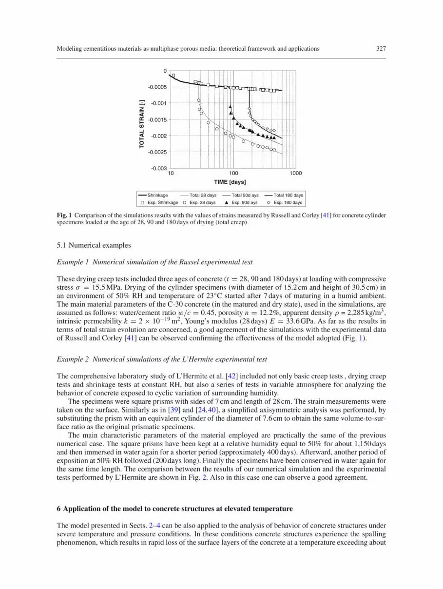
Fig. 1 Comparison of the simulations results with the values of strains measured by Russell and Corley [41] for concrete cylinderspecimens loaded at the age of 28, 90 and 180 days of drying (total creep)
5.1 Numerical examples
Example 1 Numerical simulation of the Russel experimental test
These drying creep tests included three ages of concrete (t = 28, 90 and 180 days) at loading with compressivestress σ = 15.5 MPa. Drying of the cylinder specimens (with diameter of 15.2 cm and height of 30.5 cm) inan environment of 50% RH and temperature of 23◦C started after 7 days of maturing in a humid ambient.The main material parameters of the C-30 concrete (in the matured and dry state), used in the simulations, areassumed as follows: water/cement ratio w/c = 0.45, porosity n = 12.2%, apparent density ρ = 2,285 kg/m3,intrinsic permeability k = 2 × 10⁻¹⁹ m2, Young’s modulus (28 days) E = 33.6 GPa. As far as the results interms of total strain evolution are concerned, a good agreement of the simulations with the experimental dataof Russell and Corley [41] can be observed confirming the effectiveness of the model adopted (Fig. 1).
Example 2 Numerical simulations of the L’Hermite experimental test
The comprehensive laboratory study of L’Hermite et al. [42] included not only basic creep tests , drying creeptests and shrinkage tests at constant RH, but also a series of tests in variable atmosphere for analyzing thebehavior of concrete exposed to cyclic variation of surrounding humidity.
The specimens were square prisms with sides of 7 cm and length of 28 cm. The strain measurements weretaken on the surface. Similarly as in [39] and [24,40], a simplified axisymmetric analysis was performed, bysubstituting the prism with an equivalent cylinder of the diameter of 7.6 cm to obtain the same volume-to-sur-face ratio as the original prismatic specimens.
The main characteristic parameters of the material employed are practically the same of the previousnumerical case. The square prisms have been kept at a relative humidity equal to 50% for about 1,150 daysand then immersed in water again for a shorter period (approximately 400 days). Afterward, another period ofexposition at 50% RH followed (200 days long). Finally the specimens have been conserved in water again forthe same time length. The comparison between the results of our numerical simulation and the experimentaltests performed by L’Hermite are shown in Fig. 2. Also in this case one can observe a good agreement.
6 Application of the model to concrete structures at elevated temperature
The model presented in Sects. 2–4 can be also applied to the analysis of behavior of concrete structures undersevere temperature and pressure conditions. In these conditions concrete structures experience the spallingphenomenon, which results in rapid loss of the surface layers of the concrete at a temperature exceeding about

328 F. Pesavento et al.
-0.0006
-0.0005
-0.0004
-0.0003
-0.0002
-0.0001
0
0 500 1000 1500 2000 2500
TIME [days]
TO
TA
L S
TR
AIN
[-]
-1.2E+07
-1.0E+07
-8.0E+06
-6.0E+06
-4.0E+06
-2.0E+06
0.0E+00
EF
FE
CT
IVE
ST
RE
SS
[P
a]
ShrinkageExp. ShrinkageEffective Stress
Fig. 2 Effective stress evolution and comparison of the simulations results with the values of strains measured by L’Hermite et al.[42] for the C-30 concrete specimen exposed to an environment with variable relative humidity
200–300◦C. As a result, the core concrete is exposed to these temperatures, thereby increasing the rate of heattransmission to the core part of the element and in particular to the reinforcement, what may pose a risk forthe integrity of the concrete structure.
It is commonly believed that the main reasons of the thermal spalling are build-up of high pore pressureclose to the heated concrete surface as a result of rapid evaporation of moisture, and the release of the storedenergy due to the thermal stresses resulting from high values of restrained strains caused by temperaturegradients. Nevertheless, the relative importance of the two mechanisms is not established yet and still needsfurther studies, both experimental and theoretical. The results of the research performed up to now show thatthe fire performance of concrete structures is influenced by several factors, like initial moisture content of theconcrete, the rate of temperature increase (fire intensity), porosity (density) and permeability of the concrete,its compressive strength, type of aggregate, dimensions and shape of a structure, its lateral reinforcement andloading conditions. The HSC structures are particularly affected by this phenomenon. In fact, HSC providesbetter structural performance, especially in terms of strength and durability, compared to traditional, normal-strength concrete (NSC). However, many studies showed that the fire performance of HSC differs from thatof NSC, which exhibits rather good behavior in these conditions.
For applying the present model to such a peculiar case, some modifications to its basic form are needed.Thus, the linear momentum balance equation has now the following form, [15]:
div(ηsτ s − psI
)+ρ g = 0, (55)
where the nature of the effective stress tensor has been discussed in Sect. 3. By combining Eq. (26) with (28),τ s is then given by:
τ s = (1 − d)(1 − V )�0 : (εtot − εth − εtchem − εtr) . (56)
Moreover, some evolution equations accounting for deterioration processes taking place in concrete undersuch severe conditions, are required. In particular, the following ones have been considered in the currentmodel [15,16]:− Dehydration process evolution law, considering its irreversibility, has the form:
�dehydr (t) = �dehydr (Tmax (t)) , (57)
thus
�dehydr = ∂�dehydr (T )
∂T
∂T
∂tfor T (t) ≥ Tmax (t) ,
�dehydr = 0 for T (t) < Tmax (t) ,
where Tmax(t) is the highest temperature reached by the concrete up to the time instant t .

Modeling cementitious materials as multiphase porous media: theoretical framework and applications 329
-8.0E-03
-6.0E-03
-4.0E-03
-2.0E-03
0.0E+00
2.0E-03
4.0E-03
6.0E-03
8.0E-03
1.0E-02
1.2E-02
0 100 200 300 400 500 600 700 800
TEMPERATURE [°C]
TH
ER
MA
L S
TR
AIN
[m
/m]
exp. heating
total - modeltherm_dilat
shrinkage
thermo-chem.exp. cooling
Fig. 3 Decomposition of total strains in heated concrete (C90) [16]
The constitutive relationship �dehydr (T ) can be obtained from the results of thermo-gravimetric (TG orDTA) tests using the definition of the dehydration degree by means of the mass changes during concreteheating:
�dehydr(T ) = m(To) − m(T )
m(To) − m(T∞), (58)
where m(T ) is the mass of the concrete specimen measured at temperature T during TG tests, To and T∞ aretemperatures when the dehydration process starts and finishes. We assumed here To=105◦C and T∞=1,000◦C.− Thermo-chemical damage evolution equation, obtained on the basis of the experimental results, takes intoaccount the irreversible character of the material structural changes and may be written as follows, [15]:
V (t) = V (Tmax (t)) . (59)
− Mechanical damage evolution equation, of the following form:
d (t) = d (ε (t)) (60)
is expressed in terms of the equivalent strain, ε, given by equations of the classical non-local, isotropic damagetheory [15–17]. The parameters of the theory can be determined from the results of the strength tests (“stress–strain” curves) at various temperatures [15]. The definition of the damage parameters has been presented inSect. 3.2, Eqs. (29) and (30).
The evolution equations shown above are not enough for a complete description of the material behavior.Indeed, an unloaded sample of plain concrete or cement stone, exposed for the first time to heating, exhibitsconsiderable changes of its chemical composition, inner structure of porosity and changes of sample dimen-sions (irreversible in part). The concrete strains during first heating, called load-free thermal strains (LFTS)are usually treated as superposition of thermal and shrinkage components, and often are considered as almostinseparable. LFTS are decomposed in three main contributions (see Fig. 3 for C90 concrete) [16]:− Thermal dilatation strains,
dεth = βs (T ) dT (61)
− Capillary shrinkage strains,
dεsh = α
KT
(dxws
s pc + xwss dpc) I (62)
where KT is the bulk modulus of the porous medium,− Thermo-chemical strains
dεtchem = βtchem (V ) dV (63)
where βtchem(V)= ∂εtchem(V )∂V is obtained from experimental tests (V is the thermo-chemical damage parameter).
As far as the first contribution is concerned, the strains are treated in a manner usual in thermo-mechanics,but considering the thermal expansion coefficient βs as a function of temperature.

330 F. Pesavento et al.
0
0.0001
0.0002
0.0003
0.0004
0.0005
0.0006
0.0007
0.0008
0 10.2 0.4 0.6 0.8
RELATIVE HUMIDITY [-]
SH
RIN
KA
GE
ST
RA
IN [
m/m
] HPC - experiment
HPC - theory
Fig. 4 Shrinkage strains for high performance concrete: comparison with experimental results [16]
Shrinkage strains are modeled by means of the effective stress principle, in the form derived in Eq. (17)or (22), Sect. 3. As already pointed out, for materials with very fine pores and well developed internal poresurface, where water is also present as a thin film (like for example in concrete), the solid pressure relationshipcontains a coefficient xws
s , Eqs. (18) or (19), instead of the classical saturation S used in geomechanics [11].This coefficient is a function of saturation S and takes into account the disjoining pressure, see Eqs. (12) and(19), which is important in the range of saturation in which only a thin film of water is adsorbed to the wall ofthe pores, see Fig. 4 and reference [16].
In this way the contribution of the term related to the capillary pressure in Eq. (17) or (22) can be interpretedas a sort of “internal” load for the skeleton of the material. Hence, the associated shrinkage strains are notcomputed directly in the strain decomposition as it is usual in the classical phenomenological approaches.
In heated concrete, above the temperature of about 105◦C, the thermal decomposition of the cement matrixstarts, and at higher temperatures also of the aggregate (depending on its type and composition). This is a conse-quence of several complicated, endothermic chemical reactions, called concrete dehydration. As their result aconsiderable shrinkage of the cement matrix (called chemical shrinkage) and usually expansion of the aggregateare observed. Due to these contradictory behaviors of the material components, cracks of various dimensionsdevelop when temperature increases, causing an additional change of concrete strains (usually expansion).These strains are modeled as function of thermo-chemical damage which takes into account the thermo-chemical deterioration of the material.
Also the so-called LITS has been considered in the computation. During first heating, mechanically loadedconcrete exhibits greater strains as compared to the load-free material at the same temperature. These additionaldeformations are referred to as load-induced thermal strains (LITS) [43]. A part of them originates just fromthe elastic deformation due to mechanical load, and it increases during heating because of thermo-chemicaland mechanical degradation of the material strength properties. The time-dependent part of the strains duringtransient thermal processes due to temperature changes is generally called thermal creep.
Its physical nature is rather complicated and up today not fully understood, thus modeling is usually basedon the results of special experimental tests. Typically, they are performed at constant heating rate equal to2 K/min, for various (but constant during a particular test) levels of external load, σ = const, ranging from 0%(load-free measurements) to 60% of the compressive strength of material at room temperature, fc(Ta). Theresults of such transient thermal strain tests performed for the C-90 concrete are presented and compared tonumerical results in Fig. 5.
The formulation employed in the model is due to Thelandersson [44] in its original form, here modifiedusing a coefficient βtr(V ) as a function of thermo-chemical damage V and the effective stresses instead oftotal stresses, coupling in such a way the thermo-chemo-mechanical damage and capillary shrinkage modelwith the thermal creep model [16]:
dεtr = βtr(V )
fc(Ta)Q :τ s dV . (64)
In Eq. (64) Q is a fourth order tensor, τ s is the net stress tensor (see Sect. 3.2) and finally fc is the compressivestrength of the material at 20◦C.
The model in this form has been successfully used for solving several engineering problems, e.g., the caseof fire in tunnels [45].

Modeling cementitious materials as multiphase porous media: theoretical framework and applications 331
-10
-9
-8
-7
-6
-5
-4
-3
-2
-1
0
0 100 200 300 400 500 600
TEMPERATURE [°C]
CR
EE
P S
TR
AIN
[m
m/m
]
exp. 45% load45% loadexp. 30% load30% loadexp. 15% load15% load
Fig. 5 Evolution of thermal creep strain (C90 concrete): comparison with experimental results [16]
6.1 Numerical example: simulation of NIST spalling test
This example deals with a comparison between numerical results, obtained using the model described in theprevious sections, and experimental results, obtained from compressive tests carried out in the United Statesin the laboratories of NIST (i.e., National Institute of Standard and Technology) [46]. The main goal of thiscomparison is to show the capability of the code to assess spalling phenomena, in particular occurrence ofexplosive spalling in concrete structures subjected to elevated temperatures. The specimens, cylinders withdiameter of 100 mm and height of 200 mm, have been tested using three test methods, representing the thermo-mechanical loading conditions: stressed test method (specimens were preloaded, with a load equal to 40%of final compressive strength at room temperature, and then heated), unstressed test method (specimens weredirectly heated until the time of compressive test), residual property test method (the specimens were heatedup to the target temperature and kept at this temperature for a certain period; then they were cooled and testedat room temperature, i.e., at residual conditions). Five target temperatures, 100, 200, 300, 450 and 600◦C werereached during the tests by means of a furnace heating rate of 5◦C/min, in steady-state conditions. In this case“steady state” is defined as the temperature state when the temperature at the center of the specimen is within10◦C of the preselected target temperature T and the difference between the surface and center temperaturesof the concrete specimen is less than 10◦C. Our attention was focused on specimens made of concrete type 1,herein indicated as MIX1 in unstressed conditions with two target temperatures: 450 and 300◦C. In fact, forunstressed tests, explosive spalling occurred in all MIX1 specimens heated to 450◦C, while the same concretewas not subjected to this phenomenon when the target temperature was set equal to 300◦C. Initial and boundaryconditions used in numerical simulation are listed in [16].
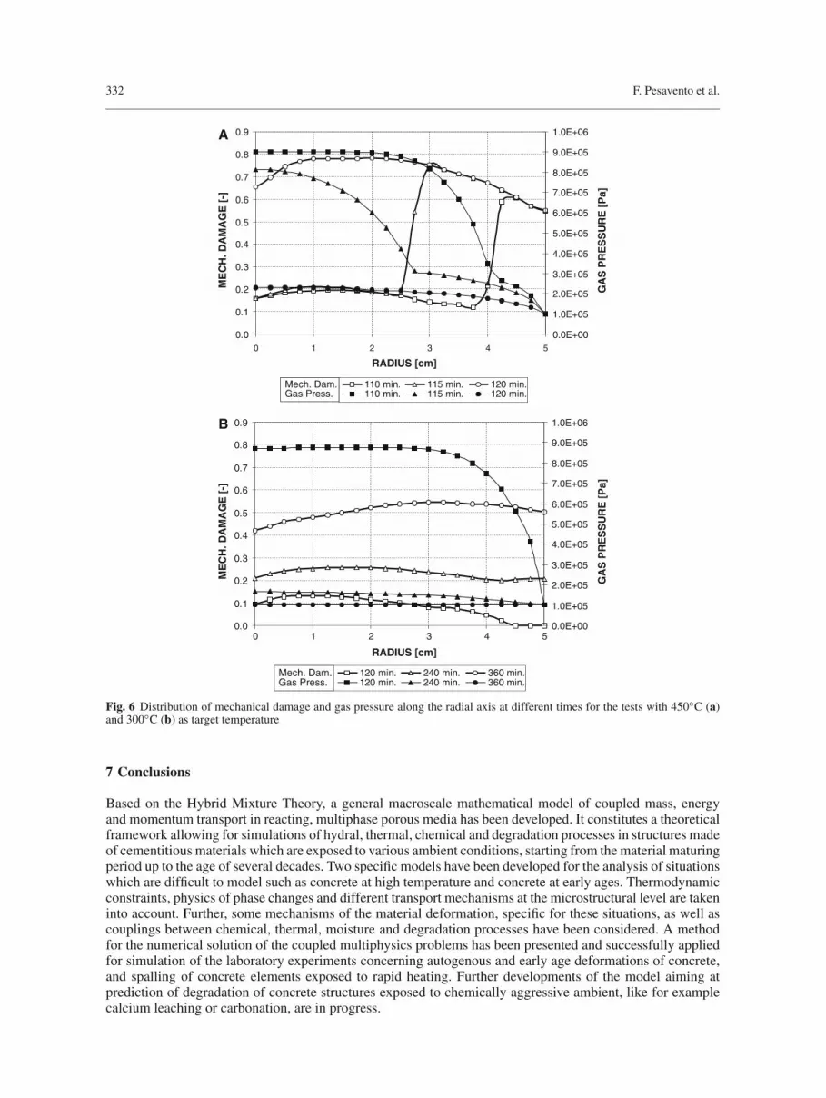
Figure 6a shows the distribution of gas pressure pg and mechanical damage d at different times for the casewith T = 450◦C. The time range between 110 and 150 min seems to be the critical range during which thematerial achieves a state favorable to spalling occurrence; the specimen experienced explosive spalling right inthis time range. Our simulations confirm this behavior: at 110 min gas pressure reaches the maximum values(0.8 MPa) in the internal part of the cylindrical specimen and 5 min later the mechanical damage distributionshows a peak (d = 80%) around 2 cm from the heated surface. This distance corresponds to the thickness ofthe spalled pieces of concrete observed in the experimental test. At 120 min the gas pressure is reduced to aresidual value as a consequence of the extensive damaging of the material throughout the whole sample. InFig. 6b similar results, but for the case characterized by a target temperature equal to 300◦C, are shown. Onecan observe that the gas pressure distribution at 120 min (approximately the time of spalling occurrence in theprevious case) is practically the same over a large part of the sample with a max value equal to 0.8 MPa, butthe damage profile displays that the stiffness of the material is reduced only by 15%.
Further details about this set of simulations can be found in [16]. In the same work it is shown that for thecase of 450◦C the maximum value of ∆T corresponds to a sharp increase of the mechanical damage parameterd (with a maximum value equal to 80%) and to a peak of gas pressure. The results of numerical simulationspresented show that both pore pressure and thermally induced strains can be identified as responsible for thespalling occurrence, and that they play a primary or secondary role depending on the particular conditionsprevailing.
332 F. Pesavento et al.
0.0
0.1
0.2
0.3
0.4
0.5
0.6
0.7
0.8
0.9
0 1 2 3 4 5
RADIUS [cm]
A
B
ME
CH
. DA
MA
GE
[-]
0.0E+00
1.0E+05
2.0E+05
3.0E+05
4.0E+05
5.0E+05
6.0E+05
7.0E+05
8.0E+05
9.0E+05
1.0E+06
GA
S P
RE
SS
UR
E [
Pa]
110 min. 115 min. 120 min.110 min. 115 min. 120 min.
Mech. Dam.Gas Press.
0.0
0.1
0.2
0.3
0.4
0.5
0.6
0.7
0.8
0.9
0 1 2 3 4 5
RADIUS [cm]
ME
CH
. DA
MA
GE
[-]
0.0E+00
1.0E+05
2.0E+05
3.0E+05
4.0E+05
5.0E+05
6.0E+05
7.0E+05
8.0E+05
9.0E+05
1.0E+06
GA
S P
RE
SS
UR
E [
Pa]
120 min. 240 min. 360 min.120 min. 240 min. 360 min.
Mech. Dam.Gas Press.
Fig. 6 Distribution of mechanical damage and gas pressure along the radial axis at different times for the tests with 450◦C (a)and 300◦C (b) as target temperature
7 Conclusions
Based on the Hybrid Mixture Theory, a general macroscale mathematical model of coupled mass, energyand momentum transport in reacting, multiphase porous media has been developed. It constitutes a theoreticalframework allowing for simulations of hydral, thermal, chemical and degradation processes in structures madeof cementitious materials which are exposed to various ambient conditions, starting from the material maturingperiod up to the age of several decades. Two specific models have been developed for the analysis of situationswhich are difficult to model such as concrete at high temperature and concrete at early ages. Thermodynamicconstraints, physics of phase changes and different transport mechanisms at the microstructural level are takeninto account. Further, some mechanisms of the material deformation, specific for these situations, as well ascouplings between chemical, thermal, moisture and degradation processes have been considered. A methodfor the numerical solution of the coupled multiphysics problems has been presented and successfully appliedfor simulation of the laboratory experiments concerning autogenous and early age deformations of concrete,and spalling of concrete elements exposed to rapid heating. Further developments of the model aiming atprediction of degradation of concrete structures exposed to chemically aggressive ambient, like for examplecalcium leaching or carbonation, are in progress.

Modeling cementitious materials as multiphase porous media: theoretical framework and applications 333
Acknowledgments This research was carried out as part of the projects PRIN prot. 2006094221_004 (2006) and ex60% prot.60A09-1314/07 financed by the Italian Ministry of Scientific Research.
Appendix: Second law of Thermodynamics
In this section we explore the second law of Thermodynamics, applied for the multiphase porous medium,whose skeleton experiences chemical reactions (hydration/dehydration) and material deterioration (boththermo-chemical and mechanical damage). This allows us to define several important quantities used in ourmodel (e.g. capillary pressure, effective stress tensor), constitutive relationships and to obtain some thermody-namic restrictions imposed on the evolution equations for the skeleton hydration/dehydration and deteriorationprocesses.The starting point for further developments is the second law of Thermodynamics written for a multiphasesystem. It states that for any process the rate of net entropy production must be non-negative:
� = �s + �w + �g +∑
αβ=gs,gw,sw
�αβ ≥ 0. (A1)
After expressing the terms for the rate of net production of entropy in the individual phases and interfaces fromEqs. (7, 8), Eq. (A1) has the following form [10]:
(1 − n) ρs Dsλs
Dt− div
((1 − n)
qs
T s
)− (1 − n) ρs hs
T s − �ssg − �s
sw
+nSwρw Dwλw
Dt− div
(nSw
qw
T w
)− nSwρw hw
T w − �wwg − �w
ws + nSgρg Dgλg
Dt
−div
(nSg
qg
T g
)− nSgρ
g hg
T g − �ggw − �
ggs +
∑
αβ=gs,gw,sw
[aαβ �αβ Dαβλαβ
Dt
−div
(aαβ qαβ
T αβ
)− aαβ�αβ hαβ
T αβ+(�α
αβ + eααβλα,αβ
)+(�
βαβ + eβ
αβλβ,αβ)
− �αβwgs
]≥ 0. (A2)
In further developments it is convenient to use the Helmholtz free energy, defined for the bulk phases as
Aα = Eα − T αλα, (α = s, w, g) (A3)
and the interfaces as
Aαβ = Eαβ − T αβλαβ, (αβ = gw, ws, gs) . (A4)
Table 1 List of independent constitutive variable
Description Symbol Indices Number
Density of bulk phase ρα α = s, w, g 3Surface excess density �αβ αβ = gs, gw, sw 3Fluid velocity vα,s α = w, g 2Interface velocity wαβ,s αβ = wg, ws, gs 3Solid phase strain tensor Eα α = s 1Temperature θα α = s, w, g 3Gradient of temperature grad T α α = s, w, g 3Temperature of the interface T αβ αβ = sg, wg, sw 3Gradient of temperature of the interface grad T αβ αβ = sg, wg, sw 3Porosity n = 1Gradient of porosity grad n = 1Degree of saturation with water Sα α = w 1Gradient of degree of saturation grad Sα α = w 1Specific surface of the interface aαβ αβ = gs, gw, sw 3Gradient of specific surface of the interfaces grad aαβ αβ = gs, gw, sw 3
Total number of independent constitutive variables 34

334 F. Pesavento et al.
Introduction of the energy balance equation in the form of Eq. (5) allows the rate of net production of entropyin the solid phase to be expressed as, see [10]:
�s = − (1 − n) ρs
T s
[Ds As
Dt+ λs DsT s
Dt
]+ (1 − n)
(T s)2 qs · gradT s
+1 − n
T s ts : grad vs − �ssg − �s
sw + Qssw
T s + Qssg
T s . (A5)
After similar transformations carried out for all the other phases and for the three interfaces, Eq. (6), and afterapplication of (A3) and (A4), the entropy inequality (A1) can be written as:
− (1 − n) ρs
T s
(Ds As
Dt+ λs DsT s
Dt
)− nSwρw
T w
(Dw Aw
Dt+ λw DwT w
Dt
)− nSgρ
g
T g
(Dg Ag
Dt+ λg DgT g
Dt
)
+1 − n
(T s)2 qs · grad T s + nSw
(T w)2 qw · grad T w + nSg
(T g)2 qg · grad T g
+1 − n
T s ts : ds + nSw
T w tw:dw + nSg
T g tg:dg +∑
αβ=sg,sw,gw
aαβsαβ
T αβ:dαβ
−∑
αβ=sg,sw,gw
aαβ�αβ
T αβ
(Dαβ Aαβ
Dt+λαβ Dαβ T αβ
Dt
)+
∑
αβ=sg,sw,gw
aαβ
(T αβ
)2 qαβ · ∇Tαβ +∑
αβ=sg,sw,gw
aαβsαβ
T αβ:dαβ
− 1
T s
∑
αβ=sg,sw,gw
[Qαβ
sgw · T αβ,s
T αβ+ sαβ
sgw · wαβ,s + eαβsgw
(Aαβ,s + 1/2
(wαβ,s)2 + λαβT αβ,s
)]
+ 1
T sw
[Qs
swT sw,s
T s + Tssw · wsw,s + es
sw
(Asw,s + 1/2
(wsw,s)2 + λsT sw,s
)]
+ 1
T sg
[Qs
sgT sg,s
T s + Tssg · wsg,s + es
sg
(Asg,s + 1/2
(wsg,s)2 + λsT sg,s
)]
+ 1
T sg
[Qw
wsT ws,w
T w + Twws · wws,w + ew
ws
(Aws,w + 1/2
(wws,w)2 + λwT ws,w
)]
+ 1
T wg
[Qw
wgT wg,w
T w + Twwg · wwg,w + ew
wg
(Awg,w + 1/2
(wwg,w)2 + λwT wg,w
)]
+ 1
T gs
[Qg
gsT gs,g
T g + Tggs · wgs,g + eg
gs
(Ags,g + 1/2
(wgs,g)2 + λgT gs,g
)]
+ 1
T gw
[Qg
gwT gw,g
T g + Tggw · wgw,g + eg
gw
(Agw,g + 1/2
(wgw,g)2 + λgT gw,g
)]≥ 0. (A6)
In this equation we have introduced the strain rate tensors for bulk phases dα (α = s, w, g) and for interfacesdαβ (αβ = gw, gs, ws) defined in the following form:
dα = 1/2
[grad vα + (grad vα
)T ] ; α = w, g, s (A7)
for the bulk phases and
dαβ = 1/2
[grad wαβ + (grad wαβ
)T ] ; αβ = ws, gs, gw (A8)
for the interfaces.

Modeling cementitious materials as multiphase porous media: theoretical framework and applications 335
Because of symmetry of the partial stress tensor tα and the surface stress tensor sαβ , the following identitieshold:
tα : grad vα = tα : dα, (A9)
sαβ : grad wαβ = sαβ : dαβ. (A10)
Entropy inequality results
The balance equations of mass, momentum and energy (1)–(6) must be supplemented by appropriate consti-tutive equations, describing the behavior of individual phases. For the bulk phases, i.e., solid, water and gasthere are three mass balance equations (1), nine momentum balance equations (3) (because each vector hasthree components) and three energy balance equations (5). Analogously for three interfaces, i.e., solid–water,solid–gas and water–gas, there are three mass balance equations (2), nine momentum balance equations (4) andthree energy balance equations (6). Hence there are totally 30 equations, and the same number of independentvariables can be chosen as basic independent fields. These field quantities or/and combinations and space andtime derivatives of them that are objective can enter as independent constitutive variables. Their choice shouldbe based on the expected behavior of the medium, as well as they should account macroscopically for themicrostructure due to the interfaces.To this last reason for instance volume fraction, their gradients, the specific surfaces of the interfaces andtheir gradients may be added to the list of primary variables. This augments accordingly the list of dependentvariables to eliminate the ensuing equation deficit. The independent variables are functions of time and space.The list of independent variables chosen here is given in Table 1.The remaining variables appearing in the balance equations must be expressed in terms of the primary unknownsand their derivatives. The equation deficit is eliminated by also requiring constitutive forms for some of thetime derivatives (here of porosity, the degree of water saturation and of specific surfaces of the interfaces, seeHassanizadeh and Gray [9]), and by thermodynamic equilibrium equations. The list of dependent variables,for which constitutive relations are needed, is given in Table 2.The Helmholtz free energies for the bulk phases are assumed to have the following functional forms:
Aw = Aw (ρw, T w, Sw), Ag = Ag (ρg, T g, Sg
), As = As (ρs, T s, Es, Sw, �hydr, D
), (A11)
and for the interfaces:
Aαβ = Aαβ(�αβ, T αβ, aαβ, Sw
), (αβ = gw, ws, gs) . (A12)
Table 2 List of dependent variables for which constitutive relations are needed
Description Symbol Indices Number
Helmholtz free energy function for the bulk phase Aα α = s,w,g 3Helmholtz free energy function for the interface Aαβ αβ = gs,gw,sw 3Stress tensor for the bulk phase tα α = s,w,g 3Stress tensor for the interface sαβ αβ = gs,gw,sw 3Body supply of momentum to the bulk phases from the interfaces Tα
αβ αβ= gw,gs,sw; α = g,w,s 6
Body supply of momentum to the interfaces from the contact line Sαβαβγ αβγ = wgs; αβ= gs,gw,sw 3
Heat vector for the bulk phase qα α = s,w,g 3Heat vector for the interface qαβ αβ = gs,gw,sw 3Body supply of the heat to the bulk phases from the interfaces Qα
αβ αβ= gw,gs,sw; α = g,w,s 6
Body supply of the heat to the interfaces from the contact line Qαβαβγ αβγ = wgs; αβ= gs,gw,sw 3
Specific internal entropy function for the bulk phase λα α = s,w,g 3Specific internal entropy function for the interface λαβ αβ = gs,gw,sw 3Rate of mass transfer to the bulk phases from interfaces eα
αβ αβ = gw,gs,sw; α = g,w,s 6
Rate of mass transfer to the interfaces from the contact line eαβαβγ αβγ = wgs; αβ = gs,gw,sw 3
Time derivative of porosity n = 1Time derivative of degree of saturation with water Sα α = w 1Time derivative of specific surfaces of the interfaces aαβ αβ = gs,gw,sw 3
Total number of constitutive relationships needed 56

336 F. Pesavento et al.
One must point out that in Eq. (A11) for the solid skeleton the effect of the two internal variables, �hydr(the hydration/dehydration degree) and D (the total damage), has been introduced, as compared to [10] forconsidering additionally the dissipative processes taking place in the material. So, the thermodynamic state ofthe dissipative material is described not only by external variables but also by some hidden parameters thatare defined directly at macroscopic level.According to the principle of admissibility, the constitutive postulates relating dependent to independent vari-ables must not violate the balance laws and the entropy inequality. These requirements are now explored usingthe procedure proposed by Coleman and Noll. For this purpose rather lengthy transformations of Eq. (A6) arenecessary, taking into account Eqs. (A11) and (A12) (see Hassanizadeh and Gray [9]). Here only the resultinginequality is listed in an “abbreviated” form (but containing all main terms used in further developments)
− (1 − n) ρs
T s
DsT s
Dt
(∂ As
∂T s + λs)
− nSwρw
T w
DwT w
Dt
(∂ Aw
∂T w + λw)
− nSgρg
T g
DgT g
Dt
(∂ Ag
∂T g + λg)
−∑
αβ=sg,sw,gw
aαβ�αβ
T αβ
Dαβ T αβ
Dt
(∂ Aαβ
∂T αβ+ λαβ
)
+nSw
T w
(pwI + tw) :dw + nSg
T g
(pgI + tg) :dg + 1 − n
T s
(psI + ts) :ds −
[(1 − n) ρs
T s
∂ As
∂Es
]:ds
+ Dsn
Dt
(Sw pw
T w + Sg pg
T g − ps
T s
)+ (1 − n)
T s A�
Ds�hydr
Dt+ (1 − n)
T s YDs D
Dt
+ Ds SwDt
(npw
T w − npg
T g − nSwρw
T w∂ Aw
∂Sw+ nSgρ
g
T g∂ Ag
∂Sg − (1−n)ρs
T s∂ As
∂Sw− ∑
αβ=sg,sw,gw
aαβ�αβ
T αβ∂ Aαβ
∂Sw
)
+⎡
⎣TERMS RELATED TO BODY SUPPLIES,DEFORMATION OF THE INTERFACES,PHASE CHANGES AND HEAT FLUXES
⎤
⎦ ≥ 0.
(A13)
The following definitions have been introduced into (A13):
– macroscopic pressure of the α phase,
pα = (ρα)2 ∂ Aα
∂ρα, (α = s, w, g) , (A14)
– macroscopic interfacial tension of the αβ interface,
γ αβ = − (�αβ)2 ∂ Aαβ
∂�αβ, (αβ = sw, wg, gs) , (A15)
– chemical affinity, being the driving force of the chemical reaction, related to the rate of the hydration extent,
�hydr = Ds�hydrDt , by means of an evolution equation,
A� = − ∂ As
∂�hydrρs, (A16)
– strain rate tensor of the solid phase (finite deformations),
DsEs
Dt= Fs · ds · (Fs)T (A17)
together with the identities:
div vα = dα:I, (α = s, w, g) (A18)
T α,s = T α − T s. (A19)

Modeling cementitious materials as multiphase porous media: theoretical framework and applications 337
In the LHS of inequality (A13) appear quantities in brackets multiplied by: DαT α
Dt , Dαβ T αβ
Dt , dα, dαβ which arenot primary variables. Therefore, the coefficient of these variables must be always zero, because (A13) is validfor all thermodynamic states. Hence the following relationships for the specific entropies and stress tensorsare obtained:
λα = −∂ Aα
∂T α, (α = w, g, s), λαβ = −∂ Aαβ
∂T αβ, (αβ = gw, ws, gs), (A20)
sαβ = γ αβI; tw = −pwI, tg = −pgI. (A21)
In particular, the total (nominal) stress tensor of the solid phase is defined by [14]:
ts = τ s − psI, (A22)
where
τ s = ρs (Fs)T ∂ As
∂Es Fs, (A23)
multiplied by the volume fraction of the solid ηs (see Eq. (16)) is the classical effective stress tensor often usedin geomechanics, that is valid also in the case of aging visco-elasticity as shown in Sect. 3.3,
ps (ρs, T s, E s, Sw) = (ρs)2 ∂ As
∂ρs (A24)
is the “thermodynamic” pressure of the solid phase,
Y = −ρs ∂ As
∂ D(A25)
is the damage energy release rate, and
pc = T wg
n
⎡
⎣−nSwρw
T w
∂ Aw
∂Sw+ nSgρ
g
T g
∂ Ag
∂Sg− (1 − n) ρs
T s
∂ As
∂Sw−
∑
αβ=sg,sw,gw
aαβ�αβ
T αβ
∂ Aαβ
∂Sw
⎤
⎦ (A26)
is the macroscopic “thermodynamic” capillary pressure, which takes into account water–gas interface curva-ture and water film effects.
Equilibrium restrictions
Some additional information can be obtained from inequality (A13), when examining the system under con-sideration at equilibrium state, which requires that the following variables are all equal to zero:
{zk, k = 1, . . . , 46} =
⎧⎪⎪⎨
⎪⎪⎩
DsnDt , Ds Sw
Dt ,
grad θ s, grad θw, grad θg, grad θαβ,
vw,s, vg,s, wαβ,s, T w,s, T g,s, T αβ,α, eααβ, eαβ
sgw
⎫⎪⎪⎬
⎪⎪⎭. (A27)
Physically this means that there is no relative movement of phases and interfaces (vw,s = 0, vg,s = 0, wαβ,s =0), the degree of saturation with water (thus also with gas) is constant ( Ds Sw
Dt = 0), and the phases and inter-faces have the same uniform temperature (grad T s = 0, grad T w = 0, grad T g = 0, grad T αβ = 0, T w,s =0, T g,s = 0, T αβ,α = 0, hence T w = T g = T s = T wg = T ws = T gs). At these conditions the total rate ofentropy production � equals zero, i.e., reaches its minimum value. Thus the necessary and sufficient conditionsfor � to be a minimum at equilibrium are
[∂�
∂zk
]
eq= 0, k = 1, . . . , 46, (A28)

338 F. Pesavento et al.
and∥∥∥∥∥
[∂2�
∂zk∂zm
]
eq
∥∥∥∥∥ be positive semi-definite, k, m = 1, . . . , 46. (A29)
Application of restriction (A28) to the entropy inequality allows to obtain some relations valid at equilibrium.In the following only the two most important ones are explicitly mentioned:
(ps)
eq = Sg pg + Sw pw, (A30)
pc = (pg − pw)eq (A31)
References
1. Svendsen, B., Hutter, K.: On the thermodynamics of a mixture of isotropic materials with constraints. Int. J. Eng. Sci. 33, 2021–2054 (1995)
2. de Boer, R.: Highlights in the historical development of the porous media theory: toward a consistent macroscopic the-ory. Appl. Mech. 49, 201 (1996)
3. Whitaker, S.: Heat and Mass Transfer in Granular Porous Media. Advances in Drying 1, Hemisphere, New York (1980)4. Hassanizadeh, S.M., Gray, W.G.: General conservation equations for multi-phase systems. 1. Averaging procedure. Adv.
Water Resour. 2, 131–144 (1979)5. Hassanizadeh, S.M., Gray, W.G.: General conservation equations for multi-phase systems: 2 Mass, momenta, energy and
entropy equations. Adv. Water Resour. 2, 191–203 (1979)6. Hassanizadeh, S.M., Gray, W.G.: General conservation equations for multi-phase systems: 3 Constitutive theory for porous
media flow. Adv. Water Resour. 3, 25–40 (1980)7. Auriault, J.L.: Non saturated deformable porous media: quasistatics. Transp. Porous Media 2, 45–64 (1987)8. Auriault, J.L.: Dynamic behaviour in porous media. In: Bear, J., Corsapcioglu, M.Y. (eds.) Transport Processes in Porous
Media, pp. 471–519. Kluwer, Dordrecht (1991)9. Hassanizadeh, S.M., Gray, W.G.: Mechanics and thermodynamics of multiphase flow in porous media including interphase
boundaries. Adv. Water Resour. 13, 169–186 (1990)10. Schrefler, B.A.: Mechanics and thermodynamics of saturated-unsaturated porous materials and quantitative solutions. Appl.
Mech. Rev. 55, 351–388 (2002)11. Lewis, R.W., Schrefler, B.A.: The finite element method in the static and dynamic deformation and consolidation of porous
media, 2nd edn. Wiley, Chichester (1998)12. Gawin, D., Pesavento, F., Schrefler, B.A.: Modelling of hygro-thermal behaviour and damage of concrete at temperature
above the critical point of water. Int. J. Numer. Anal. Meth. Geomech. 26, 537–562 (2002)13. Gray, W.G., Schrefler, B.A.: Thermodynamic approach to effective stress in partially saturated porous media. Eur. J. Mech.
A/Solids 20, 521–538 (2001)14. Gray, W.G., Schrefler, B.A.: Analysis of the solid phase stress tensor in multiphase porous media. Int. J. Numer. Anal. Meth.
Geomech. 31, 541–581 (2007)15. Gawin, D., Pesavento, F., Schrefler, B.A.: Modelling of hygro-thermal behaviour of concrete at high temperature with
thermo-chemical and mechanical material degradation. Comput. Methods Appl. Mech. Eng. 192, 1731–1771 (2003)16. Gawin, D., Pesavento, F., Schrefler, B.A.: Modelling of deformations of high strength concrete at elevated temperatures. Con-
crete Sci. Eng./Mat. Struct. 37, 218–236 (2004)17. Mazars, J.: Application de la mecanique de l’ endommagement au comportament non lineaire et la rupture du beton de
structure. Thèse de Doctorat d’ Etat, L.M.T. Universite de Paris, France (1984)18. Chaboche, J.L.: Continuum damage mechanics: part I—general concepts. J. Appl. Mech. 55, 59–64 (1988)19. Nechnech, W., Reynouard, J.M., Meftah, F.: On modelling of thermo-mechanical concrete for the finite element analysis
of structures submitted to elevated temperatures. In: de Borst, R., Mazars, J., Pijaudier-Cabot, G., van Mier, J.G.M. (eds.)Fracture Mechanics of Concrete Structures, pp. 271–278. Swets and Zeitlinger, Lisse (2001)
20. Staverman, A.J., Schwarzl, P.: Thermodynamics of viscoelastic behaviour (model theory), vol. 44, pp. 363–374. Proceedingsof Academic Science, The Netherlands (1952)
21. Staverman, A.J., Schwarzl, P.: Non-equilibrium thermodynamics of visco-elastic behaviour, vol. 44, pp. 375–381. Proceed-ings of Academic Science, The Netherlands (1952)
22. Truesdell, C.: Rational Thermodynamics. McGraw-Hill, New York (1969)23. Bazant, Z.P., Huet, C.: Thermodynamic functions for ageing viscoelasticity: integral form without internal variables. Int J
Solids Struct. 25, 3993–4016 (1999)24. Gawin, D., Pesavento, F., Schrefler, B.A.: Hygro-thermo-chemo-mechanical modelling of concrete at early ages and beyond.
Part II: Shrinkage and creep of concrete. Int. J. Numer. Meth. Eng. 67, 332–363 (2006)25. Zienkiewicz, O.C., Taylor, R.L.: The Finite Element Method, vol. 1: The Basis. Butterworth-Heinemann, Oxford (2000)26. Gawin, D., Majorana, C.E., Schrefler, B.A.: Numerical analysis of hygro-thermic behaviour and damage of concrete at high
temperature. Mech. Cohes.-Frict. Mater. 4, 37–74 (1999)27. Bianco, M., Bilardi, G., Pesavento, F., Pucci, G., Schrefler, B.A.: A frontal solver tuned for fully-coupled nonlinear hygro-
thermo-mechanical problems. Int. J. Numer. Meth. Eng. 57, 1801–1818 (2003)28. Wang, X., Gawin, D., Schrefler, B.A.: A parallel algorithm for thermo-hydro-mechanical analysis of deforming porous
media. Comp. Mech. 19, 94–104 (1996)
Modeling cementitious materials as multiphase porous media: theoretical framework and applications 339
29. Jensen, O.M., Hansen, P.F.: Influence of temperature on autogenous deformation and relative humidity change in hardeningcement paste. Cement Concrete Res. 29, 567–575 (1999)
30. Ulm, F.-J., Coussy, O.: Modeling of thermo-chemo-mechanical couplings of concrete at early ages. J. Eng. Mech.(ASCE) 121, 785–794 (1995)
31. Ulm, F.-J., Coussy, O.: Strength growth as chemo-plastic hardening in early age concrete. J. Eng. Mech. (ASCE) 122, 1123–1132 (1996)
32. Gawin, D., Pesavento, F., Schrefler, B.A.: Hygro-thermo-chemo-mechanical modelling of concrete at early ages and beyond.Part I: Hydration and hygro-thermal phenomena. Int. J. Numer. Meth. Eng. 67, 299–331 (2006)
33. Cervera, M., Olivier, J., Prato, T.: A thermo-chemo-mechanical model for concrete. II: Damage and creep. J. Eng. Mech.(ASCE) 125, 1028–1039 (1999)
34. Bazant, Z.P.: Mathematical Modeling of Creep and Shrinkage of Concrete. Wiley, Chichester (1988)35. Bazant, Z.P., Prasannan, S.: Solidification theory for concrete creep. I: Formulation. J. Eng. Mech. (ASCE) 115, 1691–
1703 (1989)36. Carol, I., Bazant, Z.P.: Viscoelasticity with aging caused by solidification of non-aging constituent. J. Eng. Mech.
(ASCE) 119, 2252–2269 (1993)37. Bazant, Z.P., Xi, Y.: Continuous retardation spectrum for solidification theory of concrete creep. J. Eng. Mech.
(ASCE) 121, 281–288 (1995)38. Bazant, Z.P., Hauggaard, A.B., Baweja, S, Ulm, F.-J.: Microprestress-solidification theory for concrete creep. I: Aging and
drying effects. J. Eng. Mech. (ASCE) 123, 1188–1194 (1997)39. Bazant, Z.P., Hauggaard, A.B., Baweja, S.: Microprestress-solidification theory for concrete creep. II: Algorithm and veri-
fication. J. Eng. Mech. (ASCE) 123, 1195–1201 (1997)40. Gawin, D., Pesavento, F., Schrefler, B.A.: Modelling creep and shrinkage of concrete by means of effective stress. Mat.
Struct. 40, 579–591 (2007). doi:10.1617/s11527-006-9165-141. Russel, H.G., Corley, W.G.: Time-dependent behaviour of columns. In: Water tower place, research and development bulletin
RD052.01B, Portland Cement Association (1977)42. L’Hermite, R., Mamillan, M., Lefevre, C.: Nouveaux resultats de rechercher sur la de′formation et la rupture du beton (in
French). Supplement aux annales de l’Institute Technique du Batiment et des Travaux Publics 207/208, pp. 325–345 (1965)43. Khoury, G.A.: Strain components of nuclear-reactor-type concretes during first heating cycle. Nucl. Eng. Des. 156, 313–
321 (1995)44. Thelandersson, S.: Modeling of combined thermal and mechanical action on concrete. J. Eng. Mech. (ASCE) 113, 893–
906 (1987)45. Schrefler, B.A., Brunello, P., Gawin, D., Majorana, C.E., Pesavento, F.: Concrete at high temperature with application to
tunnel fire. Comput. Mech. 29, 43–51 (2002)46. Phan, L.T., Lawson, J.R., Davis, F.L.: Effects of elevated temperature exposure on heating characteristics, spalling, and
residual properties of high performance concrete. Mat. Struct. 34, 83–91 (2001)


