Embed Size (px)
Citation preview

Modeling of the Uplift Response of Buried Pipelines
A. Janalizadeh Choobbasti Professor, Department of Civil Engineering, Babol University of Technology, Babol,
Mazandaran, Iran
S. Firouzian, M. J. Vahdatirad*, A. Barari and D. Rezaei Department of Civil Engineering, Babol University of Technology,
Babol, Mazandaran, Iran
ABSTRACT Over the years, researchers have tried to understand the complex behavior of buried pipelines subjected to ground ruptures due to landslides, earthquakes, faults and uplift forces in shallow trenches. In an attempt to understand this complex behavior, an experimental investigation program has been carried out on uplift resistance of buried pipes. In this research, a new laboratory model is developed. Several tests have been performed by utilizing this laboratory model. Uplift forces due to raising water table causes the initiation of failure. Based on the data obtained two mechanisms are presented. Mechanism of type one in which a sliding block with angled planes occurs in small displacements and in dense soil, and a mechanism of type two, circulation mechanism associated to soil flow under the pipe occurs in large displacement for dense soil and by continuing of loading and the soil around the pipe flows circularly. Even though the load-applying system is completely different than earlier studies, evidences found by this research are consistent with the previous research.
KEYWORDS: Laboratory model, Uplift, Buried pipeline, Sliding block mechanism, Circulation mechanism.
INTRODUCTION Safety energy systems, water and sewage, transportation and information infrastructure are the most
important aspects of development in a country. Over the past few decades, development of these systems and more dependence of civil life to them, special in industrial countries change these systems as lifelines. Using life word for above systems considers two aspects: firstly, life durability of society special in critical situation and after that depends to keep operation of these systems, and secondly damaging of these systems can cause worsen situation and addition damages, specifically more disturbance in assistance and salvage.

Vol. 14 [2009], Bund. M 2
Seismic ground faulting is a severe hazard for continuous buried pipeline; gas and sewage pipes like other shallow facilities are susceptible to damage in uplift situations. Pipelines are often trenched, filled with sand and covered to avoid damage to the pipes from anchors or for thermal insulation [1]. Since at Mazandaran estate the underground water level is high and the pit fill by sand, so the conditions to occurrence of uplift are prepare. Therefore, study of these phenomena is very important and availability of an accurate model of uplift resistance is critical to the safe and economic design of pipelines. Excessive upward movement may cause the pipe to bulge from the soil and lead to uplift. Pipe weight and soil uplift resistance mobilization can be endured this phenomenon. Therefore, occurrence or nonoccurrence of failure depends on such resistance of soil against uplift. Over the past 30 years, researchers have tried to understand the complex behavior of buried pipelines subjected to ground ruptures most often via numerical simulation and some laboratory tests, either full-scale or small-scale centrifuge tests, which are needed to validate and confirm numerical simulation assumption and results. A number of different formulations to determine uplift resistance for buried objects have been developed [2, 3, 4, 5, 6, 7, 8]. Marston (1930) developed the first rational treatment of loading on buried conduits [9]. Marston’s equation for positive projecting conduits (buried in fill), which is a vertical slip surface model, is used by the American Water Work Association for designing pipelines supported by piles or piers [10]. Meyerhof an Adams (1968) analyzed strip footing, assuming a planar failure surface and passive soil stresses [3]. Das and Seely (1975) reported uplift data for rectangular plates having a length-to-width ratio of five with H/D ranging from 1-8 [11]. The tests were conducted in dry sand, which has 31o friction angle. Also, reported data from drained uplift of pipes – albeit in sand rather than clay backfill – indicates that the depth at which peak uplift becomes governed by a flow-round mechanism (rather than heave) is typically H/D≥4 for loose backfill [12, 13, 14].
Rowe and Davis (1982) tested plate anchors having length-to-width rations ranging from 1-8.75 in dry sand with a friction angle of 32o [5]. Matyas and Davis performed tests on 48-mm diameter rigid pipes in loose sand with friction angles from 30-36o. The length-to-width ratio was 7.9, and H/D ranged from 1.67-8.75 [2]. Wang et al. (2009) present the results from 10 minidrum centrifuge tests conducted at the Schofield Centre, All these tests were designed to measure the uplift resistance of a pipeline installed into stiff clay by trenching and backfilling [15].
A model has been presented by Troutmann et al. (1986) is used in this paper, which involved test box, sand raining-device, Supporting Frame and loading system, measurement and data recording instruments [16]. An electronic load cell and an extensometer measured uplift force and displacement of pipe with accuracy of 1 mm, respectively and microcomputer recorded data. Another model that failure planes are curve imperfect pyramid, suggested by Meyerhof & Adams (1968) is used [3].
This paper aims to explore the mechanisms of failure by a laboratory model that includes four parts, which are Test box, filter, Measurement instruments, and loading System (water supply). Finally, two mechanisms of failure were done by utilizing laboratory model and several tests. During the first stage of uplift, a sliding block mechanism along angled shear planes can be identified. This mechanism occurs during mobilization of peak uplift. After further displacement, a ‘circulation’ mechanism around the pipe periphery is evident. The cavity that forms beneath the pipe during initial uplift is filled by slumping of the surrounding soil [1]. By this, the present experiment results are compared with that of previous pipe–soil interaction experiments and have agreement with them.

Vol.
To demodel als& Davis,
Test bthat is 11 glass wateangle in th
A meheight by box filled
To encourse agAccordingwash out,
Figur
14 [2009]
ecrease the boo consider acwhich model
box was madcm, wide, he
ertight and mhe middle of b
etal frame of (20 cm brack
d by gypsum s
nsure that wagregate was ug to Terzaghiwere conside
e 2: The way
F
, Bund. M
Eoundary condiccording to Tr height and w
de up of 10 meight and leng
montage with box height in
(40×40×40 mkets for incomso the entire b
ater level wasused at the boi & Peck critered in the so
y of putting
Figure 1: Se
EXPERIMition effects, trautmann sug
wide is 5 times
T
mm shatterprogth of box coaquarium str
n the corners (
mm) angle waming and outgbox was rigid.
s raised unifoottom of the bteria, two prinil properties [
box into the
ection x-x an
MENTALthe model sel
ggestion and as and its leng
Test Box
oof glass. Aconsidered 69 rong glue and(Fig. 1).
as made to sugoing water (F.
Filter formly (a necbox to prevenncipal require[17]. The rock
e metal fram
nd profile fro
L SET-Ulected as a recanalyze with th 9 times of
x
ccording to mcm, 69 cm, a
d for preservi
ustain the testFig. 2). The s
cessary assumnt water from ements for a k fill can be o
e Figure
om above the
P ctangle cube. finite elemenpipe diamete
maximum appand 177 cm, ring from ope
t box. The bospace betwee
mption of expentering in asatisfactory
observed in Fi
3: Applied b
e test box
Dimensions nt method by Rr [5].
plied pipe diarespectively. ning crack bo
ox was sustainn the rib and
periment) a 1a localized mafilter, stabilitig. 3.
bed in test b
3
of the Rowe
ameter Body olt an
ned at d glass
10 cm anner. ty and
ox

Vol. 14 [2009], Bund. M 4
Loading system (water supply)
In this laboratory test model, loading is induced by leakage force of entrance water to the box and Archimedes force generation to floating pipe (uplift). Water enters from a tank with constant level and discharges to the box. Figs. 4 and 5 show exit and entrance system for water. As shown in Fig. 5, the control valve is regulated to let entrance water volume to be 50 cm3 per second, which was kept constant in all tests.
Figure 4: Water exit and entrance system Figure 5: A schematic of exit and entrance system
Measurement equipment
Measuring tools involves extensometer, piezometer and water surface evaluation pipe. Figs. 6 and 7 indicate these measurement tools.
Figure 6: Extensometer with accuracy of 0.01 mm and related equipment
Figure 7: Installing the load cell on the test frame

Vol. 14 [2009], Bund. M 5
PREPARING TEST APPARATUS AND REGULATING MEASURING TOOLS
10 cm compacted bed was constructed on the bottom of coarse bed, primarily. This bed prevents more pipe settlement during the test. Furthermore, Piezometer reaches to their actual level. Density of the bed was obtained by compaction and submerging (Fig. 8).To ensure uniform density in two states of loose & dense sand samples, and according to the buried pipe depth, defined final surface of the soil on the body of test box (Fig. 9). Based on dimensions of test box and dry density in loose & dense modes, the volume of filling and weight of the sample can be calculated easily for each test.
Figure 8: The manner of compacting of buried pipe bed by submerging
Figure 9: Prepared bed and sign line of backfill
Preparing sample in loose state
After determining the sample's weight, pipe was laid in the middle of the bed straightly, in which every side was limited by Unlit and aquarium glue and completely have done level (Fig. 10). Two plates that their width are more than pipe's diameter with thickness of 75 mm are installed at the two ends of pipelines separately (Fig. 11) to create a distance between the top of the pipe and body of the box. Hence, the friction will be eliminated and the failure mechanism can be observed clearly.
Figure 10: The way of putting pipe and leveling with laboratory accuracy
Figure 11: The location of separator planes on two side of pipes

Vol. 14 [2009], Bund. M 6
After filling the box by sand, sample surface was made smooth with laboratory accuracy to reach a constant height of soil in all points on the pipe, then extensometer was installed in the middle of the pipe and separator planes were exited. Fig. 12 indicates the prepared sample for beginning test.
Preparing sample in dense state
For preparing sample in dense mode all steps that explained in last section were carried out except burial depth. It was divided to four layers. Each layer compacted by a 2 kg compactor to obtain the desirable dense that is shown in Fig 13. To control the specific weight of sample in each case, sandy cone method (in-situ density) was used according to ASTM D 1556-82.
Figure 12: Prepared sample Figure 13: The way of compaction and the
instrument
Piezometer monitoring
When water discharged to the test box constantly, height of Piezometer and water level in scaled pipe have been recorded in beginning the vertical displacement of pipe in a range of 1 cm. By 1 cm increasing water increase in the first Piezometer, the water level in second load cell located in the scaled pipe (the pipe for determining water level) and displacement in extensometer were recorded. The test continued until the pipe displacement of 5 cm or the displacements were halted. At the end of each test, the water of set-up was discharging by the hose such as Fig. 5 to prepare the box for the next test and remove the sample.
Testing soil materials
The test-utilized material was selected from Babolsar shore. Laboratory tests according to ASTM standard was performed to determine the type of soil, specific gravity of solid particles G, permeability, maximum and minimum dense and internal friction angle. Grading curve is presented in Fig. 14 and the soil type is recognized SP (or poor graded sand). According to Terzaghi & Peck criteria [17], grading limits of filter using grading curve indicated in Fig. 14. The soil density obtained by ASTM D 854-87 [18] and the mean value was 2.66 in three tests. By performing three permeability tests, the mean value of permeability coefficient was obtained 0.00225 cm/sec.

Vol. 14 [2009], Bund. M 7
Figure 14: soil and filter grading curve of sand
The magnitudes of maximum and minimum of dry density )( dγ were equal to 1.78 gr/cm3 and 1.38
gr/cm3, respectively. Several direct shear tests were performed to determine the shear strength parameters of soil, in two modes of loose )( 3/45.1 cmgr=γ and dense )( 3/78.1 cmgr=γ with wet sample by 25, 50 and 100 kg overburdens, which internal angle friction for the samples were obtained 32.9o and 37.6o, respectively. This test has done according to ASTM D 3083-90 [19].
OBSERVED FAILURE MECHANISM The sand density was 1.78 gr/cm3 and the testing pipe was composed of P.V.C , with diameter of 11
cm and burial depth of 11 cm. Fig. 15 indicates the cross section of the backfill before the test.
Figure 15: Cross section of backfill with H/D=1
Two failure mechanisms were observed during the tests. A sliding blocks mechanism along angled planes in dense samples that was shown in Fig. 16a and after that a ‘circulation’ mechanism around the pip (Fig. 16b) [1].

Vol. 14 [2009], Bund. M 8
Figure 16: Diagram of force-displacement in failure mechanism of soil over the pipe through uplift force
The uplift resistance decreases abrupt when the maximum strength occurred, as shown in Fig. 16d and soil failure occurs above the pipe such as Fig. 16a and beyond peak uplift, resistance drops by over 40%. After further displacement, a ‘circulation’ mechanism around the pipe occurs (Fig 16b, 16d) [1]. In this case, the magnitude of force to exit the pipe decreases about 40 % and huge displacement induced by such small amount of force, also two pits create beneath the pipe. Fig. 18a shows that the failure planes are inclined at 20o &17o to the vertical.
CALCULATION THE UPLIFT FORCE To achieve the relationship between resistance and uplift force according to observed failure
mechanism, the variations of normal stress on shear planes should be considered. At the initial condition, the vertical and horizontal stress in the element at depth of z can give by equations 1, 2:
zv '0 γσ =′ (1)
zKh '0 γσ =′ (2)
When uplift occurs, vertical stress increases to the maximum strength, then the over pipe soil fails. Whereas, No interlock aggregate resistance will remain in shear planes of slide block, buried pipe will be float over the soil. Therefore, Mohr’s cycle changes from initial stress conditions and will be tangent on failure envelope with angle maxφ [1]. Mohr’s cycle is shown in Fig. 18, In the maximum uplift resistance,
the vertical stress can be computed as the following:
2/)2cos)(1(2/)1( 00 βγγσ zKzK ′−−′+=′ (3)

Vol. 14 [2009], Bund. M 9
According to Mohr-Coulomb failure criteria for in cohesion soils, equation 4 is expressing the shear strength of soil:
maxtan. φστ ′= (4)
When Eq. (3) substitute into the Eq. (4), the shear stress in shear plane is obtained by equation 5 [1]:
2/)2)(cos1(2/)1(tan 00max βφγτ KKz −−+′= (5)
Based upon Fig. 19, shear force and vertical force on shear plane can be computed as the following relationships:
⋅= tdT τ (6)
tdN . ′= σ (7)
Figure 18: Mohr’s circle of soil element on sliding plane
The corresponding magnitude of T and N according to the failure, obtain by the equations 8, 9.
[ ] ββφγβ
τ cos22/2cos)1(2/)1(tancos 00max
2'
0KKH
dT ZH −−+== (8)
[ ] ββφγβ
σ cos22/2cos)1(2/)1(tancos
. 00max
H
0
' 2' KKHd
N Z −−+== (9)

Vol. 14 [2009], Bund. M 10
By considering the vertical equilibrium of the sliding block, uplift force in length of pipe is obtained by the following relationship:
βββγγ sincos/tan. 2222 '' NTHHHDFuplift −++= (10)
Figure 19: Observed failure mechanism
By substitute Eq. (8 and 9) in Eq. (10) the uplift force in length of pipe is equal to equation 11 [1]:
[ ]2/cos)1()1()tan(tantan 22 00max' 22'' θθφγθγγ KKHHHDFuplift −−+−++= (11)
The tests illustrate that failure mechanism with angled planes to the vertical, occurs in dense coarse grain soils in initial stages and in large displacements, this mechanism changes to ‘circulation mechanism’, but for loose soils this mechanism is circulation from the primary stage.
RESULTS AND DISCUSSION To further investigate the effects of pipe burial depth and soil density, several tests were conducted
using special weights of 3/45.1 cmgr=γ and 3/78.1 cmgr=γ , with burial ratios of H/D=0.7, 1, 1.3 and 1.6. The force per unit length versus vertical displacement is plotted in Fig. (20-22). It is plotted for different burial depths in loose and compact sand. For compact sand, uplift resistance increases in small displacement limitation, and in displacement, lower 1 mm reaches to the maximum value, as shown in Fig. 20, then the soil above the pipe failures and uplift resistance drops considerably. When this force reaches to 60 % of maximum resistance, will be permanent within the soil as a residual force. Observed failure mechanism in small displacement domain is type of sliding block mechanism with angled planes. By continue the loading, uplift resistance decreases more and more to reach the residual amount in large displacements, so corresponding failure mechanism changes from sliding block to circulation mechanism and soil flows beneath the pipe. There is similar situation when soil is loose (Fig. 22). It means that by increasing the depth of pipe, uplift resistance will increase, but failure mechanism is circulation from the

Vol. 14 [2009], Bund. M 11 beginning of test and associated with soil flow under the pipe so is not observed any sign of sliding block mechanism with angled planes.
Figure 20: Force-displacement diagram with H/D= 0.7
The cavity that forms beneath the pipe during initial uplift is filled by slumping of the surrounding soil that this shows circulation mechanism around the pipe. It seems that loose sand has an important role in determining observation mechanism type. Sand particles settle around the pipe quickly as result of increasing water level and absence of interlock aggregate force in loose soil, induce quickly settlement around the pipe. The comparison among Figures (20, 21 and 22) indicates that residual strength when the soil is loose will be more than dense mode, because in dense situation failure is angled slide block (Fig. 19). Cracks induce in this block by movement toward up as Fig. 16(a) and the remained soil above pipe is less than when soil is loose. Therefore, resistant force in this mode is less than residual resistant of loose soil.
Figure 21: Force -displacement diagram with H/D= 1
According to dependence soil shear strength to load and because of decreasing vertical stress in this mode, above analyzing is logical. In addition, Figure (20, 21 and 22) shows that with increasing soil
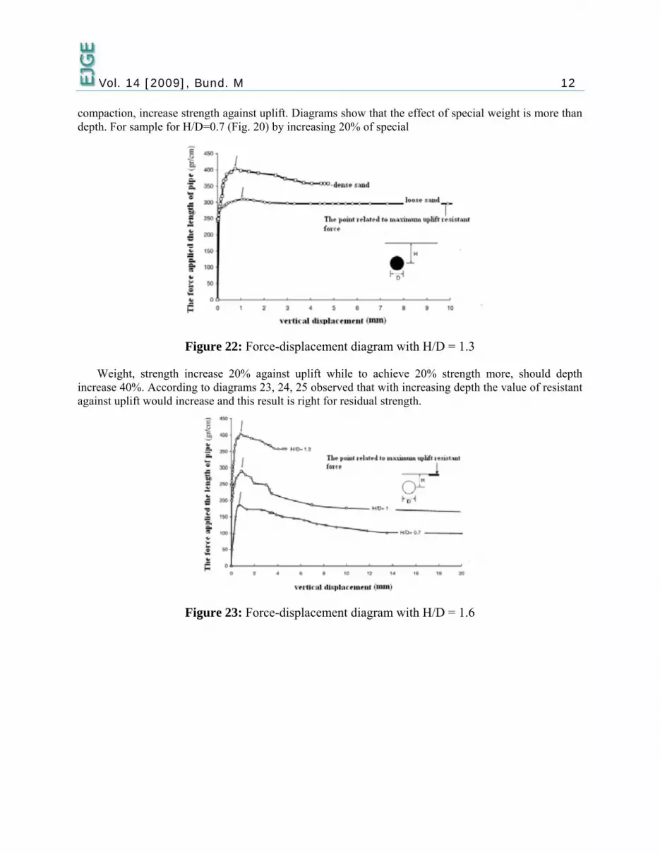
Vol. 14 [2009], Bund. M 12 compaction, increase strength against uplift. Diagrams show that the effect of special weight is more than depth. For sample for H/D=0.7 (Fig. 20) by increasing 20% of special
Figure 22: Force-displacement diagram with H/D = 1.3
Weight, strength increase 20% against uplift while to achieve 20% strength more, should depth increase 40%. According to diagrams 23, 24, 25 observed that with increasing depth the value of resistant against uplift would increase and this result is right for residual strength.
Figure 23: Force-displacement diagram with H/D = 1.6

Vol. 14 [2009], Bund. M 13
Figure 24: Force–displacement diagram for different depths of dense sand
Figure 25: Force–displacement diagram for different depths of loose and dense sand
CONCLUSION A laboratory model was designed and constructed to analyze behavior of buried pipes in different
cases of dense and depth.
The results of this laboratory model provided two types of failure mechanisms:
• A mechanism of type one (sliding block with angled planes) that occurs in small displacements and more related to tests for dense soil.
• A mechanism of type two (circular mechanism associated to soil flow under pipe) occurs in large displacement for dense soil and for loose soil occurs from the beginning steps.
From economic point of view, design of pipes based on mechanism of type 1 is accomplished by reduced costs. Tests show that special weight has more effect on uplift resistance than depth. It is observed that an increase of 20% in special weight is equivalent to an increase of 40% in buried depth

Vol. 14 [2009], Bund. M 14 when uplift resistance increases 20%. From economic point of view, increasing buried depth has greater cost than increasing special weight.
ACKNOWLEDGMENT The authors wish to acknowledge the support and assistance provided by the Babol University of
Technology, Mazandaran, Iran.
REFERENCES 1. White, D.J., Barefoot, A.J., and Bolton, M.D. (2000) “Centrifuge Modelling of Upheaval
Buckling in Sand,” Cambridge University Engineering Department.
2. Matyase, E.L., and Davis, J.B. (1983) “Prediction of Vertical Earth loads on Rigid Pipes”, Journal of Geotechnical Engineering Division, ASCE, Vol. 109, No.GT2, Paper17716, pp. 190-201.
3. Meyerhof, G.G., and Adams, J.I. (1968) “The Ultimate Uplift Capacity of Foundations”, Canadian Geotechnical Journal, Vol. 5, No. 4, pp. 225-244.
4. Kulhawy, F. H., Trautmann, C. H., Beech, J. F., O’Rourke, T. D., McGuire, W., Wood, W. A., and Capano, C. (1983) “Transmission Line Structure Foundations for Uplift-Compression Loading,” Research Report EL-2870, Electric Power Research Institute, Palo Alto, Calif., Feb., 412 pp.
5. Rowe, R.K., and Davis, E.D. (1982) “The Behavior of Anchor Plate in Sand,” Géotechnique, Vol. 32, No. 1, London, England, pp. 25-41.
6. Spangler, M. G. (1962) “Culverts and Conduits”, Foundation Engineering, G. A. Leonards, ed., Chapter 11, McGraw-Hill Book Co., Inc., New York, N.Y., pp. 965-999.
7. Vesić, A. S., (1971) “Breakout Resistance of Objects Embedded in Ocean Bottom,” Journal of the Soil Mechanics and Foundations Division, ASCE, Vol. 97, No. SM9, pp. 1183-1205
8. Spangler, M. G., and Handy, R. L. (1982) “Soil Engineering”, Harper & Row, New York, N.Y., 819 pp.
9. Marston, A. (1930) “The Theory of External Loads on Closed Conduits in the Light of Latest Experiments,” Bulletin 96, Iowa Engineering Experiment Station, Ames, Iowa.
10. American Water Works Association (1967) “USA Standard for Thickness Design of Cast-Iron Pipe,” Standard H1-67, New York, N.Y., 78 pp.
11. Das, B. M., and Seely, G. R., (1975) “Breakout Resistance of Shallow Horizontal Anchors,” Journal of the Geotechnical Engineering Division, ASCE, vol. 101, No. GT9, Sept., pp. 999-1003.
12. Van den Berghe, J.F., Cathie, D., and Ballard, J.C. (2005) “Pipeline uplift mechanisms using finite element analysis.” Proceedings of 16th International Conference of Soil Mechanics and Foundation Engineering, Osaka, 1801-1804.
13. White, D.J., Barefoot, A.J., Bolton, M.D. (2001) “Centrifuge modeling of upheaval buckling in sand.” International Journal of Physical Modelling in Geotechnics, Vol. 2 1:19-28

Vol.
14. S(2O
15. WB
16. Tof10
17. D
18. A
19. A
14 [2009]
chupp, J., By2006) “Pipeli
Offshore Mech
Wang, J., HaigBlocky Clay B
Troutmann, C.f Buried Pipe076.
Das, Braja M.
American Soci
American Soci
, Bund. M
yrne, B.W., Eine unburial hanics and Ar
gh, S.K., andBackfill”, KW
.H., O’Rourke,” Journal of
(1998) ‘Princ
iety of Testin
iety of Testin
Eacott, N., Mabehaviour in
rctic Engineer
d ThusyanthaW Ltd., Fetcham
ke, T.D., KulhGeotechnical
ciples of Geot
ng and Materia
ng and Materia
artin, C.M., On loose sandring, Hambur
an, N.I. (2009m, Surrey, Un
hawy, F.H. (1l Engineering
technical Eng
als (ASTM),
als (ASTM),
Oliphant, J., Md” Proc. 25thrg. OMAE200
9) “Uplift Renited Kingdo
1986) “Upliftg Division, AS
gineering,” Un
No. D 854-87
No. D 3083-9
Maconochie, h Internation06-92541.
esistance of Bm, Paper No.
t Force-DisplSCE, Vol. 11
niversity of T
7.
90.
A. and Cathnal Conferenc
Buried Pipelin. 2009-TPC-5
acement Resp3 , No. 1, pp.
Texas at El Pa
© 2009 ejg
15
hie, D. ce on
nes in 564.
ponse 1061-
aso.
ge