Embed Size (px)
Citation preview

University of Nebraska - LincolnDigitalCommons@University of Nebraska - Lincoln
USGS Staff -- Published Research US Geological Survey
1-1-2000
Modeling regional salinization of the Ogallalaaquifer, Southern High Plains, TX, USAS. MehtaUniversity of Kentucky
A. E. FryarUniversity of Kentucky
R. M. BradyPanhandle Ground Water Conservation District No. 3
Roger H. MorinDenver Federal Center, [email protected]
This Article is brought to you for free and open access by the US Geological Survey at DigitalCommons@University of Nebraska - Lincoln. It has beenaccepted for inclusion in USGS Staff -- Published Research by an authorized administrator of DigitalCommons@University of Nebraska - Lincoln. Formore information, please contact [email protected].
Mehta, S.; Fryar, A. E.; Brady, R. M.; and Morin, Roger H., "Modeling regional salinization of the Ogallala aquifer, Southern HighPlains, TX, USA" (2000). USGS Staff -- Published Research. Paper 356.http://digitalcommons.unl.edu/usgsstaffpub/356

Modeling regional salinization of the Ogallala aquifer, SouthernHigh Plains, TX, USA
S. Mehtaa,* , A.E. Fryara, R.M. Bradyb, R.H. Morinc
aDepartment of Geological Sciences, University of Kentucky, Lexington, Kentucky 40506, USAbPanhandle Ground Water Conservation District No. 3, P.O. Box 637, White Deer, Texas 79097, USA
cUS Geological Survey, Mail Stop 403, Denver Federal Center, Denver, Colorado 80225, USA
Received 22 November 1999; revised 15 August 2000; accepted 21 August 2000
Abstract
Two extensive plumes (combined area.1000 km2) have been delineated within the Ogallala aquifer in the Southern HighPlains, TX, USA. Salinity varies within the plumes spatially and increases with depth; Cl ranges from 50 to.500 mg l21.Variable-density flow modeling using SUTRA has identified three broad regions of upward cross-formational flow from theunderlying evaporite units. The upward discharge within the modeled plume area is in the range of 1024–1025 m3 day21, andthe TDS concentrations are typically.3000 mg l21. Regions of increased salinity, identified within the Whitehorse Group(evaporite unit) underlying the Ogallala aquifer, are controlled by the structure and thickness variations relative to the rechargeareas. Distinct flow paths, on the order of tens of km to.100 km in length, and varying flow velocities indicate that thesalinization of the Ogallala aquifer has been a slow, ongoing process and may represent circulation of waters recharged duringPleistocene or earlier times. On-going pumping has had negligible impact on the salinity distribution in the Ogallala aquifer,although simulations indicate that the velocity distribution in the underlying units may have been affected to depths of 150 mafter 30 years of pumping. Because the distribution of saline ground water in this region of the Ogallala aquifer is hetero-geneous, careful areal and vertical characterization is warranted prior to any well-field development.q 2000 Elsevier ScienceB.V. All rights reserved.
Keywords: Ogallala aquifer; Salinization; Southern High Plains; Modeling; Texas
1. Introduction
Salinization is a major concern in managing limitedwater resources in arid and semi-arid regions. Such aproblem exists in the northern part of the SouthernHigh Plains of Texas, where saline plumes ofcombined areal extent.1000 km2 are present in theregionally important Ogallala aquifer. Two plumes lie
above the Panhandle oil and gas field in Carson, Gray,and Roberts Counties, overlapping the Palo Duro andAnadarko basins (Fig. 1). The southern plume isreferred to as the Carson-Gray Counties plume,while the northern plume is referred to as the RobertsCounty plume. Chloride concentrations within theplumes range from 50 to.500 mg l21 and totaldissolved solids (TDS) from 400 to.2000 mg l21.Salinization has affected water quality for bothdomestic and industrial use, as well as the placementof future municipal wells.
Saline ground water in the Carson-Gray Countiesplume was first reported by local residents prior to
Journal of Hydrology 238 (2000) 44–64www.elsevier.com/locate/jhydrol
0022-1694/00/$ - see front matterq 2000 Elsevier Science B.V. All rights reserved.PII: S0022-1694(00)00314-0
* Corresponding author. Duke Engineering and Services, 1180Town Center Dr., Las Vegas, NV 89144, USA. Fax:11-702-295-0438.
E-mail address:[email protected] (S. Mehta).

S.
Me
hta
et
al.
/Jo
urn
alo
fH
ydro
log
y2
38
(20
00
)4
4–
64
45
Fig. 1. Location of saline plumes in the study area. The chloride concentration contours are 50 and 150 mg l21. The Amarillo uplift is hachured, and the Amarillo Carson CountyWell Field (ACCWF) is shown in a box. The stratigraphic cross-section along the bold line (A–A0) is shown in Fig. 2. The numbers represent well locations. Modified from Eiflerand Barnes (1969), Mullican et al. (1997) and Mehta et al. (2000).

1926 (Long, 1961) and was mapped by McAdoo et al.(1964). Mullican et al. (1997) developed a single-layer ground-water flow model to evaluate rechargescenarios (diffuse vs. focused) in the area of theplumes, but did not address the salinity variationswithin the Ogallala aquifer. Using end-membermixing models with chemical and isotopic data,Mehta et al. (2000) showed that the increased salinityin the Carson-Gray Counties plume is largely unre-lated to oil-field brines present in deep units. Instead,salinization results from the mixing of isotopicallydepleted, confined paleowaters with underlying salt-dissolution zone waters, followed by upwarddischarge into the Ogallala aquifer.
This study extends the findings of Mehta et al.(2000) by attempting to: (a) delineate the nature offlow processes involved in increased salinity; (b) eval-uate the structural and stratigraphic controls on solutetransport; and (c) study the effects of on-going pump-ing on water quality. Other studies of salinizationhave focused on large salt lakes and disposal basins(Rogers and Dreiss, 1995; Narayan and Armstrong,1995; Simmons and Narayan, 1998), saltwater intru-sion in coastal aquifers (Segol and Pinder, 1976;Souza and Voss, 1987), brine movement on a basinscale (Senger, 1993; Lahm et al., 1998; Dutton et al.,1989), and evaporation (Stein and Schwartz, 1990;Sanford and Wood, 1991; Wood and Sanford,1995). Our study differs in both the scale of the flowsystem and the mechanism of salinization.
2. Hydrogeologic setting
The Palo Duro and Anadarko basins are part of theintracratonic greater Permian basin, which formed asa result of late Paleozoic tectonic activity. The twosmaller basins are separated by the fault-bounded,structurally high basement rocks of the Amarillouplift (Fig. 1). The main topographic feature is theHigh Plains, which is separated from the Pecos Plainsto the west by the Pecos River and from the RollingPlains to the east by the eastern Caprock Escarpment.The Canadian River divides the Southern High Plainsfrom the Central High Plains. In the northern part ofthe Southern High Plains, average annual precipita-tion is 50^ 10 cm and average annual pan evapora-tion is 250^ 25 cm (Gutentag et al., 1984; Luckey
and Becker, 1999). The Neogene Ogallala Formationand Triassic Dockum Group form shallow aquifers,which are underlain by thick Permian evaporites(Table 1 and Fig. 2).
The unconfined Ogallala aquifer, which is the mainwater supply unit for the Southern High Plains,consists of fluvial sediments and fine-grained eoliansilts and clays (Fig. 2). Estimated recharge rates varyfrom 0.145 cm year21 (Knowles et al., 1984; Sengerand Fogg, 1987) to 0.9 cm year21 (Mullican et al.,1997). Most of the recharge is focused through playas(ephemeral lakes that collect recharge) in the northernpart of the Southern High Plains (Scanlon and Gold-smith, 1997). Ground water flows toward the north-east, following the regional topographic slope, anddischarges naturally through springs and seeps alongthe Canadian River to the north and the CaprockEscarpment to the east (Mullican et al., 1997) (Fig.1). The average flow velocity is 0.18 m day21
(Knowles et al., 1984) and average hydraulicconductivity is 8 m day21 (Senger and Fogg, 1987;Senger and Fogg, 1990; Mullican et al., 1997). Thechemical composition of Ogallala ground water varies
S. Mehta et al. / Journal of Hydrology 238 (2000) 44–6446
Table 1Generalized stratigraphic and hydrostratigraphic column for thestudy area (modified from Bassett and Bentley, 1983; Gustavson,1986)

S.
Me
hta
et
al.
/Jo
urn
alo
fH
ydro
log
y2
38
(20
00
)4
4–
64
47
Fig. 2. Stratigraphic cross-section used for creating the numerical model. Line of cross-section (A–A0) is shown in Fig. 1 relative to plume dimensions. Modified from McGookey etal. (1988) and Dutton et al. (1982).

from Ca-HCO3 to mixed-cation-HCO3 water (Nativand Smith, 1987). Pumping for irrigation startedaround 1911 and increased significantly after WorldWar II. Water volumes currently being withdrawnfrom the aquifer are greater than the annual rechargeand some areas have experienced water level declinesof as much as 15 m between 1940 and 1980 (Dugan etal., 1994). Thus sustainability of ground-waterresources is a major concern in this region.
The principal shallow confined aquifer is in thelower part of the Triassic Dockum Group, which iscomposed of sandstones and mudstones (Dutton andSimpkins, 1986; Dutton and Simpkins, 1989) (Fig. 2).The Dockum Group thins northeastward and pinchesout approximately 40 km southwest of the westernedges of the saline plumes. Present-day recharge tothe Dockum aquifer is primarily through downwardleakage from the Ogallala aquifer (Dutton, 1989;Dutton, 1995). The flow in the lower DockumGroup in the study area is toward the east-northeastand the water quality is marked by a mixed cation andmixed anion hydrochemical facies with TDS gener-ally ,2000 mg l21 (Dutton and Simpkins, 1986;Dutton and Simpkins, 1989).
The Middle and Upper Permian evaporite-confining unit consists of halite, anhydrite, dolo-mite, limestone, and fine-grained siliciclastic redbeds (Bassett and Bentley, 1983; Jorgensen et al.,1988) (Fig. 2). In the vicinity of the plumes, theUpper Permian Whitehorse Group, which iscomposed predominantly of siliciclastic red bedsand minor evaporites (McGookey et al., 1988), isunconformably overlain by the Ogallala Formation.The Whitehorse Group can have significantlyhigher permeability than the underlying evaporitestrata and locally acts as an aquifer where theOgallala Formation and Dockum Group are thinor absent, such as at the margins of the SouthernHigh Plains (Long, 1961). Several salt-dissolutionzones have been identified within the upper part ofthe evaporite-confining unit (Gustavson et al.,1980; McGookey et al., 1988) (Fig. 2). Thesezones seem to have developed as a result of shal-low, gravity-driven circulation of meteoric water(Dutton, 1989). Hydraulic conductivity ranges from0.5 m day21 in salt-dissolution zones to less than1025 m day21 for the deeper parts of the confining unit(Dutton, 1989) and TDS varies from 5000 mg l21 to
.300,000 mg l21, respectively (Nativ and Smith,1987; Dutton, 1987; Bein and Dutton, 1993).
Dissolution is most extensive on the upturned flanksof the structurally high areas at the margins of the PaloDuro and Anadarko basins above the Amarillo uplift,where salt beds are nearest to land surface (Gustavson,1986). As a result, the Whitehorse Group and equivalentformations have undergone more extensive dissolutioncompared to deeper units. The San Andres Formationhas undergone limited dissolution, primarily toward thenortheastern part of the study area. The Clear ForkGroup forms the lower part of the evaporite-confiningunit and does not undergo dissolution. Halite is thedominant lithology (Fig. 2).
In the Palo Duro basin, brine occurs in the halite-and anhydrite-cemented carbonate rocks of the SanAndres Formation, whereas south of the Palo Durobasin, San Andres carbonates are significant oil reser-voirs. The thickest San Andres carbonate bed in thePalo Duro basin, the informally named “unit 4carbonate”, yielded 0.35–2 m3 day21 of brine duringdrill-stem testing and long-term pumping (Dutton andOrr, 1986). Near-hydrostatic pressures exist in the SanAndres Formation at depths of 790–927 m (6.76–9.03 MPa) (Dutton and Orr, 1986), but at greaterdepths, the San Andres Formation and Clear ForkGroup show appreciable underpressuring, leading topotential downward cross-formational flow (Bair,1987). Several reasons for underpressuring havebeen proposed and discussed by Bair (1987). Anoverall eastward flow is inferred for the San AndresFormation on the basis of a potentiometric surfacemap derived from equivalent freshwater heads (Bair,1987).
3. Plume characterization
Mehta et al. (2000) mapped the Carson-GrayCounties plume, using chloride and sulfate datafrom existing records. Since then, more test wellshave been drilled for the City of Amarillo and theCanadian River Municipal Water Authority(CRMWA) (Harden and Associates, 1999a, b; LeeWilson and Associates, personal communication,1999). These wells are located in Roberts County,where previous data were limited due to scarcity ofmonitoring wells. An updated map based on chloride
S. Mehta et al. / Journal of Hydrology 238 (2000) 44–6448

S.
Me
hta
et
al.
/Jo
urn
alo
fH
ydro
log
y2
38
(20
00
)4
4–
64
49
Fig. 3. Plume outlines based on chloride concentrations. Contours are 50 and 150 mg l21. Diamonds indicate wells logged in this study. Circles and plus symbols represent well datafrom Harden and Associates (1999b) and Texas Water Development Board database, respectively. Cross-sections A–A0 and B–B0 are shown in Fig. 5a and b, respectively.

concentrations shows two plumes of combined arealextent .1000 km2 (Fig. 3). Sulfate concentrationshave similar spatial distributions. The areal extent ofthe plumes and the distinct zones of high concentra-tions within the plumes indicate a regional source ofsalinity that is neither localized nor completelydiffuse. Chloride and sulfate data of water samplesfrom wells drilled in Roberts County (Fig. 4) fall inthe compositional field of plume waters reported forCarson-Gray Counties plume by Mehta et al. (2000),indicating that both plumes have similar origins. Thepresence of the Canadian River to the north and prob-able dilution downgradient limits the known extent ofthe plumes. Salinization may be more extensive thanmapped because the present plume geometry iscontrolled in part by the number and locations ofmonitoring wells.
We expected salinity within the plumes to increasewith depth. In order to study the vertical distributionof salinity, four windmills were selected for fluidresistivity logging within the Carson-Gray Counties
plume. No details of well construction were knownfor any of these windmills prior to this study. Theselection criteria were based on the location withrespect to the plume geometry and the distance fromirrigation wells. All four windmills are located at least1 km from known active irrigation wells. Three wind-mills are located close to the center of the Carson-Gray Counties plume, and the fourth is located closeto the edge of the plume (Fig. 3). Two of the fourwindmills had not been in use for more than twomonths before sampling, while the other two werecontinuously pumping. For all windmills, theproduction pipes, sucker rods, and check valveswere pulled out at least 24 h prior to logging so thatquasi-equilibrium conditions of solute distributioncould return. Down-hole geophysical logging wascarried out with a slim multifunction logging tool.Logging activities consisted of recording fluidtemperature and fluid resistivity as well as naturalgamma ray and caliper. The fluid resistivity logswere combined with corresponding temperature logs
S. Mehta et al. / Journal of Hydrology 238 (2000) 44–6450
Fig. 4. SO4/Cl vs. Cl bivariate plot for end-member waters in the region (modified from Mehta et al., 2000).

to compute the fluid resistivity (ohm-m) normalized to258C according to the formula (Paillet et al., 1990):
R�T2� � R�T1��T1 1 21:5�=�T2 1 21:5�
and then converted to estimates of TDS (mg l21)according to the relation (Fishman and Friedman,
1989):
TDS� �0:65× 104�=R�T2�
where R(T1) is the resistivity given at temperatureT1(8C) that is extrapolated to the resistivityR(T2) atanother temperature,T2 (258C in this study).
S. Mehta et al. / Journal of Hydrology 238 (2000) 44–64 51
Fig. 5. (A) Fluid resistivity logs of selected windmills along cross-section A–A0 shown in Fig. 3.
The computed TDS profiles of the three windmillslocated close to the center line of the plume are shownin Fig. 5a. The Eakin well is screened across thebottom of the Ogallala aquifer and the underlyingUpper Permian red beds. It displays strong salinitystratification with depth and TDS systematicallyincreases to approximately 4000 mg l21 near thebottom of the well. The Dawkins well is screenedwithin the Ogallala aquifer and exhibits a gradualincrease in TDS with depth that is an order of magni-tude less than that observed for the Eakin well. TheCampbell well displays intermediate TDS values thatare more uniform with depth, probably because it isscreened a considerable distance (.40 m) above thebase of the Ogallala aquifer. The fourth windmilllocated south of the plume (Fig. 3) had a small satu-rated interval (,2 m) and did not show any salinityvariation (log not shown).
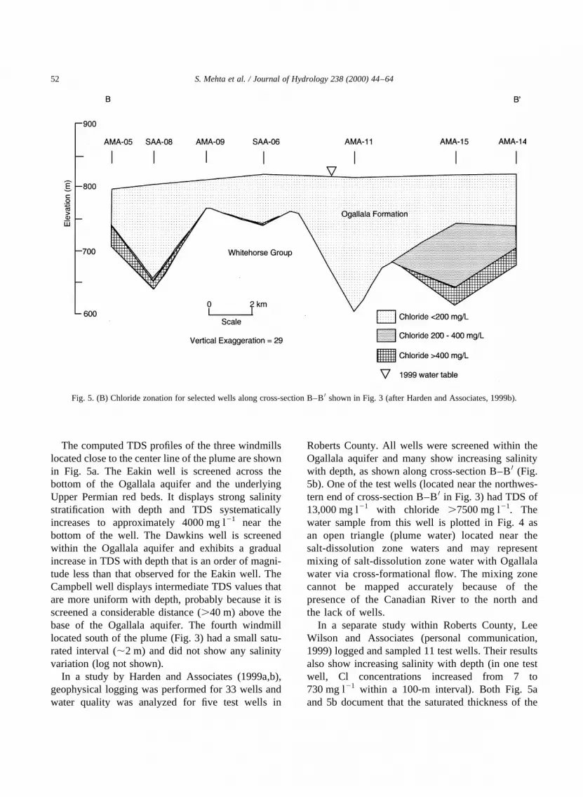
In a study by Harden and Associates (1999a,b),geophysical logging was performed for 33 wells andwater quality was analyzed for five test wells in
Roberts County. All wells were screened within theOgallala aquifer and many show increasing salinitywith depth, as shown along cross-section B–B0 (Fig.5b). One of the test wells (located near the northwes-tern end of cross-section B–B0 in Fig. 3) had TDS of13,000 mg l21 with chloride .7500 mg l21. Thewater sample from this well is plotted in Fig. 4 asan open triangle (plume water) located near thesalt-dissolution zone waters and may representmixing of salt-dissolution zone water with Ogallalawater via cross-formational flow. The mixing zonecannot be mapped accurately because of thepresence of the Canadian River to the north andthe lack of wells.
In a separate study within Roberts County, LeeWilson and Associates (personal communication,1999) logged and sampled 11 test wells. Their resultsalso show increasing salinity with depth (in one testwell, Cl concentrations increased from 7 to730 mg l21 within a 100-m interval). Both Fig. 5aand 5b document that the saturated thickness of the
S. Mehta et al. / Journal of Hydrology 238 (2000) 44–6452
Fig. 5. (B) Chloride zonation for selected wells along cross-section B–B0 shown in Fig. 3 (after Harden and Associates, 1999b).

Ogallala aquifer, by itself, does not control the salinitydistribution. The saturated thickness of the Ogallalaaquifer within the study area ranges from 15 to.100 m and the hydraulic conductivity ranges from1 to 28 m day21 (Mullican et al., 1997).
4. Numerical modeling
Mehta et al. (2000) hypothesized that salinizationresults from gravity-driven cross-formational circula-tion along flow paths tens of km long. We test thishypothesis and observe the effects of pumping onsalinity in the Ogallala aquifer by using the numericalmodel SUTRA (Voss, 1984). SUTRA employs a two-dimensional, finite-element method, with an implicitfinite-difference approximation in time to simulatevariable-density ground-water flow and solute trans-port. The method is stable and accurate when usedwith proper spatial and temporal discretization.
The fluid mass balance under saturated conditionscan be expressed as (Voss, 1984):
2�1r�=2t � 27·�1rV�1 Qp
where1 (x,y,t) is a dimensionless porosity,r (x,y,t) isthe fluid density,V(x,y,t) is the average fluid velocity,Qp(x,y,t) is a fluid source or sink,x andy are coordi-nate variables,t is time, and7 is the divergenceoperator. This equation can be expressed in terms oftwo primary variables,p (pressure) andC (TDSconcentration):
�rSop�2p=2t 1 �12r=2C�2C=2t 2 7·��rk=m�·�7r 2 rg��� Qp
where Sop � �1 2 1�a 1 1b is specific pressurestorativity, a is porous matrix compressibility,b isfluid compressibility,C(x,y,t) is solute concentrationas a mass fraction,k(x,y) is permeability,m (x,y,t) isfluid viscosity, p(x,y,t) is fluid pressure, andg isgravitational acceleration.
The solute mass balance for a single species at apoint (x,y) in an aquifer is given by (Voss, 1984):
1r�2C=2t�1 1rV·7C 2 7·�1r�DmI 1 D�·7C�� Qp�Cp 2 C�
whereDm is molecular diffusivity of a solute in solu-tion in a porous medium,I is the identity tensor,D(x,y,t) is the dispersion tensor,Cp(x,y,t) is concen-tration of solute as a mass fraction in the source fluid,andr(x,y,t) is fluid density given as a linear functionof concentration:
r � ro 1 �2r=2C��C 2 Co�wherero is fluid density whenC � Co; Co is a basesolute concentration, and2r=2C is a constant coeffi-cient of density variability.
4.1. Conceptualization, spatial discretization, andboundary conditions
A cross-section of length 200 km and depth rangingfrom 900 to 500 m was chosen for modeling (Fig. 2).The cross-section approximately parallels the Carson-Gray Counties plume orientation and the regionalflow gradient for both the Ogallala and Dockumaquifers. We chose the length of the cross-sectionon the basis of well locations with good stratigraphiccontrol and to include part of the Dockum Group.Upper and Middle Permian formation boundarieswere delineated by lithologic and geophysical logspresented by McGookey et al. (1988). Thicknessvariations for the Ogallala and Dockum aquiferswere incorporated from Mullican et al. (1997) andDutton and Simpkins (1986), respectively. The topof the model was taken to be the 1959–1960 watertable for the Ogallala aquifer. This surface approxi-mates steady-state conditions because most of theirrigation pumping in the region started after 1960.Furthermore, pre-1960 water-level data are lackingbecause of scarcity of monitoring wells. Previousmodeling studies in the region (Knowles et al.,1984; Mullican et al., 1997) also considered the1959–1960 water table to represent steady-stateconditions. The base of the model was arbitrarilychosen within the Middle Permian Clear ForkGroup, which forms a good confining unit. Themodel cell thickness in third dimension is 1 m.
Modeling was performed using the US GeologicalSurvey’s graphical-user interface for SUTRA(SUTRA GUI) as a plug-in extension (PIE) to ArgusONEe (Argus Open Numerical Environments,commercial software developed by Argus Interware).We focused on accurately discretizing the geologic
S. Mehta et al. / Journal of Hydrology 238 (2000) 44–64 53

units in order to have a distinct top and bottom withfinite elements aligned along the boundaries. AFishnet Mesh (provided in SUTRA PIE) was usedfor this purpose (Voss et al., 1997). It consists ofsuperblocks (large contiguous quadrilaterals), eachsubdivided into a specified number of quadrilateralfinite elements such that the edges of the quadrilateralare connected to each internal node inx- and y-directions. The mesh density can be varied withinthe model domain at user-specified locations.
The model cross-section was discretized into 180elements in the horizontal direction and 32 elementsin the vertical direction, resulting in a mesh containing5760 quadrilateral elements and 5973 nodes. Thehorizontal mesh spacing varied from 700 to 1400 m,with finer discretization in the vicinity of the plumeand near the pinchout of the Dockum Group. Thevertical spacing was determined by trial and errorand ranged from 3 m for the Ogallala aquifer to60 m for the Clear Fork Group. A grid convergencestudy was performed to insure proper grid discretiza-tion: a much finer grid (with grid spacing half of thatused in the model) did not produce any appreciabledifference in velocity and concentration distributions,despite being more computationally expensive.
The boundary conditions for simulation of flow andsolute transport for the cross-section are shown in Fig.6. A no-flow boundary is specified along the bottom ofthe mesh. The lateral boundaries from the top to thebase of the San Andres Formation are specified pres-sure boundaries using fresh-water hydrostatic pres-sure (p) varying linearly with depth such thatp� rwgd; whererw is the density of fresh water,gthe gravitational acceleration, andd the depth belowthe water table. No-flow lateral boundaries are speci-fied across the Clear Fork Group. A uniform rechargeflux of 6 mm year21 is applied at the top boundary.This value was selected on the basis of modelingresults presented by Knowles et al. (1984), Mullicanet al. (1997) and Luckey and Becker (1999). Mullicanet al. (1997) also found that using either areally-distributed recharge or playa-focused recharge gavesimilar results in predevelopment simulations for theOgallala aquifer.
The solute concentrations at the lateral boundariesalso vary. On the southwest (left) specified-pressureboundary, the concentrations given are 0.0002 kgTDS kg21 fluid (200 mg l21) for the Ogallala aquifer,
0.001 kg TDS kg21 fluid (1000 mg l21) for theDockum Group, 0.005 kg TDS kg21 fluid(5000 mg l21) for the Whitehorse Group, and 0.3 kgTDS kg21 fluid (300,000 mg l21) for the San AndresFormation. On the northeast (right) specified-pressureboundary, the concentrations are the same, except theOgallala aquifer is given an arbitrary concentration of0.001 kg TDS kg21 fluid (1000 mg l21) along theCanadian River. The Canadian River is gainingalong this reach but carries solute load derived largelyfrom saline seepage in eastern New Mexico (Paine etal., 1994; Mullican et al., 1997). All nodes within theClear Fork Group were assigned a constant concen-tration of 0.3 kg TDS kg21 fluid (30 wt% NaCl), anapproximate value for halite saturation at the depth ofinterest. For the recharge flux at the top boundary,zero concentration is defined. Solutes neither dispersenor advect across the no-flow boundaries.
4.2. Model parameters
Permeability values for modeled hydrologic unitsare listed in Table 2. Values were taken from Sengerand Fogg (1987) and later modified where newer datawere available. For salt-dissolution zones, the perme-ability values range from 10213 to 10217 m2 (Dutton,1989). An average salt-dissolution zone permeabilitywas taken for the Whitehorse Group on the basis ofmapping of salt-dissolution zones by Gustavson(1986). Hydraulic conductivity data for the Ogallalaaquifer are relatively abundant. Xiang (1996)calculated values ranging from 2.2 to 5.1 m day21
for the City of Amarillo Carson County well field(ACCWF). Mullican et al. (1997) calculated hydraulicconductivity values of 0.5–28 m day21 from specificcapacity tests. For this model, initial permeabilitiesfor the Ogallala aquifer were calculated from existinghydraulic conductivity data and later modified withinthe range of published values. Vertical permeabilitiesfor the Ogallala aquifer are taken to be an order ofmagnitude lower than horizontal permeabilities.
The longitudinal and transverse dispersivitieslisted in Table 2 are estimated values, which aregoverned in part by the practical limitationsimposed by the mesh size. Dispersivities havenot been measured in the study area. A discretiza-tion rule-of-thumb that guarantees spatial stabilityfor simulation with SUTRA isDLL # 4 a L, where
S. Mehta et al. / Journal of Hydrology 238 (2000) 44–6454

DLL is the maximum element length along astreamline anda L is the longitudinal dispersivity.Given a maximum element length parallel to flowof 1400 m, a value ofaL � 400 m is appropriate.Longitudinal concentration gradients are small inthe region and thus the model is not sensitive tolongitudinal dispersivity values, despite anisotropicpermeabilities in the multilayer model.
Transverse dispersivity (aT) values are typically anorder of magnitude smaller than longitudinal disper-sivity values (Gelhar et al., 1992), but may be as muchas two orders of magnitude smaller in systems withanisotropic permeability (Gelhar and Axness, 1983).We assumeaT � 10 m: Matrix compressibility valuesrange from 1028 Pa21 for sandy gravel to 10210 Pa21
for sound rock (Domenico and Schwartz, 1997).Because most of the recoverable water is stored inthe Ogallala aquifer, a value of 1028 Pa21 was used
in the model. The fluid compressibility (for water at258C) was taken to be 4:8 × 10210 Pa21
: All modelparameters are summarized in Table 2.
4.3. Steady-state simulation
To produce reasonable pressure and concentrationdistributions to represent initial conditions for thepumping simulations, a steady-state variable-densitysimulation was run. Using boundary conditionsdescribed above, a steady-state solution is found bylong-term transient simulation from arbitrary initialconditions until the system stabilizes. A rechargeflux of 0.038 kg s21 per cross-sectional thickness of1 m (6 mm year21) is used at the top of the model,which corresponds to the 1959–1960 water table.
In a separate simulation, a specified pressure ofzero was assigned to the top layer of the model in
S. Mehta et al. / Journal of Hydrology 238 (2000) 44–64 55
Table 2Model parameters
Permeability (m2) Porosity
Horizontal VerticalOgallala aquifer 4× 10212–4× 10211 4 × 10213–4× 10212 0.16Dockum Gp. 9.4× 10213 9.4× 10214 0.1Whitehorse Gp. 7× 10215 7 × 10217 0.1San Andres Fm. 9.8× 10217 9.8× 10217 0.05Clear Fork Gp. 2.7× 10219 2.7× 10219 0.05
Model cell thickness (thirddimension)
� 1 m
Freshwater density (rw) � 1000 kg m23
Fluid viscosity (m) � 1023 kg m s21
Coefficient of fluid densitychange (2r /2C)
� 700 kg m23
Water compressibility (b) � 4.8× 10210 Pa21
Matrix compressibility (a) � 1 × 1028 Pa21
Longitudinal dispersivity (aL) � 400 mTransverse dispersivity (aT) � 10 mMolecular diffusivity (Dm) � 1.5× 1029 m2 s21
Recharge � 6 mm year21
Extent of influence of a well (L) � 700 m
Well discharge (Qw):Well B � 0.44 m3 min21 (1960–1974)
0.72 m3 min21 (1975–1990)Wells A and C � 0.15 m3 min21
Pump discharge (line sink) � (Qw × rw)/LWell B � 1.05× 10²² kg s21 (1960–1974)
1.71× 10²² kg s21 (1975–1990)Wells A and C � 3.58× 10²³ kg s21

place of the recharge flux, keeping all other boundaryconditions and model parameters unchanged. Thiswas done to test the validity of the recharge flux andto observe whether similar flow dynamics developusing two different representations of the boundarycondition. The new representation produced similarflow dynamics, which strengthened our choice ofboundary conditions and added support to our originalmodel results. A comparison of velocity profiles alonga single row of the model located in the center of theOgallala aquifer for both simulations gives an averagevelocity of 0.22 m day21 (Fig. 7), which matches wellwith the average velocity of 0.18 m day21 reported byKnowles et al. (1984). The approximate calculatedvelocity of 0.09 m day21 within the paleovalley (at adistance of 60 km along the cross-section) is in therange of velocities computed from the travel timespresented by Mullican et al. (1997) for that area.
A steady-state concentration distribution (Fig. 8)shows three specific regions of elevated concentrationin the Whitehorse Group (marked by contour of0.01 kg TDS kg21 fluid [10,000 mg l21]); one isbeneath the plume. Incidentally, this is an areawhere the base of the Ogallala aquifer is also rela-tively low. The elevated concentration close to thesouthwest (left) boundary occurs in an area wherethe tops of the San Andres and the Clear Fork unitsare angled upwards, but the concentrations dropsharply within a small distance, indicating that theunderlying structure is not the primary control.Rather, the small thicknesses of both the overlyingOgallala and Dockum aquifers in that area exert theprimary control, resulting in reduced leakance to theWhitehorse Group.
Fig. 8 shows the flow paths and the regions ofupward flux interpreted from a velocity vector plot.The flow paths, which are typically on the order oftens of km and in some places.100 km in length,indicate cross-formational discharge influenced bytopography. Velocities vary for different flow pathsbased on the leakance and permeability of units.Beneath the Carson-Gray Counties plume, upwarddischarge along two different flow paths occurs inthe Whitehorse Group. The shorter flow path (30–50 km length) originates from the northeast (right)side of the paleovalley upgradient of the plume andfollows the topographic slope before intercepting thebase of the Ogallala aquifer. The longer flow path
(.100 km) originates largely within the Dockumaquifer. Part of this flow may discharge upwardtoward the southwest (left) side of the paleovalley,while the rest of it moves within the WhitehorseGroup before discharging in the plume area. Theupward directed flow at the base of the Ogallalaaquifer has velocities ranging from 1027 to1028 m day21 and TDS.3000 mg l21. The resultingupward discharge is calculated to range from 2× 1025
to 6× 1024 m3 day21 and the horizontal flowvelocities range from 1025 to 1024 m day21 in theWhitehorse Group.
It is important to note that upward flow occurs onlyin certain regions of the model, which is consistentwith the spatial extent of the zones of higher concen-trations within the plume (Fig. 3). The identified flowpaths and flow velocities suggest that the upward-discharging Whitehorse Group waters beneath theCarson-Gray Counties plume could have beenrecharged during the Pleistocene or earlier times.This observation is consistent with previous interpre-tations by Dutton (1989, 1995) based on14C, d 18O,and dD values in salt-dissolution zones and theDockum aquifer and by Mehta et al. (2000) basedon d 18O and dD values of plume waters and end-member mixing calculations.
The other two regions of upward dischargeidentified in the Whitehorse Group occur toward thesouthwest (left) side of the paleovalley and nearthe northeast (right) boundary of the model close tothe Canadian River (Fig. 8). Despite the upwarddischarge to the Ogallala aquifer, no saline plumehas been reported for these two regions in previousstudies. This is probably a result of greater thicknessof the Ogallala aquifer in the paleovalley, leading todilution of salinity, and lack of wells close to theCanadian River, where the saturated thickness issmall. The elevated concentrations close to the north-east (right) boundary of the model occur because ofupward flow from the Whitehorse Group. Theelevated concentrations may in part result from theincreased hydraulic gradient and decreased thicknessof the Ogallala aquifer, leading to higher horizontalflow velocities (Fig. 7) and decreased verticalleakance in the Whitehorse Group. This region ofupward flow in the Whitehorse Group is consistentwith the pressure data presented by Bair (1987) andthe existence of near-surface salt-dissolution zones
S. Mehta et al. / Journal of Hydrology 238 (2000) 44–6456

S. Mehta et al. / Journal of Hydrology 238 (2000) 44–64 57
Fig. 6. Model cross-section showing boundary conditions.
Fig. 7. Model cross-section velocity comparison for Ogallala aquifer (along a row).

(Gustavson et al., 1980). Furthermore, chemicalanalyses indicate that brines in the Rolling Plains,east of the Caprock Escarpment, have a shallowmeteoric origin rather than a deep-basin origin (Rich-ter and Kreitler, 1986).
Several other flow paths are indicated beneath theWhitehorse Group. Although the flow velocities aresmaller, the regions of upward discharge match. Theprimary controls seem to be the structure and thick-ness variations within the units themselves relative tothe location of recharge areas. The structure andthickness variations have been indirectly affected by
the underlying Amarillo uplift and salt-dissolutionzones (Gustavson, 1986). Permian strata follow thesubsurface rise caused by the uplift and thin athigher elevations near the margins of the adjoiningbasins. Regions of upward discharge identifiedgenerally correspond with the location of observedsalt-dissolution zones (Fig. 2).
4.4. Transient-state simulation
Transient-state simulations were undertaken toobserve the effects of pumping on depressurizing the
S. Mehta et al. / Journal of Hydrology 238 (2000) 44–6458
Fig. 8. Concentration distribution (kg TDS kg21 fluid), flow paths, and regions of upward discharge under steady-state conditions for the modelcross-section. Only selected concentration contours and flow paths are shown.

Ogallala aquifer and on salinity variations. Fig. 9shows the actual water table variation along themodel cross-section between years 1959–1960 and1990. In most areas, the water-table decline is rela-tively small, indicating lack of significant pumping inthe vicinity of the Carson-Gray Counties plume. Themaximum water-table decline observed is in thepaleovalley, where the ACCWF is located; the modelcross-section passes nearly through the center of thewell field (Fig. 1). Along other parts of the cross-section, municipal wells are not known to exist(Coker et al., 1992), so pumping for irrigation is likelyto be the main source of discharge. Pumping rates forwells in the ACCWF (from 1960 to 1990) are reason-ably well known, but rates for irrigation wells arepoorly known. ACCWF wells are pumped year-round; the average production rate per well for theperiod 1960–1990 is 0.58 m3 min21 (Mullican et al.,1997). This 30-year period can be divided into twoparts, between which the pumping rates changedappreciably. From 1960 to 1974, the pumping wasfairly uniform at a rate of 0.44 m3 min21
(7.33 kg s21) per well, while the average rate of
pumping for the period 1975–1990 was0.72 m3 min21 (12 kg s21) per well. An irrigationwell in the study area typically produces at a rate ofapproximately 2.65 m3 min21 for roughly 1500–2000 h year21, which is equivalent to an annual rateof 0.45–0.6 m3 min21 (Mullican et al.,1997). Thispumping rate can vary significantly depending onthe type of irrigated crop, area of the irrigated field,and seasonal rainfall.
Three pumping wells (shown in Fig. 6) are simu-lated for a period of 30 years. Well C is located withinthe plume, while Well A is in an area where a signifi-cant decline in the water table has occurred. Wells Aand C are considered to be irrigation wells, while WellB simulates an ACCWF well (with the pumping ratechanging in 1975 as noted above and in Table 2). Inthe model we started with an initial value of0.45 m3 min21 to simulate an irrigation well, but wemodified the pumping rate to match the observedwater levels, which are known with a greater degreeof accuracy. The final pumping rate used for eachirrigation well was 0.15 m3 min21 (2.5 kg s21).
Simulation of a pumping well presents problems
S. Mehta et al. / Journal of Hydrology 238 (2000) 44–64 59
Fig. 9. Profiles for model cross-section comparing 1959–1960 and 1990 water tables.

because the flow to the pumping well is convergentand radial, while the two-dimensional model permitsonly parallel flow in the plane of the model. Toovercome this problem, we employed a techniquesimilar to that used by Narayan and Armstrong(1995). The well is replaced by a line sink of magni-tude equivalent to the total well discharge divided bythe longitudinal extent of the influence of the well.The extent of influence is taken to be 700 m, theapproximate minimum spacing between wells in theACCWF. The value obtained is then equally distrib-uted among nodes representing the bottom two-thirdsof the saturated thickness of the Ogallala aquifer, aswells are typically screened in a similar fashion in theregion.
Xiang (1996) analyzed the pumping test data forACCWF wells. He observed steady-state conditionsdeveloping within 14 h of pumping and a late-timedelayed drainage effect from release of water fromstorage. We calculated the storativity (S) by usingthe formulaS� rwghSop; whererw is the density offresh water,g the gravitational acceleration,h the
saturated thickness, andSop the specific pressure stor-ativity defined earlier. Considering values ofhranging from 50 to 100 m (typical for the studyarea), the calculated values ofS� 4 × 10²³ to 8×10²³ are in the range of storativity values reportedby Xiang (1996) for the Ogallala aquifer.
The result of pumping from Well B is shown in Fig.10 for the 30-year simulation period. The modeledwater-level decline is compared with data fromACCWF wells and irrigation wells in the vicinity onthe basis of relative change from the 1960 water level(steady-state conditions). Considering the variabilityin pumping histories of the wells, a good match existsbetween the simulated and observed declines. Water-level data between 1960 and 1979 are not available forACCWF wells, although the rate of decline is esti-mated to be approximately 1 m year21. Simulationresults for Wells A and C also compare well withthe observed water-level declines. These resultsshow that our choices of model parameters and pump-ing rates are reasonable.
To study the effect of pumping on changes in
S. Mehta et al. / Journal of Hydrology 238 (2000) 44–6460
Fig. 10. Simulated water level decline for Well B from 1960 water level after 30 years of pumping, as compared with irrigation wells in thevicinity and wells from ACCWF.

salinity, concentrations are observed at a representa-tive node near the base of the Ogallala aquifer for eachof the simulated wells (Fig. 11). A small concentrationincrease occurs over a period of 30 years. Verticallyaveraged TDS concentrations from two nearbyACCWF wells are also plotted; these concentrationshave not changed appreciably during the period ofmonitoring (1988–1998). Both ACCWF wells havescreened intervals of.90 m and have been in opera-tion since 1959. These observations strengthen ourfinding that pumping has had a negligible effect onsalinity distributions in the Ogallala aquifer.
In the underlying Whitehorse Group, the upwardvelocity component under Well B increased by asmuch as three orders of magnitude, while that forWells A and C increased by as much as two ordersof magnitude. The 30 years of continuous pumpinghas influenced velocities down to a depth of 150 mbelow the base of the Ogallala aquifer for Well Band to a depth of 90 m for Wells A and C. Pumpingeffects on salinity may become more significant withcontinued water-table decline.
4.5. Sensitivity analyses
A sensitivity analysis was performed to determine
the model response to changes in permeability,recharge, dispersivity, diffusion coefficient, andmatrix compressibility. Ranges in permeability andrecharge rates are constrained by previous modelingand field studies, but ranges in other parameters havenot been determined in the field. Because the water-table elevations are well known, any change inrecharge rate warrants corresponding changes in thepermeability distribution (and vice versa) to simulatethe water-table geometry. For a single row in themodel within the Ogallala aquifer the calculatedaverage velocities are 0.08 m day21 for a rechargeof 1.5 mm year21 and 0.22 m day21 for a rechargeof 6 mm year21. The concentrations observed in theOgallala aquifer are typically an order of magnitudehigher for the recharge rate of 1.5 mm year21
compared to those for 6 mm year21. The model isfairly insensitive to the vertical permeability withinthe Dockum aquifer. Decreasing the vertical perme-ability by an order of magnitude did not appreciablychange the velocity distribution in the model. This isprobably because the extent of the Dockum aquifermodeled is minor compared to the model size.
Sensitivity analyses for transverse dispersivity andthe molecular diffusivity were carried out understeady-state conditions as these parameters do not
S. Mehta et al. / Journal of Hydrology 238 (2000) 44–64 61
Fig. 11. Simulated variation in TDS concentration with pumping for Wells A, B, and C.

affect the velocity distribution in the Ogallala aquifer.Concentrations were observed for nodes located atWell B across the entire thickness of the Ogallalaaquifer. Varying the transverse dispersivity between1 and 15 m produced an increase in TDS from about400 to 650 mg l21, while varying the molecular diffu-sivity between 10210 m2 s21 and 1028 m2 s21
produced an increase in TDS from about 250 mg l21
to 3900 mg l21. Sensitivity analyses for matrixcompressibility were carried out under transientconditions. Varying the matrix compressibility from1028 Pa21 to 10210 Pa21 (two orders of magnitudechange) produced a head decline of about 30 to80 m in Well B after 30 years of pumping. Themodel is insensitive to longitudinal dispersivity.Concentrations and velocity distributions do notappear to change for density-dependent vs. non-density-dependent flow.
5. Conclusions
Salinization has affected an area of the Ogallalaaquifer .1000 km2 in the northern part of theSouthern High Plains. We mapped two plumes in afour-county area on the basis of chloride and sulfateconcentrations. The present areal extent of theCarson-Gray Counties plume is greater thanpreviously reported. Distinct zones of higher salinitywithin the plume are separated by zones of lowersalinity. In higher salinity zones, concentrationsincrease with depth, as indicated by fluid resistivitylogs.
Geochemical studies suggested that the salinity isa result of cross-formational flow from underlyingevaporite units, but the actual flow paths were notknown. In order to study the flow processesinvolved and to delineate the factors controllingthe plume characteristics, we performed numericalmodeling of variable-density flow and solute trans-port using SUTRA. Three regions (including theobserved plume area) have been identified whereincreased salinity exists within the WhitehorseGroup below the Ogallala aquifer. In the south-western part of the cross-section, the increasedsalinity is controlled by the geometry of the under-lying San Andres Formation and the decreasedthickness of the overlying Dockum and Ogallala
aquifers. In the other two regions, increased salinityis attributed to natural cross-formational dischargealong distinct flow paths as influenced by topo-graphy. The flow paths are typically on the orderof a few tens of kilometers to more than 100 kmin length. The flow velocities within the WhitehorseGroup range from 1027 to 1028 m day21, andTDS concentrations below the Ogallala aquiferare typically .3000 mg l21 where the DockumGroup is absent. The waters present under theCarson-Gray Counties plume, where upward dis-charge is calculated to range from 2× 1025 to 6×1024 m3 day21
; could have been recharged duringPleistocene or earlier times. On-going pumpinghas had a negligible effect on salinity distri-butions in the Ogallala aquifer, but has affectedvelocity distributions in underlying units to depthsof 150 m.
Results of this study indicate that salinization ofthe Ogallala aquifer is a slow, ongoing process. Theprimary controls on ground-water flow in the studyarea seem to be the structure and variations in thick-ness within the various units relative to the locationof recharge areas. These variations have been indir-ectly affected by the underlying Amarillo uplift andsalt-dissolution zones. Because the distribution ofsaline ground water is heterogeneous, careful arealand vertical characterization is warranted prior towell-field development in this region of the Ogallalaaquifer.
Acknowledgements
Our research was supported by grants from theGeological Society of America, the American Asso-ciation of Petroleum Geologists, the Kentucky WaterResources Research Institute, and the University ofKentucky Graduate School. The US GeologicalSurvey and the Panhandle Groundwater ConservationDistrict #3 provided in-kind support. We thank theCanadian River Municipal Water Authority, the Cityof Amarillo, R.W. Harden and Associates, and LeeWilson and Associates for sharing data, and CliffVoss and Terry Lahm for advice on modeling. AlanDutton, Jeffrey Hanor, Bill Thomas, Steve Workman,and an anonymous reviewer provided thoughtfulreviews. We appreciate the cooperation of the
S. Mehta et al. / Journal of Hydrology 238 (2000) 44–6462

Eakin, Dawkins, Campbell, and McCain families forproviding access to their windmills.
References
Bair, E.S., 1987. Regional hydrodynamics of the proposed high-level nuclear-waste repository sites in the Texas Panhandle. J.Hydrol. 92, 149–172.
Bassett, R.L., Bentley, M.E., 1983. Deep brine aquifers in the PaloDuro Basin: Regional flow and geochemical constraints. Univ.Tex., Bur. Econ. Geol., Rep. Invest. No. 130, 59pp.
Bein, A., Dutton, A.R., 1993. Origin, distribution, and movement ofbrine in the Permian Basin (USA): a model for displacement ofconnate brine. Geol. Soc. Am. Bull. 105, 695–707.
Coker, D., Waterreus, T.C., Peckham, D.S., Ashworth, J.B., 1992.Public supply ground-water use in the northern High Plains ofTexas. Tex. Water Development Board Rep. No. 336, 136pp.
Domenico, P.A., Schwartz, F.W., 1997. Physical and ChemicalHydrogeology. Wiley, New York 506 pp.
Dugan, J.T., McGrath, T., Zelt, R.B., 1994. Water-level changes inthe High Plains aquifer-predevelopment to 1992. US Geol.Surv., Water Resour. Invest. Rep. No. 94-4027, 56 pp.
Dutton, A.R., 1987. Origin of brine in the San Andres Formation,evaporite confining system, Texas Panhandle and eastern NewMexico. Geol. Soc. Am. Bull. 99, 103–112.
Dutton, A.R., 1989. Hydrogeochemical processes involved in salt-dissolution zones, Texas Panhandle, U.S.A. Hydrol. Process. 3,75–89.
Dutton, A.R., 1995. Groundwater isotopic evidence for paleore-charge in U.S. High Plains aquifers. Quat. Res. 43, 221–231.
Dutton, A.R., Orr, E.D., 1986. Hydrogeology and hydrochemicalfacies of the San Andres Formation in eastern New Mexico andthe Texas Panhandle. Univ. Tex., Bur. Econ. Geol., Rep. Invest.No. 157, 58pp.
Dutton, A.R., Richter, B.C., Kreitler, C.W., 1989. Brine dischargeand salinization, Concho River watershed, West Texas. GroundWater 27, 375–383.
Dutton, A.R., Simpkins, W.W., 1986. Hydrogeochemistry andwater resources of the Triassic lower Dockum Group in theTexas Panhandle and eastern New Mexico. Univ. Tex., Bur.Econ. Geol., Rep. Invest. No. 161, 51pp.
Dutton, A.R., Simpkins, W.W., 1989. Isotopic evidence for paleo-hydrologic evolution of ground-water flow paths, SouthernGreat Plains, U.S.A. Geology 17, 653–656.
Dutton, S.P., Goldstein, A.G., Ruppel, S.C., 1982. Petroleumpotential of the Palo Duro basin, Texas Panhandle. Univ.Tex., Bur. Econ. Geol., Rep. Invest. No. 123, 87pp.
Eifler, G.K., Jr., Barnes, V.E., 1969. Amarillo sheet. Geologic Atlasof Texas, scale 1:250,000. Univ. Tex., Bur. Econ. Geol.
Fishman, M.J., Friedman, L.C., 1989. Methods for determination ofinorganic substances in water and fluvial sediments. U.S. Geol.Surv., Techniques of Water-Resour. Invest., Book 5, Ch. A1,545pp.
Gelhar, L.W., Axness, C.L., 1983. Three dimensional stochasticanalysis of macrodispersion in aquifers. Water Resour. Res.19, 161–180.
Gelhar, L.W., Welty, C., Rehfeldt, K.R., 1992. A critical review ofdata on field-scale dispersion in aquifers. Water Resour. Res. 28,1955–1974.
Gustavson, T.C., 1986. Geomorphic development of the Cana-dian River Valley, Texas Panhandle: an example of regionalsalt dissolution and subsidence. Geol. Soc. Am. Bull. 97,459–472.
Gustavson, T.C., Finley, R.J., McGillis, K.A., 1980. Regional saltdissolution in the Anadarko, Dalhart, and Palo Duro Basins ofthe Texas Panhandle. Univ. Tex., Bur. Econ. Geol., Rep. Invest.No. 106, 40pp.
Gutentag, E.D., Heimes, F.J., Krothe, N.C., Luckey, R.R., Weeks,J.B., 1984. Geohydrology of the High Plains aquifer in parts ofColorado, Kansas, Nebraska, New Mexico, Oklahoma, SouthDakota, Texas, and Wyoming. U.S. Geol. Surv., Prof. Pap.No. 1400-B, 63pp.
Harden, R.W. and Associates, Inc., 1999a. Test drilling data forSAA water rights, Roberts County, Tex., March–April 1999.Prepared for City of Amarillo, Amarillo, Tex., USA.
Harden, R.W. and Associates, Inc., 1999b. Results of test drilling -SAA water rights, Roberts County, Tex., March–April 1999.Prepared for City of Amarillo, Amarillo, TX, USA.
Jorgensen, D.G., Downey, J., Dutton, A.R., Maclay, R.W., 1988.Region 16, central nonglaciated plains. In: Back, W., Rosenshein,J.S., Seaber, P.R. (Eds.), Hydrogeology. Geol. Soc. Am., TheGeology of North America, O-2, pp. 141–156.
Knowles, T., Nordstrom, P., Klemt, W.B., 1984. Evaluating theground-water resources of the High Plains of Texas, vol. 1.Tex.. Dept. Water Resour. Rep. 288-1, 119pp.
Lahm, T.D., Bair, E.S., VanderKwaak, J., 1998. Role of salinity-derived variable-density flow in the displacement of brine froma shallow, regionally extensive aquifer. Water Resour. Res. 34,1469–1480.
Long, A.T., Jr., 1961. Geology and ground-water resources ofCarson and part of Gray County, Texas, progress report no. 1.Tex. Board Water Engineers Bull. 6102, 45pp.
Luckey, R.R., Becker, M.F., 1999. Hydrogeology, water use, andsimulation of flow in the High Plains aquifer in northwesternOklahoma, southeastern Colorado, southwestern Kansas,northeastern New Mexico, and northwestern Texas. U.S. Geol.Surv., Water Resour. Invest. Rep. No. 99-4104, 68pp.
McAdoo, G.D., Leggat, E.R., Long, A.T., 1964. Geology andground-water resources of Carson County and part of GrayCounty, Texas, progress report no. 2. Tex. Water CommissionBull. 6402, 27pp.
McGookey, D.A., Gustavson, T.C., Hoadley, A.D. 1988. Regionalstratigraphic cross sections. Mid-Permian to Quaternary strata,Texas Panhandle and Eastern New Mexico: Distribution ofevaporites and areas of evaporite dissolution and collapse.Univ. Tex., Bur. Econ. Geol., Cross Sections No. 8.
Mehta, S., Fryar, A.E., Banner, J.L., 2000. Controls on the regional-scale salinization of the Ogallala aquifer, Southern High Plains,Texas, USA. Appl. Geochem. 15, 849–864.
Mullican, W.F., III, Johns, N.D., Fryar, A.E., 1997. Playas andrecharge of the Ogallala aquifer on the Southern High Plainsof Texas-An examination using numerical techniques. Univ.Tex., Bur. Econ. Geol., Rep. Invest. No. 242, 72pp.
S. Mehta et al. / Journal of Hydrology 238 (2000) 44–64 63

Narayan, K.A., Armstrong, D., 1995. Simulation of groundwaterinterception at Lake Ranfurly, Victoria, incorporating variabledensity flow and solute transport. J. Hydrol. 165, 161–184.
Nativ, R., Smith, D.A., 1987. Hydrogeology and geochemistry of theOgallala aquifer, Southern High Plains. J. Hydrol. 91, 217–253.
Paillet, F.L., Zaghloul, E.S., Dafter, T.E., 1990. Applications ofgeophysical well log analysis to characterization of aquifers inthe Sinai region, Republic of Egypt. U.S. Geol. Surv., WaterResour. Invest. Rep. No. 90-4194, 54pp.
Paine, J.G, Avakian, A.J., Gustavson, T.C., Hovorka, S.D., Richter,B.C., 1994. Geophysical and geochemical delineation of sites ofsaline-water inflow to the Canadian River, New Mexico andTexas. Univ. Tex., Bur. Econ. Geol., Rep. Invest. No. 225, 73pp.
Richter, B.C., Kreitler, C.W., 1986. Geochemistry of salt waterbeneath the Rolling Plains, north-central Texas. Ground Water24, 735–742.
Rogers, D.B., Dreiss, S.J., 1995. Saline groundwater in Mono Basin,California. 1 Distribution. Water Resour. Res. 31, 3131–3150.
Sanford, W.E., Wood, W.W., 1991. Brine evolution and mineraldeposition in hydrologically open evaporite basins. Am. J.Sci. 291, 687–710.
Scanlon, B.R., Goldsmith, R.S., 1997. Field study of spatialvariability in unsaturated flow beneath and adjacent to playas.Water Resour. Res. 33, 2239–2252.
Segol, G., Pinder, G.F., 1976. Transient simulation of saltwaterintrusion in southeastern Florida. Water Resour. Res. 12, 65–70.
Senger, R.K., 1993. Paleohydrology of variable-density ground-water flow systems in mature sedimentary basins: Example ofPalo Duro Basin, Texas, USA. J. Hydrol. 151, 109–145.
Senger, R.K., Fogg, G.E., 1987. Regional underpressuring in deep
brine aquifers, Palo Duro Basin, Texas, 1, Effect of hydrostrati-graphy and topography. Water Resour. Res. 23, 1481–1493.
Senger, R.K., Fogg, G.E., 1990. Stream functions and equivalentfresh-water heads for modeling regional flow of variable-densityground water, 2, Applications and implications for modelingstrategy. Water Resour. Res. 26, 2097–2106.
Simmons, C.T., Narayan, K.A., 1998. Modelling density-dependentflow and solute transport at the Lake Tutchewop saline disposalcomplex, Victoria. J. Hydrol. 206, 219–236.
Souza, W.R., Voss, C.I., 1987. Analysis of an anisotropic coastalaquifer system using variable-density flow and solute transportsimulation. J. Hydrol. 92, 17–41.
Stein, R., Schwartz, F.W., 1990. On the origin of saline soils atBlackspring Ridge, Alberta, Canada. J. Hydrol. 117, 99–131.
Voss, C.I., 1984. SUTRA: A finite-element simulation model forsaturated-unsaturated fluid-density-dependent ground-waterflow with energy transport or chemically reactive single-speciessolute transport. U.S. Geol. Surv., Water Resour. Invest. Rep.No. 84-4369, 409pp.
Voss, C.I., Boldt, D., Shapiro, A.M., 1997. A graphical-user inter-face for the U.S. Geological Survey’s SUTRA code using ArgusONE (for simulation of variable-density saturated-unsaturatedground-water flow with solute or energy transport). U.S. Geol.Surv., Open File Rep. No. 97-421, 106pp.
Wood, W.W., Sanford, W.E., 1995. Eolian transport, saline lakebasins, and groundwater solutes. Water Resour. Res. 31,3121–3129.
Xiang, J., 1996. Evaluation of hydraulic conductivity of CarsonCounty Well Field, Amarillo, Texas. Ground Water 34,1042–1049.
S. Mehta et al. / Journal of Hydrology 238 (2000) 44–6464


