Embed Size (px)
Citation preview
ModelSim® GUI Reference Manual
Software Version 10.4c
© 1991-2015 Mentor Graphics CorporationAll rights reserved.
This document contains information that is proprietary to Mentor Graphics Corporation. The original recipient of thisdocument may duplicate this document in whole or in part for internal business purposes only, provided that this entirenotice appears in all copies. In duplicating any part of this document, the recipient agrees to make every reasonableeffort to prevent the unauthorized use and distribution of the proprietary information.

This document is for information and instruction purposes. Mentor Graphics reserves the right to make changes in specifications and other information contained in this publication without prior notice, and the reader should, in all cases, consult Mentor Graphics to determine whether any changes have been made.
The terms and conditions governing the sale and licensing of Mentor Graphics products are set forth in written agreements between Mentor Graphics and its customers. No representation or other affirmation of fact contained in this publication shall be deemed to be a warranty or give rise to any liability of Mentor Graphics whatsoever.
MENTOR GRAPHICS MAKES NO WARRANTY OF ANY KIND WITH REGARD TO THIS MATERIAL INCLUDING, BUT NOT LIMITED TO, THE IMPLIED WARRANTIES OF MERCHANTABILITY AND FITNESS FOR A PARTICULAR PURPOSE.
MENTOR GRAPHICS SHALL NOT BE LIABLE FOR ANY INCIDENTAL, INDIRECT, SPECIAL, OR CONSEQUENTIAL DAMAGES WHATSOEVER (INCLUDING BUT NOT LIMITED TO LOST PROFITS) ARISING OUT OF OR RELATED TO THIS PUBLICATION OR THE INFORMATION CONTAINED IN IT, EVEN IF MENTOR GRAPHICS HAS BEEN ADVISED OF THE POSSIBILITY OF SUCH DAMAGES.
U.S. GOVERNMENT LICENSE RIGHTS: The software and documentation were developed entirely at private expense and are commercial computer software and commercial computer software documentation within the meaning of the applicable acquisition regulations. Accordingly, pursuant to FAR 48 CFR 12.212 and DFARS 48 CFR 227.7202, use, duplication and disclosure by or for the U.S. Government or a U.S. Government subcontractor is subject solely to the terms and conditions set forth in the license agreement provided with the software, except for provisions which are contrary to applicable mandatory federal laws.
TRADEMARKS: The trademarks, logos and service marks ("Marks") used herein are the property of Mentor Graphics Corporation or other parties. No one is permitted to use these Marks without the prior written consent of Mentor Graphics or the owner of the Mark, as applicable. The use herein of a third-party Mark is not an attempt to indicate Mentor Graphics as a source of a product, but is intended to indicate a product from, or associated with, a particular third party. A current list of Mentor Graphics’ trademarks may be viewed at: www.mentor.com/trademarks.
The registered trademark Linux® is used pursuant to a sublicense from LMI, the exclusive licensee of Linus Torvalds, owner of the mark on a world-wide basis.
Mentor Graphics Corporation8005 S.W. Boeckman Road, Wilsonville, Oregon 97070-7777
Telephone: 503.685.7000Toll-Free Telephone: 800.592.2210
Website: www.mentor.comSupportNet: supportnet.mentor.com/
Send Feedback on Documentation: supportnet.mentor.com/doc_feedback_form
ModelSim GUI Reference Manual, v10.4c 3
Table of Contents
Chapter 1Overview . . . . . . . . . . . . . . . . . . . . . . . . . . . . . . . . . . . . . . . . . . . . . . . . . . . . . . . . . . . . . . . . . 15
General GUI Features . . . . . . . . . . . . . . . . . . . . . . . . . . . . . . . . . . . . . . . . . . . . . . . . . . . . . . 16Window Management. . . . . . . . . . . . . . . . . . . . . . . . . . . . . . . . . . . . . . . . . . . . . . . . . . . . . 16Window Arrangement. . . . . . . . . . . . . . . . . . . . . . . . . . . . . . . . . . . . . . . . . . . . . . . . . . . . . 16Column-Based Windows . . . . . . . . . . . . . . . . . . . . . . . . . . . . . . . . . . . . . . . . . . . . . . . . . . 18Bookmarks . . . . . . . . . . . . . . . . . . . . . . . . . . . . . . . . . . . . . . . . . . . . . . . . . . . . . . . . . . . . . 19Font Management . . . . . . . . . . . . . . . . . . . . . . . . . . . . . . . . . . . . . . . . . . . . . . . . . . . . . . . . 22Find and Filter Functions . . . . . . . . . . . . . . . . . . . . . . . . . . . . . . . . . . . . . . . . . . . . . . . . . . 22
General Visual Elements . . . . . . . . . . . . . . . . . . . . . . . . . . . . . . . . . . . . . . . . . . . . . . . . . . . . 26Elements of the Main Window . . . . . . . . . . . . . . . . . . . . . . . . . . . . . . . . . . . . . . . . . . . . . . 27Design Object Icons and Their Meanings. . . . . . . . . . . . . . . . . . . . . . . . . . . . . . . . . . . . . . 33Window Time Display . . . . . . . . . . . . . . . . . . . . . . . . . . . . . . . . . . . . . . . . . . . . . . . . . . . . 34
Chapter 2Menus . . . . . . . . . . . . . . . . . . . . . . . . . . . . . . . . . . . . . . . . . . . . . . . . . . . . . . . . . . . . . . . . . . . . 37
Window-specific Menu . . . . . . . . . . . . . . . . . . . . . . . . . . . . . . . . . . . . . . . . . . . . . . . . . . . . . 37File Menu. . . . . . . . . . . . . . . . . . . . . . . . . . . . . . . . . . . . . . . . . . . . . . . . . . . . . . . . . . . . . . . . 37Edit Menu. . . . . . . . . . . . . . . . . . . . . . . . . . . . . . . . . . . . . . . . . . . . . . . . . . . . . . . . . . . . . . . . 39View Menu. . . . . . . . . . . . . . . . . . . . . . . . . . . . . . . . . . . . . . . . . . . . . . . . . . . . . . . . . . . . . . . 40Compile Menu . . . . . . . . . . . . . . . . . . . . . . . . . . . . . . . . . . . . . . . . . . . . . . . . . . . . . . . . . . . . 40Simulate Menu. . . . . . . . . . . . . . . . . . . . . . . . . . . . . . . . . . . . . . . . . . . . . . . . . . . . . . . . . . . . 41Add Menu . . . . . . . . . . . . . . . . . . . . . . . . . . . . . . . . . . . . . . . . . . . . . . . . . . . . . . . . . . . . . . . 42Tools Menu . . . . . . . . . . . . . . . . . . . . . . . . . . . . . . . . . . . . . . . . . . . . . . . . . . . . . . . . . . . . . . 42Layout Menu . . . . . . . . . . . . . . . . . . . . . . . . . . . . . . . . . . . . . . . . . . . . . . . . . . . . . . . . . . . . . 42Bookmarks Menu. . . . . . . . . . . . . . . . . . . . . . . . . . . . . . . . . . . . . . . . . . . . . . . . . . . . . . . . . . 43Window Menu . . . . . . . . . . . . . . . . . . . . . . . . . . . . . . . . . . . . . . . . . . . . . . . . . . . . . . . . . . . . 43Help Menu . . . . . . . . . . . . . . . . . . . . . . . . . . . . . . . . . . . . . . . . . . . . . . . . . . . . . . . . . . . . . . . 44
Chapter 3Toolbars . . . . . . . . . . . . . . . . . . . . . . . . . . . . . . . . . . . . . . . . . . . . . . . . . . . . . . . . . . . . . . . . . . 47
Bookmarks Toolbar . . . . . . . . . . . . . . . . . . . . . . . . . . . . . . . . . . . . . . . . . . . . . . . . . . . . . . . . 47Compile Toolbar . . . . . . . . . . . . . . . . . . . . . . . . . . . . . . . . . . . . . . . . . . . . . . . . . . . . . . . . . . 48Dataflow Toolbar . . . . . . . . . . . . . . . . . . . . . . . . . . . . . . . . . . . . . . . . . . . . . . . . . . . . . . . . . . 48Help Toolbar . . . . . . . . . . . . . . . . . . . . . . . . . . . . . . . . . . . . . . . . . . . . . . . . . . . . . . . . . . . . . 49Layout Toolbar. . . . . . . . . . . . . . . . . . . . . . . . . . . . . . . . . . . . . . . . . . . . . . . . . . . . . . . . . . . . 50Memory Toolbar . . . . . . . . . . . . . . . . . . . . . . . . . . . . . . . . . . . . . . . . . . . . . . . . . . . . . . . . . . 50Mode Toolbar. . . . . . . . . . . . . . . . . . . . . . . . . . . . . . . . . . . . . . . . . . . . . . . . . . . . . . . . . . . . . 51Objectfilter Toolbar . . . . . . . . . . . . . . . . . . . . . . . . . . . . . . . . . . . . . . . . . . . . . . . . . . . . . . . . 52Process Toolbar . . . . . . . . . . . . . . . . . . . . . . . . . . . . . . . . . . . . . . . . . . . . . . . . . . . . . . . . . . . 52Schematic Toolbar . . . . . . . . . . . . . . . . . . . . . . . . . . . . . . . . . . . . . . . . . . . . . . . . . . . . . . . . . 53Simulate Toolbar . . . . . . . . . . . . . . . . . . . . . . . . . . . . . . . . . . . . . . . . . . . . . . . . . . . . . . . . . . 54
Table of Contents
4 ModelSim GUI Reference Manual, v10.4c
Source Toolbar. . . . . . . . . . . . . . . . . . . . . . . . . . . . . . . . . . . . . . . . . . . . . . . . . . . . . . . . . . . . 55Standard Toolbar . . . . . . . . . . . . . . . . . . . . . . . . . . . . . . . . . . . . . . . . . . . . . . . . . . . . . . . . . . 56Step Toolbar. . . . . . . . . . . . . . . . . . . . . . . . . . . . . . . . . . . . . . . . . . . . . . . . . . . . . . . . . . . . . . 58Wave Toolbar. . . . . . . . . . . . . . . . . . . . . . . . . . . . . . . . . . . . . . . . . . . . . . . . . . . . . . . . . . . . . 59Wave Cursor Toolbar. . . . . . . . . . . . . . . . . . . . . . . . . . . . . . . . . . . . . . . . . . . . . . . . . . . . . . . 61Wave Edit Toolbar. . . . . . . . . . . . . . . . . . . . . . . . . . . . . . . . . . . . . . . . . . . . . . . . . . . . . . . . . 62Wave Expand Time Toolbar . . . . . . . . . . . . . . . . . . . . . . . . . . . . . . . . . . . . . . . . . . . . . . . . . 63Zoom Toolbar . . . . . . . . . . . . . . . . . . . . . . . . . . . . . . . . . . . . . . . . . . . . . . . . . . . . . . . . . . . . 64Toolbar Tabs . . . . . . . . . . . . . . . . . . . . . . . . . . . . . . . . . . . . . . . . . . . . . . . . . . . . . . . . . . . . . 65
Compile Toolbar Tab . . . . . . . . . . . . . . . . . . . . . . . . . . . . . . . . . . . . . . . . . . . . . . . . . . . . . 66Debug Toolbar Tab . . . . . . . . . . . . . . . . . . . . . . . . . . . . . . . . . . . . . . . . . . . . . . . . . . . . . . . 67Edit Toolbar Tab . . . . . . . . . . . . . . . . . . . . . . . . . . . . . . . . . . . . . . . . . . . . . . . . . . . . . . . . . 71Home Toolbar Tab . . . . . . . . . . . . . . . . . . . . . . . . . . . . . . . . . . . . . . . . . . . . . . . . . . . . . . . 73Layout Toolbar Tab . . . . . . . . . . . . . . . . . . . . . . . . . . . . . . . . . . . . . . . . . . . . . . . . . . . . . . 75Schematic and Dataflow Toolbar Tab . . . . . . . . . . . . . . . . . . . . . . . . . . . . . . . . . . . . . . . . 76Simulate Toolbar Tab . . . . . . . . . . . . . . . . . . . . . . . . . . . . . . . . . . . . . . . . . . . . . . . . . . . . . 78Windows With Dedicated Toolbars . . . . . . . . . . . . . . . . . . . . . . . . . . . . . . . . . . . . . . . . . . 79Toolbar Visibility and Layout. . . . . . . . . . . . . . . . . . . . . . . . . . . . . . . . . . . . . . . . . . . . . . . 80Creating and Restoring Toolbar Tabs . . . . . . . . . . . . . . . . . . . . . . . . . . . . . . . . . . . . . . . . . 81Customizing Button and Tab Location . . . . . . . . . . . . . . . . . . . . . . . . . . . . . . . . . . . . . . . . 81Tabbed Toolbar Mapping to Default Toolbars . . . . . . . . . . . . . . . . . . . . . . . . . . . . . . . . . . 83
Chapter 4Window Reference . . . . . . . . . . . . . . . . . . . . . . . . . . . . . . . . . . . . . . . . . . . . . . . . . . . . . . . . . 85
Call Stack Window . . . . . . . . . . . . . . . . . . . . . . . . . . . . . . . . . . . . . . . . . . . . . . . . . . . . . . . . 88Class Graph Window . . . . . . . . . . . . . . . . . . . . . . . . . . . . . . . . . . . . . . . . . . . . . . . . . . . . . . . 91Class Instances Window . . . . . . . . . . . . . . . . . . . . . . . . . . . . . . . . . . . . . . . . . . . . . . . . . . . . 93Class Tree Window . . . . . . . . . . . . . . . . . . . . . . . . . . . . . . . . . . . . . . . . . . . . . . . . . . . . . . . . 96Dataflow Window . . . . . . . . . . . . . . . . . . . . . . . . . . . . . . . . . . . . . . . . . . . . . . . . . . . . . . . . . 99Dataflow Window Tasks . . . . . . . . . . . . . . . . . . . . . . . . . . . . . . . . . . . . . . . . . . . . . . . . . . . . 100
Selecting Objects in the Dataflow Window . . . . . . . . . . . . . . . . . . . . . . . . . . . . . . . . . . . . 101Zooming the View of the Dataflow Window . . . . . . . . . . . . . . . . . . . . . . . . . . . . . . . . . . . 101Panning the View of the Dataflow Window. . . . . . . . . . . . . . . . . . . . . . . . . . . . . . . . . . . . 102Displaying the Wave Viewer Pane . . . . . . . . . . . . . . . . . . . . . . . . . . . . . . . . . . . . . . . . . . . 103
Files Window. . . . . . . . . . . . . . . . . . . . . . . . . . . . . . . . . . . . . . . . . . . . . . . . . . . . . . . . . . . . . 106Library Window. . . . . . . . . . . . . . . . . . . . . . . . . . . . . . . . . . . . . . . . . . . . . . . . . . . . . . . . . . . 109List Window. . . . . . . . . . . . . . . . . . . . . . . . . . . . . . . . . . . . . . . . . . . . . . . . . . . . . . . . . . . . . . 111List Window Tasks . . . . . . . . . . . . . . . . . . . . . . . . . . . . . . . . . . . . . . . . . . . . . . . . . . . . . . . . 114
Adding Data to the List Window . . . . . . . . . . . . . . . . . . . . . . . . . . . . . . . . . . . . . . . . . . . . 114Selecting Multiple Signals . . . . . . . . . . . . . . . . . . . . . . . . . . . . . . . . . . . . . . . . . . . . . . . . . 115Setting Time Markers in the List Window . . . . . . . . . . . . . . . . . . . . . . . . . . . . . . . . . . . . . 115Searching in the List Window. . . . . . . . . . . . . . . . . . . . . . . . . . . . . . . . . . . . . . . . . . . . . . . 118Searching for Values or Transitions . . . . . . . . . . . . . . . . . . . . . . . . . . . . . . . . . . . . . . . . . . 119Using the Expression Builder for Expression Searches . . . . . . . . . . . . . . . . . . . . . . . . . . . 120Saving an Expression to a Tcl Variable . . . . . . . . . . . . . . . . . . . . . . . . . . . . . . . . . . . . . . . 122Formatting the List Window. . . . . . . . . . . . . . . . . . . . . . . . . . . . . . . . . . . . . . . . . . . . . . . . 123Saving the Window Format . . . . . . . . . . . . . . . . . . . . . . . . . . . . . . . . . . . . . . . . . . . . . . . . 125Combining Signals into Buses . . . . . . . . . . . . . . . . . . . . . . . . . . . . . . . . . . . . . . . . . . . . . . 126
Table of Contents
ModelSim GUI Reference Manual, v10.4c 5
Configuring New Line Triggering . . . . . . . . . . . . . . . . . . . . . . . . . . . . . . . . . . . . . . . . . . . 127Locals Window . . . . . . . . . . . . . . . . . . . . . . . . . . . . . . . . . . . . . . . . . . . . . . . . . . . . . . . . . . . 132Memory Data Window . . . . . . . . . . . . . . . . . . . . . . . . . . . . . . . . . . . . . . . . . . . . . . . . . . . . . 136Memory List Window . . . . . . . . . . . . . . . . . . . . . . . . . . . . . . . . . . . . . . . . . . . . . . . . . . . . . . 139Saving Memory Formats in a DO File. . . . . . . . . . . . . . . . . . . . . . . . . . . . . . . . . . . . . . . . . . 143Saving Memories to the WLF File. . . . . . . . . . . . . . . . . . . . . . . . . . . . . . . . . . . . . . . . . . . . . 144Message Viewer Window . . . . . . . . . . . . . . . . . . . . . . . . . . . . . . . . . . . . . . . . . . . . . . . . . . . 146Objects Window. . . . . . . . . . . . . . . . . . . . . . . . . . . . . . . . . . . . . . . . . . . . . . . . . . . . . . . . . . . 154Objects Window Tasks . . . . . . . . . . . . . . . . . . . . . . . . . . . . . . . . . . . . . . . . . . . . . . . . . . . . . 156
Interacting with Other Windows. . . . . . . . . . . . . . . . . . . . . . . . . . . . . . . . . . . . . . . . . . . . . 157Setting Signal Radix . . . . . . . . . . . . . . . . . . . . . . . . . . . . . . . . . . . . . . . . . . . . . . . . . . . . . . 157Finding Contents of the Objects Window. . . . . . . . . . . . . . . . . . . . . . . . . . . . . . . . . . . . . . 158Filtering Contents of the Objects Window . . . . . . . . . . . . . . . . . . . . . . . . . . . . . . . . . . . . . 158Filtering by Signal Type . . . . . . . . . . . . . . . . . . . . . . . . . . . . . . . . . . . . . . . . . . . . . . . . . . . 159
Processes Window . . . . . . . . . . . . . . . . . . . . . . . . . . . . . . . . . . . . . . . . . . . . . . . . . . . . . . . . . 161Source Window . . . . . . . . . . . . . . . . . . . . . . . . . . . . . . . . . . . . . . . . . . . . . . . . . . . . . . . . . . . 164Using the Source Window . . . . . . . . . . . . . . . . . . . . . . . . . . . . . . . . . . . . . . . . . . . . . . . . . . . 166
Dragging and Dropping Objects into the Wave and List Windows . . . . . . . . . . . . . . . . . . 166Setting your Context by Navigating Source Files. . . . . . . . . . . . . . . . . . . . . . . . . . . . . . . . 167Setting File-Line Breakpoints with the GUI. . . . . . . . . . . . . . . . . . . . . . . . . . . . . . . . . . . . 169Adding File-Line Breakpoints with the bp Command . . . . . . . . . . . . . . . . . . . . . . . . . . . . 170Editing File-Line Breakpoints. . . . . . . . . . . . . . . . . . . . . . . . . . . . . . . . . . . . . . . . . . . . . . . 170Setting Conditional Breakpoints . . . . . . . . . . . . . . . . . . . . . . . . . . . . . . . . . . . . . . . . . . . . . 172Checking Object Values and Descriptions . . . . . . . . . . . . . . . . . . . . . . . . . . . . . . . . . . . . . 174Marking Lines with Bookmarks . . . . . . . . . . . . . . . . . . . . . . . . . . . . . . . . . . . . . . . . . . . . . 175Performing Incremental Search for Specific Code . . . . . . . . . . . . . . . . . . . . . . . . . . . . . . . 175Customizing the Source Window . . . . . . . . . . . . . . . . . . . . . . . . . . . . . . . . . . . . . . . . . . . . 176
Structure Window . . . . . . . . . . . . . . . . . . . . . . . . . . . . . . . . . . . . . . . . . . . . . . . . . . . . . . . . . 177Structure Window Tasks . . . . . . . . . . . . . . . . . . . . . . . . . . . . . . . . . . . . . . . . . . . . . . . . . . . . 180
Display Source Code of a Structure Window Object . . . . . . . . . . . . . . . . . . . . . . . . . . . . . 180Add Structure Window Objects to Other Windows . . . . . . . . . . . . . . . . . . . . . . . . . . . . . . 181Finding Items in the Structure Window . . . . . . . . . . . . . . . . . . . . . . . . . . . . . . . . . . . . . . . 181Filtering Structure Window Objects . . . . . . . . . . . . . . . . . . . . . . . . . . . . . . . . . . . . . . . . . . 182
Transcript Window . . . . . . . . . . . . . . . . . . . . . . . . . . . . . . . . . . . . . . . . . . . . . . . . . . . . . . . . 184Transcript Window Tasks . . . . . . . . . . . . . . . . . . . . . . . . . . . . . . . . . . . . . . . . . . . . . . . . . . . 185
Saving the Transcript File. . . . . . . . . . . . . . . . . . . . . . . . . . . . . . . . . . . . . . . . . . . . . . . . . . 185Colorizing the Transcript . . . . . . . . . . . . . . . . . . . . . . . . . . . . . . . . . . . . . . . . . . . . . . . . . . 186Disabling Creation of the Transcript File . . . . . . . . . . . . . . . . . . . . . . . . . . . . . . . . . . . . . . 187Performing an Incremental Search . . . . . . . . . . . . . . . . . . . . . . . . . . . . . . . . . . . . . . . . . . . 187Using Automatic Command Help. . . . . . . . . . . . . . . . . . . . . . . . . . . . . . . . . . . . . . . . . . . . 188Using drivers and Readers Command Results . . . . . . . . . . . . . . . . . . . . . . . . . . . . . . . . . . 188
Watch Window . . . . . . . . . . . . . . . . . . . . . . . . . . . . . . . . . . . . . . . . . . . . . . . . . . . . . . . . . . . 189Wave Window . . . . . . . . . . . . . . . . . . . . . . . . . . . . . . . . . . . . . . . . . . . . . . . . . . . . . . . . . . . . 194
Chapter 5Keyboard Shortcuts and Mouse Actions . . . . . . . . . . . . . . . . . . . . . . . . . . . . . . . . . . . . . . . 203
Window-Specific Keyboard Shortcuts . . . . . . . . . . . . . . . . . . . . . . . . . . . . . . . . . . . . . . . . . 203User-Defined Keyboard Shortcuts. . . . . . . . . . . . . . . . . . . . . . . . . . . . . . . . . . . . . . . . . . . . . 204
Table of Contents
6 ModelSim GUI Reference Manual, v10.4c
The Keyboard Shortcuts Dialog Box . . . . . . . . . . . . . . . . . . . . . . . . . . . . . . . . . . . . . . . . . 204Creating A Keyboard Shortcut . . . . . . . . . . . . . . . . . . . . . . . . . . . . . . . . . . . . . . . . . . . . . . 205
Main and Source Window Mouse and Keyboard Shortcuts . . . . . . . . . . . . . . . . . . . . . . . . . 207List of Keyboard Shortcuts in GUI Windows . . . . . . . . . . . . . . . . . . . . . . . . . . . . . . . . . . . . 210List Window Keyboard Shortcuts . . . . . . . . . . . . . . . . . . . . . . . . . . . . . . . . . . . . . . . . . . . . . 211Wave Window Mouse and Keyboard Shortcuts . . . . . . . . . . . . . . . . . . . . . . . . . . . . . . . . . . 211
Chapter 6GUI Customization . . . . . . . . . . . . . . . . . . . . . . . . . . . . . . . . . . . . . . . . . . . . . . . . . . . . . . . . . 215
Simulator GUI Layout Customization . . . . . . . . . . . . . . . . . . . . . . . . . . . . . . . . . . . . . . . . . . 215Layout Modes . . . . . . . . . . . . . . . . . . . . . . . . . . . . . . . . . . . . . . . . . . . . . . . . . . . . . . . . . . . 215Layout Mode Loading Priority . . . . . . . . . . . . . . . . . . . . . . . . . . . . . . . . . . . . . . . . . . . . . . 215Configure Window Layouts Dialog Box . . . . . . . . . . . . . . . . . . . . . . . . . . . . . . . . . . . . . . 216Creating a Custom Layout Mode . . . . . . . . . . . . . . . . . . . . . . . . . . . . . . . . . . . . . . . . . . . . 216Changing Layout Mode Behavior. . . . . . . . . . . . . . . . . . . . . . . . . . . . . . . . . . . . . . . . . . . . 217Resetting a Layout Mode to its Default . . . . . . . . . . . . . . . . . . . . . . . . . . . . . . . . . . . . . . . 217Deleting a Custom Layout Mode . . . . . . . . . . . . . . . . . . . . . . . . . . . . . . . . . . . . . . . . . . . . 217Configuring Default Windows for Restored Layouts. . . . . . . . . . . . . . . . . . . . . . . . . . . . . 218
User-Defined Buttons and Menus . . . . . . . . . . . . . . . . . . . . . . . . . . . . . . . . . . . . . . . . . . . . . 218User-Defined Radices . . . . . . . . . . . . . . . . . . . . . . . . . . . . . . . . . . . . . . . . . . . . . . . . . . . . . . 219
Using the radix define Command . . . . . . . . . . . . . . . . . . . . . . . . . . . . . . . . . . . . . . . . . . . . 220Setting Global Signal Radix . . . . . . . . . . . . . . . . . . . . . . . . . . . . . . . . . . . . . . . . . . . . . . . . 222Setting a Fixed Point Radix . . . . . . . . . . . . . . . . . . . . . . . . . . . . . . . . . . . . . . . . . . . . . . . . 224
Chapter 7GUI Preferences . . . . . . . . . . . . . . . . . . . . . . . . . . . . . . . . . . . . . . . . . . . . . . . . . . . . . . . . . . . 225
Setting GUI Preferences . . . . . . . . . . . . . . . . . . . . . . . . . . . . . . . . . . . . . . . . . . . . . . . . . . . . 225Preferences Dialog Box . . . . . . . . . . . . . . . . . . . . . . . . . . . . . . . . . . . . . . . . . . . . . . . . . . . . . 225Wave Window Variables . . . . . . . . . . . . . . . . . . . . . . . . . . . . . . . . . . . . . . . . . . . . . . . . . . . . 227
Index
End-User License Agreement

ModelSim GUI Reference Manual, v10.4c 7
List of Examples
Example 6-1. Using the radix define Command . . . . . . . . . . . . . . . . . . . . . . . . . . . . . . . . . . 220Example 6-2. Using radix define to Specify Color . . . . . . . . . . . . . . . . . . . . . . . . . . . . . . . . 221
8 ModelSim GUI Reference Manual, v10.4c
List of Figures
Figure 1-1. Graphical User Interface . . . . . . . . . . . . . . . . . . . . . . . . . . . . . . . . . . . . . . . . . . . 15Figure 1-2. Window Header Handle . . . . . . . . . . . . . . . . . . . . . . . . . . . . . . . . . . . . . . . . . . . 17Figure 1-3. Tab Handle . . . . . . . . . . . . . . . . . . . . . . . . . . . . . . . . . . . . . . . . . . . . . . . . . . . . . 17Figure 1-4. Window Undock Button . . . . . . . . . . . . . . . . . . . . . . . . . . . . . . . . . . . . . . . . . . . 18Figure 1-5. Manage Bookmarks Dialog Box . . . . . . . . . . . . . . . . . . . . . . . . . . . . . . . . . . . . 20Figure 1-6. Bookmark Options Dialog Box. . . . . . . . . . . . . . . . . . . . . . . . . . . . . . . . . . . . . . 21Figure 1-7. Find Mode . . . . . . . . . . . . . . . . . . . . . . . . . . . . . . . . . . . . . . . . . . . . . . . . . . . . . . 22Figure 1-8. Filter Mode . . . . . . . . . . . . . . . . . . . . . . . . . . . . . . . . . . . . . . . . . . . . . . . . . . . . . 22Figure 1-9. Find Mode Popup Displaying Matches. . . . . . . . . . . . . . . . . . . . . . . . . . . . . . . . 25Figure 1-10. Find Options Popup Menu . . . . . . . . . . . . . . . . . . . . . . . . . . . . . . . . . . . . . . . . 26Figure 1-11. Main Window of the GUI . . . . . . . . . . . . . . . . . . . . . . . . . . . . . . . . . . . . . . . . . 27Figure 1-12. Main Window — Menu Bar . . . . . . . . . . . . . . . . . . . . . . . . . . . . . . . . . . . . . . . 28Figure 1-13. Main Window — Toolbar Frame . . . . . . . . . . . . . . . . . . . . . . . . . . . . . . . . . . . 28Figure 1-14. Main Window — Toolbar. . . . . . . . . . . . . . . . . . . . . . . . . . . . . . . . . . . . . . . . . 29Figure 1-15. GUI Windows . . . . . . . . . . . . . . . . . . . . . . . . . . . . . . . . . . . . . . . . . . . . . . . . . . 30Figure 1-16. GUI Tab Group . . . . . . . . . . . . . . . . . . . . . . . . . . . . . . . . . . . . . . . . . . . . . . . . . 31Figure 1-17. Wave Window Panes . . . . . . . . . . . . . . . . . . . . . . . . . . . . . . . . . . . . . . . . . . . . 32Figure 1-18. Main Window Status Bar . . . . . . . . . . . . . . . . . . . . . . . . . . . . . . . . . . . . . . . . . 32Figure 1-19. Current Time Label . . . . . . . . . . . . . . . . . . . . . . . . . . . . . . . . . . . . . . . . . . . . . 35Figure 1-20. Enter Current Time Value. . . . . . . . . . . . . . . . . . . . . . . . . . . . . . . . . . . . . . . . . 35Figure 3-1. Bookmarks Toolbar. . . . . . . . . . . . . . . . . . . . . . . . . . . . . . . . . . . . . . . . . . . . . . . 47Figure 3-2. Compile Toolbar . . . . . . . . . . . . . . . . . . . . . . . . . . . . . . . . . . . . . . . . . . . . . . . . . 48Figure 3-3. Dataflow Toolbar . . . . . . . . . . . . . . . . . . . . . . . . . . . . . . . . . . . . . . . . . . . . . . . . 49Figure 3-4. Help Toolbar . . . . . . . . . . . . . . . . . . . . . . . . . . . . . . . . . . . . . . . . . . . . . . . . . . . . 49Figure 3-5. Layout Toolbar . . . . . . . . . . . . . . . . . . . . . . . . . . . . . . . . . . . . . . . . . . . . . . . . . . 50Figure 3-6. Memory Toolbar . . . . . . . . . . . . . . . . . . . . . . . . . . . . . . . . . . . . . . . . . . . . . . . . . 50Figure 3-7. Mode Toolbar . . . . . . . . . . . . . . . . . . . . . . . . . . . . . . . . . . . . . . . . . . . . . . . . . . . 51Figure 3-8. Objectfilter Toolbar. . . . . . . . . . . . . . . . . . . . . . . . . . . . . . . . . . . . . . . . . . . . . . . 52Figure 3-9. Process Toolbar. . . . . . . . . . . . . . . . . . . . . . . . . . . . . . . . . . . . . . . . . . . . . . . . . . 52Figure 3-10. Schematic Toolbar . . . . . . . . . . . . . . . . . . . . . . . . . . . . . . . . . . . . . . . . . . . . . . 53Figure 3-11. Simulate Toolbar. . . . . . . . . . . . . . . . . . . . . . . . . . . . . . . . . . . . . . . . . . . . . . . . 54Figure 3-12. Source Toolbar . . . . . . . . . . . . . . . . . . . . . . . . . . . . . . . . . . . . . . . . . . . . . . . . . 56Figure 3-13. Standard Toolbar. . . . . . . . . . . . . . . . . . . . . . . . . . . . . . . . . . . . . . . . . . . . . . . . 56Figure 3-14. The Add Selected to Window Dropdown Menu. . . . . . . . . . . . . . . . . . . . . . . . 58Figure 3-15. Step Toolbar . . . . . . . . . . . . . . . . . . . . . . . . . . . . . . . . . . . . . . . . . . . . . . . . . . . 59Figure 3-16. Wave Toolbar . . . . . . . . . . . . . . . . . . . . . . . . . . . . . . . . . . . . . . . . . . . . . . . . . . 59Figure 3-17. Wave Cursor Toolbar . . . . . . . . . . . . . . . . . . . . . . . . . . . . . . . . . . . . . . . . . . . . 61Figure 3-18. Wave Edit Toolbar . . . . . . . . . . . . . . . . . . . . . . . . . . . . . . . . . . . . . . . . . . . . . . 62Figure 3-19. Wave Expand Time Toolbar . . . . . . . . . . . . . . . . . . . . . . . . . . . . . . . . . . . . . . . 63Figure 3-20. Zoom Toolbar . . . . . . . . . . . . . . . . . . . . . . . . . . . . . . . . . . . . . . . . . . . . . . . . . . 64
List of Figures
ModelSim GUI Reference Manual, v10.4c 9
Figure 3-21. Toolbar Tabs and Overflow Menu . . . . . . . . . . . . . . . . . . . . . . . . . . . . . . . . . . 66Figure 3-22. Compile Tab . . . . . . . . . . . . . . . . . . . . . . . . . . . . . . . . . . . . . . . . . . . . . . . . . . . 66Figure 3-23. Debug Tab. . . . . . . . . . . . . . . . . . . . . . . . . . . . . . . . . . . . . . . . . . . . . . . . . . . . . 67Figure 3-24. Edit Tab. . . . . . . . . . . . . . . . . . . . . . . . . . . . . . . . . . . . . . . . . . . . . . . . . . . . . . . 72Figure 3-25. Home Tab . . . . . . . . . . . . . . . . . . . . . . . . . . . . . . . . . . . . . . . . . . . . . . . . . . . . . 73Figure 3-26. Layout Tab . . . . . . . . . . . . . . . . . . . . . . . . . . . . . . . . . . . . . . . . . . . . . . . . . . . . 76Figure 3-27. Schematic Tab. . . . . . . . . . . . . . . . . . . . . . . . . . . . . . . . . . . . . . . . . . . . . . . . . . 76Figure 3-28. Simulate Tab . . . . . . . . . . . . . . . . . . . . . . . . . . . . . . . . . . . . . . . . . . . . . . . . . . . 78Figure 3-29. Window Specific Buttons . . . . . . . . . . . . . . . . . . . . . . . . . . . . . . . . . . . . . . . . . 80Figure 3-30. Toolbar Widget Toolbox. . . . . . . . . . . . . . . . . . . . . . . . . . . . . . . . . . . . . . . . . . 82Figure 4-1. Call Stack Window . . . . . . . . . . . . . . . . . . . . . . . . . . . . . . . . . . . . . . . . . . . . . . . 88Figure 4-2. Class Graph Window . . . . . . . . . . . . . . . . . . . . . . . . . . . . . . . . . . . . . . . . . . . . . 91Figure 4-3. Class Instances Window . . . . . . . . . . . . . . . . . . . . . . . . . . . . . . . . . . . . . . . . . . . 94Figure 4-4. Class Tree Window. . . . . . . . . . . . . . . . . . . . . . . . . . . . . . . . . . . . . . . . . . . . . . . 96Figure 4-5. Dataflow Window - ModelSim. . . . . . . . . . . . . . . . . . . . . . . . . . . . . . . . . . . . . . 100Figure 4-6. Dataflow Window and Panes . . . . . . . . . . . . . . . . . . . . . . . . . . . . . . . . . . . . . . . 104Figure 4-7. Files Window . . . . . . . . . . . . . . . . . . . . . . . . . . . . . . . . . . . . . . . . . . . . . . . . . . . 106Figure 4-8. Library Window . . . . . . . . . . . . . . . . . . . . . . . . . . . . . . . . . . . . . . . . . . . . . . . . . 109Figure 4-9. Tabular Format of the List Window . . . . . . . . . . . . . . . . . . . . . . . . . . . . . . . . . . 111Figure 4-10. List Window . . . . . . . . . . . . . . . . . . . . . . . . . . . . . . . . . . . . . . . . . . . . . . . . . . . 112Figure 4-11. Time Markers in the List Window . . . . . . . . . . . . . . . . . . . . . . . . . . . . . . . . . . 116Figure 4-12. List Window After configure list -delta none Option is Used . . . . . . . . . . . . . 117Figure 4-13. List Window After configure list -delta collapse Option is Used. . . . . . . . . . . 117Figure 4-14. List Window After write list -delta all Option is Used . . . . . . . . . . . . . . . . . . . 118Figure 4-15. List Window After write list -event Option is Used . . . . . . . . . . . . . . . . . . . . . 118Figure 4-16. Wave Signal Search Dialog Box. . . . . . . . . . . . . . . . . . . . . . . . . . . . . . . . . . . . 120Figure 4-17. Expression Builder Dialog Box . . . . . . . . . . . . . . . . . . . . . . . . . . . . . . . . . . . . 121Figure 4-18. Selecting Signals for Expression Builder . . . . . . . . . . . . . . . . . . . . . . . . . . . . . 122Figure 4-19. Modifying List Window Display Properties . . . . . . . . . . . . . . . . . . . . . . . . . . . 123Figure 4-20. List Signal Properties Dialog . . . . . . . . . . . . . . . . . . . . . . . . . . . . . . . . . . . . . . 124Figure 4-21. Changing the Radix in the List Window. . . . . . . . . . . . . . . . . . . . . . . . . . . . . . 125Figure 4-22. Line Triggering in the List Window . . . . . . . . . . . . . . . . . . . . . . . . . . . . . . . . . 127Figure 4-23. Setting Trigger Properties . . . . . . . . . . . . . . . . . . . . . . . . . . . . . . . . . . . . . . . . . 128Figure 4-24. Trigger Gating Using Expression Builder. . . . . . . . . . . . . . . . . . . . . . . . . . . . . 130Figure 4-25. Select Signal for Expression Dialog Box . . . . . . . . . . . . . . . . . . . . . . . . . . . . . 130Figure 4-26. Locals Window . . . . . . . . . . . . . . . . . . . . . . . . . . . . . . . . . . . . . . . . . . . . . . . . . 132Figure 4-27. Change Selected Variable Dialog Box . . . . . . . . . . . . . . . . . . . . . . . . . . . . . . . 132Figure 4-28. Memory Data Window . . . . . . . . . . . . . . . . . . . . . . . . . . . . . . . . . . . . . . . . . . . 136Figure 4-29. Split Screen View of Memory Contents . . . . . . . . . . . . . . . . . . . . . . . . . . . . . . 138Figure 4-30. Memory List Window. . . . . . . . . . . . . . . . . . . . . . . . . . . . . . . . . . . . . . . . . . . . 141Figure 4-31. Message Viewer Window . . . . . . . . . . . . . . . . . . . . . . . . . . . . . . . . . . . . . . . . . 147Figure 4-32. Message Viewer Window — Tasks . . . . . . . . . . . . . . . . . . . . . . . . . . . . . . . . . 148Figure 4-33. Configuration Options for Message Viewer . . . . . . . . . . . . . . . . . . . . . . . . . . . 151Figure 4-34. Edit Filter Expression Dialog Box . . . . . . . . . . . . . . . . . . . . . . . . . . . . . . . . . . 152Figure 4-35. Objects Window . . . . . . . . . . . . . . . . . . . . . . . . . . . . . . . . . . . . . . . . . . . . . . . . 154
List of Figures
10 ModelSim GUI Reference Manual, v10.4c
Figure 4-36. Object Window Toolbar . . . . . . . . . . . . . . . . . . . . . . . . . . . . . . . . . . . . . . . . . . 155Figure 4-37. Setting the Global Signal Radix from the Objects Window . . . . . . . . . . . . . . . 158Figure 4-38. Processes Window . . . . . . . . . . . . . . . . . . . . . . . . . . . . . . . . . . . . . . . . . . . . . . 161Figure 4-39. Source Window. . . . . . . . . . . . . . . . . . . . . . . . . . . . . . . . . . . . . . . . . . . . . . . . . 164Figure 4-40. Displaying Multiple Source Files . . . . . . . . . . . . . . . . . . . . . . . . . . . . . . . . . . . 166Figure 4-41. Setting Context from Source Files . . . . . . . . . . . . . . . . . . . . . . . . . . . . . . . . . . 167Figure 4-42. Breakpoint in the Source Window . . . . . . . . . . . . . . . . . . . . . . . . . . . . . . . . . . 170Figure 4-43. Modifying Existing Breakpoints . . . . . . . . . . . . . . . . . . . . . . . . . . . . . . . . . . . . 171Figure 4-44. Source Code for source.sv. . . . . . . . . . . . . . . . . . . . . . . . . . . . . . . . . . . . . . . . . 173Figure 4-45. Source Window Description . . . . . . . . . . . . . . . . . . . . . . . . . . . . . . . . . . . . . . . 175Figure 4-46. Source Window with Find Toolbar. . . . . . . . . . . . . . . . . . . . . . . . . . . . . . . . . . 176Figure 4-47. Structure Window . . . . . . . . . . . . . . . . . . . . . . . . . . . . . . . . . . . . . . . . . . . . . . . 178Figure 4-48. Find Mode Popup Displays Matches . . . . . . . . . . . . . . . . . . . . . . . . . . . . . . . . 181Figure 4-49. Changing the colorizeTranscript Preference Value . . . . . . . . . . . . . . . . . . . . . 187Figure 4-50. Transcript Window with Find Toolbar . . . . . . . . . . . . . . . . . . . . . . . . . . . . . . . 188Figure 4-51. drivers Command Results in Transcript . . . . . . . . . . . . . . . . . . . . . . . . . . . . . . 188Figure 4-52. Watch Window . . . . . . . . . . . . . . . . . . . . . . . . . . . . . . . . . . . . . . . . . . . . . . . . . 189Figure 4-53. Scrollable Hierarchical Display . . . . . . . . . . . . . . . . . . . . . . . . . . . . . . . . . . . . 190Figure 4-54. Expanded Array . . . . . . . . . . . . . . . . . . . . . . . . . . . . . . . . . . . . . . . . . . . . . . . . 193Figure 4-55. Wave Window. . . . . . . . . . . . . . . . . . . . . . . . . . . . . . . . . . . . . . . . . . . . . . . . . . 194Figure 4-56. Pathnames Pane. . . . . . . . . . . . . . . . . . . . . . . . . . . . . . . . . . . . . . . . . . . . . . . . . 195Figure 4-57. Setting the Global Signal Radix from the Wave Window . . . . . . . . . . . . . . . . 196Figure 4-58. Values Pane. . . . . . . . . . . . . . . . . . . . . . . . . . . . . . . . . . . . . . . . . . . . . . . . . . . . 197Figure 4-59. Waveform Pane. . . . . . . . . . . . . . . . . . . . . . . . . . . . . . . . . . . . . . . . . . . . . . . . . 197Figure 4-60. Analog Sidebar Toolbox . . . . . . . . . . . . . . . . . . . . . . . . . . . . . . . . . . . . . . . . . . 198Figure 4-61. Cursor Pane . . . . . . . . . . . . . . . . . . . . . . . . . . . . . . . . . . . . . . . . . . . . . . . . . . . . 198Figure 4-62. Wave Window - Message Bar. . . . . . . . . . . . . . . . . . . . . . . . . . . . . . . . . . . . . . 198Figure 4-63. View Objects Window Dropdown Menu . . . . . . . . . . . . . . . . . . . . . . . . . . . . . 199Figure 5-1. Keyboard Shortcuts for Source Window . . . . . . . . . . . . . . . . . . . . . . . . . . . . . . 203Figure 5-2. Keyboard Shortcuts Dialog Box . . . . . . . . . . . . . . . . . . . . . . . . . . . . . . . . . . . . . 204Figure 5-3. Add Keyboard Shortcut Dialog Box . . . . . . . . . . . . . . . . . . . . . . . . . . . . . . . . . . 206Figure 5-4. Schematic Window Keyboard Shortcuts . . . . . . . . . . . . . . . . . . . . . . . . . . . . . . 210Figure 6-1. User-Defined Buttons and Menus. . . . . . . . . . . . . . . . . . . . . . . . . . . . . . . . . . . . 218Figure 6-2. User-Defined Radix “States” in the Wave Window . . . . . . . . . . . . . . . . . . . . . . 221Figure 6-3. User-Defined Radix “States” in the List Window . . . . . . . . . . . . . . . . . . . . . . . 221Figure 6-4. Setting the Global Signal Radix . . . . . . . . . . . . . . . . . . . . . . . . . . . . . . . . . . . . . 223Figure 6-5. Fixed Point Radix Dialog Box . . . . . . . . . . . . . . . . . . . . . . . . . . . . . . . . . . . . . . 224Figure 7-1. Preferences Dialog Box. . . . . . . . . . . . . . . . . . . . . . . . . . . . . . . . . . . . . . . . . . . . 226Figure 7-2. Modifying Signal Display Attributes in the Wave Window. . . . . . . . . . . . . . . . 228
11 ModelSim GUI Reference Manual, v10.4c
List of Tables
Table 1-1. Graphic Elements of Toolbar in Find Mode . . . . . . . . . . . . . . . . . . . . . . . . . . . . 23Table 1-2. Graphic Elements of Toolbar in Filter Mode . . . . . . . . . . . . . . . . . . . . . . . . . . . 25Table 1-3. Information Displayed in Status Bar . . . . . . . . . . . . . . . . . . . . . . . . . . . . . . . . . . 32Table 1-4. Design Object Icons . . . . . . . . . . . . . . . . . . . . . . . . . . . . . . . . . . . . . . . . . . . . . . 33Table 1-5. Icon Shapes and Design Object Types . . . . . . . . . . . . . . . . . . . . . . . . . . . . . . . . 33Table 2-1. File Menu — Item Description . . . . . . . . . . . . . . . . . . . . . . . . . . . . . . . . . . . . . . 37Table 2-2. Edit Menu — Item Description . . . . . . . . . . . . . . . . . . . . . . . . . . . . . . . . . . . . . . 39Table 2-3. View Menu — Item Description . . . . . . . . . . . . . . . . . . . . . . . . . . . . . . . . . . . . . 40Table 2-4. Compile Menu — Item Description . . . . . . . . . . . . . . . . . . . . . . . . . . . . . . . . . . 40Table 2-5. Simulate Menu — Item Description . . . . . . . . . . . . . . . . . . . . . . . . . . . . . . . . . . 41Table 2-6. Add Menu — Item Description . . . . . . . . . . . . . . . . . . . . . . . . . . . . . . . . . . . . . . 42Table 2-7. Tools Menu — Item Description . . . . . . . . . . . . . . . . . . . . . . . . . . . . . . . . . . . . . 42Table 2-8. Layout Menu — Item Description . . . . . . . . . . . . . . . . . . . . . . . . . . . . . . . . . . . 42Table 2-9. Bookmarks Menu — Item Description . . . . . . . . . . . . . . . . . . . . . . . . . . . . . . . . 43Table 2-10. Window Menu — Item Description . . . . . . . . . . . . . . . . . . . . . . . . . . . . . . . . . 43Table 2-11. Help Menu — Item Description . . . . . . . . . . . . . . . . . . . . . . . . . . . . . . . . . . . . 44Table 3-1. Bookmarks Toolbar Buttons . . . . . . . . . . . . . . . . . . . . . . . . . . . . . . . . . . . . . . . . 47Table 3-2. Compile Toolbar Buttons . . . . . . . . . . . . . . . . . . . . . . . . . . . . . . . . . . . . . . . . . . 48Table 3-3. Dataflow Toolbar Buttons . . . . . . . . . . . . . . . . . . . . . . . . . . . . . . . . . . . . . . . . . . 49Table 3-4. Help Toolbar Buttons . . . . . . . . . . . . . . . . . . . . . . . . . . . . . . . . . . . . . . . . . . . . . 50Table 3-5. Layout Toolbar Buttons . . . . . . . . . . . . . . . . . . . . . . . . . . . . . . . . . . . . . . . . . . . . 50Table 3-6. Memory Toolbar Buttons . . . . . . . . . . . . . . . . . . . . . . . . . . . . . . . . . . . . . . . . . . 51Table 3-7. Mode Toolbar Buttons . . . . . . . . . . . . . . . . . . . . . . . . . . . . . . . . . . . . . . . . . . . . . 51Table 3-8. Objectfilter Toolbar Buttons . . . . . . . . . . . . . . . . . . . . . . . . . . . . . . . . . . . . . . . . 52Table 3-9. Process Toolbar Buttons . . . . . . . . . . . . . . . . . . . . . . . . . . . . . . . . . . . . . . . . . . . 53Table 3-10. Schematic Toolbar Buttons . . . . . . . . . . . . . . . . . . . . . . . . . . . . . . . . . . . . . . . . 53Table 3-11. Simulate Toolbar Buttons . . . . . . . . . . . . . . . . . . . . . . . . . . . . . . . . . . . . . . . . . 54Table 3-12. Source Toolbar Buttons . . . . . . . . . . . . . . . . . . . . . . . . . . . . . . . . . . . . . . . . . . . 56Table 3-13. Standard Toolbar Buttons . . . . . . . . . . . . . . . . . . . . . . . . . . . . . . . . . . . . . . . . . 56Table 3-14. Step Toolbar Buttons . . . . . . . . . . . . . . . . . . . . . . . . . . . . . . . . . . . . . . . . . . . . . 59Table 3-15. Wave Toolbar Buttons . . . . . . . . . . . . . . . . . . . . . . . . . . . . . . . . . . . . . . . . . . . . 60Table 3-16. Wave Cursor Toolbar Buttons . . . . . . . . . . . . . . . . . . . . . . . . . . . . . . . . . . . . . . 62Table 3-17. Wave Edit Toolbar Buttons . . . . . . . . . . . . . . . . . . . . . . . . . . . . . . . . . . . . . . . . 63Table 3-18. Wave Expand Time Toolbar Buttons . . . . . . . . . . . . . . . . . . . . . . . . . . . . . . . . 64Table 3-19. Zoom Toolbar Buttons . . . . . . . . . . . . . . . . . . . . . . . . . . . . . . . . . . . . . . . . . . . 64Table 3-20. Compile Toolbar Tab Buttons . . . . . . . . . . . . . . . . . . . . . . . . . . . . . . . . . . . . . . 67Table 3-21. Debug Toolbar Tab Buttons . . . . . . . . . . . . . . . . . . . . . . . . . . . . . . . . . . . . . . . 68Table 3-22. Edit Toolbar Tab Buttons . . . . . . . . . . . . . . . . . . . . . . . . . . . . . . . . . . . . . . . . . 72Table 3-23. Home Toolbar Tab Buttons . . . . . . . . . . . . . . . . . . . . . . . . . . . . . . . . . . . . . . . . 73Table 3-24. Layout Toolbar Tab Buttons . . . . . . . . . . . . . . . . . . . . . . . . . . . . . . . . . . . . . . . 76
List of Tables
12 ModelSim GUI Reference Manual, v10.4c
Table 3-25. Schematic Toolbar Tab Buttons . . . . . . . . . . . . . . . . . . . . . . . . . . . . . . . . . . . . 76Table 3-26. Simulate Toolbar Tab Buttons . . . . . . . . . . . . . . . . . . . . . . . . . . . . . . . . . . . . . . 78Table 3-27. Toolbar Tab Popup Menu . . . . . . . . . . . . . . . . . . . . . . . . . . . . . . . . . . . . . . . . . 81Table 3-28. Pre-10.3 Toolbar Mapping to Toolbar Tab Location . . . . . . . . . . . . . . . . . . . . 83Table 4-1. GUI Windows . . . . . . . . . . . . . . . . . . . . . . . . . . . . . . . . . . . . . . . . . . . . . . . . . . . 85Table 4-2. Call Stack Window Columns . . . . . . . . . . . . . . . . . . . . . . . . . . . . . . . . . . . . . . . 88Table 4-3. Commands Related to the Call Stack Window . . . . . . . . . . . . . . . . . . . . . . . . . . 89Table 4-4. Class Graph Window Popup Menu . . . . . . . . . . . . . . . . . . . . . . . . . . . . . . . . . . . 92Table 4-5. Class Instances Window Popup Menu . . . . . . . . . . . . . . . . . . . . . . . . . . . . . . . . 95Table 4-6. Class Tree Window Icons . . . . . . . . . . . . . . . . . . . . . . . . . . . . . . . . . . . . . . . . . . 97Table 4-7. Class Tree Window Columns . . . . . . . . . . . . . . . . . . . . . . . . . . . . . . . . . . . . . . . 97Table 4-8. Class Tree Window Popup Menu . . . . . . . . . . . . . . . . . . . . . . . . . . . . . . . . . . . . 97Table 4-9. Files Window Columns . . . . . . . . . . . . . . . . . . . . . . . . . . . . . . . . . . . . . . . . . . . . 107Table 4-10. Files Window Popup Menu . . . . . . . . . . . . . . . . . . . . . . . . . . . . . . . . . . . . . . . . 107Table 4-11. Files Menu . . . . . . . . . . . . . . . . . . . . . . . . . . . . . . . . . . . . . . . . . . . . . . . . . . . . . 107Table 4-12. Library Window Columns . . . . . . . . . . . . . . . . . . . . . . . . . . . . . . . . . . . . . . . . . 109Table 4-13. Library Window Popup Menu . . . . . . . . . . . . . . . . . . . . . . . . . . . . . . . . . . . . . . 109Table 4-14. List Window Popup Menu . . . . . . . . . . . . . . . . . . . . . . . . . . . . . . . . . . . . . . . . . 113Table 4-15. Actions for Time Markers . . . . . . . . . . . . . . . . . . . . . . . . . . . . . . . . . . . . . . . . . 116Table 4-16. Triggering Options . . . . . . . . . . . . . . . . . . . . . . . . . . . . . . . . . . . . . . . . . . . . . . 128Table 4-17. Locals Window Columns . . . . . . . . . . . . . . . . . . . . . . . . . . . . . . . . . . . . . . . . . 133Table 4-18. Locals Window Popup Menu . . . . . . . . . . . . . . . . . . . . . . . . . . . . . . . . . . . . . . 133Table 4-19. Memory Data Popup Menu — Address Pane . . . . . . . . . . . . . . . . . . . . . . . . . . 136Table 4-21. Memory Data Menu . . . . . . . . . . . . . . . . . . . . . . . . . . . . . . . . . . . . . . . . . . . . . 137Table 4-20. Memory Data Popup Menu — Data Pane . . . . . . . . . . . . . . . . . . . . . . . . . . . . . 137Table 4-22. Memory Identification — ModelSim . . . . . . . . . . . . . . . . . . . . . . . . . . . . . . . . 140Table 4-23. Memory List Window Columns . . . . . . . . . . . . . . . . . . . . . . . . . . . . . . . . . . . . 142Table 4-24. Memory List Popup Menu . . . . . . . . . . . . . . . . . . . . . . . . . . . . . . . . . . . . . . . . . 142Table 4-25. Memories Menu . . . . . . . . . . . . . . . . . . . . . . . . . . . . . . . . . . . . . . . . . . . . . . . . . 142Table 4-26. Message Viewer Tasks . . . . . . . . . . . . . . . . . . . . . . . . . . . . . . . . . . . . . . . . . . . 148Table 4-27. Message Viewer Window Columns . . . . . . . . . . . . . . . . . . . . . . . . . . . . . . . . . 149Table 4-28. Message Viewer Window Popup Menu . . . . . . . . . . . . . . . . . . . . . . . . . . . . . . 150Table 4-29. Columns in the Objects Window . . . . . . . . . . . . . . . . . . . . . . . . . . . . . . . . . . . . 155Table 4-30. Objects Window Popup Menu . . . . . . . . . . . . . . . . . . . . . . . . . . . . . . . . . . . . . . 155Table 4-31. Object Window Toolbar Buttons . . . . . . . . . . . . . . . . . . . . . . . . . . . . . . . . . . . . 156Table 4-32. Processes Window Column Descriptions . . . . . . . . . . . . . . . . . . . . . . . . . . . . . 161Table 4-33. Structure Window Popup Menu . . . . . . . . . . . . . . . . . . . . . . . . . . . . . . . . . . . . 179Table 4-34. Columns in the Structure Window . . . . . . . . . . . . . . . . . . . . . . . . . . . . . . . . . . 180Table 4-35. Watch Window Popup Menu . . . . . . . . . . . . . . . . . . . . . . . . . . . . . . . . . . . . . . 191Table 4-36. Watch Window Menu . . . . . . . . . . . . . . . . . . . . . . . . . . . . . . . . . . . . . . . . . . . . 192Table 4-37. Analog Sidebar Icons . . . . . . . . . . . . . . . . . . . . . . . . . . . . . . . . . . . . . . . . . . . . 201Table 4-38. Window Icons . . . . . . . . . . . . . . . . . . . . . . . . . . . . . . . . . . . . . . . . . . . . . . . . . . 201Table 5-1. Mouse Shortcuts . . . . . . . . . . . . . . . . . . . . . . . . . . . . . . . . . . . . . . . . . . . . . . . . . 207Table 5-2. Keyboard Shortcuts . . . . . . . . . . . . . . . . . . . . . . . . . . . . . . . . . . . . . . . . . . . . . . . 208Table 5-3. List Window Keyboard Shortcuts . . . . . . . . . . . . . . . . . . . . . . . . . . . . . . . . . . . . 211
List of Tables
ModelSim GUI Reference Manual, v10.4c 13
Table 5-4. Wave Window Mouse Shortcuts . . . . . . . . . . . . . . . . . . . . . . . . . . . . . . . . . . . . . 211Table 5-5. Wave Window Keyboard Shortcuts . . . . . . . . . . . . . . . . . . . . . . . . . . . . . . . . . . 212Table 7-1. Default ListTranslateTable Values . . . . . . . . . . . . . . . . . . . . . . . . . . . . . . . . . . . 227Table 7-2. Default LogicStyleTable Values . . . . . . . . . . . . . . . . . . . . . . . . . . . . . . . . . . . . . 227

List of Tables
14 ModelSim GUI Reference Manual, v10.4c
ModelSim GUI Reference Manual, v10.4c 15
Chapter 1Overview
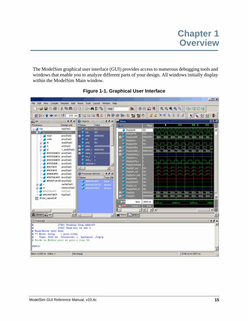
The ModelSim graphical user interface (GUI) provides access to numerous debugging tools and windows that enable you to analyze different parts of your design. All windows initially display within the ModelSim Main window.
Figure 1-1. Graphical User Interface
ModelSim GUI Reference Manual, v10.4c16
OverviewGeneral GUI Features
General GUI FeaturesThis section describes tasks common to more than one individual window and is organized into the following categories:
Window ManagementThe following tasks define actions you can take with the various windows.
Saving the Layout Upon Exit
By default when you exit ModelSim, the current layout is saved for a given design so that it appears the same the next time you invoke the tool.
Resetting the Window Layout to the Default
The windows are customizable in that you can position and size them as you see fit, and ModelSim will remember your settings upon subsequent invocations. You can restore ModelSim windows and panes to their original settings by selecting Layout > Reset in the menu bar.
Copying Text from a Window Header
You can copy the title text in a window header by selecting it and right-clicking to display a popup menu. This is useful for copying the file name of a source file for use elsewhere .
Selecting the Active Window
When the title bar of a window is highlighted - solid blue - it is the active window. All menu selections will correspond to this active window. You can change the active window in either of the following ways:
• (default) Click anywhere in a window or on its title bar.
• Move the mouse pointer into the window.
To turn on this feature, select Window > FocusFollowsMouse. Default time delay for activating a window after the mouse cursor has entered the window is 300ms. You can change the time delay with the PrefMain(FFMDelay) preference variable.
Window ArrangementThe GUI provides features for moving and grouping the various windows.
OverviewGeneral GUI Features
ModelSim GUI Reference Manual, v10.4c 17
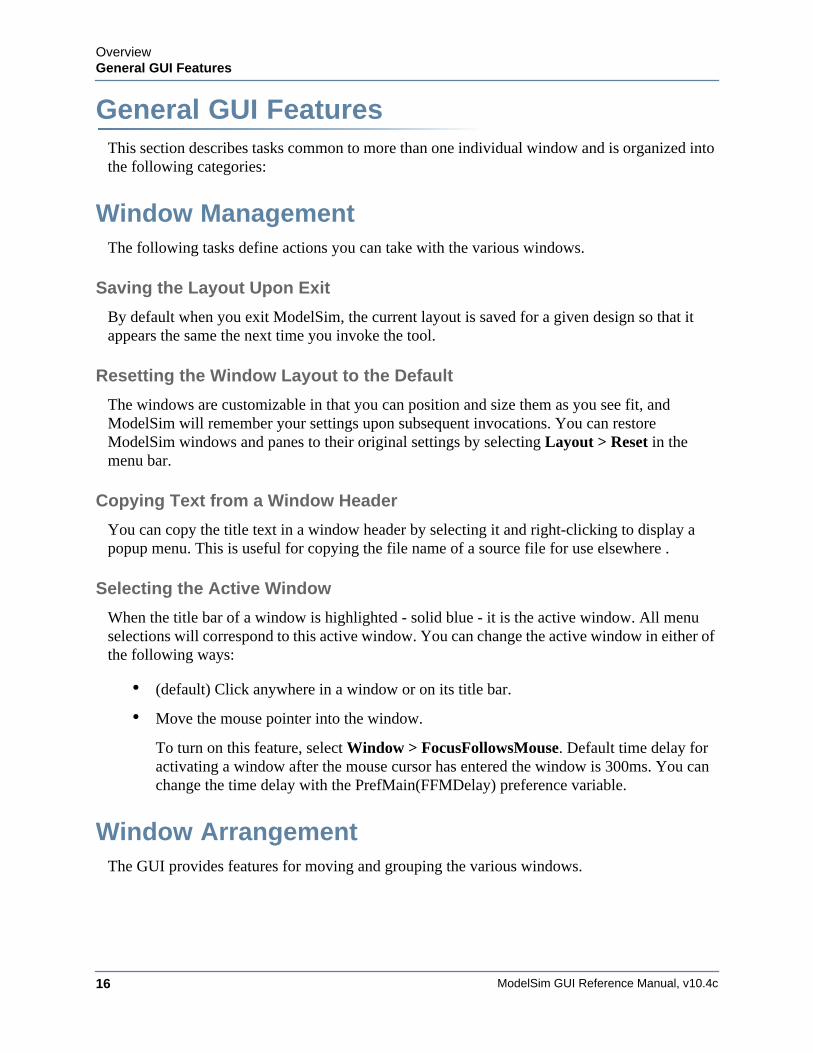
Moving a Window or Tab GroupRelocating a window or tab group to a new location within the Main window.
Procedure
1. Click on the header handle in the title bar of the window or tab group.
Figure 1-2. Window Header Handle
2. Drag, without releasing the mouse button, the window or tab group to a different area of the Main window
Wherever you move your mouse you will see a dark blue outline that previews where the window will be placed.
If the preview outline is a rectangle centered within a window, it indicates that you will convert the window or tab group into new tabs within the highlighted window.
3. Release the mouse button to complete the move.
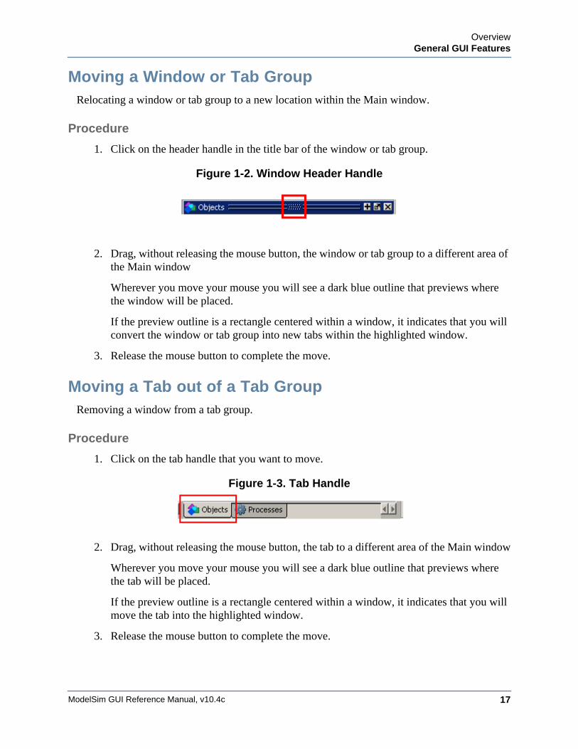
Moving a Tab out of a Tab GroupRemoving a window from a tab group.
Procedure
1. Click on the tab handle that you want to move.
Figure 1-3. Tab Handle
2. Drag, without releasing the mouse button, the tab to a different area of the Main window
Wherever you move your mouse you will see a dark blue outline that previews where the tab will be placed.
If the preview outline is a rectangle centered within a window, it indicates that you will move the tab into the highlighted window.
3. Release the mouse button to complete the move.
ModelSim GUI Reference Manual, v10.4c18
OverviewGeneral GUI Features
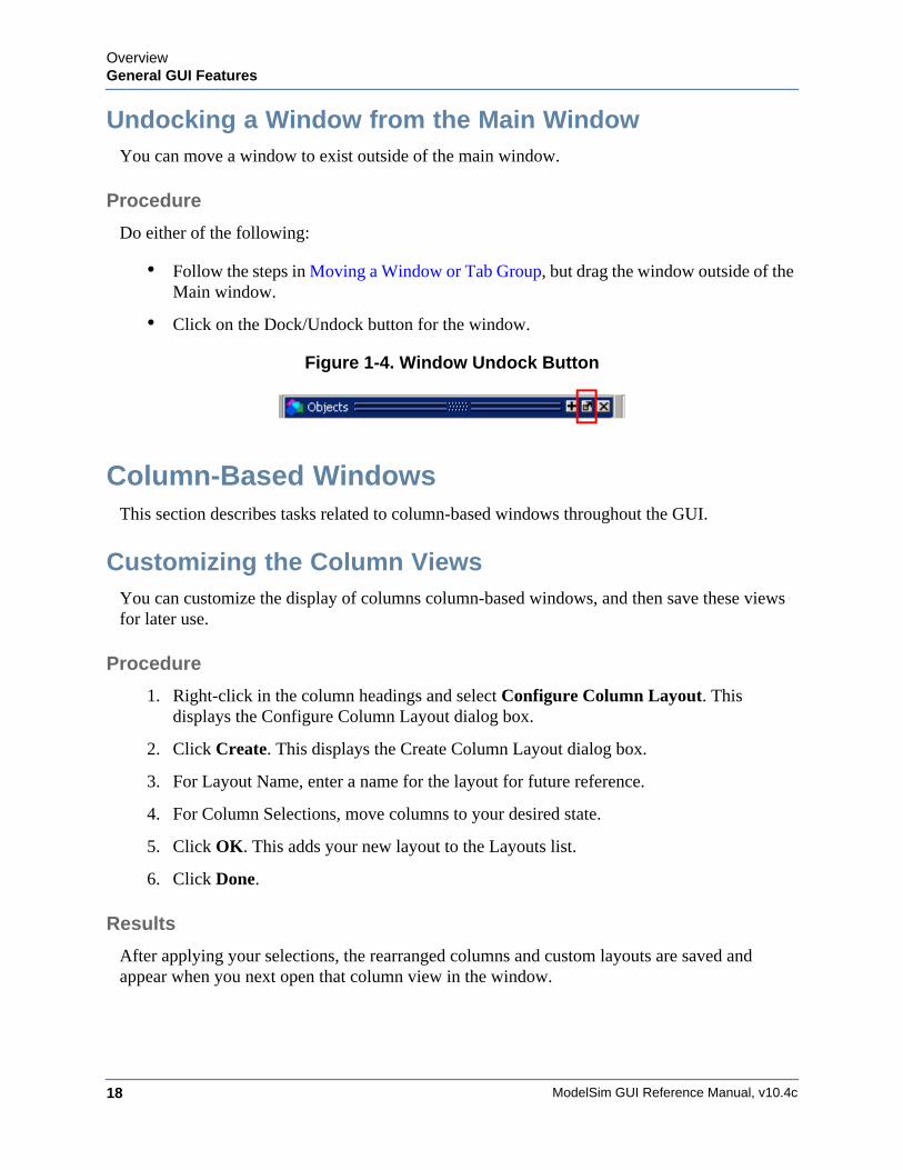
Undocking a Window from the Main WindowYou can move a window to exist outside of the main window.
Procedure
Do either of the following:
• Follow the steps in Moving a Window or Tab Group, but drag the window outside of the Main window.
• Click on the Dock/Undock button for the window.
Figure 1-4. Window Undock Button
Column-Based WindowsThis section describes tasks related to column-based windows throughout the GUI.
Customizing the Column ViewsYou can customize the display of columns column-based windows, and then save these views for later use.
Procedure
1. Right-click in the column headings and select Configure Column Layout. This displays the Configure Column Layout dialog box.
2. Click Create. This displays the Create Column Layout dialog box.
3. For Layout Name, enter a name for the layout for future reference.
4. For Column Selections, move columns to your desired state.
5. Click OK. This adds your new layout to the Layouts list.
6. Click Done.
Results
After applying your selections, the rearranged columns and custom layouts are saved and appear when you next open that column view in the window.
OverviewGeneral GUI Features
ModelSim GUI Reference Manual, v10.4c 19
BookmarksYou can create bookmarks that allow you to return to a specific view or place in your design for some of the windows. The bookmarks you make can be saved and automatically restored. Some of the windows that allow bookmarking include the Structure, Files, Wave, and Objects windows.
Bookmark ActionsThe Bookmarks toolbar and the Bookmarks menu give you access to several bookmarking features.
• Add Bookmarks — Bookmarks are added to an active window by selecting Bookmarks > Add Bookmark or by clicking the Add Bookmark button. You will be prompted to automatically save and restore your bookmarks when you set the first bookmark. You can change the automatic save and restore settings in the Bookmark Options Dialog Box.
• Add Custom — Selecting Add Custom opens the New Bookmark dialog box with the context field(s) populated and a field for specifying an alias for the bookmark. Click and hold the Add Bookmark button to access this feature from the Bookmarks toolbar.
NoteAliases are mapped to the window in which a bookmark is set. You can use the same alias for different bookmarks as long as each alias is assigned to a bookmark set in a different window.
• Deleting Bookmarks — You can choose to delete the bookmarks from the currently active window or from all windows.
• Manage Bookmarks — Opens the Manage Bookmarks dialog box. Refer to Bookmarks Management for more information.
• Load Bookmarks — Loads the bookmarks saved in the bookmarks.do file. You can choose whether to load bookmarks for the currently active window or all the bookmarks saved in the bookmarks.do file. Bookmarks are automatically loaded from the saved bookmarks.do file when you start a new simulation session.
NoteYou must reload bookmarks for a window if you close then reopen that window during the current session.
• Jump to Bookmark — Shows the available bookmarks in the currently active window followed by a drop down list of bookmarks for each window. You can set the maximum number of bookmarks listed in the Bookmark Options Dialog Box.
ModelSim GUI Reference Manual, v10.4c20
OverviewGeneral GUI Features
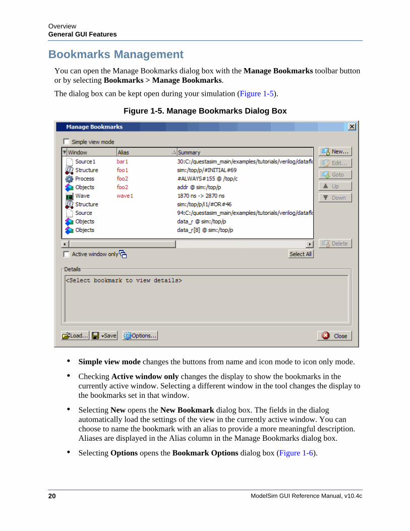
Bookmarks ManagementYou can open the Manage Bookmarks dialog box with the Manage Bookmarks toolbar button or by selecting Bookmarks > Manage Bookmarks.
The dialog box can be kept open during your simulation (Figure 1-5).
Figure 1-5. Manage Bookmarks Dialog Box
• Simple view mode changes the buttons from name and icon mode to icon only mode.
• Checking Active window only changes the display to show the bookmarks in the currently active window. Selecting a different window in the tool changes the display to the bookmarks set in that window.
• Selecting New opens the New Bookmark dialog box. The fields in the dialog automatically load the settings of the view in the currently active window. You can choose to name the bookmark with an alias to provide a more meaningful description. Aliases are displayed in the Alias column in the Manage Bookmarks dialog box.
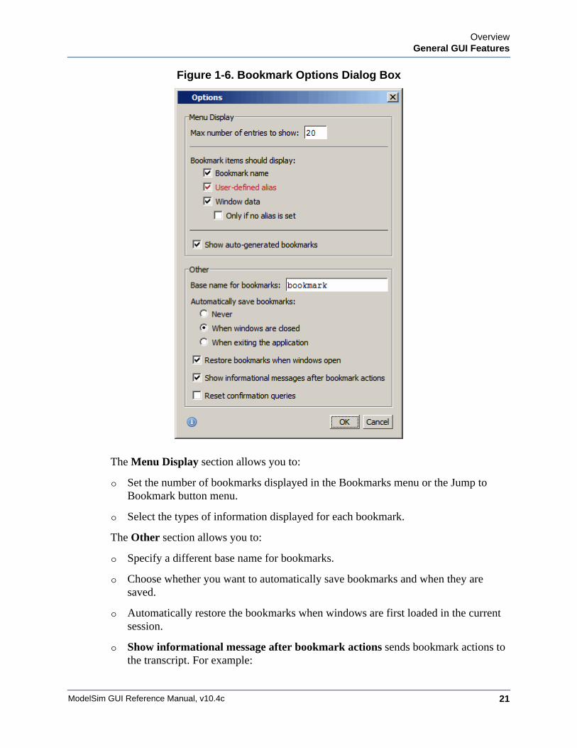
• Selecting Options opens the Bookmark Options dialog box (Figure 1-6).
OverviewGeneral GUI Features
ModelSim GUI Reference Manual, v10.4c 21
Figure 1-6. Bookmark Options Dialog Box
The Menu Display section allows you to:
o Set the number of bookmarks displayed in the Bookmarks menu or the Jump to Bookmark button menu.
o Select the types of information displayed for each bookmark.
The Other section allows you to:
o Specify a different base name for bookmarks.
o Choose whether you want to automatically save bookmarks and when they are saved.
o Automatically restore the bookmarks when windows are first loaded in the current session.
o Show informational message after bookmark actions sends bookmark actions to the transcript. For example:
ModelSim GUI Reference Manual, v10.4c22
OverviewGeneral GUI Features
# Bookmark(s) were restored for window "Source"
Saving and Reloading Formats and Content
You can use the write format restart command to create a single .do file that will recreate all debug windows and breakpoints (see Saving and Restoring Breakpoints) when invoked with the do command in subsequent simulation runs. The syntax is:
write format restart <filename>
If the ShutdownFile modelsim.ini variable is set to this .do filename, it will call the write format restart command upon exit.
Font ManagementYou may need to adjust font settings to accommodate the aspect ratios of wide screen and double screen displays or to handle launching ModelSim from an X-session.
Refer to Setting GUI Preferences for more information.
Font Scaling
To change font scaling, select the Transcript window, then Transcript > Adjust Font Scaling. You will need a ruler to complete the instructions in the lower right corner of the dialog. When you have entered the pixel and inches information, click OK to close the dialog. Then, restart ModelSim to see the change. This is a one time setting; you should not need to set it again unless you change display resolution or the hardware (monitor or video card). The font scaling applies to Windows and UNIX operating systems. On UNIX systems, the font scaling is stored based on the $DISPLAY environment variable.
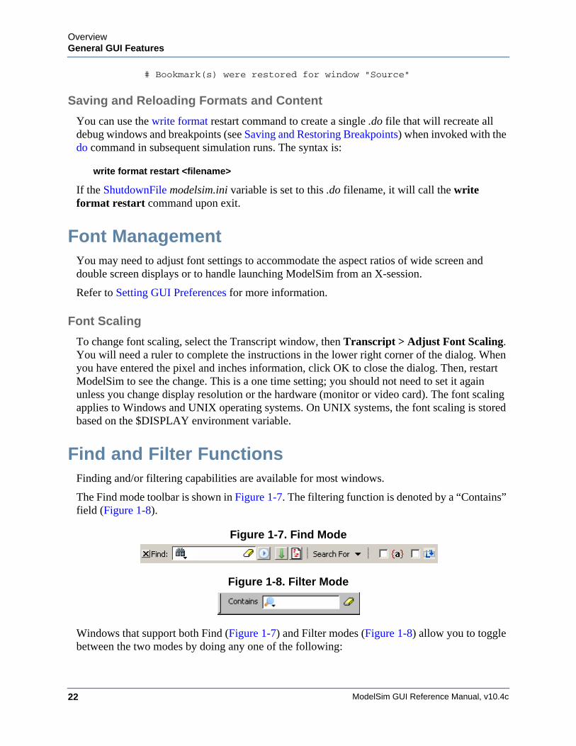
Find and Filter FunctionsFinding and/or filtering capabilities are available for most windows.
The Find mode toolbar is shown in Figure 1-7. The filtering function is denoted by a “Contains” field (Figure 1-8).
Figure 1-7. Find Mode
Figure 1-8. Filter Mode
Windows that support both Find (Figure 1-7) and Filter modes (Figure 1-8) allow you to toggle between the two modes by doing any one of the following:
OverviewGeneral GUI Features
ModelSim GUI Reference Manual, v10.4c 23
• Use the Ctrl+M hotkey.
• Click the “Find” or “Contains” words in the toolbar at the bottom of the window.
• Select the mode from the Find Options popup menu (see Find Options Popup Menu).
The last selected mode is remembered between sessions.
A “Find” toolbar will appear along the bottom edge of the active window when you do either of the following:
• Select Edit > Find in the menu bar.
• Click the Find icon in the Standard Toolbar.
All of the above actions are toggles - repeat the action and the Find toolbar will close.
The Find or Filter entry fields prefill as you type, based on the context of the current window selection. The find or filter action begins as you type.
There is a simple history mechanism that saves find or filter strings for later use. The keyboard shortcuts to use this feature are:
• Ctrl+P — retrieve previous search string
• Ctrl+N — retrieve next search string
Other hotkey actions include:
• Esc — closes the Find toolbar
• Enter — initiates a “Find Next” action
• Ctrl+T — search while typing (default is on)
The entry field turns red if no matches are found.
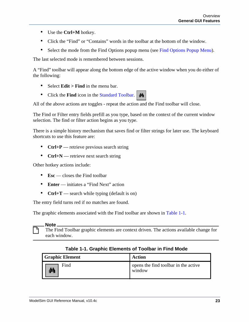
The graphic elements associated with the Find toolbar are shown in Table 1-1.
NoteThe Find Toolbar graphic elements are context driven. The actions available change for each window.
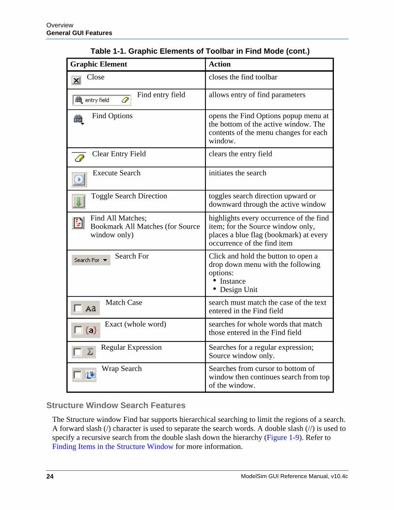
Table 1-1. Graphic Elements of Toolbar in Find Mode
Graphic Element Action
Find opens the find toolbar in the active window
ModelSim GUI Reference Manual, v10.4c24
OverviewGeneral GUI Features
Structure Window Search Features
The Structure window Find bar supports hierarchical searching to limit the regions of a search. A forward slash (/) character is used to separate the search words. A double slash (//) is used to specify a recursive search from the double slash down the hierarchy (Figure 1-9). Refer to Finding Items in the Structure Window for more information.
Close closes the find toolbar
Find entry field allows entry of find parameters
Find Options opens the Find Options popup menu at the bottom of the active window. The contents of the menu changes for each window.
Clear Entry Field clears the entry field
Execute Search initiates the search
Toggle Search Direction toggles search direction upward or downward through the active window
Find All Matches;Bookmark All Matches (for Source window only)
highlights every occurrence of the find item; for the Source window only, places a blue flag (bookmark) at every occurrence of the find item
Search For Click and hold the button to open a drop down menu with the following options:• Instance • Design Unit
Match Case search must match the case of the text entered in the Find field
Exact (whole word) searches for whole words that match those entered in the Find field
Regular Expression Searches for a regular expression; Source window only.
Wrap Search Searches from cursor to bottom of window then continues search from top of the window.
Table 1-1. Graphic Elements of Toolbar in Find Mode (cont.)
Graphic Element Action
OverviewGeneral GUI Features
ModelSim GUI Reference Manual, v10.4c 25
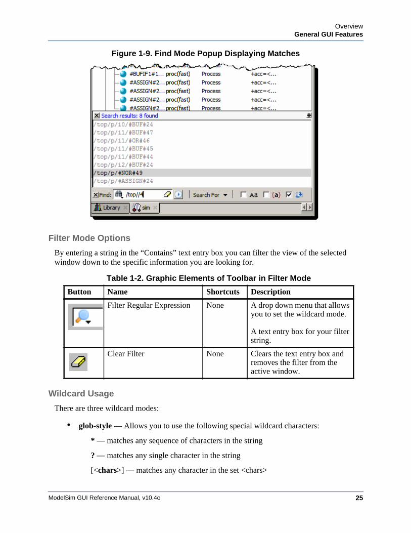
Figure 1-9. Find Mode Popup Displaying Matches
Filter Mode Options
By entering a string in the “Contains” text entry box you can filter the view of the selected window down to the specific information you are looking for.
Wildcard Usage
There are three wildcard modes:
• glob-style — Allows you to use the following special wildcard characters:
* — matches any sequence of characters in the string
? — matches any single character in the string
[<chars>] — matches any character in the set <chars>
Table 1-2. Graphic Elements of Toolbar in Filter Mode
Button Name Shortcuts Description
Filter Regular Expression None A drop down menu that allows you to set the wildcard mode.
A text entry box for your filter string.
Clear Filter None Clears the text entry box and removes the filter from the active window.
ModelSim GUI Reference Manual, v10.4c26
OverviewGeneral Visual Elements
\<x> — matches the single character <x>, which allows you to match on any special characters (*, ?, [, ], and \)
Refer to Finding Items in the Structure Window and the Tcl documentation for more information:
Help > Tcl Man Pages Tcl Commands > string > string match
• regular-expression — (Source window only) allows you to use wildcard characters based on Tcl regular expressions. For more information refer to the Tcl documentation:
Help > Tcl Man Pages Tcl Commands > re_syntax
• exact — indicates that no characters have special meaning, thus disabling wildcard features.
The string entry field of the Contains toolbar item is case-insensitive, If you need to search for case-sensitive strings in the Source window select “regular-expression” and prepend the string with (?c).
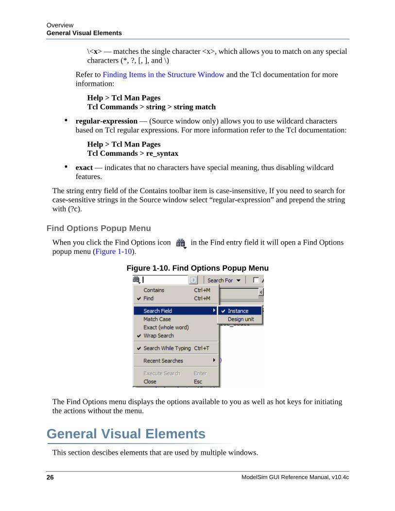
Find Options Popup Menu
When you click the Find Options icon in the Find entry field it will open a Find Options popup menu (Figure 1-10).
Figure 1-10. Find Options Popup Menu
The Find Options menu displays the options available to you as well as hot keys for initiating the actions without the menu.
General Visual ElementsThis section descibes elements that are used by multiple windows.
OverviewGeneral Visual Elements
ModelSim GUI Reference Manual, v10.4c 27
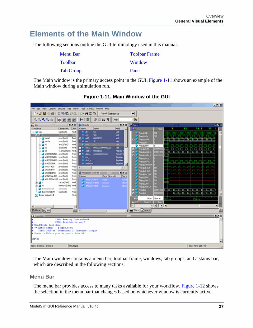
Elements of the Main WindowThe following sections outline the GUI terminology used in this manual.
The Main window is the primary access point in the GUI. Figure 1-11 shows an example of the Main window during a simulation run.
Figure 1-11. Main Window of the GUI
The Main window contains a menu bar, toolbar frame, windows, tab groups, and a status bar, which are described in the following sections.
Menu Bar
The menu bar provides access to many tasks available for your workflow. Figure 1-12 shows the selection in the menu bar that changes based on whichever window is currently active.
Menu Bar Toolbar Frame
Toolbar Window
Tab Group Pane
ModelSim GUI Reference Manual, v10.4c28
OverviewGeneral Visual Elements
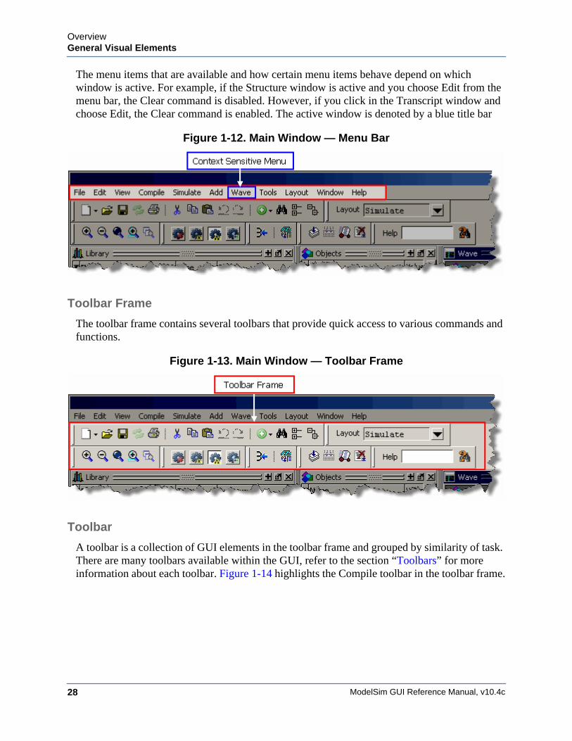
The menu items that are available and how certain menu items behave depend on which window is active. For example, if the Structure window is active and you choose Edit from the menu bar, the Clear command is disabled. However, if you click in the Transcript window and choose Edit, the Clear command is enabled. The active window is denoted by a blue title bar
Figure 1-12. Main Window — Menu Bar
Toolbar Frame
The toolbar frame contains several toolbars that provide quick access to various commands and functions.
Figure 1-13. Main Window — Toolbar Frame
Toolbar
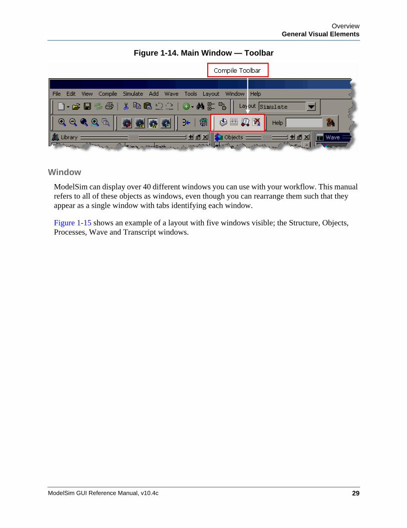
A toolbar is a collection of GUI elements in the toolbar frame and grouped by similarity of task. There are many toolbars available within the GUI, refer to the section “Toolbars” for more information about each toolbar. Figure 1-14 highlights the Compile toolbar in the toolbar frame.
OverviewGeneral Visual Elements
ModelSim GUI Reference Manual, v10.4c 29
Figure 1-14. Main Window — Toolbar
Window
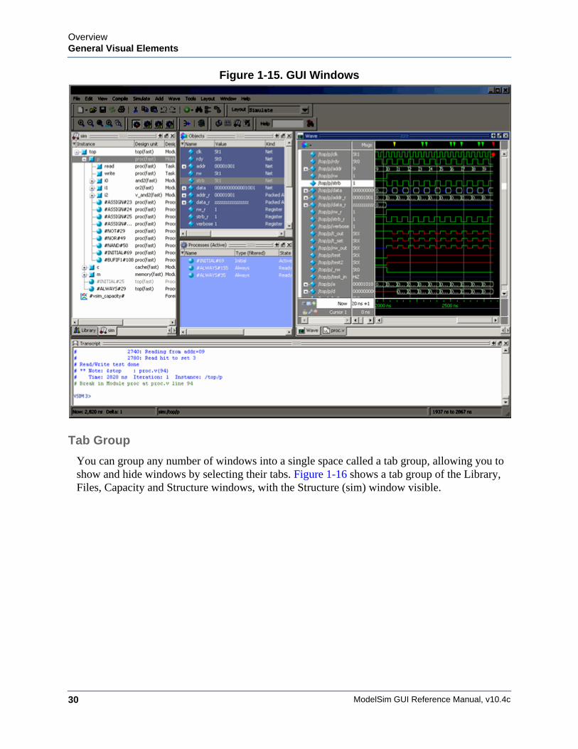
ModelSim can display over 40 different windows you can use with your workflow. This manual refers to all of these objects as windows, even though you can rearrange them such that they appear as a single window with tabs identifying each window.
Figure 1-15 shows an example of a layout with five windows visible; the Structure, Objects, Processes, Wave and Transcript windows.
ModelSim GUI Reference Manual, v10.4c30
OverviewGeneral Visual Elements
Figure 1-15. GUI Windows
Tab Group
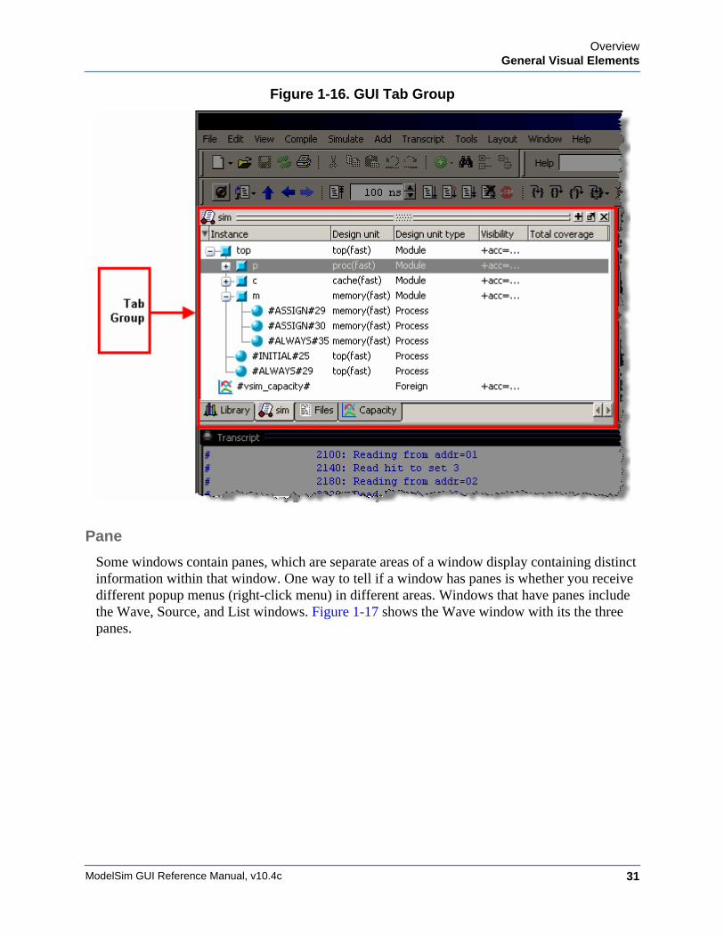
You can group any number of windows into a single space called a tab group, allowing you to show and hide windows by selecting their tabs. Figure 1-16 shows a tab group of the Library, Files, Capacity and Structure windows, with the Structure (sim) window visible.
OverviewGeneral Visual Elements
ModelSim GUI Reference Manual, v10.4c 31
Figure 1-16. GUI Tab Group
Pane
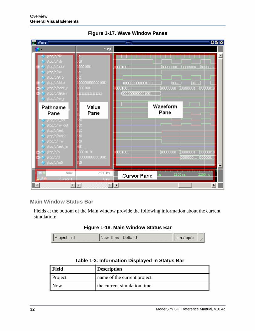
Some windows contain panes, which are separate areas of a window display containing distinct information within that window. One way to tell if a window has panes is whether you receive different popup menus (right-click menu) in different areas. Windows that have panes include the Wave, Source, and List windows. Figure 1-17 shows the Wave window with its the three panes.
ModelSim GUI Reference Manual, v10.4c32
OverviewGeneral Visual Elements
Figure 1-17. Wave Window Panes
Main Window Status Bar
Fields at the bottom of the Main window provide the following information about the current simulation:
Figure 1-18. Main Window Status Bar
Table 1-3. Information Displayed in Status Bar
Field Description
Project name of the current project
Now the current simulation time
OverviewGeneral Visual Elements
ModelSim GUI Reference Manual, v10.4c 33
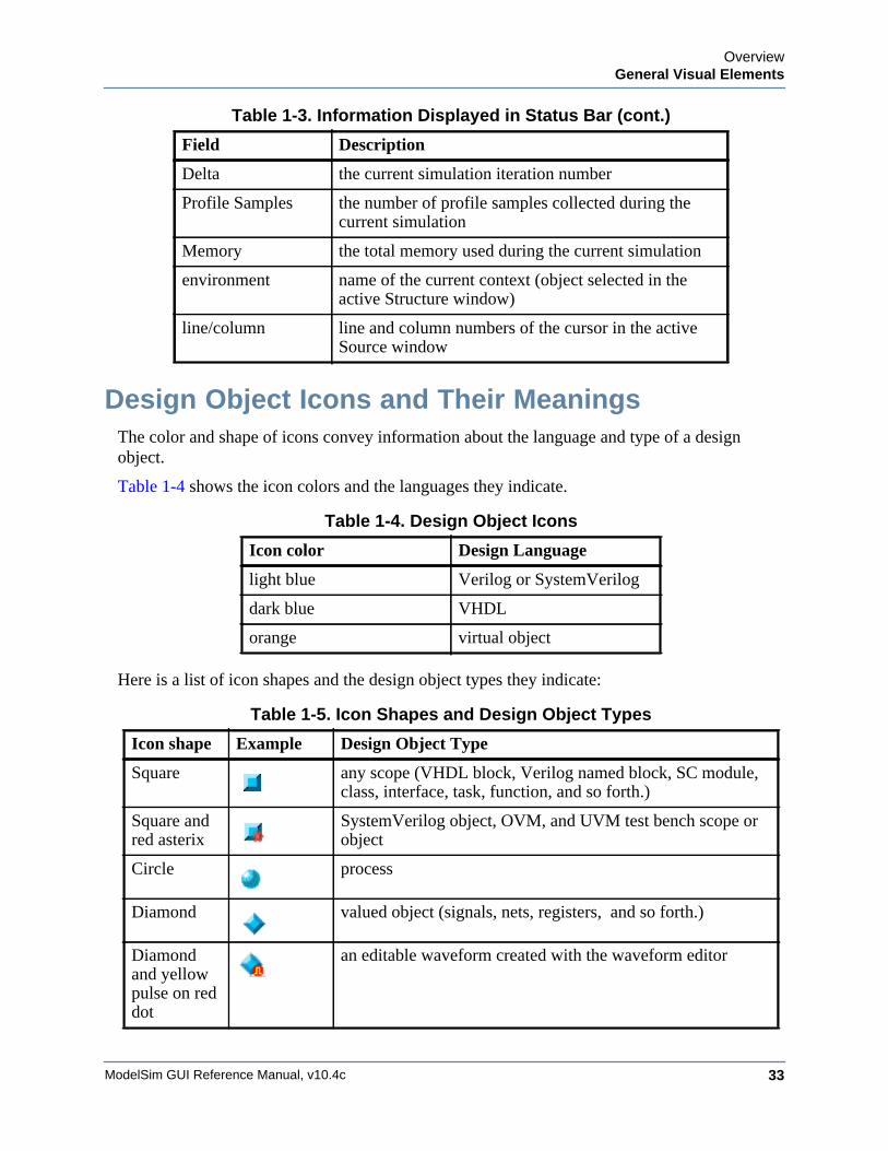
Design Object Icons and Their MeaningsThe color and shape of icons convey information about the language and type of a design object.
Table 1-4 shows the icon colors and the languages they indicate.
Here is a list of icon shapes and the design object types they indicate:
Delta the current simulation iteration number
Profile Samples the number of profile samples collected during the current simulation
Memory the total memory used during the current simulation
environment name of the current context (object selected in the active Structure window)
line/column line and column numbers of the cursor in the active Source window
Table 1-4. Design Object Icons
Icon color Design Language
light blue Verilog or SystemVerilog
dark blue VHDL
orange virtual object
Table 1-5. Icon Shapes and Design Object Types
Icon shape Example Design Object Type
Square any scope (VHDL block, Verilog named block, SC module, class, interface, task, function, and so forth.)
Square and red asterix
SystemVerilog object, OVM, and UVM test bench scope or object
Circle process
Diamond valued object (signals, nets, registers, and so forth.)
Diamond and yellow pulse on red dot
an editable waveform created with the waveform editor
Table 1-3. Information Displayed in Status Bar (cont.)
Field Description
ModelSim GUI Reference Manual, v10.4c34
OverviewGeneral Visual Elements
Window Time DisplayThere are two basic time designations used to control display of object values in many simulator windows.
• Now — The end-of-simulation time or the time at which the simulation has stopped.
• Current Time — The current time displayed in an open window. The time may be any time between 0 and the end of simulation, and is set in several ways:
o by moving a wave cursor
o by interacting with the Current Time Label. Refer to Current Time Label for more information.
A number of windows are dynamically linked to update when the time setting in one is changed. The windows include the FSM, Objects, Source, and Watch windows.
Current Time Label
The Current Time Label allows you to interact with and change the simulation time displayed in several windows. The Current Time Label displays the Now (end of simulation) or Current Time, and allows you to search the time line for a transition on a selected object in the window (Figure 1-19).
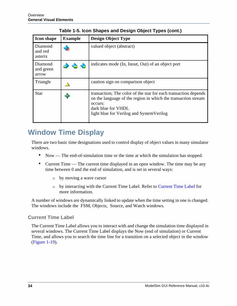
Diamond and red asterix
valued object (abstract)
Diamond and green arrow
indicates mode (In, Inout, Out) of an object port
Triangle caution sign on comparison object
Star transaction; The color of the star for each transaction depends on the language of the region in which the transaction stream occurs: dark blue for VHDLlight blue for Verilog and SystemVerilog
Table 1-5. Icon Shapes and Design Object Types (cont.)
Icon shape Example Design Object Type
OverviewGeneral Visual Elements
ModelSim GUI Reference Manual, v10.4c 35
Figure 1-19. Current Time Label
When you run a simulation and it comes to an end, the Current Time Label displays the Now time which is the end-of-simulation time. When you select a cursor in the Wave window, the Current Time Label automatically changes to display the time of the current active cursor and updates the other windows to the same time.
The Current Time Label includes a minimize/maximize button that allows you to hide or display the label.
When you select an object in a window displaying the Current Time label, you can jump to the previous or next transition for that object, with respect to the current time, by clicking the Find Previous or Find Next button.
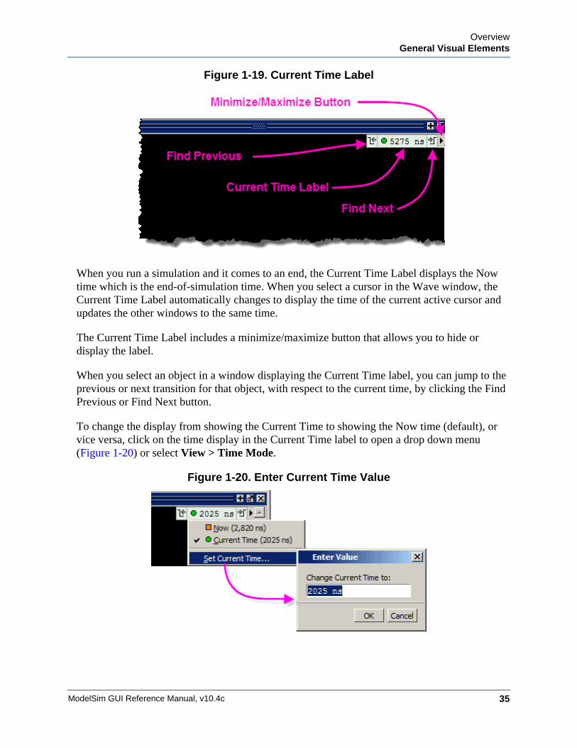
To change the display from showing the Current Time to showing the Now time (default), or vice versa, click on the time display in the Current Time label to open a drop down menu (Figure 1-20) or select View > Time Mode.
Figure 1-20. Enter Current Time Value

ModelSim GUI Reference Manual, v10.4c36
OverviewGeneral Visual Elements
MenusWindow-specific Menu
ModelSim GUI Reference Manual, v10.4c 37
Chapter 2Menus
The selections in the menu bar of the main window change dynamically, based on which window is currently active. As a result, some menu items change their names or become unavailable (dimmed). This section describes the menu items provided at the highest level provided for a given window.
Window-specific MenuEvery window has a window-specific menu that appears in the menu bar between the Add and Tools menus.
The menu options available pertain only to that window and are described in the window-specific section of the chapter “Window Reference.”
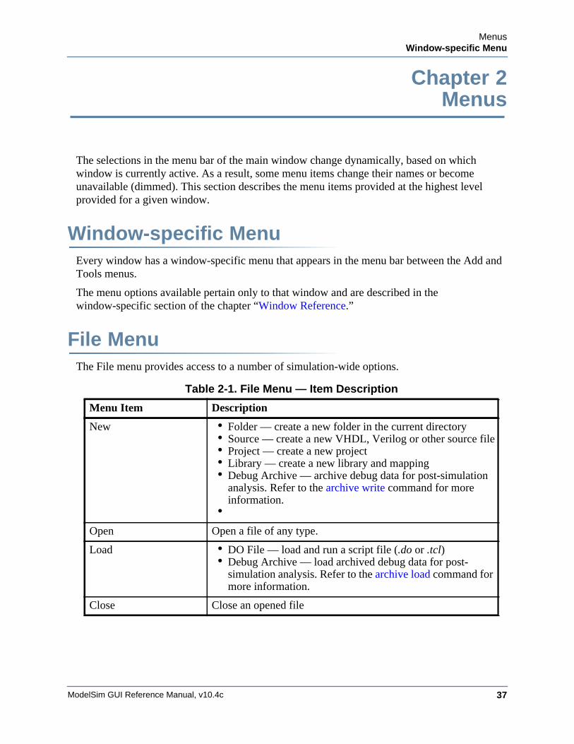
File MenuThe File menu provides access to a number of simulation-wide options.
Table 2-1. File Menu — Item Description
Menu Item Description
New • Folder — create a new folder in the current directory• Source — create a new VHDL, Verilog or other source file• Project — create a new project• Library — create a new library and mapping• Debug Archive — archive debug data for post-simulation
analysis. Refer to the archive write command for more information.
•Open Open a file of any type.
Load • DO File — load and run a script file (.do or .tcl)• Debug Archive — load archived debug data for post-
simulation analysis. Refer to the archive load command for more information.
Close Close an opened file
ModelSim GUI Reference Manual, v10.4c38
MenusFile Menu
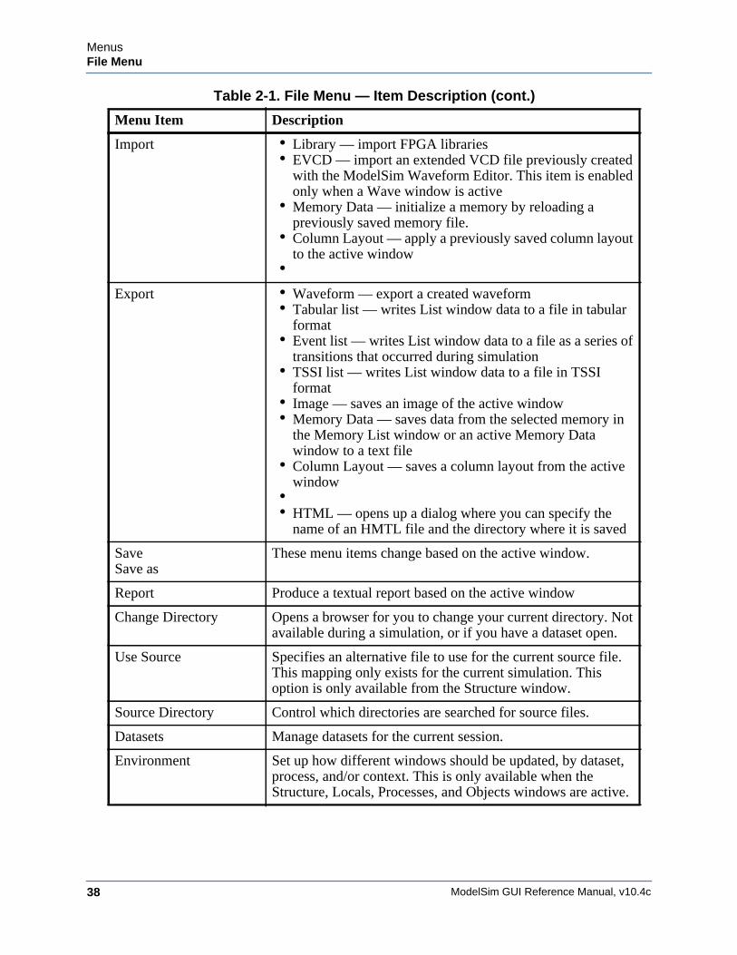
Import • Library — import FPGA libraries• EVCD — import an extended VCD file previously created
with the ModelSim Waveform Editor. This item is enabled only when a Wave window is active
• Memory Data — initialize a memory by reloading a previously saved memory file.
• Column Layout — apply a previously saved column layout to the active window
•Export • Waveform — export a created waveform
• Tabular list — writes List window data to a file in tabular format
• Event list — writes List window data to a file as a series of transitions that occurred during simulation
• TSSI list — writes List window data to a file in TSSI format
• Image — saves an image of the active window• Memory Data — saves data from the selected memory in
the Memory List window or an active Memory Data window to a text file
• Column Layout — saves a column layout from the active window
•• HTML — opens up a dialog where you can specify the
name of an HMTL file and the directory where it is saved
SaveSave as
These menu items change based on the active window.
Report Produce a textual report based on the active window
Change Directory Opens a browser for you to change your current directory. Not available during a simulation, or if you have a dataset open.
Use Source Specifies an alternative file to use for the current source file. This mapping only exists for the current simulation. This option is only available from the Structure window.
Source Directory Control which directories are searched for source files.
Datasets Manage datasets for the current session.
Environment Set up how different windows should be updated, by dataset, process, and/or context. This is only available when the Structure, Locals, Processes, and Objects windows are active.
Table 2-1. File Menu — Item Description (cont.)
Menu Item Description
MenusEdit Menu
ModelSim GUI Reference Manual, v10.4c 39
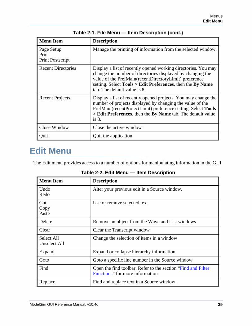
Edit MenuThe Edit menu provides access to a number of options for manipulating information in the GUI.
Page SetupPrintPrint Postscript
Manage the printing of information from the selected window.
Recent Directories Display a list of recently opened working directories. You may change the number of directories displayed by changing the value of the PrefMain(recentDirectoryLimit) preference setting. Select Tools > Edit Preferences, then the By Name tab. The default value is 8.
Recent Projects Display a list of recently opened projects. You may change the number of projects displayed by changing the value of the PrefMain(recentProjectLimit) preference setting. Select Tools > Edit Preferences, then the By Name tab. The default value is 8.
Close Window Close the active window
Quit Quit the application
Table 2-2. Edit Menu — Item Description
Menu Item Description
UndoRedo
Alter your previous edit in a Source window.
CutCopyPaste
Use or remove selected text.
Delete Remove an object from the Wave and List windows
Clear Clear the Transcript window
Select AllUnselect All
Change the selection of items in a window
Expand Expand or collapse hierarchy information
Goto Goto a specific line number in the Source window
Find Open the find toolbar. Refer to the section “Find and Filter Functions” for more information
Replace Find and replace text in a Source window.
Table 2-1. File Menu — Item Description (cont.)
Menu Item Description
ModelSim GUI Reference Manual, v10.4c40
MenusView Menu
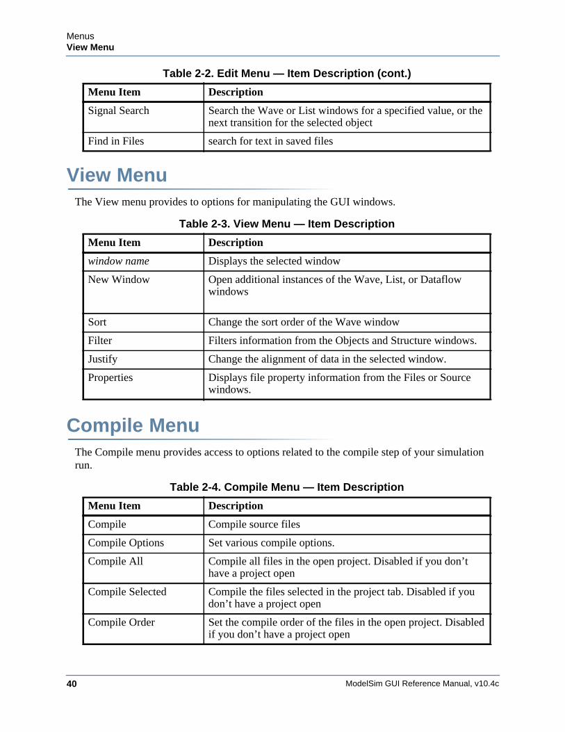
View MenuThe View menu provides to options for manipulating the GUI windows.
Compile MenuThe Compile menu provides access to options related to the compile step of your simulation run.
Signal Search Search the Wave or List windows for a specified value, or the next transition for the selected object
Find in Files search for text in saved files
Table 2-3. View Menu — Item Description
Menu Item Description
window name Displays the selected window
New Window Open additional instances of the Wave, List, or Dataflow windows
Sort Change the sort order of the Wave window
Filter Filters information from the Objects and Structure windows.
Justify Change the alignment of data in the selected window.
Properties Displays file property information from the Files or Source windows.
Table 2-4. Compile Menu — Item Description
Menu Item Description
Compile Compile source files
Compile Options Set various compile options.
Compile All Compile all files in the open project. Disabled if you don’t have a project open
Compile Selected Compile the files selected in the project tab. Disabled if you don’t have a project open
Compile Order Set the compile order of the files in the open project. Disabled if you don’t have a project open
Table 2-2. Edit Menu — Item Description (cont.)
Menu Item Description
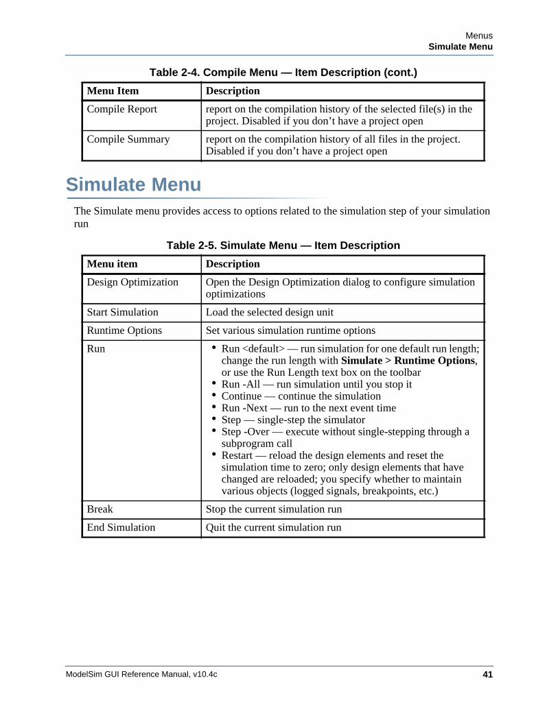
MenusSimulate Menu
ModelSim GUI Reference Manual, v10.4c 41
Simulate MenuThe Simulate menu provides access to options related to the simulation step of your simulation run
Compile Report report on the compilation history of the selected file(s) in the project. Disabled if you don’t have a project open
Compile Summary report on the compilation history of all files in the project. Disabled if you don’t have a project open
Table 2-5. Simulate Menu — Item Description
Menu item Description
Design Optimization Open the Design Optimization dialog to configure simulation optimizations
Start Simulation Load the selected design unit
Runtime Options Set various simulation runtime options
Run • Run <default> — run simulation for one default run length; change the run length with Simulate > Runtime Options, or use the Run Length text box on the toolbar
• Run -All — run simulation until you stop it• Continue — continue the simulation• Run -Next — run to the next event time• Step — single-step the simulator• Step -Over — execute without single-stepping through a
subprogram call• Restart — reload the design elements and reset the
simulation time to zero; only design elements that have changed are reloaded; you specify whether to maintain various objects (logged signals, breakpoints, etc.)
Break Stop the current simulation run
End Simulation Quit the current simulation run
Table 2-4. Compile Menu — Item Description (cont.)
Menu Item Description
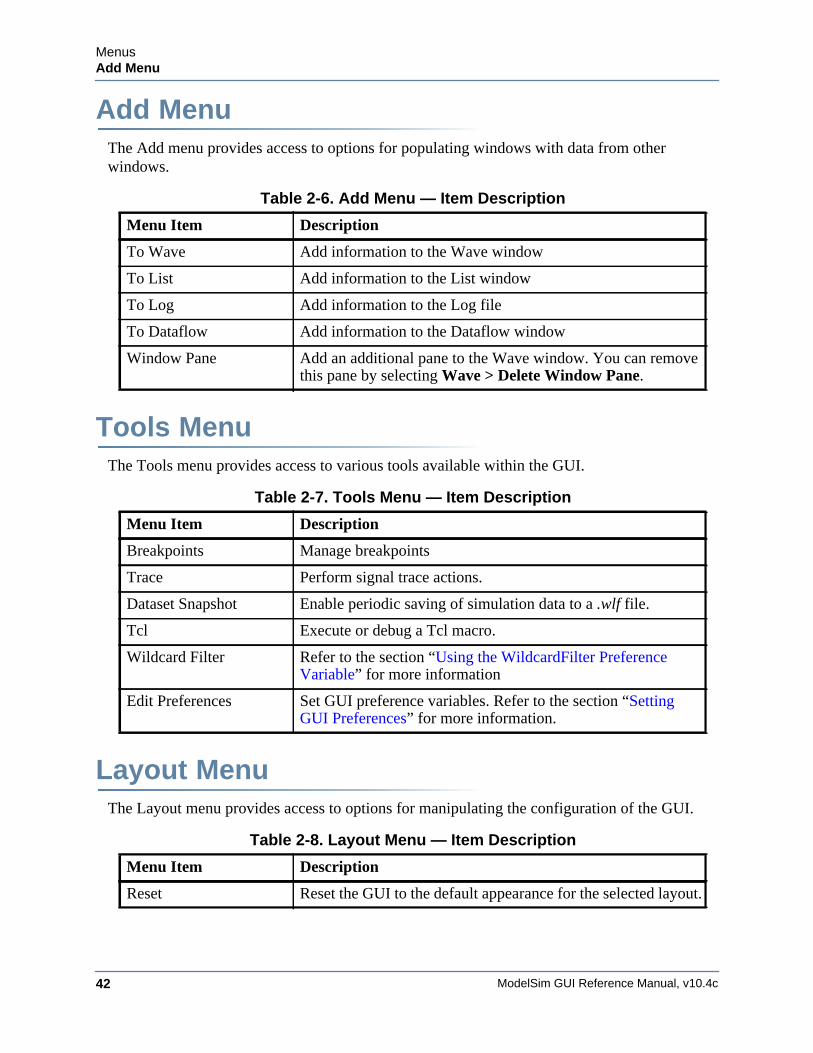
ModelSim GUI Reference Manual, v10.4c42
MenusAdd Menu
Add MenuThe Add menu provides access to options for populating windows with data from other windows.
Tools MenuThe Tools menu provides access to various tools available within the GUI.
Layout MenuThe Layout menu provides access to options for manipulating the configuration of the GUI.
Table 2-6. Add Menu — Item Description
Menu Item Description
To Wave Add information to the Wave window
To List Add information to the List window
To Log Add information to the Log file
To Dataflow Add information to the Dataflow window
Window Pane Add an additional pane to the Wave window. You can remove this pane by selecting Wave > Delete Window Pane.
Table 2-7. Tools Menu — Item Description
Menu Item Description
Breakpoints Manage breakpoints
Trace Perform signal trace actions.
Dataset Snapshot Enable periodic saving of simulation data to a .wlf file.
Tcl Execute or debug a Tcl macro.
Wildcard Filter Refer to the section “Using the WildcardFilter Preference Variable” for more information
Edit Preferences Set GUI preference variables. Refer to the section “Setting GUI Preferences” for more information.
Table 2-8. Layout Menu — Item Description
Menu Item Description
Reset Reset the GUI to the default appearance for the selected layout.
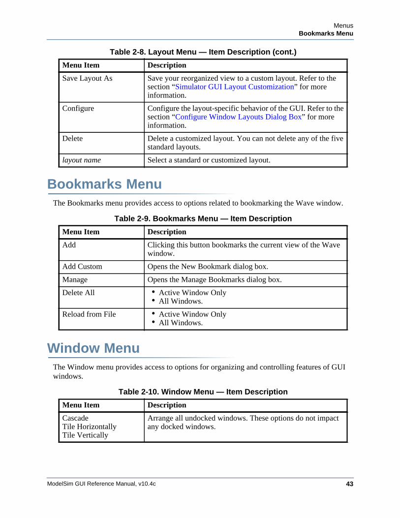
MenusBookmarks Menu
ModelSim GUI Reference Manual, v10.4c 43
Bookmarks MenuThe Bookmarks menu provides access to options related to bookmarking the Wave window.
Window MenuThe Window menu provides access to options for organizing and controlling features of GUI windows.
Save Layout As Save your reorganized view to a custom layout. Refer to the section “Simulator GUI Layout Customization” for more information.
Configure Configure the layout-specific behavior of the GUI. Refer to the section “Configure Window Layouts Dialog Box” for more information.
Delete Delete a customized layout. You can not delete any of the five standard layouts.
layout name Select a standard or customized layout.
Table 2-9. Bookmarks Menu — Item Description
Menu Item Description
Add Clicking this button bookmarks the current view of the Wave window.
Add Custom Opens the New Bookmark dialog box.
Manage Opens the Manage Bookmarks dialog box.
Delete All • Active Window Only• All Windows.
Reload from File • Active Window Only• All Windows.
Table 2-10. Window Menu — Item Description
Menu Item Description
CascadeTile HorizontallyTile Vertically
Arrange all undocked windows. These options do not impact any docked windows.
Table 2-8. Layout Menu — Item Description (cont.)
Menu Item Description
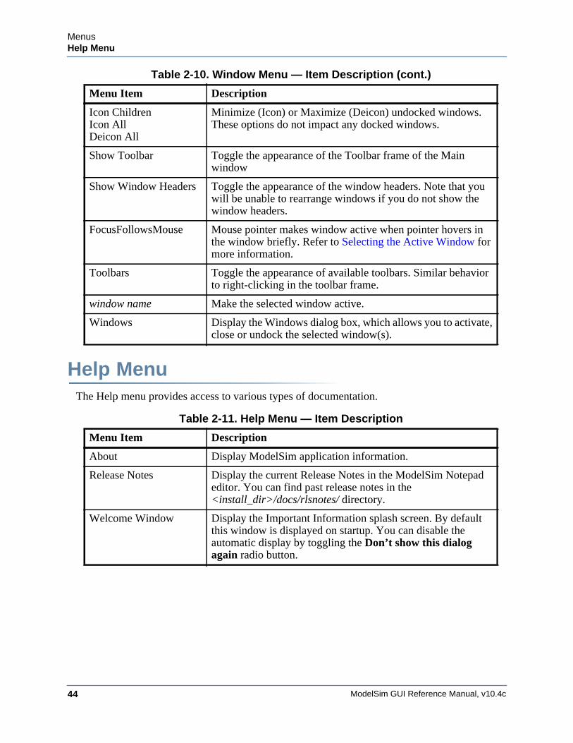
ModelSim GUI Reference Manual, v10.4c44
MenusHelp Menu
Help MenuThe Help menu provides access to various types of documentation.
Icon ChildrenIcon AllDeicon All
Minimize (Icon) or Maximize (Deicon) undocked windows. These options do not impact any docked windows.
Show Toolbar Toggle the appearance of the Toolbar frame of the Main window
Show Window Headers Toggle the appearance of the window headers. Note that you will be unable to rearrange windows if you do not show the window headers.
FocusFollowsMouse Mouse pointer makes window active when pointer hovers in the window briefly. Refer to Selecting the Active Window for more information.
Toolbars Toggle the appearance of available toolbars. Similar behavior to right-clicking in the toolbar frame.
window name Make the selected window active.
Windows Display the Windows dialog box, which allows you to activate, close or undock the selected window(s).
Table 2-11. Help Menu — Item Description
Menu Item Description
About Display ModelSim application information.
Release Notes Display the current Release Notes in the ModelSim Notepad editor. You can find past release notes in the <install_dir>/docs/rlsnotes/ directory.
Welcome Window Display the Important Information splash screen. By default this window is displayed on startup. You can disable the automatic display by toggling the Don’t show this dialog again radio button.
Table 2-10. Window Menu — Item Description (cont.)
Menu Item Description
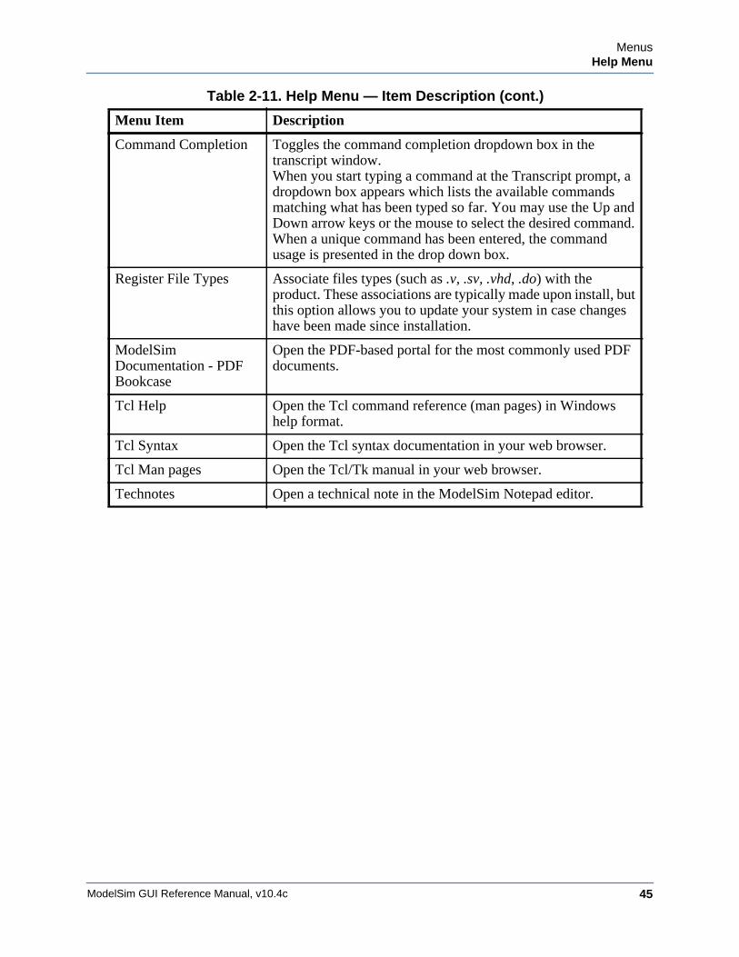
MenusHelp Menu
ModelSim GUI Reference Manual, v10.4c 45
Command Completion Toggles the command completion dropdown box in the transcript window.When you start typing a command at the Transcript prompt, a dropdown box appears which lists the available commands matching what has been typed so far. You may use the Up and Down arrow keys or the mouse to select the desired command. When a unique command has been entered, the command usage is presented in the drop down box.
Register File Types Associate files types (such as .v, .sv, .vhd, .do) with the product. These associations are typically made upon install, but this option allows you to update your system in case changes have been made since installation.
ModelSim Documentation - PDF Bookcase
Open the PDF-based portal for the most commonly used PDF documents.
Tcl Help Open the Tcl command reference (man pages) in Windows help format.
Tcl Syntax Open the Tcl syntax documentation in your web browser.
Tcl Man pages Open the Tcl/Tk manual in your web browser.
Technotes Open a technical note in the ModelSim Notepad editor.
Table 2-11. Help Menu — Item Description (cont.)
Menu Item Description

ModelSim GUI Reference Manual, v10.4c46
MenusHelp Menu
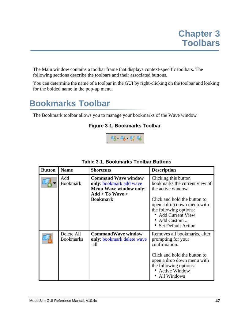
ModelSim GUI Reference Manual, v10.4c 47
Chapter 3Toolbars
The Main window contains a toolbar frame that displays context-specific toolbars. The following sections describe the toolbars and their associated buttons.
You can determine the name of a toolbar in the GUI by right-clicking on the toolbar and looking for the bolded name in the pop-up menu.
Bookmarks ToolbarThe Bookmark toolbar allows you to manage your bookmarks of the Wave window
Figure 3-1. Bookmarks Toolbar
Table 3-1. Bookmarks Toolbar Buttons
Button Name Shortcuts Description
Add Bookmark
Command Wave window only: bookmark add wave Menu Wave window only: Add > To Wave > Bookmark
Clicking this button bookmarks the current view of the active window.
Click and hold the button to open a drop down menu with the following options:• Add Current View• Add Custom ...• Set Default Action
Delete All Bookmarks
CommandWave window only: bookmark delete wave -all
Removes all bookmarks, after prompting for your confirmation.
Click and hold the button to open a drop down menu with the following options:• Active Window• All Windows
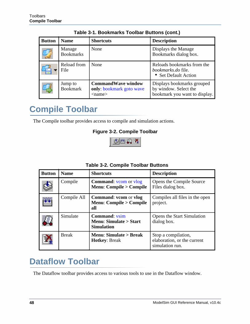
ModelSim GUI Reference Manual, v10.4c48
ToolbarsCompile Toolbar
Compile ToolbarThe Compile toolbar provides access to compile and simulation actions.
Figure 3-2. Compile Toolbar
Dataflow ToolbarThe Dataflow toolbar provides access to various tools to use in the Dataflow window.
Manage Bookmarks
None Displays the Manage Bookmarks dialog box.
Reload from File
None Reloads bookmarks from the bookmarks.do file.• Set Default Action
Jump to Bookmark
CommandWave window only: bookmark goto wave <name>
Displays bookmarks grouped by window. Select the bookmark you want to display.
Table 3-2. Compile Toolbar Buttons
Button Name Shortcuts Description
Compile Command: vcom or vlog Menu: Compile > Compile
Opens the Compile Source Files dialog box.
Compile All Command: vcom or vlogMenu: Compile > Compile all
Compiles all files in the open project.
Simulate Command: vsim Menu: Simulate > Start Simulation
Opens the Start Simulation dialog box.
Break Menu: Simulate > Break Hotkey: Break
Stop a compilation, elaboration, or the current simulation run.
Table 3-1. Bookmarks Toolbar Buttons (cont.)
Button Name Shortcuts Description
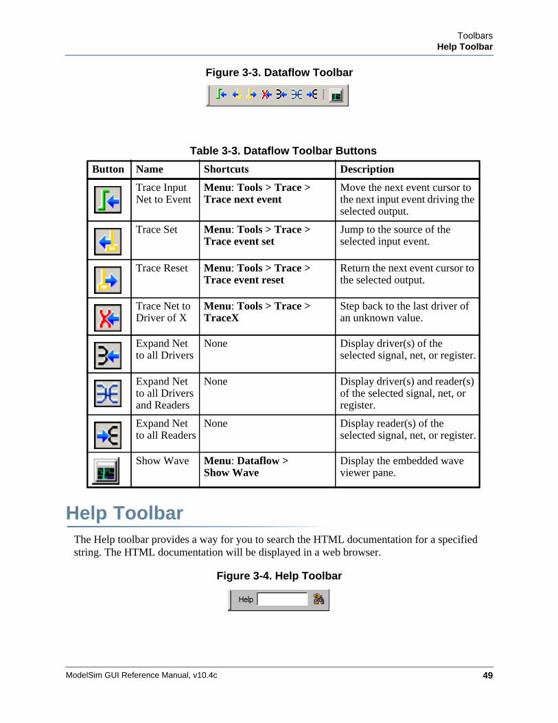
ToolbarsHelp Toolbar
ModelSim GUI Reference Manual, v10.4c 49
Figure 3-3. Dataflow Toolbar
Help ToolbarThe Help toolbar provides a way for you to search the HTML documentation for a specified string. The HTML documentation will be displayed in a web browser.
Figure 3-4. Help Toolbar
Table 3-3. Dataflow Toolbar Buttons
Button Name Shortcuts Description
Trace Input Net to Event
Menu: Tools > Trace >Trace next event
Move the next event cursor to the next input event driving the selected output.
Trace Set Menu: Tools > Trace >Trace event set
Jump to the source of the selected input event.
Trace Reset Menu: Tools > Trace >Trace event reset
Return the next event cursor to the selected output.
Trace Net to Driver of X
Menu: Tools > Trace >TraceX
Step back to the last driver of an unknown value.
Expand Net to all Drivers
None Display driver(s) of the selected signal, net, or register.
Expand Net to all Drivers and Readers
None Display driver(s) and reader(s) of the selected signal, net, or register.
Expand Net to all Readers
None Display reader(s) of the selected signal, net, or register.
Show Wave Menu: Dataflow > Show Wave
Display the embedded wave viewer pane.
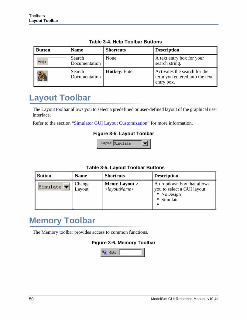
ModelSim GUI Reference Manual, v10.4c50
ToolbarsLayout Toolbar
Layout ToolbarThe Layout toolbar allows you to select a predefined or user-defined layout of the graphical user interface.
Refer to the section “Simulator GUI Layout Customization” for more information.
Figure 3-5. Layout Toolbar
Memory ToolbarThe Memory toolbar provides access to common functions.
Figure 3-6. Memory Toolbar
Table 3-4. Help Toolbar Buttons
Button Name Shortcuts Description
Search Documentation
None A text entry box for your search string.
Search Documentation
Hotkey: Enter Activates the search for the term you entered into the text entry box.
Table 3-5. Layout Toolbar Buttons
Button Name Shortcuts Description
Change Layout
Menu: Layout > <layoutName>
A dropdown box that allows you to select a GUI layout.• NoDesign• Simulate•
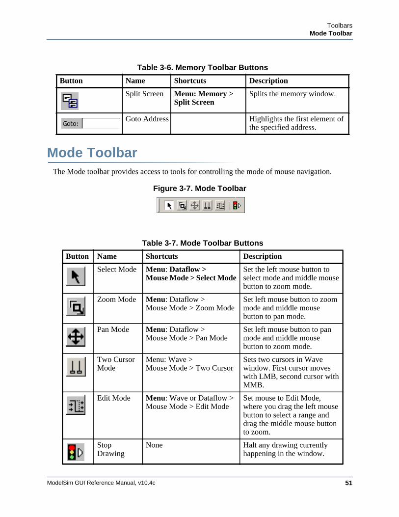
ToolbarsMode Toolbar
ModelSim GUI Reference Manual, v10.4c 51
Mode ToolbarThe Mode toolbar provides access to tools for controlling the mode of mouse navigation.
Figure 3-7. Mode Toolbar
Table 3-6. Memory Toolbar Buttons
Button Name Shortcuts Description
Split Screen Menu: Memory > Split Screen
Splits the memory window.
Goto Address Highlights the first element of the specified address.
Table 3-7. Mode Toolbar Buttons
Button Name Shortcuts Description
Select Mode Menu: Dataflow > Mouse Mode > Select Mode
Set the left mouse button to select mode and middle mouse button to zoom mode.
Zoom Mode Menu: Dataflow >Mouse Mode > Zoom Mode
Set left mouse button to zoom mode and middle mouse button to pan mode.
Pan Mode Menu: Dataflow >Mouse Mode > Pan Mode
Set left mouse button to pan mode and middle mouse button to zoom mode.
Two Cursor Mode
Menu: Wave > Mouse Mode > Two Cursor
Sets two cursors in Wave window. First cursor moves with LMB, second cursor with MMB.
Edit Mode Menu: Wave or Dataflow > Mouse Mode > Edit Mode
Set mouse to Edit Mode, where you drag the left mouse button to select a range and drag the middle mouse button to zoom.
Stop Drawing
None Halt any drawing currently happening in the window.
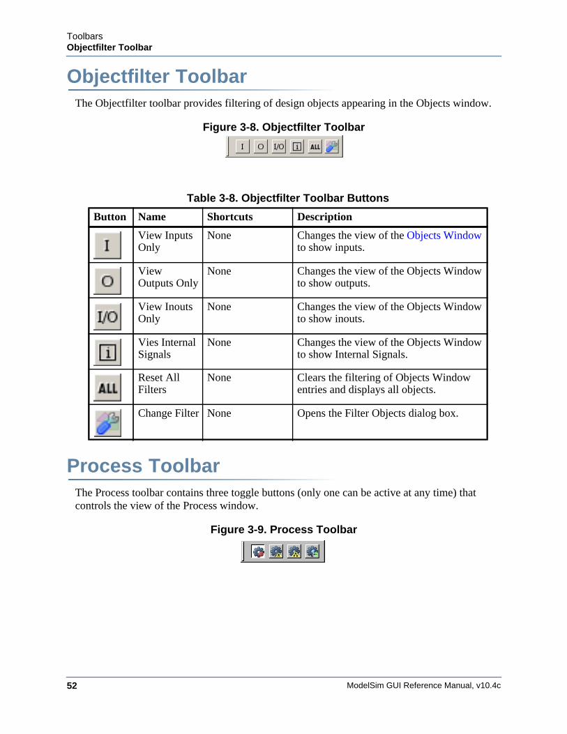
ModelSim GUI Reference Manual, v10.4c52
ToolbarsObjectfilter Toolbar
Objectfilter ToolbarThe Objectfilter toolbar provides filtering of design objects appearing in the Objects window.
Figure 3-8. Objectfilter Toolbar
Process ToolbarThe Process toolbar contains three toggle buttons (only one can be active at any time) that controls the view of the Process window.
Figure 3-9. Process Toolbar
Table 3-8. Objectfilter Toolbar Buttons
Button Name Shortcuts Description
View Inputs Only
None Changes the view of the Objects Window to show inputs.
View Outputs Only
None Changes the view of the Objects Window to show outputs.
View Inouts Only
None Changes the view of the Objects Window to show inouts.
Vies Internal Signals
None Changes the view of the Objects Window to show Internal Signals.
Reset All Filters
None Clears the filtering of Objects Window entries and displays all objects.
Change Filter None Opens the Filter Objects dialog box.
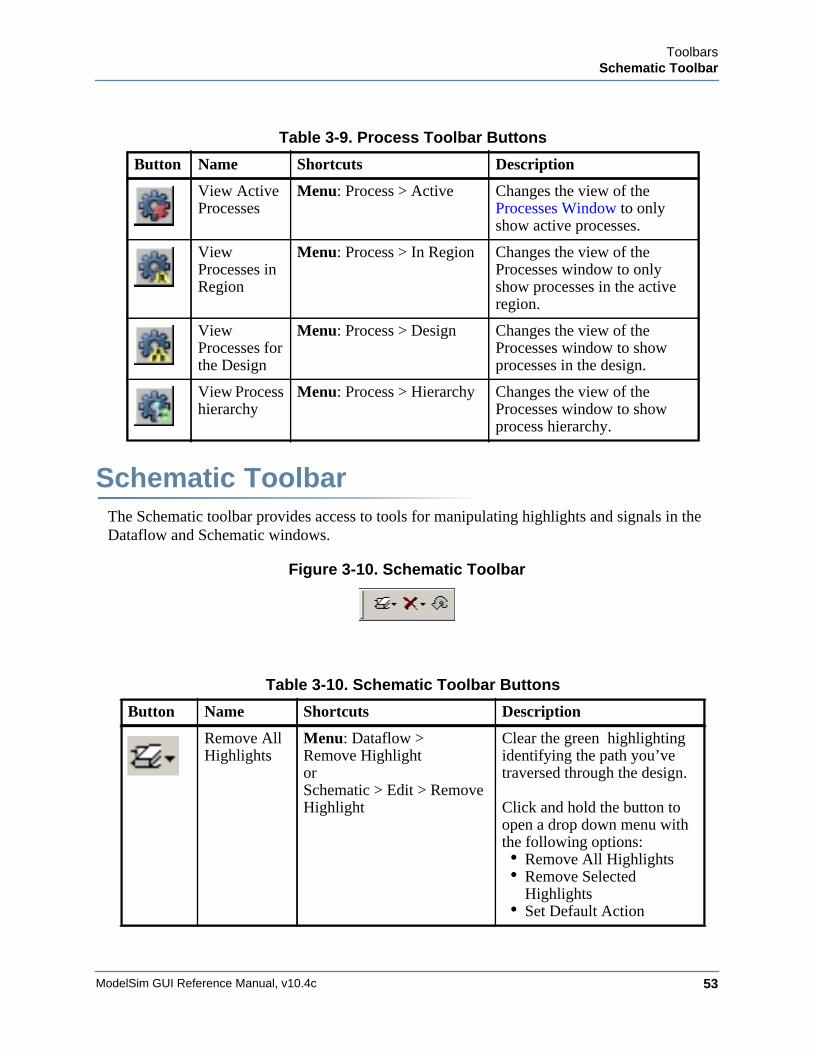
ToolbarsSchematic Toolbar
ModelSim GUI Reference Manual, v10.4c 53
Schematic ToolbarThe Schematic toolbar provides access to tools for manipulating highlights and signals in the Dataflow and Schematic windows.
Figure 3-10. Schematic Toolbar
Table 3-9. Process Toolbar Buttons
Button Name Shortcuts Description
View Active Processes
Menu: Process > Active Changes the view of the Processes Window to only show active processes.
View Processes in Region
Menu: Process > In Region Changes the view of the Processes window to only show processes in the active region.
View Processes for the Design
Menu: Process > Design Changes the view of the Processes window to show processes in the design.
View Process hierarchy
Menu: Process > Hierarchy Changes the view of the Processes window to show process hierarchy.
Table 3-10. Schematic Toolbar Buttons
Button Name Shortcuts Description
Remove All Highlights
Menu: Dataflow > Remove Highlight orSchematic > Edit > Remove Highlight
Clear the green highlighting identifying the path you’ve traversed through the design.
Click and hold the button to open a drop down menu with the following options:• Remove All Highlights • Remove Selected
Highlights• Set Default Action
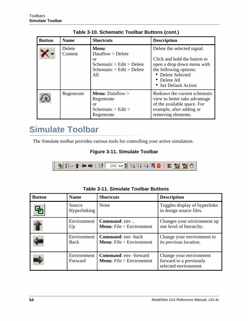
ModelSim GUI Reference Manual, v10.4c54
ToolbarsSimulate Toolbar
Simulate ToolbarThe Simulate toolbar provides various tools for controlling your active simulation.
Figure 3-11. Simulate Toolbar
Delete Content
Menu: Dataflow > Delete orSchematic > Edit > DeleteSchematic > Edit > Delete All
Delete the selected signal.
Click and hold the button to open a drop down menu with the following options:• Delete Selected• Delete All• Set Default Action
Regenerate Menu: Dataflow >RegenerateorSchematic > Edit > Regenerate
Redraws the current schematic view to better take advantage of the available space. For example, after adding or removing elements.
Table 3-11. Simulate Toolbar Buttons
Button Name Shortcuts Description
Source Hyperlinking
None Toggles display of hyperlinks in design source files.
Environment Up
Command: env ..Menu: File > Environment
Changes your environment up one level of hierarchy.
Environment Back
Command: env -backMenu: File > Environment
Change your environment to its previous location.
Environment Forward
Command: env -forwardMenu: File > Environment
Change your environment forward to a previously selected environment.
Table 3-10. Schematic Toolbar Buttons (cont.)
Button Name Shortcuts Description
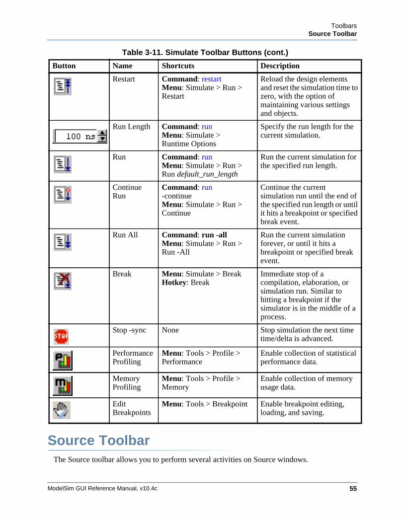
ToolbarsSource Toolbar
ModelSim GUI Reference Manual, v10.4c 55
Source ToolbarThe Source toolbar allows you to perform several activities on Source windows.
Restart Command: restart Menu: Simulate > Run >Restart
Reload the design elements and reset the simulation time to zero, with the option of maintaining various settings and objects.
Run Length Command: run Menu: Simulate > Runtime Options
Specify the run length for the current simulation.
Run Command: run Menu: Simulate > Run >Run default_run_length
Run the current simulation for the specified run length.
Continue Run
Command: run -continueMenu: Simulate > Run >Continue
Continue the current simulation run until the end of the specified run length or until it hits a breakpoint or specified break event.
Run All Command: run -allMenu: Simulate > Run >Run -All
Run the current simulation forever, or until it hits a breakpoint or specified break event.
Break Menu: Simulate > Break Hotkey: Break
Immediate stop of a compilation, elaboration, or simulation run. Similar to hitting a breakpoint if the simulator is in the middle of a process.
Stop -sync None Stop simulation the next time time/delta is advanced.
Performance Profiling
Menu: Tools > Profile >Performance
Enable collection of statistical performance data.
Memory Profiling
Menu: Tools > Profile >Memory
Enable collection of memory usage data.
Edit Breakpoints
Menu: Tools > Breakpoint Enable breakpoint editing, loading, and saving.
Table 3-11. Simulate Toolbar Buttons (cont.)
Button Name Shortcuts Description
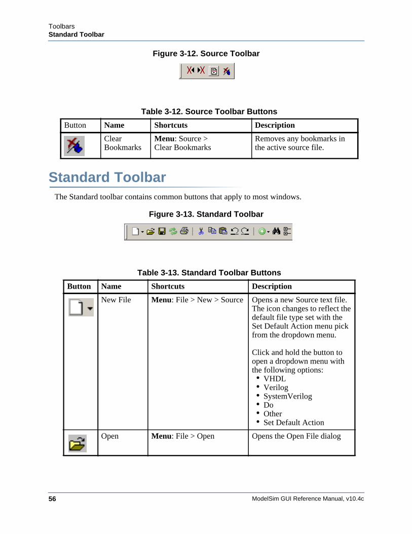
ModelSim GUI Reference Manual, v10.4c56
ToolbarsStandard Toolbar
Figure 3-12. Source Toolbar
Standard ToolbarThe Standard toolbar contains common buttons that apply to most windows.
Figure 3-13. Standard Toolbar
Table 3-12. Source Toolbar Buttons
Button Name Shortcuts Description
Clear Bookmarks
Menu: Source > Clear Bookmarks
Removes any bookmarks in the active source file.
Table 3-13. Standard Toolbar Buttons
Button Name Shortcuts Description
New File Menu: File > New > Source Opens a new Source text file. The icon changes to reflect the default file type set with the Set Default Action menu pick from the dropdown menu.
Click and hold the button to open a dropdown menu with the following options:• VHDL• Verilog• SystemVerilog• Do• Other• Set Default Action
Open Menu: File > Open Opens the Open File dialog
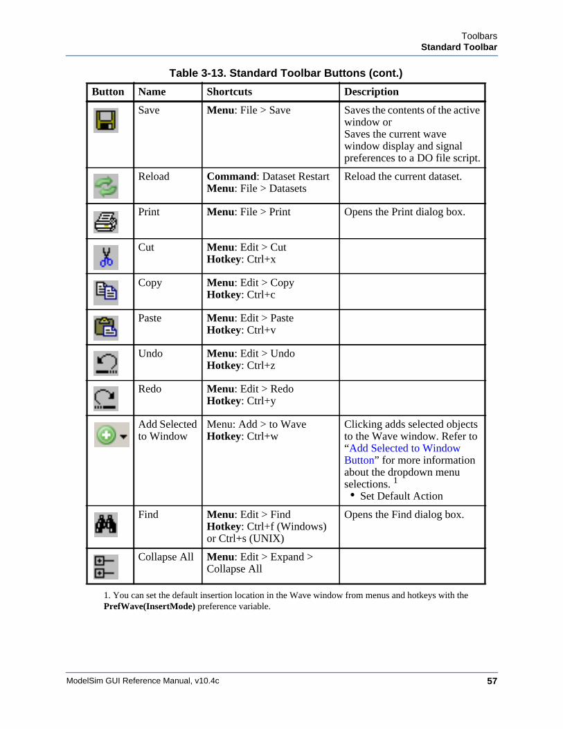
ToolbarsStandard Toolbar
ModelSim GUI Reference Manual, v10.4c 57
Save Menu: File > Save Saves the contents of the active window orSaves the current wave window display and signal preferences to a DO file script.
Reload Command: Dataset Restart Menu: File > Datasets
Reload the current dataset.
Print Menu: File > Print Opens the Print dialog box.
Cut Menu: Edit > CutHotkey: Ctrl+x
Copy Menu: Edit > CopyHotkey: Ctrl+c
Paste Menu: Edit > PasteHotkey: Ctrl+v
Undo Menu: Edit > UndoHotkey: Ctrl+z
Redo Menu: Edit > RedoHotkey: Ctrl+y
Add Selected to Window
Menu: Add > to Wave Hotkey: Ctrl+w
Clicking adds selected objects to the Wave window. Refer to “Add Selected to Window Button” for more information about the dropdown menu selections. 1
• Set Default Action
Find Menu: Edit > FindHotkey: Ctrl+f (Windows) or Ctrl+s (UNIX)
Opens the Find dialog box.
Collapse All Menu: Edit > Expand > Collapse All
1. You can set the default insertion location in the Wave window from menus and hotkeys with thePrefWave(InsertMode) preference variable.
Table 3-13. Standard Toolbar Buttons (cont.)
Button Name Shortcuts Description
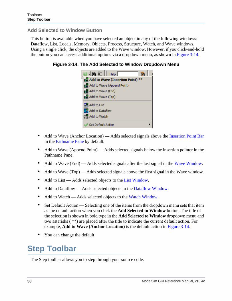
ModelSim GUI Reference Manual, v10.4c58
ToolbarsStep Toolbar
Add Selected to Window Button
This button is available when you have selected an object in any of the following windows: Dataflow, List, Locals, Memory, Objects, Process, Structure, Watch, and Wave windows. Using a single click, the objects are added to the Wave window. However, if you click-and-hold the button you can access additional options via a dropdown menu, as shown in Figure 3-14.
Figure 3-14. The Add Selected to Window Dropdown Menu
• Add to Wave (Anchor Location) — Adds selected signals above the Insertion Point Bar in the Pathname Pane by default.
• Add to Wave (Append Point) — Adds selected signals below the insertion pointer in the Pathname Pane.
• Add to Wave (End) — Adds selected signals after the last signal in the Wave Window.
• Add to Wave (Top) — Adds selected signals above the first signal in the Wave window.
• Add to List — Adds selected objects to the List Window.
• Add to Dataflow — Adds selected objects to the Dataflow Window.
• Add to Watch — Adds selected objects to the Watch Window.
• Set Default Action — Selecting one of the items from the dropdown menu sets that item as the default action when you click the Add Selected to Window button. The title of the selection is shown in bold type in the Add Selected to Window dropdown menu and two asterisks ( **) are placed after the title to indicate the current default action. For example, Add to Wave (Anchor Location) is the default action in Figure 3-14.
• You can change the default
Step ToolbarThe Step toolbar allows you to step through your source code.
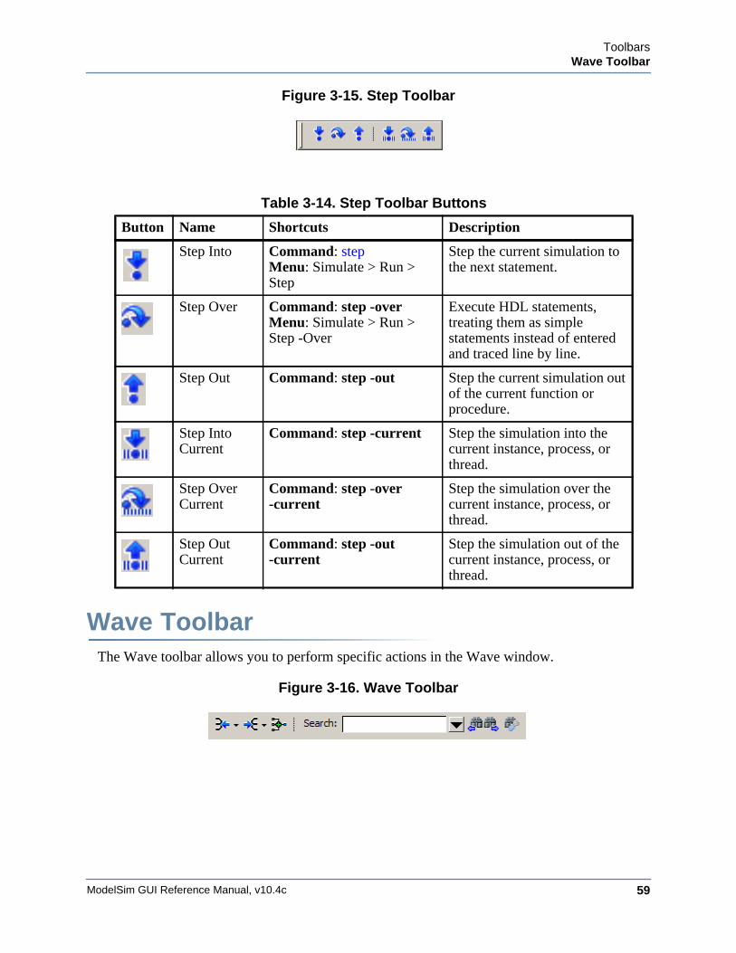
ToolbarsWave Toolbar
ModelSim GUI Reference Manual, v10.4c 59
Figure 3-15. Step Toolbar
Wave ToolbarThe Wave toolbar allows you to perform specific actions in the Wave window.
Figure 3-16. Wave Toolbar
Table 3-14. Step Toolbar Buttons
Button Name Shortcuts Description
Step Into Command: step Menu: Simulate > Run >Step
Step the current simulation to the next statement.
Step Over Command: step -overMenu: Simulate > Run > Step -Over
Execute HDL statements, treating them as simple statements instead of entered and traced line by line.
Step Out Command: step -out Step the current simulation out of the current function or procedure.
Step Into Current
Command: step -current Step the simulation into the current instance, process, or thread.
Step Over Current
Command: step -over -current
Step the simulation over the current instance, process, or thread.
Step Out Current
Command: step -out -current
Step the simulation out of the current instance, process, or thread.
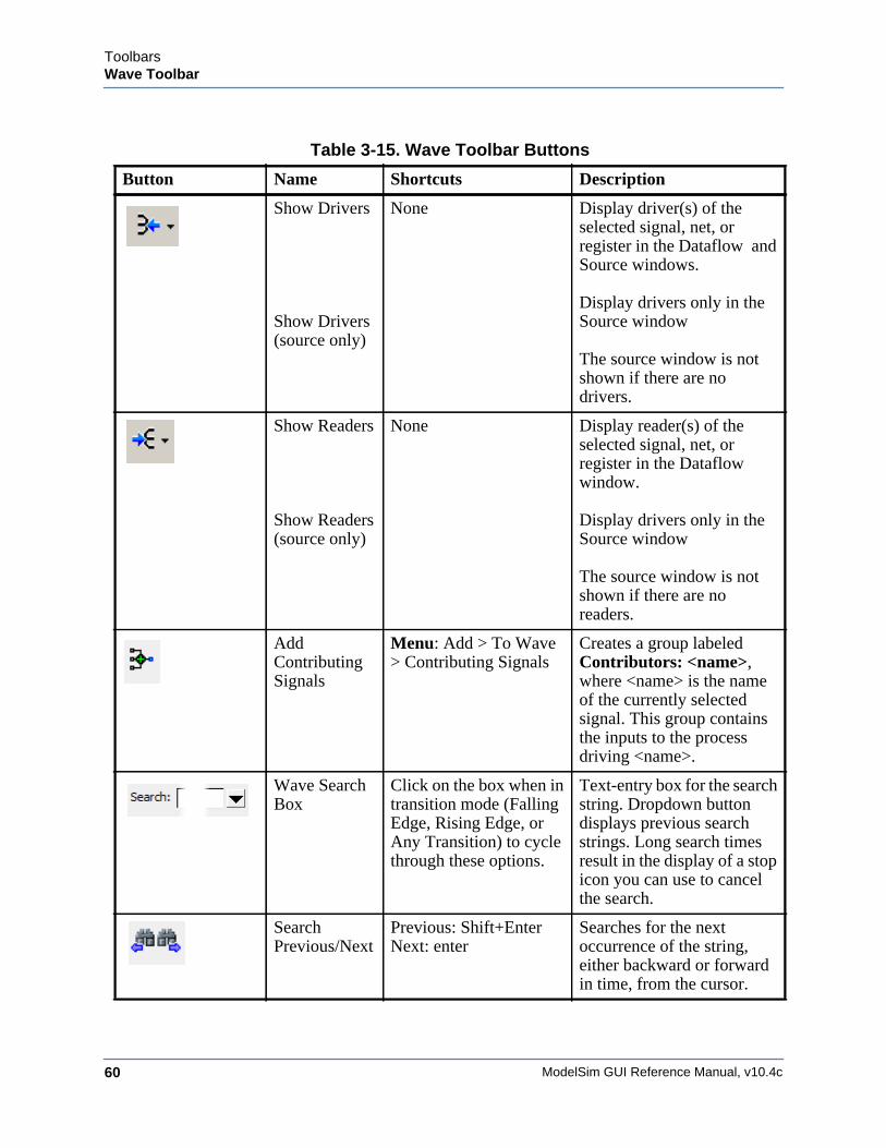
ModelSim GUI Reference Manual, v10.4c60
ToolbarsWave Toolbar
Table 3-15. Wave Toolbar Buttons
Button Name Shortcuts Description
Show Drivers
Show Drivers (source only)
None Display driver(s) of the selected signal, net, or register in the Dataflow and Source windows.
Display drivers only in the Source window
The source window is not shown if there are no drivers.
Show Readers
Show Readers (source only)
None Display reader(s) of the selected signal, net, or register in the Dataflow window.
Display drivers only in the Source window
The source window is not shown if there are no readers.
Add Contributing Signals
Menu: Add > To Wave > Contributing Signals
Creates a group labeled Contributors: <name>, where <name> is the name of the currently selected signal. This group contains the inputs to the process driving <name>.
Wave Search Box
Click on the box when in transition mode (Falling Edge, Rising Edge, or Any Transition) to cycle through these options.
Text-entry box for the search string. Dropdown button displays previous search strings. Long search times result in the display of a stop icon you can use to cancel the search.
Search Previous/Next
Previous: Shift+EnterNext: enter
Searches for the next occurrence of the string, either backward or forward in time, from the cursor.
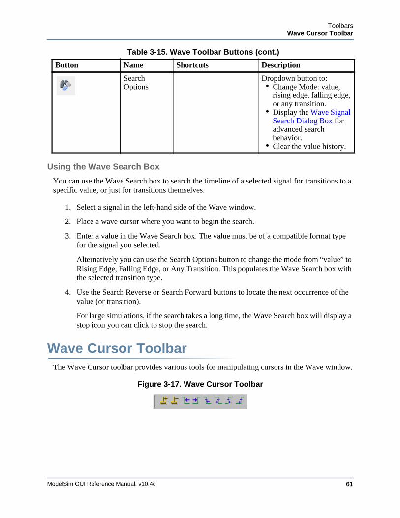
ToolbarsWave Cursor Toolbar
ModelSim GUI Reference Manual, v10.4c 61
Using the Wave Search Box
You can use the Wave Search box to search the timeline of a selected signal for transitions to a specific value, or just for transitions themselves.
1. Select a signal in the left-hand side of the Wave window.
2. Place a wave cursor where you want to begin the search.
3. Enter a value in the Wave Search box. The value must be of a compatible format type for the signal you selected.
Alternatively you can use the Search Options button to change the mode from “value” to Rising Edge, Falling Edge, or Any Transition. This populates the Wave Search box with the selected transition type.
4. Use the Search Reverse or Search Forward buttons to locate the next occurrence of the value (or transition).
For large simulations, if the search takes a long time, the Wave Search box will display a stop icon you can click to stop the search.
Wave Cursor ToolbarThe Wave Cursor toolbar provides various tools for manipulating cursors in the Wave window.
Figure 3-17. Wave Cursor Toolbar
Search Options
Dropdown button to:• Change Mode: value,
rising edge, falling edge, or any transition.
• Display the Wave Signal Search Dialog Box for advanced search behavior.
• Clear the value history.
Table 3-15. Wave Toolbar Buttons (cont.)
Button Name Shortcuts Description
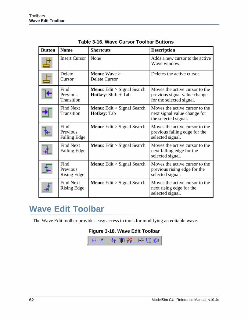
ModelSim GUI Reference Manual, v10.4c62
ToolbarsWave Edit Toolbar
Wave Edit ToolbarThe Wave Edit toolbar provides easy access to tools for modifying an editable wave.
Figure 3-18. Wave Edit Toolbar
Table 3-16. Wave Cursor Toolbar Buttons
Button Name Shortcuts Description
Insert Cursor None Adds a new cursor to the active Wave window.
Delete Cursor
Menu: Wave >Delete Cursor
Deletes the active cursor.
Find Previous Transition
Menu: Edit > Signal SearchHotkey: Shift + Tab
Moves the active cursor to the previous signal value change for the selected signal.
Find Next Transition
Menu: Edit > Signal SearchHotkey: Tab
Moves the active cursor to the next signal value change for the selected signal.
Find Previous Falling Edge
Menu: Edit > Signal Search Moves the active cursor to the previous falling edge for the selected signal.
Find Next Falling Edge
Menu: Edit > Signal Search Moves the active cursor to the next falling edge for the selected signal.
Find Previous Rising Edge
Menu: Edit > Signal Search Moves the active cursor to the previous rising edge for the selected signal.
Find Next Rising Edge
Menu: Edit > Signal Search Moves the active cursor to the next rising edge for the selected signal.
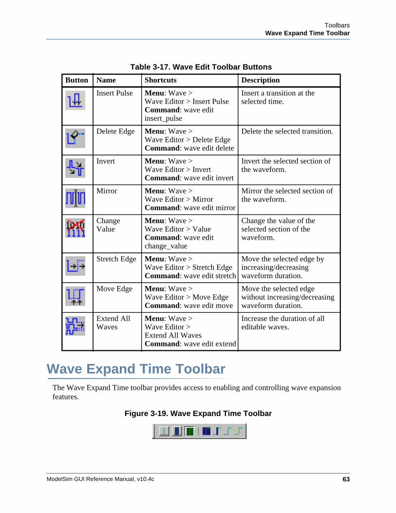
ToolbarsWave Expand Time Toolbar
ModelSim GUI Reference Manual, v10.4c 63
Wave Expand Time ToolbarThe Wave Expand Time toolbar provides access to enabling and controlling wave expansion features.
Figure 3-19. Wave Expand Time Toolbar
Table 3-17. Wave Edit Toolbar Buttons
Button Name Shortcuts Description
Insert Pulse Menu: Wave > Wave Editor > Insert PulseCommand: wave edit insert_pulse
Insert a transition at the selected time.
Delete Edge Menu: Wave > Wave Editor > Delete EdgeCommand: wave edit delete
Delete the selected transition.
Invert Menu: Wave > Wave Editor > InvertCommand: wave edit invert
Invert the selected section of the waveform.
Mirror Menu: Wave > Wave Editor > MirrorCommand: wave edit mirror
Mirror the selected section of the waveform.
Change Value
Menu: Wave > Wave Editor > ValueCommand: wave edit change_value
Change the value of the selected section of the waveform.
Stretch Edge Menu: Wave > Wave Editor > Stretch EdgeCommand: wave edit stretch
Move the selected edge by increasing/decreasing waveform duration.
Move Edge Menu: Wave > Wave Editor > Move EdgeCommand: wave edit move
Move the selected edge without increasing/decreasing waveform duration.
Extend All Waves
Menu: Wave > Wave Editor >Extend All WavesCommand: wave edit extend
Increase the duration of all editable waves.
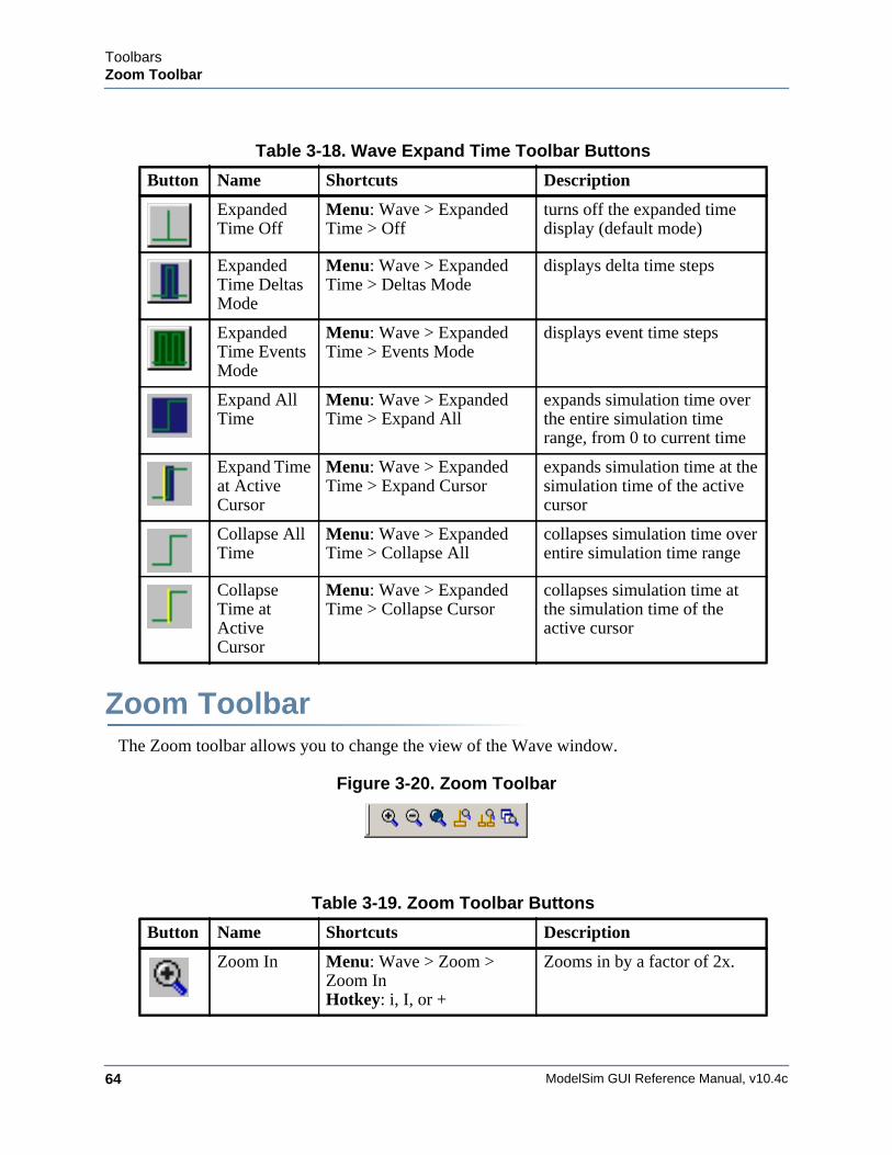
ModelSim GUI Reference Manual, v10.4c64
ToolbarsZoom Toolbar
Zoom ToolbarThe Zoom toolbar allows you to change the view of the Wave window.
Figure 3-20. Zoom Toolbar
Table 3-18. Wave Expand Time Toolbar Buttons
Button Name Shortcuts Description
Expanded Time Off
Menu: Wave > Expanded Time > Off
turns off the expanded time display (default mode)
Expanded Time Deltas Mode
Menu: Wave > Expanded Time > Deltas Mode
displays delta time steps
Expanded Time Events Mode
Menu: Wave > Expanded Time > Events Mode
displays event time steps
Expand All Time
Menu: Wave > Expanded Time > Expand All
expands simulation time over the entire simulation time range, from 0 to current time
Expand Time at Active Cursor
Menu: Wave > Expanded Time > Expand Cursor
expands simulation time at the simulation time of the active cursor
Collapse All Time
Menu: Wave > Expanded Time > Collapse All
collapses simulation time over entire simulation time range
Collapse Time at Active Cursor
Menu: Wave > Expanded Time > Collapse Cursor
collapses simulation time at the simulation time of the active cursor
Table 3-19. Zoom Toolbar Buttons
Button Name Shortcuts Description
Zoom In Menu: Wave > Zoom > Zoom InHotkey: i, I, or +
Zooms in by a factor of 2x.
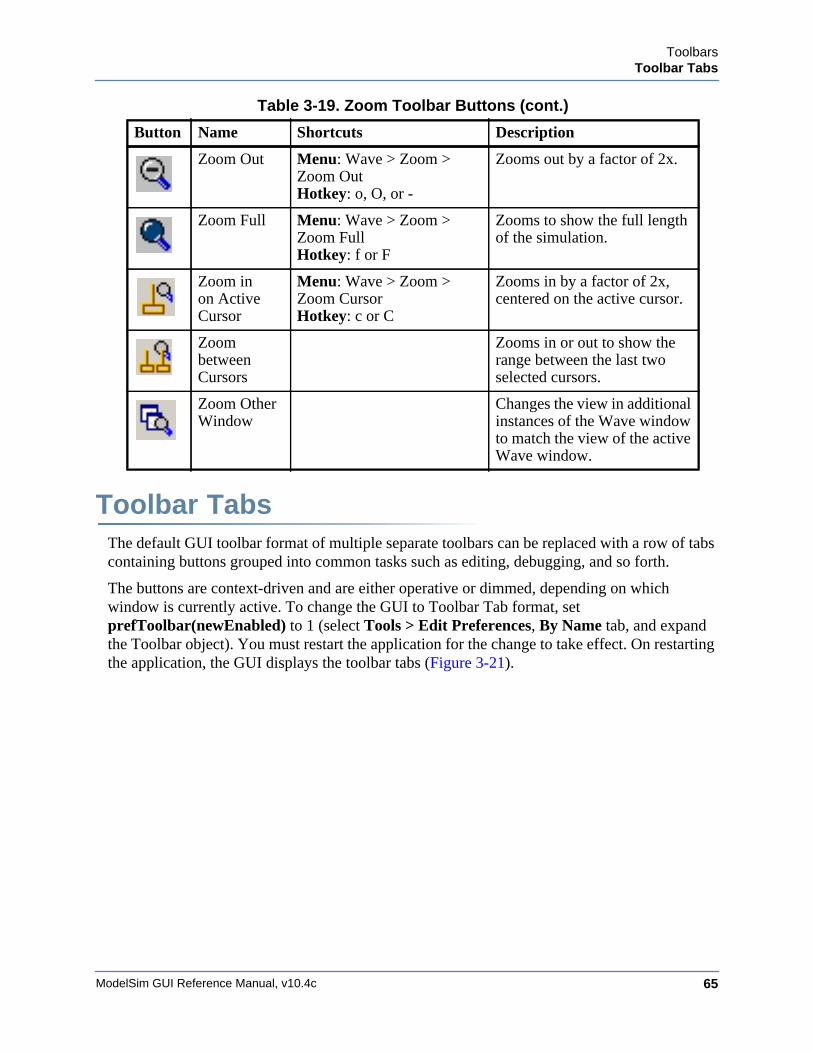
ToolbarsToolbar Tabs
ModelSim GUI Reference Manual, v10.4c 65
Toolbar TabsThe default GUI toolbar format of multiple separate toolbars can be replaced with a row of tabs containing buttons grouped into common tasks such as editing, debugging, and so forth.
The buttons are context-driven and are either operative or dimmed, depending on which window is currently active. To change the GUI to Toolbar Tab format, set prefToolbar(newEnabled) to 1 (select Tools > Edit Preferences, By Name tab, and expand the Toolbar object). You must restart the application for the change to take effect. On restarting the application, the GUI displays the toolbar tabs (Figure 3-21).
Zoom Out Menu: Wave > Zoom > Zoom OutHotkey: o, O, or -
Zooms out by a factor of 2x.
Zoom Full Menu: Wave > Zoom > Zoom FullHotkey: f or F
Zooms to show the full length of the simulation.
Zoom in on Active Cursor
Menu: Wave > Zoom > Zoom CursorHotkey: c or C
Zooms in by a factor of 2x, centered on the active cursor.
Zoom between Cursors
Zooms in or out to show the range between the last two selected cursors.
Zoom Other Window
Changes the view in additional instances of the Wave window to match the view of the active Wave window.
Table 3-19. Zoom Toolbar Buttons (cont.)
Button Name Shortcuts Description
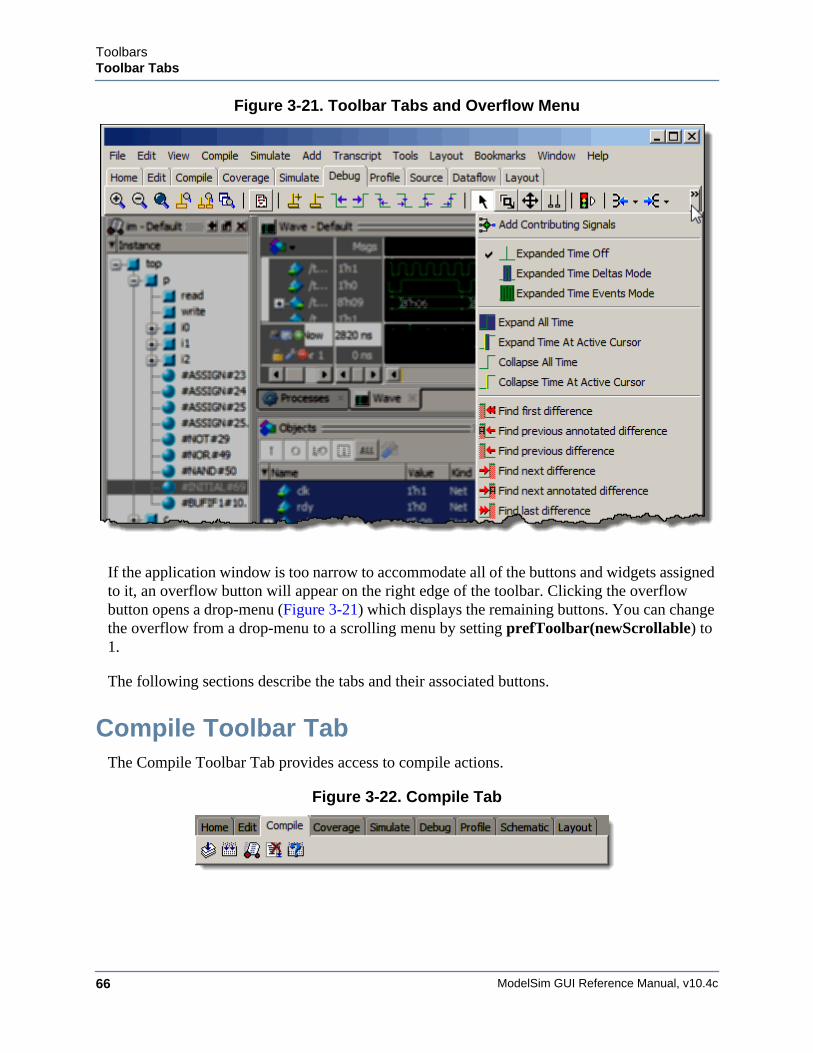
ModelSim GUI Reference Manual, v10.4c66
ToolbarsToolbar Tabs
Figure 3-21. Toolbar Tabs and Overflow Menu
If the application window is too narrow to accommodate all of the buttons and widgets assigned to it, an overflow button will appear on the right edge of the toolbar. Clicking the overflow button opens a drop-menu (Figure 3-21) which displays the remaining buttons. You can change the overflow from a drop-menu to a scrolling menu by setting prefToolbar(newScrollable) to 1.
The following sections describe the tabs and their associated buttons.
Compile Toolbar TabThe Compile Toolbar Tab provides access to compile actions.
Figure 3-22. Compile Tab
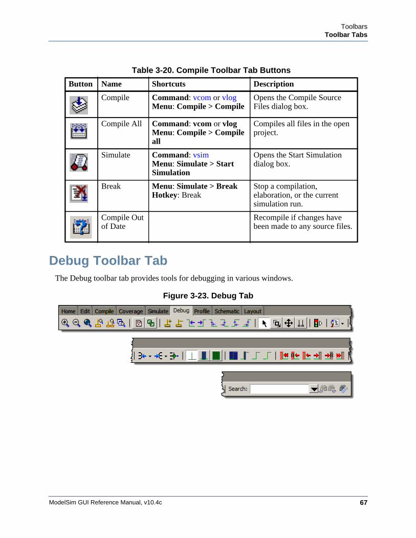
ToolbarsToolbar Tabs
ModelSim GUI Reference Manual, v10.4c 67
Debug Toolbar TabThe Debug toolbar tab provides tools for debugging in various windows.
Figure 3-23. Debug Tab
Table 3-20. Compile Toolbar Tab Buttons
Button Name Shortcuts Description
Compile Command: vcom or vlog Menu: Compile > Compile
Opens the Compile Source Files dialog box.
Compile All Command: vcom or vlogMenu: Compile > Compile all
Compiles all files in the open project.
Simulate Command: vsim Menu: Simulate > Start Simulation
Opens the Start Simulation dialog box.
Break Menu: Simulate > Break Hotkey: Break
Stop a compilation, elaboration, or the current simulation run.
Compile Out of Date
Recompile if changes have been made to any source files.
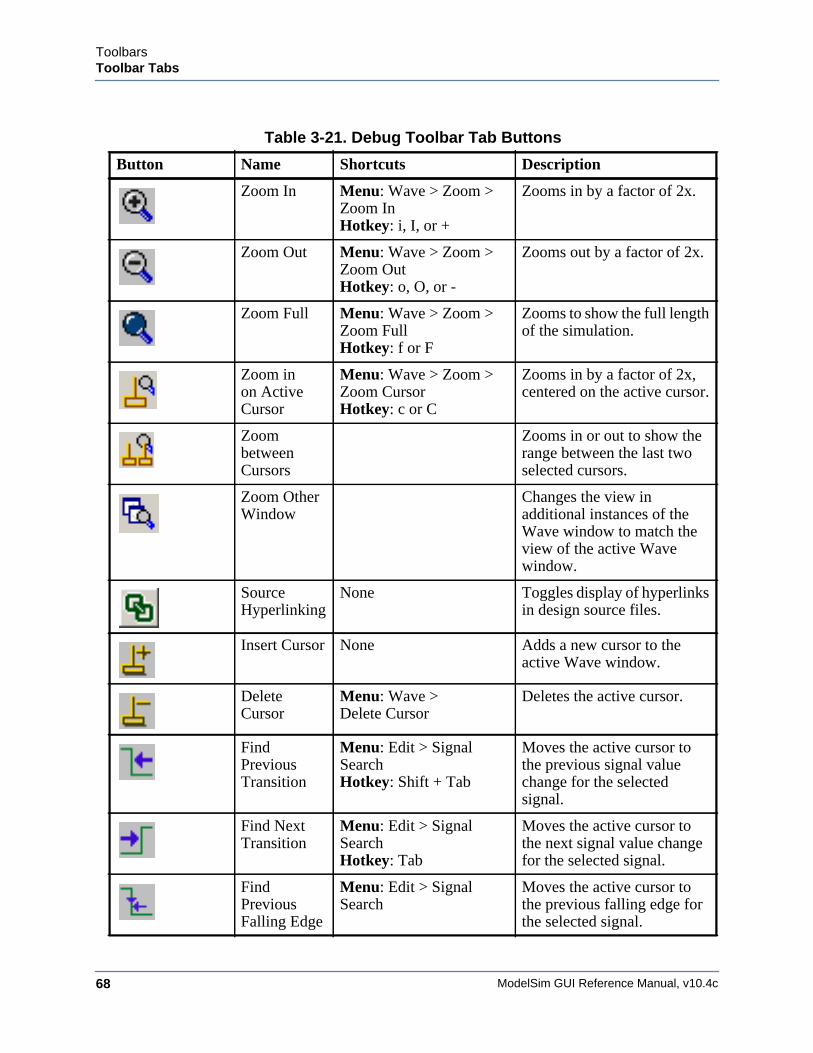
ModelSim GUI Reference Manual, v10.4c68
ToolbarsToolbar Tabs
Table 3-21. Debug Toolbar Tab Buttons
Button Name Shortcuts Description
Zoom In Menu: Wave > Zoom > Zoom InHotkey: i, I, or +
Zooms in by a factor of 2x.
Zoom Out Menu: Wave > Zoom > Zoom OutHotkey: o, O, or -
Zooms out by a factor of 2x.
Zoom Full Menu: Wave > Zoom > Zoom FullHotkey: f or F
Zooms to show the full length of the simulation.
Zoom in on Active Cursor
Menu: Wave > Zoom > Zoom CursorHotkey: c or C
Zooms in by a factor of 2x, centered on the active cursor.
Zoom between Cursors
Zooms in or out to show the range between the last two selected cursors.
Zoom Other Window
Changes the view in additional instances of the Wave window to match the view of the active Wave window.
Source Hyperlinking
None Toggles display of hyperlinks in design source files.
Insert Cursor None Adds a new cursor to the active Wave window.
Delete Cursor
Menu: Wave >Delete Cursor
Deletes the active cursor.
Find Previous Transition
Menu: Edit > Signal SearchHotkey: Shift + Tab
Moves the active cursor to the previous signal value change for the selected signal.
Find Next Transition
Menu: Edit > Signal SearchHotkey: Tab
Moves the active cursor to the next signal value change for the selected signal.
Find Previous Falling Edge
Menu: Edit > Signal Search
Moves the active cursor to the previous falling edge for the selected signal.
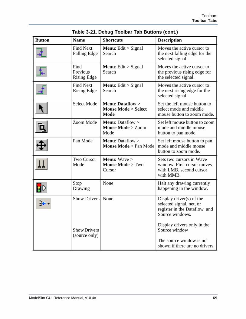
ToolbarsToolbar Tabs
ModelSim GUI Reference Manual, v10.4c 69
Find Next Falling Edge
Menu: Edit > Signal Search
Moves the active cursor to the next falling edge for the selected signal.
Find Previous Rising Edge
Menu: Edit > Signal Search
Moves the active cursor to the previous rising edge for the selected signal.
Find Next Rising Edge
Menu: Edit > Signal Search
Moves the active cursor to the next rising edge for the selected signal.
Select Mode Menu: Dataflow > Mouse Mode > Select Mode
Set the left mouse button to select mode and middle mouse button to zoom mode.
Zoom Mode Menu: Dataflow >Mouse Mode > Zoom Mode
Set left mouse button to zoom mode and middle mouse button to pan mode.
Pan Mode Menu: Dataflow >Mouse Mode > Pan Mode
Set left mouse button to pan mode and middle mouse button to zoom mode.
Two Cursor Mode
Menu: Wave > Mouse Mode > Two Cursor
Sets two cursors in Wave window. First cursor moves with LMB, second cursor with MMB.
Stop Drawing
None Halt any drawing currently happening in the window.
Show Drivers
Show Drivers (source only)
None Display driver(s) of the selected signal, net, or register in the Dataflow and Source windows.
Display drivers only in the Source window
The source window is not shown if there are no drivers.
Table 3-21. Debug Toolbar Tab Buttons (cont.)
Button Name Shortcuts Description
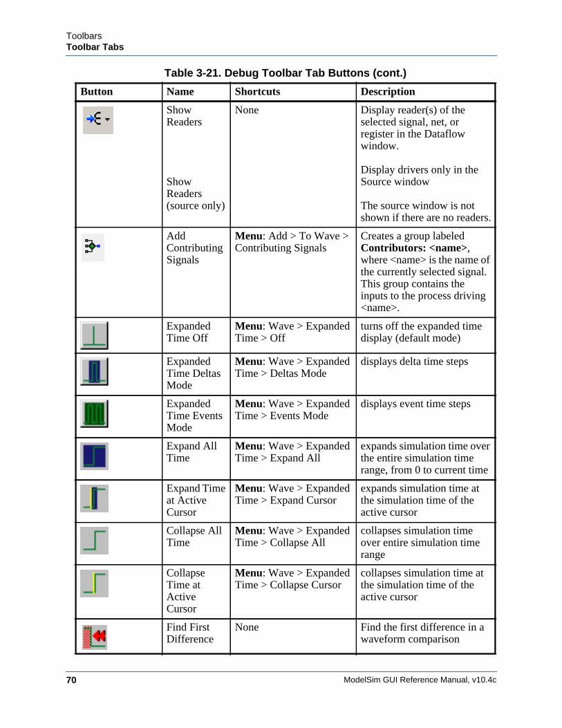
ModelSim GUI Reference Manual, v10.4c70
ToolbarsToolbar Tabs
Show Readers
Show Readers (source only)
None Display reader(s) of the selected signal, net, or register in the Dataflow window.
Display drivers only in the Source window
The source window is not shown if there are no readers.
Add Contributing Signals
Menu: Add > To Wave > Contributing Signals
Creates a group labeled Contributors: <name>, where <name> is the name of the currently selected signal. This group contains the inputs to the process driving <name>.
Expanded Time Off
Menu: Wave > Expanded Time > Off
turns off the expanded time display (default mode)
Expanded Time Deltas Mode
Menu: Wave > Expanded Time > Deltas Mode
displays delta time steps
Expanded Time Events Mode
Menu: Wave > Expanded Time > Events Mode
displays event time steps
Expand All Time
Menu: Wave > Expanded Time > Expand All
expands simulation time over the entire simulation time range, from 0 to current time
Expand Time at Active Cursor
Menu: Wave > Expanded Time > Expand Cursor
expands simulation time at the simulation time of the active cursor
Collapse All Time
Menu: Wave > Expanded Time > Collapse All
collapses simulation time over entire simulation time range
Collapse Time at Active Cursor
Menu: Wave > Expanded Time > Collapse Cursor
collapses simulation time at the simulation time of the active cursor
Find First Difference
None Find the first difference in a waveform comparison
Table 3-21. Debug Toolbar Tab Buttons (cont.)
Button Name Shortcuts Description
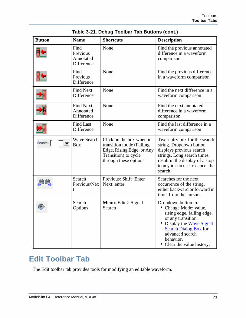
ToolbarsToolbar Tabs
ModelSim GUI Reference Manual, v10.4c 71
Edit Toolbar TabThe Edit toolbar tab provides tools for modifying an editable waveform.
Find Previous Annotated Difference
None Find the previous annotated difference in a waveform comparison
Find Previous Difference
None Find the previous difference in a waveform comparison
Find Next Difference
None Find the next difference in a waveform comparison
Find Next Annotated Difference
None Find the next annotated difference in a waveform comparison
Find Last Difference
None Find the last difference in a waveform comparison
Wave Search Box
Click on the box when in transition mode (Falling Edge, Rising Edge, or Any Transition) to cycle through these options.
Text-entry box for the search string. Dropdown button displays previous search strings. Long search times result in the display of a stop icon you can use to cancel the search.
Search Previous/Next
Previous: Shift+EnterNext: enter
Searches for the next occurrence of the string, either backward or forward in time, from the cursor.
Search Options
Menu: Edit > Signal Search
Dropdown button to:• Change Mode: value,
rising edge, falling edge, or any transition.
• Display the Wave Signal Search Dialog Box for advanced search behavior.
• Clear the value history.
Table 3-21. Debug Toolbar Tab Buttons (cont.)
Button Name Shortcuts Description
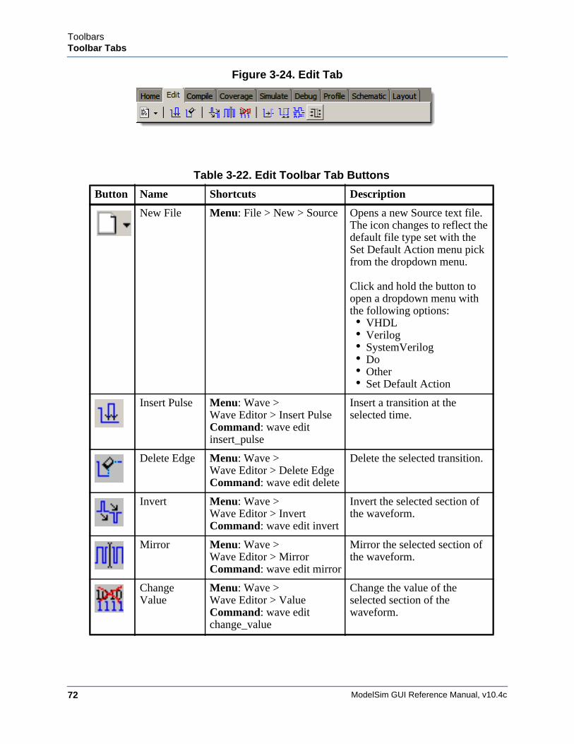
ModelSim GUI Reference Manual, v10.4c72
ToolbarsToolbar Tabs
Figure 3-24. Edit Tab
Table 3-22. Edit Toolbar Tab Buttons
Button Name Shortcuts Description
New File Menu: File > New > Source Opens a new Source text file. The icon changes to reflect the default file type set with the Set Default Action menu pick from the dropdown menu.
Click and hold the button to open a dropdown menu with the following options:• VHDL• Verilog• SystemVerilog• Do• Other• Set Default Action
Insert Pulse Menu: Wave > Wave Editor > Insert PulseCommand: wave edit insert_pulse
Insert a transition at the selected time.
Delete Edge Menu: Wave > Wave Editor > Delete EdgeCommand: wave edit delete
Delete the selected transition.
Invert Menu: Wave > Wave Editor > InvertCommand: wave edit invert
Invert the selected section of the waveform.
Mirror Menu: Wave > Wave Editor > MirrorCommand: wave edit mirror
Mirror the selected section of the waveform.
Change Value
Menu: Wave > Wave Editor > ValueCommand: wave edit change_value
Change the value of the selected section of the waveform.
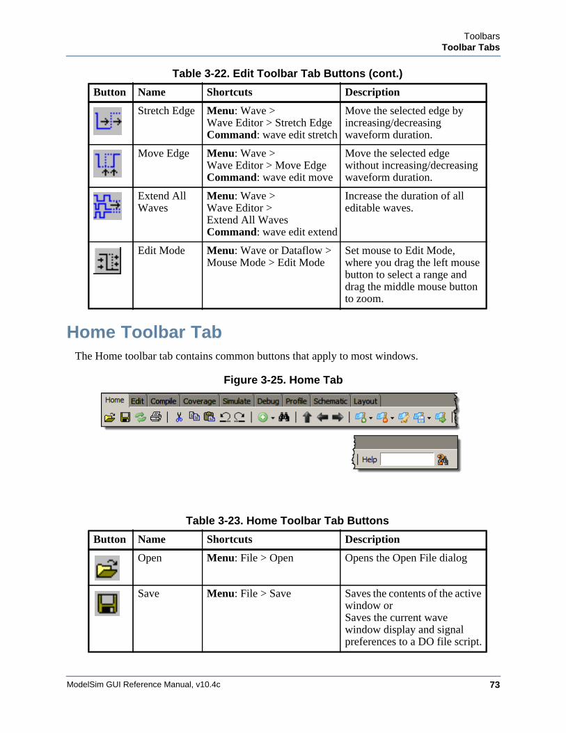
ToolbarsToolbar Tabs
ModelSim GUI Reference Manual, v10.4c 73
Home Toolbar TabThe Home toolbar tab contains common buttons that apply to most windows.
Figure 3-25. Home Tab
Stretch Edge Menu: Wave > Wave Editor > Stretch EdgeCommand: wave edit stretch
Move the selected edge by increasing/decreasing waveform duration.
Move Edge Menu: Wave > Wave Editor > Move EdgeCommand: wave edit move
Move the selected edge without increasing/decreasing waveform duration.
Extend All Waves
Menu: Wave > Wave Editor >Extend All WavesCommand: wave edit extend
Increase the duration of all editable waves.
Edit Mode Menu: Wave or Dataflow > Mouse Mode > Edit Mode
Set mouse to Edit Mode, where you drag the left mouse button to select a range and drag the middle mouse button to zoom.
Table 3-23. Home Toolbar Tab Buttons
Button Name Shortcuts Description
Open Menu: File > Open Opens the Open File dialog
Save Menu: File > Save Saves the contents of the active window orSaves the current wave window display and signal preferences to a DO file script.
Table 3-22. Edit Toolbar Tab Buttons (cont.)
Button Name Shortcuts Description
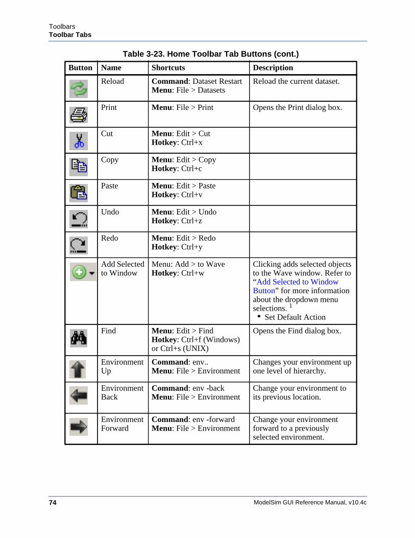
ModelSim GUI Reference Manual, v10.4c74
ToolbarsToolbar Tabs
Reload Command: Dataset Restart Menu: File > Datasets
Reload the current dataset.
Print Menu: File > Print Opens the Print dialog box.
Cut Menu: Edit > CutHotkey: Ctrl+x
Copy Menu: Edit > CopyHotkey: Ctrl+c
Paste Menu: Edit > PasteHotkey: Ctrl+v
Undo Menu: Edit > UndoHotkey: Ctrl+z
Redo Menu: Edit > RedoHotkey: Ctrl+y
Add Selected to Window
Menu: Add > to Wave Hotkey: Ctrl+w
Clicking adds selected objects to the Wave window. Refer to “Add Selected to Window Button” for more information about the dropdown menu selections. 1
• Set Default Action
Find Menu: Edit > FindHotkey: Ctrl+f (Windows) or Ctrl+s (UNIX)
Opens the Find dialog box.
Environment Up
Command: env..Menu: File > Environment
Changes your environment up one level of hierarchy.
Environment Back
Command: env -backMenu: File > Environment
Change your environment to its previous location.
Environment Forward
Command: env -forwardMenu: File > Environment
Change your environment forward to a previously selected environment.
Table 3-23. Home Toolbar Tab Buttons (cont.)
Button Name Shortcuts Description
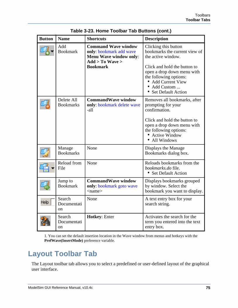
ToolbarsToolbar Tabs
ModelSim GUI Reference Manual, v10.4c 75
Layout Toolbar TabThe Layout toolbar tab allows you to select a predefined or user-defined layout of the graphical user interface.
Add Bookmark
Command Wave window only: bookmark add wave Menu Wave window only: Add > To Wave > Bookmark
Clicking this button bookmarks the current view of the active window.
Click and hold the button to open a drop down menu with the following options:• Add Current View• Add Custom ...• Set Default Action
Delete All Bookmarks
CommandWave window only: bookmark delete wave -all
Removes all bookmarks, after prompting for your confirmation.
Click and hold the button to open a drop down menu with the following options:• Active Window• All Windows
Manage Bookmarks
None Displays the Manage Bookmarks dialog box.
Reload from File
None Reloads bookmarks from the bookmarks.do file.• Set Default Action
Jump to Bookmark
CommandWave window only: bookmark goto wave <name>
Displays bookmarks grouped by window. Select the bookmark you want to display.
Search Documentation
None A text entry box for your search string.
Search Documentation
Hotkey: Enter Activates the search for the term you entered into the text entry box.
1. You can set the default insertion location in the Wave window from menus and hotkeys with thePrefWave(InsertMode) preference variable.
Table 3-23. Home Toolbar Tab Buttons (cont.)
Button Name Shortcuts Description
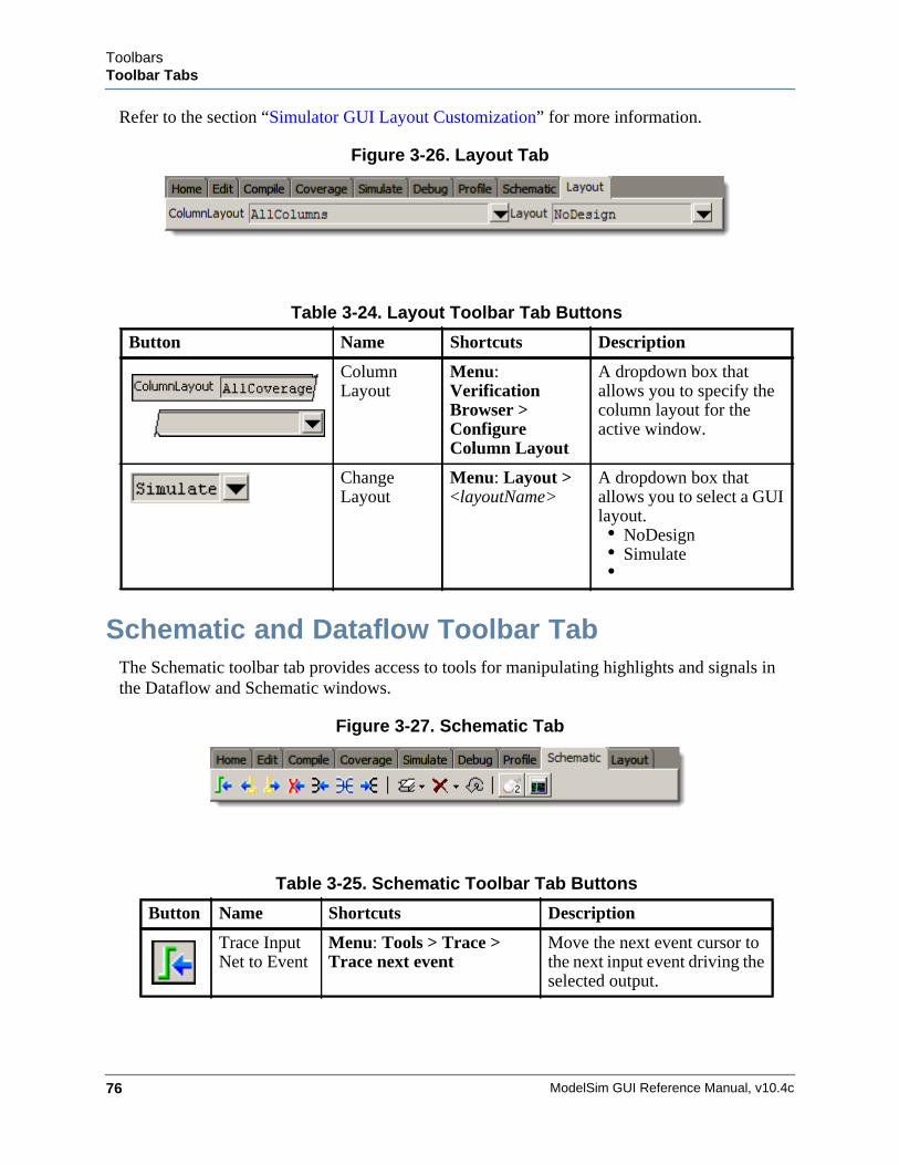
ModelSim GUI Reference Manual, v10.4c76
ToolbarsToolbar Tabs
Refer to the section “Simulator GUI Layout Customization” for more information.
Figure 3-26. Layout Tab
Schematic and Dataflow Toolbar TabThe Schematic toolbar tab provides access to tools for manipulating highlights and signals in the Dataflow and Schematic windows.
Figure 3-27. Schematic Tab
Table 3-24. Layout Toolbar Tab Buttons
Button Name Shortcuts Description
Column Layout
Menu: Verification Browser > Configure Column Layout
A dropdown box that allows you to specify the column layout for the active window.
Change Layout
Menu: Layout > <layoutName>
A dropdown box that allows you to select a GUI layout.• NoDesign• Simulate•
Table 3-25. Schematic Toolbar Tab Buttons
Button Name Shortcuts Description
Trace Input Net to Event
Menu: Tools > Trace >Trace next event
Move the next event cursor to the next input event driving the selected output.
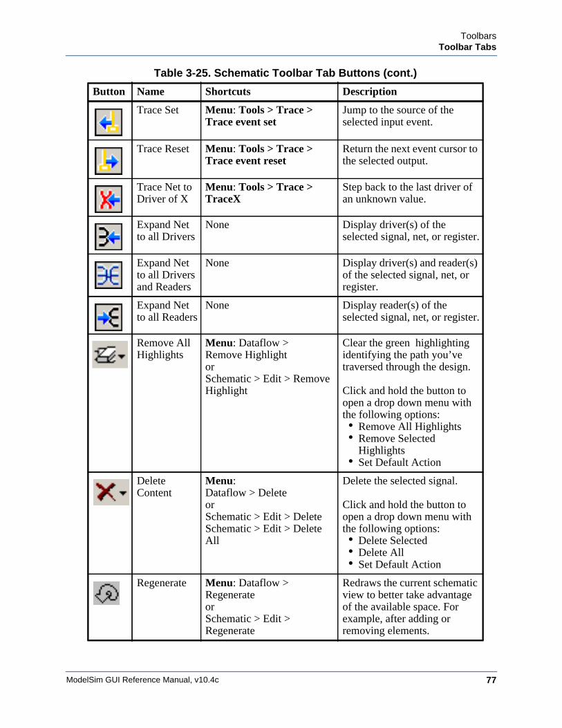
ToolbarsToolbar Tabs
ModelSim GUI Reference Manual, v10.4c 77
Trace Set Menu: Tools > Trace >Trace event set
Jump to the source of the selected input event.
Trace Reset Menu: Tools > Trace >Trace event reset
Return the next event cursor to the selected output.
Trace Net to Driver of X
Menu: Tools > Trace >TraceX
Step back to the last driver of an unknown value.
Expand Net to all Drivers
None Display driver(s) of the selected signal, net, or register.
Expand Net to all Drivers and Readers
None Display driver(s) and reader(s) of the selected signal, net, or register.
Expand Net to all Readers
None Display reader(s) of the selected signal, net, or register.
Remove All Highlights
Menu: Dataflow > Remove Highlight orSchematic > Edit > Remove Highlight
Clear the green highlighting identifying the path you’ve traversed through the design.
Click and hold the button to open a drop down menu with the following options:• Remove All Highlights • Remove Selected
Highlights• Set Default Action
Delete Content
Menu: Dataflow > Delete orSchematic > Edit > DeleteSchematic > Edit > Delete All
Delete the selected signal.
Click and hold the button to open a drop down menu with the following options:• Delete Selected• Delete All• Set Default Action
Regenerate Menu: Dataflow >RegenerateorSchematic > Edit > Regenerate
Redraws the current schematic view to better take advantage of the available space. For example, after adding or removing elements.
Table 3-25. Schematic Toolbar Tab Buttons (cont.)
Button Name Shortcuts Description
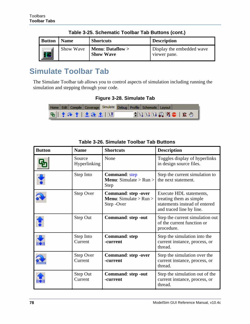
ModelSim GUI Reference Manual, v10.4c78
ToolbarsToolbar Tabs
Simulate Toolbar TabThe Simulate Toolbar tab allows you to control aspects of simulation including running the simulation and stepping through your code.
Figure 3-28. Simulate Tab
Show Wave Menu: Dataflow > Show Wave
Display the embedded wave viewer pane.
Table 3-26. Simulate Toolbar Tab Buttons
Button Name Shortcuts Description
Source Hyperlinking
None Toggles display of hyperlinks in design source files.
Step Into Command: step Menu: Simulate > Run >Step
Step the current simulation to the next statement.
Step Over Command: step -overMenu: Simulate > Run > Step -Over
Execute HDL statements, treating them as simple statements instead of entered and traced line by line.
Step Out Command: step -out Step the current simulation out of the current function or procedure.
Step Into Current
Command: step -current
Step the simulation into the current instance, process, or thread.
Step Over Current
Command: step -over -current
Step the simulation over the current instance, process, or thread.
Step Out Current
Command: step -out -current
Step the simulation out of the current instance, process, or thread.
Table 3-25. Schematic Toolbar Tab Buttons (cont.)
Button Name Shortcuts Description
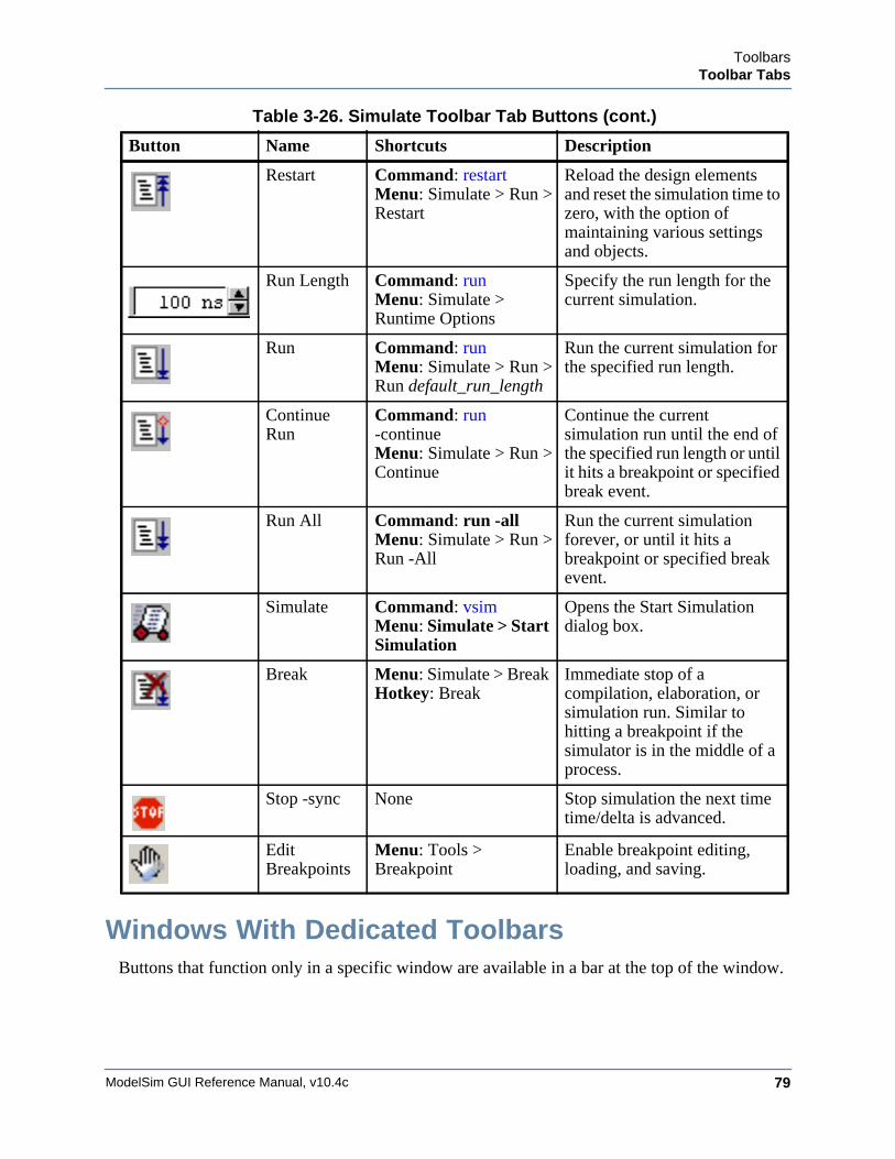
ToolbarsToolbar Tabs
ModelSim GUI Reference Manual, v10.4c 79
Windows With Dedicated ToolbarsButtons that function only in a specific window are available in a bar at the top of the window.
Restart Command: restart Menu: Simulate > Run >Restart
Reload the design elements and reset the simulation time to zero, with the option of maintaining various settings and objects.
Run Length Command: run Menu: Simulate > Runtime Options
Specify the run length for the current simulation.
Run Command: run Menu: Simulate > Run >Run default_run_length
Run the current simulation for the specified run length.
Continue Run
Command: run -continueMenu: Simulate > Run >Continue
Continue the current simulation run until the end of the specified run length or until it hits a breakpoint or specified break event.
Run All Command: run -allMenu: Simulate > Run >Run -All
Run the current simulation forever, or until it hits a breakpoint or specified break event.
Simulate Command: vsim Menu: Simulate > Start Simulation
Opens the Start Simulation dialog box.
Break Menu: Simulate > Break Hotkey: Break
Immediate stop of a compilation, elaboration, or simulation run. Similar to hitting a breakpoint if the simulator is in the middle of a process.
Stop -sync None Stop simulation the next time time/delta is advanced.
Edit Breakpoints
Menu: Tools > Breakpoint
Enable breakpoint editing, loading, and saving.
Table 3-26. Simulate Toolbar Tab Buttons (cont.)
Button Name Shortcuts Description
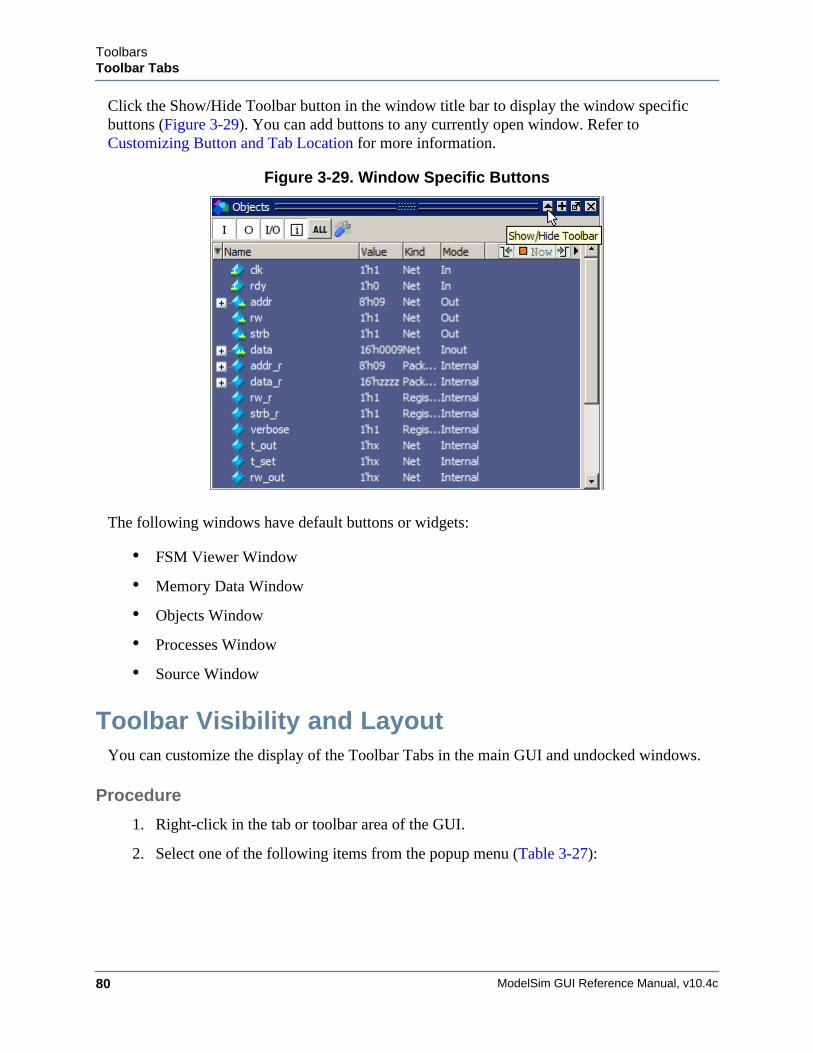
ModelSim GUI Reference Manual, v10.4c80
ToolbarsToolbar Tabs
Click the Show/Hide Toolbar button in the window title bar to display the window specific buttons (Figure 3-29). You can add buttons to any currently open window. Refer to Customizing Button and Tab Location for more information.
Figure 3-29. Window Specific Buttons
The following windows have default buttons or widgets:
• FSM Viewer Window
• Memory Data Window
• Objects Window
• Processes Window
• Source Window
Toolbar Visibility and LayoutYou can customize the display of the Toolbar Tabs in the main GUI and undocked windows.
Procedure
1. Right-click in the tab or toolbar area of the GUI.
2. Select one of the following items from the popup menu (Table 3-27):
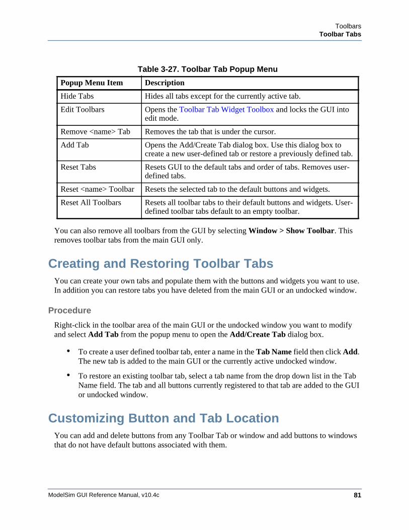
ToolbarsToolbar Tabs
ModelSim GUI Reference Manual, v10.4c 81
You can also remove all toolbars from the GUI by selecting Window > Show Toolbar. This removes toolbar tabs from the main GUI only.
Creating and Restoring Toolbar TabsYou can create your own tabs and populate them with the buttons and widgets you want to use. In addition you can restore tabs you have deleted from the main GUI or an undocked window.
Procedure
Right-click in the toolbar area of the main GUI or the undocked window you want to modify and select Add Tab from the popup menu to open the Add/Create Tab dialog box.
• To create a user defined toolbar tab, enter a name in the Tab Name field then click Add. The new tab is added to the main GUI or the currently active undocked window.
• To restore an existing toolbar tab, select a tab name from the drop down list in the Tab Name field. The tab and all buttons currently registered to that tab are added to the GUI or undocked window.
Customizing Button and Tab LocationYou can add and delete buttons from any Toolbar Tab or window and add buttons to windows that do not have default buttons associated with them.
Table 3-27. Toolbar Tab Popup Menu
Popup Menu Item Description
Hide Tabs Hides all tabs except for the currently active tab.
Edit Toolbars Opens the Toolbar Tab Widget Toolbox and locks the GUI into edit mode.
Remove <name> Tab Removes the tab that is under the cursor.
Add Tab Opens the Add/Create Tab dialog box. Use this dialog box to create a new user-defined tab or restore a previously defined tab.
Reset Tabs Resets GUI to the default tabs and order of tabs. Removes user-defined tabs.
Reset <name> Toolbar Resets the selected tab to the default buttons and widgets.
Reset All Toolbars Resets all toolbar tabs to their default buttons and widgets. User-defined toolbar tabs default to an empty toolbar.
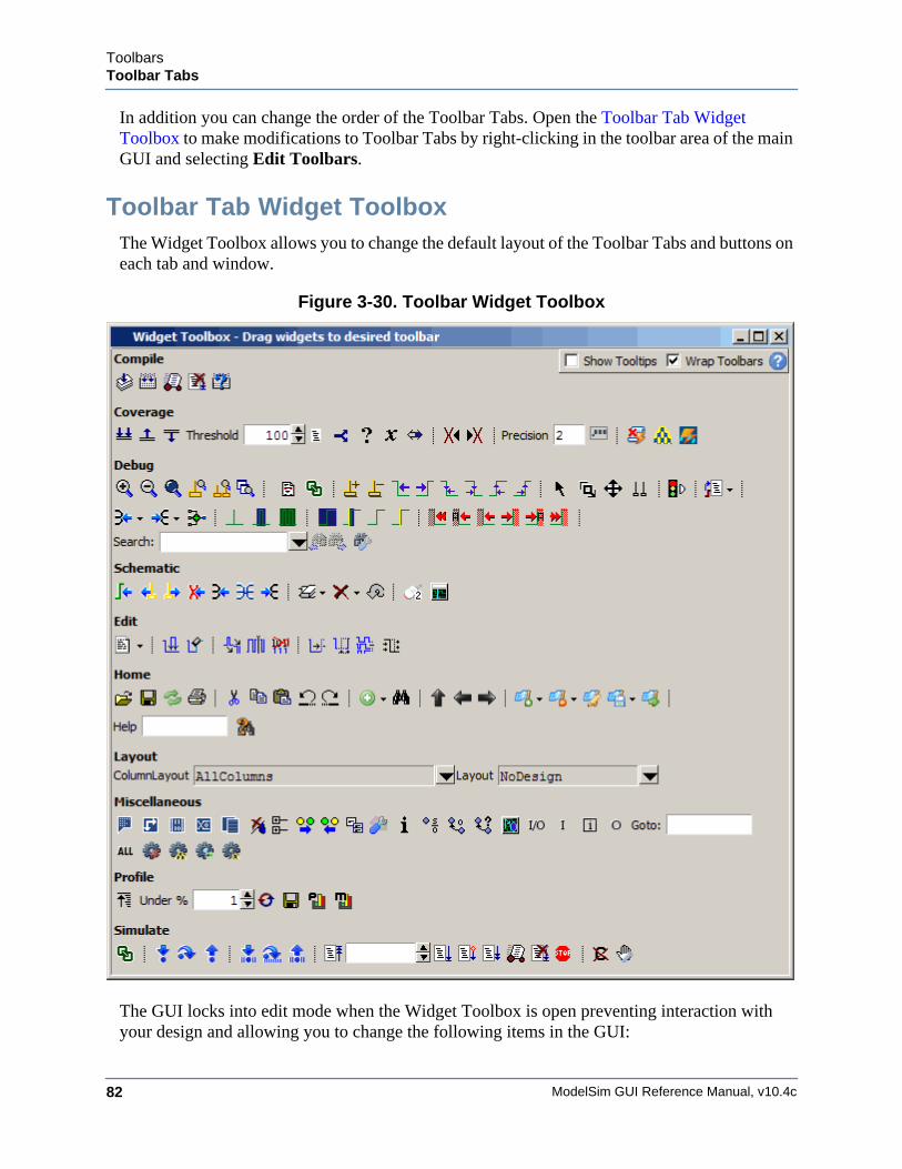
ModelSim GUI Reference Manual, v10.4c82
ToolbarsToolbar Tabs
In addition you can change the order of the Toolbar Tabs. Open the Toolbar Tab Widget Toolbox to make modifications to Toolbar Tabs by right-clicking in the toolbar area of the main GUI and selecting Edit Toolbars.
Toolbar Tab Widget ToolboxThe Widget Toolbox allows you to change the default layout of the Toolbar Tabs and buttons on each tab and window.
Figure 3-30. Toolbar Widget Toolbox
The GUI locks into edit mode when the Widget Toolbox is open preventing interaction with your design and allowing you to change the following items in the GUI:
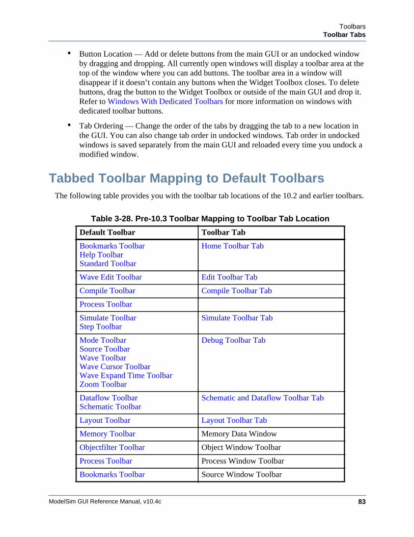
ToolbarsToolbar Tabs
ModelSim GUI Reference Manual, v10.4c 83
• Button Location — Add or delete buttons from the main GUI or an undocked window by dragging and dropping. All currently open windows will display a toolbar area at the top of the window where you can add buttons. The toolbar area in a window will disappear if it doesn’t contain any buttons when the Widget Toolbox closes. To delete buttons, drag the button to the Widget Toolbox or outside of the main GUI and drop it. Refer to Windows With Dedicated Toolbars for more information on windows with dedicated toolbar buttons.
• Tab Ordering — Change the order of the tabs by dragging the tab to a new location in the GUI. You can also change tab order in undocked windows. Tab order in undocked windows is saved separately from the main GUI and reloaded every time you undock a modified window.
Tabbed Toolbar Mapping to Default ToolbarsThe following table provides you with the toolbar tab locations of the 10.2 and earlier toolbars.
Table 3-28. Pre-10.3 Toolbar Mapping to Toolbar Tab Location
Default Toolbar Toolbar Tab
Bookmarks ToolbarHelp ToolbarStandard Toolbar
Home Toolbar Tab
Wave Edit Toolbar Edit Toolbar Tab
Compile Toolbar Compile Toolbar Tab
Process Toolbar
Simulate ToolbarStep Toolbar
Simulate Toolbar Tab
Mode ToolbarSource ToolbarWave ToolbarWave Cursor ToolbarWave Expand Time ToolbarZoom Toolbar
Debug Toolbar Tab
Dataflow ToolbarSchematic Toolbar
Schematic and Dataflow Toolbar Tab
Layout Toolbar Layout Toolbar Tab
Memory Toolbar Memory Data Window
Objectfilter Toolbar Object Window Toolbar
Process Toolbar Process Window Toolbar
Bookmarks Toolbar Source Window Toolbar

ModelSim GUI Reference Manual, v10.4c84
ToolbarsToolbar Tabs
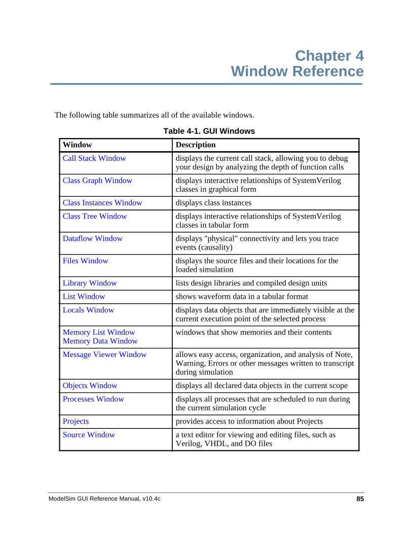
ModelSim GUI Reference Manual, v10.4c 85
Chapter 4Window Reference
The following table summarizes all of the available windows.
Table 4-1. GUI Windows
Window Description
Call Stack Window displays the current call stack, allowing you to debug your design by analyzing the depth of function calls
Class Graph Window displays interactive relationships of SystemVerilog classes in graphical form
Class Instances Window displays class instances
Class Tree Window displays interactive relationships of SystemVerilog classes in tabular form
Dataflow Window displays "physical" connectivity and lets you trace events (causality)
Files Window displays the source files and their locations for the loaded simulation
Library Window lists design libraries and compiled design units
List Window shows waveform data in a tabular format
Locals Window displays data objects that are immediately visible at the current execution point of the selected process
Memory List WindowMemory Data Window
windows that show memories and their contents
Message Viewer Window allows easy access, organization, and analysis of Note, Warning, Errors or other messages written to transcript during simulation
Objects Window displays all declared data objects in the current scope
Processes Window displays all processes that are scheduled to run during the current simulation cycle
Projects provides access to information about Projects
Source Window a text editor for viewing and editing files, such as Verilog, VHDL, and DO files
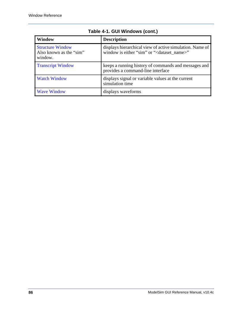
ModelSim GUI Reference Manual, v10.4c86
Window Reference
Structure WindowAlso known as the “sim” window.
displays hierarchical view of active simulation. Name of window is either “sim” or “<dataset_name>”
Transcript Window keeps a running history of commands and messages and provides a command-line interface
Watch Window displays signal or variable values at the current simulation time
Wave Window displays waveforms
Table 4-1. GUI Windows (cont.)
Window Description

Window Reference
ModelSim GUI Reference Manual, v10.4c 87
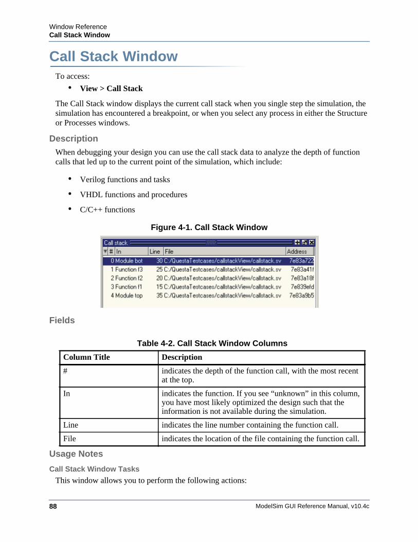
ModelSim GUI Reference Manual, v10.4c88
Window ReferenceCall Stack Window
Call Stack WindowWindow ReferenceTo access:
• View > Call Stack
The Call Stack window displays the current call stack when you single step the simulation, the simulation has encountered a breakpoint, or when you select any process in either the Structure or Processes windows.
Description
When debugging your design you can use the call stack data to analyze the depth of function calls that led up to the current point of the simulation, which include:
• Verilog functions and tasks
• VHDL functions and procedures
• C/C++ functions
Figure 4-1. Call Stack Window
Fields
Usage Notes
Call Stack Window Tasks
This window allows you to perform the following actions:
Table 4-2. Call Stack Window Columns
Column Title Description
# indicates the depth of the function call, with the most recent at the top.
In indicates the function. If you see “unknown” in this column, you have most likely optimized the design such that the information is not available during the simulation.
Line indicates the line number containing the function call.
File indicates the location of the file containing the function call.
Window ReferenceCall Stack Window
ModelSim GUI Reference Manual, v10.4c 89
• Double-click the line of any function call:
o Displays the local variables at that level in the Locals Window.
o Displays the corresponding source code in the Source Window.
Related Commands of the Call Stack Window
Table 4-3. Commands Related to the Call Stack Window
Command Name Description
stack down This command moves down the call stack.
stack frame This command selects the specified call frame.
stack level This command reports the current call frame number.
stack tb This command is an alias for the tb command.
stack up This command moves up the call stack.

ModelSim GUI Reference Manual, v10.4c90
Window ReferenceCall Stack Window
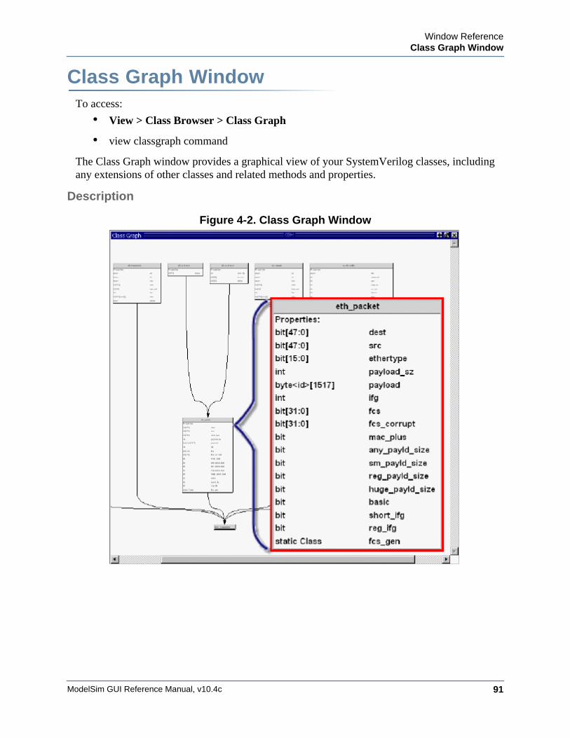
Window ReferenceClass Graph Window
ModelSim GUI Reference Manual, v10.4c 91
Class Graph WindowWindow ReferenceTo access:
• View > Class Browser > Class Graph
• view classgraph command
The Class Graph window provides a graphical view of your SystemVerilog classes, including any extensions of other classes and related methods and properties.
Description
Figure 4-2. Class Graph Window
ModelSim GUI Reference Manual, v10.4c92
Window ReferenceClass Graph Window
Fields
Usage Notes
Class Graph Window Tasks
This section describes tasks for using the Cover Directives window.
Navigating in the Class Graph Window
You can change the view of the Class Graph window with your mouse or the arrow keys on your keyboard.
• Left click-drag — Allows you to move the contents around in the window.
• Middle Mouse scroll — Zooms in and out.
• Middle mouse button strokes:
o Upper left — Zoom full
o Upper right — Zoom out. The length of the stroke changes the zoom factor.
o Lower right — Zoom area.
• Arrow Keys — Scrolls the window in the specified direction.
o Unmodified — Scrolls by a small amount.
o Ctrl+<arrow key> — Scrolls by a larger amount
o Shift+<arrow key> — Shifts the view to the edge of the display
Table 4-4. Class Graph Window Popup Menu
Popup Menu Item Description
Filter Controls the display of methods and properties from the class boxes.
Zoom Full
View Entire Design Reloads the view to show the class hierarchy of the complete design.
Print to Postscript
Organize by Base/Extended Class
Reorganizes the window so that the base or extended (default) classes are at the top of the hierarchy.
Window ReferenceClass Instances Window
ModelSim GUI Reference Manual, v10.4c 93
Class Instances WindowWindow ReferenceTo access:
• View > Class Browser > Class Instances
• view classinstances command
The Class Instances window shows the list of class instances and their values for a particular selected class type. You may add the class items directly to the wave or list windows, log them, or get other information about them.
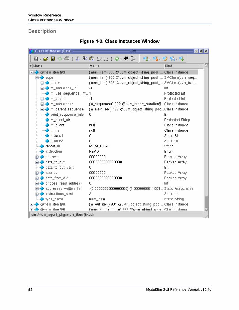
ModelSim GUI Reference Manual, v10.4c94
Window ReferenceClass Instances Window
Description
Figure 4-3. Class Instances Window
Window ReferenceClass Instances Window
ModelSim GUI Reference Manual, v10.4c 95
Fields
Usage Notes
Viewing Class Instances
The Class Instances window is dynamically populated by selecting SVClasses in the Structure (sim) window. All currently active instances of the selected class are displayed in the Class Instances window. Class instances that have not yet come into existence or have been destroyed are not displayed.
Once you have chosen the class type you want to observe, you can fix that instance in the window while you debug by choosing File > Environment > Fix to Current Context.
Class Naming Format
Class instance names are formatted as follows: @<class_type>@<nnn> where @<class_type>@ is the name of the class type and <n> is the reference identifier for a particular instance of the class type. For example, @uvm_queue_3@14 is the 14th instance of the class uvm_queue_3.
Table 4-5. Class Instances Window Popup Menu
Popup Menu Item Description
View Declaration Highlights the line of code where the type of the instance is declared, opening the source file if necessary.
Add Wave Adds the selected class instance to the Wave window.
Add to Allows you to log the selected class instance, or add it to the Wave or List windows.
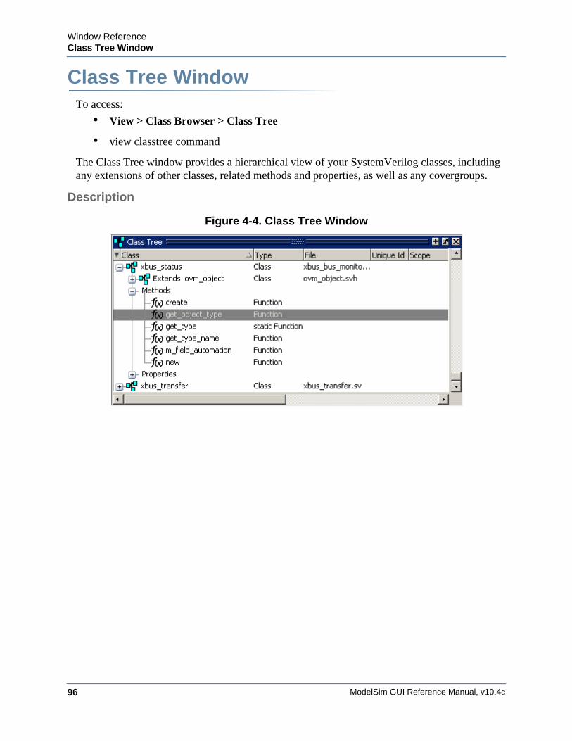
ModelSim GUI Reference Manual, v10.4c96
Window ReferenceClass Tree Window
Class Tree WindowWindow ReferenceTo access:
• View > Class Browser > Class Tree
• view classtree command
The Class Tree window provides a hierarchical view of your SystemVerilog classes, including any extensions of other classes, related methods and properties, as well as any covergroups.
Description
Figure 4-4. Class Tree Window
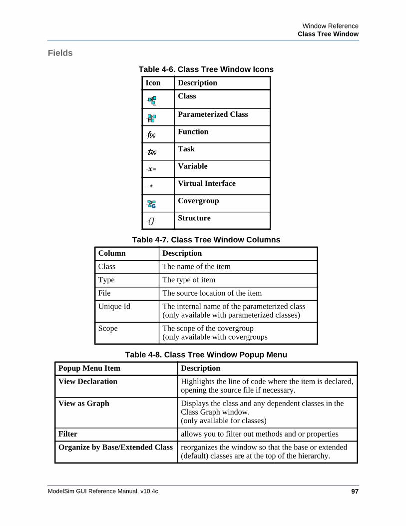
Window ReferenceClass Tree Window
ModelSim GUI Reference Manual, v10.4c 97
Fields
Table 4-6. Class Tree Window Icons
Icon Description
Class
Parameterized Class
Function
Task
Variable
Virtual Interface
Covergroup
Structure
Table 4-7. Class Tree Window Columns
Column Description
Class The name of the item
Type The type of item
File The source location of the item
Unique Id The internal name of the parameterized class(only available with parameterized classes)
Scope The scope of the covergroup (only available with covergroups
Table 4-8. Class Tree Window Popup Menu
Popup Menu Item Description
View Declaration Highlights the line of code where the item is declared, opening the source file if necessary.
View as Graph Displays the class and any dependent classes in the Class Graph window.(only available for classes)
Filter allows you to filter out methods and or properties
Organize by Base/Extended Class reorganizes the window so that the base or extended (default) classes are at the top of the hierarchy.

ModelSim GUI Reference Manual, v10.4c98
Window ReferenceClass Tree Window
ModelSim GUI Reference Manual, v10.4c 99
Dataflow WindowWindow ReferenceTo access:
• View > Dataflow
• view dataflow command
Use this window to explore the "physical" connectivity of your design. You can also use it to trace events that propagate through the design; and to identify the cause of unexpected outputs.
Description
The Dataflow window displays:
• processes
• signals, nets, and registers
The window has built-in mappings for all Verilog primitive gates (such as AND, OR, PMOS, NMOS). For components other than Verilog primitives, you can define a mapping between processes and built-in symbols. See Symbol Mapping for details.
Note
NoteThis version of ModelSim has limited Dataflow functionality resulting in many of the features described in this chapter operating differently. The window will show only one process and its attached signals or one signal and its attached processes, as displayed in Figure 4-5.
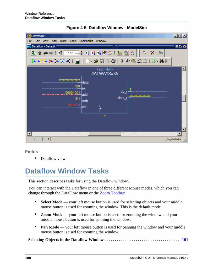
ModelSim GUI Reference Manual, v10.4c100
Window ReferenceDataflow Window Tasks
Figure 4-5. Dataflow Window - ModelSim
Fields• Dataflow view
Dataflow Window TasksThis section describes tasks for using the Dataflow window.
You can interact with the Dataflow in one of three different Mouse modes, which you can change through the DataFlow menu or the Zoom Toolbar:
• Select Mode — your left mouse button is used for selecting objects and your middle mouse button is used for zooming the window. This is the default mode.
• Zoom Mode — your left mouse button is used for zooming the window and your middle mouse button is used for panning the window.
• Pan Mode — your left mouse button is used for panning the window and your middle mouse button is used for zooming the window.
Selecting Objects in the Dataflow Window . . . . . . . . . . . . . . . . . . . . . . . . . . . . . . . . . . . . 101
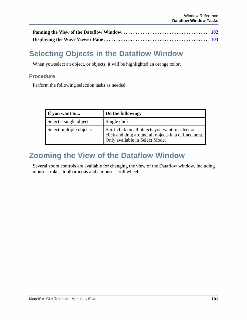
Window ReferenceDataflow Window Tasks
ModelSim GUI Reference Manual, v10.4c 101
Panning the View of the Dataflow Window. . . . . . . . . . . . . . . . . . . . . . . . . . . . . . . . . . . . 102
Displaying the Wave Viewer Pane . . . . . . . . . . . . . . . . . . . . . . . . . . . . . . . . . . . . . . . . . . . 103
Selecting Objects in the Dataflow WindowWhen you select an object, or objects, it will be highlighted an orange color.
Procedure
Perform the following selection tasks as needed:
Zooming the View of the Dataflow WindowSeveral zoom controls are available for changing the view of the Dataflow window, including mouse strokes, toolbar icons and a mouse scroll wheel.
If you want to... Do the following:
Select a single object Single click
Select multiple objects Shift-click on all objects you want to select or click and drag around all objects in a defined area. Only available in Select Mode.
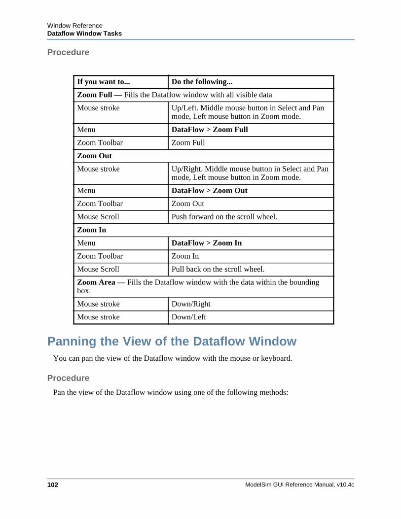
ModelSim GUI Reference Manual, v10.4c102
Window ReferenceDataflow Window Tasks
Procedure
Panning the View of the Dataflow WindowYou can pan the view of the Dataflow window with the mouse or keyboard.
Procedure
Pan the view of the Dataflow window using one of the following methods:
If you want to... Do the following...
Zoom Full — Fills the Dataflow window with all visible data
Mouse stroke Up/Left. Middle mouse button in Select and Pan mode, Left mouse button in Zoom mode.
Menu DataFlow > Zoom Full
Zoom Toolbar Zoom Full
Zoom Out
Mouse stroke Up/Right. Middle mouse button in Select and Pan mode, Left mouse button in Zoom mode.
Menu DataFlow > Zoom Out
Zoom Toolbar Zoom Out
Mouse Scroll Push forward on the scroll wheel.
Zoom In
Menu DataFlow > Zoom In
Zoom Toolbar Zoom In
Mouse Scroll Pull back on the scroll wheel.
Zoom Area — Fills the Dataflow window with the data within the bounding box.
Mouse stroke Down/Right
Mouse stroke Down/Left
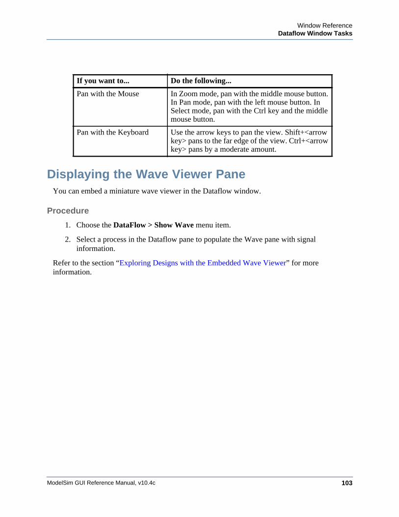
Window ReferenceDataflow Window Tasks
ModelSim GUI Reference Manual, v10.4c 103
Displaying the Wave Viewer PaneYou can embed a miniature wave viewer in the Dataflow window.
Procedure
1. Choose the DataFlow > Show Wave menu item.
2. Select a process in the Dataflow pane to populate the Wave pane with signal information.
Refer to the section “Exploring Designs with the Embedded Wave Viewer” for more information.
If you want to... Do the following...
Pan with the Mouse In Zoom mode, pan with the middle mouse button. In Pan mode, pan with the left mouse button. In Select mode, pan with the Ctrl key and the middle mouse button.
Pan with the Keyboard Use the arrow keys to pan the view. Shift+<arrow key> pans to the far edge of the view. Ctrl+<arrow key> pans by a moderate amount.
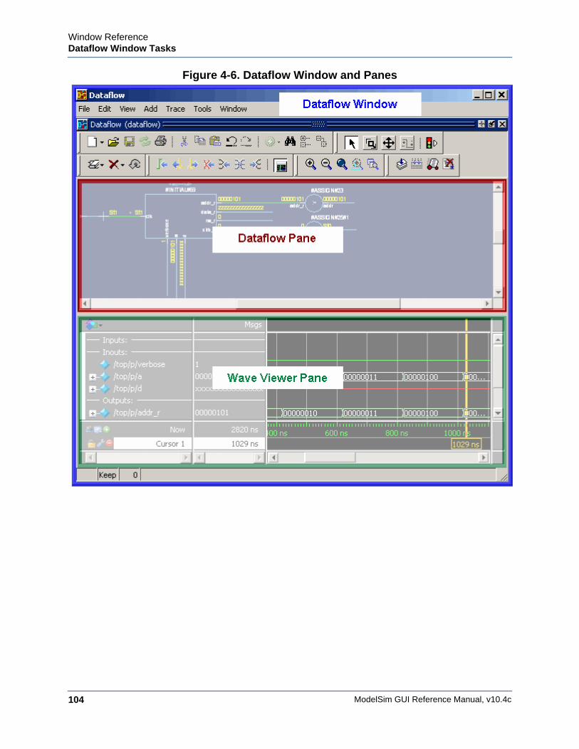
ModelSim GUI Reference Manual, v10.4c104
Window ReferenceDataflow Window Tasks
Figure 4-6. Dataflow Window and Panes

Window ReferenceDataflow Window Tasks
ModelSim GUI Reference Manual, v10.4c 105
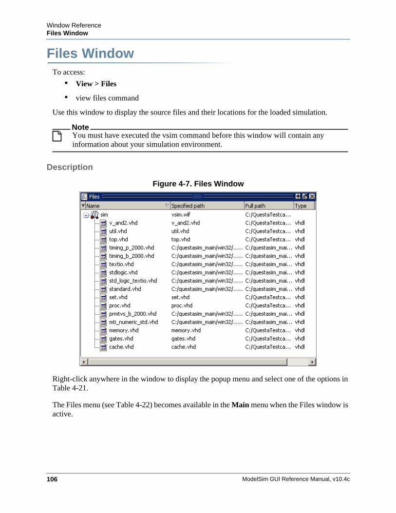
ModelSim GUI Reference Manual, v10.4c106
Window ReferenceFiles Window
Files WindowWindow ReferenceTo access:
• View > Files
• view files command
Use this window to display the source files and their locations for the loaded simulation.
NoteYou must have executed the vsim command before this window will contain any information about your simulation environment.
Description
Figure 4-7. Files Window
Right-click anywhere in the window to display the popup menu and select one of the options in Table 4-21.
The Files menu (see Table 4-22) becomes available in the Main menu when the Files window is active.
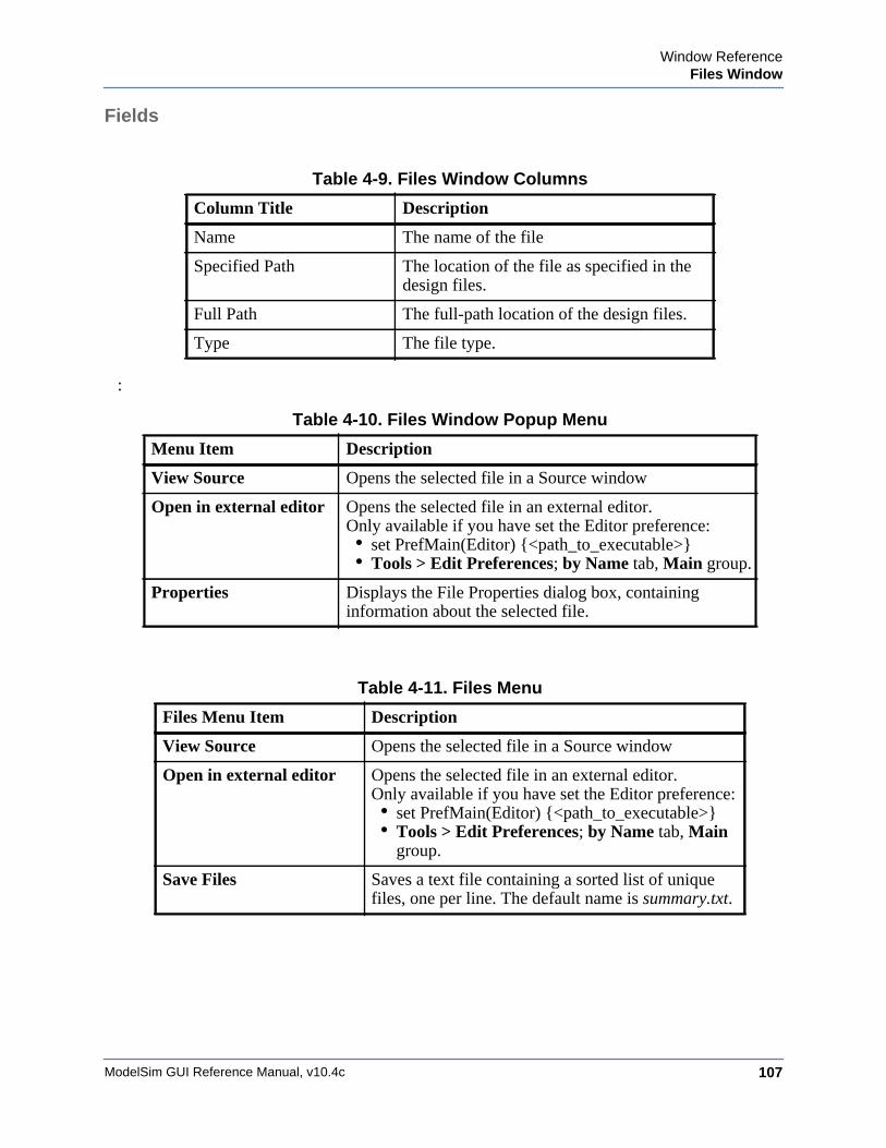
Window ReferenceFiles Window
ModelSim GUI Reference Manual, v10.4c 107
Fields
:
Table 4-9. Files Window Columns
Column Title Description
Name The name of the file
Specified Path The location of the file as specified in the design files.
Full Path The full-path location of the design files.
Type The file type.
Table 4-10. Files Window Popup Menu
Menu Item Description
View Source Opens the selected file in a Source window
Open in external editor Opens the selected file in an external editor. Only available if you have set the Editor preference:• set PrefMain(Editor) {<path_to_executable>}• Tools > Edit Preferences; by Name tab, Main group.
Properties Displays the File Properties dialog box, containing information about the selected file.
Table 4-11. Files Menu
Files Menu Item Description
View Source Opens the selected file in a Source window
Open in external editor Opens the selected file in an external editor.Only available if you have set the Editor preference:• set PrefMain(Editor) {<path_to_executable>}• Tools > Edit Preferences; by Name tab, Main
group.
Save Files Saves a text file containing a sorted list of unique files, one per line. The default name is summary.txt.

ModelSim GUI Reference Manual, v10.4c108
Window ReferenceFiles Window
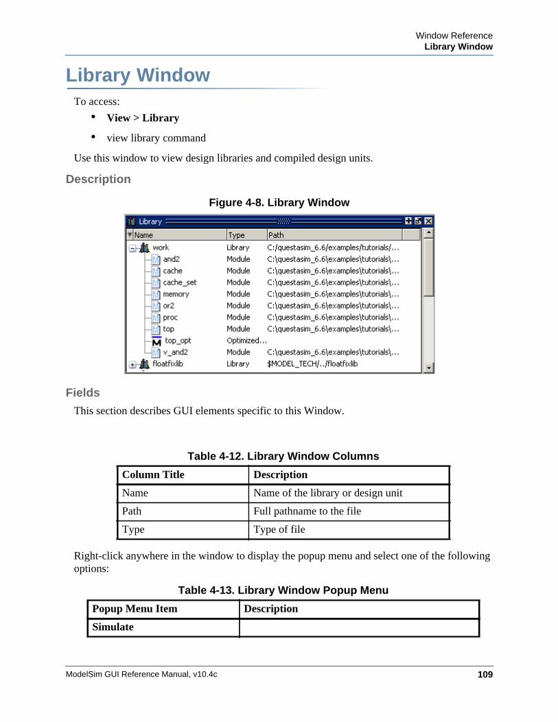
Window ReferenceLibrary Window
ModelSim GUI Reference Manual, v10.4c 109
Library WindowWindow ReferenceTo access:
• View > Library
• view library command
Use this window to view design libraries and compiled design units.
Description
Figure 4-8. Library Window
Fields
This section describes GUI elements specific to this Window.
Right-click anywhere in the window to display the popup menu and select one of the following options:
Table 4-12. Library Window Columns
Column Title Description
Name Name of the library or design unit
Path Full pathname to the file
Type Type of file
Table 4-13. Library Window Popup Menu
Popup Menu Item Description
Simulate
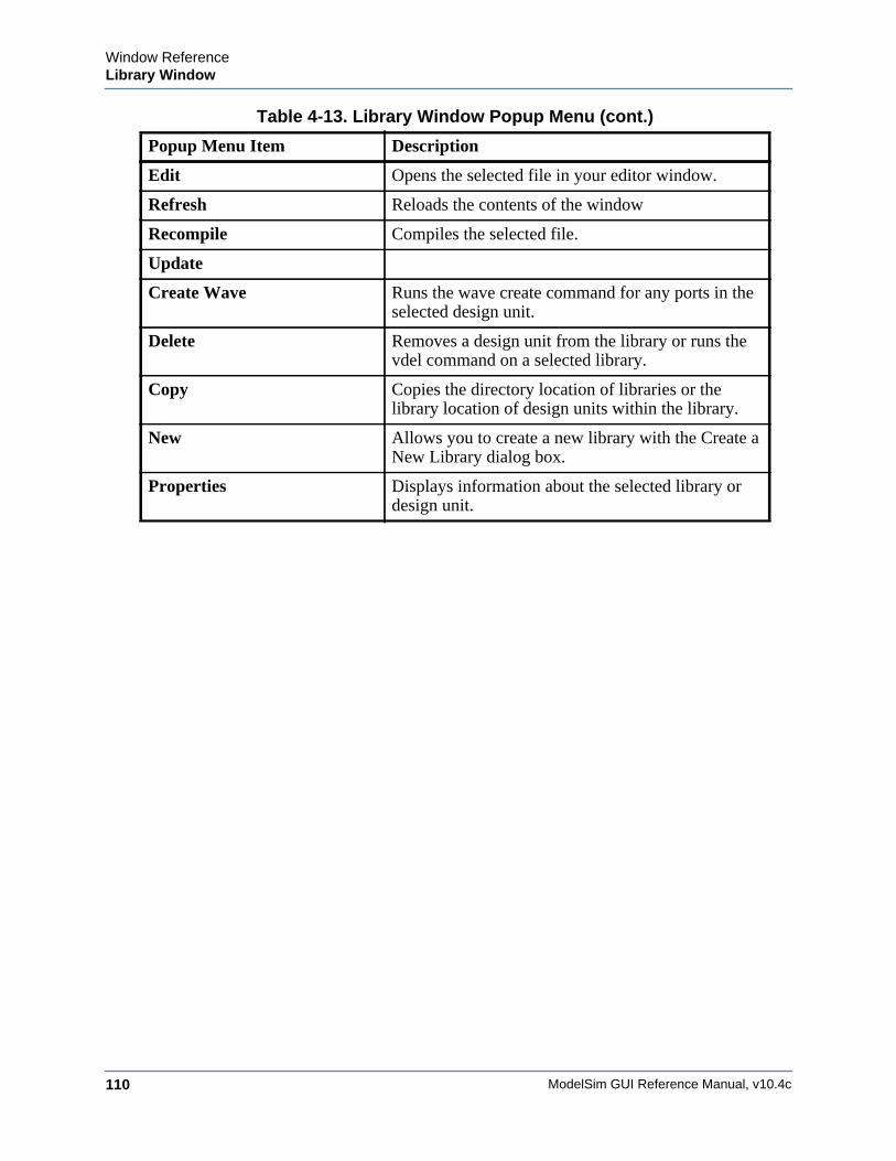
ModelSim GUI Reference Manual, v10.4c110
Window ReferenceLibrary Window
Edit Opens the selected file in your editor window.
Refresh Reloads the contents of the window
Recompile Compiles the selected file.
Update
Create Wave Runs the wave create command for any ports in the selected design unit.
Delete Removes a design unit from the library or runs the vdel command on a selected library.
Copy Copies the directory location of libraries or the library location of design units within the library.
New Allows you to create a new library with the Create a New Library dialog box.
Properties Displays information about the selected library or design unit.
Table 4-13. Library Window Popup Menu (cont.)
Popup Menu Item Description
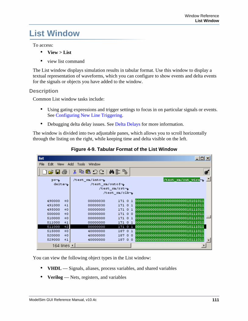
Window ReferenceList Window
ModelSim GUI Reference Manual, v10.4c 111
List WindowWindow ReferenceTo access:
• View > List
• view list command
The List window displays simulation results in tabular format. Use this window to display a textual representation of waveforms, which you can configure to show events and delta events for the signals or objects you have added to the window.
Description
Common List window tasks include:
• Using gating expressions and trigger settings to focus in on particular signals or events. See Configuring New Line Triggering.
• Debugging delta delay issues. See Delta Delays for more information.
The window is divided into two adjustable panes, which allows you to scroll horizontally through the listing on the right, while keeping time and delta visible on the left.
Figure 4-9. Tabular Format of the List Window
You can view the following object types in the List window:
• VHDL — Signals, aliases, process variables, and shared variables
• Verilog — Nets, registers, and variables
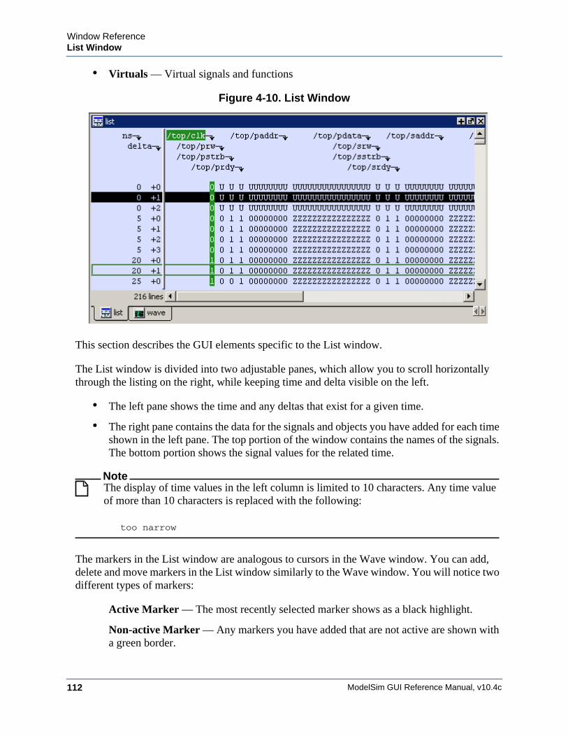
ModelSim GUI Reference Manual, v10.4c112
Window ReferenceList Window
• Virtuals — Virtual signals and functions
Figure 4-10. List Window
This section describes the GUI elements specific to the List window.
The List window is divided into two adjustable panes, which allow you to scroll horizontally through the listing on the right, while keeping time and delta visible on the left.
• The left pane shows the time and any deltas that exist for a given time.
• The right pane contains the data for the signals and objects you have added for each time shown in the left pane. The top portion of the window contains the names of the signals. The bottom portion shows the signal values for the related time.
NoteThe display of time values in the left column is limited to 10 characters. Any time value of more than 10 characters is replaced with the following:
too narrow
The markers in the List window are analogous to cursors in the Wave window. You can add, delete and move markers in the List window similarly to the Wave window. You will notice two different types of markers:
Active Marker — The most recently selected marker shows as a black highlight.
Non-active Marker — Any markers you have added that are not active are shown with a green border.
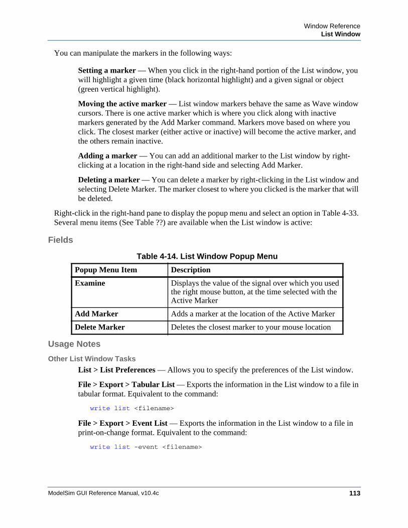
Window ReferenceList Window
ModelSim GUI Reference Manual, v10.4c 113
You can manipulate the markers in the following ways:
Setting a marker — When you click in the right-hand portion of the List window, you will highlight a given time (black horizontal highlight) and a given signal or object (green vertical highlight).
Moving the active marker — List window markers behave the same as Wave window cursors. There is one active marker which is where you click along with inactive markers generated by the Add Marker command. Markers move based on where you click. The closest marker (either active or inactive) will become the active marker, and the others remain inactive.
Adding a marker — You can add an additional marker to the List window by right-clicking at a location in the right-hand side and selecting Add Marker.
Deleting a marker — You can delete a marker by right-clicking in the List window and selecting Delete Marker. The marker closest to where you clicked is the marker that will be deleted.
Right-click in the right-hand pane to display the popup menu and select an option in Table 4-33. Several menu items (See Table ??) are available when the List window is active:
Fields
Usage Notes
Other List Window Tasks
List > List Preferences — Allows you to specify the preferences of the List window.
File > Export > Tabular List — Exports the information in the List window to a file in tabular format. Equivalent to the command:
write list <filename>
File > Export > Event List — Exports the information in the List window to a file in print-on-change format. Equivalent to the command:
write list -event <filename>
Table 4-14. List Window Popup Menu
Popup Menu Item Description
Examine Displays the value of the signal over which you used the right mouse button, at the time selected with the Active Marker
Add Marker Adds a marker at the location of the Active Marker
Delete Marker Deletes the closest marker to your mouse location
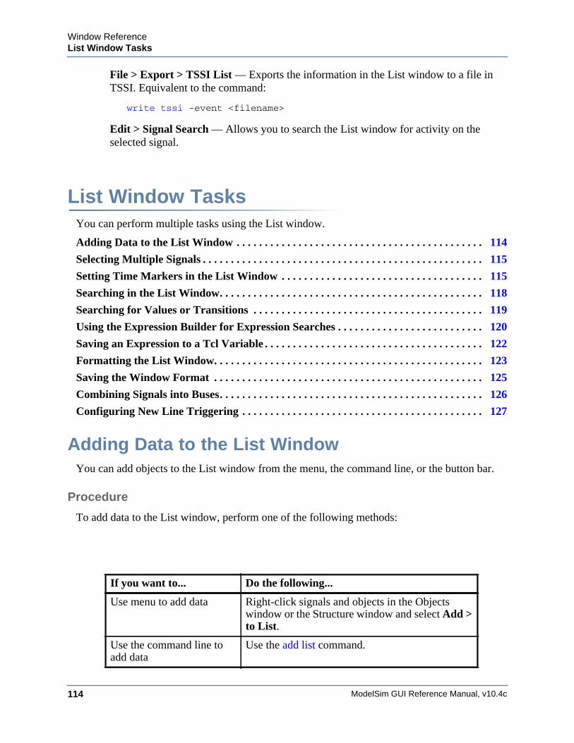
ModelSim GUI Reference Manual, v10.4c114
Window ReferenceList Window Tasks
File > Export > TSSI List — Exports the information in the List window to a file in TSSI. Equivalent to the command:
write tssi -event <filename>
Edit > Signal Search — Allows you to search the List window for activity on the selected signal.
List Window TasksYou can perform multiple tasks using the List window.
Adding Data to the List Window . . . . . . . . . . . . . . . . . . . . . . . . . . . . . . . . . . . . . . . . . . . . 114
Selecting Multiple Signals . . . . . . . . . . . . . . . . . . . . . . . . . . . . . . . . . . . . . . . . . . . . . . . . . . 115
Setting Time Markers in the List Window . . . . . . . . . . . . . . . . . . . . . . . . . . . . . . . . . . . . 115
Searching in the List Window. . . . . . . . . . . . . . . . . . . . . . . . . . . . . . . . . . . . . . . . . . . . . . . 118
Searching for Values or Transitions . . . . . . . . . . . . . . . . . . . . . . . . . . . . . . . . . . . . . . . . . 119
Using the Expression Builder for Expression Searches . . . . . . . . . . . . . . . . . . . . . . . . . . 120
Saving an Expression to a Tcl Variable . . . . . . . . . . . . . . . . . . . . . . . . . . . . . . . . . . . . . . . 122
Formatting the List Window. . . . . . . . . . . . . . . . . . . . . . . . . . . . . . . . . . . . . . . . . . . . . . . . 123
Saving the Window Format . . . . . . . . . . . . . . . . . . . . . . . . . . . . . . . . . . . . . . . . . . . . . . . . 125
Combining Signals into Buses. . . . . . . . . . . . . . . . . . . . . . . . . . . . . . . . . . . . . . . . . . . . . . . 126
Configuring New Line Triggering . . . . . . . . . . . . . . . . . . . . . . . . . . . . . . . . . . . . . . . . . . . 127
Adding Data to the List WindowYou can add objects to the List window from the menu, the command line, or the button bar.
Procedure
To add data to the List window, perform one of the following methods:
If you want to... Do the following...
Use menu to add data Right-click signals and objects in the Objects window or the Structure window and select Add > to List.
Use the command line to add data
Use the add list command.
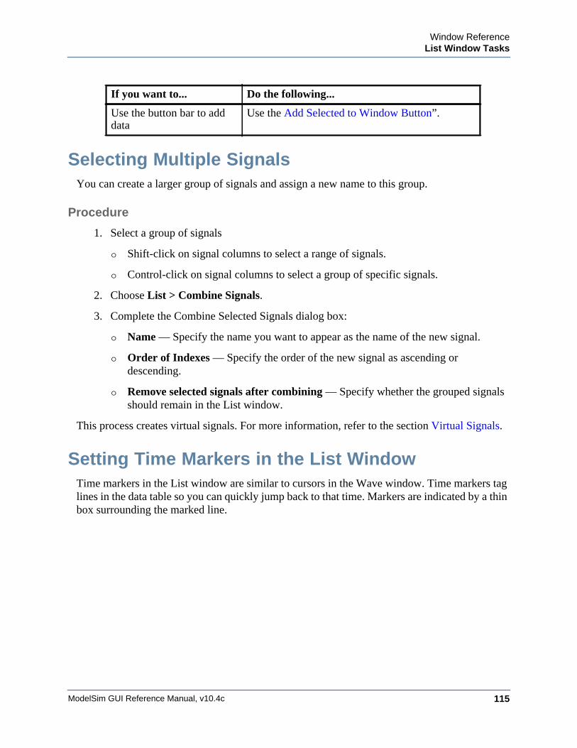
Window ReferenceList Window Tasks
ModelSim GUI Reference Manual, v10.4c 115
Selecting Multiple SignalsYou can create a larger group of signals and assign a new name to this group.
Procedure
1. Select a group of signals
o Shift-click on signal columns to select a range of signals.
o Control-click on signal columns to select a group of specific signals.
2. Choose List > Combine Signals.
3. Complete the Combine Selected Signals dialog box:
o Name — Specify the name you want to appear as the name of the new signal.
o Order of Indexes — Specify the order of the new signal as ascending or descending.
o Remove selected signals after combining — Specify whether the grouped signals should remain in the List window.
This process creates virtual signals. For more information, refer to the section Virtual Signals.
Setting Time Markers in the List WindowTime markers in the List window are similar to cursors in the Wave window. Time markers tag lines in the data table so you can quickly jump back to that time. Markers are indicated by a thin box surrounding the marked line.
Use the button bar to add data
Use the Add Selected to Window Button”.
If you want to... Do the following...
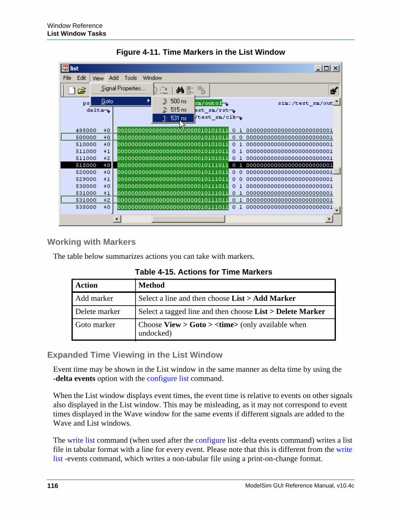
ModelSim GUI Reference Manual, v10.4c116
Window ReferenceList Window Tasks
Figure 4-11. Time Markers in the List Window
Working with Markers
The table below summarizes actions you can take with markers.
Expanded Time Viewing in the List Window
Event time may be shown in the List window in the same manner as delta time by using the -delta events option with the configure list command.
When the List window displays event times, the event time is relative to events on other signals also displayed in the List window. This may be misleading, as it may not correspond to event times displayed in the Wave window for the same events if different signals are added to the Wave and List windows.
The write list command (when used after the configure list -delta events command) writes a list file in tabular format with a line for every event. Please note that this is different from the write list -events command, which writes a non-tabular file using a print-on-change format.
Table 4-15. Actions for Time Markers
Action Method
Add marker Select a line and then choose List > Add Marker
Delete marker Select a tagged line and then choose List > Delete Marker
Goto marker Choose View > Goto > <time> (only available when undocked)
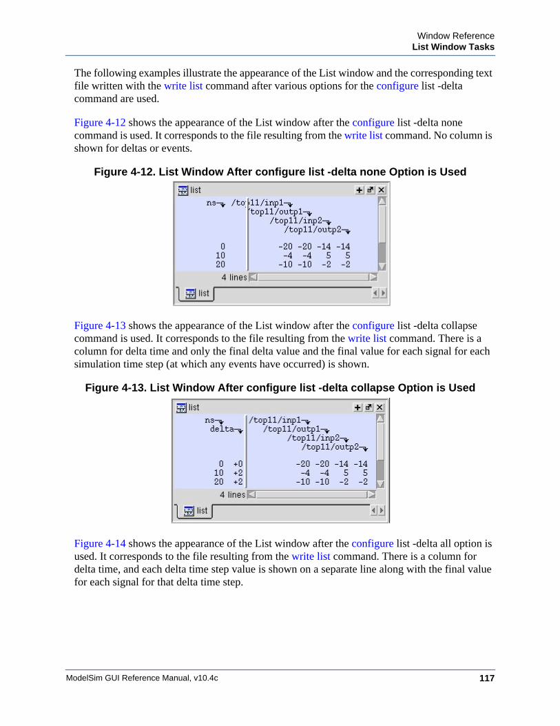
Window ReferenceList Window Tasks
ModelSim GUI Reference Manual, v10.4c 117
The following examples illustrate the appearance of the List window and the corresponding text file written with the write list command after various options for the configure list -delta command are used.
Figure 4-12 shows the appearance of the List window after the configure list -delta none command is used. It corresponds to the file resulting from the write list command. No column is shown for deltas or events.
Figure 4-12. List Window After configure list -delta none Option is Used
Figure 4-13 shows the appearance of the List window after the configure list -delta collapse command is used. It corresponds to the file resulting from the write list command. There is a column for delta time and only the final delta value and the final value for each signal for each simulation time step (at which any events have occurred) is shown.
Figure 4-13. List Window After configure list -delta collapse Option is Used
Figure 4-14 shows the appearance of the List window after the configure list -delta all option is used. It corresponds to the file resulting from the write list command. There is a column for delta time, and each delta time step value is shown on a separate line along with the final value for each signal for that delta time step.
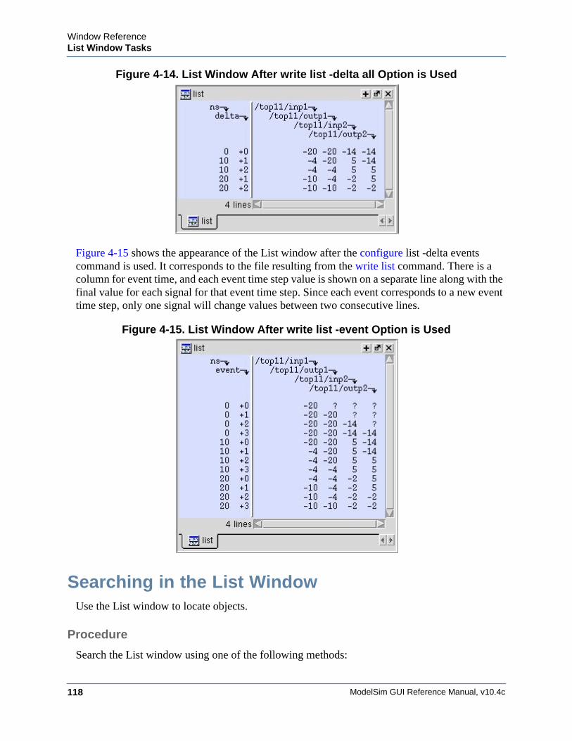
ModelSim GUI Reference Manual, v10.4c118
Window ReferenceList Window Tasks
Figure 4-14. List Window After write list -delta all Option is Used
Figure 4-15 shows the appearance of the List window after the configure list -delta events command is used. It corresponds to the file resulting from the write list command. There is a column for event time, and each event time step value is shown on a separate line along with the final value for each signal for that event time step. Since each event corresponds to a new event time step, only one signal will change values between two consecutive lines.
Figure 4-15. List Window After write list -event Option is Used
Searching in the List WindowUse the List window to locate objects.
Procedure
Search the List window using one of the following methods:
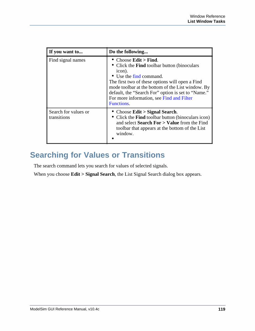
Window ReferenceList Window Tasks
ModelSim GUI Reference Manual, v10.4c 119
Searching for Values or TransitionsThe search command lets you search for values of selected signals.
When you choose Edit > Signal Search, the List Signal Search dialog box appears.
If you want to... Do the following...
Find signal names • Choose Edit > Find.• Click the Find toolbar button (binoculars
icon). • Use the find command.
The first two of these options will open a Find mode toolbar at the bottom of the List window. By default, the “Search For” option is set to “Name.” For more information, see Find and Filter Functions.
Search for values or transitions
• Choose Edit > Signal Search.• Click the Find toolbar button (binoculars icon)
and select Search For > Value from the Find toolbar that appears at the bottom of the List window.
•
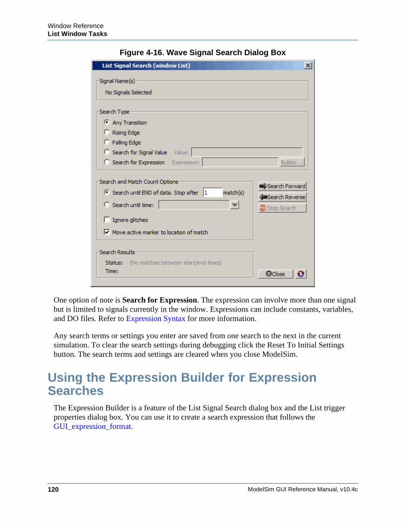
ModelSim GUI Reference Manual, v10.4c120
Window ReferenceList Window Tasks
Figure 4-16. Wave Signal Search Dialog Box
One option of note is Search for Expression. The expression can involve more than one signal but is limited to signals currently in the window. Expressions can include constants, variables, and DO files. Refer to Expression Syntax for more information.
Any search terms or settings you enter are saved from one search to the next in the current simulation. To clear the search settings during debugging click the Reset To Initial Settings button. The search terms and settings are cleared when you close ModelSim.
Using the Expression Builder for Expression Searches
The Expression Builder is a feature of the List Signal Search dialog box and the List trigger properties dialog box. You can use it to create a search expression that follows the GUI_expression_format.
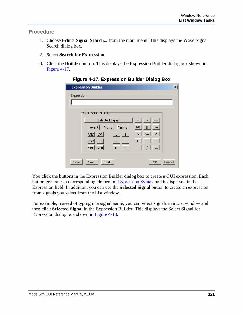
Window ReferenceList Window Tasks
ModelSim GUI Reference Manual, v10.4c 121
Procedure
1. Choose Edit > Signal Search... from the main menu. This displays the Wave Signal Search dialog box.
2. Select Search for Expression.
3. Click the Builder button. This displays the Expression Builder dialog box shown in Figure 4-17.
Figure 4-17. Expression Builder Dialog Box
You click the buttons in the Expression Builder dialog box to create a GUI expression. Each button generates a corresponding element of Expression Syntax and is displayed in the Expression field. In addition, you can use the Selected Signal button to create an expression from signals you select from the List window.
For example, instead of typing in a signal name, you can select signals in a List window and then click Selected Signal in the Expression Builder. This displays the Select Signal for Expression dialog box shown in Figure 4-18.
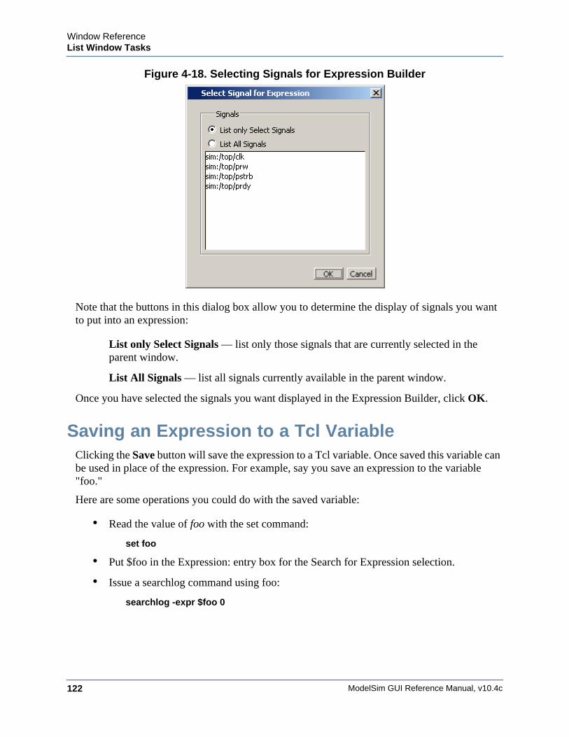
ModelSim GUI Reference Manual, v10.4c122
Window ReferenceList Window Tasks
Figure 4-18. Selecting Signals for Expression Builder
Note that the buttons in this dialog box allow you to determine the display of signals you want to put into an expression:
List only Select Signals — list only those signals that are currently selected in the parent window.
List All Signals — list all signals currently available in the parent window.
Once you have selected the signals you want displayed in the Expression Builder, click OK.
Saving an Expression to a Tcl VariableClicking the Save button will save the expression to a Tcl variable. Once saved this variable can be used in place of the expression. For example, say you save an expression to the variable "foo."
Here are some operations you could do with the saved variable:
• Read the value of foo with the set command:
set foo
• Put $foo in the Expression: entry box for the Search for Expression selection.
• Issue a searchlog command using foo:
searchlog -expr $foo 0
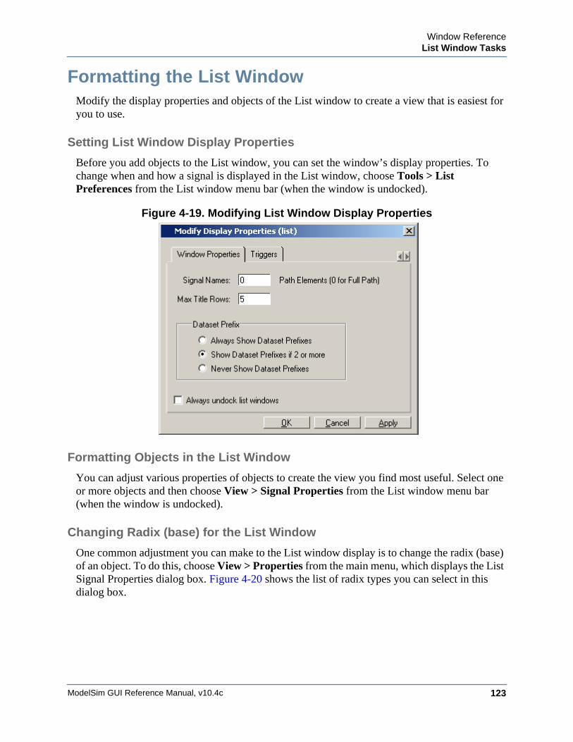
Window ReferenceList Window Tasks
ModelSim GUI Reference Manual, v10.4c 123
Formatting the List WindowModify the display properties and objects of the List window to create a view that is easiest for you to use.
Setting List Window Display Properties
Before you add objects to the List window, you can set the window’s display properties. To change when and how a signal is displayed in the List window, choose Tools > List Preferences from the List window menu bar (when the window is undocked).
Figure 4-19. Modifying List Window Display Properties
Formatting Objects in the List Window
You can adjust various properties of objects to create the view you find most useful. Select one or more objects and then choose View > Signal Properties from the List window menu bar (when the window is undocked).
Changing Radix (base) for the List Window
One common adjustment you can make to the List window display is to change the radix (base) of an object. To do this, choose View > Properties from the main menu, which displays the List Signal Properties dialog box. Figure 4-20 shows the list of radix types you can select in this dialog box.
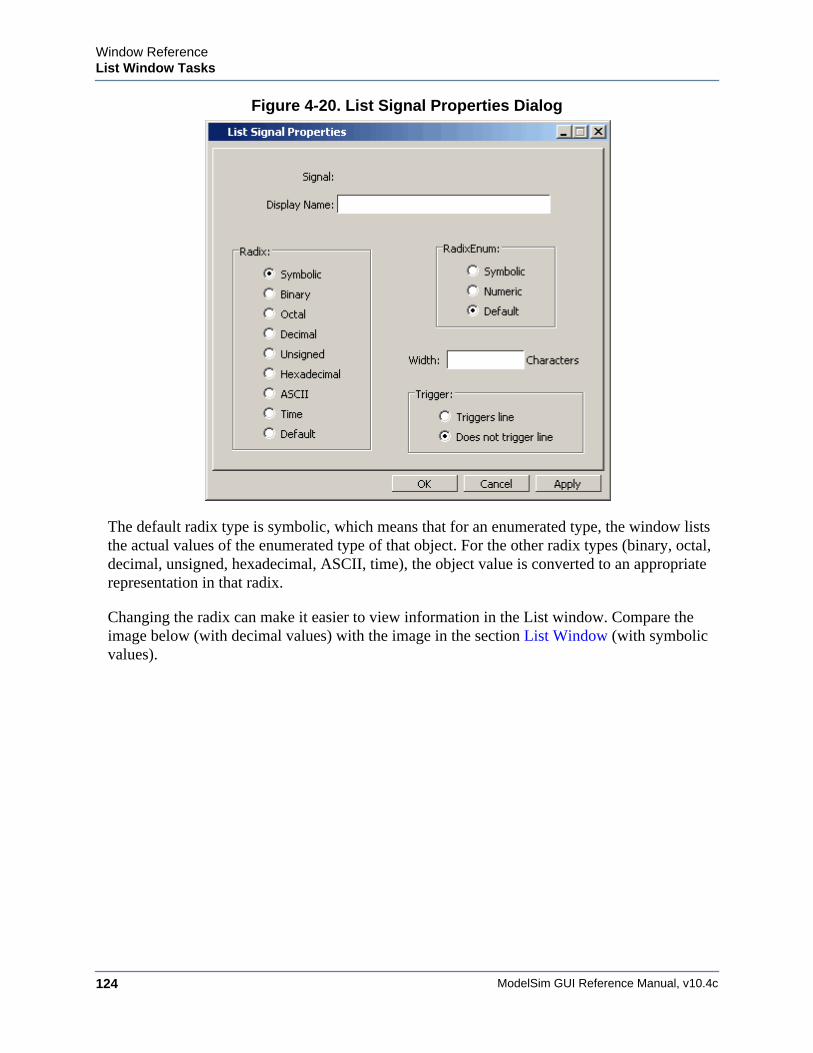
ModelSim GUI Reference Manual, v10.4c124
Window ReferenceList Window Tasks
Figure 4-20. List Signal Properties Dialog
The default radix type is symbolic, which means that for an enumerated type, the window lists the actual values of the enumerated type of that object. For the other radix types (binary, octal, decimal, unsigned, hexadecimal, ASCII, time), the object value is converted to an appropriate representation in that radix.
Changing the radix can make it easier to view information in the List window. Compare the image below (with decimal values) with the image in the section List Window (with symbolic values).
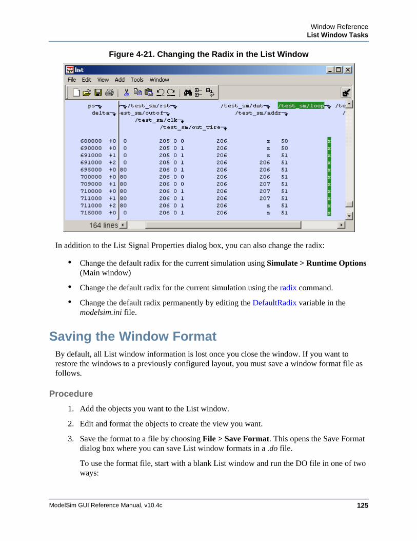
Window ReferenceList Window Tasks
ModelSim GUI Reference Manual, v10.4c 125
Figure 4-21. Changing the Radix in the List Window
In addition to the List Signal Properties dialog box, you can also change the radix:
• Change the default radix for the current simulation using Simulate > Runtime Options (Main window)
• Change the default radix for the current simulation using the radix command.
• Change the default radix permanently by editing the DefaultRadix variable in the modelsim.ini file.
Saving the Window FormatBy default, all List window information is lost once you close the window. If you want to restore the windows to a previously configured layout, you must save a window format file as follows.
Procedure
1. Add the objects you want to the List window.
2. Edit and format the objects to create the view you want.
3. Save the format to a file by choosing File > Save Format. This opens the Save Format dialog box where you can save List window formats in a .do file.
To use the format file, start with a blank List window and run the DO file in one of two ways:
ModelSim GUI Reference Manual, v10.4c126
Window ReferenceList Window Tasks
• Invoke the do command from the command line:
VSIM> do <my_format_file>
• Choose File > Load.
NoteWindow format files are design-specific. Use them only with the design you were simulating when they were created.
In addition, you can use the write format restart command to create a single .do file that will recreate all debug windows and breakpoints (see Saving and Restoring Breakpoints) when invoked with the do command in subsequent simulation runs. The syntax is:
write format restart <filename>
If the ShutdownFile modelsim.ini variable is set to this .do filename, it will call the write format restart command upon exit.
Combining Signals into BusesYou can combine signals in the List window into buses. A bus is a collection of signals concatenated in a specific order to create a new virtual signal with a specific value. A virtual compare signal (the result of a comparison simulation) is not supported for combination with any other signal.
Procedure
To combine signals into a bus, use one of the following methods:
If you want to... Do the following...
Use the GUI Select two or more signals in the Wave or List window and then choose List > Combine Signals from the menu bar. A virtual signal that is the result of a comparison simulation is not supported for combining with any other signal.
Use the Command Line Use the virtual signal command at the Main window command prompt.
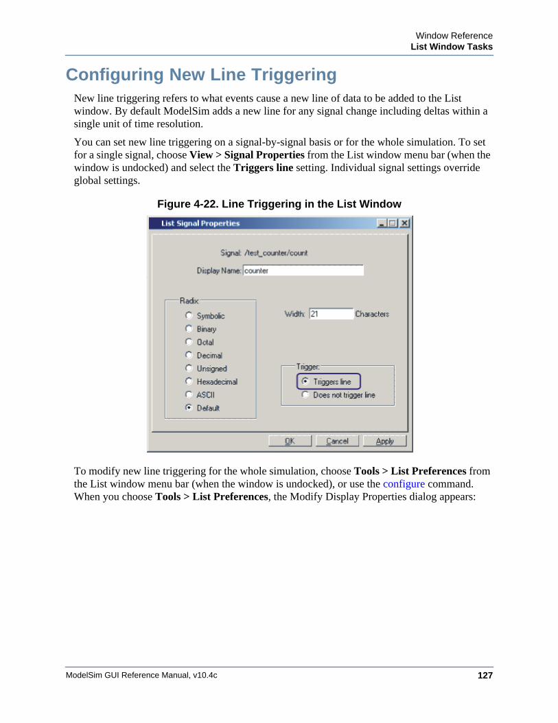
Window ReferenceList Window Tasks
ModelSim GUI Reference Manual, v10.4c 127
Configuring New Line TriggeringNew line triggering refers to what events cause a new line of data to be added to the List window. By default ModelSim adds a new line for any signal change including deltas within a single unit of time resolution.
You can set new line triggering on a signal-by-signal basis or for the whole simulation. To set for a single signal, choose View > Signal Properties from the List window menu bar (when the window is undocked) and select the Triggers line setting. Individual signal settings override global settings.
Figure 4-22. Line Triggering in the List Window
To modify new line triggering for the whole simulation, choose Tools > List Preferences from the List window menu bar (when the window is undocked), or use the configure command. When you choose Tools > List Preferences, the Modify Display Properties dialog appears:
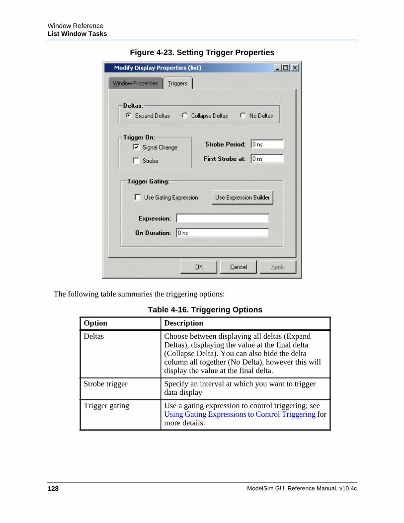
ModelSim GUI Reference Manual, v10.4c128
Window ReferenceList Window Tasks
Figure 4-23. Setting Trigger Properties
The following table summaries the triggering options:
Table 4-16. Triggering Options
Option Description
Deltas Choose between displaying all deltas (Expand Deltas), displaying the value at the final delta (Collapse Delta). You can also hide the delta column all together (No Delta), however this will display the value at the final delta.
Strobe trigger Specify an interval at which you want to trigger data display
Trigger gating Use a gating expression to control triggering; see Using Gating Expressions to Control Triggering for more details.
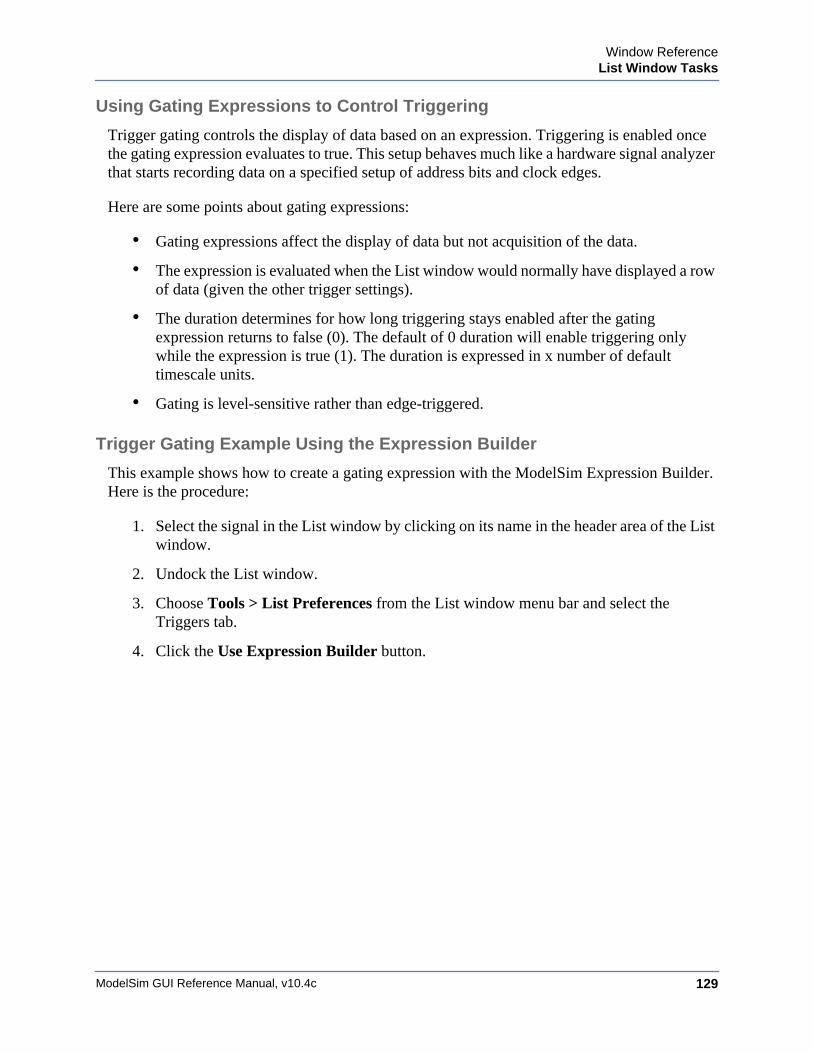
Window ReferenceList Window Tasks
ModelSim GUI Reference Manual, v10.4c 129
Using Gating Expressions to Control Triggering
Trigger gating controls the display of data based on an expression. Triggering is enabled once the gating expression evaluates to true. This setup behaves much like a hardware signal analyzer that starts recording data on a specified setup of address bits and clock edges.
Here are some points about gating expressions:
• Gating expressions affect the display of data but not acquisition of the data.
• The expression is evaluated when the List window would normally have displayed a row of data (given the other trigger settings).
• The duration determines for how long triggering stays enabled after the gating expression returns to false (0). The default of 0 duration will enable triggering only while the expression is true (1). The duration is expressed in x number of default timescale units.
• Gating is level-sensitive rather than edge-triggered.
Trigger Gating Example Using the Expression Builder
This example shows how to create a gating expression with the ModelSim Expression Builder. Here is the procedure:
1. Select the signal in the List window by clicking on its name in the header area of the List window.
2. Undock the List window.
3. Choose Tools > List Preferences from the List window menu bar and select the Triggers tab.
4. Click the Use Expression Builder button.
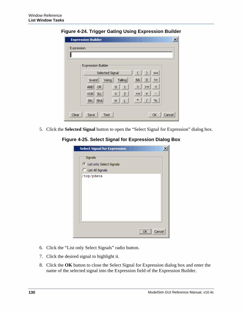
ModelSim GUI Reference Manual, v10.4c130
Window ReferenceList Window Tasks
Figure 4-24. Trigger Gating Using Expression Builder
5. Click the Selected Signal button to open the “Select Signal for Expression” dialog box.
Figure 4-25. Select Signal for Expression Dialog Box
6. Click the “List only Select Signals” radio button.
7. Click the desired signal to highlight it.
8. Click the OK button to close the Select Signal for Expression dialog box and enter the name of the selected signal into the Expression field of the Expression Builder.
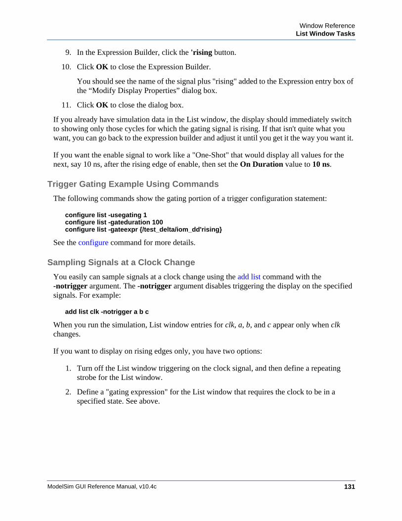
Window ReferenceList Window Tasks
ModelSim GUI Reference Manual, v10.4c 131
9. In the Expression Builder, click the 'rising button.
10. Click OK to close the Expression Builder.
You should see the name of the signal plus "rising" added to the Expression entry box of the “Modify Display Properties” dialog box.
11. Click OK to close the dialog box.
If you already have simulation data in the List window, the display should immediately switch to showing only those cycles for which the gating signal is rising. If that isn't quite what you want, you can go back to the expression builder and adjust it until you get it the way you want it.
If you want the enable signal to work like a "One-Shot" that would display all values for the next, say 10 ns, after the rising edge of enable, then set the On Duration value to 10 ns.
Trigger Gating Example Using Commands
The following commands show the gating portion of a trigger configuration statement:
configure list -usegating 1configure list -gateduration 100configure list -gateexpr {/test_delta/iom_dd'rising}
See the configure command for more details.
Sampling Signals at a Clock Change
You easily can sample signals at a clock change using the add list command with the-notrigger argument. The -notrigger argument disables triggering the display on the specified signals. For example:
add list clk -notrigger a b c
When you run the simulation, List window entries for clk, a, b, and c appear only when clk changes.
If you want to display on rising edges only, you have two options:
1. Turn off the List window triggering on the clock signal, and then define a repeating strobe for the List window.
2. Define a "gating expression" for the List window that requires the clock to be in a specified state. See above.
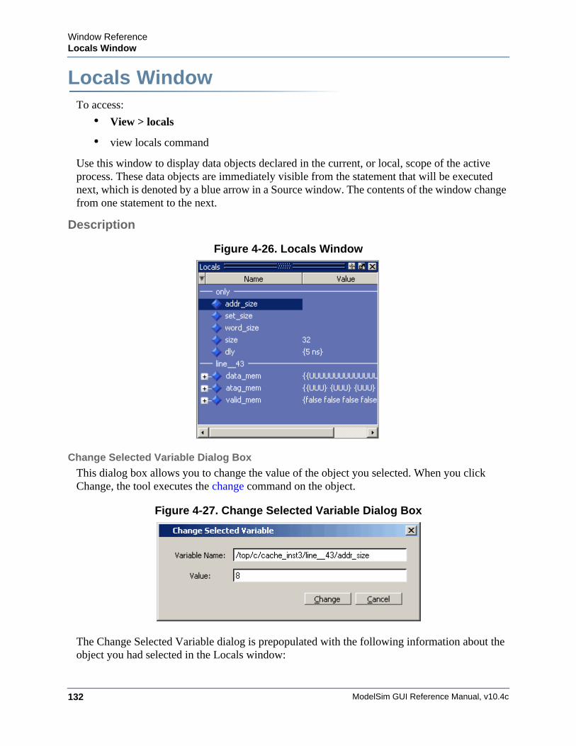
ModelSim GUI Reference Manual, v10.4c132
Window ReferenceLocals Window
Locals WindowWindow ReferenceTo access:
• View > locals
• view locals command
Use this window to display data objects declared in the current, or local, scope of the active process. These data objects are immediately visible from the statement that will be executed next, which is denoted by a blue arrow in a Source window. The contents of the window change from one statement to the next.
Description
Figure 4-26. Locals Window
Change Selected Variable Dialog Box
This dialog box allows you to change the value of the object you selected. When you click Change, the tool executes the change command on the object.
Figure 4-27. Change Selected Variable Dialog Box
The Change Selected Variable dialog is prepopulated with the following information about the object you had selected in the Locals window:
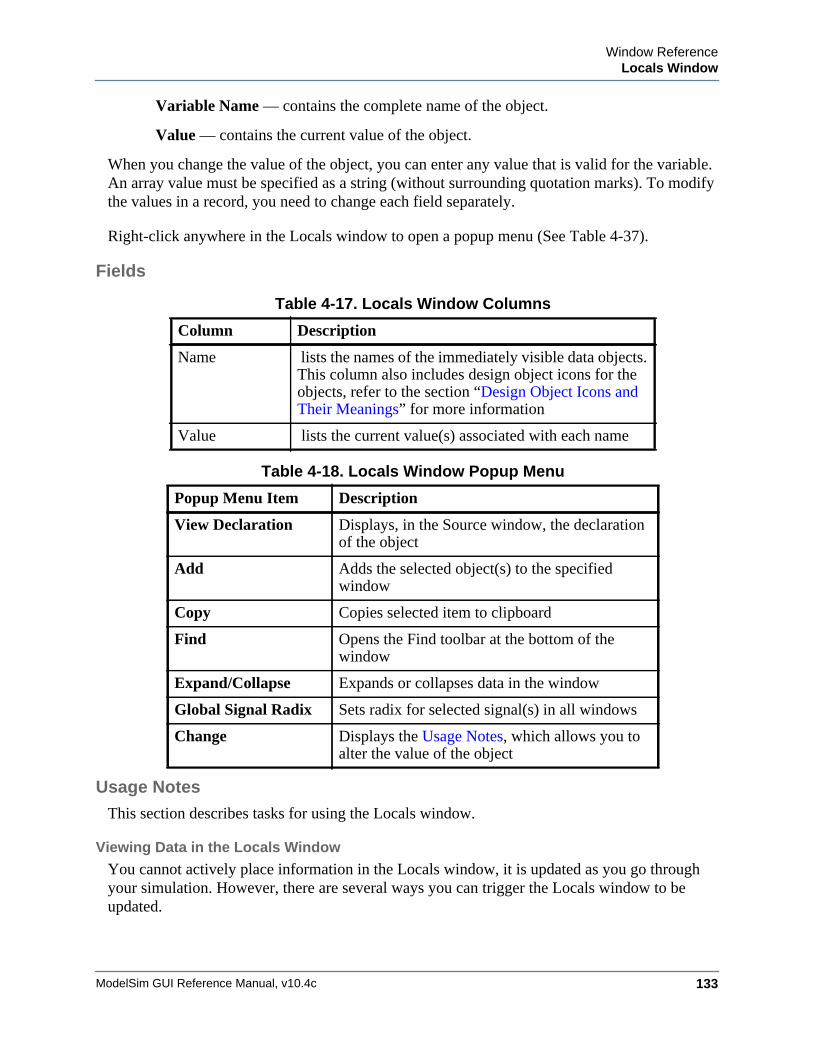
Window ReferenceLocals Window
ModelSim GUI Reference Manual, v10.4c 133
Variable Name — contains the complete name of the object.
Value — contains the current value of the object.
When you change the value of the object, you can enter any value that is valid for the variable. An array value must be specified as a string (without surrounding quotation marks). To modify the values in a record, you need to change each field separately.
Right-click anywhere in the Locals window to open a popup menu (See Table 4-37).
Fields
Usage NotesThis section describes tasks for using the Locals window.
Viewing Data in the Locals Window
You cannot actively place information in the Locals window, it is updated as you go through your simulation. However, there are several ways you can trigger the Locals window to be updated.
Table 4-17. Locals Window Columns
Column Description
Name lists the names of the immediately visible data objects. This column also includes design object icons for the objects, refer to the section “Design Object Icons and Their Meanings” for more information
Value lists the current value(s) associated with each name
Table 4-18. Locals Window Popup Menu
Popup Menu Item Description
View Declaration Displays, in the Source window, the declaration of the object
Add Adds the selected object(s) to the specified window
Copy Copies selected item to clipboard
Find Opens the Find toolbar at the bottom of the window
Expand/Collapse Expands or collapses data in the window
Global Signal Radix Sets radix for selected signal(s) in all windows
Change Displays the Usage Notes, which allows you to alter the value of the object
ModelSim GUI Reference Manual, v10.4c134
Window ReferenceLocals Window
• Run your simulation while debugging.
• Select a Process from the Processes Window.
• Select a Verilog function or task or VHDL function or procedure from the Call Stack Window.

Window ReferenceLocals Window
ModelSim GUI Reference Manual, v10.4c 135
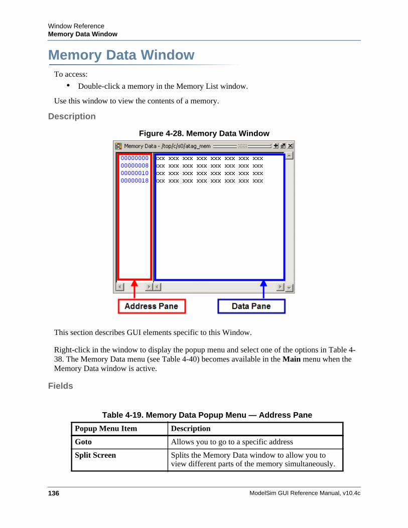
ModelSim GUI Reference Manual, v10.4c136
Window ReferenceMemory Data Window
Memory Data WindowWindow ReferenceTo access:
• Double-click a memory in the Memory List window.
Use this window to view the contents of a memory.
Description
Figure 4-28. Memory Data Window
This section describes GUI elements specific to this Window.
Right-click in the window to display the popup menu and select one of the options in Table 4-38. The Memory Data menu (see Table 4-40) becomes available in the Main menu when the Memory Data window is active.
Fields
Table 4-19. Memory Data Popup Menu — Address Pane
Popup Menu Item Description
Goto Allows you to go to a specific address
Split Screen Splits the Memory Data window to allow you to view different parts of the memory simultaneously.
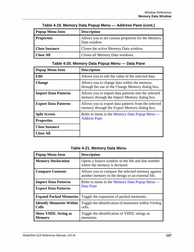
Window ReferenceMemory Data Window
ModelSim GUI Reference Manual, v10.4c 137
Properties Allows you to set various properties for the Memory Data window.
Close Instance Closes the active Memory Data window.
Close All Closes all Memory Data windows.
Table 4-20. Memory Data Popup Menu — Data Pane
Popup Menu Item Description
Edit Allows you to edit the value of the selected data.
Change Allows you to change data within the memory through the use of the Change Memory dialog box.
Import Data Patterns Allows you to import data patterns into the selected memory through the Import Memory dialog box.
Export Data Patterns Allows you to export data patterns from the selected memory through the Export Memory dialog box.
Split Screen Refer to items in the Memory Data Popup Menu — Address Pane
Properties
Close Instance
Close All
Table 4-21. Memory Data Menu
Popup Menu Item Description
Memory Declaration Opens a Source window to the file and line number where the memory is declared.
Compare Contents Allows you to compare the selected memory against another memory in the design or an external file.
Import Data Patterns Refer to items in the Memory Data Popup Menu — Data Pane
Export Data Patterns
Expand Packed Memories Toggle the expansion of packed memories.
Identify Memories Within Cells
Toggle the identification of memories within Verilog cells.
Show VHDL String as Memory
Toggle the identification of VHDL strings as memories.
Table 4-19. Memory Data Popup Menu — Address Pane (cont.)
Popup Menu Item Description
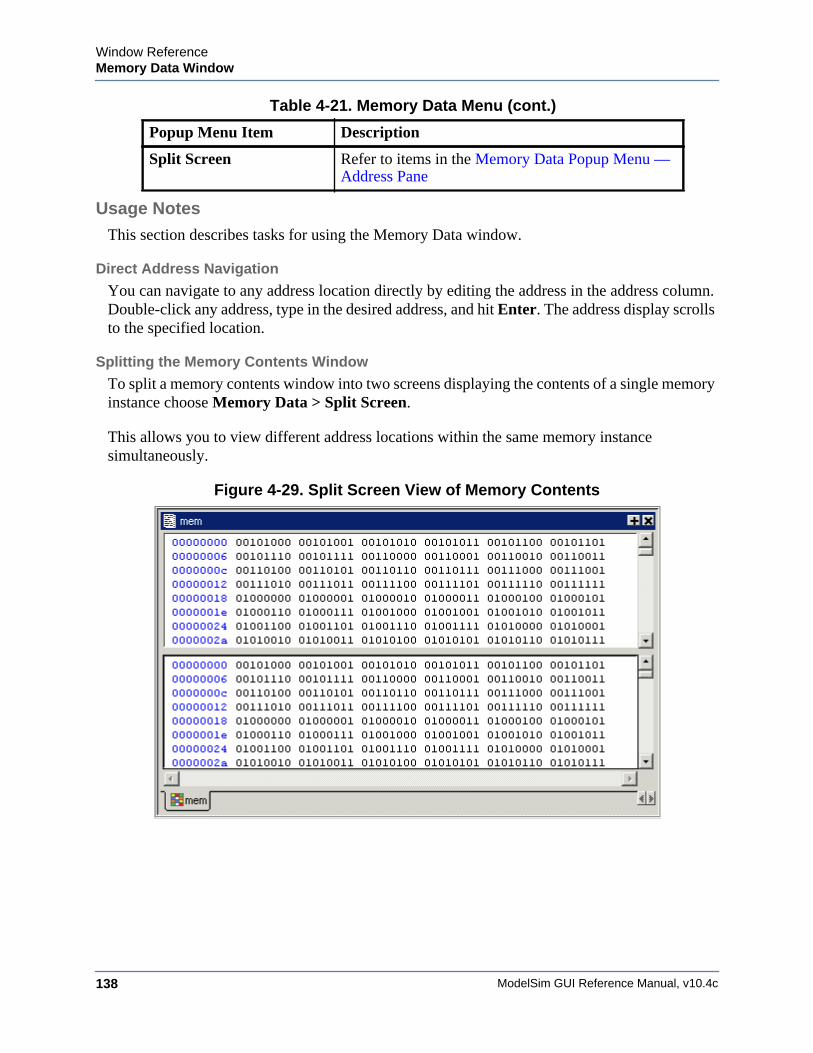
ModelSim GUI Reference Manual, v10.4c138
Window ReferenceMemory Data Window
Usage NotesThis section describes tasks for using the Memory Data window.
Direct Address Navigation
You can navigate to any address location directly by editing the address in the address column. Double-click any address, type in the desired address, and hit Enter. The address display scrolls to the specified location.
Splitting the Memory Contents Window
To split a memory contents window into two screens displaying the contents of a single memory instance choose Memory Data > Split Screen.
This allows you to view different address locations within the same memory instance simultaneously.
Figure 4-29. Split Screen View of Memory Contents
Split Screen Refer to items in the Memory Data Popup Menu — Address Pane
Table 4-21. Memory Data Menu (cont.)
Popup Menu Item Description
Window ReferenceMemory List Window
ModelSim GUI Reference Manual, v10.4c 139
Memory List WindowWindow ReferenceTo access:
• View > Memory List
• view memory list command
Use this window to view a list of all memories in your design.
Description
Single dimensional arrays of integers are interpreted as 2D memory arrays. In these cases, the word width listed in the Memory window is equal to the integer size, and the depth is the size of the array itself.
Memories with three or more dimensions display with a plus sign ’+’ next to their names in the Memory window. Click the ’+’ to show the array indices under that level. When you finally expand down to the 2D level, you can double-click on the index, and the data for the selected 2D slice of the memory will appear in a memory contents window.
The simulator identifies certain kinds of arrays in various scopes as memories. Memory identification depends on the array element kind as well as the overall array kind (that is, associative array, unpacked array, and so forth.).
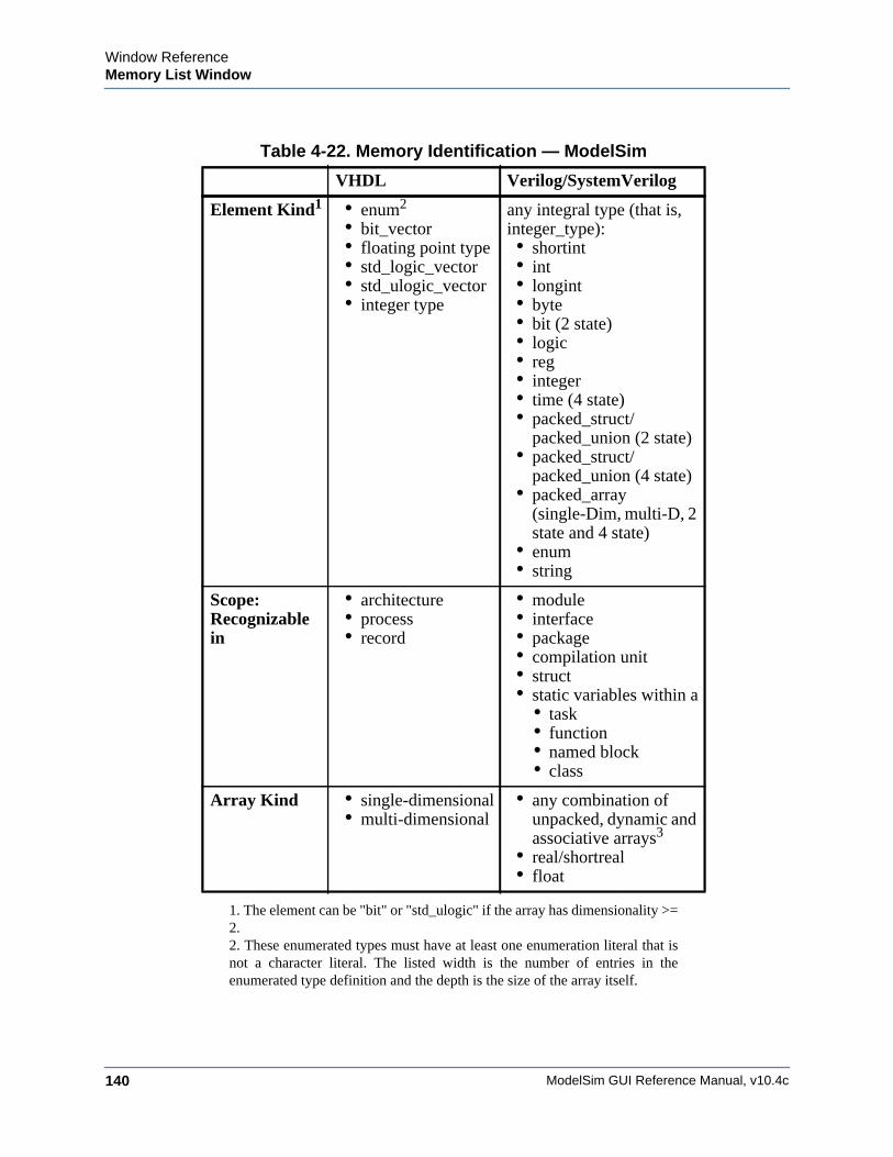
ModelSim GUI Reference Manual, v10.4c140
Window ReferenceMemory List Window
Table 4-22. Memory Identification — ModelSim
VHDL Verilog/SystemVerilog
Element Kind1
1. The element can be "bit" or "std_ulogic" if the array has dimensionality >=2.
• enum2 • bit_vector• floating point type• std_logic_vector• std_ulogic_vector• integer type
2. These enumerated types must have at least one enumeration literal that isnot a character literal. The listed width is the number of entries in theenumerated type definition and the depth is the size of the array itself.
any integral type (that is, integer_type): • shortint• int• longint• byte• bit (2 state)• logic• reg• integer• time (4 state)• packed_struct/
packed_union (2 state)• packed_struct/
packed_union (4 state)• packed_array
(single-Dim, multi-D, 2 state and 4 state)
• enum• string
Scope: Recognizable in
• architecture• process• record
• module• interface• package• compilation unit• struct• static variables within a
• task • function • named block • class
Array Kind • single-dimensional • multi-dimensional
• any combination of unpacked, dynamic and associative arrays3
• real/shortreal • float
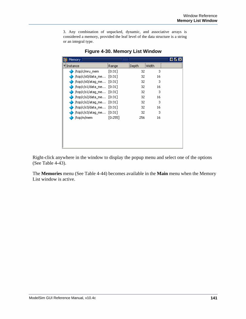
Window ReferenceMemory List Window
ModelSim GUI Reference Manual, v10.4c 141
Figure 4-30. Memory List Window
Right-click anywhere in the window to display the popup menu and select one of the options (See Table 4-43).
The Memories menu (See Table 4-44) becomes available in the Main menu when the Memory List window is active.
3. Any combination of unpacked, dynamic, and associative arrays isconsidered a memory, provided the leaf level of the data structure is a stringor an integral type.
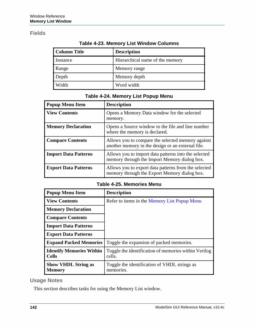
ModelSim GUI Reference Manual, v10.4c142
Window ReferenceMemory List Window
Fields
Usage NotesThis section describes tasks for using the Memory List window.
Table 4-23. Memory List Window Columns
Column Title Description
Instance Hierarchical name of the memory
Range Memory range
Depth Memory depth
Width Word width
Table 4-24. Memory List Popup Menu
Popup Menu Item Description
View Contents Opens a Memory Data window for the selected memory.
Memory Declaration Opens a Source window to the file and line number where the memory is declared.
Compare Contents Allows you to compare the selected memory against another memory in the design or an external file.
Import Data Patterns Allows you to import data patterns into the selected memory through the Import Memory dialog box.
Export Data Patterns Allows you to export data patterns from the selected memory through the Export Memory dialog box.
Table 4-25. Memories Menu
Popup Menu Item Description
View Contents Refer to items in the Memory List Popup Menu
Memory Declaration
Compare Contents
Import Data Patterns
Export Data Patterns
Expand Packed Memories Toggle the expansion of packed memories.
Identify Memories Within Cells
Toggle the identification of memories within Verilog cells.
Show VHDL String as Memory
Toggle the identification of VHDL strings as memories.
Window ReferenceSaving Memory Formats in a DO File
ModelSim GUI Reference Manual, v10.4c 143
Viewing Packed Arrays
By default, packed dimensions are treated as single vectors in the Memory List window. To expand packed dimensions of packed arrays, choose Memories > Expand Packed Memories.
To change the permanent default, edit the PrefMemory(ExpandPackedMem) variable. This variable affects only packed arrays. If the variable is set to 1, the packed arrays are treated as unpacked arrays and are expanded along the packed dimensions such that they appear as a linearized bit vector. Refer to the section “Setting GUI Preferences” for details on setting preference variables.
Viewing Memory Contents
When you double-click an instance on the Memory List window, ModelSim automatically displays a Memory Data window, where the name used on the tab is taken from the name of the instance, as seen in the Memory window. You can also enter the command add mem <instance> at the vsim command prompt.
Viewing Multiple Memory Instances
You can view multiple memory instances simultaneously. A Memory Data window appears for each instance you double-click in the Memory List window. When you open more than one window for the same memory, the name of the tab receives an numerical identifier after the name, such as “(2)”.
Saving Memory Formats in a DO FileYou can save all open memory instances and their formats (for example, address radix, data radix, and so forth) by creating a DO file.
Procedure
1. Select the Memory List window
2. Choose File > Save Format
displays the Save Memory Format dialog box
3. Enter the file name in the “Save memory format” dialog box
By default it is named mem.do. The file will contain all open memory instances and their formats.
To load it at a later time, choose File > Load.
ModelSim GUI Reference Manual, v10.4c144
Window ReferenceSaving Memories to the WLF File
Saving Memories to the WLF FileBy default, memories are not saved in the WLF file when you issue a "log -r /*" command. To get memories into the WLF file you will need to explicitly log them.
For example:
log /top/dut/i0/mem
It you want to use wildcards, then you will need to remove memories from the WildcardFilter list. To see what is currently in the WildcardFilter list, use the following command:
set WildcardFilter
If "Memories" is in the list, reissue the set WildcardFilter command with all items in the list except "Memories." For details, see Using the WildcardFilter Preference Variable.
NoteFor post-process debug, you can add the memories into the Wave or List windows but the Memory List window is not available.

Window ReferenceSaving Memories to the WLF File
ModelSim GUI Reference Manual, v10.4c 145
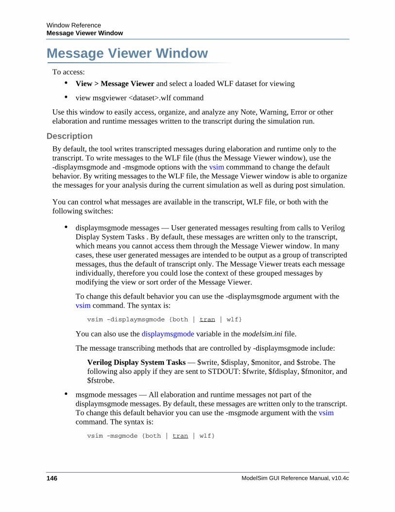
ModelSim GUI Reference Manual, v10.4c146
Window ReferenceMessage Viewer Window
Message Viewer WindowWindow ReferenceTo access:
• View > Message Viewer and select a loaded WLF dataset for viewing
• view msgviewer <dataset>.wlf command
Use this window to easily access, organize, and analyze any Note, Warning, Error or other elaboration and runtime messages written to the transcript during the simulation run.
Description
By default, the tool writes transcripted messages during elaboration and runtime only to the transcript. To write messages to the WLF file (thus the Message Viewer window), use the -displaymsgmode and -msgmode options with the vsim commmand to change the default behavior. By writing messages to the WLF file, the Message Viewer window is able to organize the messages for your analysis during the current simulation as well as during post simulation.
You can control what messages are available in the transcript, WLF file, or both with the following switches:
• displaymsgmode messages — User generated messages resulting from calls to Verilog Display System Tasks . By default, these messages are written only to the transcript, which means you cannot access them through the Message Viewer window. In many cases, these user generated messages are intended to be output as a group of transcripted messages, thus the default of transcript only. The Message Viewer treats each message individually, therefore you could lose the context of these grouped messages by modifying the view or sort order of the Message Viewer.
To change this default behavior you can use the -displaymsgmode argument with the vsim command. The syntax is:
vsim -displaymsgmode {both | tran | wlf}
You can also use the displaymsgmode variable in the modelsim.ini file.
The message transcribing methods that are controlled by -displaymsgmode include:
Verilog Display System Tasks — $write, $display, $monitor, and $strobe. The following also apply if they are sent to STDOUT: $fwrite, $fdisplay, $fmonitor, and $fstrobe.
• msgmode messages — All elaboration and runtime messages not part of the displaymsgmode messages. By default, these messages are written only to the transcript. To change this default behavior you can use the -msgmode argument with the vsim command. The syntax is:
vsim -msgmode {both | tran | wlf}
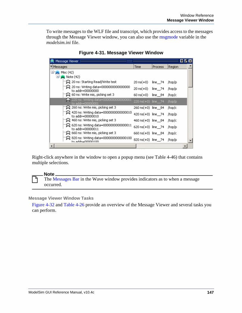
Window ReferenceMessage Viewer Window
ModelSim GUI Reference Manual, v10.4c 147
To write messages to the WLF file and transcript, which provides access to the messages through the Message Viewer window, you can also use the msgmode variable in the modelsim.ini file.
Figure 4-31. Message Viewer Window
Right-click anywhere in the window to open a popup menu (see Table 4-46) that contains multiple selections.
NoteThe Messages Bar in the Wave window provides indicators as to when a message occurred.
Message Viewer Window Tasks
Figure 4-32 and Table 4-26 provide an overview of the Message Viewer and several tasks you can perform.
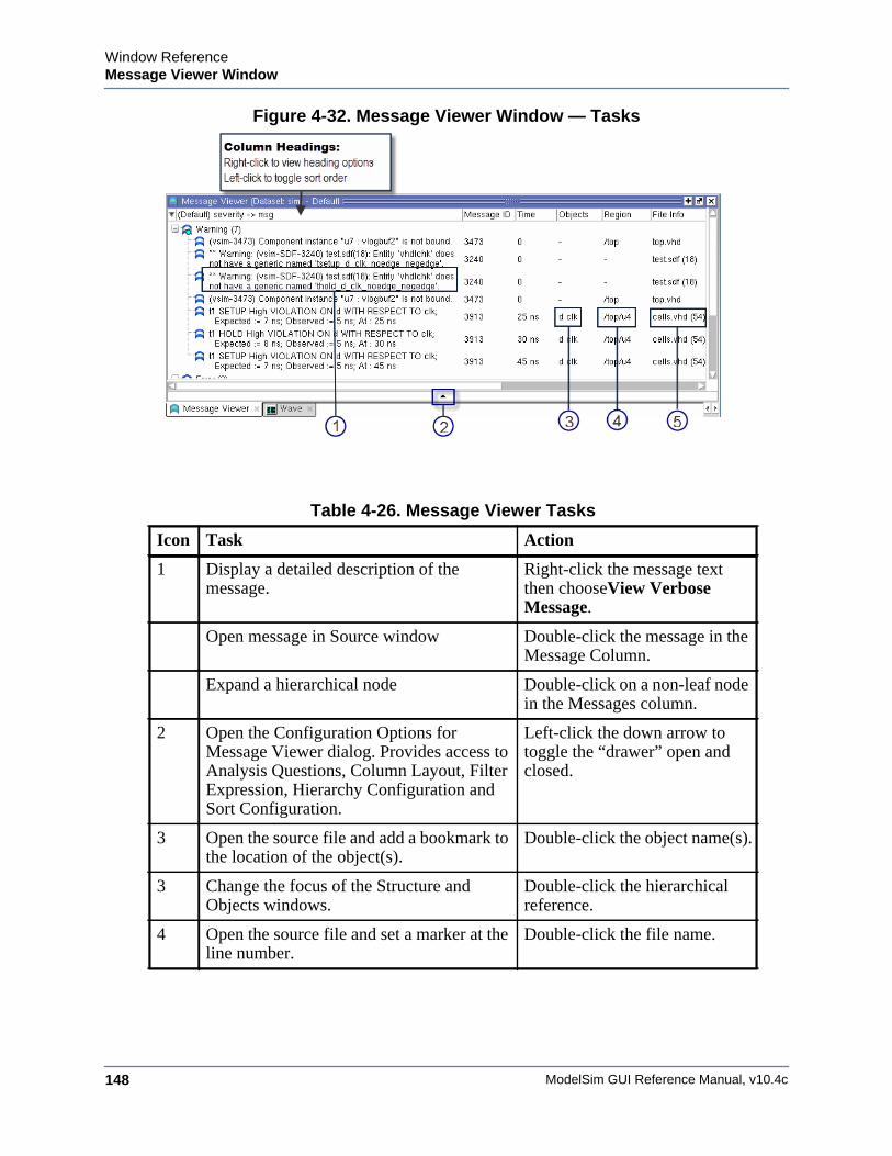
ModelSim GUI Reference Manual, v10.4c148
Window ReferenceMessage Viewer Window
Figure 4-32. Message Viewer Window — Tasks
Table 4-26. Message Viewer Tasks
Icon Task Action
1 Display a detailed description of the message.
Right-click the message text then chooseView Verbose Message.
Open message in Source window Double-click the message in the Message Column.
Expand a hierarchical node Double-click on a non-leaf node in the Messages column.
2 Open the Configuration Options for Message Viewer dialog. Provides access to Analysis Questions, Column Layout, Filter Expression, Hierarchy Configuration and Sort Configuration.
Left-click the down arrow to toggle the “drawer” open and closed.
3 Open the source file and add a bookmark to the location of the object(s).
Double-click the object name(s).
3 Change the focus of the Structure and Objects windows.
Double-click the hierarchical reference.
4 Open the source file and set a marker at the line number.
Double-click the file name.
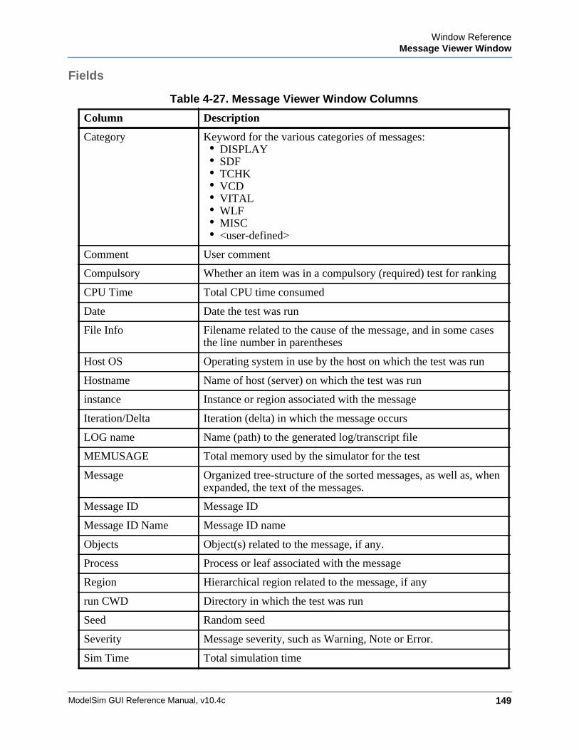
Window ReferenceMessage Viewer Window
ModelSim GUI Reference Manual, v10.4c 149
Fields
Table 4-27. Message Viewer Window Columns
Column Description
Category Keyword for the various categories of messages:• DISPLAY• SDF• TCHK• VCD• VITAL• WLF• MISC• <user-defined>
Comment User comment
Compulsory Whether an item was in a compulsory (required) test for ranking
CPU Time Total CPU time consumed
Date Date the test was run
File Info Filename related to the cause of the message, and in some cases the line number in parentheses
Host OS Operating system in use by the host on which the test was run
Hostname Name of host (server) on which the test was run
instance Instance or region associated with the message
Iteration/Delta Iteration (delta) in which the message occurs
LOG name Name (path) to the generated log/transcript file
MEMUSAGE Total memory used by the simulator for the test
Message Organized tree-structure of the sorted messages, as well as, when expanded, the text of the messages.
Message ID Message ID
Message ID Name Message ID name
Objects Object(s) related to the message, if any.
Process Process or leaf associated with the message
Region Hierarchical region related to the message, if any
run CWD Directory in which the test was run
Seed Random seed
Severity Message severity, such as Warning, Note or Error.
Sim Time Total simulation time
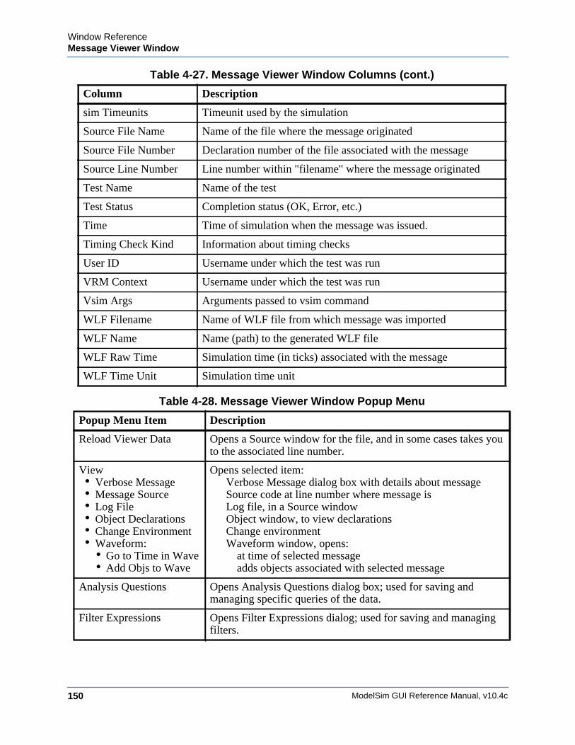
ModelSim GUI Reference Manual, v10.4c150
Window ReferenceMessage Viewer Window
sim Timeunits Timeunit used by the simulation
Source File Name Name of the file where the message originated
Source File Number Declaration number of the file associated with the message
Source Line Number Line number within "filename" where the message originated
Test Name Name of the test
Test Status Completion status (OK, Error, etc.)
Time Time of simulation when the message was issued.
Timing Check Kind Information about timing checks
User ID Username under which the test was run
VRM Context Username under which the test was run
Vsim Args Arguments passed to vsim command
WLF Filename Name of WLF file from which message was imported
WLF Name Name (path) to the generated WLF file
WLF Raw Time Simulation time (in ticks) associated with the message
WLF Time Unit Simulation time unit
Table 4-28. Message Viewer Window Popup Menu
Popup Menu Item Description
Reload Viewer Data Opens a Source window for the file, and in some cases takes you to the associated line number.
View • Verbose Message• Message Source• Log File• Object Declarations• Change Environment• Waveform:
• Go to Time in Wave• Add Objs to Wave
Opens selected item:Verbose Message dialog box with details about messageSource code at line number where message isLog file, in a Source windowObject window, to view declarationsChange environmentWaveform window, opens:
at time of selected messageadds objects associated with selected message
Analysis Questions Opens Analysis Questions dialog box; used for saving and managing specific queries of the data.
Filter Expressions Opens Filter Expressions dialog; used for saving and managing filters.
Table 4-27. Message Viewer Window Columns (cont.)
Column Description
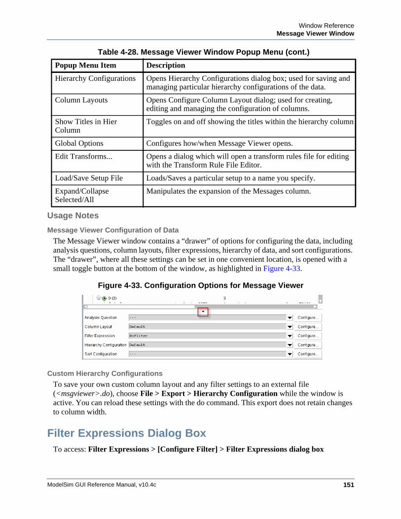
Window ReferenceMessage Viewer Window
ModelSim GUI Reference Manual, v10.4c 151
Usage Notes
Message Viewer Configuration of Data
The Message Viewer window contains a “drawer” of options for configuring the data, including analysis questions, column layouts, filter expressions, hierarchy of data, and sort configurations. The “drawer”, where all these settings can be set in one convenient location, is opened with a small toggle button at the bottom of the window, as highlighted in Figure 4-33.
Figure 4-33. Configuration Options for Message Viewer
Custom Hierarchy Configurations
To save your own custom column layout and any filter settings to an external file (<msgviewer>.do), choose File > Export > Hierarchy Configuration while the window is active. You can reload these settings with the do command. This export does not retain changes to column width.
Filter Expressions Dialog BoxTo access: Filter Expressions > [Configure Filter] > Filter Expressions dialog box
Hierarchy Configurations Opens Hierarchy Configurations dialog box; used for saving and managing particular hierarchy configurations of the data.
Column Layouts Opens Configure Column Layout dialog; used for creating, editing and managing the configuration of columns.
Show Titles in Hier Column
Toggles on and off showing the titles within the hierarchy column
Global Options Configures how/when Message Viewer opens.
Edit Transforms... Opens a dialog which will open a transform rules file for editing with the Transform Rule File Editor.
Load/Save Setup File Loads/Saves a particular setup to a name you specify.
Expand/CollapseSelected/All
Manipulates the expansion of the Messages column.
Table 4-28. Message Viewer Window Popup Menu (cont.)
Popup Menu Item Description
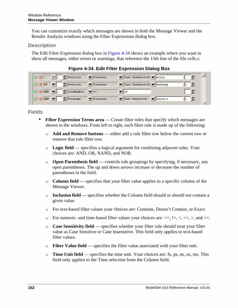
ModelSim GUI Reference Manual, v10.4c152
Window ReferenceMessage Viewer Window
You can customize exactly which messages are shown in both the Message Viewer and the Results Analysis windows using the Filter Expressions dialog box.
DescriptionThe Edit Filter Expression dialog box in Figure 4-34 shows an example where you want to show all messages, either errors or warnings, that reference the 15th line of the file cells.v.
Figure 4-34. Edit Filter Expression Dialog Box
Fields• Filter Expression Terms area — Create filter rules that specify which messages are
shown in the windows. From left to right, each filter rule is made up of the following:
o Add and Remove buttons — either add a rule filter row below the current row or remove that rule filter row.
o Logic field — specifies a logical argument for combining adjacent rules. Your choices are: AND, OR, NAND, and NOR.
o Open Parenthesis field — controls rule groupings by specifying, if necessary, any open parentheses. The up and down arrows increase or decrease the number of parentheses in the field.
o Column field — specifies that your filter value applies to a specific column of the Message Viewer.
o Inclusion field — specifies whether the Column field should or should not contain a given value.
o For text-based filter values your choices are: Contains, Doesn’t Contain, or Exact.
o For numeric- and time-based filter values your choices are: ==, !=, <, <=, >, and >=.
o Case Sensitivity field — specifies whether your filter rule should treat your filter value as Case Sensitive or Case Insensitive. This field only applies to text-based filter values.
o Filter Value field — specifies the filter value associated with your filter rule.
o Time Unit field — specifies the time unit. Your choices are: fs, ps, ns, us, ms. This field only applies to the Time selection from the Column field.
Window ReferenceMessage Viewer Window
ModelSim GUI Reference Manual, v10.4c 153
o Closed Parenthesis field — controls rule groupings by specifying, if necessary, any closed parentheses. The up and down arrows increase or decrease the number of parentheses in the field.
• First Message Filter area — Allows you to control the appearance of either all matching messages or just the first matching message (with further filtering options).
• Time Range area — Allows you to filter which messages appear according to simulation time. The default is to display messages for the complete simulation time.
• Displayed Objects area — Allows you to filter which messages appear according to the values in the Objects column. The default is to display all messages, regardless of the values in the Objects column. The Objects in the list text entry box allows you to specify filter strings, where each string must be on a new line.
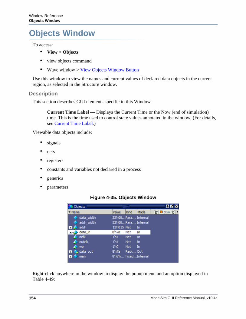
ModelSim GUI Reference Manual, v10.4c154
Window ReferenceObjects Window
Objects WindowWindow ReferenceTo access:
• View > Objects
• view objects command
• Wave window > View Objects Window Button
Use this window to view the names and current values of declared data objects in the current region, as selected in the Structure window.
Description
This section describes GUI elements specific to this Window.
Current Time Label — Displays the Current Time or the Now (end of simulation) time. This is the time used to control state values annotated in the window. (For details, see Current Time Label.)
Viewable data objects include:
• signals
• nets
• registers
• constants and variables not declared in a process
• generics
• parameters
Figure 4-35. Objects Window
Right-click anywhere in the window to display the popup menu and an option displayed in Table 4-49:
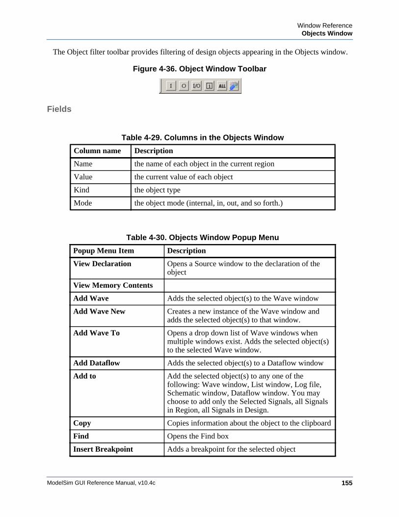
Window ReferenceObjects Window
ModelSim GUI Reference Manual, v10.4c 155
The Object filter toolbar provides filtering of design objects appearing in the Objects window.
Figure 4-36. Object Window Toolbar
Fields
Table 4-29. Columns in the Objects Window
Column name Description
Name the name of each object in the current region
Value the current value of each object
Kind the object type
Mode the object mode (internal, in, out, and so forth.)
Table 4-30. Objects Window Popup Menu
Popup Menu Item Description
View Declaration Opens a Source window to the declaration of the object
View Memory Contents
Add Wave Adds the selected object(s) to the Wave window
Add Wave New Creates a new instance of the Wave window and adds the selected object(s) to that window.
Add Wave To Opens a drop down list of Wave windows when multiple windows exist. Adds the selected object(s) to the selected Wave window.
Add Dataflow Adds the selected object(s) to a Dataflow window
Add to Add the selected object(s) to any one of the following: Wave window, List window, Log file, Schematic window, Dataflow window. You may choose to add only the Selected Signals, all Signals in Region, all Signals in Design.
Copy Copies information about the object to the clipboard
Find Opens the Find box
Insert Breakpoint Adds a breakpoint for the selected object
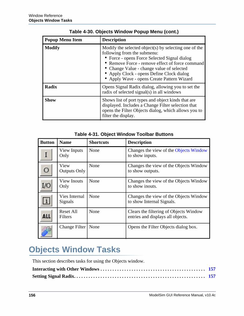
ModelSim GUI Reference Manual, v10.4c156
Window ReferenceObjects Window Tasks
Objects Window TasksThis section describes tasks for using the Objects window.
Interacting with Other Windows . . . . . . . . . . . . . . . . . . . . . . . . . . . . . . . . . . . . . . . . . . . . 157
Setting Signal Radix. . . . . . . . . . . . . . . . . . . . . . . . . . . . . . . . . . . . . . . . . . . . . . . . . . . . . . . 157
Modify Modify the selected object(s) by selecting one of the following from the submenu:• Force - opens Force Selected Signal dialog• Remove Force - remove effect of force command• Change Value - change value of selected• Apply Clock - opens Define Clock dialog• Apply Wave - opens Create Pattern Wizard
Radix Opens Signal Radix dialog, allowing you to set the radix of selected signal(s) in all windows
Show Shows list of port types and object kinds that are displayed. Includes a Change Filter selection that opens the Filter Objects dialog, which allows you to filter the display.
Table 4-31. Object Window Toolbar Buttons
Button Name Shortcuts Description
View Inputs Only
None Changes the view of the Objects Window to show inputs.
View Outputs Only
None Changes the view of the Objects Window to show outputs.
View Inouts Only
None Changes the view of the Objects Window to show inouts.
Vies Internal Signals
None Changes the view of the Objects Window to show Internal Signals.
Reset All Filters
None Clears the filtering of Objects Window entries and displays all objects.
Change Filter None Opens the Filter Objects dialog box.
Table 4-30. Objects Window Popup Menu (cont.)
Popup Menu Item Description
Window ReferenceObjects Window Tasks
ModelSim GUI Reference Manual, v10.4c 157
Finding Contents of the Objects Window . . . . . . . . . . . . . . . . . . . . . . . . . . . . . . . . . . . . . 158
Filtering Contents of the Objects Window . . . . . . . . . . . . . . . . . . . . . . . . . . . . . . . . . . . . 158
Interacting with Other WindowsYou can interact with other windows from the Objects window.
Procedure
1. Click an entry in the window to highlight that object in the Dataflow, and Wave windows.
2. Double-click an entry to highlight that object in a Source window
Setting Signal RadixYou can set the signal radix for a selected signal or signals in the Objects window as follows.
Procedure
1. Click (LMB) a signal to select it or use Ctrl-Click Shift-Click to select a group of signals.
2. ChooseObjects > Radix from the menu bar; or right-click the selected signal(s) and choose Radix from the popup menu.
This opens the Signal Radix dialog box (Figure 4-37), where you may select a radix. This sets the radix for the selected signal(s) in the Objects window and every other window where the signal appears.
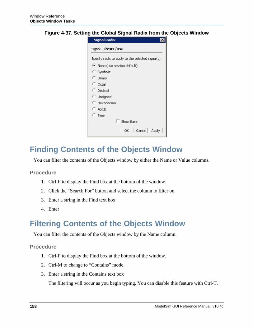
ModelSim GUI Reference Manual, v10.4c158
Window ReferenceObjects Window Tasks
Figure 4-37. Setting the Global Signal Radix from the Objects Window
Finding Contents of the Objects WindowYou can filter the contents of the Objects window by either the Name or Value columns.
Procedure
1. Ctrl-F to display the Find box at the bottom of the window.
2. Click the “Search For” button and select the column to filter on.
3. Enter a string in the Find text box
4. Enter
Filtering Contents of the Objects WindowYou can filter the contents of the Objects window by the Name column.
Procedure
1. Ctrl-F to display the Find box at the bottom of the window.
2. Ctrl-M to change to “Contains” mode.
3. Enter a string in the Contains text box
The filtering will occur as you begin typing. You can disable this feature with Ctrl-T.

Window ReferenceObjects Window Tasks
ModelSim GUI Reference Manual, v10.4c 159
Filters are stored relative to the region selected in the Structure window. If you re-select a region that had a filter applied, that filter is restored. This allows you to apply different filters to different regions.
Filtering by Signal TypeThe View > Filter menu selection allows you to specify which signal types to display in the Objects window. Multiple options can be selected. Choose Change Filter to open the Filter Objects dialog box, where you can select port modes and object types to be displayed.

ModelSim GUI Reference Manual, v10.4c160
Window ReferenceObjects Window Tasks
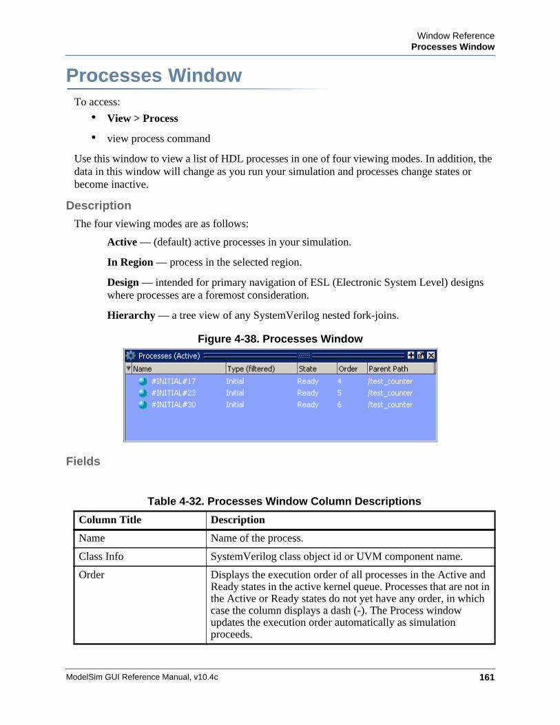
Window ReferenceProcesses Window
ModelSim GUI Reference Manual, v10.4c 161
Processes WindowWindow ReferenceTo access:
• View > Process
• view process command
Use this window to view a list of HDL processes in one of four viewing modes. In addition, the data in this window will change as you run your simulation and processes change states or become inactive.
Description
The four viewing modes are as follows:
Active — (default) active processes in your simulation.
In Region — process in the selected region.
Design — intended for primary navigation of ESL (Electronic System Level) designs where processes are a foremost consideration.
Hierarchy — a tree view of any SystemVerilog nested fork-joins.
Figure 4-38. Processes Window
Fields
Table 4-32. Processes Window Column Descriptions
Column Title Description
Name Name of the process.
Class Info SystemVerilog class object id or UVM component name.
Order Displays the execution order of all processes in the Active and Ready states in the active kernel queue. Processes that are not in the Active or Ready states do not yet have any order, in which case the column displays a dash (-). The Process window updates the execution order automatically as simulation proceeds.
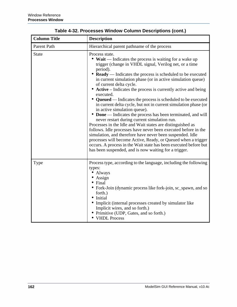
ModelSim GUI Reference Manual, v10.4c162
Window ReferenceProcesses Window
Parent Path Hierarchical parent pathname of the process
State Process state.• Wait — Indicates the process is waiting for a wake up
trigger (change in VHDL signal, Verilog net, or a time period).
• Ready — Indicates the process is scheduled to be executed in current simulation phase (or in active simulation queue) of current delta cycle.
• Active – Indicates the process is currently active and being executed.
• Queued — Indicates the process is scheduled to be executed in current delta cycle, but not in current simulation phase (or in active simulation queue).
• Done — Indicates the process has been terminated, and will never restart during current simulation run.
Processes in the Idle and Wait states are distinguished as follows. Idle processes have never been executed before in the simulation, and therefore have never been suspended. Idle processes will become Active, Ready, or Queued when a trigger occurs. A process in the Wait state has been executed before but has been suspended, and is now waiting for a trigger.
Type Process type, according to the language, including the following types:• Always• Assign• Final• Fork-Join (dynamic process like fork-join, sc_spawn, and so
forth.)• Initial• Implicit (internal processes created by simulator like
Implicit wires, and so forth.)• Primitive (UDP, Gates, and so forth.)• VHDL Process
Table 4-32. Processes Window Column Descriptions (cont.)
Column Title Description

Window ReferenceProcesses Window
ModelSim GUI Reference Manual, v10.4c 163
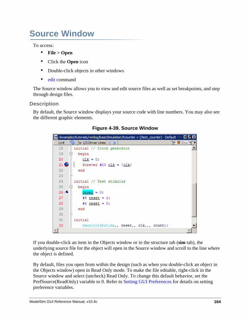
ModelSim GUI Reference Manual, v10.4c 164
Source WindowWindow ReferenceTo access:
• File > Open
• Click the Open icon
• Double-click objects in other windows
• edit command
The Source window allows you to view and edit source files as well as set breakpoints, and step through design files.
Description
By default, the Source window displays your source code with line numbers. You may also see the different graphic elements.
Figure 4-39. Source Window
If you double-click an item in the Objects window or in the structure tab (sim tab), the underlying source file for the object will open in the Source window and scroll to the line where the object is defined.
By default, files you open from within the design (such as when you double-click an object in the Objects window) open in Read Only mode. To make the file editable, right-click in the Source window and select (uncheck) Read Only. To change this default behavior, set the PrefSource(ReadOnly) variable to 0. Refer to Setting GUI Preferences for details on setting preference variables.
Window ReferenceSource Window
ModelSim GUI Reference Manual, v10.4c 165
Fields• Red line numbers — denote executable lines, where you can set a breakpoint
• Blue arrow — denotes the currently active line or a process that you have selected in the Processes Window
• Red ball in line number column — denotes file-line breakpoints; gray ball denotes breakpoints that are currently disabled
• Blue flag in line number column — denotes line bookmarks
• Current Time Label — displays the Current Time or the Now (end of simulation) time. This is the time used to control state values annotated in the window (For details, refer to Current Time Label.)
• Code Folding Indicators — denotes sections of code that can be folded or expanded
Usage Notes
Disabling Automatic Opening of Source Files
By default, the Source window opens when the simulator hits a breakpoint, encounters a call to $finish(), or you are single stepping through your code. In each case, the simulator stops, the Source window opens and displays the last line of code that was executed. You can disable automatic opening by changing the preference variable settings:
• Breakpoints — Set the PrefSource(OpenOnBreak) variable to 0.
• $finish() call — Set the PrefSource(OpenOnFinish) variable to 0.
• Single Stepping — Set the PrefSource(OpenOnStep) variable to 0.
Displaying Multiple Source Files
By default each file you open or create is marked by a window tab, as shown in the graphic below.
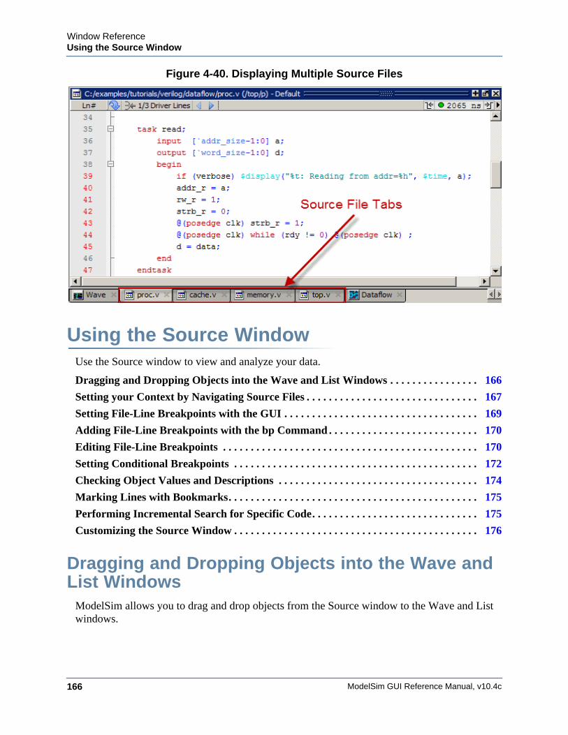
ModelSim GUI Reference Manual, v10.4c166
Window ReferenceUsing the Source Window
Figure 4-40. Displaying Multiple Source Files
Using the Source WindowUse the Source window to view and analyze your data.
Dragging and Dropping Objects into the Wave and List Windows . . . . . . . . . . . . . . . . 166
Setting your Context by Navigating Source Files . . . . . . . . . . . . . . . . . . . . . . . . . . . . . . . 167
Setting File-Line Breakpoints with the GUI . . . . . . . . . . . . . . . . . . . . . . . . . . . . . . . . . . . 169
Adding File-Line Breakpoints with the bp Command . . . . . . . . . . . . . . . . . . . . . . . . . . . 170
Editing File-Line Breakpoints . . . . . . . . . . . . . . . . . . . . . . . . . . . . . . . . . . . . . . . . . . . . . . 170
Setting Conditional Breakpoints . . . . . . . . . . . . . . . . . . . . . . . . . . . . . . . . . . . . . . . . . . . . 172
Checking Object Values and Descriptions . . . . . . . . . . . . . . . . . . . . . . . . . . . . . . . . . . . . 174
Marking Lines with Bookmarks. . . . . . . . . . . . . . . . . . . . . . . . . . . . . . . . . . . . . . . . . . . . . 175
Performing Incremental Search for Specific Code. . . . . . . . . . . . . . . . . . . . . . . . . . . . . . 175
Customizing the Source Window . . . . . . . . . . . . . . . . . . . . . . . . . . . . . . . . . . . . . . . . . . . . 176
Dragging and Dropping Objects into the Wave and List Windows
ModelSim allows you to drag and drop objects from the Source window to the Wave and List windows.
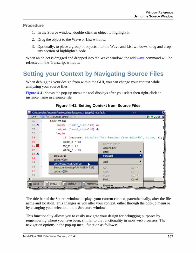
Window ReferenceUsing the Source Window
ModelSim GUI Reference Manual, v10.4c 167
Procedure
1. In the Source window, double-click an object to highlight it.
2. Drag the object to the Wave or List window.
3. Optionally, to place a group of objects into the Wave and List windows, drag and drop any section of highlighted code.
When an object is dragged and dropped into the Wave window, the add wave command will be reflected in the Transcript window.
Setting your Context by Navigating Source FilesWhen debugging your design from within the GUI, you can change your context while analyzing your source files.
Figure 4-41 shows the pop-up menu the tool displays after you select then right-click an instance name in a source file.
Figure 4-41. Setting Context from Source Files
The title bar of the Source window displays your current context, parenthetically, after the file name and location. This changes as you alter your context, either through the pop-up menu or by changing your selection in the Structure window.
This functionality allows you to easily navigate your design for debugging purposes by remembering where you have been, similar to the functionality in most web browsers. The navigation options in the pop-up menu function as follows:
ModelSim GUI Reference Manual, v10.4c168
Window ReferenceUsing the Source Window
• Open Instance — changes your context to the instance you have selected within the source file. This is not available if you have not placed your cursor in, or highlighted the name of, an instance within your source file.
If any ambiguities exists, most likely due to generate statements, this option opens a dialog box allowing you to choose from all available instances.
• Ascend Env — changes your context to the file and line number in the parent region where the current region is instantiated. This is not available if you are at the top-level of your design.
• Forward/Back — allows you to change to previously selected contexts. This is not available if you have not changed your context.
The Open Instance option is essentially executing aCn environment command to change your context, therefore any time you use this command manually at the command prompt, that information is also saved for use with the Forward/Back options.
Highlighted Text in a Source Window
The Source window can display text that is highlighted as a result of various conditions or operations, such as the following:
• Double-clicking an error message in the transcript shown during compilation
In these cases, the relevant text in the source code is shown with a persistent highlighting. To remove this highlighted display, choose More > Clear Highlights from the right-click popup menu of the Source window. If the Source window is docked, you can also perform this action by selecting Source > More > Clear Highlights from the Main menu. If the window is undocked, select Edit > Advanced > Clear Highlights.
Note Clear Highlights does not affect text that you have selected with the mouse cursor.
Example
To produce a compile error that displays highlighted text in the Source window, do the following:
1. Choose Compile > Compile Options
2. In the Compiler Options dialog box, click either the VHDL tab or the Verilog & SystemVerilog tab.
3. Enable Show source lines with errors and click OK.
4. Open a design file and create a known compile error (such as changing the word “entity” to “entry” or “module” to “nodule”).
Window ReferenceUsing the Source Window
ModelSim GUI Reference Manual, v10.4c 169
5. Choose Compile > Compile and then complete the Compile Source Files dialog box to finish compiling the file.
6. When the compile error appears in the Transcript window, double-click on it.
7. The source window is opened (if needed), and the text containing the error is highlighted.
8. To remove the highlighting, choose Source > More > Clear Highlights.
Hyperlinked Text in a Source Window
The Source window supports hyperlinked navigation. To turn hyperlinked text on or off in the Source window, do the following:
1. Click anywhere in the Source window to make it the active window.
2. Select Source > Show Hyperlinks.
When you double-click on hyperlinked text, the selection jumps from the usage of an object to its declaration. This provides the following operations:
• Jump from the usage of a signal, parameter, macro, or a variable to its declaration.
• Jump from a module declaration to its instantiation, and vice versa.
• Navigate back and forth between visited source files.
Setting File-Line Breakpoints with the GUIYou can easily set file-line breakpoints in your source code.
Procedure
1. In a Source window click in the line number column next to a red line number. A red ball denoting a breakpoint will appear (Figure 4-42).
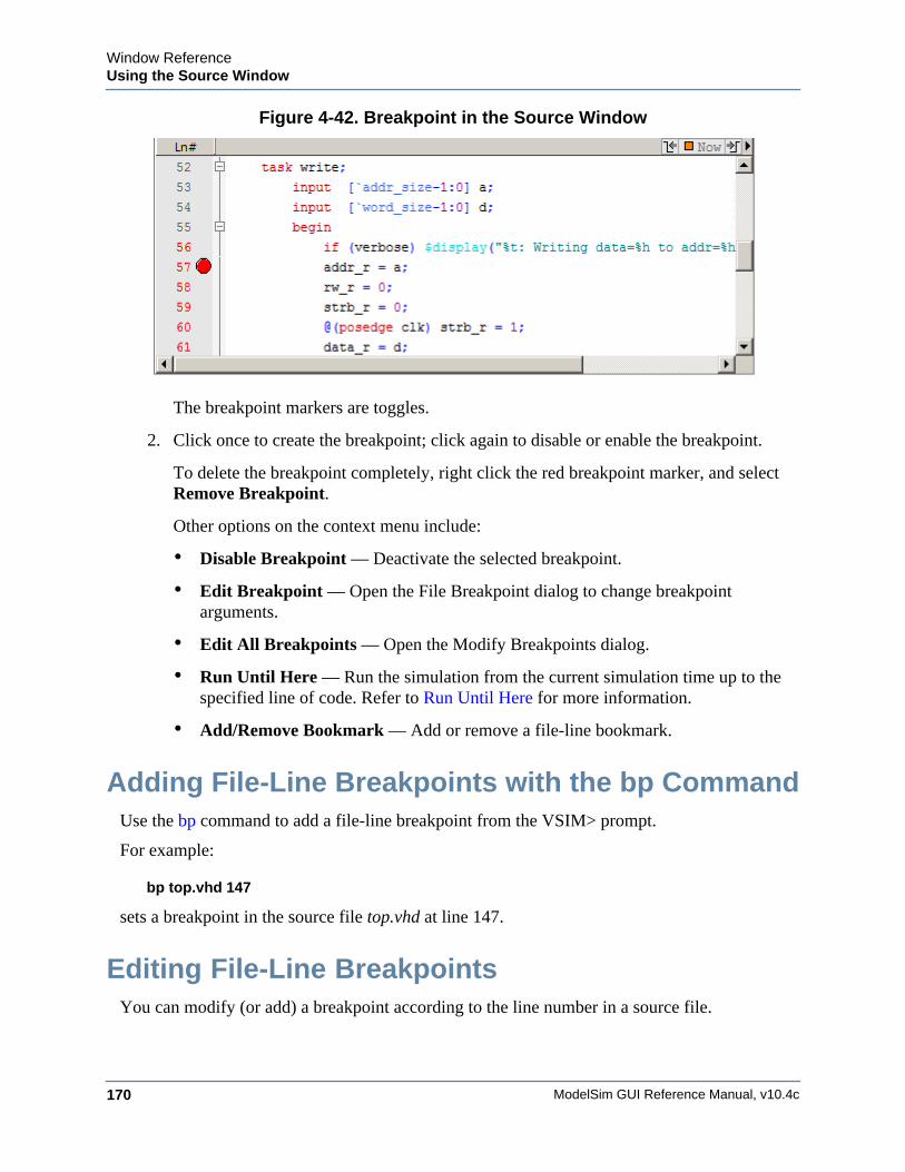
ModelSim GUI Reference Manual, v10.4c170
Window ReferenceUsing the Source Window
Figure 4-42. Breakpoint in the Source Window
The breakpoint markers are toggles.
2. Click once to create the breakpoint; click again to disable or enable the breakpoint.
To delete the breakpoint completely, right click the red breakpoint marker, and select Remove Breakpoint.
Other options on the context menu include:
• Disable Breakpoint — Deactivate the selected breakpoint.
• Edit Breakpoint — Open the File Breakpoint dialog to change breakpoint arguments.
• Edit All Breakpoints — Open the Modify Breakpoints dialog.
• Run Until Here — Run the simulation from the current simulation time up to the specified line of code. Refer to Run Until Here for more information.
• Add/Remove Bookmark — Add or remove a file-line bookmark.
Adding File-Line Breakpoints with the bp CommandUse the bp command to add a file-line breakpoint from the VSIM> prompt.
For example:
bp top.vhd 147
sets a breakpoint in the source file top.vhd at line 147.
Editing File-Line BreakpointsYou can modify (or add) a breakpoint according to the line number in a source file.
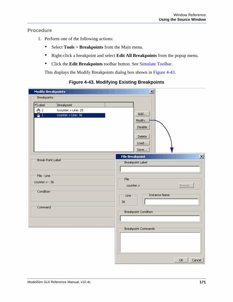
Window ReferenceUsing the Source Window
ModelSim GUI Reference Manual, v10.4c 171
Procedure
1. Perform one of the following actions:
• Select Tools > Breakpoints from the Main menu.
• Right-click a breakpoint and select Edit All Breakpoints from the popup menu.
• Click the Edit Breakpoints toolbar button. See Simulate Toolbar.
This displays the Modify Breakpoints dialog box shown in Figure 4-43.
Figure 4-43. Modifying Existing Breakpoints
ModelSim GUI Reference Manual, v10.4c172
Window ReferenceUsing the Source Window
The Modify Breakpoints dialog box provides a list of all breakpoints in the design. Select a file-line breakpoint from the list.
2. Click Modify, which opens the File Breakpoint dialog box shown in Figure 4-43.
3. Fill out any of the following fields to modify the selected breakpoint:
Breakpoint Label — Designates a label for the breakpoint.
Instance Name — The full pathname to an instance that sets a breakpoint so it applies only to that specified instance.
Breakpoint Condition — One or more conditions that determine whether the breakpoint is observed. If the condition is true, the simulation stops at the breakpoint. If false, the simulation bypasses the breakpoint. A condition cannot refer to a VHDL variable (only a signal). Refer to the tip below for more information on proper syntax for breakpoints entered in the GUI.
Breakpoint Command — A string, enclosed in braces ({}) that specifies one or more commands to be executed at the breakpoint. Use a semicolon (;) to separate multiple commands.
Tip: All fields in the File Breakpoint dialog box, except the Breakpoint Condition field, use the same syntax and format as the -inst switch and the command string of the bp command. Do not enclose the expression entered in the Breakpoint Condition field in quotation marks (“ ”). For more information on these command options, refer to the bp command in the Questa SV/AFV Reference Manual.
4. Click OK to close the File Breakpoints dialog box.
5. Click OK to close the Modify Breakpoints dialog box.
The Modify Breakpoints dialog box (Figure 4-43) includes Load and Save buttons that allow you to load or save breakpoints.
Setting Conditional BreakpointsIn dynamic class-based code, an expression can be executed by more than one object or class instance during the simulation of a design. You set a conditional breakpoint on the line in the source file that defines the expression and specifies a condition of the expression or instance you want to examine. You can write conditional breakpoints to evaluate an absolute expression or a relative expression.
NoteBe sure to first compile and load your simulation before setting a conditional breakpoint.
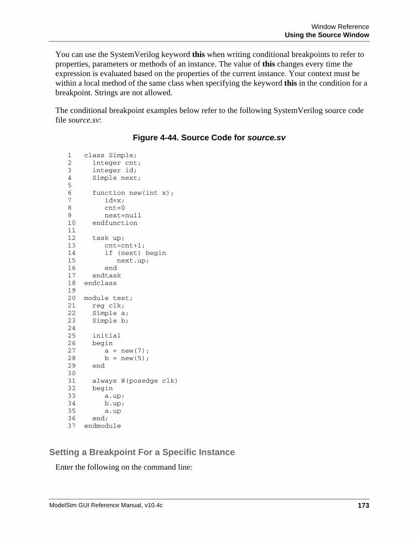
Window ReferenceUsing the Source Window
ModelSim GUI Reference Manual, v10.4c 173
You can use the SystemVerilog keyword this when writing conditional breakpoints to refer to properties, parameters or methods of an instance. The value of this changes every time the expression is evaluated based on the properties of the current instance. Your context must be within a local method of the same class when specifying the keyword this in the condition for a breakpoint. Strings are not allowed.
The conditional breakpoint examples below refer to the following SystemVerilog source code file source.sv:
Figure 4-44. Source Code for source.sv
1 class Simple;2 integer cnt;3 integer id;4 Simple next;56 function new(int x);7 id=x;8 cnt=09 next=null10 endfunction1112 task up;13 cnt=cnt+1;14 if (next) begin15 next.up;16 end17 endtask18 endclass1920 module test;21 reg clk;22 Simple a;23 Simple b;2425 initial26 begin27 a = new(7);28 b = new(5);29 end3031 always @(posedge clk)32 begin33 a.up;34 b.up;35 a.up36 end;37 endmodule
Setting a Breakpoint For a Specific Instance
Enter the following on the command line:
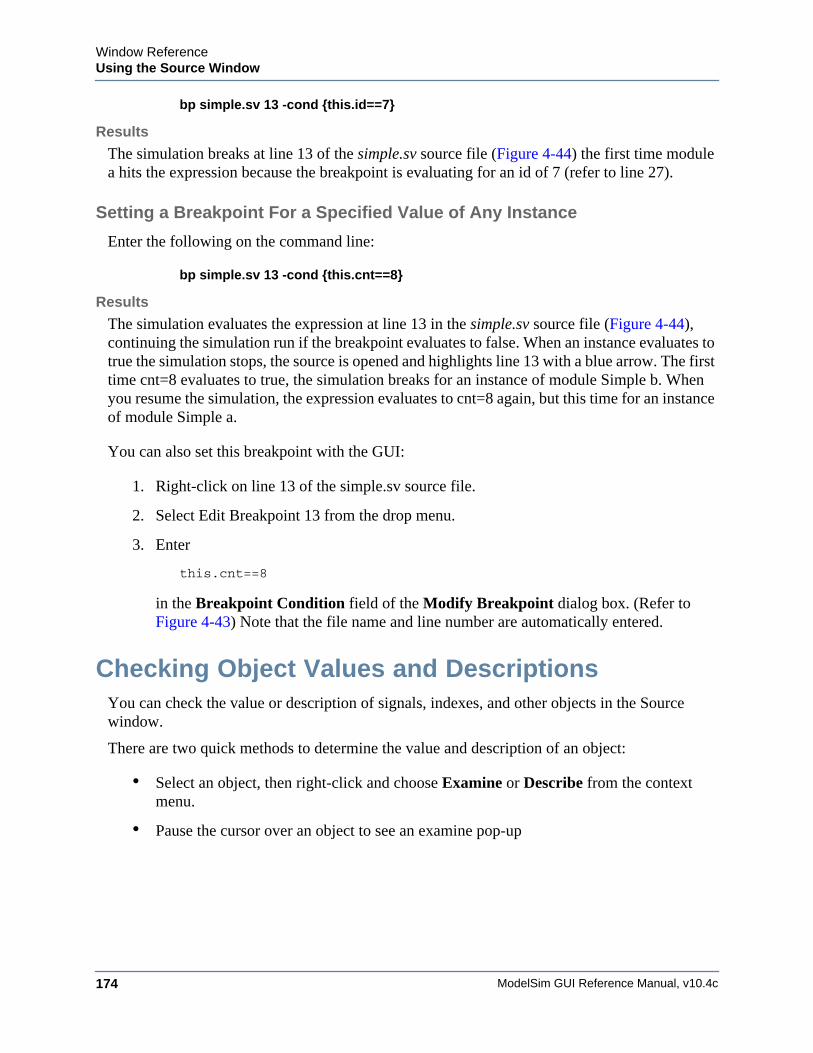
ModelSim GUI Reference Manual, v10.4c174
Window ReferenceUsing the Source Window
bp simple.sv 13 -cond {this.id==7}
Results
The simulation breaks at line 13 of the simple.sv source file (Figure 4-44) the first time module a hits the expression because the breakpoint is evaluating for an id of 7 (refer to line 27).
Setting a Breakpoint For a Specified Value of Any Instance
Enter the following on the command line:
bp simple.sv 13 -cond {this.cnt==8}
Results
The simulation evaluates the expression at line 13 in the simple.sv source file (Figure 4-44), continuing the simulation run if the breakpoint evaluates to false. When an instance evaluates to true the simulation stops, the source is opened and highlights line 13 with a blue arrow. The first time cnt=8 evaluates to true, the simulation breaks for an instance of module Simple b. When you resume the simulation, the expression evaluates to cnt=8 again, but this time for an instance of module Simple a.
You can also set this breakpoint with the GUI:
1. Right-click on line 13 of the simple.sv source file.
2. Select Edit Breakpoint 13 from the drop menu.
3. Enter
this.cnt==8
in the Breakpoint Condition field of the Modify Breakpoint dialog box. (Refer to Figure 4-43) Note that the file name and line number are automatically entered.
Checking Object Values and DescriptionsYou can check the value or description of signals, indexes, and other objects in the Source window.
There are two quick methods to determine the value and description of an object:
• Select an object, then right-click and choose Examine or Describe from the context menu.
• Pause the cursor over an object to see an examine pop-up
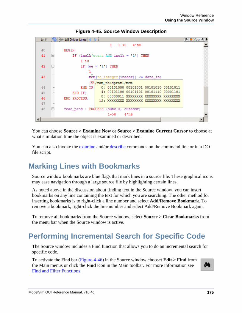
Window ReferenceUsing the Source Window
ModelSim GUI Reference Manual, v10.4c 175
Figure 4-45. Source Window Description
You can choose Source > Examine Now or Source > Examine Current Cursor to choose at what simulation time the object is examined or described.
You can also invoke the examine and/or describe commands on the command line or in a DO file script.
Marking Lines with BookmarksSource window bookmarks are blue flags that mark lines in a source file. These graphical icons may ease navigation through a large source file by highlighting certain lines.
As noted above in the discussion about finding text in the Source window, you can insert bookmarks on any line containing the text for which you are searching. The other method for inserting bookmarks is to right-click a line number and select Add/Remove Bookmark. To remove a bookmark, right-click the line number and select Add/Remove Bookmark again.
To remove all bookmarks from the Source window, select Source > Clear Bookmarks from the menu bar when the Source window is active.
Performing Incremental Search for Specific CodeThe Source window includes a Find function that allows you to do an incremental search for specific code.
To activate the Find bar (Figure 4-46) in the Source window chooset Edit > Find from the Main menus or click the Find icon in the Main toolbar. For more information see Find and Filter Functions.
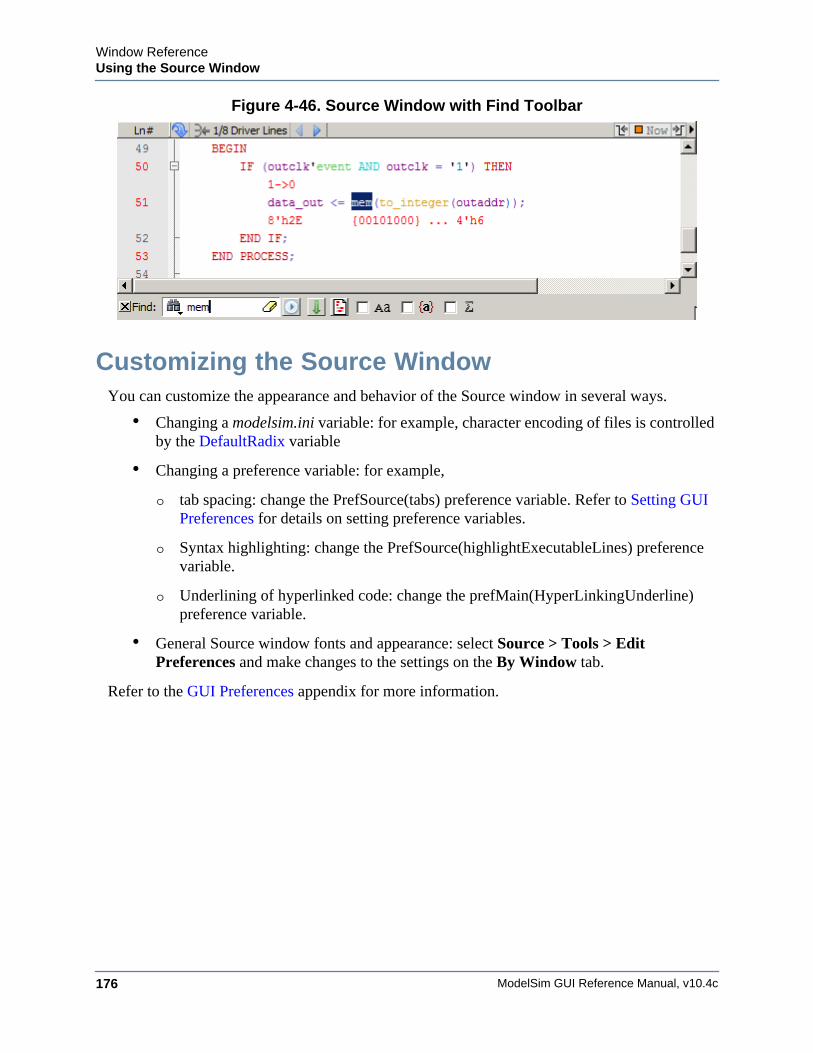
ModelSim GUI Reference Manual, v10.4c176
Window ReferenceUsing the Source Window
Figure 4-46. Source Window with Find Toolbar
Customizing the Source WindowYou can customize the appearance and behavior of the Source window in several ways.
• Changing a modelsim.ini variable: for example, character encoding of files is controlled by the DefaultRadix variable
• Changing a preference variable: for example,
o tab spacing: change the PrefSource(tabs) preference variable. Refer to Setting GUI Preferences for details on setting preference variables.
o Syntax highlighting: change the PrefSource(highlightExecutableLines) preference variable.
o Underlining of hyperlinked code: change the prefMain(HyperLinkingUnderline) preference variable.
• General Source window fonts and appearance: select Source > Tools > Edit Preferences and make changes to the settings on the By Window tab.
Refer to the GUI Preferences appendix for more information.
ModelSim GUI Reference Manual, v10.4c 177
Structure WindowWindow ReferenceTo access:
• View > Structure
• view structure command
• Button: View Objects Window Button
Use this window to view the hierarchical structure of the active simulation.
Description
The name of the structure window, as shown in the title bar or in the tab if grouped with other windows, can vary:
sim — This is the name shown for the Structure window for the active simulation.
dataset_name — The Structure window takes the name of any dataset you load through the File > Datasets menu item or the dataset open command.
By default, the Structure window opens in a tab group with the Library windows after starting a simulation. You can also open the Structure window with the “View Objects Window Button”.
The hierarchical view includes an entry for each object within the design. When you select an object in a Structure window, it becomes the current region.
The contents of several windows automatically update based on which object you select, including the Source window, Objects window, Processes window, and Locals window. All mouse button operations clear the current selection and select the item under the cursor.
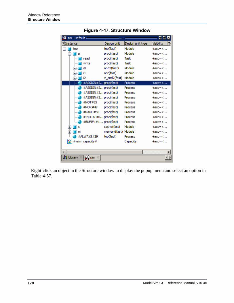
ModelSim GUI Reference Manual, v10.4c178
Window ReferenceStructure Window
Figure 4-47. Structure Window
Right-click an object in the Structure window to display the popup menu and select an option in Table 4-57.
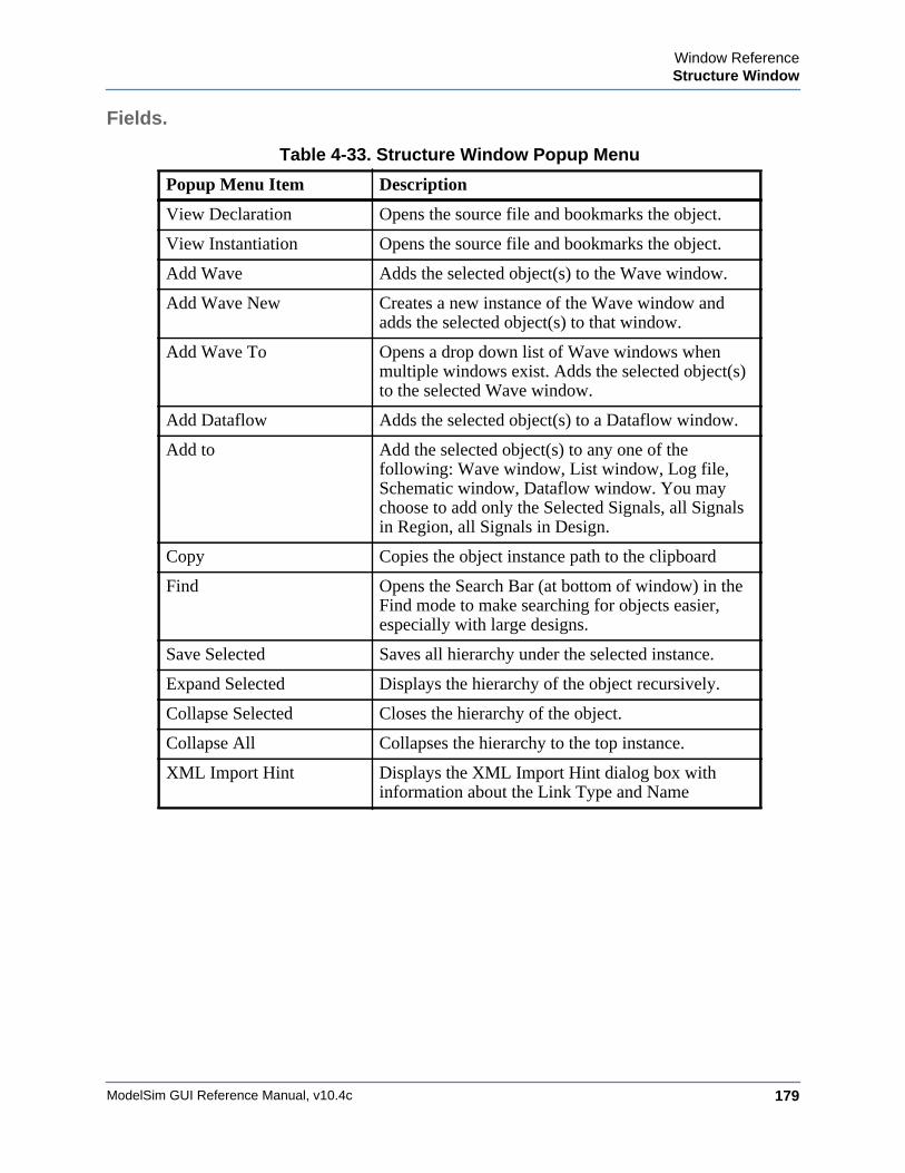
Window ReferenceStructure Window
ModelSim GUI Reference Manual, v10.4c 179
Fields.
Table 4-33. Structure Window Popup Menu
Popup Menu Item Description
View Declaration Opens the source file and bookmarks the object.
View Instantiation Opens the source file and bookmarks the object.
Add Wave Adds the selected object(s) to the Wave window.
Add Wave New Creates a new instance of the Wave window and adds the selected object(s) to that window.
Add Wave To Opens a drop down list of Wave windows when multiple windows exist. Adds the selected object(s) to the selected Wave window.
Add Dataflow Adds the selected object(s) to a Dataflow window.
Add to Add the selected object(s) to any one of the following: Wave window, List window, Log file, Schematic window, Dataflow window. You may choose to add only the Selected Signals, all Signals in Region, all Signals in Design.
Copy Copies the object instance path to the clipboard
Find Opens the Search Bar (at bottom of window) in the Find mode to make searching for objects easier, especially with large designs.
Save Selected Saves all hierarchy under the selected instance.
Expand Selected Displays the hierarchy of the object recursively.
Collapse Selected Closes the hierarchy of the object.
Collapse All Collapses the hierarchy to the top instance.
XML Import Hint Displays the XML Import Hint dialog box with information about the Link Type and Name
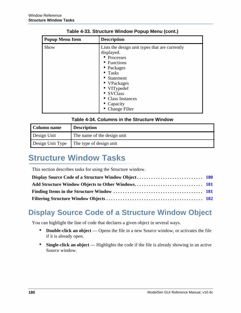
ModelSim GUI Reference Manual, v10.4c180
Window ReferenceStructure Window Tasks
Structure Window TasksThis section describes tasks for using the Structure window.
Display Source Code of a Structure Window Object . . . . . . . . . . . . . . . . . . . . . . . . . . . . 180
Add Structure Window Objects to Other Windows. . . . . . . . . . . . . . . . . . . . . . . . . . . . . 181
Finding Items in the Structure Window . . . . . . . . . . . . . . . . . . . . . . . . . . . . . . . . . . . . . . 181
Filtering Structure Window Objects . . . . . . . . . . . . . . . . . . . . . . . . . . . . . . . . . . . . . . . . . 182
Display Source Code of a Structure Window ObjectYou can highlight the line of code that declares a given object in several ways.
• Double-click an object — Opens the file in a new Source window, or activates the file if it is already open.
• Single-click an object — Highlights the code if the file is already showing in an active Source window.
Show Lists the design unit types that are currently displayed. • Processes• Functions• Packages• Tasks• Statement• VPackages• VITypedef• SVClass• Class Instances• Capacity• Change Filter
Table 4-34. Columns in the Structure Window
Column name Description
Design Unit The name of the design unit
Design Unit Type The type of design unit
Table 4-33. Structure Window Popup Menu (cont.)
Popup Menu Item Description
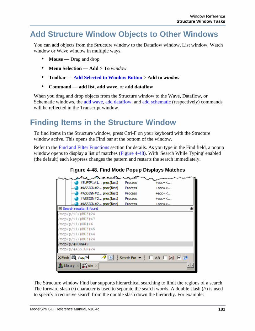
Window ReferenceStructure Window Tasks
ModelSim GUI Reference Manual, v10.4c 181
Add Structure Window Objects to Other WindowsYou can add objects from the Structure window to the Dataflow window, List window, Watch window or Wave window in multiple ways.
• Mouse — Drag and drop
• Menu Selection — Add > To window
• Toolbar — Add Selected to Window Button > Add to window
• Command — add list, add wave, or add dataflow
When you drag and drop objects from the Structure window to the Wave, Dataflow, or Schematic windows, the add wave, add dataflow, and add schematic (respectively) commands will be reflected in the Transcript window.
Finding Items in the Structure WindowTo find items in the Structure window, press Ctrl-F on your keyboard with the Structure window active. This opens the Find bar at the bottom of the window.
Refer to the Find and Filter Functions section for details. As you type in the Find field, a popup window opens to display a list of matches (Figure 4-48). With 'Search While Typing' enabled (the default) each keypress changes the pattern and restarts the search immediately.
Figure 4-48. Find Mode Popup Displays Matches
The Structure window Find bar supports hierarchical searching to limit the regions of a search. The forward slash (/) character is used to separate the search words. A double slash (//) is used to specify a recursive search from the double slash down the hierarchy. For example:
ModelSim GUI Reference Manual, v10.4c182
Window ReferenceStructure Window Tasks
foo — search the entire design space for regions containing "foo" in the name.
foo?bar — search the entire design space for regions containing "foo" then any single alphanumeric character, followed by "bar"
foo*bar — search the design for a name containing "foo", a string of zero or more alphanumeric characters, followed by "bar. For example, to following names match a search for "foo*bar": "foobar", "foo_fred_bar", and "fooIsAbar". "fooISbad" does not match the search string.
/foo — search the top of the design hierarchy for regions containing "foo".
/foo/bar — search for regions containing "foo" at the top, and then regions containing "bar".
/foo//bar — search for regions containing "bar" recursively below all top level regions containing "foo".
To search for a name that contains the slash (/) character, escape the slash using a backslash (\). For example: \/bar.
When you double-click any item in the match list that item is highlighted in the Structure window and the popup is removed. The search can be canceled by clicking on the ‘x’ button in the popup window or by pressing the Esc key on your keyboard.
Filtering Structure Window ObjectsYou can control the types of information available in the Structure window through the View > Filter menu items.
Processes — Implicit wire processes
Functions — Verilog and VHDL Functions
Packages — VHDL Packages
Tasks — Verilog Tasks
Statement — Verilog Statements
VlPackage — Verilog Packages
VlTypedef — Verilog Type Definitions
Cell Instances — Verilog cell instances or VHDL architecture instance.
Capacity — Memory capacity design unit
Subprogram — VHDL procedures and functions; Verilog functions and tasks

Window ReferenceStructure Window Tasks
ModelSim GUI Reference Manual, v10.4c 183
ModelSim GUI Reference Manual, v10.4c184
Window ReferenceTranscript Window
Transcript WindowWindow ReferenceTo access: The Transcript window is always open in the Main window and cannot be closed.
The Transcript window maintains a running history of commands that are invoked and messages that occur as you work with ModelSim. When a simulation is running, the Transcript displays a VSIM prompt, allowing you to enter command-line commands from within the graphic interface.
Description
You can scroll backward and forward through the current work history by using the vertical scrollbar. You can also use arrow keys to recall previous commands, or copy and paste using the mouse within the window (see Main and Source Window Mouse and Keyboard Shortcuts for details).
The Transcript tab contains the command line interface, identified by the ModelSim prompt, and the simulation interface, identified by the VSIM prompt.
When the Transcript window is active, a "Transcript" menu selection appears in the Main window menu bar.
When undocked, the Transcript window allows access to the following toolbars:
• Standard Toolbar
• Help Toolbar
Fields
• Adjust Font Scaling — Displays the Adjust Scaling dialog box, which allows you to adjust how fonts appear for your display environment. Directions are available in the dialog box.
• Transcript File — Allows you to change the default name used when saving the transcript file. The saved transcript file will contain all the text in the current transcript file.
• Command History — Allows you to change the default name used when saving command history information. This file is saved at the same time as the transcript file.
• Save File — Allows you to change the default name used when selecting File > Save As.
• Saved Lines — Allows you to change how many lines of text are saved in the transcript window. Setting this value to zero (0) saves all lines.
• Line Prefix — Allows you to change the character(s) that precedes the lines in the transcript.
Window ReferenceTranscript Window Tasks
ModelSim GUI Reference Manual, v10.4c 185
• Update Rate — Allows you to change the length of time (in ms) between transcript refreshes.
• ModelSim Prompt — Allows you to change the string used for the command line prompt.
• VSIM Prompt — Allows you to change the string used for the simulation prompt.
• Paused Prompt — Allows you to change the string used for when the simulation is paused.
Transcript Window TasksYou can perform multiple tasks in the Transcript window.
Saving the Transcript File. . . . . . . . . . . . . . . . . . . . . . . . . . . . . . . . . . . . . . . . . . . . . . . . . . 185
Colorizing the Transcript . . . . . . . . . . . . . . . . . . . . . . . . . . . . . . . . . . . . . . . . . . . . . . . . . . 186
Disabling Creation of the Transcript File . . . . . . . . . . . . . . . . . . . . . . . . . . . . . . . . . . . . . 187
Performing an Incremental Search . . . . . . . . . . . . . . . . . . . . . . . . . . . . . . . . . . . . . . . . . . 187
Using Automatic Command Help. . . . . . . . . . . . . . . . . . . . . . . . . . . . . . . . . . . . . . . . . . . . 188
Using drivers and Readers Command Results . . . . . . . . . . . . . . . . . . . . . . . . . . . . . . . . . 188
Saving the Transcript FileVariable settings determine the filename used for saving the transcript. If either PrefMain(file) in the .modelsim file or TranscriptFile in the modelsim.ini file is set, then the transcript output is logged to the specified file. By default the TranscriptFile variable in modelsim.ini is set to transcript. If either variable is set, the transcript contents are always saved and no explicit saving is necessary.
If you would like to save an additional copy of the transcript with a different filename, click in the Transcript window and then choose File > Save As, or File > Save. The initial save must be made with the Save As selection, which stores the filename in the Tcl variable PrefMain(saveFile). Subsequent saves can be made with the Save selection. Since no automatic saves are performed for this file, it is written only when you invoke a Save command. The file is written to the specified directory and records the contents of the transcript at the time of the save.
Refer to Creating a Transcript File for more information about creating, locating, and saving a transcript file.
Saving a Transcript File as a DO File
Perform the following steps to save a transcript file as a DO file.
1. Open a saved transcript file in a text editor.
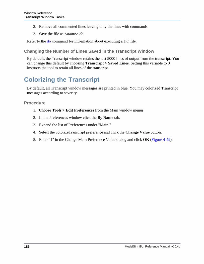
ModelSim GUI Reference Manual, v10.4c186
Window ReferenceTranscript Window Tasks
2. Remove all commented lines leaving only the lines with commands.
3. Save the file as <name>.do.
Refer to the do command for information about executing a DO file.
Changing the Number of Lines Saved in the Transcript Window
By default, the Transcript window retains the last 5000 lines of output from the transcript. You can change this default by choosing Transcript > Saved Lines. Setting this variable to 0 instructs the tool to retain all lines of the transcript.
Colorizing the TranscriptBy default, all Transcript window messages are printed in blue. You may colorized Transcript messages according to severity.
Procedure
1. Choose Tools > Edit Preferences from the Main window menus.
2. In the Preferences window click the By Name tab.
3. Expand the list of Preferences under "Main."
4. Select the colorizeTranscript preference and click the Change Value button.
5. Enter "1" in the Change Main Preference Value dialog and click OK (Figure 4-49).
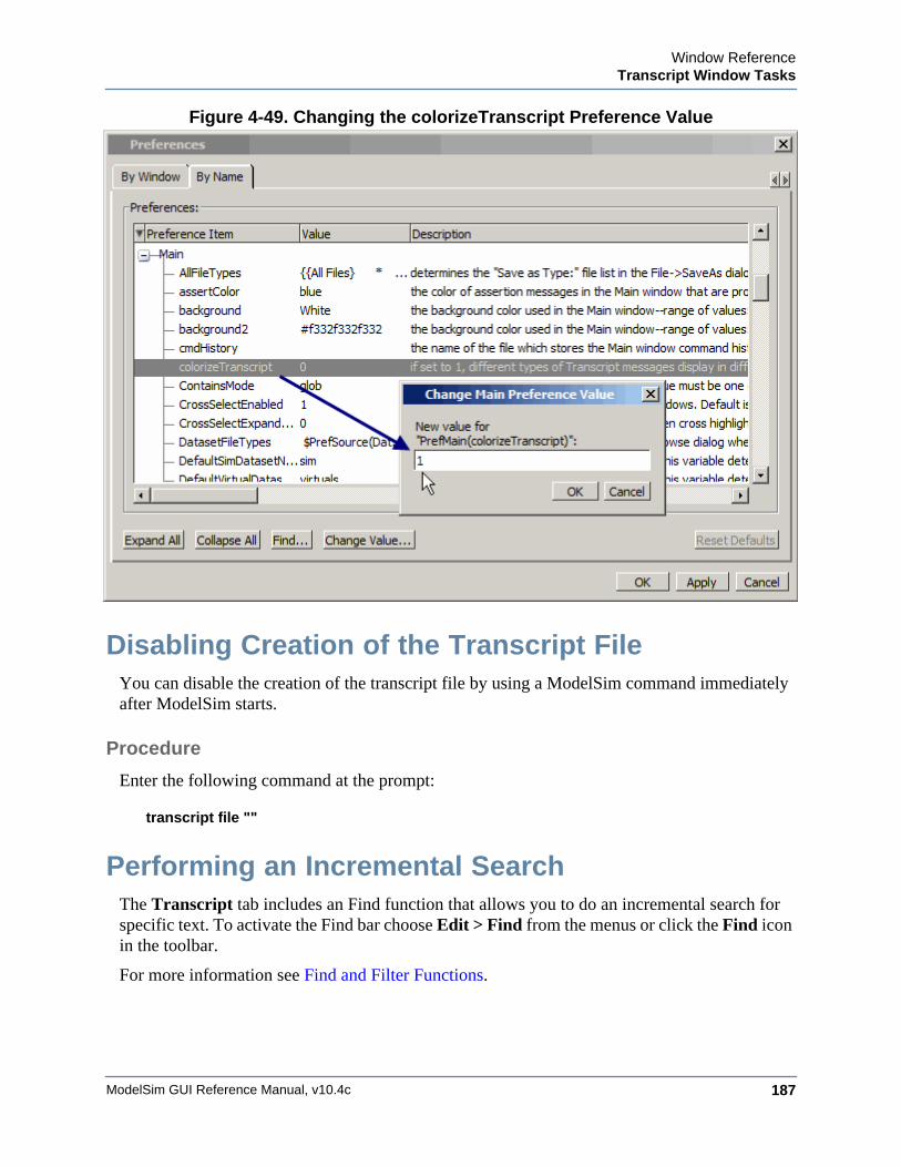
Window ReferenceTranscript Window Tasks
ModelSim GUI Reference Manual, v10.4c 187
Figure 4-49. Changing the colorizeTranscript Preference Value
Disabling Creation of the Transcript FileYou can disable the creation of the transcript file by using a ModelSim command immediately after ModelSim starts.
Procedure
Enter the following command at the prompt:
transcript file ""
Performing an Incremental SearchThe Transcript tab includes an Find function that allows you to do an incremental search for specific text. To activate the Find bar choose Edit > Find from the menus or click the Find icon in the toolbar.
For more information see Find and Filter Functions.
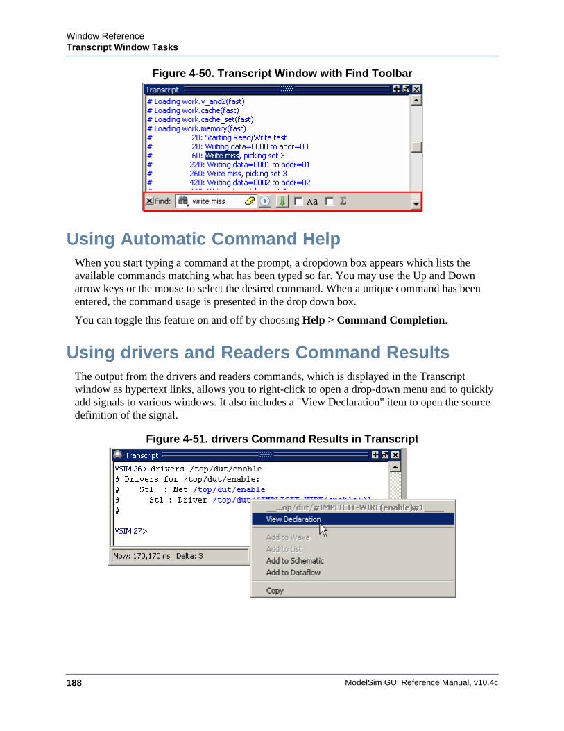
ModelSim GUI Reference Manual, v10.4c188
Window ReferenceTranscript Window Tasks
Figure 4-50. Transcript Window with Find Toolbar
Using Automatic Command HelpWhen you start typing a command at the prompt, a dropdown box appears which lists the available commands matching what has been typed so far. You may use the Up and Down arrow keys or the mouse to select the desired command. When a unique command has been entered, the command usage is presented in the drop down box.
You can toggle this feature on and off by choosing Help > Command Completion.
Using drivers and Readers Command ResultsThe output from the drivers and readers commands, which is displayed in the Transcript window as hypertext links, allows you to right-click to open a drop-down menu and to quickly add signals to various windows. It also includes a "View Declaration" item to open the source definition of the signal.
Figure 4-51. drivers Command Results in Transcript
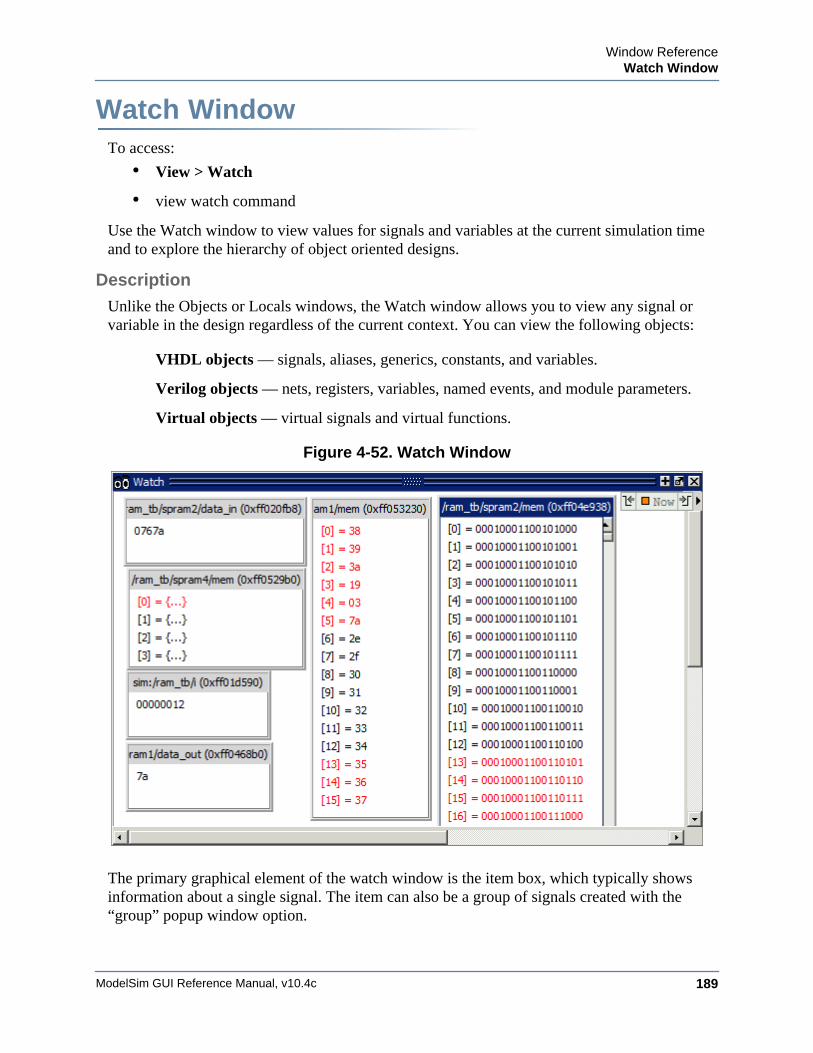
Window ReferenceWatch Window
ModelSim GUI Reference Manual, v10.4c 189
Watch WindowWindow ReferenceTo access:
• View > Watch
• view watch command
Use the Watch window to view values for signals and variables at the current simulation time and to explore the hierarchy of object oriented designs.
Description
Unlike the Objects or Locals windows, the Watch window allows you to view any signal or variable in the design regardless of the current context. You can view the following objects:
VHDL objects — signals, aliases, generics, constants, and variables.
Verilog objects — nets, registers, variables, named events, and module parameters.
Virtual objects — virtual signals and virtual functions.
Figure 4-52. Watch Window
The primary graphical element of the watch window is the item box, which typically shows information about a single signal. The item can also be a group of signals created with the “group” popup window option.
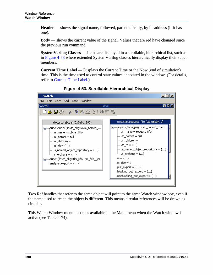
ModelSim GUI Reference Manual, v10.4c190
Window ReferenceWatch Window
Header — shows the signal name, followed, parenthetically, by its address (if it has one).
Body — shows the current value of the signal. Values that are red have changed since the previous run command.
SystemVerilog Classes — Items are displayed in a scrollable, hierarchical list, such as in Figure 4-53 where extended SystemVerilog classes hierarchically display their super members.
Current Time Label — Displays the Current Time or the Now (end of simulation) time. This is the time used to control state values annotated in the window. (For details, refer to Current Time Label.)
Figure 4-53. Scrollable Hierarchical Display
Two Ref handles that refer to the same object will point to the same Watch window box, even if the name used to reach the object is different. This means circular references will be drawn as circular.
This Watch Window menu becomes available in the Main menu when the Watch window is active (see Table 4-74).
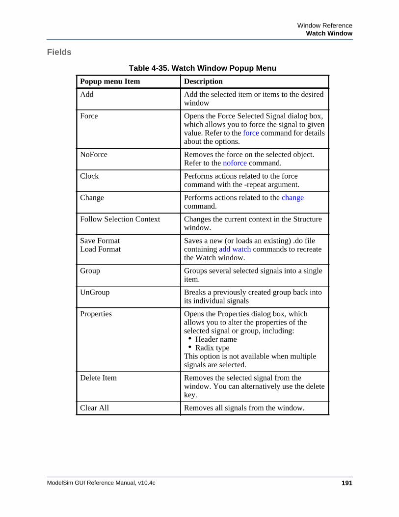
Window ReferenceWatch Window
ModelSim GUI Reference Manual, v10.4c 191
Fields
Table 4-35. Watch Window Popup Menu
Popup menu Item Description
Add Add the selected item or items to the desired window
Force Opens the Force Selected Signal dialog box, which allows you to force the signal to given value. Refer to the force command for details about the options.
NoForce Removes the force on the selected object. Refer to the noforce command.
Clock Performs actions related to the force command with the -repeat argument.
Change Performs actions related to the change command.
Follow Selection Context Changes the current context in the Structure window.
Save FormatLoad Format
Saves a new (or loads an existing) .do file containing add watch commands to recreate the Watch window.
Group Groups several selected signals into a single item.
UnGroup Breaks a previously created group back into its individual signals
Properties Opens the Properties dialog box, which allows you to alter the properties of the selected signal or group, including:• Header name• Radix type
This option is not available when multiple signals are selected.
Delete Item Removes the selected signal from the window. You can alternatively use the delete key.
Clear All Removes all signals from the window.
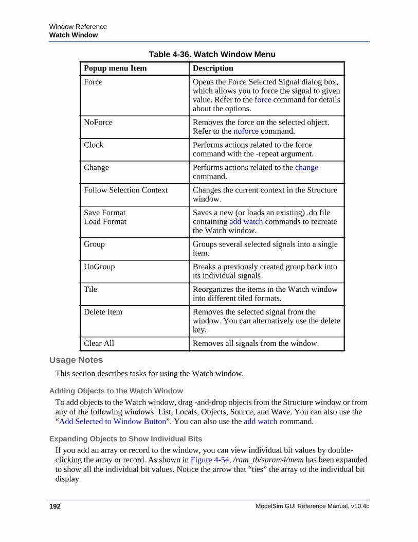
ModelSim GUI Reference Manual, v10.4c192
Window ReferenceWatch Window
Usage NotesThis section describes tasks for using the Watch window.
Adding Objects to the Watch Window
To add objects to the Watch window, drag -and-drop objects from the Structure window or from any of the following windows: List, Locals, Objects, Source, and Wave. You can also use the “Add Selected to Window Button”. You can also use the add watch command.
Expanding Objects to Show Individual Bits
If you add an array or record to the window, you can view individual bit values by double-clicking the array or record. As shown in Figure 4-54, /ram_tb/spram4/mem has been expanded to show all the individual bit values. Notice the arrow that “ties” the array to the individual bit display.
Table 4-36. Watch Window Menu
Popup menu Item Description
Force Opens the Force Selected Signal dialog box, which allows you to force the signal to given value. Refer to the force command for details about the options.
NoForce Removes the force on the selected object. Refer to the noforce command.
Clock Performs actions related to the force command with the -repeat argument.
Change Performs actions related to the change command.
Follow Selection Context Changes the current context in the Structure window.
Save FormatLoad Format
Saves a new (or loads an existing) .do file containing add watch commands to recreate the Watch window.
Group Groups several selected signals into a single item.
UnGroup Breaks a previously created group back into its individual signals
Tile Reorganizes the items in the Watch window into different tiled formats.
Delete Item Removes the selected signal from the window. You can alternatively use the delete key.
Clear All Removes all signals from the window.
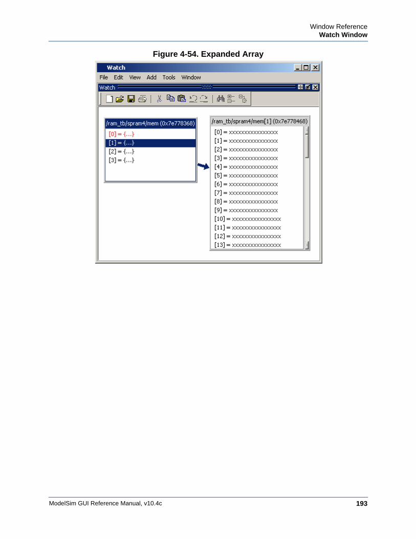
Window ReferenceWatch Window
ModelSim GUI Reference Manual, v10.4c 193
Figure 4-54. Expanded Array
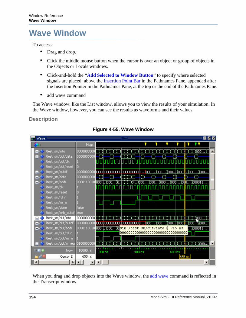
ModelSim GUI Reference Manual, v10.4c194
Window ReferenceWave Window
Wave WindowWindow ReferenceTo access:
• Drag and drop.
• Click the middle mouse button when the cursor is over an object or group of objects in the Objects or Locals windows.
• Click-and-hold the “Add Selected to Window Button” to specify where selected signals are placed: above the Insertion Point Bar in the Pathnames Pane, appended after the Insertion Pointer in the Pathnames Pane, at the top or the end of the Pathnames Pane.
• add wave command
The Wave window, like the List window, allows you to view the results of your simulation. In the Wave window, however, you can see the results as waveforms and their values.
Description
Figure 4-55. Wave Window
When you drag and drop objects into the Wave window, the add wave command is reflected in the Transcript window.
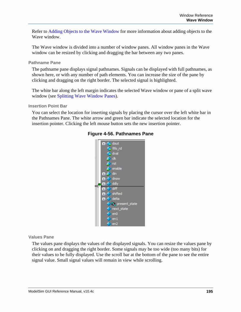
Window ReferenceWave Window
ModelSim GUI Reference Manual, v10.4c 195
Refer to Adding Objects to the Wave Window for more information about adding objects to the Wave window.
The Wave window is divided into a number of window panes. All window panes in the Wave window can be resized by clicking and dragging the bar between any two panes.
Pathname Pane
The pathname pane displays signal pathnames. Signals can be displayed with full pathnames, as shown here, or with any number of path elements. You can increase the size of the pane by clicking and dragging on the right border. The selected signal is highlighted.
The white bar along the left margin indicates the selected Wave window or pane of a split wave window (see Splitting Wave Window Panes).
Insertion Point Bar
You can select the location for inserting signals by placing the cursor over the left white bar in the Pathnames Pane. The white arrow and green bar indicate the selected location for the insertion pointer. Clicking the left mouse button sets the new insertion pointer.
Figure 4-56. Pathnames Pane
Values Pane
The values pane displays the values of the displayed signals. You can resize the values pane by clicking on and dragging the right border. Some signals may be too wide (too many bits) for their values to be fully displayed. Use the scroll bar at the bottom of the pane to see the entire signal value. Small signal values will remain in view while scrolling.
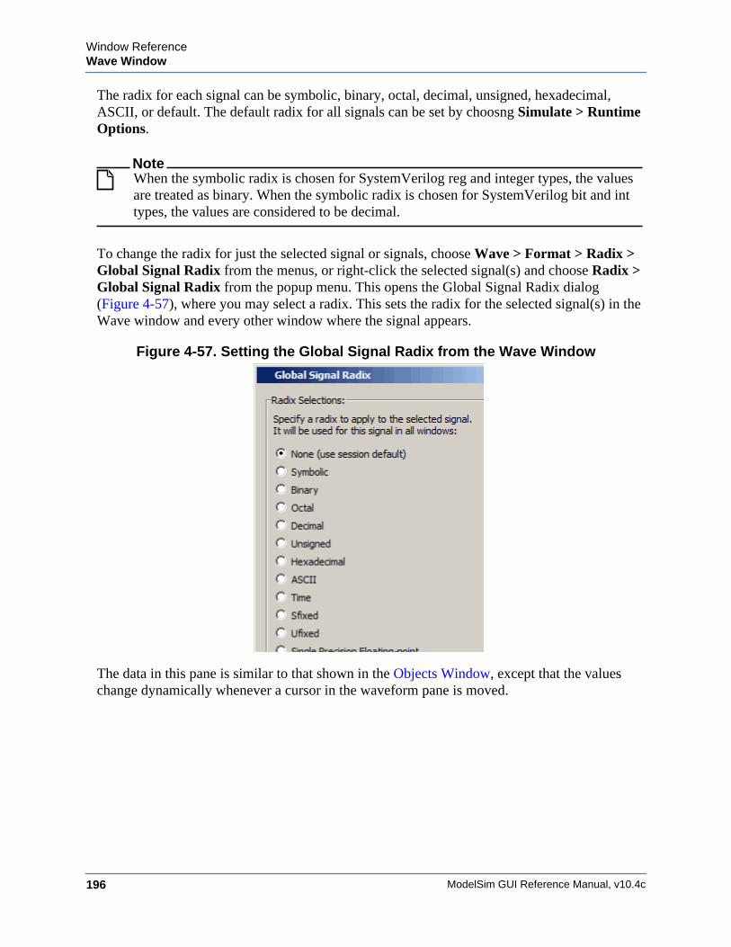
ModelSim GUI Reference Manual, v10.4c196
Window ReferenceWave Window
The radix for each signal can be symbolic, binary, octal, decimal, unsigned, hexadecimal, ASCII, or default. The default radix for all signals can be set by choosng Simulate > Runtime Options.
NoteWhen the symbolic radix is chosen for SystemVerilog reg and integer types, the values are treated as binary. When the symbolic radix is chosen for SystemVerilog bit and int types, the values are considered to be decimal.
To change the radix for just the selected signal or signals, choose Wave > Format > Radix > Global Signal Radix from the menus, or right-click the selected signal(s) and choose Radix > Global Signal Radix from the popup menu. This opens the Global Signal Radix dialog (Figure 4-57), where you may select a radix. This sets the radix for the selected signal(s) in the Wave window and every other window where the signal appears.
Figure 4-57. Setting the Global Signal Radix from the Wave Window
The data in this pane is similar to that shown in the Objects Window, except that the values change dynamically whenever a cursor in the waveform pane is moved.
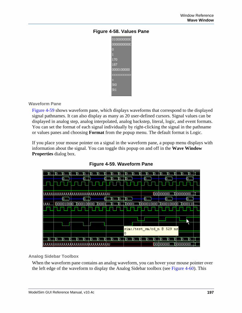
Window ReferenceWave Window
ModelSim GUI Reference Manual, v10.4c 197
Figure 4-58. Values Pane
Waveform Pane
Figure 4-59 shows waveform pane, which displays waveforms that correspond to the displayed signal pathnames. It can also display as many as 20 user-defined cursors. Signal values can be displayed in analog step, analog interpolated, analog backstep, literal, logic, and event formats. You can set the format of each signal individually by right-clicking the signal in the pathname or values panes and choosing Format from the popup menu. The default format is Logic.
If you place your mouse pointer on a signal in the waveform pane, a popup menu displays with information about the signal. You can toggle this popup on and off in the Wave Window Properties dialog box.
Figure 4-59. Waveform Pane
Analog Sidebar Toolbox
When the waveform pane contains an analog waveform, you can hover your mouse pointer over the left edge of the waveform to display the Analog Sidebar toolbox (see Figure 4-60). This
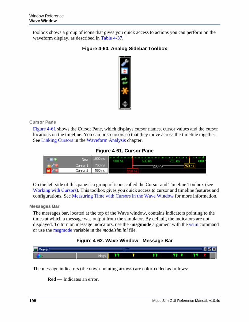
ModelSim GUI Reference Manual, v10.4c198
Window ReferenceWave Window
toolbox shows a group of icons that gives you quick access to actions you can perform on the waveform display, as described in Table 4-37.
Figure 4-60. Analog Sidebar Toolbox
Cursor Pane
Figure 4-61 shows the Cursor Pane, which displays cursor names, cursor values and the cursor locations on the timeline. You can link cursors so that they move across the timeline together. See Linking Cursors in the Waveform Analysis chapter.
Figure 4-61. Cursor Pane
On the left side of this pane is a group of icons called the Cursor and Timeline Toolbox (see Working with Cursors). This toolbox gives you quick access to cursor and timeline features and configurations. See Measuring Time with Cursors in the Wave Window for more information.
Messages Bar
The messages bar, located at the top of the Wave window, contains indicators pointing to the times at which a message was output from the simulator. By default, the indicators are not displayed. To turn on message indicators, use the -msgmode argument with the vsim command or use the msgmode variable in the modelsim.ini file.
Figure 4-62. Wave Window - Message Bar
The message indicators (the down-pointing arrows) are color-coded as follows:
Red — Indicates an error.
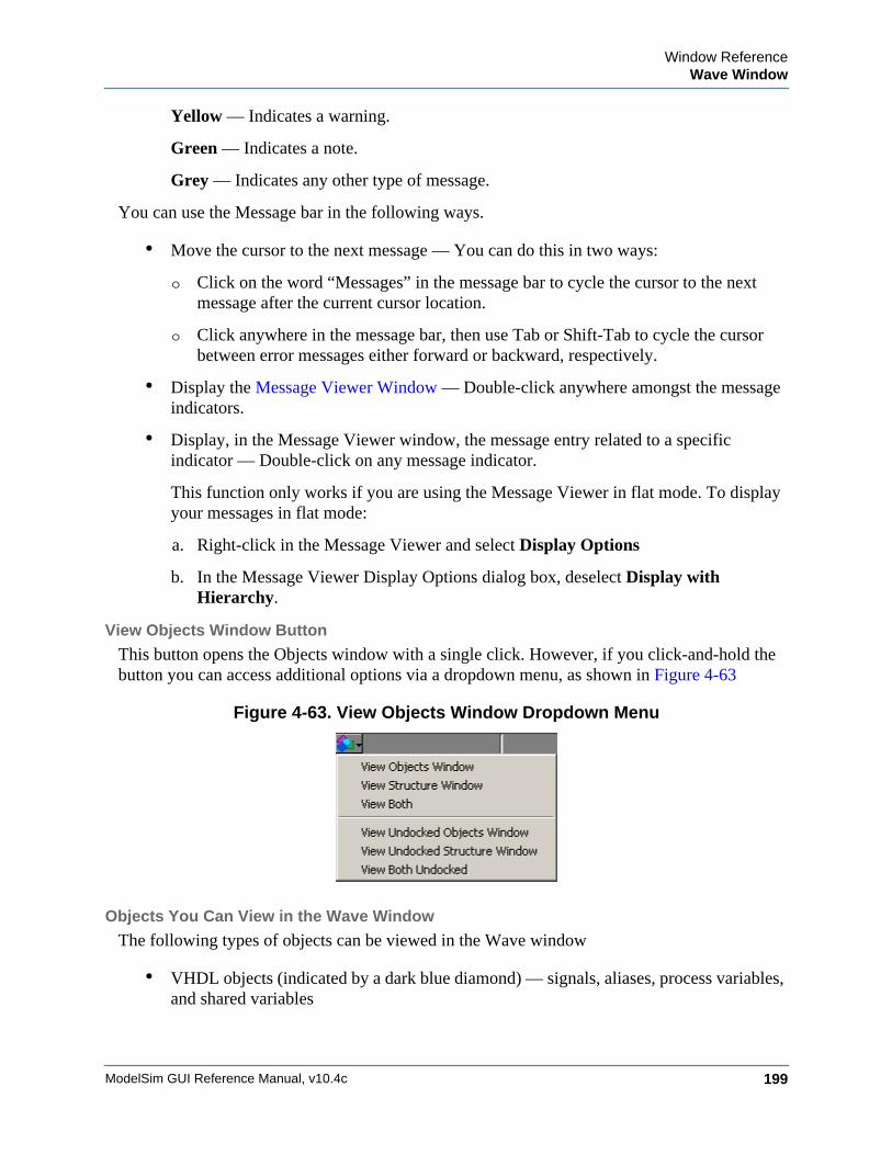
Window ReferenceWave Window
ModelSim GUI Reference Manual, v10.4c 199
Yellow — Indicates a warning.
Green — Indicates a note.
Grey — Indicates any other type of message.
You can use the Message bar in the following ways.
• Move the cursor to the next message — You can do this in two ways:
o Click on the word “Messages” in the message bar to cycle the cursor to the next message after the current cursor location.
o Click anywhere in the message bar, then use Tab or Shift-Tab to cycle the cursor between error messages either forward or backward, respectively.
• Display the Message Viewer Window — Double-click anywhere amongst the message indicators.
• Display, in the Message Viewer window, the message entry related to a specific indicator — Double-click on any message indicator.
This function only works if you are using the Message Viewer in flat mode. To display your messages in flat mode:
a. Right-click in the Message Viewer and select Display Options
b. In the Message Viewer Display Options dialog box, deselect Display with Hierarchy.
View Objects Window Button
This button opens the Objects window with a single click. However, if you click-and-hold the button you can access additional options via a dropdown menu, as shown in Figure 4-63
Figure 4-63. View Objects Window Dropdown Menu
Objects You Can View in the Wave Window
The following types of objects can be viewed in the Wave window
• VHDL objects (indicated by a dark blue diamond) — signals, aliases, process variables, and shared variables
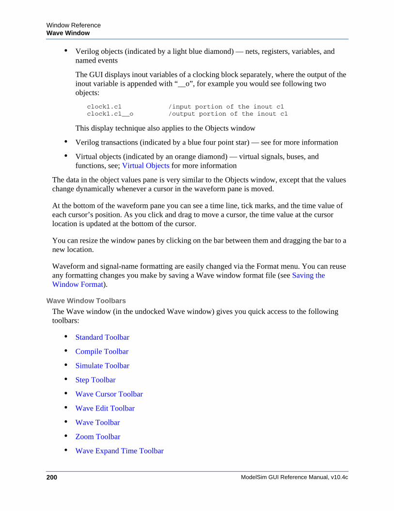
ModelSim GUI Reference Manual, v10.4c200
Window ReferenceWave Window
• Verilog objects (indicated by a light blue diamond) — nets, registers, variables, and named events
The GUI displays inout variables of a clocking block separately, where the output of the inout variable is appended with “__o”, for example you would see following two objects:
clock1.c1 /input portion of the inout c1clock1.c1__o /output portion of the inout c1
This display technique also applies to the Objects window
• Verilog transactions (indicated by a blue four point star) — see for more information
• Virtual objects (indicated by an orange diamond) — virtual signals, buses, and functions, see; Virtual Objects for more information
The data in the object values pane is very similar to the Objects window, except that the values change dynamically whenever a cursor in the waveform pane is moved.
At the bottom of the waveform pane you can see a time line, tick marks, and the time value of each cursor’s position. As you click and drag to move a cursor, the time value at the cursor location is updated at the bottom of the cursor.
You can resize the window panes by clicking on the bar between them and dragging the bar to a new location.
Waveform and signal-name formatting are easily changed via the Format menu. You can reuse any formatting changes you make by saving a Wave window format file (see Saving the Window Format).
Wave Window Toolbars
The Wave window (in the undocked Wave window) gives you quick access to the following toolbars:
• Standard Toolbar
• Compile Toolbar
• Simulate Toolbar
• Step Toolbar
• Wave Cursor Toolbar
• Wave Edit Toolbar
• Wave Toolbar
• Zoom Toolbar
• Wave Expand Time Toolbar
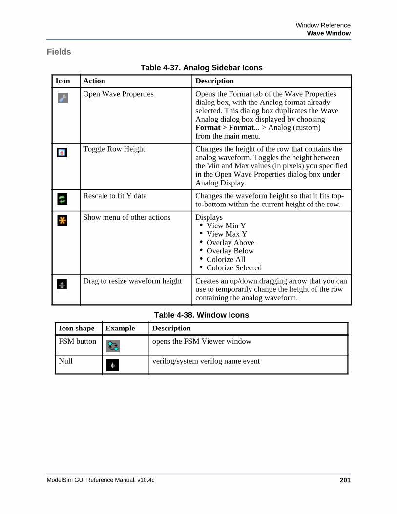
Window ReferenceWave Window
ModelSim GUI Reference Manual, v10.4c 201
Fields
Table 4-37. Analog Sidebar Icons
Icon Action Description
Open Wave Properties Opens the Format tab of the Wave Properties dialog box, with the Analog format already selected. This dialog box duplicates the Wave Analog dialog box displayed by choosing Format > Format... > Analog (custom) from the main menu.
Toggle Row Height Changes the height of the row that contains the analog waveform. Toggles the height between the Min and Max values (in pixels) you specified in the Open Wave Properties dialog box under Analog Display.
Rescale to fit Y data Changes the waveform height so that it fits top-to-bottom within the current height of the row.
Show menu of other actions Displays • View Min Y• View Max Y• Overlay Above• Overlay Below• Colorize All• Colorize Selected
Drag to resize waveform height Creates an up/down dragging arrow that you can use to temporarily change the height of the row containing the analog waveform.
Table 4-38. Window Icons
Icon shape Example Description
FSM button opens the FSM Viewer window
Null verilog/system verilog name event

ModelSim GUI Reference Manual, v10.4c202
Window ReferenceWave Window
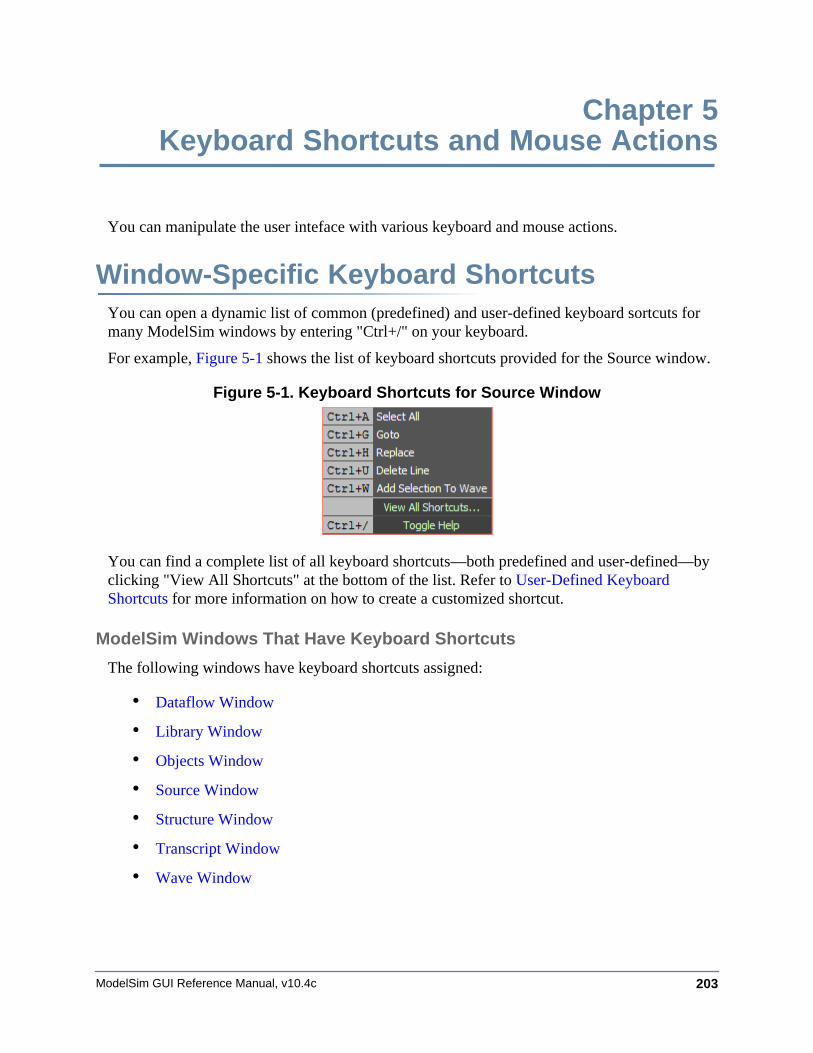
ModelSim GUI Reference Manual, v10.4c 203
Chapter 5Keyboard Shortcuts and Mouse Actions
You can manipulate the user inteface with various keyboard and mouse actions.
Window-Specific Keyboard ShortcutsYou can open a dynamic list of common (predefined) and user-defined keyboard sortcuts for many ModelSim windows by entering "Ctrl+/" on your keyboard.
For example, Figure 5-1 shows the list of keyboard shortcuts provided for the Source window.
Figure 5-1. Keyboard Shortcuts for Source Window
You can find a complete list of all keyboard shortcuts—both predefined and user-defined—by clicking "View All Shortcuts" at the bottom of the list. Refer to User-Defined Keyboard Shortcuts for more information on how to create a customized shortcut.
ModelSim Windows That Have Keyboard Shortcuts
The following windows have keyboard shortcuts assigned:
• Dataflow Window
• Library Window
• Objects Window
• Source Window
• Structure Window
• Transcript Window
• Wave Window
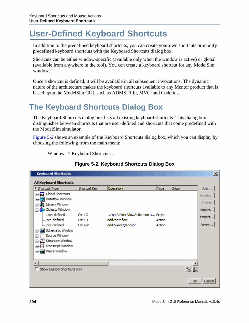
ModelSim GUI Reference Manual, v10.4c204
Keyboard Shortcuts and Mouse ActionsUser-Defined Keyboard Shortcuts
User-Defined Keyboard ShortcutsIn addition to the predefined keyboard shortcuts, you can create your own shortcuts or modify predefined keyboard shortcuts with the Keyboard Shortcuts dialog box.
Shortcuts can be either window-specific (available only when the window is active) or global (available from anywhere in the tool). You can create a keyboard shortcut for any ModelSim window.
Once a shortcut is defined, it will be available in all subsequent invocations. The dynamic nature of the architecture makes the keyboard shortcuts available to any Mentor product that is based upon the ModelSim GUI, such as ADMS, 0-In, MVC, and Codelink.
The Keyboard Shortcuts Dialog BoxThe Keyboard Shortcuts dialog box lists all existing keyboard shortcuts. This dialog box distinguishes between shortcuts that are user-defined and shortcuts that come predefined with the ModelSim simulator.
Figure 5-2 shows an example of the Keyboard Shortcuts dialog box, which you can display by choosing the following from the main menu:
Windows > Keyboard Shortcuts...
Figure 5-2. Keyboard Shortcuts Dialog Box
Keyboard Shortcuts and Mouse ActionsUser-Defined Keyboard Shortcuts
ModelSim GUI Reference Manual, v10.4c 205
The Keyboard Shortcuts dialog box allows you to:
• Add a new user defined keyboard shortcut. Refer to Creating A Keyboard Shortcut for more information.
• Modify an existing keyboard shortcut. Any shortcut can be modified including predefined shortcuts.
• Delete a shortcut.
• Import shortcuts from a previously saved bindings.do file. You can also reload the keyboard shortcuts file with the do command.
• Export all user defined keyboard shortcuts to bindings.do file. Keyboard shortcuts saved in the file can be reloaded either by selecting the Import button in the Keyboard Shorcuts Dialog Box or by entering do bindings.do on the command line.
Creating A Keyboard ShortcutYou can create your own shortcut that is either global or that applies only to a specific window.
Procedure
1. If you are creating a window specific shortcut, the window must have been opened sometime during the simulation run.
2. Open the Add Keyboard Shortcut dialog box by selecting Window > Keyboard Shortcuts.
3. Click the Add button to open the Add Keyboard Shortcut dialog box.
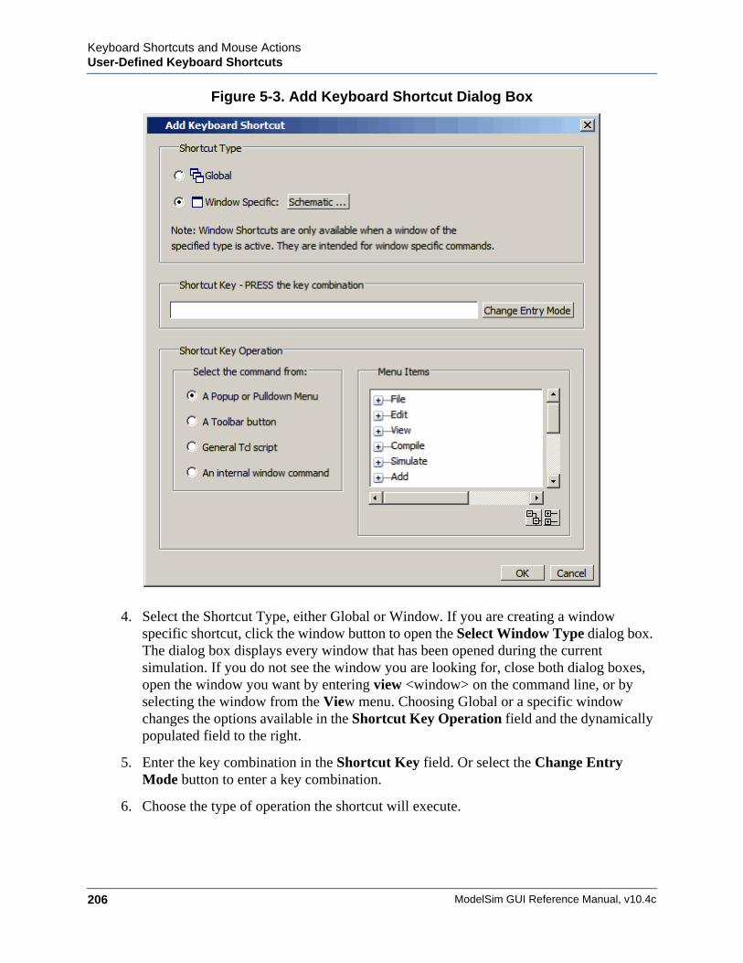
ModelSim GUI Reference Manual, v10.4c206
Keyboard Shortcuts and Mouse ActionsUser-Defined Keyboard Shortcuts
Figure 5-3. Add Keyboard Shortcut Dialog Box
4. Select the Shortcut Type, either Global or Window. If you are creating a window specific shortcut, click the window button to open the Select Window Type dialog box. The dialog box displays every window that has been opened during the current simulation. If you do not see the window you are looking for, close both dialog boxes, open the window you want by entering view <window> on the command line, or by selecting the window from the View menu. Choosing Global or a specific window changes the options available in the Shortcut Key Operation field and the dynamically populated field to the right.
5. Enter the key combination in the Shortcut Key field. Or select the Change Entry Mode button to enter a key combination.
6. Choose the type of operation the shortcut will execute.
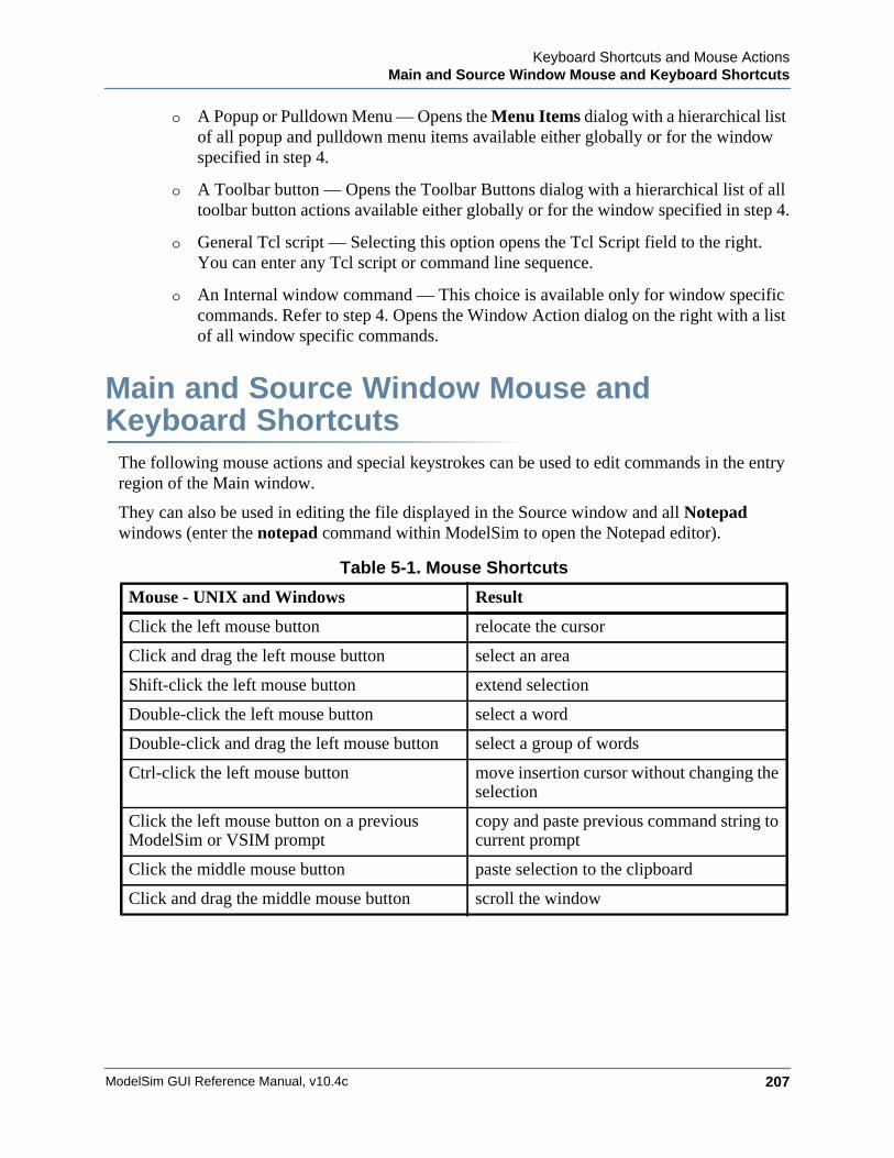
Keyboard Shortcuts and Mouse ActionsMain and Source Window Mouse and Keyboard Shortcuts
ModelSim GUI Reference Manual, v10.4c 207
o A Popup or Pulldown Menu — Opens the Menu Items dialog with a hierarchical list of all popup and pulldown menu items available either globally or for the window specified in step 4.
o A Toolbar button — Opens the Toolbar Buttons dialog with a hierarchical list of all toolbar button actions available either globally or for the window specified in step 4.
o General Tcl script — Selecting this option opens the Tcl Script field to the right. You can enter any Tcl script or command line sequence.
o An Internal window command — This choice is available only for window specific commands. Refer to step 4. Opens the Window Action dialog on the right with a list of all window specific commands.
Main and Source Window Mouse and Keyboard Shortcuts
The following mouse actions and special keystrokes can be used to edit commands in the entry region of the Main window.
They can also be used in editing the file displayed in the Source window and all Notepad windows (enter the notepad command within ModelSim to open the Notepad editor).
Table 5-1. Mouse Shortcuts
Mouse - UNIX and Windows Result
Click the left mouse button relocate the cursor
Click and drag the left mouse button select an area
Shift-click the left mouse button extend selection
Double-click the left mouse button select a word
Double-click and drag the left mouse button select a group of words
Ctrl-click the left mouse button move insertion cursor without changing the selection
Click the left mouse button on a previous ModelSim or VSIM prompt
copy and paste previous command string to current prompt
Click the middle mouse button paste selection to the clipboard
Click and drag the middle mouse button scroll the window

ModelSim GUI Reference Manual, v10.4c208
Keyboard Shortcuts and Mouse ActionsMain and Source Window Mouse and Keyboard Shortcuts
Table 5-2. Keyboard Shortcuts
Keystrokes - UNIX and Windows Result
Left ArrowRight Arrow
move cursor left or right one character
Ctrl + Left ArrowCtrl + Right Arrow
move cursor left or right one word
Shift + Any Arrow extend text selection
Ctrl + Shift + Left ArrowCtrl + Shift + Right Arrow
extend text selection by one word
Up ArrowDown Arrow
Transcript window: scroll through command historySource window: move cursor one line up or down
Ctrl + Up ArrowCtrl + Down Arrow
Transcript window: moves cursor to first or last lineSource window: moves cursor up or down one paragraph
Alt + / Open a pop-up command prompt for entering commands.
Ctrl + Home move cursor to the beginning of the text
Ctrl + End move cursor to the end of the text
BackspaceCtrl + h (UNIX only)
delete character to the left
DeleteCtrl + d (UNIX only)
delete character to the right
Esc (Windows only) cancel
Alt activate or inactivate menu bar mode
Alt-F4 close active window
HomeCtrl + a
move cursor to the beginning of the line
Ctrl + Shift + a select all contents of active window
Ctrl + b move cursor left
Ctrl + d delete character to the right
EndCtrl + e
move cursor to the end of the line
Ctrl + f (UNIX)Right Arrow (Windows)
move cursor right one character
Ctrl + k delete to the end of line
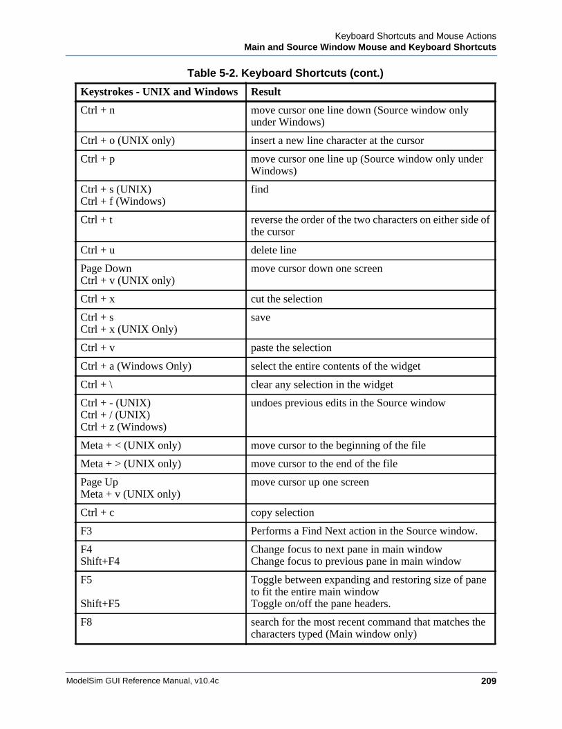
Keyboard Shortcuts and Mouse ActionsMain and Source Window Mouse and Keyboard Shortcuts
ModelSim GUI Reference Manual, v10.4c 209
Ctrl + n move cursor one line down (Source window only under Windows)
Ctrl + o (UNIX only) insert a new line character at the cursor
Ctrl + p move cursor one line up (Source window only under Windows)
Ctrl + s (UNIX)Ctrl + f (Windows)
find
Ctrl + t reverse the order of the two characters on either side of the cursor
Ctrl + u delete line
Page DownCtrl + v (UNIX only)
move cursor down one screen
Ctrl + x cut the selection
Ctrl + sCtrl + x (UNIX Only)
save
Ctrl + v paste the selection
Ctrl + a (Windows Only) select the entire contents of the widget
Ctrl + \ clear any selection in the widget
Ctrl + - (UNIX)Ctrl + / (UNIX)Ctrl + z (Windows)
undoes previous edits in the Source window
Meta + < (UNIX only) move cursor to the beginning of the file
Meta + > (UNIX only) move cursor to the end of the file
Page UpMeta + v (UNIX only)
move cursor up one screen
Ctrl + c copy selection
F3 Performs a Find Next action in the Source window.
F4Shift+F4
Change focus to next pane in main windowChange focus to previous pane in main window
F5
Shift+F5
Toggle between expanding and restoring size of pane to fit the entire main windowToggle on/off the pane headers.
F8 search for the most recent command that matches the characters typed (Main window only)
Table 5-2. Keyboard Shortcuts (cont.)
Keystrokes - UNIX and Windows Result
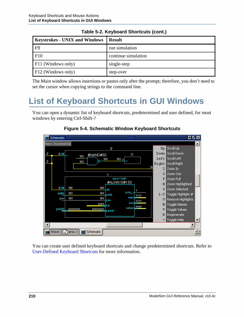
ModelSim GUI Reference Manual, v10.4c210
Keyboard Shortcuts and Mouse ActionsList of Keyboard Shortcuts in GUI Windows
The Main window allows insertions or pastes only after the prompt; therefore, you don’t need to set the cursor when copying strings to the command line.
List of Keyboard Shortcuts in GUI WindowsYou can open a dynamic list of keyboard shortcuts, predetermined and user defined, for most windows by entering Ctrl-Shift-?
Figure 5-4. Schematic Window Keyboard Shortcuts
You can create user defined keyboard shortcuts and change predetermined shortcuts. Refer to User-Defined Keyboard Shortcuts for more information.
F9 run simulation
F10 continue simulation
F11 (Windows only) single-step
F12 (Windows only) step-over
Table 5-2. Keyboard Shortcuts (cont.)
Keystrokes - UNIX and Windows Result
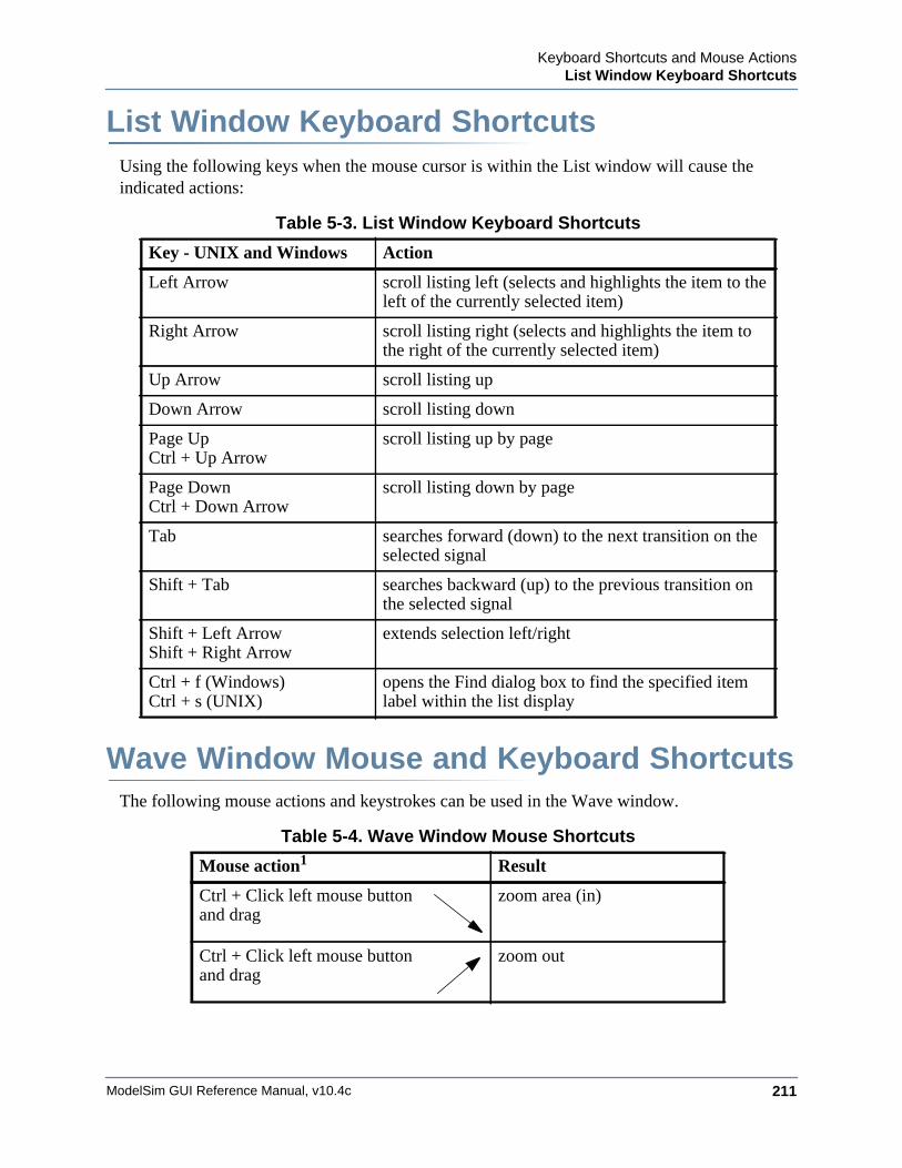
Keyboard Shortcuts and Mouse ActionsList Window Keyboard Shortcuts
ModelSim GUI Reference Manual, v10.4c 211
List Window Keyboard ShortcutsUsing the following keys when the mouse cursor is within the List window will cause the indicated actions:
Wave Window Mouse and Keyboard ShortcutsThe following mouse actions and keystrokes can be used in the Wave window.
Table 5-3. List Window Keyboard Shortcuts
Key - UNIX and Windows Action
Left Arrow scroll listing left (selects and highlights the item to the left of the currently selected item)
Right Arrow scroll listing right (selects and highlights the item to the right of the currently selected item)
Up Arrow scroll listing up
Down Arrow scroll listing down
Page UpCtrl + Up Arrow
scroll listing up by page
Page DownCtrl + Down Arrow
scroll listing down by page
Tab searches forward (down) to the next transition on the selected signal
Shift + Tab searches backward (up) to the previous transition on the selected signal
Shift + Left ArrowShift + Right Arrow
extends selection left/right
Ctrl + f (Windows)Ctrl + s (UNIX)
opens the Find dialog box to find the specified item label within the list display
Table 5-4. Wave Window Mouse Shortcuts
Mouse action1 Result
Ctrl + Click left mouse buttonand drag
zoom area (in)
Ctrl + Click left mouse buttonand drag
zoom out
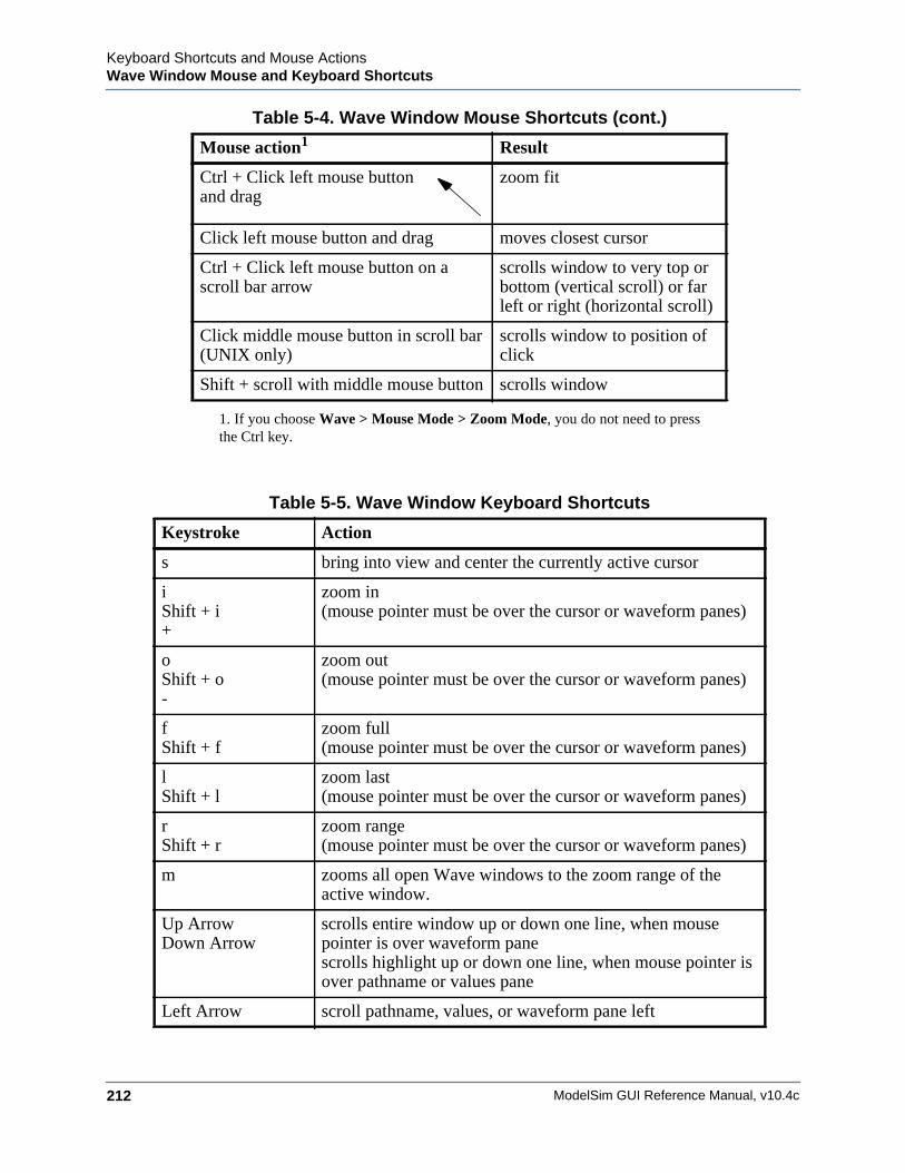
ModelSim GUI Reference Manual, v10.4c212
Keyboard Shortcuts and Mouse ActionsWave Window Mouse and Keyboard Shortcuts
Ctrl + Click left mouse buttonand drag
zoom fit
Click left mouse button and drag moves closest cursor
Ctrl + Click left mouse button on a scroll bar arrow
scrolls window to very top or bottom (vertical scroll) or far left or right (horizontal scroll)
Click middle mouse button in scroll bar (UNIX only)
scrolls window to position of click
Shift + scroll with middle mouse button scrolls window
1. If you choose Wave > Mouse Mode > Zoom Mode, you do not need to pressthe Ctrl key.
Table 5-5. Wave Window Keyboard Shortcuts
Keystroke Action
s bring into view and center the currently active cursor
iShift + i+
zoom in (mouse pointer must be over the cursor or waveform panes)
oShift + o -
zoom out (mouse pointer must be over the cursor or waveform panes)
fShift + f
zoom full (mouse pointer must be over the cursor or waveform panes)
lShift + l
zoom last (mouse pointer must be over the cursor or waveform panes)
rShift + r
zoom range (mouse pointer must be over the cursor or waveform panes)
m zooms all open Wave windows to the zoom range of the active window.
Up ArrowDown Arrow
scrolls entire window up or down one line, when mouse pointer is over waveform panescrolls highlight up or down one line, when mouse pointer is over pathname or values pane
Left Arrow scroll pathname, values, or waveform pane left
Table 5-4. Wave Window Mouse Shortcuts (cont.)
Mouse action1 Result
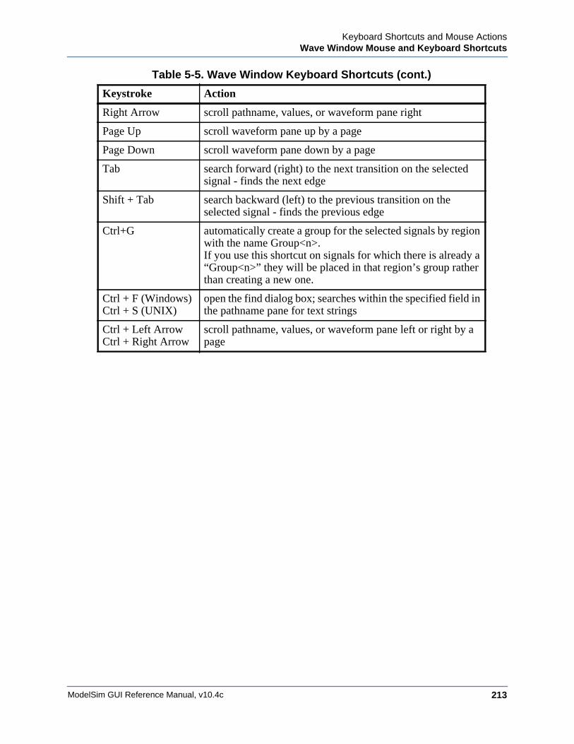
Keyboard Shortcuts and Mouse ActionsWave Window Mouse and Keyboard Shortcuts
ModelSim GUI Reference Manual, v10.4c 213
Right Arrow scroll pathname, values, or waveform pane right
Page Up scroll waveform pane up by a page
Page Down scroll waveform pane down by a page
Tab search forward (right) to the next transition on the selected signal - finds the next edge
Shift + Tab search backward (left) to the previous transition on the selected signal - finds the previous edge
Ctrl+G automatically create a group for the selected signals by region with the name Group<n>.If you use this shortcut on signals for which there is already a “Group<n>” they will be placed in that region’s group rather than creating a new one.
Ctrl + F (Windows)Ctrl + S (UNIX)
open the find dialog box; searches within the specified field in the pathname pane for text strings
Ctrl + Left ArrowCtrl + Right Arrow
scroll pathname, values, or waveform pane left or right by a page
Table 5-5. Wave Window Keyboard Shortcuts (cont.)
Keystroke Action

ModelSim GUI Reference Manual, v10.4c214
Keyboard Shortcuts and Mouse ActionsWave Window Mouse and Keyboard Shortcuts
ModelSim GUI Reference Manual, v10.4c 215
Chapter 6GUI Customization
The ModelSim GUI is programmed using Tcl/Tk. The GUI is highly customizable—you can control a wide variety of display characteristics such as window size, position, color, the text of window prompts, and default output filenames.
Most user GUI preferences are stored as Tcl variables in the Registry on Windows platforms. The variable values save automatically when you exit ModelSim. Some of the variables are modified by actions you take with menus or windows (for example, resizing a window changes its geometry variable). Alternatively, you can edit the variables directly either from the prompt in the Transcript window or by using the Tools > Edit Preferences menu item.
Simulator GUI Layout CustomizationGUI customization is saved in the form of layout modes.
Layout ModesThere are five predefined layout modes that the GUI will load dependent upon which part of the simulation flow you are currently in.
These modes include:
• NoDesign — This layout is the default view when you first open the GUI or quit out of an active simulation.
• Simulate — This layout appears after you have begun a simulation with vsim.
These layout modes are fully customizable and the GUI stores your manipulations in the registry (Windows) when you exit the simulation or change to another layout mode. The types of manipulations that are stored include: showing, hiding, moving, and resizing windows.
Layout Mode Loading PriorityThe GUI stores your manipulations on a directory by directory basis and attempts to load a layout mode in the following order.
1. Directory — The GUI attempts to load any manipulations for the current layout mode based on your current working directory.
ModelSim GUI Reference Manual, v10.4c216
GUI CustomizationSimulator GUI Layout Customization
2. Last Used — If there is no layout related to your current working directory, the GUI attempts to load your last manipulations for that layout mode, regardless of your directory.
3. Default — If you have never manipulated a layout mode, or have deleted the .modelsim file or the registry, the GUI will load the default appearance of the layout mode.
Configure Window Layouts Dialog BoxThe Configure Window Layouts dialog box allows you to alter the default behavior of the GUI layouts. You can display this dialog box by selecting the Layout > Configure menu item.
The elements of this dialog box include:
• Specify a Layout to Use — This pane allows you to map which layout is used for the four actions. Refer to the section Changing Layout Mode Behavior for additional information.
• Save window layout automatically — This option (on by default) instructs the GUI to save any manipulations to the layout mode upon exit or changing the layout mode.
• Save Window Layout by Current Directory — This option (on by default) instructs the tool to save the final state of the GUI layout on a directory by directory basis. This means that the next time you open the GUI from a given directory, the tool will load your previous GUI settings.
• Window Restore Properties Button— Opens the Window Restore Properties Dialog Box. Refer to Configuring Default Windows for Restored Layouts for more information.
Creating a Custom Layout ModeYou can create your own custom layout mode.
Procedure
1. Rearrange the GUI as you see fit.
2. Select Layout > Save Layout As.
This displays the Save Current Window Layout dialog box.
3. In the Save Layout As field, type in a new name for the layout mode.
4. Click OK.
Result
The layout is saved to the .modelsim file or registry. You can then access this layout mode from the Layout menu or the Layout toolbar.
GUI CustomizationSimulator GUI Layout Customization
ModelSim GUI Reference Manual, v10.4c 217
Changing Layout Mode BehaviorYou can assign which predefined or custom layout appears in each mode.
Procedure
1. Create your custom layouts as described in Creating a Custom Layout Mode.
2. Select Layout > Configure.
This displays the Configure Window Layouts Dialog Box.
3. Select which layout you want the GUI to load for each scenario. This behavior affects the Layout Mode Loading Priority.
4. Click OK.
Result
The layout assignment is saved to the .modelsim file or registry.
Resetting a Layout Mode to its DefaultRevert a layout back to the default arrangement.
Procedure
1. Load the layout mode you want to reset via the Layout menu or the Layout toolbar.
2. Select Layout > Reset.
Deleting a Custom Layout ModeYou can delete one of your custom-made layout modes.
Procedure
1. Load a custom layout mode from the Layout menu or the Layout toolbar.
2. Select Layout > Delete.
Displays the Delete Custom Layout dialog box.
3. Select the custom layout you wish to delete.
4. Delete.
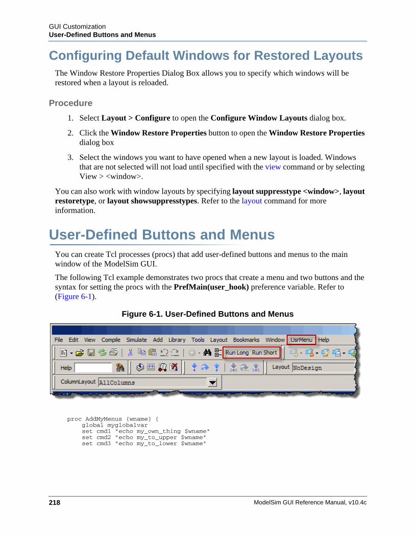
ModelSim GUI Reference Manual, v10.4c218
GUI CustomizationUser-Defined Buttons and Menus
Configuring Default Windows for Restored Layouts The Window Restore Properties Dialog Box allows you to specify which windows will be restored when a layout is reloaded.
Procedure
1. Select Layout > Configure to open the Configure Window Layouts dialog box.
2. Click the Window Restore Properties button to open the Window Restore Properties dialog box
3. Select the windows you want to have opened when a new layout is loaded. Windows that are not selected will not load until specified with the view command or by selecting View > <window>.
You can also work with window layouts by specifying layout suppresstype <window>, layout restoretype, or layout showsuppresstypes. Refer to the layout command for more information.
User-Defined Buttons and Menus You can create Tcl processes (procs) that add user-defined buttons and menus to the main window of the ModelSim GUI.
The following Tcl example demonstrates two procs that create a menu and two buttons and the syntax for setting the procs with the PrefMain(user_hook) preference variable. Refer to (Figure 6-1).
Figure 6-1. User-Defined Buttons and Menus
proc AddMyMenus {wname} { global myglobalvar set cmd1 "echo my_own_thing $wname" set cmd2 "echo my_to_upper $wname" set cmd3 "echo my_to_lower $wname"
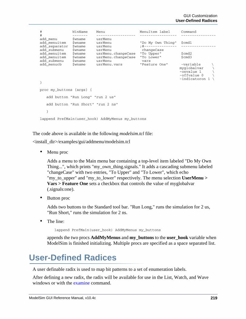
GUI CustomizationUser-Defined Radices
ModelSim GUI Reference Manual, v10.4c 219
# WinName Menu MenuItem label Command# ------- ------------------ ----------------- ----------------add_menu $wname usrMenuadd_menuitem $wname usrMenu "Do My Own Thing" $cmd1add_separator $wname usrMenu ;#--------------- ----------------add_submenu $wname usrMenu changeCaseadd_menuitem $wname usrMenu.changeCase "To Upper" $cmd2add_menuitem $wname usrMenu.changeCase "To Lower" $cmd3add_submenu $wname usrMenu varsadd_menucb $wname usrMenu.vars "Feature One" -variable \
myglobalvar \ -onvalue 1 \ -offvalue 0 \ -indicatoron 1 \
}
proc my_buttons {args} {
add button "Run Long" "run 2 us" add button "Run Short" "run 2 ns"
}
lappend PrefMain(user_hook) AddMyMenus my_buttons
The code above is available in the following modelsim.tcl file:
<install_dir>/examples/gui/addmenu/modelsim.tcl
• Menu proc
Adds a menu to the Main menu bar containing a top-level item labeled "Do My Own Thing...", which prints "my_own_thing.signals." It adds a cascading submenu labeled "changeCase" with two entries, "To Upper" and "To Lower", which echo "my_to_upper" and "my_to_lower" respectively. The menu selection UserMenu > Vars > Feature One sets a checkbox that controls the value of myglobalvar (.signals:one).
• Button proc
Adds two buttons to the Standard tool bar. "Run Long," runs the simulation for 2 us, "Run Short," runs the simulation for 2 ns.
• The line:
lappend PrefMain(user_hook) AddMyMenus my_buttons
appends the two procs AddMyMenus and my_buttons to the user_hook variable when ModelSim is finished initializing. Multiple procs are specified as a space separated list.
User-Defined RadicesA user definable radix is used to map bit patterns to a set of enumeration labels.
After defining a new radix, the radix will be available for use in the List, Watch, and Wave windows or with the examine command.
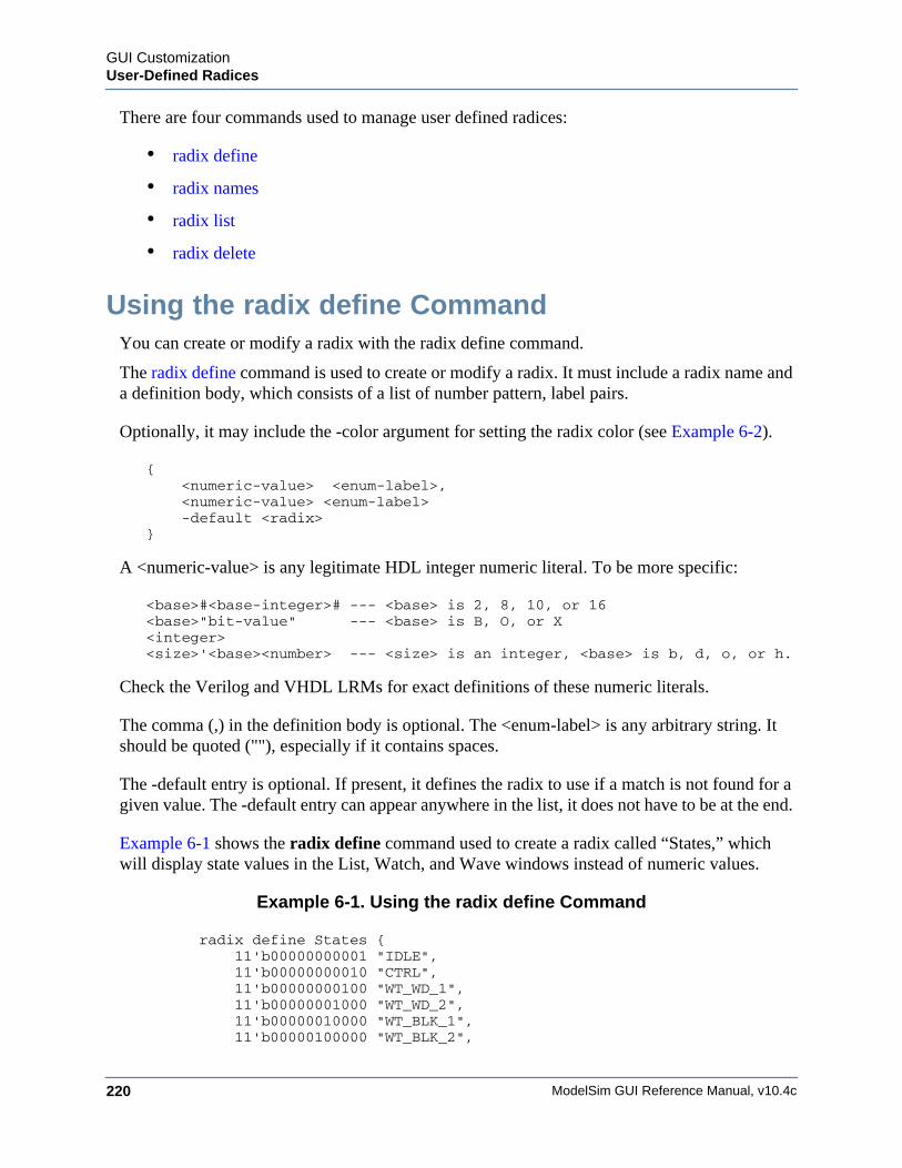
ModelSim GUI Reference Manual, v10.4c220
GUI CustomizationUser-Defined Radices
There are four commands used to manage user defined radices:
• radix define
• radix names
• radix list
• radix delete
Using the radix define CommandYou can create or modify a radix with the radix define command.
The radix define command is used to create or modify a radix. It must include a radix name and a definition body, which consists of a list of number pattern, label pairs.
Optionally, it may include the -color argument for setting the radix color (see Example 6-2).
{ <numeric-value> <enum-label>, <numeric-value> <enum-label> -default <radix>}
A <numeric-value> is any legitimate HDL integer numeric literal. To be more specific:
<base>#<base-integer># --- <base> is 2, 8, 10, or 16<base>"bit-value" --- <base> is B, O, or X<integer><size>'<base><number> --- <size> is an integer, <base> is b, d, o, or h.
Check the Verilog and VHDL LRMs for exact definitions of these numeric literals.
The comma (,) in the definition body is optional. The <enum-label> is any arbitrary string. It should be quoted (""), especially if it contains spaces.
The -default entry is optional. If present, it defines the radix to use if a match is not found for a given value. The -default entry can appear anywhere in the list, it does not have to be at the end.
Example 6-1 shows the radix define command used to create a radix called “States,” which will display state values in the List, Watch, and Wave windows instead of numeric values.
Example 6-1. Using the radix define Command
radix define States { 11'b00000000001 "IDLE", 11'b00000000010 "CTRL", 11'b00000000100 "WT_WD_1", 11'b00000001000 "WT_WD_2", 11'b00000010000 "WT_BLK_1", 11'b00000100000 "WT_BLK_2",
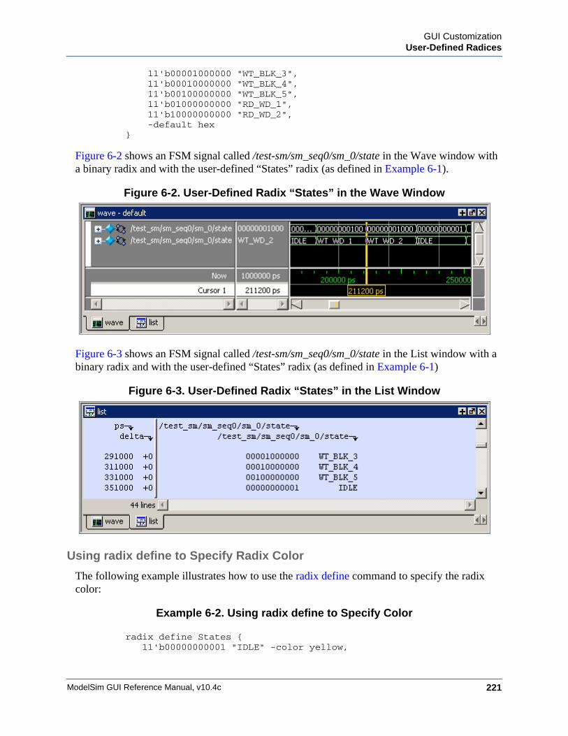
GUI CustomizationUser-Defined Radices
ModelSim GUI Reference Manual, v10.4c 221
11'b00001000000 "WT_BLK_3", 11'b00010000000 "WT_BLK_4", 11'b00100000000 "WT_BLK_5", 11'b01000000000 "RD_WD_1", 11'b10000000000 "RD_WD_2", -default hex}
Figure 6-2 shows an FSM signal called /test-sm/sm_seq0/sm_0/state in the Wave window with a binary radix and with the user-defined “States” radix (as defined in Example 6-1).
Figure 6-2. User-Defined Radix “States” in the Wave Window
Figure 6-3 shows an FSM signal called /test-sm/sm_seq0/sm_0/state in the List window with a binary radix and with the user-defined “States” radix (as defined in Example 6-1)
Figure 6-3. User-Defined Radix “States” in the List Window
Using radix define to Specify Radix Color
The following example illustrates how to use the radix define command to specify the radix color:
Example 6-2. Using radix define to Specify Color
radix define States {11'b00000000001 "IDLE" -color yellow,

ModelSim GUI Reference Manual, v10.4c222
GUI CustomizationUser-Defined Radices
11'b00000000010 "CTRL" -color #ffee00,11'b00000000100 "WT_WD_1" -color orange,11'b00000001000 "WT_WD_2" -color orange,11'b00000010000 "WT_BLK_1",11'b00000100000 "WT_BLK_2",11'b00001000000 "WT_BLK_3",11'b00010000000 "WT_BLK_4",11'b00100000000 "WT_BLK_5",11'b01000000000 "RD_WD_1" -color green,11'b10000000000 "RD_WD_2" -color green,-default hex-defaultcolor white
}
If a pattern/label pair does not specify a color, the normal wave window colors will be used. If the value of the waveform does not match any pattern, then -default <radix_type> and -defaultcolor will be used.
To specify a range of values, wildcards may be specified for bits or characters of the value. The wildcard character is '?', similar to the iteration character in a Verilog UDP, for example:
radix define {6'b01??00 "Write" -color orange,6'b10??00 "Read" -color green
}
In this example, the first pattern will match "010000", "010100", "011000", and "011100". In case of overlaps, the first matching pattern is used, going from top to bottom.
Setting Global Signal RadixThe Global Signal Radix feature allows you to set the radix for a selected signal or signals in the active window and in other windows where the signal appears.
Procedure
The Global Signal Radix can be set from the Locals, Objects, Schematic, or Wave windows as follows:
1. Select a signal or group of signals.
2. Right-click the selected signal(s) and click the following popup menu option:
• Objects Window: Radix
• Locals Window: Global Signal Radix
• Wave Window: Radix > Global Signal Radix
• Schematic Window: Edit > Global Signal Radix
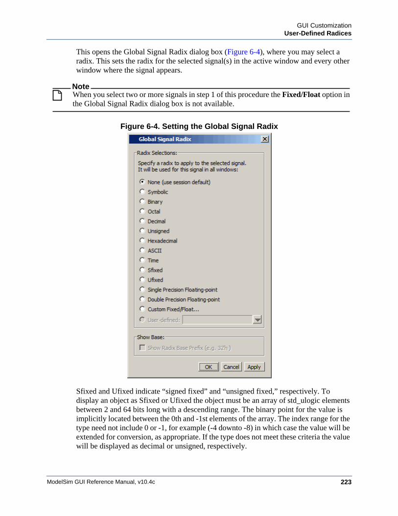
GUI CustomizationUser-Defined Radices
ModelSim GUI Reference Manual, v10.4c 223
This opens the Global Signal Radix dialog box (Figure 6-4), where you may select a radix. This sets the radix for the selected signal(s) in the active window and every other window where the signal appears.
NoteWhen you select two or more signals in step 1 of this procedure the Fixed/Float option in the Global Signal Radix dialog box is not available.
Figure 6-4. Setting the Global Signal Radix
Sfixed and Ufixed indicate “signed fixed” and “unsigned fixed,” respectively. To display an object as Sfixed or Ufixed the object must be an array of std_ulogic elements between 2 and 64 bits long with a descending range. The binary point for the value is implicitly located between the 0th and -1st elements of the array. The index range for the type need not include 0 or -1, for example (-4 downto -8) in which case the value will be extended for conversion, as appropriate. If the type does not meet these criteria the value will be displayed as decimal or unsigned, respectively.
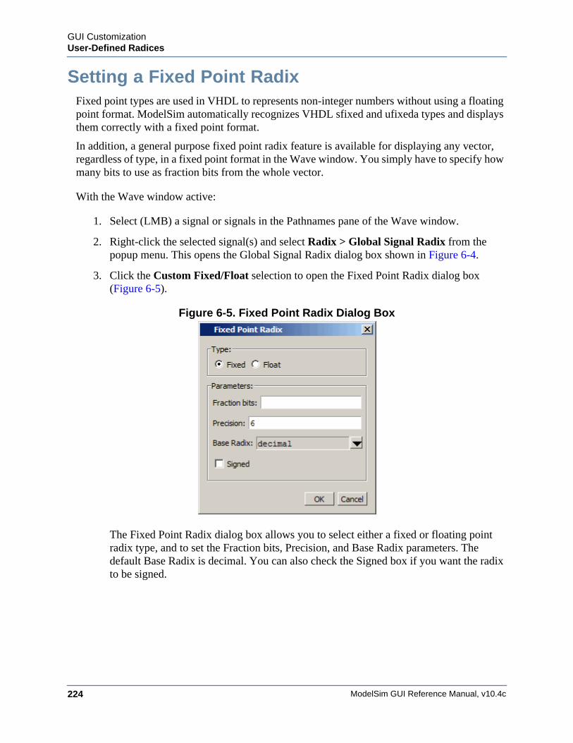
ModelSim GUI Reference Manual, v10.4c224
GUI CustomizationUser-Defined Radices
Setting a Fixed Point RadixFixed point types are used in VHDL to represents non-integer numbers without using a floating point format. ModelSim automatically recognizes VHDL sfixed and ufixeda types and displays them correctly with a fixed point format.
In addition, a general purpose fixed point radix feature is available for displaying any vector, regardless of type, in a fixed point format in the Wave window. You simply have to specify how many bits to use as fraction bits from the whole vector.
With the Wave window active:
1. Select (LMB) a signal or signals in the Pathnames pane of the Wave window.
2. Right-click the selected signal(s) and select Radix > Global Signal Radix from the popup menu. This opens the Global Signal Radix dialog box shown in Figure 6-4.
3. Click the Custom Fixed/Float selection to open the Fixed Point Radix dialog box (Figure 6-5).
Figure 6-5. Fixed Point Radix Dialog Box
The Fixed Point Radix dialog box allows you to select either a fixed or floating point radix type, and to set the Fraction bits, Precision, and Base Radix parameters. The default Base Radix is decimal. You can also check the Signed box if you want the radix to be signed.
ModelSim GUI Reference Manual, v10.4c 225
Chapter 7GUI Preferences
You can control various aspects of the Graphical User Interface through the use of user-controlled preferences.
Setting GUI PreferencesYou can set user-controlled preferences in the ModelSim GUI with the Preferences dialog box.
Procedure
1. Invoke the ModelSim GUI.
2. Select the Tools > Edit Preferences menu item to display the Preferences Dialog Box.
3. Alter the various preference options to customize your GUI.
By Window tab:
a. Make selections, from left to right, to change GUI element colors or global fonts.
By Name tab:
a. Hierarchically expand the specific category in the Preference Item column.
b. Select the specific Preference Item you want to change.
c. Click Change Value to display a dialog box specific to the item.
d. Set the preference to your desired value.
e. Click OK.
Results
The preferences are applied immediately and saved automatically upon exit, either in the registry of your Windows machine.
Preferences Dialog BoxTools > Edit Preferences
Dialog box for controlling user-defined preferences of the ModelSim GUI.
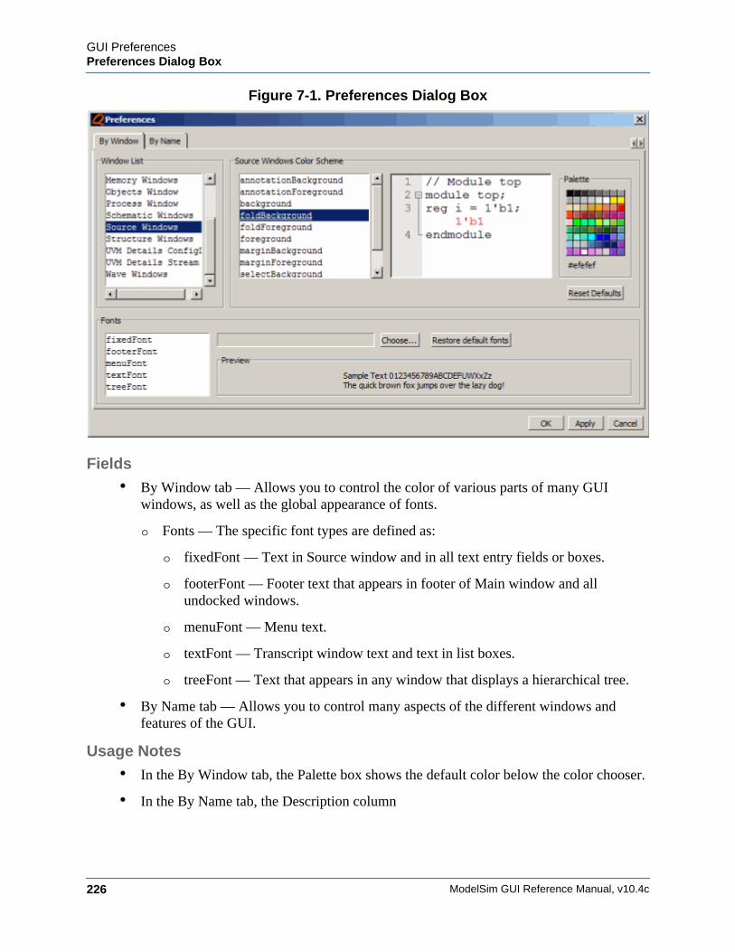
ModelSim GUI Reference Manual, v10.4c226
GUI PreferencesPreferences Dialog Box
Figure 7-1. Preferences Dialog Box
Fields• By Window tab — Allows you to control the color of various parts of many GUI
windows, as well as the global appearance of fonts.
o Fonts — The specific font types are defined as:
o fixedFont — Text in Source window and in all text entry fields or boxes.
o footerFont — Footer text that appears in footer of Main window and all undocked windows.
o menuFont — Menu text.
o textFont — Transcript window text and text in list boxes.
o treeFont — Text that appears in any window that displays a hierarchical tree.
• By Name tab — Allows you to control many aspects of the different windows and features of the GUI.
Usage Notes• In the By Window tab, the Palette box shows the default color below the color chooser.
• In the By Name tab, the Description column
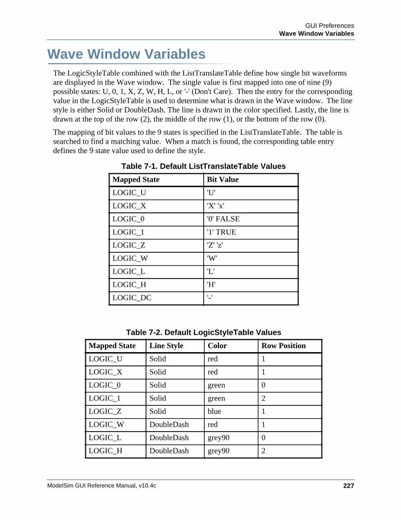
GUI PreferencesWave Window Variables
ModelSim GUI Reference Manual, v10.4c 227
Wave Window VariablesThe LogicStyleTable combined with the ListTranslateTable define how single bit waveforms are displayed in the Wave window. The single value is first mapped into one of nine (9) possible states: U, 0, 1, X, Z, W, H, L, or '-' (Don't Care). Then the entry for the corresponding value in the LogicStyleTable is used to determine what is drawn in the Wave window. The line style is either Solid or DoubleDash. The line is drawn in the color specified. Lastly, the line is drawn at the top of the row (2), the middle of the row (1), or the bottom of the row (0).
The mapping of bit values to the 9 states is specified in the ListTranslateTable. The table is searched to find a matching value. When a match is found, the corresponding table entry defines the 9 state value used to define the style.
Table 7-1. Default ListTranslateTable Values
Mapped State Bit Value
LOGIC_U 'U'
LOGIC_X 'X' 'x'
LOGIC_0 '0' FALSE
LOGIC_1 '1' TRUE
LOGIC_Z 'Z' 'z'
LOGIC_W 'W'
LOGIC_L 'L'
LOGIC_H 'H'
LOGIC_DC '-'
Table 7-2. Default LogicStyleTable Values
Mapped State Line Style Color Row Position
LOGIC_U Solid red 1
LOGIC_X Solid red 1
LOGIC_0 Solid green 0
LOGIC_1 Solid green 2
LOGIC_Z Solid blue 1
LOGIC_W DoubleDash red 1
LOGIC_L DoubleDash grey90 0
LOGIC_H DoubleDash grey90 2
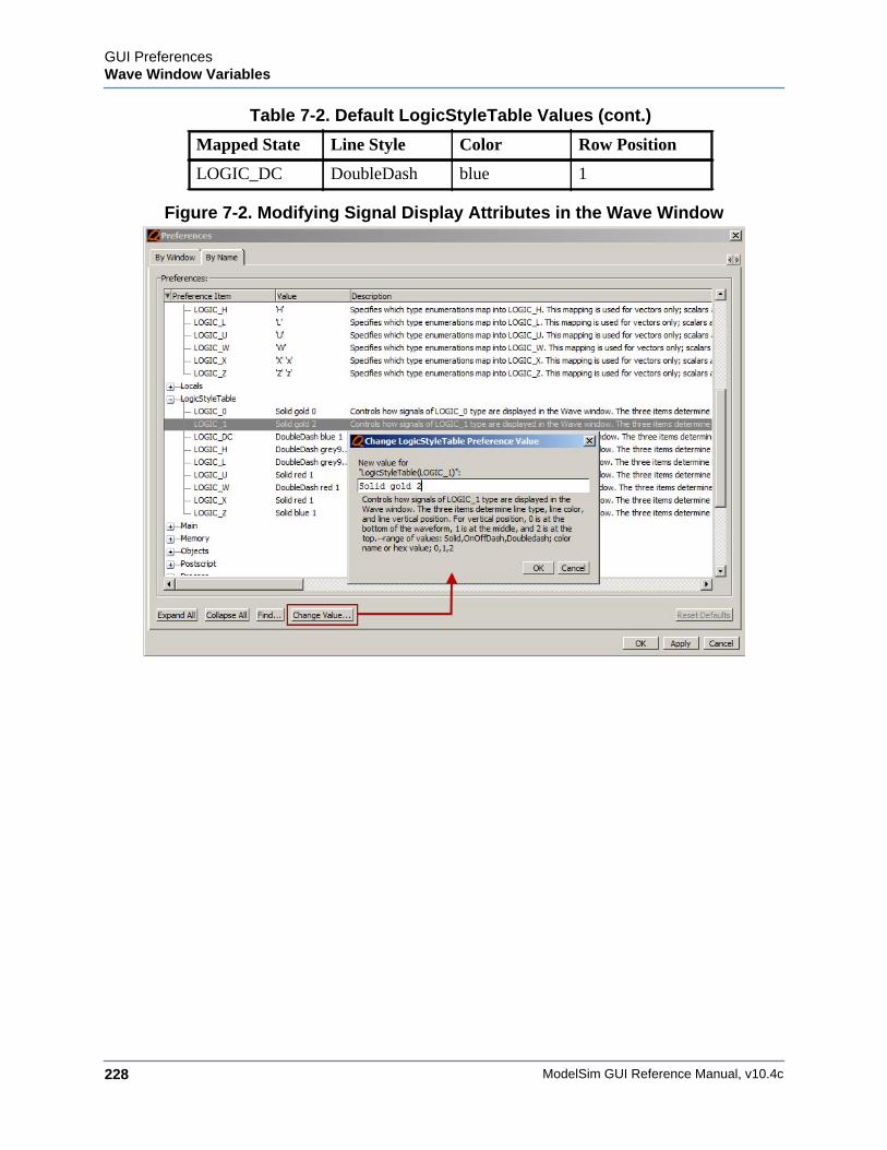
ModelSim GUI Reference Manual, v10.4c228
GUI PreferencesWave Window Variables
Figure 7-2. Modifying Signal Display Attributes in the Wave Window
LOGIC_DC DoubleDash blue 1
Table 7-2. Default LogicStyleTable Values (cont.)
Mapped State Line Style Color Row Position
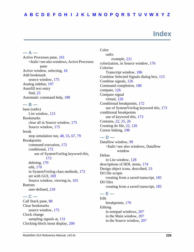
229
A B F GDC E H I J K L M N O P Q R S T U V XW Y Z
ModelSim GUI Reference Manual, v10.4c
Index
— A —Active Processes pane, 161
<Italic>see also windows, Active Processes pane
Active window, selecting, 16Add bookmark
source window, 175Analog sidebar, 197Autofill text entry
find, 23Automatic command help, 188
— B —base (radix)
List window, 123Bookmarks
clear all in Source window, 175Source window, 175
breakstop simulation run, 48, 55, 67, 79
Breakpointscommand execution, 172conditional, 172
use of SystemVerilog keyword this, 173
deleting, 170edit, 170in SystemVerilog class methods, 172set with GUI, 169Source window, viewing in, 165
Buttonsuser-defined, 218
— C —Call Stack pane, 88Clear bookmarks
source window, 175Clock change
sampling signals at, 131Clocking block inout display, 200
Colorradix
example, 221colorization, in Source window, 176Colorize
Transcript window, 186Combine Selected Signals dialog box, 115Combine signals, 126Command completion, 188compare, 126Compare signal
virtual, 126Conditional breakpoints, 172
use of SystemVerilog keyword this, 173conditional breakpoints
use of keyword this, 173Contains, 22, 25, 26Creating do file, 22, 126Cursor linking, 198
— D —Dataflow window, 99
<Italic>see also windows, Dataflow window
Deltasin List window, 128
descriptions of HDL items, 174Design object icons, described, 33DO file scripts
creating from a saved transcript, 185DO files
creating from a saved transcript, 185
— E —Edit
breakpoints, 170Editing
in notepad windows, 207in the Main window, 207in the Source window, 207
Index
230 ModelSim GUI Reference Manual, v10.4c
A B F GDC E H I J K L M N O P Q R S T U V XW Y Z
Expanded Timeviewing in List window, 116
Expression Builderconfiguring a List trigger with, 129saving expressions to Tcl variable, 122
— F —F8 function key, 209File-line breakpoints, 169
edit, 170Files window, 106Filter, 25Filtering
Contains field, 22, 26signals in Objects window, 158
Find, 22in Structure window, 181inline search bar, 175, 187prefill text entry field, 23
Fixed point radix, 224FocusFollowsMouse, 16Fonts
scaling, 22Format
saving/restoring, 22, 126signal
Wave window, 197Format file
Wave window, 125Function call, debugging, 88
— G —Global signal radix, 157, 196, 222Glob-style, 25
— H —Help
command help, 188highlighting, in Source window, 176Highlights
in Source window, 168
— I —Icons
shapes and meanings, 33inline search bar, 175, 187
— K —Keyboard shortcuts
user defined, 204keyboard shortcuts
List window, 211Main window, 207Source window, 207Wave window, 211
— L —Link cursors, 198List pane
<Italic>see also pane, List paneList window, 111
expanded time viewing, 116setting triggers, 129
Locals window, 132<Italic>see also windows, Locals window
— M —Memories
navigation, 138save to WLF file, 144saving formats, 143selecting memory instances, 143viewing contents, 143viewing multiple instances, 143
Memory tabmemories you can view, 139
Menususer-defined, 218
Message Viewer tab, 146Messages, 146modelsim.tcl
user_defined menus, 218user-defined buttons, 218
mouse shortcutsMain window, 207Source window, 207Wave window, 211
msgmode variable, 146
— N —Nets
Dataflow window, displaying in, 99values of
231ModelSim GUI Reference Manual, v10.4c
A B F GDC E H I J K L M N O P Q R S T U V XW Y Z
displaying in Objects window, 154waveforms, viewing, 194
Notepad windows, text editing, 207-notrigger argument, 131
— O —Objects window, 154
— P —Prefill text entry
find, 23PrefMemory(ExpandPackedMem) variable,
143PrefSource(OpenOnBreak) variable, 165PrefSource(OpenOnFinish) variable, 165PrefSource(OpenOnStep) variable, 165
— R —Radix
change in Watch pane, 191color
example, 221List window, 123set globally, 157, 196, 222setting fixed point, 224setting for Objects window, 157, 222user-defined, 219
definition body, 220radix
SystemVerilog types, 196Radix define command
setting radix color, 221Registers
values ofdisplaying in Objects window, 154
waveforms, viewing, 194Regular-expression, 26restart command
in GUI, 41Restoring
window format, 22, 126
— S —saveLines preference variable, 186Saving
window format, 22, 126Scaling fonts, 22
Searchin Structure window, 181inline search bar
Source window, 175Transcript, 187
prefill text entry field, 23Search bar, 22Setting radix
fixed point, 224Shortcuts
text editing, 207shortcuts
List window, 211Main window, 207Source window, 207Wave window, 211
Signal formatWave window, 197
Signal radixfor Objects window
Objects windowsetting signal radix, 157, 222
set globally, 157, 196, 222Signals
combine into bus, 126Dataflow window, displaying in, 99sampling at clock change, 131types, selecting which to view, 158values of
displaying in Objects window, 154waveforms, viewing, 194
signalsFiltering in the Objects window, 158
Simulatingviewing results in List window, 111
source highlighting, customizing, 176Source window, 164
clear highlights, 168colorization, 176disable automatic opening
$finish call, 165on break, 165single stepping, 165
inline search bar, 175tab stops in, 176
232 ModelSim GUI Reference Manual, v10.4c
A B F GDC E H I J K L M N O P Q R S T U V XW Y Z
<Italic>see also windows, Source windowStatus bar
Main window, 32Structure window
find item, 181syntax highlighting, 176SystemVerilog, 173
class methods, conditional breakpoints, 172SystemVerilog types
radix, 196
— T —tab stops
Source window, 176tabbed toolbars, 65Text
filtering, 25Text editing, 207Toolbar
filter, 25toolbar
Compile, 48Dataflow, 48Help, 49Layout, 50Memory, 50Mode, 51Objectfilter, 52Process, 52Schematic, 53Simulate, 54Source, 55Standard, 56Step, 58tabs, 65Wave, 59Wave Cursor, 61Wave Edit, 62Wave Expand Time, 63Zoom, 64
toolbar tabs, 65Compile tab, 66Debug tab, 67Edit tab, 71enabling, 65Home tab, 73
Layout tab, 75mapping to default toolbars, 83Schematic and Dataflow tab, 76Simulate tab, 78user modification, 81
Transcriptcolorize, 186command help, 188disable file creation, 187inline search bar, 187saving, 185saving as a DO file, 185
Transcript windowchanging buffer size, 186changing line count, 186
Triggersin List window, 127
Triggers, in the List window, 129
— U —user_hook variable, 218User-defined bus, 126User-defined radix, 219
definition body, 220
— V —Values
of HDL items, 174Variables
values ofdisplaying in Objects window, 154
Verilogsource code viewing, 164
VHDLsource code viewing, 164
viewing, 146Viewing files for the simulation, 106Virtual signal, 126
— W —Wave window, 194
format signal, 197saving layout, 125<Italic>see also windows, Wave window
Waveformsviewing, 194
233ModelSim GUI Reference Manual, v10.4c
A B F GDC E H I J K L M N O P Q R S T U V XW Y Z
Window formatsaving/restoring, 22, 126
WindowsActive Processes pane, 161Dataflow window, 99List window, 111
display properties of, 123formatting HDL items, 123setting triggers, 127, 129
Locals window, 132Main window
status bar, 32time and delta display, 32
Objects window, 154Signals window
VHDL and Verilog items viewed in, 154
Source window, 164viewing HDL source code, 164
Variables windowVHDL and Verilog items viewed in,
132Wave window, 194
save format file, 125windows
Main windowtext editing, 207
Source windowtext editing, 207
WLF filesaving memories to, 144
write format restart, 22, 126

234 ModelSim GUI Reference Manual, v10.4c
A B F GDC E H I J K L M N O P Q R S T U V XW Y Z

End-User License Agreement
The latest version of the End-User License Agreement is available on-line at:www.mentor.com/eula
END-USER LICENSE AGREEMENT (“Agreement”)
This is a legal agreement concerning the use of Software (as defined in Section 2) and hardware (collectively “Products”)between the company acquiring the Products (“Customer”), and the Mentor Graphics entity that issued the correspondingquotation or, if no quotation was issued, the applicable local Mentor Graphics entity (“Mentor Graphics”). Except for licenseagreements related to the subject matter of this license agreement which are physically signed by Customer and an authorizedrepresentative of Mentor Graphics, this Agreement and the applicable quotation contain the parties’ entire understandingrelating to the subject matter and supersede all prior or contemporaneous agreements. If Customer does not agree to theseterms and conditions, promptly return or, in the case of Software received electronically, certify destruction of Software and allaccompanying items within five days after receipt of Software and receive a full refund of any license fee paid.
1. ORDERS, FEES AND PAYMENT.
1.1. To the extent Customer (or if agreed by Mentor Graphics, Customer’s appointed third party buying agent) places and MentorGraphics accepts purchase orders pursuant to this Agreement (each an “Order”), each Order will constitute a contract betweenCustomer and Mentor Graphics, which shall be governed solely and exclusively by the terms and conditions of this Agreement,any applicable addenda and the applicable quotation, whether or not those documents are referenced on the Order. Anyadditional or conflicting terms and conditions appearing on an Order or presented in any electronic portal or automated ordermanagement system, whether or not required to be electronically accepted, will not be effective unless agreed in writing andphysically signed by an authorized representative of Customer and Mentor Graphics.
1.2. Amounts invoiced will be paid, in the currency specified on the applicable invoice, within 30 days from the date of such invoice.Any past due invoices will be subject to the imposition of interest charges in the amount of one and one-half percent per monthor the applicable legal rate currently in effect, whichever is lower. Prices do not include freight, insurance, customs duties, taxesor other similar charges, which Mentor Graphics will state separately in the applicable invoice. Unless timely provided with avalid certificate of exemption or other evidence that items are not taxable, Mentor Graphics will invoice Customer for allapplicable taxes including, but not limited to, VAT, GST, sales tax, consumption tax and service tax. Customer will make allpayments free and clear of, and without reduction for, any withholding or other taxes; any such taxes imposed on payments byCustomer hereunder will be Customer’s sole responsibility. If Customer appoints a third party to place purchase orders and/ormake payments on Customer’s behalf, Customer shall be liable for payment under Orders placed by such third party in the eventof default.
1.3. All Products are delivered FCA factory (Incoterms 2010), freight prepaid and invoiced to Customer, except Software deliveredelectronically, which shall be deemed delivered when made available to Customer for download. Mentor Graphics retains asecurity interest in all Products delivered under this Agreement, to secure payment of the purchase price of such Products, andCustomer agrees to sign any documents that Mentor Graphics determines to be necessary or convenient for use in filing orperfecting such security interest. Mentor Graphics’ delivery of Software by electronic means is subject to Customer’s provisionof both a primary and an alternate e-mail address.
2. GRANT OF LICENSE. The software installed, downloaded, or otherwise acquired by Customer under this Agreement, including anyupdates, modifications, revisions, copies, documentation and design data (“Software”) are copyrighted, trade secret and confidentialinformation of Mentor Graphics or its licensors, who maintain exclusive title to all Software and retain all rights not expressly grantedby this Agreement. Mentor Graphics grants to Customer, subject to payment of applicable license fees, a nontransferable, nonexclusivelicense to use Software solely: (a) in machine-readable, object-code form (except as provided in Subsection 5.2); (b) for Customer’sinternal business purposes; (c) for the term of the license; and (d) on the computer hardware and at the site authorized by MentorGraphics. A site is restricted to a one-half mile (800 meter) radius. Customer may have Software temporarily used by an employee fortelecommuting purposes from locations other than a Customer office, such as the employee’s residence, an airport or hotel, providedthat such employee’s primary place of employment is the site where the Software is authorized for use. Mentor Graphics’ standardpolicies and programs, which vary depending on Software, license fees paid or services purchased, apply to the following: (a)relocation of Software; (b) use of Software, which may be limited, for example, to execution of a single session by a single user on theauthorized hardware or for a restricted period of time (such limitations may be technically implemented through the use ofauthorization codes or similar devices); and (c) support services provided, including eligibility to receive telephone support, updates,modifications, and revisions. For the avoidance of doubt, if Customer provides any feedback or requests any change or enhancement toProducts, whether in the course of receiving support or consulting services, evaluating Products, performing beta testing or otherwise,any inventions, product improvements, modifications or developments made by Mentor Graphics (at Mentor Graphics’ sole discretion)will be the exclusive property of Mentor Graphics.
3. ESC SOFTWARE. If Customer purchases a license to use development or prototyping tools of Mentor Graphics’ Embedded SoftwareChannel (“ESC”), Mentor Graphics grants to Customer a nontransferable, nonexclusive license to reproduce and distribute executable
IMPORTANT INFORMATION
USE OF ALL SOFTWARE IS SUBJECT TO LICENSE RESTRICTIONS. CAREFULLY READ THIS LICENSE AGREEMENT BEFORE USING THE PRODUCTS. USE OF SOFTWARE INDICATES CUSTOMER’S COMPLETE AND UNCONDITIONAL ACCEPTANCE OF THE TERMS AND CONDITIONS SET FORTH IN THIS AGREEMENT.
ANY ADDITIONAL OR DIFFERENT PURCHASE ORDER TERMS AND CONDITIONS SHALL NOT APPLY.
files created using ESC compilers, including the ESC run-time libraries distributed with ESC C and C++ compiler Software that arelinked into a composite program as an integral part of Customer’s compiled computer program, provided that Customer distributesthese files only in conjunction with Customer’s compiled computer program. Mentor Graphics does NOT grant Customer any right toduplicate, incorporate or embed copies of Mentor Graphics’ real-time operating systems or other embedded software products intoCustomer’s products or applications without first signing or otherwise agreeing to a separate agreement with Mentor Graphics for suchpurpose.
4. BETA CODE.
4.1. Portions or all of certain Software may contain code for experimental testing and evaluation (which may be either alpha or beta,collectively “Beta Code”), which may not be used without Mentor Graphics’ explicit authorization. Upon Mentor Graphics’authorization, Mentor Graphics grants to Customer a temporary, nontransferable, nonexclusive license for experimental use totest and evaluate the Beta Code without charge for a limited period of time specified by Mentor Graphics. Mentor Graphics maychoose, at its sole discretion, not to release Beta Code commercially in any form.
4.2. If Mentor Graphics authorizes Customer to use the Beta Code, Customer agrees to evaluate and test the Beta Code under normalconditions as directed by Mentor Graphics. Customer will contact Mentor Graphics periodically during Customer’s use of theBeta Code to discuss any malfunctions or suggested improvements. Upon completion of Customer’s evaluation and testing,Customer will send to Mentor Graphics a written evaluation of the Beta Code, including its strengths, weaknesses andrecommended improvements.
4.3. Customer agrees to maintain Beta Code in confidence and shall restrict access to the Beta Code, including the methods andconcepts utilized therein, solely to those employees and Customer location(s) authorized by Mentor Graphics to perform betatesting. Customer agrees that any written evaluations and all inventions, product improvements, modifications or developmentsthat Mentor Graphics conceived or made during or subsequent to this Agreement, including those based partly or wholly onCustomer’s feedback, will be the exclusive property of Mentor Graphics. Mentor Graphics will have exclusive rights, title andinterest in all such property. The provisions of this Subsection 4.3 shall survive termination of this Agreement.
5. RESTRICTIONS ON USE.
5.1. Customer may copy Software only as reasonably necessary to support the authorized use. Each copy must include all noticesand legends embedded in Software and affixed to its medium and container as received from Mentor Graphics. All copies shallremain the property of Mentor Graphics or its licensors. Customer shall maintain a record of the number and primary location ofall copies of Software, including copies merged with other software, and shall make those records available to Mentor Graphicsupon request. Customer shall not make Products available in any form to any person other than Customer’s employees and on-site contractors, excluding Mentor Graphics competitors, whose job performance requires access and who are under obligationsof confidentiality. Customer shall take appropriate action to protect the confidentiality of Products and ensure that any personpermitted access does not disclose or use Products except as permitted by this Agreement. Customer shall give Mentor Graphicswritten notice of any unauthorized disclosure or use of the Products as soon as Customer becomes aware of such unauthorizeddisclosure or use. Except as otherwise permitted for purposes of interoperability as specified by applicable and mandatory locallaw, Customer shall not reverse-assemble, reverse-compile, reverse-engineer or in any way derive any source code fromSoftware. Log files, data files, rule files and script files generated by or for the Software (collectively “Files”), including withoutlimitation files containing Standard Verification Rule Format (“SVRF”) and Tcl Verification Format (“TVF”) which are MentorGraphics’ trade secret and proprietary syntaxes for expressing process rules, constitute or include confidential information ofMentor Graphics. Customer may share Files with third parties, excluding Mentor Graphics competitors, provided that theconfidentiality of such Files is protected by written agreement at least as well as Customer protects other information of asimilar nature or importance, but in any case with at least reasonable care. Customer may use Files containing SVRF or TVFonly with Mentor Graphics products. Under no circumstances shall Customer use Products or Files or allow their use for thepurpose of developing, enhancing or marketing any product that is in any way competitive with Products, or disclose to anythird party the results of, or information pertaining to, any benchmark.
5.2. If any Software or portions thereof are provided in source code form, Customer will use the source code only to correct softwareerrors and enhance or modify the Software for the authorized use. Customer shall not disclose or permit disclosure of sourcecode, in whole or in part, including any of its methods or concepts, to anyone except Customer’s employees or on-sitecontractors, excluding Mentor Graphics competitors, with a need to know. Customer shall not copy or compile source code inany manner except to support this authorized use.
5.3. Customer may not assign this Agreement or the rights and duties under it, or relocate, sublicense, or otherwise transfer theProducts, whether by operation of law or otherwise (“Attempted Transfer”), without Mentor Graphics’ prior written consent andpayment of Mentor Graphics’ then-current applicable relocation and/or transfer fees. Any Attempted Transfer without MentorGraphics’ prior written consent shall be a material breach of this Agreement and may, at Mentor Graphics’ option, result in theimmediate termination of the Agreement and/or the licenses granted under this Agreement. The terms of this Agreement,including without limitation the licensing and assignment provisions, shall be binding upon Customer’s permitted successors ininterest and assigns.
5.4. The provisions of this Section 5 shall survive the termination of this Agreement.
6. SUPPORT SERVICES. To the extent Customer purchases support services, Mentor Graphics will provide Customer with updates andtechnical support for the Products, at the Customer site(s) for which support is purchased, in accordance with Mentor Graphics’ thencurrent End-User Support Terms located at http://supportnet.mentor.com/supportterms.
7. LIMITED WARRANTY.
7.1. Mentor Graphics warrants that during the warranty period its standard, generally supported Products, when properly installed,will substantially conform to the functional specifications set forth in the applicable user manual. Mentor Graphics does notwarrant that Products will meet Customer’s requirements or that operation of Products will be uninterrupted or error free. The
warranty period is 90 days starting on the 15th day after delivery or upon installation, whichever first occurs. Customer mustnotify Mentor Graphics in writing of any nonconformity within the warranty period. For the avoidance of doubt, this warrantyapplies only to the initial shipment of Software under an Order and does not renew or reset, for example, with the delivery of (a)Software updates or (b) authorization codes or alternate Software under a transaction involving Software re-mix. This warrantyshall not be valid if Products have been subject to misuse, unauthorized modification, improper installation or Customer is notin compliance with this Agreement. MENTOR GRAPHICS’ ENTIRE LIABILITY AND CUSTOMER’S EXCLUSIVEREMEDY SHALL BE, AT MENTOR GRAPHICS’ OPTION, EITHER (A) REFUND OF THE PRICE PAID UPONRETURN OF THE PRODUCTS TO MENTOR GRAPHICS OR (B) MODIFICATION OR REPLACEMENT OF THEPRODUCTS THAT DO NOT MEET THIS LIMITED WARRANTY. MENTOR GRAPHICS MAKES NO WARRANTIESWITH RESPECT TO: (A) SERVICES; (B) PRODUCTS PROVIDED AT NO CHARGE; OR (C) BETA CODE; ALL OFWHICH ARE PROVIDED “AS IS.”
7.2. THE WARRANTIES SET FORTH IN THIS SECTION 7 ARE EXCLUSIVE. NEITHER MENTOR GRAPHICS NOR ITSLICENSORS MAKE ANY OTHER WARRANTIES EXPRESS, IMPLIED OR STATUTORY, WITH RESPECT TOPRODUCTS PROVIDED UNDER THIS AGREEMENT. MENTOR GRAPHICS AND ITS LICENSORS SPECIFICALLYDISCLAIM ALL IMPLIED WARRANTIES OF MERCHANTABILITY, FITNESS FOR A PARTICULAR PURPOSE ANDNON-INFRINGEMENT OF INTELLECTUAL PROPERTY.
8. LIMITATION OF LIABILITY. EXCEPT WHERE THIS EXCLUSION OR RESTRICTION OF LIABILITY WOULD BE VOIDOR INEFFECTIVE UNDER APPLICABLE LAW, IN NO EVENT SHALL MENTOR GRAPHICS OR ITS LICENSORS BELIABLE FOR INDIRECT, SPECIAL, INCIDENTAL, OR CONSEQUENTIAL DAMAGES (INCLUDING LOST PROFITS ORSAVINGS) WHETHER BASED ON CONTRACT, TORT OR ANY OTHER LEGAL THEORY, EVEN IF MENTOR GRAPHICSOR ITS LICENSORS HAVE BEEN ADVISED OF THE POSSIBILITY OF SUCH DAMAGES. IN NO EVENT SHALL MENTORGRAPHICS’ OR ITS LICENSORS’ LIABILITY UNDER THIS AGREEMENT EXCEED THE AMOUNT RECEIVED FROMCUSTOMER FOR THE HARDWARE, SOFTWARE LICENSE OR SERVICE GIVING RISE TO THE CLAIM. IN THE CASEWHERE NO AMOUNT WAS PAID, MENTOR GRAPHICS AND ITS LICENSORS SHALL HAVE NO LIABILITY FOR ANYDAMAGES WHATSOEVER. THE PROVISIONS OF THIS SECTION 8 SHALL SURVIVE THE TERMINATION OF THISAGREEMENT.
9. HAZARDOUS APPLICATIONS. CUSTOMER ACKNOWLEDGES IT IS SOLELY RESPONSIBLE FOR TESTING ITSPRODUCTS USED IN APPLICATIONS WHERE THE FAILURE OR INACCURACY OF ITS PRODUCTS MIGHT RESULT INDEATH OR PERSONAL INJURY (“HAZARDOUS APPLICATIONS”). EXCEPT TO THE EXTENT THIS EXCLUSION ORRESTRICTION OF LIABILITY WOULD BE VOID OR INEFFECTIVE UNDER APPLICABLE LAW, IN NO EVENT SHALLMENTOR GRAPHICS OR ITS LICENSORS BE LIABLE FOR ANY DAMAGES RESULTING FROM OR IN CONNECTIONWITH THE USE OF MENTOR GRAPHICS PRODUCTS IN OR FOR HAZARDOUS APPLICATIONS. THE PROVISIONS OFTHIS SECTION 9 SHALL SURVIVE THE TERMINATION OF THIS AGREEMENT.
10. INDEMNIFICATION. CUSTOMER AGREES TO INDEMNIFY AND HOLD HARMLESS MENTOR GRAPHICS AND ITSLICENSORS FROM ANY CLAIMS, LOSS, COST, DAMAGE, EXPENSE OR LIABILITY, INCLUDING ATTORNEYS’ FEES,ARISING OUT OF OR IN CONNECTION WITH THE USE OF MENTOR GRAPHICS PRODUCTS IN OR FOR HAZARDOUSAPPLICATIONS. THE PROVISIONS OF THIS SECTION 10 SHALL SURVIVE THE TERMINATION OF THIS AGREEMENT.
11. INFRINGEMENT.
11.1. Mentor Graphics will defend or settle, at its option and expense, any action brought against Customer in the United States,Canada, Japan, or member state of the European Union which alleges that any standard, generally supported Product acquiredby Customer hereunder infringes a patent or copyright or misappropriates a trade secret in such jurisdiction. Mentor Graphicswill pay costs and damages finally awarded against Customer that are attributable to such action. Customer understands andagrees that as conditions to Mentor Graphics’ obligations under this section Customer must: (a) notify Mentor Graphicspromptly in writing of the action; (b) provide Mentor Graphics all reasonable information and assistance to settle or defend theaction; and (c) grant Mentor Graphics sole authority and control of the defense or settlement of the action.
11.2. If a claim is made under Subsection 11.1 Mentor Graphics may, at its option and expense: (a) replace or modify the Product sothat it becomes noninfringing; (b) procure for Customer the right to continue using the Product; or (c) require the return of theProduct and refund to Customer any purchase price or license fee paid, less a reasonable allowance for use.
11.3. Mentor Graphics has no liability to Customer if the action is based upon: (a) the combination of Software or hardware with anyproduct not furnished by Mentor Graphics; (b) the modification of the Product other than by Mentor Graphics; (c) the use ofother than a current unaltered release of Software; (d) the use of the Product as part of an infringing process; (e) a product thatCustomer makes, uses, or sells; (f) any Beta Code or Product provided at no charge; (g) any software provided by MentorGraphics’ licensors who do not provide such indemnification to Mentor Graphics’ customers; or (h) infringement by Customerthat is deemed willful. In the case of (h), Customer shall reimburse Mentor Graphics for its reasonable attorney fees and othercosts related to the action.
11.4. THIS SECTION 11 IS SUBJECT TO SECTION 8 ABOVE AND STATES THE ENTIRE LIABILITY OF MENTORGRAPHICS AND ITS LICENSORS, AND CUSTOMER’S SOLE AND EXCLUSIVE REMEDY, FOR DEFENSE,SETTLEMENT AND DAMAGES, WITH RESPECT TO ANY ALLEGED PATENT OR COPYRIGHT INFRINGEMENTOR TRADE SECRET MISAPPROPRIATION BY ANY PRODUCT PROVIDED UNDER THIS AGREEMENT.
12. TERMINATION AND EFFECT OF TERMINATION.
12.1. If a Software license was provided for limited term use, such license will automatically terminate at the end of the authorizedterm. Mentor Graphics may terminate this Agreement and/or any license granted under this Agreement immediately uponwritten notice if Customer: (a) exceeds the scope of the license or otherwise fails to comply with the licensing or confidentialityprovisions of this Agreement, or (b) becomes insolvent, files a bankruptcy petition, institutes proceedings for liquidation orwinding up or enters into an agreement to assign its assets for the benefit of creditors. For any other material breach of any

provision of this Agreement, Mentor Graphics may terminate this Agreement and/or any license granted under this Agreementupon 30 days written notice if Customer fails to cure the breach within the 30 day notice period. Termination of this Agreementor any license granted hereunder will not affect Customer’s obligation to pay for Products shipped or licenses granted prior tothe termination, which amounts shall be payable immediately upon the date of termination.
12.2. Upon termination of this Agreement, the rights and obligations of the parties shall cease except as expressly set forth in thisAgreement. Upon termination, Customer shall ensure that all use of the affected Products ceases, and shall return hardware andeither return to Mentor Graphics or destroy Software in Customer’s possession, including all copies and documentation, andcertify in writing to Mentor Graphics within ten business days of the termination date that Customer no longer possesses any ofthe affected Products or copies of Software in any form.
13. EXPORT. The Products provided hereunder are subject to regulation by local laws and United States (“U.S.”) government agencies,which prohibit export, re-export or diversion of certain products, information about the products, and direct or indirect products thereof,to certain countries and certain persons. Customer agrees that it will not export or re-export Products in any manner without firstobtaining all necessary approval from appropriate local and U.S. government agencies. If Customer wishes to disclose any informationto Mentor Graphics that is subject to any U.S. or other applicable export restrictions, including without limitation the U.S. InternationalTraffic in Arms Regulations (ITAR) or special controls under the Export Administration Regulations (EAR), Customer will notifyMentor Graphics personnel, in advance of each instance of disclosure, that such information is subject to such export restrictions.
14. U.S. GOVERNMENT LICENSE RIGHTS. Software was developed entirely at private expense. The parties agree that all Software iscommercial computer software within the meaning of the applicable acquisition regulations. Accordingly, pursuant to U.S. FAR 48CFR 12.212 and DFAR 48 CFR 227.7202, use, duplication and disclosure of the Software by or for the U.S. government or a U.S.government subcontractor is subject solely to the terms and conditions set forth in this Agreement, which shall supersede anyconflicting terms or conditions in any government order document, except for provisions which are contrary to applicable mandatoryfederal laws.
15. THIRD PARTY BENEFICIARY. Mentor Graphics Corporation, Mentor Graphics (Ireland) Limited, Microsoft Corporation andother licensors may be third party beneficiaries of this Agreement with the right to enforce the obligations set forth herein.
16. REVIEW OF LICENSE USAGE. Customer will monitor the access to and use of Software. With prior written notice and duringCustomer’s normal business hours, Mentor Graphics may engage an internationally recognized accounting firm to review Customer’ssoftware monitoring system and records deemed relevant by the internationally recognized accounting firm to confirm Customer’scompliance with the terms of this Agreement or U.S. or other local export laws. Such review may include FlexNet (or successorproduct) report log files that Customer shall capture and provide at Mentor Graphics’ request. Customer shall make records available inelectronic format and shall fully cooperate with data gathering to support the license review. Mentor Graphics shall bear the expense ofany such review unless a material non-compliance is revealed. Mentor Graphics shall treat as confidential information all informationgained as a result of any request or review and shall only use or disclose such information as required by law or to enforce its rightsunder this Agreement. The provisions of this Section 16 shall survive the termination of this Agreement.
17. CONTROLLING LAW, JURISDICTION AND DISPUTE RESOLUTION. The owners of certain Mentor Graphics intellectualproperty licensed under this Agreement are located in Ireland and the U.S. To promote consistency around the world, disputes shall beresolved as follows: excluding conflict of laws rules, this Agreement shall be governed by and construed under the laws of the State ofOregon, U.S., if Customer is located in North or South America, and the laws of Ireland if Customer is located outside of North orSouth America. All disputes arising out of or in relation to this Agreement shall be submitted to the exclusive jurisdiction of the courtsof Portland, Oregon when the laws of Oregon apply, or Dublin, Ireland when the laws of Ireland apply. Notwithstanding the foregoing,all disputes in Asia arising out of or in relation to this Agreement shall be resolved by arbitration in Singapore before a single arbitratorto be appointed by the chairman of the Singapore International Arbitration Centre (“SIAC”) to be conducted in the English language, inaccordance with the Arbitration Rules of the SIAC in effect at the time of the dispute, which rules are deemed to be incorporated byreference in this section. Nothing in this section shall restrict Mentor Graphics’ right to bring an action (including for example a motionfor injunctive relief) against Customer in the jurisdiction where Customer’s place of business is located. The United NationsConvention on Contracts for the International Sale of Goods does not apply to this Agreement.
18. SEVERABILITY. If any provision of this Agreement is held by a court of competent jurisdiction to be void, invalid, unenforceable orillegal, such provision shall be severed from this Agreement and the remaining provisions will remain in full force and effect.
19. MISCELLANEOUS. This Agreement contains the parties’ entire understanding relating to its subject matter and supersedes all prioror contemporaneous agreements. Some Software may contain code distributed under a third party license agreement that may provideadditional rights to Customer. Please see the applicable Software documentation for details. This Agreement may only be modified inwriting, signed by an authorized representative of each party. Waiver of terms or excuse of breach must be in writing and shall notconstitute subsequent consent, waiver or excuse.
Rev. 140201, Part No. 258976


