Embed Size (px)
Citation preview

This journal is©The Royal Society of Chemistry 2014 Chem. Soc. Rev.
Cite this:DOI: 10.1039/c3cs60405e
Molecular artificial photosynthesis
Serena Berardi,a Samuel Drouet,a Laia Francas,a Carolina Gimbert-Surinach,a
Miguel Guttentag,a Craig Richmond,a Thibaut Stolla and Antoni Llobet*ab
The replacement of fossil fuels by a clean and renewable energy source is one of the most urgent and
challenging issues our society is facing today, which is why intense research has been devoted to this topic
recently. Nature has been using sunlight as the primary energy input to oxidise water and generate
carbohydrates (solar fuel) for over a billion years. Inspired, but not constrained, by nature, artificial systems
can be designed to capture light and oxidise water and reduce protons or other organic compounds to
generate useful chemical fuels. This tutorial review covers the primary topics that need to be understood and
mastered in order to come up with practical solutions for the generation of solar fuels. These topics are: the
fundamentals of light capturing and conversion, water oxidation catalysis, proton and CO2 reduction catalysis
and the combination of all of these for the construction of complete cells for the generation of solar fuels.
Key learning points(1) Photosynthesis and artificial photosynthesis.(2) Light harvesting molecules and materials.(3) Water oxidation catalysis.(4) Proton reduction catalysis.(5) CO2 reduction catalysis.(6) Photoelectrochemical cells for the production of solar fuels.
1. General introduction
In view of depleting fossil fuels and the concomitant drasticpollution of the environment, considerable attention is directedtowards finding alternative, more sustainable and recyclableways to store and distribute energy.1 Existing alternatives suchas solar panels, wind-, tidal- or hydroelectric-power plantsare widely used but have the disadvantage of providing theconverted energy in the form of electricity, which is difficult tostore and transport. Therefore, an alternative chemical form ofenergy carriers, similar to fossil fuels, is highly desirable.
The only real and inexhaustible energy source available on ourplanet is from the sun. Fossil resources are in fact stored sunlight,which was emitted by our sun millions of years ago and convertedby plants into high energy chemicals. Upon anaerobic fermentation,these substances were converted into the fossil fuel resources usedtoday. Unfortunately, since the process of plants storing sun-light in chemicals and the subsequent fermentation take several
millions of years, it can neither be considered recyclable, nor canit meet the rate of energy consumption of our society. However,the principle idea of storing sunlight in chemical bonds can serveas a great inspiration in the search for alternative energy carriers.
In nature, plants convert sunlight into chemically accessibleenergy by absorbing photons with photosystem II (PSII) in chloro-plasts, which results in a charge separation (or electron–hole pairs)and gives the system the necessary power to perform redox-reactions(Scheme 1). The oxidative holes are used to activate the oxygenevolving centre (OEC) which in turn oxidises water to molecularoxygen. The electrons pass through a second photosystem (PSI) andfinally serve to produce energetically enriched bio-reducing agentssuch as NADPH or ATP. These are further used in the Calvin cycleto ultimately reduce atmospheric carbon dioxide to a variety ofcarbohydrates, nature’s carbon based fuel. Upon metabolizationof these natural energy carriers their energy content is releasedand CO2 is regenerated. This system is therefore perfectly cycledand accordingly sustainable.
This concept of storing the sun’s energy in chemical bondscan be used to construct an artificial photosynthetic system:water is oxidised to oxygen and the electrons are either used toreduce CO2 to methane, methanol, formaldehyde, formate,carbon monoxide or oxalate, or they are used to reduce protons
a Institute of Chemical Research of Catalonia (ICIQ), Avinguda Paısos Catalans, 16,
43007 Tarragona, Spain. E-mail: [email protected] Departament de Quımica, Universitat Autonoma de Barcelona,
Cerdanyola del Valles, 08193 Barcelona, Spain
Received 8th November 2013
DOI: 10.1039/c3cs60405e
www.rsc.org/csr
Chem Soc Rev
TUTORIAL REVIEW
Publ
ishe
d on
29
Janu
ary
2014
. Dow
nloa
ded
by U
nive
rsita
t Rov
ira
I V
irgi
li on
29/
01/2
014
18:2
8:01
.
View Article OnlineView Journal

Chem. Soc. Rev. This journal is©The Royal Society of Chemistry 2014
to hydrogen (Table 1). In each of these cases the resultingchemicals have a higher energetic content and have all theproperties of a fuel, i.e. they can be stored, transported andburned to release their energy content.
To be able to perform artificial photosynthesis and make theprocess kinetically viable, different components are needed toperform each of the steps of the reaction, e.g. the absorption oflight, the oxidation of water and the reduction of either CO2 orprotons (Scheme 2). Since the entire reaction is very complicatedand only a handful of artificial systems are known to produce O2
and H2 simultaneously, a useful strategy is to divide the overallprocess into its two half reactions, the oxidative O2 evolvingreaction and the reductive H2 evolving (or CO2 reducing) reaction.
In both half reactions the corresponding half reaction is mimickedby a sacrificial redox agent (sacrificial electron donor, SED orsacrificial electron acceptor, SEA) in order to provide the requiredelectrons or oxidative equivalents. This separation greatly facilitatesthe study and optimisation of the catalysts and enables detailedinvestigations, avoiding undesired back- and side-reactions. Onceeach side is optimised under homogeneous conditions, the halfreactions are in principle ready to be heterogenised (e.g. ontoelectrodes) and combined in a full catalytic system as a Photoelec-trochemical Cell (PEC). There are however major challenges toovercome when connecting the half reactions, apart from stabilityand durability issues, chemical and kinetic conditions for the tworeactions need to be matched. The large excess of sacrificial redox
From left to right: Serena Berardi, Samuel Drouet, Laia Francas,Carolina Gimbert-Surinach, Miguel Guttentag, Craig Richmond,
Thibaut Stoll and Antoni Llobet
Serena Berardi graduated in Chemistry in 2006 at the University ofRome ‘‘Tor Vergata’’. She earned her PhD from the University ofPadova in 2010 under the supervision of Prof. Scorrano andDr Bonchio. After two years of postdoctoral research in the samegroup, she moved to Ferrara, to work in the team of Prof. Bignozziand Dr Argazzi. In June 2013 she joined the group of Prof. Llobet atthe ICIQ as a postdoctoral researcher. She is currently involved inthe investigation of new catalytic systems for photo-induced wateroxidation, as well as in the development of photoanodes.Samuel Drouet received his PhD in Molecular Chemistry from theUniversity of Rennes in 2010 under the supervision of Dr ChristinePaul-Roth. He then joined the Laboratory of MolecularElectrochemistry at the University Paris Diderot as a PostdoctoralResearch Associate for two years, under the guidance of Profs.
Cyrille Costentin, Marc Robert and Jean-Michel Saveant. Samuel is currently working on his second postdoctoral fellowship at ICIQ inthe group of Prof. Antoni Llobet. His research interests are centered on the synthesis and the studies of organometallic complexes for theactivation of small molecules toward the production of sustainable fuels.Laia Francas Forcada graduated in Chemistry at the Autonomous University of Barcelona (UAB) in 2006. She earned her PhD from thesame university in 2011, under the direction of Dr Lluıs Escriche, Dr Xavier Sala and Prof. Antoni Llobet investigating molecular catalystsfor water oxidation. She then moved to Institute of Chemical Research of Catalonia (ICIQ) as a project researcher in the group ofProf. Antoni Llobet. Laia is currently involved in the development of water splitting systems, focusing on the photoanodes.Carolina Gimbert Surinach obtained her PhD from the Autonomous University of Barcelona (UAB) in 2008, under the supervision ofAdelina Vallribera. After one year as an assistant professor in the same university, she moved to the University of New South Wales(UNSW) to undertake postdoctoral research with Stephen B. Colbran. In 2012 she joined Antoni Llobet’s team at the Institute of ChemicalResearch of Catalonia (ICIQ) to work on hydrogen evolving photocatalysis for water splitting.Miguel Guttentag received his bachelor’s and master’s degrees from the University of Zurich. He obtained his PhD at the same universityunder the supervision of Prof. Roger Alberto in 2013 investigating molecular catalysts for hydrogen evolution. In May 2013 he joined thegroup of Prof. Antoni Llobet at the ICIQ as a Postdoctoral Researcher where he tries to combine hydrogen and oxygen evolving reactionsinto one photocatalytic water splitting system.Craig Richmond obtained his MSci degree in Chemistry with Medicinal Chemistry with Work Placement from the University of Glasgow in2006, after which he was awarded the John L. T. Waugh Prize for Chemistry and a University of Glasgow Scholarship to continue hispredoctoral studies under the supervision of Prof. Lee Cronin. After a short postdoctoral stay in the same lab he then moved to the group ofProf. Antoni Llobet at ICIQ in 2011 with a Marie Curie Intra-European Fellowship. Here his current interests are focused on the designand evaluation of novel ruthenium based catalysts for water oxidation.Thibaut Stoll completed his master’s degree in nanochemistry and nano-objects from the Joseph Fourier University in Grenoble, France, in2009. He obtained his PhD in 2012 from the Grenoble University under the direction of Dr Marie-Noelle Collomb in the field of electro andphotocatalytical hydrogen production from water using coordination complexes. Thibaut joined the group of Prof. Antoni Llobet, at theICIQ, in February 2013 as a project researcher and currently investigates the interactions and synergies of coordination complexes andsemi-conductors for water splitting applications.Antoni Llobet received his PhD from UAB. Then he was a Postdoctoral Fellow at the University of North Carolina with T. J. Meyer and atTexas A&M University with D. T. Sawyer and A. E. Martell. He is currently a Professor of Chemistry at UAB and a Group Leader at ICIQ.
Tutorial Review Chem Soc Rev
Publ
ishe
d on
29
Janu
ary
2014
. Dow
nloa
ded
by U
nive
rsita
t Rov
ira
I V
irgi
li on
29/
01/2
014
18:2
8:01
. View Article Online

This journal is©The Royal Society of Chemistry 2014 Chem. Soc. Rev.
agents in the half reactions and their typically irreversible natureprovide a driving force for the forward electron transfer. In fullsystems however, this driving force is missing and back electrontransfers (shortcuts) as well as mismatching kinetics and undesiredside products often hinder a productive forward electron flow (forfurther details see Section 6.5).
In this tutorial review we will present an overview of the mostimportant and most recent advances in each of the half reactions.The review will focus on molecular systems or immobilised molecularsystems (heterogeneous systems will not be discussed in detail) andis divided accordingly into light absorbing molecules (Ps), water
oxidation catalysts (WOCs),2 hydrogen evolving catalysts (HECs)3,4
and CO2 reduction catalysts (CRCs).5 In the last chapter an overviewwill be given for the few systems where the two half reactions havebeen combined to form a full water splitting system.2,6,7
2. Light harvesting systems2.1. Introduction
Materials and molecules interact with light by three main physicalprocesses: reflection, refraction and absorption. Materials that
Scheme 2 Generalised schematic representation of artificial photosynthesis with light absorbing unit (Ps), water oxidation catalyst (WOC) or sacrificialelectron donor (SED), hydrogen evolving catalyst (HEC), CO2 reduction catalyst (CRC) or sacrificial electron acceptor (SEA).
Scheme 1 Schematic representation of photosynthesis with light absorbing units PSI and PSII, electron transport chain, oxygen evolving centre (OEC)and NADP+ reductase.
Table 1 Electrochemical reaction equations (all potentials vs. NHE at pH 7)
H2O oxidation/H+ reduction CO2 reduction
Reaction E00 Eqn Reaction E00 Eqn
H2O - HO� + 1H+ + 1e� 2.39 (1) CO2 + 1e� - CO2�� �1.9 (6)
2H2O - HOOH + 2H+ + 2e� 1.37 (2) CO2 + 2H+ + 2e� - HCO2H �0.61 (7)2H2O - HOO� + 3H+ + 3e� 1.26 (3) CO2 + 2H+ + 2e� - CO + H2O �0.53 (8)2H2O - O2 + 4H+ + 4e� 0.81 (4) 2CO2 + 2H+ + 2e� - H2C2O4 �0.49 (9)
CO2 + 4H+ + 4e� - HCHO + H2O �0.48 (10)2H+ + 2e� - H2 �0.41 (5) CO2 + 6H+ + 6e� - CH3OH + H2O �0.38 (11)
CO2 + 8H+ + 8e� - CH4 + 2H2O �0.24 (12)
Chem Soc Rev Tutorial Review
Publ
ishe
d on
29
Janu
ary
2014
. Dow
nloa
ded
by U
nive
rsita
t Rov
ira
I V
irgi
li on
29/
01/2
014
18:2
8:01
. View Article Online
Chem. Soc. Rev. This journal is©The Royal Society of Chemistry 2014
absorb light do so because the wavelength of light beingabsorbed is of sufficient energy to promote an electron from alow energy molecular orbital (ground state) to a higher energyorbital (excited state). The wavelength at which a material absorbswill be dependent upon the energy gap between the ground stateand the excited state, which is what gives different materials theirdistinctive colours: Materials that absorb light in the visible regionof the electromagnetic spectrum (ca. 400–700 nm) will appearcoloured whilst those that absorb in the ultraviolet or infraredregions appear colourless. In the majority of cases the energyabsorbed is eventually expelled as heat (non-radiative decay) orlight (radiative decay) as the excited electron relaxes back to itsoriginal state, however some materials, such as semiconductors,can use the potential energy of the excited electron to do work inthe form of electrical current or electrochemical transformations.The conversion of solar energy directly to electrical energy istermed photovoltaics whilst the conversion of solar energy tochemical energy is called photosynthesis; both research fields arevital in the search for solar based energy production.
2.2. Photovoltaics
2.2.1. Solar cells. Solar cells, or photovoltaic cells, aredevices that generate an electrical output under light irradiation.A semiconductor, typically crystalline silicon, absorbs visiblelight to promote an electron from the low energy valence band(VB) to the higher energy conduction band (CB), creating anelectron–hole pair. This electron–hole pair is then transportedthrough an electrical circuit where it can be used to power anelectronic device, similar to a battery. The efficiency of a photo-voltaic device is highly dependent upon the semiconductormaterial(s) from which it is made, as well as the physical devicemorphology and manufacturing techniques. Since the firstcrystalline silicon solar cells were introduced to the market over40 years ago, advances have been steady and improvements insolar to electric efficiency have increased from o1% to >40% fortoday’s state-of-the-art multi-junction GaInP/GaInAs/Ge cells.8
The benefits of sourcing electricity from photovoltaic cellsinclude large device lifespans (>20 years for most commercialsolar panels) and relatively low pollution and operating costs;however these are offset against the high material and proces-sing costs during manufacturing and the reliance on solar fluxi.e. electricity is only produced during the day. Although theproblem of inconsistent solar flux cannot be easily overcome,manufacturing costs are constantly falling as demand increasesand new technologies are developed, with claims that the priceof solar power has already reached parity with grid power insome countries.9 Thin film solar cells, multiple junction solarcells, organic/polymer solar cells, Quantum Dot Solar Cells(QDSCs), and Dye Sensitised Solar Cells (DSSCs)10,11 are themain device designs under investigation that are beginningto compete with traditional semiconductor solar cells andultimately lowering the cost of solar energy.
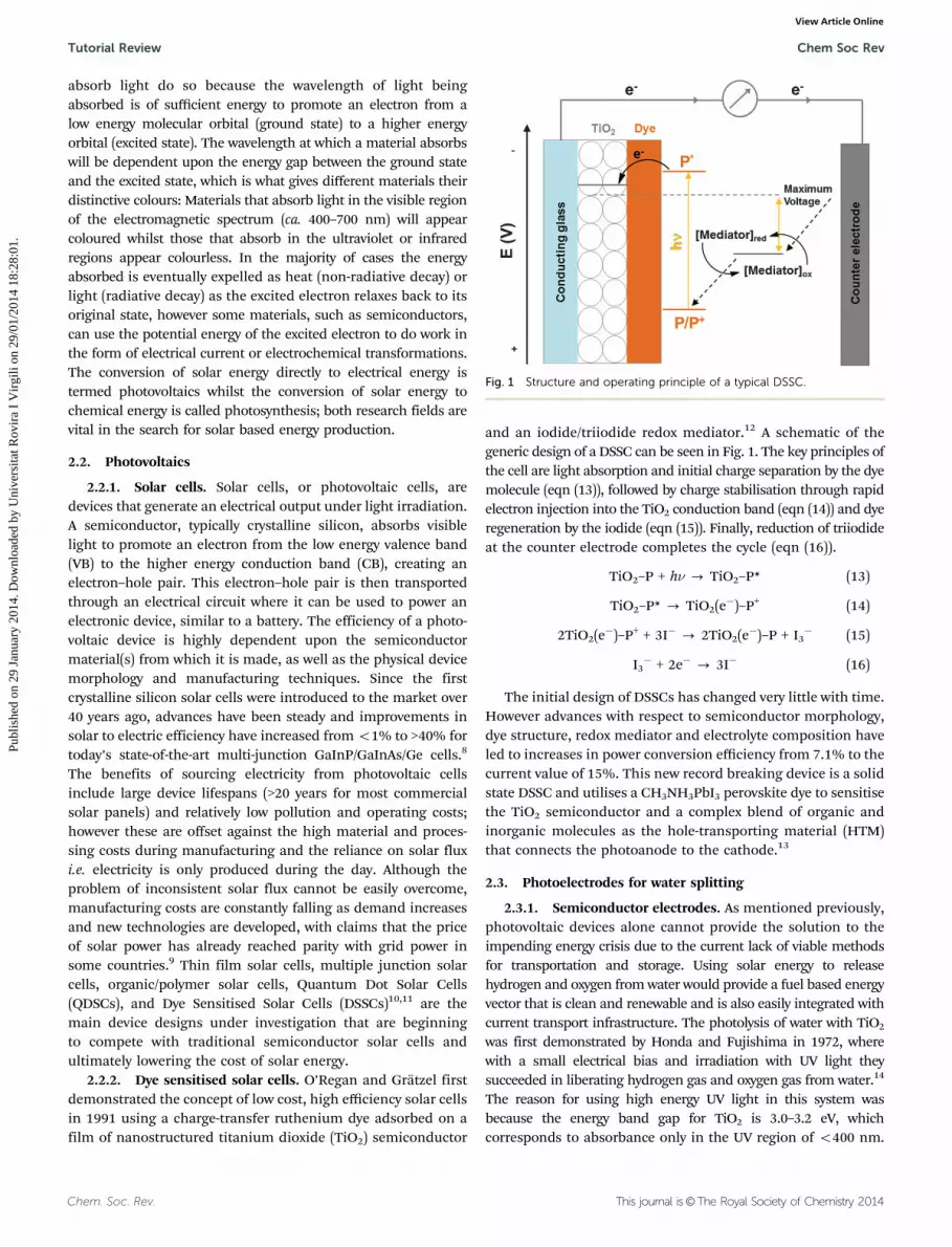
2.2.2. Dye sensitised solar cells. O’Regan and Gratzel firstdemonstrated the concept of low cost, high efficiency solar cellsin 1991 using a charge-transfer ruthenium dye adsorbed on afilm of nanostructured titanium dioxide (TiO2) semiconductor
and an iodide/triiodide redox mediator.12 A schematic of thegeneric design of a DSSC can be seen in Fig. 1. The key principles ofthe cell are light absorption and initial charge separation by the dyemolecule (eqn (13)), followed by charge stabilisation through rapidelectron injection into the TiO2 conduction band (eqn (14)) and dyeregeneration by the iodide (eqn (15)). Finally, reduction of triiodideat the counter electrode completes the cycle (eqn (16)).
TiO2–P + hn - TiO2–P* (13)
TiO2–P* - TiO2(e�)–P+ (14)
2TiO2(e�)–P+ + 3I� - 2TiO2(e�)–P + I3� (15)
I3� + 2e� - 3I� (16)
The initial design of DSSCs has changed very little with time.However advances with respect to semiconductor morphology,dye structure, redox mediator and electrolyte composition haveled to increases in power conversion efficiency from 7.1% to thecurrent value of 15%. This new record breaking device is a solidstate DSSC and utilises a CH3NH3PbI3 perovskite dye to sensitisethe TiO2 semiconductor and a complex blend of organic andinorganic molecules as the hole-transporting material (HTM)that connects the photoanode to the cathode.13
2.3. Photoelectrodes for water splitting
2.3.1. Semiconductor electrodes. As mentioned previously,photovoltaic devices alone cannot provide the solution to theimpending energy crisis due to the current lack of viable methodsfor transportation and storage. Using solar energy to releasehydrogen and oxygen from water would provide a fuel based energyvector that is clean and renewable and is also easily integrated withcurrent transport infrastructure. The photolysis of water with TiO2
was first demonstrated by Honda and Fujishima in 1972, wherewith a small electrical bias and irradiation with UV light theysucceeded in liberating hydrogen gas and oxygen gas from water.14
The reason for using high energy UV light in this system wasbecause the energy band gap for TiO2 is 3.0–3.2 eV, whichcorresponds to absorbance only in the UV region of o400 nm.
Fig. 1 Structure and operating principle of a typical DSSC.
Tutorial Review Chem Soc Rev
Publ
ishe
d on
29
Janu
ary
2014
. Dow
nloa
ded
by U
nive
rsita
t Rov
ira
I V
irgi
li on
29/
01/2
014
18:2
8:01
. View Article Online

This journal is©The Royal Society of Chemistry 2014 Chem. Soc. Rev.
Despite this drawback TiO2 is still by far the most studiedsemiconductor in artificial photosynthesis: lower energy bandgap semiconductors such as Haematite (a-Fe2O3) and CadmiumSelenide (CdSe) exist however they either lack the photostabilityof TiO2 and/or have band edges that are not appropriate forwater splitting.10,15 Fig. 2 shows a selection of common semi-conductors and their relative band positions.
An ideal semiconductor is therefore cheap to manufactureand easily sourced, has a high photochemical stability and aband gap of 1.6–2.4 eV. Until now no such material has beendiscovered but some ingenious systems have been developedwhich are able to work around some of these problems.
2.3.2. Anchored dyes and dyads. In a similar fashion to thedye sensitisation of semiconductors for use in photovoltaiccells, dye molecules can be used in conjunction with molecularcatalysts for photocatalytic water splitting. A host of molecularcatalysts exist for both water oxidation and proton reductionand will be discussed later in Sections 3 and 4, respectively.These catalysts can be adsorbed onto a semiconductor surfacein addition to a photosensitiser dye. When the latter is covalentlylinked to the catalyst, the resulting complex is known as a dyad(D), which can be similarly adsorbed on the semiconductorsurface. The photoelectrodes created work in a similar fashionto DSSCs except that in place of mediation by iodide/triiodidethe dye regeneration step is carried out by the catalystand the catalyst is subsequently regenerated by the relativecatalytic cycle. Fig. 3 shows some example structures of photo-sensitiser dyes (P) and dyads (D) that have been used in thedevelopment of molecular based photoelectrodes. The overall
concept forms a PEC, the working of which will be discussedin Section 6.
2.4. Homogeneous photoelectrocatalytic systems
Sometimes when studying the interactions of catalyst–photo-sensitiser systems, more information can be gained fromcomplementary homogeneous studies in addition to studyingthe heterogeneous electrode setup. In such cases the watersplitting reaction is simplified into its half reactions, focusingsolely on the relevant half reaction, the other half reaction isreplaced by an easier and faster redox reaction by employing aSEA or SED. A suitable photosensitiser for water oxidation musthave strong absorbance in the visible spectrum, long excited-state lifetimes at room temperature and a high oxidationpotential (high enough to oxidise the WOC). The [Ru(bpy)3]2+
family (P1 and P2 in Fig. 3, bpy = 2,20-bipyridyl) members areused almost exclusively in this application because they have allof the above-mentioned characteristics. When light is shinedon [Ru(bpy)3]2+, the excited state generated, [Ru(bpy)3]2+*, iscapable of transferring an electron to a SEA such as [Co(NH3)5Cl]2+
or Na2S2O8 and subsequently forming the strong oxidant,[Ru(bpy)3]3+ in situ. The [Ru(bpy)3]3+ should then be capableof oxidising the WOC from its low oxidation state to itsactive higher oxidation state, which in turn oxidises water todioxygen.2,17,18 [Ru(bpy)3]2+ and its analogues are somewhatunique in that they can be used as photosensitisers for bothwater oxidation and water reduction. When [Ru(bpy)3]2+ is employedin a homogeneous water reduction system, the photogenerated[Ru(bpy)3]2+* can receive an electron from a SED such as
Fig. 2 Calculated oxidation potential Eox (red bars) and reduction potential Ered (black bars) relative to the NHE and vacuum level for a series ofsemiconductors in solution at pH 0, the ambient temperature 298.15 K, and pressure 1 bar. The water redox potentials E(O2/H2O) and E(H+/H2) (dashedlines) and the valence (green columns) and conduction (blue columns) band edge positions at pH 0 are also plotted. Reprinted with permission fromref. 16. Copyright 2012 American Chemical Society.16
Chem Soc Rev Tutorial Review
Publ
ishe
d on
29
Janu
ary
2014
. Dow
nloa
ded
by U
nive
rsita
t Rov
ira
I V
irgi
li on
29/
01/2
014
18:2
8:01
. View Article Online

Chem. Soc. Rev. This journal is©The Royal Society of Chemistry 2014
triethanolamine and form the strong reductant [Ru(bpy)3]+. TheHEC is then subsequently reduced to its active oxidation statewhich in turn begins the catalytic reduction of protons.3
3. Water oxidation3.1. Introduction
Water oxidation is one of the bottlenecks for the successfuldevelopment of an overall water splitting cell with sunlight.Water oxidation is a thermodynamically demanding reaction as
can be seen in eqn (1)–(4) of Table 1. The lowest energy path,eqn (4), involves the removal of 4H+ and 4e� together with thegeneration of an O–O bond, reflecting its mechanistic complexity.Currently, there are a number of oxides capable of catalysing thewater oxidation reaction, although in general they are orders ofmagnitude slower than their molecular counterparts.
The field of molecular WOCs benefits from the capacity ofthe molecular tool to: (i) rationally design WOCs performance basedon ligand modifications, choice of transition metal, oxidationstate and geometry, through space interactions, electroniccoupling, and active site hindering; (ii) increase the solubility
Fig. 3 A selection of photosensitiser dyes (P) and dyad molecules (D).
Tutorial Review Chem Soc Rev
Publ
ishe
d on
29
Janu
ary
2014
. Dow
nloa
ded
by U
nive
rsita
t Rov
ira
I V
irgi
li on
29/
01/2
014
18:2
8:01
. View Article Online

This journal is©The Royal Society of Chemistry 2014 Chem. Soc. Rev.
by adding additional functionalities; and (iii) enable the anchoringof the catalyst onto electrodes.
Since 1982, when the first well characterised molecular WOC(the so-called ‘‘blue dimer’’, WOC1 in Fig. 4) was reported, asignificant number of WOCs have been synthesised, includingmononuclear and polynuclear transition metal complexes.2
From this existing body of WOCs, a few common features haveemerged that allow designing fast and efficient WOCs withlong-term stability: first of all, the metal centre(s) must haveeasy access to high oxidation states that should be stabilised by
the ligand framework. The stabilisation of these high oxidationstates is generally achieved by Proton Coupled Electron Transfer(PCET), thus avoiding highly charged intermediates. For thispurpose, an aquo ligand or an available coordination site to binda water molecule is essential. This requirement is also crucial inorder to generate the M–O group, responsible for the critical O–Obond formation step. Secondly, given the high thermodynamicenergy associated with the water oxidation process (0.81 V vs.NHE, eqn (4), Table 1), it is imperative that the ligands used areoxidatively robust. In addition, the ligands should not suffer
Fig. 4 A selection of water oxidation catalysts. For WOC2, the schematically represented ligands are the polyoxometalate [g-SiW10O36]8�.
Scheme 3 Potential pathways to form an O–O bond promoted by transition metal complexes. Left, water nucleophilic attack (WNA). Right, interactionbetween two M–O entities (I2M).
Chem Soc Rev Tutorial Review
Publ
ishe
d on
29
Janu
ary
2014
. Dow
nloa
ded
by U
nive
rsita
t Rov
ira
I V
irgi
li on
29/
01/2
014
18:2
8:01
. View Article Online

Chem. Soc. Rev. This journal is©The Royal Society of Chemistry 2014
easy ligand substitution by solvent water molecules under theworking conditions. If either of these two processes occur, thenature of the actual catalyst will be unknown, since the initialmolecular catalyst could be transformed to another species oreven all the way to the corresponding metal oxide.19
3.2. Water oxidation mechanisms
There are two different mechanisms that can operate in theoxygen–oxygen bond formation step:
(i) WNA: Water nucleophilic attack, where a water moleculefrom the solvent attacks the oxo group from the M–O moiety(Scheme 3). This mechanism can take place when the M–Ofragment is electrophilic enough to be attacked by a nucleophilicwater solvent molecule. The O–O bond is the result of theinteraction between the HOMO of the water molecule and theLUMO of the metal–oxo (M–O) complex. The subsequent cleavageof the M–O bond forms O2 and the reduced metal centre.2,20 Mostmononuclear WOCs and some polynuclear WOCs, such asWOC1 and the tetranuclear polyoxometalate WOC2 are reportedto oxidise water through this mechanism.2
(ii) I2M: Interaction between two M–O entities, which can be aradical coupling or a reductive elimination. The latter depends onthe oxidation state of the metal centre and on the number ofoxygens (Scheme 3). As the name indicates, this pathway consists ofthe interaction of two metal–oxo moieties and, as in the previouscase, it can take place both in an intra- and in an inter-molecularmanner. The dinuclear complex WOC3 undergoes water oxidationthrough this mechanism by the intra-molecular interaction ofthe two RuQO moieties, which are perfectly oriented for thisinteraction. On the other hand, the highly active mononuclearruthenium complex WOC6 promotes the oxygen–oxygen bondformation by an inter-molecular interaction between two com-plexes (see Section 3.3.1).
These two mechanisms have also been proposed to occur in theoxygen evolving centre of photosystem II (OEC-PSII) in greenplants and algae.2 The participation of redox active ligands, suchas semi-quinones, in the overall water oxidation reaction, has alsobeen proposed by Fujita, Muckerman and coworkers.21
3.3. Benchmarks
Before the O–O bond forming step, the WOC must be activated.This activation involves a combination of electron(s) andproton(s) removal (PCET) from the initial M–OH2 active groupin order to reach a sufficiently reactive species. The latter canbe generated either using a chemical oxidant, by applying anexternal potential, or using sunlight energy.
3.3.1. Chemically induced WO. The best catalyst describeduntil now is a mononuclear ruthenium catalyst WOC5 capable ofachieving a turnover number of 5.0 � 104 (TON), with a turnoverfrequency (TOF) of 300 s�1 using Ce(IV) ((NH4)2Ce(NO3)6 or CAN) asa chemical oxidant. In aqueous media, a solvent water moleculecoordinates complex WOC5, generating the correspondingRu–OH2 complex with concomitant decoordination of one ofthe pyridyls of the equatorial 2,20-bipyridine-6,60-dicarboxylate([bdc]2�) ligand. When the Ru(IV) oxidation state is reached, theruthenium metal centre can accommodate a seventh coordinated
ligand, thus recovering the complete pyridyl coordination fromthe [bdc]2� ligand.22 An additional oxidation step to Ru(V)and dimerization via a bimolecular I2M pathway, yields aRu(IV)–O–O–Ru(IV) intermediate. The dimeric peroxo species cansubsequently release molecular oxygen, however, under catalyticconditions in the presence of an excess of Ce(IV), the Ru(IV)–O–O–Ru(IV) intermediate is further oxidised to Ru(IV)–O–O–Ru(V) or to itssuperoxide analogue, which can also release dioxygen.
Another remarkable example is a manganese complex (WOC8)capable of oxidising water to oxygen using a one electron donortype of oxidant, such as [Ru(bpy)3]3+. The performance of thiscatalyst has been tested at pH 7.2 (0.1 M phosphate buffer),yielding a TON of 25 with a TOF of 0.027 s�1.23
A number of Ir complexes have also been proposed to workas WOCs, although it is not clear whether they are catalystprecursors to other catalytically active molecular species orsimply precursors to iridium oxide nanoparticles that areknown to be active WOCs.19
3.3.2. Electrochemically induced WO. This activation strat-egy uses a potentiostat as the electron source, in order to applythe most appropriate potential at desired pH. Within electro-chemically induced water oxidation, there are mainly twostrategies that can be followed, depending on whether (i) thecatalyst is in the homogeneous phase or (ii) is anchored ontothe electrode surface. This second approach is a step furthertowards incorporating the WOC into a photoelectrochemicalcell. Furthermore, this strategy can also enhance the reactivity,by stabilising the WOC after its heterogenisation. Differentmethods can be used to anchor a homogenous catalyst onto asurface: (i) physisorption, exploiting Van der Waals forces; (ii)electrostatic interaction, taking advantage of the differentcharges between the surface and the WOC; (iii) encapsulation,immobilizing the catalyst inside a matrix, and (iv) chemisorption,covalent bonding of the catalyst to the surface. In most ofthese examples, a previous modification of either the surface orthe complex is required.
Following the heterogenisation strategy, the best results belongto the mononuclear ruthenium catalyst (WOC9), covalently linkedto a [Ru(bpy)3]-type redox mediator. In this example, the catalyst iscovalently anchored onto an ITO (Indium Tin Oxide) conductingglass through the interaction between the terminal –OH surfacegroups and the phosphonate moieties. The new electrodes presentthe best performance reported until now towards water oxidation,with at least 2.8 � 104 TON and 0.6 s�1 TOF, applying 0.63 Voverpotential at pH 1 and yielding a 97% faradic efficiency(i.e. 97% of the current is used to evolve oxygen).24
Recently, two different copper catalysts capable of oxidisingwater with a high faradic efficiency and high TOF have beenpublished. In the first example, the catalyst was a mononuclearcompound (WOC10) capable of oxidising water by applying0.75 V overpotential at pH 13, with a TOF of 100 s�1 and 90%faradic efficiency.25 The second mononuclear copper compound(WOC11) oxidises water at 0.72 V overpotential at pH 11 witha comparable TOF and with 99% faradic efficiency. A waternucleophilic attack on the Cu(IV)–O or Cu(III)–O is proposed asthe reaction mechanism.26
Tutorial Review Chem Soc Rev
Publ
ishe
d on
29
Janu
ary
2014
. Dow
nloa
ded
by U
nive
rsita
t Rov
ira
I V
irgi
li on
29/
01/2
014
18:2
8:01
. View Article Online

This journal is©The Royal Society of Chemistry 2014 Chem. Soc. Rev.
Another interesting example reports the WO by a molecularcobalt catalyst (WOC4), yielding 77% faradic efficiency, byapplying 0.9 V overpotential (phosphate buffer, pH 2). Themolecular nature of this catalyst has been proved by studyinghow the catalytic performance was affected by changing theancillary ligands.27 The mechanism has been proposed to besimilar to the structurally related Ru WOC3 involving theintramolecular interaction of the two Co(IV)QO units (I2M).
3.3.3. Photochemically induced WO. The use of sunlight tocarry out water oxidation is one of the key points required tomimic the natural photosynthesis. Thus, the presence of a lightharvesting system is fundamental in order to use sunlightenergy to oxidise the WOC and to accumulate the oxidativeequivalents needed to evolve oxygen.
As discussed previously in Section 2.4, light-induced wateroxidation can be carried out in the homogenous phase using aphotosensitiser (P) to harvest the sunlight energy, a WOC and aSEA (Scheme 4). The absorption of sunlight energy by the photo-sensitiser generates an excited state (P*) capable of transferring anelectron to the SEA and generating the oxidised photosensitiser(P+). The latter then oxidises the WOC from its low oxidation stateto a higher one, which in turn oxidises water to dioxygen.
Different WOCs have been tested in this three componentsystem with moderate results.2 One of the main problems ofthis approach is the photosensitiser stability, which can beoxidised by singlet oxygen generated during the catalysis fromthe direct interaction between the triplet oxygen and light.
One of the best results belongs to the three componentsystem WOC2/P3/Na2S2O8.17 This example presents the maximumreported quantum yield fO2
(i.e. the number of photons used togenerate oxygen), which turns out to be 0.3. Taking into accountthat for Na2S2O8-based systems the maximum expected fO2
is 0.5,in the above-mentioned example 60% of the photons are used togenerate oxygen. Furthermore, 90% of the Na2S2O8 is consumed,which also turns to be one of the best reported results.
Another strategy for light-driven water oxidation is to buildchromophore–catalyst dyad molecules. This approach consistsof covalently linking two metal complexes, each of them playinga different role: one acts as the light-harvesting antenna andthe other one acts as the WOC. Most of the published dyads areused either to oxidise organic substrates or to study the electrontransfer between the two metal centres. However, recently adiruthenium dyad (D1 in Fig. 3) capable of reaching 134 TONupon light irradiation during 6 hours has been published.
Moreover, the performance of this new dyad is better thanthe analogous three component system.18
Finally, anchoring the photosensitiser and the catalyst onton-type semiconductor surfaces forms a photoanode, which canbe incorporated in a PEC (see Section 6.2).
4. Proton reduction4.1. Introduction
The reduction of protons into molecular hydrogen is a two-electron process (eqn (5) in Table 1), and from a thermo-dynamic point of view, all the redox couples with a more reductivepotential than the couple E(H2O/H2) = �0.41 V vs. NHE at pH 7are able to generate H2. However, some of those reactionsare kinetically disfavoured and are too slow in the absenceof a suitable catalyst. Transition metal complexes can storeelectrons via multiple redox states and therefore they aresuitable candidates to efficiently catalyse this reaction.3,4,28,29
Indeed, during the last few decades a large number of homoge-neous and heterogeneous molecular systems based on transitionmetal complexes for hydrogen evolution have been described.Even though they often show high efficiency and turnovernumbers (TON) for hydrogen production, most of them are onlyfunctional in organic or aqueous-organic media (5–50% H2O)and examples of systems working in pure water remain scarce.Nevertheless this is a necessary condition for a real applicationin a large scale artificial photosynthetic process.
In the following sections, an overview of the mechanisticproposal for proton reduction catalysed by metallic complexeswill be presented, followed by a summary of the best molecularHECs described to date, selected according to their perfor-mance and focusing on those that work in aqueous conditionsor hydro-organic media.
The HECs have been divided into two major categories, thefirst one includes catalysts based on rhodium and platinum,while the second one deals with those based on cobalt, nickel,iron or molybdenum. The first family of metals has beenstudied for a long time because of their high reactivity towardsprotons as colloids and their ability to easily form metalhydrides. However their high costs and low abundances renderthem problematic for industrial applications. For this reasonmany new studies are focused on the development and theoptimisation of metallic complexes based on cheaper and moreabundant metals.
4.2. Proton reduction mechanisms
The mechanism of proton reduction catalysis at metallic centreshas been studied experimentally and theoretically, particularlyusing cobalt, nickel and diiron catalysts.3,4,28,30 Even thoughmost of these studies have been done in organic media, theyprovide valuable information for the design of better catalyststhat will ultimately be used under aqueous conditions.
A generic mechanistic scheme for proton reduction at ametallic centre Mn+ is given in Scheme 5. Reduction of Mn+
followed by protonation affords the key intermediate hydride
Scheme 4 Combination of reactions involved in light induced WO. WOC,catalyst in non-active oxidation state. WOC+, catalyst in its active oxidationstate. P, photosensitiser. SEA, sacrificial electron acceptor.
Chem Soc Rev Tutorial Review
Publ
ishe
d on
29
Janu
ary
2014
. Dow
nloa
ded
by U
nive
rsita
t Rov
ira
I V
irgi
li on
29/
01/2
014
18:2
8:01
. View Article Online

Chem. Soc. Rev. This journal is©The Royal Society of Chemistry 2014
H–Mn+ that can react in three different ways. The first one involvesprotonation and hydrogen evolution, regenerating the starting Mn+
catalyst (heterolytic pathway, black arrow). Alternatively, thereaction with a second hydride molecule forms M(n�1)+ andreleases hydrogen (homolytic pathway, red arrow). The thirdpossible route involves further reduction of the hydride to givea low valent hydride H–M(n�1)+, which can analogously followthe heterolytic or homolytic pathways (blue arrow).
Homolytic and heterolytic pathways are competing mechanismsthat can operate uniquely or simultaneously, depending on theexperimental conditions, such as the catalyst concentration orpH. In this context, the use of bimetallic complexes can providea useful tool to discriminate in favour of one mechanism and toenhance the rate of the catalysis.
The presence of proton relays in the second coordinationsphere of the metal catalyst can favour Proton Coupled ElectronTransfer (PCET) processes in hydrogen evolving catalysis. It hasbeen proven that they facilitate the formation of the H–Mn+
hydride intermediate as well as the formation of the H–H bond.One illustrative example is that of DuBois catalysts in Scheme 5with strategically positioned amine groups that are believed tobe responsible for the high catalytic rates of the catalysis.28,31
Very often this proton relay is compared to the cofactor of the[FeFe]-hydrogenase, the best natural enzyme for proton reductionand hydrogen oxidation (Scheme 5).
4.3. Catalysts
4.3.1. Pt and Rh. The first examples of functional photo-induced hydrogen production were published in the lateseventies. They combine [Ru(bpy)3]2+ (P2) as a light harvester,a heterogeneous (platinum colloid) or homogenous (metalcomplex) proton reduction catalyst and a SED. Those systemscan be coupled to a redox mediator such as methyl viologen
(MV2+) or metal complexes. In 1979 Lehn and Sauvage3 showedthat a P2 photosensitised aqueous solution of colloidal platinum,using HEC1 (Fig. 5) as electron relay, can efficiently evolve H2
under visible light irradiation (l > 400 nm, 10.8 h�1 TOF). Theyalso showed that an equivalent solution at pH 5.2 withoutplatinum colloids produced a significant amount of hydrogen(6 TON in 3 h); in this case the rhodium complex HEC1 playsthe role of hydrogen evolving catalyst in the first fully molecularphotocatalytic system for proton reduction.
The most active rhodium catalyst (HEC2) belongs as well tothe polypyridyl family and is able to reach more than 5000 TONwith 34% of quantum yield (fH2
) in a system described byBernhard.3 Complex HEC2 was coupled to a cyclometalatediridium photosensitiser (P6, Fig. 3) and TEA (triethylamine) wasused as the SED in an aqueous–organic solvent mixture THF :H2O (80 : 20) under monochromatic irradiation (l = 460 nm).An important drawback of this system is the presence of anorganic co-solvent in addition to water.
In the last few years two new systems based on a rhodiumcatalyst that exhibit interesting activity in purely aqueousmedium have been published. The first one was developed by
Fig. 5 A selection of rhodium hydrogen evolving catalysts.
Scheme 5 Left, proposed mechanistic pathways for hydrogen evolution catalysis at a metallic centre Mn+. Right, hypothetical transition states of H–Hbond formation at the [FeFe]-hydrogenase cofactor and DuBois catalyst.31
Tutorial Review Chem Soc Rev
Publ
ishe
d on
29
Janu
ary
2014
. Dow
nloa
ded
by U
nive
rsita
t Rov
ira
I V
irgi
li on
29/
01/2
014
18:2
8:01
. View Article Online

This journal is©The Royal Society of Chemistry 2014 Chem. Soc. Rev.
Fukuzumi32 and is built with pentamethylcyclopentadienyl andbipyridine ligands (HEC3, Fig. 5). This Rh catalyst was usedtogether with P2 as a photosensitiser and sodium ascorbate/ascorbic acid buffer which acted as both the proton source andthe electron donor. Under optimized conditions the catalystcan reach up to 100 TON in 3 h under visible light irradiation(l > 430 nm). One interesting part of this work is the pH toreactivity relationship study. It has been shown that the optimalpH corresponds to a compromise between the reactivity of thecatalyst towards protons and the efficiency of the quenching ofthe photosensitiser and therefore the sodium ascorbate/ascorbicacid ratio has to be chosen wisely to optimize the efficiency ofthe system. The second system is the most active rhodium basedcatalyst that works in purely aqueous medium and has beendescribed by Collomb.33 This system is composed of the poly-pyridyl catalyst HEC4 in Fig. 5, which is similar to those used byLehn and Bernhard, and uses P2 as a photosensitiser andascorbate buffer as an electron donor. The photocatalytic solutionis irradiated under visible light (400 nm o l o 700 nm) andunder optimised conditions the system reaches more than1000 TON. This work also highlights a non-negligible hydrogenproduction from a blank solution containing a mixture of thephotosensitiser and the buffer at pH 4 that has to be taken intoaccount, particularly when the catalyst concentration is lowerthan that of the photosensitiser.
The group of Sakai has developed numerous photocatalyticproton reduction systems that are active in pure water.29 Theyare mainly based on platinum complexes (mono- and binuclear)with a nitrogen rich coordination sphere (Fig. 6).
The best performances were obtained using the dinuclearcomplex HEC5 (Fig. 6), P2 as a photosensitiser, methyl viologen(MV2+) as an electron mediator and EDTA (ethylenediaminetetraacetic acid) as a SED in acetate buffered aqueous solution(pH 5). In this case, the quantum yield (fH2
) for H2 productioncan reach an exceptionally high value of 31% using visible lightwith an average TON around 100. According to the authors, thedetermining factors for the catalyst efficiency and activity arethe distance and the interaction force between the dz2 orbitalsof the two platinum centres involved in the key hydride inter-mediate formation and thus in the proton activation process.The shorter the distance and/or the stronger the interactionbetween the two metal centres, the more active is the catalyst.To confirm this assertion, two other Pt dinuclear complexeswith different Pt–Pt bond lengths were studied (HEC6 andHEC7, Fig. 6). Indeed, complex HEC6 with a shorter Pt–Pt bondlength is more active than complex HEC7 with a longer Pt–Ptbond. The overriding role of the platinum dz2 orbitals in theproton reduction performance has also been confirmed for
mononuclear platinum complexes by tuning their energy levelusing different coordination spheres and then studying theeffects on proton reduction catalysis.29
4.3.2. Fe, Co, Ni and Mo. In the last 5–10 years there hasbeen a remarkable improvement in the performance of waterreduction catalysts using earth abundant materials like molyb-denum or the first row transition metals iron, cobalt and nickel.Fig. 7 and 8 illustrate the best molecular catalysts described todate that belong to this group. The selection includes catalyststhat have been used in aqueous media or those that have shownparticularly interesting or exceptional properties in aqueous–organic solvents. Fig. 7 shows a collection of catalysts that haveworked successfully under photochemical reactions, while Fig. 8focuses on those that have only been used in electrocatalysis.
Since the cobaloxime-type complex [Co(dmgH)2] (dmgH2 =dimethylglyoxime) was reported to promote photocatalyticproton reduction using P2 as a photosensitiser, a large familyof diimine/dioxime cobalt HECs have been described.3,28 Theyhave shown high activity in organic media and have providedvaluable insights into the proton reduction mechanism,30
however, the low stability of these kind of complexes in waterunder acidic reductive conditions has limited their use inaqueous systems, particularly under homogeneous conditions.One example of a successful homogenous photocatalytic systemin pure water uses complex HEC8 in Fig. 7, together with naturalphotosystem I (PSI) as a photosensitiser and ascorbic acid as aSED.3 The heterogeneous approach, that is the use of catalystsattached on solid surfaces, has been proven to be a good strategyto improve the performance of cobaloxime type complexes.4,28,34
Artero and coworkers fabricated a highly active cathode graftedwith catalyst HEC14 reaching up to 5.5 � 104 TON at �0.59 V vs.RHE (E(V) vs. RHE = E(V) vs. NHE – 0.059 pH) (Fig. 8).34
Electrodeposition of catalyst HEC15 (Fig. 8, X = CH3CN)on the glassy carbon electrode produced an electrocatalyticmaterial that had 5 � 106 TON at �0.61 V vs. NHE.4 It is worthnoting that in this kind of systems it is difficult to prove themolecular nature of the catalyst and formation of cobalt oxidenanoparticles cannot be ruled out.
On the other hand, cobalt complexes stabilised by other nitrogendonor ligands have shown remarkable stability in water and highactivity in both photochemical and electrochemical systems asillustrated by the selected examples HEC9, HEC11 and HEC16 inFig. 7 and 8.3,4,35 Polypyridyl-based ligands have also been used toprepare high-valent molybdenum catalysts HEC17 and HEC18 inFig. 8, which are among the best molecular electrocatalysts forhydrogen production described to date that perform in pure water.Complex HEC18 (3.5 � 103 to 1.9 � 107 TON) is considered amolecular analogue of the edge sites of two-dimensional bulk MoS2,that has also been used in water reduction.4
Iron based catalysts have also been extensively studied asHECs, most of which are dimeric iron(I) complexes resemblingthe natural enzyme [FeFe]-hydrogenase cofactor. A problemassociated with these mimics is the low solubility in water butthis can be solved by encapsulating the catalyst inside micellesor cyclodextrins, attaching the catalyst on a solid support or byusing ligands with water affinity.3,28 One example of this latterFig. 6 A selection of binuclear platinum hydrogen evolving catalysts.
Chem Soc Rev Tutorial Review
Publ
ishe
d on
29
Janu
ary
2014
. Dow
nloa
ded
by U
nive
rsita
t Rov
ira
I V
irgi
li on
29/
01/2
014
18:2
8:01
. View Article Online

Chem. Soc. Rev. This journal is©The Royal Society of Chemistry 2014
strategy is described in recent work by Wu where they usea ligand containing trimeric ethylene glycol chains (see HEC10in Fig. 7). They achieve 505 TON under visible light irradiationusing CdTe nanocrystals as photosensitisers and ascorbic acidas a SED under pure aqueous conditions.3
Diphosphine nickel complexes of the type of HEC19 andHEC20 in Fig. 8 were first developed by DuBois and coworkersas HECs in organic solvents but not in water due to theirlimited solubility.3,4,28,31 Two independent studies by Arteroand coworkers were published later where they attached cata-lysts HEC19 and HEC20 to MWCNTs (multiwalled carbon
nanotubes) by covalent bonding or pi-stacking interactions,respectively. Subsequent dropcasting on glassy carbon usingNafion afforded electrocatalytically active electrodes achievingup to 8.5 � 104 TON in pure aqueous systems.
Another emerging group of HEC studied by Eisenberg arethose based on sulfur donor ligands, which are usually redoxnon-innocent and are thought to have a role in the mechanismof proton reduction. We find examples of cobalt and nickelcomplexes in this group, HEC12–13, with both metals showingexcellent photocatalytic activity in conjunction with P2 orfluorescein (P5) photosensitisers.3,4
Fig. 8 A selection of hydrogen evolving electrocatalysts containing Co, Ni and Mo which work in aqueous media. Turnover numbers (TON) are referredas moles of H2 per mole of catalyst.
Fig. 7 A selection of hydrogen evolving photocatalysts containing Fe, Co or Ni, that work in aqueous media or aqueous–organic solvents. Turnovernumbers (TON) are referred as moles of H2 per mole of catalyst, unless otherwise indicated. Photosensitisers and sacrificial electron donors are added forcomparison. AA = ascorbic acid/sodium ascorbate, TEA = triethylamine.
Tutorial Review Chem Soc Rev
Publ
ishe
d on
29
Janu
ary
2014
. Dow
nloa
ded
by U
nive
rsita
t Rov
ira
I V
irgi
li on
29/
01/2
014
18:2
8:01
. View Article Online

This journal is©The Royal Society of Chemistry 2014 Chem. Soc. Rev.
5. CO2 reduction5.1. Introduction
Carbon dioxide is one of the major contributors to the green-house effect resulting in serious global warming, with the mainsource of this anthropogenic CO2 being the burning of hydro-carbon fuels. However, CO2 represents an important non-toxic,highly abundant and cheap carbon feedstock and should not beviewed as a waste material. In particular, the transformations ofcarbon dioxide into methanol or formic acid are important becausethese chemicals could be used as liquid fuels. Unfortunately, theinherent structural stability of the CO2 molecule makes its activationtowards reduction a difficult task. Therefore, among the contem-porary energy challenges present today, the reduction of carbondioxide is certainly one of the major issues.
Another complicated issue associated with the reduction ofCO2 is the fact that it can produce a variety of products such asformic acid, carbon monoxide, oxalic acid, methanol or methane(see Table 1 in Section 1). As depicted in eqn (6), the injection ofone electron into CO2 requires a lot of energy; the potential ofthe CO2/CO2
�� redox couple is highly negative (�1.9 V vs. NHE).This high energy value is partly due to the rearrangement from alinear to a bent structure. On the other hand, proton-coupledmultielectron transfer processes are generally more favourablethan single electron reductions because thermodynamicallymore stable molecules are produced and high energy barriersare avoided. This phenomenon is illustrated by the equationssummarised in the Table 1 (compare reduction potential ofeqn (6) with those of eqn (7)–(12)).
There are different methods to reduce CO2 including electro-catalysis, photocatalysis or the use of chemical reducing agentssuch as hydrogen. Regardless of the employed methodology,the use of a catalyst is always required in order to avoidthe formation of the CO2 radical anion intermediate and tominimize the overpotential for the overall process. Molecularcatalysts containing transition metals have been extensivelyused because low oxidation state species can easily be reached.
However, most electrochemical and photochemical systems forCO2 reduction only produce the 2e� reduction products, that is,carbon monoxide or formate. One of the main challenges inthis field is therefore to convert carbon dioxide to a morereduced product such as methanol with high efficiency andselectivity. The new catalysts for CO2 reduction should also behighly sensitive to the gas in order to react at low concentrationof CO2, ideally at atmospheric concentrations.
In the following section, an overview of the mechanisticproposal for carbon dioxide reduction catalysed by metalliccomplexes will be presented. Section 5.3 will then describe thebest catalytic systems for CO2 reduction based on complexesdepicted in Fig. 9 where they have been divided into: (i) CO2
reduction using H2, (ii) electrocatalysis and (iii) photocatalysis.
5.2. Mechanisms
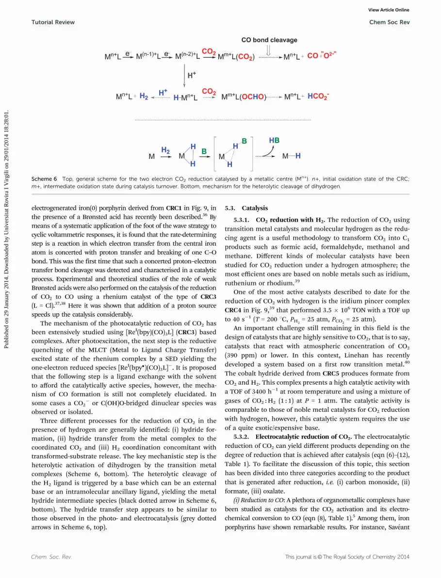
The first step towards CO2 reduction is its coordination to areduced metallic centre (Mn+) to give Mm+L(CO2) (solid blackarrows, Scheme 6). The CO2 molecule possesses both acidic andbasic properties and the carbon atom is susceptible to be attackedby nucleophiles and the oxygen atoms are susceptible to beattacked by electrophiles. The most usual coordination modes ofCO2 to a transition metal centre are the s-bonding of the metal tothe electrophilic carbon atom. During catalyst turnover, a competi-tion may occur between the addition of CO2 and addition of H+ onthe active reduced form of the catalyst leading to bond cleavageand release of CO (black dashed arrow) or to a metal hydrideintermediate H–Mn+L (solid grey arrow). This metal hydride canundergo two competing processes; it can either react with CO2 togive the desired formate (HCO2
�) or it can react with H+ to producemolecular hydrogen (H2) (compare left and right dashed greylines). The acidity of the reaction medium may influence theproduct distribution between CO, formate and H2.
The reduction of CO2 to CO requires the cleavage of a C–Obond (black dashed arrow in Scheme 6). A detailed kineticanalysis of the catalytic reduction of CO2 to CO by an
Fig. 9 A selection of carbon dioxide reduction catalysts.
Chem Soc Rev Tutorial Review
Publ
ishe
d on
29
Janu
ary
2014
. Dow
nloa
ded
by U
nive
rsita
t Rov
ira
I V
irgi
li on
29/
01/2
014
18:2
8:01
. View Article Online
Chem. Soc. Rev. This journal is©The Royal Society of Chemistry 2014
electrogenerated iron(0) porphyrin derived from CRC1 in Fig. 9, inthe presence of a Brønsted acid has recently been described.36 Bymeans of a systematic application of the foot of the wave strategy tocyclic voltammetric responses, it is found that the rate-determiningstep is a reaction in which electron transfer from the central ironatom is concerted with proton transfer and breaking of one C–Obond. This was the first time that such a concerted proton–electrontransfer bond cleavage was detected and characterised in a catalyticprocess. Experimental and theoretical studies of the role of weakBrønsted acids were also performed on the catalysis of the reductionof CO2 to CO using a rhenium catalyst of the type of CRC3(L = Cl).37,38 Here it was shown that addition of a proton sourcespeeds up the catalysis considerably.
The mechanism of the photocatalytic reduction of CO2 hasbeen extensively studied using [ReI(bpy)(CO)3L] (CRC3) basedcomplexes. After photoexcitation, the next step is the reductivequenching of the MLCT (Metal to Ligand Charge Transfer)excited state of the rhenium complex by a SED yielding theone-electron reduced species [ReI(bpy�)(CO)3L]�. It is proposedthat the following step is a ligand exchange with the solventto afford the catalytically active species, however, the mecha-nism of CO formation is still not completely elucidated. Insome cases a CO2
� or C(OH)O-bridged dinuclear species wasobserved or isolated.
Three different processes for the reduction of CO2 in thepresence of hydrogen are generally identified: (i) hydride for-mation, (ii) hydride transfer from the metal complex to thecoordinated CO2 and (iii) H2 coordination concomitant withtransformed-substrate release. The key mechanistic step is theheterolytic activation of dihydrogen by the transition metalcomplexes (Scheme 6, bottom). The heterolytic cleavage ofthe H2 ligand is triggered by a base which can be an externalbase or an intramolecular ancillary ligand, yielding the metalhydride intermediate species (black dotted arrow in Scheme 6,bottom). The hydride transfer step appears to be similar tothose observed in the photo- and electrocatalysis (grey dottedarrows in Scheme 6, top).
5.3. Catalysis
5.3.1. CO2 reduction with H2. The reduction of CO2 usingtransition metal catalysts and molecular hydrogen as the redu-cing agent is a useful methodology to transform CO2 into C1
products such as formic acid, formaldehyde, methanol andmethane. Different kinds of molecular catalysts have beenstudied for CO2 reduction under a hydrogen atmosphere; themost efficient ones are based on noble metals such as iridium,ruthenium or rhodium.39
One of the most active catalysts described to date for thereduction of CO2 with hydrogen is the iridium pincer complexCRC4 in Fig. 9,39 that performed 3.5 � 106 TON with a TOF upto 40 s�1 (T = 200 1C, PH2
= 25 atm, PCO2= 25 atm).
An important challenge still remaining in this field is thedesign of catalysts that are highly sensitive to CO2, that is to say,catalysts that react with atmospheric concentration of CO2
(390 ppm) or lower. In this context, Linehan has recentlydeveloped a system based on a first row transition metal.40
The cobalt hydride derived from CRC5 produces formate fromCO2 and H2. This complex presents a high catalytic activity witha TOF of 3400 h�1 at room temperature and using a mixture ofgases of CO2 : H2 (1 : 1) at P = 1 atm. The catalytic activity iscomparable to those of noble metal catalysts for CO2 reductionwith hydrogen, however, this catalytic system requires the useof a quite exotic/expensive base.
5.3.2. Electrocatalytic reduction of CO2. The electrocatalyticreduction of CO2 can yield different products depending on thedegree of reduction that is achieved after catalysis (eqn (6)–(12),Table 1). To facilitate the discussion of this topic, this sectionhas been divided into three categories according to the productthat is generated after reduction, i.e. (i) carbon monoxide, (ii)formate, (iii) oxalate.
(i) Reduction to CO: A plethora of organometallic complexes havebeen studied as catalysts for the CO2 activation and its electro-chemical conversion to CO (eqn (8), Table 1).5 Among them, ironporphyrins have shown remarkable results. For instance, Saveant
Scheme 6 Top, general scheme for the two electron CO2 reduction catalysed by a metallic centre (Mn+). n+, initial oxidation state of the CRC;m+, intermediate oxidation state during catalysis turnover. Bottom, mechanism for the heterolytic cleavage of dihydrogen.
Tutorial Review Chem Soc Rev
Publ
ishe
d on
29
Janu
ary
2014
. Dow
nloa
ded
by U
nive
rsita
t Rov
ira
I V
irgi
li on
29/
01/2
014
18:2
8:01
. View Article Online
This journal is©The Royal Society of Chemistry 2014 Chem. Soc. Rev.
and coworkers reported catalyst CRC1 in Fig. 9 as an efficientand stable catalyst for the selective conversion of CO2 into COin the presence of Lewis acids or weak Brønsted acids.5 In thiswork, it was also observed that the addition of a proton sourcespeeds up the catalysis. On this basis, the same group reportedcatalyst CRC2, shown in Fig. 9, bearing hydroxyl groups on thephenyl group perpendicular to the macrocycle of the porphyrin,leading to a considerable increase of catalytic activity.5 Thiscatalyst, which uses one of the most earth abundant metals,presents good selectivity towards the production of CO (above90%) with a TON of 5 � 107. Furthermore, the catalyst remainsstable over the course of 4 hours of electrolysis at a low over-potential (0.465 V).
Catalysts based on other macrocyclic structures have alsobeen studied.41 In 1980, Eisenberg reported a family of tetra-azomacrocyclic complexes of cobalt and nickel similar to CRC6shown in Fig. 9 for the reduction of CO2 to CO. These catalystsperformed with high current efficiencies (up to 98%) and atpotentials ranging from �1.3 to �1.6 V vs. SCE (E(V) vs. SCE =E(V) vs. NHE �0.2412 V).41 A few years later, the group ofSauvage reported the nickel cyclam complex CRC6.41 Thiscomplex was extremely stable and displayed good selectivityand faradic efficiency (up to 96%) at �0.86 V vs. SCE (E(V) vs.SCE = E(V) vs. NHE �0.2412 V) in aqueous solution. However, ithas been shown that Ni(cyclam) complexes are absorbed on themercury electrode. More recently the homogeneous CO2 reductionactivity of this catalyst was examined at a glassy carbon electrode,42
and it was shown that even if the same catalyst presents abetter activity on mercury, the catalysis occurs efficiently andselectively in water also on an inert electrode. Another family ofmetal catalysts used for the reduction of CO2 to CO are thosecontaining phosphine ligands such as the bimetallic palladiumcomplex CRC7, shown in Fig. 9, studied by DuBois. Thiscomplex shows high catalytic rate and faradic efficiencies
higher than 90% for CO production in acidic acetonitrilesolution. They suggest cooperative binding of CO2 that facilitatesthe formation of the CO2 adduct intermediate.5
(ii) Reduction to formate: Formic acid is one of the two possible2e� reduction products of CO2 (eqn (7), Table 1). It is the onlyproduct of the electrolysis of CO2 in water on an inert electrodewithout any catalyst present. The transformation of CO2 intoformate is an interesting option because formic acid may be usedfor hydrogen storage, as a reducing agent for organic compoundsor as a liquid fuel in formic acid fuel cell applications.
Iridium pincer complexes such as CRC8 and CRC9 have beendeveloped to electrochemically reduce CO2 to formate in a mixtureof water–acetonitrile or in pure water, respectively.43 Both electro-catalysts are highly active for the CO2 reduction with faradic yieldsup to 90% and formate being the only reduced carbon product ofthe reaction. However, simultaneous production of H2 from thereduction of water was also observed.
(iii) Reduction to oxalate: Oxalate is one of the products of thedirect reduction of CO2 on an inert electrode in aprotic media,together with carbon monoxide. It generates from the dimeriza-tion of the initial CO2 anion radical (eqn (6) and (9), Table 1),however, a high overpotential is required to perform this reactionand therefore the use of a catalyst is highly desirable.
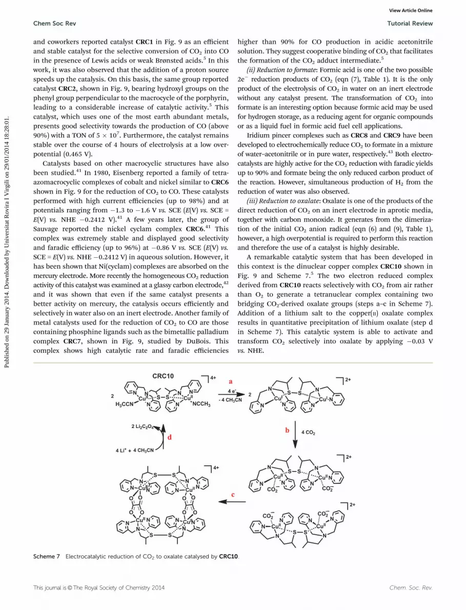
A remarkable catalytic system that has been developed inthis context is the dinuclear copper complex CRC10 shown inFig. 9 and Scheme 7.5 The two electron reduced complexderived from CRC10 reacts selectively with CO2 from air ratherthan O2 to generate a tetranuclear complex containing twobridging CO2-derived oxalate groups (steps a–c in Scheme 7).Addition of a lithium salt to the copper(II) oxalate complexresults in quantitative precipitation of lithium oxalate (step din Scheme 7). This catalytic system is able to activate andtransform CO2 selectively into oxalate by applying �0.03 Vvs. NHE.
Scheme 7 Electrocatalytic reduction of CO2 to oxalate catalysed by CRC10.
Chem Soc Rev Tutorial Review
Publ
ishe
d on
29
Janu
ary
2014
. Dow
nloa
ded
by U
nive
rsita
t Rov
ira
I V
irgi
li on
29/
01/2
014
18:2
8:01
. View Article Online

Chem. Soc. Rev. This journal is©The Royal Society of Chemistry 2014
5.3.3. Photoactivated CO2 reduction. Photocatalytic reductionof CO2 using solar energy is another attractive option to activateCO2, especially in terms of sustainability since the energy neededto run the reaction comes from sunlight.44 The first example ofphotocatalytic CO2 reduction was published by Lehn in the earlyeighties.41 They used [Ru(bpy)3]2+ (P2) as a photosensitizer, CoCl2as a catalyst, and TEOA (triethanolamine) as a SED in aqueoussolution. This system displays a quantum yield (fCO) of 0.012. Thesame group presented the photocatalyst [Re(bpy)(CO)3Cl] (CRC3)with a fCO = 0.14 and good selectivity.41 The rhenium complexplays a double role in the reaction because it both absorbs thelight and performs the catalytic CO2 reduction. One of the maindrawbacks of the latter system is that the complex absorbsmostly in the UV light region, with weak absorption in the visiblepart of the solar spectrum. In order to overcome this problem,the catalyst is covalently linked to a visible light absorbingphotosensitizer in the form a dyad, such as in D3 in Fig. 3. Thisphotocatalyst was developed by Ishitani and coworkers anddisplayed high selectivity for the CO generation with fCO =0.12 and 170 TON under visible light irradiation.44
The same group has developed supramolecular photocatalystswith different ratios of photosensitiser units and catalyst unitsbased on ruthenium complexes.45 These multinuclear complexeswere used as photocatalysts for the reduction of CO2 to formicacid. In the case of the higher ratios of the photosensitiser unit D4shown in Fig. 3, they observed a high yield of formic acid and thehighest photocatalytic activity with fHCOOH = 0.061 and 671 TON.
6. Photoelectrochemical cells (PECs)6.1. Introduction
The conversion of solar energy into chemical fuels can be achievedvia so-called water splitting, by means of sunlight-storing devices.The requirement to build such devices include the assembly ofsuitable modules for light harvesting, water oxidation and protonreduction in a single PEC, mimicking natural photosynthesis.
The overall water splitting process can be divided into the twohalf reactions, so that water oxidation and proton reduction arecarried out in two separate compartments. Each compartmentcontains an electrode (respectively the anode, performing wateroxidation, and the cathode, performing proton reduction), con-nected through an external circuit for electron flow (see Fig. 10). Atleast one of the electrodes is coupled to light absorption, i.e. it
is photoactive. In this case, the role of a visible light harvester isusually played by the semiconducting material constituting theanode and/or the cathode. Depending on the energy band gap, thesemiconductor itself can absorb the visible light or must besensitised with a suitable dye molecule P (see Fig. 10 andSection 2.2). Furthermore, the anodic and cathodic compartmentscan host the water oxidation and the proton reduction catalystsrespectively. The WOC and HEC can be molecular catalysts dis-solved in the homogeneous phase (as shown in Fig. 10), but a PECcould also be designed so that one or both catalysts are anchoredonto the electrode/photoelectrode. Finally, a proton exchangemembrane (PEM) can be used to physically separate the twocompartments, thus simplifying the product (O2 and H2) collectionand avoiding their potentially hazardous reaction back to H2O.
A common strategy to build PECs consists of optimising theproperties of the half reactions independently. In this case, asimple metallic wire or mesh (e.g. platinum) can be used as thecounter electrode, and a potentiostat is then used to apply thedesired potential to probe the system. Once independentlyoptimised, the modules should be conveniently integrated intothe final device, ensuring the matching of both the current andthe potential of all the reactions involved in the whole process, inorder to achieve high conversion efficiencies. For a schematicrepresentation of the thermodynamics involved in the lightassisted water splitting in a PEC see Fig. 11.
6.2. Molecular photoanodes for water oxidation
Focusing on the WO half-reaction, as previously indicated, astraightforward strategy is to integrate both the light absorbingmolecule (P) and the water oxidation catalyst (WOC) on thesurface of an n-type semiconductor, such as TiO2 (SC1 in Fig. 10),thus yielding a single hybrid material that can potentially act as aphotoanode. Aside from the WOC, that must be firmly anchoredwithout modifying its intrinsic coordination and catalyticproperties, an appropriate choice of the dye is also fundamental.The latter should display: (i) extended absorption in the visiblespectrum; (ii) an oxidised state able to undergo fast photo-induced electron transfer with the WOC; and (iii) a suitableoxidation potential to drive the consecutive redox processes onthe catalyst (see also Fig. 11).
Mallouk and coworkers reported the first example based onthis strategy, where IrO2 nanoparticles were attached onto dye-sensitised TiO2.46 Photocurrents up to 30 mA were registered
Fig. 10 Schematic representation of a photoelectrochemical cell (PEC) performing the overall light induced water splitting.
Tutorial Review Chem Soc Rev
Publ
ishe
d on
29
Janu
ary
2014
. Dow
nloa
ded
by U
nive
rsita
t Rov
ira
I V
irgi
li on
29/
01/2
014
18:2
8:01
. View Article Online

This journal is©The Royal Society of Chemistry 2014 Chem. Soc. Rev.
when applying 0 mV vs. Ag/AgCl (E(V) vs. Ag/AgCl = E(V) vs.NHE �0.2881 V) bias and irradiating with a 450 nm light sourcein 30 mM NaHCO3/Na2SiF6 buffer (pH 5.75). The formation ofO2 and H2 at the two compartments of the PEC (separated by aglass frit) was confirmed by means of gas chromatography andClark electrode measurements, yielding a faradic efficiency forO2 generation of ca. 20%.46
After this pioneering example, several other PECs containingtransition metal oxides as WOCs have been reported. On the otherhand, assemblies involving molecular catalysts are still rare. The firstexample of a molecular catalyst anchored onto a photoanode wasreported by Sun and coworkers.47 The ruthenium complex WOC6(Fig. 4) was confined in Nafion, and deposited onto a dye-sensitisedTiO2 electrode. Visible light-driven water splitting was successfullyachieved upon both illumination (provided by a light emitting diodeof 100 mW cm�2) and application of a�0.325 V vs. Ag/AgCl (E(V) vs.Ag/AgCl = E(V) vs. NHE �0.2881 V) bias to the device. Under theseconditions, a photocurrent density of 43 mA cm�2 was obtained in0.1 M Na2SO4 aqueous solution, although just a qualitative analysisof the generated hydrogen has been reported.
This system has been recently modified by the same group bycovalently anchoring the catalyst (functionalised with a silanemoiety, compound WOC7 in Fig. 4) onto the dye-sensitised TiO2
surface.48 By applying an external bias of 0.2 V vs. NHE, an initialphotocurrent density of 1.7 mA cm�2 was registered upon illumi-nation with a white light source of 300 mW cm�2 in phosphatebuffer (pH 6.8). The production of both O2 and H2 during thewater splitting process has been confirmed by means of gaschromatography. After 500 s of visible light illumination,ca. 0.75 mmol of O2 and 1.34 mmol of H2 were detected, corres-ponding to faradic efficiencies of 83% and 74% respectively.
6.3. Molecular photocathodes for proton reduction
With regard to the other half-reaction, proton reduction can beperformed at a photocathode assembled from a p-type semi-conductor electrode (SC2 in Fig. 10), eventually sensitised witha photosensitiser and coupled with a HEC. The latter canbe either in the homogeneous phase or anchored onto the
semiconductor surface. The redox properties of both the dyeand the catalyst must accomplish the requirements schemati-cally shown in Fig. 11.
Recently some molecular photocathodes, coupled with pla-tinum as the counter electrode, have been developed. Forexample, Sun and coworkers reported the covalent anchoringof the organic dye P7 onto a nanostructured p-type semicon-ductor (NiO, SC2 in Fig. 10).49 The resulting photocathode wascoupled with the cobalt complex HEC15 (X = H2O) and used inphosphate buffer at pH 7. Initial photocurrents of ca. 5 mA cm�2
were generated by applying �0.4 V vs. Ag/AgCl bias (E(V) vs.Ag/AgCl = E(V) vs. NHE �0.2881 V) and illuminating with alight emitting diode. Hydrogen generation (ca. 90 nmol mL�1
after 30 min of irradiation) was confirmed using a modifiedClark-type electrode.
Another interesting example of a NiO-based photocathodewas reported by Wu and coworkers.50 In this system, the majorimprovements are related to both: (i) the coating of the NiOsurface with an insulating monolayer of alumina (in order tosuppress hole–electron recombination across the semiconduc-tor surface) and (ii) the covalent anchoring of the HEC, in theform of the supramolecular dyad D2 (Fig. 3). Upon irradiatingthis photocathode with a Xe lamp and applying 0.1 V vs. NHEbias, photocurrent densities up to 9 mA cm�2 were registered inboth neutral water and phosphate buffer at pH 7. Hydrogenproduction (0.29 mmol) was confirmed by means of gaschromatography (calculated faradic yield = 45%).
Recently, Mozer and coworkers reported a molecular dye-sensitised photocathode coupled to a BiVO4 photoanode, in aPt-free tandem PEC performing the overall water splitting. Inthis device, a NiO photocathode, sensitised with P8 (Fig. 3) wasconnected in series, side by side, to a BiVO4 photoanode.6 Thetwo compartments of the PEC were separated by a Nafion PEMand the two photoelectrodes were illuminated simultaneouslywith visible light. The resulting PEC is a standalone system,i.e. able to sustain solar hydrogen generation without the applica-tion of an external electrical bias or the addition of a sacrificialoxidant/reductant. In 0.1 M Na2SO4 (pH 7), a steady photocurrent
Fig. 11 Schematic representation of the thermodynamics occurring respectively at the photoanode (left) and the photocathode (right) of a PECperforming the overall light induced water splitting.
Chem Soc Rev Tutorial Review
Publ
ishe
d on
29
Janu
ary
2014
. Dow
nloa
ded
by U
nive
rsita
t Rov
ira
I V
irgi
li on
29/
01/2
014
18:2
8:01
. View Article Online

Chem. Soc. Rev. This journal is©The Royal Society of Chemistry 2014
of 2.7 mA cm�2 was sustained over 4 hours. Hydrogen production(2.6 nmol) was confirmed by gas chromatography (97% faradicefficiency), whereas O2 could not be detected.
6.4. PECs combining photocathodes for CO2 reduction withO2 evolving photoanodes
The same concept of using sunlight to split water and generateH2 and O2 can also be applied to water splitting assisted by CO2
to generate O2 and HCOOH (or other CO2 reduction products),which is a close mimic of natural photosynthesis (eqn (17) and(18) respectively).
2CO2 + 2H2O - 2HCOOH + O2 (17)
nCO2 + nH2O - (CH2O)n + nO2 (18)
Photocatalytic CO2 reduction yielding useful chemicals isa more challenging reaction than H2 production and, whenperformed in aqueous solutions, suffers from both low productselectivity and low quantum efficiencies, due to competitionwith H2 evolution. However, some interesting examples ofthese different kinds of PECs have been reported by Sato andcoworkers.44 The reduction of CO2 to formate was catalysed bya ruthenium complex anchored onto different p-type semi-conductors by means of polypyrrole polymerization. The mostpromising results were obtained by coupling a reduced SrTiO3
photoanode with a zinc-doped indium phosphide (InP) photo-cathode (modified with the above mentioned catalyst) in a‘‘wireless’’ fashion with no external bias. With this assembly,solar CO2 reduction was successfully performed in a 0.1 MNaHCO3 aqueous solution mixed with phosphoric acid(pH 7.7), with a conversion efficiency from solar to chemicalenergy of 0.08%.7
7. Final remarks
During the last decade the field has advanced enormously at allfronts and even though catalysts and photosensitisers shouldbe further improved in terms of overall performance inaqueous solutions, the bases for the construction of a deviceare already set up. Today the main challenge ahead, for theconstruction of technologically useful PECs for the productionof solar fuels, is the harmonisation of all the numerous reac-tions that occur in each compartment. In other words, assum-ing that the thermodynamics of the whole PEC cell are correct,an indispensable requirement is that the kinetics of all thereactions involved are right so that the desired reactions occur.Given the combination of the large number of reactions involvedthis is by no means trivial.
Thus an enormous effort should be dedicated to the con-struction of complete PECs in order to fully understand thedifferent parameters involved so that they can be adequatelytuned for success.
The potential solution to today’s energy problem has strongsocietal implication since it will allow us to maintain thelifestyle of our developed societies, and also to attain decentliving standards in developing and poor countries.
Acknowledgements
Support from Generalitat de Catalunya (GenCat) 2009 SGR-69,MINECO (CTQ-2010-21497, PRI-PIBIN-2011-1278) and ‘‘La Caixa’’Foundation is gratefully acknowledged. CGS is grateful toGenCat for a Beatriu de Pinos post-doctoral grant. SB, SDand CR are grateful for post-doctoral Marie Curie Fellowships.MG is grateful for a post-doctoral grant from the SwissNational Foundation.
References
1 N. S. Lewis and D. G. Nocera, Proc. Natl. Acad. Sci. U. S. A.,2006, 103, 15729–15735.
2 R. Bofill, J. Garcıa-Anton, L. Escriche, X. Sala and A. Llobet,in Comprehensive Inorganic Chemistry II, ed. J. Reedijk andK. Poeppelmeier, Elsevier, Amsterdam, 2nd edn, 2013,pp. 505–523.
3 W. T. Eckenhoff and R. Eisenberg, Dalton Trans., 2012, 41,13004–13021.
4 V. S. Thoi, Y. Sun, J. R. Long and C. J. Chang, Chem. Soc.Rev., 2013, 42, 2388–2400.
5 C. Costentin, M. Robert and J. M. Saveant, Chem. Soc. Rev.,2013, 42, 2423–2436.
6 L. Tong, A. Iwase, A. Nattestad, U. Bach, M. Weidelener,G. Gotz, A. Mishra, P. Bauerle, R. Amal, G. G. Wallace andA. J. Mozer, Energy Environ. Sci., 2012, 5, 9472–9475.
7 T. Arai, S. Sato, T. Kajino and T. Morikawa, Energy Environ.Sci., 2013, 6, 1274–1282.
8 R. R. King, D. C. Law, K. M. Edmondson, C. M. Fetzer,G. S. Kinsey, H. Yoon, R. A. Sherif and N. H. Karam, Appl.Phys. Lett., 2007, 90, 183516.
9 K. Branker, M. J. M. Pathak and J. M. Pearce, RenewableSustainable Energy Rev., 2011, 15, 4470–4482.
10 H. K. Jun, M. A. Careem and A. K. Arof, Renewable SustainableEnergy Rev., 2013, 22, 148–167.
11 A. Hagfeldt, G. Boschloo, L. Sun, L. Kloo and H. Pettersson,Chem. Rev., 2010, 110, 6595–6663.
12 B. O’Regan and M. Gratzel, Nature, 1991, 353, 737–740.13 J. Burschka, N. Pellet, S.-J. Moon, R. Humphry-Baker,
P. Gao, M. K. Nazeeruddin and M. Gratzel, Nature, 2013,499, 316–319.
14 A. Fujishima and K. Honda, Nature, 1972, 238, 37–38.15 M. J. Katz, S. C. Riha, N. C. Jeong, A. B. F. Martinson,
O. K. Farha and J. T. Hupp, Coord. Chem. Rev., 2012, 256,2521–2529.
16 S. Chen and L.-W. Wang, Chem. Mater., 2012, 24,3659–3666.
17 F. Puntoriero, G. La Ganga, A. Sartorel, M. Carraro,G. Scorrano, M. Bonchio and S. Campagna, Chem. Commun.,2010, 46, 4725–4727.
18 N. Kaveevivitchai, R. Chitta, R. Zong, M. El Ojaimi andR. P. Thummel, J. Am. Chem. Soc., 2012, 134, 10721–10724.
19 A. Savini, P. Belanzoni, G. Bellachioma, C. Zuccaccia,D. Zuccaccia and A. Macchioni, Green Chem., 2011, 13,3360–3374.
Tutorial Review Chem Soc Rev
Publ
ishe
d on
29
Janu
ary
2014
. Dow
nloa
ded
by U
nive
rsita
t Rov
ira
I V
irgi
li on
29/
01/2
014
18:2
8:01
. View Article Online

This journal is©The Royal Society of Chemistry 2014 Chem. Soc. Rev.
20 D. J. Wasylenko, R. D. Palmer and C. P. Berlinguette, Chem.Commun., 2013, 49, 218–227.
21 J. L. Boyer, J. Rochford, M.-K. Tsai, J. T. Muckerman andE. Fujita, Coord. Chem. Rev., 2010, 254, 309–330.
22 L. Duan, F. Bozoglian, S. Mandal, B. Stewart, T. Privalov,A. Llobet and L. Sun, Nat. Chem., 2012, 4, 418–423.
23 E. A. Karlsson, B.-L. Lee, T. Åkermark, E. V. Johnston,M. D. Karkas, J. Sun, O. Hansson, J.-E. Backvall andB. Åkermark, Angew. Chem., Int. Ed., 2011, 50,11715–11718.
24 J. J. Concepcion, J. W. Jurss, P. G. Hoertz and T. J. Meyer,Angew. Chem., Int. Ed., 2009, 48, 9473–9476.
25 S. M. Barnett, K. I. Goldberg and J. M. Mayer, Nat. Chem.,2012, 4, 498–502.
26 M.-T. Zhang, Z. Chen, P. Kang and T. J. Meyer, J. Am. Chem.Soc., 2013, 135, 2048–2051.
27 M. L. Rigsby, S. Mandal, W. Nam, L. C. Spencer, A. Llobetand S. S. Stahl, Chem. Sci., 2012, 3, 3058–3062.
28 M. Wang, L. Chen and L. Sun, Energy Environ. Sci., 2012, 5,6763–6778.
29 K. Sakai and H. Ozawa, Coord. Chem. Rev., 2007, 251,2753–2766.
30 V. Artero, M. Chavarot-Kerlidou and M. Fontecave, Angew.Chem., Int. Ed., 2011, 50, 7238–7266.
31 M. L. Helm, M. P. Stewart, R. M. Bullock, M. R. DuBois andD. L. DuBois, Science, 2011, 333, 863–866.
32 S. Fukuzumi, T. Kobayashi and T. Suenobu, Angew. Chem.,Int. Ed., 2011, 50, 728–731.
33 T. Stoll, M. Gennari, I. Serrano, J. Fortage, J. Chauvin,F. Odobel, M. Rebarz, O. Poizat, M. Sliwa, A. Deronzierand M.-N. Collomb, Chem.–Eur. J., 2013, 19, 782–792.
34 E. S. Andreiadis, P.-A. Jacques, P. D. Tran, A. Leyris,M. Chavarot-Kerlidou, B. Jousselme, M. Matheron,J. Pecaut, S. Palacin, M. Fontecave and V. Artero, Nat. Chem.,2013, 5, 48–53.
35 S. Varma, C. E. Castillo, T. Stoll, J. Fortage, A. G. Blackman,F. Molton, A. Deronzier and M.-N. Collomb, Phys. Chem.Chem. Phys., 2013, 15, 17544–17552.
36 C. Costentin, S. Drouet, G. Passard, M. Robert andJ. M. Saveant, J. Am. Chem. Soc., 2013, 135, 9023–9031.
37 J. M. Smieja, E. E. Benson, B. Kumar, K. A. Grice, C. S. Seu,A. J. M. Miller, J. M. Mayer and C. P. Kubiak, Proc. Natl. Acad.Sci. U. S. A., 2012, 109, 15646–15650.
38 J. A. Keith, K. A. Grice, C. P. Kubiak and E. A. Carter, J. Am.Chem. Soc., 2013, 135, 15823–15829.
39 W. Wang, S. Wang, X. Ma and J. Gong, Chem. Soc. Rev., 2011,40, 3703–3727.
40 M. S. Jeletic, M. T. Mock, A. M. Appel and J. C. Linehan,J. Am. Chem. Soc., 2013, 135, 11533–11536.
41 E. E. Benson, C. P. Kubiak, A. J. Sathrum and J. M. Smieja,Chem. Soc. Rev., 2009, 38, 89–99.
42 J. D. Froehlich and C. P. Kubiak, Inorg. Chem., 2012, 51,3932–3934.
43 P. Kang, T. J. Meyer and M. Brookhart, Chem. Sci., 2013, 4,3497–3502.
44 C. D. Windle and R. N. Perutz, Coord. Chem. Rev., 2012, 256,2562–2570.
45 Y. Tamaki, T. Morimoto, K. Koike and O. Ishitani, Proc. Natl.Acad. Sci. U. S. A., 2012, 109, 15673–15678.
46 W. J. Youngblood, S.-H. A. Lee, Y. Kobayashi, E. A. Hernandez-Pagan, P. G. Hoertz, T. A. Moore, A. L. Moore, D. Gust andT. E. Mallouk, J. Am. Chem. Soc., 2009, 131, 926–927.
47 L. Li, L. Duan, Y. Xu, M. Gorlov, A. Hagfeldt and L. Sun,Chem. Commun., 2010, 46, 7307–7309.
48 Y. Gao, X. Ding, J. Liu, L. Wang, Z. Lu, L. Li and L. Sun,J. Am. Chem. Soc., 2013, 135, 4219–4222.
49 L. Li, L. Duan, F. Wen, C. Li, M. Wang, A. Hagfeldt andL. Sun, Chem. Commun., 2012, 48, 988–990.
50 Z. Ji, M. He, Z. Huang, U. Ozkan and Y. Wu, J. Am. Chem.Soc., 2013, 135, 11696–11699.
Chem Soc Rev Tutorial Review
Publ
ishe
d on
29
Janu
ary
2014
. Dow
nloa
ded
by U
nive
rsita
t Rov
ira
I V
irgi
li on
29/
01/2
014
18:2
8:01
. View Article Online


