Embed Size (px)
Citation preview

238 IEEE TRANSACTIONS ON INDUSTRY APPLICATIONS, VOL. 44, NO. 1, JANUARY/FEBRUARY 2008
Multicell High-Current RectifierEduardo P. Wiechmann, Senior Member, IEEE, Pablo Aqueveque, Student Member, IEEE, Anıbal S. Morales,
Pablo F. Acuna, and Rolando Burgos, Member, IEEE
Abstract—A multicell rectifier (MC) structure with N + 2 re-dundancy is presented. The topology is based on power cells im-plemented with the integrated gate commuted thyristors (IGCTs)to challenge the SCR standard industry solution for the past35 years. This rectifier is a reliable, compact, efficient, nonpollutingalternative and cost-effective solution for electrolytic applications.Its structure, based on power cells, enables load shedding to en-sure power delivery even in the event of power cell failures. Itinjects quasi-sinusoidal input currents and provides unity powerfactor without the use of passive or active filters. A complete eval-uation based on IEEE standards 493-1997 and IEEE C57.18.10for average downtime, failures rates, and efficiency is included.For comparison purposes, results are shown against conventionalsystems known for their high efficiency and reliability.
Index Terms—Electrorefining, electrowinning, high-currentrectifiers.
I. INTRODUCTION
THE COPPER ELECTROWINNING (EW) and electrore-fining (ER) metallurgical processes use high-current recti-
fiers to produce electrolysis. These converters are implementedusing thyristor (SCR) phase-controlled rectifiers that featurehigh efficiency and reliability, and as such, have become thepreferred choice for the mining industry. These converters havecontinuously improved their performance thanks to the signifi-cant advancements on thyristor technology, presenting a mini-mum conduction voltage drop of 1.3 V for EW and ER applica-tions rated 40 kA (and 300 V dc) [1]. Harmonic distortion, onthe other hand, is usually addressed by paralleling 12-pulse con-verter structures. The four-star (FS) and double-bridge rectifierswith interphase reactors (DB) are the configurations of choicein the mining industry [2]. Both topologies present an intrinsichigh reliability due to their parallel configurations and the useof thyristors. These rectifiers inject very low current distortioninto the system throughout their operational range. Despite thislow distortion injection, they consume high reactive power. For
Paper PID-07-03, presented at the 2006 IEEE Industry Applications SocietyAnnual Meeting, Tampa, FL, October 8–12, and approved for publication inthe IEEE TRANSACTIONS ON INDUSTRY APPLICATIONS by the Mining IndustryCommittee of the IEEE Industry Applications Society. Manuscript submittedfor review October 31, 2006 and released for publication August 19, 2007.This work was supported by the Chilean Fund for Science and TechnologyDevelopment (CONICYT) under Project 1060902. This work made use ofthe Engineering Research Center Shared Facilities supported by the NationalScience Foundation under NSF Award EEC-9731677 and the CPES IndustryPartnership Program.
E. P. Wiechmann, P. E. Aqueveque, A. Morales, and P. Acuna arewith the Department of Electrical Engineering, Faculty of Engineering, Uni-versity of Concepcion, Concepcion, Chile (e-mail: [email protected];[email protected]; [email protected]; [email protected]).
R. Burgos is with the Center for Power Electronics Systems, Department ofElectrical and Computer Engineering, Virginia Polytechnic Institute and StateUniversity, Blacksburg, VA 24061 USA (e-mail: [email protected]).
Digital Object Identifier 10.1109/TIA.2007.912728
example, a single EW rectifier draws up to 4 MVAR at 32 kA.It is important to point out that an EW plant may use up toeight rectifiers; hence, the total reactive power consumption ofa plant is a critical factor for the industrial distribution system.Moreover, EW and ER plants are usually located in remoteareas being fed by relatively weak systems. The preferred so-lution for the elevated reactive power demand of SCR rectifiersis the use of sequentially connected tuned passive filters. Theseare essential for their operation since, otherwise, voltage reg-ulation and current increments would significantly impair thepower conversion efficiency. This solution, however, presents anumber of drawbacks, namely the introduction of system res-onances, which degrade the overall system reliability, and theneed for the large physical space required to install the filters(5000 ft2). These factors negate this solution and open a windowof opportunity for technological breakthroughs in high-currentapplications [3]–[6].
From the previous discussion, it may be concluded that a cost-effective solution should replace phase control, eliminating theneed for reactive power compensation. The elimination of thesefilters would additionally simplify industrial maintenance andincrease reliability, since the power system would no longersuffer from the large transients introduced by the sequentialconnection of the tuned-filter stages. System reliability could befurther improved if N + K redundancy is somehow applied tothe power converter structure.
It should be borne in mind that for mining applications, anyequipment failure related to the high-current rectifier results invery high revenue losses, as the rectifier controls the electrol-ysis itself and the production of copper. Moreover, the remotelocation of mining sites, in general, delays any service or majormaintenance required, further aggravating the loss of produc-tion and revenues. It has been shown that these business factors,related to the rectifying system reliability, are, by far, moreimportant than any initial investment cost on the rectifiers [14].
Generally, the evaluation of high-current rectifiers has beenbased on power factor and harmonic current distortion. How-ever, industrial experience shows that reliability and efficiencyare more relevant issues. Following this trend, multicell high-current converters have emerged having the capability to bedesigned maximizing their reliability and availability. This typeof converter architecture is compatible with N + K redundancyand eventually with hot swappability, that is the capability toreplace cells for scheduled maintenance or replacement withoutstopping the electrolysis and the production of copper. Multicellrectifiers, therefore, improve availability and reduce possibledowntimes with consequential economic benefits.
This paper proposes a multicell rectifier for EW and ERapplications with N + 2 redundancy based on independentbut paralleled pulse width modulation (PWM) rectifier cells.
0093-9994/$25.00 © 2008 IEEE
WIECHMANN et al.: MULTICELL HIGH-CURRENT RECTIFIER 239
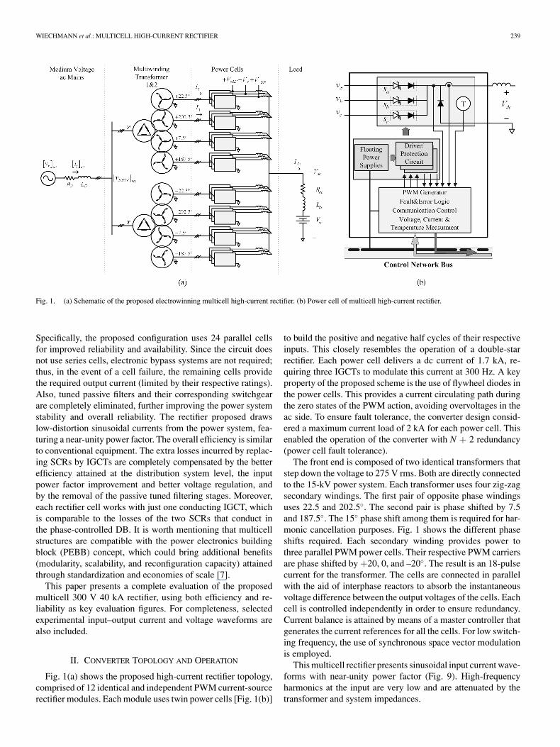
Fig. 1. (a) Schematic of the proposed electrowinning multicell high-current rectifier. (b) Power cell of multicell high-current rectifier.
Specifically, the proposed configuration uses 24 parallel cellsfor improved reliability and availability. Since the circuit doesnot use series cells, electronic bypass systems are not required;thus, in the event of a cell failure, the remaining cells providethe required output current (limited by their respective ratings).Also, tuned passive filters and their corresponding switchgearare completely eliminated, further improving the power systemstability and overall reliability. The rectifier proposed drawslow-distortion sinusoidal currents from the power system, fea-turing a near-unity power factor. The overall efficiency is similarto conventional equipment. The extra losses incurred by replac-ing SCRs by IGCTs are completely compensated by the betterefficiency attained at the distribution system level, the inputpower factor improvement and better voltage regulation, andby the removal of the passive tuned filtering stages. Moreover,each rectifier cell works with just one conducting IGCT, whichis comparable to the losses of the two SCRs that conduct inthe phase-controlled DB. It is worth mentioning that multicellstructures are compatible with the power electronics buildingblock (PEBB) concept, which could bring additional benefits(modularity, scalability, and reconfiguration capacity) attainedthrough standardization and economies of scale [7].
This paper presents a complete evaluation of the proposedmulticell 300 V 40 kA rectifier, using both efficiency and re-liability as key evaluation figures. For completeness, selectedexperimental input–output current and voltage waveforms arealso included.
II. CONVERTER TOPOLOGY AND OPERATION
Fig. 1(a) shows the proposed high-current rectifier topology,comprised of 12 identical and independent PWM current-sourcerectifier modules. Each module uses twin power cells [Fig. 1(b)]
to build the positive and negative half cycles of their respectiveinputs. This closely resembles the operation of a double-starrectifier. Each power cell delivers a dc current of 1.7 kA, re-quiring three IGCTs to modulate this current at 300 Hz. A keyproperty of the proposed scheme is the use of flywheel diodes inthe power cells. This provides a current circulating path duringthe zero states of the PWM action, avoiding overvoltages in theac side. To ensure fault tolerance, the converter design consid-ered a maximum current load of 2 kA for each power cell. Thisenabled the operation of the converter with N + 2 redundancy(power cell fault tolerance).
The front end is composed of two identical transformers thatstep down the voltage to 275 V rms. Both are directly connectedto the 15-kV power system. Each transformer uses four zig-zagsecondary windings. The first pair of opposite phase windingsuses 22.5 and 202.5. The second pair is phase shifted by 7.5and 187.5. The 15 phase shift among them is required for har-monic cancellation purposes. Fig. 1 shows the different phaseshifts required. Each secondary winding provides power tothree parallel PWM power cells. Their respective PWM carriersare phase shifted by +20, 0, and –20. The result is an 18-pulsecurrent for the transformer. The cells are connected in parallelwith the aid of interphase reactors to absorb the instantaneousvoltage difference between the output voltages of the cells. Eachcell is controlled independently in order to ensure redundancy.Current balance is attained by means of a master controller thatgenerates the current references for all the cells. For low switch-ing frequency, the use of synchronous space vector modulationis employed.
This multicell rectifier presents sinusoidal input current wave-forms with near-unity power factor (Fig. 9). High-frequencyharmonics at the input are very low and are attenuated by thetransformer and system impedances.
240 IEEE TRANSACTIONS ON INDUSTRY APPLICATIONS, VOL. 44, NO. 1, JANUARY/FEBRUARY 2008
III. DISTRIBUTED CONTROL ARCHITECTURES
Industrial control systems usually employ a distributed hier-archical structure comprised of multiple supervisory and ded-icated controllers interconnected forming a distributed controlnetwork. Numerous communication protocols have been devel-oped to enable the communication between these controllers,e.g., profibus, fieldbus foundation, among others [16]. Staticpower converters operating within such an industrial system be-come one more node in the network, receiving and transmittinghigh-level commands only. All communications internal to thepower converter, namely between the controller and the actualpower stage, have only been considered terminal point commu-nications, being left out of the distributed control architectureand communication network [15]. Accordingly, the control ofpower converters has been primarily realized using centralizedcontrol architectures, featuring a single controller responsiblefor executing all the control tasks for the converter. These con-trollers are, consequently, quite complex, acquiring all controlsignals–including sampling of state variables, processing them,and generating all control signals up to the very gate signalsused to control the converter semiconductors. This communi-cation between the centralized controller and its peripherals,i.e., state variable sensors and gate signals, is normally imple-mented with analog means, using a dedicated signal path foreach variable in question.
For low-power converter systems the control structure pre-sented earlier is not considered a limitation, since the numberof interconnections is not elevated and the physical distance be-tween the controller and its peripherals is short. For medium tohigh-power applications, however, this is no longer valid andin order to avoid electromagnetic interference (EMI) related is-sues, the use of fiberoptics becomes mandatory to transmit thecommand signals for the converter switches [16]. As the powerrating of the application increases, the number of interconnec-tions and total wiring become a significant challenge to dealwith, let alone the fact that measured variables are still trans-mitted in analog form, and hence, the overall sensitivity to EMIis not improved. This naturally affects the converter reliability,which has spawned the development of alternative structuresto implement the control systems of medium- and high-powerconverter applications.
A. Modular Controls for High-Current Applications
The power electronics module concept has gradually butsteadily been introduced into the power converter industry, gain-ing in capacities and capabilities that have enabled it to re-place cumbersome power electronic circuits by simple compactunits profiting from the advancements on materials, devices,and controls [18], [19]. The proposed converter topology forhigh-current rectifying applications is fully compatible with thisindustrial trend, exploiting the essence of the modular conceptand extrapolating it to high-power applications.
The proposed converter employs distributed controls to over-see the operation of its multiple converter modules [16], [17],i.e., power cells, comprising an application controller and mul-tiple hardware managers (HMs) or dedicated controllers, which
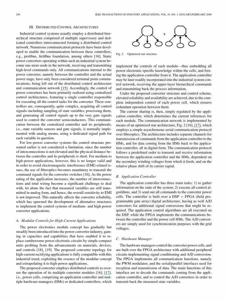
Fig. 2. Optimized star structure.
implement the controls of each module—thus embedding allpower electronic-specific knowledge within the cells, and free-ing the application controller from it. The application controllermay be later readily incorporated into the industrial system con-trol network, receiving the upper-layer hierarchical commandsand transmitting back the process information.
Under the proposed converter structure and control scheme,elevated reliability and availability are achieved, due to the com-plete independent control of each power cell, which ensuresredundant operation between them.
The current sharing is, then, simply regulated by the appli-cation controller, which determines the current references foreach module. The communication network is implemented bymeans of an optimized star architecture, Fig. 2 [16], [17], whichemploys a simple asynchronous serial communication protocolover fiberoptics. The architecture includes separate channels fortransmission of commands from the application controller to theHMs, and for data coming from the HMs back to the applica-tion controller, all in digital form. The communication protocolfollows a predefined order to transmit and receive informationbetween the application controller and the HMs, dependent onthe secondary winding voltages from which it feeds, and on therelative phase shift of its carrier signal.
B. Application Controller
The application controller has three main tasks: 1) to gatherinformation on the state of the system, 2) execute all control al-gorithms, and 3) send out all commands to the converter powercells. The controller is built over a DSP + FPGA (field pro-grammable gate array) digital architecture, having as well A/Dconverters for additional signal conversions that might be re-quired. The application control algorithms are all executed onthe DSP, while the FPGA implements the communications be-tween the controller and the power cell HMs. The A/D convert-ers are simply used for synchronization purposes with the gridvoltages.
C. Hardware Manager
The hardware managers control the converter power cells, andare built over the FPGA architecture with additional peripheralcircuits implementing signal conditioning and A/D conversion.The FPGA implements all communication functions, namelythe PWM modulator, and the serial/parallel interfaces used forreception and transmission of data. The main functions of thisinterface are to decode the commands coming from the appli-cation controller, and to control the A/D converters in order totransmit back the measured state variables.
WIECHMANN et al.: MULTICELL HIGH-CURRENT RECTIFIER 241
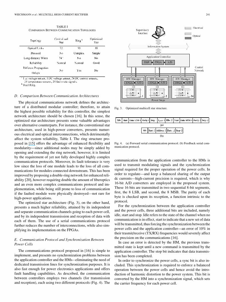
TABLE ICOMPARISON BETWEEN COMMUNICATION TOPOLOGIES
D. Comparison Between Communication Architectures
The physical communications network defines the architec-ture of a distributed modular controller; therefore, to attainthe highest possible reliability for this controller, the simplestnetwork architecture should be chosen [16]. In this sense, theoptimized star architecture presents some valuable advantagesover alternative counterparts. For instance, the conventional stararchitecture, used in high-power converters, presents numer-ous electrical and optical interconnections, which detrimentallyaffect the system reliability, Table I. The ring structure pro-posed in [15] offers the advantage of enhanced flexibility andmodularity—since additional nodes may be simply added byopening and extending the ring network; however, it is limitedby the requirement of yet not fully developed highly complexcommunication protocols. Moreover, its fault tolerance is verylow since the loss of one module leads to the loss of all com-munications for modules connected downstream. This has beenimproved by proposing a double-ring network for enhanced reli-ability [20], however requiring double the amount of fiberopticsand an even more complex communications protocol and im-plementation, while being still prone to loss of communicationif the faulted module were physically destroyed—not rare forhigh-power applications.
The optimized star architecture (Fig. 3), on the other hand,presents a much higher reliability, attained by its independentand separate communication channels going to each power cell,and by its independent transmission and reception of data witheach of them. The use of a serial communications protocolfurther reduces the number of interconnections, while also sim-plifying its implementation on the FPGAs.
E. Communication Protocol and Synchronization BetweenPower Cells
The communications protocol proposed in [16] is simple toimplement, and presents no synchronization problems betweenthe application controller and the HMs-–eliminating the need ofdedicated transmission lines for synchronization purposes. It isalso fast enough for power electronics applications and offersfault handling capabilities. As described, the communicationbetween controllers employs two channels (for transmissionand reception), each using two different protocols (Fig. 4). The
Fig. 3. Optimized multicell star structure.
Fig. 4. (a) Forward serial communication protocol. (b) Feedback serial com-munication protocol.
communication from the application controller to the HMs isused to transmit modulating signals and the synchronizationsignal required for the proper operation of the power cells. Inorder to regulate—and keep a balanced sharing of the outputdc currents—high-current precision is required, which is why16-bit A/D converters are employed in the proposed system.These 16 bits are transmitted in two sequential 8-bit segments,first, the 8 LSB, and second, the 8 MSB. The parity of eachbyte is checked upon its reception, a function intrinsic to theprotocol.
For the synchronization between the application controllerand the power cells, three additional bits are included, namelyidle, start and stop. Idle refers to the state of the channel when nocommunication is in effect, start to indicate that a new set of datawill be transmitted, thus forcing the synchronization between thepower cells and the application controller—an error of 10% intheir trasmit/receive (TX/RX) frequencies would severely affectthe precision on the communications [16].
In case an error is detected by the HM, the previous trans-mitted state is kept until a new command is transmitted by theapplication controller. The stop bit indicates that data transmis-sion has been completed.
In order to synchronize the power cells, a sync bit is also in-cluded. This synchronization is required to enforce a balancedoperation between the power cells and hence avoid the intro-duction of harmonic distortion to the power system. This bit isconverted by the HM into a synchronization signal, which setsthe carrier frequency for each power cell.
242 IEEE TRANSACTIONS ON INDUSTRY APPLICATIONS, VOL. 44, NO. 1, JANUARY/FEBRUARY 2008
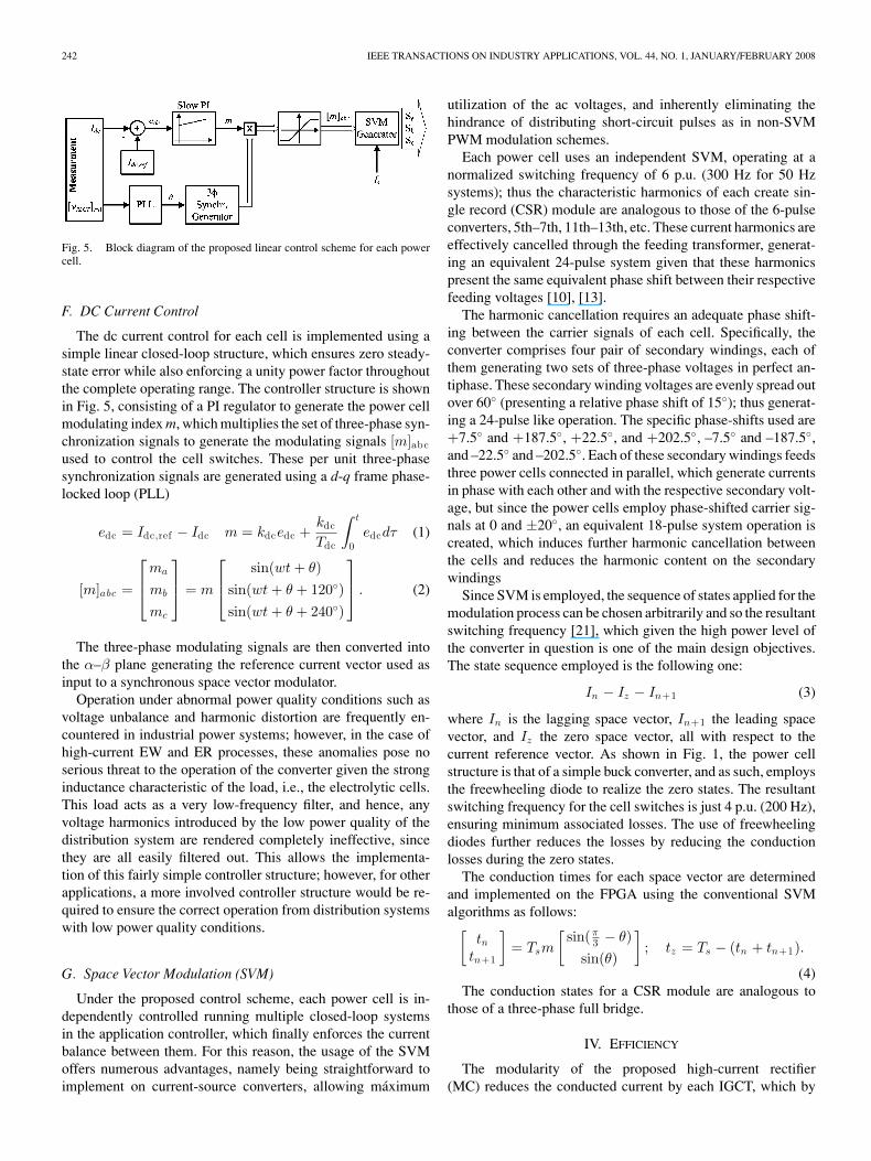
Fig. 5. Block diagram of the proposed linear control scheme for each powercell.
F. DC Current Control
The dc current control for each cell is implemented using asimple linear closed-loop structure, which ensures zero steady-state error while also enforcing a unity power factor throughoutthe complete operating range. The controller structure is shownin Fig. 5, consisting of a PI regulator to generate the power cellmodulating index m, which multiplies the set of three-phase syn-chronization signals to generate the modulating signals [m]abcused to control the cell switches. These per unit three-phasesynchronization signals are generated using a d-q frame phase-locked loop (PLL)
edc = Idc,ref − Idc m = kdcedc +kdc
Tdc
∫ t
0edcdτ (1)
[m]abc =
ma
mb
mc
= m
sin(wt + θ)sin(wt + θ + 120)sin(wt + θ + 240)
. (2)
The three-phase modulating signals are then converted intothe α–β plane generating the reference current vector used asinput to a synchronous space vector modulator.
Operation under abnormal power quality conditions such asvoltage unbalance and harmonic distortion are frequently en-countered in industrial power systems; however, in the case ofhigh-current EW and ER processes, these anomalies pose noserious threat to the operation of the converter given the stronginductance characteristic of the load, i.e., the electrolytic cells.This load acts as a very low-frequency filter, and hence, anyvoltage harmonics introduced by the low power quality of thedistribution system are rendered completely ineffective, sincethey are all easily filtered out. This allows the implementa-tion of this fairly simple controller structure; however, for otherapplications, a more involved controller structure would be re-quired to ensure the correct operation from distribution systemswith low power quality conditions.
G. Space Vector Modulation (SVM)
Under the proposed control scheme, each power cell is in-dependently controlled running multiple closed-loop systemsin the application controller, which finally enforces the currentbalance between them. For this reason, the usage of the SVMoffers numerous advantages, namely being straightforward toimplement on current-source converters, allowing maximum
utilization of the ac voltages, and inherently eliminating thehindrance of distributing short-circuit pulses as in non-SVMPWM modulation schemes.
Each power cell uses an independent SVM, operating at anormalized switching frequency of 6 p.u. (300 Hz for 50 Hzsystems); thus the characteristic harmonics of each create sin-gle record (CSR) module are analogous to those of the 6-pulseconverters, 5th–7th, 11th–13th, etc. These current harmonics areeffectively cancelled through the feeding transformer, generat-ing an equivalent 24-pulse system given that these harmonicspresent the same equivalent phase shift between their respectivefeeding voltages [10], [13].
The harmonic cancellation requires an adequate phase shift-ing between the carrier signals of each cell. Specifically, theconverter comprises four pair of secondary windings, each ofthem generating two sets of three-phase voltages in perfect an-tiphase. These secondary winding voltages are evenly spread outover 60 (presenting a relative phase shift of 15); thus generat-ing a 24-pulse like operation. The specific phase-shifts used are+7.5 and +187.5, +22.5, and +202.5, –7.5 and –187.5,and –22.5 and –202.5. Each of these secondary windings feedsthree power cells connected in parallel, which generate currentsin phase with each other and with the respective secondary volt-age, but since the power cells employ phase-shifted carrier sig-nals at 0 and ±20, an equivalent 18-pulse system operation iscreated, which induces further harmonic cancellation betweenthe cells and reduces the harmonic content on the secondarywindings
Since SVM is employed, the sequence of states applied for themodulation process can be chosen arbitrarily and so the resultantswitching frequency [21], which given the high power level ofthe converter in question is one of the main design objectives.The state sequence employed is the following one:
In − Iz − In+1 (3)
where In is the lagging space vector, In+1 the leading spacevector, and Iz the zero space vector, all with respect to thecurrent reference vector. As shown in Fig. 1, the power cellstructure is that of a simple buck converter, and as such, employsthe freewheeling diode to realize the zero states. The resultantswitching frequency for the cell switches is just 4 p.u. (200 Hz),ensuring minimum associated losses. The use of freewheelingdiodes further reduces the losses by reducing the conductionlosses during the zero states.
The conduction times for each space vector are determinedand implemented on the FPGA using the conventional SVMalgorithms as follows:[
tntn+1
]= Tsm
[sin(π
3 − θ)sin(θ)
]; tz = Ts − (tn + tn+1).
(4)The conduction states for a CSR module are analogous to
those of a three-phase full bridge.
IV. EFFICIENCY
The modularity of the proposed high-current rectifier(MC) reduces the conducted current by each IGCT, which by
WIECHMANN et al.: MULTICELL HIGH-CURRENT RECTIFIER 243
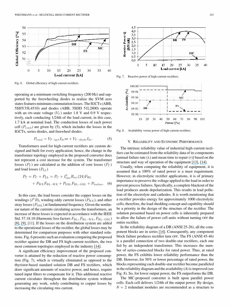
Fig. 6. Global efficiency of high-current rectifiers.
operating at a minimum switching frequency (200 Hz) and sup-ported by the freewheeling diodes to realize the SVM zerostates features minimum commutation losses. The IGCTs (ABB,5SHY35L4510) and diodes (ABB, 5SDD 51L2800) operatewith an ON-state voltage (VT ) under 1.8 V and 0.9 V respec-tively, each conducting 1/24th of the load current, in this case,1.7 kA at nominal load. The conduction losses of each powercell (Pcond ) are given by (5), which includes the losses in theIGCTs, series diodes, and freewheel diodes.
Pcond = VT −igctIdcm + VT −diodeIdc . (5)
Transformers used for high-current rectifiers are custom de-signed and built for every application; hence, the change in thetransformer topology employed in the proposed converter doesnot represent a cost increase for the system. The transformerlosses (PT ) are calculated as the addition of core losses (PC )and load losses (PLL )
PT = PC + PLL = PC + I2rmsRsec(24)FHL
+ PWEFHL−WE + POSLFHL−OSL + Pbusbar . (6)
In this case, the load losses consider the copper losses on thewindings (I2R), winding eddy current losses (PWE ), and otherstray losses (POSL ) at fundamental frequency. Given the nonlin-ear nature of the currents circulating across the transformers, anincrease of these losses is expected in accordance with the IEEEStd. 57.18.10 (Harmonic loss factors FHL , FHL−WE , FHL−OSL )[8], [9], [11]. If the losses on the distribution system are addedto the operational losses of the rectifier, the global losses may bedetermined for comparison purposes with other standard solu-tions. Fig. 6 presents such an evaluation comparing the proposedrectifier against the DB and FS high-current rectifiers, the twomost common topologies employed in the industry [14].
A significant efficiency improvement of the proposed con-verter is attained by the reduction of reactive power consump-tion (Fig. 7), which is virtually eliminated as opposed to thethyristor-based standard solution DB and FS rectifiers, whichdraw significant amounts of reactive power, and hence, requiretuned input filters to compensate for it. This additional reactivecurrent circulates throughout the distribution system withoutgenerating any work, solely contributing to copper losses byincreasing the circulating rms current.
Fig. 7. Reactive power of high-current rectifiers.
Fig. 8. Availability versus power of high-current rectifiers.
V. RELIABILITY AND ECONOMIC PERFORMANCE
The intrinsic reliability value of industrial high-current recti-fiers can be estimated from the reliability data of its components[annual failure rate (λ) and mean time to repair (r)] based on thestructure and way of operation of the equipment [13], [14].
Usually, when computing the reliability of equipment, it isassumed that a 100% of rated power is a must requirement.However, in electrolytic rectifier applications, it is of primaryimportance to preserve the voltage applied to the load in order toprevent process failures. Specifically, a complete blackout of theload produces anode depolarization. This results in lead pollu-tion of the electrolyte and cathodes. It is worth mentioning thata rectifier provides energy for approximately 1000 electrolyticcells; therefore, the load shedding concept and capability shouldbe a priority in the design of the structure of the rectifier. Thesolution presented based on power cells is inherently preparedto allow the failure of power cell units without turning OFF theentire rectifier.
In the reliability diagram of a DB (ANSI 25-26), all the com-ponent blocks are in series [14]. Consequently, any componentblock failure produces rectifier turn OFF. The FS (ANSI 45-46)is a parallel connection of two double-star rectifiers, each onefed by an independent transformer. This increases the num-ber of series-connected blocks for rated power. Thus, at ratedpower, the FS exhibits lower reliability performance than theDB. However, for 50% or lower percentage of rated power, theblocks representing each double-star rectifier become paralleledin the reliability diagram and the availability (A) is improved (seeFig. 8). So, for lower output power, the FS outperforms the DB.
The MC-proposed converter is built upon parallel powercells. Each cell delivers 1/24th of the output power. By design,N + 2 redundant modules are recommended as a structure to
244 IEEE TRANSACTIONS ON INDUSTRY APPLICATIONS, VOL. 44, NO. 1, JANUARY/FEBRUARY 2008
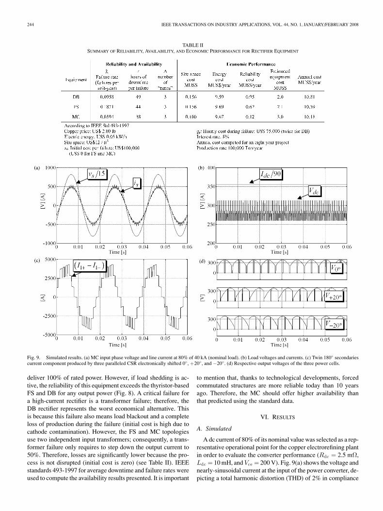
TABLE IISUMMARY OF RELIABILITY, AVAILABILITY, AND ECONOMIC PERFORMANCE FOR RECTIFIER EQUIPMENT
Fig. 9. Simulated results. (a) MC input phase voltage and line current at 80% of 40 kA (nominal load). (b) Load voltages and currents. (c) Twin 180 secondariescurrent component produced by three paralleled CSR electronically shifted 0, +20, and −20. (d) Respective output voltages of the three power cells.
deliver 100% of rated power. However, if load shedding is ac-tive, the reliability of this equipment exceeds the thyristor-basedFS and DB for any output power (Fig. 8). A critical failure fora high-current rectifier is a transformer failure; therefore, theDB rectifier represents the worst economical alternative. Thisis because this failure also means load blackout and a completeloss of production during the failure (initial cost is high due tocathode contamination). However, the FS and MC topologiesuse two independent input transformers; consequently, a trans-former failure only requires to step down the output current to50%. Therefore, losses are significantly lower because the pro-cess is not disrupted (initial cost is zero) (see Table II). IEEEstandards 493-1997 for average downtime and failure rates wereused to compute the availability results presented. It is important
to mention that, thanks to technological developments, forcedcommutated structures are more reliable today than 10 yearsago. Therefore, the MC should offer higher availability thanthat predicted using the standard data.
VI. RESULTS
A. Simulated
A dc current of 80% of its nominal value was selected as a rep-resentative operational point for the copper electrorefining plantin order to evaluate the converter performance (Rdc = 2.5 mΩ,Ldc = 10 mH, and Vce = 200 V). Fig. 9(a) shows the voltage andnearly-sinusoidal current at the input of the power converter, de-picting a total harmonic distortion (THD) of 2% in compliance
WIECHMANN et al.: MULTICELL HIGH-CURRENT RECTIFIER 245
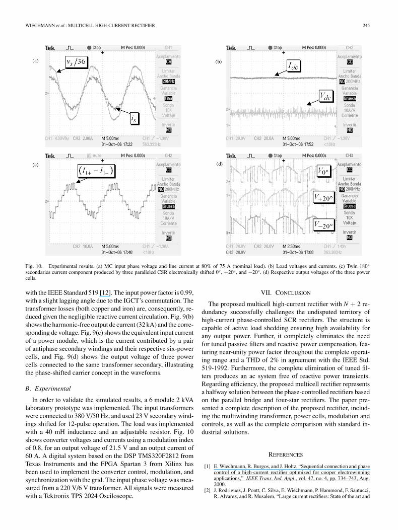
Fig. 10. Experimental results. (a) MC input phase voltage and line current at 80% of 75 A (nominal load). (b) Load voltages and currents. (c) Twin 180
secondaries current component produced by three paralleled CSR electronically shifted 0, +20, and −20. (d) Respective output voltages of the three powercells.
with the IEEE Standard 519 [12]. The input power factor is 0.99,with a slight lagging angle due to the IGCT’s commutation. Thetransformer losses (both copper and iron) are, consequently, re-duced given the negligible reactive current circulation. Fig. 9(b)shows the harmonic-free output dc current (32 kA) and the corre-sponding dc voltage. Fig. 9(c) shows the equivalent input currentof a power module, which is the current contributed by a pairof antiphase secondary windings and their respective six-powercells, and Fig. 9(d) shows the output voltage of three powercells connected to the same transformer secondary, illustratingthe phase-shifted carrier concept in the waveforms.
B. Experimental
In order to validate the simulated results, a 6 module 2 kVAlaboratory prototype was implemented. The input transformerswere connected to 380 V/50 Hz, and used 23 V secondary wind-ings shifted for 12-pulse operation. The load was implementedwith a 40 mH inductance and an adjustable resistor. Fig. 10shows converter voltages and currents using a modulation indexof 0.8, for an output voltage of 21.5 V and an output current of60 A. A digital system based on the DSP TMS320F2812 fromTexas Instruments and the FPGA Spartan 3 from Xilinx hasbeen used to implement the converter control, modulation, andsynchronization with the grid. The input phase voltage was mea-sured from a 220 V/6 V transformer. All signals were measuredwith a Tektronix TPS 2024 Osciloscope.
VII. CONCLUSION
The proposed multicell high-current rectifier with N + 2 re-dundancy successfully challenges the undisputed territory ofhigh-current phase-controlled SCR rectifiers. The structure iscapable of active load shedding ensuring high availability forany output power. Further, it completely eliminates the needfor tuned passive filters and reactive power compensation, fea-turing near-unity power factor throughout the complete operat-ing range and a THD of 2% in agreement with the IEEE Std.519-1992. Furthermore, the complete elimination of tuned fil-ters produces an ac system free of reactive power transients.Regarding efficiency, the proposed multicell rectifier representsa halfway solution between the phase-controlled rectifiers basedon the parallel bridge and four-star rectifiers. The paper pre-sented a complete description of the proposed rectifier, includ-ing the multiwinding transformer, power cells, modulation andcontrols, as well as the complete comparison with standard in-dustrial solutions.
REFERENCES
[1] E. Wiechmann, R. Burgos, and J. Holtz, “Sequential connection and phasecontrol of a high-current rectifier optimized for cooper electrowinningapplications,” IEEE Trans. Ind. Appl., vol. 47, no. 4, pp. 734–743, Aug.2000.
[2] J. Rodriguez, J. Pontt, C. Silva, E. Wiechmann, P. Hammond, F. Santucci,R. Alvarez, and R. Musalem, “Large current rectifiers: State of the art and

246 IEEE TRANSACTIONS ON INDUSTRY APPLICATIONS, VOL. 44, NO. 1, JANUARY/FEBRUARY 2008
future trends,” IEEE Trans. Ind. Electron., vol. 52, no. 3, pp. 738–746,Jun. 2005.
[3] E. P. Wiechmann and P. E. Aqueveque, “Filter-less high current rectifierfor electrolytic applications,” in Proc. IEEE Ind. Appl. Soc. Annu. Meet.,Hong Kong, 2005, vol. 1, pp. 198–203.
[4] A. Siebert, A. Troedson, and S. Ebner, “Ac to dc power conversion nowand in the future,” IEEE Trans. Ind. Appl., vol. 38, no. 4, pp. 934–940,Jul./Aug. 2002.
[5] P. Maniscalco, V. Scaini, and W. Veerkamp, “Specifying dc chopper sys-tems for electrochemical applications,” IEEE Trans. Ind. Appl., vol. 37,no. 3, pp. 941–948, May/Jun. 2001.
[6] V. Scaini and B. Urban, “High current dc choppers and their operationalbenefits,” in Proc. IEEE IAS PCIC Conf. Rec., 1998, pp. 173–180.
[7] T. Ericsen, “Power electronic building blocks: A systematic approach topower electronics,” in Proc. IEEE Power Eng. Soc. Summer Meet., Jul.2000, pp. 1216–1218.
[8] L. Pierce, “Transformer design and application considerations for nonsinu-soidal load currents,” IEEE Trans. Ind. Appl., vol. 32, no. 3, pp. 633–645,May/Jun. 1996.
[9] S. Kennedy, “Design and application of semiconductor rectifier trans-formers,” IEEE Trans. Ind. Appl., vol. 38, no. 4, pp. 927–933, Jul./Aug.2002.
[10] D. A. Paice, Power Electronic Converter Harmonics, Multipulse Methodsfor Clean Power. Piscataway, NJ: IEEE Press, 1995.
[11] IEEE Standard Practices and Requirements for Semiconductor PowerRectifier Transformers, IEEE Standard C57.18.10, 1998.
[12] IEEE Recommended Practice for the Design of Reliable Industrial andCommercial Power Systems, IEEE Standard 493, 1997.
[13] IEEE Recommended Practices and Requirements for Harmonic Controlin Electric Power Systems, IEEE Standard 519, 1992.
[14] P. Aqueveque and E. Wiechmann, “On the efficiency and reliability ofhigh current rectifiers,” in Proc. IEEE 41st Annu. Meet. Ind. Appl., Oct.2006, pp. 1290–1297.
[15] I. Milosavljevic, “Power electronics system communications,” M.S. thesis,Virginia Polytechnic Inst. State Univ., Blacksburg, VA, Jan. 1999.
[16] W. Liu, “Distributed modular controller architecture for high power con-verter applications,” M.S. thesis, North Carolina State Univ., Raleigh, NC,2005.
[17] W. Liu, R. Jayakar, W. Song, and A. Q. Huang, “A modular digital con-troller architecture for multinode high power converter applications,” inProc. IEEE 32th Annu. Conf. Ind. Electron. Soc., 2005, pp. 715–720.
[18] K. Xing, R. Lin, F. C. Lee, and D. Borojevic, “Some issues related topower electronics building blocks,” in Proc. Annu. VPEC Semin., Sep. 14,1996, pp. T1–T7.
[19] T. Ericsen, T. Tucker, D. Hamilton, G. Campisi, C. Whitcomb,J. Borraccini, and W. Jacobsen. (1997, Sep.). Standarized power switchsystem modules (power electronics building blocks). Power Syst. World.[Online]. Available: http://pebb.onr.navy.mil/techpapr.nsf
[20] G. Francis “A synchronous distributed digital control architecture for highpower converters,” M.S. thesis, Virginia Polytechnic Inst. State Univ.,Blacksburg, VA, Mar. 2004.
[21] J. R. Espinoza and G. Joos, “Current-source converter on line patterngenerator switching frequency minimization,” IEEE Trans. Ind. Electron.,vol. 44, no. 2, pp. 198–206, Apr. 1997.
Eduardo P. Wiechmann (S’81–M’86–SM’94) re-ceived the Graduate degree in electronics engineer-ing from Santa Maria University, Valparaiso, Chile, in1975, and the Ph.D. degree in electrical engineeringfrom Concordia University, Montreal, QC, Canada,in 1985.
Since 1976, he has been with the University ofConcepcion, Concepcion, Chile, where he is cur-rently a Professor in the Department of ElectricalEngineering. His industrial experience includes morethan 6000 hours in engineering projects and consult-
ing. He is the author or coauthor of numerous technical papers published invarious international journals, and is the author of several books. His currentresearch interests include power converters, high-current rectifiers, ac drives,uninterruptible power systems, harmonics, and power factor control in indus-trial power distribution systems.
Prof. Wiechmann was the recipient of the 2000 Concepcion City Award foroutstanding achievements in applied research.
Pablo Aqueveque (S’05) was born in Santiago,Chile, in 1976. He received the B.S. degree andthe Graduate degree in electronics engineering in2000 and 2002, respectively, from the University ofConcepcion, Concepcion, Chile, where he is cur-rently working toward the Ph.D. degree in powerelectronics.
His current research interests include high-currentrectifiers, power converters, and modern digitaldevices.
Anıbal S. Morales was born in Concepcion, Chile.He received the B.S. degree and the Graduate de-gree (with honors) in electronics engineering in2004 and 2007, respectively, from the University ofConcepcion, Concepcion, where he is currently work-ing toward the Ph.D. degree.
His current research interests include the areas ofthree-phase ac/dc static-power converters and miningapplications.
Pablo F. Acuna was born in Vina del Mar, Chile, in1982. He received the B.S. degree and the Graduatedegree in electronics engineering in 2004 and 2007,respectively, from the University of Concepcion,Concepcion, Chile, where he is currently working to-ward the Ph.D. degree. His current research interestsinclude the areas of three-phase ac/dc static-powerconverters and mining applications.
Rolando Burgos (S’96–A’02–M’03) received theB.S. degree, Degree in electronics engineering, theM.S. degree, and the Ph.D. degree from the Uni-versity of Concepcion, Concepcion, Chile, in 1995,1997, 1999, and 2002, respectively.
In 2002, he was a Postdoctoral Fellow at theCenter for Power Electronics Systems, Virginia Poly-technic Institute and State University (Virginia Tech),Blacksburg, where he is currently a Research Assis-tant Professor. His current research interests includemultiphase power conversion, control theory, hierar-
chical modeling, and the synthesis of power electronics conversion systems forsea, air, and land vehicular applications.


