Embed Size (px)
Citation preview
University of Central Florida University of Central Florida
STARS STARS
Institute for Simulation and Training Digital Collections
1-1-1992
Multiple Image Generator Databases: Final Report Multiple Image Generator Databases: Final Report
Curtis Lisle
Find similar works at: https://stars.library.ucf.edu/istlibrary
University of Central Florida Libraries http://library.ucf.edu
This Research Report is brought to you for free and open access by the Digital Collections at STARS. It has been
accepted for inclusion in Institute for Simulation and Training by an authorized administrator of STARS. For more
information, please contact [email protected].
Recommended Citation Recommended Citation Lisle, Curtis, "Multiple Image Generator Databases: Final Report" (1992). Institute for Simulation and Training. 144. https://stars.library.ucf.edu/istlibrary/144
I I I I I I I I I I I I I I I I I I
p 08
J •
Contract Number N61339-90-C-0042 PM TRADE
February 12,1992
Multiple Image Generator Databases (MIDB)
Final Report Visual Systems Laboratory
Institute lor Simulation and Training 12424 Research Parkway. Suite 300 Orlando FL 32826
Untverstty of Central Florida Division of Sponsored Research
IST-TR-92- 14
I I I I I I I I I I I I I I I I I I I
I NSTITUT E FO R S I MULAT I O N AND TRAINING
Multiple Image Generator Databases Final Report
The body of this report is VSL Document VSLM92.13. This document is the Final Report for Task 2 under Contract N61339-90-C-0042, sponsored by the Army Project Manager fo r
Training Devices (PM TRADE). All opinions herein expressed are solely those of the authors.
Contract N61339-90-C0042 PM TRADE
February 12, 1992
Visual Systems Laboratory IST-TR-92-14
Prepared by
Curtis Lisle, Projed Manager
Dr. J. Michael Moshell. Michael Smith, Robert Buckley, Jr .. Bill Horan, Julie Carrington
Reviewed by
Brian Goldiez
Institute for Simulation ana Training· i 2424 Research ParKway, Suita 300 • Orlando, Fionda 32826
University of Central Florida . Olvision of Sponsored Research
I I I I I I I I I I I I I I I I I I I !
FInal Report: VIsual Database Research and Development
Tuk 2: Multiple Image Generator Databales (MIDB)
(lbe body of thIa report .. VSL Document 92.13)
Curti. LIale, Project Manager, MIDB
Portions prepared by:
Dr. J. Michael Moshell. Michael Smith. Robert Buckley. Jr . •
Bill Horan. Julie Carrington
Reviewer: Brian Goldiez
Visual Systems Laboratory ' .... tltute for Simulation and Training
University of Centrat florida Orlando, F1. 32816
12 February, 1992
This document is the Flual Report for Task 2 of Contract N61339-9()'c~042: "Visual Database Research and Development". sponsored by the Army Project Manager for Training Devices (PM-TRADE). All opinions herein expressed are solely those of the authors .
I I I I I I I I I I I I I I I I I I I
Table of Contents I . Overview .................................................................................................................. .. I
1.1 Goals of Project ............................. .. .. .. .. .......................... .. .. .. .. .. .. .. ............. 1 1.2 Development Plan for the Project .. .. ........ .................... .. .. .. .. .. ............... 1
2. SimData Center Approach ................................................................ .. .. .. .. .. ........ .. . 2 2.1 Traditional DB Development Methodology .............. .. .. ........ .. .. .. .... .. .. 2 2.2 Support/Augment Vendor-supplied tools ............ ................................ 3 2.3 Toolset &open{cJosed prfnclple ............................................................. 3 2.4 Dataflow Diagram of the SlmData Center .... .................................... .. 4 2.5 Example Applications of the SimData Center ...... .. .. .. .. .. .. .. .. .. .. .. ........ 6 2.6 Interface to Project 2851 .......................................................................... 7
3. Experfence with SIOOO & The SIMNET IG System ...................................... ..... 8 3.1 Dataflow & normal modeling process ........................ .. ....................... 8 3.2 Models developed using SIOOO .............................................................. .. 10 3.2 S 1000 System File Formats ...................................................................... 12 3.3 Problems encountered exercising SI000 ...................... .... .. .. .. .... .. .. .. .. . 16 3.4 BBN CIG Architecture ............................................................................... 17 3.5 Step-by-step process for 1ST environment.. ...................... .. .................. 18
4. Experience with the ESIC-500 IG System .......................................................... .. 21 4.1 Dataflow & normal modeling process .. .. .................... .. ....................... 21 4.2 SimData Center Path to the ESIG-500 ................................................... 21 4.3 Problems encountered .............. .. .. ....................................... .................... 21
5. Constructive Solid Geometry Modeling ................................................ .. .. .. ....... 22 5.1 The CSG tree ............................................................ .. ................. .. ........ .. .. .. 22 5.2 The CSG / Boundary Rep Problem ......................................................... 24 5.3 Use of CSG in Government trainers (project 2851 ) ........................... 24 5.4 Model Conversion Results ... ... ...... .. ........................................................ 25 5.5 GMS to MultiGen Conversion ................................................................ .26
6. Correlation Experiments ........... .. .. .. .. .. .. .. .. ........ .... ............... ....... .. .......... .. .. ......... 29 6. 1 A Definition for Geometric Correlation ................................... " .......... 29 6.2 Experiment Description ............... .. .... .. .. .. .. .. .. .. .. .. .. .. .. .. .. .. .. .... .. .. .. .. .. .. .. .. . 29
6.2. 1 Post Comparison Metric ...... .. .. .. .. .. .. .. ...... .. ............................... 29 6.2.2 2Kx3K Terrain Processing ....................................................... 29 6.2.3 Results .......... .. .. .. .. ............ .. .. .. .. .. .. .......................... .. .. .. ........ .. ... .. 30
6.3 Recommendations .......... ... .. ........ .. ........................................................... 34 7 Project 285 1 GTDB Conversions ............................................................................ 35
7.1 Ft. Hood Database ................................... .. .. .. .. .. ............................. 35 7.2 Kuwait Database .. .. .. .. .. .. ........ .. .. .. .. .. .. .. .. .. .. .. .. .. .. .. .. .. .. .. .. .. .. .... .. .. .. . 37 7.3 Review of GTDB Format .. .. .. .. .. .. .. .. .. .. .. .. .. .. .. ................................ . 37
7.4 Does the GTDB Suit Army Needs? ........................................ .. .. .... ........ .. 38 8 MIDB Demonstration Database ............................................... .. .. .. .. .. .. ................. 38
8.1 Indian Springs Airport Database ............................ .. .. ............................ 38 8.2 Step-by-Step Modeling Process ................................................................. 39 8.3 Analysis of Database Modeling Time .......... .. .. .. .. .. .. .. .. .. ...................... .43 8.4 Problems encountered during modeling .. .. .. .. .. .................................. .43
9. Conclusions ........................................................... .. .. .. .. .. ............................... .. ........ 43 8.1 Summary of SimData Center Abilities .. .. .. .. .. .. .. .................................. .43 8.2 Summary of Formatting Approach for DB conversion ...... .. .. .. .. .. ...... 44 8.3 Subcontracts to IG Vendors .. ...................................... ............ ...... ........... 44

I I I I I I I I I I I I I I I I I I I
8.4 Recommendations for Future Direction .... .. ......... ...... ..... ..... ............... 44 Appendices ... .. .......... .. .. .. ...... ...... .. .. ........................ ... ............. .. .. .. .. .. .. .. .......................... 46
Appendix A. SimData Toolset Descriptions ................... .. .. .. .. .. .. .. ....... ...... 46 Appendix B. Data Interchange Format Comparison .. ............................ 63 Appendix C . Published paper ... .............................................. .. .................. ... 76
Bibliography ................................................................... .. ....................................... .. .. .. 84
I I I I I I I I I I I I I I I I I I I
1. Overview
!.1 Goals 01 Prolect
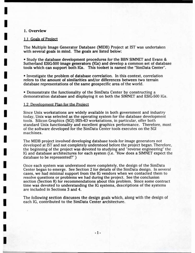
The Multiple Image Generator Database (MIDB) Project at 1ST was undertaken with several goals in mind. The goals are listed below:
• Study the database development procedures lor the BBN SIMNET and Evans & Sutherland ESIG-SOO Image generators (lGs) and develop a common set of database tools which can support both IGs. This toolset Is named the "SlmData Center".
• Investigate the problem of database correlation. In this context, correlation refers to the amount of similarities and/or dlflerences between two terrain database representations 01 the same geospeclfic area of the world .
• Demonstrate the lunctionality 01 the SimData Center by constructing a demonstration database and displaying it on both the SIMNET and ESIG-500 IGs.
1,2 Deyelopment Plan for the Project
Since Unix workstations are widely available in both government and industry today, Unix was selected as the operating system for the database development tools. Silicon Graphics (SGI) IRIS-4D workstations, in particular, ofler both standard Unix functionality and excellent graphics performance. Therefore. most of the software developed lor the SimData Center tools executes on the SGI machines.
The MIDB project involved developing database tools for image generators not developed at 1ST and not completely understood before the project began. Therefore, the beginning of the project was devoted to studying and "reverse engineering" the IG and database architectures for each system (I.e. "How does a SIMNET expect the database to be represented?" )
Once each system was understood more completely. the design of the SimData Center began to emerge. See Section 2 for details of the SimData design. In several cases, we had minimal support from the IG vendors when we contacted them to resolve questions or problems we had during the project. See the conclusion section (Section 8) for recommendations about this problem. Since some contract time was devoted to understanding the fG systems, descriptions of the systems are included in Sections 3 and 4.
The lollowing section discusses the design goals which, along with the design of each IG, contributed to the SimData Center architecture.
- I -
I I I I I I I I I I I I I I I I I I I
2. SlmData Center Approach
In this section, the design of the SimData as a set of tools used in combination with each other Is discussed. The potential dataflow of the system from source data to destination IGs Is shown and described.
2.1 Traditiooal DB Development MetbodoJQiY
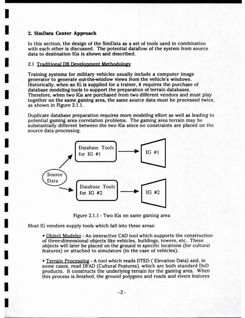
Training systems for military vehicles usually Include a computer Image generator to generate out·the-wlndow views from the vehicle's windows . Historically. when an IG Is supplied for a tralner, It requires the purchase of database modeling tools to support the preparation of terrain databases. Therefore. when two IGs are purchased from two different vendors and must play together on the same gaming area, the same source data must be processed twi ce, as shown In Figure 2.1.1.
Duplicate database preparation requires more modeling elfort as well as leading to potential gaming area correlation problems. The gaming area terrain may be substantially different between the two IGs since no constraints are placed on the source data processing.
/ Database Tools ...-for IG #1 • 10 #1
..--.... -Database Tool s .-for 10 #2 • 10 #2
... Figure 2. I . I . Two lOs on same gaming area
Most IG vendors supply tools which falilnto these areas:
• Object Modeler - An interactive CAD tool which supports the construction of three-dimensional objects like vehicles , buildings, towers , etc. These objects will later be placed on the ground In specific locations (for cultural features) or attached to simulators (in the case of vehicles).
• T errain Processing - A tool which reads DIED ( Elevation Data) and. in some cases , read DFAD (Cultural Features) , which are both standard DoD products . It constructs the underlying terraln for the gaming area. When this process is finished. the ground polygons and roads and rivers features
·2·
I I I I I I I I I I I I I I I I I I I
will be complete. Positions of major cultural features like towns or factories wlll be known, but the actual models (built by the Object Modeler above) will not be included automatically.
• Database Assembly - Here the models are merged with the terrain database. Buildings modeled In the Object Modeler are placed where they were indicated by the DFAD; special targets are placed according to the traJning purpose of the gaming area .
• Compilation for tbe IG - The completed database (coming out of the Assembly step) is reformatted Into a format direcUy-loadable on the iG. This is usually a one-directlonal process where only the IG-specific information necessary is extracted from the gaming area database. Reformatting is necessary since the IG is optimized for run-time performance and makes unique demands on the information in the gaming area database. The compiled database is sometimes referred-to as the RTDB (run-time database).
2.2 Support /Aui'meot vendor-supplied tools
Since the SiMNET and ESIG-500 IG systems were designed eisewhere and 1ST did not have detailed knowledge of their Internal architecture, a decision was mad e to output from the SimData tools into the vendor-supplied IG compilation tools. Specifically, the SimData Center had to output gaming area data in file formats which were compatible with the 51000 system (for BBN SIMNETs) and the ESED metaJile editor (for ESIG-500s). For the case of 51000, this allowed us to preview data imported from SimData tools before compilation for the SIMNETs.
2.3 Toolset & ooen!closed princiole
It is Important for software systems to have a long, useful life-cycle. especially when they required considerable effort to initially construct. This means the system will continue to be in use and will continue to benefit users for a long period of time. The long-term usefulness of a software system is usually inversely re lat ed to its complexity [Brooks 75] . This means that simple software systems are generally useful for a longer period of time.
When a piece of software is written to perform only a single task. a simple design usually results. The resultant piece of software is designed to produce the solution to a single problem without unneeded complexity. This small software system is a "tool" which solves a single problem.
When several such "tools" are grouped into a single system, the system is flexible because the tools can be used in different orders and different combinations. depending on the nature of the problem to be solved. Just break the problem into a series of steps and get a tool to solve each step. This Is the architecture of the SimData Center. There were many different data formatting problems which had to be performed during the preparation of a Visual System database - each of
-3-
I I I I I I I I I I I I I I I I I I I
which is solved by a simple, dedicated program. It is up to the user of the SimData Center to understand the functionality of the toolset and put it to use.
The Open / Closed Principle [Meyer 88J is an important concept in Object-Oriented design supported by the SimData Center design (as a tooiset composed of a set of independent tool programs). A system is considered closed when It is compieted and functional. A system is considered open when its capability can be expanded without redesign of the existing software. A tooiset fits this desCription since additional tools can be added later - with each tool adding to the overaJl system functionality.
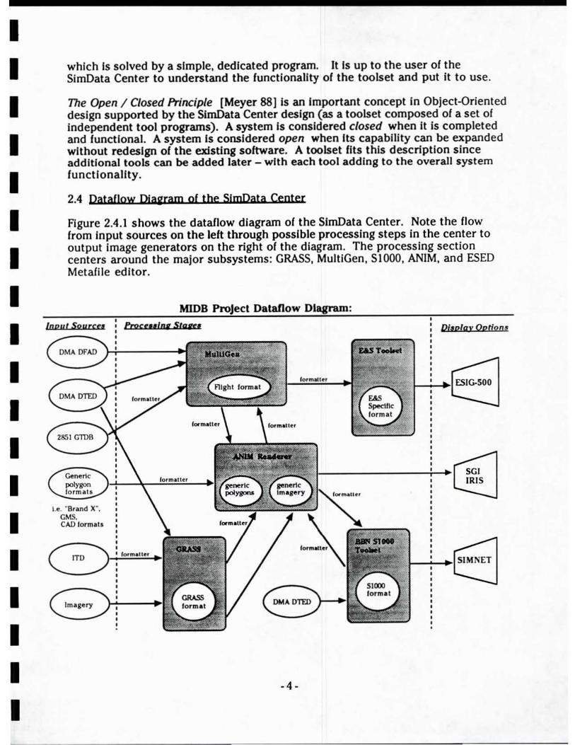
2.4 Dataflow pjagram of the SjmData Center
Figure 2.4.1 shows the data/low diagram of the SimData Center. Note the fiow from input sources on the left through possible processing steps in the center to output image generators on the right of the diagram. The processing section centers around the major subsystems: GRASS, MultiGen, 51000, ANiM, and ESED Metafile editor.
MIDB
IaDut $oY«(I Pro""'"' StaR'
I.e. "Brand X", GMS. CAD lonnltl
ITO
Imliery
Dataflow
Dj,olay Optio n ..
~~~I BIG·500
f~ ______________ -+~~
~-.,; ___ .. S1MNET
-4-

I I Figure 2.4.1 - Dataflow Diagram
I I I I I I I I I I I I I I I I
- 5 -
I
I I I I I I I I I I I I I I I I I I I
Arrows between the subsystems indicate formatters which are included in the SimData Center to allow data Interchange. The development of a particular model or gaming area may (and probably will) require several processing steps. The architecture of several subsystems connected by bidirectional conversion paths allows each subsystem to "do what It does best" on the datalile. After each processing step, the dataille Is converted for use In a different subsystem.
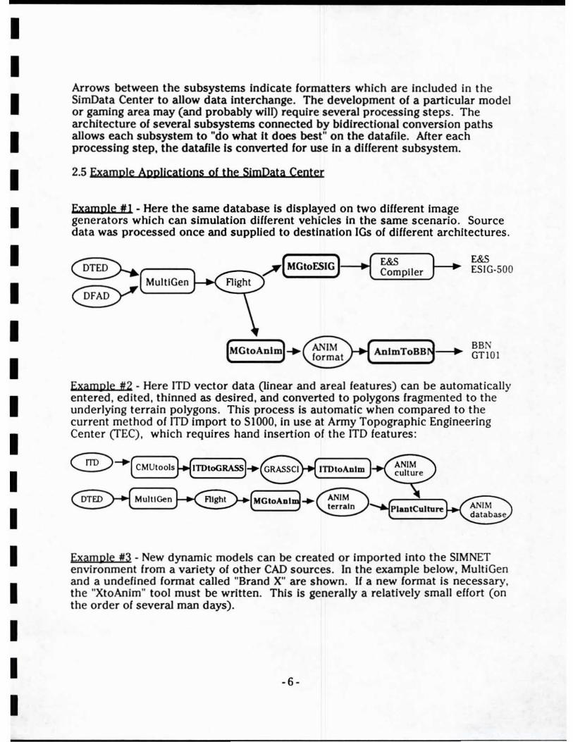
2.5 Example Applications of the SjmData Center
Example III - Here the same database is displayed on two different image generators which can simulation different vehicles in the same scenario. Source data was processed once and supplied to destination 105 of different architectures.
._-_... ....... .( MGtoFSIG )-.... -I( ~Pller }-- E&S ESIG·500
[MGtoAnlm) ..... BBN AnlmToBB - GTl OI
Example #2 . Here ITO vector data (linear and areal features) can be automatically entered, edited, thinned as desired, and converted to polygons fragmented to the underlying terrain polygons. This process is automatic when compared to the current method of ITO import to SIOOO, in use at Army Topographic Engineering Center (TEC) , which requires hand insertion of the iTO ieatures :
flight
Example #3 - New dynamic models can be created or imported into the SIMNET environment from a variety of other CAD sources. In the example below, MultiGen and a undefined fonnat caJled "Brand X" are shown. If a new format is necessary, the "XtoAnim" tool must be written. This Is generally a reiatively smali e/fort (on the order of several man days).
-6-
I I I I I I I I I I I I I I I I I I I
( MultlGen )-.~(MGIOA.lm)
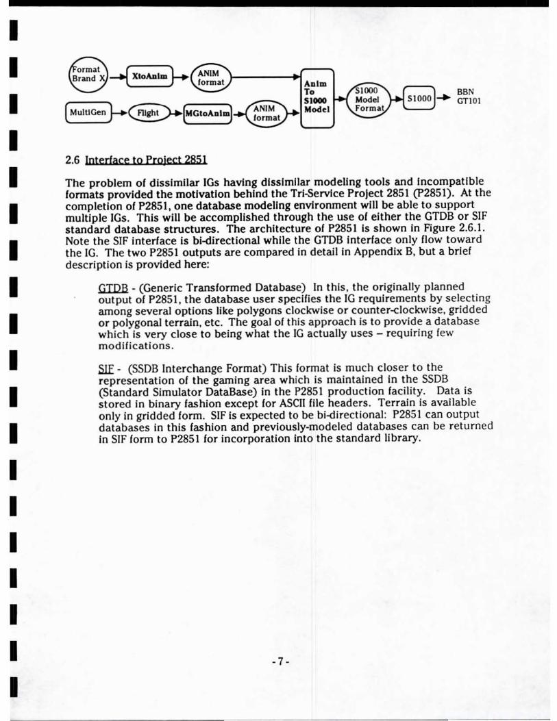
2.6 Intedace to PrQlect 2851
ADlm To SJ_ Model
SSN GTtOl
The problem of dlsslmflar IGs havIng dlsslmflar modeling tools and Incompatible formats provided the motivation behind the Trl-ServIce Prolect 2851 (P2851). At the completion of P2851, one database modeling envIronment will be able to support multiple IGs. This will be accomplished through the use of either the GTDB or SIF standard database structures. The architecture of P2851 Is shown In Figure 2.6.1. Note the SfF Interface is bi-directional while the GTDB interface only flow toward the IG. The two P2851 outputs are compared in detail In Appendix B, but a brief description is provided here:
GTDB - (GeneriC Transformed Database) In this, the originally planned output of P2851 , the database user speCifies the IG requirements by selecting among several options like polygons clockwise or counter-clockwise. gridded or polygonal terrain, etc. The goal of this approach is to provide a database which is very close to being what the IG actually uses - requiring few modifications.
S!f - (SSDB Interchange Format) This format is much closer to the representation of the gaming area which is maintained in the SSDB (Standard Simulator DataBase) in the P2851 production facility . Data is stored In binary fashion except for ASCII file headers. Terrain is available only in gridded form. SIF is expected to be bi-<lirectional: P2851 can output databases in this fashion and previously-modeled databases can be returned In SIF form to P2851 for incorporation Into the standard library.
-7-
I I I I I I I I I I I I I I I I I I I
SSDB An:blve P2851 I-..... ~ Maintained by Input P2851 Formatter
SSDB Formatler
GTDB H~Outpul
Formatler
SIF Dalabue
---~ . •
• • • .'
• ••••
•
...
Figure 2.6.1 - Projecl 2851 Dataflow
3. Experience with SIOOO & The SIMNET IG System
In this section, the S1000 tools provided to 1ST by the US Army Topographic Engineering Center are described. Since the information contained in this section is the result of unguided study by the MIDB project staff, some statements made may be incorrect. To determine the accuracy of any information here . the software designers of the SIOOO system should be consulted.
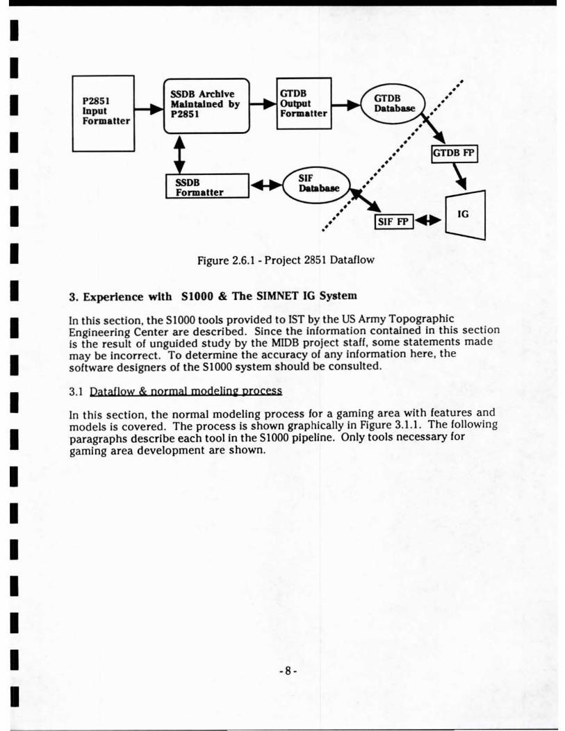
3.1 Dataflow & cormal modeliag process
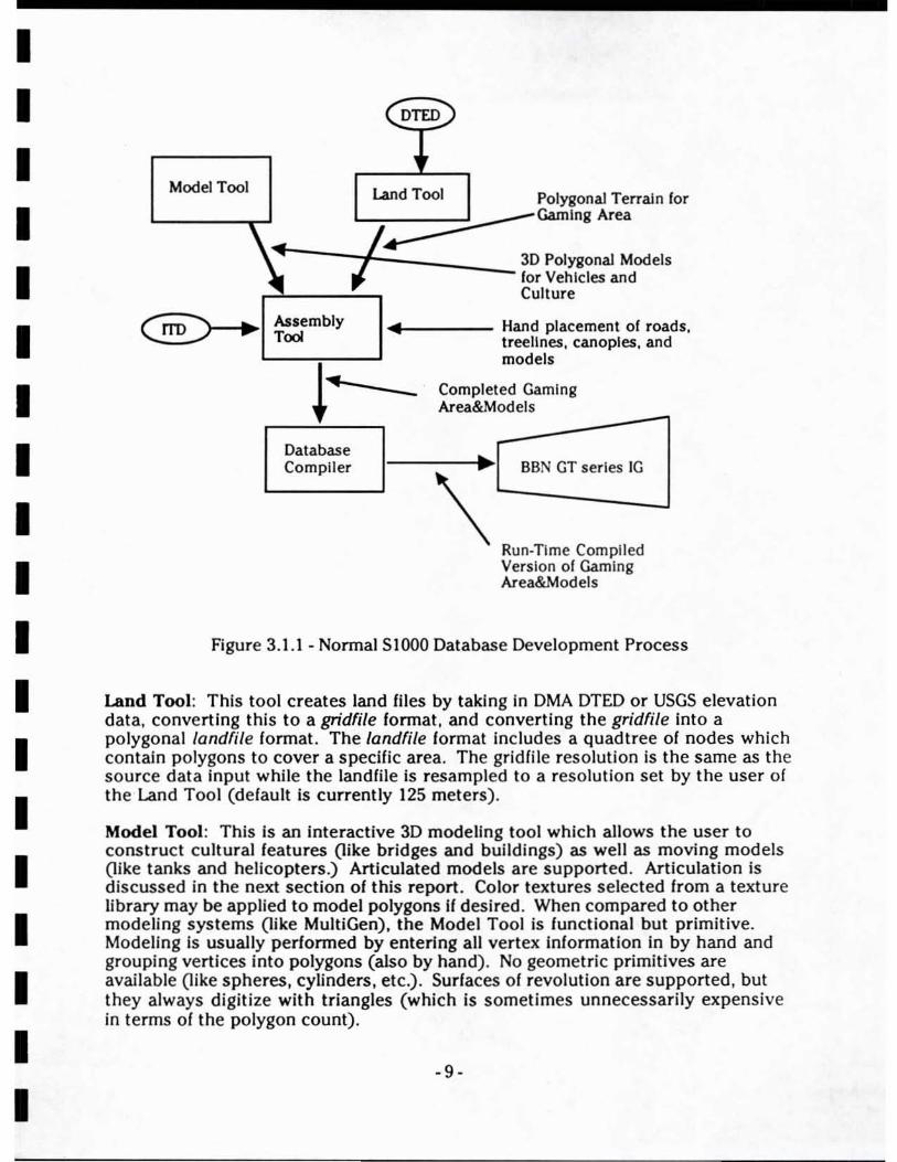
In this section, the normal modeling process for a gaming area with features and models is covered . The process is shown graphically in Figure 3.1.1. The following paragraphs describe each tool in the S1OO0 pipeline. Only tools necessary for gaming area development are shown.
-8-
I I I I I I I I I I I I I I I I I I I
Model Tool Land Tool Polygonal Terrain for
/~Gamlng Area
J 3D Polygonal Models " for Vehicles and
r"'---":"", Culture
Assembly Tool
Database Compiler
.. ~ ..... ____ Hand placement of roads, treelines, canopies , and models
Completed Gaming Area&Models
~ BBN GT series IG \'--------1 Run-Time Compiled Version of Gaming Area&Models
Figure 3.1.1 - Nonnal SIOOO Database Development Process
Land Tool: This tool creates land files by taking in DMA DTED or USGS elevation data, converting this to a gridfile fonnat, and converting the gridfile Into a polygonal landfile fonnat. The landfile fonnat includes a quad tree of nodes which contain polygons to cover a specific area. The grid file resolution is the same as the source data input while the land file is resampled to a resolution set by the user of the Land Tool (defau lt is current ly 125 meters) .
Model Tool : This is an interactive 3D modeling tool which allows the user to construct cultural features (like bridges and buildings) as well as moving models (like tanks and helicopters.) Articulated models are supported . Articulation is discussed in the next section of this report . Color textures selected from a texture library may be applied to model polygons If desired. When compared to other modeling systems (like MultiGen), the Model Tool is functional but primitive. Modeling is usually perfonned by entering all vertex Infonnation in by hand and grouping vertices into polygons (also by hand). No geometric primitives are avai lable (like spheres, cylinders, etc.) . Surfaces of revolution are supported, but they always digitize with triangles (which is sometimes unnecessarily expensive in terms of the polygon count).
-9 -
I I I I I I I I I I I I I I I I I I I
Model Enhancers - The Model tool also allows texture patterns to be attached to a single-polygon model. The resulting standalone textured polygon is called a stamp. These stamps can be attached to completed vehicle models as enhancers. An enhancer Is generally InYlslble, but when special attributes on the vehicle model are activated, the stamp appears as a special effect. Enhancers are used to provide dust clouds behind tanks, gun flashes from artillery, and fiery exhaust during the launch of an enhanced missile.
A.oembly Tool: With this Interactive tool, the modeler constructs Unique Static Objects (USOs) In the database. USOs Include roads , rivers, powerlines, treelines , and tree canopies. Cultural features constructed by the Model Tool can also be placed In the database. Also, In the assembly tool, the terrain constructed by the Land Tool can be hand edited through the creation of microterrain regions up to a load module In size. Most of the gaming area development time Is spent here since all the USOs are hand placed by the modeler. A digitizing tablet Is supported, but seems to be specific to the BBN site where the code was developed . We did not attempt to install the digitizing tablet at 1ST. ITD data can be imported in ADWAMS format . The data will be drawn on the screen and will serve as a guide for the modeler to digitize from If he chooses.
Complier: Once an assembly is complete, It Is compiled for the SIMNET IG. The output of this tool is a single binary file in one of two possible formats:
• static database ~ a compiled assembly with terrain and USOs ready for transfer to the IG hardware. Model files referenced In the assembly are added to the static database permanently and are ntr)onger movable .
• dynamic element database - Also referred to as a OED, it is a library containing all moving models and cultural features built by the Model Tool and adapted for loading directly on the IG. Some moving models are "enhanced" with special features controllable by the CIG during a simulation .
3.2 Models deyeJoped usjni SIOOO
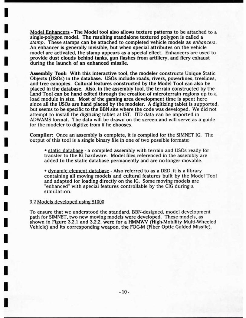
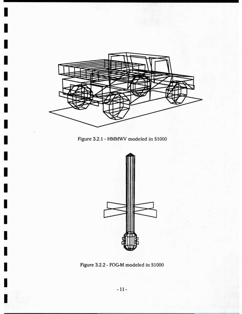
To ensure that we understood the standard, BBN-designed, model development path for SIMNET. two new moving models were developed. These models, as shown In Figure 3.2.1 and 3.2.2, were for a HMMWV (HIgh-Mobility Multi-Wheeled Vehicie) and its corresponding weapon, the FOG-M (Fiber Optic Guided Missile).
-10-
I I I I I I I I I I I I I I I I I I I
Figure 3.2.1 - HMMWV modeled In 51000
Figure 3.2.2 - FOG-M modeled in 5 I 000
- II -
I I I I I I I I I I I I I I I I I I I
Once these models were developed using SIOOO's Model Tool, they were compiled and viewed on the SIMNET at 1ST. Each model was constructed with three levels of detail. The HMMWV is articulated since the missile tubes in the back can be raised or lowered in addition to being turned side-to-side (like a tank turret) . At the time of this writing, the Model Tool supported only two types of articulated vehicles. The first type is for tanks with a hull, a turret, and a gun. The second type Is for helicopters with a hull, a top rotor, and a tail rotor. The HMMWV uses the tank articulation scheme where the missile tubes are considered the "gun" of the vehicle (and can therelore be raised or lowered). Since the "gun" Is always mounted on the "turret", the missile tubes can also be rotated side-to-side.
3.2 SIOOO System Ale Fonnats
When the SIOOO tools are used, they create a "project directory" in the Unix filesystem. Each Slooo project generally corresponds to a particular gaming area database, however multiple gaming areas can be stored in a single project. This configuration decision Is left up to the Individual user. The main SIOOO tool is used to create new projects. The top-level directory In an SIOOO project directory is placed on the workstation under the path name
/s I 000/v2/sli nks/d ata/ProJectName
This may require "soft links" in the Unix filesystem. See your Unix system manager for assistance here. For example, "/sIOOO/v2/slinks/data/lndSprings" could be a Unix directory where all data for an Indian Springs, Nevada database is stored. A series of subdirectories are created under the main project directory. The more important subdirectories are listed and described here:
... ./ProjectName/ land - where landfiles are stored
... ./ProjectName/grid - where all gridfiles (from DTED) are stored
... ./ProjectName/model - contains the modelfiles and model library
.... / ProjectName/uso - contains USO files for this gaming area
... ./ProjectName/compile - contains the extra data file and RTDS fil e
.... /ProjectName/assy
... ./ProjectName/net
Since 51000 is a set of tools running under Unix and gaming area development is a multi-step process, data is saved during the process in several different file formats. Each format is listed and described in the following paragraphs .
Grid Ale: Elevation post format set at one post per 3 arc seconds (approx 100 meters for DTED Level I). This is an easy format to figure out since the "flatgrid .c" routine exists which fills it. DTED data is read and converted into this format for import into the remaining SIOOO tools . A DTED Level 2 emulation dataset was read in and converted to a Grid File format with 1 arc second (30 meter) spacing. Therefore. Grid Files may exist at several different resolutions depending on the input source.
- 12-
I I I I I I I I I I I I I I I I I I I
Land Ale: The grid file is resampled to 125 meters per post. The 125 meter distance supports SOOm x SOOm separately loadable database portions (load modules). Two triangles are created between each set of four posts and the polygons are relaxed to reduce poly count before the data is written out as a Land File.
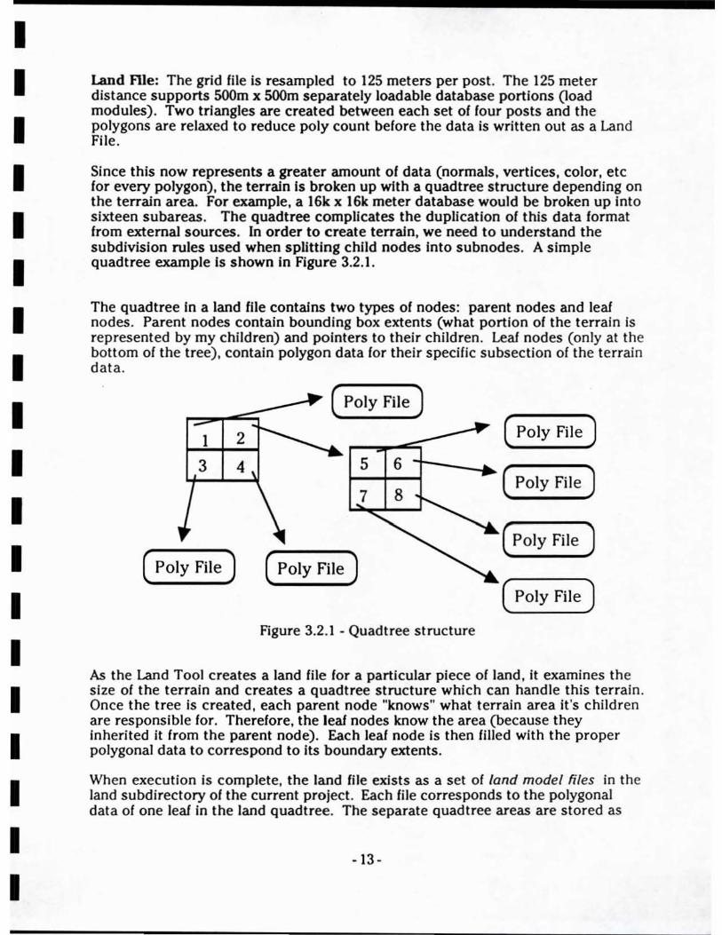
Since this now represents a greater amount of data (normals, vertices, color, etc for every polygon), the terrain Is broken up with a quadtree structure depending on the terrain area. For example, a 16k x 16k meter database would be broken up Into sixteen subareas. The quad tree complicates the duplication of this data format from external sources. In order to create terrain, we need to understand the subdivision rules used when splitting child nodes into subnodes. A simple quadtree example Is shown In Figure 3.2.1.
The quadtree In a land file contains two types of nodes: parent nodes and leaf nodes. Parent nodes contain bounding box extents (what portion of the terrain is represented by my children) and pOinters to their children. Leal nodes (only at the bottom of the tree) , contain polygon data for their specific subsection of the terrain data.
1 2
3 4
( Poly File)
( Poly File )
5 6
7 8
( Poly File)
Figure 3.2.1 - Quadtree structure
( Poly File )
( Poly File)
(POly File)
( Poly File )
As the Land Tool creates a land file for a particular piece of land, it examines the size of the terrain and creates a quadtree structure which can handle this terrain. Once the tree is created, each parent node "knows" what terrain area it's children are responsible for. Therefore, the leal nodes know the area (because they inherited it from the parent node). Each leaf node is then filled with the proper polygonal data to correspond to Its boundary extents.
When execution is complete, the land file exists as a set of land model files in the land subdirectory of the current project. Each file corresponds to the polygonal data of one leal in the land quadtree. The separate quadtree areas are stored as
- 13 -
I I I I I I I I I I I I I I I I I I I
files titled xxxxI0.m2. xxxxll.m2. xxxxI2.m2. etc. As mentioned above. the number of files depends on the polygon count In the terrain represented. These files are referenced by the land assembly file (xxx.lassy). which contains all the parent nodes of the land quadtree.
Land FIle Quadlree detalb: The quadtree for a land file is constructed according to several rules IBBN 89J. The rules are summarized here:
• The quad tree starts out as a single node (*0). As land polygons are added. the node splits into a parent and four children which together cover the sarne area originally covered by their parent. Splitting like this can occur to any leal node in the quad tree.
• Leaf nodes always reference 2100 or fewer polygons and 4000 or fewer vertices.
• Leaf nodes always cover an area greater than 4000 x 4000 meters.
This imposes a limit on the number of polygons per area the terrain database. Since each leaf covers at least a 4k x 4k area with less than 2100 polygons . then the density must be less than one poly per 87 x 87 meter area. The reader is reminded that these measurements are true for the version of S 1000 tools in use during the MIDB project. The size sizes and polygon densities may change with updated versions of the tools.
usa Model ftle: (xxxuO.m2) This Is a model format fil e used to contain all the polygon data for USO's in a particular group In a terrain database. A usa group corresponds to a leaf in the database quadtree structure. Break-up of usa model files into groups is necessary for the same reason as terrain files since the number of polygons contained in a single could otherwise become excessive.
Land Assembly ftle: (xxx.lassy) When the Landtool writes out a land file . it writes all the xxxxly.m2 fil es in the "<projectnarne>/Iand" directory and then writes an xxxx.lassy file in the "<projectname>jassy" directory. The land assembly file serves to supply the assembly tool with pOinters to each xxxxly.m2 file. a pOinter to the texture library. and a particular texture entry to use for the land.
Model FIle: (xxx.m2) This is a relatively straightforward file format composed 01 header information, a list of polygons each of which contain several vertex indices into a list of vertices. then the list of vertices. This format seems to be the base polygon format used by the land and assembly flies whenever they store a polygonal object. Therefore. reading and writing this format will yield the most benefit importing data Into and exporting data out from the SIOOO environment. Model files contain a maximum of 2100 polygons.
Assembly FIle: (xxx.assy) This file consists of several sections : an overall assembly header. pointers to all the land files (xxxll.m2. xxxI2.m2. etc.) for the terrain (which were found from the xxxx.lassy file). a usa pOinter (which points
- 14 -
I I I I I I I I I I I I I I I I I I I
to a model file representing the USO's which are in the assembly (xxxxuO.m2). There seems to be only one model file for all usa polygons.
Extra Data FIle: (xxx,xdata) The extra data file is an additional file necessary for the compilation of a completed assembly file . It stores high-fidelity bounding volumes for moving models in the model library. If accurate collision detection is requIred for articulated models, bounding volumes for each articulated part are required here. In this ASCII file, there are several lines of Infonnation for each model in the model library. 51000 provides a tool to create a baseline vers ion of the extra data file which the user can customize if desired. The tool is a standalone C program found on the workstation under the path
Is I 000/v2/sli nks/src/u t i I/mis c/make_xd ata. t .
The extra data file for the "baseln" model library given out with the 51000 tools Is a good example to study. It is important that models be numbered in the order they should appear in the final compiled DED on the CIG. Don't ever give a model the index "0" since that is not displayable on the CIG (but the DED will compile without warning you that the model with index zero is undispJayabJe).
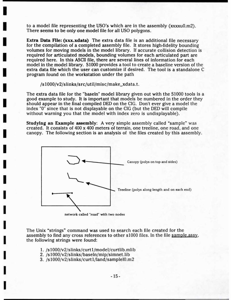
Studying an Example assembly: A very simple assembly called "sample" was created. It consists of 400 x 400 meters of terrain. one treeline, one road, and one canopy. The following section is an analysis of the files created by this assembly.
01-""'---4_ Canopy (polys on top and sides)
•
~~ • ~'~-r- Treeline (POlys along length and on each end)
\ "-
network called ~ roadM wtth two nodes
The Unix "strings" command was used to search each fil e c reated for the assembly to find any cross references to other s 1000 fil es. In the file samole,assy. the following strings were found :
I. Is 1 000/v2/slinks/ curt l /model/curtlib .mlib 2. Is 1 000/v2/s links/ baseln/ mip/simnet.lib 3. Is I 000/v2/slinks/ curt l / land/samplel0.m2
- 15-
I I I I I I I I I I I I I I I I I I I
4. Is I 000/v2/slinks/curt I/mod_lInk/samplegO.m2 5. Is 1000/v2/slinks/curt I/uso/sampleuO.m2 6. Isl000/v2/ slinks/curtl /net/road .net
These links are:
I. Model library where all 3D models In the assembly are stored. 2. Texture library reference liIe. Texture for the usa's Is assigned by picking Indices Into this liIe. 3. This polygon liIe includes the land polygons. When the land has been broken up into a quadtree, multiple references appear here in the xxxx.assy. 4. Unknown file reference. 5. This polygon liIe contalns the data for the usa's in this assembly. 6. This liIe type (NET_TYPE) contains references to the node liIe (road .nd I of type NODE_TYPE) and segment liIe ("road.sgl" of SEG_TYPE) for the networks In this assembly.
3.3 Problems encQuntered exercisio~ S1000
Most of the problems encountered by the MIDB team can be summarized under three categories:
I. Install at jon of slOaa - Especially with the first release of Slaaa, we found software which was not correctly ported to the Silicon Graphics platform. This slowed our familiarity of the tools. For example, the DTED tape reading routine made Apollo workstat ion·specific operating system calls and was not functional on the Silicon Graphics system. The slaaa source code had to be modified before we could even import DTED. Unix softlinks were created to allow the slOaa tools to reside and function in the 1ST network environment.
2. Lack of Training & Documentation - 1ST received the SIOOO tools as ins talled by Larry Brown (an NTSC employee on contract to PM-TRADE at the time). The system was not completely installed at 1ST and Larry received incomplete training while at Army TEe (t raining along with TEC's engineers). A copy of the slOaa tutorials and Version I manual were provided, but they lacked the depth necessary to instruct about the entire database development process.
3. Immaturity of S)OOO Tools - Developing a complete gaming area is a laborintense process requiring a high amount of hand editing. Ground microterrain, treelines, canopies, and road networks are all hand modeled . The model tool which develops all ~D cultural features and vehicles is primitive compared to many other modeling sys tems (MultiGen, AutoCAD. Alias , etc.). It allows only limited preview capability - models must be compiled and viewed on the CIG before most modeling errors can be detected.
-16-
I I I I I I I I I I I I I I I I I I I
However, even with these problems In mind, once we became familiar with 51000, its capabilities, and its limitations, we found the system to be consistent and reliabie. 51000 handled large gaming area development with little problems compared to the MultiGen system. The quadtree file breakup allowed the tools to operate on large databases without requiring several minutes to read in the database each time the tool is Invoked (which Is the case for MultiGen at the time of this writing).
If the databases developed for new gaming areas are generally sparse, like the original SIMNET databases, SIOOO Is a good system to use for gaming area development. The tools take a competent engineer relatively little time to understand and use effectively.
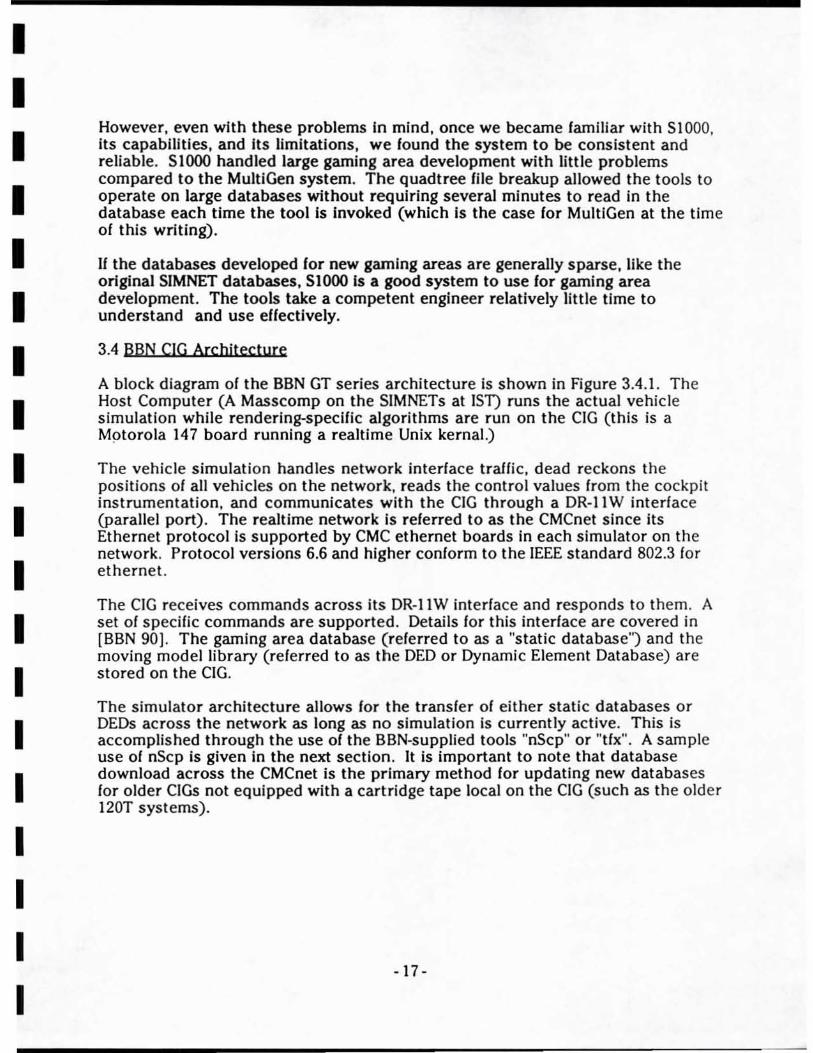
3.4 BBN CIG Archilecture
A block diagram of the BBN GT series architecture is shown in Figure 3.4.1. The Host Computer (A Masscomp on the SIMNETs at 1ST) runs the actual vehicle simulation while rendering-specific algorithms are run on the CIG (this is a Mptorola 147 board running a realtime Unix kernal.)
The vehicle simulation handles network interface traffic, dead reckons the positions of all vehicles on the network, reads the control values from the cockpit instrumentation, and communicates with the CIG through a DR-II W interface (parallel port). The realtime network Is referred to as the CMCnet since its Ethernet protocol is supported by CMC ethernet boards in each simulator on the network. Protocol versions 6.6 and higher conform to the IEEE standard 802.3 for ethernet.
The CIG receives commands across its DR-IIW interface and responds to them. A set of specific commands are supported. Details for this interface are covered in [BBN 90) . The gaming area database (referred to as a "static database") and the moving model library (referred to as the DED or Dynamic Element Database) are stored on the CIG.
The simulator architecture allows for the transfer of either static databases or DEDs across the network as long as no simulation is currently active. This is accomplished through the use of the BBN-supplied tools "nScp" or "tlx". A sample use of nScp is given in the next section. It is important to note that database download across the CMCnet is the primary method for updating new databases for older CIGs not equipped with a cartridge tape local on the CIG (such as the older 120T systems).
-17-
I I I I I I I I I I I I I I I I I I I
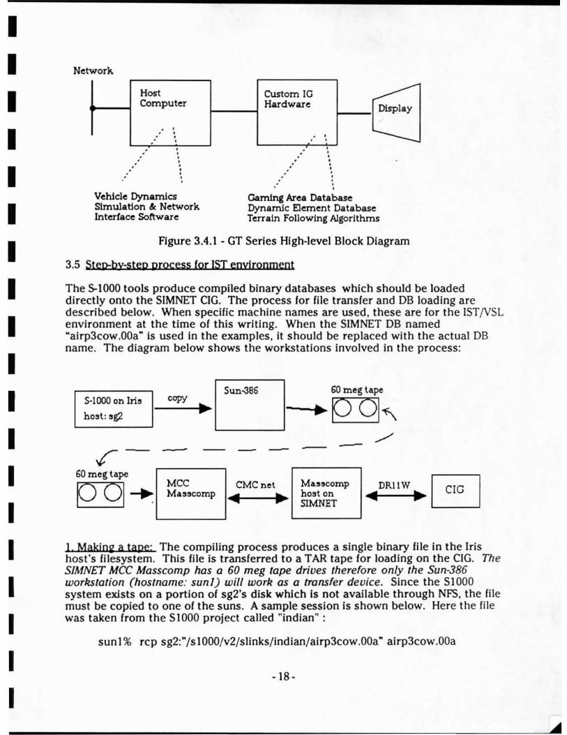
Network.
Host Custom 10 ~ Computer Hardware
. . " .
· • · • · • • • • • • ·
Vehlcle Dynamics Simulation &: Network Interface Software
. . .'
.'
• · · • • • · • · · · · ·
Display
Gaming Area Database Dynamic Element Database Terrain Following Algorithms
Figure 3.4.1 - GT Series High-level Block Diagram
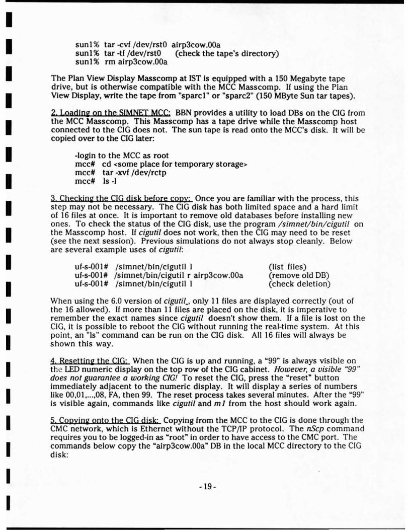
3.5 Step-by-step process for 1ST envirooment
The 5-1000 tools produce compiled binary databases which should be loaded directly onto the SIMNET CIG. The process for file transfer and DB loading are described below. When specific machine names are used. these are for the ISTjVSL environment at the time of this writing. When the SIMNET DB named "airp3cow.00a" is used in the examples. it should be replaced with the actual DB name. The diagram below shows the workstations involved in the process:
Sun-386 60 meg tApe 5-1000 on Ir13 copy • - .. ho~t: ,g2 ~~
./ --t- - -- --60 meg tape
~+ MCC CMCnet Ma"$comp DRIIW Masscomp 'ill • ho:!!t on 'ill • SIMNET
1. Makjoe a tape: The compiling process produces a single binary file in the Iris host's fil esystem. This file is transferred to a TAR tape for loading on the CIG. The SIMNET MCC Masscomp has a 60 meg tape drives therefore on ly the Sun·386 workstation (hostname: sunl) will work as a transfer device. Since the SIOOO system exists on a portion of sg2's disk which fs not available through NFS. the file must be copied to one of the suns. A sample session is shown below. Here the fil e was taken from the S 1000 project called "indian" :
sun l % rcp sg2:"/sI000/v2/slinks/indian/airp3cow.00a" ai rp3cow.00a
- 18 -
I I I I I I I I I I I I I I I I I I I
sunl % tar <vf /dev/rstO airp3cow.00a sunl % tar -If /dev/rstO (check the tape's directory) sunl% rm airp3cow.00a
The Plan View Display Masscomp at 1ST Is equipped with a ISO Megabyte tape drive, but is otherwise compatible with the MCC Masscomp. If using the Plan View Display, write the tape from "sparcl" or "sparc2" (ISO MByte Sun tar tapes).
2, Loadl02 00 the SIMNEI MCC: BBN provides a utility to load DBs on the CIG from the MCC Masscomp. This Masscomp has a tape drive while the Masscomp host connected to the CIG does not. The sun tape Is read onto the MCC's disk. It will be copied over to the CIG later:
-login to the MCC as root mcc~ cd <some place for temporary storage> mcc# tar -xvf /dev/rctp mcc# Is-I
3, Checkjo2 the CIG disk before copy: Once you are familiar with the process, this step may not be necessary. The CIG disk has both limited space and a hard limit of. 16 files at once. It is important to remove old databases before installing new ones . To check the status of the CIG disk, use the program I simnetl binlcigutil on the Masscomp host. If cigutil does not work, then the CIG may need to be reset (see the next session). Previous simulations do not always stop cleanly. Below are severa) example uses of ciguli!:
uf-s-OO I # /simnet/ bin/cigutil I uf-s-OOI# /simnet/bin/cigutil r airp3cow.00a uf-s-OOI# /simnet/ bin/cigutil I
(list files) (remove old DB) (check deletion)
When using the 6.0 version of cigutiC only II files are displayed correctly (out of the 16 allowed). If more than II files are placed on the disk, it is imperative to remember the exact names since cigutil doesn't show them. Jf a file is lost on the CIG, it is possible to reboot the CIG without running the real-time system. At this pOint, an "Is" command can be run on the CIG disk. All 16 files will always be shown this way.
4, Resettjo2 the CIG: When the CIG is up and running, a "99" is always visible on the LED numeric display on the top row of the CIG cabinet. However, a visible "99" does not guarantee a working CIG! To reset the CIG, press the "reset" button immediately adjacent to the numeric display. It will display a series of numbers like 00,01 , .. .. 08, FA, then 99. The reset process takes several minutes. After the "99" is visible again, commands like cigutil and m 1 from the host should work again.
5, COQyjn2 onto the CIG djsk: Copying from the MCC to the CIG is done through the CMC network, which is Ethernet without the TCP/IP protocol. The nScp command requires you to be logged-in as "root" in order to have access to the CMC port . The commands below copy the "airp3cow.00a" DB in the local MCC directory to the CIG disk:
-19-
I I I I I I I I I I I I I I I I I I I
mcc* cd <where database Is on the MCC > mccll /simnet/bln/nScp airp3cow.00a 2_A_ml :_ClG_:airp3cow.00a (stealth)
CJ< mcc* /simnet/bin/nScp airp3cow.OOa 1_A..ml :_CIG_:airp3cow.00a ((or ml) mcc* nn airp3cow.00a
6. Brjoiio" up the Ml simulator:
Once the new database is on the SIMNET CIG. the simulator can be brought up in either o( two modes: flee mode (standalone debug) or nonnal simulation mode (but using the new database).
10 Flee mode:
1. change the II I and #5 dip switches on the CIG real-time board) 2. press reset button on CIG realtime board (as described in the previous section) 3. go to serial tenninal hooked directly to the CIG real-time board
=> 18 => boot rt,-120t.a I09 Done. » run
(check that the database is there) (use name of your realtime system)
(hit 2 returns here or nothing will happen) > u (select a new static database- optional) > v (select a new DED - optional) > Z fly > w (enter FLEE mode)
At this pOint , your keyboard keys allow you to move the viewpoint around and place static models. This mode is helpful for viewing a new dynamic model on the CIG.
In Simulation mode:
The simulation modes (or a SIMNET system (speCifically. either the MI or a Stealth vehicles at 1ST) can be brought up on different ground databases with different DEDs under control of the command line parameters . To load a new static database, the database filename is passed as an argument for the "-t" switch. For example. to bring up a simulator on the database "myDB3cow.Olc" at position (x.y) = (100.100) with heading = 0 degrees (north) use the command line:
simuiator-host% ml -k -t myDB3cow.Olc -p 100 100 0
A file naming convention exists for BBN databases. The first four (or more characters) are the gaming area name. The name is followed by either a numeral 3 or 7 indicating a 3500 meter viewing database or a 7000 meter viewing database. respectively. Also, ei ther a "c" or a "d" should follow the numeral to deSignate the database as static or dynamic (a DED).
-20-

I I I I I I I I I I I I I I I I I I I
4. Experience with the ESIG-SOO IG Syatem
The tools for database preparation which 1ST received from Evans & Sutherland were Incomplete. Evans & Sutherland offers additional terrain preparation tools for the ESIG-500 which were not available for Incorporation in the SimData Center. Therefore. the comments made in the following sections apply to the environment which was created by the MIDB staff at 1ST. Some portions of this information may not apply to other ESIG development environments.
4.1 Dataflow & cormal IDodeIioK process
Several tools were provided by E&S which allowed modeled gaming areas to be converted to the run·tlme IG formats. Since these tools did the "compiling" for the IG. the SlmData Center supplies data In a file format which can be processed by the E&S tools.
The ESED Editor - This is a forms-driven editor which allows a user to enter vertex. polygon, texture, level-of-detail, and other types of information into the gaming area metafile prior to compilation to a run-time format. Prior to the invention of E&s's terrain tool (and the SimData Center at IS1), a modeler was required to enter every vertex and polygon explicitly using ESED. This is a very laborious task, also prone to errors. The SimData Center creates a metafile which can be altered using ESED if desired . Through this process, most of the time previously required for data entry in ESED has been saved .
4.2 SjmData Center Path to the ESIG-5QQ
As shown in Figure 2.4.1. MultiGen is used as a modeling package for the ESIG-SOO system. A completed Flight format file is then processed in several steps to create the ESIG·500 run-time database. The steps are listed here:
I.
2.
3.
4.
S.
Convert the polygonal data from Flight format to ASCII
Build the database hierarchy (of polys. objects. cells. and meshes) which the ESIG-SOO requires.
Copy the hierarchy files over to the VAX-station which is the platform for the procedural modeling tools and the ESED metafile editor.
Run custom SimData sortware which builds the database's metalile as if it had been all entered by hand from ESED.
Run the remaining compiler tools on t he metafile.
6. Transfer the run-time database fil es over to the ESIG-500 for viewing.
4.3 Problems encountered
- 21 -

I I I I I I I I I I I I I I I I I I I
Separation plane Insertion provided the greatest amount of difficulty for the SimData Center design. At the time of this writing. the SimData tools still req uire a reasonable amount of modeler Intervention to prepare correct separating planes for a gaming area.
Since the ESIG-500 relies completely on separation planes for correct priority during rendering, every pair 01 polygons In the gaming area must be correctly resolved using a separation plane. The theory of this approach Is described in the standard computer graphics algorithm 01 the BSP tree (BInary Separating Plane tree) . Two drawbacks are apparent with the BSP tree:
I. No Moying Models Supported - The BSP tree Is generally created offline, statically ordering the database via creation of a series of planes which pass between objects. Therefore, moving models cannot pass across a separation plane boundary and still expect to be correctiy rendering by the ESIG-500 hardware. This problem Is characteristic of all high-perlormance IGs previous to the addition 01 depth buffer hardware.
2. Problem with Touching Objects. Separating planes can be automatically calculated when all objects are contained in non-intersecting bounding volumes . This is the "easily separable" case. However, adjacent polygons (like those found in terrain) cannot be processed in the same fashion. Separation planes must be inserted in a brute force manner. This enforces a regular geometry on t he terrain and culture polygons.
These limitations can be summarized by saying that no gaming areas are inherently un displayable by the ESIG-500. However, it is important to pOint out that database preparation lor a static priority (separation plane) IG is generally more intricate and time consuming than for a depth buffer IG which provides dynamic priority between models and terrain.
5. Constructive Solid Geometry Modeling
Since Constructive Solid Geometry (CSG) is an emerging graphics representation used by the academic, industrial. and military communities, it deserves a mention in the context of this report . CSG allows a human modeler to build geometrical objects with geometriC primitives (like spheres, blocks, and cones) instead of having to model with polygons and vert ices .
5.1 The CSG tree
An object Is created by combining geometrical primitives through the use of standard boolean operators applied in three dimensional space. For review, boolean operations are required to have two arguments and produce a single resultant value. The most popular boolean operations used in eSG are Union, Intersection, and Subtraction. They are defined below:
-22-
I I I I I I I I I I I I I I I I I I I
Unioo - The resultant object fills volume that was in either of the original two objects. This Is somewhat analogous to the "plus" operation.
IntersectjQn - The resulting object fills volume that was common to both original objects. Therefore, only space where the input objects were co-resident will be output.
Subtractjon -In this operation, volume from one object is "scooped out" of the other object. This operation Is used extenSively to "cut away" area from solid geometry models.
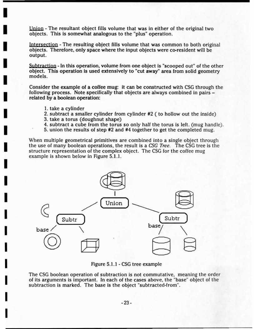
Consider the example of a coffee mug: it can be constructed with CSG thrQugh the follQwing process. Note specifically that objects are always combined in pairs -related by a boolean operation:
J. take a cylinder 2. subtract a smaller cylinder frQm cylinder #2 ( to hollow out the inside) 3. take a torus (doughnut shape) 4. subtract a cube from the torus so only hall the torus is left. (mug handle). 5. union the results of step #2 and #4 together to get the completed mug.
When multiple geometrical primitives are combined into a single object through the use Qf many boolean operations, the resuit is a CSC Tree. The CSG tree is the structure representation of the complex object. The CSG for the coffee mug example is shown below in Figure 5.1.1.
/ (Union) _____ (--S-u-bt-r --..) (--S-u-bt-r -..)
base / \ bas,! \
@ C9} § § Figure 5.1.1 - CSG tree example
The eSG boolean operation oC subtraction is not commutative. meaning the order of its arguments is important. In each of the cases above, the "base" object of the subtraction is marked. The base is the object "subtracted-from".
- 23-
I I I I I I I I I I I I I I I I I I I
5.2 The eSG I Boundary Rep Problem
To be of value for rendering with a polygonal rendering system, the eSG representation must eventually be converted to polygons. This is done through the use of a boundary representation algorithm. It is always possible to construct a polygonal representation from any eSG tree, however some of the polygons may be concave or may contain imbedded holes. Section 5.5 covers the algorithms necessary to eliminate holes from the boundary representation of the object.
Even when holes are eliminated, the boundary representation of a eSG model usually will contain high-order polygons Cwith greater than 4 vertices). Therefore , before being rendering on most IGs, the model will have to be triangulated. It is appropriate to expect less efficient polygon use in models which were originally constructed in eSG.
Algorithm complexity is another importanl pOint. Most known aigorithms for eSG to boundary representation require O(M3) processing time, where M is the number of eSG primitives in the tree. For complex objects, it can be computationally expensive to convert to a boundary representation.
Production systems like GMS get around this conversion by keeping both the eSG and boundary representations ul'to~ate at all times. Therefore there is never a need to re-evaluate the entire eSG tree. The drawback to GMS's approach can be summarized by classifying the system as basically polygonal instead of purely eSG. The modeling interface appears as if eSG was being used , however the data is actually always polygonal.
When a system constantly evaluates the eSG tree, il defeats the modeler's ability to dynamically change the number of polygons in a model for the purpose of levelof~etail creation . This is a major drawback which will force the use of "pure eSG" modeling tools in the future: all modeling will be done only with geometrical primitives. When polygons are necessary, the boundary representation algorithm will be run on the entire eSG tree.
5.3 Use of eSG in Goyernment trainers (projecI2851)
Since the polygonal representation of a complex model can become quite large. and consume substantial disk space, other geometrical representations were investigated for storing models in Project 2851's SSDB. eSG was chosen because of its compact form and ease of modeling. During the past two years, the CSG modeiing package GMS (Geometric Modeling System) from Interactive Computer Modeling, Inc. has been used by PRe Cthe P2851 vendor).
An advantage of modeling with CSG Is that a particular model can be built only once by a modeler and saved with severallevels-of-detail (LaDs). The different LaDs did not have to be separateiy constructed Cas is the case with polygonai modeling.) This is possible because the modeler only specifies position and size for
- 24-
I I I I I I I I I I I I I I I I I I I
geometric primitives (spheres , cylinders, etc.) during model construction. Each geometric primitive contains a predetennlned number of polygons . Separate LODs for a single model can be constructed by using different "resolution" geometric primitives. For example, a cylindrical gun for a high.<Jetail model could consist of 25 polygons while the 10w.<Jetail cylinder only used 5 polygons. An example of this concept Is shown in Figures 5.4.1 and 5.4.2.
In the P2851 production facility, special formatting software was written to fnterface the GMS model file format to the model storage format for the SSDB. Since GMS was used by PRC, a copy of the same modeling system was procured for Inclusion Into the SimData Center system. The models shown In Figures 5.4.1 and 5.4.2 were constructed with GMS. The "GMS Neutral File Format" (human readable) was used for exchanging data to and from GMS.
5.4 Model Cooyersion Results
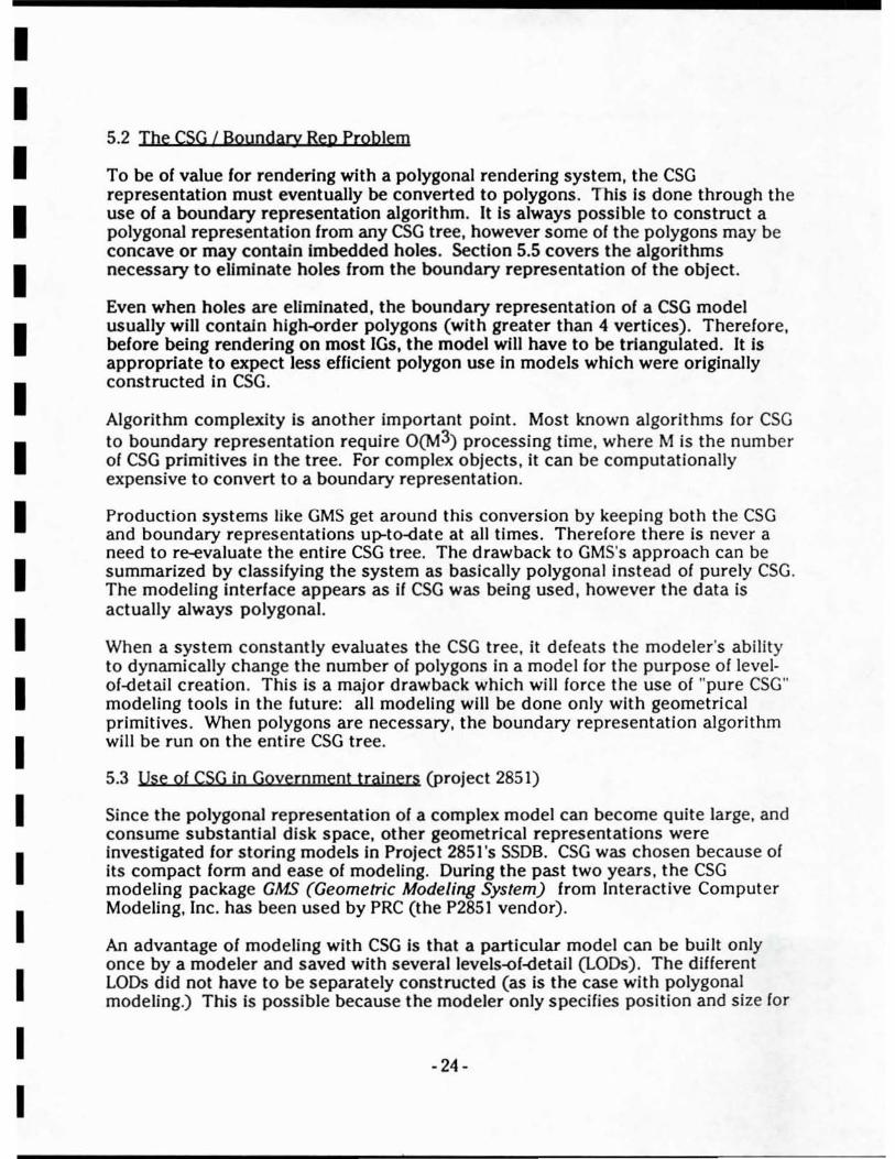
As a proof of the concept of multi-LODs Irom a single CSG tree, a tank model was constructed in GMS. It contained 8 geomet rical primitives distributed in the following way:
• hull: 5 blocks - one base with four successive subtractions • turret: one sphere with one block subtracted (cut 011 bottom of sphere) • gun: 1 block (elongated)
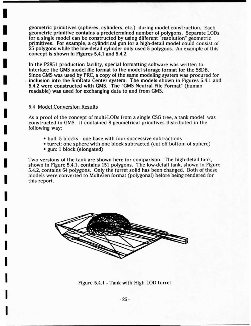
Two versions of the tank are shown here for comparison. The high-detail tank, shown In Figure 5.4.1, contains 151 polygons . The 10w.<Jetaii tank, shown in Figure 5.4.2, contains 64 polygons . Only the turret solid has been changed. Both of these models were converted to MuitiGen format (polygonal) before being rendered for this report.
Figure 5.4.1 - Tank with High LOD turret
- 25-
I I I I I I I I I I I I I I I I I I I
Figure 5.4.2 - Tank with low LOD turret
5.5 GMS to MultiGen Conyers ion
A GMS output file consists of a list of two and three dimensional objects. Each object contains a list of vertices followed by a list of polygons or faces. These can be either "solid" polygons where vertices are traversed in a clockwise direction , as seen from the outside, or holes where vertices are traversed in a counterclockwise direction.
The translation into a Multigen data file is mostly straightforward and mechanical with one problem area. That problem lies In eliminating the holes which Mult igen has no way to specify. The basic algorithm when a polygon with a hole is encountered Is as fo llows:
I. Rotate the polygon into the xy - plane 2. Specify a horizontal scanline midway between the minimum
and maximum y values of the hole 3. Define two new polygons using old polygon and hole pOints
as well as new pOints where the scan line intersects the polygon and hole.
4. For each hole check to see if it lies inside of either polygon or if it has been eliminated.
- 26-
I I I I I I I I I I I I I I I I I I I
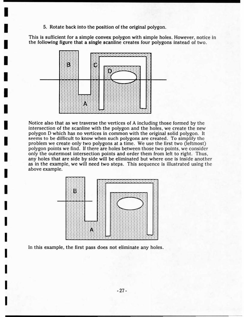
5. Rotate back into the position 01 the original polygon.
This is sufficient for a simple convex polygon with simple holes. However, notice in the following figure that a single scanllne creates four polygons Instead of two .
. :.: .:.: ::: ;::!: ........ .... .... .... .... . ~ ... ' . ,',', I ',' .
' ,: !;:; ! ::':;!: .. ..
',' . .... ,'.: : "
· · · · · :. :. : ..... .... ,
::;:; ... ... .. .... ....... ... .. .. ...... : ~~l :~ .~ . .' :::: : ::0; ::::: ::::::::::: : n n n ~ 11~;Y """:~ n .... ..:r 1:., ... .:.:. : ' :' , :!;: : ..... ..... ,', nn:
::: :::!:
~: . . :.:. .....
:::!:" .: ..•• :.:: .:.:.: " ... '. .: ... ..... : ... . ::: : : :. :::. : n .,'. .. .,'. . .• : · .: · : . · .. .. .: :.:.:
::: .:.:. :.: ':':',':"' :
: ~ :~ .1 1 Notice also that as we traverse the vertices of A including those fo rmed by the intersection 01 the scanline with the polygon and the holes, we create the new polygon D which has no vertices in common with the original solid polygon . It seems to be difficult to know when such polygons are created . To simplify the problem we create only two polygons at a time. We use the first two (leltmost) polygon points we lind. If there are holes between those two points, we consider only the outermost intersection pOints and order them from lelt to right. Thus, any holes that are side by side will be eliminated but where one is inside another as in the example, we will need two steps . This sequence is illustrated using the above example.
: .... ... .. ......... .. ............ :: . . . . ·
· ·
.:
In this example, the first pass does not eliminate any holes.
-27-
I I I I I I I I I I I I I I I I I I I
.:.: ....... ... , . , .. ', ......... , .... :. :: :: :: " .' '. .
:.:. ;: ;: :::: .:.' ::: : ;: .:.: :;
': 13" :. ',' ' •.•............ ' . , ' ;!
___ I·:;.,~.ll:~ 1l1?:': ""':'J,:::j! , ,;;~ " : : :!: " . . ,,: !:
, ' ,' '. .... '. ,',' " :i:: ;:
..... .... ., ..... . .. q :. 1 :. 1:. 1: .• ::. :::::::: ..... ' .. ,', .'.', ' ,', ....... .
::.;.:.,:.,:; ::::;:::: .:!.:! .: !.: ! ',' , ', .':', .:.:.:.: . ;';';".; .; :. ;.; .; .;.: :1 :::::: .. .. " •• •• t' .... " :. :.:.:
••• •• ;1;. · " . · ••••• ', •• .• •• • .:.:.~ . : .:.: ;. ;.:.!.;.', :: ::;: ; : " i::::::::::::: L- :::::::::: ;: :::::: !---: : .. .. ... ....... ....... •••••••••••• • • ' :0: .' ••••• ',.. • •• ' •••• :;;. • • • ......... ...... ....... , .. ' .. , .. .... , ... ... . .
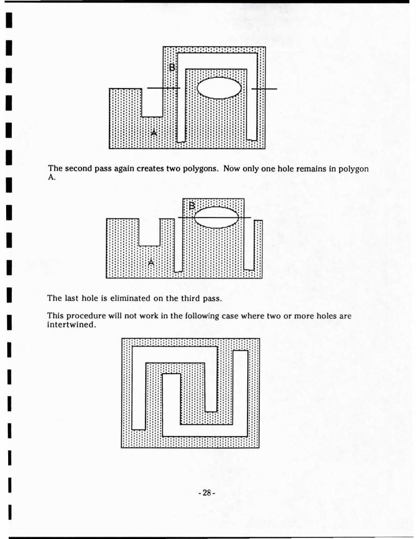
The second pass again creates two polygons. Now only one hole remains in polygon A.
.' . . . '.'.' . .: .:.: . "'T":
::::::,'1 ....... .; , : .: 'i,.,"'C",,,J ~ : i : j : i : : : : : : : ! , ; .;.:.:.; ... ;. , ••.•••••• ;k.i' •• ........... '.' :.;.; .; .: ..... . , ; .. . ' ..... ... : :;:; :;:::::;:; :
. .
.. ~ .. ' .. ' ... ".".' ... ; :.;.: ..... :.:.:.: ' ,:"'/ ....:..:;' .::;r --..;:
::
.' .:
.' n .'.' .' , " ····· ··L .' nnn::::::n
The last hole is eliminated on the third pass.
This procedure will not work in the following case where two or more holes are intertwined .
',',',', ... ,., ........... . ,',',',', ... , ...... ...... . .
- 28-
I I I I I I I I I I I I I I I I I I I
In addition to this problem. Multigen occasionally has difficulties drawing concave polygons which are facing inward. For both of these reasons it may be necessary in the future to break all polygons Into triangles or four sided polygons.
6. Correlation Experiment.
6.1 A Definition for Geometric Correlatioo
At a recent InterOperability Conference subgroup meeting. a distinction was made by the participants between the concept of Geometric Correlation and the concept of Perceived Correlation [1ST III 91]. Geometric correlation refers to the actual differences between two sets of geometrical (usually polygonal) data which are being rendered by two IGs. For example. If one database was triangulated using an irregular mesh algorithm (like the Delauney algorithm used by GE and Project 2851) while the second uses a regular mesh of polygons (like the BBN SIMNETs). they have lower "geometric correlation" than databases triangulated the same way. Note that how the databases appear on the IG screen has not even been considered yet. Perceived correlation. on the other hand , is completely based on what an observer believes is different between the two databases after he or she looks at the display units for each IG.
6.2 Experiment Description
The approach taken during the MIDB project was to develop test programs which could process a database gaming area and return a set of values (referred to as a metric) indicating some property about the geometry of the gaming area. Since th e SimData Center software developed for this contract has the capability of processing a particular gaming area a variety of ways, it was used to create geometrically~Hrrerent versions of the same gaming area. The correlation metric routines were used on these different databases. The results of such an experiment are described in the following sections.
6.2. 1 Post Comparison MetriC
A very simple comparison was implemented for this experiment. A gaming area can be represented on a two-dimensional grid where each point on the grid is given an elevation value. This is the paradigm used by DMA DTED. For this metric. the two subject databases are resampled into elevation posts from thei r polygonal representation. The same post spacing is used for each resampling. Therefore, each post represents the elevation taken from a terrain polygon at a specific point in the database. For the entire gaming area, each post from the tirst database is compared against its counterpart in the second database - yielding a value of elevation discrepancy between the two databases at a regular interval.
6.2.2 2Kx3K Terrain Processjni
- 29-

I I I I I I I I I I I I I I I I I I I
An experiment was conducted by creating a small gaming area (approximately 2 kilometers in latitude and 3 kilometers In longitude. The DTED Levell ceil with SouthWest corner at (31 0 N, 1160 W) was used. The DTED was processed separately by BBN's Slooo system (originally developed for the SIMNET IGs) and by SS!'s MultiGen system. These particular database development tools were chosen because of their availability at 1ST and their use of different terrain processing algorithms .
6.2.3 Results
This section lists the results of running the Post-Compare test on the two sample databases. Several histograms are presented here, each test case is explained in the text which goes along with the histogram. The value axis of these histograms show the number of elevation posts (out of 60000 in the entire database) which fit in each elevation category. The categories 1 to 50 are for elevation differences sorted by range. In Tests _1 through _3, the categories are "signed" with different categories for positive and negative differences. For example. in Test #1, the category with near zero difference was category number 20. In Test #4, the histogram categories are unsigned so category 1 has the least margin of error with error increasing along the category axis.
Test # I: MG to sjmtecb2 - Database A is a MultiGen database using the PolyMesh algorithm to make polys from DTED data. Database B in an S1000 (BBN) database where elevations were resampJed at 125m resolution before being polygonalized . When the same geospecific area was entered for processing in the two packages, substantially different databases came out. Topographic maps were used to determine that Database B was about 5000 meters south of Database A. Therefore, a new geocentriC coordinate was used to make the databases match "by eye" when viewed on the workstations. When the two "visually correlated" databases were processed by the post-comparison metric. a "symmetrical hump" was noticed above and below the center categories. These two humps in the histogram correspond to a mountain feature which was not correlated between the two databases (see description on next histogram). For this histogram:
category I: 20: 21 : 22: SO:
-74 to -70 meters -2.35 to 1.44 meters 1.44 to 5.23 meters 5 to 9 meters 10710 111 meters
-30-
(database B a lot higher than A) (both databases about same height) (database A higher than B)
(database A a lot higher than B)
I I I I I I I I I I I I I I I I I I I
10000
9000
8000
7000
6000
5000
4000
3000
2000
1000
o
Elevation differences: MG to simtech2
5 to 9 meters
1 35 791113151719212325272931333537394143454749
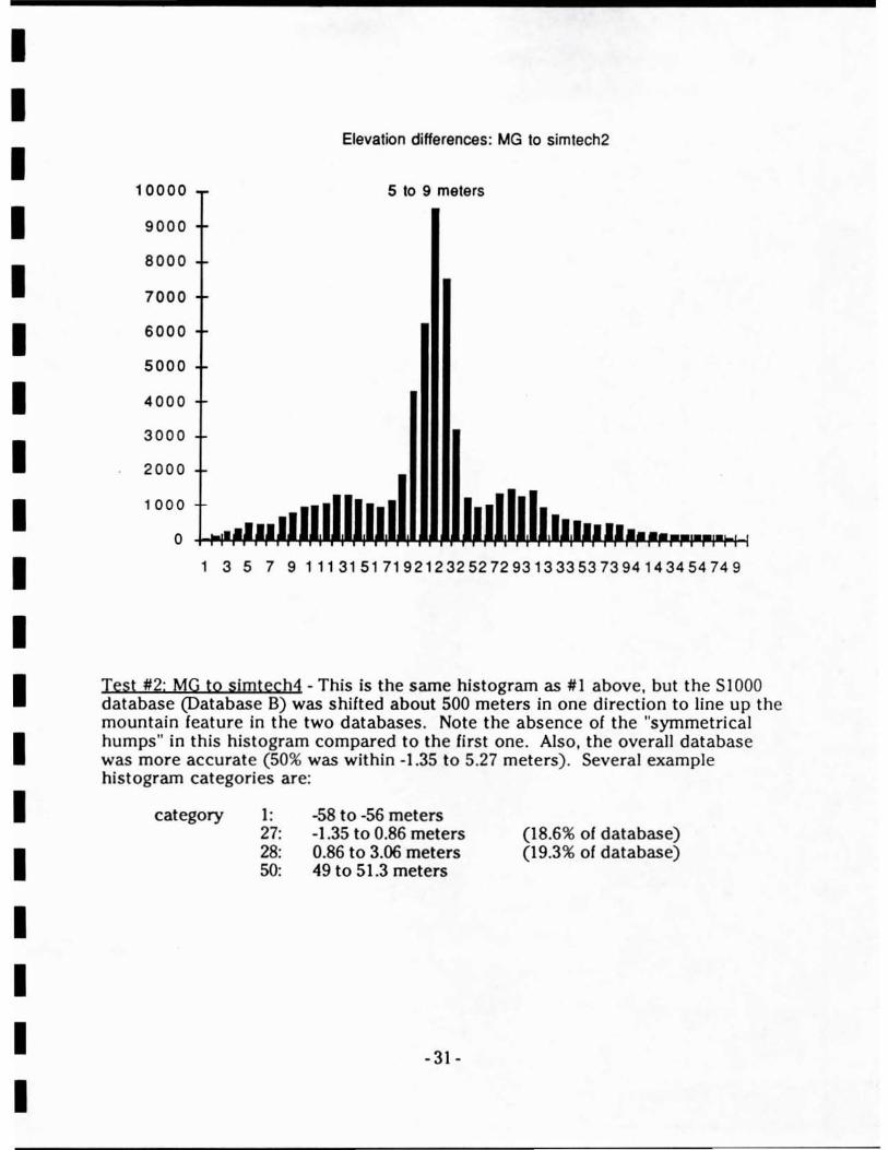
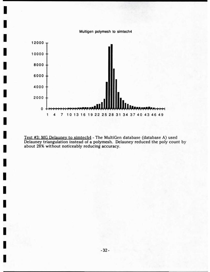
Test #2: MG to sjmtec h4 - This is the same histogram as #1 above, but the 51000 database (Database B) was shifted about 500 meters in one direction to line up the mountain feature in the two databases. Note the absence of the "symmetri cal humps" in this histogram compared to the tirst one. Also, the overall database was more accurate (50% was within -1.35 to 5.27 meters). Several example histogram categories are:
category I : 27: 28: so:
-58 to -56 meters -1.35 to 0.86 meters 0.86 to 3.06 meters 49 to 51.3 meters
- 31 -
(18.6% of database) (19.3% of database)
I I I I I I I I I I I I I I I I I I I
MulHgen polymesh to simtech4
12000
10000
8000
6000
4000
2000
o 14710 131619 22252831343740434649
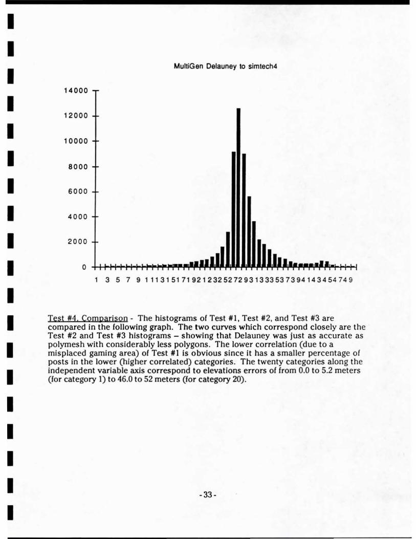
Test #3: MG Delauoey to sjmtech4 - The MultiGen database (database A) used Delauney triangulation instead of a polymesh. Delauney reduced the poly count by about 28% without noticeably reducing accuracy.
-32 -
I I I I I I I I I I I I I I I I I I I
MulliGan Delauney to simlech4
14000
12000
10000
8000
6000
4000
2000
o 1 3579111315171921232527293133353739414345474 9
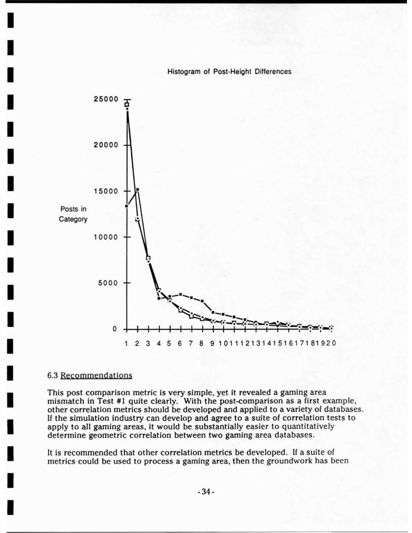
Test #4. Comoarison - The histograms of Test #1, Test #2. and Test #3 are compared in the following graph. The two curves which correspond closely are the Test #2 and Test #3 histograms - showing that Delauney was just as accurate as polymesh with considerably less polygons. The lower correlation (due to a misplaced gaming area) of Test #1 is obvious since it has a smaller percentage of posts in the lower (higher correlated) categories. The twenty categories along the independent variable axis correspond to elevations errors of from 0.0 to 5.2 meters (for category I) to 46.0 to 52 meters (for category 20).
-33-
I I I I I I I I I I I I I I I I I I I
Posts in Category
Histogram of Post-Height Differences
25000 D
20000
15000
10000
5000
o
•
•
\ \'-_..""'"\; --
. .-. .. ~., . -.- ,
~-I-+-+-++-+-+--!'--' -I··>-·...,,-·I--<-+:~--t· ··---1·=·FT·---=;.==· - "- ~ ._,;!!!!!:O.-o. , . "
1 2 3 45 6 7 8 91011121314151617181920
6.3 Recommendations
This post comparison metric is very simple, yet it revealed a gaming area mismatch in Test #1 Quite clearly_ With the post-comparison as a first example, other correlation metries should be developed and applied to a variety of databases. If the simulation industry can develop and agree to a suite of correlation tests to apply to all gaming areas, it would be substantially easier to quantitatively determine geometriC correlation between two gaming area databases.
It is recommended that other correlation metrics be developed. If a suite of metries could be used to process a gaming area, then the groundwork has been
- 34-
I I I I I I I I I I I I I I I I I I I
layed for analytically determining the usefulness of a particular gaming area database with respect to a particular training task.
7 Project 285 J GTDB Convenlons
After completion of the GTDB conversion software, four GTDBs were converted into the MultiGen format . The databases converted were:
1. Greybull, WY #1 - original GTDB output from PRC for review 2. Greybull. wy 1!2 - a special database output to UCF correcting
a problem found In the first database . 3. Et, Hood, IX - SIMNET-Iike GTDB output Including ITO culture 4. Kywait - 2 LOD database containing culture extracted from photos
Of the GTDBs processed, the last two are the most Interesting cases and will be described in detail in the following sections.
7.1 Ft, Hood Database
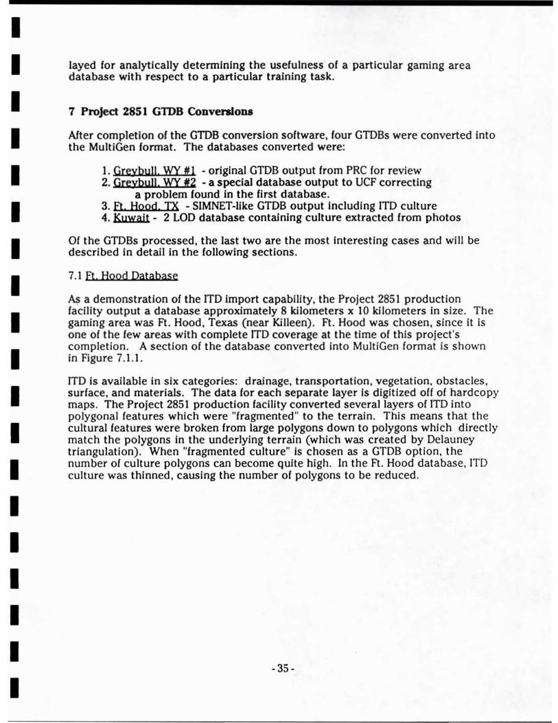
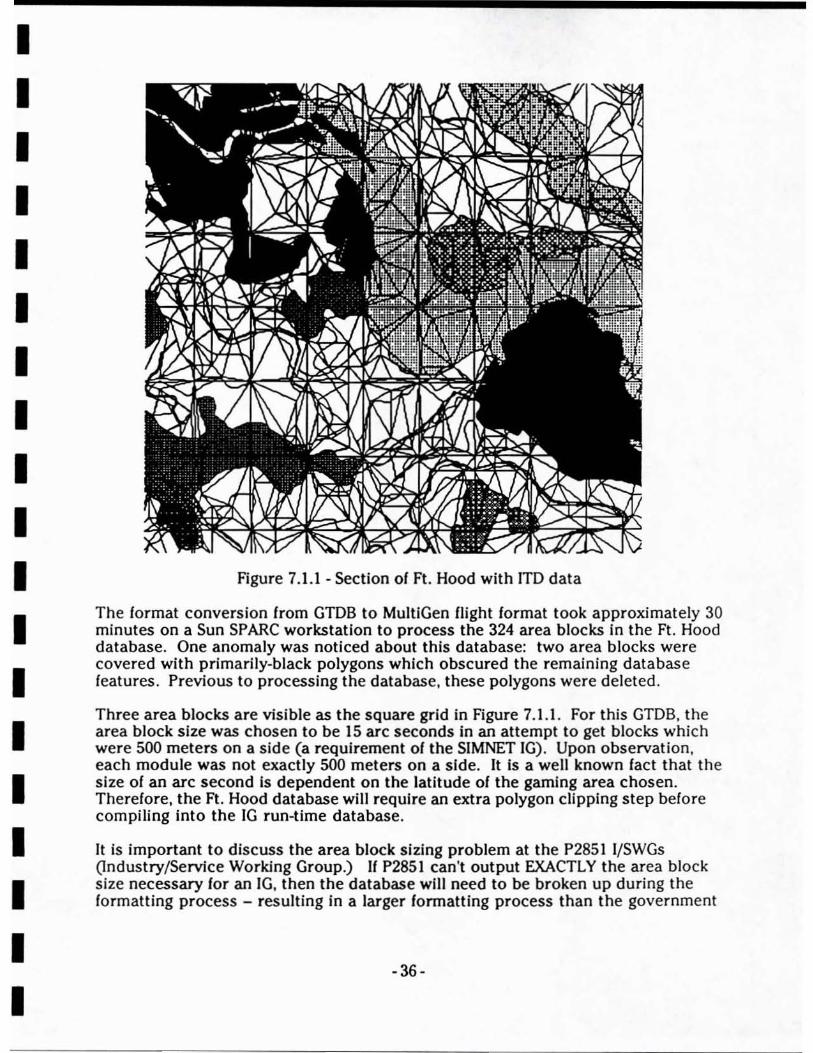
N; a demonstration of the ITO import capability, the Project 2851 production facility output a database approximately 8 kilometers x 10 kilometers in size. The gaming area was Ft. Hood , Texas (near Killeen). Ft. Hood was chosen, since it is one of the few areas with complete ITO coverage at the time of this project's completion. A section of the database converted into MultiGen format is shown in Figure 7.1.1.
lTD is available in six categories: drainage, transportation, vegetation. obstacles, surface, and materials. The data for each separate layer is digitized off of hardcopy maps. The Project 2851 production facility converted several layers of ITO into polygonal features which were "fragmented" to the terrain. This means that the cultural features were broken from large polygons down to polygons which directly match the polygons in the underlying terrain (which was created by Delauney triangulation). When "fragmented culture" Is chosen as a GTDB option, the number of culture polygons can become quite high . In the Ft. Hood database, ITO culture was thinned, causing the number of polygons to be reduced.
- 35-
I I I I I I I I I I I I I I I I I I I
Figure 7.1.1 - Section of Ft. Hood with lTD data
The format conversion from GTDB to MultiGen flight format took approximately 30 minutes on a Sun SPARC workstation to process the 324 area blocks in the Ft. Hood database. One anomaly was noticed about this database: two area blocks were covered with primarily-black polygons which obscured the remaining database features. Previous to processing the database, these polygons were deleted.
Three area blocks are visible as the square grid in Figure 7.1.1. For this GTDB, the area block size was chosen to be 15 arc seconds in an attempt to get blocks which were 500 meters on a side (a requirement of the SIMNET IG). Upon observation, each module was not exactly sao meters on a sIde. It Is a well known fact that the size of an arc second Is dependent on the latitude of the gaming area chosen. Therefore, the Ft. Hood database will requIre an extra polygon clipping step belore compiling into the IG run-time database.
It is important to discuss the area block sizing problem at the P2851 I/SWGs (Industry/Service Working Group.) If P2851 can't output EXACTLY the area block size necessary lor an IG, then the database will need to be broken up during the formatting process - resulting in a larger formatting process than the government
-36-
I I I I I I I I I I I I I I I I I I I
is currently expecting. This, along with a description of our processing steps, were presented at a P28511/SWG [Usle i/I 92).
7.2 Kywait Database
A demonstration of the P2851 production facility was conducted by PRC and its subcontractors In early 1991. The resulting database of an area near Kuwait City is the most complete GIDB distributed to Industry at the time of this writing. The Kuwait GIDB was distributed along with a complete set of fuli-<:olor, overhead Imagery (landSat & SPOT merged). Two LODs of terrain are provided. The imagery was processed by Autometric, Inc. (a P285 I subcontractor) to provide culture data and surface material categories at 25 meter resolution In the downtown Kuwait City area.
Processing of this database required a new technique since the GTDB file was split across three separate 9-track tape reels. The 1ST processing software, at the time of this writing. requires the entire GIDB to be written to disk as a single file before the file is split into its separate portions (gaming area header. SLOD header. datafiles for each area block. etc.). Kuwait was the first GTDB which required building the "aii-in-one" disk file from several tapes. In the GIDB version 1ST received from PRe, several area blocks were missing or incomplete.
The Kuwait database required 5 hours to read the 9-track tape to disk on a Harris NightHawk. After this processing was pipelined: the NightHawk split the tape image into separate files (headers and a datafile for each area block) while a Sun workstation begun processing the area block files individually. We estimate that the processing took about two-and-a-half hours (using both the NightHawk and Sun Sparcstation.)
7.3 Review of GIDB Format
In general, our first experiences reading the GTDB format were relatively painless. There is a definite learning curve involved to overcome the initial type conflicts. the ANSI tape format. and the complexity of the GIDB tape form at. However. we found PRC to be helpful in answering phone questi ons and providing technical support when it was need ed.
A shortcoming we noticed while processing the data is the Jack of a "conceptual hierarchy". This means a series of objects cannot be grouped together and referred to as "the town", for example. This results in an area block composed of a list of features which are each represented as a string of vertices . If there is a large amount of feature data, It can become hard to select particular features lor interactive editing. This Is not a major problem: formatting programs (FPs) are not expected to allow interactive editing. FPs are for reformatting of the data only.
Also. since the GTDB product is an all ASCII format with extensive headers. it is very space inefficient. The Kuwait database. for example, required 180 MBytes in GTDB format and 15 MBytes in MuitiGen Flight format. This inefficiency is the major drawback of the format.
-37-

I I I I I I I I I I I I I I I I I I I
7.4 Does the GTDB Suit AnnY Needs?
At this time, It looks like the major drawback to the GTDB lor the Army's use Is its space Inelliclency, When a gaming area Is designed lor ground tralnlng exercises, the levek>l-detall 01 the terraln Is an Important leature. In polygonal gaming areas, the terraln usually accounts lor a large majority 01 the polygons used . However, the GTDB need only be processed once per gaming area. This is an ollline process with respect to the simulation. Also, PRC Is now addressing a more elliclent data transmittal medium than ~track 1600 BPI tape (85 megabytes per tape).
For large gaming areas (on the order 01 a I degree DTED cell), the Army could accept two dillerent lormats. They are described below:
• Fragmented Culture without Terrain· For IGs without substantial database development tools. Databases like the Ft. Hood one could be used. The culture has already been polygonized at the requested density. Relatively large area blocks should be selected unless the IG can conform to geocentric rectangles. The background cultural feature of each area block will serve as the underlying terraln. The processing required here would be restricted to clipping the database lor desired load-module size and adding height, texture. and surrounding polygonal walls on features (all using the FOC [Ieature descriptor code] 01 the leature).
• vector Culture and Grjdded Terrain - For IGs with database development tools. Here no culture clipping to load module boundaries is done. Therelore, the culture must be polygonized and planted on the underlying terrain. The vector culture could easily be adapted lor input into the database development tools. Gridded terrain could be input directly into the toolset also. More processing is required for this format before a run-time database can be generated .
For today's SIMNET systems, the second option is probably the better lormat. Since the 51000 tools are lairly mature, it is the most expedient choice to let P2851 provide a finished "assembly" in the 51000 lormat. Vector culture could be imported with 51000 polygonalizing culture according to its own polygonized terrain. This will require one additional feature to be added to 51000: in the current 51000 system, vector culture Is Imported as "overlays" to guide the modeler. An extra option of directly processing vector culture (instead of requiring the modeler to hand-digitize according to guides) must be added.
8 MIDB Demonstration Database
8.1 Indian Springs Airport Database
In addition to converting databases Irom the P2851 lacility. A database gaming area was developed from source data to demonstrate the functionality of the
- 38-

I I I I I I I I I I I I I I I I I I I
SimData Center. This "from scratch" database was of the Indian Springs Airport in Nevada. To save processIng time, only a small gamIng area (approximately 6 kilometers x 4 kilometers) was selected. The followIng source data types were used:
L PIED - Levell source read by MultlGen to provide terrain background. The ground underneath the airport was artificially flattened and relaxed to reduce the polygon count.
2, DFAD - Two roads were digitized directly from DFAD Level L DFAD was also used to verify the position the airport runway data (comparing It to the DFAD runway features).
3, Top02ranhjc Map - A 1:24000 topographic Quad map was used to digitize the placement of the airport runways and surrounding roads. Digitizing was done using custom software from the GeoData Center. The polygonal representation was converted from ANIM to MultiGen for placement on the terrain.
4. SfQI - GeoData Center routines were used on a 1:24000 scale SPOT photo. The outline of the airport was verified by comparison to the airport feature in the SPOT photo.
5. Hand-held photos - 1 :6000 resolution hand photos taken from low-altitute aircraft were used to digitize the outlines of the control tower near the airfield .
Below is a step-by-step account of the processing used to construct the Indian Springs Airport database. Several steps are grouped into a single "session" lor purposes of indicating the elapsed time for these steps , This set of steps could serve as a simple guide to the type of processing necessary to construct a visual database from several different source datums.
....... o. Session 1 ••••••••••••••••
1. Imported OTEO data for Indian Springs Airport 2. Extracting roads from DFAD of area 3. Scanning and converting Images for extraction
Total for session: 23 hours
....... Session 2 .......................
4 hours 4 hours 15 hours
1. Five different digitizing sessions were done with GeoData's "2doutllne" tool: runway· wide runway features map 1 . big oval under runway map2 . trailer park map3 . little feature on right of trailer park map4 - elliptical feature above "42" on map (6 hours total extraction time)
2.These files were converted to GRASSel by hand.
-39-

I I I I I I I I I I I I I I I I I I I
l .Then re-a:panded Into ANlM using rrDtoAnlm (width of 3.0). 4. Some errors were removed from map4 .• nlm by hand. S. AnlmAddPrlor was used to add priority to each ANIM file (xxxf.anim was output). 6. AnlmMerge was used to merge mapl. map2, map3, and map4 into mapllnaI2.an lm. 7. The runway.lnlm file was copied from Mike Smith's digitizing of the culture. 8. The priority was added (runwayf.anlrn). 9. AnlmMerge was used to merge It In (creating "mapflnall.anlm") 10. When converted to GMS (to eventually Ret to MG). Some 12 vertex polys were discovered .
This should be okay, but the converter choked. 11. Polys over" aides were hand removed from mapflnall.anlm yteldlng "blgpolys.anlm" and
"mf·blgp.anlm", 12. AnlmTrl was used to break up the big polys (to "blgpolys_trl.anlm') 13. Re-merge blgpolY'_trl and mf-blgp.anlm Into mapflnal4.anlm 14. AnlmToGms ran correctly on "mapfinaI4.anlm" 15. GmsToMG (modified by Curt In ~lIsle/5gl /proJ/gms) ran on maprinal4.DAT and created the
equivalent flight database 16. Inspection In multiGen showed It was aUrlght.
Total for Session: 9 hours
...... Session 3 ................................................................................. .
1. Hand edited data to correct errors In digitizing because the screen Image was so smal l. 2. converted to Anlm (MGtoAnlm) 3. converted to S1000 (AnlmToMocI) 4. mirrored "mapalr" object (MAP extracted airport) along Y becuase 01
different coordinate system while digitizing. 5. converted back Into anlm file (mapalr2.anlm) 6. converted back to MG format (AnlmToGms & Julie's xlator) 7. brought mapalr2.f1t Into MG, scaled, & correlated It with ground 8. Reversed some backwards laces 9. Saved out airport and ground underneath because the culture must be planted: the ground Is
not flat under the small roads below the airport. AirAboveGnd.flt • airport only (96 polys) GndUnderAirJlt • ground underneath
10. Used AnlmPlantCult to plant the airport on the ground. 11. Used AnlmToGms to convert "AlrPlanted.anlm" back Into multiGen format.
Planted airport went from 96 polys to 951 polys ........ translator broke because of 5 fand 6 sided polygons!!! •••••
12. Therefore , used AnlmTrl to break up. 951 polys went to 1791 faces! Ouch! come on, guys ....
13. Imported database back In. Recorrelation was necessary because of MGtoAnlm (was It here?) rescaling everything by a facto r of IO!!!
14. Careful checking of the airport polys vs. the DFAD shows the airport Is not quite right. Maybe 9-14 weren't worth It.
Total for Session: 6 hours
..... Session 4 •••••••••••••••••••••••••••••••••••••••••••••••
l. Decided to abort the culture planting done In Session 3 because It Is correlated anymore. flatten additional ground under the airport .
2. Bulldozed extra ground and translated airport up 0.1 meter. 3. Redlgltlzed roads from DFAD because of accidentally deleting them. 4. Began changing colors to clay colors (U's Nevada!!) .
Total for Session: 2.5 hours
-40-
Just
I I I I I I I I I I I I I I I I I I I
••••• Session 5 •••••••••••••••••
1. After discussions with Bill about [SIG export, decided that the airport needed to be fragmented. 2. Took new airport (several backwards faces fixed), converted airport and ground to ANIM. 3. Planted airport with AnlmPlantCult. - 3 minutes processing on 5g4. 4. Relmported airport Into MG (using AnlmToGms and GmsToMG). S. Rescaled airport because It had a unit multiplier different than the basic database. When the
airport was copied, using paste graphics, It became ten Urnes the size. The original airport was left In 10 , could match them by hand In MG.
The result Is ftisdemoS.flt ft which was converted to the ESIO. hand sorting of the culture features.
Total lor Session: 4 hours
••••••• Session 6 •••••••
It will require
I. regrouped the cultural features as polys In objects underneath the terrain groups. Necessary because his terrain breakup routines add separating planes between data at the group level.
Total fo r Session: 2 hours
•• .•••• Session 7 ••••••••••
1. Viewed Image scanned by TASC (l :6000 hand-held photo). Selected control tower and one other building to attempt dlglUzation. Converted Image to TGA on IRIS (used ipaste, then snapshot, then Ipaste, then savevst) . For some reason the first Ipaste didn't work (screen changed during savevst execution).
2. Copied the Image over to the Mac and processed with PhotoS hop to get raw format Image files for Geospeclflc extraction process.
Total for Session: 3 hours
••••••• Session 8 •••••••••••
1. Rebuilt the terrain from scratch using the above techniques becuase there were too many polygons for the £SIC to display. Instead, used the 2 post spacing and polymesh algorithm. This resulted In an 8 x 8 group database.
2. Converted second database to ESIG - viewing was much belter . It still has sligh tly too many polygons for the ESIQ..5oo, but the database Is viewable .
Total lor Session: 6 hours
••••••• Session 9 ••••••••••
SIMNET DATABASE
1. Delete DFAD airport and planted map airport (since clipping for SIMNET). 2. Converted to separate ANIM flies with MGtoAnlm. 3. Merge ANIM flies. Resultant Is 2333 polys with bounding Info. (simnetO.anlm)
Min (x,y,z) Is -1933.919922 -3055.729980 925.000000 Max (x,Y,') Is 2826.520020 2870.550049 1153.000000 Cen (x,y,z) Is 554.050659 -122.248169 948.792725 Radius Is 3763.330811
- 41 -

I I I I I I I I I I I I I I I I I I I
4. Translate Anlm file 50 SW corner Is a 0,0: (saved In slmnetl.anlm) AnlmTran, -b -p 2487.9705781 2933.481811 925.00000
5. Figure out load modules: 4760 In X means 9.52 LMs (10 total - 9 complete. one half-full) 5926 In Y menas 11.82 l.MS (12 total) therefore there is 10·12 • 120 LMs
6. Break up database Into LMs. Broke up 3 by hand clipping AnlmCllp .lmnet1.anlm 00500 SOO ~ IrnO.anlm
(DBflle) (dimension of LM) (output filename) 7. Converted the 3 LM database for the SIMNET and previewed It unsucessfully. For some
reason kinematics were screwed up and the Ml could not terrain follow on th is database.
Total for Session: 11 hours
••••••• Session 10 ••••••••••
The process of Importing Mlcroterrain (begun In session 9) was abandoned. Instead the elevations will be Imported as ordinary ground. Creating an 51000 grldllle from the Isdem06 flight database polygons:
I. wrote out a terraln-only flight database (,lsdem06Gnd.fIt") 2. used MGtoAnlm to convert It 3. translated It so the SW corner was (0.0):
anlmtr -b -p 2416.02 2951.600 925.0 < A1IGnd.anlm > Isdem06Gnd.anlm 4. Tried AnlmtoElev to get elevation file
(size of 22 posts In x. 47 posts In Y). 5. Couldn 't get It to work , so went back to MultlGen and translated the whole gaming area so
SW corner was ( -0.92.-0.730) . 6. Tried AnlmToElev again. Stili didn 't work because of nonlinear project ion:
even though x<O at the SW corner, It was >0 at the NW corner.
7. Used AnlmTr to move the whole database SW about 2 meters In each direction. (final stored as SIMGND.anlm)
8. AnlmToElev used to make ISdem06_125_38_47.elev 9. ElevToGrld converted It to a grid file right the first time! 10. Size of land was adjusted since the compiler could not compil e
land sized 38x47 posts . Is was changed to 37x45 (to not leave any partially-filled load modules.
11 . canopy for airport was Imported by Including the SIMAIR.anlm file for pole Import.
Total lo r Session: 6 hours
•••••••• Session 11 ••••••••
1. Compiled and viewed database from Session 10. The polygon density 01 the canopy w as too dense. The compiler through out canopy polygons.
2. Attempted to compile with overnow set In the SIOOO tools unsuccessfully. Called BBN engineers to get help on overflow processing.
Total for Session: 10 hours
*.* •••• Session 12 .* ••• *
I. Used correct overflow processing values durIng compile and simplifi ed the database somewhat to allow processing.
-42-
................ ----------------------I I 2. Complied and viewed the adjusted database on the SIMNET successfully .
I I I I I I I I I I I I I I I I I
Total (or Session: 10 hours
Noting that the sessions above Include some duplicate work because of unsuccessful first attempts at some things, we develop the following summaries of the functionality of the SlmData Center tools on this particular database:
• 47.5 hours of Initial database development (shared between both IGs) • 9 hours processing for ESIG • 16 hours processing for SIMNET
Therefore, the total development time for the database from source materials to two destination IGs was 72.5 hours with the shared processing accounting for 47.5 hours (or 65.5% of the total time.) If the shared processing had been repeated for each destination IG (as in the traditional "develop from source data") method , the total times would have been:
• 56.5 hours for the ESIG-SOO • 63.5 hours for the SIMNET
The total development time for separate databases would have been 120 hours, therefore shared processing yielded a reduction of 39% in the overall development time (down from 120 hours to 72.5 hours.)
This example database was a very small gaming area, yet the shared processing still noticeably reduced the overall development time - proving the validity of the "shared development with separate formatters" paradigm as a viable technique to reduce gaming area creation costs.
8.4 Problems encountered dyriDi madeliDi
Gaining access to the low-altitude photos turned out to be one of the major problems in constructing the Indian Springs Airport database. We were d irected to acquire the photos from General Electric, but were never able to gain access to them. Finally, after repeated attempts, we settled for the 1:6000 photo described above.
As was mentioned above in the steJrby-step guide, the limited polygon capacity of the SIMNET and ESIG-500 IGs required the modeling process to be performed several times until the database had been "thinned" enough to be renderable by both realtime IGs. In the usual case, modeling would not need to be repeated since the performance of the destination IG would be known beforehand .
9. Conclusions
8.1 Summary of SjmData Center Abilities
- 43-

I I I I I I I I I I I I I I I I I I I
The suite of prototype software constructed during this project Is useful in the support of a variety of research projects since it allows database development for two different destination lGs. The amount of human intervention and computer processing time required for gaming area development Indicate the SimData Center tools are still relatively Inefficient, but this capability Is sufficient for constructing small databases and evaluating Project 2851 formats . The SimData Center Is already In use by another project at 1ST which uses the same gaming area on three different IGs In an experiment with a line-<>f-sight correlation metric.
8.2 Summary of Formatting Approach for DB conyersioo
The authors believe that a visual database or sensor database development approach which allows the Import or export of several different file formats to be cost effective in research environments such as 1ST. Once formatters are in place between the several major file formats supported for texture, terrain, and models , database construction is substantially easier.
It is obvious that some feature or attribute data can be lost in the formatting process , but it is substantially easier to develop a gaming area once and then only repeat a minor portion of the effort for display on a second IG.
8.3 Subcontracts to IG Vendors
In several cases, we had minimal support from the IG vendors when we contacted them to resolve questions or problems we had during the project. Although, our project would have been easier with more assistance, this should not be considered as a failure by the IG vendors. Instead, we recommend that future projects of this type be designed with consulting money allocated to purchase support services. In particular, when we contacted either BBN or Evans & Sutherland employees, we received answers to our questions. However, without our ability to fund technical support , they couldn't really offer the amount of training or assistance desired .
Again, this problem could be remedied in the future by allocating funds to pay for training classes and/or any custom engineering support required. With this in place, research staff could concentrate more completely in the problem-space and not be concerned with low-level problems. For example, It took several weeks to understand how to develop and copy new terrain databases over to the SIMNETs. This same knowledge could have been Imparted within several days If we could have arranged a training class on BBN's toolset and CIG architecture.
8.4 Recommendations for Future Directioo
As stated io the earlier sections, the work described in this document forms the basis for a functional laboratory capable of database development for a variety of IGs . The most notable areas where work should continue is in the area of P2851, where the SIF format has just become available, and the area of database correlation.
-44 -

..................... -----------------------I I I I I I I I I I I I I I I I I I I
It Is Important for the government and Industry to agree upon a means to exchange databases In the near-term (to solve today's engineering problems) as well as In the long-term (where P2851 Is planned). Projects like this one, with a focus on multiple Image Generators, provide the capability to make the conversion problems easier to solve - reducing database development lime and, therefore, reducing overall trainer cost.
-45 -
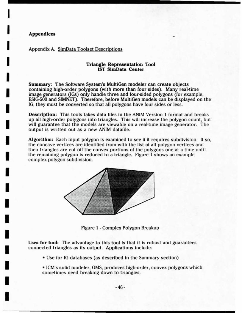
I I I I I I I I I I I I I I I I I I I
Appendlceo
Appendix A. SjmData Toolset Descriptions
TrIangle Repreaentallon Tool 1ST SlmData Center
•
Summary: The Software System's MuiliGen modeler can create objects contaJnlng hlglH>rder polygons (wi th more than four sides). Many real-time image generators (IGs) only handle three and four-sided polygons (for example, ESIG-SOO and SIMNET). Therefore, before MulliGen models can be displayed on the IG, they must be converted so that all polygons have four sides or less.
Description: This tools takes data files In the ANIM Version 1 format and breaks up all high-order polygons into triangles. This will increase the polygon count . but will guarantee that the models are viewable on a real-time image generator. The output is written out as a new ANlM datafile.
Algorithm: Each Input polygon is examined to see if it requires subdivision. If SQ,
the concave vertices are identified from with the list of all polygon vertices and then triangles are cut orr the convex portions of the polygons one at a time until the remaining polygon is reduced to a triangle. Figure 1 shows an example complex polygon subdivision.
Figure 1 - Complex Polygon Breakup
Uses for too): The advantage to this tool is that it is robust and guarantees connected triangles as its output. Applications include:
• Use for IG databases (as described in the Summary section)
• lCM's solid modeler, GMS, produces high-<)rder, convex polygons which sometimes need breaking down to triangles.
-46-

I I I I I I I I I I I I I I I I I I I
• When polygons are clipped with the tool AnimClip, they can become hlgher-order polygons - also needing breakup Into triangles.
• An artistic use Is possible when this tool is used along with the Polygon Resizing Tool. Different representations of an object can be created by resizing a polygonal model with or without polygon breakup done to it.
-47-

........................... -------------I I I I I I I I I I I I I I I I I I I
Polygon Resizing Tool 1ST SlmData Center
Summary: The 51MNET CIGs suffer from an accuracy problem in their graphics pipelines. As polygonal models move around on 51MNET, cracks appear between polygons. A relatively simple algorithm could process polygonal databases for display on the 51MNET CIG correctly.
Deacrlptlon: Write a C program which reads in a polygonal tile (in either MultlGen's Flight format or 51000's model file format) and "grows" each of the polygons by a controllable amount. The user could put in a percentage of desired polygon growth. The program would write out a new file containing the processed polygonal data.
Polygon Growth: On limited accuracy IGs, the inter-poly gap can be quite objectionable. An example is shown in figure 2. The current solution for this on 51MNET is to include invisible interior polygons for each model so that the gaps don't show as bad . This is quite time-consuming for modelers since the interior polys are wierd shaped and at wierd orientations. For some models, it can take more time to put interior polys in than it took to make the rest of the model!
Interpolygon Gap
Figure 2 - Visible Gap between polygons
If. instead, an algorithm was implemented where each polygon could be "stretched" a little while remaining in Its current plane, then overlapping polygons could be constructed easily I avoiding the possibility of gaps appearing. Figure 3 shows a single polygon example.
Algorithm: An important thing to note is that the vertex values are not just increased by a certain percent - this would move the polygon plane farther from the origin . Instead. the algorithm must find the polygon centroid, the vectors {rom the centroid to each vertex and lengthen these vectors the desired percentage.
-48-
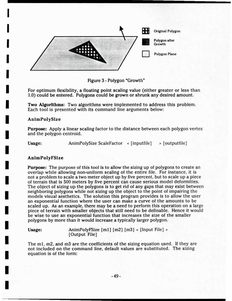
I I I I I I I I I I I I I I I I I I I
IB Original Polygon
• Polygon after Growth
0 Polygon Plane
Figure 3 - Polygon "Growth"
For optimum flexibility, a floating point scaling value (either greater or less than 1.0) could be entered. Polygons could be grown or shrunk any desired amount.
Two Algorithms: Two algorithms were Implemented to address this problem. Each tool is presented with its command line arguments below:
AnlmPolySlze
Purpose: Apply a linear scaling factor to the distance between each polygon vertex and the polygon centroid.
Usage: AnimPolySize ScaleFactor < [inputfile] > [outputfile]
AnlmPolyFSlze
Purpose: The purpose of this tool is to allow the sizing up of polygons to create an overlap while allowing non-uniform scaling of the entire file . For instance , it is not a problem to scale a two meter object up by five percent, but to scale up a piece of terrain that is 500 meters by five percent can cause serious model deformities . The object of sizing up the polygons is to get rid 01 any gaps that may exist between neighboring polygons while not sizing up the object to the point of impairing the models visual aesthetics. The solut ion this program provides is to allow the user an exponential function where the user can make a curve of the amounts to be scaled up. As an example, there may be a need to perform this operation on a large piece of terrain with smaller objects that still need to be definable. Hence it would be wise to use an exponential function that increases the size of the smaller polygons by more than it would increase a typically larger polygon .
Usage: AnimPolyFSlze [ml] [m2] [m3] < [Input File ] >
[Output File]
The mI , m2, and m3 are the coefficients of the sizing equation used. If they are not included on the command line, default values are substituted . The sizing equation is of the form:
-49 -

.................. ------------------I I I I I I I I I I I I I I I I I I I
lInaCveclor = (ml+exp(m2+poly_vector) + m3) + poly_vector
Tool UIIeS: Several uses are immediately apparent:
• Once Ihis 1001 is completed, 3D culture and vehicle modeling for the S I 000 environment will be much quicker.
• Thfs would be a good 1001 to perfonn Z-buffer accuracy evaluation since a polygonal database could be delicately adjusled, viewed, and studied for visual anomalies. Details about antlaliasing methods wouid also be available.
• Creative & artistic databases could be created by manipulating the growth/shrinkage of polygons by large amounls. This could be used along with AnimTri for Interesting artistic effects.
-50-
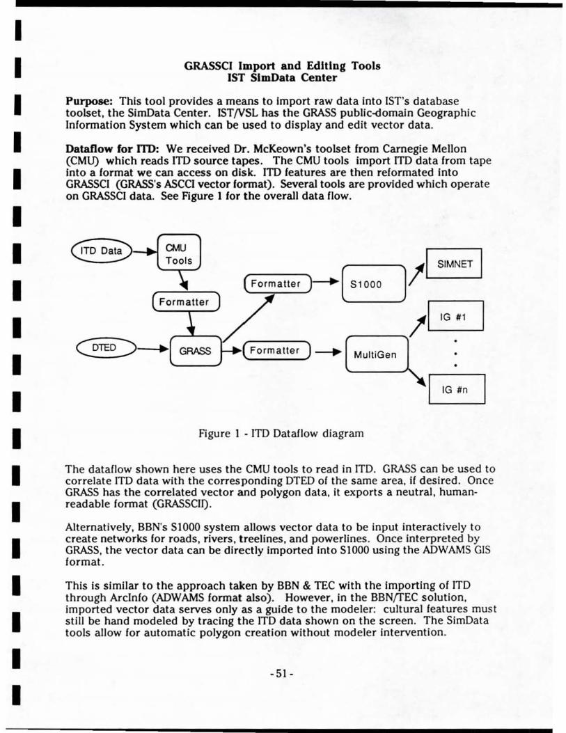
I I I I I I I I I I I I I I I I I I I
GRASSCI Import and Editing Tools 1ST SlmData Center
Purpose: This tool provides a means to import raw data into 1ST's database toolset , the SimData Center. IST/VSL has the GRASS public-domain Geographic Information System which can be used to display and edit vector data.
Dataflow for ITO: We received Dr. McKeown's toolset Irom Carnegie Mellon (CMU) which reads lTD source tapes. The CMU toois import lTD data from tape into a format we can access on disk. lTD features are then reformated Into GRASSCI (GRASS's ASCCI vector lormat). Several tools are provided which operate on GRASSCI data. See Figure I lor the overall data flow.
CMU Tools
CDlED =::>-•• , GRASS
BIB )- S1000
IB ,..---...... . (Formatter ) ~
( Formatter
MultiGen
Figure 1 - ITO Datallow diagram
The dataflow shown here uses the CMU tools to read in ITO. GRASS can be used to correlate ITO data with the corresponding DTED of the same area, if desired . Once GRASS has the correlated vector and polygon data, it exports a neutral, humanreadabie format (GRASSCI!).
Alternatively. BBN's S1000 system allows vector data to be input Interactively to create networks for roads, rivers, treelines, and powerlines . Once interpreted by GRASS, the vector data can be directly imported into 51000 using the ADWAMS GIS format.
This is similar to the approach taken by BBN & TEC with the importing of ITO through Arclnfo (ADWAMS format also). However, in the BBNfTEC solution. imported vector data serves only as a guide to the modeler: cultural features must stiil be hand modeled by tracing the ITO data shown on the screen. The SimData tools allow for automatic polygon creation without mod eler intervention.
-51-
I I I I I I I I I I I I I I I I I I I
Tools Constucted: Several tools are provided for this capability:
I. Itd2gmw\l - A fonnatter which reads the output of the CMU tools and creates an ASCII (American Standard Code for Information Interchange). human-readable datalife which can be read by GRASS.
Usage:
Input:
Output:
Itd2grassci (menu driven software)
directory with all CMU output liIes from an lTD script (xxxx.FEA. xxxxx.TXT.result. etc.)
xxxxxx.asc (vector file containing linear and areal features In GRASSCI format).
2. GmsslIoAplm - A formatter which reads the GRASSCII liIe and creates a corresponding polygonal database In the ANIM format. This liIe expands the vector data into polygons of a given width. Filtering is also provided by undersampling the vertices (to reduce the number of vertices per feature). The tool outputs in ANIM polygonal format.
Usage:
Input:
Output:
GrassciToAnim [inputfile) [linear oversample) [areal oversample) [width) [float height) > [outputfile)
xxxxxx.asc file (GRASSCI format)
yyyyy.anim (polygon data In ANIM format)
- 52-
•
I I I I I I I I I I I I I I I I I I I
AnlmPlaotCulture 1ST SlmData Ceoter
Purpose: Cultural data for a gaming area is often represented In vector format (see the GRASS import tools for further description). All GiS systems use 2D vector lormat to represent information digitized from various map layers. Belore this data can be viewed on an IG, the vector data must be converted to polygons and mapped to the underlying terrain 01 a gaming area.
AnimPlantCulture takes a culture file which has been converted into flat polygons In the ANIM format (see GrassclToAnim) and "plants" It on the terrain polygons which lie underneath the culture .
Algorithm: Processing of the culture is O(M'N) where M is the number of culture polys and N Is the number of terrain polys. Each culture polygon is compared against all terrain polys to determine if any of this feature lies on top of the particular terrain poly. A Cohen-Sutherland clipping algorithm [Foley 90) is implemented to clip the culture polygon against the terrain polygon. The resulting culture polygons (and there may now be as many culture polys as there are terrain polys) receive their Z height values from the terrain polygon plane equat ions .
A ·"culture float height" value is input from the command line. This value is added to the height of the terrain to allow the cuiture to "float"' a predetermined amount above each terrain polygon. Culture floating is required in iG systems which use limited-resolution depth buffer hardware to resolve priority (like the original SIMNET systems). Exact coplainer polygons must usually be eliminated . The S1000 system generally floats networks between 0.1 and 1 meter above the underlying terrain to assure correct rendering on the SIMNET JGs .
Usage: AnimPlantCult AnlmCulture AnimTerrain FloatVal > AnimPlantedCultureFile
-53-
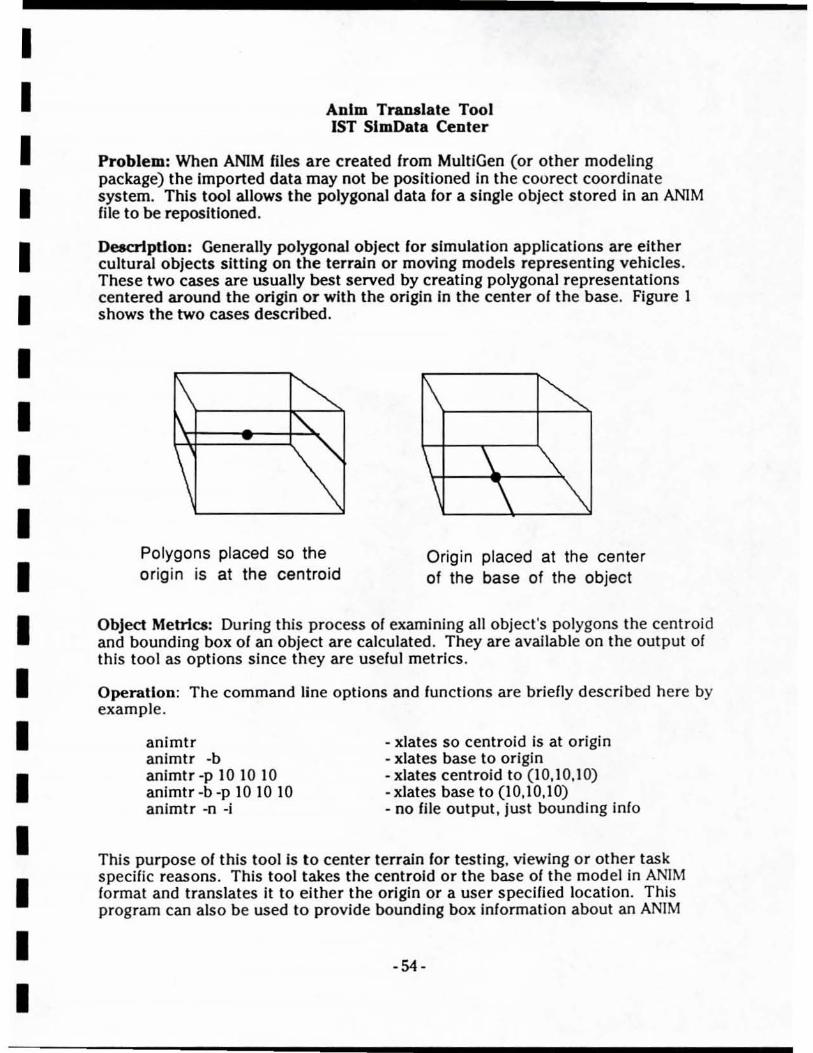
..................... --------------------I I I I I I I I I I I I I I I I I I I
Anlm Translate Tool 1ST SlmData Center
Problem: When ANiM files are created from MultiGen (or other modeling package) the Imported data may not be positioned In the courect coordinate system. This tool allows the polygonal data for a single object stored In an ANIM file to be repositioned.
Deacrlptlon: Generally polygonal object for simulation applications are either cultural objects sitting on the terraln or moving models representing vehicles. These two cases are usually best served by creating polygonal representations centered around the origin or with the origin in the center of the base. Figure 1 shows the two cases described.
Polygons placed so the origin is at the centro id
Origin placed at the center of the base of the object
Object Metrics: During this process of examining all object's polygons the centroid and bounding box of an object are calculated. They are available on the output of this tool as options since they are useful metrics.
Operation: The command line options and functions are briefly described here by example .
animtr animtr -b animtr -p 10 10 10 animtr -b -p 10 10 10 animtr -0 -i
- xlates so centroid is at origin - xlates base to origin - xlates centroid to (10,10,10) - xlates base to (10,10,10) - no file output, just bounding info
This purpose of this tool Is to center terrain for testing. viewing or other task speCific reasons. This tool takes the centroid or the base of the model in ANIM format and translates it to either the origin or a user speCified locati on. This program can also be used to provide bounding box information about an ANIM
-54-

I I I I I I I I I I I I I I I I I I I
format ffle which can be used by other tools. Here the command line presented with all options shown:
U ... ge: AnimTrans (-b) ((-p x.XX y.yy l.ll]) (-n) (-I) < [Input File) > [Output File)
-b Translates (X center, Y Center, Z min) to the origin -p Translates either the center of the object or the
bottom center of the object to the point specified. -n No output to the output ffle -I Include Bounding Inlo to STDERR
The parameters above may be used in any order and combination. If the -b switch is not used the delault Is to translate the (X Center, Y Center, Z Center) to the origin (or the point specified by -p).
- 55-
........................... ------------------I I I I I I I I I I I I I I I I I I I
MGloAnlm 1ST SlmDala Cenler
Purpose: This 1001 takes a Muiligen File In flight lonnat and breaks It down Into separate ANIM lonnat files . The name 01 the files this tool outputs depends on the names In the hierarchy 01 the flight lonnal file. For example, II the names given to group beads In the flight hierarchy were "terrain" and "house" then the tool would create the ANIM files named "terraln.anlm" and "house.anim" with their associated polygons. This 1001 disregards the ordinary group headers as being valid names (lor example, g0027, g0039, etc. are Ignored) and does not output a named liIe lor a group unless It has polygons beneath It. It may be 01 Interest that the present woridng directory Is where all 01 the liles created will be placed.
Usage: MGtoAnim [Input File] [LUT file]
The LUT file Is a color look up table that should be included with the tool package (look lor a • . ciut file) The lookup table file Is necessary because MultiGen stores only a look up table (LUT) entry with each polygon record. Therelore to create the RGB values lor each polygon in ANIM lormat, an entry is placed in the LUT. The LUT file is ASCii with a lormat as shown here:
Colorlndex RedValue BlueValue GreenValue
000 50 50 0 75 100 50 200 120 25
o o 25 128
Only points where the color table values change need to be included in the file. For the example above, colors 0 through 49 will have RGB value = (0,0,0). Colors 50 through 74 will have RGB = (50,0,0). With this scheme, the user can create any color mapping desired lor the ANIM output file.
-56-
I I I I I I I I I I I I I I I I I I I
ModAaoy 1ST SlmData Center
Purpooe: The purpose of this tool Is to allow the creation of Model Assembly files without the 51000 assembly tool. This tool Is useful If data Is to be Imported for an area that Is difficult or Impossible to be done with 51000. What this tools does is to take the fnformation In Its Assembly Definition File Format (ADFF) and create an 51000 readable assembly file or land assembly file (.assy or .Iassy) . All of the information required by this tool can be compiled from ANIM format fil es by using some of the tools in this package.
Usage: ModAssy [Assembly Definition File] [Output Linkage File]
ADFF file formal : The ADFF file has a header record and then subsequent Information records. Anything that is In parenthesis on the right Is a comment and not to be Included in the ADFF file - it is an example shown for illustration purposes only.
Header Record Format: Xmin Ymin Xmax Ymax Load Module Size #Land #Unique #U50 #Net Model Library Name Text Library Name ModellD Total # of objects
Information Record Format: XCentriod YCentriod ZCentriod Radius
(Model Extents) (500 normally) (35000) (at least a blank line) (at least a blank line) (at least a blank line) (35)
(505050) (50)
Xmin Ymin Zmin Xmax Ymax Zmax Xmin Ymin Xmax Ymax
(000100 100 100) (00100100)
Path and Name of .m2 fil e CIs I OOO/ iand I.m2)
One special note of caution. Be careful not to make the path and file name of the .m2 files to exceed 40 characters because this Is the max field size of the 51000 assembly file format.
- 57-
....................... ------------------I I I I I I I I I I I I I I I I I I I
AnlmToMod
51000 Ale Format Too'" 1ST SlmData Center
This tool converts augmented ANIM format files (where polygons have shading and priority attributes) Into the 51000 model file .m2 format. This Is useful primarily for converting vehicle models created with other modeling systems Into the 51MNET environment.
This tool Is compiled using Include files from the 51000 system. Therefore its software life cycle is limited since It makes several calls to customized versions of 51000 code. Copies of the code changed are saved along with AnimToMod. The dependency of this tool upon 51000's library Is represented In the tool's makefil e. It is recommended that thIs tool be replaced by one which is not dependent on 5 I 000 object modules.
Usage: AnimToMod AnimModelFile 51000ModelFile
Note: For 51000's model tool to recognize a modelfile , the file must be placed in a 51000 project model directory. See the section on the 51000 tools for a description of the 51000 project directory tree.
ModToAnlm
This tools converts a three-dimensional model from the 51000 model format (.m2 files) into an augmented ANIM format. No transformation is performed on the vertex or polygon data. Only the RGB color, shading value, and face priority attributes for each polygon are preserved. Only minor modification is necessary to preserve additional attributes.
This tool is compiled using include files from the 51000 system. Therefore its software life cycle is limited since it makes several calls to customized versions of 51000 code. Copies of the code changed are saved along with ModToAnim. The dependency of this tool upon 51000's library is represented in the tool's makefile . It is recommended that this tool be replaced by one which is not dependent on S 1 000 object modules.
Usage: ModToAnim 51000ModeIFilename OutputAnimFilename
15TDlsplayModel
Purpose: This tool displays an 51000 model file on the Silicon Graphics workstation Interactively. This tool includes all necessary processing routines to read the 51000 files without the use of 51000 libraries or Include files. When compared against ModToAnim and AnimToMod . this too) is considered standalone. Therefore it will have a longer software lifecycle. The source code of this tool is useful in understanding the 51000 model file format.
- 58-
I I I I I I I I I I I I I I I I I I I
Usage: Idm [SI000 model file path)
ModCbangeModelType
PurpoIe: This tools allows the changing of an S 1000 model to any type of S 1 000 fil e. For Instance, It may be used to change a model type to a land type or visa versa. Changing a model type requires only a change to the header information in the beginning of a file. Therefore, the remainder of the data Is still stored the same. For this reason, IS7DisplayModel can be used to preview terrain, USOs, or models In the SIOOO format.
Usage: ModeChangeModelType [Sloo0 Input File) [[SI000 Output File) [Model Type Attribute II)
[Model Version /I)}
-v this option is used to view the model attribute without actually changing it.
Tpe two basic Model Type Attributes are listed below. The model version number matches the version of the S1000 system which will use it (which is 2 at the time of th is writing) .
-59-
I I I I I I I I I I I I I I I I I I I
AnlmAddPrlor
ANIM rue Format Tool. 1ST SlmData Center
Purpose: This tool takes a regular ANIM file and adds shade and priority information that is required for conversion to SIOOO model format. The ANIM format including shading and priority is often referred to as the "augmented ANIM" format. This tool can be modified easily to include additional polygon attributes besides the two selected. However, the shading value and the priority are all that must be preserved for visual scene databases on the SIMNET systems at the time of this writing.
Some of the SimData tools use the augmented ANiM format while others can operate on the original ANIM format. This tool , along with AnimRemovePrior , is used to convert data between the two ANIM formats.
Usage: AnimAddPrior [Shade Value[ [Priority Value) < [input File) > [Output File)
AnlmChangePrlor
Purpose: This tool ailows an ANiM format file with shade and priority information already in the file to have all of these shade and priority values changed to another desired value. This has application when preparing cultural data for the S1000 system since networks and canopies must have one priority. static models another priority. and underlying ground still another priority. Since data is often ported into S1000 from other sources, this tool is used to reassign priorities.
Usage:
AnlmMerge
AnimChangePrior Shade Value [Priority Value ) < [Input File) > [Output File )
Purpose: This tool ailows the merging of two ANiM files together to form a third file. This program is mainly for the merging of the poiygon data. This program is not Intended for use on hierarchical data files. The order the fil es in the destination file is the first file's data followed by the second file 's data. This is useful when culture data for a gaming area is combined with the terrain data for a particular gaming area. It can also be used to recombine sections of articulated models which have been broken out into separate dataliles.
-60-
I I I I I I I I I I I I I I I I I I I
Uaage: AnimMerge [Input File I] [Input File 2] [Output File]
AnlmRemovePrlor
Purpose: This tools takes an "augmented ANIM" format datafile and removes the shading and priority in/ormation on each polygon. The resulting datafile is created In the original ANiM format. This Is the companion tool to AnimAddPrior. Depending on the application gaming area being constructed, culture, terrain, and model data could require conversion between many different 'annats. If was necessary to be able to add and remove the extra polygon attributes at any time during the SlmData processing.
Uaage: AnlmRemovePrlor [lnputFlle] [Outputfile]
Polygonal Data Format Conversion 1ST SlmData Center
Several different polygonal data formats are supported by the SimData Center. The MIDB design team realized that a wealth of model data was also in the public domain In several different formats. The tools in this section cover the importing or conversion of model data into the SimData Center internal formats. A large amount of modeling time can be saved through the use of Imported models when they are available.
Gm8ToMultiGen
Purpose: The GMS modeling tool (Geometrical Modeling System from ICM , Inc.) is currently in use by PRe, the Project 2851 contractor. Since this system is unique with its ability to represent a model In both CSG and boundary-representation formats, it was chosen as a modeling system for the SimData Center. GMS outputs models in several different formats. The output lonnat chosen for our applications is the "GMS Neutral Format". This ASCII representation is easy to parse. The GmsToMultiGen tool reads a GMS neutral fil e and converts it into a MultiGen Flight format file . A technical complication is sometimes encountered since MultiGen uses a fixed-poi nt internal representation. Sometimes very small objects will not be converted correctly. To overcome this problem. GMS objects should be scaled larger previous to being written out as a neutral file.
Usage: translate [GMSneutralfile ] (neutral files usually have a .DAT extension. A MultiGen format .fIt
file will be created with the same name as the neutral file.)
GeoToAnlm
-61-
I I I
Purpose: The Geo format fs a public domain format popular for Amiga users across America. It Is the format used for the package "VldeoScape-3D" on the Amigas. At the time of this writing, approximately 100 models were available on InterNet and Amiga bulletin boards. Many of these have been converted and Input for use in the SimData Center. Geo flIes are ASCII and very simIlar to ANIM format (with the addition of subfaces - also called decals).
I Usage: GeoToAnim < [GeoFile] > [AnlmFile]
I I I I I I I I I I I I I I I
AnImToVIa
Purpose: This tool converts ANIM files Into the text import format for Vision-3D, a public domain modeling system available for the Apple Macintosh computers. All of the wlrefrarne models Included In this report were rendered by Vision-3D and pasted as PICT files Into the document without additional processing. AnimToVis Is primarily used to created plotiiles of polygonal data for documentation.
Usage: AnimToVis < AnimFile > Visual-3Dfile
-62-

I I I I I I I I I I I I I I I I I I I
Appendix B. Data IntercbaoKe Founal Comparisoo (Revision of document distributed at the ITCG meeting in Orlando)
Curtis Lisle Oct, 28,1991
Executive Summary: The problem of database fncompatibllity for visual systems Is mentioned, Several candidate formats are explained to give a cursory knowledge of each format to the reader, The formats range from ASCII (easy & inflexible) to Project 2851 (complex & flexible).
The recommendation Is made that ASCII or other simple formats be used by the industry until Project 285\'s formats fully mature. When they mature, they should replace the Interim format . The period for Interim use would be between 2 and 5 years.
Problem: Several Incompatible formats exist for visual system databases (DBs) in the industry today. Indeed, their are even several "standard" formats for which visual databases are to be exchanged .
This paper Is a collection of thoughts from my experience actually working with the some of the formats mentioned or from familiarity with their specifications . The reader is reminded that the accuracy of these statements is limited by the author's understanding of the material presented. Some minor errors may have inadvertently been made. No intention to slant or misrepresent any company's data format is intended .
Mixed in with the format descriptions are my own opinions on the usefulness and application of each format. The formats discussed in this paper are the following:
1. ASCII formats 2. MultiGen's "Flight" 3. BBN's "SIOOO" 4. Project 2851 GTDB 5. Project 2851 SSDB
·63·
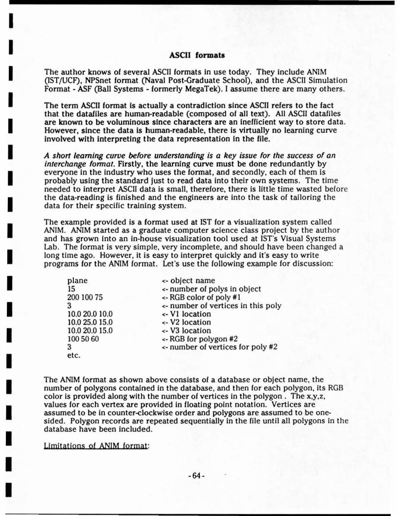
I I I I I I I I I I I I I I I I I I I
ASCII formata
The author knows of several ASCII formats in use today. They include ANiM (1ST /UCf). NPSnet format (Naval Post-Graduate School). and the ASCII Simulation Format - ASF (Ball Systems - formerly MegaTek). I assume there are many others.
The term ASCII format Is actually a contradiction since ASCII refers to the fact that the dataflles are human-readable (composed of all text). All ASCII dataiiles are known to be voluminous since characters are an Inefficient way to store data . However. since the data Is human-readable. there Is virtually no learning curve Involved with Interpreting the data representation In the file.
A short learning curve before understanding is a key issue for the success of an interchange format. Firstiy. the learning curve must be done redundantiy by everyone In the Industry who uses the format . and secondly. each of them is probably using the standard just to read data into their own systems. The time needed to Interpret ASCII data is small. therefore. there is little time wasted belore the data-reading is finished and the engineers are into the task of tailoring the data for their specific training system.
The example provided is a lonnat used at 1ST for a visualization system called ANIM. ANlM started as a graduate computer science class project by the author and has grown Into an in-house visualization tool used at 1ST's Visual Systems Lab. The format is very simple. very incomplete. and should have been changed a long time ago. However, it is easy to interpret quickly and it 's easy to write programs for the ANlM format. Let's use the following example for discussion:
plane 15 200 100 75 3 10.020.0 10.0 10.025.0 15.0 10.020.0 15.0 100 50 60 3 etc.
< - object name <- number of polys in object < - RGB color of poly # I < - number of vertices in this poly <- VI location < - V2 location <- V3 location <- RGB for polygon #2 < - number of vertices faT poly #2
The ANIM format as shown above consists of a database or object name, the number of polygons contained In the database. and then for each polygon. its RGB color Is provided along with the number of vertices in the polygon. The x.y.z. values for each vertex are provided in floating point notation, Vertices are assumed to be in counter-clockwise order and polygons are assumed to be one~ sided . Polygon records are repeated sequentially In the file until all polygons in the database have been included .
Limitations of ANIM format:
-64 -

I I I I I I I I I I I I I I I I I I I
1. No hierarchy can be structurally represented. This Is a bucket of polygons here which make an object or database. Hierarchy must be handled by splitting up a hierarchical or articulated object Into separate ANIM files with translation and rotation offsets between the files.
2. No point lights, point features, or light strings can be represented . Only polygons.
3. No attributes are carried with the polygons (tra//icability, reflectivity, materlal,etc.). In fact only RGB was originally supported since this began as a class project.
4. Size IneffiCiency. Each polygon averages 130 bytes of storage. This Is Inefficient for representation of polygonal terrain for visual DBs. For example, a 50 kilometer x 50 kilometer gaming area at \00 meter (DTED Level I) resolution would require 150 Megabytes
5. Vertices are replicated In the datafile. 6. No place for separation plane data (Zbuf/er machines only).
Adyantages of ANIM (ormat: 1. Ease of understanding. 2. Transportability across machines (no big-endian, little-ending byte swapping
problems like those which occur with binary formats). 3. Tools exist already to read, write, scale, translate, and view objects in this
format.
As mentioned above, this format is unacceptably simple to be a format in which terrain and model information is always handled , but it is easy to convert data into and out of this format for transmittal to somebody else. Therein lies its usefulness:
Wh en somebody else needs polygonal data. It is cost..,ffective to convert to a simple format since less engineering time is spent getting into and out of the format.
The only reason for the format anyway Is to transler data between dissimilar architectures . So, design a simple lormat which can represent what you want to transfer.
Case in pojnt: The ANIM format shown above (with two additional attributes for each polygon) was used to transmit all the standard SIMNET models Irom 1ST to NPGS (Naval Post-Graduate School) and to a contractor working on the UAV program (Cambridge Research Associates). This solved their problems since they didn't need any more information than the polygonal representation 01 the data. I was able to explain the format In five minutes over the phone. This action happened after a high-level meeting about database incompatibility was held at the Naval Ocean Systems Center, San Diego, CA (July, 1991, contact Tom Tiernan or Kevin Boner at NOSC for reference) at which little progress was made about how to transler model and terrain Information Irom BBN's lormats over to the UAV program's workstation-based Computer Image Generator.
The decomposition of SIMNET's articulated objects was done by represent ing each section 01 an object (i.e. tank hull . turret, or gun) as a separate ANIM liIe and
- 65-

I I I I I I I I I I I I I I I I I I I
providing a transformation tree (also in ASCII) which built each articulated object by showing which sub-objects were needed and what their relative translation and rotations were with respect to each other.
Recommendation: An ASCII format should be developed and used for database exchange (especially SIMNET databases) by the industry for the next two to three years, at which time Project 2851 formats should be available. The format should be developed during the next InterOperability conference, during I/ITSC, or during the next Project 285II/SWG (scheduled every three to six months).
Examole: Once the SIMNET formats were understood (which took several manmonths), an undergraduate student wrote a converter to the ANIM format for me in two days.
- 66-

I I I I I I I I I I I I I I I I I I I
MultlGeo'. "FIlgbt" Format
Flight is a binary fonnat which has many of the advantages of the ASCII formats described before with few of the drawbacks. It is conceptually a stream of data packets where each packet carries an "opcode" to describe what type of data this packet contains. Not unlike the DiS protocol standard:
A Flight database Is represented by a conceptual hierarchy which can contaln an unlimited number of groups, each containing an unlimited number of polygons. or other groups. The following diagram shows an example of this fonnat where a town, valley, and hill are represented .
Polygon I
// Vertex 1 Vertex n
Each object is eventually composed of polygons. Vertex records lie below the polygon records but were omitted in this drawing for simplicity. The tree can be constructed with any hierarchical grouping desired by the user. Primitives are allowed to represent point lights and point light strings, also.
There are many features of flight not shown here, such as replication , instancing. etc. However, It is easy to show that this lonnat is conceptually simple and easy to convert to and from . Several graduate students at ISTNSL have written utility programs to convert or process databases In the Flight format.
Adyantages: - supports hierarchy - binary. so more etricient storage space than ASCII - simple format - public domain - backed by MultiGen CAD system - defacto industry standard
-67-

I I I I I I I I I I I I I I I I I I I
- excellent for model transfer - supports point lights - MultiGen Is avallable for several different Image Generators . - Has "comment" field to store additional data - Room lor expansion of format by defining additional opcodes .
Disadyantages: - Vertex data repUcated per polygon - Not as efficient as other binary formats - Fixed point only supported for vertex data (with unit shifter for high accuracy). - Binary, therefore susceptible to byte swapping problems (depending on what plat/orm). - MultiGen available only on the Silicon Graphics plat/orm.
Recommendations: I believe flight to be an excellent format for exchange of models, buildings, vehicles, etc. It handles polygonal objects very well as long as the number of polygons Is not excessive. MultiGen can handle terrain, but if a large gaming area Is represented, the file can easily become hard to manage.
example: 4k x 4k gaming area, 3 LODs -= 8 Megabytes (100,200,400 meter polys)
This problem Is primarily If the database is manipulated while in Flight format. Exchanging the database in flight is relatively efficient.
-68-
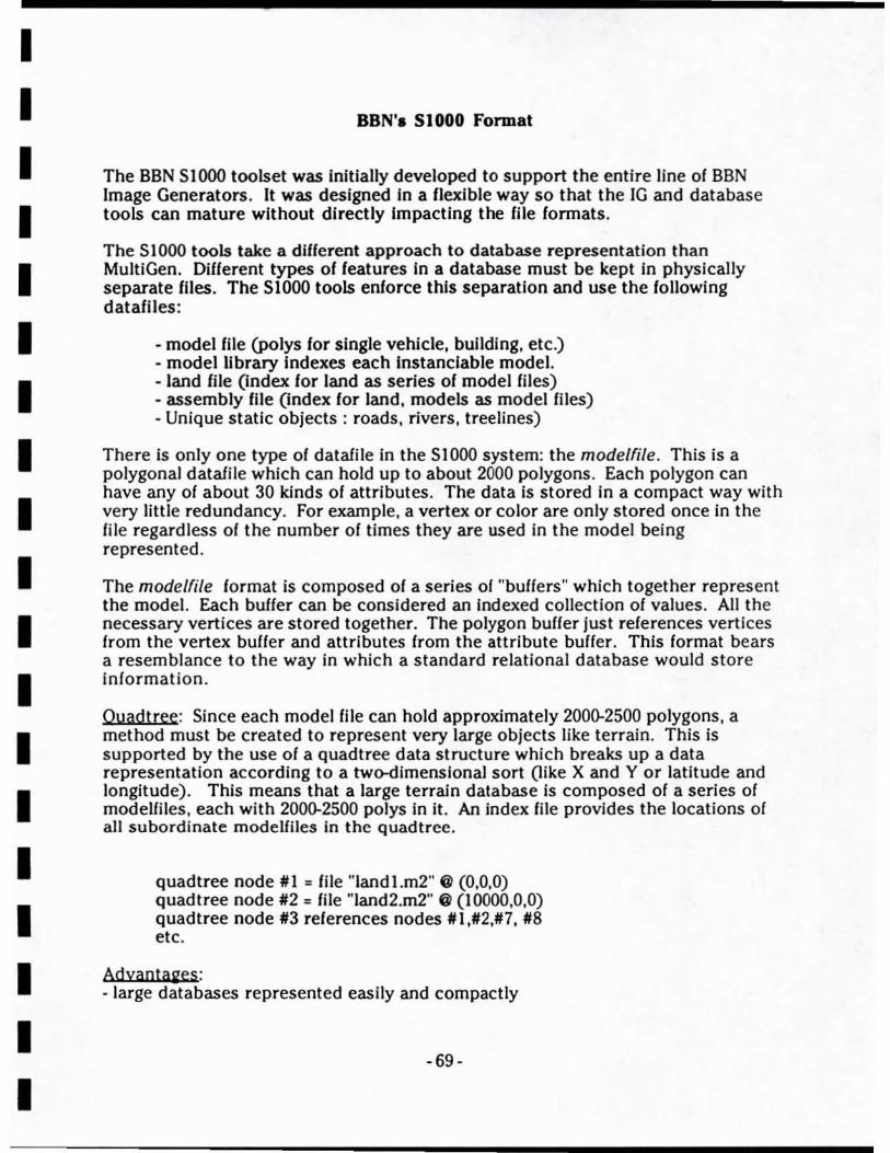
I I I I I I I I I I I I I I I I I I I
BBN'. S 1 000 Format
The BBN SIOOO toolset was Initially developed to support the entire line of BBN Image Generators. It was designed In a flexible way so that the IG and database tools can mature without directly Impacting the file formats.
The 51000 tools take a different approach to database representation than MultiGen. Different types of features fn a database must be kept in physically separate files. The SIOoo tools enforce this separation and use the following datafiles:
- model file (polys for single vehicle, building, etc.) - model library Indexes each Instanclable model. - land file (Index for land as series of model files) - assembly file (index for land, models as model files) - Unique static objects: roads, rivers, treelines)
There is only one type of datafile in the S 1000 system: the modelfile . This is a polygonal datafile which can hold up to about 2000 polygons. Each polygon can have any of about 30 kinds of attributes. The data is stored in a compact way with very little redundancy. For example, a vertex or color arc only stored once in the file regardless of the number of times they are used in the model being represented.
The modelfile format is composed of a series of "buffers" which together represent the model. Each buffer can be considered an Indexed collection of values. All the necessary vertices are stored together. The polygon buffer just references vertices from the vertex buffer and attributes from the attribute buffer . This format bears a resemblance to the way in which a standard relational database would store information.
Duadtree: Since each model file can hold approximately 200(}'2500 polygons, a method must be created to represent very large objects like terrain. This is supported by the use of a quadtree data structure which breaks up a data representation according to a two-dimenslonaJ sort (like X and Y or lati tude and longitude). This means that a large terrain database is composed of a series of modeifiles, each with 200(}'2500 polys in it. An index file provides the locations of all subordinate modelfiles in the quadtree.
quadtree node III = file "landl.m2" @ (0,0,0) quadtree node 1/2 = file "land2.m2" @ (I 0000,0,0) quadtree node 113 references nodes 111,1/2,1/7, 1/8 etc.
Adyantages: - large databases represented easily and compactly
-69 -

I I I I I I I I I I I I I I I I I I I
- data is kept conceptually separate. Terrain In one file, roads In another file, models In model library, etc. - Once you understand the modelfile format, you understand most of the S 1000 system.
Djsadyaotaies: - awkward to rebuild quad trees or simulate the breakup of land to import data into the SIOOO system (but has been done In a limited fashion at 1ST). - A single gaming area Is stored In a series of files, anyone of which could be lost. - The format has an enforced load module (or area block) size where all data must not cross. For SIMNET, the area block size Is 500 meters x 500 meters (quite small) . - No place for separation planes to be stored (supports Zbuffer machines only). - The entire database, spanning multiple flies , Is more complex to create and read than either MultiGen or ASCII formats .
-70 -
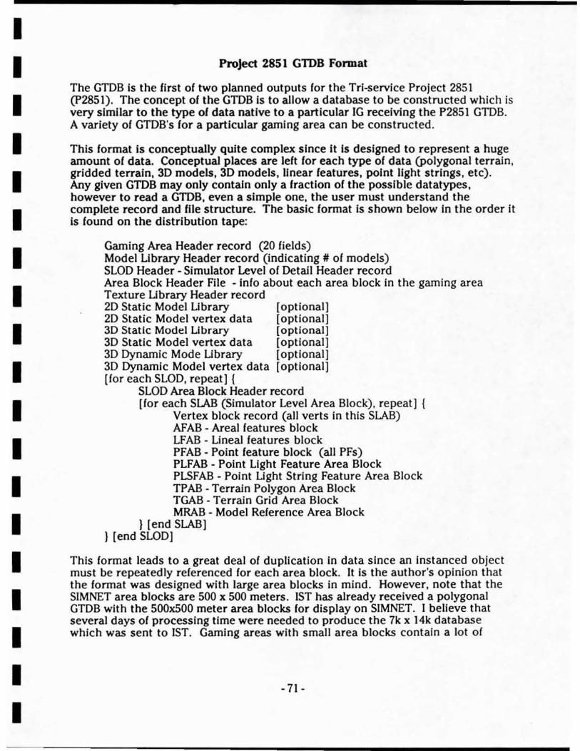
I I I I I I I I I I I I I I I I I I I
Project 2851 GTDB Format
The GTDB is the first 01 two planned outputs lor the Tri-service Project 2851 (P2851). The concept 01 the GTDB Is to allow a database to be constructed which is very similar to the type 01 data native to a particular IG receiving the P2851 GTDB. A variety 01 GTDB's lor a particular gaming area can be constructed.
This lormat Is conceptually quite complex since It Is designed to represent a huge amount 01 data. Conceptual places are lelt lor each type 01 data (polygonal terrain , gridded terrain, 3D models, 3D models, linear leatures, point light strings, etc). Any given GTDB may only contain only a Iractlon 01 the possible datatypes, however to read a GID8, even a simple one, the user must understand the complete record and liIe structure. The basic lormat Is shown below In the order it Is lound on the distribution tape:
Gaming Area Header record (20 fields) Model Library Header record (indicating # 01 models) SLOD Header - Simulator Level 01 Detail Header record Area Block Header File - Inlo about each area block in the gaming area Texture Library Header record 2D Static Model Library 2D Static Model vertex data 3D Static Model Library 3D Static Model vertex data 3D Dynamic Mode Library 3D Dynamic Mode l vertex data [lor each SLOD, repeat] {
[optional] [ optional] [ optional} [optional} [optional] [ optional]
SLOD Area Block Header record [lor each SLAB (Simulator Level Area Block), repeat] {
Vertex block record (all verts in this SLAB) AFAB - Areal features block LFAB - Lineal features block PFAB - Point leature block (all PFs) PLFAB - Point Light Feature Area Block PLSFAB - Point Light String Feature Area Block TPAB - Terrain Polygon Area Block TGAB - Terrain Grid Area Block MRAB - Model Relerence Area Block
} [end SLAB] } [end SLOD]
This format leads to a great deal of duplication in data since an instanced object must be repeatedly referenced for each area block. It is the author's opinion that the lormat was designed with large area blocks in mind . However, note that the SIMNET area blocks are 500 x 500 meters . 1ST has already received a polygonal GTDB with the 500x500 meter area blocks lor display on SIMNET. I believe that several days of processing time were needed to produce the 7k x 14k database which was sent to 1ST. Gaming areas with small area blocks contain a Jot of
- 71 -
I I I I I I I I I I I I I I I I I I I
header information, and the file size are very large when compared to all formats presented earlier.
Adyaota2es: - Once format Is understood, It Is Industry standard. - Many different types of data can be contained together in one file - Machlne-Independant ASCII data stored on tape - Format available and fairly stable today - public domain format - production software exists - Very flexible format - Good standard format for low-to-middle capability vendors to enter the market with. They don't have to develop a database production ability this way - just read GTDBs.
DjstadyaotaKes: - Not space efficient at all (inefficient ASCII + lots of headers) - complex format which is not useful for temporary or unexpected use ("I need a new model quick, send a tape this afternoon".) Instead, there is a substantial engineering learning curve necessary (4.Q man months the first time). - Not receiving acceptance among high-performance vendors (GE , E&S, etc.) - Doesn't currently support texture (in specHication, but never produced yet). - Fixed number of attributes per polygon.
CQmplexjty Estimate: 1ST has completed a GTDB tape reading utility which converts a GTDB into a MultiGen Flight format file . The development (in Ada) was estimated at approximately 4 man-months.
Recommendation: The author recommends that P285I be allowed to continue until the GTDB format is completely solid and several example databases have been tested. Then the GTDB format will be an available standard for the industry. It can be required on any future trainer procurements - helping to reduce redundant database development.
Even thoush this is a cumbersome format , once it is understood by the industry it could be very effective. The complexity is not above what is reasonable for a flexible standard. The GTDB could serve as a useful interchange format in the future when Is stable and tested . It Is the author's belief that the GmB format will be stable by late 1992 unless P2851 Is not aflowed to complete.
The GTDB is a good candidate to require across a heterogenioll5 DIS network. It is the author's belief that different simulators receiving different GTDBs will result in better terrain database correlation than those using SIF (see next section) for the next 5 - 10 years. The reason for this statement is that a consistent po!ygonalization algorithm will yield consistent results even running at different levels of resolution. However, no actual experiments have been performed by the author to support this hypothesis.
- 72-
I I I I I I I I I I I I I I I I I I I
Project 2851 SSDB Interchange Format (SIF)
The SIF is the second output format planned Irom P2851. It evolved during the past several years as industry vendors requested input/output directly from the P2851 SSDB format .
The SIF is conceptually slightly more complex than the GIDB format. Details are stili sketchy on this format , however, since it only exists in a military standard document produced by PRC, the P2851 contractor released 12;91. Previous to 12/91, the format was described only in a draft specification dated 12/90.
This data format is the most Dexlble of any described so far, at the cost of complexity. Its organization is very similar to that of the GIDB with several notable differences:
- terrain is gridded format only (any resolution grid) - polygonal terrain must be treated as features - format is binary, therefore more compressed - FACS attributes provided
FACS (Feature Attribute Coding Standard) are self-<lefining attributes which allow for the storage and transferral of a variety of datatypes not initially forseen . This allows the format to grow and develop over years of use without needing to become incompatible with older formatting programs. Self-<lefining attributes would be expressed as follows. Attributes for a polygon are chosen here:
attr III : "COLOR", range from I to 5, value = 6 attr #2: "TRANSMISSIVITY",range from 1.0 to 100.0, value = 24.5 attr #3: "SQUISHY", range from "yes" to "no", value = "no"
The intent of this example is to show that the attribute along with its values are given, allowing lor a smart formatter to scan for a variety of attribute categories it desires. The author believes that extensive use of FACS attributes coupled with an enforced "convention" about which attributes are generally provided to be the most useful. However, a statement was made by PRC at the 1/23/92 I/SWG indicating they were discouraging use of FACS attributes.
Adyaota2es: - Public domain format - Has industry acceptance (at least In preliminary form) - binary, so more compact that GTDB - greatest growth potential for long term use - Supports elevation post terrain (future IGs may use posts directly ... ) - Government programs seem to support SIF over GTDB
Djsadyaota2es : - High complexity - Not yet stable, only in design stage currently
- 73-
I I I I I I I I I I I I I I I I I I I
- Gridded terrain only, might encourage different triangulation algorithms by the industry vendors leading to correlation problems. - VAX-format binary (no longer industry-standard)
Recommendatioos: The SIF is Interesting for a c1ose-t<rsource type of database exchange. It most closely resembles existing DMA products but allows for expansion. SIF, if allowed to mature, could become a popular interchange format for the Industry. The author believes that, when used in a heterogenious DIS environment, SIF will, however, yield a lower-level of database correlation across different IGs than GTDBs.
The reason (or a lower correlation result is primarily a guess about the current need of IGs to render polygons. The grldded terrain will be converted into different sets of polygons for each IG. In contrast to the GTDB, the polygonalization algorithms will be developed by each vendor optimized for their own hardware and essentially irrespective of correlation problems. This could be solved by as-yet undecided correlation rules included in the procurement process.
If IGs develop into using gridded terrain directly, than SIF will be the format of choice in approximatly 10 years. IGs which directly render from posts would yield excellent results from the SiF format.
- 74-

I I I I I I I I I I I I I I I I I I I
Conclusion
In summary, the author believes there Is a need for a simple. intermediate format for exchange. The public-<iomain Fligh! format Is probably the best choice for the next two-years. All that Is lacking Is a more complete set of polygon or vertex attributes. These can be added as comment records In Flight easily.
ASCii formats will continue to exist because of their readability. It Is the authors experience that they are just too Inefficient to be used for large gaming areas. Most of 1ST's tools developed by the author use an ASCII format and must be extended before they can be of use for realistic training sizes. However, simple ASCII formats are excelient for quick exchange of relatively small amounts of data.
The author recommends that Project 2851 be allowed to continue Its progress through the development and testing of the OTDB and SIF products . This will produce two new standards which could serve the industry for many years to come. If a standard production facility never becomes a reality, P2851 will still have produced these standards for the industry to use.
-75-

I I I I I I I I I I I I I I I I I I I
Appendix C . Published paDer: SimTech Conference, Orlando, FL, Oct. 1991
•
TIlE PRODUCTION OF CORRELATED VISUAL DATABASES FOR IMAGE GENERATION IN NE'IWORKED SIMULATORS
Curtis R. Lisle Ron lOasky
Jacquelyn F. Morie J. Michael Moshell
Instil ute for Simulation and Training, University of Central Florida,
l2424 Research Parkway, Suite 300, Orlando, FL 32826
- 76-
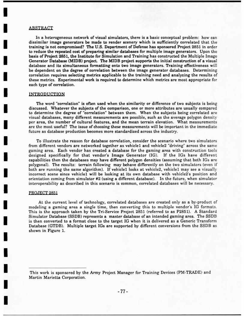
I I I I I I I I I I I I I I I I I I I
ABSTRACT
In 8 heterogeneous network of visual simulators, there is a basic conceptual problem: how can dissimilar image generators be made to render scenery which is sufficiently correlated that the training is not compromised? The U.S. Department of Defense has aponsored Project 2851 in order to reduce the repeated cost of preparing similar databases (or multiple image generators. Upon the basis of Project 2851, the Institute for Simulation and Training has constructed the Multiple Image Generator Database (MIDB) project The MIDB project supports the initial construction of 8 visual database and its simultaneous formatting onto two image generators. Training effectiveness will be dependent on the degree of correlation between the image generator databases. Determining correlation requires selecting metrics applicable to the training need and analyzing the results of these metrics. Experimental work is required to determine which metrics are most appropriate for each type of correlation.
INTRODUCTION
The word "correlation" is often used when the similarity or difference of two subjects is being discussed. Whatever the subjects or the comparison, one or more attributes are usually compared to determine the degree or "correlation" between them. When the subjects being correlated are visual databases, many different measurements are possible, such as the average polygon density per area, the number of cultural features, and the mean terrain elevation. What measurements are the most useful? The issue of choosing these measurements will be important in the immediate future as database production becomes more standardized across the industry.
To illustrate the reason for database correlation, consider the scenario where two simulators from different vendors are networked together as vehicle land vehicle2 "driving" across the same gaming area. Each vendor has created a database for the gaming area with construction tool s designed specifically for that vendor's Image Generator (lG). If the IGs have different capabilities then the databases may have different polygon densities (assuming that both IGs are polygonal) . The results : terrain fol1owing may behave differently on the two simulators (even if both are running the same algorithm). If vehiclel looks at vehicle2, vehicle! may see a visually incorrect scene since vehicle! will be looking at its own database with vehicle2's position and orientation coming from simulator 112 (using a different database). In the future, when simulator interoperability as described in thi s scenario is common, correlated databases will be necessary.
PROJECT 2851
At the current level of technology, correlated databases are created only as a by-product of modeling a gaming area a single time, then converting this to multiple vendor's JG formaLs. This is the approach taken by the Tri-Service Project 285! (referred to as P2851). A Standard Simulator Database (SSDB) represents a master database of an intended gaming area. The SSDB is then converted to a format close to the target IG when it is delivered as a Generic Transform Database (GTDB). Multiple target IGs are supported by different conversions from the SSDB as shown in Figure 1.
This work is sponsored by the Army Project Manager for Training Devices (PM-TRADE) and Martin Marietta Corporation.
-77 -
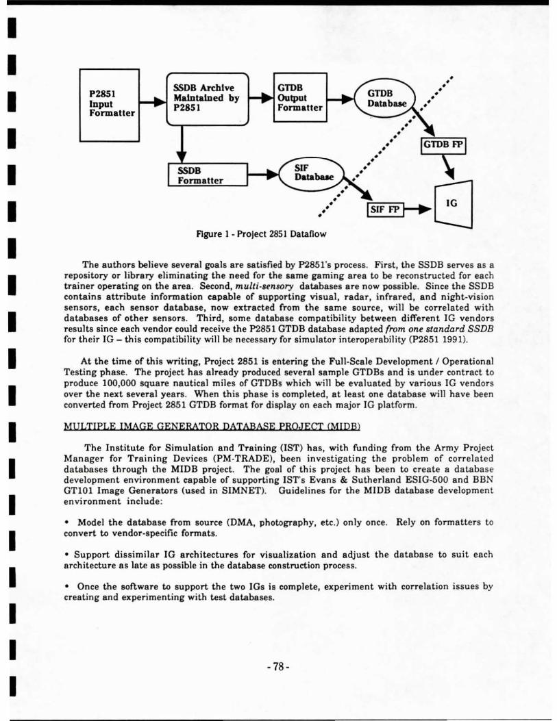
I I I I I I I I I I I I I I I I I I I
PZ8S1 Input Formatter
SSDB Archive Maintained by PZ851
G11>B I-I~Output
Formatter ...... _-" . • • • • . ' .' • . ' • •
. ' • • •
• • • •
SSDB Formatter
• ~ . ' ~ISI~F !!FP}I -I~~8
FIgure 1 - Project 2851 Datanow
The authors believe several goals are satisfied by P285l's process. First, the SSDB serves as 8
repository or library eliminating the need for the same gaming area to be reconstructed fOT each trainer operating on the aTes . Second, multi·sen,ory databases 8Te now possible. Since the SSDB contains attribute infonnation capable of supporting visual, radar, infrared, and night-vision sensors, each sensor database, now extracted from the same SOUTce, will be correlated with databases of other sensors. Third, some dat8b8le compatibility between different IG vendors results since each vendor could receive the P2851 GTDB database adapted (rom one standard SSDB for their IG - this compatibility will be necessary for simulator interoperability (P2B5 1 1991).
At the time of this writing, Project 2851 is entering the Fun-Scale Development I Operational Testing phase. The project has already produced several sample GTDBs and is under contract to produce 100,000 square nautical miles of GTDBs which will be evaluated by various IG vendors over the next several years. When this phase is completed, at least one database will have been converted from Project 285 1 GTDB format for display on each major IG platform.
MULTIPLE IMAGE GENERATOR DATABASE PROJECT (MIDB)
The Institute for Simulation and Training (1ST) has, with funding from the Army Project Manager for Training Devices (PM·TRADE), been investigating th e problem of correlated databases through the MIDB project. The goal of this project has been to create a dat.abase development environment capable of supporting 1ST's Evans & Sutherland ESIG-500 and BBN GTIOI Image Generators (used in SIMNET). Guidelines for the MIPB database developmen t envi ronment include :
• Model the database from source (DMA, photography. etc.) only once. Rely on formatters to convert to vendor-specific formats.
• Support dissimilar IG architectures for visualization and adjust the database to suit each architecture as late as possible in the database construction process.
• Once the software to support the two IGs is compJete, experiment wit.h correlation issues by creating and experimenting with test databases.
- 78-
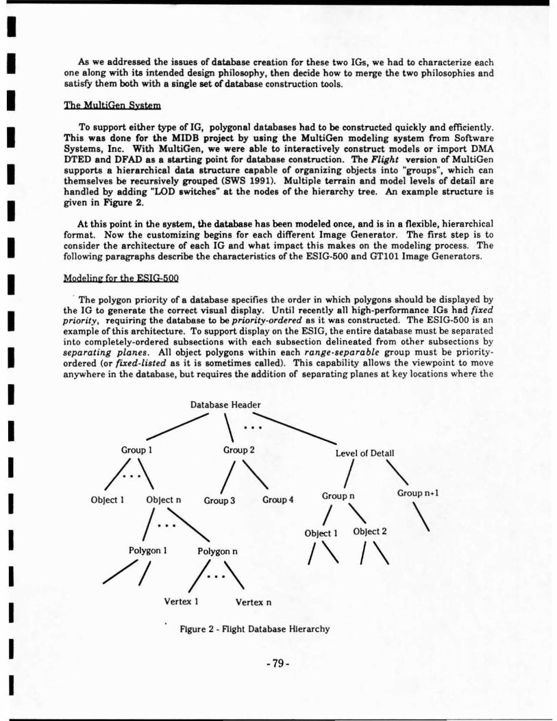
I I I I I I I I I I I I I I I I I I I
As we addressed the issues of database creation for these two lGa. we had to characterize each one along with ita intended design philosophy. then decide how to merge the two philosophies and satisfy them both with a .ingle set of database construction tools.
The MultjGen System
To support either type ofIG, polygonal databases had to be constructed quickly and efficiently. Thia was done (or the MIDS project by ulin, the MultiGen modeling system from Software Systems, Inc . With MultiGen. we were able to interactively con.truct models or import DMA DTED and DFAD as a ltarting point for databaae construction. The Flight venion of Mu1tiGen supports 8 hierarchical data structure capable of organizing objects into "gToups", which can themselves be recursively grouped (SWS 1991). Multiple terrain and model1evels of detail are handled by adding "LOD ,witches" at the nodes of the hieTarchy tree. An example structure is given in Figure 2.
At this point in the system, the database has been modeled once, and is in a flexible, hierarchical fonnal. Now the customizing begins for each different Image Generator. The first step is to consider the architecture of each IG and what impact this makes on the modeling process. The following paragraphs describe the characteristics of the ESIG·500 and GTIOllmage Generators.
Modeling for the ESIG:500
. The polygon priority of a database specifies the order in which polygons should be displayed by the JG to generate the correct visual display. Until recently all high·penormance JGs had fixed priority, requiring the database to be priority·ordered as it was constructed. The ESIG-500 is an example of this architecture. To support display on the ESIG, the entire database must be separated into completely-ordered subsections with each subsection delineated from other subsections by separating planes. All object polygons within each range·separable group must be priority · ordered (or rued-listed as it is sometimes called). This capability allows the viewpoint to move anywhere in the database, but requires the addition of separating planes at key locations whe re the
Database Header
~\.~ Group 1 Group 2 Level of Detail
/ .\ / "" Object n Croup 3 Croup 4
/ .. ~ Object 1
Polygon 1 Polygon n
/ .. \ //
/ '" Croup n+l
\ Group n
/ "-ObJect 1 Object 2
/\ /\ Vertex I Vertex n
Figure 2 - fligh t Database Hierarchy
-79-

I I I I I I I I I I I I I I I I I I I
priority order is dependent on the viewpoint position. This means separating plane locations must be "designed-in" 88 the database is constructed.
The ESIG-500 features high-quality visual, with limited intensity phototextuTe map capability. It can generally display about 500 polygons per channel at a 50 Hz update Tate. Texture and polygonal transparency are supported by the JG hardware. Polygons can have either three or fOUT
sides and must be convex.
In the MulaGen to ESIG portion olthe MIDB project., we found that rules were necessary early on in the modeling process. During MultiGen eonstruction, range-separable objects in the database (which must be fixed-listed) are labeled 88 one "object" in the MuJtiGen database hierarchy. We then apply an automated ordering algorithm which adds separating planes between the separable objects. The specific MultiGen to ESIG modeling rules are as follows:
• Within a single polygonal object, the polygons must be ordered according to priority as they are created in MultiGen.
• Objects requiring separating plane addition should adhere to a specific naming convention to alert the automated formatting software during processing.
• If polygonal objects cannot be fixed-listed, then they should be split into multiple objects named according to the above rule.
• Objects requiring separating planes should be placed first in the database . Objects in th e databa se should be priority-ordered if no separation planes are used . (The database order will be used as the priority order ).
Modeling for the BBN GTtO!
In contrast to a fIXed priority IG, a dynamic priority IG can detennine the correct priority order from the database during run-time display of the database . No (or little) specific priority information is embedded in the database during construction. The GTIOI includes Z-buffer hardware to support this capability. This flexibility does not come without a cost, however, since Z· buffer hardware is expensive when done at the high accuracy needed for a high ·performance IG. Therefore, since it is a low-cost machine, the pixel resolution and fram e update rate of the GTIOI are lower than the ESIG·500. In the GTIOl, priority is specified only between classes of objects. Within each class, the polygon priority is resolved by the Z·buffer. Polygons can have either three or four sides and must be convex.
Experimental results showed us that the GTIOI windows polygons (by tracing their edge boundaries) in a way which can result in spaces or cracks appearing between polygons a s the IG is flying around a database. This anomaly can arise from any number of architectural reasons, but the consequence is that interior polygons are needed in all models (to keep the viewer from "seeing through" the cracks in the mode}), or model polygons must always overlap slightly. The traditional BBN approach has been to include interior polygons. In the MIPB project, we have taken the latter approach and constructed a tool which stretches polygons around thei r centroid . This provides the needed overlap so the modeler need not be concerned with the windowing limitation of the GTIOI.
The MIPH Project Dataflow
Now that the target image generators have been described, the overall dataflow of the MIPB project will be presented. The high·level dataflow diagram in Figure 3 shows the flow of source
-80-
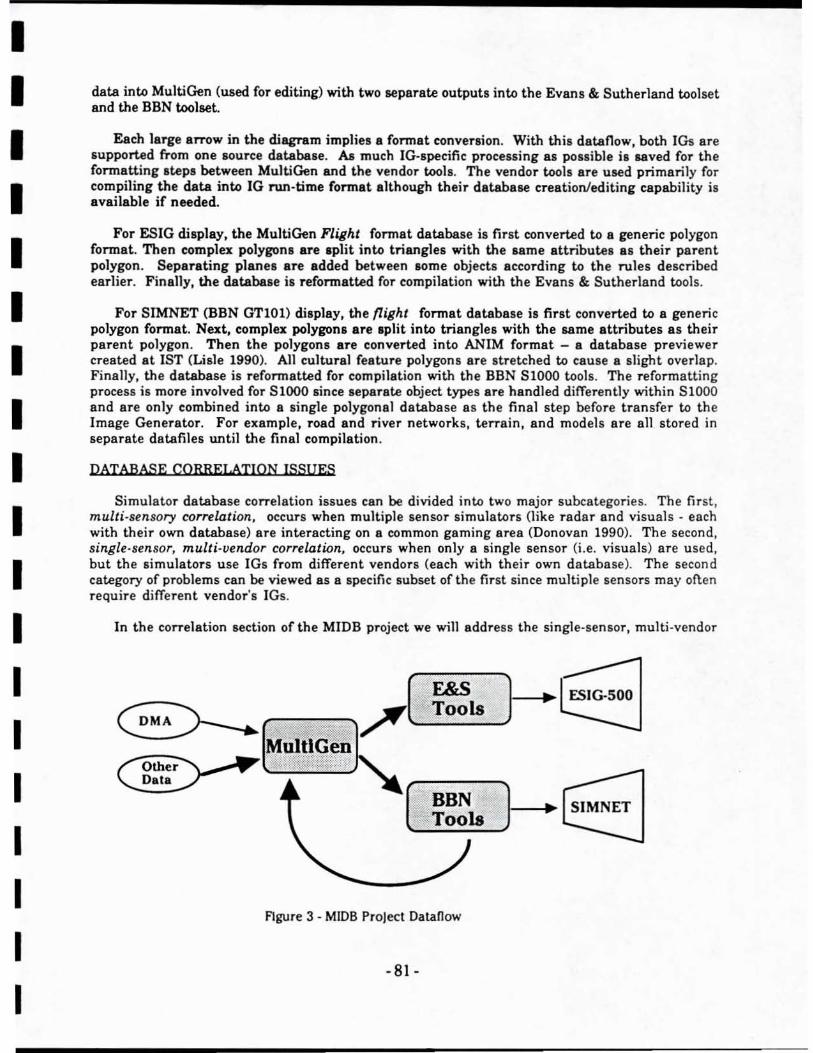
I I I I I I I I I I I I I I I I I I I
data into MultiGen (used for editing) with two separate outputs into the Evans & Sutherland toolset and the BBN toolset.
Each large arrow in the diagram implies 8 format conversion. With this dataflow, both lOs are supported from one source database. AB much IG·specific processing 8S possible is saved for the formatting steps between MultiGen and the vendor tools. The vendor tools are used primarily for compiling the data into IG run-time format although their database creation/editing capabi1ity is available if needed.
For ESIG display, the MultiGen Flight format database is first converted to 8 generic polygon format. Then complex polygons are split into triangles with the same attributes as their parent polygon. Separating planes are added between lome objects according to the rules described earlier. Finally, the database is refonnatted for compilation with the Evans & Sutherland tools.
For SIMNET (BBN GT10l) display, the flight format database is first converted to a generic polygon format. Next, complex polygons are Iplit into triangles with the same attributes as their parent polygon . Then the polygons are converted into ANIM format - a database previewer created at 1ST (Lisle 1990). All cultural feature polygons are stretched to cause a slight overlap. Finally. the database is refonnatted for compilation with the BBN 81000 tools. The reformatting process is more involved for 81000 since separate object types are handled differently within S1000 and are only combined into a single polygonal database as the final step before transfer to the Image Generator. For example, road and river networks, terrain, and models are all stored in separate datafiles until the final compilation.
DATABASE CORRELATION ISSUES
Simulator database correlation issues can be divided into two major subcategories. The first, multi-sensory correlation. occurs when multiple sensor simulators (like radar and visuals· each with their own database) are interacting on 8 common gaming area (Donovan 1990). The second, single-sensor, multi-vendor correlation, occurs when on ly a single sensor (i.e. visuals) are used, but the simulators use IGs from different vendors (each with their own database). The second category of problems can be viewed as a specific subset of the first since multiple sensors may often require different vendor's IGs .
In the correlation section of the MIDB project we will address the single-sensor. multi -vendor
~Ej ,;r[ F&S ) E>----. Tools
MultlGen
~ """,., /'.'.
Data
~E3 ( BBN ) Tools
FIgure 3 - MIDB Project Dataflow
-81-
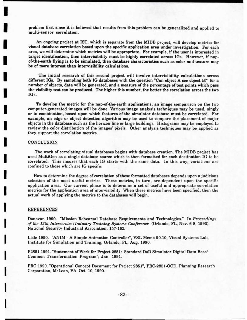
I I I I I I I I I I I I I I I I I I I
problem first since it is believed that resulta from this problem can be generalized and applied to multi-sensor correlation.
An ongoing project at 1ST, which is separate from the MIDB project, will develop metrics for visual database correlation based upon the specific applielltion area under investigation. For each area, we will determine which metries wilJ be appropriate. For example, if the user is interested in target identification, then interviaibility must be highly correlated across IGs. However, if napof-the-earth nying i, to be simulated, then d.tabue characteristics such as color and texture may be of mOTe interest than intervi.ibility calculations.
The inilial research of this second project win involve intervisibility calculations across different IGs. By sampling both IG databases with the question "Can object A lee object B?" for a number of objeeta, data will be generated, and a mea.ure of the percentage ofte.t pointl which pass the visibility test can be produced. The higher this number, the better the correlation across the two IGs.
To develop the metric for the nap-of-the-earth applications, an image comparison on the two computer-generated images will be done. Various image analysis techniques may be used, singly or in combination, based upon which features of the simulator database must be correlated. For example, an edge or object detection algorithm may be used to compare the placement of major objects in the database such as the horizon line or large buildings. Histograms may be employed to review the color distribution of the images' pixels. Other analysis techniques may be applied as they support the correlation metrics.
CONCLlJSION
The work of correlating visual databases begins with database creation. The MIDB project has used MultiGen as a single database source which is then fonnatted for each destination IG to be correlated. This insures that each IG starts with the same data . In this way, variations are confined to those which are IG specific
How to detennine the degree of correlation oftbese fonnatted databases depends upon a judicious selection of the most useful metrics. These metrics, in tum, are dependent upon the specific application area. Our current phase is to determine a set of useful and appropriate correlati on metrics for the application area of intervisibility When these metrics have been specified, then the actual work of applying the metrics to the databases will begin.
REFERENCES
Donovan 1990. "Mission Rehearsal Database Requirements and Technologies." In Proceedings of the 12th lnterservice l lndustry Training Sy.tem. Conference (Orlando, FL, Nov. 6-8,1990). National Security Industrial Association, 157-162.
Lisle 1990. "ANIM - A Simple Animation Controller", VSL Memo 90.10, Visual Systems Lab, Institute for Simulation and Training, Orlando, FL, Aug. 1990.
P2B51 1991. MStatement of Work for Project 2851 : Standard DoD Simulator Digital Data Basel Common Transformation Program"; Jan. 1991.
PRC 1990. "Operational Concept Document for Project 2851-, PRC-2851-0CD, Planning Research Corporation, McLean, VA. Oct. 10, 1990.
·82·
I I I I I I I I I I I I I I I I I I I
sws 1991. Data Fonnat Description · Software Systems Flight Data Bases, format Revision 10.0, Software Systems, Inc., May 1991.
BIOGRAPHY
Mr. Lisle has been involved in hardware design 88 wen 8S database production tools for 0
variety of high-end visual systems. While at General Electric Simulation and Control Systems Division, Mr. Lisle was . hardware designer working on GE', CompuSeene PT-2oo0 Image Generator. He i. current1y working with the Institute for Simulation and Training. At 1ST, he is focusing on the production of terrain databases for Image Generators and is managing 1ST's effort to produce a lOf\:ware toolluite capable of developing databases for multiple IGs. Mr. Lisle holds a Masten of Science in Computer Science from the University of Central Florida and 8
BacheloTs in Eleetriea1 Engineering from the Georgia Institute of Technology.
-83-
I I I I I I I I I I I I I I I I I I I
Blbllograpby
[BBN 89)- "SlooO Database File Structures - DRAFT", October 1989, Document #8914, BBN Systems and Technologies, Advanced Simulation DIvision, pages 3-16. Pg. 4-7 to 4-14.
[BBN 90)- "BBN GTioo CIG to Simulation Host Interface Manual", July 1990, Document 118912, BBN Systems and Technologies, Advanced Simulation Division
[Brooks 75)- Brooks, Frederick P. Jr., The Mythical Man-Month. Addison-Wesley, Reading, MA, 1975.
[Foley 901· Foley. James D. et. aI .• Computer Graphics: Principles and Practice, 2nd edition, Addison-Wesley, 1990
[1ST #1 91) - Proceedings from the 5th InterOperability Conference on Standards for Distributed Interactive Simulation, Institute for Simulation and Training, Orlando, fL
[Lisle #1 92)- presentation by Curtis Lisle at the Project Industry / Service Working Group Meeting, January 22-23, 1992, Daytona Beach , FL
[Meyer 88) Meyer, B., Object Oriented Software Construction. Prentice Hall, Englewood Clilfs, NJ, 1988.
-84 -

r 1 I I I I I I I I I I I I I I I I
0000035