Embed Size (px)
Citation preview
SIEM ENS/
MX3009783
r
-j . , N.., . .i . In yn
! P u lt e t ■ ' züsmkrft'n \ ....................
, : : V p r
, y - ~ ’v \ * • "T • j*
- ::# v
k ce-Ä&A <£oA<?ft
1 /.
TDS f f '
Teleservice: : I I L ~
HW-Descriptsonv i iT ~
Monitors j ^
PeripheralsX
System SoftwareX /
System Files
CablesX i l i
Appendixw

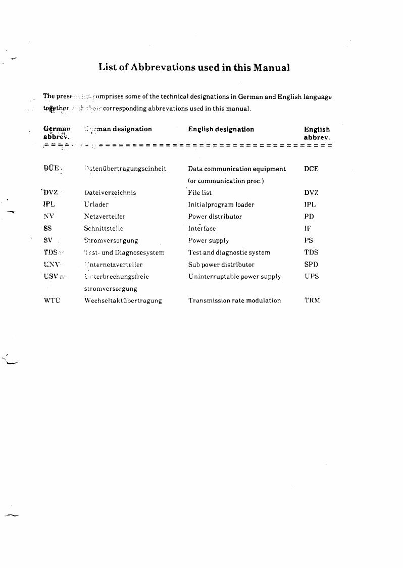
List of Abbrevations used in this Manual
'Hie prese ■ w . comprises some of the technical designations in German and English language to o th e r - A ' V-.rit-' corresponding abbrevations used in this manual.
G erm an C man designation English designation Englishaiibrev. abbrev .
DÜE . D itenübertragungseinheit Data communication equipment
(or communication proc.)
DCE
DVZ Dateiverzeichnis File list DVZ!PL Urlader Initialprogram loader IPLNV Netzverteiler Power distributor PDss Schnittstelle Interface IFsv . Stromversorgung Power supply PS
TDS ; Test- und Diagnosesystem Test and diagnostic system TDS
UNY .'nternetzverteiler Sub power distributor SPDUSV XV L nterbrechungsfreie Uninterruptable power supply UPS
Stromversorgung
WTÜ Wechseltaktübertragung Transmission rate modulation TRM

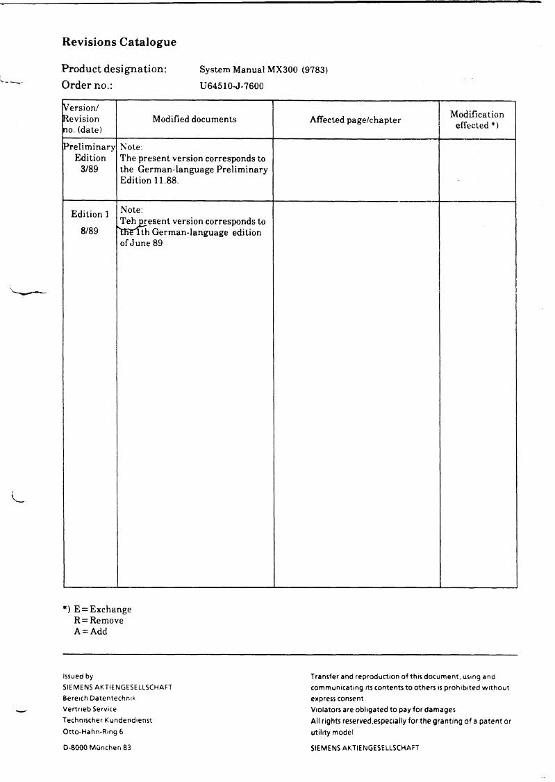
Revisions Catalogue
Product designation: System Manual MX300 (9783)
Order no.: U64510-J-7600
Version/ Revision no. (date)
Modified documents Affected page/chapter Modification effected *)
PreliminaryEdition
3/89
Note:The present version corresponds to the German-language Preliminary Edition 11.88.
Edition 1
8/89
Note:Teh present version corresponds to "tKEith German-language edition ofJune 89
*) E = Exchange R = Remove A = Add
Issued bySIEMENS AKTIENGESELLSCHAFT Bereich Datentechnik Vertrieb Service Technischer Kundendienst Otto-Hahn-Ring 6
Transfer and reproduction of this document, using and communicating its contents to others is prohibited without express consentViolators are obligated to pay for damagesAll rights reserved,especially for the granting of a patent orutility model
D-8000 München 83 SIEMENS AKTIENGESELLSCHAFT

SIEM ENS SINIX Conventions
Part IIntroduction

u
u
Part I
Introduction
Contents Page
SINIX Conventions
SINIX V5.2A M anuals
1-1
1-2

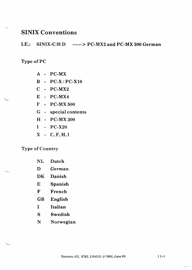
SINIX ConventionsI . E S I N I X - C / H D .......> PC-MX2 and PC-MX 300 German
Type of PC
A - PC-MXB - PC-X/PC-X10C - PC-MX2E - PC-MX4F - PC-MX 500G - special contentsH - PC-MX 300I - PC-X20X - C, F, H, I
of Country
NL DutchD GermanDK DanishE SpanishF FrenchGB EnglishI ItalianS SwedishN Norwegian
Siemens AG, 9783, U64510- J-7600, June 89 1. 1-1
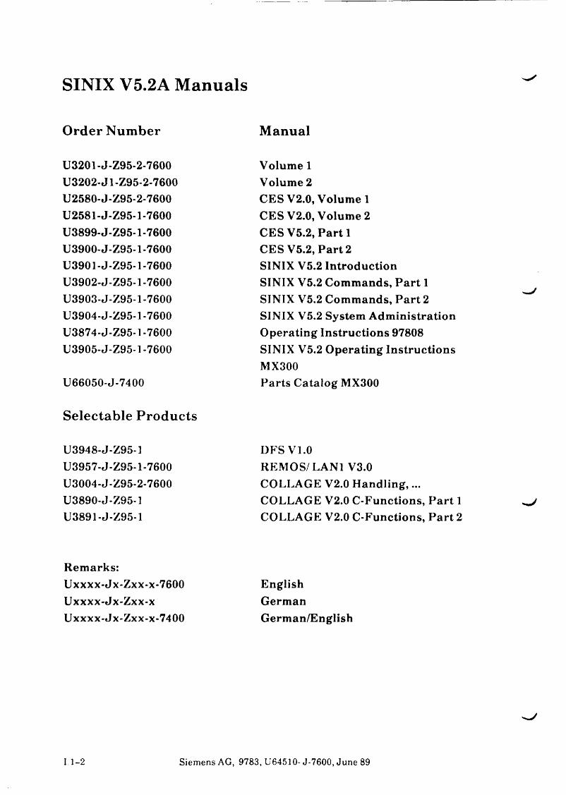
SINIX V5.2A Manuals
Order Number Manual
U3201-J-Z95-2-7600 U3202-J1-Z95-2-7600 U2580-J-Z95-2-7600 U2581-J-Z95-1-7600 U3899-J-Z95-1-7600 U3900-J-Z95-1-7600 U3901-J-Z95-1-7600 U3902-J-Z95-1-7600 U3903-J-Z95-1-7600 U3904-J-Z95-1-7600 U3874-J-Z95-1-7600 U3905-J-Z95-1-7600
U66050-J-7400
Selectable Products
U3948-J-Z95-1 U3957-J-Z95-1-7600 U3004-J-Z95-2-7600 U3890-J-Z95-1 U3891-J-Z95-1
Volume 1 Volume 2CESV2.0, Volum eiCES V2.0, Volume 2CES V5.2, Part 1CES V5.2, Part 2SINIX V5.2 IntroductionSINIX V5.2 Commands, Part 1SINIX V5.2 Commands, Part 2SINIX V5.2 System AdministrationOperating Instructions 97808SINIX V5.2 Operating InstructionsMX300Parts Catalog MX300
DFS VI.0REMOS/LAN1 V3.0 COLLAGE V2.0 Handling,... COLLAGE V2.0 C-Functions, Part 1 COLLAGE V2.0 C-Functions, Part 2
Remarks:Uxxxx-Jx-Zxx-x-7600Uxxxx-Jx-Zxx-xUxxxx-Jx-Zxx-x-7400
EnglishGermanGerman/English
1. 1-2 Siemens AG, 9783, U64510- J-7600, June 89
SIEM ENS
Part IIProduct Information
Product and Order Numbers
Technical Specifications

v j
Part II
Productinformation
Contents Page
l P ro d u c t and O rdernum bers II .l-i
2 Technical Specifications II.2-12.1 Processor II.2-12.2 Mass Storage II.2-12.3 SINTX-Operator Consoles (alphanumeric) II. 2-12.4 SINTX-Operator Consoles (graphic) II.2-22.5 Extension of the MX300 II.2-2

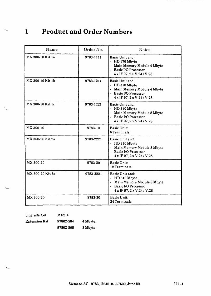
1 Product and Order Numbers
Name Order No. NotesMX 300-10 Kit la 9783-1111 Basic Unit and:
- HD 170 Mbyte- Main Memory Module 4 Mbyte- Basic I/O Processor
4 x IF 97,2 x V.24/V.28
MX 300-10 Kit lb 9783-1211 Basic Unit and:- HD 310 Mbyte- Main Memory Module 4 Mbyte- Basic I/O Processor
4 x IF 97, 2 x V.24 / V.28
MX 300-10 Kit lc 9783-1221 Basic Unit and:- HD 310 Mbyte- Main Memory Module 8 Mbyte- Basic I/O Processor
4 x IF 97, 2 x V.24/V.28
MX 300-10 9783-10 Basic Unit: 6 Terminals
MX 300-20 Kit 2a 9783-2221 Basic Unit and:- HD 310 Mbyte- Main Memory Module 8 Mbyte- Basic I/O Processor
4 x IF 97, 2 x V.24 /V.28
MX 300-20 9783-20 Basic Unit:12 Terminals
MX 300-20 Kit 3a 9783-3221 Basic Unit and:- HD 310 Mbyte- Main Memory Module 8 Mbyte- Basic I/O Processor
4 x IF 97, 2 x V.24/V.28
MX 300-30 9783-30 Basic Unit: 24 Terminals
Upgrade Set MX2 +Extension Kit 97802*504 4 Mbyte
97802-508 8 Mbyte
Siemens AG, 9783, U64510- J-7600, June 89 II 1-1
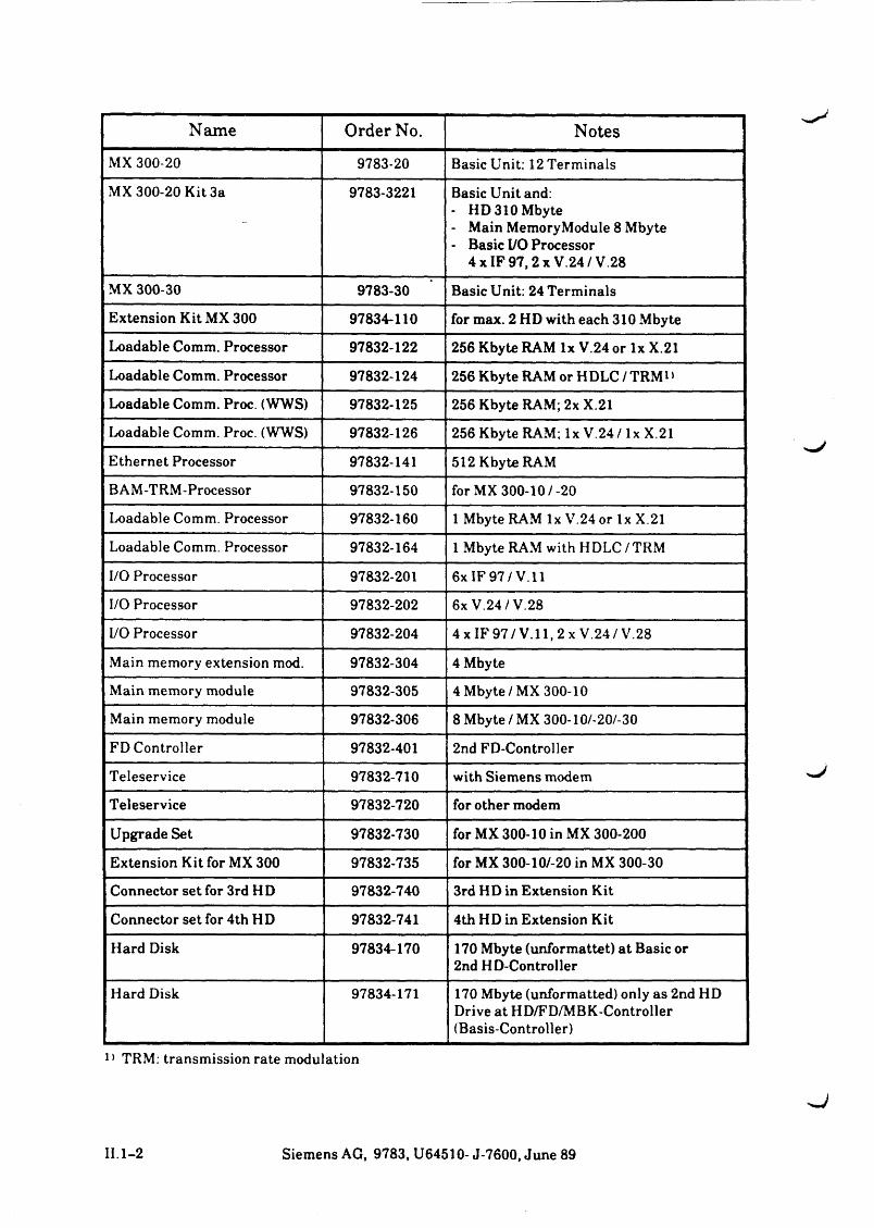
Name Order No. NotesMX 300-20 9783-20 Basic Unit: 12 Terminals
MX 300-20 Kit 3a 9783-3221 Basic Unit and:- HD 310 Mbyte- Main MemoryModule 8 Mbyte- Basic I/O Processor
4 x IF 97 .2xV .24 /V 28
MX 300-30 9783-30 Basic Unit: 24 Terminals
Extension Kit MX 300 97834-110 for max. 2 HD with each 310 Mbyte
Loadable Comm. Processor 97832-122 256 Kbyte RAM lx V.24 or lx X.21
Loadable Comm. Processor 97832-124 256 Kbyte RAM or HDLC / TRM*»
Loadable Comm. Proc. (WWS) 97832-125 256 Kbyte RAM; 2x X.21
Loadable Comm. Proc. (WWS) 97832-126 256 Kbyte RAM; lx V.24/ lx X.21
Ethernet Processor 97832-141 512 Kbyte RAM
BAM-TRM-Processor 97832-150 for MX 300-10/-20
Loadable Comm. Processor 97832-160 1 Mbyte RAM lx V.24 or lx X.21
Loadable Comm. Processor 97832-164 1 Mbyte RAM with H DLC / TRM
I/O Processor 97832-201 6x IF 97 / V. 11
I/O Processor 97832-202 6x V.24 / V.28
I/O Processor 97832-204 4 x IF 9 7 /V. 11,2 x V.24 / V.28
Main memory extension mod. 97832-304 4 Mbyte
Main memory module 97832-305 4 Mbyte/MX 300-10
Main memory module 97832-306 8 Mbyte / MX 300-10/-20/-30
FD Controller 97832-401 2nd FD-Controller
Teleservice 97832-710 with Siemens modem
Teleservice 97832-720 for other modem
Upgrade Set 97832-730 for MX 300-10 in MX 300-200
Extension Kit for MX 300 97832-735 for MX 300-10/-20 in MX 300-30
Connector set for 3rd HD 97832-740 3rd HD in Extension Kit
Connector set for 4th HD 97832-741 4th HD in Extension Kit
Hard Disk 97834-170 170 Mbyte (unformattet) a t Basic or 2nd HD-Controller
Hard Disk 97834-171 170 Mbyte (unformatted) only as 2nd HD Drive at HD/FD/MBK-Controller (Basis-Controller)
1 > TRM: transmission rate modulation
II.1-2 Siemens AG, 9783, U64510-J-7600, June 89
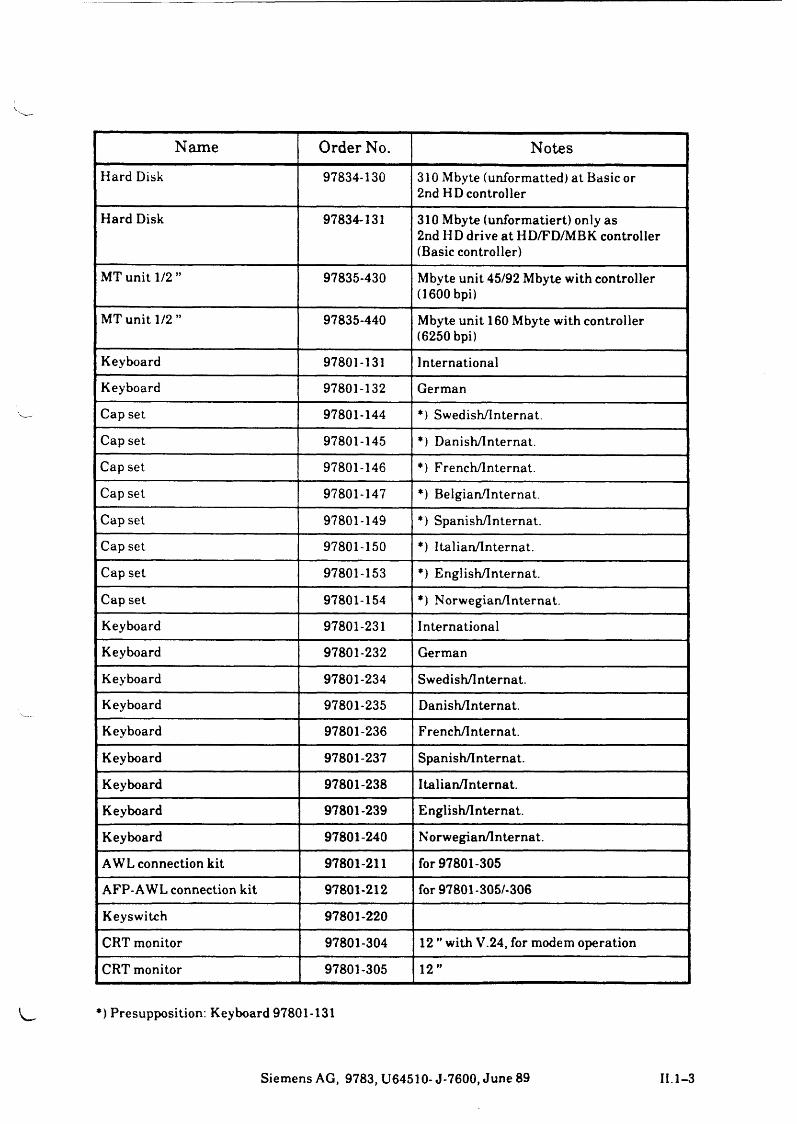
Name Order No. NotesHard Disk 97834-130 310 Mbyte (unformatted) at Basic or
2nd HD controller
Hard Disk 97834-131 310 Mbyte (unformatiert) only as 2nd HD drive at HD/FD/MBK controller (Basic controller)
MT unit 1/2 ” 97835-430 Mbyte unit 45/92 Mbyte with controller (1600 bpi)
MT unit 1/2 ” 97835-440 Mbyte unit 160 Mbyte with controller (6250 bpi)
Keyboard 97801-131 International
Keyboard 97801-132 German
Cap set 97801-144 *) Swedish/Internat.
Cap set 97801-145 *) Danish/Internat.
Cap set 97801-146 *) French/Internat.
Cap set 97801-147 *) Belgian/Internat.
Cap set 97801-149 *) Spanish/Internat.
Cap set 97801-150 *) Italian/Internat.
Cap set 97801-153 *) English/Internat.
Cap set 97801-154 *) Norwegian/lnternat.
Keyboard 97801-231 International
Keyboard 97801-232 German
Keyboard 97801-234 Swedish/Internat.
Keyboard 97801-235 Danish/Internat.
Keyboard 97801-236 French/Internat.
Keyboard 97801-237 Spanish/Internat.
Keyboard 97801-238 Italian/Internat.
Keyboard 97801-239 English/Internat.
Keyboard 97801-240 Norwegian/lnternat.
AWL connection kit 97801-211 for 97801-305
AFP-AWL connection kit 97801-212 for 97801-305/-306
Keyswitch 97801-220
CRT monitor 97801-304 12 ” with V.24, for modem operation
CRT monitor 97801-305 12”
*) Presupposition: Keyboard 97801-131
Siemens AG, 9783, U64510-J-7600, June 89 II. 1-3
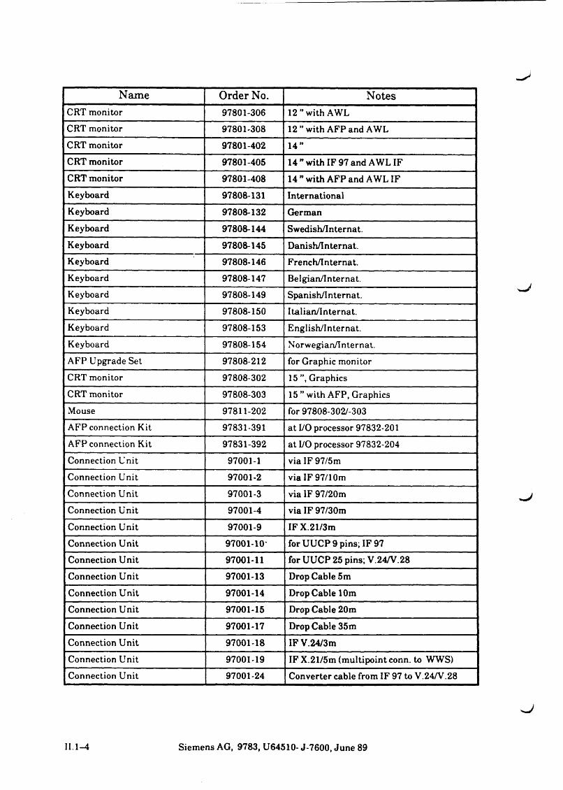
Name Order No. NotesCRT monitor 97801-306 12” with AWLCRT monitor 97801-308 12” with AFP and AWLCRT monitor 97801-402 14”CRT monitor 97801-405 14” with IF 97 and AWL IFCRT monitor 97801-408 14” with AFP and AWL IFKeyboard 97808-131 InternationalKeyboard 97808-132 GermanKeyboard 97808-144 Swedish/Internat.Keyboard 97808-145 Danish/Internat.Keyboard 97808-146 French/Internat.Keyboard 97808-147 Belgian/Internat.Keyboard 97808-149 Spanish/Internat.Keyboard 97808-150 Italian/Internat.Keyboard 97808-153 English/Internat.Keyboard 97808-154 Norwegian/Internat.AFP Upgrade Set 97808-212 for Graphic monitorCRT monitor 97808-302 15 ”, GraphicsCRT monitor 97808-303 15 ” with AFP, GraphicsMouse 97811-202 for 97808-302/-303AFP connection Kit 97831-391 at I/O processor 97832-201AFP connection Kit 97831-392 at I/O processor 97832-204Connection Unit 97001-1 via IF 97/5mConnection Unit 97001-2 via IF 97/10mConnection Unit 97001-3 via IF 97/20mConnection Unit 97001-4 via IF 97/30m
Connection Unit 97001-9 IF X.21/3mConnection Unit 97001-10- for UUCP 9 pins; IF 97Connection Unit 97001-11 for UUCP 25 pins; V.24/V.28Connection Unit 97001-13 Drop Cable 5mConnection Unit 97001-14 Drop Cable 10mConnection Unit 97001-15 Drop Cable 20mConnection Unit 97001-17 Drop Cable 35mConnection Unit 97001-18 IF V.24/3mConnection Unit 97001-19 IF X.21/5m (multipoint conn, to WWS)Connection Unit 97001-24 Converter cable from IF 97 to V.24/V.28
II. 1—4 Siemens AG, 9783, U64510- J-7600, June 89

L

^ J
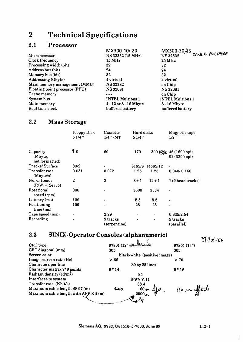
2.1Technical SpecificationsProcessor
MicrorocessorMX300-10/-20NS 32332 (15 MHz)
MX300-30/i6NS 32532 ' c
Clock frequency 15 MHz 25 MHzProcessing width (bit) 32 32Address bus (bit) 24 24Memory bus (bit) 32 32Addressing (Gbyte) 4 virtual 4 virtualMain memory management (MMU) NS 32382 on ChipFloating point processor (FPU) NS 32081 NS 32081Cache memory — on ChipSystem bus INTEL Multibus 1 INTEL Multibus 1Main memory 4 -12 or 8 -16 Mbyte 8-16 MbyteReal time clock buffered battery buffered battery
2.2 Mass StorageFloppy Disk Cassette Hard disks Magnetic tape5 1/4 ” 1/4 ” -MT 5 1/4 ” 1/2 ”
Capacity(Mbyte,
Co 60 170 300^¾¾) 46 (1600 bpi) 92(3200 bpi)
not formatted)Tracks/ Surface 80/2 - 8192/8 14592/12 -
Transfer rate 0.031 0.072 1.25 1.25 0.040/0.160(Mbyte/s)
No. of Heads 2 2 8+1 12 + 1 1 (9 head tracks)(R/W + Servo)
Rotational 300 - 3600 3534 -
speed (rpm)Latency (ms) 100 - 8.3 8.5 -
Positioning 109 - 28 25 -
time (ms)Tape speed (ms)- - 2.29 - - 0.635/2.54Recording * 9 tracks
(serpentine)- - 9 tracks
(parallel)
2.3 SINIX-Operator Consoles (alphanumeric)CRT typeCRT diagonal (mm)Screen colorImage refresh rate (Hz)Characters per line Character matrix 7*9 points Radiant density (cd/m2)Interfaces to system Transferrate (Kbit/s)Maximum cable length SS 97 (m) Maximum cable length with AFP Kit (m)
97801 (12”)305
black/white (positive image!> 66
80 by 25 lines9* 14
85IF97/V.11
38.460
2000,*
97801 0 4 ”) 365
> 70
9*16
\ l 0 A©-
Siemens AG, 9783, U64510- J-7600, June 89 II. 2-1
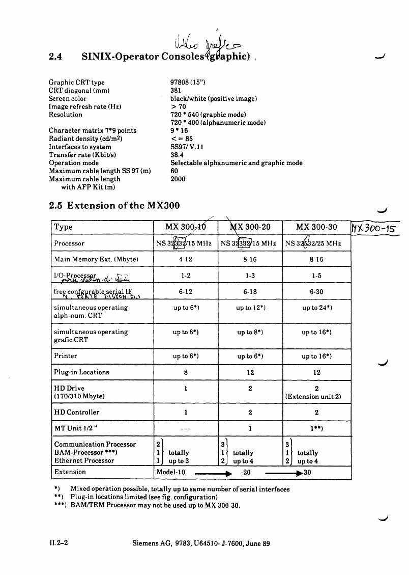
2.4|hß. Vts^
SINIX-Operator Consoles^gpaphic)
Graphic CRT type CRT diagonal (mm)Screen colorImage refresh rate (Hz)Resolution
Character matrix 7*9 points Radiant density (cd/m2) Interfaces to system Transfer rate (Kbit/s)Operation modeMaximum cable length SS 97 (m) Maximum cable length
with AFP Kit (m)
*) Mixed operation possible, totally up to same number of serial interfaces **) Plug-in locations limited (see fig. configuration)***) BAM/TRM Processor may not be used up to MX 300-30.
97808(15”)381black/white (positive image)> 70720 * 540 (graphic mode)720 * 400 (alphanumeric mode)9*16< = 8 5SS97/V.1138.4Selectable alphanumeric and graphic mode 60 2000
II.2-2 Siemens AG, 9783, U64510- J-7600, June 89
SIEM ENS
Part IIIAdjusting Specifications
Operator Area MX300
Platter Layout and Connector Area
Adjusting Specifications
Cable Layout
Connector Area MXB2

Part III
Adjusting Specifications
Contents Page
1 Pow er On/ Off and A ddress A ssignm ent of H ardw are 111.1*11.1 Power ON III.1-11.2 Power OFF III.1-11.3 Address Assignment Hardware SINIX-C/-H MX2/MX300 III.1-2
2 P la tte r Layout and C onnector A rea III.2-12.1 Platter Layout III.2-12.2 Connector Area of the MX300 III.2-2
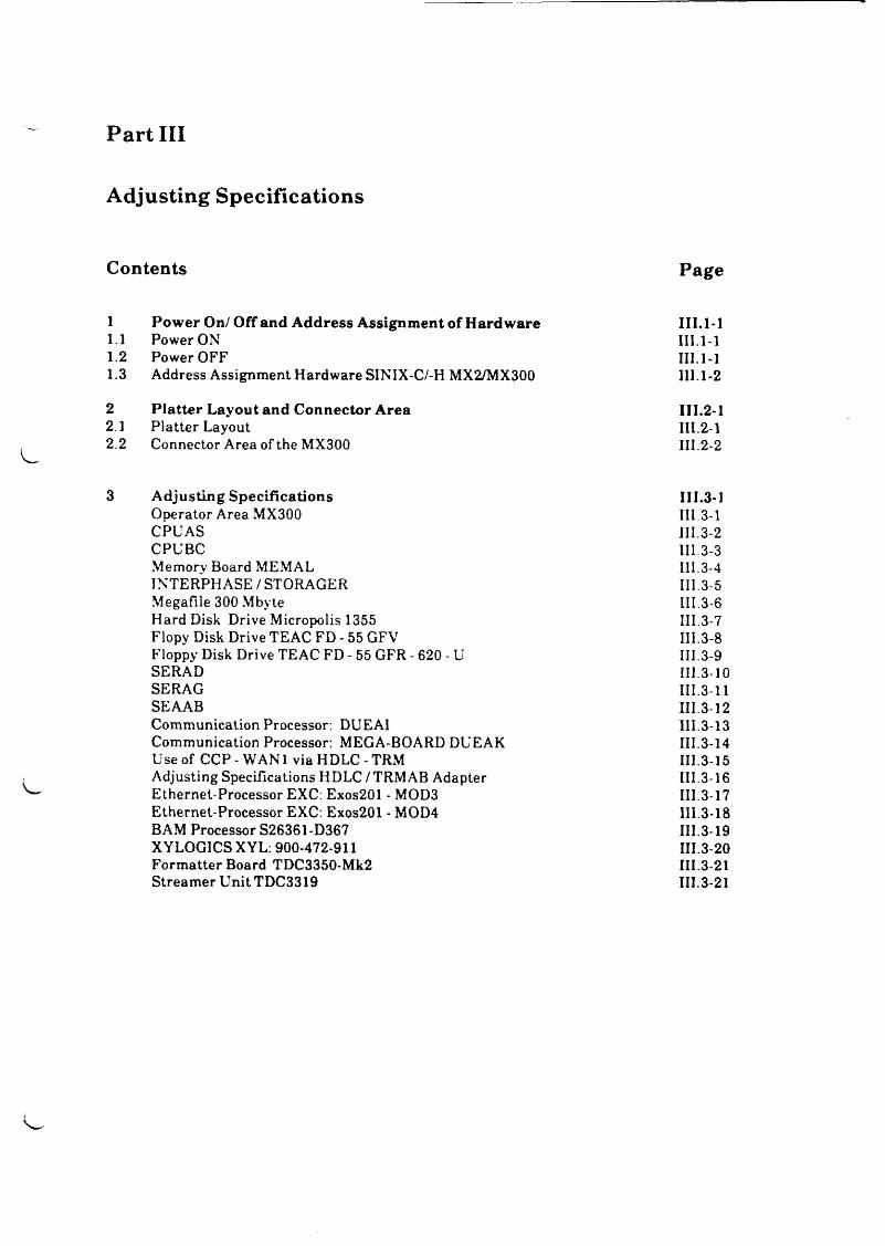
3 A djusting Specifications III.3-1Operator Area MX300 III.3-1CPU AS III.3-2CPUBC III.3-3Memory Board MEMAL III.3-4INTERPHASE / STORAGER III. 3-5Megafile 300 Mbyte III.3-6Hard Disk Drive Micropolis 1355 III.3-7Flopy Disk Drive TEAC FD - 55 GFV III.3-8Floppy Disk Drive TEAC FD - 55 GFR - 620 - U III.3-9SERAD III.3-10SERAG III.3-11SEAAB III.3-12Communication Processor: DUEAI III.3-13Communication Processor: MEGA-BOARD DUEAK III.3-14Use of CCP - WAN1 via HDLC - TRM III.3-15Adjusting Specifications HDLC/TRMAB Adapter III.3-16Ethernet-Processor EXC: Exos201 - MOD3 III.3-17Ethernet-Processor EXC: Exos201 - MOD4 III.3-18BAM Processor S26361-D367 III.3-19XYLOG1CS XYL: 900-472-911 III.3-20Formatter Board TDC3350-Mk2 III.3-21Streamer Unit TDC3319 III.3-21
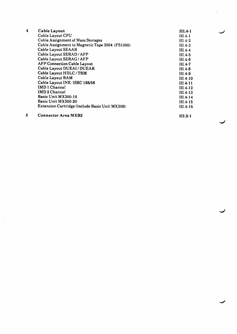
Cable Layout 111.4-1Cable Layout CPU III.4-1Cable Assignment of Mass Storages III 4-2Cable Assignment to Magnetic Tape 3504 (FS1000) III.4-3Cable Layout SEAAB III.4-4Cable Layout SERAD / AFP III.4-5Cable Layout SERAG / AFP III.4-6AFP Connection Cable Layout III.4-7Cable Layout DUEAI / DUEAK III.4-8Cable Layout HDLC / TRM III.4-9Cable Layout BAM III.4-10Cable Layout INE: ISBC 188/56 III.4-11IMD 1 Channel III.4-12IMD 2 Channel III.4-13Basic Unit MX300-10 III.4-14Basic Unit MX300-20 III.4-15Extension Cartridge (include Basic Unit MX300) III.4-16
C onnector A rea MXB2 111.5*1
^ J
1 Power On/ Off and Address Assignment of Hardware
1.1 Power ONTo switch on the system with the push-button ”ON” is only possible if the key switch is in position ”ON”. It causes the start up of the system.
Note:- In case of more than one power supply (MX300-20 or in extension cabin), all power
supplies will be shut down 3 sec after push-button ”ON” has been pressed, if one of the power supplies is defect.
- The individual power supplies are switched on time-staggered to avoid a higher pulse.
1.2 Power OFFSwitch off the power supply is effected by pressing the push-button ’’OFF” ('hard' OFF). Also this function works only if the key switch is in position ”ON".
Note: Shut down the system safely and switch off the power supply is effected by the followingSINIX commands:
- /etc/halt
- /etc/shutdown
- /etc/poweroff
- /etc/reboot
- /etc/fastboot
system terminated; PSU switched off
optional refer to SINIX manual (e.g. /etc/shutdown -h + 5 causes a
shutdown in 5 minutes)
text file that contains shutdown -h now (may be enlarged by system administrator)
system terminated and restarted
like /etc/reboot, but without file-check during next start up procedure
- /etc/fasthalt like /etc/halt, but without file-check during next start up procedure
- login password: shutdown calls /etc/poweroff (password : siemens)
III.l-l Siemens AG, 9783, U64510- J-7600, June 89
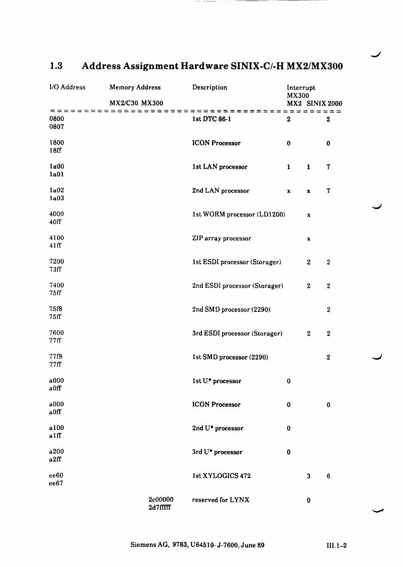
1.3 Address Assignment Hardware SINIX-C/-H MX2/MX300
I/O Address Memory Address
MX2/C30 MX300
Description InterruptMX300MX2 SINIX 2000
08000807
1st DTC 86-1 2 2
180018IT
ICON Processor 0 0
laOOlaOl
1st LAN processor 1 1 7
la02la03
2nd LAN processor x X 7
400040fT
1st WORM processor (LD1200) X
4100 4i fr
ZIP array processor X
720073ff
1st ESDI processor (Storager) 2 2
740075fT
2nd ESDI processor (Storager) 2 2
75f875fT
2nd SMD processor (2290) 2
760077fT
3rd ESDI processor (Storager) 2 2
77f877fT
1st SMD processor (2290) 2
aOOOaOff
1st U* processor 0
aOOOaOfT
ICON Processor 0 0
alOOalfT
2nd U* processor 0
a200a2ff
3rd U* processor 0
ee60ee67
1st XYLOGICS 472 3 6
2c00000 reserved for LYNX 02d7ffflf
Siemens AG, 9783, U64510- J-7600, June 89 III. 1-2
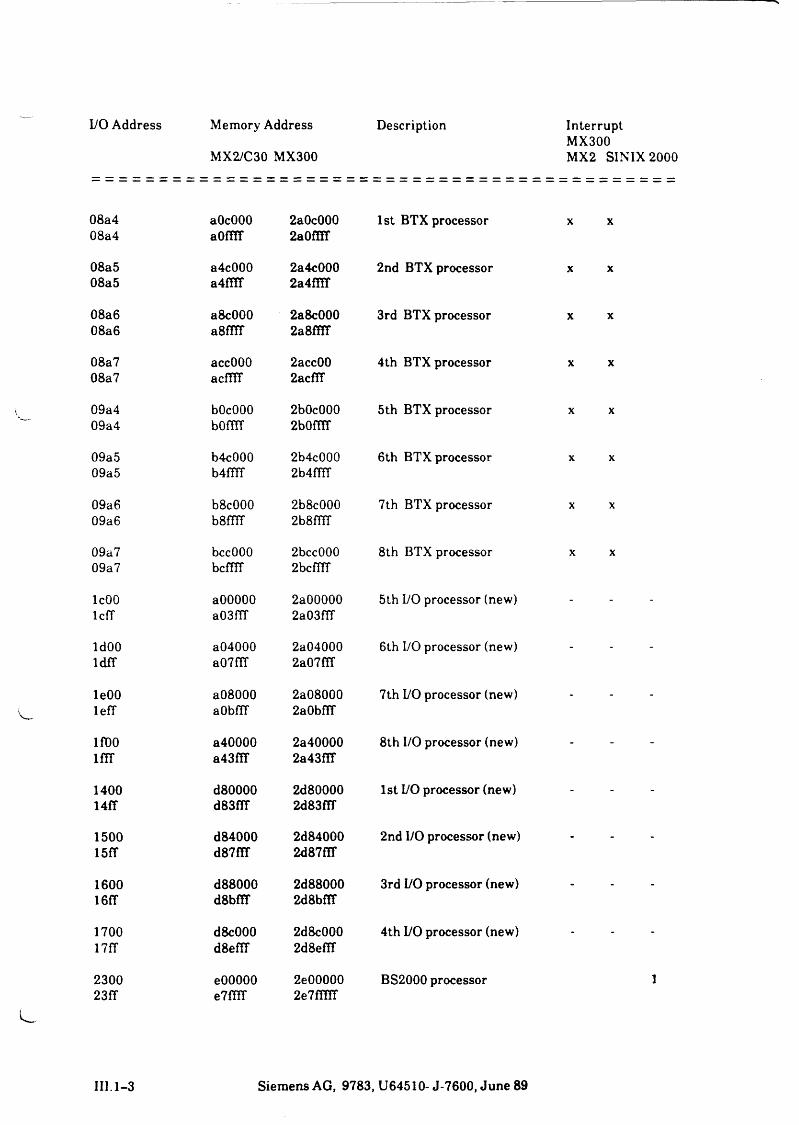
I/O Address Memory Address Description InterruptMX300MX2 SINIX 2000MX2/C30 MX300
08a408a4
aOcOOOaom r
2a0c0002a0fST
1st BTX processor X X
08a508a5
a4c000a4ffiT
2a4c0002a4f!ir
2nd BTX processor X X
08a608a6
a8c000a8ffiT
2a8c0002a8ffiT
3rd BTX processor X X
08a708a7
accOOOacfllT
2acc002acffF
4th BTX processor X X
09a409a4
bOcOOObOffiT
2b0c0002b0fiTT
5th BTX processor X X
09a509a5
b4c000b4fTff
2b4c0002b4ffiT
6th BTX processor X X
09a609a6
b8c000b8fTff
2b8c0002b8fHT
7th BTX processor X X
09a709a7
bccOOObcfflT
2bcc0002bcfirr
8th BTX processor X X
IcOOlcff
aOOOOOa03ffT
2a000002a03flT
5th L/O processor (new) - - -
ldOOldfT
a04000a07f(T
2a040002a07fTT
6th I/O processor (new) - - -
leOOlefT
a08000aObfTf
2a080002a0bfiT
7th I/O processor (new) - - -
lfOOlfTT
a40000a43f!T
2a400002a43fTT
8th I/O processor (new) - - -
140014fT
d80000d83fff
2d800002d83fTf
1st I/O processor (new) - - -
150015fT
d84000d87fIT
2d840002d87f!T
2nd I/O processor (new) - - -
160016fT
d88000d8bf!T
2d880002d8bfff
3rd I/O processor (new) - - -
170017fT
d8c000d8eflT
2d8c0002d8eflT
4th I/O processor (new) - - -
230023ff
eOOOOOe7ffiT
2e000002e7ffllT
BS2000 processor 1
III. 1-3 Siemens AG, 9783, U64510-J-7600, June 89
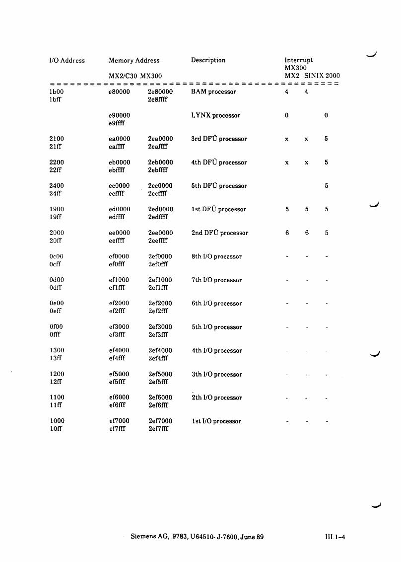
I/O Address Memory Address
MX2/C30 MX300
Description InterruptMX300MX2 SINIX 2000
lbOOlbfT
e80000 2e800002e8fiTf
BAM processor 4 4
e90000e9fflT
LYNX processor 0 0
210021fT
eaOOOOeaffiT
2ea00002eafHF
3rd DFÜ processor X X 5
220022fT
ebOOOOebfilT
2eb00002ebfüT
4th DFÜ processor X X 5
240024fT
ecOOOOecffff
2ec00002ecfTir
5th DFÜ processor 5
190019fT
edOOOOedffff
2ed00002edffiT
1st DFÜ processor 5 5 5
200020ff
eeOOOOeeffff
2ee00002eefüT
2nd DFÜ processor 6 6 5
OcOOOcff
eflOOOOe fo n r
2ef00002ef0ffT
8th I/O processor - -
OdOOOdfT
eflOOOefirrr
2efl0002eflfTf
7th I/O processor - -
OeOOOefT
ef2000ef2ffT
2ef20002ef2fTF
6th I/O processor - -
OfOOOffT
ef3000ef3fTf
2ef30002ef3fiT
5th I/O processor - -
130013fT
ef4000ef4ffF
2ef40002ef4fTT
4th I/O processor - -
120012ff
ef5000ef5f!T
2ef50002ef5fff
3th I/O processor - -
1100l l f f
ef6000ef6fff
2ef60002ef6fTT
2th I/O processor - -
1000lOff
ef7000ef7fff
2ef70002 enm
1st I/O processor - -
Siemens AG, 9783, U64510- J-7600, June 89 III.1-4
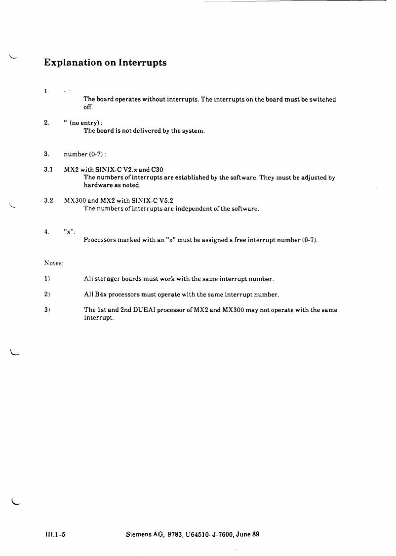
Explanation on Interrupts
l.The board operates without interrupts. The interrupts on the board must be switched off.
2. ” (no en try ):The board is not delivered by the system.
3. number (0-7):
3.1 MX2 with SINIX-C V2.x and C30The numbers of interrupts are established by the software. They must be adjusted by hardware as noted.
3.2 MX300 and MX2 with SINIX-C V5.2The numbers of interrupts are independent of the software.
4. ”x”:Processors marked with an ”x” must be assigned a free interrupt number (0-7).
Notes:
1) All storager boards must work with the same interrupt number.
2) All B4x processors must operate with the same interrupt number.
3) The 1st and 2nd DUEAI processor of MX2 and MX300 may not operate with the same interrupt.
III.1-5 Siemens AG, 9783, U64510- J-7600, June 89

Siemens AG, 9783, U64510- J-7600, June 89 III. 1-6


^J
Ass
ignm
ent E
UR
OPE
-Car
ds
MU
LTIB
US
1 Ass
ignm
ent
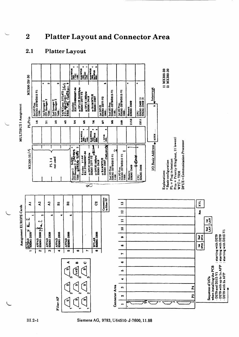
2 Platter Layout and Connector Area2.1 Platter Layout
o ©CM CO
§ § to to X X 22 S 55
COV_ -C
B g.SP 2 - -c ©id & Cc c -r © cm 5 o 3cfl —C O ft«© 'S ito,« 11* oa j u * Ö.
u s■2 2"Ö•gg£ £
< A2
A3
2 B2 C2
Conn
ectio
n to
filte
r PF
§
C4
C\)
tO
i f
IQ —<ssa. 2 u .2 < 3
•Ö
ia -
1 1
J
i i
«Ül
CM CO ** to CO «0
COX
YL
CM1
*5
>o
2nd
LAN
a»3 E
CT> CTt CM t- t* -» CM CM eoa a a00 * I jc js
I ‘5 '5
f- c c cw w w u u u
to^
CD t t (0
en flu
m -s ? ~ tS c n ft x 3 «
to
•*T
to £ s l S '5 p tg c t - r - c -
i f « « ? ®CM £
7E -K 7 ” ^ 7 * ^ 7 n
III.2-1 Siemens AG, 9783, U64510- J-7600,11.88
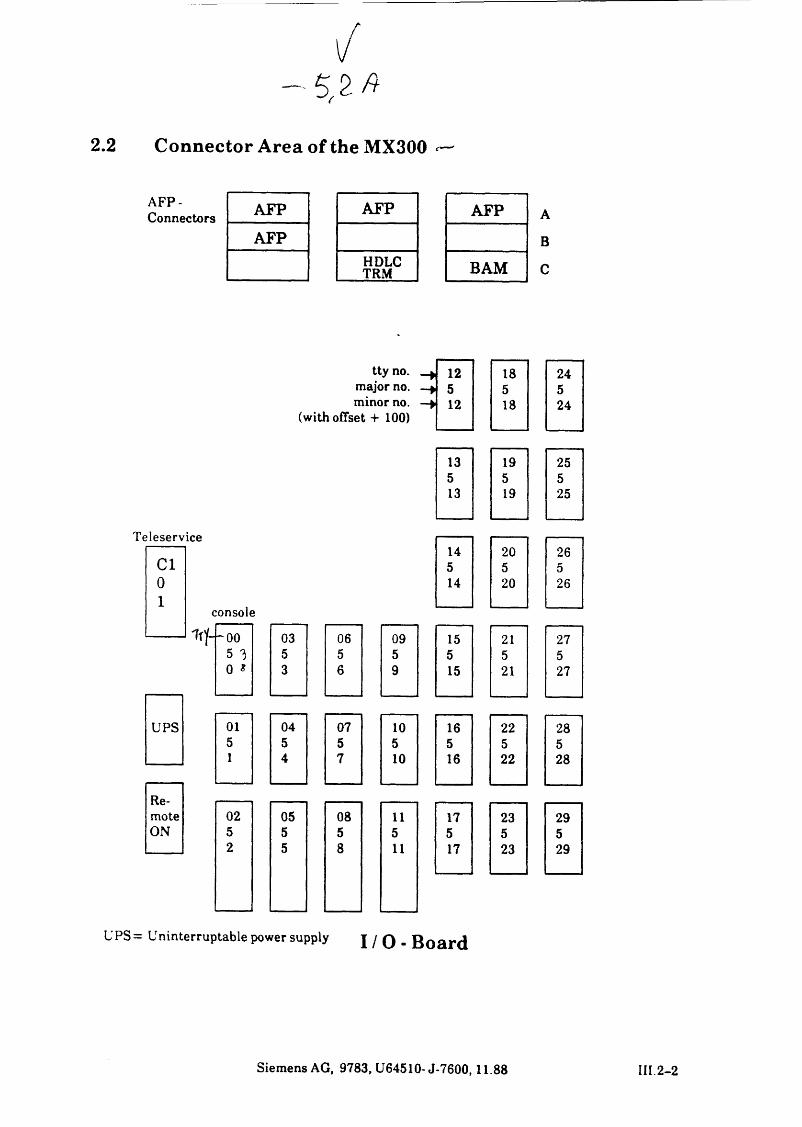
2.2 Connector Area of the MX300 ^
AFP-Connectors AFP AFP AFP
AFPHDLCTRM BAM
A
B
C
tty no. -> 12 18 24major no. -* 5 5 5minor no.
(with offset + 100)-> 12 18 24
13 19 255 5 513 19 25
Teleservice
C l145
205
265
01
14 20 26
console
i f f -oo 03 06 09 15 21 275 3 5 5 5 5 5 50 * 3 6 9 15 21 27
UPS 01 04 07 10 16 22 285 5 5 5 5 5 51 4 7 10 16 22 28
Remote 02 05 08 11 17 23 29ON 5 5 5 5 5 5 5
2 5 8 11 17 23 29
UPS= Uninterruptable power supply I / O - B o a r d
Siemens AG, 9783, U64510- J-7600,11.88 III 2-2
MU
LTIB
US
1 B
eleg
ung
Ni'Einstellanweisung
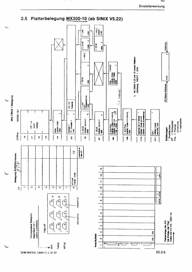
2.5 Platterbelegung MX300-10 (ab SINIX V5.22)
Einstellanweisung
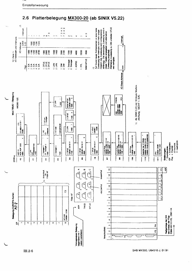
2.6 Platterbelegung MX300-20 (ab SINIX V5.22)
III.2-6 SHB MX300, U64510-J, 01.91
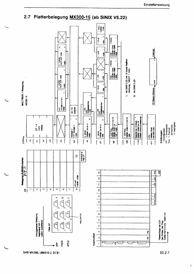
Einstellanweisung
2.7 Platterbelegung MX300-15 (ab SINIX V5.22)
SHB MX300, U64510-J, 01.91 III.2-7
Einstellanweisung
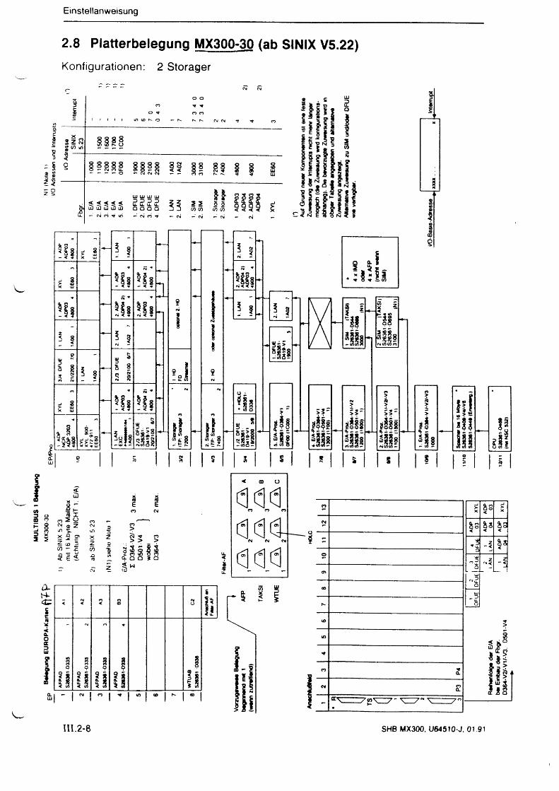
2.8 Platterbelegung MX300-30 (ab SINIX V5.22)Konfigurationen: 2 Storager
III.2-8 SHB MX300, U64510-J, 01 91
MU
LTIB
US
1 B
eleg
ung
MX3
00-3
0
IV Einstellanweisung
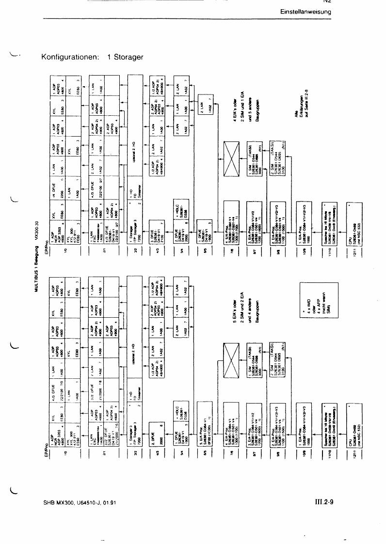
Konfigurationen: 1 Storager
I s
O (0 s
SHB MX300, U64510-J, 01.91 III.2-9


s
N—

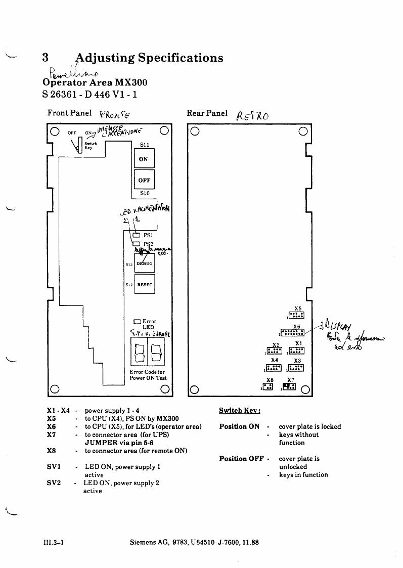
3 Adjusting SpecificationsOperator Area MX300 S 26361-D 446 V I -1
Front Panel Rear Panel
X I-X 4 - power supply 1 - 4X5 to CPU (X4), PS ON by MX300X6 to CPU (X5), for LED's (operator area)X7 to connector area (for UPS)
JU M PER via pin 5-6X8 to connector area (for remote ON)
SV1 LED ON, power supply 1 active
SV2 LED ON, power supply 2 active
Switch K ey:
Position ON - cover plate is locked keys without function
Position OFF • cover plate is unlocked keys in function
III.3-1 Siemens AG, 9783, U64510- J-7600,11.88
""4
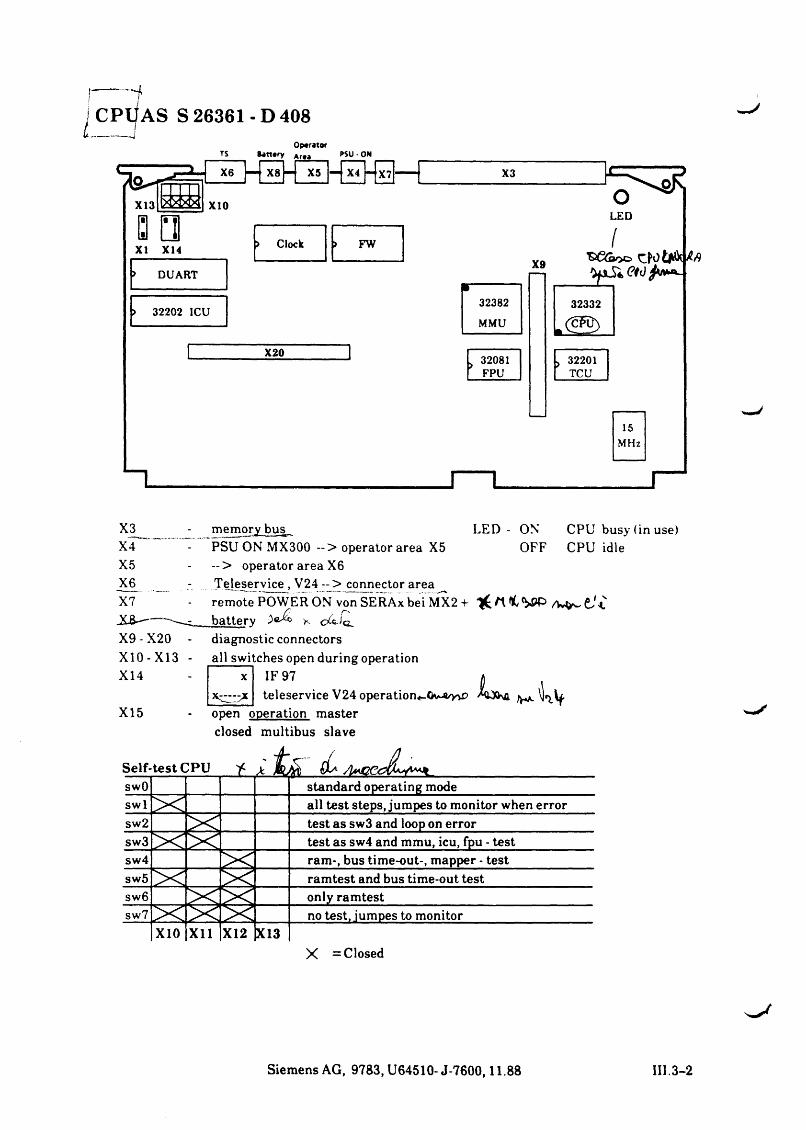
I CPl|AS S 26361 - D 408I t -------------J
OperatorBanary Ar<a PSU • ON
X6 — X8 - ■ X5 |-fxT|-[x7]---[ X3
X9
32081F P U
L E D
I
32201T C U
15M H z
_________ rX1 memory busX4 PSU ON MX300 --> operator area X5X5 — > operator area X6X6 Teleservice , V24 ~ > connector areaX7 remote POWER ON von SERAx bei MX2 +
............... battery ^ c ^ iaX9 - X20 - diagnostic connectorsX10-X13 - all switches open during operationX14 X IF 97
teleservice V24 operation*-Ov-«/y>r>X15 open operation master
LED - ON OFF
CPU busy (in use) CPU idle
h& A f K
closed multibus slave
Self-test CPU AmCC*swO standard operating modeswl all test steps, jumpes to monitor when errorsw2 test as sw3 and loop on errorsw3 test as sw4 and mmu, icu, fpu - testsw4 ram-, bus time-out-, mapper - testsw5 ramtest and bus time-out testsw6 only ramtestsw7 no test, jumpes to monitor
X10 X ll X12 X13X = Closed
Siemens AG, 9783, U64510-J-7600,11.88 III.3-2
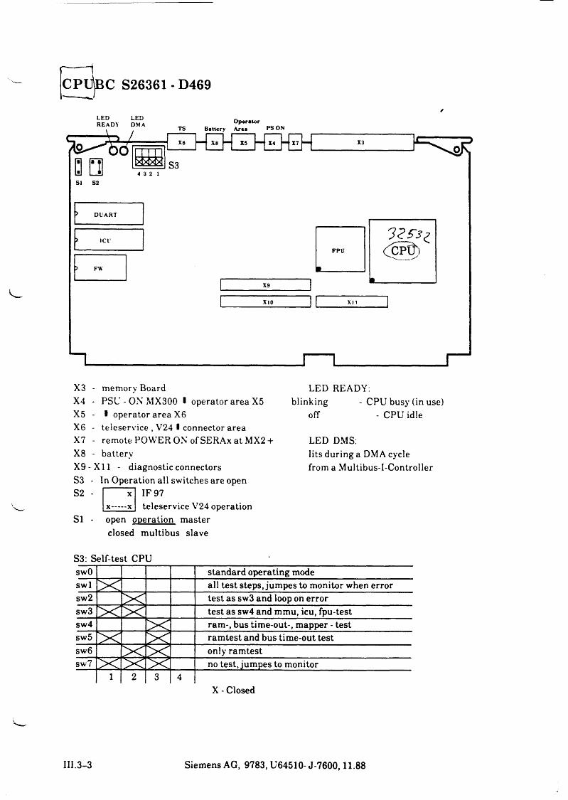
---------1CPUjßC S26361 - D469
X3 - memory BoardX4 - PSU-ONMX300 I operator area X5 X5 - I operator area X6 X6 - teleservice , V24 ■ connector area X7 - remote POWER ON of SERAx at MX2 + X8 - batteryX9-X11 - diagnostic connectors S3 - In Operation all switches are open
IF 97teleservice V24 operation
Si - open operation master closed multibus slave
LED READY:blinking - CPU busy (in use)
ofT - CPU idle
LED DMS:lits during a DMA cycle from a Multibus-I-Controller
S3: Self-test CPUswO standard operating modeswl all test steps, jumpes to monitor when errorsw2 test as sw3 and loop on errorsw3 test as sw4 and mmu, icu, fpu-testsw4 ram-, bus time-out-, mapper - testsw5 ramtest and bus time-out testsw6 only ramtestsw7 no test, jumpes to monitor
1 2 3 4X - Closed
III.3-3 Siemens AG, 9783, U64510- J-7600,11.88
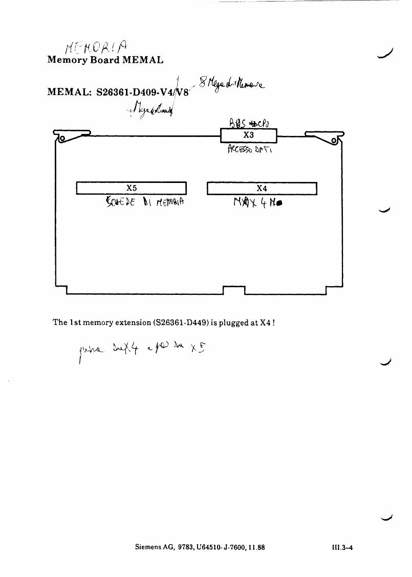
f t f t f r O f U f tMemory Board MEMAL
MEMAL: S26361-D409-V4
The 1st memory extension (S26361-D449) is plugged at X4 !
f v A J>w x 5
I
Siemens AG, 9783, U64510-J-7600,11.88 III.3-4
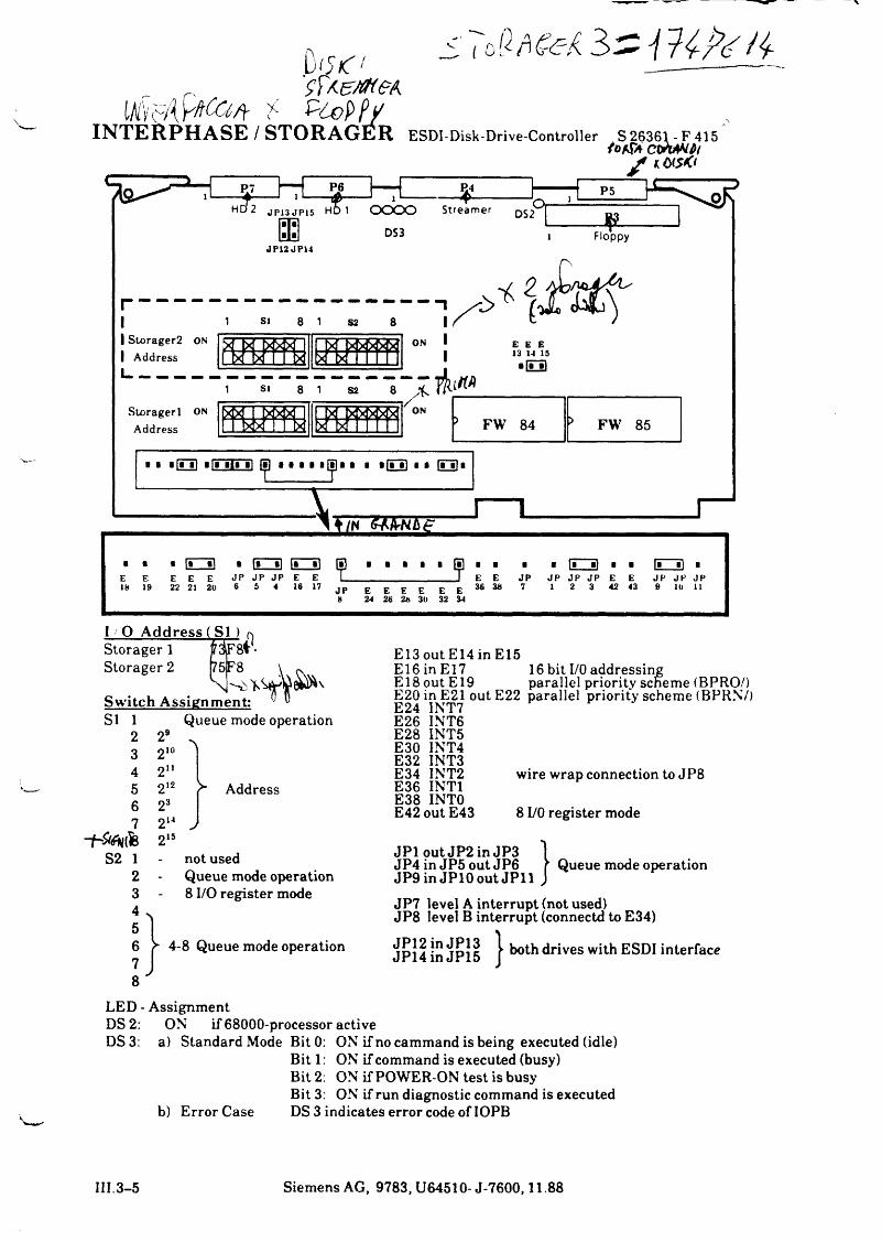
1 O A ddress ( S1 )r3£8f 75jF8X K
Switch Assignment:
Storager 1 Storager 2
8
S1 1 23456 7
292i°2n212232142is
Queue mode operation*\
Address
7
S2 1 2345678
not usedQueue mode operation 8 I/O register mode
4-8 Queue mode operation
E13 out E14 in E15E16inE17 16 bit I/O addressingE 18 out E 19 parallel priority scheme (BPRO/)E20 in E21 out E22 parallel priority scheme (BPRN7) E24 INT7E26E28E30E32E34E36E38
INT6INT5INT4INT3INT2INTIINTO
wire wrap connection to JP8
E42 out E43 8 I/O register mode
JP1 out JP2 in JP3 JP4 in JP5 out JP6 JP9 in JPlO out JP11
Queue mode operation
JP7 level A interrupt (not used)JP8 level B interrupt (connectd to E34)
JP12 in JP13 JP14 in JP15 }both drives with ESDI interface
LED - AssignmentDS 2: ON if 68000-processor activeDS 3: a) Standard Mode Bit 0: ON if no cammand is being executed (idle)
Bit 1: ON if command is executed (busy)Bit 2: ON if POWER-ON test is busy Bit 3: ON if run diagnostic command is executed
b) Error Case DS 3 indicates error code of IOPB
III.3-5 Siemens AG, 9783, U64510- J-7600,11.88
i S 5 % DL
. //
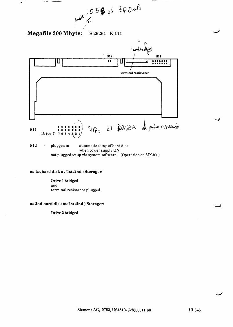
Megafile 300 Mbyte: S 26261- K i l l
S12 - plugged in automatic setup of hard diskwhen power supply ON
not pluggedsetup via system software (Operation on MX300)
as 1st hard disk a t (1st/2nd ) Storager:
Drive 1 bridged andterminal resistance plugged
as 2nd hard disk a t (1 st/2nd ) Storager:
Drive 2 bridged
Siemens AG, 9783, U64510- J-7600,11.88 III.3-6
i s s # - z & o ^ 9 >
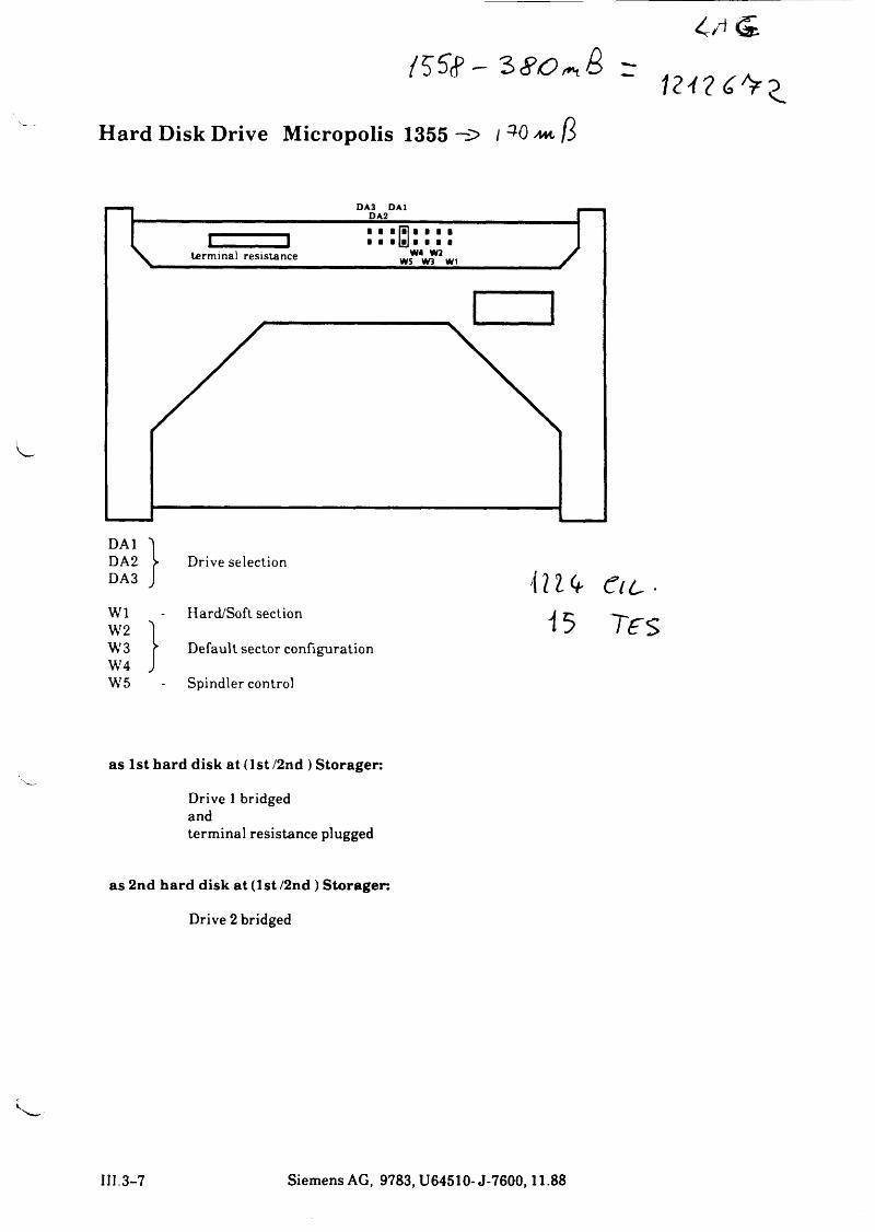
Hard Disk Drive Micropolis 1355 -f>
DAI ')DA2 > Drive selectionDA3 J i n u - C t L ■W1W2
Hard/Soft section1 i 5 T f S
W3 r Default sector configurationW4 JW5 Spindler control
as 1st hard disk at (1 st/2nd ) S toragen
Drive 1 bridged andterminal resistance plugged
as 2nd hard disk a t (1st /2nd ) S toragen
Drive 2 bridged
III.3-7 Siemens AG, 9783, U64510-J-7600,11.88
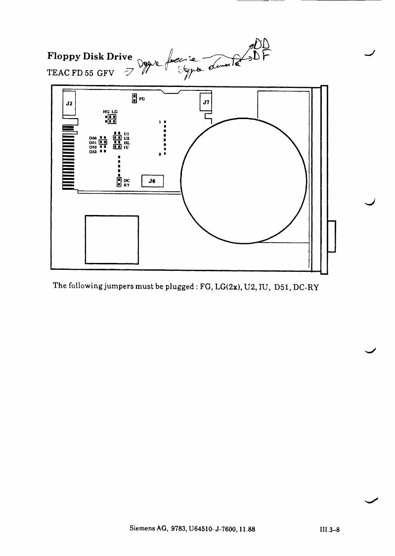
Floppy Disk DriveTEAC FD 55 GFV Ö7
The following jumpers must be plugged : FG, LG(2x), U2, IU, D51, DC-RY
Siemens AG, 9783, U64510-J-7600,11.88 HI. 3-8
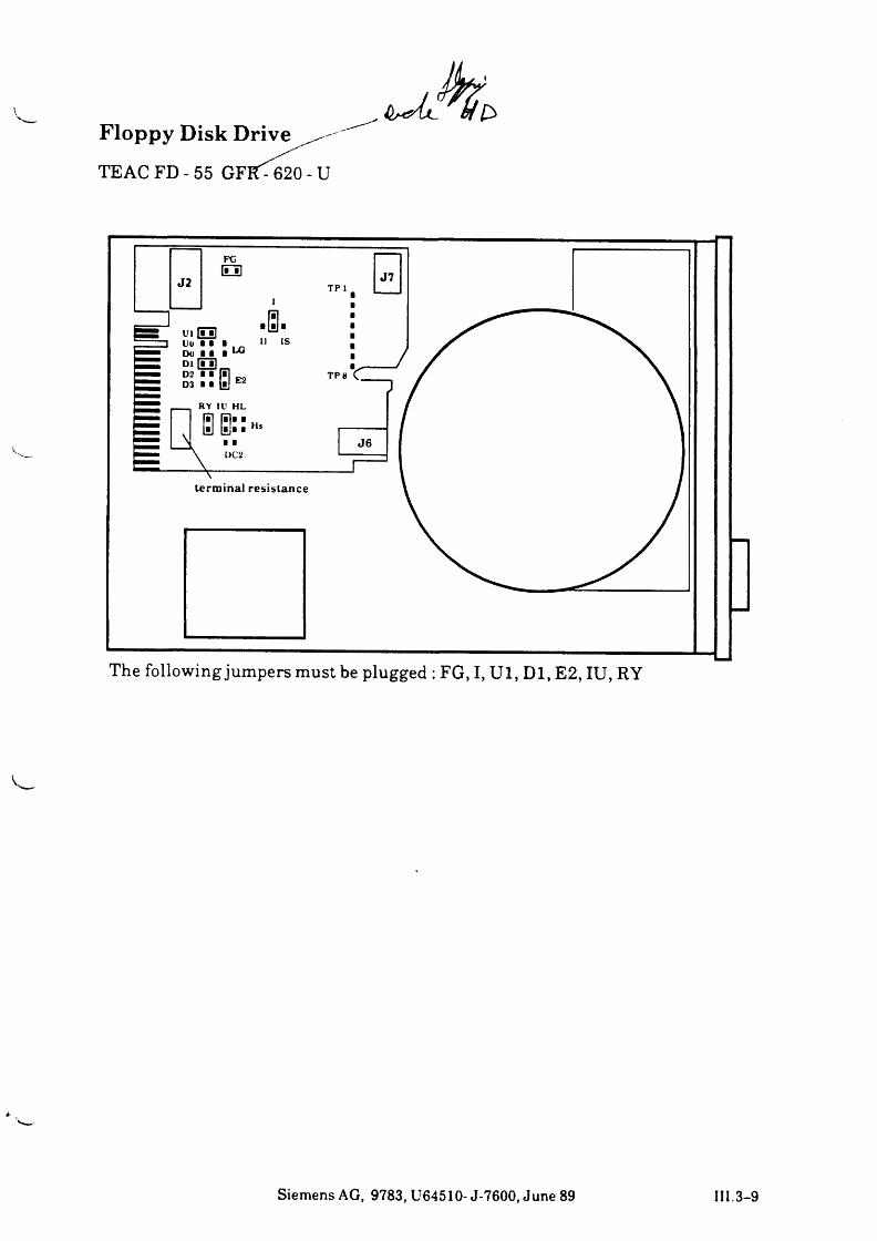
Floppy Disk D r iv e ^ -
TEAC FD - 55 GFFf^620 - U
L \>
The following jumpers must be plugged : FG, I, U l, Dl, E2, IU, RY
Siemens AG, 9783, U64510- J-7600, June 89 III.3-9
d & O v ia m y 1¾< i v4 F" ^ 5 j> ^ ^ SJ <? (¢.
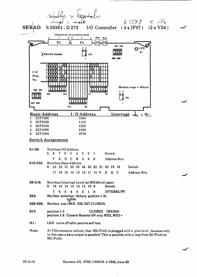
SERAD S 26361-D 279 I/O Controller (4xIF97) (2xV24)channel no. to connector area
2 1 0 5 4 3 ff«* free
2. 2EF6000 11003. 2EF5000 12004. 2EF4000 13005. 2EF3000 0F00
Switch Assignment:
S1-S8:
S18-S33:
Multibus I/O Address S: 8 7 6 5 4 3
ASwitch Address BitsF E D C B
Multibus Base AddressS: 33 32 31 30 25 24 23 22 21 20 19 18 Switch
17 16 15 14 13 12 11 10 F E D C Address Bits
S9-S16: Multibus Interrupt Level (at MX300 all open)S: 16 15 14 13 12 11 10 9 Switch
7 6 5 4 3 2 1 0 INTERRUPTS34: Mailbox selection (4kbyte position 1-3);
S26-S29: Mailbox size (4KB: S26, S27 CLOSED)
S17: position 1-3 CLOSED (MX300)position 1-2 Console Remote ON only MX2, MX2 +
H I: LED turns off after positve self-test
Note: At V24 connector ashure, that M2 (Pin5) is plugged with a plus level, because onlyin this case a data output is possible! This is possible with a loop from S2 (Pin4) to M2 (Pin5).
III.3-10 Siemens AG, 9783, U64510- J-7600, June 89
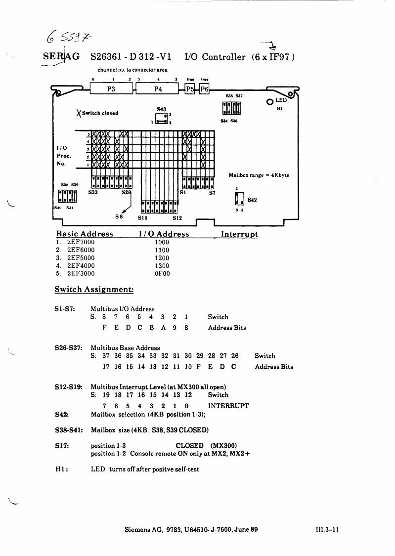
SEr L g S26361 - D 312 -VI I/O Controller (6 x IF97 )channel no. to connector area
0 1 2 5 4 3 tr— freeP3 P4 P5 P6
S 3 5 S37 s&F
) (Switch closed
m m
S43
0 L E D
H I
S34 S36
Mailbox range = 4Kbyte
S42S4U S41 S 2
Basic Address I / O Address Interrupt1. 2EF7000 10002. 2EF6000 11003. 2EF5000 12004. 2EF4000 13005. 2EF3000 0F00
Switch Assignment:
S1-S7: Multibus I/O AddressS: 8 7 6 5 4 3 2 1 Switch
F E D C B A 9 8 Address Bits
S26-S37: Multibus Base AddressS: 37 36 35 34 33 32 31 30 29 28 27 26 Switch
17 16 15 14 13 12 11 10 F E D C Address Bits
S12-S19: Multibus Interrupt Level (at MX300 all open)S: 19 18 17 16 15 14 13 12 Switch
7 6 5 4 3 2 1 0 INTERRUPT S42: Mailbox selection (4KB position 1-3);
S38-S41: Mailbox size (4KB: S38, S39 CLOSED)
S17: position 1-3 CLOSED (MX300)position 1-2 Console remote ON only at MX2, MX2 +
H I: LED turns off after positve self-test
Siemens AG, 9783, U64510- J-7600, June 89 III.3-11
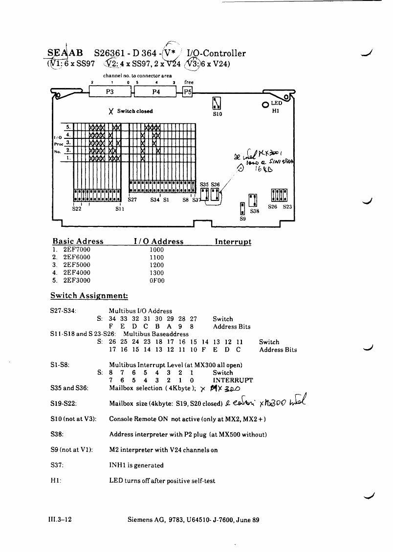
SE^AB S26361 - D 364 -V* I/O-Controller?VlT6 x SS97 ^2:4 x SS97,2 xT24 x V24)
channel no. to connector area2 1 0 5 4 3 free
X Switch closed H5. 5*555 g g
I / O .4. S g * g g g g
Proc 3. K * 3 g g g gNo. 2. * * K3 g l * g
1. g * 3 g g g *
■■I I ■I 7 • a i ■■■■
7■
7■
7■
7■
7■
7a
7■
7■
7a
7a
7a
7a
7a
7a
7a i
■■1 i ■■■■■■a ■iS27
iS34
lSI
1 f S8 S3l i t i
S22 SI 1
0 16 i b
S9
S26 S23
Basic Adress I/O Address Interrupt1. 2EF7000 10002. 2EF6000 11003. 2EF5000 12004. 2EF4000 13005. 2EF3000 0F00
Switch Assignment:
S27-S34: Multibus I/O AddressS: 34 33 32 31 30 29 28 27 Switch
F E D C B A 9 8 Address BitsSi 1 -SI8 and S 23-S26: Multibus Baseaddress
S: 26 25 24 23 18 17 16 15 14 13 12 11 Switch17 16 15 14 13 12 11 10 F E D C Address
S1-S8:S:
S3 5 and S36:
S19-S22:
S10 (not at V3):
S38:
S9 (not at VI):
S37:
HI:
Multibus Interrupt Level (at MX300 all open) 8 7 6 5 4 3 2 1 Switch7 6 5 4 3 2 1 0 INTERRUPTMailbox selection (4Kbyte); y
Mailbox size(4kbyte: Si 9, S20 closed) $-
Console Remote ON not active (only at MX2, MX2 +)
Address interpreter with P2 plug (at MX500 without)
M2 interpreter with V24 channels on
INH1 is generated
LED turns off after positive self-test
III.3-12 Siemens AG, 9783, U64510- J-7600, June 89
" M M- ^
£ £ M tik fC A & io M €
i a / y
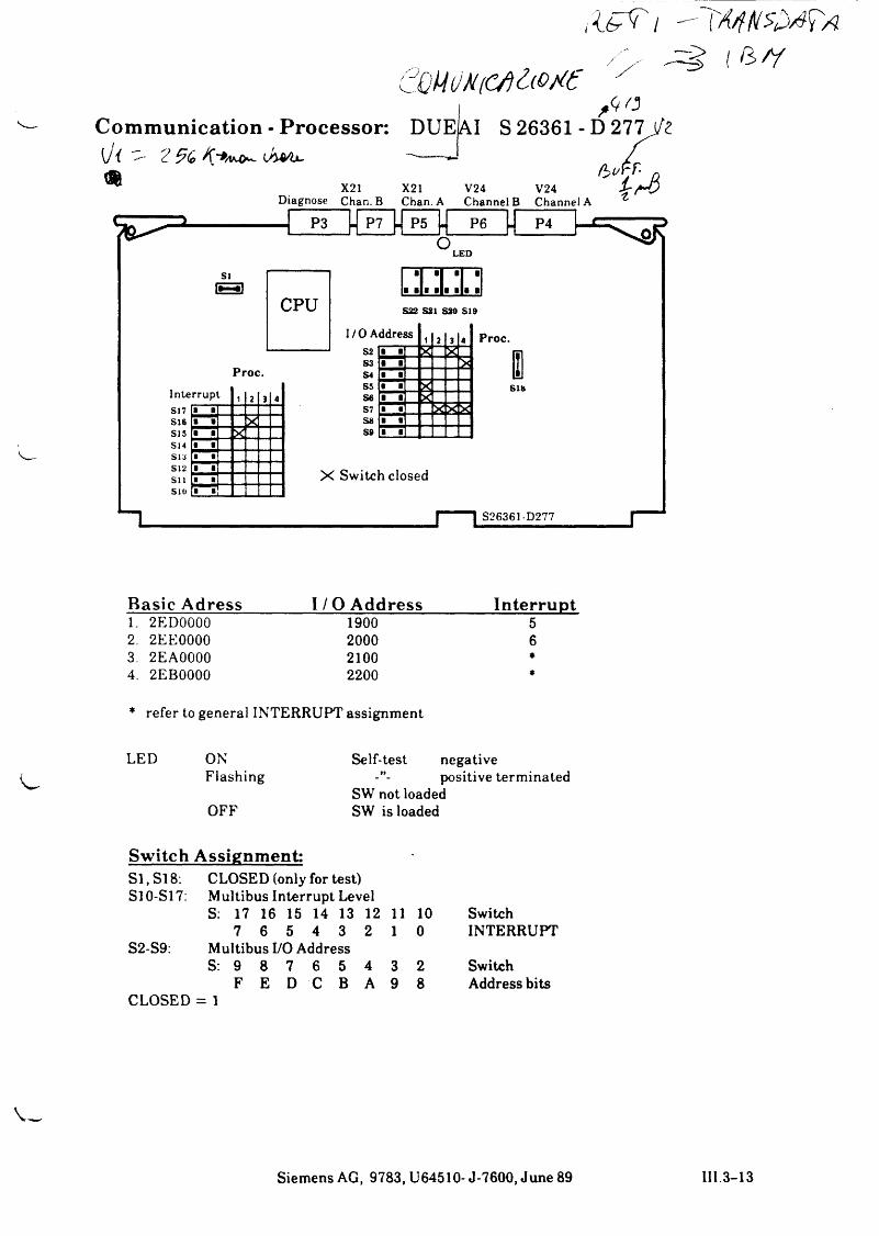
Basic Adress_______ I / O Address_______ Interrupt1. 2ED0000 1900 52. 2EE0000 2000 63. 2EA0000 2100 ♦4. 2EB0000 2200 *
* refer to general INTERRUPT assignment
LED ONFlashing
OFF
Self-test negativepositive terminated
SW not loaded SW is loaded
Switch Assignment: -SI, Si 8: S10-S17:
CLOSED (only for test) Multibus Interrupt LevelS: 17 16 15 14 13 12 11 10 Switch
S2-S9:7 6 5 4 3 2
Multibus I/O Address1 0 INTERRUPT
S: 9 8 7 6 5 4 3 2 Switch
CLOSEDF E D C B A
= 19 8 Address bits
Siemens AG, 9783, U64510- J-7600, June 89 III.3-13
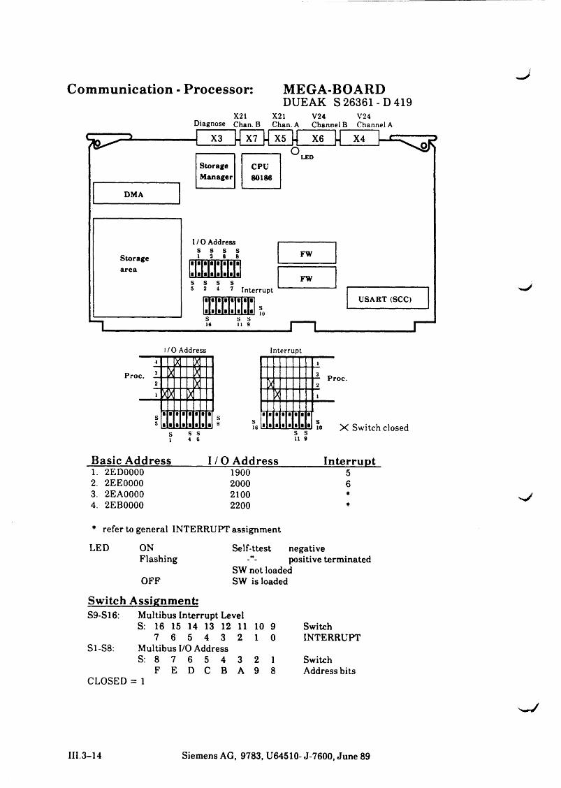
Communication - Processor:
DMA
MEGA-BOARDDUEAK S 26361-D 419
X21Diagnose Chan. B
X21Chan. A
V24Channel B
V24Channel A
StorageManager
X7 X5 . X6 X4O
L E D
CPU8018«
I/O Addresss s s s l 3 s s
s s s16 119
FW
FW2 4 7 Interrupt
USART (SCO
L io
I/O Address Interrupt
Basic Address I / 0 Address Interrupt1. 2ED0000 1900 52. 2EE0000 2000 63. 2EA0000 2100 ♦4. 2EB0000 2200 *
* refer to general INTERRUPT assignment
LED ON Self-ttest negativeFlashing positive terminated
SW not loaded OFF SW is loaded
Switch Assignment:S9-S16: Multibus Interrupt Level
S: 16 15 14 13 12 11 10 9 Switch7 6 5 4 3 2 1 0 INTERRUPT
S1-S8: Multibus I/O Address S: 8 7 6 5 4 3 2 1 Switch
F E D C B A 9 8 Address bitsCLOSED = 1
III.3-14 Siemens AG, 9783, U64510- J-7600, June 89
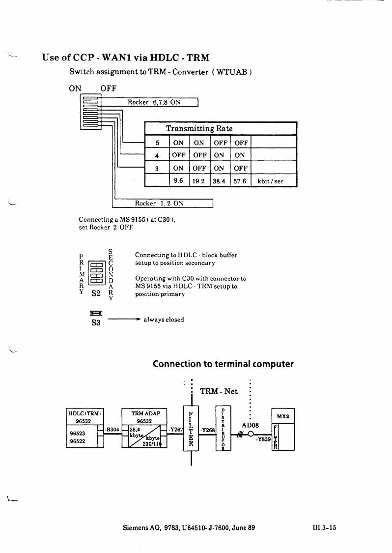
Use of CCP - WAN1 via HDLC - TRMSwitch assignment to TRM - Converter ( WTUAB )
ON____ OFFj— ;________ Rocker 6,7,8 ON
TransmittingRate5 ON ON OFF OFF
4 OFF OFF ON ON
3 ON OFF ON OFF
9.6 19.2 38.4 57.6 kbit/sec
Rocker 1,2 ON
Connecting a MS 9155 ( at C30 ), set Rocker 2 OFF
P R IM A RY S2
r~r~it i ir z o
SEC0NDARY
Connecting to H DLC - block buffer setup to position secondary
Operating with C30 with connector to MS 9155 via HDLC - TRM setup to position primary
B )S3 always closed
Connection to terminal computer
Siemens AG, 9783, U64510- J-7600, June 89 III.3-15
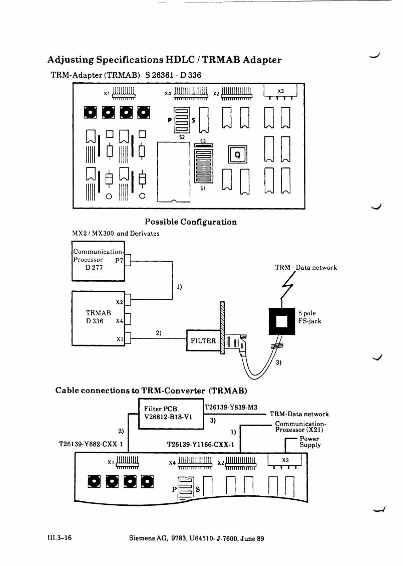
Adjusting Specifications HDLC / TRMAB AdapterTRM-Adapter (TRMAB) S 26361 - D 336
Cable connections to TRM-Converter (TRMAB)
I I I .3-16 Siemens AG, 9783, U64510- J-7600, June 89
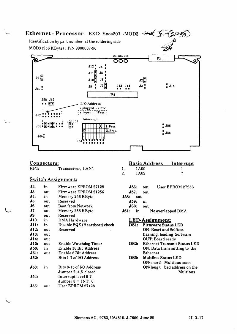
Connectors: Basic Address InterruptRP1: Transceiver, LAN1 1. 1A00 1
2. 1A02 7Switch Assignment:J2: in Firmware EPROM 27128 J56: out User EPROM 27256J3: out Firmware EPROM 21256 J57: outJ4: in Memory 256 KByte J58: outJ5: out Reserved J59: inJ6. out Boot from Network J60: outJ7: out Memory 256 KByte J61: in No overlapped DMAJ9: out ReservedJ10 in DMA Hardware LED-Assignment:J l l in Disable SQE (Heartbeat) check DSl: Firmware Status LEDJ12 out Reserved ON: Reset and SelftestJ13 out flashing: loading SoftwareJ14 out OUT: Board readyJ15 out Enable Watchdog Timer DS2: Ethernet Transmit Status LEDJ50 in Enable 16 Bit Address ON: Data transm itting to theJ51 out Enable 8 Bit Address EthernetJ52 Bits 1-7 of I/O Address DS3: Multibus Status LED
ON(short): Multibus accesJ53: in Bits 8-15 of I/O Address ON(long): bad address on the
Jumper 2 ,4,5 closed MultibusJ54: Interrupt level 0-7
Jumper 8 = INT. 0J55: out User EPROM 27128
Siemens AG, 9783, U64510- J-7600, June 89 III 3-17
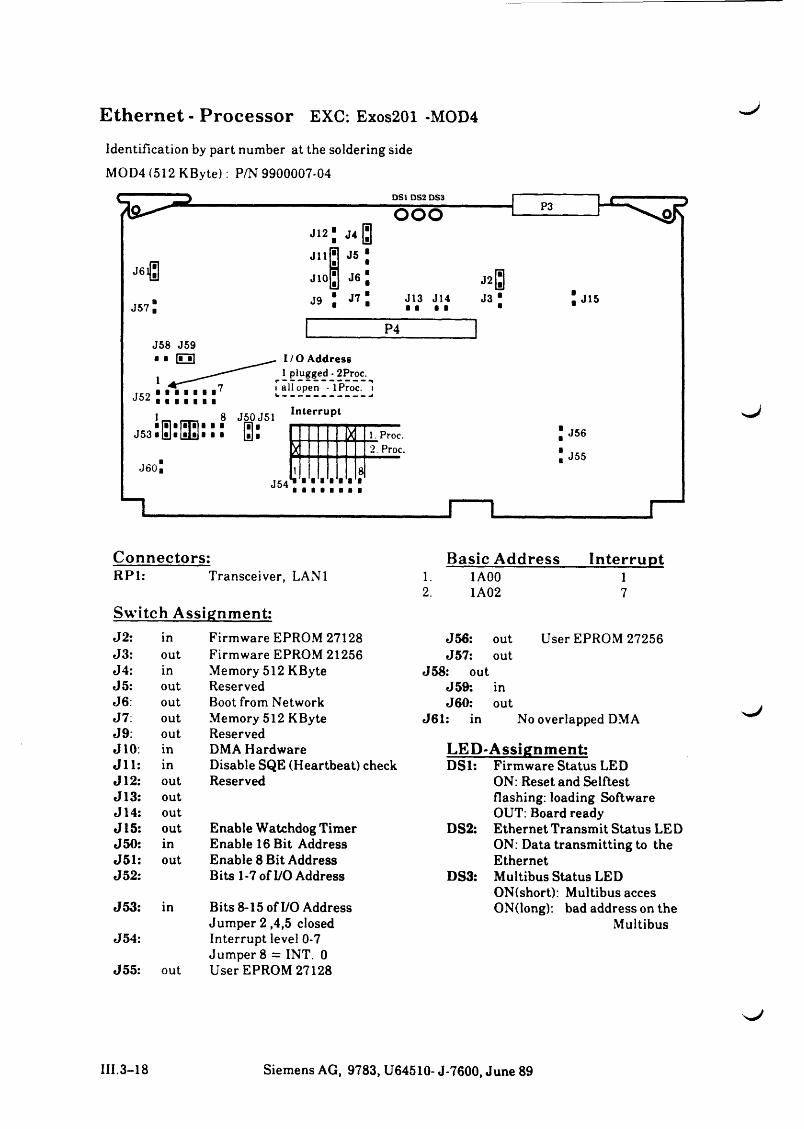
Ethernet - Processor EXC: Exos201 -MOD4
Identification by part number at the soldering side
MOD4 (512 KByte): P/N 9900007-04
H.J
Connectors:RP1: Transceiver, LAN1
Switch Assignment:
Basic Address Interrupt1. 1A00 12. 1A02 7
J2: in Firmware EPROM 27128 J56: out User EPROM 27256J3: out Firmware EPROM 21256 J57: outJ4: in Memory 512 KByte J58: outJ5: out Reserved J59: inJ6: out Boot from Network J60: outJ7: out Memory 512 KByte J61: in No overlapped DMAJ9: out ReservedJ10 in DMA Hardware LED-Assignment:J l l in Disable SQE (Heartbeat) check DS1: Firmware Status LEDJ12 out Reserved ON: Reset and SelftestJ13 out flashing: loading SoftwareJ14 out OUT: Board readyJ15 out Enable Watchdog Timer DS2: Ethernet Transmit Status LEDJ50 in Enable 16 Bit Address ON: Data transm itting to theJ51 out Enable 8 Bit Address EthernetJ52 Bits 1-7 of I/O Address DS3: Multibus Status LED
ON(short): Multibus accesJ53: in Bits 8-15 of I/O Address ON(long): bad address on the
Jum per2,4,5 closed MultibusJ54: Interrupt level 0-7
Jumper 8 = INT. 0J55. out User EPROM 27128
s. J
III.3-18 Siemens AG, 9783, U64510- J-7600, June 89
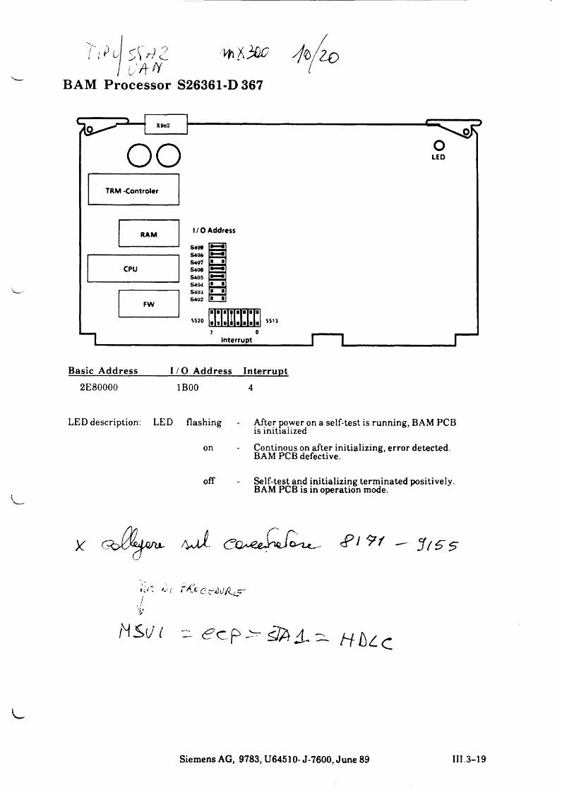
BAM Processor S26361-D367
o o
I / 0 A d d re s s
S4O054065407 S406 S40S S4(M S403 S4U2
SS20
I n t e r r u p t
S513
l
Basic A ddress I / O A ddress In te rru p t2E80000 1B00 4
LED description: LED flashing After power on a self-test is runnin is initialized
on Continous on after initializing, BAM PCB defective.
off Self-test and initializing terminate! BAM PCB is in operation mode.
<P/ 9/
NS(/1 - - < ? c p ^ 4 . - a b l e
OLEO
_______ I
, BAM PCB
r detected.
I positively.
l i e s
Siemens AG, 9783, U64510- J-7600, June 89 III 3-19
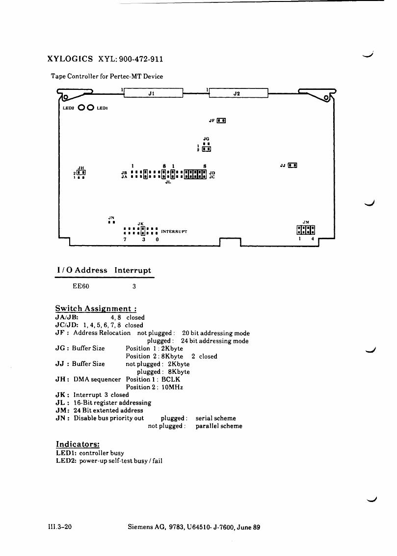
XYLOGICS XYL: 900-472-911
Tape Controller for Pertec-MT Device
I / O Address Interrupt
EE60 3
Switch Assignment :JA /JB : 4, 8 closedJC /JD : 1 ,4 ,5 ,6 ,7 ,8 closedJ F : Address Relocation not plugged: 20 bit addressing mode
plugged : 24 bit addressing modeJG : Buffer Size Position 1:2Kbyte
Position 2 : 8Kbyte 2 closed J J : Buffer Size not plugged : 2Kbyte
plugged : 8KbyteJH : DMA sequencer Position 1 : BCLK
Position 2 : 10MHz JK : Interrupt 3 closed J L : 16-Bit register addressing J M : 24 Bit extented addressJN : Disable bus priority out plugged : serial scheme
not plugged : parallel scheme
Indicators:LEDl: controller busyLED2: power-up self-test busy/fail
111.3-20 Siemens AG, 9783, U64510- J-7600, June 89
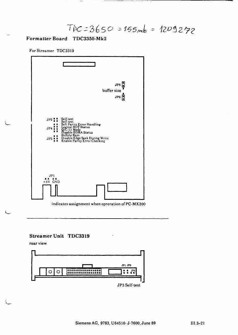
2>(>5 0 '1 6 5 J o - iZOtZ'FZFormatter Board TDC3350-Mk2
For Streamer TDC3319
]
JP5 Istbuffer size
J P 6 g
JP2
JP4
JP3
Self-test Self-testSoft Parity Error Handling Logical BOT Status
8IC-11 Mode isable EORA Status 8kByte Ram
Disable Edge Seek During Write Enable Parity Error Cheating
JP1■ a a a
+5V GND
indicates assignment when opreration of PC-MX300
Streamer Unit TDC3319rear view
Siemens AG, 9783, U64510- J-7600, June 89 III.3-21

N1
Einstellanweisung
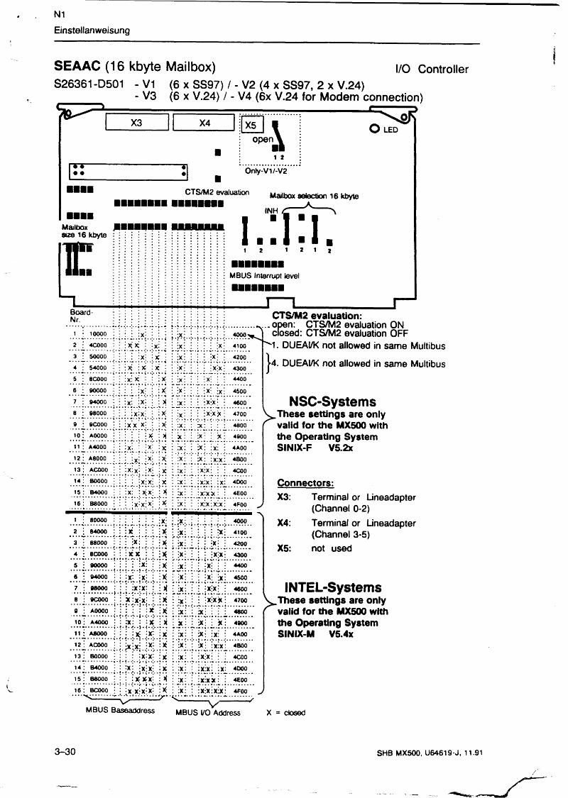
SEAAB (16 kbyte Mailbox) I/O Controller
S26361-D364 - V1 (6 x SS97) / - V2 (4 x SS97, 2 x V.24) / - V3 (6 x V.24)
X3 X4 X5
Mailbox size 16 kbyter. MBUS Interrupt
level
open I1 2
Only-VI/-V2
INH1 Mailbox selection 16 kbyte
o LEDHI
Addressevaluation/
■ ■ M U H »
Board -N r .
. J . .1 . • . J. *s . . .1. . .........1 : 10000 : : : * : : : :X : : i i i i i 40002 ; 4C000 : :xi : : x : x : •X- : •: : : :x : 4100.................... . .. .. ..3 : 50000 : :X ; X : : :x : : : : : x : : 42004 54000 : ix; X : : x : : x ; i : : x > i 43005 : 8COOO :x : : : : x : x : •x- : — x : : ; 44006 : 90000 x : : X : : : ix i i i i x i ix i 45007 : 94000 •X; : X : : x ; i x i i i i x ix i 46008 : 98000 ix ; j . X ' jX ; : : x : i ; x ; x * ; 47009 : 9COOO :x : : : \ : x :x : i x i : i x i ; 4800io : aoooo X : ;x : : % : : ix i ; * i 490011 : A4000 • x : : x : ; :x j i x i i i x i i x i i 4AOO12 : A8000 * i i x ; ; ix i : i x i i x i x i 4 BOO13: ACOOO :X: \%\ i x i x ; : x : 4COO14: B0000 ix" : x x : : • i x i ; : x : x i : x : 400015 : B4000 :x : ; x ; : x : j : x : x x : 4£0016: B8000 -x x k : :x : : i x i x : x i x i 4F00
1 ; 80000 :xi : : : : : :X: 40002 : 84000 i X : i i x : x i ■ i i i ; x ; 41003 : 88000 : X i i : X: i i x i i i ; i x ; ; 42004 ; 8COOO ijC i i i x i x i • x : : i x : x : 4300. .................. • • i .i.. ................5 : 90000 X: : : x : : i x i : : : x - : : 44006 : 94000 jx : : : x : x . : X ; : i * : i x i 45007 ■ 98000 i x : : : x i x ; : 46008 : 9COOO !xi : * * i x ! :x i i ': X ix X | 47009 : AOOOO x ; x ; ; : x : i X : : : : 480010 : A4000 ;x : : X : : x : X i i * i i * i 490011 : A8000 ix : :x : : x : i x i ■ i x i i x i i 4A0012: ACOOO ix; • * |X;X. :X ; i i x ; : x : x : 4 BOO13 : BOOOO ix; ; x x i i i x :x i : 4COO14; B4000 ixi i x x i x i x i : i x i x i ix i 400015 : B8000 bei i x ; x ; x ; : i x : ■ J X X X : : 4EOO16 : BCOOO ixj ; x x ; x x ; i x i : i x i x i x i x i 4F00
open: CTS/M2 evaluation ON closed: CTS/M2 evaluation OFF
‘ 1. DUEAI/K not allowed in same Multibus
4. DUEAI/K not allowed in same Multibus
NSC-Systems„These settings are only valid for the MX500 with the Operating System SINIX-F V5.2x
v —MBUS Baseaddress
1/ — v --------MBUS I/O Address
INTEL-Systemsl These settings are only / > - valid for the MX500 with
the Operating System SINIX-M V5.4x
Connectors:X3: Terminal or Lineadapter
(Channel 0-2)X4: Terminal or Lineadapter
(Channel 3-5)X5: not used
dosed
3-28 SHB MX500, U64619-J, 11.91
N1
Einstellanweisung
SEAAC (16 kbyte Mailbox)S26361-D501 - V1 (6 x SS97) / - V2 (4 x SS97, 2 x V.24)
V3 (6 x V.24) / - V4 (6x V.24 for Modem connection)
I/O Controller
i T • •
________________________________________________________C = ---------=>X3 X4 X5 - :
\ O LED e n \
■ Ai *■
o p
Only-\/1/-V2■
CTS/M2 evaluation Mailbox selection 16 kbyte
INH
Mailbox | l l sue 16 kbyte :
I H I H
E 1 2 1 2 1 ¾
MBUS Interrupt level
Board - Nr. CTS/M2 evaluation:
i ; 1 0 0 0 0 ; : : : : x j | : ; , X ; . * . / . . I . 4 0 0 0 ^ e.
2 I 4 C 0 0 0 : : U i ; x : : x : : : : ;X; 4 1 0 0
3 • 5 0 0 0 0 : :x - x :X : 420 0. . . . . . . • i • • 4 * • • *4 ; 5 4 0 0 0 : : X : X : x •X ; : : x :x : 430 0
5 : 8COOO : : x : x! : : : X : x : : ;X ; : I 440 0
6 : 9 0 0 0 0 • : : : ; x | | ; X : ! x i i x ! 450 0
7 : 9 4 0 0 0 : : : x : i x ; j ; X i x i : : x -x 1 • 4 600
8 : 9 8 0 0 0 : : : x : x i j : X : j x j x * ; 470 0
9 : 9COOO : : x x x | : x : x : ■x: 4 800
i o ; AOOOO : : : : : \ X I X x : I x : : '% \ 4 900
11 : A4 0 0 0 • I i x ; I ; x ; : X I x i i x | Ix i : 4A 00
12 : A 80 0 0 = : : : X j i * i J X :X : i x l I x l x i 4 8 0 0
13 : ACOOO : : x : x j ;X | : X : x : : x : x : : : 4C 00
14 • BOOOO : : : : x i x i : X : x : : x : x : I x : 4DOO
i s : B 4 0 0 0 : I x i : x x \ : X : x : : x : x x : 4E 0 0
16 : B 8 0 0 0 : : : l x : x i x | : X i x i I x l x I x l x i 4 F 0 0
1 ; 8 0 0 0 0 4 0 0 0! • • i •2 ; 8 4 0 0 0 : : : X : : : • X ix": • : : * | 4 1 0 0
• «» . . . ................3 : 8 8 0 0 0 : : . X : : : X :X : : : : x : : 4 2 0 0
* • • • • • * . / . . 1 . . , • m 9 • • , .................4 • 8 C 0 0 0 : : x x : X ;X : : : | x ; x | 4 3 0 0
5 : 9 0 0 0 0 : : : : :X : : : X :X : • -x- • • 4 4 0 0* ? * ! * ! • • J • i • v * • . • . ........... .. -
6 : 9 4 0 0 0 450 0*7 : 9 8 0 0 0 • : : : x ; x ; : : i :X : : : X:’x • | 460 0
8 : 9 C 0 0 0 j : * i x ; x i i i X : x : : | x | x j ( : 4 7 0 0
0 : AOOOO : : : : : X [ X i x : i x l 1 : : 4 8 0 0
i o : A4 0 0 0 : : : x : : : x :_ x X : l x | 1 X : 4 9 0 0
11 : A 8 0 0 0 : ; ; x | i x j : X i x i l x | i x : I 4A 00
12 : ACOOO X :X : : x : x _ 4BOO
13 : BOOOO : : : ; x ; x ; : X : x : : x :x : : 4C 00
14 : B 4 0 0 0 ; i ; x ; - x i x : I X 4 0 0 0
15 : B 8 0 0 0 : : x x x : : i : x : : x i x X : 4E0 0........... • • • # • • • • ...........
16 : BCOOO : : x x | x ; x : : X :X : : x -.x : x x : 4 F 0 0
*\...open: CTS/M2 evaluation ON closed: CTS/M2 evaluation OFF
*1 ■ DUEAi/K not allowed in same Multibus
►4. DUEAI/K not allowed in same Multibus
NSC-SystemsV These settings are only < valid for the MX500 with
the Operating System SINIX-F V5.2x
Connectors:X3: Terminal or Lineadapter
(Channel 0-2)X4: Terminal or Lineadapter
(Channel 3-5)not usedX5:
INTEL-SystemsV These settings are only ' valid for the MX500 with
the Operating System SINIX-M V5.4x
j-------- v --------
MBUS BaseaddressV
MBUS I/O Address X = closed
3-30 SHB MX500, U64619-J. 11.91
/
Einstellanweisung
'w't
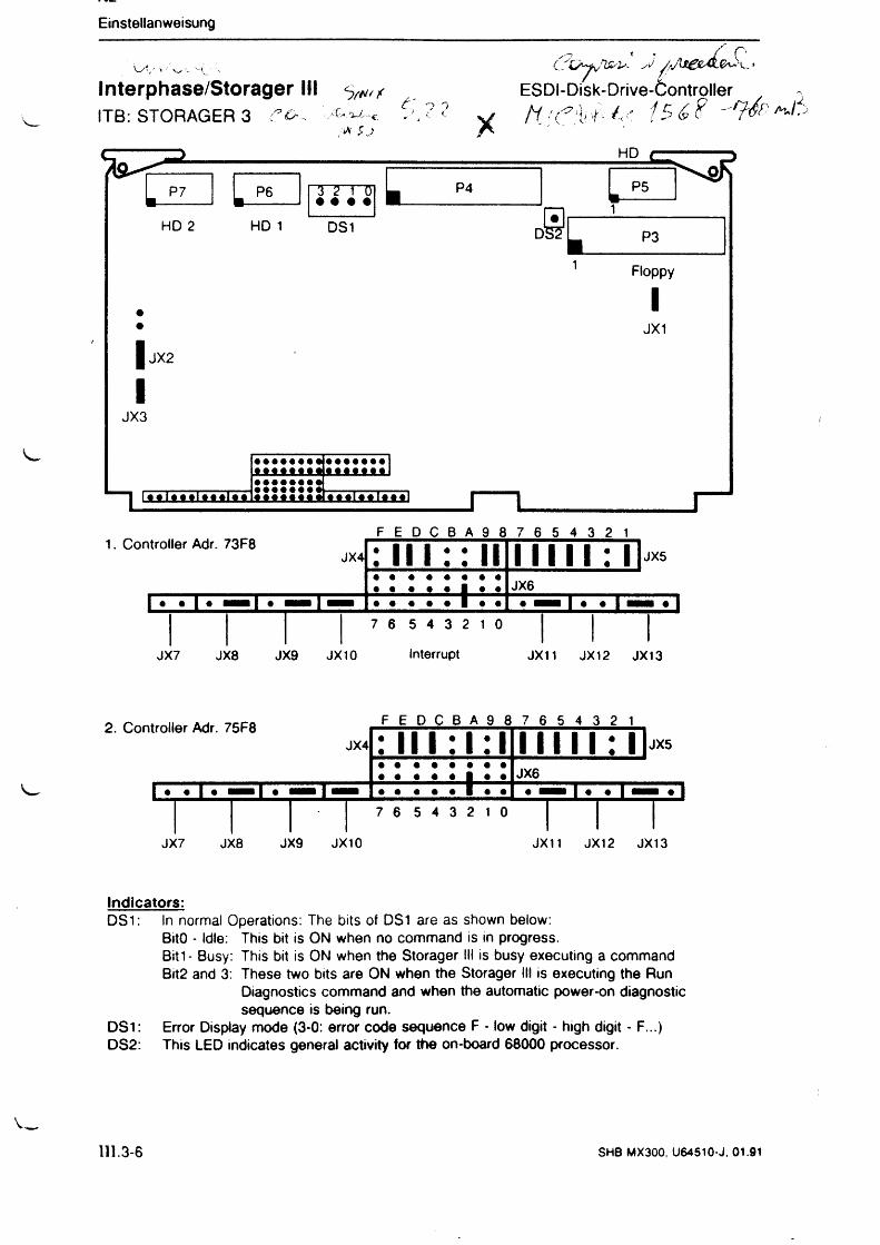
Interphase/Storager III 5^ITB: STORAGER 3 C&
■i\ $ )
ESDI-Disk-Drive-Öontroller -
1. Controller Adr. 73F8F E D C B A 9 8 7 6 5 4 3 2 1
JX4
u j l i
: I I I :: II• •
f
l l l l l : l JX5
JX6T » - 1 — * 1
7 6 5 4 3 2 1 0 I I I
JX7 JX8 JX9 JX10 Interrupt JX11 JX12 JX13
Indicators:DS1: In normal Operations: The bits of DS1 are as shown below:
BitO - Idle: This bit is ON when no command is in progress.Bitt- Busy: This bit is ON when the Storager III is busy executing a command Bit2 and 3: These two bits are ON when the Storager III is executing the Run
Diagnostics command and when the automatic power-on diagnostic sequence is being run.
DS1: Error Display mode (3-0: error code sequence F - low digit - high digit - F...) DS2: This LED indicates general activity for the on-board 68000 processor.
111.3-6 SHB MX300, U64510-J. 01.91
Emstellan Weisung
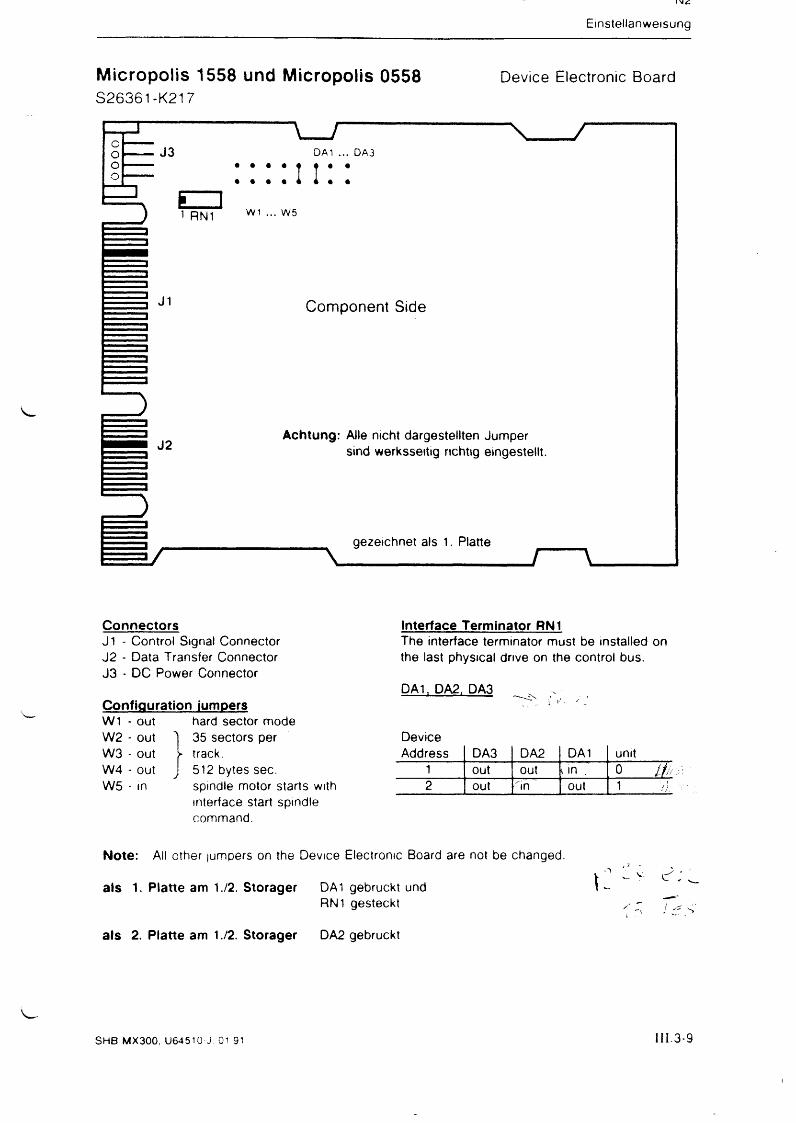
Micropolis 1558 und Micropolis 0558 Device Electronic BoardS26361-K217
ConnectorsJ1 - Control Signal Connector J2 - Data Transfer Connector J3 - DC Power Connector
Configuration jumpersW1 - out hard sector mode W2 - out 1 35 sectors per W3 - out X track.W4 - out J 512 bytes sec.W5 - in spindle motor starts with
interface start spindle command.
interface Terminator RN1The interface terminator must be installed on the last physical drive on the control bus.
DAI, DA2, DA3
DeviceAddress DA3 DA2 DA1 unit
1 out out t in . 0 M2 out "in out 1 H
Note: All other jumpers on the Device Electronic Board are not be changed.
als 1. Platte am 1./2. Storager DA1 gebruckt undRN1 gesteckt
als 2. Platte am 1./2. Storager DA2 gebruckt
SH B MX300, U64510 J Ol 91 I I I .3-9
Emstellanweisung
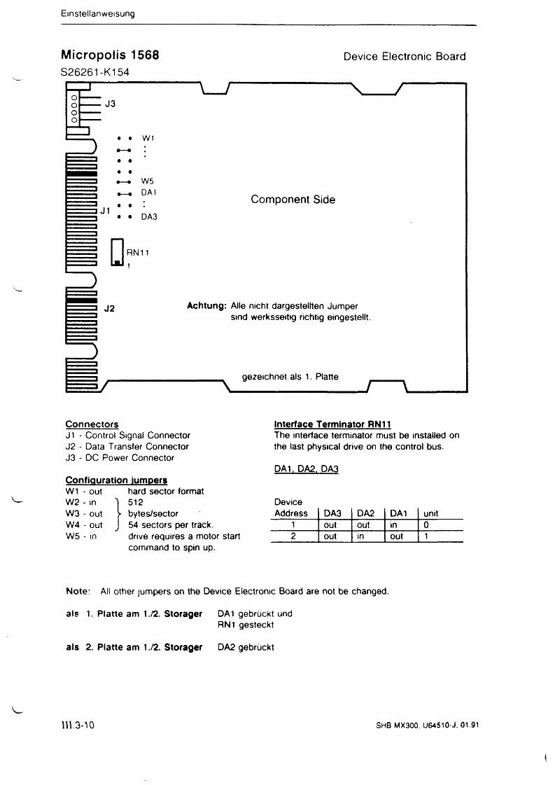
Micropolis 1568 Device Electronic BoardS26261-K154
ConnectorsJ1 - Control Signal Connector J2 - Data Transfer Connector J3 - DC Power Connector
Configuration jumpersW1 - out hard sector format W2 - in T 512W3 - out W4 - out W5 - in
bytes/sector 54 sectors per track, drive requires a motor start command to spin up.
Interface Terminator RN11The interface terminator must be installed on the last physical drive on the control bus.
DA1. DA2, DA3
DeviceAddress DA3 DA2 DA1 unit
1 out out in 02 out in out 1
Note: All other jumpers on the Device Electronic Board are not be changed.
als 1. Platte am 1./2. Storager DA1 gebrückt undRN1 gesteckt
als 2. Platte am 1 ./2. Storager DA2 gebrückt
Vw111.3-10 SHB MX300, U64510-J. 01.91
Einstellanweisung
i,., ^ ' j e £ ' c < ' ^ ........
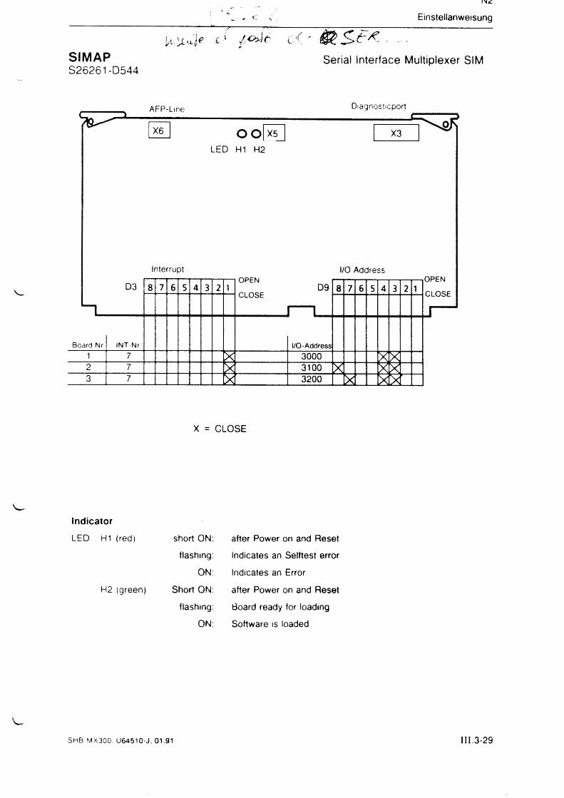
SIMAP Serial Interface Multiplexer SIMS26261-D544
X = CLOSE
Indicator
LED H1 (red) short ON: after Power on and Reset
flashing: Indicates an Selftest error
ON: Indicates an Error
H2 (green) Short ON. after Power on and Reset
flashing: Board ready for loading
ON: Software is loaded
SHB MX300. U64510-J, 01.91 III. 3 -2 9
Einstellanweisung 'V
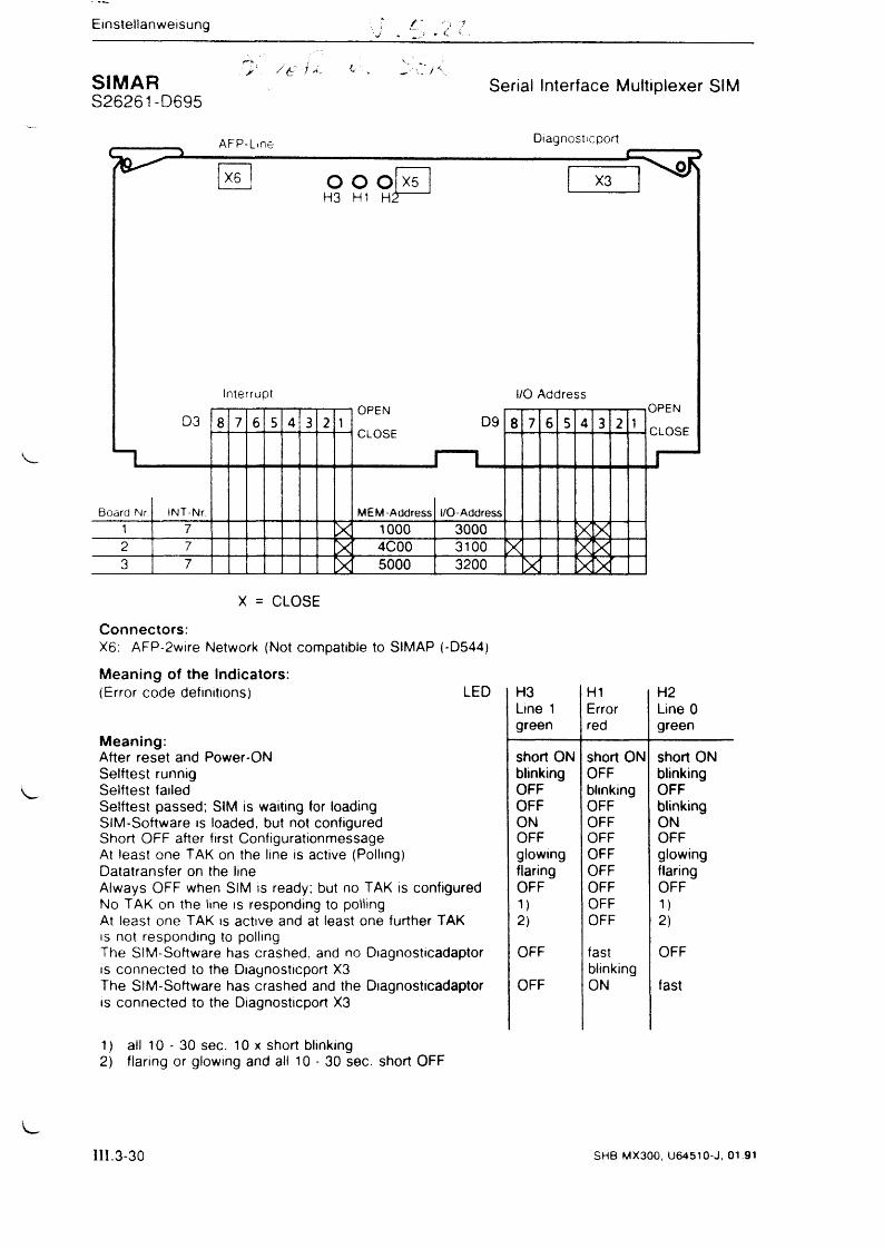
; y\. /£:■ 1 ,CSIMAR Serial Interface Multiplexer SIMS26261-D695
X = CLOSE
Connectors:X6: AFP-2wire Network (Not compatible to SIMAP (-D544)
Meaning of the Indicators:(Error code definitions) LED H3 H1 H2
Line 1 Error Line 0
Meaning:green red green
short ON short ON short ONAfter reset and Power-ONSelftest runnig blinking OFF blinkingSelftest failed OFF blinking OFFSelftest passed; SIM is waiting for loading OFF OFF blinkingSIM-Software is loaded, but not configured ON OFF ONShort OFF after first Configurationmessage OFF OFF OFFAt least one TAK on the line is active (Polling) glowing OFF glowingDatatransfer on the line flaring OFF flaringAlways OFF when SIM is ready; but no TAK is configured OFF OFF OFFNo TAK on the line is responding to polling 1) OFF 1)At least one TAK is active and at least one further TAK 2) OFF 2)is not responding to pollingThe SIM-Software has crashed, and no Diagnosticadaptor OFF fast OFFis connected to the Diaynosticport X3 blinkingThe SIM-Software has crashed and the Diagnosticadaptor is connected to the Diagnosticport X3
OFF ON fast
1) all 10 - 30 sec. 10 x short blinking2) flaring or glowing and all 10 - 30 sec. short OFF
III.3-30 SHB MX300, U 64510-J, 01.91
fr -V
IN <3
Einstellanweisung
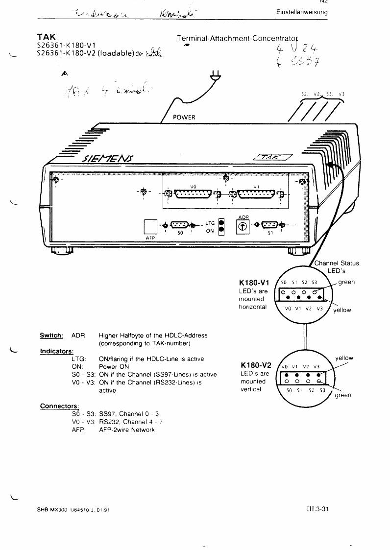
TAKS26361-K180-V1S26361-K180-V2 (loadable) e ^ a i&
Terminal-Attachment-Concentratop* 4- U ZU-
/". c' C '7V ^ ^ ‘
7 p /
POWER
S2, V 2, S3, V 3
/ / / /
S /S A 7 E /V S /7 ~ J * r /
WM
VO^ / / / / / / / ^ ^ ^ ^ 7 7 7 7 ^ 7 ¾ .
□AFP
— ADR
SO
LTGl ON ©
Switch: ADR:
Indicators:
Higher Halfbyte of the HDLC-Address (corresponding to TAK-number)
LTG: ON/flaring if the HDLC-Line is activeON: Power ONSO - S3: ON if the Channel (SS97-Lines) is active VO - V3: ON if the Channel (RS232-Lines) is
active
Connectors:SO - S3: SS97, Channel 0 - 3 VO - V3: RS232, Channel 4 - 7AFP: AFP-2wire Network
K180-V1LED’s aremountedhorizontal
K180-V2LED’s aremountedvertical
green
SHB MX300 U64510-J, 01 91 I I I .3-31
Einstellan Weisung
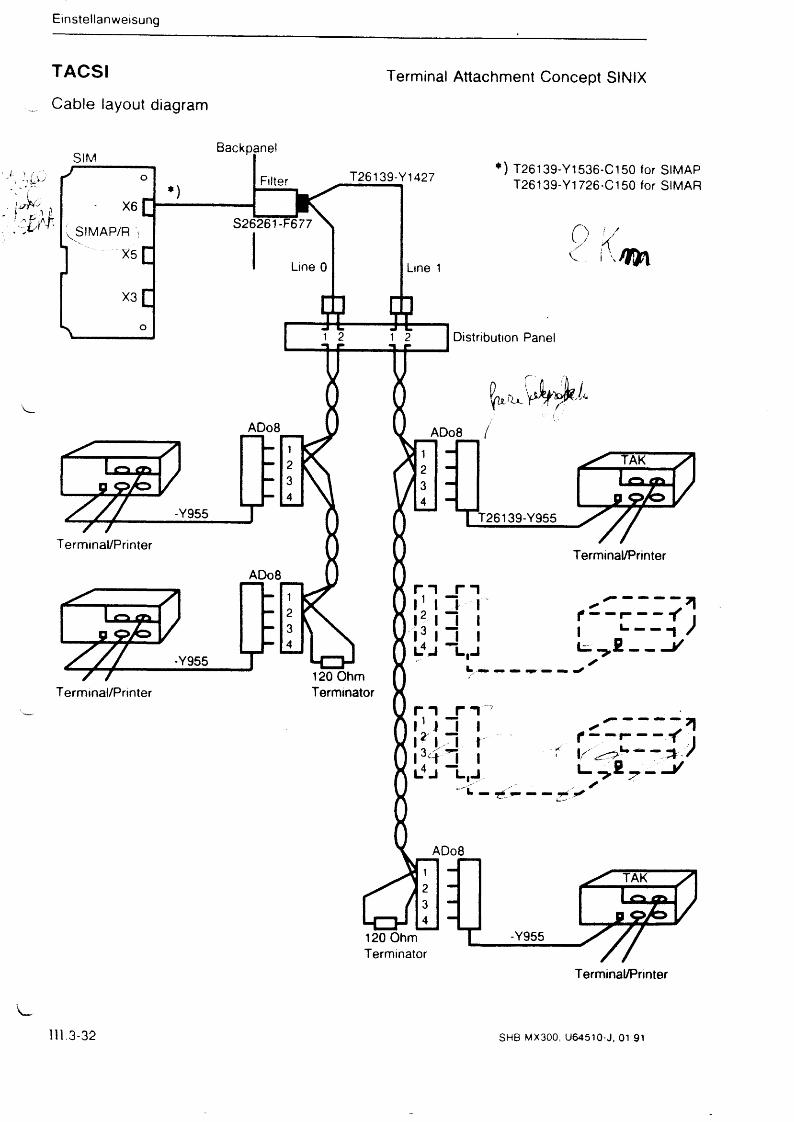
TACSI
Cable layout diagram
Terminal Attachment Concept SINIX
111.3-32 SHB MX300, U64510-J, 01.91
Einstellanweisung
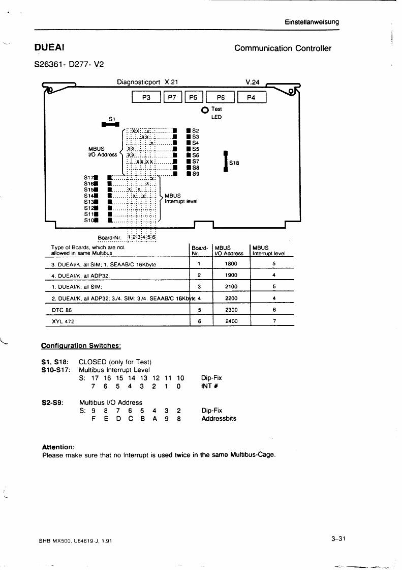
DUE AI Communication Controller
S26361- D277- V2
Board-Nr. fl |2 j3|4-|5; 6;
Type of Boards, which are not allowed in same Multibus
Board-Nr.
MBUS I/O Address
MBUSInterrupt level
3. DUEAI/K, all SIM; 1. SEAAB/C 16Kbyte 1 1800 5
4. DUEAI/K, all ADP32; 2 1900 4
1. DUEAI/K, all SIM; 3 2100 5
2. DUEAI/K, all ADP32; 374. SIM; 374. SEAAB/C 16Kb rte 4 2200 4
DTC 86 5 2300 6
XYL 472 6 2400 7
Configuration Switches:
S1, S18: CLOSED (only for Test) S10-S17: Multibus Interrupt Level
S: 17 16 15 14 13 12 11 10 Dip-Fix7 6 5 4 3 2 1 0 IN T #
Multibus I/O AddressS: 9 8 7 6 5 4 3 2 Dip-Fix
F E D C B A 9 8 Addressbits
Attention:Please make sure that no Interrupt is used twice in the same Multibus-Cage.
SHB MX500, U64619-J, 1.91 3-31
N1
Einsteilanweisung
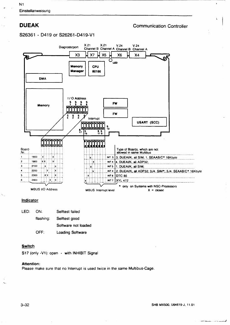
DUEAK Communication Controller
S26361 - D419 or S26261-D419-V1
Diagnosticport X.21 X.21 V.24 V.24Channel B Channel A Channel B Channel A
MBUS I/O Address MBUS Interrupt level X = closeo
Indicator
LED: ON: Selftest failed
flashing: Selftest good
Software not loaded
OFF: Loading Software
Switch
S17 (only -V I): open - with INHIBIT Signal
Attention:Please make sure that no Interrupt is used twice in the same Multibus-Cage.
3-32 SHB MX500, U64619-J, 11.91
Einstellanweisung
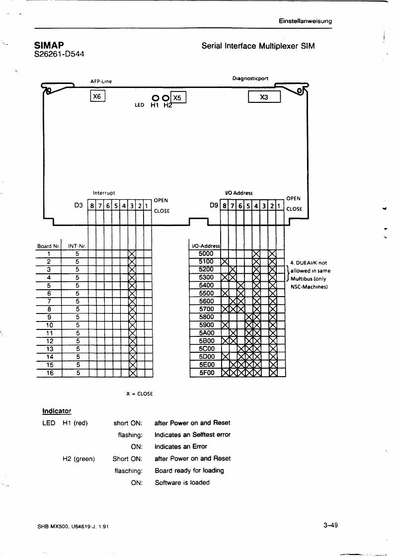
SI MAP Serial Interface Multiplexer SIMS26261-D544
x = close
Indicator
LED H1 (red)
H2 (green)
short ON:
flashing:
ON:
Short ON:
flasching:
ON:
after Power on and Reset
Indicates an Selftest error
Indicates an Error
after Power on and Reset
Board ready for loading
Software is loaded
SHB MX500, U64619-J, 1.91 3-49


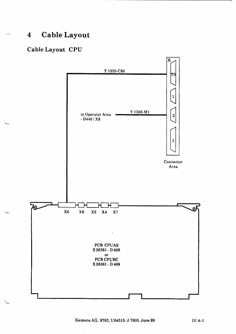
4 Cable LayoutCable Layout CPU
Siemens AG, 9783, U64510- J-7600, June 89 III.4-1
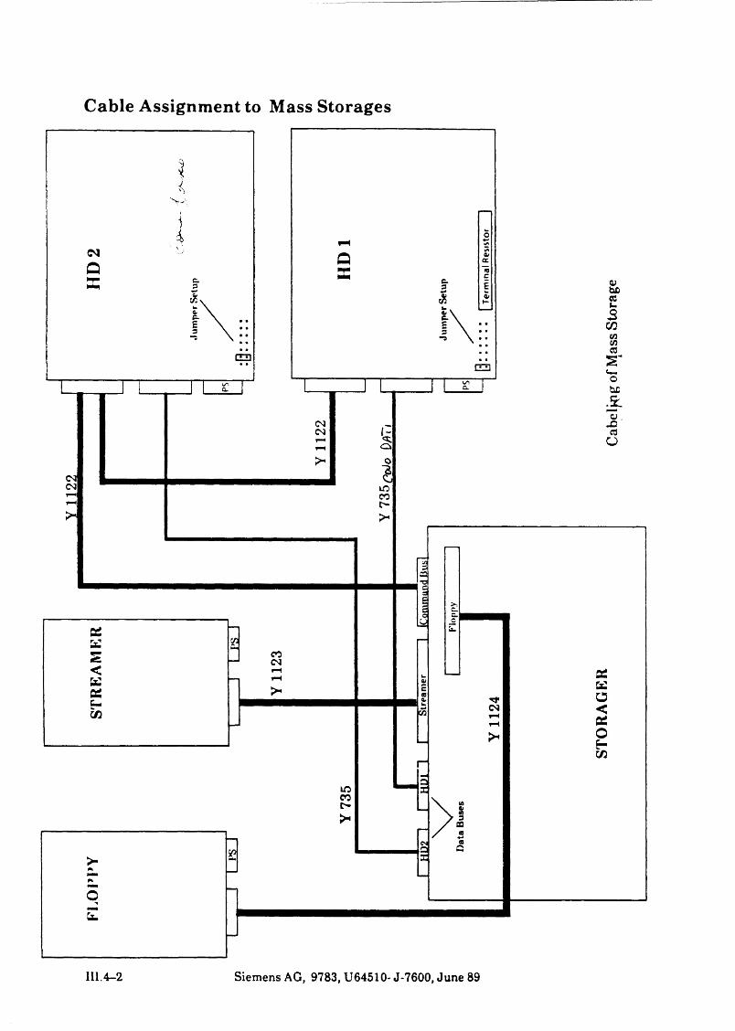
Cable Assignment to Mass Storages
III.4-2 Siemens AG, 9783, U64510- J-7600, June 89
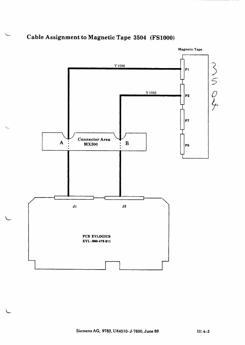
Cable Assignment to Magnetic Tape 3504 (FS1000)
Y 1056
Magnetic Tape
I
PI
IY 1056
vlA
^ C onnector A rea ^ MX300 B
P2
P7
P6
0
¥
J1 J2
PCB XYLOGICS XYL :900-472-911
Siemens AG, 9783, U64510- J-7600, June 89 III 4—3
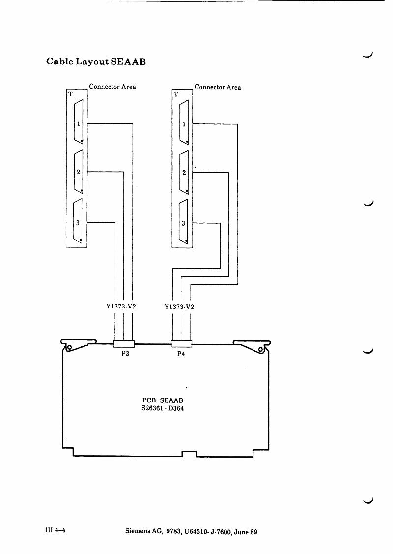
Cable Layout SEAAB
^ J
III.4-4 Siemens AG, 9783, U64510- J-7600, June 89
L .
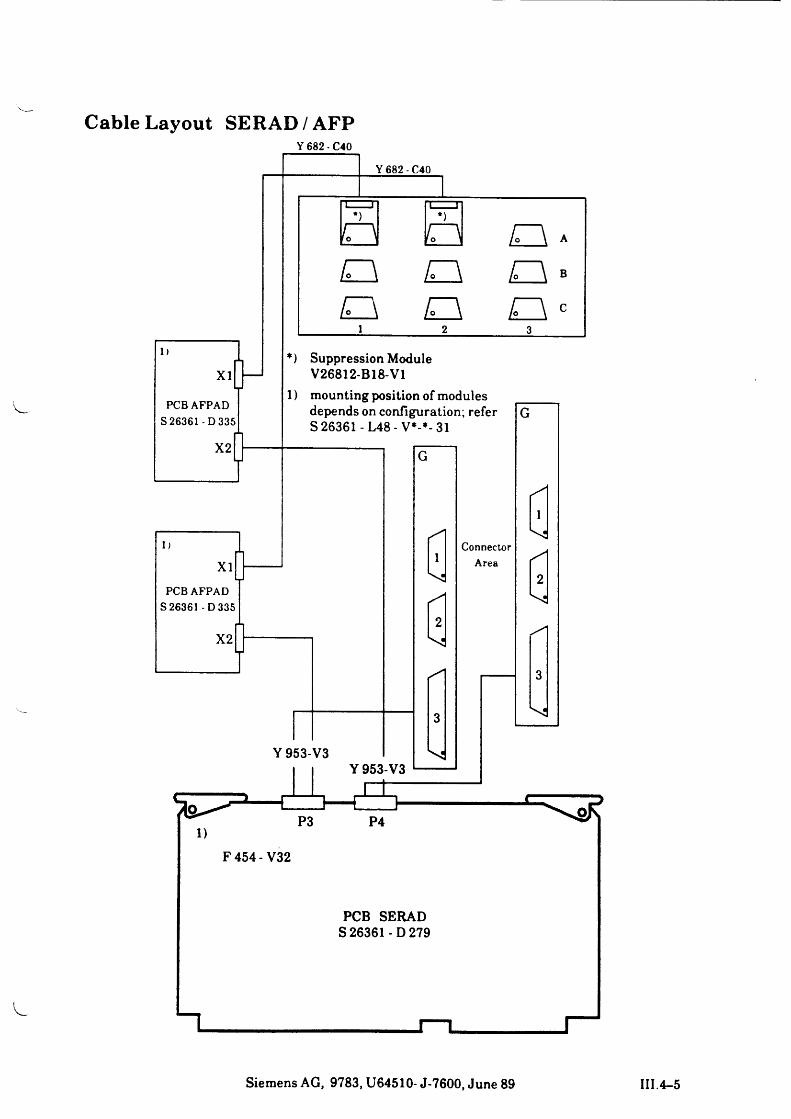
Cable Layout SERAD/AFPY 682 - C40
Siemens AG, 9783, U64510- J-7600, June 89 III.4-5
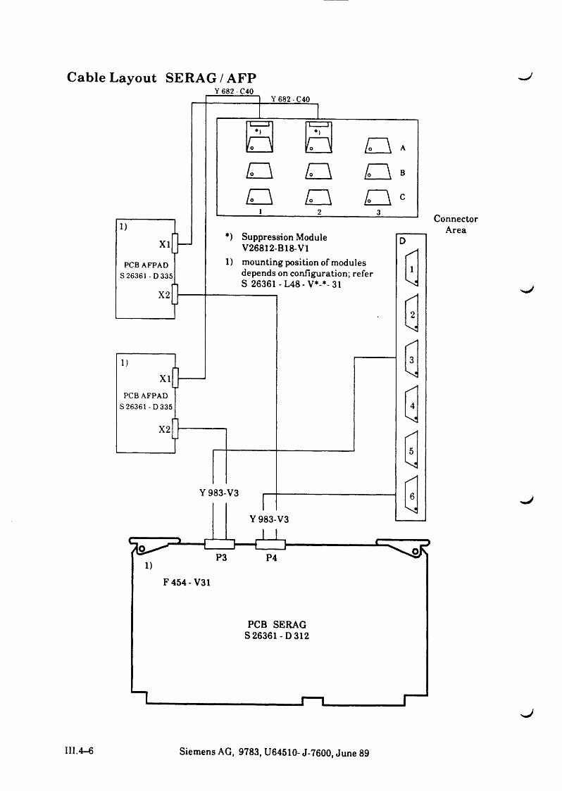
Cable Layout SERAG /AFPY 682 - C40
ConnectorArea
s j
III.4-6 Siemens AG, 9783, U64510- J-7600, June 89
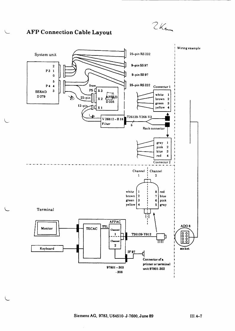
AFP Connection Cable LayoutOc .
Siemens AG, 9783, U64510- J-7600, June 89 III 4-7
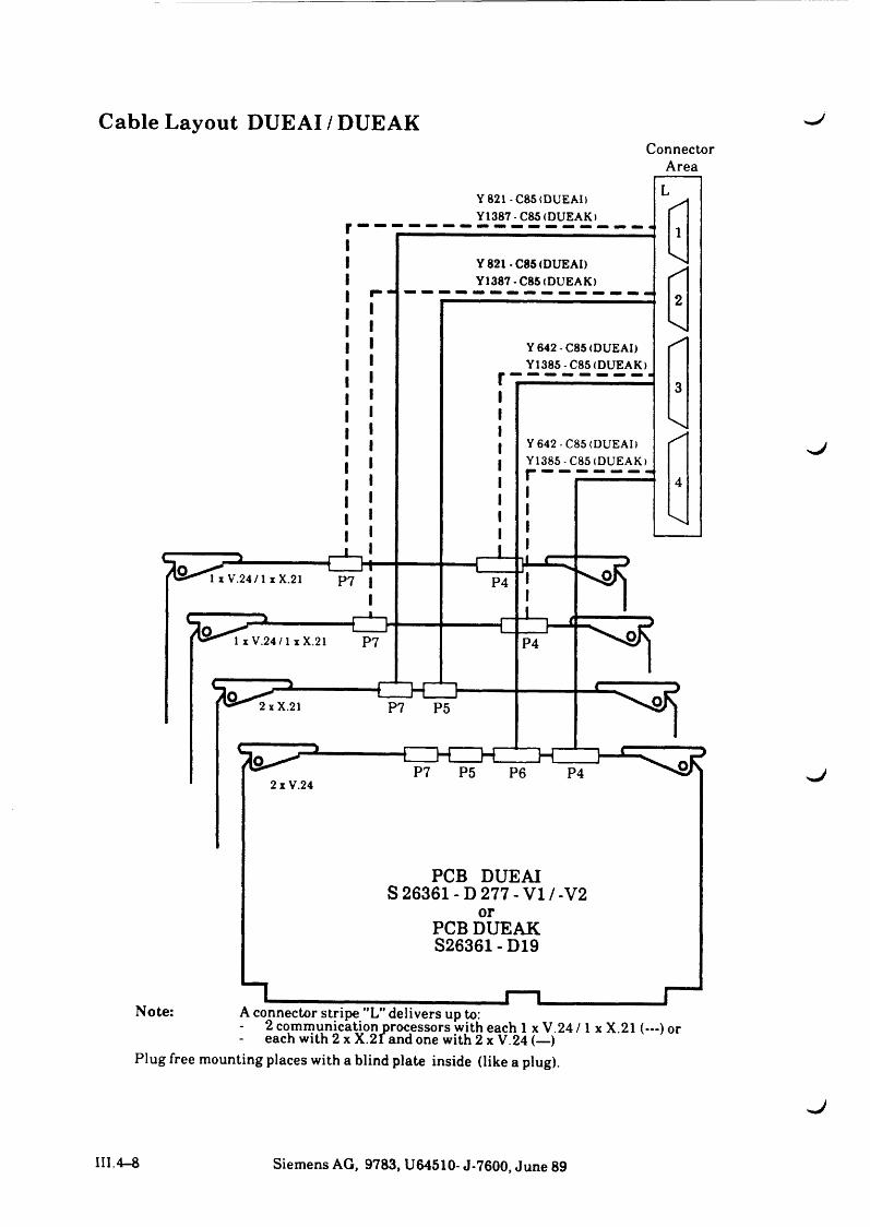
Cable Layout DUEAI / DUEAKConnector
Area
III. 4-8 Siemens AG, 9783, U64510- J-7600, June 89
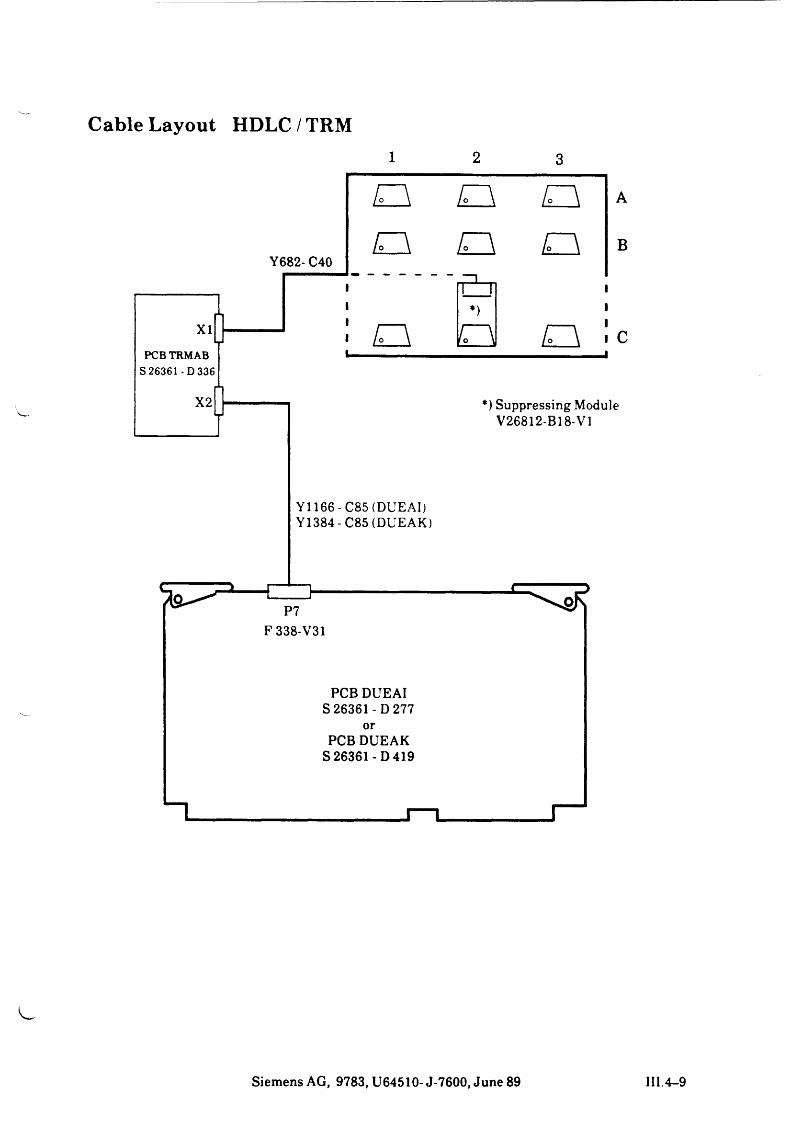
Cable Layout HDLC / TRM
1x i
PCBTRMABS 26361 -D 336
X2
o r \ aY682- C40
o o a
1----- \*)
ir\ o/° ,,\
J
A
B
*) Suppressing Module V26812-B18-V1
Y1166 - C85 (DUEAI) Y1384 - C85 (DUEAK)
1
P7F 338-V31
PCB DUEAI S 26361 - D277
orPCB DUEAK
S 26361-D 419
Siemens AG, 9783, U64510- J-7600, June 89 III.4-9
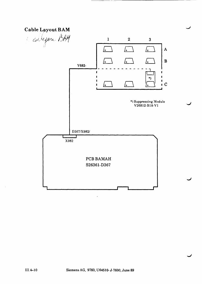
Cable Layout BAM
1 2 3! ’
O O
Y682-O O o
ii i
• £Z\ o»— ....................- .......... . , __________ . . . . . , „ I
*) Suppressing Module V26812-B18-V1
D367/X982// ü—zn
X982\
PCB BAMAH S26361-D367
III.4-10 Siemens AG, 9783, U64510- J-7600, June 89
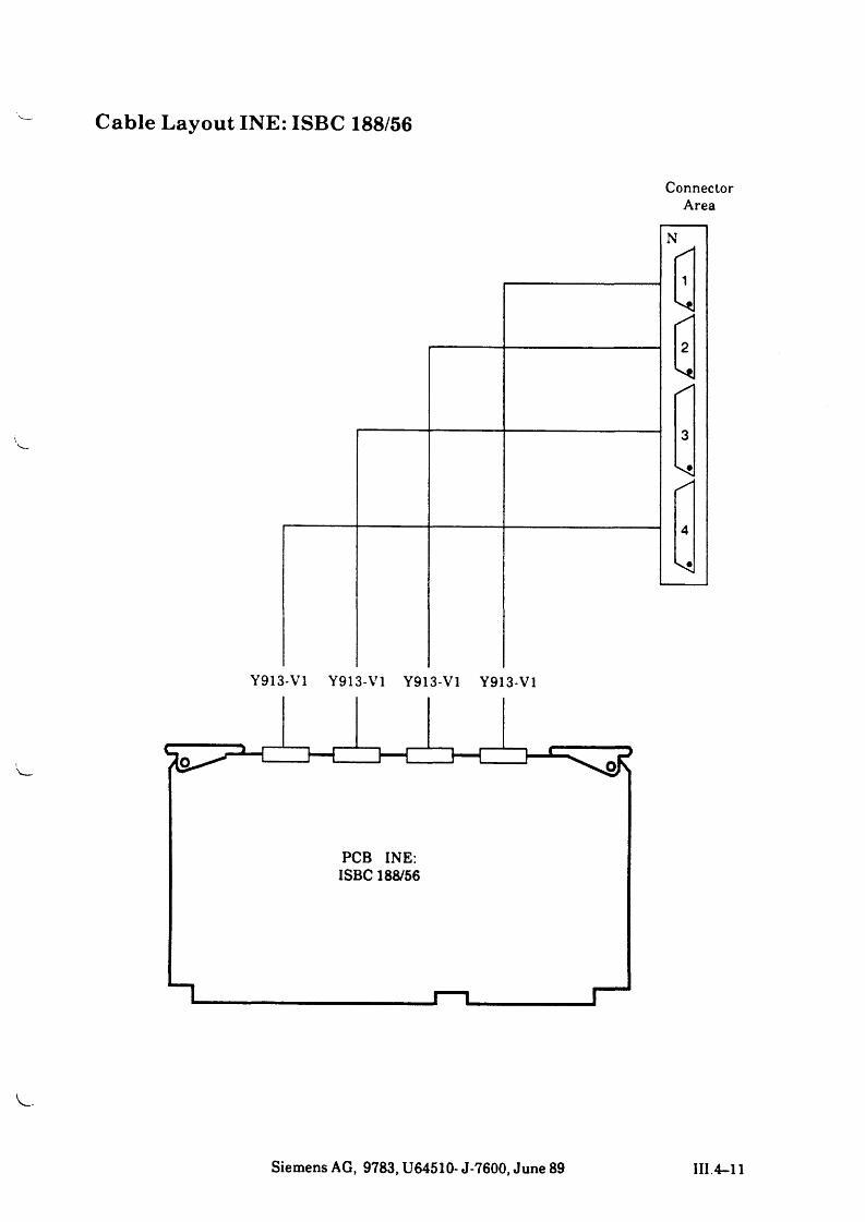
Cable Layout INE: ISBC 188/56
ConnectorArea
Siemens AG, 9783, U64510- J-7600, June 89 III.4-11
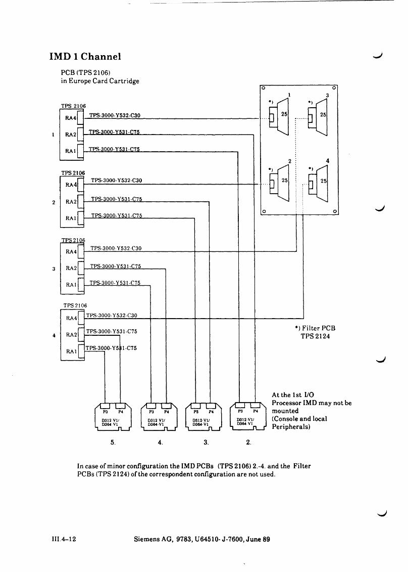
IMD 1 ChannelPCB (TPS 2106)
5. 4. 3. 2.
„J
sJ
^ J
In case of minor configuration the IMD PCBs (TPS 2106) 2.-4. and the Filter PCBs (TPS 2124) of the correspondent configuration are not used.
III.4-12 Siemens AG, 9783, U64510- J-7600, June 89
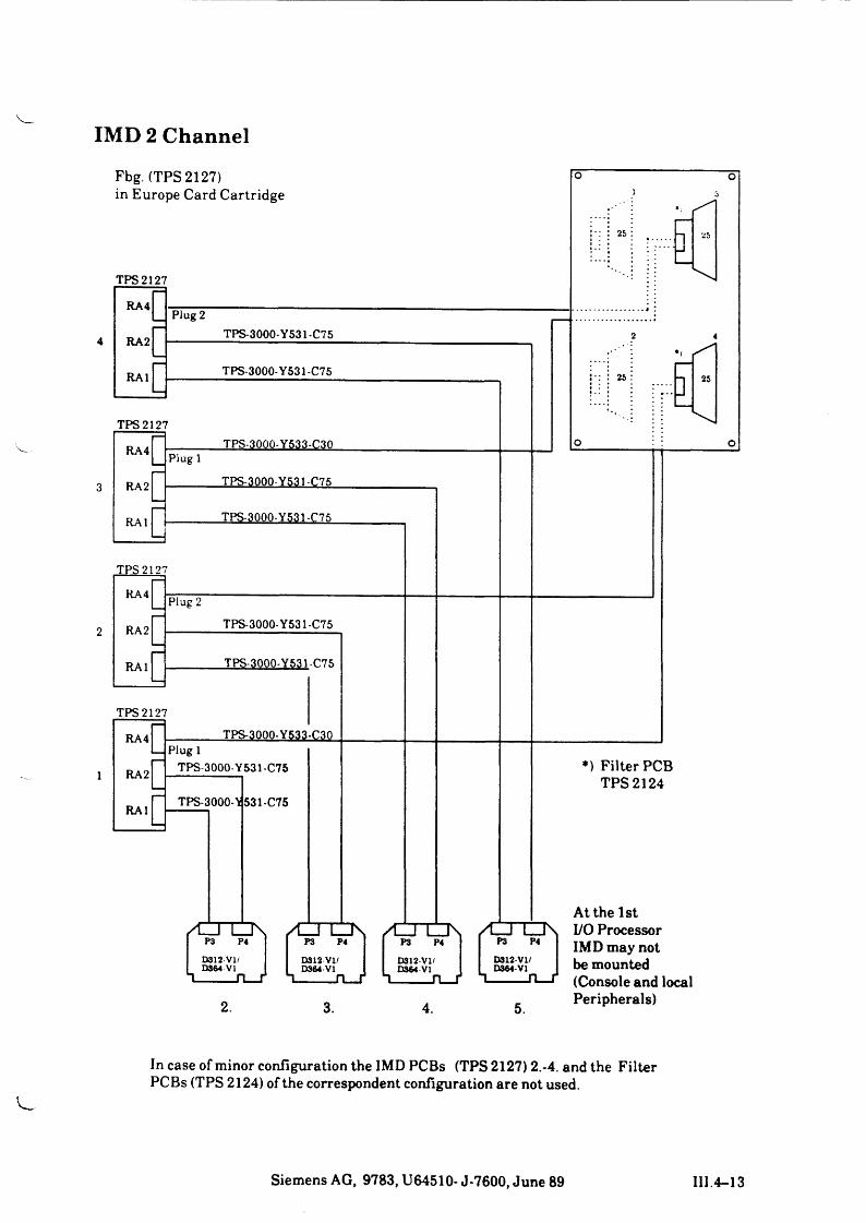
IMD 2 Channel
Peripherals)
In case of minor configuration the IMD PCBs (TPS 2127) 2.-4. and the Filter PCBs (TPS 2124) of the correspondent configuration are not used.
Siemens AG, 9783, U64510- J-7600, June 89 III.4-13
S26I
13D
336
S2
63
61
-E8
8XS
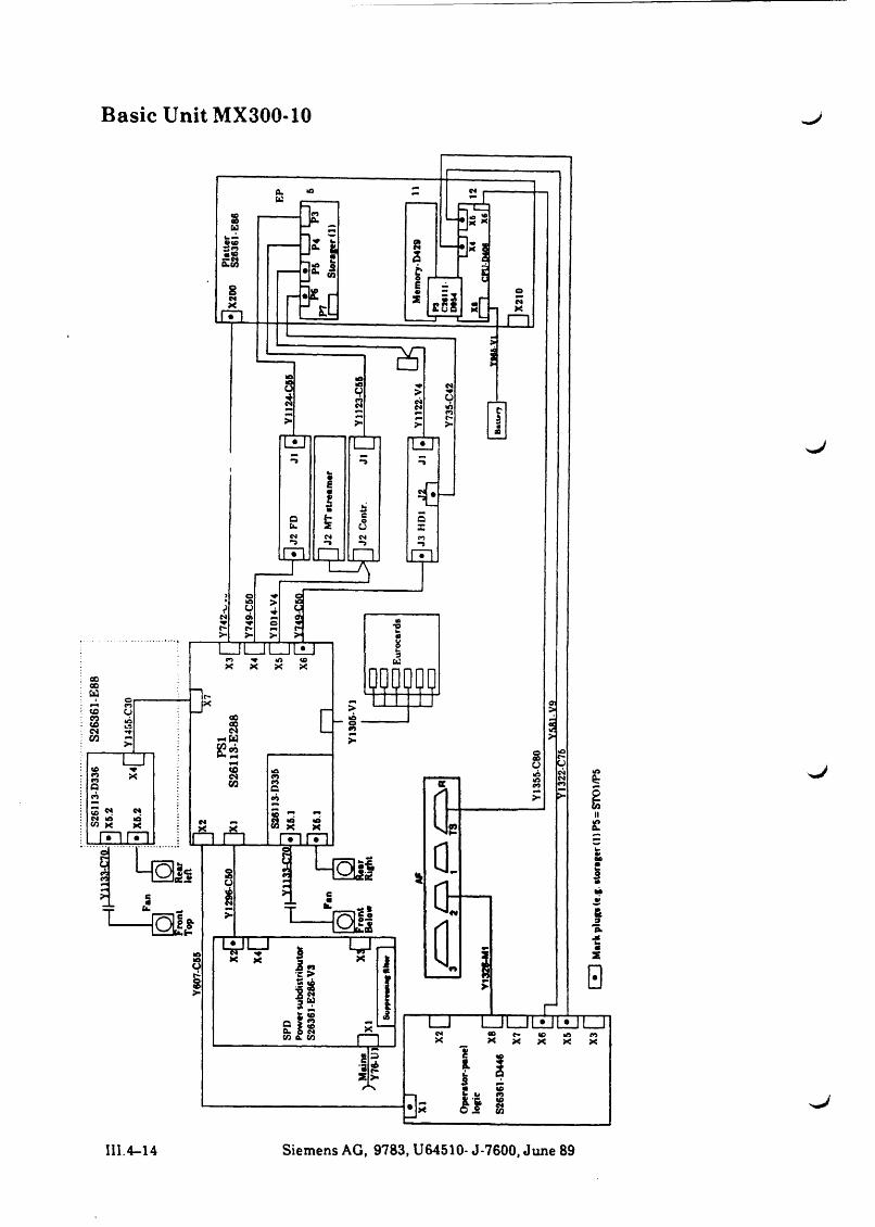
.2Basic Unit MX300-10
III.4-14 Siemens AG, 9783, U64510- J-7600, June 89
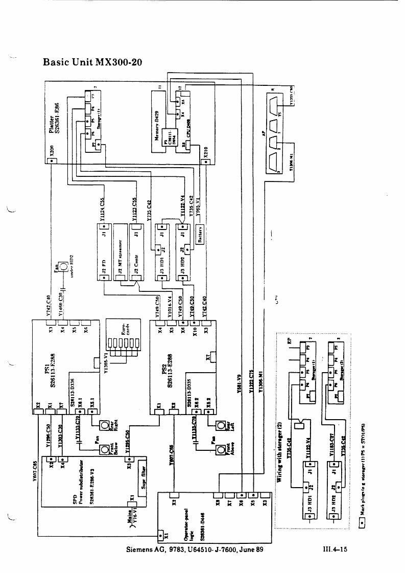
Basic Unit MX300-20
Siemens AG, 9783, U64510- J-7600, June 89 III.4-15
Uid/lOXS * SmI II) J~V|
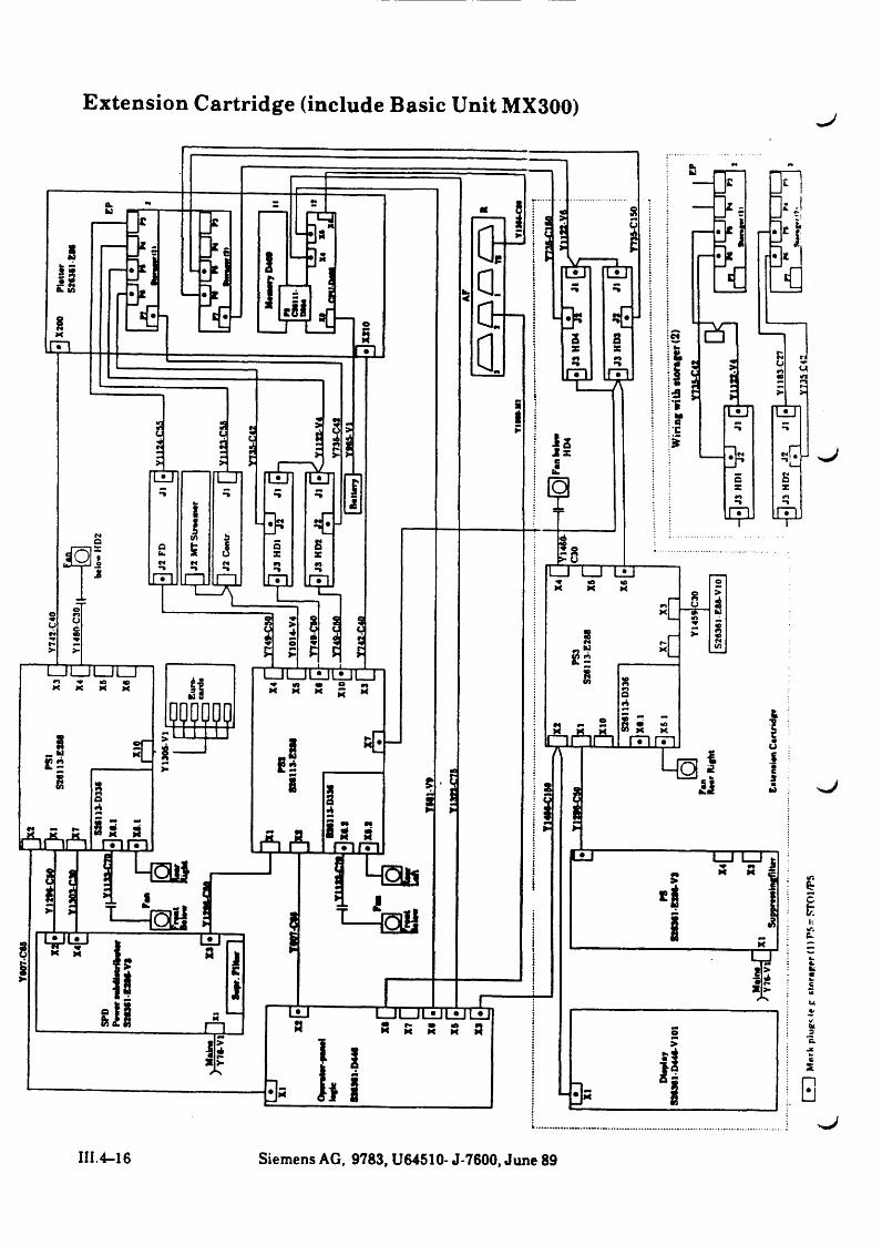
Extension Cartridge (include Basic Unit MX300)
m.4-16 Siemens AG, 9783, U64510- J-7600, June 89


^ J
s j ,
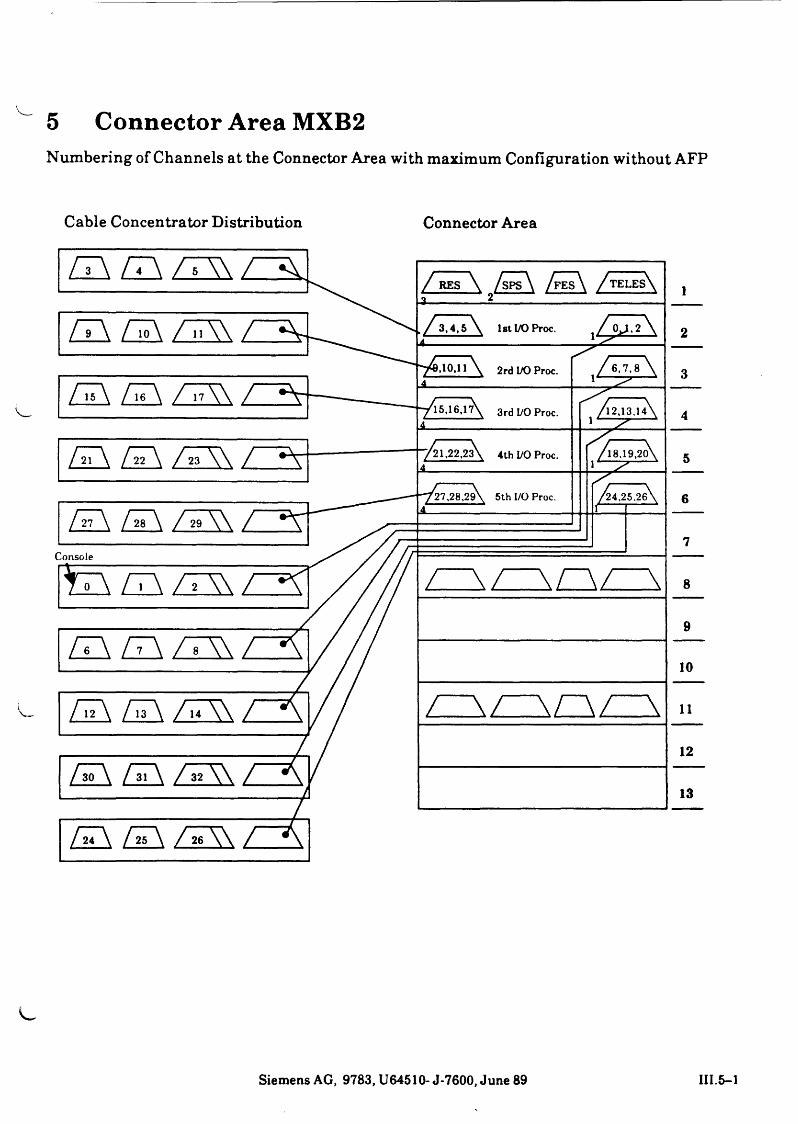
5 Connector Area MXB2Numbering of Channels at the Connector Area with maximum Configuration without AFP
Cable Concentrator Distribution Connector Area
Siemens AG, 9783, U64510- J-7600, June 89 III.5-1
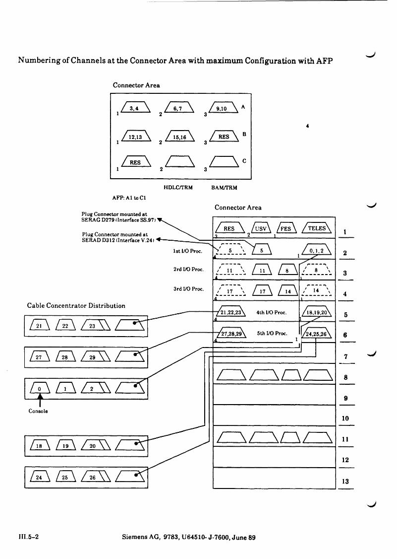
Numbering of Channels at the Connector Area with maximum Configuration with AFP
Connector Area
AFP: A1 to Cl
Connector Area
III. 5-2 Siemens AG, 9783, U64510- J-7600, June 89
MX300 Frame Mounting / Demounting
Installation of the Additional Frame for the MX300
SIEMENS
Part IVMounting / Demounting

Part IV
Mounting / Demounting
Contents Page
1 MX300 Frame - Mounting/ Demounting IV.1-1Demounting the frame IV. 1-1
Removing the front and rear panels IV. 1-2
2 Installation of the Additional Frame for the MX300 IV.2-1L

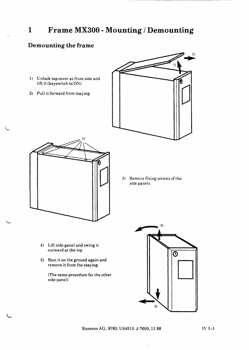
1 Frame MX300 - Mounting / DemountingDemounting the frame
1) Unlock top cover at front side and lift it (keyswitch to ON)
2) Pull it forward from staying
3) Remove fixing screws of the side panels
4) Lift side panel and swing it outward at the top
5) Rest it on the ground again and remove it from the staying
(The same procedure for the other side panel)
Siemens AG, 9783, U64510- J-7600,11.88 IV. 1-1
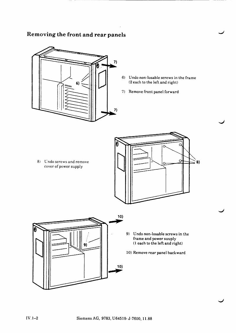
Removing the front and rear panels
9) Undo non-losable screws in the frame and power suuply(1 each to the left and right)
10) Remove rear panel backward
S,J
IV.1-2 Siemens AG, 9783, U64510- J-7600,11.88
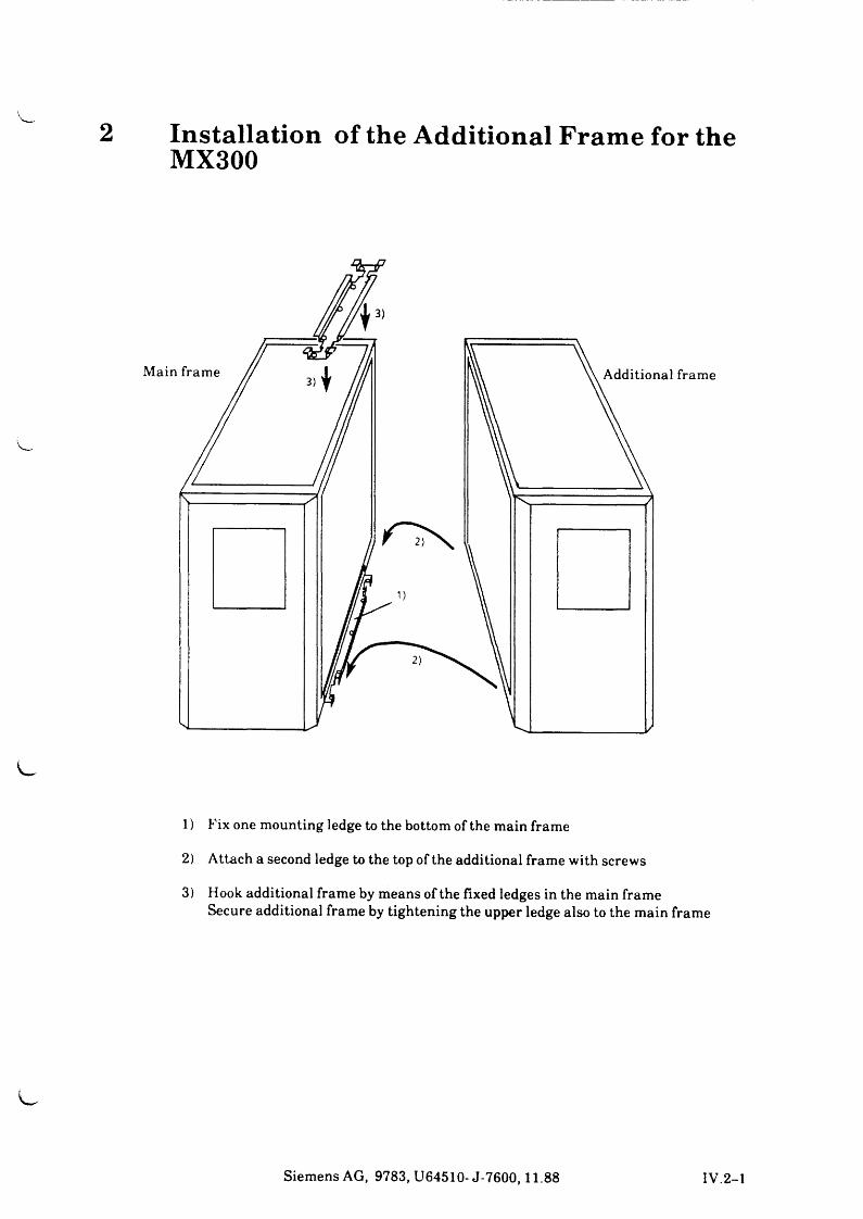
Installation of the Additional Frame for the MX300
1) Fix one mounting ledge to the bottom of the main frame
2) Attach a second ledge to the top of the additional frame with screws
3) Hook additional frame by means of the fixed ledges in the main frame Secure additional frame by tightening the upper ledge also to the main frame
Siemens AG, 9783, U64510- J-7600,11.88 IV.2-1

^ J
SIEM ENS
Part VTroubleshooting
Troubleshooting

J
PartV
Troubleshooting
Contents Page
1 Troubleshooting V.l-11.1 Startup Procedure V.l-1
2 Messages of the Firmware (Power Up Test) V.l-5
3 SINIX Loader Messages V.l-8
4 Configuration Example of MX300-20 V.l-104.1 Minimum Configuration MX300 V.l-11
5 SINIX Messages V.l-125.1 Error Messages of the Storager V.l-12

w /
J
^ J
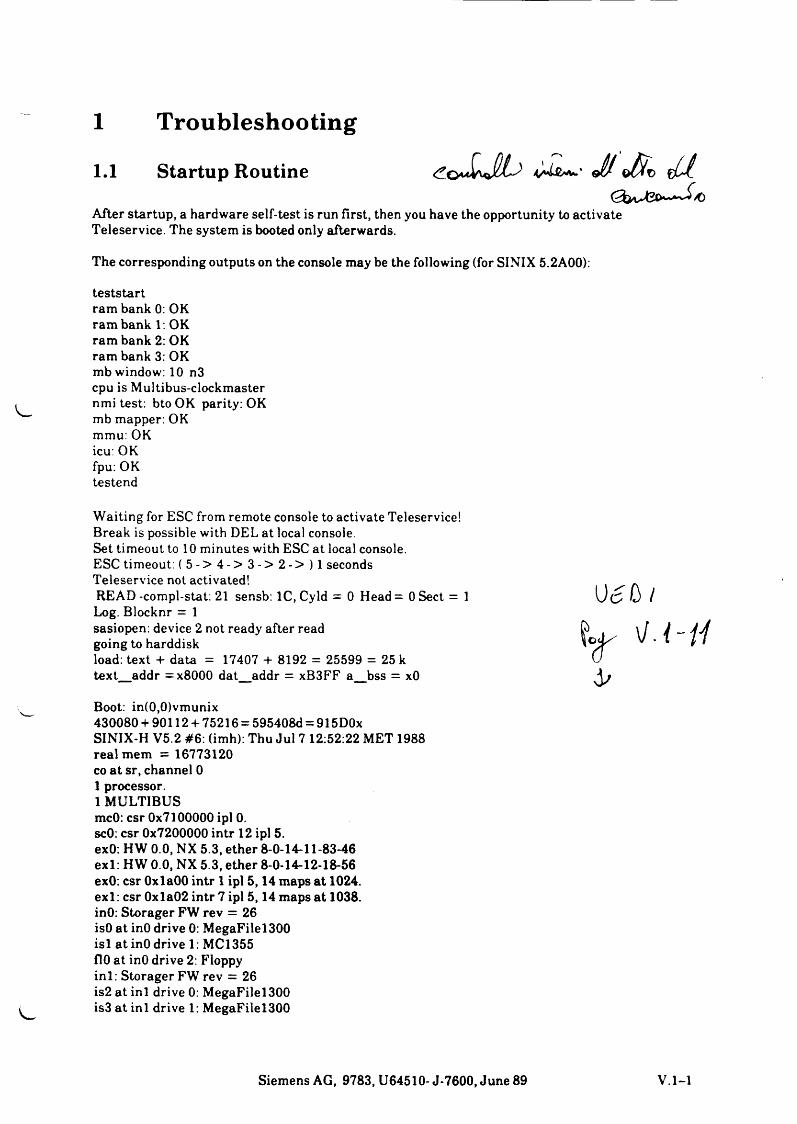
1 Troubleshooting1.1 Startup Routine
After startup, a hardware self-test is run first, then you have the opportunity to activate Teleservice. The system is booted only afterwards.
The corresponding outputs on the console may be the following (for SINIX 5.2A00):
teststart ram bank 0: OK ram bank 1. OK ram bank 2: OK ram bank 3: OK mb window: 10 n3 cpu is Multibus-clockmaster nmi test: bto OK parity: OK mb mapper: OK mmu: OK icu: OK fpu: OK testend
Waiting for ESC from remote console to activate Teleservice!Break is possible with DEL at local console.Set timeout to 10 minutes with ESC at local console.ESC timeout: ( 5 - > 4 - > 3 - > 2 - > ) l seconds Teleservice not activated!READ-compl-stat: 21 sensb: lC,Cyld = 0 Head= 0 Sect = 1 Log. Blocknr = 1sasiopen: device 2 not ready after read going to harddiskload: text + data = 17407 + 8192 = 25599 = 25 k text_addr =x8000 dat_addr = xB3FF a_bss = xO
Boot: in(0,0)vmunix430080 + 90112 + 75216 = 595408d = 915D0x SINIX-H V5.2 #6: (imh): Thu Jul 7 12:52:22 MET 1988 real mem = 16773120 co a t sr, channel 0 1 processor.1 MULTIBUS mcO: csr 0x7100000 ipl 0. scO: csr 0x7200000 intr 12 ipl 5. exO: HW 0.0, NX 5.3, ether 8-0-14-11-83-46 exl: HW 0.0, NX 5.3, ether 8-0-14-12-18-56 exO: csr OxlaOO intr 1 ipl 5,14 maps at 1024. e x l: csr 0xla02 intr 7 ipl 5,14 maps at 1038. inO: Storager FW rev = 26 isO at inO drive 0: MegaFilel300 isl at inO drive 1: MC1355 flO at inO drive 2: Floppy in i: Storager FW rev = 26 is2 a t in i drive 0: MegaFilel300 is3 at in i drive 1: MegaFilel300
0 c 0 /
u s
4/
Siemens AG, 9783, U64510- J-7600, June 89 V.l-1
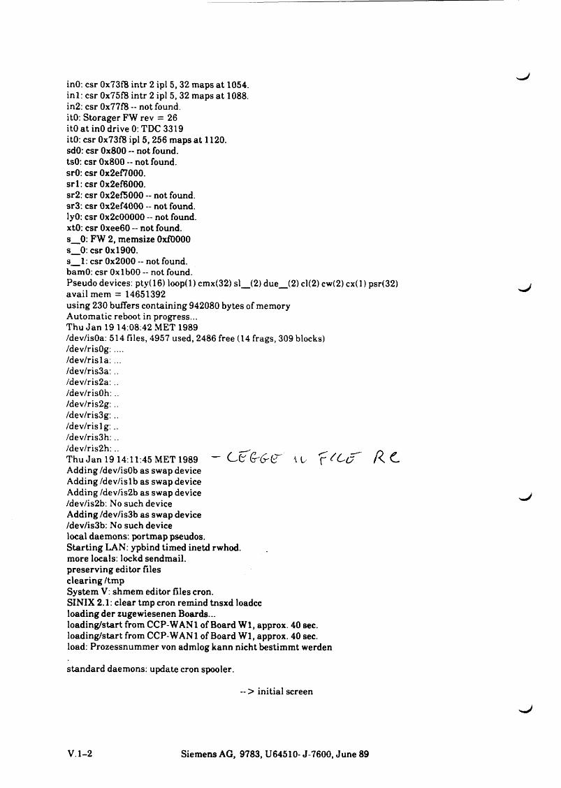
inO: csr 0x73fB intr 2 ipl 5, 32 maps at 1054.inl: csr 0x75f8 intr 2 ipl 5, 32 maps at 1088.in2: csr 0x77f8 -- not found.itO: Storager FW rev = 26itO at inO drive 0: TDC 3319itO: csr 0x73f8 ipl 5, 256 maps at 1120.sdO: csr 0x800 -- not found.tsO: csr 0x800 - not found.srO: csr 0x2ef7000.srl: csr 0x2ef6000.sr2: csr 0x2ef5000 -- not found.sr3: csr 0x2ef4000 -- not found.lyO: csr 0x2c00000 - not found.xtO: csr 0xee60 — not found.s_0: FW 2, memsize 0x10000s_0: csr 0x1900.s_1: csr 0x2000 -- not found.bamO: csr Oxl bOO -- not found.Pseudo devices: pty(16) loop(l) cmx(32) sl_(2) due_(2) cl(2) cw(2) cx(l) psr(32)avail mem = 14651392using 230 buffers containing 942080 bytes of memory Automatic reboot in progress...Thu Jan 19 14:08:42 MET 1989/dev/isOa: 514 files, 4957 used, 2486 free (14 frags, 309 blocks)/dev/risOg: ..../dev/risla: .../dev/ris3a:../dev/ris2a: ../dev/risOh: ../dev/ris2g: ../dev/ris3g:../dev/rislg :../dev/ris3h: ..
Adding /dev/isOb as swap device Adding/dev/islb as swap device Adding /dev/is2b as swap device /dev/is2b: No such device Adding /dev/is3b as swap device /dev/is3b: No such device local daemons: portmap pseudos.Starting LAN: ypbind timed inetd rwhod. more locals: lockd sendmail. preserving editor files clearing /tmpSystem V: shmem editor files cron.SINIX 2.1: clear tmp cron remind tnsxd loadcc loading der zugewiesenen Boards...loading/start from CCP-WAN 1 of Board W l, approx. 40 sec. loading/start from CCP-WAN 1 of Board Wl, approx. 40 sec. load: Prozessnummer von admlog kann nicht bestimmt werden
S t a n d a r d d a e m o n s : u p d a t e c r o n s p o o l e r .
/dev/ris2h: ..Thu Jan 1914:11:45 MET 1989
- > initial screen
V .l-2 Siemens AG, 9783, U64510- J-7600, June 89
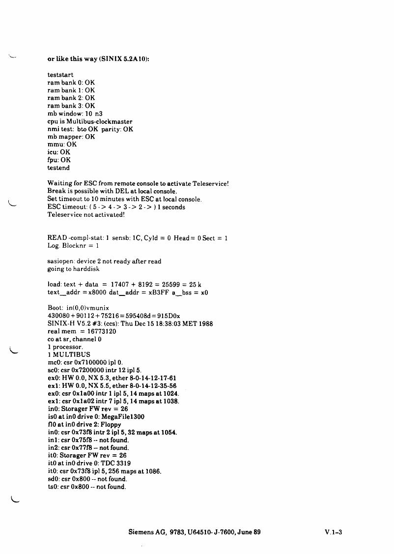
or like this way (SINIX 5.2A10):
teststartram bank 0: OKram bank 1: OKram bank 2: OKram bank 3: OKmb window: 10 n3cpu is Multibus-clockmasternmi test: bto OK parity: OKmb mapper: OKmmu: OKicu: OKfpu: OKtestend
Waiting for ESC from remote console to activate Teleservice! Break is possible with DEL at local console.Set timeout to 10 minutes with ESC at local console.ESC timeout: ( 5 - > 4 - > 3 - > 2 - > ) l seconds Teleservice not activated!
READ-compl-stat: 1 sensb: lC.Cyld = 0 Head= 0 Sect = 1 Log. Blocknr = 1
sasiopen: device 2 not ready after read going to harddisk
load: text + data = 17407 + 8192 = 25599 = 25 k text_addr = x8000 dat_addr = xB3FF a_bss = xO
Boot: in(0,0)vmunix430080 + 90112 + 75216 = 595408d = 915D0x SINIX-H V5.2 #3: (ccs): Thu Dec 15 18:38:03 MET 1988 real mem = 16773120 co at sr, channel 0 1 processor.1 MULTIBUSmcO: csr 0x7100000 ipl 0.scO: csr 0x7200000 intr 12 ipl 5.exO: HW 0.0, NX 5.3, ether 8-0-14-12-17-61exl: HW 0.0, NX 5.5, ether 8-0-14-12-35-56exO: csr 0x1 aOO intr 1 ipl 5,14 maps at 1024.exl: csr 0xla02 intr 7 ipl 5,14 maps at 1038.inO: Storager FW rev = 26isO at inO drive 0: MegaFilel300flO at inO drive 2: FloppyinO: csr 0x73fB intr 2 ipl 5,32 maps at 1054.in i : csr 0x75f8 - not found.in2: csr 0x77f8 — not found.itO: Storager FW rev = 26itO at inO drive 0: TDC 3319itO: csr 0x73f8 ipl 5,256 maps at 1086.sdO: csr 0x800 - not found.tsO: csr 0x800 - not found.
Siemens AG, 9783, U64510- J-7600, June 89
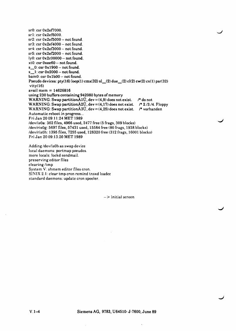
srO: csr 0x2ef7000. srl: csr 0x2ef6000. sr2: csr 0x2ef5000 -- not found. sr3: csr 0x2ef4000 - not found. sr4: csr 0x2ef3000 -- not found. sr5: csr 0x2ef2000 - not found. lyO: csr 0x2c00000 -- not found. xtO: csr 0xee60 -- not found.s_0: csr 0x1900 -- not found.s_1: csr 0x2000 -- not found.bamO: csr OxlbOO -- not found.Pseudo devices: pty(16) loop(l) cmx(32) si_(2) due_(2) cl(2) cw(2) cx(l) psr(32)vtty(16)avail mem = 14626816using 230 buffers containing 942080 bytes of memory WARNING: Swap partitionÄlÜ, dev = (4,9) does not exist. /* do notWARNING: Swap partitionÄ2Ü, dev = (4,17) does not exist. /* 2./3./4. Floppy WARNING: Swap partitionÄ3Ü, dev = (4,25) does not exist. /* vorhanden Automatic reboot in progress...Fri Jan 20 09:11:24 MET 1989/dev/isOa: 362 files, 4966 used, 2477 free (5 frags, 309 blocks)/dev/risOg: 5697 files, 57431 used, 15584 free (80 frags, 1938 blocks)/dev/risOh: 1395 files, 7255 used, 128320 free (312 frags, 16001 blocks)Fri Jan 20 09:13:20 MET 1989
Adding /dev/isOb as swap device local daemons: portmap pseudos. more locals: lockd sendmail. preserving editor files clearing /tmpSystem V: shmem editor files cron.SINIX 2.1: clear tmp cron remind tnsxd loadcc standard daemons: update cron spooler.
~ > initial screen
V .l-^ Siemens AG, 9783, U64510- J-7600, June 89
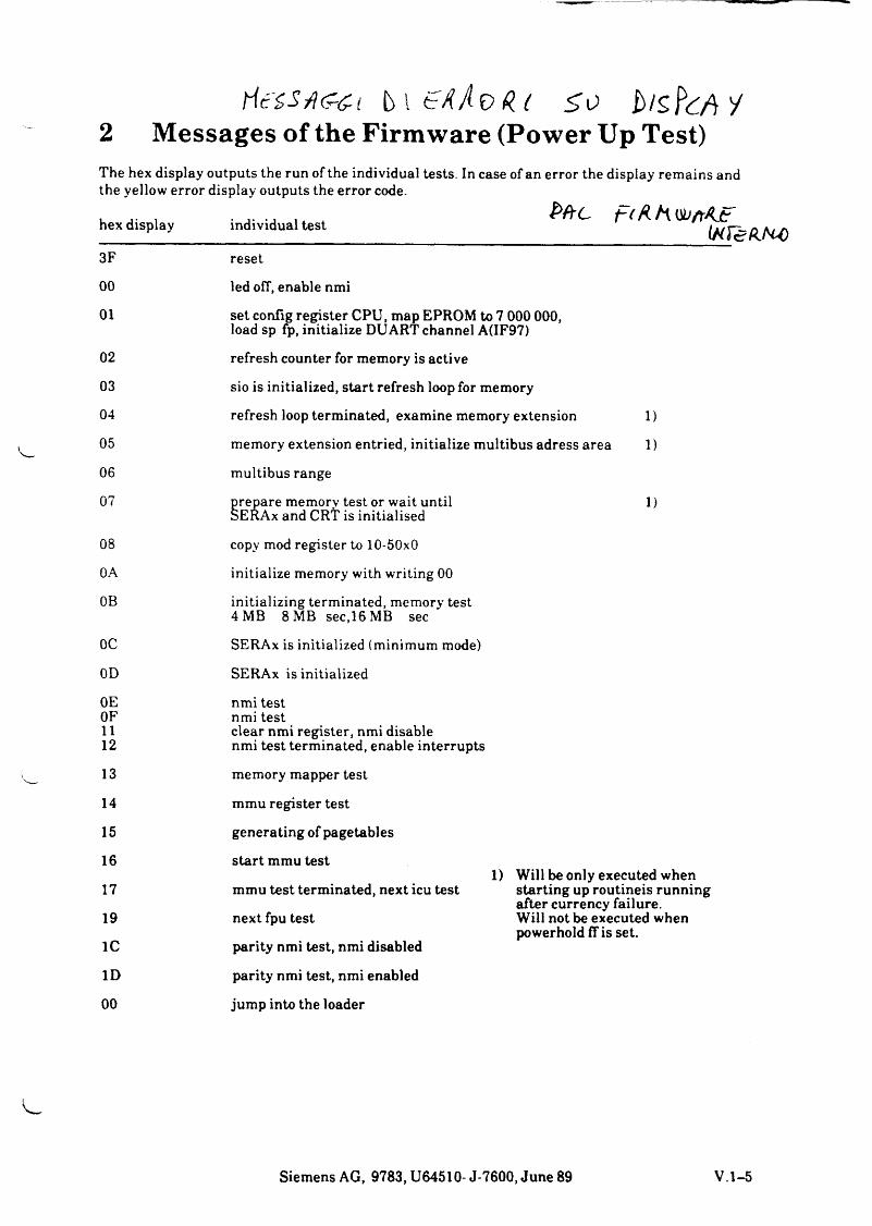
2 Messages of the Firmware (Power Up Test)The hex display outputs the run of the individual tests the yellow error display outputs the error code.
hex display individual test
3F reset
00 led off, enable nmi
01 set config register CPU, map EPROM to 7 000 000, load sp ¢ , initialize DU ART channel A(IF97)
02 refresh counter for memory is active
03 sio is initialized, start refresh loop for memory
04 refresh loop terminated, examine memory extension 1)
05 memory extension entried, initialize multibus adress area 1)
06 multibus range
07 prepare memory test or wait until 1)SERAx and CRT is initialised
. In case of an error the display remains and
Me FiUhKtjftAjf( H Y e k W )
08
0A
0B
0C
copy mod register to 10-50x0
initialize memory with writing 00
initializing terminated, memory test 4MB 8MB sec,16MB sec
SERAx is initialized (minimum mode)
0D SERAx is initialized
0E nmi testOF nmi test11 clear nmi register, nmi disable12 nmi test terminated, enable interrupts
13 memory mapper test
14 mmu register test
15 generating of pagetables
16
17
19
1C
start mmu test
mmu test terminated, next icu test
next fpu test
parity nmi test, nmi disabled
1) Will be only executed when starting up routineis running elfter currency failure.Will not be executed when powerhold ff is set.
ID parity nmi test, nmi enabled
00 jump into the loader
Siemens AG, 9783, U64510- J-7600, June 89 V .l-5
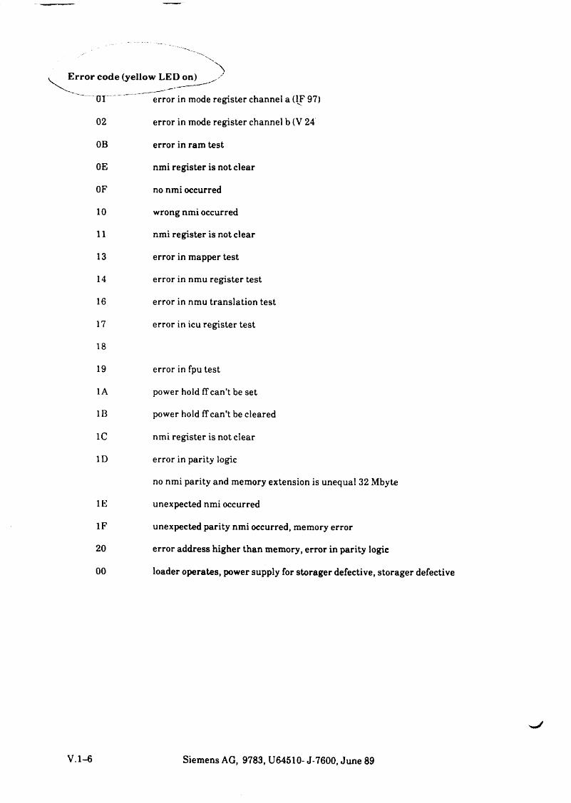
Error code (yellow LED on)
Öl error in mode register channel a (IF 97)
02 error in mode register channel b (V 24
OB error in ram test
0E nmi register is not clear
OF no nmi occurred
10 wrong nmi occurred
11 nmi register is not clear
13 error in mapper test
14 error in nmu register test
16 error in nmu translation test
17 error in icu register test
18
19 error in fpu test
1A power hold ff can't be set
1B power hold ff can’t be cleared
1C nmi register is not clear
1D error in parity logic
no nmi parity and memory extension is unequal 32 Mbyte
1E unexpected nmi occurred
1F unexpected parity nmi occurred, memory error
20 error address higher than memory, error in parity logic
00 loader operates, power supply for storager defective, storager defective
V .l-6 Siemens AG, 9783, U64510- J-7600, June 89
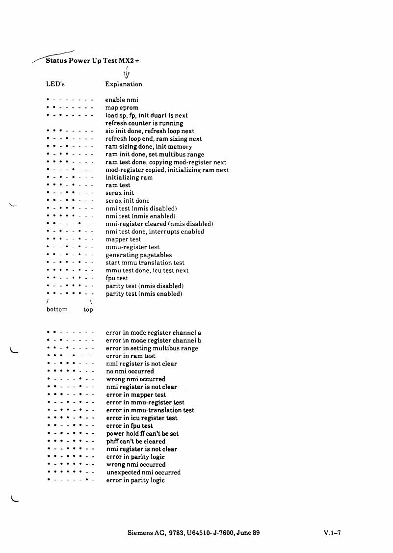
Status Pow er Up Test MX2 +/
\\t sJLED's Explanation
- _ _ •- • - +
* • * * _ • _ _
♦ * _ _ * * _ _
* _ _ * * * _ _
* * _ * * • _ _
/ \ bottom top
enable nmi map epromload sp, fp, init duart is nextrefresh counter is runningsio init done, refresh loop nextrefresh loop end, ram sizing nextram sizing done, init memoryram init done, set multibus rangeram test done, copying mod-register nextmod-register copied, initializing ram nextinitializing ramram testserax initserax init donenmi test (nmis disabled)nmi test (nmis enabled)nmi-register cleared (nmis disabled)nmi test done, interrupts enabledmapper testmmu-register testgenerating pagetablesstart mmu translation testmmu test done, icu test nextfpu testparity test (nmis disabled) parity test (nmis enabled)
* • _ .- - • __ 9 • _* * • -
• • _ •
• _ * •- • • •
error in mode register channel a error in mode register channel b error in setting multibus range error in ram test nmi register is not clear no nmi occurred wrong nmi occurred nmi register is not clear error in mapper test error in mmu-register test error in mmu-translation test error in icu register test error in fpu test power hold ff can't be set phff can't be cleared nmi register is not clear error in parity logic wrong nmi occurred unexpected nmi occurred error in parity logic
Siemens AG, 9783, U64510- J-7600, June 89 V .l-7
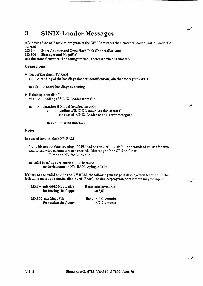
3 SINIX-Loader MessagesAfter run of the self-test (= program of the CPU firmware) the firmware loader (initial loader) ist started.MX2 + (Host Adapter and Omti Hard Disk CXontroller) and MX300 (Storager and Megafile)use the same firmware. The configuration is detected via bus timeout.
G eneral run
• Test of the clock N V RAMok - - > reading of the bootflags (loader identification, whether storager/OMTI)
not ok - - > entry bootflags by testing
• Exists system disk ?yes - - > loading of SINIX-Loader from FD
no - - > examine HD label (trackO, sectorO)ok - - > loading of SINIX-Loader (trackO, sector4)
(in case of SINIX-Loader not ok, error messgae)
not ok -- > error message
Notes:
In case of invalid clock N V RAM
- Valid bit not set (battery plug of CPU had no contact) - > default or standard values for time and teleservice parameters are entried. Meessage of the CPU seiftest:
Time and NV-RAM invalid....
- no valid bootflags are entried - - > becauseno devicename in NV-RAM, trying in(0,0)
If there are no valid data in the NV RAM, the following message is displayed on terminal.If the following message remains displayed: 'Boot:', the device/program parameters may be input:
MX2 + mit 40/80Mbyte disk for testing the floppy
Boot: sa(0,0)vmunix sa(2,0)
MX300 mitMegaFilefor testing the floppy
Boot: iri(0,0)vmunix in(2,2)vmunix
V .l-8 Siemens AG, 9783, U64510- J-7600, June 89
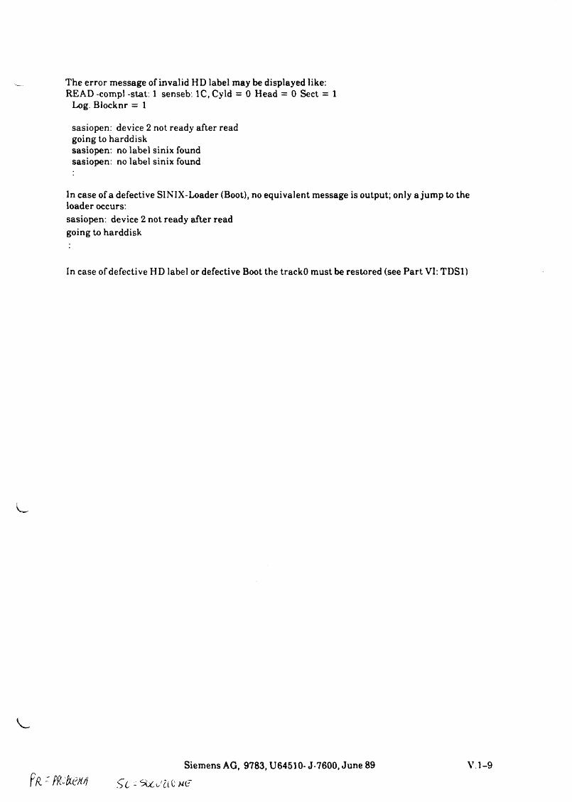
The error message of invalid HD label may be displayed like: READ -compl -stat: 1 senseb: 1C, Cyld = 0 Head = 0 Sect = 1
Log. Blocknr = 1
sasiopen: device 2 not ready after read going to harddisk sasiopen: no label sinix found sasiopen: no label sinix found
In case of a defective SINIX-Loader (Boot), no equivalent message is output; only a jump to the loader occurs:sasiopen: device 2 not ready after read going to harddisk
In case of defective HD label or defective Boot the trackO must be restored (see Part VI: TDSl)
Pä - / M a wSiemens AG, 9783, U64510- J-7600, June 89
h i - Stelae neV .l-9
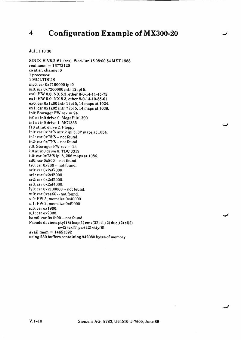
4 Configuration Example of MX300-20
Jul 11 10:30
SINIX-H V5.2 #1: (ccs): Wed Jun 15 08:00:54 MET 1988 real mem = 16773120 co at sr, channel 0 1 processor.1 MULTIBUSmcO: csr 0x7100000 ipl 0.scO: scr 0x7200000 intr 12 ipl 5.exO: HW 0.0, NX 5.3, ether 8-0-14-11-45-75exl: HW 0.0, NX 5.3, ether 8-0-14-10-85-61exO: csr OxlaOO intr 1 ipl 5,14 maps at 1024.exl: csr 0xla02 intr 7 ipl 5,14 maps at 1038.inO: Storager FW rev = 24isO a t inO drive 0: MegaFilel300isl at inO drive 1: MC1335flO at inO drive 2: FloppyinO: csr 0x73f8 intr 2 ipl 5, 32 maps at 1054.in i : csr 0x75f8 - not found.in2: csr 0x77f8 — not found.itO: Storager FW rev = 24itO at inO drive 0: TDC 3319itO: csr 0x73f8 ipl 5, 256 maps at 1086.sdO: csr 0x800 - not found.tsO. csr 0x800 - not found.srO: csr 0x2ef7000.srl: csr 0x2ef6000.sr2: csr 0x2ef5000.sr3: csr 0x2ef4000.lyO: csr 0x2c00000 - not found.xtO: csr 0xee60 - not found.s_0: FW 3, memsize 0x40000s_l: FW 2, memsize OxfOOOOs_0: csr oxl900.s_l: csr ox2000.bamO: csr OxlbOO -- not found.Pseudo devices:pty(16) loop(l) cmx(32) sl_(2) due_(2) cl(2)
cw(2) cx(l) psr(32) vtty(8). avail mem = 14651392using 230 buffers containing 942080 bytes of memory
V.l-10 Siemens AG, 9783, U64510- J-7600, June 89
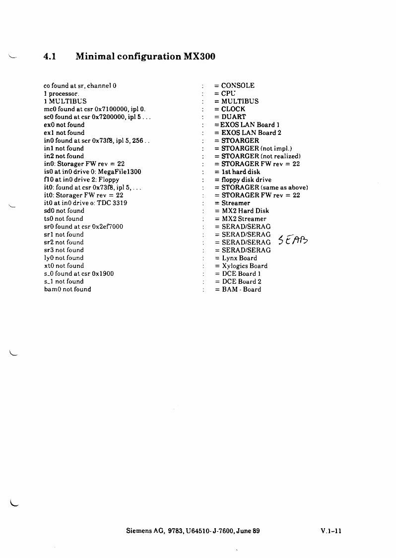
4.1 Minimal configuration MX300
co found at sr, channel 0 1 processor.1 MULTIBUSmcO found at csr 0x7100000, ipl 0. scO found at csr 0x7200000, ipl 5 . . . exO not found exl not foundinO found at scr 0x73f8, ipl 5, 256 .. in i not found in2 not foundinO: Storager FW rev = 22 isO at inO drive 0: MegaFilel300 flO a t inO drive 2: Floppy itO: found at csr 0x73f8, ipl 5 , . . . itO: Storager FW rev = 22 itO at inO drive o: TDC 3319 sdO not found tsO not foundsrO found at csr 0x2ef7000srl not foundsr2 not foundsr3 not foundlyO not foundxtO not founds_0 found at csr 0x1900s_l not foundbamO not found
= CONSOLE= CPU= MULTIBUS = CLOCK = DUART= EXOS LAN Board 1 = EXOS LAN Board 2 = STOARGER = STOARGER (not impl.)= STOARGER (not realized)= STORAGER FW rev = 22 = 1st hard disk = floppy disk drive = STORAGER (same as above) = STORAGER FW rev = 22 = Streamer = MX2 Hard Disk = MX2 Streamer = SERAD/SERAG = SERAD/SERAG = SERAD/SERAG = SERAD/SERAG = Lynx Board = Xylogics Board = DCE Board 1 = DCE Board 2 = BAM - Board
Siemens AG, 9783, U64510- J-7600, June 89 V.l-11
5 SINIX Messages. fh 6 K k Q fe ä t 'a f l -
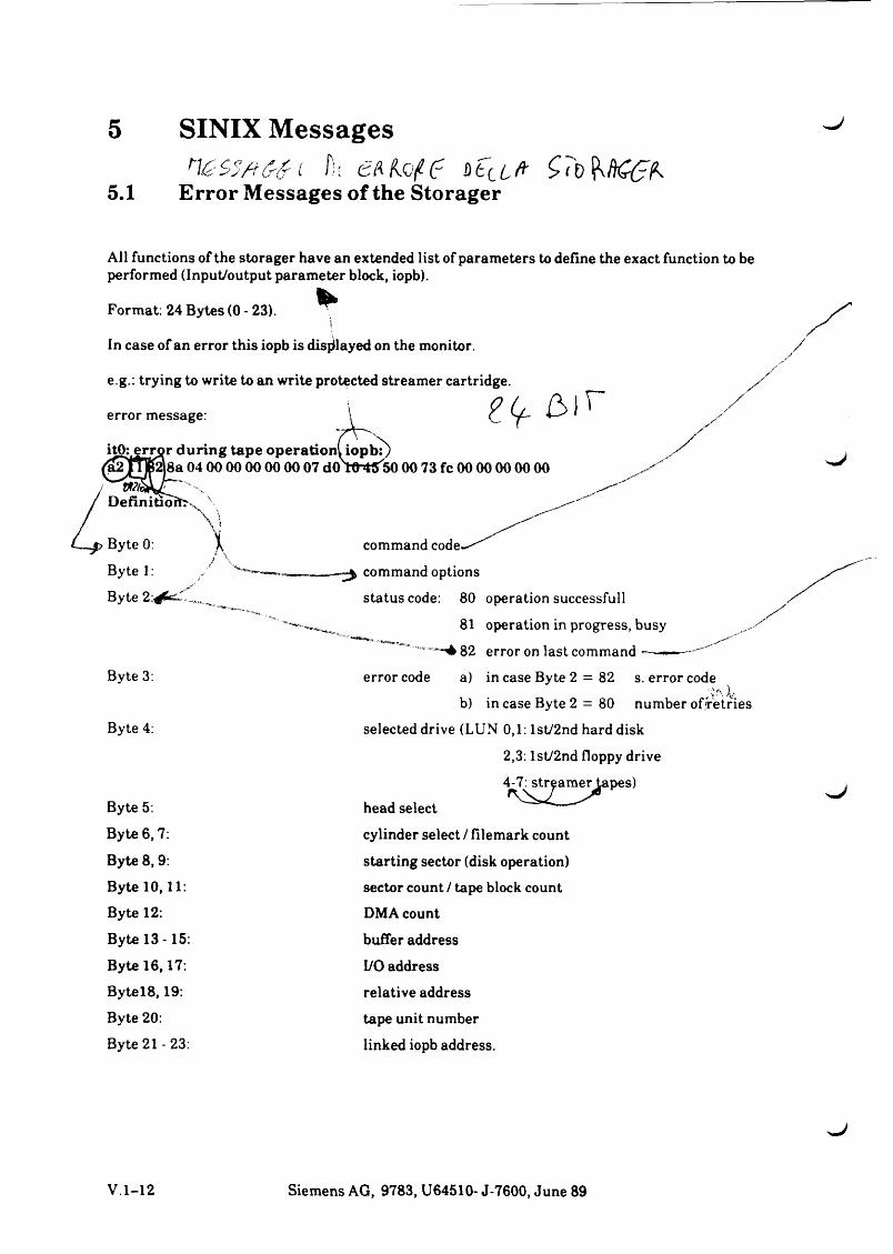
5.1 Error Messages of the Storager
All functions of the storager have an extended list of parameters to define the exact function to be performed (Input/output parameter block, iopb).
Format: 24 Bytes (0 - 23).!
In case of an error this iopb is displayed on the monitor,
e.g.: trying to write to an write protected streamer cartridge.
/
/error message:
itOjerror during tape operation! iopbT)räipJB äsa 04 00 00 00 00 00 07 d oroW sooo 73 fc 00 00 00 00 00
tmD e fin itio n , \
\ \''iiByte 0: \ command code--'"Byte 1: / ------- ^ command optionsByte 2 : ^ ^ " ^ ^ status code: 80
Byte 3:
Byte 4:
error code
81 operation in progress, busy
82 error on last command •—-=——
a) in case Byte 2 = 82 s. error codeb) in case Byte 2 = 80 number of'retries
selected drive (LUN 0,1: lst/2nd harddisk
2,3: lst/2nd floppy drive
4-7: streamer tapes)J
Byte 5: head selectByte 6,7: cylinder select / filemark countByte 8, 9: starting sector (disk operation)Byte 10,11: sector count / tape block countByte 12: DMA countByte 13 -15: buffer addressByte 16,17: I/O addressB y te l8 ,19: relative addressByte 20: tape unit numberByte 21 - 23: linked iopb address.
V .l-12 Siemens AG, 9783, U64510- J-7600, June 89
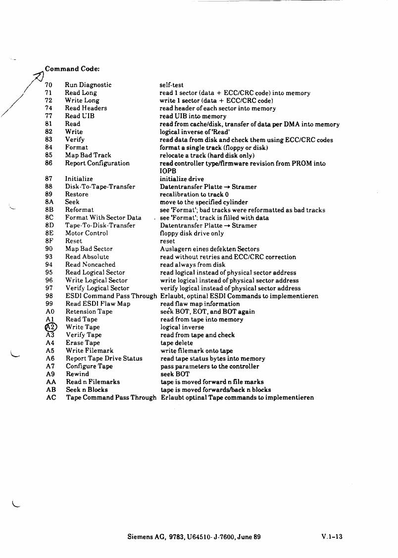
Com m and Code:
707172 74 77 81 8283848586
878889 8A 8B 8C 8D 8E 8F9093949596979899 AO A1
A3A4A5A6A7A9AAABAC
Run Diagnostic Read Long Write Long Read Headers Read UIB Read Write Verify FormatMap Bad Track Report Configuration
self-testread 1 sector (data + ECC/CRC code) into memory write 1 sector (data + ECC/CRC code) read header of each sector into memory read UIB into memoryread from cache/disk, transfer of data per DMA into memory logical inverse of'Read'read data from disk and check them using ECC/CRC codes format a single track (floppy or disk) relocate a track (hard disk only)read controller type/firmware revision from PROM into
InitializeDisk-To-Tape-TransferRestoreSeekReformatFormat With Sector Data Tape-To-Disk-Transfer Motor Control ResetMap Bad SectorRead AbsoluteRead NoncachedRead Logical SectorWrite Logical SectorVerify Logical SectorESDI Command Pass ThroughRead ESDI Flaw MapRetension TapeRead TapeWrite TapeVerify TapeErase TapeWrite FilemarkReport Tape Drive StatusConfigure TapeRewindRead n Filemarks Seek n BlocksTape Command Pass Through
IOPBinitialize driveDatentransfer Platte -* Stramer recalibration to track 0 move to the specified cylindersee 'Format'; bad tracks were reformatted as bad trackssee 'Format'; track is filled with dataDatentransfer Platte -* Stramerfloppy disk drive onlyresetAuslagern eines defekten Sectorsread without retries and ECC/CRC correctionread always from diskread logical instead of physical sector addresswrite logical instead of physical sector addressverify logical instead of physical sector addressErlaubt, optinal ESDI Commands to implementierenread flaw map informationseek BOT, EOT, and BOT againread from tape into memorylogical inverseread from tape and checktape deletewrite filemark onto tape read tape status bytes into memory pass parameters to the controller seek BOTtape is moved forward n file markstape is moved forwards/back n blocksErlaubt optinal Tape commands to implementieren
Siemens AG, 9783, U64510- J-7600, June 89 V.l-13
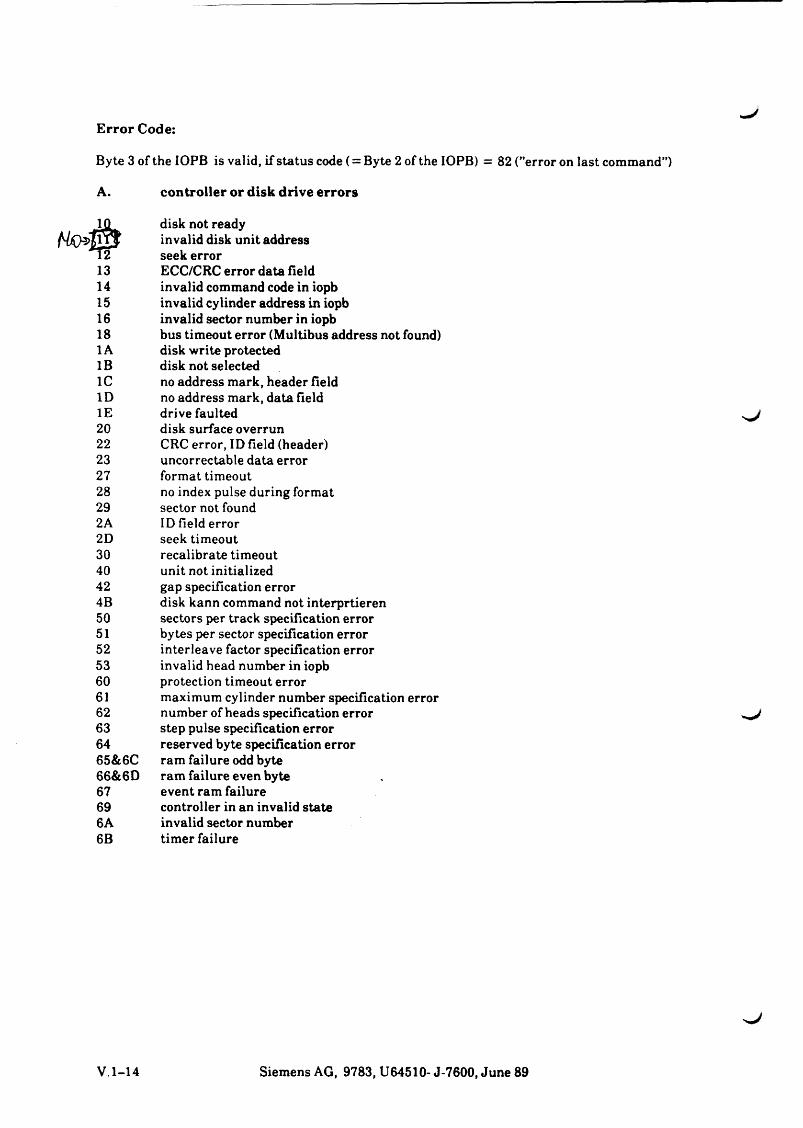
Error Code:
Byte 3 of the IOPB is valid, if status code (= Byte 2 of the IOPB) = 82 ("error on last command”)
A. contro ller o r d isk drive e rro rs
13141516 18 1A IB 1C ID IE 20 22 23272829 2A 2D30 40 42 4B50515253 60 61 62636465&6C66&6D67696A6B
disk not ready invalid disk unit address seek errorECC/CRC error data fieldinvalid command code in iopbinvalid cylinder address in iopbinvalid sector number in iopbbus timeout error (Multibus address not found)disk write protecteddisk not selectedno address mark, header fieldno address mark, data fielddrive faulteddisk surface overrunCRC error, ID field (header)uncorrectable data errorformat timeoutno index pulse during formatsector not foundID field errorseek timeoutrecalibrate timeoutunit not initializedgap specification errordisk kann command not interprtierensectors per track specification errorbytes per sector specification errorinterleave factor specification errorinvalid head number in iopbprotection timeout errormaximum cylinder number specification errornumber of heads specification errorstep pulse specification errorreserved byte specification errorram failure odd byteram failure even byteevent ram failurecontroller in an invalid stateinvalid sector numbertimer failure
V.l-14 Siemens AG, 9783, U64510- J-7600, June 89
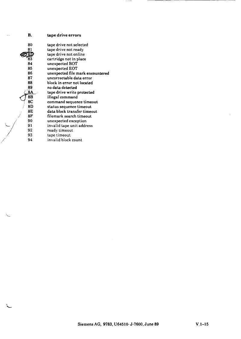
B. tape drive e rro rs
80 tape drive not selected81 tape drive not ready
tape drive not online'83 cartridge not in place84 unexpected BOT85 unexpected EOT86 unexpected file mark encountered87 uncorrectable data error88 block in error not located89 no data detected
tape drive write protected
< J 8B illegal command7 8C command sequence timeout/ 8D status sequence timeout
8E data block transfer timeout8F filemark search timeout90 unexpected exception91 invalid tape unit address92 ready timeout93 tape timeout94 invalid block count
Siemens AG, 9783, U64510- J-7600, June 89 V.l-15

SIEM ENS TDS 1
TDS 2
Test Programs Firmware (Monitor)
Part VI TDS

s j
6.1
.4
Be
arb
eit
en
ein
er
TD
S1
• D
isk
ette
1
6.2
.2
Pro
tok
oll
iere
n d
es
Ab
lau
fs
Q
®0'S « . n c < ©
T5© © ■o 5
« .®
esa
1 °o BQ.'©ÄT5if 9.E ®® ST3 ^•tr 05S b
_ 05 £TJreJC tc © •*-.52o «* « ä o c
o(0c
öJCooQlt:®
rea©•oc
0 « 00 — ■ 1■OTJ ■0O O 0E E E
■Oc3•c©Q.OJC®Cre0-©TJ
xzw
3o«2®wO£
05 TS — 44
®T3
° 2 3 1owa
4- 0-I $ € -
=> § x : tj
= 1 re 5S °re 3JC c44 "O3 & o o>■ 05 «2 3v re© HZm ^o Q= Xo a>-s »-2*0 0- ,®, ® ©
5 ' 5
®05cre
oEErek_o>o
t©
0
2 2
1 5,©W w
Q W
■0-0 o o E £
«o®■o
"m C7)
® ® JC JC O ü 3 3Ü Q
® - ; O c C ^£ | S3 « |<0.0 E 5 « 5 <■0 ^
© aS" J 23 « 5.
I S S*
iSj B S
05:0E2oc
(/)Q
ID
®
reEQ£E 05
11i . I£re m o> c 2 ©Q- 05
CD CO
I M
| ä.52® . m CM ® X « 5Q oa3 « TJXS 2
J Z c® ©05 C® x :-Q O ^ ®© QC
'03 — c ? ‘-•D C .555 ® 'c:< O £
o
£ ®
®g>o>
c'©c®xz®JC52Q
©■o
r; oOC to5 2nr ® <
E o « ' c
I «
B'SO T JE
c
®O):3
®•D
C/5Q 3h- q
wü j2Z fs fCC(tiu==* 0
e i05c344r.o<
QCQOC<u .E
©reQ
®3®c
©Oc®O)
®$NE©05©3
C _Q
§ £ ^ LT® 81 5.52 cnj
0 c © o
s icö CL £ -0 1
© wc reLU r
©3o
C23E d = ® re "o^ © E 5 ©05 O) © 33 ®u fSI £ ©
E©4-05>w: 3c©2
Oin
© cn
©05reBre
®© © r -oo> I
■fc “O© cLZ ©o x :in ®UJ 05cd .t:■E |© >— o05 t0 5© 205 3° I2 reS wre ^1 's5 s
re££o
05reo
O)
©2
_re©05
EQ
oocre££o
» Ed) ©52 w © >, T3 (h *=r :3.re c n © c 5® 05®-Sre - q £a. ^ Z> ® I— 055 0< 05f e ”© re Q E
N .0 r0 = O - C *-rec0
1 °o to
© ®- ■D £— o
v „ - Ji Q t-
CiE!Eow22OC<05T3C3<DEE(0a>oi_a.<n
</)Q
CMCD
JZoV) 2 m BCO®roQ®c®0nCO03co3<
.£ X3a. ®=« 030 0)co 03co • co<ü £ 3
- o f f CO
< ® "ff.O .2 5CO Xco ® ®
1-g ff 2C ® bCD -Qjr o 5Q.coCO®Q
CG
0co o
=*fc03 M
I I
0) ® cbJ= ®.2 co co O
® >
i i= co
03T3C0)03-Q
3Bco03S3C0O)
-S £ : 3
C «O Äe l® co^ "O
C0 = ^ 0 "ffBg$ 03X3 Z 0 03 ®QC ff>C Ö) ®© co -O p oc £io fc 03—co co ® osb cö2 « cl
Ec 20 coLL® A St: ©-0■c -O fr, — © —I ' © ^ 0 CD V =5
A0
X3
V«73
£0S.CD
CO
0aco.o 8S-I§o ® -oCO . 2 CM 0 0 —
CD CD S
A05.X3V
= 03
3 C o 03 CO52«.c
c ■!§ ® c c0 z £c'©03O2
3 O9-¾rn O
i- = 3 0 O CE -¾ co 3 _ CgS 32 55 ® |■g co Q — -¾ ra x:« 3 -a -a 3-g oiOS c c q «<2
_ .£ 3 OT 3
B g2-S 5 Eo ® 20 CL CO
3 "o CO CO CO ® ® 9 CO CD CD CD -g -g O O
g | B w
o > ® ®o c 3X3 c - CO CO•” ~ 03 03 0303© 2 c c $5 $5 -2E ro o o 3 3CO I— = = CO COc “ -----
cot-*-«-«- T3 3 3 3 3* - C « « « 0 0 C a)a)pr :®®0®®££. 2 jS-K-gEE■ . tu (u tu (u ^ ^*= 030303 032 2® co co co co ® ®■c 3 3 3 3 2 2 . £ < < < < > >
(TJ O S 2 ^ ^ '
E ^ Ü D iomf f © o b o b ? !2 0 CD CD CD CD
O i- cnjoo > > .£ o c . b O O
V
ooQ
co 6(1) *- »g>8- B!n cd «o
Ein
gabe ®3C©
EN
sa_u
rld
< C
TRL
> <
DE
L>
G <
CR
> <
CR
>
G<
CR
>
D 0
<C
TR
L> <
DE
L>
< E
ND
>
(32,
0) oöo
Ziel
Men
ü-S
yste
m
TDS1
sa_u
rld
Mon
itor
TDS1
sa_u
rld
Lade
r
TDS1
Mon
itor
Mon
itor
TDS1
(D
iske
tte)
SIN
IX (
Pla
tte)
Que
lle
TDS1
Men
ü-S
yste
m
TDS1
TDS1
Mon
itor
Mon
itor
------
------
------
------
- -----
-- ]
Mon
itor
sa_u
rld
sa_u
rld
Lade
r
Lade
r
Lade
r
CT)
o
TJ-TfCDDco'oH-XzcoCDH-co
Tco
STB
SINI
X-TD
S, U
6454
7-J,
04.
91
6-5
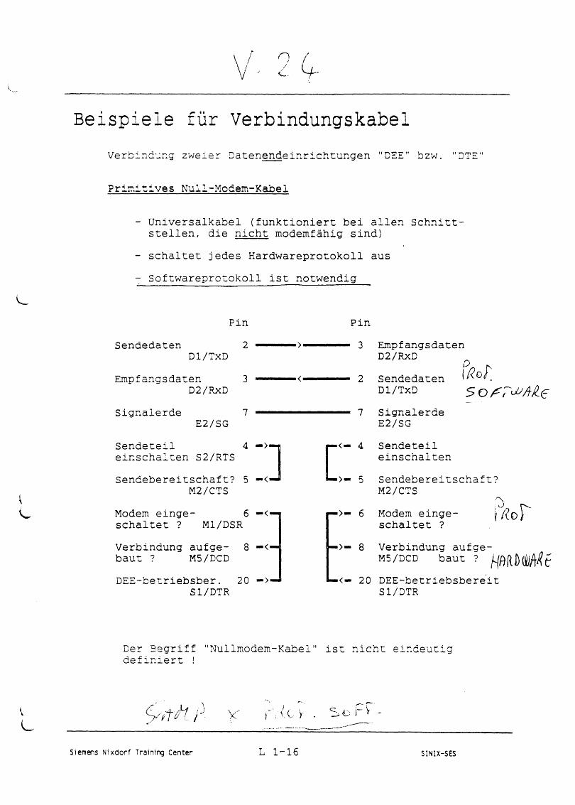
\ / 9 (y ' ' j ' '
Beispiele für VerbindungskabelVerbindung zweier Datenendeinrichtungen "DEE" bzw. "DTE"
Primitives Null-Modem-Kabel
k
- Universalkabel (funktioniert bei allen Schnittstellen, die nicht modemfähig sind)
- schaltet jedes Hardwareprotokoll aus- Softwareprotokoll ist notwendig
SendedatenPin
2Dl/TxD
Empfangsdaten 3D2/RxD
Signalerde 7E2/SG
Sendeteil 4 — >•einschalten S2/RTSSendebereitschaft? 5 — <•
M2/CTSModem einge- 6 — <—schaltet ? Ml/DSRVerbindung aufge- 8 — <■ baut ? M5/DCDDEE-betriebsber. 20 — >■
Sl/DTR
Pin■ 3 Empfangsdaten
D2/RXD• 2 Sendedaten
Dl/TxD• 7 Signalerde
E2/SG
r
><— 4 Sendeteileinschalten
■>— 5 Sendebereitschaft? M2/CTS
>>— 6 Modem eingeschaltet ? /? 0 p
'>— 8 Verbindung aufge- M5/DCD baut ?
■<— 20 DEE-betriebsbereit Sl/DTR
Der Begriff "Nullmodem-Kabel" ist nicht eindeutig definiert !
v ■ r t h Y. ( c o
Siemens Nixdorf Training Center L 1-16 SINIX-SES
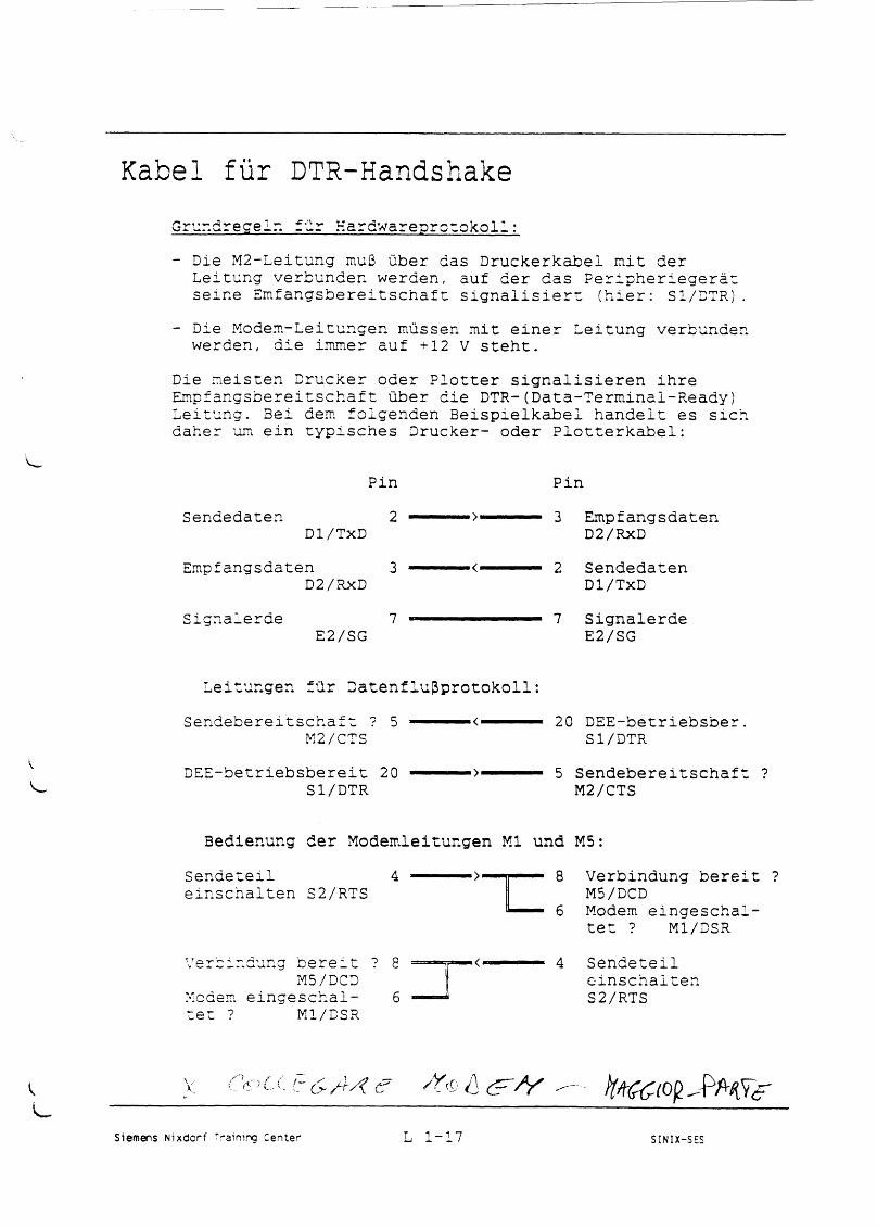
Kabel für DTR-HandshakeGrundregeln für Kardwareprotokoll:- Die M2-Leitung muß über das Druckerkabel mit der
Leitung verbunden werden, auf der das Peripheriegerät seine Emfangsbereitschaft signalisiert (hier: Sl/DTR).
- Die Modem-Leitungen müssen mit einer Leitung verbunden werden, die immer auf +12 V steht.
Die meisten Drucker oder Plotter signalisieren ihre Empfangsbereitschaft über die DTR-(Data-Terminal-Ready) Leitung. Bei dem folgenden Beispielkabei handelt es sich daher um ein typisches Drucker- oder Plotterkabel:
Pin PinSendedaten 2 ------ >------ 3 Empfangsdaten
Dl/TxD D2/RXDE m p f a n g s d a te n 3 ------- <------ 2 Sendedaten
D2/RXD Dl/TxDSignalerde 7 — — ■■■------ 7 Signalerde
E2/SG E2/SG
Leitungen für Datenflußprotokoll:S e n d e b e r e i t s c h a f t ? 5 --- ----- ---- 20 DEE-betriebsber
M2/CTS Sl/DTRDEE-betriebsbereit 20 ------ >------ 5 Sendebereitschaf
Sl/DTR M2/CTS
Bedienung der Modemleitungen Ml und M5:Sendeteil 4einschalten S2/RTS
Verbindung bereit ? M5/DCDModem eingeschaltet ? Ml/DSR
Verbindung bereit ?M5/DCD
Modem eingeschaltet ? Ml/DSR
6
4 Sendeteil einschalten S2/RTS
L <.. o
Siemens Nixdorf Training Center L 1-17 SINIX-SES
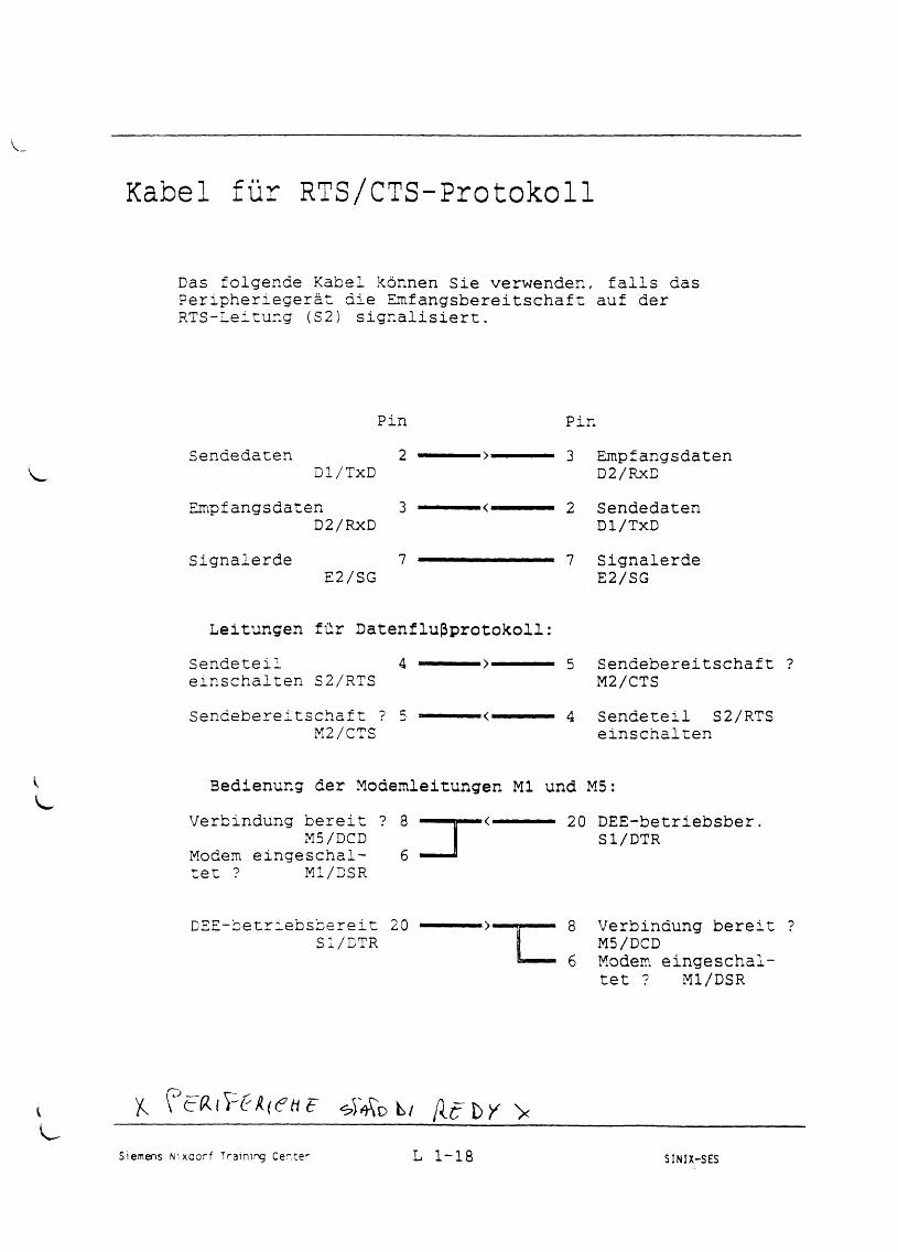
Kabel für RTS/CTS-Protokoll
Das folgende Kabel können Sie verwenden, falls das Peripheriegerät die Einfangsbereitschaft auf der RTS-Leitung (S2) signalisiert.
Pin PinSendedaten 2 --- — > — 3 Empfangsdaten
Dl/TxD D2/RxDEmpfangsdaten 3 -------— <■.. 2 Sendedaten
D2/RXD Dl/TxDSignalerde 7 — 7 Signalerde
E2/SG E2/SG
Leitungen für Datenflußprotokoll:Sendete!! 4 — — 5 Sendebereitschafteinschalten S2/RTS M2/CTSSendebereitschaft ? 5 — -— <■... — 4 Sendeteil S2/RTS
M2/CTS einschalten
Bedienung der Modemleitungen Ml und M5:Verbindung bereit ? 8 ■■■■« « < ■■■ ■ 20 DEE-betriebsber.
M5/DCD I Sl/DTRModem eingeschal- 6 — — J tet ? Ml/DSR
DEE-betriebsbereit 20 Sl/DTR
8 Verbindung bereit ? M5/DCD
1 6 Modem eingeschaltet ? Ml/DSR
K \ & <eW ib b i f i t b Y >
Siemens Nixdorf Training Center L 1-18 SINIX-SES
Part VI
TDS (Test and Diagnostic System)
Contents Page
1 TDS 1 Version 5.x for MX300/ MX2 + VI.1-1
2 TDS 2 Vl.2-1
3 Test P rogram s Firm w are VI.3-1
3.1 G e n e r a l VI.3-1
3.2 F ir m w a r e M o n ito r VI.3-1
3.3 E x a m p l e s VI. 3-2
1 TDS1 Version 5.x for MX300/ MX2 +
O F F Ü H S [ s L b & i r , )***************** ^
Information about Version 5.x
The TDSl files are recorded in the SINIX FAR-format. Hence the following changes:
Making a backup, or changes the TDSl floppy:
The floppy can no longer be mounted using ”/etc/mount” !To modify or copy the floppy it must be copied to disk by using the command ”far xv *” . This copies the contents to a SINIX-PC directory.Files can be deleted, added or modified in this directory(but: + FARDIR, TDS.txt, TDS_KERNEL,_cat,_Is,_more, mFARDIRl,mFARDIR2 ’’MUST NOT BE DELETED”.Execute the command ” mFARDIRl” (organizes files).Execute the command ’’far cv *” (creates a new TDSl floppy).
*****************
TDSl Description
The test and diagnostic system (TDSl) is part of the Siemens PC system family. The SINIX operating system is not necessary for the operation of TDSl. TDSl has its own independent loader and operating system.
The TDSl consists of:
Test operating system.Test programs Diagnostic programs Utility programsEPROM resident programs (initial loader, self-test, monitor, SCSI, and console driver).
Brief description:
Diagnostic and/or test programs are planned for the system components CPU, MMU, FPU, ICU, memory, floppy disk, hard disk, interfaces and data communication equipment (DCE), S3510 and MC 146818, or have already been implemented.
The diagnostic programs test hardware and firmware functions; errors are localized precisely. The communication with the system is executed via keyboard or monitor.For an unobserved continuous test a file-controlled operation is also possible (even without key board/monitor).
Siemens AG, 9783, U64510- J-7600, Juni 89 VI.1-1
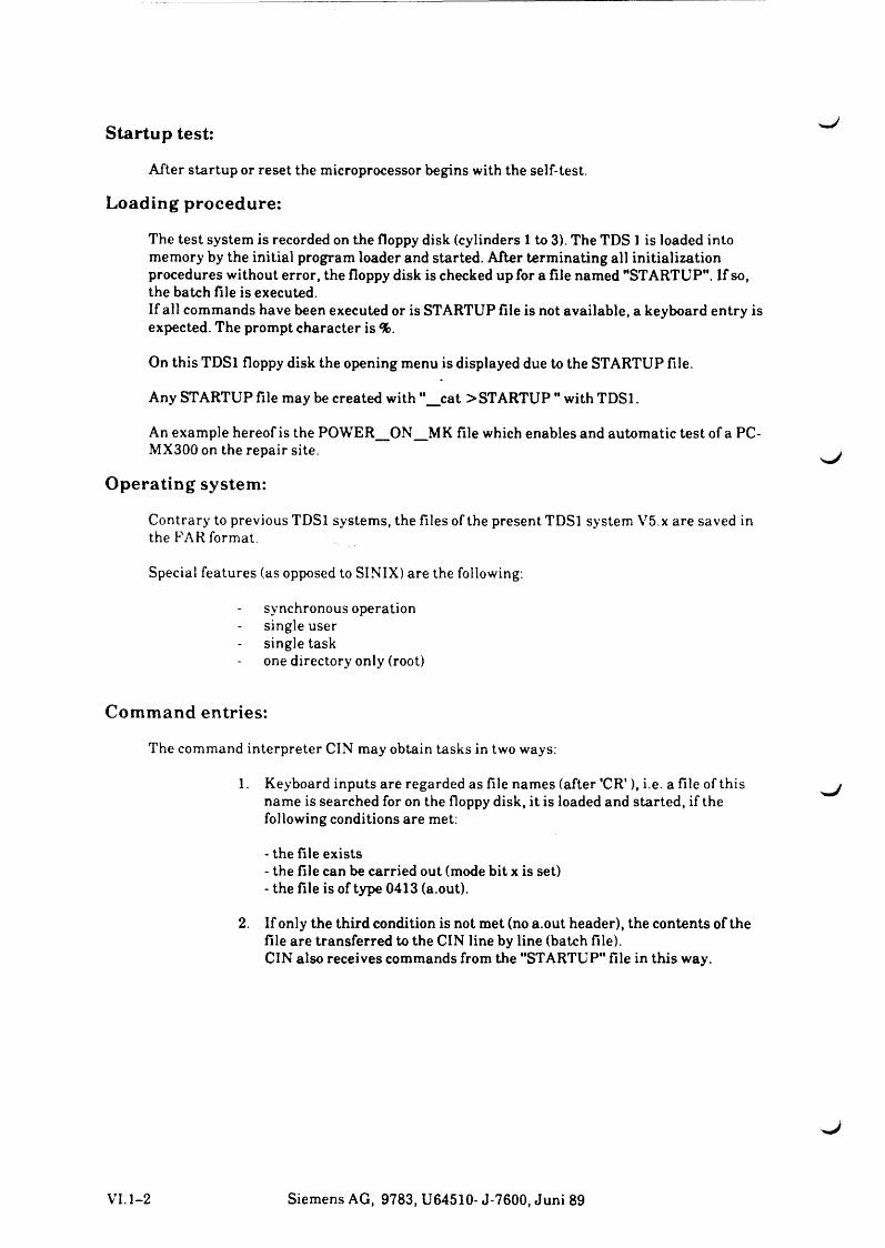
Startup test: ^J
After startup or reset the microprocessor begins with the self-test.
Loading procedure:
The test system is recorded on the floppy disk (cylinders 1 to 3). The TDS 1 is loaded into memory by the initial program loader and started. After terminating all initialization procedures without error, the floppy disk is checked up for a file named "STARTUP”. If so, the batch file is executed.If all commands have been executed or is STARTUP file is not available, a keyboard entry is expected. The prompt character is %.
On this TDSl floppy disk the opening menu is displayed due to the STARTUP file.
Any STARTUP file may be created with "__cat > STARTUP " with TDSl.
An example hereof is the POWER_ON_MK file which enables and automatic test of a PC-MX300 on the repair site.
Operating system:
Contrary to previous TDSl systems, the files of the present TDSl system V5.x are saved in the FAR format.
Special features (as opposed to SINIX) are the following:
synchronous operation single user single taskone directory only (root)
Command entries:
The command interpreter CIN may obtain tasks in two ways:
1. Keyboard inputs are regarded as file names (after 'C R '), i.e. a file of this name is searched for on the floppy disk, it is loaded and started, if the following conditions are met:
- the file exists- the file can be carried out (mode bit x is set)- the file is of type 0413 (a.out).
2. If only the third condition is not met (no a.out header), the contents of the file are transferred to the CIN line by line (batch file).CIN also receives commands from the "STARTUP" file in this way.
VI. 1-2 Siemens AG, 9783, U64510- J-7600, Juni 89
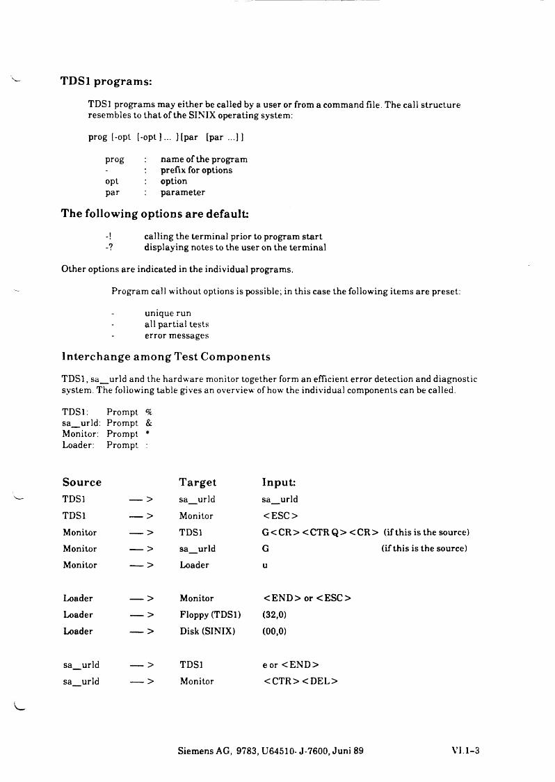
TDSl programs:
TDSl programs may either be called by a user or from a command file. The call structure resembles to that of the SINIX operating system:
prog [-opt [-opt 3... ] [par [par ...]3
prog name of the program- prefix for optionsopt optionpar parameter
The following options are default:
-! calling the terminal prior to program start-? displaying notes to the user on the terminal
Other options are indicated in the individual programs.
Program call without options is possible; in this case the following items are preset:
unique run all partial tests error messages
Interchange among Test Components
TDSl , sa_urld and the hardware monitor together form an efficient error detection and diagnosticsystem. The following table gives an overview of how the individual components can be called.
TDSl: Prompt °ksa_urld: Prompt &Monitor: Prompt * Loader: Prompt :
Source TargetTDSl — > sa_urld
TDSl -----------> Monitor
Monitor -----------> TDSlMonitor -----------> sa_urldMonitor -----------> Loader
Loader -----------> MonitorLoader -----------> Floppy (TDSl)Loader -----------> Disk (SINIX)
sa_urld — > TDSl
sa urld -----------> Monitor
Input:sa_urld
<ESC>
G <C R > <C TR Q > <C R > (if this is the source) G (if this is the source)
u
<EN D > or <ESC >
(32,0)
(00,0)
e or <EN D ><CTR> <D EL>
Siemens AG, 9783, U64510- J-7600, Juni 89 VI. 1-3
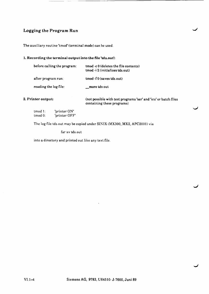
Logging the Program Run
The auxiliary routine 'tmod' (terminal mode) can be used.
1. R ecording the term inal ou tpu t into the file 'tds.out':
before calling the program: tmod -c 0 (deletes the file contents) tmod -i 2 (initializes tds.out)
after program run: tmod -f 0 (saves tds.out)
reading the log file: _more tds.out
2. P rin te r output: (not possible with test programs 'ser' and 'icu' or batch files containing these programs)
tm odl: printer ON tmod 0: ’printer OFF'
The log file tds.out may be copied under SINIX (MX300, MX2, APC2001) via
far xv tds.out
into a directory and printed out like any text file.
^J
VI. 1-4 Siemens AG, 9783, U64510- J-7600, Juni 89
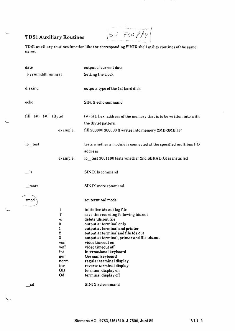
TDSl Auxiliary Routines . ^ u ^ ^ ^ ^ / \
TDSl auxiliary routines function like the corresponding SINIX shell utility routines of the same name.
date output of current datel-yymmddhhmmss] Setting the clock
diskind outputs type of the 1st hard disk
echo SINIX echo command
fill (#) (#) (Byte) (#) (#): hex. address of the memory that is to be written into with the (byte) pattern.
example: fill 200000 300000 ff writes into memory 2MB-3MB FF
io_test tests whether a module is connected at the specified multibus 1-0 address
example: io_test 3001100 tests whether 2nd SERAD(G) is installed
_Is SINIX Is command
_more SINIX more command
^ tm od^ set terminal mode
-i-f-c0123vonvoffintgernorminvODOd
initialize tds.out log filesave the recording following tds.outdelete tds.out fileoutput at terminal onlyoutput at terminal and printeroutput at terminaland file tds.outoutput at terminal, printer and file tds.outvideo timeout onvideo timeout offinternational keyboardGerman keyboardregular terminal displayreverse terminal displayterminal display onterminal display off
_xd SINIX xd command
Siemens AG, 9783, U64510- J-7600, Juni 89 VI.1-5
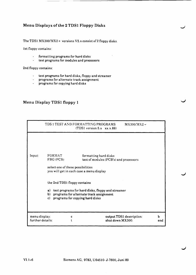
Menu Displays of the 2 TDSl Floppy Disks
The TDSl MX300/MX2+ versions V5.x consist of 2 floppy disks.
1st floppy contains:
formatting programs for hard disks test programs for modules and processors
2nd floppy contains:
test programs for hard disks, floppy and streamer programs for alternate track assignment programs for copying hard disks
Menu Display TDSl floppy 1
TDS 1 TEST AND FORMATTING PROGRAMS MX300/MX2 + (TDSl version 5.x xx.x.88)
Input: FORMAT formatting hard disksFBG (PCB) test of modules (PCB’s) and processors
select one of these possibilitiesyou will get in each case a menu display
the 2nd TDSl floppy contains
a) test programs for hard disks, floppy and streamerb) programs for alternate track assignmentc) programs for copying hard disks
menu display: c output TDSl description: bfurther details: t shut down MX300: end
N*J
VI.1-6 Siemens AG, 9783, U64510- J-7600, Juni 89
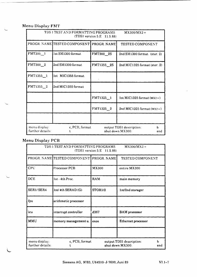
Menu Display FMTTDS 1 TEST AND FORMATTING PROGRAMS MX300/MX2 +
(TDSl version 5.E 11.5.88)
PROGR. NAME TESTED COMPONENT PROGR. NAME TESTED COMPONENT
FMT300_1 1 st SM 1300 format FMT300_2S 2nd SM1300 format (stor. 2)
FMT300_2 2nd SMI300 format FMT1355_2S 2nd MIC1325 format (stor. 2)
FMT1355_1 1st M1C1355 format
FMT1355_2 2nd MIC1355 format
FMT1325_1 1st M1C1325 format ( M X 2 + )
FMT1325_2 2nd MIC1325 format ( M X 2 + )
menu display: c, PCB, format output TDSl description: b further details: t shut down MX300: end
Menu Display PCBTDS 1 TEST AND FORMATTING PROGRAMS MX300/MX2 +
(TDSl version 5.E 11.5.88)
PROGR. NAME TESTED COMPONENT PROGR. NAME TESTED COMPONENT
CPU Processor PCB MX300 entire MX300
DCE 1st - 4th Proc. RAM main memory
SER1/SER4 1st; 4th SERAD(G) STOR1/2 1 sV2nd storager
fpu arithmetic processor
icu interrupt controller d367 BAM processor
MMU memory management u. exos Ethernet processor
menu display . c, PCB, format output TDSl description. b further details: t shut down MX300: end
Siemens AG, 9783, U64510- J-7600, Juni 89 VI.1-7
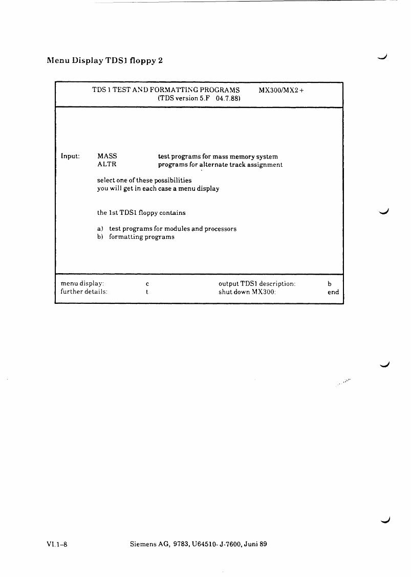
Menu Display TDSl floppy 2
TDS 1 TEST AND FORMATTING PROGRAMS MX300/MX2 +(TDS version 5.F 04.7.88)
Input: MASS test programs for mass memory systemALTR programs for alternate track assignment
select one of these possibilitiesyou will get in each case a menu display
the 1st TDSl floppy contains
a) test programs for modules and processorsb) formatting programs
menu display: c output TDSl description: bfurther details: t shut down MX300: end
xJ
VI.1-8 Siemens AG, 9783, U64510- J-7600, Juni 89
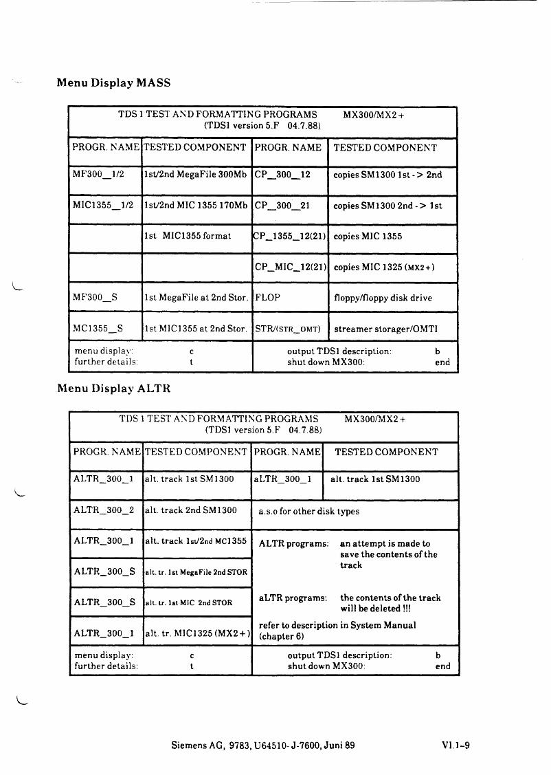
Menu Display MASS
TD Sl TEST AND FORMATTING PROGRAMS MX300/MX2 + (TDSl version 5.F 04.7.88)
PROGR. NAME TESTED COMPONENT PROGR. NAME TESTED COMPONENT
MF300_1/2 lst/2nd MegaFile 300Mb CP_300_12 copies SM 1300 1 st - > 2nd
MIC1355_1/2 lst/2nd MIC 1355 170Mb CP_300__21 copies SM 1300 2nd - > 1 st
1st MIC1355 format CP_1355_12(21) copies MIC 1355
CP_MIC_12(21) copies MIC 1325 (MX2 + )
MF300_S 1st MegaFile at 2nd Stor. FLOP floppy/floppy disk drive
MC1355_S 1st MIC1355 at 2nd Stor. STR/(str_ omt) streamer storager/OMTI
menu display. c further details: t
output TDSl description: b shut down MX300: end
Menu Display ALTR
TDS 1 TEST AND FORMATTING PROGRAMS MX300/MX2 + (TDSl version 5.F 04.7.88)
PROGR. NAME TESTED COMPONENT PROGR. NAME TESTED COMPONENT
ALTR_300_1 alt. track 1st SMI300 aLTR_300_l alt. track 1st SMI300
ALTR_300_2 alt. track 2nd SMI300 a.s.o for other disk types
ALTR_300_1 alt. track lst/2nd MCI355 ALTR programs: an attempt is made to save the contents of the track
aLTR programs: the contents of the track will be deleted!!!
refer to description in System Manual (chapter 6)
ALTR_300_S alt. tr. 1st MegaFile 2nd STOR
ALTR_300_S alt. tr. 1st MIC 2nd STOR
ALTR_300_1 alt. tr. MIC1325 (MX2 + )
menu display: c further details: t
output TDSl description: b shut down MX300: end
Siemens AG, 9783, U64510-J-7600, Juni 89 VI.1-9
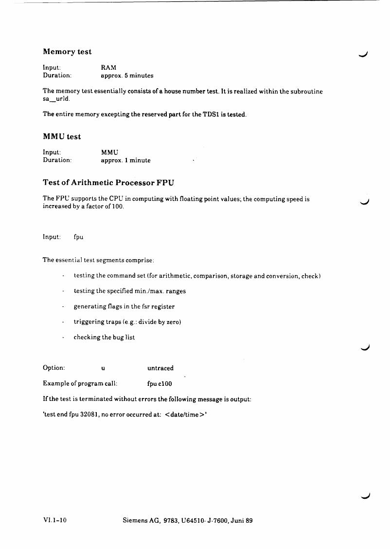
Memory test
Input: RAMDuration: approx. 5 minutes
The memory test essentially consists of a house number test. It is realized within the subroutine sa_urld.
The entire memory excepting the reserved part for the TDSl is tested.
MMU test
Input: MMUDuration: approx. 1 minute
Test of Arithmetic Processor FPU
The FPU supports the CPU in computing with floating point values; the computing speed is increased by a factor of 100.
Input: fpu
The essential test segments comprise:
testing the command set (for arithmetic, comparison, storage and conversion, check)
testing the specified min./max. ranges
generating flags in the fsr register
triggering traps (e g.: divide by zero)
checking the bug list
Option: u untraced
Example of program call: fpuclOO
If the test is terminated without errors the following message is output:
'test end fpu 32081, no error occurred at: <date/tim e> '
VI.1-10 Siemens AG, 9783, U64510- J-7600, Juni 89
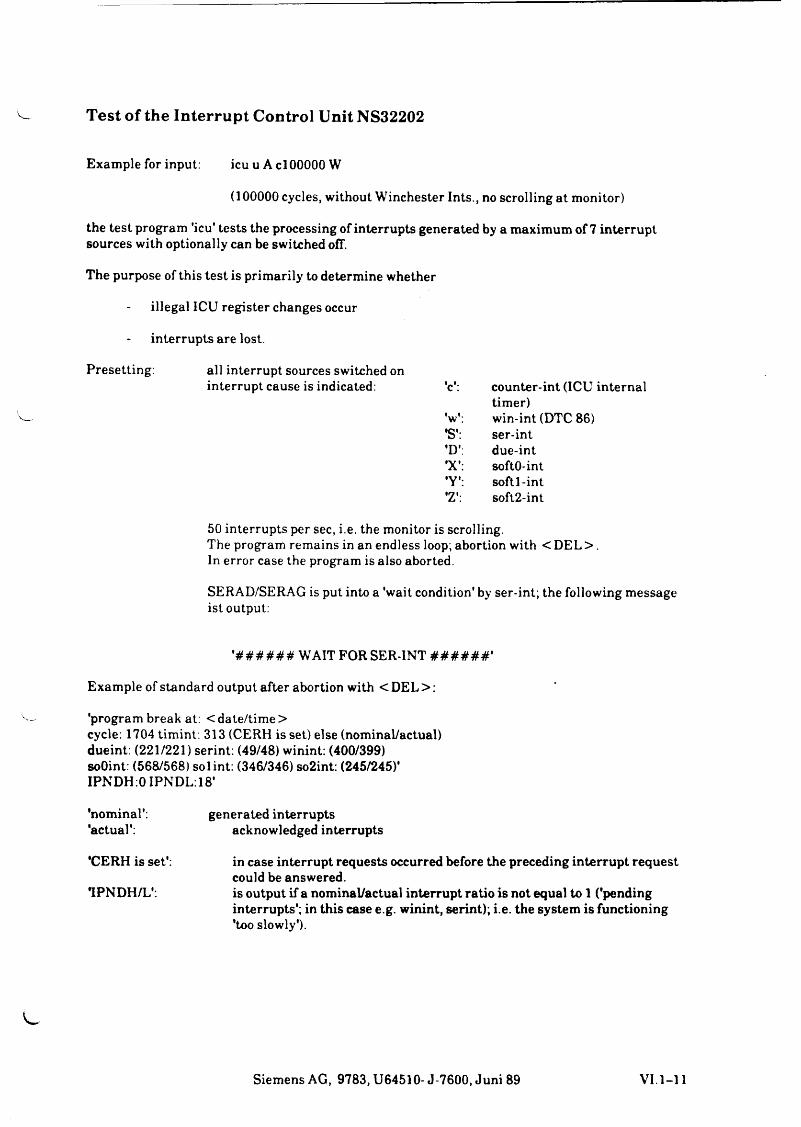
Test of the Interrupt Control Unit NS32202
Example for input: icu u A c l00000 W
(100000 cycles, without Winchester Ints., no scrolling at monitor)
the test program ’icu' tests the processing of interrupts generated by a maximum of 7 interrupt sources with optionally can be switched off.
The purpose of this test is primarily to determine whether
illegal ICU register changes occur
interrupts are lost.
Presetting: all interrupt sources switched on interrupt cause is indicated: •c': counter-int (ICU internal
timer)V : win-int (DTC 86)•S': ser-int'D': due-int•X': softO-int•Y': softl-int•Z': soft2-int
50 interrupts per sec, i.e. the monitor is scrolling.The program remains in an endless loop; abortion with < DEL > .In error case the program is also aborted.
SERAD/SERAG is put into a 'wait condition' by ser-int; the following message ist output:
'# # # # # # WAIT FOR SER-INT # # # # # # '
Example of standard output after abortion with < DEL > :
'program break at: < date/time >cycle: 1704 timint. 313 (CERH is set) else (nominal/actual) dueint: (221/221) serint: (49/48) winint: (400/399) soOint: (568/568) solint: (346/346) so2int: (245/245)'IPNDH:0 IPNDL:18'
'nominal': generated interrupts'actual': acknowledged interrupts
'CERH is set': in case interrupt requests occurred before the preceding interrupt requestcould be answered.
TPNDH/L': is output if a nominal/actual interrupt ratio is not equal to 1 ('pendinginterrupts'; in this case e.g. winint, serint); i.e. the system is functioning 'too slowly').
Siemens AG, 9783, U64510-J-7600, Juni 89 VI. 1-11
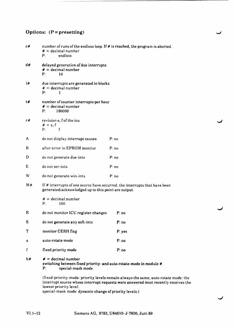
Options: (P = presetting)
c# number of runs of the endless loop. If # is reached, the program is aborted.# = decimal numberP: endless
d# delayed generation of due interrupts# = decimal numberP: 10
i# due interrupts are generated in blocks# = decimal numberP: 1
t# number of counter interrupts per hour# = decimal numberP: 180000
r# revision e, f of the icu# = e .f P: f
A do not display interrupt causes P: no
B after error in EPROM monitor P: no
D do not generate due-ints P: no
E do not ser-ints P: no
W do not generate win-ints P: no
M# If # interrupts of one source have occurred, the interrupts that have beengenerated/acknowledged up to this point are output.
# = decimal .number P: 100
R do not monitor ICU register changes P: no
S do not generate any soft*ints P: no
T monitor CERH flag P: yes
a auto-rotate mode P: no
f fixed priority mode P: no
b# # = decimal numberswitching between fixed priority- and auto-rotate-mode in module #.P: special-mask mode
(fixed-priority-mode: priority levels remain always the same; auto-rotate mode: the interrupt source whose interrupt requests were answered most recently receives the lowest priority level.special-mask mode: dynamic change of priority levels.)
>.J
VI.1-12 Siemens AG, 9783, U64510- J-7600, Juni 89
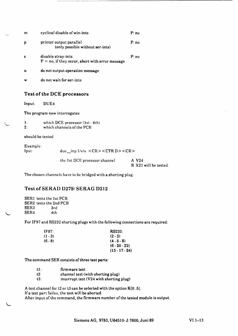
m cyclical disable of win-ints P: no
P printer output parallel(only possible without ser-ints)
P: no
s disable stray-intsP = no, if they occur, abort with error message
P: no
u do not output operation message
w do not wait for ser-ints
Test of the DCE processors
Input: DUE4
The program now interrogates
1. which DCE processor (1 st - 4th)2. which channels of the PCB
should be tested
Example:Iput: due_inp 1/v/x <C R > <CTR D> <C R >
the 1st DCE processor channel A V24B X21 will be tested.
The chosen channels have to be bridged with a shorting plug.
Test of SERAD D279/ SERAG D312
SERI tests the 1st PCB SER2 tests the 2nd PCB SER3 3rdSER4 4th
For IF97 and RS232 shorting plugs with the following connections are required:
IF97: RS232:(1-3) (2-3)(6-8) (4 -5 -8 )
(6-20-22)(15-17-24)
The command SER consists of three test parts:
tl: firmware testt2 channel test (with shorting plug)t3: interrupt test (V24 with shorting plug)
A test channel for t2 or t3 can be selected with the option K[0..5].If a test part failes, the test will be aborted.After input of the command, the firmware number of the tested module is output.
Siemens AG, 9783, U64510- J-7600, Juni 89
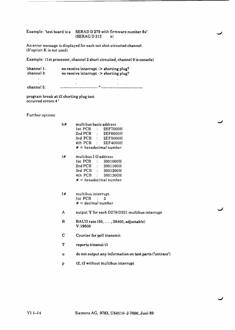
Example: 'test board is a SERAD D 279 with firmware number 8x'(SERAG D 312 x)
An error message is displayed for each not shot-circuited channel.(If option K is not used).
Example: (1st processor, channel 2 short-circuited, channel 0 is console)
'channel 1: no receive interrupt - > shorting plug?channel 3: no receive interrupt - > shorting plug?
channel 5: -------------------------
program break at t2 shorting plug test occurred errors:4 '
Further options:
b# multibus basic address1st PCB 2EF7000H 2nd PCB 2EF6000H 3rd PCB : 2EF5000H4th PCB 2EF4000H# = hexadecimal number
i# multibus 1-0 address1st PCB : 3001000H2nd PCB 3001100H 3rd PCB : 3001200H4th PCB 3001300H# = hexadecimal number
I# multibus interrupt1st PCB 3 # = decimal number
A output '§' for each D279/D321 multibus interrupt
B BAUD rate (50...... .. 38400, adjustable)V: 19600
C Counter for poll transmit
T reports timeout t l
u do not output any information on test parts ('untrace')
p t2, t3 without multibus interrupt
VI. 1-14 Siemens AG, 9783, U64510- J-7600, Juni 89
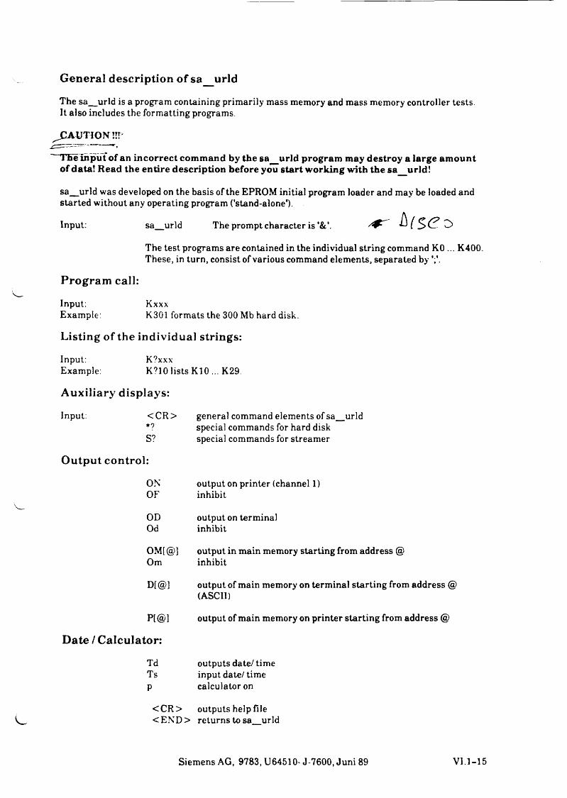
General description of sa_urld
The sa_urld is a program containing primarily mass memory and mass memory controller tests.It also includes the formatting programs.
CAUTION !!T
The input of an incorrect command by the sa_urld program may destroy a large amountof data! Read the entire description before you start working with the sa urld!
sa_urld was developed on the basis of the EPROM initial program loader and may be loaded andstarted without any operating program (’stand-alone1).
Input: sa urld The prompt character is h ( s e 2>
The test programs are contained in the individual string command KO ... K400. These, in turn, consist of various command elements, separated by
Program call:
Input: KxxxExample: K301 formats the 300 Mb hard disk.
Listing of the individual strings:
Input: K?xxxExample: K?10 lists K10 ... K29.
Auxiliary displays:
Input: < CR > general command elements of sa_urld*? special commands for hard diskS? special commands for streamer
Output control:
ON output on printer (channel 1)OF inhibit
OD output on terminalOd inhibit
OM[ @] output in main memory starting from address @Om inhibit
D[ @] output of main memory on terminal starting from address @ (ASCII)
P[@l output of main memory on printer starting from address @
Date / Calculator:
Td outputs date/ timeTs input date/ timep calculator on
<C R > outputs help file <EN D > returns to sa urld
Siemens AG, 9783, U64510- J-7600, Juni 89 VI. 1-15
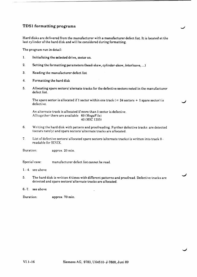
TDSl formatting programs
Hard disks are delivered from the manufacturer with a manufacturer defect list. It is located at the last cylinder of the hard disk and will be considered during formatting.
The program run in detail:
1. Initializing the selected drive, motor on.
2. Setting the formatting parameters (head-skew, cylinder-skew, interleave,...)
3. Reading the manufacturer defect list
4. Formatting the hard disk
5. Allocating spare sectors/ alernate tracks for the defective sectors noted in the manufacturer defect list.
The spare sector is allocated if 1 sector within one track (= 34 sectors + 1 spare sector) is defective.
An alternate track is allocated if more than 1 sector is defective.Alltogether there are available 60 (MegaFile)
40 (MIC 1355)
6. Writing the hard disk with pattern and proofreading. Further defective tracks are detected (occurs rarely) and spare sectors/ alternate tracks are allocated.
7. List of defective sectors/ allocated spare sectors (alternate tracks) is written into track 0 - readable for SINIX.
Duration: approx. 20 min.
Special case: manufacturer defect list cannot be read.
1.-4. see above
5. The hard disk is written 4 times with different patterns and proofread. Defective tracks are detected and spare sectors/alternate tracks are allocated.
6. -7. see above
Duration: approx. 70 min.
VI.1-16 Siemens AG, 9783, U64510- J-7600, Juni 89
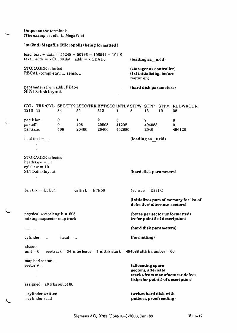
Output on the terminal:(The examples refer to MegaFile)
1st (2nd) Megafile (Micropolis) being formatted !
load: text + data = 55248 + 50796 = 106044 = 104 K text_addr = x C0300dat_addr = x CDADO
STORAGER selected RECAL-compl-stat:.., sensb:..
parameters from addr: FD454SINIXdisklayout
(loading sa_urld)
(storager as controller) (lstinitializibg, before motor on)
(hard disk parameters)
CYL TRK/CYL SEC/TRK LSEC/TRK BYT/SEC 1NTLV STPW STPP STPM REDWRCUR1216 12 34 55 512 1 5 13 19 38
partition: 0 1 2 3 7 8partoff: 0 408 20808 41208 494088 0partsize: 408 20400 20400 452880 2040 496128
load text + .... (loading sa urld)
STORAGER selected headskew = 11 cylskew = 10 SINIXdisklayout (hard disk parameters)
§errtrk = E5E04 §altrrk = E7E50
physical sectorlength = 608 mixing mapsector map track
cylinder = .. head = ..
§senseb = E33FC
(initializes part of memory for list of defective/ alternate sectors)
(bytes per sector unformatted) (refer point 5 of description)
(hard disk parameters)
(formatting)
altass:unit = 0 sec/track =34 interleave =1 alttrk stark =494088 alttrk number =60
map bad sector... sector # ..
assigned .. alttrks out of 60
.. cylinder written
.. cylinder read
(allocating sparesectors, alternatetracks from manufacturer defectlist;refer point 5 of description)
(writes bard disk with pattern, proofreading)
Siemens AG, 9783, U64510- J-7600, Juni 89 VI 1-17
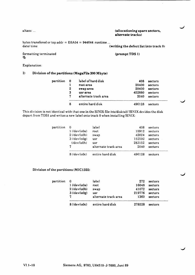
altass: (allocationing spare sectors, alternate tracks)
bytes transfered or top addr = E6A04 = 944644 runtime ...date/ time (w riting the defect list into track 0)
formatting terminated (prompt TDS 1)%
Explanation:
1) Division of the partitions (MegaFile 300 Mbyte)
partition 0 label of hard disk 408 sectors1 root area 20400 sectors2 swap area 20400 sectors3 usr area 452880 sectors7 alternate track area 2040 sectors
8 entire hard disk 496128 sectors
This division is not identical with that one in the SINIX file /etc/disktab! SINIX devides the disk depart from TDSl and writes a new label onto track 0 when installing SINIX.
partition 0 label 408 sectors1 (/dev/isOa) root 15912 sectors2 (/dev/isOb) swap 42024 sectors3 (/dev/isOg) usr 152592 sectors
(/dev/isOh) usr 283152 sectors7 alternate track area 2040 sectors
8 (/dev/isOc) entire hard disk 496128 sectors
Division of the partitions (MIC 1355)
partition 0 label 272 sectors1 (/dev/isOa) root 16048 sectors2 (/dev/isOb) swap 41072 sectors3 (/dev/isOg) usr 219776 sectors7 alternate track area 1360 sectors
8 (/dev/isOc) entire hard disk 278528 sectors
VI.1-18 Siemens AG, 9783, U64510- J-7600, Juni 89
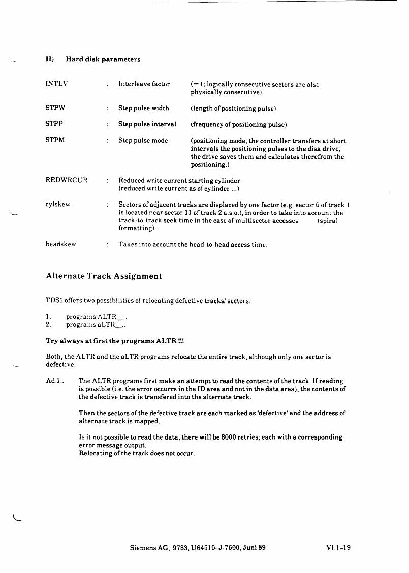
II) H ard disk param eters
INTLV Interleave factor ( = 1; logically consecutive sectors are also physically consecutive)
STPW Step pulse width (length of positioning pulse)
STPP Step pulse interval (frequency of positioning pulse)
STPM Step pulse mode (positioning mode; the controller transfers at short intervals the positioning pulses to the disk drive; the drive saves them and calculates therefrom the positioning.)
REDWRCUR Reduced write current starting cylinder(reduced write current as of cylinder ...)
cylskew Sectors of adjacent tracks are displaced by one factor (e.g. sector 0 of track 1is located near sector 11 of track 2 a .so .), in order to take into account the track-to-track seek time in the case of multisector accesses (spiralformatting).
headskew Takes into account the head-to-head access time.
Alternate Track Assignment
TDSl öfters two possibilities of relocating defective tracks/ sectors.
1. programs A LTR ..2. programs aLTR ..
Try alw ays a t first the program s A LTR !!!
Both, the ALTR and the aLTR programs relocate the entire track, although only one sector is defective.
Ad 1.: The ALTR programs first make an attempt to read the contents of the track. If readingis possible (i.e. the error occurrs in the ID area and not in the data area), the contents of the defective track is transfered into the alternate track.
Then the sectors of the defective track are each marked as 'defective' and the address of alternate track is mapped.
Is it not possible to read the data, there will be 8000 retries; each with a corresponding error message output.Relocating of the track does not occur.
Siemens AG, 9783, U64510- J-7600, Juni 89 VI.1-19
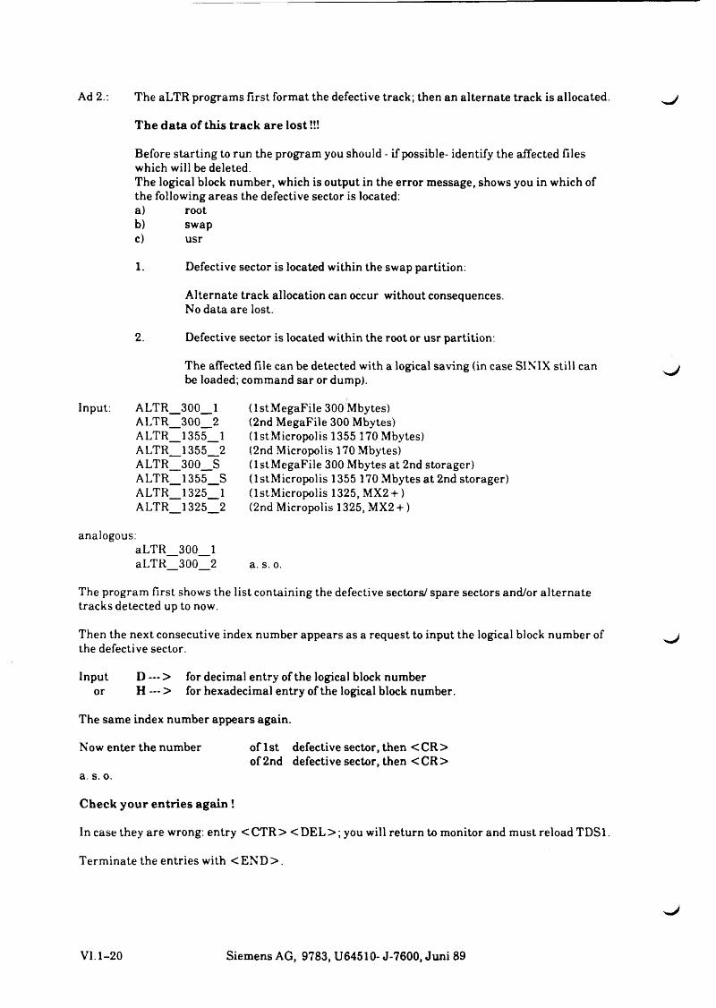
Ad 2.: The aLTR programs first format the defective track; then an alternate track is allocated.
The da ta of this track are lo s t!!!
Before starting to run the program you should - if possible- identify the affected files which will be deleted.The logical block number, which is output in the error message, shows you in which of the following areas the defective sector is located:a) rootb) swapc) usr
1. Defective sector is located within the swap partition:
Alternate track allocation can occur without consequences.No data are lost.
2. Defective sector is located within the root or usr partition:
The affected file can be detected with a logical saving (in case SINIX still can be loaded; command sar or dump).
Input: ALTR_300__1ALTR_300__2ALTR_1355__1ALTR_1355__2ALTR_300__SALTR_1355__SALTR_1325__1ALTR 1325 2
(IstMegaFile 300 Mbytes)(2nd MegaFile 300 Mbytes)(IstMicropolis 1355 170 Mbytes)(2nd Micropolis 170 Mbytes)(IstMegaFile 300 Mbytes at 2nd storager) (IstMicropolis 1355 170 Mbytes at 2nd storager) (IstMicropolis 1325, MX2 + )(2nd Micropolis 1325, MX2 + )
analogous:aLTR_300__1aLTR 300 2 a. s. o.
The program first shows the list containing the defective sectors/ spare sectors and/or alternate tracks detected up to now.
Then the next consecutive index number appears as a request to input the logical block number of the defective sector.
Input D — > for decimal entry of the logical block numberor H — > for hexadecimal entry of the logical block number.
The same index number appears again.
Now enter the number of 1st defective sector, then <C R >of 2nd defective sector, then < CR >
a. s. o.
Check your en tries again !
In case they are wrong: entry <CTR> <D EL> ; you will return to monitor and must reload TDSl.
Terminate the entries with <E N D >.
VI. 1-20 Siemens AG, 9783, U64510- J-7600, Juni 89
Now the alternate tracks are allocated and the extended list of defective tracks and the TDSl prom pt'%' are displayed.
The storager offers two alternatives to handle defective sectors on the hard disk:
1. Spare sector assignment
The hard disk is formatted in such a way that one sector each is 'reserved* per track (34 sectors + 1 spare sector). If a defective sector is detected within a track, the next consecutive sector is designed as spare sector; all the following sectors are relocated 'backwards'.
The defective sector is marked; the storager recognizes that it has to access the adjacent sector.
This option is only used by the formatting program; the ALTR and the aLTR programs apply the second possibility only.
2. Alternate track assignment
The hard disk contains an alternate track partition, (partition? consisting of the 5 last cylinders of the hard disk). Detecting a defective sector within a track, will relocate the entire track.
A defective sector is marked with a special header. When the storager accesses this sector it detects
1. that a track is defective2. the address of alternate track.
So the hard disk access requires an additional positioning. An increasing number of defective tracks causes less performance of the system.
Siemens AG, 9783, U64510- J-7600, Juni 89 VI.1-21
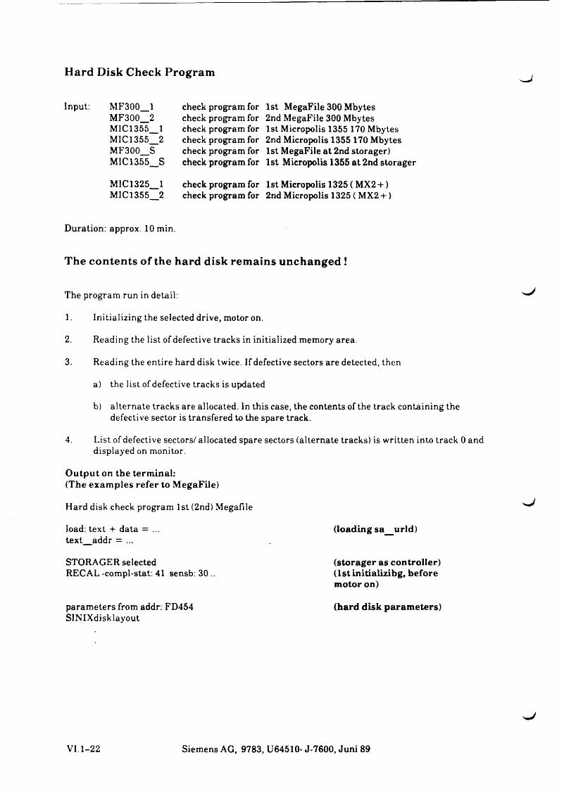
Hard Disk Check Program
Input: MF300_1MF300_2MIC1355_1MIC1355_2MF300_SMIC1355 S
check program for check program for check program for check program for check program for check program for
1st MegaFile 300 Mbytes 2nd MegaFile 300 Mbytes 1st Micropolis 1355 170 Mbytes 2nd Micropolis 1355 170 Mbytes 1st MegaFile at 2nd storager)1st Micropolis 1355 at 2nd storager
M1C1325_1 check program for 1st Micropolis 1325 ( MX2 + )MIC1355_2 check program for 2nd Micropolis 1325 ( MX2 + )
Duration: approx. 10 min.
The contents of the hard disk remains unchanged !
The program run in detail:
1. Initializing the selected drive, motor on.
2. Reading the list of defective tracks in initialized memory area.
3. Reading the entire hard disk twice. If defective sectors are detected, then
a) the list of defective tracks is updated
b) alternate tracks are allocated. In this case, the contents of the track containing the defective sector is transfered to the spare track.
4. List of defective sectors/ allocated spare sectors (alternate tracks) is written into track 0 and displayed on monitor.
O utpu t on the term inal:(The exam ples refer to MegaFile)
Hard disk check program 1st (2nd) MegaFile
load: text + data = ... (loading sa_urld)text_addr = ...
STORAGER selected (storager as controller)RECAL -compl-stat. 41 sensb. 30 .. (lstinitializibg, before
motor on)
parameters from addr: FD454 (hard disk parameters)SINIXdisklayout
VI.1-22 Siemens AG, 9783, U64510- J-7600, Juni 89
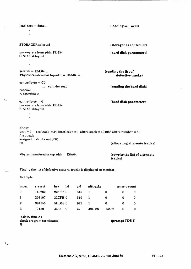
load: text + data ... (loading sa urld)
STORAGER selected (storager as controller)
parameters from addr: FD454 (hard disk parameters)SINIXdisklayout
§errtrk = E5E04 ... (reading the list of#bytes transfered or top addr = E6A04 = .. defective tracks)
control byte = CO... cylinder read (reading the hard disk)
runtime: ..<date/tim e>
control byte = 0 (hard disk parameters)parameters from addr: FD454 SINIXdisklayout
altass:unit =0 sec/track =34 interleave =1 alttrk stark =494088 alttrk number =60 First track ...assigned .. alttrks out of 6060. . (allocating alternate tracks)
#bytes transfered or top addr = E6A04 (rewrite the list of alternate tracks)
Finally the list of defective sectors/ tracks is displayed on monitor.
Example.
index errsect hex hd cyl alttracks sense-b count0 140782 225FF 0 345 1 0 0 01 208107 32CFB0 510 1 0 0 02 384355 5DD63 0 942 1 0 0 03 17459 4433 9 42 494088 14532 0 0
< date/tim e >)check program terminated (prom pt TDS 1)%
Siemens AG, 9783, U64510- J-7600, Juni 89 VI. 1-23
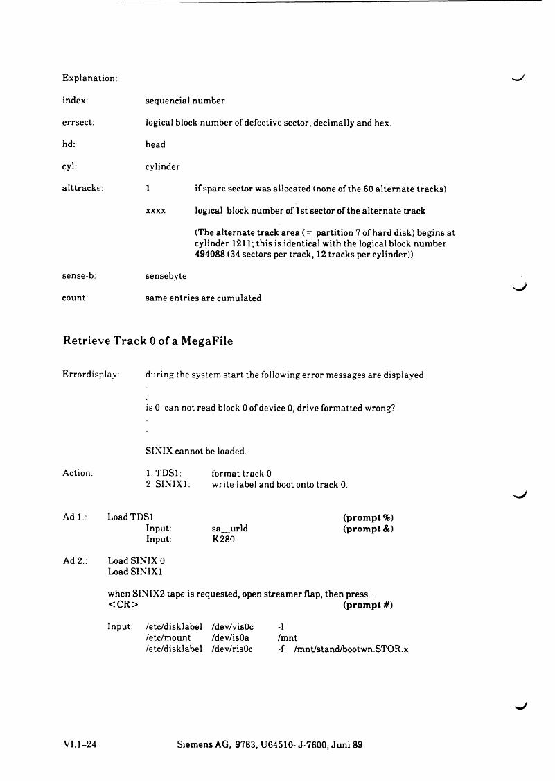
Explanation:
index:
errsect:
hd:
cyl:
alttracks:
sense-b:
count:
sequencial number
logical block number of defective sector, decimally and hex.
head
cylinder
1 if spare sector was allocated (none of the 60 alternate tracks)
xxxx logical block number of 1 st sector of the alternate track
(The alternate track area (= partition 7 of hard disk) begins at cylinder 1211; this is identical with the logical block number 494088 (34 sectors per track, 12 tracks per cylinder)).
sensebyte
same entries are cumulated
Retrieve Track 0 of a MegaFile
Errordisplay: during the system start the following error messages are displayed
is 0: can not read block 0 of device 0, drive formatted wrong?
SINIX cannot be loaded.
Action: l.TD Sl: format track 02. SINIX 1: write label and boot onto track 0.
A di.: LoadTDSlInput: sa urldInput: K280
Ad 2.: Load SINIX 0Load SINIX1
(prompt %) (prompt &)
when SINIX2 tape is requested, open streamer flap, then press . <CR> (prom pt#)
Input: /etc/disklabel /dev/visOc/etc/mount /dev/isOa /etc/disklabel /dev/risOc
-1/mnt-f /mnt/stand/bootwn.STOR.x
VI.1-24 Siemens AG, 9783, U64510- J-7600, Juni 89
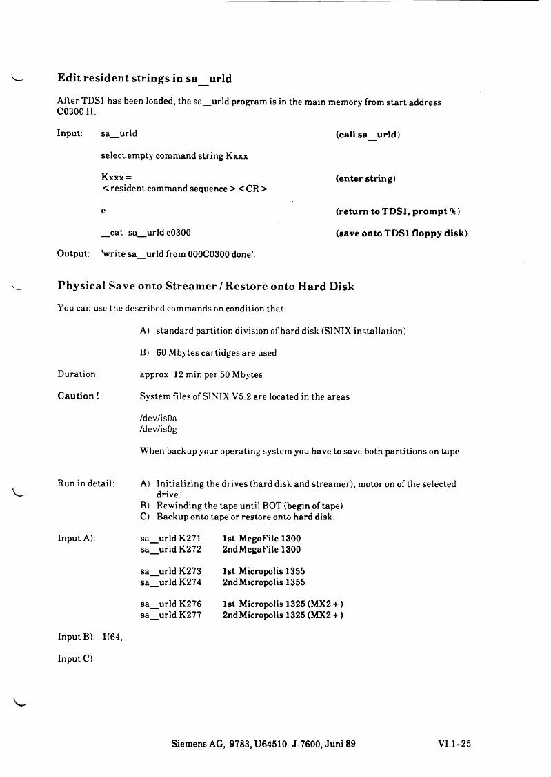
Edit resident strings in sa urld
After TDSl has been loaded, the sa_urld program is in the main memory from start addressC0300H.
Input. sa_urld (call sa_jirld)
select empty command string Kxxx
Kxxx = (enter string)< resident command sequence > < CR >
e (return to TD Sl, prompt %)
_cat -sa_urld c0300 (save onto TDSl floppy disk)
Output: 'write sa_urld from 000C0300 done'.
Physical Save onto Streamer / Restore onto Hard Disk
You can use the described commands on condition that:
A) standard partition division of hard disk (SINIX installation)
B) 60 Mbytes cartidges are used
Duration: approx. 12 min per 50 Mbytes
Caution ! System files of SINIX V5.2 are located in the areas
/dev/isOa/dev/isOg
When backup your operating system you have to save both partitions on tape.
Run in detail:
Input A):
A) Initializing the drives (hard disk and streamer), motor on of the selected drive.
B) Rewinding the tape until BOT (begin of tape)C) Backup onto tape or restore onto hard disk.
s a .s a
s a .s a .
s a .s a
urld K271 1st MegaFile 1300urld K272 2ndMegaFile 1300
urld K273 1st Micropolis 1355urld K274 2ndMicropolis 1355
urld K276 1st Micropolis 1325(MX2 + )urld K277 2nd Micropolis 1325 (MX2 + )
Input B): 1(64,
Input C):
Siemens AG, 9783, U64510- J-7600, Juni 89 VI. 1-25
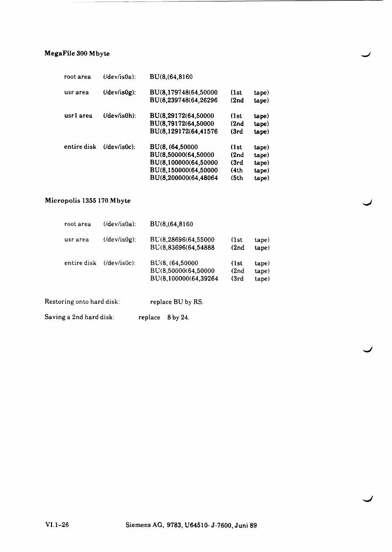
M egaFile 300 Mbyte
root area (/dev/isOa): BU(8,(64,8160
usr area (/dev/isOg): BU(8,179748(64,50000 (1st tape)BU(8,239748(64,26296 (2nd tape)
usrl area (/dev/isOh): BU(8,29172(64,50000 (1st tape)BU(8,79172(64,50000 (2nd tape)BU(8,129172(64,41576 (3rd tape)
entire disk (/dev/isOc): BU(8, (64,50000 (1st tape)BU(8,50000(64,50000 (2nd tape)BU(8,100000(64,50000 (3rd tape)BU(8,150000(64,50000 (4th tape)BU(8,200000(64,48064 (5th tape)
M icropolis 1355 170 Mbyte
root area (/dev/isOa): BU(8,(64,8160
usr area (/dev/isOg): BU(8,28696(64,55000 (1st tape)BU(8,83696(64,54888 (2nd tape)
entire disk (/dev/isOc): BU(8, (64,50000 (1st tape)BU(8,50000(64,50000 (2nd tape)BU(8,100000(64,39264 (3rd tape)
Restoring onto hard disk: replace BU by RS.
Saving a 2nd hard disk: replace 8 by 24.
^J
VI. 1-26 Siemens AG, 9783, U64510- J-7600, Juni 89
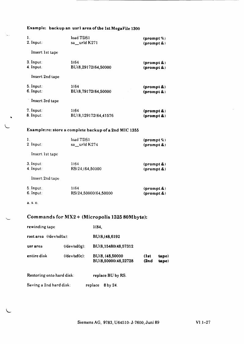
Exam ple: backup an u s r l a rea of the 1st M egaFile 1300
1. load TDSl (prom pt2. Input: sa_urld K271 (prom pt &)
Insert 1st tape
3. Input. 1(64 (prom pt &)4. Input: BU(8,29172(64,50000 (prom pt &)
Insert 2nd tape
5. Input: 1(64 (prom pt &)6. Input: BU(8,79172(64,50000 (prom pt &)
Insert 3rd tape
7. Input: 1(64 (p ro m p t&)8. Input: BU(8,129172(64,41576 (p ro m p t&)
Exam plerre: store a com plete backup of a 2nd MIC 1355
1.2. Input:
Insert 1st tape
3. Input:4. Input:
Insert 2nd tape
5 Input.6. Input:
load TDSl sa urld K274
1(64RS(24, (64,50000
1(64RS(24,50000(64,50000
a. s. o.
(prom pt %) (prom pt &)
(prom pt &) (prom pt &)
(prom pt &) (prom pt &)
Commands for MX2 + (Micropolis 1325 80Mbyte):
rewinding tape
root area (/dev/sdOa):
usr area (/dev/sdOg):
entire disk (/dev/sdOc):
1(84,
BU(8,(48,6192
BU(8,15480(48,57312
BU(8, (48,50000 BU(8,50000(48,22728
(1st tape) (2nd tape)
Restoring onto hard disk: replace BU by RS.
Saving a 2nd hard disk: replace 8 by 24.
Siemens AG, 9783, U64510- J-7600, Juni 89 VI. 1-27


L ,

. llfJ
2 TDS2.. O H C 1 / ( ( :
5 _ J U S M £
see Service Aids Overview
Service-Software SINIX Systeme
Order no.: U64530-J-7600
* 3 Tty/t f i t
X v DS 2.
D!*
cC
s
5 ( H 4 W
Suit \&1 SiM
CSo/ 1 a 2 .
H x s o &
S / / v vt* 5
.5/a/ uf/£ C 3(9
u T c-zv r < ?
S OHo ice'
c x % « r
Siemens AG, 9783, U64510- J-7600, June 89 VI.2-1

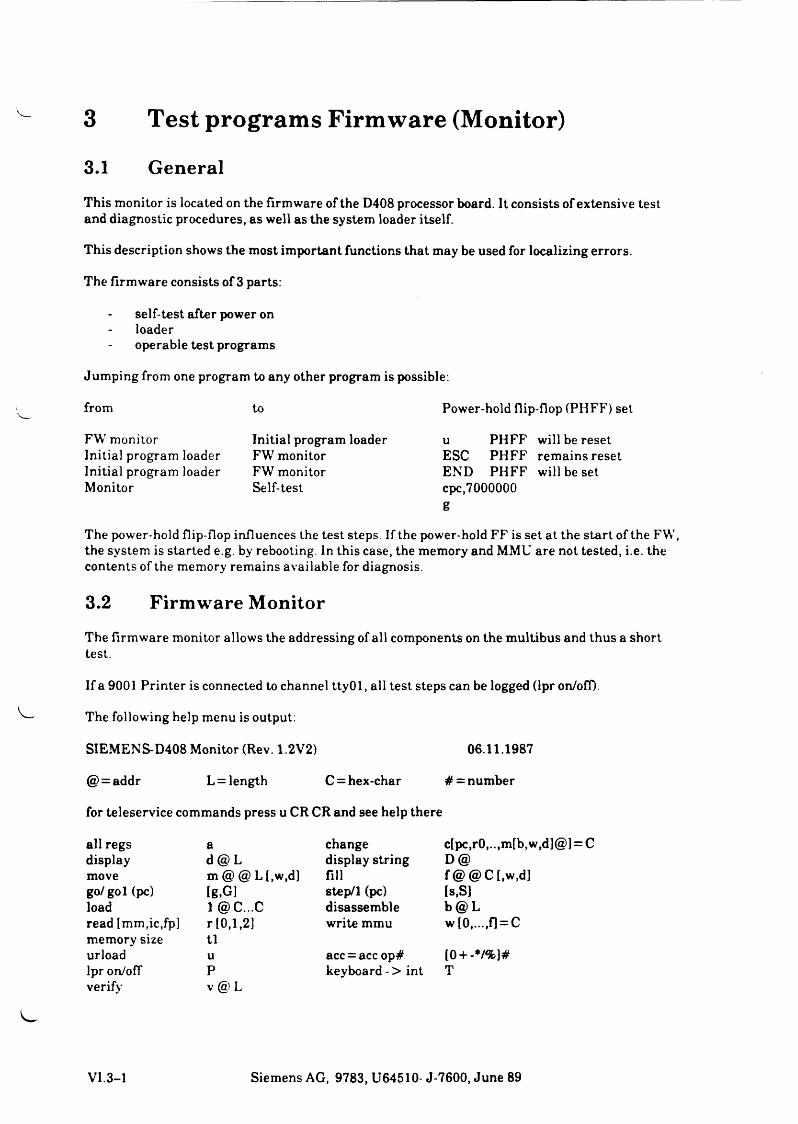
3 Test programs Firmware (Monitor)3.1 GeneralThis monitor is located on the firmware of the D408 processor board. It consists of extensive test and diagnostic procedures, as well as the system loader itself.
This description shows the most important functions that may be used for localizing errors.
The firmware consists of 3 parts:
self-test after power on loaderoperable test programs
Jumping from one program to any other program is possible:
from to Power-hold flip-flop (PH FF) set
FW monitor Initial program loader u PHFF will be resetInitial program loader FW monitor ESC PHFF remains resetInitial program loader FW monitor END PHFF will be setMonitor Self-test cpc,7000000
g
The power-hold flip-flop influences the test steps. If the power-hold FF is set at the start of the FW, the system is started e.g. by rebooting. In this case, the memory and MMU are not tested, i.e. the contents of the memory remains available for diagnosis.
3.2 Firmware MonitorThe firmware monitor allows the addressing of all components on the multibus and thus a short test.
If a 9001 Printer is connected to channel ttyOl, all test steps can be logged (lpron/off).
The following help menu is output:
SIEMENS-D408 Monitor (Rev. 1.2V2) 06.11.1987
@ = addr L = length C = hex-char # = number
for teleservice commands press u CR CR and see help there
all regs a change c[pc,r0,..,m[b,w,d]@] = Cdisplay d @ L display string D@move m @ @ Ll,w,d] fill f@ @ C[,w ,d]go/gol (pc) lg,G] step/1 (pc) Is,SIload 1 @C...C disassemble b@ Lread [mm,ic,fp] r [0,1,2] write mmu w [0,...,fi = Cmemory size tlurload u acc = acc op# [0 + -*/%]#lpr on/ofT P keyboard - > int Tverify V @ L
VI.3-1 Siemens AG, 9783, U64510- J-7600, June 89
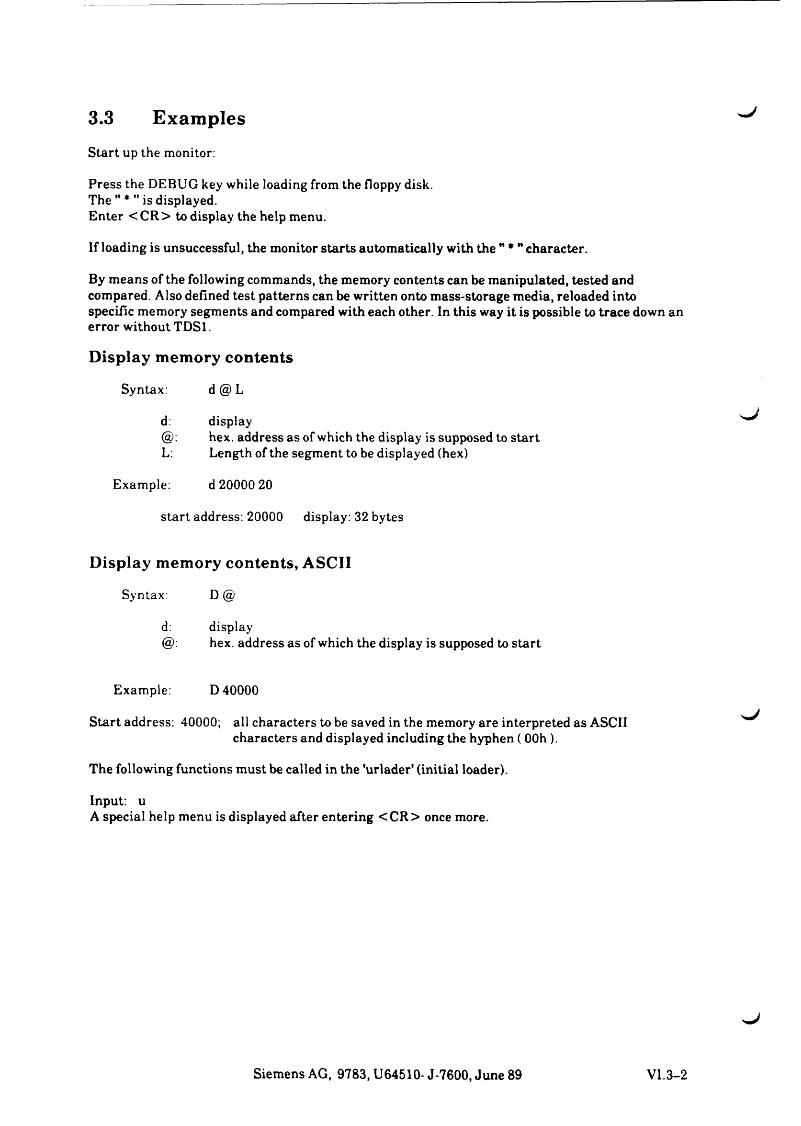
3.3 ExamplesStart up the monitor:
Press the DEBUG key while loading from the floppy disk.The " * " is displayed.Enter <C R > to display the help menu.
If loading is unsuccessful, the monitor starts automatically with the " * " character.
By means of the following commands, the memory contents can be manipulated, tested and compared. Also defined test patterns can be written onto mass-storage media, reloaded into specific memory segments and compared with each other. In this way it is possible to trace down an error without TD Sl.
Display memory contents
Syntax: d@ L
d: displayhex. address as of which the display is supposed to start
L: Length of the segment to be displayed (hex)
Example: d 20000 20
start address: 20000 display: 32 bytes
s j
Display memory contents, ASCII
Syntax: D @
d: display@: hex. address as of which the display is supposed to start
Example: D 40000
Start address: 40000; all characters to be saved in the memory are interpreted as ASCII characters and displayed including the hyphen ( 00h ).
The following functions must be called in the 'urlader' (initial loader).
Input: uA special help menu is displayed after entering <C R > once more.
Siemens AG, 9783, U64510- J-7600, June 89 VI. 3-2
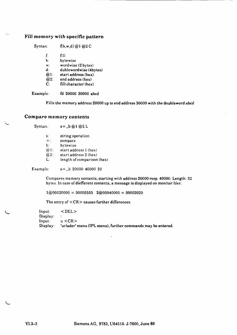
Fill memory with specific pattern
Syntax: flb,w,dj @1 @2 C
f:b:w:d:@1:@2:C:
fillbytewisewordwise (2 bytes) dublewordwise (4bytes) start address (hex) end address (hex) fill character (hex)
Example. fd 20000 30000 abed
Fills the memory address 20000 up to end address 30000 with the doubleword abed
Compare memory contents
Syntax: s= „b @1 @2 L
s: string operation
b:@1:@2:L:
comparebytewisestart address 1 (hex) start address 2 (hex) length of comparison (hex)
Example: s= ,,b 20000 40000 20
Compares memory contents, starting with address 20000 resp. 40000. Length: 32 bytes. In case of diefferent contents, a message is displayed on monitor like:
1 @00020000 = 00005555 2@00040000 = 00002020
The entry of < CR > causes further differences.
InPut:Display:Input:Display:
<D EL>
u <C R >'urlader* menu (IPL menu), further commands may be entered.
VI.3-3 Siemens AG, 9783, U64510- J-7600, June 89
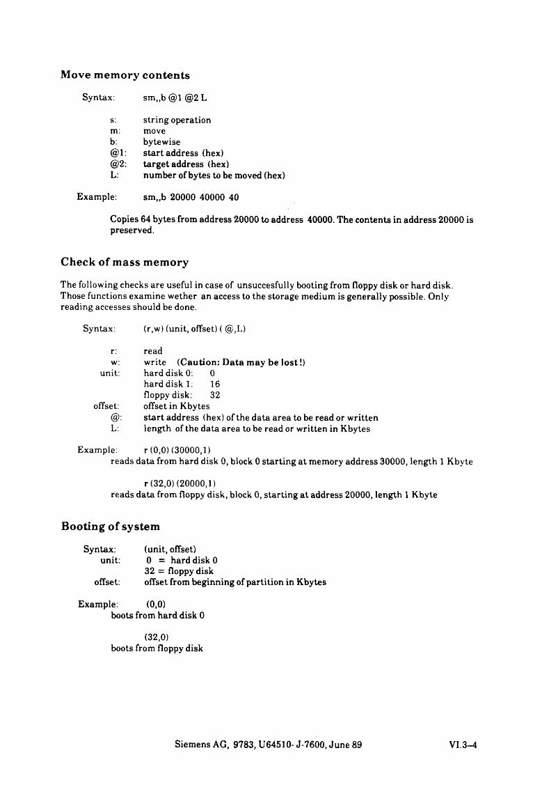
Move memory contents
Syntax: sm,,b @1 @2 L
s: string operationm: moveb: bytewise@1: start address (hex)@2: target address (hex)L: number of bytes to be moved (hex)
Example: sm„b 20000 40000 40
Copies 64 bytes from address 20000 to address 40000. The contents in address 20000 is preserved.
Check of mass memory
The following checks are useful in case of unsuccesfully booting from floppy disk or hard disk. Those functions examine wether an access to the storage medium is generally possible. Only reading accesses should be done.
Syntax: (r,w) (unit, offset) ( @,L)
r: readw: write (Caution: Data may be lo s t!)
unit: hard disk 0: 0hard disk 1: 16floppy disk: 32
offset: offset in Kbytesstart address (hex) of the data area to be read or written
L: length of the data area to be read or written in Kbytes
Example: r (0,0)(30000,1)reads data from hard disk 0, block 0 starting at memory address 30000, length 1 Kbyte
r (32,0) (20000,1)reads data from floppy disk, block 0, starting at address 20000, length 1 Kbyte
Booting of system
Syntax: (unit, offset)unit: 0 = hard disk 0
32 = floppy diskoffset: offset from beginning of partition in Kbytes
Example: (0,0)boots from hard disk 0
(32,0)boots from floppy disk
Siemens AG, 9783, U64510- J-7600, June 89 VI. 3-4
SIEMENS General
Installation of Teleservice
Important Instructions
Part VII Teleservice
Cm1'
/

s j
Part VII
Teleservice (TS)
Contents Page
1 G eneral V Il.i- ll.i O p e r a t i n g M o d es VII 1-1
1.2 O v e r v ie w o f D e v ic e F i l e s V I I .1-2
2 Installation of Teleservice into Costum er's MX300 VII.2-12.1 P r e p a r e S I N I X for o f f l in e T e le s e r v i c e VII. 2-1
2 .2 S e t u p P a r a m e t e r s o f F ir m w a r e (F W ) v ia M o n ito r for o f f l in e T S V II .2-2
2 .3 S e t u p T e l e s e r v i c e p a r a m e t e r s v ia S I N I X V I I .2-4
3 Im portan t Instructions VI 1.3-1

S ^ J
1 General
Teleservice (TS) with the MX300 is posible either via SINIX or via the firmware ('urlader' = initial program loader) of the CPU.
The TS connection is always realized via the RS232 channel of the CPU PCB. (25 pin plug at at interface 1). Each MX300 is preset for teleservice (TS).
1.1 Operating Modes
TS with a MX300 operates in two operation modes:
M odel: SINIX is started (online teleservice)
TS is effected via a regular login channel. An init must be started for this channel. The same conditions as for a local terminal shall apply. Speed and operating mode are regulated by the files t t y s t t y t y p e g e t t y t a b .
The kernel messages are output at the local console.
Teleservice channel: /dev/ttycl
Mode 2: Dialog with the firmware (offline teleservice)
A parameter of the Clock N V RAM determines whether teleservice via firmware is possible or not. If the TS enable bit is set, at any startup there is a 5 sec period to build up the connection to the firmware (also called offline TS).
If the TS enable bit is not set, no message about teleservice is output at startup.
Speed and code frame are depositted in the Clock NV RAM. If the TS enable flag' is set in the Clock N V Ram, at every system startup TS can run with the firmware.
If SINIX is booted it receives the TS parameters from the firmware. The kernel messages are now output on the remote console.
Teleservice channel: /dev/ttycl
Switching the messages onto the local console is only possible by rebooting.
*** Please note the remarks at 2.3 ****** Important Instructions ***
Siemens AG, 9783, U64510- J-7600,11.88 VII 1-1
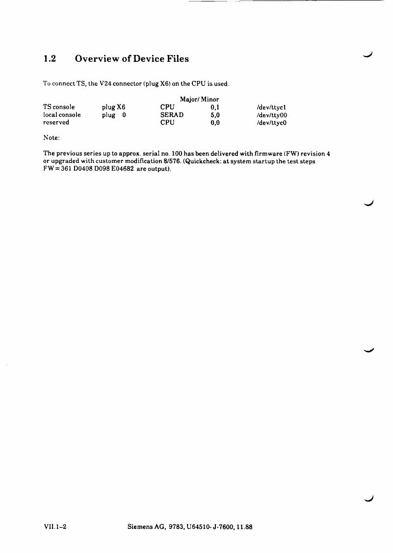
1.2 Overview of Device Files
To connect TS, the V24 connector (plug X6) on the CPU is used.
TS console plugX6local console plug 0reserved
Major/Minor CPU 0,1SERAD 5,0CPU 0,0
Note:
/dev/ttycl/dev/ttyOO/dev/ttycO
The previous series up to approx, serial no. 100 has been delivered with firmware (FW) revision 4 or upgraded with customer modification 8/576. (Quickcheck: at system startup the test steps FW = 361 D0408 D098 E04682 are output).
VII.1-2 Siemens AG, 9783, U64510-J-7600,11.88


, J
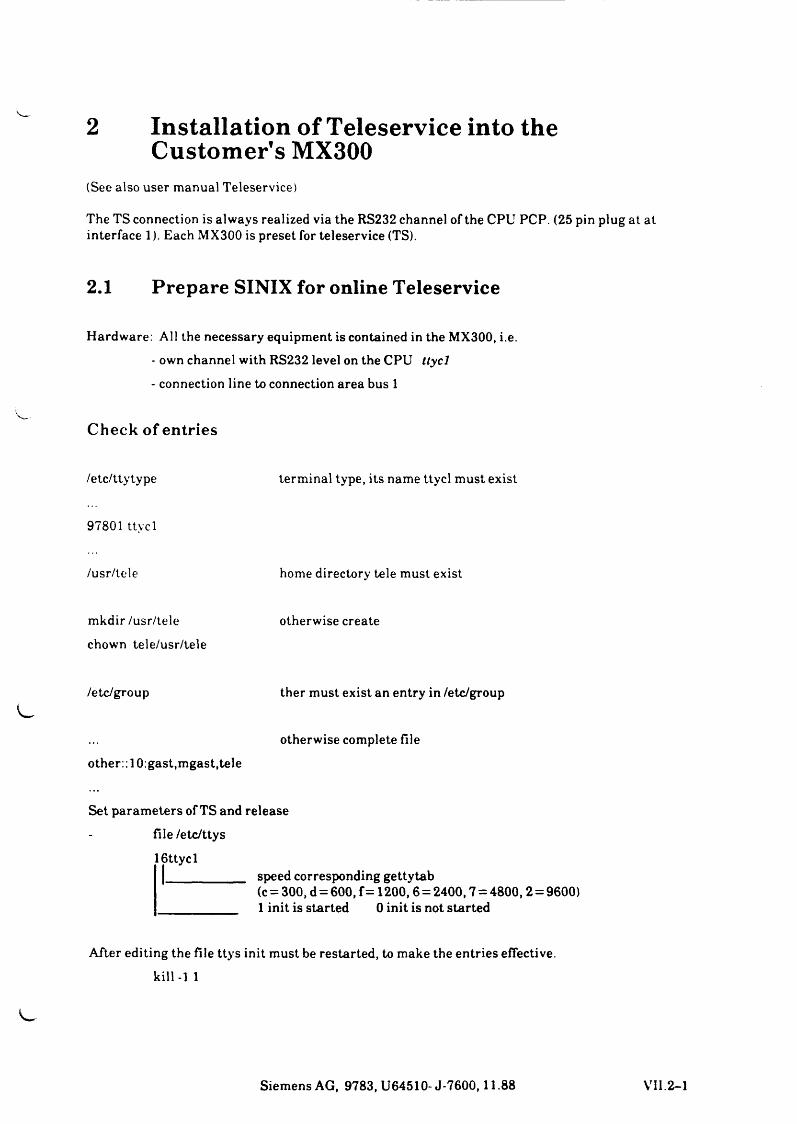
2 Installation of Teleservice into the Customer's MX300
(See also user manual Teleservice)
The TS connection is always realized via the RS232 channel of the CPU PCP. (25 pin plug at at interface 1). Each MX300 is preset for teleservice (TS).
2.1 Prepare SINIX for online Teleservice
Hardware: All the necessary equipment is contained in the MX300, i.e.- own channel with RS232 level on the CPU ttycl- connection line to connection area bus 1
Check of entries
/etc/ttytype
97801 ttycl
terminal type, its name ttycl must exist
/usr/tele home directory tele must exist
mkdir /usr/tele
chown tele/usr/teleotherwise create
/etc/group ther must exist an entry in /etc/group
other:: 10:gast,mgast,teleotherwise complete file
Set parameters of TS and release
file /etc/ttys
16ttycl1 speed corresponding gettytab
(c = 300, d = 600, f = 1200,6 = 2400,7 = 4800,2 = 9600)1 init is started 0 init is not started
After editing the file ttys init must be restarted, to make the entries effective. kill-1 1
Siemens AG, 9783, U64510- J-7600,11.88 VII.2-1
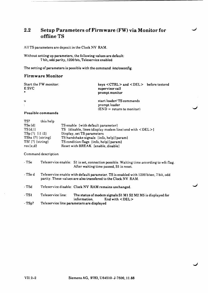
2.2 Setup Parameters of Firmware (FW) via Monitor for offline TS
All TS parameters are deposit in the Clock NV RAM.
Without setting up parameters, the following values are default:7 bit, odd parity, 1200 b/s, Teleservice enabled
The setting of parameters is possible with the command /etc/coconfig.
Firmware Monitor
Start the FW monitor:E SVC
u
Possible com m ands
TS? this help TSe [dj TS [d,l]TSp l?J [il i2]TShs [?] [stringl TSf [?] [stringl res [e,d]
Command description
- TSe Teleservice enable: SI is set, connection possible. Waiting time according to wfc flag.After waiting time passed, Si is reset.
- TSe d Teleservice enable with default parameter. TS is enabled with 1200 b/sec, 7 bit, oddparity. These values are also transfered to the Clock NV RAM.
- TSd Teleservice disable: Clock NV RAM remains unchanged.
- TSl Teleservice line: The status of modem signals SI Ml S2 M2 M5 is displayed forinformation. End with < DEL >
- TSp? Teleservice line parameters are displayed
TS enable [with default parameterlTS [disable, lines (display modem line) end with < DEL> ] Display, set TS parameters TS handshake signals [info, help) [param]TS condition flags [info, help! [param]Reset with BREAK [enable, disable]
keys < CTRL> and < DEL> before testend supervisor call prompt monitor
start loader/ TS commandsprompt loader(END = return to monitor)
VII.2-2 Siemens AG, 9783, U64510- J-7600,11.88
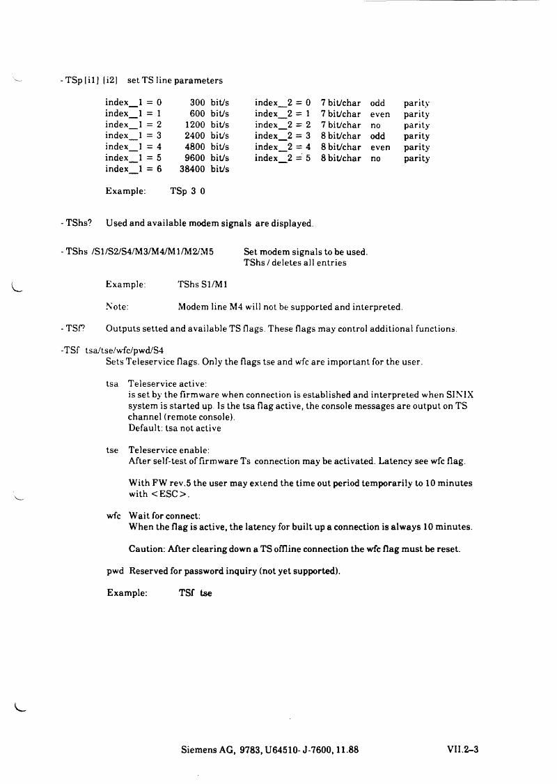
T Sp[il][i2] set TS line parameters
index_.1 = 0 300 bit/s index__2 = 0 7 bit/char odd parityindex_.1 = 1 600 bit/s index__2 = 1 7 bit/char even parityindex_.1 = 2 1200 bit/s index__2 = 2 7 bit/char no parityindex_. 1 = 3 2400 bit/s index_ 2 = 3 8 bit/char odd parityindex_. 1 = 4 4800 bit/s index. 2 = 4 8 bit/char even parityindex__.1 = 5 9600 bit/s index. IICM
1 8 bit/char no parityindex 1 = 6 38400 bit/s
Example: TSp 3 0
TShs? Used and available modem signals are displayed.
TShs /S1/S2/S4/M3/M4/M1/M2/M5 Set modem signals to be used.TShs / deletes all entries
Example: TShsSl/M l
Note: Modem line M4 will not be supported and interpreted.
TSf? Outputs setted and available TS flags. These flags may control additional functions.
TSf tsa/tse/wfc/pwd/S4Sets Teleservice flags. Only the flags tse and wfc are important for the user,
tsa Teleservice active:is set by the firmware when connection is established and interpreted when SINIX system is started up. Is the tsa flag active, the console messages are output on TS channel (remote console).Default: tsa not active
tse Teleservice enable:After self-test of firmware Ts connection may be activated. Latency see wfc flag.
With FW rev.5 the user may extend the time out period temporarily to 10 minutes with <E SC >.
wfc Wait for connect:When the flag is active, the latency for built up a connection is always 10 minutes.
Caution: After clearing down a TS offline connection the wfc flag must be reset,
pwd Reserved for password inquiry (not yet supported).
Example: TSf tse
Siemens AG, 9783, U64510- J-7600,11.88 VII.2-3
2.3 Setup Teleservice parameters via SINIX >■J
All parameters of Clock NV RAM described under 2.2 can be set with SINIX via the command/etc/coconfig.
coconfig see next page.
Example: coconfig default 2400 remote wfc
COCONFIG (8) UNIX Programmer's Manual COCONFIG(8)
NAME
coconfig - configure console tty line
SYNOPSIS
/etc/coconfig [ - c] [ select_opt line_opt spec_opt ]
DESCRIPTION
Coconfig displays or changes configuration attributes associated with the console tty line and makes them permanent.
All options expect the local/remote setting affect the remote tty line.
The options for select_opt are:
default default setting of all parameters: local line, odd parity, 7 bit/character, 2400 baud.
local select local line,
remote select remote line.
The options for line_opt are:
7,8 these specify the datasize (number of bits per character).
no, odd, evenselects the parity.
300....... . 38400selects the baudrate.
The options for spec_opt are:
wfc selection of timeout at reboot,
pwd password checking enabled.
s4 V24 S4/M4 support.
If coconfig is invoked with -c all console configuration attributes are cleared.All console configuration changes become first valid at the next reboot.
J
VII.2-4 Siemens AG, 9783, U64510-J-7600,11.88


>■J

3 Important InstructionsBooting SINIX via Teleservice
Avoid disconnection:In SINIX the connection is refused after 1 min. after a wrong/unsuccessful attempt of connection.This disconnection has to be avoided during booting. For this purpose input some blanks after the fsck message /dev/isOa xxx files... is output. The 1 min. timer is stopped in this way.
Remote console, local consoleIf the remote console (TS) is active, the console messages are output only there.A switchover to local console is only possible by rebooting. Prior to a disconnection from TS, the system must be switched over to local console by rebooting. Otherwise, all processes that output a console message are locked.Example: su
Renewals with firmware rev. 5With the Teleservice enable flag (TSe) set, the user has only 5 sec. to set up a TS connection.
With rev. 5 the user has the opportunity to extend the wait time for a process to 10 min. at the local console with the ESC key.
Siemens AG, 9783, U64510-J-7600,11.88 VII.3-1

SIEMENS
Part VIII HW-Description
Summary Description and Overview
Description of CPU and Storage Functions
Hardware Software Interface
Function Description of the I/O Processors
Hard-Disk System
Intel-Multibus 1
XYLOGIC Processor and MT 3504
Platter
Power Supply

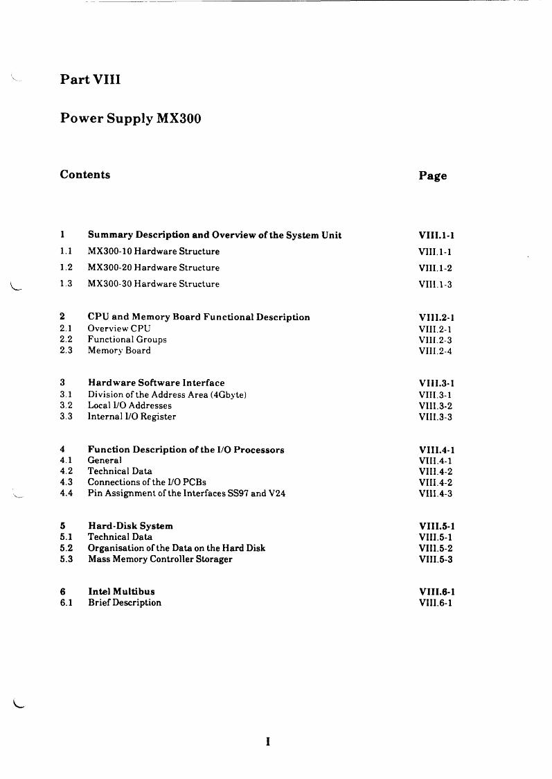
Part VIII
Power Supply MX300
Contents Page
1 Sum m ary D escription and Overview of the System Unit VIII.1-11.1 MX300-10 Hardware Structure VIII.1-11.2 MX300-20 Hardware Structure VIII.1-21.3 MX300-30 Hardware Structure VIII.1-3
2 CPU and Memory Board Functional D escription VI1I.2-12.1 Overview CPU VIII.2-12.2 Functional Groups VIII.2-32.3 Memory Board VIII.2-4
3 H ardw are Softw are Interface VIII.3-13.1 Division of the Address Area (4Gbyte) VIII.3-13.2 Local I/O Addresses VIII.3-23.3 Internal I/O Register VIII.3-3
4 Function D escription of the I/O P rocessors VIII.4-14.1 General VIII.4-14.2 Technical Data VIII.4-24.3 Connections of the I/O PCBs VIII.4-24.4 Pin Assignment of the Interfaces SS97 and V24 VIII.4-3
5 H ard-D isk System VIII.5-15.1 Technical Data VIII.5-15.2 Organisation of the Data on the Hard Disk VIII.5-25.3 Mass Memory Controller Storager VIII.5-3
6 Intel M ultibus VIII.6-16.1 Brief Description VIII.6-1
I
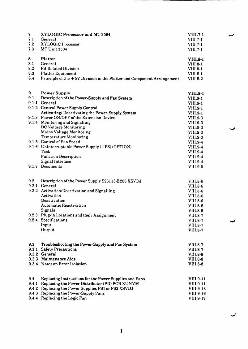
7 XYLOGIC Processor and MT 3504 VI11.7-17.1 General VIII.7-17.2 XYLOGIC Processor VIII.7-17.3 MT Unit 3504 VIII.7-1
8 P la tte r VIII.8-18.1 General VIII.8-18.2 PS-Related Division VIII.8-18.3 P latter Equipment VIII.8-18.4 Principle of the + 5V Division in the Platter and Component Arrangement VIII.8-2
9 Pow er Supply VIII.9-19.1 Description of the Power-Supply and Fan System VIII.9-19.1.1 General VIII.9-19.1.2 Central Power Supply Control VIII.9-1
Activating/ Deactivating the Power-Supply System VIII.9-19.1.3 Power ON/OFF of the Extension Device VIII.9-39.1.4 Monitoring and Signalling VIII.9-3
DC Voltage Monitoring VIII.9-3Mains Voltage Monitoring VIII.9-3Temperature Monitoring VIII.9-3
9.1.5 Control of Fan Speed VIII.9-49.1.6 Uninterruptable Power Supply (UPS) (OPTION) VIII.9-4
Task VIII.9-4Function Description VIII.9-4Signal Interface VIII.9-4
9.1.7 Documents VIII.9-5
9.2 Description of the Power Supply S26113-E288 XSVDJ VIII.8-69.2.1 General VIII. 8-69.2.2 Activation/Deactivation and Signalling VIII.8-6
Activation VIII.8-6Deactivation VIII.8-6Automatic Reactivation VIII.8-6Signals VIII.8-6
9.2.3 Plug-in Locations and their Assignment VIII.8-79.2.4 Specifications VIII.8-7
Input VIII.8-7Output VIII.8-7
9.3 Troubleshooting the Power-Supply and Fan System VIII.8-79.3.1 Safety Precautions VIII.8-79.3.2 General VIII.8-89.3.3 Maintenance Aids VIII.8-89.3.4 Notes on Error Isolation VIII.8-8
9.4 Replacing Instructions for the Power Supplies and Fans VIII.9-119.4.1 Replacing the Power Distributor (PD) PCB XUN VM VIII.9-119.4.2 Replacing the Power Supplies PSl or PS2 XSVDJ VIII.9-139.4.3 Replacing the Power-Supply Fans VIII.9-169.4.4 Replacing the Logic Fan VIII.9-17
^ J
^ J
I
Fig. 1: Logic diagram of the power-supply systemFig. 2: Activation circuit and monitor of the MX300 power-supply system Fig. 3: Plug-in locations and connectors of the power supply XSVDJ S26113-E288 Fig. 4: Plug-in locations and maintenance aids
on the operator-panel logic PCB BFAAB
Table 1: Assignment of the plug-in locations of the power supply XSVDJTable 2: Assignment of the plug-in locations of the operator-panel logic PCB BFAABTable 3: Measuring values and measuring points of the PS voltages
V III .8 -1 8 VIII. 8 -1 9 VIII. 8 -2 0
VIII. 8-21
VIII.8-22 VIII.8-23 VII1.8-24
I

w /
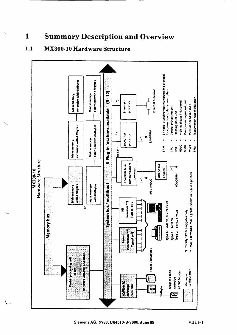
1 Summary Description and Overview1.1 MX300-10 Hardware Structure
0>3
'©a>
X *5S S
T3u. (Qz
Siemens AG, 9783, U64510- J-7600, June 89 VIII 1-1
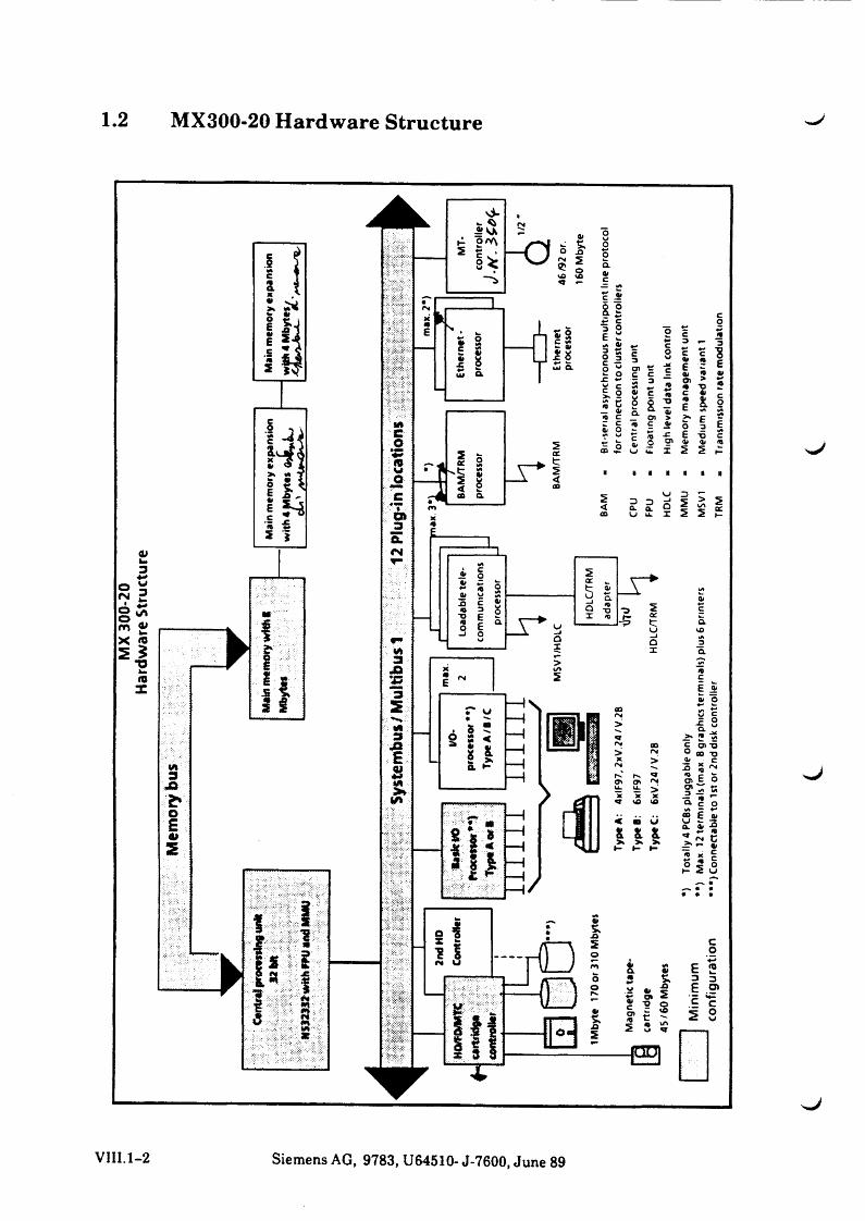
1.2 MX300-20 Hardware Structure w /
VIII.1-2 Siemens AG, 9783, U64510- J-7600, June 89
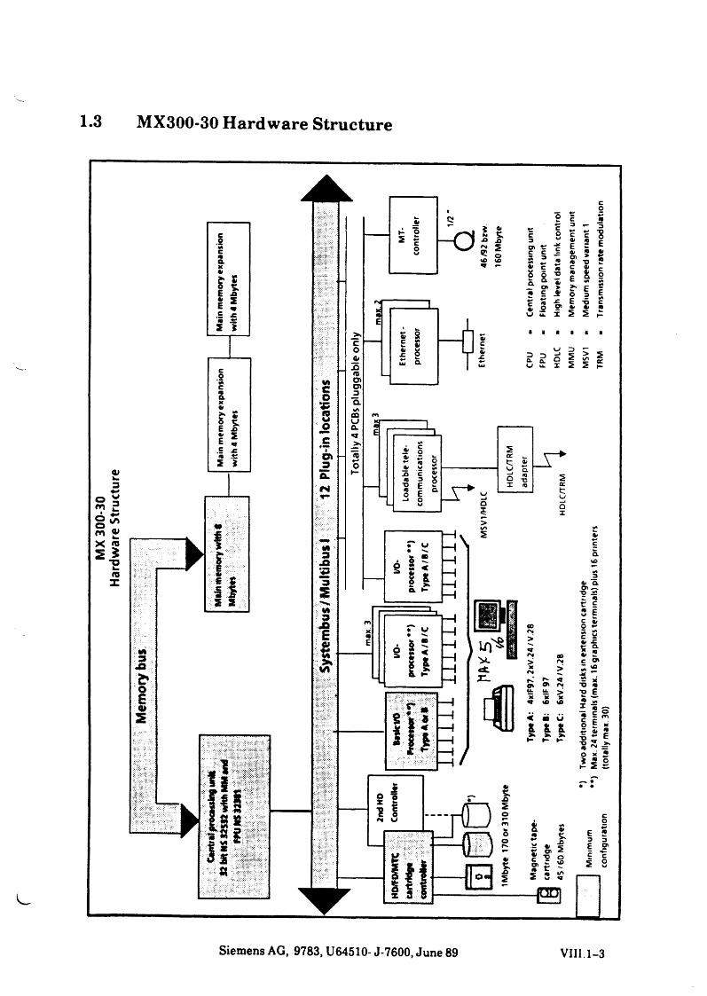
MX
300-
30
Hard
war
e St
ruct
ure
3 MX300-30 Hardware Structure
M: - CO353oer»D
KIS
co0*XJo>DlQ.«/>COuo.q
'S«->o
3JQ'♦ 3
S I «o> « c c c t5 3 *
*8= E5 #"O ffG = wg 5 -o
Q. ^ 4;
• f .2 6 3 E| X -C E -6 c£ o S’ •» * “u = x 5 5
? & 2C «*fr E *
? D u D r;- J C >„ o 2£ x 5 5
_______ L.W»
* §r s 8
5£ 8
2 § 8 -3 f 9 S e a-i O u QI
y q.Q -o X
>l/*
I/O*
proc
esso
r **)
Ty
peA/
B/C
TT
TT
TT
S
s _ T *
Siemens AG, 9783, U64510- J-7600, June 89 VIII. 1-3


2 CPU and Memory Board Functional Description
Item code no.: S 26361 -D 408Item code no.: S 26361-D 469
(CPUAS)(CPUBC)
Item code no.: S 26361 - D 409-V4Item code no.: S 26361 - D 409-V8Item code no.: S 26361 -D 449
(4 Mbyte) (MEMAL)(8 Mbyte) (MEMAL)(4 Mbyte) (MEMAF) (babyboard)
2.1 Overview CPU
The characteristical components for the performance of the CPUAS are the National Semiconductor microprocessor NS 32332, the memory management unit (MMU) NS 32382 and the floating point unit (FPU) NS 32081 which all operate with a 15MHz clock frequency.
A virtual memory up to 4 Gbyte can be addressed via demand paging with a page size of 4 kbyte.
However, the new alternative processor PCB CPUBC is equipped with the microprocessor NS 32532 and integrated MMU, instructions cache (1 Kbyte) and a new FPU NS32381, which increases the ferquency up to 25 MHz and multiplies the performance 2-3 times.
Further characteristics:
* INTEL MULTIBUS I compatible.* Maximal speed by means of:
1. 15 MHz clock pulse for CPU NS32332 / MMU NS32382 / FPU NS320812. Due to a discreet RAM controller the memory is accessed via a 32-bit local data bus
with a wait state (= 5 pulses). In the burst mode, however, that is automatically switched on by the CPU in data, read and prefetch cycles, the access to max. 4 doublewords takes only 11 pulses (as compared to the zero wait state = 16 pulses).
* Other busmasters may access the memory via the multibus by means of the dual port logic on the PCB.
* Quick transfer of data via the multibus interface by means of multibus-control logic
* In case of DMA the multibus mapper effects the translation of virtual address to physical address of the logical memory area
* Up to 64 kB EPROM available for booting as well as a monitor with minimal test and diagnosis.
Siemens AG, 9783, U64510- J-7600,11.88 VIII.2-1
Motorola clock MC146818 with external battery
The interrupt control unit (ICU) NS32202 coordinates up to 16 interrupts and also has two internal, independent timers.
NMI controller with resettable registers for displaying the NMI cause and address.
Two serial interfaces SS97, one can be switched to V24
2.2 Functional Groups
Memory address area of the firmwareThe PCB D408 comprises a 64 kbyte ROM area consisting of a 512-kbit component which includes the hardcore text, the loader and the monitor.After RESET the entire I/O area begins at address 0. Hence the processor also starts execution of the ROM program at address 0.
At the beginning of the firmware program the firmware maps the entire ROM area in an address area starting with address 7 000 000H and by setting the MAPIO bit to 0 the lower address are is switched off for the IO decoding. Then, the entire local memory is available both to the processor and the multibus as of address 0.
M ultibus ad d ress a rea
After power-on an automatic multibus address setting is carried out on the PCB.The firmware determines during the memory test the size of the connected local memory and adjusts accordingly the multibus address area. If, for example, the connected local memory has a size of 8 Mbyte, the multibus address area of the PCB is automatically set from 0 to 8 Mbyte. If the memory size is 16 Mbyte, the multibus address area is analogously set from 0 to 16 Mbyte.
As the maximal size of the multibus address area is only 16 MB, another multibus memory can overlap in this case a part of this local memory area by setting the INH1/ signal. As regards the CPU, the entire 16 Mbyte local memory can furthermore be addressed.
The automatic address setting can be modified via software.
VIII.2-2 Siemens AG, 9783, U 64510- J-7600,11.88
The m ultibus m apper
The multibus mapper is essential, for example, to the saving of data from disk to streamer, since large data blocks have to be made available quickly to the streamer via a linear address area.
The mapper consists of three fast 4 kbyte x 4 static RAMs with 35 ns access time. Thus it is possible to virtually map the 16 Mbyte multibus address area in steps of 4 kbyte into the local memory of max 16 Mbyte.
2.3 Memory Board
By using 1-Mbit components it was possible to develop for the PC-MX300 the new memory board MEMAL (S26361-D409-V*). There are two versions:
V4 with a memory capacity of 4 Mbyte, and V8 with 8 Mbyte.
It can be operated with both CPU PCBs CPU AS and CPUBC.
Both versions are provided with two plug-in locations each for the memory expansions MEM AF (S26361-D449) of 4 Mbyte capacity. By means of these baby-boards it is possible to upgrade a MEMAL
from 4 to 8 or 12 Mbyte, orfrom 8 to 12 or 16 Mbyte total capacity.
4 Mbyte each are comprised in a "ram bank" (bankO up to bank3), and these in turn are subdivided into BYTEO, BYTE1, BYTE2 and BYTE3 of 1 Mbyte each.
The refresh logic sets approx, every 15 microseconds a refresh request. In case of the CAS-before- RAS refresh a refresh counter is incremented automatically in the 1-Mbit chip.
The memory is organized doubleword by doubleword, each byte being secured with a parity bit (8bit + parity). Each parity error can generate independently an NMI.
The PCB is plugged in the Intel multibus in the platter, however, it is supplied by the CPU via a 96-pin memeory bus as far as addresses and data are concerned. Only power is supplied by the Intel multibus.
Siemens AG, 9783, U64510- J-7600,11.88 VIII.2-3
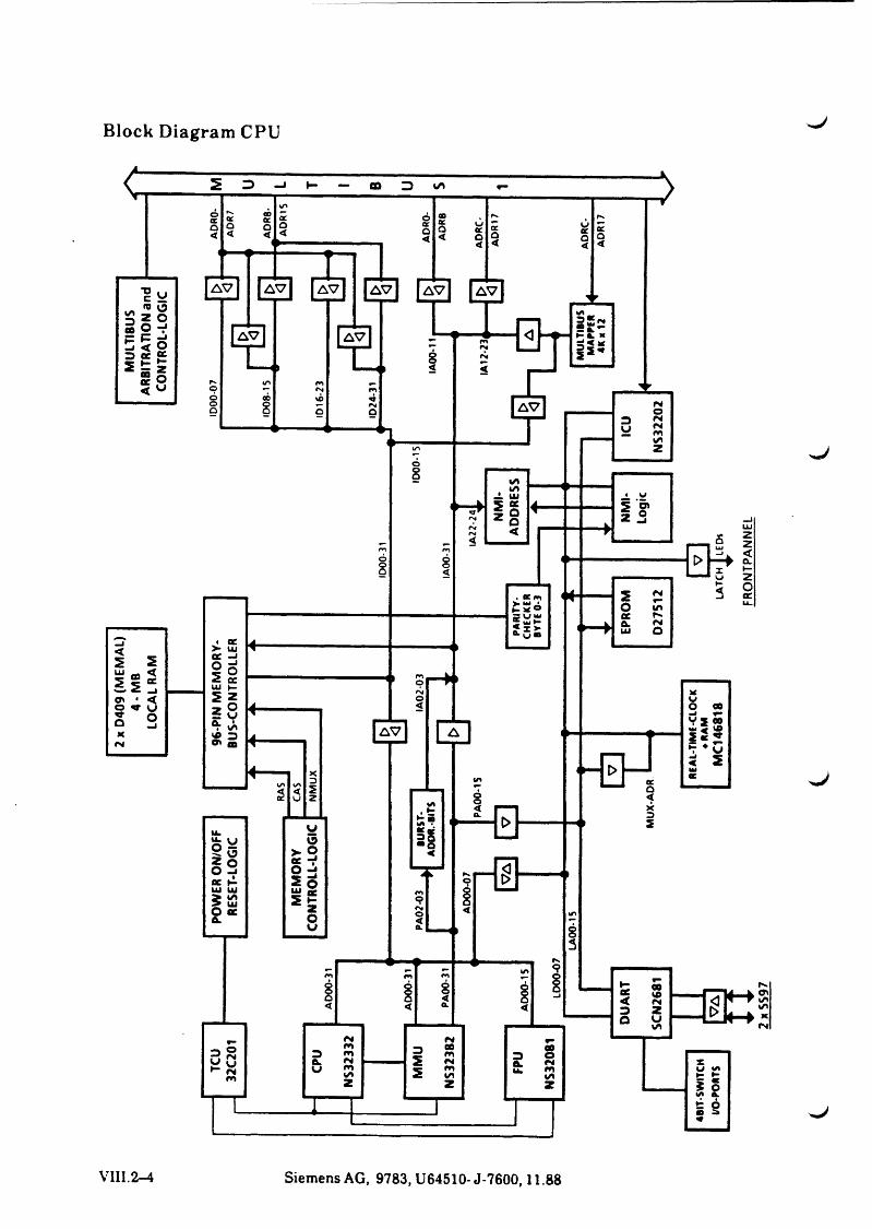
Block Diagram CPU
^J
^J
VIII.2-4 Siemens AG, 9783, U64510- J-7600,11.88


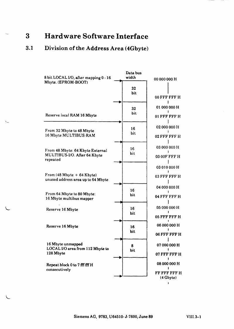
3 Hardware Software Interface3.1 Division of the Address Area (4Gbyte)
V
i
8 bit LOCAL I/O, after mapping 0-16Data bus width
Mbyte. (EPROM-BOOT) *
Reserve local RAM 16 Mbyte
32bit
32bit
p-
From 32 Mbyte to 48 Mbyte 16k i t
16 Mbyte MULTIBUS-RAM D l l
— »
From 48 Mbyte: 64 Kbyte External 16MULTIBUS-I/O. After 64 Kbyte bitrepeated
From (48 Mbyte -1- 64 Kbyte)unused address area up to 64 Mbyte
— ►16
From 64 Mbyte to 80 Mbyte: bit16 Mbyte multibus mapper
¥
Reserve 16 Mbyte 16bit
— ►Reserve 16 Mbyte 16
bit
— »16 Mbyte unmapped 8LOCAL I/O area from 112 Mbyte to bit128 Mbyte
— ►Repeat block 0 to 7 ffffiTHconsecutively
— ►
00 000 000 H
00 FFF FFF HI
01 000 000 Hl
01 FFF FFF HI
02 000 000 Hl
02 FFF FFF HI
03 000 000 Hl
03 00F FFF HI
03 010 000 H l
03 FFF FFF HI
04 000 000 Hl
04 FFF FFF HI
05 000 000 Hl
05 FFF FFF Hi
06 000 000 Hl
06 FFF FFF HI
07 000 000 HI
07 FFF FFFH I
08000 000 H l
FF FFF FFF H (4 Gbyte)
Siemens AG, 9783, U64510- J-7600, June 89 VIII.3-1
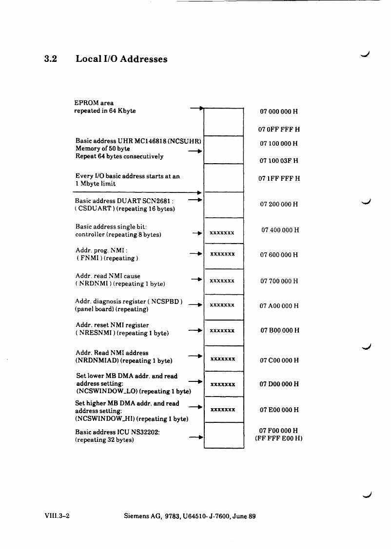
3.2 Local I/O Addresses
EPROM area repeated in 64 Kbyte
Basic address UHR MC 146818 (NCSUHR)Memory of 50 byte __Repeat 64 bytes consecutively
Every I/O basic address starts at an 1 Mbyte limit
-------------------------------------------------- ►Basic address DU ART SCN2681: — ►( CSDUART) (repeating 16 bytes)
Basic address single bit: controller (repeating 8 bytes)
Addr. prog. NM I:( FNM I) (repeating)
Addr. read NMI cause ( NRDNMI) (repeating 1 byte)
Addr. diagnosis register ( NCSPBD) (panel board) (repeating)
Addr. reset NMI register ( NRESNMI) (repeating 1 byte)
Addr. Read NMI address _(NRDNMIAD) (repeating 1 byte)
Set lower MB DMA addr. and read address setting: "(NCSWINDOW.LO) (repeating 1 byte)
Set higher MB DMA addr. and read address setting:(NCSWINDOW_HI) (repeating 1 byte)
Basic address ICU NS32202:(repeating 32 bytes)
xxxxxxx
xxxxxxx
xxxxxxx
xxxxxxx
xxxxxxx
xxxxxxx
xxxxxxx
xxxxxxx
07 000 000 H
07 OFF FFF H
07 100 000 H
07 100 03FH
07 1FFFFFH
07 200 000 H
07 400 000 H
07 600 000 H
07 700 000 H
07 A00 000 H
07 B00 000 H
07 C00 000 H
07 D00 000 H
07 E00 000 H
07 F00 000 H (FF FFF E00 H)
. J
VIII.3-2 Siemens AG, 9783, U64510- J-7600, June 89
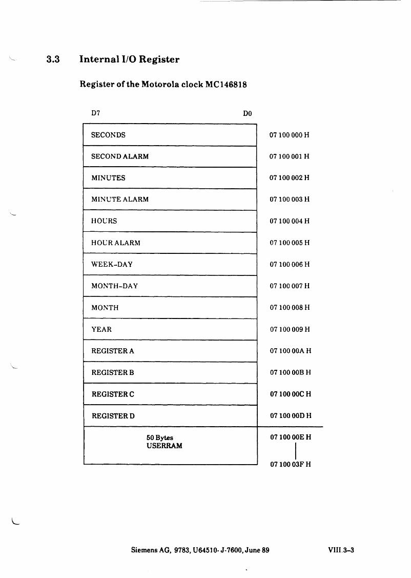
3.3 Internal I/O Register
Register of the Motorola clock MC 146818
D7 DO
SECONDS 07100 000 H
SECOND ALARM 07 100 001 H
MINUTES 07100 002 H
MINUTE ALARM 07 100 003 H
HOURS 07100 004 H
HOURALARM 07 100 005 H
WEEK-DAY 07 100 006 H
MONTH-DAY 07 100 007 H
MONTH 07100 008 H
YEAR 07 100 009 H
REGISTER A 07 100 00AH
REGISTER B 07100 00BH
REGISTER C 07100 00CH
REGISTER D 07100 00DH
50 Bytes 07100 00EHUSERRAM
07100 03FH
Siemens AG, 9783, U64510- J-7600, June 89 VIII.3-3
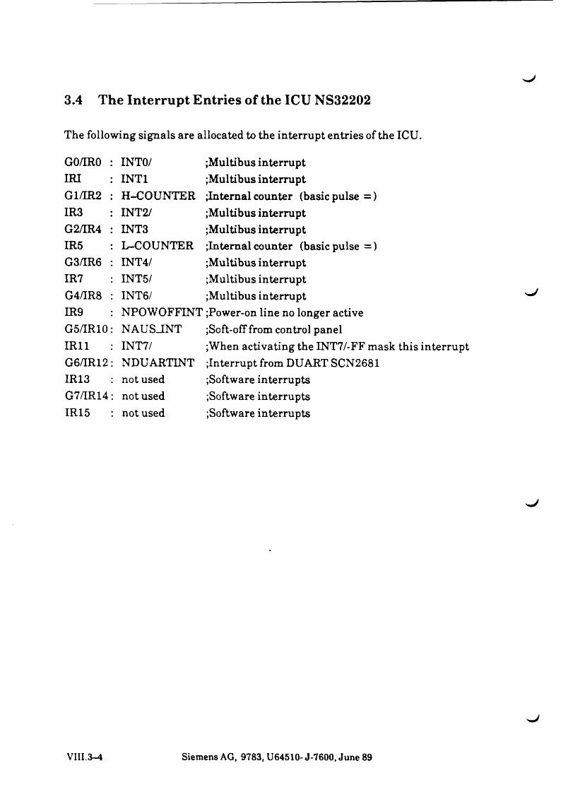
3.4 The Interrupt Entries of the ICU NS32202
The following signals are allocated to the interrupt entries of the ICU.
G o /m o INTO/ Multibus interruptIRI INTI Multibus interruptG1/IR2 H-COUNTER internal counter (basic pulse =)IR3 INT2/ Multibus interruptG2/IR4 INT3 Multibus interruptIR5 L-COUNTER Internal counter (basic pulse =)G3/IR6 INT4/ Multibus interruptIR7 INT5/ Multibus interruptG4/IR8 INT6/ Multibus interruptIR9 NPOWOFFINT Power-on line no longer activeG5/IR10 NAUSJNT Soft-off from control panelIR11 INT7/ When activating the INT7/-FF mask this interruptG6/IR12 NDUARTINT Interrupt from DUART SCN2681IR13 not used Software interruptsG7/IR14 not used Software interruptsIR15 not used Software interrupts
VIII.3-4 Siemens AG, 9783, U64510- J-7600, June 89

L

4 Function Description of the I/O Processors
4.1 GeneralThe following I/O procesors are currently being installed:
- SERAD S26361-D2794 * interfaces IF 97, 2 * V24
- SERAG S26361-D3126*IF97
- SEAAB S26361-D364-V* in three versionsV1 - 6 * interface IF 97 V2 - 4 * IF 97, 2 * V24 V3 - 6 * V 24
An I/O processor allows the connections of 6 asynchronous peripheral devices to the PC-MX300.
The data transfer rate and code frames may be set for each channel via softare.
C h arac te r output:
Characters to be output are written by the operating system to channel-specific buffers (mailbox) of programmable length.These characters are tranferred by the I/O processor autonomously to the connected device.
C h arac te r input:
Received characters are stored by the I/O processor in the same manner in the receive buffer and read out by the operating system depending on the channel.
The data and instruction exchange is performed via a dual port RAM, a 4 kbyte RAM, that is located within the address range of 16 Mbyte.This window can be read by both processors, the main processor and the I/O processor.The arbitration logic prevents collisions at simultaneous access of both processors. The basic address of the window can be set via switches.
As soon as the set address has been recognized on the multibus, the I/O processor generates the INHIBIT1 signal.
Both processors can prevent a bus transfer to the respective other processor by LOCK instructions.
Siemens AG, 9783, U64510- J-7600, June 89 VIII.4-1
4.2 Technical DataProcessor 8085 with 10 MHz
Technical possible data rate
6 channels with 38 400 b/smaximum performance of send mode approx. 150 kBit/sec
(SEAAB-V3 approx. 120 kBit/sec) maximum performance of receiving mode approx. 150 kBit/sec
(SERAD, SERAG approx. 90 kBit/sec)
Power draw + 5V 1.8 A 12 VIOmA
4.3 Connections of the I/O PCBsPI 86 pin connection Intel-Multibus P2 60 pin connection Intel-Multibus P3 30 pin connection IF D0-D2 P4 30 pin connection IF D3-D5 P5 6 pin connection Remote ON P6 6 pin connection not used
VIII.4-2 Siemens AG, 9783, U64510- J-7600, June 89
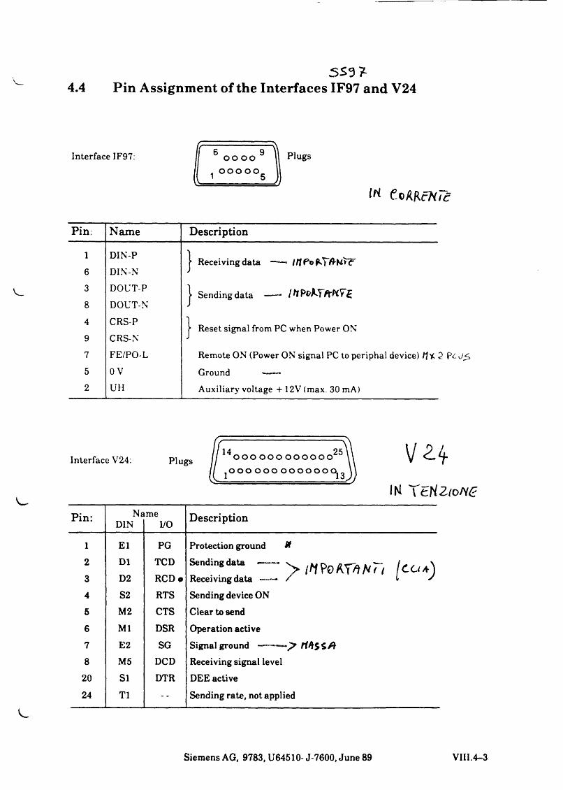
S S 3 7-4.4 Pin Assignment of the Interfaces IF97 and V24
Interface IF97:IF 6 9oo oo Plugs
n o o o o o' 5
lri CoUKcNicPin: Name Description
1 DIN-P
6 DIN-N3 DOUT-P
8 DOUT-N4 CRS-P9 CRS-N
7 FE/PO-L
5 o v2 UH
- Receiving data —■— //f P©
| Sending data ——~
| Reset signal from PC when Power ON
Remote ON (Power ON signal PC to periphal device) /f * 2 P£d<>
Ground -— —
Auxiliary voltage + 12V (max. 30 mA)
Interface V24: Plugs14 2*5o o o o o o o o o o o o
o o o o o o o o o o o o c
IKPin: Na
DINme
I/O Description
l E l PG Protection ground ff2 D1 TCD Sending data y /Af?0 KVtHu ICO*)3 D2 RCD m Receiving data —— / i s4 S2 RTS Sending device ON
5 M2 CTS Clear to send
6 Ml DSR Operation active
7 E2 SG Signal ground ff8 M5 DCD Receiving signal level
20 SI DTR DEE active
24 T1 Sending rate, not applied
Siemens AG, 9783, U64510- J-7600, June 89 VIII.4-3

s
'• - J

HD.

w '
sJ
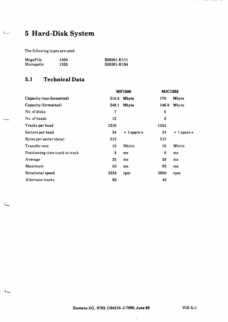
V 5 Hard-Disk System
The following types are used:
MegaFile 1300 S26261-K111Micropolis 1355 S26261-K184
5.1 Technical Data
MF1300 M1C1355
Capacity (non formatted) 310.5 Mbyte 170 MbyteCapacity (formatted) 248.1 Mbyte 146.8 MbyteNo. of disks 7 5
No. of heads 12 8
Tracks per head 1216 1024
Sectors per head 34 + 1 spare-s 34 + 1 spare-s
Bytes per sector (data) 512 512
Transfer rate 10 Mbit/s 10 Mbit/s
Positioning time track to track 5 ms 6 msAverage 25 ms 28 msMaximum 50 ms 62 msRotational speed 3534 rpm 3600 rpm
Alternate tracks 60 40
Siemens AG, 9783, U64510- J-7600, June 89 VIII.5-1
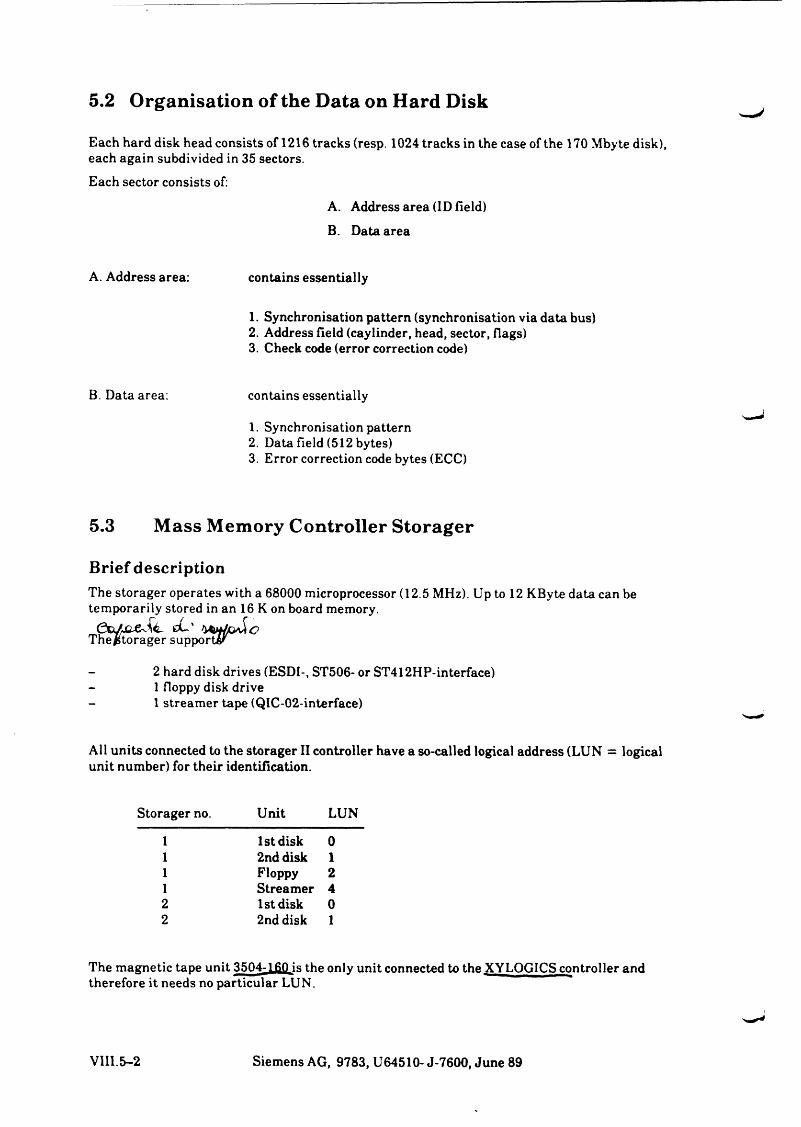
5.2 Organisation of the Data on Hard Disk
Each hard disk head consists of 1216 tracks (resp. 1024 tracks in the case of the 170 Mbyte disk), each again subdivided in 35 sectors.
Each sector consists of:
A. Address area (ID field)
B. Data area
A. Address area: contains essentially
1. Synchronisation pattern (synchronisation via data bus)2. Address field (caylinder, head, sector, flags)3. Check code (error correction code)
B. Data area: contains essentially
1. Synchronisation pattern2. Data field (512 bytes)3. Error correction code bytes (ECC)
5.3 Mass Memory Controller Storager
Brief descriptionThe storager operates with a 68000 microprocessor (12.5 MHz). Up to 12 KByte data can be temporarily stored in an 16 K on board memory.
CU'ThefStorager supports'
- 2 hard disk drives (ESDI-, ST506- or ST412HP-interface)- 1 floppy disk drive- 1 streamer tape (QIC-02-interface)
All units connected to the storager II controller have a so-called logical address (LUN = logical unit number) for their identification.
Storager no. Unit LUN
1 1st disk 01 2nd disk 11 Floppy 21 Streamer 42 1st disk 02 2nd disk 1
The magnetic tape unit 3504-160 is the only unit connected to the XYLOGICS controller and therefore it needs no particular LUN.
VIII.5-2 Siemens AG, 9783, U64510- J-7600, June 89
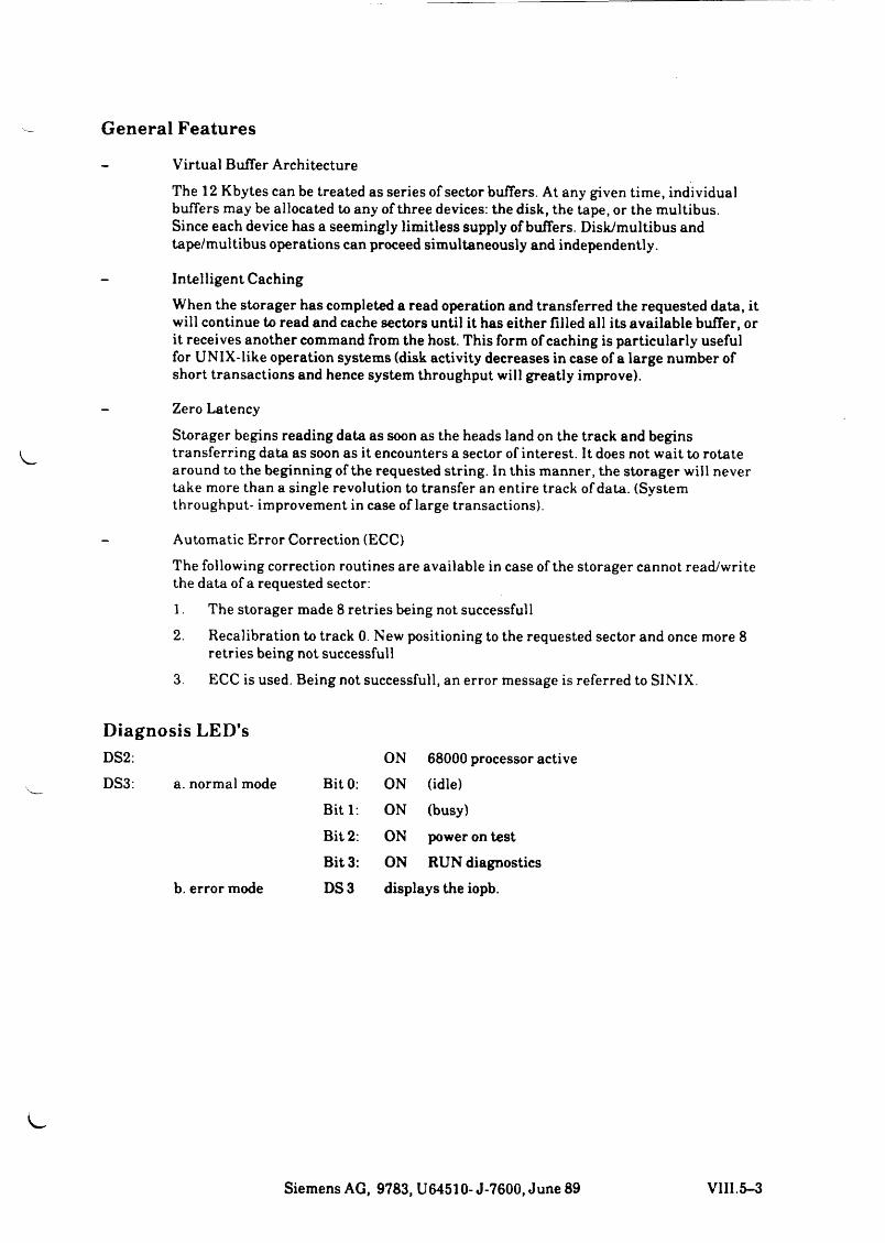
General Features
Virtual Buffer Architecture
The 12 Kbytes can be treated as series of sector buffers. At any given time, individual buffers may be allocated to any of three devices: the disk, the tape, or the multibus.Since each device has a seemingly limitless supply of buffers. Disk/multibus and tape/multibus operations can proceed simultaneously and independently.
Intelligent Caching
When the storager has completed a read operation and transferred the requested data, it will continue to read and cache sectors until it has either filled all its available buffer, or it receives another command from the host. This form of caching is particularly useful for UNIX-like operation systems (disk activity decreases in case of a large number of short transactions and hence system throughput will greatly improve).
Zero Latency
Storager begins reading data as soon as the heads land on the track and begins transferring data as soon as it encounters a sector of interest. It does not wait to rotate around to the beginning of the requested string. In this manner, the storager will never take more than a single revolution to transfer an entire track of data. (System throughput- improvement in case of large transactions).
Automatic Error Correction (ECC)
The following correction routines are available in case of the storager cannot read/write the data of a requested sector .
1. The storager made 8 retries being not successfull
2. Recalibration to track 0. New positioning to the requested sector and once more 8 retries being not successfull
3. ECC is used. Being not successfull, an error message is referred to SINIX.
Diagnosis LED'sDS2: ON 68000 processor activeDS3: a. normal mode Bit 0: ON (idle)
Bit 1: ON (busy)
Bit 2: ON power on test
Bit 3: ON RUN diagnosticsb. error mode DS3 displays the iopb.
Siemens AG, 9783, U64510- J-7600, June 89 VIII.5-3


L .

J
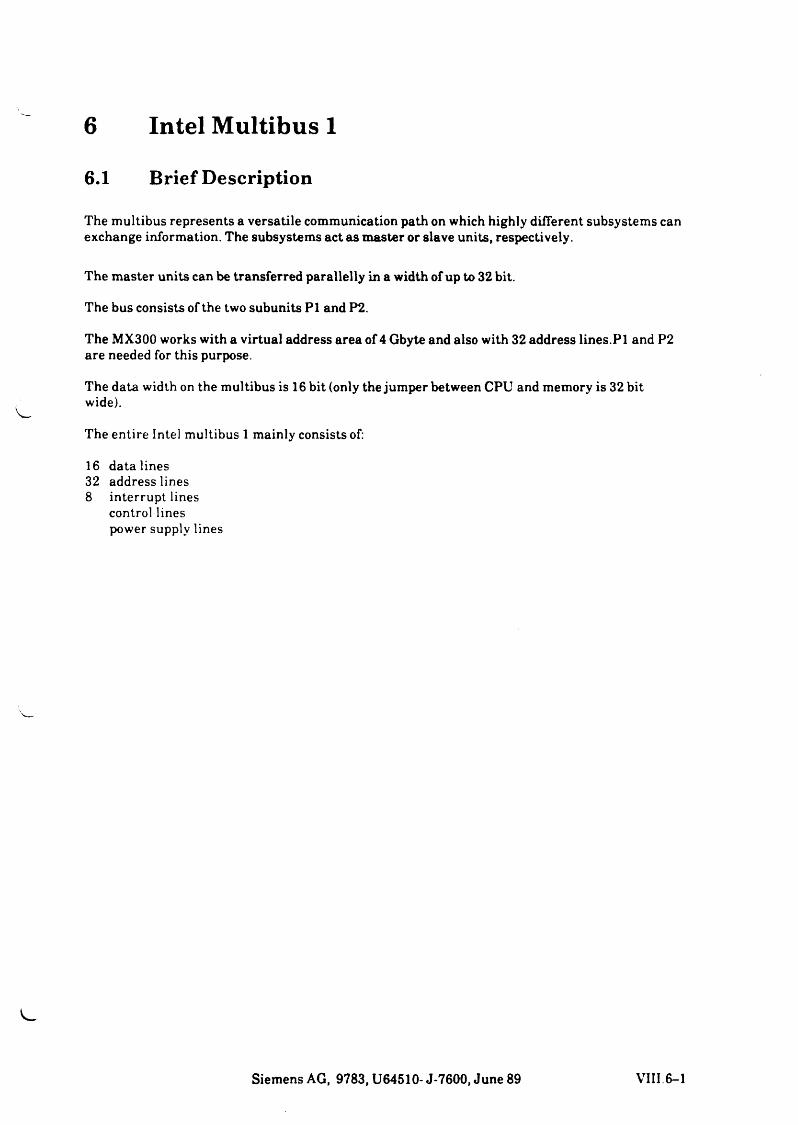
6 Intel Multibus 1
6.1 Brief Description
The multibus represents a versatile communication path on which highly different subsystems can exchange information. The subsystems act as master or slave units, respectively.
The master units can be transferred parallelly in a width of up to 32 bit.
The bus consists of the two subunits PI and P2.
The MX300 works with a virtual address area of 4 Gbyte and also with 32 address lines.PI and P2 are needed for this purpose.
The data width on the multibus is 16 bit (only the jumper between CPU and memory is 32 bit wide).
The entire Intel multibus 1 mainly consists of:
16 data lines 32 address lines 8 interrupt lines
control lines power supply lines
Siemens AG, 9783, U64510- J-7600, June 89 VIII 6-1
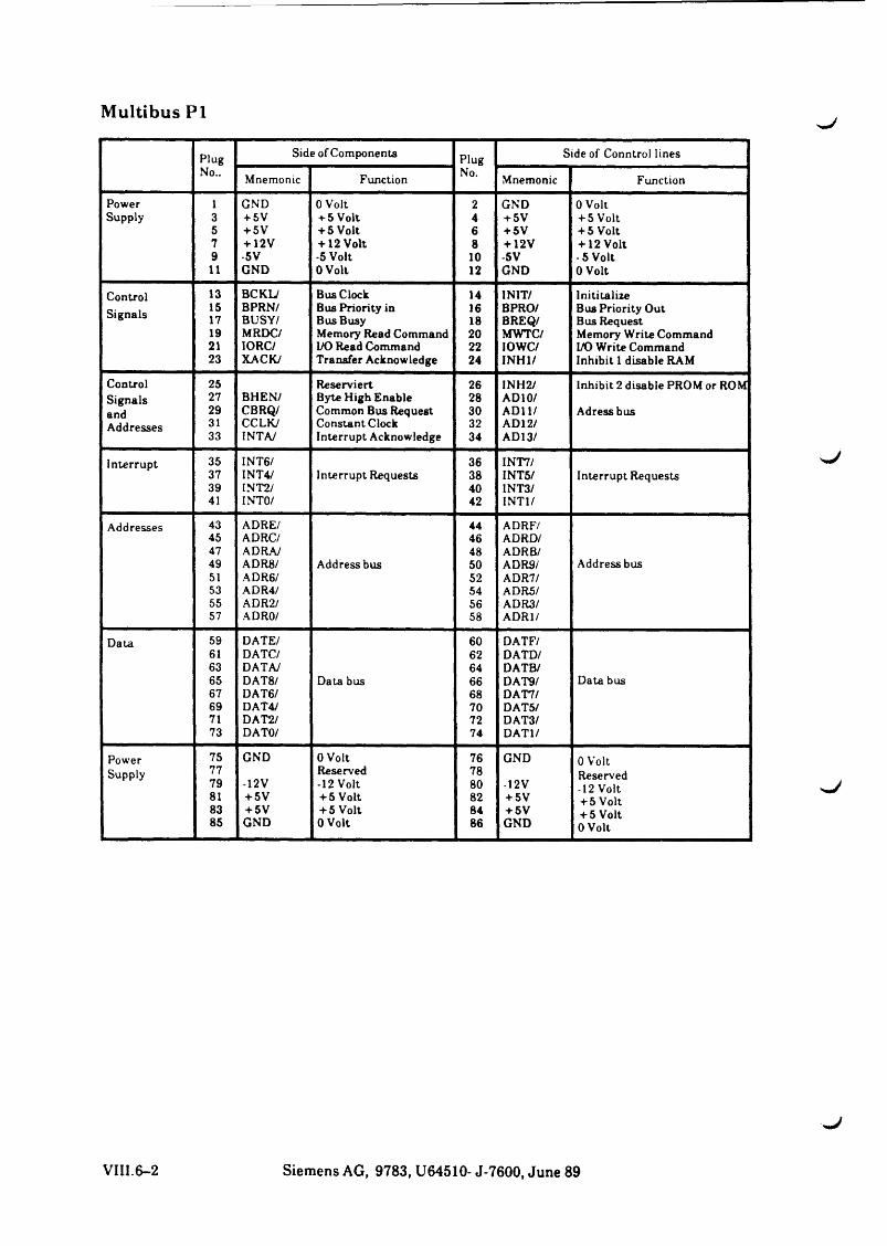
Multibus PI
Plug Side of Components Plug Side of Conntrol linesNo.. Mnemonic Function No. Mnemonic Function
Power 1 GND 0 Volt 2 GND 0 VoltSupply 3 + 5V + 5 Volt 4 + 5V + 5 Volt
5 + 5V + 5 Volt 6 + 5V + 5 Volt7 + 12V + 12 Volt 8 + 12V + 12 Volt9 -5V -5 Volt 10 -5V - 5 Volt11 GND 0 Volt 12 GND 0 Volt
Control 13 BCKL/ Bus Clock 14 INIT/ Inititalize15 BPRN/ Bus Priority in 16 BPRO/ Bus Priority Out17 BUSY/ Bus Busy 18 BREQ/ Bus Request19 MRDC/ Memory Read Command 20 MWTC / Memory Write Command21 IORC/ I/O Read Command 22 10WC/ I/O Write Command23 XACK/ Transfer Acknowledge 24 INH1/ Inhibit 1 disable RAM
Control 25 Reserviert 26 INH2/ Inhibit 2 disable PROM or ROMSignals 27 BHEN/ Byte High Enable 28 AD 10/and 29 CBRQ/ Common Bus Request 30 ADI 1/ AdressbusAddrp<»ps 31 c c l k / Constant Clock 32 AD12/
33 INTA/ Interrupt Acknowledge 34 AD13/
Interrupt 35 INT6/ 36 INT7/37 INT4/ Interrupt Requests 38 INT5/ Interrupt Requests39 INT2/ 40 INT3/41 INTO/ 42 INTI/
Addresses 43 ADRE/ 44 ADRF/45 ADRC/ 46 ADRD/47 ADRA/ 48 ADRB/49 ADR8 / Address bus 50 ADR9/ Address bus51 ADR6/ 52 ADR7/53 ADR4/ 54 ADR5/55 ADR2/ 56 ADR3/57 ADRO/ 58 ADR1/
Data 59 DATE/ 60 DATF/61 DATC/ 62 DATD/63 DATAJ 64 DATB/65 DAT8 / Data bus 66 DAT9/ Data bus67 DAT6/ 68 DAT7/69 DAT4/ 70 DAT5/71 DAT2/ 72 DAT3/73 DATO/ 74 DAT1/
Power 75 GND 0 Volt 76 GND 0 VoltSupply 77 Reserved 78 Reserved79 -12V -12 Volt 80 -12V -12 Volt81 + 5V + 5 Volt 82 + 5V + 5 Volt83 + 5V + 5 Volt 84 + 5V + 5 Volt85 GND 0 Volt 86 GND 0 Volt
VIII.6-2 Siemens AG, 9783, U64510- J-7600, June 89
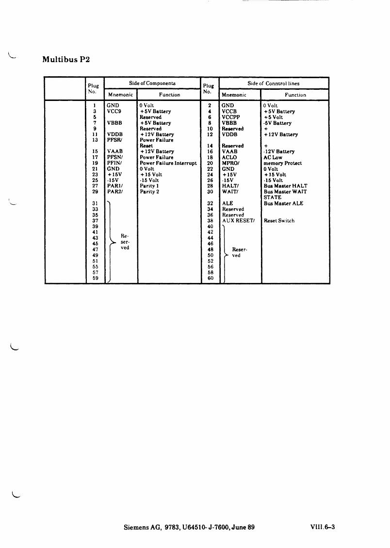
Multibus P2
Plug Side of Components Plug Side of Conntrol linesNo. Mnemonic Function No. Mnemonic Function
1 GND 0 Volt 2 GND 0 Volt3 VCC9 + 5V Battery 4 VCCB + 5V Battery5 Reserved 6 VCCPP + 5 Volt7 VBBB + 5 V Battery 8 VBBB -5V Battery9 Reserved 10 Reserved +11 VDDB + 12 V Battery 12 VDDB + 12V Battery13 PFSR/ Power Failure
Reset 14 Reserved +15 VAAB + 12V Battery 16 VAAB -12V Battery17 PFSN/ Power Failure 18 ACLO AC Low19 PFIN/ Power Failure Interrupt 20 MPRO/ memory Protect21 GND 0 Volt 22 GND 0 Volt23 + 15V + 15 Volt 24 + 15V + 15 Volt25 -15V -15 Volt 26 15V -15 Volt27 PARI/ Parity 1 28 HALT/ Bus Master HALT29 PAR2/ Parity 2 30 WAIT/ Bus Master WAIT
STATE31 N 32 ALE Bus Master ALE33 34 Reserved35 36 Reserved37 38 AUX RESET/ Reset Switch39 4041
1 Re- ser-
4243 4445 4647 ved 48 Reser-49 50 ved51 5255 5657 5859 > 60
Siemens AG, 9783, U64510- J-7600, June 89 VIII.6-3
Initiation
INIT
This initiation signal generates a certain defined initial state in the entire system. The INIT signal can be generated by one of the master units or by external logic.
Addressing
ADRO - ADR13 (hexadecimal)
These twenty address lines are used for transferring the addresses of memory locations and input/ output channels. The most significant bit is ADR13, the least significant bit is ADRO. What are referred to as 8-bit master units use the 16 lines ADRO to ADRF to output memory addresses and the 8 lines ADRO to ADR7 for the output of addresses of input/output channels. What are referred to as 16-bit master unit output memory addresses on all twenty address lines and input/output addresses on the address lines ADRO to ADRB. (The 8088 can output 20-bit addresses although it is classified as 8-bit CPU.)
INH1
This signal (INHibit) prevents RAM units from responding to address signals on the bus. INH 1 selects ROM units when both RAM and ROM units are connected to the bus.
INH2
This signal is capable of preventing part of the ROM units from responding to address signals on the bus. INH2 can be used for selecting 1 group from two groups of units if the same address occurs in both groups.INH 1 and INH2 can also be used to separately activate memory locations and input/output channels with memory addresses (memory mapped I/O).
BHEN
This signal (Byte High ENable) indicates that a byte is to be transferred on the upper 8 data lines of the multibus. The signal is used in systems containing 16-bit memories and/or 16-bit input/ output channels.
Data
DATO to DATF
On these sixteen lines, data can be transferred in both directions, that is to and from memory units and input/output channels. DATF is the most significant bit. In 8-bit systems, however, only the 8 lines DATO to DAT7 are used, here DAT7 is the most significant bit. DATO is always the least significant bit.
VIII.6-4 Siemens AG, 9783, U64510- J-7600, June 89
Synchronization and Priorities
BCLK
With the trailing edge of BCLK (Bus CLocK), the information streams on the bus are synchronized. BCLK does not run synchronously with clock signal CLK for the 8086, it can be faster or slower or occur in signal pulses during troubleshooting.
CCLK
This signal (Constant CLocK) is a frequency-stable clock signal with non-defined frequency.
BPRN
This signal (Bus PRiority iN) indicates to a master unit that no unit of the higher priority requests access to the bus. BPRN is synchronized with BCLK.
BPRO
BUSY
This signal is ouput by the respective current master unit to indicate that the bus is busy. Another unit queries to Find out whether it can gain control over the bus. BUSY is synchronized with BCLK.
BREQ
This signal (Bus REQest) is output by units wishing to gain control over the bus. BREQ is synchronized with BCLK.
CBRQ
This signal is used by other units to indicate to the current master unit that they want to gain control over the bus. If the H level is on line CBRQ, this indicates to the current master unit that no other unit needs control over the bus. The respective current master unit can therefore keep its control over the bus and continue bus cycle execution, if required.
Transfer (Log) Signals
The master unit that currently has control over the bus must output all transfer signals. The signals on the address lines must be stable a t least 50 ns prior to the transfer signal, in case of output also the signals on the data lines, and remain stable until at least 50 ns after the end of the transfer signal. The transfer signals are not synchronized with BLCK.
MRDC
This signal (Memory ReaD Control) indicates to a memory unit that the address of a memory location is on the address lines and that the memory unit can put the contents of the memory location on the data lines.
Siemens AG, 9783, U64510-J-7600, June 89 VIII.6-5
MWTC
The signal (Memory WriTe Control) indicates that a memory address is ready on the address lines and that information for the address memory location is ready on the data lines.
IORC
This signal (Input Output Read Control) indicates that the address of an input channel is on the address lines and that data from the input channel can be put on the data lines.
IOWC
This signal (Input Output Write Control) indicates that the address of an input channel is ready on the address lines and that data for the address output channel is ready on the data lines.
XACK
Each forwarding of information requires an acknowledge signal. The appropriate slave unit therefore sends the acknowledge signal XACK (eXchange ACKnowledge) to the outputting master unit. The master unit thus learns that a certain procedure is completed.
AACK
This signal (Advanced ACKnowledge) is used by the 8080A. It is an acknowledge signal advanced in time, which permits the CPU to recognize certain operations as terminated without assuming some kind of wait state. Slave units sending an AACK signal must also send the XACK signal, since not all potential master units are capable of accomodating AACK.
Asynchronous Interrupt Signals
INTO to lN T 7
In the case of parallel priority control, interrupt requests are sent on these 8 lines (INTerrupt). INTO has the lowest, INT7 the highest priority.
INTA
This signal (INTerrupt Acknowledge) is used by-the current master unit to indicate to another unit that it is expecting the vector ID of an interrupt on the data lines.
VIII.6-6 Siemens AG, 9783, U64510- J-7600, June 89


sJ
7 XYLOGIC Processor and MT 3504General7.1
The XYLOGIC processor is the controller PCB for th. . '2" magnetic tape unit MT 3504-160.
Part number:
XYLOGIC processor: S26361-F419V 31 MT 3504-160: S26261-K102
Product number:
XYLOGIC processor: 97832-430MT 3504-160: 97835-430 (MT with controller)
As a rule, this magnetic tape unit is used by SINTX-BS2000 systems (PC2000, C30, WS2000) and actual BS2000 computers for saving data of BS2000 files and partitions.
Software programs used there are, for example, ARCHIVE, SYSUPD, INIT and TSOSMT.
Furthermore, this device can also be addressed with SINIX commands, as already known from the floppy and Tandberg streamer.
The corresponding SINIX commands are the following:
tarsarstphys
A physical data saving with TDSl by means of sa_urld is not possible as sa_urld only accessesthe disk controller (storager II and OMTI 5400 in the case of MX2) and not the XYLOGIC controller.
7.2 XYLOGIC Processor
The XYLOGIC processor (D472) is Intel-multibus compatible and may be inserted in any unused plug-in location of the platter.
Attention: In the case of MX300-10 only the platters 5 to 12 are supplied with power by PSl.
The processor system allows it to address up to 4 tape units with the controller by means of a so- called tape-drive daisy chain.This connection, however, is not supported by the present system.
Siemens AG, 9783, U64510- J-7600, June 89 VIII.7-1
When the system is starting up a selff-test is running ass well al with other PCBs. In the same moment the test LED is lit. After properly "testend” the LED turns off. If the LED is still on the testprogram recognized a hardware error.
The connection from controller to MB 3504-160 is provided by seperate 2x 50 pins cable connector
Depot No. Manufactrer No.1135325 T26319 Y 1056 M 6
Contoller data:
Manufacturer Processor Clock frequency Adress lines Data lines Data buffer (FIFO) Interrupts
PERTEC803110 MHz16/20/24 switching possible8/16 switching possible2 Kbyte optional 8 Kbyte0-7 Setof MX300:1 = 3
7.3 Magnetic Tape Unit 3504%J
The magnetic tape unit 3504-160 (FS1000) of the manufacturer PERTEC is an automatically loading 1/2 ” streamer tape unit.
The main components are:Basic unit ( integrated with the writing control)Reading unut and Formatter unit.
The standard operation performs 1600bpi/25ips, its also changeable to 3200bpi750ips. Therefore the memory capacity of this unit is 45 Mbyte up to 90 Mbyte.
The default GAP value of 4.8” is gradually variable from 0.6” up to 10”. The tape speed and the GAP value are are adjustable at the front of the operator panel.
Diagnostic and test methods:1. Calling of internal test routines via operator panel.2. TDS1
Tools:MG gage for HW justages : MG 16 depot no.: 1165380 Set of american hexagon screwer Cross head screwer flat-head screwer.
For furher informations sie: WHB MBE 3504-160Order no.: U64389-J
VIII.7-2 Siemens AG, 9783, U64510- J-7600, June 89


8 Platters8.1 General
A 4-layered platter with 12 plug-in locations for multibus-I PCBs is used in the MX300. The division is at 0.8".
8.2 PS-Related Division
The platter is divided up as regards the power supply ( + 5V, + /-12V).The plug-in locations 5-12 are supplied by power supply 1 (MX300-10). Power supply 2 feeds the PCBs of plug-in locations 1 - 4.The potentials OV and 4- 5V are routed on one level, + 12V and -12V resp., in the layers for the signals.
8.3 Platter Equipment
The equipment of the platter depends on the configuration versions (MX300-10 or MX300-20).
For MX300-10 applies:
Plug-in location 5 storagerPlug-in location 6 any PCBPlug-in location 7 any PCBPlug-in location 8 any PCBPlug-in location 9 any PCBPlug-in location 10 memoryPlug-in location 11 CPUPlug-in location 12 adapter for AT/XT or any PCB
For MX300-20 applies:
Plug-in location 1 storagerPlug-in location 2 any PCBPlug-in location 3 any PCBPlug-in location 4 any PCBPlug-in location 5 any PCBPlug-in location 6 any PCBPlug-in location 7 any PCBPlug-in location 8 any PCBPlug-in location 9 any PCBPlug-in location 10 memoryPlug-in location 11 CPU n
adapter for AT/XT or any PCB#*.Plug-in location 12
Notes:• When upgrading the MX300-10, the storager has to be replugged to plug-in location 1.
• The 8 interrupt singals (INTO . . . 7) are routed via all 12 plug-in locations.
Siemens AG, 9783, U64510- J-7600, June 89 VIII. 8-1
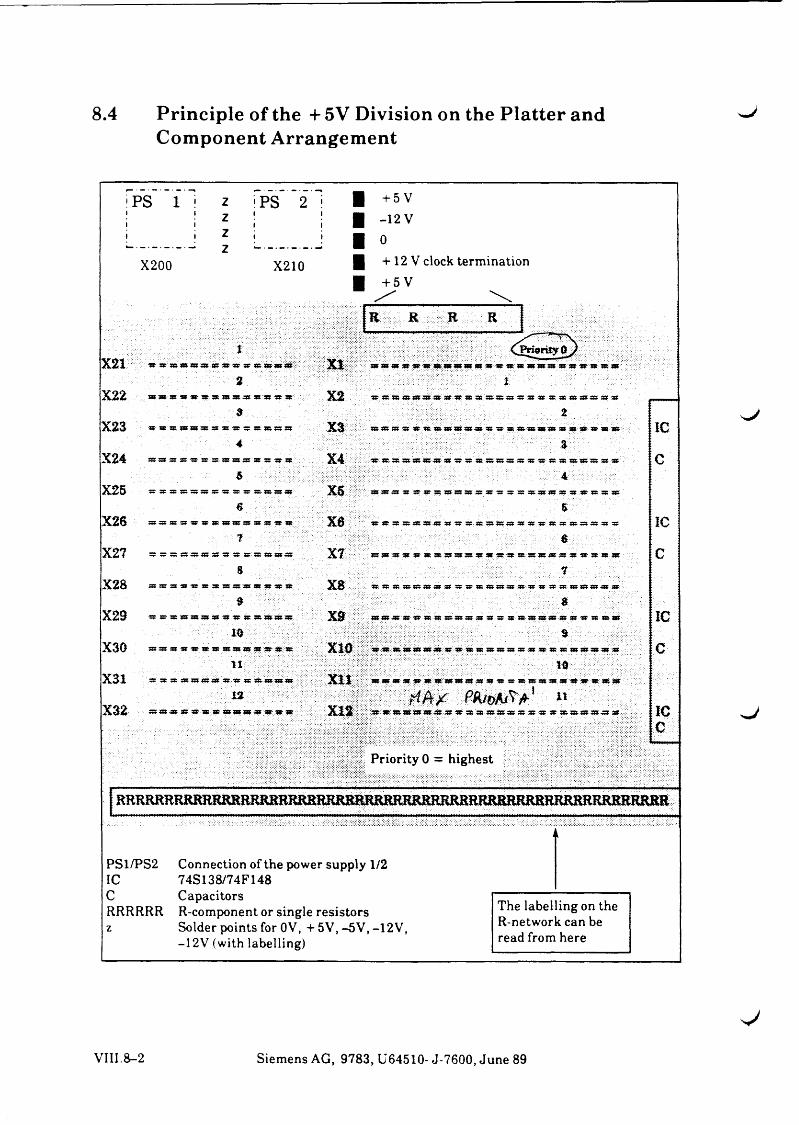
8.4 Principle of the + 5V Division on the Platter and ^Component Arrangement
X200
PS 2 i
X210
+ 5 V -12 V 0+ 12 V clock termination + 5 V
It R R R
Priority 0 = highest
X21t
X I:: « « m w w a i « » « « « « :
2
333 333 333 4 5 4 5 3 5 3 9 .3 9 333-333 43 43 4 5 4 5 35 333 333 333 33 43* 4 5 '35 35 333' .
1
X22. ■ $ . . .
X2 4 5 35 35 333 333 333 33 4 5 4 5 3 5 3 5 3 3 3 3 3 3 9 3 3 3 5 3 4 3 3 3 3 5 3 3 3 3 3 3 5 3 5 4 2
tX23
4X3 : 333 383 53 53 4 5 45 35- 343 433 333 333 5 3 4 5 3 5 .35- 333 5 4 333 53 43 .45 3 5 35-353 ’:
aI C
X246
X4 :..-55 35 35 333 333 333-53’ 53 4 5 35 35 3 5 3 9 9 3 5 5 5 3 4 5 3 5 3 5 3 3 3 3 3 3 3 9 5 3 5 2
Ac
X25S
x s ' 3 9 3 9 9 3 42 3 5 3 5 3 5 3 9 3 9 3 9 92 5 2 4 2 3 5 3 5 ^ 3 9 3 9 5 3 4 2 4 5 3 5 3 5 3 9
$
X267
x a 4 5 X 5 3 5 3 9 3 9 3 9 - 5 2 5 2 4 5 3 5 3 5 3 9 3 9 3 9 5 3 5 2 4 5 3 5 3 5 3 9 3 9 3 9 9 2 4 2
a
I C
X27 5 5 «9P 9 3 25 S3 "35 35 335 333 333 9 3 X7 . 3 9 3 9 92 4 2 4 5 3 5 3 5 - 3 9 3 9 3 9 5 2 4 4 4 5 4 5 3 9 3 9 3 9 3 9 25 5 2 4 5 3 5 3 5 3 9 --
7
c
X28 3 5 5 3 : 9 53 5 2 3 5 9 5 : 9 5 3 3 9 9 3 5 2 4 5 35
9XS 4 5 35 35 3 9 3 9 3 9 3 2 52 4 2 35 35 3 9 3 9 3 9 53 52 45 35 35 3 9 3 9 3 9 3 9 42
8
X29 5 3 35 33! 333 333 333 33 53 3 5 35 335- 333 333 333
i o
x d - : 3 9 3 9 4 3 42 5 5 35 35 3 9 3 9 3 9 S3 42 35 35 35 3 9 3 9 3 9 42 42 4 5 25 35 3 9
■ 8 S i S ; a ; r 1 ■
I C
X30 333 333 33 43 3 5 35 33» 333 333 333 53 3 5 4 5 '335
t l
x w :::;::4 5 -4 5 ':3 9 .3 9 .3 9 3 9 9 3 :'5 2 4 5 3 5 35- 3 9 3 9 3 9 5 2 52 4 5 35 3 5 3 3 3 3 9 9 3 9 2 52 '
i d
c
X31 45 35 35 3 » 333 «33 333 4 5 4 5 35 333 333 333 333 :
1 2
x t t : : 3 9 3 9 3 9 52 5 5 3 5 :-49 3 9 3 9 « 9 S3 52 4 5 35 3 9 3 9 3 9 3 9 .5 2 4 5 4 5 35 3 9 3 9
H A / P A / o A / ^ A 1 »
I C
cX32 a s a s a s a s a r s s * a s a s a s a s as- ? ? s a - : X12 - : : : - 5 5 1 5 : 3 9 3 9 3 9 3 9 5 2 5 2 4 5 3 5 3 5 3 9 3 9 9 2 S3 5 2 4 5 3 5 3 5 3 9 3 9 3 9 9 2 42:-:-:
RRRRRHRRRHRjRRRRjRHHRRRRRjRRRRERRRRRHKRREKRKRRRßRRRRRRRRRRRRR
PS1/PS2 Connection of the power supply 1/2 IC 74S138/74F148C CapacitorsRRRRRR R-component or single resistors z Solder points for OV, + 5V, -5V, -12V,
-12V (with labelling)
The labelling on the R-network can be read from here
VIII.8-2 Siemens AG, 9783, U64510- J-7600, June 89


9 Power Supply9.1 Description of the Power Supply and Fan System
(see Fig. 1)
9.1.1 General
The power connection of the device is single-phased via a 3 m power cable with a ground plug. Operation is possible with 220-240 V as well as with 110-120 V, by switching. The power supply and the fan systems mainly consist of:
• Power distributor PCB XUNVM S26113-E286-V3
• Power supply XSVDJ (S26113-E288) (maximum 2 devices in one cartridge) with forced ventilation via cabinet fan.
• Operator-panel logic PCB BFAAB (S26361-D446) and• 12 V fan V26815-B107 (maximum 4 devices).
A battery (underneath the PS cartridge) ensures operation of the clock NV RAM on CPUAS PCB-D408 in case of power off.
9.1.2 Central Power Supply Control (see Fig.2)
9.1.2.1 Activating the Power-Supply System
a) Key ”EIN” (ON) on the operator-panel logic PCB BFAABThe activation of the PS system via the key ”EIN” is only possible when the switch key is inposition 2. This causes the startup of the system.Notes:• Is no UPS (uninterruptable power supply) existing, the pins 5 and 6 at location X7 on
the operator-panel logic PCB must be bridged (shorting plug).• To avoid a high current pulse when applying mains voltage to the power supply, the
mains voltage for all further power supplies (MX300-20 and extension device) is activated in time intervals.
b) Remote activation (e.g via FES 83800)The remote activation is effected via FES 83800 with the defined interface (connector in theconnector panel).The release for permissible remote activation and deactivation is performed by the software.In case of released remote activation and deactivation:• Remote activation and deactivation is applied independently of the switch key
position.
Siemens AG, 9783, U64510- J-7600, June 89 VIII.9-1
• Remote ativation of a deactivated system causes always a startup. Remote activation of an already activated system has no effect on the system.
• Remote deativation shuts down the system via ”/etc/powerofP\
• The OFF signal of FES causes the shutdown of the system (’’hard off”).
c) Reactivation after power failureWhen mains voltage returns, the PS system only turns on if it was in ON status before power failure.The reactivation cannot be stopped.
d) Activation with PS errorIn case of a PS error the pressing of the ”EIN” key generates an activation pulse (NPO) of 3 minutes.
• Is no LED indicator lit, PSl and perhaps PS2 are defective. PS2 may only be activated when PSl operates correctly.
• If only PSl LED is lit, PS2 is defective (only at MX300-20). The error code ”3F” is ^displayed on the hexadecimal indicator.
9.1.2.2 Deactivating the Power-Supply System
a) Key ”AUS” (OFF) on the operator-panel logic PCB BFAABThe use of this key is only neccessary in special cases or in error cases.
The use of the ”AUS” key deactivates the PS system immediately (’’hard off”). This function is only applicable in switch key position 2.
With active operating system, the system must be turned off beforehand by the system administrator via ”/etc/poweroff”.
b) Deactivation via system software
• With the ”/etc/poweroff” command the polarized PS relays EIN/AUS (on/off) at the operator panel PCB is set to OFF position and the PS is turned off via the signal ”N SVAUS” (N PS OFF) at the PCB CPUAS after completing the saving routine. ^
• In UPS mode the signal "N-POWER-ON” is removed after power failure.
The ”N PO” signal for the PS is still generated via the power hold flip flop on the CPUAS PCB.
After completing the saving routines the power supplies are turned offby the power hold flip flop. The "PS ON/OFF” relay on the operator-panel PCB remains in ON position, so that the power supplies are activated when power returns and UPS is corrected.
c) Remote deactivation (e.g. via FES 83800)
see 9.1.2.1.b
VIII. 9-2 Siemens AG, 9783, U64510- J-7600, June 89
9.1.3 Power ON/OFF of the Extension DeviceThe activation and deactivation of the power supply in the extension device is performed by the basic device.
The power supplies in the extension device are controlled via PON.
The power supplies are activated in time intervals.
9.1.4 Monitoring and Signalling
9.1.4.1 DC Voltage Monitoring
The active state of the power supplies PSl and PS2 is indicated by the green LEDs ”SV!” and ”SV2” (when existing) at the operator panel.
If the voltage of PSl + 5 V or + 12 V falls below the power supply undervoltage monitoring limit, the PS system is deactivated. The LEDs SV1 and SV2 at the operator panel are off. No automatic reactivation is performed.
If the voltage of PS2 + 5V or + 12V falls below the power supply undervoltage monitoring limit, only PS2 is deactivated (error code ”3F”). In case of temporary errors an automatic reactivation is performed.
The voltages -5V and -12 V are not monitored. In case of an error, no deactivation of PSl and PS2 is performed.
9.1.4.2 Mains Voltage Monitoring
If the mains voltage monitoring of a power supply is activated (see 9.2.2.4) the system sends the message.
9.1.4.3 Temperature Monitoring
Each power supply has an overtemperat'ure monitor.
If the temperature monitor is active:
• at PSl the power supply system is deactivated, the LEDs SV1 and SV2 are turned oft.
• at PS2 only the power supply PS2 is deactivated, the LED SV2 is turned off (error code ”3F”).
If the temperature reaches the valid range again, the power supply is reactivated.
Siemens AG, 9783, U64510- J-7600, June 89 VIII.9-3
9.1.5 C ontrol of Fan SpeedDepending on the temperature at the heat dissipator of the power supply a thermo-contact turns on or off a Z-diode in the fan power supply line of the PS.
The switching level is at about 36°C ambient temperature.
Thus only the speed of the power-supply fan (plug X5 in the respective power supply) is increased or decreased.
Thermo-switch Fan voltageopen approx. + 8Vclosed approx.-I-12 V
The logic fans are always supplied via a Z-diode. The logic fan power supply is approx. 8 V (plugX6).
9.1.6 Uninterruptable Power Supply (UPS) (OPTION)9.1.6.1 Task
The uninterruptable power supply serves a defined system shut-down in case of power failure.
9.1.6.2 Function Description
The following comments are based on the assumption that the accumulator battery of the UPS is fully charged.
If a power failure > 10ms occurs, the UPS switches to battery-driven operation. Depending on the UPS setting the MX300 is at once or after 20 seconds informed via the signal USVOKP = "0" that the system has switched to battery-driven operation. The system shutdown is performed.
After termination of all activities, the PS in the MX300 is deactivated. This is signalled to the UPS (SVONP = ”0"). The UPS interrupts thereupon the line connection to the MX300.
When mains voltage is supplied again and the battery is uncharged there are two possibilities to start up the system again:
• operation of MX300 is first possible when the battery is fully charged and signal USVOKP = Hr .
• if operation of MX300 is requiredwith insufficient charge of battery the signal USVOKP = "l"has tobe simulated. A shorting plug C26139-Y1388-VI (jumper between pins 8 and 9) has to be plugged in UPS plug-in location (pin 2) at the MX300 connector area. In case of a new power failure a proper shut-down is not guaranteed.
VIII.9-4 Siemens AG, 9783, U64510- J-7600, June 89
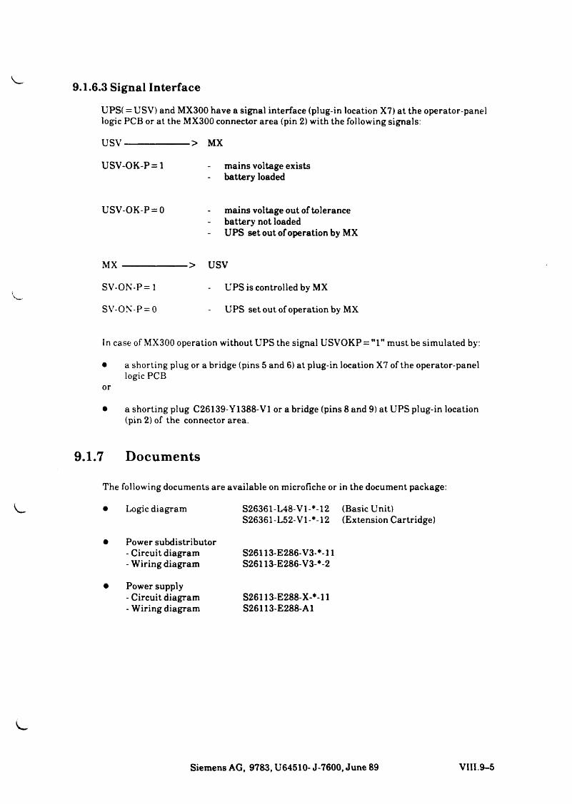
9.1.6.3 Signal Interface
UPS( = USV) and MX300 have a signal interface (plug-in location X7) at the operator-panel logic PCB or at the MX300 connector area (pin 2) with the following signals:
USV--------------------> MX
USV-OK-P = l - mains voltage existsbattery loaded
USV-OK-P = 0 mains voltage out of tolerancebattery not loadedUPS set out of operation by MX
MX --------------------> USV
SV-ON-P=l - UPS is controlled by MX
SV-ON-P = 0 - UPS set out of operation by MX
In case of MX300 operation without UPS the signal USVOKP = "l" must be simulated by:
• a shorting plug or a bridge (pins 5 and 6) at plug-in location X7 of the operator-panellogic PCB
• a shorting plug C26139-Y1388-V1 or a bridge (pins 8 and 9) at UPS plug-in location (pin 2) of the connector area.
9.1.7 Documents
The following documents are available on microfiche or in the document package:
• Logic diagram S26361-L48-Vl-*-12 (Basic Unit)S26361-L52-V1-M2 (Extension Cartridge)
• Power subdistributor- Circuit diagram S26113-E286-V3-*-ll- Wiring diagram S26113-E286-V3-*-2
• Power supply- Circuit diagram S26113-E288-X-M1- Wiring diagram S26113-E288-A1
Siemens AG, 9783, U64510- J-7600, June 89 VIII.9-5
9.2 Description of the Power Supply S26113-E288 XSVD J
9.2.1 General
The power supply XSVDJ generates the dc voltages necessary for the operation of the MX300.
It is set up as a replaceable unit and located in a closed metal housing. For ventilation purposes, a fan is mounted on the cabinet. All interface connections can be plugged. The voltages cannot be modified in the field.
9.2.2 Activation/Deactivation and Signalling / M* P¢)9.2.2.1 Activation
The power supply is activated by applying 0 V to plug-in location X2/1 or 6 (Tab. 1), signal NPON.
9.2.2.2 Deactivation
The power supply is deactivated by removing 0 V from plug-in location X2/1 or 6.
9.2.2.3 Automatic Reactivation
a) With sporadic PS errors,e g. in case of short-circuit of the -I- 5V or + 12V the PS checks whether the short-circuit persists by reactivating the system three time at 4 sec. intervals.
b) With power failureAfter power failure the system is reactivated after approx. 3 - 8 sec.
^J
sJ
VIII.9-6 Siemens AG, 9783, U64510- J-7600, June 89
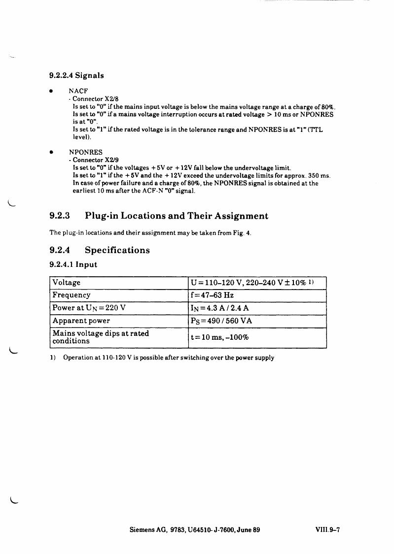
9.2.2.4 Signals
• NACF- Connector X2/8
Is set to ”0" if the mains input voltage is below the mains voltage range at a charge of 80%. Is set to "0” if a mains voltage interruption occurs at rated voltage > 10 ms or NPONRES is at "0".Is set to Ml" if the rated voltage is in the tolerance range and NPONRES is at Ml" (TTL level).
• NPONRES- Connector X2/9
Is set to M0” if the voltages + 5 V or + 12V fall below the undervoltage limit.Is set to "1M if the + 5V and the + 12V exceed the undervoltage limits for approx. 350 ms. In case of power failure and a charge of 80%, the NPONRES signal is obtained at the earliest 10 ms after the ACF-N "0" signal.
9.2.3 Plug-in Locations and Their AssignmentThe plug-in locations and their assignment may be taken from Fig. 4.
9.2.4 Specifications9.2.4.1 Input
Voltage U = 110-120 V, 220-240 V± 10% »Frequency f= 47-63 HzPower at Un = 220 V In = 4.3 A /2.4 AApparent power PS = 490 / 560 VAMains voltage dips at rated conditions t= 10 ms,-100%
1) Operation at 110-120 V is possible after switching over the power supply
Siemens AG, 9783, U64510- J-7600, June 89 VIII.9-7
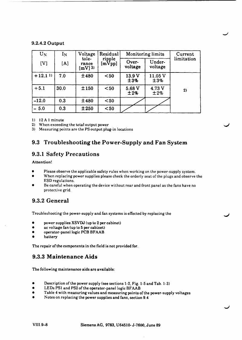
9.2.4.2 Output
UN In Voltage tolerance
[mV] 3)
Residualripple
[mVpp]
Monitoring limits Currentlimitation
[V] [A] Overvoltage
Undervoltage
+ 12.1 i) 7.0 ±480 <50 13.9 V ±3%
11.05 V ±3%
+ 5.1 30.0 ±150 <50 5.68 V ±2%
4.73 V±2% 2)
-12.0 0.3 ±480 <50- 5.0 0.3 ±250 <50 s ' s '
1) 12 A 1 minute2) When exceeding the total output power3) Measuring points are the PS output plug-in locations
9.3 Troubleshooting the Power-Supply and Fan System
9.3.1 Safety PrecautionsAttention!
• Please observe the applicable safety rules when working on the power-supply system.• When replacing power supplies please check the orderly seat of the plugs and observe the
ESD regulations.• Be careful when operating the device without rear and front panel as the fans have no
protective grid.
9.3.2 General
Troubleshooting the power-supply and fan systems is effected by replacing the
• power supplies XSVDJ (up to 2 per cabinet)• ac voltage fan (up to 5 per cabinet)• operator-panel logic PCB BFAAB• battery
The repair of the components in the field is not provided for.
9.3.3 Maintenance Aids
The following maintenance aids are available:
• Description of the power supply (see sections 1-2, Fig. 1-5 and Tab. 1-3)• LEDs PSl and PS2 of the operator-panel logic BFAAB• Table 4 with measuring values and measuring points of the power-supply voltages• Notes on replacing the power supplies and fans, section 9.4
VIII.9-8 Siemens AG, 9783, U64510- J-7600, June 89
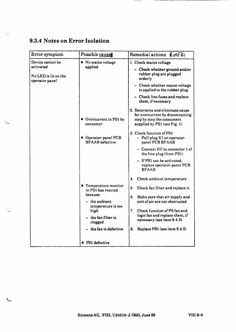
9.3.4 Notes on Error Isolation
Error symptom Possible causeß Remedial actions (li/tFß /
Device cannot be activated
No LED is lit on the operator panel
• No mains voltage applied
1. Check mains voltage- Check whether ground and/or
rubber plug are plugged orderly
- Check whether mains voltage is applied to the rubber plug
- Check line fuses and replace them, if necessary
• Overcurrent in PSl by consumer
2. Determine and eliminate cause for overcurrent by disconnecting step by step the consumers supplied by PSl (see Fig. 1)
• Operator-panel PCB BFAAB defective
3. Check function of PSl- Pull plug XI on operator-
panel PCB BFAAB
- Connect DV to connector 1 of the line plug (from P S l)
- If PSl can be activated, replace operator-panel PCB BFAAB
4. Check ambient temperature• Temperature monitor
in PSl has reacted because:- the ambient
temperature is too high
- the fan filter is clogged
5. Check fan Filter and replace it
6. Make sure that air supply and exit of air are not obstructed
7. Check function of PS fan and logic fan and replace them, if necessary (see item 9.4.3)
- the fan is defective 8. Replace PSl (see item 9.4.2)
• PSl defective
Siemens AG, 9783, U64510- J-7600, June 89 VIII.9-9
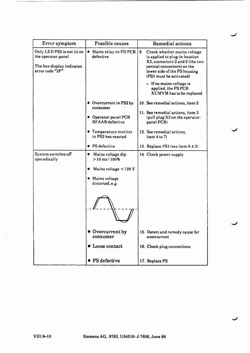
Error symptom Possible causes Remedial actionsOnly LED PS2 is not lit on the operator panel
The hex display indicates error code "3F"
• Mains relay on PD PCB defective
9. Check whether mains voltage is applied to plug-in location X3, connectors 2 and 5 (the two central connectors) on the lower side of the PS housing (PS1 must be activated)- If no mains voltage is
applied, the PS PCB XUMVM has to be replaced
• Overcurrent in PS2 by consumer
• Operator-panel PCB BFAAB defective
10. See remedial actions, item 2
11. See remedial actions, item 3 (pull plug X2 on the operator- panel PCB)
• Temperature monitor in PS2 has reacted
12. See remedial actions, item 4 to 7)
• PS defective 13. Replace PS1 (see item 9.4.2)
System switches off sporadically
• Mains voltage dip >10 m s/100%
14. Check power supply
• Mains voltage < 198 V
• Mains voltage distorted, e.g.
_A.........,
• Overcurrent by consumer
15. Detect and remedy cause for overcurrent
• Loose contact 16. Check plug connections
• PS defective 17. Replace PS
VIII.9-10 Siemens AG, 9783, U64510- J-7600, June 89
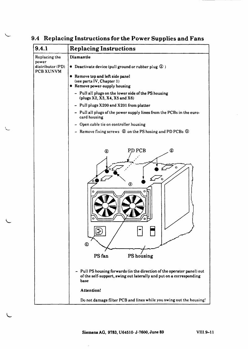
9.4 Replacing Instructions for the Power Supplies and Fans
\
9.4.1 Replacing InstructionsReplacing the powerdistributor (PD) PCBXUNVM
Dismantle
• Deactivate device (pull ground or rubber plug ® )
• Remove top and left side panel (see parts IV, Chapter 1)
• Remove power-supply housing- Pull all plugs on the lower side of the PS housing
(plugs X2, X3, X4, X5 and X6)- Pull plugs X200 and X201 from platter- Pull all plugs of the power supply lines from the PCBs in the euro
card housing- Open cable tie on controller housing- Remove fixing screws © on the PS hosing and PD PCBs ®
PS fan PS housing
- Pull PS housing forwards (in the direction of the operator panel) out of the self-support, swing out laterally and put on a corresponding base
Attention!
Do not damage filter PCB and lines while you swing out the housing!
Siemens AG, 9783, U64510- J-7600, June 89 VII1.9-11
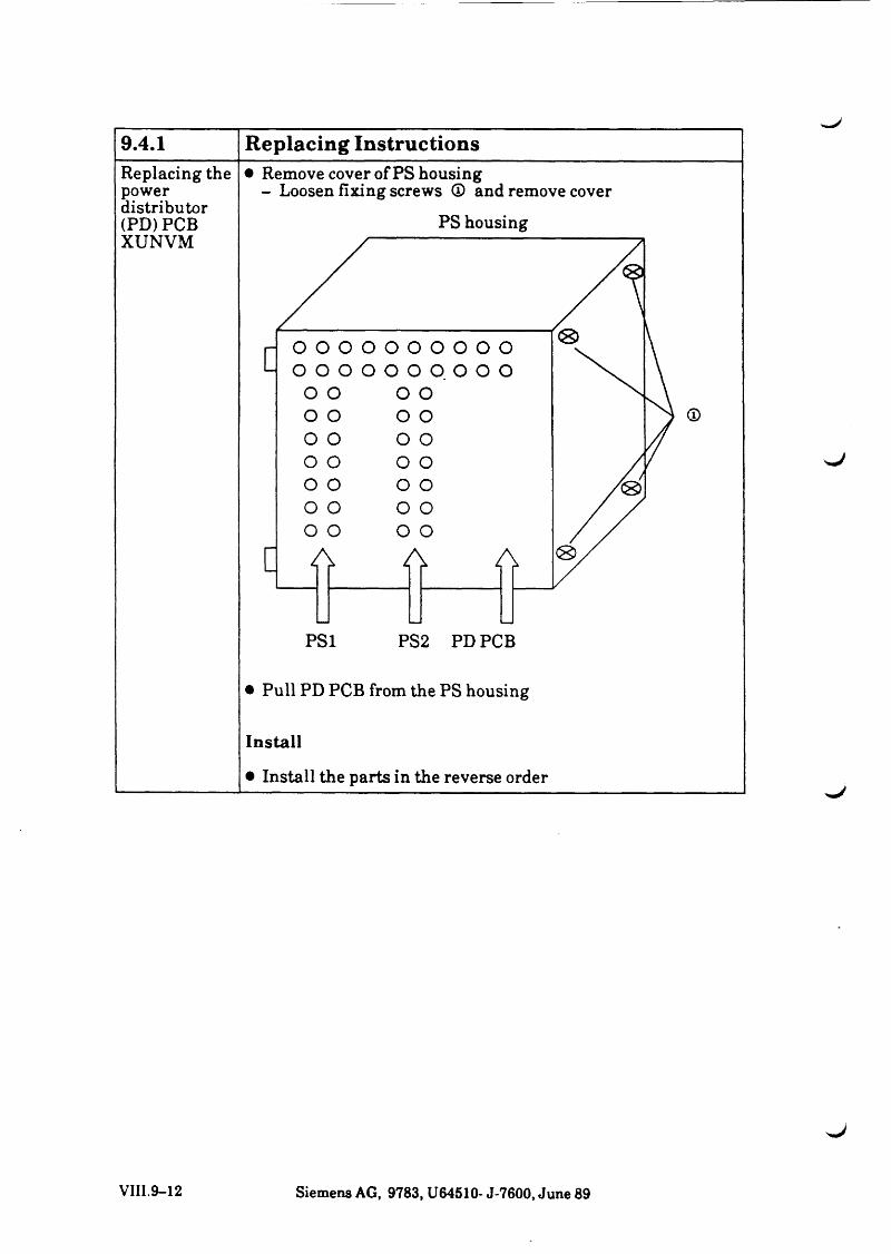
9.4.1 Replacing InstructionsReplacing the power distributor (PD) PCB XUNVM
• Remove cover of PS housing - Loosen fixing screws ® and remove cover
PS housing
©
• Pull PD PCB from the PS housing
In sta ll
• Install the parts in the reverse order>.J
VIII.9-12 Siemens AG, 9783, U64510- J-7600, June 89
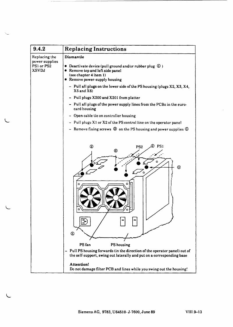
9.4.2 Replacing InstructionsReplacing the Dismantlepower suppliesPSl or PS2 • Deactivate device (pull ground and/or rubber plug ® )XSVDJ • Remove top and left side panel
(see chapter 4 item 1)• Remove power-supply housing
- Pull all plugs on the lower side of the PS housing (plugs X2, X3, X4, X5 and X6)
- Pull plugs X200 and X201 from platter- Pull all plugs of the power supply lines from the PCBs in the euro
card housing
- Open cable tie on controller housing- Pull plugs XI or X2 of the PS control line on the operator panel- Remove fixing screws ® on the PS housing and power supplies ®
PS fan PS housing- Pull PS housing forwards (in the direction of the operator panel) out of
the self-support, swing out laterally and put on a corresponding base
Attention!Do not damage filter PCB and lines while you swing out the housing!
Siemens AG, 9783, U64510- J-7600, June 89 VIII.9-13
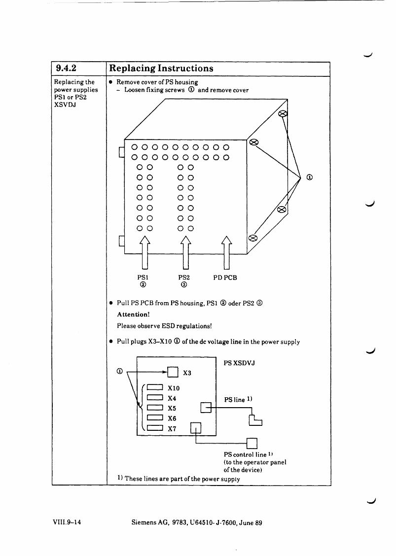
9.4.2 Replacing InstructionsReplacing the power supplies
• Remove cover of PS housing- Loosen fixing screws (D and remove cover
PS1or PS2 XSVDJ
©
• Pull PS PCB from PS housing, PSl @ oder PS2 ©Attention!
Please observe ESD regulations!
• Pull plugs X3-X10 © of the dc voltage line in the power supply
PS control line (to the operator panel of the device)
1) These lines are part of the power supply
^ J
VIII.9-14 Siemens AG, 9783, U64510- J-7600, June 89
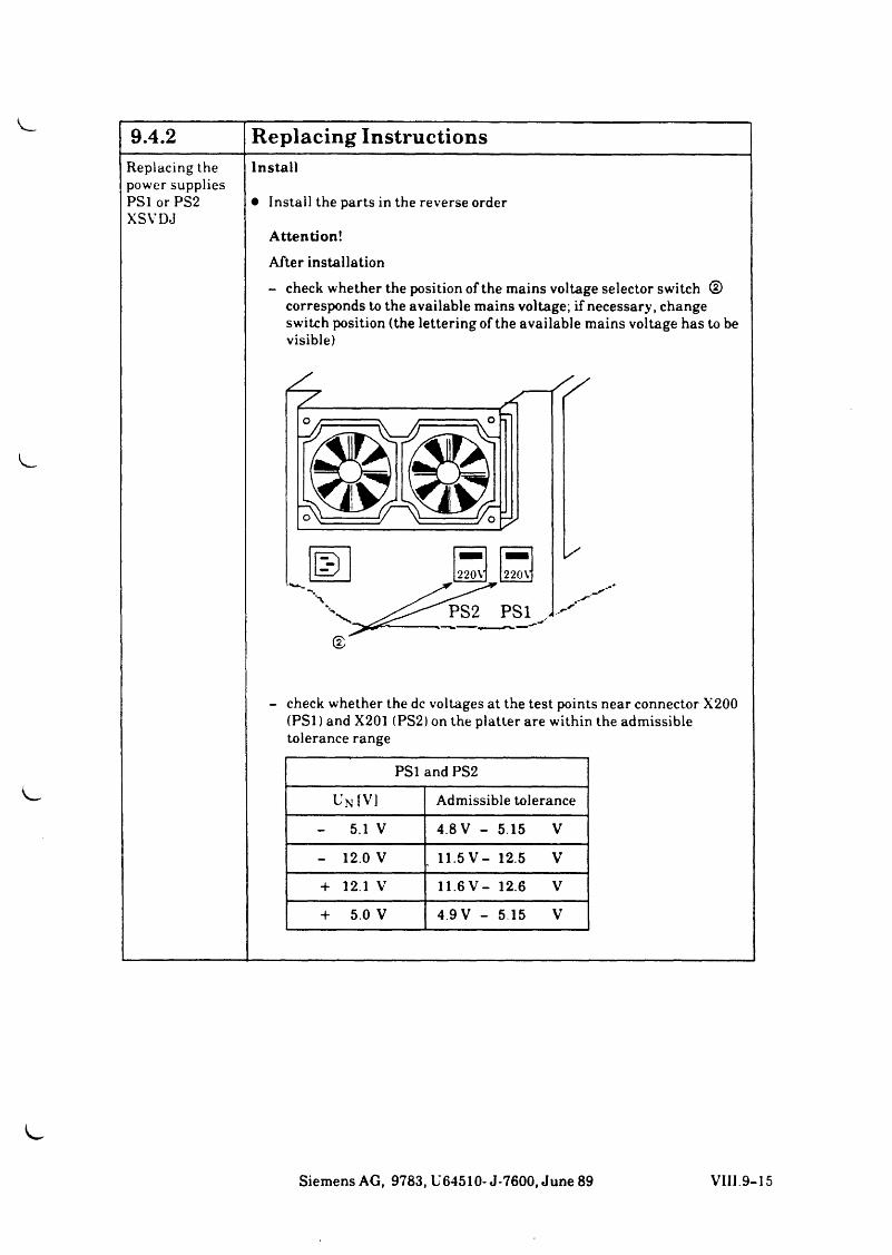
9.4.2 Replacing InstructionsReplacing the Installpower suppliesPS1 or PS2 XSVDJ
• Install the parts in the reverse order
Attention!After installation- check whether the position of the mains voltage selector switch ®
corresponds to the available mains voltage; if necessary, change switch position (the lettering of the available mains voltage has to be visible)
- check whether the dc voltages at the test points near connector X200 (PSl) and X201 (PS2) on the platter are within the admissible tolerance range
PSl and PS2
Un IV] Admissible tolerance
- 5.1 V 4.8 V - 5.15 V
- 12.0 V . 11.5V - 12.5 V
+ 12.1 V 11.6V - 12.6 V
+ 5.0 V 4.9 V - 5 15 V
Siemens AG, 9783, U64510- J-7600, June 89 VIII.9-15
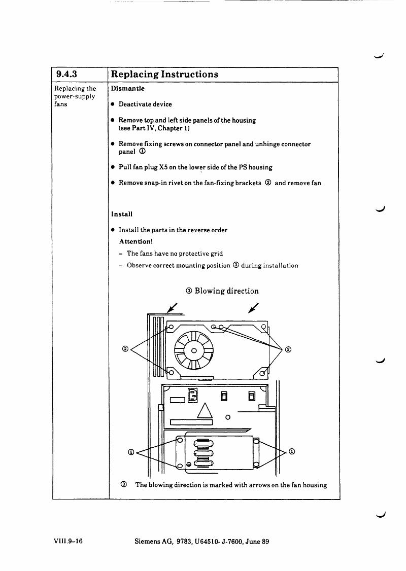
9.4.3 Replacing InstructionsReplacing the Dismantlepower-supplyfans • Deactivate device
• Remove top and left side panels of the housing (see Part IV, Chapter 1)
• Remove fixing screws on connector panel and unhinge connector panel ®
• Pull fan plug X5 on the lower side of the PS housing
• Remove snap-in rivet on the fan-fixing brackets CD and remove fan
Install
• Install the parts in the reverse order Attention!
- The fans have no protective grid- Observe correct mounting position CD during installation
® Blowing direction
X /
® The blowing direction is marked with arrows on the fan housing
>■J
VIII.9-16 Siemens AG, 9783, U64510- J-7600, June 89
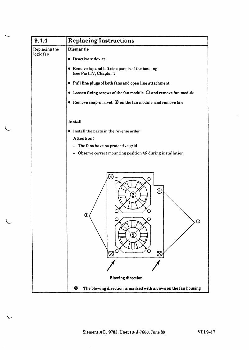
9.4.4 Replacing InstructionsReplacing the Dismantlelogic fan
• Deactivate device
• Remove top and left side panels of the housing (see Part IV, Chapter 1
• Pull line plugs of both fans and open line attachment
• Loosen fixing screws of the fan module © and remove fan module
• Remove snap-in rivet © on the fan module and remove fan
Install
• Install the parts in the reverse order Attention!
- The fans have no protective grid- Observe correct mounting position © during installation
Blowing direction
® The blowing direction is marked with arrows on the fan housing
Siemens AG, 9783, U64510- J-7600, June 89 VIII.9-17
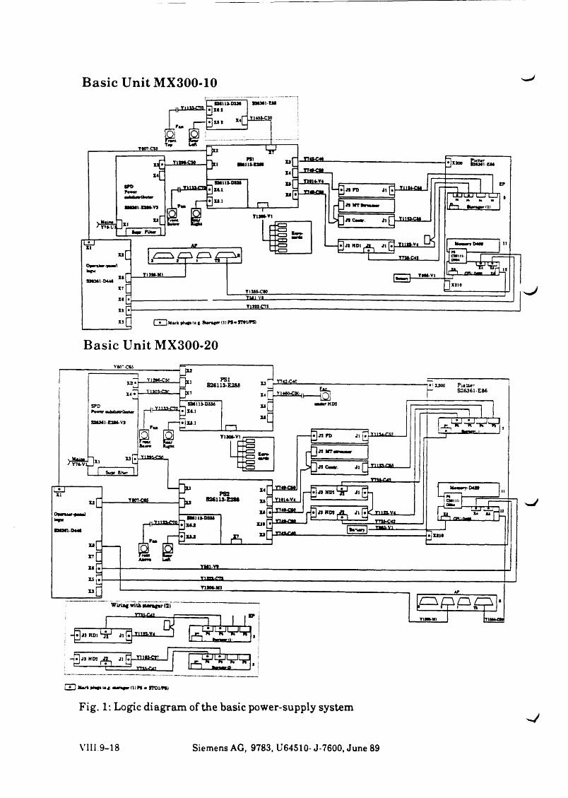
Basic Unit MX300-10
sJ
Basic Unit MX300-20
Fig. 1: Logic diagram of the basic power-supply system
VIII. 9 - 1 8 Siemens AG, 9783, U64510- J-7600, June 89
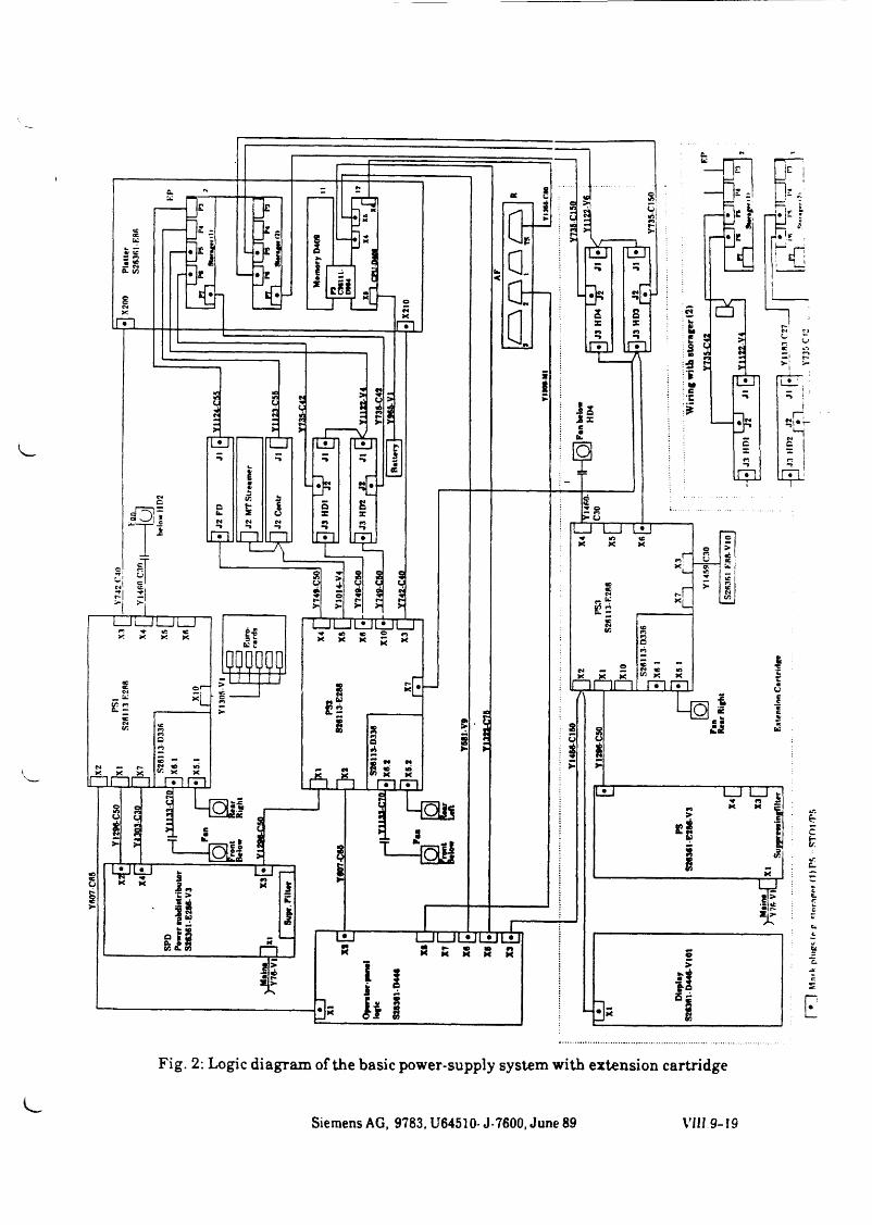
Fig. 2: Logic diagram of the basic power-supply system with extension cartridge
Siemens AG, 9783, U64510- J-7600, June 89 VIII 9-19
| • .1
Mnrk
plug
« (r p
«tni
-nror
(1) PS
~ ST
O|/P5
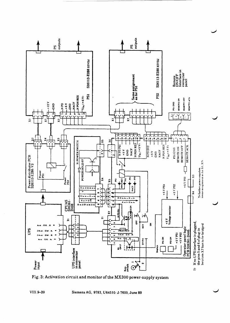
UPS
Po
wer
dis
tribu
tor P
CBS2
6113
-E28
6-V
3
Fig. 3: Activation circuit and monitor of the MX300 power-supply system
VIII.9-20 Siemens AG, 9783, U64510- J-7600, June 89
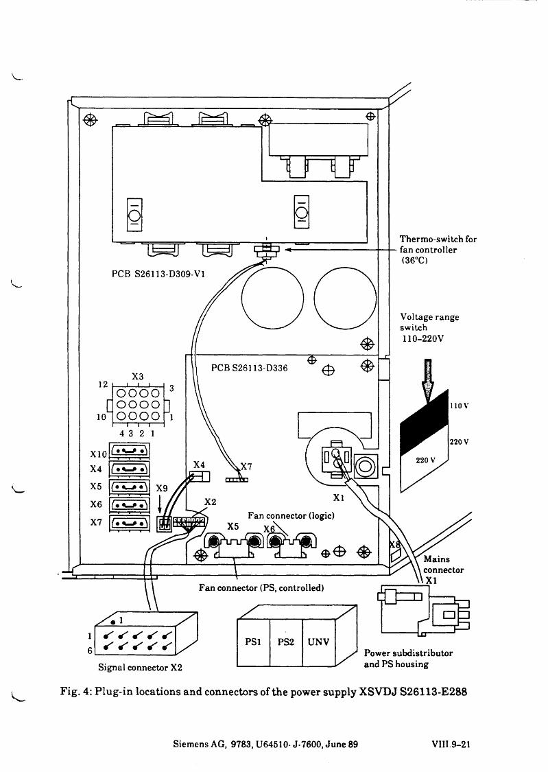
i
Siemens AG, 9783, U64510- J-7600, June 89 VIII 9-21
JML
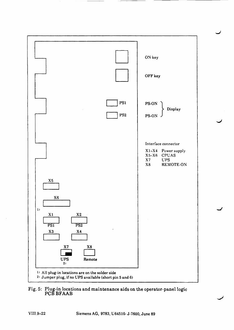
ON key
OFF key
PS1
PS2
PS-ON
PS-ONDisplay
Interface connector
X1-X4 Power supply X5-X6 CPUAS X7 UPSX8 REMOTE-ON
X2
PS2X4
X7 X8
UPS Remote2 )
1 > All plug-in locations are on the solder side 2> Jumper plug, if no UPS available (short pin 5 and 6)
Fig. 5: Plug-in locations and maintenance aids on the operator-panel logic PCB BFAAB
VIII.9-22 Siemens AG, 9783, U64510- J-7600, June 89
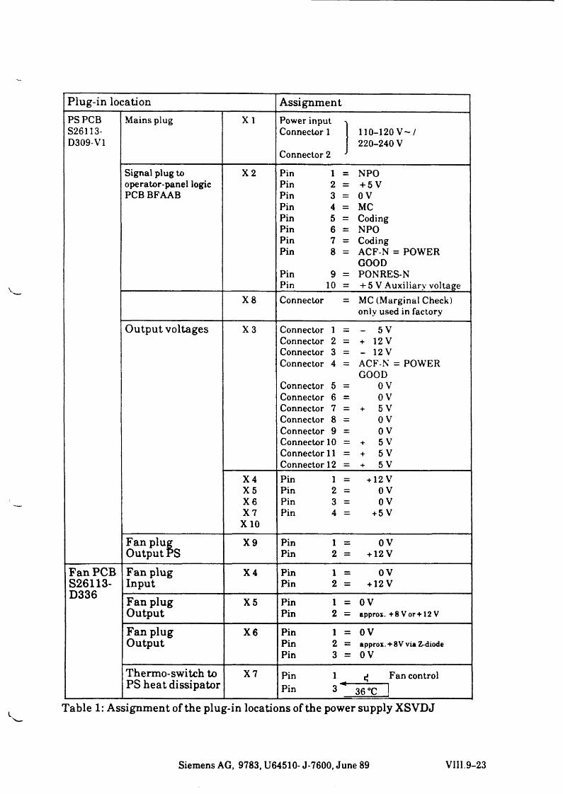
Plug-in location AssignmentPS PCB Mains plug X I Power input >S26113- Connector 1 110-120 V - /D309-V1 220-240 V
Connector 2 J
Signal plug to X 2 Pin 1 = NPOoperator-panel logic Pin 2 = + 5 VPCB BFAAB Pin 3 = OV
Pin 4 = MCPin 5 = CodingPin 6 = NPOPin 7 = CodingPin 8 = ACF-N = POWER
GOODPin 9 == PONRES-NPin 10 = -1- 5 V Auxiliary voltage
X 8 Connector == MC (Marginal Check)only used in factory
Output voltages X 3 Connector 1 == - 5 VConnector 2 == + 12VConnector 3 == - 12 VConnector 4 == ACF-N = POWER
GOODConnector 5 == OVConnector 6 == OVConnector 7 == + 5 VConnector 8 == 0 VConnector 9 == 0 VConnector 10 == + 5 VConnector 11 == + 5 VConnector 12 == + 5 V
X 4 Pin 1 == +12 VX 5 Pin 2 == OVX 6 Pin 3 == OVX 7 Pin 4 == +5 V
X 10
Fan plug X 9 Pin 1 == 0 VOutput PS Pin 2 == +12 V
Fan PCB Fan plug X 4 Pin 1 == OVS26113-D336
Input Pin 2 == +12 V
Fan plug X 5 Pin 1 == 0 VOutput Pin 2 == approx. + 8 V o r + 12V
Fan plug X 6 Pin 1 == OVOutput Pin 2 == approx. + 8 V via Z-diode
Pin 3 == OV
Thermo-switch to X 7 Pin 1 cf Fan controlPS heat dissipator Pin 3 36 °C
Table 1: Assignment of the plug-in locations of the power supply XSVDJ
Siemens AG, 9783, U64510- J-7600, June 89 VIII.9-23
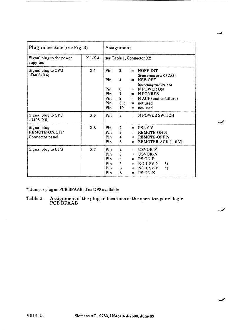
Plug-in location (see Fig. 3) Assignment
Signal plug to the power supplies
X1-X4 see Table 1, Connector X2
Signal plug to CPU -D408 (X4)
X 5 Pin 2 = NOFF-INT(from message to CPUAS)
Pin 4 = NSV-OFF(Switching via CPUAS)
Pin 6 = N POWER ONPin 7 = NPONRESPin . 8 = N ACF (mains failure)Pin 3,5 = not usedPin 10 = not used
Signal plug to CPU -D408 (X5)
X 6 Pin 3 = N POWER SWITCH
Signal plug REMOTE-ON/OFF Connector panel
X 8 Pin 2 = PS1-0VPin 3 = REMOTE-ON NPin 4 = REMOTE-OFF NPin 6 = REMOTER-ACK ( + 5 V)
Signal plug to UPS X 7 Pin 2 = USVOK-P Pin 3 = USVOK-N Pin 4 = PS-ON-P Pin 5 = NO-USV-N *) Pin 6 = NO-USV-P *) Pin 8 = PS-ON-N
*) Jumper plug on PCB BFAAB, if no UPS available
Table 2: Assignment of the plug-in locations of the operator-panel logic PCB BFAAB
VIII. 9-24 Siemens AG, 9783, U64510- J-7600, June 89
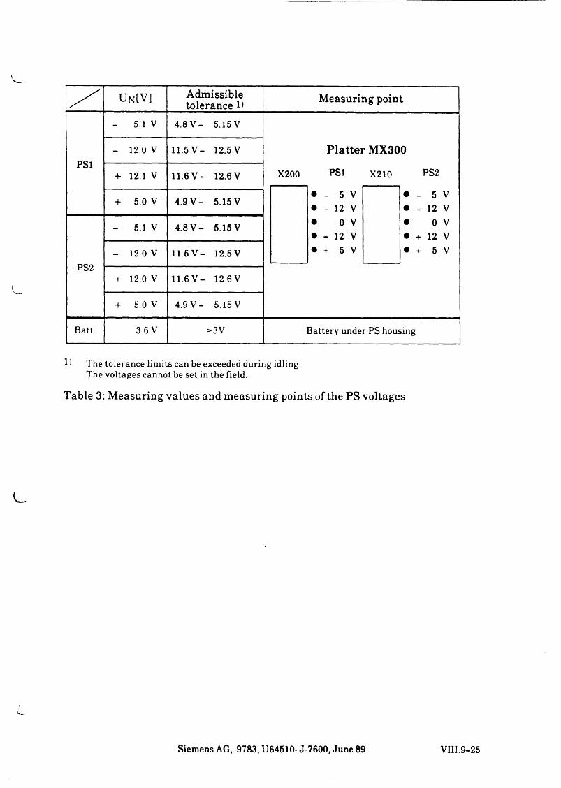
/ UN[V] Admissible tolerance D Measuring point
PS1
- 5.1 V 4 .8 V - 5.15V
Platter MX300- 12.0 V 11.5V - 12.5V
+ 12.1 V 11.6V - 12.6V X200 PS1
• - 5 V• - 12 V• 0 V• + 12 V• + 5 V
X210 PS2
• - 5 V• - 12 V• 0 V• + 12 V• + 5 V
+ 5.0 V 4 .9 V - 5.15V
PS2
- 5.1 V 4 .8 V - 5.15V
- 12.0 V 11.5V - 12.5V
+ 12.0 V 11.6V - 12.6V
+ 5.0 V 4.9 V - 5.15 V
Batt. 3.6 V >3V Battery under PS housing
1) The tolerance limits can be exceeded during idling.The voltages cannot be set in the field.
Table 3: Measuring values and measuring points of the PS voltages
Siemens AG, 9783, U64510- J-7600, June 89 VIII.9-25


c
c
o

s J
SIEMENS
Part IX Monitors

^J
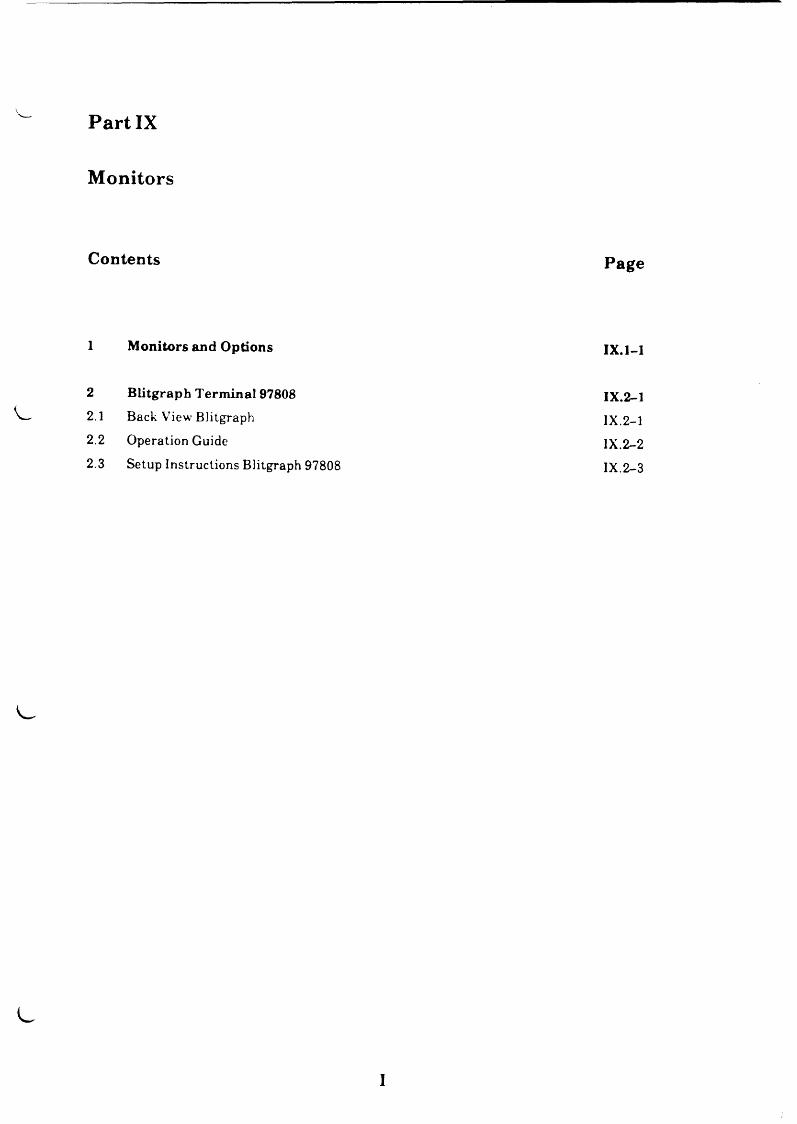
Part IX
Monitors
Contents Page
1 Monitors and Options IX.1-1
2 BLitgraph Term inal 97808 IX.2-1
2.1 Back View Blitgraph IX.2-1
2.2 Operation Guide IX.2-2
2.3 Setup Instructions Blitgraph 97808 IX.2-3
i

V
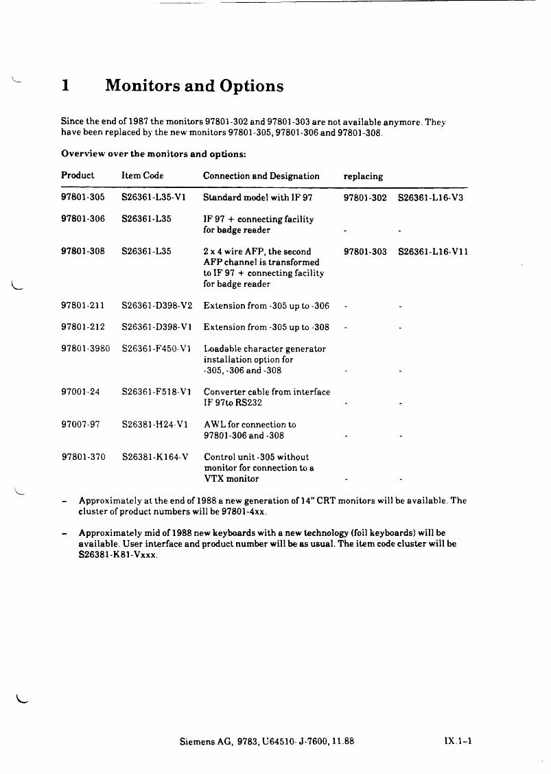
1 Monitors and Options
Since the end of 1987 the monitors 97801-302 and 97801-303 are not available anymore. They have been replaced by the new monitors 97801-305, 97801-306 and 97801-308.
Overview over the monitors and options:
Product Item Code Connection and Designation replacing
97801-305 S26361-L35-V1 Standard model with IF 97 97801-302 S26361-L16-V3
97801-306 S26361-L35 IF 97 + connecting facility for badge reader - -
97801-308 S26361-L35 2 x 4 wire AFP, the second AFP channel is transformed to IF 97 -1- connecting facility for badge reader
97801-303 S26361-L16-V11
97801-211 S26361-D398-V2 Extension from -305 up to -306 - -
97801-212 S26361-D398-V1 Extension from -305 up to -308 - -
97801-3980 S26361-F450-V1 Loadable character generator installation option for -305, -306 and -308
97001-24 S26361-F518-V1 Converter cable from interface IF 97to RS232 - -
97007-97 S26381-H24-V1 AWL for connection to 97801-306 and -308 - -
97801-370 S26381-K164-V Control unit -305 without monitor for connection to a VTX monitor
- Approximately at the end of 1988 a new generation of 14” CRT monitors will be available. The cluster of product numbers will be 97801-4xx.
- Approximately mid of 1988 new keyboards with a new technology (foil keyboards) will be available. User interface and product number will be as usual. The item code cluster will be S26381-K81-Vxxx.
Siemens AG, 9783, U64510- J-7600,11.88 IX. 1-1

^J

L .
L .

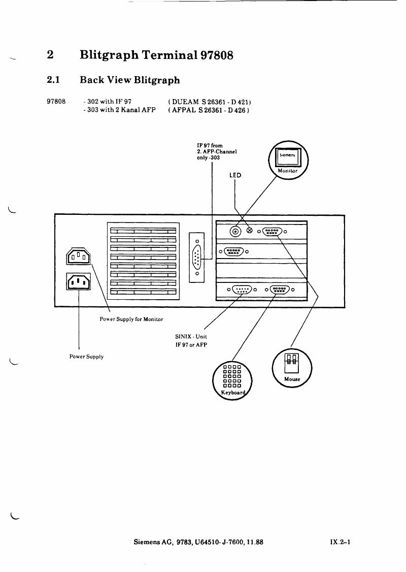
2 Blitgraph Terminal 978082.1 Back View Blitgraph
97808 -302 with IF 97 ( DUEAM S 26361 - D 421)- 303 with 2 Kanal AFP ( AFPAL S 26361 - D 426)
Siemens AG, 9783, U64510-J-7600,11.88 IX.2-1
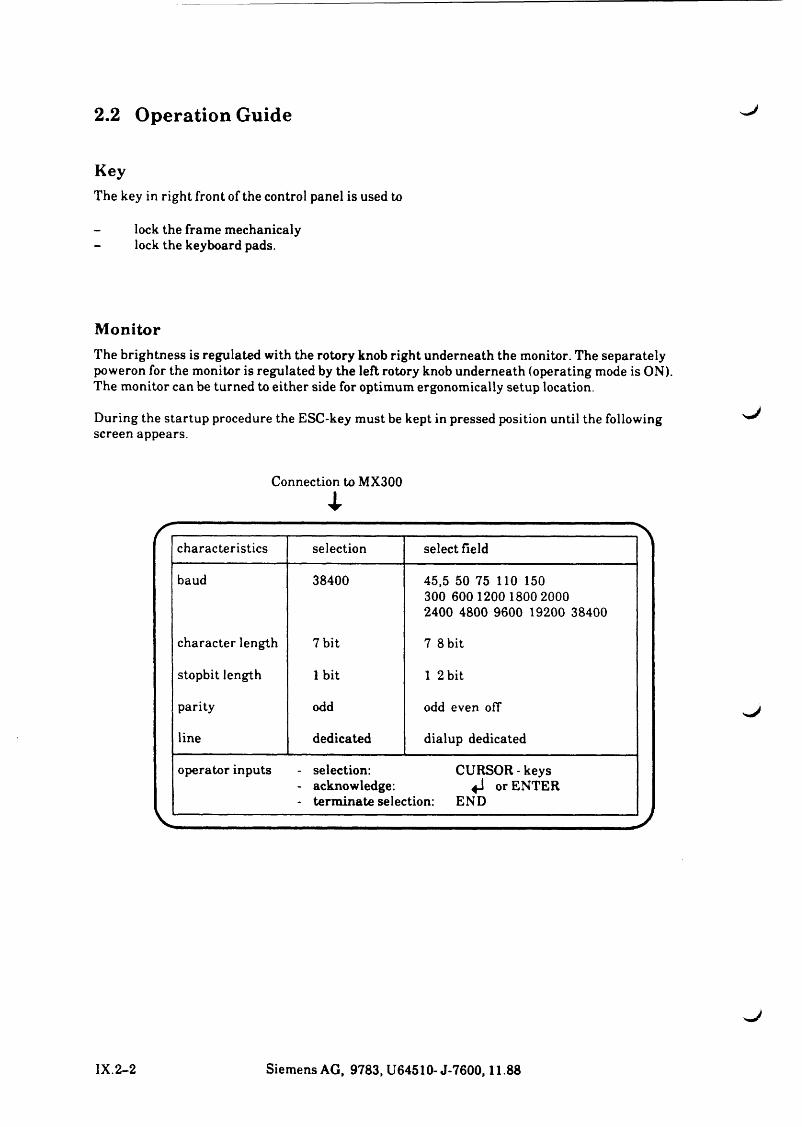
2.2 Operation Guide
KeyThe key in right front of the control panel is used to
lock the frame mechanicaly - lock the keyboard pads.
MonitorThe brightness is regulated with the rotory knob right underneath the monitor. The separately poweron for the monitor is regulated by the left rotory knob underneath (operating mode is ON). The monitor can be turned to either side for optimum ergonomically setup location.
During the startup procedure the ESC-key must be kept in pressed position until the following screen appears.
Connection to MX300
4
characteristics selection select field
baud 38400 45,5 50 75 110 150 300 600 1200 1800 2000 2400 4800 9600 19200 38400
character length 7 bit 7 8 bit
stopbit length 1 bit 1 2 bit
parity odd odd even off
line dedicated dialup dedicated
operator inputs - selection: CURSOR - keys- acknowledge: 4J or ENTER- terminate selection: END
„j
IX.2-2 Siemens AG, 9783, U64510- J-7600,11.88
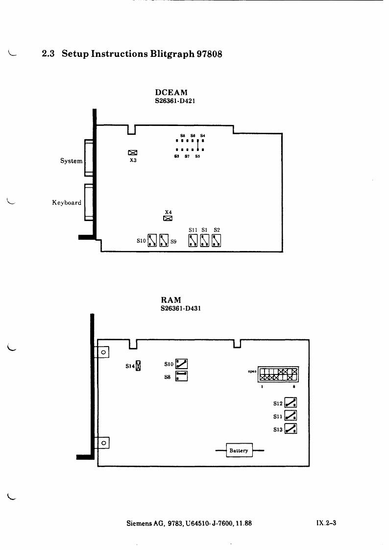
2.3 Setup Instructions Blitgraph 97808
DCEAMS26361-D421
RAMS26361-D431
O
512 Sil
513
Battery
Siemens AG, 9783, U64510- J-7600,11.88 IX.2-3
XX
X
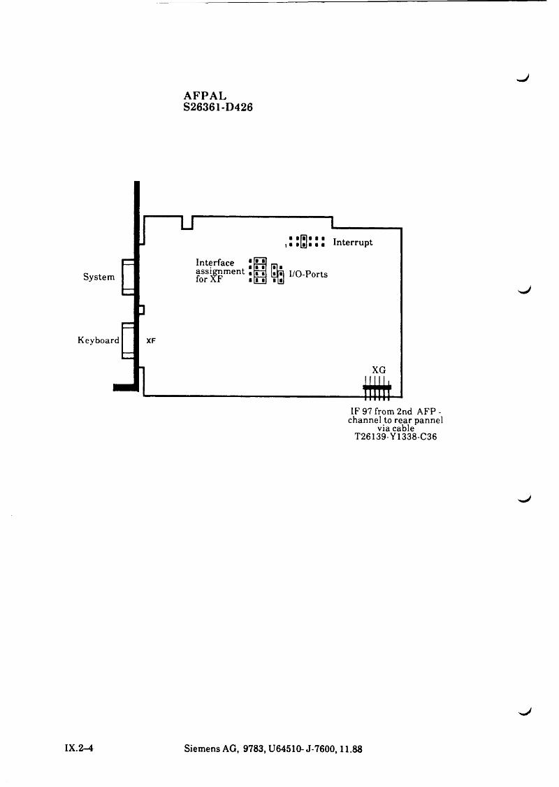
AFPALS26361-D426
uInterrupt
SystemInterface * H bi.?0sriF ment: h m I/O-Ports
3
Keyboard XF
Mi l l ,f f lW
IF 97 from 2nd AFP - channel to rear pannel
via cableT26139-Y1338-C36
IX.2-4 Siemens AG, 9783, U64510- J-7600,11.88
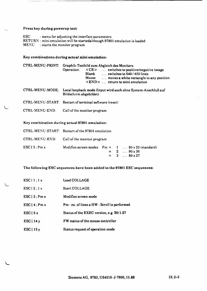
Press key during powerup test:
ESC : menu for adjusting the interface parametersRETURN : mini emulation will be startedalthough 97801 emulation is loadedMENU : starts the monitor program
Key combinations during actual mini emulation:
CTRL-MENU-PRINT: Graphik-Testbild zum Abgleich des Monitors Operation: <C R > . . . switches to positive/negative image
Blank . . . switches to 540 / 400 lines Mouse . . . moves a white rectangle to any position < END > . . . return to mini emulation
CTRL-MENU-MODE: Local loopback mode (Input wird auch ohne System-Anschluß auf Bildschirm abgebildet).
CTRL-MENU-START: Restart of terminal software (reset)
CTRL-MENU-END: Call of the monitor program
Key com bination d u ring actual 97801 em ulation:
CTRL-MENU-START: Restart of the 97801 emulation
CTRL-MENU-END: Call of the monitor program
ESC [ 3 ; Pm x Modifies screen modes Pm = 1 . . . 80 x 25 (standard)= 2 . . . 90 x 36= 3 . . . 80x27
The following ESC sequences have been added to the 97801 ESC sequences:
ESC[ 1 ; 1 x Load COLLAGE
ESC [2 ; 1 x Start COLLAGE
ESC l 3 ; Pm x Modifies screen mode
ESC [ 4 ; Pm x Pm - no. of lines a HW - Scroll is performed
ESC[5 x Status of the EXEC version, e.g. B 01.27
ESC[14 y FW status of the mouse controller
ESC [13 y Status request of operation mode
Siemens AG, 9783, U64510- J-7600,11.88 IX.
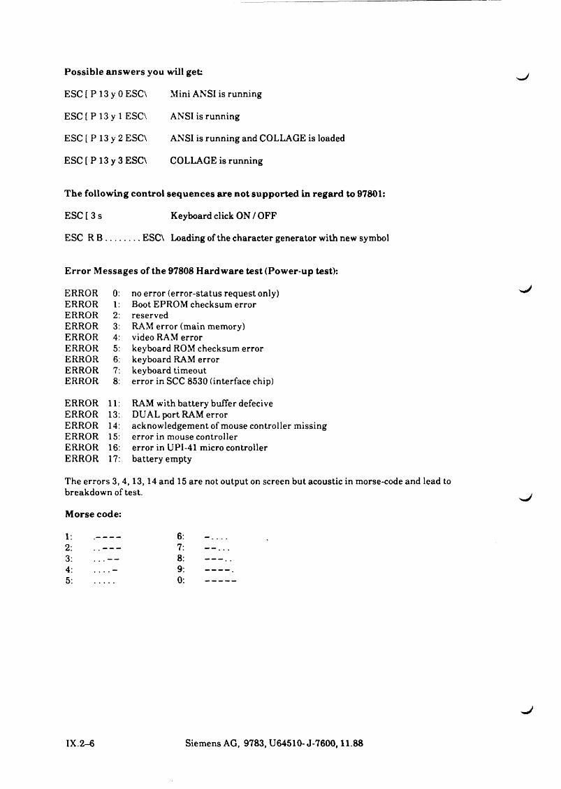
Possible answers you will get:
ESC [ P 13 y 0 ESC\ Mini ANSI is running
ESC [ P 13 y 1 ESC\ ANSI is running
ESC [ P 13 y 2 ESC\ ANSI is running and COLLAGE is loaded
ESC [ P 13 y 3 ESC\ COLLAGE is running
The following control sequences are not supported in regard to 97801:
ESC [ 3 s Keyboard click ON / OFF
ESC R B ..............ESC\ Loading of the character generator with new symbol
Error Messages of the 97808 Hardware test (Power-up test):
ERRORERRORERRORERRORERRORERRORERRORERRORERROR
0: no error (error-status request only) 1 : Boot EPROM checksum error 2: reserved3: RAM error (main memory)4: video RAM error5: keyboard ROM checksum error6: keyboard RAM error7: keyboard timeout8: error in SCC 8530 (interface chip)
ERROR 11ERROR 13ERROR 14ERROR 15ERROR 16ERROR 17
RAM with battery buffer defecive DUAL port RAM erroracknowledgement of mouse controller missing error in mouse controller error in UPI-41 micro controller battery empty
The errors 3, 4,13,14 and 15 are not output on screen but acoustic in morse-code and lead to breakdown of test.
Morse code:
12345
678 9 0
IX.2-6 Siemens AG, 9783, U64510- J-7600,11.88
SIEMENS Peripherals
Part X Peripherals

^ J
Part X
1. Peripherals
Contents Page
1 P eriphera ls X .l-11.1 P e r ip h e r a l s s u p p o r ted by th e S y s t e m X . l - 1
1 .2 P e r i p h e r a l s b y n o n - S ie m e n s M a n u fa c tu r e r s X . l - 1

1 PeripheralsThe number of available interfaces IF97 and V.24 for the direct connection of peripheral devices depends on the configuration stage (number of I/O processors) of the PC-MX300-10/-20/ -30. Siemens provides a special cable under the product no. 97001-24 for the conversion of an IF97 interface into a V.24 interface.The reverse conversion (V.24 to IF97) is only possible via non-Siemens products.
1.1 Peripherals supported by the System
It is possible to install video workstations and printers directly via AFP in the menu system of the admin identification under
system administration / configuration of the local system
The following units are supported:
the graphics terminal 97808,the 'common' terminals (97801-3xx, 97801-4xx),either with international or national keyboard,
as well as the Siemens printers 9001- 9001-b,9004,9012,9013,9022,9025,9047.
The above-mentioned printers are operated with the corresponding default setting This can be taken from the current maintenance pocket manual for printers.
1.2 Peripherals by non-Siemens ManufacturersPeripherals produced by non-Siemens manuafacturers have to be configured manually. You can obtain information on this topic from the responsible system service.
Siemens AG, 9783, U64510- J-7600,11.88 X 1-1

>.J
^J
X .l-2 Siemens AG, 9783, U64510-J-7600,11.88

L.
C
c
c

s J
SIEMENSInstallation of SINIX V5.2A
Startup and Shutdown of SINIX 5.2A
System Software in General
Part XISystem Software

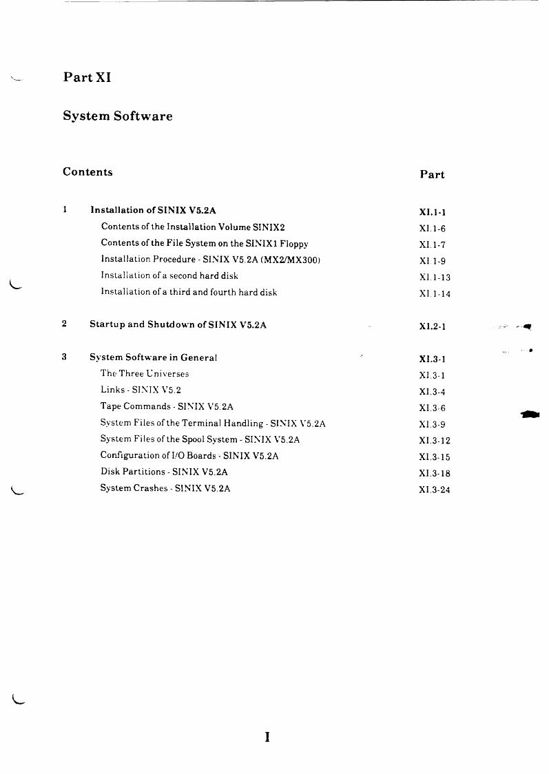
Part XI
System Software
Contents Part
1 Installation of SINIX V5.2A X I.1-1
C o n t e n t s o f t h e I n s t a l la t io n V o lu m e S I N I X 2 XI . 1-6
C o n t e n t s o f t h e F i l e S y s t e m on th e S I N I X 1 F lo p p y XI. 1-7
I n s ta l la t io n P r o c e d u r e - S I N I X V 5 .2 A ( M X 2 /M X 3 0 0 ) XI. 1-9
I n s t a l la t io n o f a se co n d h a rd d isk XI . 1-13
I n s t a l la t io n o f a th ir d a n d fo u r th h a rd d isk X I . 1-14
2 S ta rtu p and Shutdow n of SINIX V5.2A XI.2-1
3 System Softw are in G eneral XI.3-1
T h e T h r e e U n i v e r s e s XI. 3-1
L in k s - S I N I X V 5 . 2 X I .3 -4
T a p e C o m m a n d s - S I N I X V 5 .2 A X I .3 -6
S y s t e m F i l e s o f th e T e r m in a l H a n d l in g - S I N I X V 5 .2 A X I . 3-9
S y s t e m F i l e s o f th e S p o o l S y s t e m - S I N I X V 5 .2 A X I .3 -1 2
C o n f ig u r a t io n o f I/O B o a r d s - S I N I X V 5 .2 A X I .3 -1 5
D is k P a r t i t i o n s - S I N I X V 5 .2 A X I .3 -1 8
S y s t e m C r a s h e s - S I N I X V 5 .2 A X I . 3 -2 4
I
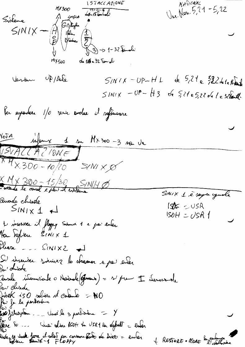
f i / io oI 5 7 » « »Zf £>*/£"
ti
6 / N I Y
N frilO W L
V W > ^ ' £ ' W
-O 1 - 3 1 % J L
cL. d $ fL S s ^ JL'
U jZ v^b i^ - ^ / /b j jL 5/// / / - op- /Vi b S/lifL tiJLuiStJ,$1MI)( " O P - / ^ 3 c 4 ^ M *-5,H pQ. / e 5*$bJ%-
fe*. e y & J u u ijo tyi/Uo b d jk iu iß qwul
y: /W j / i^ u J«
X 3 0 f y - / £ ? / & } 3 / / V 7 X ^ 0
2 r* Jle eOvryoft
4 c c'■ /H tH ( r i
SUajou^ cJL hidsL
^ I M l x ± f - i
5 aX $ * fM "/ ■*- A®*' 4 * 0 * ,
H * ~ S o jb itx . £ ( * ( / JC d _
5 > / ^ r jT ^
f s j t ^ o s / \
law /w /
ÖU*, &{ t\l l X <L J
Hb /S m /W L jL - jw J s iS k \G M eJ^
^OvSxHiL, - rf SAA- iUCfe Jc P
I W
LJ Q CT *■ ${) /*A (^0\kk^6 ✓"• ^ iOf^o Xc. yo^vlw ^—c(¾ ) ö s D v/
/OjJcAy*®**- , ÜxaäI J i . ^ ^ /
Vp - - . u*&5 ^ fw /^off *£k t Ki HW et^Mr -0uQ
iualLioHA x/^Ä>r /$*- Ikrtdb -- -£a3 X{ - t e P P y
>m0
4 ( ^ ° i e • K m c
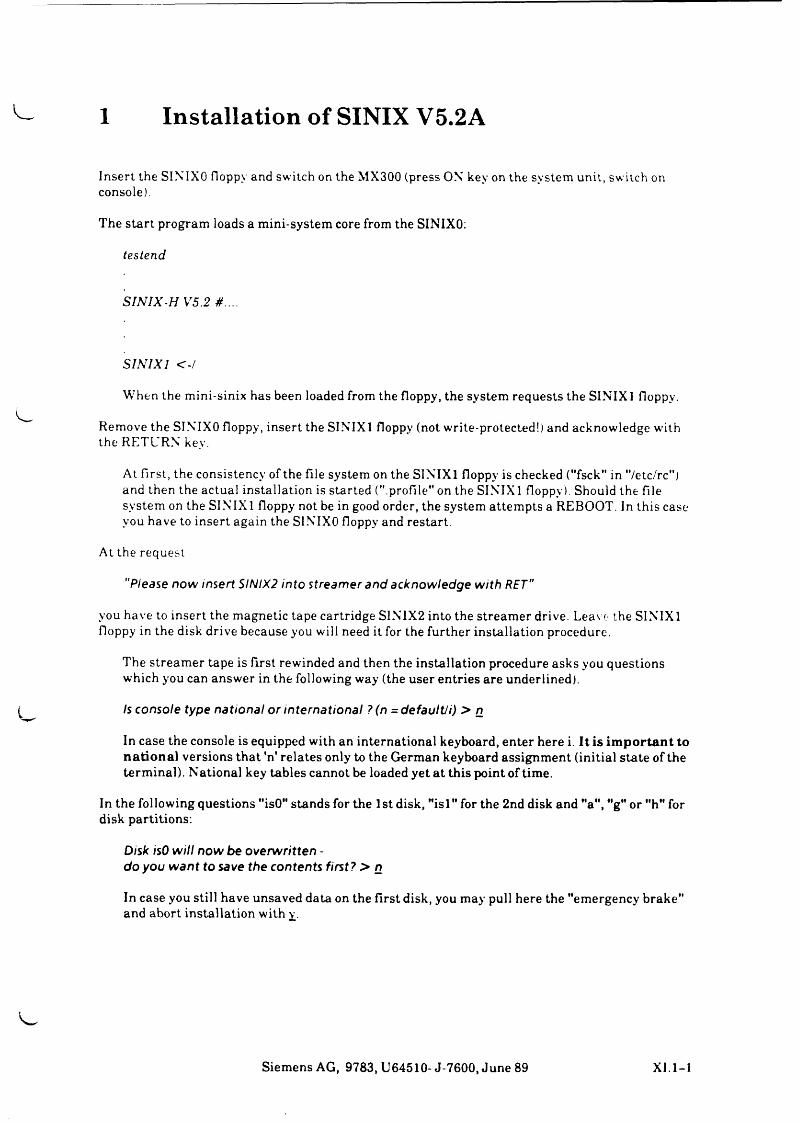
1 Installation of SINIX V5.2A
Insert the SINIXO floppy and switch on the MX300 (press ON key on the system unit, sw itch on console).
The start program loads a mini-system core from the SINIXO:
testend
S IN IX -H V 5..2 # . . . .
S1NIX1 < - /
When the mini-sinix has been loaded from the floppy, the system requests the SINIX 1 floppy.
Remove the SINIXO floppy, insert the SINIX1 floppy (not write-protected!) and acknowledge w’ith the RETURN key.
At first, the consistency of the file system on the SINIX1 floppy is checked ("fsck" in "/etc/rc") and then the actual installation is started (".profile" on the SINIX 1 floppy) Should the file system on the SINIX 1 floppy not be in good order, the system attempts a REBOOT. In this case you have to insert again the SINIXO floppy and restart.
At the request
"P lease n o w in se rt S IN IX2 in to s tre am e r a nd ac know led g e w ith R E T "
you have to insert the magnetic tape cartridge SINIX2 into the streamer drive. Leave the SINIX1 floppy in the disk drive because you will need it for the further installation procedure.
The streamer tape is first rewinded and then the installation procedure asks you questions which you can answer in the following way (the user entries are underlined).
Is conso le type n a t io n a l o r in te rn a t io n a l ? (n = d e fa u lt / i) > n
In case the console is equipped with an international keyboard, enter here i. It is important to national versions that 'n' relates only to the German keyboard assignment (initial state of the terminal). National key tables cannot be loaded yet at this point of time.
In the following questions "isO" stands for the 1st disk, Misl" for the 2nd disk and "a", "g" or "h" for disk partitions:
D isk isO w i l l n o w be o v e rw r it te n -d o y o u w a n t to save th e con ten ts f ir s t? > n
In case you still have unsaved data on the first disk, you may pull here the "emergency brake" and abort installation with y.
Siemens AG, 9783, U64510- J-7600, June 89 XI.1-1
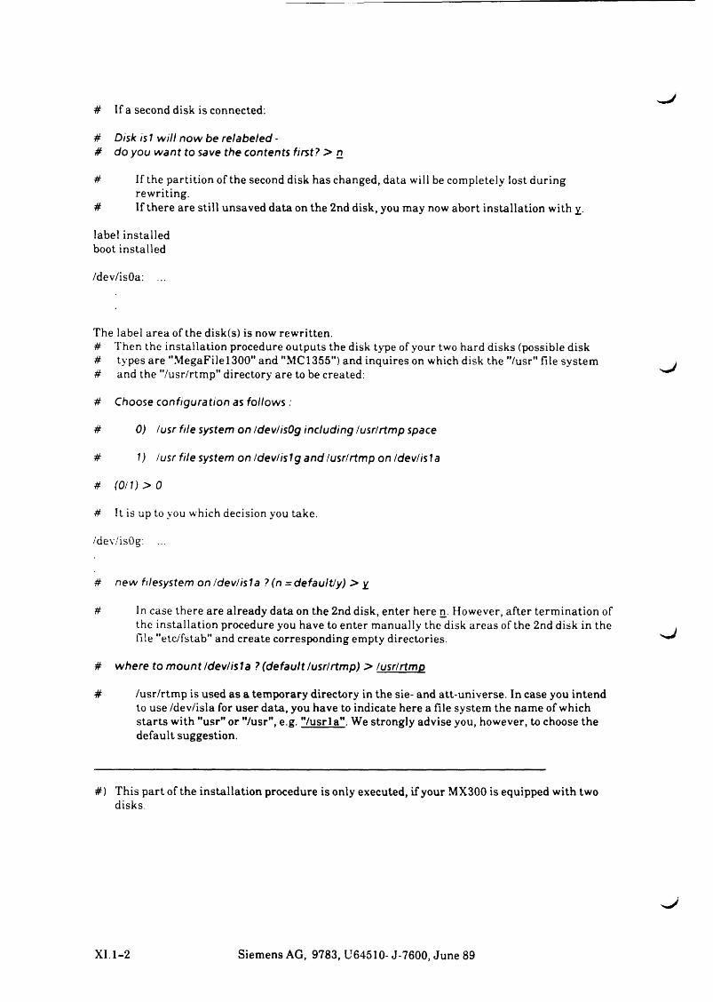
# If a second disk is connected:
# D isk is 1 w i l l n o w be re la b e led -# do y o u w a n t to save th e con ten ts f i r s t? > n
# If the partition of the second disk has changed, data will be completely lost during rewriting.
# If there are still unsaved data on the 2nd disk, you may now abort installation with y.
label installed boot installed
/dev/isOa: ...
The label area of the disk(s) is now rewritten.# Then the installation procedure outputs the disk type of your two hard disks (possible disk# types are "MegaFilel300" and "MC1355") and inquires on which disk the "/usr" file system# and the "/usr/rtmp" directory are to be created:
# Choose c o n f ig u ra t io n as fo llo w s :
# 0) /u s r f i le system on /dev /isO g in c lu d in g /u s r /r tm p space
# 1) /u s r f i le system on /dev/is1g a nd /u s r/r tm p on /d e v /is la
# ( 0/ 1) > 0# It is up to you which decision you take.
/dev/isOg:
# new filesystem on /dev/isla ?(n =default/y) > y
# In case there are already data on the 2nd disk, enter here n. However, after termination of the installation procedure you have to enter manually the disk areas of the 2nd disk in the file "etc/fstab" and create corresponding empty directories.
# w h e re to m o u n t /d e v / is la ? (d e fa u lt /u s r /r tm p ) > /u s r/r tm p
# /usr/rtmp is used as a temporary directory in the sie- and att-universe. In case you intend to use /dev/isla for user data, you have to indicate here a file system the name of which starts with "usr" or "/usr", e.g. "/usrla". We strongly advise you, however, to choose the default suggestion.
#) This part of the installation procedure is only executed, if your MX300 is equipped with twodisks.
XI.1-2 Siemens AG, 9783, U64510- J-7600, June 89
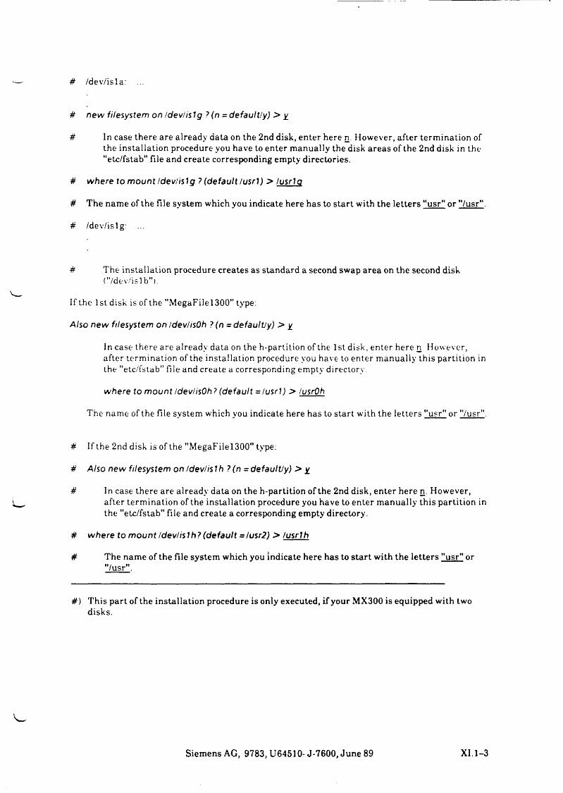
# /d e v / i s l a :
# n e w file sys tem on /d e v / is lg ? (n = d e fa u lt /y ) > y
# In c a s e t h e r e a re a lr e a d y d a ta on th e 2n d d isk , e n te r h ere n. H o w e v e r , a f te r t e r m in a t io n o f th e i n s t a l la t io n p ro ced u re y o u h a v e to e n te r m a n u a l ly th e d isk a r e a s o f th e 2 n d d isk in the "etc /fstab" f i le a n d c r e a te co r r e sp o n d in g e m p ty d ire c to r ie s .
# w h e re to m o u n t /d e v / is lg ? (d e fa u lt /u s r l) > /u s r la
i f T h e n a m e o f th e f i le s y s t e m w h ic h y o u in d ic a te h e r e h a s to s ta r t w ith th e l e t t e r s "usr" or " /usr" .
# /d e v / i s lg :
# T h e i n s t a l la t io n p ro ce d u re c r e a t e s a s s ta n d a r d a se co n d s w a p a r e a on t h e s e c o n d d isk("/dev/islb").
If th e 1s t d isk is o f th e " M e g a F i l e l3 0 0 " type:
A lso n e w file sys tem on /dev/isOh ? (n = d e fa u W y ) > y
In c a s e th e r e a re a lr e a d y d a ta on th e h -p a r t i t io n o f th e 1st d isk , e n te r h ere n. H o w e v e r , a f te r t e r m in a t io n o f th e in s t a l la t io n p ro ced u re you h a v e to e n te r m a n u a l ly t h i s p a r t i t io n in th e "etc /fstab" f i le an d c r e a te a co r r e sp o n d in g e m p ty d irec to ry
w h e re to m o u n t /dev/isOh? (d e fa u lt = /u s r l) > /usrOh
T h e n a m e o f th e f i le s y s t e m w h ich y o u in d ic a te h ere h a s to s ta r t w ith th e l e t t e r s "usr" or "/usr".
# If th e 2nd d isk is o f th e " M e g a F i l e l3 0 0 " type:
# A lso n e w file sys tem on /d e v /is !h ? (n = d e fa u lt /y ) > y
i f In c a s e t h e r e a re a lr e a d y d a ta on th e h -p a r t i t io n o f th e 2n d d isk , e n te r h e r e n. H o w e v e r ,a f te r t e r m in a t io n o f th e in s t a l la t io n p ro ce d u re y o u h a v e to e n te r m a n u a l ly th i s p a r t i t io n in th e "etc /fstab" f i le a n d c r e a te a c o r r e sp o n d in g e m p ty d irec to ry .
# w h e re to m o u n t /d e v / is lh ? (d e fa u lt - / usr2) > lu s r lh
i f T h e n a m e o f th e f i le s y s t e m w h ic h y o u in d ic a te h e r e h a s to s t a r t w ith t h e l e t t e r s "usr" or "/usr".
# ) T h i s p a r t o f th e i n s t a l la t io n p ro ced u re i s o n ly e x e c u te d , i f y o u r M X 3 0 0 is e q u ip p e d w ith tw od is k s .
Siemens AG, 9783, U64510- J-7600, June 89 XI.1-3
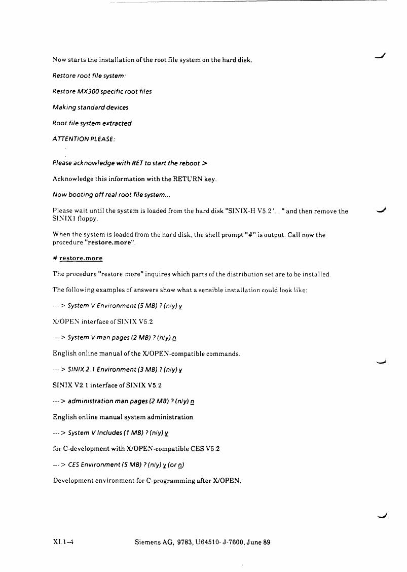
Now starts the installation of the root file system on the hard disk.
R es to re ro o t f i le sys tem :
Res to re M X 300 spec ific r o o t file s
M a k in g s tand a rd devices
R o o t f i le system e x tra c te d
A TTEN T IO N PLEASE:
P lease a c know led g e w ith RET to s ta r t th e re b o o t >
Acknowledge this information with the RETURN key.
N o w b o o t in g o f f re a l r o o t f i le system ...
Please wait until the system is loaded from the hard disk "SINIX-H V5.2 '... " and then remove the ^SIN1X1 floppy.
When the system is loaded from the hard disk, the shell prompt "#" is output. Call now the procedure "restore.more".
# restore.m ore
The procedure "restore, more" inquires which parts of the distribution set are to be installed.
The following examples of answers show what a sensible installation could look like:
- - - > System V E n v iro n m e n t (5 M B ) ?(n/y)y_
X/OPEN interface of SINIX V5.2
— > System V m an pages (2 M B ) ? (n /y ) n
English online manual of the X/OPEN-compatible commands.
— > S IN IX 2.1 E n v iro n m e n t (3 M B) ? (n /y ) y
SINIX V2.1 interface of SINIX V5.2
— > a d m in is t ra t io n m an pages (2 M B ) ? (n /y ) n
English online manual system administration
--- > System V Inc ludes (1 M B ) ? ( n ly ) y
for C-development with X/OPEN-compatible CES V5.2
— > CES E n v iro n m e n t (5 M B ) ? (n /y ) y ( o r n)
Development environment for C-programming after X/OPEN.
XI.1-4 Siemens AG, 9783, U64510- J-7600, June 89
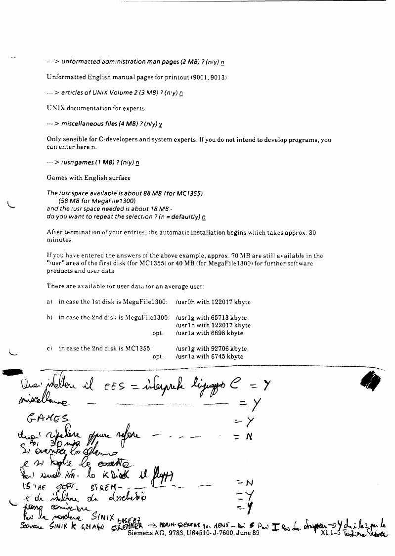
--- > u n fo rm a tte d a d m in is tra t io n m an pages (2 M B) ? (n /y ) n
U n f o r m a t t e d E n g l i s h m a n u a l p a g e s for p r in to u t ( 9 0 0 1 ,9 0 1 3 )
— > a rtic le s o f UN IX V o lum e 2 (3 M B) ? (n /y) n
U N I X d o c u m e n t a t io n for e x p e r t s
--- > m isce lla neous file s (4 M B ) ? (n /y ) y
O n ly s e n s i b l e for C -d e v e lo p e r s an d s y s t e m ex p e r ts . If y o u do not in te n d to d e v e lo p p r o g r a m s , y o u ca n e n t e r h e r e n.
- - > / us r/g am es(1 M B ) ? (n /y )n
G a m e s w ith E n g l i s h su r fa ce
The /u s r space a va ila b le is a b o u t 88 M B ( fo r M C I355)(58 M B fo r M egaF ile1300 )
and th e /u s r space needed is a b o u t 18 MB - do yo u w a n t to re p ea t the se lec tion ? (n = d e fa u lt /y ) n
A fte r t e r m in a t io n o f y o u r e n t r ie s , th e a u to m a t i c in s t a l la t io n b e g in s w h ich t a k e s ap prox . 30 m in u t e s .
If y o u h a v e e n te r e d th e a n s w e r s o f th e a b o v e e x a m p le , ap prox . 7 0 M B a re s t i l l a v a i la b le in the "/usr" a r e a o f th e f ir s t d isk (for M C 1 3 5 5 ) or 4 0 M B (for M e g a F i l e l 3 0 0 ) for fu r th e r s o f tw a r e p r o d u c ts an d u se r d ata
T h e r e a re a v a i la b le for u se r d a ta for an a v e r a g e user:
a) in c a s e th e 1 st d isk is M e g a F i l e l 3 0 0 : /usrOh w ith 1 2 2 0 1 7 k b y te
b) in c a s e th e 2n d d isk is M e g a F i l e l 3 0 0 : / u s r l g w ith 6 5 7 1 3 k b y te/ u s r l h w-ith 1 2 2 0 1 7 k b y te
opt. / u s r l a w ith 6 6 9 8 k b y te
c) in c a s e th e 2n d d isk is M C 1355: / u s r l g w ith 9 2 7 0 6 k b y teopt. / u s r l a w ith 6 7 4 5 k b y te
C t 5
------------------------ — - /
H.
AÜ • io K d- jM f)JLV 'vs - w n .e n -
gU «C»
$ ( N l {
* S i e m e n s A G , 9 7 8 3 , U 6 4 5 1 0 - J - 7 6 0 0 , J u n e 8 9 * ^ 1 . 1 - 5 ¾ ^ ¾ ^
N
. y
- r
*
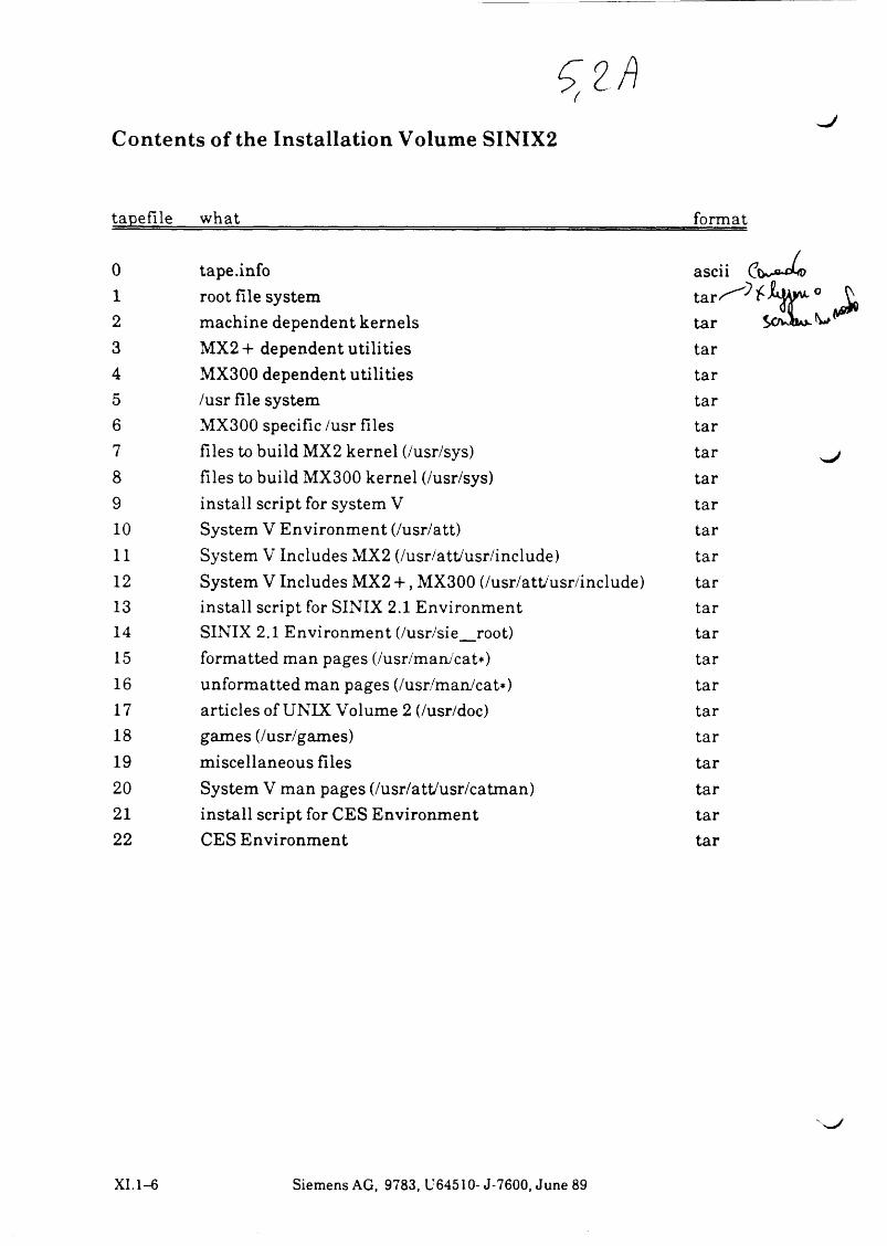
(
Contents of the Installation Volume SINIX2
tapefile what format
0 tape.info ascii (j1 root file system t a r J ,2 machine dependent kernels tar S3 MX2 + dependent utilities tar4 MX300 dependent utilities tar5 /usr file system tar6 MX300 specific /usr files tar7 files to build MX2 kernel (/usr/sys) tar8 files to build MX300 kernel (/usr/sys) tar9 install script for system V tar10 System V Environment (/usr/att) tar11 System V Includes MX2 (/usr/attAisr/include) tar12 System V Includes MX2 +, MX300 (/usr/att/usr/include) tar13 install script for SINIX 2.1 Environment tar14 SINIX 2.1 Environment (/usr/sie_root) tar15 formatted man pages (/usr/man/cat*) tar16 unformatted man pages (/usr/man/cat*) tar17 articles of UNIX Volume 2 (/usr/doc) tar18 games (/usr/games) tar19 miscellaneous files tar20 System V man pages (/usr/att/usr/catman) tar21 install script for CES Environment tar22 CES Environment tar
XI. 1 - 6 S i e m e n s A G , 9 7 8 3 , U 6 4 5 1 0 - J - 7 6 0 0 , J u n e 89
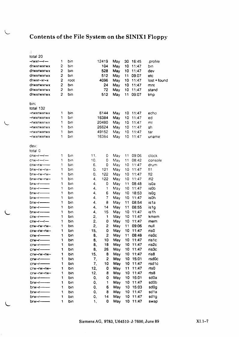
Contents of the File System on the SINIX 1 Floppy
total 20-rwxr—r— 1 bin 12419 May 30 16:45 .profiledrwxrwxrwx 2 bin 104 May 10 11:47 bindrwxrwxrwx 2 bin 528 May 10 11:47 devdrwxrwxrwx 2 bin 512 May 11 09:07 etcdrwxr-xr-x 2 root 4096 May 10 11:47 lost ♦ founddrwxrwxrwx 2 bin 24 May 10 11:47 mntdrwxrwxrwx 2 bin 72 May 10 11:47 standdrwxrwxrwx 2 bin 512 May 11 09:07 tmp
bin:total 132-rwxrwxrwx 1 bin 6144 May 10 11:47 echo-rwxrwxrwx 1 bin 16384 May 10 11:47 ed-rwxrwxrwx 1 bin 20480 May 10 11:47 mt-rwxrwxrwx 1 bin 26624 May 10 11:47 sh-rwxrwxrwx 1 bin 49152 May 10 11:47 tar-rwxrwxrwx 1 bin 16384 May 10 11:47 uname
dev:total 0crw-r—r— 1 bin 11. 0 May 11 09:06 clockcrw-r—r— 1 bin 10, 0 May 11 08:42 consolecrw-r w------ 1 bin 6, 0 May 10 11:47 drumbrw-rw-rw- 1 bin 0. 121 May 10 11:47 fl1brw-rw-rw- 1 bin 0, 122 May 10 11:47 fl2brw-rw-rw- 1 bin 4. 122 May 10 11:47 if!2brw-r------- 1 bin 4, 0 May 11 08:48 isOabrw-r------- 1 bin 4, 1 May 10 11:47 isObbrw-r------- 1 bin 4, 6 May 10 18:53 isOgbrw-r------- 1 bin 4, 7 May 10 11:47 isOhbrw-r------- 1 bin 4, 8 May 11 08:54 is1abrw-r------- 1 bin 4, 14 May 11 08:55 islgbrw-r------- 1 bin 4, 15 May 10 11:47 is1hcrw-r-------- 1 bin 2, 1 May 10 11:47 kmemcrw-r—r— 1 bin 2, 0 May 10 11:47 memcrw-rw-rw- 1 bin 2, 2 May 11 09:06 nullcrw-rw-rw- 1 bin 15, 0 May 10 11:47 risOcrw-r-------- 1 bin 8, 2 May 11 08:48 risOccrw-r-------- 1 bin 8, 10 May 10 11:47 rislccrw-r-------- 1 bin 8, 18 May 10 11:47 ris2ccrw-r-------- 1 bin 8, 26 May 10 11:47 ris3ccrw-rw-rw- 1 bin 15, 8 May 10 11:47 ris8crw-r-------- 1 bin 7, 2 May 10 15:01 rsdOccrw-r-------- 1 bin 7, 10 May 10 11:47 rsdlccrw-rw-rw- 1 bin 12, 0 May 11 11:47 rtsOcrw-rw-rw- 1 bin 12, 8 May 10 11:47 rts8brw-r------- 1 bin 0, 0 May 10 15:01 sdOabrw-r------- 1 bin 0, 1 May 10 11:47 sdObbrw-r------- 1 bin 0, 6 May 10 15:03 sdOgbrw-r------- 1 bin 0, 8 May 10 11:47 sdlabrw-r------- 1 bin 0, 14 May 10 11:47 sdlgbrw-r------- 1 bin 1, 0 May 10 11:47 swap
Siemens AG, 9783, U64510- J-7600, June 89 XI.1-7
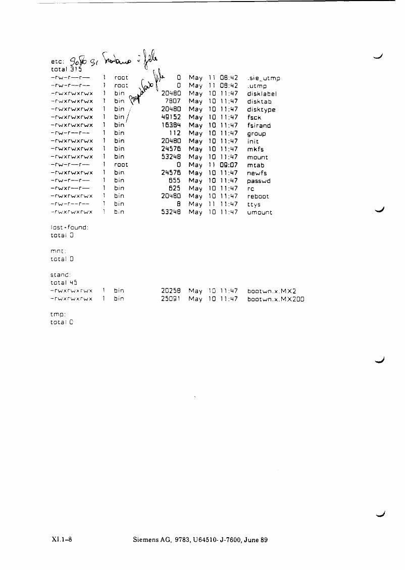
e tc : <2, (
tota l 31 5 - r w - r — r— - r w - r — r— - r w x r w x r w x - r w x r w x r w x - r w x r w x r w x - r w x r w x r w x - r w x r w x r w x - r w - r — r— - r w x r w x r w x - r w x r w x r w x - r w x r w x r w x - r w - r — r— - r w x r w x r w x - r w - r — r— - r w x r — r— - r w x r w x r w x - r w - r — r— - r w x r w x r w x
lost---found: t o t a l 0
m n t : t o t a l G
s t a n d : t o t a l 45 - r w x r w x r w x - r w x r w x r w x
t m p : t o t a l 0
X I . 1 - 8
C vW O u tP
1 root
> > 1
)]*- 0 May 11 08:42 .sie_utmp1 root , 0 May 1 1 08:42 .utmp1 bin a* 1 20480 May 10 1 1:47 disk I a be I1 bin ^ 7807 May 10 1 1:47 disktab1 bin / 2Q480 May 10 11:47 disktype1 bin / 49152 May 10 1 1:47 fsck1 bin 16384 May 10 11:47 fsirand1 bin 112 May 10 11:47 group1 bin 2048G May 10 11:47 init1 bin 24576 May 10 11:47 mkfs1 bin 53248 May 10 1 1:47 mount1 root 0 May 11 09:07 mtab1 bin 24576 May 10 11:47 newfs1 bin 655 May 10 1 1:47 passwd1 bin 625 May 10 11:47 re1 bin 20480 May 10 1 1:47 reboot1 bin 8 May 1 1 1 1:47 t tys1 bin 53248 May 10 1 1:47 umount ^J
1 bin 1 bin
2025B May 1G 11:47 25091 May 10 11:47
b o o tw n .x .M X2b o o tw n .x .M X 2 00
^J
S ie m e n s A G , 9 7 8 3 , U 6 4 5 1 0 - J -7 6 0 0 , J u n e 89
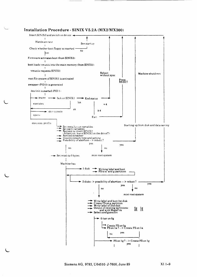
Installation Procedure - SINIX V5.2A (MX2/MX300)Insert SINIXO and switch on device
IHardware test
lCheck v. hether boot floppy is inserted
tSee startup
|>'es
Firmware activates boot (from SINIXO)I
boot loads vmunix into the main memory (from SINIXO i (
vmunix requests SINIXl1
root file system of SINIXl is activatedi
swapper (PID 0) is generated I
/etc/init is started (PID 1 >
Reboot without sync
/etc/rc fsck on SINIXl
executes !okEnd status
PressRESET
/dev/consoleok
opens
= 4
S 4
Exit
executes .profile
Machine shutdown
Set installation variablesSet path variablesRequest to insert SINTX2(Attention: leave SINIXl in the drive!!!>Rewind streamerInquire console type and settingPossibility of abortion -- > reboot ?
yes
Starting up from disk and data saving
v—► Set mtab to 0 bytes mini-root system
Machine has
-------------- ► 1 disk Writing label and boot FS to a- and g-partition
2 disks - > possibility of abortion — > reboot ?yes I yes
mini-root system
—► Write label and boot 1st disk —► Create FS on a-partition —► Write label of 2nd disk —► Output of existing partitions: Og lg
and with MegaFile Oh In—► Select configuration
0/usr on Og
bCreate FS on OgFS on 1 a ? - > Create FS on 1 a
L yes
FS on 1 g ? - > Create FS on 1 g
I yes
Siemens AG, 9783, U64510- J-7600, June 89 XI 1-9
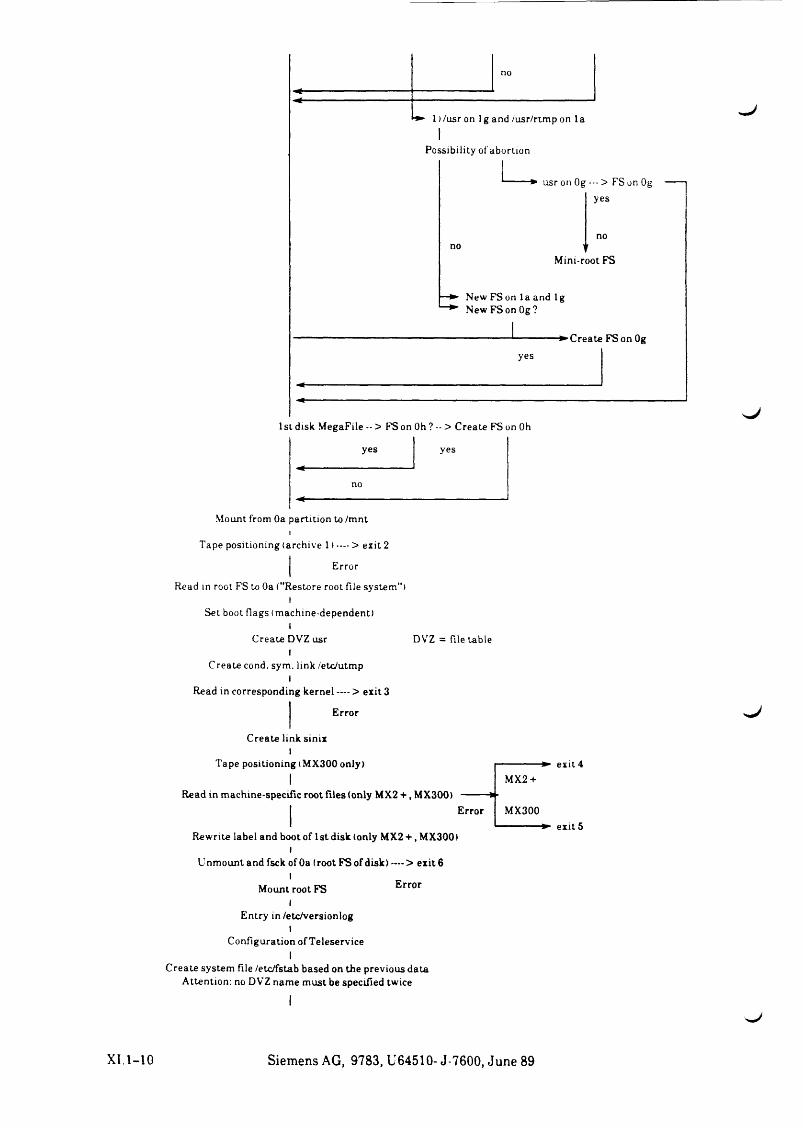
yes
no
yes
Mount from Oa partition to /mnti
Tape positioning (archive 1) — > exit 2
j Error
Read in root FS to Oa ("Restore root file system")
Set boot flags (machine-dependent)I
Create DVZ usr DVZ = file tableI
Create cond. sym. link /etc/utmp I
Read in corresponding kernel —- > exit 3
Error
Create link sinix I
Tape positioning (MX300 only)I
Read in machine-specific root files (only MX2 + , MX300)Error
exit 4MX2 +
MX300
Rewrite label and boot of 1 st disk (only MX2 + , MX300) I
Unmount and fsck of Oa (root FS of disk) — > exit 6 I
Mount root FS I
Entry in/etc/versionlog I
Configuration of Teleservice
-► exit 5
Error
Create system file /etc/fstab based on the previous data Attention: no DVZ name must be specified twice
XI.1-10 Siemens AG, 9783, U64510- J-7600, June 89
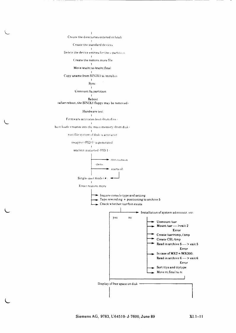
Create the directories entered in fstab I
Create the s tandard devices I
Delete the device entries for the (.-partition 1
Create the restore.more file 1
Move /etc/rc to /etc/rc.final l
Copy uname from SINIX 1 to/mnt/bin I
SyncI
Unm ount Oa parti t ion I
Reboot(after reboot, the SINIX1 floppy may be removed »
IH ardw are test
IFirm ware a c tu ates boot (from disk i
Iboot loads vmunix into the main memory (from disk i
lroot fiie system of disk is activated
iswapper (PID 0 1 is generated
I/etc/imt is sta rted 'PID 1 i
opens
Single-user mode ( #I
E nte r restore.more
— Inqui re console type and setting---- Tape rew inding + positioning to archive 5---- Check whether /usr /b in exists
/ae\ /consult
s ta r ts sh
yes
Insta lla tion of system adm im str . en\
— ► Unmount /usr — Mount /usr -—> exit 2
ErrorCreate/usr/rtmp,/.tmp
^ Create CSL/tmp ^ Read in archive 5 - - - > exit 5
Error— In case of MX2+ /MX300:
Read in archive 6 — > exit 6 Error
— Sort ttys and ttytype __Move rc.final to rt
Display of free space on disk
Siemens AG, 9783, U64510- J-7600, June 89 XI. 1-11
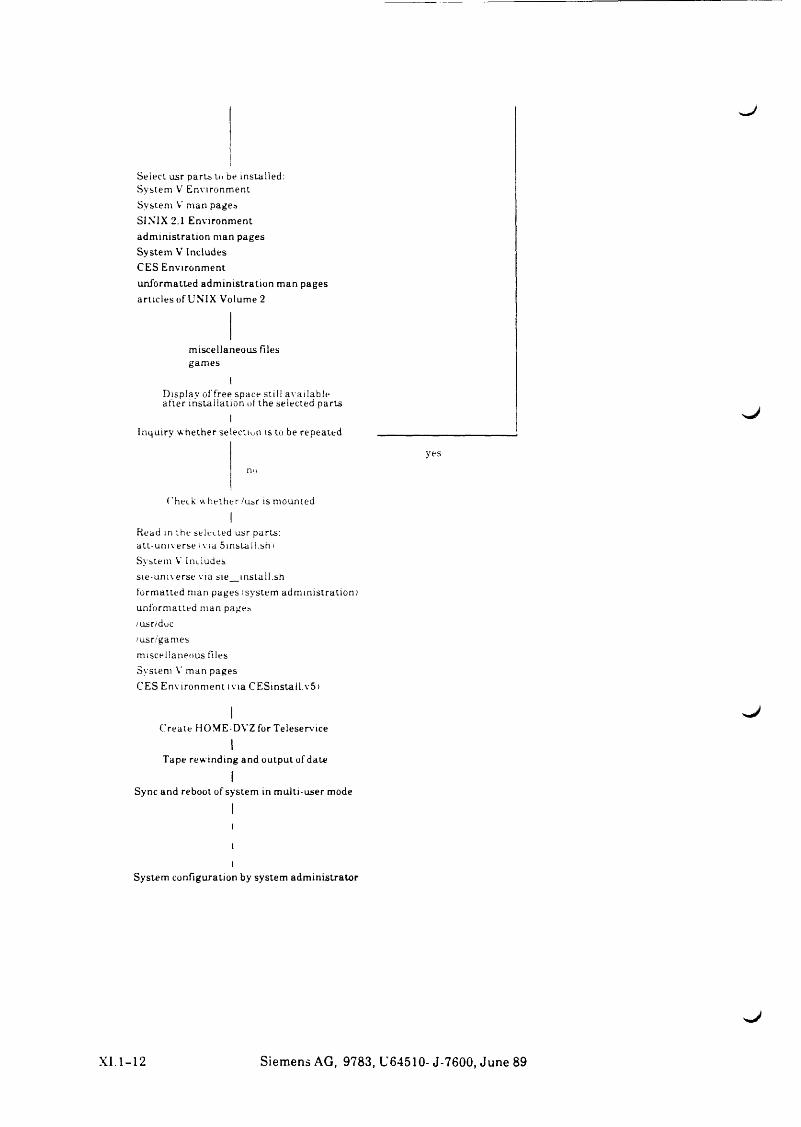
Select usr par ts to be installed:System V Environment System V man pages SINIX 2.1 E nvironm ent adm in is tra t ion man pages System V Includes CES Environm entunform atted adm in istra t ion m an pages articles of UNIX Volume 2
miscellaneous files games
IDisplay offree space still available after installation of the selected parts
IInquiry whether selection is to be repeated _____________
yesn o
Check whether /usr is mounted
IRead in the selected usr parts: a tt-uni verse (via Sinstal l.sh i System V Includessie-universe via sie_install.shformatted man pages isystem administration)unform atted man pages/usr/duc/usr/gamesmiscellaneous filesSystem V man pagesCES Environm ent (via C ESinsta l l .v5)
I - JCreate HOME-DVZ for Teleservice
ITape rewinding and output of date
ISync and reboot of system in mult i-user mode
Illl
System configuration by system adm in is t ra to r
XI 1-12 Siemens AG, 9783, U64510- J-7600, June 89
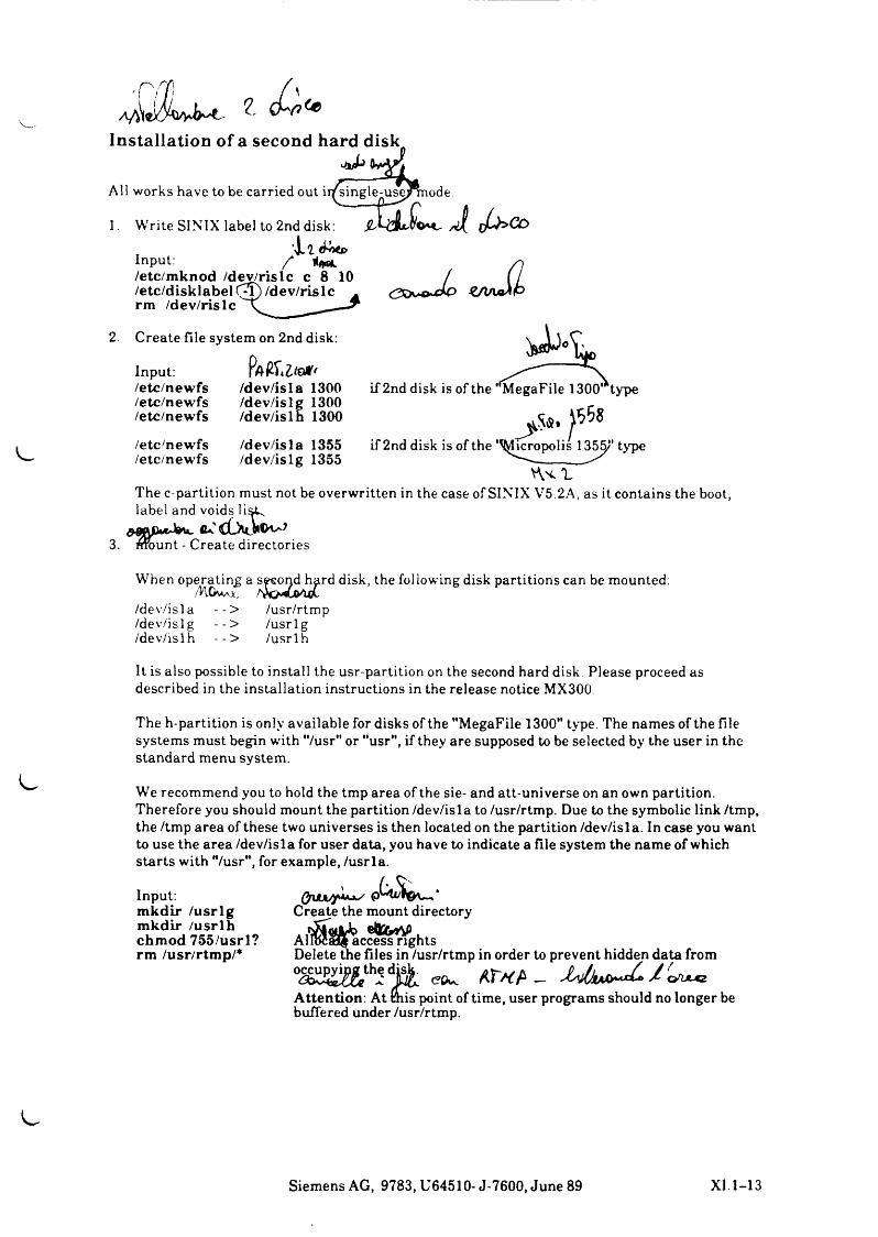
Installation of a second hard disk.
A ll w o r k s h a v e to be ca r r ied o u t ir^ s in g le^ u se ^ m o d e
1. W r i te S I N I X la b e l to 2n d d isk: SL /J [ Juh>C O
Input: / t f**/etc/m knod /dev/rislc c 8 10 /etc/disklabel C *T ) /dev/rislc rm /dev/rislc
cx*s*>**lo zriAj^k
2. Create file system on 2nd disk:
Input: Itol*/etc/newfs /dev/isla 1300/etc/newfs /dev/islg 1300/etc/newfs /dev/islh 1300
/etc/newfs/etc/newfs
/dev/isla 1355 /dev/islg 1355
if 2nd disk is of the MegaFile 1300 type
if 2nd disk is of the '^licropolis 1355J* type
T h e c -p a r t i t io n m u s t not be o v e r w r i t t e n in th e c a s e o f S IN I X V 5 .2 A , a s it c o n t a in s th e boot, la b e l an d v o id s lisk .
Ga.' CCXcJttK-73. m o u n t - C r e a te d ir e c to r ie s
W h e n o p e r a t in g a d isk , f o l lo w in g d isk p a r t i t i o n s ca n be m o u n ted :
/ d e v / i s l a - - > / d e v / i s l g - - > / d e v / i s l h - - >
/u sr /r tm p/ u s r l g/ u s r l h
It is a l so p o s s ib le to in s t a l l th e u s r -p a r t i t io n on th e se co n d hard d isk . P l e a s e p ro ceed a s d e s c r ib e d in th e i n s t a l la t io n in s t r u c t io n s in th e r e le a s e n o t ic e M X 3 0 0 .
The h-partition is only available for disks of the "MegaFile 1300" type. The names of the file systems must begin with "/usr" or "usr", if they are supposed to be selected by the user in the standard menu system.
We recommend you to hold the tmp area of the sie- and att-universe on an own partition. Therefore you should mount the partition /dev/isla to /usr/rtmp. Due to the symbolic link /tmp, the /tmp area of these two universes is then located on the partition /dev/isla. In case you want to use the area /dev/isla for user data, you have to indicate a file system the name of which starts with "/usr", for example, /usrla.
Input:m kdir /u s rlg m kdir /u s r lh chm od 755/usrl? rm /usr/rtmp/*
Create the mount directory
AllbcalJ access rights Delete the files in /usr/rtmp in order to prevent hidden data from occupying th j disk. ^ f
Attention: At mis point of time, user programs should no longer be buffered under /usr/rtmp.
Siemens AG, 9783, U64510- J-7600, June 89 XI.1-13
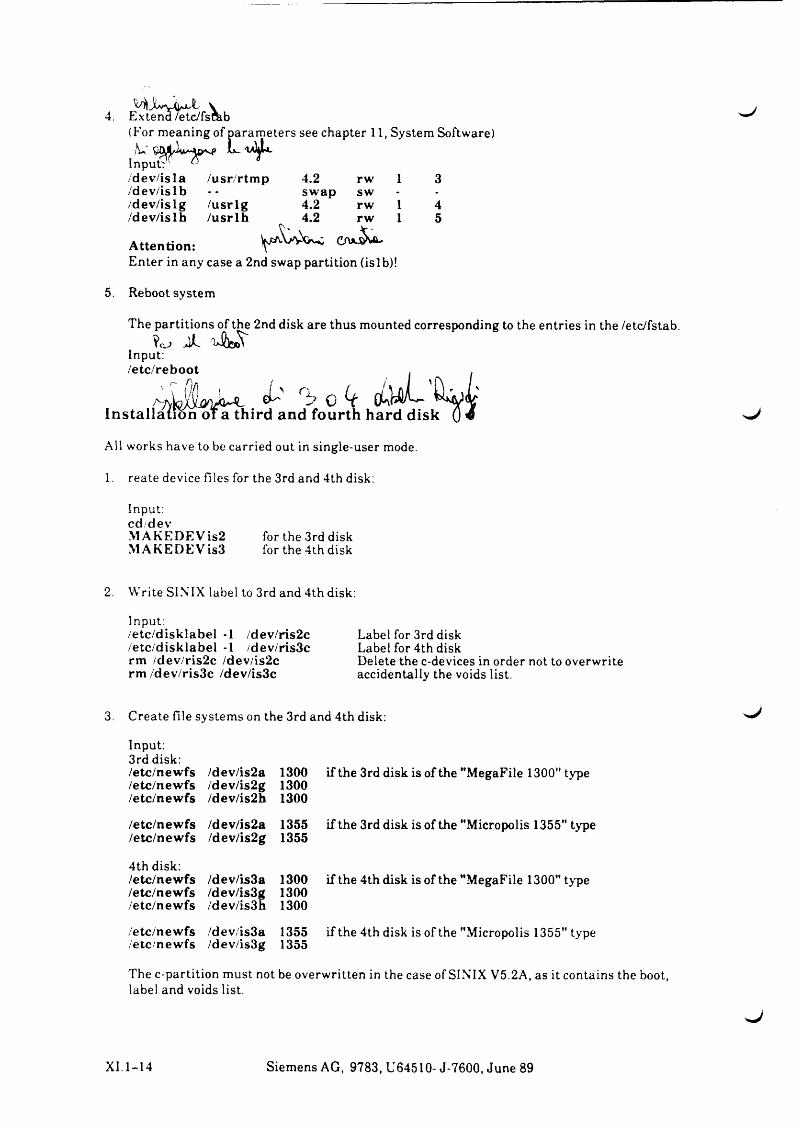
4. Extend /etc/fsrab(For meaning of parameters see chapter 11 , System Software) /*U' L.
Input? 1 ®/dev/isla /usr/rtm p 4.2 rw 1 3/dev/islb swap sw - -
/dev/islg /u srlg 4.2 rw 1 4/dev/islh /u s r lh 4.2 rw 1 5
Attention: eA’ ‘uEnter in any case a 2nd swap partition (islb)!
5. Reboot system
The partitions of the 2nd disk are thus mounted corresponding to the entries in the /etc/fstab.. j A
Input:/etc/reboot . .
Installation oi a third and fourth hard disk 0 «
All works have to be carried out in single-user mode.
1. reate device files for the 3rd and 4th disk:
Input: cd devMAKEDEVis2 for the 3rd diskMAKEDEVis3 for the 4th disk
2. Write SINIX label to 3rd and 4th disk:
Input:/etc/disklabel -1 /dev/ris2c /etc/disklabel -1 /dev/ris3c rm /dev/ris2c /dev/is2c rm /dev/ris3c /dev/is3c
Label for 3rd disk Label for 4th diskDelete the c-devices in order not to overwrite accidentally the voids list.
3. Create file systems on the 3rd and 4th disk:
Input:3rd disk: /etc/newfs /dev/is2a 1300/etc/newfs /dev/is2g 1300/etc/newfs /dev/is2h 1300
/etc/newfs /dev/is2a 1355/etc/newfs /dev/is2g 1355
4th disk:/etc/newfs /dev/is3a 1300/etc/newfs /dev/is3g 1300/etc/newfs /dev/is3h 1300
/etc/newfs /dev/is3a 1355/etc/newfs /dev/is3g 1355
if the 3rd disk is of the "MegaFile 1300" type
if the 3rd disk is of the "Micropolis 1355" type
if the 4th disk is of the "MegaFile 1300" type
if the 4th disk is of the "Micropolis 1355" type
The c-partition must not be overwritten in the case of SINIX V5.2A, as it contains the boot, label and voids list.
XI.1-14 Siemens AG, 9783, U64510- J-7600, June 89
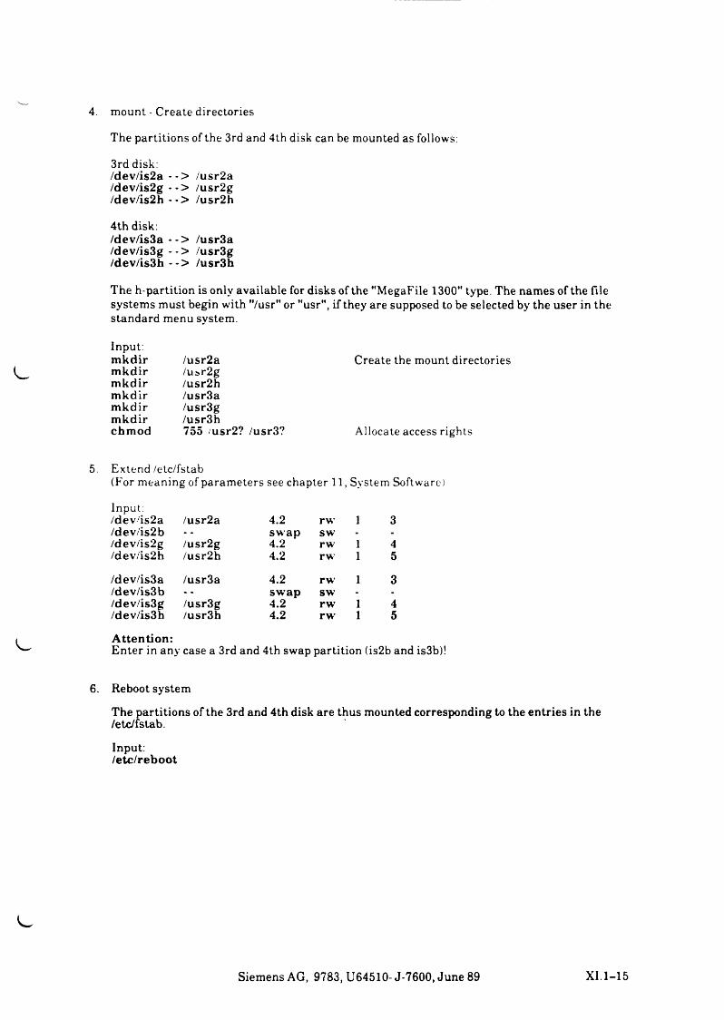
4. m o u n t - C r e a te d ir e c to r ie s
The p a r t i t i o n s o f th e 3rd and 4 th d isk ca n be m o u n te d a s fo llows:
3rd d isk:/dev/is2a --> /u sr2a /dev/is2g -*> /u sr2g /dev/is2h --> /u sr2h
4th disk:/dev/is3a --> /usr3a /dev/is3g -■> /usr3g /dev/is3h --> /usr3h
The h-partition is only available for disks of the "MegaFile 1300" type. The names of the file systems must begin with "/usr" or "usr", if they are supposed to be selected by the user in the standard menu system.
Input:m kdir /u sr2am kdir /u sr2gm kdir /u sr2hm kdir /usr3am kdir /usr3gm kdir /usr3hchmod 755 /usr2? /usr3?
Create the mount directories
A llo c a te a c c e s s r ig h t s
5. E x t e n d /e tc / f s ta b(F o r m e a n in g o f p a r a m e t e r s se e c h a p te r 1 1 , S y s te m S o ftw a re)
Input:/dev/is2a /u sr2a 4.2 rw 1 3/dev/is2b swap sw - -
/dev/is2g /u sr2g 4.2 rw 1 4/dev/is2h /u sr2h 4.2 rw 1 5
/dev/is3a /usr3a 4.2 rw 1 3/dev/is3b swap sw - -
/dev/is3g /usr3g 4.2 rw 1 4/dev/is3h /usr3h 4.2 rw 1 5
A ttention:Enter in any case a 3rd and 4th swap partition (is2b and is3b)!
6. Reboot system
The partitions of the 3rd and 4th disk are thus mounted corresponding to the entries in the /etc/fstab.
Input:/etc/reboot
Siemens AG, 9783, U64510- J-7600, June 89 XI.1-15

^J


w /
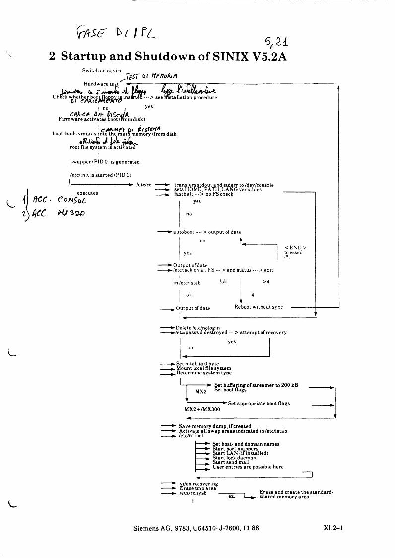
S/a2 Startup and Shutdown of SINIX V5.2A
Switch on device
• Set mtab to 0 byte . Mount local file system .Determine system type
-p--------- ► Set buffering of streamer to 200 kBSet boot flags
f------------------- ► Set appropriate boot flags
MX2 + /MX300
----- ► Save memory dump, if created----- ► Activate all swap areas indicated in /etc/fstab----- ► /etc/rc.locl
Set host- and domain names Start port mappers Start LAN (if installed)Start lock daemonStartsend mailUser entries are possible here
----- ► vi/ex recovering----- ► Erase tmp area _ , , ,----- ► /etx/rc.sys5 --------------1 Erase and create the standard-
ex. 1 ». shared memory area
Siemens AG, 9783, U64510- J-7600,11.88 X I.2-1
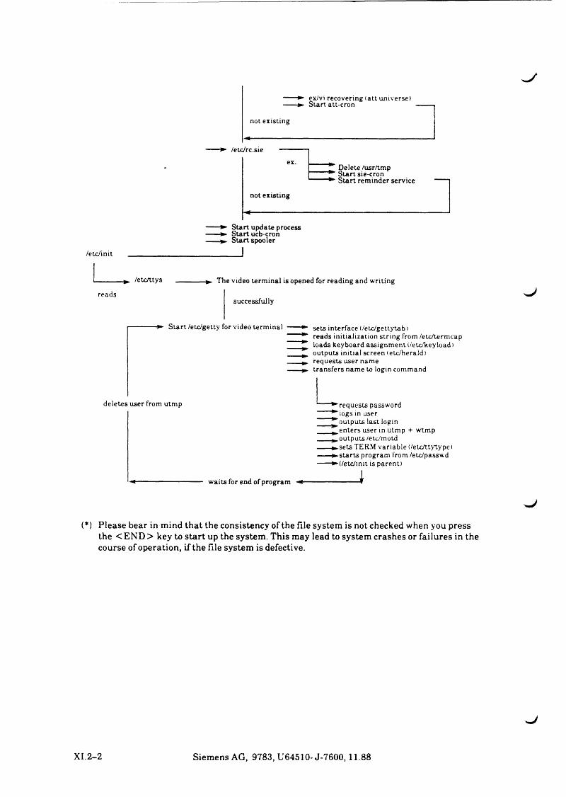
♦* ex/vi recovering (a tt universe) -► S ta r t att-cron
not existing
/etc/rc.sie
Delete /usr/tmp Start sie-cron Start reminder service
not existing
Start update process Start ucb-cron
► Start spooler
/etc/init
► /etc/t tys -------------► The video term inal is opened for reading and writing
readssuccessfully
J
S ta r t /etc/getty for video term inal sets interface ( /etc/gettytab)reads init ialization str ing from /etc/termcaploads keyboard ass ignm ent (/etc/keyload)outputs initial screen (etc/herald)requests user nametransfers name to login command
deletes user from utmp
waits for end of program
►requests password ^ logs in user * outputs last login
____^ e n t e r s user in utmp + wtmp____^ .o u tp u ts /etc 'motd------►sets TERM variable (/etcAtytype)------► star ts program from /etc/passwd------► (/etc/init is parent)
______ J
(*) Please bear in mind that the consistency of the file system is not checked when you press the <EN D > key to start up the system. This may lead to system crashes or failures in the course of operation, if the file system is defective.
XI. 2-2 Siemens AG, 9783, U64510- J-7600,11.88
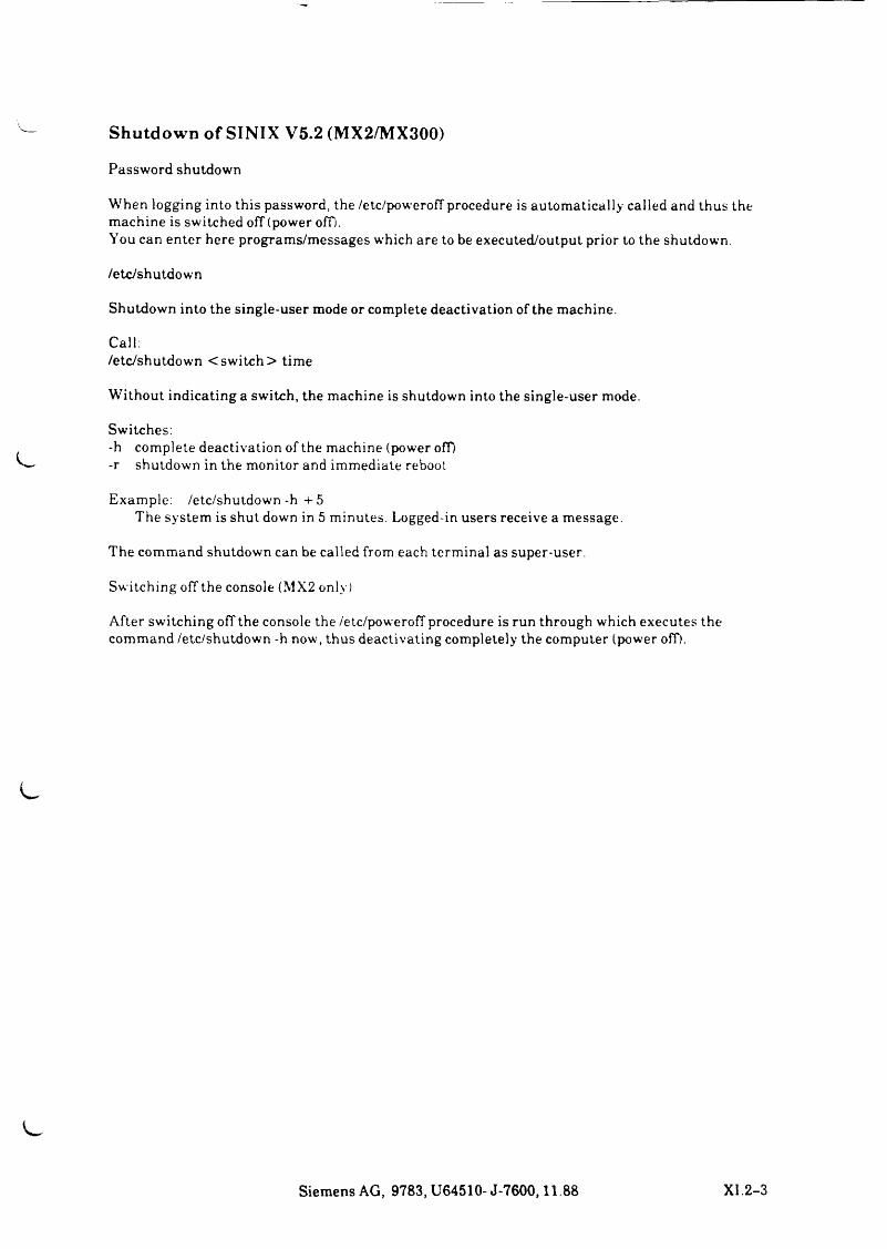
Shutdown of SINIX V5.2 (MX2/MX300)
Password shutdown
W h e n lo g g in g in to th is p a ssw o rd , th e /e tc /p o w e ro f f p ro ced u re is a u t o m a t i c a l l y c a l le d a n d th u s the m a c h in e is s w i t c h e d o f f (p o w er off).Y o u ca n e n t e r h e r e p r o g r a m s /m e s s a g e s w h ich a re to be e x e c u t e d /o u t p u t prior to th e s h u td o w n ,
/ e t c / s h u t d o w n
S h u td o w n in to th e s in g le - u s e r m o d e or c o m p le te d e a c t iv a t io n o f th e m a c h in e .
Call:/ e t c / s h u t d o w n < s w i t c h > t im e
W it h o u t i n d i c a t in g a s w i t c h , th e m a c h in e is s h u td o w n in to th e s in g le - u s e r m ode .
Switches:-h c o m p le t e d e a c t iv a t io n o f th e m a c h in e (p o w er off)-r s h u t d o w n in th e m o n ito r an d im m e d i a t e reboot
E x a m p le : / e t c / s h u t d o w n - h + 5T h e s y s t e m is s h u t d o w n in 5 m in u t e s . L o g g e d - in u s e r s r e c e iv e a m e s s a g e .
T h e c o m m a n d s h u t d o w n ca n be c a l le d from ea c h t e r m in a l a s s u p e r -u se r .
S w i t c h in g o f f th e c o n s o le (M X 2 on ly )
A f t e r s w i t c h i n g o f f th e c o n so le th e /e tc /p o w e r o f f p ro ced u re is ru n th r o u g h w h ic h e x e c u t e s th e c o m m a n d / e t c / s h u t d o w n -h n o w , t h u s d e a c t iv a t in g c o m p le t e ly th e c o m p u te r (p o w er off).
Siemens AG, 9783, U64510- J-7600,11.88 XI.2-3
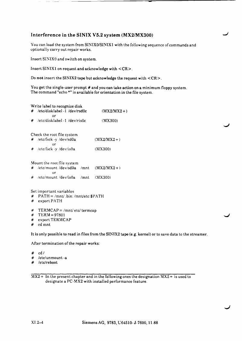
Interference in the SINIX V5.2 system (MX2/MX300) U
Y ou can load the system from SINIX0/SINIX1 with the following sequence of commands and optionally carry out repair works.
Insert SINIXO and switch on system.
Insert SINIX1 on request and acknowledge with < C R > .
Do not insert the SINIX2 tape but acknowledge the request with < CR > .
You get the single-user prompt # and you can take action on a minimum floppy system.The command "echo *" is available for orientation in the file system.
Write label to recognize disk# /etc/disk label-1 /dev/rsdOc (MX2/MX2 + )
or# /etc/disklabel-1 /dev/risOc (MX300)
Check the root file system # /etc/fsck -y /dev/sdOa (MX2/MX2 +)
or# /etc/fsck -y /dev/isOa (MX300)
Mount the root file system # /etc/mount /dev/sdOa /mnt (MX2/MX2 + )
or# /etc/mount /dev/isOa /mnt (MX300)
Set important variables# PATH = /mnt/.bin:/mnt/etc:$PATH# export PATH
# TERMCAP=/mnt/etc/termcap# TERM = 97801# export TERMCAP# cd mnt
It is only possible to read in files from the SINIX2 tape (e.g. kernel) or to save data to the streamer.
After termination of the repair works:
# cd /# /etc/unmount -a# /etc/reboot
MX2 + In the present chapter and in the following ones the designation MX2 + is used to designate a PC-MX2 with installed performance feature.
XI. 2-4 Siemens AG, 9783, U64510-J-7600,11.88


w !
3 System Software in General
The Three Universes
Links-SINIX V5.x
System sizes - SINIX V5.x
Tape commands - SINIX V5.2A
System files of the terminal handling - SINIX V5.2A
System files of the spool system - SINIX V5.2A
^ Configuration of the I/O boards - SINIX V5.2A
Disk format - SINIX V5.2A
System crashes - SINIX V5.2A
Siemens AG, 9783, U64510- J-7600,11.88 X I.3-1
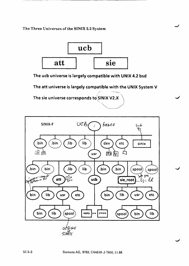
The Three Universes of the SINIX 5.2 System
ucbatt sie
The ucb universe is largely compatible with UNIX 4.2 bsd
The att universe is largely compatible with the UNIX System V/■- .—
The sie universe corresponds to(siNIX V2.X
X I.3-2 Siemens AG, 9783, U64510- J-7600,11.88
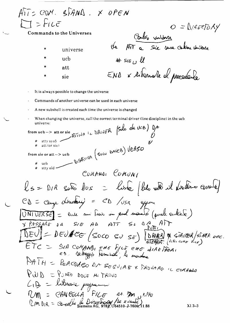
/VV ( S- C?Q/C . X o P t A /
£ z i - Pf6(TCommands to the Universes
universeu c b
a t t
s i e
O - k / / t e e f e > A /
G b J tJ o
cfc f f i T q_ .SCc, CkJiW
# • s r e , , ^
It is a l w a y s p o s s ib le to c h a n g e th e u n iv e r s e
C o m m a n d s o f a n o th e r u n iv e r s e ca n be u sed in e a c h u n iv e r s e
A n e w s u b s h e l l is c r e a te d e a c h t im e th e u n iv e r s e is ch a n g e d
W h e n c h a n g in g th e u n iv e r s e , ca l l th e co rrec t t e r m in a l d r iv e r ( l in e d is c ip l in e ) in th e ucb u n iv e r s e .
from u c b --> a tt or sie
# s t ty s y s 5# a t t ( o r s ie )
from sie or a tt -- > ucb
# ucb# s t tv old
w e *. f c W ' '
U c .
C v M f r M t ( L o f a o k i
^ 0//¾ J j o s r iz j ß d o ' 0 ^ 0
OS A
0¾ I \J tA i c I " or~ $A*J- ^i pAZSAfi-er DA fl-b f c t T <=> t, & ^ f \ \ \ -
~~ T O N I
b e O / f c e - b t o k * f < ,7 fa n s A ] $ m . J2c?C,. — • i 'u t - iy tz « ^ t $ S i c c H f r
G l C G- Co/V<f/^S, eete <P/cP" eats- ^ / A a /^&a i« v
^ 1 b / v , t c VdJ u w Yj boos- ^ Yvtooo
f £ / f l \ - <G$H(%UA ^rlCe **■ > 1 u ?< ' %
XI. 3 - 3
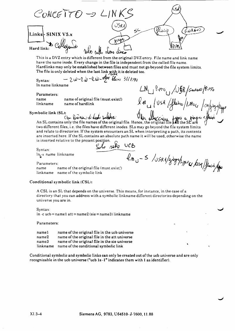
C o k o z X r o - = ? l i h K S
Links - SINIX V5.x
H ard Link:
This is a DVZ entry which is different from the original DVZ entry. File name and link name have the same inode. Every change in the file is independent from the called file name. Hardlinks may only be established between files and must not go beyond the file system limits. The file is only deleted when the last link^itjh it is deleted too.
Syntax: — tf) (tüMj K lIn name linkname
Parameters:namelinkname
name of original file (must exist!) name of hardlink
Symbolic link (SL): ^
An SL contains only the file names of the original file. Hence, the original file pma the SI two different files, i.e. the files have different inodes. SLs may go beyond the file system limits and relate to directories. If the system encounters an SL when interpreting a path, its contents are inserted here. If the SL contains an absolute path name it will be used, otherwise the name is inserted relative to the present position. ~
Syntax:ln.-s name linkname liParameters:name name of the original file (must exist!) linkname name of the symbolic link
. . - ^
Conditional symbolic link (CSL):
A CSL is an SL that depends on the universe. This means, for instance, in the case of a directory that you can address with a symbolic linkname different directories depending on the universe you are in.
Syntax: 'W*In -c ucb = namel att = name2 (sie = name3) linkname
Parameters:
namelname2name3linkname
name of the original file in the ucb universe name of the original file in the att universe name of the original file in the sie universe name of the conditional symbolic link
Conditional symbolic and symbolic links can only be created out of the ucb universe and are only recognizable in the ucb universe ("ucb Is -1" indicates them with 1 as identifier).
XI.3—4 Siemens AG, 9783, U64510- J-7600,11.88
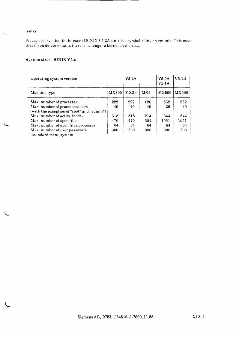
/sinix
P l e a s e o b s e r v e th a t in th e c a s e o f S IN IX V 5 .2 A s in ix is a sy m b o l ic l in k on v m u n ix . T h is m e a n s th a t i f y o u d e le t e v m u n ix t h e r e is no lo n g er a k ern e l on th e d isk .
System sizes - SINIX V5.x
O p e r a t in g s y s t e m v e r s io n V 5 .2 A V 5 .0 A V 5 1A
V 5 .1 B
M a c h i n e ty p e M X 3 0 0 M X 2 + M X 2 M X 5 0 0 M X 5 0 0
M a x . n u m b e r o f p r o c e s s e s 2 2 2 2 2 2 12 6 5 3 2 5 3 2M a x . n u m b e r o f p r o c e s s e s /u s e r s (w ith t h e e x c e p t io n o f "root” a n d "adm in")
40 4 0 4 0 2 6 4 0
M a x . n u m b e r o f a c t iv e in o d es 3 1 8 3 1 8 2 1 4 6 4 4 6 4 4M a x . n u m b e r o f op en f i le s 4 7 0 4 7 0 3 0 4 1051 1051M ax. n u m b e r o f o p en f i le s /p r o c e s s e s 64 64 64 6 4 64M ax. n u m b e r o f u se r p a s sw o r d s ( s ta n d a r d m e n u s v s t e m )
3 0 0 3 0 0 3 0 0 3 0 0 3 0 0
S i e m e n s A G , 9 7 8 3 , U 6 4 5 1 0 - J - 7 6 0 0 , 1 1 .8 8 XI. 3 - 5
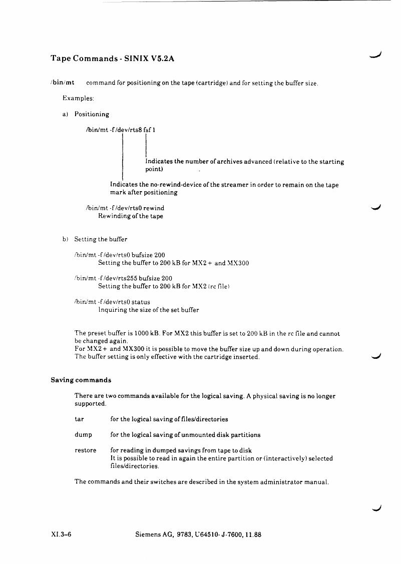
Tape Commands - SINIX V5.2A
/bin/m t command for positioning on the tape (cartridge) and for setting the buffer size.
Examples:
a) Positioning
/bin/mt -f/dev/rts8 fsf 1
Indicates the number of archives advanced (relative to the starting point)
Indicates the no-rewind-device of the streamer in order to remain on the tape mark after positioning
/bin/mt -f /dev/rtsO rewind Rewinding of the tape
b) Setting the buffer
/bin/mt -f /dev/rtsO bufsize 200Setting the buffer to 200 kB for MX2 -f and MX300
/bin/mt -f/dev/rts255 bufsize 200Setting the buffer to 200 kB for MX2 (rc file)
/bin/mt -f /dev/rtsO statusInquiring the size of the set buffer
The preset buffer is 1000 kB. For MX2 this buffer is set to 200 kB in the rc file and cannot be changed again.For MX2 + and MX300 it is possible to move the buffer size up and down during operation. The buffer setting is only effective with the cartridge inserted.
Saving com m ands
There are two commands available for the logical saving. A physical saving is no longer supported.
tar for the logical saving of files/directories
dump for the logical saving of unmounted disk partitions
restore for reading in dumped savings from tape to diskIt is possible to read in again the entire partition or (interactively) selected files/directories.
The commands and their switches are described in the system administrator manual.
XI.3-6 Siemens AG, 9783, U64510- J-7600,11.88
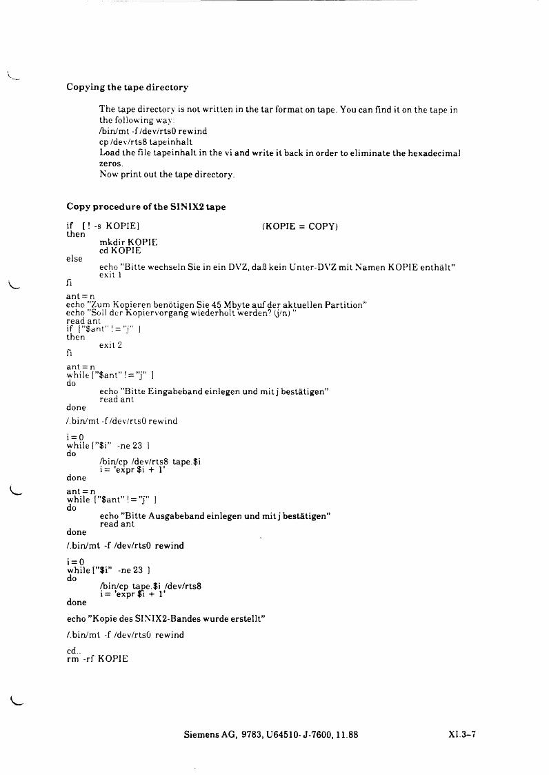
Copying the tape directory
The tape directory is not written in the tar format on tape. You can find it on the tape in the following way:/bin/mt -f/dev/rtsO rewind cp /dev/rts8 tapeinhaltLoad the file tapeinhalt in the vi and write it back in order to eliminate the hexadecimal zeros.Now print out the tape directory.
Copy p rocedure of the SIN 1X2 tape
if [! -s KOPIE! (KOPIE = COPY)then
mkdir KOPIE cd KOPIE
elseecho ’’Bitte wechseln Sie in ein DYTZ, daß kein Unter-DVZ mit Namen KOPIE enthält” exit 1
fiant = necho ”Zum Kopieren benötigen Sie 45 Mbyte auf der aktuellen Partition” echo ’’Soll der Kopiervorgang wiederholt werden? (j/n) ” read antif [”$ant” ! = ”j ” ] then
exit 2 fiant = nwhile [”$ant” ! = ”j ” 1 do
echo ’’Bitte Eingabeband einlegen und mit j bestätigen” read ant
done/.bin/mt -f/dev/rtsO rewind
i = 0while f”$i” -ne 23 1 do
/bin/cp /dev/rts8 tape.$i i = 'expr $i + 1'
done ant = nwhile [”$ant” ! = ”j ” 1 do
echo ’’Bitte Ausgabeband einlegen und mit j bestätigen” read ant
done/.bin/mt -f /dev/rtsO rewind
i = 0while l”$i” -ne 23 ] do
/bin/cp tape.$i /dev/rts8 i= ’expr fi + 1'
done
echo ’’Kopie des SINTX2-Bandes wurde erstellt”/.bin/mt -f /dev/rtsO rewind cd..rm -rf KOPIE
Siemens AG, 9783, U64510- J-7600,11.88 XI.
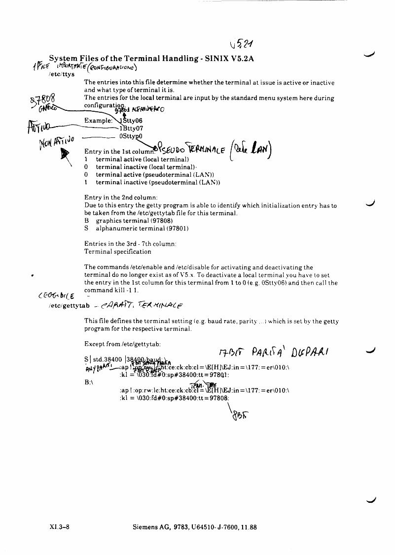
Vj
System Files of the Terminal Handling - SINIX V5.2A
/etc/ttysThe entries into this file determine whether the terminal at issue is active or inactive and what type of terminal it is.The entries for the local terminal are input by the standard menu system here during
tty06 lBtty07 OSttypO
co lu m n ^$ 6l? A c?Entry in the 1st i 1 terminal active (local terminal)0 terminal inactive (local terminal)-0 terminal active (pseudoterminal (LAN))1 terminal inactive (pseudoterminal (LAN))
Entry in the 2nd column:Due to this entry the getty program is able to identify which initialization entry has to be taken from the /etc/gettytab file for this terminal.B graphics terminal (97808)S alphanumeric terminal (97801)
Entries in the 3rd - 7th column:Terminal specification
Ct'Ofr h(( t/etc/gettytab
The commands /etc/enable and /etc/disable for activating and deactivating the terminal do no longer exist as of V5.x. To deactivate a local terminal you have to set the entry in the 1st column for this terminal from 1 to 0 (e g. 0Stty06) and then call the command kill -1 1.
This file defines the terminal setting (e.g. baud rate, parity ...) which is set by the getty program for the respective terminal.
Except from /etc/gettytab:
S | std.38400 |3Sn - b i T P /j/ tiV /} '
B:\
t:ce:ck:cb:cl = \E[H]VEJ:in = \177: =er\010:\ :kl =' \TM W 0:sp#38400:tt = 978Q1:
:ap ! :op:rw:lc:ht:ce:ck:cb*:^=\^H]\EJ:in = \177: =er\010:\ :kl = \030:fd#0:sp#38400:tt = 97808:
w
XI. 3-8 Siemens AG, 9783, U64510-J-7600,11.88
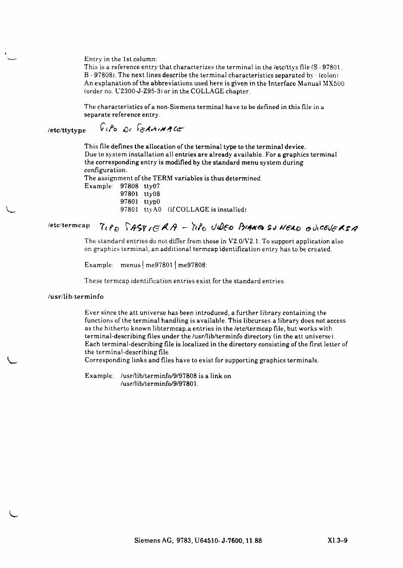
Entry in the 1st column:This is a reference entry that characterizes the terminal in the /etc/ttys file (S - 97801.B - 97808). The next lines describe the terminal characteristics separated by : (colon)An explanation of the abbreviations used here is given in the Interface Manual MX500 (order no. U2300-J-Z95-3) or in the COLLAGE chapter.
The characteristics of a non-Siemens terminal have to be defined in this file in a separate reference entry.
/etc/ttytype Q i f a
This file defines the allocation of the terminal type to the terminal device.Due to system installation all entries are already available. For a graphics terminal the corresponding entry is modified by the standard menu system during configuration.The assignment of the TERM variables is thus determined.Example: 97808 tty07
97801 tty08 97801 ttypO97801 tty A0 (if COLLAGE is installed)
/etc/term cap f t - ' u fb S o V e< 0
The standard entries do not differ from those in V2.0A72.1. To support application also on graphics terminal, an additional termcap identification entry has to be created.
Example: menus | me97801 j me97808:
These termcap identification entries exist for the standard entries.
/usr/lib/term info
Ever since the att universe has been introduced, a further library containing the functions of the terminal handling is available. This libcurses.a library does not access as the hitherto known libtermcap.a entries in the /etc/termcap file, but works with terminal-describing files under the /usr/lib/terminfo directory (in the att universe). Each terminal-describing file is localized in the directory consisting of the first letter of the terminal-describing file.Corresponding links and files have to exist for supporting graphics terminals.
Example: /usr/lib/terminfo/9/97808 is a link on /usr/lib/terminfo/9/97801.
Siemens AG, 9783, U64510- J-7600,11.88 XI. 3-9
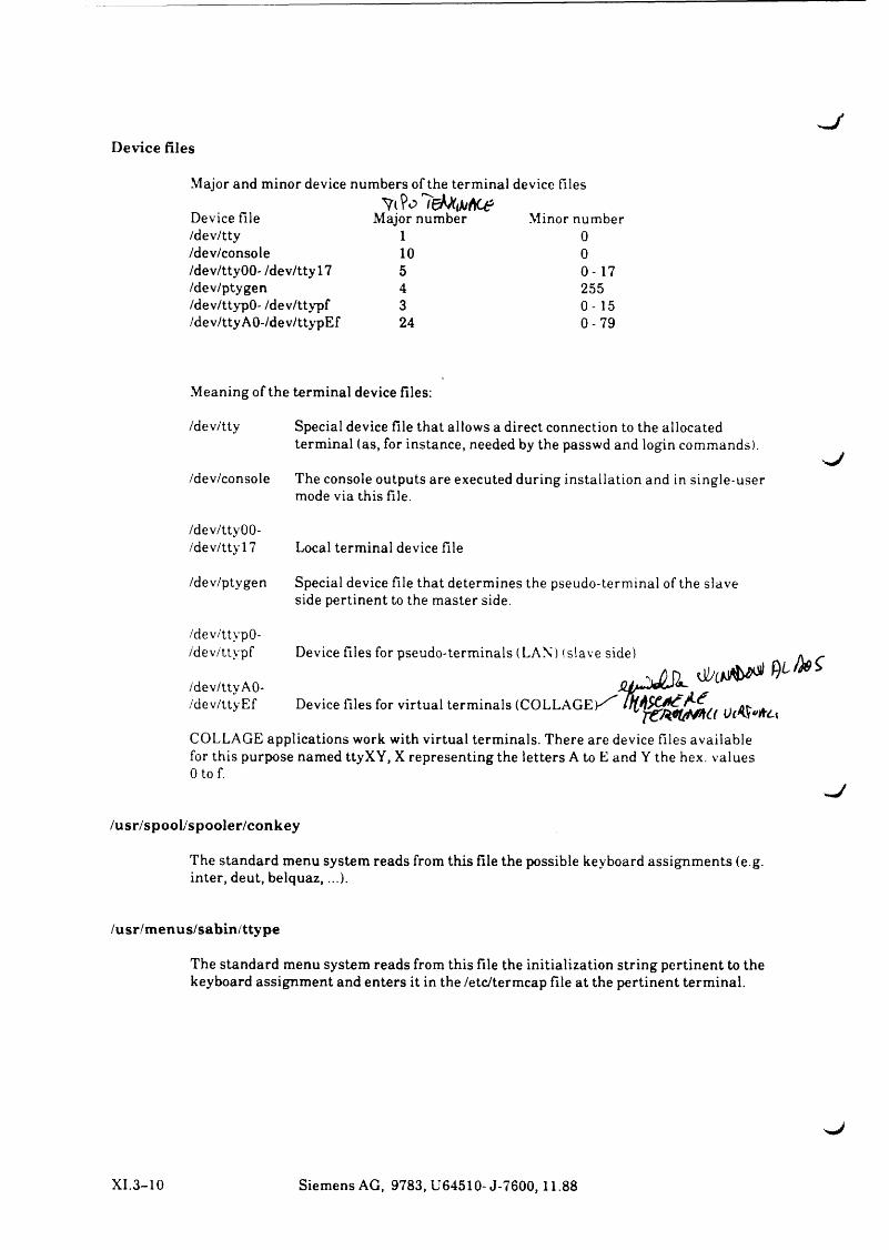
- /Device files
Major and minor device numbers of the terminal device files
Device file Major number Minor number/dev/tty 1 0/dev/console 10 0/dev/tty 00- /dev/tty 17 5 0-17/dev/ptygen 4 255/dev/ttypO- /dev/ttypf 3 0-15/dev/ttyAO-/dev/ttypEf 24 0-79
Meaning of the terminal device files:
/dev/tty Special device file that allows a direct connection to the allocatedterminal (as, for instance, needed by the passwd and login commands).
/dev/console The console outputs are executed during installation and in single-user mode via this file.
/dev/ttyOO-/dev/ttyl7
/dev/ptygen
/dev/'ttypO-/d e v / t t y p f
/dev/ttyAO-/d e v / t t y E f
Local terminal device file
Special device file that determines the pseudo-terminal of the slave side pertinent to the master side.
Device files for pseudo-terminals (LAN) (slave side) * _
Device files for virtual terminals (COLLAGEK^
COLLAGE applications work with virtual terminals. There are device files available for this purpose named ttyXY, X representing the letters A to E and Y the hex. values 0 to f.
/usr/spool/spooler/conkey
The standard menu system reads from this file the possible keyboard assignments (e.g. inter, deut, belquaz,...).
/usr/menus/sabin/ttype
The standard menu system reads from this file the initialization string pertinent to the keyboard assignment and enters it in the /etc/termcap file at the pertinent terminal.
XI.3-10 Siemens AG, 9783, U64510-J-7600,11.88
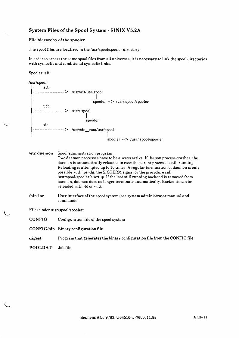
System Files of the Spool System - SINIX V5.2A
File h ierarchy of the spooler
The spool files are localized in the /usr/spool/spooler directory.
In order to access the same spool files from all universes, it is necessary to link the spool directories with symbolic and conditional symbolic links.
Spooler left:
/usr/spool I att—.......... —....... — > /usr/att/usr/spool
spooler --> /usr/.spool/spoolerucb
>
sie>
/usr/.spool
spooler
/usr/sie_root/usr/spool
spooler — > /usr/.spool/spooler
/etc/daem on Spool administration programTwo daemon processes have to be always active. If the son process crashes, the daemon is automatically reloaded in case the parent process is still running. Reloading is attempted up to 10 times. A regular termination of daemon is only possible with lpr -dg, the SIGTERM signal or the procedure call /usr/spool/spooler/startup. If the last still running backend is removed from daemon, daemon does no longer terminate automatically. Backends can be reloaded with -Id or -vld.
/bin lpr User interface of the spool system (see system administrator manual andcommands)
Files under /usr/spool/spooler:
CONFIG Configuration file of the spool system
CONFIG.bin Binary configuration file
d igest Program that generates the binary configuration file from the CONFIG file
POOLDAT Job file
Siemens AG, 9783, U64510-J-7600,11.88 XI 3-11
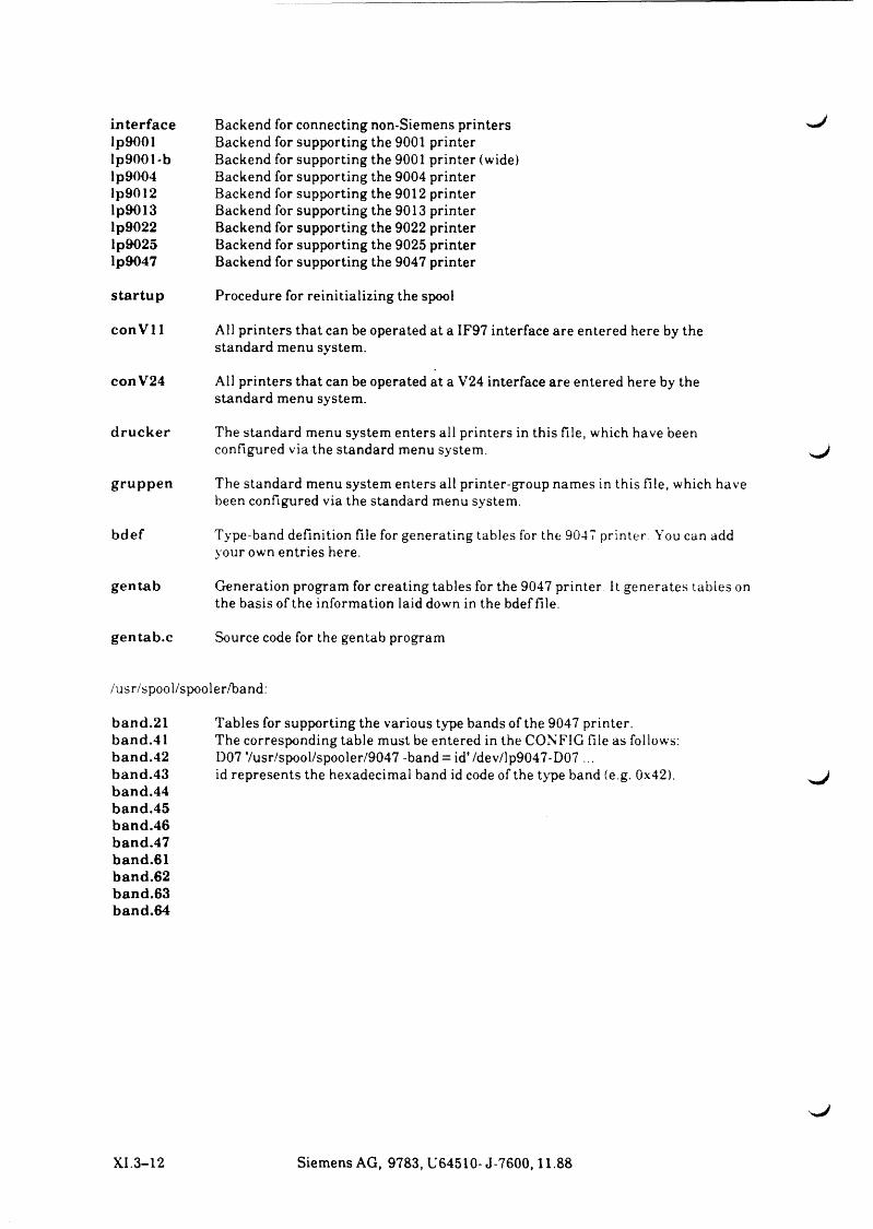
Interfacelp9001lp9001-blp9004lp9012lp9013lp9022lp9025lp9047
Backend for connecting non-Siemens printers ^ Backend for supporting the 9001 printer Backend for supporting the 9001 printer (wide)Backend for supporting the 9004 printer Backend for supporting the 9012 printer Backend for supporting the 9013 printer Backend for supporting the 9022 printer Backend for supporting the 9025 printer Backend for supporting the 9047 printer
s ta rtu p Procedure for reinitializing the spool
conV l 1 All printers that can be operated at a IF97 interface are entered here by the standard menu system.
conV24 All printers that can be operated at a V24 interface are entered here by the standard menu system.
d ru ck er The standard menu system enters all printers in this file, which have been configured via the standard menu system.
gruppen The standard menu system enters all printer-group names in this file, which have been configured via the standard menu system.
bdef Type-band definition file for generating tables for the 9047 printer You can add your own entries here.
gentab Generation program for creating tables for the 9047 printer It generates tables on the basis of the information laid down in the bdef file.
gentab.c Source code for the gentab program
/usr/spool/spooler/band
b an d .21 band .41 b and .42 b and .43 b and .44 band .45 b and .46 band.47 band .61 band.62 b and .63 band.64
Tables for supporting the various type bands of the 9047 printer.The corresponding table must be entered in the CONFIG file as follows: D07 Vusr/spool/spooler/9047 -band = id'/dev/lp9047-D07 ... id represents the hexadecimal band id code of the type band (e g. 0x42).
XI.3-12 Siemens AG, 9783, U64510- J-7600,11.88
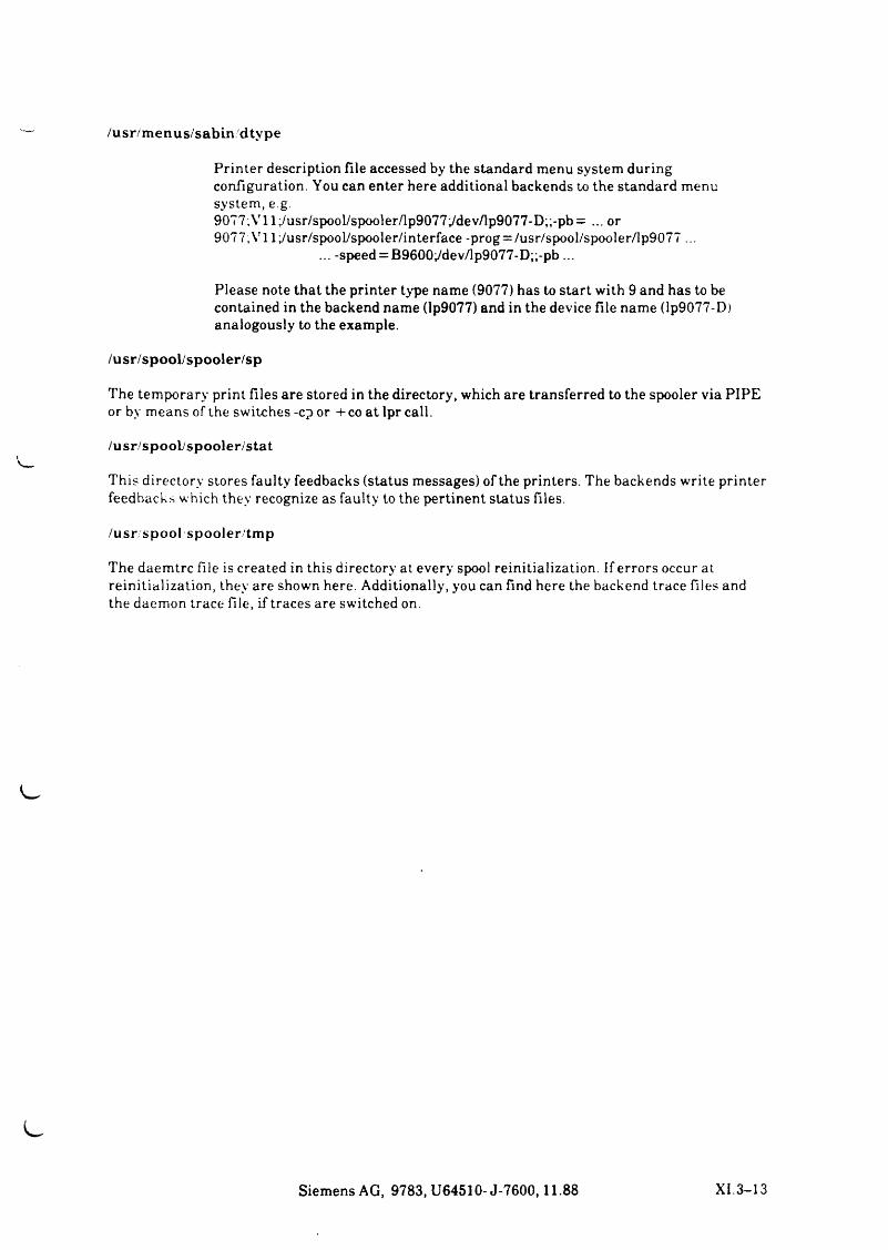
/usr/m enus/sabin dtype
P r in te r d e sc r ip tio n f i le a c c e s se d by th e sta n d a rd m en u s y s te m d u r in g c o n fig u r a tio n . Y ou ca n e n te r h ere a d d it io n a l b a c k e n d s to th e s ta n d a r d m en u s y s t e m , e g.9 0 7 7 ;V ll; /u sr /sp o o l/sp o o le r /lp 9 0 7 7 ; /d e v /lp 9 0 7 7 -D ;; -p b = ... or 9 0 7 7 .V 1 l^ u sr /s p o o l/sp o o le r / in te r fa c e -prog = /u s r /sp o o l/sp o o le r /lp 9 0 7 7 ...
... -sp e ed = B 9 6 0 0 ;/d e v /]p 9 0 7 7 -D ;;-p b ...
P le a s e n o te th a t th e p r in te r ty p e n a m e (9 0 7 7 ) h a s to s ta r t w ith 9 an d h a s to be c o n ta in e d in th e b a ck en d n a m e ( lp 9 0 7 7 ) an d in th e d e v ic e f i le n a m e (Ip 9 0 7 7 -D ) a n a lo g o u s ly to th e ex a m p le .
/usr/spool/spooler/sp
T h e te m p o r a r y p r in t f i le s a r e s to re d in th e d ire c to ry , w h ich a re tr a n s fe r r e d to th e sp o o le r v ia P IP E or by m e a n s o f th e s w itc h e s -c? or -(-co a t lpr c a ll.
/usr/spool/spooler/stat
T h is d ir e c to r y s to r e s fa u lty fe e d b a c k s ( s ta tu s m e s s a g e s ) o f th e p r in te r s . T h e b a c k e n d s w r ite p r in te r fe e d b a c k s w h ich th e y re c o g n iz e a s fa u lty to th e p e r t in e n t s ta tu s f ile s .
/u sr spool spooler/tm p
T h e d a e m tr c f ile is c r e a te d in th is d ire c to ry a t e v e r y sp oo l r e in it ia l iz a t io n . If erro r s o ccu r a t r e in it ia l iz a t io n , th e y a re sh o w n h ere . A d d it io n a lly , y ou ca n fin d h ere th e b a ck en d tra c e f i le s and th e d a e m o n tra c e f i le , i f tr a c e s a re sw itc h e d on.
S ie m e n s A G , 9 7 8 3 , U 6 4 5 1 0 - J - 7 6 0 0 ,1 1 .8 8 X I .3 - 1 3
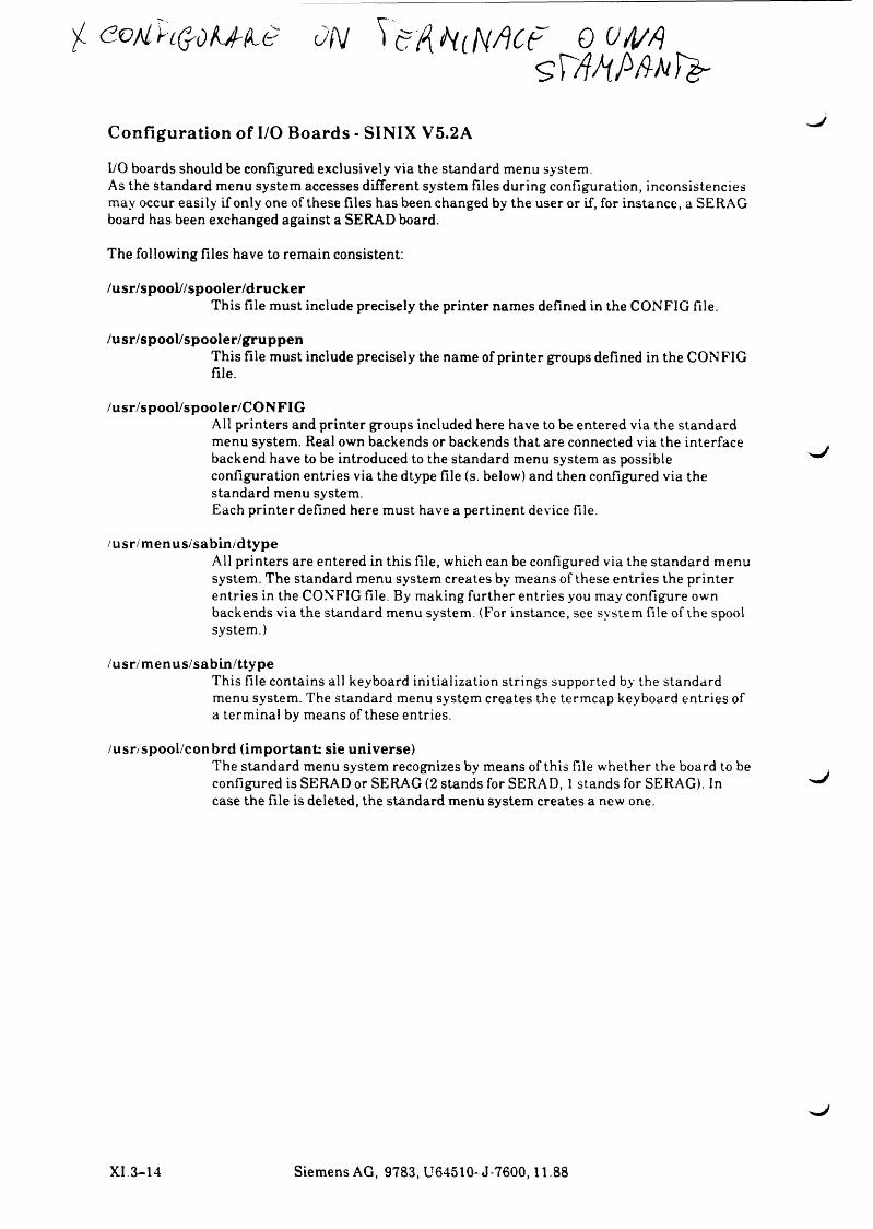
•f e o M ' n $ d U K 6 O N ^ c A k t M C f 9 V A /As r W M F >
Configuration of I/O Boards - SINIX V5.2A
I/O b o a rd s sh o u ld b e c o n fig u r ed e x c lu s iv e ly v ia th e s ta n d a rd m en u sy s te m .A s th e s ta n d a r d m en u s y s te m a c c e s s e s d iffe r e n t s y s te m f i le s d u r in g c o n fig u r a tio n , in c o n s is te n c ie s m a y o ccu r e a s i ly i f o n ly o n e o f th e s e f i le s h a s b een c h a n g ed by th e u ser or if, for in s ta n c e , a S E R A G b oard h a s b een e x c h a n g e d a g a in s t a S E R A D board .
T h e fo llo w in g f i le s h a v e to r e m a in c o n s is te n t:
/usr/spool//spooler/druckerT h is f i le m u s t in c lu d e p r e c is e ly th e p r in te r n a m e s d e fin e d in th e C O N F IG file ,
/usr/spool/spooler/gruppenT h is f i le m u st in c lu d e p r e c is e ly th e n a m e o f p r in te r g ro u p s d e fin e d in th e C O N F IG f ile .
/usr/spool/spooler/CONFIGA ll p r in te r s an d p r in te r g ro u p s in c lu d ed h ere h a v e to be e n te r e d v ia th e s ta n d a r d m en u sy s te m . R ea l ow n b a ck en d s or b a ck en d s th a t a re co n n e c te d v ia th e in te r fa c e b a ck en d h a v e to be in tro d u ced to th e sta n d a rd m en u s y s te m a s p o ss ib le c o n fig u r a tio n e n tr ie s v ia th e d ty p e f ile (s. b e low ) an d th e n c o n fig u r ed v ia th e s ta n d a rd m en u sy s te m .E a ch p r in te r d e fin e d h ere m u st h a v e a p e r t in e n t d e v ic e file ,
/usr/m enus/sabin/dtypeA ll p r in te r s a re e n te r e d in th is f ile , w h ich can be co n fig u r ed v ia th e s ta n d a r d m en u s y s te m . T h e sta n d a rd m en u sy s te m c r e a te s by m e a n s o f th e s e e n tr ie s th e p r in te r e n tr ie s in th e C O N F IG f ile . B y m a k in g fu r th e r e n tr ie s you m a y co n fig u r e ow n b a c k e n d s v ia th e sta n d a rd m en u sy s te m . (F or in s ta n c e , se e s y s te m f ile o f th e sp oo l sy s te m .)
/usr/m enus/sabin/ttypeT h is f i le c o n ta in s a ll k ey b o a rd in it ia liz a t io n s tr in g s su p p o rted by th e sta n d a rd m en u sy s te m . T h e s ta n d a rd m en u s y s te m c r e a te s th e ter m c a p k ey b o a rd e n tr ie s o f a te r m in a l by m e a n s o f th e s e e n tr ie s .
/usr/spool/conbrd (im portant: sie universe)T h e s ta n d a rd m en u s y s te m r e c o g n iz e s b y m e a n s o f th is f ile w h e th e r th e b oard to be c o n fig u r ed is S E R A D or S E R A G (2 s ta n d s for S E R A D , 1 s ta n d s for S E R A G ). In c a s e th e f i le is d e le te d , th e s ta n d a r d m en u s y s te m c r e a te s a n ew on e.
XI 3 - 1 4 S ie m e n s A G , 9 7 8 3 , U 6 4 5 1 0 - J - 7 6 0 0 ,1 1 .8 8
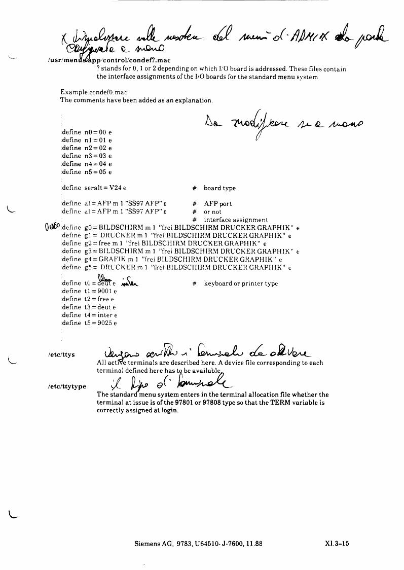
y iC U M ^ . O (~ jflßw/x Jl~ a&JL./usr/m enüsftapp/controI/condef?.mac
? s ta n d s for 0, 1 or 2 d e p e n d in g on w h ich I/O board is a d d r esse d . T h e s e f i le s co n ta in th e in te r fa c e a s s ig n m e n ts o f th e I/O b oard s for th e sta n d a rd m en u s y s te m
E x a m p le condefO .m acT h e c o m m e n ts h a v e b een ad ded a s an e x p la n a tio n .
d e f in e n 0 = 00 e d e f in e n l = 01 e d e f in e n 2 = 02 e d e f in e n 3 = 03 e d e f in e n 4 = 04 e d e f in e n 5 = 05 e
/ ] ^ SL
d e f in e s e r a lt = V 2 4 e # board type
d e fin edefine
0a£° d e fin ed e f in ed e f in ed e f in ed e f in ed e f in e
al = A F P m 1 ”S S 9 7 A F P ” e # A F P portal = A F P m 1 ”S S 9 7 A F P ” e # or not
# in te r fa c e a s s ig n m e n tgO = B IL D S C H IR M m 1 ’’fre i B IL D S C H IR M D R U C K E R G R A P H IK ” e g l = D R U C K E R m l ’’fre i B IL D S C H IR M D R U C K E R G R A P H IK ” e g2 = fre e m 1 ’’fre i B IL D SC H IR M D R U C K E R G R A P H IK " e g3 = B IL D S C H IR M m 1 ’’fre i B IL D SC H IR M D R U C K E R G R A P H IK ” e g4 = G R A F IK m 1 ’’fre i B IL D SC H IR M D R U C K E R G R A P H IK ” e g 5 = D R U C K E R m l ’’fre i B IL D SC H IR M D R U C K E R G R A P H IK ” e
d e f in ed e f in ed e f in ed e f in ed e f in ed e f in e
tO = a e u t e t l = 9 0 0 1 et2 = free e t3 = d eu t e t4 = in te r e t5 = 9 0 2 5 e
4 k ey b o a rd or p r in te r typ e
/etc/ttys
/etc/ttytype
A ll a c tfv e t e r m in a ls a re d esc r ib ed h ere . A d e v ic e f ile co r r e sp o n d in g to ea c h te r m in a l d e fin e d h e r e h a s to b e a v a ila b le ^
v / & ( 'The standard menu system enters in the terminal allocation file whether the terminal at issue is of the 97801 or 97808 type so that the TERM variable is correctly assigned at login.
Siemens AG, 9783, U64510-J-7600,11.88 XI.3-15
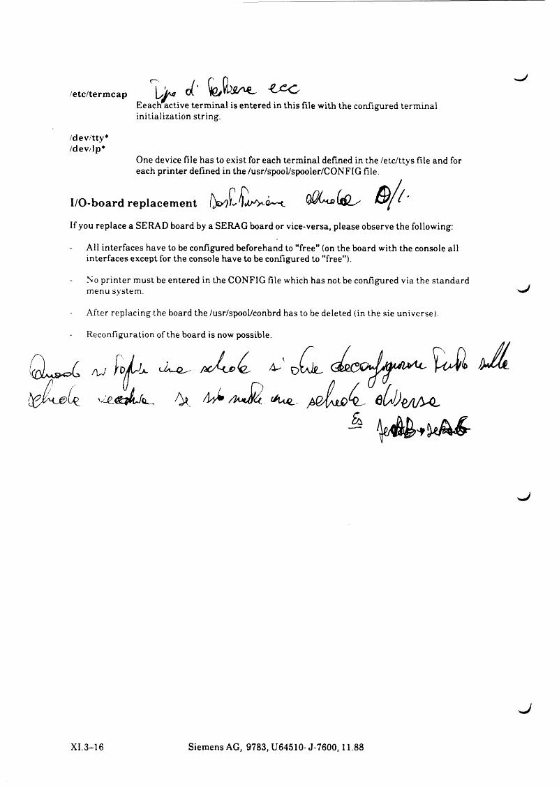
/etc/term cap X i * <£' b w w -E e a ch a c t iv e te r m in a l is e n te r e d in th is f i le w ith th e c o n fig u r ed te r m in a l in it ia l iz a t io n s tr in g .
/dev/tty*/dev/lp*
O n e d e v ic e f i le h a s to e x is t for ea c h te r m in a l d e fin e d in th e /e tc /t ty s f ile an d for ea c h p r in te r d e fin e d in th e /u sr /sp o o ly sp o o ler /C O N F IG file .
I/O-board replacement qQU>Ul- &/(■I f y o u r e p la c e a S E R A D b oard by a S E R A G board or v ic e -v e r sa , p le a s e o b se r v e th e fo llo w in g :
A ll in te r fa c e s h a v e to be co n fig u r ed b efo reh a n d to "free" (on th e board w ith th e c o n so le a ll in te r fa c e s e x c e p t for th e c o n so le h a v e to b e co n fig u r ed to "free'').
N o p r in te r m u st be e n te r e d in th e C O N F IG file w h ich h a s n ot be co n fig u r ed v ia th e s ta n d a rd m en u sy s te m .
A fte r r e p la c in g th e board th e /u sr /sp o o l/co n b rd h a s to be d e le te d (in th e s ie u n iv e r se ) .
R e c o n fig u r a t io n o f th e board is n ow p o ss ib le .
X I .3 - 1 6 S ie m e n s A G , 9 7 8 3 , U 6 4 5 1 0 - J - 7 6 0 0 ,1 1 .8 8
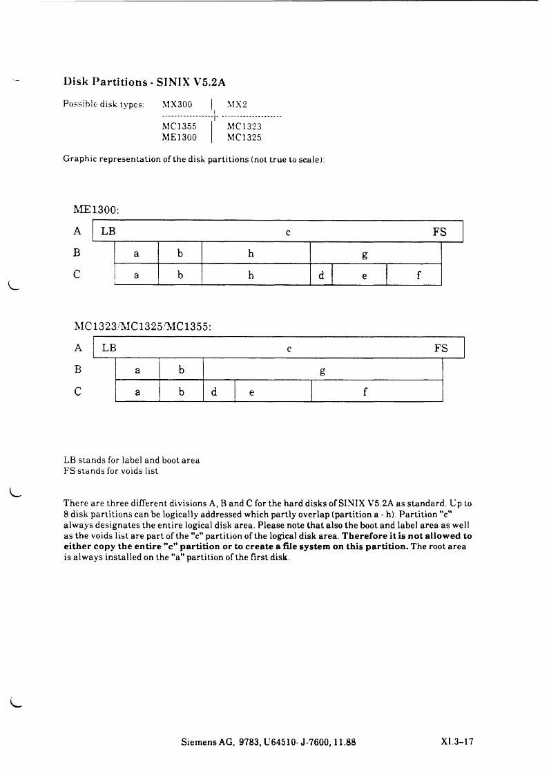
Disk Partitions - SINIX V5.2A
P o s s ib le d isk typ es: M X 3 0 0 | M X 2
MC 1355 M C I 323M E 13 0 0 MC 1325
G ra p h ic r e p r e s e n ta t io n o f th e d isk p a r t it io n s (n o t tru e to sca le ):
ME1300:
A LB FSB a b h gC a b h d e f
MC1323/'MC1325,MC1355:
A LB c FS
B a b gC a b d e f
LB s ta n d s for la b e l and boot a r e a F S s ta n d s for v o id s l is t
T h e r e a re th r e e d if fe r e n t d iv is io n s A , B an d C for th e h ard d is k s o f S IN IX V 5 .2 A a s s ta n d a r d . U p to 8 d isk p a r t it io n s ca n b e lo g ic a lly a d d r e sse d w h ich p a r tly o v e r la p (p a r tit io n a - h). P a r t it io n "c" a lw a y s d e s ig n a t e s th e e n t ir e lo g ic a l d isk a r e a . P le a s e n o te th a t a ls o th e b oo t an d la b e l a r e a a s w e ll a s th e v o id s l i s t a r e p a rt o f th e "c" p a r t it io n o f th e lo g ic a l d isk a re a . Therefore it is not allowed to either copy the entire "c" partition or to create a file system on this partition. T h e ro o t a r e a is a lw a y s in s ta l le d on th e "a" p a r t it io n o f th e f ir s t d isk .
S ie m e n s A G , 9 7 8 3 , U 6 4 5 1 0 - J - 7 6 0 0 ,1 1 .8 8 X I .3 - 1 7
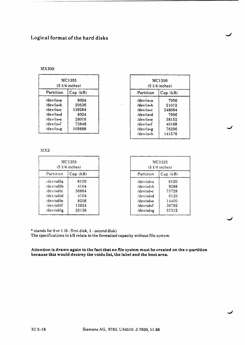
Logical format of the hard disks
M X 300:
M C 1355 (5 1/4 in c h e s )
P a r t it io n C ap. (kB )
/d e v /is* a 8 0 2 4/d ev /is* b 2 0 5 3 6/d ev /is* c 1 3 9 2 6 4/d ev /is* d 8 0 2 4/d ev /is* e 2 8 0 1 6/d e v /is* f 7 3 8 4 8/d e v /is* g 1 0 9 8 8 8
M X 2:
M C I 355(5 1/4 in ch es)
P a r t it io n C ap. (kB )
/dev/sdO a 6 1 2 0/dev/sdO b 4 1 0 4/dev/sdO c 3 6 8 6 4/devVsdOd 4 1 0 4/d ev /sdO e 8 2 0 8/d ev /sd O f 1 3 8 2 4/d ev /sdO g 2 6 1 3 6
MC 1300 (5 1/4 in c h e s )
P a r t it io n C ap. (kB )
/d ev /is* a 7 9 5 6/d ev /is* b 2 1 0 1 2/d ev /is* c 2 4 8 0 6 4/d ev /is* d 7 9 5 6/d ev /is* e 2 8 1 5 2/d e v /is* f 4 0 1 8 8/d ev /is* g 7 6 2 9 6/d ev /is* h 1 4 1 5 7 6
MC 1325(5 1/4 in ch es)
P a r t it io n C ap. (kB )
/d ev /sd *a 6 1 2 0/d ev /sd*b 9 2 8 8/d ev /sd *c 7 3 7 2 8/d ev /sd*d 6 1 2 0/d ev /sd *e 1 4 4 0 0/d ev /sd * f 3 6 7 9 2/d ev /sd * g 5 7 3 1 2
* s ta n d s for 0 or 1 (0 - f ir s t d isk , 1 - seco n d d isk )T h e s p e c if ic a t io n s in k B r e la te to th e fo rm a tted c a p a c ity w ith o u t f i le sy s te m .
Attention is drawn again to the fact that no file system must be created on the e-partition because this would destroy the voids list, the label and the boot area.
X I. 3 - 1 8 S ie m e n s A G , 9 7 8 3 , U 6 4 5 1 0 - J - 7 6 0 0 ,1 1 .8 8
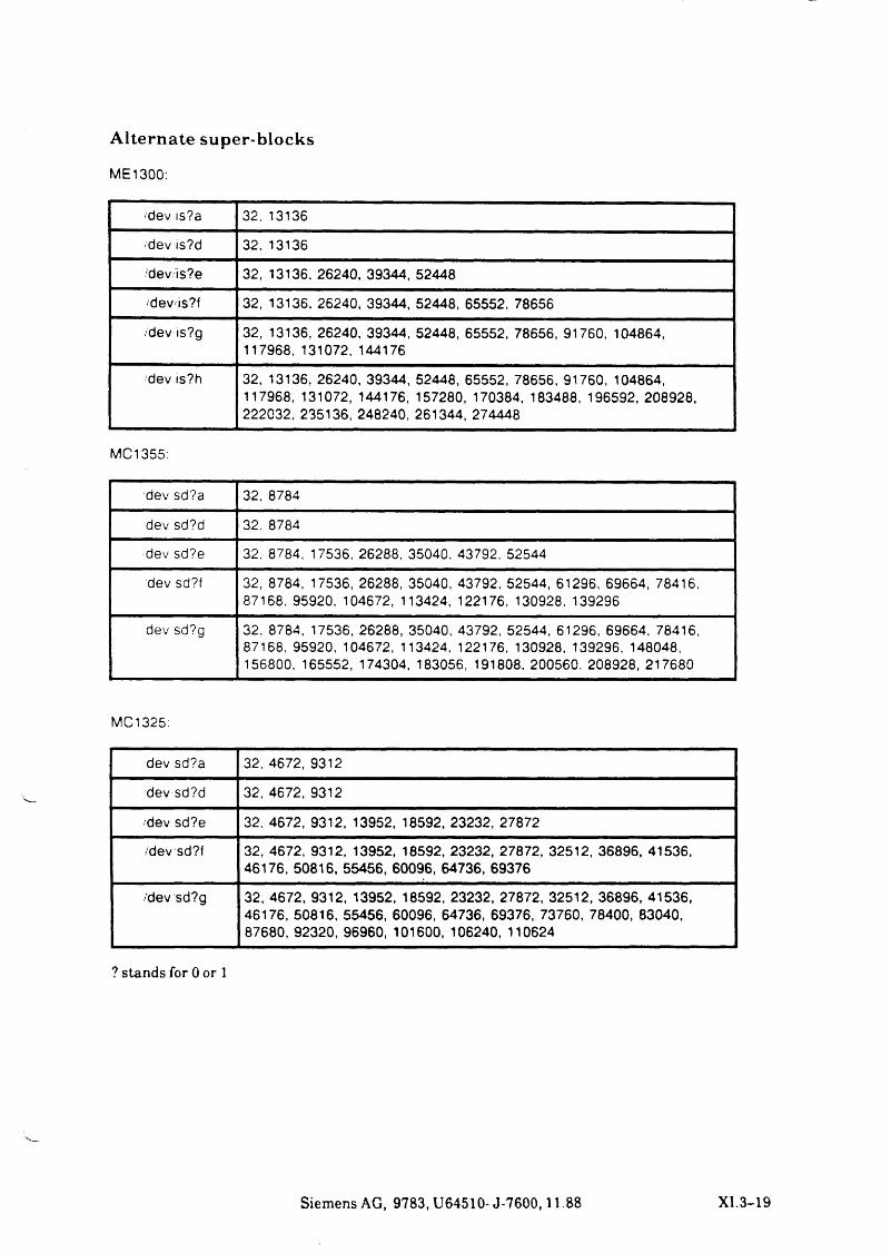
Alternate super-blocks
ME1300:
/dev is?a 32, 13136
/dev is?d 32, 13136
/dev is?e 32, 13136, 26240, 39344, 52448
/devis?f 32, 13136, 26240, 39344, 52448, 65552, 78656
/dev is?g 32, 13136, 26240, 39344, 52448, 65552, 78656, 91760, 104864, 117968, 131072, 144176
/dev,is?h 32, 13136, 26240, 39344, 52448, 65552, 78656, 91760, 104864, 117968, 131072, 144176, 157280, 170384, 183488, 196592, 208928, 222032, 235136, 248240, 261344, 274448
MC1355:
dev sd?a 32, 8784
dev sd?d 32, 8784
dev sd?e 32, 8784, 17536, 26288, 35040, 43792. 52544
dev sd?f 32, 8784, 17536, 26288, 35040, 43792, 52544, 61296, 69664, 78416, 87168, 95920, 104672, 113424, 122176, 130928. 139296
dev sd?g 32. 8784, 17536, 26288, 35040, 43792, 52544, 61296, 69664, 78416, 87168. 95920, 104672, 113424, 122176, 130928, 139296, 148048, 156800, 165552, 174304, 183056, 191808. 200560. 208928, 217680
MC1325:
dev sd?a 32, 4672, 9312
dev sd?d 32, 4672, 9312
/dev sd?e 32. 4672, 9312, 13952, 18592, 23232, 27872
/dev sd?f 32, 4672, 9312, 13952, 18592, 23232, 27872, 32512, 36896, 41536, 46176, 50816, 55456, 60096, 64736, 69376
/dev sd?g 32, 4672, 9312, 13952, 18592, 23232, 27872, 32512, 36896, 41536, 46176, 50816, 55456, 60096, 64736, 69376, 73760, 78400, 83040, 87680, 92320, 96960, 101600, 106240, 110624
? s ta n d s for 0 or 1
S ie m e n s A G , 9 7 8 3 , U 6 4 5 1 0 - J - 7 6 0 0 ,11 88 X I .3 - 1 9
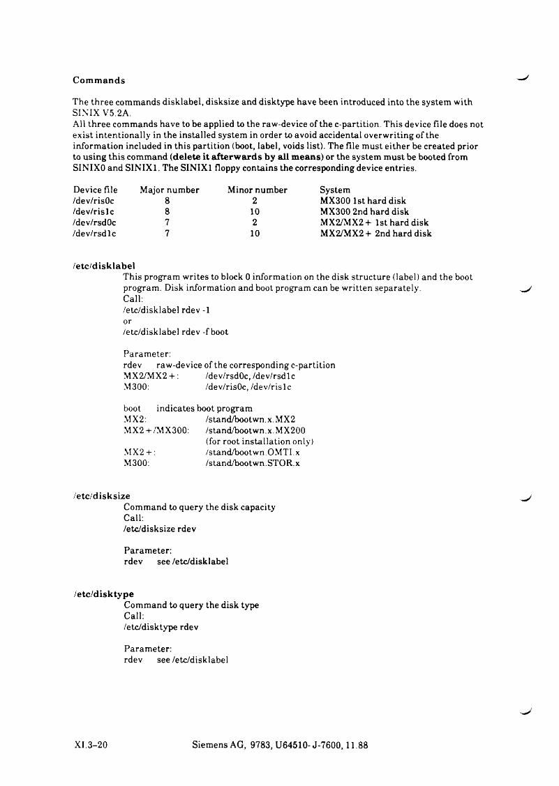
C o m m a n d s
T h e th r e e c o m m a n d s d is k la b e l, d is k s iz e an d d isk ty p e h a v e b een in tro d u ced in to th e s y s t e m w ith S IN IX V 5 .2 A .A ll th r e e co m m a n d s h a v e to b e a p p lied to th e ra w -d e v ic e o f th e c -p a r tit io n . T h is d e v ic e f i le d o e s n o t e x i s t in te n t io n a lly in th e in s ta l le d s y s te m in ord er to a v o id a c c id e n ta l o v e r w r it in g o f th e in fo r m a t io n in c lu d ed in th is p a r t it io n (boot, la b e l, v o id s l is t) . T h e f i le m u st e i th e r b e c r e a te d p rior to u s in g th is c o m m a n d ( d e l e t e i t a f t e r w a r d s b y a l l m e a n s ) or th e s y s te m m u st be b oo ted from SIN IX O a n d S IN IX 1 . T h e S IN IX 1 flop p y c o n ta in s th e c o r r e sp o n d in g d e v ic e e n tr ie s .
D e v ic e f ile M ajor n u m b e r M in or n u m b er S y s te m/d ev /r isO c 8 2 M X 3 0 0 1st h ard d isk/d e v /r is l c 8 10 M X 3 0 0 2n d h ard d isk/d ev /rsd O c 7 2 M X 2/M X 2 + 1 st h ard d isk/d e v /r s d lc 7 10 M X 2 /M X 2 + 2n d h ard d isk
/e t c / d i s k l a b e lT h is p ro g ra m w r ite s to b lock 0 in fo r m a tio n on th e d isk s tr u c tu r e ( la b e l) an d th e b oot p ro g ra m . D isk in fo r m a tio n an d boot p rogram ca n be w r it te n s e p a r a te ly .C all:/e tc /d is k la b e l rd ev -1 or/e tc /d is k la b e l rd ev - f boot
P a ra m eter :rd ev ra w -d e v ic e o f th e c o r r e sp o n d in g c -p a r tit io n M X 2 /M X 2 + : /d ev /rsd O c, /d e v /r s d lcM 300: /d ev /r isO c, /d e v /r is lc
boot in d ic a te s b oot p ro g ra m M X 2: /s ta n d /b o o tw n .x .M X 2M X 2 + /M X 3 0 0 : /s ta n d /b o o tw n .x .M X 2 0 0
(for root in s ta l la t io n o n ly )MX2-+-: /s ta n d /b o o tw n .O M T I.xM 300: /s ta n d /b o o tw n .S T O R .x
/ e t c / d i s k s i z eC o m m a n d to q u ery th e d isk ca p a c ity C all:/e tc /d is k s iz e rd ev
P a ra m eter :rd ev s e e /e tc /d is k la b e l
/ e t c / d i s k t y p eC o m m a n d to q u e ry th e d isk ty p e C all:/e tc /d is k ty p e rd ev
P a ra m eter :rd ev s e e /e t c /d is k la b e l
X I .3 - 2 0 S ie m e n s A G , 9 7 8 3 , U 6 4 5 1 0 - J - 7 6 0 0 ,1 1 .8 8
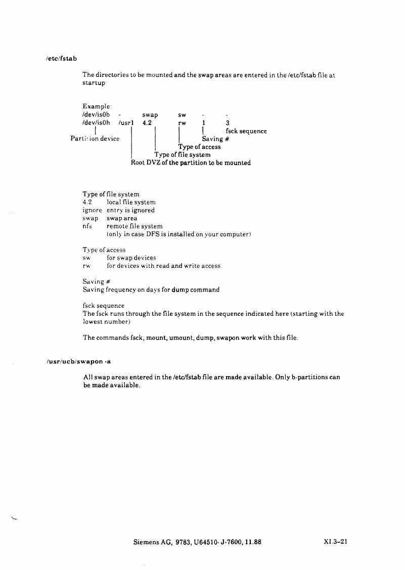
/ e t c / f s t a b
T h e d ir e c to r ie s to be m o u n ted an d th e sw a p a r e a s a re e n te r e d in th e /e tc /f s ta b f ile a t sta r tu p :
E x a m p le :/d ev /isO b - sw a p sw/d ev /isO h /u s r l 4 .2 rw 3
P a rti: ion d e v ic eI fsck se q u e n c eS a v in g #
T y p e o f a c c e s s T y p e o f f i le s y s te m
R oot D V Z o f th e p a r t it io n to b e m o u n ted
T y p e o f f i le s y s te m4 .2 lo c a l f i le s y s te mig n o r e e n tr y is ig n o redsw a p sw a p a rean fs r e m o te f ile s y s te m
(o n ly in c a s e D F S is in s ta l le d on y o u r co m p u ter )
T y p e o f a c c e s s sw for sw a p d e v ic e srw for d e v ic e s w ith read and w r ite a c c e s s
S a v in g #S a v in g fre q u en cy on d a y s for d u m p co m m a n d
fsck se q u e n c eT h e fsck ru n s th r o u g h th e f ile s y s te m in th e se q u e n c e in d ic a te d h e r e ( s ta r t in g w ith th e lo w e s t n u m b er)
T h e co m m a n d s fsck , m o u n t, u m o u n t, d u m p , sw a p o n w ork w ith th is f ile .
/usr/ucb/sw apon -a
A ll sw a p a r e a s e n te r e d in th e /e tc /f s ta b f i le a re m a d e a v a ila b le . O n ly b -p a r t it io n s ca n b e m a d e a v a ila b le .
S ie m e n s A G , 9 7 8 3 , U 6 4 5 1 0 - J - 7 6 0 0 ,1 1 .8 8 X I .3 -2 1
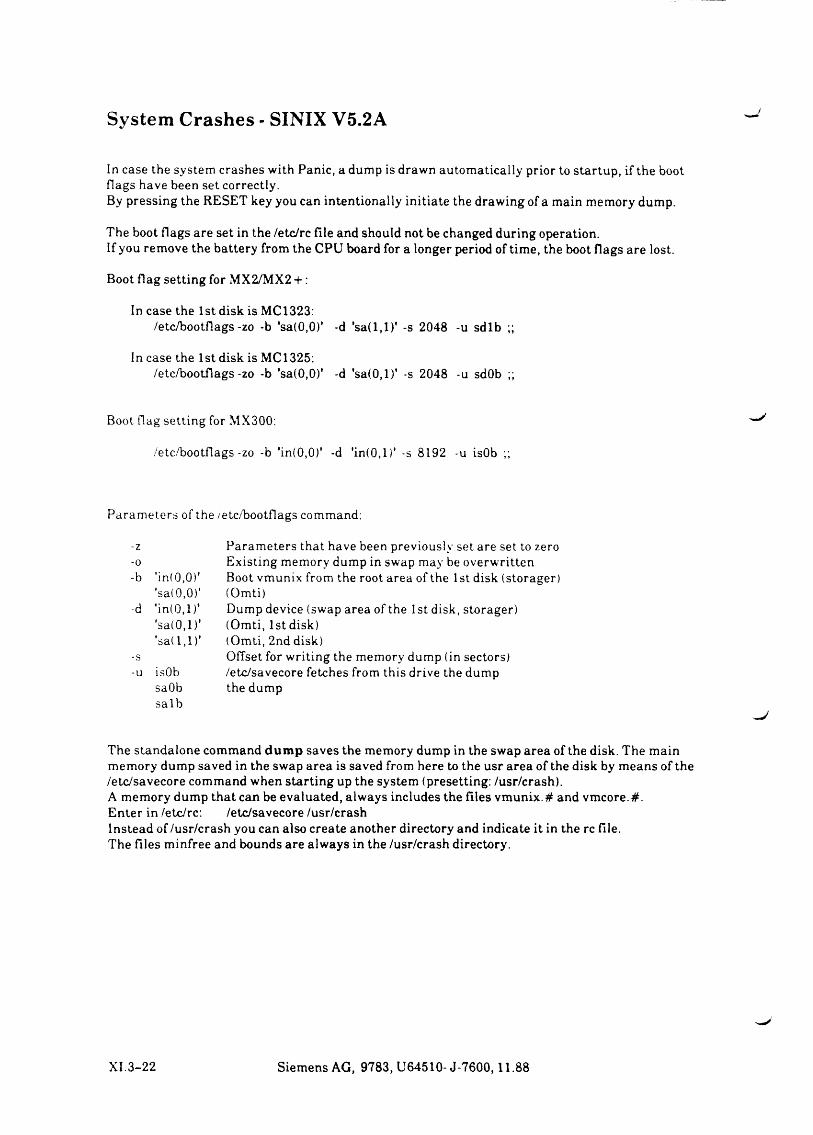
System Crashes - SINIX V5.2A
In c a s e th e s y s te m c r a s h e s w ith P a n ic , a d um p is d raw n a u to m a tic a lly p rior to s ta r tu p , i f th e b oot f la g s h a v e b een s e t c o r re c tly .B y p r e s s in g th e R E S E T k ey y ou ca n in te n t io n a lly in it ia te th e d r a w in g o f a m a in m em o ry d u m p .
T h e b oot f la g s a re s e t in th e /e tc /r c f i le a n d sh o u ld n o t be c h a n g e d d u r in g o p era tio n .If y o u r e m o v e th e b a tte r y from th e C P U b oard for a lo n g e r p eriod o f t im e , th e boot f la g s a re lo s t .
B o o t f la g s e t t in g for M X 2/M X 2 + :
In c a s e th e 1 st d isk is M C 1323:/e tc /b o o tf la g s -z o -b ’s a (0 ,0 ) ’ -d ’s a ( l , l ) ' -s 2 0 4 8 -u s d lb ;;
In c a s e th e 1 s t d isk is MC 1325:/e tc /b o o tf la g s -z o -b ’sa (0 ,0 )' -d ' s a ( 0 , l ) ’ -s 2 0 4 8 -u sdOb ;;
B oot f la g s e t t in g for M X 300:
/e tc /b o o tf la g s -zo -b 'in (0 ,0 )' -d ' in (0 ,l) ' -s 8 1 9 2 -u isOb ;;
P a r a m e te r s o f th e /e tc /b o o tf la g s com m an d :
-z P a r a m e te r s th a t h a v e b een p r e v io u s ly s e t are se t to zero-0 E x is t in g m em o ry d u m p in sw a p m ay be o v e r w r it te n-b *i n( 0,0)* B oot v m u n ix from th e root a rea o f th e 1st d isk (sto r a g er )
*sa( 0 ,0)' (O m ti)-d * in (0 ,1 )* D u m p d e v ic e (sw a p a re a o f th e 1st d isk , s to ra g e r )
's a (0 , l ) ' (O m ti, 1 st d isk )'sa( 1,1)' (O m ti, 2n d d isk )
-s O ffse t for w r it in g th e m em o ry d u m p (in se c to r s)-u isOb /e tc /sa v e c o r e fe tc h e s from th is d r iv e th e d u m p
saObs a lb
th e d u m p
T h e s ta n d a lo n e c o m m a n d dump s a v e s th e m em o ry d u m p in th e sw a p a r e a o f th e d isk . T h e m a in m em o ry d u m p sa v e d in th e sw a p a r e a is sa v e d from h ere to th e u sr a r e a o f th e d isk by m e a n s o f th e /e tc /s a v e c o r e co m m a n d w h e n s ta r t in g up th e s y s te m (p r ese tt in g : /u sr /c r a sh ) .A m em o ry d u m p th a t ca n be e v a lu a te d , a lw a y s in c lu d e s th e f i le s v m u n i x # an d v m c o r e .# .E n te r in /e tc /rc : /e tc /s a v e c o r e /u sr /c r a shIn s te a d o f /u sr /c r a sh y o u ca n a lso c r e a te a n o th e r d ire c to ry an d in d ic a te i t in th e rc f ile .T h e f i le s m in fr e e an d b o u n d s a re a lw a y s in th e /u sr /c r a sh d ire c to ry .
XI. 3 - 2 2 S ie m e n s A G , 9 7 8 3 , U 6 4 5 1 0 - J - 7 6 0 0 ,1 1 .8 8
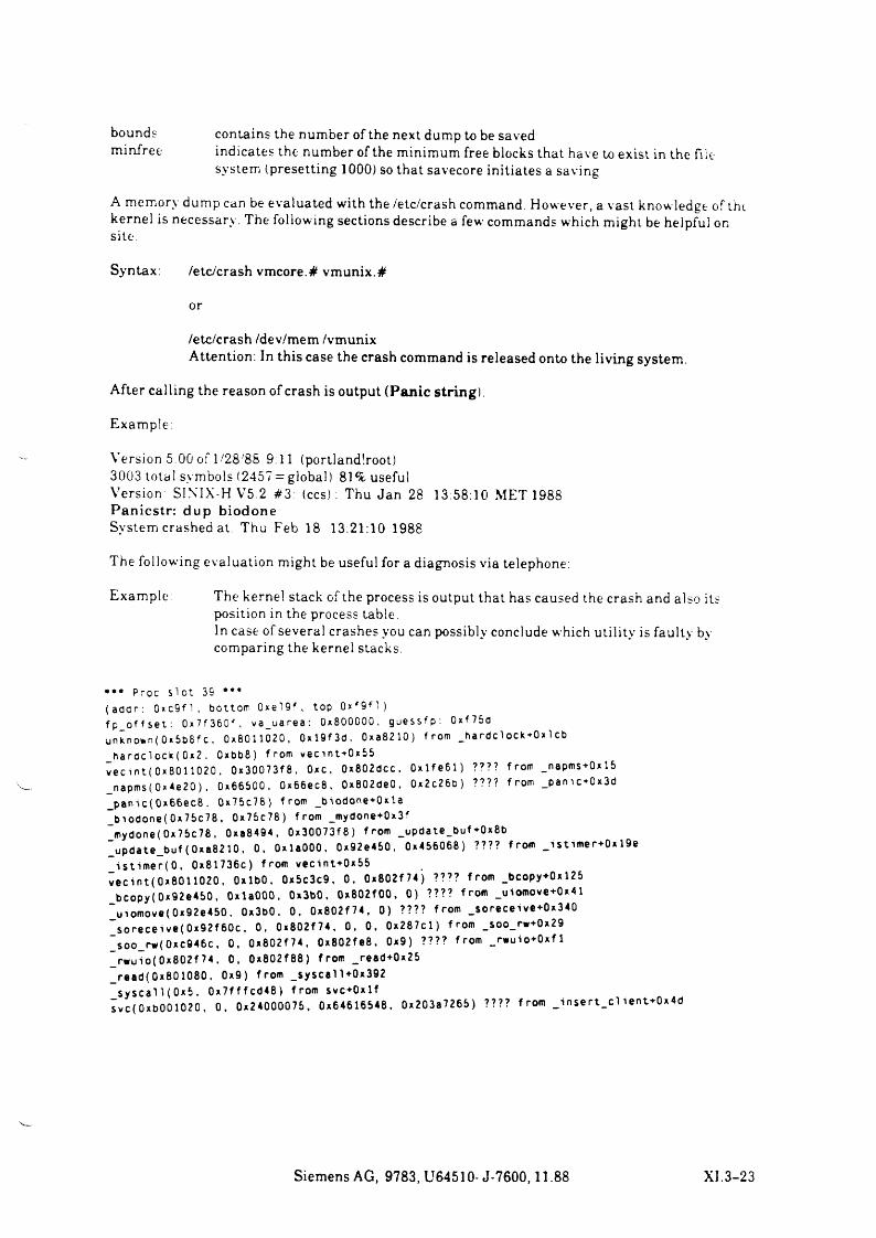
b ou n d s c o n ta in s th e n u m b er o f th e n ex t dum p to be sa v edm in fr e e in d ic a te s th e n u m b er o f th e m in im u m free b lo ck s th a t h a v e to e x is t in th e file
s y s te m (p r e se tt in g 1000) so th a t sa v e co r e in it ia te s a sa v in g
A m em o ry d u m p can be e v a lu a te d w ith th e /e tc /cr a sh com m an d . H o w ev e r , a v a st k n o w le d g e o f the k e r n e l is n e c e s sa r y . T h e fo llo w in g s e c t io n s d escr ib e a few co m m a n d s w h ich m ig h t be h e lp fu l on s ite .
S y n ta x : /e tc /c r a sh v m c o r e .# v m u n ix .#
or
/e tc /c r a sh /d ev /m e m /v m u n ixA tten tio n : In th is c a se th e cr a sh com m an d is r e le a se d o n to th e l iv in g sy s te m .
A fte r c a l l in g th e re a so n o f cr a sh is o u tp u t (Panic string).
E x a m p le :
V e r s io n 5 .0 0 o f 1 /2 8 /8 8 9:11 (p ortlan d lroo t)3 0 0 3 to ta l sy m b o ls (2 4 5 7 = g lo b a l) 81% u se fu lV e r s io n SINTX -H V 5 2 # 3 : ( c c s ) : T h u J a n 28 13:58:10 M E T 1988P a n ic s t r : d u p b io d o n eS y s te m cra sh ed at: T hu F eb 18 1 3 :21 :10 1988
T h e fo llo w in g e v a lu a t io n m ig h t be u se fu l for a d ia g n o s is v ia te lep h on e:
E x a m p le : T h e k ern e l s ta ck o f th e p ro cess is o u tp u t th a t h a s ca u sed th e cra sh and a lso itsp o s it io n in th e p ro cess ta b le .In ca se o f se v e r a l c r a sh e s you can p o ss ib ly co n c lu d e w h ich u t il ity is fa u lty by co m p a r in g th e k ern e l s ta ck s .
••• Proc s lot 35 •••( add r : 0xc9 f l , bottom 0xel9f , top 0xf 9f ! )fp_of f s e t : 0 x 7 f 360 f . va_uarea: 0x800000. guessfp: 0xf75dunknown( 0x5b8fc, 0x8011020, 0xl9f3d. 0xa8210) from _hardclock+0x1cb_hardclock( 0x2 . 0xbb8) from vec i nt+0x55v e c in t (0x8011020, 0x30073f8, Oxc, 0x802dcc. 0xlfe61) ???? from _napms+0xl5 _napms(0x4e20 ), 0x66500, 0x66ec8, 0x802de0, 0x2c26b) ???? from _pamc + 0x3d _panic(0x66ec8. 0x75c78) from _biodone+0xla _biodone(0x75c78, 0x75c78) from _mydone+0x3f _mydone(0x75c78, 0xa8494, 0x30073f8) from _update_buf+0x8b_update_buf( 0xa8210, 0. OxlaOOO, 0x92e450, 0x456068) ???? from _istimer-0x19e
is t im e r(0 . 0x81736c) from vecint+0x55 vec i n t ( 0x8011020, OxlbO, 0x5c3c9, 0, 0x802f74) ???? from _bcopy+0xl25 _bcopy( 0x92e450, OxlaOOO. Ox3bO, 0xB02f00, 0) ???? from _uiomove+0x41 _uiomove(0x92e450. 0x3b0. 0, 0x802f74, 0) ???? from _soreceive+0x340 _soreceive( 0x92 f 60c, 0, 0x802f74. 0, 0, 0x287cl) from _soo_rw0x29 _soo_rw(0xc946c, 0, 0x802f74, 0x802fe8, 0x9) ???? from _rwuio+0xf1 _rwuio(0x802f 74. 0, 0x802f88) from _read+0x25 _read(0x801080, 0x9) from _ sy sca l1+0x392
s y s c a l1(0x5, 0x7fffcd48) from svc+Oxlfsvc(OxbOO1020, 0, 0x24000075, 0x64616548. 0x203a7265) ???? from _insert_client*0*4d
Siemens AG, 9783, U64510-J-7600,11.88 X I.3 -2 3
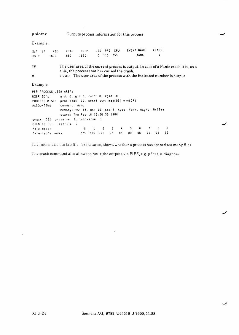
p slotnr O u tp u ts p ro cess in fo rm a tio n for th is p rocess
E x a m p le .
SLT st PID PPID PGRP UID PRI CPU EVENT NAME FLAGS 39 R 1670 1669 1560 0 113 255 dump 1
c u T h e u ser a rea o f th e cu rren t p rocess is ou tp u t. In c a se o f a P a n ic cra sh it is , a s aru le , th e p ro cess th a t h a s ca u sed th e crash .
u s lo tn r T h e u ser a rea o f th e p ro cess w ith th e in d ica ted n u m b er is ou tp u t.
E xa m p le:
PER PROCESS USER AREA:USER I D ’ s: u i d : 0. g id :0 , ruid: 0, rgid: 0PROCESS MISC: proc s lo t : 39, cntr l t ty: maj(05) min(04)ACCOUNTING: command: dump
memory: ts : 14, ds: 19, ss: 2, type: fork, magic s t ar t : Thu Feb 18 13:20:35 1988
umasic: 02 2 , universe: 1 . tuniverse: 0
OPEN F I _E S : , l a s t f i 1e: 9f i l e desc: 0 1 2 3 4 5 6 7f i l e - t a o l e index: 275 275 275 96 88 89 90 91
0xl2ea
8 992 93
T h e informat ion in la s t f i le , for in s ta n c e , sh o w s w h e th er a p ro cess h a s op en ed too m a n y f ile s
T h e cra sh com m an d a lso a llo w s to rou te the o u tp u ts v ia P IP E , e g. p ! ca t > d ia g n o se .
XI. 3-24 S ie m e n s A G , 9 7 8 3 , U 6 4 5 1 0 - J - 7 6 0 0 ,1 1 .8 8


v.J
SIEMENS
Part XII System Files

Part XII
System Files
Contents Page
1 S y s t e m F i le s / e t c /r c .s in ix l / .p r o f i le .s in ix l /d e v /M A K E D E V /e tc /r c /e tc /rc . loca l /e tc /r c .s ie /e tc /r c .s y s 5 /e tc /t ty s /e tc /t ty tv p e /e tc /g e t ty ta b /e tc /p a s sw d /e tc /g r o u p /e tc /d isk ta b /e tc /s u p e r in s ta l l /u sr /s ie _ r o o t /e tc /w a itf l /d ev
X I I . 1-1X I I .1-2 X II .1-3 X I I .1-7 X II. 1 -10 X I I .1-13 X I I .1 -14 XII 1-15 XII 1-16 X I I .1-17 X II .1-19 X I I .1-21 XII 1-22 XII 1-23 XII 1-28 X II. 1-30 X I I .1-31

1 System Files/etc/rc. (sinixl)/.profile, (sinixl)/dev/MAKEDEV/etc/rc/etc/rc.local/etc/rc.sie/etc/rc.sys5/etc/ttys/etc/ttytype/etc/gettytab/etc/passwd/etc/group/etc/disktab/etc/superinstall/usr/sie_root/etc/waitfl/dev
Siemens AG, 9783, U64510- J-7600, June 89 XII.1-1
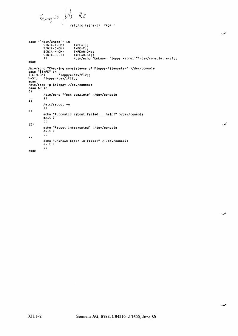
■Jo y i U/e tc/rc ( s i n i x l ) Page 1
case
esac
/bin/uname'" in SINIX-I-OH) SINIX-C-OM) SINIX-H-OM) SINIX-H-ST)*)
TYPE=I;;TYPE=C;;TYPEsH-OM;;TYPE=H-ST;;/bin/echo "Unknown floppy k e rn e l!” >/dev/console; e x i t ; ;
/bin/echo "Checking consistency of Floppy-Filesystem ” >/dev/console case ”$TYPE" inI|C|H-0M) floppys/dev/f12;;H-ST) f loppys/de v/if12; ;esac/etc/fsck -p $floppy >/dev/console case $? in0)
/bin/echo "fsck complete” >/dev/console
4)9 !
/etc/reboot -n
8)echoe xit
"Automatic reboot f a i l e d . . . he lp!” >/dev/console 1
12)I )
echoe xit
"Reboot interrupted" >/dev/console 1
*)1 9
echoe xit
"Unknown error in reboot” > /dev/console 1
esac f f
XII.1-2 Siemens AG, 9783, U64510- J-7600, June 89
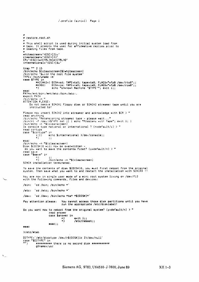
/ .p r o f i le ( s i n i x l ) Page 1
0
0 re store .root.sh 00 This she ll s c r ip t is used during i n i t i a l systeir load from 0 tape. It prompts the user for a ff irm ative re p lie s prior to 0 loading f i l e s from tape.0whltescreens’ <ESC>[21u’ c le a rscre e n s ’ <ESC>[23’CR=’ <ESC>)w<CTRl>Nle<CTRL>0' internationals'<ESC>[6u'
trap "" 2 15/bin/echo $|clearscreen}${whitescreen)/bin/echo 'Build the root f i l e system’TYPEs'/bin/uname -m‘ case $TYPE in
MX2|MX2+) DISKssd; TAPEstsO; tapests8; FLAGS=”xfpB /dev/rts8";;HX300) D ISKsis ; TAPEsisO; tape = is8 ; FLAGS="xfpB /oe v/ris8” ;j*) echo "Unknown Machine * $ TYPE’ ” ; e x it 1;;
esacPATHs/mnt/bin;/»nt/etc:/ b in :/etc :. export PATH /bin/echo -n "ATTENTION PLEASE:
Do not remove SINIX1 floppy disk or SINIX2 streamer tape u n t i l you are instructed to!
Please now insert SINIX2 into streamer and acknowledge with $CR > " read anything/bin/echo "Retensioning streamer tape - please w a it . . . "/bin/mt - f /aev/rSTAPE ret l| | echo "Problems with Tape"; e x it 1; )/bin/echc -n ”$ |c1earscreenjIs console type national or international ? ( n = d e fa u lt/ i) > "read contypecase "(contype” in
1 11) echo (in te rna t io na l >/dev/console;;*) ;;
esac/bin/echo -n "$(c 1earscreen )Disk ( {D IS K }0 w il l now be overwritten -
do you want to save the contents f i r s t ? (y=default/n) > " read save case "(save” in
n) ;;*) /bin/echo -n " ( |clearacreen)
SINIX in s t a l la t io n terminated.
To save the contents of disk ({DISK tO, you must f i r s t reboot from the o r ig in a l system. Then save what you want to and re sta rt the in s t a l la t io n with SINIXO !!
You are now in s in g le user mode of a mini root system l iv in g on /dev/fl2 with the following commands, f i l e s and devices:
/bin: “cd /bin; /bin/echo #*
/etc: “cd /etc ; /bin/echo *“
/dev: “cd /dev; /bin/echo *ts* * ({D ISK )* “
Pay attention please: You cannot access those disk p a rt it io n s u n t i l you haverun the appropriate / e t c / d is k la b e l!
Do you want now to reboot from the o r ig in a l system? (y=default/n) > " read answer case (answer in
n) e x it 1;;*) /e tc/re bo o t;;
>/etc/mtab
D2TYPE:' /etc/disktype /dev/r({D ISK} lc 2>/dev/null“ case "SD2TYPE" in"") 0 0 0 0 0 0 0 0 0 0 there is no second disk 0 0 0 0 0 0 0
gOname=/usr
Siemens AG, 9783, U64510- J-7600, June 89 XII. 1-3
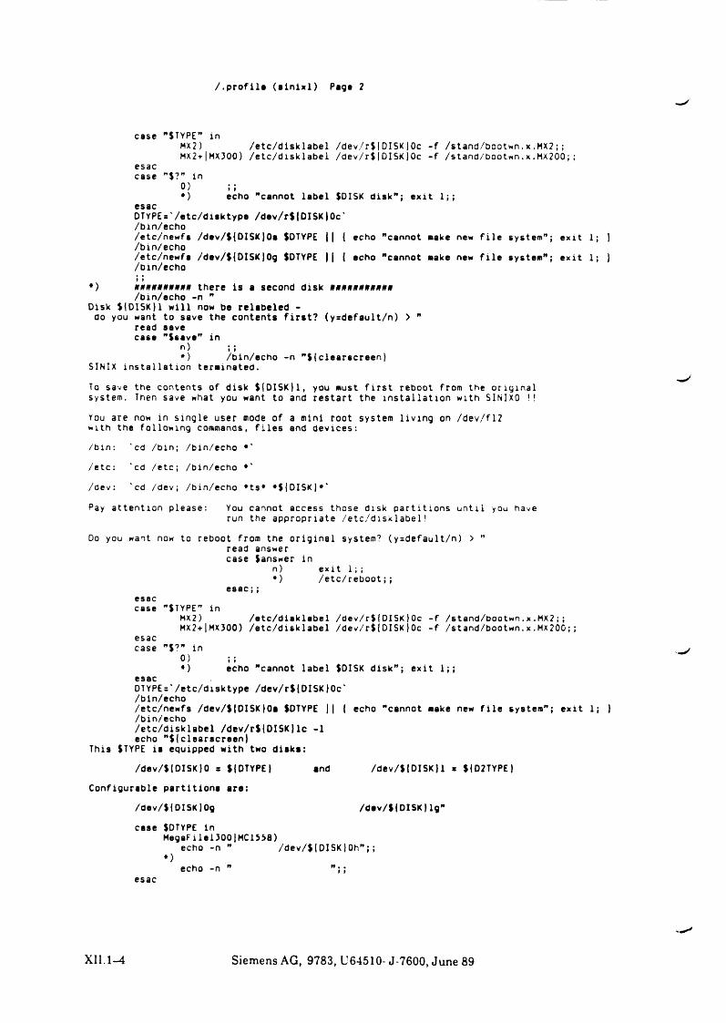
/ .p r o f i l« ( s i n i x l ) Pag« 2
case "STYPE” inMX2) /e tc/d isk label /dev/r$(DISK|Oc - f /stand/bootwn.x.MX?;;MX2+|MX300) /e tc/d isk lab e l /dev/r$(DISK}Oc - f /stand/bootwn. x . MX200;;
esaccase ”$?” in
0 ) ; ;*) echo "cannot label $DISK d isk"; e x it 1;;
esacDTYPEs'/etc/disktype /dev/r$|DISK}0c'/bin/echo/etc/newfs /dav/${DISK)0a JDTYPE || { echo "cannot sake new f i l e system"; e x it 1; ) /bin/echo/etc/newfs /dav/${DISK)0g $DTYPE || { echo "cannot sake new f i l e system"; e x it 1; } /bin/echo» t
*) *##*»»»»*# there is a second disk #»*»*####*»/bin/echo -n "
Disk ){D1SK)1 w i l l now be relabeled - do you want to save the contents f i r s t ? (ysdefault/n) > ”
read save case "$save" in
n) ;;*) /bin/echo -n "$ ic le a rsc re e n }
SINIX in s t a l la t io n terminated.
To save the contents of disk ${DISK)1, you must f i r s t reboot from the o r ig in a l system. Then save what you want to and re sta rt the in s t a l la t io n with SINIXO !!
You are now in s in g le user mode of a mini root system l iv in g on /dev/flZ with the following commands, f i l e s and devices:
/bin: "cd /bin; /bin/echo *'
/etc: 'cd /etc; /bin/echo *'
/dev: 'cd /dev; /bin/echo *ts* *$(DISK|*'
Pay attention please: You cannot access those disk p art it io n s u n t i l you haverun the appropriate /e tc/d isk label!
Do you want now to reboot from the o r ig in a l system? (y=default/n) > ”read answer case $answer in
n) e x it 1 ; ;* ) /etc/reboot;;
case "$TYPE” inMX2) /e tc/d isk lab e l /dev/r${DISK )0c - f /stand/bootwn.x . MX2;;MX2+|MX300) /e tc/d isk la b e l /dev/r$|DISK}0c - f /stand/bootwn. x .MX200;;
esaccase ”$?” in
0) ;;*) echo "cannot label $DISK d is k ” ; e x it 1;;
esacDTYPE='/etc/disktype /dev/r$(DISK}0c'/bin/echo/etc/newfs /dev/${DISK)0a $DTYPE || | echo "cannot make new f i l e system"; e x it/bin/echo/e tc/d isk lab el /dev/r${DI5KJlc -1 echo " $ (clearscreen}
This STYPE is equipped with two d isk s :
/dev/$(DISK)0 s SIOTYPE} and /dev/${DISK)1 = ${D2TYPE}
Configurable p art it io n s are:
/dev/${DISK)Og /dav/${DISK|lg"
case SDTYPE inMegaFilel300|MC1538)
echo -n " /dev/$|DISK ) Oh";;*)
echo -n ” " ; ;esac
XII. 1-4 Siemens AG, 9783, U64510- J-7600, June 89
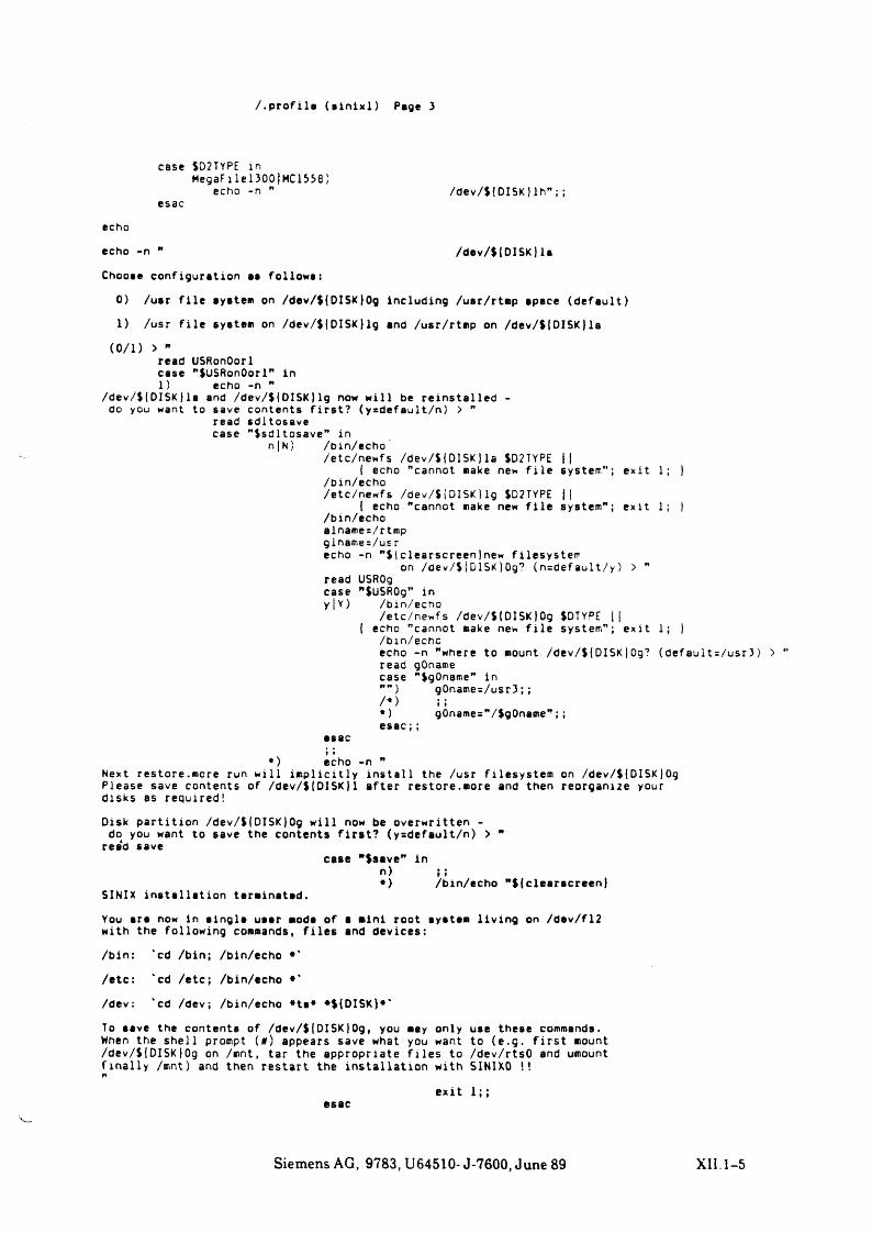
/ . p r o f i le ( e i n i x l ) Page 3
case SD2TYPE inMegaFilel300|HC1558)
echo -n " /dev/${DISK) l h ” ;;esac
echo
echo -n " /dev/$|DISK)la
Chooae configuration aa follow»:
0) /usr f i l e syatem on /dev/$(DISK}Og including /usr/rtmp space (d e fa u lt)
1) /usr f i l e system on /dev/$(DISK} lg and /usr/rtmp on /dev/${DISK) la
( 0/ 1 ) > "read USRonOorl case "SllSRonOorl" in 1) echo -n "
/dev/$(DISK) la and /dev/${DISK} lg now w i l l be re in sta l le d - do you want to save contents f i r s t ? (ysdefault/n) > ”
read sdltosave case "$sdltosave” in
n | N) /bin/echo/etc/newfs /dev/$(DISK}la JD2TYPE ||
( echo "cannot make new f i l e system” ; e x it 1; }/bin/echo/etc/newfs /dev/$tD ISK}lg $D2TYPE ||
{ echo "cannot make new f i l e system” ; e x it 1; )/bin/echoalname=/rtmpglname=/usrecho -n ”$iclearscreen(new filesystem
on /dev/$fDISKjOg? (n=default/y) > ”read USROg case ”$USR0g” iny|Y) /bin/echo
/etc/newfs /dev/${DISK)0g $DTYPE ||{ echo "cannot make new f i l e system” ; e x it 1; )
/bin/echcecho -n "where to mount /dev/${DISK)0g? (d efau lt= /u sr3) > read gOname case "SgOname” in
) g0name=/usr3;;/*) ;;*) g0name=”/$g0name” ;;e sa c ;;
esact f
*) echo -n ”Next restore.more run w i l l im p l ic i t ly i n s t a l l the /usr f i lesystem on /dev/${DISK)0g Please save contents of /dev/${DISK)1 a fte r restore.more and then reorganize your disks as required!
Disk p a rt it io n /dev/${DISKjOg w i l l now be overwritten - do you want to save the contents f i r s t ? (y=default/n) >
rea‘d save
SINIX in s t a l la t io n terminated.
case "Ssave" inh ) i I*) /bin/echo ${clearscreen)
You are now in s in g le uaer mode of a mini root aystem l i v in g on /dev/fl2 with the following commands, f i l e s and devices:
/bin: 'cd /bin; /bin/echo •*
/etc: 'cd /etc; /bin/echo •'
/dev: 'cd /dev; /bin/echo *ta* *${DISK}*'
To save the contents of /dev/${DISK)0g, you may only use these commands. When the sh e l l prompt (a) appears save what you want to (e .g . f i r s t mount /dev/$|DISK}0g on /mnt, tar the appropriate f i l e s to /dev/rtsO and umount f in a l ly /mnt) and then re sta rt the in s t a l la t io n with SINIXO !!
Siemens AG, 9783, U64510- J-7600, June 89 XII.1-5
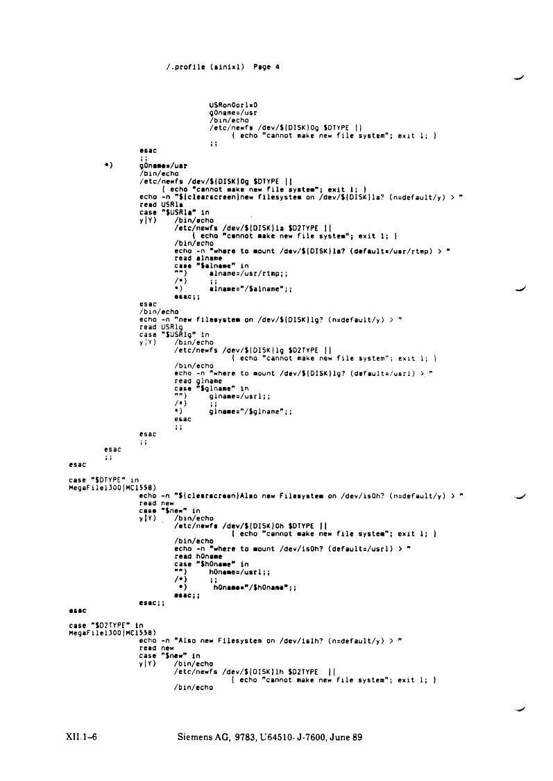
/ .p r o f i le ( s i n i x l ) Page 4
USRonOorlsOgOnames/usr/bin/echo/etc/newfa /dev/S|DISK)Og SDTYPE ||
{ echo "cannot make ne« f i l e system” ; e x it 1; }
esac» t
*) gOnamas/uar/bin/echo/etc/newfs /dev/$|DISK|Og SDTYPE ||
{ echo "cannot make new f i l e system” ; e x it 1; } echo -n ”${clearscreen)new filesystem on /dev/S(DISK) la? (n=default/y) > ” read USRla case ”)USRla” in y | Y ) /bin/echo
/etc/newfs /dev/S{DISK}la SD2TYPE ||{ echo "cannot make new f i l e system” ; e x i t 1; }
/bin/echoecho -n "where to mount /dev/$|DISK}la? (defaults/usr/rtmp) > ”read alnamecase "Salname” in”") alname=/usr/rtmp;;/•> ;;•) alnames”/$alname” ;; —/e s a c ; ;
esac/bin/echoecho -n "new filesystem on /dev/${DISK}lg? (n=default/y) > ” read USRlg case "SUSRlg” in y|Y) /bin/echo
/etc/newfs /dev/$(DISK}lg SD2TYPE ||{ echo "cannot make new f i l e system” ; e x it 1; }
/bin/echoecho -n "where to mount /dev/${DISK) lg? (default = / u s r i ) > "read glnamecase "Sglname” in”” ) glname=/usr1;;/•) ;;•) glnames”/$glname” ; ;esac
esaci i
esac i !
esac
case "SDTYPE” in MegaFllei 300|MC 1558)
echo -n "S(clearscreen}Alao new Filesystem on /dev/isOh? (n=default/y) > ” •.„/read new case "Snew" in y|Y) /bin/echo
/etc/newfs /dev/S(DISK)Oh SDTYPE ||{ echo "cannot make new f i l e system” ; e x it 1; }
/bin/echoecho -n "where to mount /dev/isOh? (d efau lt= /u sr1) > ”read hOnamecase "ShOname" in
hOnames/usrl;;! th0names"/Sh0name";;
C 9 m v j )esac
case "SD2TYPE” in MegaFilei300|MC1558)
echo -n "Also new Filesystem on /dev/islh? (n=default/y) > ” read new case "Snew" in y|Y) /bin/echo
/etc/newfs /dev/S{DISK) lh SD2TYPE ||j echo "cannot make new f i l e system” ; e x it 1; }
/bin/echo
ffR j/*>*>
a s a c ; ;
XII.1-6 Siemens AG, 9783, U64510- J-7600, June 89
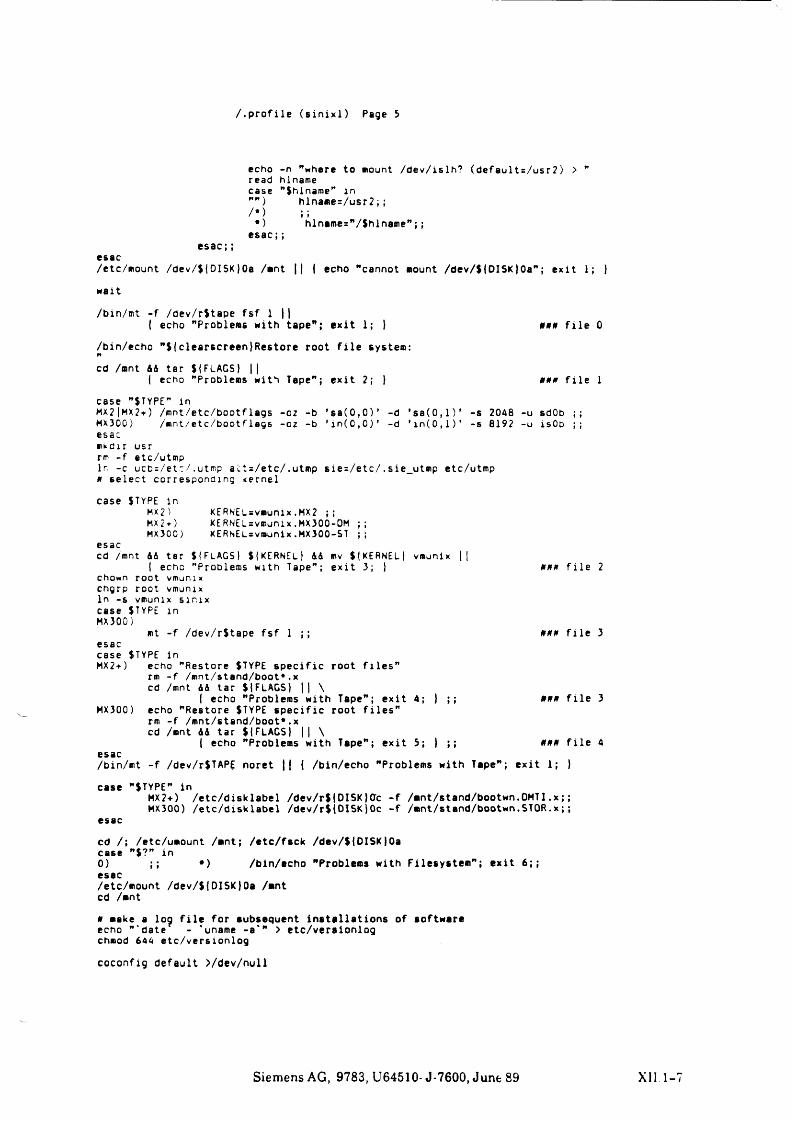
/ .p r o f i le ( s i n i x l ) Page 5
echo -n "where to eiount /dev/islh? (default = /usr 2) > " read hlname case ”$hlname” in
) hlname=/usr2;;/* ) ;;
*) hlname="/$hlname” ;;e sac;;
e s a c ; ;esac/etc/mount /dev/$(DI5K)0a /mnt || | echo "cannot mount /dev/$|DISK}Oa"; e x it 1; )
wait
/bin/mt - f /dev/r$tape f s f 1 |}{ echo "Problems with tape"; e x i t 1; } *»# f i l e 0
/bin/echo ”$ (clearscreen}Restore root f i l e system:n
cd /mnt 44 tar ${FLAGS) ||( echo "Problems with Tape” ; e x it 2; ) ### f i l e 1
case "$TYPE” inMX21MX2 + ) /mnt/etc/bootflags -02 -b * s a (0 ,0 ) ’ -d * 88(0 ,1)’ -s 2048 -u sdOb ;; MX300) /mnt/etc/bootflegs -oz -b ’ in ( C , 0 ) ' -d ’ i n ( 0 , i ) ’ -s 8192 -u isOb ;; esacmkdir usr rm - f etc/utmp1 r, -c u c b : / e t c / . utmp a c t = / e t c / . u t m p s i e = / e t c / . s ie_utmp e tc/utmp # s e l e c t co rrespond ing kernel
case $TYPE InMX2 ) K E R N E L = vmunix.MX2 ;;MX 2 + ) KERNEL=vmunix.MX300-0M ;;MX300) KERNELsvmunix.MX300-ST ;;
esaccd /mnt 44 tar $ |FLAGS) $|KERNEl) 44 mv $ ( KERNEL) vmunix ||
I echo "Problems with Tape” ; e x it 3; ) * * * f i l e 2c h o w n root vmunix chgrp root vmunix In -s vmunix s in ix case STYPE in MX300)
mt - f /dev/r$tape f s f 1 ;; * * * f i l e 3esaccase $TYPE InMX2+) echo "Restore $TYPE s p e c i f i c root f i l e s ”
rm - f /mnt/stand/boot*. x cd /mnt 44 tar St FLAGS} || \
I echo "Problems with Tape” ; e x it 4; } ; ; f i l e 3MX300) echo "Restore $TYP£ s p e c i f i c root f i l e s "
rm - f /mnt/stand/boot*. x cd /mnt 44 tar ${FLAGS} || \
I echo "Problems with Tape” ; e x i t 5; } ; ; * * * f i l e 4esac/bin/mt - f /dev/r$TAPE noret || j /bin/echo "Problems with Tape” ; e x it 1; )
case "STYPE" inMX2+) /e tc/d isk lab el /dev/r$|DISK}0c - f /mnt/stand/bootwn.OMTI.x;; MX300) /e tc/d isk lab el /dev/rilD ISK)0c - f /mnt/stand/bootwn.STOR.x;;
esac
cd /; /etc/umount /mnt; /e tc/fsck /dev/${DISK)0a case ”$?" in0) ;; *) /bin/echo "Problems with Filesystem ” ; e x it 6 ;;esac/etc/mount /dev/${DISK}0a /mnt cd /mnt
a make a log f i l e for subsequent in s t a l la t io n s of software echo "'date - ‘ unarne -a*" > etc/versionlog chmod 644 etc/verslonlog
coconfig default >/dev/null
Siemens AG, 9783, U64510- J-7600, June 89 XII 1
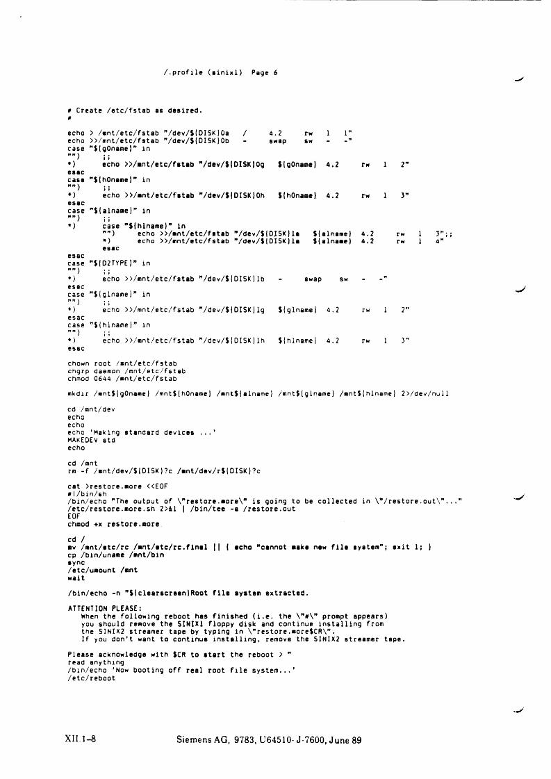
/ .p r o f i le ( s i n i x l ) Page 6
h Create /etc/fstab as desired. *
echo echo case
•)esse casen n *>esaccasen « J *)
esaccase
♦)esac case
*)esac case
*)esac
chown root /mnt/etc/fstab chgrp daemon /mnt/etc/fstab chmod 0644 /mnt/etc/fstab
mkdir /mnt$(gOname} /mnt${hOname} /mnt$|alname} /mnt${glname} /mnt$(hlname) 2>/dev/null
cd /mnt/devechoechoecho ’ Making standard devices . . . ’MAKEDEV std echo
cd /mntrm - f /«nt/dev/$|DI5K)?c /mnt/dev/r${DISK}?c
cat >restore.«ore <<E0F 0 !/bin/sh/bin/echo "The output of \"re sto re .more\” i s going to be co llected in W r e s t o r e . out\". . ./etc/restore.»ore.sh 2>&1 | /bin/tee -a /restore.outEOFchnod +x restore.«ore
cd /■ v /ant/etc/rc / « n t/ e t c / rc . f in a l || { echo "cannot make new f i l e system” ; e x it 1; Jcp /bin/unaae /*nt/binsync/etc/u«ount /«nt wait
/bin/echo -n ”${clearscreenJRoot f i l e system extracted.
ATTENTION PLEASE:When the following reboot has f in ishe d ( i . e . the \”#\” prompt appears) you should remove the SINIX1 floppy disk and continue in s t a l l in g from the SINIX2 streamer tape by typing in \ ”re sto re .more$CR\” .I f you don’ t want to continue in s t a l l i n g , remove the SINIX2 streamer tape.
Please acknowledge with $CR to s ta r t the reboot > ” read anything/bin/echo 'Now booting o ff real root f i l e s y s t e m .. . ’/etc/reboot
> /«nt/etc/fstab ”/dev/$(DISK}0a / 4.2 rw >>/mnt/etc/fstab ”/dev/${DISK)0b - swap sw "SlgOnameJ” in
i r
echo >>/«nt/etc/fstsb ”/dev/${DISKJOg S(gOname) 4.2 rw 1 2”
’${hOname)” in
echo >>/«nt/etc/fstab ”/dev/$|DISK}0h ${h0na«e} 4.2 rw 1 3”
’S ialnaae)" in
case ”${hlname)" in"” ) echo >>/«nt/etc/fatab "/dev/$|DJSK} la Sjalname} 4.2*) echo >>/mnt/etc/fstab ”/dev/${DISK} la ${alna«e) 4.2esac
D2TYPE}” in
echo >>/mnt/etc/fstab ”/dev/${DISK! lb - swap sw
”${glnamel” in
echo >>/mnt/etc/fstab ”/dev/$|DISK|lg Slglname) 4.2 rw
”$(hlname}” in
echo >>/mnt/etc/fstab ”/dev/${DISK} lh $(hlname) 4.2 rw 1
rw 1 3” ;;rw 1 4”
1 2"
XII.1-8 Siemens AG, 9783, U64510- J-7600, June 89
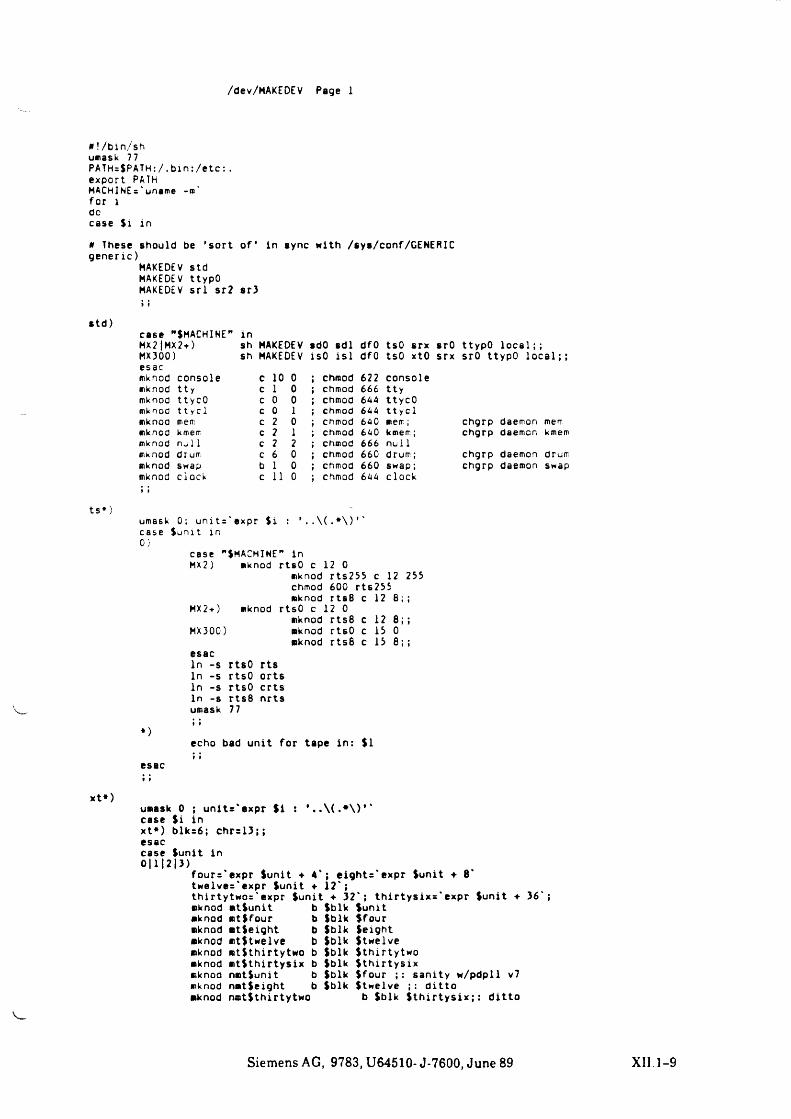
/dev/MAKEDEV Page 1
a ! /bin/sh unask 77PATH=$PATH:/. b in : /etc : .export PATHMACHINEs' uname -w'for idocase Si in
h These should be ’ sort o f ’ in sync with /sys/conf/GENERIC generic)
MAKEDEV std MAKEDEV ttypO MAKEDEV s r l sr2 sr3
std)
ts*)
case "SMACH1NE " inMX2|MX2f) sh MAKEDEV sdO sdl dfO tsO srx srO ttypO l o c a l ;MX300) sh MAKEDEV ISO i s l dfO tsO xtO srx srO ttypO l o c a l ;;esacmknod console c 10 0 chmod 622 consolemknod t t y c 1 0 chmod 666 ttymknod ttycO c 0 0 chmod 644 ttycOmknod 11 y c 1 c 0 1 chmod 644 tt y clmknod meir: c 2 0 chmod 640 mem; chgrp daemon memmknod kmem c 2 1 chmod 640 kmem; chgrp daemon kmemmknod no 11 c 2 2 chmod 666 nullmknod drum c 6 0 chmod 660 drum; chgrp daemon drummknod swap b 1 0 chmod 660 swap; chgrp daemon swapmknodt t
clock c 11 0 chmod 644 clock
umask 0; units ' expr h . \ ( .* \ )case Sunit in0}
case 'MX 2 )
MX2+)
MX300)
’SMACHIME” inmknod rtsO c 12 0
mknod rts255 c 12 255 chmod 600 rt6255 mknod rtsB c 12 8 ;;
mknod rtsO c 12 0mknod rts8 c 12 8 ; ;mknod rtsO c 15 0mknod rts6 c 15 8;;
*)
esacIn -s rtsO rts In -s rtsO orts In -s rtsO c r t s In -s rts8 nrts umask 77
echo bad unit for tape in : $1
xt*)umask 0 ; un its 'ex p r S i : ' case $i in xt») blk=6; chr=13;; esaccase Sunit in 0| 1| 2| 3)
four='expr Sunit ♦ 4*; e igh ts 'e xp r Sunit ♦ 8 twelves'expr Sunit ♦ 12';th irtytw os' expr Sunit ♦ 3 2 '; t h i r t y s ix s 'e x p r Sunit ♦ 36';mknod mtSunit b mknod mtSfour b mknod mtSeight b mknod mtStwelve b mknod mtSthirtytwo b mknod m tSth irtys ix b mknod nmtSunit b mknod nmtSeight b mknod nmtSthirtytwo
Sblk Sunit Sblk Sfour Sblk Seight Sblk Stwelve Sblk Sthirtytwo Sblk S th ir t y s ixSblk Sfour sanity w/pdpll v7 Sblk Stwelve d itto
b Sblk S t h i r t y s i x ; : d it to
Siemens AG, 9783, U64510- J-7600, June 89 XII 1-9
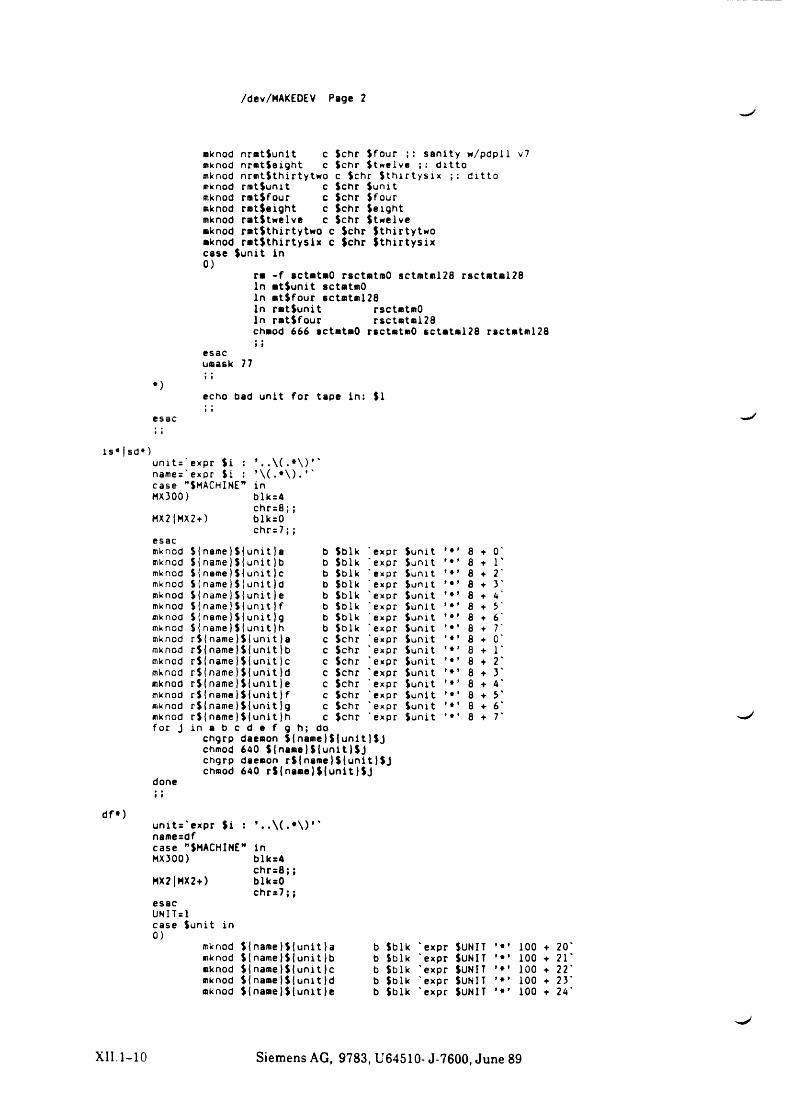
/dev/MAKEDEV Page 2
mknod nrmt(unit c Sehr (four sanity w/pdpll v7mknod nr*t(e ight c Sehr (twelve ; : d ittomknod nrmt(thirtytwo c (ehr ( t h i r t y s ix d itto mknod r* t(u m t c (ehr (u n itmknod rmtjfour c Sehr (fourmknod rmtieight c Sehr (e ightmknod rat(twelve c (ehr (twelvemknod rmtithirtytwo c (ehr (thirtytwo mknod r a t ( t h i r t y s ix c (ehr ( t h i r t y s ix case (u n it in 0 )
ra - f actataO rsetatmO sctmtml28 rsctata l28 ln a t(u n it setatmO ln at(four actatm!28 ln ra t(u n it rsetmtmOln ra t ifo u r rsct«tml28chaod 666 actataO rsetatmO sctata l28 rsctatml28» t
esacuaask 77I »
*)echo bad unit for tape in: (1 * *
esac
is* sd*)unit='expr ( i name='expr ( i case "(MACHINE MX300)
MX2|MX2+)
* \ ( -* \ ) . inblk=4 chr=8;; blk=0 chr=7;;
esacmknod ((n8me}((unit}a b (b lk ' expr (unit 8 ♦ 0'mknod (inam e)((unit)b b (blk 'expr (unit 8 1'mknod ( j name} ( { u n i t }c b (blk 'expr (unit ’ * ’ 8 ♦ 2'mknod ( !name ) ( {unit Id b (blk ' expr (u n it ’ * ’ 8 ♦ 3'mknod (iname)(|unit|e b (blk 'expr (unit 8 ♦ 4'mknod ((name|((unit|f b (blk ' expr (u n it ’ * ’ 8 5'mknod ( {name ) ( ( unit}g b (b lk ' expr (u n it 8 ♦ 6'mknod (( name|( {uni11h b (blk 'expr (unit 6 ♦ 7'mknod r ( ( name}( ( uni t }a c (chr 'expr (unit 8 + 0'mknod r(jnam e)({un itjb c (chr ' expr (unit 8 + 1'mknod r((nam e)((unit jc c (chr ' expr (u n it ’ * ’ 8 + 2'mknod r((name}({unit}d c (chr ' expr (unit 8 * 3'mknod r ( j nam e)(junitje c (chr ' expr (unit 8 ♦ 4'mknod r ( 1 name) ( j u n i t ) f c (chr 'expr (u n it ’ * ’ 8 ♦ 5'mknod r(jnam e)({unit}g c (chr ' expr (u n it ’ * ’ 8 ♦ 6'mknod for J
r((nam e)({unit)hi n a b c d e f g h ;
cdo
(chr ' expr (u n it ’ * ’ 8 7'
chgrp daemon ( ( name} ( { u n i t )( J chmod 640 (| n a » e )(| u n it)(J chgrp daemon r({n am e }({u n it} (J chmod 640 r ( { n a a e ) ( { u n it } ( J
donet »
df*)u n it s ’ expr ( i : *. . \ ( . • \ ) * ' name=dfcase "(MACHINE” inMX300)
MX2|HX2+)
esacUNlTslcase (u n it in0)
mknodmknodaknodmknodmknod
blk=4 ch r= B ;; blksO ch r= 7 ; ;
((nam e)({unit)a ({nam e)(junit)b ({nam e)({unit)c ((nam el(junit)d ({nam e}((unit}e
b (b lk 'expr (UNIT b (b lk 'expr (UNIT b (b lk * expr (UNIT b (b lk 'expr (UNIT b (b lk 'expr (UNIT
100 ♦ 20 '
100 + 21 '
100 ♦ 22 '
100 ♦ 23' 100 + 24'
XII. 1-10 Siemens AG, 9783, U64510- J-7600, June 89
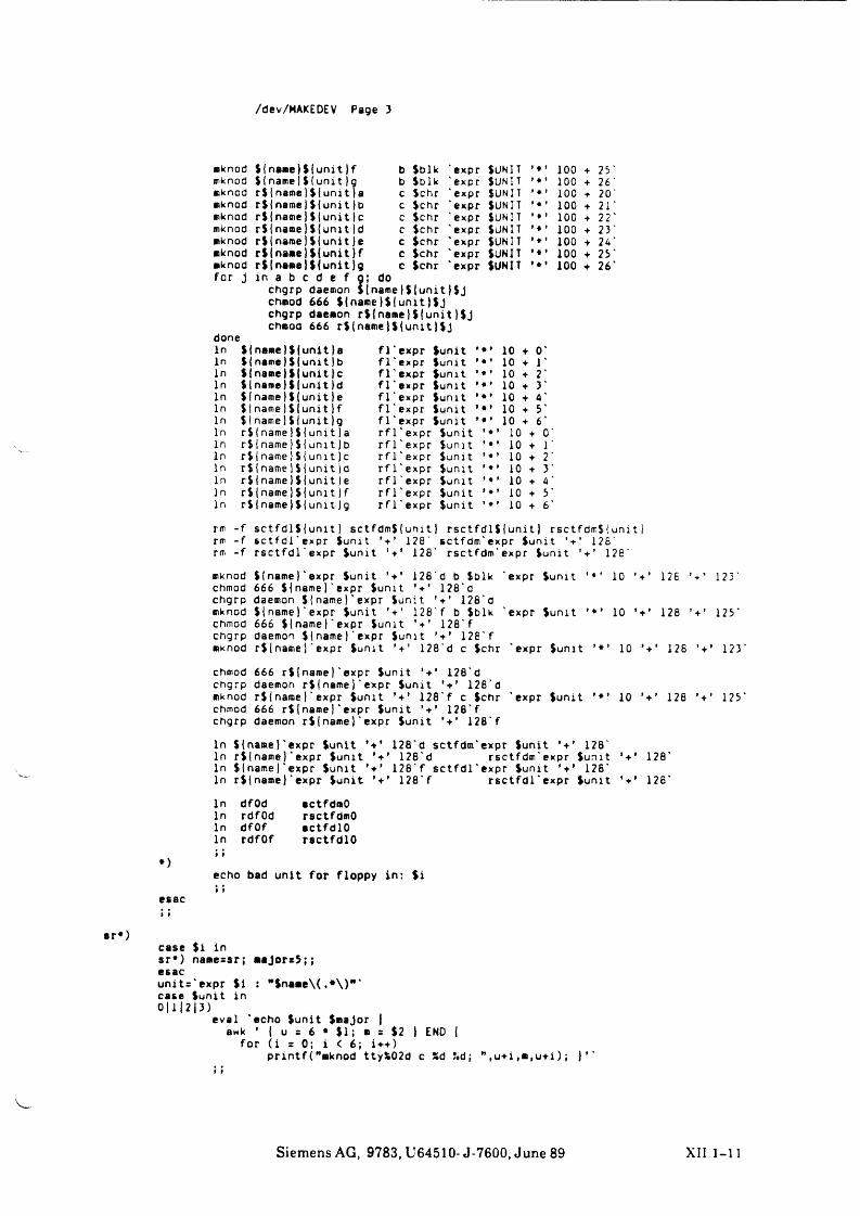
/dev/MAKEDEV Page 3
♦>
esacI t
mknod S{name)Slunit|f b Sblk ' expr SUNIT 100 25mknod SI name|SI u n it)g b Sblk ' expr SUNIT 100 + 26mknod rSInamelSIunit)a c Sehr ' expr SUNIT 100 ■f 20mknod rSlname)$(unit |D c Sehr ' expr SUNIT 100 21mknod r i in a m e j i iu n it )c c ichr ' expr Sunit ••• 100 + 22mknod rSInam elSIunitid c Sehr ' expr SUNIT 100 + 23mknod rSInam ejSlunitie c ichr ' expr Sunit 100 24mknod rSIn am e lSIun it jf c ic h r 'expr SUNIT »•' 100 + 25mknod for j
r i jn a m e i i lu n it ig in a b c d e f a;
cdo
Sehr ' expr SUNIT »*» 100 ♦ 26
doneInInInInInInInInInInInInInIn
chgrp daemon $ I name )SI u n i t }$j chmod 666 ${name}${unit)$J chgrp daemon rS|name)i(unit}$J chmod 666 rSIname|${unit|Sj
$ | n a » e ) $ ( u n i t ) a Slname) $ { u n i t ) b $ jname} $ ( u n i t } c Slname Ü j u n i t }d S l n a m e l i j u n i t }e $ I name i S l u n i t } f $ I name I SI u n i t } g r$|name}$|uni t|a r $ iname} $ { u n i t j b r $ | n a m e } $ i u n i t ) c r${name|$1 u n i t ) d r $ j n a m e } i | u n i t ) e r S I n a m e j i l u n i t j f r S I n a m e j i l u n i t j g
f l ' e x p r ( u n i t * f l ' e x p r S u n i t ’ f l ' e x p r i u n i t ’ f l ' e x p r i u n i t ’ f l ' e x p r S u n i t * f l ' e x p r S u n i t ’ f l ' e x p r S u n i t '
r f l 'e x p r S u n i t r f l 'e x p r Sunit r f l 'e x p r i u n i t r f l 'e x p r i u n i t r f l ' e x p r i u n i t r f l 'e x p r S u n i t r f l ' e x p r i u n i t
»* * »* *
10101010101010
10101010101010
rm - f s c t f d l S i u n i t 1 s c t f d m S ( u n i t } r s c t f d l S I u n i t J r s c t f d m $ ( unit j rm - f s c t f d l ' e x p r i u n i t 128' s c t f d m ' e x p r S u n i t ' + ’ 126'rm - f r s c t f d l ' expr Sunit 128' rsctfdm' expr Sunit 128'
mknod SI name} ' expr Sunit 128' d b Sblk 'expr Sunit ’ 10 128 123chmod 666 Slname}' expr Sunit 128'dchgrp daemon Slnamel'expr Sunit ' 128'dmknod Slname} ' expr Sunit ’ + ’ 128' f b Sblk 'expr Sunit ’ 10 128 125chmod 666 Slnamel'expr Sunit 128'f chgrp daemon Slnamel'expr Sunit 128'fmknod r S 1 namej' expr Sunit ’ + ’ 128'd c Sehr 'expr Sunit 10 128 ’ + ’ 123
chmod 666 r S {name} ' expr Sunit 128'd chgrp daemon rSI name) ' expr Sunit ’ + ’ 128'dmknod r S I n a m e J ' e x p r i u n i t 128'f c Sehr ' e x p r S u n i t **’ 10 128 ’ + ’ 125chmod 666 r S { name) ' expr S u n i t ’ + ’ 128'f chgrp daemon r S I n a m e ) ' expr S u n i t 128'f
In Slnamel'expr Sunit *+’ 128'd sctfdm'expr Sunit ’ + ’ 128'In ri{name) ' expr Sunit ’ + ’ 128'd rsctfdm'expr Sunit ' + ’ 128'In Slnamel'expr Sunit 128'f s c t fd l 'e x p r Sunit 128'In rSInameJ'expr Sunit ’ + ’ 128'f r s c t fd l 'e x p r Sunit 128'
In dfOd In rdfOd In dfOf In rdfOf
sctfdmOrsctfdmOectfdlOractfdlO
echo bad unit for floppy in: $i9 f
«r«)case Si insr*) namessr; major=5;; esacunit='expr S i : "Snam e\(.*\)"' case Sunit in0 11 1 2 | 3 )
eval 'echo Sunit Smajor |awk ’ | u = 6 • S I ; m = S2 ) END |
for ( i = 0; i < 6; i++)p r in t f ( "mknod ttyS02d c % d ! i d ; ” ,u+i ,m,u+i ) ;
9 t
Siemens AG, 9783, U64510- J-7600, June 89 XII 1-11
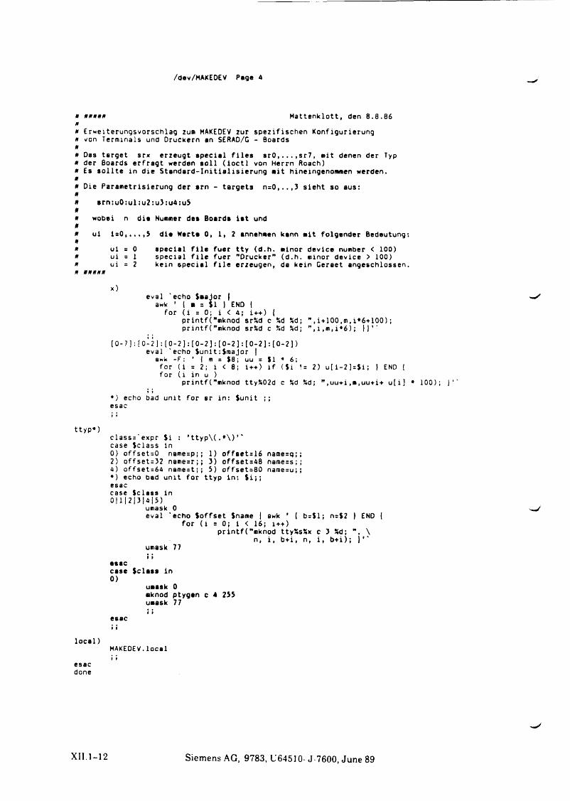
/dev/MAKEDEV Page 4
4 * * * * * Mattenklott, den 8.8.86*
* Erweiterungsvorschlag zu« MAKEDEV zur spe z if ischen Konfigurierung* von Terminals und Druckern an SERAD/G - Boards*
* Das target srx erzeugt spe cia l f i l e s s r 0 , . . . , s r 7 , « it denen der Typ* der Boards erfrag t werden s o l l ( i o c t l von Herrn Roach)* Es s o l l t e in die S ta n d a rd - In it ia l is ie ru n g « it hineingenommen werden.*
* Die Parametrisierung der srn - targets n = 0 , . . ,3 s ieht so aus:*
* srn:uO:ul:u2:u3:u4:u5*
*f f
wobei n die Nummer des Boards ia t und
*f f
c ** «1 o . . . . 5 die Werte 0,. 1, 2 annehmen kann mit folgender Bedeutung;* ui = 0 spe cia l f i l e fuer tty (d.h. minor device number < 100)* ui = 1 specia l f i l e fuer "Drucker” (d.h. minor device > 100)* ui = 2 kein specia l f i l e erzeugen, da kein Geraet angeschlossen.* *****
x)eval 'echo Sasjor | W*
awk ’ { ■ = $1 j END { for ( i = 0; i < 4; i++) {
printf("mknod sr*d c % d % d ; " , i + 100,m, i*6+100); p r i n t f ( "mknod sr£d c % d % d ; ” , i ,m , i* 6 ) ; })*'
[ 0 - 7 ] : ( 0 - 2 ] : ( 0 - 2 ) : [ 0 - 2 ] : [ 0 - 2 ] : [ 0 - 2 ] : [ 0 - 2 ] ) eval 'echo $unit:$major |
a wk - F : ’ j m = ( 8 ; uu = $ 1 * 6 ; for ( i = 2; i < 8; i++) i f ($i != 2) u [ i - 2 ] = $ i ; ) END { for ( i in u )
p r i n t f ( "mknod tty%02d c % d % d ; ” ,uu+i,«,uu+i+ u [ i ] * 100); }*'» »
*) echo bad unit for sr in : $unit ;; esac
ttyp*)c lass= 'expr Si : ’ t t y p \ ( . * \ ) ’ * case Sclass in0) offset=0 name=p;; 1) offset=16 name=q;;2) offset=32 name=r;; 3) offset=48 name=s;;4 ) offset=64 name=t;; 5) offset=80 name=u;;*) echo bad unit for ttyp in: $ i ; ; esaccase Sclass in 0|1|2|3|4|5)
umask 0eval 'echo Soffset Sname | awk * { b=Sl; n=$2 } END (
for ( i = 0; i < 16; i++)printf("aknod ttySsSx c 3 *d; ", \
n, i , b+i, n, i , b + i) ; ) ’ 'umask 77» t
esaccase Sc lass in0)
uaask 0•knod ptygan c 4 2S5 uaask 77f »
esac
l o c a l )MAKEDEV.localI i
esacdone
XII 1-12 Siemens AG, 9783, U64510- J-7600, June 89
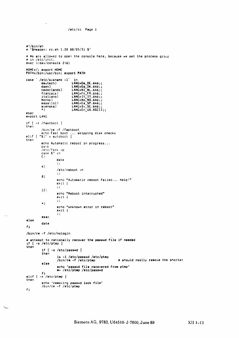
/e tc/rc Page 1
# !/bin/sh# ’ $Header: rc .sh 1.28 88/05/31 $'
# We are allowed to open the console here, because we set the process group# in / e t c / in it .exec >/dev/console 2>&1
HOME = / ; export HOME PATH=/bin:/usr/bin; export PATH
case * /etc/sysname -1 deutsch) daen)nederlands) f r a n c a is ) i t a l ia n o )Norsk ) espa\|ol) svenska)«)
esacexport LANG
inLANGsDe DE.646;; LANG=Da_DK.646;; LANG=N1_NL.646;; LANGrFr F R .646 ;; LANG=It_IT.646; ; LANG=No_NQ.646;; LANG=Es SP .6 4 6 ;; LANG=Sv~SE. 646;; LANG=En~US.ASCII; ;
i f [ - r /fastboot ] then
/bin/rm - f /fastbootecho Fast boot . . . skipping disk checks
e l i f [ "$ !” = autoboot ] then
echo Automatic reboot in p ro g re ss . . .cate/etc/fsck -pcase0)
l n
date
4)/etc/reboot -n
8)t r
echoexit
"Automatic reboot f a i le d .1
12)f t
echoexit
"Reboot interrupted” 1
*)f ♦echoe xit
"Unknown error in reboot"1
else
f i
esac
date
» 1
/bin/rm - f /etc/nologin
* attempt to ra t io n a l ly recover the pasawd f i l e i f neededi f ( - s /etc/ptmp )then
i f [ -s /etc/pesswd ] then
Is -1 /etc/passwd /etc/ptmp/bin/rm - f /etc/ptmp 0 should re a l ly remove the shorter
elseecho ’ pasawd f i l e recovered from ptmp’ mv /etc/ptmp /etc/passwd
f ie l i f [ - r /etc/ptmp ] then
echo 'removing pasawd lock f i l e '/bin/rm - f /etc/ptmp
f i
Siemens AG, 9783, U64510- J-7600, June 89 XII 1-13
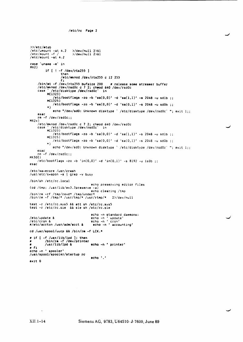
/etc/rc Page 2
>>/etc/mtab/etc/umount -at 4.2 >/dev/null 2>41 /etc/mount - f / >/dev/null 2>41/etc/mount -at 4.2
case “uname -m' in MX2)
i f l ! - f /dev/rts255 ] then/etc/mknod /dev/rts255 c 12 255 f x
/bin/*t - f /dev/rts255 bufs ize 200 * release some Streamer buffer/etc/mknod /dev/rsdOc c 7 2; chmod 640 /dev/rsdOc case ' /etc/disktype /dev/rsdOc* in
HCl 323)/etc/bootflags -zo -b ’ s a ( 0 , 0 ) ’ -d * s a ( l , l ) ’ -a 2048 -u sdlb ;;
HC1325)/etc/bootflags -zo -b * 08(0 ,0)’ -d ’ s a ( 0 , l ) ’ - s 2048 -u sdOb ;;
•)echo "/dev/sdO: Unknown disktype * /etc/disktype /dev/rsdOc' e x it 1;;
esacrm - f /dev/rsdOc;;
MX2-0/etc/mknod /dev/rsdOc c 7 2; chmod 640 /dev/rsdOc case ’ /etc/disktype /dev/rsdOc' in
HC 1323)/etc/bootflags -zo -b ’ s a ( 0 , 0 ) ’ -d * s a ( l , l ) ’ -s 2048 -u sdlb ;;
HC1325)/etc/bootflags -zo -b ’ s a ( 0 , 0 ) ’ -d ’ s a ( 0 , l ) ’ -s 2048 -u sdOb ;;
*)echo ”/dev/sd0: Unknown disktype ' /etc/disktype /dev/rsdOc' e x it 1;;
esacrm - f /dev/rsdOc;;
MX300)/etc/bootflags -zo -b ’ i n ( 0 , 0 ) ’ -d ’ i n ( 0 , 1)* -s 8192 -u isOb ;;
esac
/etc/savecore /usr/crash /usr/etc/swapon -a | grep -v busy
/bin/sh / e t c / r c . localecho preserving editor f i l e s
(cd /tmp; /usr/1ib/ex3. 7preserve -a)echo c le a r in g /tmp
/bin/rm - r f /tmp/rexd* /tmp/under*/bin/rm - f /tmp/# /usr/tmp/* /usr/rtmp/* 2>/dev/null
test - r /e tc/rc .sys5 44 att sh /e tc/rc .sys5 test - r / e t c / r c . s ie 44 s ie sh / e t c / r c . s ie
echo -n standard daemons: /etc/update 4 echo -n ’ update’/etc/cron 4 echo -n ’ cron’#/etc/accton /usr/adm/acct & echo -n ’ accounting’
cd /uar/spool/uucp 44 /bin/rm - f LCK.*
# i f [ - f / u sr/ l ib / lp d ); then# /bin/rm - f /dev/printer# /u sr/ l ib / lp d 4 echo -n ’0 f iecho -n ’ spooler’ /usr/spool/spooler/startup rc
p r in t e r ’
XII.1-14 Siemens AG, 9783, U64510- J-7600, June 89
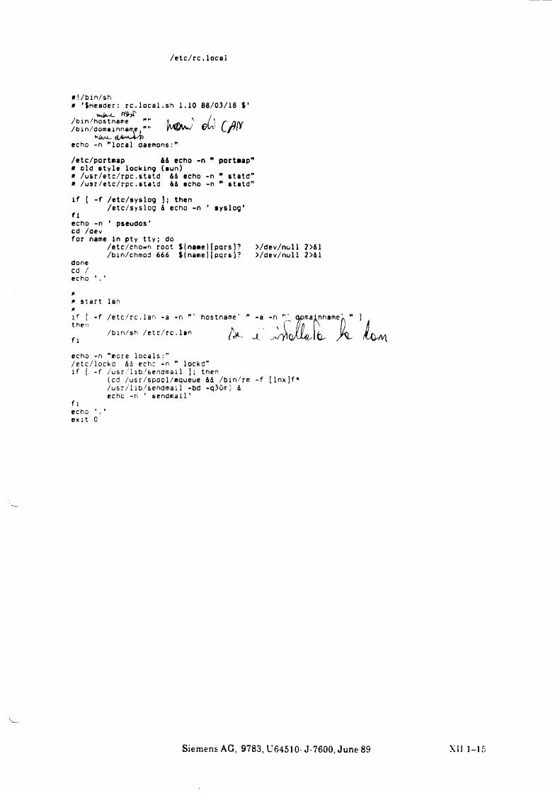
/ e t c / r c . local
# !/bin/shtf ’ $Header: rc . lo c a l , sh 1.10 88/03/18 $'
vköv-c./bin/hostname "/bin/domainname."
>-&/A, StA'WsX'pecho -n " local daemons
N /{wiöw e?u; C ß
/etc/portnap 44 echo -n " portaap"# old s ty le locking (sun)# /u sr/e tc/ rp c . statd 44 echo -n " s ta td ”# /u sr/e tc/ rp c. statd 44 echo -n ” sta td ”
i f [ - f /etc/syslog ); then/etc/syslog 4 echo -n ’ ayslog*
f iecho -n ’ pseudos’cd /devfor name in pty tty ; do
/etc/chown root % { name|(pqrs]? >/dev/null 2>&1 /bin/chmod 666 ${namej [p q r s j? >/dev/null 2>41
donecd / echo ’ . ’
0
0 s ta rt lan 0i f [ - f / e tc / rc . la n -a -n " then
/bin/sh / e tc / rc . la n f l
echo -n "more lo c a ls :"/etc/ locka 44 echc -n ” lockd” i f ( - f /usr/1ib/senomai1 ]; then
(cd /usr/spool/mqueue 44 /bin/rm - f [ ln x ]f* /usr/1 ib/sendmai 1 -bd -q30rr) 4 echo -n ’ sendmail’
fiecho ’ . ’ e x it 0
Siemens AG, 9783, U64510- J-7600, June 89 XII 1-15
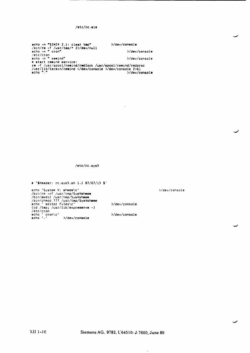
/ e tc / rc .a ie
echo -n "SINIX 2.1: c lear tmp" >/dev/conaole/bin/rm - f /usr/tmp/* 2>/dev/nullecho -n ” cron" >/dev/console/etc/cronecho -n " remind" >/dev/consolea s ta rt remind serv ice :rm - f /usr/spool/remind/rmdlock /usr/spool/remind/rmdproc /usr/lib/teroun/reaind </dev/console >/dev/console 2>d1 echo >/dev/console
/etc/rc.ays5
a ’ $Header: rc .sy s5 .sh 1.1 87/07/15 $ ’
echo ’ System V: shmem\c’/bin/rm - r f /usr/tmp/SysVahmem /bin/mkdir /usr/tmp/SysVshmem /bin/chmod 777 /usr/tmp/SysVshmemecho ’ editor f i l e s \ c ’ >/dev/console(cd /tmp; /usr/lib/expreserve - )/etc/cronecho ’ cron\c’ >/dev/consoleecho ’ . ’ >/dev/console
>/dev/console
XII 1-16 Siemens AG, 9783, U64510- J-7600, June 89
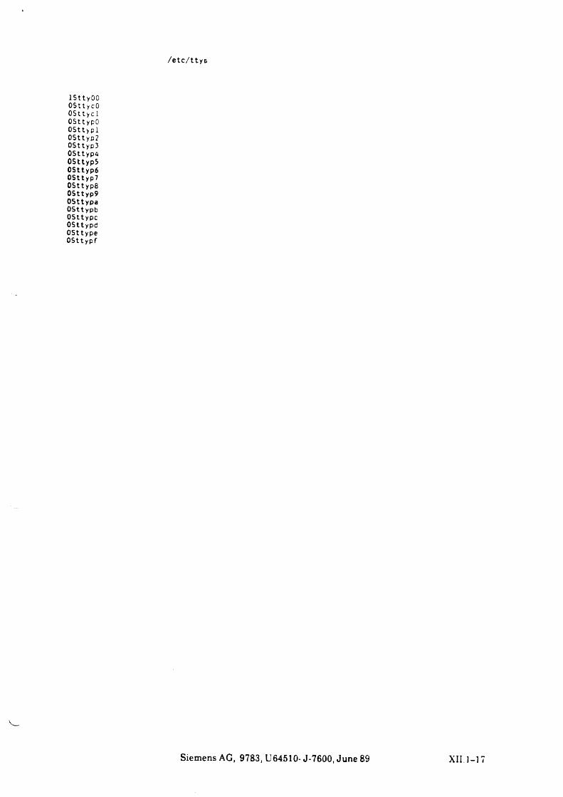
/ e t c / t t y ß
1 St t y 00 OStt ycO OSttyc 1 OSttypO OSttypl 0Sttyp2 0Sttyp3 0Sttyp4 OSttypS 0Sttyp6 0Sttyp7 0Sttyp8 0Sttyp9 OSttypa OSttypb OSttypc OSttypd OSttype OSttypf
Siemens AG, 9783, U64510- J-7600, June 89 XII. 1 -17
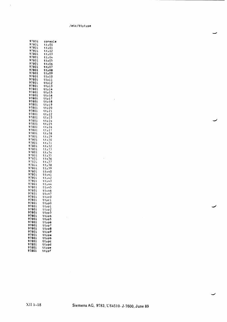
/etc/ttytype
97801 console97801 ttyOO97801 ItyOl97801 tty 0297801 tty0397801 tty0497801 tty0597801 tty 0697801 tty0797801 tty0897801 tty 0997801 ttylO97801 tty 1 197801 tty 1 297801 tty 1397801 tty 1497801 tty 1597801 tty 1697801 tty 1797801 tty 1897801 tty 1997801 tty 2097801 tty 2 197801 tty 2 297801 tty 2397801 tty2497801 tty2597801 tty 2697801 tty 2797801 tty 2897801 tty 2997801 tty3097801 tty 3 197801 tty3297801 tty 3 397801 tt y 3497801 tty 3597801 t ty 3697801 11 y 3 797801 tty 3897801 tty 3997801 tty4097801 ttyAl97801 11 y 4 297801 tty4397801 tty4497801 tty4597801 tty 4697801 tty4797801 tty cO97801 t t y c l97801 ttypO97801 ttyp l97801 tt yp 297801 ttyp397801 ttyp497801 ttyp597801 ttyp 697801 ttyp797801 ttypS97801 ttyp997801 ttypa97801 ttypb97801 ttypc97801 ttypd97801 ttype97801 ttypf
Siemens AG, 9783, U64510- J-7600, June 89
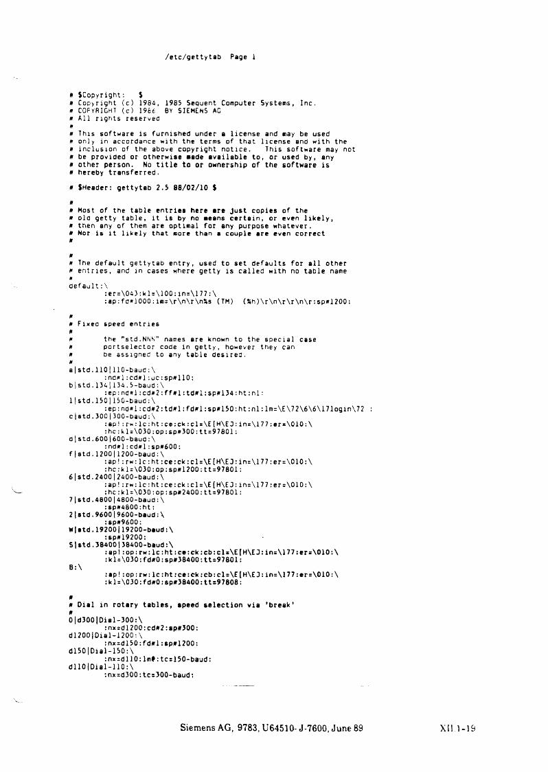
/etc/get tytab Page 1
a $Copyright: $0 Copyright (c) 1984, 1985 Sequent Computer Systems, Inc.0 COPYRIGHT (c ) 1986 BY SIEMENS AG * A l l r ig hts reserved 0
0 This software is furnished under a l icense and may be used 0 only in accordance with the terms of that l icense and with the 0 inc lusion of the above copyright notice. This software may not 0 be provided or otherwise made ava ilab le to, or used by, any 0 other person. No t i t l e to or ownership of the software is 0 hereby transferred.
0 SHeader: gettytab 2.5 88/02/10 $
00 Most of the table entries here are Just copies of the 0 old getty table, i t is by no means c e rta in , or even l i k e l y ,0 then any of them are optimal for any purpose whatever.0 Nor i s i t l ik e ly that more than a couple are even correct 0
00 The default gettytab entry, used to set defaults for a l l other 0 e ntr ie s , and in cases where getty i s ca l led with no table name 0def a u l t : \
:er=\043:klr\100:in=\177:\: ap: fd*1000: im=\r\n\r\nÄs (TM) (Sh )\ r\ n \ r\ r\ n \ r : sp#1200:
00 Fixed speed entr ies 00 the "std.NNN” names are known to the specia l case0 por tselector code in get ty, however they can0 be assigned to any table desired.0a | s t d . 1 1 0 1 1 1 0 -baud: \
:nd* l : c d# l :u c : s p # 1 1 0 : b i s td . l 34 | 13 4. 5-baud : \
:e p :n d * l :c d * 2 :f f» l:td f l1:sp#134:h t : n l :11 s t d . 1501150-baud: \
: ep:nd* l : cd # 2 : t d # l : f d # l : s p # 1 5 0 :h t :n l : lm=\E\72\6\6\171ogin\72 : c|std.300|300-baud:\
: ap! : rw: l c : h t : c e : c k : c l s \ E [H\E 0 : in=\177:er*\010:\
d
f
6
7
2
W
: h c : k l = \ 0 3 0 : o p : s p # 3 0 0 : t t = 9 7 8 0 1 : s t d . 6 0 0 1600-baud : \
: n d » l : c d * l : s p * 6 0 0: s t d . 1 2 0 0 | 1 2 0 0 - b a u d : \
: a p ! : r w : l c : h t : c e : c k : c l=\E[H\E3 : i n = \1 7 7 : e r = \0 1 0 : \ : hc :k l= \030 :op : sp#1200 : t t=97801 :
s t d . 2400|2400-baud : \:a p ! : r w : lc :h t :c e :c k :c l= \ E (H \ E J : in=\177:er=\010:\ : h c : k 1 = \ 0 3 0 : op : s p #2 4 0 0 : t t = 9 78 01 :
s t d . 4 8 0 0 |4800-baud : \: s p » 4 8 0 0 : h t :
s t d . 9 6 0 0 19600- b a u d : \: s p * 9 6 0 0 :
s t d . 19200|19200- baud:\:sp*19200:
S 1s t d . 38400|38400-baud:\:ap! :o p :rw :lc :h t :c e :ck :c b :c ls\ E[H \ E3 :in s\1 7 7 je rs\ 0 1 0 :\ :kl=\030:fd#0:sp#38400:tt=97801:
:ap!:op:rw :l c : h t : c e : c k : c b : c l=\E[H\E3: in = \ l77:er=\010:\ : k 1 = \030: f d#0: sp*38400: tt=97808:
00 D ia l in rotary tab le s, apeed se le ct io n v ia 'break* 00|d300|Dial-300:\
:nxrdl200:cd#2:sp#300: dl200(Dial-1200 : \
:nx=dl50:fd#l:sp»1200: dl50|Dial-150:\
:nx=dl10:lm?:tc=150-baud: d llO |D ia l-11 0:\
:nxrd300: tc=3Q0-baud:
Siemens AG, 9783, U64510- J-7600, June 89 XII.1-19
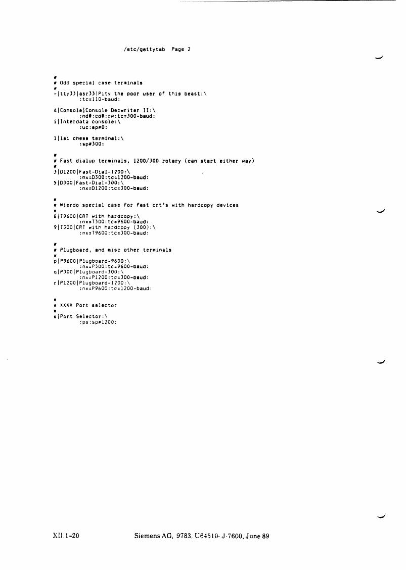
/etc/gettytab Page 2
0
0 Odd special case terminals 0
- | tty33|asr33|Pity the poor user of th is beast:\:tc=110-baud:
<41 Console |Console Decwriter 11: \: nd#: c d f : rw: tc=300-baud:
i| Interdata console:\:uc;ap*0:
1 ( 1a 1 chess term lnal:\:sp#3Q0:
00 Fast dialup terminals, 1200/300 rotary (can s ta rt either way) 03|D1200|Fast-Dial-1200:\
: nx=D30Q: tc=1200-baud:5 |D3001Fast-Dial-300: \
:nx=D1200: tc=300-baud:
00 Wierdo specia l case for fast c r t ' s with hardcopy devices 0
8 i T 9600|CR T with hardcopy;\: nxsT300: tc=96QQ-baud:
9|T300|CRT with hardcopy ( 300) : \:nx=T9600: tc=3Q0-baud:
00 Plugboard, and misc other terminals 0p|P9600|Plugboard-9600:\
: nx;P300: tc=960Q-baud: q|P300|Plugboard-300:\
:nx=P1200:tc=300-baud: r|P1200|Plugboard-1200:\
:nx=P9600:tc=1200-baud:
00 XXXX Port selector 0
s|Port Se le ctor:\: p s : sp»1 2 0 0 :
XII.1-20 Siemens AG, 9783, U64510- J-7600, June 89
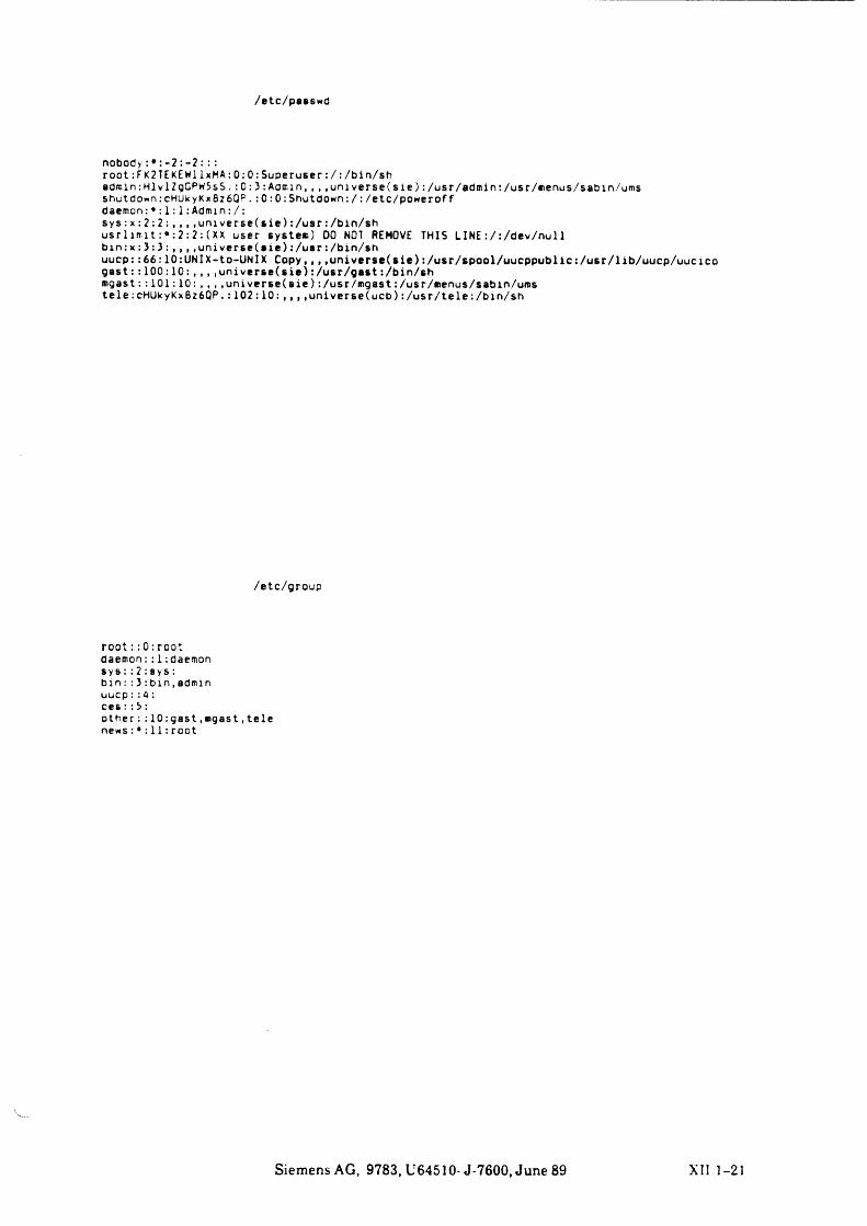
/etc/passwd
nobody: : - 2 : - 2 : : :root:FK2TEKEWllxMA:0:0: Superuser:/:/bin/shadmin:HlvlZgGPW5sS. :0:3:Aocr.in, , , .u n iv e rse (s ie ) :/usr/admin:/usr/menus/sabin/ums shutdown: cHUkyKx8z6QP. : 0 : 0 : Shutdown: / : /etc/powerof f daemon: ♦ : 1: 1: Admin:/:s y s : x : 2 : 2 : , , , , u n i v e r s e ( s i e ) : /usr : /bin/shu s r l im t :* : 2 :2 : ( X X user system) DO NOT REMOVE THIS LINE : / :/dev/nul1 b in : x : 3 : 3 : , , , ,u n iv e rse (a ie ) :/ u sr :/b in /shuucp::66:10:UNIX-to-UNlX Copy,, , ,u n ive rse (s i e ) :/usr/spool/uucppublic:/usr/lib/uucp/uucicog a s t : : 1 0 0 : 1 0 : , , , .universe( s i e ) :/ u sr/ g a s t : /bin/shmgast:: 1 0 1 : 1 0 : , , , .universe( s i e ) : /usr/mgast: /usr/menus/sabin/umste le :cHUkyKx8z6QP. : 1 0 2 : 1 0 : , , , ,un iverse(ucb) : /u sr/te le :/b in/sh
/etc/group
root : :0 : root daemon : : 1 : daemon sys : : 2 : sys : b i n : : 3 : b in , admin uucp:: A : c e s ::3 :o th e r : : 10:g a s t , mgast,tele news : * : 11: root
Siemens AG, 9783, U64510- J-7600, June 89 XII 1-21
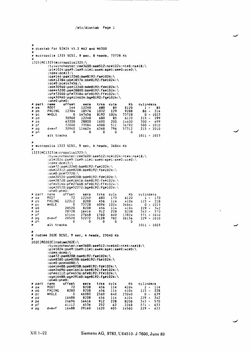
/etc/disktab Page 1
#0 disktab for SINIX V5.2 MX2 and MX300 0
0 micropolis 1325 SCSI, 9 sec, 8 heads, 73728 Kb 0
1325|MC 1325j micropolisl325 : \: ty=wincheste r : rm#360Q:se»512:nc#1024:nt#8:ns»18:\ :pl#1024:ps#9: lsff9: i 1*1 :swff4: spffl: srnffO: wc#0: \: rdff4:dc#13 :\: o a 0 144:pa#l2240:ba#8192: fa#1024:\:ob#12384:pb#18576:bb#8192:fb#1024:\:oc#0:pc#l47456:\:odff30960:pdff12240:bd#8192:fd#1074:\: oe#43200:peff28800:be#8192: fe#1024: \: o f#72000:p f#73584:b f#8192:ff#1024:\: og#30960: pgff114624;bg#8192:fgff1024:\:oh#0:ph#0:
ff part name offse t secs trks cy la Kb cy 1indersff pa ROOT 144 12240 680 85 6120 1 - 85ff pb PACING 12384 18576 1032 129 9288 86 - 214ff pc WHOLE 0 147456 8192 1024 73728 0 - 1023ff pd 30960 12240 680 85 6120 215 - 299ff pe 43200 28800 1600 200 14400 300 - 499ff Pf 72000 73584 4088 511 36792 500 - 1010ff pq d+e+f 30960 114624 6368 796 573 12 215 - 1010ff ph 0 0 0 0 0ff a lt tracks 1011 - 1023
ffff micropolis 1323 SCSI, 9 sec, 4 heads, 36864 Kb01323|MC 1323|micropolisl323:\
:ty=*anchester:rm#3600:se#512:nc#1024:ntff4:ns#18:\ : p l f f l0 2 4 :p s # 9 : l s # 9 : i l# l : sw#4 : spff l : smffO:wc#Q:\: rd#4:dc#13: \:oa#72:pa#12240:ba#8192:fa#1024:\:obffl2312:pb#8208:bbff8192:fb#1024:\: oc0O:pc#73728: \:od#20520:pd#8208:bd#8192:fd#1024:\: oe#28728:pe#164l6:be#8192:fe#1024:\ :offf45l44:pf#27648:bf#8192:ff#1024:\:og#20520:pg#52272:bg#8192:fg#1024:\: oh#0:ph#0:
ff part name o ffse t secs trks cy Is Kb cy l inders* pa ROOT 72 12240 680 170 6120 1 - 170ff pb PAGING 12312 3208 456 114 4104 115 - 228ff pc WHOLE 0 73728 4096 1024 36864 0 - 1023ff pd 20520 8208 456 114 4104 229 - 3«2ff pe 28728 16416 912 228 8208 343 - 570ff pf 45144 27648 1760 440 1 3824 571 - 1010ff P9 d + e+f 20520 52272 3128 782 26136 229 - 1010ffff
ph 0a lt tracks
0 0 0 01011 - 1023
00 rodime 202E SCSI, 9 sec, 4 heads, 23040 kb 0
202E|R0202E|rodiae202E:\: ty=winchester:rm#3600:ae#512:nc#640:nt#4:ns#18:\ :p l# 1 0 2 4 :p s# 9 : ls# 9 : i l# l :sw # 4 :sp # l:so#0:hc#0:\ :rd#4:dc#6:\:oa#72:pa#8208:ba#8192:fa#1024:\: ob#8280: pb#8208: bb#6192:fb#1024:\ :oc#0:pc#46080:\: od#16488:pd#8208:bd#8192: fd#1024: \ :oe#24696;pe#16416:be#8192:feff1024:\ :offf41112:pfff4536:bf#8192:ffffl024:\:ogff16488:pgff29160:bg#8192:fg#1024:\:oh*0:phff0:
ff part name offse t secs trks cy Is Kb cylindersff pa ROOT 72 8208 456 114 4104 1 - 114ff pb PAGING 8280 8208 456 114 4104 115 - 228ff pc whole 0 46080 2560 640 23040 0 - 639ff pd 16488 8208 456 114 4104 229 - 342ff pe 24696 16416 912 228 8208 343 - 570ff pf 41112 4536 252 63 2268 571 - 633ff pg d+e+f 16488 29160 1620 405 14580 229 - 633
XII 1-22 Siemens AG, 9783, U64510-J-7600, June 89
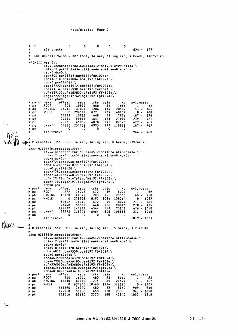
/etc/disktab Page 2
0 ph 0
0 0a lt tracks
0 0 0634 - 639
0 CDC WRENIII 94166 - 182 ESDI, 34 aec, 34 log sec, 9 heads, 148257 KD
WRENIII |wren3: \: ty=winchester: re#3600: se#512:nc#969 :nt#9:ns#34 : \:p l# 51 2:p s# 34:ls#3 4:i l# l :aw # 4 : a p # l: s«#0:wc#0: \ :rd#4:dc#5:\: oa#306: pa#15912:ba#8192: fa#1024:\ :ob#16218:pb#41004:bb#8192:fb#1024:\: oc#0: pc#2965l4: \:od#57222:pd#15912:bd#8192:fd#1024:\: oe#73134: pe#55998:be#8192: fe#1024: \: o f # l29132:p f4165852:b f»8192:ff#1024:\:og#57222:pg#237762:bg#8192: fg#1024: \: oh#0: ph#0:
# part name offset secs trks cy la Kb cy linders# pa ROOT 306 15912 468 52 7956 1 - 52# pb PAGING 16218 41004 1206 134 20502 53 _ 186# pc WHOLE 0 296514 8721 969 148257 0 . 968# pd 57222 15912 468 52 7956 187 - 238# pe 73134 55998 1647 183 27999 239 - 421
V # pf 129132 165852 4878 542 82926 422 - 9630 pg d+e+f 57222 237762 6993 777 118881 187 - 9630 ph 0 0 0 0 0# a lt tracks 964 _ 968
#H icropolis 1333 ESDI, 34 aec, 34 log sec , 8 heads , 139264 Kb
fT1355|HC 1355|micropolisl355:\
: ty = winchester : rm#3600:se#512: nc#1024 :nt#8:ns#34:\:p l# 5 1 2 :p s# 3 4 : ls# 3 4 :i l# l : sm#4: s p # l :sm#0: wc#0:: \: rd#4:dc#5: \:oa#272:pa#16046:ba#8192 : f a # l024: \:ob#16320:pb#4l072:bb#8192: fb#1024: \: oc#0:pc#278528 ; \:od#57392:pd#16048:bd#8192:fd#1024:\ :oe#73440:pe#56032:be#8192:fe#1024 : \ : o f # l29472:p f#147696:bf#8192:ff#1024: :og#57392:pg#219776:bg#8192:fg#1024:\
\
: oh#0:ph#0:# part name offse t secs trks cy Is Kb cy lin de rs0 pa ROOT 272 16048 472 59 8024 1 - 590 pb PAGING 16320 41072 1208 151 20536 60 - 2100 pc WHOLE 0 278528 8192 1024 139264 0 - 1023# pd 57392 16046 472 59 8024 211 - 269# pe 73440 56032 1648 206 28016 270 - 475# pf 129472 147696 4344 543 73848 476 - 1018# pg d+e+f 57392 219776 6464 808 109888 211 - 1018# ph 0 0 0 0 0
i& w o
#
#
a lt tracks 1019 1023
n H icro po lis 1338 ESDI, 34 aec, 34 log sec, 13 heads, 312120 Kb 013381HCl 338|nicropolis 1338:\
: ty=wx richest er : r«#3600: ae#512: nee 12 24 :nt#15: ns#34: \ :p l#51 2:ps#34:ls#3 4:i l# l:sw #4:sp#l:s«#0:w c#0:\: rd#4:dc#5:\:oa#510:pa#16320:ba#8192:fa#10?4:\ :ob#16830:pb#43350:bb#8192:fb#1024:\:oc#0:pc#624240:\: od#463590: pd#16320:bd#8192:fd#1024:\: oe#479910:pe#56100: be#8192: f e#1024: \: o f#536010:pf 483680:b f#8192:ff#1024:\ ;og#463590:pg#158100:bg#8192:fg#1024:\: oh#60180:ph#403410:bh#8192: fh#1024:
# part name off set secs trk s cy Is Kb cy lin de rs# pa ROOT 510 16320 480 32 8160 1 - 32# pb PAGING 16830 43350 1275 85 21675 33 - 117# pc WHOLE 0 624240 16360 1224 312120 0 - 1223# pd 463590 16320 480 32 8160 909 - 940# pe 479910 56100 1650 110 28050 941 - 1050# p f 536010 85680 2520 168 42840 1051 - 1218
Siemens AG, 9783, U64510- J-7600, June 89 XII 1-23
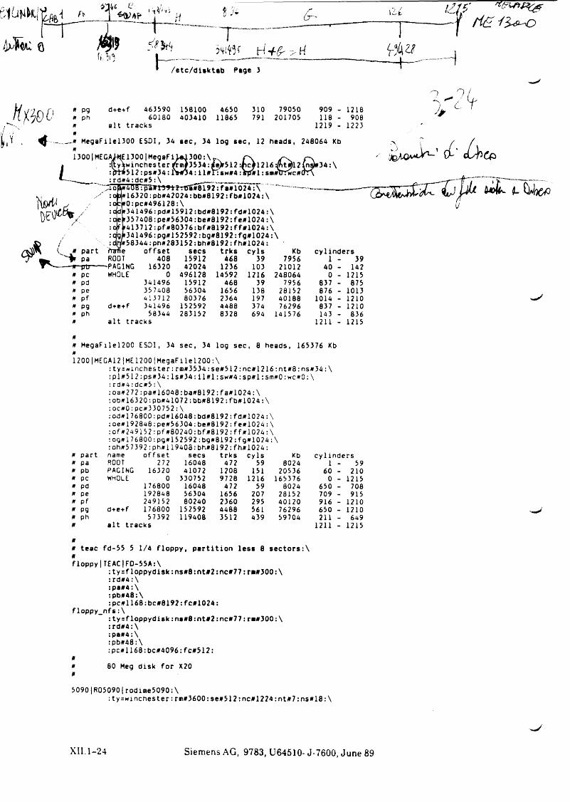
f t
0 m
H
h - f C H
/etc/disktab Page 3 ~ H —
i z / ff i & I ? ^ o
H
n p g » ph 0
d+e+f 463590 158100 465060180 403410 11865
a lt tracks
310 79050 909791 201705 118
1219
1218908
1223
L
R-R MegaFilel300 ESDI, 34 sec, 34 log sec, 12 heads, 248064 Kb 01300| MEGAJ+JE1300 | MegaF i U d 300: \ r v n s
ty»winchester {rcn#3534:se)»512 :rc)l216:/ntMl2(nsto34:\ frt»512 :ps»34: rw 04: i l»r:sw»4 :srJ»l :sm»TTTwc»(TT\ rd»4 : dc»5 : \Ö
(/■ C
/
< ?
iTpaTFt55t2rBa»8192:faal024:\ *’ -16320:pb»42024:bb»8192:fb#1024:\ r0:pc»496128:\r 3414 96:pd»15912: bd»8192: fd»1024 : \ r357408:pe»56304:be»8192: fe*1024:\ »413712:p f»80376:b f»8192:ff#1024:\ »34l496:pg»152592:bg»8192:fg#1024:\
/»58344: ph»283152: bh»8192: fh*1024 :« part frame offset secs trks c y ls Kb cy linders
pa ROOT 408 15912 468 39 7956 1 - 39— w -ptj------'PAGING 16320 42024 1236 103 21012 40 - 142
0 pc WHOLE 0 496128 14592 1216 248064 0 _ 12150 pd 341496 15912 468 39 7956 837 - 8750 pe 357408 56304 1656 138 28152 876 - 10130 pf 413712 80376 2364 197 40188 1014 - 12100 P9 d+e+f 341496 152592 4488 374 76296 837 _ 12100 ph 58344 283152 8328 694 141576 143 - 8360 a lt tracks 1211 - 1215
00 MegaFilel200 ESDI, 34 sec, 34 log sec, 8 heads, 165376 Kb 0
1200|MEGA12|ME1200|MegaFilel200:\:ty = *inchester:r®»3534:se#512: nc»1216:nt»8: ns»34:\ :p l»512:ps»34:ls»34;i l» l:sw »4: s p » l : sm»0:wc»0: \ :rd»4:dc»5:\: 0 3 0 2 7 2 : pa»16048: ba»B192: fa»1024: \: ob»163 20:pb»41072:bb#8192: fb»1024: \: oc»0: pc»330752: \: od»176800: pd»16048:bd»8192:fd»1024:\ :oe»192848:pe»56304:be»8192:fe»1024:\: o f»2491 5 2 :p f»80240:bf»8192: ff»1024: \: og» 1 76800:pg»152592:bg»8192:fg»1024:\: oh»57392:ph»119403:bh»8192:fh»1024:
» part name offset secs trks cy ls Kb cy 1inders0 pa ROOT 272 16048 472 59 8024 1 _ 590 pb PAGING 16320 41072 1708 151 20536 60 _ 2100 pc WHOLE 0 330752 9728 1216 165376 0 _ 12150 pd 176800 16048 472 59 8024 650 _ 7080 pe 192848 56304 1656 207 28152 709 _ 9150 pf 249152 80240 2360 295 40120 916 - 12100 P9 d+e+f 176800 152592 4488 561 76296 650 _ 12100 Ph 57392 119408 3512 439 59704 211 - 6490 a lt tracks 1211 - 1215
00 teac fd-55 5 1/4 floppy, p a rt it io n less 8 se c to rs :\»floppy|TEAC|FD-55A:\
: ty = floppydisk:ns»8:nt#2:nc#77:r«»300:\ : rd»4:\:pa»4:\:pb»48:\:p c» l168:bc»8192: fc» 1024:
floppy_nfs: \: ty=floppydisk: ns»8:nt»2:nc»77: r*»300:\ :rd»4:\:pa»4: \:pb»48:\:pc»1168:bcd»4096:fc#512:
»» 80 Meg disk for X20»5090|R05090|rodime5090: \
: ty=w inches t e r : r»i#3600: sea512:nc#1224 :nt»7 :ns»18: \
X II . 1 - 2 4 Siemens AG, 9783, U64510- J-7600, June 89
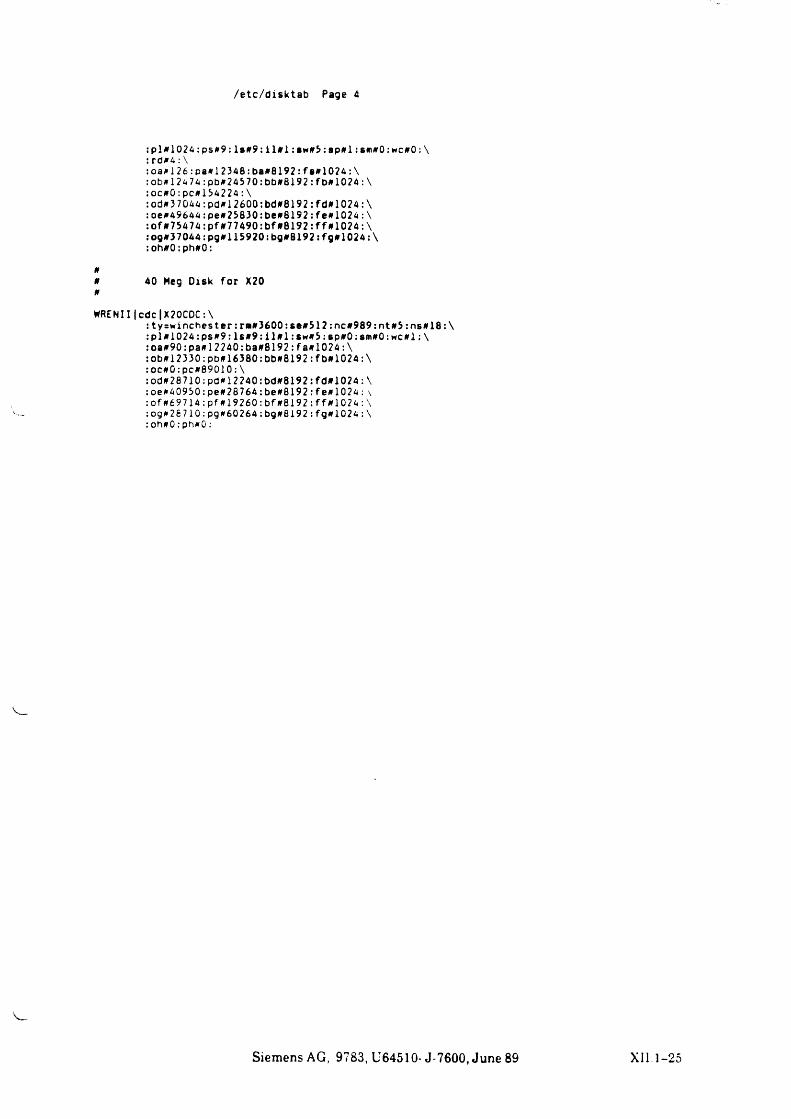
/etc/disktab Page 4
:p l» 1 0 2 4 :p s» 9 :ls» 9 : i l» l : sw »5:s p # l : sm»0: wc»0 : \ : rd»4: \:oa»126:pa»12348:ba»8192:fa»1024:\: ob»l2474: pb»24570: bb»8192: fb»1024:\:oc»0:pc»154224: \: od»3 7044: pd»l 2600:bd»8192 :fd»l 024 :\:oe»49644:pe»25830:be#8192:fe»1024: \: of »75474:pf »77490:bf»8192:ff»1024:\: og#37044:pg»115920:bg»8192: fg # 1024: \ :oh»0:ph»0:
»»»
40 Heg Disk for X20
WREN111c d c |X20CDC: \:ty=winches t e r : rn»3600:se»512 :nc»989: nt»5:ns»18:\ :pl»1024:ps»9: ls » 9 : i l» l : s w » 5 : ap»0:am»0:wc»l: \ :oa»90:pa»l2240:ba»8192: f a»1024: \: ob»l2330:pb»16380:bb»8192:fb»1024:\ :oc»0:pc#89010:\:od»28710:pd»12240:bd»8192:fd»1024:\ :oe»40950:pe»28764:be»8192:fe»1024:\ :of»69714:pf»19260:bf»8192:ff»1024:\ :og»28710:pg»60264:bg»8192:fg»1024:\:oh»0:ph»0:
Siemens AG, 9783, U64510- J-7600, June 89 XII.1-25
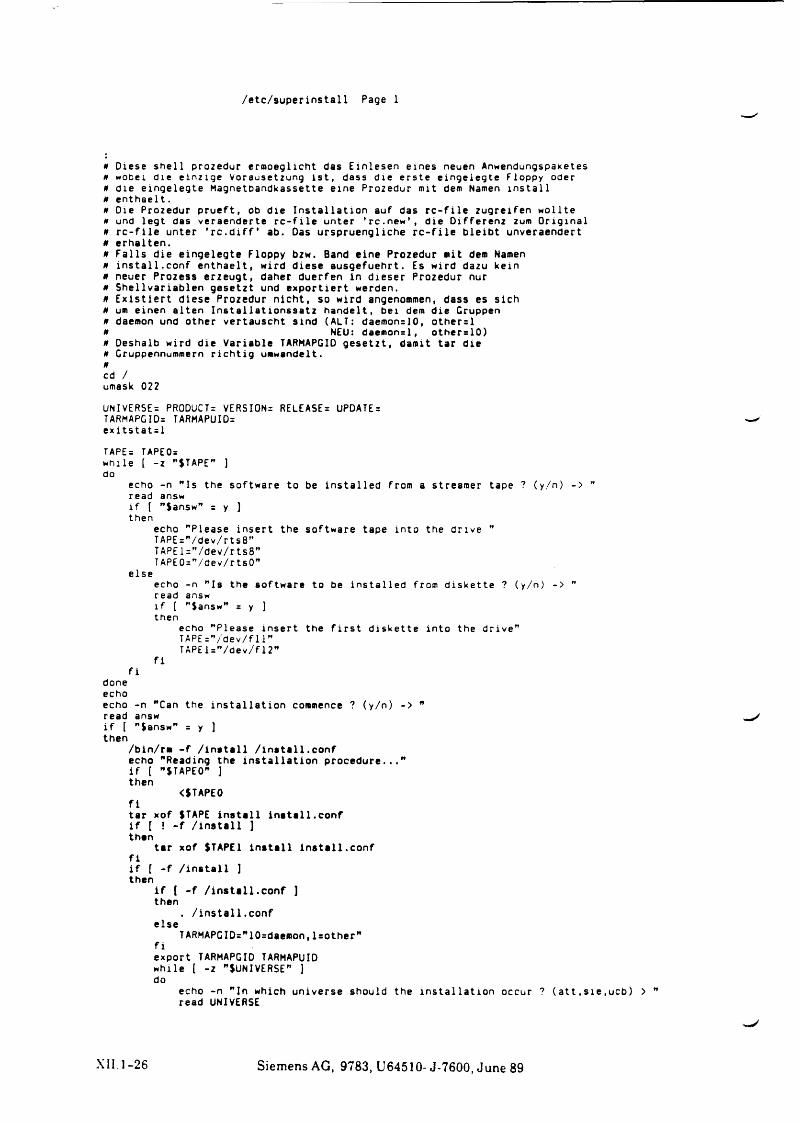
/e tc /su p e rin sta l l Page 1
0 Diese she ll Prozedur ermoeglicht das Einlesen eines neuen Anwendungspaketes 0 wobei die einzige Vorausetzung i s t , dass die erste eingelegte Floppy oder ß die eingelegte Magnetbandkassette eine Prozedur mit dem Namen i n s t a l l 0 enthaelt.0 Die Prozedur prueft, ob die In s t a l la t io n auf das r c - f i l e zugreifen wollte 0 und legt das veraenderte r c - f i l e unter ’ rc.new’ , die Differenz zum O rig in a l 0 r c - f i l e unter ’ r c . d i f f ’ ab. Das urspruengliche r c - f i l e b le ibt unveraendert 0 erhalten.0 F a l l s die eingelegte Floppy bzw. Band eine Prozedur mit dem Namen 0 i n s t a l l . conf enthaelt, wird diese ausgefuehrt. Es wird dazu kein 0 neuer Prozess erzeugt, daher duerfen in d ieser Prozedur nur 0 Sh e llvariablen gesetzt und exportiert werden.0 E x i s t ie r t diese Prozedur n ich t, so wird angenommen, dass es s ich 0 um einen alten In st a l la t io n s s a t z handelt, bei dem die Gruppen 0 daemon und other vertauscht sind (ALT: daemon=10, other=l 0 NEU: daemon=l, other=10)0 Deshalb wird die Variable TARMAPGID ge setzt , damit tar die 0 Gruppennummern r i c h t ig umwandelt.0
cd /umask 022
UNIVERSE: PRODUCT: VERSION: RELEASE: UPDATE:TARMAPGID: TARMAPUID: e x i t s t a t : l
TAPE: TAPEO:while [ -z ”$TAPE” ]do
echo -n " Is the software to be in s ta l le d from a streamer tape ? (y/n) -> ” read answi f [ ”$answ” = y ]then
echo "Please in sert the software tape into the drive ”TAPE:”/dev/rts8"TAPEl:”/dev/rts8"TAPE0:"/dev/rtsO"
elseecho -n " Is the software to be in sta l le d from d iskette ? (y/n) -> ” read answi f [ "Sansw” = y ] then
echo "Please insert the f i r s t d iskette into the d r iv e ”TAPE:”/dev/f11"TAPEl:"/dev/f12”
f i f i
doneechoecho -n "Can the in s t a l la t io n commence ? (y/n) -> ” read answi f [ "$answ” = y ) then
/bin/rm - f / i n s t a l l / i n s t a l l . c o n fecho "Reading the in s t a l la t io n p ro ce d u re .. .”i f ( "STAPEO" ]then
<$TAPE0f itar xof (TAPE i n s t a l l in s t a l l . c o n fi f [ ! - f / i n s t a l l jthan
tar xof $TAPE1 I n s t a l l in s t a l l . c o n f f ii f ( - f / i n s t a l l ] then
i f ( - f / i n s t a l l . c o n f ] then
. / i n s t a l l . c o n felse
TARMAPGID:"10:daemon,l=other" f iexport TARMAPGID TARMAPUID while ( -z "^UNIVERSE" ] do
echo -n "In which universe should the in s t a l la t io n occur ? ( a t t , s i e ,ucb) > " read UNIVERSE
XII. 1 - 2 6 Siemens AG, 9783, U64510- J-7600, June 89
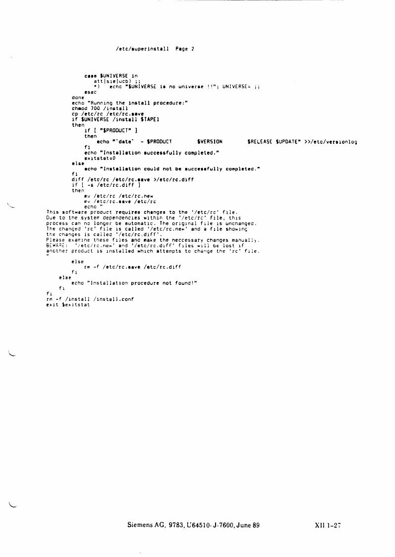
/ e tc /su p e r in sta l l Page ?
case (UNIVERSE Inatt | s ie |ucb) ;;*) echo "(UNIVERSE is no universe !!" ; UNIVERSE= ;;
esacdoneecho "Running the i n s t a l l procedure:"chmod 700 / i n s t a l lcp /etc/rc /etc/rc.savei f (UNIVERSE / i n s t a l l (TAPE1then
i f [ "(PRODUCT" ] then
echo " 'date ' - (PRODUCT (VERSION (RELEASE (UPDATE"f iecho " In s t a l la t io n su c c e ss fu l ly completed." e xitstat= 0
elseecho " In s t a l la t io n could not be su c ce ss fu l ly completed."
f id i f f /etc/rc /etc/rc.save > / e t c / r c .d i f fi f [ -s / e t c / r c . d i f f ]then
■ lv /etc/rc /etc/rc.new mv /etc/rc.save /etc/rc echo ”
This software product requires changes to the ’ /e tc / rc ' f i l e .Due to the system dependencies within the ’ / e t c / r c ’ f i l e , th is process can no longer be automatic. The o r ig in a l f i l e is unchanged.The changed ’ r e ’ f i l e is ca lled ’ / e t c / r c . new’ and a f i l e showing the changes is ca lled ' / e t c / r c . d i f f ’ .Please examine these f i l e s and make the neccessary changes manually.BEWARE: ’ /etc/rc.new' and ' / e t c / r c . d i f f ' f i l e s w i l l be lost i fanother product i s in s t a l l e d which attempts to change the ’ r e ’ f i l e .
elserm - f /etc/rc.save / e t c / r c . d i f f
f lelse
echo " In s t a l la t io n procedure not found!” f l
f lrm - f / i n s t a l l / i n s t a l 1. conf e xit ( e x i t s t a t
Siemens AG, 9783, U64510- J-7600, June 89
>>/etc/versionlog
XII 1-27
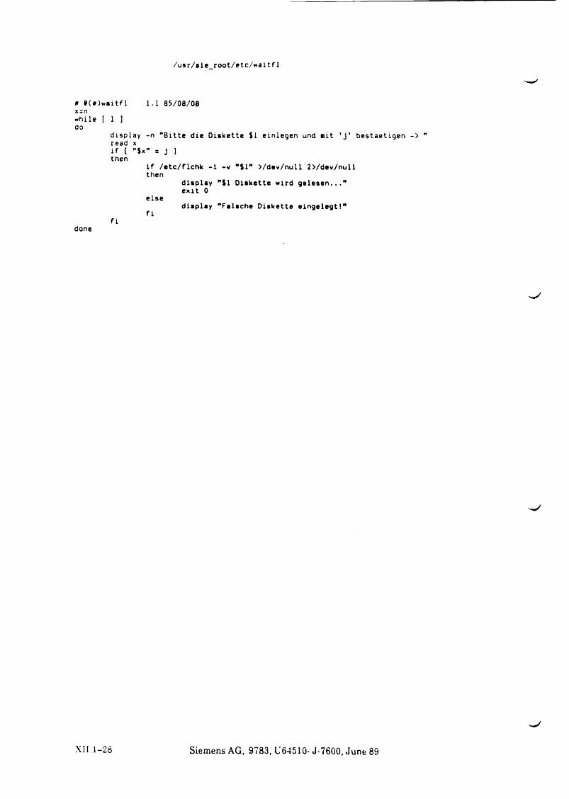
/usr/s ie_root/etc/w aitf1
n § (* )w aitf l 1.1 85/08/08 x = nwhile [ 1 ]do
display -n "B itte die Diskette $1 einlegen und « i t ’ j ’ bestaetigen -> read xi f [ ”$x" = J 1 then
i f /e tc/f lchk - i -v "$1” >/dev/null 2>/dev/null then
display "$1 Diskette wird g e le s e n . . ." e x it 0
elsedisplay "Falsche Diskette e ingelegt!"
f if i
done
X II.1-28 Siemens AG, 9783, L'64510- J-7600, June 89
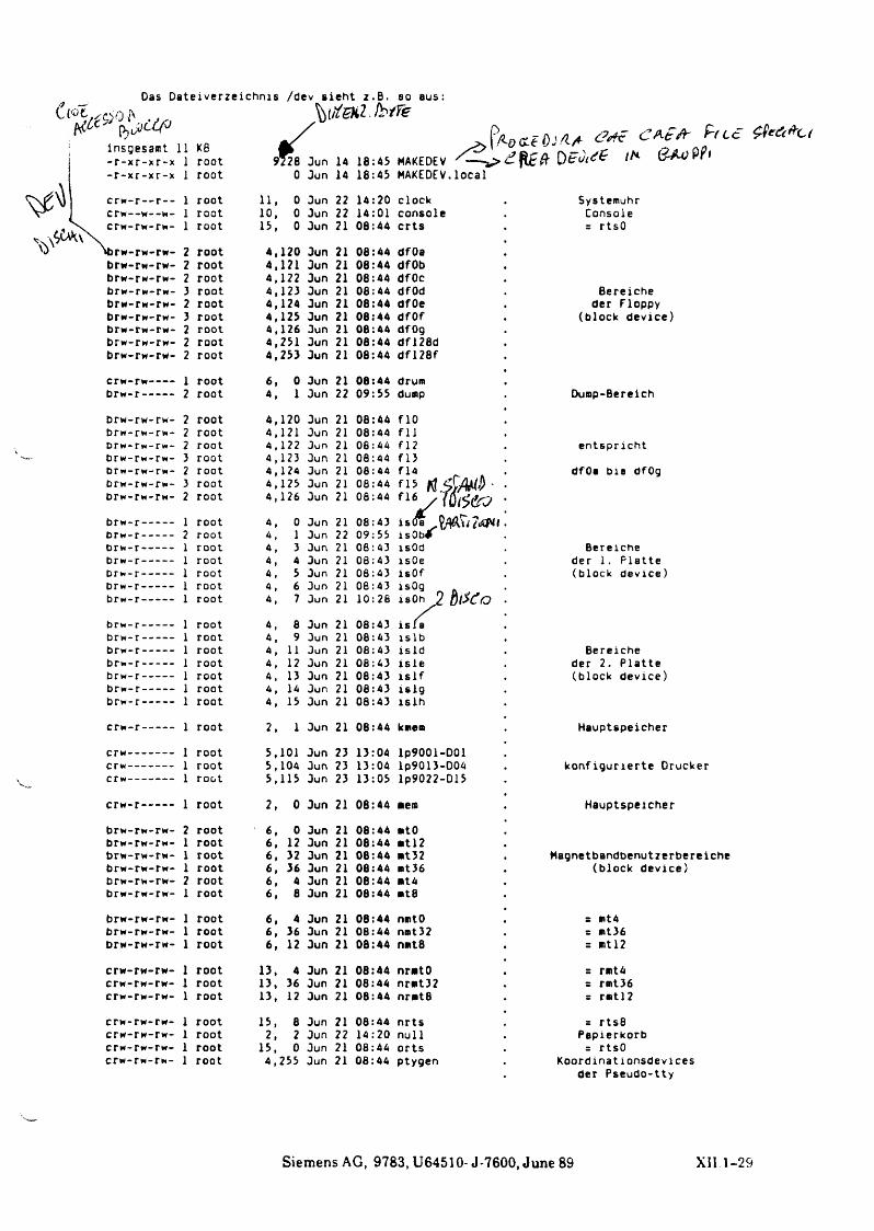
ü « < vHCc
Oas Dateiverzeichnis /dev s ie ht z .B . so aus:•>oa ^ t i t a ü . k t r e
insgesamt 11 KB i*- r - x r-x r-x 1 root 9728 Jun 14 18::45- r - x r-x r-x 1 root 0 Jun 14 18::45
CTW- r — r - - 1 root 11, 0 Jun 22 14::20crw- -w- -w- 1 root 10, 0 Jun 22 14::01crw- rw- rw- 1 root 15, 0 Jun 21 08::44
ibrw-■ rw- rw- 2 root 4, 120 Jun 21 08::44brw- rw- rw- 2 root 4, 121 Jun 21 08::44brw-■ rw- rw- 2 root 4, 122 Jun 21 08::44brw- rw- rw- ) root 4, 123 Jun 21 08::44brw-■ rw- rw- 2 root 4, 124 Jun 21 08::44brw- rw- rw- 3 root 4, 125 Jun 21 08::44brw- rw- rw- 2 root 4, 126 Jun 21 08::44brw- rw- rw- 2 root 4, 251 Jun 21 08::44brw- rw- rw- 2 root 4, 253 Jun 21 08::44
crw- rw- 1 root 6, 0 Jun 21 08::44brw- r — 2 root 4, 1 Jun 22 09::55
brw- rw- rw- 2 root 4, 120 Jun 21 08::44brw- rw- rw- 2 root 4, 121 Jun 21 08::44brw- rw- rw- 2 root 4 , 122 Jun 21 08::44brw- rw- rw- 3 root 4 , 123 Jun 21 08::44brw- rw- rw- 2 root 4, 124 Jun 21 08::44brw- rw- rw- 3 root 4, 125 Jun 21 08::44brw- rw- rw- 2 root 4, 126 Jun 21 06::44
brw- r — 1 root 4, 0 Jun 21 08::43brw- r - - 2 root 4, 1 Jun 22 09::55brw- r - - 1 root 4, 3 Jun 21 08::43brw- r - - 1 root 4, 4 Jun 21 08::43brw- r - - 1 root 4 , 5 Jun 21 08::43brw- r - - 1 root 4, 6 Jun 21 08::43brw- r - - 1 root 4, 7 Jun 21 10::28
brw- r - - 1 root 4, 8 Jun 21 08::43brw- r - - 1 root 4, 9 Jun 21 08::43brw- r — 1 root 4, 11 Jun 21 08::43brw- r - - 1 root 4, 12 Jun 21 08::43brw- r - - 1 root 4, 13 Jun 21 08::43brw- r - - 1 root 4, 14 Jun 21 08::43brw- r - - 1 root 4, 15 Jun 21 08::43
crw- r - - 1 root 2, 1 Jun 21 08::44
crw- 1 root 5, 101 Jun 23 13::04crw- 1 root 5, 104 Jun 23 13::04crw- 1 root 5, 115 Jun 23 13::05
crw- r - - 1 root 2, 0 Jun 21 08::44
brw- rw- rw- 2 root 6, 0 Jun 21 08::44brw- rw- rw- 1 root 6, 12 Jun 21 08::44brw-TW- rw- 1 root 6, 32 Jun 21 08::44brw- rw- rw- 1 root 6, 36 Jun 21 08::44brw- rw- rw- 2 root 6, 4 Jun 21 08::44brw- rw- rw- 1 root 6, 8 Jun 21 08::44
brw- rw- rw- 1 root 6 , 4 Jun 21 08::44brw- rw- rw- 1 root 6, 36 Jun 21 08::44brw- rw- rw- 1 root 6, 12 Jun 21 08;:44
crw- rw- rw- 1 root 13, 4 Jun 21 08::44crw- rw- rw- 1 root 13, 36 Jun 21 08::44crw- rw- rw- 1 root 13, 12 Jun 21 08::44
crw- rw- rw- 1 root 15, 8 Jun 21 08::44crw- rw- rw- 1 root 2, 2 Jun 22 14::20crw- rw- rw- 1 root 15, 0 Jun 21 08::44crw- rw- rw- 1 root 4, 255 Jun 21 08: 44
^ O O L t C J / l A <?<*? C A £A ' ^ t € ^ ee,&C‘
a $ M ■/ W 6& 3
flO f l l f 12 f l ) f l4 f 15f 16 y
i&(fä V/$\U&Ui s Ob# isOd isOe isOfisOg Ai s O h 2 b l X o
i s l a
Systemuhr Console r rtsO
Bereiche der Floppy
(block device)
Dump-Bereich
entspricht
dfOa b is dfOg
Bereiche der 1. P latte (block device)
Bereiche der 2. P latte(block device)
Hauptspeicher
k o n figu rie rte Drucker
Hauptspeicher
Hagnetbandbenutzerbereiche (block device)
s mt4 = mt36 = mt 12
= rmt4 = rmt)6 = rmtl?
= rts8 Papierkorb
= rtsOKoordinationsdevices
der Pseudo-tty
Siemens AG, 9783, U64510- J-7600, June 89 XII 1 - 2 9
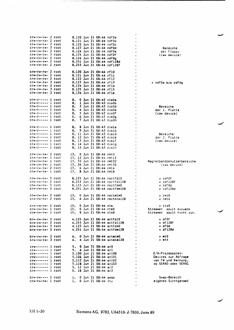
crw-rw-rw- 2 root 8,120 Jun 21 08:44 rdfOacrw-rw-rw- 2 root 8,121 Jun 21 08:44 rdfObcrw-rw-rw- 2 root 8,122 Jun 21 08:44 rdfOccrw-rw-rw- 3 root 8,123 Jun 21 08:44 rdfOd . Bereichecrw-rw-rw- 2 root 8,124 Jun 21 08:44 rdfOe . der Floppycrw-rw-rw- 3 root 8,125 Jun 21 08:44 rdfOf . (raw device)crw-rw-rw- 2 root 8,126 Jun 21 08:44 rdfOgcrw-rw-rw- 2 root 8,251 Jun 21 08:44 rdfl28dcrw-rw-rw- 2 root 8,253 Jun 21 08:44 rd f l2 8 f
crw-rw-rw- 2 root 8,120 Jun 21 08:44 r f lOcrw-rw-rw- 2 root 8,121 Jun 21 08:44 r f l lcrw-rw-rw- 2 root 8,122 Jun 21 08:44 r f l2crw-rw-rw- 3 root 8,123 Jun 21 08:44 r f l 3 . = rdfOa b is rdfOgcrw-rw-rw- 2 root 8,124 Jun 21 08:44 r f l4crw-rw-rw- 3 root 8,125 Jun 21 08:44 r f l5crw-rw-rw- 2 root 8,126 Jun 21 08:44 r f l 6
crw -r-------- 1 root 8, 0 Jun 21 08:43 riaOa-crw -r-------- 1 root 8, 1 Jun 21 08:43 risObcrw-r-------- 1 root 8, 3 Jun 21 08:43 risOd . Bereichecrw -r------- 1 root 8, 4 Jun 21 08:43 risOe . der 1. P lattecrw -r-------- 1 root 8, 5 Jun 21 08:43 r isO f . (raw device)crw -r-------- 1 root 8, 6 Jun 21 08:43 risOgcrw-r-------- 1 root 8, 7 Jun 21 08:43 risOh
crw -r------- 1 root 8, 8 Jun 21 08:43 r i s l acrw -r------- 1 root 8, 9 Jun 21 08:43 n s l bcrw -r------- 1 root 8, 11 Jun 21 08:43 n s l d . Bereichecrw -r-------- 1 root 8, 12 Jun 21 08:43 r i s l e . der 2. P lattecrw -r------- 1 root 8, 13 Jun 21 08:43 r i s l f . (raw device)crw -r------- 1 root 8, 14 Jun 21 08:43 n s l gcrw -r------- 1 root 8, 15 Jun 21 08:43 n s l n
crw-rw-rw- 2 root 13, 0 Jun 21 08:44 rmtOcrw-rw-rw- 1 root 13, 12 Jun 21 08:44 rmtl2crw-rw-rw- 1 root 13, 32 Jun 21 08:44 rmt32 . Magnetbandbenutzerbereichecrw-rw-rw- 1 root 13, 36 Jun 21 08:44 rmt36 . (raw device)crw-rw-rw- 2 root 13, 4 Jun 21 08:44 rmtAcrw-rw-rw- 1 root 13, 8 Jun 21 08:44 rmt8
crw-rw-rw- 3 root 8,125 Jun 21 08:44 rsctfd lO . = rdfOfcrw-rw-rw- 2 root 8,253 Jun 21 08:44 r s c t fd l l2 8 . = rd f l2 8 fcrw-rw-rw- 3 root 8,123 Jun 21 08:44 rsctfdmO . = rdfOdcrw-rw-rw- 2 root 8,251 Jun 21 08:44 ractfdml28 . = rdfl28d
crw-rw-rw- 2 root 13, 0 Jun 21 08:44 rsctmtmO . = rmtOcrw-rw-rw- 2 root 13, 4 Jun 21 08:44 rsctmtml28 . = rmt4
crw-rw-rw- 1 root 15, 0 Jun 21 08:44 r ts = rtsOcrw-rw-rw- 1 root 15, 0 Jun 21 08:44 rtsO . Streamer spult zurueckcrw-rw-rw- 1 root 15, 8 Jun 21 08:44 rts8 . Streamer spult nicht zur.
brw-rw-rw- 3 root 4,125 Jun 21 08:44 actfdlO . = dfOfbrw-rw-rw- 2 root 4,253 Jun 21 08:44 s c t fd l l2 8 . = d f l2 8 fbrw-rw-rw- 3 root 4,123 Jun 21 08:44 sctfdmO . s dfOdbrw-rw-rw- 2 root 4,251 Jun 21 08:44 sctfdal28 . = dfl28d
brw-rw-rw- 2 root 6, 0 Jun 21 08:44 actatmO . = atObrw-rw-rw- 2 root 6, 4 Jun 21 08:44 sctmtal28 = at4
crw------------- 1 root 5, 0 Jun 21 08:44 srOcrw------------- 1 root 5, 6 Jun 21 08:44 s r lcrw----------- 1 root 5,100 Jun 21 08:44 srlOO . E/A-Prozessoren:crw----------- 1 root 5,106 Jun 21 08:44 sr lO l . Devices zur Abfragecrw----------- 1 root 5,112 Jun 21 08:44 sr l0 2 . von FW und Kennung,crw----------- 1 root 5,118 Jun 21 08:44 sr l03 . ob SERAD oder SERACcrw------------- 1 root 5, 12 Jun 21 08:44 sr2crw------------- 1 root 5, 18 Jun 21 08:44 sr3
brw-rw------ 1 root 1, 0 Jun 21 08:44 swap . Swap-Bereichcrw-rw-rw- 1 root 1, 0 Jun 21 08:44 tty . eigenes Sichtgeraet
X11 -1-30 Siemens AG, 9783, U64510- J-7600, June 89
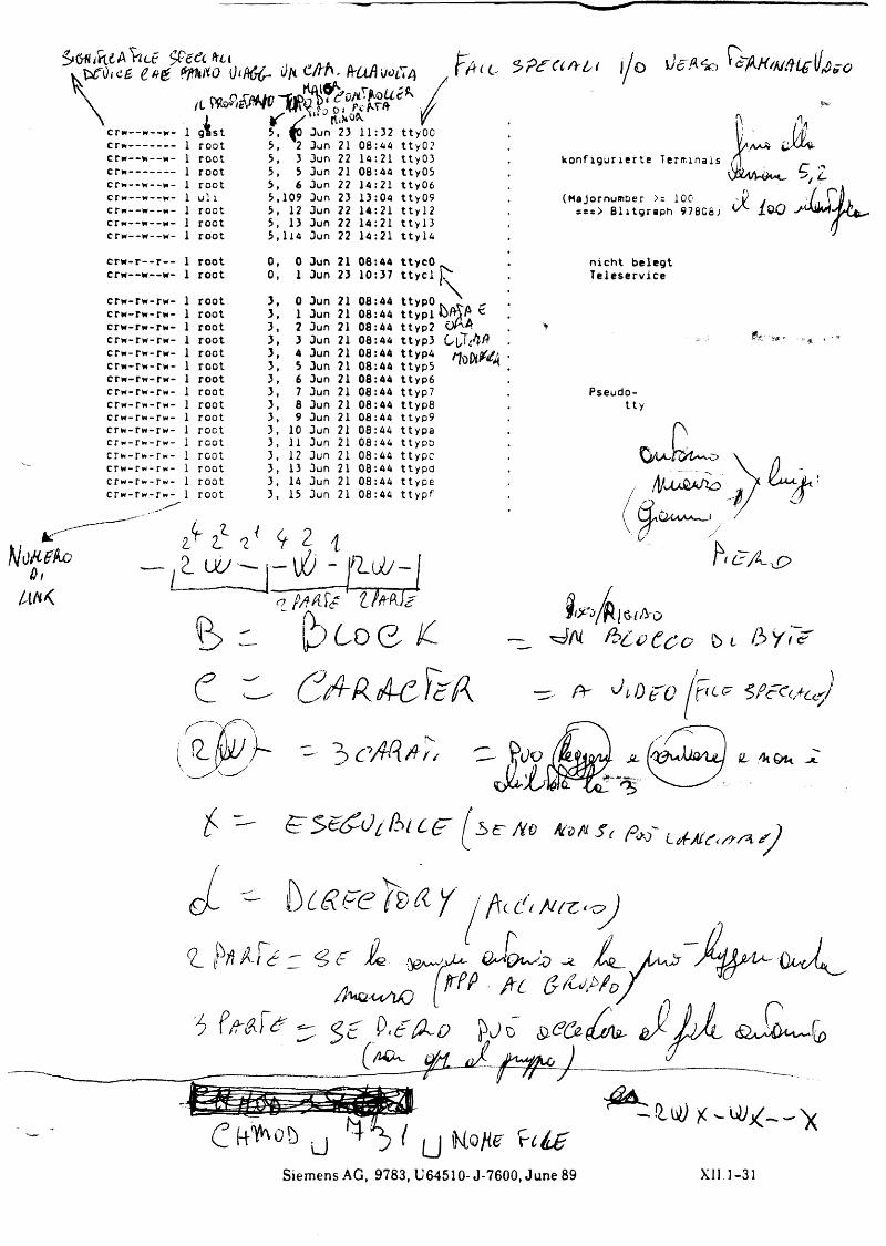
£ # & f ip t f io li/t C /r f r . frUA\)üC7/) F f i u - •^p£(lA rlyt | / o \ J C ^ , (/,4 <
f / " ,0 fa te '5, fO Jun 23 11:32 ttyOO5, 2 Jun 21 08:44 ttyO?5, 3 Jun 22 14:21 tty035, 5 Jun 21 08:44 tty055, 6 Jun 22 14:21 tty065,109 Jun 23 13:04 tty095, 12 Jun 22 14:21 tty l25, 13 Jun 22 14:21 t ty l35,114 Jun 22 14:21 tt y l4
c r w - r - - r - - crw—w— w-
crw-crw-crw-crw-cr*«-crw-crw-crw-crw-crw-crw-crw-cr*-crw-crw-crw-
rw-rw-r*»-rw-rw-rw-rw-rw-rw-rw-r*-rw-rw-rw-rw-rw-rw-rw-r w - r w -rw-rw-r w - r w -
rw-r*- rw-rw- rw-rw- rw-r«-
*£0
0 ,
Ü K
1 root 1 root
1 root 1 root 1 root 1 root 1 root 1 root 1 root 1 root 1 root 1 root 1 roct 1 root 1 rcot 1 root 1 root 1 root
0,0,3,3,3,3,3,3,3,3,3,3,3,3,3,3,3,3,
0 Jun1 Jun
21 08:44 23 10:37
Jun Jun Jun Jun Jun Jun Jun Jun
8 Jun9 Jun
10 Jun11 Jun12 Jun13 Jun14 Jun15 Jun
21 08:44 21 08:44 21 08:44 21 08:44 21 08:44 21 08:44 21 08:44 21 08:44 21 08:44 21 08:44
08:44 08 : 44 08:44 08:44 08:44 08:44
ttycOt t y c l
tty p i ettyp2 O M ttyp3 O t T ^ A
Wilt nou*4ttyp6ttyp7ttyp8t t y p 9
ttypattypbttypcttypattypettypf
ko nfigurie rte Terminals
(Majornumber >= 100 s = = > B litgraph 97606)
nicht belegt Teleservice
Pseudo-tty
2w
2 iI- w — I
(? pftßSs Z, /
¢ )6 0 0 1C
/\}UjSüJ%0
h e A &
c
3
W /u f c c o t c o b t
! \
Sh v
i(hi tfr ( be: fto
*2. Pfi iL E qu.-;jo Psi_[ m ■ *
( AC£ g jt )_________ (/
C f+^oö j , + '6 ( ( j Ho He vi(£Siemens AG, 9783, U64510- J-7600, June 89 XII.1-31
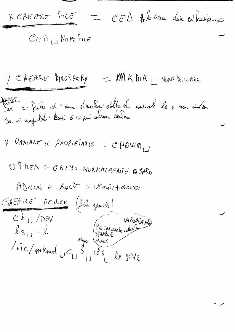
Y fr ( h r t A G*.1 U i - H A ^ o
C(? S u Nc He W'
C ^ / H ^ T O f t f \ K b l f ( U Vlo^F Vl>-eÖ«(k
/V-T ^ V u Q i c Y ' «i vy_ O ^^S. U ^ J ^ a ^ L ^ )£
£T a , ^ j J ^ L ’ - ^ K £ 'P / ^ - 0 ^ ^ - ^ '/V o
Y ÜfcUkkC Ic PAöptel'/tkiq)c t t o ^ m u
O T h ( ? / v - 6 - ^ f f a k v k k f t C H t A t f r Q S / f o

c

>.J
SIEMENS
Part XIII Cables

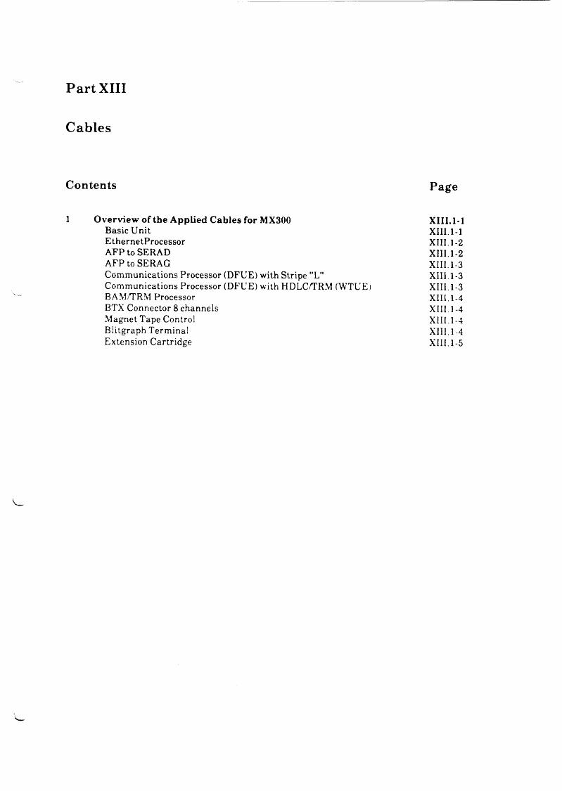
Part XIII
Cables
Contents Page
1 Overview of the Applied Cables for MX300 XIII.1Basic Unit XIII.1-EthernetProcessor XIII. 1-AFP to SERAD XIII.1-AFP to SERAG XIII.1-Communications Processor (DFUE) with Stripe ”L” XIII. 1 -Communications Processor (DFUE) with HDLC/TRM (WTUE) XIII.1-BAM/TRM Processor XIII.1-BTX Connector 8 channels XIII.1-Magnet Tape Control XIII.1-Blitgraph Terminal XIII.1-Extension Cartridge XIII.1-
-1-1-2-2-3-3-3-4-4-4-4-5

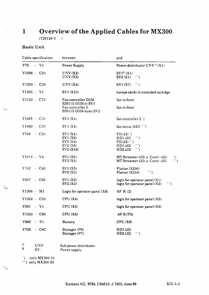
1 Overview of the Applied Cables for MX300(T26139-Y .. .1
Basic Unit
Cable specification between and
Y75 - VI Power Supply Power distributor UNV 11 (X l)
Y1296 - C50 UNV (X2) SV12 (XI)UNV (X3) SV2 (XI) **)
Y1303 - C30 UNV (X4) SVKX7) **)
Y1305 - VI SV1 (X10) europe cards in extended cartidge
Y1133 - C70 Fan controller D336 fan in frontS26113-D336 in SV1Fan controller 2 fan in frontS26113-D336 in/an SV2
Y1455 - C30 SV1 (X4) fan controller 2 ')
Y1460 - C30 SV1 (X4) fan below HD2 " )
Y749 - C50 SV1/X4) FD (J 2)')SV1 (X6) HD1(J3) **)SV2 (X4) FD (J2)' ' )SV2 (X6) HDKJ3) “ )SV2 (X10) HD2 (J3) **)
Y1014 - V4 SV1 (X5) MT Streamer (J2) u. Contr. (J2)SV2 (X5) MT Streamer (J2) u. Contr. (J2)
Y742 - C40 SV1 (X3) Platter (X200)SV2 (X3) Platter (X210) “ )
Y607 - C65 SV1 (X2) logic for operator panel (X I)SV2 (X2) logic for operator panel (X2)
Y1306 - Ml Logic for operator panel (X8) AF R (2)
Y1322 - C50 CPU (X4) logic for operator panel (X5)
Y581 - VI CPU (X5) logic for operator panel (X6)
Y1355 - C80 CPU (X6) AFR(TS)
Y965 - VI Battery CPU (X8)
Y735 - C42 Storager (P6) HD1 (J2)Storager (P7) HD2(J2) “ )
l* UNV: Sub power distributor2. SV: Power supply
*) onlyMX300-10 **) only MX300-20
')“ )
Siemens AG, 9783, U64510- J-7600, June 89 XIII.1-1
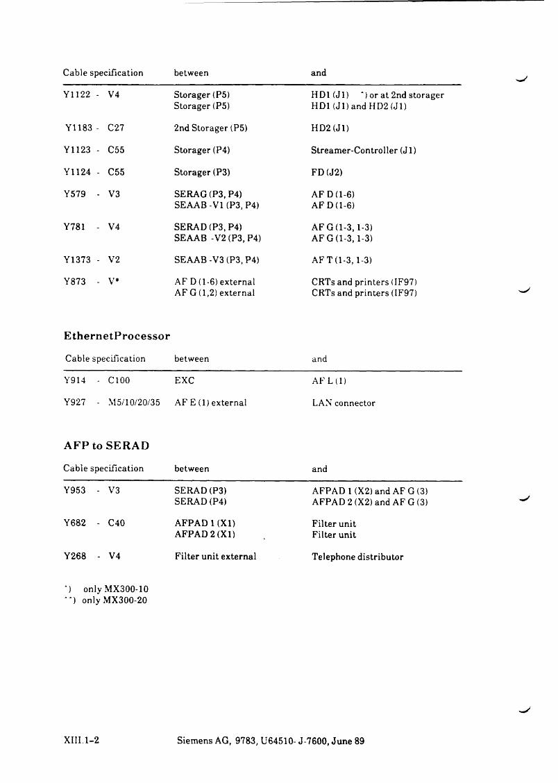
Cable specification between and
Y1122 - V4 Storager (P5) Storager (P5)
H D l(Jl) *) or at 2nd storager HD1 (J 1) and HD2 (Jl)
Y1183 - C27 2nd Storager (P5) HD2 (Jl)
Y1123 - C55 Storager (P4) Streamer-Controller (J 1)
Y1124 - C55 Storager (P3) FD(J2)
Y579 - V3 SERAG (P3.P4) SEAAB-VI (P3, P4)
AF D (1-6) AF D (1-6)
Y781 - V4 SERAD (P3, P4) SEAAB -V2 (P3, P4)
AF G (1-3,1-3) AF G (1-3,1-3)
Y1373 - V2 SEAAB -V3 (P3, P4) AF T (1-3,1-3)
Y873 - V* AF D (1-6) external AF G (1,2) external
CRTs and printers (IF97) CRTs and printers (IF97)
EthernetProcessor
Cable sipecification between and
Y914 - C 100 EXC AF L (1)
Y927 - M 5/10/20/35 AF E (1) external LAN connector
AFP toSERAD
Cable specification between and
Y953 - V3 SERAD (P3) SERAD (P4)
AFPAD 1(X2) and AF G (3) AFPAD 2 (X2) and AF G (3)
Y682 - C40 AFPAD 1 (XI) AFPAD 2 (XI)
Filter unit Filter unit
Y268 - V4 Filter unit external Telephone distributor
) only MX300-10 *) only MX300-20
XIII. 1-2 Siemens AG, 9783, U64510- J-7600, June 89
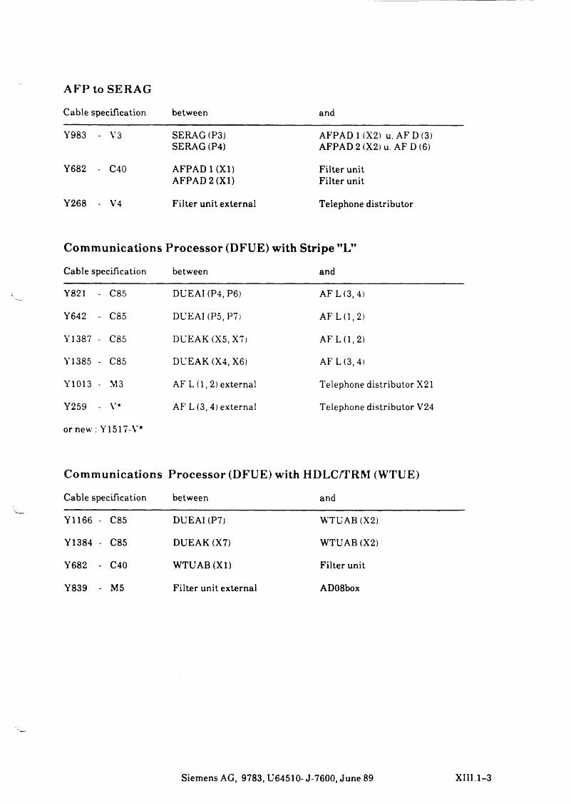
AFP to SERAG
Cable specification between and
Y983 - V3 SERAG (P3) SERAG (P4)
AFPAD 1 (X2) u. AF D (3) AFPAD 2 (X2) u. AF D (6)
Y682 - C40 AFPAD 1 (XI) AFPAD 2 (XI)
Filter unit Filter unit
Y268 - V4 Filter unit external Telephone distributor
Communications Processor (DFUE) with Stripe ”L”
Cable specification between and
Y821 - C85 DUEAKP4, P6) AF L (3, 4)
Y642 - C85 DUE AI (P5,P7) AF L (1,2)
Y1387 - C85 DUEAK (X5, X7) AF L (1,2)
Y1385 - C85 DUEAK (X4, X6) AF L(3,4)
Y1013 - M3 AF L (1 , 2) external Telephone distributor X21
Y259 - V* AF L (3, 4) external Telephone distributor V24
or new : Y1517-V*
Communications Processor (DFUE) with HDLC/TRM (WTUE)
Cable specification between and
Y1166 - C85 DUEAKP7) WTUAB (X2)
Y1384 - C85 DUEAK (X7) WTUAB (X2)
Y682 - C40 WTUAB (XI) Filter unit
Y839 - M5 Filter unit external AD08box
Siemens AG, 9783, U64510- J-7600, June 89 XIII.1-3
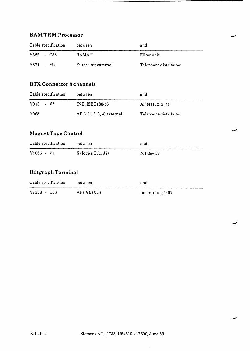
BAM/TRM Processor
Cable specification between and
Y682 - C85 BAMAH Filter unit
Y874 - M4 Filter unit external Telephone distributor
BTX Connector 8 channels
Cable specification between and
Y913 - V* INE: ISBC188/56 AF N (1,2, 3, 4)
Y968 AF N (1 , 2, 3, 4) external Telephone distributor
Magnet Tape Control
Cable specification between and
Y1056 - VI Xylogics C J1, J2) MT device
Blitgraph Terminal
Cable specification between and
Y1338 - C36 AFPAL(XG) inner lining IF97
XIII.1-4 Siemens AG, 9783, U64510- J-7600, June 89
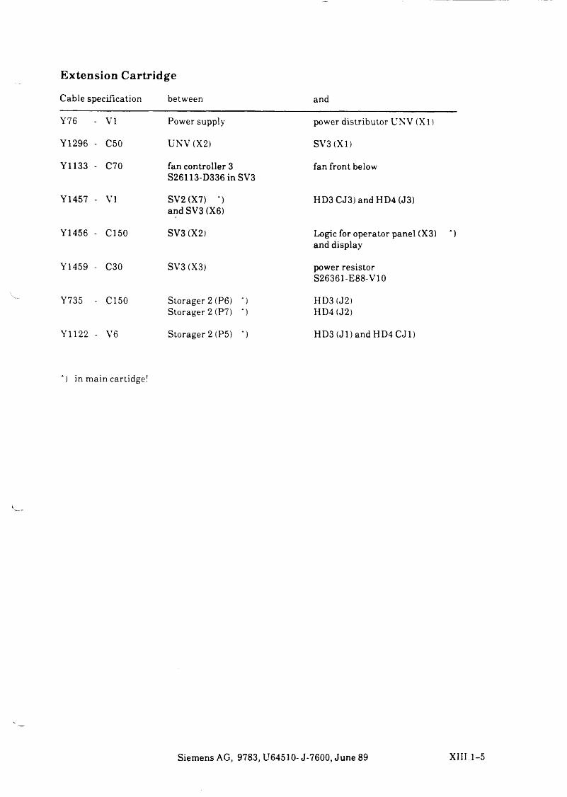
Extension Cartridge
Cable specification between and
Y76 VI Power supply power distributor UNV (X l)
Y1296 - C50 UNV (X2) SV3(XI)
Y1133 - C70 fan controller 3 S26113-D336 in SV3
fan front below
Y1457 - VI SV2 (X7) *) and SV3 (X6)
HD3 CJ3) and HD4 (J3)
Y1456 - C150 SV3 (X2) Logic for operator panel (X3) and display
Y1459 - C30 SV3 (X3) power resistor S26361-E88-V10
Y735 - C150 Storager 2 (P6) *) HD3 (J2)Storager 2 (P7) *) HD4 (J2)
Y1122 - V6 Storager 2 (P5) *) HD3 (Jl) and HD4 C J1)
) in m a i n car t idge !
Siemens AG, 9783, U64510- J-7600, June 89 X III 1-5


u
SIEMENS
Part XIV Appendix


Part XIV
Appendix
Contents Page
l P roduct Overview and Spare P arts XIV.1-1


1 Product Overview and Spare Parts
I tem D e s c r ip t io n P ro d u c t N o . P a r t N u m b e r N ote a
Q u a n t i t y b c d e f g
1 B a s ic U n i t w i t h 1 P o w e r S u p p ly
S 2 6 3 6 1 K 1 7 8 V 1 1 1
K E L E x t e n s i o n K i t M X 3 0 0 - 1 0 9 7 8 3 2 - 6 1 0 S 2 6 3 6 1 K 4 6 7 V 1 1 0 1K E L E x t e n s i o n K it M X 3 0 0 - 2 0 9 7 8 3 2 - 6 2 0 S 2 6 3 6 1 F 4 6 7 V 120 1
2 n d P o w e r S u p p ly E x t e n s io n K it
S 2 6 3 6 1 F 4 7 2 V 1 1
5 P r o c e s s o r C P U S 2 6 3 6 1 F 4 6 8 V 1 1 17 1 s t D r iv e P r o c e s s o r S 2 6 3 6 1 F 4 1 5 V 31 1 19 F D D r iv e 1 M b y te T E A -F D -5 5 G F R - E G 1 1
11 M T S t r e a m e r 4 5 M b y te S 2 6 3 6 1 F 4 1 8 V 31 1 1501 M e m o r y M o d u l 4 M b y te 9 7 8 3 2 - 3 0 5 S 2 6 3 6 1 F 4 9 6 V 4 X
5 0 2 M e m o r y M od u l 8 M b y te 9 7 8 3 2 - 3 0 6 S 2 6 3 6 1 F 4 9 6 V 8 X X
5 0 3 M e m o r y E x t e n s io n 9 7 8 3 2 - 3 0 4 S 2 6 3 6 1 F 4 9 7 X X
511 2n d D r iv e P r o c e s s o r 9 7 8 3 2 - 401 S 2 6 3 6 1 F 4 1 5 V 32 X
5 1 6 1 s t H D D r iv e 1 7 0 M b y te 9 7 8 3 4 - 17 0 S 2 6 3 6 1 K 184 X X
5 1 7 1 s t H D D r iv e 2 0 0 M b y te 9 7 8 3 4 - 1 2 0 S 2 6 3 6 1 K 12 8 X X
5 1 8 1st H D D r iv e 3 0 0 M b y te 9 7 8 3 4 - 13 0 S 2 6 3 6 1 K 111 X X
5 2 0 2 n d H D D r iv e 1 7 0 M b y te 9 7 8 3 4 - 1 7 1 S 2 6 3 6 1 F 4 1 7 V 31 X
5 2 2 2n d H D D r iv e 2 0 0 M b y te 9 7 8 3 4 - 121 S 2 6 3 6 1 F 4 5 3 V 31 X
5 2 4 1 st D r iv e P r o c e s s o r 3 0 0 M b y te
9 7 8 3 4 - 131 S 2 6 3 6 1 F 4 7 0 V 31 X X
551 I/O P r o c e s s o r 6 x S S 9 7 9 7 8 3 2 - 201 S 2 6 3 6 1 F 1 2 9 V 31 X X
5 5 2 I/O P r o c e s s o r I F 9 7 /2 x V 2 4
9 7 8 3 2 - 2 0 4 S 2 6 3 6 1 F 3 2 0 V 31 X X
5 5 3 4 x A F P to - F 12 9 9 7 8 3 1 - 3 9 1 S 2 6 3 6 1 F 3 3 9 V 31 X X
5 5 4 2 x A F P to - F 3 2 0 9 7 8 3 1 - 3 9 2 S 2 6 3 6 1 F 3 3 9 V 32 X X
5 5 6 D C E P r o c e s s o r 2 5 6 k b y te /V 2 4 /X .2 1
9 7 8 3 2 - 122 S 2 6 3 6 1 F 3 1 5 V 32 X X
5 5 7 D C E P r o c e s s o r 2 5 6 k b y t e / 2x X .2 1
9 7 8 3 2 - 1 2 5 S 2 6 3 6 1 F 3 1 5 V 34 X X
5 5 9 D C E P r o c e s s o r 2 5 6 k b y te 9 7 8 3 2 - 1 2 4 S 2 6 3 6 1 F 3 1 5 V 3 3 2 X X
5 6 0 D C E P r o c e s s o r 1 M b y te /V 2 4 /X .2 1
9 7 8 3 2 - 1 6 0 S 2 6 3 6 1 F 4 7 1 V 3 2 X X
561 D C E P r o c e s s o r 1 M b y te 9 7 8 3 2 - 1 6 4 S 2 6 3 6 1 F 4 7 1 V 3 3 2 X X
581 B A M /W T U E P r o c e s s o r 9 7 8 3 2 - 1 5 0 S 2 6 3 6 1 F 3 8 0 V 31 X X
5 8 4 E t h e r n e t P r o c e s s o r 2 5 6 k b y te 9 7 8 3 2 - 1 4 0 S 2 6 3 6 1 F 3 4 3 V 32 X X
5 8 5 E t h e r n e t P r o c e s s o r 5 1 2 k b y te 9 7 8 3 2 - 1 4 1 S 2 6 3 6 1 F 5 4 3 V 31 X X
591 M B C o n tr o l le r 9 7 8 3 2 - 4 3 0 S 2 6 3 6 1 F 4 1 9 V 31 X
6 0 0 E x t e n s i o n K i t 10 2 0 9 7 8 3 2 - 7 3 0 S 2 6 3 6 1 F 4 7 2 V 120 X X
d
c
b S y s t e m U n i t M X 3 0 0 - 2 0 9 7 8 3 - 2 0 S 2 6 3 6 1 L 4 8 V 12 0 1
a S y s t e m U n i t M X 3 0 0 - 1 0 9 7 8 3 - 10 S 2 6 3 6 1 L 4 8 V 110 1
S i e m e n s A G , 9 7 8 3 , U 6 4 5 1 0 - J - 7 6 0 0 , J u n e 89 X I Y . l - l
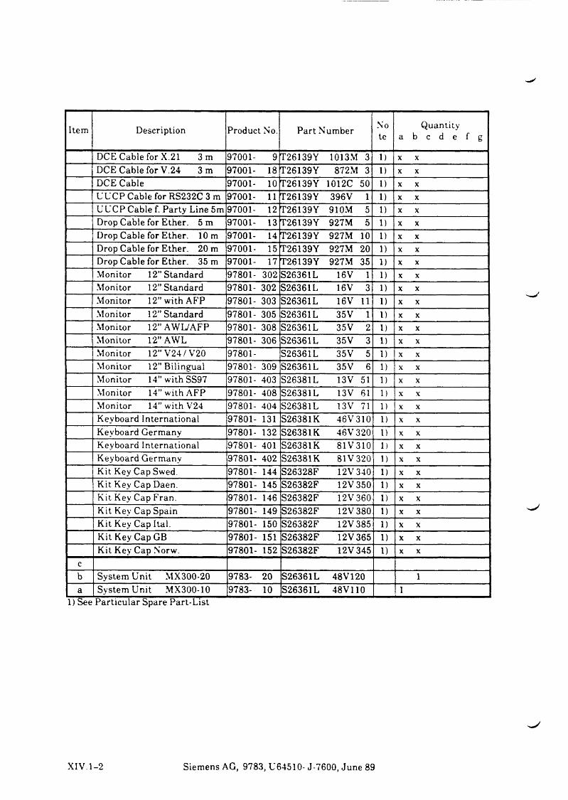
I tem D e s c r ip t io n P ro d u c t No. P a r t N u m b e rN ote a
Q u a n t i t y b c d e f g
D C E C a b le for X .21 3 m 9 7 0 0 1 - 9 T 2 6 1 3 9 Y 1 0 1 3 M 3 1) X X
D C E C a b le for V . 2 4 3 m 9 7 0 0 1 - 18 T 2 6 1 3 9 Y 8 7 2 M 3 1) X X
D C E C a b le 9 7 0 0 1 - 10 T 2 6 1 3 9 Y 1 0 1 2 C 50 1) X X
U U C P C a b le for R S 2 3 2 C 3 m 9 7 0 0 1 - 11 T 2 6 1 3 9 Y 3 9 6 V 1 1) X X
U U C P C a b le f. P a r ty L in e 5 m 9 7 0 0 1 - 12 T 2 6 1 3 9 Y 9 1 0 M 5 1) X X
D rop C a b le for E th e r . 5 m 9 7 0 0 1 - 13 T 2 6 1 3 9 Y 9 2 7 M 5 1) X X
D rop C a b le for E th e r . 10 m 9 7 0 0 1 - 14 T 2 6 1 3 9 Y 9 2 7 M 10 1) X X
D rop C a b le for E th e r . 2 0 m 9 7 0 0 1 - 15 T 2 6 1 3 9 Y 9 2 7 M 2 0 1) X X
D rop C a b le for E th e r . 35 m 9 7 0 0 1 - 17 T 2 6 1 3 9 Y 9 2 7 M 35 1) X X
M o n ito r 1 2 ” S ta n d a r d 9 7 8 0 1 - 3 0 2 S 2 6 3 6 1 L 1 6 V 1 1) X X
M o n ito r 1 2 ” S ta n d a r d 9 7 8 0 1 - 3 0 2 S 2 6 3 6 1 L 1 6 V 3 1) X X
M o n ito r 1 2 ” w ith A F P 9 7 8 0 1 - 30 3 S 2 6 3 6 1 L 1 6 V 11 1) X X
M o n ito r 1 2 ” S ta n d a r d 9 7 8 0 1 - 3 0 5 S 2 6 3 6 1 L 3 5 V 1 1) X X
M o n ito r 1 2 ” A W L /A F P 9 7 8 0 1 - 3 0 8 S 2 6 3 6 1 L 3 5 V 2 1) X X
M o n ito r 1 2 ” A W L 9 7 8 0 1 - 3 0 6 S 2 6 3 6 1 L 3 5 V 3 1) X X
M o n ito r 1 2 ” V 2 4 / V 2 0 9 7 8 0 1 - S 2 6 3 6 1 L 3 5 V 5 1) X X
M o n ito r 1 2 ” B i l in g u a l 9 7 8 0 1 - 3 0 9 S 2 6 3 6 1 L 3 5 V 6 1) X X
M o n ito r 1 4 ” w i t h S S 9 7 9 7 8 0 1 - 4 0 3 S 2 6 3 8 1 L 1 3 V 51 1) X X
M o n ito r 1 4 ” w ith A F P 9 7 8 0 1 - 4 0 8 S 2 6 3 8 1 L 1 3 V 61 1) X X
M o n ito r 1 4 ” w i t h V 2 4 9 7 8 0 1 - 4 0 4 S 2 6 3 8 1 L 1 3 V 71 1) X X
K e y b o a r d I n te r n a t io n a l 9 7 8 0 1 - 131 S 2 6 3 8 1 K 4 6 V 3 1 0 1) X X
K e y b o a r d G e r m a n y 9 7 8 0 1 - 1 32 S 2 6 3 8 1 K 4 6 V 3 2 0 1) X X
K e y b o a r d I n te r n a t io n a l 9 7 8 0 1 - 401 S 2 6 3 8 1 K 8 1 V 3 1 0 1) X X
K e y b o a r d G e r m a n y 9 7 8 0 1 - 4 0 2 S 2 6 3 8 1 K 8 1 V 3 2 0 1 ) X X
K it K e y C a p S w ed . 9 7 8 0 1 - 1 4 4 S 2 6 3 2 8 F 1 2V 3 4 0 1) X X
K it K e y C a p D a en . 9 7 8 0 1 - 14 5 S 2 6 3 8 2 F 1 2V 3 5 0 1) X X
K it K e y C a p F ra n . 9 7 8 0 1 - 146 S 2 6 3 8 2 F 1 2V 3 6 0 1) X X
K it K e y C a p S p a in 9 7 8 0 1 - 149 S 2 6 3 8 2 F 12V 3 8 0 1) X X
K it K e y C a p Ital. 9 7 8 0 1 - 15 0 S 2 6 3 8 2 F 1 2 V 3 8 5 1) X X
K it K e y C a p G B 9 7 8 0 1 - 151 S 2 6 3 8 2 F 12 V 3 6 5 1) X X
K it K e y C a p N o rw . 9 7 8 0 1 - 1 5 2 S 2 6 3 8 2 F 1 2 V 3 4 5 1) X X
cb S y s t e m U n i t M X 3 0 0 - 2 0 9 7 8 3 - 2 0 S 2 6 3 6 1 L 4 8 V 1 2 0 1
a S y s t e m U n i t M X 3 0 0 - 1 0 9 7 8 3 - 10 S 2 6 3 6 1 L 4 8 V 1 1 0 11) S e e P a r t i c u la r S p a r e P a r t - L is t
X I V . 1 - 2 S i e m e n s A G , 9 7 8 3 , U 6 4 5 1 0 - J -7 6 0 0 , J u n e 89
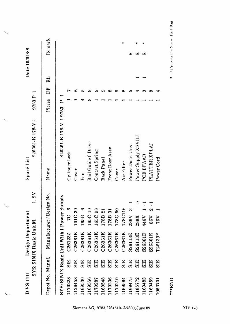
ccQC
xccC i
X
XXXCMer
x
>X
cc£©
Ci
GG
CUr*C
£
cz
ccuty
G G £i
^ - x x © © © x © x x T } < o o x ^ ,
1-1 Tf X
ccXl>c:
X
XXXCMX
PMG b£
c©© ui *©G © CU ©© X C© *3 *-> ©
”©r" © 6©© CU
©> c
«->c ©
'x o cc c c ©O O tau Ci ü G
y :w<uOc
Q«->cc©
G
©©?>c
O
©©$C
Cu
XG>XX>>C ucu
Xv.©£
CC<<tauCCCCocu
gXGgr<
T3©©
o©©£
G CU
fM c a r H X Hb£ i 1 1 iyi X X O X © X r H r H © X X r H CM r H-pH © im X p H © CSJ CO X r H
c© Q ©> CJ O G o O G G O
r H
O > X > > >© © ? t> r H X X X X X X X X X X X X©■w s © O o X X X t> t> i> X X Tf X© © G r H r H p H r H r H r H r H r H CM CM© 3a©
*CG
©>©£
rrX N3 G G G G G G G G G G Q G >*
© 3 X p H r H p H p H p H p H p H X X p H p H ©r* > <N X X X X X X X X p H p H X X Xc U P> p H X X X X X X X X p H p H X X p H
#hß © X X X X X X X X X X X X X X(/5 CC e <N CM CM CM CM CM CM CM CM CM CM CM CM CM© X
PM
G ü O o O o o O ü o X X X X G
z ©j.©
3 ¢/5Ä g g g g g g G g g g w w G GC P H P H P H P H M P H P H P H P H P H PH P H P H P H• * © X X X X X X X X X X X X X X XC/j
>- 2 XG X 6 zTT X X o X X X © X CM X © p Hp“ £-4 X CM X X X X X r H X X X ©X +u> CM rt X X CM X CM CM X t> TfO X O X Ci © © © © © © © X © © Xo< CM X X l> X t> l> X X X X X X© ?■ p H p H p H p H p H p H pH p H p H p H p H r H p H ©Q G X p H p H p H p H p H p H PH p H p H pH pH pH
cu
■*
G£G***
S i e m e n s A G , 9 7 8 3 , U 6 4 5 1 0 - J - 7 6 0 0 , J u n e 8 9 X I V . 1 - 3
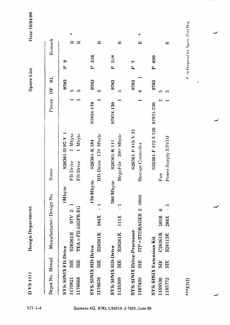
XXTTO
.as3E
25 Cix
0*i-CCax
25
X X o *"Z*— p— o XCi X X t> X CX.* A p p p u
-fvII*
X X X X XX X X X Xt> t> t> [>Ci Ci Ci ■x CiX X X X Tf 5 5
pp pH pp fH cg pp© © ot> X Xt>r- T'X XX X X[> t> t>Ci Ci Ci
05fi.0/
c#bcCi
X>
£E
Z
o£chßEo
Qj-,a>u,3pJCi
<23C3
2
3C3
26
Z•«_»ocua>Q
t>Ci
XXXcmX
Ci CipJ p-> >> >> X _C22 S
CU 0) > > 'u ’uQ C5ci 6
, oCM W> 25Ci O X Xh h Q
5 ^X II 00X ^ a> cm 23
> w h
£ w w*—< t—*2* CO X X
_ 1-t XX CM X . . X X X O X^ r-1 1—(X pH pH
VpJ>>X CM
s s25 c• C"*X ^XcmX
a>>u
Q
Xrfx
XrHxXX(NCO
Ci >
’S Qä w_ PH33 xX
i x<2 5X g* 5X p H
>>*— X
25
XXXcmX
cX_a>2.3hßo
2p 2p » * pp Cipp<2pp
>> >»-O JD-0 o ©t> oX
X
Xp HXCMXcmX
Wt-HX
XzX
05 O X X £
> >1X CMt>r>
X o ^r XPU Xupp l X
X c X cuX X cuX CJ X ~CM CM XCO tx X u3 oipc cpp 3 o
CO 2* 2.
Xx
oXocpcm
25 W O <
. 25® 2</3 X</) XG> II0 Pp*- H
Cu •“ •1Ci>’S WPT '“H53 xX
1 o ca « • • ”X *"■> «Or * p HX PH
XX
c.2*3ca>ppXr-i
« X x x X X »-• CM
S*c K3 2X pp X x cg CM O X
W WHH P PX X
CU o CMX co |>
. . x t>(X C3 X r* X X" 7 p H P P X P H PH
XIV. 1—4 Siemens AG, 9783, U64510- J-7600, June 89
***E
ND
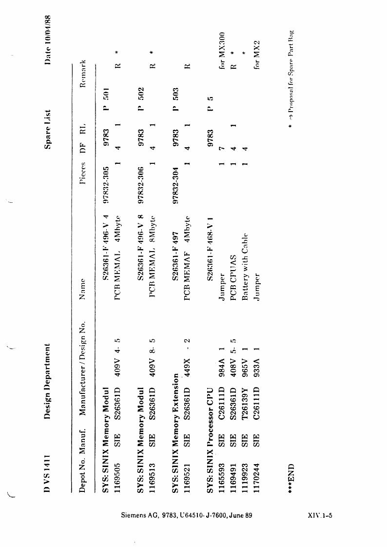
xXTTc©
Cret
05S-ccf i .
CO
* *
c CC CC CC
©o© <MX£ * +• £
u© CC £
n
c:
c.x
■— M ft© © ©Lt © ©r«Im * c-
f
CC
P
ft © ft ftcc X X Xt> t> *> l>© © © ©
*
ca Ml rH M rH FHo © © TToc © © ©ft ft ©p m IM 1IMft ft ©X X Xt> t> t>© © ©
c X O ow> XX >1©©TT
>> Xpß >©©■»r
£Tf iXl>© £ X
TTo
JCi u.1 U. P cc
ü© < © < © < © CO -C.►Jft© ©© K ©© £ ©IC rH w
i
or“Mco
ra2 CMCO £
CCo(■*
Mco
KS
IMco U0)G.Po Xu05c cc ec £ cc -H>
c o o u CCcu P © cu CC
co>
o£
oZ-«->oQ.05
P
cbc © © (M ©c ’ca i tX 1 ©& oE p > > X < > > <t_ © © © rr X © ©ff a> © © Tf X © © ©a05
i_3<«->Tf c . ^ o
© © ©o
"5 P *3 Q 1 p 3 P P >« pc 3f“* Xa © X © ■Z © ürH© ©©o © o © X © rH ©(£05 CC s ©<M ©CM K ©^ <N i.o
©<N ©<M ©<M ©CMC Xu 05 Xt. CO X CO f/i(A ü CO H OO o o 05
<m ‘ E E E 053 05 w 05 w 05 H o«
SIE W WC
cc S HCO
HHCO S CO
M »— iCO
MCO
MCO
X
COcö>■Cß
© © rH «c_ © M © Tf© CO M co <M CO © © cg Tf© © © © Tf © cg Z© cö © cö © cö © © © ©© l _ © © © © *M M M rH M *M CO CO M CO M rH *
Siemens AG, 9783, U64510- J-7600, June 89 XIV.1-5
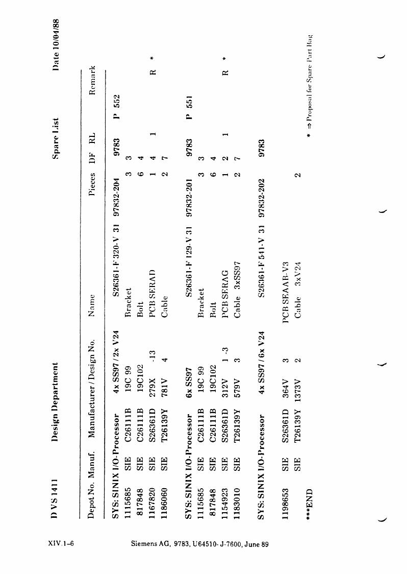
XXT*o
jau Di Di
d: CMXX
XX
0>U3aco
c
E-«huCCao
cb£"er0)
>
r-3Di
GG
XCi
C< X
CiO<
X Di X Di
Z)CMCO
*->0J
J C
CuCO <y
CMCO
u>cu W
CO£cc
CU3uu>O
NMo
-D CJ3u GO
z G DD G 6 G G G
ozcbß
*c7io
QUla>u3u>o
£3CA
S
3Ccc
S
dZ«->op ,a>
Q
XXt>05
©CMICMXXt>Ci
X
>©CMX
TCM>X
CM
COCOX
■*r
</)
o0u£ -
XXt>
CO ■** t* f- 05X ^ CM t>
X X i—t CM X CO rn CM
oCMICMr .xt>Ci
cc
CiCM
t>C iCOCOX
X
a>3cco
XXt>Ci
CM©CMICMXt>Ci
cc>
TT13
XccXCMCO
CM>Xx
CM
ci T*> CMJv ^ h- x< C i<K «y" 3CD ccy o
CO> -CO
. r f r i X X CMOiOi
CMOrH
t>Ol
OiOi
CMO Ol
COO ü X! > CO
CO O ü > > CO > >Oi Oi Oi Oi Oi CM Ol x r f XrH rH l''* X X rH rH rH X t'-CM t» X X X X
r H
G G Q >< G G Q > Q ><rH rH r 4 Oi u rH r 4 H Ol u rH OirH rH X X o rH rH X X o X XX rH r »H rH X rH er X rH
X X X X er X X X X er X XCM CM CM CM Ci CM CM CM CM O X CMo O CO E- Ci
o O O CO E- O© CO E-u U
G rMNw s s s •
O w s s W1
o s WCO GO 5 GO 3 00 CO G0 3 MH
COX £z * ■
X X o o X X X O z XX CM X GO X rj* CM rH CO XX X X o X X Oi O XX o X cö X l> •*t CO cÖ XH rH X X
> •r H rH HO 00 OirH X H rH X rH rH rHrH rH rH CO H rH rH CO r H
X IV .1-6 Siemens AG, 9783, U64510- J-7600, June 89
♦*
*E
ND
*
=> P
rojK
) sii
I for
Spa
rt*'
Por
t M
o^
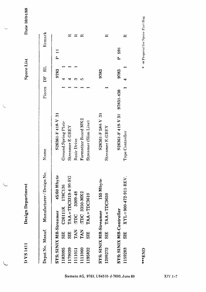
ocX
v:
Qis-ecG
X
v .
uec£c
G
GG
ooa>
G G G
XXt>Ci Tf Tt CO X
CMG
XXt>Ci
G
CiX
XXt>Ci
onrrI
XXt>Ci
x>
X 1ec >• £ c '•r
X >■Ci
'T1 r K -c *—2 X XG he
cCSo
ecc
£ » GO
G
XX
*EG K Qi
>Gk-
X XX G XCO
X X • —• Qi k. X k- X
QiCMX 73
cd£ G
—J •4-3ec
o£
CMX
d£
CMX
£ec
3Ou
ecQit-*_>
o*cHec
£t-o
ecds_•«-3
ecQik,4-3z ü X G G X X
dCdec
cc.er.
c.c
ir*
cdEXecaQi
Cebc*3}Qi
X>
V.
oZchetTjd
Quo>
oe£3cCC
s
3Cec
s
dZ>4-3oa .d
Q
«=- coo *—ix oid ec
üWcCi
C iXTfF"*
X Ci CO o O xQ "
CM
£IOX
XCOOQ
x
Ci
JQ£X oX Xp-4 ¢,0
XOQ
>WOS
oICN
ioo
fHfH
HII
X HII &*
QiHII
kp£
CiII
CD < a O < £ < "o GCN < Gr . G < ec < &■ü H ctj H Qi H c Xk4-3 o
X O
S W z<
Z< W G W
•G W
X X H H X X X
—
X Ci fH o CM Z CM Z XCi X O X X X t> X XO o o o X CM CMX Ci fH X X Ci X CiX fH fH Ci O X
fH rH fH fH F CMF* fH fH fH fH X fH X r HX r H r H
QZW***
Siemens AG, 9783, U64510- J-7600, June 89 XIV.1-7
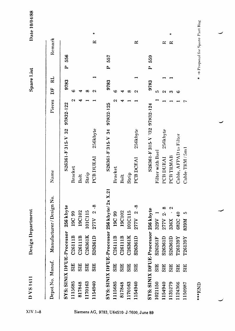
XX
o©f ta
C/5
f tim«5a
co
* *
uCC£cu
CU X»ft»ft
er; er; er: er;
Ci»ft »ft»ft »ft
per;
f cP
cacucucu
XXl>X
CScs
xxX 00 (N Ci X -** 00
cs rH fH cs» f tcs
9783
F ^ f *4
<N X CS CO COf H ^ m H f H f H
■*rcsCU csX
Xt>05
1cs •CSX xX Xt>
Ci 05cs <v . ^ TTX >2 X> - f t-*C >» f t
XX » f t
X cs XUm Um— M MX < XXX W XXcs -4-2 D cs -4-2
QU co 0/jaä G co a>£a
cuecim
-4-2o
CI«£ ffl
üoCCu
2 CQ CQ co CU «
04 X o>-4-2 X —2>2 —— >2 imX 0/-iaS •> J* -4-2
Xift »ft XX UmCS X cs Xr—1 cucq
cM M CQ mm << XXXX
< < cuKO
-4-> wG er;
U m
<Q CO u G H QU-4J cu CQ QU
-4-2 Cm CC Xo UmU-> ü 7 ü o CCCQ CO CU Cs- CU cu O
c/:
ef t£-4Mim«5af t
eM*35f t
co >
cso X
2 Xcsc 4) X X-4-2 1 *ft i ft X CS"55cu
>2X 0505CSo iOff CS -4 H
>2 0505CSo infH CS -*H
>2 CS ■ oQ X mH FF X mH fH XFF X o O O > X o O ü > X > > X ou »ft Ci 0¾ FF £> X 05 05 X 05 X csQU cs mh O l> X mH o t> X CS X XIm fF CS cs fH cs cs X cs X X3-*-> t, t. s.cu
dHoCA CQ CQ * Q oCA « P w Q o(A Cx* p p >-•3 CA mH mH mH mH CA mH mH (A mH mH mH 05c ft mH mH X X ft fH mH X X ft X X X X——fB* ft mH mH X X ft fH mH X X ft cs X X mHCw o X X X X o CO X X X o X X X XS fc« CS cs cs cs i. <N cs cs cs &. cs cs cs CScu O O O CO cu ü O U CO p CO CO CO E-i
öä K äo-l G G DD X W W W w Es. w W W W (3 S3 w wC M H M M M 4—4 M H H t - H M H M M M Mcc CO CO CO CO r ^ CO CO CO CO P CO S3 CO COs X X X
■ F mmm
d z 2 22 X X X o X X X o o o 05 X5 X X Tj* OQ X Tt X ■'t CO X t> XX X mH Ci X X 05 H 05 cs Xcn cö X O Tf cö X t> o Tf CZ) mH X rrmH mH t» X mH mH X k. CS X X csmH X mH m H m H X tH m H F o m H m H m HQ CA m H m H m H CO m H m H CO m H rH m H m H
XIV.1-8 Siemens AG, 9783, U64510- J-7600, June 89
1150
987
SIE
T261
39Y
83
9M
5 C
able
-TK
M/5
ml
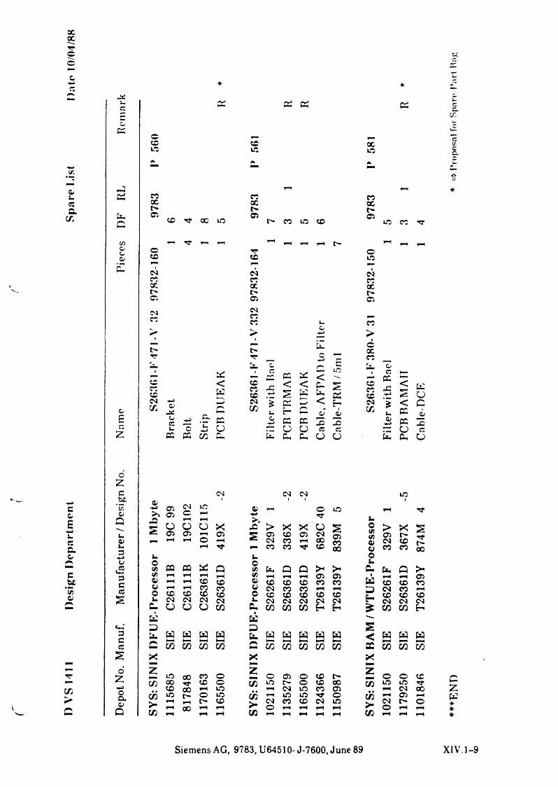
Dep
ot N
o. M
anuf
. M
anuf
actu
rer /
Des
ign
No.
N
ame
Piec
es
DF
RL
Rem
ark
xXTTOo
cx
OGx
* *
& es CSS
gX
XX
XXe-CS
©«0
CMXXt>csmx
t>Tr
GXGCMCO
xxoxX
OS csG X X iß G X X tj-
rr ^ rH rH rH t ' “ ^ rH ,-H
oG Iß<™ r -
!M !MX XX X
t-OS asMXX L. X>
C>i
<yoccJ-
t> o - XX
Cs. w c Cs. a>US J . c
CC CC*■■■*<
X ccc e :
<wH* h.
GXG
JZ»-»<£
<r_HnPhu . ÜS
PCGXG
X <%
ts:o
N i pc D < E - M £ < cc CO u r* oT i
a> CO cc 0>c* CQ o CC CC 3 3 cu cc Xo •«-> o O Ü cc CC o cc
PQ CO d . 3 Ch Ch a O Ph cc O
CM CM CM X< i i i&
OS CM LÄ rH O X T tOS G F“* ■r»
JD rH rH X &M
5T O O O X X > X X O 5§ Orm > XO as F-T os 5 G G as CM as
yfj(A asm, rH rH O rH £-, CM X rH X X 4) CM G
rH p " X X G X u X X aou i- 0O(/) CQ CQ X Q
O(/) U , Q Q > " > «
s.CU u . Q > -
(/) rH rH rH (/) rH rH as os 1 rH ^H OS0> rH rH G G OS G G G X X U2 G G XCJ rH rH X X V CM X X rH rH D CM X rH0 G G G G 0 G G G G G G G Gi- CM <N CM CM &M CM <M CM CM CM CM CM CM
C - O O O CO £ . CO CO CO CO CO H
K 3
Cs. w w w w Ur H s w w W < s s W
c 3 3 3 CO/"H
3 3 3 3 3 £ 3 3 3
X X X►-y
ziß X X 0 z 0 os 0 G
z 0 0 G3 X t T G 0 3 X 0 G X CO X X
G X rH Iß ^H CM X X as rH CM Xcö iß r * O Iß 3 rH X X 0 3 rH as rH
rH rH O G S - CM X G CM X <N i> O<■ rH X rH rH O rH rH rH rH < • O rH rHco rH rH rH CO rH rH rH rH CO rH rH
czw***
Siemens AG, 9783, U64510- J-7600, June 89 XIV.1-9
=> P
rop
osal
for
Sp
are
Par
t H
a
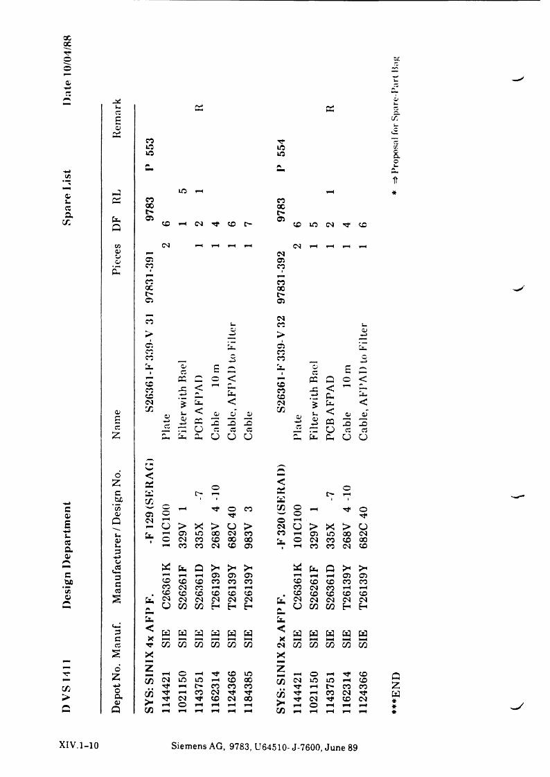
XXTTo
uc Ci a£s
QiTT
»« X»fl »flr HrJ
{/}n
cim RL xX rH
XrH
Cz Xt> X
t>CO DF
CiX rH Cs3 X C'“ Ci
CO X X
w cs rH H rH rH <N fH rH rH rHcu r- cso Ci Ci
cc Xix i
X XX Xt> t>Ci Ci
X X. CSX i-,
>a>h-J >
OJ —>Cicc
CiX a
cc , X c — >a■ o
Cd £ a■O £
r— CC r-v o < r« PC Q o <Xcc JZ < rH a X
X a <X — > a X — > a aCS i < cs i a <
a> a<D—Jcd
u < Gj JE CD CO0>
**im < O) JE£ o — > CC j3 X 3 CJ— > a 3 a
cz *“"" o c Cw Cd C3 a o Cd cdZ
5
fX »X 0-i ü ü o rhm a a O O
6 < ■rZ 2i o <•H oc t> t> rHhc a 1 i a *
c C/5 'w ' W ^H o X CO o rH o0) a> Ci vw> o t}"E Q CS rHo > X > O >
ocs
rHo > X > O
« u rH Ol X X cs X X Ci X X cscca 0) mi c cs X X X X o cs X X X
u3 rH X X cs X Ci m m• rH X X cs Xa> hh
o<52 (X Q >* > W a Q >c H rH H Ci Ci o rH rH rH Ci Ci
#bc CO X X X X X X X X X XFFcd X cs X fH H rH X cs X rH rHC/5 X X X X X X X X X X Xü a cs cs cs cs cs cs a cs cs cs cs cs
A o CO CO E-* H r ü a a H Ha a(X3 < W a a a a a < a a a a aG X mm rr rr F-M tH X M rH t-H t-H t-H
cd CO CO CO a a a cs a a a a a£ X XF" HHr» d z X zTT Z rH o fH X rH o fH Tf Xr- CO cs X X ^H X X 3 cs X X rH Xa h-> rH t"“ X X X rH t> X Xo c/5 Tf ^H X cs rt cöw . Tf rH X cs rj*> a >- cs Tf X cs X CS X csCJ rH o rH H rH rH r rH o rH rH rHc Q rH rH rH rH rH rH CO rH rH rH rH rH
C/i
Cac
QZW***
XIV.1-10 Siemens AG, 9783, U64510- J-7600, June 89
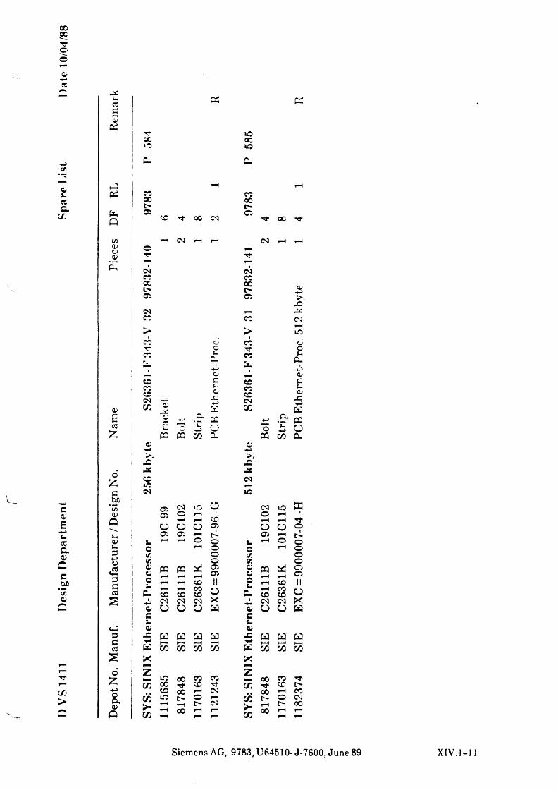
XX
o©
oCO
75
&S-cta
x
ca>£s-ccao
c*3:O
TT
X
co
a>PP
XX Xio XP- C.
P rH rH
PP co COX Xt> t>05 05
Q X cc CSJ 0C Tf
in rH CM rH rH CM rH rH
oZc
*5505
Qj-,05f-,GH->CU
<23GCOs
3Gco
s6
£<«->oa ,cu
p
pp
©rrcmxxt>0¾
cmx
>%■O
XXIN
i-O757505Ooi-
c .
(7505O05
PQ
X Ji <N 05 O G J-a>
^ W K X X
£ «X 00.. «ox
>■ 5x rn
CMCOXt>05
x>
CO cu coTT o TTX L«
Pi X-«-> Pu
p_ 05 pp.X c XCO a>
pC_3X
XCM X
CMcu X C5
UäC w X£CO
cucou.
+->'o
.& PQO
iU>O "u-4-S
z pp PQ X Pu PQ X05hhX
-C-a:CM
iß
05
uouöCMißdOu
PU-*ucuGucu
_ci-JK
OPh
<M Lß O CM iß S3io rHX O rH
rH rH rH rH TfO o 05 o ü o05 rH t> 05 rH t>rH O o rH o o
rH o o rH oo 75 oo 75 o
PQrn
XrH0505
0505 PQ
rHXrH
0505
rH X II o rH X IIrHX
XX o
trP- rH
XXX o
<N CM X CM CM Xü ü W 05 O O W
GL.05
s s W J=■ w s w WX X X K
XZ
X X X
X X X X X TtTf X X X t>X rH CM X Xc~ o rH X t - o CMrH <N rH XX rH rH r X hH rH
rH rH X hH rH
SieraensAG, 9783,U64510-J-7600, June 89 XIV.1-11