Embed Size (px)
Citation preview

(Provisional)
MYANMAR
NATIONAL
BUILDING
CODE
2012
PART3 STRUCTURAL DESIGN
(GENERAL& LOAD COMBINATIONS AND LOADS)

MYANMAR NATIONAL BUILDING CODE – 2012
(PROVISIONAL)
PART 3 STRUCTURAL DESIGN (CONTINUED)
TABLE OF CONTENTS
NO. TITLE PAGE
3.1 GENERAL
3.1.1 Definitions and Notation 1 - 3
3.1.2 Design and Construction Documents 4 - 5
3.1.3 General Design Requirements 6 - 11

STRUCTURAL DESIGN
2012 MYANMAR NATIONAL BUILDING CODE 1
SECTION 3.1 GENERAL
3.1.1 Definitions and Notation
3.1.1.1 Definitions
The following words and terms shall, for the purposes of this PART, have the meanings shown herein.
ALLOWABLE STRESS DESIGN: A method of proportioning structural members, such that elastically computed stresses produced in the members by nominal loads do not exceed specified allowable stresses (also called “working stress design”).
BALCONY, EXTERIOR: An exterior floor projecting from and supported by a structure without additional independent supports.
DEAD LOADS: The weight of materials of construction incorporated into the building, including but not limited to walls, floors, roofs, ceilings, stairways, built-in partitions, finishes, cladding and other similarly incorporated architectural and structural items, and the weight of fixed service equipment, such as cranes, plumbing stacks and risers, electrical feeders, heating, ventilating and air-conditioning systems and fire sprinkler systems.
DECK: An exterior floor supported on at least two opposing sides by an adjacent structure, and/or posts, piers or other independent supports.
DESIGN STRENGTH: The product of the nominal strength and a resistance factor (or strength reduction factor).
DIAPHRAGM: A horizontal or sloped system acting to transmit lateral forces to the vertical-resisting elements. When the term “diaphragm” is used, it shall include horizontal bracing systems.
Diaphragm blocked: In light-frame construction, a diaphragm in which all s heathing edges not occurring on a framing member are supported on and fastened to blocking.
Diaphragm boundary: In light-frame construction, a location where shear is transferred into or out of the diaphragm sheathing. Transfer is either to a boundary element or to another force-resisting element.
Diaphragm chord: A diaphragm boundary element perpendicular to the applied load that is assumed to take axial stresses due to the diaphragm moment.
Diaphragm, flexible: A diaphragm is flexible for the purpose of distribution of storey shear and torsional moment where so indicated in Section 12.3.1.1 of ASCE 7, as modified in Section 3.4.2.3.1.1 of this PART.
Diaphragm, rigid: A diaphragm is rigid for the purpose of distribution of storey shear and torsional moment when the lateral deformation of the diaphragm is less than or equal to two times the average storey drift.
DURATION OF LOAD: The period of continuous application of a given load, or the aggregate of periods of intermittent applications of the same load.
ESSENTIAL FACILITIES: Buildings and other structures that are intended to remain operational in the event of extreme environmental loading from flood, wind or earthquakes.
FABRIC PARTITIONS: A partition consisting of a finished surface made of fabric, without a continuous rigid backing, that is directly attached to a framing system in which the vertical
STRUCTURAL DESIGN
2012 MYANMAR NATIONAL BUILDING CODE 2
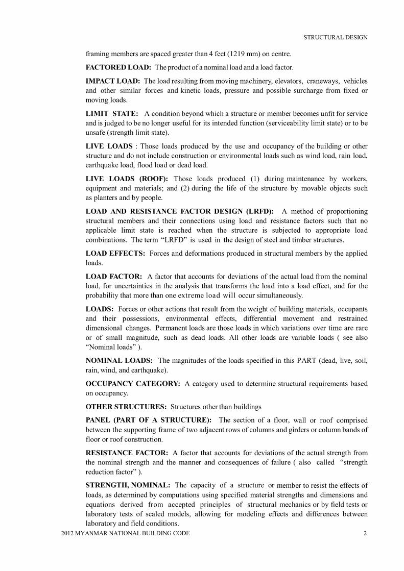
framing members are spaced greater than 4 feet (1219 mm) on centre.
FACTORED LOAD: The product of a nominal load and a load factor.
IMPACT LOAD: The load resulting from moving machinery, elevators, craneways, vehicles and other similar forces and kinetic loads, pressure and possible surcharge from fixed or moving loads.
LIMIT STATE: A condition beyond which a structure or member becomes unfit for service and is judged to be no longer useful for its intended function (serviceability limit state) or to be unsafe (strength limit state).
LIVE LOADS : Those loads produced by the use and occupancy of the building or other structure and do not include construction or environmental loads such as wind load, rain load, earthquake load, flood load or dead load.
LIVE LOADS (ROOF): Those loads produced (1) during maintenance by workers, equipment and materials; and (2) during the life of the structure by movable objects such as planters and by people.
LOAD AND RESISTANCE FACTOR DESIGN (LRFD): A method of proportioning structural members and their connections using load and resistance factors such that no applicable limit state is reached when the structure is subjected to appropriate load combinations. The term “LRFD” is used in the design of steel and timber structures.
LOAD EFFECTS: Forces and deformations produced in structural members by the applied loads.
LOAD FACTOR: A factor that accounts for deviations of the actual load from the nominal load, for uncertainties in the analysis that transforms the load into a load effect, and for the probability that more than one extreme load will occur simultaneously.
LOADS: Forces or other actions that result from the weight of building materials, occupants and their possessions, environmental effects, differential movement and restrained dimensional changes. Permanent loads are those loads in which variations over time are rare or of small magnitude, such as dead loads. All other loads are variable loads ( see also “Nominal loads” ).
NOMINAL LOADS: The magnitudes of the loads specified in this PART (dead, live, soil, rain, wind, and earthquake).
OCCUPANCY CATEGORY: A category used to determine structural requirements based on occupancy.
OTHER STRUCTURES: Structures other than buildings
PANEL (PART OF A STRUCTURE): The section of a floor, wall or roof comprised between the supporting frame of two adjacent rows of columns and girders or column bands of floor or roof construction.
RESISTANCE FACTOR: A factor that accounts for deviations of the actual strength from the nominal strength and the manner and consequences of failure ( also called “strength reduction factor” ).
STRENGTH, NOMINAL: The capacity of a structure or member to resist the effects of loads, as determined by computations using specified material strengths and dimensions and equations derived from accepted principles of structural mechanics or by field tests or laboratory tests of scaled models, allowing for modeling effects and differences between laboratory and field conditions.

STRUCTURAL DESIGN
2012 MYANMAR NATIONAL BUILDING CODE 3
STRENGTH, REQUIRED: Strength of a member, cross section or connection required to resist factored loads or related internal moments and forces in such combinations as stipulated by these provisions.
STRENGTH DESIGN: A method of proportioning structural members such that the computed forces produced in the members by factored loads do not exceed the member design strength [also called “load and resistance factor design” (LRFD)]. The term “strength design” is used in the design of concrete and masonry structural elements.
VEHICLE BARRIER SYSTEM: A system of building components near open sides of a garage floor or ramp or building walls that act as restraints for vehicles.
3.1.1.2 Notation
D = Dead load
E = Combined effect of horizontal and vertical earthquake induced forces as defined in Section 12.4.2 of ASCE 7 (Section 3.4.2.4.2)
Em = Maximum seismic load effect of horizontal and vertical seismic forces as set forth in Section 12.4.3 of ASCE 7 (Section 3.4.2.4.3) (Seismic load effect including overstrength factor)
F = Load due to fluids with well-defined pressures and maximum heights
H = Load due to lateral earth pressures, ground water pressure or pressure of bulk materials
L = Live load, except roof live load, including any permitted live load reduction
Lr = Roof live load including any permitted live load reduction
R = Rain load
T = Self-straining force arising from contraction or expansion resulting from temperature change, shrinkage, moisture change, creep in component materials, movement due to differential settlement or combinations thereof
W = Load due to wind pressure
3.1.2 - Design and Construction Documents
3.1.2.1 General
Construction documents shall show the size, section and relative locations of structural members with floor levels, column centres and offsets dimensioned, as well as structural specifications.
The design loads and other information pertinent to the structural design required by Sections 3.1.2.1.1 through 3.1.2.1.6 as well as structural specifications shall be indicated on the design documents.
3.1.2.1.1 Floor live load
The uniformly distributed, concentrated and impact floor live load (if any) used in the design shall be indicated in the design document. Use of floor live load reduction in accordance with Section 3.2.9 is permitted in the design.
3.1.2.1.2 Roof live load
The roof live load used in the design shall be indicated in the design document. Roof live load reduction in accordance with Section 3.2.3.11.2 is permitted in the design.

STRUCTURAL DESIGN
2012 MYANMAR NATIONAL BUILDING CODE 4
3.1.2.1.3 Wind design data
The following information related to wind loads shall be stated in the design document, regardless of whether wind loads govern the design of the lateral-force-resisting system of the building:
1) Basic wind speed (3-second gust), miles per hour
2) Wind importance factor, I , and occupancy category
3) Wind exposure parameters and wind coefficients
3.1.2.1.4 Earthquake design data
The following information related to seismic loads shall be stated in the design document, regardless of whether seismic loads govern the design of the lateral force resisting system of the building:
1) Seismic importance factor, I, and occupancy category
2) Specified spectral response accelerations, SS and S1 , and long period transition period TL for the location of the structure in question
3) Site class
4) Seismic design category (SDC)
5) Basic seismic-force-resisting system(s)
6) Response modification factor(s), R
7) Analysis procedure used
8) Detailing category or type
3.1.2.1.5 Special loads
Special loads that are applicable to the design of the building, structure or portions thereof shall be indicated in the design document.
3.1.2.1.6 Material properties
The properties of the materials as used in the design calculations shall be mentioned in the design document.
3.1.2.1.7 Soil and foundation data
The relevant soil and foundation data as used in the design calculations shall be mentioned in the design document.
3.1.2.2 Systems and components requiring special inspections for seismic resistance
Design and construction documents or specifications shall be prepared for those systems and components requiring special inspection for seismic resistance (if any).
3.1.2.3 Restrictions on loading
It shall be unlawful to place, or cause or permit to be placed, on any floor or roof of a building, structure or portion thereof, a load greater than is permitted by the provisions of this PART, unless approved by the authority having jurisdiction for special situation.
3.1.2.4 Structural designs
Structural designs shall be carried out by qualified structural designer(s) and the design calculations, specifications and the detail drawings shall be checked and signed by a

STRUCTURAL DESIGN
2012 MYANMAR NATIONAL BUILDING CODE 5
recognized licensed structural engineer, as specified by the building authority, before submitting the structural documents to the authority department for obtaining approval and building construction permit.
3.1.3 General Design Requirements
3.1.3.1 General
Buildings, and parts thereof, shall be designed and constructed in accordance with strength design, load and resistance factor design, allowable stress design, empirical design or conventional construction methods, as permitted by the applicable material sections of this PART. Analysis shall be carried out by following the guidelines of Section 3.1.3.4 and, where relevant, by using the methods permitted by this PART.
3.1.3.2 Strength
Buildings, and parts thereof, shall be designed and constructed to support safely the factored loads in load combinations defined in this PART without exceeding the appropriate strength limit states for the materials of construction.
Alternatively, buildings, and parts thereof, shall be designed and constructed to support safely the nominal loads in load combinations defined in this PART without exceeding the appropriate specified allowable stresses for the materials of construction.
Loads and forces for occupancies or uses not covered in this PART shall be subject to the approval of the building official.
3.1.3.3 Serviceability
Structural systems and members thereof shall be designed to have adequate stiffness to limit deflections and lateral drift. See Section 12.12 of ASCE 7 for drift limits applicable to earthquake loading.
3.1.3.3.1 Deflections
The deflections of structural members shall not exceed the more restrictive of the limitations of Sections 3.1.3.3.2 through 3.1.3.3.5 or that permitted by Table 3.1.1
Table 3.1.1 Deflection Limits a, b, g, h
CONSTRUCTION L W e D + L
c, f
Roof members:d
Supporting plaster ceiling Supporting nonplaster ceiling Not supporting ceiling
l/360 l/240 l/180
l/360 l/240 l/180
l/240
l/180
l/120
Floor members l/360 — l/240
Exterior walls and interior partitions:
With brittle finishes
—
l/240
— Farm buildings — — l/180
Greenhouses — — l/120
For SI: 1 foot = 304.8 mm.

STRUCTURAL DESIGN
2012 MYANMAR NATIONAL BUILDING CODE 6
a) For structural roofing and siding made of formed metal sheets, the total load deflection shall not exceed l/60. For secondary roof structural members supporting formed metal roofing, the live load deflection shall not exceed l/150. For secondary wall members supporting formed metal siding, the design wind load deflection shall not exceed l/90. For roofs, this exception only applies when the metal sheets have no roof covering.
b) Interior partitions not exceeding 6 feet in height and flexible, folding and portable partitions are not governed by the provisions of this section. The deflection criterion for interior partitions is based on the horizontal load.
c) For wood structural members having a moisture content of less than 16 percent at time of installation and used under dry conditions, the deflection resulting from L + 0.5D is permitted to be substituted for the deflection resulting from L + D.
d) The above deflections do not ensure against ponding. Roofs that do not have sufficient slope or camber to assure adequate drainage shall be investigated for ponding. See Section 2.4 for rain and ponding requirements and Section 2.4.2 for roof drainage requirements.
e) The wind load is permitted to be taken as 0.7 times the “component and cladding” loads for the purpose of determining deflection limits herein.
f) For steel structural members, the dead load shall be taken as zero.
g) For aluminum structural members or aluminum panels used in skylights and sloped glazing framing, roofs or walls of sunroom additions or patio covers, not supporting edge of glass or aluminum sandwich panels, the total load deflection shall not exceed l/120.
h) For cantilever members, l shall be taken as twice the length of the cantilever.
3.1.3.3.2 Reinforced concrete
The deflection of reinforced concrete structural members shall not exceed that permitted by ACI 318-05.
3.1.3.3.3 Steel
The deflection of steel structural members shall not exceed that permitted by AISC 360, AISI-NAS, AISI-General, AISI-Truss, ASCE 3, ASCE 8, SJI JG-1.1, SJI K-1.1 or SJI LH/DLH-1.1, as applicable.
3.1.3.3.4 Masonry
The deflection of masonry structural members shall not exceed that permitted by ACI 530/ASCE 5/TMS 402.
3.1.3.3.5 Aluminum
The deflection of aluminum structural members shall not exceed that permitted by AA ADM1.
3.1.3.3.6 Limits
Deflection of structural members over span, l, shall not exceed that permitted by Table 1.1.
3.1.3.4 Analysis
Load effects on structural members and their connections shall be determined by methods of

STRUCTURAL DESIGN
2012 MYANMAR NATIONAL BUILDING CODE 7
structural analysis that take into account equilibrium, general stability, geometric compatibility and both short- and long-term material properties.
Members that tend to accumulate residual deformations under repeated service loads shall have included in their analysis the added eccentricities expected to occur during their service life.
Any system or method of construction to be used shall be based on a rational analysis in accordance with well-established principles of mechanics. Such analysis shall result in a system that provides a complete load path capable of transferring loads from their point of origin to the load-resisting elements.
The total lateral force shall be distributed to the various vertical elements of the lateral-force-resisting system in proportion to their rigidities, considering the rigidity of the horizontal bracing system or diaphragm. Rigid elements assumed not to be a part of the lateral-force-resisting system are permitted to be incorporated into buildings provided their effect on the action of the system is considered and provided for in the design. Except where diaphragms are flexible, or are permitted to be analyzed as flexible, provisions shall be made for the increased forces induced on resisting elements of the structural system resulting from torsion due to eccentricity between the centre of application of the lateral forces and the centre of rigidity of the lateral-force-resisting system.
Structures shall be designed to resist the overturning effects caused by the lateral forces specified in this PART if it is required to consider lateral loads. See Section 3.3 for wind loads, Section 3.2.2 for lateral soil loads and hydrostatic pressures and Section 3.4 for earthquake loads.
3.1.3.5 Occupancy Category
Buildings shall be assigned an occupancy category in accordance with Table 3.1.2.
3.1.3.5.1 Multiple occupancies
Where a structure is occupied by two or more occupancies not included in the same occupancy category, the structure shall be assigned the classification of the highest occupancy category corresponding to the various occupancies. Where structures have two or more portions that are structurally separated, each portion shall be separately classified. Where a separated portion of a structure provides required access to, required egress from or shares life safety components with another portion having a higher occupancy category, both portions shall be assigned to the higher occupancy category.
3.1.3.6 In-situ load tests
The building official is authorized to require an engineering analysis or a strength test or a load test, or any combination, of any construction whenever there is reason to question the safety of the construction for the intended occupancy.
3.1.3.7 Preconstruction load tests
Materials and methods of construction that are not capable of being designed by approved engineering analysis or that do not comply with the applicable material design standards listed shall be load tested or tested for strength and deformation characteristics.

STRUCTURAL DESIGN
2012 MYANMAR NATIONAL BUILDING CODE 8
Table 3.1.2 Occupancy Category of Buildings and Other Structures
Occupancy Category
Nature Of Occupancy
I
Buildings and other structures that represent a low hazard to human life in the event of failure, including but not limited to:
Agricultural facilities
Certain temporary facilities
II Buildings and other structures except those listed in Occupancy Categories I, III and IV
III
Buildings and other structures that represent a substantial hazard to human life in the event of failure, including but not limited to:
Covered structures whose primary occupancy is public assembly with an occupant load greater than 300.
Buildings and other structures with elementary school, secondary school or day care facilities with an occupant load greater than 250.
Buildings and other structures with an occupant load greater than 500 for colleges or adult education facilities.
Health care facilities with an occupant load of 50 or more resident patients, but not having surgery or emergency treatment
facilities.
Jails and detention facilities.
Any other occupancy with an occupant load greater than 5,000.
Power-generating stations, water treatment for potable water, waste water treatment facilities and other public utility facilities not included in Occupancy Category IV.
IV
Buildings and other structures designated as essential facilities, including but not limited to:
Hospitals and other health care facilities having surgery or emergency treatment facilities.
Fire, rescue and police stations and emergency vehicle garages.
Designated earthquake, hurricane or other emergency shelters.
Designated emergency preparedness, communication, and operation centers and other facilities required for emergency response.
Power-generating stations and other public utility facilities required as emergency backup facilities for Occupancy Category IV structures.
Structures containing highly toxic materials.
Aviation control towers, air traffic control centers and emergency aircraft hangars.

STRUCTURAL DESIGN
2012 MYANMAR NATIONAL BUILDING CODE 9
3.1.3.8 Anchorage
3.1.3.8.1 General
Anchorage of the roof to walls and columns, and of walls and columns to foundations, shall be provided to resist the uplift and sliding forces that result from the application of the prescribed loads.
3.1.3.8.2 Concrete and masonry walls
Concrete and masonry walls shall be anchored to floors, roofs and other structural elements that provide lateral support for the wall. Such anchorage shall provide a positive direct connection capable of resisting the horizontal forces specified in this part but not less than a minimum strength design horizontal force of 280 plf (4.10 kN/m) of wall, substituted for “E” in the load combinations of Section 3.2.1.2 or 3.2.1.3. Walls shall be designed to resist bending between anchors where the anchor spacing exceeds 4 feet (1219 mm). Required anchors in masonry walls of hollow units or cavity walls shall be embedded in a reinforced grouted structural element of the wall. See Sections 3.3 for wind design requirements and see Section 3.4 for seismic design requirements.
3.1.3.9 Decks
Where supported by attachment to an exterior wall, decks shall be positively anchored to the primary structure and designed for both vertical and lateral loads as applicable. Such attachment shall not be accomplished by the use of toenails or nails subject to withdrawal. Where positive connection to the primary building structure cannot be verified during inspection, decks shall be self-supporting.
3.1.3.10 Counteracting structural actions
Structural members, systems, components and cladding shall be designed to resist forces due to earthquake and wind, with consideration of overturning, sliding, and uplift. Continuous load paths shall be provided for transmitting these forces to the foundation. Where sliding is used to isolate the elements, the effects of friction between sliding elements shall be included as a force.
3.1.3.11 Wind and seismic detailing
Where required by the authority department, lateral-force-resisting systems shall meet seismic detailing requirements and limitations prescribed in this PART and ASCE 7, excluding Chapter 14 and Appendix 11A, even when wind code prescribed load effects are greater than seismic load effects.
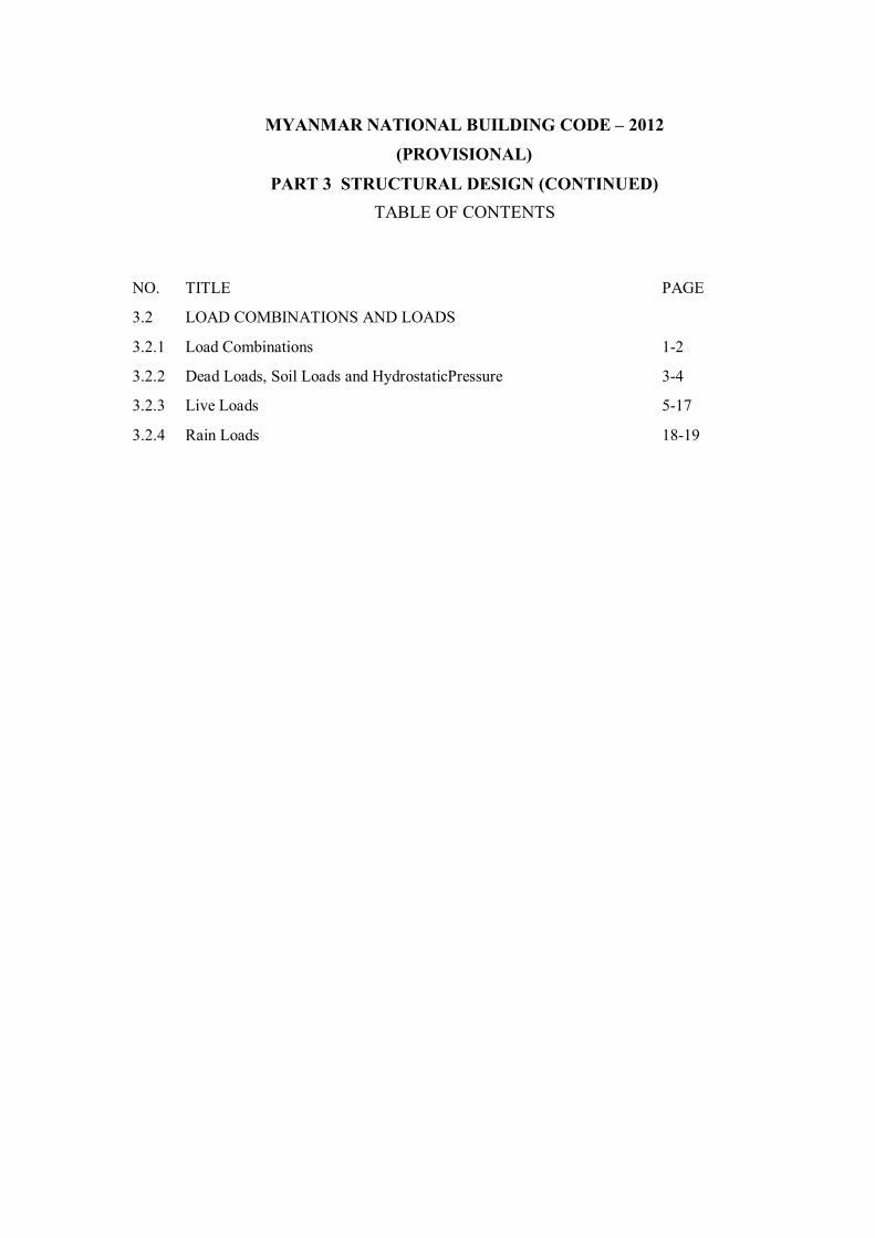
MYANMAR NATIONAL BUILDING CODE – 2012
(PROVISIONAL)
PART 3 STRUCTURAL DESIGN (CONTINUED) TABLE OF CONTENTS
NO. TITLE PAGE
3.2 LOAD COMBINATIONS AND LOADS
3.2.1 Load Combinations 1-2
3.2.2 Dead Loads, Soil Loads and HydrostaticPressure 3-4
3.2.3 Live Loads 5-17
3.2.4 Rain Loads 18-19

STRUCTURAL DESIGN
1 2012 MYANMAR NATIONAL BUILDING CODE
SECTION3.2: LOAD COMBINATIONS AND LOADS 3.2.1 Load Combinations
3.2.1.1 General
Buildings, and portions thereof, shall be designed using the provisions of either Section 3.2.1.2 or 3.2.1.3. Either Section 3.2.1.2 or 3.2.1.3 shall be used exclusively for proportioning elements of a particular construction material throughout the structure. Each load combination shall also be investigated with one or more of the variable loads set to zero.
3.2.1.2 Combining factored loads using strength design or load and resistance factor design
3.2.1.2.1 Applicability
The load combinations and load factors given in Section3.2.1.2.2 shall be used only in those cases in which they are specifically authorized by the applicable material design standard. Otherwise, the provisions of the applicable material design standard shall be used.
3.2.1.2.2 Basic load combinations
Structures, components, and foundations shall be designed so that their design strength equals or exceeds the most critical effects of the factored loads in the following combinations:
1) 1.4 (D + F) Eq. (3.2.1)
2) 1.2(D+F + T ) + 1.6(L + H ) + 0.5 (Lr or R) Eq. (3.2.2)
3) 1.2D + 1.6(Lr or R )+ (L or 0.8W ) Eq. (3.2.3)
4) 1.2D + 1.6W + L + 0.5(Lr or R ) Eq. (3.2.4)
5) 1.2D + 1.0E + L Eq. (3.2.5)
6) 0.9D + 1.6W + 1.6H Eq. (3.2.6)
7) 0.9D + 1.0E + 1.6H Eq. (3.2.7)
EXCEPTIONS:
1) The load factor on L in combinations (3), (4), and (5) is equal to 0.5 for all occupancies in which L0 in Table 3.2.2 is less than or equal to 100 psf, with the exception of garages or areas occupied as places of public assembly.
2) The load factor on H shall be set equal to zero in combinations (6) and (7) if the structural action due to H counteracts that due to W or E. Where lateral earth pressure provides resistance to structural actions from other forces, it shall not be included in H but shall be included in the design resistance.
Each relevant strength limit state shall be investigated. Effects of one or more loads not acting shall be investigated. The most unfavorable effects from both wind and earthquake loads shall be investigated, where appropriate, but they need not be considered to act simultaneously.
As an exception, where other factored load combinations are specifically required by the provisions of this PART, such combinations shall take precedence.

STRUCTURAL DESIGN
2 2012 MYANMAR NATIONAL BUILDING CODE
3.2.1.3 Combining nominal loads using allowable stress design or working stress design
3.2.1.3.1 Basicloadcombinations
Loads listed herein shall be considered to act in the following combinations; whicheverproduces the most unfavorable effect in the building, foundation, or structural member being considered. Effects of one or more loads not acting shall be considered.
1) D + F Eq. (3.2.8)
2) D + H + F + L + T Eq. (3.2.9)
3) D + H + F + (Lr or R) Eq. (3.2.10)
4) D + H + F + 0.75(L + T) + 0.75 (Lr or R) Eq. (3.2.11)
5) D + H + F + (W or 0.7E) Eq. (3.2.12)
6) D + H + F + 0.75(W or 0.7E) + 0.75L + 0.75 (Lr or R) Eq. (3.2.13)
7) 0.6D + W + H Eq. (3.2.14)
8) 0.6D + 0.7E + H Eq. (3.2.15)
The most unfavorable effects from both wind and earthquake loads shall be considered, where appropriate, but they need not be assumed to act simultaneously.
3.2.1.3.2 Stress increases
Increases in allowable stress shall not be used with the loads or load combinations given in Section 3.2.1.3.1 unless it can be demonstrated that such an increase is justified by structural behaviour caused by rate or duration of load (see section on timber and bamboo)
3.2.1.4 Load Combinations for extraordinary events
Where required by the applicable code, standard, or the authority having jurisdiction, strength and stability shall be checked to ensure that structures are capable of withstanding the effects of extraordinary (i.e., low-probability) events, such as fires, explosions, and vehicular impact.
3.2.1.5 Special seismic load combinations
For both strength and allowable stress design methods where specifically required by relevant material design standards, elements and components shall be designed to resist the forces calculated using Eq. (2.16) when the effects of the seismic ground motion are additive to gravity forces and those calculated using Eq. (2.17) when the effects of the seismic ground motion counteract gravity forces.
1) 1.2D + f1L +Em Eq. (3.2.16)
2) 0.9D+Em Eq. (3.2.17)
where Em = the maximum effect of horizontal and vertical forces as set forth in Section12.4.3 of ASCE 7-05.
The load factor f1 forL in combination Eq. (3.2.16) is equal to 0.5 for all occupancies when live load is less than or equal to 100 psf (4.79 kN/m2), with the exception of garages or areas of publicassembly. Otherwise, f1is equal to 1.

STRUCTURAL DESIGN
3 2012 MYANMAR NATIONAL BUILDING CODE
SECTION 3.2 LOAD COMBINATIONS AND LOADS (CONTINUED) 3.2.2 Dead Loads, Soil Loads and Hydrostatic Pressure
3.2.2.1 Dead loads
3.2.2.1.1 Definition
Dead loads consist of the weight of all materials of construction incorporatedinto the building including, but not limited to, walls, floors, roofs, ceilings, stairways,built-inpartitions, finishes, cladding, and other similarly incorporated architectural and structural items, and fixed service equipment including the weight of cranes.
3.2.2.1.2 Weights of materials and constructions
In determining dead loads for purposes of design, the actual weights of materials and constructions shall be used provided that in the absence of definite information, values approved by the authority having jurisdiction shall be used.
3.2.2.1.3 Weight of fixed service equipment
In determining dead loads for purposes of design, the weight of fixed service equipment, such as plumbing stacks and risers, electrical feeders, and heating, ventilating, and airconditioning systems shall be included.
3.2.2.2 Soil loads and hydrostatic pressure
3.2.2.2.1 Lateral pressures
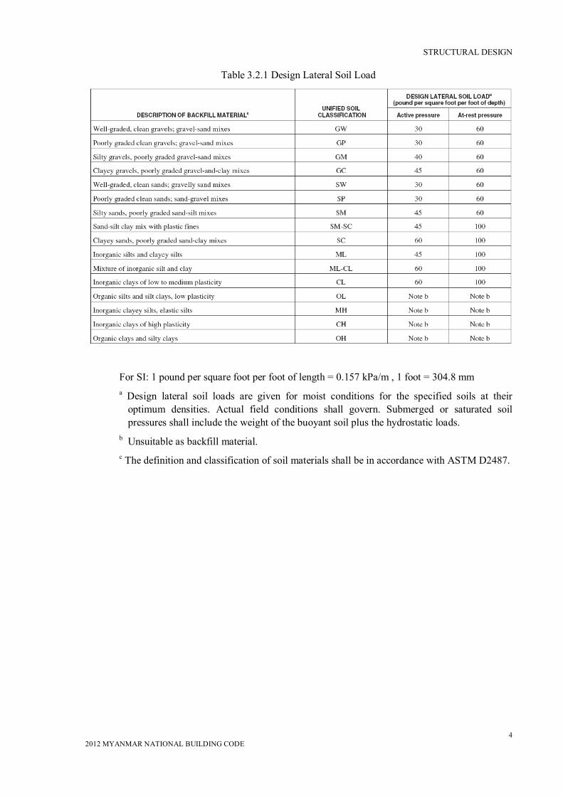
In the design of structures below grade, provision shall be made for the lateral pressure of adjacent soil. If soil loads are not given in a soil investigation report approved by the authority having jurisdiction, then the soil loads specified in Table 3.2.1 shall be used as the minimum design lateral loads. Due allowance shall be made for possible surcharge from fixed or moving loads. When a portion or the whole of the adjacent soil is below a free-water surface, computations shall be based upon the weight of the soil diminished by buoyancy, plus full hydrostatic pressure.
The lateral pressure shall be increased if soils with expansion potential are present at the site as determined by a geotechnical investigation.
Basement walls and other walls in which horizontal movement is restricted at the top shall be designed for at-rest pressure. Retaining walls free to move and rotate at the top are permitted to be designed for active pressure. As an exception, basement walls extending not more than 8 feet (2438 mm) below grade and supporting flexible floor system shall be permitted to be designed for active pressure.
3.2.2.2.2 Uplift on floors and foundations
In the design of basement floors and similar approximately horizontal elements below grade, the upward pressure of water, where applicable, shall be taken as the full hydrostatic pressure applied over the entire area. The hydrostatic load shall be measured from the underside of the construction. Any other upward loads shall be included in the design.
Where expansive soils are present under foundations or slabs-on-ground, the foundations, slabs, and other components shall be designed to tolerate the movement or resist the upward loads caused by the expansive soils, or the expansive soil shall be removed or stabilized around and beneath thestructure.
STRUCTURAL DESIGN
4 2012 MYANMAR NATIONAL BUILDING CODE
Table 3.2.1 Design Lateral Soil Load
For SI: 1 pound per square foot per foot of length = 0.157 kPa/m , 1 foot = 304.8 mm
a Design lateral soil loads are given for moist conditions for the specified soils at their optimum densities. Actual field conditions shall govern. Submerged or saturated soil pressures shall include the weight of the buoyant soil plus the hydrostatic loads.
b Unsuitable as backfill material. c The definition and classification of soil materials shall be in accordance with ASTM D2487.

STRUCTURAL DESIGN
5 2012 MYANMAR NATIONAL BUILDING CODE
SECTION 3.2: LOAD COMBINATIONS AND LOADS (CONTINUED) 3.2.3 Live Loads
3.2.3.1 Definitions
The following definitions apply only to the provision of Section 3.2.3.
LIVE LOAD: A load produced by the use and occupancy of the building or other structure that does not include construction or environmental loads, such as wind load, snow load, rain load, earthquake load, flood load, or dead load.
ROOF LIVE LOAD: A load on a roof produced (1) during maintenance by workers, equipment, and materials and (2) during the life of the structure by movable objects, such as planters or other similar small decorative appurtenances that are not occupancy related.
FIXEDLADDER: A ladder that is permanently attached to a structure, building, or equipment.
GRAB BAR SYSTEM: A bar provided to support body weight in locations such as toilets, showers, and tub enclosures.
GUARDRAIL SYSTEM: A system of building components near open sides of an elevated surface for the purpose of minimizing the possibility of a fall from the elevated surface by people, equipment, or material.
HANDRAIL: A rail grasped by hand for guidance and support. A handrail assembly includes the handrail, supporting attachments, and structures.
VEHICLE BARRIER SYSTEM: A system of building components near open sides of a garage floor or ramp, or building walls that act as restraints for vehicles.
3.2.3.2 Uniformly distributed loads
3.2.3.2.1 Required live loads
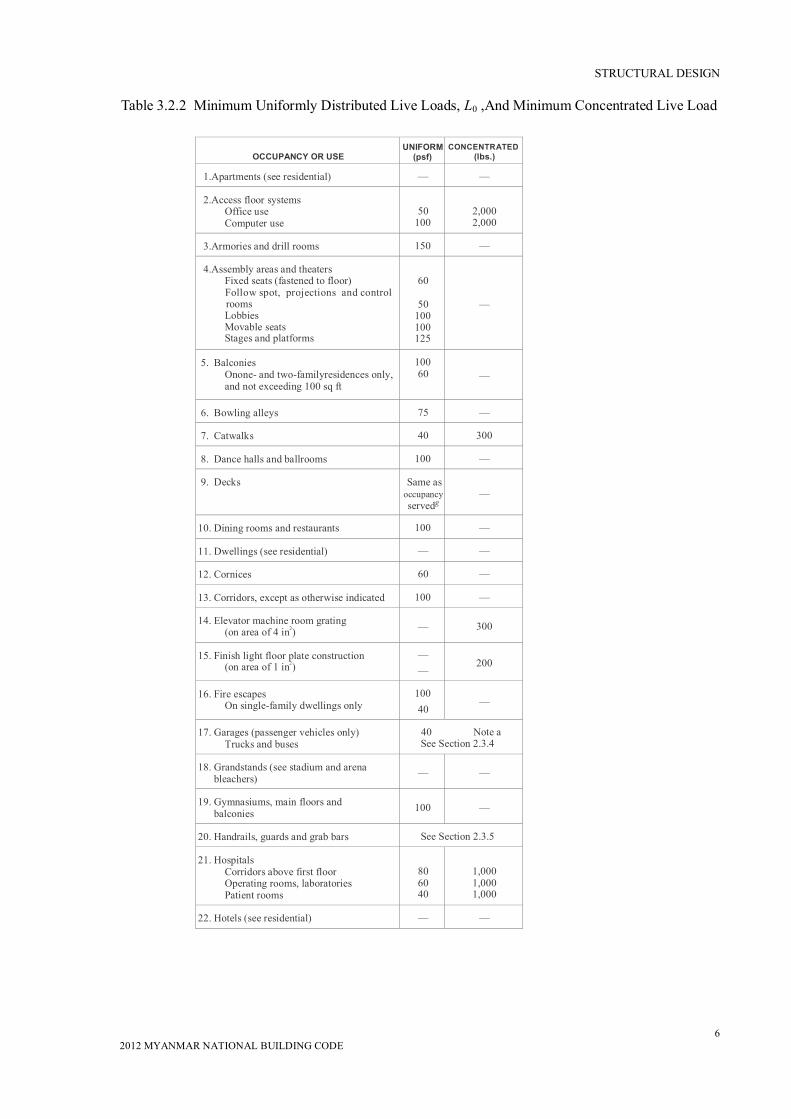
The live loads used in the design of buildings and other structures shall be the maximum loads expected by the intended use or occupancy, but shall in no case be less than the minimum uniformly distributed unit loads required by Table 3.2.2.
STRUCTURAL DESIGN
6 2012 MYANMAR NATIONAL BUILDING CODE
OCCUPANCY OR USE UNIFORM
(psf) CONCENTRATED (lbs.)
1.Apartments (see residential) — —
2.Access floor systems Office use Computer use
50
100
2,000 2,000
3.Armories and drill rooms 150 — 4.Assembly areas and theaters
Fixed seats (fastened to floor) Follow spot, projections and control rooms Lobbies Movable seats Stages and platforms
60
50
100 100 125
—
5. Balconies Onone- and two-familyresidences only, and not exceeding 100 sq ft
100 60
—
6. Bowling alleys 75 — 7. Catwalks 40 300 8. Dance halls and ballrooms 100 — 9. Decks
Same as
occupancy servedg
—
10. Dining rooms and restaurants 100 — 11. Dwellings (see residential) — — 12. Cornices 60 — 13. Corridors, except as otherwise indicated 100 — 14. Elevator machine room grating
(on area of 4 in2)
—
300
15. Finish light floor plate construction (on area of 1 in2)
— —
200
16. Fire escapes On single-family dwellings only
100 40
—
17. Garages (passenger vehicles only)
Trucks and buses 40 Note a See Section 2.3.4
18. Grandstands (see stadium and arena
bleachers)
—
— 19. Gymnasiums, main floors and
balconies
100
—
20. Handrails, guards and grab bars See Section 2.3.5 21. Hospitals
Corridors above first floor Operating rooms, laboratories Patient rooms
80 60 40
1,000 1,000 1,000
22. Hotels (see residential) — —
Table 3.2.2 Minimum Uniformly Distributed Live Loads, L0 ,And Minimum Concentrated Live Load

STRUCTURAL DESIGN
7 2012 MYANMAR NATIONAL BUILDING CODE
OCCUPANCY OR USE UNIFORM
(psf) CONCENTRATED
(lb23. Libraries
Corridors above first floor Reading rooms Stack rooms
80 60
150b
1,00
0 1,00
0 24. Manufacturing
Heavy Light
250 125
3,00
0 2,00
25. Marquees 75 — 26. Office buildings
Corridors above first floor File and computer rooms shall be designed for heavier loads based on anticipated occupancy Lobbies and first-floor corridors Offices
80
—
100 50
2,00
0
—
2,000
27. Penal institutions Cell blocks Corridors
40 100
—
28. Residential One- and two-family dwellings
UninhabitableatticswithoutstoragehUninhabitable attics with limited storageh, i,j
Habitable attics and sleeping areas All otherareas exceptbalconiesand decks
Hotels and multiple-family dwellings Private rooms andcorridors serving them Public rooms andcorridors serving them
10 20
30 40
40
100
—
29. Reviewing stands, grandstands and bleachers
Note c
30. Roofs Allroofsurfacessubjecttomaintenance workers Awnings andcanopies
Fabric construction supported by a lightweightrigidskeletonstructure All other construction
Ordinaryflat,pitched,andcurvedroofs Primary roof members, exposed to a work floor
Singlepanelpointoflowerchordof roof trusses or any point along primary structural members supporting roofs:
Over manufacturing, storage
All other occupancies Roofs used for other special purposes Roofs used for promenade purposes Roofs used for roof gardens or assembly purposes
5 nonreduceable
20 20
Note k 60 100
300
2,000 300
Note k
Table 3.2.2 (Continued) Minimum Uniformly Distributed Live Loads, L0 , and Minimum Concentrated Live Load

STRUCTURAL DESIGN
8 2012 MYANMAR NATIONAL BUILDING CODE
OCCUPANCY OR USE
UNIFORM
(psf) CONCENTRATED
(lbs.) 31. Schools
Classrooms Corridors above first floor First-floor corridors
40 80
100
1,000 1,000 1,000
32. Scuttles, skylight ribs and accessible
ceilings
—
200 33. Sidewalks, vehicular driveways and
yards, subject to trucking
250d
8,000e 34. Skating rinks
100
—
35. Stadiums and arenas
Bleachers Fixed seats (fastened to floor)
100c 60c
—
36. Stairs and exits
One- and two-family dwellings All other
40
100
Note f
37. Storage warehouses (shall be designed
for heavier loads if required for antici- pated storage)
Heavy Light
250 125
38. Stores
Retail First floor Upper floors
Wholesale, all floors
100 75
125
1,000 1,000 1,000
39. Vehicle barriers
See Section 2.3.5.3
40. Walkways andelevatedplatforms(other
thanexitways)
60
— 41. Yards and terraces, pedestrians
100
—
Table 3.2.2 (Continued) Minimum Uniformly Distributed Live Loads, L0, and Minimum Concentrated Live Load
For SI: 1 inch = 25.4 mm, 1 square inch = 645.16 mm2,
1 square foot = 0.0929 m2,
1 pound per square foot = 0.0479 kN/m2, 1 pound = 0.004448 kN,
1 pound per cubic foot = 16 kg/m3
a) Floors in garages or portions of buildings used for the storage of motor vehicles shall be designed for the uniformly distributed live loads of Table 3.2.2 or the following concentrated loads: (1) for garages restricted to vehicles accommodating not more than nine passengers, 3,000 pounds acting on an area of 4.5 inches by 4.5 inches; (2) for mechanical parking structures without slab or deck which are used for storing passenger vehicles only, 2,250 pounds per wheel.
b) The loading applies to stack room floors that support nonmobile, double-faced library bookstacks, subject to the following limitations:
1) The nominal bookstack unit height shall not exceed 90 inches;

STRUCTURAL DESIGN
9 2012 MYANMAR NATIONAL BUILDING CODE
2) The nominal shelf depth shall not exceed 12 inches for each face; and
3) Parallel rows of double-faced bookstacks shall be separated by aisles not less than 36 inches wide.
c) Design in accordance with the ICC Standard on Bleachers, Folding and Telescopic Seating and Grandstands.
d) Other uniform loads in accordance with an approved method which contains provisions for truck loadings shall also be considered where appropriate.
e) The concentrated wheel load shall be applied on an area of 20 square inches.
f) Minimum concentrated load on stair treads (on area of 4 square inches) is 300 pounds
g) See Section 3.1.3.9 for decks attached to exterior walls.
h) Attics without storage are those where the maximum clear height betweenthe joist and rafter is less than 42 inches, or where there are not two or moreadjacent trusses with the same web configuration capable of containing arectangle 42 inches high by 2 feet wide, or greater, located within the planeof the truss. For attics without storage, this live load need not be assumed toact concurrently with any other live load requirements.
i) For attics with limited storage and constructed with trusses, this live loadneed only be applied to those portions of the bottom chord where there aretwo or more adjacent trusses with the same web configuration capable ofcontaining a rectangle 42 inches high by 2 feet wide or greater, locatedwithin the plane of the truss. The rectangle shall fit between the top of thebottom chord and the bottom of any other truss member, provided that eachof the following criteria is met:
i) The attic area is accessible by a pull-down stairway or framed openingand
ii) The truss shall have a bottom chord pitch less than 2:12.
iii) Bottom chords of trusses shall be designed for the greater of actual imposeddead load or 10 psf, uniformly distributed over the entire span.
j) Attic spaces served by a fixed stair shall be designed to support the minimumlive load specified for habitable attics and sleeping rooms.
k) Roofs used for other special purposes shall be designed for appropriate loadsas approved by the building official.
3.2.3.2.2 Provision for partitions
In office buildings or other buildings where partitions will be erected or rearranged, provision for partition weight shall be made, whether or not partitions are shown on the construction documents. Partition load shall not be less than uniformly distributed live load of 15 psf.
EXCEPTION: A partition live load is not required where the minimum specified live load exceeds 80psf (3.83kN/m2).
3.2.3.3 Concentrated Loads
Floors, roofs, and other similar surfaces shall be designed to support safely the uniformly distributed live loads prescribed in Section 3.2.3.2 or the concentrated load, in pounds or kilonewtons (kN), given in Table 3.2.2, whichever produces the greater load effects. Unless otherwise specified, the indicated concentration shall be assumed to be

STRUCTURAL DESIGN
10 2012 MYANMAR NATIONAL BUILDING CODE
uniformly distributed over an area 2.5 ft (762 mm) square [6.25 ft2 (0.58 m2)] and shall be located so as to produce themaximum load effects in the structural members.
3.2.3.4 Truck and bus garages
Minimum live loads for garages having trucks or buses shall be as specified in Table 3.2.3, but shall not be less than 50 psf (2.40 kN/m2), unless other loads are specifically justified and approved by the building official. Actual loads shall be used where they are greater than the loads specified in the table.
3.2.3.4.1 Truck and bus garage live load application
The concentrated load and uniform load shall be uniformly distributed over a 10-foot (3048 mm) width on a line normal to the centreline of the lane placed within a 12-foot-wide (3658 mm) lane. The loads shall be placed within their individuallanes so as to produce the maximum stress in eachstructural member. Single spans shall be designed for theuniform load in Table 3.2.3 and one simultaneousconcentratedload positioned to produce the maximum effect. Multiplespans shall be designed for the uniform load in Table3.2.3 on the spans and two simultaneous concentratedloads in two spans positioned to produce the maximum negativemoment effect. Multiple span design loads, for othereffects, shall be the same as for single spans.
Table 3.2.3 Uniform and Concentrated Loads
For SI: 1 pound per linear foot = 0.01459 kN/m, 1 pound = 0.004448 kN,1 ton = 8.90 kN. a An H loading class designates a two-axle truck with a semitrailer. An HSloading class
designates a tractor truck with a semitrailer. The numbers followingthe letter classification indicate the gross weight in tons of the standardtruck and the year the loadings were instituted.
b See Section 3.2.3.4.1 for the loading of multiple spans.
3.2.3.5 Loads on Handrails, Guardrail Systems, Grab Bar Systems, Vehicle Barrier Systems, and Fixed Ladders
3.2.3.5.1 Loads on handrails and guard rail systems
All handrail assemblies and guardrail systems shall be designed to resist a single concentrated load of 200 lb(0.89 kN) applied in any direction at any point along the top and to transfer this load through the supports to the structure.
Further, all handrail assemblies and guardrail systems shall be designed to resist a load of 50 lb/ft (pound-force per linear foot) (0.73 kN/m) applied in any direction at the top and to transfer this load through the supports to the structure. This load need not be assumed toact concurrently with the load specified in the preceding paragraph, and this load need not be considered for the following occupancies:

STRUCTURAL DESIGN
11 2012 MYANMAR NATIONAL BUILDING CODE
1) One- and two-family dwellings.
2) Factory, industrial, and storage occupancies, in areas that are not accessible to the public and that serve an occupant load not greater than 50, the minimum load in that are shall be 20 lb/ft (0.29kN/m).
Intermediate rails (all those except the handrail), balusters, and panel fillers shall be designed to withstand a horizontally applied normal load of 50 lb (0.22 kN) on an area not to exceed 1 ft square (305 mm square) including openings and space between rails. Reactions due to this loading are not required to be superimposed with those of either preceding paragraph.
Where handrails and guards are designed using working stress design exclusively for the loads specified in this section, the allowable stress for the members and their attachments are permitted to be increased by one-third.
3.2.3.5.2 Loads on grab bar systems
Grab bar systems shall be designed to resist a single concentrated load of 250 lb (1.11 kN) applied in any direction at any point.
3.2.3.5.3 Loads on vehicle barrier systems
Vehicle barrier systems for passenger cars shall be designed to resist a single load of 6,000 lb (26.70 kN) applied horizontally in any direction to the barrier system, and shall have anchorages or attachments capable of transferring this load to the structure. For design of the system, the load shall be assumed to act at a minimum height of 1 ft 6 in. (460 mm) above the floor or ramp surface on an area not to exceed 1 foot square(305 mmsquare), and is not required to be assumed to act concurrently with any handrail or guardrail loadings specified in Section 3.2.3.4.1. Garages accommodating trucks and buses shall be designed in accordance with an approved method, which contains provision for traffic railings.
3.2.3.5.4 Loads on fixed ladders
The minimum design live load on fixed ladders with rungs shall be a single concentrated load of 300 lb (1.33 kN), and shall be applied at any point to produce the maximum load effect on the element being considered. The number and position of additional concentrated live load units shall be a minimum of 1 unit of 300 lb (1.33 kN) for every 10 ft (3,048 mm) of ladder height.
Where rails of fixed ladders extend above a floor or platform at the top of the ladder, each side rail extension shall be designed to resist a concentrated live load of100 lb (0.445 kN) inany direction at any height up to the top of the side rail extension. Ship ladders with treads instead of rungs shall have minimum design loads as stairs, defined in Table 3.2.2.
3.2.3.6 Loads not specified
For occupancies or uses not designated in Sections 3.2.3.2 or 3.2.3.3, the live load shall be determined in accordancewith amethod approved by the authority having jurisdiction.
3.2.3.7 Partial loading
The full intensity of the appropriately reduced live load applied only to a portion of a structure or member shall be accounted for if it produces a more unfavourable effect than the

STRUCTURAL DESIGN
12 2012 MYANMAR NATIONAL BUILDING CODE
same intensity applied over the full structure or member. Roof live loads are to be distributed as specified in Table 3.2.2.
3.2.3.8 Impact loads
The live loads specified in Sections 3.2.3.5.1 and 3.2.3.5.2 shall be assumed to include adequate allowance for ordinary impact conditions. Provision shall be made in the structural design for uses and loads that involve unusual vibration and impact forces.
3.2.3.8.1 Elevators
All elevator loads shall be increased by 100 percent for impact and the structural supports shall be designed within the limits of deflection prescribed by ANSI A17.2 and ANSI/ASME A17.1.
3.2.3.8.2 Machinery
For the purpose of design, the weight of machinery and moving loads shall be increased as follows to allow for impact: (I) elevator machinery, 100 percent; (2) light machinery, shaft- or motor-driven, 20 percent; (3) reciprocating machinery or power-driven units, 50 percent; and (4) hangers for floors or balconies, 33 percent. All percentages shall be increased where specified by the manufacturer.
3.2.3.9 Reduction in live loads
Except for roof uniform live loads, all other minimum uniformly distributed live loads, L0inTable 3.2.2, may be reduced according to the following provisions.
3.2.3.9.1 General
Subject to the limitations of Sections 3.2.3.9.2 through 3.2.3.9.5, members for which a value of KLLAT is 400 ft2 (37.16 m2) or more are permitted to be designed for a reduced live load in accordance with the following equation:
)1525.0(0
TLL AKLL
Eq. (3.2.18)
In SI:
) 57.4 25.0 ( 0
TLL AKLL
where
L = reduced design live load per ft2 (m2) of area supported by the member
L0 = unreduced design live load per ft2 (m2) of area supported by the member
(see Table 3.2.2)
KLL = live load element factor (see Table 3.2.4)
AT = tributary area in ft2 (m2)
L shall not be less than 0.50 L0 for members supporting one floor and L shall not be less than 0.40 L0 for members supporting two or more floors.
STRUCTURAL DESIGN
13 2012 MYANMAR NATIONAL BUILDING CODE
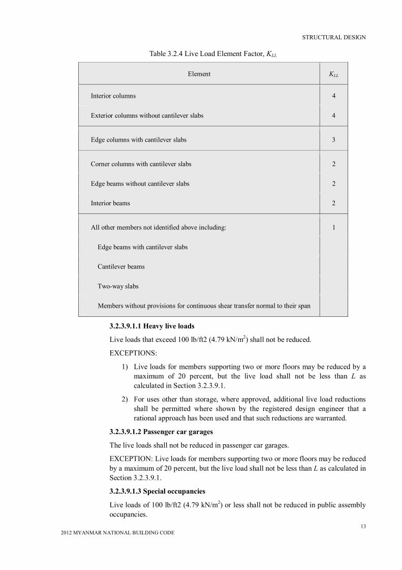
Table 3.2.4 Live Load Element Factor, KLL
3.2.3.9.1.1 Heavy live loads
Live loads that exceed 100 lb/ft2 (4.79 kN/m2) shall not be reduced.
EXCEPTIONS:
1) Live loads for members supporting two or more floors may be reduced by a maximum of 20 percent, but the live load shall not be less than L as calculated in Section 3.2.3.9.1.
2) For uses other than storage, where approved, additional live load reductions shall be permitted where shown by the registered design engineer that a rational approach has been used and that such reductions are warranted.
3.2.3.9.1.2 Passenger car garages
The live loads shall not be reduced in passenger car garages.
EXCEPTION: Live loads for members supporting two or more floors may be reduced by a maximum of 20 percent, but the live load shall not be less than L as calculated in Section 3.2.3.9.1.
3.2.3.9.1.3 Special occupancies
Live loads of 100 lb/ft2 (4.79 kN/m2) or less shall not be reduced in public assembly occupancies.
Element KLL
Interior columns 4
Exterior columns without cantilever slabs 4
Edge columns with cantilever slabs 3
Corner columns with cantilever slabs 2
Edge beams without cantilever slabs 2
Interior beams 2
All other members not identified above including: 1
Edge beams with cantilever slabs
Cantilever beams
Two-way slabs
Members without provisions for continuous shear transfer normal to their span

STRUCTURAL DESIGN
14 2012 MYANMAR NATIONAL BUILDING CODE
3.2.3.9.1.4 Special structural elements
Live load shall not be reduced for one-way slabs except as permitted in Section 3.2.3.9.2. Live loads of 100 psf(4.79 kN/m2) or less shall not be reduced for roof members except as specified in Section 3.2.3.10.
3.2.3.9.2 Alternative floor live load reduction
As an alternative to Section 3.2.3.9.1, floor live loads are permitted to be reduced in accordance with the following provisions. Such reductions shall apply to slab systems, beams, girders, columns, piers, walls and foundation.
1) A reduction shall not be permitted in group A occupancies (i.e., Assembly Group A)
2) A reduction shall not be permitted where the live load exceeds 100 psf (4.79 kN/m2) except that the design live load for members supporting two or more floors is permitted to be reduced by 20 percent.
3) A reduction shall not be permitted in passenger vehicle parking garages except that the live loads for members supporting two or more floors are permitted to be reduced by a maximum of 20 percent.
4) For live loads, not exceeding 100 psf(4.79 kN/m2), the design live load for any structural member supporting 150 square feet (13.94 m2) or more is permitted to be reduced in accordance with the following equation:
R = 0.08 (A – 150 ) Eq. (3.2.19 )
In SI: R = 0.861 (A – 13.94 )
Such reduction shall not exceed the smallest of:
40 percent for horizontal members;
60 percent for vertical members; or
R as determined by the following equation.
R = 23.1 (1 + D/L0) Eq. (3.2.20)
where A = area of floor supported by the member, ft2 (m2)
D = dead load per ft2 (m2) of area supported
L0= unreduced live load per ft2 (m2) of area supported
R = reduction in percentage
3.2.3.10 Distribution of floor live loads
Where uniform floor live loads are involved in the design of structural members arranged so as to create continuity, the minimum applied loads shall be the full dead loads on all spans in combination with the floor live loads on spans selected to produce the greatest effect at each location under consideration. It shall be permitted to reduce floor live loads in accordance with Section 3.2.3.9.
3.2.3.11 Roof loads
The structural supports of roofs and marquees shall be designed to resist wind and, where applicable, earthquake load, in addition to the dead load of construction and appropriate live

STRUCTURAL DESIGN
15 2012 MYANMAR NATIONAL BUILDING CODE
loads as prescribed in this section, or set forth in Table 3.2.2. The live loads acting on a sloping surface shall be assumed to act vertically on the horizontal projection of that surface.
3.2.3.11.1 Distribution of roof loads
Where uniform roof live loads are reduced to less than 20 psf(0.958 kN/m2) in accordance with Section 3.2.3.11.2.1 and are involved in the design of structural members arranged so as to create continuity, the minimum applied loads shall be the full dead loads on all spans in combination with the roof live loads on adjacent spans or on alternate spans, whichever produces the greatest effect. See Section 3.2.3.11.2 for minimum roof live loads.
3.2.3.11.2 Reduction in roof live loads
The minimum uniformly distributed roof live loads, L0 in Table 3.2.2, are permitted to be reduced according to the following provisions.
3.2.3.11.2.1 Flat, pitched, and curved roofs
Ordinary flat, pitched, and curved roofs are permitted to be designed for a reduced roof live load, as specified in Eq. (2.21) or other controlling combinations of loads, as discussed in Section 3.2.1, whichever produces the greater load. In structures such as greenhouses, where special scaffolding is used as a work surface for workmen and materials during maintenance and repair operations, a lower roof load than specified in Eq. (2.21) shall not be used unless approved by the authority having jurisdiction. On such structures, the minimum roof live load shall be 12 psf (0.58 kNlm2).
Eq. (3.2.21)
In SI:
where
Lr = reduced roof live load per ft2 (m2) of horizontal projection in pounds
per ft2 (kN/m2)
The reduction factors R1 and R2 shall be determined as follows:
In SI:
where At = tributary area (i.e., span length multiplied by effective width) in ft2 (m2) supported by any structural member and
Eq. (3.2.22a) Eq. (3.2.22b) Eq. (3.2.22c)

STRUCTURAL DESIGN
16 2012 MYANMAR NATIONAL BUILDING CODE
where, for a pitched roof, F = number of inches of rise per foot (in SI: F = 0.12 × slope, with slope expressed as a percentage) and, for an arch or dome, F = rise-to-span ratio multiplied by 32.
3.2.3.11.2.2 Special purpose roofs
Roofs that have an occupancy function, such as roof gardens, assembly purposes, promenade purposes, or other special purposes shall be designed for a minimum live load as required in Table 3.2.2 and are permitted to have their uniformly distributed live load reduced in accordance with the requirements of Section 3.2.3.9.
3.2.3.11.2.3 Landscaped roofs
Where roofs are to be landscaped, the uniform design live load in the landscaped area shall be 20 psf(0.958 kN/m2). The weight of the landscaping materials shall be considered as dead load and shall be computed on the basis of saturation of the soil.
3.2.3.11.2.4 Awnings and canopies
Awnings and canopies shall be designed for uniform live loads as required in Table 3.2.2 as well as for wind loads as specified in Section 3.
3.2.3.12 Crane Loads
The crane live load shall be the rated capacity of the crane. Design loads for the runway beams, including connections and support brackets, of moving bridge cranes and monorail cranes shall include the maximum wheel loads of the crane and the vertical impact, lateral, and longitudinal forces induced by the moving crane.
3.2.3.12.1 Maximumwheelload
The maximum wheel loads shall be the wheel loads produced by the weight of the bridge, as applicable, plus the sum of the rated capacity and the weight of the trolley with the trolley positioned on its runway at the location where the resulting load effect is maximum.
3.2.3.12.2 Vertical impact force
The maximum wheel loads of the crane shall be increased by the percentages shown below to determine the induced vertical impact or vibration force:
Monorail cranes (powered) 25
Cab-operated or remotely operated bridge cranes (powered) 25
Pendant-operated bridge cranes (powered) 10
Bridge cranes or monorail cranes with hand-geared bridge,
trolley, and hoist 0
3.2.3.12.3 Lateral force
The lateral force on crane runway beams with electrically powered trolleys shall be calculated as 20 percent of the sum of the rated capacity of the crane and the weight of the hoist and trolley. The lateral force shall be assumed to act horizontally at the traction
Eq. (3.2.23a) Eq. (3.2.23b) Eq. (3.2.23c)
STRUCTURAL DESIGN
17 2012 MYANMAR NATIONAL BUILDING CODE
surface of a runway beam, in either direction perpendicular to the beam, and shall be distributed according to the lateral stiffness of the runway beam and supporting structure.
3.2.3.12.4 Longitudinal force
The longitudinal force on crane runway beams, except for bridge cranes with hand-geared bridges, shall be calculated as 10 percent of the maximum wheel loads of the crane. The longitudinal force shall be assumed to act horizontally at the traction surface of a runway beam in either direction parallel to the beam.
3.2.3.13 Interior walls and partitions
Interior walls and partitions that exceed 6 fee (1829 mm) in height, including their finish materials, shall have adequate strength to resist the loads to which they are subjected but not less than a horizontal load of 5 psf (0.240 kN/m2).
EXCEPTION: Fabric partitions complying with Section 3.2.3.13.1 shall not be required to resist the minimum horizontal load of 5 psf (0.240 kN/m2).
3.2.3.13.1 Fabric partition
Fabric partitions that exceed 6 ft (1829 mm) in height, including their finish materials, shall have adequate strength to resist the following load conditions:
1) A horizontal distributed load of 5 psf(0.240 kN/m2) applied to the partition framing. The total area used to determine the distributed load shall be the area of the fabric face between the framing members to which the fabric is attached. The total distributed load shall be uniformly applied to such framing members in proportion to the length of each member.
2) A concentrated load of 40 pounds (0.176 kN) applied to an 8-in. diameter (203 mm) area [(50.3 m2 (32452 mm2)] of the fabric face at a height of 54 inches (1372 mm) above the floor.

STRUCTURAL DESIGN
18 2012 MYANMAR NATIONAL BUILDING CODE
Section 3.2: LOAD COMBINATIONS AND LOADS (CONTINUED) 3.2.4 Rain Loads
3.2.4.1 Symbols and notation
R = rain load on the undeflected roof, in lb/ft2 (kN/m2). When the phrase "undeflected roof is used, deflections from loads (including dead loads) shall not be considered when determining the amount of rain on the roof.
ds = depth of water on the undeflected roof up to the inlet of the secondary drainage system when the primary drainage system is blocked (i.e., the static head), in inches (mm).
dh = additional depth of water on the undeflected roof above the inlet of the secondary drainage system at its design flow (i.e., the hydraulic head), in inches (mm).
3.2.4.2 Roof drainage
Roof drainage systems shall be designed in accordance with the provisions of the code having jurisdiction. The flow capacity of secondary (overflow) drains or scuppers shall not be less than that of the primary drains or scuppers.
3.2.4.3 Design rain loads
Each portion of a roof shall be designed to sustain the load of all rainwater that will accumulate on it if the primary drainage system for that portion is blocked plus the uniform load caused by water that rises above the inlet of the secondary drainage system at its design flow.
R = 5.2 (ds + dh) Eq. (3.2.24)
In SI:
R = 0.0098 (ds + dh)
If the secondary drainage systems contain drain lines, such lines and their pointof discharge shall be separate from the primary drain lines.
3.2.4.4 Ponding instability
"Ponding" refers to the retention of water due solely to the deflection of relatively flat roofs. Roofs with a slope less than 1/4" per feet [1.19 degrees (0.0208 rad)] shall be investigated by structural analysis to assure that they possess adequate stiffness to preclude progressive deflection (i.e., instability) as rain falls on them. The primary drainage system within an area subjected to ponding shall be considered to be blocked in this analysis.
3.2.4.5 Controlled drainage
Roofs equipped with hardware to control the rate of drainage shall be equipped with a secondary drainage system at a higher elevation that limits accumulation of water on the roof above that elevation. Such roofs shall be designed to sustain the load of all rainwater that will accumulate on them to the elevation of the secondary drainage system plus the uniform load caused by water that rises above the inlet of the secondary drainage system at its design flow (determined from Section 3.2.4.3).
Suchroofs shall also be checked for ponding instability (determined from Section 3.2.4.4).
(Provisional)
MYANMAR
NATIONAL
BUILDING
CODE
2012
PART3 STRUCTURAL DESIGN
(WIND DESIGN CRITERIA)

MYANMAR NATIONAL BUILDING CODE – 2012
(PROVISIONAL)
PART 3STRUCTURAL DESIGN (CONTINUED)
TABLE OF CONTENTS
NO. TITLE PAGE
3.3 WIND DESIGN CRITERIA
3.3.1 General 1-1
3.3.2 Definitions 2-4
3.3.3 Symbols and Notation 5-8
3.3.4 Method 1 – Simplified Procedure 9-11
3.3.5 Method 2 – Analytical Procedure 12-26
3.3.6 Method 3 – Wind Tunnel Procedure 26-71

STRUCTURAL DESIGN
2012 MYANMAR NATIONAL BUILDING CODE 1
SECTION 3.3WIND DESIGN CRITERIA 3.3.1 General
3.3.1.1 Scope
Buildings, including the Main Wind-Force Resisting System (MWFRS) and all components and cladding thereof, shall be designed and constructed to resist wind loads as specified herein. Decreases in wind loads shall not be made for the effect of shielding by other structures.
3.3.1.2 Allowed procedures
The design wind loads for buildings, including the MWFRS and component and cladding elements thereof, shall be determined using one of the following procedures:(1) Method 1 – Simplified Procedure as specified in Section 3.3.4 for buildings meeting the requirements specified therein; (2) Method 2 – Analytical Procedure as specified in Section 3.3.5 for buildings meeting the requirements specified therein; (3) Method 3 – Wind Tunnel Procedure as specified in Section 3.3.6.
3.3.1.3 Wind pressures acting on opposite faces of each building surface
In the calculation of design wind loads for the MWFRS and for components and cladding of buildings, the algebraic sum of the pressures acting on opposite faces of each building surface shall be taken into account.
3.3.1.4 Minimum design wind loading
The design wind load, determined by any one of the procedures specified in Section 3.3.1.2, shall be not less than that specified in this section.
3.3.1.4.1 Main wind-force resisting ystem
The wind load to be used in the design of the MWFRS for an enclosed or partially enclosed building or other structure shall not be less than 10 lb/ft2 (0.48 kN/m2) multiplied by the area of the building or structure projected onto a vertical plane normal to the assumed wind direction. The design wind force for open buildings and other structures shall be not less than 10 lb/ft2 (0.48 kN/m2) multiplied by the area Af .
3.3.1.4.2 Components and cladding
The design wind pressure for components and cladding of buildings shall not be less than a net pressure of10lb/ft2(0.48kN/m2) acting in either direction normal to the surface.
3.3.2 Definitions
The following definitions apply only to the provisions of Section 3.3.
APPROVED: Acceptable to the authority having jurisdiction.
BASIC WIND SPEED, V: Three-second gust speed at 33 ft (10 m) above the ground in Exposure C (see Section 3.3.5.6.3) as determined in accordance with Section 3.3.5.4.
BUILDING, ENCLOSED: A building that does not comply with the requirements for open or partially enclosed buildings.
BUILDING ENVELOPE: Cladding, roofing, exterior walls, glazing, door assemblies, window assemblies, skylight assemblies, and other components enclosing the building.
STRUCTURAL DESIGN
2012 MYANMAR NATIONAL BUILDING CODE 2
BUILDING, FLEXIBLE: Slender buildings that have a fundamental natural frequency less than 1 Hz.
BUILDING, LOW-RISE: Enclosed or partially enclosed buildings that comply with the following conditions:
1) Mean roof height h less than or equal to 60 ft (18 m).
2) Mean roof height h does not exceed least horizontal dimension.
BUILDING, OPEN: A building having each wall at least 80percent open. This condition is expressed for each wall by the equation A0 ≥ 0.8Ag where
A0 = total area of opening sin a wall that receives positive externalpressure,inft2(m2)
Ax = the gross area of that wall in which A0 is identified, in ft2 (m2)
BUILDING, PARTIALLY ENCLOSED: A building that complies with both of the following conditions:
1) The total area of openings in a wall that receives positive external pressure exceeds the sum of the areas of openings in the balance of the building envelope (walls and roof) by more than 10 percent.
2) The total area of openings in a wall that receives positive external pressure exceeds4 ft2 (0.37 m2) or 1 percent of the area of that wall, whichever is smaller, and the percentage of openings in the balance of the building envelope does not exceed 20 percent.
These conditions are expressed by the following equations:
1) A0> 1.10 A0i ;
2) A0> 4 sqft (0.37 m2) or> 0.01 Ag, whichever is smaller,
andA0i / Agi ≤0.20
where
A0 , Ag are as defined for Open Building
A0i = the sum of the areas of openings in the building envelope (walls and roof) not including A0 ,in ft2 (m2)
Agi = the sum of the gross surface areas of the building envelope (walls and roof) not including Ag , in ft2 (m2)
BUILDING, REGULAR-SHAPED: A building having no unusual geometrical irregularity in spatial form.
BUILDING, RIGID: A building whose fundamental frequency is greater than or equal to1Hz.
BUILDING,SIMPLE DIAPHRAGM: A building in which both windward and leeward wind loads are transmitted through floor and roof diaphragms to the same vertical MWFRS (e.g., no structural separations).
COMPONENTS AND CLADDING: Elements of the building envelope that do not qualify as part of the MWFRS.
DESIGNFORCE, F: Equivalent static force to be used in the determination of wind loads for open buildings.

STRUCTURAL DESIGN
2012 MYANMAR NATIONAL BUILDING CODE 3
DESIGN PRESSURE, p: Equivalent static pressure to be used in the determination of wind loads for buildings.
EAVEHEIGHT, h: The distance from the ground surface adjacent to the building to the roof eave line at a particular wall.
If the height of the eave varies along the wall, the average height shall be used.
EFFECTIVE WIND AREA, A: The area used to determine GCp . For component and cladding elements, the effective wind area in Figs. 3.3.10 through 3.3.16 and Fig. 3.3.18 is the span length multiplied by an effective width that need not be less than one-third the span length. For cladding fasteners, the effective wind area shall not be greater than the area that is tributary to an individual fastener.
ESCARPMENT: Also known as scarp, with respect to topographic effects in Section 3.3.5.7, a cliff or steep slope generally separating two levels or gently sloping areas (see Fig. 3.3.4).
FREE ROOF: Roof with a configuration generally conforming to those shown in Figs. 3.3.17Athrough 3.3.17D (monoslope, pitched, or troughed) in an open building with no enclosing walls underneath the roof surface.
GLAZING: Glass or transparent or translucent plastic sheet used in windows, doors, skylights, or curtain walls.
GLAZING, IMPACT RESISTANT: Glazing that has been shown by testing in accordance with ASTM El886 and ASTM El996 or other approved test methods to withstand the impact of wind-borne missiles likely to be generated in wind-borne debris regions during design winds.
HILL: With respect to topographic effects in Section 3.3.5.7, a land surface characterized by strong relief in any horizontal direction (see Fig. 3.3.3).
IMPORTANCE FACTOR, I: A factor that accounts for the degree of hazard to human life and damage to property.
MAIN WIND-FORCE RESISTING SYSTEM (MWFRS): An assemblage of structural elements assigned to provide support and stability for the overall structure. The system generally receives wind loading from more than one surface.
MEAN ROOF HEIGHT, h: The average of the roof eave height and the height to the highest point on the roof surface, except that, for roof angles of less than or equal to 10°, the mean roof height shall be the roof eave height.
OPENINGS: Apertures or holes in the building envelope that allow air to flow through the building envelope and that are designed as "open" during design winds as defined by these provisions.
RECOGNIZED LITERATURE: Published research findings and technical papers that are approved.
RIDGE: With respect to topographic effects in Section 3.3.5.7 an elongated crest of a hill characterized by strong relief in two directions (see Fig. 3.3.3).
3.3.3 Symbols and Notation
The following symbols and notation apply only to the provisions of Section 3.3.
A = effective wind area, in ft2 (m2)
Af = area of open buildings either normal to the wind direction or projected on a plane normal to the wind direction, in ft2 (m2)

STRUCTURAL DESIGN
2012 MYANMAR NATIONAL BUILDING CODE 4
Ag = the gross area of that wall in which A0is identified, in ft2 (m2)
Agi = the sum of the gross surface areas of the building envelope (walls and roof) not including Ag, in ft2 (m2)
A0 = total area of openings in a wall that receives positive external pressure, in ft2 (m2)
A0i = the sum of the areas of openings in the building envelope (walls and roof) not including A0 ,in ft2 (m2)
A0g = total area of openings in the building envelope, in ft2 (m2)
As = gross area of the solid freestanding wall or solid sign, in ft2 (m2)
a = width of pressure coefficient zone, in ft (m)
B = horizontal dimension of building measured normal to wind direction, in ft (m) b = mean hourly wind speed factor in Eq. (3.14)from Table 3.3.3 b = 3-s gust speed factor from Table 3.3.3
Cf = force coefficient to be used in determination of wind loads for other structures
CN = net pressure coefficient to be used in determination of wind loads for open buildings
Cp = external pressure coefficient to be used in determination of wind loads for buildings
c = turbulence intensity factor in Eq. (3.5)from Table 3.3.3
D = diameter of a circular structure or member, in ft (m)
D' = depth of protruding elements such as ribs and spoilers, in ft (m)
F = design wind force for other structures, in lb (N)
G = gust effect factor
Gf = gust effect factor for MWFRSs of flexible buildings
GCpn = combined net pressure coefficient for a parapet
GCp = product of external pressure coefficient and gust effect factor to be used in determination of wind loads for buildings
GCpf = product of the equivalent external pressure coefficient and gust-effect factor to be used in determination of wind loads for MWFRS of low-rise buildings
GCpi = product of internal pressure coefficient and gust-effect factor to be used in determination of wind loads for buildings
gQ = peak factor for back ground response in Eqs.(3.4)and(3.8)
gR = peak factor for resonant response in Eq.(3.8)
gv = peak factor for wind response in Eqs.(3.4)and (3.8)
H = height of hill or escarpment in Fig. 3.3.3,inft(m)
h = mean roof height of a building, except that eave height shall be used for roof angle θ of less than or equal to 10°, in ft(m)
he = roof eave height at a particular wall, or the average height if the eave varies along the wall
I = importance factor

STRUCTURAL DESIGN
2012 MYANMAR NATIONAL BUILDING CODE 5
zI = intensity of turbulence from Eq.(3.5)
K1,K2,K3 = multipliers in Fig.3.3.3toobtainKzt
Kd = wind directionality factor in Table3.3.5
Kh = velocity pressure exposure coefficient valuated at height z = h
Kz = velocity pressure exposure coefficient evaluated at height z
Kzt = topographic factor as defined in Section 3.3.5.7
L = horizontal dimension of a building measured parallel to the wind direction, in ft(m)
Lh = distance upwind of crest of hill or escarpment in Fig.3.3.3 to where the difference in
ground elevation is half the height of hill or escarpment, in ft(m) zL = integral length scale of turbulence, in ft (m)
Lr = horizontal dimension of return corner for a solid freestanding wall or solid sign from
Fig.3.3.19, in ft (m) = integral length scale factor from Table3.3.3, ft (m)
N1 = reduced frequency from Eq.(3.12)
n1 = building natural frequency, Hz
p = design pressure to be used in determination of wind loads for buildings,
in lb/ft2(N/m2)
pL = wind pressure acting on leeward faceinFig.3.3.8, in lb/ft2(N/m2)
pnet = net design wind pressure from Eq.(3.2),in lb/ft2(N/m2)
pnet30 = net design wind pressure for Exposure B at h = 30 ft and I = 1.0 from Fig.3.3.1,
in lb/ft2 (N/m2)
pp = combined net pressure on a parapet from Eq.(3.20), in lb/ft2 (N/m2)
ps = net design wind pressure from Eq.(3.1),in lb/ft2 (N/m2)
ps 30 = simplified design wind pressure for Exposure Bat h = 30 ft and I = 1.0 from Fig.3.3.1,
in lb/ft2 (N/m2)
pw = wind pressure acting on wind ward face in Fig.3.3.8, in lb/ft2 (N/m2)
Q = background response factor from Eq.(3.6)
q = velocity pressure, in lb/ft2 (N/m2) hq = velocity pressure evaluated at height z = h, in lb/ft2 (N/m2) iq = velocity pressure for internal pressure determination, in lb/ft2 (N/m2)
qp = velocity pressure at top of parapet, in lb/ft2 (N/m2)
qz = velocity pressure evaluated at height z above ground, in lb/ft2(N/m2)
R = resonant response factor from Eq. (3.10)
RB, Rh , RL =values from Eq. (3.13)
Ri = reduction factor from Eq. (3.16)

STRUCTURAL DESIGN
2012 MYANMAR NATIONAL BUILDING CODE 6
Rn = value from Eq. (3. 11)
s = vertical dimension of the solid freestanding wall or solid sign from Fig. 3.3.20, in ft (m)
r = rise-to-span ratio for arched roofs
V = basic wind speed obtained from Table 3.3.1, in mi/h (m/s). The basic wind speed
corresponds to a3-s gust speed at 33 ft (10 m) above ground in exposure Category C
Vi = unpartitioned internal volume, ft3 (m3)
zV = mean hourly wind speed at height z , ft/s(m/s)
W = width of building in Figs.3.3.11 and 3.3.14 A and B and width of span in Figs.3.3.12
and 3.3.14, in ft (m)
X = distance to centre of pressure from wind ward edge in Fig.3.3.17, in ft (m)
x = distance up wind or down wind of crest in Fig.3.3.3, in ft (m)
z = height above ground level, in ft (m)
z = equivalent eight of structure, in ft (m)
zg = nominal height of the atmospheric boundary layer used in this standard. Values appear
in Table3.3.3
zmin = exposure constant from Table 3.3.3
α = 3-s gust-speed power law exponent from Table 3.3.2
= reciprocal of α from Table 3.3.3
= mean hourly wind-speed power law exponent in Eq.3.14 from Table 3.3.3
β = damping ratio, percent critical for buildings
= ratio of solid area to gross are a for solid free-standing wall, solid sign, open sign, face
of a trussed tower, or lattice structure
λ = adjustment factor for building height and exposure from Figs. 3.3.1 and 3.3.2
= integral length scale power law exponent in Eq. (3.7) from Table 3.3.3
η = value used in Eq. (3.13) (see Section 3.3.5.8.2)
= angle of plane of roof from horizontal, in degrees
v = height-to-width ratio for solid sign
3.3.4 Method 1 - Simplified Procedure
3.3.4.1 Scope
A building whose design wind loads are determined in accordance with this section shall meet all the conditions of 3.3.4.1.1 or 3.3.4.1.2. If a building qualifies only under 3.3.4.1.2 for design of its components and cladding, then its MWFRS shall be designed by Method 2 or Method 3.

STRUCTURAL DESIGN
2012 MYANMAR NATIONAL BUILDING CODE 7
3.3.4.1.1 Main wind-force resisting systems
For the design of MWFRSs the building must meet all of the following conditions:
1) The building is a simple diaphragm building as defined in Section 3.3.2.
2) The building is a low-rise building as defined in Section 3.3.2.
3) The building is enclosed as defined in Section 3.3.2
4) The building is a regular-shaped building or structure as defined in Section 3.3.2.
5) The building is not classified as a flexible building as defined in Section 3.3.2.
6) The building does not have response characteristics making it subject to across wind loading, vortex shedding, instability due to galloping or flutter; and does not have a site location for which channeling effects or buffeting in the wake of upwind obstructions warrant special consideration.
7) The building has an approximately symmetrical cross section in each direction with either a flat roof or a gable or hip roof with θ ≤ 45°.
8) The building is exempted from torsional load cases as indicated in Note 5 of Fig. 3.9, or the torsional load cases defined in Note 5 do not control the design of any of the MWFRSs of the building.
3.3.4.1.2 Components and cladding
For the design of components and cladding the building must meet all the following conditions:
1) The mean roof height h must be less than or equal to 60 ft (h ≤ 60 ft).
2) The building is enclosed as defined in Section 3.3.2
3) The building is a regular-shaped building or structure as defined in Section 3.3.2.
4) The building does not have response characteristics making it subject to across wind loading, vortex shedding, instability due to galloping or flutter; and does not have a site location for which channeling effects or buffeting in the wake of upwind obstructions warrant special consideration.
5) The building has either a flat roof, a gable roof with, or a hip roof with θ ≤ 45°, or a hip roof with θ ≤ 27°.
3.3.4.2 Design procedure
1) The basic wind speed V shall be determined in accordance with Section 3.5.4. The wind shall be assumed to come from any horizontal direction.
2) An importance factor I shall be determined in accordance with Section 3.5.5.
3) An exposure category shall be determined in accordance with Section 3.5.6.
4) A height and exposure adjustment coefficient, λ , shall be determined from Fig. 3.3.1.
3.3.4.2.1 Main wind-force resisting system
Simplified design wind pressures, ps ,for the MWFRSs of low-rise simple diaphragm buildings represent the net pressures (sum of internal and external) to be applied to the horizontal and vertical projections of building surfaces as shown in Fig. 3.3.1. For the

STRUCTURAL DESIGN
2012 MYANMAR NATIONAL BUILDING CODE 8
horizontal pressures (zones A, B, C, D), ps is the combination of the windward and leeward net pressures. ps ,shall be determined by the following equation:
30 szts pIKp Eq. (3.3.1)
where
λ = adjustment factor for building height and exposure from Fig. 3.3.1
Kzt = topographic factor as defined in Section 3.5.7 evaluated at mean roof height, h
I = importance factor as defined in Section 3.2 30sp = simplified design wind pressure for Exposure B, ath = 30 ft, and for I = 1.0,
from Fig. 3.3.1
3.3.4.2.1.1 Minimum pressures
The load effects of the design wind pressures from Section 3.3.4.2.1 shall not be less than the minimum load case from Section 3.1.4.1 assuming the pressures, ps , for zones A, B, C, and D all equal to +10 psf, while assuming zones E, F, G, and H all equal to 0 psf.
3.3.4.2.2 Components and cladding
Net design wind pressures, pnet, for the components and cladding of buildings designed using Method 1 represent the net pressures (sum of internal and external) to be applied normal to each building surface as shown in Fig. 3.2.pnet shall be determined by the following equation:
30 netztnet pIKp Eq. (3.2)
where
λ = adjustment factor for building height and exposure from Fig. 3.3.2
Kzt = topographic factor as defined in Section 3.3.5.7 evaluated at mean roof
height, h
I = importance factor as defined in Section 3.3.2
Pnet30 = net design wind pressure for exposure B, at h = 30 ft, and for I = 1.0,
from Fig. 3.3.2
3.3.4.2.2.1 Minimum pressures
The positive design wind pressures, pnet , from Section 3.3.4.2.2 shall not be less than +10 psf, and the negative design wind pressures, pnet ,from Section 3.3.4.2.2 shall not be less than - 10 psf.
3.3.4.3 Air permeable cladding
Design wind loads determined from Fig. 3.3.2 shall be used for all air permeable cladding unless approved test data or the recognized literature demonstrate lower loads for the type of air permeable cladding being considered.

STRUCTURAL DESIGN
2012 MYANMAR NATIONAL BUILDING CODE 9
3.3.5 Method 2 - Analytical Procedure
3.3.5.1 Scope
A building whose design wind loads are determined in accordance with this section shall meet all of the following conditions:
1) The building is a regular-shaped building as defined in Section 3.3.2.
2) The building does not have response characteristics making it subject to across wind loading, vortex shedding, instability due to galloping or flutter; or does not have a site location for which channeling effects or buffeting in the wake of upwind obstructions warrant special consideration.
3.3.5.2 Limitations
The provisions of Section 3.3.5 take into consideration the load magnification effect caused by gusts in resonance with along wind vibrations of flexible buildings. Buildings not meeting the requirements of Section 3.3.5.1, or having unusual shapes or response characteristics, shall be designed using recognized literature documenting such wind load effects or shall use the wind tunnel procedure specified in Section 3.3.6.
3.3.5.2.1 Shielding
There shall be no reductions in velocity pressure due to apparent shielding afforded by buildings or terrain features.
3.3.5.2.2 Air permeable cladding
Design wind loads determined from Section 3.3.5 shall be used for air permeable cladding unless approved test data or recognized literature demonstrate lower loads for the type of air permeable cladding being considered.
3.3.5.3 Design Procedure
1) The basic wind speed V and wind directionality factor Kd shall be determined in accordance with Section 3.3.5.4.
2) An importance factor I shall be determined in accordance with Section 3.3.5.5.
3) An exposure category or exposure categories and velocity pressure exposure coefficient Kzor Kh , as applicable, shall be determined for each wind direction in accordance with Section 3.3.5.6.
4) A topographic factor Kzt shall be determined in accordance with Section 3.3.5.7.
5) A gust effect factor G or Gf , as applicable, shall be determined in accordance with Section 3.3.5.8.
6) An enclosure classification shall be determined in accordance with Section 3.3.5.9.
7) Internal pressure coefficient GCpi, shall be determined in accordance with Section 3.3.5.11.1.
8) External pressure coefficients Cp or GCpf , or force coefficients Cf , as applicable, shall be determined in accordance with Section 3.3.5.11.2 or 3.3.5.11.3, respectively.
9) Velocity pressure qz or qh , as applicable, shall be determined in accordance with Section 3.3.5.10.
10) Design wind load p or F shall be determined in accordance with Sections 3.3.5.12,

STRUCTURAL DESIGN
2012 MYANMAR NATIONAL BUILDING CODE 10
3.3.5.13, 3.3.5.14, and 3.3.5.15, as applicable.
3.3.5.4 Basic Wind Speed
The basic wind speed, V , used in the determination of design wind loads on buildings shall be as given in Table 3.1 except as provided in Sections 3.3.5.4.1 and 3.3.5.4.2. The wind shall be assumed to come from any horizontal direction.
3.3.5.4.1 Special wind regions
The basic wind speed shall be increased where records or experience indicate that the wind speeds are higher than those reflected in Table 3.3.1. Mountainous terrain, gorges, and special regions shall be examined for unusual wind conditions. The authority having jurisdiction shall, if necessary, adjust the values given in Table 3.3.1 to account for higher local wind speeds. Such adjustment shall be based on meteorological information and an estimate of the basic wind speed obtained in accordance with the provisions of Section 3.3.5.4.2.
3.3.5.4.2 Estimation of basic wind speeds from regional climatic data
Regional climatic data shall only be used in lieu of the basic wind speeds given in Table 3.3.1 when (1) approved extreme-value statistical-analysis procedures have been employed in reducing the data; and (2) the length of record, sampling error, averaging time, anemometer height, data quality, and terrain exposure of the anemometer have been taken into account. Reduction in basic wind speed below that of Table 3.3.1 shall not be permitted.
When the basic wind speed is estimated from regional climatic data, the basic wind speed shall be not less than the wind speed associated with an annual probability of 0.02 (50- year mean recurrence interval), and the estimate shall be adjusted for equivalence to a 3-s gust wind speed at 33 ft (10 m) above ground in exposure Category C. The data analysis shall be performed in accordance with this section.
3.3.5.4.3 Wind directionality factor
The wind directionality factor, Kd, shall be determined from Table 3.3.5. This factor shall only be applied when used in conjunction with load combinations specified in Sections 3.2.1.2 and 3.2.1.3.
3.3.5.5 Importance factor
An importance factor, I, for the building shall be determined from Table 3.3.2 based on building categories listed in Table 3.1.2.
3.3.5.6 Exposure
For each wind direction considered, the upwind exposure category shall be based on ground surface roughness that is determined from natural topography, vegetation, and constructed facilities.
3.3.5.6.1 Wind directions and sectors
For each selected wind direction at which the wind loads are to be evaluated, the exposure of the building or structure shall be determined for the two upwind sectors extending 45° either side of the selected wind direction. The exposures in these two sectors shall be determined in accordance with Sections 3.3.5.6.2 and 3.3.5.6.3 and the exposure resulting in the highest wind loads shall be used to represent the winds from that direction.

STRUCTURAL DESIGN
2012 MYANMAR NATIONAL BUILDING CODE 11
3.3.5.6.2 Surface roughness categories
A ground surface roughness within each 45° sector shall be determined for a distance upwind of the site as defined in Section 3.3.5.6.3 from the categories defined in the following text, for the purpose of assigning an exposure category as defined in Section 3.3.5.6.3.
Surface Roughness B: Urban and suburban areas, wooded areas, or other terrain with numerous closely spaced obstructions having the size of single-family dwellings or larger.
Surface Roughness C: Open terrain with scattered obstructions having heights generally less than 30 ft (9.1 m).
Surface Roughness D: Flat, unobstructed areas and water surfaces. This category includes smooth mud flats and salt flats.
3.3.5.6.3 Exposure categories
Exposure B: Exposure B shall apply where the ground surface roughness condition, as defined by Surface Roughness B, prevails in the upwind direction for a distance of at least 2,600 ft(792 m) or 20 times the height of the building, whichever is greater.
EXCEPTION: For buildings whose mean roof height is less than or equal to 30 ft, the upwind distance may be reduced to 1,500 ft (457 m).
Exposure C: Exposure C shall apply for all cases where Exposures B or D do not apply.
Exposure D: Exposure D shall apply where the ground surface roughness, as defined by Surface Roughness D, prevails in the upwind direction for a distance greater than 5,000 ft (1,524 m) or 20 times the building height, whichever is greater. Exposure D shall extend into downwind areas of Surface Roughness B or C for a distance of 600 ft (200 m) or 20 times the height of the building, whichever is greater.
For a site located in the transition zone between exposure categories, the category resulting in the largest wind forces shall be used.
EXCEPTION: An intermediate exposure between the preceding categories is permitted in a transition zone provided that it is determined by a rational analysis method defined in the recognized literature.
3.3.5.6.4 Exposure category for main wind-force resisting system
3.3.5.6.4.1 Buildings and other structures
For each wind direction considered, wind loads for the design of the MWFRS determined from Fig. 3.3.5 shall be based on the exposure categories defined in Section 3.3.5.6.3.
3.3.5.6.4.2 Low-rise buildings
Wind loads for the design of the MWFRSs for low-rise buildings shall be determined using a velocity pressure qh based on the exposure resulting in the highest wind loads for any wind direction at the site where external pressure coefficients GCpf given in Fig. 3.3.9 are used.

STRUCTURAL DESIGN
2012 MYANMAR NATIONAL BUILDING CODE 12
3.3.5.6.5 Exposure category for components and cladding
Components and cladding design pressures for all buildings shall be based on the exposure resulting in the highest wind loads for any direction at the site.
3.3.5.6.6 Velocity pressure exposure coefficient
Based on the exposure category determined in Section 3.3.5.6.3, a velocity pressure exposure coefficient Kz or Kh ,as applicable, shall be determined from Table 3.3.4. For a site located in a transition zone between exposure categories, that is, near to a change in ground surface roughness, intermediate values of Kz or Kh, between those shown in Table 3.3.4, are permitted, provided that they are determined by a rational analysis method defined in the recognized literature.
3.3.5.7 Topographic Effects
3.3.5.7.1 Wind speed-up over hills, ridges, and escarpments
Wind speed-up effects at isolated hills, ridges, and escarpments constituting abrupt changes in the general topography, located in any exposure category, shall be included in the design when buildings and other site conditions and locations of structures meet all of the following conditions:
1) The hill, ridge, or escarpment is isolated and unobstructed upwind by other similar topographic features of comparable height for 100 times the height of the topographic feature (100H) or 2 mi (3.22 km), whichever is less. This distance shall be measured horizontally from the point at which the height H of the hill, ridge, or escarpment is determined.
2) The hill, ridge, or escarpment protrudes above the height of upwind terrain features within a 2-mi (3.22 km) radius in any quadrant by a factor of two or more.
3) The structure is located as shown in Fig. 3.3.3 in the upper one-half of a hill or ridge or near the crest of an escarpment
4) H/Lh ≥0.2.
5) H is greater than or equal to 15 ft (4.5 m) for Exposures C and D and 60 ft (18 m) for Exposure B.
3.3.5.7.2 Topographic factor
The wind speed-up effect shall be included in the calculation of design wind loads by using the factor Kzt:
23211 KKKK zt
Eq. (3.3.3)
where K1, K2, and K3 are given in Fig. 3.3.3
If site conditions and locations of structures do not meet all the conditions specified in section 3.3.5.7.1 then Kzt= 1.0.

STRUCTURAL DESIGN
2012 MYANMAR NATIONAL BUILDING CODE 13
3.3.5.8 Gust effect factor
3.3.5.8.1 Rigid structures
For rigid structures as defined in Section 3.3.2, the gust-effect factor shall be taken as 0.85 or calculated by the equation:
7.11) 7.11 (
925.0zv
zQ
IgQIg
G Eq. (3.3.4)
61
33
zcI z
Eq. (3.3.5)
In SI:
61
10
zcI z
where zI = the intensity of turbulence at height z where z = the equivalent height of the
structure defined as 0.6h, but not less than zmin for all building height sh. zmin and care listed for each exposure in Table 3.2.3 ; Qg
and vg shall be taken as 3.4. The background response Q is given by
63.0
63.01
1
zLhB
Q
Eq. (3.3.6)
where B, h are defined in Section 3.3; and zL = the integral length scale of turbulence at the equivalent height given by
33
zlLz
Eq. (3.3.7)
In SI: 10zzL l
in which ℓ and are constants listed in Table 3.3.3.
3.3.5.8.2 Flexible or dynamically sensitive structures
For flexible or dynamically sensitive structures as defined in Section 3.3.2, the gust-effect factor shall be calculated by
zv
RQzf Ig
RgQgIG
7.11
7.11925.0
2222
Eq.(3.3.8)
Qg and vg shall be taken as 3.4 and Rg is given by
11 600,3In 2
577.0 3,600In 2n
ngR
Eq.(3.3.9)
R, the resonant response factor, is given by

STRUCTURAL DESIGN
2012 MYANMAR NATIONAL BUILDING CODE 14
LRRRRR Bhn 47.053.0β1
Eq. (3.3.10)
3/51
1
3.10147.7
NNRn
Eq.(3.3.11)
z
z
VLnN 1
1
Eq.(3.3.12)
22
1 1 12
R e
for η > 0 Eq.(3.3.13a)
R = 1for η = 0 for η > 0 Eq. (3.3.13b)
where the subscript l in Eq. (3.3.13) shall be taken as h, B, and L, respectively, where h, B, and L are defined in Section 3.3.3.
n1 = building natural frequency
Rl = Rh setting η = 4.6n1h/ zv
Rl = RB setting η = 4.6n1B/ zv
Rl = RL setting η =15.4n1L/ zv
β = damping ratio , percent of critical zv = mean hourly wind speed (ft/s) at height z determined from Eq.(3.14)
6088
33 Vzbvz
Eq. (3.14)
In SI: 10zzv b V
where ഥ and ࢻഥ are constants listed in Table 3.3.3 and V is the basic wind speed in mile/hr.
3.3.5.8.3 Rational analysis
In lieu of the procedure defined in Sections 3.5.8.1 and 3.5.8.2, determination of the gust-effect factor by any rational analysis defined in the recognized literature is permitted.
3.3.5.8.4 Limitations
Where combined gust-effect factors and pressure coefficients (GCp, GCpi, and GCpf) are given in figures and tables, the gust-effect factor shall not be determined separately.
3.3.5.9 Enclosure classifications
3.3.5.9.1 General
For the purpose of determining internal pressure coefficients, all buildings shall be classified as enclosed, partially enclosed, or open as defined in Section 3.3.2.
3.3.5.9.2 Openings
A determination shall be made of the amount of openings in the building envelope to determine the enclosure classification as defined in Section 3.3.5.9.1.

STRUCTURAL DESIGN
2012 MYANMAR NATIONAL BUILDING CODE 15
3.3.5.9.3 Multiple classifications
If a building by definition complies with both the "open" and "partially enclosed" definitions, it shall be classified as an "open" building. A building that does not comply with either the "open" or "partially enclosed" definitions shall be classified as an "enclosed" building.
3.3.5.10 Velocity pressure
Velocity pressure, qz , evaluated at height z shall be calculated by the following equation:
m/sin ; N/m 613.0 :SIIn
)(lb/ft 00256.0
22
22
VIVKKKq
IVKKKq
dztzz
dztzz
Eq. (3.3.15)
where Kd is the wind directionality factor defined in Section 3.3.5.4.4, Kz is the velocity
pressure exposure coefficient defined in Section 3.3.5.6.6, Kzt is the topographic factor defined in Section 3.3.5.7.2, and qh is the velocity pressure calculated using Eq. (3.15) at mean roof height h.
The numerical coefficient 0.00256 (0.613 in SI) shall be used except where sufficient climatic data are available to justify the selection of a different value of this factor for a design application.
3.3.5.11 Pressure and force coefficients
3.3.5.11.1 Internal pressure coefficient
Internal pressure coefficients, GCpi, shall be determined from Fig. 3.3.4 based on building enclosure classifications determined from Section 3.3.5.9.
3.3.5.11.1.1 Reduction factor for large volume buildings, Ri
For a partially enclosed building containing a single, unpartitioned large volume, the internal pressure coefficient, GCpi , shall be multiplied by the following reduction factor, Ri:
Ri= 1.0 or
0.1
800,221
1 1 5.0
og
ii
AV
R
Eq. (3.3.16)
where
A0g = total area of openings in the building envelope (walls and roof, in ft2)
Vi = unpartitioned internal volume, in ft3
3.3.5.11.2 External pressure coefficients
3.3.5.11.2.1 Main wind-force resisting systems
External pressure coefficients for MWFRSs Cp are given in Figs. 3.5, 3.6 and 3.7. Combined gust effect factor and external pressure coefficients, GCpf , are given in Fig. 3.9 for low-rise buildings. The pressure coefficient values and gust effect factor in Fig. 3.9 shall not be separated.

STRUCTURAL DESIGN
2012 MYANMAR NATIONAL BUILDING CODE 16
3.3.5.11.2.2 Components and cladding
Combined gust effect factor and external pressure coefficients for components and cladding GCp are given in Figs. 3.10 through 3.16. The pressure coefficient values and gust-effect factor shall not be separated.
3.3.5.11.3 Force coefficients
Force coefficients Cf are given in Figs. 3.19 through 3.3.22.
3.3.5.11.4 Roof overhangs
3.3.5.11.4.1 Main wind-force resisting system
Roof overhangs shall be designed for a positive pressure on the bottom surface of windward roof overhangs corresponding to Cp= 0.8 in combination with the pressures determined from using Figs. 3.3.5 and 3.3.9.
3.3.5.11.4.2 Components and cladding
For all buildings, roof overhangs shall be designed for pressures determined from pressure coefficients given in Figs. 3.3.10 B, C, D.
3.3.5.11.5 Parapets
3.3.5.11.5.1 Main wind-force resisting system
The pressure coefficients for the effect of parapets on the MWFRS loads are given in Section 3.3.5.12.2.4.
3.3.5.11.5.2 Components and cladding
The pressure coefficients for the design of parapet component and cladding elements are taken from the wall and roof pressure coefficients as specified in Section 3.3.5.12.4.4.
3.3.5.12 Design wind loads on enclosed and partially enclosed buildings
3.3.5.12.1 General
3.3.5.12.1.1 Sign convention
Positive pressure acts toward the surface and negative pressure acts away from the surface.
3.3.5.12.1.2 Critical load condition
Values of external and internal pressures shall be combined algebraically to determine the most critical load.
3.3.5.12.1.3 Tributary areas greater than 700 ft2 (65 m2)
Component and cladding elements with tributary areas greater than 700 ft2 (65 m2) shall be permitted to be designed using the provisions for MWFRSs.
3.3.5.12.2 Main wind-force resisting systems
3.3.5.12.2.1 Rigid buildings of all heights
Design wind pressures for the MWFRS of buildings of all heights shall be determined by the following equation:

STRUCTURAL DESIGN
2012 MYANMAR NATIONAL BUILDING CODE 17
p = qGCp– qi(GCpi) ( Ib/ft2) (N/m2) Eq. (3.3.17)
where
q = qz for windward walls evaluated at height z above the ground
q = qh for leeward walls, side walls, and roofs, evaluated at height h
qi = qh for windward walls, side walls, leeward walls, and roofs of enclosed buildings and for negative internal pressure evaluation in partially enclosed buildings
qi = qz for positive internal pressure evaluation in partially enclosed buildings where height z is defined as the level of the highest opening in the building that could affect the positive internal pressure. For buildings sited in wind-borne debris regions, glazing that is not impact resistant or protected with an impact resistant covering, shall be treated as an opening in accordance with Section 3.3.5.9.3. For positive internal pressure evaluation, q; may conservatively be evaluated at height h (qi = qh)
G = guest effect factor from Section 3.3.5.8
Cp = external pressure coefficient from Fig. 3.3.5 or 3.3.7
(GCpi) = internal pressure coefficient from Fig. 3.3.4
q and qi shall be evaluated using exposure defined in Section 3.3.5.6.3. Pressure shall be applied simultaneously on windward and leeward walls and on roof surfaces as defined in Figs. 3.3.5 and3.3.7
3.3.5.12.2.2 Low-rise buildings
Alternatively, design wind pressures for the MWFRS of low-rise buildings shall be determined by the following equation:
p = qh((GCpf )– (GCpi)) ( Ib/ft2) (N/m2) Eq. (3.3.18)
where
qh = velocity pressure evaluated at mean roof height h using exposure defined in Section 3.3.5.6.3
(GCpf) = external pressure coefficient from Fig. 3.3.9
(GCpi) = internal pressure coefficient from Fig.3.3.4
3.3.5.12.2.3 Flexible buildings
Design wind pressures for the MWFRS of flexible buildings shall be determined from the following equation:
p = qGfCp– qi(GCpi) ( Ib/ft2) (N/m2) Eq. (3.3.19)
where q , qi , Cp, and (GCpi) are as defined in Section 3.3.5.12.2.1and
Gf = gust effect factor is defined as in Section 3.3.5.8.2.

STRUCTURAL DESIGN
2012 MYANMAR NATIONAL BUILDING CODE 18
3.3.5.12.2.4 Parapets
The design wind pressure for the effect of parapets on MWFRSs of rigid, low-rise, or flexible buildings with flat, gable, or hip roofs shall be determined by the following equation:
pp = qpGCpn (lb/ft2) Eq. (3.3.20)
where
pp = combined net pressure on the parapet due to the combination of the net pressures from the front and back parapet surfaces. Plus (and minus) signs signify net pressure acting toward (and away from) the front (exterior) side of the parapet
qp = velocity pressure evaluated at the top of the parapet
GCpn = combined net pressure coefficient
= +1.5 for windward parapet
= – 1.0 for leeward parapet
3.3.5.12.3 Design wind load cases
The MWFRS of buildings of all heights, whose wind loads have been determined under the provisions of Sections 3.3.5.12.2.1 and 3.3.5.12.2.3, shall be designed for the wind load cases as defined in Fig. 3.3.8. The eccentricity e for rigid structures shall be measured from the geometric centre of the building face and shall be considered for each principal axis (eX,ey). The eccentricity e for flexible structures shall be determined from the following equation and shall be considered for each principal axis (eX,ey):
where
22
22
)( )(7.11
)( )(7.1
RgQgI
RegQegIee
RQz
RRQQzQ
Eq. (3.3.21)
eQ = eccentricity e as determined for rigid structures in Fig. 3.3.8
eR = distance between the elastic shear centre and centre of mass of each floor
zI , gQ,Q, gR , R ,shall be as defined in Section 3.3.5.8
The sign of the eccentricity e shall be plus or minus, whichever causes the more severe load effect.
EXCEPTION: One-storey buildings with h less than or equal to 30 ft, buildings two storeys or less framed with light-frame construction, and buildings two storeys or less designed with flexible diaphragms need only be designed for Load Case 1 and Load Case 3 in Fig. 3.3.8.
3.3.5.12.4 Components and cladding
3.3.5.12.4.1 Low-rise buildings and buildings with h ≤ 60 ft (18.3 m)
Design wind pressures on component and cladding elements of low-rise buildings and buildings with h≤60 ft(18.3 m) shall be determined from the following equation:

STRUCTURAL DESIGN
2012 MYANMAR NATIONAL BUILDING CODE 19
p = qh((GCp )– (GCpi)) ( Ib/ft2) (N/m2) Eq. (3.3.22)
where
qh = velocity pressure evaluated at mean roof height h using exposure defined in Section 3.3.5.6.3
(GCp) = external pressure coefficients given in Figs. 3.3.10 through 3.3.15
(GCpi) = internal pressure coefficient given in Fig. 3.3.4
3.3.5.12.4.2 Buildings with h >60 ft (18.3 m)
Design wind pressures on components and cladding for all buildings with h>60 ft (18.3 m) shall be determined from the following equation:
p= q(GCp )–qi(GCpi) ( Ib/ft2) (N/m2) Eq. (3.3.23)
where
q = qz for windward walls calculated at height z above the ground
q = qh for leeward walls, side walls, and roofs, evaluated at height h
qi=qh for windward walls, side walls, leeward walls, and roofs of enclosed buildings and for negative internal pressure evaluation in partially enclosed buildings
qi= qz for positive internal pressure evaluation in partially enclosed buildings where height z is defined as the level of the highest opening in the building that could affect the positive internal pressure. For buildings sited in wind-borne debris regions, glazing that is not impact resistant or protected with an impact-resistant covering, shall be treated as an opening in accordance with Section 3.5.9.3. For positive internal pressure evaluation, qi may conservatively be evaluated at height h (qi=qh )
(GCp) = external pressure coefficient from Fig. 3.16
(GCpi) = internal pressure coefficient given in Fig. 3.4.
q and qi shall be evaluated using exposure defined in Section 3.5.6.3.
3.3.5.12.4.3 Alternative design wind pressures for components and cladding in buildings with 60 ft (18.3 m) < h < 90 ft (27.4 m)
Alternative to the requirements of Section 3.3.5.12.4.2, the design of components and cladding for buildings with a mean roof height greater than 60 ft (18.3 m) and less than 90 ft (27.4 m) values from Figs. 3.3.10 through 3.3.16 shall be used only if the height to width ratio is one or less (except as permitted by Note 6 of Fig. 3.3.16) and Eq. (3.22) is used.
3.3.5.12.4.4 Parapets
The design wind pressure on the components and cladding elements of parapets shall be designed by the following equation:
p = qp(GCp – GCpi) Eq. (3.3.24)

STRUCTURAL DESIGN
2012 MYANMAR NATIONAL BUILDING CODE 20
where
qp = velocity pressure evaluated at the top of the parapet
GCp = external pressure coefficient from Figs. 3.3.10 through 3.3.17
GCpi = internal pressure coefficient from Fig. 3.3.4, based on the porosity of the
parapet envelope
Two load cases shall be considered. Load Case A shall consist of applying the applicable positive wall pressure from Fig. 3.3.10A or Fig. 3.3.16 to the front surface of the parapet while applying the applicable negative edge or corner zone roof pressure from Figs.3.3.10 through 3.3.16 to the back surface. Load Case B shall consist of applying the applicable positive wall pressure from Fig. 3.3.10A or Fig. 3.3.16 to the back of the parapet surface, and applying the applicable negative wall pressure from Fig. 3.3.10A or Fig. 3.3.16 to the front surface. Edge and corner zones shall be arranged as shown in Figs. 3.3.10 through 3.3.16. GCp shall be determined for appropriate roof angle and effective wind area from Figs. 3.3.10 through 3.3.16. If internal pressure is present, both load cases should be evaluated under positive and negative internal pressure.
3.3.5.13 Design wind loads on open buildings with monoslope, pitched, or troughed roofs
3.3.5.13.1 General
3.3.5.13.1.1 Sign convention
Plus and minus signs signify pressure acting toward and away from the top surface of the roof, respectively.
3.3.5.13.1.2 Critical load condition
Net pressure coefficients CN include contributions from top and bottom surfaces.
All load cases shown for each roof angle shall be investigated.
3.3.5.13.2 Main wind-force resisting systems
The net design pressure for the MWFRSs of monoslope, pitched, or troughed roofs shall be determined by the following equation:
p = qhGCN Eq.(3.3.25)
where
qh = velocity pressure evaluated at mean roof height h using the exposure as defined in
Section 3.3.5.6.3 that results in the highest wind loads for any wind direction at the site
G = gust effect factor from Section 3.3.5.8
CN = net pressure coefficient determined from Figs. 3.3.17A through 3.3.17D
For free roofs with an angle of plane of roof from horizontal θ less than or equal to 5° and containing fascia panels, the fascia panel shall be considered an inverted parapet. The contribution of loads on the fascia to the MWFRS loads shall be determined using Section 3.3.5.12.2.4 with qp equal to qh.

STRUCTURAL DESIGN
2012 MYANMAR NATIONAL BUILDING CODE 21
3.3.5.13.3 Component and cladding elements
The net design wind pressure for component and cladding elements of monoslope, pitched, and troughed roofs shall be determined by the following equation:
p = qhGCN Eq.(3.3.26)
where
qh = velocity pressure evaluated at mean roof height h using the exposure as defined in Section 3.3.5.6.3 that results in the highest wind loads for any wind direction at the site
G = gust-effect factor from Section 3.3.5.8
CN = net pressure coefficient determined from Figs. 3.3.18A through 3.3.18C
3.3.5.14 Design wind loads on solid freestanding walls and solid signs
The design wind force for solid freestanding walls and solid signs shall be determined by the following formula:
F = qh GCfAs(lb) (N) Eq. (3.3.27)
where
qh = the velocity pressure evaluated at height h (defined in Fig. 3.3.20) using exposure defined in Section 3.3.5.6.4.1
G = gust-effect factor from Section 3.3.5.8
Cf = net force coefficient from Fig. 3.3.19
As = the gross area of the solid freestanding wall or solid sign, in ft2 (m2)
3.3.5.15 Design wind loads on other structures
The design wind force for other structures shall be determined by the following equation:
F = qzGCfAf(lb) (N) Eq. (3.3.28)
where
qz = velocity pressure evaluated at height z of the centroid of area Af using exposure defined in Section 3.3.5.6.3
G = gust-effect factor from Section 3.3.5.8
Cf = force coefficients from Figs. 3.3.20 through 3.3.22
Af = projected area normal to the wind except where Cfis specified for the actual surface area, ft2 (m2)
3.3.5.15.1 Rooftop structures and equipment for buildings with h ≤ 60 ft (18.3 m)
The force on rooftop structures and equipment with Af less than (0.1 B h) located on buildings with h ≤ 60 ft (18.3 m) shall be determined from Eq. (3.28), increased by a factor of 1.9. The factor shall be permitted to be reduced linearly from 1.9 to 1.0 as the value of Af is increased from (O.1Bh) to (Bh).

STRUCTURAL DESIGN
2012 MYANMAR NATIONAL BUILDING CODE 22
3.3.6 Method 3-Wind Tunnel Procedure
3.3.6.1 Scope
Wind tunnel tests shall be used where required by Section 3.3.5.2. Wind tunnel testing shall be permitted in lieu of Methods 1 and 2 for any building.
3.3.6.2 Test Conditions
Wind tunnel tests, or similar tests employing fluids other than air, used for the determination of design wind loads for any building, shall be conducted in accordance with this section. Tests for the determination of mean and fluctuating forces and pressures shall meet all of the following conditions:
1) The natural atmospheric boundary layer has been modeled to account for the variation of wind speed with height.
2) The relevant macro- (integral) length and micro-length scales of the longitudinal component of atmospheric turbulence are modeled to approximately the same scale as that used to model the building.
3) The modeled building and surrounding structures and topography are geometrically similar to their full-scale counterparts, except that, for low-rise buildings meeting the requirements of Section 3.3.5.1, tests shall be permitted for the modeled building in a single exposure site as defined in Section 3.3.5.6.3.
4) The projected area of the modeled building and surroundings is less than 8 percent of the test section cross-sectional area unless correction is made for blockage.
5) The longitudinal pressure gradient in the wind tunnel test section is accounted for.
6) Reynolds number effects on pressures and forces are minimized.
7) Response characteristics of the wind tunnel instrumentation are consistent with the required measurements.
3.3.6.3 Dynamic response
Tests for the purpose of determining the dynamic response of a building shall be in accordance with Section 3.3.6.2. The structural model and associated analysis shall account for mass distribution, stiffness, and damping.
3.3.6.4 Limitations
3.3.6.4.1 Limitations on wind speeds
Variation of basic wind speeds with direction shall not be permitted unless the analysis for wind speeds conforms to the requirements of Section 3.3.5.4.2.

STRUCTURAL DESIGN
2012 MYANMAR NATIONAL BUILDING CODE 23
h 60 ft
Enclosed Buildings
Main Wind Force Resisting Syatem - Method 1
Figure 3.3.1 Design Wind PressuresWalls & Roofs
Notes: 1. Pressures shown are applied to the horizontal and vertical projections, for exposure B, at h=30 ft (9.1 m ) , I = 1.0, and
Kzt = 1.0. Adjust to other condition using Equation 6 – 1. 2. The load patterns shown shall be applied to each corner of the building in turn as the reference corner (See Fig.6-10). 3. For the design of the longitudinal WFRS use θ= 0°, and locate the zone E/F, G/H boundary at the mid-length of the
building. 4. Load cases 1 and 2 must be checked for 25° <θ 45°. Load case 2 at 25° is provided only for interpolation between 25°
to 30°. 5. Plus and minus signs signify pressures acting toward and away from the projected surfaces, respectively. 6. For roof slopes other than those shown, linear interpolation is permitted. 7. The total horizontal load shall not be less than that determined by assuming ps = 0 in zones B & D. 8. The zone pressures represent the following:
Horizontal pressure zones - Sum of the windward and leeward net (sun of internal and external) pressures on vertical projection of:
A - End zone of wall ; C - Interior zone of wall B - End zone of roof ; D - Interior zone of roof
Vertical pressure zones - Net (sum of internal and external) pressures on horizontal projection of: E - End zone of windward roof ; G - Interior zone of windward roof
F - End zone of leeward roof ; H - Interior zone of leeward roof 9. Where zone E or G falls on a roof overhang on the windward side of the building, use EOHand GOHfor the pressure on
the horizontalprojection of the overhang. Overhangs on the leeward and side edges shall have the basiczone pressure applied.
10. Notation: a = 10 percent of least horizontaldimensionor 0.4h, whichever is smaller, but not less than either 4 % of least
horizontaldimensionor 3 ft (0.9 m ) h =mean roof height,in feet (meters), except that eave height shall be used for roof angles < 10°. θ = angle of plane of roof from horizontal, in degrees.

STRUCTURAL DESIGN
2012 MYANMAR NATIONAL BUILDING CODE 24
A B C D E F G H EOH GOH
0 to 5° 1 11.5 -5.9 7.6 -3.5 -13.8 -7.8 -9.6 -6.1 -19.3 -15.110° 1 12.9 -5.4 8.6 -3.1 -13.8 -8.4 -9.6 -6.5 -19.3 -15.115° 1 14.4 -4.8 9.6 -2.7 -13.8 -9.0 -9.6 -6.9 -19.3 -15.120° 1 15.9 -4.2 10.6 -2.3 -13.8 -9.6 -9.6 -7.3 -19.3 -15.1
1 14.4 2.3 10.4 2.4 -6.4 -8.7 -4.6 -7.0 -11.9 -10.12 –– –– –– –– -2.4 -4.7 -0.7 -3.0 –– ––1 12.9 8.8 10.2 7.0 1.0 -7.8 0.3 -6.7 -4.5 -5.22 12.9 8.8 10.2 7.0 5.0 -3.9 4.3 -2.8 -4.5 -5.2
0 to 5° 1 12.8 -6.7 8.5 -4.0 -15.4 -8.8 -10.7 -6.8 -21.6 -16.910° 1 14.5 -6.0 9.6 -3.5 -15.4 -9.4 -10.7 -7.2 -21.6 -16.915° 1 16.1 -5.4 10.7 -3.0 -15.4 -10.1 -10.7 -7.7 -21.6 -16.920° 1 17.8 -4.7 11.9 -2.6 -15.4 -10.7 -10.7 -8.1 -21.6 -16.9
1 16.1 2.6 11.7 2.7 -7.2 -9.8 -5.2 -7.8 -13.3 -11.42 –– –– –– –– -2.7 -5.3 -0.7 -3.4 –– ––1 14.4 9.9 11.5 7.9 1.1 -8.8 0.4 -7.5 -5.1 -5.82 14.4 9.9 11.5 7.9 5.6 -4.3 4.8 -3.1 -5.1 -5.8
0 to 5° 1 15.9 -8.2 10.5 -4.9 -19.1 -10.8 -13.3 -8.4 -26.7 -20.910° 1 17.9 -7.4 11.9 -4.3 -19.1 -11.6 -13.3 -8.9 -26.7 -20.915° 1 19.9 -6.6 13.3 -3.8 -19.1 -12.4 -13.3 -9.5 -26.7 -20.920° 1 22.0 -5.8 14.6 -3.2 -19.1 -13.3 -13.3 -10.1 -26.7 -20.9
1 19.9 3.2 14.4 3.3 -8.8 -12.0 -6.4 -9.7 -16.5 -14.02 –– –– –– –– -3.4 -6.6 -0.9 -4.2 –– ––1 17.8 12.2 14.2 9.8 1.4 -10.8 0.5 -9.3 -6.3 -7.22 17.8 12.2 14.2 9.8 6.9 -5.3 5.9 -3.8 -6.3 -7.2
0 to 5° 1 17.5 -9.0 11.6 -5.4 -13.8 -11.9 -14.7 -9.3 -29.4 -23.010° 1 19.7 -8.2 13.1 -4.7 -13.8 -12.8 -14.7 -9.8 -29.4 -23.015° 1 21.9 -7.3 14.7 -4.2 -13.8 -13.7 -14.7 -10.5 -29.4 -23.020° 1 24.3 -8.4 16.1 -3.5 -13.8 -14.7 -14.7 -11.1 -29.4 -23.0
1 21.9 3.5 15.9 3.5 -6.4 -13.2 -7.1 -10.7 -18.2 -15.42 –– –– –– –– -2.4 -7.3 -1.0 -4.6 –– ––1 19.6 13.5 15.7 10.8 1.0 -11.9 0.6 -10.3 -6.9 -7.92 19.6 13.5 15.7 10.8 5.0 -5.8 6.5 -4.2 -6.9 -7.9
0 to 5° 1 19.2 -10.1 12.7 -5.9 -13.8 -13.1 -16.0 -10.1 -32.3 -25.310° 1 21.6 -9.0 14.4 -5.2 -13.8 -14.1 -16.0 -10.8 -32.3 -25.315° 1 24.1 -8.0 16.0 -4.6 -13.8 -15.1 -16.0 -11.5 -32.3 -25.320° 1 26.6 -7.0 17.7 -3.9 -13.8 -16.0 -16.0 -12.2 -32.3 -25.3
1 24.1 3.9 17.4 4.0 -6.4 -14.6 -7.7 -11.7 -19.9 -17.02 –– –– –– –– -2.4 -7.9 -1.1 -5.1 –– ––1 21.6 14.8 17.2 11.8 1.0 -13.1 0.6 -11.3 -7.6 -8.72 21.6 14.8 17.2 11.8 5.0 -6.5 7.2 -4.6 -7.6 -8.7
0 to 5° 1 22.8 -11.9 15.1 -6.2 -13.8 -16.8 -19.1 -12.1 -38.4 -30.110° 1 25.8 -10.7 17.1 -5.4 -13.8 -17.9 -19.1 -12.9 -38.4 -30.115° 1 28.7 -9.5 19.1 -4.6 -13.8 -19.1 -19.1 -13.7 -38.4 -30.120° 1 31.6 -8.3 21.1 4.7 -13.8 -17.3 -19.1 -14.5 -38.4 -30.1
1 28.6 4.6 20.7 2.4 -6.4 -9.4 -9.2 -13.9 -23.7 -20.22 –– –– –– –– -2.4 -15.6 -1.3 -6.0 –– ––1 25.7 17.6 20.4 14.0 1.0 -7.7 0.7 -13.4 -9.0 -10.32 25.7 17.6 20.4 14.0 5.0 -3.9 8.6 -5.5 -9.0 -10.3
h 60 ft
85
Simplified Design Wind Pressure, ps30 (psf) (Exposure B at h = 30 ft, K 21 = 1.0, with 1 = 1.0 )
Enclosed Buildings
Loa
dC
aseRoof Angle
(degrees)Basic Wind Speed (mph)
Main Wind Force Resisting Syatem - Method 1
Figure 3.3.1 (cont'd) Design Wind Pressures
Horizontal Pressures
Walls & Roofs
Zones
12025°
30 to 45°
10525°
30 to 45°
11025°
30 to 45°
9025°
Overhangs
100
30 to 45°
30 to 45°
30 to 45°
Vertical Pressures
25°
25°
Unit Conversions –– 1 ft = 0.3048 m ; 1 psf = 0.0479 kN/m2
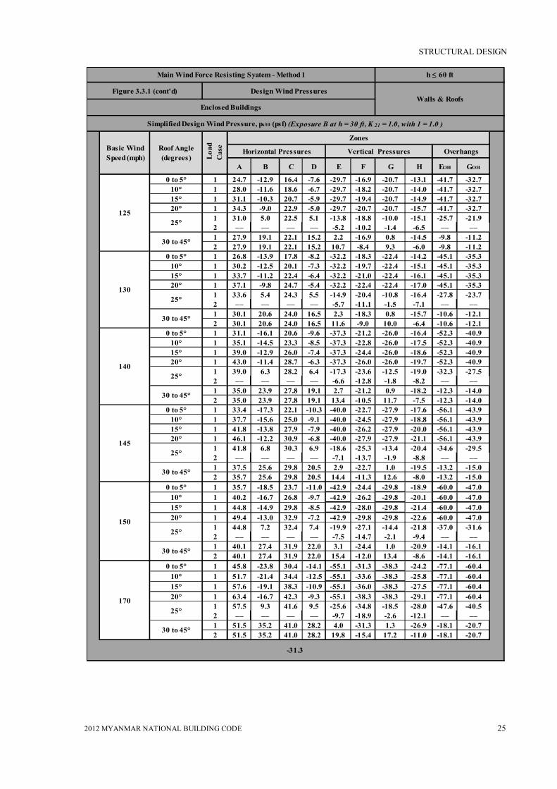
STRUCTURAL DESIGN
2012 MYANMAR NATIONAL BUILDING CODE 25
A B C D E F G H EOH GOH
0 to 5° 1 24.7 -12.9 16.4 -7.6 -29.7 -16.9 -20.7 -13.1 -41.7 -32.710° 1 28.0 -11.6 18.6 -6.7 -29.7 -18.2 -20.7 -14.0 -41.7 -32.715° 1 31.1 -10.3 20.7 -5.9 -29.7 -19.4 -20.7 -14.9 -41.7 -32.720° 1 34.3 -9.0 22.9 -5.0 -29.7 -20.7 -20.7 -15.7 -41.7 -32.7
1 31.0 5.0 22.5 5.1 -13.8 -18.8 -10.0 -15.1 -25.7 -21.92 –– –– –– –– -5.2 -10.2 -1.4 -6.5 –– ––1 27.9 19.1 22.1 15.2 2.2 -16.9 0.8 -14.5 -9.8 -11.22 27.9 19.1 22.1 15.2 10.7 -8.4 9.3 -6.0 -9.8 -11.2
0 to 5° 1 26.8 -13.9 17.8 -8.2 -32.2 -18.3 -22.4 -14.2 -45.1 -35.310° 1 30.2 -12.5 20.1 -7.3 -32.2 -19.7 -22.4 -15.1 -45.1 -35.315° 1 33.7 -11.2 22.4 -6.4 -32.2 -21.0 -22.4 -16.1 -45.1 -35.320° 1 37.1 -9.8 24.7 -5.4 -32.2 -22.4 -22.4 -17.0 -45.1 -35.3
1 33.6 5.4 24.3 5.5 -14.9 -20.4 -10.8 -16.4 -27.8 -23.72 –– –– –– –– -5.7 -11.1 -1.5 -7.1 –– ––1 30.1 20.6 24.0 16.5 2.3 -18.3 0.8 -15.7 -10.6 -12.12 30.1 20.6 24.0 16.5 11.6 -9.0 10.0 -6.4 -10.6 -12.1
0 to 5° 1 31.1 -16.1 20.6 -9.6 -37.3 -21.2 -26.0 -16.4 -52.3 -40.910° 1 35.1 -14.5 23.3 -8.5 -37.3 -22.8 -26.0 -17.5 -52.3 -40.915° 1 39.0 -12.9 26.0 -7.4 -37.3 -24.4 -26.0 -18.6 -52.3 -40.920° 1 43.0 -11.4 28.7 -6.3 -37.3 -26.0 -26.0 -19.7 -52.3 -40.9
1 39.0 6.3 28.2 6.4 -17.3 -23.6 -12.5 -19.0 -32.3 -27.52 –– –– –– –– -6.6 -12.8 -1.8 -8.2 –– ––1 35.0 23.9 27.8 19.1 2.7 -21.2 0.9 -18.2 -12.3 -14.02 35.0 23.9 27.8 19.1 13.4 -10.5 11.7 -7.5 -12.3 -14.0
0 to 5° 1 33.4 -17.3 22.1 -10.3 -40.0 -22.7 -27.9 -17.6 -56.1 -43.910° 1 37.7 -15.6 25.0 -9.1 -40.0 -24.5 -27.9 -18.8 -56.1 -43.915° 1 41.8 -13.8 27.9 -7.9 -40.0 -26.2 -27.9 -20.0 -56.1 -43.920° 1 46.1 -12.2 30.9 -6.8 -40.0 -27.9 -27.9 -21.1 -56.1 -43.9
1 41.8 6.8 30.3 6.9 -18.6 -25.3 -13.4 -20.4 -34.6 -29.52 –– –– –– –– -7.1 -13.7 -1.9 -8.8 –– ––1 37.5 25.6 29.8 20.5 2.9 -22.7 1.0 -19.5 -13.2 -15.02 35.7 25.6 29.8 20.5 14.4 -11.3 12.6 -8.0 -13.2 -15.0
0 to 5° 1 35.7 -18.5 23.7 -11.0 -42.9 -24.4 -29.8 -18.9 -60.0 -47.010° 1 40.2 -16.7 26.8 -9.7 -42.9 -26.2 -29.8 -20.1 -60.0 -47.015° 1 44.8 -14.9 29.8 -8.5 -42.9 -28.0 -29.8 -21.4 -60.0 -47.020° 1 49.4 -13.0 32.9 -7.2 -42.9 -29.8 -29.8 -22.6 -60.0 -47.0
1 44.8 7.2 32.4 7.4 -19.9 -27.1 -14.4 -21.8 -37.0 -31.62 –– –– –– –– -7.5 -14.7 -2.1 -9.4 –– ––1 40.1 27.4 31.9 22.0 3.1 -24.4 1.0 -20.9 -14.1 -16.12 40.1 27.4 31.9 22.0 15.4 -12.0 13.4 -8.6 -14.1 -16.1
0 to 5° 1 45.8 -23.8 30.4 -14.1 -55.1 -31.3 -38.3 -24.2 -77.1 -60.410° 1 51.7 -21.4 34.4 -12.5 -55.1 -33.6 -38.3 -25.8 -77.1 -60.415° 1 57.6 -19.1 38.3 -10.9 -55.1 -36.0 -38.3 -27.5 -77.1 -60.420° 1 63.4 -16.7 42.3 -9.3 -55.1 -38.3 -38.3 -29.1 -77.1 -60.4
1 57.5 9.3 41.6 9.5 -25.6 -34.8 -18.5 -28.0 -47.6 -40.52 –– –– –– –– -9.7 -18.9 -2.6 -12.1 –– ––1 51.5 35.2 41.0 28.2 4.0 -31.3 1.3 -26.9 -18.1 -20.72 51.5 35.2 41.0 28.2 19.8 -15.4 17.2 -11.0 -18.1 -20.7
h 60 ft
125
Simplified Design Wind Pressure, ps30 (psf) (Exposure B at h = 30 ft, K 21 = 1.0, with 1 = 1.0 )
Enclosed Buildings
Loa
dC
aseRoof Angle
(degrees)Basic Wind Speed (mph)
Main Wind Force Resisting Syatem - Method 1
Figure 3.3.1 (cont'd) Design Wind Pressures
Horizontal Pressures
Walls & Roofs
Zones
17025°
30 to 45°
14525°
30 to 45°
15025°
30 to 45°
13025°
Overhangs
140
30 to 45°
30 to 45°
30 to 45°
Vertical Pressures
25°
25°
-31.3
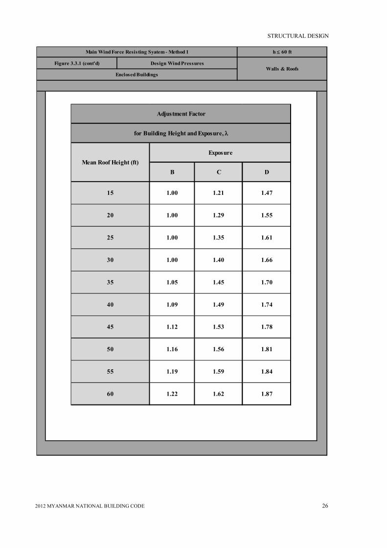
STRUCTURAL DESIGN
2012 MYANMAR NATIONAL BUILDING CODE 26
h 60 ft
Enclosed Buildings
Main Wind Force Resisting Syatem - Method 1
Figure 3.3.1 (cont'd) Design Wind PressuresWalls & Roofs
B C D
15 1.00 1.21 1.47
20 1.00 1.29 1.55
25 1.00 1.35 1.61
30 1.00 1.40 1.66
35 1.05 1.45 1.70
40 1.09 1.49 1.74
45 1.12 1.53 1.78
50 1.16 1.56 1.81
55 1.19 1.59 1.84
60 1.22 1.62 1.87
ExposureMean Roof Height (ft)
Adjustment Factor
for Building Height and Exposure, l

STRUCTURAL DESIGN
2012 MYANMAR NATIONAL BUILDING CODE 27
h 60 ft
Enclosed Buildings
Components and Cladding - Method 1
Figure 3.3.2 Design Wind PressuresWalls & Roofs
Notes: 2. Pressures shown are applied normal to the surface, for exposure B, at h=30 ft (9.1 m ) , I = 1.0, and Kzt = 1.0.
Adjust to other condition using Equation 6 – 2. 2. Plus and minus signs signify pressures acting toward and away from the surfaces, respectively. 3. For hip roofs with θ25°, Zone 3 shall be treated as Zone 2. 4. For effective wind areas between those given, value may be interpolated, otherwise use the value associated with the
lower effective wind area. 5. Notation:
a = 10 percent of least horizontaldimensionor 0.4h, whichever is smaller, but not less than either 4 % of least horizontaldimensionor 3 ft (0.9 m )
h =mean roof height,in feet (meters), except that eave height shall be used for roof angles < 10°. θ = angle of plane of roof from horizontal, in degrees.
Roofs – Zone 1/Walls – Zone 4 Roofs – Zone 2/Walls – Zone 5 Roofs – Zone 3 Interior Zones End Zones Corner Zones

STRUCTURAL DESIGN
2012 MYANMAR NATIONAL BUILDING CODE 28
1 10 5.3 -13.0 5.9 -14.6 7.3 -18.0 8.1 -19.8 8.9 -21.8 10.5 -25.91 20 5.0 -12.7 5.6 -14.2 6.9 -17.5 7.6 -19.3 8.3 -21.2 9.9 -25.21 50 4.5 -12.2 5.1 -13.7 6.3 -16.9 6.9 -18.7 7.6 -20.5 9.0 -24.41 100 4.2 -11.9 4.7 -13.3 5.8 -16.5 6.4 -18.2 7.0 -19.9 8.3 -23.72 10 5.3 -21.8 5.9 -24.4 7.3 -30.2 8.1 -33.3 8.9 -36.5 10.5 -13.52 20 5.0 -39.5 5.6 -21.8 6.9 -27.0 7.6 -29.7 8.3 -32.6 9.9 -38.82 50 4.5 -16.4 5.1 -18.4 6.3 -22.7 6.9 -25.1 7.6 -27.5 9.0 -32.72 100 4.2 -14.1 4.7 -15.8 5.8 -19.5 6.4 -21.5 7.0 -23.6 8.3 -28.13 10 5.3 -32.8 5.9 -36.8 7.3 -45.4 8.1 -50.1 8.9 -55.0 10.5 -65.43 20 5.0 -27.2 5.6 -30.5 6.9 -37.6 7.6 -41.5 8.3 -45.5 9.9 -54..23 50 4.5 -19.7 5.1 -22.0 6.3 -27.3 6.9 -30.1 7.6 -33.1 9.0 -39.33 100 4.2 -14.1 4.7 -15.8 5.8 -19.5 6.4 -21.5 7.0 -23.6 8.3 -28.11 10 7.5 -11.9 8.4 -13.3 10.4 -16.5 11.4 -18.2 12.5 -19.9 14.9 -23.71 20 6.8 -11.6 7.7 -13.0 9.4 -16.0 10.4 -17.6 11.4 -19.4 13.6 -23.01 50 6.0 -11.1 6.7 -12.5 8.2 -15.4 9.1 -17.0 10.0 -18.6 11.9 -22.21 100 5.3 -10.8 5.9 -12.1 7.3 -14.9 8.1 -16.5 8.9 -18.1 10.5 -21.52 10 7.5 -20.7 8.4 -23.2 10.4 -28.7 11.4 -31.6 12.5 -34.7 14.9 -41.32 20 6.8 -19.0 7.7 -21.4 9.4 -26.4 10.4 -29.1 11.4 -31.9 13.6 -38.02 50 6.0 -16.9 6.7 -18.9 8.2 -23.3 9.1 -25.7 10.0 -28.2 11.9 -33.62 100 5.3 -15.2 5.9 -17.0 7.3 -21.0 8.1 -23.2 8.9 -25.5 10.5 -30.33 10 7.5 -30.6 8.4 -34.3 10.4 -42.4 11.4 -46.7 12.5 -51.3 14.9 -61.03 20 6.8 -28.6 7.7 -32.1 9.4 -39.6 10.4 -43.7 11.4 -47.9 13.6 -57.13 50 6.0 -26.0 6.7 -29.1 8.2 -36.0 9.1 -39.7 10.0 -43.5 11.9 -51.83 100 5.3 -24.0 5.9 -26.9 7.3 -33.2 8.1 -36.6 8.9 -40.2 10.5 -47.91 10 11.9 -13.0 13.3 -14.6 16.5 -18.0 18.2 -19.8 19.9 -21.8 23.7 -25.91 20 11.6 -12.3 13.0 -13.8 16.0 -17.1 17.6 -18.8 19.4 -20.7 23.0 -24.61 50 11.1 -11.5 12.5 -12.8 15.4 -15.9 17.0 -17.5 18.6 -19.2 22.2 -22.81 100 10.8 -10.8 12.1 -12.1 14.9 -14.9 16.5 -16.5 18.1 -18.1 21.5 -21.52 10 11.9 -15.2 13.3 -17.0 16.5 -21.0 18.2 -23.2 19.9 -25.5 23.7 -30.32 20 11.6 -14.5 13.0 -16.3 16.0 -20.1 17.6 -22.2 19.4 -24.3 23.0 -29.02 50 11.1 -13.7 12.5 -15.3 15.4 -18.9 17.0 -20.8 18.6 -22.9 22.2 -27.22 100 10.8 -13.0 12.1 -14.6 14.9 -18.0 16.5 -19.8 18.1 -21.8 21.5 -25.93 10 11.9 -15.2 13.3 -17.0 16.5 -21.0 18.2 -23.2 19.9 -25.5 23.7 -30.33 20 11.6 -14.5 13.0 -16.3 16.0 -20.1 17.6 -22.2 19.4 -24.3 23.0 -29.03 50 11.1 -13.7 12.5 -15.3 15.4 -18.9 17.0 -20.8 18.6 -22.9 22.2 -27.03 100 10.8 -13.0 12.1 -14.6 14.9 -18.0 16.5 -19.8 18.1 -21.8 21.5 -25.94 10 13.0 -14.1 14.6 -15.8 18.0 -19.5 19.8 -21.5 21.8 -23.6 25.9 -28.14 20 12.4 -13.5 13.9 -15.1 17.2 -18.7 18.9 -20.6 20.8 -22.6 24.7 -26.94 50 11.6 -12.7 13.0 -14.3 16.1 -17.6 17.8 -19.4 19.5 21.3 23.2 -25.44 100 11.1 -12.2 12.4 -13.6 15.3 -16.8 16.9 -18.5 18.5 20.4 22.0 -24.24 500 9.7 -108.0 10.9 -12.1 13.4 -14.9 14.8 -16.5 16.2 -18.1 19.3 -21.55 10 13.0 -174.0 14.6 -19.5 18.0 -24.1 19.8 -26.6 21.8 -29.1 25.9 -34.75 20 12.4 -16.2 13.9 -18.2 17.2 -22.5 18.9 -24.8 20.8 -27.2 24.7 -32.45 50 11.6 -14.7 13.0 -16.5 16.1 -20.3 17.8 -22.4 19.5 -24.6 23.2 -29.35 100 11.1 -13.5 12.4 -15.1 15.3 -18.7 16.9 -20.6 18.5 -22.6 22.0 -26.95 500 9.7 -10.8 10.9 -12.1 13.4 -14.9 14.8 -16.5 16.2 -18.1 19.3 -21.5
Unit Conversion –– 1.0 ft = 0.3048 m ; 1.0 psf = 0.479 kN/m2
Roo
f >
27 to
45
degr
ees
Wal
l
120
Net Design Wind Pressure, pnet30 (psf) (Exposure B at h = 30 ft, with 1 = 1.0, and Kn= 1.0 )
Roo
f 0
to 7
deg
rees
Roo
f > 7
to 2
7 de
gree
s
ZoneEffective wind area
(sf) 11085 90 100 105
Basic Wind Speed
Components and Cladding Method 1
Figure 3.3.2 (cont'd) Net Design Wind Pressures
Enclosed Buuildings
h 60 ft
Walls & Roofs

STRUCTURAL DESIGN
2012 MYANMAR NATIONAL BUILDING CODE 29
1 10 11.4 -28.1 12.4 -30.4 14.3 -35.3 15.4 -37.8 16.5 -40.5 21.1 -52.01 20 10.7 -27.4 11.6 -29.6 13.4 -34.4 14.4 -36.9 15.4 -39.4 19.8 -50.71 50 9.8 -26.4 10.6 -28.6 12.3 -33.2 13.1 -35.6 14.1 -38.1 18.1 -48.91 100 9.1 -25.7 9.8 -27.8 11.4 -32.3 12.2 -34.6 13.0 -37.0 16.7 -47.62 10 11.4 -47.2 12.4 -51.0 14.3 -59.2 15.4 -63.5 16.5 -67.9 21.1 -87.22 20 10.7 -42.1 11.6 -45.6 13.4 -52.9 14.4 -56.7 15.4 -60.7 19.8 -78.02 50 9.8 -35.5 10.6 -38.4 12.3 -44.5 13.1 -47.8 14.1 -51.1 18.1 -65.72 100 9.1 -30.5 9.8 -33.0 11.4 -38.2 12.2 -41.0 13.0 -43.9 16.7 -56.43 10 11.4 -71.0 12.4 -76.8 14.3 -89.0 15.4 -95.5 16.5 -102.2 21.1 -131.33 20 10.7 -58.5 11.6 -63.6 13.4 -73.8 14.4 -79.1 15.4 -84.7 19.8 -108.73 50 9.8 -42.7 10.6 -46.2 12.3 -53.5 13.1 -57.4 14.1 -61.5 18.1 -78.93 100 9.1 -30.5 9.8 -33.0 11.4 -38.2 12.2 -41.0 13.0 -43.9 16.7 -56.41 10 16.2 -25.7 17.5 -27.8 20.3 -32.3 21.8 -34.6 23.3 -37.0 30.0 -47.61 20 14.8 -25.0 16.0 -27.0 18.5 -31.4 19.9 -33.7 21.3 -36.0 27.3 -46.31 50 12.9 -24.1 13.9 -26.0 16.1 -30.2 17.3 -32.4 18.5 -34.6 23.8 -44.51 100 11.4 -23.2 12.4 -25.2 14.3 -29.3 15.4 -31.4 16.5 -33.6 21.1 -43.22 10 16.2 -44.8 17.5 -48.4 20.3 -56.2 21.8 -60.3 23.3 -64.5 30.0 -82.82 20 14.8 -41.2 16.0 -44.6 18.5 -51.7 19.9 -55.4 21.3 -59.3 27.3 -76.22 50 12.9 -36.5 13.9 -39.4 16.1 -45.7 17.3 -49.1 18.5 -52.5 23.8 -67.42 100 11.4 -32.9 12.4 -35.6 14.3 -41.2 15.4 -44.2 16.5 -47.3 21.1 -60.83 10 16.2 -66.2 17.5 -71.6 20.3 -83.1 21.8 -89.1 23.3 -95.4 30.0 -122.53 20 14.8 -61.9 16.0 -67.0 18.5 -77.7 19.9 -83.3 21.3 -89.2 27.3 -114.53 50 12.9 -56.2 13.9 -60.8 16.1 -70.5 17.3 -75.7 18.5 -81.0 23.8 -104.03 100 11.4 -51.9 12.4 -56.2 14.3 -65.1 15.4 -69.9 16.5 -74.8 21.1 -96.01 10 25.7 -28.1 27.8 -30.4 32.3 -35.3 34.6 -37.8 37.0 -40.5 47.6 -52.01 20 25.0 -26.7 27.0 -28.9 31.4 -33.5 33.7 -35.9 36.0 -38.4 46.3 -49.31 50 24.1 -24.8 26.0 -26.8 30.2 -31.1 32.4 -33.3 34.6 -35.7 44.5 -45.81 100 23.3 -23.3 25.2 -25.2 29.3 -29.3 31.4 -31.4 33.6 -33.6 43.2 -43.22 10 25.7 -32.9 27.8 -35.6 32.3 -41.2 34.6 -44.2 37.0 -47.3 47.6 -60.82 20 25.0 -31.4 27.0 -34.0 31.4 -39.4 33.7 -42.3 36.0 -45.3 46.3 -58.12 50 24.1 -29.5 26.0 -32.0 30.2 -37.1 32.4 -39.8 34.6 -42.5 44.5 -54.62 100 23.2 -28.1 25.2 -30.4 29.3 -35.3 31.4 -37.8 33.6 -40.5 43.2 -52.03 10 25.7 -32.9 27.8 -35.6 32.3 -41.2 34.6 -44.2 37.0 -47.3 47.6 -60.83 20 25.0 -31.4 27.0 -34.0 31.4 -39.4 33.7 -42.3 36.0 -45.3 46.3 -58.13 50 24.1 -29.5 26.0 -32.0 30.2 -37.1 32.4 -39.8 34.6 -42.5 44.5 -54.63 100 23.3 -28.1 25.2 -30.4 29.3 -35.3 31.4 -37.8 33.6 -40.5 43.2 -52.04 10 28.1 -30.5 30.4 -33.0 35.3 -38.2 37.8 -41.0 40.5 -43.9 52.0 -56.44 20 26.8 -29.2 29.0 -31.6 33.7 -36.7 36.1 -39.3 38.7 -42.1 49.6 -54.14 50 25.2 -27.5 27.2 -29.8 31.6 -34.6 33.9 -37.1 36.2 -39.7 46.6 -51.04 100 23.9 -26.3 25.9 -28.4 30.0 -33.0 32.2 -35.4 34.4 -37.8 44.2 -48.64 500 21.0 -23.3 22.7 -25.2 26.3 -29.3 28.2 -31.4 30.2 -33.6 38.8 -43.25 10 28.1 -37.6 30.4 -40.7 35.3 -47.2 37.8 -50.6 40.5 -54.2 52.0 -69.65 20 26.8 -35.1 29.0 -38.0 33.7 -44.0 36.1 -47.2 38.7 -50.5 49.6 -64.95 50 25.2 -31.8 27.2 -34.3 31.6 -39.8 33.9 -42.7 36.2 -45.7 46.6 -58.75 100 23.9 -29.2 25.9 -31.6 30.0 -36.7 32.2 39.3 34.4 -42.1 44.2 -54.15 500 21.0 -23.2 22.7 -25.2 26.3 -29.3 28.2 -31.1 30.2 -33.6 38.8 -43.2
Unit Conversion –– 1.0 ft = 0.3048 m ; 1.0 psf = 0.479 kN/m2
Roo
f >
27 to
45
degr
ees
Wal
l
170
Net Design Wind Pressure, pnet30 (psf) (Exposure B at h = 30 ft. with 1 = 1.0 and Kzt= 1.0 )R
oof
0 to
7 d
egre
esR
oof >
7 to
27
degr
ees
ZoneEffective wind area
(sf) 150125 130 140 145
Basic Wind Speed V (mph)
Components and Cladding - Method 1
Figure 3.3.2 (cont'd) Net Design Wind Pressures
Enclosed Buuildings
h 60 ft
Walls & Roofs

STRUCTURAL DESIGN
2012 MYANMAR NATIONAL BUILDING CODE 30
90 100 110 120 130 140 150 170
2 10 -21.0 -25.9 -31.4 -37.3 -43.8 -50.8 -58.3 -74.92 20 -20.6 -25.5 -30.8 -36.7 -43.0 -49.9 -57.3 -73.62 50 -20.1 -24.9 -30.1 -35.8 -42.0 -48.7 -55.9 -71.82 100 -19.8 -24.4 -29.5 -35.1 -41.2 -47.8 -54.9 -70.53 10 -34.6 -42.7 -51.6 -61.5 -72.1 -83.7 -96.0 -123.43 20 -27.1 -33.5 -40.5 -48.3 -56.6 -65.7 -75.4 -96.83 50 -17.3 -21.4 -25.9 -30.8 -36.1 -41.9 -48.1 -61.83 100 -10.0 -12.2 -14.8 -17.6 -20.6 -23.9 -27.4 -35.22 10 -27.2 -33.5 -40.6 -48.3 -56.7 -65.7 -75.5 -96.92 20 -27.2 -33.5 -40.6 -48.3 -56.7 -65.7 -75.5 -96.92 50 -27.2 -33.5 -40.6 -48.3 -56.7 -65.7 -75.5 -96.92 100 -27.2 -33.5 -40.6 -48.3 -56.7 -65.7 -75.5 -96.93 10 -45.7 -56.4 -68.3 -81.2 -95.3 -110.6 -126.9 -163.03 20 -41.2 -50.9 -61.1 -73.3 -86.0 -99.8 -114.5 -147.13 50 -35.3 -43.6 -52.8 -62.8 -73.7 -85.5 -98.1 -126.13 100 -30.9 -38.1 -46.1 -54.9 -64.4 -74.7 -85.8 -110.12 10 -24.7 -30.5 -36.9 -43.9 -51.5 -59.8 -68.6 -88.12 20 -24.0 -29.6 -35.8 -42.6 -50.0 -58.0 -66.5 -85.52 50 -23.0 -28.4 -34.4 -40.8 -47.9 -55.6 -63.8 -82.02 100 -22.2 -27.4 -33.2 -39.5 -46.4 -53.8 -61.7 -79.33 10 -24.7 -30.5 -36.9 -43.9 -51.5 -59.8 -68.6 -88.13 20 -24.0 -29.6 -35.8 -42.6 -50.0 -58.0 -66.5 -85.53 50 -23.0 -28.4 -34.4 -40.8 -47.9 -55.6 -63.8 -82.03 100 -22.2 -27.4 -33.2 -39.5 -46.4 -53.8 -61.7 -79.3
Figure 3.3.2 (contd.) Net Design Wind Pressures
Unit Conversion –– 1.0 ft = 0.3048 m ; 1.0 psf = 0.479 kN/m2
h 60 ft.Components and Cladding - Method 1
Enclosed Buildings
Roo
0 >
7to
27
deg
rees
Roo
0 >
27to
45
degr
ees
Walls & Roofs
Basic Wind Speed V(mph)
Roof Overhang Net Design wind Pressure, pnet30 (psf)(Exposure B at h = 30 ft, with I = 1.0| )
Effective Wind
Area (sf)Zone
Roo
0 to
7 d
egre
es
B C D
15 1.00 1.21 1.4720 1.00 1.29 1.5525 1.00 1.35 1.6130 1.00 1.40 1.6635 1.05 1.45 1.7040 1.09 1.49 1.7445 1.12 1.53 1.7850 1.16 1.56 1.8155 1.19 1.59 1.8460 1.22 1.62 1.87
ExposureMean Roof Height (ft)
Adjustment Factor
for Building Height and Exposure, l

STRUCTURAL DESIGN
2012 MYANMAR NATIONAL BUILDING CODE 31
Escarpment 2-D ridge or 3-D axisymmetrical hill
Topographic multipliers for Exposure C
H/Lh
K1 multiplier
x/Lh
K2 multiplier
z/Lh
K3 multiplier
2-D ridge
2-D escarp.
3-D axisym.
hill
2-D escarp.
All other cases
2-D ridge
2-D escarp.
3-D axisym.
hill
0.20 0.29 0.17 0.21 0.00 1.00 1.00 0.00 1.00 1.00 1.00
0.25 0.36 0.21 0.26 0.50 0.88 0.67 0.10 0.74 0.78 0.67
0.30 0.43 0.26 0.32 1.00 0.75 0.33 0.20 0.55 0.61 0.45
0.35 0.51 0.30 0.37 1.50 0.63 0.00 0.30 0.41 0.47 0.30
0.40 0.58 0.34 0.42 2.00 0.50 0.00 0.40 0.30 0.37 0.20
0.45 0.65 0.38 0.47 2.50 0.38 0.00 0.50 0.22 0.29 0.14
0.50 0.72 0.43 0.53 3.00 0.25 0.00 0.60 0.17 0.22 0.09
3.50 0.13 0.00 0.70 0.12 0.17 0.06
4.00 0.00 0.00 0.80 0.09 0.14 0.04
0.90 0.07 0.11 0.03
1.00 0.05 0.08 0.02
1.50 0.01 0.02 0.00
2.00 0.00 0.00 0.00
z
V(z)
V(z) Speed-up
H H/2 H/2 Lh
x (downwind) x (upwind)
z
V(z)
V(z) Speed-up
H H/2 H/2 Lh
x (downwind) x (upwind)
Topographic Factor ,Kzt - Method 2
Figure 3.3.3

STRUCTURAL DESIGN
2012 MYANMAR NATIONAL BUILDING CODE 32
Notes:
1. For values ofH/Lh,x/Lhandz/Lh other than those shown, linear interpolation is permitted.
2. For H/Lh>0.5, assume H/Lh=0.5 for evaluating K1 and substitute 2Hfor Lhfor evaluating K2and K3 .
3. Multipliers are based on the assumption that wind approaches the hill or escarpment along the direction of maximum slope.
4. Notation:
H : Height of hill or escarpment relative to the upwind terrain, in feet (meters).
Lh : Distance upwind of crest to where the difference in ground elevation is half the height of hill or escarpment, in feet (meters).
K1 : Factor to account for shape of topographic feature and maximum speed-up effect.
K2 : Factor to account for reduction in speed-up with distance upwind or downwind of crest.
K3 : Factor to account for reduction in speed-up with height above local terrain.
x :Distance (upwind or downwind) from the crest to the building site, in feet (meters).
z : Height above local ground level, in feet (meters).
µ : Horizontal attenuation factor.

STRUCTURAL DESIGN
2012 MYANMAR NATIONAL BUILDING CODE 33
γ: Height attenuation factor.
Kzt= (1+K1K2K3 )2,K1determined from table below ,K2= ( hL
x
–1
) ,K3= hLze /–
Parameters for speed-up over hills and escarpments
Hill shape
K1 /(H/Lh)
γ
Exposure Upwind of crest
Downwind of crest
B C D
2-dimensional ridges
(or valleys with negative H in K1/(H/Lh)
1.30 1.45 1.55 3 1.5 1.5
2-dimensional escarpments 0.75 0.85 0.95 2.5 1.5 4
3-dimensional axisym. hill 0.95 1.05 1.15 4 1.5 1.5
Topographic Factor ,Kzt - Method 2
Figure 3.3.3 (contd.)

STRUCTURAL DESIGN
2012 MYANMAR NATIONAL BUILDING CODE 34
Figure 3.3.4 Internal Pressure Coefficient, G C pi
All heightsMain Wind Force Res. Sys. / Comp and Clad. - Method 2
Enclosed, Partially Enclosed and Open BuildingsWalls & Roofs
Notes:
1. Plus and minus signs signify pressures acting toward and away from the internal surfaces, respectively.
2. Values of GCpi shall be used with qz or qh as specified in 6.5.12.
3. Two cases shall be considered to determine the critical load requirements for the appropriate condition:
(i) a positive value of GCpi applied to all internal surfaces
(ii) a negative value of GCpi applied to all internal surfaces
Enclosure classification GCpi
Open buildings 0.00
Partially enclosed buildings + 0.55
– 0.55
Enclosed buildings + 0.18
– 0.18

STRUCTURAL DESIGN
2012 MYANMAR NATIONAL BUILDING CODE 35
Figure 3.3.5
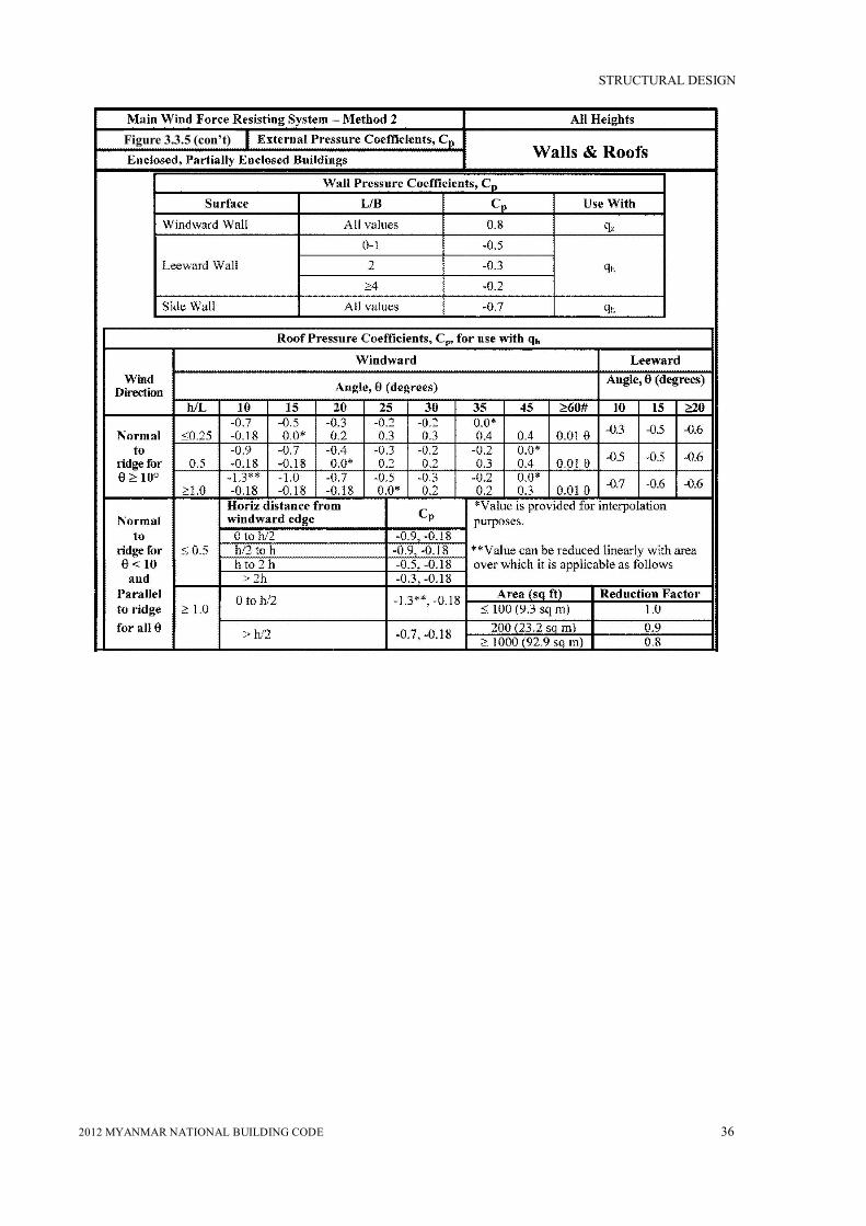
STRUCTURAL DESIGN
2012 MYANMAR NATIONAL BUILDING CODE 36
Figure 3.3.5 (con’t)

STRUCTURAL DESIGN
2012 MYANMAR NATIONAL BUILDING CODE 37
Notes:
1. Plus and minus signs signify pressures acting toward and away from the surfaces, respectively.
2. Linear interpolation is permitted for values of L/B,h/L and θother than shown. Interpolation shall only be carried out between values of the same sign. Where no value of the same sign is given, assume 0.0 for interpolation purposes.
3. Where two values of Cpare listed, this indicates that the windward roof slope is subjected to either positive or negative pressures and the roof structure shall be designed for both conditions. Interpolation for intermediate ratios of h/L in this case shall only be carried out between Cpvalues of like sign.
4. For monoslope roofs, entire roof surface is either a windward or leeward surface.
5. For flexible buildings use appropriate Gf as determined by ASCE Section 6.5.8.
6. Refer to ASCE Figure 6-7 for domes and ASCE Figure 6-8 for arched roofs.
7. Notation:
B : Horizontal dimension of building, in feet (meter), measured normal to wind direction.
L : Horizontal dimension of building, in feet (meter), mcasurcd parallel to wind direction.
H : Mean roof height in feet (meters): except that eave height shall be used for θ≤10 degrees.
z : Height above ground, in feet (meters).
G : Gust effect factor.
qz ,qh : Velocity pressure, in pounds per square foot (N/m2), evaluated at respective height.
θ : Angle of plane of roof from horizontal, in degrees.
8. For mansard roofs, the top horizontal surface and leeward inclined surface shall be treated as leeward surfaces from the table.
9. Except for MWFRS's at the roof consisting of moment resisting frames, the total horizontal shear shall not be less than that determined by neglecting wind forces on roof surfaces.
# For roof slopes greater than 80°, use Cp= 0.8

STRUCTURAL DESIGN
2012 MYANMAR NATIONAL BUILDING CODE 38
1. Two load cases shall be considered: Case A. Cp values between A and B and between B and C shall be determined by linear
interpolation along arcs on the dome parallel to the wind direction; Case B. Cpshall be the constant value of A for ≤ 25 degrees, and shall be determined by linear
interpolation from 25 degrees to B and from B to C. 2. Values denote Cp to be used with q(hD+ f ) where hD+ f is the height at the top of the dome. 3. Plus and minus signs signify pressures acting toward and away from the surfaces, respectively. 4. Cp is constant on the dome surface for arcs of circles perpendicular to the wind direction; for example, the
arc passing through B-B-B and all arcs parallel to B-B-B. 5. For values of hD/D between those listed on the graph curves, linear interpolation shall be permitted. 6. = 0 degrees on dome springline, = 90 degrees at dome center top point. f is measured from
springline to top. 7. The total horizontal shear shall not be less than that determined by neglecting w~ndforces on roof
surfaces. 8. For f/D values less than 0.05, use Figure 3.5.
Figure 3.3.6

STRUCTURAL DESIGN
2012 MYANMAR NATIONAL BUILDING CODE 39
*When the rise-to-span ratio is 0.2 ≤ r ≤ 0.3, alternate coefficients given by 6r – 2.1 shall also be used for the windward quarter. Notes: 1. Values listed are for the determination of average loads on main wind force resisting
systems. 2. Plus and minus signs signify pressures acting toward and away from the surfaces,
respectively. 3. For wind directed parallel to the axis of the arch, use pressure coefficients from Fig. 3.5
with wind directed parallel to ridge. 4. For components and cladding: (1) At roof perimeter, use the external pressure coefficients
in Fig. 3.10with based on spring-line slope and (2) for remaining roof areas, use external pressure coefficients of this table multiplied by 0.87.
Figure 3.3.7

STRUCTURAL DESIGN
2012 MYANMAR NATIONAL BUILDING CODE 40
Notes: 1. Design wind pressures for windward and leeward faces shall be determined in accordance with the
provisions of 3.5.12.2.1 and 3.5.12.2.3 as applicable for building of all heights. 2. Diagrams show plan views of building. 3. Notation:
Pwx,Pwy: Windward face design pressure acting in the x, y principal axis, respectively. PLx,PLy: Leeward face design pressure acting in the x, y principal axis, respectively. e (ex ,ey) : Eccentricity for the x, y principal axis of the structure, respectively. MT: Torsional moment per unit height acting about a vertical axis of the building.
Figure 3.3.8

STRUCTURAL DESIGN
2012 MYANMAR NATIONAL BUILDING CODE 41
Figure 3.3.9

STRUCTURAL DESIGN
2012 MYANMAR NATIONAL BUILDING CODE 42
Notes: 1. Plus and minus signs signify pressures acting toward and away from the surfaces, respectively. 2. For values of other than those shown, linear interpolation is permitted. 3. The building must be designed for all wind directions using the 8 loading patterns shown. The load patterns are
applied to each building comer in turn as the Reference Comer. 4. Combinations of external and internal pressures (see Figure 3.4) shall be evaluated as required to obtain the most
severe loadings. 5. For the torsional load cases shown below, the pressures in zones designated with a "T" (IT, 2T, 3T, 4T) shall be 25% of
the full design wind pressures (zones 1,2, 3,4). Exception: One story buildings with h less than or equal to 30 ft (9. 1 m), buildings two stories or less framed with light frame construction, and buildings two stories or less designed with flexible diaphragms need not be designed for the torsional load cases.
Torsional loading shall apply to all eight basic load patterns using the figures below applied at each reference comer. 6. Except for moment-resisting frames, the total horizontal shear shall not be less than that determined by neglecting
wind forces on roof surfaces. 7. For the design of the MWFRS providing lateral resistance in a direction parallel to a ridge line or for flat roofs, use =
0° and locate the zone 2/3 boundary at the mid-length of the building. 8. The roof pressure coefficient GCpf, when negative in Zone 2 or 2E, shall be applied in Zone 2/2E for a distance from the
edge of roof equal to 0.5 times the horizontal dimension of the building parallel to the direction of the MWFRS being designed or 2.5 times the eave height, he , at the windward wall, whichever is less; the remainder of Zone 2/2E extending to the ridge line shall use the pressure coefficient GCpf for Zone 3/3E.
9. Notation: a :10 percent of least horizontal dimension or 0.4h, whichever is smaller, but not less than either4% of least
horizontal dimension or 3 ft (0.9 m). h:Mean roof height, in feet (meters), except that eave height shall be used for ≤ 10° : Angle of plane of roof from horizontal, in degrees.

STRUCTURAL DESIGN
2012 MYANMAR NATIONAL BUILDING CODE 43
Figure 3.3.10A

STRUCTURAL DESIGN
2012 MYANMAR NATIONAL BUILDING CODE 44
Notes: 1. Vertical scale denotes GCpto be used with qh. 2. Horizontal scale denotes effective wind area, in square feet (square meters). 3. Plus and minus signs signify pressures acting toward and away from the surfaces, respectively. 4. Each component shall be designed for maximum positive and negative pressures. 5. If a parapet equal to or higher than 3 ft (0.9m) is provided around the perimeter of the roof with θ ≤ 7°,
the negative values of GCp in Zone 3 shall be equal to those for Zone 2 and positive values of GCp inZones 2 and 3 shall be set equal to those for wall Zones 4 and 5 respectively in Figure 3.10A.
6. Values of GCpfor roof overhangs include pressure contributions from both upper and lower surfaces. 7. Notation:
a: 10 percent of least horizontal dimension or 0.4h, whichever is smaller, but not less than either 4% of least horizontal dimension or 3 ft (0.9 m).
h :Eave height shall be used for θ ≤ 10°. θ: Angle of plane of roof from horizontal, in degrees.
Figure 3.3.10B

STRUCTURAL DESIGN
2012 MYANMAR NATIONAL BUILDING CODE 45
Figure 3.3.10D

STRUCTURAL DESIGN
2012 MYANMAR NATIONAL BUILDING CODE 46
Notes:
1. On the lower level of flat, stepped roofs shown in Fig. 3.11, the zone designations and
pressure coefficients shown in Fig. 3.10B shall apply, except that at the roof-upper wall
intersection(s),Zone 3 shall be treated as Zone 2 and Zone 2 shall be treated as Zone 1.
Positive values of GCp equal to those for walls in Fig. 3.10A shall apply on the cross-hatched
areas shown in Fig. 3.11.
2. Notation:
b: 1.5h1 in Fig. 3.11, but not greater than 100 ft (30.5 m).
h :Mean roof height, in feet (meters).
hi:h1 or h2 in Fig. 3.11; h = h1 + h2; h1≥10 ft (3.1 m); hi/h = 0.3 to 0.7.
W: Building width in Fig. 3.11.
Wi: W1 or W2 or W3 in Fig. .11. W = W1 + W2 or W1 + W2 + W3; Wi/W = 0.25 to 0.75.
: Angle of plane of roof from horizontal, in degrees.
Figure3. 3.11

STRUCTURAL DESIGN
2012 MYANMAR NATIONAL BUILDING CODE 47
Figure 3.3.12

STRUCTURAL DESIGN
2012 MYANMAR NATIONAL BUILDING CODE 48
3.10B
Figure 3.3.13A

STRUCTURAL DESIGN
2012 MYANMAR NATIONAL BUILDING CODE 49
Figure3. 3.13B

STRUCTURAL DESIGN
2012 MYANMAR NATIONAL BUILDING CODE 50
Figure 3.3.14

STRUCTURAL DESIGN
2012 MYANMAR NATIONAL BUILDING CODE 51
Fig. 3.3.15
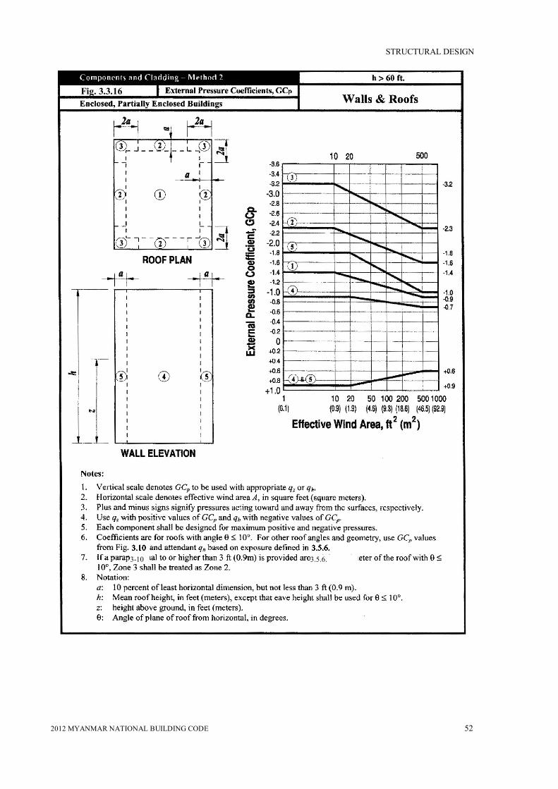
STRUCTURAL DESIGN
2012 MYANMAR NATIONAL BUILDING CODE 52
3.5.6. 3-10
Fig. 3.3.16
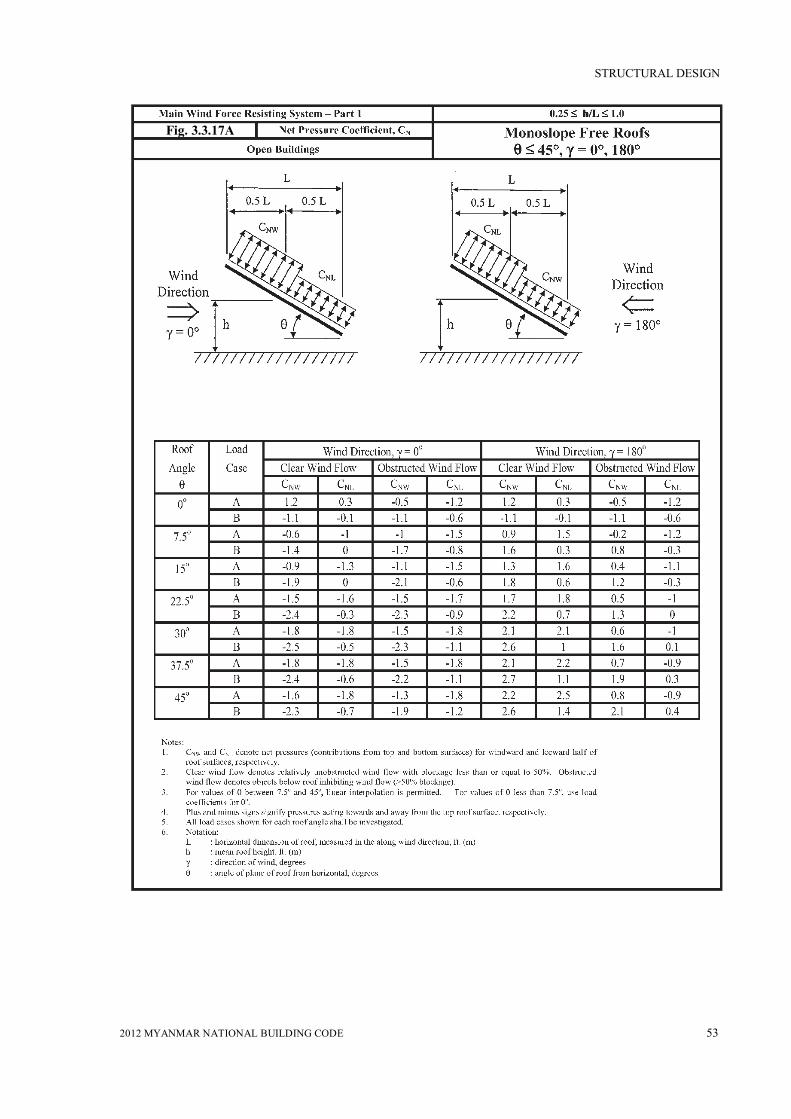
STRUCTURAL DESIGN
2012 MYANMAR NATIONAL BUILDING CODE 53
Fig. 3.3.17A

STRUCTURAL DESIGN
2012 MYANMAR NATIONAL BUILDING CODE 54
Fig. 3.3.17B

STRUCTURAL DESIGN
2012 MYANMAR NATIONAL BUILDING CODE 55
Fig. 3.3.17C

STRUCTURAL DESIGN
2012 MYANMAR NATIONAL BUILDING CODE 56
Fig. 3.3.17D
Notes: 1. CN denotes net pressures (contributions from top and bottom surfaces). 2. Clear wind flow denotes relatively unobstructed wind flow with blockage less than or equal to 50%.
Obstructed wind flow denotes objects below roof inhibiting wind flow (>50% blockage). 3. Plus and minus signs signify pressures acting towards and away from the top roof surface, respectively. 4. All load cases shown for each roof angle shall be investigated. 5. For monoslope roofs with theta less than 5 degrees, Cn values shown apply also for cases where gamma = 0
degrees and 0.05 less than or equal to h/L less than or equal to 0.25. See Figure 3.17A for other h/L values. 6. Notation:
L : horizontal dimension of roof, measured in the along wind direction, ft. (m) h : mean roof height, ft. (m). γ : direction of wind, degrees θ : angle of plane of roof from horizontal, degrees

STRUCTURAL DESIGN
2012 MYANMAR NATIONAL BUILDING CODE 57
0.25 ≤ h /L ≤ 1.0
Monoslope Free Roofs θ ≤ 1.0Open Buildings
Net Pressure Coefficient, C N
Components and Cladding
Figure 3.3.18A
Notes:1. CN denotes net pressures (contributions from top and bottom surfaces).2. Clear wind flow denotes relatively unobstructed wind flow with blockage less than or equal to 50%. Obstructed
wind flow denotes objects below roof inhibiting wind flow (>50% blockage).3. For values of θ other than those shown, linear interpolation is permitted.4. Plus and minus signs signify pressures acting towards and away from the top roof surface, respectively.5. Components and cladding elements shall be designed for positive and negative pressure coefficients shown.6. Notation:
a : 10% of least horizontal dimension or 0.4h, whichever is smaller but not less than 4% of least horizontaldimension or 3 ft. (0.9 m)
h : mean roof height, ft. (m)L : horizontal dimension of building, measured in along wind direction, ft. (m)
θ : angle of plane of roof from horizontal, degrees

STRUCTURAL DESIGN
2012 MYANMAR NATIONAL BUILDING CODE 58
Fig. 3.3.18B
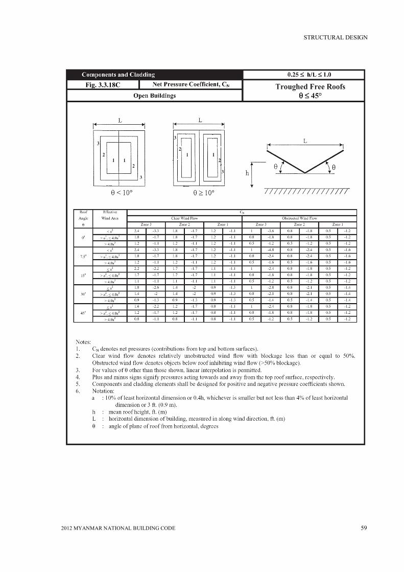
STRUCTURAL DESIGN
2012 MYANMAR NATIONAL BUILDING CODE 59
Fig. 3.3.18C

STRUCTURAL DESIGN
2012 MYANMAR NATIONAL BUILDING CODE 60
3.3.21

STRUCTURAL DESIGN
2012 MYANMAR NATIONAL BUILDING CODE 61
3.3.22

STRUCTURAL DESIGN
2012 MYANMAR NATIONAL BUILDING CODE 62
1 Sittwe (Akyab) 1402 Kyaukpyu (Kyaukphyu) 1403 Thandwe (Sandoway) 1404 Pathein (Bassein) 1205 Bogalay 1206 Yangon (Rangoon) 1207 Mawlamyine (Mawlamyaing) 1008 Ye 1009 Dawei (Tavoy) 100
10 Myeik (Mergui) 10011 Kawthaung 10012 Bago (Pegu) 10013 Pyay (Prome) 8014 Hpa-An (Pa-An) 8015 Loikaw 8016 Taunggyi 8017 Lashio 8018 Kengtung 8019 Magwe 8020 Yenangyaung 8021 Mandalay 10022 Naypyitaw 8023 Meiktila 8024 Monywa 8025 Bhamo 8026 Myitkyina 8027 Putao 8028 Hakha (Haka) 8029 Kale 8030 Muse 80
Basic Wind Speed (3-s Gust Wind Speed) in mph
Basic Wind Speed(mph)City/TownSr. No.
Table 3.3.1

STRUCTURAL DESIGN
2012 MYANMAR NATIONAL BUILDING CODE 63
I
II
III
IV
Note:
1. The building and structure classification categories are listed in Table 1.2.
Importance Factor, I (Wind Loads)
Category
Table 3.3.2
Non-Cyclone Prone Regionsand CycloneProne Regions
with V = 85-100 mphand Alaska
Cyclone Prone Regionswith V > 100 mph
0.87
1
1.15
1.15
0.77
1
1.15
1.15

STRUCTURAL DESIGN
2012 MYANMAR NATIONAL BUILDING CODE 64
Table 3.3.3

STRUCTURAL DESIGN
2012 MYANMAR NATIONAL BUILDING CODE 65
Velocity Pressure Exposure Coefficients, K h and K z
Table 3.3.4
Notes: 1. Case 1: a. All components and cladding.
b. Main wind force resisting system in low-rise buildings designed using Figure 3-9.
Case 2: a. All main wind force resisting systems in buildings except those in low-rise buildings designed using Figure 3-9.
b. All main wind force resisting systems in other structures. 2. The velocity pressure exposure coefficient K, may be determined from the following
formula: For 15 ft ≤ z ≤ zg For z < 15 ft Kz= 2.0 1 (z/zg)2/ Kz= 2.0 1 (15/zg)2/ Note: z shall not be talcenless than 30 feet for Case 1 in exposure B.
3. and zg are tabulated in Table 3.3. 4. Linear interpolation for intermediate values of height z is acceptable. 5. Exposure categories are defined in 3.5.6.

STRUCTURAL DESIGN
2012 MYANMAR NATIONAL BUILDING CODE 66
Wind Directionality factor, K d
Table 3.3.5
* Directionality Factor Kd has been calibrated with combinations of loadsspecified in Section 2. This factor shall only be applied when used inconjunction with load combinations specified in 2.1.2 and 2.1.3.

(Provisional)
MYANMAR
NATIONAL
BUILDING
CODE
2012
PART3 STRUCTURAL DESIGN
( SEISMIC DESIGN CRITERIA AND
DESIGN REQUIREMENTS FOR BUILDINGS )

MYANMAR NATIONAL BUILDING CODE – 2012
(PROVISIONAL)
PART 3 STRUCTURAL DESIGN (CONTINUED)
TABLE OF CONTENTS
NO. TITLE PAGE
3.4 SEISMIC DESIGN CRITERIA AND DESIGN REQUIREMENTS
FOR BUILDINGS
3.4.1 Seismic Design Criteria 1-24
3.4.2 Seismic Design Requirements for Building Structures 25-84
3.4.3 Seismic Response History Procedures 85-89
3.4.4 Site-Specific Ground Motion Procedures for 90-93
Seismic Design

STRUCTURAL DESIGN
2012 MYANMAR NATIONAL BUILDING CODE 1
SECTION 3.4: SEISMIC DESIGN CRITERIA AND DESIGN REQUIREMENTS FOR BUILDINGS
3.4.1 Seismic Design Criteria
3.4.1.1 General
3.4.1.1.1 Purpose
This section presents criteria for the design and construction of buildings subject to earthquake ground motions. The specified earthquake loads are based upon post-elastic energy dissipation in the structure, and because of this fact, the requirements for design, detailing, and construction shall be satisfied even for structures and members for which load combinations that do not contain earthquake loads indicate larger demands than combinations that include earthquake loads.
3.4.1.1.2 Scope
Every building structure, and portion thereof, including nonstructural components, shall be designed and constructed to resist the effects of earthquake motions as prescribed by the seismic requirements of this standard.
1) Detached one- and two-family dwellings that are located where the short period, spectral response acceleration parameter, SS , is less than 0.4 or where the Seismic Design Category determined in accordance with Section 3.4.1.6 is A, B, or C.
2) Detached one- and two-family wood-frame dwellings not included in Exception 1 with not more than two storyes.
3) Agricultural storage structures that are intended only for incidental human occupancy.
4) Structures that require special consideration of their response characteristics and environment and for which other regulations provide seismic criteria, such as vehicular bridges, electrical transmission towers, hydraulic structures, buried utility lines and their appurtenances, and nuclear reactors.
3.4.1.1.3 Applicability
Structures and their nonstructural components shall be designed and constructed in accordance with the requirement of Section 3.4.2.
3.4.1.1.4 Alternative materials and methods of construction
Alternative materials and methods of this standard shall not be used unless approved by the authority having jurisdiction. Substantiating evidence shall be submitted demonstrating that the proposed alternative, for the purpose intended, will be at least equal in strength, durability, and seismic resistance.
3.4.1.2 Definitions
The following definitions apply only to the seismic requirements of this standard.
ACTIVE FAULT: A fault determined to be active by the authority having jurisdiction from properly substantiated data (e.g., most recent mapping of active faults by the authority Department).
ADDITION: An increase in building area, aggregate floor area, height, or number of storyes of a structure.

STRUCTURAL DESIGN
2012 MYANMAR NATIONAL BUILDING CODE 2
ALTERATION: Any construction or renovation to an existing structure other than an addition.
APPENDAGE: An architectural component such as a canopy, marquee, ornamental balcony, or statuary.
APPROVAL: The written acceptance by the authority having jurisdiction of documentation that establishes the qualification of a material, system, component, procedure, or person to fulfill the requirements of this standard for the intended use.
ATTACHMENTS: Means by which components and their supports are secured or connected to the seismic force-resisting system of the structure. Such attachments include anchor bolts, welded connections, and mechanical fasteners.
BASE: The level at which the horizontal seismic ground motions are considered to be imparted to the structure.
BASEMENT: A basement is any storey below the lowest storey above grade.
BASE SHEAR: Total design lateral force or shear at the base.
BOUNDARY ELEMENTS: Diaphragm and shear wall boundary members to which the diaphragm transfers forces. Boundary members include chords and drag struts at diaphragm and shear wall perimeters, interior openings, discontinuities, and reentrant corners.
BOUNDARY MEMBERS: Portions along wall and diaphragm edges strengthened by longitudinal and transverse reinforcement. Boundary members include chords and drag struts at diaphragm and shear wall perimeters, interior openings, discontinuities, and reentrant corners.
BUILDING: Any structure whose intended use includes shelter of human occupants.
CANTILEVERED COLUMN SYSTEM: A seismic force-resisting system in which lateral forces are resisted entirely by columns acting as cantilevers from the base.
CHARACTERISTIC EARTHQUAKE: An earthquake assessed for an active fault having a magnitude equal to the best estimate of the maximum magnitude capable of occurring on the fault, but not less than the largest magnitude that has occurred historically on the fault.
COMPONENT: A part or element of an architectural, electrical, mechanical, or structural system.
Component, Equipment: A mechanical or electrical component or element that is part of a mechanical and/or electrical system within or without a building system.
Component, Flexible: Component, including its attachments, having a fundamental period greater than 0.06s.
Component, Rigid: Component, including its attachments, having a fundamental period less than or equal to 0.06s.
COMPONENT SUPPORT: Those structural members or assemblies of members, including braces, frames, struts, and attachments that transmit all loads and forces between systems, components, or elements and the structures.
CONCRETE, PLAIN: Concrete that is either unreinforced or contains less reinforcement than the minimum amount specified in ACI 318-05 for reinforced concrete.

STRUCTURAL DESIGN
2012 MYANMAR NATIONAL BUILDING CODE 3
CONCRETE, REINFORCED: Concrete reinforced with no less reinforcement than the minimum amount required by ACI 318-05 prestressed or nonprestressed, and designed on the assumption that the two materials act together in resisting forces.
COUPLING BEAM: A beam that is used to connect adjacent concrete wall elements to make them act together as a unit to resist lateral loads.
DEFORMABILITY: The ratio of the ultimate deformation to the limit deformation.
High-Deformability Element: An element whose deformability is not less than 3.5 where subjected to four fully reversed cycles at the limit deformation.
Limited-Deformability Element: An element that is neither a low- deformability or a high-deformability element.
Low-Deformability Element: An element whose deformability is 1.5 or less.
DEFORMATION:
Limit Deformation: Two times the initial deformation that occurs at a load equal to 40 percent of the maximum strength.
Ultimate Deformation: The deformation at which failure occurs and that shall be deemed to occur if the sustainable load reduces to 80 percent or less of the maximum strength.
DESIGN AND CONSTRUCTION DOCUMENTS: The written, graphic, electronic, and pictorial documents describing the design, locations, and physical characteristics of the project required to verify compliance with this standard.
DESIGNATED SEISMIC SYSTEMS: The seismic force-resisting system and those architectural, electrical, and mechanical system or their components and for which the component importance factor, Ip, is greater than 1.0.
DESIGN EARTHQUAKE: The earthquake effects that are two-thirds of the corresponding Maximum Considered Earthquake (MCE) effects.
DESIGN EARTHQUAKE GROUND MOTION: The earthquake ground motions that are two-thirds of the corresponding MCE ground motions.
DIAPHRAGM: Roof, floor, or other membrane or bracing system acting to transfer the lateral forces to the vertical resisting elements.
DIAPHRAGM BOUNDARY: A location where shear is transferred into or out of the diaphragm element. Transfer is either to a boundary element or to another force-resisting element.
DIAPHRAGM CHORD: A diaphragm boundary element perpendicular to the applied load that is assumed to take axial stresses due to the diaphragm moment.
DRAG STRUT (COLLECTOR, TIE, DIAPHRAGM STRUT): A diaphragm or shear wall boundary element parallel to the applied load that collects and transfers diaphragm shear forces to the vertical force-resisting elements or distributes forces within the diaphragm or shear wall.
ENCLOSURE: An interior space surrounded by walls.

STRUCTURAL DESIGN
2012 MYANMAR NATIONAL BUILDING CODE 4
EQUIPMENT SUPPORT: Those structural members or assemblies of members or manufactured elements, including braces, frames, legs, lugs, snuggers, hangers, or saddles that transmit gravity loads and operating loads between the equipment and the structure.
FLEXIBLE EQUIPMENT CONNECTIONS: Those connections between equipment components that permit rotational and/or translational movement without degradation of performance. Examples include universal joints, bellows expansion joints, and flexible metal hose.
FRAME:
Braced Frame: An essentially vertical truss, or its equivalent, of the concentric or eccentric type that is provided in a building frame system or dual system to resist seismic forces.
Concentrically Braced Frame (CBF): A braced frame in which the members are subjected primarily to axial forces. CBFs are categorized as ordinary concentrically braced frames (OCBF) or special concentrically braced frames (SCBF).
Eccentrically Braced Frame (EBF): A diagonally braced frame in which at least one end of each frames into a beam a short distance from a beam-column or from another diagonal brace.
Moment Frame: A Frame in which members and joints resist lateral forces by flexure as well as along the axis of the members. Moment frames are categorized as intermediate moment frames (IMF), ordinary moment frames (OMF), and special moment frames (SMF).
STRUCTURAL SYSTEM:
Building Frame System: A structural system with an essentially complete space frame providing support for vertical loads. Seismic force resistance is provided by shear walls or braced frames.
Dual System: A structural system with an essentially complete space frame providing support for vertical loads. Seismic force resistance is provided by
moment resisting fames and shear walls or braced frames as prescribed in Section3.4.2.2.5.1.
Shear Wall-Frame Interactive System: A structural system that uses combinations of ordinary reinforced concrete shear walls and ordinary reinforced concrete moment frames designed to resist lateral forces in proportion to their rigidities considering interaction between shear walls and frames on all levels.
Space Frame System: A 3-D structural system composed of interconnected members, other than bearing walls, that is capable of supporting vertical loads and, where designed for such an application, is capable of providing resistance to seismic forces.
GLAZED CURTAIN WALL: A nonbearing wall that extends beyond the edges of building floor slabs, and includes a glazing material installed in the curtain wall framing.
GLAZED STOREFRONT: A nonbearing wall that is installed between floor slabs, typically including entrances, and includes a glazing material installed in the storefront framing.
GRADE PLANE: A reference plane representing the average of finished ground level adjoining the structure at all exterior walls. Where the finished ground level slopes away from the exterior walls, the reference plane shall be established by the lowest points within the area

STRUCTURAL DESIGN
2012 MYANMAR NATIONAL BUILDING CODE 5
between the buildings and the lot line or, where the lot line is more than 6 ft (1,829 mm) from the structure, between the structure and a point 6 ft (1,829 mm) from the structure.
HAZARDOUS CONTENTS: A material that is highly toxic or potentially explosive and in sufficient quantity to pose a significant life- safety threat to the general public if an uncontrolled release were to occur.
IMPORTANCE FACTOR: A factor assigned to each structure according to its Occupancy Category as prescribed in Section 3.4.1.5.
INSPECTION, SPECIAL: The observation of the work by a special inspector to determine compliance with the approved construction documents and these standards in accordance with the quality assurance plan.
Continuous Special Inspection: The full-time or intermittent observation of the work by a special inspector who is present in the area where work is being performed.
Periodic Special Inspection: The part-time or intermittent observation of the work by a special inspector who is present in the area where work has been or is being preformed.
INSPECTOR, SPECIAL (who shall be identified as the owner’s inspector): A person approved by the authority having jurisdiction to perform special inspection.
INVERTED PENDULUM-TYPE STRUCTURES: Structures in which more than 50 percent of the structure’s mass is concentrated at the top of a slender, cantilevered structure and in which stability of the mass at the top of the structure relies on rotational restraint to the top of the cantilevered element.
JOINT: The geometric volume common to intersecting members.
LIGHT-FRAME CONSTRUCTION: A method of construction where the structural assemblies (e.g., walls, floors, ceilings and roofs) are primarily formed by a system of
repetitive wood or cold- formed steel framing members of subassemblies of these members (e.g., trusses).
LONGITUDINAL REINFORCEMENT RATIO: Area of longitudinal reinforcement divided by the cross-sectional area of the concrete.
MAXIMUM CONSIDERED EARTHQUAKE (MCE) GROUND MOTION: The most severe earthquake effects considered by this standard as defined in Section 3.4.1.4.
MECHANICALLY ANCHORED TANKS OR VESSELS: Tanks or vessels provided with mechanical anchors to resist overturning moments.
NONBUILDING STRUCTURE: A structure, other than a building.
NONBUILDING STRUCTURE SIMILAR TO A BUILDING: A nonbuilding structure that is designed and constructed in a manner similar to buildings, will respond to strong ground motion in a fashion similar to buildings, and have basic lateral and vertical seismic-force-resisting-system conforming to one of the types indicated in Table 3.4.9.
ORTHOGONAL: To be in two horizontal directions, at 90 to each other.
OWNER: Any person, agent, firm, or corporation having a legal or equitable interest in the property.

STRUCTURAL DESIGN
2012 MYANMAR NATIONAL BUILDING CODE 6
PARTITION: A nonstructural interior wall that spans horizontally or vertically from support to support. The supports may be the basic building frame, subsidiary structural members, or other portions of the partition system.
P-DELTA EFFECT: The secondary effect on shears and moments of structural members due to the action of the vertical loads induced by horizontal displacement of the structure resulting from various loading conditions.
PILE: Deep foundation components including piers, caissons, and piles.
PILE CAP: Foundation elements to which piles are connected including grade beams and mats.
REGISTERED STRUCTURAL DESIGN PROFESSIONAL: An engineer, registered or licensed to practice professional engineering, as defined by the statutory requirements of the professional registrations laws of the state in which the project is to be constructed.
SEISMIC DESIGN CATEGORY: A classification assigned to a structure based on its Occupancy Category and the severity of the design earthquake ground motion at the site as defined in Section 3.4.1.4.
SEISMIC FORCE-RESISTING SYSTEM: That part of the structural system that has been considered in the design to provide the required resistance to the seismic forces prescribed herein.
SEISMIC FORCES: The assumed forces prescribed herein, related to the response of the structure to earthquake motions, to be used in the design of the structure and its components.
SELF-ANCHORED TANKS OR VESSELS: Tanks or vessels that are stable under design overturning moment without the need for mechanical anchors to resist uplift.
SHEAR PANEL: A floor, roof, or wall component sheathed to act as a shear wall or diaphragm.
SITE CLASS: A classification assigned to a site based on the types of soils present and their engineering properties.
STORAGE RACKS: Include industrial pallet racks, moveable shelf racks, and stacker racks made of cold-formed or hot-rolled structural members. Does not include other types of racks such as drive-in and drive-through racks, cantilever racks, portable racks, or racks made of materials other than steel.
STOREY: The portion of a structure between the tops of two successive finished floor surfaces and, for the topmost storey, from the top of the floor finish to the top of the roof structural element.
STOREY ABOVE GRADE: Any storey having its finished floor surface entirely above grade, except that a storey shall be considered as a storey above grade where the finished floor surface of the storey immediately above is more than 6 ft (1,829 mm) above the grade plane, more than 6 ft (1,829 mm) above the finished ground level for more than 40 percent of the total structure perimeter, or more than 12 ft (3,658 mm) above the finished ground level at any point.
STOREY DRIFT: The horizontal deflection at the top of the storey relative to the bottom of the storey as determined in Section 3.4.2.8.6.
STOREY DRIFT RATIO: The storey drift, as determined in Section 3.4.2.8.6 divided by the storey height.
STRUCTURAL DESIGN
2012 MYANMAR NATIONAL BUILDING CODE 7
STOREY SHEAR: The summation of design lateral seismic forces at levels above the storey under consideration.
STRENGTH:
Design Strength: Nominal strength multiplied by a strength reduction factor, ϕ.
Nominal Strength: Strength of a member or cross-section calculated in accordance with the requirements and assumptions of the strength design methods of this standard (or the reference documents) before application of any strength- reduction factors.
Required Strength: Strength of a member, cross-section, or connection required to resist factored loads or related internal moments and forces in such combinations as stipulated by this standard.
STRUCTURAL OBSERVATIONS: The visual observations to determine that the seismic force-resisting system is constructed in general conformance with the construction documents.
STRUCTURE: That which is built or constructed and limited to buildings and nonbuilding structures as defined herein.
SUBDIAPHRAGM: A portion of a diaphragm used to transfer wall anchorage forces to diaphragm cross ties.
SUPPORTS: Those structural members, assemblies of members, or manufactured elements, including braces, frames, legs, lugs, snubbers, hangers, saddles, or struts, which transmit loads between the nonstructural components and the structure.
TESTING AGENCY: A company or corporation that provides testing and/or inspection services.
VENEERS: Facings or ornamentation of brick, concrete, stone, tile, or similar materials attached to a backing.
WALL: A component that has a slope of 60 or greater with the horizontal plane used to enclose or divide space.
Bearing Wall: Any wall meeting either of the following classifications:
1) Any metal or wood stud wall that supports more than 100 lb/linear ft (1,459 N/m) of vertical load in addition to its own weight.
2) Any concrete or masonry wall that supports more than 200 lb/linear ft (2,919 N/m) of vertical load in addition to its own weight.
Light-Framed Wall: A wall with wood or steel studs.
Light-Framed Wood Shear Wall: A wall constructed with wood studs and sheathed with material rated for shear resistance.
Nonbearing Wall: Any wall that is not a bearing wall.
Nonstructural Wall: All walls other than bearing walls or shear walls.
Shear Wall (Vertical Diaphragm): A wall, bearing or non- bearing, designed to resist lateral forces acting in the plane of the wall (sometimes referred to as a “vertical diaphragm”).
Structural Wall: Walls that meet the definition for bearing walls or shear walls.
STRUCTURAL DESIGN
2012 MYANMAR NATIONAL BUILDING CODE 8
WALL SYSTEM, BEARING: A structural system with bearing walls providing support for all or major portions of the vertical loads. Shear walls or braced frames provide seismic force resistance.
WOOD STRUCTURAL PANEL: A wood-based panel product that meets the requirements of DOC PS1 or DOC PS2 and is bonded with a waterproof adhesive. Included under this designation are plywood, oriented strand board, and composite panels.
3.4.1.3 Notation
The unit dimensions used with the items covered by the symbols shall be consistent throughout except where specifically noted. Notation presented in this section applies only to the seismic requirements in this standard as indicated.
Ach = cross-sectional area (in2 or mm2 ) of a structural member measured out-to-out of transverse reinforcement
A0 = area of the load-carrying foundation (ft2 or m2 )
Ash = total cross-sectional area of hoop reinforcement (in2 or mm2), including supplementary cross-ties, having a spacing of sh and crossing a section with a core dimension of hc
Avd = required area of leg (in2 or mm2 ) of diagonal reinforcement
Ax = torsional amplification factor (Section 3.4.2.8.4.3)
ai = the acceleration at level i obtained from a modal analysis
ap = the amplification factor related to the response of a system or component as affected by the type of seismic attachment.
bp = the width of the rectangular glass panel
Cd = deflection amplification factor as given in Table 3.4.9.
Cs = seismic response coefficient determined in Section 3.4.2.8.1.1. (dimensionless)
CT = building period coefficient in Section 3.4.2.8.2.1
Cvx = vertical distribution factor as determined in Section 3.4.2.8.3
c = distance from the neutral axis of a flexural member to the fiber of maximum compressive strain (in. or mm)
D = the effect of dead load
Dclear = relative horizontal (drift) displacement, measured over the height of the glass panel under consideration, which causes initial glass-to-frame contact.
dC = The total thickness of cohesive soil layers in the top 100 ft (30 m); see Section 3.4.1.4.2 (ft or m)
di = The thickness of any soil or rock layer i (between 0 and 100 ft [30 m]); see Section 3.4.1.4.2 (ft or m)
dS = The total thickness of cohesionless soil layers in the top 100 ft (30 m); see Section 3.4.1.4.2 (ft or m)
E = effect of horizontal and vertical earthquake- induced forces (Section 3.4.2.4).

STRUCTURAL DESIGN
2012 MYANMAR NATIONAL BUILDING CODE 9
Fa = short-period site coefficient (at 0.2 s-period); see Section 3.4.1.4.3
Fi , Fn ,Fx = portion of the seismic base shear, V , induced at Level i , n , or x , respectively, as determined in Section 3.4.2.8.3
Fp = the seismic force acting on a component of a structure
Fv = long-period site coefficient (at 1.0 s-period); see Section 3.4.1.4.3
fc’ = specified compressive strength of concrete used in design
fs’ = ultimate tensile strength (psi or MPa) of the bolt, stud, or insert leg wires. For A307 bolts or A108 studs, it is permitted to be assumed to be 60,000 psi (415 MPa).
fy = specified yield strength of reinforcement (psi or MPa)
fyh = specified yield strength of the special lateral reinforcement (psi or kPa)
G = γ vs2 /g = the average shear modulus for the soils beneath the foundation at large
strain levels (psf or Pa)
G0 = γ v2so/g = the average shear modulus for the soils beneath the foundation at small
strain levels (psf or Pa)
g = acceleration due to gravity
H = thickness of soil
h = height of a shear wall measured as the maximum clear height from top of foundation to bottom of diaphragm framing above, or the maximum clear height from top of diaphragm to bottom of diaphragm framing above
h = average roof height of structure with respect to the base
hc = core dimension of a component measured to the outside of the special lateral reinforcement (in. or mm)
hi , hn , h x = the height above the base to Level i , n, or x , respectively
hp = the height of the rectangular glass panel
hsx = the storey height below Level x = (hx − hx −1 )
I = the importance factor in Section 3.4.1.5.1
Ip = the component importance factor
i = the building level referred to by the subscript i ; i=1
Kp = the stiffness of the component or attachment
KL/r = the lateral slenderness ratio of a compression member measured in terms of its effective length, KL, and the least radius of gyration of the member cross section, r
k = distribution exponent given in Section 3.4.2.8.3
L = overall length of the building (ft or m) at the base in the direction being analyzed
Mt = torsional moment resulting from eccentricity between the locations of centre of mass and the centre of rigidity (Section 3.4.2.8.4.1)

STRUCTURAL DESIGN
2012 MYANMAR NATIONAL BUILDING CODE 10
Mta = accidental torsional moment as determined in Section 3.4.2.8.4.2
m = a subscript denoting the mode of vibration under consideration; that is, m = 1 for the fundamental mode
N = standard penetration resistance, ASTM 1586
N = number of storeys (Section 3.4.2.8.2.1)
푵 = average field standard penetration resistance for the top 100 ft (30 m); see Section 3.4.1.4.8
푵풄풉 = average standard penetration resistance for cohesionless soil layers for the top 100 ft (30 m); see Section 3.4.1.4.8
Ni = standard penetration resistance of any soil or rock layer i [ between 0 and 100 ft (30 m) ]; see Section 3.4.1.4.2
n = designation for the level that is uppermost in the main portion of the building
Px = total unfactored vertical design load at and above Level x , for use in Section 3.4.2.8.7
PI = plasticity index, ASTM D4318
QE = effect of horizontal seismic (earthquake-induced) forces
R = response modification coefficient as given in Tables 3.4.9.
Rp = component response modification factor
SS = specified MCE, 5 percent damped, spectral response acceleration parameter at short periods as defined in Section 3.4.1.4.1
S1 = specified MCE, 5 percent damped, spectral response acceleration parameter at a period of 1 s as defined in Section 3.4.1.4.1
SaM = the site-specific MCE spectral response acceleration at any period
SDS = design, 5 percent damped, spectral response acceleration parameter at short periods as defined in Section 3.4.1.4.4
SD1 = design, 5 percent damped, spectral response acceleration parameter at a period of 1 s as defined in Section 3.4.1.4.4
SMS = the MCE, 5 percent damped, spectral response acceleration at short periods adjusted for site class effects as defined in Section 3.4.1.4.3
SM1 = the MCE, 5 percent damped, spectral response acceleration at a period of 1 s adjusted for site class effects as defined in Section 3.4.1.4.3
su = undrained shear strength; see Section 3.4.1.4.2
풔u = average undrained shear strength in top 100 ft (30 m); see Sections 3.4.1.4.8, ASTM D2166 or ASTM D2850
sui = undrained shear strength of any cohesive soil layer i (between 0 and 100 ft [30 m]); see Section 3.4.1.4.8
sh = spacing of special lateral reinforcement (in. or mm)
T = the fundamental period of the building

STRUCTURAL DESIGN
2012 MYANMAR NATIONAL BUILDING CODE 11
Ta = approximate fundamental period of the building as determined in Section 3.4.2.8.2
TL = long-period transition period as defined in Section 3.4.1.4.5 (Table 3.4.1)
Tp = fundamental period of the component and its attachment
T0 = 0.2SD1 /SDS
TS = SD1 /SDS
V = total design lateral force or shear at the base
Vt = design value of the seismic base shear as determined in Section 3.4.2.9.4
Vx = seismic design shear in storey x as determined in Section 3.4.2.8.4 or 3.4.2.9.4
vs = shear wave velocity at small shear strains (equal to 10−3 percent strain or less); see Section 3.4.1.4.2 (ft/s or m/s)
풗s = average shear wave velocity at small shear strains in top 100 ft (30 m); see Sections 3.4.1.4.8
vsi = the shear wave velocity of any soil or rock layer i (between 0 and 100 ft [30 m]); see Section 3.4.1.4.2
W = effective seismic weight of the building as defined in Section 3.4.2.7.2
Wc = gravity load of a component of the building
Wp = component operating weight (lb or N)
w = moisture content (in percent), ASTM D2216
wi , wn , wx = portion of W that is located at or assigned to Level i , n, or x , respectively
x = level under consideration, 1 designates the first level above the base
z = height in structure of point of attachment of component with respect to the base
β = ratio of shear demand to shear capacity for the story between Level x and x – 1
β0 = foundation damping factor
γ = average unit weight of soil (lb/ft3 or N/m3 )
∆ = design storey drift as determined in Section 3.4.2.8.6
∆fallout = the relative seismic displacement (drift) at which glass fallout from the curtain wall, storefront, or partition occurs
∆a = allowable storey drift as specified in Section 3.4.2.12.1
δmax = maximum displacement at Level x , considering torsion, Section 3.4.2.8.4.3
δavg = the average of the displacements at the extreme points of the structure at Level x , Section 3.4.2.8.4.3
δx = deflection of Level x at the centre of the mass at and above Level x ,Eq. (3.4.22).
STRUCTURAL DESIGN
2012 MYANMAR NATIONAL BUILDING CODE 12
δxe = deflection of Level x at the centre of the mass at and above Level x determined by an elastic analysis, Section 3.4.2.8.6.
θ = stability coefficient for P -delta effects as determined in Section 3.4.2.8.7
ρ = a redundancy factor based on the extent of structural redundancy present in building as defined in Section 3.4.2.3.4.
λ = time effect factor
0 = over strength factor as defined in Tables 3.4.9.
3.4.1.4 Seismic ground motion values
3.4.1.4.1 Specified acceleration parameters
The parameters SS and S1 shall be determined from the 0.2s and 1.0 s spectral response accelerations in Table 3.4.1. Where S1 is less than or equal to 0.04 and SS is less than or equal to 0.15, the structure is permitted to be assigned to Seismic Design Category A and is only required to comply with Section 3.4.1.7.
3.4.1.4.2 Site class
Based on the site soil properties, the site shall be classified as Site Class A, B, C, D, E, or F in accordance with Table 3.4.2. Where the soil properties are not known in sufficient detail to determine the site class, Site Class D shall be used unless the authority having jurisdiction or geotechnical data determines Site Class E or F soils are present at the site.

STRUCTURAL DESIGN
2012 MYANMAR NATIONAL BUILDING CODE 13
Table 3.4.1 0.2s (Ss) and 1.0s (S1) Spectral Response Accelerations
Sr. No.
City / Town
Ss
S1
Remarks
1. 2. 3.
3.4. 5. 6. 7. 8. 9.
10. 11. 12. 13.
13.4. 15. 16. 17. 18. 19. 20. 21. 22. 23.
23.4. 25. 26. 27. 28. 29. 30. 31.
Bagan Bago (Pegu) Bhamo Coco Islands (Great Coco Island) Dawei (Tavoy) Hakha Hpa-An (Pa-An) Kengtung Kyaukpyu (Kyaukphyu) Labutta Lashio Loikaw Magwe Mandalay Mawlamyine (Mawlamyaing) Meiktila Monywa Myitkyina Naypyitaw Pakokku Pathein (Bassein) Putao Pyay (prome) Pyinmana Sagaing Shwebo Sittwe (Akyab) Taungoo Taunggyi Thandwe (Sandoway) Yangon (Rangoon)
1.55 1.07 0.66 1.18 0.25 1.87 0.74 1.32 0.84 0.64 0.48 1.41 1.45 2.01 0.74 2.07 1.72 1.7
1.32 1.54 0.87 2.05 0.80 1.32 2.12 2.25 1.26 1.20 1.69 0.88 0.77
0.62 0.43 0.26 0.47 0.10 0.75 0.30 0.52 0.33 0.26 0.19 0.56 0.58 0.80 0.30 0.83 0.69 0.68 0.53 0.61 0.35 0.82 0.32 0.53 0.85 0.90 0.50 0.48 0.68 0.35 0.31
Note: Long-period transition period TL is to be taken as 6 sec.

STRUCTURAL DESIGN
2012 MYANMAR NATIONAL BUILDING CODE 14
SITE
CLASS
SOIL PROFILE NAME
AVERAGE PROPERTIES IN TOP 100 feet, SEE SECTION 3.4.1.3.4.2
Soil shear wave
velocity, v S , (ft/s)
Standard penetration resistance, N
Soil undrained shear strength, s u , (psf)
A
Hard rock v s 5,000
N/A
N/A
B
Rock 2,500 v s 5,000
N/A
N/A
C
Very dense soil and soft rock
1,200 v 2,500
N 50
s 2,000
D
Stiff soil profile 600 v s 1,200 15 N 50 1,000 su 2,000
E
Soft soil profile v s 600 N 15 su 1,000 E
—
Any profile with more than 10 feet of soil having the following characteristics:
1. Plasticity index PI 20, 2. Moisture content w 40%, and 3. Undrained shear strength su 500 psf
F
—
Any profile containing soils having one or more of the following characteristics:
1. Soils vulnerable to potential failure or collapse under seismic loading such as liquefiable soils, quick and highly sensitive clays, collapsible weakly cemented soils.
2. Peats and/or highly organic clays (H 10 feet of peat and/or highly organic clay where
H = thickness of soil) 3. Very high plasticity clays (H 25 feet with plasticity index PI 75)3.4. Very thick soft/medium stiff clays (H 120 feet)
For SI: 1 foot = 303.4.8 mm, 1 square foot = 0.0929 m2, 1 pound per square foot = 0.0479 kPa. N/A = Not applicable
Table 3.4.2 Site Class Definitions
3.4.1.4.3 Site coefficients and adjusted Maximum Considered Earthquake (MCE) spectral response acceleration parameters
The MCE spectral response acceleration for short periods (SMS) and at 1 s (SM1), adjusted for Site Class effects, shall be determined by Eqs. (3.4.1) and (3.4.2), respectively.
SMS = Fa Ss Eq. [3.4.1]
SM1 = Fv S1 Eq. [3.4.2]
where
SS = the MCE spectral response acceleration at short periods as determined from Table 3.4.1
S1 = the MCE spectral response acceleration at a period of 1 s as determined from Table 3.4.1
where site coefficients Fa and Fv are defined in Tables 3.4.3 and 3.4.4, respectively. Where the simplified design procedure of Section 3.4.2.14 is used, the value of Fa shall be determined in accordance with Section 3.4.2.14.8.1, and the values for Fv , SMS , and SM1 need not be determined.

STRUCTURAL DESIGN
2012 MYANMAR NATIONAL BUILDING CODE 15
Site Class
Mapped Maximum Considered Earthquake Spectral Response Acceleration Parameter at Short Period
SS ≤ 0.25 SS = 0.5 SS = 0.75 SS = 1.0 SS ≥ 1.25
A 0.8 0.8 0.8 0.8 0.8 B 1.0 1.0 1.0 1.0 1.0 C 1.2 1.2 1.1 1.0 1.0 D 1.6 1.4 1.2 1.1 1.0 E 2.5 1.7 1.2 0.9 0.9
F See Section 11.3.4.7
Table 3.4.3 Site Coefficient, Fa
NOTE: Use straight-line interpolation for intermediate values of Ss .
Table 3.4.4 Site Coefficient, Fv
NOTE : Use straight-line interpolation for intermediate values of S1.
3.4.1.4.4 Design spectral acceleration parameters
Design earthquake spectral response acceleration parameter at short period, SDS , and at 1 s period, SD1 , shall be determined from Eqs. (3.4.3) and (3.4.4), respectively. Where the alternative simplified design procedure of Section 3.4.2.14 is used, the value of SDS shall be determined in accordance with Section 3.4.2.13.4.8.1, and the value for SD1 need not be determined.
SDS = 2/3 SMS Eq. [3.4.3]
SD1 = 2/3 SM1 Eq. [3.4.4]
3.4.1.4.5 Design response spectrum
Where a design response spectrum is required by this standard and site-specific ground motion procedures are not used, the design response spectrum curve shall be developed as indicated in Fig. 3.4.1 and as follows:
1) For periods less than T0, the design spectral response acceleration, Sa, shall be taken as given by Eq. (3.4.5):
Sa = SDS (0.4 + 0.6 T/ T0) Eq. [3.4.5]
2) For periods greater than or equal to T0 and less than or equal to TS , the design spectral response acceleration, Sa , shall be taken equal to SDS .
Site Class
Mapped Maximum Considered Earthquake Spectral Response Acceleration Parameter at 1-s Period
S1 ≤ 0.1 S1 = 0.2 S1 = 0.3 S1 = 0.4 S1 ≥ 0.5
A 0.8 0.8 0.8 0.8 0.8 B 1.0 1.0 1.0 1.0 1.0 C 1.7 1.6 1.5 1.4 1.3 D 2.4 2.0 1.8 1.6 1.5 E 3.5 3.2 2.8 2.4 2.4 F See Section 11.3.4.7

STRUCTURAL DESIGN
2012 MYANMAR NATIONAL BUILDING CODE 16
Figure 3.4.1 Design Response Spectrum
3) For periods greater than TS, and less than or equal to TL, the design spectral response acceleration, Sa , shall be taken as given by Eq. (3.4.6):
Sa = SD1/T Eq. [3.4.6]
4) For periods greater than TL , Sa shall be taken as given by Eq. (3.4.7):
Sa = SD1TL/T2 Eq. [3.4.7]
where
SDS = the design spectral response acceleration parameter at short periods
SD1 = the design spectral response acceleration parameter at 1-s period
T = the fundamental period of the structure, s
T0 = 0.2 SD1/ SDS
TS = SD1/ SDS and
TL = long-period transition period as specified in Table 3.4.1
3.4.1.4.6 MCE response spectrum
Where a MCE response spectrum is required, it shall be determined by multiplying the design response spectrum by 1.5.
3.4.1.4.7 Site-Specific ground motion procedures
The site-specific ground motion procedures set forth in Chapter 21 of ASCE (see section 3.4.4) are permitted to be used to determine ground motions for any structure.
3.4.1.4.8 Site classification for seismic design
Site classification for Site Class C, D or E shall be determined from Table 3.4.5.
Spec
tral R
espo
nse
Acc
eler
atio
n,Sa
(g) SDS
SD1
T0 Ts 1.0 TL
Sa =
Sa =
Period, T (sec)

STRUCTURAL DESIGN
2012 MYANMAR NATIONAL BUILDING CODE 17
The notation presented below apply to the upper 100 feet (30 480 mm) of the site profile. Profiles containing distinctly different soil and/or rock layers shall be subdivided into those layers designated by a number that ranges from 1 to n at the bottom where there is a total of n distinct layers in the upper 100 feet (30 480 mm). The symbol i then refers to any one of the layers between 1 and n.
where
vsi = the shear wave velocity in feet per second (m/s).
di = the thickness of any layer between 0 and 100 feet (30 480 mm).
where
휈 = ∑
∑ Eq. (3.4.8)
푑 = 100feet(30480mm)
Ni is the Standard Penetration Resistance (ASTM D 1586) not to exceed 100 blows/foot (305 mm) as directly measured in the field without corrections. When refusal is met for a rock layer, Ni shall be taken as 100 blows/foot (305 mm).
푁 = ∑
∑ Eq. (3.4.9)
where Ni and di in Equation (4-9) are for cohesionless soil, cohesive soil and rock layers.
푁 = 푑푠∑ 푑푖
푁푖푚푖=1
Eq. (3.4.10)
where
푑 = 푑
Use di and Ni for cohesionless soil layers only in Equation (3.4.10)
ds = total thickness of cohesionless soil layers in the top 100 feet (30 480 mm).
m = number of cohesionless soil layers in the top 100 feet (30 480 mm).
sui = the undrained shear strength in psf (kPa), not to exceed 5,000 psf (240 kPa),
ASTM D 2166 or D 2850.
푆 =∑
Eq. (3.4.11)
where
푑 = 푑

STRUCTURAL DESIGN
2012 MYANMAR NATIONAL BUILDING CODE 18
dc = the total thickness of cohesive soil layers in the top 100 feet (30 480 mm).
k = the number of cohesive soil layers in the top 100 feet (30 480 mm).
PI = the plasticity index, ASTM D 4318
w = the moisture content in percent, ASTM D 2216
Where a site does not qualify under the criteria for Site Class F and there is a total thickness of soft clay greater than 10 feet (3048 mm) where a soft clay layer is defined by: su < 500 psf (24 kPa), w ≥ 40 percent, and PI > 20, it shall be classified as Site Class E.
The shear wave velocity for rock, Site Class B, shall be either measured on site or estimated by a geotechnical engineer or engineering geologist/seismologist for competent rock with moderate fracturing and weathering. Softer and more highly fractured and weathered rock shall either be measured on site for shear wave velocity or classified as Site Class C.
The hard rock category, Site Class A, shall be supported by shear wave velocity measurements either on site or on profiles of the same rock type in the same formation with an equal or greater degree of weathering and fracturing. Where hard rock conditions are known to be continuous to a depth of 100 feet (30480 mm), surficial shear wave velocity measurements are permitted to be extrapolated to assess 풗풔 .
The rock categories, Site Classes A and B, shall not be used if there is more than 10 feet (3048 mm) of soil between the rock surface and the bottom of the spread footing or mat foundation.
TABLE 3.4.5 SITE Classificationa
For SI: 1 foot per second = 304.8 mm per second, 1 pound per square foot = 0.0479 kN/m2.
a. If the 푆 method is used and the 푁 and 푆 criteria differ, select the category with the softer soils (for example, use Site Class E instead of D).
3.4.1.4.8.1 Steps for classifying a site
1) Check for the four categories of Site Class F requiring site-specific evaluation. If the site corresponds to any of these categories, classify the site as Site Class F and conduct a site-specific evaluation.
2) Check for the existence of a total thickness of soft clay > 10 feet (3048 mm) where a soft clay layer is defined by: su < 500 psf (24 kPa), w ≥ 40 percent and PI > 20. If these criteria are satisfied, classify the site as Site Class E.
SITE CLASS 퐯퐬 푵 or 푵풄풉 푺풖
E < 600 ft/s < 15 < 1,000 psf
D 600 to 1,200 ft/s 15 to 50 1,000 to 2,000 psf
C 1,200 to 2,500 ft/s >50 > 2,000

STRUCTURAL DESIGN
2012 MYANMAR NATIONAL BUILDING CODE 19
3) Categorize the site using one of the following three methods with 풗풔, 푵, and 풔풖and computed in all cases as specified:
(i) 풗풔 for the top 100 feet (30480 mm) ( 풗풔method)
(ii) 푵풄풉for the top 100 feet (30480 mm) (푵 method)
(iii) 푵for cohesionless soil layers (PI < 20) in the top 100 feet (30480 mm) and average, 풔풖for cohesive soil layers (PI > 20) in the top 100 feet (30480 mm)( 풔풖 method )
3.4.1.5 Importance factor and occupancy category
3.4.1.5.1 Importance factor
An importance factor, I , shall be assigned to each structure in accordance with Table 3.4.6 based on the Occupancy Category from Table 1.2.
Table 3.4.6 Importance Factors
Occupancy Category I
I or II 1.0
III 1.25
IV 1.5
3.4.1.5.2 Protected access for occupancy category IV
Where operational access to an Occupancy Category IV structure is required through an adjacent structure, the adjacent structure shall conform to the requirements for Occupancy Category IV structures. Where operational access is less than 10 ft from an interior lot line or another structure on the same lot, protection from potential falling debris from adjacent structures shall be provided by the owner of the Occupancy Category IV structure.
3.4.1.6 Seismic design category
Structures shall be assigned a Seismic Design Category in accordance with Section 3.4.1.6.1.
3.4.1.6.1 Assignment of seismic design category
Occupancy Category I, II, or III structures located where the spectral response acceleration parameter at 1-s period, S1, is greater than or equal to 0.75 shall be assigned to Seismic Design Category E. Occupancy Category IV structures located where the spectral response acceleration parameter at 1- s period, S1 , is greater than or equal to 0.75 shall be assigned to Seismic Design Category F. All other structures shall be assigned to a Seismic Design Category based on their Occupancy Category and the design spectral response acceleration parameters, SDS and SD1 , determined in accordance with Section 3.4.1.4.4. Each building shall be assigned to the more severe Seismic Design Category in accordance with Table 3.4.7 or 3.4.8, irrespective of the fundamental period of vibration of the structure, T .

STRUCTURAL DESIGN
2012 MYANMAR NATIONAL BUILDING CODE 20
Value of SD1
OCCUPANCY CATEGORY
I or II III IV
SD 1 < 0.067 A A A
0.067 ≤ SD1 < 0.133 B B C
0.133 ≤ SD1 < 0.20 C C D
0.20 ≤ SD 1 D D D
Table 3.4.7 Seismic Design Category Based On Short Period Response Acceleration Parameter
Table 3.4.8 Seismic Design Category Based On 1-S Period Response Acceleration Parameter
3.4.1.6.2 Alternative seismic design category determination
Where S1 is less than 0.75, the Seismic Design Category is permitted to be determined from Table 3.4.7 alone where all of the following apply:
1) In each of the two orthogonal directions, the approximate fundamental period of the structure, Ta , determined in accordance with Section 3.4.2.8.2.1 is less than 0.8Ts , where Ts is determined in accordance with Section 3.4.1.4.5.
2) In each of two orthogonal directions, the fundamental period of the structure used to calculate the storey drift is less than Ts .
3) Eq. (3.4.21) is used to determine the seismic response coefficient Cs .
4) The diaphragms are rigid as defined in Section 3.4.2.3.1.3 or for diaphragms that are flexible, the distance between vertical elements of the seismic force-resisting system does not exceed 40 ft.
3.4.1.6.3 Simplified design procedure
Where the alternative simplified design procedure of Section 3.4.2.14 is used, the Seismic Design Category is permitted to be determined from Table 3.4.7 alone, using the value of SDS determined in Section 3.4.2.14.8.1.
Value of SDS
Occupancy Category
I or II III IV
SDS < 0.167 A A A
0.167 ≤ SDS < 0.33 B B C
0.33 ≤ SDS < 0.50 C C D
0.50 ≤ SDS D D D

STRUCTURAL DESIGN
2012 MYANMAR NATIONAL BUILDING CODE 21
3.4.1.7 Design requirements for seismic design category A
3.4.1.7.1 Applicability of seismic requirements for seismic design category A structures
Structures assigned to Seismic Design Category A need only comply with the requirements of Section 3.4.1.7. The effects on the structure and its components due to the forces prescribed in this section shall be taken as E and combined with the effects of other loads in accordance with the load combinations of Section 2.1.2 or 2.1.3.
3.4.1.7.2 Lateral forces
Each structure shall be analyzed for the effects of static lateral forces applied independently in each of two orthogonal directions. In each direction, the static lateral forces at all levels shall be applied simultaneously. For purposes of analysis, the force at each level shall be determined using Eq. (3.4.12) as follows:
Fx = 0.01wx Eq. (3.4.12)
where
Fx = the design lateral force applied at storey x , and
wx = the portion of the total dead load of the structure, D, located or assigned to
Level x
3.4.1.7.3 Load path connections
All parts of the structure between separation joints shall be interconnected to form a continuous path to the lateral force-resisting system, and the connections shall be capable of transmitting the lateral forces induced by the parts being connected. Any smaller portion of the structure shall be tied to the remainder of the structure with elements having design strength of not less than 5 percent of the portion’s weight. This connection force does not apply to the overall design of the lateral force-resisting system. Connection design forces need not exceed the maximum forces that the structural system can deliver to the connection.
3.4.1.7.4 Connection to supports
A positive connection for resisting a horizontal force acting parallel to the member shall be provided for each beam, girder, or truss either directly to its supporting elements, or to slabs designed to act as diaphragms. Where the connection is through a diaphragm, then the member’s supporting element must also be connected to the diaphragm. The connection shall have a minimum design strength of 5 percent of the dead plus live load reaction.
3.4.1.7.5 Anchorage of concrete or masonry walls
Concrete and masonry walls shall be anchored to the roof and all floors and members that provide lateral support for the wall or that are supported by the wall. The anchorage shall provide a direct connection between the walls and the roof or floor construction. The connections shall be capable of resisting the horizontal forces specified in Section 3.4.1.7.2, but not less than a minimum strength level horizontal force of 280 lb/ linear ft (3.4.09 kN/m) of wall substituted for E in the load combinations of Section 2.1.2 or 2.1.3.

STRUCTURAL DESIGN
2012 MYANMAR NATIONAL BUILDING CODE 22
3.4.1.8 Geologic hazards and geotechnical investigation
3.4.1.8.1 Site limitation for seismic design categories E and F
A structure assigned to Seismic Design Category E or F shall not be located where there is a known potential for an active fault to cause rupture of the ground surface at the structure.
3.4.1.8.2 Geotechnical investigation report for seismic design categories C through F
A geotechnical investigation report shall be provided for a structure assigned to Seismic Design Category C, D, E, or F in accordance with this section. An investigation shall be conducted and a report shall be submitted that shall include an evaluation of the following potential geologic and seismic hazards:
a) Slope instability;
b) Liquefaction;
c) Differential settlement;
d) Surface displacement due to faulting or lateral spreading.
The report shall contain recommendations for appropriate foundation designs or other measures to mitigate the effects of the previously mentioned hazards. Where deemed appropriate by the authority having jurisdiction, a site-specific geotechnical report is not
required where prior evaluations of nearby sites with similar soil conditions provide sufficient direction relative to the proposed construction.
3.4.1.8.3 Additional geotechnical investigation report requirements for seismic design categories D through F
The geotechnical investigation report for a structure assigned to Seismic Design Category D, E, or F shall include:
1) The determination of lateral pressures on basement and retaining walls due to earthquake motions;
2) The potential for liquefaction and soil strength loss evaluated for site peak ground accelerations, magnitudes, and source characteristics consistent with the design earthquake ground motions. Peak ground acceleration is permitted to be determined based on a site-specific study taking into account soil amplification effects or, in the absence of such a study, peak ground accelerations shall be assumed equal to SS /2.5;
3) Assessment of potential consequences of liquefaction and soil strength loss, including estimation of differential settlement, lateral movement, lateral loads on foundations, reduction in foundation soil-bearing capacity, increases in lateral pressures on retaining walls, and flotation of buried structures;
4) Discussion of mitigation measures such as, but not limited to, ground stabilization, selection of appropriate foundation type and depths, selection of appropriate structural systems to accommodate anticipated displacements and forces, or any combination of these measures and how they shall be considered in the design of the structure.


STRUCTURAL DESIGN
2012 MYANMAR NATIONAL BUILDING CODE 26
SECTION 3.4: SEICMIC DESIGN CRITERIA AND DESIGN REQUIREMENTS FOR BUILDINGS (CONTINUED)
3.4.2 Seismic Design Requirements for Building Structures
3.4.2.1 Structural design basis
3.4.2.1.1 Basic requirements
The seismic analysis and design procedures to be used in the design of building structures and their components shall be as prescribed in this section. The building structure shall include complete lateral and vertical force-resisting systems capable of providing adequate strength, stiffness, and energy dissipation capacity to withstand the design ground motions within the prescribed limits of deformation and strength demand. The design ground motions shall be assumed to occur along any horizontal direction of a building structure. The adequacy of the structural systems shall be demonstrated through the construction of a mathematical model and evaluation of this model for the effects of design ground motions. The design seismic forces, and their distribution over the height of the building structure, shall be established in accordance with one of the applicable procedures indicated in Section 3.4.2.6 and the corresponding internal forces and deformations in the members of the structure shall be determined. An approved alternative procedure shall not be used to establish the seismic forces and their distribution unless the corresponding internal forces and deformations in the members are determined using a model consistent with the procedure adopted.
EXCEPTION: As an alternative, the simplified design procedures of Section 3.4.2.14 is permitted to be used in lieu of the requirements of Sections 3.4.2.1 through 3.4.2.12, subject to all of the limitations contained in Section 3.4.2.14
3.4.2.1.2 Member design, connection design, and deformation limit
Individual members, including those not part of the seismic force–resisting system, shall be provided with adequate strength to resist the shears, axial forces, and moments determined in accordance with this standard, and connections shall develop the strength of the connected members or the forces indicated in Section 3.4.2.1.1. The deformation of the structure shall not exceed the prescribed limits where the structure is subjected to the design seismic forces.
3.4.2.1.3 Continuous load path and interconnection
A continuous load path, or load paths, with adequate strength and stiffness shall be provided to transfer all forces from the point of application to the final point of resistance. All parts of the structure between separation joints shall be interconnected to form a continuous path to the seismic force–resisting system, and the connections shall be capable of transmitting the seismic force ( Fp ) induced by the parts being connected. Any smaller portion of the structure shall be tied to the remainder of the structure with elements having a design strength capable of transmitting a seismic force of 0.133 times the short period design spectral response acceleration parameter, SDS , times the weight of the smaller portion or 5 percent of the portion’s weight, whichever is greater. This connection force does not apply to the overall design of the seismic force–resisting system. Connection design forces need not exceed the maximum forces that the structural system can deliver to the connection.

STRUCTURAL DESIGN
2012 MYANMAR NATIONAL BUILDING CODE 27
3.4.2.1.4 Connection to supports
A positive connection for resisting a horizontal force acting parallel to the member shall be provided for each beam, girder, or truss either directly to its supporting elements, or to slabs designed to act as diaphragms. Where the connection is through a diaphragm, then the member’s supporting element must also be connected to the diaphragm. The connection shall have a minimum design strength of 5 percent of the dead plus live load reaction.
3.4.2.1.5 Foundation design
The foundation shall be designed to resist the forces developed and accommodate the movements imparted to the structure by the design ground motions. The dynamic nature of the forces, the expected ground motion, the design basis for strength and energy dissipation capacity of the structure, and the dynamic properties of the soil shall be included in the determination of the foundation design criteria. The design and construction of foundations shall comply with Section 3.4.2.13
3.4.2.1.6 Material design and detailing requirements
Structural elements including foundation elements shall conform to the material design and detailing requirements set forth in later sections on material design standards.
3.4.2.2 Structural system selection
3.4.2.2.1 Selection and limitations
The basic lateral and vertical seismic force–resisting system shall conform to one of the types indicated in Table 3.4.9 or a combination of systems as permitted in Sections 3.4.2.2.2, 3.4.2.2.3, and 3.4.2.2.4. Each type is subdivided by the types of vertical elements used to resist lateral seismic forces. The structural system used shall be in accordance with the Seismic Design Category and height limitations indicated in Table 3.4.9. The appropriate response modification coefficient, R , system overstrength factor, Ω0 , and the deflection amplification factor, Cd , indicated in Table 3.4.9 shall be used in determining the base shear, element design forces, and design storey drift.
Seismic force–resisting systems that are not contained in Table 3.4.9 are permitted if analytical and test data are submitted that establish the dynamic characteristics and demonstrate the lateral force resistance and energy dissipation capacity to be equivalent to the structural systems listed in Table 3.4.9 for equivalent response modification coefficient, R , system overstrength coefficient, Ω0 , and deflection amplification factor, Cd , values.
The selected seismic force-resisting system shall be designed and detailed in accordance with the specific requirements for the system per the applicable reference document and the additional requirements set forth in later sections on material design standards.
3.4.2.2.2 Combinations of framing systems in different directions
Different seismic force–resisting systems are permitted to be used to resist seismic forces along each of the two orthogonal axes of the structure. Where different systems are used, the respective R , Cd , and Ω0 coefficients shall apply to each system, including the limitations on system use contained in Table 3.4.9.
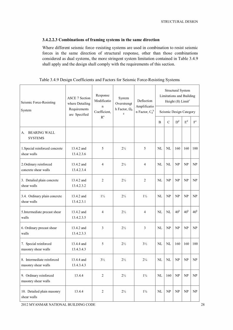
STRUCTURAL DESIGN
2012 MYANMAR NATIONAL BUILDING CODE 28
3.4.2.2.3 Combinations of framing systems in the same direction
Where different seismic force–resisting systems are used in combination to resist seismic forces in the same direction of structural response, other than those combinations considered as dual systems, the more stringent system limitation contained in Table 3.4.9 shall apply and the design shall comply with the requirements of this section.
Table 3.4.9 Design Coefficients and Factors for Seismic Force-Resisting Systems
Seismic Force-Resisting
System
ASCE 7 Section where Detailing Requirements are Specified
Response Modificatio
n Coefficient,
Ra
System Overstrength Factor, Ω0
g
Deflection Amplification Factor, Cd
b
Structural System Limitations and Building
Height (ft) Limitc
Seismic Design Category
B C Dd Ed Fe
A. BEARING WALL SYSTEMS
1.Special reinforced concrete shear walls
13.4.2 and 13.4.2.3.6
5 2½ 5 NL NL 160 160 100
2.Ordinary reinforced concrete shear walls
13.4.2 and 13.4.2.3.4
4 2½ 4 NL NL NP NP NP
3. Detailed plain concrete shear walls
13.4.2 and 13.4.2.3.2
2 2½ 2 NL NP NP NP NP
3.4. Ordinary plain concrete shear walls
13.4.2 and 13.4.2.3.1
1½ 2½ 1½ NL NP NP NP NP
5.Intermediate precast shear walls
13.4.2 and 13.4.2.3.5
4 2½ 4 NL NL 40k 40k 40k
6. Ordinary precast shear walls
13.4.2 and 13.4.2.3.3
3 2½ 3 NL NP NP NP NP
7. Special reinforced masonry shear walls
13.4.4 and 13.4.3.4.3
5 2½ 3½ NL NL 160 160 100
8. Intermediate reinforced masonry shear walls
13.4.4 and 13.4.3.4.3
3½ 2½ 2¼ NL NL NP NP NP
9. Ordinary reinforced masonry shear walls
13.4.4 2 2½ 1¾ NL 160 NP NP NP
10. Detailed plain masonry shear walls
13.4.4 2 2½ 1¾ NL NP NP NP NP

STRUCTURAL DESIGN
2012 MYANMAR NATIONAL BUILDING CODE 29
Table 3.4.9 Design coefficients and Factors for Seismic Force-Resisting Systems (Continued)
Seismic Force-Resisting
System
ASCE 7 Section where Detailing Requirements are Specified
Response Modificatio
n Coefficient,
Ra
System Overstrength Factor, Ω0
g
Deflection Amplification Factor, Cd
b
Structural System Limitations and Building
Height (ft) Limitc
Seismic Design Category
B C Dd Ed Fe
11. Ordinary plain masonry shear walls
13.4.4 1½ 2½ 1¼ NL NP NP NP NP
12. Prestressed masonry shear walls
13.4.4 1½ 2½ 1¾ NL NP NP NP NP
13. Light-framed walls sheathed with wood structural panels rated for shear resistance or steel sheets
13.4.1 and 13.4.1.3.4.2, and
13.4.5
6½ 3 4 NL NL 65 65 65
14. Light-framed walls with shear panels of all other materials
13.4.1 and 13.4.1.3.4.2, and
13.4.5
2 2½ 2 NL NL 35 NP NP
15. Light-framed wall systems using flat strap bracing
13.4.1 and 13.4.1.3.4.2, and
13.4.5
4 2 3½ NL NL 65 65 65
B. BUILDING FRAME SYSTEMS
1. Steel eccentrically braced frames, moment resisting connections at columns away from links
13.4.1 8 2 4 NL NL 160 160 100
2. Steel eccentrically braced frames, non-moment-resisting, connections at columns away from links
13.4.1 7 2 4 NL NL 160 160 100
3. Special steel concentrically braced frames
13.4.1 6 2 5 NL NL 160 160 100
4. Ordinary steel concentrically braced frames
13.4.1 3¼ 2 2½ NL NL 35j 35j NPj
5. Special reinforced concrete 13.4.2 and 6 2½ 5 NL NL 160 160 100

STRUCTURAL DESIGN
2012 MYANMAR NATIONAL BUILDING CODE 30
shear walls 13.4.2.3.6
Table 3.4.9 Design coefficients and Factors for Seismic Force-Resisting Systems (Continued)
Seismic Force-Resisting
System
ASCE 7 Section
where Detailing
Requirements
are Specified
Response
Modificatio
n
Coefficient,
Ra
System
Overstrengt
h Factor, Ω0 g
Deflection
Amplificatio
n Factor, Cdb
Structural System
Limitations and Building Seismic Design Category
B C Dd Ed Fe
6. Ordinary reinforced concrete shear walls
13.4.2 and 13.4.2.3.4
5 2½ 4½ NL NL NP NP NP
7. Detailed plain concrete shear walls
13.4.2 and 13.4.2.3.2
2 2½ 2 NL NP NP NP NP
8. Ordinary plain concrete shear walls
13.4.2 and 13.4.2.3.1
1½ 2½ 1½ NL NP NP NP NP
9. Intermediate precast shear walls 13.4.2 and 13.4.2.3.5
5 2½ 4½ NL NL 40k 40k 40k
10. Ordinary precast shear walls 13.4.2 and 13.4.2.3.3
4 2½ 4 NL NP NP NP NP
11. Composite steel and concrete eccentrically braced frames
13.4.3 8 2 4 NL NL 160 160 100
12. Composite steel and concrete concentrically braced frames
13.4.3 5 2 4½ NL NL 160 160 100
13. Ordinary composite steel and concrete braced frames
13.4.3 3 2 3 NL NL NP NP NP
13.4. Composite steel plate shear walls
13.4.3 6½ 2½ 5½ NL NL 160 160 100
15. Special composite reinforced concrete shear walls with steel elements
13.4.3 6 2½ 5 NL NL 160 160 100
16. Ordinary composite reinforced concrete shear walls with steel elements
13.4.3 5 2½ 4½ NL NL NP NP NP
17. Special reinforced masonry shear walls
13.4.4 5½ 2½ 4 NL NL 160 160 100
18.Intermidiate reinforced masonry shear walls
13.4.4 4 2½ 4 NL NL NP NP NP

STRUCTURAL DESIGN
2012 MYANMAR NATIONAL BUILDING CODE 31
19. Ordinary reinforced masonry shear walls
13.4.4 2 2½ 2 NL 160 NP NP NP
Table 3.4.9 Design coefficients and Factors for Seismic Force-Resisting Systems (Continued)
Seismic Force-Resisting
System
ASCE 7 Section
where Detailing
Requirements
are Specified
Response
Modificatio
n
Coefficient,
Ra
System
Overstrengt
h Factor, Ω0 g
Deflection
Amplificatio
n Factor, Cdb
Structural System
Limitations and Building Seismic Design Category
B C Dd Ed Fe
20. Detailed plain masonry shear walls
14 2 2½ 2 NL NP NP NP NP
21. Ordinary plain masonry shear walls
14 1½ 2½ 1¼ NL NP NP NP NP
22. Prestressed masonry shear 13.4.4 1½ 2½ 1¾ NL NP NP NP NP
23. Light-framed walls sheathed with wood structural panels rated for shear resistance or steel sheets
13.4.1, 13.4.1.3.4.2, and
13.4.5
7 2½ 4½ NL NL 65 65 65
23.4. Light-framed walls with shear panels of all other materials
13.4.1, 13.4.1.3.4.2, and
13.4.5
2½ 2½ 2½ NL NL 35 NP NP
25. Buckling-restrained braced frames, non-moment-resisting beam-column connections
13.4.1 7 2 5½ NL NL 160 160 100
26. Buckling-restrained braced frames, moment-resisting beam-column connections
13.4.1 8 2½ 5 NL NL 160 160 100
C. MOMENT-RESISTING
1. Special steel moment frames 13.4.1 and 8 3 5½ NL NL NL NL NL 2. Special steel truss moment frames
13.4.1 7 3 5½ NL NL 160 100 NP
3. Intermediate steel moment frames
12.2.5.6, 12.2.5.7,
3.4.5 3 4 NL NL 35h,i NPh NPi
4. Ordinary steel moment frames 12.2.5.6, 12.2.5.7,
3.5 3 3 NL NL NPh NPh NPi
5. Special reinforced concrete 12.2.5.5 and 8 3 5½ NL NL NL NL NL
6. Intermediate reinforced concrete 13.4.2 5 3 4½ NL NL NP NP NP
7. Ordinary reinforced concrete 13.4.2 3 3 2½ NL NP NP NP NP
8. Special composite steel and 12.2.5.5 and 8 3 5½ NL NL NL NL NL

STRUCTURAL DESIGN
2012 MYANMAR NATIONAL BUILDING CODE 32
9. Intermediate composite moment 13.4.3 5 3 4½ NL NL NP NP NP
10. Composite partially restrained 13.4.3 6 3 5½ 160 160 100 NP NP
11. Ordinary composite moment 13.4.3 3 3 5½ NL NP NP NP NP
Table 3.4.9 Design coefficients and Factors for Seismic Force-Resisting Systems (Continued)
Seismic Force-Resisting
System
ASCE 7 Section
where Detailing
Requirements
are Specified
Response
Modificatio
n
Coefficient,
Ra
System
Overstrengt
h Factor, Ω0 g
Deflection
Amplificatio
n Factor, Cdb
Structural System
Limitations and Building Seismic Design Category
B C Dd Ed Fe
D. DUAL SYSTEMS WITH SPECIAL MOMENT FRAMES CAPABLE OF RESISTING AT LEAST 25% OF PRESCRIBED
12.2.5.1
1. Steel eccentrically braced frames 13.4.1 8 2½ 4 NL NL NL NL NL
2. Special steel concentrically 13.4.1 7 2½ 5½ NL NL NL NL NL
3. Special reinforced concrete 13.4.2 7 2½ 5½ NL NL NL NL NL
4. Ordinary reinforced concrete shear walls
13.4.2 6 2½ 5 NL NL NP NP NP
5. Composite steel and concrete 13.4.3 8 2½ 4 NL NL NL NL NL
6. Composite steel and concrete concentrically braced frames
13.4.3 6 2½ 5 NL NL NL NL NL
7. Composite steel plate shear 13.4.3 7½ 2½ 6 NL NL NL NL NL
8. Special composite reinforced concrete shear walls with steel
13.4.3 7 2½ 6 NL NL NL NL NL
9. Ordinary composite reinforced concrete shear walls with steel
13.4.3 6 2½ 5 NL NL NP NP NP
10. Special reinforced masonry 13.4.4 5½ 3 5 NL NL NL NL NL
11. Intermediate reinforced 13.4.4 4 3 3½ NL NL NP NP NP
12. Buckling-restrained braced frame
13.4.1 8 2½ 5 NL NL NL NL NL
13. Special steel plate shear walls 13.4.1 8 2½ 6½ NL NL NL NL NL
E. DUAL SYSTEMS WITH INTERMEDIATE MOMENT FRAMES CAPABLE OF RESISTING AT LEAST
25% OF PRESCRIBED SEISMIC FORCES
12.2.5.1
1. Special steel concentrically braced framesf
13.4.1 6 2½ 5 NL NL 35 NP NPh,k

STRUCTURAL DESIGN
2012 MYANMAR NATIONAL BUILDING CODE 33
2. Special reinforced concrete 13.4.2 6½ 2½ 5 NL NL 160 100 100
3. Ordinary reinforced masonry 13.4.4 3 3 2½ NL 160 NP NP NP
4. Intermediate reinforced masonry 13.4.4 3½ 3 3 NL NL NP NP NP
Table 3.4.9 Design coefficients and Factors for Seismic Force-Resisting Systems (Continued)
Seismic Force-Resisting
System
ASCE 7 Section
where Detailing
Requirements
are Specified
Response
Modificatio
n
Coefficient,
Ra
System
Overstrengt
h Factor, Ω0 g
Deflection
Amplificatio
n Factor, Cdb
Structural System
Limitations and Building Seismic Design Category
B C Dd Ed Fe
5. Composite steel and concrete 13.4.3 5½ 2½ 4½ NL NL 160 100 NP
6. Ordinary composite braced 13.4.3 3½ 2½ 3 NL NL NP NP NP
7. Ordinary composite reinforced concrete shear walls with steel
13.4.3 5 3 4½ NL NL NP NP NP
8. Ordinary reinforced concrete 13.4.2 5½ 2½ 4½ NL NL NP NP NP
F. SHEAR WALL-FRAME INTERACTIVE SYSTEM WITH ORDINARY REINFORCED CONCRETE MOMENT FRAMES AND ORDINARY REINFORCED CONCRETE SHEAR WALLS
12.2.5.10 and 13.4.2
4½ 2½ 4 NL NP NP NP NP
G. CANTILEVERED COLUMN SYSTEMS DETAILED TO CONFORM TO THE REQUIREMENTS FOR:
12.2.5.2
1. Special steel moment frames 12.2.5.5 and 13.4.1
2½ 1¼ 2½ 35 35 35 35 35
2. Intermediate steel moment frames
13.4.1 1½ 1¼ 1½ 35 35 35h NPh,i
NPh,i
3. Ordinary steel moment frames 13.4.1 1¼ 1¼ 1¼ 35 35 NP NPh,i
NPh,i
3.4. Special reinforced concrete moment frames
12.2.5.5 and 13.4.2
2½ 1¼ 2½ 35 35 35 35 35
5. Intermediate concrete moment frames
13.4.2 1½ 1¼ 1½ 35 35 NP NP NP
6. Ordinary concrete moment frames
13.4.2 1 1¼ 1 35 NP NP NP NP
7. Timber frames 13.4.5 1½ 1½ 1½ 35 35 35 NP NP

STRUCTURAL DESIGN
2012 MYANMAR NATIONAL BUILDING CODE 34
H. STEEL SYSTEMS NOT SPECIFICALLY DETAILED FOR SEISMIC RESISTANCE, EXCLUDING CANTILEVER COLUMN SYSTEMS
13.4.1 3 3 3 NL NL NP NP NP
a. Response modification coefficient, R, for use throughout the standard. Note R reduces forces to a strength level, not an allowable stress level.
b. Reflection amplification factor, Cd , for use in Sections 3.4.2.8.6 and 3.4.2.8.7
c. NL = Not Limited and NP = Not Permitted. For metric units use 30.5 m for 100 ft and use 48.8 m for 160 ft. Heights are measured from the base of the structure as defined in Section 3.4.1.2.
d. See Section 3.4.2.2.5.4 for a description of building systems limited to buildings with a height of 240 ft (73.2 m) or less.
e. See Section 3.4.2.2.5.4 for building systems limited to buildings with a height of 160 ft (48.8m) or less.
f. Ordinary moment frame is permitted to be used in lieu of intermediate moment frame for Seismic Design Categories B or C.
g. The tabulated value of the overstrength factor, ∅, is permitted to be reduced by subtracting one-half for structures with flexible diaphragms, but shall not be taken as less than 2.0 for any structure.
h. See Sections 3.4.2.2.5.6 and 3.4.2.2.5.7 for limitations for steel OMFs and IMFs in structures assigned to Seismic Design Category D or E.
i. See Sections 3.4.2.2.5.8 and 3.4.2.2.5.9 for limitations for steel OMFs and IMFs in structures assigned to Seismic Design Category F.
j. Steel ordinary concentrically braced frames are permitted in single-storey buildings up to a height of 60 ft (18.3 m) where the dead load of the roof does not exceed 20 psf (0.96 kN/m2 ) and in penthouse structures.
k Increase in height to 45 ft (13.7 m) is permitted for single storey storage warehouse facilities.
3.4.2.2.3.1 R, Cd, and Ω0 values for vertical combinations.
The value of the response modification coefficient, R, used for design at any storey shall not exceed the lowest value of R that is used in the same direction at any storey above that storey. Likewise, the deflection amplification factor, Cd , and the system overstrength factor, Ω0 , used for the design at any storey shall not be less than the largest value of this factor that is used in the same direction at any storey above that storey.
EXCEPTIONS:
1) Rooftop structures not exceeding two storeys in height and 10 percent of the total structure weight.
2) Other supported structural systems with a weight equal to or less than 10 percent of the weight of the structure.

STRUCTURAL DESIGN
2012 MYANMAR NATIONAL BUILDING CODE 35
3) Detached one- and two-family dwellings of light-frame construction.
A two-stage equivalent lateral force procedure is permitted to be used for structures having a flexible upper portion above a rigid lower portion, provided that the design of the structure complies with the following:
a) The stiffness of the lower portion must be at least 10 times the stiffness of the upper portion.
b) The period of the entire structure shall not be greater than 1.1 times the period of the upper portion considered as a separate structure fixed at the base.
c) The flexible upper portion shall be designed as a separate structure using the appropriate values of R and ρ.
d) The rigid lower portion shall be designed as a separate structure using the appropriate values of R and ρ. The reactions from the upper portion shall be those determined from the analysis of the upper portion amplified by the ratio of the R/ρ of the upper portion over R/ρ of the lower portion. This ratio shall not be less than 1.0.
3.4.2.2.3.2 R, Cd, and Ω0 values for horizontal combinations
Where a combination of different structural systems is utilized to resist lateral forces in the same direction, the value of R used for design in that direction shall not be greater than the least value of R for any of the systems utilized in that direction. Resisting elements are permitted to be designed using the least value of R for the different structural systems found in each independent line of resistance if the following three conditions are met: (1) Occupancy Category I or II building, (2) two storeys or less in height, and (3) use of light-frame construction or flexible diaphragms. The value of R used for design of diaphragms in such structures shall not be greater than the least value for any of the systems utilized in the same direction.
The deflection amplification factor, Cd , and the system over strength factor, Ω0 , in the direction under consideration at any storey shall not be less than the largest value of this factor for the R factor used in the same direction being considered.
3.4.2.2.4 Combination framing detailing requirements
Structural components common to different framing systems used to resist seismic motions in any direction shall be designed using the detailing requirements of Section 3.4.2 required by the highest response modification coefficient, R, of the connected framing systems.
3.4.2.2.5 System specific requirements
The structural framing system shall also comply with the following system specific requirements of this section.
3.4.2.2.5.1 Dual system
For a dual system, the moment frames shall be capable of resisting at least 25 percent of the design seismic forces. The total seismic force resistance is to be provided by the combination of the moment frames and the shear walls or braced frames in proportion to their rigidities.
3.4.2.2.5.2 Cantilever column systems

STRUCTURAL DESIGN
2012 MYANMAR NATIONAL BUILDING CODE 36
Cantilever column systems are permitted as indicated in Table 3.4.9 and as follows. The axial load on individual cantilever column elements calculated in accordance with the load combinations of Section 2.1.2 shall not exceed 15 percent of the design strength of the column to resist axial loads alone, or for allowable stress design, the axial load stress on individual cantilever column elements, calculated in accordance with the load combinations of Section 2.1.3 shall not exceed 15 percent of the permissible axial stress.
Foundation and other elements used to provide overturning resistance at the base of cantilever column elements shall have the strength to resist the load combinations with overstrength factor of Section 3.4.2.4.3.2.
3.4.2.2.5.3 Inverted pendulum-type structures
Regardless of the structural system selected, inverted pendulums as defined in Section 3.4.1.2, shall comply with this section. Supporting columns or piers of inverted pendulum-type structures shall be designed for the bending moment calculated at the base determined using the procedures given in Section 3.4.2.8 and varying uniformly to a moment at the top equal to one-half the calculated bending moment at the base.
3.4.2.2.5.4 Increased building height limit for steel braced frames and special reinforced concrete shear walls
The height limits in Table 3.4.9 are permitted to be increased from160 ft (50 m) to 240 ft (75 m) for structures assigned to Seismic Design Categories D or E and from 100 ft (30 m) to 160 ft (50 m) for structures assigned to Seismic Design Category F that have steel braced frames or special reinforced concrete cast-in-place shear walls and that meet both of the following requirements:
1) The structure shall not have an extreme torsional irregularity as defined in Table 3.4.9 (horizontal structural irregularity Type 1b).
2) The braced frames or shear walls in any one plane shall resist no more than 60 percent of the total seismic forces in each direction, neglecting accidental torsional effects.
3.4.2.2.5.5 Special moment frames in structures assigned to seismic design categories D through F
For structures assigned to Seismic Design Categories D, E, or F, a special moment frame that is used but not required by Table 3.4.9 shall not be discontinued and supported by a more rigid system with a lower response modification coefficient, R, unless the requirements of Sections 3.4.2.3.3.2 and 3.4.2.3.3.4 are met. Where a special moment frame is required by Table 3.4.9, the frame shall be continuous to the foundation.
3.4.2.2.5.6 Single-storey steel ordinary and intermediate moment frames in structures assigned to Seismic Design Category D or E
Single-storey steel ordinary moment frames and intermediate moment frames in structures assigned to Seismic Design Category D or E are permitted up to a height of 65 ft (20 m) where the dead load supported by and tributary to the roof does not exceed 20 psf (0.96 kN/m2 ). In addition, the dead loads tributary to the moment
frame, of the exterior wall more than 35 ft above the base shall not exceed 20 psf (0.96 kN/m2 ).

STRUCTURAL DESIGN
2012 MYANMAR NATIONAL BUILDING CODE 37
3.4.2.2.5.7 Other steel ordinary and intermediate moment frames in structures assigned to Seismic Design Category D or E
Steel ordinary moment frames in structures assigned to Seismic Design Category D or E not meeting the limitations set forth in Section 3.4.2.2.5.6 are permitted within light-frame construction up to a height of 35 ft (10.6 m) where neither the roof nor the floor dead load supported by and tributary to the moment frames exceeds 35 psf (1.68 kN/m2 ). In addition, the dead load of the exterior walls tributary to the moment frame shall not exceed 20 psf (0.96 kN/m2 ). Steel intermediate moment frames in structures assigned to Seismic Design Category D or E not meeting the limitations set forth in Section 3.4.2.2.5.6 permitted as follows:
1) In Seismic Design Category D, intermediate moment frames are permitted to a height of 35 ft (10.6 m).
2) In Seismic Design Category E, intermediate moment frames are permitted to a height of 35 ft (10.6 m) provided neither the roof nor the floor dead load supported by and tributary to the moment frames exceeds 35 psf (1.68 kN/m2). In addition, the dead load of the exterior walls tributary to the moment frame shall not exceed 20 psf (0.96 kN/m2 ).
Figure 3.4.2 Flexible diaphragm
3.4.2.2.5.8 Single-storey steel ordinary and intermediate moment frames in structures assigned to Seismic Design Category F
Single-storey steel ordinary moment frames and intermediate moment frames in structures assigned to Seismic Design Category F are permitted up to a height of 65 ft (20 m) where the dead load supported by and tributary to the roof does not exceed 20 psf (0.96 kN/m2 ). In addition, the dead loads of the exterior walls tributary to the moment frame shall not exceed 20 psf (0.96 kN/m2 ).
3.4.2.2.5.9 Other steel intermediate moment frame limitations in structures assigned to Seismic Design Category F
MAXIMUM DIAPHRAGM DEFLECTION (MDD)
AVERAGE DRIFT OF VERTICAL ELEMENT (ADVE) S
De
SEISMIC LOADING

STRUCTURAL DESIGN
2012 MYANMAR NATIONAL BUILDING CODE 38
In addition to the limitations for steel intermediate moment frames in structures assigned to Seismic Design Category E as set forth in Section 3.4.2.2.5.7, steel intermediate moment frames in structures assigned to Seismic Design Category F are permitted in light-frame construction.
3.4.2.2.5.10 Shear wall-frame interactive systems
The shear strength of the shear walls of the shear wall-frame interactive system shall be at least 75 percent of the design storey shear at each storey. The frames of the shear wall-frame interactive system shall be capable of resisting at least 25 percent of the design storey shear in every storey.
3.4.2.3 Diaphragm flexibility, configuration irregularities, and redundancy
3.4.2.3.1 Diaphragm flexibility
The structural analysis shall consider the relative stiffnesses of diaphragms and the vertical elements of the seismic force–resisting system. Unless a diaphragm can be idealized as either flexible or rigid in accordance with Sections 3.4.2.3.1.1, 3.4.2.3.1.2, or 3.4.2.3.1.3, the structural analysis shall explicitly include consideration of the stiffness of the diaphragm (i.e., semirigid modeling assumption).
3.4.2.3.1.1 Flexible diaphragm condition
Diaphragms constructed of untopped steel decking or wood structural panels are permitted to be idealized as flexible in structures in which the vertical elements are steel or composite steel and concrete braced frames, or concrete, masonry, steel, or composite shear walls. Diaphragms of wood structural panels or untopped steel decks in one- and two-family residential buildings of light-frame construction shall also be permitted to be idealized as flexible.
3.4.2.3.1.2 Alternatives to ASCE 7
The following provisions shall be permitted as alternatives to the relevant provisions of ASCE 7. Diaphragms constructed of wood structural panels or untopped steel decking shall also be permitted to be idealized as flexible, provided all of the following conditions are met:
1) Toppings of concrete or similar materials are not placed over wood structural panel diaphragms except for nonstructural toppings no greater than 1½ inches (38 mm) thick.
2) Each line o f vertical elements of the lateral-force-resisting system complies with the allowable storey drift of Table 3.4.8.
3) Vertical elements of the lateral-force-resisting system are light-framed walls sheathed with wood structural panels rated for shear resistance or steel sheets.
4) Portions of wood structural panel diaphragms that cantilever beyond the vertical elements of the lateral-force-resisting system are designed in accordance with Section 2305.2.5 of the International Building Code.
3.4.2.3.1.3 Rigid diaphragm condition
Diaphragms of concrete slabs or concrete-filled metal deck with span-to-depth ratios of 3 or less in structures that have no horizontal irregularities are permitted to be idealized as rigid.

STRUCTURAL DESIGN
2012 MYANMAR NATIONAL BUILDING CODE 39
3.4.2.3.1.4 Calculated flexible diaphragm condition
Diaphragms not satisfying the conditions of Sections 3.4.2.3.1.1 or 3.4.2.3.1.2 are permitted to be idealized as flexible where the computed maximum in-plane deflection of the diaphragm under lateral load is more than two times the average storey drift of adjoining vertical elements of the seismic force–resisting system of the associated storey under equivalent tributary lateral load as shown in Fig. 3.4.2. The loadings used for this calculation shall be those prescribed by Section 3.4.2.8.
3.4.2.3.2 Irregular and regular classification
Structures shall be classified as regular or irregular based upon the criteria in this section. Such classification shall be based on horizontal and vertical configurations.
3.4.2.3.2.1 Horizontal irregularity
Structures having one or more of the irregularity types listed in Table 3.4.10 shall be designated as having horizontal structural irregularity.
Such structures assigned to the seismic design categories listed in Table 3.4.10 shall comply with the requirements in the sections referenced in that table.
3.4.2.3.2.2 Vertical irregularity
Structures having one or more of the irregularity types listed in Table 3.4.11 shall be designated as having vertical irregularity. Such structures assigned to the Seismic Design Categories listed in Table 3.4.11 shall comply with the requirements in the sections referenced in that table.
EXCEPTIONS:
1) Vertical structural irregularities of Types 1a, 1b, or 2 in Table 3.4.11 do not apply where no storey drift ratio under design lateral seismic force is greater than 130 percent of the storey drift ratio of the next storey above. Torsional effects need not be considered in the calculation of storey drifts. The storey drift ratio relationship for the top two storeys of the structure are not required to be evaluated.
2) Irregularities of Types 1a, 1b, and 2 in Table 3.4.11 are not required to be considered for one-storey buildings in any Seismic Design Category or for two-storey buildings assigned to Seismic Design Categories B, C, or D.
3.4.2.3.3 Limitations and additional requirements for systems with structural irregularities
3.4.2.3.3.1 Prohibited horizontal and vertical irregularities for Seismic Design Categories D through F
Structures assigned to Seismic Design Category E or F having horizontal irregularity Type 1b of Table 3.4.10 or vertical irregularities Type 1b, 5a, or 5b of Table 3.4.11 shall not be permitted. Structures assigned to Seismic Design Category D having vertical irregularity Type 5b of Table 3.4.11 shall not be permitted.

STRUCTURAL DESIGN
2012 MYANMAR NATIONAL BUILDING CODE 40
Table 3.4.10 Horizontal Structural Irregularities
Irregularity Type and Description Reference Section Seismic Design Category Application
1a. Torsional Irregularity is defined to exist where the maximum storey drift, computed including accidental torsion, at one end of the structure transverse to an axis is more than 1.2 times the average of the storey drifts at the two ends of the structure. Torsional irregularity requirements in the reference sections apply only to structures in which the diaphragms are rigid or semirigid.
3.4.2.3.3.4 3.4.2.8.3.4.3
3.4.2.7.3 3.4.2.12.1
Table 3.4.13 3.4.3.2.2
D, E, and F C, D, E, and F
B, C, D, E, and F C, D, E, and F
D, E, and F B, C, D, E, and F
1b. Extreme Torsional Irregularity is defined to exist where the maximum storey drift, computed including accidental torsion, at one end of the structure transverse to an axis is more than 1.4 times the average of the storey drifts at the two ends of the structure. Extreme torsional irregularity requirements in the reference sections apply only to structures in which the diaphragms are rigid or semirigid.
3.4.2.3.3.1 3.4.2.3.3.4 3.4.2.7.3 3.4.2.8.3.4.3 3.4.2.12.1 Table 3.4.13 3.4.3.2.2
E and F D B, C, and D C and D C and D D B, C, and D
2. Reentrant Corner Irregularity is defined to exist where both plan projections of the structure beyond a reentrant corner are greater than 15% of the plan dimension of the structure in the given direction.
3.4.2.3.3.4 Table 3.4.13
D, E, and F D, E, and F
3. Diaphragm Discontinuity Irregularity is defined to exist where there are diaphragms with abrupt discontinuities or variations in stiffness, including those having cutout or open areas greater than 50% of the gross enclosed diaphragm area, or changes in effective diaphragm stiffness of more than 50% from one storey to the next.
3.4.2.3.3.4 Table 3.4.13
D, E, andF D, E, and F
3.4. Out-of-Plane Offsets Irregularity is defined to exist where there are discontinuities in a lateral force-resistance path, such as out-of-plane offsets of the vertical elements.
3.4.2.3.3.4 3.4.2.3.3.3 3.4.2.7.3 Table 3.4.13 3.4.3.2.2
D, E, and F B, C, D, E, and F B, C, D, E, and F D, E, and F B, C, D, E, and F
5. Nonparallel Systems-Irregularity is defined to exist where the vertical lateral force-resisting elements are not parallel to or symmetric about the major orthogonal axes of the seismic force–resisting system.
3.4.2.5.3 3.4.2.7.3 Table 3.4.13 3.4.3.2.2
C, D, E, and F B, C, D, E, and F D, E, and F B, C, D, E, and F
STRUCTURAL DESIGN
2012 MYANMAR NATIONAL BUILDING CODE 41
3.4.2.3.3.2 Extreme weak storeys
Structures with a vertical irregularity Type 5b as defined in Table 3.4.11, shall not be over two storeys or 30 ft (9 m) in height.
EXCEPTION: The limit does not apply where the “weak” storey is capable of resisting a total seismic force equal to Ω0 times the design force prescribed in Section 3.4.2.8
3.4.2.3.3.3 Elements supporting discontinuous walls or frames
Columns, beams, trusses, or slabs supporting discontinuous walls or frames of structures having horizontal irregularity Type 4 of Table 3.4.10 or vertical irregularity Type 4 of Table 3.4.11 shall have the design strength to resist the maximum axial force that can develop in accordance with the load combinations with overstrength factor of Section 3.4.2.4.3.2. The connections of such discontinuous elements to the supporting members shall be adequate to transmit the forces for which the discontinuous elements were required to be designed.
3.4.2.3.3.4 Increase in forces due to irregularities for Seismic Design Categories D through F
For structures assigned to Seismic Design Category D, E, or F and having a horizontal structural irregularity of Type 1a, 1b, 2, 3, or 4 in Table 3.4.10 or a vertical structural irregularity of Type 4 in Table 3.4.11, the design forces determined from Section 3.4.2.8.1 shall be increased 25 percent for connections of diaphragms to vertical elements and to collectors and for connections of collectors to the vertical elements. Collectors and their connections also shall be designed for these increased forces unless they are designed for the load combinations with overstrength factor of Section 3.4.2.4.3.2, in accordance with Section 3.4.2.10.2.1.
3.4.2.3.4 Redundancy
A redundancy factor, ρ, shall be assigned to the seismic force–resisting system in each of two orthogonal directions for all structures in accordance with this section.

STRUCTURAL DESIGN
2012 MYANMAR NATIONAL BUILDING CODE 42
Table 3.4.11 Vertical Structural Irregularities
Irregularity Type and Description Reference Section
Seismic Design Category
Application
1a. Stiffness-Soft Storey Irregularity is defined to exist where there is a storey in which the lateral stiffness is less than 70% of that in the storey above or less
than 80% of the average stiffness of the three storeys above.
Table 3.4.13 D, E, and F
1b. Stiffness-Extreme Soft Storey Irregularity is defined to exist where there is a storey in which the lateral stiffness is less than 60% of that in the storey
above or less than 70% of the average stiffness of the three storeys above.
3.4.2.3.3.1 Table 3.4.13
E and F D, E, and F
2. Weight (Mass) Irregularity is defined to exist where the effective mass of any storey is more than 150% of the effective mass of an adjacent storey. A
roof that is lighter than the floor below need not be considered.
Table 3.4.13 D, E, and F
3. Vertical Geometric Irregularity is defined to exist where the horizontal dimension of the seismic force–resisting system in any storey is more than
130% of that in an adjacent storey.
Table 3.4.13 B ,D, E, and F
4. In-Plane Discontinuity in Vertical Lateral Force-Resisting Element Irregularity is defined to exist where an in-plane offset of the lateral force-
resisting elements is greater than the length of those elements or there exists a reduction in stiffness of the resisting element in the storey below.
3.4.2.3.3.3 3.4.2.3.3.4
Table 3.4.13
B, C, D, E, and F D, E, and F
D, E, and F
5a. Discontinuity in Lateral Strength–Weak Storey Irregularity is defined to exist where the storey lateral strength is less than 80% of that in the storey above. The storey lateral strength is the total lateral strength of all seismic-
resisting elements sharing the storey shear for the direction under consideration.
3.4.2.3.3.1 Table 3.4.13
E and F D, E, and F
5b. Discontinuity in Lateral Strength–Extreme Weak Storey Irregularity is defined to exist where the storey lateral strength is less than 65% of that in
the storey above. The storey strength is the total strength of all seismic-resisting elements sharing the storey shear for the direction under
consideration.
3.4.2.3.3.1 3.4.2.3.3.2 Table 4.13
D, E, and F B and C
D, E, and F

STRUCTURAL DESIGN
2012 MYANMAR NATIONAL BUILDING CODE 43
3.4.2.3.4.1 Conditions where value of ρ is 1.0
The value of ρ is permitted to equal 1.0 for the following:
1) Structures assigned to Seismic Design Category B or C.
2) Drift calculation and P-delta effects.
3) Design of nonstructural components.
4) Design of nonbuilding structures that are not similar to buildings.
5) Design of collector elements, splices, and their connections for which the load combinations with overstrength factor of Section 3.4.2.4.3.2 are used.
6) Design of members or connections where the load combinations with overstrength of Section 3.4.2.4.3.2 are required for design.
7) Diaphragm loads determined using Eq. (3.4.37).
8) Structures with damping systems
3.4.2.3.4.2 Redundancy factor, ρ , for Seismic Design Categories D through F
For structures assigned to Seismic Design Category D, E, or F, ρ shall equal 1.3 unless one of the following two conditions is met, whereby ρ is permitted to be taken as 1.0:
a) Each storey resisting more than 35 percent of the base shear in the direction of interest shall comply with Table 3.4.12.
b) Structures that are regular in plan at all levels provided that the seismic force–resisting systems consist of at least two bays of seismic force–resisting perimeter framing on each side of the structure in each orthogonal direction at each storey resisting more than 35 percent of the base shear. The number of bays for a shear wall shall be calculated as the length of shear wall divided by the storey height or two times the length of shear wall divided by the storey height for light- framed construction.
3.4.2.4 Seismic load effects and combinations
3.4.2.4.1 Applicability
All members of the structure, including those not part of the seismic force–resisting system, shall be designed using the seismic load effects of Section 3.4.2.4 unless otherwise exempted by this standard. Seismic load effects are the axial, shear, and flexural member forces resulting from application of horizontal and vertical seismic forces as set forth in Section 3.4.2.4.2. Where specifically required, seismic load effects shall be modified to account for system overstrength, as set forth in Section 3.4.2.4.3.

STRUCTURAL DESIGN
2012 MYANMAR NATIONAL BUILDING CODE 44
Lateral Force-Resisting Element Requirement
Braced Frames Removal of an individual brace, or connection thereto, would not result in more than a 33% reduction in storey strength, nor does the resulting system have an extreme torsional
irregularity (horizontal structural irregularity Type 1b).
Moment Frames Loss of moment resistance at the beam-to-column connections at both ends of a single beam would not result in more than a 33% reduction in storey strength, nor does the resulting
system have an extreme torsional irregularity (horizontal structural irregularity Type 1b).
Shear Walls or Wall Pier with a height-to-length ratio of
greater than 1.0
Removal of a shear wall or wall pier with a height-to-length ratio greater than 1.0 within any storey, or collector connections thereto, would not result in more than a 33% reduction
in storey strength, nor does the resulting system have an extreme torsional irregularity (horizontal structural irregularity Type 1b).
Cantilever Columns Loss of moment resistance at the base connections of any single cantilever column would not result in more than a 33% reduction in storey strength, nor does the resulting system
have an extreme torsional irregularity (horizontal structural irregularity Type 1b).
Other No requirements
Table 3.4.12 Requirements for Each Storey Resisting More Than 35% Of The Base Shear
3.4.2.4.2 Seismic load effect
The seismic load effect, E , shall be determined in accordance with the following:
1) For use in load combination 5 in Section 2.1.2.2 or load combinations 5 and 6 in Section 2.1.3.1, E shall be determined in accordance with Eq. (3.4.13) as follows:
E = Eh + Ev Eq. (3.4.13)
2) For use in load combination 7 in Section 2.1.2.2 or load combination 8 in Section 2.1.3.1, E shall be determined in accordance with Eq. (3.4.14) as follows:
E = Eh − Ev Eq. (3.4.14)
where
E = seismic load effect
Eh = effect of horizontal seismic forces as defined in Section 3.4.2.4.2.1

STRUCTURAL DESIGN
2012 MYANMAR NATIONAL BUILDING CODE 45
Ev = effect of vertical seismic forces as defined in Section 3.4.2.4.2.2
3.4.2.4.2.1 Horizontal seismic load effect
The horizontal seismic load effect, Eh , shall be determined in accordance with Eq.(3.4.15) as follows:
Eh = ρ QE Eq. (3.4.15)
where
QE = effects of horizontal seismic forces from V or Fp . Where required in Sections 3.4.2.5.3 and 3.4.2.5.4, such effects shall result from application of horizontal forces simultaneously in two directions at right angles to each other.
ρ = redundancy factor, as defined in Section 3.4.2.3.4
3.4.2.4.2.2 Vertical seismic load effect
The vertical seismic load effect, Ev , shall be determined in accordance with Eq. (3.4.16) as follows:
Ev = 0.2 SDS D Eq. (3.4.16)
where
SDS = design spectral response acceleration parameter at short periods obtained from Section 3.4.1.4.4
D = effect of dead load
EXCEPTIONS: The vertical seismic load effect, Ev , is permitted to be taken as zero for either of the following conditions:
1) In Eqs. (3.4.13), (3.4.14), (3.4.17), and (3.4.18) where SDS is equal to or less than 0.125.
2) In Eq. (3.4.14) where determining demands on the soil-structure interface of foundations.
3.4.2.4.2.3 Seismic load combinations
Where the prescribed seismic load effect, E , defined in Section 3.4.2.4.2 is combined with the effects of other loads as set forth in Section 2, the following seismic load combinations for structures not subject to flood or atmospheric ice loads shall be used in lieu of the seismic load combinations in either Section 2.1.2.2 or 2.1.3.1.
Basic combinations for strength design (see Sections 2.1.2.2 and 1.1.2 for notation)
5. (1.2 + 0.2 SDS ) D + ρ QE + L
7. (0.9 − 0.2 SDS ) D + ρ QE + 1.6 H
NOTES:
1) The load factor on L in combination 5 is permitted to equal 0.5 for all occupancies in which L0 in Table 2.2 is less than or equal to 100 psf (3.4.79 kN/m2), with the exception of garages or areas occupied as places

STRUCTURAL DESIGN
2012 MYANMAR NATIONAL BUILDING CODE 46
of public assembly.
2) The load factor on H shall be set equal to zero in combination 7 if the structural action due to H counteracts that due to E . Where lateral earth pressure provides resistance to structural actions from other forces, it shall not be included in H but shall be included in the design resistance.
Basic combinations for allowable stress design (see Sections 2.1.3.1 and 1.1.2 for notation).
5. (1.0 + 0.14 SDS ) D + H + F + 0.7ρ QE
6. (1.0 + 0.105 SDS ) D + H + F + 0.525ρ QE + 0.75L+ 0.75(Lr or R)
8. (0.6 − 0.14SDS ) D + 0.7ρ QE + H
3.4.2.4.3 Seismic load effect including overstrength factor
Where specifically required, conditions requiring overstrength factor applications shall be determined in accordance with the following:
1) For use in load combination 5 in Section 2.1.2.2 or load combinations 5 and 6 in Section 2.1.3.1, E shall be taken equal to Em as determined in accordance with Eq. (3.4.17) as follows:
Em = Emh + Ev Eq. (3.4.17)
2) For use in load combination 7 in Section 2.1.2.2 or load combination 8 in Section 2.1.3.1, E shall be taken equal to Em as determined in accordance with Eq. (3.4.18) as follows:
Em = Emh − Ev Eq. (3.4.18)
where
Em = seismic load effect including overstrength factor
Emh = effect of horizontal seismic forces including structural overstrength as defined in Section 3.4.2.4.3.1
Ev = vertical seismic load effect as defined in Section 3.4.2.4.2.2
3.4.2.4.3.1 Horizontal seismic load effect with overstrength factor
The horizontal seismic load effect with overstrength factor, Emh , shall be determined in accordance with Eq. (3.4.19) as follows:
Emh = Ωo QE Eq. (3.4.19)
where
QE = effects of horizontal seismic forces from V as specified in Sections 3.4.2.8.1 . Where required in Sections 3.4.2.5.3 and 3.4.2.5.4, such effects shall result from application of horizontal forces simultaneously in two directions at right angles to each other.
Ωo = overstrength factor
EXCEPTION: The value of Emh need not exceed the maximum force that can develop in the element as determined by a rational, plastic mechanism analysis or nonlinear response analysis utilizing realistic expected values of material strengths.

STRUCTURAL DESIGN
2012 MYANMAR NATIONAL BUILDING CODE 47
3.4.2.4.3.2 Load combinations with overstrength factor
Where the seismic load effect with overstrength, Em , defined in Section 3.4.2.4.3 is combined with the effects of other loads as set forth in Section 2, the following seismic load combination for structures not subject to flood or atmospheric ice loads shall be used in lieu of the seismic load combinations
in either Section 2.1.2.2 or 2.1.3.1:
Basic combinations for strength design with overstrength factor (see Sections 2.1.2.2 and 1.1.2 for notation)
5. (1.2 + 0.2SDS ) D + o QE + L
7. (0.9 − 0.2SDS ) D + o QE + 1.6 H
NOTES:
1) The load factor on L in combination 5 is permitted to equal 0.5 for all occupancies in which L0 in Table 2.2 is less than or equal to 100 psf (3.4.79 kN/m2 ), with the exception of garages or areas occupied as places of public assembly.
2) The load factor on H shall be set equal to zero in combination 7 if the structural action due to H counteracts that due to E. Where lateral earth pressure provides resistance to structural actions from other forces, it shall not be included in H but shall be included in the design resistance.
Basic combinations for allowable stress design with overstrength factor (see Sections 2.1.3.1 and 1.1.2 for notation).
5. (1.0 + 0.14SDS ) D + H + F + 0.7 Ωo QE
6. (1.0 + 0.105SDS ) D + H + F + 0.525 Ωo QE + 0.75L+ 0.75(Lr or R)
8. (0.6 − 0.14SDS ) D + 0.7 Ωo QE + H
3.4.2.4.3.3 Allowable stress increase for load combinations with overstrength.
Where allowable stress design methodologies are used with the seismic load effect defined in Section 3.4.2.4.3 applied in load combinations 5, 6, or 8 of Section 2.1.3.1, allowable stresses are permitted to be determined using an allowable stress increase of 1.2. This increase shall not be combined with increases in allowable stresses or load combination reductions otherwise permitted by this standard or the material reference document except that combination with the duration of load increases permitted in AF&PA NDS is permitted.
3.4.2.4.4 Minimum upward force for horizontal cantilevers for Seismic Design Categories D through F
In structures assigned to Seismic Design Category D, E, or F, horizontal cantilever structural components shall be designed for a minimum net upward force of 0.2 times the dead load in addition to the applicable load combinations of Section 3.4.2.4.
3.4.2.5 Direction of loading
3.4.2.5.1 Direction of loading criteria
The directions of application of seismic forces used in the design shall be those which will produce the most critical load effects. It is permitted to satisfy this requirement using

STRUCTURAL DESIGN
2012 MYANMAR NATIONAL BUILDING CODE 48
the procedures of Section 3.4.2.5.2 for Seismic Design Category B, Section 3.4.2.5.3 for Seismic Design Category C, and Section 3.4.2.5.4 for Seismic Design Categories D, E, and F.
3.4.2.5.2 Seismic design category B
For structures assigned to Seismic Design Category B, the design seismic forces are per- mitted to be applied independently in each of two orthogonal directions and orthogonal interaction effects are permitted to be neglected.
3.4.2.5.3 Seismic design category C
Loading applied to structures assigned to Seismic Design Category C shall, as a minimum, conform to the requirements of Section 3.4.2.5.2 for Seismic Design Category B and the requirements of this section. Structures that have horizontal structural irregularity Type 5 in Table 3.4.10 shall use one of the following procedures:
a) Orthogonal combination procedure
The structure shall be analyzed using the equivalent lateral force analysis procedure of Section 3.4.2.8, the modal response spectrum analysis procedure of Section 3.4.2.9, or the linear response history procedure of Section 3.4.3.1, as permitted under Section 3.4.2.6, with the loading applied independently in any two orthogonal directions and the most critical load effect due to direction of application of seismic forces on the structure is permitted to be assumed to be satisfied if components and their foundations are designed for the following combination of prescribed loads: 100 percent of the forces for one direction plus 30 percent of the forces for the perpendicular direction; the combination requiring the maximum component strength shall be used.
b) Simultaneous application of orthogonal ground motion
The structure shall be analyzed using the linear response history procedure of Section 3.4.3.1 or the nonlinear response history procedure of Section 3.4.3.2, as permitted by Section 3.4.2.6, with orthogonal pairs of ground motion acceleration histories applied simultaneously.
3.4.2.5.4 Seismic design categories D through F
Structures assigned to Seismic Design Category D, E, or F shall, as a minimum, conform to the requirements of Section 3.4.2.5.3. In addition, any column or wall that forms part of two or more intersecting seismic force–resisting systems and is subjected to axial load due to seismic forces acting along either principal plan axis equaling or exceeding 20 percent of the axial design strength of the column or wall shall be designed for the most critical load effect due to application of seismic forces in any direction. Either of the procedures of Section 3.4.2.5.3 a or b are permitted to be used to satisfy this requirement. Except as required by Section 3.4.2.7.3, 2-D analyses are permitted for structures with flexible diaphragms.
3.4.2.6 Analysis procedure selection
The structural analysis required by Section 3.4.2 shall consist of one of the types permitted in Table 3.4.13, based on the structure’s Seismic Design Category, structural system, dynamic properties, and regularity, or with the approval of the authority having jurisdiction, an alternative generally accepted procedure is permitted to be used. The analysis procedure
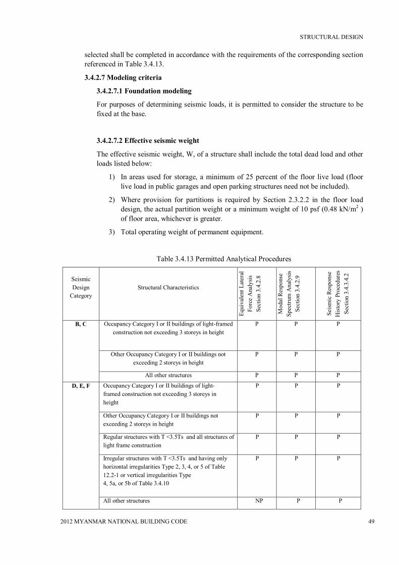
STRUCTURAL DESIGN
2012 MYANMAR NATIONAL BUILDING CODE 49
selected shall be completed in accordance with the requirements of the corresponding section referenced in Table 3.4.13.
3.4.2.7 Modeling criteria
3.4.2.7.1 Foundation modeling
For purposes of determining seismic loads, it is permitted to consider the structure to be fixed at the base.
3.4.2.7.2 Effective seismic weight
The effective seismic weight, W, of a structure shall include the total dead load and other loads listed below:
1) In areas used for storage, a minimum of 25 percent of the floor live load (floor live load in public garages and open parking structures need not be included).
2) Where provision for partitions is required by Section 2.3.2.2 in the floor load design, the actual partition weight or a minimum weight of 10 psf (0.48 kN/m2 ) of floor area, whichever is greater.
3) Total operating weight of permanent equipment.
Table 3.4.13 Permitted Analytical Procedures
Seismic Design
Category
Structural Characteristics
Equi
vale
nt L
ater
al
Forc
e A
naly
sis
Sect
ion
3.4.
2.8
Mod
al R
espo
nse
Spec
trum
Ana
lysi
s Se
ctio
n 3.
4.2.
9
Seis
mic
Res
pons
e H
isto
ry P
roce
dure
s Se
ctio
n 3.
4.3.
4.2
B, C Occupancy Category I or II buildings of light-framed construction not exceeding 3 storeys in height
P P P
Other Occupancy Category I or II buildings not exceeding 2 storeys in height
P P P
All other structures P P P
D, E, F Occupancy Category I or II buildings of light-framed construction not exceeding 3 storeys in height
P P P
Other Occupancy Category I or II buildings not exceeding 2 storeys in height
P P P
Regular structures with T <3.5Ts and all structures of light frame construction
P P P
Irregular structures with T <3.5Ts and having only horizontal irregularities Type 2, 3, 4, or 5 of Table 12.2-1 or vertical irregularities Type 4, 5a, or 5b of Table 3.4.10
P P P
All other structures NP P P

STRUCTURAL DESIGN
2012 MYANMAR NATIONAL BUILDING CODE 50
NOTE: P: Permitted ; NP: Not Permitted
3.4.2.7.3 Structural modeling
A mathematical model of the structure shall be constructed for the purpose of determining member forces and structure displacements resulting from applied loads and any imposed displacements or P-Delta effects. The model shall include the stiffness and strength of elements that are significant to the distribution of forces and deformations in the structure and represent the spatial distribution of mass and stiffness throughout the structure.
Structures that have horizontal structural irregularity Type 1a, 1b, 4, or 5 of Table 3.4.10 shall be analyzed using a 3-D representation. Where a 3-D model is used, a minimum of three dynamic degrees of freedom consisting of translation in two orthogonal plan directions and torsional rotation about the vertical axis shall be included at each level of the structure. Where the diaphragms have not been classified as rigid or flexible in accordance with Section 3.4.2.3.1, the model shall include representation of the diaphragm’s stiffness characteristics and such additional dynamic degrees of freedom as are required to account for the participation of the diaphragm in the structure’s dynamic response. In addition, the model shall comply with the following:
a) Stiffness properties of concrete and masonry elements shall consider the effects of cracked sections.
b) For steel moment frame systems, the contribution of panel zone deformations to overall storey drift shall be included.
3.4.2.7.4 Interaction effects
Moment-resisting frames that are enclosed or adjoined by elements that are more rigid and not considered to be part of the seismic force–resisting system shall be designed so that the action or failure of those elements will not impair the vertical load and seismic force–resisting capability of the frame. The design shall provide for the effect of these rigid elements on the structural system at structural deformations corresponding to the design storey drift (∆ ) as determined in Section 3.4.2.8.6. In addition, the effects of these elements shall be considered where determining whether a structure has one or more of the irregularities defined in Section 3.4.2.3.2.
3.4.2.8 Equivalent lateral force procedure
3.4.2.8.1 Seismic base shear
The seismic base shear, V, in a given direction shall be determined in accordance with the following equation:
V = Cs W Eq. (3.4.20)
where

STRUCTURAL DESIGN
2012 MYANMAR NATIONAL BUILDING CODE 51
Cs = the seismic response coefficient determined in accordance with Section 3.4.2.8.1.1
W = the effective seismic weight per Section 3.4.2.7.2.
3.4.2.8.1.1 Calculation of seismic response coefficient
The seismic response coefficient, Cs, shall be determined in accordance with Eq. (3.4.21).
Cs = Eq. (3.4.21)
where
SDS = the design spectral response acceleration parameter in the short period range as determined from Section 3.4.1.3.4.3.4.
R = the response modification factor in Table 3.4.9
I = the occupancy importance factor determined in accordance with Section 3.4.1.5.1
The value of Cs computed in accordance with Eq. (3.4.21) need not exceed the following:
Cs = for T ≤ TL Eq. (3.4.22)
Cs = for T > TL Eq. (3.4.23)
Cs shall not be less than
Cs =0.01 Eq. (3.4.24)
In addition, for structures located where S1 is equal to or greater than 0.6g, Cs shall not be less than
Cs = .
Eq. (3.4.25)
Table 3.4.14 Coefficient for Upper Limit On Calculated Period
Design Spectral Response Acceleration Parameter at 1 s, SD1
Coefficient Cu
≥ 0.4 1.4 0.3 1.4 0.2 1.5
0.15 1.6 ≤ 0.1 1.7
where I and R are as defined in Section 3.4.2.8.1.1 and
SD1 = the design spectral response acceleration parameter at a period of 1.0 s, as determined from Section 3.4.1.4.4

STRUCTURAL DESIGN
2012 MYANMAR NATIONAL BUILDING CODE 52
Structure Type C x Moment-resisting frame systems in which the frames resist 100% of the required seismic force and are not enclosed or adjoined by components that are more rigid and will prevent the frames from deflecting where subjected to seismic forces:
Steel moment-resisting frames 0.028
(0.0724)a
0.8
Concrete moment-resisting frames 0.016
(0.0466)a
0.9
Eccentrically braced steel frames 0.03
(0.0731)a
0.75
All other structural systems 0.02
(0.0488)a
0.75
T = the fundamental period of the structure (s) determined in Section 3.4.2.8.2
TL = long-period transition period (s) determined in Section 3.4.1.4.5
S1 = the mapped maximum considered earthquake spectral response acceleration parameter determined in accordance with Section 3.4.1.4.1.
3.4.2.8.1.2 Soil structure interaction reduction
A soil structure interaction reduction is permitted where determined using generally accepted procedures approved by the authority having jurisdiction.
3.4.2.8.1.3 Maximum Ss value in determination of Cs
For regular structures five storeys or less in height and having a period, T, of 0.5 s or less, Cs is permitted to be calculated using a value of 1.5 for SS .
3.4.2.8.2 Period determination
The fundamental period of the structure, T, in the direction under consideration shall be established using the structural properties and deformational characteristics of the resisting elements in a properly substantiated analysis. The fundamental period, T, shall not exceed the product of the coefficient for upper limit on calculated period (Cu) from Table 3.4.14 and the approximate fundamental period, Ta , determined from Eq. (3.4.26). As an alternative to performing an analysis to determine the fundamental period, T, it is permitted to use the approximate building period, Ta , calculated in accordance with Section 3.4.2.8.2.1, directly.
3.4.2.8.2.1 Approximate fundamental period
The approximate fundamental period (Ta), in s, shall be determined from the following equation:
Ta = 퐶 ℎ Eq.(3.4.26)
where hn is the height in ft above the base to the highest level of the structure and the coefficients Ct and x are determined from Table 3.4.15.qhyhkjk
Table 3.4.15 Values of Approximate Period Parameters Ct And x

STRUCTURAL DESIGN
2012 MYANMAR NATIONAL BUILDING CODE 53
a Metric equivalents are shown in parentheses.
Alternatively, it is permitted to determine the approximate fundamental period (Ta), in s, from the following equation for structures not exceeding 12 storeys in height in which the seismic force–resisting system consists entirely of concrete or steel moment resisting frames and the storey height is at least 10 ft (3 m):
Ta = 0.1 N Eq. (3.4.27)
where
N = number of storeys.
The approximate fundamental period, Ta , in s for masonry or concrete shear wall structures is permitted to be determined from Eq. (3.4.28) as follows:
Ta = . ℎ푛 Eq. (3.4.28)
where hn is as defined in the preceding text and Cw is calculated from Eq. (3.4.29) as follows:
퐶 = ∑.
Eq. (3.4.29)
where
AB = area of base of structure, ft2
Ai = web area of shear wall “i” in ft2
Di = length of shear wall “i” in ft
hi = height of shear wall “i” in ft
x = number of shear walls in the building effective in resisting lateral forces in the direction under consideration.
3.4.2.8.3 Vertical distribution of seismic forces
The lateral seismic force ( Fx ) (kip or kN) induced at any level shall be determined from the following equations:
Fx = Cvx V Eq. (3.4.30)
and
퐶 = ∑
Eq. (3.4.31)

STRUCTURAL DESIGN
2012 MYANMAR NATIONAL BUILDING CODE 54
where
Cvx = vertical distribution factor,
V = total design lateral force or shear at the base of the structure (kip or kN)
wi and wx = the portion of the total effective seismic weight of the structure (W ) located or assigned to Level i or x
hi and hx = the height (ft or m) from the base to Level i or x
k = an exponent related to the structure period as follows:
for structures having a period of 0.5 s or less, k = 1
for structures having a period of 2.5 s or more, k = 2
for structures having a period between 0.5 and 2.5s, k shall be 2 or shall be determined by linear interpolation between 1 and 2
3.4.2.8.4 Horizontal distribution of forces
The seismic design storey shear in any storey (Vx ) (kip or kN) shall be determined from the following equation:
Vx = ∑ 퐹 Eq. (3.4.20)
Where
Fi = the portion of the seismic base shear (Vx ) (kip or kN) induced at Level i.
The seismic design storey shear (Vx ) (kip or kN) shall be distributed to the various vertical elements of the seismic force– resisting system in the storey under consideration based on the relative lateral stiffness of the vertical resisting elements and the diaphragm.
3.4.2.8.4.1 Inherent torsion
For diaphragms that are not flexible, the distribution of lateral forces at each level shall consider the effect of the inherent torsional moment, Mt , resulting from eccentricity between the locations of the centre of mass and the centre of rigidity. For flexible diaphragms, the distribution of forces to the vertical elements shall account for the position and distribution of the masses supported.
3.4.2.8.4.2 Accidental torsion
Where diaphragms are not flexible, the design shall include the inherent torsional moment ( Mt ) (kip or kN) resulting from the location of the structure masses plus the accidental torsional moments ( Mta) (kip or kN) caused by assumed displacement of the centre of mass each way from its actual location by a distance equal to 5 percent of the dimension of the structure perpendicular to the direction of the applied forces.
Where earthquake forces are applied concurrently in two orthogonal directions, the required 5 percent displacement of the centre of mass need not be applied in both of the orthogonal directions at the same time, but shall be applied in the direction that produces the greater effect.
3.4.2.8.4.3 Amplification of accidental torsional moment
Structures assigned to Seismic Design Category C, D, E, or F, where Type 1a or 1b torsional irregularity exists as defined in Table 3.4.10 shall have the effects accounted for by multiplying Mta at each level by a torsional amplification factor ( Ax ) as

STRUCTURAL DESIGN
2012 MYANMAR NATIONAL BUILDING CODE 55
illustrated in Fig. 3.4.3 and determined from the following equation:
Ax = . Eq. (3.4.33)
where
δmax = the maximum displacement at Level x (in. or mm) computed assuming Ax = 1
δavg = the average of the displacements at the extreme points of the structure at Level x computed assuming Ax = 1 (in. or mm)
EXCEPTION: The accidental torsional moment need not be amplified for structures of light-frame construction.
The torsional amplification factor ( Ax ) is not required to exceed 3.0. The more severe loading for each element shall be considered for design.
3.4.2.8.5 Overturning
The structure shall be designed to resist overturning effects caused by the seismic forces determined in Section 3.4.2.8.3.
3.4.2.8.6 Storey drift determination
The design storey drift (∆) shall be computed as the difference of the deflections at the centres of mass at the top and bottom of the storey under consideration. See Fig. 3.4.4. Where allowable stress design is used, ∆ shall be computed using the strength level seismic forces specified in Section 3.4.2.8 without reduction for allowable stress design.
Figure 3.4.3 Torsional Amplification Factor, Ax
The deflections of Level x at the centre of the mass (δx) (in. or mm) shall be determined
훿
훿
훿 + 훿 훿 = 2 퐴 =
훿1.2훿

STRUCTURAL DESIGN
2012 MYANMAR NATIONAL BUILDING CODE 56
in accordance with the following equation:
δx = Eq. (3.4.34)
where
Cd = the deflection amplification factor in Table 3.4.9
δxe = the deflections determined by an elastic analysis
I = the importance factor determined in accordance with Section 3.4.1.5.1
3.4.2.8.6.1 Minimum base shear for computing drift
The elastic analysis of the seismic force–resisting system shall be made using the prescribed seismic design forces of Section 3.4.2.8.
3.4.2.8.6.2 Period for computing drift
For determining compliance with the story drift limits of Section 3.4.2.12.1, it is permitted to determine the elastic drifts, (δxe), using seismic design forces based on the computed fundamental period of the structure without the upper limit (CuTa) specified in Section 3.4.2.8.2.
3.4.2.8.7 P-Delta effects
P-delta effects on storey shears and moments, the resulting member forces and moments, and the storey drifts induced by these effects are not required to be considered where the stability coefficient (θ) as determined by the following equation is equal to or less than 0.10:
휃 = ∆ Eq. (3.4.35)
Storey Level 2
F2 = strength-level design earthquake force
훿 = elastic displacement computed under strength-level design earthquake forces
훿 = 퐶 훿 퐼⁄ = amplified displacement
∆ = (훿 − 훿 )퐶 퐼⁄ ≤∆ (Table 3.4.16)
Storey Level 1
F1 = strength-level design earthquake force
훿 = elastic displacement computed under strength-level design earthquake forces
훿 = 퐶 훿 퐼⁄ = amplified displacement
∆ =훿 ≤∆ (Table 3.4.16)
∆ L⁄ = Storeydriftratio
∆ = Storey drift
훿 = Total displacement
퐿
퐿

STRUCTURAL DESIGN
2012 MYANMAR NATIONAL BUILDING CODE 57
Figure 3.4.4 Storey drift determination
where
Px = the total vertical design load at and above Level x (kip or kN); where computing Px, no individual load factor need exceed 1.0
∆ = the design storey drift as defined in Section 3.4.2.8.6 occurring simultaneously with Vx (in. or mm)
Vx = the seismic shear force acting between Levels x and x −1 (kip or kN)
hsx = the storey height below Level x (in. or mm)
Cd = the deflection amplification factor in Table 3.4.9.
The stability coefficient (θ ) shall not exceed θmax determined as follows:
휃 = . ≤ 0.25 Eq. (3.4.36)
where β is the ratio of shear demand to shear capacity for the storey between Levels x and x−1. This ratio is permitted to be conservatively taken as 1.0.
Where the stability coefficient (훉) is greater than 0.10 but less than or equal to 훉max, the incremental factor related to P-delta effects on displacements and member forces shall be determined by rational analysis. Alternatively, it is permitted to multiply displacements and member forces by 1.0/(1−훉).
Where θ is greater than 훉max , the structure is potentially unstable and shall be redesigned.
Where the P-delta effect is included in an automated analysis, Eq. (3.4.36) shall still be satisfied, however, the value of θ computed from Eq. (3.4.35) using the results of the P-delta analysis is permitted to be divided by (1 + θ ) before checking Eq. (3.4.36).
3.4.2.9 Modal response spectrum analysis
3.4.2.9.1 Number of modes
An analysis shall be conducted to determine the natural modes of vibration for the structure. The analysis shall include a sufficient number of modes to obtain a combined modal mass participation of at least 90 percent of the actual mass in each of the orthogonal horizontal directions of response considered by the model.
3.4.2.9.2 Modal response parameters
The value for each force- related design parameter of interest, including storey drifts, support forces, and individual member forces for each mode of response shall be computed using the properties of each mode and the response spectra defined in either Section 3.4.1.4.5 divided by the quantity 푹
푰 . The value for displacement and drift
quantities shall be multiplied by the quantity 푪풅푰
.
3.4.2.9.3 Combined response parameters
The value for each parameter of interest calculated for the various modes shall be combined using either the square root of the sum of the squares method (SRSS) or the complete quadratic combination method (CQC), in accordance with ASCE 3.4. The CQC

STRUCTURAL DESIGN
2012 MYANMAR NATIONAL BUILDING CODE 58
method shall be used for each of the modal values or where closely spaced modes that have significant cross-correlation of translational and torsional response.
3.4.2.9.4 Scaling design values of combined response
A base shear (V) shall be calculated in each of the two orthogonal horizontal directions using the calculated fundamental period of the structure T in each direction and the procedures of Section 3.4.2.8, except where the calculated fundamental period exceeds (Cu) (Ta ),then (Cu)(Ta ) shall be used in lieu of T in that direction. Where the combined response for the modal base shear (Vt ) is less than 85 percent of the calculated base shear (V ) using the equivalent lateral force procedure, the forces, but not the drifts, shall be multiplied by 0.85 푽
푽풕 :
where
V = the equivalent lateral force procedure base shear, calculated in accordance with this section and Section 3.4.2.8.
Vt = the base shear from the required modal combination
3.4.2.9.5 Horizontal shear distribution
The distribution of horizontal shear shall be in accordance with the requirements of Section 3.4.2.8.4.3 except that amplification of torsion per Section 3.4.2.8.4 is not required where accidental torsional effects are included in the dynamic analysis model.
3.4.2.9.6 P-Delta effects
The P-delta effects shall be determined in accordance with Section 3.4.2.8.7. The base shear used to determine the storey shears and the storey drifts shall be determined in accordance with Section 3.4.2.8.6.
3.4.2.9.7 Soil structure interaction reduction
A soil structure interaction reduction is permitted where determined using generally accepted procedures approved by the authority having jurisdiction.
3.4.2.10 Diaphragms, Chords, and Collectors
3.4.2.10.1 Diaphragm design
Diaphragms shall be designed for both the shear and bending stresses resulting from design forces. At diaphragm discontinuities, such as openings and reentrant corners, the design shall assure that the dissipation or transfer of edge (chord) forces combined with other forces in the diaphragm is within shear and tension capacity of the diaphragm.
3.4.2.10.1.1 Diaphragm design forces
Floor and roof diaphragms shall be designed to resist design seismic forces from the structural analysis, but shall not be less than that determined in accordance with Eq. (3.4.37) as follows:
Fpx =∑∑ wpx Eq. (3.4.37)
where
Fpx = the diaphragm design force

STRUCTURAL DESIGN
2012 MYANMAR NATIONAL BUILDING CODE 59
Fi = the design force applied to Level i
wi = the weight tributary to Level i
wpx = the weight tributary to the diaphragm at Level x
The force determined from Eq. (3.4.37) need not exceed 0.4SDS Iwpx , but shall not be less than 0.2SDS Iwpx .Where the diaphragm is required to transfer design seismic force from the vertical resisting elements above the diaphragm to other vertical resisting elements below the diaphragm due to offsets in the placement of the elements or to changes in relative lateral stiffness in the vertical elements, these forces shall be added to those determined from Eq. (3.4.37). The redundancy factor, ρ , applies to the design of diaphragms in structures assigned to Seismic Design Category D, E, or F. For inertial forces calculated in accordance with Eq. (3.4.37), the redundancy factor shall equal 1.0. For transfer forces, the redundancy factor, ρ, shall be the same as that used for the structure. For structures having horizontal or vertical structural irregularities of the types indicated in Section 3.4.2.3.3.4, the requirements of that section shall also apply.
Figure 3.4.5 Collectors
3.4.2.10.2 Collector elements
Collector elements shall be provided that are capable of transferring the seismic forces originating in other portions of the structure to the element providing the resistance to those forces.
3.4.2.10.2.1 Collector elements requiring load combinations with overstrength factor for Seismic Design Categories C through F
In structures assigned to Seismic Design Category C, D, E, or F, collector elements (see Fig. 3.4.5), splices, and their connections to resisting elements shall resist the load combinations with overstrength of Section 3.4.2.4.3.2.
EXCEPTION: In structures or portions thereof braced entirely by light- frame shear walls, collector elements, splices, and connections to resisting elements need only be designed to resist forces in accordance with Section 3.4.2.10.1.1.
3.4.2.11 Structural walls and their anchorage
3.4.2.11.1 Design for out-of-plane forces
FULL LENGTH SHEAR WALL (NO COLLECTOR REQUIRED)
COLLECTOR ELEMENT TO TRANSFER FORCE BETWEEN DIAPHRAGM AND SHEAR WALL
SHEAR WALL AT STAIRWELL

STRUCTURAL DESIGN
2012 MYANMAR NATIONAL BUILDING CODE 60
Structural walls and their anchorage shall be designed for a force normal to the surface equal to 0.4SDSI times the weight of the structural wall with a minimum force of 10 percent of the weight of the structural wall. Interconnection of structural wall elements and connections to supporting framing systems shall have sufficient ductility, rotational capacity, or sufficient strength to resist shrinkage, thermal changes, and differential foundation settlement when combined with seismic forces.
3.4.2.11.2 Anchorage of concrete or masonry structural walls
The anchorage of concrete or masonry structural walls to supporting construction shall provide a direct connection capable of resisting the greater of the following:
a) The force set forth in Section 3.4.2.11.1.
b) A force of 400 SDS I lb/ linear ft (5.84 SDS I kN/m) of wall
c) 280 lb/linear ft (3.4.09 kN/m) of wall
Structural walls shall be designed to resist bending between anchors where the anchor spacing exceeds 4 ft (1,219 mm).
3.4.2.11.2.1 Anchorage of concrete or masonry structural walls to flexible diaphragms
In addition to the requirements set forth in Section 3.4.2.11.2, anchorage of concrete or masonry structural walls to flexible diaphragms in structures assigned to Seismic Design Category C, D, E, or F shall have the strength to develop the out-of-plane force given by Eq. (3.4.38):
Fp = 0.8SDS IWp Eq. (3.4.38)
where
Fp = the design force in the individual anchors
SDS = the design spectral response acceleration parameter at short periods per Section 3.4.1.4.4
I = the occupancy importance factor per Section 3.4.1.5.1
Wp = the weight of the wall tributary to the anchor
3.4.2.11.2.2 Additional requirements for diaphragms in structures assigned to Seismic Design Categories C through F
3.4.2.11.2.2.1 Transfer of anchorage forces into diaphragm
Diaphragms shall be provided with continuous ties or struts between diaphragm chords to distribute these anchorage forces into the diaphragms. Diaphragm connections shall be positive, mechanical, or welded. Added chords are permitted to be used to form subdiaphragms to transmit the anchorage forces to the main continuous cross-ties. The maximum length-to-width ratio of the structural subdiaphragm shall be 2.5 to 1. Connections and anchorages capable of resisting the prescribed forces shall be provided between the diaphragm and the attached components. Connections shall extend into the diaphragm a sufficient distance to develop the force transferred into the diaphragm.
3.4.2.11.2.2.2 Steel elements of structural wall anchorage system
The strength design forces for steel elements of the structural wall anchorage

STRUCTURAL DESIGN
2012 MYANMAR NATIONAL BUILDING CODE 61
system, with the exception of anchor bolts and reinforcing steel, shall be increased by 1.4 times the forces otherwise required by this section.
3.4.2.11.2.2.3 Wood diaphragms
In wood diaphragms, the continuous ties shall be in addition to the diaphragm sheathing. Anchorage shall not be accomplished by use of toe nails or nails subject to withdrawal nor shall wood ledgers or framing be used in cross-grain bending or cross-grain tension. The diaphragm sheathing shall not be considered effective as providing the ties or struts required by this section.
3.4.2.11.2.2.4 Metal deck diaphragms
In metal deck diaphragms, the metal deck shall not be used as the continuous ties required by this section in the direction perpendicular to the deck span.
3.4.2.11.2.2.5 Embedded straps
Diaphragm to structural wall anchorage using embedded straps shall be attached to, or hooked around, the reinforcing steel or otherwise terminated so as to effectively transfer forces to the reinforcing steel.
3.4.2.11.2.2.6 Eccentrically loaded anchorage system
Where elements of the wall anchorage system are loaded eccentrically or are not perpendicular to the wall, the system shall be designed to resist all components of the forces induced by the eccentricity.
Table 3.4.16 Allowable Storey Drift, ∆a a.b
Structure Occupancy Category
I or II III IV
Structures, other than masonry shear wall structures, 4 storeys or less with interior walls, partitions, ceilings and exterior wall systems that have been designed to
accommodate the storey drifts.
0.025hsxc
0.020hsx
0.015hsx
Masonry cantilever shear wall structures d 0.010hsx 0.010hsx 0.010hsx
Other masonry shear wall structures 0.007hsx 0.007hsx 0.007hsx
All other structures 0.020hsx 0.020hsx 0.020hsx
a hsx is the storey height below Level x .
b For seismic force–resisting systems comprised solely of moment frames in Seismic Design Categories D, E, and F, the allowable storey drift shall comply with the requirements of Section 3.4.2.12.1.1.

STRUCTURAL DESIGN
2012 MYANMAR NATIONAL BUILDING CODE 62
c There shall be no drift limit for single-storey structures with interior walls, partitions, ceilings, and exterior wall systems that have been designed to accommodate the storey drifts. The structure separation requirement of Section 3.4.2.12.3 is not waived.
d Structures in which the basic structural system consists of masonry shear walls designed as vertical elements cantilevered from their base or foundation support which are so constructed that moment transfer between shear walls (coupling) is negligible.
3.4.2.11.2.2.7 Walls with pilasters
Where pilasters are present in the wall, the anchorage force at the pilasters shall be calculated considering the additional load transferred from the wall panels to the pilasters. However, the minimum anchorage force at a floor or roof shall not be reduced.
3.4.2.12 Drift and deformation
3.4.2.12.1 Storey drift limit
The design storey drift (∆ ) as determined in Sections 3.4.2.8.6, 3.4.2.9.2, or 3.4.3.1
shall not exceed the allowable story drift ( ∆a ) as obtained from Table 3.4.16 for any storey. For structures with significant torsional deflections, the maximum drift shall include torsional effects. For structures assigned to Seismic Design Category C, D, E, or F having horizontal irregularity Types 1a or 1b of Table 3.4.10, the design storey drift, ∆ , shall be computed as the largest difference of the deflections along any of the edges of the structure at the top and bottom of the storey under consideration.
3.4.2.12.1.1 Moment frames in structures assigned to Seismic Design Categories D through F
For seismic force–resisting systems comprised solely of moment frames in structures assigned to Seismic Design Categories D, E, or F, the design storey drift (∆ ) shall not exceed ∆a /ρ for any storey. ρ shall be determined in accordance with Section 3.4.2.3.4.2.
3.4.2.12.2 Diaphragm deflection
The deflection in the plane of the diaphragm, as determined by engineering analysis, shall not exceed the permissible deflection of the attached elements. Permissible deflection shall be that deflection that will permit the attached element to maintain its structural integrity under the individual loading and continue to support the prescribed loads.
3.4.2.12.3 Building separation
All portions of the structure shall be designed and constructed to act as an integral unit in resisting seismic forces unless separated structurally by a distance sufficient to avoid damaging contact under total deflection (δx ) as determined in Section 3.4.2.8.6.
3.4.2.12.4 Deformation compatibility for Seismic Design Categories D through F
For structures assigned to Seismic Design Category D, E, or F, every structural component not included in the seismic force–resisting system in the direction under consideration shall be designed to be adequate for the gravity load effects and the seismic forces resulting from displacement to the design storey drift (∆ ) as determined in

STRUCTURAL DESIGN
2012 MYANMAR NATIONAL BUILDING CODE 63
accordance with Section 3.4.2.8.6 (see also Section 3.4.2.12.1).
EXCEPTION: Reinforced concrete frame members not designed as part of the seismic force–resisting system shall comply with Section 21.9 of ACI 318-05.
Where determining the moments and shears induced in components that are not included in the seismic force–resisting system in the direction under consideration, the stiffening effects of adjoining rigid structural and nonstructural elements shall be considered and a rational value of member and restraint stiffness shall be used.
3.4.2.13 Foundation Design
3.4.2.13.1 Design basis
The design basis for foundations shall be as set forth in Section 3.4.2.1.5.
3.4.2.13.2 Materials of construction
Materials used for the design and construction of foundations shall comply with the requirements of material sections. Design and detailing of concrete piles shall comply with PART 4 of this Code.
3.4.2.13.3 Foundation load-deformation characteristics
Where foundation flexibility is included for the linear analysis procedures in Section 3.4.2, the load-deformation characteristics of the foundation-soil system (foundation stiffness) shall be modeled in accordance with the requirements of this section. The linear load-deformation behaviour of foundations shall be represented by an equivalent linear stiffness using soil properties that are compatible with the soil strain levels associated with the design earthquake motion. The strain-compatible shear modulus, G , and the associated strain-compatible shear wave velocity, vs, needed for the evaluation of equivalent linear stiffness shall be determined based on soil structure interaction for seismic design or a site-specific study. A 50 percent increase and decrease in stiffness shall be incorporated in dynamic analyses unless smaller variations can be justified based on field measurements of dynamic soil properties or direct measurements of dynamic foundation stiffness. The largest values of response shall be used in design.
3.4.2.13.4 Reduction of foundation overturning
Overturning effects at the soil-foundation interface are permitted to be reduced by 25 percent for foundations of structures that satisfy both of the following conditions:
a) The structure is designed in accordance with the Equivalent Lateral Force Analysis as set forth in Section 3.4.2.8.
b) The structure is not an inverted pendulum or cantilevered column type structure.
Overturning effects at the soil-foundation interface are permitted to be reduced by 10 percent for foundations of structures designed in accordance with the modal analysis requirements of Section 3.4.2.9.
3.4.2.13.5 Requirements for structures assigned to Seismic Design Category C
In addition to the requirements of Section 3.4.1.8.2, the following foundation design requirements shall apply to structures assigned to Seismic Design Category C.
3.4.2.13.5.1 Pole-type structures

STRUCTURAL DESIGN
2012 MYANMAR NATIONAL BUILDING CODE 64
Where construction employing posts or poles as columns embedded in earth or embedded in concrete footings in the earth is used to resist lateral loads, the depth of embedment required for posts or poles to resist seismic forces shall be determined by means of the design criteria established in the foundation investigation report.
3.4.2.13.5.2 Foundation ties
Individual pile caps, drilled piers, or caissons shall be interconnected by ties. All ties shall have a design strength in tension or compression at least equal to a force equal to 10 percent of SDS times the larger pile cap or column factored dead plus factored live load unless it is demonstrated that equivalent restraint will be provided by reinforced concrete beams within slabs on grade or reinforced concrete slabs on grade or confinement by competent rock, hard cohesive soils, very dense granular soils, or other approved means.
3.4.2.13.5.3 Pile anchorage requirements
In addition to the requirements of Section 3.4.2.2.3.1, anchorage of piles shall comply with this section. Where required for resistance to uplift forces, anchorage of steel pipe (round HSS sections), concrete-filled steel pipe or H piles to the pile cap shall be made by means other than concrete bond to the bare steel section.
EXCEPTION: Anchorage of concrete-filled steel pipe piles is permitted to be accomplished using deformed bars developed into the concrete portion of the pile.
3.4.2.13.6 Requirements for structures assigned to Seismic Design Categories D through F
In addition to the requirements of Sections 3.4.1.8.2, and 3.4.1.8.3, the following foundation design requirements shall apply to structures assigned to Seismic Design Category D, E, or F. Design and construction of concrete foundation components shall conform to the requirements of ACI 318-05, Section 21.8, except as modified by the requirements of this section.
EXCEPTION: Detached one- and two-family dwellings of light-frame construction not exceeding two storeys in height above grade need only comply with the requirements for Sections 3.4.1.8.2, 3.4.1.8.3 (Items 2 through 4), 3.4.2.13.2, and 3.4.2.13.5.
3.4.2.13.6.1 Pole-type structures
Where construction employing posts or poles as columns embedded in earth or embedded in concrete footings in the earth is used to resist lateral loads, the depth of embedment required for posts or poles to resist seismic forces shall be determined by means of the design criteria established in the foundation investigation report.
3.4.2.13.6.2 Foundation ties
Individual pile caps, drilled piers, or caissons shall be interconnected by ties. In addition, individual spread footings founded on Site Class E or F shall be interconnected by ties. All ties shall have a design strength in tension or compression at least equal to a force equal to 10 percent of SDS times the larger pile cap or column factored dead plus factored live load unless it is demonstrated that equivalent restraint will be provided by reinforced concrete beams within slabs on grade or reinforced concrete slabs on grade or confinement by competent rock, hard cohesive soils, very dense granular soils, or other approved means.
3.4.2.13.6.3 General pile design requirement

STRUCTURAL DESIGN
2012 MYANMAR NATIONAL BUILDING CODE 65
Piling shall be designed and constructed to withstand deformations from earthquake ground motions and structure response. Deformations shall include both free-field soil strains (without the structure) and deformations induced by lateral pile resistance to structure seismic forces, all as modified by soil-pile interaction.
3.4.2.13.6.4 Batter piles
Batter piles and their connections shall be capable of resisting forces and moments from the load combinations with overstrength factor of Section 3.4.2.4.3.2 or 3.4.2.14.3.2.2. Where vertical and batter piles act jointly to resist foundation forces as a group, these forces shall be distributed to the individual piles in accordance with their relative horizontal and vertical rigidities and the geometric distribution of the piles within the group.
3.4.2.13.6.5 Pile anchorage requirements
In addition to the requirements of Section 3.4.2.3.5.3, anchorage of piles shall comply with this section. Design of anchorage of piles into the pile cap shall consider the combined effect of axial forces due to uplift and bending moments due to fixity to the pile cap. For piles required to resist uplift forces or provide rotational restraint, anchorage into the pile cap shall be capable of developing the following:
1) In the case of uplift, the lesser of the nominal tensile strength of the longitudinal reinforcement in a concrete pile, or the nominal tensile strength of a steel pile, or 1.3 times the pile pullout resistance, or the axial tension force resulting from the load combinations with overstrength factor of Section 3.4.2.4.3.2 or 3.4.2.14.3.2.2. The pile pullout resistance shall be taken as the ultimate frictional or adhesive force that can be developed between the soil and the pile plus the pile weight.
2) In the case of rotational restraint, the lesser of the axial and shear forces and moments resulting from the load combinations with overstrength factor of Section 3.4.2.4.3.2 or 3.4.2.14.3.2.2 or development of the full axial, bending, and shear nominal strength of the pile.
3.4.2.13.6.6 Splices of pile segments
Splices of pile segments shall develop the nominal strength of the pile section, but the splice need not develop the nominal strength of the pile in tension, shear, and bending where it has been designed to resist axial and shear forces and moments from the load combinations with overstrength factor of Section 3.4.2.4.3.2 or 3.4.2.14.3.2.2.
3.4.2.13.6.7 Pile soil interaction
Pile moments, shears, and lateral deflections used for design shall be established considering the interaction of the shaft and soil. Where the ratio of the depth of embedment of the pile to the pile diameter or width is less than or equal to 6, the pile is permitted to be assumed to be flexurally rigid with respect to the soil.
3.4.2.13.6.8 Pile group effects

STRUCTURAL DESIGN
2012 MYANMAR NATIONAL BUILDING CODE 66
Pile group effects from soil on lateral pile nominal strength shall be included where pile centre-to-centre spacing in the direction of lateral force is less than eight pile diameters or widths. Pile group effects on vertical nominal strength shall be included where pile centre-to-centre spacing is less than three pile diameters or widths.
3.4.2.14 Alternative simplified structural design criteria for simple bearing wall or building frame systems
3.4.2.14.1 General
3.4.2.14.1.1 Simplified design procedure
The procedures of this section are permitted to be used in lieu of other analytical procedures in Section 3.4.2 for the analysis and design of simple buildings with bearing wall or building frame systems, subject to all of the limitations listed in Section 3.4.2.14.1.1. Where these procedures are used, the Seismic Design Category shall be determined from Table 3.4.15 using the value of SDS from Section 3.4.2.14.8.1.
Figure 3.4.6 Notation used in torsion check for nonflexible diaphragms
Axis
2
Y-ax
is
d
d=
d
k
k
e
k
Centre of Rigidity
Centre of Mass
d d
Wall 3
k k
Axis 1
Wall 2
X- axis
b
b

STRUCTURAL DESIGN
2012 MYANMAR NATIONAL BUILDING CODE 67
Table 3.4.17 Design Coefficients and Factors for Seismic Force-Resisting Systems for
Simplified Design Procedure
Seismic Force–Resisting System ASCE 7 Section where
Detailig Requirements are Specified
Response Modification
Coefficient, Ra
Limitationsb
Seismic Design Category
B C D, E A. BEARING WALL SYSTEMS
1. Special reinforced concrete shear walls 13.4.2 and 13.4.2.3.6 5 P P P 2. Ordinary reinforced concrete shear walls 13.4.2 and 13.4.2.3.4 4 P P NP 3. Detailed plain concrete shear walls 13.4.2 and 13.4.2.3.2 2 P NP NP 4. Ordinary plain concrete shear walls 13.4.2 and 13.4.2.3.1 1½ P NP NP
5. Intermediate precast shear walls 13.4.2 and 13.4.2.3.5 4 P P 406. Ordinary precast shear walls 13.4.2 and 13.4.2.3.3 3 P NP NP 7. Special reinforced masonry shear walls 13.4.4 and 13.4.3.4.3 5 P P P 8. Intermediate reinforced masonry shear
walls 13.4.4 and 13.4.3.4.3 3½ P P NP
Table 3.4.17 Design Coefficients and Factors for Seismic Force-Resisting Systems for
Simplified Design Procedure (Continued)
Seismic Force–Resisting System ASCE 7 Section where
Detailig Requirements are Specified
Response Modification
Coefficient, Ra
Limitationsb
Seismic Design Category
B C D, E 9. Ordinary reinforced masonry shear walls 13.4.4 2 P NP NP
10. Detailed plain masonry shear walls 13.4.4 2 P NP NP 11. Ordinary plain masonry shear walls 13.4.4 1½ P NP NP
12. Prestressed masonry shear walls 13.4.4 1½ P NP NP
13. Light-frame walls sheathed with wood structural panels rated for shear resistance or steel sheets
13.4.1, 13.4.1.3.4.2, and 13.4.5
6½ P P P
13.4. Light-framed walls with shear panels of all other materials
13.4.1, 13.4.1.3.4.2, and 13.4.5
2 P P NPd
15. Light-framed wall systems using flat strapbracing
13.4.1, 13.4.1.3.4.2, and 13.4.5
4 P P P
B. BUILDING FRAME SYSTEMS 1. Steel eccentrically braced frames,
moment-resisting connections at columns away from links
13.4.1 8 P P P
2. Steel eccentrically braced frames, non-moment-resisting connections at columns away from links
13.4.1 7 P P P
3. Special steel concentrically braced frames 13.4.1 6 P P P
3.4. Ordinary steel concentrically braced frames
13.4.1 3¼ P P P
5. Special reinforced concrete shear walls 13.4.2 and 13.4.2.3.6 6 P P P 6. Ordinary reinforced concrete shear walls 13.4.2 and 13.4.2.3.4 5 P P NP 7. Detailed plain concrete shear walls 13.4.2 and 13.4.2.3.2 2 P NP NP

STRUCTURAL DESIGN
2012 MYANMAR NATIONAL BUILDING CODE 68
8. Ordinary plain concrete shear walls 13.4.2 and 13.4.2.3.1 1½ P NP NP
9. Intermediate precast shear walls 13.4.2 and 13.4.2.3.5 5 P P 4010. Ordinary precast shear walls 13.4.2 and 13.4.2.3.3 4 P NP NP
11. Composite steel and concrete eccentrically braced frames
13.4.3 8 P P P
12. Composite steel and concrete concentrically braced frames
13.4.3 5 P P P
13. Ordinary composite steel and concrete braced frames
13.4.3 3 P P NP
13.4. Composite steel plate shear walls 13.4.3 6½ P P P
15. Special composite reinforced concrete shear walls with steel elements
13.4.3 6 P P P
16. Ordinary composite reinforced concrete shear walls with steel elements
13.4.3 5 P P NP
17. Special reinforced masonry shear walls 13.4.4 5 ½ P P P
18. Intermediate reinforced masonry shear walls
13.4.4 4 P P NP
19. Ordinary reinforced masonry shear walls 13.4.4 2 P NP NP
Table 3.4.17 Design Coefficients and Factors for Seismic Force-Resisting Systems for
Simplified Design Procedure (Continued)
Seismic Force–Resisting System ASCE 7 Section where
Detailig Requirements are Specified
Response Modification
Coefficient, Ra
Limitationsb
Seismic Design Category
B C D, E 20. Detailed plain masonry shear walls 13.4.4 2 P NP NP
21. Ordinary plain masonry shear walls 13.4.4 1 ½ P NP NP
22. Prestressed masonry shear walls 13.4.4 1 ½ P NP NP
23. Light-frame walls sheathed with wood structural panels rated for shear resistance or steel sheets
13.4.1, 13.4.1.3.4.2, and 13.4.5
7 P P P
23.4. Light-framed walls with shear panels of all other materials
13.4.1, 13.4.1.3.4.2, and 13.4.5
2 ½ P P NPd
25. Buckling-restrained braced frames, non-moment-resisting beam-column connections
13.4.1 7 P P P
26. Buckling-restrained braced frames, moment-resisting beam-column connections
13.4.1 8 P P P
27. Special steel plate shear wall 13.4.1 7 P P P
a Response modification coefficient, R, for use throughout the standard.
b P = permitted; NP = not permitted.
c Light-framed walls with shear panels of all other materials not permitted in Seismic Design Category E.

STRUCTURAL DESIGN
2012 MYANMAR NATIONAL BUILDING CODE 69
d Light-framed walls with shear panels of all other materials permitted up to 35 ft in height in Seismic Design Category D and not permitted in Seismic Design Category E.
The simplified design procedure is permitted to be used if the following limitations are met:
1) The structure shall qualify for Occupancy Category I or II in accordance with Table 1.2.
2) The site class shall not be class E or F.
3) The structure shall not exceed three storeys in height above grade.
4) The seismic-force resisting system shall be either a bearing wall system or building frame system, as indicated in Table 3.4.17.
5) The structure shall have at least two lines of lateral resistance in each of two major axis directions.
6) At least one line of resistance shall be provided on each side of the centre of mass in each direction.
7) For structures with flexible diaphragms, overhangs beyond the outside line of shear walls or braced frames shall satisfy the following:
a ≤ d/5 Eq.(3.4.39)
where
a = the distance perpendicular to the forces being considered from the extreme edge of the diaphragm to the line of vertical resistance closest to that edge
d = the depth of the diaphragm parallel to the forces being considered at the line of vertical resistance closest to the edge
8) For buildings with a diaphragm that is not flexible, the distance between the centre of rigidity and the centre of mass parallel to each major axis shall not exceed 15 percent of the greatest width of the diaphragm parallel to that axis. In addition, the following shall be satisfied for each major axis direction:
∑ 푘 푑 +∑ 푘 푑 ≥ 2.5 (0.05+ )푏 ∑ 푘 Eq. (3.4.40)
where (see Fig. 3.4.6):
k1i = the lateral load stiffness of wall “i ” or braced frame “i ” parallel to major axis1
k2j = the lateral load stiffness of wall “ j ” or braced frame“ j ” parallel to major axis2
d1i = the distance from the wall “i ”or braced frame “i ” to the centre of rigidity, perpendicular to major axis 1
d2j = the distance from the wall “ j ”or braced frame“ j ” to the centre of rigidity, perpendicular to major axis 2
b1 = the width of the diaphragm perpendicular to major axis 1
STRUCTURAL DESIGN
2012 MYANMAR NATIONAL BUILDING CODE 70
m = the number of walls and braced frames resisting lateral force in direction 1
n = the number of walls and braced frames resisting lateral force in direction 2
Eq. (3.4.40) need not be checked where a structure fulfills all the following limitations:
1) The arrangement of walls or braced frames is symmetric about each major axis direction.
2) The distance between the two most separated lines of walls or braced frames is at least 90 percent of the dimension of the structure perpendicular to that axis direction.
3) The stiffness along each of the lines considered for item 2 above is at least 33 percent of the total stiffness in that axis direction.
9) Lines of resistance of the lateral force-resisting system shall be oriented at angles of no more than 15 from alignment with the major orthogonal horizontal axes of the building.
10) The simplified design procedure shall be used for each major orthogonal horizontal axis direction of the building.
11) System irregularities caused by in-plane or out-of-plane offsets of lateral force- resisting elements shall not be permitted.
EXCEPTION: Out-of-plane and in-plane offsets of shear walls are permitted in two-storey buildings of light-frame construction provided that the framing supporting the upper wall is designed for seismic force effects from overturning of the wall amplified by a factor of 2.5.
12) The lateral-load-resistance of any storey shall not be less than 80 percent of the storey above.
3.4.2.14.1.2 Definitions
The definitions listed in Section 3.4.1.2 shall be used in addition to the following:
PRINCIPAL ORTHOGONAL HORIZONTAL DIRECTIONS: The orthogonal directions that overlay the majority of lateral force resisting elements.
3.4.2.14.1.3 Notation
D = The effect of dead load
E = The effect of horizontal and vertical earthquake- induced forces
Fa = Acceleration-based site coefficient, see Section 3.4.2.14.8.1.
Fi = The portion of the seismic base shear, V , induced at Level i
Fp = The seismic design force applicable to a particular structural component
Fx = See Section 3.4.2.14.8.2
hi = The height above the base to Level i
h x = The height above the base to Level x

STRUCTURAL DESIGN
2012 MYANMAR NATIONAL BUILDING CODE 71
Level i = The building level referred to by the subscript i ;
i = 1 designates the first level above the base
Level n = The level that is uppermost in the main portion of the building
Level x = See “Level i”
Q E = The effect of horizontal seismic forces
R = The response modification coefficient as given in Table 3.4.17
SDS = See Section 3.4.2.14.8.1
SS = See Section 3.4.14.1
V = The total design shear at the base of the structure in the direction of
interest, as determined using the procedure of 3.4.2.14.8.1
Vx = The seismic design shear in Storey x . See Section 3.4.2.14.8.3
W = See Section 3.4.2.14.8.1
Wc = Weight of wall
W p = Weight of structural component
wi = The portion of the effective seismic weight, W, located at or assigned to Level i
wx = See Section 3.4.2.14.8.2
3.4.2.14.2 Design basis
The structure shall include complete lateral and vertical-force-resisting systems with adequate strength to resist the design seismic forces, specified in this section, in combination with other loads. Design seismic forces shall be distributed to the various elements of the structure and their connections using a linear elastic analysis in accordance with the procedures of Section 3.4.2.14.8. The members of the seismic
force–resisting system and their connections shall be detailed to conform with the applicable requirements for the selected structural system as indicated in Section 3.4.2.13.4.3.4.1. A continuous load path, or load paths, with adequate strength and stiffness shall be provided to transfer all forces from the point of application to the final point of resistance. The foundation shall be designed to accommodate the forces developed.
3.4.2.14.3 Seismic load effects and combinations
All members of the structure, including those not part of the seismic force–resisting system, shall be designed using the seismic load effects of Section 3.4.2.14.3 unless otherwise exempted by this standard. Seismic load effects are the axial, shear, and flexural member forces resulting from application of horizontal and vertical seismic forces as set forth in Section 3.4.2.14.3.1. Where specifically required, seismic load effects shall be modified to account for system overstrength, as set forth in Section 3.4.2.14.3.1.3.
3.4.2.14.3.1 Seismic load effect
The seismic load effect, E , shall be determined in accordance with the following:

STRUCTURAL DESIGN
2012 MYANMAR NATIONAL BUILDING CODE 72
1) For use in load combination 5 in Section 2.1.2.2 or load combination 5 and 6 in Section 2.1.3.1, E shall be determined in accordance with Eq. (3.4.41) as follows:
E = Eh + Ev Eq. (3.4.41)
2) For use in load combination 7 in Section 2.1.2.2 or load combination 8 in Section 2.1.3.1, E shall be determined in accordance with Eq. (3.4.42) as follows:
E = Eh − Ev Eq. (3.4.42)
where
E = seismic load effect
Eh = effect of horizontal seismic forces as defined in Section 3.4.2.14.3.1.1.
Ev = effect of vertical seismic forces as defined in Section 3.4.2.14.3.1.2.
3.4.2.14.3.1.1 Horizontal seismic load effect
The horizontal seismic load effect, Eh, shall be determined in accordance with Eq. (3.4.43) as follows:
Eh = QE Eq. (3.4.43)
where
QE = effects of horizontal seismic forces from V or Fp as specified in Sections 3.4.2.14.7.5, and 3.4.2.14.8.1.
3.4.2.14.3.1.2 Vertical seismic load effect
The vertical seismic load effect, Ev, shall be determined in accordance with Eq. (3.4.44) as follows:
Ev = 0.2SDSD Eq. (3.4.44)
where
SDS = design spectral response acceleration parameter at short periods obtained from Section 3.4.1.4.4
D = effect of dead load
EXCEPTION: The vertical seismic load effect, Ev , is permitted to be taken as zero for either of the following conditions:
1) In Eqs. (3.4.3), (3.4.4), (3.4.7), and (3.4.46) where SDS is equal to or less than 0.125.
2) In Eq. (3.4.42) where determining demands on the soil-structure interface of foundations.
3.4.2.14.3.1.3 Seismic load combinations
Where the prescribed seismic load effect, E , defined in Section 3.4.2.14.3.1 is combined with the effects of other loads as set forth in Chapter 2, the following seismic load combinations for structures not subject to flood or atmospheric ice loads shall be used in lieu of the seismic load combinations in Sections 2.1.2.2 or 2.1.3.1.

STRUCTURAL DESIGN
2012 MYANMAR NATIONAL BUILDING CODE 73
Basic combinations for strength design (see Sections 2.1.2 and 1.1.2 for notation).
5. (1.2 + 0.2SDS ) D + QE + L
7. (0.9 − 0.2SDS ) D + QE + 1.6 H
NOTES:
1) The load factor on L in combination 5 is permitted to equal 0.5 for all occupancies in which Lo in Table 2.2 is less than or equal to 100 psf (3.4.79 kN/m2 ), with the exception of garages or areas occupied as places of public assembly.
2) The load factor on H shall be set equal to zero in combination 7 if the structural action due to H counteracts that due to E . Where lateral earth pressure provides resistance to structural actions from other forces, it shall not be included in H but shall be included in the design resistance.
Basic combinations for allowable stress design (see Sections 2.1.3 and 1.1.2 for notation).
5. (1.0 + 0.14SDS ) D + H + F + 0.7 QE
6. (1.0 + 0.105SDS ) D + H + F + 0.525 QE + 0.75L+ 0.75(Lr or R)
8. (0.6 − 0.14SDS ) D + 0.7 QE + H
3.4.2.14.3.2 Seismic load effect including a 2.5 overstrength factor
Where specifically required, conditions requiring overstrength factor applications shall be determined in accordance with the following:
1) For use in load combination 5 in Section 2.1.2.2 or load combinations 5 and 6 in Section 2.1.3.1, E shall be taken equal to Em as determined in accordance with Eq. (3.4.45) as follows:
Em = Emh + Ev Eq. (3.4.45)
2) For use in load combination 7 in Section 2.1.2.2 or load com bination 8 in Section 2.1.3.1, E shall be taken equal to Em as determined in accordance with Eq. 3.4.46 as follows:
Em = Emh − Ev Eq. (3.4.46)
where
Em = seismic load effect including overstrength factor
Emh = effect of horizontal seismic forces including structural overstrength as defined in Section 3.4.2.14.3.2.1
Ev = vertical seismic load effect as defined in Section 3.4.2.14.3.1.2
3.4.2.14.3.2.1 Horizontal seismic load effect with a 2.5 overstrength factor
The horizontal seismic load effect with overstrength factor, Emh , shall be determined in accordance with Eq.(3.4.47) as follows:
Emh = 2.5 QE Eq. (3.4.47)
where

STRUCTURAL DESIGN
2012 MYANMAR NATIONAL BUILDING CODE 74
QE = effects of horizontal seismic forces from V or Fp as specified in Sections 3.4.2.14.8.1and 3.4.2.14.7.5.
EXCEPTION: The value of Emh need not exceed the maximum force that can develop in the element as determined by a rational, plastic mechanism analysis or nonlinear response analysis utilizing realistic expected values of material strengths.
3.4.2.14.3.2.2 Load combinations with overstrength factor
Where the seismic load effect with overstrength, Em , defined in Section 3.4.2.14.3.2 is combined with the effects of other loads as set forth in Section 2, the following seismic load combinations for structures not subject to flood or atmospheric ice loads shall be used in lieu of the seismic load combinations in Section 2.1.2.2 or 2.1.3.1:
Basic combinations for strength design with overstrength factor (see Sections 2.1.2.2 and 1.1.2 for notation)
5. (1.2 + 0.2SDS ) D + 2.5 QE + L
7. (0.9 − 0.2SDS ) D + 2.5 QE + 1.6 H
NOTES:
1) The load factor on L in combination 5 is permitted to equal 0.5 for all occupancies in which L0 in Table 2.2 is less than or equal to 100 psf (3.4.79 kN/m2 ), with the exception of garages or areas occupied as places of public assembly.
2) The load factor on H shall be set equal to zero in combination 7 if the structural action due to H counteracts that due to E. Where lateral earth pressure provides resistance to structural actions from other forces, it shall not be included in H but shall be included in the design resistance.
Basic combinations for allowable stress design with overstrength factor (see Sections 2.1.3.1 and 1.1.2 for notation)
5. (1.0 + 0.14SDS ) D + H + F + 0.7 QE
6. (1.0 + 0.105SDS ) D + H + F + 0.525 QE + 0.75L+ 0.75(Lr or R)
8. (0.6 − 0.14SDS ) D + 0.7 QE + H
3.4.2.14.3.2.3 Allowable stress increase for load combinations with overstrength
Where allowable stress design methodologies are used with the seismic load effect defined in Section 3.4.2.14.3.2 applied in load combinations 5, 6, or 8 of Section 2.1.3.1, allowable stresses are permitted to be determined using an allowable stress increase of 1.2. This increase shall not be combined with increases in allowable stresses or load combination reductions otherwise permitted by this standard or the material reference document except that combination with the duration of load increases permitted in AF&PA NDS (American Forest and Paper Association, Natural Design Specification for Wood

STRUCTURAL DESIGN
2012 MYANMAR NATIONAL BUILDING CODE 75
Construction, AF&PA NDS-05, 2005) is permitted.
3.4.2.14.4 Seismic force–resisting system
3.4.2.14.4.1 Selection and limitations
The basic lateral and vertical seismic force–resisting system shall conform to one of the types indicated in Table 3.4.17 and shall conform to all of the detailing requirements referenced in the table. The appropriate response modification coefficient, R, indicated in Table 3.4.17 shall be used in determining the base shear and element design forces as set forth in the seismic requirements of this standard.
Special framing and detailing requirements are indicated in Section 3.4.2.14.7 and in sections on material design standards.
3.4.2.14.4.2 Combinations of framing systems
3.4.2.14.4.2.1 Horizontal combinations
Different seismic force-resisting systems are permitted to be used in each of the two principal orthogonal building directions. Where a combination of different structural systems is utilized to resist lateral forces in the same direction, the value of R used for design in that direction shall not be greater than the least value of R for any of the systems utilized in that direction.
EXCEPTION: For buildings of light-frame construction or have flexible diaphragms and that are two stories or less in height, resisting elements are permitted to be designed using the least value of R of the different seismic force–resisting systems found in each independent line of framing. The value of R used for design of diaphragms in such structures shall not be greater than the least value for any of the systems utilized in that same direction.
3.4.2.14.4.2.2 Vertical combinations
Different seismic force– resisting systems are permitted to be used in different storeys. The value of R used in a given direction shall not be greater than the least value of any of the systems used in that direction.
3.4.2.14.4.2.3 Combination framing detailing requirements
The detailing requirements of Section 3.4.2.14.7 required by the higher response modification coefficient, R, shall be used for structural components common to systems having different response modification coefficients.
3.4.2.14.5 Diaphragm flexibility
Diaphragms constructed of steel decking, (untopped), wood structural panels, or similar panelized construction are permitted to be considered flexible.
3.4.2.14.6 Application of loading
The effects of the combination of loads shall be considered as prescribed in Section 3.4.2.14.3. The design seismic forces are permitted to be applied separately in each orthogonal direction and the combination of effects from the two directions need not be considered. Reversal of load shall be considered.
3.4.2.14.7 Design and detailing requirements
The design and detailing of the components of the seismic force–resisting system shall

STRUCTURAL DESIGN
2012 MYANMAR NATIONAL BUILDING CODE 76
comply with the requirements of this section. The foundation shall be designed to resist the forces developed and accommodate the movements imparted to the structure by the design ground motions. The dynamic nature of the forces, the expected ground motion, the design basis for strength and energy dissipation capacity of the structure, and the dynamic properties of the soil shall be included in the determination of the foundation design criteria. The design and construction of foundations shall comply with Section 3.4.2.13. Structural elements including foundation elements shall conform to the material design and detailing requirements.
3.4.2.14.7.1 Connections
All parts of the structure between separation joints shall be interconnected, and the connection shall be capable of transmitting the seismic force, Fp , induced by the parts being connected. Any smaller portion of the structure shall be tied to the remainder of the structure with elements having a strength of 0.20 times the short period design spectral response acceleration coefficient, SDS , times the weight of the smaller portion or 5 percent of the portion’s weight, whichever is greater.
A positive connection for resisting a horizontal force acting parallel to the member shall be provided for each beam, girder, or truss either directly to its supporting
elements, or to slabs designed to act as diaphragms. Where the connection is through a diaphragm, then the member’s supporting element must also be connected to the diaphragm. The connection shall have minimum design strength of 5 percent of the dead plus live load reaction.
3.4.2.14.7.2 Openings or reentrant building corners
Except where as otherwise specifically provided for in this standard, openings in shear walls, diaphragms, or other plate-type elements, shall be provided with reinforcement at the edges of the openings or reentrant corners designed to transfer the stresses into the structure. The edge reinforcement shall extend into the body of the wall or diaphragm a distance sufficient to develop the force in the reinforcement.
EXCEPTION: Perforated shear walls of wood structural panels are permitted where designed in accordance with AF&PA SDPWS.
3.4.2.14.7.3 Collector elements
Collector elements shall be provided with adequate strength to transfer the seismic forces originating in other portions of the structure to the element providing the resistance to those forces (see Fig. 3.4.4). Collector elements, splices, and their connections to resisting elements shall be designed to resist the forces defined in Section 3.4.2.14.3.2.
EXCEPTION: In structures, or portions thereof, braced entirely by light-frame shear walls, collector elements, splices, and connections to resisting elements are permitted to be designed to resist forces in accordance with Section 3.4.2.14.7.4.
3.4.2.14.7.4 Diaphragms
Floor and roof diaphragms shall be designed to resist the design seismic forces at each level, Fx , calculated in accordance with Section 3.4.2.14.8.2. Where the diaphragm is required to transfer design seismic forces from the vertical- resisting elements above the diaphragm to other vertical-resisting elements below the diaphragm due to changes in relative lateral stiffness in the vertical elements, the

STRUCTURAL DESIGN
2012 MYANMAR NATIONAL BUILDING CODE 77
transferred portion of the seismic shear force at that level, Vx , shall be added to the diaphragm design force. Diaphragms shall provide for both the shear and bending stresses resulting from these forces. Diaphragms shall have ties or struts to distribute the wall anchorage forces into the diaphragm. Diaphragm connections shall be positive, mechanical, or welded type connections.
3.4.2.14.7.5 Anchorage of concrete or masonry structural walls
Concrete or masonry structural walls shall be anchored to all floors, roofs, and members that provide out-of-plane lateral support for the wall or that are supported by the wall. The anchorage shall provide a positive direct connection between the wall and floor, roof, or supporting member with the strength to resist horizontal forces specified in this section for structures with flexible diaphragms.
Anchorage of structural walls to flexible diaphragms shall have the strength to develop the out-of-plane force given by Eq. (3.4.48):
Fp = 0.8SDS Wp Eq. (3.4.48)
where
Fp = the design force in the individual anchors
SDS = the design spectral response acceleration at short periods per Section 3.4.2.14.8.1
Wp = the weight of the wall tributary to the anchor
EXCEPTION: For Seismic Design Category B, the coefficient 0.8 shall be 0.4, with a minimum force of 10 percent of the tributary weight of the wall or 400SDS in pounds per foot, whichever is greater.
3.4.2.14.7.5 Transfer of anchorage forces into diaphragms
Diaphragms shall be provided with continuous ties or struts between diaphragm chords to distribute these anchorage forces into the diaphragms. Added chords are permitted to be used to form subdiaphragms to transmit the anchorage forces to the main continuous cross ties. The maximum length-to-width ratio of the structural subdiaphragm shall be 2.5 to 1. Connections and anchorages capable of resisting the prescribed forces shall be provided between the diaphragm and the attached components. Connections shall extend into the diaphragm a sufficient distance to develop the force transferred into the diaphragm.
3.4.2.14.7.5.1 Wood diaphragms
In wood diaphragms, the continuous ties shall be in addition to the diaphragm sheathing. Anchorage shall not be accomplished by use of toenails or nails subject to withdrawal nor shall wood ledgers or framing be used in cross-grain bending or cross-grain tension. The diaphragm sheathing shall not be considered effective as providing the ties or struts required by this section.
3.4.2.14.7.5.2 Metal deck diaphragms
In metal deck diaphragms, the metal deck shall not be used as the continuous ties required by this section in the direction perpendicular to the deck span.
3.4.2.14.7.5.3 Embedded straps
Diaphragm to wall anchorage using embedded straps shall be attached to or

STRUCTURAL DESIGN
2012 MYANMAR NATIONAL BUILDING CODE 78
hooked around the reinforcing steel or otherwise terminated so as to effectively transfer forces to the reinforcing steel.
3.4.2.14.7.6 Bearing walls and shear walls
Exterior and interior bearing walls and shear walls and their anchorage shall be designed for a force equal to 40 percent of the short period design spectral response acceleration SDS times the weight of wall, Wc , normal to the surface, with a minimum force of 10 percent of the weight of the wall. Interconnection of wall elements and connections to supporting framing systems shall have sufficient ductility, rotational capacity, or sufficient strength to resist shrinkage, thermal changes, and differential foundation settlement where combined with seismic forces.
3.4.2.14.8 Simplified lateral force analysis procedure
An equivalent lateral force analysis shall consist of the application of equivalent static lateral forces to a linear mathematical model of the structure. The lateral forces applied in each direction shall sum to a total seismic base shear given by Section 3.4.2.14.8.1 and shall be distributed vertically in accordance with Section 3.4.2.14.8.2. For purposes of analysis, the structure shall be considered fixed at the base.
3.4.2.14.8.1 Seismic base shear
The seismic base shear, V, in a given direction shall be determined in accordance with Eq. (3.4.49):
V = 푤 Eq. (3.4.49)
where
SDS = 퐹 푆
where Fa is permitted to be taken as 1.0 for rock sites, 1.4 for soil sites, or determined in accordance with Section 3.4.1.4.3. For the purpose of this section, sites are permitted to be considered to be rock if there is no more than 10 ft (3 m) of soil between the rock surface and the bottom of spread footing or mat foundation. In calculating SDS , Ss shall be in accordance with Section 3.4.1.4.1, but need not be taken larger than 1.5.
F = 1.0 for one-storey buildings
F = 1.1 for two-storey buildings
F = 1.2 for three-storey buildings
R = the response modification factor from Table 3.4.17
W = effective seismic weight of structure that shall include the total dead load and other loads listed in the following text
1) In areas used for storage, a minimum of 25 percent of the floor live load (floor live load in public garages and open parking structures need not be included).
2) Where provision for partitions is required by Section 3.4.2.2 in the floor

STRUCTURAL DESIGN
2012 MYANMAR NATIONAL BUILDING CODE 79
load design, the actual partition weight, or a minimum weight of 10 psf (0.48 kN/m2) of floor area, whichever is greater.
3) Total operating weight of permanent equipment.
4) Where the flat roof snow load, Pf , exceeds 30 psf (1.44 kN/m2 ), 20 percent of the uniform design snow load, regardless of actual roof slope.
3.4.2.14.8.2 Vertical distribution
The forces at each level shall be calculated using the following equation:
Fx = V Eq. (3.4.50)
where
wx = the portion of the effective seismic weight of the structure, W , at level x..
3.4.2.14.8.3 Horizontal shear distribution
The seismic design storey shear in any storey, Vx (kip or kN), shall be determined from the following equation:
Vx = ∑ 퐹 Eq. (3.4.51)
where Fi = the portion of the seismic base shear, V (kip or kN) induced at Level, i .
3.4.2.14.8.3.1 Flexible diaphragm structures
The seismic design storey shear in stories of structures with flexible diaphragms, as defined in Section 3.4.2.14.5, shall be distributed to the vertical elements of the lateral force resisting system using tributary area rules. Two-dimensional analysis is permitted where diaphragms are flexible.
3.4.2.14.8.3.2 Structures with diaphragms that are not flexible
For structures with diaphragms that are not flexible, as defined in Section 3.4.2.14.5, the seismic design storey shear, Vx , (kip or kN) shall be distributed to the various vertical elements of the seismic force–resisting system in the storey under consideration based on the relative lateral stiffnesses of the vertical elements and the diaphragm.
3.4.2.14.8.3.2.1 Torsion
The design of structures with diaphragms that are not flexible shall include the torsional moment, Mt (kip-ft or KN-m) resulting from eccentricity between the locations of centre of mass and the centre of rigidity.
3.4.2.14.8.4 Overturning
The structure shall be designed to resist overturning effects caused by the seismic forces determined in Section 3.4.2.14.8.2. The foundations of structures shall be designed for not less than 75 percent of the foundation overturning design moment, Mf (kip-ft or kN-m) at the foundation-soil interface.
3.4.2.14.8.5 Drift limits and building separation
Structural drift need not be calculated. Where a drift value is needed for use in material standards, to determine structural separations between buildings, for design of cladding, or for other design requirements, it shall be taken as 1 percent of building

STRUCTURAL DESIGN
2012 MYANMAR NATIONAL BUILDING CODE 80
height unless computed to be less. All portions of the structure shall be designed to act as an integral unit in resisting seismic forces unless separated structurally by a distance sufficient to avoid damaging contact under the total deflection.
SECTION 3.4: SEICMIC DESIGN CRITERIA AND DESIGN REQUIREMENTS FOR BUILDINGS (CONTINUED)
3.4.3 Seismic Response History Procedures
3.4.3.1 Linear response history procedure Where linear response history procedure is performed the requirements of this section shall be satisfied.
3.4.3.1.1 Analysis requirements
A linear response history analysis shall consist of an analysis of a linear mathematical model of the structure to determine its response, through methods of numerical integration, to suites of ground motion acceleration histories compatible with the design response spectrum for the site. The analysis shall be performed in accordance with the requirements of this section.
3.4.3.1.2 Modeling
Mathematical models shall conform to the requirements of Section 3.4.2.7.
3.4.3.1.3 Ground motion
A suite of not less than three appropriate ground motions shall be used in the analysis. Ground motion shall conform to the requirements of this section.
3.4.3.1.3.1 Two-dimensional analysis
Where 2-D analyses are performed, each ground motion shall consist of a horizontal acceleration history, selected from an actual recorded event. Appropriate acceleration histories shall be obtained from records of events having magnitudes, fault distance, and source mechanisms that are consistent with those that control the maximum considered earthquake. Where the required number of appropriate recorded ground motion records are not available, appropriate simulated ground motion records shall be used to make up the total number required. The ground motions shall be scaled such that the average value of the 5 percent damped response spectra for the suite of motions is not less than the design response spectrum for the site for periods ranging from 0.2T to 1.5T where T is the natural period of the structure in the fundamental mode for the direction of response being analyzed.
3.4.3.1.3.2 Three-dimensional analysis
Where 3-D analysis is performed, ground motions shall consist of pairs of appropriate horizontal ground motion acceleration components that shall be selected and scaled from individual recorded events. Appropriate ground motions shall be selected from events having magnitudes, fault distance, and source mechanisms that are consistent with those that control the maximum considered earthquake. Where the required number of recorded ground motion pairs are not available, appropriate simulated ground motion pairs shall be used to make up the total number required. For each pair of horizontal ground motion components, a square root of the sum of the squares (SRSS) spectrum shall be constructed by taking the SRSS of the 5 percent-damped

STRUCTURAL DESIGN
2012 MYANMAR NATIONAL BUILDING CODE 81
response spectra for the scaled components (where an identical scale factor is applied to both components of a pair). Each pair of motions shall be scaled such that for each period between 0.2T and 1.5T , the average of the SRSS spectra from all horizontal component pairs does not fall below 1.3 times the corresponding ordinate of the design response spectrum, determined in accordance with Section 3.4.1.4.5 or 3.4.4.2, by more than 10 percent.
3.4.3.1.4 Response parameters
For each ground motion analyzed, the individual response parameters shall be multiplied by the scalar quantity I/R where I is the importance factor determined in accordance with Section 3.4.1.5.1 and R is the response modification coefficient selected in accordance with Section 3.4.2.2.1. For each ground motion i , where i is the designation assigned to each ground motion, the maximum value of the base shear, Vi , member forces, QEi , and storey drifts, i at each storey, scaled as indicated in the preceding text shall be determined. Where the maximum scaled base shear predicted by the analysis, Vi , is less than the value of V determined using the minimum value of Cs set forth in Eq. (3.4.24) or when located where S1 is equal to or greater than 0.6g, the minimum value of Cs set forth in Eq. (3.4.25), the scaled member forces, QEi , shall be additionally multiplied by V where V is the minimum base shear that has been determined using the minimum value of Cs set forth in Eq. (3.4.24), or when located where S1 is equal to or greater than 0.6g, the minimum value of Cs set forth in Eq. (3.4.25).
If at least seven ground motions are analyzed, the design member forces used in the load combinations of Section 3.4.2.4.2.1, and the design story drift used in the evaluation of drift in accordance with Section 3.4.2.12.1 is permitted to be taken respectively as the average of the scaled QEi and ∆i values determined from the analyses and scaled as indicated in the preceding text. If fewer than seven ground motions are analyzed, the design member forces and the design story drift shall be taken as the maxi- mum value of the scaled QEi and ∆i values determined from the analyses.
Where this standard requires the consideration of the load combinations with overstrength factor of Section 3.4.2.4.3.2, the value of Ω0 QE need not be taken larger than the maximum of the unscaled value, QEi, obtained from the analyses.
3.4.3.2 Nonlinear response history procedure
Where nonlinear response history procedure is performed the requirements of Section 3.4.3.2 shall be satisfied.
3.4.3.2.1 Analysis requirements
A nonlinear response history analysis shall consist of an analysis of a mathematical model of the structure that directly accounts for the nonlinear hysteretic behaviour of the structure’s components to determine its response through methods of numerical integration to suites of ground motion acceleration histories compatible with the design response spectrum for the site. The analysis shall be performed in accordance with this section. See Section 3.4.2.1.1 for limitations on the use of this procedure.
3.4.3.2.2 Modeling
A mathematical model of the structure shall be constructed that represents the spatial distribution of mass throughout the structure. The hysteretic behaviour of elements shall

STRUCTURAL DESIGN
2012 MYANMAR NATIONAL BUILDING CODE 82
be modeled consistent with suitable laboratory test data and shall account for all significant yielding, strength degradation, stiffness degradation, and hysteretic pinching indicated by such test data. Strength of elements shall be based on expected values considering material overstrength, strain hardening, and hysteretic strength degradation. Linear properties, consistent with the requirements of Section 3.4.2.7.3, are permitted to be used for those elements demonstrated by the analysis to remain within their linear range of response. The structure shall be assumed to have a fixed-base, or alternatively, it is permitted to use realistic assumptions with regard to the stiffness and load-carrying characteristics of the foundations consistent with site-specific soils data and rational principles of engineering mechanics.
For regular structures with independent orthogonal seismic force−resisting systems, independent 2-D models are permitted to be constructed to represent each system. For structures having plan irregularities Types 1a, 1b, 4, or 5 of Table 3.4.10 or structures without independent orthogonal systems, a 3-D model incorporating a minimum of three dynamic degrees of freedom consisting of translation in two orthogonal plan directions and torsional rotation about the vertical axis at each level of the structure shall be used. Where the diaphragms are not rigid compared to the vertical elements of the seismic force–resisting system, the model should include representation of the diaphragm’s flexibility and such additional dynamic degrees of freedom as are required to account for the participation of the diaphragm in the structure’s dynamic response.
3.4.3.2.3 Ground motion and other loading
Ground motion shall conform to the requirements of Section 3.4.3.1.3. The structure shall be analyzed for the effects of these ground motions simultaneously with the effects of dead load in combination with not less than 25 percent of the required live loads.
3.4.3.2.4 Response parameters
For each ground motion analyzed, individual response parameters consisting of the maximum value of the individual member forces, QEi , member inelastic deformations, ψi, and storey drifts, ∆i , at each storey shall be determined, where i is the designation assigned to each ground motion.
If at least seven ground motions are analyzed, the design values of member forces, QE, member inelastic deformations, ψ, and storey drift, ∆i , are permitted to be taken as the average of the QEi , ψi , and ∆i values determined from the analyses. If fewer than seven ground motions are analyzed, the design member forces, QE, design member inelastic deformations, ψ, and the design storey drift, ∆i , shall be taken as the maximum value of the QEi, ψi and ∆i values determined from the analyses.
3.4.3.2.4.1 Member strength
The adequacy of members to resist the combination of load effects of Section 3.4.2.4 need not be evaluated.
EXCEPTION: Where this standard requires the consideration of the load combinations with overstrength factor of Section 3.4.2.4.3.2, the maximum value of QEi obtained from the suite of analyses shall be taken in place of the quantity Ω0 QE .
3.4.3.2.4.2 Member deformation

STRUCTURAL DESIGN
2012 MYANMAR NATIONAL BUILDING CODE 83
The adequacy of individual members and their connections to withstand the estimated design deformation values, ψi , as predicted by the analyses shall be evaluated based on laboratory test data for similar components. The effects of gravity and other loads on member deformation capacity shall be considered in these evaluations. Member deformation shall not exceed two-thirds of a value that results in loss of ability to carry gravity loads, or that results in deterioration of member strength to less than the 67 percent of the peak value.
3.4.3.2.3.4.3 Storey drift
The design storey drift, ∆I , obtained from the analyses shall not exceed 125 percent of the drift limit specified in Section 3.4.2.12.1.
3.4.3.2.5 Design review
A design review of the seismic force–resisting system and the structural analysis shall be performed by an independent team of registered design professionals in the appropriate disciplines and others experienced in seismic analysis methods and the theory and application of nonlinear seismic analysis and structural behaviour under extreme cyclic loads. The design review shall include, but need not be limited to, the following:
Review of any site-specific seismic criteria employed in the analysis including the development of site-specific spectra and ground motion time histories.
1) Review of acceptance criteria used to demonstrate the adequacy of structural elements and systems to withstand the calculated force and deformation demands, together with that laboratory and other data used to substantiate these criteria.
2) Review of the preliminary design including the selection of structural system and the configuration of structural elements.
3) Review of the final design of the entire structural system and all supporting analyses.
SECTION 3.4: SEICMIC DESIGN CRITERIA AND DESIGN REQUIREMENTS FOR BUILDINGS (continued)
3.4.4 Site-Specific Ground Motion Procedures for Seismic Design
3.4.4.1 Site response analysis
The requirements of Section 3.4.3.4.1 shall be satisfied where site response analysis is performed or required by Section 3.4.1.3.4.7. The analysis shall be documented in a report.
3.4.4.1.1 Base ground motions
A maximum considered earthquake (MCE) response spectrum shall be developed for bedrock, using the procedure of Sections 3.4.1.4.6 or 3.4.4.2. Unless a site- specific ground motion hazard analysis described in Section 3.4.4.2 is carried out, the MCE rock response spectrum shall be developed using the procedure of Section 3.4.1.4.6 assuming Site Class B. If bedrock consists of Site Class A, the spectrum shall be adjusted using the site coefficients in Section 3.4.1.4.3 unless other site coefficients can be justified. At least five recorded or simulated horizontal ground motion acceleration time histories shall be selected from events having magnitudes and fault distances that are consistent with those

STRUCTURAL DESIGN
2012 MYANMAR NATIONAL BUILDING CODE 84
that control the MCE. Each selected time history shall be scaled so that its response spectrum is, on average, approximately at the level of the MCE rock response spectrum over the period range of significance to structural response.
3.4.4.1.2 Site condition modeling
A site response model based on low-strain shear wave velocities, nonlinear or equivalent linear shear stress-strain relationships, and unit weights shall be developed. Low-strain shear wave velocities shall be determined from field measurements at the site or from measurements from similar soils in the site vicinity. Nonlinear or equivalent linear shear stress-strain relationships and unit weights shall be selected on the basis of laboratory tests or published relationships for similar soils. The uncertainties in soil properties shall be estimated. Where very deep soil profiles make the development of a soil model to bedrock impractical, the model is permitted to be terminated where the soil stiffness is at least as great as the values used to define Site Class D . In such cases, the MCE response spectrum and acceleration time histories of the base motion developed in Section 3.4.4.1.1 shall be adjusted upward using site coefficients in Section 3.4.1.4.3 consistent with the classification of the soils at the profile base.
3.4.4.1.3 Site response analysis and computed results
Base ground motion time histories shall be input to the soil profile as outcropping motions. Using appropriate computational techniques that treat nonlinear soil properties in a nonlinear or equivalent-linear manner, the response of the soil profile shall be determined and surface ground motion time histories shall be calculated. Ratios of 5 percent damped response spectra of surface ground motions to input base ground motions shall be calculated. The recommended surface MCE ground motion response spectrum shall not be lower than the MCE response spectrum of the base motion multiplied by the average surface-to-base response spectral ratios (calculated period by period) obtained from the site response analyses. The recommended surface ground motions that result from the analysis shall reflect consideration of sensitivity of response to uncertainty in soil properties, depth of soil model, and input motions
3.4.4.2 Ground motion hazard analysis
The requirements of Section 3.4.4.2 shall be satisfied where a ground motion hazard analysis is performed or required by Section 3.4.1.4.7. The ground motion hazard analysis shall account for the regional tectonic setting, geology, and seismicity, the expected recurrence rates and maximum magnitudes of earthquakes on known faults and source zones, the characteristics of ground motion attenuation, near source effects, if any, on ground motions, and the effects of subsurface site conditions on ground motions. The characteristics of subsurface site conditions shall be considered either using attenuation relations that represent regional and local geology or in accordance with Section 3.4.4.1. The analysis shall incorporate current seismic interpretations, including uncertainties for models and parameter values for seismic sources and ground motions. The analysis shall be documented in a report.
3.4.4.2.1 Probabilistic MCE
The probabilistic MCE spectral response accelerations shall be taken as the spectral response accelerations represented by a 5 percent damped acceleration response spectrum having a 2 percent probability of exceedance within a 50-yr. period.
3.4.4.2.2 Deterministic MCE
The deterministic MCE response acceleration at each period shall be calculated as 150

STRUCTURAL DESIGN
2012 MYANMAR NATIONAL BUILDING CODE 85
percent of the largest median 5 percent damped spectral response acceleration computed at that period for characteristic earthquakes on all known active faults within the region. For the purposes of this standard, the ordinates of the deterministic MCE ground motion response spectrum shall not be taken lower than the corresponding ordinates of the response spectrum determined in accordance with Fig. 3.4.7, where Fa and Fv are determined using Tables 3.4.3 and 3.4.4, respectively, with the value of SS taken as 1.5 and the value of S1 taken as 0.6.
3.4.4.2.3 Site-specific MCE
The site-specific MCE spectral response acceleration at any period, SaM , shall be taken as the lesser of the spectral response accelerations from the probabilistic MCE of Section 3.4.4.2.1 and the deterministic MCE of Section 3.4.4.2.2.
Figure 3.4.7 Deterministic lower limit on MCE response spectrum
3.4.4.3 Design response spectrum
The design spectral response acceleration at any period shall be determined from Eq. (3.4.52):
Sa = ퟐퟑ SaM Eq. (3.4.52)
where SaM is the MCE spectral response acceleration obtained from Section 3.4.4.1 or 3.4.4.2. The design spectral response acceleration at any period shall not be taken less than 80 percent of Sa determined in accordance with Section 3.4.1.4.5. For sites classified as Site Class F requiring site response analysis in accordance with Section 3.4.1.4.7, the design spectral response acceleration at any period shall not be taken less than 80 percent of Sa determined for Site Class E in accordance with Section 3.4.1.4.5.
3.4.4.4 Design acceleration parameters
Where the site-specific procedure is used to determine the design ground motion in accordance with Section 3.4.4.3, the parameter SDS shall be taken as the spectral acceleration, Sa , obtained from the site-specific spectra at a period of 0.2 s, except that it shall not be taken less than 90 percent of the peak spectral acceleration, Sa , at any period larger than 0.2 s. The parameter SD1 shall be taken as the greater of the spectral acceleration, Sa , at a period of 1s or

STRUCTURAL DESIGN
2012 MYANMAR NATIONAL BUILDING CODE 86
two times the spectral acceleration, Sa , at a period of 2 sec. The parameters SMS and SM1 shall be taken as 1.5 times SDS and SD1 , respectively. The values so obtained shall not be less than 80 percent of the values determined in accordance with Section 3.4.1.4.3 for SMS and SM1 and Section 3.4.1.4.4 for SDS and SD1.

(Provisional)
MYANMAR
NATIONAL
BUILDING
CODE
2012
PART3 STRUCTURAL DESIGN
(CONCRETE)

MYANMAR NATIONAL BUILDING CODE 2012 (PROVISIONAL)
PART 3 STRUCTURAL DESIGN (CONTINUED)
TABLE OF CONTENTS
NO. TITLE PAGE
3.5 CONCRETE 3.5.1 General 1-1 3.5.2 Definitions 2-2 3.5.3 Specifications for Tests and Materials 2-2 3.5.4 Durability Requirements 2-2 3.5.5 Concrete Quality, Mixing and Placing 3-10 3.5.6 Formwork, Embedded Pipes and Construction Joints 10-10 3.5.7 Details of Reinforcement 10-19 3.5.8 Modifications to ACI 318-05 19-25 3.5.9 Structural Plain Concrete 25-26 3.5.10 Minimum Slab Provisions 26-26 3.5.11 Anchorage to Concrete –– Allowable Stress Design 26-28 3.5.12 Anchorage to Concrete –– Strength Design 28-28 3.5.13 Shotcrete 28-30 3.5.14 Concrete Filled Pipe Columns 30-31 APPENDIX A

STRUCTURAL DESIGN
2012 MYANMAR NATIONAL BUILDING CODE 1
3.5 CONCRETE Italics are used for text within Sections 3.5.3 through 3.5.8 of this PART to indicate provisions that differ from ACI 318-05.
3.5.1 General
3.5.1.1 Scope
The provisions of this section shall govern the materials, quality control, design and construction of concrete used in structures.
3.5.1.2 Plain and reinforced concrete
Structural concrete shall be designed and constructed in accordance with the requirements of this SECTION and ACI 318-05 as amended in Section 5.8. Except for the provisions of Sections 5.4 and 5.10, the design and construction of slabs on grade shall not be governed by this SECTION unless they transmit vertical loads or lateral forces from other parts of the structure to the soil.
3.5.1.3 Source and applicability
The format and subject matter of Sections 5.2 through 5.4 and 5.6 of this section are patterned after, and in general conformity with, the provisions for structural concrete in ACI 318-05. Sections 5.5, 5.7 and 5.8 are reproduced from chapters 5, 7 and 9 of the ACI Code.
3.5.1.4 Design and construction documents
The design and construction documents for structural concrete construction shall include:
1) The specified compressive strength of concrete at the stated ages or stages of construction for which each concrete element is designed.
2) The specified strength or grade of reinforcement.
3) The size and location of structural elements, reinforcement, and anchors.
4) Provision for dimensional changes resulting from creep, shrinkage and temperature.
5) Details and location of contraction or isolation joints specified for plain concrete.
6) Anchorage length of reinforcement and location and length of lap splices.
7) Type and location of mechanical and welded splices of reinforcement.
8) The magnitude and location of prestressing forces.
9) Minimum concrete compressive strength at time of post tensioning.
10) Stressing sequence for post tensioning tendons.
11) For structures assigned to Seismic Design Category D, E or F, a statement if slab on grade is designed as a structural diaphragm (see Section 21.10.3.4 of ACI 318).
12) Structural specifications
13) Soil data used in design)

STRUCTURAL DESIGN
2012 MYANMAR NATIONAL BUILDING CODE 2
3.5.2 Definitions
3.5.2.1 General
The words and terms defined in ACI 318 shall, for the purposes of this SECTION and as used elsewhere in this PART for concrete construction, have the meanings shown in ACI 318-05.
3.5.3 Specifications for Tests and Materials
3.5.3.1 General
Materials used to produce concrete, concrete itself and testing thereof shall comply with the applicable standards listed in ACI 318.
3.5.3.2 Glass fiber reinforced concrete
Glass fiber reinforced concrete (GFRC) and the materials used in such concrete shall be in accordance with the PCI MNL 128 standard.
3.5.4 Durability Requirements
3.5.4.1 Water-Cementitious materials ratio
Where maximum water-cementitious materials ratios are specified in ACI 318, they shall be calculated in accordance with ACI 318, Section 4.1.
3.5.4.2 Freezing and thawing exposures
Concrete that will be exposed to freezing and thawing, deicing chemicals or other exposure conditions as defined below shall comply with Sections 3.5.4.2.1 through 3.5.4.2.3.
3.5.4.2.1 Air entrainment
Concrete exposed to freezing and thawing or deicing chemicals shall be air entrained in accordance with ACI 318, Section 4.2.1.
3.5.4.2.2 Concrete properties
Concrete that will be subject to the following exposures shall conform to the corresponding maximum water-cementitious materials ratios and minimum specified concrete compressive strength requirements of ACI 318, Section 4.2.2.
1) Concrete intended to have low permeability where exposed to water; 2) Concrete exposed to freezing and thawing in a moist condition or deicer
chemicals; or 3) Concrete with reinforcement where the concrete is exposed to chlorides from
deicing chemicals, salt, salt water, brackish water, seawater or spray from these sources.
3.5.4.3 Sulfate exposures
Concrete that will be exposed to sulfate-containing solutions or soils shall comply with the maximum water-cementitious materials ratios, minimum specified compressive strength and be made with the appropriate type of cement in accordance with the provisions of ACI 318, Section 4.3.
3.5.4.4 Corrosion protection of reinforcement
Reinforcement in concrete shall be protected from corrosion and exposure to chlorides in accordance with ACI 318, Section 4.

STRUCTURAL DESIGN
2012 MYANMAR NATIONAL BUILDING CODE 3
3.5.5 Concrete Quality, Mixing and Placing
3.5.5.1 General
The required strength and durability of concrete shall be determined by compliance with the proportioning, testing, mixing and placing provisions of Sections 3.5.5.1.1 through 3.5.5.13.
3.5.5.1.1 Concrete shall be proportioned to provide an average compressive strength,풇풄풓′ , as prescribed in Section 3.5.5.3.2 and shall satisfy the durability criteria of Section 5.4. Concrete shall be produced to minimize the frequency of strength tests below 풇풄′ , as prescribed in 3.5.5.6.3.3. For concrete designed and constructed in accordance with the code, 풇풄′ shall not be less than 2500 psi. However, for design of earthquake-resistant structures, specified compressive strength of concrete, 풇풄′ , shall not be less than 3000 psi (see also Section 21.1.3 of the ACI Code).
3.5.5.1.2 Requirements for 퐟퐜′ shall be based on tests of specimens made and tested as prescribed in 3.5.5.6.3.
3.5.5.1.3 Unless otherwise specified, 퐟퐜′ shall be based on 28-day tests. If other than 28 days, test age for 퐟퐜′ shall be as indicated in design drawings or specifications.
3.5.5.1.4 Where design criteria in ACI Sections 9.5.2.3, 11.2, and 12.2.4 provide for use of a splitting tensile strength value of concrete, laboratory tests shall be made in accordance with “Standard Specification for Lightweight Aggregates for Structural Concrete” (ASTM C 330) to establish a value of fct corresponding to 퐟퐜′ .
3.5.5.1.5 Splitting tensile strength tests shall not be used as a basis for field acceptance of concrete.
3.5.5.2 Selection of Concrete Proportions
3.5.5.2.1 Proportions of materials for concrete shall be established to provide:
(a) Workability and consistency to permit concrete to be worked readily into forms and around reinforcement under conditions of placement to be employed, without segregation or excessive bleeding;
(b) Resistance to special exposures as required by Section 3.5.4. (c) Conformance with strength test requirements of Section 3.5.5.6.
3.5.5.2.2 Where different materials are to be used for different portions of proposed work, each combination shall be evaluated.
3.5.5.2.3 Concrete proportions shall be established in accordance with Section 3.5.5.3 or, alternatively Section 3.5.5.4, and shall meet applicable requirements of Section 3.5.4.
3.5.5.3 Proportioning on the Basis of Field Experience or Trial Mixtures, or Both
3.5.5.3.1 Sample standard deviation
3.5.5.3.1.1 Where a concrete production facility has test records, a sample standard deviation, ss , shall be established. Test records from which ss is calculated:

STRUCTURAL DESIGN
2012 MYANMAR NATIONAL BUILDING CODE 4
a) Shall represent materials, quality control procedures, and conditions similar to those expected and changes in materials and proportions within the test records shall not have been more restricted than those for proposed work;
b) Shall represent concrete produced to meet a specified compressive strength or strengths within 1000s psi of 푓 ;
c) Shall consist of at least 30 consecutive tests or two groups of consecutive tests totaling at least 30 tests as defined in Section 3.5.5.6.2.4 except as provided in Section 3.5.5.3.1.2.
3.5.5.3.1.2 Where a concrete production facility does not have test records meeting requirements of Section 3.5.5.3.1.1, but does have a record based on 15 to 29 consecutive tests, a sample standard deviation ss shall be established as the product of the calculated sample standard deviation and modification factor of Table 3.5.1. To be acceptable, test records shall meet requirements (a) and (b) of Section 3.5.5.3.1.1, and represent only a single record of consecutive tests that span a period of not less than 45 calendar days.
Table 3.5.1 Modification Factor for Sample Standard Deviation when Less than 30 Tests are Available
No. of tests* Modification factor for sample standard deviation†
Less than 15 Use Table 3.5.2 15 1.16 20 1.08 25 1.03
30 or more 1.00 **Interpolate for intermediate numbers of tests. † Modified sample standard deviation, ss , to be used to
determine required average strength, 풇풄풓, from Section 3.5.5.3.2.1.
3.5.5.3.2 Required average strength
3.5.5.3.2.1 Required average compressive strength 퐟퐜퐫′ used as the basis for selection of concrete proportions shall be determined from Table 3.5.2 using the sample standard deviation, ss, calculated in accordance with Section 3.5.5.3.1.1 or Section 3.5.5.3.1.2.
Table 3.5.2 Required Average Compressive Strength when Data are Available to Establish a Sample Standard Deviation
Specified compressive strength, psi
Required average compressive strength, psi
f ’c ≤ 5000 Use the larger value computed from Eq. (5-1) and (5-2)
f ’cr = f ’c + 1.34 ss (5-1) f ’cr = f ’c + 2.33 ss 500 (5-2)
f ’c > 5000 Use the larger value computed from Eq. (5-1) and (5-3)
f ’cr = f ’c + 1.34 ss (5-1) f ’cr = 0.90 f ’c + 2.33 ss (5-3)

STRUCTURAL DESIGN
2012 MYANMAR NATIONAL BUILDING CODE 5
3.5.5.3.2.2 When a concrete production facility does not have field strength test records for calculation of ss meeting requirements of Section 3.5.5.3.1.1 or Section 3.5.5.3.1.2, 퐟퐜퐫′ shall be determined from Table 3.5.3 and documentation of average strength shall be in accordance with requirements of Section 3.5.5.3.3.
Table 3.5.3 Required Average Compressive Strength When Data are not Available to Establish a Sample Standard Deviation
Specified compressive strength, psi
Required average compressive strength, psi
f ’c < 3000 f ’cr = f ’c + 1000 3000 ≤ f ’c ≤ 5000 f ’cr = f ’c + 1200 f ’c > 5000 f ’cr = 1.1f ’c + 700
3.5.5.3.3 Documentation of average compressive strength Documentation that proposed concrete proportions will produce an average compressive strength equal to or greater than required average compressive strength f (see Section 3.5.5.3.2) shall consist of a field strength test record, several strength test records, or trial mixtures.
3.5.5.3.3.1 When test records are used to demonstrate that proposed concrete proportions will produce 풇풄풓 (see Section 3.5.5.3.2), such records shall represent materials and conditions similar to those expected. Changes in materials, conditions, and proportions within the test records shall not have been more restricted than those for proposed work. For the purpose of documenting average strength potential, test records consisting of less than 30 but not less than 10 consecutive tests are acceptable provided test records encompass a period of time not less than 45 days. Required concrete proportions shall be permitted to be established by interpolation between the strengths and proportions of two or more test records, each of which meets other requirements of this section. 3.5.5.3.3.2 When an acceptable record of field test results is not available, concrete proportions established from trial mixtures meeting the following restrictions shall be permitted:
a) Materials shall be those for proposed work; b) Trial mixtures having proportions and consistencies required for proposed
work shall be made using at least three different water-cementitious materials ratios or cementitious materials contents that will produce a range of strengths encompassing 풇풄풓;
c) Trial mixtures shall be designed to produce a slump within ± 0.75 in. of maximum permitted, and for air-entrained concrete, within ± 0.5 percent of maximum allowable air content;
d) For each water-cementitious materials ratio or cementitious materials content, at least three test specimens for each test age shall be made and cured in accordance with “Method of Making and Curing Concrete Test Specimens in the Laboratory” (ASTM C 192) or the corresponding British Standard practice (BS 1881-108) for cube specimens. Specimens shall be tested at 28 days or at test age designated for determination of 풇풄;
e) From results of tests a curve shall be plotted showing the relationship between water-cementitious materials ratio or cementitious materials content and compressive strength at designated test age;

STRUCTURAL DESIGN
2012 MYANMAR NATIONAL BUILDING CODE 6
f) Maximum water-cementitious material ratio or minimum cementitious
materials content for concrete to be used in proposed work shall be that shown by the curve to produce 풇풄풓 required by Section 3.5.5.3.2, unless a lower water-cementitious materials ratio or higher strength is required by Section 3.5.4.
3.5.5.4 Proportioning without Field Experience or Trial Mixtures
3.5.5.4.1 If data required by Section 3.5.5.3 are not available, concrete proportions shall be based upon other experience or information, if approved by the registered design professional. The required average compressive strength f of concrete produced with materials similar to those proposed for use shall be at least 1200 psi greater than f . This alternative shall not be used if f is greater than 5000 psi. 3.5.5.4.2 Concrete proportioned by this section shall conform to the durability requirements of Section 3.5.4 and to compressive strength test criteria of Section 3.5.5.6.
3.5.5.5 Average compressive strength reduction As data become available during construction, it shall be permitted to reduce the amount by which the required average concrete strength, f , must exceedf , provided:
a) Thirty or more test results are available and average of test results exceeds that required by Section 3.5.5.3.2.1, using a sample standard deviation calculated in accordance with Section 3.5.5.3.1.1; or
b) Fifteen to 29 test results are available and average of test results exceeds that required by Section 3.5.5.3.2.1 using a sample standard deviation calculated in accordance with Section 3.5.5.3.1.2; and
c) Special exposure requirements of Section 3.5.4 are met.
3.5.5.6 Evaluation and acceptance of concrete
3.5.5.6.1 Concrete shall be tested in accordance with the requirements of Sections 3.5.5.6.2 through 3.5.5.6.5. Qualified field testing technicians shall perform tests on fresh concrete at the job site, prepare specimens required for curing under field conditions, prepare specimens required for testing in the laboratory, and record the temperature of the fresh concrete when preparing specimens for strength tests. Qualified laboratory technicians shall perform all required laboratory tests. 3.5.5.6.2 Frequency of testing
3.5.5.6.2.1 Samples for strength tests of each class of concrete placed each day shall be taken not less than once a day, nor less than once for each 150 yd3of concrete, nor less than once for each 5000 ft2 of surface area for slabs or walls. 3.5.5.6.2.2 On a given project, if total volume of concrete is such that frequency of testing required by Section 3.5.5.6.2.1 would provide less than five strength tests for a given class of concrete, tests shall be made from at least five randomly selected batches or from each batch if fewer than five batches are used. 3.5.5.6.2.3 When total quantity of a given class of concrete is less than 50 yd3, strength tests are not required when evidence of satisfactory strength is submitted to and approved by the building official. 3.5.5.6.2.4 A strength test shall be the average of the strengths of two specimens made from the same sample of concrete and tested at 28 days or at test age designated for determination of 퐟퐜.

STRUCTURAL DESIGN
2012 MYANMAR NATIONAL BUILDING CODE 7
3.5.5.6.3 Laboratory-cured specimens
3.5.5.6.3.1 Samples for strength tests shall be taken in accordance with “Method of Sampling Freshly Mixed Concrete” (ASTM C 172) or the corresponding British Standard practice (BS 1881-125) for cube specimens. 3.5.5.6.3.2 Specimens for strength tests shall be molded and laboratory-cured in accordance with “Practice for Making and Curing Concrete Test Specimens in the laboratory” (ASTM C192) (or BS 1881-108 for cube specimens) and tested in accordance with “Test Method for Compressive Strength of Cylindrical Concrete Specimens” (ASTM C39) or the corresponding British Standard practice for cube specimens (BS 1881-116). 3.5.5.6.3.3 Strength level of an individual class of concrete shall be considered satisfactory if both of the following requirements are met:
a) Every arithmetic average of any three consecutive strength tests equals or exceeds f ;
b) No individual strength test (average of two cylinders) falls below f by more than 500 psi when f is 5000 psi or less; or by more than 0.10f’c when f’c is more than 5000 psi.
3.5.5.6.3.4 If either of the requirements of Section 3.5.5.6.3.3 is not met, steps shall be taken to increase the average of subsequent strength test results. Requirements of Section 3.5.5.6.5 shall be observed if requirement of Section 3.5.5.6.3.3(b) is not met. 3.5.5.6.3.5 For conversion of cube strength to cylinder strengths and vice versa, the following relationships shall be used, where f’c is the cylinder strength.
a) 푓 , 푐푢푏푒 ≅ 푓 ÷ 0.78(푓 ≤ 3500푝푠푖) b)푓 , 푐푢푏푒 ≅ 푓 ÷ 0.80(3500 < 푓 ≤ 5000푝푠푖) c)푓 , 푐푢푏푒 ≅ 푓 ÷ 0.81(5000 < 푓 ≤ 6000푝푠푖) d) 푓 , 푐푢푏푒 ≅ 푓 ÷ 0.83(6000 < 푓 ≤ 7500푝푠푖)
3.5.5.6.4 Field-cured specimens
3.5.5.6.4.1 If required by the building official, results of strength tests of specimens cured under field conditions shall be provided. 3.5.5.6.4.2 Field-cured specimens shall be cured under field conditions in accordance with “Practice for Making and Curing Concrete Test Specimens in the Field” (ASTM C31) or the corresponding British Standard practice (BS 1881-108) for cube specimens. 3.5.5.6.4.3 Field-cured test cylinders shall be molded at the same time and from the same samples as laboratory-cured test specimens. 3.5.5.6.4.4 Procedures for protecting and curing concrete shall be improved when strength of field-cured specimens at test age designated for determination of 퐟퐜 is less than 85 percent of that of companion laboratory-cured specimens. The 85 percent limitation shall not apply if field-cured cylinder strength exceeds 퐟퐜by more than 500 psi.
3.5.5.6.5 Investigation of low-strength test results
3.5.5.6.5.1 If any strength test (see Section 3.5.5.6.2.4) of laboratory-cured cylinders falls below 퐟퐜by more than the values given in Section 3.5.5.6.3.3(b) or if tests of field-cured cylinders indicate deficiencies in protection and curing (see Section 3.5.5.6.4.4), steps shall be taken to assure that load-carrying capacity of the structure is not jeopardized.

STRUCTURAL DESIGN
2012 MYANMAR NATIONAL BUILDING CODE 8
3.5.5.6.5.2 If the likelihood of low-strength concrete is confirmed and calculations indicate that load-carrying capacity is significantly reduced, tests of cores drilled from the area in question in accordance with “Method of Obtaining and Testing Drilled Cores and Sawed Beams of Concrete” (ASTM C42) shall be permitted. In such cases, three cores shall be taken for each strength test that falls below the values given in Section 3.5.5.6.3.3(b). 3.5.5.6.5.3 Cores shall be prepared for transport and storage by wiping drilling water from their surfaces and placing the cores in watertight bags or containers immediately after drilling. Cores shall be tested no earlier than 48 hours and not later than 7 days after coring unless approved by the registered design professional. 3.5.5.6.5.4 Concrete in an area represented by core tests shall be considered structurally adequate if the average of three cores is equal to at least 85 percent of 퐟퐜 and if no single core is less than 75 percent of 퐟퐜 .Additional testing of cores extracted from locations represented by erratic core strength results shall be permitted. 3.5.5.6.5.5 If criteria of Section 3.5.5.6.5.4 are not met and if the structural adequacy remains in doubt, the responsible authority shall be permitted to order a strength evaluation in accordance with Chapter 20 of ACI Code for the questionable portion of the structure, or take other appropriate action.
3.5.5.7 Preparation of Equipment and Place of Deposit
3.5.5.7.1 Preparation before concrete placement shall include the following:
a) All equipment for mixing and transporting concrete shall be clean; b) All debris shall be removed from spaces to be occupied by concrete; c) Forms shall be properly coated; d) Masonry filler units that will be in contact with concrete shall be well drenched; e) Reinforcement shall be thoroughly clean of deleterious coatings; f) Water shall be removed from place of deposit before concrete is placed unless a
tremie is to be used or unless otherwise permitted by the building official; g) All laitance and other unsound material shall be removed before additional
concrete is placed against hardened concrete.
3.5.5.8 Mixing
3.5.5.8.1 All concrete shall be mixed until there is a uniform distribution of materials and shall be discharged completely before mixer is recharged. 3.5.5.8.2 Ready-mixed concrete shall be mixed and delivered in accordance with requirements of “Specification for Ready-Mixed Concrete” (ASTM C94) or “Specification for Concrete Made by Volumetric Batching and Continuous Mixing” (ASTM C685). 3.5.5.8.3 Job-mixed concrete shall be mixed in accordance with the following:
a) Mixing shall be done in a batch mixer of approved type; b) Mixer shall be rotated at a speed recommended by the manufacturer; c) Mixing shall be continued for at least 1½ minutes after all materials are in the
drum, unless a shorter time is shown to be satisfactory by the mixing uniformity tests of “Specification for Ready-Mixed Concrete” (ASTM C 94);
d) Materials handling, batching, and mixing shall conform to applicable provisions of “Specification for Ready-Mixed Concrete” (ASTM C94);
e) A detailed record shall be kept to identify:
1) number of batches produced;

STRUCTURAL DESIGN
2012 MYANMAR NATIONAL BUILDING CODE 9
2) proportions of materials used; 3) approximate location of final deposit in structure; 4) time and date of mixing and placing.
3.5.5.9 Conveying
3.5.5.9.1 Concrete shall be conveyed from mixer to place of final deposit by methods that will prevent separation or loss of materials. 3.5.5.9.2 Conveying equipment shall be capable of providing a supply of concrete at site of placement without separation of ingredients and without interruptions sufficient to permit loss of plasticity between successive increments.
3.5.5.10 Depositing
3.5.5.10.1 Concrete shall be deposited as nearly as practical in its final position to avoid segregation due to rehandling or flowing. 3.5.5.10.2 Concreting shall be carried on at such a rate that concrete is at all times plastic and flows readily into spaces between reinforcement. 3.5.5.10.3 Concrete that has partially hardened or been contaminated by foreign materials shall not be deposited in the structure. 3.5.5.10.4 Retempered concrete or concrete that has been remixed after initial set shall not be used unless approved by the engineer. 3.5.5.10.5 After concreting is started, it shall be carried on as a continuous operation until placing of a panel or section, as defined by its boundaries or predetermined joints, is completed except as permitted or prohibited by Section 3.6.4 of ACI Code. 3.5.5.10.6 Top surfaces of vertically formed lifts shall be generally level. 3.5.5.10.7 When construction joints are required, joints shall be made in accordance with Section 3.6.4 of ACI Code. 3.5.5.10.8 All concrete shall be thoroughly consolidated by suitable means during placement and shall be thoroughly worked around reinforcement and embedded fixtures and into corners of forms.
3.5.5.11 Curing
3.5.5.11.1 Concrete (other than high-early-strength) shall be maintained above 50 F and in a moist condition for at least the first 7 days after placement, except when cured in accordance with Section 3.5.5.11.3. 3.5.5.11.2 High-early-strength concrete shall be maintained above 50 F and in a moist condition for at least the first 3 days, except when cured in accordance with Section 3.5.5.11.3. 3.5.5.11.3 Accelerated curing
3.5.5.11.3.1 Curing by high-pressure steam, steam at atmospheric pressure, heat and moisture, or other accepted processes, shall be permitted to accelerate strength gain and reduce time of curing. 3.5.5.11.3.2 Accelerated curing shall provide a compressive strength of the concrete at the load stage considered at least equal to required design strength at that load stage. 3.5.5.11.3.3 Curing process shall be such as to produce concrete with a durability at least equivalent to the curing method of Section 3.5.5.11.1 or Section 3.5.5.11.2.
3.5.5.11.4 When required by the engineer or architect, supplementary strength tests in accordance with Section 3.5.5.6.4 shall be performed to assure that curing is satisfactory.

STRUCTURAL DESIGN
2012 MYANMAR NATIONAL BUILDING CODE 10
3.5.5.12 Cold weather requirements
3.5.5.12.1 Adequate equipment shall be provided for heating concrete materials and protecting concrete during freezing or near-freezing weather. 3.5.5.12.2 All concrete materials and all reinforcement, forms, fillers, and ground with which concrete is to come in contact shall be free from frost. 3.5.5.12.3 Frozen materials or materials containing ice shall not be used.
3.5.5.13 Hot weather requirements During hot weather, proper attention shall be given to ingredients, production methods, handling, placing, protection, and curing to prevent excessive concrete temperatures or water evaporation that could impair required strength or serviceability of the member or structure.
3.5.6 Formwork, Embedded Pipes and Construction Joints
3.5.6.1 Formwork The design, fabrication and erection of forms shall comply with ACI 318, Section 3.6.1. 3.5.6.2 Removal of forms, shores and reshores The removal of forms and shores, including from slabs and beams (except where cast on the ground), and the installation of reshores shall comply with ACI 318, Section 3.6.2. 3.5.6.3 Conduits and Pipes Embedded in Concrete Conduits, pipes and sleeves of any material not harmful to concrete and within the limitations of ACI 318, Section 3.6.3, are permitted to be embedded in concrete with approval of the registered design professional. 3.5.6.4 Construction Joints. Construction joints, including their location, shall comply with the provisions of ACI 318, Section 3.6.4.
3.5.7 Details of Reinforcement
3.5.7.1 Standard hooks The term standard hook as used in this PART shall mean one of the following:
3.5.7.1.1 180-deg bend plus 4db extension, but not less than 2½ in. at free end of bar. 3.5.7.1.2 90-deg bend plus 12db extension at free end of bar. 3.5.7.1.3 For stirrup and tie hooks
a) No.5 bar and smaller, 90-deg bend plus 6db extension at free end of bar; or b) No.6, No.7, and No.8 bar, 90-deg bend plus 12db extension at free end of bar; or c) No. 8 bar and smaller, 135-deg bend plus 6db extension at free end of bar.
3.5.7.1.4 Seismic hooks as defined in Section 21.1of ACI Code.
3.5.7.2 Minimum bend diameters
3.5.7.2.1 Diameter of bend measured on the inside of the bar, other than for stirrups and ties in sizes No.3 through No.5, shall not be less than the values in Table 3.5.4. 3.5.7.2.2 Inside diameter of bend for stirrups and ties shall not be less than 4db for No. 5 bar and smaller. For bars larger than No. 5, diameter of bend shall be in accordance with Table 3.5.4. 3.5.7.2.3 Inside diameter of bend in welded wire reinforcement for stirrups and ties shall not be less than 4db for deformed wire larger than D6 and 2db for all other wires. Bends with inside diameter of less than 8db shall not be less than 4db from nearest welded intersection.

STRUCTURAL DESIGN
2012 MYANMAR NATIONAL BUILDING CODE 11
Table 3.5.4 Minimum Diameters of Bend Bar size Minimum diameter
No.3 through No.8 6db No.9, No.10, and No.11 8db No.14 and No.18 10db
3.5.7.3 Bending
3.5.7.3.1 All reinforcement shall be bent cold, unless otherwise permitted by the engineer. 3.5.7.3.2 Reinforcement partially embedded in concrete shall not be field bent, except as shown on the design drawings or permitted by the engineer.
3.5.7.4 Surface conditions of reinforcement
3.5.7.4.1 At the time concrete is placed, reinforcement shall be free from mud, oil, or other nonmetallic coatings that decrease bond. Epoxy-coating of steel reinforcement in accordance with standards referenced in Section 3.5.3.7 and Section 3.5.3.8 of ACI Code shall be permitted. 3.5.7.4.2 Except for prestressing steel, steel reinforcement with rust, mill scale, or a combination of both shall be considered satisfactory, provided the minimum dimensions (including height of deformations) and weight of a hand-wire-brushed test specimen comply with applicable ASTM specifications referenced in Section 3.5 of ACI Code. 3.5.7.4.3 Prestressing steel shall be clean and free of oil, dirt, scale, pitting and excessive rust. A light coating of rust shall be permitted.
3.5.7.5 Placing reinforcement
3.5.7.5.1 Reinforcement, including tendons, and post-tensioning ducts shall be accurately placed and adequately supported before concrete is placed, and shall be secured against displacement within tolerances permitted in Section 7.5.2 of ACI Code. 3.5.7.5.2 Unless otherwise specified by the registered design professional, reinforcement, including tendons, and post-tensioning ducts shall be placed within the tolerances in Section 7.5.2.1 and Section 7.5.2.2 of ACI Code.
3.5.7.5.2.1 Tolerance for d and minimum concrete cover in flexural members, walls, and compression members shall be as follows:
Tolerance on d Tolerance on minimum concrete cover
d≤ 8in. ±3/8 in. -3/8 in. d> 8in. ±1/2 in. -1/2 in.
except that tolerance for the clear distance to formed soffits shall be minus 1/4 in. and tolerance for cover shall not exceed minus 1/3 the minimum concrete cover required in the design drawings and specifications. 3.5.7.5.2.2 Tolerance for longitudinal location of bends and ends of reinforcement shall be ±ퟐ퐢퐧., except the tolerance shall be ± ½ in. at the discontinuous ends of brackets and corbels, and ± 1 in. at the discontinuous ends of other members. The tolerance for minimum concrete cover of Section 7.5.2.1 of ACI Code shall also apply at discontinuous ends of members.
3.5.7.5.3 Welded wire reinforcement (with wire size not greater than W5 or D5) used in slabs not exceeding 10 ft in span shall be permitted to be curved from a point near the top

STRUCTURAL DESIGN
2012 MYANMAR NATIONAL BUILDING CODE 12
of slab over the support to a point near the bottom of slab at midspan, provided such reinforcement is either continuous over, or securely anchored at support. 3.5.7.5.4 Welding of crossing bars shall not be permitted for assembly of reinforcement unless authorized by the engineer.
3.5.7.6 Spacing limits for reinforcement
3.5.7.6.1 The minimum clear spacing between parallel bars in a layer shall be db , but not less than 1 in. See also Section 3.3.2 of ACI Code. 3.5.7.6.2 Where parallel reinforcement is placed in two or more layers, bars in the upper layers shall be placed directly above bars in the bottom layer with clear distance between layers not less than 1 in. 3.5.7.6.3 In spirally reinforced or tied reinforced compression members, clear distance between longitudinal bars shall be not less than 1.5db nor less than 1½ in. See also Section 3.3.2 of ACI Code. 3.5.7.6.4 Clear distance limitation between bars shall apply also to the clear distance between a contact lap splice and adjacent splices or bars. 3.5.7.6.5 In walls and slabs other than concrete joist construction, primary flexural reinforcement shall not be spaced farther apart than three times the wall or slab thickness, nor farther apart than 18 in. 3.5.7.6.6 Bundled bars
3.5.7.6.6.1 Groups of parallel reinforcing bars bundled in contact to act as a unit shall be limited to four in any one bundle. 3.5.7.6.6.2 Bundled bars shall be enclosed within stirrups or ties. 3.5.7.6.6.3 Bars larger than No. 11 shall not be bundled in beams. 3.5.7.6.6.4 Individual bars within a bundle terminated within the span of flexural members shall terminate at different points with at least 40db stagger. 3.5.7.6.6.5 Where spacing limitations and minimum concrete cover are based on bar diameter, db, a unit of bundled bars shall be treated as a single bar of a diameter derived from the equivalent total area.
3.5.7.6.7 Tendons and ducts
3.5.7.6.7.1 Centre-to-centre spacing of pretensioning tendons at each end of a member shall be not less than 4db for strands, or 5db for wire, except that if specified compressive strength of concrete at time of initial prestress, 퐟퐜퐢is 4000 psi or more, minimum centre-to-centre spacing of strands shall be 1¾ in. for strands of ½ in. nominal diameter or smaller and 2 in. for strands of 0.6 in. nominal diameter. See also Section 3.3.2. Closer vertical spacing and bundling of tendons shall be permitted in the middle portion of a span. 3.5.7.6.7.2 Bundling of post-tensioning ducts shall be permitted if shown that concrete can be satisfactorily placed and if provision is made to prevent the prestressing steel, when tensioned, from breaking through the duct.
3.5.7.7 Concrete protection for reinforcement
3.5.7.7.1 Cast-in-place concrete (nonprestressed) The following minimum concrete cover shall be provided for reinforcement, but shall not be less than required by Section 7.7.5 and Section 7.7.7 of ACI Code: Minimum cover, in.
a) Concrete cast against and

STRUCTURAL DESIGN
2012 MYANMAR NATIONAL BUILDING CODE 13
permanently exposed to earth ........................................................ 3 b) Concrete exposed to earth or weather: No. 6 through No. 18 bars............................................................. 2 No. 5 bar, W31 or D31 wire, and smaller .................................................................................... 1½ c) Concrete not exposed to weather or in contact with ground: Slabs, walls, joists: No. 14 and No. 18 bars ................................................................... 1½ No. 11 bar and smaller .................................................................... 3/4 Beams, columns: Primary reinforcement, ties, stirrups, spirals .............................................................................. 1½ Shells, folded plate members: No. 6 bar and larger............................................................................ 3/4 No. 5 bar, W31 or D31 wire, and smaller ......................................................................................... ½
3.5.7.7.2 Cast-In-place concrete (prestressed) The following minimum concrete cover shall be provided for prestressed and nonprestressed reinforcement, ducts, and end fitting, but shall not be less than required by Section 7.7.5, Section 7.7.5.1, and Section 7.7.7 of ACI Code. Minimum cover, in.
a) Concrete cast against and permanently exposed to earth ....................................................... 3 b) Concrete exposed to earth or weather: Wall panels, slabs, joists............................................................... 1 Other members ............................................................................ 1½ c) Concrete not exposed to weather or in contact with ground: Slabs, walls, joists ……………………………………………… 3/4 Beams, columns Primary reinforcement,………………………………………… 1½ Ties, stirrups, spirals ................................................................... 1 Shells, folded plate members: No. 5 bar, W31 or D31 wire and smaller,....................................................................................... 3/8 Other reinforcement .............................................db but not less than 3/4
3.5.7.7.3 Precast concrete (manufactured under plant control conditions) The following minimum concrete cover shall be provided for prestressed and nonprestressed reinforcement, ducts, and end fittings, but shall not be less than required by Section 7.7.5, Section 7.7.5.1, and Section 7.7.7 of ACI Code: Minimum cover, in.
a) Concrete exposed to earth or weather: Wall panels:
No.14 and No. 18 bars, prestressing tendons larger than 1½ in. diameter......................................... 1½ No. 11 bar and smaller, prestressing tendons 1½ in. diameter and smaller, W31 and D31 wire and smaller.................................................. 3/4

STRUCTURAL DESIGN
2012 MYANMAR NATIONAL BUILDING CODE 14
Other members: No. 14 and No. 18 bars, prestressing tendons larger than 1½ in. diameter ........................................ 2 No.6 through No. 11 bars, prestressing tendons larger than 5/8 in. diameter through 1½ in. diameter ........................................................... 1½ No. 5 bar and smaller, prestressing tendons 5/8 in. diameter and smaller, W31 and D31 wire, and smaller ................................................. 1¼
b) Concrete not exposed to weather or in contact with ground: Slabs, walls, joists: No. 14 and No. 18 bars, prestressing tendons larger than 1½ in. diameter .................................................................................... 1¼ Prestressing tendons 1½ in. diameter and smaller ................................................................ 3/4 No. 11 bar and smaller, W31 or D31 wire, and smaller ....................................................... 5/8
Beams, columns:
Primary reinforcement ...................................................... db
but not less than 5/8 and need not exceed 1½ Ties, stirrups, spirals .......................................................... 3/8
Shells, folded plate members:
Prestressing tendons ........................................................... 3/4 No. 6 bar and larger ............................................................ 5/8 No. 5 bar and smaller, W31 or D31 wire, and smaller ............................................ 3/8
3.5.7.7.4 Bundled bars For bundled bars, minimum concrete cover shall be equal to the equivalent diameter of the bundle, but need not be greater than 2 in.; except for concrete cast against and permanently exposed to earth, where minimum cover shall be 3 in. 3.5.7.7.5 Corrosive environments In corrosive environments or other severe exposure conditions, amount of concrete protection shall be suitably increased, and denseness and nonporosity of protecting concrete shall be considered, or other protection shall be provided.
3.5.7.7.5.1 For prestressed concrete members exposed to corrosive environments or other severe exposure conditions, and which are classified as Class T or C in Section 18.3.3 of ACI Code, minimum cover to the prestressed reinforcement shall be increased 50 percent. This requirement shall be permitted to be waived if the pre-compressed tensile zone is not in tension under sustained loads.
3.5.7.7.6 Future extensions Exposed reinforcement, inserts, and plates intended for bonding with future extensions shall be protected from corrosion. 3.5.7.7.7 Fire protection

STRUCTURAL DESIGN
2012 MYANMAR NATIONAL BUILDING CODE 15
Thickness of cover for fire protection greater than the minimum concrete cover specified in Section 7.7 of ACI Code shall be permitted to be used if required by the authority having jurisdiction.
3.5.7.8 Special reinforcement details for columns
3.5.7.8.1 Offset bars Offset bent longitudinal bars shall conform to the following:
3.5.7.8.1.1 Slope of inclined portion of an offset bar with axis of column shall not exceed 1 in 6. 3.5.7.8.1.2 Portions of bar above and below an offset shall be parallel to axis of column. 3.5.7.8.1.3 Horizontal support at offset bends shall be provided by lateral ties, spirals, or parts of the floor construction. Horizontal support provided shall be designed to resist 1½ times the horizontal component of the computed force in the inclined portion of an offset bar. Lateral ties or spirals, if used, shall be placed not more than 6 in. from points of bend. 3.5.7.8.1.4 Offset bars shall be bent before placement in the forms. See Section 5.7.3. 3.5.7.8.1.5 Where a column face is offset 3 in. or greater, longitudinal bars shall not be offset bent. Separate dowels, lap spliced with the longitudinal bars adjacent to the offset column faces, shall be provided. Lap splices shall conform to Section 12.17 of ACI Code.
3.5.7.8.2 Steel cores Load transfer in structural steel cores of composite compression members shall be provided by the following:
3.5.7.8.2.1 Ends of structural steel cores shall be accurately finished to bear at end bearing splices, with positive provision for alignment of one core above the other in concentric contact. 3.5.7.8.2.2 At end bearing splices, bearing shall be considered effective to transfer not more than 50 per- cent of the total compressive stress in the steel core. 3.5.7.8.2.3 Transfer of stress between column base and footing shall be designed in accordance with Section 15.8 of ACI Code. 3.5.7.8.2.4 Base of structural steel section shall be designed to transfer the total load from the entire composite member to the footing; or, the base shall be designed to transfer the load from the steel core only, provided ample concrete section is available for transfer of the portion of the total load carried by the reinforced concrete section to the footing by compression in the concrete and by reinforcement.
3.5.7.9 Connections
3.5.7.9.1 At connections of principal framing elements (such as beams and columns), enclosure shall be provided for splices of continuing reinforcement and for anchorage of reinforcement terminating in such connections. 3.5.7.9.2 Enclosure at connections shall consist of external concrete or internal closed ties, spirals, or stirrups.
3.5.7.10 Lateral reinforcement for compression members

STRUCTURAL DESIGN
2012 MYANMAR NATIONAL BUILDING CODE 16
3.5.7.10.1 Lateral reinforcement for compression members shall conform to the provisions of Section 5.7.10.4 and Section 5.7.10.5 and, where shear or torsion reinforcement is required, shall also conform to provisions of Chapter 11 of ACI Code. 3.5.7.10.2 Lateral reinforcement requirements for composite compression members shall conform to Section 10.16 of ACI Code. Lateral reinforcement requirements for tendons shall conform to Section 18.11 of ACI Code. 3.5.7.10.3 It shall be permitted to waive the lateral reinforcement requirements of Section 7.10, Section 10.16, and Section 18.11 of ACI Code where tests and structural analysis show adequate strength and feasibility of construction. 3.5.7.10.4 Spirals Spiral reinforcement for compression members shall conform to Section 10.9.3 of ACI Code and to the following:
3.5.7.10.4.1 Spirals shall consist of evenly spaced continuous bar or wire of such size and so assembled to permit handling and placing without distortion from designed dimensions. 3.5.7.10.4.2 For cast-in-place construction, size of spirals shall not be less than 3/8 in. diameter. 3.5.7.10.4.3 Clear spacing between spirals shall not exceed 3 in., nor be less than 1 in. See also Section 3.3.2 of ACI Code. 3.5.7.10.4.4 Anchorage of spiral reinforcement shall be provided by 1½ extra turns of spiral bar or wire at each end of a spiral unit. 3.5.7.10.4.5 Spiral reinforcement shall be spliced, if needed, by any one of the following methods:
a) Lap splices not less than the larger of 12 in. and the length indicated in one of (1) through (5) below:
1) deformed uncoated bar or wire.......... 48db 2) plain uncoated bar or wire ................. 72db 3) epoxy-coated deformed bar or wire ... 72db 4) plain uncoated bar or wire with a standard stirrup or tie hook in
accordance with Section 5.7.1.3 at ends of lapped spiral reinforcement. The hooks shall be embedded within the core confined by the spiral reinforcement ........................... 48db
5) epoxy-coated deformed bar or wire with a standard stirrup or tie hook in accordance with Section 5.7.1.3 at ends of lapped spiral reinforcement. The hooks shall be embedded within the core confined by the spiral reinforcement ............................... 48db
b) Full mechanical or welded splices in accordance with Section 12.14.3 of ACI Code.
3.5.7.10.4.6 Spirals shall extend from top of footing or slab in any storey to level of lowest horizontal reinforcement in members supported above. 3.5.7.10.4.7 Where beams or brackets do not frame into all sides of a column, ties shall extend above termination of spiral to bottom of slab or drop panel. 3.5.7.10.4.8 In columns with capitals, spirals shall extend to a level at which the diameter or width of capital is two times that of the column. 3.5.7.10.4.9 Spirals shall be held firmly in place and true to line.
3.5.7.10.5 Ties

STRUCTURAL DESIGN
2012 MYANMAR NATIONAL BUILDING CODE 17
Tie reinforcement for compression members shall conform to the following:
3.5.7.10.5.1 All nonprestressed bars shall be enclosed by lateral ties, at least No. 3 in size for longitudinal bars No. 10 or smaller, and at least No. 4 in size for No. 11, No. 14, No. 18, and bundled longitudinal bars. Deformed wire or welded wire reinforcement of equivalent area shall be permitted. 3.5.7.10.5.2 Vertical spacing of ties shall not exceed 16 longitudinal bar diameters, 48 tie bar or wire diameters, or least dimension of the compression member. 3.5.7.10.5.3 Ties shall be arranged such that every corner and alternate longitudinal bar shall have lateral support provided by the corner of a tie with an included angle of not more than 135 deg and no bar shall be farther than 6 in. clear on each side along the tie from such a laterally supported bar. Where longitudinal bars are located around the perimeter of a circle, a complete circular tie shall be permitted. 3.5.7.10.5.4 Ties shall be located vertically not more than one-half a tie spacing above the top of footing or slab in any storey, and shall be spaced as provided herein to not more than one-half a tie spacing below the lowest horizontal reinforcement in slab or drop panel above. 3.5.7.10.5.5 Where beams or brackets frame from four directions into a column, termination of ties not more than 3 in. below lowest reinforcement in shallowest of such beams or brackets shall be permitted. 3.5.7.10.5.6 Where anchor bolts are placed in the top of columns or pedestals, the bolts shall be enclosed by lateral reinforcement that also surrounds at least four vertical bars of the column or pedestal. The lateral reinforcement shall be distributed within 5 in. of the top of the column or pedestal, and shall consist of at least two No. 4 or three No. 3 bars.
3.5.7.11 Lateral reinforcement for flexural members
3.5.7.11.1 Compression reinforcement in beams shall be enclosed by ties or stirrups satisfying the size and spacing limitations in Section 5.7.10.5 or by welded wire reinforcement of equivalent area. Such ties or stirrups shall be provided throughout the distance where compression reinforcement is required. 3.5.7.11.2 Lateral reinforcement for flexural framing members subject to stress reversals or to torsion at supports shall consist of closed ties, closed stirrups, or spirals extending around the flexural reinforcement. 3.5.7.11.3 Closed ties or stirrups shall be formed in one piece by overlapping standard stirrup or tie end hooks around a longitudinal bar, or formed in one or two pieces lap spliced with a Class B splice (lap of 1.3ld) or anchored in accordance with Section 12.13 of ACI Code.
3.5.7.12 Shrinkage and temperature reinforcement
3.5.7.12.1 Reinforcement for shrinkage and temperature stresses normal to flexural reinforcement shall be provided in structural slabs where the flexural reinforcement extends in one direction only.
3.5.7.12.1.1 Shrinkage and temperature reinforcement shall be provided in accordance with either Section 5.7.12.2 or Section 5.7.12.3. 3.5.7.12.1.2 Where shrinkage and temperature movements are significantly restrained, the requirements of Section 8.2.4 and Section 9.2.3 of ACI Code shall be considered.

STRUCTURAL DESIGN
2012 MYANMAR NATIONAL BUILDING CODE 18
3.5.7.12.2 Deformed reinforcement conforming to Section 3.5.3 of ACI Code used for shrinkage and temperature reinforcement shall be provided in accordance with the following:
3.5.7.12.2.1 Area of shrinkage and temperature reinforcement shall provide at least the following ratios of reinforcement area to gross concrete area, but not less than 0.0014:
a) Slabs where Grade 40 or 50 deformed bars are used.......... 0.0020 b) Slabs where Grade 60 deformed bars or welded wire reinforcement are used............... 0.0018 c) Slabs where reinforcement with yield stress exceeding 60,000 psi measured at
a yield strain of 0.35 percent is used… 0.0018 × 60,000
3.5.7.12.2.2 Shrinkage and temperature reinforcement shall be spaced not farther apart than five times the slab thickness, nor farther apart than 18 in. 3.5.7.12.2.3 At all sections where required, reinforcement to resist shrinkage and temperature stresses shall develop fy in tension in accordance with Chapter 12 of ACI Code.
3.5.7.12.3 Prestressing steel conforming to Section 3.5.5 of ACI Code used for shrinkage and temperature reinforcement shall be provided in accordance with the following:
3.5.7.12.3.1 Tendons shall be proportioned to provide a minimum average compressive stress of 100 psi on gross concrete area using effective prestress, after losses, in accordance with Section 18.6 of ACI Code. 3.5.7.12.3.2 Spacing of tendons shall not exceed 6 ft. 3.5.7.12.3.3 When spacing of tendons exceeds 54 in., additional bonded shrinkage and temperature reinforcement conforming to Section 5.7.12.2 shall be provided between the tendons at slab edges extending from the slab edge for a distance equal to the tendon spacing.
3.5.7.13 Requirements for structural integrity
3.5.7.13.1 In the detailing of reinforcement and connections, members of a structure shall be effectively tied together to improve integrity of the overall structure. 3.5.7.13.2 For cast-in-place construction, the following shall constitute minimum requirements:
3.5.7.13.2.1 In joist construction, at least one bottom bar shall be continuous or shall be spliced with a Class A tension splice or a mechanical or welded splice satisfying Section 12.14.3 of ACI Code and at noncontinuous supports shall be terminated with a standard hook. 3.5.7.13.2.2 Beams along the perimeter of the structure shall have continuous reinforcement consisting of:
a) at least one-sixth of the tension reinforcement required for negative moment at the support, but not less than two bars; and
b) at least one-quarter of the tension reinforcement required for positive moment at midspan, but not less than two bars.
3.5.7.13.2.3 Where splices are needed to provide the required continuity, the top reinforcement shall be spliced at or near midspan and bottom reinforcement shall be spliced at or near the support. Splices shall be Class A tension splices or mechanical or
풇풚

STRUCTURAL DESIGN
2012 MYANMAR NATIONAL BUILDING CODE 19
welded splices satisfying Section 12.14.3. The continuous reinforcement required in Section 5.7.13.2.2 (a) and Section 5.7.13.2.2 (b) shall be enclosed by the corners of U-stirrups having not less than 135-deg hooks around the continuous top bars, or by one-piece closed stirrups with not less than 135- deg hooks around one of the continuous top bars. Stirrups need not be extended through any joints. 3.5.7.13.2.4 In other than perimeter beams, when stirrups as defined in Section 5.7.13.2.3 are not provided, at least one-quarter of the positive moment reinforcement required at midspan, but not less than two bars, shall be continuous or shall be spliced over or near the support with a Class A tension splice or a mechanical or welded splice satisfying Section 12.14.3 of ACI Code, and at noncontinuous supports shall be terminated with a standard hook. 3.5.7.13.2.5 For two-way slab construction, see Section 13.3.8.5 of ACI Code.
3.5.7.13.3 For precast concrete construction, tension ties shall be provided in the transverse, longitudinal, and vertical directions and around the perimeter of the structure to effectively tie elements together. The provisions of Section 16.5 of ACI Code shall apply. 3.5.7.13.4 For lift-slab construction, see Section13.3.8.6 and Section18.12.6 of ACI Code.
3.5.8 Modifications to ACI 318-05
3.5.8.1 General The text of ACI 318-05 shall be modified as indicated in Sections 5.8.1.1 through 5.8.1.20.
3.5.8.1.1 ACI 318, Section 1.3 Modify ACI 318, Section 1.3, by amending Section 1.3.3 to read as follows:
1.3.3- When the ambient temperature falls below 40°F or rises above 95°F, a record shall be kept of the protection given to concrete during placement and curing.
3.5.8.1.2 ACI 318, Section 3.5 Modify ACI 318, Section 3.5, by adding to Section 3.5.3.2 the following: Deformed reinforcement resisting earthquake-induced flexural and axial forces in frame members, structural walls, and coupling beams, shall comply with ASTM A706. ASTM A615 Grades 40 and 60 reinforcement shall be permitted in these members if:
a) The actual yield strength based on mill tests does not exceed fy by more than 18,000 psi; and
b) The ratio of the actual tensile strength to the actual yield strength is not less than 1.25 (see also ACI 318 Section 21.1.5.2).
3.5.8.1.3. ACI 318, Section 8.1 Modify ACI 318, Section 8.1, by renumbering Section 8.1.3 as Section 8.1.4 and adding new Section 8.1.3 to read as follows:
8.1.3 Design of reinforced concrete using the Allowable Stress Design method as given in APPENDIX A- ALTERNATIVE DESIGN METHOD of ACI 318-99 and reprinted as APPENDIX A in this SECTION shall be permitted. Limitations for the use of this method shall be specified by the local authority department.
3.5.8.1.4 ACI 318, Section 9.3 Modify ACI 318, Section 9.3, by changing the ∅ values in Section 9.3.2.1 to 9.3.2.7 to read as follows:
9.3.2.1-Tension-controlled sections, as defined in Section 10.3.4 (see also Section 9.3.2.7) of ACI Code ……………………… 0.80

STRUCTURAL DESIGN
2012 MYANMAR NATIONAL BUILDING CODE 20
9.3.2.2- Compression-controlled sections, as defined in Section 10.3.3 of ACI Code: (a) Members with spiral reinforcement conforming to Section 10.9.3 of ACI Code
……….0.67 (b) Other reinforced members
……………………………………………………………….……..0.62 For sections in which the net tensile strain in the extreme tension steel at normal strength, ∈풕, is between the limits for compression-controlled and tension-controlled sections, ∅ shall be permitted to be linearly increased from that for compression-controlled sections to 0.80 as ∈풕increases from the compression-controlled strain limit to 0.005. Alternatively, when Appendix B is used, for members in which fy does not exceed 60,000 psi, with symmetric reinforcement, and with (d-d’)/h not less than 0.70, ∅ shall be permitted to be increased linearly to 0.80 as ∅Pn decreases from 0.10 풇풄푨품 to zero. For other reinforced members, ∅ shall be permitted to be increased linearly to 0.80 as ∅Pn decreases from 0.10풇풄푨품or ∅Pb, whichever is smaller, to zero.
9.3.2.3-Shear and torsion……………………………………………………………………….0.75 9.3.2.4-Bearing on concrete (except for post-tensioned anchorage zones and strut-and-tie models)………………………………………………………………………………………….. 0.60 9.3.2.5- Post-tensioned anchorage zones…………………………………………………… 0.80 9.3.2.6- Strut-and –tie models (Appendix A), and struts, ties, nodal zones, and bearing areas in such models…………………………0.70 9.3.2.7- Flexural sections in pretensioned members where strand embedment is less than the development length as provided in Section 12.9.1.1 of ACI Code:
(a) From the end of the member to the end of the transfer length………………… 0.70 (b) From the end of the transfer length to the end of the development length ∅ shall
be permitted to be linearly increased ………………………………from 0.90 to 0.85 Where bonding of a strand does not extend to the end of the member, strand embedment shall be assumed to begin at the end of the debonded length. See also Section 12.9.3 of ACI Code.
3.5.8.1.5 ACI 318, Section 10.5 Modify ACI 318, Section 10.5, by adding new Section 10.5.5 to read as follows:
10.5.5 In structures assigned to Seismic Design Category B, beams in ordinary moment frames forming part of the seismic-force-resisting system shall have at least two main flexural reinforcing bars continuously top and bottom throughout the beam and continuous through or developed within exterior columns or boundary elements.
3.5.8.1.6 ACI 318, Section 11.11 Modify ACI 318, Section 11.11, by changing its title to read as shown below and by adding new Section 11.11.3 to read as follows:
11.11– Special provisions for columns. 11.11.3 –In structures assigned to Seismic Design Category B, columns of ordinary moment frames having a clear height-to-maximum-plan-dimension ratio of five or less shall be designed for shear in accordance with Section 21.12.3.
3.5.8.1.7 ACI 318, Section 21.1 Modify existing definitions and add the following definitions to ACI 318, Section 21.1.

STRUCTURAL DESIGN
2012 MYANMAR NATIONAL BUILDING CODE 21
DESIGN DISPLACEMENT. Total lateral displacement expected for the design-basis earthquake, as specified by Section 12.8.6 of ASCE 7. DETAILED PLAIN CONCRETE STRUCTURAL WALL. A wall complying with the requirements of Chapter 22 of ACI Code, including Section 22.6.7. ORDINARY PRECAST STRUCTURAL WALL. A precast wall complying with the requirements of Chapters 1 through 18. ORDINARY REINFORCED CONCRETE STRUCTURAL WALL. A cast-in-place wall complying with the requirements of Chapters 1 through 18 of ACI Code. ORDINARY STRUCTURAL PLAIN CONCRETE WALL. A wall complying with the requirements of Chapter 22 of ACI Code, excluding 22.6.7. WALL PIER. A wall segment with a horizontal length-to-thickness ratio of at least 2.5, but not exceeding 6, whose clear height is at least two times its horizontal length. 3.5.8.1.8 ACI 318, Section 21.2.1 Modify ACI 318 Sections 21.2.1.2, 21.2.1.3 and 21.2.1.4, to read as follows:
21.2.1.2 For structures assigned to Seismic Design Category A or B, provisions of Chapters 1 through 18 and 22 of ACI Code shall apply except as modified by the provisions of this SECTION. Where the seismic design loads are computed using provisions for intermediate or special concrete systems, the requirements of Chapter 21 of ACI Code for intermediate or special systems, as applicable, shall be satisfied. 21.2.1.3 For structures assigned to Seismic Design Category C, intermediate or special moment frames, intermediate precast structural walls or ordinary or special reinforced concrete structural walls shall be used to resist seismic forces induced by earthquake motions. Where the design seismic loads are computed using provisions for special concrete systems, the requirements of Chapter 21 of ACI Code for special systems, as applicable, shall be satisfied. 21.2.1.4 For structures assigned to Seismic Design Category D, E or F, special moment frames, special reinforced concrete structural walls, diaphragms and trusses and foundations complying with Sections 21.2 through 21.10 or intermediate precast structural walls complying with Section 21.13 shall be used to resist forces induced by earthquake motions. Members not proportioned to resist earthquake forces shall comply with Section 21.11.
3.5.8.1.9 ACI 318, Section 21.2.5 Modify ACI 318, Section 21.2.5, by renumbering as Section 21.2.5.1 and adding new Section 21.2.5.2 to read as follows:
21.2.5 Reinforcement in members resisting earthquake-induced forces. 21.2.5.1 Except as permitted in Section 21.2.5.2, reinforcement resisting earthquake-induced flexural and axial forces in frame members and in structural wall boundary elements shall comply with ASTM A 706. ASTM 615, Grades 40 and 60 reinforcement, shall be permitted in these members if (a) the actual yield strength based on mill tests does not exceed the specified yield, fy , strength by more than 18,000 psi (124 MPa) [retests shall not exceed this value by more than an additional 3,000 psi (21 MPa)], and (b) the ratio of the actual tensile strength to the actual yield strength is not less than 1.25. For computing shear strength, the value of fyt for transverse reinforcement, including spiral reinforcement, shall not exceed 60,000 psi (414 MPa). 21.2.5.2 Prestressing steel shall be permitted in flexural members of frames, provided the average prestress, fpc, calculated for an area equal to the member’s shortest cross-

STRUCTURAL DESIGN
2012 MYANMAR NATIONAL BUILDING CODE 22
sectional dimension multiplied by the perpendicular dimension shall be the lesser of 700 psi (4.83 MPa) or fc /6 at locations of nonlinear action where prestressing steel is used in members of frames.
3.5.8.1.10 ACI 318, Section 21.2 Modify ACI 318, Section 21.2, by adding new Section 21.2.9 to read as follows:
21.2.9 Anchorages for unbonded post-tensioning tendons resisting earthquake induced forces in structures assigned to Seismic Design Category C, D, E or F shall withstand, without failure, 50 cycles of loading ranging between 40 and 85 percent of the specified tensile strength of the prestressing steel.
3.5.8.1.11 ACI 318, Section 21.3 Modify ACI 318, Section 21.3, by adding new Section 21.3.2.5 to read as follows:
21.3.2.5 Unless the special moment frame is qualified for use through structural testing as required by Section 21.6.3, for flexural members prestressing steel shall not provide more than one-quarter of the strength for either positive or negative moment at the critical section in a plastic hinge location and shall be anchored at or beyond the exterior face of a joint.
3.5.8.1.12 ACI 318, Section 21.7 Modify ACI 318, Section 21.7, by adding new Section 21.7.10 to read as follows:
21.7.10 Wall piers and wall segments. 21.7.10.1 Wall piers not designed as a part of a special moment frame shall have transverse reinforcement designed to satisfy the requirements in Section 21.7.10.2.
EXCEPTIONS:
1) Wall piers that satisfy Section 21.11. 2) Wall piers along a wall line within a storey where other shear wall segments
provide lateral support to the wall piers and such segments have a total stiffness of at least six times the sum of the stiffness of all the wall piers.
21.7.10.2 Transverse reinforcement with seismic hooks at both ends shall be designed to resist the shear forces determined from Section 21.4.5.1. Spacing of transverse reinforcement shall not exceed 6 inches (152 mm). Transverse reinforcement shall be extended beyond the pier clear height for at least 12 inches (305 mm). 21.7.10.3 Wall segments with a horizontal length-to-thickness ratio less than 2.5 shall be designed as columns.
3.5.8.1.13 ACI 318, Section 21.8 Modify Section 21.8.1 to read as follows:
21.8.1 Special structural walls constructed using precast concrete shall satisfy all the requirements of Section 21.7 for cast-in-place special structural walls in addition to Sections 21.13.2 through 21.13.4.
3.5.8.1.14 ACI 318, Section 21.10.1.1 Modify ACI 318, Section 21.10.1.1, to read as follows:
21.10.1.1 Foundations resisting earthquake-induced forces or transferring earthquake-induced forces between a structure and the ground shall comply with the

STRUCTURAL DESIGN
2012 MYANMAR NATIONAL BUILDING CODE 23
requirements of Section 21.10 and other applicable provisions of ACI 318 unless modified by PART 4 of the Code on soil and foundations.
3.5.8.1.15 ACI 318, Section 21.11 Modify ACI 318, Section 21.11.2.2 to read as follows:
21.11.2.2 Members with factored gravity axial forces exceeding (Ag 푓 / 10) shall satisfy Sections 21.4.3, 21.4.4.1(c), 21.4.4.3 and 21.4.5. The maximum longitudinal spacing of ties shall be so for the full column height. Spacing, so , shall not exceed the smaller of six diameters of the smallest longitudinal bar enclosed and 6 inches (152 mm). Lap splices of longitudinal reinforcement in such members need not satisfy Section 21.4.3.2 in structures where the seismic-force-resisting system does not include special moment frames.
3.5.8.1.16 ACI 318, Section 21.12.5 Modify ACI 318, Section 21.12.5, by adding new Section 21.12.5.6 to read as follows:
21.12.5.6 Columns supporting reactions from discontinuous stiff members, such as walls, shall be designed for the special load combinations in Section 2.1.5 of this PART and shall be provided with transverse reinforcement at the spacing, so, as defined in Section 21.12.5.2 over their full height beneath the level at which the discontinuity occurs. This transverse reinforcement shall be extended above and below the column as required in Section 21.4.4.5.
3.5.8.1.17 ACI 318, Section 21.13 Modify ACI 318, Section 21.13, by renumbering Section 21.13.3 to become 21.13.4 and adding new Sections 21.13.3, 21.13.5 and 21.13.6 to read as follows:
21.13.3 Except for Type 2 mechanical splices, connection elements that are designed to yield shall be capable of maintaining 80 percent of their design strength at the deformation induced by the design displacement. 21.13.4 –Elements of the connection that are not designed to yield shall develop at least 1.5 Sy. 21.13.5 Wall piers not designed as part of a moment frame shall have transverse reinforcement designed to resist the shear forces determined from Section 21.12.3. Spacing of transverse reinforcement shall not exceed 8 inches (203 mm). Transverse reinforcement shall be extended beyond the pier clear height for at least 12 inches (305 mm).
EXCEPTIONS: 1) Wall piers that satisfy Section 21.11. 2) Wall piers along a wall line within a storey where other shear wall segments
provide lateral support to the wall piers and such segments have a total stiffness of at least six times the sum of the stiffnesses of all the wall piers.
21.13.6–Wall segments with a horizontal length-to-thickness ratio less than 2.5 shall be designed as columns.
3.5.8.1.18 ACI 318, Section 22.6 Modify ACI 318, Section 22.6, by adding new Section 22.6.7 to read:
22.6.7 Detailed plain concrete structural walls. 22.6.7.1 Detailed plain concrete structural walls are walls conforming to the requirements of ordinary structural plain concrete walls and Section 22.6.7.2. 22.6.7.2 Reinforcement shall be provided as follows:

STRUCTURAL DESIGN
2012 MYANMAR NATIONAL BUILDING CODE 24
(a) Vertical reinforcement of at least 0.20 square inch (129 mm2) in cross-sectional area shall be provided continuously from support to support at each corner, at each side of each opening and at the ends of walls. The continuous vertical bar required beside an opening is permitted to substitute for one of the two No. 5 bars required by Section 22.6.6.5.
(b) Horizontal reinforcement at least 0.20 square inch (129 mm2) in cross-sectional area shall be provided: 1) Continuously at structurally connected roof and floor levels and at the top of
walls; 2) At the bottom of load-bearing walls or in the top of foundations where
doweled to the wall; and 3) At a maximum spacing of 120 inches (3048 mm).
Reinforcement at the top and bottom of openings, where used in determining the maximum spacing specified in Item 3 above, shall be continuous in the wall.
3.5.8.1.19 ACI 318, Section 22.10 Delete ACI 318, Section 22.10, and replace with the following:
22.10 Plain concrete in structures assigned to Seismic Design Category C, D, E or F. 22.10.1–Structures assigned to Seismic Design Category C, D, E or F shall not have elements of structural plain concrete, except as follows:
(a) Structural plain concrete basement, foundation or other walls below the base are permitted in detached one- and two-family dwellings three storeys or less in height constructed with stud-bearing walls. In dwellings assigned to Seismic Design Category D or E, the height of the wall shall not exceed 8 feet (2438 mm), the thickness shall not be less than 7½ inches (190 mm), and the wall shall retain no more than 4 feet (1219 mm) of unbalanced fill. Walls shall have reinforcement in accordance with Section 22.6.6.5.
(b) Isolated footings of plain concrete supporting pedestals or columns are permitted, provided the projection of the footing beyond the face of the supported member does not exceed the footing thickness.
EXCEPTION: In detached one- and two-family dwellings three stories or less in height, the projection of the footing beyond the face of the supported member is permitted to exceed the footing thickness.
(c) Plain concrete footings supporting walls are permitted, provided the footings have at least two continuous longitudinal reinforcing bars. Bars shall not be smaller than No. 4 and shall have a total area of not less than 0.002 times the gross cross-sectional area of the footing. For footings that exceed 8 inches (203 mm) in thickness, a minimum of one bar shall be provided at the top and bottom of the footing. Continuity of reinforcement shall be provided at corners and intersections.
EXCEPTIONS: 1) In detached one- and two-family dwellings three storeys or less in height and
constructed with stud-bearing walls, plain concrete footings without longitudinal reinforcement supporting walls are permitted.
2) For foundation systems consisting of a plain concrete footing and a plain concrete stemwall, a minimum of one bar shall be provided at the top of the stemwall and at the bottom of the footing.

STRUCTURAL DESIGN
2012 MYANMAR NATIONAL BUILDING CODE 25
3) Where a slab on ground is cast monolithically with the footing, one No. 5 bar is permitted to be located at either the top of the slab or bottom of the footing.
3.5.8.1.20 ACI 318, Section D.3.3 Modify ACI 318, Sections D.3.3.2 through D.3.3.5, to read as follows:
D.3.3.2 In structures assigned to Seismic Design Category C, D, E or F, post-installed anchors for use under D.2.3 shall have passed the Simulated Seismic Tests of ACI 355.2. D.3.3.3 In structures assigned to Seismic Design Category C, D, E or F, the design strength of anchors shall be taken as 0.75ϕNn and 0.75ϕVn, where ϕ is given in D.4.4 or D.4.5, and Nn and Vn are determined in accordance with D.4.1. D.3.3.4 In structures assigned to Seismic Design Category C, D, E or F, anchors shall be designed to be governed by tensile or shear strength of a ductile steel element, unless D.3.3.5 is satisfied. D.3.3.5 Instead of D.3.3.4, the attachment that the anchor is connecting to the structure shall be designed so that the attachment will undergo ductile yielding at a load level corresponding to anchor forces no greater than the design strength of anchors specified in D.3.3.3, or the minimum design strength of the anchors shall be at least 2.5 times the factored forces transmitted by the attachment.
3.5.9 Structural Plain Concrete
3.5.9.1 Scope The design and construction of structural plain concrete, both cast-in-place and precast, shall comply with the minimum requirements of Section 3.5.9 and Chapter 22 of ACI 318, as modified in Section 3.5.8.
3.5.9.1.1 Special structures For special structures, such as arches, underground utility structures, gravity walls and shielding walls, the provisions of this section shall govern where applicable.
3.5.9.2 Limitations The use of structural plain concrete shall be limited to:
1). Members that are continuously supported by soil, such as walls and footings, or by other structural members capable of providing continuous vertical support.
2) Members for which arch action provides compression under all conditions of loading.
3) Walls and pedestals.
The use of structural plain concrete columns and structural plain concrete footings on piles is not permitted. See Section 3.5.8.1.15 for additional limitations on the use of structural plain concrete.
3.5.9.3 Joints Contraction or isolation joints shall be provided to divide structural plain concrete members into flexurally discontinuous elements in accordance with ACI 318, Section 22.3. 3.5.9.4 Design Structural plain concrete walls, footings and pedestals shall be designed for adequate strength in accordance with ACI 318, Sections 22.4 through 22.8. EXCEPTION: For Group R-3 occupancies and buildings of other occupancies less than two storeys in height of light-frame construction, the required edge thickness of ACI 318 is

STRUCTURAL DESIGN
2012 MYANMAR NATIONAL BUILDING CODE 26
permitted to be reduced to 6 inches (152 mm), provided that the footing does not extend more than 4 inches (102 mm) on either side of the supported wall. 3.5.9.5 Precast Members The design, fabrication, transportation and erection of precast, structural plain concrete elements shall be in accordance with ACI 318, Section 22.9. 3.5.9.6 Walls In addition to the requirements of this section, structural plain concrete walls shall comply with the applicable requirements of ACI 318, Chapter 22.
3.5.9.6.1 Basement walls The thickness of exterior basement walls and foundation walls shall be not less than 7½ inches (191 mm). Structural plain concrete exterior basement walls shall be exempt from the requirements for special exposure conditions of Section 1904.2.2. 3.5.9.6.2 Other walls Except as provided for in Section 1909.6.1, the thickness of bearing walls shall be not less than 1/24 the unsupported height or length, whichever is shorter, but not less than 5½ inches (140 mm). 3.5.9.6.3 Openings in walls Not less than two No. 5 bars shall be provided around window and door openings. Such bars shall extend at least 24 inches (610 mm) beyond the corners of openings.
3.5.10 Minimum Slab Provisions
3.5.10.1 General The thickness of concrete floor slabs supported directly on the ground shall not be less than 3½ inches (89 mm). A 6-mil (0.006 inch; 0.15 mm) polyethylene vapour retarder with joints lapped not less than 6 inches (152 mm) shall be placed between the base course or subgrade and the concrete floor slab, or other approved equivalent methods or materials shall be used to retard vapour transmission through the floor slab. EXCEPTION: A vapour retarder is not required:
1) For detached structures accessory to occupancies in Group R-3 (permanent residential group), such as garages, utility buildings or other unheated facilities.
2) For unheated storage rooms having an area of less than 70 square feet (6.5 m2) and carports attached to occupancies in Group R-3.
3) For buildings of other occupancies where migration of moisture through the slab from below will not be detrimental to the intended occupancy of the building.
4) For driveways, walks, patios and other flatwork which will not be enclosed at a later date.
5) Where approved based on local site conditions.
3.5.11 Anchorage to Concrete –– Allowable Stress Design
3.5.11.1 Scope The provisions of this section shall govern the allowable stress design of headed bolts and headed stud anchors cast in normal-weight concrete for purposes of transmitting structural loads from one connected element to the other. These provisions do not apply to anchors installed in hardened concrete or where load combinations include earthquake loads or effects. The bearing area of headed anchors shall be not less than one and one-half times the shank area. Where strength design is used, or where load combinations include earthquake loads or effects, the design strength of anchors shall be determined in accordance with Section 3.5.12. Bolts shall conform to ASTM A 307 or an approved equivalent.

STRUCTURAL DESIGN
2012 MYANMAR NATIONAL BUILDING CODE 27
3.5.11.2 Allowable Service Load The allowable service load for headed anchors in shear or tension shall be as indicated in Table 3.5.1.Where anchors are subject to combined shear and tension, the following relationship shall be satisfied:
(Ps / Pt )5/3 + (Vs / Vt ) 5/3 ≤ 1 Eq. (3.5.1)
where:
Ps = Applied tension service load, pounds (N). Pt = Allowable tension service load from Table 3.5.1, pounds (N). Vs = Applied shear service load, pounds (N). Vt = Allowable shear service load from Table 3.5.1, pounds (N).
Table 3.5.1 Allowable Service Load on Embedded Bolts (Pounds) Bolt
Diameter (inches)
Minimum Embedment (inches)
Edge Distance (inches)
Spacing (inches)
MINIMUM CONCRETE STRENGTH (psi) f c = f c = 3,000 f c = 4,000
Tension
Shear Tension Shear Tension Shear ¼ 21/2 11/2 3 200 500 200 50 20 500
3/8 3 21/4 41/
500 1,100 500 1,100 50 1,100
½ 4 4
3 5
6 5
950 1,450
1,250 1,600
950 1,500
1,250 1,650
950
1,550
1,250 1,750
5/8 1
41/2
3 61/4
1 71/2
1,500 2,125
2,750 2,950
1,500 2,200
2,750 3,000
1,500 2,400
2,750 3,050
¾ 5
5 1
71/2 9 9
2,250 2,825
3,250 4,275
2,250 2,950
3,560 4,300
2,250 3,200
3,560 4,400
7/8 6 51/4 101/2 2,550 3,700 2,550 4,050 2,550 4,050
1 7 6 12
3,050 4,125 3,250 4,500 3,650 5,300
11/8 8 63/4 131/2 3,400 4,750 3,400 4,750 3,400 4,750
11/4 9 71/2 15
4,000 5,800 4,000 5,800 4,000 5,800
For SI: 1 inch = 25.4 mm, 1 pound per square inch = 0.00689 MPa, 1 pound = 4.45 N.
3.5.11.3 Required edge distance and spacing The allowable service loads in tension and shear specified in Table 3.5.1 are for the edge distance and spacing specified. The edge distance and spacing are permitted to be reduced to 50 percent of the values specified with an equal reduction in allowable service load. Where edge distance and spacing are reduced less than 50 percent, the allowable service load shall be determined by linear interpolation. 3.5.11.4 Increase for special inspection

STRUCTURAL DESIGN
2012 MYANMAR NATIONAL BUILDING CODE 28
Where special inspection is provided for the installation of anchors, a 100-percent increase in the allowable tension values of Table 3.5.1 is permitted. No increase in shear value is permitted.
3.5.12 Anchorage to concrete –– strength design 3.5.12.1 Scope The provisions of this section shall govern the strength design of anchors installed in concrete for purposes of transmitting structural loads from one connected element to the other. Headed bolts, headed studs and hooked (J- or L-) bolts cast in concrete and expansion anchors and undercut anchors installed in hardened concrete shall be designed in accordance with Appendix D of ACI 318 as modified by Section 9.8.1.16, provided they are within the scope of Appendix D of ACI Code. EXCEPTION: Where the basic concrete breakout strength in tension of a single anchor, Nb, is determined in accordance with Equation (D-7), the concrete breakout strength requirements of Section D.4.2.2 of ACI Code shall be considered satisfied by the design procedures of Sections D.5.2 and D.6.2 of ACI Code for anchors exceeding 2 inches (51 mm) in diameter or 25 inches (635 mm) tensile embedment depth. The strength design of anchors that are not within the scope of Appendix D of ACI 318, and as amended above, shall be in accordance with an approved procedure.
3.5.13 Shotcrete
3.5.13.1 General Shotcrete is mortar or concrete that is pneumatically projected at high velocity onto a surface. Except as specified in this section, shotcrete shall conform to the requirements of this section for plain or reinforced concrete. 3.5.13.2 Proportions and materials Shotcrete proportions shall be selected that allow suitable placement procedures using the delivery equipment selected and shall result in finished in-place hardened shotcrete meeting the strength requirements of this code. 3.5.13.3 Aggregate Coarse aggregate, if used, shall not exceed 3/4 inch (19.1 mm). 3.5.13.4 Reinforcement Reinforcement used in shotcrete construction shall comply with the provisions of Sections 3.5.13.4.1 through 3.5.13.4.4.
3.5.13.4.1 Size The maximum size of reinforcement shall be No. 5 bars unless it is demonstrated by preconstruction tests that adequate encasement of larger bars will be achieved. 3.5.13.4.2 Clearance When No. 5 or smaller bars are used, there shall be a minimum clearance between parallel reinforcement bars of 2½ inches (64 mm). When bars larger than No. 5 are permitted, there shall be a minimum clearance between parallel bars equal to six diameters of the bars used. When two curtains of steel are provided, the curtain nearer the nozzle shall have a minimum spacing equal to 12 bar diameters and the remaining curtain shall have a mini- mum spacing of six bar diameters. EXCEPTION: Subject to the approval of the building official, required clearances shall be reduced where it is demonstrated by preconstruction tests that adequate encasement of the bars used in the design will be achieved. 3.5.13.4.3 Splices

STRUCTURAL DESIGN
2012 MYANMAR NATIONAL BUILDING CODE 29
Lap splices of reinforcing bars shall utilize the noncontact lap splice method with a minimum clearance of 2 inches (51 mm) between bars. The use of contact lap splices necessary for support of the reinforcing is permitted when approved by the building official, based on satisfactory preconstruction tests that show that adequate encasement of the bars will be achieved, and provided that the splice is oriented so that a plane through the centre of the spliced bars is perpendicular to the surface of the shotcrete. 3.5.13.4.4 Spirally tied columns Shotcrete shall not be applied to spirally tied columns.
3.5.13.5 Preconstruction tests When required by the building official, a test panel shall be shot, cured, cored or sawn, examined and tested prior to commencement of the project. The sample panel shall be representative of the project and simulate job conditions as closely as possible. The panel thickness and reinforcing shall reproduce the thickest and most congested area specified in the structural design. It shall be shot at the same angle, using the same nozzleman and with the same concrete mix design that will be used on the project. The equipment used in preconstruction testing shall be the same equipment used in the work requiring such testing, unless substitute equipment is approved by the building official.
3.5.13.6 Rebound Any rebound or accumulated loose aggregate shall be removed from the surfaces to be covered prior to placing the initial or any succeeding layers of shotcrete. Rebound shall not be used as aggregate. 3.5.13.7 Joints Except where permitted herein, unfinished work shall not be allowed to stand for more than 30 minutes unless edges are sloped to a thin edge. For structural elements that will be under compression and for construction joints shown on the approved construction documents, square joints are permitted. Before placing additional material adjacent to previously applied work, sloping and square edges shall be cleaned and wetted. 3.5.13.8 Damage In-place shotcrete that exhibits sags, sloughs, segregation, honeycombing, sand pockets or other obvious defects shall be removed and replaced. Shotcrete above sags and sloughs shall be removed and replaced while still plastic. 3.5.13.9 Curing During the curing periods specified herein, shotcrete shall be maintained above 40°F (4°C) and in moist condition.
3.5.13.9.1 Initial curing Shotcrete shall be kept continuously moist for 24 hours after shotcreting is complete or shall be sealed with an approved curing compound. 3.5.13.9.2 Final curing Final curing shall continue for seven days after shotcreting, or for three days if high- early-strength cement is used, or until the specified strength is obtained. Final curing shall consist of the initial curing process or the shotcrete shall be covered with an approved moisture-retaining cover. 3.5.13.9.3 Natural curing Natural curing shall not be used in lieu of that specified in this section unless the relative humidity remains at or above 85 percent, and is authorized by the registered design professional and approved by the building official.
3.5.13.10 Strength Tests

STRUCTURAL DESIGN
2012 MYANMAR NATIONAL BUILDING CODE 30
Strength tests for shotcrete shall be made by an approved agency on specimens that are representative of the work and which have been water soaked for at least 24 hours prior to testing. When the maximum-size aggregate is larger than 3/8 inch (9.5 mm), specimens shall consist of not less than three 3-inch-diameter (76 mm) cores or 3-inch (76 mm) cubes. When the maximum-size aggregate is 3/8 inch (9.5 mm) or smaller, specimens shall consist of not less than 2-inch-diameter (51 mm) cores or 2-inch (51 mm) cubes.
3.5.13.10.1 Sampling Specimens shall be taken from the in-place work or from test panels, and shall be taken at least once each shift, but not less than one for each 50 cubic yards (38.2 m3) of shotcrete. 3.5.13.10.2 Panel criteria When the maximum-size aggregate is larger than 3/8 inch (9.5 mm), the test panels shall have minimum dimensions of 18 inches by 18 inches (457 mm by 457 mm). When the maximum size aggregate is 3/8 inch (9.5 mm) or smaller, the test panels shall have minimum dimensions of 12 inches by 12 inches (305 mm by 305 mm). Panels shall be shot in the same position as the work, during the course of the work and by the nozzlemen doing the work. The conditions under which the panels are cured shall be the same as the work. 3.5.13.10.3 Acceptance criteria The average compressive strength of three cores from the in-place work or a single test panel shall equal or exceed 0.85 푓 with no single core less than 0.75 푓 . The average compressive strength of three cubes taken from the in-place work or a single test panel shall equal or exceed 푓 with no individual cube less than 0.88 푓 . To check accuracy, locations represented by erratic core or cube strengths shall be retested.
3.5.14 Concrete- Filled Pipe Columns
3.5.14.1 General Concrete-filled pipe columns shall be manufactured from standard, extra-strong or double-extra-strong steel pipe or tubing that is filled with concrete so placed and manipulated as to secure maximum density and to ensure complete filling of the pipe without voids. 3.5.14.2 Design The safe supporting capacity of concrete-filled pipe columns shall be computed in accordance with the approved rules or as determined by a test. 3.5.14.3 Connections Caps, base plates and connections shall be of approved types and shall be positively attached to the shell and anchored to the concrete core. Welding of brackets without mechanical anchorage shall be prohibited. Where the pipe is slotted to accommodate webs of brackets or other connections, the integrity of the shell shall be restored by welding to ensure hooping action of the composite section. 3.5.14.4 Reinforcement To increase the safe load-supporting capacity of concrete-filled pipe columns, the steel reinforcement shall be in the form of rods, structural shapes or pipe embedded in the concrete core with sufficient clearance to ensure the composite action of the section, but not nearer than 1 inch (25 mm) to the exterior steel shell. Structural shapes used as reinforcement shall be milled to ensure bearing on cap and base plates. 3.5.14.5 Fire-resistance-rating protection Pipe columns shall be of such size or so protected as to develop the required fire-resistance ratings specified in this Code. Where an outer steel shell is used to enclose the fire-resistant covering, the shell shall not be included in the calculations for strength of the column section.

STRUCTURAL DESIGN
2012 MYANMAR NATIONAL BUILDING CODE 31
The minimum diameter of pipe columns shall be 4 inches (102 mm) except that in structures of Type V construction not exceeding three storeys or 40 feet (12192 mm) in height, pipe columns used in the basement and as secondary steel members shall have a minimum diameter of 3 inches (76 mm). 3.5.14.6 Approvals Details of column connections and splices shall be shop fabricated by approved methods and shall be approved only after tests in accordance with the approved rules. Shop-fabricated concrete-filled pipe columns shall be inspected by the building official or by an approved representative of the manufacturer at the plant.

STRUCTURAL DESIGN
2012 MYANMAR NATIONAL BUILDING CODE 32
APPENDIX A ALTERNATIVE DESIGN METHOD
A.0 Notation
Some notation definitions are modified from those in the main body of the SECTION for specific use in the application of Appendix A.
푨품 = gross area of section, in2 푨풗 = area of shear reinforcement within a distance s, in2 푨ퟏ = loaded area 푨ퟐ = maximum area of the portion of the supporting surface that is geometrically similar to and
concentric with the loaded area 풃풐 = perimeter of critical section for slabs and footings, in. 풃풘 = web width, or diameter of circular section, in. d = distance from extreme compression fiber to centroid of tension reinforcement, in. 푬풄 = modulus of elasticity of concrete, psi 푬풔 = modulus of elasticity of reinforcement, psi 풇풄 = specified compressive strength of concrete, psi 풇풄 = square root of specified compressive strength of concrete, psi
풇풄풕 = average splitting tensile strength of light-weight aggregate concrete, psi 풇풔 = permissible tensile stress in reinforcement, psi 풇풚 = specified yield strength of reinforcement, psi M = design moment n = modular ratio of elasticity =푬풔 푬풄⁄ N = design axial load normal to cross section occurring simultaneously with V; to be taken as
positive for compression, negative for tension, and to include effects of tension due to creep and shrinkage
s = spacing of shear reinforcement in direction parallel to longitudinal reinforcement, in. v = design shear stress 풗풄 = permissible shear stress carried by concrete, psi 풗풉 = permissible horizontal shear stress, psi V = design shear force at section 휶 = angle between inclined stirrups and longitudinal axis of member 휷풄 = ratio of long side to short side of concentrated load or reaction area 흆풘 = ratio of tension reinforcement = 푨풔 풃풘풅⁄ ∅ = strength reduction factor
A.1 Scope
A.1.1 Nonprestressed reinforced concrete members shall be permitted to be designed using service loads (without load factors) and permissible service load stresses in accordance with provisions of Appendix A. Limitations, if any, for the use of this method shall be specified by the authority department. A.1.2 For design of members not covered by Appendix A, appropriate provisions of ACI Code shall apply. A.1.3 All applicable provisions of ACI Code for nonprestressed concrete, except Section 8.4, shall apply to members designed by the Alternative Design Method. A.1.4 Flexural members shall meet requirements for deflection control in Section 9.5, and requirements of Sections 10.4 through 10.7 of ACI Code.
STRUCTURAL DESIGN
2012 MYANMAR NATIONAL BUILDING CODE 33
A.2 General
A.2.1 Load factors and strength reduction factors ∅ shall be taken as unity for members designed by the Alternative Design Method. A.2.2 It shall be permitted to proportion members for 75 percent of capacities required by other parts of Appendix A when considering wind or earthquake forces combined with other loads, provided the resulting section is not less than that required for the combination of dead and live load. A.2.3 When dead load reduces effects of other loads, members shall be designed for 85 percent of dead load in combination with the other loads.
A.3 Permissible Service Load Stresses
A.3.1 Stresses in concrete shall not exceed the following: (a) Flexure Extreme fiber stress in compression ............ 0.45 풇풄 (b) Shear* Beams and one-way slabs and footings: Shear carried by concrete, 퐯퐜…………. 1.1 풇풄 Maximum shear carried by concrete plus Shear reinforcement…………………… 퐯퐜+4.4 퐟퐜 Joists:**
Shear carried by concrete, vc………………….. 1.2 풇풄 Two-way slabs and footings:
Footnote: * For more detailed calculation of shear stress carried by concrete Vc and shear
values for lightweight aggregate concrete, see Section A.7.4. ** Designed in accordance with Section 8.11 of ACI Code.
Shear carried by concrete, vc†…………………….(1+ ퟐ
휷풄) 풇풄 but not greater than ퟐ 풇풄
(c) Bearing on loaded area‡……………………………………….. 0.3풇풄 A.3.2 Tensile stress in reinforcement fs shall not exceed the following:
(a) Grade 40 or Grade 50 reinforcement ............................................20,000 psi (b) Grade 60 reinforcement or greater and welded wire fabric (plain or deformed)……………………………………………………………..24,000 psi (c) For flexural reinforcement, 3/8 in. or less in diameter, in one-way slabs of not more than 12 ft span ............................. 0.50fy but not greater than 30,000 psi
A.4 Development and Splices of Reinforcement
A.4.1 Development and splices of reinforcement shall be as required in Chapter 12 of ACI Code. A.4.2 In satisfying requirements of Section 12.11.3, Mn shall be taken as computed moment capacity assuming all positive moment tension reinforcement at the section to be stressed to the permissible tensile stress fs , and Vu shall be taken as unfactored shear force at the section.
A.5 Flexure For investigation of stresses at service loads, straight-line theory (for flexure) shall be used with the following assumptions.
A.5.1 Strains vary linearly as the distance from the neutral axis, except for deep flexural members with overall depth-span ratios greater than 2/5 for continuous spans and 4/5 for simple spans, a nonlinear distribution of strain shall be considered, See Section 10.7 of ACI Code. A.5.2 Stress-strain relationship of concrete is a straight line under service loads within permissible

STRUCTURAL DESIGN
2012 MYANMAR NATIONAL BUILDING CODE 34
service load stresses. A.5.3 In reinforced concrete members, concrete resists no tension. A.5.4 It shall be permitted to take the modular ratio, n = Es /Ec , as the nearest whole number (but not less than 6). Except in calculations for deflections, value of n for lightweight concrete shall be assumed to be the same as for normal weight concrete of the same strength.
Footnote: † If shear reinforcement is provided, see Section A.7.7.4 and A.7.7.5. ‡ When the supporting surface is wider on all sides than the loaded area, permissible
bearing stress on the loaded area shall be permitted to be multiplied by 퐴퐴 but
no more than 2. When the supporting surface is sloped or stepped, A2 shall be permitted to be taken as the area of the lower base of the largest frustum of a right pyramid or cone contained wholly within the support and having for its upper base the loaded area, and having side slopes of 1 vertical to 2 horizontal.
A.5.5 In doubly reinforced flexural members, an effective modular ratio of 2Es / Ec shall be used to transform compression reinforcement for stress computations. Compressive stress in such reinforcement shall not exceed permissible tensile stress.
A.6 Compression Members with or without Flexure
A.6.1 Combined flexure and axial load capacity of compression members shall be taken as 40 percent of that computed in accordance with provisions in Chapter 10 of ACI Code. A.6.2 Slenderness effects shall be included according to requirements of Sections 10.10 through 10.13. In Eq. (10.9) and (10.18) the term Pu shall be replaced by 2.5 times the design axial load, and the factor 0.75 shall be taken equal to 1.0. A.6.3 Walls shall be designed in accordance with Chapter 14 of this ACI Code with flexure and axial load capacities taken as 40 percent of that computed using Chapter 14. In Eq. (14-1) , ∅ shall be taken equal to 1.0.
A.7 Shear and Torsion
A.7.1 Design shear stress v shall be computed by v = 푽
풃풘풅 (A-1)
where V is design shear force at section considered. A.7.2 When the reaction, in direction of applied shear, introduces compression into the end regions of a member, sections located less than a distance d from face of support shall be permitted to be designed for the same shear v as that computed at a distance d. A.7.3 Whenever applicable, effects of torsion, in accordance with provisions of Chapter 11 of ACI Code, shall be added. Shear and torsional moment strengths provided by concrete and limiting maximum strengths for torsion shall be taken as 55 percent of the values given in Chapter 11. A.7.4 Shear Stress Carried by Concrete
A.7.4.1 For members subject to shear and flexure only, shear stress carried by concrete vc shall not exceed 1.1 풇풄 unless a more detailed calculation is made in accordance with Section A .7.4.4. A.7.4.2 For members subject to axial compression, shear stress carried by concrete vc shall not exceed 1.1 풇풄 unless a more detailed calculation is made in accordance with Section A.7.4.5. A.7.4.3 For members subject to significant axial tension, shear reinforcement shall be designed to carry total shear, unless a more detailed calculation is made using
vc = 1.1(1+0.004 푵푨품
) 풇풄 (A-2)

STRUCTURAL DESIGN
2012 MYANMAR NATIONAL BUILDING CODE 35
where N is negative for tension. Quantity N/Ag shall be expressed in psi. A.7.4.4 For members subject to shear and flexure only, it shall be permitted to compute vc by vc = 풇풄 + ퟏퟑퟎퟎ흆풘 푽풅
푴 (A-3)
but vc shall not exceed 1.9 풇풄. Quantity Vd/M shall not be taken greater than 1.0, where M is design moment occurring simultaneously with V at section considered. A.7.4.5 For members subject to axial compression, it shall be permitted to compute vc by vc =1.1(1+0.0006 푵
푨품 ) 풇풄 (A-4)
Quantity N/Ag shall be expressed in psi. A.7.4.6 Shear stresses carried by concrete vc apply to normal weight concrete. When lightweight aggregate concrete is used, one of the following modifications shall apply:
(a) When 풇풄풕 is specified and concrete is proportioned in accordance with Section 5.2, 풇풄풕/6.7 shall be substituted for 풇풄 but the value of 풇풄풕/6.7 shall not exceed 풇풄;
(b) When 풇풄풕 is not specified, the value of 풇풄 shall be multiplied by 0.75 for “all-lightweight” concrete and by 0.85 for “sand-lightweight” concrete. Linear interpolation shall be permitted when partial sand replacement is used.
A.7.4.7 In determining shear stress carried by concrete vc , whenever applicable, effects of axial tension due to creep and shrinkage in restrained members shall be included and it shall be permitted to include effects of inclined flexural compression in variable-depth members.
A.7.5 Shear Stress Carried by Shear Reinforcement A.7.5.1 Types of Shear Reinforcement Shear reinforcement shall consist of one of the following:
(a) Stirrups perpendicular to axis of member; (b) Welded wire fabric with wires located perpendicular to axis of member making an
angle of 45 deg or more with longitudinal tension reinforcement; (c) Longitudinal reinforcement with bent portion making an angle of 30 deg or more with
longitudinal tension reinforcement; (d) Combinations of stirrups and bent longitudinal reinforcement; (e) Spirals.
A.7.5.2 Design yield strength of shear reinforcement shall not exceed 60,000 psi. A.7.5.3 Stirrups and other bars or wires used as shear reinforcement shall extend to a distance d from extreme compression fiber and shall be anchored at both ends according to Section 12.13 of ACI Code to develop design yield strength of reinforcement. A.7.5.4 Spacing Limits for Shear Reinforcement
A.7.5.4.1 Spacing of shear reinforcement placed perpendicular to axis of member shall not exceed d/2, nor 24 in. A.7.5.4.2 Inclined stirrups and bent longitudinal reinforcement shall be so spaced that every 45-deg line, extending toward the reaction from middepth of member (d/2) to longitudinal tension reinforcement, shall be crossed by at least one line of shear reinforcement. A.7.5.4.3 When (v-vc) exceeds 2 풇풄 , maximum spacing given in Sections A.7.5.4.1 and A.7.5.4.2 shall be reduced by one-half.
A.7.5.5 Minimum Shear Reinforcement A.7.5.5.1 A minimum area of shear reinforcement shall be provided in all reinforced concrete flexural members where design shear stress v is greater than one-half the permissible shear stress vc carried by concrete, except:
(a) Slabs and footings; (b) Concrete joist construction defined by Section 8.11 of ACI Code; (c) Beams with total depth not greater than 10 in., 2.5 times thickness of flange, or

STRUCTURAL DESIGN
2012 MYANMAR NATIONAL BUILDING CODE 36
one-half the width of web, whichever is greatest. A.7.5.5.2 Minimum shear reinforcement requirements of Section A.7.5.5.1 shall be permitted to be waived if shown by test that required ultimate flexural and shear strength can be developed when shear reinforcement is omitted. A.7.5.5.3 Where shear reinforcement is required by Section A.7.5.5.1 or by analysis, minimum area of shear reinforcement shall be computed by
Av = 50 풃풘풔풇풚 (A-5)
where bw and s are in inches. A.7.5.6 Design of Shear Reinforcement
A.7.5.6.1 Where design shear stress v exceeds shear stress carried by concrete vc , shear reinforcement shall be provided in accordance with Sections A.7.5.6.2 through A.7.5.6.8. A.7.5.6.2 When shear reinforcement perpendicular to axis of member is used, Av = (풗 풗풄)풃풘풔
퐟퐬 (A-6)
A.7.5.6.3 When inclined stirrups are used as shear reinforcement, Av = (풗 풗풄)풃풘풔
퐟퐬(풔풊풏휶 풄풐풔휶) (A-7)
A.7.5.6.4 When shear reinforcement consists of a single bar or a single group of parallel bars, all bent up at the same distance from the support, Av = (풗 풗풄)풃풘풅
퐟퐬풔풊풏휶 (A-8)
where (v-vc) shall not exceed 1.6 풇풄 . A.7.5.6.5 When shear reinforcement consists of a series of parallel bent-up bars or groups of parallel bent-up bars at different distances from the support, required area shall be computed by Eq. (A-7). A.7.5.6.6 Only the centre three-quarters of the inclined portion of any longitudinal bent bar shall be considered effective for shear reinforcement. A.7.5.6.7 When more than one type of shear reinforcement is used to reinforce the same portion of a member, required area shall be computed as the sum of the various types separately. In such computations, vc shall be included only once. A.7.5.6.8 Value of (풗 − 풗풄) shall not exceed 4.4 풇풄 .
A.7.6 Shear Friction Where it is appropriate to consider shear transfer across a given plane, such as an existing or potential crack, an interface between dissimilar materials, or an interface between two concretes cast at different times, shear-friction provisions of Section 11.7 of ACI Code shall be permitted to be applied, with limiting maximum stress for shear taken as 55 percent of that given in Section 11.7.5. Permissible stress in shear-friction reinforcement shall be that given in Section A.3.2. A.7.7 Special Provisions for Slabs and Footings
A.7.7.1 Shear capacity of slabs and footings in the vicinity of concentrated loads or reactions is governed by the more severe of two conditions:
A.7.7.1.1 Beam action for slab or footing, with a critical section extending in a plane across the entire width and located at a distance d from face of concentrated load or reaction area. For this condition, the slab or footing shall be designed in accordance with Sections A.7.1 through A.7.5. A.7.7.1.2 Two-way action for slab or footing, with a critical section perpendicular to plane of slab and located so that its perimeter is a minimum, but need not approach closer than d /2 to perimeter of concentrated load or reaction area. For this condition, the slab or footing shall be designed in accordance with Section A.7.7.2 and A.7.7.3.

STRUCTURAL DESIGN
2012 MYANMAR NATIONAL BUILDING CODE 37
A.7.7.2 Design shear stress v shall be computed by v = 푽
풃풐풅 (A-9)
where v and bo shall be taken at the critical section defined in Section A.7.7.1.2. A.7.7.3 Design shear stress v shall not exceed vc given by Eq. (A-10) unless shear reinforcement is provided vc =(1+ ퟐ
휷풄) 풇풄 (A-10)
But vc shall not exceed 2 풇풄 .휷풄 is the ratio of long side to short side of concentrated load or reaction area. When lightweight aggregate concrete is used, the modifications of Section A.7.4.6 shall apply. A.7.7.4 If shear reinforcement consisting of bars or wires is provided in accordance with Section 11.12.3 of ACI Code, vc shall not exceed 풇풄, and v shall not exceed 3 풇풄. A.7.7.5 If shear reinforcement consisting of steel I- or channel-shaped sections (shearheads) is provided in accordance with Section 11.12.4 of ACI Code, v on the critical section defined in Section A.7.7.1.2 shall not exceed 3.5 풇풄, and v on the critical section defined in Section 11.12.4.7 shall not exceed 2 풇풄. In Eq. (11.37) and Eq. (11.38), design shear force V shall be multiplied by 2 and substituted for Vu .
A.7.8 Special Provisions for Other Members For design of deep flexural members, brackets and corbels, and walls, the special provisions of Chapter11 of ACI Code shall be used, with shear strengths provided by concrete and limiting maximum strengths for shear taken as 55 percent of the values given in Chapter 11 of ACI Code. In Section 11.10.6, the design axial load shall be multiplied by 1.2 if compression and 2.0 if tension, and substituted for Nu . A.7.9 Composite Concrete Flexural Members For design of composite concrete flexural members, permissible horizontal shear stress vh shall not exceed 55 percent of the horizontal shear strengths given in Section 17.5.3 of ACI Code.

(Provisional)
MYANMAR
NATIONAL
BUILDING
CODE
2012
PART3 STRUCTURAL DESIGN
( STEEL )

MYANMAR NATIONAL BUILDING CODE – 2012
(PROVISIONAL)
PART 3 STRUCTURAL DESIGN (CONTINUED)
TABLE OF CONTENTS
NO. TITLE PAGE
3.6 STEEL
3.6.1 General 1 - 1
3.6.2 Definitions 1 - 4
3.6.3 Identification and Protection of Steel for 4 - 4
Structural Purposes
3.6.4 Connections 5 - 5
3.6.5 Structural Steel–Design 5 - 6
3.6.6 Structural Steel–Fabrication and Erection 6 - 39
3.6.7 Steel Joists 39 - 41
3.6.8 Steel Cable Structures 41 - 41
3.6.9 Steel Storage Racks 41 - 41
3.6.10 Cold-Formed Steel 41 - 42
3.6.11 Cold-Formed Steel, Light-Framed Construction 42 - 42

STRUCTURAL DESIGN
2012 MYANMAR NATIONAL BUILDING CODE 1
SECTION 3.6: STEEL
3.6.1 General
3.6.1.1 Scope
The provisions of this section govern the quality, design, fabrication and erection of steel used structurally in buildings.
3.6.2 Definitions
The following terms as used in this Section have the following meanings.
AASHTO: American Association of State Highway and Transportation Officials.
ADJUSTABLE ITEMS: See Section 3.6.6.7.13.1.3.
AESS: See Architecturally Exposed Structural Steel.
AISC: American Institute of Steel Construction, Inc.
The AISC CODE: The AISC Code of Standard Practice for Steel Buildings and Bridges, 2005, as adopted by the American Institute of Steel Construction, Inc.
The AISC SPECIFICATION: The AISC Specification for Structural Steel Buildings, 2005, as adopted by the American Institute of Steel Construction, Inc.
ANCHOR BOLT: See Anchor Rod.
ANCHOR ROD: A mechanical device that is either cast or drilled and chemically adhered, grouted or wedged into concrete and/or masonry for the purpose of the subsequent attachment of Structural Steel.
ANCHOR- ROD GROUP: A set of Anchor Rods that receives a single fabricated Structural Steel shipping piece.
ANSI: American National Standards Institute.
ARCHITECT: The entity that is professionally qualified and duly licensed to perform architectural services.
ARCHITECTURALLY EXPOSED STRUCTURAL STEEL: See Section 3.6.6.9.
AREMA: American Railway Engineering and Maintenance of Way Association.
ASME : American Society of Mechanical Engineers.
ASTM: American Society for Testing and Materials.
AWS: American Welding Society.
BEARING DEVICES: Shop-attached base and bearing plates, loose base and bearing plates and leveling devices, such as leveling plates, leveling nuts and washers and leveling screws.
CASE: Council of American Structural Engineers.
CLARIFICATION: An interpretation, of the Design Drawings or Specifications that have been Released for Construction, made in response to an RFI or a note on an approval drawing and providing an explanation that neither revises the information that has been Released for Construction nor alters the cost or schedule of performance of the work.
COLUMN LIN: The grid line of column centres set in the field based on the dimensions shown on the structural design drawings and using the building layout provided by the
STRUCTURAL DESIGN
2012 MYANMAR NATIONAL BUILDING CODE 2
Owners Designated Representative for Construction. Column offsets are taken from the column line. The column line may be straight or curved as shown in the structural design drawings.
CONNECTION: An assembly of one or more joints that is used to transmit forces between two or more members and/or connection elements.
CONTRACT DOCUMENTS: The documents that define the responsibilities of the parties that are involved in bidding, fabricating and erecting Structural Steel. These documents normally include the Design Drawings, the Specifications and the contract.
DESIGN DRAWINGS: The graphic and pictorial portions of the Contract Documents showing the design, location and dimensions of the work. These documents generally include plans, elevations, sections, details, schedules, diagrams and notes.
EMBEDMENT DRAWINGS : Drawings that show the location and placement of items that are installed to receive Structural Steel.
EOR: See Structural Engineer of Record.
ENGINEER: See Structural Engineer of Record.
ENGINEER OF RECORD : See Structural Engineer of Record.
ERECTION BRACING DRAWINGS: Drawings that are prepared by the Erector to illustrate the sequence of erection, any requirements for temporary supports and the requirements for raising, bolting and/or welding. These drawings are in addition to the Erection Drawings.
ERECTION DRAWINGS: Field-installation or member-placement drawings that are prepared by the Fabricator to show the location and attachment of the individual shipping pieces.
ERECTOR : The entity that is responsible for the erection of the Structural Steel.
ESTABLISHED COLUMN LINE: The actual field line that is most representative of the erected column centres along a line of columns placed using the dimensions shown in the structural Design Drawings and the lines and bench marks
established by the Owner’s Designated Representative for Construction, to be used in applying the erection tolerances given in this SECTION for column shipping pieces.
FABRICATOR: The entity that is responsible for fabricating the Structural Steel.
HAZARDOUS MATERIALS: Components, compounds or devices that are either encountered during the performance of the contract work or incorporated into it containing substances that, not withstanding the application of reasonable care, present a threat of harm to persons and/or the environment.
INSPECTOR: The Owner’s testing and inspection agency.
MBMA : Metal Building Manufacturers Association.
MILL MATERIAL: Steel mill products that are ordered expressly for the requirements of a specific project.
OWNER: The entity that is identified as such in the Contract Documents.
OWNER’S DESIGNATED REPRESENTATIVE FOR CONSTRUCTION: The Owner or the entity that is responsible to the Owner for the overall construction of the project,

STRUCTURAL DESIGN
2012 MYANMAR NATIONAL BUILDING CODE 3
including its planning, quality and completion. This is usually the general contractor, the construction manager or similar authority at the job site.
OWNER’S DESIGNATED REPRESENTATIVE FOR DESIGN: The Owner or the entity that is responsible to the Owner for the overall structural design of the project, including the Structural Steel frame. This is usually the Structural Engineer of Record.
PLANS: See Design Drawings.
RCSC: Research Council on Structural Connections.
RELEASED FOR CONSTRUCTION: The term that describes the status of Contract Documents that are in such a condition that the Fabricator and the Erector can rely upon them for the performance of their work, including the ordering of material and the preparation of Shop and Erection Drawings.
REVISION: An instruction or directive providing information that differs from information that has been Released for Construction. A Revision may, but does not always, impact the cost or schedule of performance of the work.
RFI : A written request for information or clarification generated during the construction phase of the project.
SER: See Structural Engineer of Record.
SHOP DRAWINGS: Drawings of the individual Structural Steel shipping pieces that are to be produced in the fabrication shop.
SJI : Steel Joist Institute.
SPECIFICATIONS: The portion of the Contract Documents that consists of the written requirements for materials, standards and workmanship.
SSPC: The Society for Protective Coatings, which was formerly known as the Steel Structures Painting Council.
STANDARD STRUCTURAL SHAPES : Hot-rolled W-, S-, M- and HP-shapes, channels and angles listed in ASTM A6/A6M; structural tees split from the hot-rolled W-, S- and M- shapes listed in ASTM A6/A6M; hollow structural sections produced to ASTM A500, A501, A618 or A847; and, steel pipe produced to ASTM A53/A53M.
STEEL DETAILER: The entity that produces the Shop and Erection Drawings.
STRUCTURAL ENGINEER OF RECORD: The licensed professional who is responsible for sealing the Contract Documents, which indicates that he or she has performed or supervised the analysis, design and document preparation for the structure and has knowledge of the load-carrying structural system.
STRUCTURAL STEEL: The elements of the structural frame as given in Section 6.6.2.1.
TIER: The Structural Steel framing defined by a column shipping piece.
WELD SHOW-THROUGH: In Architecturally Exposed Structural Steel, visual indication of the presence of a weld or welds on the side of the member opposite the weld.
3.6.3 Identification and Protection of Steel for Structural Purposes
3.6.3.1 Identification
Steel furnished for structural load-carrying purposes shall be properly identified for conformity to the ordered grade in accordance with the specified ASTM standard or other

STRUCTURAL DESIGN
2012 MYANMAR NATIONAL BUILDING CODE 4
specification and the provisions of this section. Steel that is not readily identifiable as to grade from marking and test records shall be tested to determine conformity to such standards.
3.6.3.2 Protection
Painting of structural steel shall comply with the requirements contained in AISC 360. Individual structural members and assembled panels of cold-formed steel construction, except where fabricated of approved corrosion-resistant steel or of steel having a corrosion-resistant or other approved coating, shall be protected against corrosion with an approved coat of paint, enamel or other approved protection.
3.6.4 Connections
3.6.4.1 Welding
The details of design, workmanship and technique for welding, inspection of welding and qualification of welding operators shall conform to the requirements of the specifications listed in Sections 3.6.5, 3.6.6, 3.6.7, 3.6.8, 3.6.10 and 3.6.11. Special inspection of welding shall be provided where required by the authority having jurisdiction.
3.6.4.2 Bolting
The design, installation and inspection of bolts shall be in accordance with the requirements of the specifications listed in Sections 3.6.5, 3.6.6, 3.6.7, 3.6.8, and 3.6.10, 3.6.11. Special inspection of the installation of high-strength bolts shall be provided where required by the authority having jurisdiction.
3.6.4.2.1 Anchor rods
Anchor rods shall be set accurately to the pattern and dimensions called for on the plans. The protrusion of the threaded ends through the connected material shall be sufficient to fully engage the threads of the nuts, but shall not be greater than the length of the threads on the bolts.
3.6.5 Structural Steel–Design
3.6.5.1 General
The design of structural steel for buildings and structures shall be in accordance with AISC 360-05. Where required, the seismic design of steel structures shall be in accordance with the additional provisions of Section 3.6.5.2.
3.6.5.2 Seismic requirements for steel structures
The design of structural steel structures to resist seismic forces shall be in accordance with the provisions of Section 3.6.5.2.1 or 3.6.5.2.2 for the appropriate Seismic Design Category.
3.6.5.2.1 Seismic Design Category A, B or C
Structural steel structures assigned to Seismic Design Category A, B or C shall be of any construction permitted in Section 3.6.5. An R factor as set forth in Section 3.12.2.1 of ASCE 7-05 for the appropriate steel system is permitted where the structure is designed and detailed in accordance with the provisions of AISC 341, Part I. Systems not detailed in accordance with the above shall use the R factor in Section 12.2.1 of ASCE 7-05 designated for “structural steel systems not specifically detailed for seismic resistance.”

STRUCTURAL DESIGN
2012 MYANMAR NATIONAL BUILDING CODE 5
3.6.5.2.2 Seismic Design Category D, E or F
Structural steel structures assigned to Seismic Design Category D, E or F shall be designed and detailed in accordance with AISC 341, Part I.
3.6.5.3 Seismic requirements for composite construction
The design, construction and quality of composite steel and concrete components that resist seismic forces shall conform to the requirements of the AISC 360-05 and ACI 318-05. An R factor as set forth in Section 12.2.1 of ASCE 7-05 for the appropriate composite steel and concrete system is permitted where the structure is designed and detailed in accordance with the provisions of AISC 341, Part II. In Seismic Design Category B or above, the design of such systems shall conform to the requirements of AISC 341, Part II.
3.6.5.3.1 Seismic Design Categories D, E and F
Composite structures are permitted in Seismic Design Categories D, E and F, subject to the limitations in Section 12.2.1 of ASCE 7-05, where substantiating evidence is provided to demonstrate that the proposed system will perform as intended by AISC 341, Part II. The substantiating evidence shall be subject to building official approval. Where composite elements or connections are required to sustain inelastic deformations, the substantiating evidence shall be based on cyclic testing.
3.6.6 Structural Steel–Fabrication and Erection
3.6.6.1 General
3.6.6.1.1 Scope
In the absence of specific instructions to the contrary in the Contract Documents, the trade practices that are defined in this SECTION shall govern the fabrication and erection of Structural Steel.
3.6.6.1.2 Referenced specifications, codes and standards
The following documents are referenced in this SECTION:
AASHTO Specification—The 2004 AASHTO LRFD Bridge Design Specifications, 3rd Edition, with interims, or the 2002 AASHTO Standard Specifications for Highway Bridges, 17th Edition, with interims.
AISC Manual of Steel Construction—The AISC Manual of Steel Construction, 13th Edition.
AISC Seismic Provisions—The AISC Seismic Provisions for Structural Steel Buildings, March 9, 2005.
AISC Specification—The AISC Specification for Structural Steel Buildings, March 9, 2005.
ANSI/ASME B46.1—ANSI/ASME B46.1-95, Surface Texture (Surface Roughness, Waviness and Lay).
AREMA Specification—The 1999 AREMA Manual for Railway Engineering, Volume II—Structures, Chapter 15.
ASTM A6/A6M—04a, Standard Specification for General Requirements for Rolled Structural Steel Bars, Plates, Shapes, and Sheet Piling.

STRUCTURAL DESIGN
2012 MYANMAR NATIONAL BUILDING CODE 6
ASTM A53/A53M—02, Standard Specification for Pipe, Steel, Black and Hot-Dipped, Zinc-Coated, Welded and Seamless.
ASTM A325—04, Standard Specification for Structural Bolts, Steel, Heat Treated, 120/105 ksi Minimum Tensile Strength.
ASTM A325M—04, Standard Specification for High-Strength Bolts for Structural Steel Joints (Metric).
ASTM A490—04, Standard Specification for Heat-Treated Steel Structural Bolts, 150 ksi Minimum Tensile Strength.
ASTMA490M—04, Standard Specification for High-Strength Steel Bolts, Classes 10.9 and 10.9.3, for Structural Steel Joints (Metric).
ASTM A500—03a, Standard Specification for Cold-Formed Welded and Seamless Carbon Steel
Structural Tubing in Rounds and Shapes. No metric equivalent exists.
ASTM A501—01, Standard Specification for Hot-Formed Welded and Seamless Carbon Steel Structural Tubing. No metric equivalent exists.
ASTM A618—04, Standard Specification for Hot-Formed Welded and Seamless High-Strength Low-Alloy Structural Tubing. No metric equivalent exists.
ASTM A847—99a (2003), Standard Specification for Cold-Formed Welded and Seamless High-Strength, Low-Alloy Structural Tubing with Improved Atmospheric Corrosion Resistance. No metric equivalent exists.
ASTM F1852/F1852M—04, Standard Specification for "Twist-Off" Type Tension Control Structural Bolt/Nut/Washer Assemblies, Steel, Heat Treated, 120/105 ksi Minimum Tensile Strength.
AWS D1.1—The AWS D1.1 Structural Welding Code—Steel, 2004.
CASE Document 11—An Agreement Between Structural Engineer of Record and Contractor for Transfer of Computer Aided Drafting (CAD) files on Electronic Media, 2000
CASE Document 962—The National Practice Guidelines for the Structural Engineer of Record, Fourth Edition, 2000.
RCSC Specification—The Specification for Structural Joints Using ASTM A325 or A490 Bolts, 2004.
SSPC SP2—SSPC Surface Preparation Specification No. 2, Hand Tool Cleaning, 2004.
SSPC SP6—SSPC Surface Preparation Specification No. 6, Commercial Blast Cleaning, 2004.
3.6.6.1.3 Units
In this SECTION, dimensions, weights and other measures are given in U.S. customary units with rounded or rationalized metric-unit equivalents in brackets. Because the values stated in each system are not exact equivalents, the selective combination of values from each of the two systems is not permitted.

STRUCTURAL DESIGN
2012 MYANMAR NATIONAL BUILDING CODE 7
3.6.6.1.4 Responsibility for design
3.6.6.1.4.1 When the owner’s designated representative for design provides the design, design drawings and specifications, the fabricator and the erector are not responsible for the suitability, adequacy or building-code conformance of the design.
3.6.6.1.4.2 When the owner enters into a direct contract with the fabricator to both design and fabricate an entire, completed steel structure, the fabricator shall be responsible for the suitability, adequacy, conformance with owner-established performance criteria, and building-code conformance of the structural steel design. The owner shall be responsible for the suitability, adequacy and building-code conformance of the non-structural steel elements and shall establish the performance criteria for the structural steel frame.
3.6.6.1.5 Existing structures
3.6.6.1.5.1 Demolition and shoring of any part of an existing structure are not within the scope of work that is provided by either the fabricator or the erector. Such demolition and shoring shall be performed in a timely manner so as not to interfere with or delay the work of the fabricator and the erector.
3.6.6.1.5.2 Protection of an existing structure and its contents and equipment, so as to prevent damage from normal erection processes, is not within the scope of work that is provided by either the fabricator or the erector. Such protection shall be performed in a timely manner so as not to interfere with or delay the work of the fabricator or the erector.
3.6.6.1.5.3 Surveying or field dimensioning of an existing structure is not within the scope of work that is provided by either the fabricator or the erector. Such surveying or field dimensioning, which is necessary for the completion of shop and erection drawings and fabrication, shall be performed and furnished to the fabricator in a timely manner so as not to interfere with or delay the work of the fabricator or the erector.
3.6.6.1.5.4 Abatement or removal of hazardous materials is not within the scope of work that is provided by either the fabricator or the erector. Such
abatement or removal shall be performed in a timely manner so as not to interfere with or delay the work of the fabricator and the erector.
3.6.6.1.6 Means, methods and safety of erection
3.6.6.1.6.1 The erector shall be responsible for the means, methods and safety of erection of the structural steel frame.
3.6.6.1.6.2 The structural engineer of record shall be responsible for the structural adequacy of the design of the structure in the completed project. The structural engineer of record shall not be responsible for the means, methods and safety of erection of the structural steel frame. See also Sections 3.6.6.3.1.4 and 3.6.6.7.10.

STRUCTURAL DESIGN
2012 MYANMAR NATIONAL BUILDING CODE 8
3.6.6.2 Classification of materials
3.6.6.2.1 Definition of structural steel
Structural steel shall consist of the elements of the structural frame that are shown and sized in the structural design drawings, essential to support the design loads and described as:
Anchor rods that will receive structural steel.
Base plates.
Beams, including built-up beams, if made from standard structural shapes and/or plates.
Bearing plates.
Bearings of steel for girders, trusses or bridges. Bracing, if permanent.
Canopy framing, if made from standard structural shapes and/or plates.
Columns, including built-up columns, if made from standard structural shapes and/or plates.
Connection materials for framing structural steel to structural steel.
Crane stops, if made from standard structural shapes and/or plates.
Door frames, if made from standard structural shapes and/or plates and if part of the structural steel frame.
Edge angles and plates, if attached to the structural steel frame or steel (open-web) joists.
Embedded sructural steel parts, other than bearing plates, that will receive structural steel.
Expansion joints, if attached to the structural steel frame.
Fasteners for connecting structural steel items: permanent shop bolts, nuts and washers; shop bolts, nuts and washers for shipment; field bolts, nuts and washers for permanent connections; and, permanent pins.
Floor-opening frames, if made from standard structural shapes and/or plates and attached to the structural steel frame or steel (open-web) joists.
Floor plates (checkered or plain), if attached to the structural steel frame.
Girders, including built-up girders, if made from standard structural shapes and/or plates.
Girts, if made from standard structural shapes.
Grillage beams and girders.
Hangers, if made from standard structural shapes, plates and/or rods and framing structural steel to structural steel.
Leveling nuts and washers.
Leveling plates.
Leveling screws.

STRUCTURAL DESIGN
2012 MYANMAR NATIONAL BUILDING CODE 9
Lintels, if attached to the structural steel frame.
Marquee framing, if made from standard structural shapes and/or plates.
Machinery supports, if made from standard structural shapes and/or plates and attached to the structural steel frame.
Monorail elements, if made from standard structural shapes and/or plates and attached to the structural steel frame.
Posts, if part of the structural steel frame.
Purlins, if made from standard structural shapes.
Relieving angles, if attached to the structural steel frame.
Roof-opening frames, if made from standard structural shapes and/or plates and attached to the structural steel frame or steel (open-web) joists.
Roof-screen support frames, if made from standard structural shapes.
Sag rods, if part of the structural steel frame and connecting structural steel to structural steel.
Shear stud connectors, if specified to be shop attached. Shims, if permanent.
Struts, if permanent and part of the structural steel frame. Tie rods, if part of the structural steel frame.
Trusses, if made from standard structural shapes and/or built-up members. Wall-opening frames, if made from standard structural shapes and/or plates and attached to the structural steel frame. Wedges, if permanent.
Note: The fibricator shall fabricate the items in Section 3.6.6.2.1. Such items must be shown, sized and described in the structural design drawings. bracing includes vertical bracing for resistance to wind and seismic load and structural stability, horizontal bracing for floor and roof systems and permanent stability bracing for components of the structural steel frame.
3.6.6.2.2 Other steel, iron or metal items
Structural steel shall not include other steel, iron or metal items that are not generally described in Section 3.6.6.2.1, even where such items are shown in the structural design drawings or are attached to the structural steel frame. Other steel, iron or metal items include but are not limited to:
Bearings, if non-steel.
Cables for permanent bracing or suspension systems.
Castings.
Catwalks.
Chutes.
Cold-formed steel products.
Cold-rolled steel products, except those that are specifically covered in the AISC Specification.
Corner guards.

STRUCTURAL DESIGN
2012 MYANMAR NATIONAL BUILDING CODE 10
Crane rails, splices, bolts and clamps.
Crane stops, if not made from standard structural shapes or plates.
Door guards.
Embedded steel parts, other than bearing plates, that do not receive structural steel or that are embedded in precast concrete.
Expansion joints, if not attached to the structural steel frame.
Flagpole support steel.
Floor plates (checkered or plain), if not attached to the structural steel frame.
Forgings.
Gage-metal products. Grating.
Handrail.
Hangers, if not made from standard structural shapes, plates and/or rods or not framing structural steel to structural steel.
Hoppers.
Items that are required for the assembly or erection of materials that are furnished by trades other than the fabricator or erector.
Ladders.
Lintels, if not attached to the structural steel frame.
Masonry anchors.
Miscellaneous metal.
Ornamental metal framing.
Pressure vessels.
Reinforcing steel for concrete or masonry.
Relieving angles, if not attached to the structural steel frame.
Roof screen support frames, if not made from standard structural shapes.
Safety cages.
Shear stud connectors, if specified to be field installed.
Stacks.
Stairs.
Steel deck.
Steel (open-web) joists.
Steel joist girders.
Tanks.
Toe plates.
Trench or pit covers.

STRUCTURAL DESIGN
2012 MYANMAR NATIONAL BUILDING CODE 11
Note: Section 3.6.6.2.2 includes many items that may be furnished by the fabricator if contracted to do so by specific notation and detail in the contract documents.
3.6.6.3 Design drawings and specifications
3.6.6.3.1. Structural design drawings and specifications
Unless otherwise indicated in the contract documents, the structural design drawings shall be based upon consideration of the design loads and forces to be resisted by the structural steel frame in the completed project.
The structural design drawings shall clearly show the work that is to be performed and shall give the following information with sufficient dimensions to accurately convey the quantity and nature of the structural steel to be fabricated:
a) The size, section, material grade and location of all members;
b) All geometry and working points necessary for layout;
c) Floor elevations;
d) Column centers and offsets;
e) The camber requirements for members; and,
f) The information that is required in Sections 3.6.6.3.1.1 through 3.6.6.3.1.6.
The structural steel specification shall include any special requirements for the fabrication and erection of the structural steel.
The structural design drawings, specifications and addenda shall be numbered and dated for the purposes of identification.
3.6.6.3.1.1 Permanent bracing, column stiffeners, column web doubler plates, bearing stiffeners in beams and girders, web reinforcement, openings for other trades and other special details, where required, shall be shown in sufficient detail in the structural design drawings so that the quantity, detailing and fabrication requirements for these items can be readily understood.
3.6.6.3.1.2 The owner’s designated representative for design shall either show the complete design of the connections in the structural design drawings or allow the fabricator to select or complete the connection details while preparing the shop and erection drawings.
When the fabricator is allowed to select or complete the connection details, the following information shall be provided in the structural design drawings:
a) Any restrictions on the types of connections that are permitted;
b) Data concerning the loads, including shears, moments, axial forces and transfer forces, that are to be resisted by the individual members and their connections, sufficient to allow the fabricator to select or complete the connection details while preparing the shop and erection drawings;
c) Whether the data required in (b) is given at the service-load level or the factored-load level; and,
d) Whether LRFD or ASD is to be used in the selection or completion of connection details.

STRUCTURAL DESIGN
2012 MYANMAR NATIONAL BUILDING CODE 12
When the fabricator selects or completes the connection details, the fabricator shall utilize the requirements in the AISC Specification and the contract documents and submit the connection details to the owner’s designated representative for design for approval.
Note: When the owner’s designated representative for design shows the complete design of the connections in the structural design drawings, the following information is included:
a) All weld sizes and lengths;
b) All bolt sizes, locations, quantities and grades;
c) All plate and angle sizes, thicknesses and dimensions; and,
d) All work point locations and related information.
3.6.6.3.1.3 When leveling plates are to be furnished as part of the contract requirements, their locations and required thickness and sizes shall be specified in the contract documents.
3.6.6.3.1.4 When the structural steel frame, in the completely erected and fully connected state, requires interaction with non-structural steel elements (see Section 3.6.6.2) for strength and/or stability, those non-structural steel elements shall be identified in the contract documents as required in Section 3.6.6.7.10.
Note: Examples of non-structural steel elements include diaphragms made of steel deck, diaphragms made of concrete on steel deck and masonry and/or concrete shear walls.
3.6.6.3.1.5 When camber is required, the magnitude, direction and location of camber shall be specified in the structural design drawings.
3.6.6.3.1.6 Specific members or portions thereof that are to be left unpainted shall be identified in the contract documents. When shop painting is required, the painting requirements shall be specified in the Contract Documents, including the following information:
a) The identification of specific members or portions thereof to be painted;
b) The surface preparation that is required for these members;
c) The paint specifications and manufacturer’s product identification that are required for these members; and,
d) The minimum dry-film shop-coat thickness that is required for these members.
3.6.6.3.2 Architectural, electrical and mechanical design drawings and specifications
All requirements for the quantities, sizes and locations of structural steel shall be shown or noted in the structural design drawings. The use of architectural, electrical and/or mechanical design drawings as a supplement to the structural design drawings is permitted for the purposes of defining detail configurations and construction information.
3.6.6.3.3 Discrepancies
When discrepancies exist between the design drawings and Specifications, the design drawings shall govern. When discrepancies exist between scale dimensions in the

STRUCTURAL DESIGN
2012 MYANMAR NATIONAL BUILDING CODE 13
design drawings and the figures written in them, the figures shall govern. When discrepancies exist between the structural design drawings and the architectural, electrical or mechanical design drawings or design drawings for other trades, the structural design drawings shall govern.
When a discrepancy is discovered in the contract documents in the course of the fabricator’s work, the fabricator shall promptly notify the owner’s designated representative for construction so that the discrepancy can be resolved by the owner’s designated representative for design. Such resolution shall be timely so as not to delay the fabricator’s work. See Section 3.6.6.3.5.
3.6.6.3.4 Legibility of design drawings
Design Drawings shall be clearly legible and drawn to an identified scale that is appropriate to clearly convey the information.
Note: Historically, the most commonly accepted scale for structural steel plans has been 1/8 in. per ft [10 mm per 1000 mm]. There are, however, situations where a smaller or larger scale is appropriate. Ultimately, consideration must be given to the clarity of the drawing.
3.6.6.3.5 Revisions to the design drawings and specifications
Revisions to the design drawings and specifications shall be made either by issuing new design drawings and specifications or by reissuing the existing design drawings and specifications. In either case, all revisions, including revisions that are communicated through responses to RFIs or the annotation of shop and/or erection drawings (see Section 3.6.6.4), shall be clearly and individually indicated in the contract documents. The contract documents shall be dated and identified by revision number. Each design drawing shall be identified by the same drawing number throughout the duration of the project, regardless of the revision.
3.6.6.3.6 Fast-track project delivery
When the fast-track project delivery system is selected, release of the structural design drawings and specifications shall constitute a Release for construction, regardless of the status of the architectural, electrical, mechanical and other interfacing designs and contract documents. Subsequent revisions, if any, shall be the responsibility of the owner and shall be made in accordance with Sections 3.6.6.3.5.
Note: The fast-track project delivery system generally provides for a condensed schedule for the design and construction of a project. Under this delivery system, the owner elects to release for construction the structural design drawings and specifications, which may be partially complete, at a time that may precede the completion of and coordination with architectural, mechanical, electrical and other design work and contract documents. The release of these structural design drawings and specifications may also precede the release of the general conditions and division 1 specifications.
3.6.6.4 Shop and erection drawings
3.6.6.4.1 Owner responsibility
The owner shall furnish, in a timely manner and in accordance with the contract documents, complete structural design drawings and specifications that have been Released for construction. Unless otherwise noted, design drawings that are
STRUCTURAL DESIGN
2012 MYANMAR NATIONAL BUILDING CODE 14
provided as part of a contract bid package shall constitute authorization by the owner that the design drawings are released for construction.
Note: When the owner issues released-for-construction design drawings and specifications, the fabricator and the erector rely on the fact that these are the owner’s requirements for the project. This release is required by the fabricator prior to the ordering of material and the preparation and completion of shop and erection drawings.
3.6.6.4.2 Fabricator responsibility
Except as provided in Section 3.6.6.4.5, the fabricator shall produce shop and erection drawings for the fabrication and erection of the structural steel and is responsible for the following:
a) The transfer of information from the contract documents into accurate and complete shop and erection drawings; and,
b) The development of accurate, detailed dimensional information to provide for the fit-up of parts in the field.
Each shop and erection drawing shall be identified by the same drawing number throughout the duration of the project and shall be identified by revision number and date, with each specific revision clearly identified.
When the fabricator submits a request to change connection details that are described in the contract documents, the Fabricator shall notify the owner’s designated representatives for design and construction in writing in advance of the submission of the shop and erection drawings. The owner’s designated representative for design shall review and approve or reject the request in a timely manner.
When requested to do so by the owner’s designated representative for design, the fabricator shall provide to the owner’s designated representatives for design and construction its schedule for the submittal of shop and erection drawings so as to facilitate the timely flow of information between all parties.
3.6.6.4.3 Use of CAD files and/or copies of design drawings
The fabricator shall neither use nor reproduce any part of the design drawings as part of the shop or erection drawings without the written permission of the owner's designated representative for design. When CAD files or copies of the design drawings are made available for the fabricator’s use, the fabricator shall accept this information under the following conditions:
a) All information contained in the CAD files or copies of the design drawings shall be considered instruments of service of the owner's designated representative for design and shall not be used for other projects, additions to the project or the completion of the project by others. CAD files and copies of the design drawings shall remain the property of the owner's designated representative for design and in no case shall the transfer of these CAD files or copies of the design drawings be considered a sale.
b) The CAD files or copies of the design drawings shall not be considered to be contract documents. In the event of a conflict between the design drawings and the CAD files or copies thereof, the design drawings shall govern;

STRUCTURAL DESIGN
2012 MYANMAR NATIONAL BUILDING CODE 15
c) The use of CAD files or copies of the design drawings shall not in any way obviate the Fabricator’s responsibility for proper checking and coordination of dimensions, details, member sizes and fit-up and quantities of materials as required to facilitate the preparation of shop and erection drawings that are complete and accurate as required in Section 3.6.6.4.2; and,
d) The fabricator shall remove information that is not required for the fabrication or erection of the structural steel from the CAD files or copies of the design drawings.
3.6.6.4.4 Approval
Except as provided in Section 3.6.6.4.5, the shop and erection drawings shall be submitted to the owner’s designated representatives for design and construction for review and approval. These drawings shall be returned to the fabricator within 14 calendar days. Approved shop and erection drawings shall be individually annotated by the owner’s designated representatives for design and construction as either approved or approved subject to corrections noted. When so required, the fabricator shall subsequently make the corrections noted and furnish corrected shop and erection drawings to the owner’s designated representatives for design and construction.
3.6.6.4.4.1 Approval of the shop and erection drawings, approval subject to corrections noted and similar approvals shall constitute the following:
a) Confirmation that the fabricator has correctly interpreted the contract documents in the preparation of those submittals;
b) Confirmation that the owner’s designated representative for design has reviewed and approved the connection details shown on the shop and erection drawings and submitted in accordance with Section 3.6.6.3.1.2, if applicable; and,
c) Release by the owner’s designated representatives for design and construction for the fabricator to begin fabrication using the approved submittals.
Such approval shall not relieve the fabricator of the responsibility for either the accuracy of the detailed dimensions in the shop and erection drawings or the general fit-up of parts that are to be assembled in the field.
The fabricator shall determine the fabrication schedule that is necessary to meet the requirements of the contract.
3.6.6.4.4.2 Unless otherwise noted, any additions, deletions or revisions that are indicated in responses to RFIs or on the approved shop and erection drawings shall constitute authorization by the owner that the additions, deletions or revisions are released for construction. The fabricator and the erector shall promptly notify the owner’s designated representative for construction when any direction or notation in responses to RFIs or on the shop or erection drawings or other information will result in an additional cost and/or a delay. See Sections 3.6.6.3.5.
3.6.6.4.5 Shop and/or erection drawings not furnished by the fabricator
When the shop and erection drawings are not prepared by the fabricator, but are furnished by others, they shall be delivered to the fabricator in a timely manner. These shop and erection drawings shall be prepared, insofar as is practical, in

STRUCTURAL DESIGN
2012 MYANMAR NATIONAL BUILDING CODE 16
accordance with the shop fabrication and detailing standards of the fabricator. The fabricator shall neither be responsible for the completeness or accuracy of shop and erection drawings so furnished, nor for the general fit-up of the members that are fabricated from them.
3.6.6.4.6. The RFI process
When Requests for Information (RFIs) are issued, the process shall include the maintenance of a written record of inquiries and responses related to interpretation and implementation of the contract documents, including the clarifications and/or revisions to the contract documents that result, if any. RFIs shall not be used for the incremental release for construction of design drawings. When RFIs involve discrepancies or revisions, see Sections 3.6.6.3.3, 3.6.6.3.5, and 3.6.6.4.4.2.
3.6.6.5 Materials
3.6.6.5.1 Mill materials
Unless otherwise noted in the contract documents, the fabricator is permitted to order the materials that are necessary for fabrication when the fabricator receives contract documents that have been released for construction.
3.6.6.5.1.1 Unless otherwise specified by means of special testing requirements in the contract documents, mill testing shall be limited to those tests that are required for the material in the ASTM specifications indicated in the contract documents. Materials ordered to special material requirements shall be marked by the supplier as specified in ASTM A6/A6M Section 12 prior to delivery to the fabricator’s shop or other point of use. Such material not so marked by the supplier, shall not be used until:
a) Its identification is established by means of testing in accordance with the applicable ASTM specifications; and,
b) A fabricator’s identification mark, as described in Section 3.6.1.2 and 3.6.1.3, has been applied.
3.6.6.5.1.2 When mill material does not satisfy ASTM A6/A6M tolerances for camber, profile, flatness or sweep, the fabricator shall be permitted to perform corrective procedures, including the use of controlled heating and/or mechanical straightening, subject to the limitations in the AISC Specification.
3.6.6.5.1.3 When variations that exceed ASTM A6/A6M tolerances are discovered or occur after the receipt of mill material the fabricator shall, at the fabricator’s option, be permitted to perform the ASTM A6/A6M corrective procedures for mill reconditioning of the surface of structural steel shapes and plates.
3.6.6.5.1.4 When special tolerances that are more restrictive than those in ASTM A6/A6M are required for mill materials, such special tolerances shall be specified in the contract documents. The fabricator shall, at the fabricator’s option, be permitted to order material to ASTM A6/A6M tolerances and subsequently perform the corrective procedures described in Sections 3.6.6.5.1.2 and 3.6.6.5.1.3.
3.6.6.5.2 Stock materials
3.6.6.5.2.1 If used for structural purposes, materials that are taken from stock by the fabricator shall be of a quality that is at least equal to that required in the ASTM Specifications indicated in the contract documents.

STRUCTURAL DESIGN
2012 MYANMAR NATIONAL BUILDING CODE 17
3.6.6.5.2.2 Certified mill test reports shall be accepted as sufficient record of the quality of materials taken from stock by the fabricator. The fabricator shall review and retain the certified mill test reports that cover such stock materials. However, the fabricator need not maintain records that identify individual pieces of stock material against individual certified mill test reports, provided the fabricator purchases stock materials that meet the requirements for material grade and quality in the applicable ASTM Specifications.
3.6.6.5.2.3 Stock materials that are purchased under no particular specification, under a specification that is less rigorous than the applicable ASTM Specifications or without certified mill test reports or other recognized test reports shall not be used without the approval of the owner’s designated representative for design.
3.6.6.6 Shop fabrication and delivery
3.6.6.6.1 Identification of material
3.6.6.6.1.1 The fabricator shall be able to demonstrate by written procedure and actual practice a method of material identification, visible up to the point of assembling members as follows:
a) For shop-standard material, identification capability shall include shape designation. Representative mill test reports shall be furnished by the fabricator if requested to do so by the owner’s designated representative for design, either in the contract documents or in separate written instructions given to the fabricator prior to ordering mill materials.
b) For material of grade other than shop-standard material, identification capability shall include shape designation and material grade. Representative mill test reports shall be furnished by the fabricator if requested to do so by the owner’s designated representative for design, either in the contract documents or in separate written instructions given to the fabricator prior to ordering mill materials.
c) For material ordered in accordance with an ASTM supplement or other special material requirements in the contract documents, identification capability shall include shape designation, material grade, and heat number. The corresponding mill test reports shall be furnished by the fabricator if requested to do so by the owner’s designated representative for design, either in the contract documents or in separate written instructions given to the fabricator prior to ordering mill materials.
Unless an alternative system is established in the fabricator’s written procedures, shop-standard material shall be as follows:
Material Shop-standard material grade
W and WT ASTM A992
M, S, MT and ST ASTM A36
HP ASTM A36
L ASTM A36
C and MC ASTM A36

STRUCTURAL DESIGN
2012 MYANMAR NATIONAL BUILDING CODE 18
HSS ASTM A500 grade B
Steel Pipe ASTM A53 grade B
Plates and Bars ASTM A36
3.6.6.6.1.2 During fabrication, up to the point of assembling members, each piece of material that is ordered to special material requirements shall carry a fabricator’s identification mark or an original supplier’s identification mark. The fabricator’s identification mark shall be in accordance with the fabricator’s established material identification system, which shall be on record and available prior to the start of fabrication for the information of the owner’s designated representative for construction, the building-code authority and the inspector.
3.6.6.6.1.3 Members that are made of material that is ordered to special material requirements shall not be given the same assembling or erection mark as members made of other material, even if they are of identical dimensions and detail.
3.6.6.6.2 Preparation of material
3.6.6.6.2.1 The thermal cutting of structural steel by hand-guided or mechanically guided means is permitted.
3.6.6.6.2.2 Surfaces that are specified as “finished” in the contract documents shall have a roughness height value measured in accordance with ANSI/ASME B46.1 that is equal to or less than 500. The use of any fabricating technique that produces such a finish is permitted.
3.6.6.6.3 Fitting and fastening
3.6.6.6.3.1 Projecting elements of connection materials need not be straightened in the connecting plane, subject to the limitations in the AISC Specification.
3.6.6.6.3.2 Backing bars and runoff tabs shall be used in accordance with AWS D1.1 as required to produce sound welds. The fabricator or erector need not remove backing bars or runoff tabs unless such removal is specified in the contract documents. When the removal of backing bars is specified in the contract documents, such removal shall meet the requirements in AWS D1.1. When the removal of runoff tabs is specified in the contract documents, hand flame- cutting close to the edge of the finished member with no further finishing is permitted, unless other finishing is specified in the contract documents.
3.6.6.6.3.3 Unless otherwise noted in the shop drawings, high-strength bolts for shop- attached connection material shall be installed in the shop in accordance with the requirements in the AISC Specification.
3.6.6.6.4 Fabrication tolerances
The tolerances on structural steel fabrication shall be in accordance with the requirements in Sections 3.6.6.6.4.1 through 3.6.6.6.4.6.
3.6.6.6.4.1 For members that have both ends finished (see Section 3.6.6.6.2.2) for contact bearing, the variation in the overall length shall be equal to or less than 1/32 in. [1 mm]. For other members that frame to other structural steel elements, the variation in the detailed length shall be as follows:

STRUCTURAL DESIGN
2012 MYANMAR NATIONAL BUILDING CODE 19
a) For members that are equal to or less than 30 ft [9 000 mm] in length, the variation shall be equal to or less than 1/16 in. [2 mm].
(b) For members that are greater than 30 ft [9 000 mm] in length, the variation shall be equal to or less than 1/8 in. [3 mm].
3.6.6.6.4.2 For straight structural members other than compression members, whether of a single standard structural shape or built-up, the variation in straightness shall be equal to or less than that specified for wide-flange shapes in ASTM A6/A6M, except when a smaller variation in straightness is specified in the contract documents. For straight compression members, whether of a standard structural shape or built-up, the variation in straightness shall be equal to or less than 1/1000 of the axial length between points that are to be laterally supported. For curved structural members, the variation from the theoretical curvature shall be equal to or less than the variation in sweep that is specified for an equivalent straight member of the same straight length in ASTM A6/A6M.
In all cases, completed members shall be free of twists, bends and open joints. Sharp kinks or bends shall be cause for rejection.
3.6.6.6.4.3 For beams and trusses that are detailed without specified camber, the member shall be fabricated so that, after erection,
any incidental camber due to rolling or shop fabrication is upward.
3.6.6.6.4.4 For beams that are specified in the contract documents with camber, beams received by the fabricator with 75% of the specified camber shall require no further cambering. Otherwise, the variation in camber shall be as follows:
a) For beams that are equal to or less than 50 ft [15 000 mm] in length, the variation shall be equal to or less than minus zero / plus 1/2 in. [13 mm].
b) For beams that are greater than 50 ft [15 000 mm] in length, the variation shall be equal to or less than minus zero / plus 1/2 in. plus 1/8 in. for each 10 ft or fraction thereof [13 mm plus 3 mm for each 3 000 mm or fraction thereof] in excess of 50 ft [15 000 mm] in length.
For the purpose of inspection, camber shall be measured in the fabricator’s shop in the unstressed condition.
3.6.6.6.4.5 For fabricated trusses that are specified in the contract documents with camber, the variation in camber at each specified camber point shall be equal to or less than plus or minus 1/800 of the distance to that point from the nearest point of support. For the purpose of inspection, camber shall be measured in the fabricator’s shop in the unstressed condition. For fabricated trusses that are specified in the contract documents without indication of camber, the foregoing requirements shall be applied at each panel point of the truss with a zero camber ordinate.
3.6.6.6.4.6 When permissible variations in the depths of beams and girders result in abrupt changes in depth at splices, such deviations shall be accounted for as follows:
a) For splices with bolted joints, the variations in depth shall be taken up with filler plates; and,
STRUCTURAL DESIGN
2012 MYANMAR NATIONAL BUILDING CODE 20
b) For splices with welded joints, the weld profile shall be adjusted to conform to the variations in depth, the required cross-section of weld shall be provided and the slope of the weld surface shall meet the requirements in AWS D1.1.
3.6.6.6.5 Shop cleaning and painting (see also Section 3.6.6.3.1.6)
Structural steel that does not require shop paint shall be cleaned of oil and grease with solvent cleaners, and of dirt and other foreign material by sweeping with a fiber brush or other suitable means. For structural steel that is required to be shop painted, the requirements in Sections 3.6.6.6.5.1 through 3.6.6.6.5.4 shall apply.
3.6.6.6.5.1 The fabricator is not responsible for deterioration of the shop coat that may result from exposure to ordinary atmospheric conditions or corrosive conditions that are more severe than ordinary atmospheric conditions.
3.6.6.6.5.2 Unless otherwise specified in the contract documents, the fabricator shall, as a minimum, hand clean the structural steel of loose rust, loose mill scale, dirt and other foreign matter, prior to painting, by means of wire brushing or by other methods elected by the fabricator, to meet the requirements of SSPC-SP2. If the fabricator’s workmanship on surface preparation is to be inspected by the Inspector, such inspection shall be performed in a timely manner prior to the application of the shop coat.
3.6.6.6.5.3 Unless otherwise specified in the contract documents, paint shall be applied by brushing, spraying, rolling, flow coating, dipping or other suitable means, at the election of the fabricator. When the term “shop coat”, “shop paint” or other equivalent term is used with no paint system specified, the fabricator’s standard shop paint shall be applied to a minimum dry-film thickness of one mil [25 µm].
3.6.6.6.5.4 Touch-up of abrasions caused by handling after painting shall be the responsibility of the contractor that performs touch-up in the field or field painting.
3.6.6.6.6. Marking and shipping of materials
3.6.6.6.6.1 Unless otherwise specified in the contract documents, erection marks shall be applied to the structural steel members by painting or other suitable means.
3.6.6.6.6.2 Bolt assemblies and loose bolts, nuts and washers shall be shipped in separate closed containers according to length and diameter, as applicable. Pins and other small parts and packages of bolts, nuts and washers shall be shipped in boxes, crates, kegs or barrels. A list and description of the material shall appear on the outside of each closed container.
3.6.6.6.7 Delivery of materials
3.6.6.6.7.1 Fabricated structural steel shall be delivered in a sequence that will permit efficient and economical fabrication and erection, and that is consistent with requirements in the contract documents. If the owner or owner’s designated representative for construction wishes to prescribe or control the sequence of delivery of materials, that entity shall specify the required sequence in the contract documents. If the owner’s designated representative for construction contracts separately for delivery and for erection, the owner’s designated representative for construction shall coordinate planning between contractors.

STRUCTURAL DESIGN
2012 MYANMAR NATIONAL BUILDING CODE 21
3.6.6.6.7.2 Anchor Rods, washers, nuts and other anchorage or grillage materials that are to be built into concrete or masonry shall be shipped so that they will be available when needed. The owner’s designated representative for construction shall allow the fabricator sufficient time to fabricate and ship such materials before they are needed.
3.6.6.6.7.3 If any shortage is claimed relative to the quantities of materials that are shown in the shipping statements, the owner’s designated representative for construction or the erector shall promptly notify the fabricator so that the claim can be investigated.
3.6.6.6.7.4 Unless otherwise specified in the contract documents, and subject to the approved shop and erection drawings, the fabricator shall limit the number of field splices to that consistent with minimum project cost.
3.6.6.6.7.5 If material arrives at its destination in damaged condition, the receiving entity shall promptly notify the fabricator and carrier prior to unloading the material, or promptly upon discovery prior to erection.
3.6.6.7 Erection
3.6.6.7.1 Method of erection
Fabricated structural Steel shall be erected using methods and a sequence that will permit efficient and economical performance of erection, and that is consistent with the requirements in the contract documents. If the owner or owner’s designated representative for construction wishes to prescribe or control the method and/or sequence of erection, or specifies that certain members cannot be erected in their normal sequence, that entity shall specify the required method and sequence in the contract documents. If the owner’s designated representative for construction contracts separately for fabrication services and for erection services, the owner’s designated representative for construction shall coordinate planning between contractors.
3.6.6.7.2 Job-site conditions
The owner’s designated representative for construction shall provide and maintain the following for the fabricator and the erector:
a) Adequate access roads into and through the job site for the safe delivery and movement of the material to be erected and of derricks, cranes, trucks and other necessary equipment under their own power;
b) A firm, properly graded, drained, convenient and adequate space at the job site for the operation of the erector’s equipment, free from overhead obstructions, such as power lines, telephone lines or similar conditions; and,
c) Adequate storage space, when the structure does not occupy the full available job site, to enable the fabricator and the erector to operate at maximum practical speed.
Otherwise, the owner’s designated representative for construction shall inform the fabricator and the erector of the actual job-site conditions and/or special delivery requirements prior to bidding.

STRUCTURAL DESIGN
2012 MYANMAR NATIONAL BUILDING CODE 22
3.6.6.7.3 Foundation, piers and abutments
The accurate location, strength and suitability of, and access to, all foundations, piers and abutments shall be the responsibility of the owner’s designated representative for construction.
3.6.6.7.4 Lines and bench marks
The owner’s designated representative for construction shall be responsible for the accurate location of lines and benchmarks at the job site and shall furnish the erector with a plan that contains all such information. The owner’s designated representative for construction shall establish offset lines and reference elevations at each level for the erector’s use in the positioning of adjustable items (see section 3.6.7.13.1.3), if any.
3.6.6.7.5 Installation of anchor rods, foundation bolts and other embedded items
3.6.6.7.5.1 Anchor rods, foundation bolts and other embedded items shall be set by the owner’s designated representative for construction in accordance with embedment drawings that have been approved by the owner’s designated representatives for design and construction. The variation in location of these items from the dimensions shown in the embedment drawings shall be as follows:
a) The variation in dimension between the centres of any two anchor rods within an anchor-rod group shall be equal to or less than 1/8 in. [3 mm].
b) The variation in dimension between the centres of adjacent anchor-rod groups shall be equal to or less than 1/4 in. [6 mm].
c) The variation in elevation of the tops of anchor rods shall be equal to or less than plus or minus 1/2 in. [13 mm].
d) The accumulated variation in dimension between centres of anchor-rod groups along the column line through multiple anchor-rod groups shall be equal to or less than 1/4 in. per 100 ft [2 mm per 10000 mm], but not to exceed a total of 1 in. [25 mm].
e) The variation in dimension from the centre of any anchor-rod group to the column line through that group shall be equal to or less than 1/4 in. [6 mm].
The tolerances that are specified in (b), (c) and (d) shall apply to offset dimensions shown in the structural design drawings, measured parallel and perpendicular to the nearest column line, for individual columns that are shown in the structural design drawings as offset from column lines.
3.6.6.7.5.2 Unless otherwise specified in the contract documents, anchor rods shall be set with their longitudinal axis perpendicular to the theoretical bearing surface.
3.6.6.7.5.3 Embedded items and connection materials that are part of the work of other trades, but that will receive structural steel, shall be located and set by the owner’s designated representative for construction in accordance with an approved embedment drawing. The variation in location of these items shall be limited to a magnitude that is consistent with the tolerances that are specified in Section 3.6.7.13 for the erection of the structural steel.

STRUCTURAL DESIGN
2012 MYANMAR NATIONAL BUILDING CODE 23
3.6.6.7.5.4 All work that is performed by the owner’s designated representative for construction shall be completed so as not to delay or interfere with the work of the fabricator and the erector. The owner’s designated representative for construction shall conduct a survey of the as-built locations of anchor rods, foundation bolts and other embedded items, and shall verify that all items covered in Section 3.6.6.7.5 meet the corresponding tolerances. When corrective action is necessary, the owner’s designated representative for construction shall obtain the guidance and approval of the owner’s designated representative for design.
3.6.6.7.6 Installation of bearing devices
All leveling plates, leveling nuts and washers and loose base and bearing plates that can be handled without a derrick or crane are set to line and grade by the owner’s designated representative for construction. Loose base and bearing plates that require handling with a derrick or crane shall be set by the erector to lines and grades established by the owner’s designated representative for construction. The fabricator shall clearly scribe loose base and bearing plates with lines or other suitable marks to facilitate proper alignment.
Promptly after the setting of bearing devices, the owner’s designated representative for construction shall check them for line and grade. The variation in elevation relative to the established grade for all bearing devices shall be equal to or less than plus or minus 1/8 in. [3 mm]. The final location of bearing devices shall be the responsibility of the owner’s designated representative for construction.
3.6.6.7.7 Grouting
Grouting shall be the responsibility of the owner’s designated representative for construction. Leveling plates and loose base and bearing plates shall be promptly grouted after they are set and checked for line and grade. Columns with attached base plates, beams with attached bearing plates and other similar members with attached bearing devices that are temporarily supported on leveling nuts and washers, shims or other similar leveling devices, shall be promptly grouted after the structural steel frame or portion thereof has been plumbed.
Note: In the majority of structures the vertical load from the column bases is transmitted to the foundations through structural grout. In general, there are three methods by which support is provided for column bases during erection:
a) Pre-grouted leveling plates or loose base plates;
b) Shims; and,
c) Leveling nuts and washers on the Anchor Rods beneath the column base.
3.6.6.7.8 Field connection material
3.6.6.7.8.1 The fabricator shall provide field connection details that are consistent with the requirements in the contract documents and that will, in the fabricator’s opinion, result in economical fabrication and erection.
3.6.6.7.8.2 When the fabricator is responsible for erecting the structural steel, the fabricator shall furnish all materials that are required for both temporary and permanent connection of the component parts of the structural steel frame.

STRUCTURAL DESIGN
2012 MYANMAR NATIONAL BUILDING CODE 24
3.6.6.7.8.3 When the erection of the structural steel is not performed by the fabricator, the fabricator shall furnish the following field connection material:
a) Bolts, nuts and washers of the required grade, type and size and in sufficient quantity for all structural steel-to-structural steel field connections that are to be permanently bolted, including an extra 2 percent of each bolt size (diameter and length);
b) Shims that are shown as necessary for make-up of permanent structural steel-to-structural steel connections; and,
c) Backing bars and run-off tabs that are required for field welding.
3.6.6.7.8.4 The erector shall furnish all welding electrodes, fit-up bolts and drift pins used for the erection of the Structural Steel.
3.6.6.7.9 Loose material
Unless otherwise specified in the contract documents, loose structural steel items that are not connected to the structural steel frame shall be set by the owner’s designated representative for construction without assistance from the erector.
3.6.6.7.10 Temporary support of structural steel frames
3.6.6.7.10.1 The owner's designated representative for design shall identify the following in the contract documents:
a) The lateral-load-resisting system and connecting diaphragm elements that provide for lateral strength and stability in the completed structure; and,
b) Any special erection conditions or other considerations that are required by the design concept, such as the use of shores, jacks or loads that must be adjusted as erection progresses to set or maintain camber, position within specified tolerances or prestress.
3.6.6.7.10.2 The owner's designated representative for construction shall indicate to the erector prior to bidding, the installation schedule for non-structural steel elements of the lateral-load-resisting system and connecting diaphragm elements identified by the owner's designated representative for design in the contract documents.
3.6.6.7.10.3 Based upon the information provided in accordance with Sections 3.6.7.10.1 and 3.6.7.10.2, the erector shall determine, furnish and install all temporary supports, such as temporary guys, beams, falsework, cribbing or other elements required for the erection operation. These temporary supports shall be sufficient to secure the bare structural steel framing or any portion thereof against loads that are likely to be encountered during erection, including those due to wind and those that result from erection operations.
The erector need not consider loads during erection that result from the performance of work by, or the acts of, others, except as specifically identified by the owner’s designated representatives for design and construction, nor those that are unpredictable, such as loads due to hurricane, tornado, earthquake, explosion or collision.
Temporary supports that are required during or after the erection of the structural steel frame for the support of loads caused by non-structural steel elements,

STRUCTURAL DESIGN
2012 MYANMAR NATIONAL BUILDING CODE 25
including cladding, interior partitions and other such elements that will induce or transmit loads to the structural steel frame during or after erection, shall be the responsibility of others.
3.6.6.7.10.4 All temporary supports that are required for the erection operation and furnished and installed by the erector shall remain the property of the erector and shall not be modified, moved or removed without the consent of the erector. Temporary supports provided by the erector shall remain in place until the portion of the structural steel frame that they brace is complete and the lateral-load-resisting system and connecting diaphragm elements identified by the owner’s designated representative for design in accordance with Section 3.6.7.10.1 are installed. Temporary supports that are required to be left in place after the completion of Structural Steel erection shall be removed when no longer needed by the owner’s designated representative for construction and returned to the erector in good condition.
3.6.6.7.11 Safety protection
3.6.6.7.11.1 The erector shall provide floor coverings, handrails, walkways and other safety protection for the erector’s personnel as required by law and the applicable safety regulations. Unless otherwise specified in the contract documents, the erector is permitted to remove such safety protection from areas where the erection operations are completed.
3.6.6.7.11.2 When safety protection provided by the erector is left in an area for the use of other trades after the structural steel erection activity is completed, the owner’s designated representative for construction shall:
a) Accept responsibility for and maintain this protection;
b) Indemnify the fabricator and the erector from damages that may be incurred from the use of this protection by other trades;
c) Ensure that this protection is adequate for use by other affected trades;
d) Ensure that this protection complies with applicable safety regulations when being used by other trades; and,
e) Remove this protection when it is no longer required and return it to the erector in the same condition as it was received.
3.6.6.7.11.3 Safety protection for other trades that are not under the direct employment of the erector shall be the responsibility of the owner’s designated representative for construction.
3.6.6.7.11.4 When permanent steel decking is used for protective flooring and is installed by the owner’s designated representative for construction, all such work shall be scheduled and performed in a timely manner so as not to interfere with or delay the work of the fabricator or the erector. The sequence of installation that is used shall meet all safety regulations.
3.6.6.7.11.5 Unless the interaction and safety of activities of others, such as construction by others or the storage of materials that belong to others, are coordinated with the work of the erector by the owner’s designated representative for construction, such activities shall not be permitted until the erection of the

STRUCTURAL DESIGN
2012 MYANMAR NATIONAL BUILDING CODE 26
structural steel frame or portion thereof is completed by the erector and accepted by the owner’s designated representative for construction.
3.6.6.7.12 Structural steel frame tolerances
The accumulation of the mill tolerances and fabrication tolerances shall not cause the erection tolerances to be exceeded.
3.6.6.7.13 Erection tolerances
Erection tolerances shall be defined relative to member working points and working lines, which shall be defined as follows:
a) For members other than horizontal members, the member work point shall be the actual centre of the member at each end of the shipping piece.
b) For horizontal members, the working point shall be the actual centerline of the top flange or top surface at each end.
c) The member working line shall be the straight line that connects the member working points.
The substitution of other working points is permitted for ease of reference, provided they are based upon the above definitions.
The tolerances on structural steel erection shall be in accordance with the requirements in Sections 3.6.7.13.1 through 3.6.7.13.3.
3.6.6.7.13.1 The tolerances on position and alignment of member working points and working lines shall be as described in Sections 3.6.7.13.1.1 through 3.6.7.13.1.3.
3.6.6.7.13.1.1 For an individual column shipping piece, the angular variation of the working line from a plumb line shall be equal to or less than 1/500 of the distance between working points, subject to the following additional limitations:
a) For an individual column shipping piece that is adjacent to an elevator shaft, the displacement of member working points shall be equal to or less than 1 in. [25 mm] from the established column line in the first 20 storeys. Above this level, an increase in the displacement of 1/32 in. [1 mm] is permitted for each additional storey up to a maximum displacement of 2 in. [50 mm] from the established column line.
b) For an exterior individual column shipping piece, the displacement of member working points from the established column line in the first 20 storeys shall be equal to or less than 1 in. [25 mm] toward and 2 in. [50 mm] away from the building line. Above this level, an increase in the displacement of 1/16 in. [2 mm] is permitted for each additional storey up to a maximum displacement of 2 in. [50 mm] toward and 3 in. [75 mm] away from the building line.
c) For an exterior individual column shipping piece, the member working points at any splice level for multi-tier buildings and at the tops of columns for single-tier buildings shall fall within a horizontal envelope, parallel to the building line, that is equal to or less than 1 1/2 in. [38 mm] wide for buildings up to 300 ft [90000 mm] in length. An

STRUCTURAL DESIGN
2012 MYANMAR NATIONAL BUILDING CODE 27
increase in the width of this horizontal envelope of 1/2 in. [13 mm] is permitted for each additional 100 ft [30 000 m] in length up to a maximum width of 3 in. [75 mm].
d) For an exterior column shipping piece, the displacement of member working points from the established column line, parallel to the building line, shall be equal to or less than 2 in. [50 mm] in the first 20 storeys. Above this level, an increase in the displacement of 1/16 in. [2 mm] is permitted for each additional storey up to a maximum displacement of 3 in. [75 mm] parallel to the building line.
3.6.6.7.13.1.2 For members other than column shipping pieces, the following limitations shall apply:
a) For a member that consists of an individual, straight shipping piece without field splices, other than a cantilevered member, the variation in alignment shall be acceptable if it is caused solely by variations in column alignment and/or primary supporting member alignment that are within the permissible variations for the fabrication and erection of such members.
b) For a member that consists of an individual, straight shipping piece that connects to a column, the variation in the distance from the member working point to the upper finished splice line of the column shall be equal to or less than plus 3/16 in. [5 mm] and minus 5/16 in. [8mm].
c) For a member that consists of an individual shipping piece that does not connect to a column, the variation in elevation shall be acceptable if it is caused solely by the variations in the elevations of the supporting members within the permissible variations for the fabrication and erection of those members.
d) For a member that consists of an individual, straight shipping piece and that is a segment of a field assembled unit containing field splices between points of support, the plumbness, elevation and alignment shall be acceptable if the angular variation of the working line from the plan alignment is equal to or less than 1/500 of the distance between working points.
e) For a cantilevered member that consists of an individual, straight shipping piece, the plumbness, elevation and alignment shall be acceptable if the angular variation of the working line from a straight line that is extended in the plan direction from the working point at its supported end is equal to or less than 1/500 of the distance from the working point at the free end.
f) For a member of irregular shape, the plumbness, elevation and alignment shall be acceptable if the fabricated member is within its tolerances and the members that support it are within the tolerances specified in this SECTION.

STRUCTURAL DESIGN
2012 MYANMAR NATIONAL BUILDING CODE 28
g) For a member that is fully assembled in the field in an unstressed condition, the same tolerances shall apply as if fully assembled in the shop.
h) For a member that is field-assembled, element-by-element in place, temporary support shall be used or an alternative erection plan shall be submitted to the owner’s designated representatives for design and construction. The tolerance in Section 7.13.1.2(d) shall be met in the supported condition with working points taken at the point(s) of temporary support.
3.6.6.7.13.1.3 For members that are identified as Adjustable Items by the owner’s designated representative for design in the contract documents, the fabricator shall provide adjustable connections for these members to the supporting structural steel frame. Otherwise, the fabricator is permitted to provide non-adjustable connections. When adjustable items are specified, the owner's designated representative for design shall indicate the total adjustability that is required for the proper alignment of these supports for other trades. The variation in the position and alignment of adjustable items shall be as follows:
a) The variation in the vertical distance from the upper finished splice line of the nearest column to the support location specified in the structural design drawings shall be equal to or less than plus or minus 3/8 in. [10 mm].
b) The variation in the horizontal distance from the established finish line at the particular floor shall be equal to or less than plus or minus 3/8 in. [10 mm].
c) The variation in vertical and horizontal alignment at the abutting ends of adjustable items shall be equal to or less than plus or minus 3/16 in. [5 mm].
3.6.6.7.13.2 In the design of steel structures, the owner's designated representative for design shall provide for the necessary clearances and adjustments for material furnished by other trades to accommodate the mill tolerances, fabrication tolerances and erection tolerances in this section for the structural steel frame.
3.6.6.7.13.3 Prior to placing or applying any other materials, the owner's designated representative for construction shall determine that the location of the structural steel is acceptable for plumbness, elevation and alignment. the erector shall be given either timely notice of acceptance by the owner's designated representative for construction, or a listing of specific items that are to be corrected in order to obtain acceptance. Such notice shall be rendered promptly upon completion of any part of the work and prior to the start of work by other trades that may be supported, attached or applied to the structural steel frame.
3.6.6.7.14 Correction of errors
The correction of minor misfits by moderate amounts of reaming, grinding, welding or cutting, and the drawing of elements into line with drift pins, shall be considered to be normal erection operations. Errors that cannot be corrected using the foregoing means, or that require major changes in member or connection configuration, shall

STRUCTURAL DESIGN
2012 MYANMAR NATIONAL BUILDING CODE 29
be promptly reported to the owner's designated representatives for design and construction and the fabricator by the erector, to enable the responsible entity to either correct the error or approve the most efficient and economical method of correction to be used by others.
3.6.6.7.15 Cuts, alterations and holes for other trades
Neither the fabricator nor the erector shall cut, drill or otherwise alter their work, nor the work of other trades, to accommodate other trades, unless such work is clearly specified in the contract documents. When such work is so specified, the owner's designated representatives for design and construction shall furnish complete information as to materials, size, location and number of alterations in a timely manner so as not to delay the preparation of shop and erection drawings.
3.6.6.7.16 Handling and storage
The erector shall take reasonable care in the proper handling and storage of the structural steel during erection operations to avoid the accumulation of excess dirt and foreign matter. The erector shall not be responsible for the removal from the structural steel of dust, dirt or other foreign matter that may accumulate during erection as the result of job-site conditions or exposure to the elements. The erector shall handle and store all bolts, nuts, washers and related fastening products in accordance with the requirements of the RCSC Specification.
3.6.6.7.17 Field painting
Neither the fabricator nor the erector is responsible to paint field bolt heads and nuts or field welds, nor to touch up abrasions of the shop coat, nor to perform any other field painting.
3.6.6.7.18 Final cleaning up
Upon the completion of erection and before final acceptance, the erector shall remove all of the erector’s falsework, rubbish and temporary buildings.
3.6.6.8 Quality assurance
3.6.6.8.1 General
3.6.6.8.1.1 The fabricator shall maintain a quality assurance program to ensure that the work is performed in accordance with the requirements in this SECTION, the AISC Specification and the contract documents. The fabricator shall have the option to use the AISC Quality Certification Program to establish and administer the quality assurance program.
Note: The AISC Quality Certification Program confirms to the construction industry that a certified structural steel fabrication shop has the capability by reason of commitment, personnel, organization, experience, procedures, knowledge and equipment to produce fabricated structural steel of the required quality for a given category of work. The AISC Quality Certification Program is not intended to involve inspection and/or judgment of product quality on individual projects. Neither is it intended to guarantee the quality of specific fabricated structural steel products.

STRUCTURAL DESIGN
2012 MYANMAR NATIONAL BUILDING CODE 30
3.6.6.8.1.2 The erector shall maintain a quality assurance program to ensure that the work is performed in accordance with the requirements in this SECTION, the AISC Specification and the contract documents. The Erector shall be capable of performing the erection of the structural steel, and shall provide the equipment, personnel and management for the scope, magnitude and required quality of each project. The Erector shall have the option to use the AISC Erector Certification Program to establish and administer the quality assurance program.
Note: The AISC Erector Certification Program confirms to the construction industry that a certified structural steel erector has the capability by reason of commitment, personnel, organization, experience, procedures, knowledge and equipment to erect fabricated structural steel to the required quality for a given category of work. The AISC Erector Certification Program is not intended to involve inspection and/or judgment of product quality on individual projects. Neither is it intended to guarantee the quality of specific erected structural steel products.
3.6.6.8.1.3 When the owner requires more extensive quality assurance or independent inspection by qualified personnel, or requires that the fabricator be certified under the AISC Quality Certification Program and/or requires that the erector be certified under the AISC Erector Certification Program, this shall be clearly stated in the contract documents, including a definition of the scope of such inspection.
3.6.6.8.2 Inspection of mill material
Certified mill test reports shall constitute sufficient evidence that the mill product satisfies material order requirements. The fabricator shall make a visual inspection of material that is received from the mill, but need not perform any material tests unless the owner's designated representative for design specifies in the contract documents that additional testing is to be performed at the owner’s expense.
3.6.6.8.3 Non-destructive testing
When non-destructive testing is required, the process, extent, technique and standards of acceptance shall be clearly specified in the contract documents.
3.6.6.8.4 Surface preparation and shop painting inspection
Inspection of surface preparation and shop painting shall be planned for the acceptance of each operation as the fabricator completes it. Inspection of the paint system, including material and thickness, shall be made promptly upon completion of the paint application. When wet-film thickness is to be inspected, it shall be measured during the application.
3.6.6.8.5 Independent inspection
When inspection by personnel other than those of the fabricator and/or erector is specified in the contract documents, the requirements in Sections 3.6.6.8.5.1 through 3.6.6.8.5.6 shall be met.
3.6.6.8.5.1 The fabricator and the erector shall provide the inspector with access to all places where the work is being performed. A minimum of 24 hours notification shall be given prior to the commencement of work.

STRUCTURAL DESIGN
2012 MYANMAR NATIONAL BUILDING CODE 31
3.6.6.8.5.2 Inspection of shop work by the inspector shall be performed in the fabricator’s shop to the fullest extent possible. Such inspections shall be timely, in-sequence and performed in such a manner as will not disrupt fabrication operations and will permit the repair of non-conforming work prior to any required painting while the material is still in-process in the fabrication shop.
3.6.6.8.5.3 Inspection of field work shall be promptly completed without delaying the progress or correction of the work.
3.6.6.8.5.4 Rejection of material or workmanship that is not in conformance with the contract documents shall be permitted at any time during the progress of the work. However, this provision shall not relieve the owner or the inspector of the obligation for timely, in-sequence inspections.
3.6.6.8.5.5 The fabricator, erector, and owner’s designated representatives for design and construction shall be informed of deficiencies that are noted by the inspector promptly after the inspection. Copies of all reports prepared by the inspector shall be promptly given to the fabricator, erector and owner’s designated representatives for design and construction. The necessary corrective work shall be performed in a timely manner.
3.6.6.8.5.6 The inspector shall not suggest, direct, or approve the fabricator or erector to deviate from the contract documents or the approved shop and erection drawings, or approve such deviation, without the written approval of the owner’s designated representatives for design and construction.
3.6.6.9 Architecturally exposed structural steel
3.6.6.9.1 General Requirements
When members are specifically designated as “Architecturally Exposed Structural Steel” or “AESS” in the contract documents, the requirements in Sections 3.6.6.1 through 3.6.6.8 shall apply as modified in Section 3.6.6.9. AESS members or components shall be fabricated and erected with the care and dimensional tolerances that are stipulated in Sections 3.6.6.9.2 through 3.6.6.9.4. The following additional information shall be provided in the contract documents when AESS is specified:
a) Specific identification of members or components that are AESS;
b) Fabrication and/or erection tolerances that are to be more restrictive than provided for in this SECTION, if any; and,
c) Requirements, if any, of a mock-up panel or components for inspection and acceptance standards prior to the start of fabrication.
3.6.6.9.2 Fabrication
3.6.6.9.2.1 The permissible tolerances for out-of-square or out-of-parallel, depth, width and symmetry of rolled shapes shall be as specified in ASTM A6/A6M. Unless otherwise specified in the contract documents, the exact matching of abutting cross-sectional configurations shall not be necessary. The as-fabricated straightness tolerances of members shall be one-half of the standard camber and sweep tolerances in ASTM A6/A6M.
3.6.6.9.2.2 The tolerances on overall profile dimensions of members that are built-up from a series of standard structural shapes, plates and/or bars by welding shall be taken as the accumulation of the variations that are permitted for the component

STRUCTURAL DESIGN
2012 MYANMAR NATIONAL BUILDING CODE 32
parts in ASTM A6/A6M. The as-fabricated straightness tolerances for the member as a whole shall be one-half the standard camber and sweep tolerances for rolled shapes in ASTM A6/A6M.
3.6.6.9.2.3 Unless specific visual acceptance criteria for weld show-through are specified in the contract documents, the members or components shall be acceptable as produced.
3.6.6.9.2.4 All copes, mitres and cuts in surfaces that are exposed to view shall be made with uniform gaps of 1/8 in. [3 mm] if shown as open joints, or in reasonable contact if shown without gap.
3.6.6.9.2.5 All welds that are exposed to view shall be visually acceptable if they meet the requirements in AWS D1.1, except all groove and plug welds that are exposed to view shall not project more than 1/16 in. [2 mm] above the exposed surface. Finishing or grinding of welds shall not be necessary, unless such treatment is required to provide for clearances or fit of other components.
3.6.6.9.2.6 Erection marks or other painted marks shall not be made on those surfaces of weathering steel AESS members that are to be exposed in the completed structure. Unless otherwise specified in the contract documents, the fabricator shall clean weathering steel AESS members to meet the requirements of SSPC- SP6.
3.6.6.9.2.7 Stamped or raised manufacturer’s identification marks shall not be filled, ground or otherwise removed.
3.6.6.9.2.8 Seams of hollow structural sections shall be acceptable as produced. Seams shall be oriented away from view or as directed in the contract documents.
3.6.6.9.3 Delivery of materials
The fabricator shall use special care to avoid bending, twisting or otherwise distorting the structural steel.
3.6.6.9.4 Erection
3.6.6.9.4.1 The erector shall use special care in unloading, handling and erecting the structural steel to avoid marking or distorting the structural steel. Care shall also be taken to minimize damage to any shop paint. If temporary braces or erection clips are used, care shall be taken to avoid the creation of unsightly surfaces upon removal. Tack welds shall be ground smooth and holes shall be filled with weld metal or body solder and smoothed by grinding or filing. The erector shall plan and execute all operations in such a manner that the close fit and neat appearance of the structure will not be impaired.
3.6.6.9.4.2 Unless otherwise specified in the contract documents, AESS members and components shall be plumbed, leveled and aligned to a tolerance that is one-half that permitted for non-AESS members. To accommodate these erection tolerances for AESS, the owner's designated representative for design shall specify connections between AESS members and non-AESS members, masonry, concrete and other supports as adjustable items, in order to provide the erector with means for adjustment.

STRUCTURAL DESIGN
2012 MYANMAR NATIONAL BUILDING CODE 33
3.6.6.9.4.3 When AESS is backed with concrete, the owner's designated representative for construction shall provide sufficient shores, ties and strong backs to prevent sagging, bulging or similar deformation of the AESS members due to the weight and pressure of the wet concrete.
3.6.7 Steel Joists
3.6.7.1 General
The design, manufacture and use of open web steel joists and joist girders shall be in accordance with one of the following Steel Joist Institute (SJI) specifications:
1) SJI K-1.1
2) SJI LH/DLH-1.1
3) SJI JG-1.1
Where required, the seismic design of buildings shall be in accordance with the additional provisions of Section 6.5.2 or 6.10.5.
3.6.7.2 Design
The registered design professional shall indicate on the construction documents the steel joist and/or steel joist girder designations from the specifications listed in Section 3.6.6.1 and shall indicate the requirements for joist and joist girder design, layout, end supports, anchorage, non-SJI standard bridging, bridging termination connections and bearing connection design to resist uplift and lateral loads. These documents shall indicate special requirements as follows:
1) Special loads including:
1.1. Concentrated loads;
1.2. Nonuniform loads;
1.3. Net uplift loads;
1.4. Axial loads;
1.5. End moments; and
1.6. Connection forces.
2) Special considerations including:
2.1. Profiles for nonstandard joist and joist girder configurations (standard joist and joist girder configurations are as indicated in the SJI catalog);
2.2. Oversized or other nonstandard web openings; and
2.3. Extended ends.
3) Deflection criteria for live and total loads for non-SJI standard joists.
3.6.7.3 Calculations
The steel joist and joist girder manufacturer shall design the steel joists and/or steel joist girders in accordance with the current SJI specifications and load tables to support the load requirements of Section 3.6.6.2. The registered design professional may require submission of the steel joist and joist girder calculations as prepared by a registered design professional responsible for the product design. If requested by the registered design professional, the steel joist manufacturer shall submit design calculations with a cover letter bearing the seal and

STRUCTURAL DESIGN
2012 MYANMAR NATIONAL BUILDING CODE 34
signature of the joist manufacturer’s registered design professional. In addition to standard calculations under this seal and signature, submittal of the following shall be included:
1) Non-SJI standard bridging details (e.g. for cantilevered conditions, net uplift, etc.).
2) Connection details for:
2.1. Non-SJI standard connections (e.g. flush-framed or framed connections);
2.2. Field splices; and
2.3. Joist headers.
3.6.7.4 Steel joist drawings
Steel joist placement plans shall be provided to show the steel joist products as specified on the construction documents and are to be utilized for field installation in accordance with specific project requirements as stated in Section 3.6.6.2. Steel placement plans shall include, at a minimum, the following:
1) Listing of all applicable loads as stated in Section 3.6.6.2 and used in the design of the steel joists and joist girders as specified in the construction documents.
2) Profiles for nonstandard joist and joist girder configurations (standard joist and joist girder configurations are as indicated in the SJI catalog).
3) Connection requirements for:
3.1. Joist supports;
3.2. Joist girder supports;
3.3. Field splices; and
3.4. Bridging attachments.
4) Deflection criteria for live and total loads for non-SJI standard joists.
5) Size, location and connections for all bridging.
6) Joist headers.
Steel joist placement plans do not require the seal and signature of the joist manufacturer’s registered design professional.
3.6.7.5 Certification
At completion of fabrication, the steel joist manufacturer shall submit a certificate of compliance stating that work was performed in accordance with approved construction documents and with SJI standard specifications.
3.6.8 Steel Cable Structures
3.6.8.1 General
The design, fabrication and erection including related connections, and protective coatings of steel cables for buildings shall be in accordance with ASCE 19.
3.6.8.2 Seismic requirements for steel cable
The design strength of steel cables shall be determined by the provisions of ASCE 19 except as modified by these provisions.

STRUCTURAL DESIGN
2012 MYANMAR NATIONAL BUILDING CODE 35
1) A load factor of 1.1 shall be applied to the prestress force included in T3 and T4 as defined in Section 3.12.
2) In Section 3.2.1, Item (c) shall be replaced with “1.5 T3” and Item (d) shall be replaced with “1.5 T4.”
3.6.9 Steel Storage Racks
3.6.9.1 Storage racks
The design, testing and utilization of industrial steel storage racks shall be in accordance with the RMI Specification for the Design, Testing and Utilization of Industrial Steel Storage Racks. Racks in the scope of this specification include industrial pallet racks, movable shelf racks and stacker racks and does not apply to other types of racks, such as drive-in and drive-through racks, cantilever racks, portable racks or rack buildings. Where required, the seismic design of storage racks shall be in accordance with the provisions of Section 15.5.3 of ASCE 7.
3.6.10 Cold-Formed Steel
3.6.10.1 General
The design of cold-formed carbon and low-alloy steel structural members shall be in accordance with AISI-NAS. The design of cold-formed stainless-steel structural members shall be in accordance with ASCE 8. Cold-formed steel light-framed construction shall comply with Section 3.6.10.
3.6.10.2 Composite Slabs on Steel Decks
Composite slabs of concrete and steel deck shall be designed and constructed in accordance with ASCE 3.
3.6.11 Cold-Formed Steel, Light-Framed Construction
3.6.11.1 General
The design, installation and construction of cold-formed carbon or low-alloy steel, structural and nonstructural steel framing shall be in accordance with AISI-General and AISI-NAS.
3.6.11.2 Headers
The design and installation of cold-formed steel box headers, back-to-back headers and single and double L-headers used in single-span conditions for load-carrying purposes shall be in accordance with AISI-Header, subject to the limitations therein.
3.6.11.3 Trusses
The design, quality assurance, installation and testing of cold-formed steel trusses shall be in accordance with AISI-Truss, subject to the limitations therein.
3.6.11.4 Wall stud design
The design and installation of cold-formed steel studs for structural and nonstructural walls shall be in accordance with AISI-WSD.
3.6.11.5 Lateral design
The design of light-framed cold-formed steel walls and diaphragms to resist wind and seismic loads shall be in accordance with AISI-Lateral.

STRUCTURAL DESIGN
2012 MYANMAR NATIONAL BUILDING CODE 36
3.6.11.6 Prescriptive framing
Detached one- and two-family dwellings and townhouses, up to two storeys in height, shall be permitted to be constructed in accordance with AISI-PM, subject to the limitations therein.

(Provisional)
MYANMAR
NATIONAL
BUILDING
CODE
2012
PART3 STRUCTURAL DESIGN
(MASONRY )

MYANMAR NATIONAL BUILDING CODE – 2012
(PROVISIONAL)
PART 3 STRUCTURAL DESIGN (CONTINUED)
TABLE OF CONTENTS
NO. TITLE PAGE
3.7 Masonry
3.7.1 General 1 - 2
3.7.2 Definitions and Notation 2 - 10
3.7.3 Masonry Construction Materials 10 -18
3.7.4 Construction 18 - 24
3.7.5 Quality Assurance 25 - 28
3.7.6 Seismic Design 28 - 30
3.7.7 Allowable Stress Design 30 - 32
3.7.8 Strength Design of Masonry 33 - 33
3.7.9 Empirical Design of Masonry 33 - 48
3.7.10 Glass Unit Masonry 48 - 50
3.7.11 Masonry Fireplaces 51 - 56
3.7.12 Masonry Heaters 56 - 57
3.7.13 Masonry Chimneys 58 - 67

STRUCTURAL DESIGN
2012 MYANMAR NATIONAL BUILDING CODE 1
SECTION 3.7: MASONRY
3.7.1 General
3.7.1.1 Scope
This chapter shall govern the materials, design, construction and quality of masonry.
3.7.1.2 Design methods
Masonry shall comply with the provisions of one of the following design methods in this Section as well as the requirements of Sections 3.7.1 through 3.7.4. Masonry designed by the allowable stress design provisions of Section 3.7.1.2.1, the strength design provisions of Section 3.7.1.2.2 or the prestressed masonry provisions of Section 3.7.1.2.3 shall comply with Section 3.7.5.
3.7.1.2.1 Allowable stress design
Masonry designed by the allowable stress design method shall comply with the provisions of Sections 3.7.6 and 3.7.7.
3.7.1.2.2 Strength design
Masonry designed by the strength design method shall comply with the provisions of Sections 3.7.6 and 3.7.8, except that autoclaved aerated concrete (AAC) masonry shall comply with the provisions of Section 3.7.6 and Chapter 1 and Appendix A of ACI 530/ASCE 5/TMS 402. AAC masonry shall not be used in the seismic-force-resisting system of structures classified as Seismic Design Category B, C, D, E or F.
3.7.1.2.3 Prestressed masonry
Prestressed masonry shall be designed in accordance with Chapters 1 and 4 of ACI 530/ASCE 5/TMS 402 and Section 3.7.6.
3.7.1.2.4 Empirical design
Masonry designed by the empirical design method shall comply with the provisions of Sections 3.7.6 and 3.7.9 or Chapter 5 of ACI 530/ASCE 5/TMS 402.
3.7.1.2.5 Glass unit masonry
Glass unit masonry shall comply with the provisions of Section 3.7.10 or Chapter 7 of ACI 530/ASCE 5/ TMS 402.
3.7.1.2.6 Masonry veneer
Masonry veneer shall comply with the provisions of Chapter 14 or Chapter 6 of ACI 530/ASCE 5/TMS 402.
3.7.1.3 Design and construction documents
The construction documents shall show all of the items required by this PART including the following:
1) Design calculations (in design documents only)
2) Specified size, grade, type and location of reinforcement, anchors and wall ties.
3) Reinforcing bars to be welded and welding procedure.
4) Size and location of structural elements.
5) Provisions for dimensional changes resulting from elastic deformation, , shrinkage,

STRUCTURAL DESIGN
2012 MYANMAR NATIONAL BUILDING CODE 2
temperature and moisture.
3.7.1.3.1 Fireplace drawings
The construction documents shall describe in sufficient detail the location, size and construction of masonry fireplaces. The thickness and characteristics of materials and the clearances from walls, partitions and ceilings shall be clearly indicated.
3.7.2 Defination and Notation
3.7.2.1 Definitions
Following words and terms shall, for the purposes of this SECTION and as used elsewhere in this PART, have the meanings shown herein.
AAC MASONRY: Masonry made of autoclaved aerated concrete (AAC) units, manufactured without internal reinforcement and bonded together using thin- or thick-bed mortar.
ADOBE CONSTRUCTION: Construction in which the exterior load-bearing and nonload-bearing walls and partitions are of unfired clay masonry units, and floors, roofs and interior framing are wholly or partly of wood or other approved materials.
Adobe, stabilized: Unfired clay masonry units to which admixtures, such as emulsified asphalt, are added during the manufacturing process to limit the units’ water absorption so as to increase their durability.
Adobe, unstabilized: Unfired clay masonry units that do not meet the definition of “Adobe, stabilized.”
ANCHOR: Metal rod, wire or strap that secures masonry to its structural support.
ARCHITECTURAL TERRA COTTA: Plain or ornamental hard-burned modified clay units, larger in size than brick, with glazed or unglazed ceramic finish.
AREA:
Bedded: The area of the surface of a masonry unit that is in contact with mortar in the plane of the joint.
Gross cross-sectional: The area delineated by the out-to-out specified dimensions of masonry in the plane under consideration.
Net cross-sectional: The area of masonry units, grout and mortar crossed by the plane under consideration based on out-to-out specified dimensions.
AUTOCLAVED AERATED CONCRETE (AAC ): Low-density cementitious product of calcium silicate hydrates, whose material specifications are defined in ASTM C 1386.
BED JOINT: The horizontal layer of mortar on which a masonry unit is laid.
BOND BEAM: A horizontal grouted element within masonry in which reinforcement is embedded.
BOND REINFORCING: The adhesion between steel reinforcement and mortar or grout.
BRICK
Calcium silicate (sand lime brick): A masonry unit made of sand and lime.
Clay or shale: A masonry unit made of clay or shale, usually formed into a rectangular prism while in the plastic state and burned or fired in a kiln.

STRUCTURAL DESIGN
2012 MYANMAR NATIONAL BUILDING CODE 3
Concrete: A masonry unit having the approximate shape of a rectangular prism and composed of inert aggregate particles embedded in a hardened cementitious matrix.
BUTTRESS: A projecting part of a masonry wall built integrally therewith to provide lateral stability.
CAST STONE: A building stone manufactured from portland cement concrete precast and used as a trim, veneer or facing on or in buildings or structures.
CELL: A void space having a gross cross-sectional area greater than 1½ square inches (967 mm2).
CHIMNEY: A primarily vertical enclosure containing one or more passageways for conveying flue gases to the outside atmosphere.
CHIMNEY TYPES
High-heat appliance type: An approved chimney for removing the products of combustion from fuel-burning, high-heat appliances producing combustion gases in excess of 2,000°F (1093°C) measured at the appliance flue outlet (see Section 3.21.13.11.3).
Low-heat appliance type: An approved chimney for removing the products of combustion from fuel-burning, low-heat appliances producing combustion gases not in excess of 1,000°F (538°C) under normal operating conditions, but capable of producing combustion gases of 1,400°F (760°C) during intermittent forced firing for periods up to 1 hour. Temperatures shall be measured at the appliance flue outlet.
Masonry type: A field-constructed chimney of solid masonry units or stones.
Medium-heat appliance type: An approved chimney for removing the products of combustion from fuel-burning, medium-heat appliances producing combustion gases not exceeding 2,000°F (1093°C) measured at the appliance flue outlet (see Section 3.7.13.11.2).
CLEANOUT: An opening to the bottom of a grout space of sufficient size and spacing to allow the removal of debris.
COLLAR JOINT: Vertical longitudinal joint between wythes of masonry or between masonry and backup construction that is permitted to be filled with mortar or grout.
COLUMN, MASONRY: An isolated vertical member whose horizontal dimension measured at right angles to its thickness does not exceed three times its thickness and whose height is at least four times its thickness.
COMPOSITE ACTION: Transfer of stress between components of a member designed so that in resisting loads, the combined components act together as a single member.
COMPOSITE MASONRY: Multiwythe masonry members acting with composite action.
COMPRESSIVE STRENGTH OF MASONRY: Maximum compressive force resisted per unit of net cross-sectional area of masonry, determined by the testing of masonry prisms or a function of individual masonry units, mortar and grout.
CONNECTOR: A mechanical device for securing two or more pieces, parts or members together, including anchors, wall ties and fasteners.
COVER: Distance between surface of reinforcing bar and edge of member.

STRUCTURAL DESIGN
2012 MYANMAR NATIONAL BUILDING CODE 4
DIAPHRAGM: A roof or floor system designed to transmit lateral forces to shear walls or other lateral-load-resisting elements.
DIMENSIONS
Actual: The measured dimension of a masonry unit or element.
Nominal: The specified dimension plus an allowance for the joints with which the units are to be laid. Thickness is given first, followed by height and then length.
Specified: The dimensions specified for the manufacture or construction of masonry, masonry units, joints or any other component of a structure.
EFFECTIVE HEIGHT: For braced members, the effective height is the clear height between lateral supports and is used for calculating the slenderness ratio. The effective height for unbraced members is calculated in accordance with engineering mechanics.
FIREPLACE: A hearth and fire chamber or similar prepared place in which a fire may be made and which is built in conjunction with a chimney.
FIREPLACE THROAT: The opening between the top of the firebox and the smoke chamber.
FOUNDATION PIER: An isolated vertical foundation member whose horizontal dimension measured at right angles to its thickness does not exceed three times its thickness and whose height is equal to or less than four times its thickness.
GLASS UNIT MASONRY: Masonry composed of glass units bonded by mortar.
GROUTED MASONRY
Grouted hollow-unit masonry: That form of grouted masonry construction in which certain designated cells of hollow units are continuously filled with grout.
Grouted multiwythe masonry: That form of grouted masonry construction in which the space between the wythes is solidly or periodically filled with grout.
HEAD JOINT: Vertical mortar joint placed between masonry units within the wythe at the time the masonry units are laid.
HEADER (Bonder): A masonry unit that connects two or more adjacent wythes of masonry.
HEIGHT, WALLS: The vertical distance from the foundation wall or other immediate support of such wall to the top of the wall.
MASONRY: A built-up construction or combination of building units or materials of clay, shale, concrete, glass, gypsum, stone or other approved units bonded together with or without mortar or grout or other accepted methods of joining.
Ashlar masonry: Masonry composed of various-sized rectangular units having sawed, dressed or squared bed surfaces, properly bonded and laid in mortar.
Coursed ashlar: Ashlar masonry laid in courses of stone of equal height for each course, although different courses shall be permitted to be of varying height.
Glass unit masonry: Masonry composed of glass units bonded by mortar.
Plain masonry: Masonry in which the tensile resistance of the masonry is taken into consideration and the effects of stresses in reinforcement are neglected.
Random ashlar: Ashlar masonry laid in courses of stone set without continuous joints

STRUCTURAL DESIGN
2012 MYANMAR NATIONAL BUILDING CODE 5
and laid up without drawn patterns. When composed of material cut into modular heights, discontinuous but aligned horizontal joints are discernible.
Reinforced masonry: Masonry construction in which reinforcement acting in conjunction with the masonry is used to resist forces.
Solid masonry: Masonry consisting of solid masonry units laid contiguously with the joints between the units filled with mortar.
Unreinforced (plain) masonry: Masonry in which the tensile resistance of masonry
is taken into consideration and the resistance of the reinforcing steel, if present, is neglected.
MASONRY UNIT: Brick, tile, stone, glass block or concrete block conforming to the requirements specified in Section 3.7.3.
Clay: A building unit larger in size than a brick, composed of burned clay, shale, fired clay or mixtures thereof.
Concrete: A building unit or block larger in size than 12 inches by 4 inches by 4 inches (305 mm by 102 mm by 102 mm) made of cement and suitable aggregates.
Hollow: A masonry unit whose net cross-sectional area in any plane parallel to the load-bearing surface is less than 75 percent of its gross cross-sectional area measured in the same plane.
Solid: A masonry unit whose net cross-sectional area in every plane parallel to the load-bearing surface is 75 percent or more of its gross cross-sectional area measured in the same plane.
MEAN DAILY TEMPERATURE: The average daily temperature of temperature extremes predicted by a local weather bureau for the next 24 hours.
MORTAR: A plastic mixture of approved cementitious materials, fine aggregates and water used to bond masonry or other structural units.
MORTAR, SURFACE-BONDING: A mixture to bond concrete masonry units that contains hydraulic cement, glass fiber reinforcement with or without inorganic fillers or organic modifiers and water.
PLASTIC HINGE: The zone in a structural member in which the yield moment is anticipated to be exceeded under loading combinations that include earthquakes.
PRESTRESSED MASONRY: Masonry in which internal stresses have been introduced to counteract potential tensile stresses in masonry resulting from applied loads.
PRISM: An assemblage of masonry units and mortar with or without grout used as a test specimen for determining properties of the masonry.
RUBBLE MASONRY: Masonry composed of roughly shaped stones.
Coursed rubble: Masonry composed of roughly shaped stones fitting approximately on level beds and well bonded.
Random rubble: Masonry composed of roughly shaped stones laid without regularity of coursing but well bonded and fitted together to form well-divided joints.
Rough or ordinary rubble: Masonry composed of unsquared field stones laid without regularity of coursing but well bonded.

STRUCTURAL DESIGN
2012 MYANMAR NATIONAL BUILDING CODE 6
RUNNING BOND: The placement of masonry units such that head joints in successive courses are horizontally offset at least one-quarter the unit length.
SHEAR WALL:
Detailed plain masonry shear wall: A masonry shear wall designed to resist lateral forces neglecting stresses in reinforcement, and designed in accordance with Section 3.7.6.1.1.
Intermediate prestressed masonry shear wall: A prestressed masonry shear wall designed to resist lateral forces considering stresses in reinforcement, and designed in accordance with Section 3.7.6.1.1.2.
Intermediate reinforced masonry shear wall: A masonry shear wall designed to resist lateral forces considering stresses in reinforcement, and designed in accordance with Section 3.7.6.1.1.
Ordinary plain masonry shear wall: A masonry shear wall designed to resist lateral forces neglecting stresses in reinforcement, and designed in accordance with Section 3.7.6.1.1.
Ordinary plain prestressed masonry shear wall: A prestressed masonry shear wall designed to resist lateral forces considering stresses in reinforcement, and designed in accordance with Section 3.7.6.1.1.1.
Ordinary reinforced masonry shear wall: A masonry shear wall designed to resist lateral forces considering stresses in reinforcement, and designed in accordance with Section 3.7.6.1.1.
Special prestressed masonry shear wall: A prestressed masonry shear wall designed to resist lateral forces considering stresses in reinforcement and designed in accordance with Section 3.7.6.1.1.3 except that only grouted, laterally restrained tendons are used.
Special reinforced masonry shear wall: A masonry shear wall designed to resist lateral forces considering stresses in reinforcement, and designed in accordance with Section 3.7.6.1.1.
SHELL: The outer portion of a hollow masonry unit as placed in masonry.
SPECIFIED: Required by design and construction documents.
SPECIFIED COMPRESSIVE STRENGTH OF MASONRY: 풇풎′ . Minimum compressive strength, expressed as force per unit of net cross-sectional area, required of the masonry used in construction by the design and construction documents, and upon which the project design is based. Whenever the quantity 풇풎′ is under the radical sign, the square root of numerical value only is intended and the result has units of pounds per square inch (psi) (MPa).
STACK BOND: The placement of masonry units in a bond pattern is such that head joints in successive courses are vertically aligned. For the purpose of this PART, requirements for stack bond shall apply to masonry laid in other than running bond.
STONE MASONRY: Masonry composed of field, quarried or cast stone units bonded by mortar.
Ashlar stone masonry: Stone masonry composed of rectangular units having sawed, dressed or squared bed surfaces and bonded by mortar.

STRUCTURAL DESIGN
2012 MYANMAR NATIONAL BUILDING CODE 7
Rubble stone masonry: Stone masonry composed of irregular-shaped units bonded by mortar.
STRENGTH:
Design strength: Nominal strength multiplied by a strength reduction factor.
Nominal strength: Strength of a member or cross section calculated in accordance with these provisions before application of any strength-reduction factors.
Required strength: Strength of a member or cross section required to resist factored loads.
THIN-BED MORTAR: Mortar for use in construction of AAC unit masonry with joints 0.06 inch (1.5 mm) or less.
TIE, LATERAL: Loop of reinforcing bar or wire enclosing longitudinal reinforcement.
TIE, WALL: A connector that connects wythes of masonry walls together.
TILE: A ceramic surface unit, usually relatively thin in relation to facial area, made from clay or a mixture of clay or other ceramic materials, called the body of the tile, having either a “glazed” or “unglazed” face and fired above red heat in the course of manufacture to a temperature sufficiently high enough to produce specific physical properties and characteristics.
TILE, STRUCTURAL CLAY: A hollow masonry unit composed of burned clay, shale, fire clay or mixture thereof, and having parallel cells.
WALL: A vertical element with a horizontal length-to-thickness ratio greater than three, used to enclose space.
Cavity wall: A wall built of masonry units or of concrete, or a combination of these materials, arranged to provide an air- space within the wall, and in which the inner and outer parts of the wall are tied together with metal ties.
Composite wall: A wall built of a combination of two or more masonry units bonded together, one forming the backup and the other forming the facing elements.
Dry-stacked, surface-bonded walls: A wall built of concrete masonry units where the units are stacked dry, without mortar on the bed or head joints, and where both sides of the wall are coated with a surface-bonding mortar.
Masonry-bonded hollow wall: A wall built of masonry units so arranged as to provide an airspace within the wall, and in which the facing and backing of the wall are bonded together with masonry units.
Parapet wall: The part of any wall entirely above the roof line.
WEB: An interior solid portion of a hollow masonry unit as placed in masonry.
WYTHE: Each continuous, vertical section of a wall, one masonry unit in thickness.
3.7.2.2 Notation
An = Net cross-sectional area of masonry, square inches (mm2).
b = Effective width of rectangular member or width of flange for T and I sections, inches (mm).
db = Diameter of reinforcement, inches (mm).

STRUCTURAL DESIGN
2012 MYANMAR NATIONAL BUILDING CODE 8
Fs = Allowable tensile or compressive stress in reinforcement, psi (MPa).
fr = Modulus of rupture, psi (MPa).
fy = Specified yield stress of the reinforcement or the anchor bolt, psi (MPa).
풇푨푨푪′ = Specified compressive strength of AAC masonry, the minimum compressive strength for a class of AAC masonry as specified in ASTM C 1386, psi (MPa).
풇풎′ = Specified compressive strength of masonry at age of 28 days, psi (MPa).
풇풎풊′ = Specified compressive strength of masonry at the time of prestress transfer, psi
(MPa).
K = The lesser of the masonry cover, clear spacing between adjacent reinforcement, or five times db , inches (mm).
Ls = Distance between supports, inches (mm).
Lw = Length of wall, inches (mm).
ld = Required development length or lap length of reinforcement, inches (mm).
lde = Embedment length of reinforcement, inches (mm).
Pw = Weight of wall tributary to section under consideration, pounds (N).
t = Specified wall thickness dimension or the least lateral dimension of a column, inches (mm).
Vn = Nominal shear strength, pounds (N).
Vu = Required shear strength due to factored loads, pounds (N).
W = Wind load, or related internal moments in forces.
= Reinforcement size factor.
ρn = Ratio of distributed shear reinforcement on plane perpendicular to plane of Amv.
흆max = Maximum reinforcement ratio.
φ = Strength reduction factor.
3.7.3 Masonry Construction Materials
3.7.3.1 Concrete masonry units
Concrete masonry units shall conform to the following standards: ASTM C 55 for concrete brick; ASTM C 73 for calcium silicate face brick; ASTM C 90 for load-bearing concrete masonry units or ASTM C 744 for prefaced concrete and calcium silicate masonry units.
3.7.3.2 Clay or Shale masonry units
Clay or shale masonry units shall conform to the following standards: ASTM C 34 for structural clay load-bearing wall tile; ASTM C 56 for structural clay nonload-bearing wall tile; ASTM C 62 for building brick (solid masonry units made from clay or shale); ASTM C 1088 for solid units of thin veneer brick; ASTM C 126 for ceramic-glazed structural clay facing tile, facing brick and solid masonry units; ASTM C 212 for structural clay facing tile; ASTM C 216 for facing brick (solid masonry units made from clay or shale); ASTM C 652 for hollow brick (hollow masonry units made from clay or shale); and ASTM C 1405 for glazed brick (single-fired solid brick units).

STRUCTURAL DESIGN
2012 MYANMAR NATIONAL BUILDING CODE 9
EXCEPTION: Structural clay tile for nonstructural use in fire-proofing of structural members and in wall furring shall not be required to meet the compressive strength specifications. The fire-resistance rating shall be determined in accordance with ASTM E 119 and shall comply with the requirements of this Code.
3.7.3.3 AAC Masonry
AAC masonry units shall conform to ASTM C 1386 for the strength class specified.
3.7.3.4 Stone masonry units
Stone masonry units shall conform to the following standards: ASTM C 503 for marble building stone (exterior); ASTM C 568 for limestone building stone; ASTM C 615 for granite building stone; ASTM C 616 for sandstone building stone; or ASTM C 629 for slate building stone.
3.7.3.5 Ceramic tile
Ceramic tile shall be as defined in, and shall conform to the requirements of, ANSI A137.1.
3.7.3.6 Glass unit masonry
Hollow glass units shall be partially evacuated and have a minimum average glass face thickness of 3/16 inch (4.8 mm). Solid glass-block units shall be provided when required. The surfaces of units intended to be in contact with mortar shall be treated with a polyvinyl butyral coating or latex- based paint. Reclaimed units shall not be used.
3.7.3.7 Second-Hand units
Second-hand masonry units shall not be reused unless they conform to the requirements of new units. The units shall be of whole, sound materials and free from cracks and other defects that will interfere with proper laying or use. Old mortar shall be cleaned from the unit before reuse.
3.7.3.8 Mortar
Mortar for use in masonry construction shall conform to ASTM C 270 and shall conform to the proportion specifications of Table 3.7.1 or the property specifications of Table 3.7.2. Type S or N mortar shall be used for glass unit masonry. The amount of water used in mortar for glass unit masonry shall be adjusted to account for the lack of absorption. Retempering of mortar for glass unit masonry shall not be permitted after initial set. Unused mortar shall be discarded within 2½ hours after initial mixing, except that unused mortar for glass unit masonry shall be discarded within 1½ hours after initial mixing.
3.7.3.9 Surface-bonding mortar
Surface-bonding mortar shall comply with ASTM C 887. Surface bonding of concrete masonry units shall comply with ASTM C 946.
3.7.3.10 Mortars for ceramic wall and floor tile
Portland cement mortars for installing ceramic wall and floor tile shall comply with ANSI A108.1A and ANSI A108.1B and be of the compositions indicated in Table 3.7.3.

STRUCTURAL DESIGN
2012 MYANMAR NATIONAL BUILDING CODE 10
Table 3.7.3 Ceramic Tile Mortar Compositions
3.7.3.10.1 Dry-set portland cement mortars
Premixed prepared portland cement mortars, which require only the addition of water and are used in the installation of ceramic tile, shall comply with ANSI A118.1. The shear bond strength for tile set in such mortar shall be as required in accordance with ANSI A118.1. Tile set in dry-set portland cement mortar shall be installed in accordance with ANSI A108.5.
3.7.3.10.2 Latex-modified portland cement mortar
Latex-modified portland cement thin-set mortars in which latex is added to dry-set mortar as a replacement for all or part of the gauging water that are used for the installation of ceramic tile shall comply with ANSI A118.4. Tile set in latex-modified portland cement shall be installed in accordance with ANSI A108.5.
3.7.3.10.3 Epoxy mortar
Ceramic tile set and grouted with chemical-resistant epoxy shall comply with ANSI A118.3. Tile set and grouted with epoxy shall be installed in accordance with ANSI A108.6.
3.7.3.10.4 Furan mortar and grout
Chemical-resistant furan mortar and grout that are used to install ceramic tile shall comply with ANSI A118.5. Tile set and grouted with furan shall be installed in accordance with ANSI A108.8.
Location Mortar Composition
Walls
Scratchcoat
1 cement; 1/5 hydrated lime; 4 dry or 5 damp sand
Setting bed and leveling coat
1 cement; 1/2 hydrated lime; 5 damp sand to 1 cement
1 hydrated lime, 7 damp sand
Floors
Setting bed 1 cement; 1/10 hydrated lime; 5 dry or 6 damp sand; or 1
cement; 5 dry or 6 damp sand
Ceilings Scratchcoat and
sand bed 1 cement; 1/2 hydrated lime; 21/2 dry sand or 3 damp sand

STRUCTURAL DESIGN
2012 MYANMAR NATIONAL BUILDING CODE 11
Table 3.7.1 Mortar Proportions
Mortar
Type
PROPORTIONS BY VOLUME (Cementitious Materials) Aggregate Measured In
A Damp, Loose
Condition
Portland cementa or
blended cementb
Masonry Mortar cementd Hydrated
Limee Or Lime Putty
M
S
N
M
S
N
Cement-
lime
MSNO
1 1 1 1
— — — —
— — — —
— — — —
— — — —
— — — —
— — — —
1/4 over 1/4 to
1/2 over 1/2 to
11/4 over 11/4 to
21/2
Not less than 21/4 and not more than 3
times the sum of the
separate volumes of
cementitious materials
Mortar cement
MMSSNO
1
1/2 — — —
— — — — — —
— — — — — —
— — — — — —
— 1 — — — —
— — — 1 — —
1 — 1 — 1 1
— — — — — —
Masonry cement
MMSSNO
1 — 1/2 — — —
— 1
— — — —
— — — 1 — —
1 — 1 — 1 1
— — — — — —
— — — — — —
— — — — — —
— — — — — —
a. Portland cement conforming to the requirements of ASTM C 150.
b. Blended cement conforming to the requirements of ASTM C 595.
c. Masonry cement conforming to the requirements of ASTM C 91.
d. Mortar cement conforming to the requirements of ASTM C 1329.
e. Hydrated lime conforming to the requirements of ASTM C 207.

STRUCTURAL DESIGN
2012 MYANMAR NATIONAL BUILDING CODE 12
Table 3.7.2 Mortar Propertiesa
MORTAR
TYPE
Average Compressiveb
Strength At 28 Days Minimum (Psi)
Water Retention
Minimum (%)
Air Content
Maximum (%)
Cement-lime
MSNO 2,500
1,800
750
350
75
75
75
75
12
12
14c
14c
Mortar cement
MSNO 2,500
1,800
750
350
75
75
75
75
12
12
14c
14c
Masonry cement
MSNO 2,500
1,800
750
350
75
75
75
75
18
18
20d
20d
For SI: 1 inch = 25.4 mm, 1 pound per square inch = 6.895 kPa.
a. This aggregate ratio (measured in damp, loose condition) shall not be less than 21/4 and not more than 3 times the sum of the separate volumes of cementitious materials.
b. Average of three 2-inch cubes of laboratory-prepared mortar, in accordance with ASTM C 270.
c. When structural reinforcement is incorporated in cement-lime or mortar cement mortars, the maximum air content shall not exceed 12 percent.
d. When structural reinforcement is incorporated in masonry cement mortar, the maximum air content shall not exceed 18 percent.
3.7.3.10.5 Modified epoxy-emulsion mortar and grout
Modified epoxy-emulsion mortar and grout that are used to install ceramic tile shall comply with ANSI A118.8. Tile set and grouted with modified epoxy-emulsion mortar and grout shall be installed in accordance with ANSI A108.9.
3.7.3.10.6 Organic adhesives
Water-resistant organic adhesives used for the installation of ceramic tile shall comply with ANSI A136.1. The shear bond strength after water immersion shall not be less than 40 psi (275 kPa) for Type I adhesive and not less than 20 psi (138 kPa) for Type II adhesive when tested in accordance with ANSI A136.1. Tile set in organic adhesives shall be installed in accordance with ANSI A108.4.

STRUCTURAL DESIGN
2012 MYANMAR NATIONAL BUILDING CODE 13
3.7.3.10.7 Portland cement grouts
Portland cement grouts used for the installation of ceramic tile shall comply with ANSI A118.6. Portland cement grouts for tile work shall be installed in accordance with ANSI A108.10.
3.7.3.11 Mortar for AAC masonry
Thin-bed mortar for AAC masonry shall comply with Section 3.7.3.11.1. Mortar for leveling courses of AAC masonry shall comply with Section 3.7.3.11.2.
3.7.3.11.1 Thin-bed mortar for AAC masonry
Thin-bed mortar for AAC masonry shall be specifically manufactured for use with AAC masonry. Testing to verify mortar properties shall be conducted by the thin-bed mortar manufacturer and confirmed by an independent testing agency:
1) The compressive strength of thin-bed mortar, as determined by ASTM C 109, shall meet or exceed the strength of the AAC masonry units.
2) The shear strength of thin-bed mortar shall meet or exceed the shear strength of the AAC masonry units for wall assemblages tested in accordance with ASTM E 519.
3) The flexural tensile strength of thin-bed mortar shall not be less than the modulus of rupture of the masonry units. Flexural strength shall be determined by testing in accordance with ASTM E 72 (transverse load test), ASTM E 518 Method A (flexural bond strength test) or ASTM C 1072 (flexural bond strength test).
3.1. For conducting flexural strength tests in accordance with ASTM E 518, at least five test specimens shall be construct e d a s stack-bonded prisms at least 32 inches (810 mm) high. The type of mortar specified by the AAC unit manufacturer shall be used.
3.2. For flexural strength tests in accordance with ASTM C 1072, test specimens shall be constructed as stack-bonded prisms comprised with at least three bed joints. A total of at least five joints shall be tested using the type of mortar specified by the AAC unit manufacturer.
4) The splitting tensile strength of AAC masonry assemblages composed of two AAC masonry units bonded with one thin-bed mortar joint shall be determined in accordance with ASTM C 1006 and shall equal or exceed 2.4 푓 .
3.7.3.11.2 Mortar for leveling courses of AAC masonry
Mortar used for the leveling courses of AAC masonry shall conform to Section 3.7.3.8 and shall be Type M or S.
3.7.3.12 Grout
Grout shall conform to Table 3.7.4 or to ASTM C 476. When grout conforms to ASTM C 476, the grout shall be specified by proportion requirements or property requirements.

STRUCTURAL DESIGN
2012 MYANMAR NATIONAL BUILDING CODE 14
Table 3.7.4 Grout Proportions by Volume For Masonry Construction
Type
Parts By Volume Of
Portland Cement Or Blended
Cement
Parts By Volume Of
Hydrated Lime Or Lime Putty
Aggregate, Measured In A Damp, Loose Condition
Fine
Coarse
Fine grout
1
1
21/4-3 times the sum of the volumes of the cementitious materials
—
Coarse grout
1
1
21/4-3 times the sum of the volumes of the cementitious materials
1-2 times the sum of the volumes of the cementitious materials
3.7.3.13 Metal reinforcement and accessories
Metal reinforcement and accessories shall conform to Sections 3.7.3.13.1 through 3.7.3.13.8.
3.7.3.13.1 Deformed reinforcing bars
Deformed reinforcing bars shall conform to one of the following standards: ASTM A 615 for deformed and plain billet-steel bars for concrete reinforcement; ASTM A 706 for low-alloy steel deformed bars for concrete reinforcement; ASTM A 767 for zinc-coated reinforcing steel bars; ASTM A 775 for epoxy-coated reinforcing steel bars; and ASTM A 996 for rail and axle steel-deformed bars for concrete reinforcement.
3.7.3.13.2 Joint reinforcement
Joint reinforcement shall comply with ASTM A 951. The maximum spacing of crosswires in ladder-type joint reinforcement and point of connection of cross wires to longitudinal wires of truss-type reinforcement shall be 16 inches (400 mm).
3.7.3.13.3 Deformed reinforcing wire
Deformed reinforcing wire shall conform to ASTM A 496.
3.7.3.13.4 Wire fabric
Wire fabric shall conform to ASTM A 185 for plain steel-welded wire fabric for concrete reinforcement or ASTM A 497 for welded deformed steel wire fabric for concrete reinforcement.
3.7.3.13.5 Anchors, ties and accessories
Anchors, ties and accessories shall conform to the following standards: ASTM A 36 for structural steel; ASTM A 82 for plain steel wire for concrete reinforcement; ASTM A 185 for plain steel-welded wire fabric for concrete reinforcement; ASTM A 240 for chromium and chromium-nickle stainless steel plate, sheet and strip; ASTM A 307
STRUCTURAL DESIGN
2012 MYANMAR NATIONAL BUILDING CODE 15
Grade A for anchor bolts; ASTM A 480 for flat rolled stainless and heat-resisting steel plate, sheet and strip; and ASTM A 1008 for cold-rolled carbon steel sheet.
3.7.3.13.6 Prestressing tendons
Prestressing tendons shall conform to one of the following standards:
1) Wire . . . . . . . . . . . . . . . . . . . . . . . . . . ASTM A 421
2) Low-relaxation wire . . . . . . . . . . ASTM A 421
3) Strand . . . . . . . . . . . . . . . . . . . . . . . . . ASTM A 416
4) Low-relaxation strand . . . . . . . . . ASTM A 416
5) Bar . . . . . . . . . . . . . . . . . . . . . . . . . . . ASTM A 722
EXCEPTIONS:
1) Wire, strands and bars not specifically listed in ASTM A 421, ASTM A 416 or ASTM A 722 are permitted, provided they conform to the minimum requirements in ASTM A 421, ASTM A 416 or ASTM A 722 and are approved by the architect/engineer.
2) Bars and wires of less than 150 kips per square inch (ksi) (1034 MPa) tensile strength and conforming to ASTM A 82, ASTM A 510, ASTM A 615, ASTM A 996 or ASTM A 706 are permitted to be used as prestressed tendons, provided that:
2.1. The stress relaxation properties have been assessed by testsaccording to ASTM E 328 for the maximum permissible stress in the tendon.
2.2. Other nonstress-related requirements of ACI 530/ASCE 5/TMS 402, Chapter 4, addressing prestressing tendons are met.
3.7.3.13.7 Corrosion protection
Corrosion protection for prestressing tendons shall comply with the requirements of ACI 530.1/ASCE 6/TMS 602, Article 2.4G. Corrosion protection for prestressing anchorages, couplers and end blocks shall comply with the requirements of ACI 530.1/ASCE 6/TMS 602, Article 2.4H. Corrosion protection for carbon steel accessories used in exterior wall construction or interior walls exposed to a mean relative humidity exceeding 75 percent shall comply with either Section3.7.3.13.7.2 or 3.7.3.13.7.3. Corrosion protection for carbon steel accessories used in interior walls exposed to a mean relative humidity equal to or less than 75 percent shall comply with either Section 3.7.3.13.7.1, 3.7.3.13.7.2 or 3.7.3.13.7.3.
3.7.3.13.7.1 Mill galvanized
Mill galvanized coatings shall be applied as follows:
1) For joint reinforcement, wall ties, anchors and inserts, a minimum coating of 0.1 ounce per square foot (31g/m2) complying with the requirements of ASTM A 641 shall be applied.
2) For sheet metal ties and sheet metal anchors, a minimum coating complying with Coating Designation G-60 according to the requirements of ASTM A 653 shall be applied.
3) For anchor bolts, steel plates or bars not exposed to the earth, weather or a

STRUCTURAL DESIGN
2012 MYANMAR NATIONAL BUILDING CODE 16
mean relative humidity exceeding 75 percent, a coating is not required.
3.7.3.13.7.2 Hot-dipped galvanized
Hot-dipped galvanized coatings shall be applied after fabrication as follows:
1) For joint reinforcement, wall ties, anchors and inserts, a minimum coating of 1.5 ounces per square foot (458 g/m2) complying with the requirements of ASTM A 153, Class B shall be applied.
2) For sheet metal ties and anchors, the requirements of ASTM A 153, Class B shall be met.
3) For steel plates and bars, the requirements of either ASTM A 123 or ASTM A 153, Class B shall be met.
3.7.3.13.7.3 Epoxy coatings
Carbon steel accessories shall be epoxy coated as follows:
1) For joint reinforcement, the requirements of ASTM A 884, Class A,Type 1 having a minimum thickness of 7 mils (175 µm) shall be met.
2) For wire ties and anchors, the requirements of ASTM A 899, Class C having a minimum thickness of 20 mils (508 µm) shall be met.
3) For sheet metal ties and anchors, a minimum thickness of 20 mils (508 µm) per surface shall be provided or a minimum thickness in accordance with the manufacturer’s specification shall be provided.
3.7.3.13.8 Tests
Where unidentified reinforcement is approved for use, not less than three tension and three bending tests shall be made on representative specimens of the reinforcement from each shipment and grade of reinforcing steel proposed for use in the work.
3.7.4 Construction
3.7.4.1 Masonry construction
Masonry construction shall comply with the requirements of Sections3.7.4.1.1 through 3.7.4.5 and with ACI 530.1/ASCE 6/TMS 602.
3.7.4.1.1 Tolerances
Masonry, except masonry veneer, shall be constructed within the tolerances specified in ACI 530.1/ASCE 6/TMS 602.
3.7.4.1.2 Placing mortar and units
Placement of mortar and clay and concrete units shall comply with Sections 3.7.4.1.2.1, 3.7.4.1.2.2, 3.7.4.1.2.3 and 3.7.4.1.2.5. Placement of mortar and glass unit masonry shall comply with Sections 3.7.4.1.2.4 and 3.7.4.1.2.5. Placement of thin-bed mortar and AAC masonry shall comply with Section 3.7.4.1.2.6.
3.7.4.1.2.1 Bed and head joints
Unless otherwise required or indicated on the construction documents, head bed joints shall be 3/8 inch (9.5 mm) thick, except that the thickness of the bed joint of the starting course placed over foundations shall not be less than 1/4 inch (6.4 mm) and not more than 3/4 inch (19.1 mm).

STRUCTURAL DESIGN
2012 MYANMAR NATIONAL BUILDING CODE 17
3.7.4.1.2.1.1 Open-end units
Open-end units with beveled ends shall be fully grouted. Head joints of open-end units with beveled ends need not be mortared. The beveled ends shall form a grout key that permits grouts within 5/8 inch (15.9 mm) of the face of the unit. The units shall be tightly butted to prevent leakage of the grout.
3.7.4.1.2.2 Hollow units
Hollow units shall be placed such that face shells of bed joints are fully mortared. Webs shall be fully mortared in all courses of piers, columns, pilasters, in the starting course on foundations where adjacent cells or cavities are to be grouted, and where otherwise required. Head joints shall be mortared a minimum distance from each face equal to the face shell thickness of the unit.
3.7.4.1.2.3 Solid units
Unless otherwise required or indicated on the construction documents, solid units shall be placed in fully mortared bed and head joints. The ends of the units shall be completely buttered. Head joints shall not be filled by slushing with mortar. Head joints shall be constructed by shoving mortar tight against the adjoining unit. Bed joints shall not be furrowed deep enough to produce voids.
3.7.4.1.2.4 Glass unit masonry
Glass units shall be placed so head and bed joints are filled solidly. Mortar shall not be furrowed.
Unless otherwise required, head and bed joints of glass unit masonry shall be 1/4 inch (6.4 mm) thick, except that vertical joint thickness of radial panels shall less than not be less than 1/8 inch (3.2 mm). The bed joint thickness tolerance shall be minus 1/16 inch (1.6 mm) and plus 1/8 inch (3.2 mm). The head joint thickness tolerance shall be plus or minus 1/8 inch (3.2 mm).
3.7.4.1.2.5 Placement in mortar
Units shall be placed while the mortar is soft and plastic. Any unit disturbed to the extent that the initial bond is broken after initial positioning shall be removed and relaid in fresh mortar.
3.7.4.1.2.6 Thin-bed mortar and AAC masonry units
AAC masonry construction shall begin with a leveling course of masonry meeting the requirements of Section 3.7.4.1.2. Subsequent courses of AAC masonry units shall be laid with thin-bed mortar using a special notched trowel manufactured for use with thin-bed mortar to spread the mortar so that it completely fills the bed joints.
Unless otherwise specified, the head joints shall be similarly filled. Joints in AAC masonry shall be approximately 1/16 inch (1.5 mm) and shall be formed by striking on the ends and tops of AAC masonry units with a rubber mallet. Minor adjustments in unit position shall be made while the mortar is still soft and plastic by tapping it into the proper position. Minor sanding of the exposed faces of AAC masonry shall be permitted to provide a smooth and plumb surface.
3.7.4.1.2.7 Grouted masonry
Between grout pours, a horizontal construction joint shall be formed by stopping all wythes at the same elevation and with the grout stopping a minimum of 1½ inches

STRUCTURAL DESIGN
2012 MYANMAR NATIONAL BUILDING CODE 18
(38 mm) below a mortar joint, except at the top of the wall. Where bond beams occur, the grout pour shall be stopped a minimum of ½ inch (12.7 mm) below the top of the masonry.
3.7.4.1.3 Installation of wall ties
The ends of wall ties shall be embedded in mortar joints. Wall tie ends shall engage outer face shells of hollow units by at least ½ inch (12.7 mm). Wire wall ties shall be embedded at least 1½ inches (38 mm) into the mortar bed of solid masonry units or solid-grouted hollow units. Wall ties shall not be bent after being embedded in grout or mortar.
3.7.4.1.4 Chases and recesses
Chases and recesses shall be constructed as masonry units are laid. Masonry directly above chases or recesses wider than 12 inches (305 mm) shall be supported on lintels.
3.7.4.1.5 Lintels
The design for lintels shall be in accordance with the masonry design provisions of either Section 3.7.7 or 3.7.8. Minimum length of end support shall be 4 inches (102 mm).
3.7.4.1.6 Support on wood
Masonry shall not be supported on wood girders or other forms of wood construction.
3.7.4.1.7 Masonry protection
The top of unfinished masonry work shall be covered to protect the masonry from the weather.
3.7.4.1.8 Weep holes
Weep holes provided in the outside wythe of masonry walls shall be at a maximum spacing of 33 inches (838 mm) on center (o.c.). Weep holes shall not be less than 3/16 inch (4.8 mm) in diameter.
3.7.4.2 Corbeled masonry
Except for corbels designed per Section 3.7.4 or 3.7.8, the following shall apply:
1) Corbels shall be constructed of solid masonry units.
2) The maximum corbeled projection beyond the face of the wall shall not exceed:
2.1. One-half of the wall thickness for multiwythe walls bonded by mortar or grout and wall ties or masonry headers or
2.2. One-half the wythe thickness for single wythe walls, masonry bonded hollow walls, multiwythe walls with open collar joints and veneer walls.
3) The maximum projection of one unit shall not exceed:
3.1. One-half the nominal unit height of the unit or
3.2. One-third the nominal thickness of the unit or wythe.
4) The back surface of the corbelled section shall remain within 1 inch (25 mm) of plane.
3.7.4.2.1 Molded cornices
Unless structural support and anchorage are provided to resist the overturning moment, the center of gravity of projecting masonry or molded cornices shall lie within the middle

STRUCTURAL DESIGN
2012 MYANMAR NATIONAL BUILDING CODE 19
one-third of the supporting wall. Terra cotta and metal cornices shall be provided with a structural frame of approved noncombustible material anchored in an approved manner.
3.7.4.3 Cold weather construction
The cold weather construction provisions of ACI 530.1/ASCE 6/TMS 602, Article 1.8 C, or the following procedures shall be implemented when either the ambient temperature falls below 40°F (4°C) or the temperature of masonry units is below 40°F (4°C).
3.7.4.3.1 Preparation
1) Temperatures of masonry units shall not be less than 20°F (-7°C) when laid in the masonry. Masonry units containing frozen moisture, visible ice or snow on their surface shall not be laid.
2) Visible ice and snow shall be removed from the top surface of existing foundations and masonry to receive new construction. These surfaces shall be heated to above freezing, using methods that do not result in damage.
3.7.4.3.2 Construction
The following requirements shall apply to work in progress and shall be based on ambient temperature.
3.7.4.3.2.1 Construction requirements for temperatures between 40°F (4°C) and 32°F (0°C). The following construction requirements shall be met when the ambient temperature is between 40°F (4°C) and 32°F (0°C):
1) Glass unit masonry shall not be laid.
2) Water and aggregates used in mortar and grout shall not be heated above 140°F (60°C).
3) Mortar sand or mixing water shall be heated to produce mortar temperatures between 40°F (4°C) and 120°F (49°C) at the time of mixing. When water and aggregates for grout are below 32°F (0°C), they shall be heated.
3.7.4.3.2.2 Construction requirements for temperatures between 32°F (0°C) and 25°F(-4°C).The requirements of Section 2104.3.2.1 and the following construction requirements shall be met when the ambient temperature is between 32°F (0°C) and 25°F (-4°C):
1) The mortar temperature shall be maintained above freezing until used in masonry.
2) Aggregates and mixing water for grout shall be heated to produce grout temperature between 70°F (21°C) and 120°F (49°C) at the time of mixing. Grout temperature shall be maintained above 70°F (21°C) at the time of grout placement.
3) Heat AAC masonry units to a minimum temperature of 40°F (4°C) before installing thin-bed mortar.
3.7.4.3.2.3 Construction requirements for temperatures between 25°F (-4°C) and 20°F (-7°C). The requirements of Sections 3.7.4.3.2.1 and 3.7.4.3.2.2 and the following construction requirements shall be met when the ambient temperature is between 25°F (-4°C) and 20°F (-7°C):

STRUCTURAL DESIGN
2012 MYANMAR NATIONAL BUILDING CODE 20
1) Masonry surfaces under construction shall be heated to 40°F (4°C).
2) Wind breaks or enclosures shall be provided when the wind velocity exceeds 15 miles per hour (mph) (24 km/h).
3) Prior to grouting, masonry shall be heated to a minimum of 40°F (4°C).
3.7.4.3.2.4 Construction requirements for temperatures below 20°F (-7°C). The requirements of Sections 3.7.4.3.2.1, 3.7.4.3.2.2 and 3.7.4.3.2.3 and the following construction requirement shall be met when the ambient temperature is below 20°F (-7°C): Enclosures and auxiliary heat shall be provided to maintain air temperature within the enclosure to above 32°F (0°C).
3.7.4.3.3 Protection
The requirements of this Section and Sections 3.7.4.3.3.1 through 3.7.4.3.3.5 apply after the masonry is placed and shall be based on anticipated minimum daily temperature for grouted masonry and anticipated mean daily temperature for ungrouted masonry.
3.7.4.3.3.1 Glass unit masonry
The temperature of glass unit masonry shall be maintained above 40°F (4°C) for 48 hours after construction.
3.7.4.3.3.2 AAC masonry
The temperature of AAC masonry shall be maintained above 32°F (0°C) for the first 4 hours after thin-bed mortar application.
3.7.4.3.3.3 Protection requirements for temperatures between 40°F (4°C) and
25°F (-4°C). When the temperature is between 40°F (4°C) and 25°F (-4°C), newly constructed masonry shall be covered with a weather-resistive membrane for 24 hours after being completed.
3.7.4.3.3.4 Protection requirements for temperatures between 25°F (-4°C) and 20°F (-7°C). When the temperature is between 25°F (-4°C) and 20°F (-7°C), newly constructed masonry shall be completely covered with weather-
resistive insulating blankets, or equal protection, for 24 hours after being completed. The time period shall be extended to 48 hours for grouted masonry, unless the only cement in the grout is Type III portland cement.
3.7.4.3.3.5 Protection requirements for temperatures below 20°F (-7°C). When the temperature is below 20°F (-7°C), newly constructed masonry shall be maintained at a temperature above 32°F (0°C) for at least 24 hours after being completed by using heated enclosures, electric heating blankets, infrared lamps or other acceptable methods. The time period shall be extended to 48 hours for grouted masonry, unless the only cement in the grout is Type III portland cement.
3.7.4.4 Hot weather construction
The hot weather construction provisions of ACI 530.1/ASCE 6/TMS 602, Article 1.8 D, or the following procedures shall be implemented when the temperature or the temperature and wind-velocity limits of this Section are exceeded.
3.7.4.4.1 Preparation
The following requirements shall be met prior to conducting masonry work.
STRUCTURAL DESIGN
2012 MYANMAR NATIONAL BUILDING CODE 21
3.7.4.4.1.1 Temperature
When the ambient temperature exceeds 100°F (38°C), or exceeds 90°F (32°C) with a wind velocity greater than 8 mph (3.5 m/s):
1) Necessary conditions and equipment shall be provided to produce mortar having a temperature below 120°F (49°C).
2) Sand piles shall be maintained in a damp, loose condition.
3.7.4.4.1.2 Special conditions
When the ambient temperature exceeds 115°F (46°C), or 105°F (40°C) with a wind velocity greater than 8 mph (3.5 m/s), the requirements of Section 7.4.4.1.1 shall be implemented, and materials and mixing equipment shall be shaded from direct sunlight.
3.7.4.4.2 Construction
The following requirements shall be met while masonry work is in progress.
3.7.4.4.2 Temperature
When the ambient temperature exceeds 100°F (38°C), or exceeds 90°F (32°C) with a wind velocity greater than 8 mph (3.5 m/s):
1) The temperature of mortar and grout shall be maintained below 120°F (49°C).
2) Mixers, mortar transport containers and mortar boards shall be flushed with cool water before they come into contact with mortar ingredients or mortar.
3) Mortar consistency shall be maintained by retempering with cool water.
4) Mortar shall be used within 2 hours of initial mixing.
5) Thin-bed mortar shall be spread no more than 4 feet (1219 mm) ahead of AAC masonry units.
6) AAC masonry units shall be placed within one minute after spreading thin-bed mortar.
3.7.4.4.2.2 Special conditions
When the ambient temperature exceeds 115°F (46°C), or exceeds 105°F (40°C) with a wind velocity greater than 8 mph (3.5 m/s), the requirements of Section 3.7.4.4.2.1 shall be implemented and cool mixing water shall be used for mortar and grout. The use of ice shall be permitted in the mixing water prior to use. Ice shall not be permitted in the mixing water when added to the other mortar or grout materials.
3.7.4.4.3 Protection
When the mean daily temperature exceeds 100°F (38°C) or exceeds 90°F (32°C) with a wind velocity greater than 8 mph (3.5 m/s), newly constructed masonry shall be fog sprayed until damp at least three times a day until the masonry is three days old.
3.7.4.5 Wetting of brick
Brick (clay or shale) at the time of laying shall require wetting if the unit’s initial rate of water absorption exceeds 30 grams per 30 square inches (19 355 mm2) per minute or 0.035 ounce per square inch (1 g/645 mm2) per minute, as determined by ASTM C 67.

STRUCTURAL DESIGN
2012 MYANMAR NATIONAL BUILDING CODE 22
3.7.5 Quality Assurance
3.7.5.1 General
A quality assurance program shall be used to ensure that the constructed masonry is in compliance with the construction documents. The quality assurance program shall comply with the inspection and testing requirements specified.
3.7.5.2 Acceptance relative to strength requirements
3.7.5.2.1 Compliance with 풇풎 and풇푨푨푪. Compressive strength of masonry shall be considered satisfactory if the compressive strength of each masonry wythe and grouted collar joint equals or exceeds the value of풇풎 for clay and concrete masonry and 풇푨푨푪for푨푨푪 masonry. For partially grouted clay and concrete masonry, the compressive strength of both the grouted and ungrouted masonry shall equal or exceed the applicable 풇풎. At the time of prestress, the compressive strength of the masonry shall equal or exceed풇풎풊, which shall be less than or equal to 풇풎.
3.7.5.2.2 Determination of compressive strength
The compressive strength for each wythe shall be determined by the unit strength method or by the prism test method as specified herein.
3.7.5.2.2.1 Unit strength method
3.7.5.2.2.1.1 Clay masonry
The compressive strength of masonry shall be determined based on the strength of the units and the type of mortar specified using Table 7.5, provided:
1) Units conform to ASTM C 62, ASTM C 216 or ASTM C 652 and are sampled and tested in accordance with ASTM C 67.
2) Thickness of bed joints does not exceed 5/8 inch (15.9 mm).
3) For grouted masonry, the grout meets one of the following requirements:
3.1. Grout conforms to ASTM C 476.
3.2. Minimum grout compressive strength equals or exceeds 풇풎but not less than 2,000 psi (13.79 MPa). The compressive strength of grout shall be determined in accordance with ASTM C 1019.

STRUCTURAL DESIGN
2012 MYANMAR NATIONAL BUILDING CODE 23
Table 3.7.5 Compressive Strength Of Clay Masonry
Net Area Compressive Strength Of Clay Masonry Units (psi)
Net Area Compressive Strength Of
Masonry (psi) Type M or S mortar Type N mortar
1,700 2,100 1,000
3,350 4,150 1,500
4,950 6,200 2,000 6,600 8,250 2,500
8,250 10,300 3,000
9,900 — 3,500
13,200 — 4,000
For SI: 1 pound per square inch = 0.00689 MPa.
3.7.5.2.2.1.2 Concrete masonry
The compressive strength of masonry shall be determined based on the strength of the unit and type of mortar specified using Table 7.6, provided:
1) Units conform to ASTM C 55 or ASTM C 90 and are sampled and tested in accordance with ASTM C 140.
2) Thickness of bed joints does not exceed 5/8 inch (15.9 mm).
3) For grouted masonry, the grout meets one of the following requirements:
3.1. Grout conforms to ASTM C 476.
3.2. Minimum grout compressive strength equals or exceeds 풇풎but not less than 2,000 psi (13.79 MPa). The compressive strength of grout shall be determined in accordance with ASTM C 1019.
Table 3.7.6 Compressive Strength Of Concrete Masonry
Net Area Compressive Strength Of Concrete Masonry Units (psi)
Net Area Compressive Strength Of Masonry (psi)a
Type M or S mortar
Type N mortar 1,250 1,300 1,000
1,900 2,150 1,500 2,800 3,050 2,000
3,750 4,050 2,500
4,800 5,250 3,000
For SI: 1 inch = 25.4 mm, 1 pound per square inch = 0.00689 MPa.
a. For units less than 4 inches in height, 85 percent of the values listed.

STRUCTURAL DESIGN
2012 MYANMAR NATIONAL BUILDING CODE 24
3.7.5.2.2.1.3 AAC masonry
The compressive strength of AAC masonry shall be based on the strength of the AAC masonry unit only and the following shall be met:
1) Units conform to ASTM C 1386.
2) Thickness of bed joints does not exceed 1/8 inch (3.2 mm).
3) For grouted masonry, the grout meets one of the following requirements:
3.1. Grout conforms to ASTM C 476.
3.2. Minimum grout compressive strength equals or exceeds 풇푨푨푪but not less than 2,000 psi (13.79 MPa). The compressive strength of grout shall be determined in accordance with ASTM C 1019.
3.7.5.2.2.2 Prism test method
3.7.5.2.2.2.1 General
The compressive strength of clay and concrete masonry shall be determined by the prism test method:
1) Where specified in the construction documents.
2) Where masonry does not meet the requirements for application of the unit strength method in Section 3.7.5.2.2.1.
3.7.5.2.2.2.2 Number of prisms per test
A prism test shall consist of three prisms constructed and tested in accordance with ASTM C 1314.
3.7.5.3 Testing prisms from constructed masonry
When approved by the building official, acceptance of masonry that does not meet the requirements of Section 3.7.5.2.2.1 or 3.7.5.2.2.2 shall be permitted to be based on tests of prisms cut from the masonry construction in accordance with Sections 3.7.5.3.1, 3.7.5.3.2 and 3.7.5.3.3
3.7.5.3.1 Prism sampling and removal
A set of three masonry prisms that are at least 28 days old shall be saw cut from the masonry for each 5,000 square feet (465 m2) of the wall area that is in question but not less than one set of three masonry prisms for the project. The length, width and height dimensions of the prisms shall comply with the requirements of ASTM C 1314. Transporting, preparation and testing of prisms shall be in accordance with ASTM C 1314.
3.7.5.3.2 Compressive strength calculations
The compressive strength of prisms shall be the value calculated in accordance ASTM C 1314, except that the net cross-sectional area of the prism shall be based on the net mortar bedded area.
3.7.5.3.3 Compliance
Compliance with the requirement for the specified compressive strength of masonry, 풇풎, shall be considered satisfied provided the modified compressive strength equals or

STRUCTURAL DESIGN
2012 MYANMAR NATIONAL BUILDING CODE 25
exceeds the specified풇풎. Additional testing of specimens cut from locations in question shall be permitted.
3.7.6 Seismic Design
3.7.6.1 Seismic design requirements for masonry
Masonry structures and components shall comply with the requirements in Section 3.1.14.2.2 and Section 3.1.14.3, 3.1.14.4, 3.1.14.5, 3.1.14.6 or 3.1.14.7 of ACI 530/ASCE 5/TMS 402 depending on the structure’s Seismic Design Category. All masonry walls, unless isolated on
three edges from in-plane motion of the basic structural systems, shall be considered to be part of the seismic-force-resisting system. In addition, the following requirements shall be met.
3.7.6.1.1 Basic seismic-force-resisting system
Buildings relying on masonry shear walls as part of the basic seismic-force-resisting system shall comply with Section 3.1.14.2.2 of ACI 530/ASCE 5/TMS 402 or with Section 3.7.6.1.1.1, 3.7.6.1.1.2 or 3.7.6.1.1.3
3.7.6.1.1.1 Ordinary plain prestressed masonry shear walls
Ordinary plain prestressed masonry shear walls shall comply with the requirements of Chapter 4 of ACI 530/ASCE 5/TMS 402.
3.7.6.1.1.2 Intermediate prestressed masonry shear walls
Intermediate prestressed masonry shear walls shall comply with the requirements of Section 3.1.14.2.2.4 of ACI 530/ASCE 5/TMS 402 and shall be designed by Chapter 4, Section 3.4.4.3, of ACI 530/ASCE 5/TMS 402 for flexural strength and by Section 3.3.3.4.1.2 of ACI 530/ASCE 5/TMS 402 for shear strength. Sections 3.1.14.2.2.5, 3.3.3.3.5 and 3.3.3.4.3.2(c) of ACI 530/ASCE 5/TMS 402 shall be applicable for reinforcement. Flexural elements subjected to load reversals shall be symmetrically reinforced. The nominal moment strength at any section along a member shall not be less than one-fourth the maximum moment strength. The cross-sectional area of bonded tendons shall be considered to contribute to the minimum reinforcement in Section 3.1.14.2.2.4 of ACI 530/ASCE 5/TMS 402. Tendons shall be located in cells that are grouted the full height of the wall.
3.7.6.1.1.3 Special prestressed masonry shear walls
Special prestressed masonry shear walls shall comply with the requirements of Section 3.1.14.2.2.5 of ACI 530/ASCE 5/TMS 402 and shall be designed by Chapter 4, Section 3.4.4.3, of ACI 530/ASCE 5/TMS 402 for flexural strength and by Section 3.3.3.4.1.2 of ACI 530/ASCE 5/TMS 402 for shear strength. Sections 3.1.14.2.2.5(a), 3.3.3.3.5 and 3.3.3.4.3.2(c) of ACI 530/ASCE 5/TMS 402 shall be applicable for reinforcement. Flexural elements subjected to load reversals shall be symmetrically reinforced. The nominal moment strength at any section along a member shall not be less than one-fourth the maximum moment strength. The cross-sectional area of bonded tendons shall be considered to contribute to the minimum reinforcement in Section 3.1.14.2.2.5 of ACI 530/ASCE 5/TMS 402.
3.7.6.1.1.3.1 Prestressing tendons
Prestressing tendons shall consist of bars conforming to ASTM A 722.

STRUCTURAL DESIGN
2012 MYANMAR NATIONAL BUILDING CODE 26
3.7.6.1.1.3.2 Grouting
All cells of the masonry wall shall be grouted.
3.7.6.2 Anchorage of masonry walls
Masonry walls shall be anchored to the roof and floors that provide lateral support for the wall in accordance with Section 1604.8.2.
3.7.6.3 Seismic design category B
Structures assigned to Seismic Design Category B shall conform to the requirements of Section 3.1.14.4 of ACI 530/ASCE 5/TMS 402 and to the additional requirements of this Section.
3.7.6.3.1 Masonry walls not part of the lateral-force-resisting system
Masonry partition walls, masonry screen walls and other masonry elements that are not designed to resist vertical or lateral loads, other than those induced by their own mass, shall be isolated from the structure so that the vertical and lateral forces are not imparted to these elements. Isolation joints and connectors between these elements and the structure shall be designed to accommodate the design storey drift.
3.7.6.4 Additional requirements for structures in seismic design category C
Structures assigned to Seismic Design Category C shall conform to the requirements of Section 3.7.6.3, Section 3.1.14.5 of ACI 530/ASCE 5/TMS 402 and the additional requirements of this Section.
3.7.6.4.1 Design of discontinuous members that are part of the lateral-force-resisting system
Columns and pilasters that are part of the lateral-force-resisting system and that support reactions from discontinuous stiff members such as walls shall be provided with transverse reinforcement spaced at no more than one-fourth of the least nominal dimension of the column or pilaster. The minimum transverse reinforcement ratio shall be 0.0015. Beams supporting reactions from discontinuous walls or frames shall be provided with transverse reinforcement spaced at no more than one-half of the nominal depth of the beam. The minimum transverse reinforcement ratio shall be 0.0015.
3.7.6.5 Additional requirements for structures in Seismic Design Category D
Structures assigned to Seismic Design Category D shall conform to the requirements of Section 3.7.6.4, Section 3.1.14.6 of ACI 530/ASCE 5/TMS 402 and the additional requirements of this Section.
3.7.6.5.1 Loads for shear walls designed by the working stress design method
When calculating in-plane shear or diagonal tension stresses by the working stress design method, shear walls that resist seismic forces shall be designed to resist 1.5 times the seismic forces. The 1.5 multiplier need not be applied to the overturning moment.
3.7.6.5.2 Shear wall shear strength
For a shear wall whose nominal shear strength exceeds the shear corresponding to development of its nominal flexural strength, two shear regions exist.
For all cross sections within a region defined by the base of the shear wall and a plane at a distance Lw above the base of the shear wall, the nominal shear strength shall be determined by Equation (7.1).

STRUCTURAL DESIGN
2012 MYANMAR NATIONAL BUILDING CODE 27
푽풏 = 푨풏 흆풏풇풚 Eq. (7.1)
The required shear strength for this region shall be calculated at a distance Lw /2 above the base of the shear wall, but not to exceed one-half storey height.
For the other region, the nominal shear strength of the shear wall shall be determined from Section 3.7.8.
3.7.6.6 Additional requirements for structures in Seismic Design Category E or F
Structures assigned to Seismic Design Category E or F shall conform to the requirements of Section 3.7.6.5 and Section 3.1.14.7 of ACI 530/ASCE 5/TMS 402.
3.7.7 Allowable Stress Design
3.7.7.1 General
The design of masonry structures using allowable stress design shall comply with Section 2106 and the requirements of Chapters 1 and 2 of ACI 530/ASCE 5/TMS 402 except as modified by Sections 3.7.7.2 through 3.7.7.8.
3.7.7.2 ACI 530/ASCE 5/TMS 402, Section 3.2.1.2, load combinations
Delete Section 3.2.1.2.1.
3.7.7.3 ACI 530/ASCE 5/TMS 402, Section 2.1.3, design strength
Delete Sections 3.2.1.3.4 through 3.2.1.3.4.3.
3.7.7.4 ACI 530/ASCE 5/TMS 402, Section 3.2.1.6, columns
Add the following text to Section 3.2.1.6:
3.2.1.6.6 Light-frame construction. Masonry columns used only to support light-frame roofs of carports, porches, sheds or similar structures with a maximum area of 450 square feet (41.8 m2) assigned to Seismic Design Category A, B or C are permitted to be designed and constructed as follows:
1) Concrete masonry materials shall be in accordance with Section 3.7.3.1 of this PART of the Code. Clay or shale masonry units shall be in accordance with Section 3.7.3.2 of this PART of the Code.
2) The nominal cross-sectional dimension of columns shall not be less than 8 inches (203 mm).
3) Columns shall be reinforced with not less than one No. 4 bar centered in each cell of the column.
4) Columns shall be grouted solid.
5) Columns shall not exceed 12 feet (3658 mm) in height.
6) Roofs shall be anchored to the columns. Such anchorage shall be capable of resisting the design loads specified in this PART of this Code.
7) Where such columns are required to resist uplift loads, the columns shall be anchored to their footings with two No.4 bars extending a minimum of 24 inches (610 mm) into the columns and bent horizontally a minimum of 15 inches (381 mm) in opposite directions into the footings. One of these bars is permitted to be the reinforcing bar specified in Item 3 above. The total weight of a column and its footing shall not be less than 1.5 times the design uplift load.

STRUCTURAL DESIGN
2012 MYANMAR NATIONAL BUILDING CODE 28
3.7.7.5 ACI 530/ASCE 5/TMS 402, Section 3.2.1.10.7.1.1, lap splices
Modify Section 3.2.1.10.7.1.1 as follows:
3.2.1.10.7.1.1 The minimum length of lap splices for reinforcing bars in tension or compression, ld, shall be
ld = 0.002dbfs Eq.(7.2)
For SI: ld = 0.29dbfs
but not less than 12 inches (305 mm). In no case shall the length of the lapped splice be less than 40 bar diameters.
where:
db = Diameter of reinforcement, inches (mm).
fs = Computed stress in reinforcement due to design loads, psi (MPa).
In regions of moment where the design tensile stresses in the reinforcement are greater than 80 percent of the allowable steel tension stress, Fs, the lap length of splices shall be increased not less than 50 percent of the minimum required length. Other equivalent means of stress transfer to accomplish the same 50 percent increase shall be permitted.
Where epoxy coated bars are used, lap length shall be increased by 50 percent.
3.7.7.6 ACI 530/ASCE 5/TMS 402, Section 3.2.1.10.7, splices of reinforcement
Modify Section 3.2.1.10.7 as follows:
3.2.1.10.7 Splices of reinforcement. Lap splices, welded splices or mechanical splices are permitted in accordance with the provisions of this section. All welding shall conform to AWS D1.4. Reinforcement larger than No. 9 (M#29) shall be spliced using mechanical connections in accordance with Section 2.1.10.7.3.
3.7.7.7 ACI 530/ASCE 5/TMS 402, Section 3.2.3.6, maximum bar size
Add the following to Chapter 3.2:
3.2.3.6 Maximum bar size. The bar diameter shall not exceed one-eighth of the nominal wall thickness and shall not exceed one-quarter of the least dimension of the cell, course or collar joint in which it is placed.
3.7.7.8 ACI 530/ASCE 5/TMS 402, Section 3.2.3.7, maximum reinforcement percentage
Add the following text to Chapter 3.2:
3.2.3.7 Maximum reinforcement percentage. Special rein- forced masonry shear walls having a shear span ratio, M/Vd, equal to or greater than 1.0 and having an axial load, P, greater than 0.05 푓 퐴 that are subjected to in-plane forces shall have a maximum reinforcement ratio, 휌 , not greater than that computed as follows:
흆풎풂풙 = 풏풇풎ퟐ풇풚 풏
풇풚풇풎
Eq. (7.3)
The maximum reinforcement ratio does not apply in the out-of-plane direction.

STRUCTURAL DESIGN
2012 MYANMAR NATIONAL BUILDING CODE 29
3.7.8 Strength Design of Masonry
3.7.8.1 General
The design of masonry structures using strength design shall comply with Section 3.7.6 and the requirements of Chapters 1 and 3 of ACI 530/ASCE 5/TMS 402, except as modified by Sections 3.7.8.2 through 3.7.8.4.
EXCEPTION: AAC masonry shall comply with the requirements of Chapter 1 and Appendix A of ACI 530/ASCE5/TMS 402.
3.7.8.2 ACI 530/ASCE 5/TMS 402, Section 3.3.3.3.3 development
Add the following text to Section 3.3.3.3.3:
The required development length of reinforcement shall be determined by Equation (3-15), but shall not be less than 12 inches (305 mm) and need not be greater than 72 db.
3.7.8.3 ACI 530/ASCE 5/TMS 402, Section 3.3.3.3.4, splices
Modify items (b) and (c) of Section 3.3.3.4 as follows:
3.3.3.3.4 (b). A welded splice shall have the bars butted and welded to develop at least 125 percent of the yield strength, ƒy, of the bar in tension or compression, as required. Welded splices shall be of ASTM A 706 steel reinforcement. Welded splices shall not be permitted in plastic hinge zones of intermediate or special reinforced walls or special moment frames of masonry.
3.3.3.4 (c). Mechanical splices shall be classified as Type 1 or 2 according to Section 21.2.6.1 of ACI 318. Type 1 mechanical splices shall not be used within a plastic hinge zone or within a beam-column joint of intermediate or special reinforced masonry shear walls or special moment frames. Type 2 mechanical splices are permitted in any location within a member.
3.7.8.4 ACI 530/ASCE 5/TMS 402, Section 3.3.3.3.5, maximum areas of flexural tensile reinforcement
Add the following text to Section 3.3.3.3.5:
3.3.3.3.5.5 For special prestressed masonry shear walls, strain in all prestressing steel shall be computed to be compatible with a strain in the extreme tension reinforcement equal to five times the strain associated with the reinforcement yield stress, fy. The calculation of the maximum reinforcement shall consider forces in the prestressing steel that correspond to these calculated strains.
3.7.9 Empirical Design of Masonry
3.7.9.1 General
Empirically designed masonry shall conform to this SECTION or Chapter 5 of ACI 530/ASCE 5/TMS 402.
3.7.9.1.1 Limitations
The use of empirical design of masonry shall be limited as follows:
1) Empirical design shall not be used for buildings assigned to Seismic Design Category D, E or F, nor for the design of the seismic-force-resisting system for buildings assigned to Seismic Design Category B or C.
2) Empirical design shall not be used for masonry elements that are part of the

STRUCTURAL DESIGN
2012 MYANMAR NATIONAL BUILDING CODE 30
lateral force-resisting system where the basic wind speed exceeds 110 mph (79 m/s).
3) Empirical design shall not be used for interior masonry elements that are not part of the lateral-force-resisting system in buildings other than enclosed buildings as defined in Chapter 6 of ASCE 7 in:
3.1. Buildings over 180 feet (55 100 mm) in height.
3.2. Buildings over 60 feet (18 400 mm) in height where the basic wind speed exceeds 90 mph (40 m/s).
3.3. Buildings over 35 feet (10 700 mm) in height where the basic wind speed exceeds 100 mph (45 m/s).
3.4. Where the basic wind speed exceeds 110 mph (79 m/s).
4) Empirical design shall not be used for exterior masonry elements that are not part of the lateral- force-resisting system and that are more than 35 feet (10 700 mm) above ground:
4.1. Buildings over 180 feet (55 100 mm) in height.
4.2. Buildings over 60 feet (18 400 mm) in height where the basic wind speed exceeds 90 mph (40 m/s).
4.3. Buildings over 35 feet (10 700 mm) in height where the basic wind speed exceeds 100 mph (45 m/s).
5) Empirical design shall not be used for exterior masonry elements that are less than or equal to 35 feet (10700 mm) above ground where the basic wind speed exceeds 110 mph (79 m/s).
6) Empirical design shall only be used when the resultant of gravity loads is within the centre third of the wall thickness and within the central area bounded by lines at one-third of each cross-sectional dimension of foundation piers.
7) Empirical design shall not be used for AAC masonry.
In buildings that exceed one or more of the above limitations, masonry shall be designed in accordance with the engineered design provisions of Section 3.7.7 or 3.7.8 or the foundation wall provisions of Section 1805.5.
3.7.9.2 Lateral stability
3.7.9.2.1 Shear walls
Where the structure depends upon masonry walls for lateral stability, shear walls shall be provided parallel to the direction of the lateral forces resisted.
3.7.9.2.1.1 Cumulative length of shear walls
In each direction in which shear walls are required for lateral stability, shear walls shall be positioned in two separate planes. The minimum cumulative length of shear walls provided shall be 0.4 times the long dimension of the building. Cumulative length of shear walls shall not include openings or any element with a length that is less than one-half its height.

STRUCTURAL DESIGN
2012 MYANMAR NATIONAL BUILDING CODE 31
3.7.9.2.1.2 Maximum diaphragm ratio
Masonry shear walls shall be spaced so that the length-to-width ratio of each diaphragm transferring lateral forces to the shear walls does not exceed the values given in Table 3.7.7.
Table 3.7.7 Diaphragm Length-To-Width Ratios
FLOOR OR ROOF DIAPHRAGM
CONSTRUCTION
MAXIMUM LENGTH-TO-WIDTH RATIO OF DIAPHRAGM PANEL
Cast-in-place concrete 5:1
Precast concrete 4:1
Metal deck with concrete fill 3:1
Metal deck with no fill 2:1
Wood 2:1
3.7.9.2.2 Roofs
The roof construction shall be designed so as not to impart out-of-plane lateral thrust to the walls under roof gravity load.
3.7.9.2.3 Surface-bonded walls
Dry-stacked, surface-bonded concrete masonry walls shall comply with the requirements of this SECTION for masonry wall construction, except where otherwise noted in this Section.
3.7.9.2.3.1 Strength
Dry-stacked, surface-bonded concrete masonry walls shall be of adequate strength and proportions to support all superimposed loads without exceeding the allowable stresses listed in Table 3.7.8. Allowable stresses not specified in Table 3.7.8 shall comply with the requirements of ACI 530/ASCE 5/TMS 402.

STRUCTURAL DESIGN
2012 MYANMAR NATIONAL BUILDING CODE 32
Tabel 3.7.8 Allowable Stress Gross Cross-Sectional Area For Dry-Stacked,
Surface-Bonded Concrete Masonry Walls
DESCRIPTION MAXIMUM ALLOWABLE STRESS (psi)
Compression standard block 45
Flexural tension
Horizontal span Vertical span
30
18
Shear 10
For SI: 1 pound per square inch = 0.006895 MPa.
3.7.9.2.3.2 Construction
Construction of dry- stacked, surface-bonded masonry walls, including stacking and leveling of units, mixing and application of mortar and curing and protection shall comply with ASTM C 946.
3.7.9.3 Compressive stress requirements
3.7.9.3.1 Calculations
Compressive stresses in masonry due to vertical dead plus live loads, excluding wind or seismic loads, shall be determined in accordance with Section 3.7.9.3.2.1. Dead and live loads shall be as specified in this PART of the Code, with live load reductions as permitted in this Code.
3.7.9.3.2 Allowable compressive stresses
The compressive stresses in masonry shall not exceed the values given in Table 3.7.9. Stress shall be calculated based on specified rather than nominal dimensions.
3.7.9.3.2.1 Calculated compressive stresses
Calculated compressive stresses for single wythe walls and for multiwythe composite masonry walls shall be determined by dividing the design load by the gross cross-sectional area of the member. The area of openings, chases or recesses in walls shall not be included in the gross cross-sectional area of the wall.
3.7.9.3.2.2 Multiwythe walls
The allowable stress shall be as given in Table 7.9 for the weakest combination of the units used in each wythe.
3.7.9.4 Lateral support
3.7.9.4.1 Intervals
Masonry walls shall be laterally supported in either the horizontal or vertical direction at intervals not exceeding those given in Table 3.7.10.

STRUCTURAL DESIGN
2012 MYANMAR NATIONAL BUILDING CODE 33
Table 3.7.10 Wall Lateral Support Requirements
CONSTRUCTION
MAXIMUM WALL LENGTH TO THICKNESS OR WALL HEIGHT TO THICKNESS
Bearing walls
Solid units or fully grouted
All others
20
18
Nonbearing walls
Exterior Interior
18
36
3.7.9.4.2 Thickness
Except for cavity walls and cantilever walls, the thickness of a wall shall be its nominal thickness measured perpendicular to the face of the wall. For cavity walls, the thickness shall be determined as the sum of the nominal thicknesses of the individual wythes .For cantilever walls, except for parapets, the ratio of height-to-nominal thickness shall not exceed 6 for solid masonry or 4 for hollow masonry. For parapets, see Section 3.7.9.5.4.
3.7.9.4.3 Support elements
Lateral support shall be provided by cross walls, pilasters, buttresses or structural frame members when the limiting distance is taken horizontally, or by floors, roofs acting as diaphragms or structural frame members when the limiting distance is taken vertically.
3.7.9.5 Thickness of masonry
Minimum thickness requirements shall be based on nominal dimensions of masonry.
3.7.9.5.1 Thickness of walls
The thickness of masonry walls shall conform to the requirements of Section 3.7.9.5.
3.7.9.5.2 Minimum thickness
3.7.9.5.2.1 Bearing walls
The minimum thickness of masonry bearing walls more than one storey high shall be 8 inches (203 mm). Bearing walls of one-storey buildings shall not be less than 6 inches (152 mm) thick.
3.7.9.5.2.2 Rubble stone walls
The minimum thickness of rough, random or coursed rubble stone walls shall be 16 inches (406 mm).
3.7.9.5.2.3 Shear walls
The minimum thickness of masonry shear walls shall be 8 inches (203 mm).
3.7.9.5.2.4 Foundation walls
The minimum thickness of foundation walls shall be 8 inches (203 mm) and as required by Section 3.7.9.5.3.1.

STRUCTURAL DESIGN
2012 MYANMAR NATIONAL BUILDING CODE 34
Table 3.7.9 Allowable Compressive Stresses For Empirical Design Of Masonry
CONSTRUCTION; COMPRESSIVE STRENGTH OF
UNIT GROSS AREA (psi)
ALLOWABLE COMPRESSIVE STRESSESa GROSS CROSS-SECTIONAL AREA (psi)
Type M or S mortar Type N mortar
Solid masonry of brick and other solid units of clay or shale; sand-lime or concrete brick: 8,000 or greater 4,500 2,500 1,500
350 225 160 115
300 200 140 100
Grouted masonry, of clay or shale; sand-lime or concrete: 4,500 or greater 2,500 1,500
225 160 115
200 140 100
Solid masonry of solid concrete masonry units: 3,000 or greater 2,000 1,200
225 160 115
200 140 100
Masonry of hollow load-bearing units: 2,000 or greater 1,500 1,000 700
140 115 75 60
120 100 70 55
Hollow walls (noncomposite masonry bonded)b Solid units: 2,500 or greater 1,500 Hollow units
160 115 75
140 100 70
Stone ashlar masonry: Granite Limestone or marble Sandstone or cast stone
720 450 360
640 400 320
Rubble stone masonry Coursed, rough or random
120
100

STRUCTURAL DESIGN
2012 MYANMAR NATIONAL BUILDING CODE 35
For SI: 1 pound per square inch = 0.006895 MPa.
a. Linear interpolation for determining allowable stresses for masonry units having compressive strengths which are intermediate between those given in the table is permitted.
b. Where floor and roof loads are carried upon one wythe, the gross cross-sectional area is that of the wythe under load; if both wythes are loaded, the gross cross-sectional area is that of the wall minus the area of the cavity between the wythes. Walls bonded with metal ties shall be considered as noncomposite walls unless collar joints are filled with mortar or grout.
3.7.9.5.2.5 Foundation piers
The minimum thickness of foundation piers shall be 8 inches (203 mm).
3.7.9.5.2.6 Parapet walls
The minimum thickness of parapet walls shall be 8 inches (203 mm) and as required by Section 3.7.9.5.4.1.
3.7.9.5.2.7 Change in thickness
Where walls of masonry of hollow units or masonry bonded hollow walls are decreased in thickness, a course or courses of solid masonry shall be interposed between the wall below and the thinner wall above, or special units or construction shall be used to transmit the loads from face shells or wythes above to those below.
3.7.9.5.3 Foundation walls
Foundation walls shall comply with the requirements of Section 3.7.9.5.3.1 or 3.7.9.5.3.2.
3.7.9.5.3.1 Minimum thickness
Minimum thickness for foundation walls shall comply with the requirements of Table 3.7.11. The provisions of Table 3.7.11 are only applicable where the following conditions are met
1) The foundation wall does not exceed 8 feet (2438 mm) in height between lateral supports;
2) The terrain surrounding foundation walls is graded to drain surface water away from foundation walls;
3) Backfill is drained to remove ground water away from foundation walls;
4) Lateral support is provided at the top of foundation walls prior to backfilling;
5) The length of foundation walls between perpendicular masonry walls or pilasters is a maximum of three times the basement wall height;
6) The backfill is granular and soil conditions in the area are nonexpansive; and
7) Masonry is laid in running bond using Type M or S mortar.

STRUCTURAL DESIGN
2012 MYANMAR NATIONAL BUILDING CODE 36
Table 3.7.11 Foundation Wall Construction
For SI: 1 inch = 25.4 mm, 1 foot = 304.8 mm.
3.7.9.5.3.2 Design requirements
Where the requirements of Section 3.7.9.5.3.1 are not met, foundation walls shall be designed in accordance with PART 4 of this Code.
3.7.9.5.4 Parapet walls
3.7.9.5.4.1 Minimum thickness
The minimum thickness of unreinforced masonry parapets shall meet Section 3.7.9.5.2.6 and their height shall not exceed three times their thickness.
3.7.9.6 Bond
3.7.9.6.1 General
The facing and backing of multiwythe masonry walls shall be bonded in accordance with Section 3.7.9.6.2, 3.7.9.6.3, 3.7.9.6.4.
3.7.9.6.2 Bonding with masonry headers
3.7.9.6.2.1 Solid units
Where the facing and backing (adjacent wythes) of solid masonry construction are bonded by means of masonry headers, no less than 4 percent of the wall surface of each face shall be composed of headers extending not less than 3 inches (76 mm) into the backing. The distance between adjacent full-length headers shall not exceed 24 inches (610 mm) either vertically or horizontally. In walls in which a single header does not extend through the wall, headers from the opposite sides shall overlap at least 3 inches (76 mm), or headers from opposite sides shall be covered with another header course overlapping the header below at least 3 inches (76 mm).
3.7.9.6.2.2 Hollow units
Where two or more hollow units are used to make up the thickness of a wall, the stretcher courses shall be bonded at vertical intervals not exceeding 34 inches (864 mm) by lapping at least 3 inches (76 mm) over the unit below, or by lapping at
WALL CONSTRUC
TION
NOMINAL WALL THICKNESS (inches)
MAXIMUM DEPTH OF UNBALANCED
BACKFILL (feet)
Fully grouted masonry
8 10 12
7 8 8
Hollow unit masonry
8 10 12
5 6 7
Solid unit masonry
8 10 12
5 7 7

STRUCTURAL DESIGN
2012 MYANMAR NATIONAL BUILDING CODE 37
vertical intervals not exceeding 17 inches (432 mm) with units that are at least 50 percent greater in thickness than the units below.
3.7.9.6.2.3 Masonry bonded hollow walls
In masonry bonded hollow walls, the facing and backing shall be bonded so that not less than 4 percent of the wall surface of each face is composed of masonry bonded units extending not less than 3 inches (76 mm) into the backing. The distance between adjacent bonders shall not exceed 24 inches (610 mm) either vertically or horizontally.
3.7.9.6.3 Bonding with wall ties or joint reinforcement
3.7.9.6.3.1 Bonding with wall ties
Except as required by Section 7.9.6.3.1.1, where the facing and backing (adjacent wythes) of masonry walls are bonded with wire size W2.8 (MW18) wall ties or metal wire of equivalent stiffness embedded in the horizontal mortar joints, there shall be at least one metal tie for each 4½ square feet (0.42 m2) of wall area. The maximum vertical distance between ties shall not exceed 24 inches (610 mm), and the maximum horizontal distance shall not exceed 36 inches (914 mm). Rods or ties bent to rectangular shape shall be used with hollow masonry units laid with the cells vertical. In other walls, the ends of ties shall be bent to 90-degree (1.57 rad) angles to provide hooks no less than 2 inches (51 mm) long. Wall ties shall be without drips. Additional bonding ties shall be provided at all openings, spaced not more than 36 inches (914 mm) apart around the perimeter and within 12 inches (305 mm) of the opening.
3.7.9.6.3.1.1 Bonding with adjustable wall ties
Where the facing and backing (adjacent wythes) of masonry are bonded with adjustable wall ties, there shall be at least one tie for each 1.77 square feet (0.164 m2) of wall area. Neither the vertical nor horizontal spacing of the adjustable wall ties shall exceed 16 inches (406 mm). The maximum vertical offset of bed joints from one wythe to the other shall be 1¼ inches (32 mm). The maximum clearance between connecting parts of the ties shall be 1/16 inch (1.6 mm). When pintle legs are used, ties shall have at least two wire size W2.8 (MW 18) legs.
3.7.9.6.3.2 Bonding with prefabricated joint reinforcement
Where the facing and backing (adjacent wythes) of masonry are bonded with prefabricated joint reinforcement, there shall be at least one cross wire serving as a tie for each 2ퟐ ퟑ square feet (0.25 m2) of wall area. The vertical spacing of the joint reinforcing shall not exceed 24 inches (610 mm). Cross wires on prefabricated joint reinforcement shall not be less than W1.7 (MW11) and shall be without drips. The longitudinal wires shall be embedded in the mortar.
3.7.9.6.4 Bonding with natural or cast stone
3.7.9.6.4.1 Ashlar masonry
In ashlar masonry, bonder units, uniformly distributed, shall be provided to the extent of not less than 10 percent of the wall area. Such bonder units shall extend not less than 4 inches (102 mm) into the backing wall.

STRUCTURAL DESIGN
2012 MYANMAR NATIONAL BUILDING CODE 38
3.7.9.6.4.2 Rubble stone masonry
Rubble stone masonry 24 inches (610 mm) or less in thickness shall have bonder units with a maximum spacing of 36 inches (914 mm) vertically and 36 inches (914 mm) horizontally, and if the masonry is of greater thickness than 24 inches (610 mm), shall have one bonder unit for each 6 square feet (0.56 m2) of wall surface on both sides.
3.7.9.6.5 Masonry bonding pattern
3.7.9.6.5.1 Masonry laid in running bond
Each wythe of masonry shall be laid in running bond, head joints in successive courses shall be offset by not less than one-fourth the unit length or the masonry walls shall be reinforced longitudinally as required in Section 3.7.9.6.5.2.
3.7.9.6.5.2 Masonry laid in stack bond
Where unit masonry is laid with less head joint offset than in Section 7.9.6.5.1, the minimum area of horizontal reinforcement placed in mortar bed joints or in bond beams spaced not more than 48 inches (1219 mm) apart, shall be 0.0003 times the vertical cross-sectional area of the wall.
3.7.9.7 Anchorage
3.7.9.7.1 General
Masonry elements shall be anchored in accordance with Sections 3.7.9.7.2 through 3.7.9.7.4.
3.7.9.7.2 Intersecting walls
Masonry walls depending upon one another for lateral support shall be anchored or bonded at locations where they meet or intersect by one of the methods indicated in Sections 3.7.9.7.2.1 through 3.7.9.7.2.5.
3.7.9.7.2.1 Bonding pattern
Fifty percent of the units at the intersection shall be laid in an overlapping masonry bonding pattern, with alternate units having a bearing of not less than 3 inches (76 mm) on the unit below.
3.7.9.7.2.2 Steel connectors
Walls shall be anchored by steel connectors having a minimum section of ¼ inch (6.4 mm) by 1½ inches (38 mm), with ends bent up at least 2 inches (51 mm) or with cross pins to form anchorage. Such anchors shall be at least 24 inches (610 mm) long and the maximum spacing shall be 48 inches (1219 mm).
3.7.9.7.2.3 Joint reinforcement
Walls shall be anchored by joint reinforcement spaced at a maximum distance of 8 inches (203 mm). Longitudinal wires of such reinforcement shall be at least wire size W1.7 (MW 11) and shall extend at least 30 inches (762 mm) in each direction at the intersection.
3.7.9.7.2.4 Interior nonload-bearing walls
Interior nonload-bearing walls shall be anchored at their intersection, at vertical intervals of not more than 16 inches (406 mm) with joint reinforcement or ¼-inch

STRUCTURAL DESIGN
2012 MYANMAR NATIONAL BUILDING CODE 39
(6.4 mm) mesh galvanized hardware cloth.
3.7.9.7.2.5 Ties, joint reinforcement or anchors
Other metal ties, joint reinforcement or anchors, if used, shall be spaced to provide equivalent area of anchorage to that required by this Section.
3.7.9.7.3 Floor and roof anchorage
Floor and roof diaphragms providing lateral support to masonry shall comply with the live loads specified in this PART of the Code and shall be connected to the masonry in accordance with Sections 3.7.9.7.3.1 through 3.7.9.7.3.3. Roof loading shall be determined in accordance with PART 3 of this Code and, when net uplift occurs, uplift shall be resisted entirely by an anchorage system designed in accordance with
the provisions of Sections 3.2.1 and 3.2.3, Sections 3.3.1 and 3.3.3 or Chapter 4 of ACI 530/ASCE 5/TMS 402.
3.7.9.7.3.1 Wood floor joists
Wood floor joists bearing on masonry walls shall be anchored to the wall at intervals not to exceed 72 inches (1829 mm) by metal strap anchors. Joists parallel to the wall shall be anchored with metal straps spaced not more than 72 inches (1829 mm) o.c. extending over or under and secured to at least three joists. Blocking shall be provided between joists at each strap anchor.
3.7.9.7.3.2 Steel floor joists
Steel floor joists bearing on masonry walls shall be anchored to the wall with 3/8-inch (9.5 mm) round bars, or their equivalent, spaced not more than 72 inches (1829 mm) o.c. Where joists are parallel to the wall, anchors shall be located at joist bridging.
3.7.9.7.3.3 Roof diaphragms
Roof diaphragms shall be anchored to masonry walls with ½-inch-diameter (12.7 mm) bolts, 72 inches (1829 mm) o.c. or their equivalent. Bolts shall extend and be embedded at least 15 inches (381 mm) into the masonry, or be hooked or welded to not less than 0.20 square inch (129 mm2) of bond beam reinforcement placed not less than 6 inches (152 mm) from the top of the wall.
3.7.9.7.4 Walls adjoining structural framing
Where walls are dependent upon the structural frame for lateral support, they shall be anchored to the structural members with metal anchors or otherwise keyed to the structural members. Metal anchors shall consist of ½-inch (12.7 mm) bolts spaced at 48 inches (1219 mm) o.c. embedded 4 inches (102 mm) into the masonry, or their equivalent area.
3.7.9.8 Adobe Construction
Adobe construction shall comply with this section and shall be subject to the requirements of this Section for Type V construction.
3.7.9.8.1 Unstabilized adobe
3.7.9.8.1.1 Compressive strength
Adobe units shall have an average compressive strength of 300 psi (2068 kPa) when tested in accordance with ASTM C 67. Five samples shall be tested and no individual unit is permitted to have a compressive strength of less than 250 psi (1724 kPa).

STRUCTURAL DESIGN
2012 MYANMAR NATIONAL BUILDING CODE 40
3.7.9.8.1.2 Modulus of rupture
Adobe units shall have an average modulus of rupture of 50 psi (345 kPa) when tested in accordance with the following procedure. Five samples shall be tested and no individual unit shall have a modulus of rupture of less than 35 psi (241 kPa).
3.7.9.8.1.2.1 Support conditions
A cured unit shall be simply supported by 2-inch-diameter (51 mm) cylindrical supports located 2 inches (51 mm) in from each end and extending the full width of the unit.
3.7.9.8.1.2.2 Loading conditions
A 2-inch-diameter (51 mm) cylinder shall be placed at midspan parallel to the supports.
3.7.9.8.1.2.3 Testing procedure
A vertical load shall be applied to the cylinder at the rate of 500 pounds per minute (37 N/s) until failure occurs.
3.7.9.8.1.2.4 Modulus of rupture determination
The modulus of rupture shall be determined by the equation:
fr = 3WLs /2bt 2 Eq. (7.4)
where, for the purposes of this section only:
b = Width of the test specimen measured parallel to the loading cylinder, inches (mm).
fr = Modulus of rupture, psi (MPa).
Ls = Distance between supports, inches (mm).
t = Thickness of the test specimen measured parallel to the direction of load, inches (mm).
W = The applied load at failure, pounds (N).
3.7.9.8.1.3 Moisture content requirements
Adobe units shall have a moisture content not exceeding 4 percent by weight.
3.7.9.8.1.4 Shrinkage cracks
Adobe units shall not contain more than three shrinkage cracks and any single shrinkage crack shall not exceed 3 inches (76 mm) in length or 1/8 inch (3.2 mm) in width.
3.7.9.8.2 Stabilized adobe
3.7.9.8.2.1 Material requirements
Stabilized adobe shall comply with the material requirements of unstabilized adobe in addition to Sections 3.7.9.8.2.1.1 and 3.7.9.8.2.1.2.
3.7.9.8.2.1.1 Soil requirements
Soil used for stabilized adobe units shall be chemically compatible with the stabilizing material.

STRUCTURAL DESIGN
2012 MYANMAR NATIONAL BUILDING CODE 41
3.7.9.8.2.1.2 Absorption requirements
A 4-inch (102 mm) cube, cut from a stabilized adobe unit dried to a constant weight in a ventilated oven at 212°F to 239°F (100°C to 115°C), shall not absorb more than 2½ percent moisture by weight when placed upon a constantly water-saturated, porous surface for seven days. A minimum of five specimens shall be tested and each specimen shall be cut from a separate unit.
3.7.9.8.3 Allowable stress
The allowable compressive stress based on gross cross-sectional area of adobe shall not exceed 30 psi (207 kPa).
3.7.9.8.3.1 Bolts
Bolt values shall not exceed those set forth in Table 3.7.12.
3.7.9.8.4 Construction
3.7.9.8.4.1 General
3.7.9.8.4.1.1 Height restrictions
Adobe construction shall be limited to buildings not exceeding one storey, except that two-storey construction is allowed when designed by a registered design professional.
3.7.9.8.4.1.2 Mortar restrictions
Mortar for stabilized adobe units shall comply with this Section or adobe soil. Adobe soil used as mortar shall comply with material requirements for stabilized adobe. Mortar for unstabilized adobe shall be portland cement mortar.
Table 3.7.12 Allowable Shear On Bolts In Adobe Masonry
DIAMETER OF BOLTS
(inches)
MINIMUM EMBEDMENT
(inches)
SHEAR (pounds)
1/2 — —
5/8 12 200
3/4 15 300
7/ 18 400
1 21 500
11/8 24 600
For SI: 1 inch = 25.4 mm, 1 pound = 4.448 N.

STRUCTURAL DESIGN
2012 MYANMAR NATIONAL BUILDING CODE 42
3.7.9.8.4.1.3 Mortar joints
Adobe units shall be laid with full head and bed joints and in full running bond.
3.7.9.8.4.1.4 Parapet walls
Parapet walls constructed of adobe units shall be waterproofed.
3.7.9.8.4.2 Wall thickness
The minimum thickness of exterior walls in one-story buildings shall be 10 inches (254 mm). The walls shall be laterally supported at intervals not exceeding 24 feet (7315 mm). The minimum thickness of interior load-bearing walls shall be 8 inches (203 mm). In no case shall the unsupported height of any wall constructed of adobe units exceed 10 times the thickness of such wall.
3.7.9.8.4.3 Foundations
3.7.9.8.4.3.1 Foundation support
Walls and partitions constructed of adobe units shall be supported by foundations or footings that extend not less than 6 inches (152 mm) above adjacent ground surfaces and are constructed of solid masonry (excluding adobe) or concrete. Footings and foundations shall comply with PART 4 of this Code.
3.7.9.8.4.3.2 Lower course requirements
Stabilized adobe units shall be used in adobe walls for the first 4 inches (102 mm) above the finished first-floor elevation.
3.7.9.8.4.4 Isolated piers or columns
Adobe units shall not be used for isolated piers or columns in a load-bearing capacity. Walls less than 24 inches (610 mm) in length shall be considered isolated piers or columns.
3.7.9.8.4.5 Tie beams
Exterior walls and interior load-bearing walls constructed of adobe units shall have a continuous tie beam at the level of the floor or roof bearing and meeting the following requirements.
3.7.9.8.4.5.1 Concrete tie beams
Concrete tie beams shall be a minimum depth of 6 inches (152 mm) and a minimum width of 10 inches (254 mm). Concrete tie beams shall be continuously reinforced with a minimum of two No. 4 reinforcing bars. The ultimate compressive strength of concrete shall be at least 2,500 psi (17.2 MPa) at 28 days.
3.7.9.8.4.5.2 Wood tie beams
Wood tie beams shall be solid or built up of lumber having a minimum nominal thickness of 1 inch (25 mm), and shall have a minimum depth of 6 inches (152 mm) and a minimum width of 10 inches (254 mm). Joints in wood tie beams shall be spliced a minimum of 6 inches (152 mm). No splices shall be allowed within 12 inches (305 mm) of an opening. Wood used in tie beams shall be approved naturally decay-resistant or pressure-treated wood.
3.7.9.8.4.6 Exterior finish

STRUCTURAL DESIGN
2012 MYANMAR NATIONAL BUILDING CODE 43
Exterior walls constructed of unstabilized adobe units shall have their exterior surface covered with a minimum of two coats of portland cement plaster having a minimum thickness of 3/4 inch (19.1 mm) and conforming to ASTM C 926. Lathing shall comply with ASTM C 1063. Fasteners shall be spaced at 16 inches (406 mm) o.c. maximum. Exposed wood surfaces shall be treated with an approved wood preservative or other protective coating prior to lath application.
3.7.9.8.4.7 Lintels
Lintels shall be considered structural members and shall be designed in accordance with the applicable provisions of this PART of this Code.
3.7.10 Glass Unit Masonry
3.7.10.1 Scope
This section covers the empirical requirements for nonload-bearing glass unit masonry elements in exterior or interior walls.
3.7.10.1.1 Limitations
Solid or hollow approved glass block shall not be used in fire walls, party walls, fire barriers or fire partitions, or for load-bearing construction. Such blocks shall be erected with mortar and reinforcement in metal channel-type frames, structural frames, masonry or concrete recesses, embedded panel anchors as provided for both exterior and interior walls or other approved joint materials. Wood strip framing shall not be used in walls required to have a fire-resistance rating by other provisions of this Code.
EXCEPTIONS:
1) Glass-block assemblies having a fire protection rating of not less than 3/4 hour shall be permitted as opening protectives in fire barriers and fire partitions that have a required fire-resistance rating of 1 hour or less and do not enclose exit stairways or exit passageways.
2) Glass-block assemblies.
3.7.10.2 Units
Hollow or solid glass-block units shall be standard or thin units.
3.7.10.2.1 Standard units
The specified thickness of standard units shall be at least 3 ퟕ ퟖ inches (98 mm).
3.7.10.2.2 Thin units
The specified thickness of thin units shall be 3 ퟏ ퟖ inches (79 mm) for hollow units or 3 inches (76 mm) for solid units.
3.7.10.3 Panel size
3.7.10.3.1 Exterior standard-unit panels
The maximum area of each individual exterior standard-unit panel shall be 144 square feet (13.4 m2) when the design wind pressure is 20 psf (958 N/m2). The maximum panel dimension between structural supports shall be 25 feet (7620 mm) in width or 20 feet (6096 mm) in height. The panel areas are permitted to be adjusted in accordance with Figure 3.7.1 for other wind pressures.

STRUCTURAL DESIGN
2012 MYANMAR NATIONAL BUILDING CODE 44
3.7.10.3.2 Exterior thin-unit panels
The maximum area of each individual exterior thin-unit panel shall be 85 square feet (7.9 m2). The maximum dimension between structural supports shall be 15 feet (4572 mm) in width or 10 feet (3048 mm) in height. Thin units shall not be used in applications where the design wind pressure exceeds 20 psf (958 N/m2).
3.7.10.3.3 Interior panels
The maximum area of each individual standard-unit panel shall be 250 square feet (23.2 m2). The maximum area of each thin-unit panel shall be 150 square feet (13.9 m2). The maximum dimension between structural supports shall be 25 feet (7620 mm) in width or 20 feet (6096 mm) in height.
3.7.10.3.4 Solid units
The maximum area of solid glass-block wall panels in both exterior and interior walls shall not be more than 100 square feet (9.3 m2).
3.7.10.3.5 Curved panels
The width of curved panels shall conform to the requirements of Sections 7.10.3.1, 7.10.3.2 and 7.10.3.3, except additional structural supports shall be provided at locations where a curved section joins a straight section, and at inflection points in multicurved walls.
3.7.10.4 Support
3.7.10.4.1 General requirements
Glass unit masonry panels shall be isolated so that in-plane loads are not imparted to the panel.
3.7.10.4.2 Vertical
Maximum total deflection of structural members supporting glass unit masonry shall not exceed l/600.
3.7.10.4.2.1 Support on wood construction
Glass unit masonry having an installed weight of 40 psf (195 kg/m2) or less and a maximum height of 12 feet (3658 mm) shall be permitted to be supported on wood construction.
3.7.10.4.2.2 Expansion joint
A vertical expansion joint in glass unit masonry shall be provided to isolate the glass unit masonry supported by wood construction from that supported by other types of construction.
3.7.10.4.3 Lateral
Glass unit masonry panels more than one unit wide or one unit high shall be laterally supported along their tops and sides. Lateral support shall be provided by panel anchors along the top and sides spaced not more than 16 inches (406 mm) o.c. or by channel-type restraints. Glass unit masonry panels shall be recessed at least 1 inch (25 mm) within channels and chases. Channel-type restraints shall be oversized to accommodate expansion material in the opening and packing and sealant between the framing restraints and the glass unit masonry perimeter units. Lateral supports for glass unit masonry panels shall be designed to resist applied loads, or a minimum of 200 pounds per lineal feet (plf)

STRUCTURAL DESIGN
2012 MYANMAR NATIONAL BUILDING CODE 45
(2919 N/m) of panel, whichever is greater.
EXCEPTIONS:
1) Lateral support at the top of glass unit masonry panels that are no more than one unit wide shall not be required.
2) Lateral support at the sides of glass unit masonry panels that are no more than one unit high shall not be required.
3.7.10.4.3.1 Single unit panels
Single unit glass unit masonry panels shall conform to the requirements of Section 3.7.10.4.3, except lateral support shall not be provided by panel anchors.
3.7.10.5 Expansion joints
Glass unit masonry panels shall be provided with expansion joints along the top and sides at structural supports. Expansion joints shall have sufficient thickness to accommodate displacements of the supporting structure, but shall not be less than 3/8 inch (9.5 mm) in thickness. Expansion joints shall be entirely free of mortar or other debris and shall be filled with resilient material. The sills of glass-block panels shall be coated with approved water-based asphaltic emulsion, or other elastic waterproofing material, prior to laying the first mortar course.
3.7.10.6 Mortar
Mortar for glass unit masonry shall comply with Section 3.7.3.8.
3.7.10.7 Reinforcement
Glass unit masonry panels shall have horizontal joint reinforcement spaced not more than 16 inches (406 mm) on centre, located in the mortar bed joint, and extending the entire length of the panel but not across expansion joints. Longitudinal wires shall be lapped a minimum of 6 inches (152 mm) at splices. Joint reinforcement shall be placed in the bed joint immediately below and above openings in the panel. The reinforcement shall have not less than two parallel longitudinal wires of size W1.7 (MW11), and have welded cross wires of size W1.7 (MW11).
3.7.11 Masonry Fireplaces
3.7.11.1 Definition
A masonry fireplace is a fireplace constructed of concrete or masonry. Masonry fireplaces shall be constructed in accordance with this Section.
3.7.11.2 Footings and foundations
Footings for masonry fire-places and their chimneys shall be constructed of concrete or solid masonry at least 12 inches (305 mm) thick and shall extend at least 6 inches (153 mm) beyond the face of the fire- place or foundation wall on all sides. Footings shall be founded on natural undisturbed earth or engineered fill below frost depth. In areas not subjected to freezing, footings shall be at least 12 inches (305 mm) below finished grade.

STRUCTURAL DESIGN
2012 MYANMAR NATIONAL BUILDING CODE 46
For SI: 1 square foot = 0.0929 m2, 1 pound per square foot = 47.9 N/m2.
Figure 3.7.1 Glass Masonry Design Wind Load Resistance
3.7.11.2.1 Ash dump cleanout
Cleanout openings, located within foundation walls below fireboxes, when provided, shall be equipped with ferrous metal or masonry doors and frames constructed to remain tightly closed, except when in use. Cleanouts shall be accessible and located so that ash removal will not create a hazard to combustible materials.
3.7.11.3 Seismic reinforcing
Masonry or concrete fireplaces shall be constructed, anchored, supported and reinforced as required in this Section. In Seismic Design Category D, masonry and concrete fireplaces shall be reinforced and anchored as detailed in Sections 3.7.11.3.1, 3.7.11.3.2, 3.7.11.4 and 3.7.11.4.1 for chimneys serving fireplaces. In Seismic Design Category A, B or C, reinforcement and seismic anchorage is not required. In Seismic Design Category E or F, masonry and concrete chimneys shall be reinforced in accordance with the requirements of Sections 3.7.1 through 3.7.8.
3.7.11.3.1 Vertical reinforcing
For fireplaces with chimneys up to 40 inches (1016 mm) wide, four No. 4 continuous vertical bars, anchored in the foundation, shall be placed in the concrete between wythes of solid masonry or within the cells of hollow unit masonry and grouted in accordance with Section 3.11.3.12. For fireplaces with chimneys greater than 40 inches (1016 mm) wide, two additional No. 4 vertical bars shall be provided for each additional 40 inches (1016 mm) in width or fraction thereof.
3.7.11.3.2 Horizontal reinforcing
Vertical reinforcement shall be placed enclosed within 1/4-inch (6.4 mm) ties or other reinforcing of equivalent net cross-sectional area, spaced not to exceed 18 inches (457 mm) on centre in concrete; or placed in the bed joints of unit masonry at a minimum of
DESI
GN W
IND
PRES
SURE
, psf
AREA OF PANEL, sq-ft

STRUCTURAL DESIGN
2012 MYANMAR NATIONAL BUILDING CODE 47
every 18 inches (457 mm) of vertical height. Two such ties shall be provided at each bend in the vertical bars.
3.7.11.4 Seismic anchorage
Masonry and concrete chimneys in Seismic Design Category D shall be anchored at each floor, ceiling or roof line more than 6 feet (1829 mm) above grade, except where constructed completely within the exterior walls. Anchorage shall conform to the following requirements.
3.7.11.4.1 Anchorage
Two 3/16-inch by 1-inch (4.8 mm by 25.4 mm) straps shall be embedded a minimum of 12 inches (305 mm) into the chimney. Straps shall be hooked around the outer bars and extend 6 inches (152 mm) beyond the bend. Each strap shall be fastened to a minimum of four floor joists with two 1/2-inch (12.7 mm) bolts.
3.7.11.5 Firebox walls
Masonry fireboxes shall be constructed of solid masonry units, hollow masonry units grouted solid, stone or concrete. When a lining of firebrick at least 2 inches (51 mm) in thickness or other approved lining is provided, the minimum thickness of back and sidewalls shall each be 8 inches (203 mm) of solid masonry, including the lining. The width of joints between firebricks shall not be greater than 1/4 inch (6.4 mm). When no lining is provided, the total minimum thickness of back and sidewalls shall be 10 inches (254 mm) of solid masonry. Firebrick shall conform to ASTM C 27 or ASTM C 1261 and shall be laid with medium-duty refractory mortar conforming to ASTM C 199.
3.7.11.5.1 Steel fireplace units
Steel fireplace units are permitted to be installed with solid masonry to form a masonry fireplace provided they are installed according to either the requirements of their listing or the requirements of this section. Steel fireplace units incorporating a steel firebox lining shall be constructed with steel not less than 1/4 inch (6.4 mm) in thickness, and an air-circulating chamber which is ducted to the interior of the building. The firebox lining shall be encased with solid masonry to provide a total thickness at the back and sides of not less than 8 inches (203 mm), of which not less than 4 inches (102 mm) shall be of solid masonry or concrete. Circulating air ducts employed with steel fireplace units shall be constructed of metal or masonry.
3.7.11.6 Firebox dimensions
The firebox of a concrete r masonry fireplace shall have a minimum depth of 20 inches (508 mm). The throat shall not be less than 8 inches (203 mm) above the fireplace opening. The throat opening shall not be less than 4 inches (102 mm) in depth. The cross-sectional area of the passageway above the firebox, including the throat, damper and smoke chamber, shall not be less than the cross-sectional area of the flue.
EXCEPTION:
Rumford fireplaces shall be permitted provided that the depth of the fireplace is at least 12 inches (305 mm) and at least one-third of the width of the fireplace opening, and the throat is at least 12 inches (305 mm) above the lintel, and at least 1/20 the cross-sectional area of the fireplace opening.

STRUCTURAL DESIGN
2012 MYANMAR NATIONAL BUILDING CODE 48
3.7.11.7 Lintel and throat
Masonry over a fireplace opening shall be supported by a lintel of noncombustible material. The minimum required bearing length on each end of the fireplace opening shall be 4 inches (102 mm). The fireplace throat or damper shall be located a minimum of 8 inches (203 mm) above the top of the fireplace opening.
3.7.11.7.1 Damper
Masonry fireplaces shall be equipped with a ferrous metal damper located at least 8 inches (203 mm) above the top of the fireplace opening. Dampers shall be installed in the fireplace or at the top of the flue venting the fireplace, and shall be operable from the room containing the fireplace. Damper controls shall be permitted to be located in the fireplace.
3.7.11.8 Smoke chamber walls
Smoke chamber walls shall be constructed of solid masonry units, hollow masonry units grouted solid, stone or concrete. Corbeling of masonry units shall not leave unit cores exposed to the inside of the smoke chamber. The inside surface of corbeled masonry shall be parged smooth. Where no lining is provided, the total minimum thickness of front, back and sidewalls shall be 8 inches (203 mm) of solid masonry. When a lining of firebrick at least 2 inches (51 mm) thick, or a lining of vitrified clay at least 5/8 inch (15.9 mm) thick, is provided, the total minimum thickness of front, back and sidewalls shall be 6 inches (152 mm) of solid masonry, including the lining. Firebrick shall conform to ASTM C 27 or ASTM C 1261 and shall be laid with refractory mortar conforming to ASTM C 199.
3.7.11.8.1 Smoke chamber dimensions
The inside height of the smoke chamber from the fireplace throat to the beginning of the flue shall not be greater than the inside width of the fireplace opening. The inside surface of the smoke chamber shall not be inclined more than 45 degrees (0.76 rad) from vertical when prefabricated smoke chamber linings are used or when the smoke chamber walls are rolled or sloped rather than corbeled. When the inside surface of the smoke chamber is formed by corbeled masonry, the walls shall not be corbeled more than 30 degrees (0.52 rad) from vertical.
3.7.11.9 Hearth and hearth extension
Masonry fireplace hearths and hearth extensions shall be constructed of concrete or masonry, supported by noncombustible materials, and reinforced to carry their own weight and all imposed loads. No combustible material shall remain against the underside of hearths or hearth extensions after construction.
3.7.11.9.1 Hearth thickness
The minimum thickness of fireplace hearths shall be 4 inches (102 mm).
3.7.11.9.2 Hearth extension thickness
The minimum thickness of hearth extensions shall be 2 inches (51 mm).
EXCEPTION:
When the bottom of the firebox opening is raised at least 8 inches (203 mm) above the top of the hearth extension, a hearth extension of not less than 3/8-inch-thick (9.5 mm) brick, concrete, stone, tile or other approved noncombustible material is permitted.

STRUCTURAL DESIGN
2012 MYANMAR NATIONAL BUILDING CODE 49
3.7.11.10 Hearth extension dimensions
Hearth extensions shall extend at least 16 inches (406 mm) in front of, and at least 8 inches (203 mm) beyond, each side of the fireplace opening. Where the fireplace opening is 6 square feet (0.557 m2) or larger, the hearth extension shall extend at least 20 inches (508 mm) in front of, and at least 12 inches (305 mm) beyond, each side of the fireplace opening.
3.7.11.11 Fireplace clearance
Any portion of a masonry fire- place located in the interior of a building or within the exterior wall of a building shall have a clearance to combustibles of not less than 2 inches (51 mm) from the front faces and sides of masonry fireplaces and not less than 4 inches (102 mm) from the back faces of masonry fireplaces. The airspace shall not be filled, except to provide fireblocking in accordance with Section 3.7.11.12.
EXCEPTIONS:
1) Masonry fireplaces listed and labeled for use in con- tact with combustibles in accordance with UL 127 and installed in accordance with the manufacturer’s installation instructions are permitted to have combustible material in contact with their exterior surfaces.
2) When masonry fireplaces are constructed as part of masonry or concrete walls, combustible materials shall not be in contact with the masonry or concrete walls less than 12 inches (306 mm) from the inside surface of the nearest firebox lining.
3) Exposed combustible trim and the edges of sheathing materials, such as wood siding, flooring and drywall, are permitted to abut the masonry fireplace sidewalls and hearth extension, in accordance with Figure 3.7.2, provided such combustible trim or sheathing is a minimum of 12 inches (306 mm) from the inside surface of the nearest firebox lining.
4) Exposed combustible mantels or trim is permitted to be placed directly on the masonry fireplace front surrounding the fireplace opening, provided such combustible materials shall not be placed within 6 inches (153 mm) of a fireplace opening. Combustible material directly above and within 12 inches (305 mm) of the fireplace opening shall not project more than 1/8 inch (3.2 mm) for each 1-inch (25 mm) distance from such opening. Combustible materials located along the sides of the fireplace opening that project more than 1½ inches (38 mm) from the face of the fireplace shall have an additional clearance equal to the projection.
For SI: 1 inch = 25.4 mm
Figure 3.7.2 Illustration Of Exception To Fireplace Clearance Provision

STRUCTURAL DESIGN
2012 MYANMAR NATIONAL BUILDING CODE 50
3.7.11.12 Fireplace fireblocking
All spaces between fireplaces and floors and ceilings through which fireplaces pass shall be fireblocked with noncombustible material securely fastened in place. The fireblocking of spaces between wood joists, beams or headers shall be to a depth of 1 inch (25 mm) and shall only be placed on strips of metal or metal lath laid across the spaces between combustible material and the chimney.
3.7.11.13 Exterior air
Factory-built or masonry fireplaces covered in this section shall be equipped with an exterior air supply to ensure proper fuel combustion unless the room is mechanically ventilated and controlled so that the indoor pressure is neutral or positive.
3.7.11.13.1 Factory-built fireplaces
Exterior combustion air ducts for factory-built fireplaces shall be listed components of the fireplace, and installed according to the fireplace manufacturer’s instructions.
3.7.11.13.2 Masonry fireplaces
Listed combustion air ducts for masonry fireplaces shall be installed according to the terms of their listing and manufacturer’s instructions.
3.7.11.13.3 Exterior air intake
The exterior air intake shall be capable of providing all combustion air from the exterior of the dwelling. The exterior air intake shall not be located within the garage, attic, basement or crawl space of the dwelling nor shall the air intake be located at an elevation higher than the firebox. The exterior air intake shall be covered with a corrosion-resistant screen of ¼-inch (6.4 mm) mesh.
3.7.11.13.4 Clearance
Unlisted combustion air ducts shall be installed with a minimum 1-inch (25 mm) clearance to combustibles for all parts of the duct within 5 feet (1524 mm) of the duct outlet.
3.7.11.13.5 Passageway
The combustion air passageway shall be a minimum of 6 square inches (3870 mm2) and not more than 55 square inches (0.035 m2), except that combustion air systems for listed fireplaces or for fireplaces tested for emissions shall be constructed according to the fireplace manufacturer’s instructions.
3.7.11.13.6 Outlet
The exterior air outlet is permitted to be located in the back or sides of the firebox chamber or within 24 inches (610 mm) of the firebox opening on or near the floor. The outlet shall be closable and designed to prevent burning material from dropping into concealed combustible spaces.
3.7.12 Masonry Heaters
3.7.12.1 Definition
A masonry heater is a heating appliance constructed of concrete or solid masonry, hereinafter referred to as “masonry,” which is designed to absorb and store heat from a solid fuel fire built in the firebox by routing the exhaust gases through internal heat exchange channels in which the flow path downstream of the firebox may include flow in a horizontal or downward

STRUCTURAL DESIGN
2012 MYANMAR NATIONAL BUILDING CODE 51
direction before entering the chimney and which delivers heat by radiation from the masonry surface of the heater.
3.7.12.2 Installation
Masonry heaters shall be installed in accordance with this Section and comply with one of the following:
1) Masonry heaters shall comply with the requirements of ASTM E 1602; or
2) Masonry heaters shall be listed and labeled in accordance with UL 1482 and installed in accordance with the manufacturer’s installation instructions.
3.7.12.3 Footings and foundation
The firebox floor of a masonry heater shall be a minimum thickness of 4 inches (102 mm) of noncombustible material and be supported on a noncombustible footing and foundation in accordance with Section 3.7.13.2.
3.7.12.4 Seismic reinforcing
In Seismic Design Category D, E and F, masonry heaters shall be anchored to the masonry foundation in accordance with Section 3.7.13.3. Seismic reinforcing shall not be required within the body of a masonry heater with a height that is equal to or less than 3.5 times its body width and where the masonry chimney serving the heater is not supported by the body of the heater. Where the masonry chimney shares a common wall with the facing of the masonry heater, the chimney portion of the structure shall be reinforced in accordance with Section 3.7.13.
3.7.12.5 Masonry heater clearance
Combustible materials shall not be placed within 36 inches (765 mm) of the outside surface of a masonry heater in accordance with NFPA 211, Section 8-7 (clearances for solid fuel-burning appliances), and the required space between the heater and combustible material shall be fully vented to permit the free flow of air around all heater surfaces.
EXCEPTIONS:
1) When the masonry heater wall thickness is at least 8 inches (203 mm) thick of solid masonry and the wall thickness of the heat exchange channels is at least 5 inches (127 mm) thick of solid masonry, combustible materials shall not be placed within 4 inches (102 mm) of the outside surface of a masonry heater. A clearance of at least 8 inches (203 mm) shall be provided between the gas-tight capping slab of the heater and a combustible ceiling.
2) Masonry heaters listed and labeled in accordance with UL 1482 and installed in accordance with the manufacturer’s instructions.
3.7.13 Masonry Chimneys
3.7.13.1 Definition
A masonry chimney is a chimney constructed of concrete or masonry, hereinafter referred to as “masonry.” Masonry chimneys shall be constructed, anchored, supported and reinforced as required in this Section.
3.7.13.2 Footings and foundations
Footings for masonry chimneys shall be constructed of concrete or solid masonry at least 12 inches (305 mm) thick and shall extend at least 6 inches (152 mm) beyond the face of the

STRUCTURAL DESIGN
2012 MYANMAR NATIONAL BUILDING CODE 52
foundation or support wall on all sides. Footings shall be founded on natural undisturbed earth or engineered fill below frost depth. In areas not subjected to freezing, footings shall be at least 12 inches (305 mm) below finished grade.
3.7.13.3 Seismic reinforcing
Masonry or concrete chimneys shall be constructed, anchored, supported and reinforced as required in this Section. In Seismic Design Category D, masonry and concrete chimneys shall be reinforced and anchored as detailed in Sections 3.7.13.3.1, 3.7.13.3.2 and 3.7.13.4. In Seismic Design Category A, B or C, reinforcement and seismic anchorage is not required. In Seismic Design Category E or F, masonry and concrete chimneys shall be reinforced in accordance with the requirements of Sections 3.7.1 through 3.7.8.
3.7.13.3.1 Vertical reinforcing
For chimneys up to 40 inches (1016 mm) wide, four No. 4 continuous vertical bars anchored in the foundation shall be placed in the concrete between wythes of solid masonry or within the cells of hollow unit masonry and grouted in accordance with Section 3.7.3.12. Grout shall be prevented from bonding with the flue liner so that the flue liner is free to move with thermal expansion. For chimneys greater than 40 inches (1016 mm) wide, two additional No. 4 vertical bars shall be provided for each additional 40 inches (1016 mm) in width or fraction thereof.
3.7.13.3.2 Horizontal reinforcing.
Vertical reinforcement shall be placed enclosed within 1/4-inch (6.4 mm) ties, or other reinforcing of equivalent net cross-sectional area, spaced not to exceed 18 inches (457 mm) o.c. in concrete, or placed in the bed joints of unit masonry, at a minimum of every 18 inches (457 mm) of vertical height. Two such ties shall be provided at each bend in the vertical bars.
3.7.13.4 Seismic anchorage
Masonry and concrete chimneys and foundations in Seismic Design Category D shall be anchored at each floor, ceiling or roof line more than 6 feet (1829 mm) above grade, except where constructed completely within the exterior walls. Anchorage shall conform to the following requirements.
3.7.13.4.1 Anchorage
Two 3/16-inch by 1-inch (4.8 mm by 25 mm) straps shall be embedded a minimum of 12 inches (305 mm) into the chimney. Straps shall be hooked around the outer bars and extend 6 inches (152 mm) beyond the bend. Each strap shall be fastened to a minimum of four floor joists with two 1/2-inch (12.7 mm) bolts.
3.7.13.5 Corbeling
Masonry chimneys shall not be corbeled more than half of the chimney’s wall thickness from a wall or foundation, nor shall a chimney be corbeled from a wall or foundation that is less than 12 inches (305 mm) in thickness unless it projects equally on each side of the wall, except that on the second storey of a two-storey dwelling, corbeling of chimneys on the exterior of the enclosing walls is permitted to equal the wall thickness. The projection of a single course shall not exceed one-half the unit height or one-third of the unit bed depth, whichever is less.

STRUCTURAL DESIGN
2012 MYANMAR NATIONAL BUILDING CODE 53
3.7.13.6 Changes in dimension
The chimney wall or chimney flue lining shall not change in size or shape within 6 inches (152 mm) above or below where the chimney passes through floor components, ceiling components or roof components.
3.7.13.7 Offsets
Where a masonry chimney is constructed with a fireclay flue liner surrounded by one wythe of masonry, the maximum offset shall be such that the centreline of the flue above the offset does not extend beyond the centre of the chimney wall below the offset. Where the chimney offset is supported by masonry below the offset in an approved manner, the maximum offset limitations shall not apply. Each individual corbeled masonry course of the offset shall not exceed the projection limitations specified in Section 3.7.13.5.
3.7.13.8 Additional load
Chimneys shall not support loads other than their own weight unless they are designed and constructed to support the additional load. Masonry chimneys are permitted to be constructed as part of the masonry walls or concrete walls of the building.
3.7.13.9 Termination
Chimneys shall extend at least 2 feet (610 mm) higher than any portion of the building within 10 feet (3048 mm), but shall not be less than 3 feet (914 mm) above the highest point where the chimney passes through the roof.
3.7.13.9.1 Spark arrestors
Where a spark arrestor is installed on a masonry chimney, the spark arrestor shall meet all of the following requirements:
1) The net free area of the arrestor shall not be less than four times the net free area of the outlet of the chimney flue it serves.
2) The arrestor screen shall have heat and corrosion resistance equivalent to 19-gage galvanized steel or 24-gage stainless steel.
3) Openings shall not permit the passage of spheres having a diameter greater than 1/2 inch (13 mm) nor block the passage of spheres having a diameter less than 3/8 inch (11 mm).
4) The spark arrestor shall be accessible for cleaning and the screen or chimney cap shall be removable to allow for cleaning of the chimney flue.
3.7.13.10 Wall thickness
Masonry chimney walls shall be constructed of concrete, solid masonry units or hollow masonry units grouted solid with not less than 4 inches (102 mm) nominal thickness.
3.7.13.10.1 Masonry veneer chimneys
Where masonry is used as veneer for a framed chimney, through flashing and weep holes shall be provided.
3.7.13.11 Flue lining (Material)
Masonry chimneys shall be lined. The lining material shall be appropriate for the type of appliance connected, according to the terms of the appliance listing and the manufacturer’s instructions.

STRUCTURAL DESIGN
2012 MYANMAR NATIONAL BUILDING CODE 54
3.7.13.11.1 Residential-type appliances (general)
Flue lining systems shall comply with one of the following:
1) Clay flue lining complying with the requirements of ASTM C 315, or equivalent.
2) Listed chimney lining systems complying with UL1777.
3) Factory-built chimneys or chimney units listed for installation within masonry chimneys.
4) Other approved materials that will resist corrosion, erosion, softening or cracking from flue gases and condensate at temperatures up to 1,800°F (982°C).
3.7.13.11.1.1 Flue linings for specific appliances
Flue linings other than those covered in Section 3.7.13.11.1 intended for use with specific appliances shall comply with Sections 3.7.13.11.1.2 through 3.7.13.11.1.4 and Sections 3.7.13.11.2 and 3.7.13.11.3.
3.7.13.11.1.2 Gas appliances
Flue lining systems for gas appliances shall be in accordance with the International Fuel Gas Code.
3.7.13.11.1.3 Pellet fuel-burning appliances
Flue lining and vent systems for use in masonry chimneys with pellet fuel-burning appliances shall be limited to flue lining systems complying with Section 3.7.13.11.1 and pellet vents listed for installation within masonry chimneys (see Section 3.7.13.11.1.5 for marking).
3.7.13.11.1.4 Oil-fired appliances approved for use with L-vent
Flue lining and vent systems for use in masonry chimneys with oil-fired appliances approved for use with Type L vent shall be limited to flue lining systems complying with Section 3.7.13.11.1 and listed chimney liners complying with UL 641 (see Section 3.7.13.11.1.5 for marking).
3.7.13.11.1.5 Notice of usage
When a flue is relined with a material not complying with Section 3.7.13.11.1, the chimney shall be plainly and permanently identified by a label attached to a wall, ceiling or other conspicuous location adjacent to where the connector enters the chimney. The label shall include the following message or equivalent language: “This chimney is for use only with (type or category of appliance) that burns (type of fuel). Do not connect other types of appliances.”
3.7.13.11.2 Concrete and masonry chimneys for medium-heat appliances
3.7.13.11.2.1 General
Concrete and masonry chimneys for medium-heat appliances shall comply with Sections 3.7.13.1 through 3.7.13.5.
3.7.13.11.2.2 Construction
Chimneys for medium-heat appliances shall be constructed of solid masonry units or of concrete with walls a minimum of 8 inches (203 mm) thick, or with stone masonry a minimum of 12 inches (305 mm) thick.

STRUCTURAL DESIGN
2012 MYANMAR NATIONAL BUILDING CODE 55
3.7.13.11.2.3 Lining
Concrete and masonry chimneys shall be lined with an approved medium-duty refractory brick a minimum of 4½ inches (114 mm) thick laid on the 4½-inch bed (114 mm) in an approved medium-duty refractory mortar. The lining shall start 2 feet (610 mm) or more below the lowest chimney connector entrance. Chimneys terminating 25 feet (7620 mm) or less above a chimney connector entrance shall be lined to the top.
3.7.13.11.2.4 Multiple passageway
Concrete and masonry chimneys containing more than one passage- way shall have the liners separated by a minimum 4-inch-thick (102 mm) concrete or solid masonry wall.
3.7.13.11.2.5 Termination height
Concrete and masonry chimneys for medium-heat appliances shall extend a minimum of 10 feet (3048 mm) higher than any portion of any building within 25 feet (7620 mm).
3.7.13.11.2.6 Clearance
A minimum clearance of 4 inches (102 mm) shall be provided between the exterior surfaces of a concrete or masonry chimney for medium-heat appliances and combustible material.
3.7.13.11.3 Concrete and masonry chimneys for high-heat appliances
3.7.13.11.3.1 General
Concrete and masonry chimneys for high-heat appliances shall comply with Sections 3.7.13.1 through 3.7.13.5.
3.7.13.11.3.2 Construction
Chimneys for high-heat appliances shall be constructed with double walls of solid masonry units or of concrete, each wall to be a minimum of 8 inches (203 mm) thick with a minimum air space of 2 inches (51 mm) between the walls.
3.7.13.11.3.3 Lining
The inside of the interior wall shall be lined with an approved high-duty refractory brick, a minimum of 4½ inches (114 mm) thick laid on the 4½-inch bed (114 mm) in an approved high-duty refractory mortar. The lining shall start at the base of the chimney and extend continuously to the top.
3.7.13.11.3.4 Termination height
Concrete and masonry chimneys for high-heat appliances shall extend a minimum of 20 feet (6096 mm) higher than any portion of any building within 50 feet (15 240 mm).
3.7.13.11.3.5 Clearance
Concrete and masonry chimneys for high-heat appliances shall have approved
clearance from buildings and structures to prevent overheating combustible materials, permit inspection and maintenance operations on the chimney and prevent danger of burns to persons.

STRUCTURAL DESIGN
2012 MYANMAR NATIONAL BUILDING CODE 56
3.7.13.12 Clay flue lining (installation)
Clay flue liners shall be installed in accordance with ASTM C 1283 and extend from a point not less than 8 inches (203 mm) below the lowest inlet or, in the case of fireplaces, from the top of the smoke chamber to a point above the enclosing walls. The lining shall be carried up vertically, with a maximum slope no greater than 30 degrees (0.52 rad) from the vertical.
Clay flue liners shall be laid in medium-duty refractory mortar conforming to ASTM C 199 with tight mortar joints left smooth on the inside and installed to maintain an air space or insulation not to exceed the thickness of the flue liner separating the flue liners from the interior face of the chimney masonry walls. Flue lining shall be supported on all sides. Only enough mortar shall be placed to make the joint and hold the liners in position.
3.7.13.13 Additional requirements
3.7.13.13.1 Listed materials
Listed materials used as flue linings shall be installed in accordance with the terms of their listings and the manufacturer’s instructions.
3.7.13.13.2 Space around lining
The space surrounding a chimney lining system or vent installed within a masonry chimney shall not be used to vent any other appliance.
EXCEPTION:
This shall not prevent the installation of a separate flue lining in accordance with the manufacturer’s instructions.
3.7.13.14 Multiple Flues
When two or more flues are located in the same chimney, masonry wythes shall be built between adjacent flue linings. The masonry wythes shall be at least 4 inches (102 mm) thick and bonded into the walls of the chimney.
EXCEPTION:
When venting only one appliance, two flues are permitted to adjoin each other in the same chimney with only the flue lining separation between them. The joints of the adjacent flue linings shall be staggered at least 4 inches (102 mm).
3.7.13.5 Flue area (Appliance)
Chimney flues shall not be smaller in area than the area of the connector from the appliance. Chimney flues connected to more than one appliance shall not be less than the area of the largest connector plus 50 percent of the areas of additional chimney connectors.
EXCEPTIONS:
1) Chimney flues serving oil-fired appliances sized in accordance with NFPA 31.
2) Chimney flues serving gas-fired appliances sized in accordance with the International Fuel Gas Code.
3.7.13.16 Flue area (Masonry Fireplace)
Flue sizing for chimneys serving fireplaces shall be in accordance with Section 3.7.13.16.1 or 3.7.13.16.2.

STRUCTURAL DESIGN
2012 MYANMAR NATIONAL BUILDING CODE 57
3.7.13.16.1 Minimum area
Round chimney flues shall have a minimum net cross-sectional area of at least 1/12 of the fire- place opening. Square chimney flues shall have a minimum net cross-sectional area of at least 1/10 of the fireplace opening. Rectangular chimney flues with an aspect ratio less than 2 to 1 shall have a minimum net cross-sectional area of at least 1/10 of the fireplace opening. Rectangular chimney flues with an aspect ratio of 2 to 1 or more shall have a minimum net cross-sectional area of at least 1/8 of the fireplace opening.
3.7.13.16.2 Determination of minimum area
The minimum net cross-sectional area of the flue shall be determined in accordance with Figure 3.7.3. A flue size providing at least the equivalent net cross-sectional area shall be used. Cross-sectional areas of clay flue linings are as provided in Tables 3.7.13 and 3.7.14 or as provided by the manufacturer or as measured in the field. The height of the chimney shall be measured from the firebox floor to the top of the chimney flue.
For SI: 1 inch = 25.4 mm, 1 square inch = 645.16 mm2. a. Flue sizes are based on ASTM C 315.
Figure 3.7.3 Flue Sizes For Masonry Chimneys
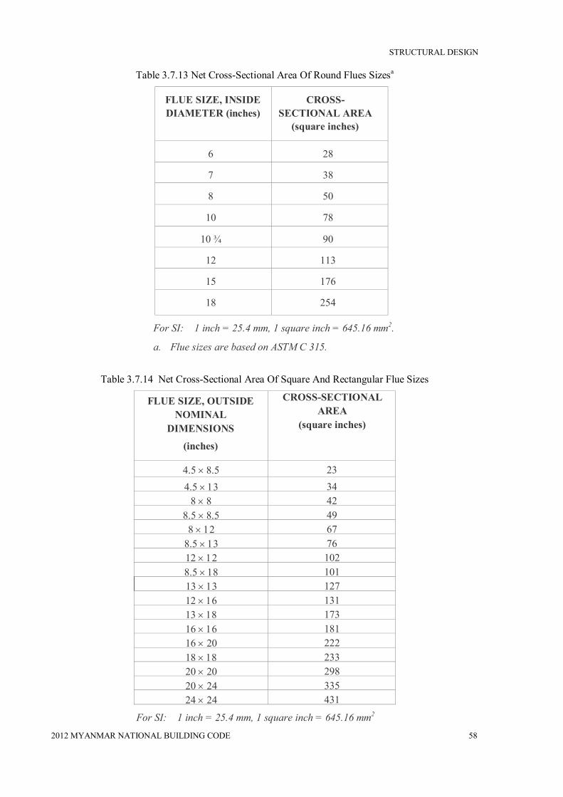
STRUCTURAL DESIGN
2012 MYANMAR NATIONAL BUILDING CODE 58
Table 3.7.13 Net Cross-Sectional Area Of Round Flues Sizesa
FLUE SIZE, INSIDE DIAMETER (inches)
CROSS-SECTIONAL AREA
(square inches)
6 28
7 38
8 50
10 78
10 ¾ 90
12 113
15 176
18 254
For SI: 1 inch = 25.4 mm, 1 square inch = 645.16 mm2.
a. Flue sizes are based on ASTM C 315.
Table 3.7.14 Net Cross-Sectional Area Of Square And Rectangular Flue Sizes
FLUE SIZE, OUTSIDE NOMINAL
DIMENSIONS
(inches)
CROSS-SECTIONAL AREA
(square inches)
4.5 23 4.5 34
8 42 8.5 49
8 67 8.5 76 12 102 8.5 101 13 127 12 131 13 173 16 181 16 222 18 233 20 298 20 335 24 431
For SI: 1 inch = 25.4 mm, 1 square inch = 645.16 mm2

STRUCTURAL DESIGN
2012 MYANMAR NATIONAL BUILDING CODE 59
3.7.13.17 Inlet
Inlets to masonry chimneys shall enter from the side. Inlets shall have a thimble of fireclay, rigid refractory material or metal that will prevent the connector from pulling out of the inlet or from extending beyond the wall of the liner.
3.7.13.18 Masonry chimney cleanout openings
Cleanout openings shall be provided within 6 inches (152 mm) of the base of each flue within every masonry chimney. The upper edge of the cleanout shall be located at least 6 inches (152 mm) below the lowest chimney inlet opening. The height of the opening shall be at least 6 inches (152 mm). The cleanout shall be provided with a noncombustible cover.
EXCEPTION:
Chimney flues serving masonry fireplaces, where cleaning is possible through the fireplace opening.
3.7.13.19 Chimney clearances
Any portion of a masonry chimney located in the interior of the building or within the exterior wall of the building shall have a minimum airspace clearance to combustibles of 2 inches (51 mm). Chimneys located entirely outside the exterior walls of the building, including chimneys that pass through the soffit or cornice, shall have a minimum airspace clearance of 1 inch (25 mm). The airspace shall not be filled, except to provide fireblocking in accordance with Section 3.7.13.20.
EXCEPTIONS:
1) Masonry chimneys equipped with a chimney lining system listed and labeled or use in chimneys in contact with combustibles in accordance with UL 1777, and installed in accordance with the manufacturer’s instruction, are permitted to have combustible material in contact with their exterior surfaces.
2) Where masonry chimneys are constructed as part of masonry or concrete walls, combustible materials shall not be in contact with the masonry or concrete wall less than 12 inches (305 mm) from the inside surface of the nearest flue lining.
3) Exposed combustible trim and the edges of sheathing materials, such as wood siding, are permitted to abut the masonry chimney sidewalls, in accordance with Figure 7.4, provided such combustible trim or sheathing is a minimum of 12 inches (305 mm) from the inside surface of the nearest flue lining. Combustible material and trim shall not overlap the corners of the chimney by more than 1 inch (25 mm).
For SI: 1 inch = 25.4 mm.
Figure 3.7.4 Illustration Of Exception Three Chimney Clearance Provision

STRUCTURAL DESIGN
2012 MYANMAR NATIONAL BUILDING CODE 60
3.7.13.20 Chimney fireblocking
All spaces between chimneys and floors and ceilings through which chimneys pass shall be fireblocked with noncombustible material securely fastened in place. The fireblocking of spaces between wood joists, beams or headers shall be to a depth of 1 inch (25 mm) and shall only be placed on strips of metal or metal lath laid across the spaces between combustible material and the chimney.


