Embed Size (px)
Citation preview
Nanorattles or Yolk–Shell Nanoparticles—What Are They, How AreThey Made, and What Are They Good For?
Magdalena Priebe* and Katharina M. Fromm*[a]
1
Published in which should be cited to refer to this work.
http
://do
c.re
ro.c
h
Abstract: The development of nanotechnology has led tothe design of cutting-edge nanomaterials with increasinglevels of complexity. Although “traditional” solid, uniformnanoparticles are still the most frequently reported struc-tures, new generations of nanoparticles have been constant-ly emerging over the last several decades. The outcome ofthis nano-art extends beyond nanomaterials with alternativecompositions and/or morphologies. The current state-of-the-art allows for the design of nanostructures composed of dif-ferent building blocks that exhibit diverse properties. Fur-thermore, those properties can be a reflection of either indi-vidual features, which are characteristic of a particular build-ing block alone, and/or synergistic effects resulting from in-
teractions between building blocks. Therefore, the uniquestructures as well as the outstanding properties of nanorat-tles have attracted increasing attention for possible biomedi-cal and industrial applications. Although these nanoparticlesresemble core–shell particles, they have a distinctive feature,which is a presence of a void that provides a homogenousenvironment for the encapsulated core. In this Review, wegive a comprehensive insight into the fabrication of nanorat-tles. A special emphasis is put on the choice of buildingblocks as well as the choice of preparation method, becausethose two aspects further influence properties and thus pos-sible future applications, which will also be discussed.
1. Introduction to Nanorattles
The first visionary outlook for the development of nanotech-nology dates back to December 1959 when Richard Feynmangave his eminent talk entitled “There’s Plenty of Room at theBottom”.[1] Although the term nanotechnology was not utilizedat that time and it has taken decades for Feynman’s visions tobecome respected and partially realized,[2] humanity has cer-tainly been fabricating and using nanoparticles since ancienttimes without even realizing it. The prime example is the Ly-curgus cup—a fabulous cup dating back to the 4th centuryA.D. made of dichroic glass that changes color depending onwhether light is reflected or transmitted. These extraordinaryproperties originate from the presence of gold–silver alloynanoparticles with a diameter of 50–100 nm, and were themasterstroke of ancient Roman glassmakers.[3]
With the development of electron-microscopy techniques,a “micro and nano fever” swept the scientific world.[2] On onehand, there has been an interest in preparing finer and finerparticles with variable properties depending on their size andshape.[4] On the other hand, considerable focus has been puton the development of fancy structures.[5] As numerous re-views on nanoparticles have already been published,[6,7] the au-thors of this work would like to present a review solely on thenanorattle type of nanomaterials, also frequently called yolk–shell nanoparticles. These structures should be distinguishedfrom solid nanoparticles[8–12] (composed of one or many ele-ments, but with a uniform structure), Janus particles[13] (twoparts of the particle have different chemical or physical proper-ties), hollow particles[9–11,14] (with an empty interior), core–shellparticles[8,12,15] (comprising smaller solid particle(s) coated witha tight layer of other element(s)), as well as from reversebumpy balls[16,17] (encapsulated cores attached to the shell). Asshown in Figure 1, the feature differentiating nanorat-
tles[8–10,12,14, 15] from the aforementioned structures is the voidbetween the encapsulated cargo and the surrounding shell.This is clearly a generalization, because more than one particlecan be encapsulated in the cavity[9,18–20] or the shell can becomposed of several cavities with single particles inside.[21] Ad-ditionally, the shell can be constituted of multiple layers[8,22–25]
and contain functional groups[26,27] or targeting moieties.[27]
With regard to shape, spheres[9,14,15,18, 23,28–33] are the most fre-quent; however, other possibilities have been reported as well.These include spindle,[34,35] rodlike,[20,36,37] and cubic[38–41] nano-rattles. Very often the shell adopts the same shape as thecore,[33,34] but it is not a general rule.[20,33,39] Last but not least,a core does not necessarily need to be a solid nanoparticleand can be made of hollow sphere(s), resulting in a rattle-typeball-in-ball sphere.[42,43]
Normally, nanorattles are denoted as core@shell, for exampleAu@MgSiO3,
[44] as well as Au@HSNs (for hollow silica nano-spheres)[9] but sometimes they are also described as core@-void@shell[19,23, 45] such as Si@void@C,[19] Pt@void@TiO2,
[46] or Au,@ZrO2
[15] to emphasize the presence of the void. In caseswhere the shell consists of two layers, the designation takesthe form of core@shell1@shell2, such as a-Fe2O3@SiO2@SiO2,
[47]
or SnO2@SnO2@SnO2.[24] Herein, the presence of the void will
not be additionally indicated and only the denotation core@-shell will be used, since mainly rattle structures are consideredin the scope of this review.
The principal purpose of encapsulation is to provide protec-tion for the core so that its functionalities are not diminished
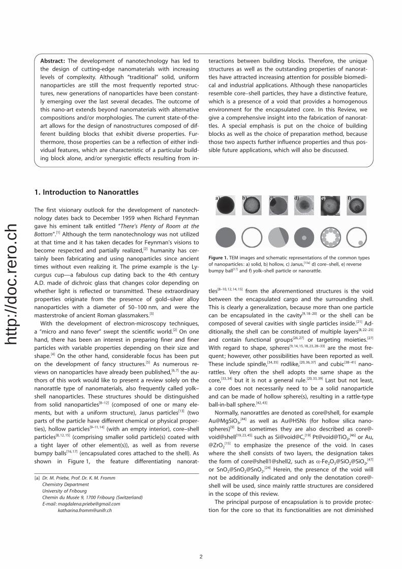
Figure 1. TEM images and schematic representations of the common typesof nanoparticles : a) solid, b) hollow, c) Janus,[13a] d) core–shell, e) reversebumpy ball[17] and f) yolk–shell particle or nanorattle.
[a] Dr. M. Priebe, Prof. Dr. K. M. FrommChemistry DepartmentUniversity of FribourgChemin du Mus�e 9, 1700 Fribourg (Switzerland)E-mail : [email protected]
2
http
://do
c.re
ro.c
h
and do not vanish upon aggregation and sintering,[15,21, 31,44, 48]
under harsh reaction conditions,[9,15,21] or through interactionwith the surrounding environment.[9,19, 30] In many cases, how-ever, the shell provides some important functionalities itself.This can include the presence of reactive sites, such as �NH2
groups, for the attachment of targeting molecules for drug de-livery[27,31] or sites for the absorption of target molecules, suchas groups aimed at the extraction of organic targets.[30]
Multiple possible applications enabled by nanorattles havebecome a source of inspiration for scientists to develop thebest and most efficient methods for their preparation. Nanorat-tles can be prepared in numerous ways and a border line isnot always lucid. As nanotechnology is a multidisciplinary sci-ence gathering researchers from various fields, we will makean attempt to provide general guidelines for the preparationof nanorattles based on the current literature. In the scope ofthis Review, we categorize those methods depending on 1) theuse of a template, 2) the sequence of core and shell formation,3) the way to obtain a void between core and shell, 4) the im-portance of building blocks in the design of future applicationsas well as 5) their characterization methods. In the followingsubchapters, we will show that a vast number of possiblenanorattles can be fabricated with combinations of the diversefunctionalities of their components (see section 2. NanorattleBuilding Blocks). This can clearly be achieved by several differ-ent approaches (see section 3. Methods for the Fabrication ofNanorattles) influencing further the properties of the obtainedproducts, such as the dimensions of the compartments. Then,we will emphasize the importance of the nanorattle buildingblocks in the design of the future applications (section 4) andwill show that despite of a variety of analytical methods, thecharacterization of nanorattles is not always straightforwardand complex analysis is often required (section 5). Finally, wewill provide some recent examples of nanorattles with poten-tial for practical applications (section 6).
2. Nanorattle Building Blocks
A vast number of possible building blocks provide a variety ofcompositions for the construction of nanorattles. The core isusually made of metals (Au,[29, 31,44,49] Ag,[50–52] Cu,[51] Pt,[28,46]
Pd,[21,53] Ni[12]), metalloids (Si[19]), oxides (SiO2,[10] Fe2O3,
[31,34]
Fe3O4,[14,27, 54–56] SnO2,
[24] Co3O4,[40]), doped oxides (Gd2O3:Eu
3+ [57])or sulfides (Ag2S, CdS, PbS, ZnS, AgInS2),
[41] whereas the shellcan be composed of metal (Pt[49]), oxides (SiO2,
[10,29,31, 51]
MgSiO3,[44] CuSiO3,
[44] NiSiO3,[44] NiTiO3,
[45] CeO2,[21,28] ZrO2,
[15]
TiO2,[46,56] SnO2,
[8,24] Fe2O3[52]), polymers[50,58] (P(NIPAm-coAAM),[57]
PMAA,[59] PANi[55]) or carbon[58] (C18 groups,[30] nitrogen-dopedcarbon[19]).
The chemical composition of nanorattles largely determinestheir properties. For example, Au,[9,15,18,31, 44,48,60] Ni,[12] andPd[21,53,61] mainly constitute the core of catalytic nanorattles.Very often, functionality depends solely on the nature of thecore[9,12,18] and the function of the shell is reduced to a protect-ing role.[9,15,18] However, some studies report a synergistic roleof both core and shell, as seen for example in Pt@CeO2,
[28]
Co3O4@SiO2,[40] or Fe3O4@SnO2
[8] resulting in improved visible-
light photocatalysis,[28] catalysis,[40] as well as microwave ab-sorption,[8] respectively. Nanorattles with individual functionali-ties for different compartments are gaining increased atten-tion; for instance, in the combination of a magnetic Fe3O4 coreand a photocatalytic TiO2 shell.[56] The presence of pores onthe surface of shells provides channels through which smallmolecules can enter the cavity.[40] This aspect should be espe-cially kept in mind when nanorattles are intended to act asdrug carriers or nanoreactors, as pore blockage can diminishthe overall performance. Although still neglected, the void alsoseems to play a crucial role in determining the finalproperties.[34]
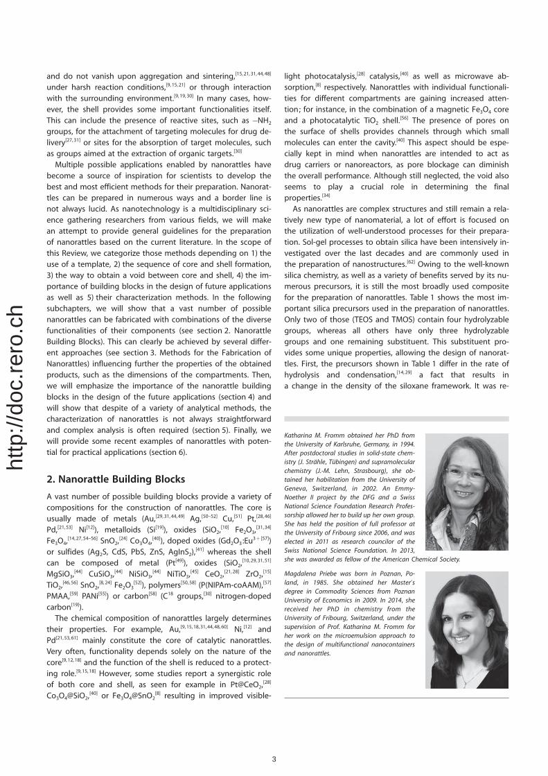
As nanorattles are complex structures and still remain a rela-tively new type of nanomaterial, a lot of effort is focused onthe utilization of well-understood processes for their prepara-tion. Sol-gel processes to obtain silica have been intensively in-vestigated over the last decades and are commonly used inthe preparation of nanostructures.[62] Owing to the well-knownsilica chemistry, as well as a variety of benefits served by its nu-merous precursors, it is still the most broadly used compositefor the preparation of nanorattles. Table 1 shows the most im-portant silica precursors used in the preparation of nanorattles.Only two of those (TEOS and TMOS) contain four hydrolyzablegroups, whereas all others have only three hydrolyzablegroups and one remaining substituent. This substituent pro-vides some unique properties, allowing the design of nanorat-tles. First, the precursors shown in Table 1 differ in the rate ofhydrolysis and condensation,[14,29] a fact that results ina change in the density of the siloxane framework. It was re-
Katharina M. Fromm obtained her PhD fromthe University of Karlsruhe, Germany, in 1994.After postdoctoral studies in solid-state chem-istry (J. Str�hle, T�bingen) and supramolecularchemistry (J.-M. Lehn, Strasbourg), she ob-tained her habilitation from the University ofGeneva, Switzerland, in 2002. An Emmy-Noether II project by the DFG and a SwissNational Science Foundation Research Profes-sorship allowed her to build up her own group.She has held the position of full professor atthe University of Fribourg since 2006, and waselected in 2011 as research councilor of theSwiss National Science Foundation. In 2013,she was awarded as fellow of the American Chemical Society.
Magdalena Priebe was born in Poznan, Po-land, in 1985. She obtained her Master’sdegree in Commodity Sciences from PoznanUniversity of Economics in 2009. In 2014, shereceived her PhD in chemistry from theUniversity of Fribourg, Switzerland, under thesupervision of Prof. Katharina M. Fromm forher work on the microemulsion approach tothe design of multifunctional nanocontainersand nanorattles.
3
http
://do
c.re
ro.c
h
ported, for example, that hydrolysis of TEOS leads to the for-mation of a more dense silica network than hydrolysis andpolycondensation of TEOS together with APTES.[63] This possi-bility to tune the density is frequently used to selectivelyremove the silica core[29] or the interlayer between core andshell.[10, 15,26,27, 60] Organosiloxanes with longer carbon chains ex-hibit the ability to influence the pore size of the silicashell.[10, 12,29,31] Depending on the substituent (group R), surfaceproperties such as the zeta potential[10] or the hydrophobici-ty[27,29, 30] of certain compartments, such as the outer layer[29]
and the void,[27,30] can be altered. In addition, amino silanes,such as APTES, can be used as both vesicle-inducing as well asco-structure directing agents,[22] whereas silanes with longcarbon chains, such as C18TMS, act as pore directingagents.[27,31] And last but not least, R serves as a moiety for sur-face functionalization. Owing to the presence of �NH2 groups,APTES[14,26] and APTMS[10,57] are often used for functionalizationof the shell with fluorescent dyes by coupling, for example,with the thioisocyanate group of fluorescein isothiocya-nate.[10,14] The so-prepared fluorescent silica precursors can beeither used to coat already synthetized nanorattles throughsilane coupling[26,57] or directly in the synthesis of nanorattlesduring hydrolysis and polycondensation with other silica pre-cursors.[14] As nitrogen-containing molecules can coordinate tometal ions, such as gold ions,[64] they can also be used in theencapsulation of gold by forming a gold complex followed byreduction to metallic gold.[9,18, 29] For example, when N-[3-(tri-methoxysilyl)propyl]ethylenediamine (TSD) was used as theamine source, the reduction was carried out solely by heatingand no additional reducing agent was necessary.[18,29] However,in case of shorter carbon chains, such as in APTMS, an addi-tional reducing agent, for example, NaBH4 was required toobtain the Au nanoparticles (NPs).[9] This might be related tostructural differences between TSD and APTMS with regard to
the number of nitrogen atoms.As the former contains two Natoms, it can form chelates withgold, whereas the latter containsonly one site for interaction andthe complexation is weaker.Polymers such as polyethyleneglycol (PEG) can also be at-tached to the silica surfaceeither by incorporation of PEGby silanization directly with PEG-silane[27] or by reaction betweenthe amine group on the shellsurface with methoxy poly(ethy-lene glycol) succinimidyl carbon-ate (mPEG-SC).[26] Another possi-bility to change the propertiesof the surface is the oxidation of�SH groups originating from (3-mercaptopropyl)trimethoxysilaneinto �SO3H or the deprotectionof 3-tert-butyloxycarbonyl ami-nopropyl–triethoxysilane, leading
to the presence of �NH2 groups.[23] An extensive review bySapsford et al. provides useful guidelines for the functionaliza-tion of nanoparticles with biological molecules,[65] techniquesthat certainly can be applied to nanorattles as well.
3. Methods for the Fabrication of Nanorattles
The preparation of nanorattles is hardly ever performed ina single-step synthesis.[24,32] Usually, the procedure involvesseveral steps including the fabrication of the core, growth ofthe shell, as well as various post-synthesis treatments such ascore removal, functionalization of compartments, and loadingwith cargo (drug or metal precursors for top-down synthesis ofmetal@shell nanorattles). Owing to multistep and complex ap-proaches that are often intertwined, the strict classification offabrication methods is difficult. Herein, we present someguidelines that might be helpful in the decision-making pro-cess with regard to the choice of the method for the prepara-tion of a functional nanorattle. While planning the fabricationof nanorattles, three major questions should be answered:
1 Which template should be used?2 Which compartment of the nanorattle should be fabricated
first? Core or shell?3 How to obtain the desired void between core and shell in
cases where core–shell particles are an intermediate form?
3.1. Use of a template
In general, the synthesis can be classified depending onwhether a template is used or not. In the former case, eithera hard or a soft template constitutes a scaffold for the growth
Table 1. Silica precursors used in the preparation of nanorattles.
Acronym Full name References
TEOS tetraethyl orthosilicate, tetraethoxysilane, tetraethylortho-silane
[9,14, 18, 20,23, 26,27, 29–31, 34,40, 44,54, 57, 66–68]
TMOS tetramethyl orthosilicate [12, 53,69]APTES (3-aminopropyl) triethoxysilane [26, 29]APTMS (3-aminopropyl) trimethoxysilane [9,14]BTME 1,2-bis(trimethoxysilyl) ethane [23, 69]BTEB 1,4-bis(triethoxysilyl)benzene [69]C18TMS n-octadecyl trimethoxysilane [12, 27,31]C18TES n-octadecyl triethoxysilane [30]IBMS isobutyltrimethoxy silane [70]MPTMS (3-mercaptopropyl) trimethoxysilane [23, 29]PDES 1H, 1H, 2H, 2H-perfluoro decyltriethoxysilane [29]PEG-silane
polyethyleneglycol silane [27]
PMTMSMPS
3-(trimethoxysilyl) propyl methacrylate[3-(methacryloyloxy) propyl]trimethoxy silane
[29, 31]
3-TBS 3-tert-butyloxycarbonyl aminopropyl-triethoxysilane [23]TMAPS N-trimethoxysilylpropyl-N,N,N-trimethylammonium chlo-
ride[22]
TPI (3-isocyanatopropyl) triethoxysilane [31]TSD N-[3-(trimethoxysilyl)propyl]ethylene diamine [10, 18,29, 68]
4
http
://do
c.re
ro.c
h
of the shell. In the latter case, the shell occurs as a result ofphysical transformations of intermediate templates.
3.1.1. Hard template methods
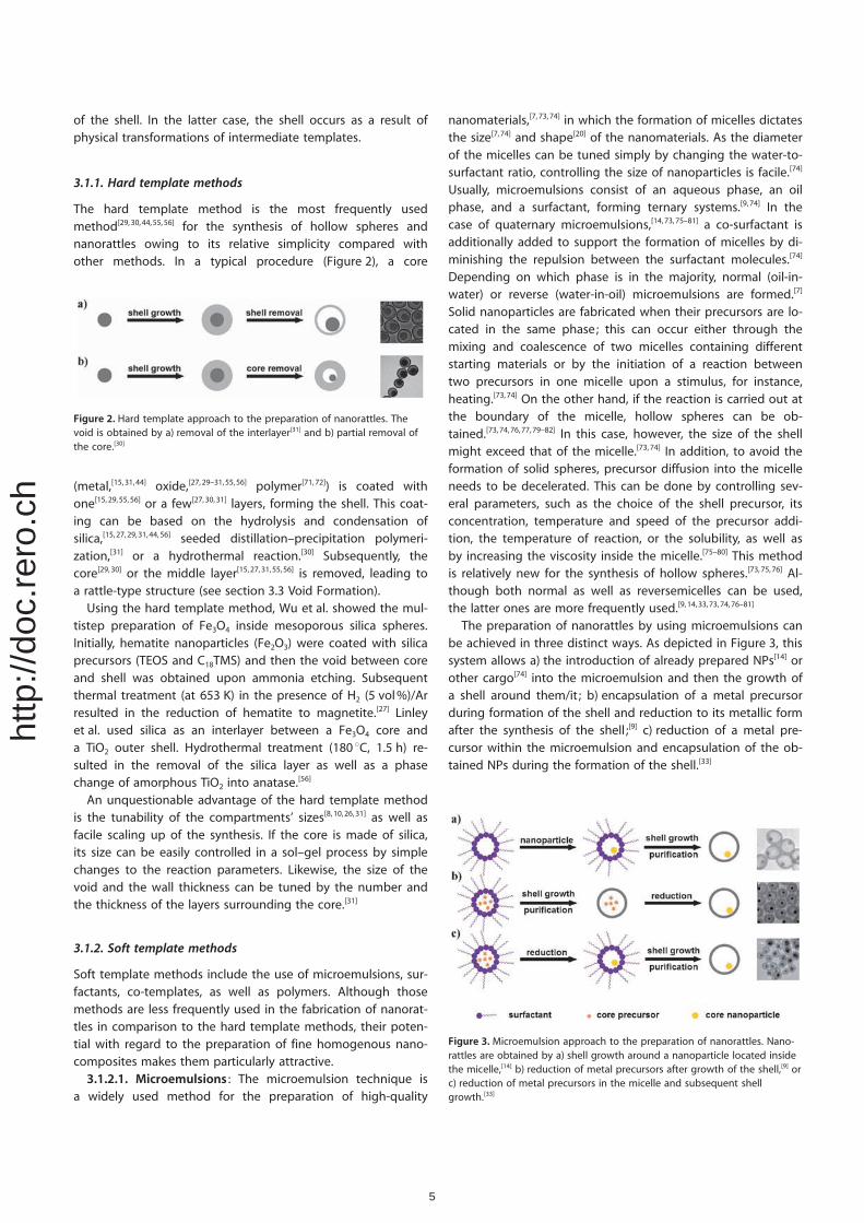
The hard template method is the most frequently usedmethod[29,30,44,55, 56] for the synthesis of hollow spheres andnanorattles owing to its relative simplicity compared withother methods. In a typical procedure (Figure 2), a core
(metal,[15,31,44] oxide,[27,29–31,55,56] polymer[71,72]) is coated withone[15,29,55, 56] or a few[27,30,31] layers, forming the shell. This coat-ing can be based on the hydrolysis and condensation ofsilica,[15,27, 29,31,44, 56] seeded distillation–precipitation polymeri-zation,[31] or a hydrothermal reaction.[30] Subsequently, thecore[29,30] or the middle layer[15,27, 31,55,56] is removed, leading toa rattle-type structure (see section 3.3 Void Formation).
Using the hard template method, Wu et al. showed the mul-tistep preparation of Fe3O4 inside mesoporous silica spheres.Initially, hematite nanoparticles (Fe2O3) were coated with silicaprecursors (TEOS and C18TMS) and then the void between coreand shell was obtained upon ammonia etching. Subsequentthermal treatment (at 653 K) in the presence of H2 (5 vol%)/Arresulted in the reduction of hematite to magnetite.[27] Linleyet al. used silica as an interlayer between a Fe3O4 core anda TiO2 outer shell. Hydrothermal treatment (180 8C, 1.5 h) re-sulted in the removal of the silica layer as well as a phasechange of amorphous TiO2 into anatase.[56]
An unquestionable advantage of the hard template methodis the tunability of the compartments’ sizes[8,10,26, 31] as well asfacile scaling up of the synthesis. If the core is made of silica,its size can be easily controlled in a sol–gel process by simplechanges to the reaction parameters. Likewise, the size of thevoid and the wall thickness can be tuned by the number andthe thickness of the layers surrounding the core.[31]
3.1.2. Soft template methods
Soft template methods include the use of microemulsions, sur-factants, co-templates, as well as polymers. Although thosemethods are less frequently used in the fabrication of nanorat-tles in comparison to the hard template methods, their poten-tial with regard to the preparation of fine homogenous nano-composites makes them particularly attractive.
3.1.2.1. Microemulsions : The microemulsion technique isa widely used method for the preparation of high-quality
nanomaterials,[7, 73,74] in which the formation of micelles dictatesthe size[7,74] and shape[20] of the nanomaterials. As the diameterof the micelles can be tuned simply by changing the water-to-surfactant ratio, controlling the size of nanoparticles is facile.[74]
Usually, microemulsions consist of an aqueous phase, an oilphase, and a surfactant, forming ternary systems.[9,74] In thecase of quaternary microemulsions,[14,73, 75–81] a co-surfactant isadditionally added to support the formation of micelles by di-minishing the repulsion between the surfactant molecules.[74]
Depending on which phase is in the majority, normal (oil-in-water) or reverse (water-in-oil) microemulsions are formed.[7]
Solid nanoparticles are fabricated when their precursors are lo-cated in the same phase; this can occur either through themixing and coalescence of two micelles containing differentstarting materials or by the initiation of a reaction betweentwo precursors in one micelle upon a stimulus, for instance,heating.[73,74] On the other hand, if the reaction is carried out atthe boundary of the micelle, hollow spheres can be ob-tained.[73,74,76,77, 79–82] In this case, however, the size of the shellmight exceed that of the micelle.[73,74] In addition, to avoid theformation of solid spheres, precursor diffusion into the micelleneeds to be decelerated. This can be done by controlling sev-eral parameters, such as the choice of the shell precursor, itsconcentration, temperature and speed of the precursor addi-tion, the temperature of reaction, or the solubility, as well asby increasing the viscosity inside the micelle.[75–80] This methodis relatively new for the synthesis of hollow spheres.[73,75,76] Al-though both normal as well as reversemicelles can be used,the latter ones are more frequently used.[9,14,33,73, 74,76–81]
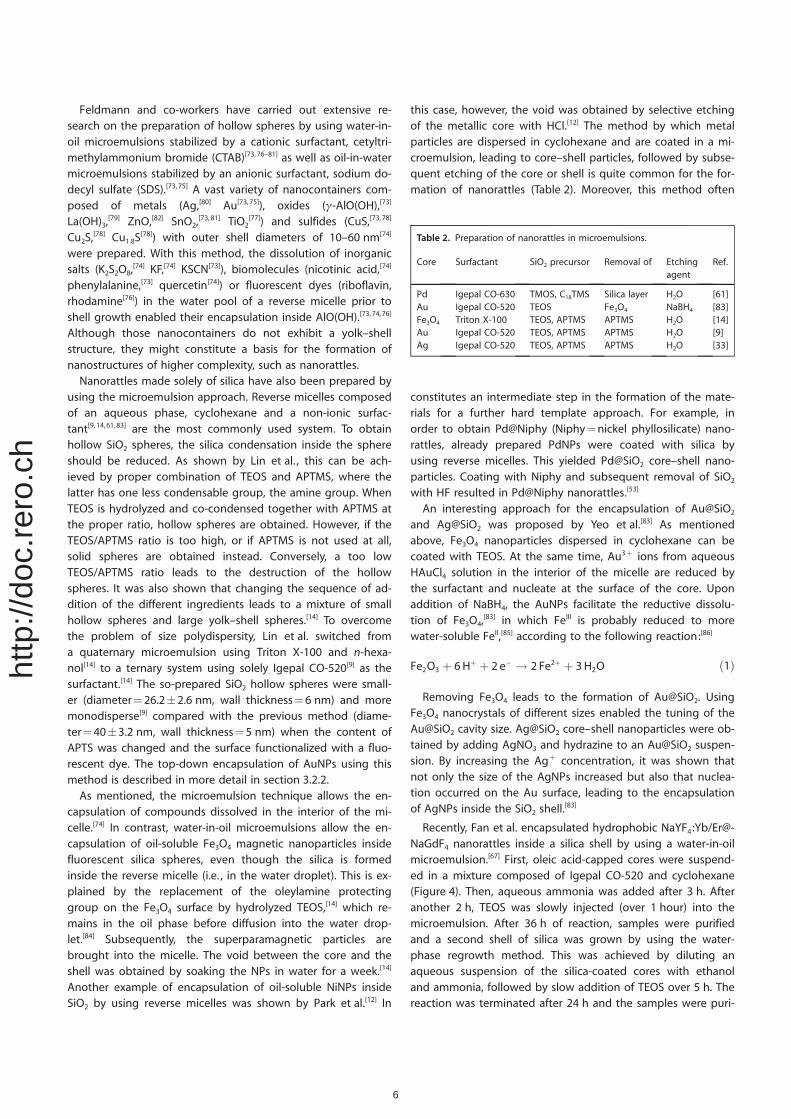
The preparation of nanorattles by using microemulsions canbe achieved in three distinct ways. As depicted in Figure 3, thissystem allows a) the introduction of already prepared NPs[14] orother cargo[74] into the microemulsion and then the growth ofa shell around them/it ; b) encapsulation of a metal precursorduring formation of the shell and reduction to its metallic formafter the synthesis of the shell ;[9] c) reduction of a metal pre-cursor within the microemulsion and encapsulation of the ob-tained NPs during the formation of the shell.[33]
Figure 2. Hard template approach to the preparation of nanorattles. Thevoid is obtained by a) removal of the interlayer[31] and b) partial removal ofthe core.[30]
Figure 3. Microemulsion approach to the preparation of nanorattles. Nano-rattles are obtained by a) shell growth around a nanoparticle located insidethe micelle,[14] b) reduction of metal precursors after growth of the shell,[9] orc) reduction of metal precursors in the micelle and subsequent shellgrowth.[33]
5
http
://do
c.re
ro.c
h
Feldmann and co-workers have carried out extensive re-search on the preparation of hollow spheres by using water-in-oil microemulsions stabilized by a cationic surfactant, cetyltri-methylammonium bromide (CTAB)[73,76–81] as well as oil-in-watermicroemulsions stabilized by an anionic surfactant, sodium do-decyl sulfate (SDS).[73,75] A vast variety of nanocontainers com-posed of metals (Ag,[80] Au[73,75]), oxides (g-AlO(OH),[73]
La(OH)3,[79] ZnO,[82] SnO2,
[73,81] TiO2[77]) and sulfides (CuS,[73,78]
Cu2S,[78] Cu1.8S
[78]) with outer shell diameters of 10–60 nm[74]
were prepared. With this method, the dissolution of inorganicsalts (K2S2O8,
[74] KF,[74] KSCN[73]), biomolecules (nicotinic acid,[74]
phenylalanine,[73] quercetin[74]) or fluorescent dyes (riboflavin,rhodamine[76]) in the water pool of a reverse micelle prior toshell growth enabled their encapsulation inside AlO(OH).[73,74, 76]
Although those nanocontainers do not exhibit a yolk–shellstructure, they might constitute a basis for the formation ofnanostructures of higher complexity, such as nanorattles.
Nanorattles made solely of silica have also been prepared byusing the microemulsion approach. Reverse micelles composedof an aqueous phase, cyclohexane and a non-ionic surfac-tant[9,14,61,83] are the most commonly used system. To obtainhollow SiO2 spheres, the silica condensation inside the sphereshould be reduced. As shown by Lin et al. , this can be ach-ieved by proper combination of TEOS and APTMS, where thelatter has one less condensable group, the amine group. WhenTEOS is hydrolyzed and co-condensed together with APTMS atthe proper ratio, hollow spheres are obtained. However, if theTEOS/APTMS ratio is too high, or if APTMS is not used at all,solid spheres are obtained instead. Conversely, a too lowTEOS/APTMS ratio leads to the destruction of the hollowspheres. It was also shown that changing the sequence of ad-dition of the different ingredients leads to a mixture of smallhollow spheres and large yolk–shell spheres.[14] To overcomethe problem of size polydispersity, Lin et al. switched froma quaternary microemulsion using Triton X-100 and n-hexa-nol[14] to a ternary system using solely Igepal CO-520[9] as thesurfactant.[14] The so-prepared SiO2 hollow spheres were small-er (diameter=26.2�2.6 nm, wall thickness=6 nm) and moremonodisperse[9] compared with the previous method (diame-ter=40�3.2 nm, wall thickness=5 nm) when the content ofAPTS was changed and the surface functionalized with a fluo-rescent dye. The top-down encapsulation of AuNPs using thismethod is described in more detail in section 3.2.2.
As mentioned, the microemulsion technique allows the en-capsulation of compounds dissolved in the interior of the mi-celle.[74] In contrast, water-in-oil microemulsions allow the en-capsulation of oil-soluble Fe3O4 magnetic nanoparticles insidefluorescent silica spheres, even though the silica is formedinside the reverse micelle (i.e. , in the water droplet). This is ex-plained by the replacement of the oleylamine protectinggroup on the Fe3O4 surface by hydrolyzed TEOS,[14] which re-mains in the oil phase before diffusion into the water drop-let.[84] Subsequently, the superparamagnetic particles arebrought into the micelle. The void between the core and theshell was obtained by soaking the NPs in water for a week.[14]
Another example of encapsulation of oil-soluble NiNPs insideSiO2 by using reverse micelles was shown by Park et al.[12] In
this case, however, the void was obtained by selective etchingof the metallic core with HCl.[12] The method by which metalparticles are dispersed in cyclohexane and are coated in a mi-croemulsion, leading to core–shell particles, followed by subse-quent etching of the core or shell is quite common for the for-mation of nanorattles (Table 2). Moreover, this method often
constitutes an intermediate step in the formation of the mate-rials for a further hard template approach. For example, inorder to obtain Pd@Niphy (Niphy=nickel phyllosilicate) nano-rattles, already prepared PdNPs were coated with silica byusing reverse micelles. This yielded Pd@SiO2 core–shell nano-particles. Coating with Niphy and subsequent removal of SiO2
with HF resulted in Pd@Niphy nanorattles.[53]
An interesting approach for the encapsulation of Au@SiO2
and Ag@SiO2 was proposed by Yeo et al.[83] As mentionedabove, Fe3O4 nanoparticles dispersed in cyclohexane can becoated with TEOS. At the same time, Au3+ ions from aqueousHAuCl4 solution in the interior of the micelle are reduced bythe surfactant and nucleate at the surface of the core. Uponaddition of NaBH4, the AuNPs facilitate the reductive dissolu-tion of Fe3O4,
[83] in which FeIII is probably reduced to morewater-soluble FeII,[85] according to the following reaction:[86]
Fe2O3 þ 6Hþ þ 2 e� ! 2 Fe2þ þ 3H2O ð1Þ
Removing Fe3O4 leads to the formation of Au@SiO2. UsingFe3O4 nanocrystals of different sizes enabled the tuning of theAu@SiO2 cavity size. Ag@SiO2 core–shell nanoparticles were ob-tained by adding AgNO3 and hydrazine to an Au@SiO2 suspen-sion. By increasing the Ag+ concentration, it was shown thatnot only the size of the AgNPs increased but also that nuclea-tion occurred on the Au surface, leading to the encapsulationof AgNPs inside the SiO2 shell.
[83]
Recently, Fan et al. encapsulated hydrophobic NaYF4:Yb/Er@-NaGdF4 nanorattles inside a silica shell by using a water-in-oilmicroemulsion.[67] First, oleic acid-capped cores were suspend-ed in a mixture composed of Igepal CO-520 and cyclohexane(Figure 4). Then, aqueous ammonia was added after 3 h. Afteranother 2 h, TEOS was slowly injected (over 1 hour) into themicroemulsion. After 36 h of reaction, samples were purifiedand a second shell of silica was grown by using the water-phase regrowth method. This was achieved by diluting anaqueous suspension of the silica-coated cores with ethanoland ammonia, followed by slow addition of TEOS over 5 h. Thereaction was terminated after 24 h and the samples were puri-
Table 2. Preparation of nanorattles in microemulsions.
Core Surfactant SiO2 precursor Removal of Etchingagent
Ref.
Pd Igepal CO-630 TMOS, C18TMS Silica layer H2O [61]Au Igepal CO-520 TEOS Fe3O4 NaBH4 [83]Fe3O4 Triton X-100 TEOS, APTMS APTMS H2O [14]Au Igepal CO-520 TEOS, APTMS APTMS H2O [9]Ag Igepal CO-520 TEOS, APTMS APTMS H2O [33]
6
http
://do
c.re
ro.c
h
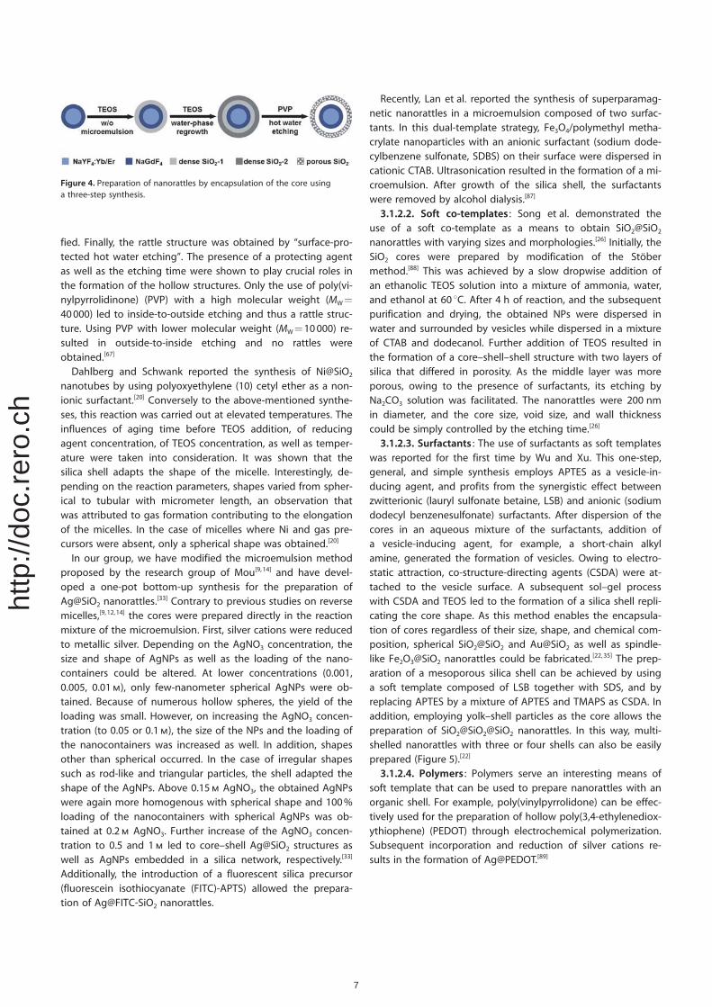
fied. Finally, the rattle structure was obtained by “surface-pro-tected hot water etching”. The presence of a protecting agentas well as the etching time were shown to play crucial roles inthe formation of the hollow structures. Only the use of poly(vi-nylpyrrolidinone) (PVP) with a high molecular weight (MW=
40000) led to inside-to-outside etching and thus a rattle struc-ture. Using PVP with lower molecular weight (MW=10000) re-sulted in outside-to-inside etching and no rattles wereobtained.[67]
Dahlberg and Schwank reported the synthesis of Ni@SiO2
nanotubes by using polyoxyethylene (10) cetyl ether as a non-ionic surfactant.[20] Conversely to the above-mentioned synthe-ses, this reaction was carried out at elevated temperatures. Theinfluences of aging time before TEOS addition, of reducingagent concentration, of TEOS concentration, as well as temper-ature were taken into consideration. It was shown that thesilica shell adapts the shape of the micelle. Interestingly, de-pending on the reaction parameters, shapes varied from spher-ical to tubular with micrometer length, an observation thatwas attributed to gas formation contributing to the elongationof the micelles. In the case of micelles where Ni and gas pre-cursors were absent, only a spherical shape was obtained.[20]
In our group, we have modified the microemulsion methodproposed by the research group of Mou[9,14] and have devel-oped a one-pot bottom-up synthesis for the preparation ofAg@SiO2 nanorattles.
[33] Contrary to previous studies on reversemicelles,[9, 12,14] the cores were prepared directly in the reactionmixture of the microemulsion. First, silver cations were reducedto metallic silver. Depending on the AgNO3 concentration, thesize and shape of AgNPs as well as the loading of the nano-containers could be altered. At lower concentrations (0.001,0.005, 0.01m), only few-nanometer spherical AgNPs were ob-tained. Because of numerous hollow spheres, the yield of theloading was small. However, on increasing the AgNO3 concen-tration (to 0.05 or 0.1m), the size of the NPs and the loading ofthe nanocontainers was increased as well. In addition, shapesother than spherical occurred. In the case of irregular shapessuch as rod-like and triangular particles, the shell adapted theshape of the AgNPs. Above 0.15m AgNO3, the obtained AgNPswere again more homogenous with spherical shape and 100%loading of the nanocontainers with spherical AgNPs was ob-tained at 0.2m AgNO3. Further increase of the AgNO3 concen-tration to 0.5 and 1m led to core–shell Ag@SiO2 structures aswell as AgNPs embedded in a silica network, respectively.[33]
Additionally, the introduction of a fluorescent silica precursor(fluorescein isothiocyanate (FITC)-APTS) allowed the prepara-tion of Ag@FITC-SiO2 nanorattles.
Recently, Lan et al. reported the synthesis of superparamag-netic nanorattles in a microemulsion composed of two surfac-tants. In this dual-template strategy, Fe3O4/polymethyl metha-crylate nanoparticles with an anionic surfactant (sodium dode-cylbenzene sulfonate, SDBS) on their surface were dispersed incationic CTAB. Ultrasonication resulted in the formation of a mi-croemulsion. After growth of the silica shell, the surfactantswere removed by alcohol dialysis.[87]
3.1.2.2. Soft co-templates : Song et al. demonstrated theuse of a soft co-template as a means to obtain SiO2@SiO2
nanorattles with varying sizes and morphologies.[26] Initially, theSiO2 cores were prepared by modification of the Stçbermethod.[88] This was achieved by a slow dropwise addition ofan ethanolic TEOS solution into a mixture of ammonia, water,and ethanol at 60 8C. After 4 h of reaction, and the subsequentpurification and drying, the obtained NPs were dispersed inwater and surrounded by vesicles while dispersed in a mixtureof CTAB and dodecanol. Further addition of TEOS resulted inthe formation of a core–shell–shell structure with two layers ofsilica that differed in porosity. As the middle layer was moreporous, owing to the presence of surfactants, its etching byNa2CO3 solution was facilitated. The nanorattles were 200 nmin diameter, and the core size, void size, and wall thicknesscould be simply controlled by the etching time.[26]
3.1.2.3. Surfactants : The use of surfactants as soft templateswas reported for the first time by Wu and Xu. This one-step,general, and simple synthesis employs APTES as a vesicle-in-ducing agent, and profits from the synergistic effect betweenzwitterionic (lauryl sulfonate betaine, LSB) and anionic (sodiumdodecyl benzenesulfonate) surfactants. After dispersion of thecores in an aqueous mixture of the surfactants, addition ofa vesicle-inducing agent, for example, a short-chain alkylamine, generated the formation of vesicles. Owing to electro-static attraction, co-structure-directing agents (CSDA) were at-tached to the vesicle surface. A subsequent sol–gel processwith CSDA and TEOS led to the formation of a silica shell repli-cating the core shape. As this method enables the encapsula-tion of cores regardless of their size, shape, and chemical com-position, spherical SiO2@SiO2 and Au@SiO2 as well as spindle-like Fe2O3@SiO2 nanorattles could be fabricated.[22,35] The prep-aration of a mesoporous silica shell can be achieved by usinga soft template composed of LSB together with SDS, and byreplacing APTES by a mixture of APTES and TMAPS as CSDA. Inaddition, employing yolk–shell particles as the core allows thepreparation of SiO2@SiO2@SiO2 nanorattles. In this way, multi-shelled nanorattles with three or four shells can also be easilyprepared (Figure 5).[22]
3.1.2.4. Polymers : Polymers serve an interesting means ofsoft template that can be used to prepare nanorattles with anorganic shell. For example, poly(vinylpyrrolidone) can be effec-tively used for the preparation of hollow poly(3,4-ethylenediox-ythiophene) (PEDOT) through electrochemical polymerization.Subsequent incorporation and reduction of silver cations re-sults in the formation of Ag@PEDOT.[89]
Figure 4. Preparation of nanorattles by encapsulation of the core usinga three-step synthesis.
7
http
://do
c.re
ro.c
h
3.1.3. Template-free Methods
3.1.3.1. Ostwald ripening : Ostwald ripening is a well-knownphysical phenomenon in which minuscule crystallites dissolveand recrystallize to form larger ones.[90] Recently, Cao et al. pro-posed such a mechanism for the formation of “fluffy” core–shell, yolk–shell, and hollow anatase nanoparticles. Whenamorphous titania spheres were coated with metastable am-monium titanate and subsequently calcinated at 500 8C in air,only the outer layer underwent a phase transition to anatasenanocrystals. Those crystals functioned as seeds for furthergrowth of titania dissolved from the core. As a result of Ost-wald ripening, the core was dissolving whereas the shell wasenlarging.[91]
Cubic Co3O4@SiO2 nanorattles were prepared by thermal de-composition of Co3[Co(CN)6]2@SiO2 core–shell nanocubesduring calcination at 550 8C for 1 h.[40] This thermal treatmentled to the conversion of the Co3[Co(CN)6]2 nanoparticles tomonodisperse Co3O4 nanocrystals owing to Ostwald ripening.In addition, due to the high temperatures during this process,the surfaces of the cores were cleaned as well.[40]
Zhang et al. have prepared Pt@CeO2 yolk–shell spheres byusing a template-free hydrothermal method.[28] As PtNPs arenecessary to form the spherical CeO2 shells and because thepresence of the void depended on the reaction time as well ason the concentration of the ceria precursor, heterogeneousseeded growth and Ostwald ripening processes both seem tobe involved in the mechanism of formation of theseparticles.[28]
3.1.3.2. Spray pyrolysis : Another template-free approachwas proposed by Zheng and co-workers.[32] Various metal@car-bon were prepared by ultrasonic spray pyrolysis. In this one-step method, the metal salt is initially reduced by sodium cit-rate in an aqueous droplet at high temperature. Then, excesssodium citrate forms a shell at the periphery of this hot drop-let. Once the shell is carbonized, the carbon shell is obtained.Removal of water-soluble byproducts leads to the formation ofnanocontainers with multiple encapsulated cores. As differentaqueous solutions can be used, this method allows the encap-
sulation of different metal nanoparticles to form metal@carbonnanorattles, such as Sn@carbon, Pt@carbon, Ag@carbon, andFe–FeO@carbon. Interestingly, the loading can be tuned bysimple variations of the salt concentrations.[32]
Spray pyrolysis was also successfully used in a one-pot syn-thesis of double-shelled rattles. Using solely tin oxalate as a pre-cursor, water as a solvent, and sucrose as a source of carbon,all of which were heated at 1000 8C for 22 s, resulted in poly-crystalline SnO2@SnO2@SnO2 without the need for any post-synthesis treatment. The formation of yolk–shell structures washighly dependent on the presence of sucrose, without whichonly solid SnO2 spheres could be obtained. In the proposedmechanism, voids were formed as a result of unequal supplyof oxygen to different parts of the initially formed C–SnO2
composite and thus its unequal combustion to SnO2. In addi-tion, the temperature dictated the speed of this combustionand as a result determined whether only one or two shellswere formed.[24] Using this method, binary (TiO2–Al2O3), ternary(TiO2–Al2O3–ZrO2), quaternary (TiO2–Al2O3–ZrO2–CeO2), and alsoquinary (TiO2–Al2O3–ZrO2–CeO2–Y2O3) systems with yolk–shellstructures could be obtained.[25]
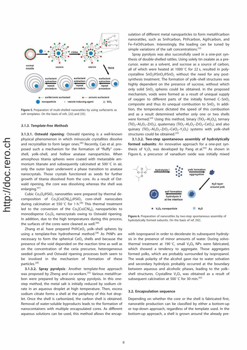
3.1.3.2. Two-step spontaneous assembly of hydrolyticallyformed subunits : An innovative approach for a one-pot syn-thesis of V2O5 was developed by Pang et al.[92] As shown inFigure 6, a precursor of vanadium oxide was initially mixed
with isopropanol in order to decelerate its subsequent hydroly-sis in the presence of minor amounts of water. During solvo-thermal treatment at 190 8C, small V4O9 NPs were fabricated,which showed a tendency to aggregate. Those aggregatesformed yolks, which are probably surrounded by isopropanol.The weak polarity of the alcohol gave rise to water solvationand secondary hydrolysis probably occurred at the boundarybetween aqueous and alcoholic phases, leading to the yolk–shell structures. Crystalline V2O5 was obtained as a result ofsubsequent calcination at 500 8C for 30 min.[92]
3.2. Encapsulation sequence
Depending on whether the core or the shell is fabricated first,nanorattle production can be classified by either a bottom-upor top-down approach, regardless of the template used. In thebottom-up approach, a shell is grown around the already pre-
Figure 5. Preparation of multi-shelled nanorattles by using surfactants assoft templates. On the basis of refs. [22] and [35] .
Figure 6. Preparation of nanorattles by two-step spontaneous assembly ofhydrolytically formed subunits. On the basis of ref. [92] .
8
http
://do
c.re
ro.c
h
pared core, and therefore can be considered as direct encapsu-lation. In the top-down approach, the procedure is reversedwith the shell being produced first.[39,51]
3.2.1. Bottom-up encapsulation
The bottom-up procedure, also named pre-core-post-shell,[93]
for the preparation of core@shell nanocomposites is the mostfrequently used method nowadays.[14,21,26, 31,44,45] In general, thecore is first produced[94] by one of many available methods forthe preparation of solid nanoparticles.[6b,95] Then, the formedcore is encapsulated by the shell. As already described, encap-sulation can be carried out by several different methods (Fig-ures 2, 3a and c) by using the microemulsion (section 1.3.1.2)or hard template methods (1.3.1.1). As cores frequently serveas nucleation centers for the subsequent growth of the shellaround them, this method is relatively facile compared withthe top-down-encapsulation approach, where certain precau-tions are required to ensure the initial entrance of the coreprecursors into the formed nanocontainer and their retentionbefore the subsequent formation of the core, as will be de-scribed in the next section.
3.2.2. Top-down encapsulation
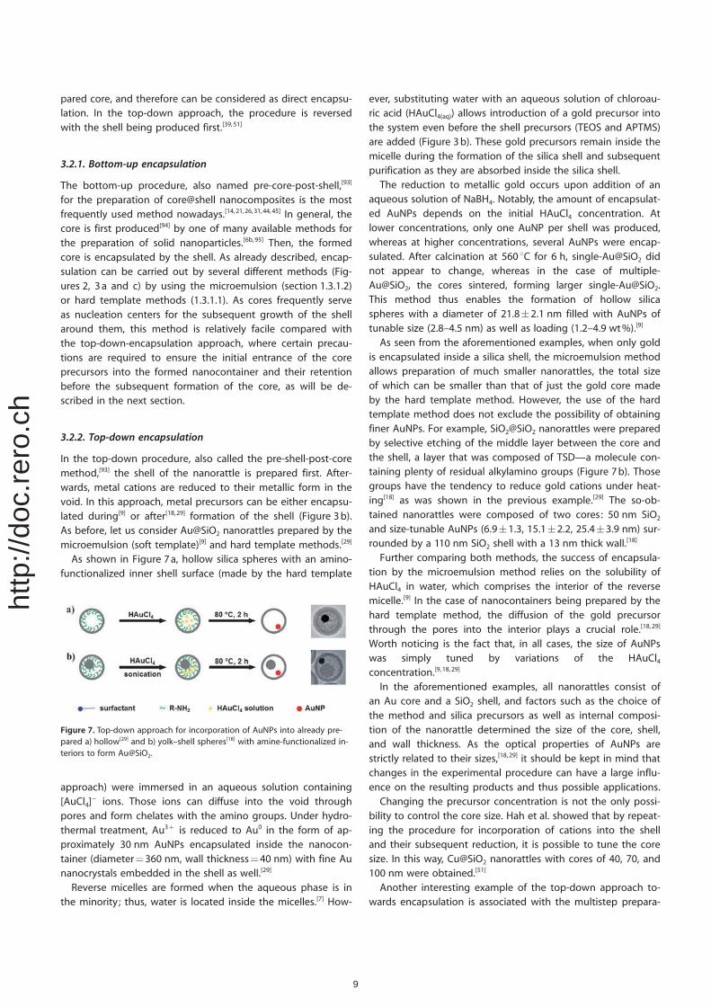
In the top-down procedure, also called the pre-shell-post-coremethod,[93] the shell of the nanorattle is prepared first. After-wards, metal cations are reduced to their metallic form in thevoid. In this approach, metal precursors can be either encapsu-lated during[9] or after[18,29] formation of the shell (Figure 3b).As before, let us consider Au@SiO2 nanorattles prepared by themicroemulsion (soft template)[9] and hard template methods.[29]
As shown in Figure 7a, hollow silica spheres with an amino-functionalized inner shell surface (made by the hard template
approach) were immersed in an aqueous solution containing[AuCl4]
� ions. Those ions can diffuse into the void throughpores and form chelates with the amino groups. Under hydro-thermal treatment, Au3+ is reduced to Au0 in the form of ap-proximately 30 nm AuNPs encapsulated inside the nanocon-tainer (diameter=360 nm, wall thickness=40 nm) with fine Aunanocrystals embedded in the shell as well.[29]
Reverse micelles are formed when the aqueous phase is inthe minority; thus, water is located inside the micelles.[7] How-
ever, substituting water with an aqueous solution of chloroau-ric acid (HAuCl4(aq)) allows introduction of a gold precursor intothe system even before the shell precursors (TEOS and APTMS)are added (Figure 3b). These gold precursors remain inside themicelle during the formation of the silica shell and subsequentpurification as they are absorbed inside the silica shell.
The reduction to metallic gold occurs upon addition of anaqueous solution of NaBH4. Notably, the amount of encapsulat-ed AuNPs depends on the initial HAuCl4 concentration. Atlower concentrations, only one AuNP per shell was produced,whereas at higher concentrations, several AuNPs were encap-sulated. After calcination at 560 8C for 6 h, single-Au@SiO2 didnot appear to change, whereas in the case of multiple-Au@SiO2, the cores sintered, forming larger [email protected] method thus enables the formation of hollow silicaspheres with a diameter of 21.8�2.1 nm filled with AuNPs oftunable size (2.8–4.5 nm) as well as loading (1.2–4.9 wt%).[9]
As seen from the aforementioned examples, when only goldis encapsulated inside a silica shell, the microemulsion methodallows preparation of much smaller nanorattles, the total sizeof which can be smaller than that of just the gold core madeby the hard template method. However, the use of the hardtemplate method does not exclude the possibility of obtainingfiner AuNPs. For example, SiO2@SiO2 nanorattles were preparedby selective etching of the middle layer between the core andthe shell, a layer that was composed of TSD—a molecule con-taining plenty of residual alkylamino groups (Figure 7b). Thosegroups have the tendency to reduce gold cations under heat-ing[18] as was shown in the previous example.[29] The so-ob-tained nanorattles were composed of two cores: 50 nm SiO2
and size-tunable AuNPs (6.9�1.3, 15.1�2.2, 25.4�3.9 nm) sur-rounded by a 110 nm SiO2 shell with a 13 nm thick wall.[18]
Further comparing both methods, the success of encapsula-tion by the microemulsion method relies on the solubility ofHAuCl4 in water, which comprises the interior of the reversemicelle.[9] In the case of nanocontainers being prepared by thehard template method, the diffusion of the gold precursorthrough the pores into the interior plays a crucial role.[18,29]
Worth noticing is the fact that, in all cases, the size of AuNPswas simply tuned by variations of the HAuCl4concentration.[9,18, 29]
In the aforementioned examples, all nanorattles consist ofan Au core and a SiO2 shell, and factors such as the choice ofthe method and silica precursors as well as internal composi-tion of the nanorattle determined the size of the core, shell,and wall thickness. As the optical properties of AuNPs arestrictly related to their sizes,[18,29] it should be kept in mind thatchanges in the experimental procedure can have a large influ-ence on the resulting products and thus possible applications.
Changing the precursor concentration is not the only possi-bility to control the core size. Hah et al. showed that by repeat-ing the procedure for incorporation of cations into the shelland their subsequent reduction, it is possible to tune the coresize. In this way, Cu@SiO2 nanorattles with cores of 40, 70, and100 nm were obtained.[51]
Another interesting example of the top-down approach to-wards encapsulation is associated with the multistep prepara-
Figure 7. Top-down approach for incorporation of AuNPs into already pre-pared a) hollow[29] and b) yolk–shell spheres[18] with amine-functionalized in-teriors to form Au@SiO2.
9
http
://do
c.re
ro.c
h
tion of thermoresponsive, luminescent nanorattles for con-trolled drug release (section 6.1.).[57] First, hollow mesoporoussilica shells were prepared by the sacrificial hard templatemethod and air was evacuated from the void under vacuum.Then, gadolinium and europium precursors were sucked intothe interior. Subsequent calcination at 550 8C led to the forma-tion of gadolinium oxide doped with europium cations. Toobtain thermoresponsive P(NIPAm-co-AAm) polymers, themonomers as well as a photoinitiator were encapsulated withthe aid of vacuum in a similar way. Exposing the purified nano-rattles to UV-light resulted in a photoinduced polymerizationinside the void and thus polymer located in between the coreand the shell. Fluorescent nanorattles were obtained by silani-zation with fluorescent silica precursor, whereas drug loadingwas achieved by soaking for 24 h.[57]
3.2.3. Changing the core
In the previous sections, methods of core incorporation werepresented. An alternative approach to core formation is metaldisplacement, a method that provides an interesting way toexchange already encapsulated metal cores for another metal.For example, Cu@SiO2 can be transformed into Ag@SiO2 bya redox reaction in which zero-valent CuNPs are oxidized toCu2+ cations while Ag+ cations are reduced to metallic Aginside the core.[51]
3.3. Void formation
3.3.1. Selective removal
In the previous subchapters, we have already seen diversifiedapproaches to building nanorattle structures. Most of thosemethods, however, do not provide direct formation of yolk–shell structures and core–shell nanoparticles are formed in-stead. The common procedures to reach yolk–shell structuresinvolve a) removal of the interlayer;[10, 15,19,21, 26,27,31, 34,37,46, 48,53,60, 67]
b) partial removal of the shell ;[70] c) partial[12,29, 30,96] or com-plete[29,57,83] removal of the core; d) removal of unreactedchemicals from the void.[9,14] Depending on the nature of thecompartment intended to be removed, in general, eithera chemical[10,29,30, 45] or a thermal[31,34,54] treatment is applied.
Chemical removal usually involves the use of aqueous solu-tions[15,21, 27,30,45, 46,48,55, 56,60,67] as well as organic solvents.[71,72] Inthe case of silica nanorattles, differences in density betweenthe silica building blocks are widely used. Porous compart-ments are less dense and thus more susceptible to etchingthan denser ones. The different porosities are generally ob-tained due to differences in structure or composition. In thefirst case, the presence of surfactants and co-surfactants leadsto the formation of silica shells with different porosity evenwhen a single silica precursor (TEOS) is used.[26] In the secondcase, the combination of silanes with organosilanes plays a cru-cial role.[10] For example, hybrid silica spheres composed of aninorganic core and an outer layer with a middle layer contain-ing organosilica frameworks was transformed into yolk–shellstructures upon etching with HF.[10] For the removal of silicacompartments, hot water,[56,67] solutions of HF,[10,19,53,70]
Na2CO3,[26,29] NH4OH,
[27,30,45] NaOH,[15,21,46, 48,55,60] KMnO4,[66] and/or
organosilane-assisted etching[23,69] are normally used. For exam-ple, Yang et al. demonstrated a one-pot transformation ofFe3O4@SiO2 and Au@SiO2 core–shell nanoparticles into yolk–shell ones by using an organosilane-assisted selective etchingmethod. As the Si�O�Si bonds of silica shells obtained fromTEOS in metal@SiO2 core–shell nanoparticles were disorderedowing to the short reaction time, the balance between hydrol-ysis and condensation was disturbed upon addition of organo-silane precursors. The outer layer of the silica shell was proba-bly protected from hydrolysis by deposited organosilica,whereas the silica network closer to the core was broken andgradually replaced by moieties of organosilanes.[69] The oppo-site mechanism was proposed by Zhang et al. ,[29] wherein SiO2
cores prepared by hydrolysis and condensation of TEOS by theStçber method[88] are the factors determining the size as wellas the polydispersity of further obtained nanorattles. Thesecores can be subsequently functionalized with amino groupsby hydrolysis and co-condensation of APTES and TEOS. Duringmild etching with Na2CO3, the solid silica core is dissolved. Theresistance of the shell towards etching is provided by the pres-ence of carbon chains (originating from organosilane) locatedon the inner and outer surface of the shell. These chains cancontain, for example, nitrogen and hydrogen atoms able toform hydrogen bonds with each other. The so-formed hydro-phobic layer protects the silica framework from the aqueousetching.[29] The void can also be formed by self-etching ofsilica. For instance, treatment of an Au@SiO2 core–shell nano-particle with mild aqueous ammonia leads to partial dissolu-tion of the shell and formation of silicate anions. Those anionsreact further with metal cations, resulting in the formation ofAu@metal silicate yolk–shell structures.[44] In the case of nano-rattles prepared by microemulsions, a void was obtained eitherby soaking in water for a few days[14] or by washing with hotwater for 40 min.[9,33] Moreover, PVP can be used in the so-called “surface-protected etching” process. In this process, thesilica compartment is removed either by hot water treat-ment[67,97] or by concentrated NaOH at room temperature.[98]
Removal of metal (Ni[12]) and metal oxide (Fe3O4[57]) cores is
usually done by etching with HCl. Dissolution of a Fe3O4 coreby NaBH4 catalyzed by AuNPs has been reported as well.[83] Asilver interlayer can be dissolved by oxidation with H2O2.
[37] De-spite the toxicity of KCN, it can be efficiently used for partial orcomplete removal of Au cores.[96,99]
When polystyrene beads are used as a hard template, theycan be removed by dissolution with organic solvents such astoluene[71] or xylene.[72] In the case of thermal removal of or-ganic compartments, a poly(methyl acrylic acid (PMAA) interlayer is decomposed to form the void, whereas the organiccomponent of C18TMS forms pores during pyrolysis (500 8C,6 h).[31] The polymeric carbon can be calcinated at 400 8C in2 h.[34]
3.3.2. Chemical transformation
3.3.2.1. Galvanic displacement : Galvanic displacement, alsocalled galvanic replacement, is a method based on the fact
10
http
://do
c.re
ro.c
h
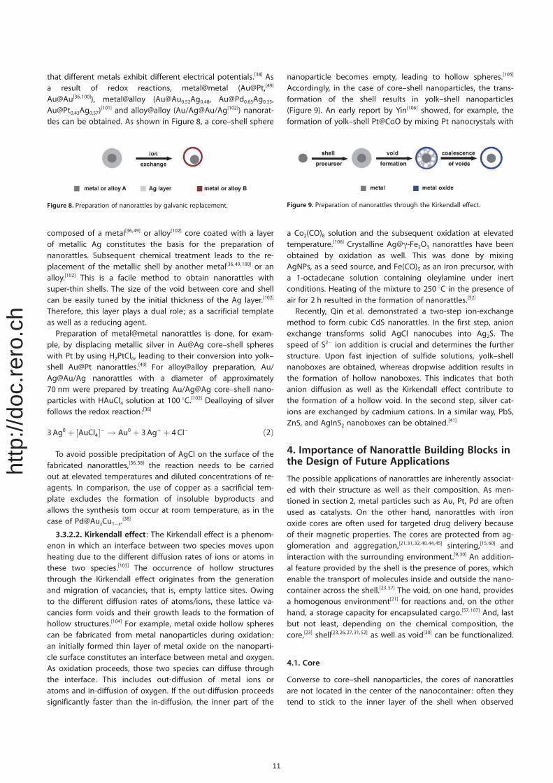
that different metals exhibit different electrical potentials.[38] Asa result of redox reactions, metal@metal (Au@Pt,[49]
Au@Au[36,100]), metal@alloy ([email protected], [email protected],[email protected])
[101] and alloy@alloy (Au/Ag@Au/Ag[102]) nanorat-tles can be obtained. As shown in Figure 8, a core–shell sphere
composed of a metal[36,49] or alloy[102] core coated with a layerof metallic Ag constitutes the basis for the preparation ofnanorattles. Subsequent chemical treatment leads to the re-placement of the metallic shell by another metal[36,49,100] or analloy.[102] This is a facile method to obtain nanorattles withsuper-thin shells. The size of the void between core and shellcan be easily tuned by the initial thickness of the Ag layer.[102]
Therefore, this layer plays a dual role; as a sacrificial templateas well as a reducing agent.
Preparation of metal@metal nanorattles is done, for exam-ple, by displacing metallic silver in Au@Ag core–shell sphereswith Pt by using H2PtCl6, leading to their conversion into yolk–shell Au@Pt nanorattles.[49] For alloy@alloy preparation, Au/Ag@Au/Ag nanorattles with a diameter of approximately70 nm were prepared by treating Au/Ag@Ag core–shell nano-particles with HAuCl4 solution at 100 8C.[102] Dealloying of silverfollows the redox reaction:[36]
3 Ag0 þ ½AuCl4�� ! Au0 þ 3 Agþ þ 4 Cl� ð2Þ
To avoid possible precipitation of AgCl on the surface of thefabricated nanorattles,[36,38] the reaction needs to be carriedout at elevated temperatures and diluted concentrations of re-agents. In comparison, the use of copper as a sacrificial tem-plate excludes the formation of insoluble byproducts andallows the synthesis tom occur at room temperature, as in thecase of Pd@AuxCu1�x.
[38]
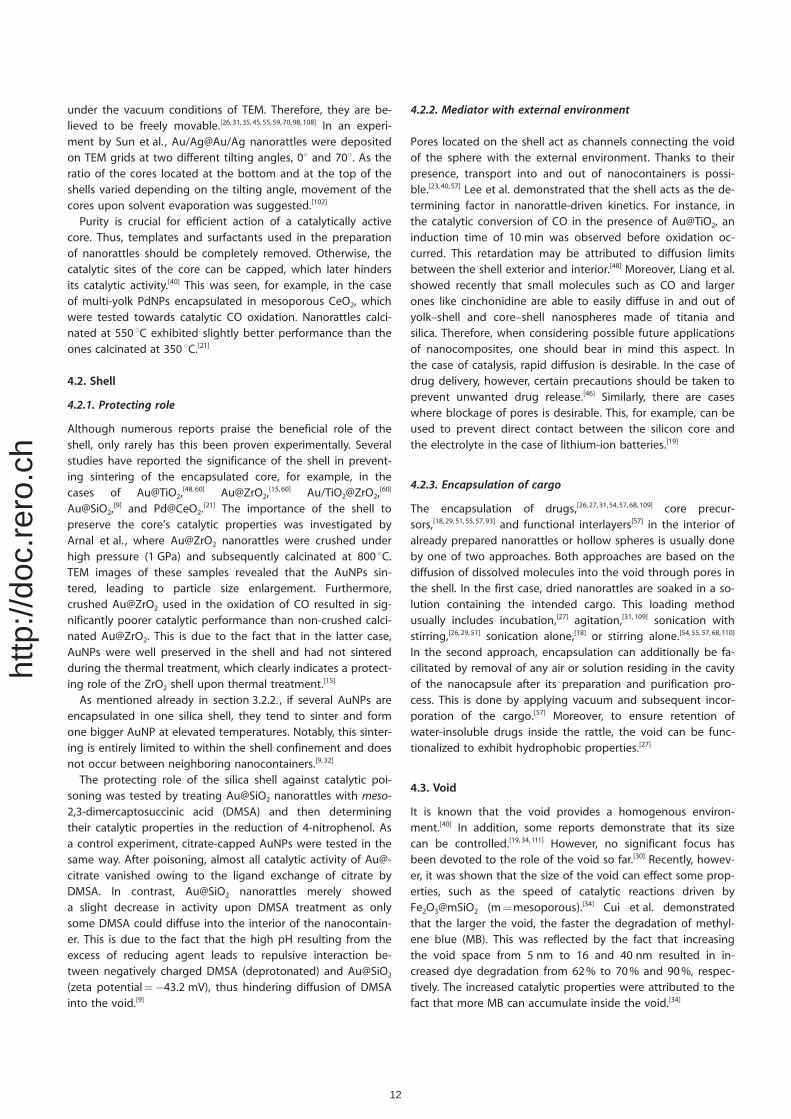
3.3.2.2. Kirkendall effect : The Kirkendall effect is a phenom-enon in which an interface between two species moves uponheating due to the different diffusion rates of ions or atoms inthese two species.[103] The occurrence of hollow structuresthrough the Kirkendall effect originates from the generationand migration of vacancies, that is, empty lattice sites. Owingto the different diffusion rates of atoms/ions, these lattice va-cancies form voids and their growth leads to the formation ofhollow structures.[104] For example, metal oxide hollow spherescan be fabricated from metal nanoparticles during oxidation:an initially formed thin layer of metal oxide on the nanoparti-cle surface constitutes an interface between metal and oxygen.As oxidation proceeds, those two species can diffuse throughthe interface. This includes out-diffusion of metal ions oratoms and in-diffusion of oxygen. If the out-diffusion proceedssignificantly faster than the in-diffusion, the inner part of the
nanoparticle becomes empty, leading to hollow spheres.[105]
Accordingly, in the case of core–shell nanoparticles, the trans-formation of the shell results in yolk–shell nanoparticles(Figure 9). An early report by Yin[106] showed, for example, theformation of yolk–shell Pt@CoO by mixing Pt nanocrystals with
a Co2(CO)8 solution and the subsequent oxidation at elevatedtemperature.[106] Crystalline Ag@g-Fe2O3 nanorattles have beenobtained by oxidation as well. This was done by mixingAgNPs, as a seed source, and Fe(CO)5 as an iron precursor, witha 1-octadecane solution containing oleylamine under inertconditions. Heating of the mixture to 250 8C in the presence ofair for 2 h resulted in the formation of nanorattles.[52]
Recently, Qin et al. demonstrated a two-step ion-exchangemethod to form cubic CdS nanorattles. In the first step, anionexchange transforms solid AgCl nanocubes into Ag2S. Thespeed of S2� ion addition is crucial and determines the furtherstructure. Upon fast injection of sulfide solutions, yolk–shellnanoboxes are obtained, whereas dropwise addition results inthe formation of hollow nanoboxes. This indicates that bothanion diffusion as well as the Kirkendall effect contribute tothe formation of a hollow void. In the second step, silver cat-ions are exchanged by cadmium cations. In a similar way, PbS,ZnS, and AgInS2 nanoboxes can be obtained.[41]
4. Importance of Nanorattle Building Blocks inthe Design of Future Applications
The possible applications of nanorattles are inherently associat-ed with their structure as well as their composition. As men-tioned in section 2, metal particles such as Au, Pt, Pd are oftenused as catalysts. On the other hand, nanorattles with ironoxide cores are often used for targeted drug delivery becauseof their magnetic properties. The cores are protected from ag-glomeration and aggregation,[21,31,32,40, 44,45] sintering,[15,60] andinteraction with the surrounding environment.[9,30] An addition-al feature provided by the shell is the presence of pores, whichenable the transport of molecules inside and outside the nano-container across the shell.[23, 57] The void, on one hand, providesa homogenous environment[21] for reactions and, on the otherhand, a storage capacity for encapsulated cargo.[57,107] And, lastbut not least, depending on the chemical composition, thecore,[23] shell[23,26, 27,31,52] as well as void[30] can be functionalized.
4.1. Core
Converse to core–shell nanoparticles, the cores of nanorattlesare not located in the center of the nanocontainer: often theytend to stick to the inner layer of the shell when observed
Figure 8. Preparation of nanorattles by galvanic replacement. Figure 9. Preparation of nanorattles through the Kirkendall effect.
11
http
://do
c.re
ro.c
h
under the vacuum conditions of TEM. Therefore, they are be-lieved to be freely movable.[26,31,35, 45,55,59, 70,98,108] In an experi-ment by Sun et al. , Au/Ag@Au/Ag nanorattles were depositedon TEM grids at two different tilting angles, 08 and 708. As theratio of the cores located at the bottom and at the top of theshells varied depending on the tilting angle, movement of thecores upon solvent evaporation was suggested.[102]
Purity is crucial for efficient action of a catalytically activecore. Thus, templates and surfactants used in the preparationof nanorattles should be completely removed. Otherwise, thecatalytic sites of the core can be capped, which later hindersits catalytic activity.[40] This was seen, for example, in the caseof multi-yolk PdNPs encapsulated in mesoporous CeO2, whichwere tested towards catalytic CO oxidation. Nanorattles calci-nated at 550 8C exhibited slightly better performance than theones calcinated at 350 8C.[21]
4.2. Shell
4.2.1. Protecting role
Although numerous reports praise the beneficial role of theshell, only rarely has this been proven experimentally. Severalstudies have reported the significance of the shell in prevent-ing sintering of the encapsulated core, for example, in thecases of Au@TiO2,
[48,60] Au@ZrO2,[15,60] Au/TiO2@ZrO2,
[60]
Au@SiO2,[9] and Pd@CeO2.
[21] The importance of the shell topreserve the core’s catalytic properties was investigated byArnal et al. , where Au@ZrO2 nanorattles were crushed underhigh pressure (1 GPa) and subsequently calcinated at 800 8C.TEM images of these samples revealed that the AuNPs sin-tered, leading to particle size enlargement. Furthermore,crushed Au@ZrO2 used in the oxidation of CO resulted in sig-nificantly poorer catalytic performance than non-crushed calci-nated Au@ZrO2. This is due to the fact that in the latter case,AuNPs were well preserved in the shell and had not sinteredduring the thermal treatment, which clearly indicates a protect-ing role of the ZrO2 shell upon thermal treatment.[15]
As mentioned already in section 3.2.2. , if several AuNPs areencapsulated in one silica shell, they tend to sinter and formone bigger AuNP at elevated temperatures. Notably, this sinter-ing is entirely limited to within the shell confinement and doesnot occur between neighboring nanocontainers.[9, 32]
The protecting role of the silica shell against catalytic poi-soning was tested by treating Au@SiO2 nanorattles with meso-2,3-dimercaptosuccinic acid (DMSA) and then determiningtheir catalytic properties in the reduction of 4-nitrophenol. Asa control experiment, citrate-capped AuNPs were tested in thesame way. After poisoning, almost all catalytic activity of Au@-citrate vanished owing to the ligand exchange of citrate byDMSA. In contrast, Au@SiO2 nanorattles merely showeda slight decrease in activity upon DMSA treatment as onlysome DMSA could diffuse into the interior of the nanocontain-er. This is due to the fact that the high pH resulting from theexcess of reducing agent leads to repulsive interaction be-tween negatively charged DMSA (deprotonated) and Au@SiO2
(zeta potential=�43.2 mV), thus hindering diffusion of DMSAinto the void.[9]
4.2.2. Mediator with external environment
Pores located on the shell act as channels connecting the voidof the sphere with the external environment. Thanks to theirpresence, transport into and out of nanocontainers is possi-ble.[23,40,57] Lee et al. demonstrated that the shell acts as the de-termining factor in nanorattle-driven kinetics. For instance, inthe catalytic conversion of CO in the presence of Au@TiO2, aninduction time of 10 min was observed before oxidation oc-curred. This retardation may be attributed to diffusion limitsbetween the shell exterior and interior.[48] Moreover, Liang et al.showed recently that small molecules such as CO and largerones like cinchonidine are able to easily diffuse in and out ofyolk–shell and core–shell nanospheres made of titania andsilica. Therefore, when considering possible future applicationsof nanocomposites, one should bear in mind this aspect. Inthe case of catalysis, rapid diffusion is desirable. In the case ofdrug delivery, however, certain precautions should be taken toprevent unwanted drug release.[46] Similarly, there are caseswhere blockage of pores is desirable. This, for example, can beused to prevent direct contact between the silicon core andthe electrolyte in the case of lithium-ion batteries.[19]
4.2.3. Encapsulation of cargo
The encapsulation of drugs,[26,27, 31,54,57, 68,109] core precur-sors,[18,29, 51,55,57, 93] and functional interlayers[57] in the interior ofalready prepared nanorattles or hollow spheres is usually doneby one of two approaches. Both approaches are based on thediffusion of dissolved molecules into the void through pores inthe shell. In the first case, dried nanorattles are soaked in a so-lution containing the intended cargo. This loading methodusually includes incubation,[27] agitation,[31,109] sonication withstirring,[26,29, 51] sonication alone,[18] or stirring alone.[54,55, 57,68, 110]
In the second approach, encapsulation can additionally be fa-cilitated by removal of any air or solution residing in the cavityof the nanocapsule after its preparation and purification pro-cess. This is done by applying vacuum and subsequent incor-poration of the cargo.[57] Moreover, to ensure retention ofwater-insoluble drugs inside the rattle, the void can be func-tionalized to exhibit hydrophobic properties.[27]
4.3. Void
It is known that the void provides a homogenous environ-ment.[40] In addition, some reports demonstrate that its sizecan be controlled.[19,34,111] However, no significant focus hasbeen devoted to the role of the void so far.[30] Recently, howev-er, it was shown that the size of the void can effect some prop-erties, such as the speed of catalytic reactions driven byFe2O3@mSiO2 (m=mesoporous).[34] Cui et al. demonstratedthat the larger the void, the faster the degradation of methyl-ene blue (MB). This was reflected by the fact that increasingthe void space from 5 nm to 16 and 40 nm resulted in in-creased dye degradation from 62% to 70% and 90%, respec-tively. The increased catalytic properties were attributed to thefact that more MB can accumulate inside the void.[34]
12
http
://do
c.re
ro.c
h
A sufficiently large and rigid void is important in caseswhere the core changes its volume, as occurs when alloyanodes of Li-ion batteries undergo a lithium insertion/extrac-tion process.[19,32, 111]
Hydrophobic voids can be prepared by silylation of compart-ments with silica precursors containing long carbon chains, forexample, C18TES
[30] and C18TMS.[27] Additionally, using a precur-sor with branched organic chains, such as IBMS, superhydro-phobic shells can be obtained.[70]
5. Nanorattle Characterization
As mentioned, the building blocks of the nanorattles deter-mine their properties and thus influence their potential appli-cations. Therefore, it is crucial to know the exact chemicalcomposition as well as the structure of the prepared nanorat-tles. It is well known that the characterization of nanomaterialsshould always include more than one technique owing to thelimitations of the used methods. Thus, special care should betaken in the choice of adequate methods as well as the inter-pretation of the results.
5.1. Composition of the nanorattles
There are several methods to determine the composition ofnanorattles. The method best suited depends on the nature ofthe nanorattle properties, such as crystallinity, magnetism, orluminescence. The presence of noble metals, such as Ag[33] andAu,[9,18,29, 31,37,83] can be verified by simple UV/Vis spectroscopydue to their surface plasmon resonance. The content of themetallic core (Ag,[33] Au,[9,18] Fe,[52,54] Pd[61]) in the nanorattle orthe composition of alloy nanorattles[101] can be determined by,for example, inductively coupled plasma optical-emission spec-troscopy (ICP-OES).
The composition of crystalline nanorattles isnormally determined by X-ray diffraction(XRD),[8,9,12, 19,21,23, 26–29,31,32, 40,41,44, 45,51,53, 56,57, 69,83,87, 92] or X-raypowder diffraction (XRPD),[61] energy-dispersive X-ray spectros-copy (EDS or EDX), or wide-angle XRD.[18] Sometimes, however,strong background signals from the amorphous silica shell canhinder the detection of the encapsulated core at low core con-tents, as shown in a study by Zhu et al. , where the XRD pat-tern of the crystalline Fe3O4 core could only be observed afterdissolution of the silica shell.[54] Furthermore, we have observedthat XRPD does not detect small amounts of metallic silverpresent in Ag@SiO2 nanorattles. Therefore, the presence ofAgNPs can be only detected by UV/Vis spectroscopy. Alterna-tively, increased loading with AgNPs results in clearly visible Agpeaks in the diffractograms.[33]
In the case of rattles containing organic residues, their con-tent can be verified by thermal analysis, such as thermogravi-metric analysis and differential thermal analysis, TGA-DTA.[10,27,31, 55,87,89]
Fourier transform infrared spectroscopy (FTIR) is frequentlyused for the detection of functional groups.[23,26,29–31,40, 45,55,57, 87]
However, if some components, such as molecules attachedinto the surface, are only present in small amounts, their pres-
ence might not be detected.[55] Furthermore, encapsulationcan lead to a significant weakening of the bands correspond-ing to the cargo as well.[87] With regard to composites contain-ing �NH2 groups, their content can be quantified by the Kaiserassay,[10] or a fluorenylmethyloxycarbonyl (FMOC) quantificationprotocol.[26] Less frequently used but powerful methods in-clude UV-Raman spectroscopy,[23] 13C cross-polarization magic-angle spinning (CP-MAS) nuclear magnetic resonance (NMR)spectroscopy[23] and 29Si CP-MAS NMR spectroscopy.[69]
In the case of magnetic-compartment-containing rattles,such as those with Fe3O4
[8,30,55, 69,87,109] and Fe2O3,[27,31] a magneti-
zation hysteresis loop is frequently measured. It should be no-ticed that the saturation magnetization is decreased whennonmagnetic layers are built around magnetic iron oxide.[8,55, 87]
The presence of fluorescent dyes[26] and folic acid[27] can usu-ally be detected by UV/Vis spectroscopy,[26,27] whereas FITC[26]
and luminescent particles like Gd2O3[57] are measured by photo-
luminescence spectroscopy.As already mentioned, the charge of the particle surface
changes depending of the presence of functional groups[10]
and coatings.[68] This influences the zeta potential (z-potential)as well as the stability of nanorattles. For measurement of thez-potential, dynamic light scattering (DLS)[68,110] is usually used.
5.2. Proof of core encapsulation
Transmission electron microscopy (TEM) is the most frequentlyused method for determining whether the obtainednanoparticles are nanorattles or not.[8–10,12,14, 15,18–26,28–32,34, 35,
37,40–42,44, 45,48, 49,51–57,60,61, 66,69,70, 83,87, 89,91,92, 101,109,112,113] As electronstraverse the specimen, it is possible to distinguish between re-gions of varying electron density. In general, compartmentswith higher electron density appear darker compared withthose of lower electron density.[114] For example, Ag@SiO2
nanorattles appear to be composed of a darker core anda brighter shell.[33] In the case of a silica core coated with layersof silica functionalized with organic groups,[10] no differencecould be observed in the TEM, but removal of the middle layerled to the formation of a bright void.[10] In situ TEM is a power-ful technique to study the progress of reactions.[19] In the workof Liu et al. , for instance, it was successfully used to show theelectrochemical lithiation of Si@C nanorattles and for observ-ing the size expansion of the core.[19]
Scanning electron microscopy (SEM) is oftenused for the visualization of the morpholo-gy[8,10,19, 22,24–26,28,29, 34,40–42,44, 45,56,66, 69,83,87, 89,91,92, 109,112,113] of thesample and in many cases, images of broken spheres with thecore located inside provide proof of encapsulation.[10,24,92, 113]
Usually, the core of the rattle is invisible when usingSEM.[8,28, 29,32,44, 45,66,83, 113] However, working at elevated accelera-tion voltages (5 kV,[26] 10 kV[10]) may enable visualization of thecore.[10,22, 26,32] Converse to TEM, the more electron dense ele-ments appear brighter than less electron dense elements,which appear dark. For example, gold in Au@SiO2 nanorattlesis far brighter than its surrounding silica shell.[29] Sometimesother electron microscopes such as high-angle annular dark-field scanning TEM (HAADF-STEM) can be used.[8,18,38, 52,57]
13
http
://do
c.re
ro.c
h
SEM and TEM are often coupled to EDS,[23,28,29,38, 41,44, 45,54–57]
enabling elemental mapping of nanorattles. This techniquecan be particularly useful when other detection methods fail inthe assessment of chemical composition.
X-ray photoelectron spectroscopy (XPS) allows the character-ization of surface composition[18,19,26, 28,40,52] with a detectiondepth limit of approximately 10 nm.[18,28] Therefore, if the shellthickness exceeds this value, any encapsulated cargo will notbe detected; thus, this can prove encapsulation. In this case,however, another method should also be used to confirm thepresence and nature of the encapsulated core. For example, ina study by Zhang et al. , TEM of Pt@CeO2 demonstrated a rattlestructure, EDS confirmed the presence of Pt, Ce, and O, where-as XPS showed only Ce and O, thus additionally confirming theencapsulation of Pt.[28] However, in a study by Tan et al. , thesilica nanorattles were of much smaller size and had thinnershells than the aforementioned rattles so the presence of theAu core could be detected by XPS.[18] In conclusion, thereshould always be a combination of different methods for thecharacterization of nanorattles.
5.3. Surface area and porosity
Nitrogen absorption–desorption isotherms allow the determi-nation of the specific surface area (SSA) of nanorat-tles,[8–10,21, 23,26,27, 29–31,40,45, 53,54,56, 57,61,66, 69,87,109,112] whereas the poredistribution can be addressed by the Barett–Joyner–Haleda(BJH) method.[10,21, 26,27,29–31, 54,66,69, 112] These parameters are espe-cially crucial when considering potential applications. The spe-cific surface area is generally related to the size of the porevolume. Thus, it largely depends on the presence of moleculesattached to or absorbed on the surface. For example, magneticiron oxide encapsulated in mesoporous silica has a specific sur-face area of 494.5 m2g�1, which decreases significantly to120.3 m2g�1 after attachment of PEG and folic acid (FA) conju-gates. However, the presence of a large hysteresis loop be-tween absorption and desorption shows the presence of anaccessible cavity structure, which is necessary for further drugloading.[31] Similarly, Kang et al. showed that a gradual decreasein pore volume, surface area, and pore diameter was the resultof step-wise loading of hollow mesoporous silica spheres witha Gd2O3:Eu
3+ core, a thermoresponsive polymer, and subse-quently with a drug.[57]
5.4. Loading with cargo
Loading of nanocontainers with a drug as well as its releasecan be determined by UV/Vis spectroscopy in case of UV/Vis-active drugs.[26,31, 37] For example, loading can be measured in-directly by calculating the difference between the concentra-tion of the drug in the initial solution and in the remaining su-pernatant after loading.[31] Another method to verify loadingwith a drug is FTIR,[54,57] which indicates the presence of thefunctional groups of the drug, whereas thermogravimetricanalysis (TGA) allows determination of the weight content ofthe drug.[54] However, when using UV/Vis spectroscopy andTGA for determination of drug loading, one should take into
consideration the possible presence of molecules attached tothe nanocontainer surface rather than encapsulated within, thepresence of which can be due to not only drug but also impur-ities or surfactants as well. In addition, single differential ther-mal analysis (SDTA) could serve as an elegant complementarymethod to determine the temperature differences of samplesunder heating.[115] Cargo absorbed on the surface should, ingeneral, decompose earlier than the encapsulated cargo.
6. Applications
Already several reviews have focused on the properties andpossible applications of nanorattles.[16,116] Thus, we will focuson some more recent examples of these applications as well ashighlight the superior performance of nanorattles comparedwith traditional nanoparticles. Owing to the diversity of thepossible combinations of the building blocks, research is in-creasingly focused on applications in areas of social and eco-nomic interest, such as drug delivery, catalysis, and Li-ion bat-teries. Although magnetic solid-phase extraction, high-per-formance microwave absorbers, and antimicrobial nanorattlescurrently constitute a niche area based on the amount of pub-lications, they may well find broader application in the future.
6.1. Drug delivery
Development of new materials to efficiently fight cancer stillremains an eminent challenge, and high requirements are im-posed on nanoparticles intended to serve as drug carriers.Nanoparticles that act solely as storage and transport for drugsis not sufficient in terms of efficient treatment; therefore, novelnanodrugs often exhibit several additional functionalities. Rat-tles with magnetic cores[27] and ligands for cellular recep-tors[27,31] located on the shell surface are intended for targeteddrug delivery. Visualization of the nanocontainers can be ach-ieved either by magnetic resonance imaging (MRI)[27] or func-tionalization with fluorescent dyes.[26] In addition, the latestgeneration of smart nanorattles is equipped with stimuli-re-sponsive mechanisms.[57] As will be shown, only nanorattlescomposed of silica shells are of the interest for biomedical ap-plications so far.
After encapsulation of maghemite g-Fe2O3 into mesoporoussilica (g-Fe2O3@SiO2), the surface of the shell can be furthergrafted with PEG, which is a biocompatible polymer, and withFA, widely used for tumor targeting. These nanorattles can beefficiently loaded with an anti-cancer drug, such as doxorubicinhydrochloride (DOX), with a relatively large loading capacity of220 mgmg�1 and slowly release the drug over 67 h.[31] As DOXis released rapidly only during first 6 h and subsequently its re-lease is significantly slower, this rattle-type carrier could possi-bly be used in small doses to avoid flooding patients’ bodieswith a drug and at the same time provide a constant cancertreatment.
Nanorattles of 200 nm SiO2@SiO2 were fluorescently labelledand pegylated, then tested for applications in drug delivery aswell as cell imaging. After penetrating the plasma membrane,these nanorattles were found in the cytoplasm of cancer cells
14
http
://do
c.re
ro.c
h
(cell line MDA-MB-231) with some located inside lysosomes. Asdetermined by an MTT assay using 3-(4,5-dimethylthiazol-2-yl)-2,5-diphenyltetrazolium bromide, no significant cytotoxicitywas observed after 1 and 2 days when concentrations of up to200 mgmL�1 were applied, showing their promising biocom-patibility. As determined by UV/Vis spectroscopy, 44.25 mg ofDOX can be loaded into 1 mg of functionalized nanorattles,with a loading efficiency of 70.8%. The speed of drug releasewas strictly pH dependent as it was observed that after 107 hat pH 4.8, 45% of drug was released, whereas at pH 7.4 only17% was released. This was attributed to the protonation anddeprotonation of the amine groups of the drug, leading to al-tered electrostatic interactions with the mesoporous silica.DOX-loaded nanorattles showed extraordinary cytotoxicity,even at concentrations as low as 3.125 mgmL�1, the toxicity ofwhich was time dependent and increased with longer incuba-tion times.[26]
Although DOX is a frequently studied drug for encapsulationin nanorattles,[26,31] it is not the only one being tested. For ex-ample, ferromagnetic Fe3O4@mSiO2 (m=mesoporous) can beefficiently loaded with aspirin (27.7 wt%).[54] The aspirin-loadedrattles were characterized by initial fast drug release within thefirst 12 h, which gradually decelerated with time. As with theaforementioned fluorescent SiO2@SiO2 nanorattles loaded withDOX, the release was highly pH dependent. In contrast toDOX, aspirin release was higher at high pH, which was relatedto its higher solubility at high pH.[54]
Another example of nanorattles with a magnetic Fe3O4 corewas reported by Wu and co-workers.[27] A hydrophobic voidwas obtained by use of a silica precursor containing n-octadec-yl groups, whereas conjugation with PEG and FA provided sur-face functionality. The cytotoxicity and cellular uptake towardstwo cancer cell lines, namely HeLa and MCF-7, were studied.These magnetic mesoporous silica nanorattles showed low tox-icity and folate-receptor-mediated uptake. Loading with doce-taxel (DOC) resulted in significant cytotoxicity towards bothcell lines with the HeLa cells showing higher cytotoxicity. Thiswas probably due to enhanced uptake owing to the overex-pression of folate receptors on the HeLa cell surface, a processthat does not occur in the case of MCF-7 cells. Superior cyto-toxicity of encapsulated DOC over the free drug showed theevident and advantageous role of the shell. As the interior ofthe nanorattle is hydrophobic, the water-insoluble drug can beefficiently loaded inside the nanocontainers. Once they aretaken up, the drug is released in the hydrophobic parts of thecellular compartments. In vivo tests showed that these mag-netic nanocontainers can be guided to the tumor location byuse of an external magnet, a process that resulted in increaseduptake (0.24 mg of Fe per gram liver weight) compared to theuptake in the absence of an external magnetic field (0.18 mgof Fe per gram liver weight). All functionalities provided by thecore (magnetic), void (hydrophobic), and shell (containing li-gands), make these nanorattles an attractive means of target-ing drug delivery as well as for magnetic resonance imaging.[27]
The aforementioned nanorattles might serve as potentialvectors in drug delivery primarily because of the possibility ofloading drugs in their cavities. These drugs can then be re-
leased over quite long periods of time.[26,31, 54] In many cases,however, controlled drug release is more desirable. As severalmaterials have been reported to respond to external stimuli,such as temperature, pH, ionic strength, magnetic field, ultra-sound, and enzymes, they have potential for such medical ap-plications.[117,118] A lot of focus has been devoted to polymersbecause of their temperature-responsive ability to reversiblyundergo a phase transition.[118, 119] For example, PNIPAm(poly(N-isopropylacrylamide)) is swollen below 32 8C, whereasabove this temperature, the polymer shrinks.[120] This featurecan be effectively utilized in the temperature-responsive open-ing of shell pores. Kang et al. produced hybrid nanorattlescomposed of an inorganic Gd2O3:Eu
3+ core and a silica shellwith an organic polymer layer in between.[57] These hybrids didnot show significant toxicity towards SKOV3 ovarian cancercells. Additionally, fluorescently labelled nanorattles wereshown to be taken up and localized in the cytoplasm. Owingto the presence of Gd, those composites might serve as poten-tial contrast agents in MRI. Then, a non-steroidal, anti-inflam-matory drug, indomethacin (IMC), was loaded into the rattleswith and without PNIPAm polymer. In absence of the hydrogel,the drug was constantly released regardless of the appliedtemperature (20 8C and 45 8C). In the presence of the polymerlayer, however, IMC release was observed only at higher tem-perature (45 8C), whereas at lower temperature (20 8C), the re-lease was completely blocked. This temperature-responsive be-havior is probably due to water absorption as well as volumeexpansion at 20 8C, which led to the filling of the channels andthe void, thus preventing the drug from being released. Whenthe temperature is increased, the polymer shrinks, channels areopened, and IMC is squeezed out from the hydrogel network.Interestingly, Gd2O3:Eu
3+ photoluminescence was highly de-pendent on the concentration of the loaded drug. Therefore,these nanorattles can also function as tracing or detectingagents.[57]
Silica nanorattles also demonstrate potential as vaccine adju-vants.[110] In a study by Liu et al. , a model protein, ovalbumin(OVA), was loaded on SiO2 nanorattles, mesoporous SiO2 NPs,and solid SiO2 NPs for comparison. Greater amounts of proteinwere absorbed on the nanorattles compared with the othersilica particles. The positive charge on the surface of the nano-rattles, as well as the presence of the void, contributed to a rel-atively high loading content of 14.76%. Treating murine mac-rophage cell lines with these nanorattles at concentrations inthe range 6.25–400 mgmL�1 did not affect cell viability. Like-wise, regardless of the concentration of the nanorattles used(10, 25 and 50 mgkg�1), the immune organs of mice, that is,the spleen and thymus, did not demonstrate any abnormalities14 days after the last injection. OVA-loaded nanorattles stimu-lated the immune response of mice, leading to increased levelsof OVA-specific IgG antibodies. Interestingly, those levels wereconsiderably higher (OD=0.42) than those resulting fromtreatment solely with OVA (OD=0.11). Good in vitro and invivo biocompatibility of these nanorattles, as well as the eleva-tion of the OVA antibody level after single dose vaccination,make those nanorattles promising candidates for vaccineadjuvants.[110]
15
http
://do
c.re
ro.c
h
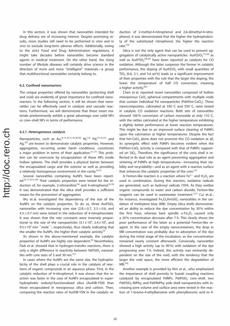
In this section, it was shown that nanorattles intended fordrug delivery are of increasing interest. Despite promising re-sults, more studies still need to be performed in vitro and invivo to exclude long-term adverse effects. Additionally, owingto the strict Food and Drug Administration regulations, itmight take decades before nanorattles become standardagents in medical treatment. On the other hand, the risingnumber of lifestyle diseases will certainly drive science in thedirection of more and more “intelligent” materials—a groupthat multifunctional nanorattles certainly belong to.
6.2. Confined nanoreactors
The unique properties offered by nanorattles (protecting shelland void) are evidently of great importance for confined nano-reactors. In the following section, it will be shown that nano-rattles can be effectively used in catalysis and cascade reac-tions. Furthermore, we will demonstrate that these smart ma-terials predominantly exhibit a great advantage over solid NPsor core–shell NPs in terms of performance.
6.2.1. Heterogeneous catalysis
Nanoparticles, such as Au,[9,15,18, 31,44, 48,60] Ni,[12] Pd,[21,53, 61] andAg,[33] are known to demonstrate catalytic properties. However,aggregation, occurring under harsh conditions, constitutesa major problem in terms of their application.[21,31] This prob-lem can be overcome by encapsulation of these NPs insidehollow spheres. The shell provides a physical barrier betweenthe encapsulated cargo and the exterior as well as providinga relatively homogenous environment in the cavity.[9, 21]
Several nanorattles containing AuNPs have been report-ed.[9,15, 18,31,60] Their catalytic properties were tested for the re-duction of, for example, 2-nitroaniline[18] and 4-nitrophenol.[9, 70]
It was demonstrated that the silica shell provides a sufficientmeans for the prevention of aggregation.
Wu et al. investigated the dependency of the size of theAuNPs on the catalytic properties. To do so, three Au@SiO2
nanorattles with increasing core size (2.8�0.7, 3.3�0.6, and4.5�0.7 nm) were tested in the reduction of 4-nitrophenolate.It was shown that the rate constants were inversely propor-tional to the size of the nanoparticles (3.1�106, 2.4�106, and9.5�105 min�1mole�1, respectively), thus clearly indicating thatthe smaller the AuNPs, the higher their catalytic activity.[9]
As shown in the above-mentioned example, the catalyticproperties of AuNPs are highly size dependent.[9] Nevertheless,Park et al. showed that in hydrogen-transfer reactions, there isonly a slight difference in reactivity between Ni@SiO2 nanorat-tles with core sizes of 3 and 30 nm.[12]
In cases where the AuNPs are the same size, the hydropho-bicity of the shell plays a crucial role in the catalysis of reac-tions of organic compounds in an aqueous phase. First, in thecatalytic reduction of 4-nitrophenol, it was shown that the re-action was faster in the case of AuNPs encapsulated in super-hydrophobic isobutyl-functionalized silica (Au@IB-YSN) thanthose encapsulated in mesoporous silica and carbon. Then,comparing the reaction rates of Au@IB-YSN in the catalytic re-
duction of 2-methyl-4-nitrophenol and 2,6-dimethyl-4-nitro-phenol, it was demonstrated that the higher the hydrophobici-ty of the substituted nitrophenol, the higher the reactionrate.[70]
Silica is not the only agent that can be used to prevent ag-gregation of catalytically active nanoparticles: Au@ZrO2
[15,60] aswell as Au@TiO2
[48,60] have been reported as catalysts for COoxidation. Although the latter surpasses the former in catalyticperformance, the doping of Au@ZrO2 with small quantities ofTiO2 (0.6, 3.1, and 5.6 wt%) leads to a significant improvementof their properties with the rule that the larger the doping, thelower the temperature of half CO conversion, meaninga higher activity.[60]
Chen et al. reported novel nanorattles composed of hollowmesoporous CeO2 spherical compartments with multiple voidsthat contain individual Pd nanoparticles (Pd@hm-CeO2). Thesenanocomposites, calcinated at 350 8C and 550 8C, were testedin catalytic CO oxidation reactions. Both sets of nanorattlesshowed 100% conversion of carbon monoxide at only 110 8C,with the rattles calcinated at the higher temperature exhibitinga slightly better performance at lower reaction temperatures.This might be due to an improved surface cleaning of PdNPsupon the calcination at higher temperatures. Despite the factthat hm-CeO2 alone does not promote this CO oxidation at all,its synergetic effect with PdNPs becomes evident when thePd@hm-CeO2 activity is compared with that of PdNPs support-ed on SiO2. Therefore, the significance of the ceria shell is re-flected in its dual role as an agent preventing aggregation andsintering of PdNPs at high temperatures—increasing their sta-bility and recyclability—and as an agent with a reactive surfacethat enhances the catalytic properties of the core.[21]
A Fenton-like reaction is a reaction where Fe3+ and H2O2 areused in combination. During this reaction, oxidative radicalsare generated, such as hydroxyl radicals (COH). As they oxidizeorganic compounds to water and carbon dioxide, Fenton-likereagents can be used in wastewater treatment.[121] Cui et al. ,for instance, investigated Fe2O3@mSiO2 nanorattles in the oxi-dation of methylene blue (MB). Empty silica shells demonstrat-ed an ability to reduce the dye concentration by 30% withinthe first hour, whereas bare spindle a-Fe2O3 caused onlya 20% concentration decrease after 7 h. This clearly shows thepoor performance of the latter as a potential Fenton-like re-agent. In the case of the empty nanocontainers, the drop inMB concentration was probably due to adsorption of the dyeduring the initial stage of the incubation, as the concentrationremained nearly constant afterwards. Conversely, nanorattlesshowed a high activity (up to 90%) with oxidation of the dyeprogressing over 7 h. Indeed, this activity was eminently de-pendent on the size of the void, with the tendency that thelarger the void space, the more efficient the degradation ofMB.[34]
Another example is provided by Kim et al. , who emphasizedthe importance of shell porosity in Suzuki coupling reactionscatalyzed by encapsulated PdNPs. Pd@SiO2 core–shell, twoPd@SiO2-NiPhy, and Pd@NiPhy yolk–shell nanoparticles with in-creasing pore volume and surface area were tested in the reac-tion of 1-bromo-4-ethylbenzene with phenylboronic acid to 4-
16
http
://do
c.re
ro.c
h
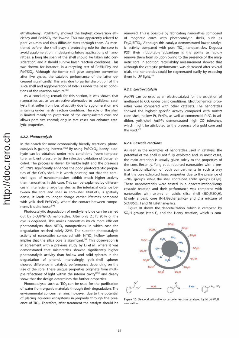
ethylbiphenyl. Pd@NiPhy showed the highest conversion effi-ciency and Pd@SiO2 the lowest. This was apparently related topore volumes and thus diffusion rates through them. As men-tioned before, the shell plays a protecting role for the core toavoid agglomeration. In designing future applications of nano-rattles, a long life span of the shell should be taken into con-sideration, and it should survive harsh reaction conditions. Thiswas shown, for instance, in a recycling test of Pd@NiPhy andPd@SiO2. Although the former still gave complete conversionafter five cycles, the catalytic performance of the latter de-creased significantly. This was due to partial dissolution of thesilica shell and agglomeration of PdNPs under the basic condi-tions of the reaction mixture.[53]
As a concluding remark for this section, it was shown thatnanorattles act as an attractive alternative to traditional cata-lysts that suffer from loss of activity due to agglomeration andsintering under harsh reaction condition. The role of the shellis limited mainly to protection of the encapsulated core andallows pore size control ; only in rare cases can enhance cata-lytic properties.
6.2.2. Photocatalysis
In the search for more economically friendly reactions, photo-catalysis is gaining interest.[122] By using Pt@CeO2, benzyl alde-hyde can be obtained under mild conditions (room tempera-ture, ambient pressure) by the selective oxidation of benzyl al-cohol. The process is driven by visible light and the presenceof PtNPs significantly enhances the poor photocatalytic proper-ties of the CeO2 shell. It is worth pointing out that the core–shell type of nanocomposites exhibit much higher activitythan nanorattles in this case. This can be explained by differen-ces in interfacial charge transfer : as the interfacial distance be-tween the core and shell in core–shell Pt@CeO2 is spatiallydense, it leads to longer charge carrier lifetimes comparedwith yolk–shell Pt@CeO2, where the contact between compo-nents is quite loose.[28]
Photocatalytic degradation of methylene blue can be carriedout by SiO2@NiTiO3 nanorattles. After only 2.5 h, 90% of thedye is degraded. This makes nanorattles much more efficientphotocatalysts than NiTiO3 nanoparticles, in which case thedegradation reached solely 22%. The superior photocatalyticactivity of nanorattles compared with NiTiO3 hollow spheresimplies that the silica core is significant.[45] This observation isin agreement with a previous study by Li et al. , where it wasdemonstrated that microrattles showed significantly higherphotocatalytic activity than hollow and solid spheres in thedegradation of phenol. Interestingly, yolk–shell spheresshowed difference in catalytic performance depending on thesize of the core. These unique properties originate from multi-ple reflections of light within the interior cavity[113] and clearlyshow that the design determines the further properties.
Photocatalysts such as TiO2 can be used for the purificationof water from organic materials through their degradation. Theenvironmental concern remains, however, due to the potentialof placing aqueous ecosystems in jeopardy through the pres-ence of TiO2. Therefore, after treatment the catalyst should be
removed. This is possible by fabricating nanorattles composedof magnetic cores with photocatalytic shells, such asFe3O4@TiO2. Although this catalyst demonstrated lower catalyt-ic activity compared with pure TiO2 nanoparticles, DegussaP25, their indubitable advantage is the ability to rapidlyremove them from solution owing to the presence of the mag-netic core. In addition, recyclability measurement showed thatalthough the catalytic performance was decreased after severaltrials, the nanorattles could be regenerated easily by exposingthem to UV light.[56]
6.2.3. Electrocatalysis
Au@Pt can be used as an electrocatalyst for the oxidation ofmethanol to CO2 under basic conditions. Electrochemical prop-erties were compared with other catalysts. The nanorattlesshowed the highest specific activity compared with Au@Ptcore–shell, hollow Pt, PtNPs, as well as commercial Pt/C. In ad-dition, yolk–shell Au@Pt demonstrated high CO tolerance,which might be attributed to the presence of a gold core andthe void.[49]
6.2.4. Cascade reactions
As seen in the examples of nanorattles used in catalysis, thepotential of the shell is not fully exploited and, in most cases,the main attention is usually given solely to the properties ofthe core. Recently, Yang et al. reported nanorattles with a pre-cise functionalization of both compartments in such a waythat the core exhibited basic properties due to the presence of�NH2 groups, while the shell contained acidic groups (SO3H).These nanomaterials were tested in a deacetalization/Henrycascade reaction and their performance was compared withnanorattles with a) only an acidic silica shell (SiO2@SO3H),b) only a basic core (NH2@ethanesilica) and c) a mixture ofSiO2@SO3H and NH2@ethanesilica.
Figure 10 shows the deacetalization, which is catalyzed bySO3H groups (step 1), and the Henry reaction, which is cata-
Figure 10. Deacetalization/Henry cascade reaction catalyzed by NH2@SO3Hnanorattles.
17
http
://do
c.re
ro.c
h
lyzed by NH2 groups (step 2). As a result of its structural prop-erties, SiO2@SO3H could catalyze only step 1 of this cascade re-action, whereas in the case of NH2@ethanesilica, no reactionoccurred owing to the absence of benzyl aldehyde. BothNH2@SO3H as well as the mixture of SiO2@SO3H andNH2@ethanesilica yielded nitrostyrene, showing that bothsteps occurred. The higher yield of nitrostyrene, in the case ofthe reaction catalyzed by NH2@SO3H (>99%) in comparison tothe mixture (55%), was attributed to different reaction routes.In the former case, a short distance between the catalytic moi-eties within this nanoreactor played a crucial role. In addition,this distance seemed to be ideal as the sulfonic moieties ofshells and the amine moieties of the cores do not neutralizeeach other. In the case of the mixture, however, the reactionpathway lengthens as formed benzylaldehyde needs to diffusefrom SiO2@SO3H to NH2@ethanesilica. With regard to recyclabil-ity, NH2@SO3H demonstrated high catalytic activity even afterthe 2nd and 3rd cycles, with 88% and 72% yields of nitrostyr-ene, respectively.[23]
6.3. Li-batteries
Along with the increasing demand for rechargeable batteries,improvement of lithium and lithium-ion batteries is gainingmore and more interest.[123] Anodes used in lithium-ion batter-ies can be typically either graphite-type or alloy-type (such asSi and Sn), with the former dominating the market eventhough the latter demonstrate higher Li-storage capacity. Thisis due to the formation of a solid-electrode interphase (SEI)film, which forms on the surface of anodes while the organicelectrolyte is reductively decomposed. The formed film breakson the surface of the alloy electrodes as the anode volume ex-pands and contracts while Li is inserted or extracted. Asa result, cracks are exposed at the interface of the electrodewith the electrolyte, leading to further growth and formationof a thick SEI layer during the cycling procedure. This processis clearly unfavorable due to the constant consumption of theelectrolyte and thus, drying of the cell.[19]
Si@carbon nanorattles can provide an attractive possibilityto overcome the problem of SEI rupture in the aforementionedelectrodes. In this system, the encapsulated Si core is physicallyseparated from the SEI film located on the outer layer of thecarbon shell. At the same time, the void provides space for thealloy to change in volume without destroying the SEI film. Asdetermined by in situ TEM, the Si core expands upon electro-chemical lithiation. Its enlargement, however, does not causerupture of the carbon shell.[19]
Sn@carbon might also serve as a promising candidate foranode materials in lithium batteries.[32,111] When comparingnanorattles differing significantly in the size of the encapsulat-ed particles, the diameter of the rattle, as well as the size distri-bution,[32,111] the differences in electrochemical performanceshow that the method used is of great importance in terms offurther applications.
The preparation of more complex nanocomposites, such asSnO2@carbon hollow spheres with embedded Sn nanoparti-cles, increases the reversible capacity. These ameliorated cy-
cling abilities and exceptional capacities, compared withSn@carbon alone, can be attributed to, among others, SnO2
nanoplates enhancing the charge transfer and decreasing thetransport distance for electrons and lithium cations. Thanks tothese properties, the aforementioned hybrid appears to be anexcellent candidate for application in lithium-ion batteries.[111]
Additionally, electrodes produced with double-shelledSnO2@SnO2@SnO2 nanorattles showed better electrochemicalproperties compared with the ones prepared with solid SnO2.This extraordinary capacity to store lithium is due to the highporosity of the material as well as the presence of the void.Nevertheless, the above-mentioned SEI film was formed on thesurface of both SnO2 electrodes.
[24]
6.4. Magnetic solid-phase extraction
Magnetic solid-phase extraction is a relatively new method forthe separation and preconcentration of components fromlarge volumes of solutions.[124] Recently, Zeng et al. reporteda rattle-type microsphere with a magnetic-carbon double-lay-ered shell that demonstrated potential to detect trace organictargets in environmental water. In this system, the hydropho-bic interior of the nanorattle was obtained by functionalizationof the SiO2 core and the inner Fe3O4 layer with C18 groups. Theouter carbon layer plays a dual role: on one hand, it protectsthe Fe3O4 layer from the surrounding environment; on theother hand, it provides a surface with numerous adsorptionsites for extraction of trace analytes. The performance of theso-composed sorbents was determined by the extraction oftoxic polycyclic aromatic hydrocarbons (PACs). Interestingly, itwas observed that if the sorbent is used in high amounts,there is almost no difference in extraction efficacy betweennanorattles functionalized with C18 groups and non-functional-ized ones. Conversely, functionalized nanorattles showed supe-rior extraction capacity at low concentrations of the nanorattle.This clearly indicates that the C18 groups significantly enhancethe properties of the aforementioned adsorption sites on theouter carbon layer.[30]
6.5. High performance microwave absorbers
Recently, Liu et al. showed for the first time the potential ofdouble-shelled rattles as high performance microwave absorb-ers. These materials are composed of a magnetic core (Fe3O4)surrounded by a dielectric double shell (SnO2). The double-shelled rattles, naked solid Fe3O4, core–shell Fe3O4@SiO2, aswell as single-shell Fe3O4@SiO2 rattles were tested for their abil-ity to absorb microwaves. Greater microwave absorption wasobserved with increasing complexity of the tested material forthe bare core, core–shell, and single-shell rattles. Interestingly,when the core was surrounded by a double layer, the absorp-tion could be enhanced even more depending on the spheres’parameters such as size, void, and wall thickness. The above-mentioned microwave absorption was attributed to, amongothers, a synergistic role of core and shell as well as the pres-ence of the void.[8]
18
http
://do
c.re
ro.c
h
6.6. Antimicrobial nanorattles
Wei et al. prepared Ag@g-Fe2O3 nanorattles conjugated withglucose through a dopamine anchor. Owing to the presence ofthis monosaccharide, the nanorattles could specifically targetEscherichia coli ER2566. The magnetic shell allowed the physi-cal removal of attached bacteria from the medium. In addition,owing to the presence of AgNPs, these nanorattles showed an-timicrobial properties against Escherichia coli O157:H7 and Ba-cillus subtilis.[52]
In our group, we have prepared Ag@SiO2 nanorattles thatexhibit good antimicrobial properties against Escherichia coli K12 TH14515. As the silica shell is functionalized with the NH2
groups, these nanorattles can be functionalized with fluores-cent dyes or attached to a surface.[125]
7. Conclusion
Rapid progress of nanotechnology within the last several de-cades has favored the creation of nanostructures with increas-ing levels of complexity. As was shown in this Review, variousmethods that are frequently used for the preparation of solidnanoparticles also constitute a basis for the development ofmicro- and nanorattles as well. Although solid nanoparticleshave received relatively a lot of work, nanorattles still remaina niche area to be further explored. Their undoubtable advan-tages over traditional NPs result mainly from the presence ofthe void, which allows movement of the encapsulated core aswell as its protection, factors that subsequently contribute tothe enhanced properties of nanorattles.
The current literature gives a growing number of impressiveexamples, but these results are not always directly comparableowing to different materials, different measurement conditions,different aspects/influences, and/or frequently incompletesample characterization. Therefore, it is of great importance toestablish precise guidelines for standard testing of these newmaterials to facilitate research by scientists all over the world.
We anticipate an increasing trend in research focused on thepreparation of multifunctional nanorattles. As frequently em-phasized, particle size governs their properties. Bearing inmind the potential offered by nanorattles in industrial andmedical applications, research with significant focus on simple,eco-friendly, scalable methods leading to the formation ofmonodisperse samples is expected.
Acknowledgements
We would like to thank the University of Fribourg, the FribourgCenter for Nanomaterials FriMat and the Swiss National Re-search Foundation for the generous funding of the project.This project was carried within The National Research Pro-gramme NRP-62 “Smart Materials”.
Keywords: nanofabrication · nanoparticles · nanorattles ·smart nanomaterials · yolk–shell nanoparticles
[1] a) R. P. Feynman, Eng. Sci. 1960, 22–36; b) K. E. Drexler, Bull. Sci. Tech-nol. Soc. 2004, 24, 21–27.
[2] C. Toumey, Nat. Nanotechnol. 2009, 4, 783–784.[3] I. Freestone, N. Meeks, M. Sax, C. Higgitt, Gold Bull 2007, 40, 270–277.[4] a) M.-C. Daniel, D. Astruc, Chem. Rev. 2004, 104, 293–346; b) S. Eck-
hardt, P. S. Brunetto, J. Gagnon, M. Priebe, B. Giese, K. M. Fromm,Chem. Rev. 2013, 113, 4708–4754; c) N. L. Rosi, C. A. Mirkin, Chem. Rev.2005, 105, 1547–1562; d) C. Burda, X. Chen, R. Narayanan, M. A. El-Sayed, Chem. Rev. 2005, 105, 1025–1102.
[5] a) K. Ariga, T. Mori, S. Ishihara, K. Kawakami, J. P. Hill, Chem. Mater.2014, 26, 519–532; b) S. E. Skrabalak, J. Chen, Y. Sun, X. Lu, L. Au, C. M.Cobley, Y. Xia, Acc. Chem. Res. 2008, 41, 1587–1595; c) K. Sun, T.-S.Wei, B. Y. Ahn, J. Y. Seo, S. J. Dillon, J. A. Lewis, Adv. Mater. 2013, 25,4539–4543; d) M. Imboden, H. Han, J. Chang, F. Pardo, C. A. Bolle, E.Lowell, D. J. Bishop, Nano Lett. 2013, 13, 3379–3384; e) C. Joachim, G.Rapenne, ACS Nano 2013, 7, 11–14.
[6] a) G. Schmid, Nanoparticles: From theory to application, Wiley-VCH,Weinheim, 2010 ; b) C. Altavilla, E. Ciliberto, Inorganic nanoparticles:Synthesis applications, and perspectives, CRC Press, Boca Raton, 2011;c) D. L. Feldheim, C. A. Foss, Metal nanoparticles: Synthesis characteriza-tion, and applications, Marcel Dekker, New York, 2002.
[7] D. Ganguli, M. Ganguli, Inorganic particle synthesis via macro- and mi-croemulsions: A micrometer to nanometer landscape, Kluwer Acad./Plenum Publishing, New York, 2003.
[8] J. Liu, J. Cheng, R. Che, J. Xu, M. Liu, Z. Liu, J. Phys. Chem. C 2013, 117,489–495.
[9] S.-H. Wu, C.-T. Tseng, Y.-S. Lin, C.-H. Lin, Y. Hung, C.-Y. Mou, J. Mater.Chem. 2010, 20, 789–794.
[10] D. Chen, L. Li, F. Tang, S. Qi, Adv. Mater. 2009, 21, 3804–3807.[11] Y. Yin, C. Erdonmez, S. Aloni, A. P. Alivisatos, J. Am. Chem. Soc. 2006,
128, 12671–12673.[12] J. C. Park, H. J. Lee, J. Y. Kim, K. H. Park, H. Song, J. Phys. Chem. C 2010,
114, 6381–6388.[13] a) S.-H. Hu, X. Gao, J. Am. Chem. Soc. 2010, 132, 7234–7237; b) A.
Walther, A. H. E. M�ller, Soft Matter 2008, 4, 663; c) A. Walther, A. H. E.M�ller, Chem. Rev. 2013, 113, 5194–5261.
[14] Y.-S. Lin, S.-H. Wu, C.-T. Tseng, Y. Hung, C. Chang, C.-Y. Mou, Chem.Commun. 2009, 3542–3544.
[15] P. M. Arnal, M. Comotti, F. Sch�th, Angew. Chem. Int. Ed. 2006, 45,8224–8227; Angew. Chem. 2006, 118, 8404–8407.
[16] M. P�rez-Lorenzo, B. Vaz, V. SalgueiriÇo, M. A. Correa-Duarte, Chem.Eur. J. 2013, 19, 12196–12211.
[17] Z. Chen, Z.-M. Cui, P. Li, C.-Y. Cao, Y.-L. Hong, Z.-y. Wu, W.-G. Song, J.Phys. Chem. C 2012, 116, 14986–14991.
[18] L. Tan, D. Chen, H. Liu, F. Tang, Adv. Mater. 2010, 22, 4885–4889.[19] N. Liu, H. Wu, M. T. McDowell, Y. Yao, C. Wang, Y. Cui, Nano Lett. 2012,
12, 3315–3321.[20] K. A. Dahlberg, J. W. Schwank, Chem. Mater. 2012, 24, 2635–2644.[21] C. Chen, X. Fang, B. Wu, L. Huang, N. Zheng, ChemCatChem 2012, 4,
1578–1586.[22] X.-J. Wu, D. Xu, Adv. Mater. 2010, 22, 1516–1520.[23] Y. Yang, X. Liu, X. Li, J. Zhao, S. Bai, J. Liu, Q. Yang, Angew. Chem. Int.
Ed. 2012, 51, 9164–9168; Angew. Chem. 2012, 124, 9298–9302.[24] Y. J. Hong, M. Y. Son, Y. C. Kang, Adv. Mater. 2013, 25, 2279–2283.[25] Y. J. Hong, M. Y. Son, B. K. Park, Y. C. Kang, Small 2013, 9, 2224–2227.[26] G. Song, C. Li, J. Hu, R. Zou, K. Xu, L. Han, Q. Wang, J. Yang, Z. Chen, Z.
Qin, J. Mater. Chem. 2012, 22, 17011–17018.[27] H. Wu, G. Liu, S. Zhang, J. Shi, L. Zhang, Y. Chen, F. Chen, H. Chen, J.
Mater. Chem. 2011, 21, 3037–3045.[28] N. Zhang, X. Fu, Y.-J. Xu, J. Mater. Chem. 2011, 21, 8152–8158.[29] K. Zhang, H. Chen, Y. Zheng, Y. Chen, M. Ma, X. Wang, L. Wang, D.
Zeng, J. Shi, J. Mater. Chem. 2012, 22, 12553–12561.[30] T. Zeng, X. Zhang, Y. Ma, S. Wang, H. Niu, Y. Cai, Chem. Commun. 2013,
49, 6039–6041.[31] B. Liu, J. Wang, S. Sun, X. Wang, M. Zhao, W. Zhang, H. Zhang, X. Yang,
RSC Adv. 2013, 3, 18506–18518.[32] R. Zheng, X. Meng, F. Tang, L. Zhang, J. Ren, J. Phys. Chem. C 2009,
113, 13065–13069.[33] M. Priebe, K. M. Fromm, Part. Part. Syst. Charact. 2013, 31, 645–651.[34] Z.-M. Cui, Z. Chen, C.-Y. Cao, L. Jiang, W.-G. Song, Chem. Commun.
2013, 49, 2332–2334.
19
http
://do
c.re
ro.c
h
[35] X.-J. Wu, D. Xu, J. Am. Chem. Soc. 2009, 131, 2774–2775.[36] Y. Khalavka, J. Becker, C. Sçnnichsen, J. Am. Chem. Soc. 2009, 131,
1871–1875.[37] E. Choi, M. Kwak, B. Jang, Y. Piao, Nanoscale 2013, 5, 151–154.[38] S. Xie, M. Jin, J. Tao, Y. Wang, Z. Xie, Y. Zhu, Y. Xia, Chem. Eur. J. 2012,
18, 14974–14980.[39] Z. Wang, D. Luan, C. M. Li, F. Su, S. Madhavi, F. Y. C. Boey, X. W. Lou, J.
Am. Chem. Soc. 2010, 132, 16271–16277.[40] N. Yan, Q. Chen, F. Wang, Y. Wang, H. Zhong, L. Hu, J. Mater. Chem. A
2013, 1, 637–643.[41] Z. Qin, H. Sun, Z. Jiang, X. Jiao, D. Chen, CrystEngComm 2013, 15, 897–
902.[42] H. B. Wu, A. Pan, H. H. Hng, X. W. D. Lou, Adv. Funct. Mater. 2013, 23,
5669–5674.[43] W. Cho, Y. H. Lee, H. J. Lee, M. Oh, Adv. Mater. 2011, 23, 1720–1723.[44] K. Dong, Z. Liu, J. Ren, CrystEngComm 2013, 15, 6329–6334.[45] W. Dong, Y. Zhu, H. Huang, L. Jiang, H. Zhu, C. Li, B. Chen, Z. Shi, G.
Wang, J. Mater. Chem. A 2013, 1, 10030–10036.[46] X. Liang, J. Li, J. B. Joo, A. Guti�rrez, A. Tillekaratne, I. Lee, Y. Yin, F.
Zaera, Angew. Chem. Int. Ed. 2012, 51, 8034–8036; Angew. Chem.2012, 124, 8158–8160.
[47] Y. Hu, X. T. Zheng, J. S. Chen, M. Zhou, C. M. Li, X. W. Lou, J. Mater.Chem. 2011, 21, 8052–8056.
[48] I. Lee, J. B. Joo, Y. Yin, F. Zaera, Angew. Chem. Int. Ed. 2011, 50, 10208–10211; Angew. Chem. 2011, 123, 10390–10393.
[49] L. Kuai, S. Wang, B. Geng, Chem. Commun. 2011, 47, 6093–6095.[50] S. N. Shmakov, E. Pinkhassik, Chem. Commun. 2010, 46, 7346–7348.[51] H. J. Hah, J. I. Um, S. H. Han, S. M. Koo, Chem. Commun. 2004, 1012–
1013.[52] Z. Wei, Z. Zhou, M. Yang, C. Lin, Z. Zhao, D. Huang, Z. Chen, J. Gao, J.
Mater. Chem. 2011, 21, 16344–16348.[53] M. Kim, J. C. Park, A. Kim, K. H. Park, H. Song, Langmuir 2012, 28,
6441–6447.[54] Y. Zhu, E. Kockrick, T. Ikoma, N. Hanagata, S. Kaskel, Chem. Mater. 2009,
21, 2547–2553.[55] B. Shi, J. Ren, X. Liu, G. Lu, Y. Wang, Synt. Met. 2012, 162, 1443–1450.[56] S. Linley, T. Leshuk, F. X. Gu, ACS Appl. Mater. Interfaces 2013, 5, 2540–
2548.[57] X. Kang, Z. Cheng, D. Yang, P. Ma, M. Shang, C. Peng, Y. Dai, J. Lin, Adv.
Funct. Mater. 2012, 22, 1470–1481.[58] M. Kim, K. Sohn, H. B. Na, T. Hyeon, Nano Lett. 2002, 2, 1383–1387.[59] G. L. Li, C. A. Tai, K. G. Neoh, E. T. Kang, X. Yang, Polym. Chem. 2011, 2,
1368–1374.[60] R. G�ttel, M. Paul, F. Sch�th, Catal. Sci. Technol. 2011, 1, 65–68.[61] J. C. Park, E. Heo, A. Kim, M. Kim, K. H. Park, H. Song, J. Phys. Chem. C
2011, 115, 15772–15777.[62] a) R. Ciriminna, A. Fidalgo, V. Pandarus, F. B�land, L. M. Ilharco, M. Pa-
gliaro, Chem. Rev. 2013, 113, 6592–6620; b) Y. Chen, H.-R. Chen, J. L.Shi, Acc. Chem. Res. 2014, 47, 125–137.
[63] A. van Blaaderen, A. Vrij, J. Colloid Interface Sci. 1993, 156, 1–18.[64] J. Vicente, M.-T. Chicote, R. Guerrero, P. G. Jones, M. C. Ram�rez de Arel-
lano, Inorg. Chem. 1997, 36, 4438–4443.[65] K. E. Sapsford, W. R. Algar, L. Berti, K. B. Gemmill, B. J. Casey, E. Oh,
M. H. Stewart, I. L. Medintz, Chem. Rev. 2013, 113, 1904–2074.[66] Q. Yu, J. Hui, P. Wang, X. Wang, Inorg. Chem. 2012, 51, 9539–9543.[67] W. Fan, B. Shen, W. Bu, F. Chen, K. Zhao, S. Zhang, L. Zhou, W. Peng, Q.
Xiao, H. Xing, J. Am. Chem. Soc. 2013, 135, 6494–6503.[68] L. Li, Y. Zhang, N. Hao, D. Chen, F. Tang, Chin. Sci. Bull. 2012, 57, 3631–
3638.[69] Y. Yang, J. Liu, X. Li, X. Liu, Q. Yang, Chem. Mater. 2011, 23, 3676–3684.[70] S. Shi, M. Wang, C. Chen, J. Gao, H. Ma, J. Ma, J. Xu, Chem. Commun.
2013, 49, 9591–9593.[71] A. Imhof, Langmuir 2001, 17, 3579–3585.[72] A.-H. Pei, Z.-W. Shen, G.-S. Yang, Mater. Lett. 2007, 61, 2757–2760.[73] H. Grçger, F. Gyger, P. Leidinger, C. Zurm�hl, C. Feldmann, Adv. Mater.
2009, 21, 1586–1590.[74] H. Grçger, C. Kind, P. Leidinger, M. Roming, C. Feldmann, Materials
2010, 3, 4355–4386.[75] C. Zimmermann, C. Feldmann, M. Wanner, D. Gerthsen, Small 2007, 3,
1347–1349.[76] D. H. M. Buchold, C. Feldmann, Nano Lett. 2007, 7, 3489–3492.
[77] C. Zurm�hl, R. Popescu, D. Gerthsen, C. Feldmann, Solid State Sci.2011, 13, 1505–1509.
[78] P. Leidinger, R. Popescu, D. Gerthsen, H. L�nsdorf, C. Feldmann, Nano-scale 2011, 3, 2544–2551.
[79] P. Leidinger, R. Popescu, D. Gerthsen, C. Feldmann, Small 2010, 6,1886–1891.
[80] C. Kind, R. Popescu, E. M�ller, D. Gerthsen, C. Feldmann, Nanoscale2010, 2, 2223–2229.
[81] F. Gyger, M. H�bner, C. Feldmann, N. Barsan, U. Weimar, Chem. Mater.2010, 22, 4821–4827.
[82] P. Leidinger, N. Dingenouts, R. Popescu, D. Gerthsen, C. Feldmann, J.Mater. Chem. 2012, 22, 14551–14558.
[83] K. M. Yeo, J. Shin, I. S. Lee, Chem. Commun. 2010, 46, 64–66.[84] S.-H. Chung, D.-W. Lee, M.-S. Kim, K.-Y. Lee, J. Colloid Interface Sci.
2011, 355, 70–75.[85] K. R. Henke, Arsenic : Environmental chemistry, health threats and waste
treatment, Wiley, Chichester, 2009.[86] a) Y. Waseda, S. Suzuki, Characterization of corrosion products on steel
surfaces, Springer, Heidelberg, 2006 ; b) I. T. Lucas, E. Dubois, J. Cheva-let, S. Durand-Vidal, S. Joiret, Phys. Chem. Chem. Phys. 2008, 10, 3274.
[87] F. Lan, H. Hu, W. Jiang, K. Liu, X. Zeng, Y. Wu, Z. Gu, Nanoscale 2012, 4,2264–2267.
[88] W. Stçber, A. Fink, E. Bohn, J. Colloid Interface Sci. 1968, 26, 62–69.[89] Y. Xia, L. Xu, Synt. Met. 2010, 160, 545–548.[90] G. Cao, Y. Wang, Nanostructures and nanomaterials: Synthesis proper-
ties, and applications, World Scientific, Singapore, 2011.[91] L. Cao, D. Chen, R. A. Caruso, Angew. Chem. Int. Ed. 2013, 52, 9014–
9018; Angew. Chem. 2013, 125, 9184–9188.[92] H. Pang, P. Cheng, H. Yang, J. Lu, C. X. Guo, G. Ning, C. M. Li, Chem.
Commun. 2013, 49, 1536–1538.[93] L. Qiang, X. Meng, L. Li, D. Chen, X. Ren, H. Liu, J. Ren, C. Fu, T. Liu, F.
Gao, Chem. Commun. 2013, 49, 7902–7904.[94] a) J. S. Chen, C. Chen, J. Liu, R. Xu, S. Z. Qiao, X. W. Lou, Chem.
Commun. 2011, 47, 2631; b) C. Galeano, R. G�ttel, M. Paul, P. Arnal, A.-H. Lu, F. Sch�th, Chem. Eur. J. 2011, 17, 8434–8439.
[95] R. Nagarajan, T. A. Hatton, Nanoparticles : Synthesis stabilization, passi-vation, and functionalization, American Chemical Society, Oxford Uni-versity Press, Washington, DC, 2008.
[96] J. Lee, J. C. Park, H. Song, Adv. Mater. 2008, 20, 1523–1528.[97] Y. Hu, Q. Zhang, J. Goebl, T. Zhang, Y. Yin, Phys. Chem. Chem. Phys.
2010, 12, 11836–11842.[98] Q. Zhang, J. Ge, J. Goebl, Y. Hu, Z. Lu, Y. Yin, Nano Res. 2009, 2, 583–
591.[99] J. Lee, J. C. Park, J. U. Bang, H. Song, Chem. Mater. 2008, 20, 5839–
5844.[100] H. M. Chen, R.-S. Liu, K. Asakura, J.-F. Lee, L.-Y. Jang, S.-F. Hu, J. Phys.
Chem. B 2006, 110, 19162–19167.[101] E. C. Cho, P. H. C. Camargo, Y. Xia, Adv. Mater. 2010, 22, 744–748.[102] Y. Sun, B. Wiley, Z.-Y. Li, Y. Xia, J. Am. Chem. Soc. 2004, 126, 9399–9406.[103] L. Cademartiri, G. A. Ozin, Concepts of nanochemistry, Wiley-VCH, Wein-
heim, 2009.[104] H. J. Fan, U. Gçsele, M. Zacharias, Small 2007, 3, 1660–1671.[105] G. E. Fryxell, G. Cao, Environmental applications of nanomaterials : Syn-
thesis sorbents and sensors, Imperial College Press, London, 2012.[106] Y. Yin, Science 2004, 304, 711–714.[107] L. Li, Y. Guan, H. Liu, N. Hao, T. Liu, X. Meng, C. Fu, Y. Li, Q. Qu, Y.
Zhang, ACS Nano 2011, 5, 7462–7470.[108] a) S. Xing, L. H. Tan, T. Chen, Y. Yang, H. Chen, Chem. Commun. 2009,
1653–1654; b) C. C. Yec, H. C. Zeng, Chem. Mater. 2012, 24, 1917–1929.
[109] F. Zhang, G. B. Braun, A. Pallaoro, Y. Zhang, Y. Shi, D. Cui, M. Moskovits,D. Zhao, G. D. Stucky, Nano Lett. 2012, 12, 61–67.
[110] T. Liu, H. Liu, C. Fu, L. Li, D. Chen, Y. Zhang, F. Tang, J. Colloid InterfaceSci. 2013, 400, 168–174.
[111] X. Song, J. Pan, L. Xiao, L. Gao, S. Mathur, Nanotechnology 2013, 24,205401.
[112] H. Wang, J.-G. Wang, H.-J. Zhou, Y.-P. Liu, P.-C. Sun, T.-H. Chen, Chem.Commun. 2011, 47, 7680–7682.
[113] H. Li, Z. Bian, J. Zhu, D. Zhang, G. Li, Y. Huo, H. Li, Y. Lu, J. Am. Chem.Soc. 2007, 129, 8406–8407.
[114] U. W. Gedde, Polymer physics, Chapman & Hall, London, 1995.
20
http
://do
c.re
ro.c
h

[115] M. E. Brown, Handbook of thermal analysis and calorimetry, Elsevier,Amsterdam, 1998.
[116] a) J. Liu, S. Z. Qiao, J. S. Chen, X. W. Lou, X. Xing, G. Q. Lu, Chem.Commun. 2011, 47, 12578–12591; b) G. Li, Z. Tang, Nanoscale 2014, 6,3995–4011; c) J. C. Park, H. Song, Nano. Res. 2011, 4, 33–49.
[117] R. Lehner, X. Wang, S. Marsch, P. Hunziker, Nanomedicine 2013, 9, 742–757.
[118] A. S. Hoffman, Adv. Drug Delivery Rev. 2013, 65, 10–16.[119] F. D. Jochum, P. Theato, Chem. Soc. Rev. 2013, 42, 7468–7483.[120] R. W. Kelsall, I. W. Hamley, M. Geoghegan, Nanoscale science and tech-
nology, Wiley, Hoboken, 2005.
[121] Z. Ai, L. Lu, J. Li, L. Zhang, J. Qiu, M. Wu, J. Phys. Chem. C 2007, 111,4087–4093.
[122] D. Ravelli, D. Dondi, M. Fagnoni, A. Albini, Chem. Soc. Rev. 2009, 38,1999–2011.
[123] M. S. Whittingham, Chem. Rev. 2004, 104, 4271–4302.[124] M. Safar�kov�, I. Safar�k, J. Magn. Magn. Mater. 1999, 194, 108–112.[125] M. Priebe, PhD thesis, University of Fribourg, Switzerland, 2014.
21
http
://do
c.re
ro.c
h