Embed Size (px)
Citation preview
National Trust Study of
Victoria’s Concrete Road Bridges
National Trust of Australia (Victoria)
Funded by
VicRoads
and
Heritage Victoria
Gary Vines
(Biosis Research Pty. Ltd.)
2008
Revised 2010
Concrete Bridges in Victoria Gary Vines
i
Acknowledgments
I would like to acknowledge and thank the Concrete Bridges Study Steering Committee for their invaluable contribution and guidance in this project. They are as follows:
David Beauchamp
Norm Butler Retired VicRoads Regional Manager Eastern Victoria.
Paul Grundy Engineering Department, Monash University
Brian Harper Department of History and Philosophy of Science, University of Melbourne
Matthew Churchward Museum Victoria
George Deutsch George Deutsch Consulting Pty Ltd
Max Lay RACV
Maurice Lowe VicRoads
Peter Mills Heritage Victoria
David Moloney National Trust of Australia (Victoria)
David Morris GHD
Geoff Taplin Engineering Department, Monash University, Principal Bridge Engineer, Maunsell Australia
Bruce Sandie (Chairman of Committee) Engineering Heritage (Victoria)
Peter Selby-Smith GHD
Geoff Sutherland Heritage Council of Victoria
Martin Zweep Heritage Victoria
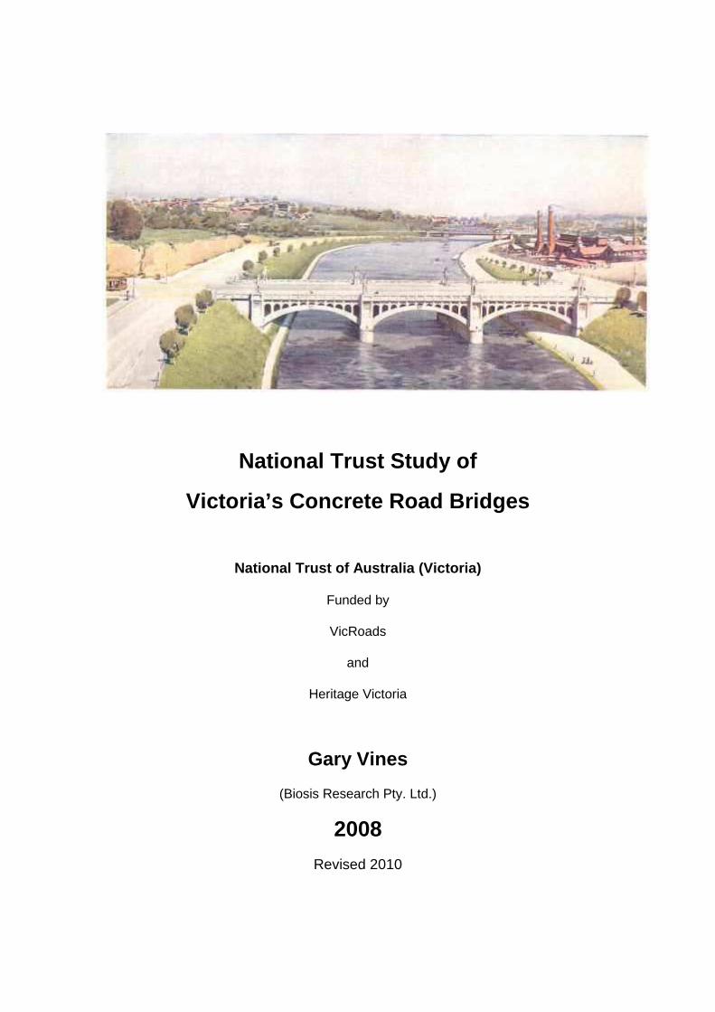
Cover image – Church Street Bridge Stonnington Local History Service
Concrete Bridges in Victoria Gary Vines
ii
Contents Acknowledgments .......................................................................................................................... i Introduction....................................................................................................................................1
Steering Committee ............................................................................................................1
Study Format.......................................................................................................................1
Limitations ...........................................................................................................................2
Thematic History............................................................................................................................3 Bridge Building in Victoria....................................................................................................3
Concrete Origins .................................................................................................................5 Australian Cement ...................................................................................................................... 6 Mass Concrete............................................................................................................................ 7 Reinforced Concrete................................................................................................................... 9
Development of Concrete Bridge Designs in Victoria .......................................................15 Introduction of Monier Concrete to Australia............................................................................. 15 Monash and Monier Arch Bridges............................................................................................. 17 Girder Bridges........................................................................................................................... 25 New Arch Styles........................................................................................................................ 30 Role of the Country Roads Board ............................................................................................. 32 Bridge Aesthetics...................................................................................................................... 38 Other Experiments .................................................................................................................... 45 Rigid Frame Bridges ................................................................................................................. 46
Post-War Developments ...................................................................................................53 Freeways and the administration of road and bridge construction ........................................... 57 Design Standards and Precasting ............................................................................................ 60 Precast Reinforced Concrete “U” Slabs.................................................................................... 61 Precast Reinforced Concrete Beams........................................................................................ 62 Substructures............................................................................................................................ 64 Prestressed Concrete ............................................................................................................... 64 Prestressing in Australia ........................................................................................................... 66 Prestressed Concrete Slabs. .................................................................................................... 67 Prestressed Concrete Beams................................................................................................... 70 High Strength “U” Slabs ............................................................................................................ 70
Freeways and recent developments .................................................................................72 Cast in Situ Prestressed Box Girder Bridges ............................................................................ 72 Segmental Construction ........................................................................................................... 73 Segmented Beam Bridges........................................................................................................ 73 Precast Segmental Prestressed Concrete Box Girder.............................................................. 74 Inverted U Beams (Bathtub Beams) ......................................................................................... 74 Crown Units .............................................................................................................................. 75 Prestressed Concrete Inverted Tee Beams.............................................................................. 76 Match Cast Segmental Prestressed Concrete Box Girders ...................................................... 76 Incremental Launched Prestressed Concrete Box Girder ........................................................ 78 Prestressed Concrete Super Tee Beams ................................................................................. 80
Historic Bridge Survey .................................................................................................................81 Criteria for Assessment.....................................................................................................82
Numbers of Concrete Bridges................................................................................................... 83 Concrete Bridge Structural Types............................................................................................. 83 Arch Bridges ............................................................................................................................. 84
Concrete Bridges in Victoria Gary Vines
iii
Beam Bridges ........................................................................................................................... 86 Proportion of Structural Types .................................................................................................. 91 Age of Bridges .......................................................................................................................... 94 Regional Distribution................................................................................................................. 96
Numerical assessments. ...................................................................................................99
Results ............................................................................................................................101 Registered Historic Concrete Road Bridges ........................................................................... 101 Regionally and Locally Significant Bridges ............................................................................. 109 Widened Masonry Bridges...................................................................................................... 118
Conclusion.................................................................................................................................119 Recommendations ..........................................................................................................120
Appendices................................................................................................................................122 Appendix 1 Chronology of Australian and International Bridge Developments...............123
Appendix 2 Interstate Influences.....................................................................................131 South Australia ....................................................................................................................... 131 Queensland ............................................................................................................................ 135 New South Wales ................................................................................................................... 136 Western Australia ................................................................................................................... 139
Appendix 3 Engineers & Designers.................................................................................140
Glossary ..........................................................................................................................154
Bibliography...............................................................................................................................182 Index to Engineers and Bridges ......................................................................................192
Volume 2 ...................................................................................................................................195 Bridge Classification Reports for assessed concrete bridges.........................................195
List of Figures
Figure 1: Breakdown of Victorian Road Bridges by main material.............................................................83 Figure 2: Arch styles and structural forms (from Miller et al 2000) ............................................................85 Figure 3: Concrete arch bridge terms (from Miller et al. 2000) ..................................................................86 Figure 4: Breakdown of concrete road bridges according to structural type..............................................93 Figure 5: Concrete bridges according to type............................................................................................93 Figure 6: Concrete bridges according to combined type. ..........................................................................94 Figure 7: Age distribution of concrete bridges in Victoria. .........................................................................96 Figure 8: Number of concrete bridges in Victorian regions........................................................................97 Figure 9: Map of Victoria showing distribution of concrete bridges. ..........................................................98 Figure 10: Quantitative assessment Criteria form used in Metal and Concrete Bridges Studies. ...........100
Concrete Bridges in Victoria Gary Vines
iv
List of Tables Table 1: List of bridge tenders let by CRB in 1915 Annual Report ............................................................34 Table 2: Types of concrete bridges in Victoria...........................................................................................92 Table 3: Age and Structure Type categories and scores...........................................................................99 Table 4: Local, Regional and State significant concrete road bridges.....................................................101 Table 5: Existing concrete bridges on the Victorian Heritage Register and Register of the National Estate
.......................................................................................................................................................103 Table 6: Concrete bridges of State significance proposed for Victorian Heritage Register .....................105 Table 7: Bendigo Monash Bridges group classification report.................................................................106 Table 8: Maroondah Aqueduct Bridges group classification report .........................................................106 Table 9: Eastern Freeway Bridges group classification report.................................................................107 Table 10: Westgate Freeway Southern Link Bridges group classification report ....................................108 Table 10: Regionally significant concrete bridges in Victoria with National Trust classification reports
completed.......................................................................................................................................111 Table 11: Locally significant concrete bridges with completed National Trust classification reports .......112 Table 12: Other locally significant concrete bridges in Victoria identified in Concrete Bridges Study. ....117 Table 13: Masonry bridges with concrete components for consideration in proposed Masonry Bridges
Study. .............................................................................................................................................118 Table 14: Summary of numbers of bridges on various heritage registers. ..............................................119
List of Plates Plate 1: Long Gully Road Bridge over Maroondah Aqueduct ......................................................................9 Plate 2: Alvord Bridge, Golden Gate Park, San Francisco (photo HAER) .................................................11 Plate 3: 1911 Nicholson Bridge, Wyoming USA........................................................................................12 Plate 4: Salginatobel Bridge, Switzerland..................................................................................................12 Plate 5: Johnston’s Creek aqueduct ..........................................................................................................16 Plate 6: Lamington Bridge Maryborough (photo: Register of the National Estate) ....................................17 Plate 7: John Monash in 1896 (Melbourne University Archives) ...............................................................18 Plate 8: Construction of Monier reinforced concrete arch (from Alves et al)..............................................19 Plate 9: Morrell or Anderson Bridge South Yarra (photo AHC)..................................................................20 Plate 10: Fyansford Bridge during construction (photo, Monash Uni. Archives)........................................20 Plate 11: Wheelers Bridge (photo State Library Victoria). .........................................................................21 Plate 12: The first Kings Bridge collapsed under load testing (photo Melbourne Uni. Archives) ...............24 Plate 13: Diagram of Monier reinforced concrete T girder bridge (Alves et al.) .........................................26 Plate 14: Hurstbridge bridge during construction (photo Eltham Historical Society) .................................31 Plate 15: William Calder, first CRB Chairman (photo Stonnington Library)...............................................33 Table 1: List of bridge tenders let by CRB in 1915 Annual Report ............................................................34 Plate 16: Standard drawings for handrails and reinforced concrete girders (CRB Annual Report 1916) ..35 Plate 17: Standard designs for concrete girders of various spans (CRB Annual Report 1916).................36 Plate 18: Original artist’s impression for design of Church Street Bridge (State Library of Victoria) .........40 Plate 19: Punt Road or Hoddle Bridge in the 1950s (photo State Library Victoria) ...................................41 Plate 20: Remaining pillar from Centenary Bridge.....................................................................................42 Plate 21: Earliest type of CRB handrail design, Black Bridge, Sydney Rd Wangaratta c1920 (CRB
Drawing #13862)..............................................................................................................................43 Plate 22: Colonnade type handrail design, No 2 Maribyrnong Tributary Bridge, Keilor 1926 (CRB plan
#13284). ...........................................................................................................................................43 Plate 23: Post 1929 handrail design, Korong Creek Bridge 1937 (CRB Plan #13354) ............................. 44 Plate 24: Mesh panel handrail type, Healesville Bridge c1934 (CRB Drawing #14646)............................44 Plate 25: Later continuous concrete rail type, Kiewa Valley Bridge c1951 (CRB Drawing #14010)..........44 Plate 26: Tooronga Road Bridge, Gardiner’s Creek during testing, 1914 (Melb Uni. Archives) ................46 Plate 27: Toomuc Creek Bridge, Pakenham (CRB Annual Report 1929)..................................................47
Concrete Bridges in Victoria Gary Vines
v
Plate 28: Little River Bridge, Geelong Road (CRB Annual Report 1929) ..................................................48 Plate 29: Kananook Creek Bridge, Frankston (CRB Annual Report 1936)................................................48 Plate 30: Warragul Road Gardiner’s Creek Bridge (CRB Annual Report 1938)........................................49 Plate 31: McKinnon’s Bridge over Mount Emu Creek, Princes Highway West (CRB Annual Report 1924)
......................................................................................................................................................... 50 Plate 32: Extract from Country Roads Board Chief Engineer’s Report (1934 Fig.2) .................................51 Plate 33: Extract from Country Roads Board Chief Engineer’s Report (1936 Fig. H)................................52 Plate 34: 1969 Freeway Plan for Melbourne..............................................................................................58 Plate 35: First Stage of South Eastern Freeway under construction (photo State Library Victoria) ..........58 Plate 36: Standard U Slab Design (CRB 1948) .........................................................................................61 Plate 37: Detail of a typical precast reinforced concrete beam (CRB Ann Rep. 1949)..............................62 Plate 38: Bridge Foundation Types ...........................................................................................................64 Plate 39: Typical cross section of 15’ prestressed Concrete Slab Bridge (CRB drawings) .......................68 Plate 40: Typical details of CRB 15’ prestressed Concrete Slab (CRB drawings).....................................68 Plate 41: Typical cross section of 30’ prestressed Concrete Slab Bridge (CRB drawings) .......................69 Plate 42: Cross section of 30 foot span Prestressed Concrete Slab .........................................................69 Plate 43: A typical Cross Section of 60 foot Prestressed Concrete Beam ................................................70 Plate 44: Typical Arrangement using High Strength U Slabs (CRB drawing) ............................................71 Plate 45: Calder Highway – Lancefield Road Overpass during construction (CRB Annual Report)..........72 Plate 46: Barmah Bridge construction – placing the steel truss falsework (CRB Annual Report) .............73 Plate 47: Bell Street overpass during construction (CRB annual Report 1969).........................................74 Plate 48: Typical Cross Section of Inverted U Beam (Princes Highway Snowy River) ..............................75 Plate 49: Typical cross section of slab-linked Crown section Box Culvert.................................................75 Plate 50: Typical Crown Unit Bridge (Huon Ck Rd over House Ck Wodonga) ..........................................76 Plate 51: Typical cross section of Prestressed Concrete Inverted Tee Beams. ........................................76 Plate 52: Westgate Freeway (South Melbourne section) prestressed match cast segmental box girder
construction......................................................................................................................................77 Plate 53: Bolte Bridge during construction (Bauldestone Hornibrook).......................................................78 Plate 54: EJ Whitten Bridge during construction (photo National Library).................................................79 Plate 55: EJ Whitten Bridges following completion (VicRoads Annual Report 1996)................................80 Plate 56: Typical section of prestressed concrete Super T-Beam.............................................................80 Plate 57: William Charles Kernot.............................................................................................................140
Concrete Bridges in Victoria Gary Vines
1
Introduction
This Historic Concrete Road Bridges Study has been undertaken by Gary Vines of Biosis Research Pty. Ltd. on behalf of the National Trust of Australia (Victoria) with major funding from VicRoads and further financial assistance from Heritage Victoria.
The purpose of this study is to identify historic concrete road bridges in Victoria and assess them for future preservation and study and to classify these bridges in order of significance, whether at State, regional or local level. The study provides guidance for future management and for undertaking works affecting significant concrete bridges.
Steering Committee
The project has benefited from an enthusiastic and expert steering committee made up of current and retired engineers and heritage practitioners. The steering committee has contributed amounts of energy and information to the study both through discussions during steering committee meetings and written and emailed comments directly to the author. Norm Butler in particular, contributed two substantial research documents, one on flat slab bridges, and another on post war developments in bridge design in the CRB. These have formed the major part of the sections covering the respective subjects in this report. The members of the steering committee are listed in the acknowledgements section above, and I would like to thank them here for their great efforts, without which the study would have been far less comprehensive.
Study Format
This report contains a thematic history of concrete road bridges in Victoria, definitions, survey results and analysis of surviving concrete bridges, and criteria and methods used for the assessment of significant bridges.
The report was initially completed in 2008, and following approval of individual bridge classification reports by National Trust expert committees, was revised in late 2010.
For the purpose of this study, concrete road bridges are defined as bridges where the principal load-bearing structures are of concrete. These may be the arches, beams, piers, deck, trusses or a combination of these. Bridges with minor concrete components, such as bearing sills, retaining walls, hand rails and relieving beams have not been considered as concrete bridges.
In some cases, bridges that have previously been assessed by the National Trust’s Timber Bridges Study1 and Metal Bridges Study2 also appear in this assessment, either because they are composite with significant components of timber or steel and concrete, or they incorporate different sections, such as concrete approach spans and steel central span.
1 Don Chambers 1997, National Trust Timber Bridges Study – see also Don Chambers, 2006, Wooden Wonders: Victoria’s Timber Bridges 2 Gary Vines 2003, National Trust Metal Bridges Study
Concrete Bridges in Victoria Gary Vines
2
This study has attempted to assess all concrete road bridges in Victoria within its scope, whether or not they were originally built as road bridges, have been subsequently converted to other uses such as foot or stock bridges, were originally built for other uses and are now road bridges or have been abandoned and are unused.
Both declared road bridges, built and maintained by the state road authority (Country Roads Board, Roads Construction Authority, VicRoads etc) and local road bridges (built by shire or municipal councils) were included. Road over rail bridges were included in the study, whether they were built by the railways or road authorities.
Although legally in New South Wales territory, the Murray River bridges were included in the assessment and database, as at least the southern abutments are in Victoria, some were built by Victorian authorities and many are managed jointly by New South Wales and Victorian road authorities.
The Concrete Bridges Study incorporates a summary background history, (which should be read in conjunction with the background history in the Metal Bridges Study structural analysis, and discussion of the results of the survey and assessment of significant concrete bridges.
Appendix 1 provides a chronology of events related to bridge design and construction. Events related to Victorian bridge history are highlighted. Appendix 2 provides some comparative material on concrete bridge developments in other states and Appendix 3 includes brief details of some road and bridge designers, engineers and contractors who are of interest in the history of road bridges. This is not an authoritative or exhaustive list, and so apologies are due for any engineers omitted.
Throughout the background history, influential bridge engineers, designers, contractors and transport administrators are identified through the use of bold text. An Appendix is provided near the end of the report giving some further information about prominent bridge engineers and contractors who have had an impact on Victorian Concrete Bridges.
Engineers and designers, and individual bridges discussed in the text are also indexed at the end of the report.
Limitations
The study has generally relied on existing local histories, VicRoads bridge records and more readily available historic sources. It has not been possible to investigate more detailed local archival sources such as newspaper accounts, council minutes, engineer’s reports, contracts or drawings. In general, such material has proved to be difficult to either locate or access.
While every effort has been made to ensure thorough survey coverage, limited time and resources meant it was not possible to physically inspect every bridge.
Concrete Bridges in Victoria Gary Vines
3
Thematic History
The thematic history of the development of concrete road bridges in Victoria has been prepared as the first stage of this study. This history is intended to help in the assessment of surviving historic concrete road bridges by providing a thematic framework based on a chronological history, technological development, economic and political structures and the role of key individuals including designers, engineers and concrete manufacturers.
A glossary of bridge engineering and design terms is included, along with a brief bibliography. In the text, the names of Victorian bridge engineers, contractors and designers have been highlighted in bold, and further information is included in Appendix 5. The report also includes an index to engineers and bridges referred to in the text.
The study also covers the process used in identifying and assessing historic concrete road bridges, including the criteria for assessing significance in accordance with both the Heritage Victoria assessment process, and a quantitative evaluation system developed specifically for this project.
Bridge Building in Victoria
The Metal Bridges Study provides a general history of bridge building in Victoria,3 focussing on the development and trends in metal bridge design and construction. The introduction and ultimate domination of reinforced concrete technology transformed bridge building in the twentieth century, so that the vast majority of road bridges existing today are of concrete. However, this transformation can best be understood as part of a gradual progress in bridge design and construction with timber and metal designs still finding application today when economic and engineering circumstances are right.
The earliest bridges in the Port Phillip district were simple log bridges, spanning small creeks and gullies. Larger rivers remained barriers that could only be crossed by punt or ford. More complex timber designs were used when government public works took over from the makeshift attempts of the settlers. Laminated timber arches and strutted or stayed timber beam structures evolved to use available local timbers. Initially only abutments and piers were constructed of stone. Permanent stone arch bridges soon followed, with the first major stone bridge in the colony being the fully fledged and exceptionally long Princes Bridge, designed with a low stone arch of 45.7 metres, the longest ever built in Australia.
With the wealth generated by the gold rushes and the establishment and funding of Public Works Department and later Central Road Board administration, the 1850s and 60s saw substantial new bridge construction. This included a mix of ‘permanent’ stone arch bridges on major roads, stone and timber or all timber bridges on lesser roads and crossings, and for especially difficult or important crossings, wrought iron girder and truss bridges. This latter group included the 1850s ‘Crimea’ bridges at Church Street
3 Vines 2003, National Trust Metal Bridges Study
Concrete Bridges in Victoria Gary Vines
4
over the Yarra and on the Barwon River in Geelong.4 These were similar to the first wrought iron box girder railway bridges such as the 1859 Saltwater River Bridge on the Melbourne Williamstown Railway, which is also believed to have used some of these girders which were originally manufactured in Britain for use during the Crimean War.
Metal bridge design became more sophisticated with the use of lattice truss spans, first imported, such as the 1861 Hawthorn Bridge, and then locally fabricated, such as Bung Bong near Avoca. Metal truss designs evolved further through the work of Professor Kernot at Melbourne University on optimal truss geometry. This design work coincided with a mature local metal engineering industry and development of local manufacture of construction material including, steel and cement works.
The introduction of standard dimension steel girders in the form of rolled steel joists (RSJs), initially imported and then, from the early twentieth century, locally rolled, and the establishment of the Country Roads Board in 1913 led to more standardised bridge designs.
At the very end of the nineteenth century reinforced concrete made its appearance as a potential bridge construction material, owing a great deal to the work of Monash and Anderson, who introduced and developed the Monier patent construction methods. Following two decades of experimentation and the reluctant but eventual acceptance by government and municipal road departments, reinforced concrete took over as the major structural form for bridges, either on its own, or in combination with timber and steel. Monash and Anderson initially employed reinforced concrete arches in bridge building, but soon found the greater simplicity of construction and predictability in calculating forces in reinforced concrete girders far more useful and economic.
Shortly before reinforced concrete became universally accepted as a preferred bridge material, Anderson left the partnership and Monash took up a career in the military. However the Country Roads Board was formed in 1913 and took up the mantle in researching and promoting concrete bridge construction. Within a few years the Board had established a policy of building bridges in ‘permanent concrete’ as a preference to temporary timber, and produced standard designs to guide both State and shire council initiated works.
The reinforced cast-in-place T Girder (or “TEE Girder”) became the most common new type of bridge. Advances or improvements to this design were progressively applied, such as rigid frame construction and then rigid flat slab designs. Cast in place construction of bridges continued until the early 1950s.
Post World War Two, materials shortages and a reconstruction backlog (on a world scale) saw a reinvigoration of design research and resulted in new techniques of precasting, prestressing and post tensioning to improve the strength and increase span length of concrete bridges. The Country Roads Board actively sought out these new developments and undertook their own experiments and testing to determine the most
4 The British Army had commissioned wrought iron box girder bridges from William Fairbairne, for use during the Crimean War, but the cessation of the war before the contract was completed, meant that the girders could be diverted to other uses.
Concrete Bridges in Victoria Gary Vines
5
efficient and economic means to modernise and repair the state’s network of roads and bridges to accommodate vastly increased transport needs.
Ultimately, the benefits of precasting bridge components displaced many of the cast-in-place designs until match cast segmental and incrementally launched systems began to be used for very large box girder bridges.
Concrete Origins
The origins of concrete are firmly placed in Roman traditions. The rediscovery in Europe however, did not occur until the 18th century, despite attempts in the Renaissance to revive the Roman art of making a water-resistant concrete. The understanding of the hydraulic properties of certain lime mortars came to public notice with John Smeaton’s Eddystone Lighthouse, and the experiments he made with samples from a large number of limestone deposits. He settled on a bluish limestone from Wales which when dissolved with nitric acid produced a clay rich solution. Adding terra pozzolano or pozzolana, (a material containing burned lime and volcanic ash) was a traditional practice for creating stronger mortars that will also set under water.5
His conclusion that the purest limestone did not make the best concrete, but that an intimate mixture of clay and limestone made a stronger cement, led to the first commercial production of modern hydraulic cement in 1796, by James Parker. Parker obtained ‘concretions of clay containing veins of calcareous matter’ from a quarry near London and sold it as ‘Roman Cement’. However, naturally occurring deposits were limited and in 1811, Joseph Aspdin produced the first artificial cement from separate deposits of limestone and clay, which he called ‘Portland Cement’ as Portland stone was the most highly regarded natural stone in London at the time, and he imagined some likeness with his new product.
Edgar Dabbs obtained a patent in 1810 for mixing chalk or limestone with clay, burning it and grinding the clinker, but specifically avoided vitrification. A similar method used in France by L. J. Vicat was reported in Andrew Ure’s 1839 Dictionary of Arts, Manufactures and Mines, a publication available in Victoria from at least the 1850s, when the Public Library obtained a copy.6
J. B. White, works manager of a competing manufacturer, subsequently claimed to have invented modern cement in the 1840s and appears to have been the first to achieve burning to near vitrification, and so produced Portland cement in the modern sense.7 By that time, Aspdin had also modified his cement to make it stronger, obtaining a patent in 1824. Tests by the London Metropolitan Board of Works and others concluded that the two companies produced cements of approximately the same strength.8
The Victorian hydraulic Freestone Company marketed what appears to have been an early Portland Cement manufactured according to R. Holden Stone’s patent. David
5 Cowan, H. 1998, From Wattle and Daub to Concrete and Steel p.79. 6 Lewis, Miles, n.d., Australian Building, a cultural investigation, 7.04.1. Web Publication (http://www.arbld.unimelb.edu.au/~milesbl/australian%20building/pdfs/1.00.pdf). 7 Lewis, Australian Building, 7.04.2 8 Cowan 1998 p.80
Concrete Bridges in Victoria Gary Vines
6
Munro, who was prominent in Melbourne’s building industry, was one of the first to use the material, which was still confined to architectural details and foundation work.9
Australian Cement
Natural cement was imported to Australia from Britain in the 1830s or 40s and was specified for Sydney’s first public sewer built during 1855-7. Portland Cement was being imported in increasing quantities in the second half of the nineteenth century, with more than a dozen brands available in the 1880s from Britain, America, France and Germany. Imports continued into the 20th century, with Danish supplies replacing the considerable German cement imports during the First World War.
Local Australian manufacture of Portland cement can be traced to William Lewis, a South Australian lime burner, with assistance from J. C. Gostling, of Gostling’s Portland Cement Company in London. The Gawler works was built in 1882. Following the success of John Wilson’s New Zealand Portland Cement works, manufacturers were established in most Australian colonies. The Cullen Bullen Company claimed to have made Portland Cement in New South Wales in 1884, though it did not achieve commercial production for some years. In Tasmania, W. Penn Smith & Co. Limited was formed in 1886 to manufacture cement at Rosedale, South Bridgewater, and A. D. Bernacchi and the Victorian politician and financier M. H. Davies formed the Maria Island Company to manufacture cement on the island off the Tasmanian east coast.10
Robert Ferguson’s experiments with Portland Cement manufacture in 1890, resulted in a patent for his improvements in the process. Some of the more successful and enduring enterprises were:
− Australian Portland Cement Co. Vic., 1889 − Victorian Cement Works Vic., 1890 − Shearing's Portland Cement Co. SA, (renamed South Australian Portland Cement Co.)
c1890 − Cullen Bullen Lime and Cement Co, NSW (later Commonwealth Portland Cement) 1889 − Goodlet & Smith, NSW 1893.
An English expert, R. D. Langley, who was involved with some of these enterprises, claimed to have produced Portland Cement in Brisbane in 1889. He later assisted David Mitchell in establishing the Victorian Cement Works in 1890 and was in partnership with William Shearing in the South Australian Portland Cement Company in Adelaide in 1891 (Lewis 7.04.9).
Mitchell was one of the most prominent promoters of the use of cement and concrete, having acquired the Cave Hill Farm in Lilydale in 1878 for the production of lime, as part of his involvement in the Melbourne Builders' Lime and Cement Co. While lime-burning was carried out at Cave Hill, cement manufacture was initially undertaken at a newly-installed plant in Mitchell’s Burnley factory in 1890 when Mitchell established the Victorian Cement Company, partly in response to disagreements with the Melbourne Builders' Lime and Cement Co. over distribution. When the partnership of Monash and
9 Lewis, Australian Building, 7.04.2 10 Fraser, D. J., 'Early reinforced concrete in Near South Wales 1895-1915', Transactions of the Institution of Engineers Australia, October 1985.
Concrete Bridges in Victoria Gary Vines
7
Anderson was dissolved in 1905, David Mitchell joined Monash and John Gibson in forming the Reinforced Concrete and Monier Pipe Construction Company.11
Manufacture and maintaining the quality at many of these works was hampered by the difficulty of procuring adequate machinery. Equipment was generally adapted from other industries. For example, edge runner or Chilean mills were adopted from mineral processing, millstones from flour milling, pug mills and jaw crushers from brickworks and stone crushers from quarries, were all being adapted for cement manufacture.
T. R. Crampton in Britain and Frederick Ransome in 1885 separately patented rotary kilns in 1877. By the end of the century, rotary kilns were firmly established in the USA but were still rare in Britain. They were introduced into Australia in the early 1900s, with Goodlet & Smith installing one in 1901, and the Victorian Cement Co. in 1907-8.12
Gippsland Cement.
In Gippsland, a unique form of cement was made in Traralgon between 1947 and 1991 using brown coal and a limestone clay/loam. The process is believed to have been developed in Germany, possibly in response to Wartime shortages. The limestone clay/loam and the pulverised brown coal were mixed together, rolled into golf ball sized pellets then fed into a vertical furnace. The continuous fire in the furnace burnt the coal and converted the limestone material into clinker. The clinker from the bottom of the furnace was then ground into cement. Gippsland Cement was widely used in bridge building in Gippsland during the 1950s and 60s. It was characteristically slower setting than most other available cement (a property that had advantages where hand mixing was still being done) and sometimes had black spots of unburnt coal in the finished surface.13
Mass Concrete
With the hydraulic cement problem solved, construction in concrete moved more slowly than its use in mortar and artificial stone. The first use of mass concrete in Britain occurred in the 1830s, beginning with the foundations for Millbank Penitentiary. Construction of whole houses in concrete followed and made inroads into Australia in the 1840s and 1850s, particularly, it seems, in Adelaide. One of the earliest surviving concrete buildings in Victoria is ‘Craiglee’ Homestead built in 1865 at Sunbury.14
A special form of concrete for building was the French beton, made with hydraulic lime or cement in a slurry, then added to aggregate, while the British method was to add water last. House building forms of concrete were sometimes little more than stabilised earth used in much the same way as pise, or rammed earth, and lacking the compressive strength of true concrete.
11 Light Railways, No. 111 Jan. 1991, Cave Hill Tramway”; Geoff Taplin, Alan Holgate, Innovation in Concrete Technology: The Contribution of Sir John Monash; James, D.P., & Chanson, H. 2000. "Cement by the Barrel and Cask." Concrete in Australia, Vol. 26, No. 3, pp. 10-13; Joan Campbell, 'Mitchell, David (1829 - 1916)', Australian Dictionary of Biography; Searle, G. John Monash, ; a biography 12 Lewis, Australian Building, 7.04.0 13 Pers. Comm. Norm Butler 2006 (ex VicRoads engineer and National Trust Committee Member) 14 Lewis M, Australian Building,7.02.5
Concrete Bridges in Victoria Gary Vines
8
Construction of foundations using rubble mixed with lime, or in some cases hydraulic lime or cement, had become general practice by the 1840s in Britain, and in Australia by at least the 1870s. The expense of imported hydraulic cement still appears to have limited its use in foundations, with lime being more common. However, for special application, cement would be used, such as the Alfred Graving Dock built during 1868-72, which employed a bed of 600 mm deep concrete below a 1.5 metre thick stone floor.15 In 1887 the Green Cape Lighthouse, designed by James Barnet, became the largest concrete structure in Australia. Barnet also designed the Gabo Island Lighthouse with mass concrete walls.16
The first concrete tunnel and culvert in Queensland was built in 1875-7 for the Stanthorpe Railway Extension, while vaulted ceilings in several buildings including the Sydney GPO of 1868-74 and the Lands Department building of 1876 used a coke breeze concrete. The gun emplacements at Battery Hill, Port Fairy, and Point Nepean comprise bluestone and concrete fortifications built by the Public Works Department in 1886-87.17
Mass concrete has also been used extensively for foundations and fill for stone bridges. One example is the 1893 Footscray Swing Bridge, which incorporated a solid fill of un-reinforced concrete behind the stone abutments and wingwalls. The bluestone structure comprises a single wall of coursed stone about one metre thick, with a fill of concrete poured behind the walls and over arched formwork, with the weight of the concrete taken, presumably, on concrete footings that extend under the bluestone walls and ultimately on driven timber piles on the deep Coode Island Silt.18
Concrete for the foundations, abutments and piers of bridges was being employed extensively by the beginning of the twentieth century, and had been developed somewhat separately from concrete spanning members. When simply supported girders are used (and in some cases where continuous or even rigid frame designs are employed), bridge substructures are generally designed entirely in compression. Mass concrete in dam construction may have shown the way forward.19
The use of mass concrete without reinforcement for bridge construction was considered in the late nineteenth century, but limited by the poor availability and unreliability of the material. Early evidence of its use in Australia can be found in the example of Black Bob’s Creek Bridge near Berrima, NSW, completed in 1896 on what became the Hume Highway.20
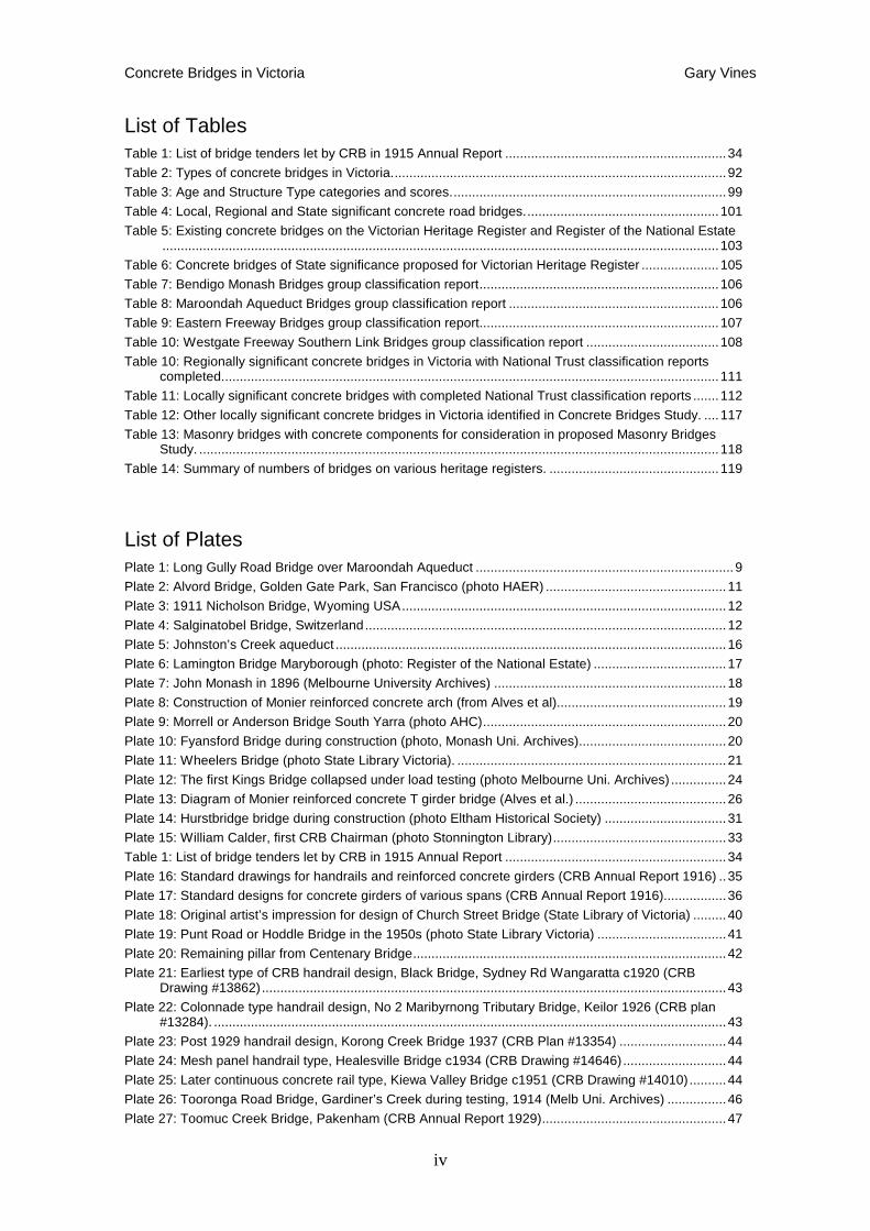
A number of small unreinforced concrete arch bridges were built over the Watts River Aqueduct (later named Maroondah Aqueduct) near Melbourne between 1889 and 1896 by the Department of Water Supply, probably designed by Chief Engineer William Davidson.
15 Lewis Australian Building, 7.02.9 16 Nelsen, et al, 1992, Conservation Plan, Gabo Island Lightstation Victoria, Australian Construction Services. 17 Register of the National Estate; NSW Heritage Register 18 Vines G. 2006, Heritage Recording of Old Footscray Swing Bridge abutments, unpublished report. 19 Historical Development of Arch Dams. From Cut-Stone Arches to Modern Concrete Designs, Hubert Chanson, D. Patrick James 20 Evans L.H., A History of Concrete Road Bridges in New South Wales, RTA, Sydney.
Concrete Bridges in Victoria Gary Vines
9
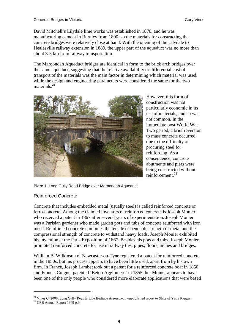
David Mitchell’s Lilydale lime works was established in 1878, and he was manufacturing cement in Burnley from 1890, so the materials for constructing the concrete bridges were relatively close at hand. With the opening of the Lilydale to Healesville railway extension in 1889, the upper part of the aqueduct was no more than about 3-5 km from railway transportation.
The Maroondah Aqueduct bridges are identical in form to the brick arch bridges over the same aqueduct, suggesting that the relative availability or differential cost of transport of the materials was the main factor in determining which material was used, while the design and engineering parameters were considered the same for the two materials.21
However, this form of construction was not particularly economic in its use of materials, and so was not common. In the immediate post World War Two period, a brief reversion to mass concrete occurred due to the difficulty of procuring steel for reinforcing. As a consequence, concrete abutments and piers were being constructed without reinforcement.22
Plate 1: Long Gully Road Bridge over Maroondah Aqueduct
Reinforced Concrete
Concrete that includes embedded metal (usually steel) is called reinforced concrete or ferro-concrete. Among the claimed inventors of reinforced concrete is Joseph Monier, who received a patent in 1867 after several years of experimentation. Joseph Monier was a Parisian gardener who made garden pots and tubs of concrete reinforced with iron mesh. Reinforced concrete combines the tensile or bendable strength of metal and the compressional strength of concrete to withstand heavy loads. Joseph Monier exhibited his invention at the Paris Exposition of 1867. Besides his pots and tubs, Joseph Monier promoted reinforced concrete for use in railway ties, pipes, floors, arches and bridges.
William B. Wilkinson of Newcastle-on-Tyne registered a patent for reinforced concrete in the 1850s, but his process appears to have been little used, apart from by his own firm. In France, Joseph Lambet took out a patent for a reinforced concrete boat in 1850 and Francis Coignet patented ‘Beton Agglomere’ in 1855, but Monier appears to have been one of the only people who considered more elaborate applications that were based
21 Vines G. 2006, Long Gully Road Bridge Heritage Assessment, unpublished report to Shire of Yarra Ranges 22 CRB Annual Report 1949 p.9
Concrete Bridges in Victoria Gary Vines
10
on a more substantial understanding of the tensile properties of reinforced concrete. Monier took out further patents for pipes, beams, vaults and bridges and he also registered his patents in Germany, Austria-Hungary, Belgium, Spain and in Britain and its colonies. However, Monier appears to have sold his patents in various territories outright and died in poverty in 1906.23
The applications of Monier construction techniques were developed and promoted in the German-speaking world by a number of licensees, amongst whom G. A. Wayss became dominant. Freytag and Heidschuch acquired interest in Monier Patents in 1884 but ceded them to Gustav Wayss in 1885. The two companies merged in 1888 to form Wayss & Freytag. Wayss was pre-eminent in the development of the Monier system and persuaded the experimental engineers Koenen & Morsch, who had produced the first published theory of reinforced concrete in 1886 – ‘Das System Monier’, to join the company. Wayss & Freytag also supported the engineers Buch and Graf in their research program into the mechanical behaviour of reinforced concrete.24
America also experimented with the material, led by Thaddeus Hyatt, who received a patent for reinforced concrete in 1878. However, it was German and French engineers who first studied and tested the principles of steel reinforcement for tensile stresses in concrete arches in the 1880s. In the early 1890s the Austrian Society of Engineers and Architects conducted extensive experiments on full-sized concrete arches, publishing the results in engineering journals throughout Europe and America.
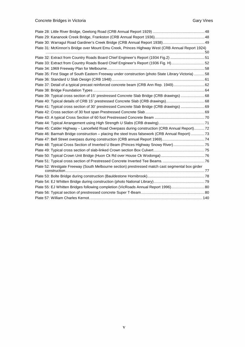
The first US reinforced concrete bridge was built in Golden Gate Park, San Francisco in 1889, designed by E L Ransome. This was followed in the US and elsewhere by a number of bridges employing ‘I’ beams encased in concrete, rather than rod or bar reinforcement. Austrian Engineer Joseph Melan introduced such a patent scheme in the US in 1894. However, beam reinforcement was soon recognised as requiring excessive amounts of steel and bar reinforcement came to replace it as a more efficient use of materials.
23 Cowan 1998 pp 87-8). 24 Cowan 1998 pp 88-9.
Concrete Bridges in Victoria Gary Vines
11
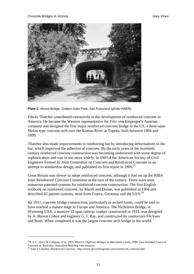
Plate 2: Alvord Bridge, Golden Gate Park, San Francisco (photo HAER)
Edwin Thatcher contributed extensively to the development of reinforced concrete in America. He became the Western representative for Fritz von Emperger’s Austrian company and designed the first major reinforced concrete bridge in the US, a three-span Melan-type concrete arch over the Kansas River at Topeka, built between 1894 and 1899.
Thatcher also made improvements to reinforcing bar by introducing deformations to the bar, which improved the adhesion of concrete. By the early years of the twentieth century reinforced concrete construction was becoming understood with some degree of sophistication and was in use more widely. In 1903-4 the American Society of Civil Engineers formed its Joint Committee on Concrete and Reinforced Concrete in an attempt to standardise design, and published its first report in 1909.25
Great Britain was slower to adopt reinforced concrete, although it had set up the RIBA Joint Reinforced Concrete Committee at the turn of the century. There were soon numerous patented systems for reinforced concrete construction. The first English textbook on reinforced concrete, by Marsh and Dunne, was published in 1904 and described 42 patents systems, most from France, Germany and the USA.26
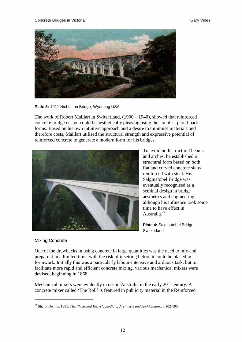
By 1911, concrete bridge construction, particularly in arched forms, could be said to have reached a mature stage in Europe and America. The Nicholson Bridge, in Wyoming USA, a massive 12 span railway viaduct constructed in 1911, was designed by A. Burton Cohen and engineer G. J. Ray, and constructed by contractors Flickwer and Bush. When completed it was the largest concrete arch bridge in the world.
25P A C Spero & Company et al, 1995, Historic Highway Bridges In Maryland; Lewis, 1988 'Two Hundred Years of Concrete in Australia'; Australian Building web resource 26 John F Claydon, Reinforced Concrete, http://www.jfccivilengineer.com/reinforced_concrete.htm
Concrete Bridges in Victoria Gary Vines
12
Plate 3: 1911 Nicholson Bridge, Wyoming USA
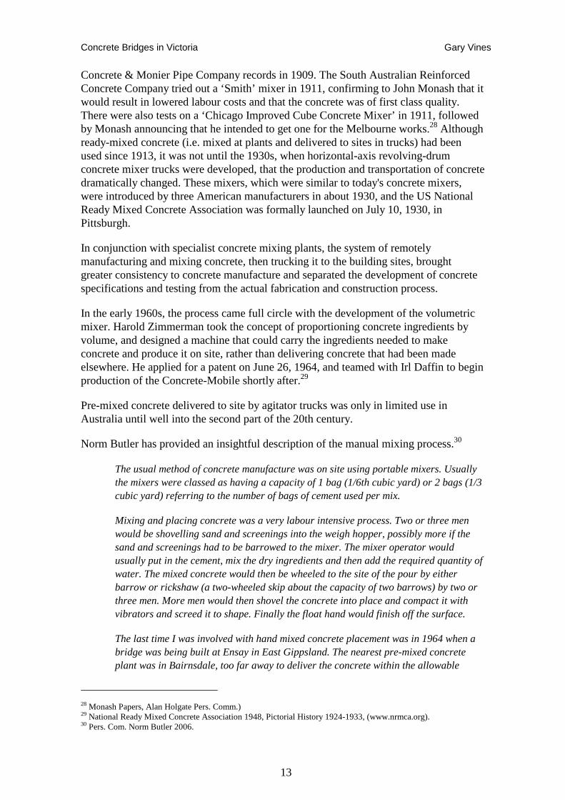
The work of Robert Maillart in Switzerland, (1900 – 1940), showed that reinforced concrete bridge design could be aesthetically pleasing using the simplest pared-back forms. Based on his own intuitive approach and a desire to minimise materials and therefore costs, Maillart utilised the structural strength and expressive potential of reinforced concrete to generate a modern form for his bridges.
To avoid both structural beams and arches, he established a structural form based on both flat and curved concrete slabs reinforced with steel. His Salginatobel Bridge was eventually recognised as a seminal design in bridge aesthetics and engineering, although his influence took some time to have effect in Australia.27
Plate 4: Salginatobel Bridge, Switzerland
Mixing Concrete
One of the drawbacks in using concrete in large quantities was the need to mix and prepare it in a limited time, with the risk of it setting before it could be placed in formwork. Initially this was a particularly labour-intensive and arduous task, but to facilitate more rapid and efficient concrete mixing, various mechanical mixers were devised, beginning in 1868.
Mechanical mixers were evidently in use in Australia in the early 20th century. A concrete mixer called ‘The Roll’ is featured in publicity material in the Reinforced
27 Sharp, Dennis, 1991, The Illustrated Encyclopaedia of Architects and Architecture.. p 102-103. .
Concrete Bridges in Victoria Gary Vines
13
Concrete & Monier Pipe Company records in 1909. The South Australian Reinforced Concrete Company tried out a ‘Smith’ mixer in 1911, confirming to John Monash that it would result in lowered labour costs and that the concrete was of first class quality. There were also tests on a ‘Chicago Improved Cube Concrete Mixer’ in 1911, followed by Monash announcing that he intended to get one for the Melbourne works.28 Although ready-mixed concrete (i.e. mixed at plants and delivered to sites in trucks) had been used since 1913, it was not until the 1930s, when horizontal-axis revolving-drum concrete mixer trucks were developed, that the production and transportation of concrete dramatically changed. These mixers, which were similar to today's concrete mixers, were introduced by three American manufacturers in about 1930, and the US National Ready Mixed Concrete Association was formally launched on July 10, 1930, in Pittsburgh.
In conjunction with specialist concrete mixing plants, the system of remotely manufacturing and mixing concrete, then trucking it to the building sites, brought greater consistency to concrete manufacture and separated the development of concrete specifications and testing from the actual fabrication and construction process.
In the early 1960s, the process came full circle with the development of the volumetric mixer. Harold Zimmerman took the concept of proportioning concrete ingredients by volume, and designed a machine that could carry the ingredients needed to make concrete and produce it on site, rather than delivering concrete that had been made elsewhere. He applied for a patent on June 26, 1964, and teamed with Irl Daffin to begin production of the Concrete-Mobile shortly after.29
Pre-mixed concrete delivered to site by agitator trucks was only in limited use in Australia until well into the second part of the 20th century.
Norm Butler has provided an insightful description of the manual mixing process.30
The usual method of concrete manufacture was on site using portable mixers. Usually the mixers were classed as having a capacity of 1 bag (1/6th cubic yard) or 2 bags (1/3 cubic yard) referring to the number of bags of cement used per mix.
Mixing and placing concrete was a very labour intensive process. Two or three men would be shovelling sand and screenings into the weigh hopper, possibly more if the sand and screenings had to be barrowed to the mixer. The mixer operator would usually put in the cement, mix the dry ingredients and then add the required quantity of water. The mixed concrete would then be wheeled to the site of the pour by either barrow or rickshaw (a two-wheeled skip about the capacity of two barrows) by two or three men. More men would then shovel the concrete into place and compact it with vibrators and screed it to shape. Finally the float hand would finish off the surface.
The last time I was involved with hand mixed concrete placement was in 1964 when a bridge was being built at Ensay in East Gippsland. The nearest pre-mixed concrete plant was in Bairnsdale, too far away to deliver the concrete within the allowable
28 Monash Papers, Alan Holgate Pers. Comm.) 29 National Ready Mixed Concrete Association 1948, Pictorial History 1924-1933, (www.nrmca.org). 30 Pers. Com. Norm Butler 2006.
Concrete Bridges in Victoria Gary Vines
14
transport mixing time. When the contractors arrived in the locality to start the bridge, two of them [had] joined the local footy team, so concrete mix day became a Footy Club working bee/fundraiser with 15 or so volunteers each time. The best effort was casting the deck of the central 60 foot span requiring about 36 cubic yards of concrete. Due to the cold morning the cast could not start until 9am when the temperature reached 40 degrees F. Even so, the mixing water was heated to ensure that the concrete was not too cold when being placed. There were about 15 men on site who worked flat out until 2pm to get the concrete all mixed and in place. We used Gippsland Cement for this work and it did not ‘go off’ until late into the evening. The contractors were floating off the deck surface until about 9pm under the light of Tilly pressure lanterns. Notwithstanding the difficult conditions in finishing off the deck, the final product had a good riding surface.
Large direct labour bridge gangs were in use by the CRB in the 1930s to 1950s, reflecting both the need for labour on the works and the need to provide employment.
From problems encountered on many old bridges, the concrete mixes used in early days were not as dense as would now be specified with the consequence of water penetration. …Often in remote areas, screened river gravel or sometimes just straight river gravel were utilised as aggregate, since crushed product was not locally available.
A possible consequence of the difficulties and limitations associated with hand mixing of concrete was the casting of early Reinforced Concrete arches in strips; one strip was a day’s work for a team before the concrete set. It was one of the three strips that broke away when King’s Bridge in Bendigo collapsed under test loads. These strips can clearly be seen under many arch bridges such as the Morell Bridge over the Yarra.
Concrete Bridges in Victoria Gary Vines
15
Development of Concrete Bridge Designs in Victoria
The advent of concrete and steel, and the emergence of scientific design at the end of the nineteenth century, influenced Australian bridge design. The role played by Professor Kernot and the University of Melbourne in developing optimal steel truss forms and the introduction of rolled steel joists has been discussed in the Metal Bridges Study.31 Along with the introduction of reinforced concrete, these factors enabled much more efficient bridges to be built. and the local production of these materials freed the designer from the limitations imposed by masonry (brick and stone) and the need to import iron.
By the time concrete came to dominate bridge construction in Australia, most of the expansion of road and rail networks associated with the boom years had already taken place. Bridge building concentrated on consolidating and improving transport networks within cities and upgrading existing bridges and roads to carry greater loads, more traffic or better withstand floods and other environmental forces. Almost all concrete bridges are therefore found at sites where earlier timber, masonry or metal structures have previously stood.
The technology of riveted steel bridges was highly refined by the early twentieth century, mainly in the form of the plate girder. Few bridges on a grand scale were needed, although an exception to this, and perhaps the climax of riveted steel construction, was the building of the Sydney Harbour Bridge. This was completed in 1932 and at the time was the longest steel arch bridge in the world. At this stage concrete bridges were not economically competitive with steel in this range and because of their large dead weight, the strength limitations of reinforced concrete and the requirements for falsework, they were confined to shorter span structures.32
The development of reinforced concrete and in particular concrete bridge construction in Australia, can be traced to the influence of just a handful of individuals. One of the most influential in Victoria was John Monash who was indirectly involved in the first reinforced concrete bridge in Victoria – the 1899 Morrell Bridge, but went on to establish the economic and structural viability of concrete arch and girder bridges in the 1st decade of the 20th century. However, it is worth examining some of the precursors – both the men and the bridges they designed.
Introduction of Monier Concrete to Australia
W. J. Baltzer, a German immigrant trained as an engineering draftsman in Germany and working for the New South Wales Public Works Department, was also kept informed of developments in European concrete engineering by his brother and in 1890 went to Germany to gather information. When he returned to Australia he tried to interest his superiors in the new technique and joined several businessmen to obtain licences through Wayss to cover the Australian colonies. Their vehicle was the firm of Carter Gummow & Co.’ which, after small trial projects, obtained contracts to build two large arched sewage aqueducts over Johnston's and White's Creeks in Annandale, now a
31 Vines G. 2003-5, National Trust Metal Bridges Study. 32 Australian Science and Technology Heritage Centre (Austech), Technology in Australia 1788-1988 p.360 (http://www.austehc.unimelb.edu.au/tia)
Concrete Bridges in Victoria Gary Vines
16
suburb of Sydney. These were completed in 1896. Baltzer moved across from the Public Works Department to Carter Gummow, effectively becoming the Chief Engineer of the company. He also produced what is possibly the first English language text on reinforced concrete – a type-written manuscript probably intended for internal use within the Public Works Department.33
F. M. Gummow graduated from the Department of Engineering at the University of Melbourne. He was fluent in German and had access to German reinforced concrete texts and also German patents of the Monier System.
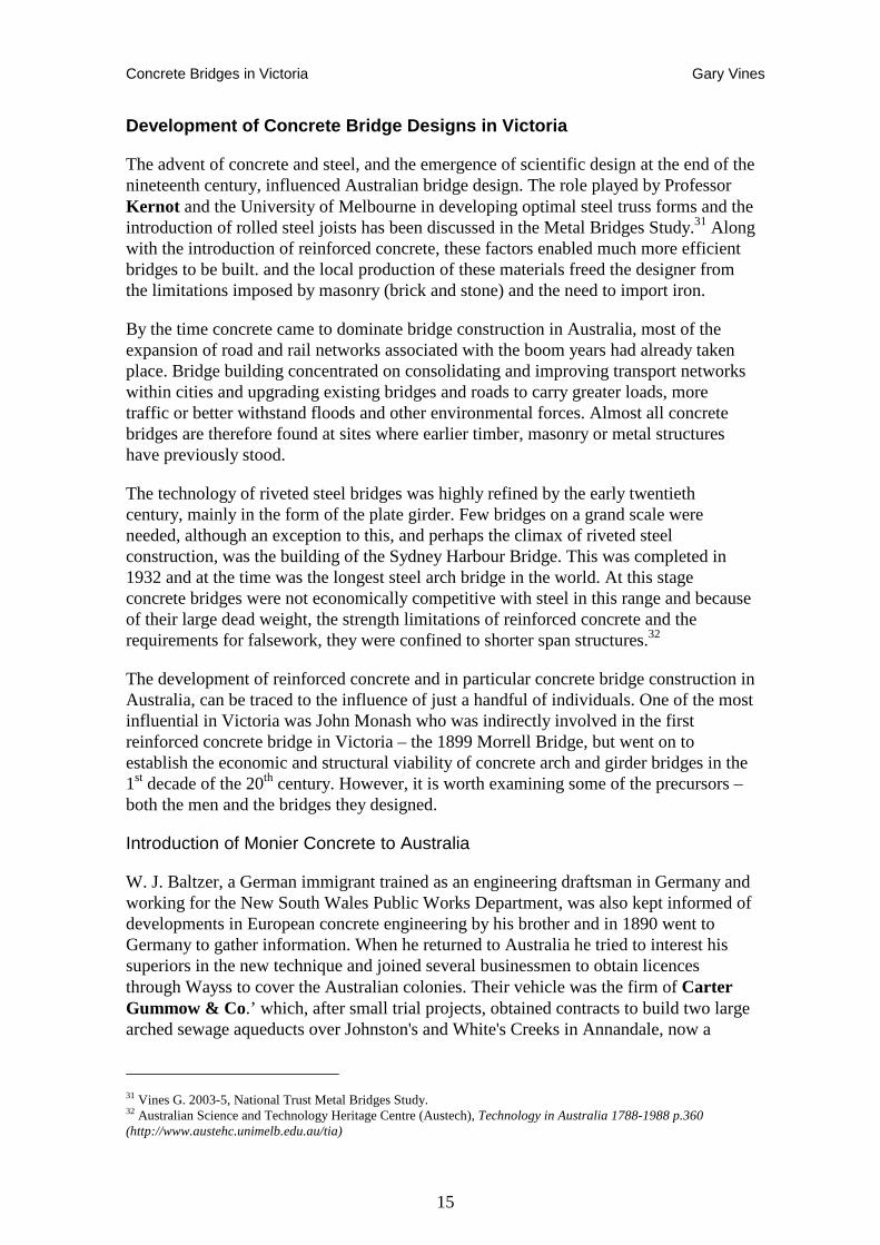
Johnston's and White's Creeks aqueducts, 1896
W. J. Balzer designed the Johnston’s and White’s Creeks aqueducts to carry the Annandale Sewer in about 1895. These were the first substantial structures built in
reinforced concrete in Australia. The longest of the bridges had a 75 ft. span (23 m), making it the longest reinforced concrete span in the world at the time it was built. They were built one year before the first listed reinforced concrete structure in Britain (a flour mill in Swansea).
Plate 5: Johnston’s Creek aqueduct
Construction was undertaken by Carter Gummow & Co. However, because of complaints about the circumstances surrounding financial irregularities and the selection of the contractors and designer, and perhaps doubts about the pioneering use of reinforced concrete in such large and original structures, the bridges became the subject of a Royal Commission, appointed in May 1896.34
There was a great deal of suspicion among some engineers, especially shire engineers, about reinforced concrete. This may have been simply a result of their conservatism and isolation from more up-to-date engineering developments. Monash and his supporters, including the Public Works Department Chief Engineer Carlo Catani, had to work particularly hard to convince people that the designs were practical and safe. The collapse of Monash’s King’s Bridge in Bendigo may have set back the more widespread
33 Alves et al, Introduction of Monier concrete to Victoria, Australia.: Cowan pp.88-90, a copy of Baltzer’s manuscript on Monier construction is held in the NSW State Rail Archives) Melbourne University’s Baillieu Library holds Gummow’s ‘Masters Thesis’, which is basically Baltzer’s report with some additions. On one of the blank pages at the back, Kernot has added his explanation of the Bendigo King’s Bridge collapse. 34 O’Connor 1985 p43; O'Connor 1983 ‘Register of Australian Historic Bridges’; Fraser 1985 pp. 82-91; Cowan 1998 pp.91, 95; New South Wales Legislative Assembly 1897.
Concrete Bridges in Victoria Gary Vines
17
introduction of Reinforced Concrete, despite the Commission’s determination that this was not due to any intrinsic problem with concrete or any fault of the designer.
Lamington Bridge, 1896
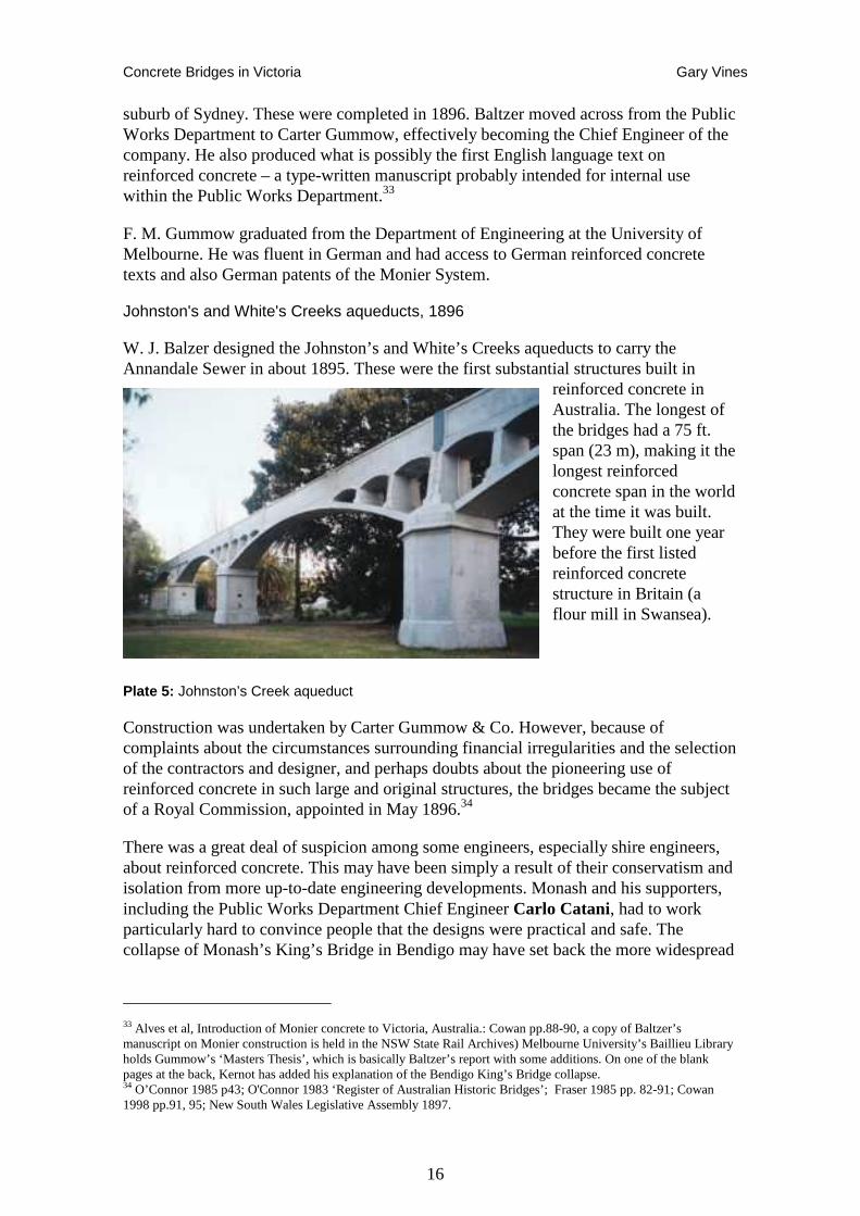
One of the world's first trafficable reinforced concrete girder bridges was the Lamington Bridge at Maryborough, Queensland, opened in 1896 and designed by A. P. Brady, the Queensland Government Engineer. The structure is a continuous reinforced concrete arch bridge supported on reinforced concrete piers.
The cost of the bridge was 25,000 pounds and it was completed in fifteen months, opening to traffic on the 30 October 1896. It is now listed by the Institution of Engineers Australia as a National Engineering Landmark.35
The bridge is built on the Wuntsch reinforced concrete system with eleven 16.6m spans and is unique in Australia. The flat arches are more properly seen as girder spans because the arch rise is so slight that the abutments and piers could not provide the axial thrust necessary to keep the arch ribs in compression (which denotes a true arch). Rails spliced with fishplates provided continuous reinforcement.36
Plate 6: Lamington Bridge Maryborough (photo: Register of the National Estate)
Monash and Monier Arch Bridges37
The young John Monash gained his early engineering experience in the 1880s and ’90s working on a range of engineering projects throughout Australia. In 1885 he joined the firm of prominent bridge builder David Munro , for whom he worked on Princes Bridge in Melbourne and on several other large metropolitan bridges, learning the practicalities of bridge design and construction. At the same time he continued to pursue his studies. He completed his Bachelor of Civil Engineering examinations at the end of 1890, then passed Honours early in 1891, entitling him to take out the Master of Civil Engineering in 1893. He also passed the Municipal Surveyors' examination in late 1891 and enrolled for his LLB. He passed the Water Supply Engineers' examination in 1892 and the following year completed his exams in Law and Arts, entitling him to L.L.B. and BA. He was qualified as a Patent Attorney by 1894 then obtained a Doctorate of Engineering in 1921. Following his significant career in the AIF during World War I, Monash went
35 Brady Brady, A.B., ‘Low-Level Concrete Bridge over the Mary River’. IE Australia 1985 36 Queensland Heritage Register. Place Number 600721 37 Much of this section is drawn from the work of the Monash University study team Lesley Alves, Alan Holgate, Geoff Taplin and their Monash Website - http://home.vicnet.net.au/~aholgate/jm/mainpages/list_main.html; Generally the history and significance sections of the website are by Leslie Alves, while the introduction, technical descriptions, and glossary etc. are by Holgate and Taplin. For ease of reference it is generally referred to as ‘Alves et al.’ Specific footnotes reference various subsections of the Monash Website.
Concrete Bridges in Victoria Gary Vines
18
on to become General Manager of the newly formed SEC in 1924 organising the development of the Latrobe Valley Brown Coal power generation.38
His early employment in the engineering field included supervising construction works on the Outer Circle Railway for the contractors Graham and Wadick39 and working as Assistant Engineer and Chief Draftsman for the Melbourne Harbour Trust. Both jobs involved some bridge construction – with a series of typical riveted iron girder and brick road over rail bridges, and the more substantial lattice truss bridge over the Yarra River (Chandler Highway Bridge) constructed as part of the railway works, and the Footscray Swing Bridge over the Yarra, constructed for the Harbour Trust.40
Recent demolition work on the Footscray Swing Bridge site has revealed that the abutments comprised a bluestone skin of coursed ashlar blocks about 1 metre wide, with a central core of un-reinforced solid concrete. This may in fact be the first example of Monash’s involvement in concrete bridge work, although only in a peripheral way in respect of an otherwise traditional stone and riveted iron bridge. The failure of one abutment (with a 100mm wide crack developing clean through the centre of the abutment and concrete core) not long after its completion, puts some doubt on the quality of the foundation work.
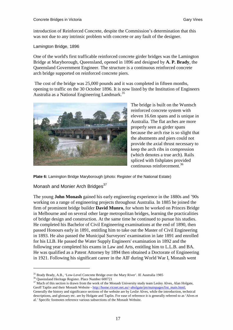
Plate 7: John Monash in 1896 (Melbourne University Archives)
In 1894, after being retrenched from the Harbour Trust, Monash went into partnership with J. T. Noble Anderson, an Irish born engineer who had tutored Monash at Melbourne University. After a period of difficulty, the firm found some success in 1897 when Anderson met Sydney engineer Frank Gummow of the engineering and contracting firm Carter, Gummow & Co. This firm had acquired the New South Wales and Victorian patents for the Monier system of reinforced concrete construction.
It is probable that Carter Gummow & Co. encouraged professional interest in the new Monier reinforced concrete system by promoting it through engineering societies and journals and at exhibitions. In 1897 Baltzer described the system to the Engineering Association of NSW; and Carter Gummow's stand at the Engineering and Electrical
38 Searle, G. 2002, John Monash, a biography. 39 Beardsell, D,.1979, 'The Outer Circle: A History of the Oakleigh to Fairfield Park Railway', Australian Railway Historical Society 40 National Library of Australia, MS 1884 Papers of Sir John Monash, 149 1094-1100 Saltwater River Swing Bridge, calculations, specifications, plans etc.
Concrete Bridges in Victoria Gary Vines
19
Exhibition in Sydney was given extensive coverage in the Building, Mining and Engineering Journal. In September of that year W. C. Kernot, Professor of Engineering at the University of Melbourne, mounted an exhibition on the subject aided by his counterpart from Sydney.
Gummow was also in Melbourne in September 1897 to negotiate the contract to construct a new bridge over the Yarra River at Anderson Street for the Victorian Public Works Department. At this time Monash was involved in a number of engineering related legal disputes, and was absent from Melbourne for long periods. Anderson recognised the opportunity for the partnership to establish itself as Carter Gummow's sole representative in Victoria and approached Gummow late in September 1897. At the same time he promoted Monier concrete as an option for replacing the decaying timber bridge at Fyansford near Geelong, using the product of the local cement works. Monash and Anderson obtained an exclusive licence from Carter, Gummow & Co for the Monier patent in Victoria.41
Plate 8: Construction of Monier reinforced concrete arch (from Alves et al)
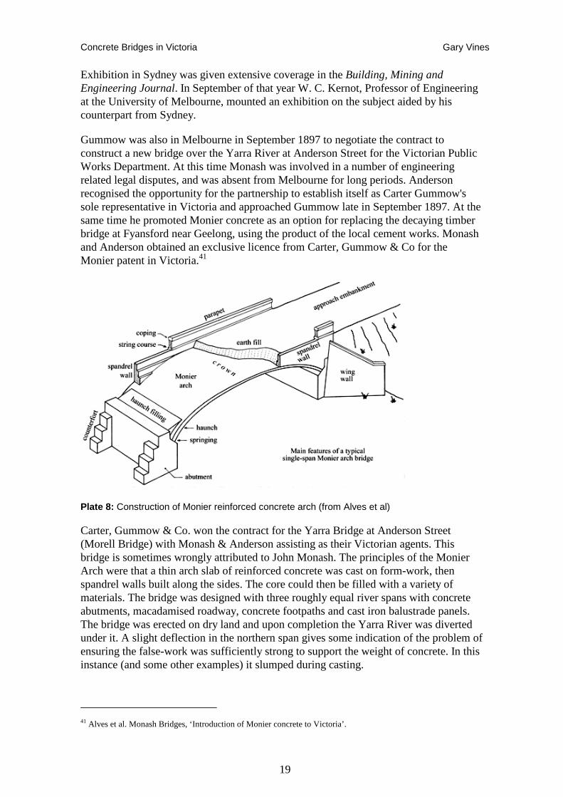
Carter, Gummow & Co. won the contract for the Yarra Bridge at Anderson Street (Morell Bridge) with Monash & Anderson assisting as their Victorian agents. This bridge is sometimes wrongly attributed to John Monash. The principles of the Monier Arch were that a thin arch slab of reinforced concrete was cast on form-work, then spandrel walls built along the sides. The core could then be filled with a variety of materials. The bridge was designed with three roughly equal river spans with concrete abutments, macadamised roadway, concrete footpaths and cast iron balustrade panels. The bridge was erected on dry land and upon completion the Yarra River was diverted under it. A slight deflection in the northern span gives some indication of the problem of ensuring the false-work was sufficiently strong to support the weight of concrete. In this instance (and some other examples) it slumped during casting.
41 Alves et al. Monash Bridges, ‘Introduction of Monier concrete to Victoria’.
Concrete Bridges in Victoria Gary Vines
20
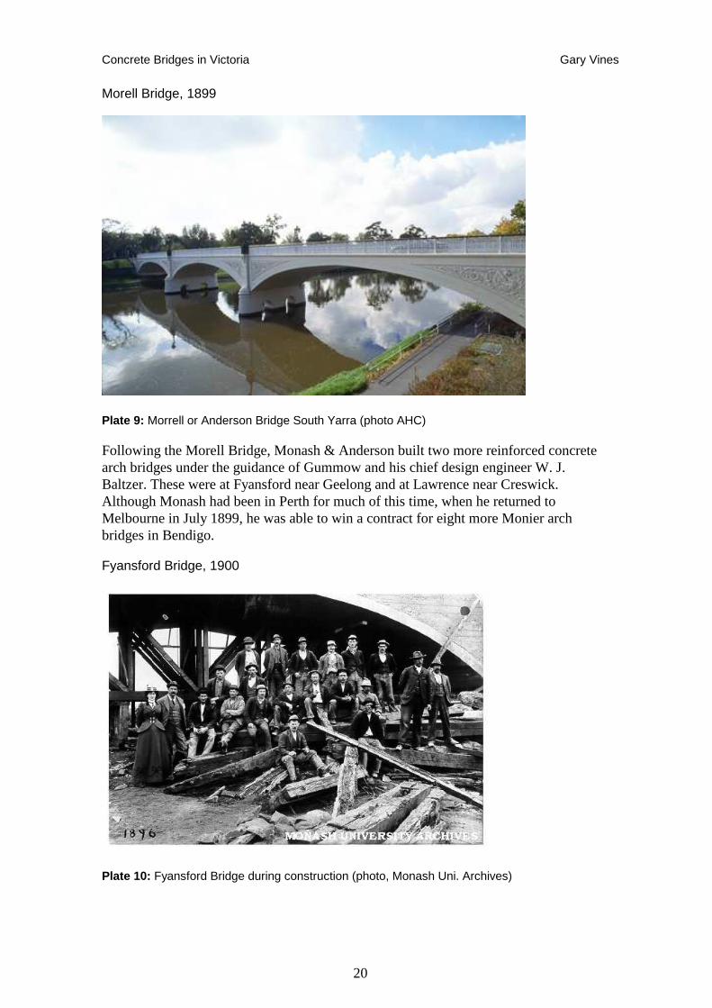
Morell Bridge, 1899
Plate 9: Morrell or Anderson Bridge South Yarra (photo AHC)
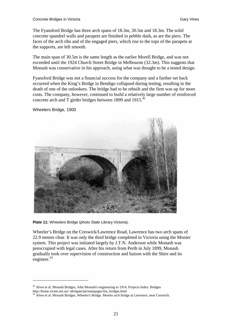
Following the Morell Bridge, Monash & Anderson built two more reinforced concrete arch bridges under the guidance of Gummow and his chief design engineer W. J. Baltzer. These were at Fyansford near Geelong and at Lawrence near Creswick. Although Monash had been in Perth for much of this time, when he returned to Melbourne in July 1899, he was able to win a contract for eight more Monier arch bridges in Bendigo.
Fyansford Bridge, 1900
Plate 10: Fyansford Bridge during construction (photo, Monash Uni. Archives)
Concrete Bridges in Victoria Gary Vines
21
The Fyansford Bridge has three arch spans of 18.3m, 30.5m and 18.3m. The solid concrete spandrel walls and parapets are finished in pebble dash, as are the piers. The faces of the arch ribs and of the engaged piers, which rise to the tops of the parapets at the supports, are left smooth.
The main span of 30.5m is the same length as the earlier Morell Bridge, and was not exceeded until the 1924 Church Street Bridge in Melbourne (32.3m). This suggests that Monash was conservative in his approach, using what was thought to be a tested design.
Fyansford Bridge was not a financial success for the company and a further set back occurred when the King’s Bridge in Bendigo collapsed during testing, resulting in the death of one of the onlookers. The bridge had to be rebuilt and the firm was up for more costs. The company, however, continued to build a relatively large number of reinforced concrete arch and T girder bridges between 1899 and 1915.42
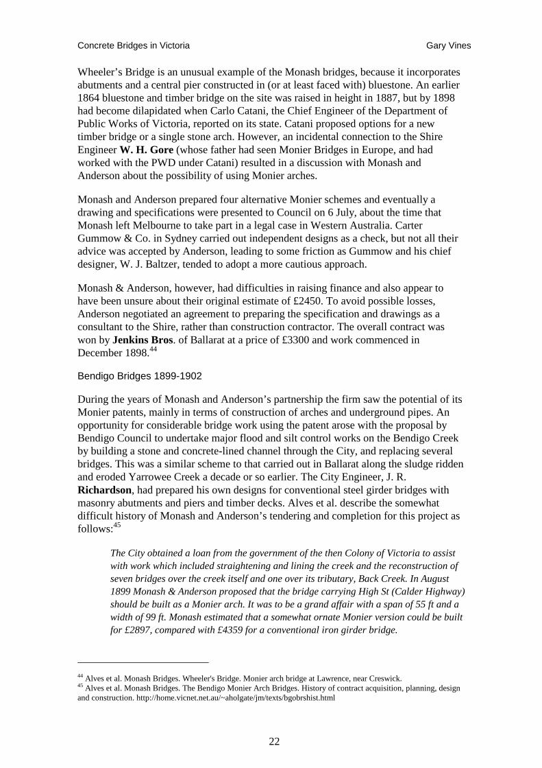
Wheelers Bridge, 1900
Plate 11: Wheelers Bridge (photo State Library Victoria).
Wheeler’s Bridge on the Creswick/Lawrence Road, Lawrence has two arch spans of 22.9 metres clear. It was only the third bridge completed in Victoria using the Monier system. This project was initiated largely by J.T.N. Anderson while Monash was preoccupied with legal cases. After his return from Perth in July 1899, Monash gradually took over supervision of construction and liaison with the Shire and its engineer.43
42 Alves et al. Monash Bridges, John Monash's engineering to 1914. Projects Index: Bridges http://home.vicnet.net.au/~aholgate/jm/mainpages/list_bridges.html 43 Alves et al. Monash Bridges, Wheeler's Bridge. Monier arch bridge at Lawrence, near Creswick.
Concrete Bridges in Victoria Gary Vines
22
Wheeler’s Bridge is an unusual example of the Monash bridges, because it incorporates abutments and a central pier constructed in (or at least faced with) bluestone. An earlier 1864 bluestone and timber bridge on the site was raised in height in 1887, but by 1898 had become dilapidated when Carlo Catani, the Chief Engineer of the Department of Public Works of Victoria, reported on its state. Catani proposed options for a new timber bridge or a single stone arch. However, an incidental connection to the Shire Engineer W. H. Gore (whose father had seen Monier Bridges in Europe, and had worked with the PWD under Catani) resulted in a discussion with Monash and Anderson about the possibility of using Monier arches.
Monash and Anderson prepared four alternative Monier schemes and eventually a drawing and specifications were presented to Council on 6 July, about the time that Monash left Melbourne to take part in a legal case in Western Australia. Carter Gummow & Co. in Sydney carried out independent designs as a check, but not all their advice was accepted by Anderson, leading to some friction as Gummow and his chief designer, W. J. Baltzer, tended to adopt a more cautious approach.
Monash & Anderson, however, had difficulties in raising finance and also appear to have been unsure about their original estimate of £2450. To avoid possible losses, Anderson negotiated an agreement to preparing the specification and drawings as a consultant to the Shire, rather than construction contractor. The overall contract was won by Jenkins Bros. of Ballarat at a price of £3300 and work commenced in December 1898.44
Bendigo Bridges 1899-1902
During the years of Monash and Anderson’s partnership the firm saw the potential of its Monier patents, mainly in terms of construction of arches and underground pipes. An opportunity for considerable bridge work using the patent arose with the proposal by Bendigo Council to undertake major flood and silt control works on the Bendigo Creek by building a stone and concrete-lined channel through the City, and replacing several bridges. This was a similar scheme to that carried out in Ballarat along the sludge ridden and eroded Yarrowee Creek a decade or so earlier. The City Engineer, J. R. Richardson, had prepared his own designs for conventional steel girder bridges with masonry abutments and piers and timber decks. Alves et al. describe the somewhat difficult history of Monash and Anderson’s tendering and completion for this project as follows:45
The City obtained a loan from the government of the then Colony of Victoria to assist with work which included straightening and lining the creek and the reconstruction of seven bridges over the creek itself and one over its tributary, Back Creek. In August 1899 Monash & Anderson proposed that the bridge carrying High St (Calder Highway) should be built as a Monier arch. It was to be a grand affair with a span of 55 ft and a width of 99 ft. Monash estimated that a somewhat ornate Monier version could be built for £2897, compared with £4359 for a conventional iron girder bridge.
44 Alves et al. Monash Bridges. Wheeler's Bridge. Monier arch bridge at Lawrence, near Creswick. 45 Alves et al. Monash Bridges. The Bendigo Monier Arch Bridges. History of contract acquisition, planning, design and construction. http://home.vicnet.net.au/~aholgate/jm/texts/bgobrshist.html
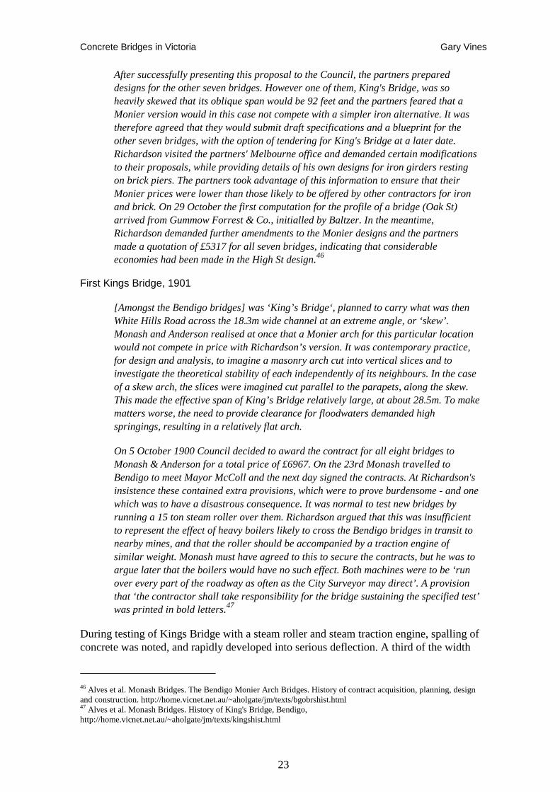
Concrete Bridges in Victoria Gary Vines
23
After successfully presenting this proposal to the Council, the partners prepared designs for the other seven bridges. However one of them, King's Bridge, was so heavily skewed that its oblique span would be 92 feet and the partners feared that a Monier version would in this case not compete with a simpler iron alternative. It was therefore agreed that they would submit draft specifications and a blueprint for the other seven bridges, with the option of tendering for King's Bridge at a later date. Richardson visited the partners' Melbourne office and demanded certain modifications to their proposals, while providing details of his own designs for iron girders resting on brick piers. The partners took advantage of this information to ensure that their Monier prices were lower than those likely to be offered by other contractors for iron and brick. On 29 October the first computation for the profile of a bridge (Oak St) arrived from Gummow Forrest & Co., initialled by Baltzer. In the meantime, Richardson demanded further amendments to the Monier designs and the partners made a quotation of £5317 for all seven bridges, indicating that considerable economies had been made in the High St design.46
First Kings Bridge, 1901
[Amongst the Bendigo bridges] was ‘King’s Bridge‘, planned to carry what was then White Hills Road across the 18.3m wide channel at an extreme angle, or ‘skew’. Monash and Anderson realised at once that a Monier arch for this particular location would not compete in price with Richardson’s version. It was contemporary practice, for design and analysis, to imagine a masonry arch cut into vertical slices and to investigate the theoretical stability of each independently of its neighbours. In the case of a skew arch, the slices were imagined cut parallel to the parapets, along the skew. This made the effective span of King’s Bridge relatively large, at about 28.5m. To make matters worse, the need to provide clearance for floodwaters demanded high springings, resulting in a relatively flat arch.
On 5 October 1900 Council decided to award the contract for all eight bridges to Monash & Anderson for a total price of £6967. On the 23rd Monash travelled to Bendigo to meet Mayor McColl and the next day signed the contracts. At Richardson's insistence these contained extra provisions, which were to prove burdensome - and one which was to have a disastrous consequence. It was normal to test new bridges by running a 15 ton steam roller over them. Richardson argued that this was insufficient to represent the effect of heavy boilers likely to cross the Bendigo bridges in transit to nearby mines, and that the roller should be accompanied by a traction engine of similar weight. Monash must have agreed to this to secure the contracts, but he was to argue later that the boilers would have no such effect. Both machines were to be ‘run over every part of the roadway as often as the City Surveyor may direct’. A provision that ‘the contractor shall take responsibility for the bridge sustaining the specified test’ was printed in bold letters.47
During testing of Kings Bridge with a steam roller and steam traction engine, spalling of concrete was noted, and rapidly developed into serious deflection. A third of the width
46 Alves et al. Monash Bridges. The Bendigo Monier Arch Bridges. History of contract acquisition, planning, design and construction. http://home.vicnet.net.au/~aholgate/jm/texts/bgobrshist.html 47 Alves et al. Monash Bridges. History of King's Bridge, Bendigo, http://home.vicnet.net.au/~aholgate/jm/texts/kingshist.html
Concrete Bridges in Victoria Gary Vines
24
of the arch and spandrel wall fell into the creek, taking the traction engine with it, and killing A. E. Boldt, a business associate of the owner of the traction engine.
W. C. Kernot, Professor of Engineering at the University of Melbourne, was retained to investigate the causes of the collapse on behalf of Monash and Anderson. The cause of failure was identified as the inability of the abutment concrete to resist the magnified stresses imposed by the highly skewed arch.
Plate 12: The first Kings Bridge collapsed under load testing (photo Melbourne Uni. Archives)
Second Kings Bridge, 1902
Reconstruction of Kings Bridge using the original abutment form was not feasible as it would have required demolition of the abutments and reconstruction in stronger concrete, and/or a large increase in the thickness of the arch near the overstressed corners to reduce the intensity of stress. Monash and Anderson therefore decided to retain the existing abutments and build a new pier midstream so that the bridge would consist of two arches each of a 13.2m span rather than one of 28.5m. This would reduce the calculated thrust on the abutments to little more than a quarter of the value for the single arch. Also, the ratio of skew-span to width would be reduced by more than half, and the abutments of each arch would be situated more directly opposite each other.48
The second Kings Bridge survived the load tests, allowing Monash and Anderson to continue with the Bendigo contracts, ultimately constructing eight arch bridges. The other bridges in the group, erected during 1900-1902, were at Oak Street, Booth Street, High Street, Wade Street, Abbot Street, Myrtle Street and Thistle Street. All except Oak Street and Myrtle Street, which were demolished, are still in use.
48 Alves et al. Monash Bridges. History of King's Bridge, Bendigo.
Concrete Bridges in Victoria Gary Vines
25
The second Kings Bridge also survives in use, but there is evidence of outward movement of the spandrel walls and the arch ribs are not well shaped. This may be also a sign of movement, indicating some of the problems that Monash and Anderson continued to experience in the construction process.49
Anderson left Australia for New Zealand to take up a municipal position in 1902. Monash continued to carry on the work of the partnership, until 1905 when the Reinforced Concrete & Monier Pipe Construction Co. Pty. Ltd. was formed. Monash clearly had skills in developing the engineering side of the company and began experimenting with reinforced concrete girder designs for bridges. Girder bridges became the main form constructed by the firm from 1905.50
Monash persisted with their arch designs for about 6 years, from their minor involvement in the Morell Bridge to the completion of the Spargo Creek Road bridge for the Shire of Ballan in 1905, although 1903 was the last year that they had more than one arch project on their books. One more Monier arch bridge was constructed by the company during Monash’s involvement, The Porepunkah Bridge of 1913, a design chosen for its aesthetic qualities as much as engineering requirements.
After having built over 15 Monier arch bridges prior to 1903, Monash came to realise that in most situations it was more economic and practicable to build a bridge of horizontal girders, resting on intermediate piers if necessary. After 1903 he always attempted to dissuade clients from adopting arch designs unless there was a demand for an imposing ornamental structure and the site was particularly well adapted. This was the case with the Porepunkah Bridge, when Monash’s assistant P T Fairway made a mild attempt to dissuade the Engineer for the Shire of Bright, H G Oliver , pointing out that a girder bridge could be built for £75 less, but he agreed that an arch would look better.51
Girder Bridges
St Kilda Street Bridge, 1905
With the Monier arch bridges becoming less practical or difficult to get adopted by conservative shire engineers, Monash turned to another use of reinforced concrete in the form of T- girder bridge bridges.52
From 1905 to 1907 the Reinforced Concrete & Monier Pipe Construction Co. built seven bridges in the Elwood district. Six of them were built across the Elwood Canal for the Public Works Department, all under separate contracts. Again Carlo Catani seems to have been influential in progressing both the adoption of reinforced concrete technology for bridge construction, and the fortunes of Monash and Anderson.
49 Register of the National Estate, 16057 50 Alves et al. Monash Bridges. John Monash's engineering career to 1914. 51 Alves et al. ‘Porepunkah Monier arch bridge’. http://home.vicnet.net.au/~aholgate/jm/texts/ppkhist.html 52 Alves et al. 'Monash Bridges: Typology study; reinforced concrete bridges in Victoria 1897-1917'. Lesley Alves 1998, Alan Holgate and Geoff Taplin.
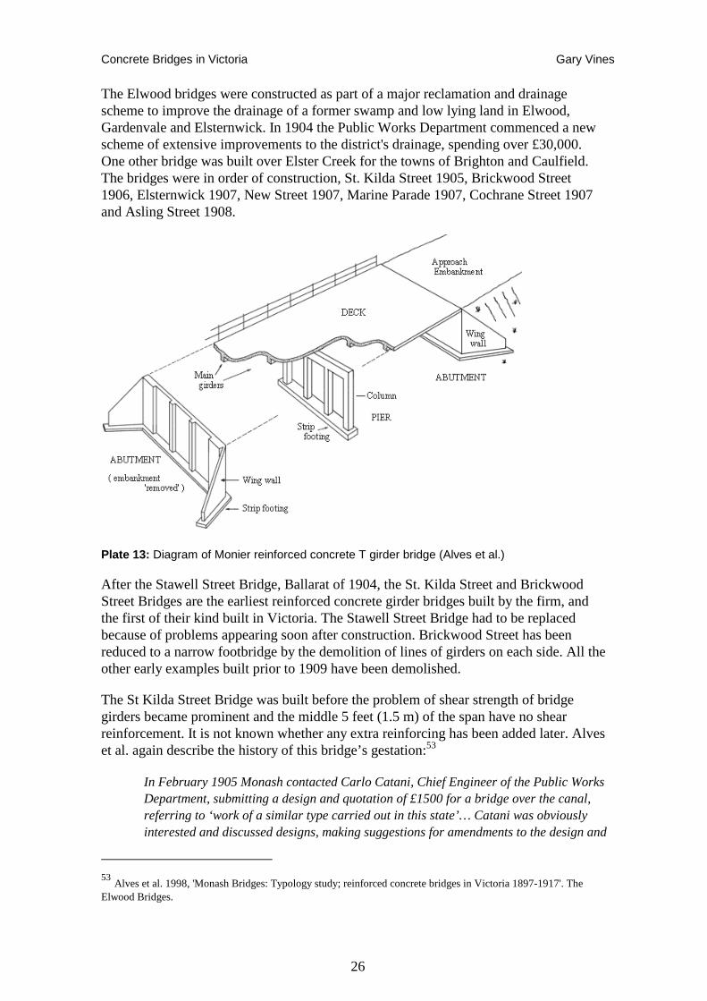
Concrete Bridges in Victoria Gary Vines
26
The Elwood bridges were constructed as part of a major reclamation and drainage scheme to improve the drainage of a former swamp and low lying land in Elwood, Gardenvale and Elsternwick. In 1904 the Public Works Department commenced a new scheme of extensive improvements to the district's drainage, spending over £30,000. One other bridge was built over Elster Creek for the towns of Brighton and Caulfield. The bridges were in order of construction, St. Kilda Street 1905, Brickwood Street 1906, Elsternwick 1907, New Street 1907, Marine Parade 1907, Cochrane Street 1907 and Asling Street 1908.
Plate 13: Diagram of Monier reinforced concrete T girder bridge (Alves et al.)
After the Stawell Street Bridge, Ballarat of 1904, the St. Kilda Street and Brickwood Street Bridges are the earliest reinforced concrete girder bridges built by the firm, and the first of their kind built in Victoria. The Stawell Street Bridge had to be replaced because of problems appearing soon after construction. Brickwood Street has been reduced to a narrow footbridge by the demolition of lines of girders on each side. All the other early examples built prior to 1909 have been demolished.
The St Kilda Street Bridge was built before the problem of shear strength of bridge girders became prominent and the middle 5 feet (1.5 m) of the span have no shear reinforcement. It is not known whether any extra reinforcing has been added later. Alves et al. again describe the history of this bridge’s gestation:53
In February 1905 Monash contacted Carlo Catani, Chief Engineer of the Public Works Department, submitting a design and quotation of £1500 for a bridge over the canal, referring to ‘work of a similar type carried out in this state’… Catani was obviously interested and discussed designs, making suggestions for amendments to the design and
53 Alves et al. 1998, 'Monash Bridges: Typology study; reinforced concrete bridges in Victoria 1897-1917'. The Elwood Bridges.
Concrete Bridges in Victoria Gary Vines
27
quality. When tenders were called in April for a bridge to the design of the Public Works Department, tenders for the design and supply of a Monier bridge were also invited, with a caution that it should be understood that a Monier bridge would be subject to a test with a 15 ton steam roller and that only half of the tender price would be paid before the bridge was satisfactorily tested. The Reinforced Concrete & Monier Pipe Construction Co. was successful in gaining the contract. John Monash was chief design engineer and did most of the drawings himself, with J. S. Gregory assisting with some of the calculations. During the development of the design Monash was in close consultation with Baltzer of Gummow, Forrest & Co. in Sydney, who provided a critique of his plans and calculations, and gave instructions regarding the placement of the reinforcing steel. Baltzer and Gummow had been Monash & Anderson’s mentors since they began building Monier structures and it was logical that Monash would confer with them at this important new stage in developing the technology. It is not known whether Gummow, Forrest & Co. actually designed and constructed any reinforced concrete girder bridges of their own in New South Wales during these early years. None have been identified by the researches of Colin O’Connor or Don Fraser. It is likely then that the St Kilda Street bridge is the earliest extant bridge of its kind in Australia, and only the second to be built. Construction commenced early in July and was completed by the end of September. The bridge was tested successfully in the presence of Catani, the St Kilda city surveyor and municipal representatives from Brighton and Caulfield. The following week the bridge was opened for traffic, apparently without ceremony.
More Monash Girder Bridges
With the success and ongoing cash-flow generated by the Elwood bridges, Monash and Anderson were able to win a number of other tenders with their reinforced concrete bridges. Individual commissions were won for a bridge at Mansfield in 1906, McIsaac’s Bridge Kilmore, Gellies Bridge at Sunbury (both built 1907), Waterford Bridge in Gippsland in 1908 and Excelsior Bridge at Shepherds Flat in 1909.
A particularly challenging commission was for a private client, Mr F. S. Staughton, for whom Monash's firm obtained a design-and-build contract, with J. S. Sharland acting as consulting engineer for a private access bridge at the Staughton Vale Property south of Bacchus Marsh. The bridge was designed by Monash himself in May 1907, and in June, Monash tendered £285, which was accepted after minor modifications requested by Sharland. Work commenced on 7 July under foreman Thomas W Wood and was completed on 25 August. An extra cost of £25-10-0 was incurred because abutment works were more extensive than expected. The bridge was tested on 28 September and Monash claimed it as 'the largest bridge work of this kind yet in existence in Victoria'.54
Benalla Bridge, 1909-10
Late in 1907 the Benalla Shire Council organised a deputation to the Premier seeking financial assistance to repair or replace the main road bridge into the town on the Hume Highway. In March 1908 the government offered £3000 for a new Benalla Bridge, and
54 Alves et al. 'Monash Bridges: Typology study; reinforced concrete bridges in Victoria 1897-1917'.The Elwood Bridges. 1998,
Concrete Bridges in Victoria Gary Vines
28
the Shire Engineer, Samuel Jeffrey, investigated the cost of a steel lattice girder bridge, reporting to Council that £6000 would be sufficient. Jeffrey also visited Monash in Melbourne to discuss the option of using reinforced concrete with steel lattice girders to span 120 feet of waterway with spans of 44 feet.
Monash saw this as a chance to promote reinforced concrete in Victoria and further his company's business prospects. The longest span in a reinforced concrete girder Monash had built up to that time was 38 feet for the single-span Staughton Vale Bridge, so the requirement of 44 foot spans presented a challenge. Monash managed to convince Jeffrey of the worth of reinforced concrete, supplying him with the latest literature on the subject.
After further negotiations, The Reinforced Concrete & Monier Pipe Construction Co. was successful tenderer with £5856, being the lowest of five received, including one other for a concrete bridge by Wilson & Sly.
Work commenced in February but problems were experienced with the foundations and floods during construction. Monash, who had left much of the management of the work to his assistants (P. T. Fairway and Alex Lynch, RCMP Co's Works Manager), was eventually called to Benalla for a special meeting with Council to iron out the problems. The bridge was completed in January 1910 at a final cost of £6532 and tested successfully on 18 February.55
Its overall length of 121.3 metres, comprised of ten 12.2 metre spans, was long for its time. The same concrete girder structural form and design was sympathetically employed when the bridge was widened in 1936 and again in 1939-40 to plans prepared by Allan Ozanne of the Country Roads Board, assisted by the Shire Engineer, Les Fawkner. Until 1987 it carried the Hume Highway across the Broken River.
Following the success of the Benalla Bridge, the Reinforced Concrete & Monier Pipe Construction Co. continued to construct a large number of reinforced concrete girder bridges, with a total of more than 70 completed by 1915.56
Janevale Loddon River Road Bridge, 1911
Janevale Bridge, replaced a large timber bridge that was destroyed in widespread floods in 1909. Monash’s estimate of £4000 for a reinforced concrete girder bridge was close to the Shire Engineer’s estimate for a timber bridge. The Public Works Department considered both prices too low, but Monash, in conjunction with Read, proceeded to develop a design with 40 foot spans. Tenders were called for timber and concrete bridges, and Monash’s tender was eventually accepted. The bridge was a joint project with the Bet Bet Council. Work commenced in October 1910. The Shire Engineer was given credit for the design. The new bridge was longer than the previous longest of its type in the State, at Benalla (also by Monash), by 20 feet. By 1912 cracks were discovered in the bridge but Monash asserted that they were no more extensive than expected. Further tests were conducted. In the 1930s the Country Roads Board
55 ibid 56 ibid
Concrete Bridges in Victoria Gary Vines
29
introduced additional shear reinforcement to counter extensive cracking in the form of underslung metal stirrups.57
The Janevale Bridge has ten spans of 12.8 m, each totalling 128 m divided into two end spans, which are simply supported, and the eight interior spans, which are continuous. The first interior pier at each end is a double pier, split to permit expansion and contraction of the central portion without restraint from the abutments. A distinctive feature of the Janevale Bridge is its slender splayed pier columns, giving the appearance of a trestle framed bridge. In general, the piers tend to show the most visually distinct variation in the Monash girder bridges, with earlier bridges having closer spaced multiple columns with arched cross heads or solid panels between the columns, designed to prevent debris catching in floods. 58
Ararat Shire Bridges
The few years before WWI were very prolific for Monash. Of particular note, are a group of six girder bridges built for the Shire of Ararat, as part of the development of new access roads for closer settlement estates. The young Shire Engineer, Robert Speed, was aware of the advantages of reinforced concrete, having had experimented with the new technology himself, building a bridge with a steel girder encased in concrete. In November he asked for a quote for two new bridges to replace timber bridges washed away by floodwaters. He told the Company that he was satisfied that a Monier structure was the best. The RCMP Co. submitted designs for the two bridges, and for two others for a total of £1268.
Monash had to convince the Ararat Shire Council that it was worth spending a bit more -'only one fifth more than timber' - to have a 'permanent structure, proof against fire flood and decay'. Speed recommended Monash's designs to his council and the firm was contracted to build four reinforced concrete girder bridges.59
After nearly a decade of promoting their patents with varied success, Monash and Anderson found an unlikely competitor. George Taylor, the editor of the influential Building Magazine, challenged Monash’s near monopoly in editorials in 1908. At dispute was the ‘prime cost’ method of tendering that Monash was employing generally and his concerns about the closed tender process for the State Library domed reading room in Melbourne, which ultimately caused the Library Trustees to open up tendering. The result was that an alternative bid by Swanston Brothers, with the Trussed Concrete Steel Company of New York, won over Monash’s. Monash claimed patent infringement when he saw that the Truscon design was very similar to his Monier patents, but Taylor called his bluff in Building, Magazine and when Monash failed to take any legal action, this opened up the reinforced concrete construction field to all-comers.60
57 ibid 58 Register of the National Estate 16060 59 Alves et al. 1998, 'Monash Bridges: Typology study; reinforced concrete bridges in Victoria 1897-1917'.The Elwood Bridges. Bridges in The Shire of Ararat 60 Cowan 1998 p94.
Concrete Bridges in Victoria Gary Vines
30
Leigh River Road Bridge, 1911
As evidence of the other reinforced concrete construction which was undertaken in the early decades of the century, and perhaps the impact of the Building Magazine affair, the Leigh River Road Bridge north of Geelong is not a Monash or Reinforced Concrete & Monier Pipe Construction Co design, but is still characteristic of the early girder bridges in the use of a reinforced concrete slab integral with four T-section reinforced concrete girders, continuous over five spans. It was completed in 1911 by C. P. Wilson, son of C. A. C. Wilson who had designed the Shelford Bridge. The bridge deck is very tall at a maximum height of 9.5m above the stream. The slender reinforced concrete piers each consist of four separate rectangular, reinforced concrete shafts interconnected by heavy diaphragms at two levels. The pier shafts are made continuous with the deck girders by prominent triangular fillets. A sharp triangular section cut-water is formed in the lower section of each pier. One abutment is of reinforced concrete, the other is of bluestone, suggesting it replaces a former masonry and timber bridge. The bridge is said to have been reinforced using recycled tramway cable, which had been untwisted and straightened, a technique that was also being used for concrete pipe manufacture by the Hume Pipe Co. in about 1910-11.61 If wire cable was used, then there may have been no infringement of the Monier patent in any case. The Reinforced Concrete and Monier Pipe Company records include a letter (Letter Book J p.629 dated 21 April 1910) from P T Fairweather to C. A. C. Wilson that may relate to the Leigh Road Bridge suggesting that the Monier company had an unsuccessful tender: ‘P.T.F. to C. A. C. Wilson, Sec, Shire of Leigh, Teesdale. ‘I regret that we were too late to submit … I quite realise however that the fact of the Council having the girders and about half the masonry on hand would make the proposed design more economical under the circumstances’’.62
New Arch Styles
The open-spandrel, single-arch bridge at Hurstbridge was built by the Reinforced Concrete & Monier Pipe Construction Co. and probably designed by J. A. Laing after Monash left for active service. As often happened, the municipality's engineer was given credit. With a 29m span and colonnaded open spandrels, it is unusual in form and was one of the later reinforced concrete arch bridges by the company with an attributed date of 1917. The narrow arch ring is in fact a pair of ribs with a thin web plate between them, and the deck is cantilevered out beyond the paired columns that rise from the ribs.63
61 Register of the National Estate 62 Pers. com. Alan Holgate 14/5/06 quoting letter from Monash Collection, University of Melbourne Archive 63 Register of the National Estate 5594; The Eltham and Whittlesea Shires Advertiser and Diamond Creek Valley Advocate. Friday, November 9, 1917 (Bridge Opening)

Concrete Bridges in Victoria Gary Vines
31
Plate 14: Hurstbridge bridge during construction (photo Eltham Historical Society)
Open spandrel designs were unusual in Victoria, despite such bridges being particularly popular in the US where their aesthetic appeal suited large important crossings, and were promoted by the City Beautiful movement. The development of Parkways in the early twentieth century (the aesthetically designed, controlled-access motor roads that might be seen as the precursors to freeways) gave further impetus to construction of attractive bridge designs that would enhance the visual environment around these roads. Melbourne gained limited elements of these movements, such as the development of the Yarra Boulevard. Other Victorian open span bridges include the Church Street Bridge. It is interesting that this was built at the same time as Alexandra Avenue – an incipient parkway in Melbourne of the 1920s and intersecting that work.
One of the instrumental designers in American reinforced concrete bridges was Daniel B. Luten, who rigorously applied theory and test results to develop bridge designs that used much less steel and concrete. These resulted in some distinctive open spandrel rib designs (among many other types), which became influential in many other countries. However his influence waned as his patents expired, and US state highway officials began to favour designs based on trusses, slabs and beams, which were more easily analysed and required less empirical formulae than arches.
Luten’s bridges and other US designs were already well known in Victoria at least by the inception of the Country Roads Board, as is evident by illustration and reference to them in Annual Reports of the Board, the reports of Board Members’ investigative trips abroad and contemporary bridge publications obtained by the State Library and Melbourne University prior to World War 1.64
The1954 bridge at Belgrave was possibly the last major arched bridge built in Victoria, with a unique form employing a three pin, open spandrel rib arch design.
64 See for example: Hool, George A. 1912, Reinforced concrete construction, University of Wisconsin, New York: Houghton, A. A, 1912, Concrete Bridges, Culverts and Sewers. New York: Wescott, L. c1925. Reinforced Concrete Bridges
Concrete Bridges in Victoria Gary Vines
32
Barwon Sewer Aqueduct, 1913-15
The Barwon Sewer Aqueduct stands out as an oddity in Victorian and Australian bridge design. It is the longest aqueduct of its type in the world: namely a reinforced concrete, trussed, balanced cantilever. Built during 1913-15 for the Geelong Water Works & Sewerage Trust, the design of the concrete members is based upon principles developed by the outstanding pioneer concrete work of the French engineer Armand Considere. The structure was designed and constructed by the firm of Stone & Siddeley.
Edward Giles Stone was one of the most innovative, creative engineers Australia has produced, especially in reinforced concrete design. The aqueduct includes his patented system of concrete pipe construction. In 1910-11, Stone built a reinforced concrete wool store with a column-free show floor of 56m x 52m, the largest column-free covered space in the world at the time. This was also at Geelong (now demolished). The bridge was part of the outfall sewer from Geelong to an ocean discharge point at Black Rock. The Considere reinforced concrete system involved hooped iron reinforcement used to provide confinement. When the concrete inside the wire helix expands laterally due to longitudinal compression, the helix resists and so compression stress develops in the core concrete. The ovoid reinforced concrete sewer pipes carried by the bridge were manufactured on-site by a patented process invented by Stone. Connection of the first Geelong property to the sewerage system occurred on 26 January 1916.65
Role of the Country Roads Board
Prior to 1913, the administration of the road network was variously the responsibility of the Colonial Government’s Public Works Department, a short-lived Central Road Board, District Road Boards and their descendent Shire Councils, and various parts of the Government planning and public works authorities. More detailed discussion of this administration is provided in the Metal Bridges Study and other histories of Victorian roads.66
The issues of poor roads were considered in the 1910 report of the Inspector General of Public Works, William Davidson. The major recommendation was for the establishment of the Country Roads Board (CRB), which could act in co-operation with municipalities for the improvement of roads and bridges. This resulted in the Country Roads Act 1912, which constituted the CRB and identified the relationship with municipalities. Under the Act the CRB would be responsible for main roads, but construction costs would be shared with municipalities on a half and half basis. On-going maintenance would be funded 1/3 by the board and 2/3 by shires.
With the formation of the Country Roads Board in 1913 with William Calder its first Chairman, Government funds for the construction of roads and bridges became available to all municipalities outside the Metropolitan area. The majority of new bridge construction from that time was therefore subject to the scrutiny of the Country Roads
65 O'Connor 1983. Register of Australian Historic Bridges; O'Connor 1985. Alsop 1971 ‘History of The Fyansford Bridge’, Lecture to The Geelong Historical Society, 6 October 71. Alsop 1971. ‘The Reinforced Concrete Arch Bridge at Fyansford’, Unpublished report Alsop 1981, ‘Letter to The Editor’, in Engineers Australia, February 6-19, 1981, P.3. 66 Vines 2004, Metal Bridges Study; Anderson, 1994,
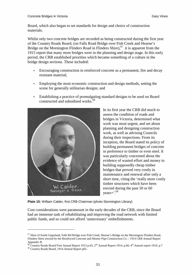
Concrete Bridges in Victoria Gary Vines
33
Board, which also began to set standards for design and choice of construction materials.
Whilst only two concrete bridges are recorded as being constructed during the first year of the Country Roads Board, (on Falls Road Bridge over Fish Creek and Hearne’s Bridge on the Mornington Flinders Road in Flinders Shire),67 it is apparent from the 1915 report that many more bridges were in the planning and design stage. In this early period, the CRB established priorities which became something of a culture in the bridge design sections. These included:
• Encouraging construction in reinforced concrete as a permanent, fire and decay resistant material;
• Employing the most economic construction and design methods, setting the scene for generally utilitarian designs; and
• Establishing a practice of promulgating standard designs to be used on Board constructed and subsidised works.68
In its first year the CRB did much to assess the condition of roads and bridges in Victoria, determined what work was most urgent, and set about planning and designing construction work, as well as advising Councils during their inspections. From its inception, the Board stated its policy of building permanent bridges of concrete in preference to timber or even steel. It was particularly concerned about the evidence of wasted effort and money in building supposedly cheap timber bridges that proved very costly in maintenance and renewal after only a short time, citing the ‘really more costly timber structures which have been erected during the past 50 or 60 years+’.69
Plate 15: William Calder, first CRB Chairman (photo Stonnington Library)
Cost considerations were paramount in the early decades of the CRB, since the Board had an immense task of rehabilitating and improving the road network with limited public funds, and so could not afford ‘unnecessary’ embellishments.
67 Shire of South Gippsland, Falls Rd Bridge over Fish Creek; Hearne’s Bridge on the Mornington Flinders Road, Flinders Shire erected by the Reinforced Concrete and Monier Pipe Construction Co .- 1914 CRB Annual Report Appendix B. 68 Country Roads Board First Annual Report 1913 p.65; 2nd Annual Report 1914, p.66; 4th Annual report 1916, p.7 69 Country Roads Board, 1914 Annual Report p65.
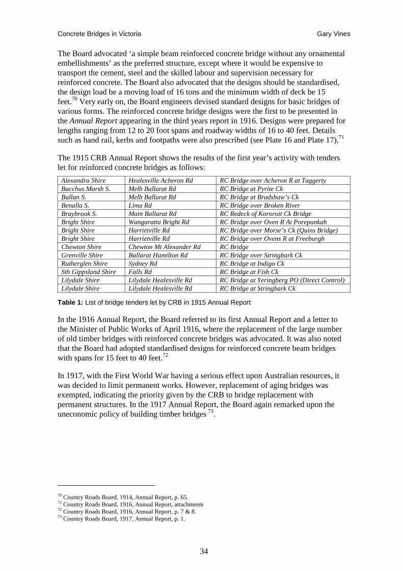
Concrete Bridges in Victoria Gary Vines
34
The Board advocated ‘a simple beam reinforced concrete bridge without any ornamental embellishments’ as the preferred structure, except where it would be expensive to transport the cement, steel and the skilled labour and supervision necessary for reinforced concrete. The Board also advocated that the designs should be standardised, the design load be a moving load of 16 tons and the minimum width of deck be 15 feet.70 Very early on, the Board engineers devised standard designs for basic bridges of various forms. The reinforced concrete bridge designs were the first to be presented in the Annual Report appearing in the third years report in 1916. Designs were prepared for lengths ranging from 12 to 20 foot spans and roadway widths of 16 to 40 feet. Details such as hand rail, kerbs and footpaths were also prescribed (see Plate 16 and Plate 17).71
The 1915 CRB Annual Report shows the results of the first year’s activity with tenders let for reinforced concrete bridges as follows:
Alexandra Shire Healesville Acheron Rd RC Bridge over Acheron R at Taggerty Bacchus Marsh S. Melb Ballarat Rd RC Bridge at Pyrite Ck Ballan S. Melb Ballarat Rd RC Bridge at Bradshaw’s Ck Benalla S. Lima Rd RC Bridge over Broken River Braybrook S. Main Ballarat Rd RC Redeck of Kororoit Ck Bridge Bright Shire Wangaratta Bright Rd RC Bridge over Oven R At Porepunkah Bright Shire Harrietville Rd RC Bridge over Morse’s Ck (Quins Bridge) Bright Shire Harrietville Rd RC Bridge over Ovens R at Freeburgh Chewton Shire Chewton Mt Alexander Rd RC Bridge Grenville Shire Ballarat Hamilton Rd RC Bridge over Stringbark Ck Rutherglen Shire Sydney Rd RC Bridge at Indigo Ck Sth Gippsland Shire Falls Rd RC Bridge at Fish Ck Lilydale Shire Lilydale Healesville Rd RC Bridge at Yeringberg PO (Direct Control) Lilydale Shire Lilydale Healesville Rd RC Bridge at Stringbark Ck
Table 1: List of bridge tenders let by CRB in 1915 Annual Report
In the 1916 Annual Report, the Board referred to its first Annual Report and a letter to the Minister of Public Works of April 1916, where the replacement of the large number of old timber bridges with reinforced concrete bridges was advocated. It was also noted that the Board had adopted standardised designs for reinforced concrete beam bridges with spans for 15 feet to 40 feet.72
In 1917, with the First World War having a serious effect upon Australian resources, it was decided to limit permanent works. However, replacement of aging bridges was exempted, indicating the priority given by the CRB to bridge replacement with permanent structures. In the 1917 Annual Report, the Board again remarked upon the uneconomic policy of building timber bridges 73.
70 Country Roads Board, 1914, Annual Report, p. 65. 71 Country Roads Board, 1916, Annual Report, attachments 72 Country Roads Board, 1916, Annual Report, p. 7 & 8. 73 Country Roads Board, 1917, Annual Report, p. 1.
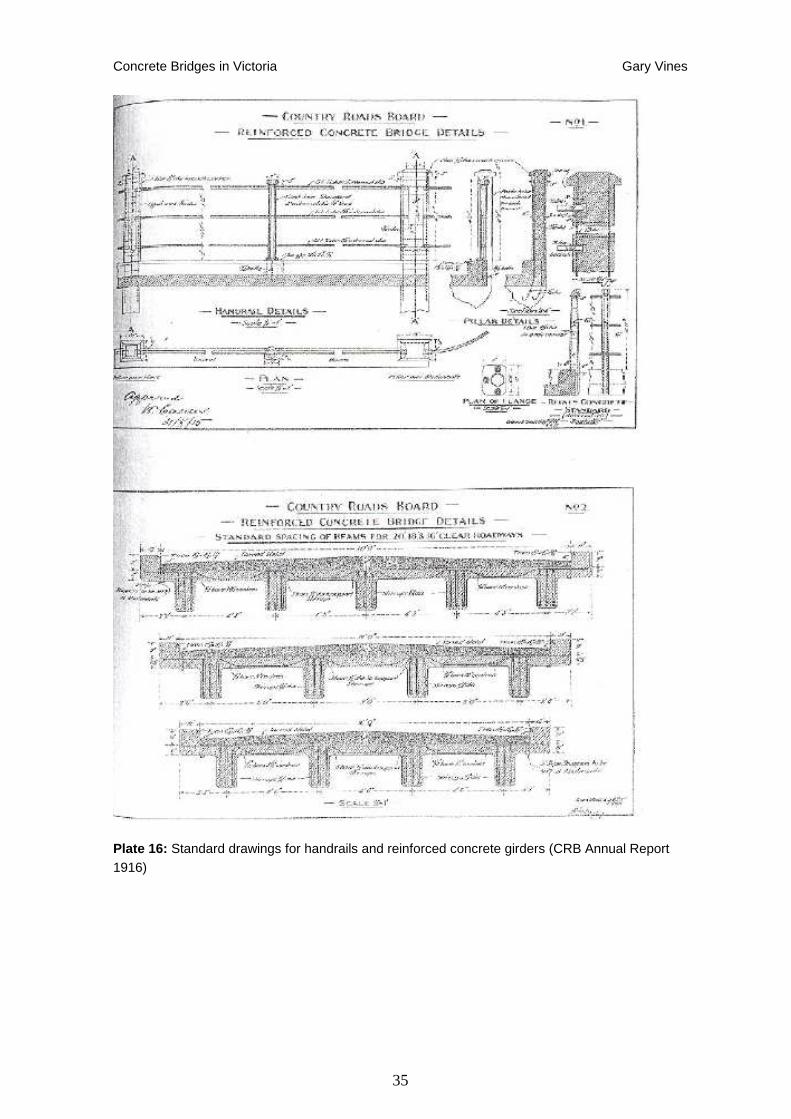
Concrete Bridges in Victoria Gary Vines
35
Plate 16: Standard drawings for handrails and reinforced concrete girders (CRB Annual Report 1916)
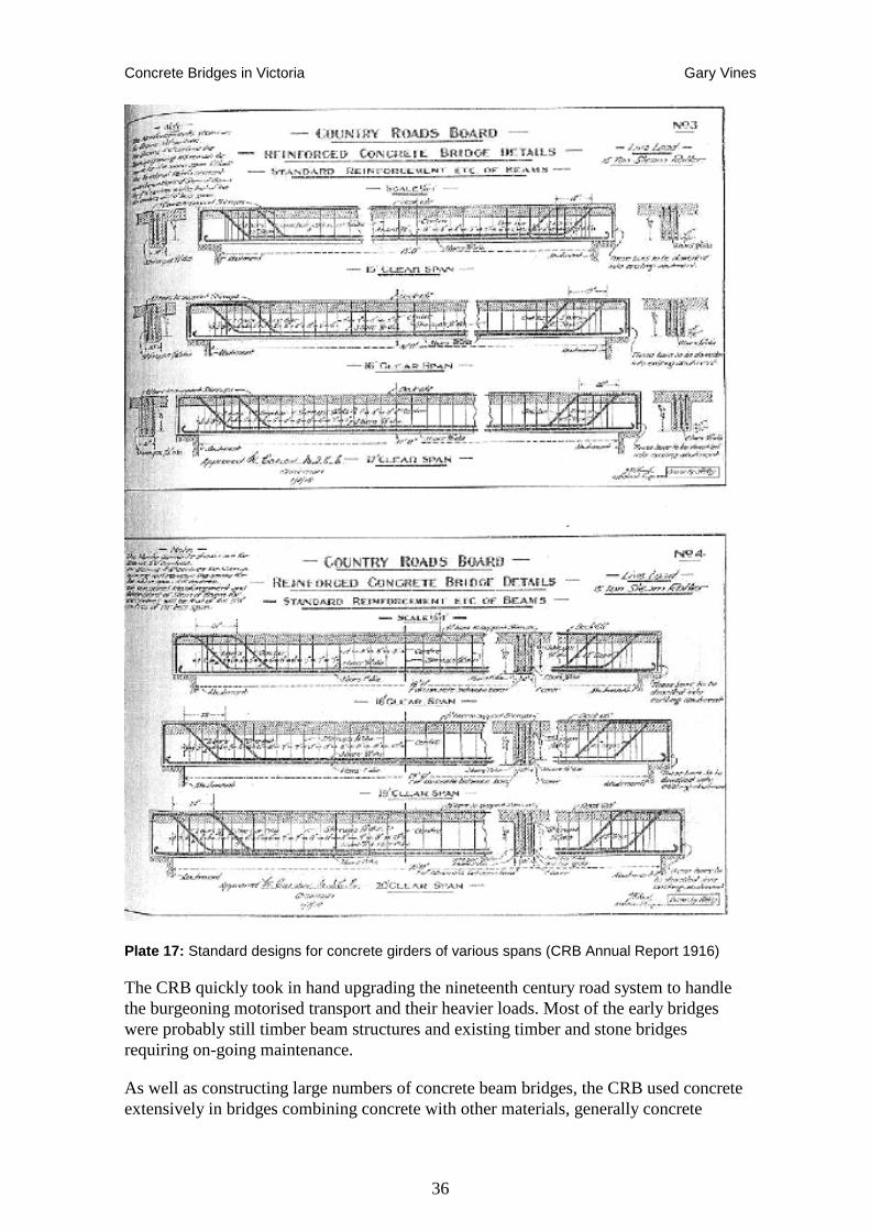
Concrete Bridges in Victoria Gary Vines
36
Plate 17: Standard designs for concrete girders of various spans (CRB Annual Report 1916)
The CRB quickly took in hand upgrading the nineteenth century road system to handle the burgeoning motorised transport and their heavier loads. Most of the early bridges were probably still timber beam structures and existing timber and stone bridges requiring on-going maintenance.
As well as constructing large numbers of concrete beam bridges, the CRB used concrete extensively in bridges combining concrete with other materials, generally concrete
Concrete Bridges in Victoria Gary Vines
37
substructures and steel or timber superstructures. An early example is the U. T. Bridge in Alexandra, which combines mass concrete abutments (probably reinforced with steel bar) and riveted steel girders.
Prior to the establishment of the CRB, concrete had already been employed extensively for abutments and piers in addition to Monash’s small number of concrete arch bridges and somewhat greater numbers of concrete girder bridges. For example, Monash’s reconstruction of Mains Bridge on Flemington Road in 1913 involved new concrete abutments and repositioned riveted metal girders, supplemented by new reinforced concrete beams supporting tram tracks for the extension of the electric tram system. The practice of combining concrete and riveted metal components, sometimes using recycled girders, continued for some time, with bridges such as the Peace Memorial Bridge in Dandenong incorporating concrete abutments with riveted girders.74
Other bridges of this type were being built, or rebuilt in Melbourne, but as the CRB did not have jurisdiction in the Metropolitan area, they were carried out by local councils or other authorities. In 1923, the Federal State Grant to Victoria for roads and bridges was ₤70,000, of which ₤32,100 was allocated to Councils on a 1 to 1 basis on condition that ‘the Board approved of the class of work proposed’75. In the post World War II period’ the Commonwealth Roads Act allowed significant funds to flow to Local Government through the Country Roads Board, with all works, of course, being to the Board's approval.76
The CRB did, however, obtain authority in the Metropolitan area under the Highways and Vehicles Act 1924 (Special Provision), but exercised this authority sparingly for some years. The concerns appear to be that the CRB had been set up specifically to address problems on country roads, with metropolitan roads still considered the realm of municipal councils, the Public Works Department, MMBW and Railway Construction Branch, sometimes with considerable rivalry evident.77 Projects undertaken were as developmental roads including Williamstown Short Road (1925) and the experimental concrete road at Oakleigh (1925).
Under the provisions of the Country Roads Board (Borrowing) Act 1933 No.4188, the Country Roads Board was financed to assume responsibility for roads ‘between the declared country roads leading to the metropolis tramway terminals or connecting with Metropolitan through roads’ The interpretation appears to have been liberal, as works stretched to the boundary of the City of Melbourne in some cases. The result was that the Country Roads Board then became involved in most of the major bridgeworks in the metropolitan area from 1934 onwards, including the widening of the Merri Creek stone arch bridge on Heidelberg Road in 1935, Lynch's Bridge over the Maribyrnong River on Ballarat Road, Punt Road Bridge and Swan Street Bridge over the Yarra, Gardner’s Creek Bridge on Warragul Road and others.78
74 National Trust n.d. Classification Report, Mains Bridge,; David Beauchamp,2005, ‘Peace Memorial Bridge, Conservation Management Plan’ VicRoads 75 Country Roads Board Annual Report 1923, p.10 76 Pers. com., Norm Butler 2006 77 CRB Annual Report 1924 p.2 78 Pers. com., Norm Butler 2006
Concrete Bridges in Victoria Gary Vines
38
Bridge Aesthetics
Despite the CRB making it clear throughout its early decades that it could not afford ‘unnecessary’ embellishments, it still made considerable efforts to ensure that its new bridges were fitting in the landscape, and recognised the intrinsic advantage of concrete in certain situations or designs.79
Consideration was given to the aesthetic qualities of reinforced concrete, as its smooth monolithic forms eliminated the complexities and contrasts of mixed materials and textures inherent in timber and metal bridges, in addition to designing beam bridges to provide harmonious profiles, or using arch forms in particular cases.
It is difficult to judge how CRB and other bridge engineers approached the issue of aesthetics in their designs, although even the choice to avoid unnecessary embellishment can be seen as part of an aesthetic. It is clear, however, that overseas practice was closely watched both for technical and aesthetic directions. Various board members, who undertook investigative tours to Europe and North America, subsequently influenced the design of Victorian bridges. For example, the Kananook Creek Bridge of 1938 was reported as following ‘recent trends in American practice’, evidently referring to both the cantilevered rigid frame structural design as well as its Art Deco style.80
In certain cases a decision was made to use less than optimal or less cost-effective designs because the location or purpose of a bridge demanded something which also made a visual impact. One example was the choice of a reinforced concrete arch for the Germantown Bridge near Bright, which was built as part of a tourist road improvement, despite this type of bridge being redundant in most other applications.81
While in Europe and the United States concrete was seen as a material that could free bridge engineers to follow more adventurous and contemporary design aesthetics, the CRB’s policy of avoiding unnecessary embellishments, and the dire needs for reconstruction of the many neglected bridges, had the opposite effect of producing mostly very plain and un-interesting bridges. There were of course, always exceptions.
Often subtle design elements were introduced in the otherwise utilitarian structures, such as chamfering the arrises on piers or simple curved fillets between pier and beam to create a more balanced effect. Much of the aesthetic input in bridge design was focussed on the appearance from the users’ point of view, so that various forms of handrail were employed, often with a compromise needed between appearance, safety and cost. Art Deco also influenced designs for a short period, with some notable examples being the Hoddle Bridge and Dynon Road Bridge. Generally these more dramatic structures were confined to the most important crossings or bridges seen as gateways.
Writings on bridge aesthetics have burgeoned in recent decades with the work of Fritz Leonhardt among the more influential publications. The rise and fall of the importance of aesthetics in bridge design might be seen as a mirror of both Government policy and
79 Country Roads Board, 1914 Annual Report p. 65 80 Country Roads Board, 1938 Chief Engineers Report p. 33 81 Country Roads Board, 1925 Annual Report p. 8
Concrete Bridges in Victoria Gary Vines
39
public attitudes and a reflection of prevailing priorities.82 However, sometimes the most beautiful bridges come out of quite unexpected processes, such as the gestation of the Church Street Bridge arising from the competing interests of five different councils and government authorities.
Church Street Bridge, 1924
The Church Street Bridge is an interesting case, where a different approach was taken for a very prominent crossing. It demonstrates the way responsibility for bridge construction was sometimes fragmented, requiring the co-operation of two municipal councils, State Government, the Tramways Board and a specific Act of Parliament, before it could be commenced. It might be said to demonstrate the maturation of concrete bridge construction. It reflects the tradition of Beau Arts designs favoured by the City Beautiful Movement and which can be traced to Luten in the United States. It replaced an earlier iron bridge over this important Yarra crossing, the first major new bridge over the Yarra for 25 years and the first of a group of important new classical bridges. While engineering designs changed substantially over the following decades, the next Yarra bridges at Punt Road in the 1930s and Swan Street in the 1950s both employed designs which gave the appearance of arches, even though structurally they are both continuous girder designs.
Church Street Bridge was built by the Reinforced Concrete & Monier Pipe Construction Co., but not designed by John Monash, who by this time had moved on through his military career to Chairman of the SEC. The engineering role was taken by J. A. Laing. Although a common design overseas, it was an unusual structural type for a bridge in Victoria, having colonnaded open spandrel arches, and as such is one of only a few examples of the type known in Victoria.83
A joint committee of the Prahran and Richmond councils was appointed to have the bridge built. The Prahran Council called for competitive designs for a reinforced concrete bridge. The first prize was awarded to Messrs. H. Desbrowe Annear and T. R. Ashworth, the second to Mr. A. C. Leith, and the third to Mr. A. E. Kneen.
Desbrowe Annear and Ashworth, in conjunction with Mr. J. A. Laing, were commissioned to prepare designs and working drawings for a reinforced concrete bridge of the multiple ribbed arch type, consisting of three spans of 100 feet each. The bridge was among architect Harold Desbrowe Annear's later work, and was important in forming part of his developing ideas on urban design.84
82 Fritz Leonhardt Bridges: Aesthetics and Design 1984; Bridge Aesthetics: Design guidelines to improve the appearance of bridges in NSW, RTA New South Wales; Gauvreau, Paul, ‘The Three Myths of Bridge Aesthetics’ University of Toronto 1999; Zuk, William. ‘A Rating Index for Bridge Aesthetics’. Concrete International 17 (August 1995): 45-47. 83 Register of the National Estate 84 http://www.stonnington.vic.gov.au/library/online/coopers_history_of_prahran_chap11.htm#169
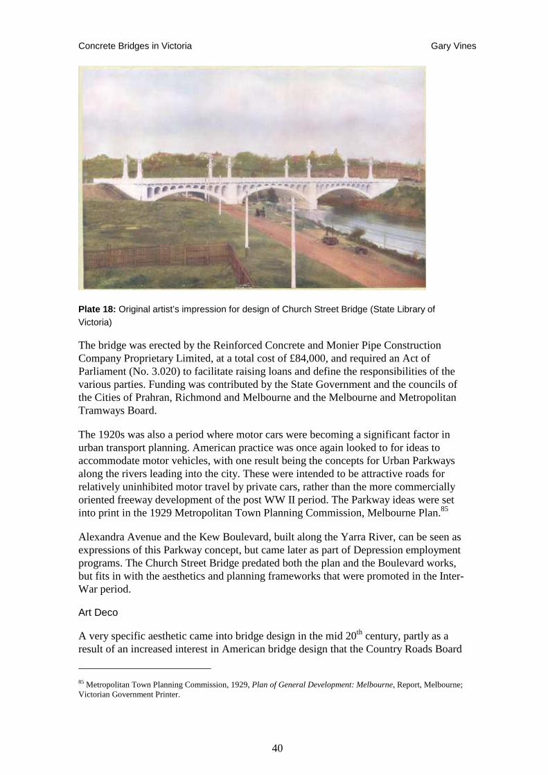
Concrete Bridges in Victoria Gary Vines
40
Plate 18: Original artist’s impression for design of Church Street Bridge (State Library of Victoria)
The bridge was erected by the Reinforced Concrete and Monier Pipe Construction Company Proprietary Limited, at a total cost of £84,000, and required an Act of Parliament (No. 3.020) to facilitate raising loans and define the responsibilities of the various parties. Funding was contributed by the State Government and the councils of the Cities of Prahran, Richmond and Melbourne and the Melbourne and Metropolitan Tramways Board.
The 1920s was also a period where motor cars were becoming a significant factor in urban transport planning. American practice was once again looked to for ideas to accommodate motor vehicles, with one result being the concepts for Urban Parkways along the rivers leading into the city. These were intended to be attractive roads for relatively uninhibited motor travel by private cars, rather than the more commercially oriented freeway development of the post WW II period. The Parkway ideas were set into print in the 1929 Metropolitan Town Planning Commission, Melbourne Plan.85
Alexandra Avenue and the Kew Boulevard, built along the Yarra River, can be seen as expressions of this Parkway concept, but came later as part of Depression employment programs. The Church Street Bridge predated both the plan and the Boulevard works, but fits in with the aesthetics and planning frameworks that were promoted in the Inter-War period.
Art Deco
A very specific aesthetic came into bridge design in the mid 20th century, partly as a result of an increased interest in American bridge design that the Country Roads Board
85 Metropolitan Town Planning Commission, 1929, Plan of General Development: Melbourne, Report, Melbourne; Victorian Government Printer.
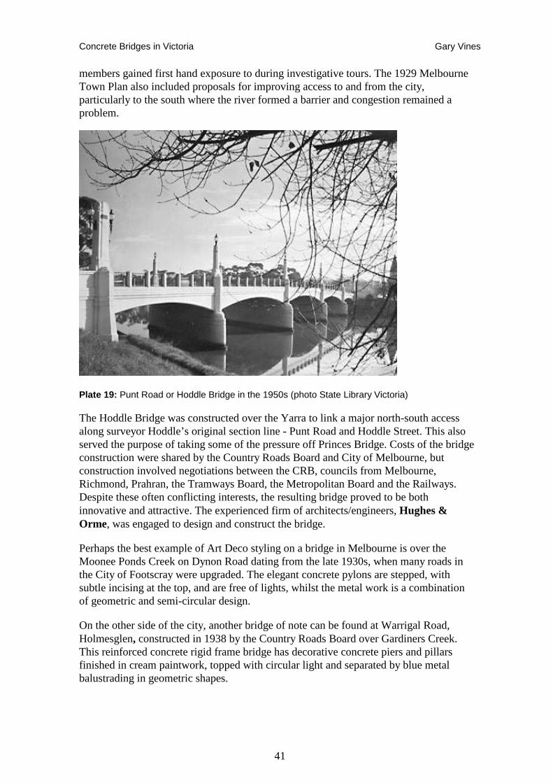
Concrete Bridges in Victoria Gary Vines
41
members gained first hand exposure to during investigative tours. The 1929 Melbourne Town Plan also included proposals for improving access to and from the city, particularly to the south where the river formed a barrier and congestion remained a problem.
Plate 19: Punt Road or Hoddle Bridge in the 1950s (photo State Library Victoria)
The Hoddle Bridge was constructed over the Yarra to link a major north-south access along surveyor Hoddle’s original section line - Punt Road and Hoddle Street. This also served the purpose of taking some of the pressure off Princes Bridge. Costs of the bridge construction were shared by the Country Roads Board and City of Melbourne, but construction involved negotiations between the CRB, councils from Melbourne, Richmond, Prahran, the Tramways Board, the Metropolitan Board and the Railways. Despite these often conflicting interests, the resulting bridge proved to be both innovative and attractive. The experienced firm of architects/engineers, Hughes & Orme, was engaged to design and construct the bridge.
Perhaps the best example of Art Deco styling on a bridge in Melbourne is over the Moonee Ponds Creek on Dynon Road dating from the late 1930s, when many roads in the City of Footscray were upgraded. The elegant concrete pylons are stepped, with subtle incising at the top, and are free of lights, whilst the metal work is a combination of geometric and semi-circular design.
On the other side of the city, another bridge of note can be found at Warrigal Road, Holmesglen, constructed in 1938 by the Country Roads Board over Gardiners Creek. This reinforced concrete rigid frame bridge has decorative concrete piers and pillars finished in cream paintwork, topped with circular light and separated by blue metal balustrading in geometric shapes.
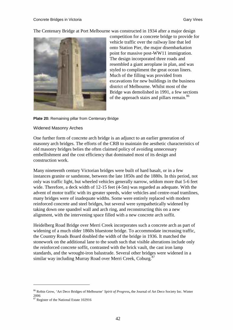
Concrete Bridges in Victoria Gary Vines
42
The Centenary Bridge at Port Melbourne was constructed in 1934 after a major design competition for a concrete bridge to provide for vehicle traffic over the railway line that led onto Station Pier, the major disembarkation point for massive post-WW11 immigration. The design incorporated three roads and resembled a giant aeroplane in plan, and was styled to compliment the great ocean liners. Much of the filling was provided from excavations for new buildings in the business district of Melbourne. Whilst most of the Bridge was demolished in 1991, a few sections of the approach stairs and pillars remain.86
Plate 20: Remaining pillar from Centenary Bridge
Widened Masonry Arches
One further form of concrete arch bridge is an adjunct to an earlier generation of masonry arch bridges. The efforts of the CRB to maintain the aesthetic characteristics of old masonry bridges belies the often claimed policy of avoiding unnecessary embellishment and the cost efficiency that dominated most of its design and construction work.
Many nineteenth century Victorian bridges were built of hard basalt, or in a few instances granite or sandstone, between the late 1850s and the 1880s. In this period, not only was traffic light, but wheeled vehicles generally narrow, seldom more that 5-6 feet wide. Therefore, a deck width of 12-15 feet (4-5m) was regarded as adequate. With the advent of motor traffic with its greater speeds, wider vehicles and centre-road tramlines, many bridges were of inadequate widths. Some were entirely replaced with modern reinforced concrete and steel bridges, but several were sympathetically widened by taking down one spandrel wall and arch ring, and reconstructing this on a new alignment, with the intervening space filled with a new concrete arch soffit.
Heidelberg Road Bridge over Merri Creek incorporates such a concrete arch as part of widening of a much older 1860s bluestone bridge. To accommodate increasing traffic, the Country Roads Board doubled the width of the bridge in 1936. It matched the stonework on the additional lane to the south such that visible alterations include only the reinforced concrete soffit, contrasted with the brick vault, the cast iron lamp standards, and the wrought-iron balustrade. Several other bridges were widened in a similar way including Murray Road over Merri Creek, Coburg.87
86 Robin Grow, ‘Art Deco Bridges of Melbourne’ Spirit of Progress, the Journal of Art Deco Society Inc. Winter 2006 87 Register of the National Estate 102916
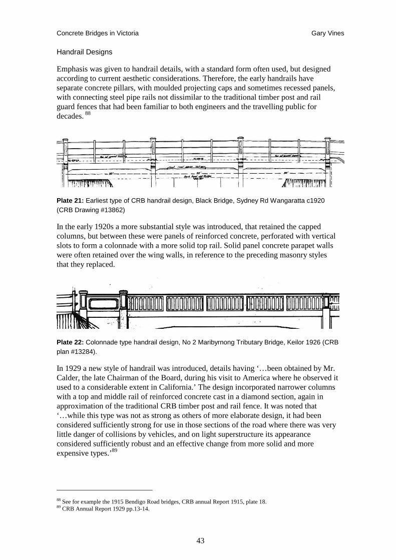
Concrete Bridges in Victoria Gary Vines
43
Handrail Designs
Emphasis was given to handrail details, with a standard form often used, but designed according to current aesthetic considerations. Therefore, the early handrails have separate concrete pillars, with moulded projecting caps and sometimes recessed panels, with connecting steel pipe rails not dissimilar to the traditional timber post and rail guard fences that had been familiar to both engineers and the travelling public for decades. 88
Plate 21: Earliest type of CRB handrail design, Black Bridge, Sydney Rd Wangaratta c1920 (CRB Drawing #13862)
In the early 1920s a more substantial style was introduced, that retained the capped columns, but between these were panels of reinforced concrete, perforated with vertical slots to form a colonnade with a more solid top rail. Solid panel concrete parapet walls were often retained over the wing walls, in reference to the preceding masonry styles that they replaced.
Plate 22: Colonnade type handrail design, No 2 Maribyrnong Tributary Bridge, Keilor 1926 (CRB plan #13284).
In 1929 a new style of handrail was introduced, details having ‘…been obtained by Mr. Calder, the late Chairman of the Board, during his visit to America where he observed it used to a considerable extent in California.’ The design incorporated narrower columns with a top and middle rail of reinforced concrete cast in a diamond section, again in approximation of the traditional CRB timber post and rail fence. It was noted that ‘…while this type was not as strong as others of more elaborate design, it had been considered sufficiently strong for use in those sections of the road where there was very little danger of collisions by vehicles, and on light superstructure its appearance considered sufficiently robust and an effective change from more solid and more expensive types.’89
88 See for example the 1915 Bendigo Road bridges, CRB annual Report 1915, plate 18. 89 CRB Annual Report 1929 pp.13-14.
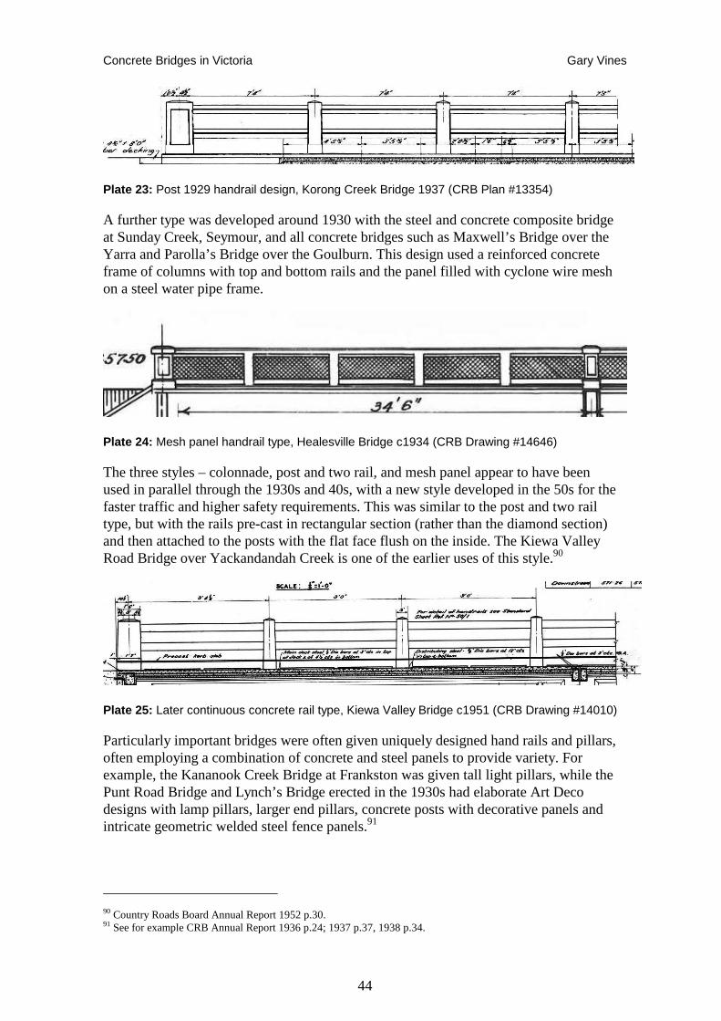
Concrete Bridges in Victoria Gary Vines
44
Plate 23: Post 1929 handrail design, Korong Creek Bridge 1937 (CRB Plan #13354)
A further type was developed around 1930 with the steel and concrete composite bridge at Sunday Creek, Seymour, and all concrete bridges such as Maxwell’s Bridge over the Yarra and Parolla’s Bridge over the Goulburn. This design used a reinforced concrete frame of columns with top and bottom rails and the panel filled with cyclone wire mesh on a steel water pipe frame.
Plate 24: Mesh panel handrail type, Healesville Bridge c1934 (CRB Drawing #14646)
The three styles – colonnade, post and two rail, and mesh panel appear to have been used in parallel through the 1930s and 40s, with a new style developed in the 50s for the faster traffic and higher safety requirements. This was similar to the post and two rail type, but with the rails pre-cast in rectangular section (rather than the diamond section) and then attached to the posts with the flat face flush on the inside. The Kiewa Valley Road Bridge over Yackandandah Creek is one of the earlier uses of this style.90
Plate 25: Later continuous concrete rail type, Kiewa Valley Bridge c1951 (CRB Drawing #14010)
Particularly important bridges were often given uniquely designed hand rails and pillars, often employing a combination of concrete and steel panels to provide variety. For example, the Kananook Creek Bridge at Frankston was given tall light pillars, while the Punt Road Bridge and Lynch’s Bridge erected in the 1930s had elaborate Art Deco designs with lamp pillars, larger end pillars, concrete posts with decorative panels and intricate geometric welded steel fence panels.91
90 Country Roads Board Annual Report 1952 p.30. 91 See for example CRB Annual Report 1936 p.24; 1937 p.37, 1938 p.34.
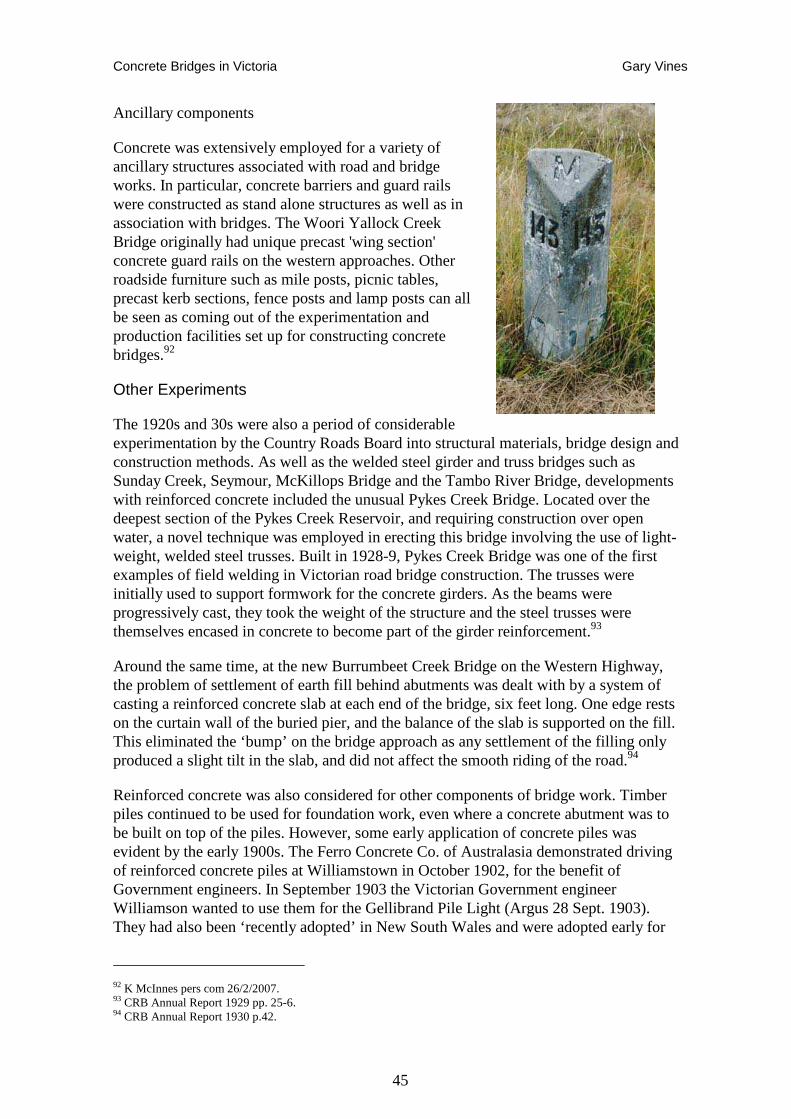
Concrete Bridges in Victoria Gary Vines
45
Ancillary components
Concrete was extensively employed for a variety of ancillary structures associated with road and bridge works. In particular, concrete barriers and guard rails were constructed as stand alone structures as well as in association with bridges. The Woori Yallock Creek Bridge originally had unique precast 'wing section' concrete guard rails on the western approaches. Other roadside furniture such as mile posts, picnic tables, precast kerb sections, fence posts and lamp posts can all be seen as coming out of the experimentation and production facilities set up for constructing concrete bridges.92
Other Experiments
The 1920s and 30s were also a period of considerable experimentation by the Country Roads Board into structural materials, bridge design and construction methods. As well as the welded steel girder and truss bridges such as Sunday Creek, Seymour, McKillops Bridge and the Tambo River Bridge, developments with reinforced concrete included the unusual Pykes Creek Bridge. Located over the deepest section of the Pykes Creek Reservoir, and requiring construction over open water, a novel technique was employed in erecting this bridge involving the use of light-weight, welded steel trusses. Built in 1928-9, Pykes Creek Bridge was one of the first examples of field welding in Victorian road bridge construction. The trusses were initially used to support formwork for the concrete girders. As the beams were progressively cast, they took the weight of the structure and the steel trusses were themselves encased in concrete to become part of the girder reinforcement.93
Around the same time, at the new Burrumbeet Creek Bridge on the Western Highway, the problem of settlement of earth fill behind abutments was dealt with by a system of casting a reinforced concrete slab at each end of the bridge, six feet long. One edge rests on the curtain wall of the buried pier, and the balance of the slab is supported on the fill. This eliminated the ‘bump’ on the bridge approach as any settlement of the filling only produced a slight tilt in the slab, and did not affect the smooth riding of the road.94
Reinforced concrete was also considered for other components of bridge work. Timber piles continued to be used for foundation work, even where a concrete abutment was to be built on top of the piles. However, some early application of concrete piles was evident by the early 1900s. The Ferro Concrete Co. of Australasia demonstrated driving of reinforced concrete piles at Williamstown in October 1902, for the benefit of Government engineers. In September 1903 the Victorian Government engineer Williamson wanted to use them for the Gellibrand Pile Light (Argus 28 Sept. 1903). They had also been ‘recently adopted’ in New South Wales and were adopted early for
92 K McInnes pers com 26/2/2007. 93 CRB Annual Report 1929 pp. 25-6. 94 CRB Annual Report 1930 p.42.
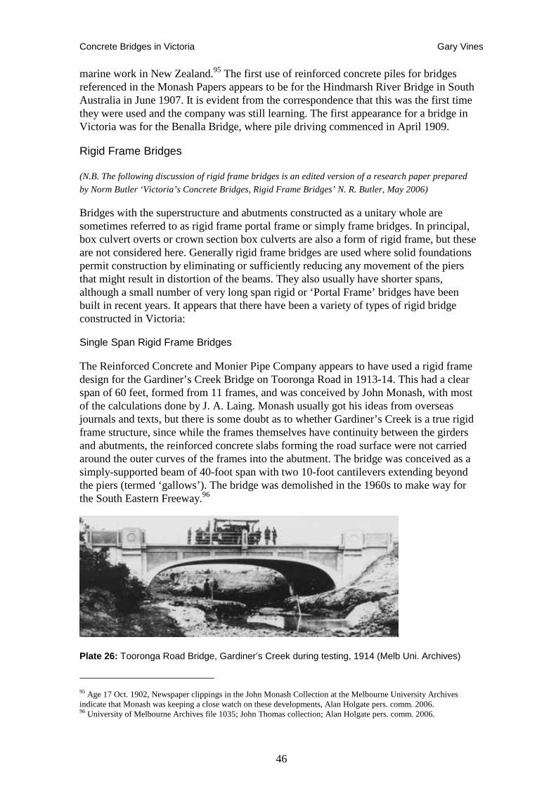
Concrete Bridges in Victoria Gary Vines
46
marine work in New Zealand.95 The first use of reinforced concrete piles for bridges referenced in the Monash Papers appears to be for the Hindmarsh River Bridge in South Australia in June 1907. It is evident from the correspondence that this was the first time they were used and the company was still learning. The first appearance for a bridge in Victoria was for the Benalla Bridge, where pile driving commenced in April 1909.
Rigid Frame Bridges
(N.B. The following discussion of rigid frame bridges is an edited version of a research paper prepared
by Norm Butler ‘Victoria’s Concrete Bridges, Rigid Frame Bridges’ N. R. Butler, May 2006)
Bridges with the superstructure and abutments constructed as a unitary whole are sometimes referred to as rigid frame portal frame or simply frame bridges. In principal, box culvert overts or crown section box culverts are also a form of rigid frame, but these are not considered here. Generally rigid frame bridges are used where solid foundations permit construction by eliminating or sufficiently reducing any movement of the piers that might result in distortion of the beams. They also usually have shorter spans, although a small number of very long span rigid or ‘Portal Frame’ bridges have been built in recent years. It appears that there have been a variety of types of rigid bridge constructed in Victoria:
Single Span Rigid Frame Bridges
The Reinforced Concrete and Monier Pipe Company appears to have used a rigid frame design for the Gardiner’s Creek Bridge on Tooronga Road in 1913-14. This had a clear span of 60 feet, formed from 11 frames, and was conceived by John Monash, with most of the calculations done by J. A. Laing. Monash usually got his ideas from overseas journals and texts, but there is some doubt as to whether Gardiner’s Creek is a true rigid frame structure, since while the frames themselves have continuity between the girders and abutments, the reinforced concrete slabs forming the road surface were not carried around the outer curves of the frames into the abutment. The bridge was conceived as a simply-supported beam of 40-foot span with two 10-foot cantilevers extending beyond the piers (termed ‘gallows’). The bridge was demolished in the 1960s to make way for the South Eastern Freeway.96
Plate 26: Tooronga Road Bridge, Gardiner’s Creek during testing, 1914 (Melb Uni. Archives)
95 Age 17 Oct. 1902, Newspaper clippings in the John Monash Collection at the Melbourne University Archives indicate that Monash was keeping a close watch on these developments, Alan Holgate pers. comm. 2006. 96 University of Melbourne Archives file 1035; John Thomas collection; Alan Holgate pers. comm. 2006.
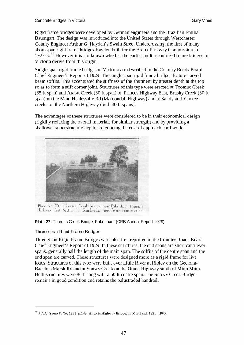
Concrete Bridges in Victoria Gary Vines
47
Rigid frame bridges were developed by German engineers and the Brazilian Emilia Baumgart. The design was introduced into the United States through Westchester County Engineer Arthur G. Hayden’s Swain Street Undercrossing, the first of many short-span rigid frame bridges Hayden built for the Bronx Parkway Commission in 1922-3. 97 However it is not known whether the earlier multi-span rigid frame bridges in Victoria derive from this origin.
Single span rigid frame bridges in Victoria are described in the Country Roads Board Chief Engineer’s Report of 1929. The single span rigid frame bridges feature curved beam soffits. This accentuated the stiffness of the abutment by greater depth at the top so as to form a stiff corner joint. Structures of this type were erected at Toomuc Creek (35 ft span) and Ararat Creek (30 ft span) on Princes Highway East, Brushy Creek (30 ft span) on the Main Healesville Rd (Maroondah Highway) and at Sandy and Yankee creeks on the Northern Highway (both 30 ft spans).
The advantages of these structures were considered to be in their economical design (rigidity reducing the overall materials for similar strength) and by providing a shallower superstructure depth, so reducing the cost of approach earthworks.
Plate 27: Toomuc Creek Bridge, Pakenham (CRB Annual Report 1929)
Three span Rigid Frame Bridges.
Three Span Rigid Frame Bridges were also first reported in the Country Roads Board Chief Engineer’s Report of 1929. In these structures, the end spans are short cantilever spans, generally half the length of the main span. The soffits of the centre span and the end span are curved. These structures were designed more as a rigid frame for live loads. Structures of this type were built over Little River at Ripley on the Geelong-Bacchus Marsh Rd and at Snowy Creek on the Omeo Highway south of Mitta Mitta. Both structures were 86 ft long with a 50 ft centre span. The Snowy Creek Bridge remains in good condition and retains the balustraded handrail.
97 P.A.C. Spero & Co. 1995, p.149. Historic Highway Bridges In Maryland: 1631- 1960.
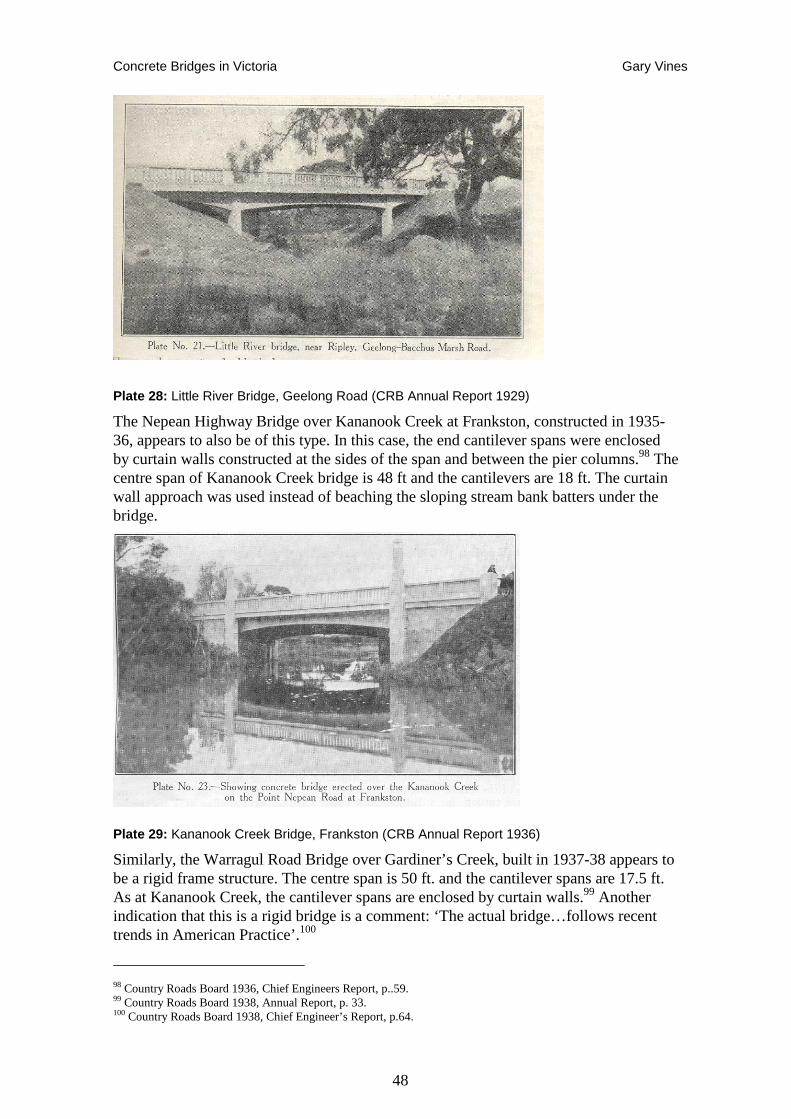
Concrete Bridges in Victoria Gary Vines
48
Plate 28: Little River Bridge, Geelong Road (CRB Annual Report 1929)
The Nepean Highway Bridge over Kananook Creek at Frankston, constructed in 1935-36, appears to also be of this type. In this case, the end cantilever spans were enclosed by curtain walls constructed at the sides of the span and between the pier columns.98 The centre span of Kananook Creek bridge is 48 ft and the cantilevers are 18 ft. The curtain wall approach was used instead of beaching the sloping stream bank batters under the bridge.
Plate 29: Kananook Creek Bridge, Frankston (CRB Annual Report 1936)
Similarly, the Warragul Road Bridge over Gardiner’s Creek, built in 1937-38 appears to be a rigid frame structure. The centre span is 50 ft. and the cantilever spans are 17.5 ft. As at Kananook Creek, the cantilever spans are enclosed by curtain walls.99 Another indication that this is a rigid bridge is a comment: ‘The actual bridge…follows recent trends in American Practice’.100
98 Country Roads Board 1936, Chief Engineers Report, p..59. 99 Country Roads Board 1938, Annual Report, p. 33. 100 Country Roads Board 1938, Chief Engineer’s Report, p.64.
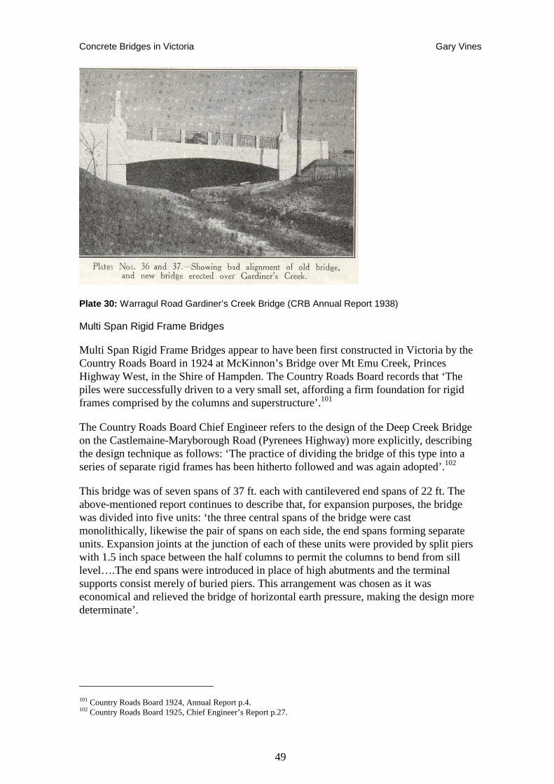
Concrete Bridges in Victoria Gary Vines
49
Plate 30: Warragul Road Gardiner’s Creek Bridge (CRB Annual Report 1938)
Multi Span Rigid Frame Bridges
Multi Span Rigid Frame Bridges appear to have been first constructed in Victoria by the Country Roads Board in 1924 at McKinnon’s Bridge over Mt Emu Creek, Princes Highway West, in the Shire of Hampden. The Country Roads Board records that ‘The piles were successfully driven to a very small set, affording a firm foundation for rigid frames comprised by the columns and superstructure’.101
The Country Roads Board Chief Engineer refers to the design of the Deep Creek Bridge on the Castlemaine-Maryborough Road (Pyrenees Highway) more explicitly, describing the design technique as follows: ‘The practice of dividing the bridge of this type into a series of separate rigid frames has been hitherto followed and was again adopted’.102
This bridge was of seven spans of 37 ft. each with cantilevered end spans of 22 ft. The above-mentioned report continues to describe that, for expansion purposes, the bridge was divided into five units: ‘the three central spans of the bridge were cast monolithically, likewise the pair of spans on each side, the end spans forming separate units. Expansion joints at the junction of each of these units were provided by split piers with 1.5 inch space between the half columns to permit the columns to bend from sill level….The end spans were introduced in place of high abutments and the terminal supports consist merely of buried piers. This arrangement was chosen as it was economical and relieved the bridge of horizontal earth pressure, making the design more determinate’.
101 Country Roads Board 1924, Annual Report p.4. 102 Country Roads Board 1925, Chief Engineer’s Report p.27.
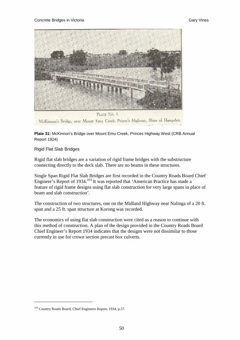
Concrete Bridges in Victoria Gary Vines
50
Plate 31: McKinnon’s Bridge over Mount Emu Creek, Princes Highway West (CRB Annual Report 1924)
Rigid Flat Slab Bridges
Rigid flat slab bridges are a variation of rigid frame bridges with the substructure connecting directly to the deck slab. There are no beams in these structures.
Single Span Rigid Flat Slab Bridges are first recorded in the Country Roads Board Chief Engineer’s Report of 1934.103 It was reported that ‘American Practice has made a feature of rigid frame designs using flat slab construction for very large spans in place of beam and slab construction’.
The construction of two structures, one on the Midland Highway near Nalinga of a 20 ft. span and a 25 ft. span structure at Korong was recorded.
The economics of using flat slab construction were cited as a reason to continue with this method of construction. A plan of the design provided in the Country Roads Board Chief Engineer’s Report 1934 indicates that the designs were not dissimilar to those currently in use for crown section precast box culverts.
103 Country Roads Board, Chief Engineers Report, 1934, p.57.
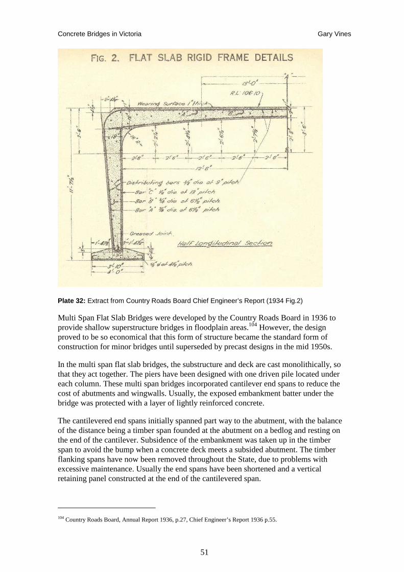
Concrete Bridges in Victoria Gary Vines
51
Plate 32: Extract from Country Roads Board Chief Engineer’s Report (1934 Fig.2)
Multi Span Flat Slab Bridges were developed by the Country Roads Board in 1936 to provide shallow superstructure bridges in floodplain areas.104 However, the design proved to be so economical that this form of structure became the standard form of construction for minor bridges until superseded by precast designs in the mid 1950s.
In the multi span flat slab bridges, the substructure and deck are cast monolithically, so that they act together. The piers have been designed with one driven pile located under each column. These multi span bridges incorporated cantilever end spans to reduce the cost of abutments and wingwalls. Usually, the exposed embankment batter under the bridge was protected with a layer of lightly reinforced concrete.
The cantilevered end spans initially spanned part way to the abutment, with the balance of the distance being a timber span founded at the abutment on a bedlog and resting on the end of the cantilever. Subsidence of the embankment was taken up in the timber span to avoid the bump when a concrete deck meets a subsided abutment. The timber flanking spans have now been removed throughout the State, due to problems with excessive maintenance. Usually the end spans have been shortened and a vertical retaining panel constructed at the end of the cantilevered span.
104 Country Roads Board, Annual Report 1936, p.27, Chief Engineer’s Report 1936 p.55.
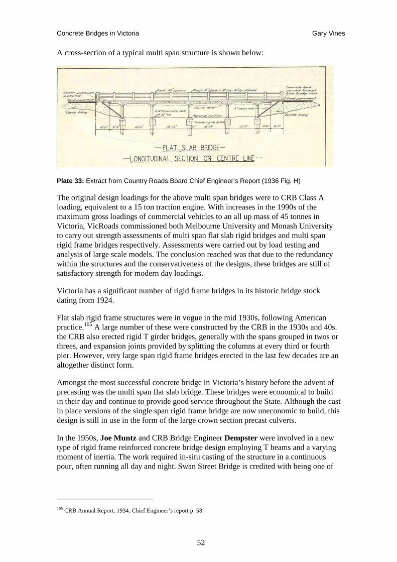
Concrete Bridges in Victoria Gary Vines
52
A cross-section of a typical multi span structure is shown below:
Plate 33: Extract from Country Roads Board Chief Engineer’s Report (1936 Fig. H)
The original design loadings for the above multi span bridges were to CRB Class A loading, equivalent to a 15 ton traction engine. With increases in the 1990s of the maximum gross loadings of commercial vehicles to an all up mass of 45 tonnes in Victoria, VicRoads commissioned both Melbourne University and Monash University to carry out strength assessments of multi span flat slab rigid bridges and multi span rigid frame bridges respectively. Assessments were carried out by load testing and analysis of large scale models. The conclusion reached was that due to the redundancy within the structures and the conservativeness of the designs, these bridges are still of satisfactory strength for modern day loadings.
Victoria has a significant number of rigid frame bridges in its historic bridge stock dating from 1924.
Flat slab rigid frame structures were in vogue in the mid 1930s, following American practice.105 A large number of these were constructed by the CRB in the 1930s and 40s. the CRB also erected rigid T girder bridges, generally with the spans grouped in twos or threes, and expansion joints provided by splitting the columns at every third or fourth pier. However, very large span rigid frame bridges erected in the last few decades are an altogether distinct form.
Amongst the most successful concrete bridge in Victoria’s history before the advent of precasting was the multi span flat slab bridge. These bridges were economical to build in their day and continue to provide good service throughout the State. Although the cast in place versions of the single span rigid frame bridge are now uneconomic to build, this design is still in use in the form of the large crown section precast culverts.
In the 1950s, Joe Muntz and CRB Bridge Engineer Dempster were involved in a new type of rigid frame reinforced concrete bridge design employing T beams and a varying moment of inertia. The work required in-situ casting of the structure in a continuous pour, often running all day and night. Swan Street Bridge is credited with being one of
105 CRB Annual Report, 1934, Chief Engineer’s report p. 58.
Concrete Bridges in Victoria Gary Vines
53
the largest bridges constructed in this manner, with a continuous pour running for more than 72 hours.106
A special type of frame bridge, adapted for longer and multiple spans uses ‘V’ shaped piers, with hinges at the bottom, allowing a rigid connection between the tops of the piers and the spanning members, and so helps reduce the depth of the girders.107
The Portal Frame bridge design, employing a tapered hollow box section, was employed for two roads and one footbridge over the Eastern Freeway including as the Yarra Boulevard Bridge. These bridges provided very long flat spans with uninterrupted, flowing lines, but were more expensive to built than a conventional girder bridge.
Post-War Developments
The depression times of the early 1930s continued through to a greater or lesser degree until the commencement of World War 2 with the Australian economy sluggish and limited expenditure on roads and bridges. Employment levels were not high and “sustenance” works (work for the dole) persisted.
Immediately post war development works were commenced by both State and Commonwealth Governments. In particular the Snowy Mountains Hydro Electric Scheme, the Kiewa Hydro Electric Scheme and upgrading of Eildon Reservoir produced significant activity.
Although preparations had been made for post war reconstruction, shortages of supplies hindered development until the early 1950’s. In particular steel and cement were in short supply and until the Menzies Government of 1949, petrol rationing was still in effect.
Victoria was governed by a minority Country Party Government until 1952 at which time the Cain Labor Government was elected, providing more stable government. The long standing Bolte Liberal Country Party Government then followed in 1955 and oversaw a lengthy period of development in the State. During this time there was a realisation that local road bridging needed to be upgraded for farm to market traffic and to assist the economy grow. The Commonwealth Government contributed to these works with the Commonwealth Aid Roads (CAR) Programme.108
Shortage of materials or skill has often been a motivator for innovation in engineering, and this is particularly true for concrete. Material shortages also remained a serious constraint in Post-War Australia. This was also a particularly innovative period in Victoria, when a major backlog of obsolete and inadequate bridges needed to be replaced to keep pace with Australia’s development requirements. In this period, the use of precasting and prestressing was developed for most bridging situations.
106 VicRoads Retirees Association, 1995 107 Leonhardt, Fritz. 1984 Bridges: Aesthetic and Design. MIT Press, Massachusetts 108 Norm Butler, “Victorian Concrete Bridges, Post World War 2 Development”, unpublished research report 22/12/06.
Concrete Bridges in Victoria Gary Vines
54
The Country Roads Board tackled the demands of the period by developing and employing simple standardised designs, which could be modified and applied to most bridge replacement situations. Precasting was widely adopted to reduce costs and simplify on-site work. For shorter span bridges, prestressed slabs were adopted, and for longer span, precast beams were used. Precast concrete piles were universally adopted. On-site concrete work comprised construction of the abutments, piers and wing walls and casting the deck where precast beams were used.
As well as the labour intensiveness of concrete mixing and placing, the whole process of concrete bridge building was labour intensive prior to the Second World War. Considerable manpower was needed in building the formwork (there was no form ply or steel shuttering available at that time), cutting and bending the reinforcement on site and placing and tying the reinforcement. There were no shortcuts such as welded mesh which is commonly used today. Reinforcement was made up of many individual rods and bars, wired together into the required shapes. At that time, there were no precast elements used in the works, so all works had to be done on-site.109
The post-World War Two period saw enormous growth in Australia, with a wool boom, increased immigration and advances in technology. More goods movement by truck and increasing demand involved increases in the size and mass of road transport vehicles. Semi-trailers became commonplace and a new load standard was instigated to accommodate the greater vehicles and load tonnages. With the combination of increased legal loading being allowed and a legacy of many old and dilapidated pre-war bridges, many of which were of timber and under-strength, a major bridge replacement was required. This reconstruction program was largely financed with Commonwealth Aid Roads (CAR) funds.
In the immediate post World War 2 period, the major problem of old, weak and seriously deteriorated bridges dating as far back to the 1890s, mainly on rural roads, was identified. This was seen as an obvious brake on the development of the state. Due to the poor condition of many roads and bridges, it became necessary to place 6 ton load limits on many roads, including State Highways.110
The task to replace so many bridges effectively took over 30 years from the mid fifties to the mid eighties. There are still areas in Gippsland, mainly East Gippsland and Wellington Shires where there are still many old timber bridges subject to load limits and in need replacement .111
In the 1950s and 1960s the rapid increase in road vehicle usage and city expansion again put pressure on the transport network, particularly in main highways and city radial main roads. Larger bridges and structures at higher levels to deal with the problems of flooding and steep approach grades were also a priority. Also at this time there was an increasing awareness of bridge form within the landscape, and designers were required to produce environmentally sympathetic structures. Driving and safety standards required that the road alignment determined the bridge location, rather than the other
109 Norm Butler pers. comm. 2006 110 CRB Annual Report, 1948/49, p21 111 Norm Butler, “Victorian Concrete Bridges, Post World War 2 Development”, unpublished research report 22/12/06.
Concrete Bridges in Victoria Gary Vines
55
way around. Earlier practice sited the bridge location and alignment to provide the simplest and shortest crossing regardless of the road approach angles. As a consequence post-war bridges were more often designed on a skewed angle, resulting in longer spans than would otherwise be necessary and more complex designs to deal with sometimes less than optimal foundations.
The post war period was exemplified by the rise in the use simple bridge designs utilising precast units to reduce costs and increase flexibility of designs and in response to a general shortage of labour, particularly skilled labour. Reinforced concrete deck units and piles, prestressed concrete deck units and beams, together with standardised designs were utilised to meet the need to urgently replace many small to medium bridges, mainly in rural areas. The need for a high level of economical design and construction methods produced precast designs, which were developed and improved as the era progressed.
As well as replacement of existing bridge infrastructure, the need arose in the 1960s onwards to freeways incorporating larger and more complex bridges to meet the growing traffic demands in the Melbourne metropolitan area.
In rural areas, precast U slabs first appeared in 1947/48, largely to replace rotting timber decks on small to medium sized culverts, and this then developed into a means of economical construction of small bridges of up to 6m span. The precast U Slabs were superseded by more economical prestressed concrete slab units in the mid 1950s for spans of up to 9 metres. The Country Roads Board then moved to utilising an equally economical High Strength U slab design for bridges up to 9 metres, whilst the State Rivers and Water Supply Commission continued with the use of prestressed slab unit bridges. For small to medium bridges, the High Strength U slab and the Prestressed slab units continue to be used, with maximum spans of up to 11.5 metres
Precast Beams were used for construction of larger bridges for the late 1940s, with the major projects at Kiewa and Eildon creating the need to produce many bridges quickly. The Country Roads Board and some Municipalities set up precasting yards around the State to supply the need for precast units. . Beams were generally in the 10.7 to 13.7 metre range. In 1958, these designs were replaced by prestressed concrete beams, which were more economical to manufacture and lighter to handle. Prestressed concrete beams were developed up to 18m span. Since the 1960s, various improvements have been made upon prestressed concrete beam designs, including Inverted U Beams, bulb tee beams, inverted tee beams and super tee beams, all designed to increase to span length and effectiveness of the precast concrete units.
Cast in situ post tensioned prestressed box girder bridges were developed in the early 1960s to meet the specific demands of freeway interchange designs and have been extensively used. These bridges are able to provide long spans, flexibility in design and a smooth underside for aesthetics. Where the situation allowed, precast prestressed units providing a smooth underside such as the Inverted Tee Beam were used, but only to a limited extent. Later developments to improve cost effectiveness of box girder construction included post tensioned prestressed segmental reinforced concrete box girders and incrementally launched prestressed box girders. Concurrently with these developments, Cast in situ Portal Frame (Rigid) bridges were utilised in some freeway works, particularly the Melbourne and Metropolitan Board of Works designed Eastern
Concrete Bridges in Victoria Gary Vines
56
Freeway. With the introduction of design and construct contracts on freeways in the 1990s, there was a movement back to precast prestressed units with larger spans, such as Super Tee beams and the underside aesthetics considerations were swept away.
The major concrete bridge built in recent times was the Bolte Bridge built as a balanced cantilever prestressed concrete bridge over the Yarra River for the City Link project.112
Some of the notable and innovative bridges of this period include the Gladesville Bridge in Sydney with its elegant concrete arch span; the Westgate Bridge, Melbourne, which utilises cable-stayed steel box girder main spans and post-tensioned concrete box girder approaches; Batman Bridge Tasmania, the first cable-stayed bridge in Australia; and the Gateway Bridge, Brisbane, being at its construction the largest balanced cantilever construction in concrete in the world.113
112 Norm Butler, “Victorian Concrete Bridges, Post World War 2 Development”, unpublished research report 22/12/06. 113 Bright Sparcs, Australian Science and Technology Heritage Centre http://www.asap.unimelb.edu.au/bsparcs/
Concrete Bridges in Victoria Gary Vines
57
Freeways and the administration of road and bridge construction
The Country Roads Board influence, with particularly centralised control, continued until the 1980s. During this time the CRB sought opportunities from interstate and overseas to introduce innovations and developments in the structure of bridges, the traffic requirements and the waterway provisions.
One variation from the CRB’s influence was the State Rivers and Water Supply Commission's (SRWSC) bridges over their structures (dams, weirs etc), channels on local roads and on occupational crossings. The SRWSC was particularly active in the post-War period in the use of precast units for this work, including prestressed deck slab units made at their Tatura precast yard.
Another variation in influence was with road over rail bridges, where the Victorian Railways Commissioners insisted upon approving the designs. Well into the 1970s, the railways would not accept reinforced concrete beams in bridges, with the result that most road over rail bridges are steel beam bridges.
In the late 1960s and 1970s, the Melbourne & Metropolitan Board of Works was given authority by the Government to carry out freeway construction on both the Eastern Freeway and South Eastern Freeway. The bridge designs for these works, particularly the Eastern Freeway, were significant and innovative in their break with the CRB approach to bridge design.
Plans for the South Eastern Freeway first appeared in the Metropolitan Town Planning Commission report 1929 Melbourne Plan of General Development, where the ‘Gardiner Valley Parkway’ was presented as a ‘continuous strip of reserves’ along Gardiners Creek.114 while the commencement of this route as a limited access fast motor road was not commenced for 30 years, some elements such as the construction of Alexander Parade and new bridges on the river were progressively added to the Melbourne transport network. The MMBW took up the idea in its 1954 Melbourne Strategy Plan.115
The Melbourne Strategy Plan of 1954, proposed as series of radial freeways and ring roads to provide for Melbourne's future transport needs. Although some projects that came out of this plan, such as Kings Way and the South Eastern Freeway, were commenced in the late 1950s and 1960s, it was not until the 1970s that freeway construction in Melbourne really took off and at the same time became a major social and political issue.
The 1969 Melbourne Transportation Plan was promoted by the then transport minister, Vernon Wilcox, as: "... a plan that recognises that there is a place for all forms of transport in attempting to solve the problem ... in other words, it believes that balanced transport is the only hope." However, of the various rail projects proposed, only the rail loop was retained as policy, while freeway construction was given the green light.
114 Metropolitan Town Planning Commission report 1929 Melbourne Plan of General Development, p. 129. 115 Melbourne and Metropolitan Board of Works, 1953, Melbourne Metropolitan Planning Scheme 1954, Melbourne and Metropolitan Board of Works.
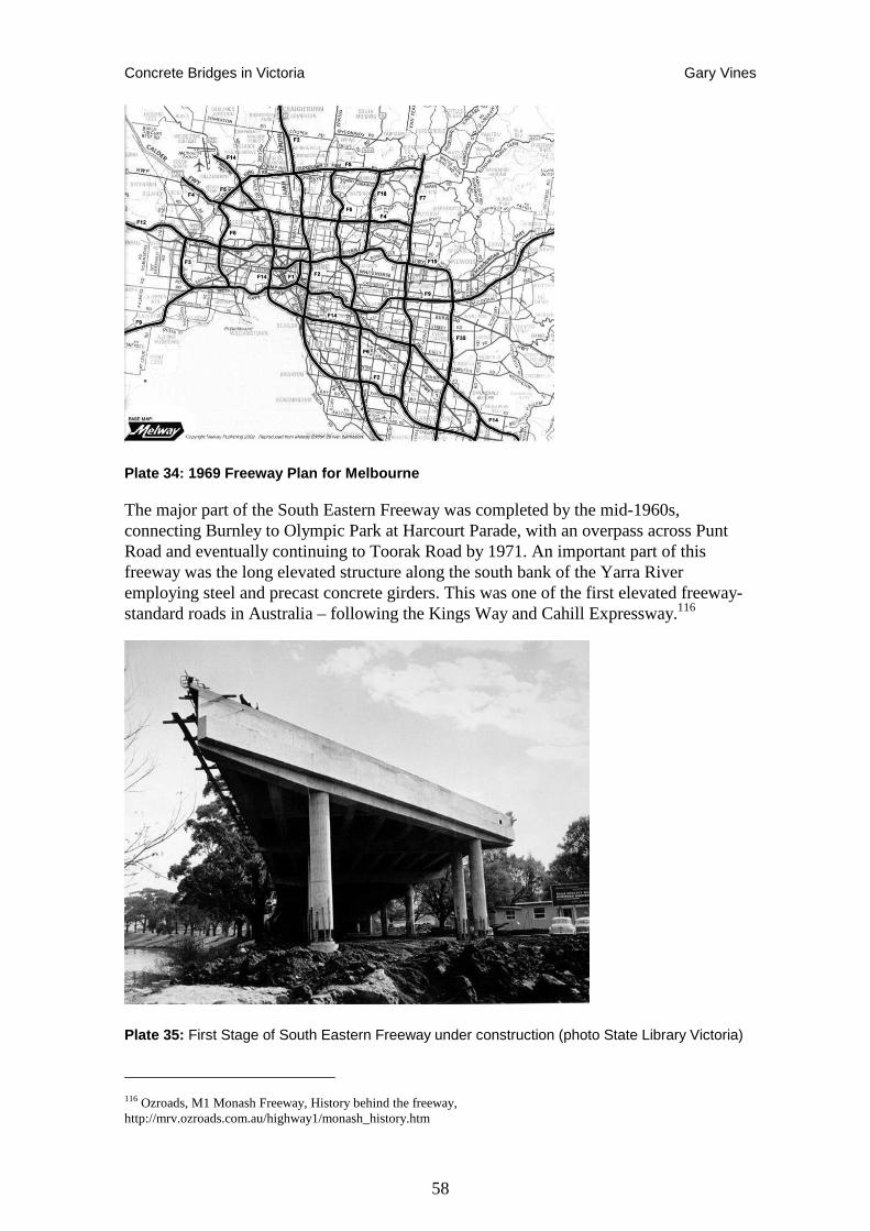
Concrete Bridges in Victoria Gary Vines
58
Plate 34: 1969 Freeway Plan for Melbourne
The major part of the South Eastern Freeway was completed by the mid-1960s, connecting Burnley to Olympic Park at Harcourt Parade, with an overpass across Punt Road and eventually continuing to Toorak Road by 1971. An important part of this freeway was the long elevated structure along the south bank of the Yarra River employing steel and precast concrete girders. This was one of the first elevated freeway-standard roads in Australia – following the Kings Way and Cahill Expressway.116
Plate 35: First Stage of South Eastern Freeway under construction (photo State Library Victoria)
116 Ozroads, M1 Monash Freeway, History behind the freeway, http://mrv.ozroads.com.au/highway1/monash_history.htm
Concrete Bridges in Victoria Gary Vines
59
The Westgate Bridge Authority was also established by the Victorian Government during 1960s to build the Westgate Bridge which included a significant amount of prestressed reinforced concrete in the approach spans.
A shift in attitudes to freeway construction came to the fore in the early 1970s as local communities protested against the impacts to the historic inner suburbs. The Eastern Freeway was constructed through Yarra parklands by the MMBW, a pet project of premier Henry Bolte, who had enthusiastically adopted American road planning philosophies.
By 1972, thousands of concerned Melbourne residents were attending public meetings in the inner city, signing petitions, and building links with the ALP and the unions in a wide public attempt to influence the direction of urban planning and development. The Liberal Government of Sir Henry Bolte had been in government since 1955, but in August 1972 a new Liberal Premier Rupert Hamer took over the leadership. Although not anti-freeway, Hamer had previously as transport minister, delayed some of the proposals and demanded further assessment of their sociological and environmental effects (Lay 2003:201).
The cream of Melbourne society was also fighting freeways, at least the one that would follow the Yarra through Heidelberg. They used their connections to have the road reserve removed from their side of the river. In March 1973, Hamer scrapped some of the most controversial freeways, but opposition continued against those that remained.
Hamer’s 1973 compromise gave the Eastern Freeway the go-ahead, but, opposition continued. The protest had some help from Tom Uren, Minister for Urban and Regional Development in Whitlam’s federal government, and over $200,000 in today’s money from Fitzroy and Collingwood Councils, but they were never able to get the Doncaster rail on the political agenda as an alternative to a half-built freeway. Instead, the argument centred on where the traffic would go after it left the freeway.117
In 1977, the road was built and Hamer announced the inevitable: traffic would be allowed across Hoddle Street and into Alexandra Parade. The protest culminated in residents building barricades and hundreds of police were brought in to take them down. The local protests included direct action by residents, radical students and even councillors such as Theo Sidiropoulos Mayor of Collingwood Bill Peterson, Mayor of Fitzroy, who were arrested at the blockade in full Mayoral regalia. Hamer eventually offered bus lanes on the freeway and some limits to road widening in Rathdowne Street and other approaches to the city.118
In 1974, the State Government legislated to transfer the road related functions (road planning, road design and construction) and approximately 140 staff from the Melbourne Metropolitan Board of Works to the CRB. At the time, a number of major road projects were under way, including: the Eastern Freeway as well as the St Kilda
117 Stone, J. "Political and social factors in the decline of mass transit: an investigation of failed policies to rebuild Melbourne's mass transit MA Thesis in prep, Institute for Social Research, Swinburne http://www.sisr.net/publications/0501stone.doc. 118Graeme Davidson, Car Wars: How the car won our hearts and conquered our cities, Allen & Unwen 2004; Jeff Sparrow and Jill Sparrow, Radical Melbourne 2: The Enemy Within, The Vulgar Press, 2004;
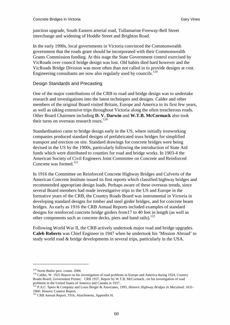
Concrete Bridges in Victoria Gary Vines
60
junction upgrade, South Eastern arterial road, Tullamarine Freeway-Bell Street interchange and widening of Hoddle Street and Brighton Road.
In the early 1990s, local governments in Victoria convinced the Commonwealth government that the roads grant should be incorporated with their Commonwealth Grants Commission funding. At this stage the State Government control exercised by VicRoads over council bridge design was lost. Old habits died hard however and the VicRoads Bridge Division was more often than not called in to provide designs at cost. Engineering consultants are now also regularly used by councils.119
Design Standards and Precasting
One of the major contributions of the CRB to road and bridge design was to undertake research and investigations into the latest techniques and designs. Calder and other members of the original Board visited Britain, Europe and America in its first few years, as well as taking extensive trips throughout Victoria along the often treacherous roads. Other Board Chairmen including D. V. Darwin and W.T.B. McCormack also took their turns on overseas research tours.120
Standardisation came to bridge design early in the US, where initially ironworking companies produced standard designs of prefabricated truss bridges for simplified transport and erection on site. Standard drawings for concrete bridges were being devised in the US by the 1900s, particularly following the introduction of State Aid funds which were distributed to counties for road and bridge works. In 1903-4 the American Society of Civil Engineers Joint Committee on Concrete and Reinforced Concrete was formed.121
In 1916 the Committee on Reinforced Concrete Highway Bridges and Culverts of the American Concrete Institute issued its first reports which classified highway bridges and recommended appropriate design loads. Perhaps aware of these overseas trends, since several Board members had made investigative trips to the US and Europe in the formative years of the CRB, the Country Roads Board was instrumental in Victoria in developing standard designs for timber and steel girder bridges, and for concrete beam bridges. As early as 1916 the CRB Annual Reports included examples of standard designs for reinforced concrete bridge girders from17 to 40 feet in length (as well as other components such as concrete decks, piers and hand rails).122
Following World War II, the CRB actively undertook major road and bridge upgrades. Caleb Roberts was Chief Engineer in 1947 when he undertook his ‘Mission Abroad’ to study world road & bridge developments in several trips, particularly in the USA.
119 Norm Butler pers. comm. 2006 120 Calder, W. 1925 Report on his investigation of road problems in Europe and America during 1924, Country Roads Board, Government Printer; CRB 1937, Report by W.T.B. McCormack...on his investigation of road problems in the United States of America and Canada in 1937.. 121 P.A.C. Spero & Company and Louis Berger & Associates, 1995, Historic Highway Bridges In Maryland: 1631- 1960: Historic Context Report, 122 CRB Annual Report, 1916, Attachments, Appendix H.
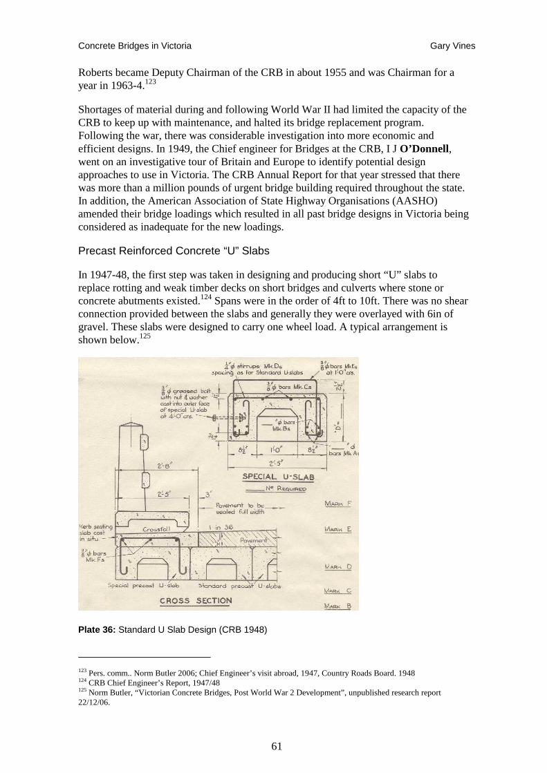
Concrete Bridges in Victoria Gary Vines
61
Roberts became Deputy Chairman of the CRB in about 1955 and was Chairman for a year in 1963-4.123
Shortages of material during and following World War II had limited the capacity of the CRB to keep up with maintenance, and halted its bridge replacement program. Following the war, there was considerable investigation into more economic and efficient designs. In 1949, the Chief engineer for Bridges at the CRB, I J O’Donnell, went on an investigative tour of Britain and Europe to identify potential design approaches to use in Victoria. The CRB Annual Report for that year stressed that there was more than a million pounds of urgent bridge building required throughout the state. In addition, the American Association of State Highway Organisations (AASHO) amended their bridge loadings which resulted in all past bridge designs in Victoria being considered as inadequate for the new loadings.
Precast Reinforced Concrete “U” Slabs
In 1947-48, the first step was taken in designing and producing short “U” slabs to replace rotting and weak timber decks on short bridges and culverts where stone or concrete abutments existed.124 Spans were in the order of 4ft to 10ft. There was no shear connection provided between the slabs and generally they were overlayed with 6in of gravel. These slabs were designed to carry one wheel load. A typical arrangement is shown below.125
Plate 36: Standard U Slab Design (CRB 1948)
123 Pers. comm.. Norm Butler 2006; Chief Engineer’s visit abroad, 1947, Country Roads Board. 1948 124 CRB Chief Engineer’s Report, 1947/48 125 Norm Butler, “Victorian Concrete Bridges, Post World War 2 Development”, unpublished research report 22/12/06.
Concrete Bridges in Victoria Gary Vines
62
The development of the Big Eildon Dam and the Kiewa Hydro Electricity Scheme were projects hindered by material and labour shortages, but still demanded considerable road and bridge upgrades. The CRB was given the task of upgrading roads and bridges so that heavy loads could be conveyed to the hydro construction sites, With Wodonga the most convenient location for connection to rail transport, the Kiewa Valley Road became the main route for materials, men and equipment. In particular, the concrete pipes, transformers, generators and turbine components were particularly heavy. In the CRB Annual Reports for 1948, 49 and 50, the chief engineer reported on a variety of experiments and programs to develop precast concrete components and designs for bridge work.
Precast Reinforced Concrete Beams
In 1948-49, in conjunction with the need for reconstruction of many bridges on the Kiewa Valley Road and Upper Goulburn Valley Road (Now Kiewa Valley Highway and Goulburn Valley Highway respectively) to allow heavy vehicle access to the Kiewa Hydro Electric Scheme and the Eildon Dam improvement, the Country Roads Board embarked upon construction of precast bridges. In the initial stages this involved precast elements for beams and crossheads, however this soon resolved to beams only, due to variability in crosshead requirements. 126
Plate 37: Detail of a typical precast reinforced concrete beam (CRB Ann Rep. 1949)
126 Norm Butler, “Victorian Concrete Bridges, Post World War 2 Development”, unpublished research report 22/12/06.
Concrete Bridges in Victoria Gary Vines
63
Then when the designs proved efficient and effective, standards were prepared covering spans from 4 ft to 20 ft, at which span it was generally economical to change to Tee-beam construction. Further precasting yards were set up at Warrnambool, Geelong, Ballarat and then in 1951 new field casting yards were set up in Thornton for works on the Big Eildon Dam project, and at Wodonga, for works associated with the Kiewa hydro project.127 Additional precasting yards were also established by the CRB in Bendigo, Benalla, Bairnsdale and Horsham, while some local municipalities, notable the Shire of Avoca, also established their own precast yards.
Precast concrete beams were used extensively for spans of up to 40 ft until 1958 when they were superseded by prestressed concrete beams, which were found to be more economical to manufacture (approx 50% saving).128
Other CRB staff were investigating particular aspects of road and bridge construction, again looking to America, as well as Europe, for the latest ideas. As prestressed concrete became more common in the USA, Australian engineers were quick to learn, although they may have had to wait for some time for appropriate projects to apply the new knowledge. Material shortages following the war, which continued into the 1950s in Australia, gave considerable impetus to technical advances, particularly where they could lead to savings in scarce materials such as steel.129
One issue with reinforced concrete bridges, which took some time to be appreciated, was the problem of inadequate cover provided to the reinforcing steel in many early bridges. Failure of concrete around the reinforcement, through ingress of moisture causing corrosive expansion on the reinforcement and large sections spalling off, was prevalent with many of the old bridges. The North Arm Bridge at Lakes Entrance, built in 1916, and the Monash-design Janevale Bridge near Laanecoorie are cases in point, with the former being demolished and the latter restored. The problem with insufficient cover was compounded by porous concrete due to either poor choice of materials, poor mixing or insufficient compaction during placement.130
When the new Patterson River Bridge at Carrum was erected in reinforced concrete, special consideration was given to ‘…additional [concrete] cover … provided over all reinforcement so as to guard against corrosion from salt water and sea air.’ 131
In the late 1950s AASHTO (American Association of State Highway and Transportation Officials) reviewed design specifications for the use of pre-stressed concrete in bridges> Design specifications appeared in the 1961 edition of the AASHTO Specifics for Highway Bridges. Pre-stressed and post-tensioned concrete bridges offered greater overall bridge performance at a more economical cost, and many US states started using these designs instead of reinforced concrete deck girder (RCDG) bridge designs in the mid-1960s.132
127 CRB Annual Report 1948; Annual Report 1951 Chief Engineers Report, pp 45-6; Annual Report 1952 p 29 128 Norm Butler, “Victorian Concrete Bridges, Post World War 2 Development”, unpublished research report 22/12/06. 129 CRB, Report of the Materials research engineer’s visit abroad. Country Roads Board. 1949 130 CRB Annual Report 1929 p13. 131 Norm Butler Pers. comm. 2006 132 P.A.C. Spero & Company and Louis Berger & Associates, 1995
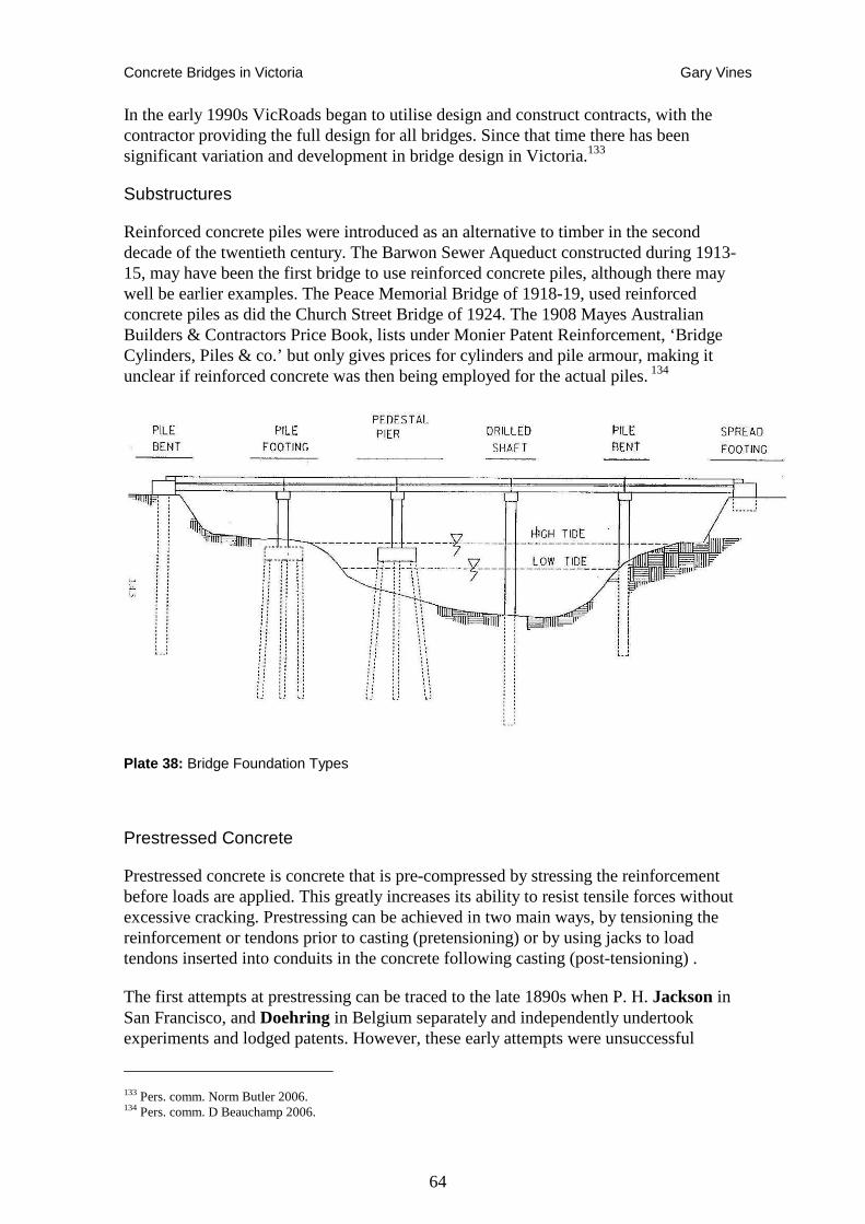
Concrete Bridges in Victoria Gary Vines
64
In the early 1990s VicRoads began to utilise design and construct contracts, with the contractor providing the full design for all bridges. Since that time there has been significant variation and development in bridge design in Victoria.133
Substructures
Reinforced concrete piles were introduced as an alternative to timber in the second decade of the twentieth century. The Barwon Sewer Aqueduct constructed during 1913-15, may have been the first bridge to use reinforced concrete piles, although there may well be earlier examples. The Peace Memorial Bridge of 1918-19, used reinforced concrete piles as did the Church Street Bridge of 1924. The 1908 Mayes Australian Builders & Contractors Price Book, lists under Monier Patent Reinforcement, ‘Bridge Cylinders, Piles & co.’ but only gives prices for cylinders and pile armour, making it unclear if reinforced concrete was then being employed for the actual piles. 134
Plate 38: Bridge Foundation Types
Prestressed Concrete
Prestressed concrete is concrete that is pre-compressed by stressing the reinforcement before loads are applied. This greatly increases its ability to resist tensile forces without excessive cracking. Prestressing can be achieved in two main ways, by tensioning the reinforcement or tendons prior to casting (pretensioning) or by using jacks to load tendons inserted into conduits in the concrete following casting (post-tensioning) .
The first attempts at prestressing can be traced to the late 1890s when P. H. Jackson in San Francisco, and Doehring in Belgium separately and independently undertook experiments and lodged patents. However, these early attempts were unsuccessful
133 Pers. comm. Norm Butler 2006. 134 Pers. comm. D Beauchamp 2006.
Concrete Bridges in Victoria Gary Vines
65
because the prestressing forces in the mild steel bars were completely eliminated by losses due to creep and shrinkage in the concrete. R. H. Dill recognised that high strength wire could be used as a more effective prestressing tendon. One of the first prestressed bridges in Europe, the River Elz Bridge at Emmendingen, Germany, achieved a main span of 30 metres with slenderness ratios of 1:25 over the piers and 1:52 mid-span. 135
As early as 1888 a German engineer had examined prestressed concrete members, yet it was the Frenchman, Eugène Freyssinet (1879 - 1962), a graduate of the École des Ponts et Chaussées, who is considered the father of prestressed concrete bridges.
He produced the first successful practical design in prestressed concrete in the 1930s as a method for overcoming concrete's natural weakness in tension and to produce beams, floors or bridges with a longer span than is practical with ordinary reinforced concrete.
Freyssinet’s best known bridge is the Plougastel Bridge, built between 1925 and 1930 in France. For the three 186-m long arches of reinforced concrete with a box girder cross-section, Freyssinet employed large timber falsework that was brought into place by pontoons and reused for all three arch spans. It was the Plougastel Bridge where Freyssinet became aware of the phenomenon of concrete creep, which needs to be considered in prestressed construction. Freyssinet implemented jacking the concrete bridge spans apart prior to closure of the mid-span gap to account for creep.
Freyssinet came up with concepts for ‘both pre-tensioned and post-tensioned concrete’ and thus initiated the rapid development of prestressed concrete bridges.136
Prestressing of concrete bridges reduced deflections, prevented cracking, and allowed higher loads to be carried by the bridges. Freyssinet’s system of implementing full prestressing was not very economical. However, partial prestressing became more prevalent as it was introduced into the design codes. Partial prestressing permitted limited tensile stresses in concrete and made use of mild reinforcement to alleviate the cracking of the concrete because of these stresses.
Prestressed concrete railway sleepers were being manufactured in the UK in 1943, while during the early part of WW II, a number of prefabricated prestressed concrete beams were made in the same way, to be stored for emergency use. At least two bridges built with these beams survived into recent times.137
As time-dependent creep and shrinkage behaviour of concrete became better understood in the USA, the Preload Corporation developed a technique for pre-tensioning a variety of structures. This work appears to have also led to construction of prefabricated bridge girders.
The first prestressed concrete bridge in America was the Walnut Street Bridge in Philadelphia. It opened in 1949 the same year that the Institute of Civil Engineers held
135 Structures of Leonhardt, Andra & Partners, http://nisee.berkeley.edu/leonhardt 136 Menn 1990, Prestressed Concrete Bridges p.30. 137 University of Cambridge, 2004, History of Prestressed Concrete in UK, Department of Engineering, Civil Engineering Structures Group, http://www-civ.eng.cam.ac.uk/cjb/4d8/public/history.html
Concrete Bridges in Victoria Gary Vines
66
an influential conference, which established prestressing as a preferred method for creating lighter, longer and stronger concrete spanning members. This conference provided a comprehensive review of the state of the art at the time.138
In the 1960s, with the development of higher strength steel, better attachment hardware, better construction techniques, and simplified design methods, the use of post-tensioning to reinforce structures became more popular. By the early 1990s the mystery of post-tensioning subsided with further refinements to the tensioning process, the development of more corrosion-resistant anchorages, and the widespread dissemination of design software. Because of these factors, post-tensioning has become a preferred method for reinforcing concrete today.
Precast segmental construction also emerged in the early 1960s. In the following decades, solutions for the problem of segment joints were developed, including match-casting of the segments at the precasting yard, implementation of shear keys, and use of epoxy agents that sealed and glued the joint faces together.
In the decades since the first prestressed concrete bridges were built many technological achievements have been made. Research allowed better understanding of the internal flow of forces in concrete and in the embedded steel, and helped improve material properties of these construction materials.139
Tung-Yen Lin was a pioneer in the theory and design of prestressed concrete structures. As leader of T.Y. Lin International, which he founded in 1953, he built innovative bridges in Costa Rica, Libya, Taipei and the United States.140
Prestressing rapidly took over as the major form of bridge construction, surpassing the number of standard reinforced concrete bridges built in the US annually in about 1970, and steel in about 1975, to comprise more than 50 percent of all bridges built by the mid 1990s. Prestressing has also played a role in extending the capability of concrete spans, with spliced-girder spans reaching a record 100 metres by the late 1990s.141
Prestressing in Australia
Introduction of prestressing in Australia can be traced to the 1940s when several miles of prestressed reinforced concrete pipeline was laid for the Lithgow water supply scheme, probably the first example of prestressed concrete used in Australia. One of the first structural applications of prestressed concrete in Australia was the ice tower at Warragamba Dam, built in the early 1950s wan employing a multi-story concrete
138 Thomas F.G. (ed.), 1949. Proceedings of a conference on Prestressed Concrete held at the ICE, February 1949 139 G Lucko, 1999, Means and Methods Analysis of a Cast-In-Place Balanced Cantilever Segmental Bridge: The Wilson Creek Bridge Case Study MSc thesis Virginia Polytechnic Institute and State University http://scholar.lib.vt.edu/theses/available/etd-120199-224950/unrestricted/ 140 David Pescovitz ‘Lab Notes’ Public Affairs Office, UC Berkeley College of Engineering http://www.coe.berkeley.edu/labnotes/0802/history.html; Lin, T'ung-yen Design of Prestressed Concrete Structures (3rd edition), John Wiley & Sons, New York (USA) , ISBN 0-471-01898-8, 1981. 141 Concrete Bridges, Transport in the New Millenia, Committee on Concrete Bridges A2C03, Mary Lou Ralls (chair)
Concrete Bridges in Victoria Gary Vines
67
frame.142 The precast beams and columns were prestressed when fabricated and subsequently post-tensioned together after erection.143
The first pre-tensioned concrete bridge superstructure in Australia may have been the Mittagong Creek Bridge near Bowral, built for the Bowral Municipal Council in June 1953.144 A railway flyover built in 1955 between Seven Hills and Blacktown used prestressed concrete girders over Sunnyholt Road and is purported to be the first use of such a structure on the NSW rail system.145
A bridge across Pipers Creek near Guthega Power Station, completed in September 1953, was the first post-tensioned concrete bridge in New South Wales (and possibly Australia). It was erected by the Snowy Mountains Authority, possibly reflecting the role of overseas engineers in the development of this scheme. The NSW Department of Main Roads (DMR) was a little slower to adopt prestressed concrete, with the first bridge being Cockle Creek at Bobin Head, opened in September 1956. The DMR’s first post-tensioned concrete bridges were Corunna Lake Bridge and Nangudga Lake Bridge on the Princess Highway, both completed in 1957.146
The earliest prestressed concrete bridges in Victoria were erected in the mid 1950s. CRB engineer Norm Haylock was given a design group of about 16 people in 1954 with space in the old Exhibition Building annexe to develop new precast, prestressed concrete bridge units. They designed slab units of 15, 20, 30 and 35 foot long spans and also new prestressed beams for 40 foot and 60 foot long spans.147
Raleigh Robinson also played a significant role in the introduction of prestressing in Victoria. He spent 1955-6 in Scotland and London under a ‘Federation of British Industry’ scholarship with assistance from the CRB. There he met Allan Harris who was famous in the prestressing area. Both Cec Wilson and Gerry Masterton were in the United Kingdom at the same time, touting for tenders for the King Street Bridge project and made contact with Robinson. By 1957, all three men were involved in the King Street Bridge work at the CRB, with Robinson taking on the prestressed and precast concrete components.148
Prestressed Concrete Slabs.
In 1955/56, the Country Roads Board developed prestressed concrete slabs to provide for situations where a shallow depth of superstructure was required, such as at floodways. Up until this time, the cast in situ flat slab bridge, which required a large labour input, was being utilised for this purpose.
The precast prestressed slabs were provided with a male keyway on one side and female keyway on the other so that when the slabs were placed, each was connected to the next with interlocking keyways. Transverse bolts held the slabs together. The slabs were
142 Anon 1977 The Mother of Invention, 50th anniversary edition of the Construction Review. 143 R. F. Warner, K. A. Faulkes, 1988, Prestressed Concrete, Longman Cheshire, pp.18-19. 144 RTA Thematic History 145 NSW Heritage Register. 146 NSW Department of Main Roads, Heritage and Conservation Register. 147 VicRoads Retirees Association, 1995, p.22 148 VicRoads Retirees Association, 1995, pp.63-4.
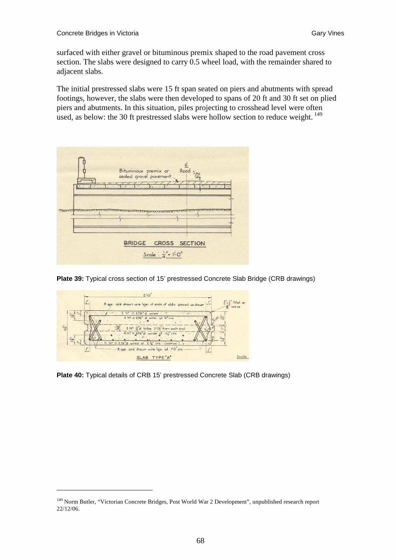
Concrete Bridges in Victoria Gary Vines
68
surfaced with either gravel or bituminous premix shaped to the road pavement cross section. The slabs were designed to carry 0.5 wheel load, with the remainder shared to adjacent slabs.
The initial prestressed slabs were 15 ft span seated on piers and abutments with spread footings, however, the slabs were then developed to spans of 20 ft and 30 ft set on plied piers and abutments. In this situation, piles projecting to crosshead level were often used, as below: the 30 ft prestressed slabs were hollow section to reduce weight. 149
Plate 39: Typical cross section of 15’ prestressed Concrete Slab Bridge (CRB drawings)
Plate 40: Typical details of CRB 15’ prestressed Concrete Slab (CRB drawings)
149 Norm Butler, “Victorian Concrete Bridges, Post World War 2 Development”, unpublished research report 22/12/06.
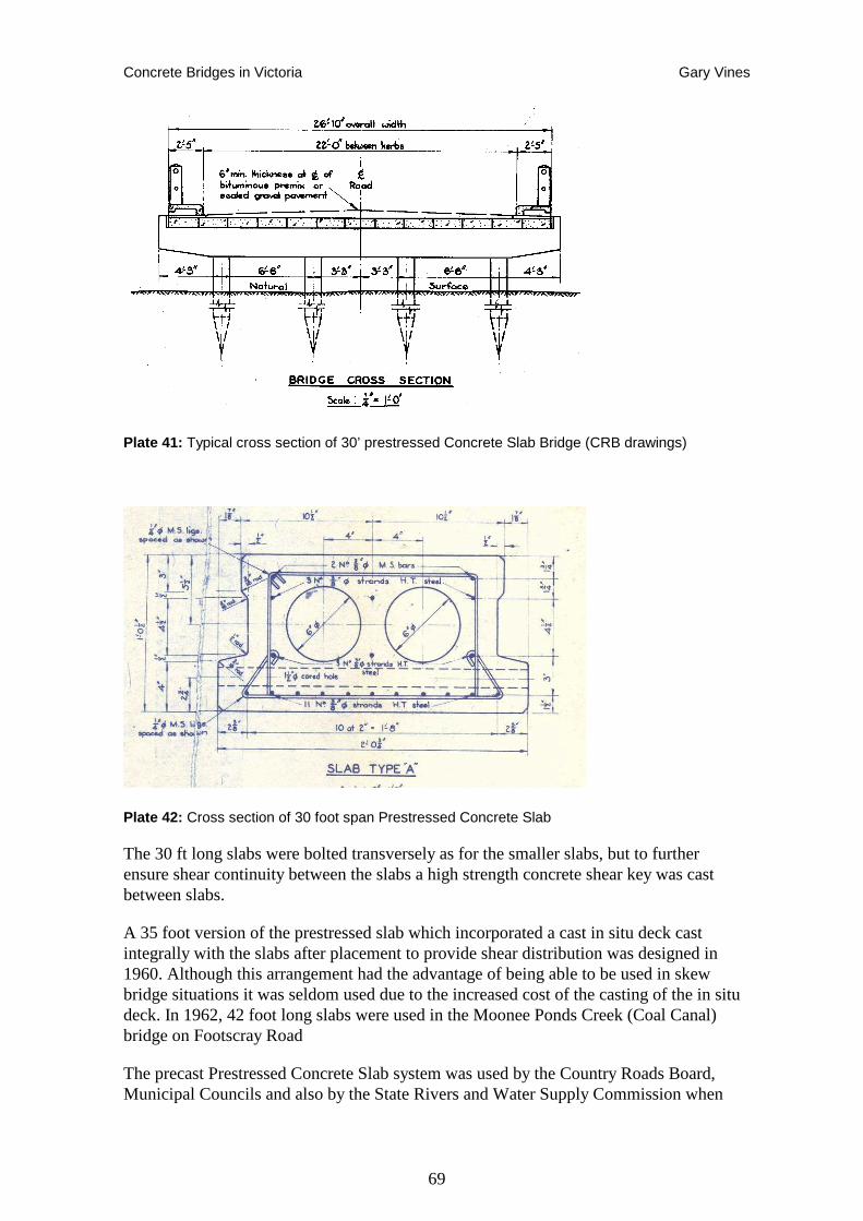
Concrete Bridges in Victoria Gary Vines
69
Plate 41: Typical cross section of 30’ prestressed Concrete Slab Bridge (CRB drawings)
Plate 42: Cross section of 30 foot span Prestressed Concrete Slab
The 30 ft long slabs were bolted transversely as for the smaller slabs, but to further ensure shear continuity between the slabs a high strength concrete shear key was cast between slabs.
A 35 foot version of the prestressed slab which incorporated a cast in situ deck cast integrally with the slabs after placement to provide shear distribution was designed in 1960. Although this arrangement had the advantage of being able to be used in skew bridge situations it was seldom used due to the increased cost of the casting of the in situ deck. In 1962, 42 foot long slabs were used in the Moonee Ponds Creek (Coal Canal) bridge on Footscray Road
The precast Prestressed Concrete Slab system was used by the Country Roads Board, Municipal Councils and also by the State Rivers and Water Supply Commission when
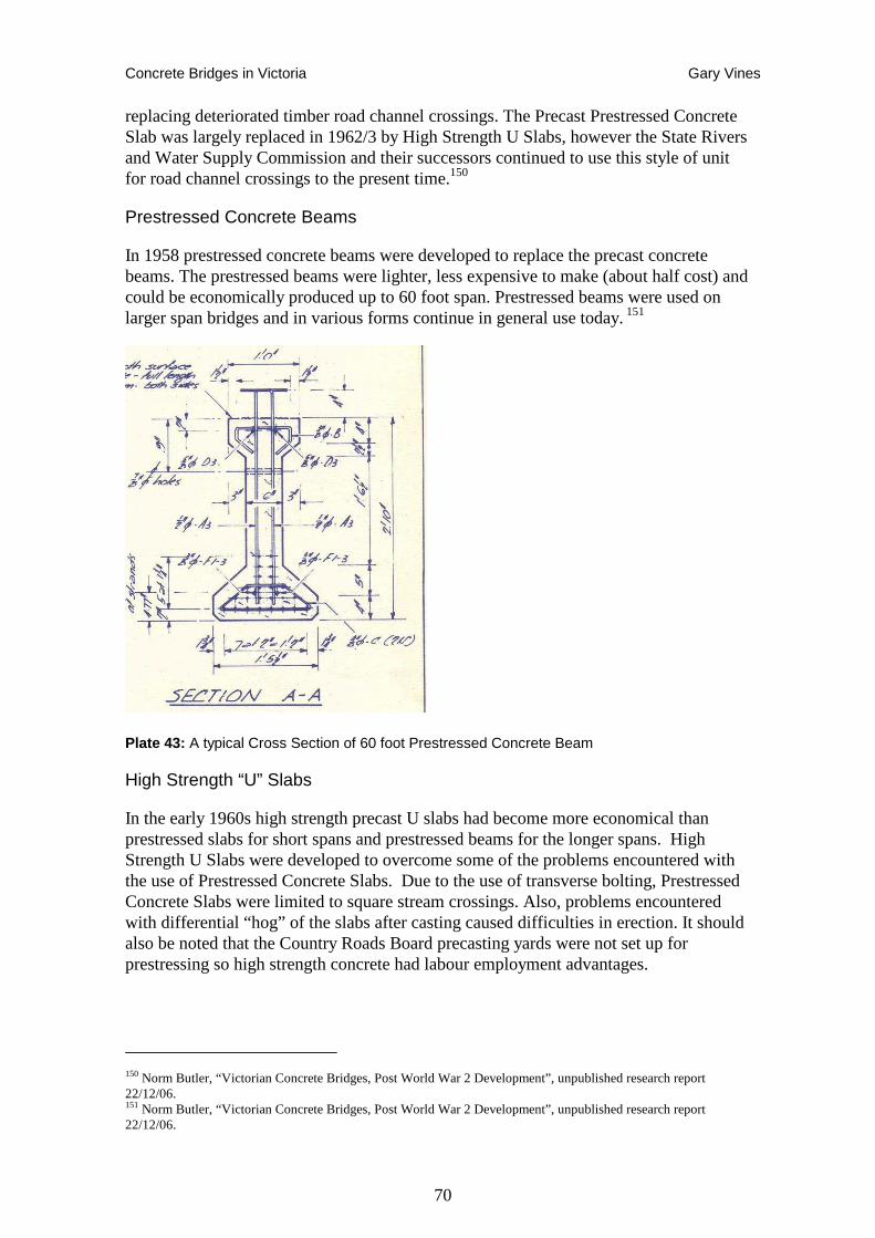
Concrete Bridges in Victoria Gary Vines
70
replacing deteriorated timber road channel crossings. The Precast Prestressed Concrete Slab was largely replaced in 1962/3 by High Strength U Slabs, however the State Rivers and Water Supply Commission and their successors continued to use this style of unit for road channel crossings to the present time.150
Prestressed Concrete Beams
In 1958 prestressed concrete beams were developed to replace the precast concrete beams. The prestressed beams were lighter, less expensive to make (about half cost) and could be economically produced up to 60 foot span. Prestressed beams were used on larger span bridges and in various forms continue in general use today. 151
Plate 43: A typical Cross Section of 60 foot Prestressed Concrete Beam
High Strength “U” Slabs
In the early 1960s high strength precast U slabs had become more economical than prestressed slabs for short spans and prestressed beams for the longer spans. High Strength U Slabs were developed to overcome some of the problems encountered with the use of Prestressed Concrete Slabs. Due to the use of transverse bolting, Prestressed Concrete Slabs were limited to square stream crossings. Also, problems encountered with differential “hog” of the slabs after casting caused difficulties in erection. It should also be noted that the Country Roads Board precasting yards were not set up for prestressing so high strength concrete had labour employment advantages.
150 Norm Butler, “Victorian Concrete Bridges, Post World War 2 Development”, unpublished research report 22/12/06. 151 Norm Butler, “Victorian Concrete Bridges, Post World War 2 Development”, unpublished research report 22/12/06.
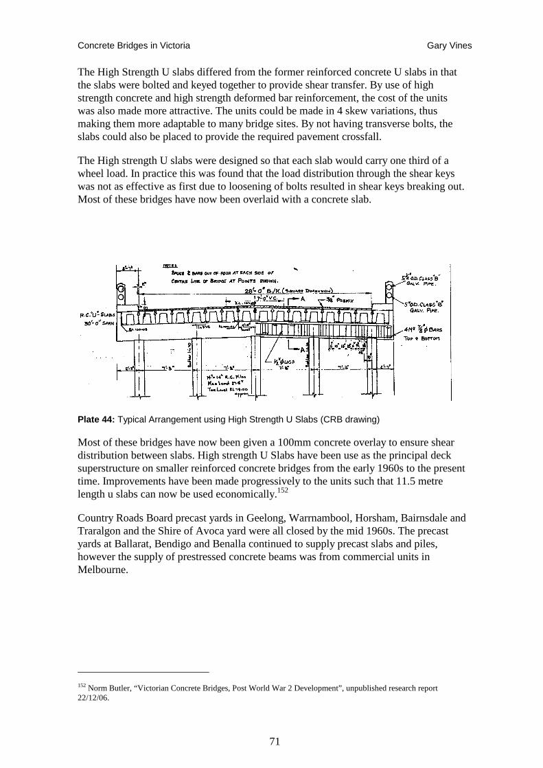
Concrete Bridges in Victoria Gary Vines
71
The High Strength U slabs differed from the former reinforced concrete U slabs in that the slabs were bolted and keyed together to provide shear transfer. By use of high strength concrete and high strength deformed bar reinforcement, the cost of the units was also made more attractive. The units could be made in 4 skew variations, thus making them more adaptable to many bridge sites. By not having transverse bolts, the slabs could also be placed to provide the required pavement crossfall.
The High strength U slabs were designed so that each slab would carry one third of a wheel load. In practice this was found that the load distribution through the shear keys was not as effective as first due to loosening of bolts resulted in shear keys breaking out. Most of these bridges have now been overlaid with a concrete slab.
Plate 44: Typical Arrangement using High Strength U Slabs (CRB drawing)
Most of these bridges have now been given a 100mm concrete overlay to ensure shear distribution between slabs. High strength U Slabs have been use as the principal deck superstructure on smaller reinforced concrete bridges from the early 1960s to the present time. Improvements have been made progressively to the units such that 11.5 metre length u slabs can now be used economically.152
Country Roads Board precast yards in Geelong, Warrnambool, Horsham, Bairnsdale and Traralgon and the Shire of Avoca yard were all closed by the mid 1960s. The precast yards at Ballarat, Bendigo and Benalla continued to supply precast slabs and piles, however the supply of prestressed concrete beams was from commercial units in Melbourne.
152 Norm Butler, “Victorian Concrete Bridges, Post World War 2 Development”, unpublished research report 22/12/06.
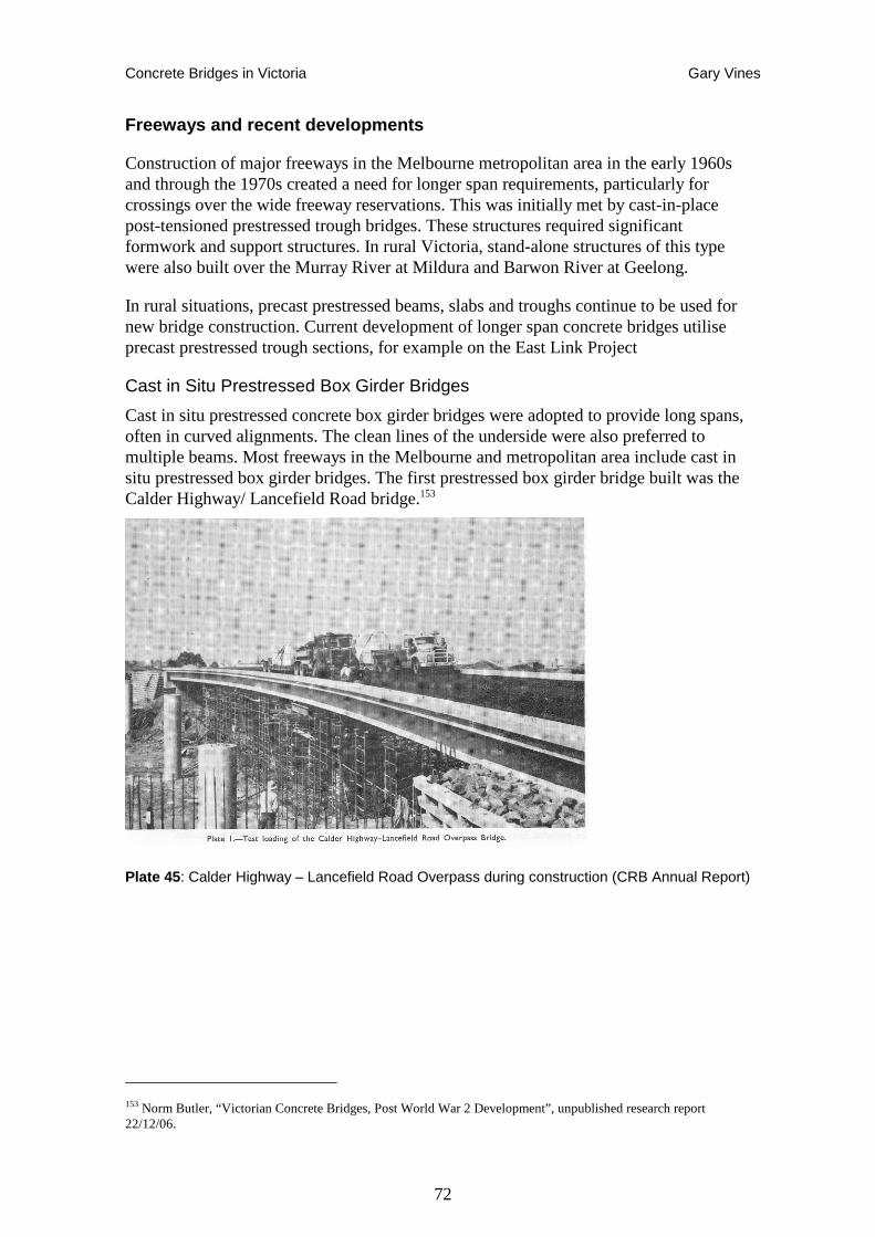
Concrete Bridges in Victoria Gary Vines
72
Freeways and recent developments
Construction of major freeways in the Melbourne metropolitan area in the early 1960s and through the 1970s created a need for longer span requirements, particularly for crossings over the wide freeway reservations. This was initially met by cast-in-place post-tensioned prestressed trough bridges. These structures required significant formwork and support structures. In rural Victoria, stand-alone structures of this type were also built over the Murray River at Mildura and Barwon River at Geelong.
In rural situations, precast prestressed beams, slabs and troughs continue to be used for new bridge construction. Current development of longer span concrete bridges utilise precast prestressed trough sections, for example on the East Link Project
Cast in Situ Prestressed Box Girder Bridges
Cast in situ prestressed concrete box girder bridges were adopted to provide long spans, often in curved alignments. The clean lines of the underside were also preferred to multiple beams. Most freeways in the Melbourne and metropolitan area include cast in situ prestressed box girder bridges. The first prestressed box girder bridge built was the Calder Highway/ Lancefield Road bridge.153
Plate 45 : Calder Highway – Lancefield Road Overpass during construction (CRB Annual Report)
153 Norm Butler, “Victorian Concrete Bridges, Post World War 2 Development”, unpublished research report 22/12/06.
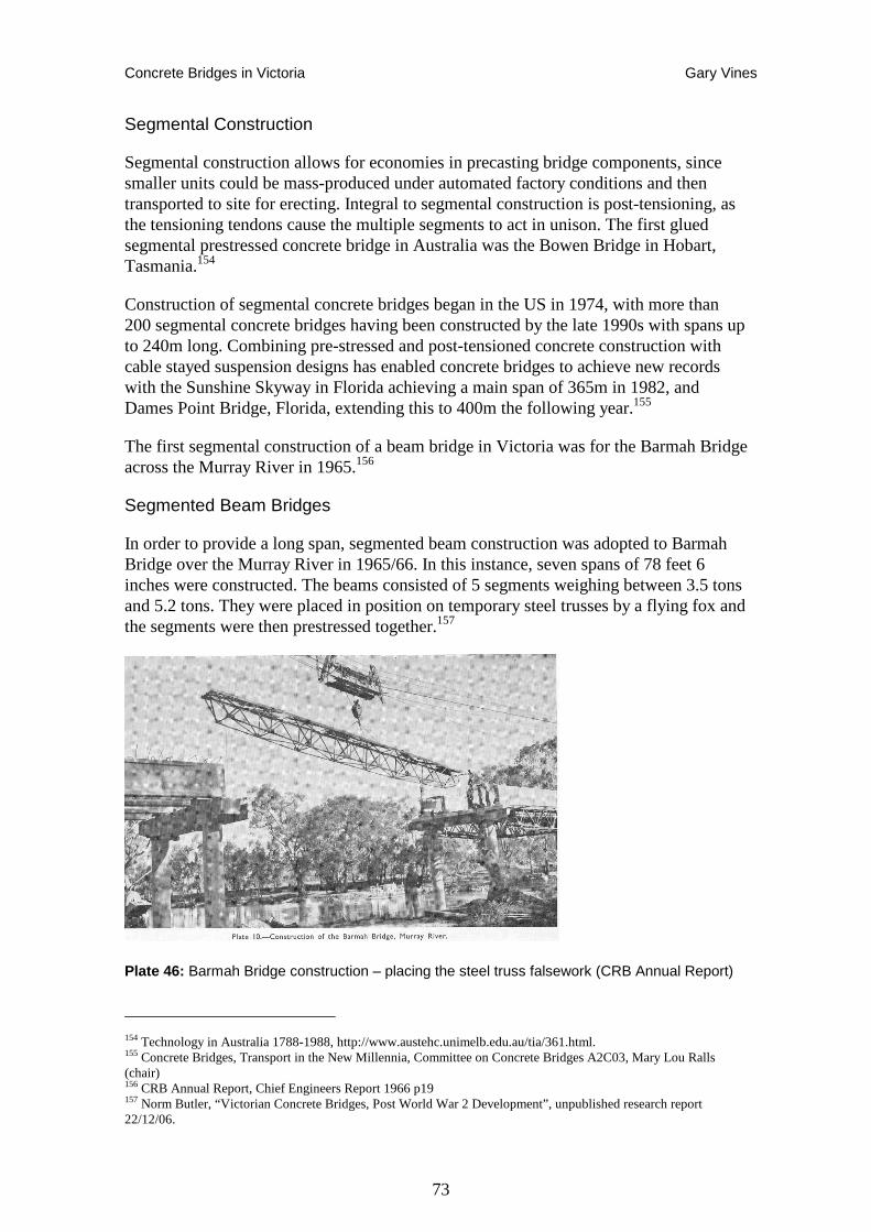
Concrete Bridges in Victoria Gary Vines
73
Segmental Construction
Segmental construction allows for economies in precasting bridge components, since smaller units could be mass-produced under automated factory conditions and then transported to site for erecting. Integral to segmental construction is post-tensioning, as the tensioning tendons cause the multiple segments to act in unison. The first glued segmental prestressed concrete bridge in Australia was the Bowen Bridge in Hobart, Tasmania.154
Construction of segmental concrete bridges began in the US in 1974, with more than 200 segmental concrete bridges having been constructed by the late 1990s with spans up to 240m long. Combining pre-stressed and post-tensioned concrete construction with cable stayed suspension designs has enabled concrete bridges to achieve new records with the Sunshine Skyway in Florida achieving a main span of 365m in 1982, and Dames Point Bridge, Florida, extending this to 400m the following year.155
The first segmental construction of a beam bridge in Victoria was for the Barmah Bridge across the Murray River in 1965.156
Segmented Beam Bridges
In order to provide a long span, segmented beam construction was adopted to Barmah Bridge over the Murray River in 1965/66. In this instance, seven spans of 78 feet 6 inches were constructed. The beams consisted of 5 segments weighing between 3.5 tons and 5.2 tons. They were placed in position on temporary steel trusses by a flying fox and the segments were then prestressed together.157
Plate 46: Barmah Bridge construction – placing the steel truss falsework (CRB Annual Report)
154 Technology in Australia 1788-1988, http://www.austehc.unimelb.edu.au/tia/361.html. 155 Concrete Bridges, Transport in the New Millennia, Committee on Concrete Bridges A2C03, Mary Lou Ralls (chair) 156 CRB Annual Report, Chief Engineers Report 1966 p19 157 Norm Butler, “Victorian Concrete Bridges, Post World War 2 Development”, unpublished research report 22/12/06.
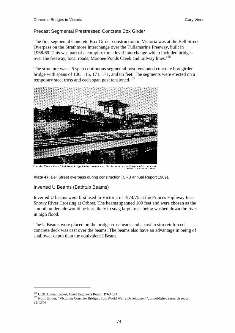
Concrete Bridges in Victoria Gary Vines
74
Precast Segmental Prestressed Concrete Box Girder
The first segmental Concrete Box Girder construction in Victoria was at the Bell Street Overpass on the Strathmore Interchange over the Tullamarine Freeway, built in 1968/69. This was part of a complex three level interchange which included bridges over the freeway, local roads, Moonee Ponds Creek and railway lines.158
The structure was a 5 span continuous segmental post tensioned concrete box girder bridge with spans of 106, 115, 171, 171, and 85 feet. The segments were erected on a temporary steel truss and each span post tensioned.159
Plate 47: Bell Street overpass during construction (CRB annual Report 1969).
Inverted U Beams (Bathtub Beams)
Inverted U beams were first used in Victoria in 1974/75 at the Princes Highway East Snowy River Crossing at Orbost. The beams spanned 100 feet and were chosen as the smooth underside would be less likely to snag large trees being washed down the river in high flood.
The U Beams were placed on the bridge crossheads and a cast in situ reinforced concrete deck was cast over the beams. The beams also have an advantage in being of shallower depth than the equivalent I Beam.
158 CRB Annual Report, Chief Engineers Report 1969 p23 159 Norm Butler, “Victorian Concrete Bridges, Post World War 2 Development”, unpublished research report 22/12/06.
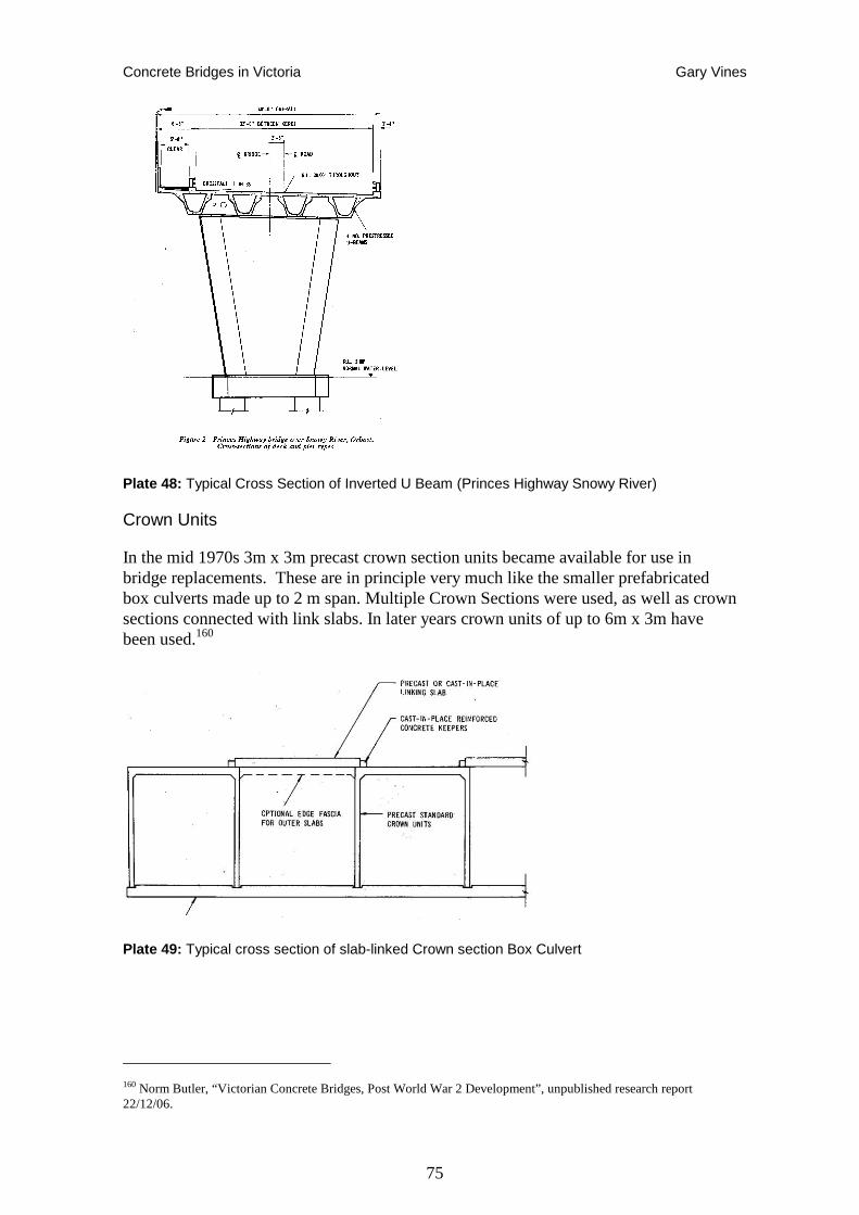
Concrete Bridges in Victoria Gary Vines
75
Plate 48: Typical Cross Section of Inverted U Beam (Princes Highway Snowy River)
Crown Units
In the mid 1970s 3m x 3m precast crown section units became available for use in bridge replacements. These are in principle very much like the smaller prefabricated box culverts made up to 2 m span. Multiple Crown Sections were used, as well as crown sections connected with link slabs. In later years crown units of up to 6m x 3m have been used.160
Plate 49: Typical cross section of slab-linked Crown section Box Culvert
160 Norm Butler, “Victorian Concrete Bridges, Post World War 2 Development”, unpublished research report 22/12/06.
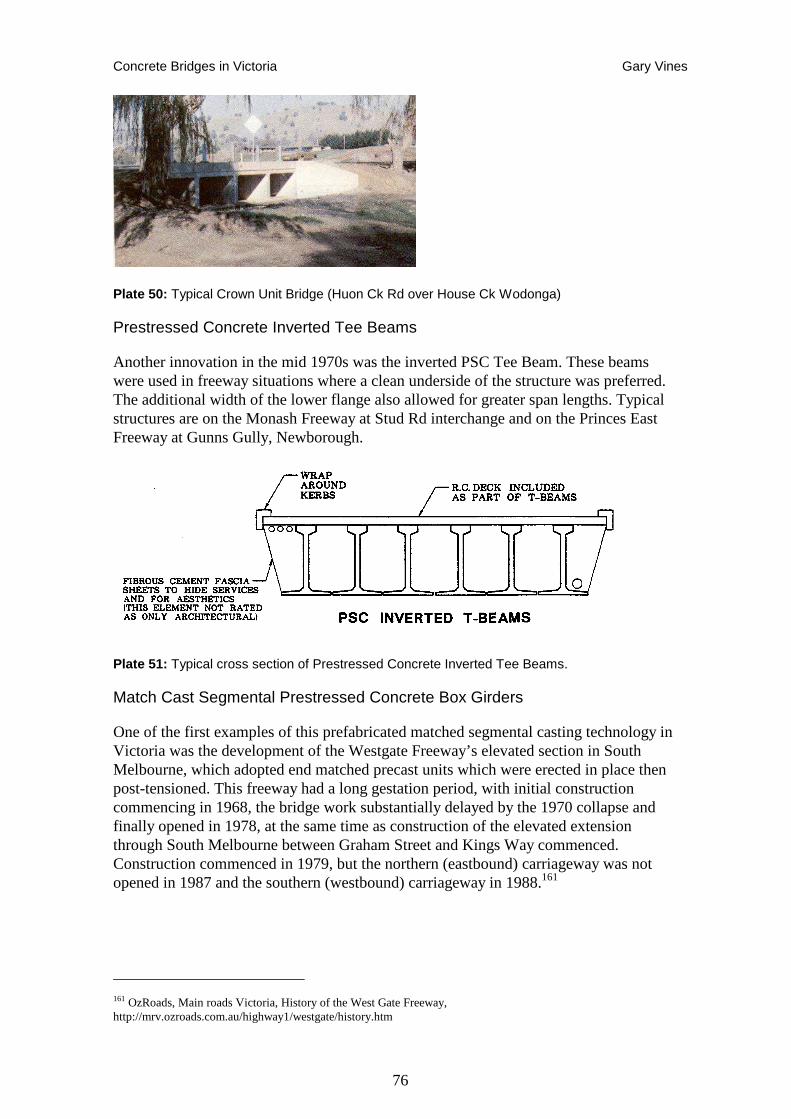
Concrete Bridges in Victoria Gary Vines
76
Plate 50: Typical Crown Unit Bridge (Huon Ck Rd over House Ck Wodonga)
Prestressed Concrete Inverted Tee Beams
Another innovation in the mid 1970s was the inverted PSC Tee Beam. These beams were used in freeway situations where a clean underside of the structure was preferred. The additional width of the lower flange also allowed for greater span lengths. Typical structures are on the Monash Freeway at Stud Rd interchange and on the Princes East Freeway at Gunns Gully, Newborough.
Plate 51: Typical cross section of Prestressed Concrete Inverted Tee Beams.
Match Cast Segmental Prestressed Concrete Box Girders
One of the first examples of this prefabricated matched segmental casting technology in Victoria was the development of the Westgate Freeway’s elevated section in South Melbourne, which adopted end matched precast units which were erected in place then post-tensioned. This freeway had a long gestation period, with initial construction commencing in 1968, the bridge work substantially delayed by the 1970 collapse and finally opened in 1978, at the same time as construction of the elevated extension through South Melbourne between Graham Street and Kings Way commenced. Construction commenced in 1979, but the northern (eastbound) carriageway was not opened in 1987 and the southern (westbound) carriageway in 1988.161
161 OzRoads, Main roads Victoria, History of the West Gate Freeway, http://mrv.ozroads.com.au/highway1/westgate/history.htm
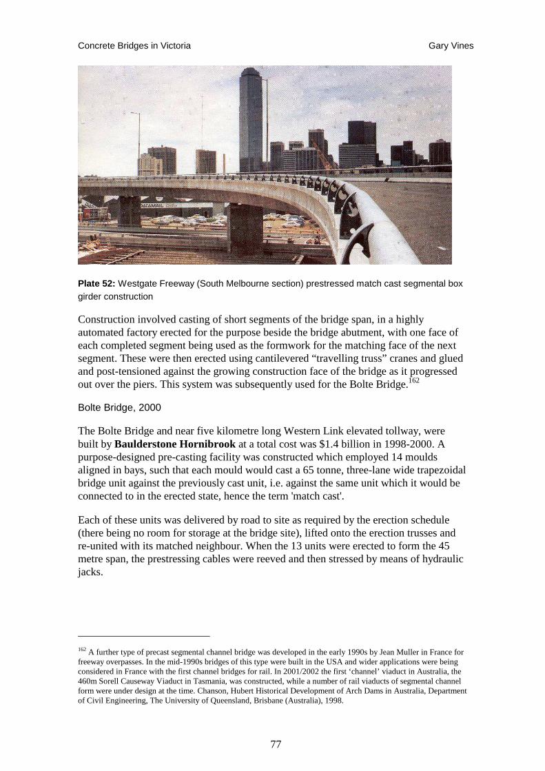
Concrete Bridges in Victoria Gary Vines
77
Plate 52: Westgate Freeway (South Melbourne section) prestressed match cast segmental box girder construction
Construction involved casting of short segments of the bridge span, in a highly automated factory erected for the purpose beside the bridge abutment, with one face of each completed segment being used as the formwork for the matching face of the next segment. These were then erected using cantilevered “travelling truss” cranes and glued and post-tensioned against the growing construction face of the bridge as it progressed out over the piers. This system was subsequently used for the Bolte Bridge.162
Bolte Bridge, 2000
The Bolte Bridge and near five kilometre long Western Link elevated tollway, were built by Baulderstone Hornibrook at a total cost was $1.4 billion in 1998-2000. A purpose-designed pre-casting facility was constructed which employed 14 moulds aligned in bays, such that each mould would cast a 65 tonne, three-lane wide trapezoidal bridge unit against the previously cast unit, i.e. against the same unit which it would be connected to in the erected state, hence the term 'match cast'.
Each of these units was delivered by road to site as required by the erection schedule (there being no room for storage at the bridge site), lifted onto the erection trusses and re-united with its matched neighbour. When the 13 units were erected to form the 45 metre span, the prestressing cables were reeved and then stressed by means of hydraulic jacks.
162 A further type of precast segmental channel bridge was developed in the early 1990s by Jean Muller in France for freeway overpasses. In the mid-1990s bridges of this type were built in the USA and wider applications were being considered in France with the first channel bridges for rail. In 2001/2002 the first ‘channel’ viaduct in Australia, the 460m Sorell Causeway Viaduct in Tasmania, was constructed, while a number of rail viaducts of segmental channel form were under design at the time. Chanson, Hubert Historical Development of Arch Dams in Australia, Department of Civil Engineering, The University of Queensland, Brisbane (Australia), 1998.
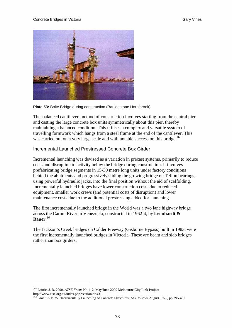
Concrete Bridges in Victoria Gary Vines
78
Plate 53: Bolte Bridge during construction (Bauldestone Hornibrook)
The 'balanced cantilever' method of construction involves starting from the central pier and casting the large concrete box units symmetrically about this pier, thereby maintaining a balanced condition. This utilises a complex and versatile system of travelling formwork which hangs from a steel frame at the end of the cantilever. This was carried out on a very large scale and with notable success on this bridge.163
Incremental Launched Prestressed Concrete Box Girder
Incremental launching was devised as a variation in precast systems, primarily to reduce costs and disruption to activity below the bridge during construction. It involves prefabricating bridge segments in 15-30 metre long units under factory conditions behind the abutments and progressively sliding the growing bridge on Teflon bearings, using powerful hydraulic jacks, into the final position without the aid of scaffolding. Incrementally launched bridges have lower construction costs due to reduced equipment, smaller work crews (and potential costs of disruption) and lower maintenance costs due to the additional prestressing added for launching.
The first incrementally launched bridge in the World was a two lane highway bridge across the Caroni River in Venezuela, constructed in 1962-4, by Leonhardt & Bauer.164
The Jackson’s Creek bridges on Calder Freeway (Gisborne Bypass) built in 1983, were the first incrementally launched bridges in Victoria. These are beam and slab bridges rather than box girders.
163 Laurie, J. B. 2000, ATSE Focus No 112, May/June 2000 Melbourne City Link Project http://www.atse.org.au/index.php?sectionid=431 164 Grant, A.1975, ‘Incrementally Launching of Concrete Structures’ ACI Journal August 1975, pp 395-402.
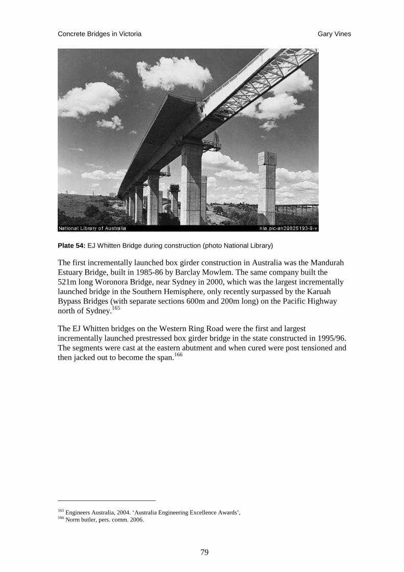
Concrete Bridges in Victoria Gary Vines
79
Plate 54: EJ Whitten Bridge during construction (photo National Library)
The first incrementally launched box girder construction in Australia was the Mandurah Estuary Bridge, built in 1985-86 by Barclay Mowlem. The same company built the 521m long Woronora Bridge, near Sydney in 2000, which was the largest incrementally launched bridge in the Southern Hemisphere, only recently surpassed by the Karuah Bypass Bridges (with separate sections 600m and 200m long) on the Pacific Highway north of Sydney.165
The EJ Whitten bridges on the Western Ring Road were the first and largest incrementally launched prestressed box girder bridge in the state constructed in 1995/96. The segments were cast at the eastern abutment and when cured were post tensioned and then jacked out to become the span.166
165 Engineers Australia, 2004. ‘Australia Engineering Excellence Awards’, 166 Norm butler, pers. comm. 2006.
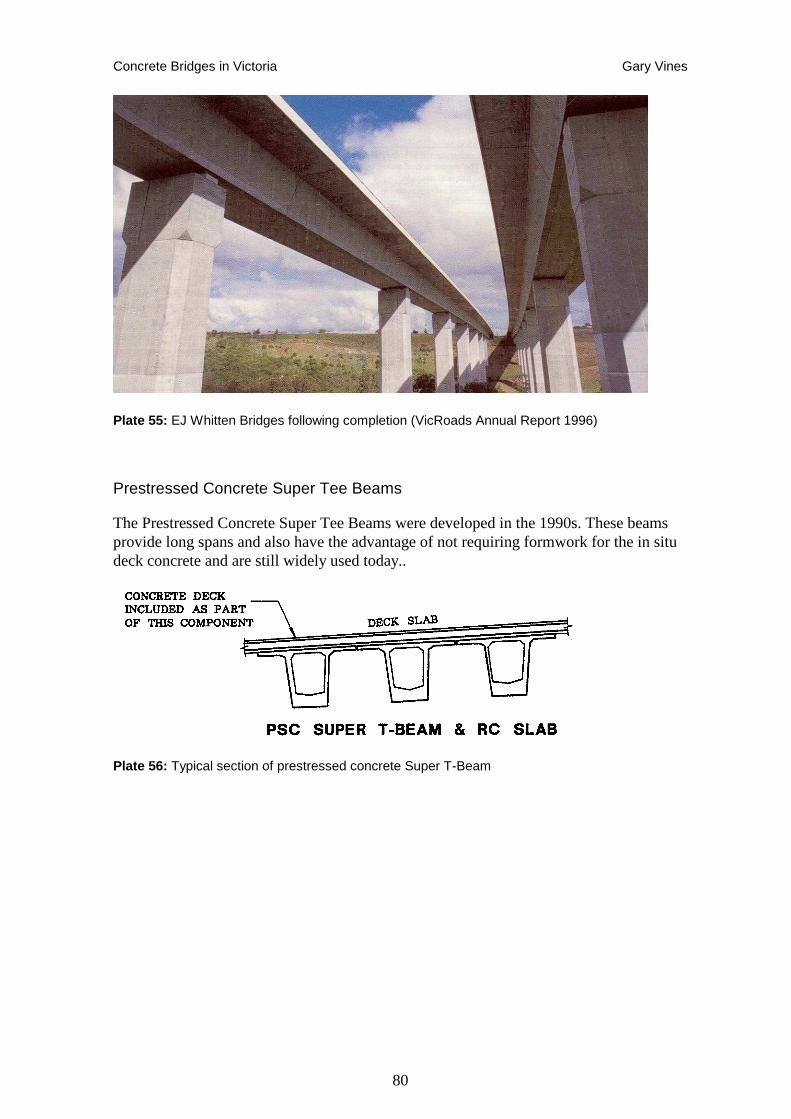
Concrete Bridges in Victoria Gary Vines
80
Plate 55: EJ Whitten Bridges following completion (VicRoads Annual Report 1996)
Prestressed Concrete Super Tee Beams
The Prestressed Concrete Super Tee Beams were developed in the 1990s. These beams provide long spans and also have the advantage of not requiring formwork for the in situ deck concrete and are still widely used today..
Plate 56: Typical section of prestressed concrete Super T-Beam
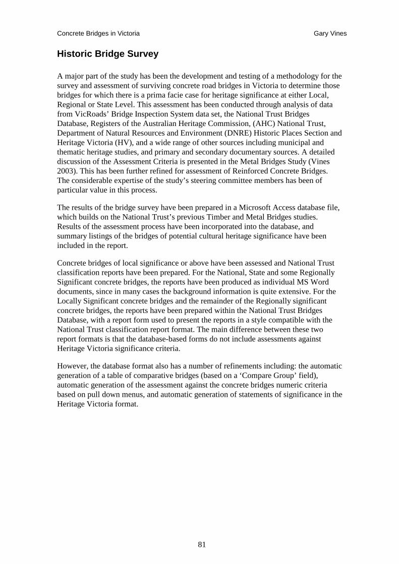
Concrete Bridges in Victoria Gary Vines
81
Historic Bridge Survey
A major part of the study has been the development and testing of a methodology for the survey and assessment of surviving concrete road bridges in Victoria to determine those bridges for which there is a prima facie case for heritage significance at either Local, Regional or State Level. This assessment has been conducted through analysis of data from VicRoads’ Bridge Inspection System data set, the National Trust Bridges Database, Registers of the Australian Heritage Commission, (AHC) National Trust, Department of Natural Resources and Environment (DNRE) Historic Places Section and Heritage Victoria (HV), and a wide range of other sources including municipal and thematic heritage studies, and primary and secondary documentary sources. A detailed discussion of the Assessment Criteria is presented in the Metal Bridges Study (Vines 2003). This has been further refined for assessment of Reinforced Concrete Bridges. The considerable expertise of the study’s steering committee members has been of particular value in this process.
The results of the bridge survey have been prepared in a Microsoft Access database file, which builds on the National Trust’s previous Timber and Metal Bridges studies. Results of the assessment process have been incorporated into the database, and summary listings of the bridges of potential cultural heritage significance have been included in the report.
Concrete bridges of local significance or above have been assessed and National Trust classification reports have been prepared. For the National, State and some Regionally Significant concrete bridges, the reports have been produced as individual MS Word documents, since in many cases the background information is quite extensive. For the Locally Significant concrete bridges and the remainder of the Regionally significant concrete bridges, the reports have been prepared within the National Trust Bridges Database, with a report form used to present the reports in a style compatible with the National Trust classification report format. The main difference between these two report formats is that the database-based forms do not include assessments against Heritage Victoria significance criteria.
However, the database format also has a number of refinements including: the automatic generation of a table of comparative bridges (based on a ‘Compare Group’ field), automatic generation of the assessment against the concrete bridges numeric criteria based on pull down menus, and automatic generation of statements of significance in the Heritage Victoria format.
Concrete Bridges in Victoria Gary Vines
82
Criteria for Assessment
The assessment criteria and methodology used for identifying concrete bridges and determining their heritage significance has been adapted from that used in the Metal Bridges Study.167 The assessment criteria are based on the Heritage Council Criteria which is as follows:
CRITERION A:
The historical importance, association with or relationship to Victoria's history of the place or object.
CRITERION B:
The importance of a place or object in demonstrating rarity or uniqueness.
CRITERION C:
The place or object's potential to educate, illustrate or provide further scientific investigation in relation to Victoria's cultural heritage.
CRITERION D:
The importance of a place or object in exhibiting the principal characteristics or the representative nature of a place or object as part of a class or type of places or objects.
CRITERION E:
The importance of the place or object in exhibiting good design or aesthetic characteristics and/or in exhibiting a richness, diversity or unusual integration of features
CRITERION F:
The importance of the place or object in demonstrating or being associated with scientific or technical innovations or achievements.
CRITERION G:
The importance of the place or object in demonstrating social or cultural associations.
CRITERION H:
Any other matter which the Council considers relevant to the determination of cultural heritage significance
These criteria and their specific application to historic bridges, are discussed in detail in the Metal Bridges Study (volume 2, pp.23-33) so it is not proposed to reiterate them here. However, one area which has been reworked for the Concrete Bridges Study is in terms of technical significance – Criterion F. A specific measure has been used in identifying technical significance in bridge design and construction according to a date range for its introduction and application, referred to a ‘Early Example of Structure Type’. The structural categories and periods of their introduction and use are summarised in Table 2 below. The quantitative assessment table developed for the Metal Bridges Study, has therefore been modified to accommodate these different criteria measures. An example of the quantitative criteria assessment table is included in Appendix 4 of this report.
167 Vines 2003, National Trust Metal Bridges Study.
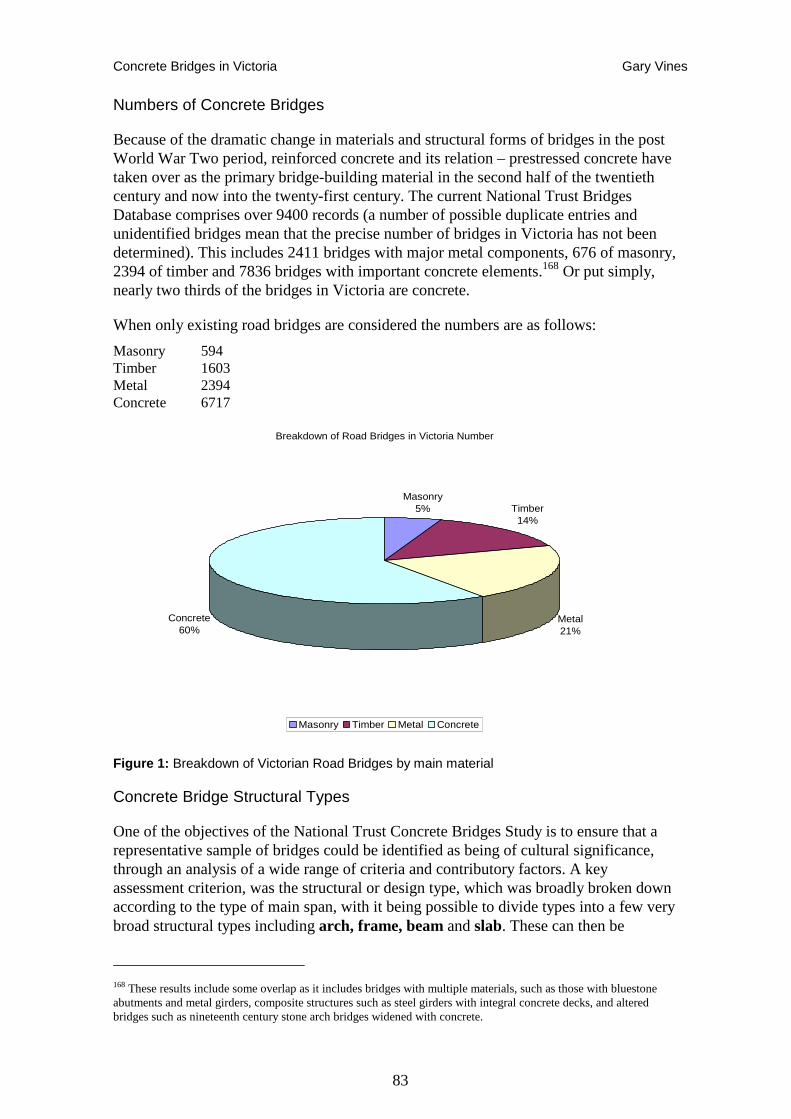
Concrete Bridges in Victoria Gary Vines
83
Numbers of Concrete Bridges
Because of the dramatic change in materials and structural forms of bridges in the post World War Two period, reinforced concrete and its relation – prestressed concrete have taken over as the primary bridge-building material in the second half of the twentieth century and now into the twenty-first century. The current National Trust Bridges Database comprises over 9400 records (a number of possible duplicate entries and unidentified bridges mean that the precise number of bridges in Victoria has not been determined). This includes 2411 bridges with major metal components, 676 of masonry, 2394 of timber and 7836 bridges with important concrete elements.168 Or put simply, nearly two thirds of the bridges in Victoria are concrete.
When only existing road bridges are considered the numbers are as follows:
Masonry 594 Timber 1603 Metal 2394 Concrete 6717
Breakdown of Road Bridges in Victoria Number
Masonry5% Timber
14%
Metal21%
Concrete60%
Masonry Timber Metal Concrete
Figure 1: Breakdown of Victorian Road Bridges by main material
Concrete Bridge Structural Types
One of the objectives of the National Trust Concrete Bridges Study is to ensure that a representative sample of bridges could be identified as being of cultural significance, through an analysis of a wide range of criteria and contributory factors. A key assessment criterion, was the structural or design type, which was broadly broken down according to the type of main span, with it being possible to divide types into a few very broad structural types including arch, frame, beam and slab. These can then be
168 These results include some overlap as it includes bridges with multiple materials, such as those with bluestone abutments and metal girders, composite structures such as steel girders with integral concrete decks, and altered bridges such as nineteenth century stone arch bridges widened with concrete.
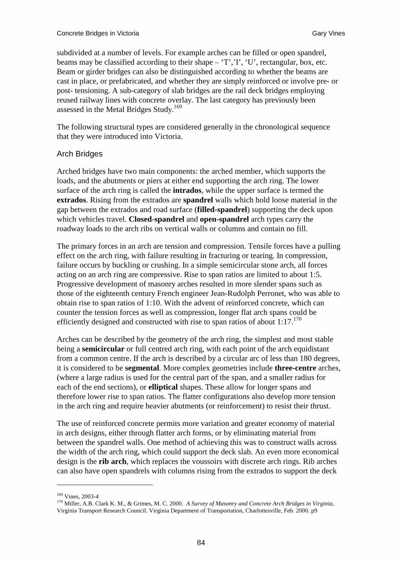
Concrete Bridges in Victoria Gary Vines
84
subdivided at a number of levels. For example arches can be filled or open spandrel, beams may be classified according to their shape – ‘T’,’I’, ‘U’, rectangular, box, etc. Beam or girder bridges can also be distinguished according to whether the beams are cast in place, or prefabricated, and whether they are simply reinforced or involve pre- or post- tensioning. A sub-category of slab bridges are the rail deck bridges employing reused railway lines with concrete overlay. The last category has previously been assessed in the Metal Bridges Study.169
The following structural types are considered generally in the chronological sequence that they were introduced into Victoria.
Arch Bridges
Arched bridges have two main components: the arched member, which supports the loads, and the abutments or piers at either end supporting the arch ring. The lower surface of the arch ring is called the intrados, while the upper surface is termed the extrados. Rising from the extrados are spandrel walls which hold loose material in the gap between the extrados and road surface (filled-spandrel) supporting the deck upon which vehicles travel. Closed-spandrel and open-spandrel arch types carry the roadway loads to the arch ribs on vertical walls or columns and contain no fill.
The primary forces in an arch are tension and compression. Tensile forces have a pulling effect on the arch ring, with failure resulting in fracturing or tearing. In compression, failure occurs by buckling or crushing. In a simple semicircular stone arch, all forces acting on an arch ring are compressive. Rise to span ratios are limited to about 1:5. Progressive development of masonry arches resulted in more slender spans such as those of the eighteenth century French engineer Jean-Rudolph Perronet, who was able to obtain rise to span ratios of 1:10. With the advent of reinforced concrete, which can counter the tension forces as well as compression, longer flat arch spans could be efficiently designed and constructed with rise to span ratios of about 1:17.170
Arches can be described by the geometry of the arch ring, the simplest and most stable being a semicircular or full centred arch ring, with each point of the arch equidistant from a common centre. If the arch is described by a circular arc of less than 180 degrees, it is considered to be segmental. More complex geometries include three-centre arches, (where a large radius is used for the central part of the span, and a smaller radius for each of the end sections), or elliptical shapes. These allow for longer spans and therefore lower rise to span ratios. The flatter configurations also develop more tension in the arch ring and require heavier abutments (or reinforcement) to resist their thrust.
The use of reinforced concrete permits more variation and greater economy of material in arch designs, either through flatter arch forms, or by eliminating material from between the spandrel walls. One method of achieving this was to construct walls across the width of the arch ring, which could support the deck slab. An even more economical design is the rib arch , which replaces the voussoirs with discrete arch rings. Rib arches can also have open spandrels with columns rising from the extrados to support the deck
169 Vines, 2003-4 170 Miller, A.B. Clark K. M., & Grimes, M. C. 2000. A Survey of Masonry and Concrete Arch Bridges in Virginia, Virginia Transport Research Council. Virginia Department of Transportation, Charlottesville, Feb. 2000. p9
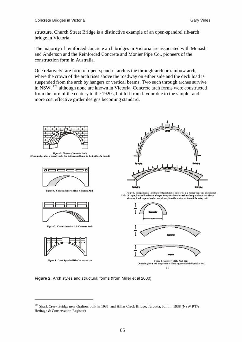
Concrete Bridges in Victoria Gary Vines
85
structure. Church Street Bridge is a distinctive example of an open-spandrel rib-arch bridge in Victoria.
The majority of reinforced concrete arch bridges in Victoria are associated with Monash and Anderson and the Reinforced Concrete and Monier Pipe Co., pioneers of the construction form in Australia.
One relatively rare form of open-spandrel arch is the through-arch or rainbow arch, where the crown of the arch rises above the roadway on either side and the deck load is suspended from the arch by hangers or vertical beams. Two such through arches survive in NSW, 171 although none are known in Victoria. Concrete arch forms were constructed from the turn of the century to the 1920s, but fell from favour due to the simpler and more cost effective girder designs becoming standard.
171 Shark Creek Bridge near Grafton, built in 1935, and Hillas Creek Bridge, Tarcutta, built in 1938 (NSW RTA Heritage & Conservation Register)
Figure 2: Arch styles and structural forms (from Miller et al 2000)
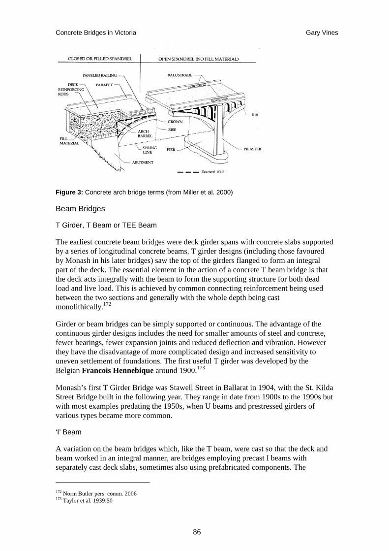
Concrete Bridges in Victoria Gary Vines
86
Figure 3: Concrete arch bridge terms (from Miller et al. 2000)
Beam Bridges
T Girder, T Beam or TEE Beam
The earliest concrete beam bridges were deck girder spans with concrete slabs supported by a series of longitudinal concrete beams. T girder designs (including those favoured by Monash in his later bridges) saw the top of the girders flanged to form an integral part of the deck. The essential element in the action of a concrete T beam bridge is that the deck acts integrally with the beam to form the supporting structure for both dead load and live load. This is achieved by common connecting reinforcement being used between the two sections and generally with the whole depth being cast monolithically.172
Girder or beam bridges can be simply supported or continuous. The advantage of the continuous girder designs includes the need for smaller amounts of steel and concrete, fewer bearings, fewer expansion joints and reduced deflection and vibration. However they have the disadvantage of more complicated design and increased sensitivity to uneven settlement of foundations. The first useful T girder was developed by the Belgian Francois Hennebique around 1900.173
Monash’s first T Girder Bridge was Stawell Street in Ballarat in 1904, with the St. Kilda Street Bridge built in the following year. They range in date from 1900s to the 1990s but with most examples predating the 1950s, when U beams and prestressed girders of various types became more common.
‘I’ Beam
A variation on the beam bridges which, like the T beam, were cast so that the deck and beam worked in an integral manner, are bridges employing precast I beams with separately cast deck slabs, sometimes also using prefabricated components. The
172 Norm Butler pers. comm. 2006 173 Taylor et al. 1939:50
Concrete Bridges in Victoria Gary Vines
87
integrity of the structure was formed by using shear connectors on the top of the precast beam to which the deck was cast. The essential difference to a cast in place T beam is that the I beam supports the dead load, including the slab concrete, and the integral structure supports the live load.
I beams get their name from the profile having slightly wider sections at the top and bottom. A variation on this is the straight sided, rectangular beam. Precasting resulted in greater standardisation of beam sizes and finishes, so that bridges of this type are more likely to fit with standard designs. I beams also accommodate prestressing or pretensioning since this was best conducted in factory conditions. I beams were first used in Victoria on works on the Kiewa Valley Highway (then Kiewa Road Bridge) in 1950 using reinforced concrete made at a precast yard near Wodonga. Precast reinforced concrete I beams came into general use in the 1950s. In 1958, precast reinforced concrete I beams were superseded by prestressed concrete I beams which came into general use because they were lighter and cheaper to make and transport.
Rigid Frame Bridges
Rigid Frame bridges have superficial similarities to arch structures, but are distinct in their mechanical behaviour. They provide a solution to locations where space is not available for side spans and where simply-supported beams would require too much construction depth. However, the descriptions used by VicRoads and municipal engineers do not appear to include rigid frame types.
Rigid frames resist bending moments as well as axial tension and compressive forces. They do not have discrete components such as arch rings and abutments, but instead everything is united into a single complex structural system, with the vertical supports tied into the span member and deck. This results in greater structural efficiency and economy of materials. Rigid Frame structures have been used for small culverts since the early 20th century, and in more recent years have been revived for some large long-span road bridges, particularly where earthworks at the abutments provide strong foundations, such as bridges over deep cuttings.174
Rigid frame bridges were developed and extensively built in Victoria in the 1920s and 30s. A rigid bridge is one where the substructure interacts with the super structure as a whole. The junction between the substructure and the superstructure is a moment resisting connection, which transfers bending moments from the superstructure to the substructure. Two principal types of rigid bridge were constructed in Victoria: rigid frame bridges where columns of the substructure are integrally connected with the beams of the deck, and rigid flat slab bridges, where the substructure is integrally connected to the flat slab superstructure.
Rigid frame bridges were constructed by the Country Roads Board in various forms from 1924 until the advent of precast concrete bridge construction became prevalent in the 1950s. The Country Roads Board constructed many of these structures in rural and urban areas. They can be considered to be in three categories:
174 Miller et al. p12.
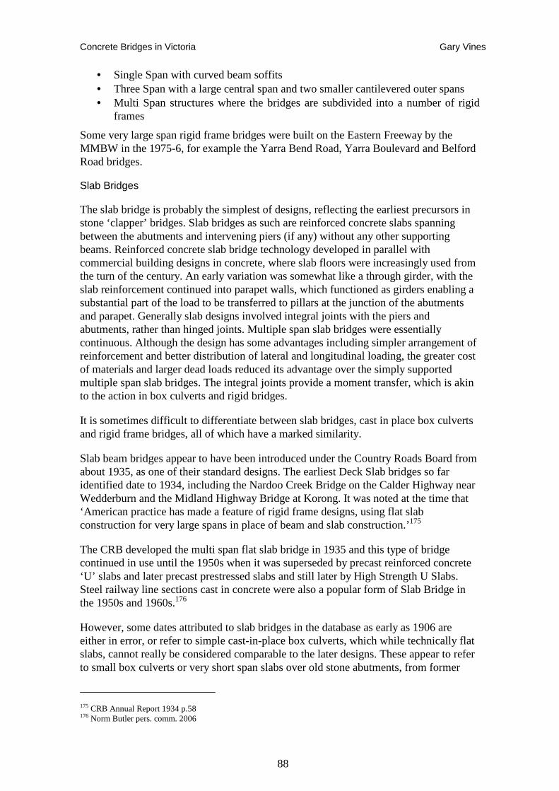
Concrete Bridges in Victoria Gary Vines
88
• Single Span with curved beam soffits • Three Span with a large central span and two smaller cantilevered outer spans • Multi Span structures where the bridges are subdivided into a number of rigid
frames
Some very large span rigid frame bridges were built on the Eastern Freeway by the MMBW in the 1975-6, for example the Yarra Bend Road, Yarra Boulevard and Belford Road bridges.
Slab Bridges
The slab bridge is probably the simplest of designs, reflecting the earliest precursors in stone ‘clapper’ bridges. Slab bridges as such are reinforced concrete slabs spanning between the abutments and intervening piers (if any) without any other supporting beams. Reinforced concrete slab bridge technology developed in parallel with commercial building designs in concrete, where slab floors were increasingly used from the turn of the century. An early variation was somewhat like a through girder, with the slab reinforcement continued into parapet walls, which functioned as girders enabling a substantial part of the load to be transferred to pillars at the junction of the abutments and parapet. Generally slab designs involved integral joints with the piers and abutments, rather than hinged joints. Multiple span slab bridges were essentially continuous. Although the design has some advantages including simpler arrangement of reinforcement and better distribution of lateral and longitudinal loading, the greater cost of materials and larger dead loads reduced its advantage over the simply supported multiple span slab bridges. The integral joints provide a moment transfer, which is akin to the action in box culverts and rigid bridges.
It is sometimes difficult to differentiate between slab bridges, cast in place box culverts and rigid frame bridges, all of which have a marked similarity.
Slab beam bridges appear to have been introduced under the Country Roads Board from about 1935, as one of their standard designs. The earliest Deck Slab bridges so far identified date to 1934, including the Nardoo Creek Bridge on the Calder Highway near Wedderburn and the Midland Highway Bridge at Korong. It was noted at the time that ‘American practice has made a feature of rigid frame designs, using flat slab construction for very large spans in place of beam and slab construction.’175
The CRB developed the multi span flat slab bridge in 1935 and this type of bridge continued in use until the 1950s when it was superseded by precast reinforced concrete ‘U’ slabs and later precast prestressed slabs and still later by High Strength U Slabs. Steel railway line sections cast in concrete were also a popular form of Slab Bridge in the 1950s and 1960s.176
However, some dates attributed to slab bridges in the database as early as 1906 are either in error, or refer to simple cast-in-place box culverts, which while technically flat slabs, cannot really be considered comparable to the later designs. These appear to refer to small box culverts or very short span slabs over old stone abutments, from former
175 CRB Annual Report 1934 p.58 176 Norm Butler pers. comm. 2006
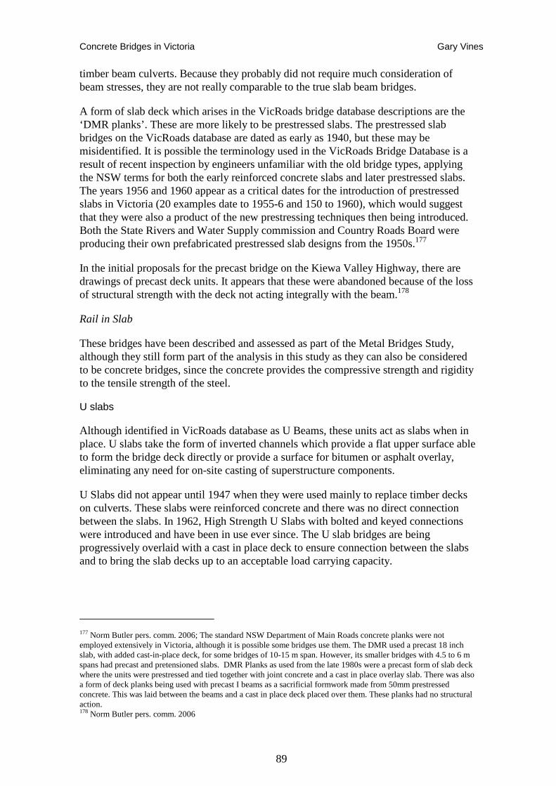
Concrete Bridges in Victoria Gary Vines
89
timber beam culverts. Because they probably did not require much consideration of beam stresses, they are not really comparable to the true slab beam bridges.
A form of slab deck which arises in the VicRoads bridge database descriptions are the ‘DMR planks’. These are more likely to be prestressed slabs. The prestressed slab bridges on the VicRoads database are dated as early as 1940, but these may be misidentified. It is possible the terminology used in the VicRoads Bridge Database is a result of recent inspection by engineers unfamiliar with the old bridge types, applying the NSW terms for both the early reinforced concrete slabs and later prestressed slabs. The years 1956 and 1960 appear as a critical dates for the introduction of prestressed slabs in Victoria (20 examples date to 1955-6 and 150 to 1960), which would suggest that they were also a product of the new prestressing techniques then being introduced. Both the State Rivers and Water Supply commission and Country Roads Board were producing their own prefabricated prestressed slab designs from the 1950s.177
In the initial proposals for the precast bridge on the Kiewa Valley Highway, there are drawings of precast deck units. It appears that these were abandoned because of the loss of structural strength with the deck not acting integrally with the beam.178
Rail in Slab
These bridges have been described and assessed as part of the Metal Bridges Study, although they still form part of the analysis in this study as they can also be considered to be concrete bridges, since the concrete provides the compressive strength and rigidity to the tensile strength of the steel.
U slabs
Although identified in VicRoads database as U Beams, these units act as slabs when in place. U slabs take the form of inverted channels which provide a flat upper surface able to form the bridge deck directly or provide a surface for bitumen or asphalt overlay, eliminating any need for on-site casting of superstructure components.
U Slabs did not appear until 1947 when they were used mainly to replace timber decks on culverts. These slabs were reinforced concrete and there was no direct connection between the slabs. In 1962, High Strength U Slabs with bolted and keyed connections were introduced and have been in use ever since. The U slab bridges are being progressively overlaid with a cast in place deck to ensure connection between the slabs and to bring the slab decks up to an acceptable load carrying capacity.
177 Norm Butler pers. comm. 2006; The standard NSW Department of Main Roads concrete planks were not employed extensively in Victoria, although it is possible some bridges use them. The DMR used a precast 18 inch slab, with added cast-in-place deck, for some bridges of 10-15 m span. However, its smaller bridges with 4.5 to 6 m spans had precast and pretensioned slabs. DMR Planks as used from the late 1980s were a precast form of slab deck where the units were prestressed and tied together with joint concrete and a cast in place overlay slab. There was also a form of deck planks being used with precast I beams as a sacrificial formwork made from 50mm prestressed concrete. This was laid between the beams and a cast in place deck placed over them. These planks had no structural action. 178 Norm Butler pers. comm. 2006
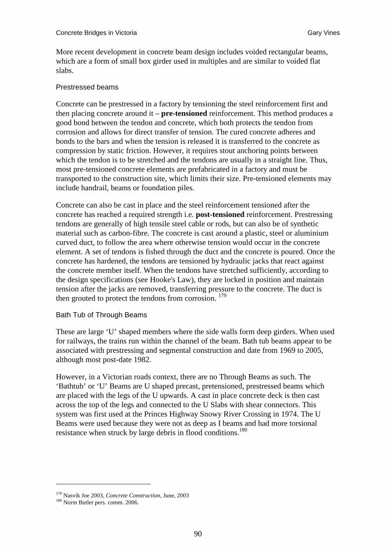
Concrete Bridges in Victoria Gary Vines
90
More recent development in concrete beam design includes voided rectangular beams, which are a form of small box girder used in multiples and are similar to voided flat slabs.
Prestressed beams
Concrete can be prestressed in a factory by tensioning the steel reinforcement first and then placing concrete around it – pre-tensioned reinforcement. This method produces a good bond between the tendon and concrete, which both protects the tendon from corrosion and allows for direct transfer of tension. The cured concrete adheres and bonds to the bars and when the tension is released it is transferred to the concrete as compression by static friction. However, it requires stout anchoring points between which the tendon is to be stretched and the tendons are usually in a straight line. Thus, most pre-tensioned concrete elements are prefabricated in a factory and must be transported to the construction site, which limits their size. Pre-tensioned elements may include handrail, beams or foundation piles.
Concrete can also be cast in place and the steel reinforcement tensioned after the concrete has reached a required strength i.e. post-tensioned reinforcement. Prestressing tendons are generally of high tensile steel cable or rods, but can also be of synthetic material such as carbon-fibre. The concrete is cast around a plastic, steel or aluminium curved duct, to follow the area where otherwise tension would occur in the concrete element. A set of tendons is fished through the duct and the concrete is poured. Once the concrete has hardened, the tendons are tensioned by hydraulic jacks that react against the concrete member itself. When the tendons have stretched sufficiently, according to the design specifications (see Hooke's Law), they are locked in position and maintain tension after the jacks are removed, transferring pressure to the concrete. The duct is then grouted to protect the tendons from corrosion. 179
Bath Tub of Through Beams
These are large ‘U’ shaped members where the side walls form deep girders. When used for railways, the trains run within the channel of the beam. Bath tub beams appear to be associated with prestressing and segmental construction and date from 1969 to 2005, although most post-date 1982.
However, in a Victorian roads context, there are no Through Beams as such. The ‘Bathtub’ or ‘U’ Beams are U shaped precast, pretensioned, prestressed beams which are placed with the legs of the U upwards. A cast in place concrete deck is then cast across the top of the legs and connected to the U Slabs with shear connectors. This system was first used at the Princes Highway Snowy River Crossing in 1974. The U Beams were used because they were not as deep as I beams and had more torsional resistance when struck by large debris in flood conditions.180
179 Nasvik Joe 2003, Concrete Construction, June, 2003 180 Norm Butler pers. comm. 2006.
Concrete Bridges in Victoria Gary Vines
91
Culverts
A modern version of rigid frame reinforced concrete span is the crown section culvert, which also acts as a rigid frame bridge. These were generally limited to a 3 metre span, but in recent years up to 6 metre spans have been available. Generally culverts are structures entirely beneath and having no part integral with the elevation of the roadway surface. Structures over 20 feet in span are usually termed bridges, although prefabrication techniques now enable box culverts greater than this size. Disregarding pipe culverts, concrete culverts can be divided into box and arch culverts. Box culverts have square or rectangular openings while arch culverts have semicircular or segmental arches. Nineteenth century culverts often employed masonry abutment walls with timber beams. When these were replaced in the twentieth century, concrete beams or slabs were often constructed on the old masonry. Because of the unclear distinction between large culverts and small bridges, they are sometimes included in this study, but generally only where other distinctive features make them stand out.
By at least the 1920s, reinforced concrete box culverts were being manufactured and used extensively on Victoria’s road system, particularly where softer ground conditions prevailed. A variety of sizes were employed, generally in short sections, either as a channel, with a precast slab top, or as inverts laid on a cast in place, or even a precast floor slab.
A small number of the bridges in the database are described as culverts (see explanation above under structural types). Generally, data supplied by VicRoads, and other sources of bridge data, have not included culverts. However, large masonry culverts are sometimes treated as bridges in other data such as heritage place registers and municipal heritage studies sources. There are probably many thousands of simple box and pipe culverts on the road and rail networks in Victoria. The present study has avoided consideration of these for the most part, although some larger structures that may technically come under the definition of culverts (greater than 20 foot spans wholly below the road level) may have still been included in the data, and so are part of the analysis.
There has always been a size limitation on precast culverts related to the capacity of lifting and transporting gear. Initially precast culverts were no more than to 1200 x 900mm, and generally crown section culverts up to 3000 x 3000mm, but in recent times larger versions up to 6000 x 3000mm have been manufactured. Larger cast in place culverts were commonplace in the 1920s to early 1950s.
Proportion of Structural Types
The breakdown of major concrete bridge types is shown in Table 1. This has summarised and grouped the various descriptive types used in data sets to simplify the assessment. There is not a single standard terminology or classification system employed for bridge structural forms. Variation is found between construction and management authorities, for example council engineers and VicRoads, and at different periods of time. Various engineering texts also employ a wide range of different terms. The major distinctions described above, however, have formed the basis of a classification system for the purposes of assessing cultural significance in this report, although there may be disagreement among engineers about the technical terms used.
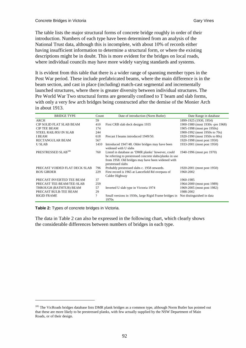
Concrete Bridges in Victoria Gary Vines
92
The table lists the major structural forms of concrete bridge roughly in order of their introduction. Numbers of each type have been determined from an analysis of the National Trust data, although this is incomplete, with about 10% of records either having insufficient information to determine a structural form, or where the existing descriptions might be in doubt. This is more evident for the bridges on local roads, where individual councils may have more widely varying standards and systems.
It is evident from this table that there is a wider range of spanning member types in the Post War period. These include prefabricated beams, where the main difference is in the beam section, and cast in place (including) match-cast segmental and incrementally launched structures, where there is greater diversity between individual structures. The Pre World War Two structural forms are generally confined to T beam and slab forms, with only a very few arch bridges being constructed after the demise of the Monier Arch in about 1913.
BRIDGE TYPE Count Date of introduction (Norm Butler) Date Range in database ARCH 59 1899-1925 (1930, 1954) CIP SOLID FLAT SLAB BEAM 410 First CRB slab deck designs 1935 1900-1980 (most 1930s -pre 1968) CIP TEE BEAM 174 1905-1998 (most pre 1950s) STEEL RAIL/RSJ IN SLAB 244 1900-1992 (most 1950s to 70s) I BEAM 618 Precast I beams introduced 1949/50. 1920-1990 (most 1950s to 80s) RECTANGULAR BEAM 567 1920-1998 (most post 1950) U SLAB 1410 Introduced 1947/48. Older bridges may have been
widened with U slabs 1933-2001 (most post 1950)
PRESTRESSED SLAB181 760 Listed in database as ‘DMR planks’ however, could be referring to prestressed concrete slabs/planks in use from 1958. Old bridges may have been widened with prestressed slabs
1940-1996 (most pre 1970)
PRECAST VOIDED FLAT DECK SLAB 796 Probably prestressed slabs c. 1958 onwards. 1920-2001 (most post 1950) BOX GIRDER 229 First record is 1965 at Lancefield Rd overpass of
Calder Highway 1960-2002
PRECAST INVERTED TEE BEAM 37 1960-1985 PRECAST TEE-BEAM/TEE-SLAB 259 1964-2000 (most post 1989) THROUGH (BATHTUB) BEAM 57 Inverted U slab type in Victoria 1974 1969-2005 (most post 1982) PRECAST BULB-TEE BEAM 29 1988-2002 RIGID FRAME ? Small versions in 1930s, large Rigid Frame bridges in
1970s Not distinguished in data
Table 2: Types of concrete bridges in Victoria.
The data in Table 2 can also be expressed in the following chart, which clearly shows the considerable differences between numbers of bridges in each type.
181 The VicRoads bridges database lists DMR plank bridges as a common type, although Norm Butler has pointed out that these are more likely to be prestressed planks, with few actually supplied by the NSW Department of Main Roads, or of their design.
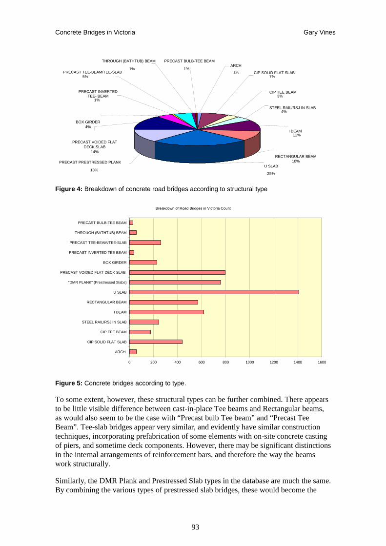
Concrete Bridges in Victoria Gary Vines
93
Figure 4: Breakdown of concrete road bridges according to structural type
Breakdown of Road Bridges in Victoria Count
0 200 400 600 800 1000 1200 1400 1600
ARCH
CIP SOLID FLAT SLAB
CIP TEE BEAM
STEEL RAIL/RSJ IN SLAB
I BEAM
RECTANGULAR BEAM
U SLAB
"DMR PLANK" (Prestressed Slabs)
PRECAST VOIDED FLAT DECK SLAB
BOX GIRDER
PRECAST INVERTED TEE BEAM
PRECAST TEE-BEAM/TEE-SLAB
THROUGH (BATHTUB) BEAM
PRECAST BULB-TEE BEAM
Figure 5: Concrete bridges according to type.
To some extent, however, these structural types can be further combined. There appears to be little visible difference between cast-in-place Tee beams and Rectangular beams, as would also seem to be the case with “Precast bulb Tee beam” and “Precast Tee Beam”. Tee-slab bridges appear very similar, and evidently have similar construction techniques, incorporating prefabrication of some elements with on-site concrete casting of piers, and sometime deck components. However, there may be significant distinctions in the internal arrangements of reinforcement bars, and therefore the way the beams work structurally.
Similarly, the DMR Plank and Prestressed Slab types in the database are much the same. By combining the various types of prestressed slab bridges, these would become the
STEEL RAIL/RSJ IN SLAB 4%
I BEAM 11%
PRECAST TEE-BEAM/TEE-SLAB 5%
1%
PRECAST INVERTED TEE- BEAM
1%
BOX GIRDER 4%
PRECAST PRESTRESSED PLANK 13% U SLAB
25%
RECTANGULAR BEAM 10%
PRECAST BULB-TEE BEAM 1%
1% CIP SOLID FLAT SLAB 7%
CIP TEE BEAM 3%
PRECAST VOIDED FLAT DECK SLAB
14%
ARCH THROUGH (BATHTUB) BEAM
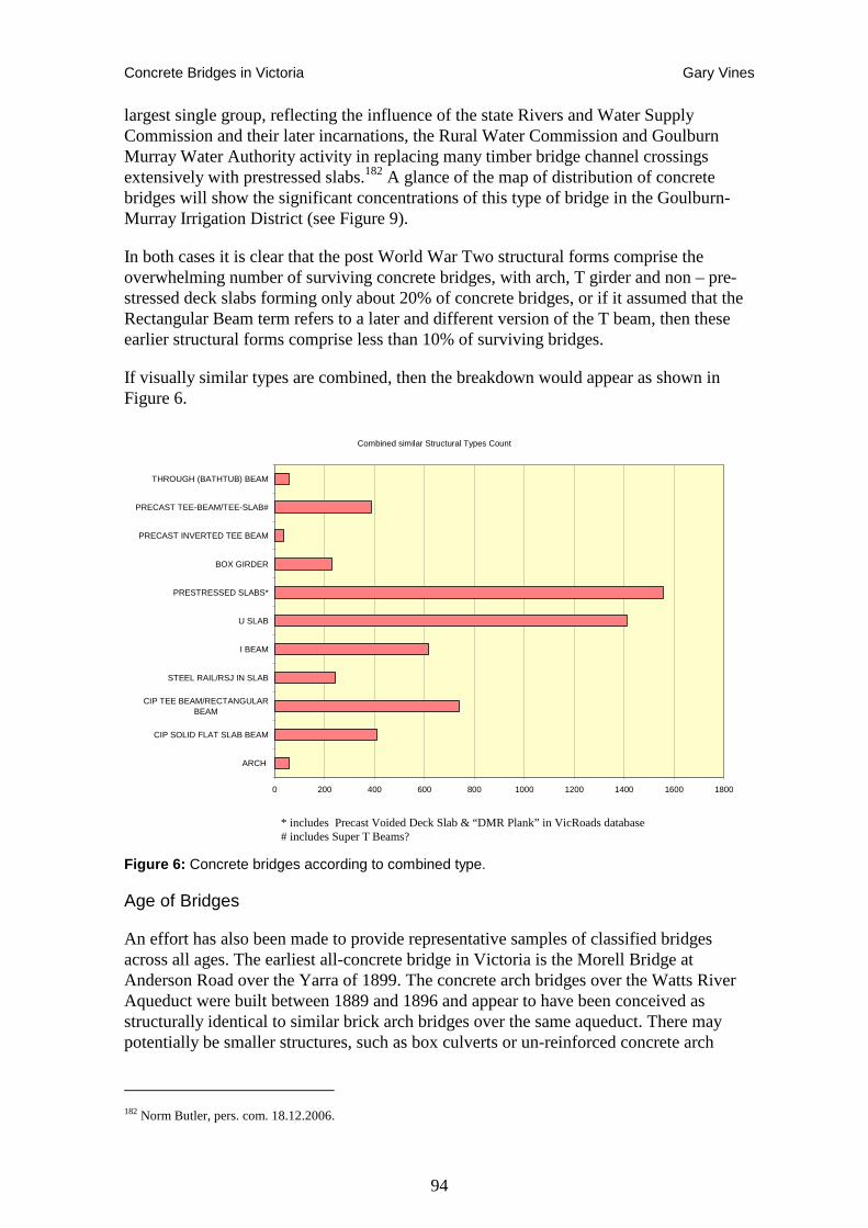
Concrete Bridges in Victoria Gary Vines
94
largest single group, reflecting the influence of the state Rivers and Water Supply Commission and their later incarnations, the Rural Water Commission and Goulburn Murray Water Authority activity in replacing many timber bridge channel crossings extensively with prestressed slabs.182 A glance of the map of distribution of concrete bridges will show the significant concentrations of this type of bridge in the Goulburn-Murray Irrigation District (see Figure 9).
In both cases it is clear that the post World War Two structural forms comprise the overwhelming number of surviving concrete bridges, with arch, T girder and non – pre-stressed deck slabs forming only about 20% of concrete bridges, or if it assumed that the Rectangular Beam term refers to a later and different version of the T beam, then these earlier structural forms comprise less than 10% of surviving bridges.
If visually similar types are combined, then the breakdown would appear as shown in Figure 6.
Combined similar Structural Types Count
0 200 400 600 800 1000 1200 1400 1600 1800
ARCH
CIP SOLID FLAT SLAB BEAM
CIP TEE BEAM/RECTANGULARBEAM
STEEL RAIL/RSJ IN SLAB
I BEAM
U SLAB
PRESTRESSED SLABS*
BOX GIRDER
PRECAST INVERTED TEE BEAM
PRECAST TEE-BEAM/TEE-SLAB#
THROUGH (BATHTUB) BEAM
* includes Precast Voided Deck Slab & “DMR Plank” in VicRoads database # includes Super T Beams?
Figure 6: Concrete bridges according to combined type.
Age of Bridges
An effort has also been made to provide representative samples of classified bridges across all ages. The earliest all-concrete bridge in Victoria is the Morell Bridge at Anderson Road over the Yarra of 1899. The concrete arch bridges over the Watts River Aqueduct were built between 1889 and 1896 and appear to have been conceived as structurally identical to similar brick arch bridges over the same aqueduct. There may potentially be smaller structures, such as box culverts or un-reinforced concrete arch
182 Norm Butler, pers. com. 18.12.2006.
Concrete Bridges in Victoria Gary Vines
95
culverts earlier than this, but considering the emphasis given in the contemporary literature to the pioneering nature of these early Monier patent bridges, it is unlikely any substantial earlier structures will be identified. If there are, they are most likely to be vernacular mass concrete, possibly incorporating other (timber or metal) spanning member.
There has been some chronological progression from one structural form to another among concrete bridges, commencing with Monier arches in 1899-1900, and rapidly moving first to T Girders by the end of the first decade of the 20th century, then Deck Slab types in the 1930s. The earliest confirmed surviving T beam bridge is the Monash designed St. Kilda Street Bridge of 1905. The earliest Deck Slab bridge is more difficult to determine because of the confusion in the data with slab culverts. However, one of the earliest that has so far been identified dates to 1934 and survives on the Calder Highway near Wedderburn.
It is a little more difficult to date the introduction of Deck Slab bridges, with the earliest so far identified being Taylors Outlet Crossing at Yarriambiack of 1905. However, this is a simple slab culvert over an irrigation channel, and similar reinforced concrete culverts may have been constructed on many such channels in the early twentieth century. The use of deck slab spans for larger bridges appears to have commenced in about 1920. Frankenburg’s Bridge in the Macedon Ranges Shire dates to 1921, and has a particularly thick, but short-span, concrete slab on bluestone abutments from a much earlier bridge. The true multi span Slab Beam bridges, however, only occur from the 1930s onwards, and disappear in favour of precast slab and beam bridges in the 1970s.
In the post-World War Two period, the rapid development of a wide range of structural types saw many new precast and prestressed systems introduced with I Beam, Rectangular Beam, U Slab, Prestressed Slab, Precast Voided Flat Deck Slab, Box Girder, and Precast Inverted Tee Beam, all appearing within a decade or so of each other in the 1950s.
Table 2 also gives a general idea of the rate of introduction of various concrete bridge types. It should be noted, however, that about 20% of records in the National Trust bridges database, do not have data on the construction date. For the purposes of this report, some conjecture has been made based on the structure, appearance and other factors, but the assessment has avoided such circular technique, by taking a sample of known age bridges and showing relative ages. The more complex analysis of determining numbers of each structural type by date has not been undertaken. For this analysis, bridges are included where the main spanning components include significant use of concrete, and where they were erected in the particular decade, i.e. where an older bridge has been reconstructed using concrete elements, the date is taken to be that of the reconstruction.
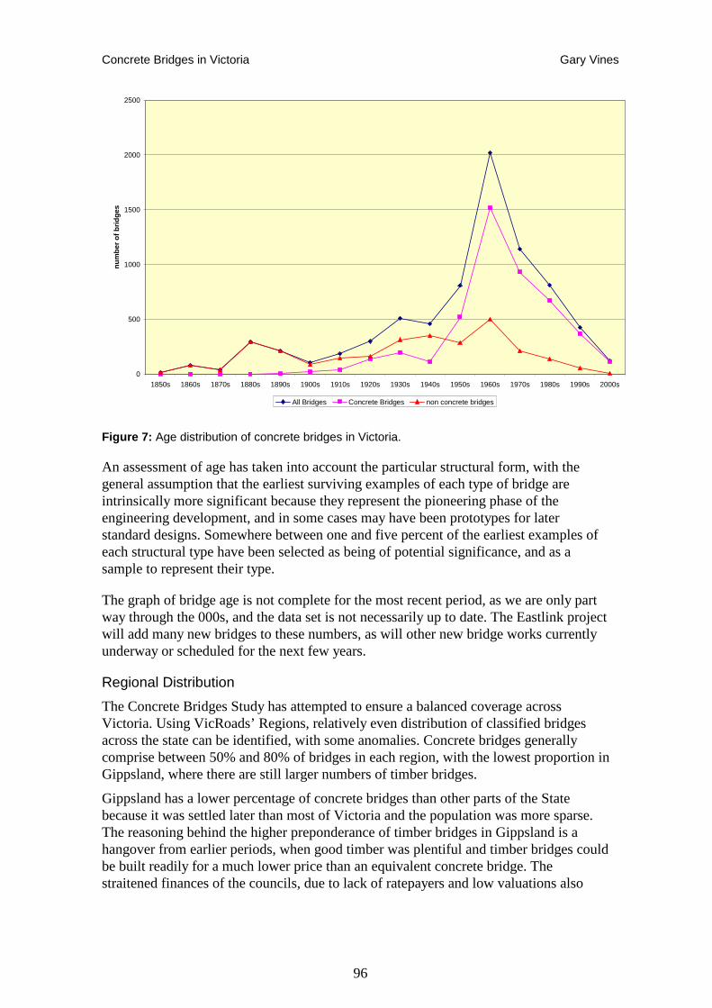
Concrete Bridges in Victoria Gary Vines
96
0
500
1000
1500
2000
2500
1850s 1860s 1870s 1880s 1890s 1900s 1910s 1920s 1930s 1940s 1950s 1960s 1970s 1980s 1990s 2000s
num
ber
of b
ridge
s
All Bridges Concrete Bridges non concrete bridges
Figure 7: Age distribution of concrete bridges in Victoria.
An assessment of age has taken into account the particular structural form, with the general assumption that the earliest surviving examples of each type of bridge are intrinsically more significant because they represent the pioneering phase of the engineering development, and in some cases may have been prototypes for later standard designs. Somewhere between one and five percent of the earliest examples of each structural type have been selected as being of potential significance, and as a sample to represent their type.
The graph of bridge age is not complete for the most recent period, as we are only part way through the 000s, and the data set is not necessarily up to date. The Eastlink project will add many new bridges to these numbers, as will other new bridge works currently underway or scheduled for the next few years.
Regional Distribution
The Concrete Bridges Study has attempted to ensure a balanced coverage across Victoria. Using VicRoads’ Regions, relatively even distribution of classified bridges across the state can be identified, with some anomalies. Concrete bridges generally comprise between 50% and 80% of bridges in each region, with the lowest proportion in Gippsland, where there are still larger numbers of timber bridges.
Gippsland has a lower percentage of concrete bridges than other parts of the State because it was settled later than most of Victoria and the population was more sparse. The reasoning behind the higher preponderance of timber bridges in Gippsland is a hangover from earlier periods, when good timber was plentiful and timber bridges could be built readily for a much lower price than an equivalent concrete bridge. The straitened finances of the councils, due to lack of ratepayers and low valuations also
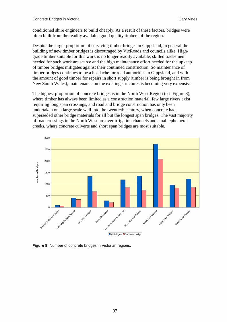
Concrete Bridges in Victoria Gary Vines
97
conditioned shire engineers to build cheaply. As a result of these factors, bridges were often built from the readily available good quality timbers of the region.
Despite the larger proportion of surviving timber bridges in Gippsland, in general the building of new timber bridges is discouraged by VicRoads and councils alike. High-grade timber suitable for this work is no longer readily available, skilled tradesmen needed for such work are scarce and the high maintenance effort needed for the upkeep of timber bridges mitigates against their continued construction. So maintenance of timber bridges continues to be a headache for road authorities in Gippsland, and with the amount of good timber for repairs in short supply (timber is being brought in from New South Wales), maintenance on the existing structures is becoming very expensive.
The highest proportion of concrete bridges is in the North West Region (see Figure 8), where timber has always been limited as a construction material, few large rivers exist requiring long span crossings, and road and bridge construction has only been undertaken on a large scale well into the twentieth century, when concrete had superseded other bridge materials for all but the longest span bridges. The vast majority of road crossings in the North West are over irrigation channels and small ephemeral creeks, where concrete culverts and short span bridges are most suitable.
0
500
1000
1500
2000
2500
3000
Barwon
& O
tway
Reg
ion
Geelong
/Ball
arat
Reg
ion
Gippsla
nd R
egion
Inner
Melb
ourn
e
Midd
le & O
uter
Melb
ourn
e
North
Centra
l Vict
oria
North
East V
ictor
ia
North
Wes
t Vict
oria
South
Wes
t Vict
oria
num
ber
of b
ridge
s
All bridges Concrete bridge
Figure 8: Number of concrete bridges in Victorian regions.

Concrete Bridges in Victoria Gary Vines
98
Figure 9: Map of Victoria showing distribution of concrete bridges.
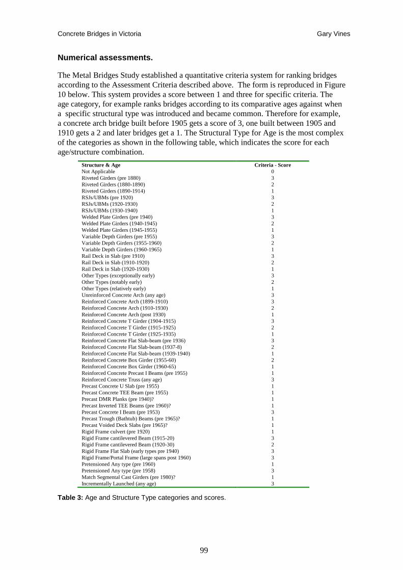
Concrete Bridges in Victoria Gary Vines
99
Numerical assessments.
The Metal Bridges Study established a quantitative criteria system for ranking bridges according to the Assessment Criteria described above. The form is reproduced in Figure 10 below. This system provides a score between 1 and three for specific criteria. The age category, for example ranks bridges according to its comparative ages against when a specific structural type was introduced and became common. Therefore for example, a concrete arch bridge built before 1905 gets a score of 3, one built between 1905 and 1910 gets a 2 and later bridges get a 1. The Structural Type for Age is the most complex of the categories as shown in the following table, which indicates the score for each age/structure combination.
Structure & Age Criteria - Score Not Applicable 0 Riveted Girders (pre 1880) 3 Riveted Girders (1880-1890) 2 Riveted Girders (1890-1914) 1 RSJs/UBMs (pre 1920) 3 RSJs/UBMs (1920-1930) 2 RSJs/UBMs (1930-1940) 1 Welded Plate Girders (pre 1940) 3 Welded Plate Girders (1940-1945) 2 Welded Plate Girders (1945-1955) 1 Variable Depth Girders (pre 1955) 3 Variable Depth Girders (1955-1960) 2 Variable Depth Girders (1960-1965) 1 Rail Deck in Slab (pre 1910) 3 Rail Deck in Slab (1910-1920) 2 Rail Deck in Slab (1920-1930) 1 Other Types (exceptionally early) 3 Other Types (notably early) 2 Other Types (relatively early) 1 Unreinforced Concrete Arch (any age) 3 Reinforced Concrete Arch (1899-1910) 3 Reinforced Concrete Arch (1910-1930) 2 Reinforced Concrete Arch (post 1930) 1 Reinforced Concrete T Girder (1904-1915) 3 Reinforced Concrete T Girder (1915-1925) 2 Reinforced Concrete T Girder (1925-1935) 1 Reinforced Concrete Flat Slab-beam (pre 1936) 3 Reinforced Concrete Flat Slab-beam (1937-8) 2 Reinforced Concrete Flat Slab-beam (1939-1940) 1 Reinforced Concrete Box Girder (1955-60) 2 Reinforced Concrete Box Girder (1960-65) 1 Reinforced Concrete Precast I Beams (pre 1955) 1 Reinforced Concrete Truss (any age) 3 Precast Concrete U Slab (pre 1955) 1 Precast Concrete TEE Beam (pre 1955) 1 Precast DMR Planks (pre 1940)? 1 Precast Inverted TEE Beams (pre 1960)? 1 Precast Concrete I Beam (pre 1953) 3 Precast Trough (Bathtub) Beams (pre 1965)? 1 Precast Voided Deck Slabs (pre 1965)? 1 Rigid Frame culvert (pre 1920) 1 Rigid Frame cantilevered Beam (1915-20) 3 Rigid Frame cantilevered Beam (1920-30) 2 Rigid Frame Flat Slab (early types pre 1940) 3 Rigid Frame/Portal Frame (large spans post 1960) 3 Pretensioned Any type (pre 1960) 1 Pretensioned Any type (pre 1958) 3 Match Segmental Cast Girders (pre 1980)? 1 Incrementally Launched (any age) 3
Table 3: Age and Structure Type categories and scores.
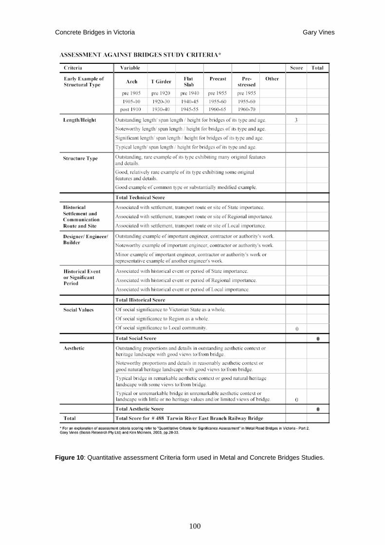
Concrete Bridges in Victoria Gary Vines
100
Figure 10 : Quantitative assessment Criteria form used in Metal and Concrete Bridges Studies.
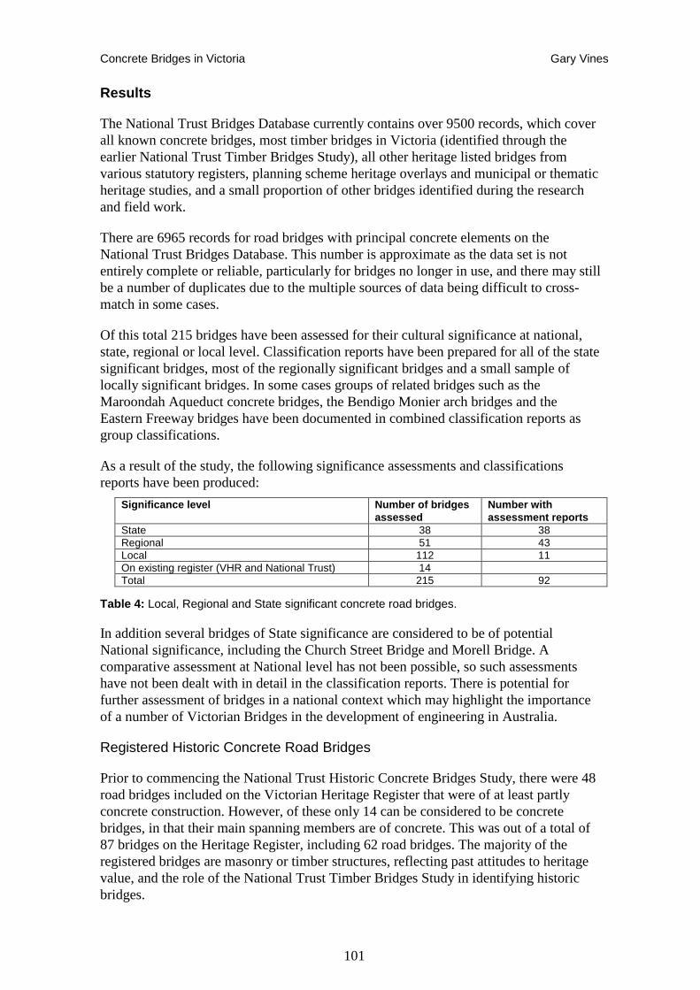
Concrete Bridges in Victoria Gary Vines
101
Results
The National Trust Bridges Database currently contains over 9500 records, which cover all known concrete bridges, most timber bridges in Victoria (identified through the earlier National Trust Timber Bridges Study), all other heritage listed bridges from various statutory registers, planning scheme heritage overlays and municipal or thematic heritage studies, and a small proportion of other bridges identified during the research and field work.
There are 6965 records for road bridges with principal concrete elements on the National Trust Bridges Database. This number is approximate as the data set is not entirely complete or reliable, particularly for bridges no longer in use, and there may still be a number of duplicates due to the multiple sources of data being difficult to cross-match in some cases.
Of this total 215 bridges have been assessed for their cultural significance at national, state, regional or local level. Classification reports have been prepared for all of the state significant bridges, most of the regionally significant bridges and a small sample of locally significant bridges. In some cases groups of related bridges such as the Maroondah Aqueduct concrete bridges, the Bendigo Monier arch bridges and the Eastern Freeway bridges have been documented in combined classification reports as group classifications.
As a result of the study, the following significance assessments and classifications reports have been produced:
Significance level Number of bridges assessed
Number with assessment reports
State 38 38 Regional 51 43 Local 112 11 On existing register (VHR and National Trust) 14 Total 215 92
Table 4: Local, Regional and State significant concrete road bridges.
In addition several bridges of State significance are considered to be of potential National significance, including the Church Street Bridge and Morell Bridge. A comparative assessment at National level has not been possible, so such assessments have not been dealt with in detail in the classification reports. There is potential for further assessment of bridges in a national context which may highlight the importance of a number of Victorian Bridges in the development of engineering in Australia.
Registered Historic Concrete Road Bridges
Prior to commencing the National Trust Historic Concrete Bridges Study, there were 48 road bridges included on the Victorian Heritage Register that were of at least partly concrete construction. However, of these only 14 can be considered to be concrete bridges, in that their main spanning members are of concrete. This was out of a total of 87 bridges on the Heritage Register, including 62 road bridges. The majority of the registered bridges are masonry or timber structures, reflecting past attitudes to heritage value, and the role of the National Trust Timber Bridges Study in identifying historic bridges.
Concrete Bridges in Victoria Gary Vines
102
The registered concrete bridges also include bridges that were registered primarily for their importance as stone masonry timber bridges but with some concrete components, such as Murray Road Bridge in Coburg. In effect, only five bridges have been placed on the Victorian Heritage Register for their significance as historic concrete bridges in their own right.
Table 5 lists the concrete (or part-concrete) bridges previously included in the Victorian Heritage Register, National Trust Register and Register of the National Estate. Previous assessments of bridges are quite variable in the level of detail, inclusion of technical or engineering data and the amount of comparative analysis undertaken. The major source of registrations has come out of the Monash Bridges Project and National Trust classifications. These include the Morell Bridge, Kings Bridge, Fyansford Bridge, Benalla Bridge, Janevale Bridge and St. Kilda Street Bridge. The Thompson and Cole Street Bridges were registered as part of the Williamstown Railway Line, while Murray Road Bridge is registered primarily for its bluestone structure. The Railway Dam Road Bridge was registered as part of the Elphinstone precinct of the Bendigo Railway line, but is a concrete bridge only because the original wrought iron girders were replaced in about 2002. Church Street Bridge is clearly a significant structure identified in its own right, but it is unclear why the Llandeilo Bridge was included, as this appears to be a typical example of a fairly common type of bridge.
The Concrete Bridges Study has identified a further 38 concrete bridges of State significance in addition to the 14 already included on the Victorian Heritage Register. . It is proposed that these bridges should be classified by the National Trust at State Level and are nominated for inclusion on the Victorian Heritage Register.
Bridges of State significance assessed and recorded in National Trust classification reports are listed below in Table 6.
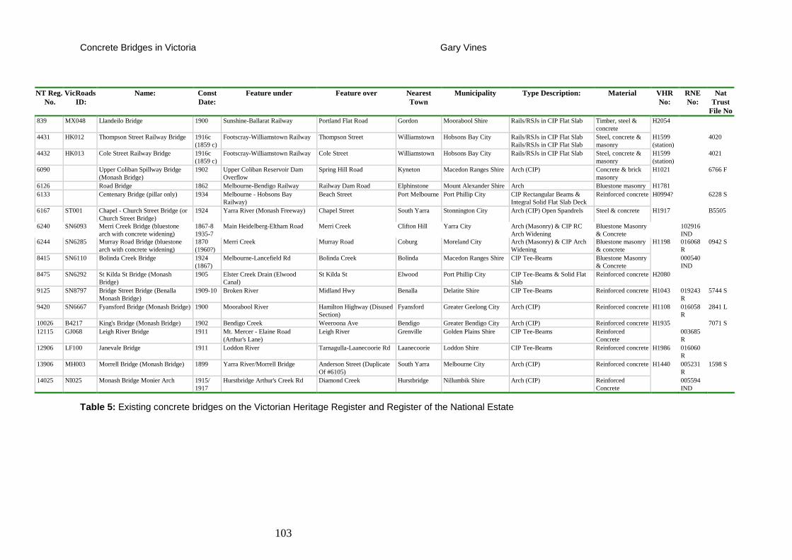
Concrete Bridges in Victoria Gary Vines
103
NT Reg. No.
VicRoads ID:
Name: Const Date:
Feature under Feature over Nearest Town
Municipality Type Description: Material VHR No:
RNE No:
Nat Trust
File No 839 MX048 Llandeilo Bridge 1900 Sunshine-Ballarat Railway Portland Flat Road Gordon Moorabool Shire Rails/RSJs in CIP Flat Slab Timber, steel &
concrete H2054
4431 HK012 Thompson Street Railway Bridge 1916c (1859 c)
Footscray-Williamstown Railway Thompson Street Williamstown Hobsons Bay City Rails/RSJs in CIP Flat Slab Rails/RSJs in CIP Flat Slab
Steel, concrete & masonry
H1599 (station)
4020
4432 HK013 Cole Street Railway Bridge 1916c (1859 c)
Footscray-Williamstown Railway Cole Street Williamstown Hobsons Bay City Rails/RSJs in CIP Flat Slab Steel, concrete & masonry
H1599 (station)
4021
6090 Upper Coliban Spillway Bridge (Monash Bridge)
1902 Upper Coliban Reservoir Dam Overflow
Spring Hill Road Kyneton Macedon Ranges Shire Arch (CIP) Concrete & brick masonry
H1021 6766 F
6126 Road Bridge 1862 Melbourne-Bendigo Railway Railway Dam Road Elphinstone Mount Alexander Shire Arch Bluestone masonry H1781 6133 Centenary Bridge (pillar only) 1934 Melbourne - Hobsons Bay
Railway) Beach Street Port Melbourne Port Phillip City CIP Rectangular Beams &
Integral Solid Flat Slab Deck Reinforced concrete H0994? 6228 S
6167 ST001 Chapel - Church Street Bridge (or Church Street Bridge)
1924 Yarra River (Monash Freeway) Chapel Street South Yarra Stonnington City Arch (CIP) Open Spandrels Steel & concrete H1917 B5505
6240 SN6093 Merri Creek Bridge (bluestone arch with concrete widening)
1867-8 1935-7
Main Heidelberg-Eltham Road Merri Creek Clifton Hill Yarra City Arch (Masonry) & CIP RC Arch Widening
Bluestone Masonry & Concrete
102916 IND
6244 SN6285 Murray Road Bridge (bluestone arch with concrete widening)
1870 (1960?)
Merri Creek Murray Road Coburg Moreland City Arch (Masonry) & CIP Arch Widening
Bluestone masonry & concrete
H1198 016068 R
0942 S
8415 SN6110 Bolinda Creek Bridge 1924 (1867)
Melbourne-Lancefield Rd Bolinda Creek Bolinda Macedon Ranges Shire CIP Tee-Beams Bluestone Masonry & Concrete
000540 IND
8475 SN6292 St Kilda St Bridge (Monash Bridge)
1905 Elster Creek Drain (Elwood Canal)
St Kilda St Elwood Port Phillip City CIP Tee-Beams & Solid Flat Slab
Reinforced concrete H2080
9125 SN8797 Bridge Street Bridge (Benalla Monash Bridge)
1909-10 Broken River Midland Hwy Benalla Delatite Shire CIP Tee-Beams Reinforced concrete H1043 019243 R
5744 S
9420 SN6667 Fyansford Bridge (Monash Bridge) 1900 Moorabool River Hamilton Highway (Disused Section)
Fyansford Greater Geelong City Arch (CIP) Reinforced concrete H1108 016058 R
2841 L
10026 B4217 King's Bridge (Monash Bridge) 1902 Bendigo Creek Weeroona Ave Bendigo Greater Bendigo City Arch (CIP) Reinforced concrete H1935 7071 S 12115 GJ068 Leigh River Bridge 1911 Mt. Mercer - Elaine Road
(Arthur's Lane) Leigh River Grenville Golden Plains Shire CIP Tee-Beams Reinforced
Concrete 003685
R
12906 LF100 Janevale Bridge 1911 Loddon River Tarnagulla-Laanecoorie Rd Laanecoorie Loddon Shire CIP Tee-Beams Reinforced concrete H1986 016060 R
13906 MH003 Morrell Bridge (Monash Bridge) 1899 Yarra River/Morrell Bridge Anderson Street (Duplicate Of #6105)
South Yarra Melbourne City Arch (CIP) Reinforced concrete H1440 005231 R
1598 S
14025 NI025 Monash Bridge Monier Arch 1915/ 1917
Hurstbridge Arthur's Creek Rd Diamond Creek Hurstbridge Nillumbik Shire Arch (CIP) Reinforced Concrete
005594 IND
Table 5: Existing concrete bridges on the Victorian Heritage Register and Register of the National Estate
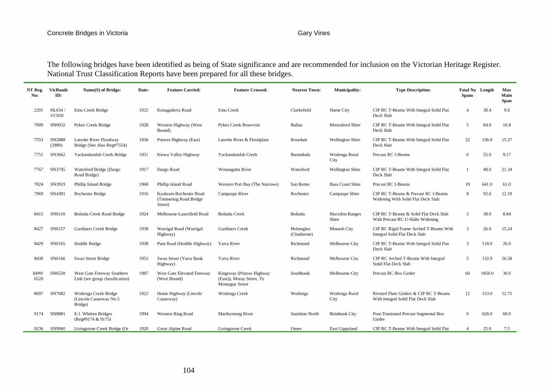
Concrete Bridges in Victoria Gary Vines
104
The following bridges have been identified as being of State significance and are recommended for inclusion on the Victorian Heritage Register. National Trust Classification Reports have been prepared for all these bridges.
NT Reg. No:
VicRoads ID:
Name(S) of Bridge: Date: Feature Carried: Feature Crossed: Nearest Town: Municipality: Type Description: Total No Spans
Length Max Main Span
2291 HL034 / VC020
Emu Creek Bridge 1922 Konagaderra Road Emu Creek Clarkefield Hume City CIP RC T-Beams With Integral Solid Flat Deck Slab
4 38.4 9.6
7009 SN0032 Pykes Creek Bridge 1928 Western Highway (West Bound)
Pykes Creek Reservoir Ballan Moorabool Shire CIP RC T-Beams With Integral Solid Flat Deck Slab
5 84.0 16.8
7553 SN2888 (2889)
Latrobe River Floodway Bridge (See Also Reg#7554)
1936 Princes Highway (East) Latrobe River & Floodplain Rosedale Wellington Shire CIP RC T-Beams With Integral Solid Flat Deck Slab
22 336.0 15.27
7751 SN3662 Yackandandah Creek Bridge 1951 Kiewa Valley Highway Yackandandah Creek Baranduda Wodonga Rural City
Precast RC I-Beams 6 55.0 9.17
7767 SN3745 Waterford Bridge (Dargo Road Bridge)
1917 Dargo Road Wonangatta River Waterford Wellington Shire CIP RC T-Beams With Integral Solid Flat Deck Slab
1 48.0 21.34
7824 SN3919 Phillip Island Bridge 1968 Phillip Island Road Western Port Bay (The Narrows) San Remo Bass Coast Shire Precast RC I-Beams 19 641.0 61.0
7969 SN4381 Rochester Bridge 1916 Kyabram-Rochester Road (Timmering Road Bridge Street)
Campaspe River Rochester Campaspe Shire CIP RC T-Beams & Precast RC I-Beams Widening With Solid Flat Deck Slab
8 92.6 12.19
8415 SN6110 Bolinda Creek Road Bridge 1924 Melbourne-Lancefield Road Bolinda Creek Bolinda Macedon Ranges Shire
CIP RC T-Beams & Solid Flat Deck Slab With Precast RC U-Slabs Widening
3 38.0 8.84
8427 SN6157 Gardiners Creek Bridge 1938 Warrigal Road (Warrigal Highway)
Gardiners Creek Holmsglen (Chadstone)
Monash City CIP RC Rigid Frame Arched T-Beams With Integral Solid Flat Deck Slab
3 26.0 15.24
8429 SN6165 Hoddle Bridge 1938 Punt Road (Hoddle Highway) Yarra River Richmond Melbourne City CIP RC T-Beams With Integral Solid Flat Deck Slab
3 118.0 26.0
8430 SN6166 Swan Street Bridge 1952 Swan Street (Yarra Bank Highway)
Yarra River Richmond Melbourne City CIP RC Arched T-Beams With Integral Solid Flat Deck Slab
5 132.9 26.58
8499/ 6520
SN6520 West Gate Freeway Southern Link (see group classification)
1987 West Gate Elevated Freeway (West Bound)
Kingsway (Princes Highway (East)), Moray Street, To Montague Street
Southbank Melbourne City Precast RC Box Girder 60 1850.0 30.0
8697 SN7082 Wodonga Creek Bridge (Lincoln Causeway No.5 Bridge)
1922 Hume Highway (Lincoln Causeway)
Wodonga Creek Wodonga Wodonga Rural City
Riveted Plate Girders & CIP RC T-Beams With Integral Solid Flat Deck Slab
12 153.0 12.75
9174 SN8881 E.J. Whitten Bridges (Reg#9174 & 9175)
1994 Western Ring Road Maribyrnong River Sunshine North Brimbank City Post-Tensioned Precast Segmental Box Girder
9 620.0 60.0
9236 SN9060 Livingstone Creek Bridge (Or 1920 Great Alpine Road Livingstone Creek Omeo East Gippsland CIP RC T-Beams With Integral Solid Flat 4 25.0 7.5
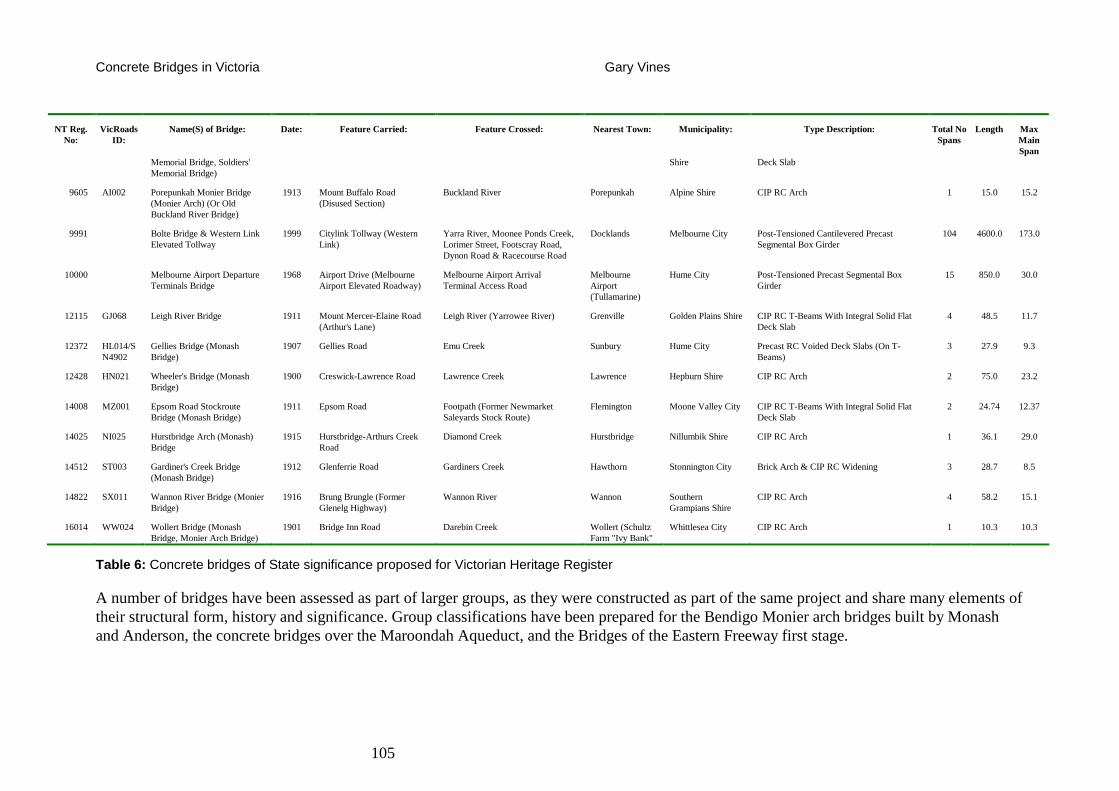
Concrete Bridges in Victoria Gary Vines
105
NT Reg. No:
VicRoads ID:
Name(S) of Bridge: Date: Feature Carried: Feature Crossed: Nearest Town: Municipality: Type Description: Total No Spans
Length Max Main Span
Memorial Bridge, Soldiers' Memorial Bridge)
Shire Deck Slab
9605 AI002 Porepunkah Monier Bridge (Monier Arch) (Or Old Buckland River Bridge)
1913 Mount Buffalo Road (Disused Section)
Buckland River Porepunkah Alpine Shire CIP RC Arch 1 15.0 15.2
9991 Bolte Bridge & Western Link Elevated Tollway
1999 Citylink Tollway (Western Link)
Yarra River, Moonee Ponds Creek, Lorimer Street, Footscray Road, Dynon Road & Racecourse Road
Docklands Melbourne City Post-Tensioned Cantilevered Precast Segmental Box Girder
104 4600.0 173.0
10000 Melbourne Airport Departure Terminals Bridge
1968 Airport Drive (Melbourne Airport Elevated Roadway)
Melbourne Airport Arrival Terminal Access Road
Melbourne Airport (Tullamarine)
Hume City Post-Tensioned Precast Segmental Box Girder
15 850.0 30.0
12115 GJ068 Leigh River Bridge 1911 Mount Mercer-Elaine Road (Arthur's Lane)
Leigh River (Yarrowee River) Grenville Golden Plains Shire CIP RC T-Beams With Integral Solid Flat Deck Slab
4 48.5 11.7
12372 HL014/SN4902
Gellies Bridge (Monash Bridge)
1907 Gellies Road Emu Creek Sunbury Hume City Precast RC Voided Deck Slabs (On T-Beams)
3 27.9 9.3
12428 HN021 Wheeler's Bridge (Monash Bridge)
1900 Creswick-Lawrence Road Lawrence Creek Lawrence Hepburn Shire CIP RC Arch 2 75.0 23.2
14008 MZ001 Epsom Road Stockroute Bridge (Monash Bridge)
1911 Epsom Road Footpath (Former Newmarket Saleyards Stock Route)
Flemington Moone Valley City CIP RC T-Beams With Integral Solid Flat Deck Slab
2 24.74 12.37
14025 NI025 Hurstbridge Arch (Monash) Bridge
1915 Hurstbridge-Arthurs Creek Road
Diamond Creek Hurstbridge Nillumbik Shire CIP RC Arch 1 36.1 29.0
14512 ST003 Gardiner's Creek Bridge (Monash Bridge)
1912 Glenferrie Road Gardiners Creek Hawthorn Stonnington City Brick Arch & CIP RC Widening 3 28.7 8.5
14822 SX011 Wannon River Bridge (Monier Bridge)
1916 Brung Brungle (Former Glenelg Highway)
Wannon River Wannon Southern Grampians Shire
CIP RC Arch 4 58.2 15.1
16014 WW024 Wollert Bridge (Monash Bridge, Monier Arch Bridge)
1901 Bridge Inn Road Darebin Creek Wollert (Schultz Farm "Ivy Bank"
Whittlesea City CIP RC Arch 1 10.3 10.3
Table 6: Concrete bridges of State significance proposed for Victorian Heritage Register
A number of bridges have been assessed as part of larger groups, as they were constructed as part of the same project and share many elements of their structural form, history and significance. Group classifications have been prepared for the Bendigo Monier arch bridges built by Monash and Anderson, the concrete bridges over the Maroondah Aqueduct, and the Bridges of the Eastern Freeway first stage.
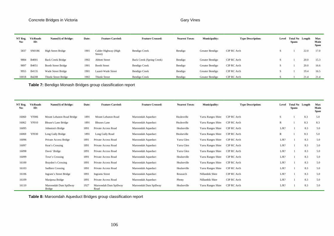
Concrete Bridges in Victoria Gary Vines
106
NT Reg. No:
VicRoads ID:
Name(S) of Bridge: Date: Feature Carried: Feature Crossed: Nearest Town: Municipality: Type Description: Level Total No Spans
Length Max Main Span
5837 SN0186 High Street Bridge 1901 Calder Highway (High Street)
Bendigo Creek Bendigo Greater Bendigo CIP RC Arch S 1 22.0 17.0
9884 B4001 Back Creek Bridge 1902 Abbott Street Back Creek (Spring Creek) Bendigo Greater Bendigo CIP RC Arch S 1 20.0 15.3
9897 B4051 Booth Street Bridge 1901 Booth Street Bendigo Creek Bendigo Greater Bendigo CIP RC Arch S 1 20.0 16.6
9955 B4135 Wade Street Bridge 1901 Laurel-Wade Street Bendigo Creek Bendigo Greater Bendigo CIP RC Arch S 1 19.4 16.5
10018 B4208 Thistle Street Bridge 1902 Thistle Street Bendigo Creek Bendigo Greater Bendigo CIP RC Arch S 1 21.4 21.4
Table 7: Bendigo Monash Bridges group classification report
NT Reg. No:
VicRoads ID:
Name(S) of Bridge: Date: Feature Carried: Feature Crossed: Nearest Town: Municipality: Type Description: Level Total No Spans
Length Max Main Span
16060 YF006 Mount Lebanon Road Bridge 1891 Mount Lebanon Road Maroondah Aqueduct Healesville Yarra Ranges Shire CIP RC Arch S 1 8.3 5.0
16062 YF010 Blease's Lane Bridge 1891 Bleases Lane Maroondah Aqueduct Healesville Yarra Ranges Shire CIP RC Arch R 1 8.3 8.3
16095 Johnston's Bridge 1891 Private Access Road Maroondah Aqueduct Healseville Yarra Ranges Shire CIP RC Arch L/R? 1 8.3 5.0
16069 YF030 Long Gully Bridge 1891 Long Gully Road Maroondah Aqueduct Healseville Yarra Ranges Shire CIP RC Arch R 1 8.3 5.0
16096 Private Access Bridge 1891 Private Access Road Maroondah Aqueduct Yarra Glen Yarra Ranges Shire CIP RC Arch L/R? 1 8.3 5.0
16097 Keat’s Crossing 1891 Private Access Road Maroondah Aqueduct Yarra Glen Yarra Ranges Shire CIP RC Arch L/R? 1 8.3 5.0
16098 Davis’ Bridge 1891 Private Access Road Maroondah Aqueduct Yarra Glen Yarra Ranges Shire CIP RC Arch L/R? 1 8.3 5.0
16099 Towt’s Crossing 1891 Private Access Road Maroondah Aqueduct Healseville Yarra Ranges Shire CIP RC Arch L/R? 1 8.3 5.0
16100 Brayden’s Crossing 1891 Private Access Road Maroondah Aqueduct Healseville Yarra Ranges Shire CIP RC Arch L/R? 1 8.3 5.0
16103 Sadliers Crossing 1891 Private Access Road Maroondah Aqueduct Healseville Yarra Ranges Shire CIP RC Arch L/R? 1 8.3 5.0
16106 Ingram’s Street Bridge 1891 Ingrams Street Maroondah Aqueduct Research Nillumbik Shire CIP RC Arch L/R? 1 8.3 5.0
16109 Mariposa Bridge 1891 Private Access Road Maroondah Aqueduct Plenty Nillumbik Shire CIP RC Arch L/R? 1 8.3 5.0
16110 Maroondah Dam Spillway Bridge
1927 Maroondah Dam Spillway Road
Maroondah Dam Spillway Healseville Yarra Ranges Shire CIP RC Arch L/R? 1 8.3 5.0
Table 8: Maroondah Aqueduct Bridges group classification report
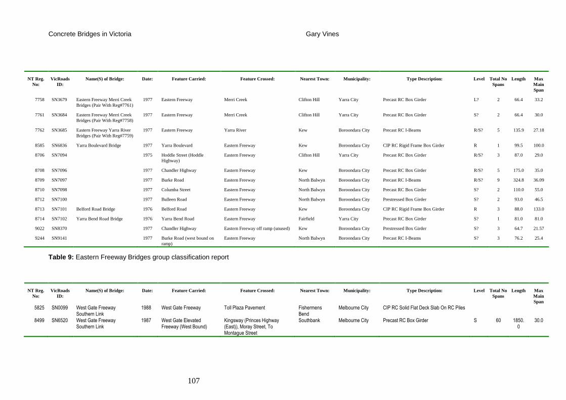
Concrete Bridges in Victoria Gary Vines
107
NT Reg. No:
VicRoads ID:
Name(S) of Bridge: Date: Feature Carried: Feature Crossed: Nearest Town: Municipality: Type Description: Level Total No Spans
Length Max Main Span
7758 SN3679 Eastern Freeway Merri Creek Bridges (Pair With Reg#7761)
1977 Eastern Freeway Merri Creek Clifton Hill Yarra City Precast RC Box Girder L? 2 66.4 33.2
7761 SN3684 Eastern Freeway Merri Creek Bridges (Pair With Reg#7758)
1977 Eastern Freeway Merri Creek Clifton Hill Yarra City Precast RC Box Girder S? 2 66.4 30.0
7762 SN3685 Eastern Freeway Yarra River Bridges (Pair With Reg#7759)
1977 Eastern Freeway Yarra River Kew Boroondara City Precast RC I-Beams R/S? 5 135.9 27.18
8585 SN6836 Yarra Boulevard Bridge 1977 Yarra Boulevard Eastern Freeway Kew Boroondara City CIP RC Rigid Frame Box Girder R 1 99.5 100.0
8706 SN7094 1975 Hoddle Street (Hoddle Highway)
Eastern Freeway Clifton Hill Yarra City Precast RC Box Girder R/S? 3 87.0 29.0
8708 SN7096 1977 Chandler Highway Eastern Freeway Kew Boroondara City Precast RC Box Girder R/S? 5 175.0 35.0
8709 SN7097 1977 Burke Road Eastern Freeway North Balwyn Boroondara City Precast RC I-Beams R/S? 9 324.8 36.09
8710 SN7098 1977 Columba Street Eastern Freeway North Balwyn Boroondara City Precast RC Box Girder S? 2 110.0 55.0
8712 SN7100 1977 Bulleen Road Eastern Freeway North Balwyn Boroondara City Prestressed Box Girder S? 2 93.0 46.5
8713 SN7101 Belford Road Bridge 1976 Belford Road Eastern Freeway Kew Boroondara City CIP RC Rigid Frame Box Girder R 3 88.0 133.0
8714 SN7102 Yarra Bend Road Bridge 1976 Yarra Bend Road Eastern Freeway Fairfield Yarra City Precast RC Box Girder S? 1 81.0 81.0
9022 SN8370 1977 Chandler Highway Eastern Freeway off ramp (unused) Kew Boroondara City Prestressed Box Girder S? 3 64.7 21.57
9244 SN9141 1977 Burke Road (west bound on ramp)
Eastern Freeway North Balwyn Boroondara City Precast RC I-Beams S? 3 76.2 25.4
Table 9: Eastern Freeway Bridges group classification report
NT Reg. No:
VicRoads ID:
Name(S) of Bridge: Date: Feature Carried: Feature Crossed: Nearest Town: Municipality: Type Description: Level Total No Spans
Length Max Main Span
5825 SN0099 West Gate Freeway Southern Link
1988 West Gate Freeway Toll Plaza Pavement Fishermens Bend
Melbourne City CIP RC Solid Flat Deck Slab On RC Piles 8499 SN6520 West Gate Freeway
Southern Link 1987 West Gate Elevated
Freeway (West Bound) Kingsway (Princes Highway (East)), Moray Street, To Montague Street
Southbank Melbourne City Precast RC Box Girder S 60 1850.0
30.0
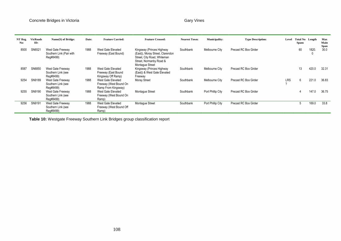
Concrete Bridges in Victoria Gary Vines
108
NT Reg. No:
VicRoads ID:
Name(S) of Bridge: Date: Feature Carried: Feature Crossed: Nearest Town: Municipality: Type Description: Level Total No Spans
Length Max Main Span
8500 SN6521 West Gate Freeway Southern Link (Pair with Reg#8499)
1988 West Gate Elevated Freeway (East Bound)
Kingsway (Princes Highway (East)), Moray Street, Clarendon Street, City Road, Whiteman Street, Normanby Road & Montague Street
Southbank Melbourne City Precast RC Box Girder 60 1820.0
30.0
8587 SN6850 West Gate Freeway Southern Link (see Reg#8499)
1988 West Gate Elevated Freeway (East Bound Kingsway Off Ramp)
Kingsway (Princes Highway (East)) & West Gate Elevated Freeway
Southbank Melbourne City Precast RC Box Girder 13 420.0 32.31
9254 SN9189 West Gate Freeway Southern Link (see Reg#8499)
1988 West Gate Elevated Freeway (West Bound On Ramp From Kingsway)
Moray Street Southbank Melbourne City Precast RC Box Girder LRS?
6 221.0 36.83
9255 SN9190 West Gate Freeway Southern Link (see Reg#8499)
1988 West Gate Elevated Freeway (West Bound On Ramp)
Montague Street Southbank Port Phillip City Precast RC Box Girder 4 147.0 36.75
9256 SN9191 West Gate Freeway Southern Link (see Reg#8499)
1988 West Gate Elevated Freeway (West Bound Off Ramp)
Montague Street Southbank Port Phillip City Precast RC Box Girder 5 169.0 33.8
Table 10: Westgate Freeway Southern Link Bridges group classification report
Concrete Bridges in Victoria Gary Vines
109
Regionally and Locally Significant Bridges
Prior to commencement of the study there were a small number of concrete bridges that had been classified by the National Trust at local or regional level, while there was a larger body of records on locally significant bridges, obtained from local and regional heritage studies, and/or which had already been included in Planning Scheme Heritage Overlays. There are about 73 bridges on the National Trust Bridges Database with possible concrete components which are identified in Municipal Planning Scheme Heritage Overlays. However, of these only 13 can be considered to be concrete bridges in terms of the principal spans being of concrete. Most of these bridges are included in the Heritage Overlays because they are also on the Victorian Heritage Register. Local Heritage Studies appear to identify masonry and brick arch bridges consistently, but not concrete structures, even where historical documentation such as local histories are available, which can readily establish the bridges’ heritage value.
There are nine concrete bridges that have previously been listed on the Register of the National Estate. These are identified in Table 5 above.
This study has identified a further 167 concrete road bridges in Victoria that are of regional or local significance. Assessment reports have been prepared for 43 State significant bridges and 11 Locally significant bridges.
The remaining bridges, considered to be of potential local significance, require further investigation at the local level to determine the appropriate form of heritage protection. It is recommended that these bridges are considered as part of future Heritage Studies and Heritage Reviews by municipal councils.
The following tables summarise concrete road bridges in Victoria that have been assessed as being of Regional and Local cultural significance.
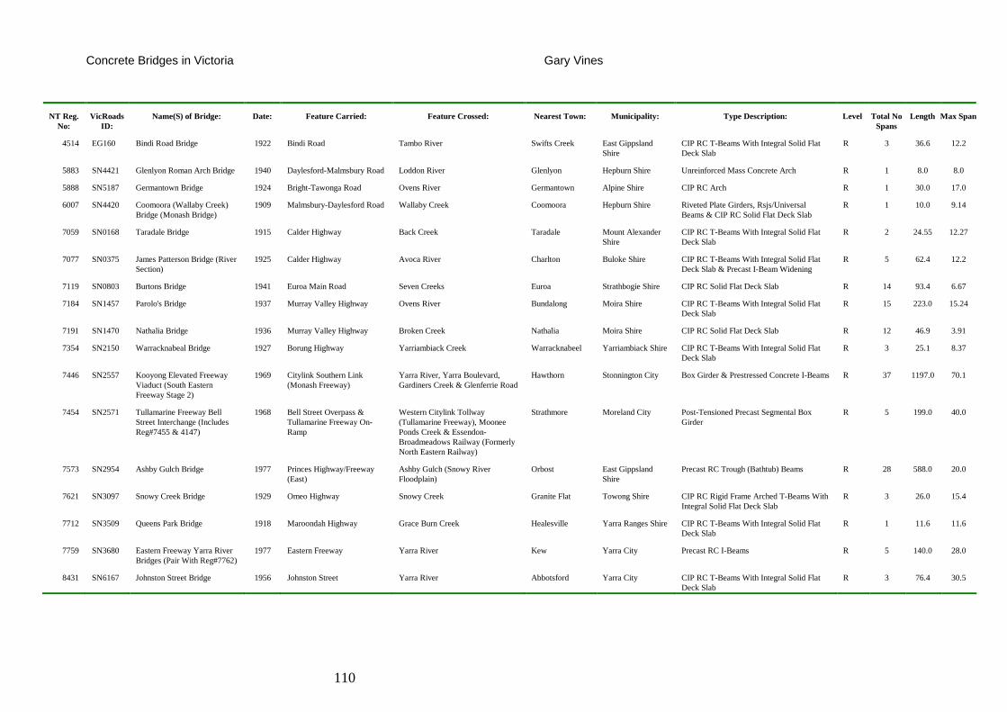
Concrete Bridges in Victoria Gary Vines
110
NT Reg. No:
VicRoads ID:
Name(S) of Bridge: Date: Feature Carried: Feature Crossed: Nearest Town: Municipality: Type Description: Level Total No Spans
Length Max Span
4514 EG160 Bindi Road Bridge 1922 Bindi Road Tambo River Swifts Creek East Gippsland Shire
CIP RC T-Beams With Integral Solid Flat Deck Slab
R 3 36.6 12.2
5883 SN4421 Glenlyon Roman Arch Bridge 1940 Daylesford-Malmsbury Road Loddon River Glenlyon Hepburn Shire Unreinforced Mass Concrete Arch R 1 8.0 8.0
5888 SN5187 Germantown Bridge 1924 Bright-Tawonga Road Ovens River Germantown Alpine Shire CIP RC Arch R 1 30.0 17.0
6007 SN4420 Coomoora (Wallaby Creek) Bridge (Monash Bridge)
1909 Malmsbury-Daylesford Road Wallaby Creek Coomoora Hepburn Shire Riveted Plate Girders, Rsjs/Universal Beams & CIP RC Solid Flat Deck Slab
R 1 10.0 9.14
7059 SN0168 Taradale Bridge 1915 Calder Highway Back Creek Taradale Mount Alexander Shire
CIP RC T-Beams With Integral Solid Flat Deck Slab
R 2 24.55 12.27
7077 SN0375 James Patterson Bridge (River Section)
1925 Calder Highway Avoca River Charlton Buloke Shire CIP RC T-Beams With Integral Solid Flat Deck Slab & Precast I-Beam Widening
R 5 62.4 12.2
7119 SN0803 Burtons Bridge 1941 Euroa Main Road Seven Creeks Euroa Strathbogie Shire CIP RC Solid Flat Deck Slab R 14 93.4 6.67
7184 SN1457 Parolo's Bridge 1937 Murray Valley Highway Ovens River Bundalong Moira Shire CIP RC T-Beams With Integral Solid Flat Deck Slab
R 15 223.0 15.24
7191 SN1470 Nathalia Bridge 1936 Murray Valley Highway Broken Creek Nathalia Moira Shire CIP RC Solid Flat Deck Slab R 12 46.9 3.91
7354 SN2150 Warracknabeal Bridge 1927 Borung Highway Yarriambiack Creek Warracknabeel Yarriambiack Shire CIP RC T-Beams With Integral Solid Flat Deck Slab
R 3 25.1 8.37
7446 SN2557 Kooyong Elevated Freeway Viaduct (South Eastern Freeway Stage 2)
1969 Citylink Southern Link (Monash Freeway)
Yarra River, Yarra Boulevard, Gardiners Creek & Glenferrie Road
Hawthorn Stonnington City Box Girder & Prestressed Concrete I-Beams R 37 1197.0 70.1
7454 SN2571 Tullamarine Freeway Bell Street Interchange (Includes Reg#7455 & 4147)
1968 Bell Street Overpass & Tullamarine Freeway On-Ramp
Western Citylink Tollway (Tullamarine Freeway), Moonee Ponds Creek & Essendon-Broadmeadows Railway (Formerly North Eastern Railway)
Strathmore Moreland City Post-Tensioned Precast Segmental Box Girder
R 5 199.0 40.0
7573 SN2954 Ashby Gulch Bridge 1977 Princes Highway/Freeway (East)
Ashby Gulch (Snowy River Floodplain)
Orbost East Gippsland Shire
Precast RC Trough (Bathtub) Beams R 28 588.0 20.0
7621 SN3097 Snowy Creek Bridge 1929 Omeo Highway Snowy Creek Granite Flat Towong Shire CIP RC Rigid Frame Arched T-Beams With Integral Solid Flat Deck Slab
R 3 26.0 15.4
7712 SN3509 Queens Park Bridge 1918 Maroondah Highway Grace Burn Creek Healesville Yarra Ranges Shire CIP RC T-Beams With Integral Solid Flat Deck Slab
R 1 11.6 11.6
7759 SN3680 Eastern Freeway Yarra River Bridges (Pair With Reg#7762)
1977 Eastern Freeway Yarra River Kew Yarra City Precast RC I-Beams R 5 140.0 28.0
8431 SN6167 Johnston Street Bridge 1956 Johnston Street Yarra River Abbotsford Yarra City CIP RC T-Beams With Integral Solid Flat Deck Slab
R 3 76.4 30.5
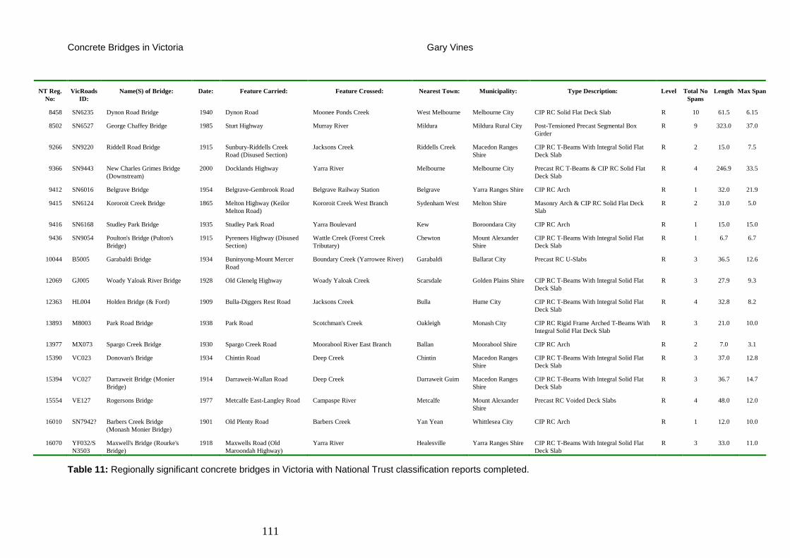
Concrete Bridges in Victoria Gary Vines
111
NT Reg. No:
VicRoads ID:
Name(S) of Bridge: Date: Feature Carried: Feature Crossed: Nearest Town: Municipality: Type Description: Level Total No Spans
Length Max Span
8458 SN6235 Dynon Road Bridge 1940 Dynon Road Moonee Ponds Creek West Melbourne Melbourne City CIP RC Solid Flat Deck Slab R 10 61.5 6.15
8502 SN6527 George Chaffey Bridge 1985 Sturt Highway Murray River Mildura Mildura Rural City Post-Tensioned Precast Segmental Box Girder
R 9 323.0 37.0
9266 SN9220 Riddell Road Bridge 1915 Sunbury-Riddells Creek Road (Disused Section)
Jacksons Creek Riddells Creek Macedon Ranges Shire
CIP RC T-Beams With Integral Solid Flat Deck Slab
R 2 15.0 7.5
9366 SN9443 New Charles Grimes Bridge (Downstream)
2000 Docklands Highway Yarra River Melbourne Melbourne City Precast RC T-Beams & CIP RC Solid Flat Deck Slab
R 4 246.9 33.5
9412 SN6016 Belgrave Bridge 1954 Belgrave-Gembrook Road Belgrave Railway Station Belgrave Yarra Ranges Shire CIP RC Arch R 1 32.0 21.9
9415 SN6124 Kororoit Creek Bridge 1865 Melton Highway (Keilor Melton Road)
Kororoit Creek West Branch Sydenham West Melton Shire Masonry Arch & CIP RC Solid Flat Deck Slab
R 2 31.0 5.0
9416 SN6168 Studley Park Bridge 1935 Studley Park Road Yarra Boulevard Kew Boroondara City CIP RC Arch R 1 15.0 15.0
9436 SN9054 Poulton's Bridge (Pulton's Bridge)
1915 Pyrenees Highway (Disused Section)
Wattle Creek (Forest Creek Tributary)
Chewton Mount Alexander Shire
CIP RC T-Beams With Integral Solid Flat Deck Slab
R 1 6.7 6.7
10044 B5005 Garabaldi Bridge 1934 Buninyong-Mount Mercer Road
Boundary Creek (Yarrowee River) Garabaldi Ballarat City Precast RC U-Slabs R 3 36.5 12.6
12069 GJ005 Woady Yaloak River Bridge 1928 Old Glenelg Highway Woady Yaloak Creek Scarsdale Golden Plains Shire CIP RC T-Beams With Integral Solid Flat Deck Slab
R 3 27.9 9.3
12363 HL004 Holden Bridge (& Ford) 1909 Bulla-Diggers Rest Road Jacksons Creek Bulla Hume City CIP RC T-Beams With Integral Solid Flat Deck Slab
R 4 32.8 8.2
13893 M8003 Park Road Bridge 1938 Park Road Scotchman's Creek Oakleigh Monash City CIP RC Rigid Frame Arched T-Beams With Integral Solid Flat Deck Slab
R 3 21.0 10.0
13977 MX073 Spargo Creek Bridge 1930 Spargo Creek Road Moorabool River East Branch Ballan Moorabool Shire CIP RC Arch R 2 7.0 3.1
15390 VC023 Donovan's Bridge 1934 Chintin Road Deep Creek Chintin Macedon Ranges Shire
CIP RC T-Beams With Integral Solid Flat Deck Slab
R 3 37.0 12.8
15394 VC027 Darraweit Bridge (Monier Bridge)
1914 Darraweit-Wallan Road Deep Creek Darraweit Guim Macedon Ranges Shire
CIP RC T-Beams With Integral Solid Flat Deck Slab
R 3 36.7 14.7
15554 VE127 Rogersons Bridge 1977 Metcalfe East-Langley Road Campaspe River Metcalfe Mount Alexander Shire
Precast RC Voided Deck Slabs R 4 48.0 12.0
16010 SN7942? Barbers Creek Bridge (Monash Monier Bridge)
1901 Old Plenty Road Barbers Creek Yan Yean Whittlesea City CIP RC Arch R 1 12.0 10.0
16070 YF032/SN3503
Maxwell's Bridge (Rourke's Bridge)
1918 Maxwells Road (Old Maroondah Highway)
Yarra River Healesville Yarra Ranges Shire CIP RC T-Beams With Integral Solid Flat Deck Slab
R 3 33.0 11.0
Table 11: Regionally significant concrete bridges in Victoria with National Trust classification reports completed.
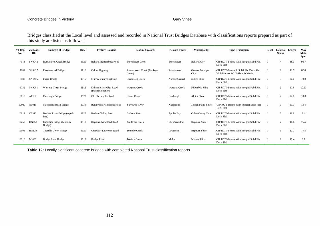
Concrete Bridges in Victoria Gary Vines
112
Bridges classified at the Local level and assessed and recorded in National Trust Bridges Database with classifications reports prepared as part of this study are listed as follows:
NT Reg. No:
VicRoads ID:
Name(S) of Bridge: Date: Feature Carried: Feature Crossed: Nearest Town: Municipality: Type Description: Level Total No Spans
Length Max Main Span
7013 SN0042 Burrumbeet Creek Bridge 1929 Ballarat-Burrumbeet Road Burrumbeet Creek Burrumbeet Ballarat City CIP RC T-Beams With Integral Solid Flat Deck Slab
L 4 38.3 9.57
7082 SN0427 Ravenswood Bridge 1916 Calder Highway Ravenswood Creek (Buckeye Creek)
Ravenswood Greater Bendigo City
CIP RC T-Beams & Solid Flat Deck Slab With Precast RC U-Slabs Widening
L 2 12.7 6.35
7183 SN1455 Fuges Bridge 1915 Murray Valley Highway Black Dog Creek Norong Central Indigo Shire CIP RC T-Beams With Integral Solid Flat Deck Slab
L 3 30.0 10.0
9238 SN9081 Watsons Creek Bridge 1918 Eltham-Yarra Glen Road (Disused Section)
Watsons Creek Watsons Creek Nillumbik Shire CIP RC T-Beams With Integral Solid Flat Deck Slab
L 3 32.8 10.93
9613 AI021 Freeburgh Bridge 1920 Old Harrietville Road Ovens River Freeburgh Alpine Shire CIP RC T-Beams With Integral Solid Flat Deck Slab
L 2 22.0 10.0
10049 B5010 Napoleons Road Bridge 1930 Buninyong-Napoleons Road Yarrowee River Napoleons Golden Plains Shire CIP RC T-Beams With Integral Solid Flat Deck Slab
L 3 35.3 12.4
10812 CS313 Barham River Bridge (Apollo Bay)
1925 Barham Valley Road Barham River Apollo Bay Colac-Otway Shire CIP RC T-Beams With Integral Solid Flat Deck Slab
L 2 18.8 9.4
12459 HN058 Excelsior Bridge (Monash Bridge)
1910 Hepburn-Newstead Road Jim Crow Creek Shepherds Flat Hepburn Shire CIP RC T-Beams With Integral Solid Flat Deck Slab
L 2 16.6 7.45
12508 HN124 Tourello Creek Bridge 1920 Creswick-Lawrence Road Tourello Creek Lawrence Hepburn Shire CIP RC T-Beams With Integral Solid Flat Deck Slab
L 1 12.2 17.5
13910 MI003 Bridge Road Bridge 1913 Bridge Road Toolern Creek Melton Melton Shire CIP RC T-Beams With Integral Solid Flat Deck Slab
L 2 19.4 9.7
Table 12: Locally significant concrete bridges with completed National Trust classification reports
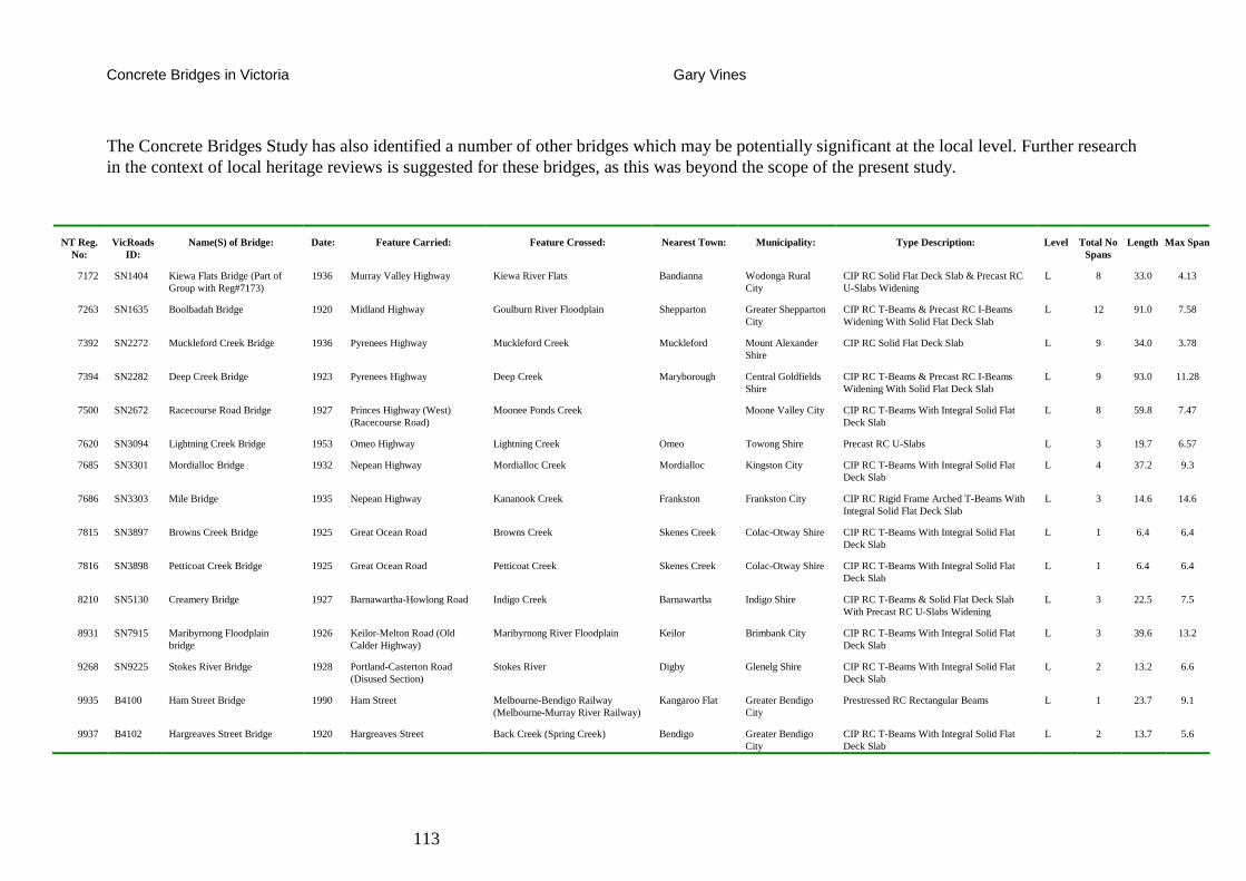
Concrete Bridges in Victoria Gary Vines
113
The Concrete Bridges Study has also identified a number of other bridges which may be potentially significant at the local level. Further research in the context of local heritage reviews is suggested for these bridges, as this was beyond the scope of the present study.
NT Reg. No:
VicRoads ID:
Name(S) of Bridge: Date: Feature Carried: Feature Crossed: Nearest Town: Municipality: Type Description: Level Total No Spans
Length Max Span
7172 SN1404 Kiewa Flats Bridge (Part of Group with Reg#7173)
1936 Murray Valley Highway Kiewa River Flats Bandianna Wodonga Rural City
CIP RC Solid Flat Deck Slab & Precast RC U-Slabs Widening
L 8 33.0 4.13
7263 SN1635 Boolbadah Bridge 1920 Midland Highway Goulburn River Floodplain Shepparton Greater Shepparton City
CIP RC T-Beams & Precast RC I-Beams Widening With Solid Flat Deck Slab
L 12 91.0 7.58
7392 SN2272 Muckleford Creek Bridge 1936 Pyrenees Highway Muckleford Creek Muckleford Mount Alexander Shire
CIP RC Solid Flat Deck Slab L 9 34.0 3.78
7394 SN2282 Deep Creek Bridge 1923 Pyrenees Highway Deep Creek Maryborough Central Goldfields Shire
CIP RC T-Beams & Precast RC I-Beams Widening With Solid Flat Deck Slab
L 9 93.0 11.28
7500 SN2672 Racecourse Road Bridge 1927 Princes Highway (West) (Racecourse Road)
Moonee Ponds Creek Moone Valley City CIP RC T-Beams With Integral Solid Flat Deck Slab
L 8 59.8 7.47
7620 SN3094 Lightning Creek Bridge 1953 Omeo Highway Lightning Creek Omeo Towong Shire Precast RC U-Slabs L 3 19.7 6.57
7685 SN3301 Mordialloc Bridge 1932 Nepean Highway Mordialloc Creek Mordialloc Kingston City CIP RC T-Beams With Integral Solid Flat Deck Slab
L 4 37.2 9.3
7686 SN3303 Mile Bridge 1935 Nepean Highway Kananook Creek Frankston Frankston City CIP RC Rigid Frame Arched T-Beams With Integral Solid Flat Deck Slab
L 3 14.6 14.6
7815 SN3897 Browns Creek Bridge 1925 Great Ocean Road Browns Creek Skenes Creek Colac-Otway Shire CIP RC T-Beams With Integral Solid Flat Deck Slab
L 1 6.4 6.4
7816 SN3898 Petticoat Creek Bridge 1925 Great Ocean Road Petticoat Creek Skenes Creek Colac-Otway Shire CIP RC T-Beams With Integral Solid Flat Deck Slab
L 1 6.4 6.4
8210 SN5130 Creamery Bridge 1927 Barnawartha-Howlong Road Indigo Creek Barnawartha Indigo Shire CIP RC T-Beams & Solid Flat Deck Slab With Precast RC U-Slabs Widening
L 3 22.5 7.5
8931 SN7915 Maribyrnong Floodplain bridge
1926 Keilor-Melton Road (Old Calder Highway)
Maribyrnong River Floodplain Keilor Brimbank City CIP RC T-Beams With Integral Solid Flat Deck Slab
L 3 39.6 13.2
9268 SN9225 Stokes River Bridge 1928 Portland-Casterton Road (Disused Section)
Stokes River Digby Glenelg Shire CIP RC T-Beams With Integral Solid Flat Deck Slab
L 2 13.2 6.6
9935 B4100 Ham Street Bridge 1990 Ham Street Melbourne-Bendigo Railway (Melbourne-Murray River Railway)
Kangaroo Flat Greater Bendigo City
Prestressed RC Rectangular Beams L 1 23.7 9.1
9937 B4102 Hargreaves Street Bridge 1920 Hargreaves Street Back Creek (Spring Creek) Bendigo Greater Bendigo City
CIP RC T-Beams With Integral Solid Flat Deck Slab
L 2 13.7 5.6
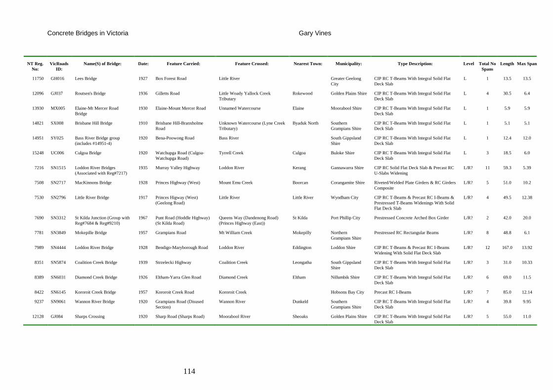
Concrete Bridges in Victoria Gary Vines
114
NT Reg. No:
VicRoads ID:
Name(S) of Bridge: Date: Feature Carried: Feature Crossed: Nearest Town: Municipality: Type Description: Level Total No Spans
Length Max Span
11750 GH016 Lees Bridge 1927 Box Forest Road Little River Greater Geelong City
CIP RC T-Beams With Integral Solid Flat Deck Slab
L 1 13.5 13.5
12096 GJ037 Routsen's Bridge 1936 Gilletts Road Little Woady Yallock Creek Tributary
Rokewood Golden Plains Shire CIP RC T-Beams With Integral Solid Flat Deck Slab
L 4 30.5 6.4
13930 MX005 Elaine-Mt Mercer Road Bridge
1930 Elaine-Mount Mercer Road Unnamed Watercourse Elaine Moorabool Shire CIP RC T-Beams With Integral Solid Flat Deck Slab
L 1 5.9 5.9
14821 SX008 Brisbane Hill Bridge 1910 Brisbane Hill-Branxholme Road
Unknown Watercourse (Lyne Creek Tributary)
Byaduk North Southern Grampians Shire
CIP RC T-Beams With Integral Solid Flat Deck Slab
L 1 5.1 5.1
14951 SY025 Bass River Bridge group (includes #14951-4)
1920 Bena-Poowong Road Bass River South Gippsland Shire
CIP RC T-Beams With Integral Solid Flat Deck Slab
L 1 12.4 12.0
15248 UC006 Culgoa Bridge 1920 Watchupga Road (Culgoa-Watchupga Road)
Tyrrell Creek Culgoa Buloke Shire CIP RC T-Beams With Integral Solid Flat Deck Slab
L 3 18.5 6.0
7216 SN1515 Loddon River Bridges (Associated with Reg#7217)
1935 Murray Valley Highway Loddon River Kerang Gannawarra Shire CIP RC Solid Flat Deck Slab & Precast RC U-Slabs Widening
L/R? 11 59.3 5.39
7508 SN2717 MacKinnons Bridge 1928 Princes Highway (West) Mount Emu Creek Boorcan Corangamite Shire Riveted/Welded Plate Girders & RC Girders Composite
L/R? 5 51.0 10.2
7530 SN2796 Little River Bridge 1917 Princes Higway (West) (Geelong Road)
Little River Little River Wyndham City CIP RC T-Beams & Precast RC I-Beams & Prestressed T-Beams Widenings With Solid Flat Deck Slab
L/R? 4 49.5 12.38
7690 SN3312 St Kilda Junction (Group with Reg#7684 & Reg#9210)
1967 Punt Road (Hoddle Highway) (St Kilda Road)
Queens Way (Dandenong Road) (Princes Highway (East))
St Kilda Port Phillip City Prestressed Concrete Arched Box Girder L/R? 2 42.0 20.0
7781 SN3849 Mokepille Bridge 1957 Grampians Road Mt William Creek Mokepilly Northern Grampians Shire
Prestressed RC Rectangular Beams L/R? 8 48.8 6.1
7989 SN4444 Loddon River Bridge 1928 Bendigo-Maryborough Road Loddon River Eddington Loddon Shire CIP RC T-Beams & Precast RC I-Beams Widening With Solid Flat Deck Slab
L/R? 12 167.0 13.92
8351 SN5874 Coalition Creek Bridge 1939 Strzelecki Highway Coalition Creek Leongatha South Gippsland Shire
CIP RC T-Beams With Integral Solid Flat Deck Slab
L/R? 3 31.0 10.33
8389 SN6031 Diamond Creek Bridge 1926 Eltham-Yarra Glen Road Diamond Creek Eltham Nillumbik Shire CIP RC T-Beams With Integral Solid Flat Deck Slab
L/R? 6 69.0 11.5
8422 SN6145 Kororoit Creek Bridge 1957 Kororoit Creek Road Kororoit Creek Hobsons Bay City Precast RC I-Beams L/R? 7 85.0 12.14
9237 SN9061 Wannon River Bridge 1920 Grampians Road (Disused Section)
Wannon River Dunkeld Southern Grampians Shire
CIP RC T-Beams With Integral Solid Flat Deck Slab
L/R? 4 39.8 9.95
12128 GJ084 Sharps Crossing 1920 Sharp Road (Sharps Road) Moorabool River Sheoaks Golden Plains Shire CIP RC T-Beams With Integral Solid Flat Deck Slab
L/R? 5 55.0 11.0
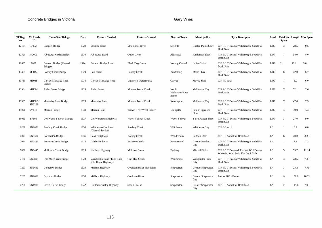
Concrete Bridges in Victoria Gary Vines
115
NT Reg. No:
VicRoads ID:
Name(S) of Bridge: Date: Feature Carried: Feature Crossed: Nearest Town: Municipality: Type Description: Level Total No Spans
Length Max Span
12134 GJ092 Coopers Bridge 1920 Steiglitz Road Moorabool River Steiglitz Golden Plains Shire CIP RC T-Beams With Integral Solid Flat Deck Slab
L/R? 3 28.5 9.5
12520 HO001 Albacutya Outlet Bridge 1930 Albacutya Road Outlet Creek Albacutya Hindmarsh Shire CIP RC T-Beams With Integral Solid Flat Deck Slab
L/R? 7 54.0 8.0
12637 IA027 Estcourt Bridge (Monash Bridge)
1914 Estcourt Bridge Road Black Dog Creek Norong Central, Indigo Shire CIP RC T-Beams With Integral Solid Flat Deck Slab
L/R? 2 19.1 9.0
13451 M3032 Boosey Creek Bridge 1929 Barr Street Boosey Creek Bundalong Moira Shire CIP RC T-Beams With Integral Solid Flat Deck Slab
L/R? 6 42.0 6.7
13780 M5038 Garvoc-Mortlake Road Bridge
1930 Garvoc-Mortlake Road Unknown Watercourse Garvoc Moyne Shire CIP RC Arch L/R? 1 6.0 6.0
13904 MH001 Arden Street Bridge 1923 Arden Street Moonee Ponds Creek North Melbourne/Kensington
Melbourne City CIP RC T-Beams With Integral Solid Flat Deck Slab
L/R? 7 52.1 7.6
13905 MH002 / SN6261
Macaulay Road Bridge 1923 Macaulay Road Moonee Ponds Creek Kensington Melbourne City CIP RC T-Beams With Integral Solid Flat Deck Slab
L/R? 7 47.0 7.3
15026 SY140 Mardan Bridge 1930 Mardan Road Tarwin River West Branch Leongatha South Gippsland Shire
CIP RC T-Beams With Integral Solid Flat Deck Slab
L/R? 3 30.0 12.0
16085 YF106 Old Woori Yallock Bridges 1927 Old Warburton Highway Woori Yallock Creek Woori Yallock Yarra Ranges Shire CIP RC T-Beams With Integral Solid Flat Deck Slab
L/R? 3 27.0 9.0
6288 SN9676 Scrubby Creek Bridge 1950 Whittlesea-Yea Road (Disused Section)
Scrubby Creek Whittlesea Whittlesea City CIP RC Arch L? 1 6.2 6.0
7073 SN0304 Coronation Bridge 1936 Calder Highway Korong Creek Wedderburn Loddon Shire CIP RC Solid Flat Deck Slab L? 6 20.0 3.33
7084 SN0429 Buckeye Creek Bridge 1915 Calder Highway Buckeye Creek Ravenswood Greater Bendigo City
CIP RC T-Beams With Integral Solid Flat Deck Slab
L? 1 7.2 7.2
7086 SN0445 Mollisons Creek Bridge 1929 Northern Highway Mollison Creek Pyalong Mitchell Shire CIP RC T-Beams & Precast RC I-Beams Widening With Solid Flat Deck Slab
L? 5 55.7 11.14
7130 SN0890 One Mile Creek Bridge 1923 Wangaratta Road (Tone Road) (Old Hume Highway)
One Mile Creek Wangaratta Wangaratta Rural City
CIP RC T-Beams With Integral Solid Flat Deck Slab
L? 3 23.5 7.83
7261 SN1633 Geraghtys Bridge 1920 Midland Highway Goulburn River Floodplain Shepparton Greater Shepparton City
CIP RC T-Beams With Integral Solid Flat Deck Slab
L? 3 23.2 7.73
7265 SN1639 Bayntons Bridge 1955 Midland Highway Goulburn River Shepparton Greater Shepparton City
Precast RC I-Beams L? 14 150.0 10.71
7298 SN1936 Seven Creeks Bridge 1942 Goulburn Valley Highway Seven Creeks Shepparton Greater Shepparton City
CIP RC Solid Flat Deck Slab L? 15 119.0 7.93
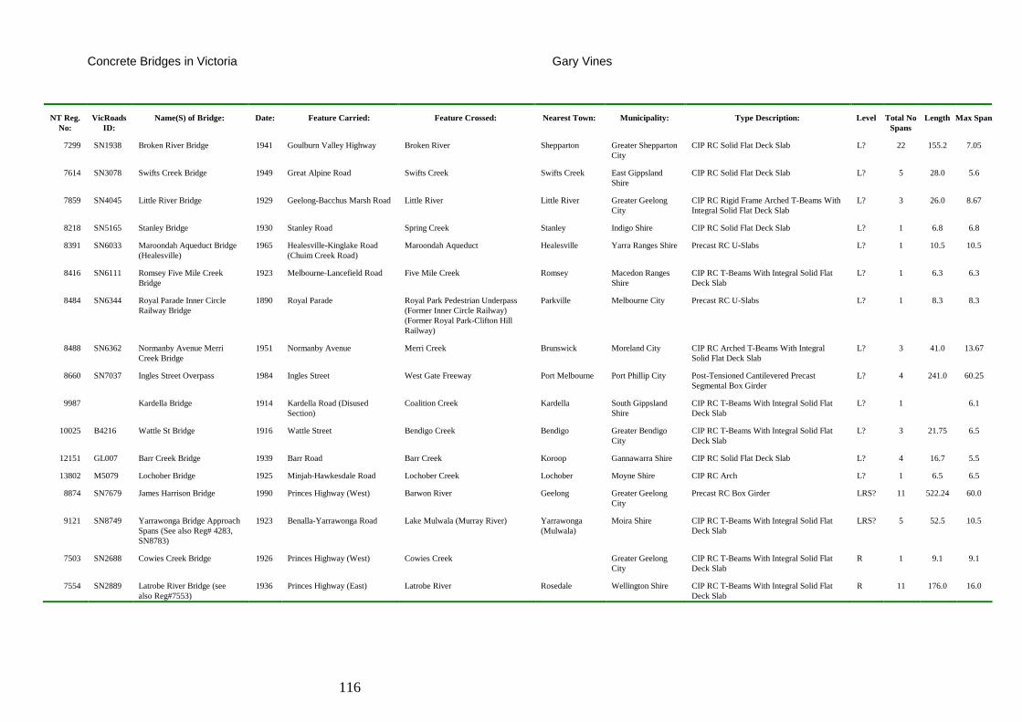
Concrete Bridges in Victoria Gary Vines
116
NT Reg. No:
VicRoads ID:
Name(S) of Bridge: Date: Feature Carried: Feature Crossed: Nearest Town: Municipality: Type Description: Level Total No Spans
Length Max Span
7299 SN1938 Broken River Bridge 1941 Goulburn Valley Highway Broken River Shepparton Greater Shepparton City
CIP RC Solid Flat Deck Slab L? 22 155.2 7.05
7614 SN3078 Swifts Creek Bridge 1949 Great Alpine Road Swifts Creek Swifts Creek East Gippsland Shire
CIP RC Solid Flat Deck Slab L? 5 28.0 5.6
7859 SN4045 Little River Bridge 1929 Geelong-Bacchus Marsh Road Little River Little River Greater Geelong City
CIP RC Rigid Frame Arched T-Beams With Integral Solid Flat Deck Slab
L? 3 26.0 8.67
8218 SN5165 Stanley Bridge 1930 Stanley Road Spring Creek Stanley Indigo Shire CIP RC Solid Flat Deck Slab L? 1 6.8 6.8
8391 SN6033 Maroondah Aqueduct Bridge (Healesville)
1965 Healesville-Kinglake Road (Chuim Creek Road)
Maroondah Aqueduct Healesville Yarra Ranges Shire Precast RC U-Slabs L? 1 10.5 10.5
8416 SN6111 Romsey Five Mile Creek Bridge
1923 Melbourne-Lancefield Road Five Mile Creek Romsey Macedon Ranges Shire
CIP RC T-Beams With Integral Solid Flat Deck Slab
L? 1 6.3 6.3
8484 SN6344 Royal Parade Inner Circle Railway Bridge
1890 Royal Parade Royal Park Pedestrian Underpass (Former Inner Circle Railway) (Former Royal Park-Clifton Hill Railway)
Parkville Melbourne City Precast RC U-Slabs L? 1 8.3 8.3
8488 SN6362 Normanby Avenue Merri Creek Bridge
1951 Normanby Avenue Merri Creek Brunswick Moreland City CIP RC Arched T-Beams With Integral Solid Flat Deck Slab
L? 3 41.0 13.67
8660 SN7037 Ingles Street Overpass 1984 Ingles Street West Gate Freeway Port Melbourne Port Phillip City Post-Tensioned Cantilevered Precast Segmental Box Girder
L? 4 241.0 60.25
9987 Kardella Bridge 1914 Kardella Road (Disused Section)
Coalition Creek Kardella South Gippsland Shire
CIP RC T-Beams With Integral Solid Flat Deck Slab
L? 1 6.1
10025 B4216 Wattle St Bridge 1916 Wattle Street Bendigo Creek Bendigo Greater Bendigo City
CIP RC T-Beams With Integral Solid Flat Deck Slab
L? 3 21.75 6.5
12151 GL007 Barr Creek Bridge 1939 Barr Road Barr Creek Koroop Gannawarra Shire CIP RC Solid Flat Deck Slab L? 4 16.7 5.5
13802 M5079 Lochober Bridge 1925 Minjah-Hawkesdale Road Lochober Creek Lochober Moyne Shire CIP RC Arch L? 1 6.5 6.5
8874 SN7679 James Harrison Bridge 1990 Princes Highway (West) Barwon River Geelong Greater Geelong City
Precast RC Box Girder LRS? 11 522.24 60.0
9121 SN8749 Yarrawonga Bridge Approach Spans (See also Reg# 4283, SN8783)
1923 Benalla-Yarrawonga Road Lake Mulwala (Murray River) Yarrawonga (Mulwala)
Moira Shire CIP RC T-Beams With Integral Solid Flat Deck Slab
LRS? 5 52.5 10.5
7503 SN2688 Cowies Creek Bridge 1926 Princes Highway (West) Cowies Creek Greater Geelong City
CIP RC T-Beams With Integral Solid Flat Deck Slab
R 1 9.1 9.1
7554 SN2889 Latrobe River Bridge (see also Reg#7553)
1936 Princes Highway (East) Latrobe River Rosedale Wellington Shire CIP RC T-Beams With Integral Solid Flat Deck Slab
R 11 176.0 16.0
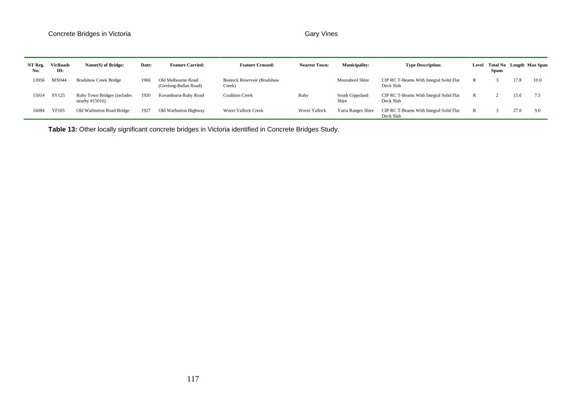
Concrete Bridges in Victoria Gary Vines
117
NT Reg. No:
VicRoads ID:
Name(S) of Bridge: Date: Feature Carried: Feature Crossed: Nearest Town: Municipality: Type Description: Level Total No Spans
Length Max Span
13956 MX044 Bradshaw Creek Bridge 1966 Old Melbourne Road (Geelong-Ballan Road)
Bostock Reservoir (Bradshaw Creek)
Moorabool Shire CIP RC T-Beams With Integral Solid Flat Deck Slab
R 3 17.8 10.0
15014 SY125 Ruby Town Bridges (includes nearby #15016)
1920 Korumburra-Ruby Road Coalition Creek Ruby South Gippsland Shire
CIP RC T-Beams With Integral Solid Flat Deck Slab
R 2 15.0 7.5
16084 YF105 Old Warburton Road Bridge 1927 Old Warburton Highway Woori Yallock Creek Woori Yallock Yarra Ranges Shire CIP RC T-Beams With Integral Solid Flat Deck Slab
R 3 27.0 9.0
Table 13: Other locally significant concrete bridges in Victoria identified in Concrete Bridges Study.
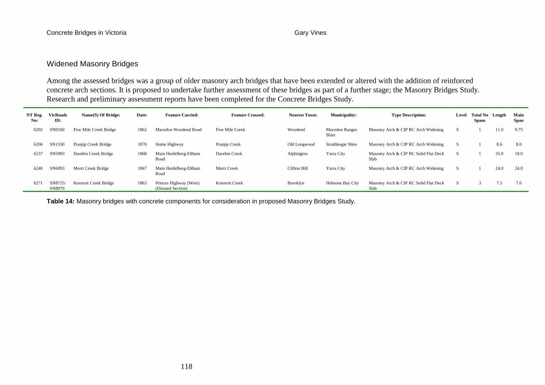
Concrete Bridges in Victoria Gary Vines
118
Widened Masonry Bridges
Among the assessed bridges was a group of older masonry arch bridges that have been extended or altered with the addition of reinforced concrete arch sections. It is proposed to undertake further assessment of these bridges as part of a further stage; the Masonry Bridges Study. Research and preliminary assessment reports have been completed for the Concrete Bridges Study.
NT Reg. No:
VicRoads ID:
Name(S) Of Bridge: Date: Feature Carried: Feature Crossed: Nearest Town: Municipality: Type Description: Level Total No Spans
Length Main Span
6202 SN0160 Five Mile Creek Bridge 1862 Macedon Woodend Road Five Mile Creek Woodend Macedon Ranges Shire
Masonry Arch & CIP RC Arch Widening S 1 11.0 9.75
6206 SN1330 Pranjip Creek Bridge 1870 Hume Highway Pranjip Creek Old Longwood Strathbogie Shire Masonry Arch & CIP RC Arch Widening S 1 8.6 8.0
6237 SN5993 Darebin Creek Bridge 1868 Main Heidelberg-Eltham Road
Darebin Creek Alphington Yarra City Masonry Arch & CIP RC Solid Flat Deck Slab
S 1 35.0 18.0
6240 SN6093 Merri Creek Bridge 1867 Main Heidelberg-Eltham Road
Merri Creek Clifton Hill Yarra City Masonry Arch & CIP RC Arch Widening S 1 24.0 24.0
6271 SN8725/SN8979
Kororoit Creek Bridge 1863 Princes Highway (West) (Disused Section)
Kororoit Creek Brooklyn Hobsons Bay City Masonry Arch & CIP RC Solid Flat Deck Slab
S 3 7.5 7.6
Table 14: Masonry bridges with concrete components for consideration in proposed Masonry Bridges Study.
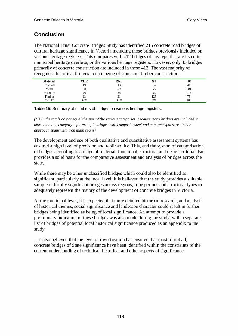
Concrete Bridges in Victoria Gary Vines
119
Conclusion
The National Trust Concrete Bridges Study has identified 215 concrete road bridges of cultural heritage significance in Victoria including those bridges previously included on various heritage registers. This compares with 412 bridges of any type that are listed in municipal heritage overlays, or the various heritage registers. However, only 43 bridges primarily of concrete construction are included in these 412. The vast majority of recognised historical bridges to date being of stone and timber construction.
Material VHR RNE NT HO Concrete 19 13 14 40
Metal 38 29 65 101 Masonry 26 35 33 115 Timber 23 21 125 75 Total* 105 116 236 294
Table 15: Summary of numbers of bridges on various heritage registers.
(*N.B. the totals do not equal the sum of the various categories because many bridges are included in
more than one category – for example bridges with composite steel and concrete spans, or timber
approach spans with iron main spans)
The development and use of both qualitative and quantitative assessment systems has ensured a high level of precision and replicability. This, and the system of categorisation of bridges according to a range of material, functional, structural and design criteria also provides a solid basis for the comparative assessment and analysis of bridges across the state.
While there may be other unclassified bridges which could also be identified as significant, particularly at the local level, it is believed that the study provides a suitable sample of locally significant bridges across regions, time periods and structural types to adequately represent the history of the development of concrete bridges in Victoria.
At the municipal level, it is expected that more detailed historical research, and analysis of historical themes, social significance and landscape character could result in further bridges being identified as being of local significance. An attempt to provide a preliminary indication of these bridges was also made during the study, with a separate list of bridges of potential local historical significance produced as an appendix to the study.
It is also believed that the level of investigation has ensured that most, if not all, concrete bridges of State significance have been identified within the constraints of the current understanding of technical, historical and other aspects of significance.
Concrete Bridges in Victoria Gary Vines
120
Recommendations
• It is recommended that the bridges identified in this study as being Local, Regional and State significance and listed in Tables 5-7 above, should be included on the National Trust Register.
• Bridges identified as being of State significance and for which classification reports have been prepared, should be nominated to the Victorian Heritage Register.
• It is also recommended that those bridges identified as being of potential local significance, but for which classification reports have not been prepared, should be brought to the notice of the relevant municipal councils, and that the councils should be encouraged to include these bridges in any future heritage assessments, such as reviews of local heritage studies.
• Further research and assessment of masonry road bridges is still required. A number of bridges identified in the Concrete Bridges Study also have major masonry components. These bridge assessment reports indicated in Table 14, should reviewed as part of a masonry bridges study, before being submitted to Heritage Victoria for consideration.
• Railway bridges have not been systematically researched or assessed, apart from some road-over-rail bridges assessed as part of the metal and concrete bridges studies, and some of the timber bridges considered by the earlier National Trust Timber Bridges Study. It is therefore recommended that a study of metal, masonry and concrete railway bridges should be commissioned.

Concrete Bridges in Victoria Gary Vines
121

Concrete Bridges in Victoria Gary Vines
122
Appendices
Concrete Bridges in Victoria Gary Vines
123
Appendix 1 Chronology of Australian and Internation al Bridge Developments.
(Victorian and Australian bridge developments highlighted)
(Modern concrete developments – date in bold)
(Specific developments in concrete bridge design are italicised)
12,000,000 BC A natural deposit of cement compounds forms due to the reactions between limestone and oil shale during spontaneous combustion near present-day Israel.
5600 BC: The first concrete structures were built. :
3000 BC: The Egyptians began to use mud mixed with straw to bind dried bricks. They also used gypsum mortars and mortars of lime in the building of the pyramids.
800 BC: The Greeks used lime mortars that were much harder than later Roman mortars. This material was also in evidence in Crete and Cyprus at this time.
300 BC: The Babylonians and Assyrians used bitumen to bind stones and bricks together.
300 BC: The Chinese used cementatious materials in the construction of the Great Wall.
299 BC to 476 AD: The Romans used pozzolano cement from Pozzuoli, Italy near Mt. Vesuvius to build many famous Roman structures.
27 AD: Pollio Vitruvius completes his books on architecture including a discussion of the properties of concrete.
64 AD: Nero's Golden House is built in Rome with concrete walls, domes, and vaults during the rebuilding of Rome.
540 AD: Concrete is used in the construction of the vaults and arches on the lower levels of St. Sophia's in Constantinople.
1200 to 1500: The quality of cementing materials deteriorated and even the use of concrete died out during the Middle Ages as the art of using burning lime and pozzolano (admixture) was lost, but it was later reintroduced in the 1300s.
1414: The manuscripts of the Roman Pollio Vitruvius are discovered in a Swiss monastery reviving general interest in concrete.
1499: Fra Giocondo used pozzolanic mortar in the pier of the Pont de Notre Dame in Paris. It is the first acknowledged use of concrete in modern times.
1738: The caisson, a device essential to building bridge piers in water, is developed for a bridge over the Thames at Westminster.
1755: The earliest attempt to use iron for an arched bridge was made at Lyons, France.
1774: John Smeaton discovered that combining quicklime with other materials created an extremely hard material that could be used to bind together other materials.
1779: Bry Higgins was issued a patent for hydraulic cement (stucco) for exterior plastering use.
1779: The first completed iron bridge was the semicircular cast-iron arch bridge over the river Severn at Coalbrookdale, England, built by Abraham Darby III in 1779, which still stands.
1780: Bry Higgins published ‘Experiments and Observations Made With the View of Improving the Art of Composing and Applying Calcareous Cements and of Preparing Quicklime.’
Concrete Bridges in Victoria Gary Vines
124
1780: First steam powered rolling mill opening in England.
1789: Riveting machine introduced to manufacture by William Fairbairn. This enabled steam boilers and fabricated girders to be built more easily.
1793: John Smeaton found that the calcination of limestone containing clay produced a lime that hardened under water (hydraulic lime). He used hydraulic lime to rebuild Eddystone Lighthouse in Cornwall, England.
1796: An Englishman, James Parker, patented a natural hydraulic cement by calcining nodules of impure limestone containing clay, called Parker's Cement or Roman Cement.
1800: William Jessop uses mass concrete on a large scale to build the West India Dock in Great Britain.
1801: First modern iron suspension bridge built by James Finney of Pennsylvania carries pedestrians.
1809: First suspension bridge capable of carrying vehicles, with a span of 74m, built across the Merrimac River in Massachusetts.
1810: Edgar Dobbs received a patent for hydraulic mortars, stucco and plaster, although they were of poor quality due to lack of kiln precautions.
1812 to 1813: Louis Vicat of France prepared artificial hydraulic lime by calcining synthetic mixtures of limestone and clay.
1816: The world's first unreinforced concrete bridge was built at Souillac, France.
1818: A British engineer, Ralph Dodd, takes out a patent introducing wrought iron bars into concrete.
1818: The Institution of Civil Engineers is founded in England.
1820 to 1821: John Tickell and Abraham Chambers were issued more patents for hydraulic cement.
1822: James Frost of England prepared artificial hydraulic lime like Vicat's and called it ‘British Cement.’
1824: Joseph Aspdin, a British bricklayer, produced and patented the first ‘Portland’ cement
1825: Suspension Bridge over the Menai Straits in Wales, by Thomas Telford, single span of 176m. Seen by many to inaugurate the age of modern bridge building.
1828: I. K. Brunel is credited with the first engineering application of Portland cement, which was used to fill a breach in the Thames Tunnel.
1830: The first production of lime and hydraulic cement took place in Canada.
1830s: New York's Obadiah Parker develops a cement similar to Aspdin's and builds a number of houses using monolithic walls.
1833: The earliest tied bowstring arch was built at Lugao, Hungary, 1833, where a cast-iron arch was tied at deck level by a chain.
1835: Melbourne settled.
1836: The first systematic tests of tensile and compressive strength took place in Germany.
1843: J. M. Mauder, Son & Co. was licensed to produce patented Portland cement.
1845: Isaac Johnson claims to have burned the raw materials of Portland cement to clinkering temperatures.
1845: Wooden Balbirnie's Bridge erected over the Yarra River (demolished 1850).
Concrete Bridges in Victoria Gary Vines
125
1847: Gold discovered in California - lead to first 'gold rush'.
1847: Institution of Mechanical Engineers is founded in England.
1847: Major suspension bridge built over the Ohio, one of the first in the USA.
1849: Pettenkofer & Fuches performed the first accurate chemical analysis of Portland cement.
1850: First stone arch Princes Bridge built over Yarra River by David Lennox, replaced 1888
1850: Joseph Monier, a French nurseryman, conceived and developed a form of reinforced concrete in an effort to build a durable flowerpot.
1850: The riveted wrought-iron box girder, forming a closed tube, was first used in the Britannia tubular bridge over the Menai Straits 1850, designed by Robert Stephenson (1803-1859), and fabricated by William Fairbairn (1789-1874), established the superiority of wrought-iron over cast iron.
1851: First wooden Hawthorn Bridge.
1851: Gold Rushes in Victoria commence.
1852: The American Society of Civil Engineers is founded in New York.
1853: First wooden Keilor Bridge over the Maribyrnong River, Replaced 1860s.
1854: Louis Cézanne invents the hand-operated concrete mixer.
1854-1859: The wrought-iron box girder, Victoria Bridge over the St. Lawrence at Montréal, Canada, built 1854-59, was for many years the longest bridge in the world.
1855: Francois Coignet invents a system for combining concrete with iron joists.
1855c: Botanic Gardens pedestrian bridge Between Richmond and Gardens Demolished
1856: Bessemer Process was developed for making inexpensive steel.
1856: Quamby Stone Arch Bridge, near Woolsthorpe
1856: Seimens in UK and Martin in France develops the regenerative furnace, that burns previously unburnt gases for greater efficiency - reduces the coal used and increases steel production.
1857: First Church Street Bridge between Richmond and Prahran riveted box girder (Replaced 1923)
1857: First Johnson Street Bridge between Richmond and Kew timber (replaced 1877)
1857: Studley Park Bridge Church St. Richmond to Kew (demolished 1930s)
1859: Djerriwarrh Creek Bridge Stone Arch
1859: First Iron Bridge over Barwon River Geelong riveted wrought iron box girder (replaced 1926)
1859: Hughes Creek Bridge, Avenel Stone Arch
1859: Moorabool River Bridge, Batesford Stone Arch
1860: The beginning of the era of Portland cements of modern composition.
1861: Merri Creek Bridge Heidelberg Road Stone Arch
1861: Second Hawthorn Bridge, Bridge Road wrought iron lattice truss
1864: The first wrought-iron arch bridge of importance was constructed, when a bridge of three spans was built crossing the Rhine at Koblenz, Germany.
Concrete Bridges in Victoria Gary Vines
126
1867: Joseph Monier, of France, reinforced William Wand's (USA) flowerpots with wire ushering in the idea of iron reinforcing bars (re-bar).
1868: Mia Mia Bridge, Redesdale (lattice trusses 1859 originally for Hawthorn Bridge)
1868: Second Keilor Bridge over Maribyrnong River riveted box girder (restored 1984)
1869: First railway line across USA completed from the Atlantic to the Pacific.
1869: The Suez canal (1859-1869) opens to shipping, linking the Mediterranean and the Red Seas, shortening the voyage to Australia.
1870 c: First (mass) concrete bridge in England, 48ft span Homersfield bridge over the River Waveney England.
1871: Bet Bet Bridge Bung Bong wrought iron lattice truss
1871: David O. Saylor was issued the first American patent for Portland cement in Copley, Pennsylvania. He showed the importance of true clinkering.
1872: Banksia Street Bridge, first metal arch bridge in Victoria, demolished 1960s.
1874: Jorgensons Bridge near Clunes wrought iron lattice truss
1874: Shelford Bridge designed by C.A.C.Wilson, wrought iron box girder
1874: The first major steel bridge, Captain Ead's great bridge over the Mississippi at St Louis, USA, was completed 1874. The arches are formed of open triangulated ribs, supporting the roadway by vertical columns at the apexes of the arch bracing.
1875: Merri Creek Bridge High Street, Northcote stone arch
1877: Second Johnson Street Bridge Between Richmond and Kew (replaced 1958)
1878: First all steel bridge erected in 1878, crossing the Missouri River at Glasgow, South Dakota, USA. (Encyclopaedia Britannica 1964 edition).
1880: Woady Yaloak River Bridge Cressy wrought iron lattice truss.
1883: Brooklyn Suspension Bridge, New York opened - introduces revolutionary method of cable spinning.
1883: Manganese Steel patented - a super hard alloy that is one of the first of the specialist alloy steels.
1883: Swing Bridge near Sale wrought iron lattice truss and plate girder.
1884: Victoria Street Bridge Richmond - Hawthorn wrought iron lattice truss.
1885: First transcontinental railway opens across Canada.
1886: The first rotary kiln was introduced in England to replace the vertical shaft kilns.
1887: Brunton's Bridge Thomson River, Walhalla (similar to Victoria Street Bridge).
1888: Second Princes Bridge over Yarra River wrought iron lattice truss and arch
1889: Queens Bridge, The Falls Bridge.
1889: The first concrete reinforced bridge is built, Golden Gate Park, San Francisco.
1890: Chandler Highway Bridge Kew / Fairfield (former Railway Bridge) steel truss.
1890: The addition of gypsum when grinding clinker to act as a retardant to the setting of concrete was introduced in the U.S. Vertical shaft kilns were replaced with rotary kilns and ball mills were used for grinding cement.
1890: Wollaston Suspension Bridge Warrnambool
Concrete Bridges in Victoria Gary Vines
127
1890c: Watts River Aqueduct Mass Concrete Arch Bridges
1892: Moonie Ponds Creek Bridge Brunswick (demolished).
1892: Walmer Street footbridge Abbotsford / Fairfield.
1894: Manchester Ship Canal opened, linking Manchester to the Atlantic Ocean.
1896: Annandale Sewer Viaducts NSW.
1896: First mass concrete bridge in Australia, Black Bob’s Creek, Berrima.
1898: Cement manufacturers used 91 different formulas.
1899: Morell Bridge Anderson Street Monier concrete arch, Carter Gummow & Co.
1900: Bendigo Creek Bridge Bendigo Monier concrete arch.
1900: Basic cement tests were standardized.
1900: Electric arc steel-making furnace is used for the first time. Developed in Sheffield during World War 1.
1900: Reeds Gully Bridge, Tamworth, first reinforced concrete arch in New South Wales.
1900: Fyansford Bridge over Moorabool River Monier concrete arch.
1900: Tungsten carbon steel - high-speed steel - demonstrated for cutting tools.
1900: Wheeler's Bridge Lawrence.
1901: Chewton Bunny (strengthened brick arch using Hennebique's specification, first reinforced concrete bridge in the U.K.
1901: First King Street Bridge Bendigo collapses during testing.
1902: August Perret designs and builds an apartment building in Paris that uses what was called ‘a system for reinforced concrete’. This structure deeply influenced architecture and concrete construction for decades since it was built without load-bearing walls using instead columns, beams, and slabs.
1902-4: Stawell St Ballarat and St. Kilda St. Elwood, 1st reinforced concrete girder bridges in Victoria.
1905: Hawkesbury River Bridge – Monier system designed by Harvey Dare.
1907: Alexandra Bridge Hindmarsh - first reinforced concrete railway bridge in Australia.
1909: Electric arc welding machines, with an asbestos shield around the electrode, gave a much better control of the heat from the arc, thus achieving a stronger more reliable weld.
1909: Thomas Edison was issued a patent for rotary cement kilns.
1910: Benalla Bridge erected by Monash & Anderson – longest girder bridge in Victoria.
1911: Janevale Bridge, Laanecoorie Monier concrete arch.
1911: Leigh River Bridge near Mt Mercer .
1911: Reinforced concrete is used to build the Risorgimento Bridge in Rome that spans 328 feet.
1913: Moonie Ponds Creek Bridge Mount Alexander Road, (Monash concrete reconstruction of 1868 cast and wrought iron bridge).
1913: The first load of ready-mixed concrete delivered in Baltimore, Maryland.
1913: Country Roads Board formed.
Concrete Bridges in Victoria Gary Vines
128
1914: First reinforced concrete slab bridge in NSW, American Creek Figtree.
1914-18: Iron and steel demand sours due to war demands.
1915: BHP Newcastle Steel Works opened.
1915: Footbridge, Castlemaine Concrete Truss.
1915: Road Bridge, Castlemaine Concrete Truss (demolished).
1916: Campaspe River Bridge Rochester.
1916: The Portland Cement Association was formed in Chicago. Stephen Stepanian of Columbus, Ohio applied for a patent for the first truck mixer.
1917: Fullers Bridge, Lane Cover River NSW, continuous girder reinforced concrete.
1917: The National Bureau of Standards (now the National Bureau of standards and Technology) and the American Society for Testing Materials established a standard formula for Portland cement.
1918: First radio link between Australia and England is opened.
1919: Oxy-acetylene cutting demonstrated in Melbourne.
1920: Australian Iron & Steel Port Kembla integrated steel works opened.
1920: Electric arc welding is introduced into shipyards and immediately proves its superiority over riveting.
1920: Electricity Supplies spread throughout industrialised nations.
1920: Panama Canal (1879-1889, 1904-1914) opened - linking the Pacific and Atlantic Oceans.
1921: Electric arc welded pipes produced for the gas pipeline industry.
1924: Second Church Street Bridge between Richmond and Prahran.
1926: World's first continuous hot-strip steel mill is opened in Pennsylvania. Primarily produced sheet metal for the automobile industries.
1927: Eugene Freyssinet, a French engineer, developed pre-stressed concrete.
1927: In Seattle, Washington the first horizontal drum truck mixer – the Paris Transit Mixer – debuted and became popular across the country.
1928: Invention of furnace for smelting iron ore electrically - the Tysland-Hole furnace.
1930: Horizontal-axis revolving-drum mixer trucks similar to today's concrete mixers were introduced by three American manufacturers. Air entraining agents were introduced to improve concrete's resistance to freeze/thaw damage.
1930: Spencer Street Bridge over Yarra River, Variable depth riveted plate girder.
1931: George Washington Suspension Bridge, New York opened - double the span (1066m) of the previous record holder.
1931: Sunday Creek Bridge, Broadford, first welded steel truss.
1931: McKillops Bridge, Snowy River, Welded steel truss.
1932: The Sydney Harbour Bridge is opened, one of the great single-arch bridges of the world, with a span of 503m / 1,650 ft.
1933: First continuously cast steel machine used in Germany - prototype of later industrial scale steel plants from 1943.
1934: Grange Road Bridge Welded steel truss.
Concrete Bridges in Victoria Gary Vines
129
1935: BHP acquires A.I.S.
1935-8: Hillas Creek and Sharks Creek bowstring concrete arches, NSW.
1936: The first major concrete dams, Hoover Dam and Grand Coulee Dam, were built.
1937: Golden Gate Suspension Bridge, San Francisco opened - world's longest span 1280m.
1938: Hoddle Bridge Punt Road over Yarra River, Melbourne Concrete Beams with curved soffits.
1940: Tecoma Narrows Suspension Bridge collapses - leads engineers to re-consider aerodynamic stability of structures.
1947: Pre-stressed concrete was introduced and first used in airport pavements.
1948: Walnut Lane Bridge Philadelphia, first pre-stressed bridge.
1948-52: Swan Street Bridge over Yarra River, Melbourne. Concrete arched girders.
1950: Rhinefield Drive bridge, first pre-stressed concrete bridge in England designed by E.W.H .Gifford.
1950: Precast I beams were first used in Victoria on Kiewa Road Bridge.
1951: 1,700 ready mix plants operate in over 1,300 U.S. towns and cities.
1951: Precast concrete beams manufactured for Eildon and Kiewa projects
1952: First steel made using a new oxygen steel making process, developed by Linz-Donawitz of Austria, where oxygen is injected through the roof of the furnace to purify the molten iron before it is converted to steel.
1953: Post-tensioned concrete, used at Pipers Creek bridge, Guthega Power Station.
1953: Pre-tensioned concrete bridge, Mittagong Creek Bowral NSW.
1955: Prestressed concrete slabs first used by CRB
1956: Sorell Causeway in Tasmania (the first major pre-stressed concrete bridge to be built in Australia).
1958: Prestressed concrete beams developed by CRB to replace precast beams
1966: Bowen Bridge Hobart Tasmania - first glued segmental prestressed concrete bridge in Australia.
1960: Kings Way Bridge over Yarra, first ‘freeway’ style crossing welded steel plate cantilevered and suspended girder.
1961: High strength steels - maraging steel - created with up to 19% nickel, 9% cobalt, 5% molybdenum and about 0.5% titanium. Primarily used for rockets and missiles.
1962: Caroni River Bridge Venezuela, first incrementally launched bridge.
1962: Moonee Ponds Creek (Coal Canal) bridge on Footscray Road used 42 ft prestressed concrete slabs
1964: South Eastern Freeway, Punt Road to Burnley St section opened.
1964: Verazzano Narrows Suspension Bridge, New York opened - world's longest span 1298m.
1964-71: South Eastern Freeway – elevated concrete girder freeway bridges.
1965: South Eastern Freeway to Toorak Rd opened.
1965: Barmah Bridge - segmented beam
Concrete Bridges in Victoria Gary Vines
130
1968: First steel made using a new spray steel-making process, developed in England, where molten iron is sprayed out and becomes atomised, rapidly turning into steel.
1968: Lancefield Road Overpass – first prestressed box girder bridge
1968-9: Bell Street Overpass, Strathmore Interchange, Tullamarine Freeway – first segmental concrete box girder construction in Victoria.
1968-70: Tullamarine Airport Departures Ramp – prestressed segmental box girder built on curve,
1970s: Fibre reinforcement in concrete was introduced.
1970s: West Gate Freeway – precast girder and box girder approach spans.
1974-5: Princes Highway East, Snowy River Crossing, Orbost – first inverted U beams
1978: West Gate Bridge completed.
1980s: Superplasticizers were introduced as admixtures.
1980s: Westgate Freeway extension - match cast segmental box girder.
1981: Humber Estuary Suspension Bridge, United Kingdom opened - world's longest span 1410m.
1983: Jackson’s Creek bridges, Calder Freeway – first incrementally launched bridges in Victoria
1985: Silica fume was introduced as a pozzolanic additive.
1985-86: Mandurah Estuary Bridge WA, first incrementally launched box girder construction in Australia.
1990: Prestressed Concrete Super Tee Beams
1995-6: EJ Whitten bridges, Western Ring Road – first and largest incrementally launched prestressed box girder in Victoria
1997: Store Baelt Suspension Bridge, Denmark opened - world's longest span 1600m.
1998: Akashi-Kaikyo Suspension Bridge, Japan opened - world's longest span 1990m.
2000: Bolte Bridge – balanced cantilever, and Western Link elevated freeway – match cast segmental box girders.
2000: Woronora Bridge, NSW, largest incrementally launched bridge in the Southern Hemisphere.
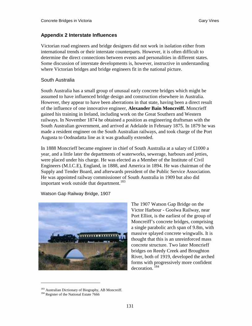
Concrete Bridges in Victoria Gary Vines
131
Appendix 2 Interstate Influences
Victorian road engineers and bridge designers did not work in isolation either from international trends or their interstate counterparts. However, it is often difficult to determine the direct connections between events and personalities in different states. Some discussion of interstate developments is, however, instructive in understanding where Victorian bridges and bridge engineers fit in the national picture.
South Australia
South Australia has a small group of unusual early concrete bridges which might be assumed to have influenced bridge design and construction elsewhere in Australia. However, they appear to have been aberrations in that state, having been a direct result of the influence of one innovative engineer, Alexander Bain Moncreiff. Moncrieff gained his training in Ireland, including work on the Great Southern and Western railways. In November 1874 he obtained a position as engineering draftsman with the South Australian government, and arrived at Adelaide in February 1875. In 1879 he was made a resident engineer on the South Australian railways, and took charge of the Port Augusta to Oodnadatta line as it was gradually extended.
In 1888 Moncrieff became engineer in chief of South Australia at a salary of £1000 a year, and a little later the departments of waterworks, sewerage, harbours and jetties, were placed under his charge. He was elected as a Member of the Institute of Civil Engineers (M.I.C.E), England, in 1888, and America in 1894. He was chairman of the Supply and Tender Board, and afterwards president of the Public Service Association. He was appointed railway commissioner of South Australia in 1909 but also did important work outside that department.183
Watson Gap Railway Bridge, 1907
The 1907 Watson Gap Bridge on the Victor Harbour - Goolwa Railway, near Port Elliot, is the earliest of the group of Moncreiff’s concrete bridges, comprising a single parabolic arch span of 9.8m, with massive splayed concrete wingwalls. It is thought that this is an unreinforced mass concrete structure. Two later Moncrieff bridges on Reedy Creek and Broughton River, both of 1919, developed the arched forms with progressively more confident decoration. 184
183 Australian Dictionary of Biography, AB Moncreiff. 184 Register of the National Estate 7666
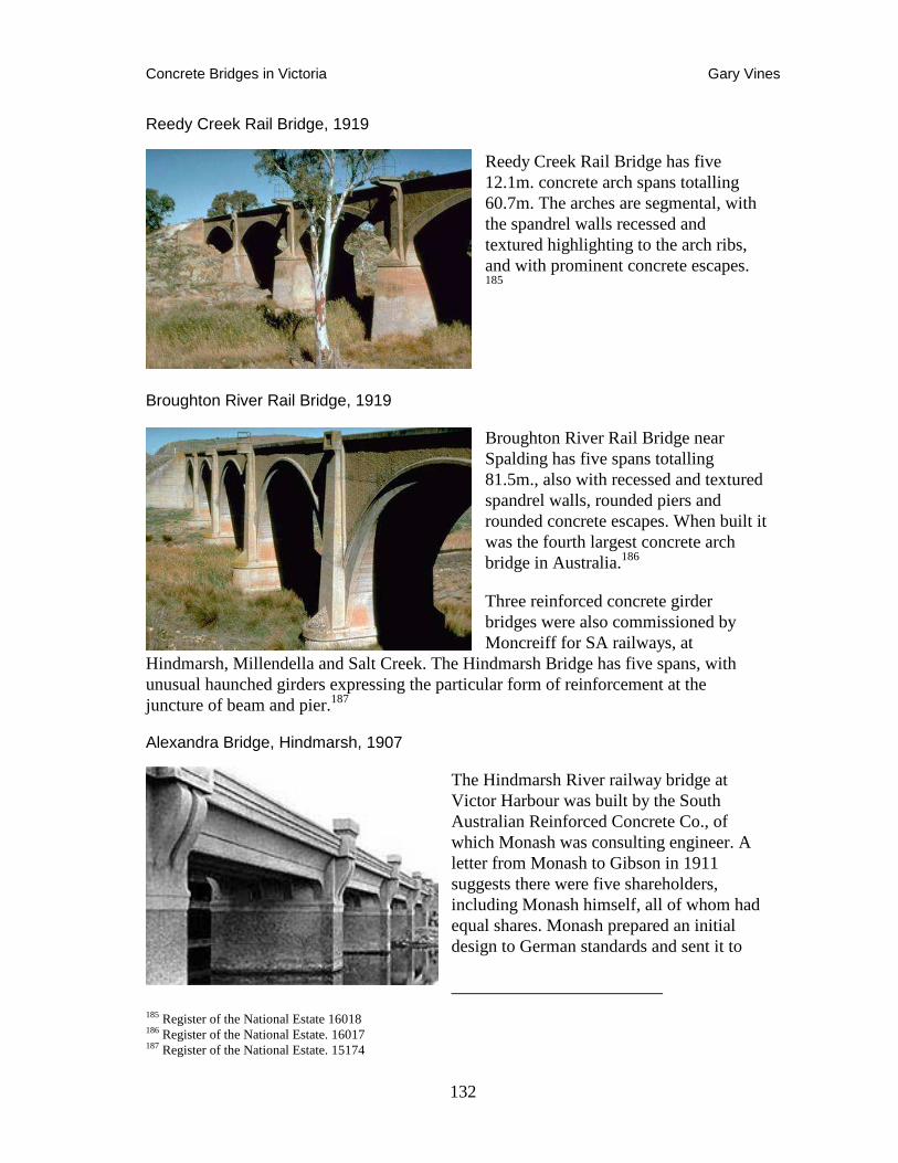
Concrete Bridges in Victoria Gary Vines
132
Reedy Creek Rail Bridge, 1919
Reedy Creek Rail Bridge has five 12.1m. concrete arch spans totalling 60.7m. The arches are segmental, with the spandrel walls recessed and textured highlighting to the arch ribs, and with prominent concrete escapes. 185
Broughton River Rail Bridge, 1919
Broughton River Rail Bridge near Spalding has five spans totalling 81.5m., also with recessed and textured spandrel walls, rounded piers and rounded concrete escapes. When built it was the fourth largest concrete arch bridge in Australia.186
Three reinforced concrete girder bridges were also commissioned by Moncreiff for SA railways, at
Hindmarsh, Millendella and Salt Creek. The Hindmarsh Bridge has five spans, with unusual haunched girders expressing the particular form of reinforcement at the juncture of beam and pier.187
Alexandra Bridge, Hindmarsh, 1907
The Hindmarsh River railway bridge at Victor Harbour was built by the South Australian Reinforced Concrete Co., of which Monash was consulting engineer. A letter from Monash to Gibson in 1911 suggests there were five shareholders, including Monash himself, all of whom had equal shares. Monash prepared an initial design to German standards and sent it to
185 Register of the National Estate 16018 186 Register of the National Estate. 16017 187 Register of the National Estate. 15174
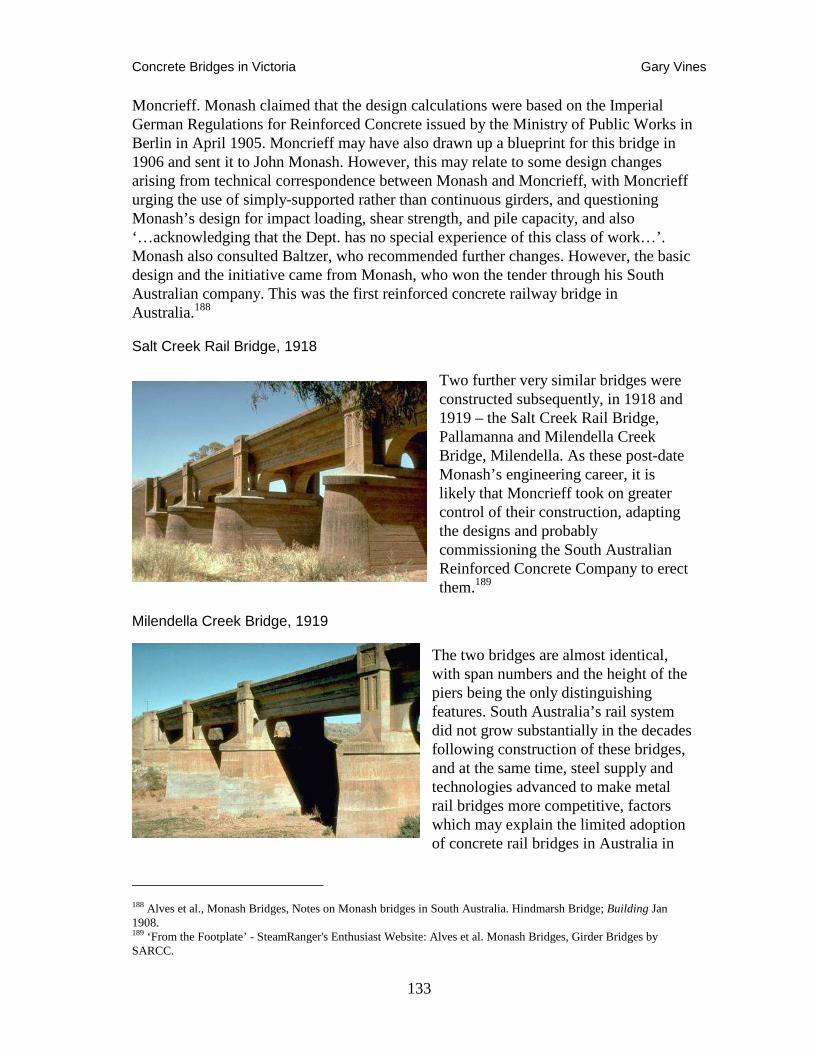
Concrete Bridges in Victoria Gary Vines
133
Moncrieff. Monash claimed that the design calculations were based on the Imperial German Regulations for Reinforced Concrete issued by the Ministry of Public Works in Berlin in April 1905. Moncrieff may have also drawn up a blueprint for this bridge in 1906 and sent it to John Monash. However, this may relate to some design changes arising from technical correspondence between Monash and Moncrieff, with Moncrieff urging the use of simply-supported rather than continuous girders, and questioning Monash’s design for impact loading, shear strength, and pile capacity, and also ‘…acknowledging that the Dept. has no special experience of this class of work…’. Monash also consulted Baltzer, who recommended further changes. However, the basic design and the initiative came from Monash, who won the tender through his South Australian company. This was the first reinforced concrete railway bridge in Australia.188
Salt Creek Rail Bridge, 1918
Two further very similar bridges were constructed subsequently, in 1918 and 1919 – the Salt Creek Rail Bridge, Pallamanna and Milendella Creek Bridge, Milendella. As these post-date Monash’s engineering career, it is likely that Moncrieff took on greater control of their construction, adapting the designs and probably commissioning the South Australian Reinforced Concrete Company to erect them.189
Milendella Creek Bridge, 1919
The two bridges are almost identical, with span numbers and the height of the piers being the only distinguishing features. South Australia’s rail system did not grow substantially in the decades following construction of these bridges, and at the same time, steel supply and technologies advanced to make metal rail bridges more competitive, factors which may explain the limited adoption of concrete rail bridges in Australia in
188 Alves et al., Monash Bridges, Notes on Monash bridges in South Australia. Hindmarsh Bridge; Building Jan 1908. 189 ‘From the Footplate’ - SteamRanger's Enthusiast Website: Alves et al. Monash Bridges, Girder Bridges by SARCC.
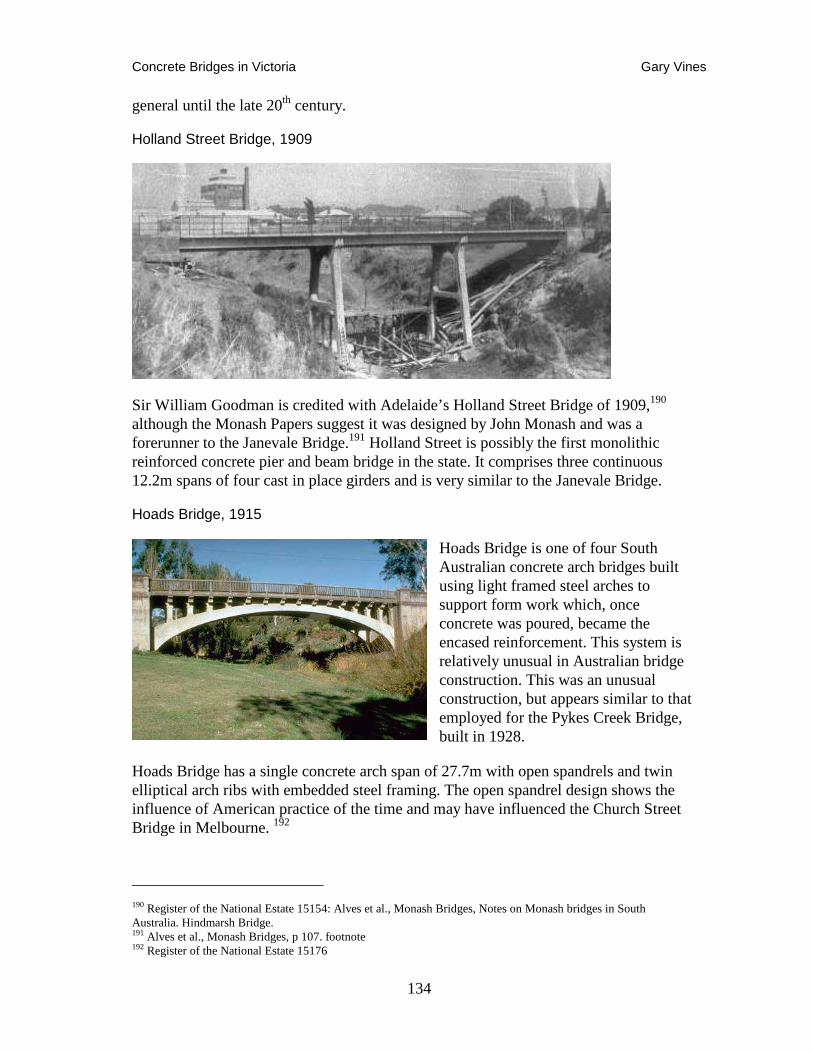
Concrete Bridges in Victoria Gary Vines
134
general until the late 20th century.
Holland Street Bridge, 1909
Sir William Goodman is credited with Adelaide’s Holland Street Bridge of 1909,190 although the Monash Papers suggest it was designed by John Monash and was a forerunner to the Janevale Bridge.191 Holland Street is possibly the first monolithic reinforced concrete pier and beam bridge in the state. It comprises three continuous 12.2m spans of four cast in place girders and is very similar to the Janevale Bridge.
Hoads Bridge, 1915
Hoads Bridge is one of four South Australian concrete arch bridges built using light framed steel arches to support form work which, once concrete was poured, became the encased reinforcement. This system is relatively unusual in Australian bridge construction. This was an unusual construction, but appears similar to that employed for the Pykes Creek Bridge, built in 1928.
Hoads Bridge has a single concrete arch span of 27.7m with open spandrels and twin elliptical arch ribs with embedded steel framing. The open spandrel design shows the influence of American practice of the time and may have influenced the Church Street Bridge in Melbourne. 192
190 Register of the National Estate 15154: Alves et al., Monash Bridges, Notes on Monash bridges in South Australia. Hindmarsh Bridge. 191 Alves et al., Monash Bridges, p 107. footnote 192 Register of the National Estate 15176
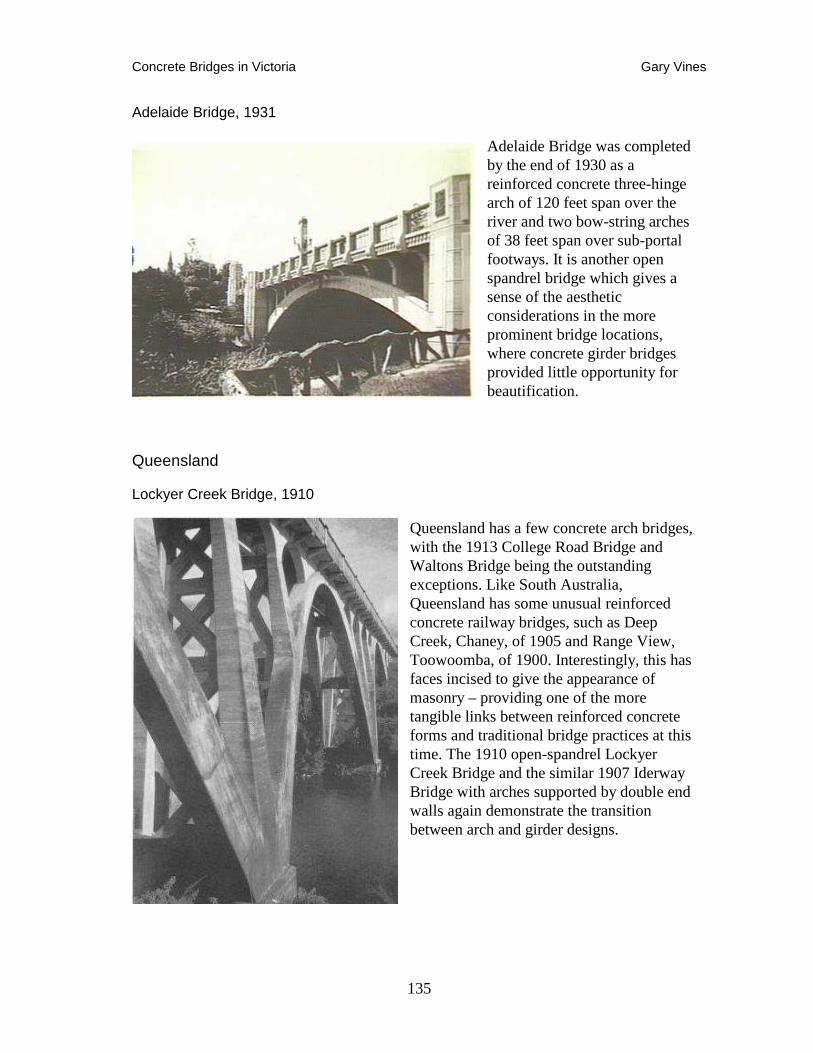
Concrete Bridges in Victoria Gary Vines
135
Adelaide Bridge, 1931
Adelaide Bridge was completed by the end of 1930 as a reinforced concrete three-hinge arch of 120 feet span over the river and two bow-string arches of 38 feet span over sub-portal footways. It is another open spandrel bridge which gives a sense of the aesthetic considerations in the more prominent bridge locations, where concrete girder bridges provided little opportunity for beautification.
Queensland
Lockyer Creek Bridge, 1910
Queensland has a few concrete arch bridges, with the 1913 College Road Bridge and Waltons Bridge being the outstanding exceptions. Like South Australia, Queensland has some unusual reinforced concrete railway bridges, such as Deep Creek, Chaney, of 1905 and Range View, Toowoomba, of 1900. Interestingly, this has faces incised to give the appearance of masonry – providing one of the more tangible links between reinforced concrete forms and traditional bridge practices at this time. The 1910 open-spandrel Lockyer Creek Bridge and the similar 1907 Iderway Bridge with arches supported by double end walls again demonstrate the transition between arch and girder designs.
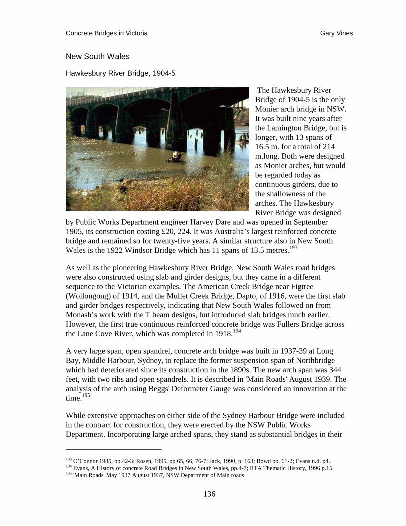
Concrete Bridges in Victoria Gary Vines
136
New South Wales
Hawkesbury River Bridge, 1904-5
The Hawkesbury River Bridge of 1904-5 is the only Monier arch bridge in NSW. It was built nine years after the Lamington Bridge, but is longer, with 13 spans of 16.5 m. for a total of 214 m.long. Both were designed as Monier arches, but would be regarded today as continuous girders, due to the shallowness of the arches. The Hawkesbury River Bridge was designed
by Public Works Department engineer Harvey Dare and was opened in September 1905, its construction costing £20, 224. It was Australia’s largest reinforced concrete bridge and remained so for twenty-five years. A similar structure also in New South Wales is the 1922 Windsor Bridge which has 11 spans of 13.5 metres.193
As well as the pioneering Hawkesbury River Bridge, New South Wales road bridges were also constructed using slab and girder designs, but they came in a different sequence to the Victorian examples. The American Creek Bridge near Figtree (Wollongong) of 1914, and the Mullet Creek Bridge, Dapto, of 1916, were the first slab and girder bridges respectively, indicating that New South Wales followed on from Monash’s work with the T beam designs, but introduced slab bridges much earlier. However, the first true continuous reinforced concrete bridge was Fullers Bridge across the Lane Cove River, which was completed in 1918.194
A very large span, open spandrel, concrete arch bridge was built in 1937-39 at Long Bay, Middle Harbour, Sydney, to replace the former suspension span of Northbridge which had deteriorated since its construction in the 1890s. The new arch span was 344 feet, with two ribs and open spandrels. It is described in 'Main Roads' August 1939. The analysis of the arch using Beggs' Deformeter Gauge was considered an innovation at the time.195
While extensive approaches on either side of the Sydney Harbour Bridge were included in the contract for construction, they were erected by the NSW Public Works Department. Incorporating large arched spans, they stand as substantial bridges in their
193 O’Connor 1985, pp.42-3: Rosen, 1995, pp 65, 66, 76-7; Jack, 1990, p. 163; Bowd pp. 61-2; Evans n.d. p4. 194 Evans, A History of concrete Road Bridges in New South Wales, pp.4-7; RTA Thematic History, 1996 p.15. 195 'Main Roads' May 1937 August 1937, NSW Department of Main roads
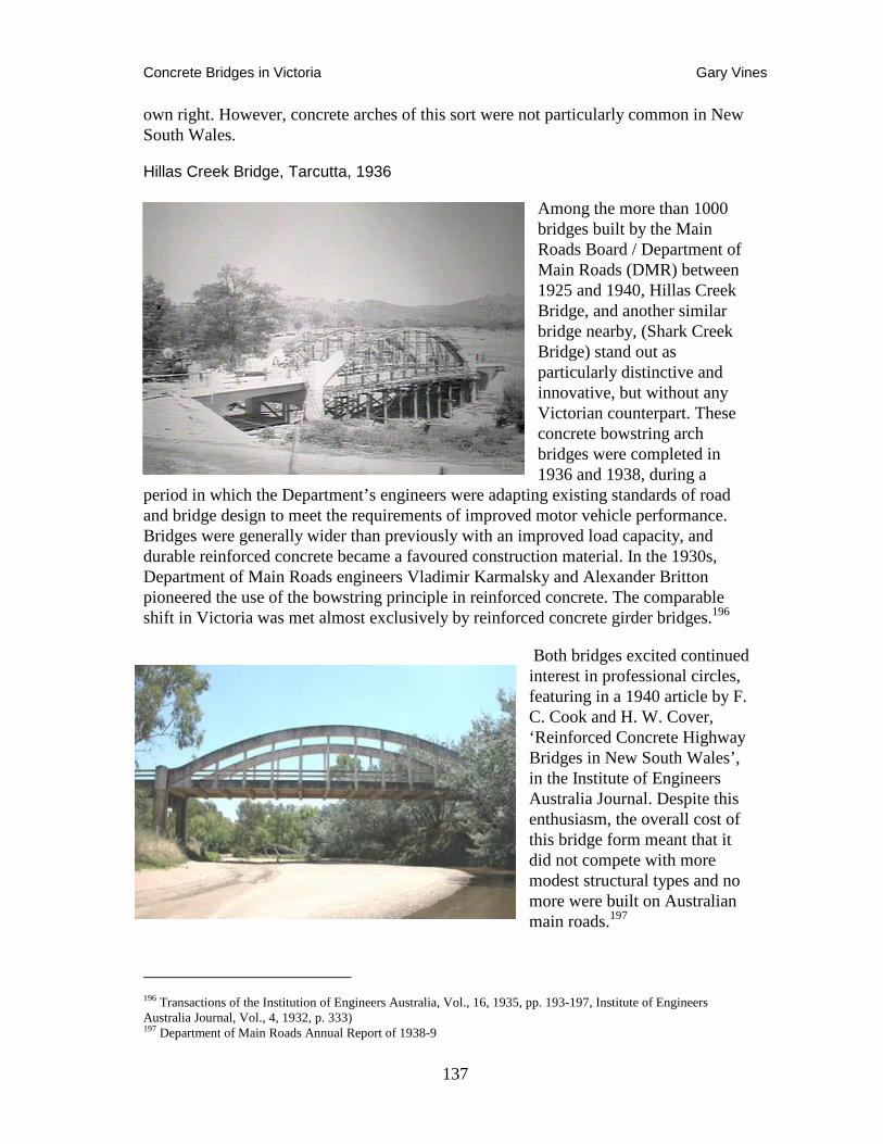
Concrete Bridges in Victoria Gary Vines
137
own right. However, concrete arches of this sort were not particularly common in New South Wales.
Hillas Creek Bridge, Tarcutta, 1936
Among the more than 1000 bridges built by the Main Roads Board / Department of Main Roads (DMR) between 1925 and 1940, Hillas Creek Bridge, and another similar bridge nearby, (Shark Creek Bridge) stand out as particularly distinctive and innovative, but without any Victorian counterpart. These concrete bowstring arch bridges were completed in 1936 and 1938, during a
period in which the Department’s engineers were adapting existing standards of road and bridge design to meet the requirements of improved motor vehicle performance. Bridges were generally wider than previously with an improved load capacity, and durable reinforced concrete became a favoured construction material. In the 1930s, Department of Main Roads engineers Vladimir Karmalsky and Alexander Britton pioneered the use of the bowstring principle in reinforced concrete. The comparable shift in Victoria was met almost exclusively by reinforced concrete girder bridges.196
Both bridges excited continued interest in professional circles, featuring in a 1940 article by F. C. Cook and H. W. Cover, ‘Reinforced Concrete Highway Bridges in New South Wales’, in the Institute of Engineers Australia Journal. Despite this enthusiasm, the overall cost of this bridge form meant that it did not compete with more modest structural types and no more were built on Australian main roads.197
196 Transactions of the Institution of Engineers Australia, Vol., 16, 1935, pp. 193-197, Institute of Engineers Australia Journal, Vol., 4, 1932, p. 333) 197 Department of Main Roads Annual Report of 1938-9
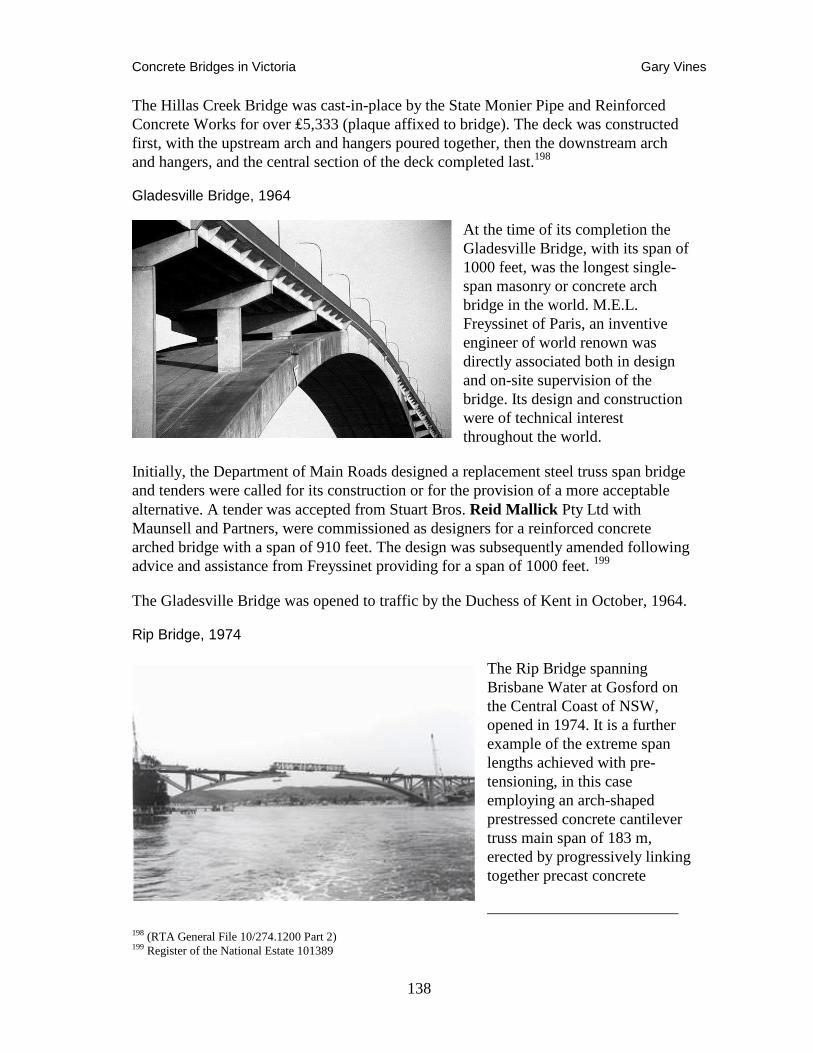
Concrete Bridges in Victoria Gary Vines
138
The Hillas Creek Bridge was cast-in-place by the State Monier Pipe and Reinforced Concrete Works for over ₤5,333 (plaque affixed to bridge). The deck was constructed first, with the upstream arch and hangers poured together, then the downstream arch and hangers, and the central section of the deck completed last.198
Gladesville Bridge, 1964
At the time of its completion the Gladesville Bridge, with its span of 1000 feet, was the longest single-span masonry or concrete arch bridge in the world. M.E.L. Freyssinet of Paris, an inventive engineer of world renown was directly associated both in design and on-site supervision of the bridge. Its design and construction were of technical interest throughout the world.
Initially, the Department of Main Roads designed a replacement steel truss span bridge and tenders were called for its construction or for the provision of a more acceptable alternative. A tender was accepted from Stuart Bros. Reid Mallick Pty Ltd with Maunsell and Partners, were commissioned as designers for a reinforced concrete arched bridge with a span of 910 feet. The design was subsequently amended following advice and assistance from Freyssinet providing for a span of 1000 feet. 199
The Gladesville Bridge was opened to traffic by the Duchess of Kent in October, 1964.
Rip Bridge, 1974
The Rip Bridge spanning Brisbane Water at Gosford on the Central Coast of NSW, opened in 1974. It is a further example of the extreme span lengths achieved with pre-tensioning, in this case employing an arch-shaped prestressed concrete cantilever truss main span of 183 m, erected by progressively linking together precast concrete
198 (RTA General File 10/274.1200 Part 2) 199 Register of the National Estate 101389
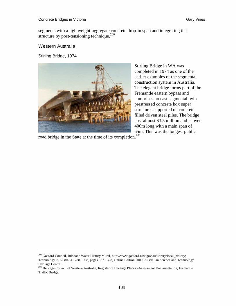
Concrete Bridges in Victoria Gary Vines
139
segments with a lightweight-aggregate concrete drop-in span and integrating the structure by post-tensioning technique.200
Western Australia
Stirling Bridge, 1974
Stirling Bridge in WA was completed in 1974 as one of the earlier examples of the segmental construction system in Australia. The elegant bridge forms part of the Fremantle eastern bypass and comprises precast segmental twin prestressed concrete box super structures supported on concrete filled driven steel piles. The bridge cost almost $3.5 million and is over 400m long with a main span of 65m. This was the longest public
road bridge in the State at the time of its completion.201
200 Gosford Council, Brisbane Water History Mural, http://www.gosford.nsw.gov.au/library/local_history; Technology in Australia 1788-1988, pages 327 - 328, Online Edition 2000, Australian Science and Technology Heritage Centre. 201 Heritage Council of Western Australia, Register of Heritage Places –Assessment Documentation, Fremantle Traffic Bridge.
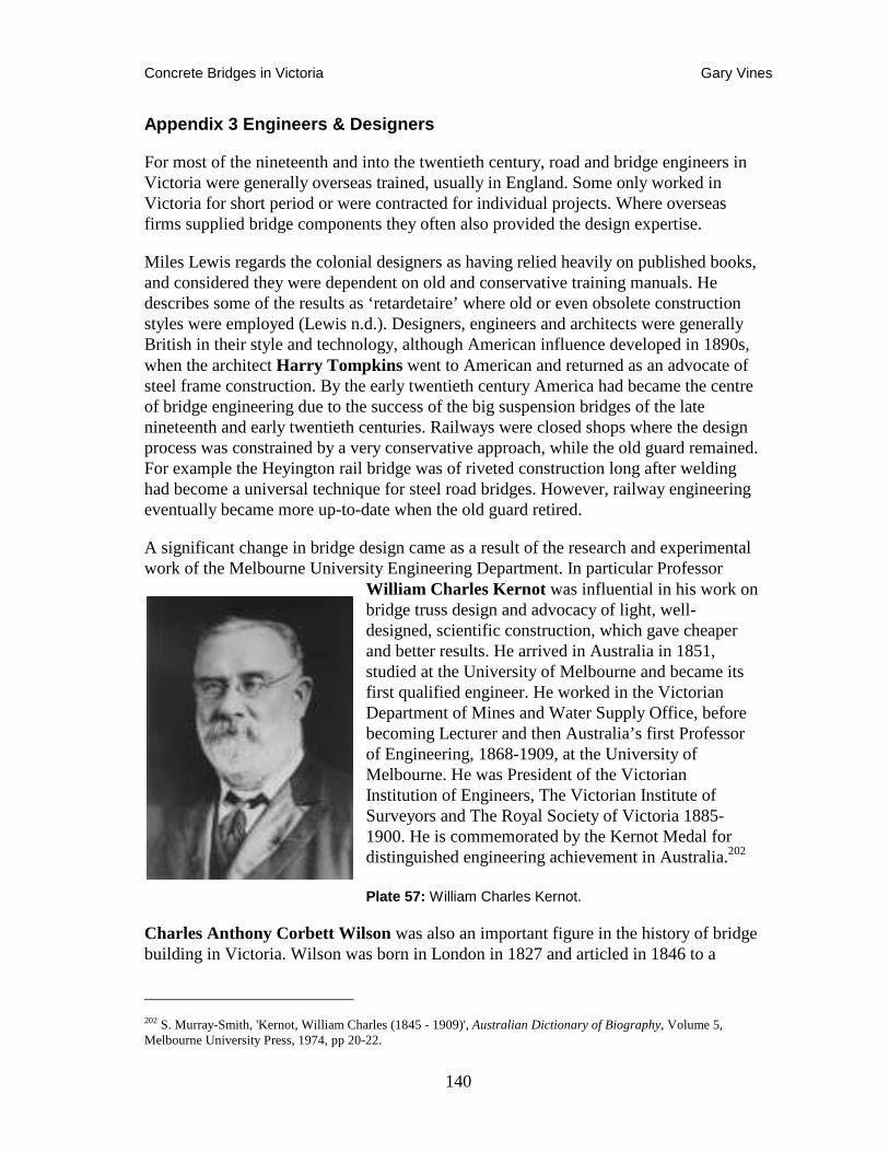
Concrete Bridges in Victoria Gary Vines
140
Appendix 3 Engineers & Designers
For most of the nineteenth and into the twentieth century, road and bridge engineers in Victoria were generally overseas trained, usually in England. Some only worked in Victoria for short period or were contracted for individual projects. Where overseas firms supplied bridge components they often also provided the design expertise.
Miles Lewis regards the colonial designers as having relied heavily on published books, and considered they were dependent on old and conservative training manuals. He describes some of the results as ‘retardetaire’ where old or even obsolete construction styles were employed (Lewis n.d.). Designers, engineers and architects were generally British in their style and technology, although American influence developed in 1890s, when the architect Harry Tompkins went to American and returned as an advocate of steel frame construction. By the early twentieth century America had became the centre of bridge engineering due to the success of the big suspension bridges of the late nineteenth and early twentieth centuries. Railways were closed shops where the design process was constrained by a very conservative approach, while the old guard remained. For example the Heyington rail bridge was of riveted construction long after welding had become a universal technique for steel road bridges. However, railway engineering eventually became more up-to-date when the old guard retired.
A significant change in bridge design came as a result of the research and experimental work of the Melbourne University Engineering Department. In particular Professor
William Charles Kernot was influential in his work on bridge truss design and advocacy of light, well-designed, scientific construction, which gave cheaper and better results. He arrived in Australia in 1851, studied at the University of Melbourne and became its first qualified engineer. He worked in the Victorian Department of Mines and Water Supply Office, before becoming Lecturer and then Australia’s first Professor of Engineering, 1868-1909, at the University of Melbourne. He was President of the Victorian Institution of Engineers, The Victorian Institute of Surveyors and The Royal Society of Victoria 1885-1900. He is commemorated by the Kernot Medal for distinguished engineering achievement in Australia.202
Plate 57: William Charles Kernot.
Charles Anthony Corbett Wilson was also an important figure in the history of bridge building in Victoria. Wilson was born in London in 1827 and articled in 1846 to a
202 S. Murray-Smith, 'Kernot, William Charles (1845 - 1909)', Australian Dictionary of Biography, Volume 5, Melbourne University Press, 1974, pp 20-22.
Concrete Bridges in Victoria Gary Vines
141
London engineering firm. He arrived in Victoria in 1851, unsuccessfully trying his luck at the gold diggings. He carried out the original survey for the Geelong to Melbourne Railway and was employed in the construction of the original iron Barwon Bridge at Geelong and the Shelford Bridge. He was the Shire of Leigh Engineer, when considerable road and bridge work was being undertaken in the Western Distorict. He later expressed a debt to the training he received there under Charles Rowand. Wilson practised his profession for an incredible sixty-four years (1846-1910) and was responsible for many iron, timber and concrete bridges in western Victoria. He was succeeded by his son Charles Corbett Powell Wilson as shire engineer on his retirement.
In the twentieth century, bridge engineering was pushed forward on several fronts. In this regard John Monash was particularly influential albeit as a reinforced concrete design engineer. However, he certainly helped to have new ideas accepted in bridge design. In partnership with J.T.N. Anderson from 1897, was responsible first for a group of reinforced concrete arch bridges, and then the first reinforced T girder bridge in the state.
Due recognition should also be given to the Country Roads Board for its influence on bridge design and construction in the State. From a policy point of view, William Calder, the first Chairman, should be recognised for his view that more permanent materials should be used for bridge construction, timber being only used where other materials were well out of the question. Other significant CRB bridge designers / constructors would include D. V. Darwin (Later Chairman of CRB), and I. J. O’Donnell (also later Chairman of CRB).203
Designers and engineers of Victorian bridges are only occasionally recorded. Some who appear to have played significant roles in Victorian bridge-building have been listed below. These have been gleaned from Cumming’s paper on Victorian engineers204 and the work of Alves, Taplin and Holgate on Monash and Anderson bridges.205 They are included for reference against future research on metal road bridges. More research is still required in this area to recognise the significant contribution made by individual bridge engineers in Victoria.
A. B. A'Beckett, Engineer for Shire of Poowong & Jeetho, c1900
Basil R. Abery, CRB Chief Bridge Engineer and Deputy Chief Bridge Engineer, Geelong division in 1950s, involved in Werribee bypass.
203 Don Chambers, 'Darwin, Donald Victor (1896 - 1972)', Australian Dictionary of Biography, Volume 13, Melbourne University Press, 1993, pp 572-573. 204 Cumming 1985. 205 Alves et al. 1998, Monash Bridges – web resource: John Monash. Engineering enterprise prior to WW1 http://home.vicnet.net.au/~aholgate/jm/jm_intro.html
Concrete Bridges in Victoria Gary Vines
142
Joshua T. Noble Anderson, partner of John Monash 1897-1905
L. H. Anderson, Shire engineer, Tambo 1945 –
C. R. Anderson, Shire Engineer, Tambo -built timber Tambo R. Bridge.
W. J. Andrew, Shire Engineer, Braybrook.
Harold Desbrowe Annear, prominent Melbourne architect and engineer, specialising in concrete industrial structures, and designer of Church Street Bridge.
Rudolph (Rudy) Baggs, Bridge Construction overseer and superintendent of Works in Stawell District and Horsham district, CRB, in 1950s-60s under E.J. Munz and others.
John Barrow, Acting Engineer in Portland erected the timber 20 span Glenelg River Bridge in Harrow in about 1858.
Francis C. E. Bell, practiced in the North of Britain and NSW then became engineer of the Essendon Railway in 1858 and gave evidence to several select committees 1859-61.
R. Boyd, Shire Engineer, Talbot & Clunes,1965, shortly after amalgamation.
Joseph Brady, involved as agent for Cornish and Bruce on the Bendigo Railway, practicing in Melbourne in the 1870s.
William Edward Bryson, designed many of the bridges and viaducts on the Melbourne, Mt. Alexander and Murray River Railway and worked under George W. Hemans in Britain.
L T Butler CRB Divisional Engineer Bendigo and then Dandenong, 1940s.
Eric Byrne CRB Bridge Inspection Enginee,r 1940s.
William Calder , (1860 - 1928), Assistant town surveyor for the City of Footscray 1889, town engineer from July 1890. Obtained certificates as municipal engineer (1890) and engineer of water-supply (1892) in night school. city engineer and building surveyor to the City of Prahran 1897-1913, first Chairman, CRB 1913-1928 (Died in Office).
Arthur E Callaway, Shire Engineer, Woorayl.
Archibald Lorne Campbell , Shire Engineer, for Corio, also Shire of Meredith.
Henry Cadogan Campbell, Engineer for the Central Roads Board in 1853.
Carlo Giorgio Domenico Enrico Catani, (1852-1918), Chief Engineer of the Victorian Public Works Department in early 20th century. Important ally of John

Concrete Bridges in Victoria Gary Vines
143
Monash in his early career, involved in river improvements on Yarra, including Anderson Street Bridge, and drainage works in Elwood inc Elwood Canal.206
W.T. Chaplin, Consulting Engineer for Monash and Anderson at Kyneton 1900-1, later Rochester Shire Engineer.
R. J. Chambers Shire of Berwick Engineer 1948-73.207
Chochrane Brothers contractors, erected Calulu Bridge 1920
Captain Andrew Clarke, R.E. M.P. Surveyor General during late 1850s and in charge of the design and procurement for the Mt. Alexander Railway. Chair of the Railways Committee and advocate for substantial railway construction as opposed to American light lines.
G. Clayfield Contractor, Daylesford, Excelsior Bridge, Coomoora Bridge.
James Fraser Cleeland, Shire Engineer, Valuer and Inspector, Thistles, Mansfield.
John Montgomery Coane, studied engineering in Dublin before moving to Australia in 1867c. He worked in Queensland 1867-70, then came to Victoria in 1871 as a teacher around Ballarat. In 1879 he became an authorized surveyor and was appointed to the country town of Benalla. John Coane later established a consulting company in partnership with G. H. Grant. This soon became one of the countries peek consulting firms and they carried out general surveying and civil, hydraulic and mining engineering projects throughout country Victoria and in the cities. His treatise on roads was highly influential and became a standard text for road and bridge engineers between 1908 and the 1930s.208
Other chronological events include: 1880 Extensive land surveys of Yea and Seymour areas , 1890 – 1891 President of the Victorian Institute of Surveyors , 1899 - 1921 Consulting Engineer to the City of Brighton , 1905 - 1906 President of the Victorian Institute of Surveyors , 1905 - 1917 Chairman of the Sludge Abatement Board (Mines Department) , 1906 - 1914 Representative on the Land Surveyors' Board.209
R. B. Comer, [or Corner?], Surveyor, Kyneton.
Frank M. Corrigan , Shire Engineer Alberton 1930, CRB Board Member 1940s.
206 Ronald McNicoll, 'Catani, Carlo Giorgio Domenico Enrico (1852 - 1918)', Australian Dictionary of Biography, Volume 7, Melbourne University Press, 1979, pp 589-590. 207 In the Wake of the Pack Tracks Berwick Pakenham Hist. Soc 1973 208 Roger J. Southern, 'Coane, John Montgomery (1848 - 1923)', Australian Dictionary of Biography, Volume 8, Melbourne University Press, 1981, pp 35-36 209 Bright Sparks, http://www.asap.unimelb.edu.au/bsparcs/biogs/P001036b.htm
Concrete Bridges in Victoria Gary Vines
144
J. E. Cowley, Proprietor of Cowley’s Iron Works, Ballarat. Prepared iron for Barham-Koondrook Bridge, Grant St Bridge Project, Saltwater Bridge Project.
John William Crawley , Engineer with the Central Roads Board 1853, and gave evidence to the select committee of Roads and Bridges in 1861, then worked in Warrnambool in 1888.
A. F. Daniel, Bulla Shire engineer, 1900s.
George Christian Darbyshire, Engineer of the Melbourne and Mt. Alexander Railway in 1855 and then Engineer-in-Chief of the Victorian Railways from 1857, he reported extensively on railway and bridge engineering to a number of select committees.
Donald Victor Darwin, CRB assistant-engineer 1920, Bridge Engineer 1924, Assist Chief Eng. 1928, Chief Eng. 1941, joined Board 1940, Chairman 1949, retired June 1962, died 8.3.1972. One of his major projects was to design the Princes Highway's crossing of the Barwon River.210
William Davidson, Inspector General of Public Works Department, Victoria in 1900s.211
M. G. ‘Bridgie’ Dempster, Bridge Engineer CRB 1930s, designed unbuilt Fitzimmons Lane Bridge.212
Charles Devlin, Assistant Engineer 'Clerk of Works' Borough of Daylesford in 1901, also Engineer for the Shire of Mount Franklin. Devlin's death was noted in The Age of 17 September 1906, which stated that he had been Borough Engineer of Daylesford since 1875.
Edward Dobson, Initially worked in Victoria as Acting Engineer of the Melbourne and Hobson’s Bay Railway in 1870 but also published extensively on bridge and engineering matters.
William Dwyer and Alfred Lloyd of Gnarwarre, contract for stonework repairs to Pollocksford Bridge for the price was £393 in 1882 (stated by Mr W. J. Dwyer, son of William, to N.S. McAdam, letter in National Trust file).
Bob Easlick, Bridge Construction Engineer, Kings Street Bridge.
C.E. Edwards, Shire engineer of Kyneton in late nineteenth century.
210 Don Chambers, 'Darwin, Donald Victor (1896 - 1972)', Australian Dictionary of Biography, Volume 13, Melbourne University Press, 1993, pp 572-573. 211 Ronald McNicoll, 'Davidson, William (1844 - 1920)', Australian Dictionary of Biography, Volume 8, Melbourne University Press, 1981, pp 230-231 212 VicRoads Retirees Association 1995
Concrete Bridges in Victoria Gary Vines
145
Thomas Ewing, Kyneton Shire Engineer.
P. T. Fairway, assistant to John Monash.
Farquahar Brothers, undertook a number of significant contracts in the 1890s and early 1900s including Chinaman’s Bridge and the Goulburn River Bridge at Seymour and some of the Murray River Bridge work. I. E. W. Farquaharson carried out timberwork repairs to Pollocksford Bridge for £227-7-0 in 1882.
Arthur Farrer, Ballarat City engineer, opposed to Monier design for Grant Street and submitted his own in 1902-3. Also involved in reconstruction of Yarrowee Creek drain, and probably other bridges in Ballarat.
Les Fawkner, Shire Engineer, Benalla in 1930s and 40s.
Mephan Ferguson, Ironfounder and engineer responsible for fabricating ironwork for many road and rail bridges including the Johnson Street, Cordite Avenue and Bruntons Bridges.
E. F. Gilchrist, City Engineer, Malvern. Shire Engr., Charlton.
W Gibbons, Ballarat Road Engineer Department of Roads & Bridges 1860.213
Robert Grey Ford, Head of Railways Design Office 1882 and later engineer in the Department of Public Works. He was given the task of preparing specifications and plans for Yarra Falls Bridge, but resigned before completing it.
George Francis, District Roads Engineer, responsible for a number of seminal bridges from the 1860s to the 1880s, including the replacement Flemington Bridge incorporating cast iron columns, the lift span Lynchs Bridge, the light weight lattice truss Plenty River Bridge and Maribyrnong Road Bridge.
J Gardiner, Shire of Berwick Engineer 1890-93.
W. A. Gay, Box Hill Shire Engineer, supervised the reforming and metalling of roads throughout the settled areas.
William Gibbins , Road Surveyor 1853-7, Acting Road Engineer 1862.
Richard B. Gibson, Engineer with the Central Roads Board 1854-8.
Henry Gore, Shire Secretary and Engineer Creswick, also Public Works Department engineer, father of W. H. Gore.
213 Braillere's Directory of Victoria for 1868, 69, 70 & 1871-72 lists ‘Gibbins, W. Engineer, Victorian Water Supply’, BDM records indicate William Joseph Gibbons as an engineer in Ballarat in the early 1860s - http://mywebsite.bigpond.com/tblack7/black/gibbins.htm
Concrete Bridges in Victoria Gary Vines
146
William Henry Gore , Shire Secretary Engineer and Valuer, Shire of Creswick, followed by his son Henry Gore who was also Creswick’s engineer.
William Henry Green , came to Victoria in 1855 to become Engineer and Surveyor with the Victorian Railways Resident Engineer on the Melbourne-Sandhurst Line 1862, Echuca Line 1866 and at Kyneton on 1878, then worked in other Australian colonies.
John George Griffith, Engineer to Portland Shire Council in 1869.
Tom Hamilton , Maffra Shire Council Assistant Shire Engineer, 1950s.
George William Harris , Inspector of Roads in Victoria 1853-6, then engineer-Secretary to the Mount Gambier and Victoria Roads Boards until about 1888.
Alfred R.C. Harrison , Chairman of Melbourne, Mt. Alexander and Murray River Railway in 1852, then Road Engineer for Department of Roads and Bridges 1854-63.
Norm Haylock, CRB Bridge engineer 1950s?, designed earliest prestressed concrete bridges in Victoria.
C. H. R. Heale, Omeo Shire Engineer, designed Livingstone Creek bridge 1919-1921, - said to be the first concrete bridge in the Shire. replaced a previous bridge known as Connely’s Bridge that was damaged by floods in 1916.
I. F. Higgens, Shire of Berwick Engineer 1862-5.
Thomas Higginbotham, among his many railway and water supply posts he was Inspector General of Roads and Bridges in the Public Works Department of the Board of Land and Works around 1858.
J. Holland, Shire of Berwick Engineer, 1873-6.
George Holmes, Contractor for the Saltwater Bridge, then the Essendon Railway in 1860.
Hughes & Orme, firm of architects/engineers, won tender for design and construct of Hoddle Bridge over the Yarra in 1930s.
William Bennet Hull , Resident Engineer for Malmsbury and Castlemaine sections of Bendigo Line in 1861.
S. Jeffrey, Benalla Shire Engineer, c1900.
John North Kelly, designed the 1876 Victoria Bridge, and also the 1868 Merri Creek bridge and probably the Rocky Waterholes Bridge, Shire of Merriang Engineer from 1870s to retirement in 1906, and was followed by E. P. Munz.
Concrete Bridges in Victoria Gary Vines
147
Sir John (Winterburn) Robert Kemp, (1883-1955), engineer and public servant, draftsman and cadet engineer in the Victorian Department of Public Works 1905-07; Shire engineer of Karkarooc Shire 1910; Country Roads Board engineer c1913-20; Foundation chairman of the Queensland Main Roads Board 1920. Sole Commissioner, Qld. Main Roads Commission 1925.214
R. Kempson, Shire of Berwick Engineer and Secretary, 1865-73.
H. L. Keys, Shire of Berwick Engineer 1904-48.
George Kermode, Public works Department Chief Engineer in the 1920s and 30s, responsible for supervising the reinforcing of the Hawthorn Bridge using electrical welding.
Prof. William Charles Kernot , (1845-1909), engineer with Victorian Department of Mines and Water Supply Office, Professor of Engineering, University of Melbourne, 1868-1909.215
M. E. Kernot , Engineer in Chief for construction of railways in the Board of Land and Works in the early 20th century.
Andrew Kerr , Surveyor and Engineer to Warrnambool from 1850s to about 1855.
J. A. Laing, design engineer with Reinforced Concrete & Monier Pipe Construction Co after Monash left, designed Hurstbridge arch bridge.
R. W. Larritt , Inspector General of Roads in 1860.
Le Cocq, Shire Engineer Marong and Bet Bet.
Hugh Lindsay, surveyor of the Geelong Ballarat Line then private civil engineer giving advice on roadworks.
P. Lingford , Consultant Shire Secretary and Engineer, South Gippsland.
D. A. Little , Shire Secretary and Engineer, Bacchus Marsh 1920s.
C. W. K. Little , Shire of Leigh Secretary and Engineer, 1932-8.
F. N. Lock, Shire Engineer, Springfield.
W. H. Lockwood, Engineer, Shires of Whittlesea and Epping, 1900s.
214 Kay Cohen, 'Kemp, Sir John Robert (1883 - 1955)', Australian Dictionary of Biography, Volume 15, Melbourne University Press, 2000, pp 1-2. 215 S. Murray-Smith, 'Kernot, William Charles (1845 - 1909)', Australian Dictionary of Biography, Volume 5, Melbourne University Press, 1974, pp 20-22.
Concrete Bridges in Victoria Gary Vines
148
Daniel Luten, influential US bridge designer and promoter of open spandrel styles.
Alex Lynch, assistant to John Monash and RCMPCo's Works Manager.
John Arnold MacCarthy , Railways engineer in Charge of Castlemaine to Sandhurst section of Bendigo line in 1862.
W. T. B. McCormack, founding member of Country Roads Board, supervised construction of Great Ocean Road; Acting chairman of the board during William Calder's visit to Europe and the United States of America in 1924; appointed chairman upon Calder's death in March 1928-38.216
Sir Warren D'arcy Mcdonald, (1901-1965), briefly assistant-engineer of Hampden Shire 1925-06, then moved to Canberra, supervising house construction and a section of the Federal Highway between Canberra and Goulburn.
G. A. Masterton, Bridge Engineer at CRB 1930s – Nathalia Bridge 1936, Senior Bridge Design Engineer, CRB 1940s, supervised strengthening of VR bridges on Murray using welding in 1928-9, Designed Lynch’s Bridge – first welded steel composite concrete deck, went to Europe with Cec Wilson to seek tenders for King Street Bridge.
J. Matheison, CRB Engineer in 1940s-60s.
George Maughan, Engineer for Shires of Creswick, Mt. Franklin and Glenlyon in early 1900s, involved in Monash & Anderson Coomoora concrete and steel bridge, 1909.
J. Maxwell, Kyneton Shire Engineer.
James Meldrum, Shire of Numurkah Engineer.
Thomas H. Merritt , Engineer of the Melbourne and Suburban Railway where he was responsible for 12 bridges, including one over the Yarra.
C. A. Mickle, Assistant Engineer, Shire of Toowong and Jeetho, Hampden Shire Engineer in 1930.
S. Morris, Bannockburn Shire engineer, supervised tender for repairs to Pollocksford laminated timber arch and bluestone bridge, 1882, for rebuilding the Bannockburn abutment and pier and reconstructing the deck.
John Monash, Bridge Engineer responsible for Chandler Highway, Outer Circle Railway Bridge, Footscray Swing Bridge and many concrete arch and beam Monier bridges.
216 Diane Langmore, 'McCormack, William Thomas Bartholomew (1879 - 1938)', Australian Dictionary of Biography, Volume 10, Melbourne University Press, 1986, pp 235-236.
Concrete Bridges in Victoria Gary Vines
149
John Montgomery, Shire of Grenville engineer, 1864-1889.
Samuel Morris, Secretary and Engineer for Shire of Bannockburn in 1900s.
Adrian Charles Mountain , principally a road and sanitation engineer, produced many papers including ‘The Evolution of The Modern Road.’ Engineer for City of Melbourne, commemorated in Mountain Street at Victoria Dock.
David Munro , (1844-1898) blacksmith and contractor, won the contract for the Moorabool viaduct in Geelong in 1858, Queens Bridge 1890; new Princes Bridge 1888. His many railway contracts included the Fitzroy-Whittlesea line and the Frankston-Crib Point line.217
F. P (or EP?). Muntz, Shire Engineer Merriang from 1906. MB-Darraweit Guim.
Joe Muntz, Shire engineer from Beaufort, son of E. J. Muntz
E. J. Munz, Shire Engineer for Ripon, 1890s to 1920s, consulting Engineer to Lexton and Avoca, and for a while Gremville. District engineer for Stawell district from 1924, when offices in Stawell. Retired from CRB 1935 but continued as shire of Lexton enginer until his death in 1950.
Thomas Bingham Muntz, senior consulting engineer, member of a large family of engineers in Victoria. Arbitrator for the Fyansford Bridge contract. Designer of the Bendigo Creek Improvement Scheme and friend of Monash and Anderson. Also began as a shire engineer at Metcalf, near Woodend, Coode Canal, Redesdale Bridge, and Mayor of Prahran, Melbourne & father of famous artist Josephine Muntz Adams.
William Jamison Muntz, Water resources engineer.
Stuart Murray Snr., Chief Engineer Victorian Water Supply commission, responsible for irrigation schemes on Goulburn-Murray.
Sir Francis Murphy , President of Board of Main Roads 1853-5.
Dave Nicholson, Bridge Division, CRB on Werribee Bypass in 1950s.
D. A. Nowlan, Acting Shire Secretary and Engineer, Shire of Creswick.
I. J. O’Donnell, later Chairman of CRB
William O’Hara , worked under significant engineers in Britain and Ireland including Alexander Nimmo and Sir John MacNeill. Draftsman with the Victorian Railways from 1855-65 where he designed many bridges and viaducts on the Mt. Alexander line.
217 Michael Cannon, 'Munro, David (1844 - 1898)', Australian Dictionary of Biography, Volume 5, Melbourne University Press, 1974, pp 311-312.
Concrete Bridges in Victoria Gary Vines
150
Keith Opie, CRB engineer, worked on Bonnie Doon Bridge.
H. G. Oliver, Shire Engineer Bright.
W. Allan Ozanne, CRB and Gippsland engineer who was responsible for the welded steel girder Swan Reach Bridge on the Tambo River, the Glenaladale welded steel truss bridge and Latrobe River concrete bridges at Rosedale, also designed the Major Mitchell Bridge, Wangaratta, of 1934.
C. H. Perrin, Engineer with the Victorian Railways from at least 1902 and was Chief Engineer of the Railway Construction Branch in 1930 when the Spencer Street Bridge was erected.
William Zachary Perrott, Engineer with Central Roads Board, 1853-63.
Thomas E. Rawlinson, Road Engineer in the Department of Roads and Bridges in 1860, responsible for the Banksia Street wrought iron arch bridge c1872.
George Somerset Read, Assistant Surveyor, City of Bendigo. Later, Shire Engineer, Marong & Bet Bet.
W. Rettie, District Inspector of Public Works.
Joseph Richard Richardson, City Surveyor, Bendigo.-Short St. Bridge
G. W. Robinson, Shire of Berwick Engineer and Secretary 1876-90, 1894-1904.
Raleigh Robinson, CRB Engineer, introduced prestressing in Victoria from UK tour 1955-6 CRB.
Caleb Grafton Roberts, (1898-1965) assistant highway engineer with CRB from 1925. Highway engineer 1928. Chief engineer from 30 October 1944. Undertook study tour for CRB to U.S.A. and Britain from June 1947 to January 1948 “His report constituted a landmark in the analysis of Australia's needs: it recommended fresh approaches to highway planning, to predicting traffic demand, to constructing and repairing roads, and to developing the skills of personnel involved in these activities.” Instrumental in establishment with (Sir) Louis Loder of Australian Road Research Board in 1959.218
W. Robertson, Surveyor/Engineer with Town of Ballarat East c1899-1903+. Favoured Monash design for Grant St Bridge against Farrer in Ballarat City, described as a clerk of works.
H. M. Rooney, Hampden shire engineer in 1946 to at least 1953.
218 A. (Len) Puglisi, 'Roberts, Caleb Grafton (1898 - 1965)', Australian Dictionary of Biography, Volume 16, Melbourne University Press, 2002, pp 100-101.
Concrete Bridges in Victoria Gary Vines
151
Charles Rowand, Engineer with Roads and Bridges Department in 1856, Ballarat Road Engineer 1860-2, then Department of Railways and Roads Engineer in 1876. He went on to work as a consulting engineer on such projects as the Victoria Street Bridge in Richmond in 1882. Influenced the Wilsons.
Francis Ryley, Engineer in the Roads and Bridges Department, 1857. Responsible for work on Wangaratta timber arch bridge in 1850s.
L. H. Sambell, Shire Engineer, Beechworth, 1920s, council member and a booster for the Shire Lake Sambell is named after him.219
A. K. T. Sambell, Shire Engineer, Traralgon water supply, relieved as shire secretary in 1907 by Walter West.
Harry E. Sando, CE. Town Clerk and Engineer, Clunes Borough Council, responsible for Government Bridge, Clunes, 1896.
Captain Charles Seabrook, municipal engineer with Sandringham Council.
G. M. Scott, Shire Engineer, Howqua, in 1900s.
Mr. Scott, Engineer, Casterton, 1896.220
James S. Sharland, consulting contractor – provided design-and-build contract for Staughton’s Bridge to Monash in 1907. Engineer for the Shire of Springfield c1901.
J. L. Shaw, Leigh Shire secretary and engineer, 1862-3.
Cecil Short, Shire Engineer, Alexandra.
Alexander Kennedy Smith, 1854-1880, principally a gasworks engineer, though a member of the royal commission on the Echuca Bridge.221
James Alexander Smith, 1878 – 1933, carpenter & timber bridge contractor, president of the Victorian Institute of Engineers from 1908-1911. Born 1857 in South Yarra, first son, John Thomas, died in 1911 due to a fall from a bridge.
Robert Speed, Shire Engineer, Ararat, in c1910.
John Stevenson, Commissioner of Roads and Bridges in 1858, Assistant Commissioner of Roads under the Local Government Act in 1864, Secretary of Railways Department 1871 and gave several submission on Select Committees on Roads and Bridges.
219 Beechworth Advertiser, 18/1/1922; 19/4/1922; Griffiths p.67 220 Back-To Sandford Centenary – 1957 221 (Cumming; Miles Lewis, Victorian Building
Concrete Bridges in Victoria Gary Vines
152
Edward Giles Stone, innovative Australian engineer specialising in reinforced concrete design, inc. Barwon Sewer Aqueduct.
Stone & Siddeley, design firm for Barwon Sewer Aqueduct.
Armand Considere, French engineer and pioneer of concrete reinforcement designs.
Swanston Brothers, Monash competitor with the Trussed Concrete Steel Company of New York, bid for State Library dome contract.
George Taylor, editor of the influential Building Magazine, who challenged Monash’s patent claim on Monier.
Harry Tompkins, architect went to American 1890s, and returned as an advocate of steel frame construction.
Saxil Tuxen, Engineer to Shire of Mornington Peninsular and others.
A. MacKenzie Tyers, Shire of Bright Engineer.
J. A. L Waddell, Structural Engineer, Kansas, USA., Tambo Bridge.
Prof. William Henry Warren, Professor of Engineering at the University of Sydney.
Bruce Watson, CRB Bridge Design Section, designed Johnston Street Bridge, 1950s.
Cec Wilson, CRB Bridge Engineer, worked on Bonnie Doon, went to Europe with G Masterton to seek tenders for King Street Bridge.
Wilson & Sly, Bridge contractors in early 20th century – provided competing tender for Benalla Bridge.
Thomas Haynes Upton, (1889-1956), civil engineer and public servant, appointed assistant-engineer to Country Roads Board in 1914, investigated road making in Britain and USA for Board wither side of WWI, engaged in road and bridge works 1919-22, supervised Barwon River bridge, on Church street Bridge judging committee with William Calder, and Professor Henry Payne, in early 1920, senior lecturer () in civil engineering at Melbourne university from 1922, when he undertook a survey of the State's road-making materials and established a road-materials testing laboratory. Appointed to the statutory Main Roads Board in New South Wales in February 1925.222
Walter West, Shire Engineer, Traralgon, 1907- .
222 T. F. C. Lawrence, 'Upton, Thomas Haynes (1889 - 1956)', Australian Dictionary of Biography, Volume 16, Melbourne University Press, 2002, pp 431-432.
Concrete Bridges in Victoria Gary Vines
153
Clement Wilks, architect of Congregational Church at Castlemaine 1855, Engineer with Central Roads Board 1854-62, Ballarat Road engineer 1858-1860 and Engineer with Department of Roads and Bridges in 1864. Designed 1871 Wilks Creek Bridge Marysville Road.
Charles Anthony Corbett Wilson, practised (1846-1910), Surveyor for the Geelong to Melbourne Railway, involved on original Barwon Bridge and Shelford Bridge, Engineer for the Shires of Leigh (1863-1910)and Bannockburn. Influenced by Rowand.223
Charles Corbett Powell Wilson, followed his father C. A. C. Wilson as Leigh Shire Engineer on his retirement (1910-32).
Charles Symons Wingrove, (c1819-1905) Secretary and Engineer of the Eltham Roads Board from 1857, and remained so until 1904. Employed by Heidelberg shire in 1872 so survey and estimate improvements to Banksia Street. Also secretary to Heidelberg in 1872, and 1878-88.224
Robert Hopper Woodcock, (1881-1951) Secretary and Engineer to the Dandenong Shire in 1912. Continued as Shire Engineer until his resignation in 1936 due to Parkinson’s Disease. In 1942 he came back for a short period as Acting Shire Engineer. At the opening ceremony for the Dandenong Creek Bridge, the CRB chairman, William Calder, stated that Woodcock ‘was considered one of the best engineers in Victoria’.225
Sir William Austin Zeal , Agent for Cornish and Bruce on railway construction at Castlemaine.
223 Griffith, Peter, 'Father and Son: Victorian Engineers Charles Anthony Corbett Wilson and Charles Corbett Powell Wilson', Memo, vol. 67, August, 1986, pp. 30-31, 34-35. 224 Garden 124-5. 225 South Bourke and Mornington Journal September 1919.
Concrete Bridges in Victoria Gary Vines
154
Glossary
Conversions
12 pennies (12d) = 1 shilling (s). 20 s = one pound (£1). Written as £/s/d. £1 = $2. 12 inches (in. or ‘) = 1 foot (ft or '). 3 ' = 1 yard (yd). 22yd = 1 chain (ch or chn). 80 ch = 1 mile. 1 mile = 1.609 kilometres. 1 foot = 30.48 centimetres. 1 pound mass (lb) = 0.453 kilograms.
Abbreviations
AASHTO American Association of State Highway Technical Organisations AHC Australian Heritage Commission AIF Australian Infantry forces CRB Country Roads Board DMR Department of Main Roads New South Wales DNRE Department of Natural Resources and Environment HV Heritage Victoria JRCC Joint Reinforced Concrete Committee M&A Monash and Anderson MMBW Melbourne and Metropolitan Board of Works NT National Trust of Australia PWD Public Works Department RACV Royal Automobile Club of Victoria RIBA Royal Institute of British Architects RSJ Rolled Steel Joist SEC State Electricity Commission SR & WSC State Rivers and Water Supply Commission
Glossary
This Glossary is a compilation from several sources including: Cridlebaugh, Bruce S., 1997-2002, Bridges and Tunnels of Allegheny County, Pennsylvania, http://www.wsdot.wa.gov/Projects/I82/KeysRd/BridgeGlossary.htm Alves et al. 1998, Monash Bridges, http://home.vicnet.net.au/~aholgate/jm/refrence/glossary.html Prairie Materials Readymix Web Resource, http://www.prairie.com/readymix/doityourself/glossary.asp Glossary
Bridge Definition
A bridge is a structure that provides a continuous path or road over water, valleys, ravines, or over other pathways.
Whilst most bridges are built to convey humans and their means of transport, they may also be built to convey water, canals, pipelines and livestock.
Theoretical frameworks:
Rule of Thumb is a term used to identify a range of empirical rules used in engineering theory prior to scientific analysis of forces.
Method of Joints: analytical system used to calculate the loads in truss members, which rests on the proposition that if the truss as a whole is in equilibrium, then every joint must be in equilibrium. Thus the equilibrium of each joint can be looked at in isolation i.e. the sum of all the forces coming into the joint must be zero. Thus every joint can be analysed as a concurrent force system in equilibrium.
Method of Sections: a form of truss analysis which allows up to three unknown forces to be solved in a less prescribed, but more efficient manner then the method of joints. Instead of looking at the equilibrium of each joint, it determines the equilibrium of a larger portion of the truss. It is especially useful for finding the force in a particular member in a large truss, or as a random check on the method of joints.
Graphic Analysis, or graphical statics: a branch of statics, in which the magnitude, direction, and position of forces are represented by scaled straight lines, used to resolve forces in structures by graphical means.
Concrete Bridges in Victoria Gary Vines
155
Three-Moment Theorem: The three-moment equation was derived by the French Engineer Emile Clapeyron in 1857 using the differential equations of. beam bending. The equation is used in connection with continuous girders, expressing the relation of the moment at any support to the moments at the preceding and following supports in terms of the loading and span lengths. It is particularly helpful in solving for the moments at the supports of indeterminate beams.
Structural Form:
The basic design and form of a bridge is based on the way they bear the weight of the structure and its load.
Arch bridges thrust outwards but downwards at their ends; they are in compression. Tied arches avoid the need for strong abutments to support the thrust of the arch, which is sustained by the carriageway instead.
Beam or girder bridges are supported at each end on abutments on the ground with the weight thrusting downwards.
Cable-stayed bridges, rely on diagonal cables connected directly between the bridge deck and supporting towers to reduce bending moments in bridge spans.
Cantilever bridges are a form of girder or truss bridge where the centre span is suspended from other girders which are cantilevered beyond their supporting piers.
Movable Bridges: Some bridges that were too low to allow traffic to pass beneath easily, were designed with movable parts, like swing bridges, drawbridges, lift bridges, bascule bridges, sliding bridges.
Rigid frame bridges are a type of girder bridge with moment-resistant connections between the superstructure and the substructure to produce an integral, elastic structure. Unlike typical girder bridges which are constructed so that the deck rests on bearings atop the piers, a rigid frame bridge acts as a unit. Pier design may vary.
Suspension bridges, originally made of woven vines or later rope and iron chains, generally comprise steel cable under tension to pull inwards against anchorages on either side of the span, and the roadway hangs from the main cables by a network of vertical cables.
Truss bridges are formed from triangulated frame members in tension and compression. There is a wide variety of truss designs, which follow an evolution to greater economy in materials and manufacture.
Fabrication:
Any of these bridge structural forms might be constructed of either 'trusses', or 'girders' and these might be of constant or varying height. Girders have solid plates of metal joining the top and bottom flanges, whereas trusses are open and have many members that connect the top and bottom chords together.
Spans formed from a single piece of metal (e.g. Rolled Steel Joists - RSJ) or cast in place or precast concrete girders requiring little fabrication, are often referred to as 'beams'. Today a beam is any member that works in bending.
Fabricated girders may be described as 'plate girders', with a solid plate between the upper and lower flanges, whether welded, riveted or bolted.
When the several plates are joined to form a hollow section, (rectangular, square, cylindrical or other shape) the girder is referred to as a 'box girder'.
Trusses are referred to as 'single' or 'double' to denote the number of planes of support between flanges.
STRUCTURES: Engineering
Camber A positive, upward curve built into a beam which compensates for some of the vertical load and anticipated deflection.
Compression Stress characterized by pressing together. When a material is squeezed it is said to be 'in compression'. Also, adjective 'compressive', as in 'compressive stress'.
Creep A very gradual change in length which occurs over time when a material is subjected to sustained load. The rate of creep decreases with the passage of time but does not die out completely. In the context of this study, creep is produced mainly by the self-weight of bridges. It is appreciable only in concrete or mortar; insignificant in steel. In slabs and girders the effect is to increase the downward deflection. In arches, creep reduces the circumferential length of the arch ring. This leads to sagging of the crown, causing the arch profile to deviate from that chosen for optimum stability by the designers. Photo.
Dead load A static load due to the weight of the structure itself, independent of traffic or the environment, which must be supported by the structure. Compare to live load.
Damping The action of reducing the vibration of an object. This tends to return the vibrating object to its original position.
Deflection The perpendicular distance a beam bends from straight, due to load and span.
Concrete Bridges in Victoria Gary Vines
156
Design In structural engineering English, the word 'design' includes not only conception of form but the calculation required to prove that the structure and its foundations will successfully resist the loadings and other influences to which they will be subjected. Generally, conception is the responsibility of a senior experienced engineer and the calculation is done by an assistant. Calculating the necessary dimensions of structural components may be called 'sizing', but this is not common. Some languages (e.g. French) have separate words for conception and sizing, while the word 'design' is applied to the modelling of the structure, especially from an 'aesthetic' point of view.
Elastic Shortening The shortening of a member in pre-stressed concrete which occurs on the application of forces induced by prestressing.
Factor of safety A structure which is twice as 'strong' as the worst forces that can reasonably be expected to act upon it can be said to have a 'factor of safety' of 2. Engineers provide the extra strength to allow for uncertainties in the estimation of loads; inevitable variations in dimensions, in materials and in the quality of work; etc. It also provides a measure of safety against overloading by ignorant users. was limited to a proportion of the yield stress.
Fatigue Cause of structural deficiencies, usually due to repetitive loading over time.
Flexure When structural components are bent by superimposed loading they are said to be subjected to 'flexure'.
Flutter Self-induced harmonic motion. A self-excited aerodynamic instability that can grow to very large amplitudes of vibrations.
Force External influence on an object which tends to produce a change in its shape or causes movement. Vertical forces on structures arise from gravity loads such as the weight of people, vehicles, building contents and contained liquids (e.g. water in elevated tanks). Horizontal forces are applied by wind; by retained solids (e.g. earth behind bridge abutments and basement perimeter walls, wheat in silos); by contained liquids (e.g. water behind dams and in tanks) and by earthquake accelerations. The action of such forces generally results in compression, extension, flexure or other distortion of the structure, generally invisible to the naked eye.
Lateral Force A force acting in a generally horizontal direction, such as wind, earthquake, or soil pressure against a foundation wall.
Live load A load which changes in magnitude with time, such as a dynamic or moving weight, such as traffic, carried by a structure. Compare to dead load.
Moment The tendency of a force to cause a rotating motion.
Oscillation A periodic movement back and forth between two extreme limits. An example is the string of a guitar that has been plucked. Its vibration back and forth is one oscillation. A vibration is described by its size (amplitude), its oscillation rate (frequency), and its timing (phase). In a suspension bridge, oscillation results from energy collected and stored by the bridge. If a part of the bridge has to store more energy than it is capable of storing, that part will probably fail.
Parallel Positioning of a member so that it is aligned with another in such a way that if extended the two members would not meet. Compare to perpendicular and transverse.
Perpendicular Positioning of a member so that it projects out from or crosses another at a right angle. Compare to parallel and transverse.
Post-tension A type of Prestressing in which reinforcing tendons are fed through tubes which are covered by concrete poured into the form. Once the concrete cures and the forms are removed, the tendon is clamped on one end and jacked tighter on the other until the required tension is achieved. This produces a reinforced concrete beam with a positive camber which is able to withstand greater loads without deflection as compared to unreinforced beams of similar dimensions. Compare to pretension.
Pressure The force applied to a surface, per unit area of surface. Usually reserved for the pressure of footings on soil; and of soil, water and gas against surfaces which contain them.
Prestressing Methods of increasing the load bearing capacity of concrete by applying increased tension on steel tendons or bars inside a beam. Types of prestressing include post-tension and pretension.
Pretension A type of prestressing in which reinforcing tendons stretched to a desired tension and then covered by concrete poured into the form. Once the concrete cures and the forms are removed, the tension of tendon is transferred to the concrete increasing its compression and creating a positive camber. This produces a reinforced concrete beam which is able to withstand greater loads without excessive deflection as compared to unreinforced beams of similar dimensions. Compare to post-tension. Also, cable hangers (or suspenders) used to support a bridge deck are commonly pretensioned before being attached to the deck.
Redundancy Principle of incorporating additional or duplicated structural members above that needed to make the structure stable and prevent it collapsing as a mechanism
Shear Stress placed transversely on a member in opposite directions. A situation in which a portion of material or a structural member is subjected to an action similar to that caused by a pair of scissors or shears. In a bridge beam this
Concrete Bridges in Victoria Gary Vines
157
is most evident when a wheel has just moved onto the span and is tending to shear the beam against the face of the support. However shearing action in general, conceived as the tendency of a particle of material to slide against the particle adjacent to it, may be present in all directions under many circumstances of loading. See also Monash's tests on shear in T-girders.
Strain The deformation of an object caused by a force acting upon it. Compressive strain is the shortening of an object in compression. Tensile strain is the elongation of an object in tension. Shearing strain is a lateral deformation caused by a force which tends to move part of an object more than another. In modern engineering: the extension or contraction of a unit length of material due to applied force, foundation settlement, etc. (Normally expressed in 'dimensionless' form, but sometimes as a percentage and occasionally in mixed units such as 'millimetres per metre'.)Compare to stress.
Stress The resistance of an object to external force. In engineering, the force transmitted through unit area of cross-section of a material. Compressive stress develops as an object in compression resists being shortened. Tensile stress develops as an object in tension resists being elongated. Shearing stress develops as an object subject to shearing forces resists deformation. Compare to strain. In structural engineering in the English-speaking world at Monash's time it was usually measured in pounds (force) per square inch (lb/in2 or psi). Now generally expressed in Newtons per square millimetre (N/mm2) which are known as megapascals (MPa) in most countries. At the start of our period, Monash and his associates used the word 'strain' where modern engineers would use 'stress'. At the start of our period, Monash and his associates used the word 'stress' where modern engineers would use 'load'.
Structure A stable assembly of components which carries a load while resisting various applied stresses, and transfers the load though its foundation to the ground.
Tension Stress characterized by pulling apart When a material is being pulled apart (stretched) it is said to be 'in tension'. Also, adjective 'tensile', as in 'tensile stress'.
Thrust A force caused by one part of a structure pushing outward against another. The thrust at the abutments of segmental arch is also called drift.
Torsion A twisting force or action.
Transverse Positioning of a member so that it projects out from or crosses another, generally in a horizontal position. Compare to parallel and perpendicular. Also, describes a movement across the length of an object as opposed to along its length.
STRUCTURES: Bridge
Abutment A substructure element (wall, block of masonry, etc) supporting each end of a single span or the extreme ends of a multi-span superstructure and, in general, retaining or supporting the approach embankment. Sometimes the natural rock or soil at this location. See sketches of arch bridge and girder bridge.
Anchor span Located at the outermost end, it counterbalances the arm of an interior span extending in the opposite direction from a major point of support. Often attached to an abutment.
Anchorage Located at the outermost ends, the part of a suspension bridge to which the cables are attached. Similar in location to an abutment of a beam bridge.
Approach span The span or spans connecting the abutment with the main span or spans.
Aqueduct A pipe or channel, open or enclosed, which carries water. May also be used as part of a canal to carry boats. Sometimes carried by a bridge.
Arch A curved structure which supports a vertical load mainly by axial compression. Shapes can be defined as semi-circular or Roman, segmental, elliptical or parabolic.
Arch barrel An arch extending the full width of the structure.
Arch, elliptical An arch in the shape of an ellipse or an approximate ellispe formed by multiple arcs each of which is drawn from its own centre. Compare to a roman arch which is a semi-circular arc drawn from a single centrepoint.
Arch, hinged A two-hinged arch is supported by a pinned connection at each end. A three-hinged arch also includes a third pinned connection at the crown of the arch near the middle of a span. Compare to fixed arch.
Arch, Monier A form of arch construction in which Monier concrete replaced traditional brick or stone masonry.
Arch ring An outer course of stone forming the arch. Made of a series of voussoirs. An archivolt is an arch ring with decorating moldings.
Arch, segmental An arch formed along an arc which is drawn from a point below its spring line, thus forming a less than semicircular arch. The intrados of a Roman arch follows an arc drawn from a point on its spring line, thus forming a semi-circle.
Backfill The replacement of excavated earth into a trench or hole, or against a basement or foundation wall.
Concrete Bridges in Victoria Gary Vines
158
Baltimore truss A subdivided Pratt truss commonly constructed for the Baltimore and Ohio Railroad. It has angled end posts and a top chord which is straight and horizontal. Compare to camelback truss and Pennsylvania truss.
Balustrade A decorative railing, especially one constructed of concrete or stone, including the top and bottom rail and the vertical supports called balusters. May also include larger vertical supports called stanchions.
Bascule bridge From the French word for ‘see-saw,’ a bascule bridge features a movable span (leaf) which rotates on a horizontal hinged axis (trunnion) to raise one end vertically. A large counterweight is used to offset to weight of the raised leaf. May have a single raising leaf or two which meet in the centre when closed. Compare to swing bridge and vertical lift bridge.
Batter A constructed slope of introduced earth or other fill material on an embankment, or excavated cutting, usually steep, measured by 1 mete horizontally for so many metres (e.g. 1:3).
Battledeck heavy steel plate deck supported on beams or cross-beams, sometimes employing rail lines. Usually overlayed with gravel of asphalt.
Beam A horizontal linear structure member supporting vertical loads by resisting bending. A girder is a larger beam, especially when made of multiple plates. Deeper, longer members are created by using trusses. Monash referred to the smaller 'beams' projecting below floor slabs in a building as 'ribs', and the larger ones as 'girders'. Where beams project below slabs, a situation that also occurs in bridge decks, the height of the 'beam' is thought of as the full height from bottom of projection to top of slab. A width of slab larger than the width of the projection may be considered an integral part of the beam, which then becomes a 'T-beam'.
Bearing A device at the ends of beams which is placed on top of a pier or abutment. The ends of the beam rest on the bearing.
Bent A substructure unit supporting each end of a bridge span; also called a pier; made up of two or more columns or column-like members connected at their top most ends by a cap, strut, or other member holding them in their correct positions.
Bent Part of a bridge substructure. A rigid frame commonly made of reinforced concrete or steel which supports a vertical load and is placed transverse to the length of a structure. Bents are commonly used to support beams and girders. An end bent is the supporting frame forming part of an abutment. Each vertical member of a bent may be called a column, pier, or pile. The horizontal member resting on top of the columns is a bent cap. The columns stand on top of some type of foundation or footer which is usually hidden below grade. A bent commonly has at least two or more vertical supports. Another term used to describe a bent is capped pile pier. A support having a single column with bent cap is sometimes called a ‘hammerhead’ pier.
Bowstring truss A truss having a curved top chord and straight bottom chord meeting at each end.
Box Girder A support beam that is a hollow box; its cross-section is a rectangle or square. A steel beam built-up from many shapes to form a hollow cross-section.
Brace-ribbed arch (trussed arch) An arch with parallel chords connected by open webbing.
Buttress A wall projecting perpendicularly from another wall which helps prevent its outward movement. Usually wider at its base and tapering toward the top.
Cable Part of a suspension bridge extending from an anchorage over the tops of the towers and down to the opposite anchorage. Suspenders or hangers are attached along its length to support the deck.
Cable-stayed bridge A variation of suspension bridge in which the tension members extend from one or more towers at varying angles to carry the deck. Allowing much more freedom in design form, this type does not use cables draped over towers, nor the anchorages at each end, as in a traditional suspension bridge.
Caisson ‘Caisson’ is the French word for ‘box.’ A caisson is a huge box made of steel-reinforced and waterproof concrete with an open central core pumped out to allow preparation of foundations in the river bed.. At the base of the caisson is its ‘cutting edge’ of plate steel. In a suspension bridge the caisson becomes the foundation, the pier, supporting for the bridge's towers. Typical caissons are built by driving a ring of piles into the bed, or allowing a timber or metal box to sink at the desired location. Large diameter concrete pipes stood on end serve the same purpose.
Camelback truss A truss having a curved top chord and straight bottom chord meeting at each end, especially when there are more than one used end to end. Compare to Baltimore truss and Pennsylvania truss.
Cantilever A structural member which projects beyond a supporting column or wall and is counterbalanced and/or supported at only one end.
Castellated girder A steel beam fabricated by making a zig-zag cut along the centreline of its web, then welding the two sides together at their peaks leaving a series of holes in the web. This creates a beam which has increased depth and therefore greater strength, but is not increased in weight.
Concrete Bridges in Victoria Gary Vines
159
Cast-in-place Concrete poured within form work on site to create a structural element in its final position.
Catenary Curve formed by a rope or chain hanging freely between two supports. The curved cables or chains used to support suspension bridges may be referred to as catenaries.
Catenary bars A true catenary is the shape adopted by a rope or cable when hung between two supports. It is similar, but not identical, to a parabola. In the period we are studying the term was used loosely to describe reinforcement draped or bent in a similar fashion. In a reinforced concrete beam that is continuous over several supports, some of the bars that lie in the bottom at mid-span may be bent up so that they run along the top of the beam over the supports. (This is because the concrete in a continuous beam is subjected to tension at the bottom at mid-span and at the top over the supports.) JM and his contemporaries referred to these 'bent-up' bars as 'catenary bars'. Some of the bars are run along the bottom for the full length, and these were referred to (inconsistently) as 'tension bars'. N.B. The term 'catenary bar' and its distinction from 'tension bar' would be unfamiliar to a modern engineer.
Cathodic protection A method of controlling corrosion of an iron or steel object – in this study, reinforcing grids or cages. In the 'sacrificial' method the ferrous object is connected to a lump of less noble metal such as magnesium, aluminium or zinc, which becomes the anode of an electrical cell. Corrosion occurs in the anode rather than the reinforcement. In the 'impressed current' method, the object to be protected is connected to the cathode of a supply of electricity. Applied to protect the Anderson St Bridge.
Catwalks Temporary foot bridges, used by bridge workers to spin the main cables (several feet above each catwalk), and to attach the suspender cables that connect the main cables to the deck.
Centering A temporary structure intended to support the weight of an arch or dome during construction, until it has sufficient integrity and strength to support itself. For Monash & Anderson's bridges, centring was composed of timber members and supported timber sheeting. On this surface was placed the steel reinforcing bars and eventually the wet concrete (compo). The centring was removed when the compo had hardened sufficiently to carry its own weight. (US spelling: centres, centering. In the UK centering is the most common spelling in this context.)
Chord Either of the two principal members of a truss extending from end to end, connected by web members. A
Column In engineering terminology, a vertical, linear structural member (its length large in comparison with its cross-sectional dimensions) which carries vertical (gravity) load and is therefore compressed. A column is normally bent by the action of the beams and floors that it supports and transfers dead and live load from the bridge deck and girders to the footings or shafts. Also see pier and pile.
Column cross brace Transverse brace between two main longitudinal compression members.
Composite Construction Any element in which concrete and steel, other than reinforcing bars, work as a single structural unit, usually with integral steel and reinforced concrete structure forming single structural member where the concrete deck and steel beams underneath work together in carrying the load to the supports, also known as composite deck beam.
Composite materials concrete, steel, timber and masonry used in various combinations so that they act together to carry loads.
Concrete A mixture of sand and stones bonded by a cementing material. In modern usage the term normally refers to cement concrete. At the end of the 19th century lime, being less expensive than Portland cement, was still used as a binder in mass concrete where high compressive strength was not required. Concrete is strong in compression (difficult to crush), but weak in tension (easily pulled apart).
Concrete, reinforced After some uncertainty, the engineering world finally settled on reinforced concrete as the generic term for concrete reinforced with bars placed at specific locations to carry the tension which plain concrete cannot resist, and sometimes to aid it in carrying compression.
Concrete, rubble Concrete containing small boulders or randomly shaped blocks of stone embedded in a matrix of lime or cement mortar, often used for foundations and abutments in Monash & Anderson bridges.
Continuous span A superstructure which extends as one piece over multiple supports.
Coping The horizontal bed of stones or concrete forming the top layer of a wall and designed to shed rainwater.
Corbel In reinforced concrete construction: a bracket projecting from a column, usually to support a beam. The term may also be applied to a cantilever, particularly if it projects from the side of a bridge and has an ornamental shape. (Also verb: to corbel, corbelled.)
Corbelled arch Masonry built over an opening by progressively extending the courses from each side until they meet at the top centre. Not a true arch as the structure relies on strictly vertical compression, not axial compression.
Counter A truss web member which functions only when a structure is partially loaded.
Counterfort A vertical rib or fin projecting usually from the back of a wall, similar in form and function to a buttress, but bonded to or integral with the wall. The term is applied to such fins on earth-retaining walls.
Concrete Bridges in Victoria Gary Vines
160
Cradle Part of a suspension bridge which carries the cable over the top of the tower.
Cripple A structural member which does not extend to the full height of others around it and does not carry as much load.
Cross-girder A beam or girder running across the width of the bridge to support the ends of the main girders, itself supported on columns and forming part of a pier. See sketch.
Crosshead In this study: a thickening of the top of a cross-wall (part of a pier) to provide seating for the ends of bridge girders. The crosshead has the appearance of a beam, but does not function as such because of the support it receives from the wall. See sketch.
Crown (i) On road surfaces, where the centre is the highest point and the surface slopes downward in opposite directions, assisting in drainage.
Crown (ii) The highest point of an arch.
Culvert (vs bridge) In present usage: a pipe or box-like tube which penetrates an embankment to allow passage of water. The box culvert would normally have an integral floor or 'invert'. The Monash & Anderson office applied this term to small bridges.
Curtain wall See 'wall, curtain'.
Deck, decking This term applies to the reinforced concrete slab which provides the supporting surface for traffic and pedestrians in girder bridges, but may also include the beams and girders directly beneath it. In all extant Monash bridges the slab was cast in situ and is integral with the girders. Sketch. Deck bridge A bridge in which the supporting members are all beneath the roadway.
Deck truss A truss which carries its deck on its top chord. Compare to pony truss and through truss.
Diagonal A sloping structural member of a truss or bracing system.
Embankment Angled grading of the ground.
End post The outwardmost vertical or angled compression member of a truss.
Expansion joint A meeting point between two parts of a structure which is designed to allow for movement of the parts due to thermal or moisture factors while protecting the parts from damage. Commonly visible on a bridge deck as a hinged or movable connection. A surface divider joint that provides space for the surface to expand. It is usually composed of a fibrous material (~1/2’ thick) and often installed in and around a concrete slab to permit it to move up and down (seasonally) along the non-moving foundation wall.
'Extra' Because of the uncertainty involved in civil engineering projects, especially in the excavation and construction of foundations, the contractor is usually recompensed for unforeseen work at a specified price per unit quantity e.g. per cubic metre of extra concrete poured. In building construction it is common for the client or architect to alter the design of the building after the contract has been signed. Recompense claimed by the contractor for an item under these headings is known as an 'extra'. (Extras are also known as 'variations', because they represent variations from the original contract, but this term was not used by M&A or RCMPC.) Extras are not payable in a 'bulk sum' contract where a contractor has tendered a fixed price for a specific task. The Supreme Court of Victoria ruled that M&A had entered into a bulk sum contract for construction of the Fyansford Bridge and they were unable to recoup a large amount of money they had spent, mainly on additional concrete in the foundations.
Extrados The outer exposed curve of an arch; defines the lower arc of a spandrel.
Eye bar A structural member having a long body and an enlarged head at each end. Each head has a hole though which a pin is inserted to connect to other members.
Falsework Temporary structure used as support during construction. Falsework for arch construction is called ‘centreing.’
Fill Earth, stone or other material used to raise the ground level, form an embankment or fill the inside of an abutment, pier or closed spandrel.
Finial A sculpted decorative element placed at the top of a spire or highpoint of a structure.
Fixed arch A structure anchored in its position. Compare to hinged arch.
Flange The horizontal portion(s) of a beam - typically beams with I or T cross-sections. Flanges play an important part in resisting bending.
Floor beam Horizontal members which are placed transversely to the major beams, girders, or trusses; used to support the deck.
Footing A footing is a widening of the base of a column or wall to spread its weight and any load it may carry over a wider area of soil or rock. The area is calculated to ensure that the pressure on the soil or rock is within its carrying
Concrete Bridges in Victoria Gary Vines
161
capacity. The footing also provides stability to the column, restricting rotation of its lower end and preventing overturning. Spread footing. A footing of a column, usually in the form of a slab, which is square or rectangular in plan. Sometimes the upper surface of the slab has the form of a very flat truncated pyramid. Strip footing A common footing serving a line of columns or a wall.
Foundation 1. The base of a structure in contact with the soil or rock on which it rests. 2. The soil or rock on which a structure rests.
Foundation, cylinder In RCMPC work, a form of foundation in which lengths of (usually large diameter) Monier pipes placed vertically end-to-end were sunk through soft soil usually to reach bed rock.
Frame In this study: a portal formed by two columns joined at their tops by a beam.
Gabion A galvanized wire box filled with stones used to form an abutment or retaining wall.
Girder A horizontal structure member supporting vertical loads by resisting bending. A girder is a larger beam, especially when made of multiple metal plates. The plates are usually riveted or welded together. Monash referred to the main members of his building floors as 'girders' and the minor members as 'ribs'.
Girder, T These occur in bridge decks and in building floors. The deck of a bridge with four main girders appears as a TTTT form in cross-section, as can be seen in Sketch 1 and Sketch 2. Each T acts structurally as a beam, the bar (or 'flange') of the T sharing with the stem (or 'web') in resisting the bending caused by loads on the span. In the period covered by this study the webs were cast integrally with the deck or floor slab.
Girder, trough Sheets of heavily troughed iron or steel placed across a gap to be bridged (the corrugations running in the direction of span) and covered with a thick layer of concrete. Bond between metal and concrete ensured composite action, similar to the principle of reinforced concrete.
Gravel Beam A timber or concrete member along the edge of the bridge deck designed to contain gravel or ballast.
Gusset plate A metal plate used to unite multiple structural members of a truss.
Hanger A tension member serving to suspend an attached member.
Haunch In the Monash & Anderson office this term was applied to the ends of an arch close to the springing. The thickness of the arch at the springing was referred to as the 'haunch thickness'. Sketch. The term is also applied when the depth of a long girder is gradually increased towards its ends.
Haunch The enlarged part of a beam near its supported ends which results in increased strength; visible as the curved or angled bottom edge of a beam.
Hinge A point in a structure at which a member is free to rotate.
Howe truss A type of truss in which vertical web members are in tension and diagonal web members in compression. Maybe be recognized by diagonal members which appear to form an ‘A’ shape (without the crossbar) toward the centre of the truss when viewed in profile. Compare to Pratt truss and Warren truss.
Humpback A description of the sideview of a bridge having relatively steep approach embankments leading to the bridge deck.
Hundredweight (cwt) = 112 pounds or one twentieth of an imperial ton..
Impost The surface which receives the vertical weight at the bottom of an arch.
In situ Concrete poured wet into its final position is said to be cast 'in situ'. The alternative is to precast it and transport the solid component to its final location.
Intrados The inner surface of a vault or arch.
Iron, cast A ferrous metal containing a relatively large proportion of impurities and especially carbon. As it is brittle (weak in tension) its use in beams prior to the 20th Century caused some disasters, but it was used satisfactorily in parts of structures subjected to compression, such as columns.
Iron, wrought A ferrous metal with a low carbon content made by melting pig iron with mill scale (iron oxide), separating purified iron from the resulting slag, and hammering and rolling it when cool. It was the preferred material for metal construction in the 19th century for parts of structures subjected to tension or flexure, such as tie rods, chains and girders.
Jack arch A common floor system that predated reinforced concrete floors consisted of shallow vaults resting on the bottom flanges of the floor joists between which they spanned. The vaults were sometimes of brick masonry covered with filling to obtain a flat floor surface. In the Dennett system shown below, the vault was of concrete with a level top surface. Such vaults are often referred to as 'jack arches'.
Jersey barrier A low, reinforced concrete wall wider at the base, tapering vertically to near mid-height, then continuing straight up to its top. The shape is designed to direct automotive traffic back toward its own lane of travel
Concrete Bridges in Victoria Gary Vines
162
and prevent crossing of a median or leaving the roadway. Commonly used on new and reconstructed bridges in place of decorative balustrades, railings or parapets.
Joint In stone masonry, the space between individual stone; in concrete, a division in continuity of the concrete; in a truss, the point at which members of a truss frame are joined.
Joist Generally applied to relatively small beams supporting a floor or ceiling.
Keystone The uppermost wedge-shaped voussoir at the crown of an arch which locks the other voussoirs into place.
King Truss Two triangular shapes sharing a common centre vertical member (king post); the simplest triangular truss system. Compare to queen truss.
Knee brace Additional support connecting the deck with the main beam which keeps the beam from buckling outward. Commonly made from plates and angles.
Lag Crosspieces used to connect the ribs in centreing.
Lateral bracing Members used to stabilize a structure by introducing diagonal connections.
Lattice An assembly of smaller pieces arranged in a gridlike pattern; sometimes used a decorative element or to form a truss of primarily diagonal members.
Lenticular truss A truss which uses curved top and bottom chords placed opposite one another to form a lens shape. The chords are connected by additional truss web members.
Main beam A beam supporting the spans and bearing directly onto a column or wall.
Member An individual angle, beam, plate, or built piece intended to become an integral part of an assembled frame or structure.
Monier 1. The surname of Joseph Monier. 2. In the early part of the period covered by this study: a 'composite' material consisting of a layer of coarse mortar containing a grid of iron bars as used in the arch bridges. When the Monash office changed to girder bridges the term 'Monier' continued to be used for a time for what was more properly reinforced concrete.
Monolithic Although reinforced concrete construction is normally interrupted at the end of a day's work and the concrete poured that day sets and hardens to some extent, when pouring is recommenced the following day a good bond can be ensured between the 'old' concrete and the new by removing the surface of the old concrete before the new is poured against it (see cold joint). Reinforcement can be made effectively continuous by 'lapping' (i.e. over-lapping) reinforcing bars. Where the bars overlap they are held together by thin wire ties. The force in one bar is transferred to the other through the bonding action of the concrete. Care is taken to ensure that cold joints are not formed where laps occur in the reinforcement. As a result the entire concrete structure: foundations, columns, girders and deck may become a single 'monolithic' unit.
Mortar A mixture of sand, cement and sometimes lime to which water has been added.
Orthotropic In bridge design, an orthotropic deck is one in which the deck is solid steel plate. The deck plate is used as the top flange of the main girder system, and also as the top flange of transverse floor beam system, and also as the top flange of the deck ribs.
Parabola A form of arch defined by a moving point which remains equidistant from a fixed point inside the arch and a moving point along a line. This shape when inverted into an arch structure results in a form which allows equal vertical loading along its length.
Parapet A low wall along the outside edge of a bridge deck used to protect vehicles and pedestrians.
Pennsylvania truss A subdivided Pratt truss invented for use by the Pennsylvania Railroad. The Pennsylvania truss is similar in bracing to a Baltimore truss, but the former has a camelback profile while the latter has angled end posts only, leaving the upper chord straight and horizontal. Compare to camelback truss and Baltimore truss.
Pier A vertical support or substructure unit that supports the spans of a multi-span superstructure at an intermediate location between its abutments. Also see column and pile.
Pier, cylinder In some bridges the columns forming the pier were constructed from large diameter reinforced concrete pipes placed vertically end-on-end and filled with concrete (containing a cylindrical cage of reinforcing bars).
Pile A long vertical shaft and column driven deep into the ground to form part of a foundation or substructure. In soft ground a foundation can be obtained by driving long posts of timber, steel or reinforced concrete into the soil until friction of the soil against the sides of the pile can suffice to support a considerable load.. If rock exists at a convenient depth, the pile may be driven to contact hard rock or penetrate soft rock. Also see column and pier.
Pile bent A row of driven or placed piles with a pile cap to hold them in their correct positions; see Bent.
Concrete Bridges in Victoria Gary Vines
163
Pillar This term has been used in our publications to describe the short columns seated on the arch ring of an open-spandrel arch bridge to support the deck (see e.g. Hurstbridge Bridge).
Pin A cylindrical bar which is used to connect various members of a truss; such as those inserted through the holes of a meeting pair of eyebars.
Plate girder A large, solid web plate with flange plates attached to the web plate by flange angles or fillet welds. Typically fabricated from steel.
Plate In structural engineering: a thin, essentially rigid, sheet of material; especially a horizontal sheet subjected to vertical loading such as a floor in a building. In Monier construction thin slabs of reinforced concrete laid on steel bridge girders to form a deck were known as 'Monier plates'. They were also used as covers for drains and septic tanks.
Pony truss A truss which carries its traffic near its top chord but not low enough to allow cross-bracing between the parallel top chords. Compare to deck truss and through truss.
Portal The clear, unobstructed space of a bridge forming the entrance to the structure.
Portal The opening at the ends of a through truss with forms the entrance. Also the open entrance of a tunnel.
Post One of the vertical compression members of a truss which is perpendicular to the bottom chord.
Pratt truss A type of truss in which vertical web members are in compression and diagonal web members in tension. Many possible configuartions include pitched, flat, or camelback top chords. Maybe be recognized by diagonal members which appear to form a ‘V’ shape toward the centre of the truss when viewed in profile. Variations include the Baltimore truss and Pennsylvania truss. Compare to Warren truss and Howe truss.
Precast concrete Structural components of reinforced concrete are sometimes cast in a factory off site and transported to site.
Pylon A monumental vertical structure marking the entrance to a bridge or forming part of a gateway.
Queen Truss A truss having two triangular shapes spaced on either side of central apex connected by horizontal top and bottom chords. Compare to king truss.
Reinforcement Adding strength or bearing capacity to a structural member. Examples include the placing of metal reinforcement bar into forms before pouring concrete, or attaching gusset plates at the intersection of multiple members of a truss.
Requisition. Orders for materials, such as steel reinforcing bars and cement.
Resonance The regular vibration of an object as it responds in step (at the same frequency) with an external force.
Revet The process of covering an embankment with stones.
Revetment A facing of masonry or stones to protect an embankment from erosion.
Rib Any one of the arched series of members which is parallel to the length of a bridge, especially those on a metal arch bridge.
Ring, arch The term 'arch ring' is used to emphasise that reference is made to the arch itself – the structural member which carries the load – and not to the entire assembly of abutments, spandrel walls, filling, etc. which might be thought to constitute the arch.
Rise The measure of an arch from the spring line to the highest part of the intrados, which is to say from its base support to the crown.
Riveted connection A rigid connection of metal bridge members that is assembled with rivets. Riveted connections increase the strength of the structure.
RSJ Rolled steel joist A standard steel beam of I shape in cross section, produced by repeatedly rolling a block of red hot steel between progressively narrowing rollers. Although the term 'joist' is normally used for minor floor Beams RSJs could be of considerable size. For the first hundred years or so, the flanges of rolled I sections had a characteristic taper. (This still occurs in the smallest sections currently rolled.)
Scour scouring Excavation of the soil in a river bed by the flow of water, especially around the base of piers and walls. This can lead to undermining of foundations.
Screed Here: a layer of mortar laid on top of a concrete floor to provide a smooth finish, often with a gentle slope to allow water to drain off the surface.
Set (of cement) When mortar or concrete is first mixed it is in a plastic condition. The first stiffening, as perceived by a standard test, is known as set.
Shaft A vertical load bearing structure that uses end bearing and friction to support loads.
Concrete Bridges in Victoria Gary Vines
164
Simple span A span in which the effective length is the same as the length of the spanning structure. The spanning superstructure extends from one vertical support, abutment or pier, to another, without crossing over an intermediate support or creating a cantilever.
Skew A bridge which does not span directly across a river or road at right angles is said to be 'skewed', or 'on the skew'. A bridge which spans directly across is said to be 'square' or 'on the square'. The angle of skew of a bridge is most commonly defined as the angle by which the centreline of the roadway it carries deviates from that of a square bridge. In a 'lightly skewed bridge' this angle will be small, while in a 'heavily skewed bridge' it will be large. However, Monash and his colleagues defined angle of skew in the other sense as the angle between the centreline of the roadway and the centreline of the creek. Professor Kernot, in making notes on the failure of the first King's Bridge at Bendigo, wrote 'angle of skew 40o (a square arch being 90o)'.
Skew When the superstructure is not perpendicular to the substructure, a skew angle is created. The skew angle is the acute angle between the alignment of the superstructure and the alignment of the substructure.
Slab In structural engineering, principally a structural member for which the horizontal dimensions are considerably greater than the depth, such as the flat portion of a building floor or bridge deck.
Slab-and-girder bridge 1. Another way of envisaging a T-girder bridge (see below). 2. Also used in this study to indicate a bridge formed by placing Monier plates (slabs) on iron girders.
Soffit The lower surface of a arch, beam or [floor] plate.
Spalling In this study: the process in which rust formed from corrosion of reinforcing bars forces off the concrete or mortar which is intended to provide protection. (Rust occupies a larger volume than the iron or steel from which it is produced.) Photo
Span The horizontal space between two supports of a structure. Also refers to the structure itself. May be used as a noun or a verb. The clear span is the space between the inside surfaces of piers or other vertical supports. The effective span is the distance between the centres of two supports. That part of a bridge between two adjacent supports. 2. The distance between two adjacent supports. The 'clear' span is the distance between the vertical faces of the supports. For descriptive purposes the distance between centres of supports of a multi-span bridge is usually quoted. The value used by engineers for computation depends on a number of technical factors.
Spandrel The roughly triangular area above an arch and below a horizontal bridge deck. A closed spandrel encloses fill material. An open spandrel carries its load using interior walls or columns. When an arch bridge is viewed from the side, the spandrel is the area between the upper surface of the arch ring and the line of the deck. In the Monier arch bridges, this area was occupied by a 'spandrel wall' which retained the soil filling on which the road was built. At one time, the spelling 'spandril' was used.
Splice plate A plate which joins two girders or plates to make them continuous. Commonly riveted or bolted.
Spring line The place where an arch rises from its support; a line drawn from the impost.
Springer The first voussoir resting on the impost of an arch.
Springing The location at which an arch ring emerges from its support or abutment. Sketch.
'Square' As a measure of building floor area: 10 feet x 10 feet.
Stable The ability of a structure to resist forces that can cause material deformation or structural collapse.
Stanchion One of the larger vertical posts supporting a railing. Smaller, closely spaced vertical supports are ballusters. Also see ballustrade.
Standard In this context: a vertical post in the balustrade of a bridge.
Stay Diagonal brace installed to minimize structural movement.
Steel Any ferrous metal (i.e. mainly iron) with a low level of impurities and low carbon content. Towards the end of the 19th Century steel was becoming available in large economic quantities and replacing iron for most structural engineering work.
Stiffener On plate girders, structural steel shapes, such as an angle, are attached to the web to add intermediate strength.
Stirrup A reinforcing rod of small diameter bent into an elongated U shape, placed in a vertical position in beams, with its bottom end looped around one or more main reinforcing bars. Stirrups help resist failure of the beam due to diagonal cracking (conventionally attributed to shear force). See beam No.6 in Monash's tests of shear strength of T-beams.
Strike (verb) To lower and/or dismantle the temporary framing which has supported a structure during construction.
Concrete Bridges in Victoria Gary Vines
165
String course In this study: the single layer of bricks or stones at the top of the spandrel wall of an arch. This line was normally accentuated by having it project from the face of the spandrel wall, and sometimes (as in most of the Bendigo bridges) by building it in bluestone to contrast with the brick face of the spandrel wall and parapet. The string course could also be made of concrete.
Stringer A beam aligned with the length of a span which supports the deck.
Strip (of arch) The arch rings of the wider and longer Monier arches were cast (turned) in a number of parallel strips, about 12 feet (3.66 m) wide, so that one strip could be completed in a single day. The joins between the strips can be seen clearly in the underside of the larger arches, as at Morell Bridge, Melbourne.
Strut A compressive member.
Substructure The parts of a bridge structure including abutments and piers, pilings, shafts, spread footings, and columns that are below the bottom of the girders and which support the superstructure.
Superstructure The parts of a bridge that are above the bottom of the girders. Girders, bridge deck, and bridge railing are parts of the superstructure, which carries the traffic load and passes that load to the substructure.
Suspended span A simple beam supported by cantilevers of adjacent spans, commonly connected by pins.
Suspenders Tension members of a suspension bridge which hang from the main cable to support the deck. Also similar tension members of an arch bridge which features a suspended deck. Also called hangers.
Suspension bridge A bridge in which the deck is carried by many tension members attached to cables draped over tower piers.
Swing bridge A movable deck bridge which opens by rotating horizontally on an axis. Compare to bascule bridge and vertical lift bridge.
T-girder See Girder, T.
Through truss A truss which carries its traffic through the interior of the structure with crossbracing between the parallel top and bottom chords. Compare to deck truss and pony truss.
Tie A member carrying tension, A tension member of a truss.
Tied arch An arch which has a tension member across its base which connects one end to the other.
Tower A tall pier or frame supporting the cable of a suspension bridge.
Trestle A bridge structure consisting of spans supported upon frame bents.
Trough girder See Girder, trough.
Truss – A rigid, jointed structure made up of individual straight pieces arranged and connected, usually in a triangular pattern, so as to support longer spans.
Truss A structural form which is used in the same way as a beam, but because it is made of an web-like assembly of smaller members it can be made longer, deeper, and therefore, stronger than a beam or girder while being lighter than a beam of similar dimensions. Truss types may include: Warren, Pratt / De Burgh, Howe / Allan / Dare, Deck Truss / Through Truss, King Post Truss, Queen Post Truss, Double Diagonal, Smith Truss, MacDonald Truss / Whipple Truss (1889-94), Long Truss, Bow String Truss.
Truss forms X Truss or cross truss – generally shallow girders with closely spaced flat or angle diagonals, usually riveted at cross junction Lattice – a vertical line through the truss intersects more than 2 diagonals Double Warren Truss – proprietary or patented design – can be analysed, top and bottom intersections are joined, usually not riveted at cross junctions of diagonal members
Trussed arch A metal arch bridge which features a curved truss.
Turn (verb) To 'turn' an arch is to complete its construction from one abutment to the other. This expression was applied by Monash and his associates to Monier arches. Most engineers today would use the verb 'to cast' for a reinforced concrete arch.
Upper chord The top longitudinal member of a truss.
Vault An enclosing structure formed by building a series of adjacent arches. Used in this study as synonymous with 'arch ring' (see 'Ring, arch' above.
Vertical lift bridge A movable deck bridge in which the deck may be raised vertically by synchronized machinery at each end. Compare to swing bridge and bascule bridge.
Viaduct A long, multi-span structure.
Concrete Bridges in Victoria Gary Vines
166
Voussoir Any one of the wedge shaped blocks used to form an arch.
Wall , curtain This term has been used in our publications for a thin wall filling the spaces between a row of columns in a bridge pier. Sketch. Later in the 20th Century, the term was applied to the external surfaces of buildings in which all major loads were carried by a skeleton of beams and columns, leaving the 'envelope' with the task only of keeping out wind and weather. This contrasted with previous practice in which massive masonry walls carried the major loads, leading to extremely thick external walls.
Wall , wing A wing wall in a bridge is a short wall continuing the face of an abutment, but usually angled back away from the stream or thoroughfare over which the bridge spans. Its purpose is to retain and protect the earth of a river bank or the embankment of an approach road. See sketch.
Warren truss A type of truss in which vertical web members are inclined to form isosceles triangles. May be recognized by diagonal members which appear to form a series of alternating ‘V’ and ‘A’ shapes (without the crossbar) along the length of the truss when viewed in profile. Often the triangles are bisected by vertical members to reduce the length of the members of the top chord. Compare to Pratt truss and Howe truss.
Web The portion of a beam located between and connected to the flanges.
Web The system of members connecting the top and bottom chords of a truss. Or the vertical portion of an I-beam or girder.
Welded joint A joint in which the assembled elements and members are united through fusion of metal.
Wing walls Extensions of a retaining wall as part of an abutment; used to contain the fill of an approach embankment
Yield When metal is subjected to a small tensile load (or 'pull') it stretches. If, when the load is removed, it returns to its original length, as a rubber band does, the metal is said to be 'elastic'. With steel, the change in length is initially proportional to the load and the material is said to be 'linearly elastic' but beyond the ‘yield point’ it deforms and does not recover its original shape.
MATERIALS: Masonry
Aggregate Crushed stone, gravel, or sand added to cement to make concrete.
Ashlar Cut, squared building stone finely dressed on all sides adjacent to other stones. Requires only very thin mortar joints. Random ashlar uses rectangular stones in discontinuous courses. Coursed ashlar uses rectangular stones of the same height in each horizontal course, but each course may vary in height. Broken range-work arranges ashlar units into horizontal courses of varying heights, which may be divided into horizontal groups at various intervals.
Composite Employing two or more materials for distinct major components eg. masonry and iron, masonry and timber, timber and iron, masonry timber and iron, steel and concrete. Often used to donate a bridge where materials are used in combination to provide additional strength, such as reinforced concrete cast to girders and fixed via welded studs forming an integral spanning member.
Concrete An artificial, stone-like building material made by combining cement with aggregate and adding sufficient water to cause it to set and bind the materials together. There are various mixtures to meet specific performance requirements. It is also commonly reinforced by placing steel mesh or rods before pouring into the forms.
Dressed stone A stone masonry unit which has been squared and shaped for precise fit with other stones. Undressed stone has naturally rough and irregular shapes.
Joint The place where two masonry units meet, often bound together by mortar.
Masonry Construction method using units such as stone, brick, and concrete block which are usually joined with a binding agent such as mortar. Mortar is a mixture of lime and/or pulverized clay (cement) with very fine sand and water. Less often, the units are held in place by their own weight, especially with very large stones. Also includes concrete construction.
Rubble Rough, irregular stone fragments used in construction of a wall or wall surface.
A random rubble wall has discontinuous courses and may include smaller garrets, small stones used to wedge larger ones into position or fill gaps. A coursed rubble wall is more organized and built to a level course at various intervals. A squared rubble wall is built of roughly squared stones of varying size which are brought to level courses every third of fourth stone.
Rustication Ashlar masonry having the visible surfaces raised or textured in contrast to the finely dressed joints.
String-course A horizontal course in a masonry wall which is of different colour, texture, or size.
Concrete Bridges in Victoria Gary Vines
167
MATERIALS: Metal
Alloy Two or more metals, or metal combined with non-metallic substances, to obtain a desired performance characteristic, such as hardness, elasticity, corrosion resistance, etc.
American standard beam Common name for an S-Shape steel beam.
Angle Structural steel shape resembling L. May be Equal Leg Angle or Unequal Leg Angle (shown). Used in trusses and built-up girders.
C-Shape or Channel Structural steel shape, which has a cross-section resembling. Similar to W-Shapes with half-width flanges on one side. Used in trusses and built-up girders.
Extrusion A structural member formed by forcing a material, such as steel, through a hole of the desired cross section; refers to both the process and the final product.
Fasteners common fasteners used in metal structures include: rivets, threaded bolts, and pin/eyebar connections.
Flange On structural steel shapes, such as C-Shapes, S-Shapes, and W-Shapes, the horizontal portions at the top and bottom which are perpendicular to the web.
Forge Process used in forming a metal structural member by heating and hammering to the desired shape.
I-beam Common name for an S-Shape steel beam.
Iron A malleable (may be pressed and shaped without returning to its original form), ductile (may be stretched or hammered without breaking), metallic element. The main ingredient used in the production of steel. Once a common building material for bridges, but was gradually replaced by steel around the turn of the 20th century.
Cast iron has a higher carbon content (2.0% - 4.5%) and is less malleable (more brittle). It is shaped by pouring it in a fluid, molten state into moulds. Steel alloys are next in decreasing order of carbon content (approx. 0.2% - 2.0%), followed by wrought iron , which has less carbon content (approx. 0.2%). This makes wrought iron tough, but more malleable. It is more easily shaped by heating and hammering (forging).
Narrow Flange Beam An S-Shape steel beam.
Rivet A metal fastener with a large head on one end, used to connect multiple metal plates by passing the shank through aligned holes in the plates and hammering the plain end to form a second head.
Rolled section A structural member formed by heating a material, such as steel, and passing it through a series of rollers to achieve a desired shape.
S-Shape or Narrow Flange Beam Structural steel shape which has a cross-section resembling an I with sloped inner flange surfaces adjacent to the web. May be formed by extrusion or rolling. Designated by the prefix S followed by the depth in inches and the weight per linear foot in pounds, such as S6x10. Commonly called I-beam or American standard beam. Compare to W-Shape.
Steel Any of a variety of iron-based metallic alloys having less carbon content than cast iron, but more than wrought iron.
W-Shape or Wide Flange Beam Structural steel shape which has a cross-section resembling an H with flat inner flange surfaces adjacent to the web. May be formed by extrusion or rolling. Designated by the prefix W followed by the depth in inches and the weight per linear foot in pounds, such as W18x40. Compare to S-Shape.
Web On structural steel shapes, such as C-Shapes, S-Shapes, and W-Shapes, the flat portion which is perpendicular to and joining the flanges. Also, the system of members connecting the top and bottom chords of a truss.
Weld Joining two metal pieces by heating them and allowing them to flow together. Creating a bond by using another nonferrous metal which melts below 800 degrees Fahrenheit is called soldering. Creating a bond by using another nonferrous metal which melts above 800 degrees Fahrenheit is called brazing. The continuous deposit of fused metal created in these processes is called a bead.
MATERIALS: Concrete
Abrasion Resistance Resistance of a surface to being worn away by friction or a rubbing process.
Absolute Volume The volume of an ingredient in its solid state, without voids between individual pieces or particles; in the case of fluids, the cubic content occupied. In concrete, the actual volume occupied by the different ingredients determined by dividing the weight of each ingredient in pounds, by ifs specific gravity, times the weight of one cubic foot of water in pounds. Example: Absolute Volume of one sack of cement equals: 94 ÷ (3.15X62.4) = 0.478 cubic feet
Absorbed Moisture Moisture which is mechanically held in a material. In aggregates, water that is not available to become part of the mixing water is designated ‘absorbed’ water.
Concrete Bridges in Victoria Gary Vines
168
Absorption The process by which water is absorbed. The amount of water absorbed under specific conditions, usually expressed as percentage of the dry weight of the material.
Accelerator An admixture which, when added to concrete, mortar, or grout, increases the rate of hydration of the hydraulic cement, shortens the time of set and increases the rate of hardening or strength development.
Adiabatic Curing The maintenance of ambient conditions during the setting and hardening of concrete so that heat is neither lost nor gained from the surroundings of the concrete.
Admixture A material other than water, aggregates, and Portland cement that is used as an ingredient of concrete, and is added to the batch in small doses immediately before or during the mixing operation to produce some desired modifications, either to the physical or chemical properties of the mix or of the hardened product. The most common admixtures affect plasticity, air entrainment, and curing time.
Adsorption Water Water held on surfaces in a material by either physical and/or chemical forces.
Aggregate A mixture of sand, rock, crushed stone, expanded materials, or particles that typically compose 75% of concrete by volume. Aggregates improve the formation and flow of cement paste and improve the concrete's structural performance.
Air Content The amount of entrained or entrapped air in concrete or mortar, exclusive of pore space in aggregate particles, usually expressed as a percentage of total volume of concrete or mortar. A controlled air content prevents concrete from cracking during the freeze/thaw cycle
Air Entraining Agent An addition for hydraulic cement, or an admixture for concrete or mortar which entrains air in the form of minute bubbles in the concrete or mortar during mixing usually to increase its workability and frost resistance.
Air Permeability Test A procedure for determining the fineness of powdered material such as cement.
Alkali-Silica Reactivity - ASR The reaction of aggregates, which contain some form of silica or carbonates with sodium oxides or potassium oxides in cement, particularly in warm, moist climates or environments, causing expansion, cracking or popouts in concrete.
Aluminous Cement A hydraulic cement in which the principal constituents are calcium aluminates, instead of calcium silicates which comprise the major ingredients of Portland cement.
Autoclave A chamber in which an environment of steam and high pressure is produced. Used in curing of concrete products and in the testing of hydraulic cement for soundness.
Anchor Bolts Steel bolts used to secure a wooden sill plate to concrete, masonry floor, or wall.
Angle Float/Trowel A trowel with two surfaces meeting at right angles. An angle float is used for finishing plaster or concrete in an inside corner.
Asphalt Expansion Joint Premolded felt or fiberboard impregnated with asphalt and used extensively as an expansion joint for cast-in-place concrete.
Autoclaved Aerated Concrete - AAC Exceptionally lightweight precast concrete with high thermal qualities and fire resistance, suitable for cutting with ordinary hand tools. The mix design is composed of Portland cement, sand or siliceous material, lime, gypsum, finely powdered aluminium, and water. The finely powdered aluminium reacts with the alkaline components of the cement and lime to produce hydrogen gas, which increases the volume approximately five times producing a uniformly, dispersed cellular structure. Units are cut to required shape and placed in an autoclave, an enclosed pressurized chamber, and steam cured at 350 0 F. Approximately 80% of the ultimate volume consists of air voids.
Bag A quantity of Portland cement; 94 pounds in the United States, 87.5 pounds in Canada, 112 pounds in the United Kingdom, and 50 kilograms in most other countries. Different weights per bag are commonly used for other types of cement.
Ball Test A test to determine the consistency of freshly mixed concrete by measuring the depth of penetration of a cylindrical metal weight or plunger that has been dropped into it.
Bar Support (Bar Chair) A rigid device of formed wire, plastic, or concrete, used to support or hold reinforcing bars in proper position during concrete operations.
Barrel A unit of weight measure for Portland cement, equivalent to four bags or 376 pounds.
Batch The quantity produced as the result of one mixing operation, as in a batch of concrete.
Batch Box A container of known volume used to measure the constituents of concrete or mortar in proper proportions.
Concrete Bridges in Victoria Gary Vines
169
Batch plant A temporary concrete mixing plant usually erected at a jobsite to fulfil the specific needs of that job. They are typically erected when a large volume of concrete will be required at a specific job. Batch plants can reduce transportation costs, increase control of the mixture, and speed up job completion.
Binder Almost any cementing material, either hydrated cement or a product of cement or lime and reactive siliceous materials. The kinds of cement and the curing conditions determine the general type of binder formed. Any material, such as asphalt or resin, that forms the matrix of concretes, mortars, and sanded grouts.
Blaine Fineness The fineness of granular materials such as cement and pozzolan, expressed as total surface area in square centimetres per gram, determined by the Blaine air-permeability apparatus and procedure.
Blaine Test A method for determining the fineness of cement or other material based on the permeability to air of a sample prepared under specified conditions.
Blanket Insulation sandwiched between sheets of fabric, plaster, or paper facing, used for protecting fresh concrete during curing.
Bleeding, Bleed Water A form of segregation in which some of the water in a mix tends to rise to the surface of freshly placed concrete. Bleeding is caused by the settlement of the solid materials within the mass. Bleeding is also called water gain.
Blended Cement A hydraulic cement consisting of a uniform blend of any of the following: granulated blast-furnace slag and hydrated lime; Portland cement and granulated blast-furnace slag; Portland cement and pozzolano; or Portland cement, blast-furnace slag, and pozzolano. Blended cement is produced by intergrinding Portland cement clinker with the other materials or by a combination of intergrinding and blending.
Blowhole In concrete, a bug hole or small regular or irregular cavity, not exceeding 15 mm in diameter, resulting from entrapment of air bubbles in the surface of formed concrete during placement and compaction.
Blowout Term used when the ready-mixed concrete breaks through the forming boards due to insufficient bracing. Also, the localized buckling or breaking up of rigid pavement as a result of excessive longitudinal pressure.
Blowup Slang term used to describe the unexpected fast setting of concrete that does not allow proper finishing.
Board Foot The basic unit of measurement for lumber. One board foot is equal to a 1 inch thick board, 12 inches in width and 1 foot in length. Therefore, a 10 ft long, 12 inch wide, and 1inch thick piece contains 10 board feet. Nominal sizes are assumed when calculating board feet.
Bond Adhesion of concrete or mortar to reinforcement, or to other surfaces. The adhesion of cement paste to aggregate.
Bull Float A board of wood, aluminium, or magnesium mounted on a pole and used to spread and smooth freshly placed, horizontal concrete surfaces. After screeding, the first stage in the final finish of concrete, smoothes and levels hills and voids left after screeding. Sometimes substituted for darbying.
Burlap Material often used to protect newly finished concrete from rain as well as maintaining moisture in a slab.
Caisson The structural support for a type of foundation wall, porch, patio, monopost, or other structure. A 10’ or 12’ diameter hole drilled into the earth and embedded into bedrock 3 to 4 feet. Two or more ‘sticks’ of reinforcing bars (rebar) are inserted into and run the full length of the hole and then concrete is poured into the caisson hole. A caisson is designed to rest on an underlying stratum of rock or satisfactory soil and is used when unsatisfactory soil exists.
Calcareous Containing calcium carbonate or, less generally, containing the element calcium.
Calcine To alter composition or physical state by heating to a specific temperature for a specific length of time.
Calcite The main raw material used in the manufacture of Portland cement. Calcite is a crystallized form of calcium carbonate and is the principal component in limestone, chalk, and marble.
Calcium aluminate cement A combination of calcium carbonate and aluminates that have been thermally fused or sintered and ground to make cement.
Calcium Chloride An additive used in ready-mix to accelerate the curing, usually used during damp conditions.
Capillarity A wick-like action whereby a liquid will migrate vertically through material, in an upward direction; as oil in a lamp travels upward through the wick.
Capillary space In cement paste, any space not occupied by anhydrous cement or cement gel. Air bubbles, whether entrained or entrapped, are not considered as part of the cement paste.
Carbonation 1) Reaction between the products of Portland cement (soluble calcium hydroxides), water and carbon dioxide to produce insoluble calcium carbonate (efflorescence). 2) Soft white, chalky surface dusting of freshly placed, unhardened concrete caused by carbon dioxide from unvented heaters or gasoline powered equipment in an
Concrete Bridges in Victoria Gary Vines
170
enclosed space. Carbonation arises when carbon dioxide in the atmosphere reduces the alkalinity of concrete and may result in rusting of steel reinforcing if moisture can penetrate the concrete.
Casting Pouring a liquid material, or slurry, like concrete, into a mould or form whose physical form it will take on as it solidifies.
Casting bed A permanent, fixed form, in which permanent pre-cast concrete forms are produced.
Cement In modern civil engineering usage this term refers almost always to 'Portland' cement: a fine powder made by heating a mixture of clay and crushed limestone in a rotating furnace and grinding the resulting nodules. When this cement is mixed with water a chemical reaction takes place forming a brittle solid.
Cement, Portland (ASTM C150) A powdery substance made by burning, at a high temperature, a mixture of clay and limestone producing lumps called ‘clinkers’ which are ground into a fine powder consisting of hydraulic calcium silicates.
Cement content A quantity of cement contained in a unit volume of concrete or mortar, ordinarily expressed as pounds, barrels, or bags per cubic yard.
Cement gel The colloidal gel (glue like) material that makes up the major portion of the porous mass of which hydrated cement paste is composed.
Cementitious Having cement-like, cementing, or bonding type properties. Material or substance producing bonding properties or cement-like materials.
Cement slurry A thin, watery cement mixture for pumping or for use as a wash over a surface.
Central plant A facility that makes and distributes ready-mix or pre-mixed concrete loading the material into agitator trucks.
Chair(s) In concrete formwork, a small metal or plastic support for the reinforcing steel. The support is used to maintain proper positioning during concrete placement.
Cinder block A masonry block made of crushed cinders and Portland cement. This type of block is lighter and has a higher insulating value than concrete. Because moisture causes deterioration of cinder block, it is used primarily for interior rather than exterior walls.
Clinker The resulting admixture from burning a combination of limestone with silica, alumina, and iron oxide-containing materials. A lump or ball of the fused material, usually 1/8’ to 1’ in diameter, is formed by heating cement slurry in a kiln. Clinker, when cool, is ground into a fine powder and interground with gypsum to form cement.
Coarse aggregate Naturally occurring, processed or manufactured, inorganic particles in prescribed gradation or size range, the smallest size of which will be retained on the No. 4 (4.76 mm) sieve.
Cold joint A joint formed in a mass of concrete or mortar when work is suspended for an interval and this concrete has time to set before fresh concrete is placed against it when construction is resumed. Because of the uncertain bond between the older concrete and the new, a 'cold joint' forms a potential plane of weakness in the concrete mass.
Colloidal A gel-like mass which does not allow the transfer of ions
Compo The term used around the turn of the century to describe the coarse dry mortar used in Monier construction.
Compaction The elimination of voids in construction materials, as in concrete, plaster, or soil, by vibration, tamping, rolling, or some other method or combination of methods. The process of eliminating voids in the non-set concrete mixture that has been placed often using various vibration devices.
Compressive Strength The measured resistance of a concrete or mortar specimen to axial loading expressed as pounds per square inch (psi) of cross-sectional area. The maximum compressive stress which Portland cement, concrete, or grout is capable of sustaining.
Concrete A composite material which consists essentially of a binding medium, within which are embedded particles or fragments of a relatively inert filler. In Portland cement concrete, the binder is a mixture of Portland cement and any additional cementitious materials such as fly ash, and water. The filler may be any of a wide variety of natural or artificial fine and coarse aggregates, and in some instances, an admixture.
Concrete Block A concrete masonry unit, most often hollow, that is larger than a brick.
Concrete Contraction The shrinkage of concrete that occurs as it cures and dries.
Concrete Finish A description of the smoothness, texture, or hardness of a concrete surface.
Concrete Finishing Machine A portable machine with large paddles like fan blades used to float and finish concrete floors and slabs. A large power-driven machine mounted on wheels that ride on steel pavement forms. These machines are used to finish concrete pavements
Concrete Bridges in Victoria Gary Vines
171
Concrete Masonry Unit A block of hardened concrete, with or without hollow cores, designed to be laid in the same manner as a brick or stone. A CMU is also referred to as a concrete block.
Concrete Mixture The percentage of cement content contained in the concrete. A rich mixture contains a high proportion of cement. A lean mixture is a mixture of concrete or mortar with a relatively low cement content. A harsh mixture of concrete is one without mortar or aggregate fines, resulting in an undesirable consistency and workability.
Condensation When a moisture laden gas comes in contact with a cooler surface a change of state from gaseous to liquid occurs.
Consistency The degree of plasticity of fresh concrete or mortar. The normal measure of consistency is slump for concrete and flow for mortar.
Consolidation Compaction usually accomplished by vibration of newly placed concrete to mould it within form shapes and around embedded parts and reinforcement, and to eliminate voids other than entrained air.
Construction Joint A horizontal or vertical joint formed when placement of concrete is interrupted for some reason, usually the end of a day’s work. A 'surface' is formed as the placed concrete cures, and then fresh, plastic concrete is poured against this surface at some later point in time.
Control Joint Tooled or sawn, straight grooves made on concrete floors to ‘control’ where the concrete should crack.
Cover The distance between the surface of a reinforcing rod and the nearest surface of the enclosing mortar or concrete. Strictly, this is measured from the surface of any reinforcement, but some codes allowed it to be measured from the 'main' reinforcement, neglecting elements such as 'ties' (or ligatures') in columns, and 'stirrups' in beams.
Cream Construction slang term to describe the cement and sand component of ready-mix that rises when the aggregate is worked down by way of agitation – floating, towelling, screeding, etc.
Cure Method of maintaining sufficient internal humidity and proper temperature for freshly placed concrete to assure proper hydration of the cement, and proper hardening of the concrete.
Curing Blanket A layer of straw, burlap, sawdust, or other suitable material placed over fresh concrete and moistened to help maintain humidity and temperature for proper hydration
Curing Compound A chemical applied to the surface of fresh concrete to minimize the loss of moisture during the first stages of setting and hardening.
Curing Membrane Any of several kinds of sheet material or spray-on coatings used to temporarily retard the evaporation of water from the exposed surface of fresh concrete, thus ensuring a proper cure.
Cut and Fill A term used to describe the addition or subtraction from a grade mark. Also, an operation commonly used in road building and other rock and earthmoving operations in which the material excavated and removed from one location is used as fill material at another location.
Darby (derby, derby float, derby slicker) A stiff straightedge of wood or metal used to level the surface of wet concrete. A portable machine with large paddles like fan blades used to float and finish concrete floors and slabs. A large power-driven machine mounted on wheels that ride on steel pavement forms and is used to finish concrete pavements.
Density Mass per unit volume. (Weight per unit volume is ‘Specific Weight’).
Dispersing Agent An admixture capable of increasing the fluidity of pastes, mortars, or concretes by reduction of interparticle attraction.
Dowel A cylindrical piece of stock inserted into holes in adjacent pieces of material to align and/or attach the two pieces.
Dowel-Bar Reinforcement Short sections of reinforcing steel that extend from one concrete placement into the next. They are used to increase strength in the joint.
Dry Concrete Concrete that has a low water content, making it relatively stiff. The effects are a lower water-cement ratio, less pressure on forms, lower heat of hydration, and a consistency that allows for placement on a sloping surface.
Dry Pack A low-slump grout tamped into the space in a connection between pre-cast concrete members.
Dry Shake (Dry Topping) A concrete surface treatment, such as colour, hardening, or antiskid, which is applied to a concrete slab by shaking on a dry, granular material before the concrete has set and then trowelling it in.
Drying Shrinkage A decrease in the volume of concrete upon drying.
Durability The ability of concrete to resist weathering action, chemical attack, and abrasion.
Concrete Bridges in Victoria Gary Vines
172
Efflorescence The process by which water leeches soluble salts out of concrete or mortar and deposits them on the surface. Also used as the name for these deposits.
Entrained Air Microscopic air bubbles intentionally incorporated in mortar or concrete, to improve workability and durability (usually producing a higher degree of resistance to freezing and thawing).
Entrapped Air Air in concrete which is not purposely en-trained. Entrapped air bubbles are normally much larger and more irregular than entrained air bubbles.
Exposed Aggregate Finish A method of finishing concrete which washes the cement/sand mixture off the top layer of the aggregate - usually gravel. It is often used in driveways, patios and other exterior surfaces.
Extension Chute An additional chute used by a concrete contractor to extend the length of the existing chutes from a ready-mix concrete truck. They are frequently used to pour floors.
False Set The rapid development of rigidity in a mixed Portland cement paste, mortar, or concrete without the evolution of much heat. This rigidity can be dispelled and plasticity regained by further mixing without addition of water. Premature stiffening, and rubber set are terms referring to the same phenomenon, but false set is the preferred term.
F Numbers The specification of the degree of flatness that a slab or floor must have. The degree of flatness of a concrete floor is extremely critical for warehouse or manufacturing plant floors where specialized materials handling equipment may be guided by wires under the concrete floor.
Face Forms Concrete forms that are used to create a desired curb profile. They attach to the curb and gutter form set up by hooking to the clips of the division plate. Face forms are designed based on the amount of batter specified.
Faced Concrete To finish the front and all vertical sides of a concrete porch, step(s), or patio. Normally the ‘face’ is broom finished.
Fat Mix / Rich Mix A mortar or concrete mix with a relatively high cement content. Fat mix is more easily spread and worked than a mix with the minimum amount of cement required for strength.
Fibre Reinforced Concrete A variant of concrete that is produced by adding fibres made of stainless steel, glass, carbon or polypropylene to the mixture.
Fibrous Admixture Special fibrous substances of glass, steel, or polypropylene that are mixed into concrete to act as a reinforcement against plastic shrinkage cracking.
Fine Aggregate Aggregate passing the 3/8-in. sieve and almost entirely passing the No.4(4.76 mm) sieve and predominantly retained on the No. 200 (74 micron) sieve(ASTM125).
Fineness Modulus An index of fineness or coarseness of an aggregate sample. An empirical factor determined by adding total percentages of an aggregate sample retained on each of a specified series of sieves, and dividing the sum by 100. Note: US Standard sieve sizes are used: No. 100, No.50, No. 30, No. 16, No. 8, and No. 4, and 3/8 in., 3/4 in., I in., 2 in., 3 in., and 6 in.
Finishing Levelling, smoothing, compacting, and otherwise treating surfaces of fresh or recently placed concrete to produce the desired appearance and service.
Fixed Nose Form A metal concrete pouring form with a fixed nose piece to allow it to interlock with the rear section of another form creating a solid interconnection. Fixed nose forms must be removed in order or reverse order after a pour due to their interlocking nature.
Flash Set The rapid development of rigidity in a mixed Portland cement paste, mortar or concrete usually with the evolution of considerable heat, which rigidity cannot be dispelled nor can the plasticity be regained by further mixing without addition of water Also referred to as quick set or grab set.
Flatwork Common word for concrete floors, driveways, basements, and sidewalks.
Flatwork Forms Metal or wood forms used in concrete flatwork placement. These forms are typically used for edge forming, sidewalks, driveways, footings, industrial slabs, foundations, patios, general flatwork, and in curb and gutter work.
Flexible Forms Metal forms used to form radius shapes such as islands, serpentine sidewalks, curved curbs, parking lot turnouts, and similar applications. They are made from spring steel and are typically 10 feet long with stake pockets riveted onto the form every 18’. They range in height form 4’ to 12’. The same as radius forms.
Flexural Strength A property of a solid that indicates its ability to withstand bending.
Float A tool (not a darby), usually of wood, aluminium, magnesium, rubber, or sponge, used in concrete or tile finishing operations to impart a relatively even but still open texture to an unformed fresh concrete surface.
Floating The operation of finishing a fresh concrete or mortar surface by use of a hand float or bull float smoothing and bringing water to the surface, preceding towelling when that is the final finish.
Concrete Bridges in Victoria Gary Vines
173
Floating Wall A non-bearing wall built on a concrete floor. It is constructed so that the bottom two horizontal plates can compress or pull apart if the concrete floor moves up or down. A floating wall is normally built on basements and garage slabs.
Fly Ash The finely divided residue that results from the combustion of ground or powdered coal, transported from the firebox through the boiler by flue gases. Fly ash contains aluminosilicate and small amounts of lime. It is a concrete admixture.
Form A temporary erected structure or mould for the support and containment of concrete during placement and while it is setting and gaining sufficient strength to be self-supporting.
Form Release Agent Material used to prevent bonding of concrete to a surface, such as to forms.
Forming The use of metal or wood forms to create the proper placement of concrete. The forming process channels the concrete into the desired shape and thickness.
Formwork Temporary structures or forms made of wood, metal, or plastic used in the placing of concrete to ensure the slurry is shaped to its desired final form. Formwork must be strong enough to support the considerable weight and pressure of wet concrete without deflection.
Foundation Form Sets Custom made sets of metal concrete forms used for houses, garage, car port, strip mall, warehouse floors, and other structures which require slab on grade foundations.
Foundation Ties Metal wires that hold the foundation wall panels and rebar in place during the concrete pour.
Gap-graded Aggregate Aggregate containing particles of both large and small sizes, in which particles of certain intermediate sizes are wholly or substantially absent.
Gauging The process of measuring sand, gravel, cement and water in specified proportions for mixing to form concrete. In M&A's early Monier work sand and gravel were measured in shallow boxes and mixed prior to addition of cement and water. Mechanical concrete mixers were adopted by RCMPC around 1910.
Glass Fibre Reinforced Concrete (GFRC) Concrete panels, usually architectural designs, reinforced with a high zirconia (16% minimum), alkali-resistant glass fibre. Optimum glass fibre content of 5% by weight. Lower fibre content results in lower early ultimate strengths; higher fibre content can produce composite compaction and consolidation difficulties. It is usually a thin cementitious material laminated to plywood or other lightweight backing.
Gillmore Needle A device used in determining time of setting of hydraulic cement, described in ASTM 0 266.
Gradation The sizing of granular materials; for concrete materials, usually expressed in terms of cumulative percentages larger or smaller than each of a series of sieve openings or the percentages between certain ranges of sieve openings.
Grade The surface or level of the ground. The existing or proposed ground level or elevation on a building site or around a building. The slope or rate of incline or decline of a road, expressed as a percent. A designation of a subfloor, either above grade, on grade, or below grade. Any surface prepared to accept paving, conduit, or rails.
Grade Beam A reinforced concrete beam around the perimeter of a building that transmits the load from a bearing wall into spaced foundations such as pile caps or caissons.
Grade Line A strong string used to establish the top of a concrete placement.
Grout A fluid mixture of cement, sand, and water or cement and water. The hardened equivalent of such mixtures. A high-slump mixture of Portland cement, aggregates, and water which can be poured or pumped into cavities in concrete or masonry for the purpose of embedding reinforcing bars, and/or increasing the amount of load-bearing material in a wall.
Gunite A term sometimes used to designate dry-mix shotcrete.
Hand Float A wooden tool used to lay on and to smooth or texture a finish coat of plaster or concrete.
Hangers A straight metal bar with pockets on an adjustable slide that allow straight forms to be placed in areas where securing forms into position is difficult due to soil conditions, existing pavement, or obstacles. Hangers are often used in applications such as sidewalks, foundations, and curb and gutter work.
Hardener The curing agent of a two-part synthetic resin, adhesive, or similar coating.
Heat of Hydration The quantity of heat expressed in calories per gram, evolved upon complete hydration of Portland cement at a given temperature.
Holding Period In the manufacture of concrete products, the period between completion of casting and the introduction of additional heat or steam curing period.
Concrete Bridges in Victoria Gary Vines
174
Honeycomb An area in a foundation wall where the aggregate (gravel) is visible. Honeycombs can be usually be remedied by applying a thin layer of grout or other cement product over the affected area. A method by which concrete is poured and not puddled or vibrated, allowing the edges to have voids or holes after the forms are removed.
Hot Load Construction slang used to describe ready-mix concrete that has begun its hydration process while still in the delivery drum of the agitator truck. Hydration causes heat build up in the concrete mix.
HRM (High Reactivity Metakaolin) Refined form of an ASTM C618, Class N (natural) pozzolan. A high performance, mineral admixture, similar in performance to silica fume. The pure white powdered form will not affect the natural colour or darken concrete as silica fume does. Suitable for high-performance colour matching in architectural concrete.
Hydration The chemical reaction that occurs when cement is mixed with water. A concrete slab needs to completely hydrate prior to the application of paints, coatings, and flooring materials.
Hydraulic Cement A variety of cement engineered to harden under water (ASTM 219).
Hydrogenesis Another term for condensation. The term is especially applied to base and soil substrates under highway pavements where the barometric pump causes the inhalation of humid air, which then condenses in those structures, causing an ever increasing moisture content and sometimes instability.
Impermeable The ability of a material or product to reduce or eliminate gaseous transmissions through it's mass; measured as the rate of Water Vapour Transmission (WVT). Note: Not all materials that are waterproof are vapourproof; all materials that are vapourproof are inherently waterproof.
Initial Set A degree of stiffening of the cement and water mixture. This is a degree less than final set and is generally stated as an empirical value, indicating the time in hours and minutes required for a cement paste to stiffen sufficiently to resist to an established degree the penetration of a weighted test needle. (Refer to ASTM C191 or C286 for weight and penetration data.)
Initial stress In prestressed concrete, the stresses occurring in the prestressed members before any losses occur.
Jacking Equipment In prestress concrete, the device used to stress the tendons.
Jacking Force The temporary force exerted by the jacking device which introduces tension into the tendons.
Jacking Stress In prestress concrete, the maximum stress occurring in a tendon during stressing.
Jitterbug A grate tamper used to bring sand and cement grout to the surface of wet concrete during placement of slabs. May be motorized or hand operated.
Joint Position where two or more building materials, components or assemblies are put together, fixed or united, with or without the use of extra jointing products. The location between the touching surfaces of two members or components joined and held together by nails, glue, cement, mortar, or other means.
Keene's Cement A finely ground high density plaster composed of anhydrous, (calcined or ‘dead burned’) gypsum, the set of which is accelerated by the addition of other materials.
Kelly Ball A device for determining the consistency of fresh concrete, sometimes used as an alternative to the slump test.
Key A slot formed into a concrete surface for the purpose of interlocking with a subsequent pour of concrete.
Keyway A recess or groove in one lift or placement of concrete that is filled with concrete of the next lift, giving shear strength to the joint.
Laitance A residue of weak and non-durable material consisting of cement, aggregate, fines, or impurities brought to the surface of over-wet concrete by the bleeding water
Lift A depth of concrete poured in one operation..
Lift-Slab Construction A building method for multi-story site-cast concrete buildings that casts all the slabs in a stack on the ground and then lifts them up the columns and welds them into place.
Lime The burning of limestone produces calcium oxide or 'quicklime'. When water is added to quicklime a strong chemical reaction produces calcium hydroxide, commonly known as lime. When lime is used as a bonding agent in mortar the initial 'set' occurs simply as a result of drying. Over a long period the lime reacts with carbon dioxide in the atmosphere to form calcium carbonate (limestone). Some limestones contain clay, and when they are burnt the result includes some of the constituents of Portland cement. They thus gain some strength as a result of a chemical reaction with added water. These are known as 'hydraulic limes'. In the period considered in this report, good quality cement was still expensive and in short supply in Australia and lime was still considered a suitable substitute in structural engineering in locations where high strength was not required.
Long Float A concrete finishing float designed to be handled by two men.
Concrete Bridges in Victoria Gary Vines
175
Low-Lift Grouting The common and simple method of unifying concrete masonry, in which the wall sections are built to a height of not more than 1200 mm before the cells of the masonry units are filled with grout.
Magnetite An aggregate used in heavy weight concrete, consisting primarily of ferrous metaferrite (Fe304). A black magnetic iron ore with a specific gravity of approximately 5.2 and a Mohs hardness of about 6.
Marl A calcareous clay, containing approximately 30 to 65 percent calcium carbonate (05003), found normally in extinct fresh wafer basins, swamps, or bottoms of shallow lakes.
Masonry Construction composed of shaped or moulded units, usually small enough to be handled by one man and composed of stone, ceramic brick, or tile, concrete, glass, adobe, or the like. The term masonry is sometimes used to designate cast-in-place concrete.
Masonry Cement Hydraulic cement manufactured for use in mortars for masonry construction. Normally a blend of two or more of the following materials: Portland cement, natural cement, Portland-pozzolan cement, hydraulic lime, slag cement, hydrated lime, pulverized limestone, talc, chalk, pozzolan, clay or gypsum; also may include air entraining additions.
Mass Concrete Any large volume of concrete cast in place intended to resist applied loads by virtue of mass. Generally a monolithic structure incorporating a low cement factor with a high proportion of large coarse aggregate.
Mass Curing Adiabatic curing, using sealed containers.
Maturing The curing and hardening of construction materials such as concrete, plaster, and mortar.
Maul A heavy mallet with an oversized wooden head used for driving wood takes, pegs, or wedges into the ground or in other applications where material might sustain damage if struck with a conventional sledgehammer. It is also referred to as a ‘beetle’.
Maximum Size Aggregate Aggregate whose largest particle size is present in sufficient quantity to affect the physical properties of concrete; generally designated by the sieve size on which the maximum amount permitted to be retained is 5 or 10 percent by weight.
Membrane Curing A process of controlling the curing of concrete by sealing in the moisture that would be lost to evaporation. The process is accomplished either by spraying a sealer on the surface or by covering the surface with a sheet film.
Mix A general term referring to the combined ingredients of concrete or mortar. Examples might be a six-bag mix, a lean mix, or a 3,000-psi mix.
Mixing Speed Rate of mixer drum rotation or that of the paddles in a pan, open-top, or trough type mixer, when mixing a batch; expressed in revolutions per minute (rpm) or in peripheral feet per minute of a point on the circumference at maximum diameter.
Mixing Time The period during which materials used in a batch of concrete are combined by the mixer. For stationary mixers, mixing time is calculated in minutes from the completion of charging the mixer until the beginning of discharge. For truck mixers, time is calculated in total minutes at a specified mixing speed.
Modulus of Elasticity An engineering term which is a measure of the stiffness of a material under load, defined as stress divided by strain.
Monolithic A plain or reinforced mass of concrete cast as a single, one piece, integral structure.
Monolithic Surface Treatment A concrete finish obtained by shaking a dry mixture of cement and sand on a concrete slab after strike-off, then towelling it into the surface.
Mortar A mixture of cement, sand and water. When used in masonry construction, the mixture may contain masonry cement, or standard Portland cement with lime or other ad-mixtures which may produce greater degrees of plasticity and/or durability.
Mortar Board A mason's hand tool used to hold small amounts of material that is typically being applied to a vertical surface with a hand trowel. The mortar board is a square flat piece of wood or metal with a handle placed in its centre on the bottom side. It is often used in patching and finish work.
Mud Slab A base slab of low-strength concrete from 2’ to 6’ thick placed over a wet sub-base before placing a concrete footing or grade slab.
Mule A hand-held or machine mounted device used to shape concrete by dragging or pressing it over the form boards. This device is commonly used in curb and gutter work.
Mushroom The unacceptable occurrence when the top of a caisson concrete pier spreads out and hardens to become wider than the foundation wall thickness.
Neat Cement Unhydrated hydraulic cement.
Concrete Bridges in Victoria Gary Vines
176
Neat Cement-Paste A mixture of water and hydraulic cement, both before and after setting and hardening.
No-Fines Concrete A concrete mixture in which only the coarse gradation (3/8' to 3/4' normally) of aggregate issued.
Non-Agitating Unit A truck-mounted unit for transporting ready-mixed concrete short distances, not equipped to provide agitation (slow mixing) during delivery.
Non-Air-Entrained Concrete Concrete in which neither an air-entraining admixture nor air-entraining cement has been used.
Ottawa Sand A sand used as a standard in testing hydraulic cements by means of mortar test specimens. Sand is produced by processing silica rock particles obtained by hydraulic mining of the orthoquartzite situated in open-pit deposits near Ottawa, Illinois.
Overvibration Excessive vibration of freshly mixed concrete during placement-causing segregation.
Parging Portland cement plaster applied over masonry to make it less permeable to water.
Particle-Size Distribution Particle distribution of granular materials among various sizes. Usually expressed in terms of cumulative percentages smaller or larger than each of a series of sieve openings or percentages between certain ranges of sieve openings.
Paving Forms Heavy duty metal forms used in the placement of concrete for concrete roadways, commercial driveways, intersection entrance and exit ramps, and airport work.
Paving Machine A self-propelled piece of construction equipment that forms and finishes concrete simultaneously.
Pea Gravel Portion of concrete aggregate passing the 3/8' sieve and retained on a No.4 sieve.
Peeling A process in which thin flakes of matrix or mortar are broken away from concrete surface. Caused by adherence of surface mortar to forms when forms are removed, or to trowel or float in Portland cement plaster.
Pining Development of relatively small cavities in a concrete surface, due to phenomena such as cavitation or corrosion.
Pervious Concrete A mixture of Portland cement, pea gravel, and water. It is ordinary concrete without the sand. Because of the absence of sand, the void space is between 15% and 30%, which allows water to percolate through the pavement to the subsoil beneath.
Pitch The amount of angle or slope used in concrete flatwork to disperse water.
Pitch-In A curb and gutter profile designed to accept water into the flow-line of the gutter. It is also referred to as wet-curb.
Pitch-Out A curb and gutter profile designed to direct water away form the curb. It is also known as a dry-curb or spill-out curb.
Placement The process of placing and consolidating concrete. A quantity of concrete placed and finished during a continuous operation. Also, inappropriately referred to as pouring.
Placing The deposition, distribution, and consolidation of freshly mixed concrete in the place where it is to harden. Also, inappropriately referred to as pouring.
Plain Concrete Concrete without reinforcement, or reinforced only for shrinkage or temperature changes.
Plane of Weakness The plane along which a structure under stress will tend to fracture; may exist because of the nature of the structure and its loading, by accident or by design.
Plant Mix Any mixture produced at a mixing plant.
Plastic Consistency Condition in which concrete, mortar, or cement paste will sustain deformation continuously in any direction without rupture.
Plasticity Property of freshly mixed concrete, cement paste or mortar which determines its ease of moulding or resistance to deformation.
Plasticizer A material that increases the workability or consistency of a concrete mixture, mortar or cement paste.
Polyethylene A thermoplastic widely used in sheet form for vapour retarders, moisture barriers, and temporary construction coverings.
Porosity The ratio of the volume of voids in the material to the total volume of the material, including the voids, usually expressed as a percentage.
Portland Cement (ASTM C 150) A special synthetic blend of limestone and clay used to make concrete which is generally believed to be stronger, more durable, and more consistent than concrete made from natural cement. It is a hydraulic cement consisting of finely pulverized compounds of silica, lime, and alumina.
Concrete Bridges in Victoria Gary Vines
177
Portland-Pozzolan Cement (ASTM C 595) The product obtained by intimately intergrinding a mixture of Portland-cement clinker and pozzolan, or an intimate and uniform blend of Portland cement and fine pozzolan.
Post-tensioning A method of prestressing concrete in which tendons are tensioned after the concrete has hardened.
Pour To cast concrete. A pour is an increment of concrete casting carried out without interruption.
Pozzolan (ASTM C 618) A mineral admixture. A siliceous, or siliceous and aluminous material, which in itself possesses little or no cementitious value but will, in a finely divided form, such as a powder or liquid and in the presence of moisture, chemically react with calcium hydroxide at ordinary temperatures to form permanent, insoluble compounds possessing cementitious properties. From volcanic origin earth found at Rome, and used in manufacture of ancient Roman concrete in conjunction with lime.
Precast A concrete unit, structure or member that is cast and cured in an area other than its final position or place.
Preplaced Concrete Concrete manufactured by placing clean, graded coarse aggregate in a form and later injecting a Portland cement-sand grout under pressure, to fill the voids.
Proportioning Selection of proportions of material for concrete to make the most economical use of available materials to manufacture concrete of the required strength, placeability, and durability,
Prestressed Concrete Concrete in which stresses have been introduced which are opposite in sense to those that the structural member will be expected to carry during its use, which may eliminate the need for steel reinforcement. In reinforced concrete, the pre-stress is commonly introduced by tensioning the tendons.
Pre-Stressed Concrete Wire Steel wire with a very high tensile strength, used in pre-stressed concrete. The wire is initially stressed close to its tensile strength. Then some of this load is transferred to the concrete, by chemical bond or mechanical anchors, to compress the concrete.
Pretensioning A method of prestressing reinforced concrete in which the steel is stressed before the concrete has hardened and is restrained from gaining its unstressed position by bond to the concrete.
Pump Mix Special concrete used in a concrete pump. Generally, the mix has smaller rock aggregate than regular concrete mix.
Radius Forms Metal forms used to form radius shapes such as islands, serpentine sidewalks, curved curbs, parking lot turnouts, and similar applications. Also known as flexible forms.
Reactive Aggregate Aggregate containing substances capable of reacting chemically with the products of solution or hydration of the Portland cement in concrete or mortar, under ordinary conditions of exposure, resulting in harmful expansion, cracking, or staining.
Ready-Mixed Concrete Concrete that is batched or mixed at a central plant before it is delivered to a construction site and delivered ready for placement. It is also known as transit-mixed concrete since it is often transported in an agitator truck.
Rebar The ribbed steel bars installed in foundation concrete walls, footers, and poured in place concrete structures designed to strengthen concrete. Rebar comes in various thickness' and strength grade. The term rebar is short for reinforcing bar.
Refractory concrete Concrete suitable for use at high temperatures, as in wood burning ovens for pizza. Calcium-aluminate cement and refractory aggregates are normally used for the manufacture of this product.
Reinforced concrete Concrete reinforced by the addition of steel bars making it more able to tolerate tension and stress.
Release Agent Material used to prevent bonding of concrete to a surface, such as to forms.
Retardation Delaying the hardening or strength gain of fresh concrete, mortar or grout.
Retarder An admixture which extends the setting time of cement paste, and therefore of mixtures such as concrete, mortar, or grout.
Retempering The addition of water and remixing of concrete which has started to stiffen: usually not acceptable as it may affect the ultimate strength.
Revibration Delayed vibration of concrete that has already been placed and consolidated. Most effective when done at the latest time a running vibrator will sink of its own weight into the concrete and make it plastic and workable again.
Road Forms Heavy duty 3/16’ or 1/4’ metal paving forms capable of supporting large screed machines. The screed machines ride on the top rails of the paving forms to level the concrete.
Concrete Bridges in Victoria Gary Vines
178
Rock Pocket Area or portion of hardened concrete which is deficient in mortar and consisting primarily of coarse aggregate and open voids. Generally caused by insufficient consolidation or separation during placement, or by leakage from form.
Rod (tamping) (ASTM C24l) A round, straight steel rod, 5/8' in diameter and approximately 24' in length, having the tamping end rounded into a hemispherical tip, the diameter of which is 5/8', used in some standard concrete tests.
Rodding Compaction of concrete or the like by means of a tamping rod.
Rotary Float (Power Float) Motor-driven revolving blades that smooth, flatten, and compact the surface of concrete slabs or floor toppings.
Sacking/Sack Rub/Sack Finish Removing or alleviating defects on a concrete surface by applying a mixture of sand and cement to the moistened surface and rubbing with a coarse material such as burlap.
Sand (ASTM C125) That portion of an aggregate passing the No. 4 (4.76 mm) sieve and predominantly retained on the No. 200 (74 micron) sieve.
Saponification The deposit of a gray scum or gray dust on the inside surface of a sub-grade wall or floor as the result of moisture moving through the concrete and washing certain chemicals from the concrete mass.
Scaling T he local flaking or peeling of a hardened concrete surface , usually less than 1/8th inch, caused primarily by hydraulic pressures from freeze-thaw cycles affecting the concrete at the surface.
Screed To level off concrete to the correct elevation during a concrete pour. To strike off concrete lying above the desired plane or shape. A screed is also a tool for striking off the concrete surface, sometimes referred to as a strike off.
Screed Guide/Screed Rail Firmly established grade strips or side forms for unformed concrete that will guide the strike off in producing the desired plane or shape.
Screen(or Sieve) A metallic sheet or plate, woven wire cloth, or similar device, with regularly spaced openings of uniform size, mounted in a suitable frame or holder for use in separating material according to size.
Segregation The tendency for the coarse particles to separate from the finer particles caused by excessive handling or vibration. In concrete, the coarse aggregate and drier material remains behind and the mortar and wetter material flows ahead. This also occurs in a vertical direction when wet concrete is over vibrated or dropped vertically into the forms, the mortar and wetter material rising to the top.
Separation The tendency of coarse aggregate to separate from the concrete and accumulate at one side as concrete passes from the unconfined ends of chutes, conveyor belts, or similar arrangements.
Set A term used to describe the stiffening of cement paste; a condition reached by a concrete, cement paste, or mortar when plasticity is lost to an arbitrary degree, usually measured in terms of resistance to penetration or deformation. (Initial set refers to first stiffening. Final set refers to attainment of significant rigidity.)
Set Retarders Agents used to delay or slow down the setting of concrete.
Setting Time The time required for a specimen of cement paste, mortar or concrete, prepared and tested under standardized conditions to attain a specified degree of rigidity with particular reference to initial and final setting time.
Settlement Sinking of solid particles in grout, mortar, or fresh concrete, after placement and before initial set.
Shake-On Hardener A dry powder that is dusted onto the surface of a concrete slab before towelling to react with the concrete and produce a hard-wearing surface for industrial uses.
Shotcrete Mortar or concrete conveyed through a hose and projected pneumatically at high velocity onto a surface.
Shrinkage A reduction in volume of concrete prior to the final set of cement, caused by settling of the solids and by the decrease in volume due to the chemical combination of water with cement.
Site-Cast Concrete Concrete that is poured and cured in its final position at a construction project.
Sieve Analysis Determination of the proportions of particles of granular material lying within certain size ranges on sieves of different size openings.
Slab (concrete) Concrete pavement that would be found in driveways, garages, and basement floors.
Slab on Grade A type of foundation with a concrete floor that is placed directly on the soil. The edge of the slab is usually thicker and acts as the footing for the walls.
Slag A non-metallic waste product developed in the manufacture of pig iron, consisting basically of a mixture of lime, silica and alumina, the same oxides that make up Portland cement, but not in the same proportions or forms. It is used both in the manufacture of Portland blast furnace slag cement and as an aggregate for lightweight concrete.
Concrete Bridges in Victoria Gary Vines
179
Slip Form A form which is raised or pulled as concrete is placed. Slip forms may move vertically to form walls, stacks, bins or silos, usually of uniform cross section from bottom to top; or a generally horizontal direction to lay concrete evenly for highways, on slopes and inverts of canals, tunnels, and siphons.
Slip Forming The process of simultaneously extruding and finishing concrete pavement, curb and gutter combinations, median barriers, and like applications using a paving machine.
Slope The incline angle of a sidewalk or road surface, given as a ratio of the rise (in inches) to the run (in feet).
Slump The ‘wetness’ of concrete. A measure of the consistency of plastic concrete relative to the amount it falls when a slump cone filled with concrete is lifted vertically. A 3 inch slump is dryer and stiffer than a 5 inch slump.
Slump Cone A metal mould in the form of a truncated cone with a top diameter of 4’, a bottom diameter of 8’, and a height of 12’, used to fabricate the specimen for a slump test.
Slump Loss The amount by which the slump of freshly mixed concrete changes during a period of time after an initial slump test was made on a sample.
Slump Test A test to determine the plasticity of concrete. A sample of wet concrete is placed in a cone-shaped container 12’ high. The cone is removed by slowly pulling it upward. The slump cone is then placed beside the specimen of concrete and the number of inches from the top of the cone to the top of the specimen of concrete is the slump (see ASTM C143). If the concrete flattens out into a pile 4’ high, it is said to have an 8’ slump. This test is done on the job site. If more water is added to the concrete mix, the strength of the concrete decreases and the slump increases.
Slurry A mixture of water and such finely divided materials, such as Portland cement, slag, or soil in suspension.
Spall A fragment, usually of flaky shape, detached from a larger mass by pressure, expansion from within the larger mass, a blow, or by the action of weather.
Spalling The chipping or flaking of concrete, bricks, or other masonry This condition due to the over use of salt, numerous freeze/thaw cycles, improper drainage or venting or an inferior concrete mix.
Specific Gravity The ratio of the weight of a material at a stated temperature to the weight of the same volume of gas-free distilled water.
Specifications or Specs A narrative list of materials, methods, model numbers, colours, allowances, and other details which supplement the information contained in the blue prints. Written elaboration in specific detail about construction materials and methods. Specs are written to supplement working drawings.
Spring Steel A high alloy metal that will spring back to its original shape after being formed or bent into another shape. It is often used to manufacture flexible forms.
Steam Curing Curing of concrete or mortar in water vapour at atmospheric or higher pressures and at temperatures between about 100° and 420° F (40° and 215° C). Usually used in pre-cast concrete operations.
Steel Trowel A steel hand tool or machine used to create a dense, smooth finish on a concrete surface.
Straight Forms Formed metal channels, typically 10 feet long, with a height that varies from 4’ to 24’ and used for straight concrete forming and pours. The width of the base can vary between 2’ and 4’ dependent on form height and application. The top rail of the form is typically 2’ wide. Applications for straight forms include, front and back form for curb and gutter setups, sidewalks, patios, retaining walls, foundation footers, and similar applications.
Straightedge A rigid and straight, piece of wood or metal used to strike off or screed a concrete surface to the proper grade, or to check the flatness of a finished grade.
Strike Off To remove excess concrete evenly from a form or bring the surface to grade. Usually performed with a straight-edged piece of wood or metal by means of a forward sawing movement or by a power-operated tool.
Stripping Removing the formwork from concrete.
Stucco A Portland cement mortar material that can be applied to the surface of any building or structure to form a hard and durable covering for the exterior wails or other exterior surfaces.
Sub-Base Clay or soil material used underneath a stone base.
Sulfate Attack Deleterious chemical and/or physical re-action between sulfates in ground water or soil and certain constituents in cement, which result in expansion and disruption of the concrete.
Sulfate Resistance Ability of cement paste, aggregate, or mixtures thereof to withstand sulfate attack.
Super Flat Floor A concrete slab finished to a high degree of flatness according to recognized systems of measurement.
Concrete Bridges in Victoria Gary Vines
180
Superplasticizer A concrete admixture that makes wet concrete extremely fluid without additional water. These agents perform the same function as a plasticizer, but are composed of different materials.
Surface Moisture Free moisture retained on the surfaces of aggregate particles which becomes part of the mixing water in the concrete mix;
Swirl Finish A nonskid texture imparted to a concrete surface during final towelling by keeping the trowel flat and using a rotary motion.
Tamper An implement used to consolidate concrete or mortar in moulds or forms. A hand-operated device for compacting floor topping or other unformed concrete by impact from the dropped device in preparation for strike off and finishing. Contact surface often consists of a screen or a grid of bars to force coarse aggregates below the surface that prevents interference with floating or towelling. It is also known as a jitterbug.
Temper The addition of water to the cement mix whether at the batch plant, during transit or at the jobsite to achieve the specified water to cement ratio.
Temperature Rise The increase of concrete temperature caused by heat of hydration and heat from other sources.
Tendon A steel element such as a wire, cable, bar, rod, or strand used to impart pre-stress to concrete when the element is tensioned.
Tensile Strength Maximum unit stress which a material is capable of resisting under axial tensile loading, based on the cross sectional area of the specimen before loading.
Tilt-Up A method of concrete construction in which members are cast horizontally near their eventual position, usually on a recently placed slab, and then tilted into place after removal of forms.
Tilt-Up Reversible Forms Specially engineered forms with two-sided formed metal channels used to pour horizontal concrete slabs that will later be tilted up to vertical and fastened in place and used as walls. Each side of the tilt-up form will have a different height so that two different wall thickness depths can be poured using the same set of forms.
Tilt-Up Wall Cast concrete units which are preformed which, when cured, are tilted to their vertical position and secured by mechanical fasteners to prior erected structural steel. Tilt-up wall units may be pre-cast.
Transit-Mixed Concrete Concrete produced from a central-batching plant, where the materials are proportioned and placed in truck-mixers for mixing enroute to the job or after arrival there.
Tremie A pipe through which concrete may be placed under water, having at its upper end a hopper for filling, and a bale which permits handling of the assembly by a derrick. The bottom is kept beneath the surface of the concrete and raised as the form is filled.
Trowel A thin, flat steel tool, either pointed or rectangular, provided with a handle and held in the hand, used to manipulate concrete, mastic, or mortar to create a dense, smooth finish on a concrete surface. It is also a machine whose rotating blades are used to finish concrete slabs.
Trowel Finish The smooth finish surface produced by towelling.
Towelling Smoothing and compacting the unformed surface of fresh concrete by strokes of a trowel.
Truck Mixer A concrete mixer capable of mixing concrete in transit when mounted on a truck chassis.
Truckload or Trailerload A quantity of commodities weighing as much as 44,000 pounds, which is the standard weight limit on U.S. highways.
Ultimate Strength The maximum resistance to loads that a structure or member is capable of developing before failure occurs, or, with reference to cross sections of members, the largest axial force, shear or moment a structural concrete cross section will support.
Unbonded Construction Post-tensioned concrete construction in which the tendons are not grouted to the surrounding concrete.
Unit Water Content The quantity of water per unit volume of freshly mixed concrete, often expressed as gallons or pounds per cubic yard. This is the quantity of water on which the water cement ratio is based, and does not include water absorbed by the aggregate
Unreinforced Concrete Concrete made without steel reinforcing bars.
Vapour Pressure The pressure exerted by a vapour that is calculated based upon relative humidity and temperature. The higher the humidity and higher temperature, in degrees Fahrenheit, the greater the vapour pressure exerted.
Vapour When a liquid changes to a gaseous form. The ability of the gas to hold moisture will reduce as temperatures reduce; more moisture can be contained in the gas as the temperatures increase.
Concrete Bridges in Victoria Gary Vines
181
Vapourproof A material that is totally immune to the passage of a gas under pressure. Any material that is truly vapourproof will inherently be waterproof.
Vermiculite An aggregate similar to perlite that is used in lightweight roof decks and deck fills. It is formed from mica, a hydrous silicate with the ability of expanding on heating to form lightweight material with insulation quality. Used as bulk insulation and also as aggregate in insulating and acoustical plaster and in insulating concrete.
Vibrating Screed A machine designed to act as a vibrator while levelling freshly placed concrete.
Vibration Energetic agitation of freshly mixed concrete during placement by mechanical devices, either pneumatic or electric, that create vibratory impulses of moderately high frequency that assist in evenly distributing and consolidating the concrete in the formwork. External vibration employs a device attached to the forms and is particularly applicable to the manufacture of precast items and for the vibration of tunnel lining forms. Internal vibration employs an element which can be inserted into the concrete; and is more generally used for cast-in-place construction.
Vicat Apparatus A penetration device used to determine the setting characteristics of hydraulic cements.
Visqueen A 4 mil or 6 mil plastic sheeting often used for construction coverings.
Water-Cement Ratio The ratio of the amount of water, exclusive of that absorbed by the aggregates, to the amount of cement in a concrete mix. Typically expressed as percentage of water, by weight in pounds, to the total weight of Portland cement, fly ash, and any other cementitious material, per cubic yard, exclusive of any aggregates.
Waterproof A material or surface that is impervious or unaffected by water in its liquid form; will repel water in it's liquid form but may not necessarily be vapourproof.
Water-Reducing Agents A material that either increases workability of freshly mixed mortar or concrete without increasing water content, or maintains workability with a reduced amount of water; the effect being due to factors other than air entrainment.
Water Stop A synthetic rubber strip used to seal joints in concrete foundations walls.
Weep Screed A tool used to drain moisture from concrete.
Wet Screeds Concrete strips placed beforehand at the proper elevation to act as height guides when pouring a concrete slab.
Wetting Agent A substance capable of lowering the surface tension of liquids, facilitating the wetting of solid surfaces and permitting the penetration of liquids into the capillaries.
Workability The ease with which a given set of materials can be mixed into concrete and subsequently handled, transported, placed and finished with a minimum loss of uniformity.
Yard (of concrete) One cubic yard of concrete is 3' x 3' x 3' in volume, or 27 cubic feet. One cubic yard of concrete will pour 80 square feet of 3.5' sidewalk or basement/garage floor.
Yield The amount of concrete produced by a given combination of materials, the total weight of ingredients divided by the unit weight of the freshly mixed concrete; also, The cubic test of concrete produced per sack of cement; also, the number of product units, such as block, produced per batch of concrete or sack of cement.
Concrete Bridges in Victoria Gary Vines
182
Bibliography
Allan, J. A., 1939, The Greater Highways of Melbourne’. Victorian Historical Magazine, Vol. XVII, 1939, pp.77-86.
Alsop, P.F. B., 1984-6, ‘An outline history of Victoria’s early roads’. Roads Victoria, December 1984; March-April 1985; August-Sept 1985; Jan-Feb. 1986; April 1986.
Alsop, P.F.B., 1965, A History of the Prince Albert Bridge with a short Biography of Captain Foster Fyans. P.F.B. Alsop, Roadlines June 1965. pp.11-19 Bridge over the Barwon River at Marnock Vale, 1862.
Alsop, P.F.B., 1968, Bridging the Rivers 1939-1859 – Part I: The Barwon Breakwater. P.F.B. Alsop, The Investigator Vol. 3. No. 2 May pp.85-109.
Alsop, P.F.B., 1968, Bridging the Rivers 1939-1859 – Part II: David Lennox. P.F.B. Alsop, The Investigator Vol. 3. No. 3 Aug. pp.155-174.
Alsop, P.F.B., 1968, Bridging the Rivers 1939-1859 – Part III: Punts. The 1852 Flood. Timber Bridges to 1853. P.F.B. Alsop, The Investigator Vol. 3. No. 4 Nov. pp. 214-230
Alsop, P.F.B., 1969, Bridging the Rivers – Part V: (Conclusion) The Barwon Iron Bridge. P.F.B. Alsop, The Investigator Vol. 4. No. 2 May pp. 84-101.
Alsop, P.F.B., 1969, Bridging the Rivers 1939-1859 – Part IV: Punts. The Road Act of 1853. The Central Road Board. Conditions on the Queen’s Highways. P.F.B. Alsop, The Investigator Vol. 4. No. 1 Feb. pp. 33-43.
Alsop, P.F.B., 1971, ‘History of The Fyansford Bridge’, Lecture to The Geelong Historical Society, 6 October 71.
Alsop, P.F.B., 1971, ‘The Reinforced Concrete Arch Bridge at Fyansford’, Unpublished, paper (cited in National Trust Classification Report Barwon Sewer Aqueduct).
Alsop, P.F.B., 1971, An Historical Note about three Bridges built over the Geelong-Melbourne Railway Line at Ashby, Geelong:1854, replaced 1862, widened 1929, replaced 1971.
Alsop, P.F.B., 1972, ‘The Telegraph Bridge at Ashby, Geelong’, The Investigator Vol.7. No.1 Mar Pp 8-11.
Alsop, P.F.B., 1978, Letter, Arches through the ages. Engineers Australia Dec. 1, p.4.
Alsop, P.F.B., 1981, Letter: Bridge Construction at the Turn of the Century. Engineers Australia Feb. 6-19, p.3.
Alsop, P.F.B., n.d., ‘Concrete Bridges in Victoria: Morell, Wheeler’s Creek, Fyansford’.
Alsop, P.F.B.,1981, Letter To The Editor, in Engineers Australia, February 6-19, 1981, P.3.
Alves, L., 1997a, ‘Weeroona Avenue Bridge Bendigo’, National Trust Classification Report.
Concrete Bridges in Victoria Gary Vines
183
Alves, L., 1997b, ‘Anderson Street Bridge/Morell Bridge’, National Trust Classification Report.
Alves, L., Holgate, A. & Taplin, G., 1996, John Monash engineering to 1914, Monier Arch Bridge across the spillway of the Upper Coliban Reservoir, National Trust Classification Report file No. 6766.
Alves, L., Holgate, A., Taplin, G., 1998, Monash Bridges: Typology Study - Reinforced Concrete Bridges in Victoria 1897-1917, Faculties of Arts and Engineering, Monash University, Melbourne, 2nd edn., September 1998.
Anderson, J. T., 1934, Metropolitan roads and bridges. Part 2. One hundred years of engineering (editor L. R. East). J IEAust, 6(10):359-60, Oct.
Anderson, W. K., 1994, Roads for the People, A History of Victoria’s Roads, VicRoads, Hyland House, Melbourne.
Anon., 1977, The Mother of Invention, 50th anniversary edition of the Construction Review.
Anon., 1939, A survey of bridge building in Australia. The Australasian Engineer, 7 Nov. 17-44.
Anon., 1980, A look at Victoria’s bridges - past and present. CRB News, 44:8.
Atkinson, W. L., Burke, K. J., Deutsch, G. P., Selby-Smith, P. & Wedgwood, R. 1990, The Echuca bridges - meeting the engineering, historic and user needs. Trans Multi-disciplinary engineering, IEAust, GE14(1):13-21.
Australian Academy of Technological Sciences and Engineering, 1988, Technology in Australia 1788-1988, A condensed history of Australian technological innovation and adaptation during the first two hundred years, Australian Science and Technology Heritage Centre <http://www.austehc.unimelb.edu.au/tia/titlepage.html> Online Edition 2000.
Barret, B., 1979, The Civic Frontier, Melbourne University Press.
Bayley, J., 1985? Roads Administration in Victoria 1832-1985, unpublished manuscript (quoted in Anderson 1994).
Beardsell, D,.1979, 'The Outer Circle: A History of the Oakleigh to Fairfield Park Railway', Australian Railway Historical Society (Victorian Division).
Beeston, R., 1995, Government Buildings Register Review of Country Railway Places.
Bennet, D., 1999, The Creation of Bridges, Lothian Melbourne.
Book Review: Builders of Melbourne, The Cockrams and their contemporaries 1853-1972. P.F.B. Alsop, The Investigator Vol.8. No. 4.
Brady, A.B., ‘Low-Level Concrete Bridge over the Mary River’. IE Australia 1985
Broomham, Rosemary, 2001, Vital Connections, A History of New South Wales Roads from 1788, NSW Roads and Traffic Authority (Hale and Iremonger).
Concrete Bridges in Victoria Gary Vines
184
Butler, Norm, 2006, ‘Development of Flat Slab Bridges’ – unpublished research paper prepared for National Trust Bridges Committee.
Butler, Norm, 2006, ‘Victorian Concrete Bridges, Post World War 2 Development’ – unpublished research report for National Trust Bridges Committee 22/12/06.
Calder, W., 1925, Report on his investigation of road problems in Europe and America during 1924, Country Roads Board, Government Printer;
Campbell, Joan, 'Mitchell, David (1829 - 1916)', Australian Dictionary of Biography, Volume 5, Melbourne University Press, 1974, pp 259-260.
Cardew, J. H., 1907, Report on the Sewerage Scheme for Geelong, Newtown and Chilwell and Geelong West, printed by Henry Franks and Co., Geelong.
Carrol, Brian, 1983, The Hume, Australia’s Highway of History, A Heritage Field Guide, Kangaroo Press.
Chambers, D., 1989, A history of road development in Victoria 1834-1961, Road Construction Authority, Kew.
Chambers, D., 1996, Cheynes Bridge, National Trust Classification Report.
Chambers, D., 1997, Timber Bridges Study – Unpublished report and individual bridge cistations prepared for National Trust of Australia, (Victoria) Bridges advisory committee.
Chambers, D., 2006, Wooden Wonders. Victoria's timber bridges, Published by Hyland House Publishing for the National Trust of Australia (Victoria)
Chanson, Hubert’ & D. Patrick James, 2002, Historical Development of Arch Dams. From Cut-Stone Arches to Modern Concrete Designs, Australian Civil Engineering Transactions.
Chettoe, C.S. & Adams, Haddon C., 1933, Reinforced Concrete Bridge Design, London. (Public Library)
Church Street Bridge 1861 Photographer: Cox and Luckin <http://www.slv.vic.gov.au/pictoria/b/3/6/doc/b36204.htm>
Coane, J. M. & H. E. [revised B. M Coutie], 1927, Coane's Australasian Roads. 4th ed, Melbourne
Coane, J. M., H. E. Coane & J. M. Coane junior, 1908, Australian Roads. 1st ed, Melbourne
Committee on Concrete Bridges, n.d., Concrete Bridges, Transport in the New Millenia, A2C03, Mary Lou Ralls (chair).
Corbett, A. H., 1962, 'Kernot. The Man among his Students', University of Melbourne Gazette, vol. 8, pp. 2-5.
Cottman, N.H., 1976, ‘Fivefold Increase Obtained in the Capacity of a Small Bridge using a Shaped Minimum Energy Subway.’ Aust. Road Res., Vol. 6, No. 4, pp. 42-45.
Concrete Bridges in Victoria Gary Vines
185
Cottman, N.H., and McKAY, G.R., 1990, ‘Bridges and Culverts Reduced in Size and Cost by Use of Critical Flow Conditions.’ Proc. Instn. Civ. Engrs., London, Part 1, Vol. 88, pp. 421 437. Discussion :1992, Vol. 90, pp. 643-645.
Country Roads Board, 1914-1985, Annual Reports (incorporates Chief Engineers Report)
Country Roads Board, 1937, Report by W.T.B. McCormack...on his investigation of road problems in the United States of America and Canada in Victoria. Country Roads Board.
Country Roads Board, 1963, Fifty Years of Progress, Melbourne.
Country Roads Board, 1970, The Road Builders. Country Roads Board of Victoria, (SLV 625.709945 V66CO)
Country Roads Board, 1975, The Country Roads Board, Victoria, 1913-1975, Melbourne
Country Roads Board, various dates, Annual Report, [Norm Butler index of references to metal bridges in CRB Annual Reports.]
Cowan, Henry J, 1998, From Wattle and Daub to Concrete and Steel the engineering heritage of Australia's buildings, pp 69-70., Melbourne University Press,
Cronin, Bernard, 1948, How Runs the Road, Acacia Press, Melbourne.
Cumming, D.A., 1985, ‘Some Public Works Engineers in Victoria in the Nineteenth Century:, notes prepared while a Visiting Fellow, Melbourne University engineering Department Technology Note TR-85/10.
Davis, A. C., 1924, A Hundred Years of Portland Cement 1824-1924, Concrete Publications Ltd.
Delony, Eric, 1996, Context for World Heritage Bridges, A joint publication with TICCIH, International Council on Monuments and Sites, http://www.icomos.org/studies/bridges.htm
Dingle, T. and Rasmussuen, C. 1991, Vital Connections: Melbourne and its Board of Works 1891-1991, p.246, McPhee Gribble/Penguin, Melbourne.
Edmonds, Leigh, 2002, Moving Goods and People, An Historic Survey of Road and Rail Transport in Victoria: a cultural sites network background study, report to Historic Places Section Department of Natural Resources and Environment.
European Committee for Concrete (CEB), 1991. Durable Concrete Structures, D. A. Books and Journals.
Evans L.H., A History of Concrete Road Bridges in New South Wales, RTA, Sydney.
Ford, O, and Vines, G. 1998, City of Brimbank Post-contact Cultural Heritage Study.
Fraser, D. J., 'Early reinforced concrete in Near South Wales 1895-1915', Transactions of the Institution of Engineers Australia, October 1985.
Concrete Bridges in Victoria Gary Vines
186
Galloway, P., 1986, 'The Edward Stone Reinforced Concrete Aqueduct Across the Barwon River at Geelong', fourth year project, Department of Civil Engineering, Monash University.
Griffith, Peter, 'Father and Son: Victorian Engineers Charles Anthony Corbett Wilson and Charles Corbett Powell Wilson', Memo, vol. 67, August, 1986, pp. 30-31, 34-35.
Grow, R. 2006, ‘Art Deco Bridges of Melbourne’ Spirit of Progress, the Journal of Art Deco Society Inc. Winter 2006
Harrigan, L., 1962, Victorian Railways to '62, Victorian Railways Public Relations and Betterment Board, Melbourne.
Holgate, A. Taplin, G & Alves L.. 1996, Monier Arch Bridge across the spillway of the Upper Coliban Reservoir, National Trust Classification Report file No. 6766.
Holgate, A., 1998, Fyansford Monier Arch Bridge. Dept of Civil Engineering, Monash University, September. Vol 1. Planning, Design, Construction and Aftermath.
Holgate, A., 1998, Monier Arch Bridge at Anderson Street, Melbourne: The Morell Bridge, Dept of Civil Engineering, Monash University, Clayton, November.
Holgate, A., 1999, Failure and Re-design of a Skew Monier Arch Bridge: King’s Bridge, Bendigo, Dept of Civil Engineering, Monash University, Clayton.
Holgate, A., 1999, Monier Arch Bridge, Ford’s Creek, Mansfield, Victoria, Dept of Civil Engineering, Monash University, Clayton, July. 32 pp. ISBN 0-7326-2072-4.
Holgate, A., 2000, Unrealised Monier Arch Bridges: Monash & Anderson and the Reinforced Concrete & Monier Pipe Construction Co. Dept of Civil Engineering, Monash University, Clayton, February 82 pp. ISBN 0-7326-2132-1.
Holgate,A., Taplin,G., Alves,L., 1996, Upper Coliban Spillway Bridge: Working Dossier. Faculties of Engineering and Arts, Monash University, Clayton, Australia, November.
Holgate,A., Taplin,G., Alves,L., 1997, Barber’s Creek and Wollert Monier Arch Bridges: Working Dossier. Department of Civil Engineering, Monash University, Melbourne.
Holgate,A., Taplin,G., Alves,L., 1997, Monier Arch Bridges of Bendigo: Working Dossier. Faculties of Engineering and Arts, Monash University, Clayton, Australia.
Holgate,A., Taplin,G., Alves,L., 1997, Porepunkah Monier Arch Bridge: Working Dossier. Department of Civil Engineering, Monash University, Clayton, Australia.
Holgate,A., Taplin,G., Alves,L., 1997, Wheeler’s Bridge, Lawrence: Working Dossier. Faculties of Engineering and Arts, Monash University, Clayton, Australia.
Hool, George A. (Drawings by Frank C. Theiss), 1912, Reinforced concrete construction, University of Wisconsin, New York, (includes extensive load and destruction testing of a variety of reinforcement types) (Public Library Stamp 1912).
Hotchin, Betty, 1997, Concrete Bridge, Monbulk Historical Society, Heritage Study, Shire of Yarra Ranges.
Concrete Bridges in Victoria Gary Vines
187
Houghton, A. A, 1912, concrete bridges, culverts and sewers. New York (Public Library Stamp 1918).
Hunter L. E. 1947, Standard Design of Reinforced concrete road Bridges (mostly calculations of shear and reinforcement charts) (Public Library Stamp 1948).
James, D.P., and Chanson, H. (2000). "Cement by the Barrel and Cask." Concrete in Australia, Vol. 26, No. 3, pp. 10-13
Kernot, William Charles, biographical entry in Physics in Australia to 1945, R.W. Home, with the assistance of Paula J. Needham, Australian Science Archives Project, 1995, http://www.asap.unimelb.edu.au/bsparcs/physics/P000538p.htm.
Kernot, William Charles, MA, MCE, 1845-1909., Obituary, Kernot, W C, Minutes of the Proceedings, Institution of Civil Engineers, Volume 178, part 4, session 1908-1909. P 368.
Lay, M. G., 1984, History of Australian Roads, Special Report No. 29, Australian Road Research Council.
Lay, M.G., 1993, Ways of the World, A History of the Worlds Roads and of the Vehicles That Used Them, Primavera Press.
Lay, M.G., 2001, Conference Proceedings, 11th Engineering Heritage Conference, IE Australia.
Lay, M.G., 2002, pers. comm. Information on Victorian roads and bridges from research for a new history in preparation.
Lay, M.G., 2003, Melbourne Miles: The Story of Melbourne’s Roads, Australian Scholarly Publishing.
Leonhardt, Fritz., 1984, Bridges: Aesthetic and Design. MIT Press, Massachusetts.
Lewis, Miles (compiler), 'Engineering structures of Geelong', Council for the Historic Environment, Institution of Engineers, Engineering Heritage Branch, February 1990.
Lewis, Miles, 1988, Two Hundred Years of Concrete in Australia, Concrete Institute of Australia, New South Wales.
Lewis, Miles, 1995, Melbourne: the City’s History and Development, City of Melbourne.
Lewis, Miles, n.d., Australian Building, a cultural investigation, Web Publication (http://www.arbld.unimelb.edu.au/~milesbl/australian%20building/pdfs/1.00.pdf).
Light Railways, No. 111 January 1991: Cave Hill Tramway - Lilydale - Mount Evelyn
Lin, T'ung-yen, 1981, Design of Prestressed Concrete Structures (3rd edition), John Wiley & Sons, New York (USA).
Lucko, G., 1999, Means and Methods Analysis of a Cast-In-Place Balanced Cantilever Segmental Bridge: The Wilson Creek Bridge Case Study MSc thesis Virginia Polytechnic Institute and State University http://scholar.lib.vt.edu/theses/available/etd-120199-224950/unrestricted/.
Concrete Bridges in Victoria Gary Vines
188
Mackay, R., 1911, Report Relating to the Proposed Scheme of Sewerage for the Geelong Waterworks and Sewerage Trust, Geelong.
Mackay, R., 1917?, 'Sewage with reference to the Geelong scheme', a paper read before the Victorian Institute of Surveyors 24 January, 1917, Investigation and Planning.
Melbourne and Metropolitan Board of Works, 1953, Melbourne Metropolitan Planning Scheme 1954, Melbourne and Metropolitan Board of Works.
Menn, C. (1990). Prestressed Concrete Bridges. (Original title: Stahlbetonbrücken.) Birkhäuser Verlag AG, Basel, Switzerland.
Metropolitan Town Planning Commission, 1929, Plan of General Development: Melbourne, Report, Melbourne; Victorian Government Printer.
Miller, A. B. 2002, A Management Plan for Historic Bridges in Virginia, Virginia Transportation Research Council Virginia Department of Transportation.
Miller, A.B. Clark K. M., & Grimes, M. C. 2000, A Survey of Masonry and Concrete Arch Bridges in Virginia, Virginia Transport Research Council. Virginia Department of Transportation, Charlottesville, Feb. 2000.
Mitchell, G.W., 1922, 'Genesis and development of reinforced concrete in Australia', Transactions of the Institution of Engineers Australia. vol. III,
Moloney, D. & Vicky Johnson, 1998, Shire of Bulla Heritage Study.
Murray, S., n.d., 'The sewerage of Geelong', a paper read before the Victorian Institute of Surveyors 15 April 1914, Investigation and Planning. (date unknown), pp 31-43.
Museum Victoria, Biggest Family Album – photographic database.
National Trust of Victoria (Australia) Bridges Working Group, 1989, Numerical Rating System of Evaluation of Significant Bridges, Typescript Manuscript 19/6/1989
Nelsen, Ivar; Miller, Patrick; Sawyer, Terry, 1992, Conservation Plan, Gabo Island Lightstation Victoria, Australian Construction Services.
New South Wales Legislative Assembly, 1897, Public Works Enquiry Commission: Report of the Royal Commission; Minutes of Proceedings and Evidence; Appendices and Plans. Government Printer, Sydney.
Newby, F. (ed), 2001, ‘Early Reinforced Concrete’, Studies in the History of Civil Engineering, Vol 4, Ashgate.
O’Connor, C., 1975, The Design of Bridge: An Historical Study,
O’Connor, C., 1983a, Historic Bridges of Australia, Technical Papers, IEAust., Queensland Division, 29(28):9-15, Sep.
O'Connor, C., 1983b, Register of Australian Historic Bridges, Canberra: Institute of Engineers Australia. p. 65.
Concrete Bridges in Victoria Gary Vines
189
O’Connor, C., 1985, Spanning Two Centuries, Historic Bridges of Australia, University of Queensland Press.
O’Connor, C., 1986, The selection of bridges for the Australian register of the National Estate. University of Queensland, Department of Civil Engineering, Research Report No. CE69, Mar.
O’Connor, C., 1997, The history and development of bridging in Australia. Proc. Austroads Bridge Conference ‘Bridging the Millennia’, Sydney, Nov, p3-24.
P.A.C. Spero & Company and Louis Berger & Associates, 1995, Historic Highway Bridges In Maryland: 1631- 1960: Historic Context Report, Maryland State Highway Administration,
People in Bright Sparcs n.d., - Anderson, J. T.; Brady, A. P.; Laurie, J. B.; Monash, Sir John, Australian Academy of Technological Sciences and Engineering
Pescovitz, David, 1981, ‘Lab Notes’ Public Affairs Office, UC Berkeley College of Engineering http://www.coe.berkeley.edu/labnotes/0802/history.html;
Phillips, Valmai, 1983, Bridges and Ferries of Australia, Bay Books, Sydney and London.
Priestly, S., 1984, The Victorians: Making Their Mark Fairfax, Syme & Weldon Associates.
Wescott, L. c1925. Reinforced Concrete Bridges : the practical design of modern reinforced concrete, London Wescott, Chief engineer Considere Construction Ltd. (Public Library of Victoria Stamp 19.12.1925).
Repair and Strengthening of Concrete Structures, FIP Guide to Good Practice, D. A. Books and Journals, 1991.
RTA NSW, 1996, Thematic History, A component of the Roads and Traffic Authority’s Heritage and Conservation Register. Compiled by Terry Cass.
RTA NSW, Heritage Significance of NSW Pre 1948 Concrete Slab, Beam and Arch Bridges (Burns and Roe Worley, 2004).
RTA NSW, Murray River Crossings Heritage Study (HTR, 1998).
RTA NSW, Study of heritage significance of pre 1930 RTA controlled metal road bridges in NSW (Cardno MBK, 2001).
RTA NSW, Study of relative heritage significance of all timber truss road bridges in NSW (MBK, 1999).
RTA NSW, Study of relative heritage significance of RTA controlled timber beam road bridges in NSW (Cardno MBK, 2000).
Searle, G. 2002, John Monash, a biography, Melbourne University Press.
Sharp, Dennis, 1991, The Illustrated Encyclopaedia of Architects and Architecture. New York: Quatro Publishing, 1991. p 102-103.
Concrete Bridges in Victoria Gary Vines
190
Smyth, Dacre, 1980, The Bridges of the Yarra - A Book of Paintings, Poetry and Prose, Melbourne, Published by the Author 1979 (2nd. edition, 1980).
Stone, E., Papers held at the Mitchell Library, Sydney. (ML ref. A3170).
Stone, E., 'Reinforced Concrete Construction in Australia', reprinted from the Commonwealth Engineer, 1920. Held at the Bray Reference Library, State Library of South Australia.
Taplin, Geoff, & Holgate, Alan, “Innovation in Concrete Technology: The Contribution Of Sir John Monash”. As delivered to the 2001 Conference of the Concrete Institute of Australia, Perth, WA, September, 2001.
Trevor Budge & Associates, 1994, Macedon Ranges Heritage and Landscape Study Shire of Macedon Ranges, pp 515-7, Appendix 1 p. 360.
VicRoads Retirees Association, 1995, Reminiscences of life in the Country Roads Board. VicRoads Retirees Association, Kew, Vic.
VicRoads, Bridges Database, Oct. 2001.
VicRoads, various dates, standard design drawings for timber and metal bridge, VicRoads Design Department, Camberwell.
Victorian Government Gazette, Victorian Railways Annual Reports, Statement Showing Dates of Line Openings.
Victorian Public Records Series (VPRS) VA 669 Public Works Department, Public Records Office of Victoria.
Victorian Railways Bridge Maintenance Files and Contract Registers (Eng Ref No D12321 File 12/979
Vines, G., 2003, Metal Road Bridges in Victoria, Part 1 - History of Metal Road Bridges in Victoria, report to National Trust of Australia (Victoria).
Vines, G., 2003, Metal Road Bridges in Victoria, Part 2 - Survey and Analysis of Historic Metal Road Bridges, report to National Trust of Australia (Victoria).
Vines, G., 2004, National Trust Study of Victoria’s Metal Road Bridges, Part 3 – Assessment of Significant Bridges, report to National Trust of Australia (Victoria).
Vines, G., 2006, Heritage Recording of Old Footscray Swing Bridge abutments, unpublished report.
Vines, G., 2006, Long Gully Road Bridge Heritage Assessment, unpublished report to Shire of Yarra Ranges
Waddell J. A. L.. 1916, Bridge Engineering, New York, Wiley, Chapter LXXX (Glossary of Bridge Terminology).
Waddell, J. A. L.. 1891, Designing of ordinary iron highway bridges. Edition: 5th ed. (Public Library of Victoria Stamp 1924).
Concrete Bridges in Victoria Gary Vines
191
Waddell, J. A. L.. 1921. Economics of bridgework: a sequel to Bridge engineering: figures. N.Y., (Public Library of Victoria Stamp 1924).
Ward, A.C. & Associates, 1988, Study of Historic Railway Buildings and structures or V/Line (V/Line, March 1988).
Warner, R. F. & K. A. Faulkes, 1988, Prestressed Concrete, Longman Cheshire, pp.18-19.
Williams, J.P, ‘The Theorem of Three Moments’, Transactions of the American Society of Civil Engineers, Vol LXXVI, c1912.
Willingham, A., 'The Life and Death of the Bow Truss Woolstore Catch 22 on Corio Bay', Victorian Historical Journal., vol. 61, nos. 2 and 3, August 1990, pp 96-120.
Concrete Bridges in Victoria Gary Vines
192
Index to Engineers and Bridges
A'Beckett, 132 Abery, 132 Anderson, 18 Anderson C. R., 133 Anderson L. H., 133 Anderson, J. T. N., 132 Anderson, J. T. N., 133 Andrew, 133 Ashworth, 39 Bagg, 133 Barmah Bridge, 73 Barrow, 133 Barwon Bridge, 132 Barwon Sewer Aqueduct, 32, 63 Batman Bridge Tasmania, 56 Baulderstone Hornibrook, 77 Bell, 133 Benalla Bridge, 27, 46 Bendigo Creek, 22 Bolte Bridge, 77 Bowen Bridge, 73 Boyd, 133 Brady, 17, 133 Bryson, 133 Burrumbeet Creek Bridge, 45 Butler, 133 Byrne, 133 Calder, 32, 132, 133 Calder Highway Bridge Wedderburn, 94 Callaway, 133 Campbell, 133 Carter Gummow & Co, 15 Catani, 133 Catani, Carlo, 16 Chambers, 134 Chandler Highway Bridge, 18 Chaplin, 134 Church Street Bridge, 21, 39, 64 Clarke, 134 Clayfield, 134 Cleeland, 134 Coane, 134 Cochrane Brothers, 134 Comer, 134 Considere, 32, 142 Corrigan, 134 Cowley, 134 Crawley, 134 Daniel, 134 Darbyshire, 134 Darwin, 60, 132, 135 Davidson, 8, 32, 135 Deep Creek Bridge, 49
Dempster, 52, 135 Desbrowe Annear, 39, 133 Devlin, 135 Dobson, 135 Doehring, 64 Dwyer Lloyd, 135 Dynon Road Bridge, 38 Easlick, 135 Edwards, 135 Elwood bridges, 26 Ewing, 135 Excelsior Bridge, 27 Fairway, 28, 135 Fairway P. T., 25 Falls Road Bridge, 33 Farquahar Brothers, 135 Farrer, 135 Fawkner, 28, 136 Ferguson, 136 Ferro Concrete Co of Australasia, 45 Footscray Swing Bridge, 18 Ford, 136 Francis, 136 Frankenburg’s Bridge, 95 Freyssinet, 65 Fyansford Bridge, 21 Gardiner, 136 Gardiner’s Creek, 48 Gardiner’s Creek Bridge, 46 Gardner’s Creek Bridge, 37 Gateway Bridge, Brisbane, 56 Gay, 136 Gellies Bridge, 27 Germantown Bridge, 38 Gibbins, 136 Gibbons, 136 Gibson, 136 Gilchrist, 136 Gladesville Bridge, 56 Gore W. H., 22 Gore W.H., 136 Gore, Henry, 136 Graham and Wadick, 18 Green, 136 Griffith, 136 Hamilton, 136 Harris, 136 Harrison, 136 Haylock, 67, 137 Heale, 137 Heidelberg Road Bridge, 42 Hennebique, 86 Heyington rail bridge, 131
Concrete Bridges in Victoria Gary Vines
193
Higgens, 137 Higginbotham, 137 Hindmarsh River Bridge, 46 Hoddle Bridge, 38, 41 Holland, 137 Holmes, 137 Hughes & Orme, 41, 137 Hull, 137 Hume Pipe Co, 30 Hurstbridge, 30 Jackson, 64 Janevale Bridge, 28, 29 Jeffrey, 28, 137 Jenkins Bros, 22 Johnstone’s and White’s Creeks aqueducts, 16 Kananook Creek, 48 Kananook Creek Bridge, 38, 44 Karuah Bypass Bridges, 79 Kelly, 137 Kemp J R, 137 Kempson, 137 Kermode, 137 Kernot, 4, 15 Kernot, M.E., 138 Kernot, W.C., 131, 138 Kerr, 138 Keys, 137 Kiewa Road Bridge, 87 Kiewa Valley Road Bridge, 44 King’s Bridge, 14, 16, 21, 23, 24 Kneen, 39 Laing, 39 Laing J A, 138 Laing J. A., 30 Lamington Bridge, 17 Larritt, 138 Le Cocq, 138 Leigh Road Bridge, 30 Leith, 39 Leonhardt & Bauer, 78 Lindsay, 138 Lingford, 138 Little, 138 Little River, 47 Lock, 138 Lockwood, 138 Luten Daniel B, 31 Lynch, 28, 138 Lynch's Bridge, 37 MacCarthy, 138 Mains Bridge, 37 Mandurah Estuary Bridge,, 79 Maroondah Aqueduct bridges, 9 Masterton, 67, 139 Matheison, 139 Maughan, 139 Maxwell, 139 McCormack, 60, 138
McIsaac’s Bridge, 27 McKinnon’s Bridge, 49 Meldrum, 139 Merri Creek, 37 Merritt, 139 Mickle, 139 Mitchell, David, 6 Mittagong Creek Bridge, 66 Monash, 17, 132, 139 Monash and Anderson, 4 Moncreiff, 122 Montgomery, 139 Morell Bridge, 14, 19, 21, 94 Morris, 139 Mountain, 139 Munro, 17 Muntz, 140 Muntz, F.P., 140 Muntz, J., 52 Munz, 140 Murphy, 140 Murray, 140 Nardoo Creek Bridge, 88 Nicholson, 140 North Arm Bridge, 63 Nowlan, 140 O’Donnell, I J, 60, 132, 140 O’Hara, 140 Oliver, 140 Oliver H G, 25 Opie, 140 Ozanne, 28, 140 Patterson River Bridge, 63 Peace Memorial Bridge, 37, 64 Perrin, 141 Perrott, 141 Porepunkah Bridge, 25 Punt Road Bridge, 37 Pykes Creek Bridge, 45, 125 Rawlinson, 141 Read, 141 Reid Mallick, 129 Reinforced Concrete & Monier Pipe
Construction Co., 39 Rettie, 141 Richardson, 141 Richardson J. R., 22 Roberts C G, 141 Roberts Caleb, 60 Robertson, 141 Robinson, 67, 141 Rooney, 141 Rowand, 132, 141 Ryley, 141 Sambell A.K.T., 142 Sambell L.H., 142 Sando, 142 Scott, 142
Concrete Bridges in Victoria Gary Vines
194
Seabrook, 142 Sharland J. S., 142 Shaw, 142 Shelford Bridge, 132 Short, 142 Smith A K, 142 Smith, J. A., 142 Snowy Creek, 47 Sorell Causeway Viaduct, 77 Speed, 29, 142 St Kilda Street Bridge, 26 St. Kilda Street Bridge, 94 Staughton Vale Bridge, 28 Stawell Street Bridge, 26 Steavenson, 142 Stone, 32, 142 Stone & Siddeley, 32, 142 Sunday Creek Seymour, 44 Swan Street Bridge, 37 Swanston Brothers, 29, 143 Sydney Harbour Bridge, 15 Taylor, 29, 143 Taylors Outlet Crossing, 94 Tompkins, 131, 143 Toomuc Creek, 47 Tung-Yen Lin, 66 Tuxen, 143
Tyers, 143 U. T. Bridge, 37 Waddell, 143 Walnut Street Bridge, 65 Warren, 143 Waterford Bridge, 27 Watson, 143 West, 143 Westgate Bridge, 56 Westgate Bridge Authority, 58 Westgate Freeway elevated section, 76 Wheeler’s Bridge, 21 Wilkes, 143 Wilson, 143 Wilson & Sly, 28, 143 Wilson C. A. C., 30 Wilson C. P., 30 Wilson,, 131 Wilson, C. C. P., 132 Wilson, C.A.C., 143 Wilson, C.C.P., 144 Wilson, Cecil, 67 Wingrove, 144 Woodcock, 144 Woronora Bridge, 79 Yarra Boulevard Bridge, 53 Zeal, 144

Concrete Bridges in Victoria Gary Vines
195
Volume 2
Bridge Classification Reports for assessed concrete bridges


