Embed Size (px)
Citation preview
Citation: Jafary, P.; Supponen, A.;
Repo, S. Network Architecture for
IEC61850-90-5 Communication: Case
Study of Evaluating R-GOOSE over
5G for Communication-Based
Protection. Energies 2022, 15, 3915.
https://doi.org/10.3390/en15113915
Academic Editor: Marco Pau
Received: 10 April 2022
Accepted: 20 May 2022
Published: 25 May 2022
Publisher’s Note: MDPI stays neutral
with regard to jurisdictional claims in
published maps and institutional affil-
iations.
Copyright: © 2022 by the authors.
Licensee MDPI, Basel, Switzerland.
This article is an open access article
distributed under the terms and
conditions of the Creative Commons
Attribution (CC BY) license (https://
creativecommons.org/licenses/by/
4.0/).
energies
Article
Network Architecture for IEC61850-90-5 Communication:Case Study of Evaluating R-GOOSE over 5G forCommunication-Based ProtectionPeyman Jafary * , Antti Supponen and Sami Repo
Laboratory of Electrical Energy Engineering, Tampere University, 33720 Tampere, Finland;[email protected] (A.S.); [email protected] (S.R.)* Correspondence: [email protected]
Abstract: The smart grid includes wide-area applications in which inter-substation communicationis required to realize innovative monitoring, protection, and control solutions. Internet-based dataexchange, i.e., communication over Internet Protocol (IP), is regarded as the latest trend for inter-substation communication. Interoperability can be achieved via the use of standardized IEC 61850-90-5 messages communicating over IP. Wide-area applications can obtain benefits from IP-multicasttechnologies and use a one-to-many communication model among substations communicatingacross a communication network. Cellular Internet is being considered as a potential cost-efficientsolution which can be used for the IP-multicast communication. However, it requires knowledge ofcommunicating uncommon IP-multicast traffic over the Internet. Moreover, it presents challenges interms of cybersecurity and real-time requirements. These challenges must be overcome to realizeauthentic and correct operation of the wide-area applications. There is thus a need to examinecommunication security and to evaluate if the communication network characteristics satisfy theapplication real-time requirement. This paper investigates the secure communication of IEC61850-90-5 multicast messages over the public communication network and proposes two network architecturesusing the Generic Routing Encapsulation (GRE) tunnel and multipoint GRE (mGRE) within DynamicMultipoint VPN (DMVPN). Additionally, this paper evaluates the feasibility of cellular (5G and 4G)Internet for the communication of multicast Routable Generic Object Oriented Substation Events (R-GOOSE) messages in wide-area protection applications. For this purpose, we introduce a lab setup toexperiment the transmission of R-GOOSE messages within the proposed network architectures. Thelab setup contains both software and hardware components. A software application is developed topublish multicast R-GOOSE with a fresh timestamp acquired from time synchronization equipment.These messages are transmitted over the Internet by computer networking devices that supportcellular communication. The communication latency of the transmitted messages is measured andanalyzed statistically. The statistical analysis results are discussed to evaluate performance of R-GOOSE over cellular Internet for two communication-based protection applications: Logic Selectivityand Loss-of-Main protection schemes.
Keywords: R-GOOSE; IEC61850-90-5 multicast over Internet; IP-multicast; inter-substation commu-nication; smart grid
1. Introduction
The smart grid enables advanced protection, monitoring and controlling applicationsvia the use of Intelligent Electronic Devices (IEDs) that are installed at different geographicallocations and utilized for wide-area applications in transmission and distribution networks.In transmission networks, Wide-area Monitoring, Protection and Control (WAMPAC) [1]applications use time-synchronized system-wide measurements data to provide globalnetwork monitoring and grid controllability. Additionally, modern distribution networks
Energies 2022, 15, 3915. https://doi.org/10.3390/en15113915 https://www.mdpi.com/journal/energies
Energies 2022, 15, 3915 2 of 36
include a large number of Distributed Energy Resources (DERs). The use of DERs signifi-cantly changes the classic electricity paradigm, based on centralized power generation, andrequires novel protection/control algorithms that allow for the fact that the DERs are oftendispersed over a wide geographical area. Therefore, any protection/control decisions mustbe based on network-wide measurements and the coordinated interactions of the IEDs.
The industry is responding to the challenge, and rapid developments in communica-tion technologies and protocols have led to the design of emerging wide-area applicationsin the smart grid. The state-of-the-art wide-area applications provide interoperability byusing standard-based messages (based on IEC61850 standards) transmitted over IP. There-fore, these wide-area applications can use IP-multicast technology. This offers not onlyoptimized performance through better bandwidth utilization but also makes configurationsimpler, since only new interested receivers need to be configured. The two IEC61850-based IP-multicast message types are Routable Sampled Value (R-SV) and R-GOOSE.These were originally defined in the IEC 61850-90-5 Technical Report [2] as standardizedmessages that support IP-multicast and can be used in wide-area applications. WhileR-SV messages simplify wide-area measurements, R-GOOSE messages enable wide-areaand communication-based electrical protection. R-SV/R-GOOSE messages send moni-toring/protection data across a communication network from one IED to several IEDsat once via the use of IP-multicast technologies. Recent studies proposed IP-multicastframeworks and algorithms [3,4] for R-SV/R-GOOSE exchange over a communicationnetwork. However, the proposed solutions consider an IP network dedicated to multicastcommunication. Therefore, utility companies have to make additional investment to im-plement such a communication network, which is an issue for any business. Experimentswith 3G and 4G technologies [5,6] indicate that one cost-effective solution would be toutilize cellular communication in which the existing IP infrastructure can be utilized fordata communication in smart grid wide-area applications [7,8]. This will also align withthe concept of the smart city which utilizes the Internet to improve quality of life [9]. TheICT infrastructure provides connectivity between smart devices and distributed databasesapplying for Internet of Things and Artificial Intelligence applications.
Cellular Internet has a delay, which may affect the real-time requirements of wide-areaapplications. Therefore, it is essential to ensure that the communication characteristics sat-isfy the application requirements. Wide-area applications, particularly wide-area protectionsolutions for the grid, have special requirements such as extremely high availability andlow latency. These make the design of such protection systems non-trivial. However, recentdevelopments in the cellular technology enabled [10,11] these technologies to be appliedin mission-critical protection systems as well. Advanced cellular technology can nowprovide high-performance IP-based communication with low latency for data exchangein wide-area applications. This communication must be secure since a public networkinginfrastructure is used for the R-SV/R-GOOSE communication, which means that criticaldata may be exposed to cybersecurity threats.
Recent research [10–15] has already begun to address the use of 5G communication insmart grid applications and analysis delay of IEC61850-based communication. However,previous works did not investigate multicast communication over the Internet accessing bypublic 5G communication. This paper introduces architectural solutions for this purposeand experiments the proposed architectures for measuring the delay of time-synchronizedR-GOOSE messages while cybersecurity solutions are also designed.
In [10], the authors investigate 5G communication performance for line-differentialprotection. In [11], the authors study 5G network for distribution grid protection and faultlocation applications by focusing on the line-differential, inter-trip protection, and virtualfault passage indication. The authors of [12] discuss 5G technology as an enabler for smartgrid applications, and later authors analyze 5G communication for microgrid adaptiveprotection schemes [13]. While use of 5G is reviewed for various protection applicationsin [10–13], the authors did not study 5G communication for Logic Selectivity and Loss-of-Main protection schemes. The authors of [10,11,14,15] analyzed 5G communication delay
Energies 2022, 15, 3915 3 of 36
for time-critical protection and substation automation systems, but they did not measurethe delay of multicast R-GOOSE messages communicating over the public Wide AreaNetwork (WAN). Moreover, in [10,11,14,15], authors measured communication delay byusing single time sever for time synchronization which necessitates sender and receiverdevices to be located in the same place, and in case of [14] even in the same machine.Their time synchronization approach cannot be used for measuring communication delaywhen the sender and receiver are in two different locations. Furthermore, while authorsmentioned about communication security, they did not discuss details of cybersecuritymechanisms that can be applied for securing multicast R-SV/R-GOOSE messages.
This study focuses on the details of IEC 61850-90-5 multicast communication and itscybersecurity in wide-area applications. Cybersecurity is investigated in both messagelevel and network level. In message level, two possibilities for implementing decentral-ized security architectures are proposed. In network level, cybersecurity is studied forboth private and public WAN, and the Defense-in-Depth security approach is discussed.Furthermore, we introduce a time synchronization setup that can be used for measuringthe communication delay of R-SV/R-GOOSE messages even when sender and receiverdevices are at different locations. Furthermore, the paper’s contribution is to examine theapplicability of novel cellular (5G and 4G) Internet in wide-area applications combined withnecessary architecture solutions for secure communication of IP-multicast traffic (R-SV/R-GOOSE) over the public IP network via tunneling protocols. Two network architectures areproposed and experimented for communicating multicast R-GOOSE messages with a freshtimestamp. A software application is developed to generate R-GOOSE messages while theyacquire time information from the Global Positioning System (GPS). These messages arecommunicated within the proposed network architectures under various configurations.The performance of each configuration is statistically analyzed in terms of communicationlatency (represented in 1st centile, mean, and 99th centile) and packet loss.
The rest of this paper is structured as follows: Related Work is presented in Section 2.Section 3 discusses interoperability for wide-area applications; Section 4 explains IEC61850multicast communication for wide-area applications; Section 5 explains communicationdependability; Section 6 proposes network architectures for IEC61850 multicast communi-cation over the public WAN; Section 7 presents the performance evaluation of multicastR-GOOSE over the public WAN; and Section 8 contains our conclusions.
2. Related Work
Smart grid applications [6–15] can use state-of-the-art cellular technology to facili-tate communication of power system components over IP-based networks such as theInternet. The communication performance should be validated to find out if the real-timerequirements are met. This is particularly important for communication-based protec-tion applications which require R-GOOSE messages to be communicated strictly duringcertain times.
In [10,11], authors analyzed the communication delay of unicast R-GOOSE messagespublished from ABB equipment and transmitted over private 5G communication andtested network infrastructure. In this paper, a software application is developed to publishmulticast R-GOOSE messages exchanging over the Internet by utilizing the commercial5G network. Since R-GOOSE messages are multicast messages, the network architecturesolutions are also implemented for communicating these messages over the Internet, andassociated delays are measured. While in [10,11], authors did not discuss securing R-GOOSE messages, our developed software application can generate secured R-GOOSEmessages. Moreover, the secure communication path is also established for multicastR-GOOSE communication, and the delays imposed by applying security mechanisms(additional communication headers and processing times) are also considered. This paperalso measures communication delay for secured R-GOOSE messages transmitted in securecommunication paths. Our measurement results are presented in terms of statistical key
Energies 2022, 15, 3915 4 of 36
values (1st centile, mean, and 99th centile), instead of presenting them as plain scalar values,and interpreted for Logic Selectivity and Loss-of-Main protection schemes.
To measure communication delay, a synchronized time reference is required betweensender and receiver devices. In [10,11,14,15], authors measured communication delaywhile using a single time server for sender and receiver devices. The authors of [14,15]measured delay by using the system time without using the external time synchronizationsetup. In [10,11], authors utilized time synchronization, but both sender and receiverdevices are synchronized with the same “Stratum 0” [16] device. This paper proposes atime synchronization system which can use multiple Stratum 0 devices instead of just one.In our proposed system, time synchronization is expandable and not tied to the devicelocations. Thus, our setup can be used for measuring delay not only inside the laboratorybut also in the field.
3. Interoperability for Wide-Area Applications
Wide-area applications include different areas such as WAMPAC and protection/controlapplications that require inter-substation communication. These applications use wide-areameasurements and protection data collected from multiple IEDs that are distributed overlarge geographical areas. Interoperability in order to facilitate integration and informationexchange is one of the main issues to be addressed for wide-area applications. IEC 61850standards provide interoperability via a standardized data model and communicationservices (R-SV and R-GOOSE). These services can be applied in multicast communicationto publish data to multiple receivers placed at different physical locations simultaneously.R-SV is a stream-based protocol while R-GOOSE is an event-driven protocol, and they aresuitable for wide-area measurement and protection applications.
3.1. R-SV for Wide-Area Measurement
Traditional Supervisory Control and Data Acquisition (SCADA) systems receive mea-surements data from remote devices every few seconds. However, current SynchronizedMeasurement Technology can provide hundreds of samples of data per second. Thistechnology consists of four components: Phasor Measurement Units (PMU), Phasor DataConcentrator (PDC), time-synchronization source from GPS, and a communication network.While a PDC is located in the control center, PMUs are deployed at substations.
In each substation, the PMU connects to the substation Local Area Network (LAN)and sends synchrophasor data (time-synchronized wide-area measurement data) to theremote PDC via [17] WAN. The PDC processes the wide-area measurement data andforwards it to the WAMPAC application. Many legacy PMUs use the IEEE C37.118.2communication framework for WAN communication with the PDC. One drawback withthis communication is its cybersecurity vulnerabilities [18] since there is no built-in securitymechanism in the IEEE C37.118.2 framework. To counter this, IEC 61850-90-5 published acommunication framework for secure transmission of synchrophasor data (measurementdata such as voltage, current, frequency, etc.) based on the IEC61850 data model andcommunication services. IEC 61850-90-5 R-SV is a suitable solution [3,19,20] for transferringwide-area measurement data between PMUs and PDCs in an interoperable and securemanner. R-SV messages contain measurement data modeled on the IEC61850 data modeland secured by defined security mechanisms in IEC61850-90-5. R-SV messages can beapplied for Coordinated Voltage Control (CVC) schemes that aim to optimize systemvoltage by receiving measurements from different locations. One such setup for CVC thatcould utilize R-SV communication is presented by authors in [21].
3.2. R-GOOSE for Wide-Area Protection
IEC 61850-90-5 also defines R-GOOSE so that it can transport the data required toachieve wide-area protection applications, as explained in [22,23]. Wide-area protectionapplications can either be designed based on Synchronized Measurement Technology (i.e.,PMU-based) or on generic protection IEDs. Conventional protection schemes are largely
Energies 2022, 15, 3915 5 of 36
local with communication only taking place inside the substation area. In substations,protection IEDs receive local measurement data and exchange protection data (tripping,interlocking, blocking, etc.) in the form of GOOSE communication (IEC61850-8-1) over asubstation LAN. The use of these data will be expanded in wide-area protection applica-tions to build new distributed protection systems [24,25]. In such systems, the protectiondecision is made based on other means than just utilizing local measurements. More-over, the control action is optimized via messages exchanging among the IEDs scatteredacross the power system. This introduces the important concept of communication-basedprotection automation that uses local intelligence along with inter-IED communicationto acquire the real-time data required for making intelligent protection decisions. Exam-ples of communication-based protection automation can be found under GOOSE-basedLogic Selectivity [26] and communication-based Loss-of-Main (LOM) protection [27] inwhich tripping/blocking messages exchange among IEDs and affect decision-making ofthe protection algorithm. IEC 61850-90-5 R-GOOSE [2] is a good candidate for use incommunication-based protection applications because tripping/blocking messages canbe defined in standardized format. In addition, secured WAN communication is enabledfor these messages since R-GOOSE includes new fields used for routing and cybersecurity.Therefore, R-GOOSE provides interoperable and secure communication for wide-area andcommunication-based protection applications.
4. IEC61850 Multicast Communication for Wide-Area Applications
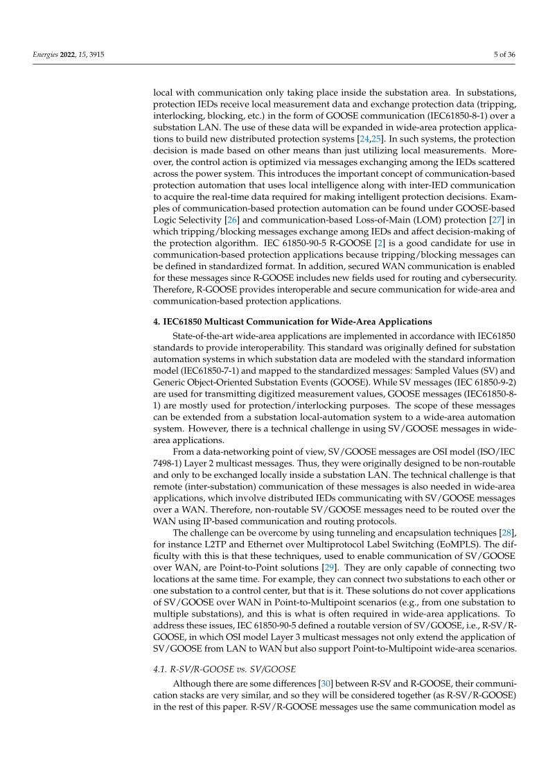
State-of-the-art wide-area applications are implemented in accordance with IEC61850standards to provide interoperability. This standard was originally defined for substationautomation systems in which substation data are modeled with the standard informationmodel (IEC61850-7-1) and mapped to the standardized messages: Sampled Values (SV) andGeneric Object-Oriented Substation Events (GOOSE). While SV messages (IEC 61850-9-2)are used for transmitting digitized measurement values, GOOSE messages (IEC61850-8-1) are mostly used for protection/interlocking purposes. The scope of these messagescan be extended from a substation local-automation system to a wide-area automationsystem. However, there is a technical challenge in using SV/GOOSE messages in wide-area applications.
From a data-networking point of view, SV/GOOSE messages are OSI model (ISO/IEC7498-1) Layer 2 multicast messages. Thus, they were originally designed to be non-routableand only to be exchanged locally inside a substation LAN. The technical challenge is thatremote (inter-substation) communication of these messages is also needed in wide-areaapplications, which involve distributed IEDs communicating with SV/GOOSE messagesover a WAN. Therefore, non-routable SV/GOOSE messages need to be routed over theWAN using IP-based communication and routing protocols.
The challenge can be overcome by using tunneling and encapsulation techniques [28],for instance L2TP and Ethernet over Multiprotocol Label Switching (EoMPLS). The dif-ficulty with this is that these techniques, used to enable communication of SV/GOOSEover WAN, are Point-to-Point solutions [29]. They are only capable of connecting twolocations at the same time. For example, they can connect two substations to each other orone substation to a control center, but that is it. These solutions do not cover applicationsof SV/GOOSE over WAN in Point-to-Multipoint scenarios (e.g., from one substation tomultiple substations), and this is what is often required in wide-area applications. Toaddress these issues, IEC 61850-90-5 defined a routable version of SV/GOOSE, i.e., R-SV/R-GOOSE, in which OSI model Layer 3 multicast messages not only extend the application ofSV/GOOSE from LAN to WAN but also support Point-to-Multipoint wide-area scenarios.
4.1. R-SV/R-GOOSE vs. SV/GOOSE
Although there are some differences [30] between R-SV and R-GOOSE, their communi-cation stacks are very similar, and so they will be considered together (as R-SV/R-GOOSE)in the rest of this paper. R-SV/R-GOOSE messages use the same communication model as
Energies 2022, 15, 3915 6 of 36
SV/GOOSE, i.e., the publish-subscribe model that is used in multicast communication. Inthis model, the sender (publisher) sends the same data across a computer network to mul-tiple receivers (subscribers) at the same time. While SV/GOOSE uses Ethernet-multicastover LAN (in other words, multicasting inside a substation), R-SV/R-GOOSE messagescan be published via IP-multicast over both LAN and WAN (in other words, acting as amulticasting inter-substation). Ethernet-multicast is based on the Media Access Control(MAC) address, but IP-multicast is based on a specific range of IP addresses reserved forthat multicast communication. Figure 1 depicts the communication stack as well as thestructure of the messages with respect to the OSI model (ISO/IEC 7498-1) layers. As can beseen, SV/GOOSE communications are directly mapped to the Ethernet frames. However,the R-SV/R-GOOSE messages are longer messages since they additionally use Network,Transport, and Session layers.
Energies 2022, 15, x FOR PEER REVIEW 6 of 37
GOOSE, in which OSI model Layer 3 multicast messages not only extend the application of
SV/GOOSE from LAN to WAN but also support Point-to-Multipoint wide-area scenarios.
4.1. R-SV/R-GOOSE vs. SV/GOOSE
Although there are some differences [30] between R-SV and R-GOOSE, their commu-
nication stacks are very similar, and so they will be considered together (as R-SV/R-
GOOSE) in the rest of this paper. R-SV/R-GOOSE messages use the same communication
model as SV/GOOSE, i.e., the publish-subscribe model that is used in multicast commu-
nication. In this model, the sender (publisher) sends the same data across a computer net-
work to multiple receivers (subscribers) at the same time. While SV/GOOSE uses Ethernet-
multicast over LAN (in other words, multicasting inside a substation), R-SV/R-GOOSE
messages can be published via IP-multicast over both LAN and WAN (in other words,
acting as a multicasting inter-substation). Ethernet-multicast is based on the Media Access
Control (MAC) address, but IP-multicast is based on a specific range of IP addresses re-
served for that multicast communication. Figure 1 depicts the communication stack as
well as the structure of the messages with respect to the OSI model (ISO/IEC 7498-1) lay-
ers. As can be seen, SV/GOOSE communications are directly mapped to the Ethernet
frames. However, the R-SV/R-GOOSE messages are longer messages since they addition-
ally use Network, Transport, and Session layers.
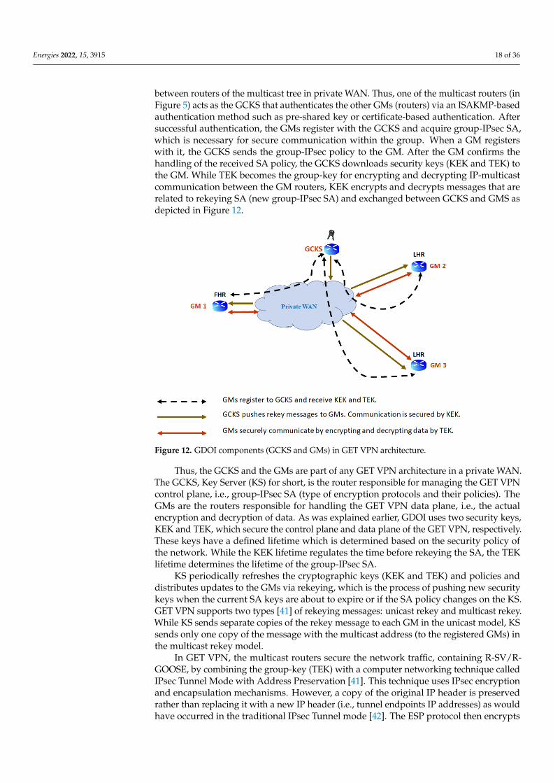
Figure 1. Frame structures of SV/GOOSE and R-SV/R-GOOSE.
R-SV/R-GOOSE messages use the Session layer, based on the IEC61850-90-5 session
protocol, and the Key Distribution Center (KDC), which will be explained in Section 5.2.1.
The IEC61850-90-5 Session protocol includes: a Session Identifier (that identifies the mes-
sage type: R-SV, R-GOOSE, Routable-Tunneled SV/GOOSE (or Management message); a
Session Header (cybersecurity-related information provided by KDC); and session user
data (payload data based on the Session Identifier). It should be noted that the focus of
this paper is on the R-SV and R-GOOSE messages. The Session layer data are encapsulated
in the User Datagram Protocol (UDP), which is used for transporting messages at the
Transport Layer. In the Network layer, IP is used for routing and multicasting R-SV/R-
GOOSE messages over a communication network in which Ethernet is used for device
communication at the Data Link Layer.
4.2. R-SV/R-GOOSE vs. Routable-Tunneled SV/GOOSE
As stated above, R-SV/R-GOOSE messages support IP and, therefore, become capa-
ble of WAN communication via the use of routers, which are the networking devices for
forwarding IP packets between LANs. Moreover, R-SV/R-GOOSE can be applied in Point-
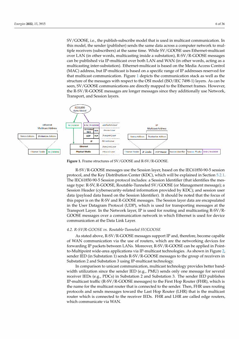
to-Multipoint wide-area applications via IP-multicast technologies. As shown in Figure 2,
sender IED (in Substation 1) sends R-SV/R-GOOSE messages to the group of receivers in
Substation 2 and Substation 3 using IP-multicast technology.
Figure 1. Frame structures of SV/GOOSE and R-SV/R-GOOSE.
R-SV/R-GOOSE messages use the Session layer, based on the IEC61850-90-5 sessionprotocol, and the Key Distribution Center (KDC), which will be explained in Section 5.2.1.The IEC61850-90-5 Session protocol includes: a Session Identifier (that identifies the mes-sage type: R-SV, R-GOOSE, Routable-Tunneled SV/GOOSE (or Management message); aSession Header (cybersecurity-related information provided by KDC); and session userdata (payload data based on the Session Identifier). It should be noted that the focus ofthis paper is on the R-SV and R-GOOSE messages. The Session layer data are encapsulatedin the User Datagram Protocol (UDP), which is used for transporting messages at theTransport Layer. In the Network layer, IP is used for routing and multicasting R-SV/R-GOOSE messages over a communication network in which Ethernet is used for devicecommunication at the Data Link Layer.
4.2. R-SV/R-GOOSE vs. Routable-Tunneled SV/GOOSE
As stated above, R-SV/R-GOOSE messages support IP and, therefore, become capableof WAN communication via the use of routers, which are the networking devices forforwarding IP packets between LANs. Moreover, R-SV/R-GOOSE can be applied in Point-to-Multipoint wide-area applications via IP-multicast technologies. As shown in Figure 2,sender IED (in Substation 1) sends R-SV/R-GOOSE messages to the group of receivers inSubstation 2 and Substation 3 using IP-multicast technology.
In comparison to unicast communication, multicast technology provides better band-width utilization since the sender IED (e.g., PMU) sends only one message for severalreceiver IEDs (e.g., PDCs) in Substation 2 and Substation 3. The sender IED publishesIP-multicast traffic (R-SV/R-GOOSE messages) to the First Hop Router (FHR), which isthe name for the multicast router that is connected to the sender. Then, FHR uses routingprotocols and sends messages toward the Last Hop Router (LHR) that is the multicastrouter which is connected to the receiver IEDs. FHR and LHR are called edge routers,which communicate via WAN.
Energies 2022, 15, 3915 7 of 36Energies 2022, 15, x FOR PEER REVIEW 7 of 37
Figure 2. Multicast communication of R-SV/R-GOOSE from Substation 1 to Substation 2 and 3.
In comparison to unicast communication, multicast technology provides better band-
width utilization since the sender IED (e.g., PMU) sends only one message for several
receiver IEDs (e.g., PDCs) in Substation 2 and Substation 3. The sender IED publishes IP-
multicast traffic (R-SV/R-GOOSE messages) to the First Hop Router (FHR), which is the
name for the multicast router that is connected to the sender. Then, FHR uses routing
protocols and sends messages toward the Last Hop Router (LHR) that is the multicast
router which is connected to the receiver IEDs. FHR and LHR are called edge routers,
which communicate via WAN.
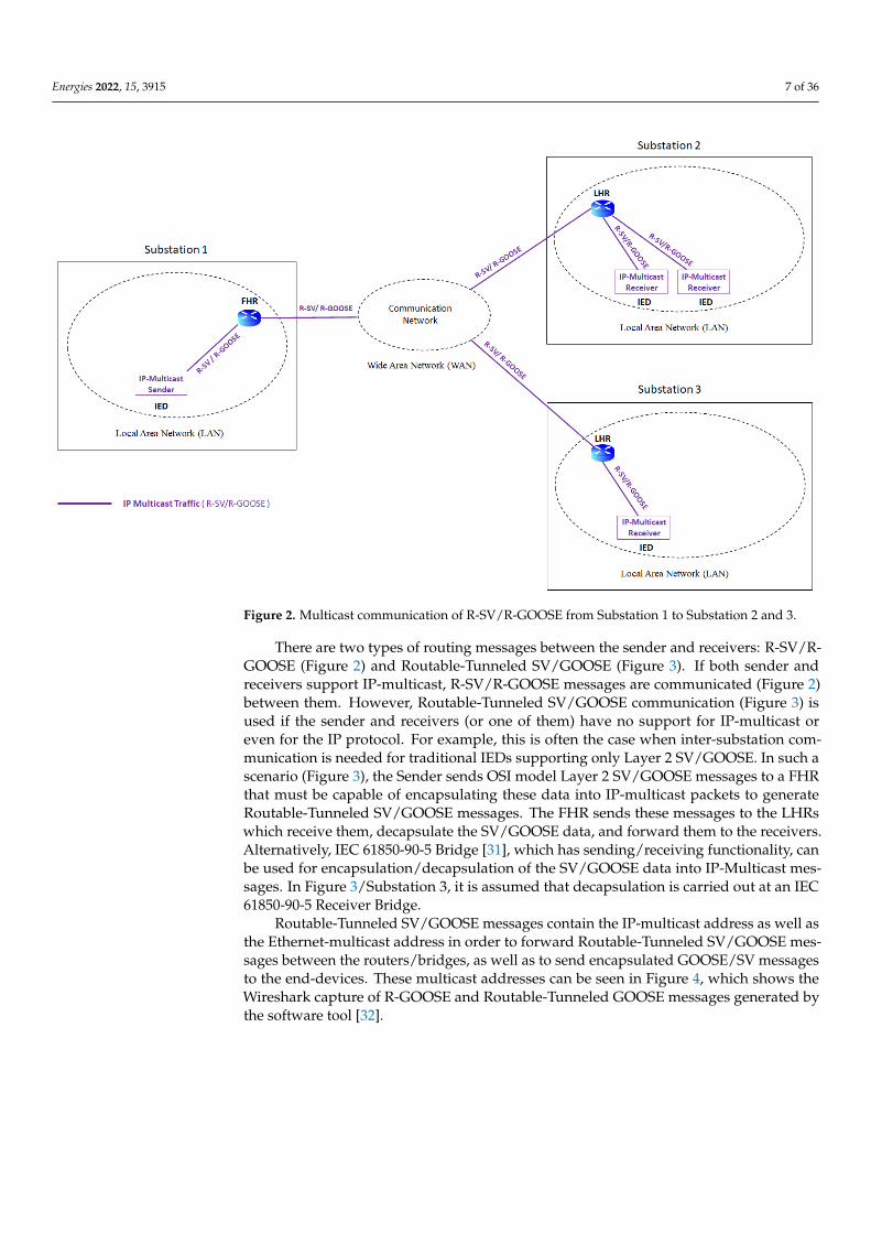
There are two types of routing messages between the sender and receivers: R-SV/R-
GOOSE (Figure 2) and Routable-Tunneled SV/GOOSE (Figure 3). If both sender and re-
ceivers support IP-multicast, R-SV/R-GOOSE messages are communicated (Figure 2) be-
tween them. However, Routable-Tunneled SV/GOOSE communication (Figure 3) is used
if the sender and receivers (or one of them) have no support for IP-multicast or even for
the IP protocol. For example, this is often the case when inter-substation communication
is needed for traditional IEDs supporting only Layer 2 SV/GOOSE. In such a scenario (Fig-
ure 3), the Sender sends OSI model Layer 2 SV/GOOSE messages to a FHR that must be capa-
ble of encapsulating these data into IP-multicast packets to generate Routable-Tunneled
SV/GOOSE messages. The FHR sends these messages to the LHRs which receive them, de-
capsulate the SV/GOOSE data, and forward them to the receivers. Alternatively, IEC 61850-
90-5 Bridge [31], which has sending/receiving functionality, can be used for encapsulation/de-
capsulation of the SV/GOOSE data into IP-Multicast messages. In Figure 3/Substation 3, it is
assumed that decapsulation is carried out at an IEC 61850-90-5 Receiver Bridge.
Figure 2. Multicast communication of R-SV/R-GOOSE from Substation 1 to Substation 2 and 3.
There are two types of routing messages between the sender and receivers: R-SV/R-GOOSE (Figure 2) and Routable-Tunneled SV/GOOSE (Figure 3). If both sender andreceivers support IP-multicast, R-SV/R-GOOSE messages are communicated (Figure 2)between them. However, Routable-Tunneled SV/GOOSE communication (Figure 3) isused if the sender and receivers (or one of them) have no support for IP-multicast oreven for the IP protocol. For example, this is often the case when inter-substation com-munication is needed for traditional IEDs supporting only Layer 2 SV/GOOSE. In such ascenario (Figure 3), the Sender sends OSI model Layer 2 SV/GOOSE messages to a FHRthat must be capable of encapsulating these data into IP-multicast packets to generateRoutable-Tunneled SV/GOOSE messages. The FHR sends these messages to the LHRswhich receive them, decapsulate the SV/GOOSE data, and forward them to the receivers.Alternatively, IEC 61850-90-5 Bridge [31], which has sending/receiving functionality, canbe used for encapsulation/decapsulation of the SV/GOOSE data into IP-Multicast mes-sages. In Figure 3/Substation 3, it is assumed that decapsulation is carried out at an IEC61850-90-5 Receiver Bridge.
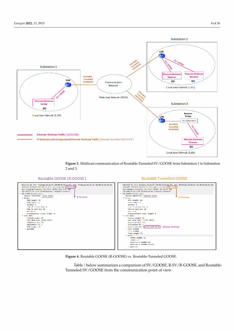
Routable-Tunneled SV/GOOSE messages contain the IP-multicast address as well asthe Ethernet-multicast address in order to forward Routable-Tunneled SV/GOOSE mes-sages between the routers/bridges, as well as to send encapsulated GOOSE/SV messagesto the end-devices. These multicast addresses can be seen in Figure 4, which shows theWireshark capture of R-GOOSE and Routable-Tunneled GOOSE messages generated bythe software tool [32].
Energies 2022, 15, 3915 8 of 36Energies 2022, 15, x FOR PEER REVIEW 8 of 37
Figure 3. Multicast communication of Routable-Tunneled SV/GOOSE from Substation 1 to Substa-
tion 2 and 3.
Routable-Tunneled SV/GOOSE messages contain the IP-multicast address as well as
the Ethernet-multicast address in order to forward Routable-Tunneled SV/GOOSE mes-
sages between the routers/bridges, as well as to send encapsulated GOOSE/SV messages
to the end-devices. These multicast addresses can be seen in Figure 4, which shows the
Wireshark capture of R-GOOSE and Routable-Tunneled GOOSE messages generated by
the software tool [32].
Figure 4. Routable GOOSE (R-GOOSE) vs. Routable-Tunneled GOOSE.
Table 1 below summarizes a comparison of SV/GOOSE, R-SV/R-GOOSE, and Routa-
ble-Tunneled SV/GOOSE from the communication point of view.
Figure 3. Multicast communication of Routable-Tunneled SV/GOOSE from Substation 1 to Substation2 and 3.
Energies 2022, 15, x FOR PEER REVIEW 8 of 37
Figure 3. Multicast communication of Routable-Tunneled SV/GOOSE from Substation 1 to Substa-
tion 2 and 3.
Routable-Tunneled SV/GOOSE messages contain the IP-multicast address as well as
the Ethernet-multicast address in order to forward Routable-Tunneled SV/GOOSE mes-
sages between the routers/bridges, as well as to send encapsulated GOOSE/SV messages
to the end-devices. These multicast addresses can be seen in Figure 4, which shows the
Wireshark capture of R-GOOSE and Routable-Tunneled GOOSE messages generated by
the software tool [32].
Figure 4. Routable GOOSE (R-GOOSE) vs. Routable-Tunneled GOOSE.
Table 1 below summarizes a comparison of SV/GOOSE, R-SV/R-GOOSE, and Routa-
ble-Tunneled SV/GOOSE from the communication point of view.
Figure 4. Routable GOOSE (R-GOOSE) vs. Routable-Tunneled GOOSE.
Table 1 below summarizes a comparison of SV/GOOSE, R-SV/R-GOOSE, and Routable-Tunneled SV/GOOSE from the communication point of view.
Energies 2022, 15, 3915 9 of 36
Table 1. Comparison of IEC61850 multicast messages.
CommunicationProtocol
CommunicationModel
CommunicationType
MessageMulticast Address
OSI Model LayerMulticast
CommunicationNetwork
SV/GOOSE Publish-Subscribe Multicast Ethernet-multicast Layer 2 LAN
R-SV/R-GOOSE Publish-Subscribe Multicast IP-multicast Layer 3 WAN, LAN
Routable-Tunneled
SV/GOOSEPublish-Subscribe Multicast IP-multicast and
Ethernet-multicast Layer 3 and Layer 2 WAN, LAN
4.3. WAN Communication in Wide-Area Applications
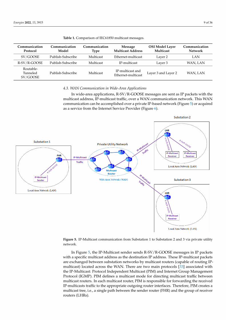
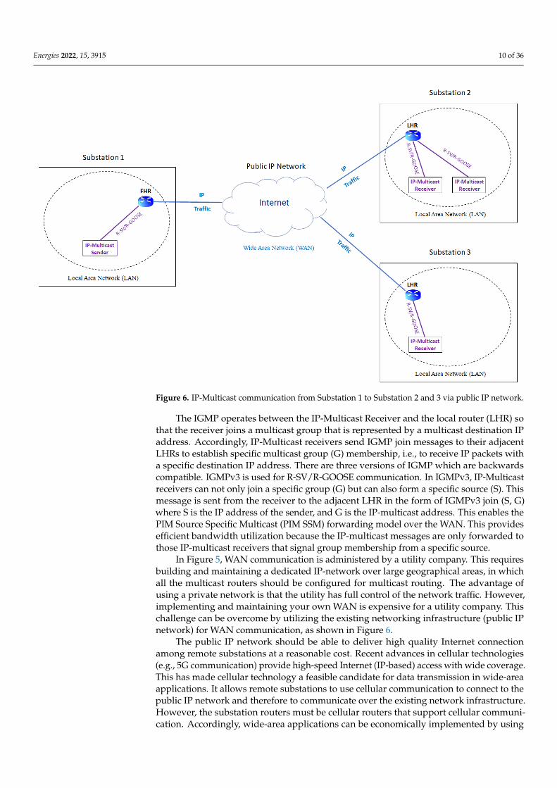
In wide-area applications, R-SV/R-GOOSE messages are sent as IP packets with themulticast address, IP-multicast traffic, over a WAN communication network. This WANcommunication can be accomplished over a private IP-based network (Figure 5) or acquiredas a service from the Internet Service Provider (Figure 6).
Energies 2022, 15, x FOR PEER REVIEW 9 of 37
Table 1. Comparison of IEC61850 multicast messages.
Communication
Protocol
Communication
Model
Communication
Type
Message Multicast
Address
OSI Model Layer
Multicast
Communication
Network
SV/GOOSE Publish-Subscribe Multicast Ethernet-multicast Layer 2 LAN
R-SV/R-GOOSE Publish-Subscribe Multicast IP-multicast Layer 3 WAN, LAN
Routable-Tunneled
SV/GOOSE Publish-Subscribe Multicast
IP-multicast and
Ethernet-multicast Layer 3 and Layer 2 WAN, LAN
4.3. WAN Communication in Wide-Area Applications
In wide-area applications, R-SV/R-GOOSE messages are sent as IP packets with the
multicast address, IP-multicast traffic, over a WAN communication network. This WAN
communication can be accomplished over a private IP-based network (Figure 5) or ac-
quired as a service from the Internet Service Provider (Figure 6).
Figure 5. IP-Multicast communication from Substation 1 to Substation 2 and 3 via private utility
network. Figure 5. IP-Multicast communication from Substation 1 to Substation 2 and 3 via private utilitynetwork.
In Figure 5, the IP-Multicast sender sends R-SV/R-GOOSE messages in IP packetswith a specific multicast address as the destination IP address. These IP-multicast packetsare exchanged between substation networks by multicast routers (capable of routing IP-multicast) located across the WAN. There are two main protocols [33] associated withthe IP-Multicast: Protocol Independent Multicast (PIM) and Internet Group ManagementProtocol (IGMP). PIM defines a multicast mode for directing multicast traffic betweenmulticast routers. In each multicast router, PIM is responsible for forwarding the receivedIP-multicasts traffic to the appropriate outgoing router interfaces. Therefore, PIM creates amulticast tree, i.e., a single path between the sender router (FHR) and the group of receiverrouters (LHRs).
Energies 2022, 15, 3915 10 of 36Energies 2022, 15, x FOR PEER REVIEW 10 of 37
Figure 6. IP-Multicast communication from Substation 1 to Substation 2 and 3 via public IP net-
work.
In Figure 5, the IP-Multicast sender sends R-SV/R-GOOSE messages in IP packets
with a specific multicast address as the destination IP address. These IP-multicast packets
are exchanged between substation networks by multicast routers (capable of routing IP-
multicast) located across the WAN. There are two main protocols [33] associated with the
IP-Multicast: Protocol Independent Multicast (PIM) and Internet Group Management Proto-
col (IGMP). PIM defines a multicast mode for directing multicast traffic between multicast
routers. In each multicast router, PIM is responsible for forwarding the received IP-multicasts
traffic to the appropriate outgoing router interfaces. Therefore, PIM creates a multicast tree,
i.e., a single path between the sender router (FHR) and the group of receiver routers (LHRs).
The IGMP operates between the IP-Multicast Receiver and the local router (LHR) so
that the receiver joins a multicast group that is represented by a multicast destination IP
address. Accordingly, IP-Multicast receivers send IGMP join messages to their adjacent
LHRs to establish specific multicast group (G) membership, i.e., to receive IP packets with
a specific destination IP address. There are three versions of IGMP which are backwards
compatible. IGMPv3 is used for R-SV/R-GOOSE communication. In IGMPv3, IP-Multicast
receivers can not only join a specific group (G) but can also form a specific source (S). This
message is sent from the receiver to the adjacent LHR in the form of IGMPv3 join (S, G)
where S is the IP address of the sender, and G is the IP-multicast address. This enables the
PIM Source Specific Multicast (PIM SSM) forwarding model over the WAN. This provides
efficient bandwidth utilization because the IP-multicast messages are only forwarded to
those IP-multicast receivers that signal group membership from a specific source.
In Figure 5, WAN communication is administered by a utility company. This requires
building and maintaining a dedicated IP-network over large geographical areas, in which
all the multicast routers should be configured for multicast routing. The advantage of us-
ing a private network is that the utility has full control of the network traffic. However,
implementing and maintaining your own WAN is expensive for a utility company. This
Figure 6. IP-Multicast communication from Substation 1 to Substation 2 and 3 via public IP network.
The IGMP operates between the IP-Multicast Receiver and the local router (LHR) sothat the receiver joins a multicast group that is represented by a multicast destination IPaddress. Accordingly, IP-Multicast receivers send IGMP join messages to their adjacentLHRs to establish specific multicast group (G) membership, i.e., to receive IP packets witha specific destination IP address. There are three versions of IGMP which are backwardscompatible. IGMPv3 is used for R-SV/R-GOOSE communication. In IGMPv3, IP-Multicastreceivers can not only join a specific group (G) but can also form a specific source (S). Thismessage is sent from the receiver to the adjacent LHR in the form of IGMPv3 join (S, G)where S is the IP address of the sender, and G is the IP-multicast address. This enables thePIM Source Specific Multicast (PIM SSM) forwarding model over the WAN. This providesefficient bandwidth utilization because the IP-multicast messages are only forwarded tothose IP-multicast receivers that signal group membership from a specific source.
In Figure 5, WAN communication is administered by a utility company. This requiresbuilding and maintaining a dedicated IP-network over large geographical areas, in whichall the multicast routers should be configured for multicast routing. The advantage ofusing a private network is that the utility has full control of the network traffic. However,implementing and maintaining your own WAN is expensive for a utility company. Thischallenge can be overcome by utilizing the existing networking infrastructure (public IPnetwork) for WAN communication, as shown in Figure 6.
The public IP network should be able to deliver high quality Internet connectionamong remote substations at a reasonable cost. Recent advances in cellular technologies(e.g., 5G communication) provide high-speed Internet (IP-based) access with wide coverage.This has made cellular technology a feasible candidate for data transmission in wide-areaapplications. It allows remote substations to use cellular communication to connect to thepublic IP network and therefore to communicate over the existing network infrastructure.However, the substation routers must be cellular routers that support cellular communi-cation. Accordingly, wide-area applications can be economically implemented by using
Energies 2022, 15, 3915 11 of 36
cellular routers that tunnel IP-multicast traffic (R-SV/R-GOOSE) over IP traffic within theexisting public IP network as shown in Figure 6. GRE [34] is a well-known protocol thatcan be used for tunneling. GRE is a tunneling protocol between two networks, whichencapsulates IP-multicast packets and delivers them to the destination network.
In wide-area applications, WAN communication over a private or public networkrequires careful attention in terms of network determinism and cybersecurity in order tosatisfy the application’s real-time requirement and thus ensures that it functions correctly.
5. Communication Dependability
In wide-area applications, R-SV/R-GOOSE communication must be dependable (real-time and cybersecure) to ensure correct and authentic operation of the applications.
5.1. Real-Time Requirement in Wide-Area Applications
WAN communication imposes additional delays to R-SV/R-GOOSE exchanges be-tween sender and receiver devices. This communication must be real-time, i.e., sufficientlyfast to achieve the objectives of the wide-area application. In the electricity grid, threeclasses (Local, Wide-Area, and Remote) can be defined for monitoring, protection, andcontrol applications. The wide-area applications aim to bridge the gap between the Localand Remote classes, as depicted in Table 2.
Table 2. Monitoring, protection, and control classes in power system.
Class Integration Scope Participants Operation Level TimeConstraint Response Time
Local Internal Substation IED Substation Level Highlytime-critical <10 ms
Wide-Area Horizontal Inter-Substation IED, PMU, PDC CoordinatedLevel Time-critical 10–1000 ms
Remote Vertical Control Center SCADA,EMS, DMS TSO/DSO Level Lesser
time-critical >1 min
In the Local class, the focus is on a system with localized operation by internal in-tegration of the devices, for example, highly time-critical electrical protection functionscarried out by the IEDs inside substations. With Remote class applications, the empha-sis is on the system as a whole, and takes in the Distribution System Operator (DSO)or Transmission System Operator (TSO) levels through the Vertical integration of thepower system components to the control center. While SCADA is used for power systemmonitoring/control in the Remote class, the Energy Management System (EMS) and theDistribution Management System (DMS) are applied for less time-critical grid monitoringand management applications.
The Wide-Area class is based on a network-wide view of the system utilizing Hori-zontal integration, i.e., coordination between IEDs located in remote substations. In thisclass, the real-time requirement value is in the range of 10–1000 ms. The exact value isapplication-specific and determined by the algorithm used in wide-area application: forexample, 50 ms to 500 ms for synchrophasor applications [2], 100 ms in the case of GOOSE-based Logic Selectivity [26], and 300 ms for Communication-based LOM [27]. Thus, thecommunication latency of R-SV/R-GOOSE over WAN has to be less than this real-timerequirement to ensure the correct operation of the wide-area application. This latency timeis equal to the transmission time of messages over WAN, as well as their processing timesin the routers and in other possible networking devices.
It should be mentioned that R-SV/R-GOOSE communication over WAN supports [30]IP Class of Traffic (CoT) that can reduce delays in processing IP-multicast communicationby routers. IP CoT enables Quality of Service for prioritizing IP-multicast traffic (R-SV/R-
Energies 2022, 15, 3915 12 of 36
GOOSE messages) in the routers by defining IP priority tagging. This results in fasterprocessing of multicast traffic and, subsequently, smaller processing delays in the routers.
5.2. Cybersecurity for IEC61850 Multicast Communication in Wide-Area Applications
WAN communication presents cybersecurity challenges and threats arising from thenetworked environment. Cyber-attacks to R-SV/R-GOOSE communication may not onlymodify or destroy critical monitoring and protection data but may also lead to undesiredoutages and damage to electrical components. Therefore, cybersecurity should be under-stood thoroughly in this context [35,36], and security requirements must be satisfied. Thesecurity requirements depend on the wide-area applications. For example, IEC 61850-90-5specifies security requirements for synchrophasors in which integrity and authenticationare mandatory requirements, but confidentiality is an optional requirement.
Whatever the wide-area application, cybersecurity solutions must be applied to R-SV/R-GOOSE communication to ensure data authenticity and thus the reliable operationof the application. This can be achieved by creating secured messages, a secured communi-cation path, or both, as with the most common solutions shown in Table 3.
Table 3. Security solutions for R-SV/R-GOOSE communication over WAN.
Secu
rity
Solu
tion
s Secured Messages Security by encryption and digital signature of R-SV/R-GOOSE messages via the use ofsecurity keys provided by KDC in the Group Domain of Interpretation (GDOI) framework.
SecuredCommunication Path
Private WAN Security by GET VPN (Figure 14)
Public WAN Security by IPsec Tunnel (Figure 15)
5.2.1. Secured Messages
In order to create secured messages, IEC61850-90-5 introduces KDC, which providessecurity-related information for the securing (digital signature and encryption) of R-SV/R-GOOSE messages. IEC 61850-90-5 recommends a security mechanism based on GroupDomain of Interpretation (GDOI) [37], which is a group-key management security frame-work. This framework is suitable for IP-multicast applications such as wide-area appli-cations in which common security policy and keying materials are shared among groupof participants.
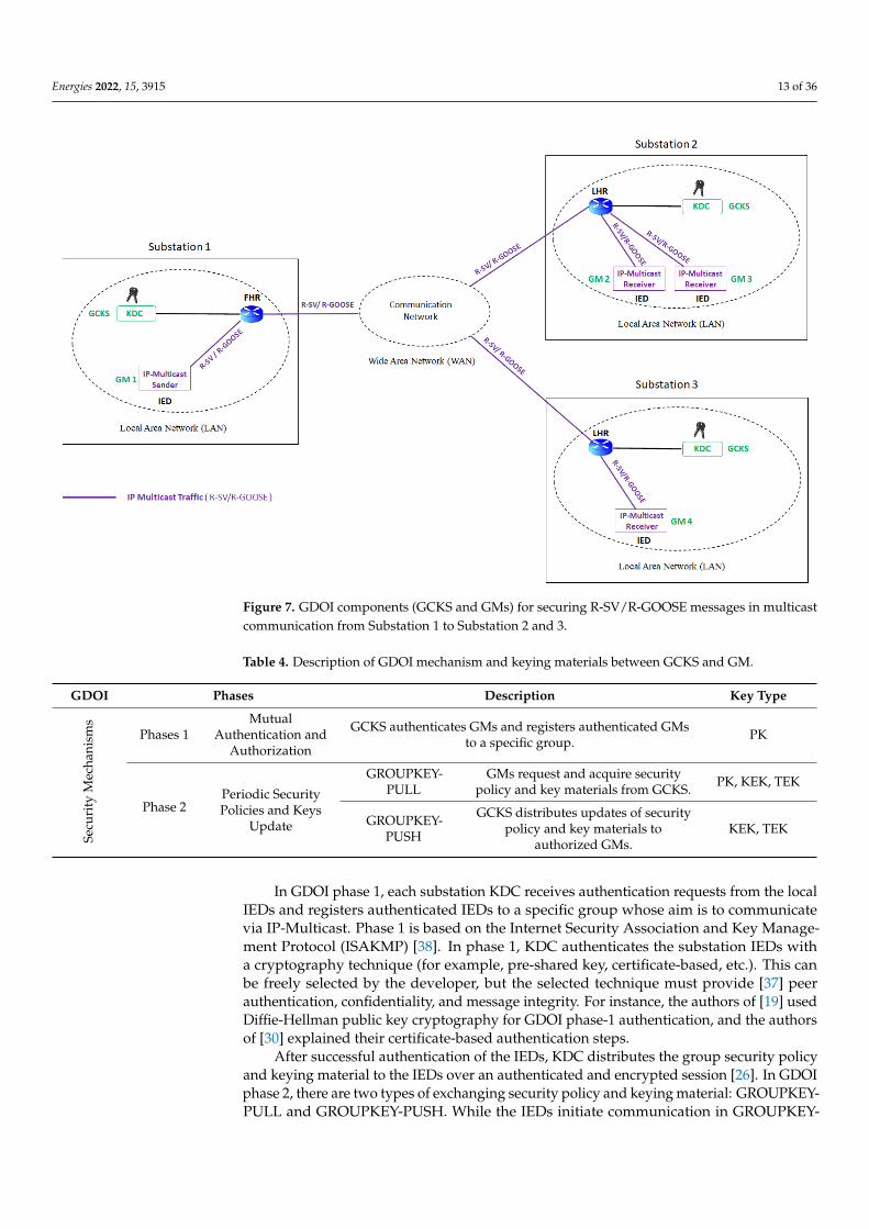
There are two types [37] of participants in the GDOI framework: Group Controller/KeyServer (GCKS) and Group Member (GM). GCKS defines and distributes security policiesand keying materials between the GMs. The GMs are authorized members of a securegroup, which can send/receive IP packets related to the group. The GDOI framework canbe implemented for securing R-SV/R-GOOSE messages in which GMs are IEDs (e.g., PMUor PDC) with GDOI support, and GCKS is KDC, as shown in Figure 7 below.
In Figure 7, there are two possible security architectures for implementing KDC:centralized and decentralized. While a single KDC is used for all GMs in centralized archi-tecture, multiple KDCs are used in decentralized architecture to increase their availabilityin case of a lack of one KDC. Decentralized architecture prevents single-point-of-failureand reduces key storage complexity, but it requires additional work regarding the adminis-tration and maintenance of the KDCs. The type of security architecture is selected basedon the size of the network and the utility security policy. Figure 7 shows a decentralizedarchitecture in which multiple KDCs are distributed in the substations. KDC functions asGCKS in the GDOI security framework.
GDOI security mechanisms consist of two phases: Mutual Authentication and Au-thorization phase, and the Periodic Security Policies and Key Update phase. Table 4summarizes the different phases of a GDOI mechanism.
Energies 2022, 15, 3915 13 of 36Energies 2022, 15, x FOR PEER REVIEW 13 of 37
Figure 7. GDOI components (GCKS and GMs) for securing R-SV/R-GOOSE messages in multicast
communication from Substation 1 to Substation 2 and 3.
In Figure 7, there are two possible security architectures for implementing KDC: cen-
tralized and decentralized. While a single KDC is used for all GMs in centralized architec-
ture, multiple KDCs are used in decentralized architecture to increase their availability in
case of a lack of one KDC. Decentralized architecture prevents single-point-of-failure and
reduces key storage complexity, but it requires additional work regarding the administra-
tion and maintenance of the KDCs. The type of security architecture is selected based on
the size of the network and the utility security policy. Figure 7 shows a decentralized ar-
chitecture in which multiple KDCs are distributed in the substations. KDC functions as
GCKS in the GDOI security framework.
GDOI security mechanisms consist of two phases: Mutual Authentication and Au-
thorization phase, and the Periodic Security Policies and Key Update phase. Table 4 sum-
marizes the different phases of a GDOI mechanism.
Table 4. Description of GDOI mechanism and keying materials between GCKS and GM.
GDOI Phases Description Key
Type
Sec
uri
ty M
ech
anis
ms
Phases 1
Mutual Au-
thentication
and Authori-
zation
GCKS authenticates GMs and registers authenticated GMs to a specific
group. PK
Phase 2
Periodic Secu-
rity Policies
and Keys Up-
date
GROUPKEY-
PULL
GMs request and acquire security policy and key mate-
rials from GCKS.
PK,
KEK,
TEK
GROUPKEY-
PUSH
GCKS distributes updates of security policy and key
materials to authorized GMs.
KEK,
TEK
Figure 7. GDOI components (GCKS and GMs) for securing R-SV/R-GOOSE messages in multicastcommunication from Substation 1 to Substation 2 and 3.
Table 4. Description of GDOI mechanism and keying materials between GCKS and GM.
GDOI Phases Description Key Type
Secu
rity
Mec
hani
sms
Phases 1Mutual
Authentication andAuthorization
GCKS authenticates GMs and registers authenticated GMsto a specific group. PK
Phase 2Periodic SecurityPolicies and Keys
Update
GROUPKEY-PULL
GMs request and acquire securitypolicy and key materials from GCKS. PK, KEK, TEK
GROUPKEY-PUSH
GCKS distributes updates of securitypolicy and key materials to
authorized GMs.KEK, TEK
In GDOI phase 1, each substation KDC receives authentication requests from the localIEDs and registers authenticated IEDs to a specific group whose aim is to communicatevia IP-Multicast. Phase 1 is based on the Internet Security Association and Key Manage-ment Protocol (ISAKMP) [38]. In phase 1, KDC authenticates the substation IEDs witha cryptography technique (for example, pre-shared key, certificate-based, etc.). This canbe freely selected by the developer, but the selected technique must provide [37] peerauthentication, confidentiality, and message integrity. For instance, the authors of [19] usedDiffie-Hellman public key cryptography for GDOI phase-1 authentication, and the authorsof [30] explained their certificate-based authentication steps.
After successful authentication of the IEDs, KDC distributes the group security policyand keying material to the IEDs over an authenticated and encrypted session [26]. In GDOIphase 2, there are two types of exchanging security policy and keying material: GROUPKEY-PULL and GROUPKEY-PUSH. While the IEDs initiate communication in GROUPKEY-
Energies 2022, 15, 3915 14 of 36
PULL, KDC periodically initiates communication to distribute security updates to the IEDsin GROUPKEY-PUSH, as will be explained below.
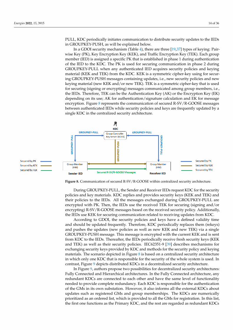
In a GDOI security mechanism (Table 4), there are three [19,37] types of keying: Pair-wise Key (PK), Key Encryption Key (KEK), and Traffic Encryption Key (TEK). Each groupmember (IED) is assigned a specific PK that is established in phase 1 during authenticationof the IED to the KDC. The PK is used for securing communication in phase 2 duringGROUPKEY-PULL when any authenticated IED acquires security policies and keyingmaterial (KEK and TEK) from the KDC. KEK is a symmetric cipher-key using for secur-ing GROUPKEY-PUSH messages containing updates, i.e., new security policies and newkeying material (new KEK and/or new TEK). TEK is a symmetric cipher-key that is usedfor securing (signing or encrypting) messages communicated among group members, i.e.,the IEDs. Therefore, TEK can be the Authentication Key (AK) or the Encryption Key (EK)depending on its use; AK for authentication/signature calculation and EK for messageencryption. Figure 8 represents the communication of secured R-SV/R-GOOSE messagesbetween authenticated IEDs while security policies and keys are frequently updated by asingle KDC in the centralized security architecture.
Energies 2022, 15, x FOR PEER REVIEW 14 of 37
In GDOI phase 1, each substation KDC receives authentication requests from the lo-
cal IEDs and registers authenticated IEDs to a specific group whose aim is to communicate
via IP-Multicast. Phase 1 is based on the Internet Security Association and Key Manage-
ment Protocol (ISAKMP) [38]. In phase 1, KDC authenticates the substation IEDs with a
cryptography technique (for example, pre-shared key, certificate-based, etc.). This can be
freely selected by the developer, but the selected technique must provide [37] peer au-
thentication, confidentiality, and message integrity. For instance, the authors of [19] used
Diffie-Hellman public key cryptography for GDOI phase-1 authentication, and the au-
thors of [30] explained their certificate-based authentication steps.
After successful authentication of the IEDs, KDC distributes the group security pol-
icy and keying material to the IEDs over an authenticated and encrypted session [26]. In
GDOI phase 2, there are two types of exchanging security policy and keying material:
GROUPKEY-PULL and GROUPKEY-PUSH. While the IEDs initiate communication in
GROUPKEY-PULL, KDC periodically initiates communication to distribute security up-
dates to the IEDs in GROUPKEY-PUSH, as will be explained below.
In a GDOI security mechanism (Table 4), there are three [19,37] types of keying: Pair-
wise Key (PK), Key Encryption Key (KEK), and Traffic Encryption Key (TEK). Each group
member (IED) is assigned a specific PK that is established in phase 1 during authentication
of the IED to the KDC. The PK is used for securing communication in phase 2 during
GROUPKEY-PULL when any authenticated IED acquires security policies and keying
material (KEK and TEK) from the KDC. KEK is a symmetric cipher-key using for securing
GROUPKEY-PUSH messages containing updates, i.e., new security policies and new key-
ing material (new KEK and/or new TEK). TEK is a symmetric cipher-key that is used for
securing (signing or encrypting) messages communicated among group members, i.e., the
IEDs. Therefore, TEK can be the Authentication Key (AK) or the Encryption Key (EK) de-
pending on its use; AK for authentication/signature calculation and EK for message en-
cryption. Figure 8 represents the communication of secured R-SV/R-GOOSE messages be-
tween authenticated IEDs while security policies and keys are frequently updated by a
single KDC in the centralized security architecture.
Figure 8. Communication of secured R-SV/R-GOOSE within centralized security architecture.
During GROUPKEY-PULL, the Sender and Receiver IEDs request KDC for the secu-
rity policies and key materials. KDC replies and provides security keys (KEK and TEK)
and their policies to the IEDs. All the messages exchanged during GROUPKEY-PULL are
encrypted with PK. Then, the IEDs use the received TEK for securing (signing and/or en-
crypting) R-SV/R-GOOSE messages based on the received security policy. Additionally,
the IEDs use KEK for securing communication related to receiving updates from KDC.
According to GDOI, the security policies and keys have a defined validity time and
should be updated frequently. Therefore, KDC periodically replaces them (rekeys) and
pushes the updates (new policies as well as new KEK and new TEK) via a single GROUP-
KEY-PUSH message. This message is encrypted with the current KEK and is sent from
Figure 8. Communication of secured R-SV/R-GOOSE within centralized security architecture.
During GROUPKEY-PULL, the Sender and Receiver IEDs request KDC for the securitypolicies and key materials. KDC replies and provides security keys (KEK and TEK) andtheir policies to the IEDs. All the messages exchanged during GROUPKEY-PULL areencrypted with PK. Then, the IEDs use the received TEK for securing (signing and/orencrypting) R-SV/R-GOOSE messages based on the received security policy. Additionally,the IEDs use KEK for securing communication related to receiving updates from KDC.
According to GDOI, the security policies and keys have a defined validity timeand should be updated frequently. Therefore, KDC periodically replaces them (rekeys)and pushes the updates (new policies as well as new KEK and new TEK) via a singleGROUPKEY-PUSH message. This message is encrypted with the current KEK and is sentfrom KDC to the IEDs. Thereafter, the IEDs periodically receive fresh security keys (KEKand TEK) as well as their security policies. IEC62351-9 [39] describes mechanisms forexchanging security keys provided by KDC and methods for the security policy and keyingmaterials. The scenario depicted in Figure 8 is based on a centralized security architecturein which only one KDC that is responsible for the security of the whole system is used. Incontrast, Figure 9 depicts distributed KDCs in a decentralized security architecture.
In Figure 9, authors propose two possibilities for decentralized security architectures:Fully Connected and Hierarchical architectures. In the Fully Connected architecture, anyredundant KDCs are connected to each other and have the same level of functionalityneeded to provide complete redundancy. Each KDC is responsible for the authenticationof the GMs in its own substation. However, it also informs all the external KDCs aboutupdates such as registered GMs and group memberships. The KDCs are numericallyprioritized as an ordered list, which is provided to all the GMs for registration. In this list,the first one functions as the Primary KDC, and the rest are regarded as redundant KDCs
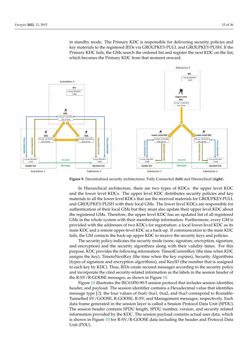
Energies 2022, 15, 3915 15 of 36
in standby mode. The Primary KDC is responsible for delivering security policies andkey materials to the registered IEDs via GROUPKEY-PULL and GROUPKEY-PUSH. If thePrimary KDC fails, the GMs search the ordered list and register the next KDC on the list,which becomes the Primary KDC from that moment onward.
Energies 2022, 15, x FOR PEER REVIEW 15 of 37
KDC to the IEDs. Thereafter, the IEDs periodically receive fresh security keys (KEK and
TEK) as well as their security policies. IEC62351-9 [39] describes mechanisms for exchang-
ing security keys provided by KDC and methods for the security policy and keying materials.
The scenario depicted in Figure 8 is based on a centralized security architecture in which only
one KDC that is responsible for the security of the whole system is used. In contrast, Figure 9
depicts distributed KDCs in a decentralized security architecture.
Figure 9. Decentralized security architectures: Fully Connected (left) and Hierarchical (right).
In Figure 9, authors propose two possibilities for decentralized security architectures:
Fully Connected and Hierarchical architectures. In the Fully Connected architecture, any
redundant KDCs are connected to each other and have the same level of functionality
needed to provide complete redundancy. Each KDC is responsible for the authentication
of the GMs in its own substation. However, it also informs all the external KDCs about
updates such as registered GMs and group memberships. The KDCs are numerically pri-
oritized as an ordered list, which is provided to all the GMs for registration. In this list,
the first one functions as the Primary KDC, and the rest are regarded as redundant KDCs
in standby mode. The Primary KDC is responsible for delivering security policies and key
materials to the registered IEDs via GROUPKEY-PULL and GROUPKEY-PUSH. If the
Primary KDC fails, the GMs search the ordered list and register the next KDC on the list,
which becomes the Primary KDC from that moment onward.
In Hierarchical architecture, there are two types of KDCs: the upper level KDC and
the lower level KDCs. The upper level KDC distributes security policies and key materials
to all the lower level KDCs that use the received materials for GROUPKEY-PULL and
GROUPKEY-PUSH with their local GMs. The lower level KDCs are responsible for au-
thentication of their local GMs but they must also update their upper level KDC about the
registered GMs. Therefore, the upper level KDC has an updated list of all registered GMs
in the whole system with their membership information. Furthermore, every GM is pro-
vided with the addresses of two KDCs for registration: a local lower-level KDC as its main
KDC and a remote upper-level KDC as a back-up. If communication to the main KDC
fails, the GM contacts the back-up upper KDC to receive the security keys and policies.
The security policy indicates the security mode (none, signature, encryption, signa-
ture, and encryption) and the security algorithms along with their validity times. For this
Figure 9. Decentralized security architectures: Fully Connected (left) and Hierarchical (right).
In Hierarchical architecture, there are two types of KDCs: the upper level KDCand the lower level KDCs. The upper level KDC distributes security policies and keymaterials to all the lower level KDCs that use the received materials for GROUPKEY-PULLand GROUPKEY-PUSH with their local GMs. The lower level KDCs are responsible forauthentication of their local GMs but they must also update their upper level KDC aboutthe registered GMs. Therefore, the upper level KDC has an updated list of all registeredGMs in the whole system with their membership information. Furthermore, every GM isprovided with the addresses of two KDCs for registration: a local lower-level KDC as itsmain KDC and a remote upper-level KDC as a back-up. If communication to the main KDCfails, the GM contacts the back-up upper KDC to receive the security keys and policies.
The security policy indicates the security mode (none, signature, encryption, signature,and encryption) and the security algorithms along with their validity times. For thispurpose, KDC provides the following information: TimeofCurrentKey (the time when KDCassigns the key), TimetoNextKey (the time when the key expires), Security Algorithms(types of signature and encryption algorithms), and KeyID (the number that is assignedto each key by KDC). Thus, IEDs create secured messages according to the security policyand incorporate the cited security-related information as the labels in the session header ofthe R-SV/R-GOOSE messages, as shown in Figure 10.
Figure 10 illustrates the IEC61850-90-5 session protocol that includes session identifier,header, and payload. The session identifier contains a Hexadecimal value that identifiesmessage type [2]: the four values of 0xa0, 0xa1, 0xa2, and 0xa3 correspond to Routable-Tunnelled SV/GOOSE, R-GOOSE, R-SV, and Management messages, respectively. Eachdata frame generated in the session layer is called a Session Protocol Data Unit (SPDU).The session header contains SPDU length, SPDU number, version, and security relatedinformation provided by the KDC. The session payload contains actual user data, whichis shown in Figure 10 for R-SV/R-GOOSE data including the header and Protocol DataUnit (PDU).
Energies 2022, 15, 3915 16 of 36
Energies 2022, 15, x FOR PEER REVIEW 16 of 37
purpose, KDC provides the following information: TimeofCurrentKey (the time when
KDC assigns the key), TimetoNextKey (the time when the key expires), Security Algo-
rithms (types of signature and encryption algorithms), and KeyID (the number that is as-
signed to each key by KDC). Thus, IEDs create secured messages according to the security
policy and incorporate the cited security-related information as the labels in the session
header of the R-SV/R-GOOSE messages, as shown in Figure 10.
Figure 10. IEC61850-90-5 session protocol—security related information in the session header.
Figure 10 illustrates the IEC61850-90-5 session protocol that includes session identi-
fier, header, and payload. The session identifier contains a Hexadecimal value that iden-
tifies message type [2]: the four values of 0xa0, 0xa1, 0xa2, and 0xa3 correspond to Routa-
ble-Tunnelled SV/GOOSE, R-GOOSE, R-SV, and Management messages, respectively.
Each data frame generated in the session layer is called a Session Protocol Data Unit
(SPDU). The session header contains SPDU length, SPDU number, version, and security re-
lated information provided by the KDC. The session payload contains actual user data, which
is shown in Figure 10 for R-SV/R-GOOSE data including the header and Protocol Data Unit
(PDU).
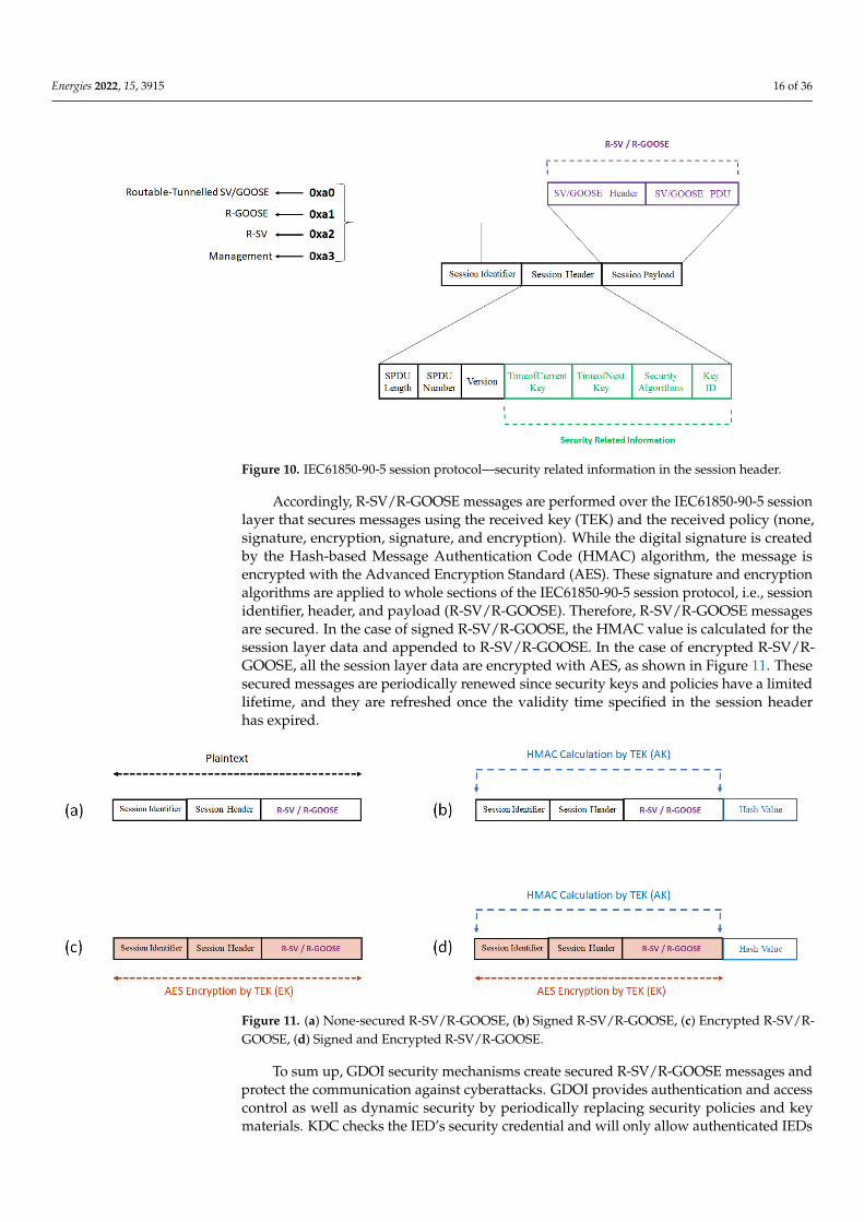
Accordingly, R-SV/R-GOOSE messages are performed over the IEC61850-90-5 ses-
sion layer that secures messages using the received key (TEK) and the received policy
(none, signature, encryption, signature, and encryption). While the digital signature is
created by the Hash-based Message Authentication Code (HMAC) algorithm, the mes-
sage is encrypted with the Advanced Encryption Standard (AES). These signature and
encryption algorithms are applied to whole sections of the IEC61850-90-5 session protocol,
i.e., session identifier, header, and payload (R-SV/R-GOOSE). Therefore, R-SV/R-GOOSE
messages are secured. In the case of signed R-SV/R-GOOSE, the HMAC value is calculated
for the session layer data and appended to R-SV/R-GOOSE. In the case of encrypted R-SV/R-
GOOSE, all the session layer data are encrypted with AES, as shown in Figure 11. These se-
cured messages are periodically renewed since security keys and policies have a limited life-
time, and they are refreshed once the validity time specified in the session header has expired.
Figure 10. IEC61850-90-5 session protocol—security related information in the session header.
Accordingly, R-SV/R-GOOSE messages are performed over the IEC61850-90-5 sessionlayer that secures messages using the received key (TEK) and the received policy (none,signature, encryption, signature, and encryption). While the digital signature is createdby the Hash-based Message Authentication Code (HMAC) algorithm, the message isencrypted with the Advanced Encryption Standard (AES). These signature and encryptionalgorithms are applied to whole sections of the IEC61850-90-5 session protocol, i.e., sessionidentifier, header, and payload (R-SV/R-GOOSE). Therefore, R-SV/R-GOOSE messagesare secured. In the case of signed R-SV/R-GOOSE, the HMAC value is calculated for thesession layer data and appended to R-SV/R-GOOSE. In the case of encrypted R-SV/R-GOOSE, all the session layer data are encrypted with AES, as shown in Figure 11. Thesesecured messages are periodically renewed since security keys and policies have a limitedlifetime, and they are refreshed once the validity time specified in the session headerhas expired.
Energies 2022, 15, x FOR PEER REVIEW 17 of 37
Figure 11. (a) None-secured R-SV/R-GOOSE, (b) Signed R-SV/R-GOOSE, (c) Encrypted R-SV/R-
GOOSE, (d) Signed and Encrypted R-SV/R-GOOSE.
To sum up, GDOI security mechanisms create secured R-SV/R-GOOSE messages and
protect the communication against cyberattacks. GDOI provides authentication and ac-
cess control as well as dynamic security by periodically replacing security policies and
key materials. KDC checks the IED’s security credential and will only allow authenticated
IEDs to join a specific group. The access control is provided by KDC in two ways: back-
ward access control, i.e., the IED has no access to security keys before joining the group
and forward access control, i.e., the IED has no access to the security keys after leaving the
group (because KDC replaces the group keys with new ones when a GM leaves the
group). Moreover, KDC ensures perfect-forward secrecy, which means that a minimum
amount of data is exposed if a security key is hacked because KDC replaces and distrib-
utes security keys automatically and frequently.
There are other improvements. For example, IEC 61850-90-5 and IEC 62351-9 extend
the original GDOI model to enhance its security for R-SV/R-GOOSE communication. IEC
61850-90-5 extends the original GDOI model in which security keys are specific to IP ad-
dresses only [30]. The extension allows security keys to be associated not only with IP
addresses but also with an IEC61850 Dataset or delivery service. This extension enables
key management for situations when a device with a single IP address contains multiple
subscribers that support different services. In such cases, the security keys can be man-
aged at the Dataset level (Dataset specific security key) or at the delivery service (R-SV or
R-GOOSE) level, even if the IP address and the Dataset values are the same. Additionally,
IEC 62351-9 uses a GDOI extension [40] that defines the support for IEC 62351 security
services such as the standardized authentication and confidentiality algorithms used in
TEK. This extension also enables KDC to distribute two sets of policies and keys (Pol-
icy1/Key1 and Policy2/Key2) in one message to the GMs. Each policy includes the remain-
ing lifetime and the activation delay values. The first set (Policy1/Key1) is regarded as the
current set and is activated immediately while the second set (Policy2/Key2) is regarded
as the next set, in which the remaining lifetime and activation delay can be defined so as
to overlap between the two sets. Allowing an overlap between the remaining lifetimes of
the two sets provides a resilient security solution if a GM is disconnected from a KDC
because the GM can still communicate securely, at least for the remaining lifetime defined
in Policy 2.
5.2.2. Secured Communication Path
In wide-area applications, R-SV/R-GOOSE communication can also be protected by
securing the communication path (WAN). While the Group Encrypted Transport Virtual
Figure 11. (a) None-secured R-SV/R-GOOSE, (b) Signed R-SV/R-GOOSE, (c) Encrypted R-SV/R-GOOSE, (d) Signed and Encrypted R-SV/R-GOOSE.
To sum up, GDOI security mechanisms create secured R-SV/R-GOOSE messages andprotect the communication against cyberattacks. GDOI provides authentication and accesscontrol as well as dynamic security by periodically replacing security policies and keymaterials. KDC checks the IED’s security credential and will only allow authenticated IEDs
Energies 2022, 15, 3915 17 of 36
to join a specific group. The access control is provided by KDC in two ways: backwardaccess control, i.e., the IED has no access to security keys before joining the group andforward access control, i.e., the IED has no access to the security keys after leaving thegroup (because KDC replaces the group keys with new ones when a GM leaves the group).Moreover, KDC ensures perfect-forward secrecy, which means that a minimum amount ofdata is exposed if a security key is hacked because KDC replaces and distributes securitykeys automatically and frequently.
There are other improvements. For example, IEC 61850-90-5 and IEC 62351-9 extendthe original GDOI model to enhance its security for R-SV/R-GOOSE communication. IEC61850-90-5 extends the original GDOI model in which security keys are specific to IPaddresses only [30]. The extension allows security keys to be associated not only with IPaddresses but also with an IEC61850 Dataset or delivery service. This extension enableskey management for situations when a device with a single IP address contains multiplesubscribers that support different services. In such cases, the security keys can be managedat the Dataset level (Dataset specific security key) or at the delivery service (R-SV or R-GOOSE) level, even if the IP address and the Dataset values are the same. Additionally, IEC62351-9 uses a GDOI extension [40] that defines the support for IEC 62351 security servicessuch as the standardized authentication and confidentiality algorithms used in TEK. Thisextension also enables KDC to distribute two sets of policies and keys (Policy1/Key1 andPolicy2/Key2) in one message to the GMs. Each policy includes the remaining lifetime andthe activation delay values. The first set (Policy1/Key1) is regarded as the current set andis activated immediately while the second set (Policy2/Key2) is regarded as the next set, inwhich the remaining lifetime and activation delay can be defined so as to overlap betweenthe two sets. Allowing an overlap between the remaining lifetimes of the two sets providesa resilient security solution if a GM is disconnected from a KDC because the GM can stillcommunicate securely, at least for the remaining lifetime defined in Policy 2.
5.2.2. Secured Communication Path
In wide-area applications, R-SV/R-GOOSE communication can also be protected bysecuring the communication path (WAN). While the Group Encrypted Transport VirtualPrivate Network (GET VPN) is used to secure a private WAN, the IP security (IPsec) tunnelis used for a public WAN.
GET VPN for Private WAN
For a private WAN (Figure 5), GET VPN [41] provides network level security byencrypting IP-multicast traffic (R-GOOSE/R-SV) transmitted between the edge routers.GET VPN is tunnel-less VPN based on GDOI [37] in which all the GMs (multicast treerouters) share a common security material, based on the group-IPsec [42] security paradigm.In traditional point-to-point IPsec VPN, two communication peers negotiate to establish acommon IPsec Security Association (SA) that specifies the type of cryptographic algorithmsand the security policies for an IPsec tunnel. Then, the Encapsulated Security Payload (ESP)protocol [42] provides symmetric encryption for data transmitted in the tunnel.
However, tunnel-based encryption is not a scalable solution for securing IP-multicasttraffic in a private WAN because so many IPsec tunnels and associated SAs are requiredbetween each of the multicast tree routers, i.e., FHR, intermediary WAN routers, and LHRs.GET VPN provides a highly scalable solution by introducing the concept of group-IPsec SA,which is a common cryptographic key and policy sharing between the group participants,i.e., multicast tree routers. GET VPN is tunnel-less VPN because there is no need tonegotiate point-to-point IPsec tunnels between each of the two routers of the multicast tree.GETVPN uses GDOI and encrypts the communication between the multicast tree routerswhile keeping them synchronized.
GET VPN security is based on the GDOI mechanism [37] that was explained inthe previous section. GET VPN combines group-key protocol, based on GDOI, withIPsec encryption that is based on ESP to secure IP-multicast traffic (R-SV/R-GOOSE)
Energies 2022, 15, 3915 18 of 36
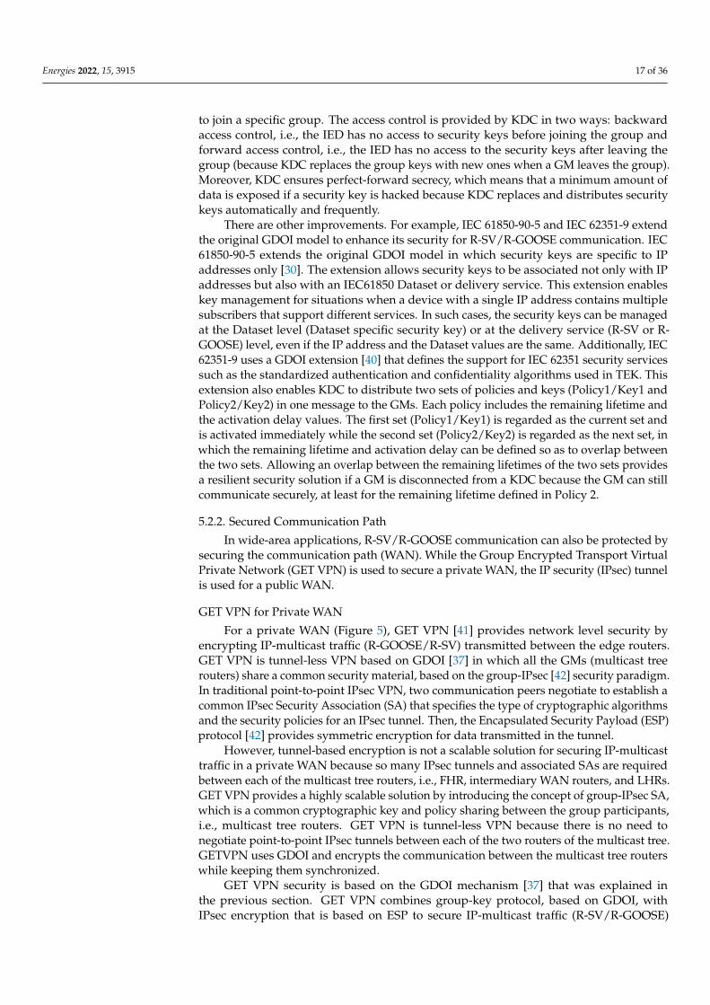
between routers of the multicast tree in private WAN. Thus, one of the multicast routers (inFigure 5) acts as the GCKS that authenticates the other GMs (routers) via an ISAKMP-basedauthentication method such as pre-shared key or certificate-based authentication. Aftersuccessful authentication, the GMs register with the GCKS and acquire group-IPsec SA,which is necessary for secure communication within the group. When a GM registerswith it, the GCKS sends the group-IPsec policy to the GM. After the GM confirms thehandling of the received SA policy, the GCKS downloads security keys (KEK and TEK) tothe GM. While TEK becomes the group-key for encrypting and decrypting IP-multicastcommunication between the GM routers, KEK encrypts and decrypts messages that arerelated to rekeying SA (new group-IPsec SA) and exchanged between GCKS and GMS asdepicted in Figure 12.
Energies 2022, 15, x FOR PEER REVIEW 18 of 37
Private Network (GET VPN) is used to secure a private WAN, the IP security (IPsec) tun-
nel is used for a public WAN.
GET VPN for Private WAN
For a private WAN (Figure 5), GET VPN [41] provides network level security by en-
crypting IP-multicast traffic (R-GOOSE/R-SV) transmitted between the edge routers. GET
VPN is tunnel-less VPN based on GDOI [37] in which all the GMs (multicast tree routers)
share a common security material, based on the group-IPsec [42] security paradigm. In
traditional point-to-point IPsec VPN, two communication peers negotiate to establish a
common IPsec Security Association (SA) that specifies the type of cryptographic algo-
rithms and the security policies for an IPsec tunnel. Then, the Encapsulated Security Pay-
load (ESP) protocol [42] provides symmetric encryption for data transmitted in the tunnel.
However, tunnel-based encryption is not a scalable solution for securing IP-multicast
traffic in a private WAN because so many IPsec tunnels and associated SAs are required
between each of the multicast tree routers, i.e., FHR, intermediary WAN routers, and
LHRs. GET VPN provides a highly scalable solution by introducing the concept of group-
IPsec SA, which is a common cryptographic key and policy sharing between the group
participants, i.e., multicast tree routers. GET VPN is tunnel-less VPN because there is no
need to negotiate point-to-point IPsec tunnels between each of the two routers of the mul-
ticast tree. GETVPN uses GDOI and encrypts the communication between the multicast
tree routers while keeping them synchronized.
GET VPN security is based on the GDOI mechanism [37] that was explained in the
previous section. GET VPN combines group-key protocol, based on GDOI, with IPsec en-
cryption that is based on ESP to secure IP-multicast traffic (R-SV/R-GOOSE) between rout-
ers of the multicast tree in private WAN. Thus, one of the multicast routers (in Figure 5)
acts as the GCKS that authenticates the other GMs (routers) via an ISAKMP-based authen-
tication method such as pre-shared key or certificate-based authentication. After success-
ful authentication, the GMs register with the GCKS and acquire group-IPsec SA, which is
necessary for secure communication within the group. When a GM registers with it, the
GCKS sends the group-IPsec policy to the GM. After the GM confirms the handling of the
received SA policy, the GCKS downloads security keys (KEK and TEK) to the GM. While
TEK becomes the group-key for encrypting and decrypting IP-multicast communication be-
tween the GM routers, KEK encrypts and decrypts messages that are related to rekeying SA
(new group-IPsec SA) and exchanged between GCKS and GMS as depicted in Figure 12.
Figure 12. GDOI components (GCKS and GMs) in GET VPN architecture. Figure 12. GDOI components (GCKS and GMs) in GET VPN architecture.
Thus, the GCKS and the GMs are part of any GET VPN architecture in a private WAN.The GCKS, Key Server (KS) for short, is the router responsible for managing the GET VPNcontrol plane, i.e., group-IPsec SA (type of encryption protocols and their policies). TheGMs are the routers responsible for handling the GET VPN data plane, i.e., the actualencryption and decryption of data. As was explained earlier, GDOI uses two security keys,KEK and TEK, which secure the control plane and data plane of the GET VPN, respectively.These keys have a defined lifetime which is determined based on the security policy ofthe network. While the KEK lifetime regulates the time before rekeying the SA, the TEKlifetime determines the lifetime of the group-IPsec SA.
KS periodically refreshes the cryptographic keys (KEK and TEK) and policies anddistributes updates to the GMs via rekeying, which is the process of pushing new securitykeys when the current SA keys are about to expire or if the SA policy changes on the KS.GET VPN supports two types [41] of rekeying messages: unicast rekey and multicast rekey.While KS sends separate copies of the rekey message to each GM in the unicast model, KSsends only one copy of the message with the multicast address (to the registered GMs) inthe multicast rekey model.
In GET VPN, the multicast routers secure the network traffic, containing R-SV/R-GOOSE, by combining the group-key (TEK) with a computer networking technique calledIPsec Tunnel Mode with Address Preservation [41]. This technique uses IPsec encryptionand encapsulation mechanisms. However, a copy of the original IP header is preservedrather than replacing it with a new IP header (i.e., tunnel endpoints IP addresses) as wouldhave occurred in the traditional IPsec Tunnel mode [42]. The ESP protocol then encrypts
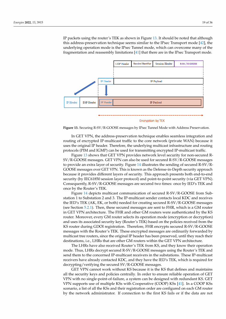
Energies 2022, 15, 3915 19 of 36
IP packets using the router’s TEK as shown in Figure 13. It should be noted that althoughthis address-preservation technique seems similar to the IPsec Transport mode [42], theunderlying operation mode is the IPsec Tunnel mode, which can overcome many of thefragmentation and reassembly limitations [41] that there are in the IPsec Transport mode.
Energies 2022, 15, x FOR PEER REVIEW 19 of 37
Thus, the GCKS and the GMs are part of any GET VPN architecture in a private
WAN. The GCKS, Key Server (KS) for short, is the router responsible for managing the
GET VPN control plane, i.e., group-IPsec SA (type of encryption protocols and their poli-
cies). The GMs are the routers responsible for handling the GET VPN data plane, i.e., the
actual encryption and decryption of data. As was explained earlier, GDOI uses two secu-
rity keys, KEK and TEK, which secure the control plane and data plane of the GET VPN,
respectively. These keys have a defined lifetime which is determined based on the security
policy of the network. While the KEK lifetime regulates the time before rekeying the SA,
the TEK lifetime determines the lifetime of the group-IPsec SA.
KS periodically refreshes the cryptographic keys (KEK and TEK) and policies and
distributes updates to the GMs via rekeying, which is the process of pushing new security
keys when the current SA keys are about to expire or if the SA policy changes on the KS.
GET VPN supports two types [41] of rekeying messages: unicast rekey and multicast re-
key. While KS sends separate copies of the rekey message to each GM in the unicast
model, KS sends only one copy of the message with the multicast address (to the regis-
tered GMs) in the multicast rekey model.
In GET VPN, the multicast routers secure the network traffic, containing R-SV/R-
GOOSE, by combining the group-key (TEK) with a computer networking technique called
IPsec Tunnel Mode with Address Preservation [41]. This technique uses IPsec encryption
and encapsulation mechanisms. However, a copy of the original IP header is preserved
rather than replacing it with a new IP header (i.e., tunnel endpoints IP addresses) as would
have occurred in the traditional IPsec Tunnel mode [42]. The ESP protocol then encrypts
IP packets using the router’s TEK as shown in Figure 13. It should be noted that although
this address-preservation technique seems similar to the IPsec Transport mode [42], the
underlying operation mode is the IPsec Tunnel mode, which can overcome many of the
fragmentation and reassembly limitations [41] that there are in the IPsec Transport mode.
Figure 13. Securing R-SV/R-GOOSE messages by IPsec Tunnel Mode with Address Preservation.
In GET VPN, the address-preservation technique enables seamless integration and
routing of encrypted IP-multicast traffic to the core network (private WAN) because it
uses the original IP header. Therefore, the underlying multicast infrastructure and routing
protocols (PIM and IGMP) can be used for transmitting encrypted IP-multicast traffic.
Figure 13 shows that GET VPN provides network level security for non-secured R-
SV/R-GOOSE messages. GET VPN can also be used for secured R-SV/R-GOOSE messages
to provide an extra layer of security. Figure 14 illustrates the sending of secured R-SV/R-
GOOSE messages over GET VPN. This is known as the Defense-in-Depth security ap-
proach because it provides different layers of security. This approach presents both end-
to-end security (by IEC61850 session layer protocol) and point-to-point security (via GET
Figure 13. Securing R-SV/R-GOOSE messages by IPsec Tunnel Mode with Address Preservation.
In GET VPN, the address-preservation technique enables seamless integration androuting of encrypted IP-multicast traffic to the core network (private WAN) because ituses the original IP header. Therefore, the underlying multicast infrastructure and routingprotocols (PIM and IGMP) can be used for transmitting encrypted IP-multicast traffic.
Figure 13 shows that GET VPN provides network level security for non-secured R-SV/R-GOOSE messages. GET VPN can also be used for secured R-SV/R-GOOSE messagesto provide an extra layer of security. Figure 14 illustrates the sending of secured R-SV/R-GOOSE messages over GET VPN. This is known as the Defense-in-Depth security approachbecause it provides different layers of security. This approach presents both end-to-endsecurity (by IEC61850 session layer protocol) and point-to-point security (via GET VPN).Consequently, R-SV/R-GOOSE messages are secured two times: once by IED’s TEK andonce by the Router’s TEK.
Figure 14 depicts multicast communication of secured R-SV/R-GOOSE from Sub-station 1 to Substation 2 and 3. The IP-multicast sender contacts local KDC and receivesthe IED’s TEK (AK, EK, or both) needed for creating secured R-SV/R-GOOSE messages(see Section 5.2.1). Then, these secured messages are sent to FHR, which is a GM routerin GET VPN architecture. The FHR and other GM routers were authenticated by the KSrouter. Moreover, every GM router selects its operation mode (encryption or decryption)and uses its associated security key (Router’s TEK) based on the policies received from theKS router during GDOI registration. Therefore, FHR encrypts secured R-SV/R-GOOSEmessages with the Router’s TEK. These encrypted messages are ordinarily forwarded bymulticast tree routers, since the original IP header has been preserved, until they reach theirdestinations, i.e., LHRs that are other GM routers within the GET VPN architecture.
The LHRs have also received Router’s TEK from KS, and they know their operationmode. Thus, LHRs decrypt secured R-SV/R-GOOSE messages using the Router’s TEK andsend them to the concerned IP-multicast receivers in the substations. These IP-multicastreceivers have already contacted KDC, and they have the IED’s TEK, which is required fordecrypting/verifying the secured SV/R-GOOSE messages.
GET VPN cannot work without KS because it is the KS that defines and maintainsall the security keys and policies centrally. In order to ensure reliable operation of GETVPN with no single-point-of-failure, a system can be designed with redundant KS. GETVPN supports use of multiple KSs with Cooperative (COOP) KSs [41]. In a COOP KSsscenario, a list of all the KSs and their registration order are configured on each GM routerby the network administrator. If connection to the first KS fails or if the data are not
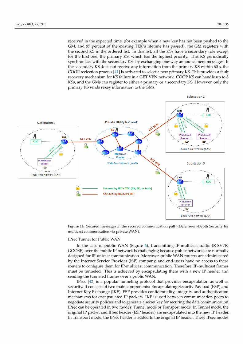
Energies 2022, 15, 3915 20 of 36
received in the expected time, (for example when a new key has not been pushed to theGM, and 95 percent of the existing TEK’s lifetime has passed), the GM registers withthe second KS in the ordered list. In this list, all the KSs have a secondary role exceptfor the first one, the primary KS, which has the highest priority. This KS periodicallysynchronizes with the secondary KSs by exchanging one-way announcement messages. Ifthe secondary KS does not receive any information from the primary KS within 60 s, theCOOP reelection process [41] is activated to select a new primary KS. This provides a faultrecovery mechanism for KS failure in a GET VPN network. COOP KS can handle up to 8KSs, and the GMs can register to either a primary or a secondary KS. However, only theprimary KS sends rekey information to the GMs.
Energies 2022, 15, x FOR PEER REVIEW 20 of 37
VPN). Consequently, R-SV/R-GOOSE messages are secured two times: once by IED’s TEK
and once by the Router’s TEK.
Figure 14. Secured messages in the secured communication path (Defense-in-Depth Security for
multicast communication via private WAN).
Figure 14 depicts multicast communication of secured R-SV/R-GOOSE from Substa-
tion 1 to Substation 2 and 3. The IP-multicast sender contacts local KDC and receives the
IED’s TEK (AK, EK, or both) needed for creating secured R-SV/R-GOOSE messages (see
Section 5.2.1). Then, these secured messages are sent to FHR, which is a GM router in GET
VPN architecture. The FHR and other GM routers were authenticated by the KS router.
Moreover, every GM router selects its operation mode (encryption or decryption) and
uses its associated security key (Router’s TEK) based on the policies received from the KS
router during GDOI registration. Therefore, FHR encrypts secured R-SV/R-GOOSE mes-
sages with the Router’s TEK. These encrypted messages are ordinarily forwarded by mul-
ticast tree routers, since the original IP header has been preserved, until they reach their
destinations, i.e., LHRs that are other GM routers within the GET VPN architecture.
The LHRs have also received Router’s TEK from KS, and they know their operation
mode. Thus, LHRs decrypt secured R-SV/R-GOOSE messages using the Router’s TEK and
send them to the concerned IP-multicast receivers in the substations. These IP-multicast
receivers have already contacted KDC, and they have the IED’s TEK, which is required
for decrypting/verifying the secured SV/R-GOOSE messages.
GET VPN cannot work without KS because it is the KS that defines and maintains all
the security keys and policies centrally. In order to ensure reliable operation of GET VPN
with no single-point-of-failure, a system can be designed with redundant KS. GET VPN
supports use of multiple KSs with Cooperative (COOP) KSs [41]. In a COOP KSs scenario,
a list of all the KSs and their registration order are configured on each GM router by the
network administrator. If connection to the first KS fails or if the data are not received in
the expected time, (for example when a new key has not been pushed to the GM, and 95
percent of the existing TEK’s lifetime has passed), the GM registers with the second KS in
Figure 14. Secured messages in the secured communication path (Defense-in-Depth Security formulticast communication via private WAN).
IPsec Tunnel for Public WAN
In the case of public WAN (Figure 6), transmitting IP-multicast traffic (R-SV/R-GOOSE) over the public IP network is challenging because public networks are normallydesigned for IP-unicast communication. Moreover, public WAN routers are administeredby the Internet Service Provider (ISP) company, and end-users have no access to theserouters to configure them for IP-multicast communication. Therefore, IP-multicast framesmust be tunneled. This is achieved by encapsulating them with a new IP header andsending the tunneled frames over a public WAN.
IPsec [42] is a popular tunneling protocol that provides encapsulation as well assecurity. It consists of two main components: Encapsulating Security Payload (ESP) andInternet Key Exchange (IKE). ESP provides confidentiality, integrity, and authenticationmechanisms for encapsulated IP packets. IKE is used between communication peers tonegotiate security policies and to generate a secret key for securing the data communication.IPsec can be operated in two modes: Tunnel mode or Transport mode. In Tunnel mode, theoriginal IP packet and IPsec header (ESP header) are encapsulated into the new IP header.In Transport mode, the IPsec header is added to the original IP header. These IPsec modes
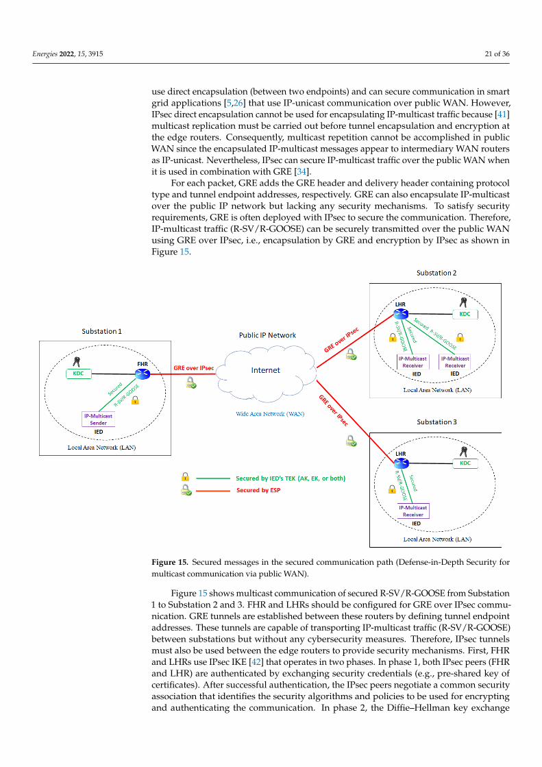
Energies 2022, 15, 3915 21 of 36
use direct encapsulation (between two endpoints) and can secure communication in smartgrid applications [5,26] that use IP-unicast communication over public WAN. However,IPsec direct encapsulation cannot be used for encapsulating IP-multicast traffic because [41]multicast replication must be carried out before tunnel encapsulation and encryption atthe edge routers. Consequently, multicast repetition cannot be accomplished in publicWAN since the encapsulated IP-multicast messages appear to intermediary WAN routersas IP-unicast. Nevertheless, IPsec can secure IP-multicast traffic over the public WAN whenit is used in combination with GRE [34].
For each packet, GRE adds the GRE header and delivery header containing protocoltype and tunnel endpoint addresses, respectively. GRE can also encapsulate IP-multicastover the public IP network but lacking any security mechanisms. To satisfy securityrequirements, GRE is often deployed with IPsec to secure the communication. Therefore,IP-multicast traffic (R-SV/R-GOOSE) can be securely transmitted over the public WANusing GRE over IPsec, i.e., encapsulation by GRE and encryption by IPsec as shown inFigure 15.
Energies 2022, 15, x FOR PEER REVIEW 22 of 37
Figure 15. Secured messages in the secured communication path (Defense-in-Depth Security for
multicast communication via public WAN).
Figure 15 shows multicast communication of secured R-SV/R-GOOSE from Substa-
tion 1 to Substation 2 and 3. FHR and LHRs should be configured for GRE over IPsec
communication. GRE tunnels are established between these routers by defining tunnel
endpoint addresses. These tunnels are capable of transporting IP-multicast traffic (R-
SV/R-GOOSE) between substations but without any cybersecurity measures. Therefore,
IPsec tunnels must also be used between the edge routers to provide security mechanisms.
First, FHR and LHRs use IPsec IKE [42] that operates in two phases. In phase 1, both IPsec
peers (FHR and LHR) are authenticated by exchanging security credentials (e.g., pre-
shared key of certificates). After successful authentication, the IPsec peers negotiate a com-
mon security association that identifies the security algorithms and policies to be used for
encrypting and authenticating the communication. In phase 2, the Diffie–Hellman key ex-
change method is used to generate a shared key used for securing the WAN communica-
tion by ESP: encrypting IP packet and adding authentication data (ESP Auth). Thus, a
secured communication path is created for R-SV/R-GOOSE messages as depicted in Fig-
ure 15. In the following, Figure 16 shows the structure of the messages transmitted be-
tween FHR and each LHR after successful IKE authentication.
Figure 15. Secured messages in the secured communication path (Defense-in-Depth Security formulticast communication via public WAN).
Figure 15 shows multicast communication of secured R-SV/R-GOOSE from Substation1 to Substation 2 and 3. FHR and LHRs should be configured for GRE over IPsec commu-nication. GRE tunnels are established between these routers by defining tunnel endpointaddresses. These tunnels are capable of transporting IP-multicast traffic (R-SV/R-GOOSE)between substations but without any cybersecurity measures. Therefore, IPsec tunnelsmust also be used between the edge routers to provide security mechanisms. First, FHRand LHRs use IPsec IKE [42] that operates in two phases. In phase 1, both IPsec peers (FHRand LHR) are authenticated by exchanging security credentials (e.g., pre-shared key ofcertificates). After successful authentication, the IPsec peers negotiate a common securityassociation that identifies the security algorithms and policies to be used for encryptingand authenticating the communication. In phase 2, the Diffie–Hellman key exchange
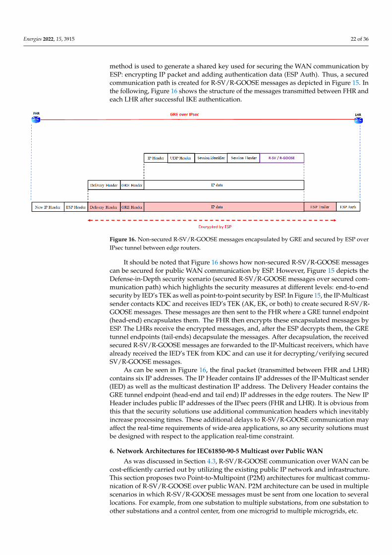
Energies 2022, 15, 3915 22 of 36
method is used to generate a shared key used for securing the WAN communication byESP: encrypting IP packet and adding authentication data (ESP Auth). Thus, a securedcommunication path is created for R-SV/R-GOOSE messages as depicted in Figure 15. Inthe following, Figure 16 shows the structure of the messages transmitted between FHR andeach LHR after successful IKE authentication.
Energies 2022, 15, x FOR PEER REVIEW 23 of 37
Figure 16. Non-secured R-SV/R-GOOSE messages encapsulated by GRE and secured by ESP over
IPsec tunnel between edge routers.
It should be noted that Figure 16 shows how non-secured R-SV/R-GOOSE messages
can be secured for public WAN communication by ESP. However, Figure 15 depicts the
Defense-in-Depth security scenario (secured R-SV/R-GOOSE messages over secured com-
munication path) which highlights the security measures at different levels: end-to-end
security by IED’s TEK as well as point-to-point security by ESP. In Figure 15, the IP-Mul-
ticast sender contacts KDC and receives IED’s TEK (AK, EK, or both) to create secured R-
SV/R-GOOSE messages. These messages are then sent to the FHR where a GRE tunnel
endpoint (head-end) encapsulates them. The FHR then encrypts these encapsulated mes-
sages by ESP. The LHRs receive the encrypted messages, and, after the ESP decrypts them,
the GRE tunnel endpoints (tail-ends) decapsulate the messages. After decapsulation, the
received secured R-SV/R-GOOSE messages are forwarded to the IP-Multicast receivers,
which have already received the IED’s TEK from KDC and can use it for decrypting/ver-
ifying secured SV/R-GOOSE messages.
As can be seen in Figure 16, the final packet (transmitted between FHR and LHR)
contains six IP addresses. The IP Header contains IP addresses of the IP-Multicast sender
(IED) as well as the multicast destination IP address. The Delivery Header contains the
GRE tunnel endpoint (head-end and tail end) IP addresses in the edge routers. The New
IP Header includes public IP addresses of the IPsec peers (FHR and LHR). It is obvious
from this that the security solutions use additional communication headers which inevi-
tably increase processing times. These additional delays to R-SV/R-GOOSE communica-
tion may affect the real-time requirements of wide-area applications, so any security so-
lutions must be designed with respect to the application real-time constraint.
6. Network Architectures for IEC61850-90-5 Multicast over Public WAN
As was discussed in Section 4.3, R-SV/R-GOOSE communication over WAN can be
cost-efficiently carried out by utilizing the existing public IP network and infrastructure.
This section proposes two Point-to-Multipoint (P2M) architectures for multicast commu-
nication of R-SV/R-GOOSE over public WAN. P2M architecture can be used in multiple
scenarios in which R-SV/R-GOOSE messages must be sent from one location to several
locations. For example, from one substation to multiple substations, from one substation
to other substations and a control center, from one microgrid to multiple microgrids, etc.
6.1. P2M Architecture with Seperate GRE Tunnels
As discussed earlier, multicast communication of R-SV/R-GOOSE over public WAN
requires tunneling multicast traffic across the IP network. GRE tunnels can be used for
this purpose in a P2M architecture (Figure 17) which enables multicast communication of
Figure 16. Non-secured R-SV/R-GOOSE messages encapsulated by GRE and secured by ESP overIPsec tunnel between edge routers.
It should be noted that Figure 16 shows how non-secured R-SV/R-GOOSE messagescan be secured for public WAN communication by ESP. However, Figure 15 depicts theDefense-in-Depth security scenario (secured R-SV/R-GOOSE messages over secured com-munication path) which highlights the security measures at different levels: end-to-endsecurity by IED’s TEK as well as point-to-point security by ESP. In Figure 15, the IP-Multicastsender contacts KDC and receives IED’s TEK (AK, EK, or both) to create secured R-SV/R-GOOSE messages. These messages are then sent to the FHR where a GRE tunnel endpoint(head-end) encapsulates them. The FHR then encrypts these encapsulated messages byESP. The LHRs receive the encrypted messages, and, after the ESP decrypts them, the GREtunnel endpoints (tail-ends) decapsulate the messages. After decapsulation, the receivedsecured R-SV/R-GOOSE messages are forwarded to the IP-Multicast receivers, which havealready received the IED’s TEK from KDC and can use it for decrypting/verifying securedSV/R-GOOSE messages.
As can be seen in Figure 16, the final packet (transmitted between FHR and LHR)contains six IP addresses. The IP Header contains IP addresses of the IP-Multicast sender(IED) as well as the multicast destination IP address. The Delivery Header contains theGRE tunnel endpoint (head-end and tail end) IP addresses in the edge routers. The New IPHeader includes public IP addresses of the IPsec peers (FHR and LHR). It is obvious fromthis that the security solutions use additional communication headers which inevitablyincrease processing times. These additional delays to R-SV/R-GOOSE communication mayaffect the real-time requirements of wide-area applications, so any security solutions mustbe designed with respect to the application real-time constraint.
6. Network Architectures for IEC61850-90-5 Multicast over Public WAN
As was discussed in Section 4.3, R-SV/R-GOOSE communication over WAN can becost-efficiently carried out by utilizing the existing public IP network and infrastructure.This section proposes two Point-to-Multipoint (P2M) architectures for multicast commu-nication of R-SV/R-GOOSE over public WAN. P2M architecture can be used in multiplescenarios in which R-SV/R-GOOSE messages must be sent from one location to severallocations. For example, from one substation to multiple substations, from one substation toother substations and a control center, from one microgrid to multiple microgrids, etc.
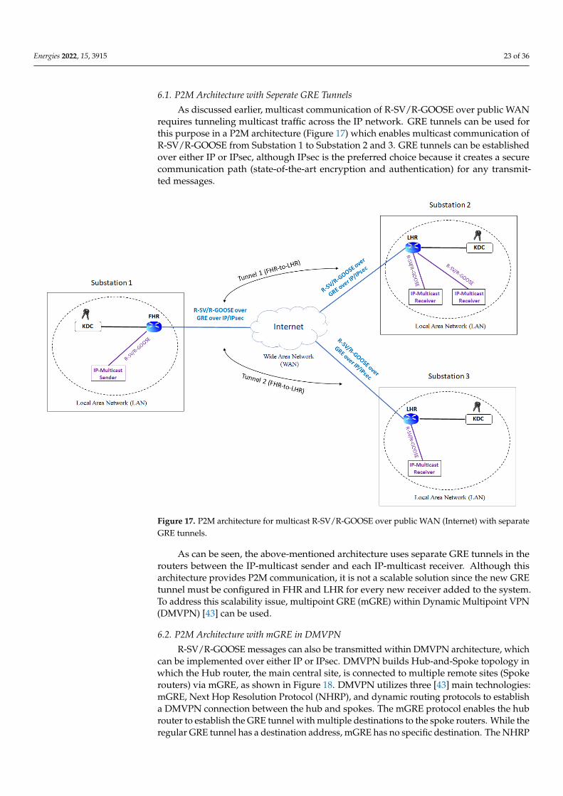
Energies 2022, 15, 3915 23 of 36
6.1. P2M Architecture with Seperate GRE Tunnels
As discussed earlier, multicast communication of R-SV/R-GOOSE over public WANrequires tunneling multicast traffic across the IP network. GRE tunnels can be used forthis purpose in a P2M architecture (Figure 17) which enables multicast communication ofR-SV/R-GOOSE from Substation 1 to Substation 2 and 3. GRE tunnels can be establishedover either IP or IPsec, although IPsec is the preferred choice because it creates a securecommunication path (state-of-the-art encryption and authentication) for any transmit-ted messages.
Energies 2022, 15, x FOR PEER REVIEW 24 of 37
R-SV/R-GOOSE from Substation 1 to Substation 2 and 3. GRE tunnels can be established
over either IP or IPsec, although IPsec is the preferred choice because it creates a secure
communication path (state-of-the-art encryption and authentication) for any transmitted
messages.
Figure 17. P2M architecture for multicast R-SV/R-GOOSE over public WAN (Internet) with separate
GRE tunnels.
As can be seen, the above-mentioned architecture uses separate GRE tunnels in the
routers between the IP-multicast sender and each IP-multicast receiver. Although this ar-
chitecture provides P2M communication, it is not a scalable solution since the new GRE
tunnel must be configured in FHR and LHR for every new receiver added to the system.
To address this scalability issue, multipoint GRE (mGRE) within Dynamic Multipoint
VPN (DMVPN) [43] can be used.
6.2. P2M Architecture with mGRE in DMVPN
R-SV/R-GOOSE messages can also be transmitted within DMVPN architecture,
which can be implemented over either IP or IPsec. DMVPN builds Hub-and-Spoke topol-
ogy in which the Hub router, the main central site, is connected to multiple remote sites
(Spoke routers) via mGRE, as shown in Figure 18. DMVPN utilizes three [43] main tech-
nologies: mGRE, Next Hop Resolution Protocol (NHRP), and dynamic routing protocols
to establish a DMVPN connection between the hub and spokes. The mGRE protocol ena-
bles the hub router to establish the GRE tunnel with multiple destinations to the spoke
routers. While the regular GRE tunnel has a destination address, mGRE has no specific
destination. The NHRP is a client-server protocol used by the routers to inform each
other’s public IP addresses. NHRP supports authentication to ensure that only configured
Figure 17. P2M architecture for multicast R-SV/R-GOOSE over public WAN (Internet) with separateGRE tunnels.
As can be seen, the above-mentioned architecture uses separate GRE tunnels in therouters between the IP-multicast sender and each IP-multicast receiver. Although thisarchitecture provides P2M communication, it is not a scalable solution since the new GREtunnel must be configured in FHR and LHR for every new receiver added to the system.To address this scalability issue, multipoint GRE (mGRE) within Dynamic Multipoint VPN(DMVPN) [43] can be used.
6.2. P2M Architecture with mGRE in DMVPN
R-SV/R-GOOSE messages can also be transmitted within DMVPN architecture, whichcan be implemented over either IP or IPsec. DMVPN builds Hub-and-Spoke topology inwhich the Hub router, the main central site, is connected to multiple remote sites (Spokerouters) via mGRE, as shown in Figure 18. DMVPN utilizes three [43] main technologies:mGRE, Next Hop Resolution Protocol (NHRP), and dynamic routing protocols to establisha DMVPN connection between the hub and spokes. The mGRE protocol enables the hubrouter to establish the GRE tunnel with multiple destinations to the spoke routers. While theregular GRE tunnel has a destination address, mGRE has no specific destination. The NHRP
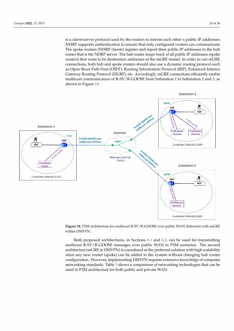
Energies 2022, 15, 3915 24 of 36
is a client-server protocol used by the routers to inform each other’s public IP addresses.NHRP supports authentication to ensure that only configured routers can communicate.The spoke routers (NHRP clients) register and report their public IP addresses to the hubrouter that is the NHRP server. The hub router keeps track of all public IP addresses (spokerouters) that want to be destination addresses of the mGRE tunnel. In order to run mGREconnections, both hub and spoke routers should also use a dynamic routing protocol suchas Open Short Path First (OSPF), Routing Information Protocol (RIP), Enhanced InteriorGateway Routing Protocol (EIGRP), etc. Accordingly, mGRE connections efficiently enablemulticast communication of R-SV/R-GOOSE from Substation 1 to Substation 2 and 3, asshown in Figure 18.
Energies 2022, 15, x FOR PEER REVIEW 25 of 37
routers can communicate. The spoke routers (NHRP clients) register and report their pub-
lic IP addresses to the hub router that is the NHRP server. The hub router keeps track of
all public IP addresses (spoke routers) that want to be destination addresses of the mGRE
tunnel. In order to run mGRE connections, both hub and spoke routers should also use a
dynamic routing protocol such as Open Short Path First (OSPF), Routing Information Pro-
tocol (RIP), Enhanced Interior Gateway Routing Protocol (EIGRP), etc. Accordingly,
mGRE connections efficiently enable multicast communication of R-SV/R-GOOSE from
Substation 1 to Substation 2 and 3, as shown in Figure 18.
Figure 18. P2M architecture for multicast R-SV/R-GOOSE over public WAN (Internet) with mGRE
within DMVPN.
Both proposed architectures, in Sections 6.1 and 6.2, can be used for transmitting
multicast R-SV/R-GOOSE messages over public WAN in P2M scenarios. The second ar-
chitecture (mGRE in DMVPN) is considered as the preferred solution with high scalability
since any new router (spoke) can be added to the system without changing hub router
configuration. However, implementing DMVPN requires extensive knowledge of com-
puter networking standards. Table 5 shows a comparison of networking technologies that
can be used in P2M architecture for both public and private WAN.
Figure 18. P2M architecture for multicast R-SV/R-GOOSE over public WAN (Internet) with mGREwithin DMVPN.
Both proposed architectures, in Sections 6.1 and 6.2, can be used for transmittingmulticast R-SV/R-GOOSE messages over public WAN in P2M scenarios. The secondarchitecture (mGRE in DMVPN) is considered as the preferred solution with high scalabilitysince any new router (spoke) can be added to the system without changing hub routerconfiguration. However, implementing DMVPN requires extensive knowledge of computernetworking standards. Table 5 shows a comparison of networking technologies that can beused in P2M architecture for both public and private WAN.
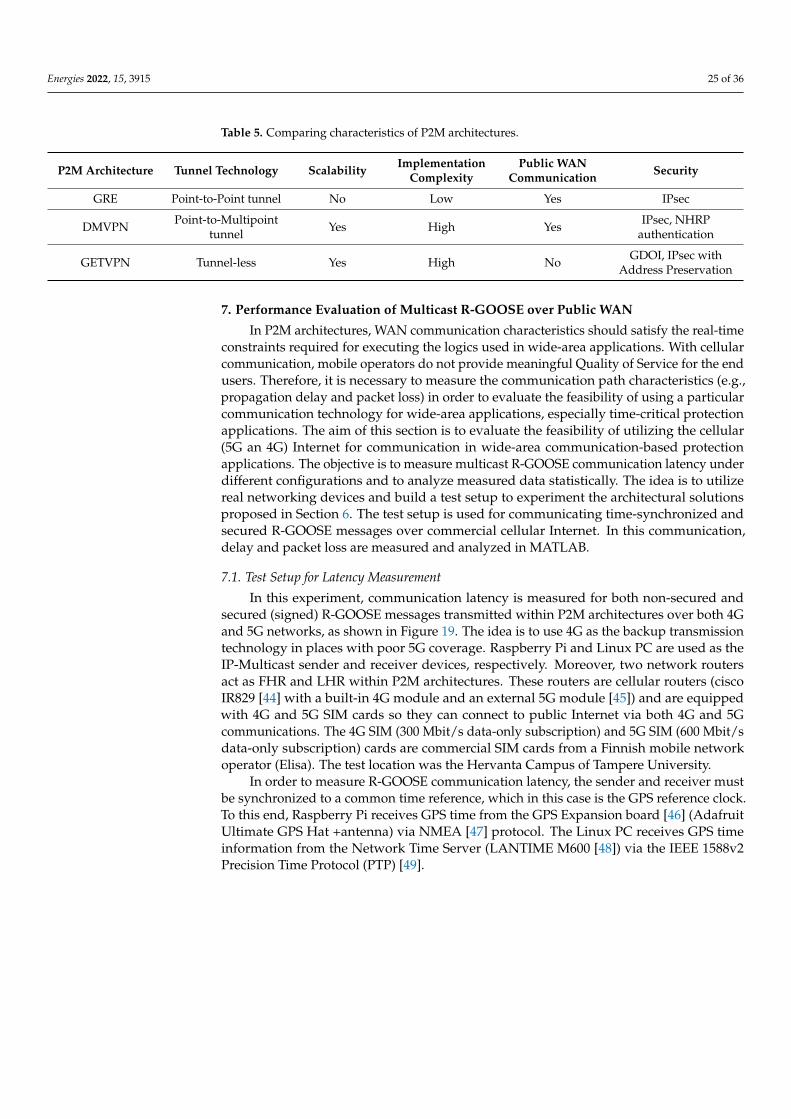
Energies 2022, 15, 3915 25 of 36
Table 5. Comparing characteristics of P2M architectures.
P2M Architecture Tunnel Technology Scalability ImplementationComplexity
Public WANCommunication Security
GRE Point-to-Point tunnel No Low Yes IPsec
DMVPN Point-to-Multipointtunnel Yes High Yes IPsec, NHRP
authentication
GETVPN Tunnel-less Yes High No GDOI, IPsec withAddress Preservation
7. Performance Evaluation of Multicast R-GOOSE over Public WAN
In P2M architectures, WAN communication characteristics should satisfy the real-timeconstraints required for executing the logics used in wide-area applications. With cellularcommunication, mobile operators do not provide meaningful Quality of Service for the endusers. Therefore, it is necessary to measure the communication path characteristics (e.g.,propagation delay and packet loss) in order to evaluate the feasibility of using a particularcommunication technology for wide-area applications, especially time-critical protectionapplications. The aim of this section is to evaluate the feasibility of utilizing the cellular(5G an 4G) Internet for communication in wide-area communication-based protectionapplications. The objective is to measure multicast R-GOOSE communication latency underdifferent configurations and to analyze measured data statistically. The idea is to utilizereal networking devices and build a test setup to experiment the architectural solutionsproposed in Section 6. The test setup is used for communicating time-synchronized andsecured R-GOOSE messages over commercial cellular Internet. In this communication,delay and packet loss are measured and analyzed in MATLAB.
7.1. Test Setup for Latency Measurement
In this experiment, communication latency is measured for both non-secured andsecured (signed) R-GOOSE messages transmitted within P2M architectures over both 4Gand 5G networks, as shown in Figure 19. The idea is to use 4G as the backup transmissiontechnology in places with poor 5G coverage. Raspberry Pi and Linux PC are used as theIP-Multicast sender and receiver devices, respectively. Moreover, two network routersact as FHR and LHR within P2M architectures. These routers are cellular routers (ciscoIR829 [44] with a built-in 4G module and an external 5G module [45]) and are equippedwith 4G and 5G SIM cards so they can connect to public Internet via both 4G and 5Gcommunications. The 4G SIM (300 Mbit/s data-only subscription) and 5G SIM (600 Mbit/sdata-only subscription) cards are commercial SIM cards from a Finnish mobile networkoperator (Elisa). The test location was the Hervanta Campus of Tampere University.
In order to measure R-GOOSE communication latency, the sender and receiver mustbe synchronized to a common time reference, which in this case is the GPS reference clock.To this end, Raspberry Pi receives GPS time from the GPS Expansion board [46] (AdafruitUltimate GPS Hat +antenna) via NMEA [47] protocol. The Linux PC receives GPS timeinformation from the Network Time Server (LANTIME M600 [48]) via the IEEE 1588v2Precision Time Protocol (PTP) [49].
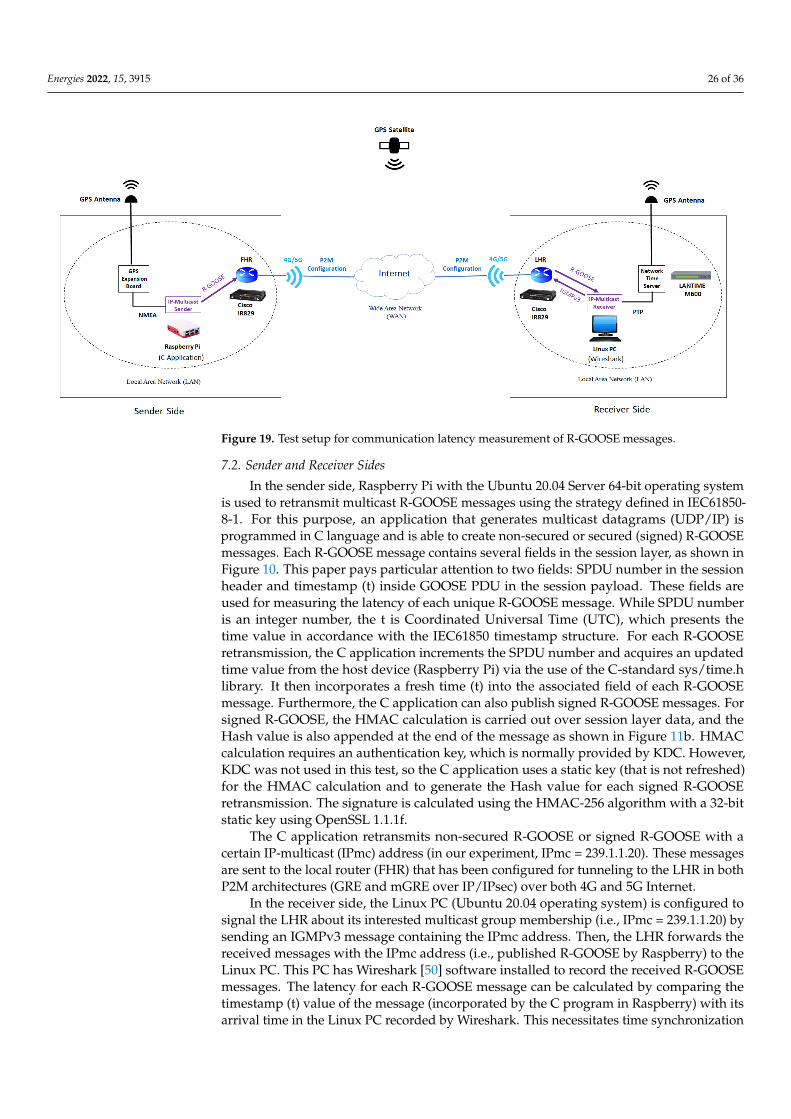
Energies 2022, 15, 3915 26 of 36Energies 2022, 15, x FOR PEER REVIEW 27 of 37
Figure 19. Test setup for communication latency measurement of R-GOOSE messages.
In order to measure R-GOOSE communication latency, the sender and receiver must be
synchronized to a common time reference, which in this case is the GPS reference clock. To
this end, Raspberry Pi receives GPS time from the GPS Expansion board [46] (Adafruit Ulti-
mate GPS Hat +antenna) via NMEA [47] protocol. The Linux PC receives GPS time infor-
mation from the Network Time Server (LANTIME M600 [48]) via the IEEE 1588v2 Precision
Time Protocol (PTP) [49].
7.2. Sender and Receiver Sides
In the sender side, Raspberry Pi with the Ubuntu 20.04 Server 64-bit operating system
is used to retransmit multicast R-GOOSE messages using the strategy defined in
IEC61850-8-1. For this purpose, an application that generates multicast datagrams
(UDP/IP) is programmed in C language and is able to create non-secured or secured
(signed) R-GOOSE messages. Each R-GOOSE message contains several fields in the ses-
sion layer, as shown in Figure 10. This paper pays particular attention to two fields: SPDU
number in the session header and timestamp (t) inside GOOSE PDU in the session pay-
load. These fields are used for measuring the latency of each unique R-GOOSE message.
While SPDU number is an integer number, the t is Coordinated Universal Time (UTC),
which presents the time value in accordance with the IEC61850 timestamp structure. For
each R-GOOSE retransmission, the C application increments the SPDU number and ac-
quires an updated time value from the host device (Raspberry Pi) via the use of the C-
standard sys/time.h library. It then incorporates a fresh time (t) into the associated field of
each R-GOOSE message. Furthermore, the C application can also publish signed R-
GOOSE messages. For signed R-GOOSE, the HMAC calculation is carried out over session
layer data, and the Hash value is also appended at the end of the message as shown in
Figure 11b. HMAC calculation requires an authentication key, which is normally pro-
vided by KDC. However, KDC was not used in this test, so the C application uses a static
key (that is not refreshed) for the HMAC calculation and to generate the Hash value for
each signed R-GOOSE retransmission. The signature is calculated using the HMAC-256
algorithm with a 32-bit static key using OpenSSL 1.1.1f.
The C application retransmits non-secured R-GOOSE or signed R-GOOSE with a cer-
tain IP-multicast (IPmc) address (in our experiment, IPmc = 239.1.1.20). These messages
are sent to the local router (FHR) that has been configured for tunneling to the LHR in
both P2M architectures (GRE and mGRE over IP/IPsec) over both 4G and 5G Internet.
Figure 19. Test setup for communication latency measurement of R-GOOSE messages.
7.2. Sender and Receiver Sides
In the sender side, Raspberry Pi with the Ubuntu 20.04 Server 64-bit operating systemis used to retransmit multicast R-GOOSE messages using the strategy defined in IEC61850-8-1. For this purpose, an application that generates multicast datagrams (UDP/IP) isprogrammed in C language and is able to create non-secured or secured (signed) R-GOOSEmessages. Each R-GOOSE message contains several fields in the session layer, as shown inFigure 10. This paper pays particular attention to two fields: SPDU number in the sessionheader and timestamp (t) inside GOOSE PDU in the session payload. These fields areused for measuring the latency of each unique R-GOOSE message. While SPDU numberis an integer number, the t is Coordinated Universal Time (UTC), which presents thetime value in accordance with the IEC61850 timestamp structure. For each R-GOOSEretransmission, the C application increments the SPDU number and acquires an updatedtime value from the host device (Raspberry Pi) via the use of the C-standard sys/time.hlibrary. It then incorporates a fresh time (t) into the associated field of each R-GOOSEmessage. Furthermore, the C application can also publish signed R-GOOSE messages. Forsigned R-GOOSE, the HMAC calculation is carried out over session layer data, and theHash value is also appended at the end of the message as shown in Figure 11b. HMACcalculation requires an authentication key, which is normally provided by KDC. However,KDC was not used in this test, so the C application uses a static key (that is not refreshed)for the HMAC calculation and to generate the Hash value for each signed R-GOOSEretransmission. The signature is calculated using the HMAC-256 algorithm with a 32-bitstatic key using OpenSSL 1.1.1f.
The C application retransmits non-secured R-GOOSE or signed R-GOOSE with acertain IP-multicast (IPmc) address (in our experiment, IPmc = 239.1.1.20). These messagesare sent to the local router (FHR) that has been configured for tunneling to the LHR in bothP2M architectures (GRE and mGRE over IP/IPsec) over both 4G and 5G Internet.
In the receiver side, the Linux PC (Ubuntu 20.04 operating system) is configured tosignal the LHR about its interested multicast group membership (i.e., IPmc = 239.1.1.20) bysending an IGMPv3 message containing the IPmc address. Then, the LHR forwards thereceived messages with the IPmc address (i.e., published R-GOOSE by Raspberry) to theLinux PC. This PC has Wireshark [50] software installed to record the received R-GOOSEmessages. The latency for each R-GOOSE message can be calculated by comparing thetimestamp (t) value of the message (incorporated by the C program in Raspberry) with itsarrival time in the Linux PC recorded by Wireshark. This necessitates time synchronization
Energies 2022, 15, 3915 27 of 36
to a common time reference between the sender (Raspberry) and the receiver (LinuxPC) devices.
7.3. Time Synchronization
In [8], we measured GOOSE communication latency by using the SENSOR that is aPC with two Ethernet network ports connected to the sender and receiver. In SENSOR,Wireshark software was installed, and GOOSE messages were recorded on both Ethernetports simultaneously. This recording saved as a Wireshark file that was used as the referencefor GOOSE latency measurement and further statistical analyses. This approach is a lab-restricted-measurement method which is applicable for latency measurement inside thelab because the sender and receiver should be in the same location and connect to Ethernetports of SENSOR. This approach works fine for measuring communication latency ofR-GOOSE messages in our test setup because both Raspberry and the Linux PC are in thelab. However, in practice, the sender and receivers are in different locations. Therefore, wealso introduce a new method in the following.
In this paper, the authors introduce a field-capable-measurement method (i.e., senderand receiver can be in different locations) that relies on two “Stratum 0” [16] devices fortime synchronization between the sender and receiver devices. In order to synchronizethese two devices (the Raspberry and Linux PC), a common time reference is needed,and this is provided by the GPS clock, as shown in Figure 19—and elaborated on inFigure 20. The Raspberry is fitted with the GPS expansion board which is connected toan antenna and is used to synchronize the system clock on the device. The Expansionboard includes a Pulse Per Second (PPS) signal output which yields nanosecond levelprecision to system timing. Time information is received from the expansion board overthe serial port connection as a NMEA sentence, and the PPS signal is used to fine-tune theclock drift. Time synchronization with the operating system is implemented using Chronydaemon [51].
The Linux PC receives GPS time information by communicating with the NetworkTime Server via IEEE 1588v2 PTP, PTP for short. The network Time Server has a GPSreceiver that connects to a GPS antenna and receives GPS clock information from thesatellite. It can thus function as a time server that can provide GPS time informationfor other nodes in the network (e.g., the Linux PC). It does this via various networkingprotocols for clock synchronization, such as PTP. This protocol has been selected because itcan provide highly accurate time synchronization, within nanosecond-range accuracy, andconsequently it can even satisfy the requirements of extremely time-demanding wide-areaapplications such as synchrophasors.
PTP provides high accuracy by using hardware generated timestamps over Ethernetports, which are used for time synchronization. The PTP network infrastructure is based ona master-slave architecture, in which the source of time (master) transmits synchronizationinformation to the destination nodes (slaves) over Ethernet communication. In the testsetup, the Network Time Server (LANTIME M600) is configured to function as the PTPmaster that provides GPS time to the Linux PC, which functions as the PTP slave. TheLinux PC is configured to act as a PTP slave by installing PTP4L [52], which is a PTPimplementation for the Linux operating system. Consequently, the Linux PC receivesPTP hardware-timestamping from the Network Time Server and can thus synchronize itssystem time with the time server. This means that software applications such as Wiresharkcan receive system time that has been synchronized to GPS time.
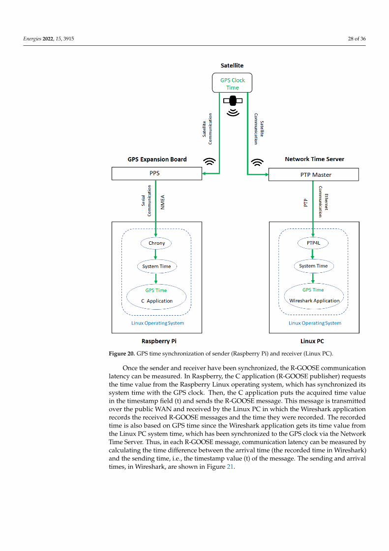
Energies 2022, 15, 3915 28 of 36Energies 2022, 15, x FOR PEER REVIEW 29 of 37
Figure 20. GPS time synchronization of sender (Raspberry Pi) and receiver (Linux PC).
The Linux PC receives GPS time information by communicating with the Network
Time Server via IEEE 1588v2 PTP, PTP for short. The network Time Server has a GPS
receiver that connects to a GPS antenna and receives GPS clock information from the sat-
ellite. It can thus function as a time server that can provide GPS time information for other
nodes in the network (e.g., the Linux PC). It does this via various networking protocols
for clock synchronization, such as PTP. This protocol has been selected because it can pro-
vide highly accurate time synchronization, within nanosecond-range accuracy, and con-
sequently it can even satisfy the requirements of extremely time-demanding wide-area
applications such as synchrophasors.
PTP provides high accuracy by using hardware generated timestamps over Ethernet
ports, which are used for time synchronization. The PTP network infrastructure is based
on a master-slave architecture, in which the source of time (master) transmits synchroni-
zation information to the destination nodes (slaves) over Ethernet communication. In the
test setup, the Network Time Server (LANTIME M600) is configured to function as the
PTP master that provides GPS time to the Linux PC, which functions as the PTP slave. The
Linux PC is configured to act as a PTP slave by installing PTP4L [52], which is a PTP
implementation for the Linux operating system. Consequently, the Linux PC receives PTP
Figure 20. GPS time synchronization of sender (Raspberry Pi) and receiver (Linux PC).
Once the sender and receiver have been synchronized, the R-GOOSE communicationlatency can be measured. In Raspberry, the C application (R-GOOSE publisher) requeststhe time value from the Raspberry Linux operating system, which has synchronized itssystem time with the GPS clock. Then, the C application puts the acquired time valuein the timestamp field (t) and sends the R-GOOSE message. This message is transmittedover the public WAN and received by the Linux PC in which the Wireshark applicationrecords the received R-GOOSE messages and the time they were recorded. The recordedtime is also based on GPS time since the Wireshark application gets its time value fromthe Linux PC system time, which has been synchronized to the GPS clock via the NetworkTime Server. Thus, in each R-GOOSE message, communication latency can be measured bycalculating the time difference between the arrival time (the recorded time in Wireshark)and the sending time, i.e., the timestamp value (t) of the message. The sending and arrivaltimes, in Wireshark, are shown in Figure 21.
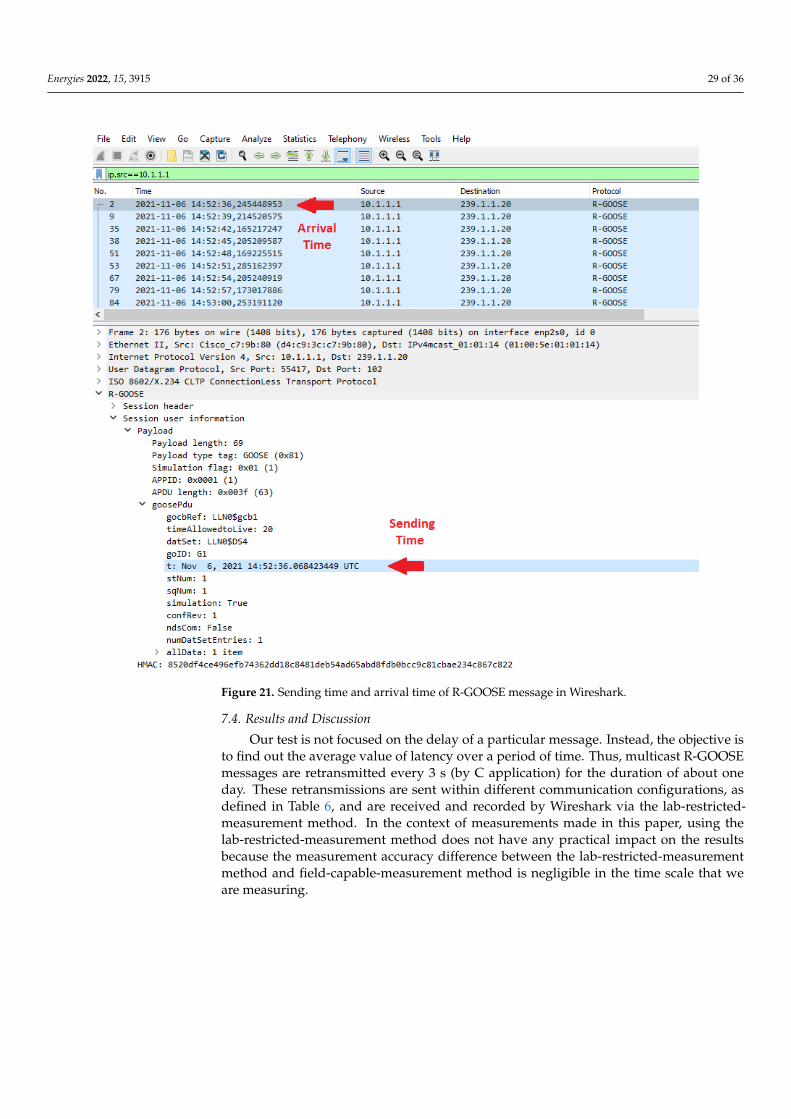
Energies 2022, 15, 3915 29 of 36
Energies 2022, 15, x FOR PEER REVIEW 30 of 37
hardware-timestamping from the Network Time Server and can thus synchronize its sys-
tem time with the time server. This means that software applications such as Wireshark
can receive system time that has been synchronized to GPS time.
Once the sender and receiver have been synchronized, the R-GOOSE communication
latency can be measured. In Raspberry, the C application (R-GOOSE publisher) requests
the time value from the Raspberry Linux operating system, which has synchronized its
system time with the GPS clock. Then, the C application puts the acquired time value in
the timestamp field (t) and sends the R-GOOSE message. This message is transmitted over
the public WAN and received by the Linux PC in which the Wireshark application records
the received R-GOOSE messages and the time they were recorded. The recorded time is
also based on GPS time since the Wireshark application gets its time value from the Linux
PC system time, which has been synchronized to the GPS clock via the Network Time
Server. Thus, in each R-GOOSE message, communication latency can be measured by cal-
culating the time difference between the arrival time (the recorded time in Wireshark) and
the sending time, i.e., the timestamp value (t) of the message. The sending and arrival
times, in Wireshark, are shown in Figure 21.
Figure 21. Sending time and arrival time of R-GOOSE message in Wireshark.
Figure 21. Sending time and arrival time of R-GOOSE message in Wireshark.
7.4. Results and Discussion
Our test is not focused on the delay of a particular message. Instead, the objective isto find out the average value of latency over a period of time. Thus, multicast R-GOOSEmessages are retransmitted every 3 s (by C application) for the duration of about oneday. These retransmissions are sent within different communication configurations, asdefined in Table 6, and are received and recorded by Wireshark via the lab-restricted-measurement method. In the context of measurements made in this paper, using thelab-restricted-measurement method does not have any practical impact on the resultsbecause the measurement accuracy difference between the lab-restricted-measurementmethod and field-capable-measurement method is negligible in the time scale that weare measuring.
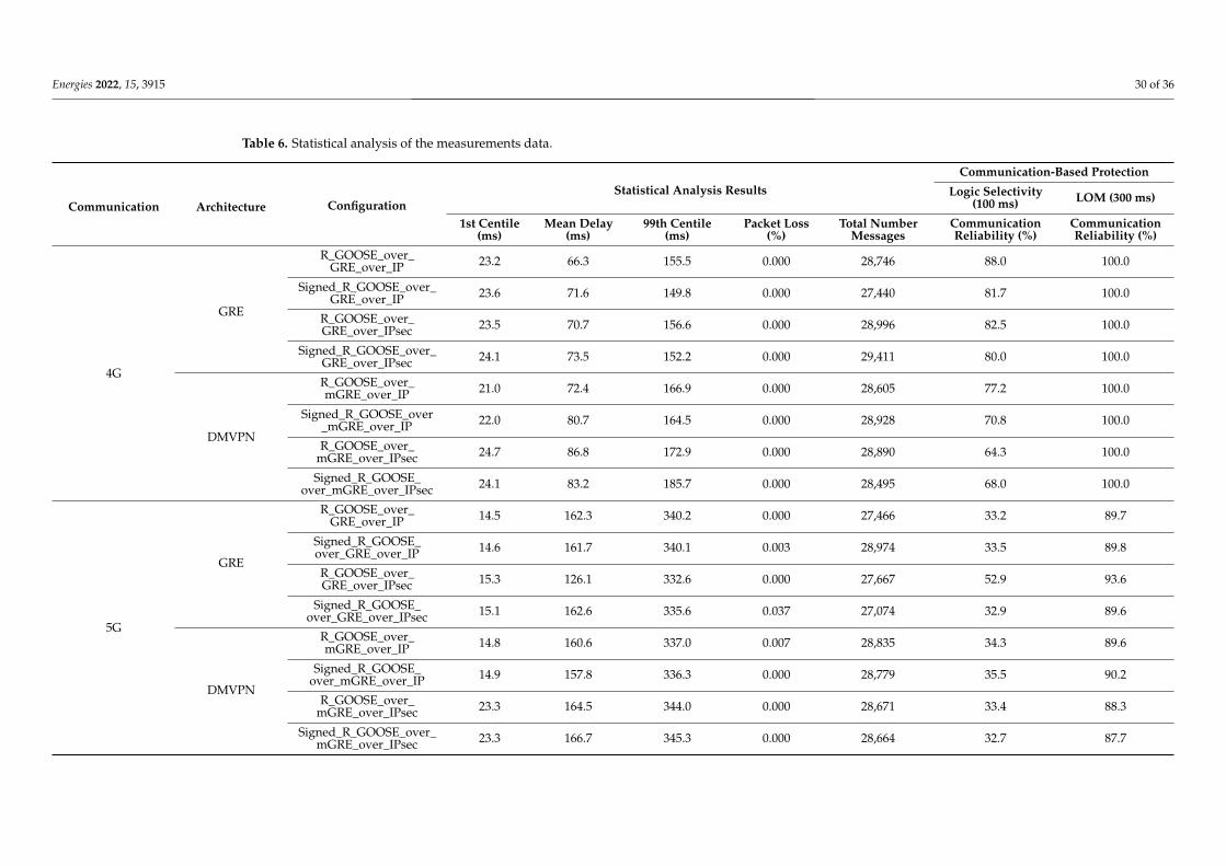
Energies 2022, 15, 3915 30 of 36
Table 6. Statistical analysis of the measurements data.
Communication Architecture ConfigurationStatistical Analysis Results
Communication-Based Protection
Logic Selectivity(100 ms) LOM (300 ms)
1st Centile(ms)
Mean Delay(ms)
99th Centile(ms)
Packet Loss(%)
Total NumberMessages
CommunicationReliability (%)
CommunicationReliability (%)
4G
GRE
R_GOOSE_over_GRE_over_IP 23.2 66.3 155.5 0.000 28,746 88.0 100.0
Signed_R_GOOSE_over_GRE_over_IP 23.6 71.6 149.8 0.000 27,440 81.7 100.0
R_GOOSE_over_GRE_over_IPsec 23.5 70.7 156.6 0.000 28,996 82.5 100.0
Signed_R_GOOSE_over_GRE_over_IPsec 24.1 73.5 152.2 0.000 29,411 80.0 100.0
DMVPN
R_GOOSE_over_mGRE_over_IP 21.0 72.4 166.9 0.000 28,605 77.2 100.0
Signed_R_GOOSE_over_mGRE_over_IP 22.0 80.7 164.5 0.000 28,928 70.8 100.0
R_GOOSE_over_mGRE_over_IPsec 24.7 86.8 172.9 0.000 28,890 64.3 100.0
Signed_R_GOOSE_over_mGRE_over_IPsec 24.1 83.2 185.7 0.000 28,495 68.0 100.0
5G
GRE
R_GOOSE_over_GRE_over_IP 14.5 162.3 340.2 0.000 27,466 33.2 89.7
Signed_R_GOOSE_over_GRE_over_IP 14.6 161.7 340.1 0.003 28,974 33.5 89.8
R_GOOSE_over_GRE_over_IPsec 15.3 126.1 332.6 0.000 27,667 52.9 93.6
Signed_R_GOOSE_over_GRE_over_IPsec 15.1 162.6 335.6 0.037 27,074 32.9 89.6
DMVPN
R_GOOSE_over_mGRE_over_IP 14.8 160.6 337.0 0.007 28,835 34.3 89.6
Signed_R_GOOSE_over_mGRE_over_IP 14.9 157.8 336.3 0.000 28,779 35.5 90.2
R_GOOSE_over_mGRE_over_IPsec 23.3 164.5 344.0 0.000 28,671 33.4 88.3
Signed_R_GOOSE_over_mGRE_over_IPsec 23.3 166.7 345.3 0.000 28,664 32.7 87.7
Energies 2022, 15, 3915 31 of 36
These recorded messages are saved as Wireshark files, and these are used as thereferences for measuring the R-GOOSE communication latency and packet losses. Tothis end, R-GOOSE contents are exported from the Wireshark files and saved as CSV(Comma Separated Values) files. These files are then imported into MATLAB for statisticalanalysis. This procedure is used to calculate the latency values for the R-GOOSE messagesin each configuration in Table 6. This also allows the packet loss for the R-GOOSE messagesretransmitted within a one-day period to be calculated. Each unique R-GOOSE message hasa unique SPDU number. The number of lost packets is determined by checking the SPDUnumber in the recorded messages in order to ascertain how many consecutive numbersare missing.
Statistical analysis consists of the calculation of key statistical values for the messagedelays. Table 6 presents delays (mean, 1st and 99th centile), packet loss, and the totalnumber of messages transmitted in each configuration for both 5G and 4G communication.
According to 5G specification, we expected higher transmission speed in 5G communi-cation. However, 4G communication had better latency characteristics as shown in Table 6.This indicates that the 5G network is not in its full performance in the location of ourexperiment. The difference could also originate from the fact that our measurement trafficis low-bandwidth communication, and 4G may have better performance in this type oftraffic. The authors are not familiar with the performance of 5G versus 4G communicationon low-bandwidth traffic. In the following, the statistical analysis results are interpreted.
In Table 6, by looking at the 1st centile values, the best-case performance characteristicof each communication, architecture, or configuration can be evaluated. There does notseem to be a significant difference in the best-performance characteristics between thevarious tested configurations and only a slight indication that the 5G network could operatefaster than 4G. The mean delay values show the average performance characteristics, andthey should be considered when the overall performance of an individual configurationis considered. 4G communication seems to perform on average better than 5G withlittle difference between architectures and configurations. Finally, the 99th centile valueshows us the worst-case performance characteristics which should be considered whenthe reliability of a configuration is being evaluated for a particular application. Again,the 4G communication performs better than 5G without significant differences betweenarchitectures and configurations. Packet loss should also be considered when the reliabilityof the communication is analyzed. In our test, however, the packet loss was insignificant inall test cases.
The communication configurations in Table 6 can be used to transmit R-SV and R-GOOSE messages in various wide-area applications as long as the real-time requirementsare met. In each configuration, it is possible to investigate the impact of the communicationcharacteristics (e.g., delay and packet loss) on the real-time requirement of wide-areaapplication. To achieve this, constraints such as max delay should be defined for themeasured communication characteristics so that they fulfill the real-time requirement of theapplication. These real-time requirements are application-specific and determined based onthe wide-area monitoring or protection algorithm. The focus of this paper is on R-GOOSEand wide-area protection algorithms. For instance, in GOOSE-based Logic Selectivity andCommunication-based LOM, real-time requirements are defined as maximum permissiblecommunication delays, which should be 100 ms and 300 ms for Logic Selectivity and LOMprotection algorithms, respectively. Therefore, these values (100 ms and 300 ms) specify theWAN communication constraints (maximum allowable delay) required for each protectionapplication to operate correctly. So, the communication constraints need to be determinedon a case-by-case basis.
After specifying WAN communication constraints (e.g., maximum allowable delay)based on the application’s real-time requirement, it becomes possible to calculate a proba-bility value for the communication reliability in each configuration for a specific wide-areaprotection application. The reliability can be calculated by analyzing the measurements ineach configuration (Table 6) with the defined constraints (e.g., 100 ms and 300 ms delays)
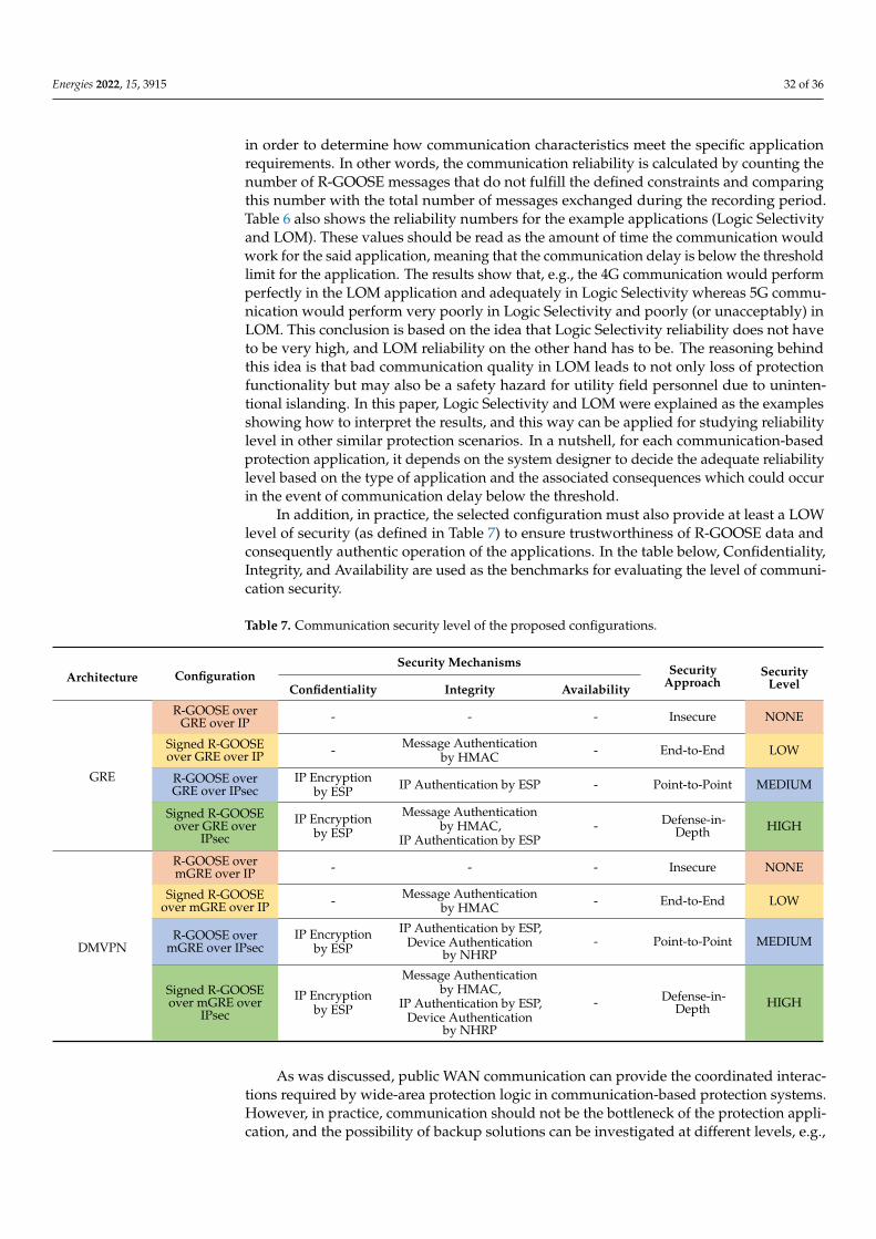
Energies 2022, 15, 3915 32 of 36
in order to determine how communication characteristics meet the specific applicationrequirements. In other words, the communication reliability is calculated by counting thenumber of R-GOOSE messages that do not fulfill the defined constraints and comparingthis number with the total number of messages exchanged during the recording period.Table 6 also shows the reliability numbers for the example applications (Logic Selectivityand LOM). These values should be read as the amount of time the communication wouldwork for the said application, meaning that the communication delay is below the thresholdlimit for the application. The results show that, e.g., the 4G communication would performperfectly in the LOM application and adequately in Logic Selectivity whereas 5G commu-nication would perform very poorly in Logic Selectivity and poorly (or unacceptably) inLOM. This conclusion is based on the idea that Logic Selectivity reliability does not haveto be very high, and LOM reliability on the other hand has to be. The reasoning behindthis idea is that bad communication quality in LOM leads to not only loss of protectionfunctionality but may also be a safety hazard for utility field personnel due to uninten-tional islanding. In this paper, Logic Selectivity and LOM were explained as the examplesshowing how to interpret the results, and this way can be applied for studying reliabilitylevel in other similar protection scenarios. In a nutshell, for each communication-basedprotection application, it depends on the system designer to decide the adequate reliabilitylevel based on the type of application and the associated consequences which could occurin the event of communication delay below the threshold.
In addition, in practice, the selected configuration must also provide at least a LOWlevel of security (as defined in Table 7) to ensure trustworthiness of R-GOOSE data andconsequently authentic operation of the applications. In the table below, Confidentiality,Integrity, and Availability are used as the benchmarks for evaluating the level of communi-cation security.
Table 7. Communication security level of the proposed configurations.
Architecture ConfigurationSecurity Mechanisms Security
ApproachSecurity
LevelConfidentiality Integrity Availability
GRE
R-GOOSE overGRE over IP - - - Insecure NONE
Signed R-GOOSEover GRE over IP - Message Authentication
by HMAC - End-to-End LOW
R-GOOSE overGRE over IPsec
IP Encryptionby ESP IP Authentication by ESP - Point-to-Point MEDIUM
Signed R-GOOSEover GRE over
IPsec
IP Encryptionby ESP
Message Authenticationby HMAC,
IP Authentication by ESP- Defense-in-
Depth HIGH
DMVPN
R-GOOSE overmGRE over IP - - - Insecure NONE
Signed R-GOOSEover mGRE over IP - Message Authentication
by HMAC - End-to-End LOW
R-GOOSE overmGRE over IPsec
IP Encryptionby ESP
IP Authentication by ESP,Device Authentication
by NHRP- Point-to-Point MEDIUM
Signed R-GOOSEover mGRE over
IPsec
IP Encryptionby ESP
Message Authenticationby HMAC,
IP Authentication by ESP,Device Authentication
by NHRP
- Defense-in-Depth HIGH
As was discussed, public WAN communication can provide the coordinated interac-tions required by wide-area protection logic in communication-based protection systems.However, in practice, communication should not be the bottleneck of the protection appli-cation, and the possibility of backup solutions can be investigated at different levels, e.g.,
Energies 2022, 15, 3915 33 of 36
communication network or protection application levels. At the communication networklevel, redundant communication channels can be designed to maximize network availabil-ity. This can be achieved via the use of edge routers that support two (primary and backup)SIM cards connecting to two different mobile operators. At the protection application level,non-communication-dependent backup solutions (based on only local measurements) canalso be designed for the power system, for example, time-based Logic Selectivity [26] asthe backup solution for GOOSE-based Logic Selectivity and the Passive LOM method [53]as the backup for Communication-based LOM. The protection IEDs can be configured toswitch dynamically from the primary solution (communication-based protection logic) tothe backup solution if there is a communication failure or bad quality. Although backupsolutions are only based on local measurements and do not have the full performance ofcommunication-based solutions (which are based on both local and remote data), they canmanage risks in a timely manner; they can recover their protection capability; and they canprevent physical consequences in case of loss-of-communication. This will enhance thesafety of electrical power systems.
In practice, DSO or TSO can utilize the proposed architecture solutions to realizemulticast communication between the substations in communication-based protection ap-plications. DSO/TSO saves money because they use cellular Internet instead of using theirown communication network which requires both implementation and maintenance costs.
8. Conclusions
This experiment studied the applicability of cellular Internet for communication ofmulticast R-GOOSE messages over GRE and mGRE tunnels. These tunnels were establishedwith real networking devices connected to a commercial cellular network. The performanceof the proposed tunnels was analyzed for various configurations: unsecured (plaintextR-GOOSE) and secured (signed R-GOOSE) messages as well as unsecured (GRE/mGREover IP) and secured (GRE/mGRE over IPsec) communication paths. Although tunnelingand security protocols impose extra communication headers and processing delays, thesedelays can be compensated by novel cellular technology characteristics. This confirmsthat cellular Internet can be considered for transmitting multicast R-GOOSE messagesin P2M communication-based protection scenarios. In our experiment’s location, the 4Gcommunication had higher performance than 5G communication. Since the implementationof the 5G network is not in a mature stage, the more proper comparison between 4G and5G performances could be conducted in the future when 5G network implementation iscomplete. In the future work, this experiment can be extended to a larger geographical areawhere sender and receivers located in different cities obtain statistical data on the spatialvariation of the communication delay and investigate the impact of 5G coverage. From astatistical analysis point of view, the future work is to analyze the measured data to findout the parameters of the underlying statistical mechanism and create a forecast model forthe communication delay.
Information exchange and integration are the key enablers for designing novel smartgrid wide-area protection applications. In P2M applications, multicast communicationenables efficient integration of the substations that exchange protection data via the Inter-net. Cellular technology is considered as a cost-effective solution for the inter-substationcommunication of multicast R-GOOSE messages over the Internet. In this context, deter-ministic communication and cybersecurity must be noticed. According to the measurementresults, security mechanisms caused insignificant delay when compared to communicationlatency. Therefore, secured configurations are preferred ones because they not only providereal-time communication but also protect R-GOOSE messages against cyber-attacks. Thisensures reliable functioning of the wide-area protection applications.
Author Contributions: Conceptualization, P.J. and A.S.; Methodology, P.J.; Software, A.S.; Supervi-sion, S.R.; Writing—original draft, P.J. All authors have read and agreed to the published version ofthe manuscript.
Energies 2022, 15, 3915 34 of 36
Funding: This paper was financially supported by “Distributed management of electricity system—project number 322673” funded by the Academy of Finland.
Data Availability Statement: The data used to support the reported results are available from thecorresponding author upon request.
Conflicts of Interest: The authors declare no conflict of interest.
References1. Terzija, V.; Valverde, G.; Cai, D.; Regulski, P.; Madani, V.; Fitch, J.; Skok, S.; Begovic, M.M.; Phadke, A. Wide-area monitoring,
protection, and control of future electric power networks. Proc. IEEE 2010, 99, 80–93. [CrossRef]2. IEC/TR 61850-90-5; Communication Networks and Systems for Power Utility Automation—Part 90-5: Use of IEC 61850 to
Transmit Synchrophasor Information According to IEEE C37.118. Triangle MicroWorks: Raleigh, NC, USA, 2012.3. Adrah, C.M.; Yellajosula, J.R.; Kure, Ø.; Palma, D.; Heegaard, P.E. An IP multicast framework for routable sample value
communication in transmission grids. J. Commun 2019, 14, 765–772. [CrossRef]4. Adrah, C.M.; Palma, D.; Kure, Ø.; Heegaard, P.E. A network design algorithm for multicast communication architectures in smart
transmission grids. Electr. Power Syst. Res. 2020, 187, 106484. [CrossRef]5. Jafary, P.; Repo, S.; Koivisto, H. Security Solutions for Smart Grid Feeder Automation Data Communication. In Proceedings of the
2016 IEEE International Conference on Industrial Technology (ICIT), Taipei, Taiwan, 14–17 March 2016.6. Jafary, P.; Supponen, A.; Salmenperä, M.; Repo, S. Analyzing reliability of the communication for secure and highly available
goose-based logic selectivity. J. Secur. Commun. Netw. 2019, 2019, 9682189. [CrossRef]7. Borenius, S.; Hämmäinen, H.; Lehtonen, M.; Ahokangas, P. Smart grid evolution and mobile communications—Scenarios on the
Finnish power grid. Electr. Power Syst. Res. 2021, 199, 107367. [CrossRef]8. Zeinali, M.; Thompson, J.S. Implementation of Highly Accurate Testbed for Practical Evaluation of Wired and Wireless Internet
based Smart Grid Communications. In Proceedings of the 2019 UK/China Emerging Technologies (UCET), IEEE, Glasgow, UK,21–22 August 2019.
9. Sobnath, D.; Rehman, I.; Nasralla, M. Smart cities to improve mobility and quality of life of the visually impaired. In TechnologicalTrends in Improved Mobility of the Visually Impaired; Springer: Berlin/Heidelberg, Germany, 2020; pp. 3–28.
10. Hovila, P.; Syväluoma, P.; Kokkoniemi-Tarkkanen, H.; Horsmanheimo, S.; Borenius, S.; Li, Z.; Uusitalo, M. 5G Networks EnablingNew Smart Grid Protection Solutions. In Proceedings of the CIRED 2019 Conference, Madrid, Spain, 3–6 June 2019.
11. Hovila, P.; Kokkoniemi-Tarkkanen, H.; Horsmanheimo, S.; Raussi, P.; Borenius, S.; Ahola, K. Cellular Networks ProvidingDistribution Grid Communications Platform. In Proceedings of the CIRED 2021—The 26th International Conference andExhibition on Electricity Distribution, Online Conference, 20–23 September 2021.
12. Rivas, A.E.L.; Abrao, T. Faults in smart grid systems: Monitoring, detection and classification. Electr. Power Syst. Res. 2021, 189,106602. [CrossRef]
13. Gutierrez-Rojas, D.; Nardelli, P.H.J.; Mendes, G.; Popovski, P. Review of the state of the art on adaptive protection for microgridsbased on communications. IEEE Trans. Ind. Informat 2020, 17, 1539–1552. [CrossRef]
14. Nguyen, V.G.; Grinnemo, K.J.; Cheng, J.; Taheri, J.; Brunstrom, A. On the Use of a Virtualized 5G Core for Time CriticalCommunication in Smart Grid. In Proceedings of the 8th IEEE International Conference on Mobile Cloud Computing, Services,and Engineering (MobileCloud), Oxford, UK, 3–6 August 2020.
15. Nguyen, V.G.; Grinnemo, K.J.; Taheri, J.; Brunstrom, A. A Deployable Containerized 5G Core Solution for Time CriticalCommunication in Smart Grid. In Proceedings of the 23rd Conference on Innovation in Clouds, Internet and Networks andWorkshops (ICIN), Paris, France, 24–27 February 2020.
16. The NTP Stratum Model. Available online: https://orolia.com/manuals/SS/Content/_Global/Topics/NTP/NTP_Stratums.htm(accessed on 13 May 2022).
17. Zhu, K.; Chenine, M.; Nordstrom, L. ICT architecture impact on wide area monitoring and control systems’ reliability. IEEE Trans.Power Deliv. 2011, 26, 2801–2808. [CrossRef]
18. Wang, Y.; Gamage, T.T.; Hauser, C.H. Security implications of transport layer protocols in power grid synchrophasor datacommunication. IEEE Trans. Smart Grid 2015, 7, 807–816. [CrossRef]
19. Khan, R.; Mclaughlin, K.; Laverty, D.; Sezer, S. Design and implementation of security gateway for synchrophasor based real-timecontrol and monitoring in smart grid. IEEE Access 2017, 5, 11626–11644. [CrossRef]
20. Firouzi, S.R.; Vanfretti, L.; Ruiz-Alvarez, A.; Mahmood, F.; Hooshyar, H.; Cairo, I. An IEC 61850-90-5 Gateway for IEEE C37. 118.2Synchrophasor Data Transfer. In Proceedings of the 2016 IEEE Power and Energy Society General Meeting (PESGM), Boston, MA,USA, 17–21 July 2016.
21. Ruuth, K.; Supponen, A.; Repo, S.; Rosenørn, K.R.; Douglass, P.; Møller, M. Practical Implementation of Optimal Voltage Controlin Distribution Network–System Verification, Testing and Safety Precautions. In Proceedings of the 2020 IEEE PES InnovativeSmart Grid Technologies Europe (ISGT-Europe), The Hague, The Netherlands, 26–28 October 2020.
22. Eissa, M.M. Challenges and novel solution for wide-area protection due to renewable sources integration into smart grid: Anextensive review. IET Renew. Power Gener. 2018, 12, 1843–1853. [CrossRef]
Energies 2022, 15, 3915 35 of 36
23. An, W.; Zhao, M.Y.; Li, J.S.; Zhou, H.Y.; Chen, Z.H.; Yu, J.; Huang, W.F.; Li, L.; Chen, S.J. Application of Wide Area MonitoringProtection and Control in an Electricity Distribution Network. In Proceedings of the 12th IET International Conference onDevelopments in Power System Protection (DPSP 2014), Copenhagen, Denmark, 31 March–3 April 2014.
24. Ledesma, P.; Jafary, P.; Repo, S.; Álvarez, A.; Ramos, F.; Della Giustina, D.; Dedè, A. Event-based simulation of a decentralizedprotection system based on secured GOOSE messages. Energies 2020, 13, 3250. [CrossRef]
25. Eriksson, M.; Armendariz, M.; Vasilenko, O.O.; Saleem, A.; Nordström, L. Multiagent-based distribution automation solution forself-healing grids. IEEE Trans. Ind. Electron 2014, 62, 2620–2628. [CrossRef]
26. Jafary, P.; Raipala, O.; Repo, S.; Salmenperä, M.; Seppälä, J.; Koivisto, H.; Horsmanheimo, S.; Kokkoniemi-Tarkkanen, H.;Tuomimäki, L.; Alvarez, A.; et al. Secure Layer 2 Tunneling over IP for GOOSE-based Logic Selectivity. In Proceedings of the 2017IEEE International Conference on Industrial Technology (ICIT), Toronto, ON, Canada, 22–25 March 2017.
27. Raipala, O.; Repo, S.; Järventausta, P. A Communication based Protection System for Solving DG related Protection Challenges.In Proceedings of the CIRED 2015, Lyon, France, 15–18 June 2015.
28. De Oliveira, C.H.R.; Bowen, A.P. IEC 61850 Goose Message over Wan. In Proceedings of the International Conference on WirelessNetworks (ICWN), The Steering Committee of The World Congress in Computer Science, Computer Engineering and AppliedComputing (WorldComp), Las Vegas, NV, USA, 22–25 July 2013.
29. Wen, J.; Hammond, C.; Udren, E.A. Wide-area Ethernet Network Configuration for System Protection Messaging. In Proceedingsof the 2012 65th Annual Conference for Protective Relay Engineers, IEEE, College Station, TX, USA, 2–5 April 2012.
30. Kanabar, M.; Cioraca, A.; Johnson, A. Wide Area Protection & Control Using High-speed and Secured Routable Goose mechanism.In Proceedings of the 2016 69th Annual Conference for Protective Relay Engineers (CPRE), IEEE, College Station, TX, USA, 4–7April 2016.
31. Seewald, M. Building an architecture based on IP-Multicast for Large Phasor Measurement Unit (PMU) Networks. In Proceedingsof the 2013 IEEE PES Innovative Smart Grid Technologies Conference (ISGT), Washington, DC, USA, 24–27 February 2013.
32. IEC61850 Avenue Software Tools. Available online: https://www.infotech.pl/products/iec-61850 (accessed on 13May 2022).
33. Configuring IP-Multicast Routing. Available online: https://www.cisco.com/c/en/us/td/docs/switches/metro/me3600x_3800x/software/release/12-2_52_ey/configuration/guide/swmcast.html (accessed on 13 May 2022).
34. Generic Routing Encapsulation (GRE). Available online: https://datatracker.ietf.org/doc/html/rfc1701 (accessed on 13May 2022).
35. Zseby, T.; Fabini, J. Security challenges for wide area monitoring in smart grids. E & I Elektrotechnik und Informationstechnik 2014,131, 105–111.
36. Ashok, A.; Govindarasu, M.; Wang, J. Cyber-physical attack-resilient wide-area monitoring, protection, and control for the powergrid. Proc. IEEE 2017, 105, 1389–1407. [CrossRef]
37. The Group Domain of Interpretation. Available online: https://tools.ietf.org/html/rfc6407 (accessed on 13 May 2022).38. Internet Security Association and Key Management Protocol (ISAKMP). Available online: https://tools.ietf.org/html/rfc2408
(accessed on 13 May 2022).39. IEC 62351-9; Power Systems Management and Associated Information Exchange—Data and Communications Security—Part 9:
Cyber Security Key Management for Power System Equipment. International Electrotechnical Commission: Geneva, Switzer-land, 2017.
40. Group Domain of Interpretation (GDOI). Protocol Support for IEC 62351 Security Services, RFC 8052. Available online: https://datatracker.ietf.org/doc/html/rfc8052 (accessed on 13 May 2022).
41. Group Encrypted Transport VPN (GETVPN) Design and Implementation Guide. Available online: https://www.cisco.com/c/dam/en/us/products/collateral/security/group-encrypted-transport-vpn/GETVPN_DIG_version_2_0_External.pdf (accessedon 13 May 2022).
42. Security Architecture for the Internet Protocol. Available online: https://tools.ietf.org/html/rfc2401 (accessed on 13 May 2022).43. Introduction to DMVPN. Available online: https://networklessons.com/cisco/ccie-routing-switching/introduction-to-dmvpn#
Multipoint_GRE (accessed on 13 May 2022).44. Cisco IR829 Industrial Integrated Services Routers. Available online: https://www.cisco.com/c/en/us/products/collateral/
routers/829-industrial-router/datasheet-c78-734981.html (accessed on 13 May 2022).45. Cisco Catalyst Cellular Gateways. Available online: https://www.cisco.com/c/en/us/products/collateral/routers/catalyst-
cellular-gateways/data-sheet-c78-744210.html (accessed on 13 May 2022).46. Adafruit Ultimate GPS HAT for Raspberry Pi. Available online: https://www.adafruit.com/product/2324 (accessed on 13
May 2022).47. NMEA Revealed. Available online: https://gpsd.gitlab.io/gpsd/NMEA.html (accessed on 13 May 2022).48. Meinberg LANTIME M600/GPS. Available online: https://www.meinberg-usa.com/products/network-time-server/high-end-
gps-time-server.htm (accessed on 13 May 2022).49. IEEE 1588v2-2008: IEEE Standard for a Precision Clock Synchronization Protocol for Networked Measurement and Control
Systems. Available online: https://ieeexplore.ieee.org/stamp/stamp.jsp?arnumber=4579760 (accessed on 13 May 2022).50. Wireshark. Available online: https://www.wireshark.org/ (accessed on 13 May 2022).51. Chrony. Available online: https://chrony.tuxfamily.org/documentation.html (accessed on 13 May 2022).
Energies 2022, 15, 3915 36 of 36
52. Ptp4l. Available online: https://linux.die.net/man/8/ptp4l (accessed on 13 May 2022).53. Raipala, O. Novel Methods for Loss of Mains Protection. Ph.D. Thesis, Tampere University of Technology, Tampere, Finland, 2018.


