Embed Size (px)
Citation preview
Integrated Storage ServerHardware Installation and User Guide
Broadcast Communications4393 Digital Way | Mason, OH USA 45040 | Tel: 1 (513) 459 3400
www.broadcast.harris.com
©2007 Harris CorporationPart Number: 175-000407-00
Harris is a registered trademark of Harris Corporation. Trademarks and tradenames are the property of their respective companies.
NX3601H
DIIn
stallationandUser
Guide
175-000407-00
NX3601HDI_175-000407-00:NX3600HDX_175-000303-01.qxd 11/8/2007 4:43 PM Page 1

April 2011
NEXIO AMP(NX3801HDI)Integrated Storage
Hardware Installation andUser Guide
175-100257-00 REV A
Harris CorporationBroadcast Communications
Transmission4393 Digital WayMason, OH USA 45040
Media & Workflow9800 South Meridian Blvd.Suite 300Englewood, CO USA 80112
Infrastructure & Networking25 Dyas RoadNorth York, ON M3B 1V7Canada
Copyright © 2011 Harris Corporation. All rights reserved. This publication supersedes all previousreleases. No part of this documentation may be reproduced in any form or by any means or used tomake any derivative work without permission from Harris Corporation.
Harris Corporation reserves the right to revise this documentation and to make changes in contentfrom time to time without obligation on the part of Harris Corporation to provide notification ofsuch revision or change.
UNITED STATES GOVERNMENT LEGEND If you are a United States government agency, then thisdocumentation and the software described herein are provided to you subject to the following:
All technical data and computer software are commercial in nature and developed solely at privateexpense. Software is delivered as “Commercial Computer Software” as defined in DFARS252.227-7014 (June 1995) or as a “commercial item” as defined in FAR 2.101(a) and as such isprovided with only such rights as are provided by Harris’ standard commercial license for theSoftware. Technical data is provided with limited rights only as provided in DFAR 252.227-7015(Nov 1995) or FAR 52.227-14 (June 1987), whichever is applicable. You agree not to remove ordeface any portion of any legend provided on any licensed program or documentation containedin, or delivered to you in conjunction with, this User Guide.
This publication, or any part thereof, may not be reproduced in any form, by any method, for anypurpose, without the written consent of Harris Corporation.
Contact Harris Corporation for permission to use materials as well as guidelines concerning foreignlanguage translation and publication.
Harris Corporation reserves the right to revise and improve its products as it chooses. Thispublication is designed to assist in the use of the product, as it exists on the date of publication ofthis manual, and may not reflect the product at the current time or an unknown time in the future.This publication does not in any way warrant description accuracy or guarantee the use for theproduct to which it refers.
The Harris logo and assuredcommunications are registered trademarks of Harris Corporation.D-Series is a trademark of Harris Corporation. All other trademarks are held by their respectiveowners.
This user guide was created for Harris Corporation Broadcast Communications Style Guide.
Revision date: March 30, 2010
Windows is a registered trademark of Microsoft Corporation. AMD and Operton are trademarks ofAdvanced Micro Devices, Inc. Dolby Digital is a registered trademark of Dolby Laboratories.
All other trademarks are the property of their respective holders.
April 2011
iii
Contents
About This Guide......................................................................................1
Purchasing Documents ................................................................................5Unpacking a Harris Product .........................................................................5Returning a Harris Product ...........................................................................5
Chapter 1 Introduction ...............................................................................................9
System ......................................................................................................14Video ........................................................................................................15Audio ........................................................................................................16Video Compression ...................................................................................16Storage .....................................................................................................19RAID Redundancy ......................................................................................20Timecode Connection Options ..................................................................20Remote GPI Control ..................................................................................20Remote Serial Interface ..............................................................................20Controls ....................................................................................................21Physical .....................................................................................................21Power Supply ............................................................................................21Supported Television Formats ....................................................................21
Chapter 2 Hardware Installation..........................................................................23
Rear Panel Port Connectors .......................................................................25
©2011 Harris Corporation. All rights reserved.
Contentsiv
Rear Panel Port Descriptions ......................................................................28Front Panel Descriptions ............................................................................35
Chapter 3 Getting Started........................................................................................39
Registering Your Software .........................................................................43Confirming Connection to Additional Systems ...........................................48Verifying Audio and Video I/O Connections ...............................................48Testing Input and Output Signals ...............................................................49
Chapter 4 Using NEXIO Config...............................................................................53
Creating or Modifying a Preset ..................................................................56Creating a Default Preset ...........................................................................57Information ...............................................................................................61Channel Configuration ..............................................................................62Video Options ..........................................................................................63Audio Options ...........................................................................................68GPRX Options ............................................................................................70Automation/Serial ......................................................................................71IP Config ..................................................................................................74FTP Folders ................................................................................................77LLM Parameters .........................................................................................78Error Logging ............................................................................................79LLM ..........................................................................................................81MPEG ........................................................................................................83FTP ............................................................................................................85Startup ......................................................................................................87CV/Logo ....................................................................................................89Other ........................................................................................................91LLM 1 ........................................................................................................93
Chapter 5 Monitoring Server Status ...................................................................95
LED Indicators ................................................................................................95NEXIO Monitor ..............................................................................................96
©2011 Harris Corporation. All rights reserved.
NEXIO AMPHardware Installation and User Guide
v
Testing the LED Lights ............................................................................... 98Selecting Monitored Diagnostics ............................................................... 98Checking Status ........................................................................................ 99
LCD Keypad Buttons ................................................................................... 101
Chapter 6 Connectors, Jumper Settings, and Circuits ............................ 103
Chapter 7 Troubleshooting ................................................................................... 113
©2011 Harris Corporation. All rights reserved.

Contentsvi
©2011 Harris Corporation. All rights reserved.
vii
List of Procedures
Chapter 1 Introduction ...............................................................................................9
Chapter 2 Hardware Installation..........................................................................23To rack mount NEXIO AMP ..............................................................................24To remove NEXIO AMP from the rack ..............................................................25To identify and remove the failed power supply ...............................................28To insert a new power supply ..........................................................................29
Chapter 3 Getting Started........................................................................................39To start NEXIO AMP .........................................................................................39To log on to NXOS ...........................................................................................41To create the deployment (.dc) file ...................................................................44To confirm connection to additional systems ....................................................48To test I/O signals on a channel ........................................................................49To test output signals on remaining playout channels ......................................51
Chapter 4 Using NEXIO Config ..............................................................................53To start NEXIO Config ......................................................................................54To create or modify a configuration preset .......................................................56To restore the factory default settings ..............................................................57To specify a default preset ...............................................................................58To select a configuration and include or exclude options ..................................62To specify video options ...................................................................................64
©2011 Harris Corporation. All rights reserved.
Proceduresviii
To specify audio options .................................................................................. 68To specify GPRX options .................................................................................. 70To specify each available 422 port ................................................................... 72To specify general parameters ......................................................................... 72To specify VDCP parameters ............................................................................ 73To specify IP configuration settings .................................................................. 75To change virtual folders settings .................................................................... 77To change LLM parameters ............................................................................. 78To change Error Logging settings .................................................................... 79To change LLM registry settings ....................................................................... 81To change MPEG registry settings .................................................................... 83To change FTP parameters ............................................................................... 85To change Startup registry settings .................................................................. 87To change CV/Logo registry settings ................................................................ 89To change Other registry settings .................................................................... 91To change LLM1 registry settings ..................................................................... 93
Chapter 5 Monitoring Server Status................................................................... 95To open NEXIO Monitor .................................................................................. 97To test the LED lights ....................................................................................... 98To select a diagnostic ...................................................................................... 99To deselect a diagnostic .................................................................................. 99
Chapter 6 Connectors, Jumper Settings, and Circuits ............................ 103To assemble a MDR connector ...................................................................... 108
Chapter 7 Troubleshooting ................................................................................... 113To remove the failed drive ............................................................................. 114To manually start the Rebuild ........................................................................ 115To replace a media drive ................................................................................ 116
©2011 Harris Corporation. All rights reserved.
1
About This Guide
About This Guide provides an overview of this guide, describes guide conventions,and tells you where to look for specific information. This section also gives youimportant information on unpacking and shipping your Harris product.
This guide introduces and describes procedures for installing and using NEXIOAMP™.
If the information in the release notes shipped with your product differs from theinformation in this guide, follow the instructions in the release notes.
Intended AudienceThis guide is intended for users installing and operating NEXIO AMP Generation 5.
©2011 Harris Corporation. All rights reserved.
About This Guide2
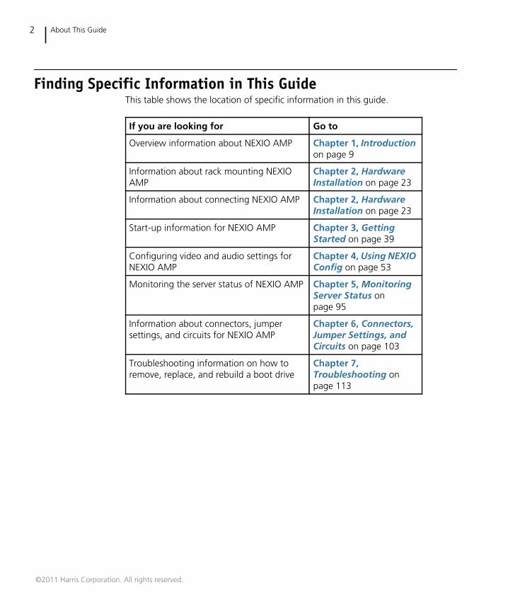
Finding Specific Information in This GuideThis table shows the location of specific information in this guide.
If you are looking for Go to
Overview information about NEXIO AMP Chapter 1, Introductionon page 9
Information about rack mounting NEXIOAMP
Chapter 2, HardwareInstallation on page 23
Information about connecting NEXIO AMP Chapter 2, HardwareInstallation on page 23
Start-up information for NEXIO AMP Chapter 3, GettingStarted on page 39
Configuring video and audio settings forNEXIO AMP
Chapter 4, Using NEXIOConfig on page 53
Monitoring the server status of NEXIO AMP Chapter 5, MonitoringServer Status onpage 95
Information about connectors, jumpersettings, and circuits for NEXIO AMP
Chapter 6, Connectors,Jumper Settings, andCircuits on page 103
Troubleshooting information on how toremove, replace, and rebuild a boot drive
Chapter 7,Troubleshooting onpage 113
©2011 Harris Corporation. All rights reserved.
NEXIO AMPHardware Installation and User Guide
3
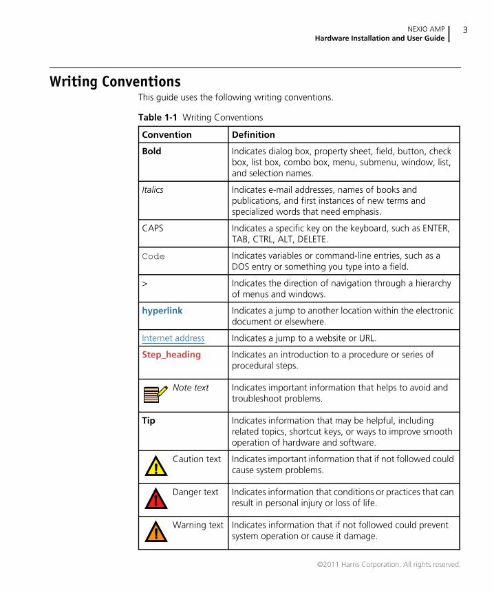
Writing ConventionsThis guide uses the following writing conventions.
Table 1-1 Writing Conventions
Convention Definition
Bold Indicates dialog box, property sheet, field, button, checkbox, list box, combo box, menu, submenu, window, list,and selection names.
Italics Indicates e-mail addresses, names of books andpublications, and first instances of new terms andspecialized words that need emphasis.
CAPS Indicates a specific key on the keyboard, such as ENTER,TAB, CTRL, ALT, DELETE.
Code Indicates variables or command-line entries, such as aDOS entry or something you type into a field.
> Indicates the direction of navigation through a hierarchyof menus and windows.
hyperlink Indicates a jump to another location within the electronicdocument or elsewhere.
Internet address Indicates a jump to a website or URL.
Step_heading Indicates an introduction to a procedure or series ofprocedural steps.
Note text Indicates important information that helps to avoid andtroubleshoot problems.
Tip Indicates information that may be helpful, includingrelated topics, shortcut keys, or ways to improve smoothoperation of hardware and software.
Caution text Indicates important information that if not followed couldcause system problems.
Danger text Indicates information that conditions or practices that canresult in personal injury or loss of life.
Warning text Indicates information that if not followed could preventsystem operation or cause it damage.
©2011 Harris Corporation. All rights reserved.
About This Guide4
Related Documentation NEXIO NX3801HDI Installation Quick Start
NEXIO Software Installation Guide
NEXIO Low Level Module User Guide
NEXIO Safety & Compliance Information
NEXIO NXOS User Guide
NEXIO NX1010MIOH User Guide
NEXIO FTP User Guide
NXUSBTC User Guide
Software License Key Registration Card
NEXIO Server Protocol Developer Guide
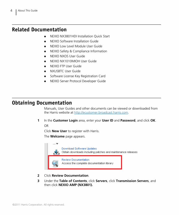
Obtaining DocumentationManuals, User Guides and other documents can be viewed or downloaded fromthe Harris website at http://ecustomer.broadcast.harris.com.
1 In the Customer Login area, enter your User ID and Password, and click OK.
OR
Click New User to register with Harris.
The Welcome page appears.
2 Click Review Documentation.
3 Under the Table of Contents, click Servers, click Transmission Servers, andthen click NEXIO AMP (NX3801).
©2011 Harris Corporation. All rights reserved.
NEXIO AMPHardware Installation and User Guide
5
4 Click on the title of the document, and click Open to view it.
OR
Click Save to download the document.
PurchasingDocuments
Additionally, you can purchase product documentation on ourHarris E-commerce site, or contact your Harris Customer Service Representative torequest a document.
Unpacking/Shipping Information
Unpacking aHarris
Product
All Harris NEXIO products have been carefully inspected, tested, and calibratedbefore shipment to ensure stable and trouble-free service.
1 Check the equipment for any visible damage that may have occurred duringtransit.
2 Confirm that you have received all items listed on the packing list.
3 Contact your Harris NEXIO dealer if any item on the packing list is missing.
4 Contact the carrier if any item is damaged.
5 Remove all packaging material from the product and its associated componentsbefore you install the unit.
Returning aHarris
Product
In the unlikely event that a Harris product fails to operate properly, contact theHarris Customer Service Department to obtain a Return Material Authorization(RMA) number, then send the unit back for servicing. Include the RMA number onthe outside of the return box.
Keep at least one set of original packaging in the event that a product needs to bereturned for service. If the original package is not available, you can purchasereplacement packaging from Harris Corporation.
©2011 Harris Corporation. All rights reserved.
About This Guide6
Otherwise, you can supply your own packaging as long as it meets the followingcriteria:
The packaging must be able to withstand the product’s weight.
The product must be held rigid within the package.
There must be at least 2 in. (5 cm) of space between the product and thecontainer.
The corners of the product must be protected.
If the product is still within the warranty period, Harris Corporation will return it toyou by prepaid ground shipping after servicing.
Technical SupportTechnical support is available 24 hours a day, 7 days a week. You can contacttechnical support by phone or e-mail.
Harris Broadcast Communications Division (BCD) Support
Call: 1-416-445-4032
Toll Free: +1-888-534-8246
Email: [email protected]
Website: http://support.broadcast.harris.com.
Video Server Division
Email: [email protected]
Website: http://www.broadcast.harris.com/productsandsolutions/Servers/
U.S., Canada, Central America, and Latin America (CALA)
Video Processing, Distribution, Servers, Storage, News, Inscriber and Videotek
Call: 1-888-534-8246
Fax: 1-416-445-9020
Email: [email protected]
©2011 Harris Corporation. All rights reserved.

NEXIO AMPHardware Installation and User Guide
7
Europe, Middle East, and Africa
24 hours a day, 7 days a week
Regular Business Hours (9am to 5pm, Monday to Friday)
Call: +44-118-964-8100
Fax: +44-118-964-8054
Email:
Infrastructure products: [email protected]
RMA’s: [email protected]
DAM Support: [email protected]
ADC Automation: [email protected]
D Series Support: [email protected]
Transmitters: [email protected]
Asia, Pacific Rim
24 hours a day, 7 days a week
Regular Business Hours (9am to 5pm HKT Monday to Friday)
Call: +852-2776-0628
After-Hour Hotline: 1-888-534-8246
Fax: +852-2776-0227
Email: [email protected]
©2011 Harris Corporation. All rights reserved.

About This Guide8
©2011 Harris Corporation. All rights reserved.
9
1 Introduction
This guide describes the NEXIO AMP™ Generation 5 integrated storage server.
NEXIO AMP is an award winning broadcast video server integrated with SD and HDI/O, “agile” software-based codecs, high performance IT connectivity, and access toNEXIO's shared storage system via NEXIO's RAIDsoft™ software RAID controller.
NEXIO AMP is software configurable, and uses software codec technology toencode and decode HD and SD content. NEXIO AMP supports real-time I/O andredundant network interfaces.
This chapter includes the following sections:
NEXIO AMP Configurations on page 10
NEXIO AMP Upgrades and Options on page 11
Optional Software Applications on page 11
Key Features on page 12
Specifications on page 14
©2011 Harris Corporation. All rights reserved.
Chapter 1Introduction
10
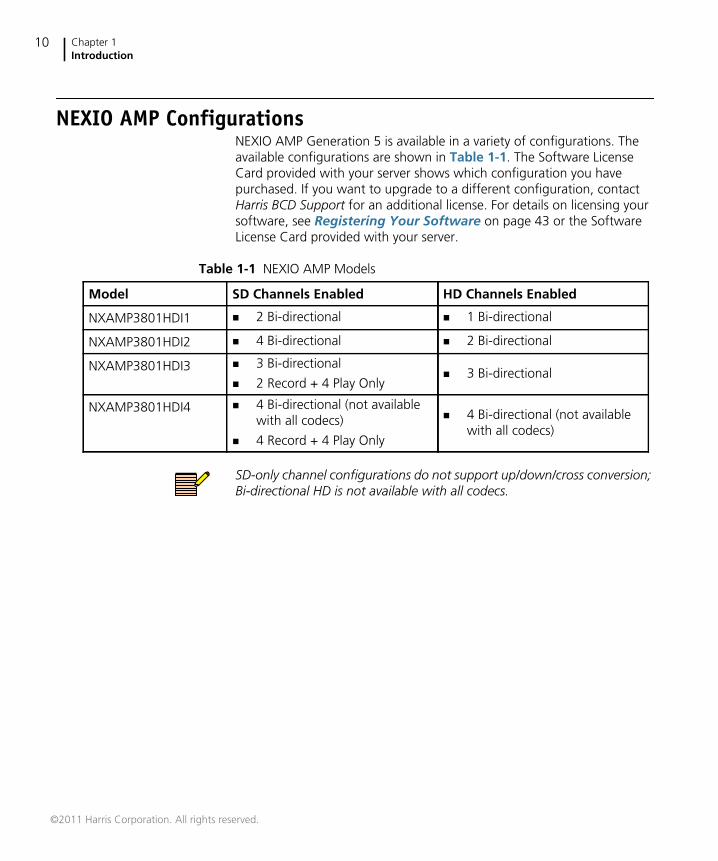
NEXIO AMP ConfigurationsNEXIO AMP Generation 5 is available in a variety of configurations. Theavailable configurations are shown in Table 1-1. The Software LicenseCard provided with your server shows which configuration you havepurchased. If you want to upgrade to a different configuration, contactHarris BCD Support for an additional license. For details on licensing yoursoftware, see Registering Your Software on page 43 or the SoftwareLicense Card provided with your server.
SD-only channel configurations do not support up/down/cross conversion;Bi-directional HD is not available with all codecs.
Table 1-1 NEXIO AMP Models
Model SD Channels Enabled HD Channels Enabled
NXAMP3801HDI1 2 Bi-directional 1 Bi-directional
NXAMP3801HDI2 4 Bi-directional 2 Bi-directional
NXAMP3801HDI3 3 Bi-directional
2 Record + 4 Play Only 3 Bi-directional
NXAMP3801HDI4 4 Bi-directional (not availablewith all codecs)
4 Record + 4 Play Only
4 Bi-directional (not availablewith all codecs)
©2011 Harris Corporation. All rights reserved.
NEXIO AMPHardware Installation and User Guide
11
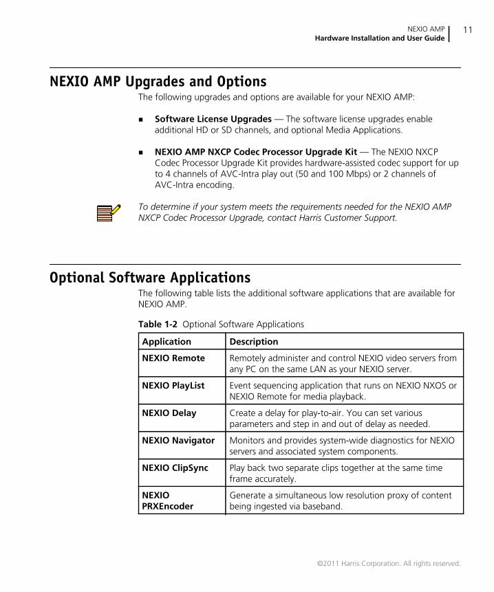
NEXIO AMP Upgrades and OptionsThe following upgrades and options are available for your NEXIO AMP:
Software License Upgrades — The software license upgrades enableadditional HD or SD channels, and optional Media Applications.
NEXIO AMP NXCP Codec Processor Upgrade Kit — The NEXIO NXCPCodec Processor Upgrade Kit provides hardware-assisted codec support for upto 4 channels of AVC-Intra play out (50 and 100 Mbps) or 2 channels ofAVC-Intra encoding.
To determine if your system meets the requirements needed for the NEXIO AMPNXCP Codec Processor Upgrade, contact Harris Customer Support.
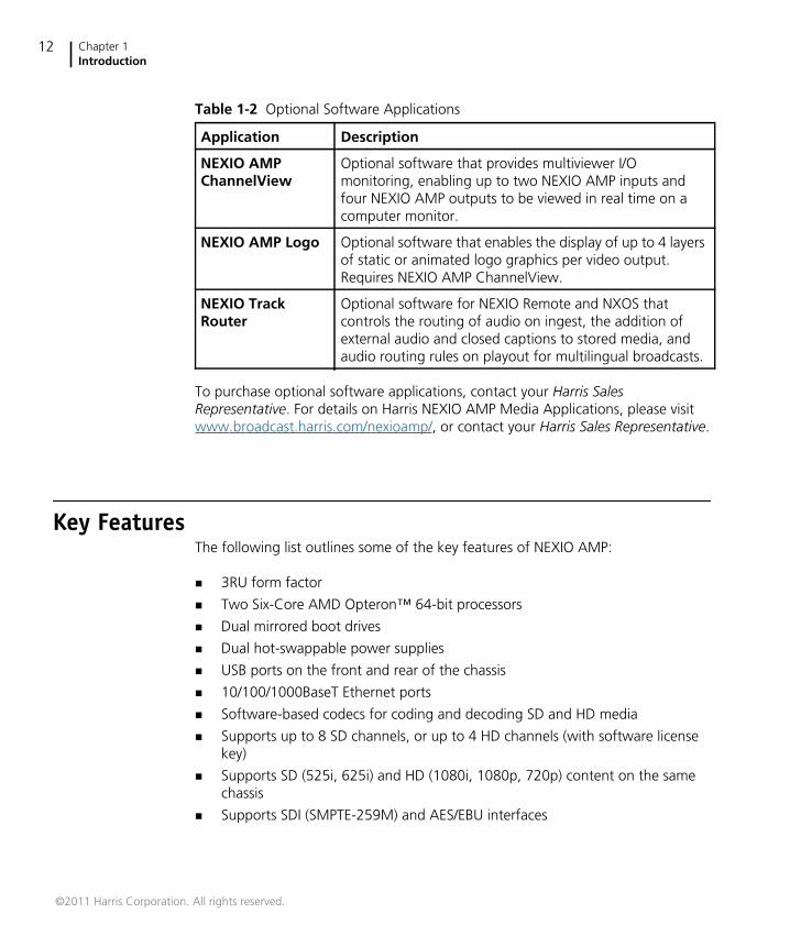
Optional Software ApplicationsThe following table lists the additional software applications that are available forNEXIO AMP.
Table 1-2 Optional Software Applications
Application Description
NEXIO Remote Remotely administer and control NEXIO video servers fromany PC on the same LAN as your NEXIO server.
NEXIO PlayList Event sequencing application that runs on NEXIO NXOS orNEXIO Remote for media playback.
NEXIO Delay Create a delay for play-to-air. You can set variousparameters and step in and out of delay as needed.
NEXIO Navigator Monitors and provides system-wide diagnostics for NEXIOservers and associated system components.
NEXIO ClipSync Play back two separate clips together at the same timeframe accurately.
NEXIOPRXEncoder
Generate a simultaneous low resolution proxy of contentbeing ingested via baseband.
©2011 Harris Corporation. All rights reserved.
Chapter 1Introduction
12
To purchase optional software applications, contact your Harris SalesRepresentative. For details on Harris NEXIO AMP Media Applications, please visitwww.broadcast.harris.com/nexioamp/, or contact your Harris Sales Representative.
Key FeaturesThe following list outlines some of the key features of NEXIO AMP:
3RU form factor
Two Six-Core AMD Opteron™ 64-bit processors
Dual mirrored boot drives
Dual hot-swappable power supplies
USB ports on the front and rear of the chassis
10/100/1000BaseT Ethernet ports
Software-based codecs for coding and decoding SD and HD media
Supports up to 8 SD channels, or up to 4 HD channels (with software licensekey)
Supports SD (525i, 625i) and HD (1080i, 1080p, 720p) content on the samechassis
Supports SDI (SMPTE-259M) and AES/EBU interfaces
NEXIO AMPChannelView
Optional software that provides multiviewer I/Omonitoring, enabling up to two NEXIO AMP inputs andfour NEXIO AMP outputs to be viewed in real time on acomputer monitor.
NEXIO AMP Logo Optional software that enables the display of up to 4 layersof static or animated logo graphics per video output.Requires NEXIO AMP ChannelView.
NEXIO TrackRouter
Optional software for NEXIO Remote and NXOS thatcontrols the routing of audio on ingest, the addition ofexternal audio and closed captions to stored media, andaudio routing rules on playout for multilingual broadcasts.
Table 1-2 Optional Software Applications
Application Description
©2011 Harris Corporation. All rights reserved.
NEXIO AMPHardware Installation and User Guide
13
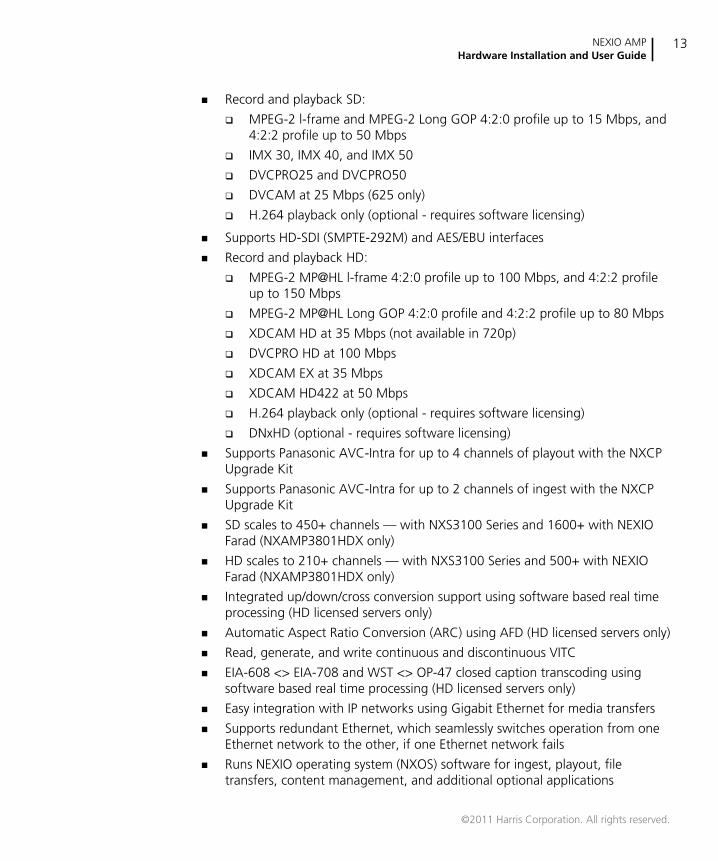
Record and playback SD:
MPEG-2 l-frame and MPEG-2 Long GOP 4:2:0 profile up to 15 Mbps, and4:2:2 profile up to 50 Mbps
IMX 30, IMX 40, and IMX 50
DVCPRO25 and DVCPRO50
DVCAM at 25 Mbps (625 only)
H.264 playback only (optional - requires software licensing)
Supports HD-SDI (SMPTE-292M) and AES/EBU interfaces
Record and playback HD:
MPEG-2 MP@HL l-frame 4:2:0 profile up to 100 Mbps, and 4:2:2 profileup to 150 Mbps
MPEG-2 MP@HL Long GOP 4:2:0 profile and 4:2:2 profile up to 80 Mbps
XDCAM HD at 35 Mbps (not available in 720p)
DVCPRO HD at 100 Mbps
XDCAM EX at 35 Mbps
XDCAM HD422 at 50 Mbps
H.264 playback only (optional - requires software licensing)
DNxHD (optional - requires software licensing)
Supports Panasonic AVC-Intra for up to 4 channels of playout with the NXCPUpgrade Kit
Supports Panasonic AVC-Intra for up to 2 channels of ingest with the NXCPUpgrade Kit
SD scales to 450+ channels — with NXS3100 Series and 1600+ with NEXIOFarad (NXAMP3801HDX only)
HD scales to 210+ channels — with NXS3100 Series and 500+ with NEXIOFarad (NXAMP3801HDX only)
Integrated up/down/cross conversion support using software based real timeprocessing (HD licensed servers only)
Automatic Aspect Ratio Conversion (ARC) using AFD (HD licensed servers only)
Read, generate, and write continuous and discontinuous VITC
EIA-608 <> EIA-708 and WST <> OP-47 closed caption transcoding usingsoftware based real time processing (HD licensed servers only)
Easy integration with IP networks using Gigabit Ethernet for media transfers
Supports redundant Ethernet, which seamlessly switches operation from oneEthernet network to the other, if one Ethernet network fails
Runs NEXIO operating system (NXOS) software for ingest, playout, filetransfers, content management, and additional optional applications
©2011 Harris Corporation. All rights reserved.
Chapter 1Introduction
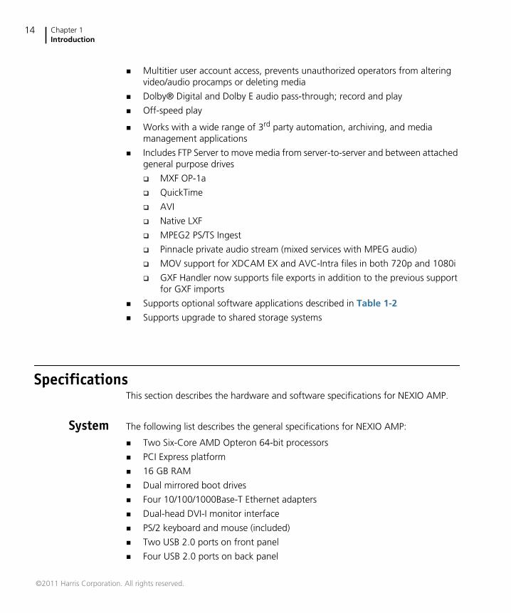
14
Multitier user account access, prevents unauthorized operators from alteringvideo/audio procamps or deleting media
Dolby® Digital and Dolby E audio pass-through; record and play
Off-speed play
Works with a wide range of 3rd party automation, archiving, and mediamanagement applications
Includes FTP Server to move media from server-to-server and between attachedgeneral purpose drives
MXF OP-1a
QuickTime
AVI
Native LXF
MPEG2 PS/TS Ingest
Pinnacle private audio stream (mixed services with MPEG audio)
MOV support for XDCAM EX and AVC-Intra files in both 720p and 1080i
GXF Handler now supports file exports in addition to the previous supportfor GXF imports
Supports optional software applications described in Table 1-2
Supports upgrade to shared storage systems
SpecificationsThis section describes the hardware and software specifications for NEXIO AMP.
System The following list describes the general specifications for NEXIO AMP:
Two Six-Core AMD Opteron 64-bit processors
PCI Express platform
16 GB RAM
Dual mirrored boot drives
Four 10/100/1000Base-T Ethernet adapters
Dual-head DVI-I monitor interface
PS/2 keyboard and mouse (included)
Two USB 2.0 ports on front panel
Four USB 2.0 ports on back panel
©2011 Harris Corporation. All rights reserved.
NEXIO AMPHardware Installation and User Guide
15
One FireWire (IEEE 1394) port (not powered) on front panel
Windows 7 Professional x64
NEXIO Operating System (NXOS)
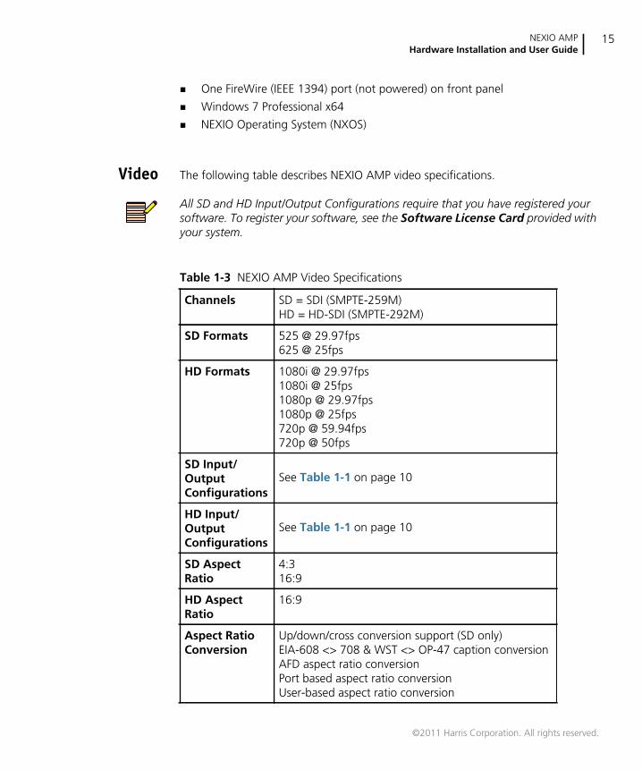
Video The following table describes NEXIO AMP video specifications.
All SD and HD Input/Output Configurations require that you have registered yoursoftware. To register your software, see the Software License Card provided withyour system.
Table 1-3 NEXIO AMP Video Specifications
Channels SD = SDI (SMPTE-259M)HD = HD-SDI (SMPTE-292M)
SD Formats 525 @ 29.97fps625 @ 25fps
HD Formats 1080i @ 29.97fps1080i @ 25fps1080p @ 29.97fps1080p @ 25fps720p @ 59.94fps720p @ 50fps
SD Input/OutputConfigurations
See Table 1-1 on page 10
HD Input/OutputConfigurations
See Table 1-1 on page 10
SD AspectRatio
4:316:9
HD AspectRatio
16:9
Aspect RatioConversion
Up/down/cross conversion support (SD only)EIA-608 <> 708 & WST <> OP-47 caption conversionAFD aspect ratio conversionPort based aspect ratio conversionUser-based aspect ratio conversion
©2011 Harris Corporation. All rights reserved.
Chapter 1Introduction
16
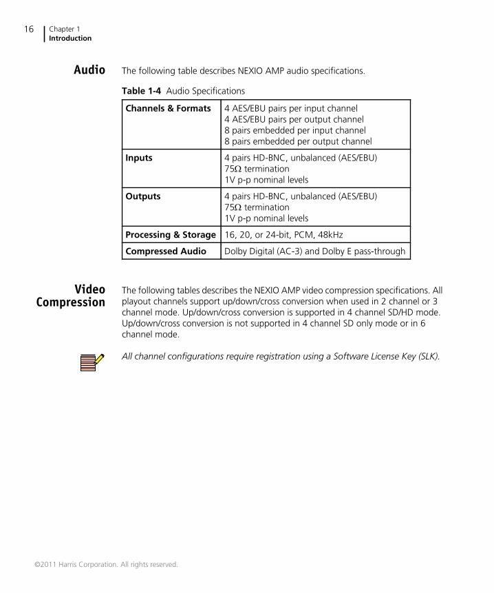
Audio The following table describes NEXIO AMP audio specifications.
VideoCompression
The following tables describes the NEXIO AMP video compression specifications. Allplayout channels support up/down/cross conversion when used in 2 channel or 3channel mode. Up/down/cross conversion is supported in 4 channel SD/HD mode.Up/down/cross conversion is not supported in 4 channel SD only mode or in 6channel mode.
All channel configurations require registration using a Software License Key (SLK).
Table 1-4 Audio Specifications
Channels & Formats 4 AES/EBU pairs per input channel4 AES/EBU pairs per output channel8 pairs embedded per input channel8 pairs embedded per output channel
Inputs 4 pairs HD-BNC, unbalanced (AES/EBU)75 termination1V p-p nominal levels
Outputs 4 pairs HD-BNC, unbalanced (AES/EBU)75 termination1V p-p nominal levels
Processing & Storage 16, 20, or 24-bit, PCM, 48kHz
Compressed Audio Dolby Digital (AC-3) and Dolby E pass-through
©2011 Harris Corporation. All rights reserved.
NEXIO AMPHardware Installation and User Guide
17
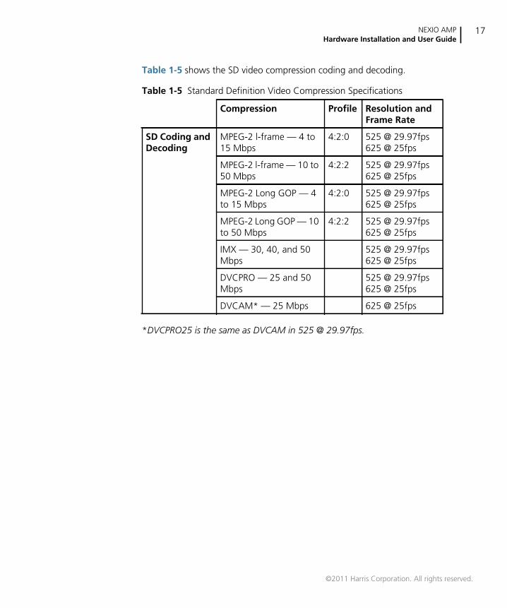
Table 1-5 shows the SD video compression coding and decoding.
*DVCPRO25 is the same as DVCAM in 525 @ 29.97fps.
Table 1-5 Standard Definition Video Compression Specifications
Compression Profile Resolution andFrame Rate
SD Coding andDecoding
MPEG-2 l-frame — 4 to15 Mbps
4:2:0 525 @ 29.97fps625 @ 25fps
MPEG-2 l-frame — 10 to50 Mbps
4:2:2 525 @ 29.97fps625 @ 25fps
MPEG-2 Long GOP — 4to 15 Mbps
4:2:0 525 @ 29.97fps625 @ 25fps
MPEG-2 Long GOP — 10to 50 Mbps
4:2:2 525 @ 29.97fps625 @ 25fps
IMX — 30, 40, and 50Mbps
525 @ 29.97fps625 @ 25fps
DVCPRO — 25 and 50Mbps
525 @ 29.97fps625 @ 25fps
DVCAM* — 25 Mbps 625 @ 25fps
©2011 Harris Corporation. All rights reserved.
Chapter 1Introduction
18
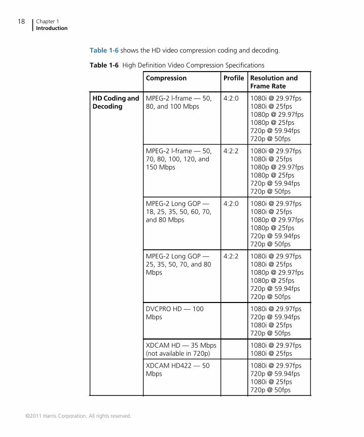
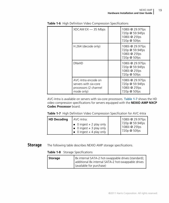
Table 1-6 shows the HD video compression coding and decoding.
Table 1-6 High Definition Video Compression Specifications
Compression Profile Resolution andFrame Rate
HD Coding andDecoding
MPEG-2 l-frame — 50,80, and 100 Mbps
4:2:0 1080i @ 29.97fps1080i @ 25fps1080p @ 29.97fps1080p @ 25fps720p @ 59.94fps720p @ 50fps
MPEG-2 l-frame — 50,70, 80, 100, 120, and150 Mbps
4:2:2 1080i @ 29.97fps1080i @ 25fps1080p @ 29.97fps1080p @ 25fps720p @ 59.94fps720p @ 50fps
MPEG-2 Long GOP —18, 25, 35, 50, 60, 70,and 80 Mbps
4:2:0 1080i @ 29.97fps1080i @ 25fps1080p @ 29.97fps1080p @ 25fps720p @ 59.94fps720p @ 50fps
MPEG-2 Long GOP —25, 35, 50, 70, and 80Mbps
4:2:2 1080i @ 29.97fps1080i @ 25fps1080p @ 29.97fps1080p @ 25fps720p @ 59.94fps720p @ 50fps
DVCPRO HD — 100Mbps
1080i @ 29.97fps720p @ 59.94fps1080i @ 25fps720p @ 50fps
XDCAM HD — 35 Mbps(not available in 720p)
1080i @ 29.97fps1080i @ 25fps
XDCAM HD422 — 50Mbps
1080i @ 29.97fps720p @ 59.94fps1080i @ 25fps720p @ 50fps
©2011 Harris Corporation. All rights reserved.
NEXIO AMPHardware Installation and User Guide
19
AVC-Intra is available on servers with six-core processors. Table 1-7 shows the HDvideo compression specifications for servers equipped with the NEXIO AMP NXCPCodec Processor board.
Storage The following table describes NEXIO AMP storage specifications.
XDCAM EX — 35 Mbps 1080i @ 29.97fps720p @ 59.94fps1080i @ 25fps720p @ 50fps
H.264 (decode only) 1080i @ 29.97fps720p @ 59.94fps1080i @ 25fps720p @ 50fps
DNxHD 1080i @ 29.97fps720p @ 59.94fps1080i @ 25fps720p @ 50fps
AVC-Intra encode onservers with six-coreprocessors (2 channelmode only)
1080i @ 29.97fps720p @ 59.94fps1080i @ 25fps720p @ 50fps
Table 1-7 High Definition Video Compression Specification for AVC-Intra
HD Decoding AVC-Intra:
0 ingest + 2 play only 0 ingest + 3 play only 0 ingest + 4 play only
1080i @ 29.97fps720p @ 59.94fps1080i @ 25fps720p @ 50fps
Table 1-6 High Definition Video Compression Specifications
Table 1-8 Storage Specifications
Storage 8x internal SATA-2 hot-swappable drives (standard);additional 8x internal SATA-2 hot-swappable drives(available for purchase)
©2011 Harris Corporation. All rights reserved.
Chapter 1Introduction
20
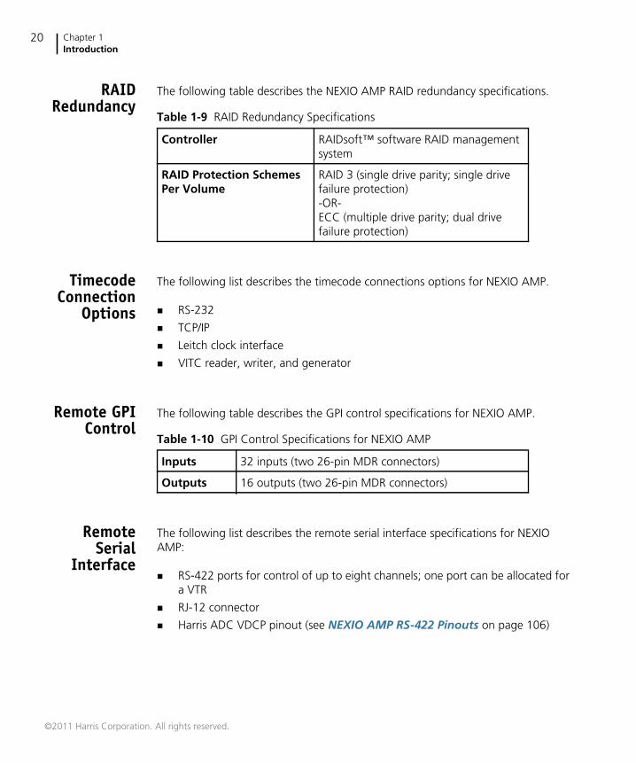
RAIDRedundancy
The following table describes the NEXIO AMP RAID redundancy specifications.
TimecodeConnection
Options
The following list describes the timecode connections options for NEXIO AMP.
RS-232
TCP/IP
Leitch clock interface
VITC reader, writer, and generator
Remote GPIControl
The following table describes the GPI control specifications for NEXIO AMP.
RemoteSerial
Interface
The following list describes the remote serial interface specifications for NEXIOAMP:
RS-422 ports for control of up to eight channels; one port can be allocated fora VTR
RJ-12 connector
Harris ADC VDCP pinout (see NEXIO AMP RS-422 Pinouts on page 106)
Table 1-9 RAID Redundancy Specifications
Controller RAIDsoft™ software RAID managementsystem
RAID Protection SchemesPer Volume
RAID 3 (single drive parity; single drivefailure protection)-OR-ECC (multiple drive parity; dual drivefailure protection)
Table 1-10 GPI Control Specifications for NEXIO AMP
Inputs 32 inputs (two 26-pin MDR connectors)
Outputs 16 outputs (two 26-pin MDR connectors)
©2011 Harris Corporation. All rights reserved.
NEXIO AMPHardware Installation and User Guide
21
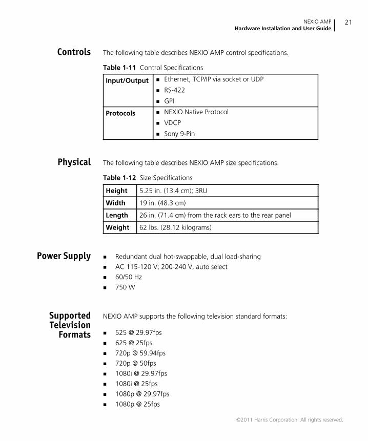
Controls The following table describes NEXIO AMP control specifications.
Physical The following table describes NEXIO AMP size specifications.
Power Supply Redundant dual hot-swappable, dual load-sharing
AC 115-120 V; 200-240 V, auto select
60/50 Hz
750 W
SupportedTelevision
Formats
NEXIO AMP supports the following television standard formats:
525 @ 29.97fps
625 @ 25fps
720p @ 59.94fps
720p @ 50fps
1080i @ 29.97fps
1080i @ 25fps
1080p @ 29.97fps
1080p @ 25fps
Table 1-11 Control Specifications
Input/Output Ethernet, TCP/IP via socket or UDP
RS-422
GPI
Protocols NEXIO Native Protocol
VDCP
Sony 9-Pin
Table 1-12 Size Specifications
Height 5.25 in. (13.4 cm); 3RU
Width 19 in. (48.3 cm)
Length 26 in. (71.4 cm) from the rack ears to the rear panel
Weight 62 lbs. (28.12 kilograms)
©2011 Harris Corporation. All rights reserved.

Chapter 1Introduction
22
©2011 Harris Corporation. All rights reserved.
23
2 Hardware Installation
This chapter describes how to install and begin using NEXIO AMP. This chapterincludes the following sections:
Rack Mounting on page 23
Connecting NEXIO AMP on page 25
Rack MountingThe NEXIO AMP comes with the rack mounting rails.
The following are installation requirements/recommendations:
Equipment — Mount the chassis on an appropriate rack using the providedrack mounting and support equipment.
Power source — Connect the power inlet to an adequate power source. Usinga UPS is strongly recommended. Connect each of the two redundant powersupply connections to a separate electrical circuit for added protection.
Adequate airflow — NEXIO AMP frames require adequate airflow around thechassis to provide sufficient cooling. All components draw air in through thefront and exhaust via the rear of the frame. The surfaces must be clear ofobstructions to provide proper air circulation and cooling.
External device connections — Video monitors and all connections toexternal devices should be available and in working order.
©2011 Harris Corporation. All rights reserved.
Chapter 2Hardware Installation
24
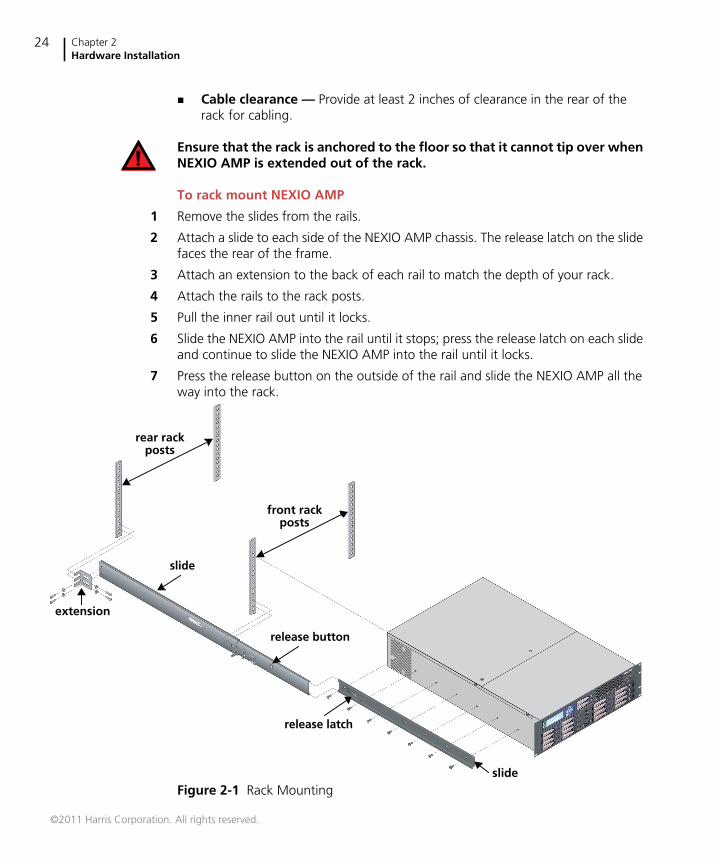
Cable clearance — Provide at least 2 inches of clearance in the rear of therack for cabling.
Ensure that the rack is anchored to the floor so that it cannot tip over whenNEXIO AMP is extended out of the rack.
To rack mount NEXIO AMP
1 Remove the slides from the rails.
2 Attach a slide to each side of the NEXIO AMP chassis. The release latch on the slidefaces the rear of the frame.
3 Attach an extension to the back of each rail to match the depth of your rack.
4 Attach the rails to the rack posts.
5 Pull the inner rail out until it locks.
6 Slide the NEXIO AMP into the rail until it stops; press the release latch on each slideand continue to slide the NEXIO AMP into the rail until it locks.
7 Press the release button on the outside of the rail and slide the NEXIO AMP all theway into the rack.
Figure 2-1 Rack Mounting
rear rackposts
front rackposts
extension
slide
release button
release latch
slide
©2011 Harris Corporation. All rights reserved.
NEXIO AMPHardware Installation and User Guide
25
To remove NEXIO AMP from the rack
1 Stand in front of the NEXIO AMP and pull NEXIO AMP out as far as it will go.
2 Press the release latch on each side of the slide, and pull the NEXIO AMP out therest of the way.
For more information on rack mounting, see the NEXIO NX3801HDI InstallationQuick Start Guide.
Connecting NEXIO AMPThis section contains the following topics:
Rear Panel Port Connectors on page 25
Rear Panel Port Descriptions on page 28
Front Panel Descriptions on page 35
Rear PanelPort
Connectors
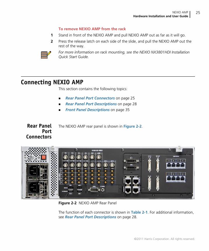
The NEXIO AMP rear panel is shown in Figure 2-2.
Figure 2-2 NEXIO AMP Rear Panel
The function of each connector is shown in Table 2-1. For additional information,see Rear Panel Port Descriptions on page 28.
©2011 Harris Corporation. All rights reserved.
Chapter 2Hardware Installation
26
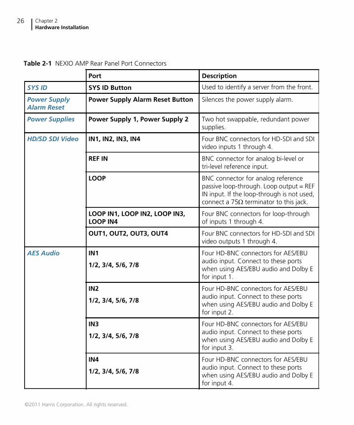
Table 2-1 NEXIO AMP Rear Panel Port Connectors
Port Description
SYS ID SYS ID Button Used to identify a server from the front.
Power SupplyAlarm Reset
Power Supply Alarm Reset Button Silences the power supply alarm.
Power Supplies Power Supply 1, Power Supply 2 Two hot swappable, redundant powersupplies.
HD/SD SDI Video IN1, IN2, IN3, IN4 Four BNC connectors for HD-SDI and SDIvideo inputs 1 through 4.
REF IN BNC connector for analog bi-level ortri-level reference input.
LOOP BNC connector for analog referencepassive loop-through. Loop output = REFIN input. If the loop-through is not used,connect a 75terminator to this jack.
LOOP IN1, LOOP IN2, LOOP IN3,LOOP IN4
Four BNC connectors for loop-throughof inputs 1 through 4.
OUT1, OUT2, OUT3, OUT4 Four BNC connectors for HD-SDI and SDIvideo outputs 1 through 4.
AES Audio IN1 Four HD-BNC connectors for AES/EBUaudio input. Connect to these portswhen using AES/EBU audio and Dolby Efor input 1.
1/2, 3/4, 5/6, 7/8
IN2 Four HD-BNC connectors for AES/EBUaudio input. Connect to these portswhen using AES/EBU audio and Dolby Efor input 2.
1/2, 3/4, 5/6, 7/8
IN3 Four HD-BNC connectors for AES/EBUaudio input. Connect to these portswhen using AES/EBU audio and Dolby Efor input 3.
1/2, 3/4, 5/6, 7/8
IN4 Four HD-BNC connectors for AES/EBUaudio input. Connect to these portswhen using AES/EBU audio and Dolby Efor input 4.
1/2, 3/4, 5/6, 7/8
©2011 Harris Corporation. All rights reserved.
NEXIO AMPHardware Installation and User Guide
27
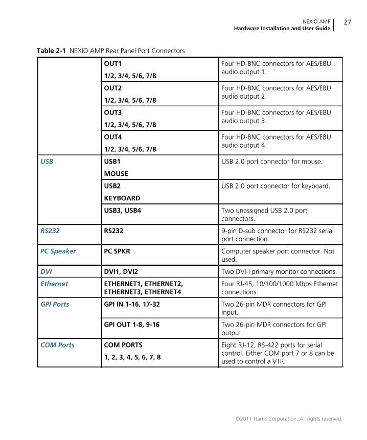
OUT1 Four HD-BNC connectors for AES/EBUaudio output 1.
1/2, 3/4, 5/6, 7/8
OUT2 Four HD-BNC connectors for AES/EBUaudio output 2.
1/2, 3/4, 5/6, 7/8
OUT3 Four HD-BNC connectors for AES/EBUaudio output 3.
1/2, 3/4, 5/6, 7/8
OUT4 Four HD-BNC connectors for AES/EBUaudio output 4.
1/2, 3/4, 5/6, 7/8
USB USB1 USB 2.0 port connector for mouse.
MOUSE
USB2 USB 2.0 port connector for keyboard.
KEYBOARD
USB3, USB4 Two unassigned USB 2.0 portconnectors.
RS232 RS232 9-pin D-sub connector for RS232 serialport connection.
PC Speaker PC SPKR Computer speaker port connector. Notused.
DVI DVI1, DVI2 Two DVI-I primary monitor connections.
Ethernet ETHERNET1, ETHERNET2,ETHERNET3, ETHERNET4
Four RJ-45, 10/100/1000 Mbps Ethernetconnections.
GPI Ports GPI IN 1-16, 17-32 Two 26-pin MDR connectors for GPIinput.
GPI OUT 1-8, 9-16 Two 26-pin MDR connectors for GPIoutput.
COM Ports COM PORTS Eight RJ-12, RS-422 ports for serialcontrol. Either COM port 7 or 8 can beused to control a VTR.
1, 2, 3, 4, 5, 6, 7, 8
Table 2-1 NEXIO AMP Rear Panel Port Connectors
©2011 Harris Corporation. All rights reserved.
Chapter 2Hardware Installation
28
Rear PanelPort
Descriptions
The following sections describe the NEXIO AMP rear panel port connections.
SYS IDThe SYS ID button enables you to identify a server from the front. When you pressthe SYS ID button, the front panel indicator illuminates so that you can easilyidentify the applicable server.
Power Supply Alarm ResetThe power supply alarm reset button silences the power supply alarm.
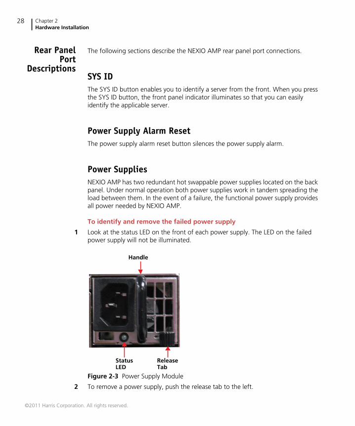
Power SuppliesNEXIO AMP has two redundant hot swappable power supplies located on the backpanel. Under normal operation both power supplies work in tandem spreading theload between them. In the event of a failure, the functional power supply providesall power needed by NEXIO AMP.
To identify and remove the failed power supply
1 Look at the status LED on the front of each power supply. The LED on the failedpower supply will not be illuminated.
Figure 2-3 Power Supply Module
2 To remove a power supply, push the release tab to the left.
ReleaseTab
Handle
StatusLED
©2011 Harris Corporation. All rights reserved.
NEXIO AMPHardware Installation and User Guide
29
3 Hold the release tab to the left, grasp the power supply handle, and pull the powersupply out of the frame.
To insert a new power supply
1 Slide the replacement power supply into the empty slot.
2 Press firmly so that it clicks in place. If the power supply cord is in place, themodule's status LED will illuminate.
HD/SD SDI VideoThe HD/SD SDI video ports use BNC connectors for HD-SDI and SDI video input andoutput.
The ports can be configured for SMPTE-259M SD or SMPTE-292M HD outputs.
Reference Ports
There are two reference ports on the NEXIO AMP back panel: REF IN and LOOP.
The reference ports use BNC connectors for analog bi-level or tri-level syncreference connection. A valid reference signal must be applied to the REF IN portwhen the system is configured for external sync.
Looping is not recommended. If you do loop, use caution when looping referencethroughout the server system. If one external cable fails or you replace a failedserver, you will compromise the reference signal to other servers in the loopedchain. Always terminate unused loop outputs with a 75terminatorprovided inthe accessories bag).
Each frame should have its own reference for the source device to ensure correcttiming.
Referencing the Server System to the House Time Clock (Optional)
Refer to the NXUSBTC User Guide for more information on referencing the NEXIOAMP to your house time clock. When recording from a satellite feed, apply framesynchronization hardware between the receiver and the video input channel. Thesynchronization hardware and the NEXIO AMP mainframe must be connected tothe house reference.
©2011 Harris Corporation. All rights reserved.
Chapter 2Hardware Installation
30
In addition, refer to the NXUSBLTC User Guide for support of one LTC input perchannel and one LTC output per channel. NXUSBLTC is ideal if you want topreserve LTC input timecode from VTRs and other sources, and if you are usingdownstream devices that require an LTC input, such as closed caption insertors.
Do not use wire or plastic ties on cables as this can impede cable performance. Usesoft cable ties such as Velcro-based ties for wrapping cables.
The BNC connectors use coaxial cable to connect devices together. Use high-qualitycable suitable for HD-SDI with the NEXIO AMP frame, for example, the Belden1694A cable. Cable used for analog, SDI, and ASI devices may not be high enoughquality.
AES AudioThe audio ports use HD-BNC connectors for AES/EBU digital audio input.
RECORD 1 (5) and RECORD 2 (6) — Supports a total of 4 pairs (8 channels) ofdigital audio in per video channel. Each input connector supports one pair of AES/EBU digital audio.
PLAY 1-4 — Supports a total of 4 pairs (8 channels) of digital audio out per videochannel. Each output connector supports one pair of AES/EBU digital audio.
USBThere is a USB port designated for use with a USB keyboard and a USB portdesignated for use with a USB mouse.
In addition, there are four available USB 2.0 ports. Two USB ports are located onthe front of NEXIO AMP. Two USB ports are located on the rear of NEXIO AMP. Theavailable USB ports can be used to connect devices to the server.
The following USB devices can be used as sources and destinations when movingcontent in and out of the server:
USB CD-ROM/R/RW drives (source only)
USB DVD-ROM/RW/RAM drives (source only)
USB hard drives
USB thumb drives
©2011 Harris Corporation. All rights reserved.
NEXIO AMPHardware Installation and User Guide
31
An FTP site created for a USB device is created as Folder type rather than an FTPServer type.
NEXIO AMP supports USB 1.0, 1.1, and 2.0.
RS232There is one serial port designated for RS232 communication. This port can be usedwith a supported Time Code Corrector module to lock the NEXIO AMP serversystem to your house time reference. For more information, see the NXUSBTCUser Guide and your Adrienne AEC Box (NXUSBTC) documentation.
PC SpeakerComputer speaker port connector. Not used.
DVIThe NEXIO AMP has two available DVI ports. This lets you simultaneously connecttwo monitors to the system.
DVI1 is the primary DVI port. DVI2 is optional. If the DVI2 connection is used, itsupports spanning of the desktop or a second simultaneous instance of thedesktop.
EthernetNEXIO AMP is equipped with four Ethernet ports, labeled Ethernet 1, Ethernet 2,Ethernet 3, and Ethernet 4. Each port is 10/100/1000 Mbps capable with fullautonegotiation. The ports may be flexibly used for NEXIO LAN, Media Host LAN,FTP, Proxy, and Protocol (control). Full duplex operation is always preferred fornetworks and is required for the NEXIO LAN. Category 5, 5e, or 6 cables must beused at 100 Mbps operation, and Category 5e or 6 cables are required foroperation at 1000 Mbps.
©2011 Harris Corporation. All rights reserved.
Chapter 2Hardware Installation
32
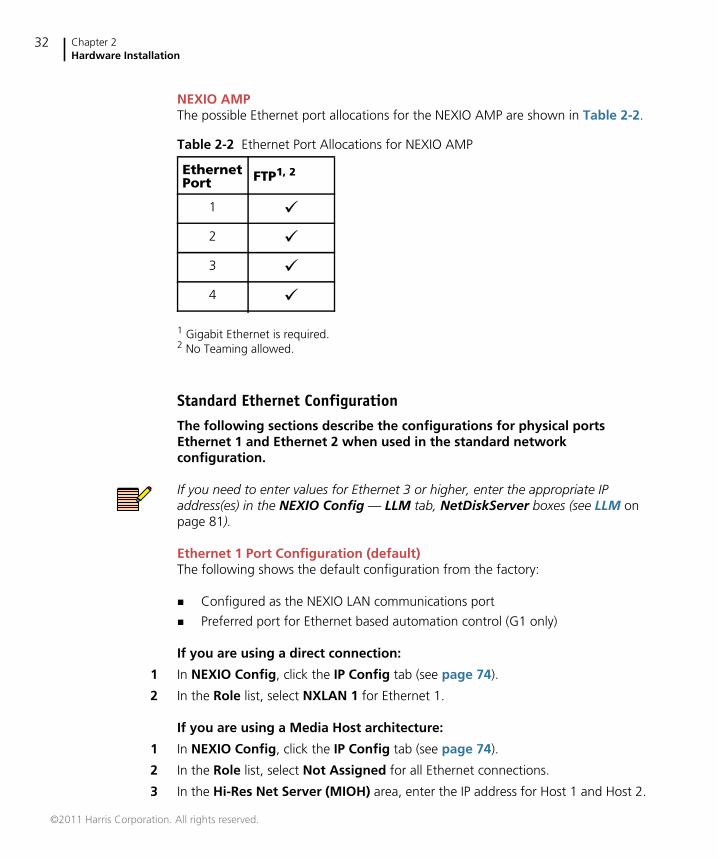
NEXIO AMPThe possible Ethernet port allocations for the NEXIO AMP are shown in Table 2-2.
1 Gigabit Ethernet is required.2 No Teaming allowed.
Standard Ethernet ConfigurationThe following sections describe the configurations for physical portsEthernet 1 and Ethernet 2 when used in the standard networkconfiguration.
If you need to enter values for Ethernet 3 or higher, enter the appropriate IPaddress(es) in the NEXIO Config — LLM tab, NetDiskServer boxes (see LLM onpage 81).
Ethernet 1 Port Configuration (default)The following shows the default configuration from the factory:
Configured as the NEXIO LAN communications port
Preferred port for Ethernet based automation control (G1 only)
If you are using a direct connection:
1 In NEXIO Config, click the IP Config tab (see page 74).
2 In the Role list, select NXLAN 1 for Ethernet 1.
If you are using a Media Host architecture:
1 In NEXIO Config, click the IP Config tab (see page 74).
2 In the Role list, select Not Assigned for all Ethernet connections.
3 In the Hi-Res Net Server (MIOH) area, enter the IP address for Host 1 and Host 2.
Table 2-2 Ethernet Port Allocations for NEXIO AMP
EthernetPort FTP1, 2
1 2 3 4
©2011 Harris Corporation. All rights reserved.
NEXIO AMPHardware Installation and User Guide
33
FTP with EthernetThe FTP Server can move both SD and HD content in and out of the server system.
The following rules apply for when moving content in and out of a servermainframe via FTP:
FTP Server module must be running on the mainframe that is used to moveclips in and out of the server system.
The FTP client controlling the transfer process may run on any computer thathas connectivity to the Ethernet port bound to the FTP service.
FTP cannot use the same Ethernet port as the low resolution proxy(PRXEncoder).
Protocol can be used via any Ethernet port. Ethernet ports 3 and 4 can beteamed for port redundancy. Do not team Ethernet ports 3 and 4 if they areused in servers with the low resolution proxy (PRXEncoder) application.
If Media Most architecture is used, no FTP support is allowed using anyEthernet port.
If you are using FTP services:
1 In NEXIO Config, click the IP Config tab (see page 74).
2 In the Role list, select FTP LAN for the appropriate Ethernet connection (typicallyEthernet 3 or Ethernet 4).
GPI PortsThe NEXIO AMP provides 4 GPI connectors.
GPI IN 1-16
GPI IN 17-32
GPI OUT 1-8
GPI OUT 9-16
GPI IN — There are two GPI IN connectors. Each GPI IN connector manages 16 GPIinput triggers. Inputs can be used to trigger playlist functions such as play, stop,and record of each channel.
GPI OUT — There are two GPI OUT connectors. Each GPI OUT connector manages8 GPI output triggers. Outputs can be programmed to trigger certain events in thePlaylist and to indicate a RAIDset error.
©2011 Harris Corporation. All rights reserved.
Chapter 2Hardware Installation
34
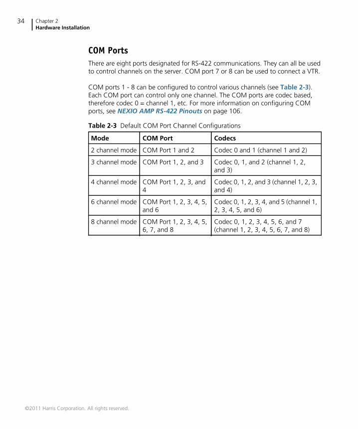
COM PortsThere are eight ports designated for RS-422 communications. They can all be usedto control channels on the server. COM port 7 or 8 can be used to connect a VTR.
COM ports 1 - 8 can be configured to control various channels (see Table 2-3).Each COM port can control only one channel. The COM ports are codec based,therefore codec 0 = channel 1, etc. For more information on configuring COMports, see NEXIO AMP RS-422 Pinouts on page 106.
Table 2-3 Default COM Port Channel Configurations
Mode COM Port Codecs
2 channel mode COM Port 1 and 2 Codec 0 and 1 (channel 1 and 2)
3 channel mode COM Port 1, 2, and 3 Codec 0, 1, and 2 (channel 1, 2,and 3)
4 channel mode COM Port 1, 2, 3, and4
Codec 0, 1, 2, and 3 (channel 1, 2, 3,and 4)
6 channel mode COM Port 1, 2, 3, 4, 5,and 6
Codec 0, 1, 2, 3, 4, and 5 (channel 1,2, 3, 4, 5, and 6)
8 channel mode COM Port 1, 2, 3, 4, 5,6, 7, and 8
Codec 0, 1, 2, 3, 4, 5, 6, and 7(channel 1, 2, 3, 4, 5, 6, 7, and 8)
©2011 Harris Corporation. All rights reserved.
NEXIO AMPHardware Installation and User Guide
35
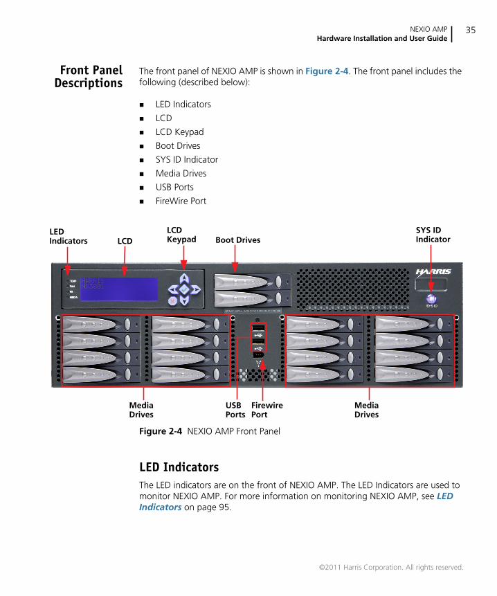
Front PanelDescriptions
The front panel of NEXIO AMP is shown in Figure 2-4. The front panel includes thefollowing (described below):
LED Indicators
LCD
LCD Keypad
Boot Drives
SYS ID Indicator
Media Drives
USB Ports
FireWire Port
Figure 2-4 NEXIO AMP Front Panel
LED IndicatorsThe LED indicators are on the front of NEXIO AMP. The LED Indicators are used tomonitor NEXIO AMP. For more information on monitoring NEXIO AMP, see LEDIndicators on page 95.
USBPorts
LCDLCDKeypad Boot Drives
LEDIndicators
FirewirePort
MediaDrives
MediaDrives
SYS IDIndicator
©2011 Harris Corporation. All rights reserved.
Chapter 2Hardware Installation
36
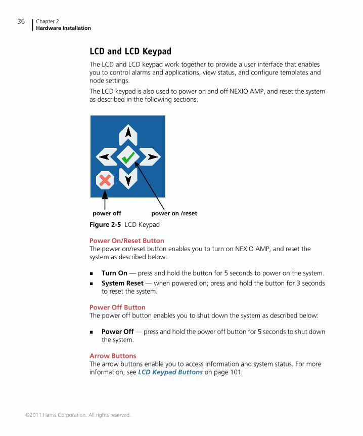
LCD and LCD KeypadThe LCD and LCD keypad work together to provide a user interface that enablesyou to control alarms and applications, view status, and configure templates andnode settings.
The LCD keypad is also used to power on and off NEXIO AMP, and reset the systemas described in the following sections.
Figure 2-5 LCD Keypad
Power On/Reset ButtonThe power on/reset button enables you to turn on NEXIO AMP, and reset thesystem as described below:
Turn On — press and hold the button for 5 seconds to power on the system.
System Reset — when powered on; press and hold the button for 3 secondsto reset the system.
Power Off ButtonThe power off button enables you to shut down the system as described below:
Power Off — press and hold the power off button for 5 seconds to shut downthe system.
Arrow ButtonsThe arrow buttons enable you to access information and system status. For moreinformation, see LCD Keypad Buttons on page 101.
power off power on /reset
©2011 Harris Corporation. All rights reserved.
NEXIO AMPHardware Installation and User Guide
37
Boot DrivesNEXIO AMP has two boot drives. For information on replacing a drive, seeReplacing a Boot Drive on page 114.
SYS ID Front Panel IndicatorThe SYS ID back panel indicator illuminates when the SYS ID button on the backpanel is pressed. This allows you to identify the applicable server from the front.
Media DrivesNEXIO AMP comes with eight media drives for internal storage. Additional mediadrives can be purchased for added storage (contact your Harris Customer ServiceRepresentative).
USB PortsThe front of NEXIO AMP has two USB 2.0 ports. For more information, see USB onpage 30.
Firewire PortNEXIO AMP has an IEEE1394 Firewire port connector that can be used for aportable storage device.
©2011 Harris Corporation. All rights reserved.

Chapter 2Hardware Installation
38
©2011 Harris Corporation. All rights reserved.
39
3 Getting Started
This chapter describes how to start and begin using the NEXIO AMP. This chapterincludes the following sections:
Starting NEXIO AMP on page 39
Startup Operations on page 43
Starting NEXIO AMPThis section describes how to start the NEXIO AMP and the initial startup tasks thatyou should perform. After you have performed the tasks described here, you shouldrun the Using NEXIO Config on page 53 to assign your video and audio I/Osettings.
To start NEXIO AMP
Press the power button on the front panel. Under normal operation, the NEXIOAMP server software starts when you start the server. The following applicationshortcuts appear on your desktop:
NEXIO Startup
LLM
FTP Server
NXOS
NEXIO Config
©2011 Harris Corporation. All rights reserved.
Chapter 3Getting Started
40
The NXOS Log On dialog box appears after you start the server and the LLM andNXOS applications are started (see Figure 3-1). The first time you log on to NXOSthere are two default user accounts: Administrator and Guest. Log on to NXOSusing the default Administrator account.
Tip If you log on as a Guest, you do not need a password.
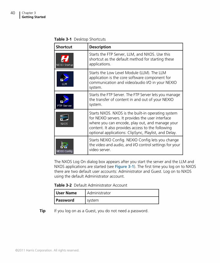
Table 3-1 Desktop Shortcuts
Shortcut Description
Starts the FTP Server, LLM, and NXOS. Use thisshortcut as the default method for starting theseapplications.
Starts the Low Level Module (LLM). The LLMapplication is the core software component forcommunication and video/audio I/O in your NEXIOsystem.
Starts the FTP Server. The FTP Server lets you managethe transfer of content in and out of your NEXIOsystem.
Starts NXOS. NXOS is the built-in operating systemfor NEXIO servers. It provides the user interfacewhere you can encode, play out, and manage yourcontent. It also provides access to the followingoptional applications: ClipSync, Playlist, and Delay.
Starts NEXIO Config. NEXIO Config lets you changethe video and audio, and I/O control settings for yourvideo server.
Table 3-2 Default Administrator Account
User Name Administrator
Password system
©2011 Harris Corporation. All rights reserved.
NEXIO AMPHardware Installation and User Guide
41
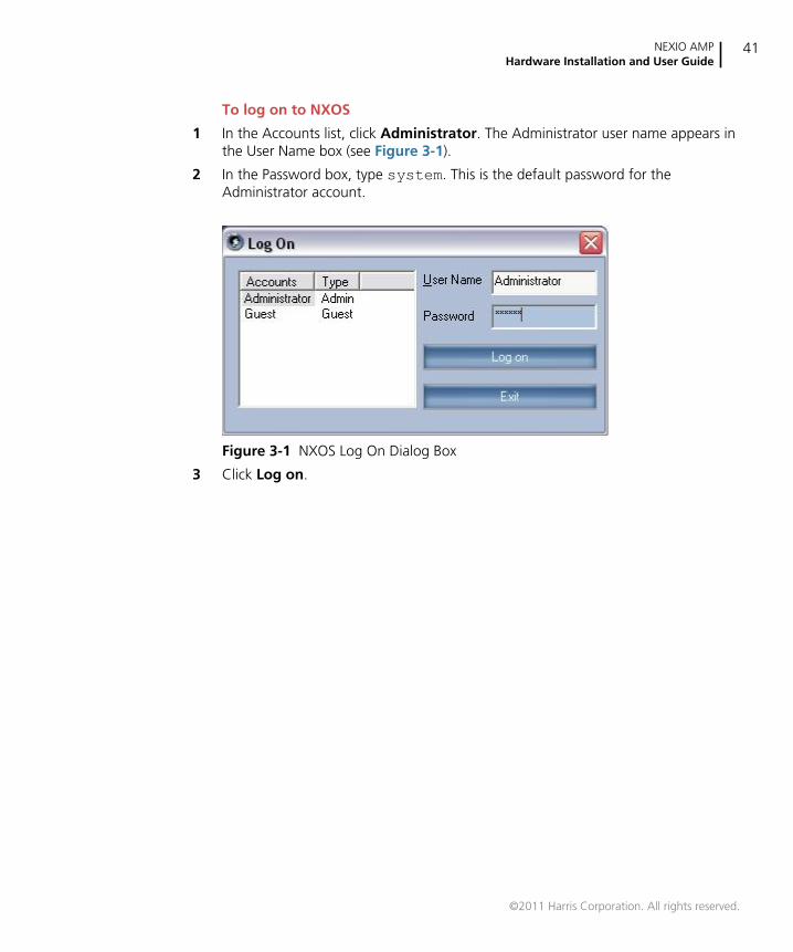
To log on to NXOS
1 In the Accounts list, click Administrator. The Administrator user name appears inthe User Name box (see Figure 3-1).
2 In the Password box, type system. This is the default password for theAdministrator account.
Figure 3-1 NXOS Log On Dialog Box
3 Click Log on.
©2011 Harris Corporation. All rights reserved.
Chapter 3Getting Started
42
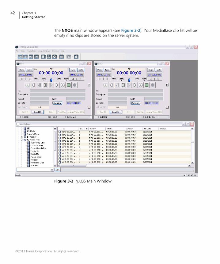
The NXOS main window appears (see Figure 3-2). Your MediaBase clip list will beempty if no clips are stored on the server system.
Figure 3-2 NXOS Main Window
©2011 Harris Corporation. All rights reserved.
NEXIO AMPHardware Installation and User Guide
43
Startup OperationsOnce NEXIO AMP is successfully started, complete the following startup operationsto ensure the NEXIO AMP is operating properly:
Registering Your Software on page 43
Confirming Connection to Additional Systems on page 48
Verifying Audio and Video I/O Connections on page 48
Testing Input and Output Signals on page 49
RegisteringYour
Software
Your software must be registered. Typically this gets done during thecommissioning process. If your software does not get registered during thecommissioning process, you can register your software. To register your softwareyou will need to send Harris BCD Support the deployment file (.dc file) for thesoftware. The .dc file is a unique encrypted file for each server. Therefore you mustmake sure that you name each server with a unique name for easy identification.
The following procedure describes how to create the deployment (.dc) file that youneed to send to Harris BCD Support. This information can also be found on theSoftware Registration Card provided with your server.
If you have any questions about registering your software, contact BCD TechnicalSupport (see Technical Support on page 6).
©2011 Harris Corporation. All rights reserved.
Chapter 3Getting Started
44
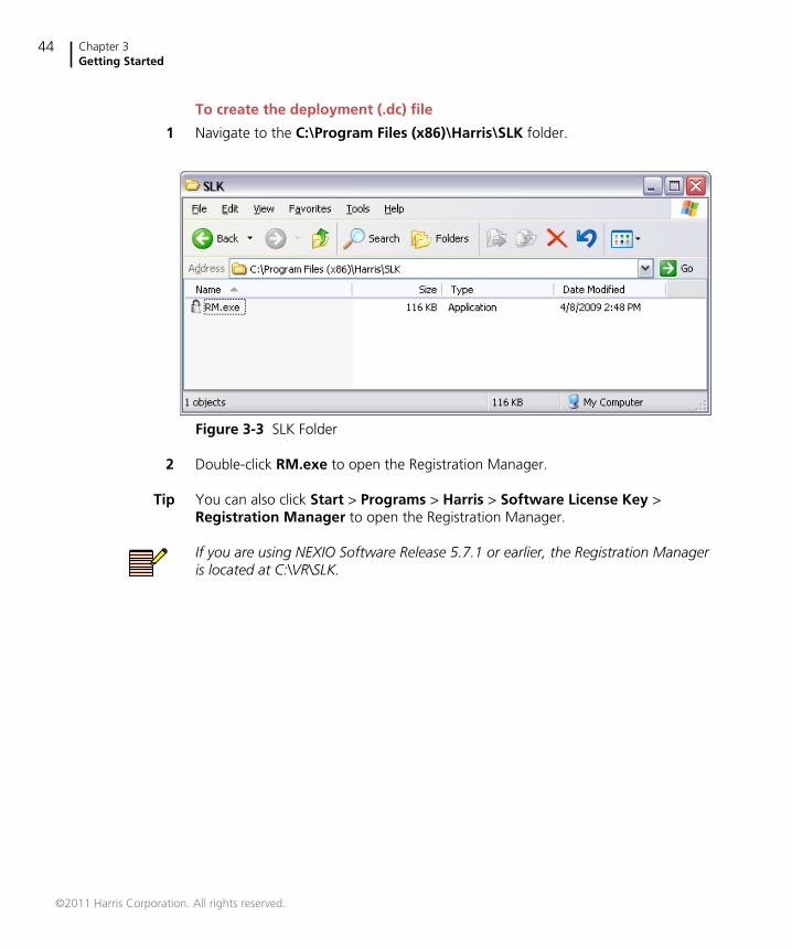
To create the deployment (.dc) file
1 Navigate to the C:\Program Files (x86)\Harris\SLK folder.
Figure 3-3 SLK Folder
2 Double-click RM.exe to open the Registration Manager.
Tip You can also click Start > Programs > Harris > Software License Key >Registration Manager to open the Registration Manager.
If you are using NEXIO Software Release 5.7.1 or earlier, the Registration Manageris located at C:\VR\SLK.
©2011 Harris Corporation. All rights reserved.
NEXIO AMPHardware Installation and User Guide
45
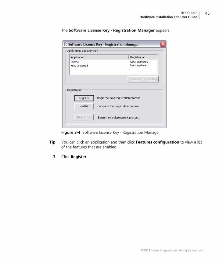
The Software License Key - Registration Manager appears.
Figure 3-4 Software License Key - Registration Manager
Tip You can click an application and then click Features configuration to view a listof the features that are enabled.
3 Click Register.
©2011 Harris Corporation. All rights reserved.
Chapter 3Getting Started
46
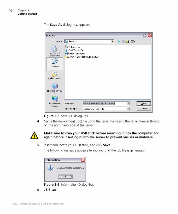
The Save As dialog box appears.
Figure 3-5 Save As Dialog Box
4 Name the deployment (.dc) file using the server name and the serial number (foundon the right hand side of the server).
Make sure to scan your USB stick before inserting it into the computer andagain before inserting it into the server to prevent viruses or malware.
5 Insert and locate your USB stick, and click Save.
The following message appears telling you that the .dc file is generated.
Figure 3-6 Information Dialog Box
6 Click OK.
©2011 Harris Corporation. All rights reserved.
NEXIO AMPHardware Installation and User Guide
47
7 Email the .dc file and the description of what you are registering (e.g., 4 ChannelsSD/HD) to Harris BCD Support at [email protected].
Harris BCD Support will send you a redistribution code (.rc) file.
8 Copy the .rc file to the USB stick and insert it into server.
9 Open the Software License Key - Registration Manager as described above.
10 In the Open dialog box, locate the USB stick and double-click the .rc file.
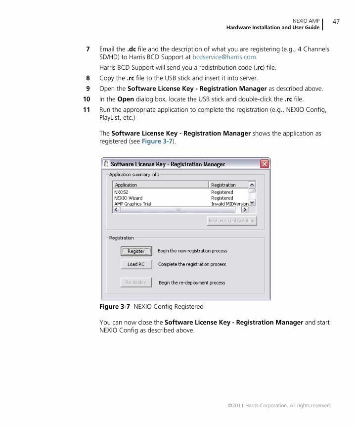
11 Run the appropriate application to complete the registration (e.g., NEXIO Config,PlayList, etc.)
The Software License Key - Registration Manager shows the application asregistered (see Figure 3-7).
Figure 3-7 NEXIO Config Registered
You can now close the Software License Key - Registration Manager and startNEXIO Config as described above.
©2011 Harris Corporation. All rights reserved.
Chapter 3Getting Started
48
ConfirmingConnection
to AdditionalSystems
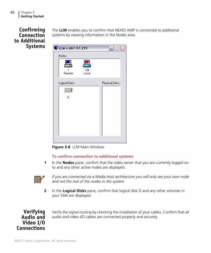
The LLM enables you to confirm that NEXIO AMP is connected to additionalsystems by viewing information in the Nodes area.
Figure 3-8 LLM Main Window
To confirm connection to additional systems
1 In the Nodes pane, confirm that the video server that you are currently logged onto and any other active nodes are displayed.
If you are connected via a Media Host architecture you will only see your own nodeand not the rest of the nodes in the system.
2 In the Logical Disks pane, confirm that logical disk D and any other volumes inyour SAN are displayed.
VerifyingAudio andVideo I/O
Connections
Verify the signal routing by checking the installation of your cables. Confirm that allaudio and video I/O cables are connected properly and securely.
©2011 Harris Corporation. All rights reserved.
NEXIO AMPHardware Installation and User Guide
49
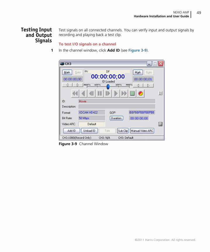
Testing Inputand Output
Signals
Test signals on all connected channels. You can verify input and output signals byrecording and playing back a test clip.
To test I/O signals on a channel
1 In the channel window, click Add ID (see Figure 3-9).
Figure 3-9 Channel Window
©2011 Harris Corporation. All rights reserved.
Chapter 3Getting Started
50
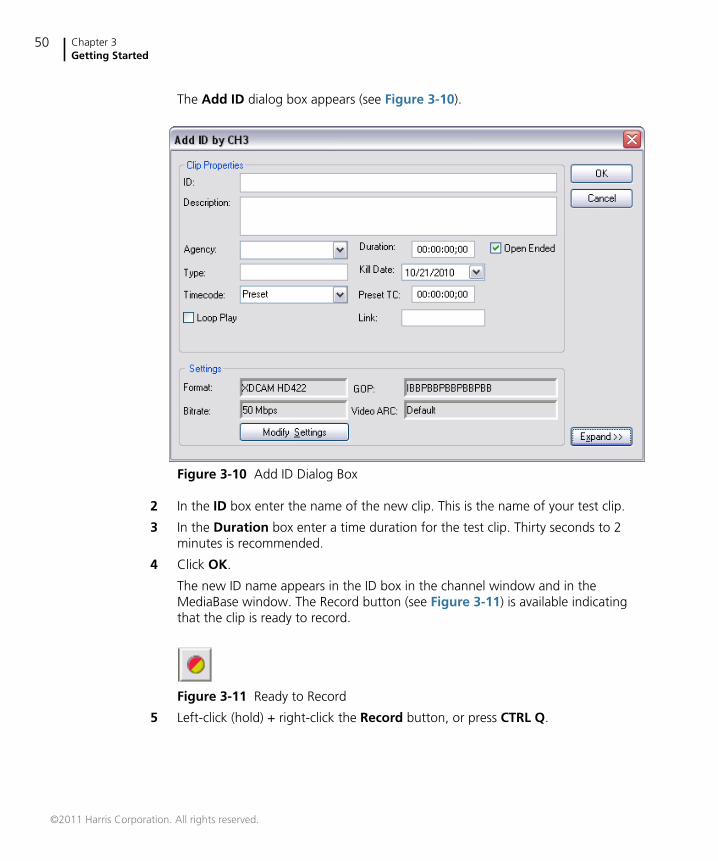
The Add ID dialog box appears (see Figure 3-10).
Figure 3-10 Add ID Dialog Box
2 In the ID box enter the name of the new clip. This is the name of your test clip.
3 In the Duration box enter a time duration for the test clip. Thirty seconds to 2minutes is recommended.
4 Click OK.
The new ID name appears in the ID box in the channel window and in theMediaBase window. The Record button (see Figure 3-11) is available indicatingthat the clip is ready to record.
Figure 3-11 Ready to Record
5 Left-click (hold) + right-click the Record button, or press CTRL Q.
©2011 Harris Corporation. All rights reserved.
NEXIO AMPHardware Installation and User Guide
51
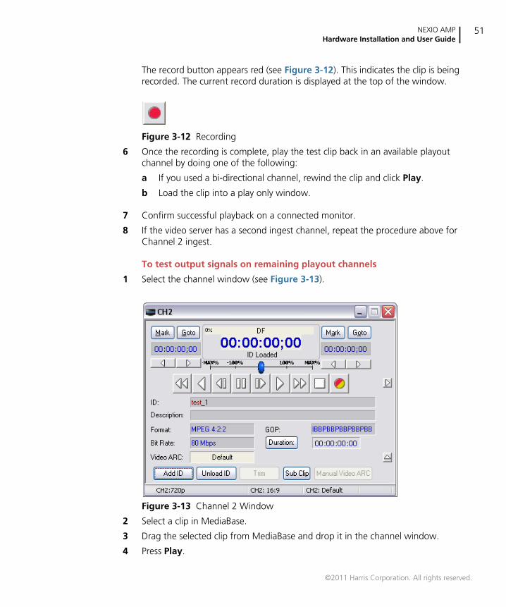
The record button appears red (see Figure 3-12). This indicates the clip is beingrecorded. The current record duration is displayed at the top of the window.
Figure 3-12 Recording
6 Once the recording is complete, play the test clip back in an available playoutchannel by doing one of the following:
a If you used a bi-directional channel, rewind the clip and click Play.
b Load the clip into a play only window.
7 Confirm successful playback on a connected monitor.
8 If the video server has a second ingest channel, repeat the procedure above forChannel 2 ingest.
To test output signals on remaining playout channels
1 Select the channel window (see Figure 3-13).
Figure 3-13 Channel 2 Window
2 Select a clip in MediaBase.
3 Drag the selected clip from MediaBase and drop it in the channel window.
4 Press Play.
©2011 Harris Corporation. All rights reserved.
Chapter 3Getting Started
52
5 Confirm playback on a connected monitor.
6 Repeat Steps 1 though 5 for all configured playback channels.
You can also verify output by dragging a clip from an ingest channel window to aplayout channel window. For example, drag a clip from Channel 1 and drop it inChannel 3. You may do this while recording a clip in Channel 1. Press the Playbutton in Channel 3 to play the clip back during the ingest process.
For more information on NXOS, see the NXOS User Guide.
©2011 Harris Corporation. All rights reserved.
53
4 Using NEXIO Config
NEXIO Config OverviewNEXIO Config enables you to easily configure all of the settings for your NEXIO AMPservers. You can create and save these settings in configuration presets to use at anytime, or copy presets between servers for fast, reliable setup of multiple servers.
In this chapter you will learn how to work with configuration presets. You will alsobe provided detailed information on each NEXIO Config window.
This chapter includes the following sections:
Starting NEXIO Config on page 54
Working with Configuration Presets on page 55
NEXIO Config Windows on page 60
NEXIO Config is intended to be run while the LLM is not running. Most changesmade within NEXIO Config require a restart of the LLM for the changes to takeeffect.
©2011 Harris Corporation. All rights reserved.
Chapter 4Using NEXIO Config
54
Starting NEXIO Config
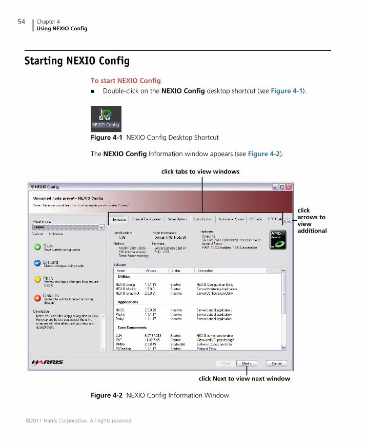
To start NEXIO Config
Double-click on the NEXIO Config desktop shortcut (see Figure 4-1).
Figure 4-1 NEXIO Config Desktop Shortcut
The NEXIO Config Information window appears (see Figure 4-2).
Figure 4-2 NEXIO Config Information Window
click tabs to view windows
clickarrows toviewadditional
click Next to view next window
©2011 Harris Corporation. All rights reserved.
NEXIO AMPHardware Installation and User Guide
55
If you have not registered your software using your Software License Key (SLK), amessage appears telling you to contact Harris BCD Support to obtain a license. SeeTechnical Support on page 6 for contact information.
Registering your software will require that you send Harris BCD Support thedeployment (.dc) file for the software. The .dc file is a unique encrypted file foreach server. Therefore you must make sure that you name each server with aunique name for easy identification. For information on creating the .dc file, seeRegistering Your Software on page 43.
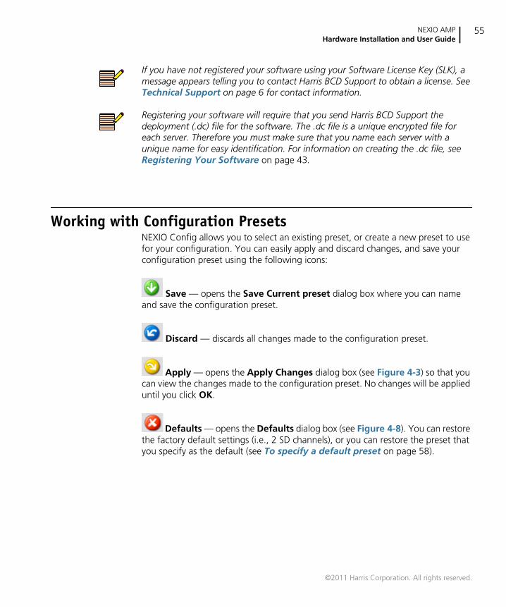
Working with Configuration PresetsNEXIO Config allows you to select an existing preset, or create a new preset to usefor your configuration. You can easily apply and discard changes, and save yourconfiguration preset using the following icons:
Save — opens the Save Current preset dialog box where you can nameand save the configuration preset.
Discard — discards all changes made to the configuration preset.
Apply — opens the Apply Changes dialog box (see Figure 4-3) so that youcan view the changes made to the configuration preset. No changes will be applieduntil you click OK.
Defaults — opens the Defaults dialog box (see Figure 4-8). You can restorethe factory default settings (i.e., 2 SD channels), or you can restore the preset thatyou specify as the default (see To specify a default preset on page 58).
©2011 Harris Corporation. All rights reserved.
Chapter 4Using NEXIO Config
56
Creating orModifying a
Preset
The following procedure describes how to create or modify a preset.
To create or modify a configuration preset
1 In the Preset in use list, select the desired preset, or select <new> to create a newpreset.
2 Make the desired changes to each NEXIO Config window.
You can click Discard at anytime to discard all the changes made to the selectedconfiguration preset.
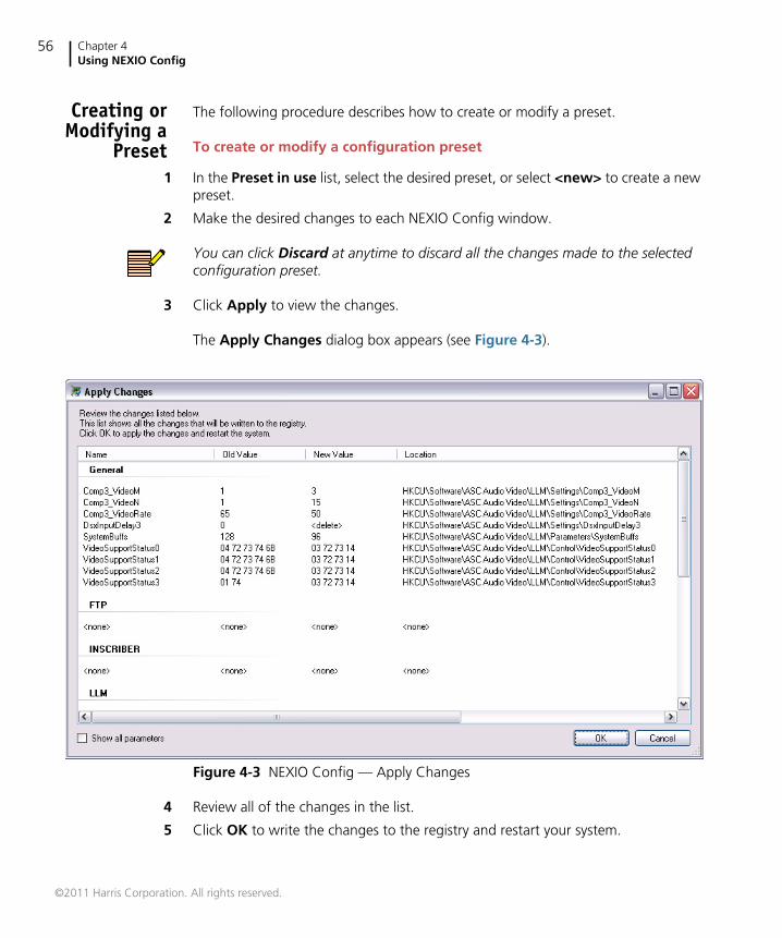
3 Click Apply to view the changes.
The Apply Changes dialog box appears (see Figure 4-3).
Figure 4-3 NEXIO Config — Apply Changes
4 Review all of the changes in the list.
5 Click OK to write the changes to the registry and restart your system.
©2011 Harris Corporation. All rights reserved.
NEXIO AMPHardware Installation and User Guide
57
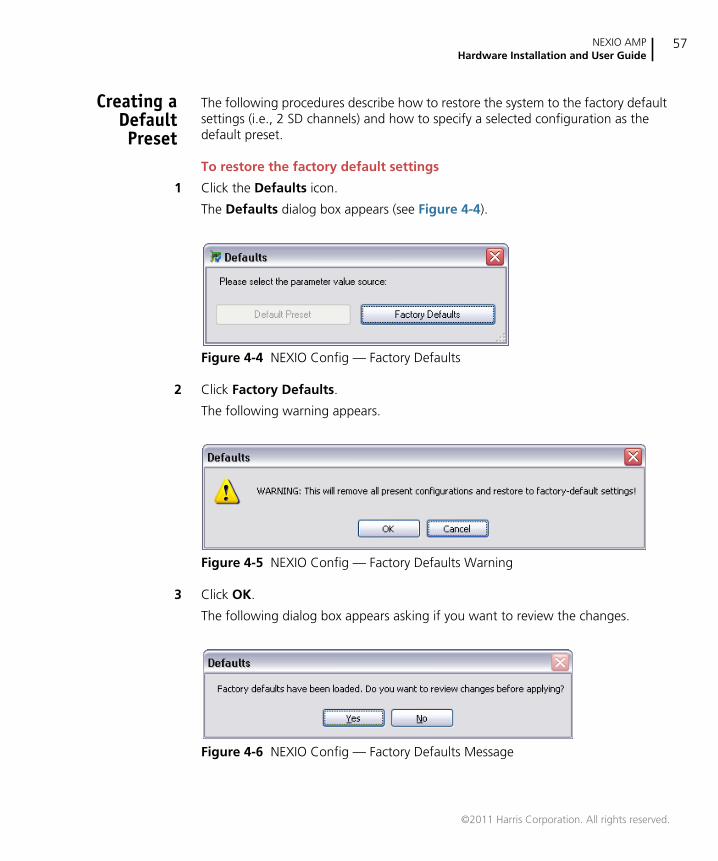
Creating aDefaultPreset
The following procedures describe how to restore the system to the factory defaultsettings (i.e., 2 SD channels) and how to specify a selected configuration as thedefault preset.
To restore the factory default settings
1 Click the Defaults icon.
The Defaults dialog box appears (see Figure 4-4).
Figure 4-4 NEXIO Config — Factory Defaults
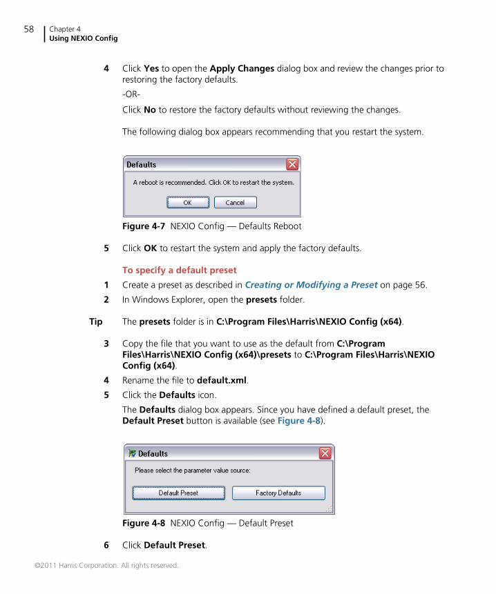
2 Click Factory Defaults.
The following warning appears.
Figure 4-5 NEXIO Config — Factory Defaults Warning
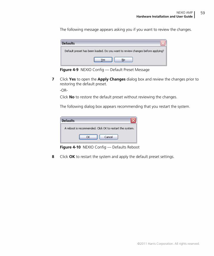
3 Click OK.
The following dialog box appears asking if you want to review the changes.
Figure 4-6 NEXIO Config — Factory Defaults Message
©2011 Harris Corporation. All rights reserved.
Chapter 4Using NEXIO Config
58
4 Click Yes to open the Apply Changes dialog box and review the changes prior torestoring the factory defaults.
-OR-
Click No to restore the factory defaults without reviewing the changes.
The following dialog box appears recommending that you restart the system.
Figure 4-7 NEXIO Config — Defaults Reboot
5 Click OK to restart the system and apply the factory defaults.
To specify a default preset
1 Create a preset as described in Creating or Modifying a Preset on page 56.
2 In Windows Explorer, open the presets folder.
Tip The presets folder is in C:\Program Files\Harris\NEXIO Config (x64).
3 Copy the file that you want to use as the default from C:\ProgramFiles\Harris\NEXIO Config (x64)\presets to C:\Program Files\Harris\NEXIOConfig (x64).
4 Rename the file to default.xml.
5 Click the Defaults icon.
The Defaults dialog box appears. Since you have defined a default preset, theDefault Preset button is available (see Figure 4-8).
Figure 4-8 NEXIO Config — Default Preset
6 Click Default Preset.
©2011 Harris Corporation. All rights reserved.
NEXIO AMPHardware Installation and User Guide
59
The following message appears asking you if you want to review the changes.
Figure 4-9 NEXIO Config — Default Preset Message
7 Click Yes to open the Apply Changes dialog box and review the changes prior torestoring the default preset.
-OR-
Click No to restore the default preset without reviewing the changes.
The following dialog box appears recommending that you restart the system.
Figure 4-10 NEXIO Config — Defaults Reboot
8 Click OK to restart the system and apply the default preset settings.
©2011 Harris Corporation. All rights reserved.
Chapter 4Using NEXIO Config
60
NEXIO Config WindowsThe following sections describe the settings for each of the NEXIO Configwindows:
Information on page 61
Channel Configuration on page 62
Video Options on page 63
Audio Options on page 68
GPRX Options on page 70
Automation/Serial on page 71
IP Config on page 74
FTP Folders on page 77
LLM Parameters on page 78
Error Logging on page 79
LLM on page 81
MPEG on page 83
FTP on page 85
Startup on page 87
CV/Logo on page 89
Other on page 91
LLM 1 on page 93
It is important to understand that if a value appears in a box that is grayed out, thevalue is valid but cannot be edited. In addition, if a check box is selected and isgrayed out, the option is enabled and cannot be disabled from that window.
©2011 Harris Corporation. All rights reserved.
NEXIO AMPHardware Installation and User Guide
61
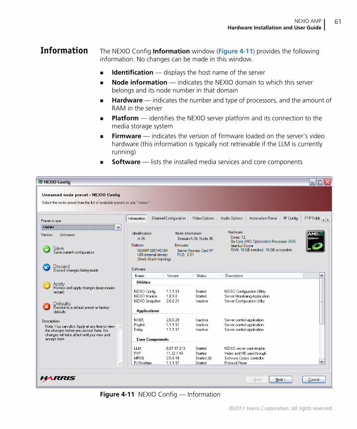
Information The NEXIO Config Information window (Figure 4-11) provides the followinginformation. No changes can be made in this window.
Identification — displays the host name of the server
Node information — indicates the NEXIO domain to which this serverbelongs and its node number in that domain
Hardware — indicates the number and type of processors, and the amount ofRAM in the server
Platform — identifies the NEXIO server platform and its connection to themedia storage system
Firmware — indicates the version of firmware loaded on the server’s videohardware (this information is typically not retrievable if the LLM is currentlyrunning)
Software — lists the installed media services and core components
Figure 4-11 NEXIO Config — Information
©2011 Harris Corporation. All rights reserved.
Chapter 4Using NEXIO Config
62
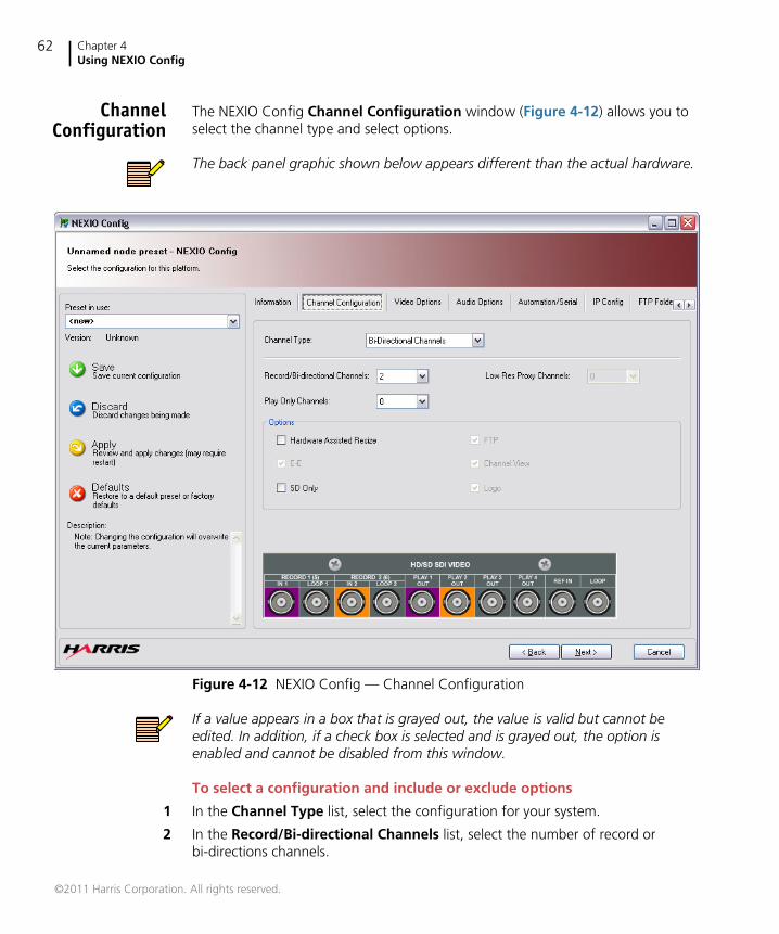
ChannelConfiguration
The NEXIO Config Channel Configuration window (Figure 4-12) allows you toselect the channel type and select options.
The back panel graphic shown below appears different than the actual hardware.
Figure 4-12 NEXIO Config — Channel Configuration
If a value appears in a box that is grayed out, the value is valid but cannot beedited. In addition, if a check box is selected and is grayed out, the option isenabled and cannot be disabled from this window.
To select a configuration and include or exclude options
1 In the Channel Type list, select the configuration for your system.
2 In the Record/Bi-directional Channels list, select the number of record orbi-directions channels.
©2011 Harris Corporation. All rights reserved.
NEXIO AMPHardware Installation and User Guide
63
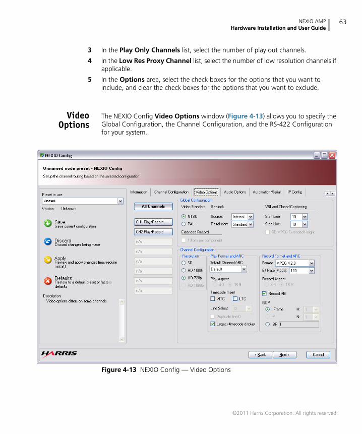
3 In the Play Only Channels list, select the number of play out channels.
4 In the Low Res Proxy Channel list, select the number of low resolution channels ifapplicable.
5 In the Options area, select the check boxes for the options that you want toinclude, and clear the check boxes for the options that you want to exclude.
VideoOptions
The NEXIO Config Video Options window (Figure 4-13) allows you to specify theGlobal Configuration, the Channel Configuration, and the RS-422 Configurationfor your system.
Figure 4-13 NEXIO Config — Video Options
©2011 Harris Corporation. All rights reserved.
Chapter 4Using NEXIO Config
64
To specify video options
1 Click All Channels to set the video configuration for all of the channels, or clickthe desired channel (e.g., CH1 Play) to configure a channel individually.
2 In the Global Configuration area, set the options described below:
Video Standard
Under Video Standard, select the video standard (i.e., NTSC or PAL).
Genlock
Under Genlock, select the source and resolution setting.
The available Source settings are:
Internal — this uses the internal clock of the server rather thanreferencing to an external reference source.
Input1 — this references the output video of all channels to thetiming derived from video input 1.
External — this references the video outputs to the external referencesignal applied to the REF IN connector. This is the recommendedsetting.
The available Resolution settings are:
Standard — use for bi-level 525 or 625 line reference.
HD1080i — use for tri-level 1080i reference.
HD720 — use for tri-level 720p reference.
HD1080p — use for tri-level 1080p reference.
VBI and Closed Captioning
a Under VBI and Closed Captioning, set the start and stop lines for storedclosed captioning and other ancillary data. This data is stored as clipessence.
b Select the SD MPEG Extended Height check box to compress theancillary data. This only applies to SD-only, MPEG 4:2:2 configurations.
Extended Record
a Select the Extended Record check box to increase the number of verticalpixels recorded to include those that make up the VBI data closedcaptioning. This saves space if the recorded VBI lines are set to the samevalues. This only applies to SD MPEG 4:2:2 configurations.
©2011 Harris Corporation. All rights reserved.
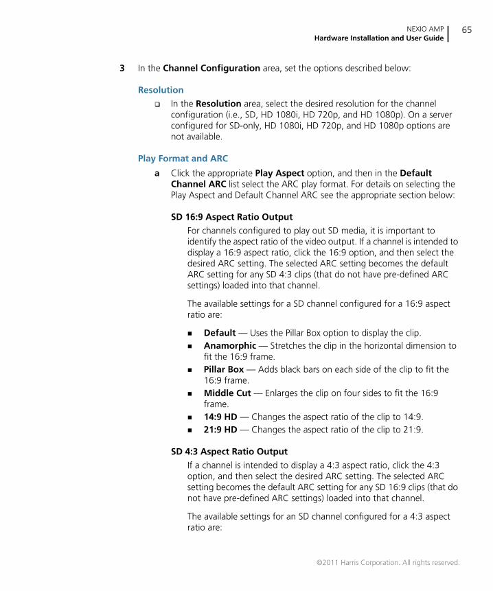
NEXIO AMPHardware Installation and User Guide
65
3 In the Channel Configuration area, set the options described below:
Resolution
In the Resolution area, select the desired resolution for the channelconfiguration (i.e., SD, HD 1080i, HD 720p, and HD 1080p). On a serverconfigured for SD-only, HD 1080i, HD 720p, and HD 1080p options arenot available.
Play Format and ARC
a Click the appropriate Play Aspect option, and then in the DefaultChannel ARC list select the ARC play format. For details on selecting thePlay Aspect and Default Channel ARC see the appropriate section below:
SD 16:9 Aspect Ratio Output
For channels configured to play out SD media, it is important toidentify the aspect ratio of the video output. If a channel is intended todisplay a 16:9 aspect ratio, click the 16:9 option, and then select thedesired ARC setting. The selected ARC setting becomes the defaultARC setting for any SD 4:3 clips (that do not have pre-defined ARCsettings) loaded into that channel.
The available settings for a SD channel configured for a 16:9 aspectratio are:
Default — Uses the Pillar Box option to display the clip. Anamorphic — Stretches the clip in the horizontal dimension to
fit the 16:9 frame. Pillar Box — Adds black bars on each side of the clip to fit the
16:9 frame. Middle Cut — Enlarges the clip on four sides to fit the 16:9
frame. 14:9 HD — Changes the aspect ratio of the clip to 14:9. 21:9 HD — Changes the aspect ratio of the clip to 21:9.
SD 4:3 Aspect Ratio Output
If a channel is intended to display a 4:3 aspect ratio, click the 4:3option, and then select the desired ARC setting. The selected ARCsetting becomes the default ARC setting for any SD 16:9 clips (that donot have pre-defined ARC settings) loaded into that channel.
The available settings for an SD channel configured for a 4:3 aspectratio are:
©2011 Harris Corporation. All rights reserved.
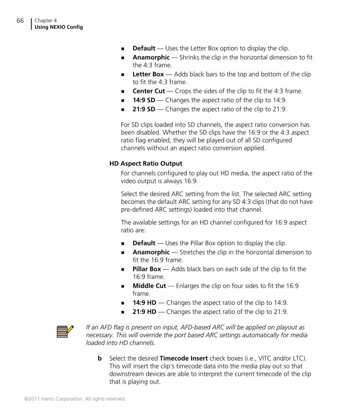
Chapter 4Using NEXIO Config
66
Default — Uses the Letter Box option to display the clip. Anamorphic — Shrinks the clip in the horizontal dimension to fit
the 4:3 frame. Letter Box — Adds black bars to the top and bottom of the clip
to fit the 4:3 frame. Center Cut — Crops the sides of the clip to fit the 4:3 frame. 14:9 SD — Changes the aspect ratio of the clip to 14:9. 21:9 SD — Changes the aspect ratio of the clip to 21:9.
For SD clips loaded into SD channels, the aspect ratio conversion hasbeen disabled. Whether the SD clips have the 16:9 or the 4:3 aspectratio flag enabled, they will be played out of all SD configuredchannels without an aspect ratio conversion applied.
HD Aspect Ratio Output
For channels configured to play out HD media, the aspect ratio of thevideo output is always 16:9.
Select the desired ARC setting from the list. The selected ARC settingbecomes the default ARC setting for any SD 4:3 clips (that do not havepre-defined ARC settings) loaded into that channel.
The available settings for an HD channel configured for 16:9 aspectratio are:
Default — Uses the Pillar Box option to display the clip. Anamorphic — Stretches the clip in the horizontal dimension to
fit the 16:9 frame. Pillar Box — Adds black bars on each side of the clip to fit the
16:9 frame. Middle Cut — Enlarges the clip on four sides to fit the 16:9
frame. 14:9 HD — Changes the aspect ratio of the clip to 14:9. 21:9 HD — Changes the aspect ratio of the clip to 21:9.
If an AFD flag is present on input, AFD-based ARC will be applied on playout asnecessary. This will override the port based ARC settings automatically for medialoaded into HD channels.
b Select the desired Timecode Insert check boxes (i.e., VITC and/or LTC).This will insert the clip’s timecode data into the media play out so thatdownstream devices are able to interpret the current timecode of the clipthat is playing out.
©2011 Harris Corporation. All rights reserved.
NEXIO AMPHardware Installation and User Guide
67
c In the Line Select list, select the desired line for the VITC output (i.e., 10,11, 12, 13, 14, 15, 16, 17, 18, 19, or 20). This option is only applicable forSD-only clips and if VITC insert is selected.
d Select the Duplicate line 0 check box if desired to add a duplicate line ofthe VITC output 2 lines later. For example, if you have VITC output on line16, a duplicate of the output will appear on line 18. This option is onlyapplicable for SD-only clips and if VITC insert is selected.
e Select the Legacy timecode display check box to report a channel’scurrent output timecode based on the start time of a currently playing clipinstead of the embedded timecode within the clip.
Record Format and ARC
a In the Format list, select the appropriate record format.
b In the Bit Rate (Mbps) list, select the appropriate bit rate for the format.
c Click the appropriate Record Aspect option.
d Select the Record VBI check box if you want to record the VBIinformation.
e Click the appropriate GOP option, and select the M and N value ifapplicable.
©2011 Harris Corporation. All rights reserved.
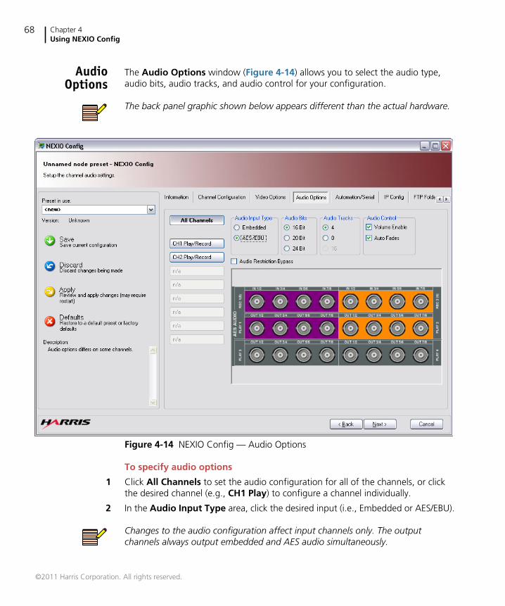
Chapter 4Using NEXIO Config
68
AudioOptions
The Audio Options window (Figure 4-14) allows you to select the audio type,audio bits, audio tracks, and audio control for your configuration.
The back panel graphic shown below appears different than the actual hardware.
Figure 4-14 NEXIO Config — Audio Options
To specify audio options
1 Click All Channels to set the audio configuration for all of the channels, or clickthe desired channel (e.g., CH1 Play) to configure a channel individually.
2 In the Audio Input Type area, click the desired input (i.e., Embedded or AES/EBU).
Changes to the audio configuration affect input channels only. The outputchannels always output embedded and AES audio simultaneously.
©2011 Harris Corporation. All rights reserved.
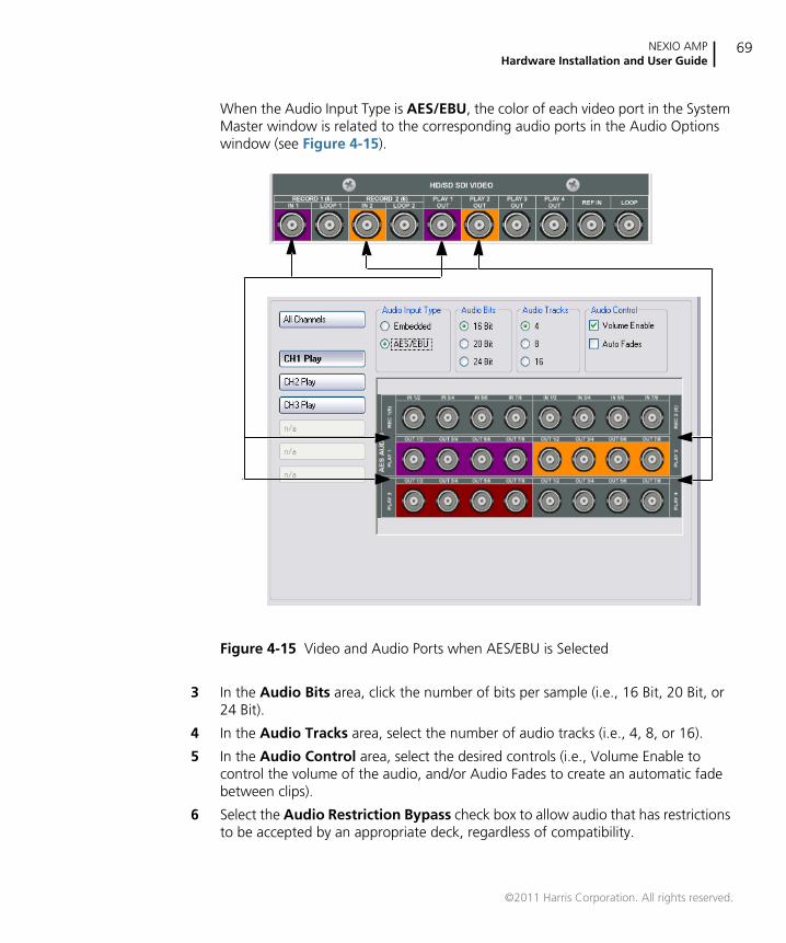
NEXIO AMPHardware Installation and User Guide
69
When the Audio Input Type is AES/EBU, the color of each video port in the SystemMaster window is related to the corresponding audio ports in the Audio Optionswindow (see Figure 4-15).
Figure 4-15 Video and Audio Ports when AES/EBU is Selected
3 In the Audio Bits area, click the number of bits per sample (i.e., 16 Bit, 20 Bit, or24 Bit).
4 In the Audio Tracks area, select the number of audio tracks (i.e., 4, 8, or 16).
5 In the Audio Control area, select the desired controls (i.e., Volume Enable tocontrol the volume of the audio, and/or Audio Fades to create an automatic fadebetween clips).
6 Select the Audio Restriction Bypass check box to allow audio that has restrictionsto be accepted by an appropriate deck, regardless of compatibility.
©2011 Harris Corporation. All rights reserved.
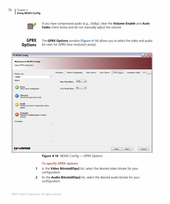
Chapter 4Using NEXIO Config
70
If you have compressed audio (e.g., Dolby), clear the Volume Enable and AutoFades check boxes and do not manually adjust the volume.
GPRXOptions
The GPRX Options window (Figure 4-14) allows you to select the video and audiobit rates for GPRX (low resolution proxy).
Figure 4-16 NEXIO Config — GPRX Options
To specify GPRX options
1 In the Video Bitrate(Khps) list, select the desired video bitrate for yourconfiguration.
2 IIn the Audio Bitrate(Khps) list, select the desired audio bitrate for yourconfiguration.
©2011 Harris Corporation. All rights reserved.
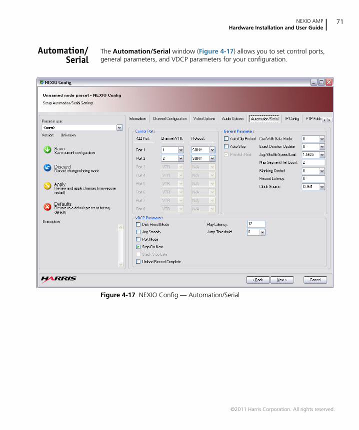
NEXIO AMPHardware Installation and User Guide
71
Automation/Serial
The Automation/Serial window (Figure 4-17) allows you to set control ports,general parameters, and VDCP parameters for your configuration.
Figure 4-17 NEXIO Config — Automation/Serial
©2011 Harris Corporation. All rights reserved.
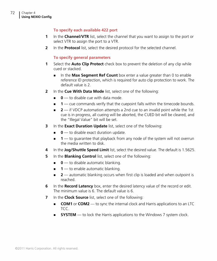
Chapter 4Using NEXIO Config
72
To specify each available 422 port
1 In the Channel/VTR list, select the channel that you want to assign to the port orselect VTR to assign the port to a VTR.
2 In the Protocol list, select the desired protocol for the selected channel.
To specify general parameters
1 Select the Auto Clip Protect check box to prevent the deletion of any clip whilecued or stacked.
In the Max Segment Ref Count box enter a value greater than 0 to enablereference ID protection, which is required for auto clip protection to work. Thedefault value is 2.
2 In the Cue With Data Mode list, select one of the following:
0 — to disable cue with data mode.
1 — cue commands verify that the cuepoint falls within the timecode bounds.
2 — if VDCP automation attempts a 2nd cue to an invalid point while the 1stcue is in progress, all cueing will be aborted, the CUED bit will be cleared, andthe “Illegal Value” bit will be set.
3 In the Exact Duration Update list, select one of the following:
0 — to disable exact duration update.
1 — to guarantee that playback from any node of the system will not overrunthe media written to disk.
4 In the Jog/Shuttle Speed Limit list, select the desired value. The default is 1.5625.
5 In the Blanking Control list, select one of the following:
0 — to disable automatic blanking.
1 — to enable automatic blanking.
2 — automatic blanking occurs when first clip is loaded and when outpoint isreached.
6 In the Record Latency box, enter the desired latency value of the record or edit.The minimum value is 6. The default value is 6.
7 In the Clock Source list, select one of the following:
COM1 or COM2 — to sync the internal clock and Harris applications to an LTCTCC.
SYSTEM — to lock the Harris applications to the Windows 7 system clock.
©2011 Harris Corporation. All rights reserved.
NEXIO AMPHardware Installation and User Guide
73
To specify VDCP parameters
1 Select the Disk Preroll Mode check box to enable disk preroll. The amount of thepreroll specified by the VDCP controller is added to any existing timecode offsetsestablished for the channel.
2 Select the Jog Smooth check box to enable jog smooth. If the jump threshold isexceeded then VDCP Jog command performs a jump without a scrub, otherwise itperforms a smooth jog with scrub.
In the Jump Threshold list, select one of the following:
0 — to translate to CX.01/CX.02. This is the default.
1 — to translate to C1.00/C4.00.
3 Select the Port Mode check box to enable port mode. This enables VDCPcontrollers to send record commands to a play port and play commands to a recordport.
4 Select the Stop On Next check box to enable stop on next. During stacked(back-to-back ID) playout, the play channel will stop when it reaches the end of thecurrent ID.
5 Select the Unload Record Complete check box to enable automaticrecord-channel unloading of completed recordings.
6 In the Play Latency list, enter the field value that you want between the receipt ofa play-command and the time the first frame of video plays. The minimum valueis 12.
Stack Stop Late is not an available option.
©2011 Harris Corporation. All rights reserved.
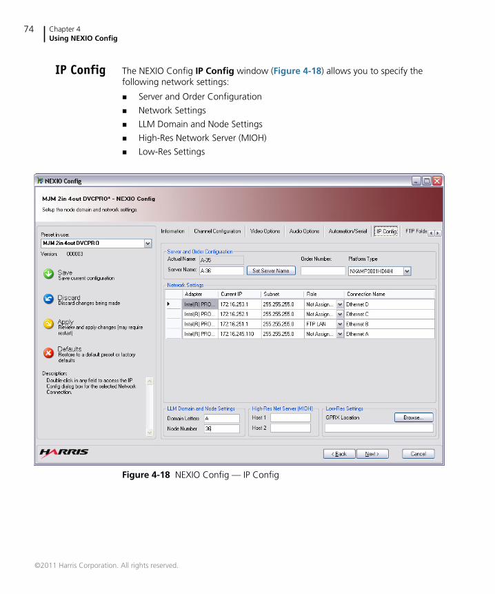
Chapter 4Using NEXIO Config
74
IP Config The NEXIO Config IP Config window (Figure 4-18) allows you to specify thefollowing network settings:
Server and Order Configuration
Network Settings
LLM Domain and Node Settings
High-Res Network Server (MIOH)
Low-Res Settings
Figure 4-18 NEXIO Config — IP Config
©2011 Harris Corporation. All rights reserved.
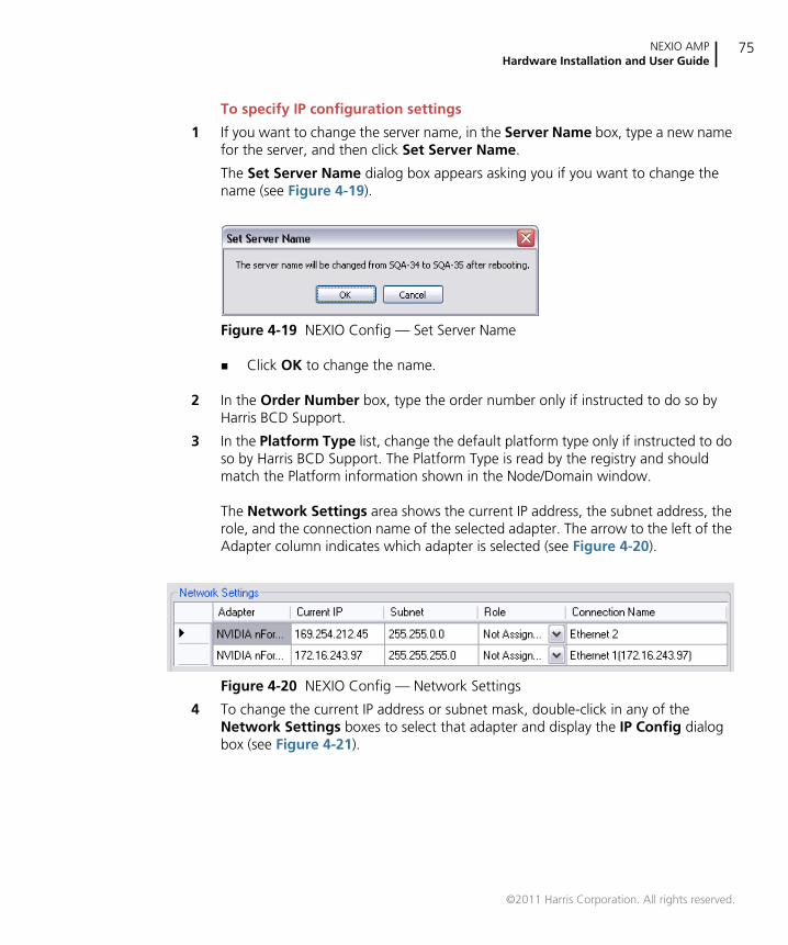
NEXIO AMPHardware Installation and User Guide
75
To specify IP configuration settings
1 If you want to change the server name, in the Server Name box, type a new namefor the server, and then click Set Server Name.
The Set Server Name dialog box appears asking you if you want to change thename (see Figure 4-19).
Figure 4-19 NEXIO Config — Set Server Name
Click OK to change the name.
2 In the Order Number box, type the order number only if instructed to do so byHarris BCD Support.
3 In the Platform Type list, change the default platform type only if instructed to doso by Harris BCD Support. The Platform Type is read by the registry and shouldmatch the Platform information shown in the Node/Domain window.
The Network Settings area shows the current IP address, the subnet address, therole, and the connection name of the selected adapter. The arrow to the left of theAdapter column indicates which adapter is selected (see Figure 4-20).
Figure 4-20 NEXIO Config — Network Settings
4 To change the current IP address or subnet mask, double-click in any of theNetwork Settings boxes to select that adapter and display the IP Config dialogbox (see Figure 4-21).
©2011 Harris Corporation. All rights reserved.
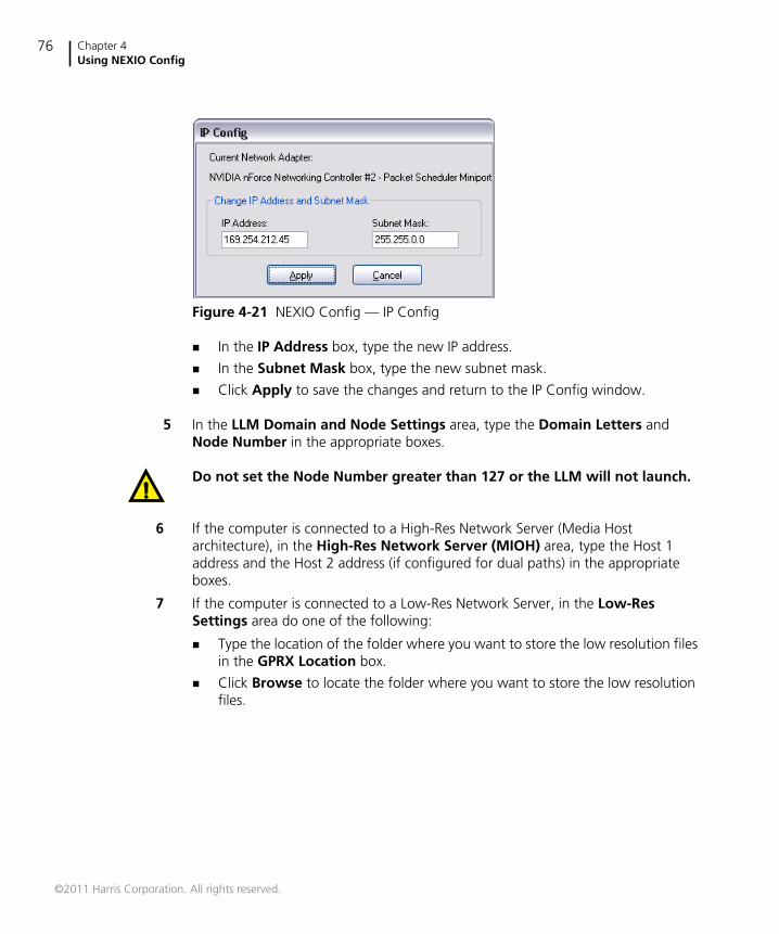
Chapter 4Using NEXIO Config
76
Figure 4-21 NEXIO Config — IP Config
In the IP Address box, type the new IP address.
In the Subnet Mask box, type the new subnet mask.
Click Apply to save the changes and return to the IP Config window.
5 In the LLM Domain and Node Settings area, type the Domain Letters andNode Number in the appropriate boxes.
Do not set the Node Number greater than 127 or the LLM will not launch.
6 If the computer is connected to a High-Res Network Server (Media Hostarchitecture), in the High-Res Network Server (MIOH) area, type the Host 1address and the Host 2 address (if configured for dual paths) in the appropriateboxes.
7 If the computer is connected to a Low-Res Network Server, in the Low-ResSettings area do one of the following:
Type the location of the folder where you want to store the low resolution filesin the GPRX Location box.
Click Browse to locate the folder where you want to store the low resolutionfiles.
©2011 Harris Corporation. All rights reserved.
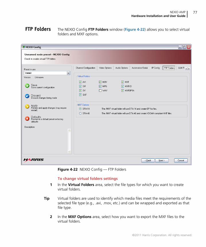
NEXIO AMPHardware Installation and User Guide
77
FTP Folders The NEXIO Config FTP Folders window (Figure 4-22) allows you to select virtualfolders and MXF options.
Figure 4-22 NEXIO Config — FTP Folders
To change virtual folders settings
1 In the Virtual Folders area, select the file types for which you want to createvirtual folders.
Tip Virtual folders are used to identify which media files meet the requirements of theselected file type (e.g., .avi, .mov, etc.) and can be wrapped and exported as thatfile type.
2 In the MXF Options area, select how you want to export the MXF files to thevirtual folders.
©2011 Harris Corporation. All rights reserved.
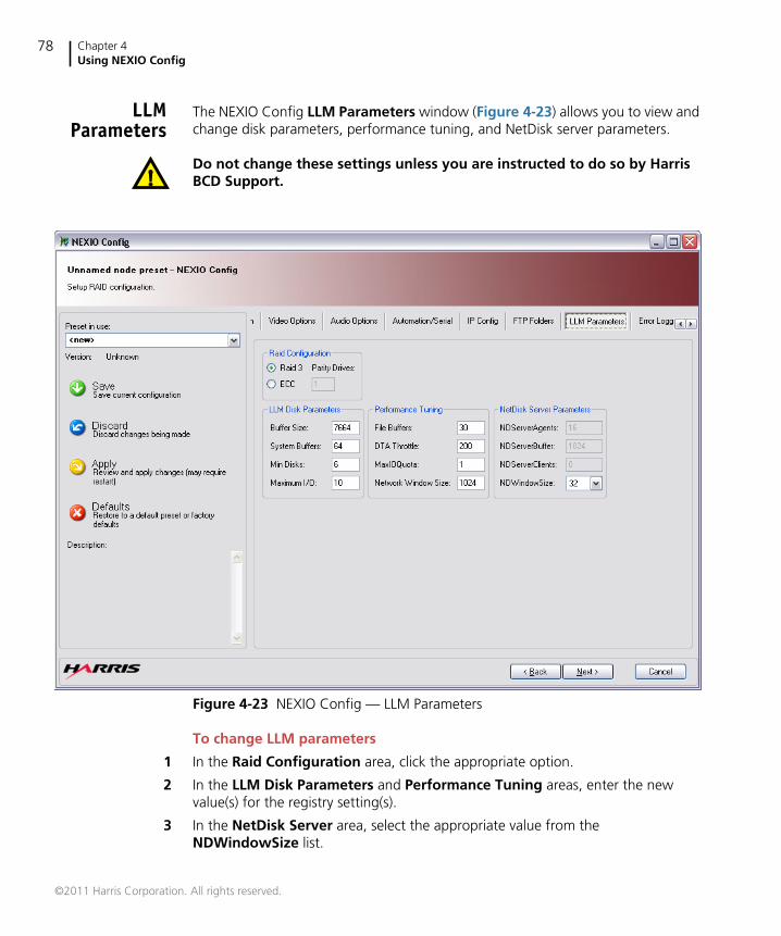
Chapter 4Using NEXIO Config
78
LLMParameters
The NEXIO Config LLM Parameters window (Figure 4-23) allows you to view andchange disk parameters, performance tuning, and NetDisk server parameters.
Do not change these settings unless you are instructed to do so by HarrisBCD Support.
Figure 4-23 NEXIO Config — LLM Parameters
To change LLM parameters
1 In the Raid Configuration area, click the appropriate option.
2 In the LLM Disk Parameters and Performance Tuning areas, enter the newvalue(s) for the registry setting(s).
3 In the NetDisk Server area, select the appropriate value from theNDWindowSize list.
©2011 Harris Corporation. All rights reserved.
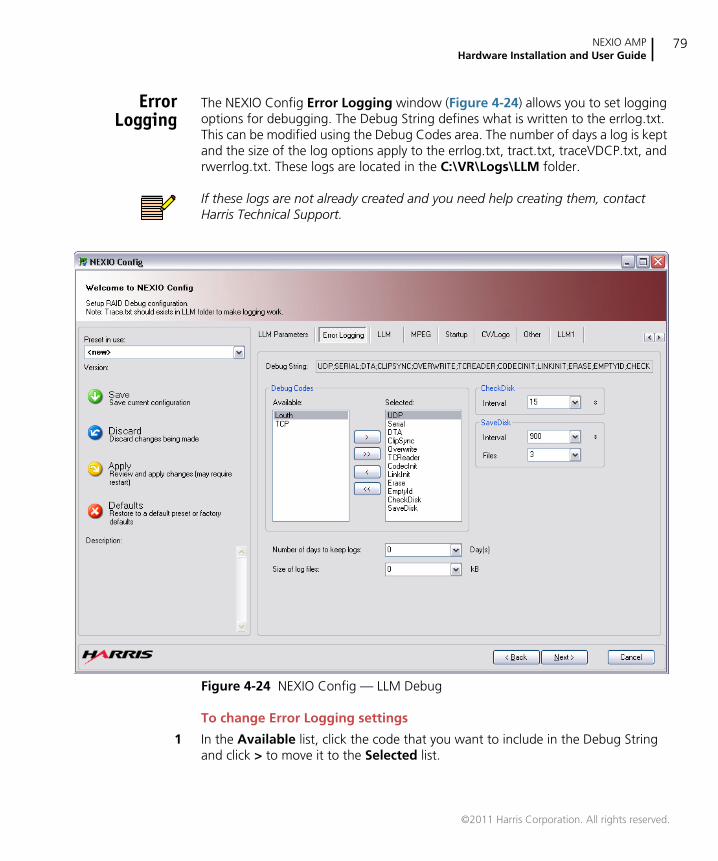
NEXIO AMPHardware Installation and User Guide
79
ErrorLogging
The NEXIO Config Error Logging window (Figure 4-24) allows you to set loggingoptions for debugging. The Debug String defines what is written to the errlog.txt.This can be modified using the Debug Codes area. The number of days a log is keptand the size of the log options apply to the errlog.txt, tract.txt, traceVDCP.txt, andrwerrlog.txt. These logs are located in the C:\VR\Logs\LLM folder.
If these logs are not already created and you need help creating them, contactHarris Technical Support.
Figure 4-24 NEXIO Config — LLM Debug
To change Error Logging settings
1 In the Available list, click the code that you want to include in the Debug Stringand click > to move it to the Selected list.
©2011 Harris Corporation. All rights reserved.
Chapter 4Using NEXIO Config
80
2 In the Selected list, click the code that you do not want to include in the DebugString and click < to move it back to the Available list.
Tip Click >> to move all of the codes to the Selected list. Click << to move all of thecodes to the Available list.
All codes that appear in the Debug String are included in the errlog.txt file.
3 In the Number of days to keep logs list, select the number of days that you wantthe logs to be saved.
Tip It is recommended that you select a minimum of 3 days to keep the logs so thatthey are saved through the weekend.
4 In the Size of log files list, select the maximum size in kB for the log files.
Tip It is recommended that you select at least 32000 kB for the log files.
5 In the CheckDisk area Interval list, select the desired time (in seconds) that youwant between LLM integrity checks (i.e., 15, 30, 60, 120, 340).
When CheckDisk is added to the Debug String, the CheckDisk area becomesavailable. The LLM performs an integrity check on the FAT table held in RAM at theselected time interval.
6 In the SaveDisk area:
In the Interval list select the desired time (in seconds) that you want betweenFAT snapshots (i.e., 900, 1800, 3600, 7200).
In the Files list select the desired number of files that you want to save in thesnapshot (i.e., 3, 4, 5, 6, 7, 8, 9, 10).
©2011 Harris Corporation. All rights reserved.

NEXIO AMPHardware Installation and User Guide
81
LLM The NEXIO Config LLM window (Figure 4-25) allows you to view and changevarious LLM registry settings. The name, type, data value, and status of eachparameter is shown.
Do not change these settings unless you are instructed to do so by HarrisBCD Support.
Figure 4-25 NEXIO Config — LLM
To change LLM registry settings
1 Double-click in the Data column of the registry setting that you want to change.
2 Type the new value for the registry setting. Changed values appear in bold.
©2011 Harris Corporation. All rights reserved.

Chapter 4Using NEXIO Config
82
The status of each parameter appears in the Status column. The status icons aredescribed below:
green check mark — indicates that the LLM parameter currently exists inthe registry.
green plus sign — indicates that the LLM parameter is absent in the registryand will be created.
red minus sign — indicates that the LLM parameter will be deleted.
purple question mark — indicates that the LLM parameter has no meaningin the current configuration.
yellow exclamation mark — indicates that the LLM parameter has beenmanually changed and does not meet the predefined rules.
©2011 Harris Corporation. All rights reserved.
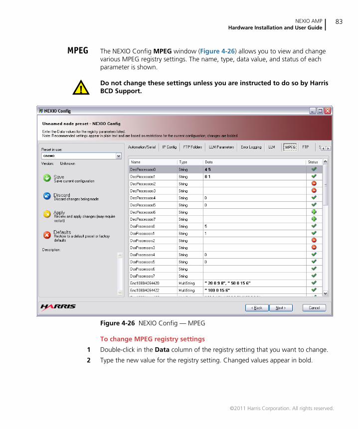
NEXIO AMPHardware Installation and User Guide
83
MPEG The NEXIO Config MPEG window (Figure 4-26) allows you to view and changevarious MPEG registry settings. The name, type, data value, and status of eachparameter is shown.
Do not change these settings unless you are instructed to do so by HarrisBCD Support.
Figure 4-26 NEXIO Config — MPEG
To change MPEG registry settings
1 Double-click in the Data column of the registry setting that you want to change.
2 Type the new value for the registry setting. Changed values appear in bold.
©2011 Harris Corporation. All rights reserved.
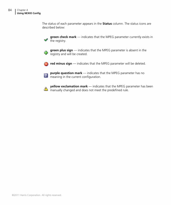
Chapter 4Using NEXIO Config
84
The status of each parameter appears in the Status column. The status icons aredescribed below:
green check mark — indicates that the MPEG parameter currently exists inthe registry.
green plus sign — indicates that the MPEG parameter is absent in theregistry and will be created.
red minus sign — indicates that the MPEG parameter will be deleted.
purple question mark — indicates that the MPEG parameter has nomeaning in the current configuration.
yellow exclamation mark — indicates that the MPEG parameter has beenmanually changed and does not meet the predefined rule.
©2011 Harris Corporation. All rights reserved.
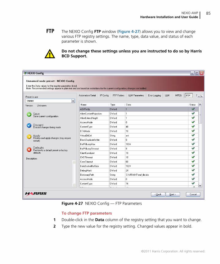
NEXIO AMPHardware Installation and User Guide
85
FTP The NEXIO Config FTP window (Figure 4-27) allows you to view and changevarious FTP registry settings. The name, type, data value, and status of eachparameter is shown.
Do not change these settings unless you are instructed to do so by HarrisBCD Support.
Figure 4-27 NEXIO Config — FTP Parameters
To change FTP parameters
1 Double-click in the Data column of the registry setting that you want to change.
2 Type the new value for the registry setting. Changed values appear in bold.
©2011 Harris Corporation. All rights reserved.

Chapter 4Using NEXIO Config
86
The status of each parameter appears in the Status column. The status icons aredescribed below:
green check mark — indicates that the LLM1 parameter currently exists inthe registry.
green plus sign — indicates that the LLM1 parameter is absent in theregistry and will be created.
red minus sign — indicates that the LLM1 parameter will be deleted.
purple question mark — indicates that the LLM1 parameter has nomeaning in the current configuration.
yellow exclamation mark — indicates that the LLM1 parameter has beenmanually changed and does not meet the predefined rules.
©2011 Harris Corporation. All rights reserved.
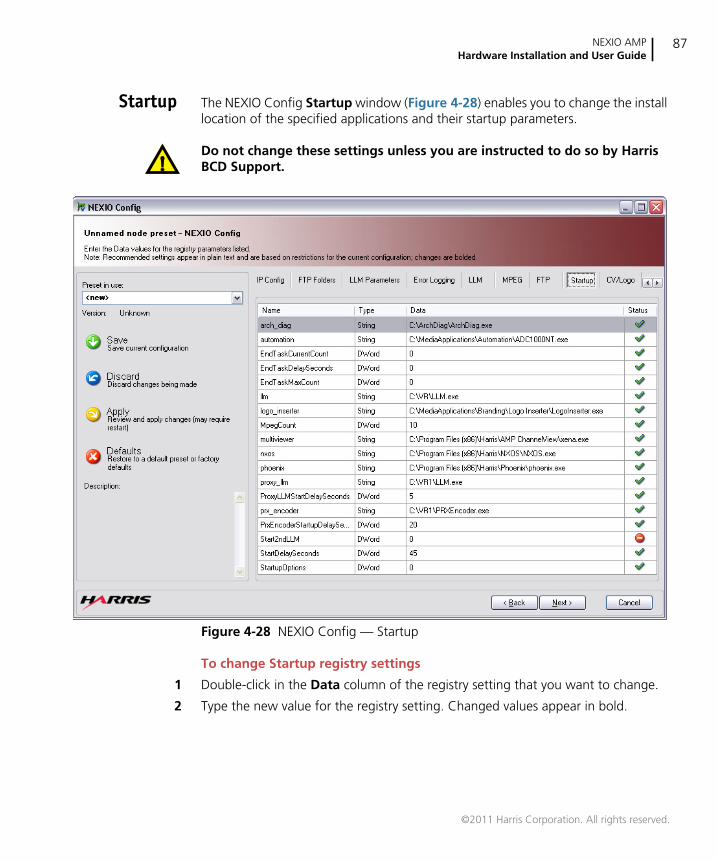
NEXIO AMPHardware Installation and User Guide
87
Startup The NEXIO Config Startup window (Figure 4-28) enables you to change the installlocation of the specified applications and their startup parameters.
Do not change these settings unless you are instructed to do so by HarrisBCD Support.
Figure 4-28 NEXIO Config — Startup
To change Startup registry settings
1 Double-click in the Data column of the registry setting that you want to change.
2 Type the new value for the registry setting. Changed values appear in bold.
©2011 Harris Corporation. All rights reserved.

Chapter 4Using NEXIO Config
88
The status of each parameter appears in the Status column. The status icons aredescribed below:
green check mark — indicates that the parameter currently exists in theregistry.
green plus sign — indicates that the parameter is absent in the registry andwill be created.
red minus sign — indicates that the parameter will be deleted.
purple question mark — indicates that the parameter has no meaning inthe current configuration.
yellow exclamation mark — indicates that the parameter has beenmanually changed and does not meet the predefined rules.
©2011 Harris Corporation. All rights reserved.

NEXIO AMPHardware Installation and User Guide
89
CV/Logo The NEXIO Config CV/Logo window (Figure 4-29) allows you to view and changevarious ChannelView and Logo registry settings. The name, type, data value, andstatus of each parameter is shown.
Do not change these settings unless you are instructed to do so by HarrisBCD Support.
Figure 4-29 NEXIO Config — CV/Logo
To change CV/Logo registry settings
1 Double-click in the Data column of the registry setting that you want to change.
2 Type the new value for the registry setting. Changed values appear in bold.
©2011 Harris Corporation. All rights reserved.

Chapter 4Using NEXIO Config
90
The status of each parameter appears in the Status column. The status icons aredescribed below:
green check mark — indicates that the parameter currently exists in theregistry.
green plus sign — indicates that the parameter is absent in the registry andwill be created.
red minus sign — indicates that the parameter will be deleted.
purple question mark — indicates that the parameter has no meaning inthe current configuration.
yellow exclamation mark — indicates that the parameter has beenmanually changed and does not meet the predefined rules.
©2011 Harris Corporation. All rights reserved.
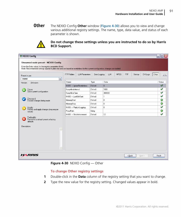
NEXIO AMPHardware Installation and User Guide
91
Other The NEXIO Config Other window (Figure 4-30) allows you to view and changevarious additional registry settings. The name, type, data value, and status of eachparameter is shown.
Do not change these settings unless you are instructed to do so by HarrisBCD Support.
Figure 4-30 NEXIO Config — Other
To change Other registry settings
1 Double-click in the Data column of the registry setting that you want to change.
2 Type the new value for the registry setting. Changed values appear in bold.
©2011 Harris Corporation. All rights reserved.
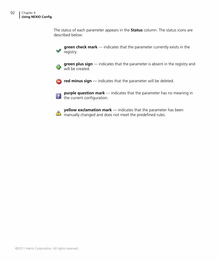
Chapter 4Using NEXIO Config
92
The status of each parameter appears in the Status column. The status icons aredescribed below:
green check mark — indicates that the parameter currently exists in theregistry.
green plus sign — indicates that the parameter is absent in the registry andwill be created.
red minus sign — indicates that the parameter will be deleted.
purple question mark — indicates that the parameter has no meaning inthe current configuration.
yellow exclamation mark — indicates that the parameter has beenmanually changed and does not meet the predefined rules.
©2011 Harris Corporation. All rights reserved.
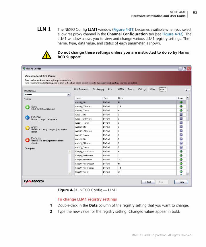
NEXIO AMPHardware Installation and User Guide
93
LLM 1 The NEXIO Config LLM1 window (Figure 4-31) becomes available when you selecta low res proxy channel in the Channel Configuration tab (see Figure 4-12). TheLLM1 window allows you to view and change various LLM1 registry settings. Thename, type, data value, and status of each parameter is shown.
Do not change these settings unless you are instructed to do so by HarrisBCD Support.
Figure 4-31 NEXIO Config — LLM1
To change LLM1 registry settings
1 Double-click in the Data column of the registry setting that you want to change.
2 Type the new value for the registry setting. Changed values appear in bold.
©2011 Harris Corporation. All rights reserved.

Chapter 4Using NEXIO Config
94
The status of each parameter appears in the Status column. The status icons aredescribed below:
green check mark — indicates that the LLM parameter currently exists inthe registry.
green plus sign — indicates that the LLM parameter is absent in the registryand will be created.
red minus sign — indicates that the LLM parameter will be deleted.
purple question mark — indicates that the LLM parameter has no meaningin the current configuration.
yellow exclamation mark — indicates that the LLM parameter has beenmanually changed and does not meet the predefined rules.
©2011 Harris Corporation. All rights reserved.
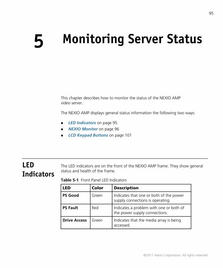
95
5 Monitoring Server Status
This chapter describes how to monitor the status of the NEXIO AMPvideo server.
The NEXIO AMP displays general status information the following two ways:
LED Indicators on page 95
NEXIO Monitor on page 96
LCD Keypad Buttons on page 101
LEDIndicators
The LED indicators are on the front of the NEXIO AMP frame. They show generalstatus and health of the frame.
Table 5-1 Front Panel LED Indicators
LED Color Description
PS Good Green Indicates that one or both of the powersupply connections is operating.
PS Fault Red Indicates a problem with one or both ofthe power supply connections.
Drive Access Green Indicates that the media array is beingaccessed.
©2011 Harris Corporation. All rights reserved.
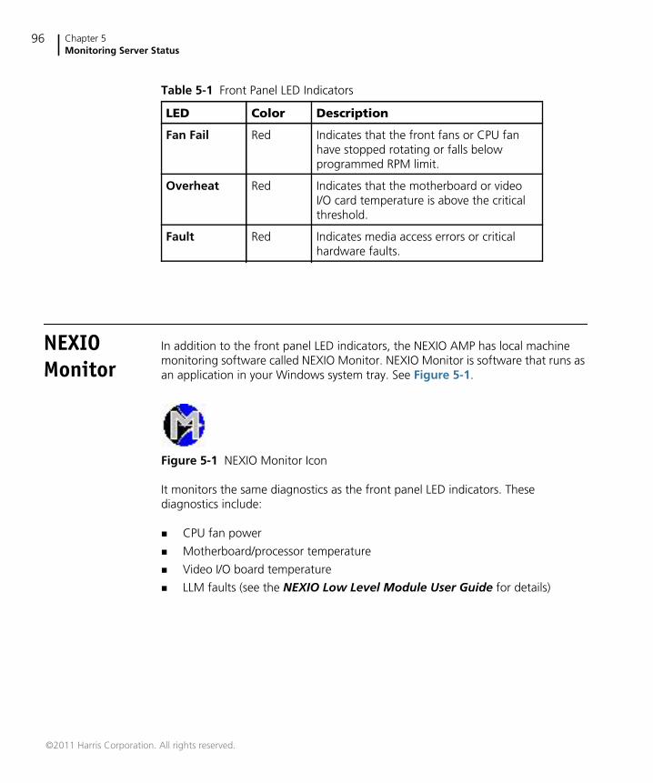
Chapter 5Monitoring Server Status
96
NEXIOMonitor
In addition to the front panel LED indicators, the NEXIO AMP has local machinemonitoring software called NEXIO Monitor. NEXIO Monitor is software that runs asan application in your Windows system tray. See Figure 5-1.
Figure 5-1 NEXIO Monitor Icon
It monitors the same diagnostics as the front panel LED indicators. Thesediagnostics include:
CPU fan power
Motherboard/processor temperature
Video I/O board temperature
LLM faults (see the NEXIO Low Level Module User Guide for details)
Fan Fail Red Indicates that the front fans or CPU fanhave stopped rotating or falls belowprogrammed RPM limit.
Overheat Red Indicates that the motherboard or videoI/O card temperature is above the criticalthreshold.
Fault Red Indicates media access errors or criticalhardware faults.
Table 5-1 Front Panel LED Indicators
LED Color Description
©2011 Harris Corporation. All rights reserved.
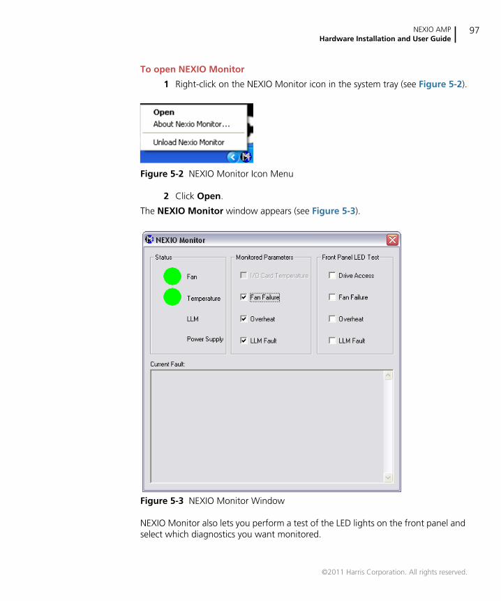
NEXIO AMPHardware Installation and User Guide
97
To open NEXIO Monitor
1 Right-click on the NEXIO Monitor icon in the system tray (see Figure 5-2).
Figure 5-2 NEXIO Monitor Icon Menu
2 Click Open.
The NEXIO Monitor window appears (see Figure 5-3).
Figure 5-3 NEXIO Monitor Window
NEXIO Monitor also lets you perform a test of the LED lights on the front panel andselect which diagnostics you want monitored.
©2011 Harris Corporation. All rights reserved.
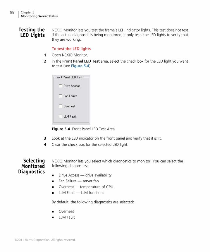
Chapter 5Monitoring Server Status
98
Testing theLED Lights
NEXIO Monitor lets you test the frame’s LED indicator lights. This test does not testif the actual diagnostic is being monitored; it only tests the LED lights to verify thatthey are working.
To test the LED lights
1 Open NEXIO Monitor.
2 In the Front Panel LED Test area, select the check box for the LED light you wantto test (see Figure 5-4).
Figure 5-4 Front Panel LED Test Area
3 Look at the LED indicator on the front panel and verify that it is lit.
4 Clear the check box for the selected LED light.
SelectingMonitored
Diagnostics
NEXIO Monitor lets you select which diagnostics to monitor. You can select thefollowing diagnostics:
Drive Access — drive availability
Fan Failure — server fan
Overheat — temperature of CPU
LLM Fault — LLM functions
By default, the following diagnostics are selected:
Overheat
LLM Fault
©2011 Harris Corporation. All rights reserved.
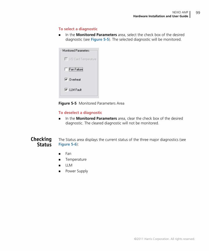
NEXIO AMPHardware Installation and User Guide
99
To select a diagnostic
In the Monitored Parameters area, select the check box of the desireddiagnostic (see Figure 5-5). The selected diagnostic will be monitored.
Figure 5-5 Monitored Parameters Area
To deselect a diagnostic
In the Monitored Parameters area, clear the check box of the desireddiagnostic. The cleared diagnostic will not be monitored.
CheckingStatus
The Status area displays the current status of the three major diagnostics (seeFigure 5-6):
Fan
Temperature
LLM
Power Supply
©2011 Harris Corporation. All rights reserved.
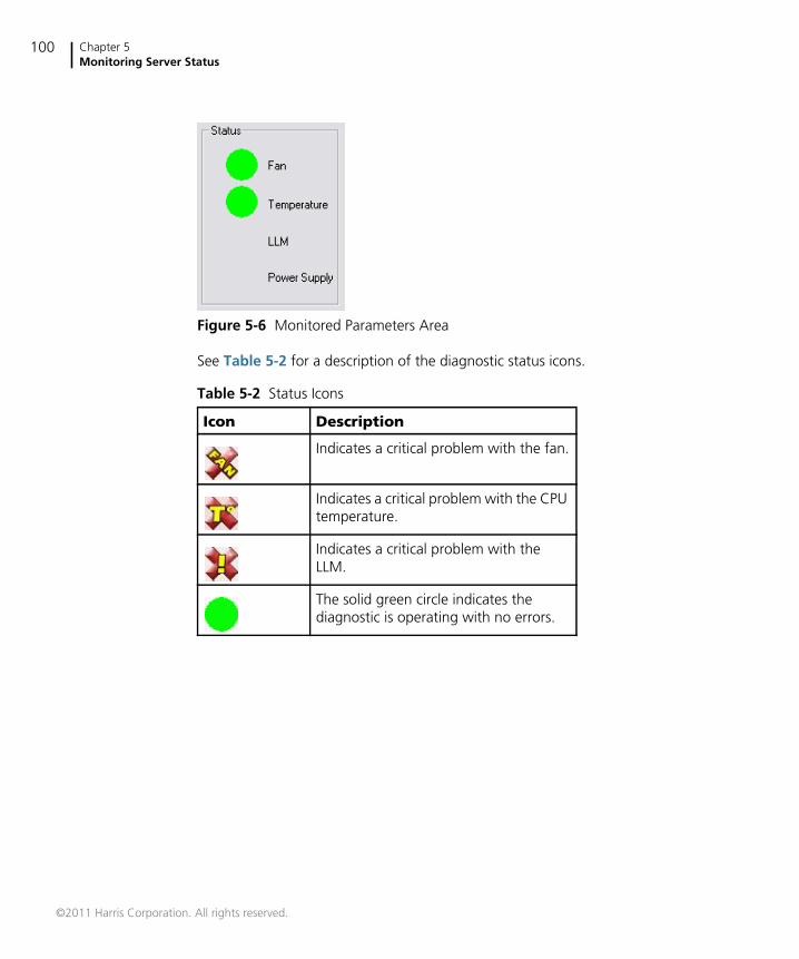
Chapter 5Monitoring Server Status
100
Figure 5-6 Monitored Parameters Area
See Table 5-2 for a description of the diagnostic status icons.
Table 5-2 Status Icons
Icon Description
Indicates a critical problem with the fan.
Indicates a critical problem with the CPUtemperature.
Indicates a critical problem with theLLM.
The solid green circle indicates thediagnostic is operating with no errors.
©2011 Harris Corporation. All rights reserved.
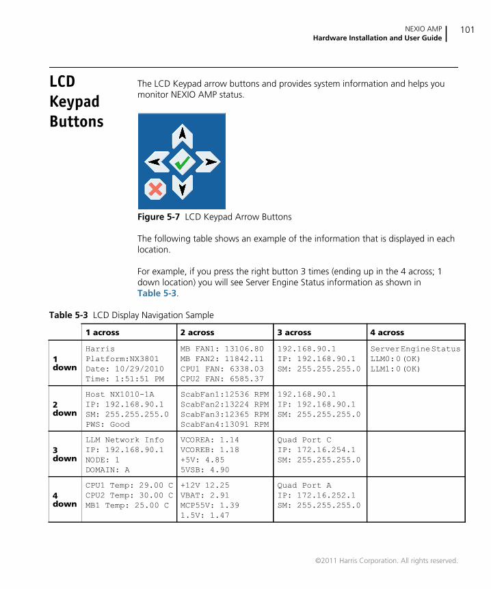
NEXIO AMPHardware Installation and User Guide
101
LCDKeypadButtons
The LCD Keypad arrow buttons and provides system information and helps youmonitor NEXIO AMP status.
Figure 5-7 LCD Keypad Arrow Buttons
The following table shows an example of the information that is displayed in eachlocation.
For example, if you press the right button 3 times (ending up in the 4 across; 1down location) you will see Server Engine Status information as shown inTable 5-3.
Table 5-3 LCD Display Navigation Sample
1 across 2 across 3 across 4 across
1down
Harris
Platform:NX3801
Date: 10/29/2010
Time: 1:51:51 PM
MB FAN1: 13106.80
MB FAN2: 11842.11
CPU1 FAN: 6338.03
CPU2 FAN: 6585.37
192.168.90.1
IP: 192.168.90.1
SM: 255.255.255.0
Server Engine Status
LLM0: 0 (OK)
LLM1: 0 (OK)
2down
Host NX1010-1A
IP: 192.168.90.1
SM: 255.255.255.0
PWS: Good
ScabFan1:12536 RPM
ScabFan2:13224 RPM
ScabFan3:12365 RPM
ScabFan4:13091 RPM
192.168.90.1
IP: 192.168.90.1
SM: 255.255.255.0
3down
LLM Network Info
IP: 192.168.90.1
NODE: 1
DOMAIN: A
VCOREA: 1.14
VCOREB: 1.18
+5V: 4.85
5VSB: 4.90
Quad Port C
IP: 172.16.254.1
SM: 255.255.255.0
4down
CPU1 Temp: 29.00 C
CPU2 Temp: 30.00 C
MB1 Temp: 25.00 C
+12V 12.25
VBAT: 2.91
MCP55V: 1.39
1.5V: 1.47
Quad Port A
IP: 172.16.252.1
SM: 255.255.255.0
©2011 Harris Corporation. All rights reserved.

Chapter 5Monitoring Server Status
102
©2011 Harris Corporation. All rights reserved.
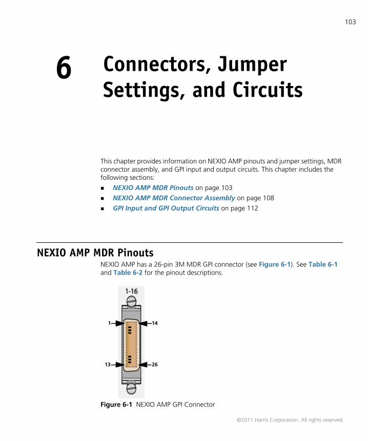
103
6 Connectors, JumperSettings, and Circuits
This chapter provides information on NEXIO AMP pinouts and jumper settings, MDRconnector assembly, and GPI input and output circuits. This chapter includes thefollowing sections:
NEXIO AMP MDR Pinouts on page 103
NEXIO AMP MDR Connector Assembly on page 108
GPI Input and GPI Output Circuits on page 112
NEXIO AMP MDR PinoutsNEXIO AMP has a 26-pin 3M MDR GPI connector (see Figure 6-1). See Table 6-1and Table 6-2 for the pinout descriptions.
Figure 6-1 NEXIO AMP GPI Connector
1
13
14
26
©2011 Harris Corporation. All rights reserved.
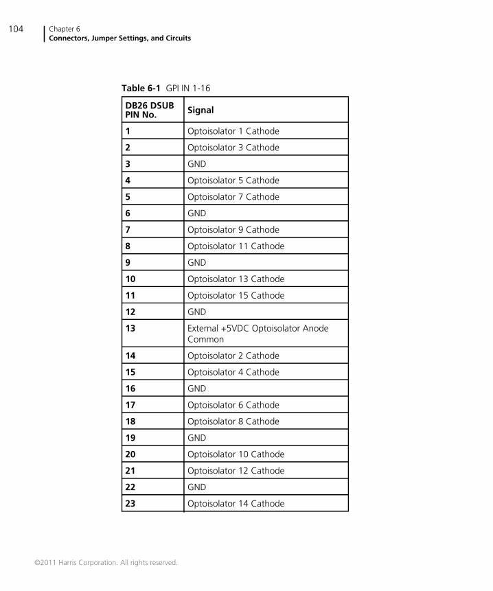
Chapter 6Connectors, Jumper Settings, and Circuits
104
Table 6-1 GPI IN 1-16
DB26 DSUBPIN No. Signal
1 Optoisolator 1 Cathode
2 Optoisolator 3 Cathode
3 GND
4 Optoisolator 5 Cathode
5 Optoisolator 7 Cathode
6 GND
7 Optoisolator 9 Cathode
8 Optoisolator 11 Cathode
9 GND
10 Optoisolator 13 Cathode
11 Optoisolator 15 Cathode
12 GND
13 External +5VDC Optoisolator AnodeCommon
14 Optoisolator 2 Cathode
15 Optoisolator 4 Cathode
16 GND
17 Optoisolator 6 Cathode
18 Optoisolator 8 Cathode
19 GND
20 Optoisolator 10 Cathode
21 Optoisolator 12 Cathode
22 GND
23 Optoisolator 14 Cathode
©2011 Harris Corporation. All rights reserved.
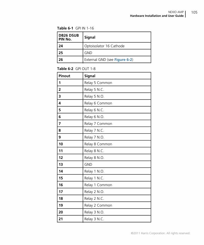
NEXIO AMPHardware Installation and User Guide
105
24 Optoisolator 16 Cathode
25 GND
26 External GND (see Figure 6-2)
Table 6-2 GPI OUT 1-8
Pinout Signal
1 Relay 5 Common
2 Relay 5 N.C.
3 Relay 5 N.O.
4 Relay 6 Common
5 Relay 6 N.C.
6 Relay 6 N.O.
7 Relay 7 Common
8 Relay 7 N.C.
9 Relay 7 N.O.
10 Relay 8 Common
11 Relay 8 N.C.
12 Relay 8 N.O.
13 GND
14 Relay 1 N.O.
15 Relay 1 N.C.
16 Relay 1 Common
17 Relay 2 N.O.
18 Relay 2 N.C.
19 Relay 2 Common
20 Relay 3 N.O.
21 Relay 3 N.C.
Table 6-1 GPI IN 1-16
DB26 DSUBPIN No. Signal
©2011 Harris Corporation. All rights reserved.
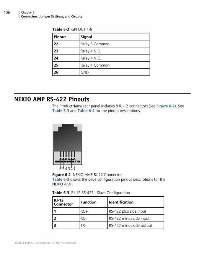
Chapter 6Connectors, Jumper Settings, and Circuits
106
NEXIO AMP RS-422 PinoutsThe ProductName rear panel includes 8 RJ-12 connectors (see Figure 6-2). SeeTable 6-3 and Table 6-4 for the pinout descriptions.
Figure 6-2 NEXIO AMP RJ-12 ConnectorTable 6-3 shows the slave configuration pinout descriptions for theNEXIO AMP.
22 Relay 3 Common
23 Relay 4 N.O.
24 Relay 4 N.C.
25 Relay 4 Common
26 GND
Table 6-2 GPI OUT 1-8
Pinout Signal
Table 6-3 RJ-12 RS-422 - Slave Configuration
RJ-12Connector Function Identification
1 RC+ RS-422 plus side input
2 RC- RS-422 minus side input
3 TX- RS-422 minus side output
23456 1
©2011 Harris Corporation. All rights reserved.
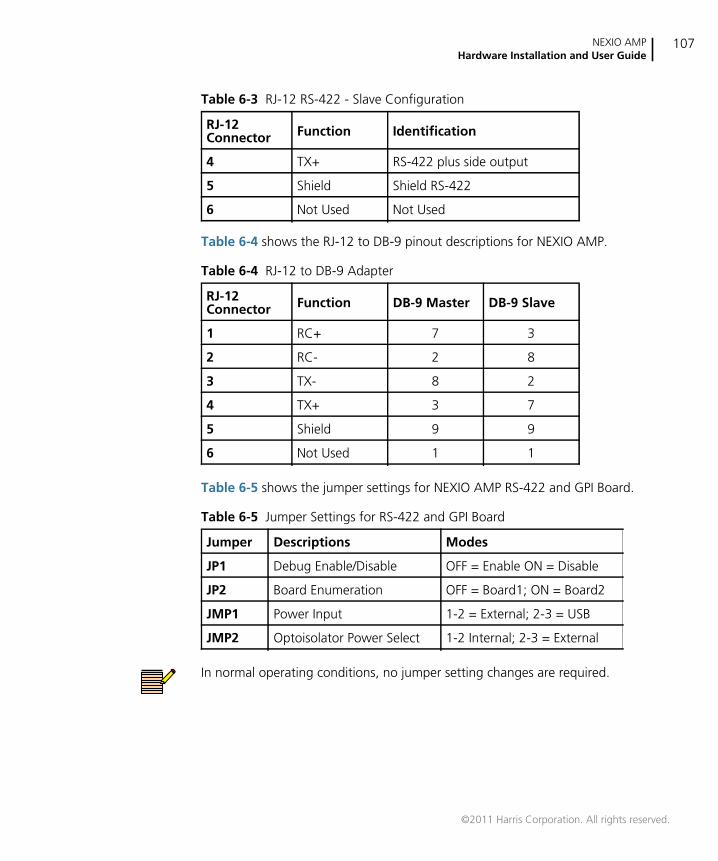
NEXIO AMPHardware Installation and User Guide
107
Table 6-4 shows the RJ-12 to DB-9 pinout descriptions for NEXIO AMP.
Table 6-5 shows the jumper settings for NEXIO AMP RS-422 and GPI Board.
In normal operating conditions, no jumper setting changes are required.
4 TX+ RS-422 plus side output
5 Shield Shield RS-422
6 Not Used Not Used
Table 6-4 RJ-12 to DB-9 Adapter
RJ-12Connector Function DB-9 Master DB-9 Slave
1 RC+ 7 3
2 RC- 2 8
3 TX- 8 2
4 TX+ 3 7
5 Shield 9 9
6 Not Used 1 1
Table 6-5 Jumper Settings for RS-422 and GPI Board
Jumper Descriptions Modes
JP1 Debug Enable/Disable OFF = Enable ON = Disable
JP2 Board Enumeration OFF = Board1; ON = Board2
JMP1 Power Input 1-2 = External; 2-3 = USB
JMP2 Optoisolator Power Select 1-2 Internal; 2-3 = External
Table 6-3 RJ-12 RS-422 - Slave Configuration
RJ-12Connector Function Identification
©2011 Harris Corporation. All rights reserved.
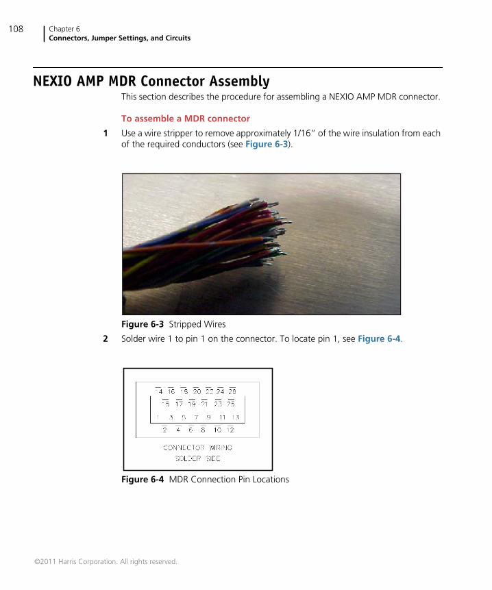
Chapter 6Connectors, Jumper Settings, and Circuits
108
NEXIO AMP MDR Connector AssemblyThis section describes the procedure for assembling a NEXIO AMP MDR connector.
To assemble a MDR connector
1 Use a wire stripper to remove approximately 1/16” of the wire insulation from eachof the required conductors (see Figure 6-3).
Figure 6-3 Stripped Wires
2 Solder wire 1 to pin 1 on the connector. To locate pin 1, see Figure 6-4.
Figure 6-4 MDR Connection Pin Locations
©2011 Harris Corporation. All rights reserved.
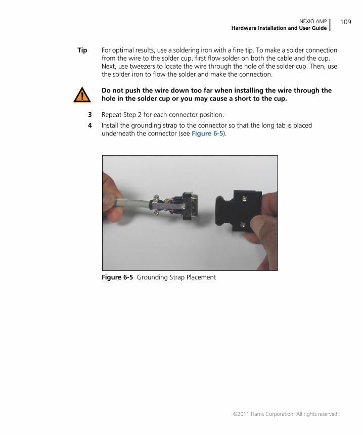
NEXIO AMPHardware Installation and User Guide
109
Tip For optimal results, use a soldering iron with a fine tip. To make a solder connectionfrom the wire to the solder cup, first flow solder on both the cable and the cup.Next, use tweezers to locate the wire through the hole of the solder cup. Then, usethe solder iron to flow the solder and make the connection.
Do not push the wire down too far when installing the wire through thehole in the solder cup or you may cause a short to the cup.
3 Repeat Step 2 for each connector position.
4 Install the grounding strap to the connector so that the long tab is placedunderneath the connector (see Figure 6-5).
Figure 6-5 Grounding Strap Placement
©2011 Harris Corporation. All rights reserved.
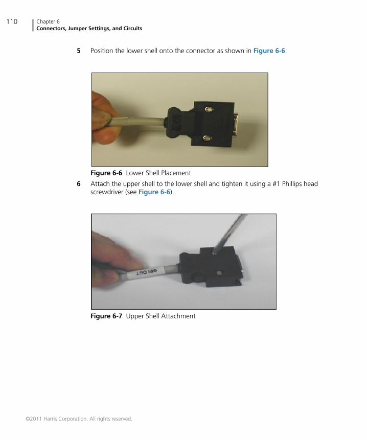
Chapter 6Connectors, Jumper Settings, and Circuits
110
5 Position the lower shell onto the connector as shown in Figure 6-6.
Figure 6-6 Lower Shell Placement
6 Attach the upper shell to the lower shell and tighten it using a #1 Phillips headscrewdriver (see Figure 6-6).
Figure 6-7 Upper Shell Attachment
©2011 Harris Corporation. All rights reserved.
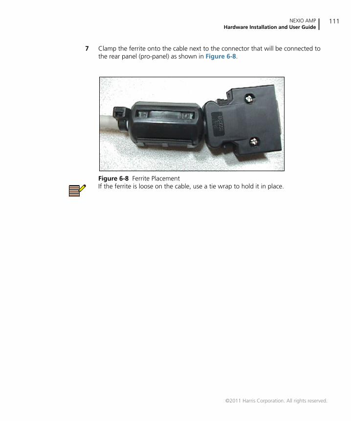
NEXIO AMPHardware Installation and User Guide
111
7 Clamp the ferrite onto the cable next to the connector that will be connected tothe rear panel (pro-panel) as shown in Figure 6-8.
Figure 6-8 Ferrite PlacementIf the ferrite is loose on the cable, use a tie wrap to hold it in place.
©2011 Harris Corporation. All rights reserved.
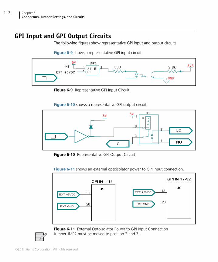
Chapter 6Connectors, Jumper Settings, and Circuits
112
GPI Input and GPI Output CircuitsThe following figures show representative GPI input and output circuits.
Figure 6-9 shows a representative GPI input circuit.
Figure 6-9 Representative GPI Input Circuit
Figure 6-10 shows a representative GPI output circuit.
Figure 6-10 Representative GPI Output Circuit
Figure 6-11 shows an external optoisolator power to GPI input connection.
Figure 6-11 External Optoisolator Power to GPI Input ConnectionJumper JMP2 must be moved to position 2 and 3.
©2011 Harris Corporation. All rights reserved.
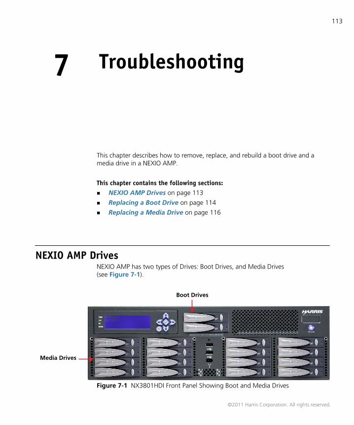
113
7 Troubleshooting
This chapter describes how to remove, replace, and rebuild a boot drive and amedia drive in a NEXIO AMP.
This chapter contains the following sections: NEXIO AMP Drives on page 113
Replacing a Boot Drive on page 114
Replacing a Media Drive on page 116
NEXIO AMP DrivesNEXIO AMP has two types of Drives: Boot Drives, and Media Drives(see Figure 7-1).
Figure 7-1 NX3801HDI Front Panel Showing Boot and Media Drives
Media Drives
Boot Drives
©2011 Harris Corporation. All rights reserved.
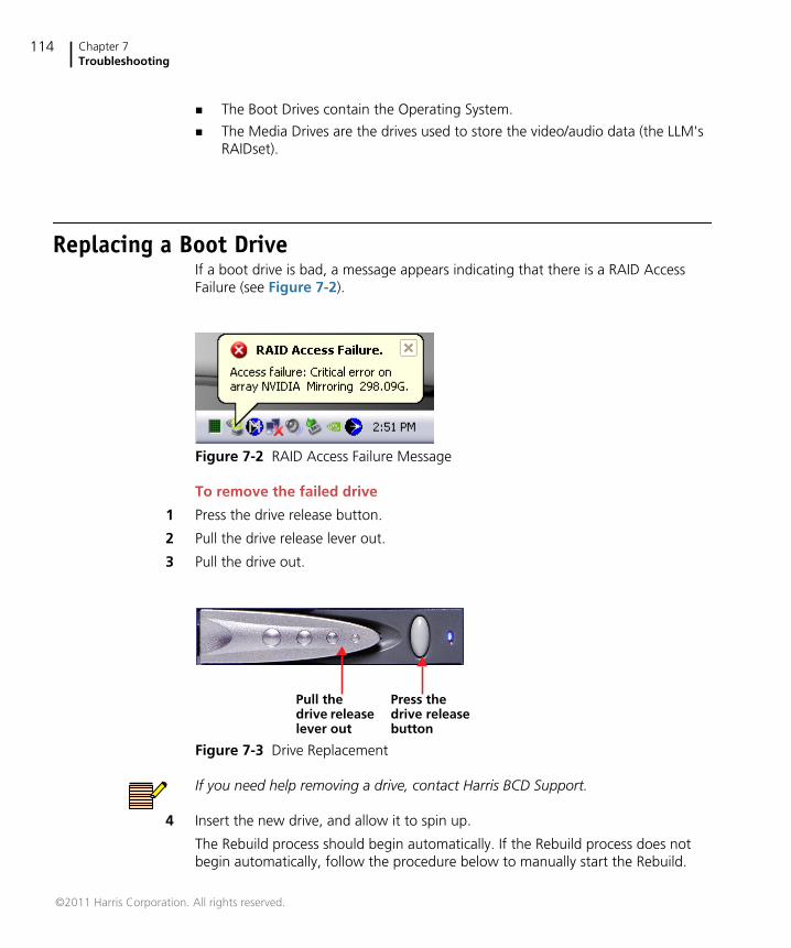
Chapter 7Troubleshooting
114
The Boot Drives contain the Operating System.
The Media Drives are the drives used to store the video/audio data (the LLM'sRAIDset).
Replacing a Boot DriveIf a boot drive is bad, a message appears indicating that there is a RAID AccessFailure (see Figure 7-2).
Figure 7-2 RAID Access Failure Message
To remove the failed drive
1 Press the drive release button.
2 Pull the drive release lever out.
3 Pull the drive out.
Figure 7-3 Drive Replacement
If you need help removing a drive, contact Harris BCD Support.
4 Insert the new drive, and allow it to spin up.
The Rebuild process should begin automatically. If the Rebuild process does notbegin automatically, follow the procedure below to manually start the Rebuild.
Press thedrive releasebutton
Pull thedrive releaselever out
©2011 Harris Corporation. All rights reserved.
NEXIO AMPHardware Installation and User Guide
115
To manually start the Rebuild
5 During the system reboot (after the Memory Count appears), press F10.
The MediaShield BIOS Array List appears.
6 Press Enter.
The NVIDIA Mirror RAID Detail window appears showing the information for thenew drive.
7 Press the R (Rebuild) key.
The NVIDIA Mirror Select From Free Disk List appears.
8 Press the A (Add) key.
A message appears asking if you want to Rebuild the array.
9 Press Enter to accept the Rebuild.
A message appears indicating that all the data on the new (or added) disk will beoverwritten, and asks you if you want to continue.
10 Press the Y (Yes) key.
The MediaShield BIOS Array List reappears. The status indicates “Rebuild”.
11 Press Ctrl X (Exit) to exit and reboot the system.
The Rebuild processes in the background. A message appears when the Rebuild iscomplete.
©2011 Harris Corporation. All rights reserved.
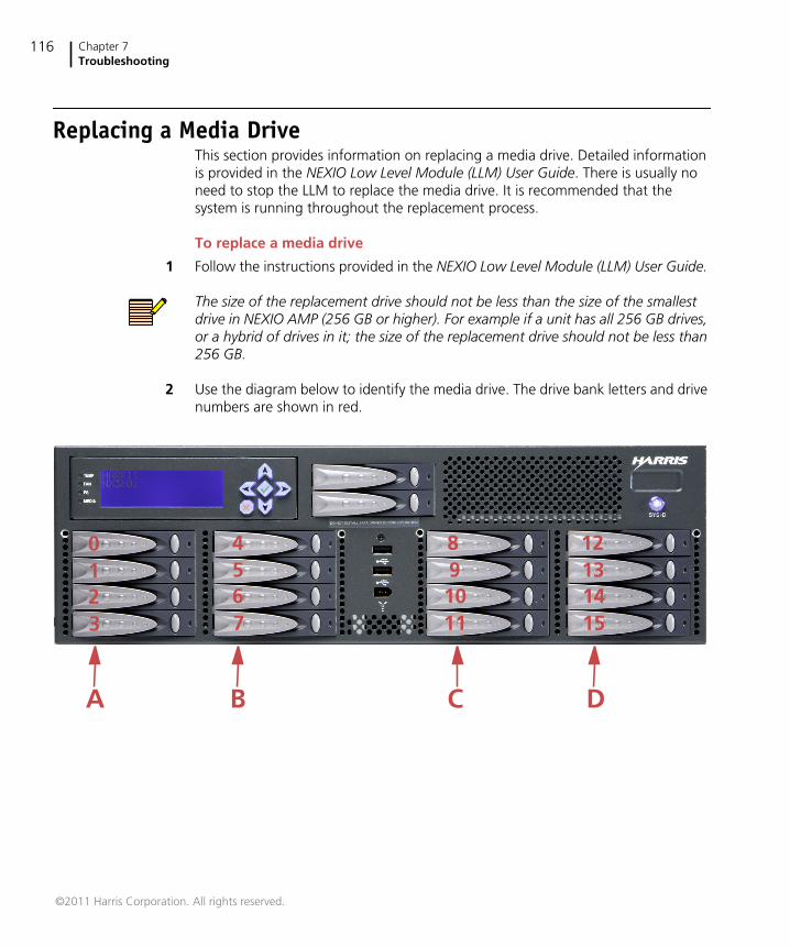
Chapter 7Troubleshooting
116
Replacing a Media DriveThis section provides information on replacing a media drive. Detailed informationis provided in the NEXIO Low Level Module (LLM) User Guide. There is usually noneed to stop the LLM to replace the media drive. It is recommended that thesystem is running throughout the replacement process.
To replace a media drive
1 Follow the instructions provided in the NEXIO Low Level Module (LLM) User Guide.
The size of the replacement drive should not be less than the size of the smallestdrive in NEXIO AMP (256 GB or higher). For example if a unit has all 256 GB drives,or a hybrid of drives in it; the size of the replacement drive should not be less than256 GB.
2 Use the diagram below to identify the media drive. The drive bank letters and drivenumbers are shown in red.
3210
111098
7654
15141312
A B C D
©2011 Harris Corporation. All rights reserved.
117
Index
AAES/EBU 68, 69AES/EBU audio 30analog reference 29anamorphic 65, 66ARC 13aspect ratio 15aspect ratio conversion 13audio configuration 68audio input 68audio options 68, 71audio ports 30audio specifications 16
Bbit rate (Mbps) 67
Ccenter cut 66changing
video routing, audio routing 40changing configuration templates 55channel configuration 65checking frame status 99closed captioning 64COM Ports 34compressed audio 16configuration templates 55
changing 55discarding 55saving 55
control specifications 21customer support 6
Ddiscarding configuration templates 55documents
purchasing 5Dolby E 14Drive Access LED 95
EEthernet configuration
Ethernet 1 32
FFan Fail 95, 96Fault LED 96features 62finding information 2firmware information 61frame dimensions 21front panel
LED indicators 35, 95
GGOP 67GPI
input 33output 33
Index118
pinouts 106, 107
Hhardware information 61high-res network server (MIOH) 74house time clock 29
Iidentification 61inserting timecode 66intended audience 1
Kkey features 12
LLCD keypad 36LCD user interface 101LED indicators 35, 95
Drive Access 95Fan Fail 95, 96Fault 96Overheat 96PS Fault 95PS Good 95
legacy timecode display 67letter box 66license
SLK 55LLM domain and node settings 74LOOP 29low-res network server (PRXH) 74
Mmanuals
purchasing 5middle cut 65, 66MIOH 74monitoring diagnostics 98
Nnetwork settings 75
NEXIO Config windowsAudio Options 68, 70, 71IP Config 74LLM 81, 93LLM Debug 79LLM Parameters 77, 78, 85MPEG 83Node/Domain 61Other 91System Master 62Video Options 63
NEXIO Monitorabout 96open 97selecting diagnostics 98status icons 99testing lights 98
node information 61
OOverheat LED 96
Ppillar box 65, 66pinouts 106, 107platform information 61play format and ARC 65ports
COM 34keyboard 30serial 31USB 30
power off 36power on 36protocols 21PRXH 74PS Fault LED 95PS Good LED 95purchasing documents 5
RRAID 20redundancy 20REF IN 29reference 29
NEXIO AMPHardware Installation and User Guide
119
reference input 29reset 36reset system 36resolution 65
Ssaving configuration templates 55selecting diagnostics 98server and order configuration 74server name
changing 75SLK 55software information 61software license key 55specifications
audio 16GPI 20physical 21RAID 20storage 19supported formats 21video 15video compression 16
starting NEXIO Config 54storage 19support 6system configuration 14system features 62
Ttechnical support 6television formats 21templates
changing 55discarding 55saving 55
testing LED lights 98timecode connection 20Transfer Manager 14tri-level sync 29
UUSB 30user guides
purchasing 5
VVBI 64video compression 16video options 63video ports 29video specifications 15video standard 64
Wwriting conventions 3

Index120


Broadcast Communications 4393 Digital Way | Mason, OH USA 45040 | Tel: 1 (513) 459 3400
www.broadcast.harris.com
Copyright© 2011 Harris Corporation P/N 175-100257-00 REV A
Harris is a registered trademark of Harris Corporation. Trademarks and tradenames are the property of their respective companies.


