Embed Size (px)
Citation preview
GSM Association Non-confidential
Official Document NG.126 – Cloud Infrastructure Model
V2.0 Page 1 of 173
Cloud Infrastructure Reference Model
Version 2.0
26 October 2021
This is a Non-binding Permanent Reference Document of the GSMA
Security Classification: Non-confidential
Access to and distribution of this document is restricted to the persons permitted by the security classification. This document is confidential to the
Association and is subject to copyright protection. This document is to be used only for the purposes for which it has been supplied and
information contained in it must not be disclosed or in any other way made available, in whole or in part, to persons other than those permitted
under the security classification without the prior written approval of the Association.
Copyright Notice
Copyright © 2021 GSM Association
Disclaimer
The GSM Association (“Association”) makes no representation, warranty or undertaking (express or implied) with respect to and does not accept
any responsibility for, and hereby disclaims liability for the accuracy or completeness or timeliness of the information contained in this document.
The information contained in this document may be subject to change without prior notice.
Antitrust Notice
The information contain herein is in full compliance with the GSM Association’s antitrust compliance policy.
CGSM Association Non-confidential
Official Document NG.126 – Cloud Infrastructure Model
V2.0 Page 1 of 173
Table of Contents
1 Introduction 1
1.1 Overview 1
1.2 Scope 3
1.3 Principles 4
1.4 Definitions/Terminology 4
1.5 Abbreviations 4
1.6 References 10
1.7 Conventions 13
2 Workload Requirements & Analysis 13
2.1 Workloads Collateral 14
2.2 Use cases 16
2.3 Analysis 20
2.4 Profiles, Profile Extensions & Flavours 21
2.4.1 Profiles (top-level partitions) 22
2.4.2 Profile Extensions (specialisations) 22
3 Modelling 25
3.1 Model 26
3.2 Virtual Infrastructure Layer 27
3.2.1 Virtual Resources 27
3.2.2 Virtual Infrastructure Manager 29
3.3 Hardware Infrastructure Layer 30
3.3.1 Hardware Infrastructure Resources 30
3.3.2 Hardware Infrastructure Manager 32
3.4 Left for future use 33
3.5 Network 33
3.5.1 Network Principles 34
3.5.2 Networking Layering and Concepts 34
3.5.3 Networking Reference Model 39
3.5.4 Deployment examples based on the Networking Reference Model 39
3.5.5 Service Function Chaining 42
3.5.6 Time Sensitive Networking 48
3.6 Storage 49
3.7 Sample reference model realization 53
3.8 Hardware Acceleration Abstraction 54
3.8.1 Types of Accelerators 54
3.8.2 Infrastructure and Application Level Acceleration 55
3.8.3 Workload Placement 56
3.8.4 CPU Instructions 57
3.8.5 Fixed Function Accelerators 57
3.8.6 Firmware-programmable Adapters 57
CGSM Association Non-confidential
Official Document NG.126 – Cloud Infrastructure Model
V2.0 Page 2 of 173
3.8.7 SmartNICs 58
3.8.8 Smart Switches 59
3.8.9 Decoupling Applications from Infrastructure and Platform with Hardware
Acceleration 60
4 Infrastructure Capabilities, Measurements and Catalogue 61
4.1 Capabilities and Performance Measurements 61
4.1.1 Exposed vs Internal 61
4.1.2 Exposed Infrastructure Capabilities 62
4.1.3 Exposed Infrastructure Performance Measurements 64
4.1.4 Internal Infrastructure Capabilities 65
4.1.5 Cloud Infrastructure Management Capabilities 66
4.1.6 Cloud Infrastructure Management Performance Measurements 67
4.2 Profiles and Workload Flavours 68
4.2.1 Profiles 70
4.2.2 Profiles Specifications & Capability Mapping 71
4.2.3 Profile Extensions 71
4.2.4 Workload Flavours and Other Capabilities Specifications 74
4.2.5 Virtual Network Interface Specifications 77
4.2.6 Storage Extensions 78
5 Feature set and Requirements from Infrastructure 78
5.1 Cloud Infrastructure Software profile description 79
5.1.1 Virtual Compute 80
5.1.2 Virtual Storage 81
5.1.3 Virtual Networking 82
5.1.4 Security 83
5.1.5 Platform Services 83
5.2 Cloud Infrastructure Software Profiles features and requirements 83
5.2.1 Virtual Compute 83
5.2.2 Virtual Storage 84
5.2.3 Virtual Networking 84
5.3 Cloud Infrastructure Hardware Profile description 85
5.4 Cloud Infrastructure Hardware Profiles features and requirements. 87
5.4.1 Compute Resources 87
5.4.2 Storage Configurations 88
5.4.3 Network Resources 88
6 External Interfaces 89
6.1 Introduction 89
6.2 Cloud Infrastructure APIs 90
6.2.1 Tenant Level APIs 91
6.2.2 Hardware Acceleration Interfaces 93
6.3 Intra-Cloud Infrastructure Interfaces 98
CGSM Association Non-confidential
Official Document NG.126 – Cloud Infrastructure Model
V2.0 Page 3 of 173
6.3.1 Hypervisor Hardware Interface 98
6.4 Enabler Services Interfaces 98
7 Security 98
7.1 Introduction 98
7.2 Potential attack vectors 99
7.3 Security Scope 99
7.3.1 In-scope and Out-of-Scope definition 99
7.3.2 High level security Requirements 99
7.3.3 Common security standards 100
7.4 Cloud Infrastructure Security 102
7.4.1 General Platform Security 102
7.4.2 Platform ‘back-end’ access security 104
7.4.3 Platform ‘front-end’ access security 104
7.4.4 Infrastructure as a Code security 104
7.5 Workload Security - Vendor Responsibility 105
7.5.1 Software Hardening 105
7.5.2 Port Protection 106
7.5.3 Software Code Quality and Security 106
7.5.4 Alerting and monitoring 106
7.5.5 Logging 106
7.5.6 NF images 106
7.5.7 Vulnerability Management 106
7.6 Workload Security - Cloud Infrastructure Operator Responsibility 107
7.6.1 Remote Attestation/openCIT 107
7.6.2 Workload Image Scanning / Signing 107
7.6.3 Networking Security Zoning 108
7.6.4 Volume Encryption 108
7.6.5 Root of Trust for Measurements (RTM) 108
7.6.6 Zero Trust Architecture (ZTA) 110
7.7 Open Source Software Security 110
7.8 Testing & certification 112
7.8.1 Testing demarcation points 112
7.8.2 Certification requirements 113
7.9 Consolidated Security Requirements 113
7.9.1 System Hardening 113
7.9.2 Platform and Access 114
7.9.3 Confidentiality and Integrity 116
7.9.4 Workload Security 117
7.9.5 Image Security 118
7.9.6 Security LCM 118
7.9.7 Monitoring and Security Audit 119
CGSM Association Non-confidential
Official Document NG.126 – Cloud Infrastructure Model
V2.0 Page 4 of 173
7.9.8 Open Source Software 121
7.9.9 IaaC - Secure Design and Architecture Stage Requirements 121
7.9.10 IaaC - Secure Code Stage Requirements 121
7.9.11 IaaC - Continuous Build, Integration and Testing Stage Requirements 122
7.9.12 IaaC - Continuous Delivery and Deployment Stage Requirements 123
7.9.13 IaaC - Runtime Defence and Monitoring Requirements 123
7.9.14 Compliance with Standards 124
7.10 Security References 125
8 Hybrid Multi-Cloud: Data Centre to Edge 126
8.1 Introduction 126
8.2 Hybrid Multi-Cloud Architecture 127
8.2.1 Characteristics of a Federated Cloud 128
8.2.2 Telco Cloud 128
8.2.3 Telco Operator Platform Conceptual Architecture 130
8.3 Telco Edge Cloud 132
8.3.1 Telco Edge Cloud: Deployment Environment Characteristics 132
8.3.2 Telco Edge Cloud: Infrastructure Characteristics 133
8.3.3 Telco Edge Cloud: Infrastructure Profiles 133
8.3.4 Telco Edge Cloud: Platform Services Deployment 134
8.3.5 Comparison of Deployment Topologies and Edge terms 135
9 Infrastructure Operations and Lifecycle Management 139
9.1 Introduction 139
9.2 Configuration and Lifecycle Management 139
9.3 Assurance 141
9.4 Capacity Management 142
9.5 Automation 142
9.5.1 Infrastructure LCM Automation 142
9.5.2 Software Onboarding Automation and CI/CD Requirements 143
9.5.3 Tenant Creation Automation 147
9.6 Telemetry and Observability 148
9.6.1 Why Observability 148
9.6.2 The Architecture 151
10 Challenges and Gaps 153
10.1 Introduction 153
10.2 Challenges 153
10.3 Gaps 153
10.3.1 Discovery 153
10.3.2 Support Load Balance of VNF/CNFs 154
10.3.3 Service Function Chain 154
10.3.4 Closed-loop automation 155
10.3.5 Acceleration Abstraction 155
CGSM Association Non-confidential
Official Document NG.126 – Cloud Infrastructure Model
V2.0 Page 5 of 173
Annex A Principles 156
A.1 Overall Principles 156
A.2 Requirements Principles 157
A.3 Architectural Principles 158
Annex B Reference Model Glossary 158
B.1 Terminology 158
B.2 Software Layer Terminology 158
B.3 Hardware Layer Terminology 161
B.4 Operational and Administrative Terminology 161
B.5 Container Related Terminology 162
B.6 OpenStack Related Terminology 163
B.7 Cloud Platform Abstraction Related Terminology: 164
B.8 Test Related Terminology 164
B.9 Other Referenced Terminology 166
Annex C Document Management 167
C.1 Document History 167
GSM Association Non-confidential
Official Document NG.126 - Cloud Infrastructure Model
V2.0 Page 1 of 173
1 Introduction
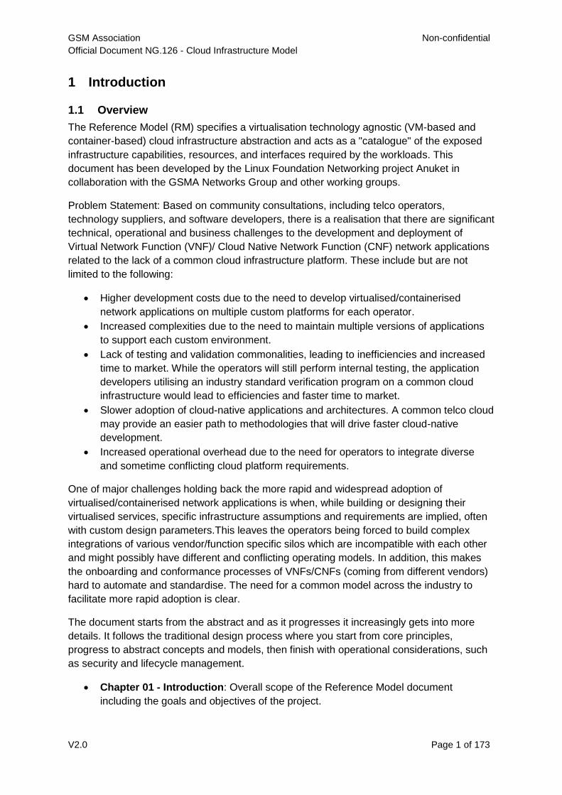
1.1 Overview
The Reference Model (RM) specifies a virtualisation technology agnostic (VM-based and
container-based) cloud infrastructure abstraction and acts as a "catalogue" of the exposed
infrastructure capabilities, resources, and interfaces required by the workloads. This
document has been developed by the Linux Foundation Networking project Anuket in
collaboration with the GSMA Networks Group and other working groups.
Problem Statement: Based on community consultations, including telco operators,
technology suppliers, and software developers, there is a realisation that there are significant
technical, operational and business challenges to the development and deployment of
Virtual Network Function (VNF)/ Cloud Native Network Function (CNF) network applications
related to the lack of a common cloud infrastructure platform. These include but are not
limited to the following:
Higher development costs due to the need to develop virtualised/containerised
network applications on multiple custom platforms for each operator.
Increased complexities due to the need to maintain multiple versions of applications
to support each custom environment.
Lack of testing and validation commonalities, leading to inefficiencies and increased
time to market. While the operators will still perform internal testing, the application
developers utilising an industry standard verification program on a common cloud
infrastructure would lead to efficiencies and faster time to market.
Slower adoption of cloud-native applications and architectures. A common telco cloud
may provide an easier path to methodologies that will drive faster cloud-native
development.
Increased operational overhead due to the need for operators to integrate diverse
and sometime conflicting cloud platform requirements.
One of major challenges holding back the more rapid and widespread adoption of
virtualised/containerised network applications is when, while building or designing their
virtualised services, specific infrastructure assumptions and requirements are implied, often
with custom design parameters.This leaves the operators being forced to build complex
integrations of various vendor/function specific silos which are incompatible with each other
and might possibly have different and conflicting operating models. In addition, this makes
the onboarding and conformance processes of VNFs/CNFs (coming from different vendors)
hard to automate and standardise. The need for a common model across the industry to
facilitate more rapid adoption is clear.
The document starts from the abstract and as it progresses it increasingly gets into more
details. It follows the traditional design process where you start from core principles,
progress to abstract concepts and models, then finish with operational considerations, such
as security and lifecycle management.
Chapter 01 - Introduction: Overall scope of the Reference Model document
including the goals and objectives of the project.
GSM Association Non-confidential
Official Document NG.126 - Cloud Infrastructure Model
V2.0 Page 2 of 173
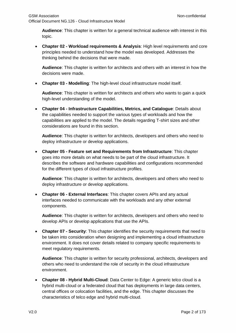
Audience: This chapter is written for a general technical audience with interest in this
topic.
Chapter 02 - Workload requirements & Analysis: High level requirements and core
principles needed to understand how the model was developed. Addresses the
thinking behind the decisions that were made.
Audience: This chapter is written for architects and others with an interest in how the
decisions were made.
Chapter 03 - Modelling: The high-level cloud infrastructure model itself.
Audience: This chapter is written for architects and others who wants to gain a quick
high-level understanding of the model.
Chapter 04 - Infrastructure Capabilities, Metrics, and Catalogue: Details about
the capabilities needed to support the various types of workloads and how the
capabilities are applied to the model. The details regarding T-shirt sizes and other
considerations are found in this section.
Audience: This chapter is written for architects, developers and others who need to
deploy infrastructure or develop applications.
Chapter 05 - Feature set and Requirements from Infrastructure: This chapter
goes into more details on what needs to be part of the cloud infrastructure. It
describes the software and hardware capabilities and configurations recommended
for the different types of cloud infrastructure profiles.
Audience: This chapter is written for architects, developers and others who need to
deploy infrastructure or develop applications.
Chapter 06 - External Interfaces: This chapter covers APIs and any actual
interfaces needed to communicate with the workloads and any other external
components.
Audience: This chapter is written for architects, developers and others who need to
develop APIs or develop applications that use the APIs.
Chapter 07 - Security: This chapter identifies the security requirements that need to
be taken into consideration when designing and implementing a cloud infrastructure
environment. It does not cover details related to company specific requirements to
meet regulatory requirements.
Audience: This chapter is written for security professional, architects, developers and
others who need to understand the role of security in the cloud infrastructure
environment.
Chapter 08 - Hybrid Multi-Cloud: Data Center to Edge: A generic telco cloud is a
hybrid multi-cloud or a federated cloud that has deployments in large data centers,
central offices or colocation facilities, and the edge. This chapter discusses the
characteristics of telco edge and hybrid multi-cloud.
GSM Association Non-confidential
Official Document NG.126 - Cloud Infrastructure Model
V2.0 Page 3 of 173
Audience: This chapter is written for a general technical audience with interest in this
topic.
Chapter 09 - Life Cycle Management: This chapter focuses on the operational
aspects of the cloud infrastructure. Discussions include deployment considerations,
on-going management, upgrades and other lifecycle concerns and requirements. It
does not cover details related to company specific operational requirements, nor does
it go into how the cloud infrastructure will interface with existing BSS/OSS systems.
Audience: This chapter is written for lifecycle managers, operational support teams
and others who need to support the infrastructure or the applications.
Chapter 10 - Challenges and Gaps: Opportunities for future developments as
technology changes over time.
Audience: This chapter is written for a general technical audience with interest in this
topic.
The next step after the development of the Reference Model is to take this general model,
purposely designed to be technology-independent, and apply it to a discrete number of
concrete and deployable Reference Architecture (RA) platforms. The intention is to choose
the Reference Architectures carefully so that the specific requirements for supporting Cloud
Infrastructure and Telecom specific applications are met through just a small set of
architectures.
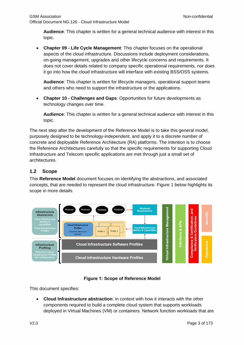
1.2 Scope
This Reference Model document focuses on identifying the abstractions, and associated
concepts, that are needed to represent the cloud infrastructure. Figure 1 below highlights its
scope in more details.
Figure 1: Scope of Reference Model
This document specifies:
Cloud Infrastructure abstraction: in context with how it interacts with the other
components required to build a complete cloud system that supports workloads
deployed in Virtual Machines (VM) or containers. Network function workloads that are
GSM Association Non-confidential
Official Document NG.126 - Cloud Infrastructure Model
V2.0 Page 4 of 173
deployed on virtual machines and containers are referred to as virtual network
functions (VNF) and containerised network functions (CNF), respectively; please note
that it is now more common to refer CNFs as cloud native network functions.
o Cloud Infrastructure capabilities & metrics: A set of cloud infrastructure
capabilities and metrics required to perform telco scale network functions and
satisfy their performance criterion.
o Infrastructure profiles catalogue: A catalogue of standard infrastructure
software and hardware configurations, referred to as profiles; these profiles
abstract the infrastructure for the workloads. Only a few profiles, with well-defined
characteristics, can meet the operational and performance requirements of all
workloads.
Cloud Infrastructure Software and Hardware profiles:
o Cloud Infrastructure software profiles: These software profiles are components
of the corresponding infrastructure profiles within the infrastructure profiles
catalogue, and specify the host infrastructure software configurations.
o Cloud Infrastructure hardware profiles: These hardware profiles are
components of the corresponding infrastructure profiles within the infrastructure
profiles catalogue, and specify the host infrastructure hardware configurations.
Conformance and verification
o Conformance programs: These define the requirements for verification and
validation programs for both the cloud infrastructure and workloads.
o Test framework: Provides test suites to allow conformance of cloud infrastructure
and workloads.
1.3 Principles
The Reference Model specifications conform to the overall principles defined in Annex A.
1.4 Definitions/Terminology
To help guide the reader, the Reference Model Glossary (see Annex B) provides an
introduction to the main terms used within this document and throughout the project in
general. These definitions are, with a few exceptions, based on the ETSI GR NFV 003 [1]
definitions. In a few cases, they have been modified to avoid deployment technology
dependencies only when it seems necessary to avoid confusion.
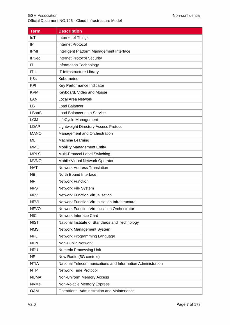
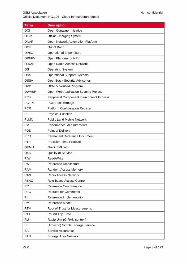
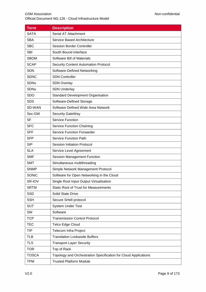
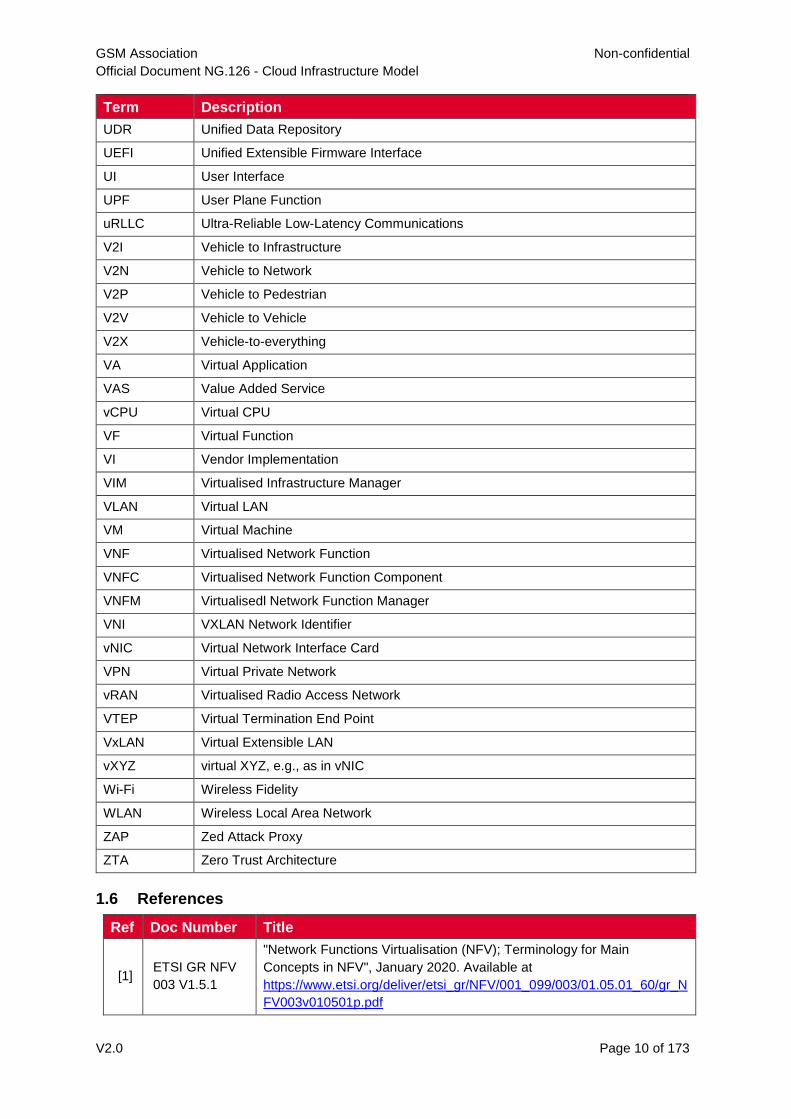
1.5 Abbreviations
Term Description
3GPP 3rd Generation Partnership Project
AAA Authentication, Authorisation, and Accounting
AES Advanced Encryption Standard
AES-NI AES New Instructions
AI Artificial Intelligence
GSM Association Non-confidential
Official Document NG.126 - Cloud Infrastructure Model
V2.0 Page 5 of 173
Term Description
AMF Access and Mobility management Function
API Application Programming Interface
ARM Advanced RISC Machines
AS Application Server
ASIC Application-Specific Integrated Circuit
B2B Business to Business
B2C Business to Consumer
BIOS Basic Input Output System
BMC Baseband Management Controller
BNG Broadband Network Gateway
BSS Business Support Systems
CaaS Container as a Service
CAPEX Capital Expenditure
CDN Content Distribution (or Delivery) Network
CI/CD Continuous Integration / Continuous Deployment
CIM Cloud Infrastructure Management
CIS Center for Internet Security
CIT Cloud Integrity Tool
CLI Command Line Interface
CNCF Cloud Native Computing Foundation
CNF Cloud Native Network Function
CNI Container Network Interface
CPU Central Processing Unit
CRTM Core Root of Trust for Measurements
CSA Cloud Security Alliance
CSCF Call Session Control Function
CSP Cloud Service Provider
CU Centralised Unit (O-RAN context)
CVE Common Vulnerabilities and Exposures
DBaaS Data Base as a Service
DC Data Center
DDoS Distributed Denial of Service
DHCP Dynamic Host Configuration Protocol
DMA Direct Memory Access
DNS Domain Name System
DPDK Data Plane Development Kit
DPU Data Processing Unit
DRAM Dynamic Random Access Memory
GSM Association Non-confidential
Official Document NG.126 - Cloud Infrastructure Model
V2.0 Page 6 of 173
Term Description
DRTM Dynamic Root of Trust for Measurements
DU Distributed Unit (O-RAN context)
E2E End to End
eMBB Enhanced Mobile BroadBand
EPA Enhanced Platform Awareness
ESXi (VMware) ESX Integrated
eTOM Enhanced Telecom Operations Map
ETSI European Telecommunications Standards Institute
EUAG (Linux Foundation Networking) End User Advisory Group
EUD End User Devices
EULA End-User License Agreement
EVPN Ethernet Virtual Private Network
FCAPS fault, configuration, accounting, performance, security
FPGA Field Programmable Gate Array
FTTx Fiber to the x
GB Giga Byte
Gi or GiB Gibibyte (10243 bytes)
GPRS General Packet Radio Service
GPS Global Positioning System
GPU Graphics Processing Unit
GRE Generic Routing Encapsulation
GSM Global System for Mobile Communications, previously Groupe Speciale Mobile
Association
GSMA GSM Association
GUI Graphical User Interface
HA High Availability
HCP Hyperscaler Cloud Providers
HDD Hard Disk Drive
HW Hardware
IaaC Infrastructure as a Code
IaaS Infrastructure as a Service
IaC Infrastructure as Code (or "as a")
ICMP Internet Control Message Protocol
ID Identifier
IMS IP Multimedia Subsystem
IO Input/Output
IOMMU Input/Output Memory Management Unit
IOPS Input/Output per Second
GSM Association Non-confidential
Official Document NG.126 - Cloud Infrastructure Model
V2.0 Page 7 of 173
Term Description
IoT Internet of Things
IP Internet Protocol
IPMI Intelligent Platform Management Interface
IPSec Internet Protocol Security
IT Information Technology
ITIL IT Infrastructure Library
K8s Kubernetes
KPI Key Performance Indicator
KVM Keyboard, Video and Mouse
LAN Local Area Network
LB Load Balancer
LBaaS Load Balancer as a Service
LCM LifeCycle Management
LDAP Lightweight Directory Access Protocol
MANO Management and Orchestration
ML Machine Learning
MME Mobility Management Entity
MPLS Multi-Protocol Label Switching
MVNO Mobile Virtual Network Operator
NAT Network Address Translation
NBI North Bound Interface
NF Network Function
NFS Network File System
NFV Network Function Virtualisation
NFVI Network Function Virtualisation Infrastructure
NFVO Network Function Virtualisation Orchestrator
NIC Network Interface Card
NIST National Institute of Standards and Technology
NMS Network Management System
NPL Network Programming Language
NPN Non-Public Network
NPU Numeric Processing Unit
NR New Radio (5G context)
NTIA National Telecommunications and Information Administration
NTP Network Time Protocol
NUMA Non-Uniform Memory Access
NVMe Non-Volatile Memory Express
OAM Operations, Administration and Maintenance
GSM Association Non-confidential
Official Document NG.126 - Cloud Infrastructure Model
V2.0 Page 8 of 173
Term Description
OCI Open Container Initiative
OFCS Offline Charging System
ONAP Open Network Automation Platform
OOB Out of Band
OPEX Operational Expenditure
OPNFV Open Platform for NFV
O-RAN Open Radio Access Network
OS Operating System
OSS Operational Support Systems
OSSA OpenStack Security Advisories
OVP OPNFV Verified Program
OWASP Open Web Application Security Project
PCIe Peripheral Component Interconnect Express
PCI-PT PCIe PassThrough
PCR Platform Configuration Register
PF Physical Function
PLMN Public Land Mobile Network
PM Performance Measurements
POD Point of Delivery
PRD Permanent Reference Document
PTP Precision Time Protocol
QEMU Quick EMUlator
QoS Quality of Service
R/W Read/Write
RA Reference Architecture
RAM Random Access Memory
RAN Radio Access Network
RBAC Role-bases Access Control
RC Reference Conformance
RFC Request for Comments
RI Reference Implementation
RM Reference Model
RTM Root of Trust for Measurements
RTT Round Trip Time
RU Radio Unit (O-RAN context)
S3 (Amazon) Simple Storage Service
SA Service Assurance
SAN Storage Area Network
GSM Association Non-confidential
Official Document NG.126 - Cloud Infrastructure Model
V2.0 Page 9 of 173
Term Description
SATA Serial AT Attachment
SBA Service Based Architecture
SBC Session Border Controller
SBI South Bound Interface
SBOM Software Bill of Materials
SCAP Security Content Automation Protocol
SDN Software-Defined Networking
SDNC SDN Controller
SDNo SDN Overlay
SDNu SDN Underlay
SDO Standard Development Organisation
SDS Software-Defined Storage
SD-WAN Software Defined Wide Area Network
Sec-GW Security GateWay
SF Service Function
SFC Service Function Chaining
SFF Service Function Forwarder
SFP Service Function Path
SIP Session Initiation Protocol
SLA Service Level Agreement
SMF Session Management Function
SMT Simultaneous multithreading
SNMP Simple Network Management Protocol
SONiC Software for Open Networking in the Cloud
SR-IOV Single Root Input Output Virtualisation
SRTM Static Root of Trust for Measurements
SSD Solid State Drive
SSH Secure SHell protocol
SUT System Under Test
SW Software
TCP Transmission Control Protocol
TEC Telco Edge Cloud
TIP Telecom Infra Project
TLB Translation Lookaside Buffers
TLS Transport Layer Security
TOR Top of Rack
TOSCA Topology and Orchestration Specification for Cloud Applications
TPM Trusted Platform Module
GSM Association Non-confidential
Official Document NG.126 - Cloud Infrastructure Model
V2.0 Page 10 of 173
Term Description
UDR Unified Data Repository
UEFI Unified Extensible Firmware Interface
UI User Interface
UPF User Plane Function
uRLLC Ultra-Reliable Low-Latency Communications
V2I Vehicle to Infrastructure
V2N Vehicle to Network
V2P Vehicle to Pedestrian
V2V Vehicle to Vehicle
V2X Vehicle-to-everything
VA Virtual Application
VAS Value Added Service
vCPU Virtual CPU
VF Virtual Function
VI Vendor Implementation
VIM Virtualised Infrastructure Manager
VLAN Virtual LAN
VM Virtual Machine
VNF Virtualised Network Function
VNFC Virtualised Network Function Component
VNFM Virtualisedl Network Function Manager
VNI VXLAN Network Identifier
vNIC Virtual Network Interface Card
VPN Virtual Private Network
vRAN Virtualised Radio Access Network
VTEP Virtual Termination End Point
VxLAN Virtual Extensible LAN
vXYZ virtual XYZ, e.g., as in vNIC
Wi-Fi Wireless Fidelity
WLAN Wireless Local Area Network
ZAP Zed Attack Proxy
ZTA Zero Trust Architecture
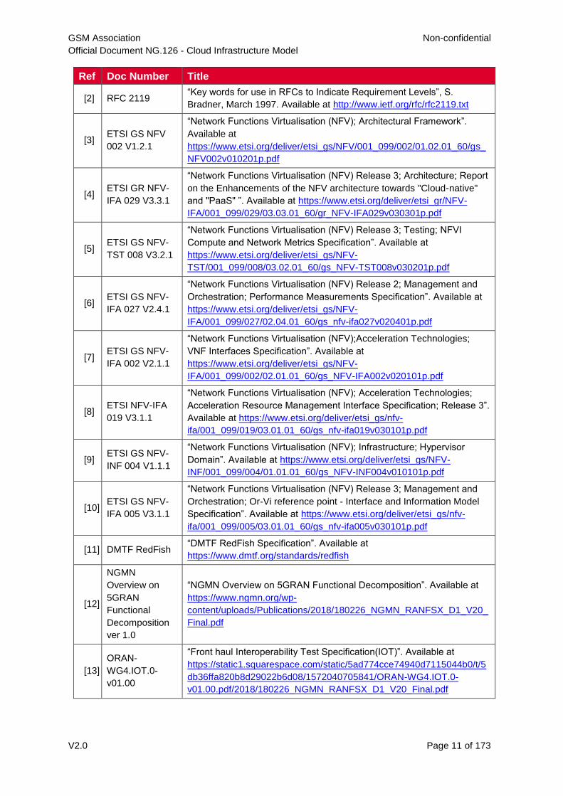
1.6 References
Ref Doc Number Title
[1] ETSI GR NFV
003 V1.5.1
"Network Functions Virtualisation (NFV); Terminology for Main
Concepts in NFV", January 2020. Available at
https://www.etsi.org/deliver/etsi_gr/NFV/001_099/003/01.05.01_60/gr_N
FV003v010501p.pdf
GSM Association Non-confidential
Official Document NG.126 - Cloud Infrastructure Model
V2.0 Page 11 of 173
Ref Doc Number Title
[2] RFC 2119 “Key words for use in RFCs to Indicate Requirement Levels”, S.
Bradner, March 1997. Available at http://www.ietf.org/rfc/rfc2119.txt
[3] ETSI GS NFV
002 V1.2.1
“Network Functions Virtualisation (NFV); Architectural Framework”.
Available at
https://www.etsi.org/deliver/etsi_gs/NFV/001_099/002/01.02.01_60/gs_
NFV002v010201p.pdf
[4] ETSI GR NFV-
IFA 029 V3.3.1
“Network Functions Virtualisation (NFV) Release 3; Architecture; Report
on the Enhancements of the NFV architecture towards "Cloud-native"
and "PaaS" ”. Available at https://www.etsi.org/deliver/etsi_gr/NFV-
IFA/001_099/029/03.03.01_60/gr_NFV-IFA029v030301p.pdf
[5] ETSI GS NFV-
TST 008 V3.2.1
“Network Functions Virtualisation (NFV) Release 3; Testing; NFVI
Compute and Network Metrics Specification”. Available at
https://www.etsi.org/deliver/etsi_gs/NFV-
TST/001_099/008/03.02.01_60/gs_NFV-TST008v030201p.pdf
[6] ETSI GS NFV-
IFA 027 V2.4.1
“Network Functions Virtualisation (NFV) Release 2; Management and
Orchestration; Performance Measurements Specification”. Available at
https://www.etsi.org/deliver/etsi_gs/NFV-
IFA/001_099/027/02.04.01_60/gs_nfv-ifa027v020401p.pdf
[7] ETSI GS NFV-
IFA 002 V2.1.1
“Network Functions Virtualisation (NFV);Acceleration Technologies;
VNF Interfaces Specification”. Available at
https://www.etsi.org/deliver/etsi_gs/NFV-
IFA/001_099/002/02.01.01_60/gs_NFV-IFA002v020101p.pdf
[8] ETSI NFV-IFA
019 V3.1.1
“Network Functions Virtualisation (NFV); Acceleration Technologies;
Acceleration Resource Management Interface Specification; Release 3”.
Available at https://www.etsi.org/deliver/etsi_gs/nfv-
ifa/001_099/019/03.01.01_60/gs_nfv-ifa019v030101p.pdf
[9] ETSI GS NFV-
INF 004 V1.1.1
“Network Functions Virtualisation (NFV); Infrastructure; Hypervisor
Domain”. Available at https://www.etsi.org/deliver/etsi_gs/NFV-
INF/001_099/004/01.01.01_60/gs_NFV-INF004v010101p.pdf
[10] ETSI GS NFV-
IFA 005 V3.1.1
“Network Functions Virtualisation (NFV) Release 3; Management and
Orchestration; Or-Vi reference point - Interface and Information Model
Specification”. Available at https://www.etsi.org/deliver/etsi_gs/nfv-
ifa/001_099/005/03.01.01_60/gs_nfv-ifa005v030101p.pdf
[11] DMTF RedFish “DMTF RedFish Specification”. Available at
https://www.dmtf.org/standards/redfish
[12]
NGMN
Overview on
5GRAN
Functional
Decomposition
ver 1.0
“NGMN Overview on 5GRAN Functional Decomposition”. Available at
https://www.ngmn.org/wp-
content/uploads/Publications/2018/180226_NGMN_RANFSX_D1_V20_
Final.pdf
[13]
ORAN-
WG4.IOT.0-
v01.00
“Front haul Interoperability Test Specification(IOT)”. Available at
https://static1.squarespace.com/static/5ad774cce74940d7115044b0/t/5
db36ffa820b8d29022b6d08/1572040705841/ORAN-WG4.IOT.0-
v01.00.pdf/2018/180226_NGMN_RANFSX_D1_V20_Final.pdf
GSM Association Non-confidential
Official Document NG.126 - Cloud Infrastructure Model
V2.0 Page 12 of 173
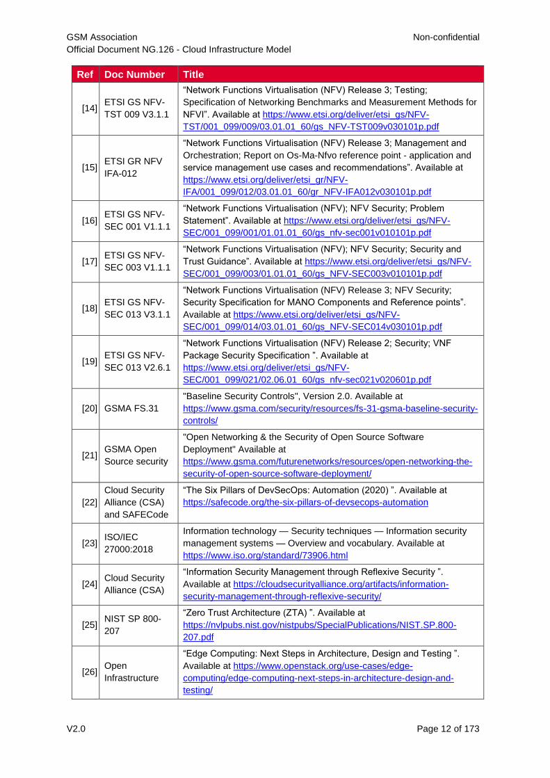
Ref Doc Number Title
[14] ETSI GS NFV-
TST 009 V3.1.1
“Network Functions Virtualisation (NFV) Release 3; Testing;
Specification of Networking Benchmarks and Measurement Methods for
NFVI”. Available at https://www.etsi.org/deliver/etsi_gs/NFV-
TST/001_099/009/03.01.01_60/gs_NFV-TST009v030101p.pdf
[15] ETSI GR NFV
IFA-012
“Network Functions Virtualisation (NFV) Release 3; Management and
Orchestration; Report on Os-Ma-Nfvo reference point - application and
service management use cases and recommendations”. Available at
https://www.etsi.org/deliver/etsi_gr/NFV-
IFA/001_099/012/03.01.01_60/gr_NFV-IFA012v030101p.pdf
[16] ETSI GS NFV-
SEC 001 V1.1.1
“Network Functions Virtualisation (NFV); NFV Security; Problem
Statement”. Available at https://www.etsi.org/deliver/etsi_gs/NFV-
SEC/001_099/001/01.01.01_60/gs_nfv-sec001v010101p.pdf
[17] ETSI GS NFV-
SEC 003 V1.1.1
“Network Functions Virtualisation (NFV); NFV Security; Security and
Trust Guidance”. Available at https://www.etsi.org/deliver/etsi_gs/NFV-
SEC/001_099/003/01.01.01_60/gs_NFV-SEC003v010101p.pdf
[18] ETSI GS NFV-
SEC 013 V3.1.1
“Network Functions Virtualisation (NFV) Release 3; NFV Security;
Security Specification for MANO Components and Reference points”.
Available at https://www.etsi.org/deliver/etsi_gs/NFV-
SEC/001_099/014/03.01.01_60/gs_NFV-SEC014v030101p.pdf
[19] ETSI GS NFV-
SEC 013 V2.6.1
“Network Functions Virtualisation (NFV) Release 2; Security; VNF
Package Security Specification ”. Available at
https://www.etsi.org/deliver/etsi_gs/NFV-
SEC/001_099/021/02.06.01_60/gs_nfv-sec021v020601p.pdf
[20] GSMA FS.31
"Baseline Security Controls", Version 2.0. Available at
https://www.gsma.com/security/resources/fs-31-gsma-baseline-security-
controls/
[21] GSMA Open
Source security
"Open Networking & the Security of Open Source Software
Deployment" Available at
https://www.gsma.com/futurenetworks/resources/open-networking-the-
security-of-open-source-software-deployment/
[22]
Cloud Security
Alliance (CSA)
and SAFECode
“The Six Pillars of DevSecOps: Automation (2020) ”. Available at
https://safecode.org/the-six-pillars-of-devsecops-automation
[23] ISO/IEC
27000:2018
Information technology — Security techniques — Information security
management systems — Overview and vocabulary. Available at
https://www.iso.org/standard/73906.html
[24] Cloud Security
Alliance (CSA)
“Information Security Management through Reflexive Security ”.
Available at https://cloudsecurityalliance.org/artifacts/information-
security-management-through-reflexive-security/
[25] NIST SP 800-
207
“Zero Trust Architecture (ZTA) ”. Available at
https://nvlpubs.nist.gov/nistpubs/SpecialPublications/NIST.SP.800-
207.pdf
[26] Open
Infrastructure
“Edge Computing: Next Steps in Architecture, Design and Testing ”.
Available at https://www.openstack.org/use-cases/edge-
computing/edge-computing-next-steps-in-architecture-design-and-
testing/
GSM Association Non-confidential
Official Document NG.126 - Cloud Infrastructure Model
V2.0 Page 13 of 173
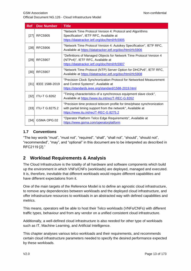
Ref Doc Number Title
[27] RFC5905
"Network Time Protocol Version 4: Protocol and Algorithms
Specification", IETF RFC, Available at
https://datatracker.ietf.org/doc/html/rfc5905
[28] RFC5906 "Network Time Protocol Version 4: Autokey Specification", IETF RFC,
Available at https://datatracker.ietf.org/doc/html/rfc5906
[29] RFC5907
"Definitions of Managed Objects for Network Time Protocol Version 4
(NTPv4)", IETF RFC, Available at
https://datatracker.ietf.org/doc/html/rfc5907
[30] RFC5907 "Network Time Protocol (NTP) Server Option for DHCPv6", IETF RFC,
Available at https://datatracker.ietf.org/doc/html/rfc5908
[31] IEEE 1588-2019
"Precision Clock Synchronization Protocol for Networked Measurement
and Control Systems", Available at
https://standards.ieee.org/standard/1588-2019.html
[32] ITU-T G.8262 "Timing characteristics of a synchronous equipment slave clock",
Available at https://www.itu.int/rec/T-REC-G.8262
[33] ITU-T G.8275.2
"Precision time protocol telecom profile for time/phase synchronization
with partial timing support from the network", Available at
https://www.itu.int/rec/T-REC-G.8275.2
[34] GSMA OPG.02 "Operator Platform Telco Edge Requirements", Available at
https://www.gsma.com/operatorplatform
1.7 Conventions
“The key words “must”, “must not”, “required”, “shall”, “shall not”, “should”, “should not”,
“recommended”, “may”, and “optional” in this document are to be interpreted as described in
RFC2119 [2].”
2 Workload Requirements & Analysis
The Cloud Infrastructure is the totality of all hardware and software components which build
up the environment in which VNFs/CNFs (workloads) are deployed, managed and executed.
It is, therefore, inevitable that different workloads would require different capabilities and
have different expectations from it.
One of the main targets of the Reference Model is to define an agnostic cloud infrastructure,
to remove any dependencies between workloads and the deployed cloud infrastructure, and
offer infrastructure resources to workloads in an abstracted way with defined capabilities and
metrics.
This means, operators will be able to host their Telco workloads (VNFs/CNFs) with different
traffic types, behaviour and from any vendor on a unified consistent cloud infrastructure.
Additionally, a well-defined cloud infrastructure is also needed for other type of workloads
such as IT, Machine Learning, and Artificial Intelligence.
This chapter analyses various telco workloads and their requirements, and recommends
certain cloud infrastructure parameters needed to specify the desired performance expected
by these workloads.
GSM Association Non-confidential
Official Document NG.126 - Cloud Infrastructure Model
V2.0 Page 14 of 173
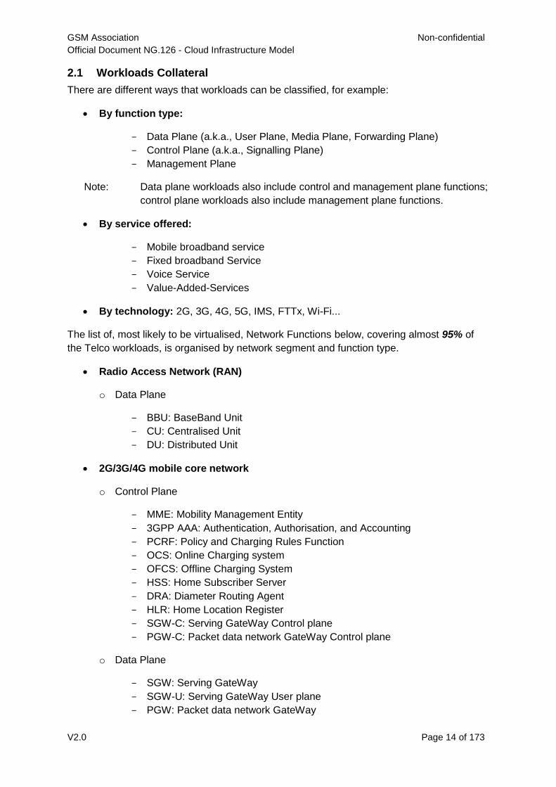
2.1 Workloads Collateral
There are different ways that workloads can be classified, for example:
By function type:
- Data Plane (a.k.a., User Plane, Media Plane, Forwarding Plane)
- Control Plane (a.k.a., Signalling Plane)
- Management Plane
Note: Data plane workloads also include control and management plane functions;
control plane workloads also include management plane functions.
By service offered:
- Mobile broadband service
- Fixed broadband Service
- Voice Service
- Value-Added-Services
By technology: 2G, 3G, 4G, 5G, IMS, FTTx, Wi-Fi...
The list of, most likely to be virtualised, Network Functions below, covering almost 95% of
the Telco workloads, is organised by network segment and function type.
Radio Access Network (RAN)
o Data Plane
- BBU: BaseBand Unit
- CU: Centralised Unit
- DU: Distributed Unit
2G/3G/4G mobile core network
o Control Plane
- MME: Mobility Management Entity
- 3GPP AAA: Authentication, Authorisation, and Accounting
- PCRF: Policy and Charging Rules Function
- OCS: Online Charging system
- OFCS: Offline Charging System
- HSS: Home Subscriber Server
- DRA: Diameter Routing Agent
- HLR: Home Location Register
- SGW-C: Serving GateWay Control plane
- PGW-C: Packet data network GateWay Control plane
o Data Plane
- SGW: Serving GateWay
- SGW-U: Serving GateWay User plane
- PGW: Packet data network GateWay
GSM Association Non-confidential
Official Document NG.126 - Cloud Infrastructure Model
V2.0 Page 15 of 173
- PGW-U: Packet data network GateWay User plane
- ePDG: Evolved Packet Data GateWay
- MSC: Mobile Switching Center
- SGSN: Serving GPRS Support Node
- GGSN: Gateway GPRS Support Node
- SMSC : SMS Center
5G core network 5G core nodes are virtualizable by design and strong candidate to
be on boarded onto Telco Cloud as "cloud native application"
o Data Plane
- UPF: User Plane Function
o Control Plane
- AMF: Access and Mobility management Function
- SMF: Session Management Function
- PCF: Policy Control Function
- AUSF: Authentication Server Function
- NSSF: Network Slice Selection Function
- UDM: Unified Data Management
- UDR: Unified Data Repository
- NRF: Network Repository Function
- NEF: Network Exposure Function
- CHF: Charging Function part of the Converged Charging System (CCS)
Note: for Service-based Architecture (SBA) all Network Functions are stateless
(store all sessions/ state on unified data repository UDR)
IP Multimedia Subsystem (IMS)
o Data Plane
- MGW: Media GateWay
- SBC: Session Border Controller
- MRF: Media Resource Function
o Control Plane
- CSCF: Call Session Control Function
- MTAS: Mobile Telephony Application Server
- BGCF: Border Gateway Control Function
- MGCF: Media Gateway Control Function
Fixed network
o Data Plane
- MSAN: MultiService Access Node
- OLT: Optical Line Termination
- WLC: WLAN Controller
GSM Association Non-confidential
Official Document NG.126 - Cloud Infrastructure Model
V2.0 Page 16 of 173
- BNG: Broadband Network Gateway
- BRAS: Broadband Remote Access Server
- RGW: Residential GateWay
- CPE: Customer Premises Equipment
o Control Plane
- AAA: Authentication, Authorisation, and Accounting
Other network functions
o Data Plane
- LSR: Label Switching Router
- DPI: Deep Packet Inspection
- CG-NAT: Carrier-Grade Network Address Translation
- ADC: Application Delivery Controller
- FW: FireWall
- Sec-GW: Security GateWay
- CDN: Content Delivery Network
o Control plane
- RR: Route Reflector
- DNS: Domain Name System
o Management Plane
- NMS: Network Management System
2.2 Use cases
The intent of this section is to describe some important use cases that are pertinent to this
Reference Model. We start with some typical Edge related use cases. The list of use cases
will be extended in the future releases.
Telco Edge is commonly coupled with 5G use cases, seen as one of the ingredients of the
Ultra-Reliable Low-latency Communication (URLLC) and Enhanced Mobile Broadband
(eMBB) Network Slicing. The requirements for user plane Local Breakout / Termination are
common mandating that Value Added Services (VASs) & Any Gi-LAN applications are
locally hosted at the Edge. The Telco Edge is a perfect fit for centralized vRAN deployment
and vDU/vCU hosting that satisfy the latency requirements.
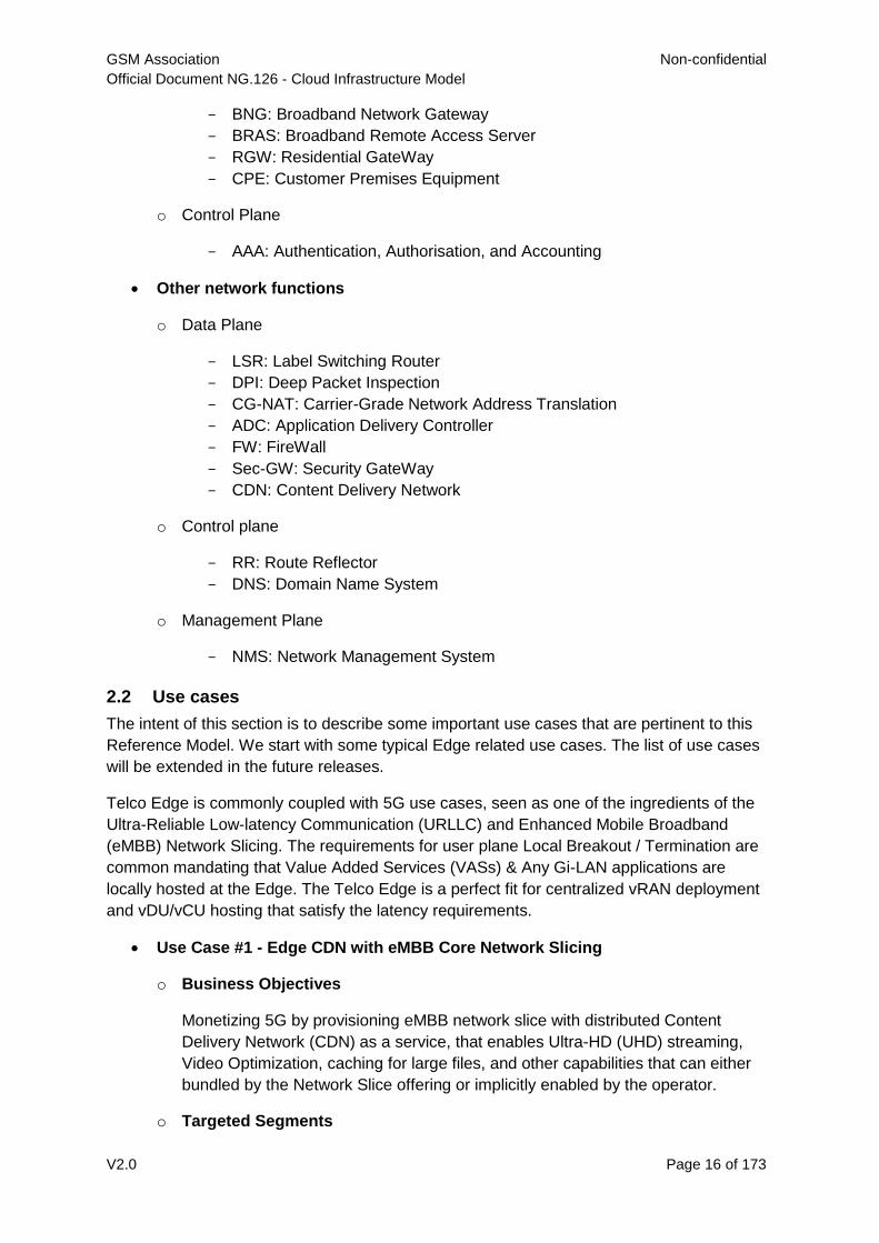
Use Case #1 - Edge CDN with eMBB Core Network Slicing
o Business Objectives
Monetizing 5G by provisioning eMBB network slice with distributed Content
Delivery Network (CDN) as a service, that enables Ultra-HD (UHD) streaming,
Video Optimization, caching for large files, and other capabilities that can either
bundled by the Network Slice offering or implicitly enabled by the operator.
o Targeted Segments
GSM Association Non-confidential
Official Document NG.126 - Cloud Infrastructure Model
V2.0 Page 17 of 173
- B2C (Targeting high Tier Packages & Bundles)
- Content Owners (Potential revenue sharing model)
- Mobile Virtual Network Operators (MVNOs - Wholesale)
- Stadiums and Venues.
o Architecture
Figure 2: Edge CDN with eMBB Core Network Slicing.
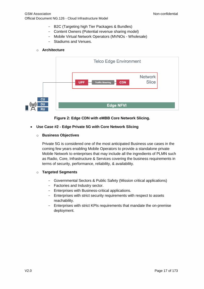
Use Case #2 - Edge Private 5G with Core Network Slicing
o Business Objectives
Private 5G is considered one of the most anticipated Business use cases in the
coming few years enabling Mobile Operators to provide a standalone private
Mobile Network to enterprises that may include all the ingredients of PLMN such
as Radio, Core, Infrastructure & Services covering the business requirements in
terms of security, performance, reliability, & availability.
o Targeted Segments
- Governmental Sectors & Public Safety (Mission critical applications)
- Factories and Industry sector.
- Enterprises with Business-critical applications.
- Enterprises with strict security requirements with respect to assets
reachability.
- Enterprises with strict KPIs requirements that mandate the on-premise
deployment.
GSM Association Non-confidential
Official Document NG.126 - Cloud Infrastructure Model
V2.0 Page 18 of 173
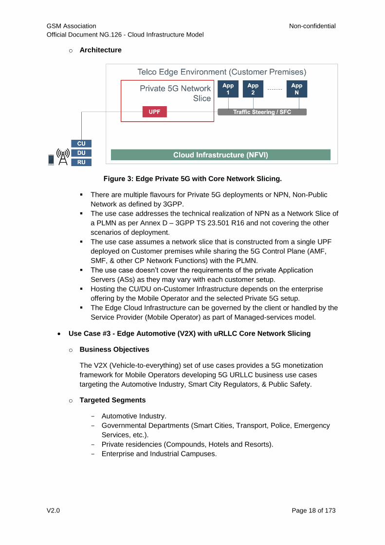
o Architecture
Figure 3: Edge Private 5G with Core Network Slicing.
There are multiple flavours for Private 5G deployments or NPN, Non-Public
Network as defined by 3GPP.
The use case addresses the technical realization of NPN as a Network Slice of
a PLMN as per Annex D – 3GPP TS 23.501 R16 and not covering the other
scenarios of deployment.
The use case assumes a network slice that is constructed from a single UPF
deployed on Customer premises while sharing the 5G Control Plane (AMF,
SMF, & other CP Network Functions) with the PLMN.
The use case doesn’t cover the requirements of the private Application
Servers (ASs) as they may vary with each customer setup.
Hosting the CU/DU on-Customer Infrastructure depends on the enterprise
offering by the Mobile Operator and the selected Private 5G setup.
The Edge Cloud Infrastructure can be governed by the client or handled by the
Service Provider (Mobile Operator) as part of Managed-services model.
Use Case #3 - Edge Automotive (V2X) with uRLLC Core Network Slicing
o Business Objectives
The V2X (Vehicle-to-everything) set of use cases provides a 5G monetization
framework for Mobile Operators developing 5G URLLC business use cases
targeting the Automotive Industry, Smart City Regulators, & Public Safety.
o Targeted Segments
- Automotive Industry.
- Governmental Departments (Smart Cities, Transport, Police, Emergency
Services, etc.).
- Private residencies (Compounds, Hotels and Resorts).
- Enterprise and Industrial Campuses.
GSM Association Non-confidential
Official Document NG.126 - Cloud Infrastructure Model
V2.0 Page 19 of 173
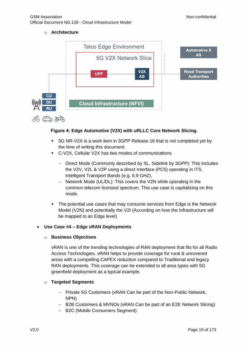
o Architecture
Figure 4: Edge Automotive (V2X) with uRLLC Core Network Slicing.
5G NR-V2X is a work item in 3GPP Release 16 that is not completed yet by
the time of writing this document.
C-V2X, Cellular V2X has two modes of communications
- Direct Mode (Commonly described by SL, Sidelink by 3GPP): This includes
the V2V, V2I, & V2P using a direct Interface (PC5) operating in ITS,
Intelligent Transport Bands (e.g. 5.9 GHZ).
- Network Mode (UL/DL): This covers the V2N while operating in the
common telecom licensed spectrum. This use case is capitalizing on this
mode.
The potential use cases that may consume services from Edge is the Network
Model (V2N) and potentially the V2I (According on how the Infrastructure will
be mapped to an Edge level)
Use Case #4 – Edge vRAN Deployments
o Business Objectives
vRAN is one of the trending technologies of RAN deployment that fits for all Radio
Access Technologies. vRAN helps to provide coverage for rural & uncovered
areas with a compelling CAPEX reduction compared to Traditional and legacy
RAN deployments. This coverage can be extended to all area types with 5G
greenfield deployment as a typical example.
o Targeted Segments
- Private 5G Customers (vRAN Can be part of the Non-Public Network,
NPN)
- B2B Customers & MVNOs (vRAN Can be part of an E2E Network Slicing)
- B2C (Mobile Consumers Segment).
GSM Association Non-confidential
Official Document NG.126 - Cloud Infrastructure Model
V2.0 Page 20 of 173
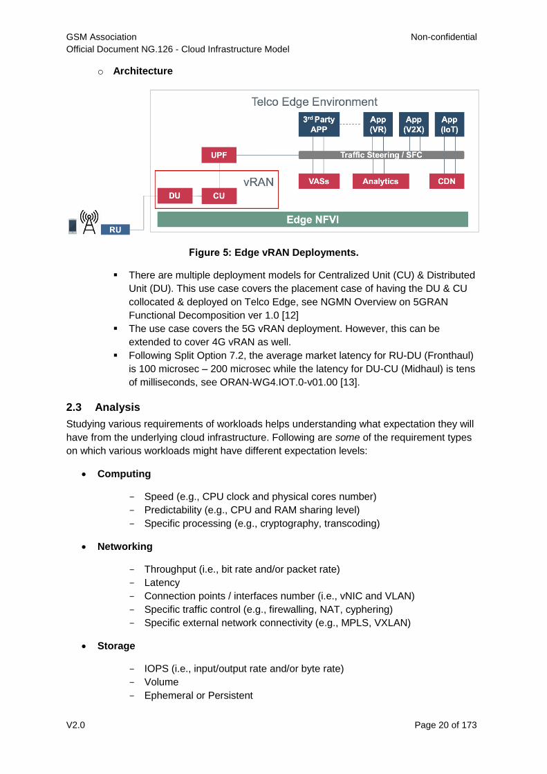
o Architecture
Figure 5: Edge vRAN Deployments.
There are multiple deployment models for Centralized Unit (CU) & Distributed
Unit (DU). This use case covers the placement case of having the DU & CU
collocated & deployed on Telco Edge, see NGMN Overview on 5GRAN
Functional Decomposition ver 1.0 [12]
The use case covers the 5G vRAN deployment. However, this can be
extended to cover 4G vRAN as well.
Following Split Option 7.2, the average market latency for RU-DU (Fronthaul)
is 100 microsec – 200 microsec while the latency for DU-CU (Midhaul) is tens
of milliseconds, see ORAN-WG4.IOT.0-v01.00 [13].
2.3 Analysis
Studying various requirements of workloads helps understanding what expectation they will
have from the underlying cloud infrastructure. Following are some of the requirement types
on which various workloads might have different expectation levels:
Computing
- Speed (e.g., CPU clock and physical cores number)
- Predictability (e.g., CPU and RAM sharing level)
- Specific processing (e.g., cryptography, transcoding)
Networking
- Throughput (i.e., bit rate and/or packet rate)
- Latency
- Connection points / interfaces number (i.e., vNIC and VLAN)
- Specific traffic control (e.g., firewalling, NAT, cyphering)
- Specific external network connectivity (e.g., MPLS, VXLAN)
Storage
- IOPS (i.e., input/output rate and/or byte rate)
- Volume
- Ephemeral or Persistent
GSM Association Non-confidential
Official Document NG.126 - Cloud Infrastructure Model
V2.0 Page 21 of 173
- Specific features (e.g., object storage, local storage)
By trying to sort workloads into different categories based on the requirements observed,
below are the different profiles concluded, which are mainly driven by expected performance
levels:
Profile One
o Workload types
- Control plane functions without specific need, and management plane
functions
- Examples: OFCS, AAA, NMS
o No specific requirement
Profile Two
o Workload types
- Data plane functions (i.e., functions with specific networking and computing
needs)
- Examples: BNG, S/PGW, UPF, Sec-GW, DPI, CDN, SBC, MME, AMF,
IMS-CSCF, UDR
o Requirements
- Predictable computing
- High network throughput
- Low network latency
2.4 Profiles, Profile Extensions & Flavours
Profiles are used to tag infrastructure (such as hypervisor hosts, or Kubernetes worker
nodes) and associate it with a set of capabilities that are exploitable by the workloads.
Two profile layers are proposed:
The top level profiles represent macro-characteristics that partition infrastructure into
separate pools, i.e.: an infrastructure object can belong to one and only one profile,
and workloads can only be created using a single profile. Workloads requesting a
given profile must be instantiated on infrastructure of that same profile.
For a given profile, profile extensions represent small deviations from (or further
qualification, such as infrastructure sizing differences (e.g. memory size)) the profile
that do not require partitioning the infrastructure into separate pools, but that have
specifications with a finer granularity of the profile. Profile Extensions can be
optionally requested by workloads that want a more granular control over what
infrastructure they run on, i.e.: an infrastructure resource can have more than one
profile extension label attached to it, and workloads can request resources to be
instantiated on infrastructure with a certain profile extension. Workloads requesting a
given profile extension must be instantiated on infrastructure with that same profile
GSM Association Non-confidential
Official Document NG.126 - Cloud Infrastructure Model
V2.0 Page 22 of 173
extension. It is allowed to instantiate workloads on infrastructure tagged with more
profile extensions than requested, as long as the minimum requirements are satisfied.
Workloads specify infrastructure capability requirements as workload metadata, indicating
what kind of infrastructure they must run on to achieve functionality and/or the intended level
of performance. Workloads request resources specifying the Profiles and Profile Extensions,
and a set of sizing metadata that maybe expressed as flavours that are required for the
workload to run as intended. A resource request by a workload can be met by any
infrastructure node that has the same or a more specialised profile and the necessary
capacity to support the requested flavour or resource size.
Profiles, Profile Extensions and Flavours will be considered in greater detail in Section 4.2.
2.4.1 Profiles (top-level partitions)
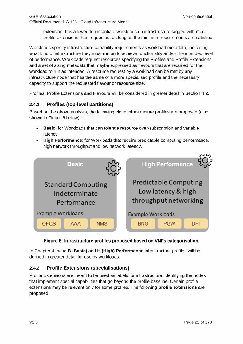
Based on the above analysis, the following cloud infrastructure profiles are proposed (also
shown in Figure 6 below)
Basic: for Workloads that can tolerate resource over-subscription and variable
latency.
High Performance: for Workloads that require predictable computing performance,
high network throughput and low network latency.
Figure 6: Infrastructure profiles proposed based on VNFs categorisation.
In Chapter 4 these B (Basic) and H (High) Performance infrastructure profiles will be
defined in greater detail for use by workloads.
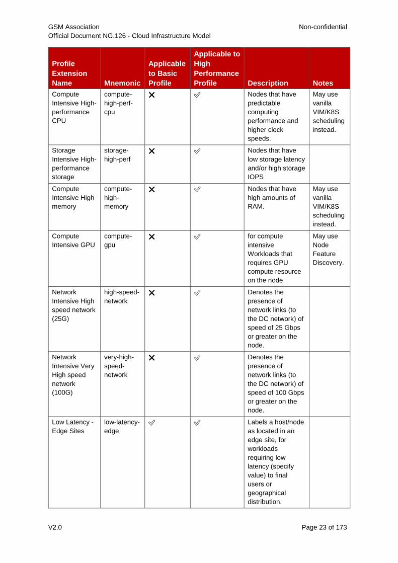
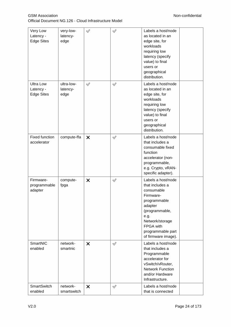
2.4.2 Profile Extensions (specialisations)
Profile Extensions are meant to be used as labels for infrastructure, identifying the nodes
that implement special capabilities that go beyond the profile baseline. Certain profile
extensions may be relevant only for some profiles. The following profile extensions are
proposed:
GSM Association Non-confidential
Official Document NG.126 - Cloud Infrastructure Model
V2.0 Page 23 of 173
Profile
Extension
Name Mnemonic
Applicable
to Basic
Profile
Applicable to
High
Performance
Profile Description Notes
Compute
Intensive High-
performance
CPU
compute-
high-perf-
cpu
❌ ✅ Nodes that have
predictable
computing
performance and
higher clock
speeds.
May use
vanilla
VIM/K8S
scheduling
instead.
Storage
Intensive High-
performance
storage
storage-
high-perf
❌ ✅ Nodes that have
low storage latency
and/or high storage
IOPS
Compute
Intensive High
memory
compute-
high-
memory
❌ ✅ Nodes that have
high amounts of
RAM.
May use
vanilla
VIM/K8S
scheduling
instead.
Compute
Intensive GPU
compute-
gpu
❌ ✅ for compute
intensive
Workloads that
requires GPU
compute resource
on the node
May use
Node
Feature
Discovery.
Network
Intensive High
speed network
(25G)
high-speed-
network
❌ ✅ Denotes the
presence of
network links (to
the DC network) of
speed of 25 Gbps
or greater on the
node.
Network
Intensive Very
High speed
network
(100G)
very-high-
speed-
network
❌ ✅ Denotes the
presence of
network links (to
the DC network) of
speed of 100 Gbps
or greater on the
node.
Low Latency -
Edge Sites
low-latency-
edge
✅ ✅ Labels a host/node
as located in an
edge site, for
workloads
requiring low
latency (specify
value) to final
users or
geographical
distribution.
GSM Association Non-confidential
Official Document NG.126 - Cloud Infrastructure Model
V2.0 Page 24 of 173
Very Low
Latency -
Edge Sites
very-low-
latency-
edge
✅ ✅ Labels a host/node
as located in an
edge site, for
workloads
requiring low
latency (specify
value) to final
users or
geographical
distribution.
Ultra Low
Latency -
Edge Sites
ultra-low-
latency-
edge
✅ ✅ Labels a host/node
as located in an
edge site, for
workloads
requiring low
latency (specify
value) to final
users or
geographical
distribution.
Fixed function
accelerator
compute-ffa ❌ ✅ Labels a host/node
that includes a
consumable fixed
function
accelerator (non-
programmable,
e.g. Crypto, vRAN-
specific adapter).
Firmware-
programmable
adapter
compute-
fpga
❌ ✅ Labels a host/node
that includes a
consumable
Firmware-
programmable
adapter
(programmable,
e.g.
Network/storage
FPGA with
programmable part
of firmware image).
SmartNIC
enabled
network-
smartnic
❌ ✅ Labels a host/node
that includes a
Programmable
accelerator for
vSwitch/vRouter,
Network Function
and/or Hardware
Infrastructure.
SmartSwitch
enabled
network-
smartswitch
❌ ✅ Labels a host/node
that is connected
GSM Association Non-confidential
Official Document NG.126 - Cloud Infrastructure Model
V2.0 Page 25 of 173
to a Programmable
Switch Fabric or
TOR switch
Table 1: Profile extensions
Note: This is an initial set of proposed profiles and profile extensions and it is
expected that more profiles and/or profile extensions will be added as more
requirements are gathered and as technology enhances and matures.
3 Modelling
It is necessary to clearly define the infrastructure resources and their capabilities a shared
cloud infrastructure (network function virtualisation infrastructure, NFVI) will provide for
hosting workloads including virtual network functions (VNFs) and/or cloud-native network
functions (CNFs). The lack of a common understanding of which resources and
corresponding capabilities a suitable cloud infrastructure should provide may lead to several
issues which could negatively impact the time and the cost for on-boarding and maintaining
these solutions on top of a virtualised infrastructure.
The abstraction model presented in this Reference Model (RM) specifies a common set of
virtual infrastructure resources that a cloud infrastructure will need to provide to be able to
host most of the typical VNF/CNF telco workloads. The intention of this Reference Model is
to follow the following principles:
Scope: the model should describe the most relevant virtualised infrastructure
resources (incl. acceleration technologies) a cloud infrastructure needs to host Telco
workloads
Separation of Concern: the model should support a clear distinction between the
responsibilities related to maintaining the network function virtualisation infrastructure
and the responsibilities related to managing the various VNF workloads
Simplicity: the amount of different types of resources (including their attributes and
relationships amongst one another) should be kept to a minimum to reduce the
configuration spectrum which needs to be considered
Declarative: the model should allow for the description of the intended state and
configuration of the cloud infrastructure resources for automated life cycle
management
Explicit: the model needs to be rich enough to allow for the instantiation and the on-
going operation of the cloud infrastructure
Lifecycle: the model must distinguish between resources which have independent
lifecycles but should group together those resources which share a common lifecycle
Aligned: the model should clearly highlight the dependencies between its
components to allow for a well-defined and simplified synchronisation of independent
automation tasks.
To summarise: the abstraction model presented in this document will build upon existing
modelling concepts and simplify and streamline them to the needs of telco operators who
intend to distinguish between infrastructure related and workload related responsibilities.
GSM Association Non-confidential
Official Document NG.126 - Cloud Infrastructure Model
V2.0 Page 26 of 173
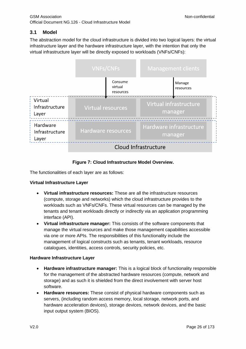
3.1 Model
The abstraction model for the cloud infrastructure is divided into two logical layers: the virtual
infrastructure layer and the hardware infrastructure layer, with the intention that only the
virtual infrastructure layer will be directly exposed to workloads (VNFs/CNFs):
Figure 7: Cloud Infrastructure Model Overview.
The functionalities of each layer are as follows:
Virtual Infrastructure Layer
Virtual infrastructure resources: These are all the infrastructure resources
(compute, storage and networks) which the cloud infrastructure provides to the
workloads such as VNFs/CNFs. These virtual resources can be managed by the
tenants and tenant workloads directly or indirectly via an application programming
interface (API).
Virtual infrastructure manager: This consists of the software components that
manage the virtual resources and make those management capabilities accessible
via one or more APIs. The responsibilities of this functionality include the
management of logical constructs such as tenants, tenant workloads, resource
catalogues, identities, access controls, security policies, etc.
Hardware Infrastructure Layer
Hardware infrastructure manager: This is a logical block of functionality responsible
for the management of the abstracted hardware resources (compute, network and
storage) and as such it is shielded from the direct involvement with server host
software.
Hardware resources: These consist of physical hardware components such as
servers, (including random access memory, local storage, network ports, and
hardware acceleration devices), storage devices, network devices, and the basic
input output system (BIOS).
GSM Association Non-confidential
Official Document NG.126 - Cloud Infrastructure Model
V2.0 Page 27 of 173
Workload Layer
Workloads (VNFs/CNFs): These consist of workloads such as virtualized and/or
containerized network functions that run within a virtual machine (VM) or as a set of
containers.
3.2 Virtual Infrastructure Layer
3.2.1 Virtual Resources
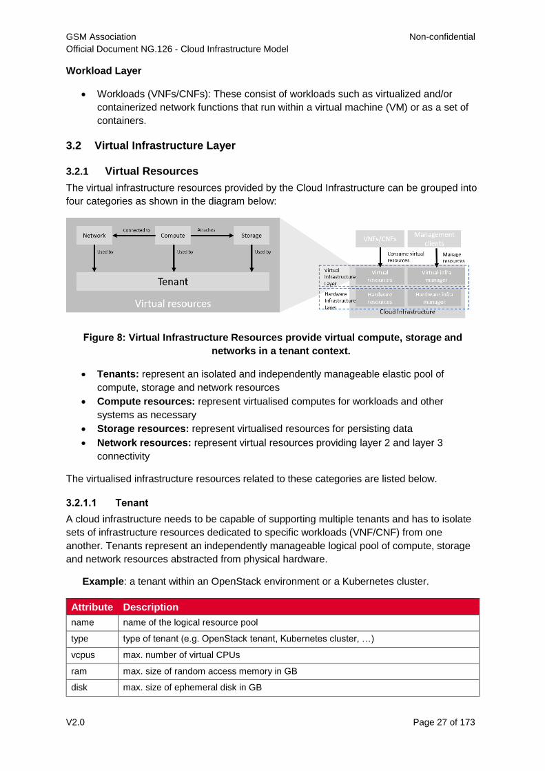
The virtual infrastructure resources provided by the Cloud Infrastructure can be grouped into
four categories as shown in the diagram below:
Figure 8: Virtual Infrastructure Resources provide virtual compute, storage and
networks in a tenant context.
Tenants: represent an isolated and independently manageable elastic pool of
compute, storage and network resources
Compute resources: represent virtualised computes for workloads and other
systems as necessary
Storage resources: represent virtualised resources for persisting data
Network resources: represent virtual resources providing layer 2 and layer 3
connectivity
The virtualised infrastructure resources related to these categories are listed below.
3.2.1.1 Tenant
A cloud infrastructure needs to be capable of supporting multiple tenants and has to isolate
sets of infrastructure resources dedicated to specific workloads (VNF/CNF) from one
another. Tenants represent an independently manageable logical pool of compute, storage
and network resources abstracted from physical hardware.
Example: a tenant within an OpenStack environment or a Kubernetes cluster.
Attribute Description
name name of the logical resource pool
type type of tenant (e.g. OpenStack tenant, Kubernetes cluster, …)
vcpus max. number of virtual CPUs
ram max. size of random access memory in GB
disk max. size of ephemeral disk in GB
GSM Association Non-confidential
Official Document NG.126 - Cloud Infrastructure Model
V2.0 Page 28 of 173
networks description of external networks required for inter-domain connectivity
metadata key/value pairs for selection of the appropriate physical context (e.g. location,
availability zone, …)
Table 2: Attributes of a tenant
3.2.1.2 Virtual Compute
A virtual machine or a container/pod is used by a tenant capable of hosting the application
components of workloads (VNFs). A virtual compute therefore requires a tenant context and,
since it will need to communicate with other communication partners, it is assumed that the
networks have been provisioned in advance.
Example: a virtual compute descriptor as defined in TOSCA Simple Profile for NFV.
Attribute Description
name name of the virtual host
vcpus number of virtual CPUs
ram size of random access memory in GB
disk size of root disc in GB
nics sorted list of network interfaces connecting the host to the virtual networks
acceleration key/value pairs for selection of the appropriate acceleration technology
metadata key/value pairs for selection of the appropriate redundancy domain
Table 3: Attributes of compute resources
3.2.1.3 Virtual Storage
A workload can request storage based on data retaining policy (persistent or ephemeral
storage), different types of storage (HDD, SSD, etc.) and storage size. Persistent storage
outlives the compute instance whereas ephemeral storage is linked to compute instance
lifecycle.
There are multiple storage performance attributes such as latency, IOPS (Input/Output
Operations per second), and throughput. For example, a workload may require one of its
storage devices to provide low latency, high IOPS and very large/huge storage size
(terabytes of data). Low Latency storage is for workloads which have strong constraints on
the time to access the storage. High IOPS oriented storage is for workloads requiring lots of
read/write actions. Large size storage is for workloads that need lots of volume without
strong performance constraints. Note that approximate numeric ranges for the qualitative
values used above are given in section 4.2.6, Storage Extensions.
Storage resources have the following attributes, with metric definitions that support
verification through passive measurements (telemetry) where appropriate:
Attribute Description
name name of storage resources
data retaining
policy
persistent or ephemeral
GSM Association Non-confidential
Official Document NG.126 - Cloud Infrastructure Model
V2.0 Page 29 of 173
performance Read and Write Latency, The average amount of time to perform a R/W
operation, in milliseconds
Read and Write IOPS, The average rate of performing R/W in IO operations
per second
Read and Write Throughput, The average rate of performing R/W operations
in Bytes per second
enhanced
features
replication, encryption
type block, object or file
size size in GB, telemetry includes the amount of free, used, and reserved disk
space, in bytes
Table 4: Attributes of storage resources
3.2.1.4 Virtual Network
This topic is currently covered in section 3.5, Network.
3.2.1.5 Availability Zone
An availability zone is a logical pool of physical resources (e.g. compute, block storage, and
network). These logical pools segment the physical resources of a cloud based on factors
chosen by the cloud operator. The cloud operator may create availability zones based on
location (rack, datacentre), or indirect failure domain dependencies like power sources.
Workloads can leverage availability zones to utilise multiple locations or avoid sharing failure
domains for a workload, and thus increase its fault-tolerance.
As a logical group with operator-specified criteria, the only mandatory attribute for an
Availability Zone is the name.
Attribute Description
name name of the availability zone
Table 5: Attributes of availability zones
3.2.2 Virtual Infrastructure Manager
The virtual infrastructure manager allows to:
setup, manage and delete tenants,
setup, manage and delete user- and service-accounts,
manage access privileges and
provision, manage, monitor and delete virtual resources.
GSM Association Non-confidential
Official Document NG.126 - Cloud Infrastructure Model
V2.0 Page 30 of 173
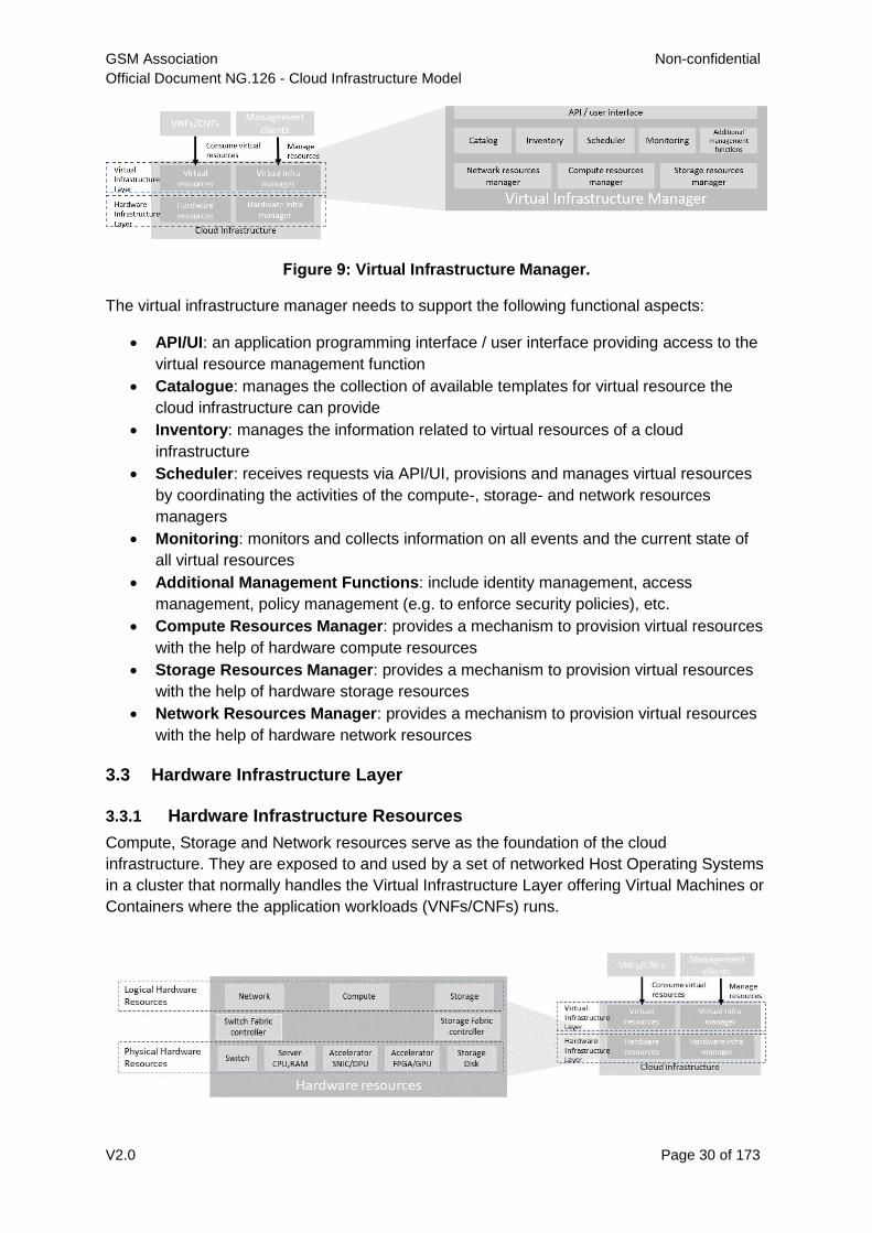
Figure 9: Virtual Infrastructure Manager.
The virtual infrastructure manager needs to support the following functional aspects:
API/UI: an application programming interface / user interface providing access to the
virtual resource management function
Catalogue: manages the collection of available templates for virtual resource the
cloud infrastructure can provide
Inventory: manages the information related to virtual resources of a cloud
infrastructure
Scheduler: receives requests via API/UI, provisions and manages virtual resources
by coordinating the activities of the compute-, storage- and network resources
managers
Monitoring: monitors and collects information on all events and the current state of
all virtual resources
Additional Management Functions: include identity management, access
management, policy management (e.g. to enforce security policies), etc.
Compute Resources Manager: provides a mechanism to provision virtual resources
with the help of hardware compute resources
Storage Resources Manager: provides a mechanism to provision virtual resources
with the help of hardware storage resources
Network Resources Manager: provides a mechanism to provision virtual resources
with the help of hardware network resources
3.3 Hardware Infrastructure Layer
3.3.1 Hardware Infrastructure Resources
Compute, Storage and Network resources serve as the foundation of the cloud
infrastructure. They are exposed to and used by a set of networked Host Operating Systems
in a cluster that normally handles the Virtual Infrastructure Layer offering Virtual Machines or
Containers where the application workloads (VNFs/CNFs) runs.
GSM Association Non-confidential
Official Document NG.126 - Cloud Infrastructure Model
V2.0 Page 31 of 173
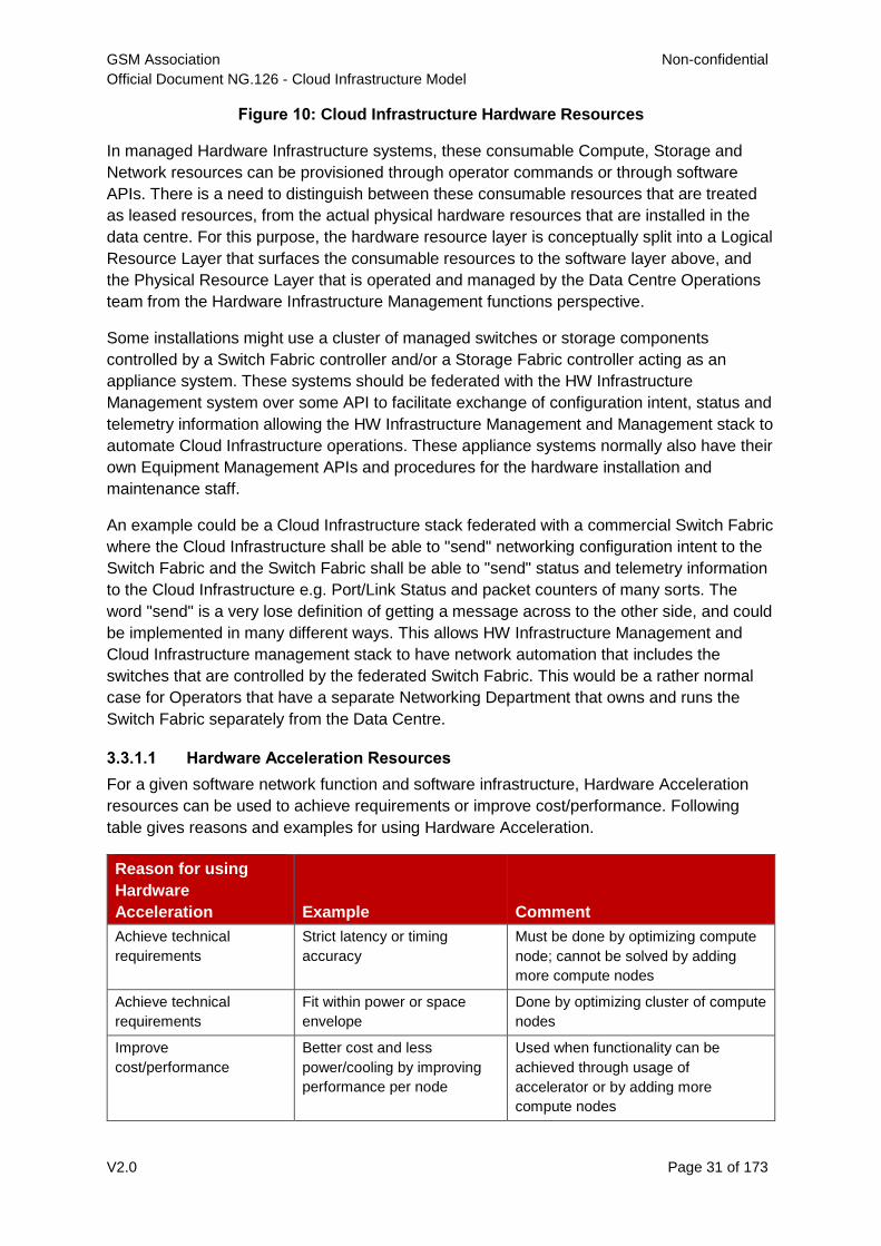
Figure 10: Cloud Infrastructure Hardware Resources
In managed Hardware Infrastructure systems, these consumable Compute, Storage and
Network resources can be provisioned through operator commands or through software
APIs. There is a need to distinguish between these consumable resources that are treated
as leased resources, from the actual physical hardware resources that are installed in the
data centre. For this purpose, the hardware resource layer is conceptually split into a Logical
Resource Layer that surfaces the consumable resources to the software layer above, and
the Physical Resource Layer that is operated and managed by the Data Centre Operations
team from the Hardware Infrastructure Management functions perspective.
Some installations might use a cluster of managed switches or storage components
controlled by a Switch Fabric controller and/or a Storage Fabric controller acting as an
appliance system. These systems should be federated with the HW Infrastructure
Management system over some API to facilitate exchange of configuration intent, status and
telemetry information allowing the HW Infrastructure Management and Management stack to
automate Cloud Infrastructure operations. These appliance systems normally also have their
own Equipment Management APIs and procedures for the hardware installation and
maintenance staff.
An example could be a Cloud Infrastructure stack federated with a commercial Switch Fabric
where the Cloud Infrastructure shall be able to "send" networking configuration intent to the
Switch Fabric and the Switch Fabric shall be able to "send" status and telemetry information
to the Cloud Infrastructure e.g. Port/Link Status and packet counters of many sorts. The
word "send" is a very lose definition of getting a message across to the other side, and could
be implemented in many different ways. This allows HW Infrastructure Management and
Cloud Infrastructure management stack to have network automation that includes the
switches that are controlled by the federated Switch Fabric. This would be a rather normal
case for Operators that have a separate Networking Department that owns and runs the
Switch Fabric separately from the Data Centre.
3.3.1.1 Hardware Acceleration Resources
For a given software network function and software infrastructure, Hardware Acceleration
resources can be used to achieve requirements or improve cost/performance. Following
table gives reasons and examples for using Hardware Acceleration.
Reason for using
Hardware
Acceleration Example Comment
Achieve technical
requirements
Strict latency or timing
accuracy
Must be done by optimizing compute
node; cannot be solved by adding
more compute nodes
Achieve technical
requirements
Fit within power or space
envelope
Done by optimizing cluster of compute
nodes
Improve
cost/performance
Better cost and less
power/cooling by improving
performance per node
Used when functionality can be
achieved through usage of
accelerator or by adding more
compute nodes
GSM Association Non-confidential
Official Document NG.126 - Cloud Infrastructure Model
V2.0 Page 32 of 173
Table 6: Reasons and examples for using Hardware Acceleration
Hardware Accelerators can be used to offload software execution for purpose of accelerating
tasks to achieve faster performance, or offloading the tasks to another execution entity to get
more predictable execution times, efficient handling of the tasks or separation of authority
regarding who can control the tasks execution.
More details about Hardware Acceleration are in Section 3.8 Hardware Acceleration
Abstraction .
3.3.2 Hardware Infrastructure Manager
The HW Infrastructure Manager shall at least support equipment management for all
managed physical hardware resources of the Cloud Infrastructure.
In most deployments the HW Infrastructure Manager should also be the HW Infrastructure
Layer provisioning manager of the Compute, Storage and Network resources that can be
used by the Virtualization Infrastructure Layer instances. It shall provide an API enabling vital
resource recovery and control functions of the provisioned functions e.g. Reset and Power
control of the Computes.
For deployments with more than one Virtualization Infrastructure Layer instance that will be
using a common pool of hardware resources there is a need for a HW Infrastructure Layer
provisioning manager of the Compute, Storage and Network resources to handle the
resource assignment and arbitration.
The resource allocation could be a simple book-keeping of which Virtualization Infrastructure
Layer instance that have been allocated a physical hardware resource or a more advanced
resource Composition function that assemble the consumed Compute, Storage and Network
resources on demand from the pools of physical hardware resources.
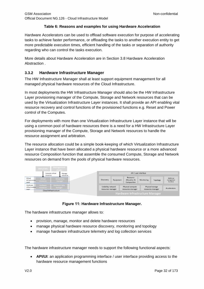
Figure 11: Hardware Infrastructure Manager.
The hardware infrastructure manager allows to:
provision, manage, monitor and delete hardware resources
manage physical hardware resource discovery, monitoring and topology
manage hardware infrastructure telemetry and log collection services
The hardware infrastructure manager needs to support the following functional aspects:
API/UI: an application programming interface / user interface providing access to the
hardware resource management functions
GSM Association Non-confidential
Official Document NG.126 - Cloud Infrastructure Model
V2.0 Page 33 of 173
Discovery: discover physical hardware resources and collect relevant information
about them
Topology: discover and monitor physical interconnection (e.g. cables) in between the
physical hardware resources
Equipment: manages the physical hardware resources in terms of configuration,
firmware status, health/fault status and autonomous environmental control functions
such as fan and power conversion regulations
Resource Allocation and Composition: creates, modifies and deletes logical
Compute, Network and Storage Resources through Composition of allocated physical
hardware resources
Underlay Network Resources Manager: provides a mechanism to provision
hardware resources and provide separation in between multiple Virtualization
Infrastructure instances for the use of the underlay network (e.g. switch fabric,
switches, SmartNICs)
Monitoring: monitors and collects information on events, current state and telemetry
data of physical hardware resources, autonomous equipment control functions as
well as Switch and Storage Fabric systems
Additional Management Functions: include software and configuration life cycle
management, identity management, access management, policy management (e.g.
to enforce security policies), etc.
3.4 Left for future use
This section is left blank for future use.
3.5 Network
Networking, alongside Compute and Storage, is an integral part of the Cloud Infrastructure
(Network Function Virtualisation Infrastructure). The general function of networking in this
context is to provide the connectivity between various virtual and physical resources required
for the delivery of a network service. Such connectivity may manifest itself as a virtualised
network between VMs and/or containers (e.g. overlay networks managed by SDN
controllers, and/or programmable network fabrics) or as an integration into the infrastructure
hardware level for offloading some of the network service functionality.
Normalization of the integration reference points between different layers of the Cloud
Infrastructure architecture is one of the main concerns. In the networking context the primary
focus is directed on the packet flow and control flow interfaces between the virtual resources
(referred to as Software (SW) Virtualisation Layer) and physical resources (referred to as
Hardware (HW) Infrastructure Layer), as well as on related integration into the various
MANO reference points (hardware/network infrastructure management, orchestration). The
identification of these two different layers (SW Virtualisation Layer and HW Infrastructure
Layer) remains in alignment with the separation of resources into virtual and physical
resources, generally used in this document, see e.g. Figure 7. The importance of
understanding the separation of concerns between SW Virtualisation Layer and HW
Infrastructure Layer is important because without it, the cardinality of having multiple CaaS
and IaaS instances executing on their own private virtual resources from the single shared
HW Infrastructure Layer cannot be expressed into separate administrative domains.
GSM Association Non-confidential
Official Document NG.126 - Cloud Infrastructure Model
V2.0 Page 34 of 173
3.5.1 Network Principles
Principles that should be followed during the development and definition of the networking
scope for the Reference Model, Reference Architectures, Reference Implementations and
Reference Conformance test suites:
Abstraction: A standardized network abstraction layer between the Virtualisation
Layers and the Network Physical Resources Layer that hides (or abstracts) the
details of the Network Physical resources from the Virtualisation Layers.
Note: In deployment phases this principle may be applied in many different ways
e.g. depending on target use case requirements, workload characteristics,
different algorithm implementations of pipeline stages and available
platforms. The network abstraction layer supports, for example, physical
resources with or without programmable hardware acceleration, or
programmable network switches
Agnosticism: Define Network Fabric concepts and models that can carry any type of
traffic in terms of:
- Control, User and Management traffic types
- Acceleration technologies that can support multiple types of infrastructure
deployments and network function workloads
Automation: Enable end-to-end automation, from Physical Fabric installation and
provisioning to automation of workloads (VNF/CNF) onboarding.
Openness: All networking is based on open source or standardized APIs (North
Bound Interfaces (NBI) and South Bound Interfaces (SBI)) and should enable
integration of open source networking components such as SDN controllers.
Programmability: Network model enables a programmable forwarding plane
controlled from a separately deployed control plane.
Scalability: Network model enables scalability to handle all traffic traverse North-
South and East-West enabling small up to large deployments in a non-blocking
manner.
Workload agnostic: Network model is capable of providing connectivity to any type of
workloads, including VNF, CNF and BareMetal workloads.
Carrier Grade: Network model is capable of supporting deployments of the carrier
grade workloads.
Future proof: Network model is extendible to support known and emerging technology
trends including SmartNICs, FPGAs and Programmable Switches, integrated for
multi-clouds, and Edge related technologies.
3.5.2 Networking Layering and Concepts
The Cloud Infrastructure Networking Reference Model is an essential foundation that
governs all Reference Architectures and Cloud Infrastructure implementations to enable
multiple cloud infrastructure virtualisation technology choices and their evolution. These
include:
Single Infrastructure as a Service (IaaS) based virtualisation instances with Virtual
Machines (VM)
GSM Association Non-confidential
Official Document NG.126 - Cloud Infrastructure Model
V2.0 Page 35 of 173
Multi IaaS based virtualisation instances
Cloud Native Container as a Service (CaaS) based virtualisation instances, and
Hybrid multi IaaS and CaaS based virtualisation instances
To retain the cloud paradigms of automation, scalability and usage of shared hardware
resources when introducing CaaS instances it is necessary to enable an ability to co-deploy
multiple simultaneous IaaS and CaaS instances on a shared pool of hardware resources.
Compute and Storage resources are rarely shared in between IaaS or CaaS instances, but
the underpinning networking, most commonly implemented with Ethernet and IP, must be
shared and managed as a shared pool of underlay network resources to enable the pooled
usage of Compute and Storage from a managed shared pool.
Throughout this chapter and its figures a number of references to ETSI NFV are made and
they explicitly are made towards the ETSI NFV models in the Architectural Framework:
ETSI GS NFV 002 V1.2.1 [3]
ETSI GR NFV-IFA 029 V3.3.1 [4]
Cloud and Telco networking are layered, and it is very important to keep the dependencies
between the layers low to enable security, separation and portability in between multiple
implementations and generations.
Before we start developing a deep model we need to agree on some foundational concepts
and layering that allow decoupling of implementations in between the layers. We will
emphasize four concepts in this section:
Underlay and Overlay Networking concepts
Hardware and Virtual Infrastructure Layer concepts
Software Defined Underlay and Overlay Networking concepts
Programmable Networking Fabric concept
3.5.2.1 Underlay and Overlay Networking concepts
The ETSI Network Functions Virtualisation Architectural Framework (as referred above)
describes how a Virtual Infrastructure Layer instance abstracts the hardware resources and
separates Virtualisation Tenants (Workload) from each other. It does also specifically state
that the control and implementation of the hardware layer is out of scope for that
specification.
When having multiple Virtual Infrastructure Layer instances on a shared hardware
infrastructure, the networking can be layered in an Underlay and an Overlay Network layer.
The purpose with this layering is to ensure separation of the Virtualisation Tenants
(Workload) Overlay Networks from each other, whilst allowing the traffic to flow on the
shared Underlay Network in between all Ethernet connected hardware (HW) devices.
The Overlay Networking separation is often done through encapsulation of Tenants traffic
using overlay protocols e.g. through VxLAN or EVPN on the Underlay Networks e.g. based
on L2 (VLAN) or L3 (IP) networks.
GSM Association Non-confidential
Official Document NG.126 - Cloud Infrastructure Model
V2.0 Page 36 of 173
The Overlay Network for each Cloud Infrastructure deployment must support a basic primary
Tenant Network between the Instances within each Tenant. Due to the nature of Telecom
applications handling of Networks and their related Network Functions they often need
access to external non-translated traffic flows and have multiple separated or secondary
traffic channels with abilities for different traffic treatments.
In some instances, the Virtualisation Tenants can bypass the Overlay Networking
encapsulation to achieve better performance or network visibility/control. A common method
to bypass the Overlay Networking encapsulation normally done by the Virtualisation Layer, is
the VNF/CNF usage of SR-IOV that effectively take over the Physical and Virtual Functions
of the NIC directly into the VNF/CNF Tenant. In these cases, the Underlay Networking must
handle the separation e.g. through a Virtual Termination End Point (VTEP) that encapsulate
the Overlay Network traffic.
Note: Bypassing the Overlay Networking layer is a violation of the basic
decoupling principles, but is in some cases unavoidable with existing
technologies and available standards. Until suitable technologies and
standards are developed, a set of agreed exemptions has been agreed that
forces the Underlay Networking to handle the bypassed Overlay Networking
separation.
VTEP could be manually provisioned in the Underlay Networking or be automated and
controlled through a Software Defined Networking controller interfaces into the underlying
networking in the HW Infrastructure Layer.
3.5.2.2 Hardware and Virtual Infrastructure Layer concepts
The Cloud Infrastructure (based on ETSI NFV Infrastructure with hardware extensions) can
be considered to be composed of two distinct layers, here referred to as HW Infrastructure
Layer and Virtual Infrastructure Layer. When there are multiple separated simultaneously
deployed Virtual Infrastructure domains, the architecture and deployed implementations
must enable each of them to be in individual non-dependent administrative domains. The
HW Infrastructure must then also be enabled to be a fully separated administrative domain
from all of the Virtualisation domains.
For Cloud Infrastructure implementations of multiple well separated simultaneous Virtual
Infrastructure Layer instances on a shared HW Infrastructure there must be a separation of
the hardware resources i.e. servers, storage and the Underlay Networking resources that
interconnect the hardware resources e.g. through a switching fabric.
To allow multiple separated simultaneous Virtual Infrastructure Layer instances onto a
shared switching fabric there is a need to split up the Underlay Networking resources into
non overlapping addressing domains on suitable protocols e.g. VxLAN with their VNI
Ranges. This separation must be done through an administrative domain that could not be
compromised by any of the individual Virtualisation Infrastructure Layer domains either by
malicious or unintentional Underlay Network mapping or configuration.
These concepts are very similar to how the Hyperscaler Cloud Providers (HCP) offer Virtual
Private Clouds for users of Bare Metal deployment on the HCP shared pool of servers,
storage and networking resources.
GSM Association Non-confidential
Official Document NG.126 - Cloud Infrastructure Model
V2.0 Page 37 of 173
The separation of Hardware and Virtual Infrastructure Layers administrative domains makes
it important that the Reference Architectures do not include direct management or
dependencies of the pooled physical hardware resources in the HW Infrastructure Layer e.g.
servers, switches and underlay networks from within the Virtual Infrastructure Layer. All
automated interaction from the Virtual Infrastructure Layer implementations towards the HW
Infrastructure with its shared networking resources in the HW Infrastructure Layer must go
through a common abstracted Reference Model interface.
3.5.2.3 Software Defined Underlay and Overlay Networking concepts
A major point with a Cloud Infrastructures is to automate as much as possible. An important
tool for Networking automation is Software Defined Networking (SDN) that comes in many
different shapes and can act on multiple layers of the networking. In this section we will deal
with the internal networking of a datacentre and not how datacentres interconnect with each
other or get access to the world outside of a datacentre.
When there are multiple simultaneously deployed instances of the Virtual Infrastructure
Layers on the same HW Infrastructure, there is a need to ensure Underlay networking
separation in the HW Infrastructure Layer. This separation can be done manually through
provisioning of a statically configured separation of the Underlay Networking in the HW
Infrastructure Layer. A better and more agile usage of the HW Infrastructure is to offer each
instance of the Virtual Infrastructure Layer a unique instance of a SDN interface into the
shared HW Infrastructure. Since these SDN instances only deal with a well separated
portion (or slice) of the Underlay Networking we call this interface SDN-Underlay (SDNu).
The HW Infrastructure Layer is responsible for keeping the different Virtual Infrastructure
Layer instances separated in the Underlay Networking. This can be done through manual
provisioning methods or be automated through a HW Infrastructure Layer orchestration
interface. The separation responsibility is also valid between all instances of the SDNu
interface since each Virtual Infrastructure Layer instance shall not know about, be disturbed
by or have any capability to reach the other Virtual Infrastructure instances.
An SDN-Overlay control interface (here denoted SDNo) is responsible for managing the
Virtual Infrastructure Layer virtual switching and/or routing as well as its encapsulation and
its mapping onto the Underlay Networks.
In cases where the VNF/CNF bypasses the Virtual Infrastructure Layer virtual switching and
its encapsulation, as described above, the HW Infrastructure Layer must perform the
encapsulation and mapping onto the Underlay Networking to ensure the Underlay
Networking separation. This should be a prioritized capability in the SDNu control interface
since Anuket currently allows exemptions for bypassing the virtual switching (e.g. through
SR-IOV).
SDNo controllers can request Underlay Networking encapsulation and mapping to be done
by signalling to an SDNu controller. There are however today no standardized way for this
signalling and because of that there is a missing reference point and API description in this
architecture.
Multiple instances of Container as a Service (CaaS) Virtual Infrastructure Layers running on
an Infrastructure as a Service (IaaS) Virtual Infrastructure Layer could make use of the IaaS
GSM Association Non-confidential
Official Document NG.126 - Cloud Infrastructure Model
V2.0 Page 38 of 173
layer to handle the required Underlay Networking separation. In these cases, the IaaS
Virtualisation Infrastructure Manager (VIM) could include an SDNu control interface enabling
automation.
Note: The Reference Model describes a logical separation of SDNu and SDNo
interfaces to clarify the separation of administrative domains where
applicable. In real deployment cases an Operator can select to deploy a
single SDN controller instance that implements all needed administrative
domain separations or have separate SDN controllers for each
administrative domain. A common deployment scenario today is to use a
single SDN controller handling both Underlay and Overlay Networking which
works well in the implementations where there is only one administrative
domain that owns both the HW Infrastructure and the single Virtual
Infrastructure instance. However a shared Underlay Network that shall
ensure separation must be under the control of the shared HW Infrastructure
Layer. One consequence of this is that the Reference Architectures must not
model collapsed SDNo and SDNu controllers since each SDNo must stay
unaware of other deployed implementations in the Virtual Infrastructure
Layer running on the same HW Infrastructure.
3.5.2.4 Programmable Networking Fabric concept
The concept of a Programmable Networking Fabric pertains to the ability to have an effective
forwarding pipeline (a.k.a. forwarding plane) that can be programmed and/or configured
without any risk of disruption to the shared Underlay Networking that is involved with the
reprogramming for the specific efficiency increase.
The forwarding plane is distributed by nature and must be possible to implement both in
switch elements and on SmartNICs (managed outside the reach of host software), that both
can be managed from a logically centralised control plane, residing in the HW Infrastructure
Layer.
The logically centralised control plane is the foundation for the authoritative separation
between different Virtualisation instances or Bare Metal Network Function applications that
are regarded as untrusted both from the shared layers and each other.
Although the control plane is logically centralized, scaling and control latency concerns must
allow the actual implementation of the control plane to be distributed when required.
All VNF, CNF and Virtualisation instance acceleration as well as all specific support
functionality that is programmable in the forwarding plane must be confined to the well
separated sections or stages of any shared Underlay Networking. A practical example could
be a Virtualisation instance or VNF/CNF that controls a NIC/SmartNIC where the Underlay
Networking (Switch Fabric) ensures the separation in the same way as it is done for SR-IOV
cases today.
The nature of a shared Underlay Network that shall ensure separation and be robust is that
all code in the forwarding plane and in the control plane must be under the scrutiny and life
cycle management of the HW Infrastructure Layer.
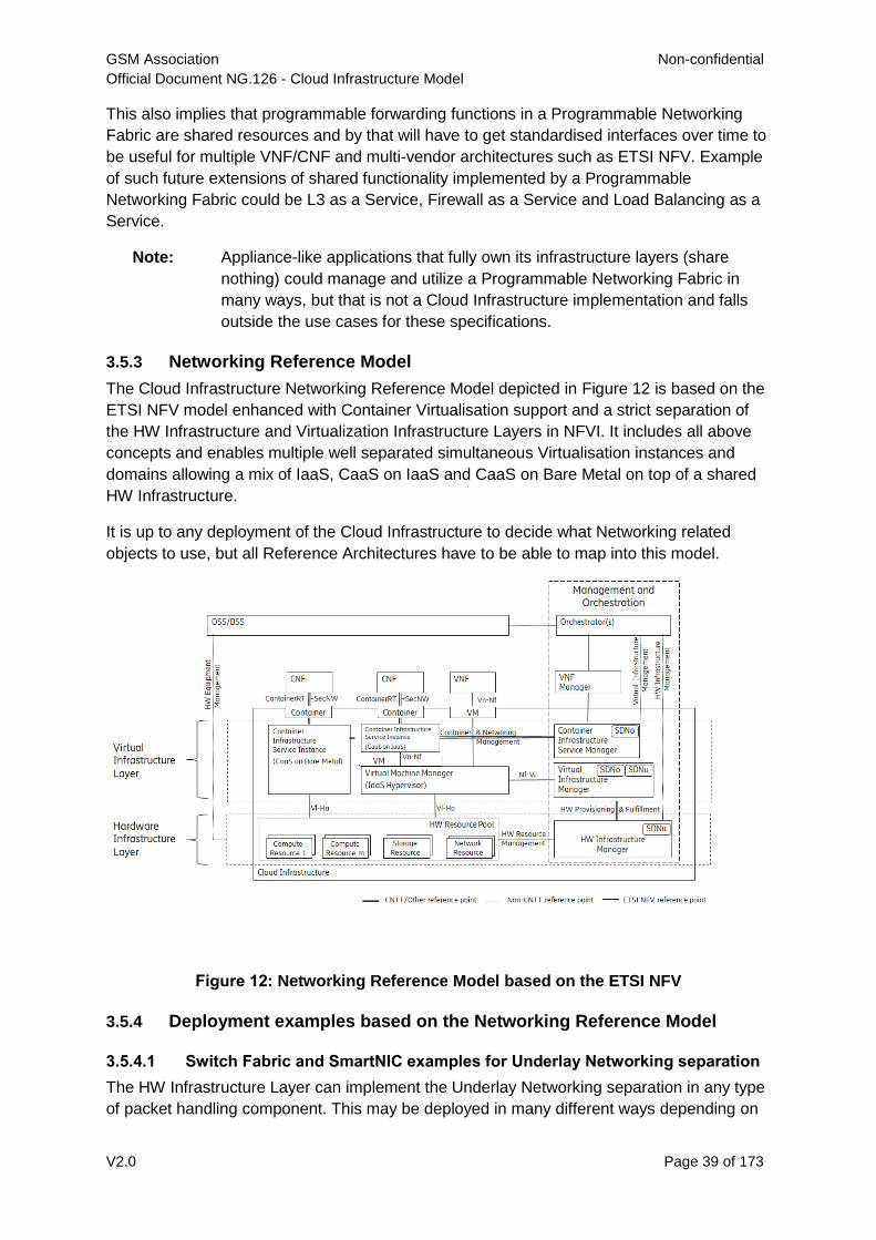
GSM Association Non-confidential
Official Document NG.126 - Cloud Infrastructure Model
V2.0 Page 39 of 173
This also implies that programmable forwarding functions in a Programmable Networking
Fabric are shared resources and by that will have to get standardised interfaces over time to
be useful for multiple VNF/CNF and multi-vendor architectures such as ETSI NFV. Example
of such future extensions of shared functionality implemented by a Programmable
Networking Fabric could be L3 as a Service, Firewall as a Service and Load Balancing as a
Service.
Note: Appliance-like applications that fully own its infrastructure layers (share
nothing) could manage and utilize a Programmable Networking Fabric in
many ways, but that is not a Cloud Infrastructure implementation and falls
outside the use cases for these specifications.
3.5.3 Networking Reference Model
The Cloud Infrastructure Networking Reference Model depicted in Figure 12 is based on the
ETSI NFV model enhanced with Container Virtualisation support and a strict separation of
the HW Infrastructure and Virtualization Infrastructure Layers in NFVI. It includes all above
concepts and enables multiple well separated simultaneous Virtualisation instances and
domains allowing a mix of IaaS, CaaS on IaaS and CaaS on Bare Metal on top of a shared
HW Infrastructure.
It is up to any deployment of the Cloud Infrastructure to decide what Networking related
objects to use, but all Reference Architectures have to be able to map into this model.
Figure 12: Networking Reference Model based on the ETSI NFV
3.5.4 Deployment examples based on the Networking Reference Model
3.5.4.1 Switch Fabric and SmartNIC examples for Underlay Networking separation
The HW Infrastructure Layer can implement the Underlay Networking separation in any type
of packet handling component. This may be deployed in many different ways depending on
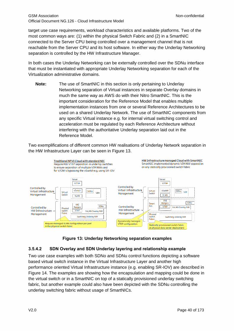
GSM Association Non-confidential
Official Document NG.126 - Cloud Infrastructure Model
V2.0 Page 40 of 173
target use case requirements, workload characteristics and available platforms. Two of the
most common ways are: (1) within the physical Switch Fabric and (2) in a SmartNIC
connected to the Server CPU being controlled over a management channel that is not
reachable from the Server CPU and its host software. In either way the Underlay Networking
separation is controlled by the HW Infrastructure Manager.
In both cases the Underlay Networking can be externally controlled over the SDNu interface
that must be instantiated with appropriate Underlay Networking separation for each of the
Virtualization administrative domains.
Note: The use of SmartNIC in this section is only pertaining to Underlay
Networking separation of Virtual instances in separate Overlay domains in
much the same way as AWS do with their Nitro SmartNIC. This is the
important consideration for the Reference Model that enables multiple
implementation instances from one or several Reference Architectures to be
used on a shared Underlay Network. The use of SmartNIC components from
any specific Virtual instance e.g. for internal virtual switching control and
acceleration must be regulated by each Reference Architecture without
interfering with the authoritative Underlay separation laid out in the
Reference Model.
Two exemplifications of different common HW realisations of Underlay Network separation in
the HW Infrastructure Layer can be seen in Figure 13.
Figure 13: Underlay Networking separation examples
3.5.4.2 SDN Overlay and SDN Underlay layering and relationship example
Two use case examples with both SDNo and SDNu control functions depicting a software
based virtual switch instance in the Virtual Infrastructure Layer and another high
performance oriented Virtual Infrastructure instance (e.g. enabling SR-IOV) are described in
Figure 14. The examples are showing how the encapsulation and mapping could be done in
the virtual switch or in a SmartNIC on top of a statically provisioned underlay switching
fabric, but another example could also have been depicted with the SDNu controlling the
underlay switching fabric without usage of SmartNICs.
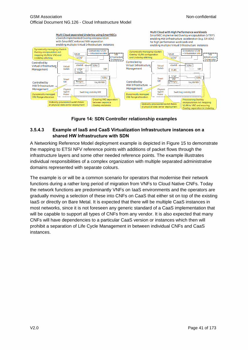
GSM Association Non-confidential
Official Document NG.126 - Cloud Infrastructure Model
V2.0 Page 41 of 173
Figure 14: SDN Controller relationship examples
3.5.4.3 Example of IaaS and CaaS Virtualization Infrastructure instances on a
shared HW Infrastructure with SDN
A Networking Reference Model deployment example is depicted in Figure 15 to demonstrate
the mapping to ETSI NFV reference points with additions of packet flows through the
infrastructure layers and some other needed reference points. The example illustrates
individual responsibilities of a complex organization with multiple separated administrative
domains represented with separate colours.
The example is or will be a common scenario for operators that modernise their network
functions during a rather long period of migration from VNFs to Cloud Native CNFs. Today
the network functions are predominantly VNFs on IaaS environments and the operators are
gradually moving a selection of these into CNFs on CaaS that either sit on top of the existing
IaaS or directly on Bare Metal. It is expected that there will be multiple CaaS instances in
most networks, since it is not foreseen any generic standard of a CaaS implementation that
will be capable to support all types of CNFs from any vendor. It is also expected that many
CNFs will have dependencies to a particular CaaS version or instances which then will
prohibit a separation of Life Cycle Management in between individual CNFs and CaaS
instances.
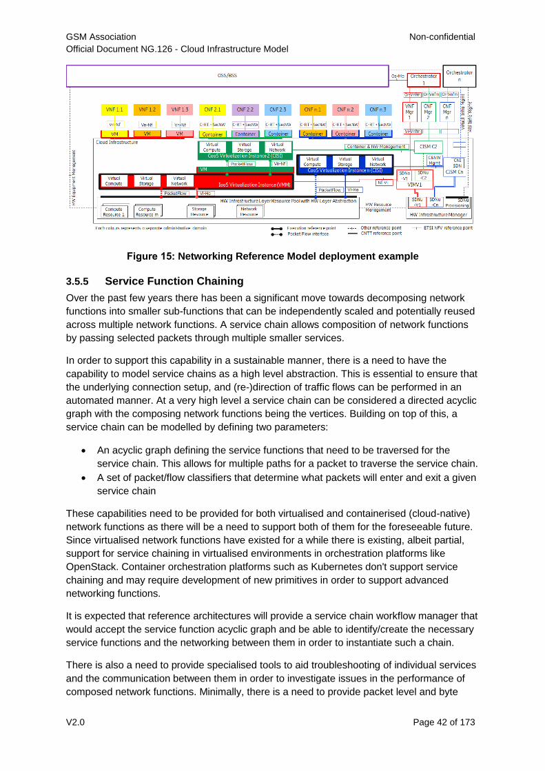
GSM Association Non-confidential
Official Document NG.126 - Cloud Infrastructure Model
V2.0 Page 42 of 173
Figure 15: Networking Reference Model deployment example
3.5.5 Service Function Chaining
Over the past few years there has been a significant move towards decomposing network
functions into smaller sub-functions that can be independently scaled and potentially reused
across multiple network functions. A service chain allows composition of network functions
by passing selected packets through multiple smaller services.
In order to support this capability in a sustainable manner, there is a need to have the
capability to model service chains as a high level abstraction. This is essential to ensure that
the underlying connection setup, and (re-)direction of traffic flows can be performed in an
automated manner. At a very high level a service chain can be considered a directed acyclic
graph with the composing network functions being the vertices. Building on top of this, a
service chain can be modelled by defining two parameters:
An acyclic graph defining the service functions that need to be traversed for the
service chain. This allows for multiple paths for a packet to traverse the service chain.
A set of packet/flow classifiers that determine what packets will enter and exit a given
service chain
These capabilities need to be provided for both virtualised and containerised (cloud-native)
network functions as there will be a need to support both of them for the foreseeable future.
Since virtualised network functions have existed for a while there is existing, albeit partial,
support for service chaining in virtualised environments in orchestration platforms like
OpenStack. Container orchestration platforms such as Kubernetes don't support service
chaining and may require development of new primitives in order to support advanced
networking functions.
It is expected that reference architectures will provide a service chain workflow manager that
would accept the service function acyclic graph and be able to identify/create the necessary
service functions and the networking between them in order to instantiate such a chain.
There is also a need to provide specialised tools to aid troubleshooting of individual services
and the communication between them in order to investigate issues in the performance of
composed network functions. Minimally, there is a need to provide packet level and byte
GSM Association Non-confidential
Official Document NG.126 - Cloud Infrastructure Model
V2.0 Page 43 of 173
level counters and statistics as the packets pass through the service chain in order to
ascertain any issues with forwarding and performance. Additionally, there is a need for
mechanisms to trace the paths of selected subsets of traffic as they flow through the service
chain.
3.5.5.1 Service Function Chaining Model Introduction
Service Function Chaining (SFC) can be visualized as a layered structure where the Service
Function plane (SFC data plane, consists of service function forwarder, classifier, service
function, service function proxy) resides over a Service Function overlay network. SFC
utilizes a service-specific overlay that creates the service topology. The service overlay
provides service function connectivity built "on top" of the existing network topology. It
leverages various overlay network technologies (e.g., Virtual eXtensible Local Area Network
(VXLAN)) for interconnecting SFC data-plane elements and allows establishing Service
Function Paths (SFPs).
In a typical overlay network, packets are routed based on networking principles and use a
suitable path for the packet to be routed from a source to its destination.
However, in a service-specific overlay network, packets are routed based on policies. This
requires specific support at network level such as at CNI in CNF environment to provide
such specific routing mechanism.
3.5.5.2 SFC Architecture
The SFC Architecture is composed of functional management, control and data components
as categorised in the Table 7 below.
The table below highlights areas under which common SFC functional components can be
categorized.
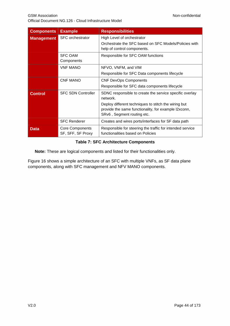
GSM Association Non-confidential
Official Document NG.126 - Cloud Infrastructure Model
V2.0 Page 44 of 173
Components Example Responsibilities
Management SFC orchestrator High Level of orchestrator
Orchestrate the SFC based on SFC Models/Policies with
help of control components.
SFC OAM
Components
Responsible for SFC OAM functions
VNF MANO NFVO, VNFM, and VIM
Responsible for SFC Data components lifecycle
CNF MANO CNF DevOps Components
Responsible for SFC data components lifecycle
Control SFC SDN Controller SDNC responsible to create the service specific overlay
network.
Deploy different techniques to stitch the wiring but
provide the same functionality, for example l2xconn,
SRv6 , Segment routing etc.
SFC Renderer Creates and wires ports/interfaces for SF data path
Data Core Components
SF, SFF, SF Proxy
Responsible for steering the traffic for intended service
functionalities based on Policies
Table 7: SFC Architecture Components
Note: These are logical components and listed for their functionalities only.
Figure 16 shows a simple architecture of an SFC with multiple VNFs, as SF data plane
components, along with SFC management and NFV MANO components.
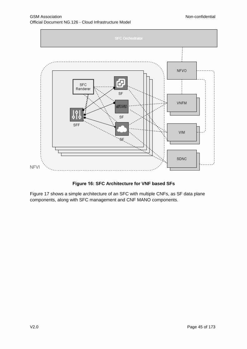
GSM Association Non-confidential
Official Document NG.126 - Cloud Infrastructure Model
V2.0 Page 45 of 173
Figure 16: SFC Architecture for VNF based SFs
Figure 17 shows a simple architecture of an SFC with multiple CNFs, as SF data plane
components, along with SFC management and CNF MANO components.
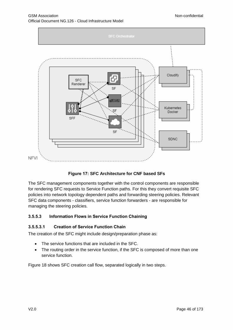
GSM Association Non-confidential
Official Document NG.126 - Cloud Infrastructure Model
V2.0 Page 46 of 173
Figure 17: SFC Architecture for CNF based SFs
The SFC management components together with the control components are responsible
for rendering SFC requests to Service Function paths. For this they convert requisite SFC
policies into network topology dependent paths and forwarding steering policies. Relevant
SFC data components - classifiers, service function forwarders - are responsible for
managing the steering policies.
3.5.5.3 Information Flows in Service Function Chaining
3.5.5.3.1 Creation of Service Function Chain
The creation of the SFC might include design/preparation phase as:
The service functions that are included in the SFC.
The routing order in the service function, if the SFC is composed of more than one
service function.
Figure 18 shows SFC creation call flow, separated logically in two steps.
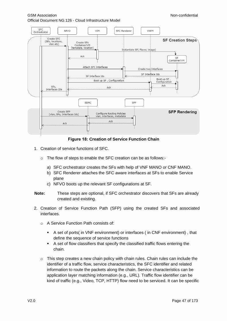
GSM Association Non-confidential
Official Document NG.126 - Cloud Infrastructure Model
V2.0 Page 47 of 173
Figure 18: Creation of Service Function Chain
1. Creation of service functions of SFC.
o The flow of steps to enable the SFC creation can be as follows:-
a) SFC orchestrator creates the SFs with help of VNF MANO or CNF MANO.
b) SFC Renderer attaches the SFC aware interfaces at SFs to enable Service
plane
c) NFVO boots up the relevant SF configurations at SF.
Note: These steps are optional, if SFC orchestrator discovers that SFs are already
created and existing.
2. Creation of Service Function Path (SFP) using the created SFs and associated
interfaces.
o A Service Function Path consists of:
A set of ports( in VNF environment) or interfaces ( in CNF environment) , that
define the sequence of service functions
A set of flow classifiers that specify the classified traffic flows entering the
chain.
o This step creates a new chain policy with chain rules. Chain rules can include the
identifier of a traffic flow, service characteristics, the SFC identifier and related
information to route the packets along the chain. Service characteristics can be
application layer matching information (e.g., URL). Traffic flow identifier can be
kind of traffic (e.g., Video, TCP, HTTP) flow need to be serviced. It can be specific
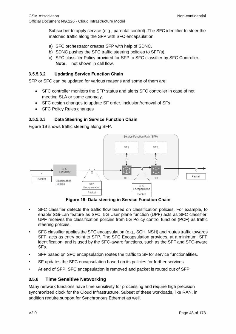
GSM Association Non-confidential
Official Document NG.126 - Cloud Infrastructure Model
V2.0 Page 48 of 173
Subscriber to apply service (e.g., parental control). The SFC identifier to steer the
matched traffic along the SFP with SFC encapsulation.
a) SFC orchestrator creates SFP with help of SDNC.
b) SDNC pushes the SFC traffic steering policies to SFF(s).
c) SFC classifier Policy provided for SFP to SFC classifier by SFC Controller.
Note: not shown in call flow.
3.5.5.3.2 Updating Service Function Chain
SFP or SFC can be updated for various reasons and some of them are:
SFC controller monitors the SFP status and alerts SFC controller in case of not
meeting SLA or some anomaly.
SFC design changes to update SF order, inclusion/removal of SFs
SFC Policy Rules changes
3.5.5.3.3 Data Steering in Service Function Chain
Figure 19 shows traffic steering along SFP.
Figure 19: Data steering in Service Function Chain
• SFC classifier detects the traffic flow based on classification policies. For example, to enable SGi-Lan feature as SFC, 5G User plane function (UPF) acts as SFC classifier. UPF receives the classification policies from 5G Policy control function (PCF) as traffic steering policies.
• SFC classifier applies the SFC encapsulation (e.g., SCH, NSH) and routes traffic towards SFF, acts as entry point to SFP. The SFC Encapsulation provides, at a minimum, SFP identification, and is used by the SFC-aware functions, such as the SFF and SFC-aware SFs.
• SFF based on SFC encapsulation routes the traffic to SF for service functionalities.
• SF updates the SFC encapsulation based on its policies for further services.
• At end of SFP, SFC encapsulation is removed and packet is routed out of SFP.
3.5.6 Time Sensitive Networking
Many network functions have time sensitivity for processing and require high precision
synchronized clock for the Cloud Infrastructure. Subset of these workloads, like RAN, in
addition require support for Synchronous Ethernet as well.
GSM Association Non-confidential
Official Document NG.126 - Cloud Infrastructure Model
V2.0 Page 49 of 173
Reason for using
Synchronous Precision
Clock Example Comment
Achieve technical requirements Strict latency or
timing accuracy
Must be done for precise low latency
communication between data source and
receiver
Achieve technical requirements Separation of
processing pipeline
Ability to separate RAN into RU, DU, CU
on different or stretch clusters
Table 8: Reasons and examples for Precise Clock and Synchronization
Precise Synchronization require specialized card that can be on server or network device motherboard or be part of NIC or both.
OpenStack and Kubernetes clusters use Network Time Protocol (NTP) (Protocol and Algorithms Specification [27], Autokey Specification [28], Managed Objects [29], Server Option for DHCPv6 [30]) as the default time synchronization for the cluster. That level of synchronization is not sufficient for some network functions. Just like real-time operating systems instead of base OS, so is precision timing for clock synchronization. Precision Time Protocol version 2 PTP [31] is commonly used for Time-Sensitive Networking. This allow synchronization in microsecond range rather than millisecond range that NTP provides.
Some Network functions, like vDU, of vRAN, also require SyncE [32]. Control, User and Synchronization (CUS) Plane specification defines different topology options that provides Lower Layer Split Control plane 1-4 (LLS-C1 - LLS-C4) with different synchronization requirements (ITU-T G.8275.2 [33]).
SyncE was standardized by the ITU-T, in cooperation with IEEE, as three recommendations:
ITU-T Rec. G.8261 that defines aspects about the architecture and the wander
performance of SyncE networks
ITU-T Rec. G.8262 that specifies Synchronous Ethernet clocks for SyncE
ITU-T Rec. G.8264 that describes the specification of Ethernet Synchronization
Messaging Channel (ESMC) SyncE architecture minimally requires replacement of
the internal clock of the Ethernet card by a phase locked loop in order to feed the
Ethernet PHY.
3.6 Storage
The general function of storage subsystem is to provide the persistent data store required for
the delivery of a network service. In the context of Cloud Infrastructure the storage sub-
system needs to accommodate needs of: the tenanted VNF applications and the platform
management. Storage is multi-faceted and so can be classified based on its: cost,
performance (IOPS, throughput, latency), capacity and consumption model (platform native,
network shared, object or archival) and the underlying implementation model (in chassis,
software defined, appliance). A simplified view of this is provided in the following illustrative
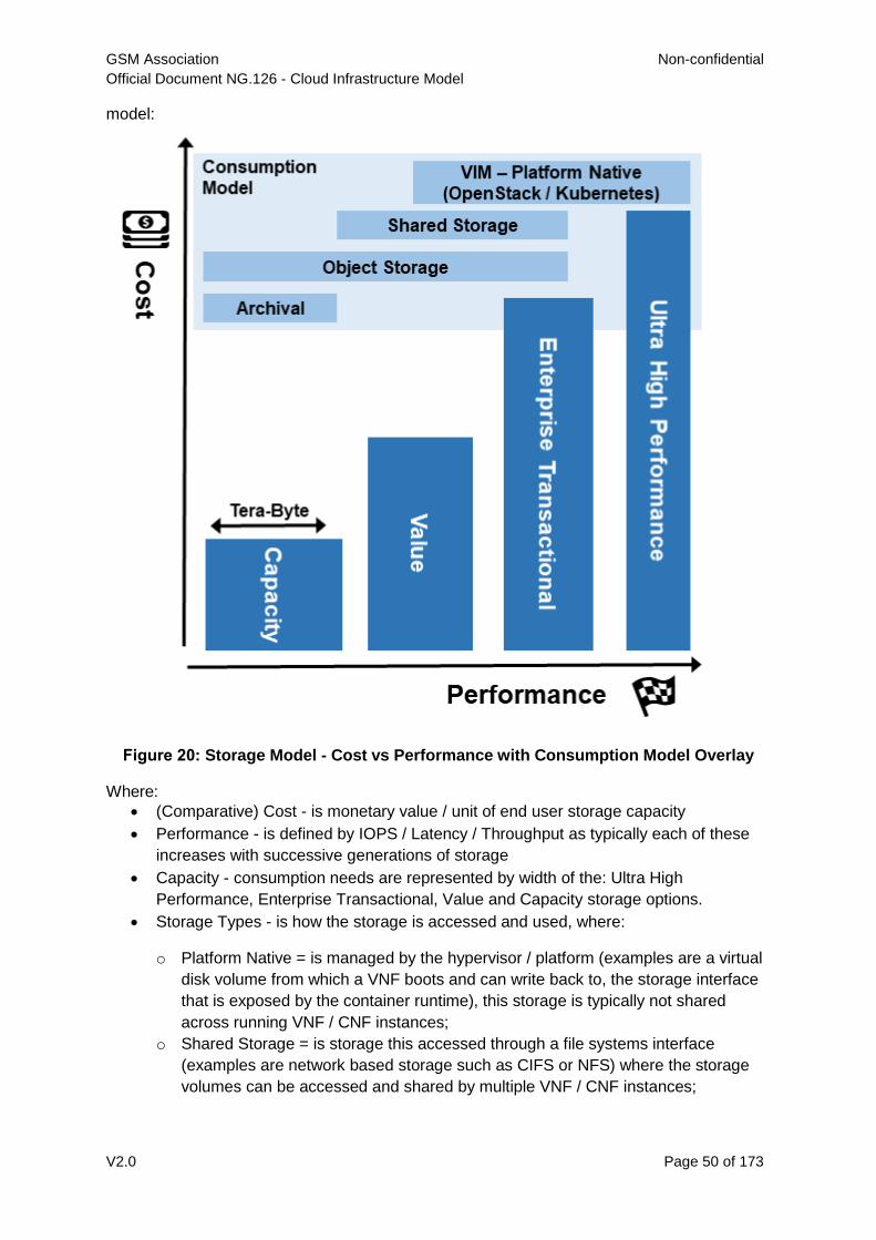
GSM Association Non-confidential
Official Document NG.126 - Cloud Infrastructure Model
V2.0 Page 50 of 173
model:
Figure 20: Storage Model - Cost vs Performance with Consumption Model Overlay
Where:
(Comparative) Cost - is monetary value / unit of end user storage capacity
Performance - is defined by IOPS / Latency / Throughput as typically each of these
increases with successive generations of storage
Capacity - consumption needs are represented by width of the: Ultra High
Performance, Enterprise Transactional, Value and Capacity storage options.
Storage Types - is how the storage is accessed and used, where:
o Platform Native = is managed by the hypervisor / platform (examples are a virtual
disk volume from which a VNF boots and can write back to, the storage interface
that is exposed by the container runtime), this storage is typically not shared
across running VNF / CNF instances;
o Shared Storage = is storage this accessed through a file systems interface
(examples are network based storage such as CIFS or NFS) where the storage
volumes can be accessed and shared by multiple VNF / CNF instances;
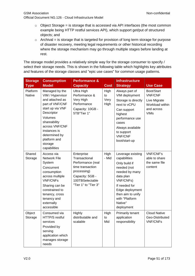
GSM Association Non-confidential
Official Document NG.126 - Cloud Infrastructure Model
V2.0 Page 51 of 173
o Object Storage = is storage that is accessed via API interfaces (the most common
example being HTTP restful services API), which support get/put of structured
objects; and
o Archival = is storage that is targeted for provision of long term storage for purpose
of disaster recovery, meeting legal requirements or other historical recording
where the storage mechanism may go through multiple stages before landing at
rest.
The storage model provides a relatively simple way for the storage consumer to specify /
select their storage needs. This is shown in the following table which highlights key attributes
and features of the storage classes and "epic use cases" for common usage patterns.
Storage
Type
Consumption
Model
Performance &
Capacity Cost
Infrastructure
Strategy Use Case
Platform
Native
Managed by the
VIM / Hypervisor
and attached as
part of VNF/CNF
start up via VNF
Descriptor
Volumes
shareability
across VNF/CNF
instances is
determined by
platform and
storage
capabilities
Ultra High
Performance &
Very High
Performance
Capacity: 10GB -
5TB"Tier 1"
High
to
Very
High
Always part of
VIM deployment
Storage is directly
next to vCPU
Can support
highest
performance use
cases
Always available
to support
VNF/CNF
boot/start-up
Boot/Start
VNF/CNF
Live Migrate
Workload within
and across
VIMs
Shared
Storage
Access via
Network File
System
Concurrent
consumption
across multiple
VNF/CNFs
Sharing can be
constrained to
tenancy, cross
tenancy and
externally
accessible
Enterprise
Transactional
Performance (real
time transaction
processing)
Capacity: 5GB -
100TBSelectable
"Tier 1" to "Tier 3"
High
- Mid
Leverage existing
capabilities
Only build if
needed (not
needed by many
data plan
VNF/CNFs)
If needed for
Edge deployment
then aim to unify
with "Platform
Native"
deployment
VNF/CNF's
able to share
the same file
content
Object
Storage
Consumed via
HTTP/S restful
services
Provided by
serving
application which
manages storage
needs
Highly
distributable and
scalable
High
to
Mid
Primarily tenant
application
responsibility
Cloud Native
Geo-Distributed
VNF/CNFs
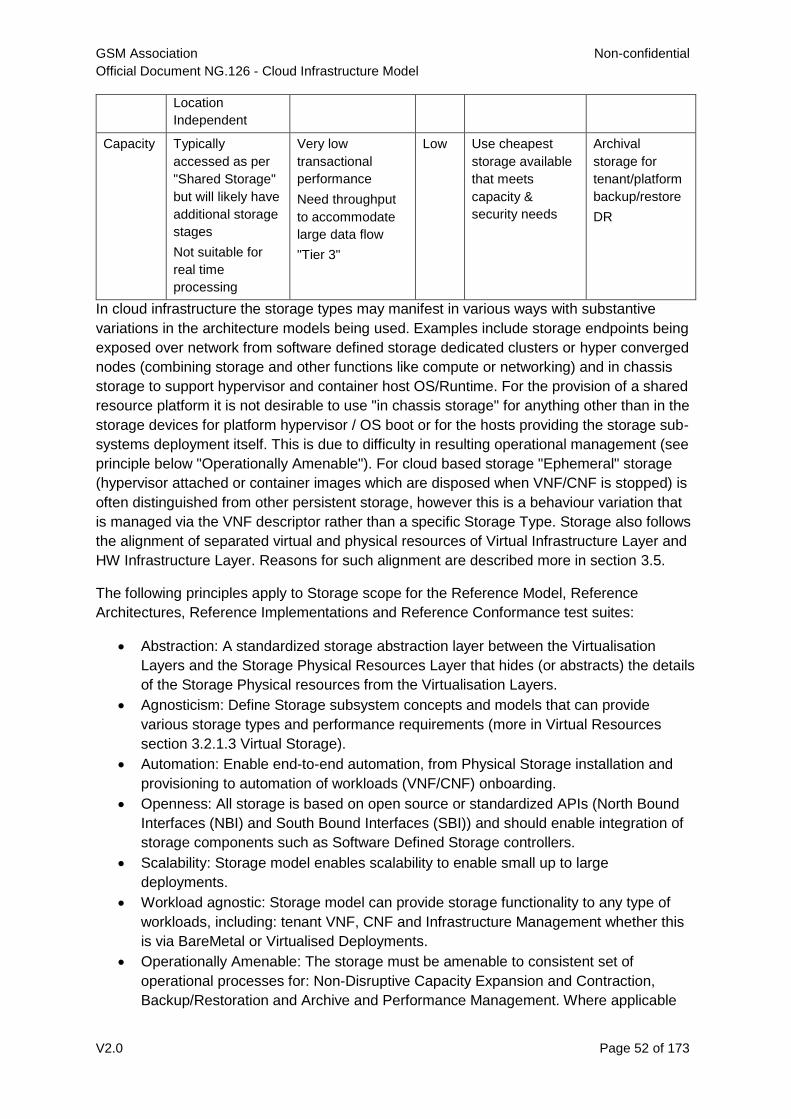
GSM Association Non-confidential
Official Document NG.126 - Cloud Infrastructure Model
V2.0 Page 52 of 173
Location
Independent
Capacity Typically
accessed as per
"Shared Storage"
but will likely have
additional storage
stages
Not suitable for
real time
processing
Very low
transactional
performance
Need throughput
to accommodate
large data flow
"Tier 3"
Low Use cheapest
storage available
that meets
capacity &
security needs
Archival
storage for
tenant/platform
backup/restore
DR
In cloud infrastructure the storage types may manifest in various ways with substantive
variations in the architecture models being used. Examples include storage endpoints being
exposed over network from software defined storage dedicated clusters or hyper converged
nodes (combining storage and other functions like compute or networking) and in chassis
storage to support hypervisor and container host OS/Runtime. For the provision of a shared
resource platform it is not desirable to use "in chassis storage" for anything other than in the
storage devices for platform hypervisor / OS boot or for the hosts providing the storage sub-
systems deployment itself. This is due to difficulty in resulting operational management (see
principle below "Operationally Amenable"). For cloud based storage "Ephemeral" storage
(hypervisor attached or container images which are disposed when VNF/CNF is stopped) is
often distinguished from other persistent storage, however this is a behaviour variation that
is managed via the VNF descriptor rather than a specific Storage Type. Storage also follows
the alignment of separated virtual and physical resources of Virtual Infrastructure Layer and
HW Infrastructure Layer. Reasons for such alignment are described more in section 3.5.
The following principles apply to Storage scope for the Reference Model, Reference
Architectures, Reference Implementations and Reference Conformance test suites:
Abstraction: A standardized storage abstraction layer between the Virtualisation
Layers and the Storage Physical Resources Layer that hides (or abstracts) the details
of the Storage Physical resources from the Virtualisation Layers.
Agnosticism: Define Storage subsystem concepts and models that can provide
various storage types and performance requirements (more in Virtual Resources
section 3.2.1.3 Virtual Storage).
Automation: Enable end-to-end automation, from Physical Storage installation and
provisioning to automation of workloads (VNF/CNF) onboarding.
Openness: All storage is based on open source or standardized APIs (North Bound
Interfaces (NBI) and South Bound Interfaces (SBI)) and should enable integration of
storage components such as Software Defined Storage controllers.
Scalability: Storage model enables scalability to enable small up to large
deployments.
Workload agnostic: Storage model can provide storage functionality to any type of
workloads, including: tenant VNF, CNF and Infrastructure Management whether this
is via BareMetal or Virtualised Deployments.
Operationally Amenable: The storage must be amenable to consistent set of
operational processes for: Non-Disruptive Capacity Expansion and Contraction,
Backup/Restoration and Archive and Performance Management. Where applicable
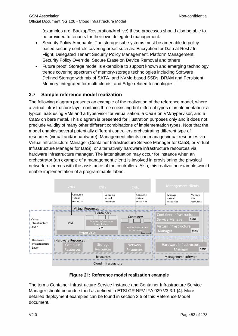
GSM Association Non-confidential
Official Document NG.126 - Cloud Infrastructure Model
V2.0 Page 53 of 173
(examples are: Backup/Restoration/Archive) these processes should also be able to
be provided to tenants for their own delegated management.
Security Policy Amenable: The storage sub-systems must be amenable to policy
based security controls covering areas such as: Encryption for Data at Rest / In
Flight, Delegated Tenant Security Policy Management, Platform Management
Security Policy Override, Secure Erase on Device Removal and others
Future proof: Storage model is extendible to support known and emerging technology
trends covering spectrum of memory-storage technologies including Software
Defined Storage with mix of SATA- and NVMe-based SSDs, DRAM and Persistent
Memory, integrated for multi-clouds, and Edge related technologies.
3.7 Sample reference model realization
The following diagram presents an example of the realization of the reference model, where
a virtual infrastructure layer contains three coexisting but different types of implementation: a
typical IaaS using VMs and a hypervisor for virtualisation, a CaaS on VM/hypervisor, and a
CaaS on bare metal. This diagram is presented for illustration purposes only and it does not
preclude validity of many other different combinations of implementation types. Note that the
model enables several potentially different controllers orchestrating different type of
resources (virtual and/or hardware). Management clients can manage virtual resources via
Virtual Infrastructure Manager (Container Infrastructure Service Manager for CaaS, or Virtual
Infrastructure Manager for IaaS), or alternatively hardware infrastructure resources via
hardware infrastructure manager. The latter situation may occur for instance when an
orchestrator (an example of a management client) is involved in provisioning the physical
network resources with the assistance of the controllers. Also, this realization example would
enable implementation of a programmable fabric.
Figure 21: Reference model realization example
The terms Container Infrastructure Service Instance and Container Infrastructure Service
Manager should be understood as defined in ETSI GR NFV-IFA 029 V3.3.1 [4]. More
detailed deployment examples can be found in section 3.5 of this Reference Model
document.
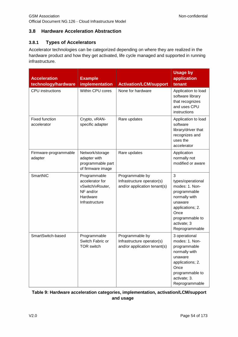
GSM Association Non-confidential
Official Document NG.126 - Cloud Infrastructure Model
V2.0 Page 54 of 173
3.8 Hardware Acceleration Abstraction
3.8.1 Types of Accelerators
Accelerator technologies can be categorized depending on where they are realized in the
hardware product and how they get activated, life cycle managed and supported in running
infrastructure.
Acceleration
technology/hardware
Example
implementation Activation/LCM/support
Usage by
application
tenant
CPU instructions Within CPU cores None for hardware Application to load
software library
that recognizes
and uses CPU
instructions
Fixed function
accelerator
Crypto, vRAN-
specific adapter
Rare updates Application to load
software
library/driver that
recognizes and
uses the
accelerator
Firmware-programmable
adapter
Network/storage
adapter with
programmable part
of firmware image
Rare updates Application
normally not
modified or aware
SmartNIC Programmable
accelerator for
vSwitch/vRouter,
NF and/or
Hardware
Infrastructure
Programmable by
Infrastructure operator(s)
and/or application tenant(s)
3
types/operational
modes: 1. Non-
programmable
normally with
unaware
applications; 2.
Once
programmable to
activate; 3
Reprogrammable
SmartSwitch-based Programmable
Switch Fabric or
TOR switch
Programmable by
Infrastructure operator(s)
and/or application tenant(s)
3 operational
modes: 1. Non-
programmable
normally with
unaware
applications; 2.
Once
programmable to
activate; 3.
Reprogrammable
Table 9: Hardware acceleration categories, implementation, activation/LCM/support
and usage
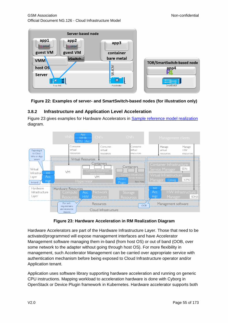
GSM Association Non-confidential
Official Document NG.126 - Cloud Infrastructure Model
V2.0 Page 55 of 173
Figure 22: Examples of server- and SmartSwitch-based nodes (for illustration only)
3.8.2 Infrastructure and Application Level Acceleration
Figure 23 gives examples for Hardware Accelerators in Sample reference model realization
diagram.
Figure 23: Hardware Acceleration in RM Realization Diagram
Hardware Accelerators are part of the Hardware Infrastructure Layer. Those that need to be
activated/programmed will expose management interfaces and have Accelerator
Management software managing them in-band (from host OS) or out of band (OOB, over
some network to the adapter without going through host OS). For more flexibility in
management, such Accelerator Management can be carried over appropriate service with
authentication mechanism before being exposed to Cloud Infrastructure operator and/or
Application tenant.
Application uses software library supporting hardware acceleration and running on generic
CPU instructions. Mapping workload to acceleration hardware is done with Cyborg in
OpenStack or Device Plugin framework in Kubernetes. Hardware accelerator supports both
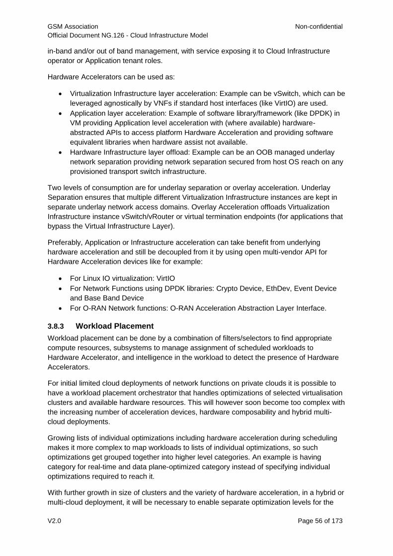
GSM Association Non-confidential
Official Document NG.126 - Cloud Infrastructure Model
V2.0 Page 56 of 173
in-band and/or out of band management, with service exposing it to Cloud Infrastructure
operator or Application tenant roles.
Hardware Accelerators can be used as:
Virtualization Infrastructure layer acceleration: Example can be vSwitch, which can be
leveraged agnostically by VNFs if standard host interfaces (like VirtIO) are used.
Application layer acceleration: Example of software library/framework (like DPDK) in
VM providing Application level acceleration with (where available) hardware-
abstracted APIs to access platform Hardware Acceleration and providing software
equivalent libraries when hardware assist not available.
Hardware Infrastructure layer offload: Example can be an OOB managed underlay
network separation providing network separation secured from host OS reach on any
provisioned transport switch infrastructure.
Two levels of consumption are for underlay separation or overlay acceleration. Underlay
Separation ensures that multiple different Virtualization Infrastructure instances are kept in
separate underlay network access domains. Overlay Acceleration offloads Virtualization
Infrastructure instance vSwitch/vRouter or virtual termination endpoints (for applications that
bypass the Virtual Infrastructure Layer).
Preferably, Application or Infrastructure acceleration can take benefit from underlying
hardware acceleration and still be decoupled from it by using open multi-vendor API for
Hardware Acceleration devices like for example:
For Linux IO virtualization: VirtIO
For Network Functions using DPDK libraries: Crypto Device, EthDev, Event Device
and Base Band Device
For O-RAN Network functions: O-RAN Acceleration Abstraction Layer Interface.
3.8.3 Workload Placement
Workload placement can be done by a combination of filters/selectors to find appropriate
compute resources, subsystems to manage assignment of scheduled workloads to
Hardware Accelerator, and intelligence in the workload to detect the presence of Hardware
Accelerators.
For initial limited cloud deployments of network functions on private clouds it is possible to
have a workload placement orchestrator that handles optimizations of selected virtualisation
clusters and available hardware resources. This will however soon become too complex with
the increasing number of acceleration devices, hardware composability and hybrid multi-
cloud deployments.
Growing lists of individual optimizations including hardware acceleration during scheduling
makes it more complex to map workloads to lists of individual optimizations, so such
optimizations get grouped together into higher level categories. An example is having
category for real-time and data plane-optimized category instead of specifying individual
optimizations required to reach it.
With further growth in size of clusters and the variety of hardware acceleration, in a hybrid or
multi-cloud deployment, it will be necessary to enable separate optimization levels for the
GSM Association Non-confidential
Official Document NG.126 - Cloud Infrastructure Model
V2.0 Page 57 of 173
workload placement and each Cloud Infrastructure provider. The workload placement
orchestrator will operate on one or several Cloud Infrastructures resources to satisfy the
workloads according to Service Level Agreements (SLA) that do not specify all
implementation and resource details. Each Cloud Infrastructure provider will make internal
Infrastructure optimisations towards their own internal optimisation targets whilst fulfilling the
SLAs.
3.8.4 CPU Instructions
The CPU architecture often includes instructions and execution blocks for most common
compute-heavy algorithms like block cypher (example AES-NI), Random Number Generator
or vector instructions. These functions are normally consumed in infrastructure software or
applications by using enabled software libraries that run faster when custom CPU
instructions for the execution of such functions are available in hardware and slower when
these specific instructions are not available in hardware as only the general CPU instructions
are used. Custom CPU instructions don’t need to be activated or life-cycle-managed. When
scheduling workloads, compute nodes with such custom CPU instructions can be found by
applications or an orchestrator using OpenStack Nova filters or Kubernetes Node Feature
Discovery labels, or directly from the Hardware Management layer.
3.8.5 Fixed Function Accelerators
Fixed function accelerators can come as adapters with in-line (typically PCIe adapter with
Ethernet ports or storage drives) or look-aside (typically PCIe adapters without any external
ports) functionality, additional chip on motherboard, included into server chipsets or
packaged/embedded into main CPU. They can accelerate cryptographic functions, highly
parallelized or other specific algorithms. Initial activation and rare life cycle management
events (like updating firmware image) can typically be done from the Host OS (e.g. the OS
driver or a Library), the Hardware Infrastructure Manager (from a library) or the NF (mostly
through a library).
Beyond finding such compute nodes during scheduling workloads, those workloads also
need to be mapped to the accelerator, both of which in Kubernetes can be done with Device
Plugin framework. Once mapped to the application, the application can use enabled
software libraries and/or device drivers that will use hardware acceleration. If hardware
acceleration is used to improve cost/performance, then application can also run on generic
compute node without hardware accelerator when application will use the same software
library to run on generic CPU instructions.
3.8.6 Firmware-programmable Adapters
Firmware-programmable network adapters with programmable pipeline are types of network
adapters where usual Ethernet controller functionality (accelerates common network
overlays, checksums or protocol termination) can be extended with partially programmable
modules so that additional protocols can be recognized, parsed and put into specific queues,
which helps increase performance and reduce load on main CPU.
Firmware-programmable storage adapters can offload some of the storage functionality and
include storage drive emulation to enable partial drive assignments up to the accessing host
OS. These adapters can over time include more supported storage offload functions or
support more drive emulation functions.
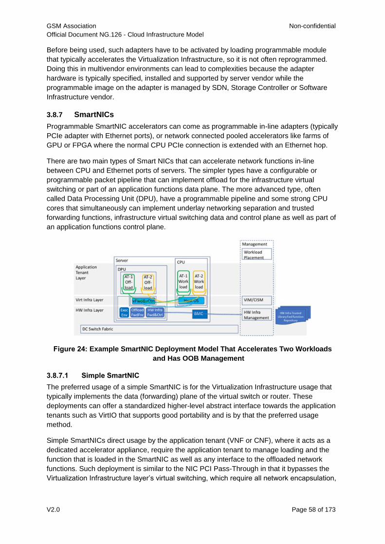
GSM Association Non-confidential
Official Document NG.126 - Cloud Infrastructure Model
V2.0 Page 58 of 173
Before being used, such adapters have to be activated by loading programmable module
that typically accelerates the Virtualization Infrastructure, so it is not often reprogrammed.
Doing this in multivendor environments can lead to complexities because the adapter
hardware is typically specified, installed and supported by server vendor while the
programmable image on the adapter is managed by SDN, Storage Controller or Software
Infrastructure vendor.
3.8.7 SmartNICs
Programmable SmartNIC accelerators can come as programmable in-line adapters (typically
PCIe adapter with Ethernet ports), or network connected pooled accelerators like farms of
GPU or FPGA where the normal CPU PCIe connection is extended with an Ethernet hop.
There are two main types of Smart NICs that can accelerate network functions in-line
between CPU and Ethernet ports of servers. The simpler types have a configurable or
programmable packet pipeline that can implement offload for the infrastructure virtual
switching or part of an application functions data plane. The more advanced type, often
called Data Processing Unit (DPU), have a programmable pipeline and some strong CPU
cores that simultaneously can implement underlay networking separation and trusted
forwarding functions, infrastructure virtual switching data and control plane as well as part of
an application functions control plane.
Figure 24: Example SmartNIC Deployment Model That Accelerates Two Workloads
and Has OOB Management
3.8.7.1 Simple SmartNIC
The preferred usage of a simple SmartNIC is for the Virtualization Infrastructure usage that
typically implements the data (forwarding) plane of the virtual switch or router. These
deployments can offer a standardized higher-level abstract interface towards the application
tenants such as VirtIO that supports good portability and is by that the preferred usage
method.
Simple SmartNICs direct usage by the application tenant (VNF or CNF), where it acts as a
dedicated accelerator appliance, require the application tenant to manage loading and the
function that is loaded in the SmartNIC as well as any interface to the offloaded network
functions. Such deployment is similar to the NIC PCI Pass-Through in that it bypasses the
Virtualization Infrastructure layer’s virtual switching, which require all network encapsulation,
GSM Association Non-confidential
Official Document NG.126 - Cloud Infrastructure Model
V2.0 Page 59 of 173
mapping and separation to be done by the underlay network, often by manual provisioning
and therefore is not a preferred usage method.
3.8.7.2 DPU
The DPU can accelerate software infrastructure functions (vSwitch/vRouter) from the main
CPU and simultaneously offer networking services e.g. load balancers, firewalls and
application tenant offload functions. Through Out of band management it can also ensure
underlay separation and map a selected part of the underlay network to the specific
Virtualization Infrastructure instance that the server it is mounted on requires allowing them
to be used on any statically provisioned underlay network.
The forwarding path (data plane) needs to be installed and controlled by the Hardware
Infrastructure Manager through an isolated Out of band management channel into the DPU
control and operating system completely out of reach for the main CPU Host SW. All content
in the forwarding path must come from Hardware Infrastructure operator trusted code since
any fault or malicious content can seriously disturb the whole network for all connected
devices.
The trusted forwarding functions must be handled through a Hardware Infrastructure
Management repository and have APIs for their respective control functions. These APIs
must have an ability to handle some version differences since the forwarding and control
planes life cycle management will not be atomic. The offload functions that should be offered
as services must have published and preferably standardized open APIs, but the application
specific forwarding functions do not have to be open APIs since they will only communicate
with the application tenant provided control functions. P4 (see https://p4.org/) and
OpenConfig (see https://openconfig.net/) are examples of suitable languages and models,
with different levels of flexibility, usable for these forwarding and control functions.
The separated management channel could either come in through the Baseband
Management Controller (BMC), a direct management port on the DPU or through a
management VPN on the switch ports. This enable the Hardware Infrastructure
Management to automate its networking through the DPU without any need to dynamically
manage the switch fabric, thereby enabling a free choice of switch fabric vendor. These
deployments allow the switch fabric to be statically provisioned by the operators networking
operation unit, as it is often required.
The DPU can offload control and data plane of the virtual switching to the DPU as well as
trusted hardware offload for virtualized Packet Core and Radio data plane networking and
transport related functionality in a power efficient way. It can also offload relevant application
tenant control functions if the DPU offers an Execution Environment for VMs or containers
and there is space and performance headroom. In such cases the DPU must also setup a
communication channel into respective application tenant environment.
3.8.8 Smart Switches
Smart Switches can be broadly categorized into Configurable Switches and Programmable
Switches.
Configurable Smart Switches run generic “smart” configurable network operating system
offering full range of network functionality and are flexible enough to support most network
GSM Association Non-confidential
Official Document NG.126 - Cloud Infrastructure Model
V2.0 Page 60 of 173
solutions. The most common such network operating system is Linux-based SONiC (see
https://azure.github.io/SONiC/) allowing hardware and software disaggregation by running
on switches from multiple switch vendors with different types of vendor fixed-function
Application-Specific Integrated Circuits (ASIC). Still, SONiC today cannot implement new
type of data plane functionality or patch/modify/correct an ASIC, which is the type of support
offered by programmable smart switches.
Programmable Smart Switches make it possible to quickly support new or correct/modify
existing protocols and network functions, allow end customers to implement network
functions, and to only implement and load functionality that is needed. Such switches contain
one or more programmable switch ASICs of the same or different types. The two most used
programming languages are P4 (see https://p4.org/) and NPL (see https://nplang.org/), and
both can be used with vendor-specific toolchains to program their switch ASICs and/or
FPGAs. Open Networking Foundation Stratum (see https://opennetworking.org/stratum/) is
an example of network operating system that offers generic life cycle management control
services for the P4 components and a management API. The control API for the individual
network functions are not part of the Stratum APIs.
Based on Smart Switches, products exist for fully integrated edge and fabric solutions from
vendors like Arista, Cisco or Kaloom.
3.8.9 Decoupling Applications from Infrastructure and Platform with
Hardware Acceleration
Decoupling applications (see section B.7) from hardware accelerator is normally accomplished using drivers that, if available, are preferred with standardised interfaces across vendors and their products, or if not available then through drivers specific to the vendor hardware device. Decoupling infrastructure software from hardware accelerators is also preferred using standard interfaces. If those are not available for target hardware accelerator, coupling one or limited number of software infrastructures is less of an issue compared to coupling multiple applications.
Taking advantage of RM and RA environments with common capabilities, applications can be developed and deployed more rapidly, providing more service agility and easier operations. The extent to which this can be achieved will depend on levels of decoupling between application and infrastructure or platform underneath the application:
3.8.9.1 Infrastructure:
a) Application functionality or application control requires infrastructure
components beyond RM profiles or infrastructure configuration changes
beyond APIs specified by RA. Generally, such an application is tightly coupled
with the infrastructure which results in an Appliance deployment model (see
section B.7).
b) Application control using APIs specified by RA finds nodes (already configured
in support of the profiles) with the required infrastructure component(s), and in
that node using APIs specified by RA configures infrastructure components
that make application work. Example is an application that to achieve latency
requirements needs certain hardware acceleration available in RM profile and
is exposed through APIs specified by RA.
c) Application control using APIs specified by RA finds nodes (already configured
in support of the profiles) with optional infrastructure component(s), and in
GSM Association Non-confidential
Official Document NG.126 - Cloud Infrastructure Model
V2.0 Page 61 of 173
these nodes using APIs specified by RA configures infrastructure
component(s) that make application work better (like more performant) than
without that infrastructure component. Example is an application that would
have better cost/performance with certain acceleration adapter but can also
work without it.
d) Application control using APIs specified by RA finds general profile nodes
without any specific infrastructure components.
3.8.9.2 Platform Services:
a) Application functionality or application control can work only with its own
components instead of using defined Platform Services. Example is an
application that brings its own Load Balancer.
b) With custom integration effort, application can be made to use defined
Platform Services. Example is application that with custom integration effort
can use defined Load Balancer which can be accelerated with hardware
acceleration in way that is fully decoupled from application (i.e. application
does not have awareness of Load Balancer being hardware-accelerated).
c) Application is designed and can be configured for running with defined
Platform Services. Example is application that can be configured to use
defined Load Balancer which can be accelerated with hardware acceleration.
4 Infrastructure Capabilities, Measurements and Catalogue
4.1 Capabilities and Performance Measurements
This section describes and uniquely identifies the Capabilities provided directly by the
Infrastructure, as well as Performance Measurements (PMs) generated directly by the
Infrastructure (i.e. without the use of external instrumentation).
The Capability and PM identifiers conform to the following schema:
a.b.c (Ex. "e.pm.001")
a = Scope <(e)xternal | (i)nternal | (t)hird_party_instrumentation>
b = Type <(cap) capability | (man) management | (pm) performance | (man-
pm)>
c = Serial Number
4.1.1 Exposed vs Internal
The following pertains to the context of Cloud Infrastructure Resources, Capabilities and
Performance Measurements (PMs) as discussed within this chapter.
Exposed: Refers to any object (e.g., resource discovery/configuration/consumption, platform
telemetry, Interface, etc.) that exists in or pertains to, the domain of the Cloud Infrastructure
and is made visible (aka “Exposed”) to a workload. When an object is exposed to a given
workload, the scope of visibility within a given workload is at the discretion of the specific
workload’s designer. From an Infra perspective, the Infra-resident object is simply being
exposed to one or more virtual environments (i.e. Workloads). It is then the responsibility of
the kernel or supervisor/executive within the VM to control how, when and where the object
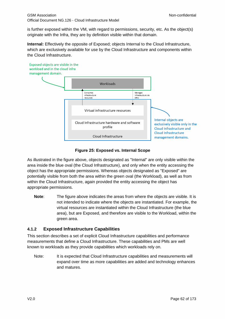
GSM Association Non-confidential
Official Document NG.126 - Cloud Infrastructure Model
V2.0 Page 62 of 173
is further exposed within the VM, with regard to permissions, security, etc. As the object(s)
originate with the Infra, they are by definition visible within that domain.
Internal: Effectively the opposite of Exposed; objects Internal to the Cloud Infrastructure,
which are exclusively available for use by the Cloud Infrastructure and components within
the Cloud Infrastructure.
Figure 25: Exposed vs. Internal Scope
As illustrated in the figure above, objects designated as "Internal" are only visible within the
area inside the blue oval (the Cloud Infrastructure), and only when the entity accessing the
object has the appropriate permissions. Whereas objects designated as "Exposed" are
potentially visible from both the area within the green oval (the Workload), as well as from
within the Cloud Infrastructure, again provided the entity accessing the object has
appropriate permissions.
Note: The figure above indicates the areas from where the objects are visible. It is
not intended to indicate where the objects are instantiated. For example, the
virtual resources are instantiated within the Cloud Infrastructure (the blue
area), but are Exposed, and therefore are visible to the Workload, within the
green area.
4.1.2 Exposed Infrastructure Capabilities
This section describes a set of explicit Cloud Infrastructure capabilities and performance
measurements that define a Cloud Infrastructure. These capabilities and PMs are well
known to workloads as they provide capabilities which workloads rely on.
Note: It is expected that Cloud Infrastructure capabilities and measurements will
expand over time as more capabilities are added and technology enhances
and matures.
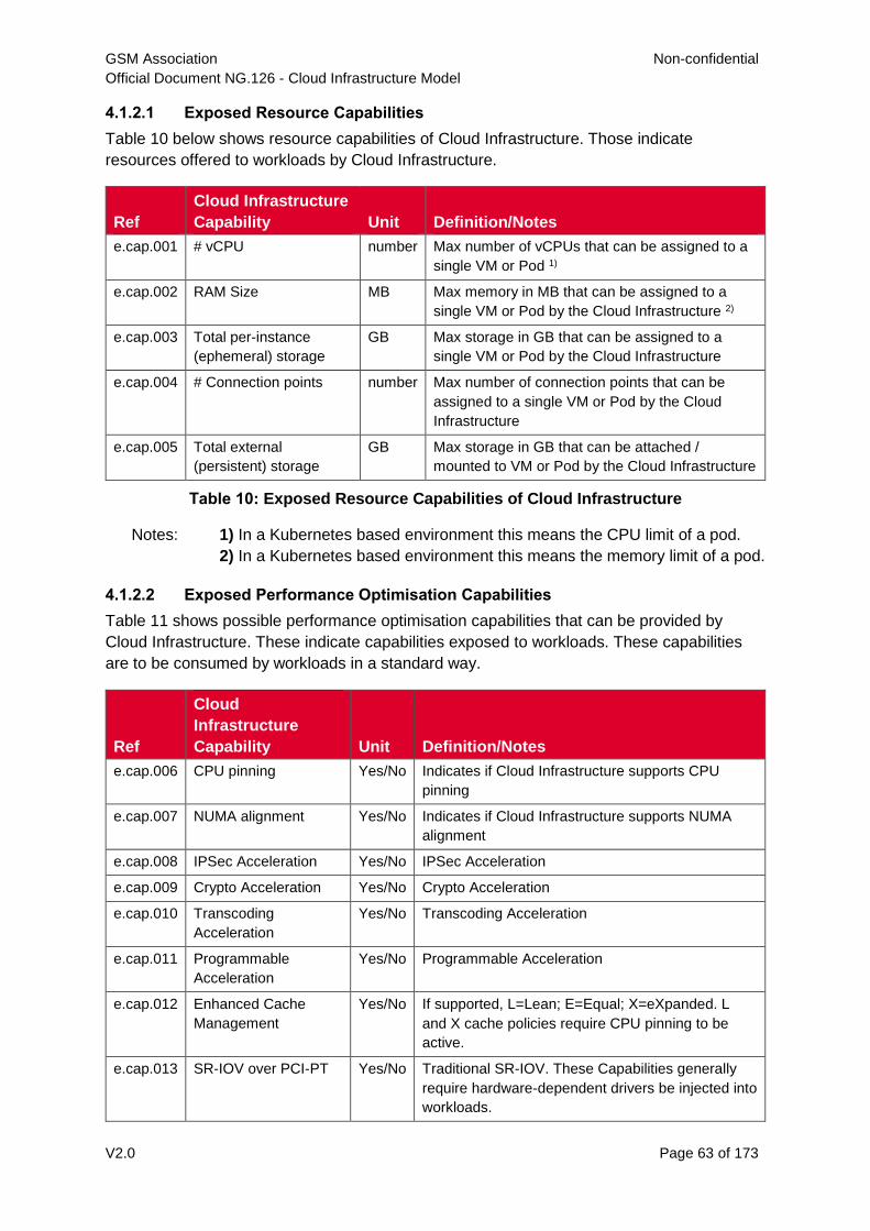
GSM Association Non-confidential
Official Document NG.126 - Cloud Infrastructure Model
V2.0 Page 63 of 173
4.1.2.1 Exposed Resource Capabilities
Table 10 below shows resource capabilities of Cloud Infrastructure. Those indicate
resources offered to workloads by Cloud Infrastructure.
Ref
Cloud Infrastructure
Capability Unit Definition/Notes
e.cap.001 # vCPU number Max number of vCPUs that can be assigned to a
single VM or Pod 1)
e.cap.002 RAM Size MB Max memory in MB that can be assigned to a
single VM or Pod by the Cloud Infrastructure 2)
e.cap.003 Total per-instance
(ephemeral) storage
GB Max storage in GB that can be assigned to a
single VM or Pod by the Cloud Infrastructure
e.cap.004 # Connection points number Max number of connection points that can be
assigned to a single VM or Pod by the Cloud
Infrastructure
e.cap.005 Total external
(persistent) storage
GB Max storage in GB that can be attached /
mounted to VM or Pod by the Cloud Infrastructure
Table 10: Exposed Resource Capabilities of Cloud Infrastructure
Notes: 1) In a Kubernetes based environment this means the CPU limit of a pod.
2) In a Kubernetes based environment this means the memory limit of a pod.
4.1.2.2 Exposed Performance Optimisation Capabilities
Table 11 shows possible performance optimisation capabilities that can be provided by
Cloud Infrastructure. These indicate capabilities exposed to workloads. These capabilities
are to be consumed by workloads in a standard way.
Ref
Cloud
Infrastructure
Capability Unit Definition/Notes
e.cap.006 CPU pinning Yes/No Indicates if Cloud Infrastructure supports CPU
pinning
e.cap.007 NUMA alignment Yes/No Indicates if Cloud Infrastructure supports NUMA
alignment
e.cap.008 IPSec Acceleration Yes/No IPSec Acceleration
e.cap.009 Crypto Acceleration Yes/No Crypto Acceleration
e.cap.010 Transcoding
Acceleration
Yes/No Transcoding Acceleration
e.cap.011 Programmable
Acceleration
Yes/No Programmable Acceleration
e.cap.012 Enhanced Cache
Management
Yes/No If supported, L=Lean; E=Equal; X=eXpanded. L
and X cache policies require CPU pinning to be
active.
e.cap.013 SR-IOV over PCI-PT Yes/No Traditional SR-IOV. These Capabilities generally
require hardware-dependent drivers be injected into
workloads.
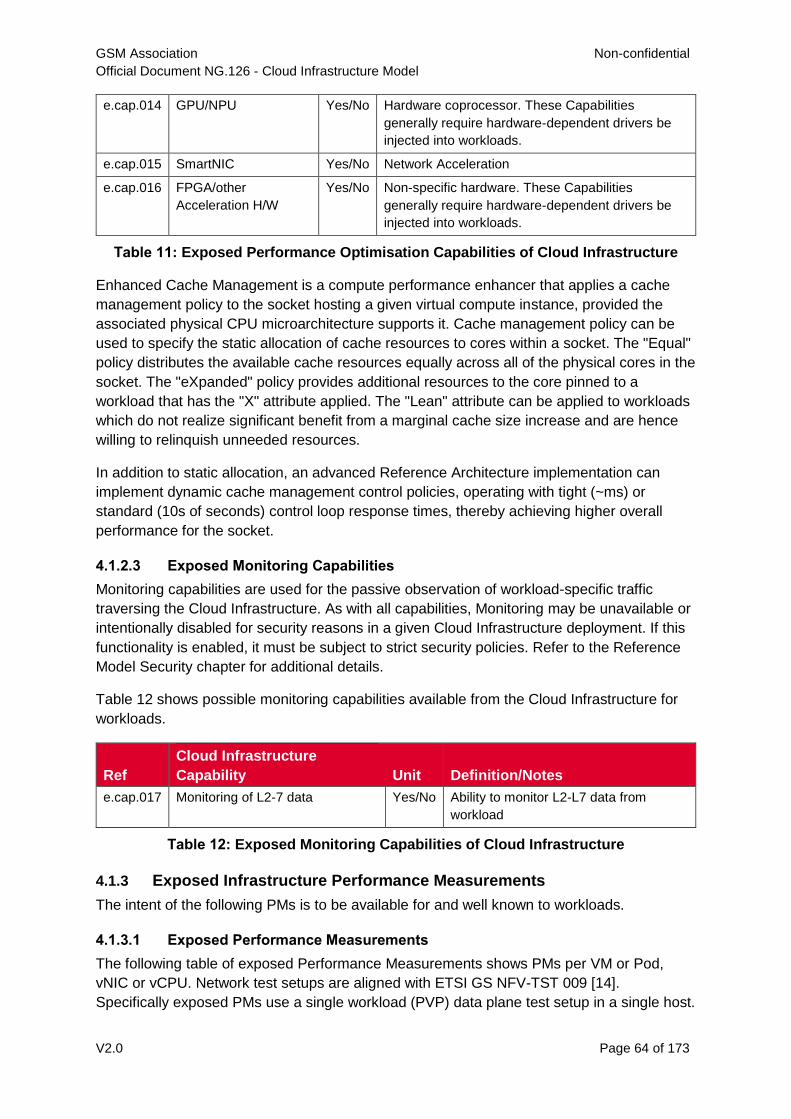
GSM Association Non-confidential
Official Document NG.126 - Cloud Infrastructure Model
V2.0 Page 64 of 173
e.cap.014 GPU/NPU Yes/No Hardware coprocessor. These Capabilities
generally require hardware-dependent drivers be
injected into workloads.
e.cap.015 SmartNIC Yes/No Network Acceleration
e.cap.016 FPGA/other
Acceleration H/W
Yes/No Non-specific hardware. These Capabilities
generally require hardware-dependent drivers be
injected into workloads.
Table 11: Exposed Performance Optimisation Capabilities of Cloud Infrastructure
Enhanced Cache Management is a compute performance enhancer that applies a cache
management policy to the socket hosting a given virtual compute instance, provided the
associated physical CPU microarchitecture supports it. Cache management policy can be
used to specify the static allocation of cache resources to cores within a socket. The "Equal"
policy distributes the available cache resources equally across all of the physical cores in the
socket. The "eXpanded" policy provides additional resources to the core pinned to a
workload that has the "X" attribute applied. The "Lean" attribute can be applied to workloads
which do not realize significant benefit from a marginal cache size increase and are hence
willing to relinquish unneeded resources.
In addition to static allocation, an advanced Reference Architecture implementation can
implement dynamic cache management control policies, operating with tight (~ms) or
standard (10s of seconds) control loop response times, thereby achieving higher overall
performance for the socket.
4.1.2.3 Exposed Monitoring Capabilities
Monitoring capabilities are used for the passive observation of workload-specific traffic
traversing the Cloud Infrastructure. As with all capabilities, Monitoring may be unavailable or
intentionally disabled for security reasons in a given Cloud Infrastructure deployment. If this
functionality is enabled, it must be subject to strict security policies. Refer to the Reference
Model Security chapter for additional details.
Table 12 shows possible monitoring capabilities available from the Cloud Infrastructure for
workloads.
Ref
Cloud Infrastructure
Capability Unit Definition/Notes
e.cap.017 Monitoring of L2-7 data Yes/No Ability to monitor L2-L7 data from
workload
Table 12: Exposed Monitoring Capabilities of Cloud Infrastructure
4.1.3 Exposed Infrastructure Performance Measurements
The intent of the following PMs is to be available for and well known to workloads.
4.1.3.1 Exposed Performance Measurements
The following table of exposed Performance Measurements shows PMs per VM or Pod,
vNIC or vCPU. Network test setups are aligned with ETSI GS NFV-TST 009 [14].
Specifically exposed PMs use a single workload (PVP) data plane test setup in a single host.
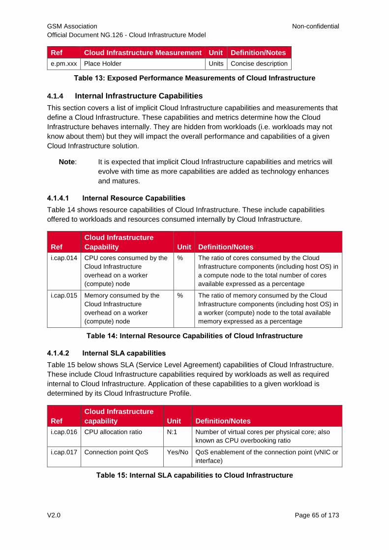
GSM Association Non-confidential
Official Document NG.126 - Cloud Infrastructure Model
V2.0 Page 65 of 173
Ref Cloud Infrastructure Measurement Unit Definition/Notes
e.pm.xxx Place Holder Units Concise description
Table 13: Exposed Performance Measurements of Cloud Infrastructure
4.1.4 Internal Infrastructure Capabilities
This section covers a list of implicit Cloud Infrastructure capabilities and measurements that
define a Cloud Infrastructure. These capabilities and metrics determine how the Cloud
Infrastructure behaves internally. They are hidden from workloads (i.e. workloads may not
know about them) but they will impact the overall performance and capabilities of a given
Cloud Infrastructure solution.
Note: It is expected that implicit Cloud Infrastructure capabilities and metrics will
evolve with time as more capabilities are added as technology enhances
and matures.
4.1.4.1 Internal Resource Capabilities
Table 14 shows resource capabilities of Cloud Infrastructure. These include capabilities
offered to workloads and resources consumed internally by Cloud Infrastructure.
Ref
Cloud Infrastructure
Capability Unit Definition/Notes
i.cap.014 CPU cores consumed by the
Cloud Infrastructure
overhead on a worker
(compute) node
% The ratio of cores consumed by the Cloud
Infrastructure components (including host OS) in
a compute node to the total number of cores
available expressed as a percentage
i.cap.015 Memory consumed by the
Cloud Infrastructure
overhead on a worker
(compute) node
% The ratio of memory consumed by the Cloud
Infrastructure components (including host OS) in
a worker (compute) node to the total available
memory expressed as a percentage
Table 14: Internal Resource Capabilities of Cloud Infrastructure
4.1.4.2 Internal SLA capabilities
Table 15 below shows SLA (Service Level Agreement) capabilities of Cloud Infrastructure.
These include Cloud Infrastructure capabilities required by workloads as well as required
internal to Cloud Infrastructure. Application of these capabilities to a given workload is
determined by its Cloud Infrastructure Profile.
Ref
Cloud Infrastructure
capability Unit Definition/Notes
i.cap.016 CPU allocation ratio N:1 Number of virtual cores per physical core; also
known as CPU overbooking ratio
i.cap.017 Connection point QoS Yes/No QoS enablement of the connection point (vNIC or
interface)
Table 15: Internal SLA capabilities to Cloud Infrastructure
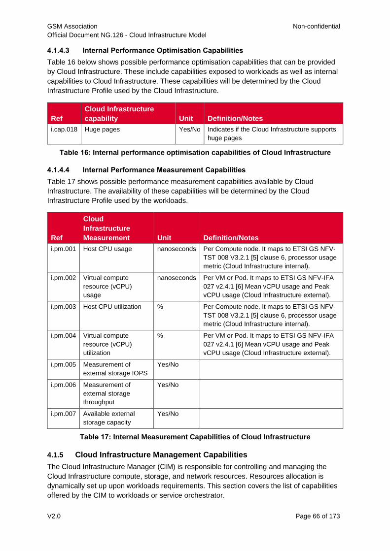
GSM Association Non-confidential
Official Document NG.126 - Cloud Infrastructure Model
V2.0 Page 66 of 173
4.1.4.3 Internal Performance Optimisation Capabilities
Table 16 below shows possible performance optimisation capabilities that can be provided
by Cloud Infrastructure. These include capabilities exposed to workloads as well as internal
capabilities to Cloud Infrastructure. These capabilities will be determined by the Cloud
Infrastructure Profile used by the Cloud Infrastructure.
Ref
Cloud Infrastructure
capability Unit Definition/Notes
i.cap.018 Huge pages Yes/No Indicates if the Cloud Infrastructure supports
huge pages
Table 16: Internal performance optimisation capabilities of Cloud Infrastructure
4.1.4.4 Internal Performance Measurement Capabilities
Table 17 shows possible performance measurement capabilities available by Cloud
Infrastructure. The availability of these capabilities will be determined by the Cloud
Infrastructure Profile used by the workloads.
Ref
Cloud
Infrastructure
Measurement Unit Definition/Notes
i.pm.001 Host CPU usage nanoseconds Per Compute node. It maps to ETSI GS NFV-
TST 008 V3.2.1 [5] clause 6, processor usage
metric (Cloud Infrastructure internal).
i.pm.002 Virtual compute
resource (vCPU)
usage
nanoseconds Per VM or Pod. It maps to ETSI GS NFV-IFA
027 v2.4.1 [6] Mean vCPU usage and Peak
vCPU usage (Cloud Infrastructure external).
i.pm.003 Host CPU utilization % Per Compute node. It maps to ETSI GS NFV-
TST 008 V3.2.1 [5] clause 6, processor usage
metric (Cloud Infrastructure internal).
i.pm.004 Virtual compute
resource (vCPU)
utilization
% Per VM or Pod. It maps to ETSI GS NFV-IFA
027 v2.4.1 [6] Mean vCPU usage and Peak
vCPU usage (Cloud Infrastructure external).
i.pm.005 Measurement of
external storage IOPS
Yes/No
i.pm.006 Measurement of
external storage
throughput
Yes/No
i.pm.007 Available external
storage capacity
Yes/No
Table 17: Internal Measurement Capabilities of Cloud Infrastructure
4.1.5 Cloud Infrastructure Management Capabilities
The Cloud Infrastructure Manager (CIM) is responsible for controlling and managing the
Cloud Infrastructure compute, storage, and network resources. Resources allocation is
dynamically set up upon workloads requirements. This section covers the list of capabilities
offered by the CIM to workloads or service orchestrator.
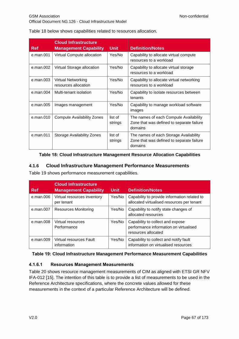
GSM Association Non-confidential
Official Document NG.126 - Cloud Infrastructure Model
V2.0 Page 67 of 173
Table 18 below shows capabilities related to resources allocation.
Ref
Cloud Infrastructure
Management Capability Unit Definition/Notes
e.man.001 Virtual Compute allocation Yes/No Capability to allocate virtual compute
resources to a workload
e.man.002 Virtual Storage allocation Yes/No Capability to allocate virtual storage
resources to a workload
e.man.003 Virtual Networking
resources allocation
Yes/No Capability to allocate virtual networking
resources to a workload
e.man.004 Multi-tenant isolation Yes/No Capability to isolate resources between
tenants
e.man.005 Images management Yes/No Capability to manage workload software
images
e.man.010 Compute Availability Zones list of
strings
The names of each Compute Availability
Zone that was defined to separate failure
domains
e.man.011 Storage Availability Zones list of
strings
The names of each Storage Availability
Zone that was defined to separate failure
domains
Table 18: Cloud Infrastructure Management Resource Allocation Capabilities
4.1.6 Cloud Infrastructure Management Performance Measurements
Table 19 shows performance measurement capabilities.
Ref
Cloud Infrastructure
Management Capability Unit Definition/Notes
e.man.006 Virtual resources inventory
per tenant
Yes/No Capability to provide information related to
allocated virtualised resources per tenant
e.man.007 Resources Monitoring Yes/No Capability to notify state changes of
allocated resources
e.man.008 Virtual resources
Performance
Yes/No Capability to collect and expose
performance information on virtualised
resources allocated
e.man.009 Virtual resources Fault
information
Yes/No Capability to collect and notify fault
information on virtualised resources
Table 19: Cloud Infrastructure Management Performance Measurement Capabilities
4.1.6.1 Resources Management Measurements
Table 20 shows resource management measurements of CIM as aligned with ETSI GR NFV
IFA-012 [15]. The intention of this table is to provide a list of measurements to be used in the
Reference Architecture specifications, where the concrete values allowed for these
measurements in the context of a particular Reference Architecture will be defined.
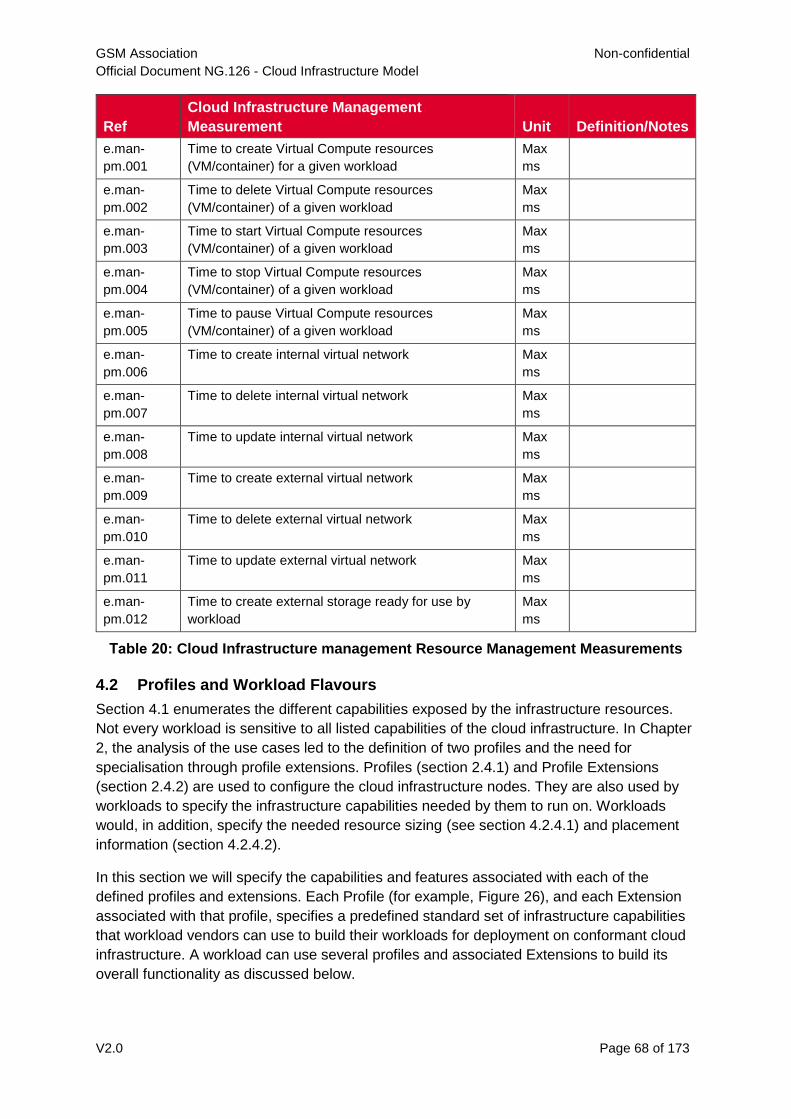
GSM Association Non-confidential
Official Document NG.126 - Cloud Infrastructure Model
V2.0 Page 68 of 173
Ref
Cloud Infrastructure Management
Measurement Unit Definition/Notes
e.man-
pm.001
Time to create Virtual Compute resources
(VM/container) for a given workload
Max
ms
e.man-
pm.002
Time to delete Virtual Compute resources
(VM/container) of a given workload
Max
ms
e.man-
pm.003
Time to start Virtual Compute resources
(VM/container) of a given workload
Max
ms
e.man-
pm.004
Time to stop Virtual Compute resources
(VM/container) of a given workload
Max
ms
e.man-
pm.005
Time to pause Virtual Compute resources
(VM/container) of a given workload
Max
ms
e.man-
pm.006
Time to create internal virtual network Max
ms
e.man-
pm.007
Time to delete internal virtual network Max
ms
e.man-
pm.008
Time to update internal virtual network Max
ms
e.man-
pm.009
Time to create external virtual network Max
ms
e.man-
pm.010
Time to delete external virtual network Max
ms
e.man-
pm.011
Time to update external virtual network Max
ms
e.man-
pm.012
Time to create external storage ready for use by
workload
Max
ms
Table 20: Cloud Infrastructure management Resource Management Measurements
4.2 Profiles and Workload Flavours
Section 4.1 enumerates the different capabilities exposed by the infrastructure resources.
Not every workload is sensitive to all listed capabilities of the cloud infrastructure. In Chapter
2, the analysis of the use cases led to the definition of two profiles and the need for
specialisation through profile extensions. Profiles (section 2.4.1) and Profile Extensions
(section 2.4.2) are used to configure the cloud infrastructure nodes. They are also used by
workloads to specify the infrastructure capabilities needed by them to run on. Workloads
would, in addition, specify the needed resource sizing (see section 4.2.4.1) and placement
information (section 4.2.4.2).
In this section we will specify the capabilities and features associated with each of the
defined profiles and extensions. Each Profile (for example, Figure 26), and each Extension
associated with that profile, specifies a predefined standard set of infrastructure capabilities
that workload vendors can use to build their workloads for deployment on conformant cloud
infrastructure. A workload can use several profiles and associated Extensions to build its
overall functionality as discussed below.
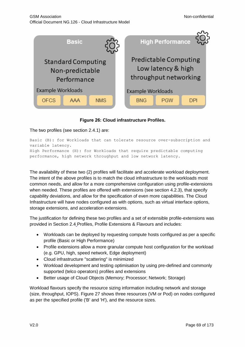
GSM Association Non-confidential
Official Document NG.126 - Cloud Infrastructure Model
V2.0 Page 69 of 173
Figure 26: Cloud infrastructure Profiles.
The two profiles (see section 2.4.1) are:
Basic (B): for Workloads that can tolerate resource over-subscription and
variable latency.
High Performance (H): for Workloads that require predictable computing
performance, high network throughput and low network latency.
The availability of these two (2) profiles will facilitate and accelerate workload deployment.
The intent of the above profiles is to match the cloud infrastructure to the workloads most
common needs, and allow for a more comprehensive configuration using profile-extensions
when needed. These profiles are offered with extensions (see section 4.2.3), that specify
capability deviations, and allow for the specification of even more capabilities. The Cloud
Infrastructure will have nodes configured as with options, such as virtual interface options,
storage extensions, and acceleration extensions.
The justification for defining these two profiles and a set of extensible profile-extensions was
provided in Section 2.4 Profiles, Profile Extensions & Flavours and includes:
Workloads can be deployed by requesting compute hosts configured as per a specific
profile (Basic or High Performance)
Profile extensions allow a more granular compute host configuration for the workload
(e.g. GPU, high, speed network, Edge deployment)
Cloud infrastructure "scattering" is minimized
Workload development and testing optimisation by using pre-defined and commonly
supported (telco operators) profiles and extensions
Better usage of Cloud Objects (Memory; Processor; Network; Storage)
Workload flavours specify the resource sizing information including network and storage
(size, throughput, IOPS). Figure 27 shows three resources (VM or Pod) on nodes configured
as per the specified profile ('B' and 'H'), and the resource sizes.
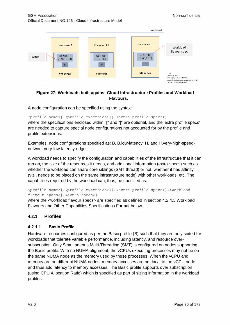
GSM Association Non-confidential
Official Document NG.126 - Cloud Infrastructure Model
V2.0 Page 70 of 173
Figure 27: Workloads built against Cloud Infrastructure Profiles and Workload
Flavours.
A node configuration can be specified using the syntax:
<profile name>[.<profile_extension>][.<extra profile specs>]
where the specifications enclosed within "[" and "]" are optional, and the 'extra profile specs'
are needed to capture special node configurations not accounted for by the profile and
profile extensions.
Examples, node configurations specified as: B, B.low-latency, H, and H.very-high-speed-
network.very-low-latency-edge.
A workload needs to specify the configuration and capabilities of the infrastructure that it can
run on, the size of the resources it needs, and additional information (extra-specs) such as
whether the workload can share core siblings (SMT thread) or not, whether it has affinity
(viz., needs to be placed on the same infrastructure node) with other workloads, etc. The
capabilities required by the workload can, thus, be specified as:
<profile name>[.<profile_extension>][.<extra profile specs>].<workload
flavour specs>[.<extra-specs>]
where the <workload flavour specs> are specified as defined in section 4.2.4.3 Workload
Flavours and Other Capabilities Specifications Format below.
4.2.1 Profiles
4.2.1.1 Basic Profile
Hardware resources configured as per the Basic profile (B) such that they are only suited for
workloads that tolerate variable performance, including latency, and resource over-
subscription. Only Simultaneous Multi-Threading (SMT) is configured on nodes supporting
the Basic profile. With no NUMA alignment, the vCPUs executing processes may not be on
the same NUMA node as the memory used by these processes. When the vCPU and
memory are on different NUMA nodes, memory accesses are not local to the vCPU node
and thus add latency to memory accesses. The Basic profile supports over subscription
(using CPU Allocation Ratio) which is specified as part of sizing information in the workload
profiles.
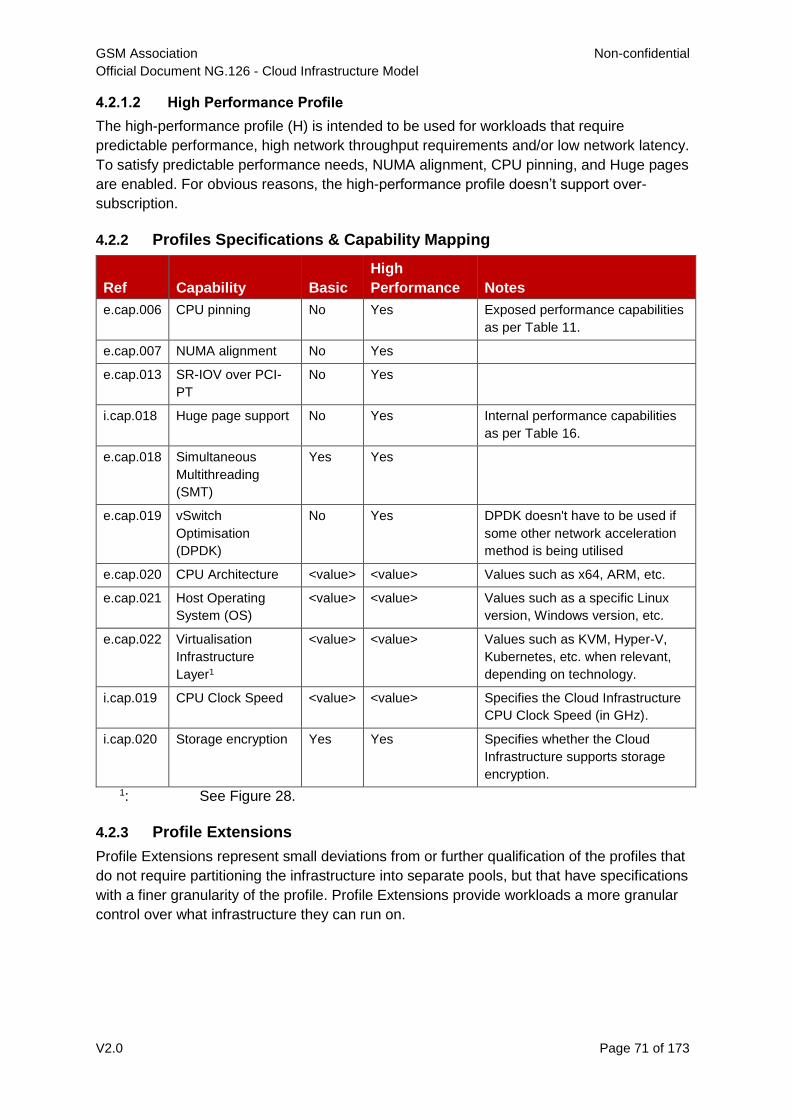
GSM Association Non-confidential
Official Document NG.126 - Cloud Infrastructure Model
V2.0 Page 71 of 173
4.2.1.2 High Performance Profile
The high-performance profile (H) is intended to be used for workloads that require
predictable performance, high network throughput requirements and/or low network latency.
To satisfy predictable performance needs, NUMA alignment, CPU pinning, and Huge pages
are enabled. For obvious reasons, the high-performance profile doesn’t support over-
subscription.
4.2.2 Profiles Specifications & Capability Mapping
Ref Capability Basic
High
Performance Notes
e.cap.006 CPU pinning No Yes Exposed performance capabilities
as per Table 11.
e.cap.007 NUMA alignment No Yes
e.cap.013 SR-IOV over PCI-
PT
No Yes
i.cap.018 Huge page support No Yes Internal performance capabilities
as per Table 16.
e.cap.018 Simultaneous
Multithreading
(SMT)
Yes Yes
e.cap.019 vSwitch
Optimisation
(DPDK)
No Yes DPDK doesn't have to be used if
some other network acceleration
method is being utilised
e.cap.020 CPU Architecture <value> <value> Values such as x64, ARM, etc.
e.cap.021 Host Operating
System (OS)
<value> <value> Values such as a specific Linux
version, Windows version, etc.
e.cap.022 Virtualisation
Infrastructure
Layer1
<value> <value> Values such as KVM, Hyper-V,
Kubernetes, etc. when relevant,
depending on technology.
i.cap.019 CPU Clock Speed <value> <value> Specifies the Cloud Infrastructure
CPU Clock Speed (in GHz).
i.cap.020 Storage encryption Yes Yes Specifies whether the Cloud
Infrastructure supports storage
encryption.
1: See Figure 28.
4.2.3 Profile Extensions
Profile Extensions represent small deviations from or further qualification of the profiles that
do not require partitioning the infrastructure into separate pools, but that have specifications
with a finer granularity of the profile. Profile Extensions provide workloads a more granular
control over what infrastructure they can run on.
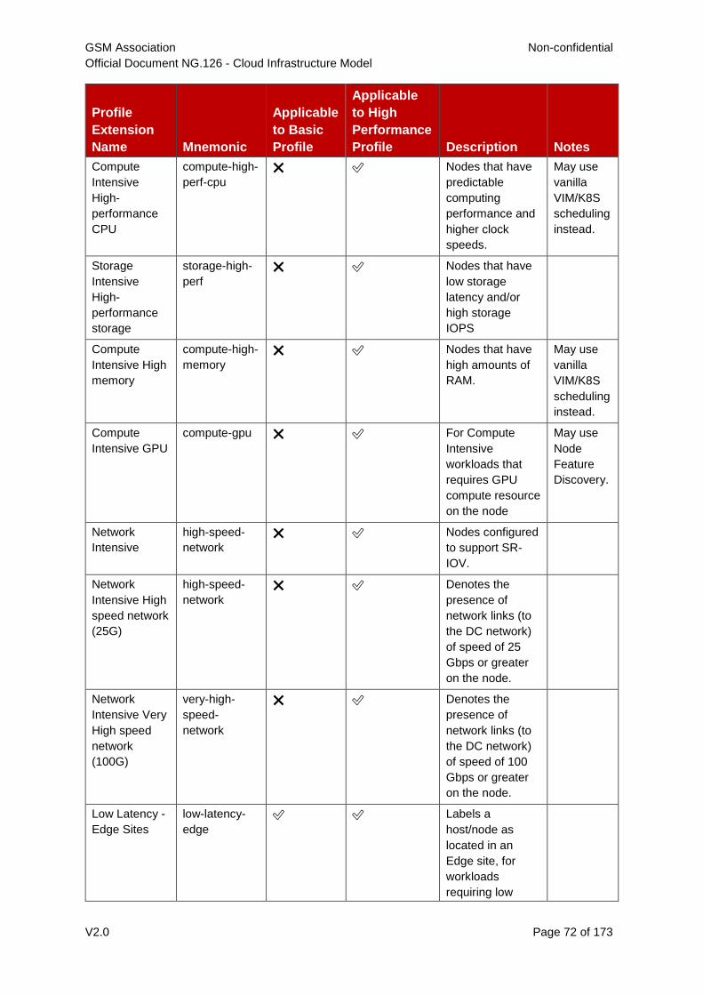
GSM Association Non-confidential
Official Document NG.126 - Cloud Infrastructure Model
V2.0 Page 72 of 173
Profile
Extension
Name Mnemonic
Applicable
to Basic
Profile
Applicable
to High
Performance
Profile Description Notes
Compute
Intensive
High-
performance
CPU
compute-high-
perf-cpu
❌ ✅ Nodes that have
predictable
computing
performance and
higher clock
speeds.
May use
vanilla
VIM/K8S
scheduling
instead.
Storage
Intensive
High-
performance
storage
storage-high-
perf
❌ ✅ Nodes that have
low storage
latency and/or
high storage
IOPS
Compute
Intensive High
memory
compute-high-
memory
❌ ✅ Nodes that have
high amounts of
RAM.
May use
vanilla
VIM/K8S
scheduling
instead.
Compute
Intensive GPU
compute-gpu ❌ ✅ For Compute
Intensive
workloads that
requires GPU
compute resource
on the node
May use
Node
Feature
Discovery.
Network
Intensive
high-speed-
network
❌ ✅ Nodes configured
to support SR-
IOV.
Network
Intensive High
speed network
(25G)
high-speed-
network
❌ ✅ Denotes the
presence of
network links (to
the DC network)
of speed of 25
Gbps or greater
on the node.
Network
Intensive Very
High speed
network
(100G)
very-high-
speed-
network
❌ ✅ Denotes the
presence of
network links (to
the DC network)
of speed of 100
Gbps or greater
on the node.
Low Latency -
Edge Sites
low-latency-
edge
✅ ✅ Labels a
host/node as
located in an
Edge site, for
workloads
requiring low
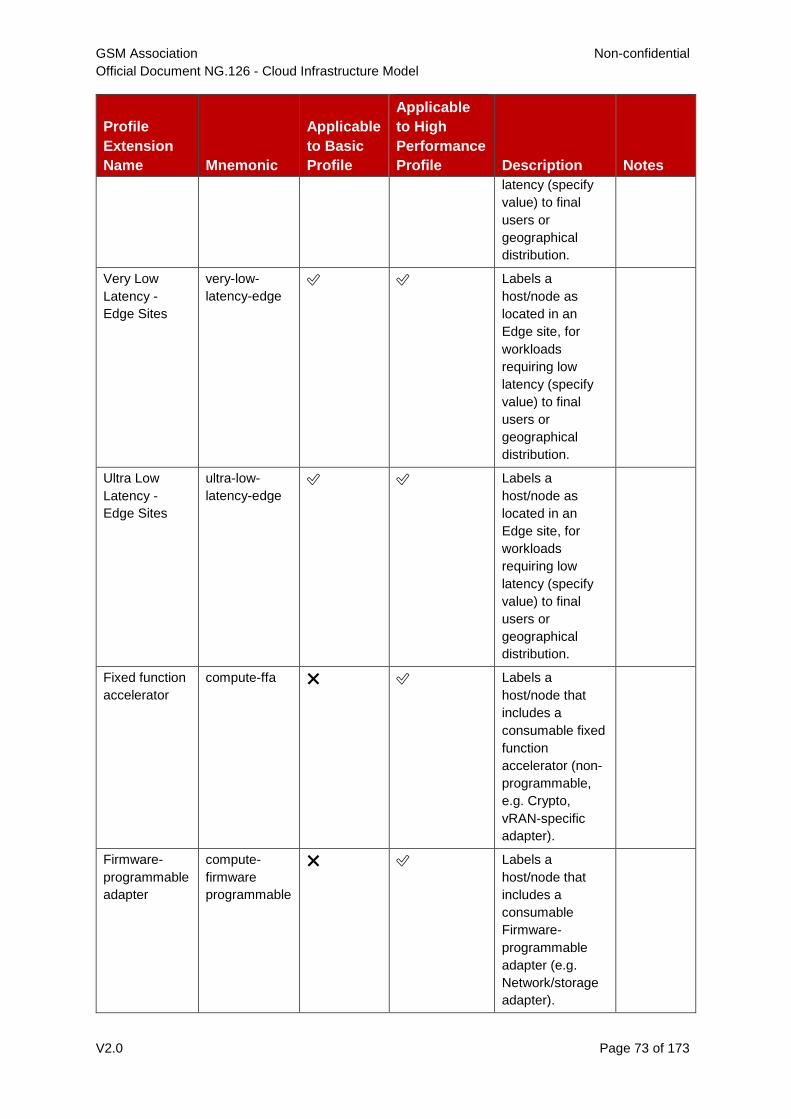
GSM Association Non-confidential
Official Document NG.126 - Cloud Infrastructure Model
V2.0 Page 73 of 173
Profile
Extension
Name Mnemonic
Applicable
to Basic
Profile
Applicable
to High
Performance
Profile Description Notes
latency (specify
value) to final
users or
geographical
distribution.
Very Low
Latency -
Edge Sites
very-low-
latency-edge
✅ ✅ Labels a
host/node as
located in an
Edge site, for
workloads
requiring low
latency (specify
value) to final
users or
geographical
distribution.
Ultra Low
Latency -
Edge Sites
ultra-low-
latency-edge
✅ ✅ Labels a
host/node as
located in an
Edge site, for
workloads
requiring low
latency (specify
value) to final
users or
geographical
distribution.
Fixed function
accelerator
compute-ffa ❌ ✅ Labels a
host/node that
includes a
consumable fixed
function
accelerator (non-
programmable,
e.g. Crypto,
vRAN-specific
adapter).
Firmware-
programmable
adapter
compute-
firmware
programmable
❌ ✅ Labels a
host/node that
includes a
consumable
Firmware-
programmable
adapter (e.g.
Network/storage
adapter).
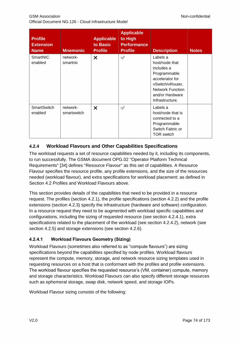
GSM Association Non-confidential
Official Document NG.126 - Cloud Infrastructure Model
V2.0 Page 74 of 173
Profile
Extension
Name Mnemonic
Applicable
to Basic
Profile
Applicable
to High
Performance
Profile Description Notes
SmartNIC
enabled
network-
smartnic
❌ ✅ Labels a
host/node that
includes a
Programmable
accelerator for
vSwitch/vRouter,
Network Function
and/or Hardware
Infrastructure.
SmartSwitch
enabled
network-
smartswitch
❌ ✅ Labels a
host/node that is
connected to a
Programmable
Switch Fabric or
TOR switch
4.2.4 Workload Flavours and Other Capabilities Specifications
The workload requests a set of resource capabilities needed by it, including its components,
to run successfully. The GSMA document OPG.02 "Operator Platform Technical
Requirements" [34] defines "Resource Flavour" as this set of capabilities. A Resource
Flavour specifies the resource profile, any profile extensions, and the size of the resources
needed (workload flavour), and extra specifications for workload placement; as defined in
Section 4.2 Profiles and Workload Flavours above.
This section provides details of the capabilities that need to be provided in a resource
request. The profiles (section 4.2.1), the profile specifications (section 4.2.2) and the profile
extensions (section 4.2.3) specify the infrastructure (hardware and software) configuration.
In a resource request they need to be augmented with workload specific capabilities and
configurations, including the sizing of requested resource (see section 4.2.4.1), extra
specifications related to the placement of the workload (see section 4.2.4.2), network (see
section 4.2.5) and storage extensions (see section 4.2.6).
4.2.4.1 Workload Flavours Geometry (Sizing)
Workload Flavours (sometimes also referred to as “compute flavours”) are sizing
specifications beyond the capabilities specified by node profiles. Workload flavours
represent the compute, memory, storage, and network resource sizing templates used in
requesting resources on a host that is conformant with the profiles and profile extensions.
The workload flavour specifies the requested resource’s (VM, container) compute, memory
and storage characteristics. Workload Flavours can also specify different storage resources
such as ephemeral storage, swap disk, network speed, and storage IOPs.
Workload Flavour sizing consists of the following:
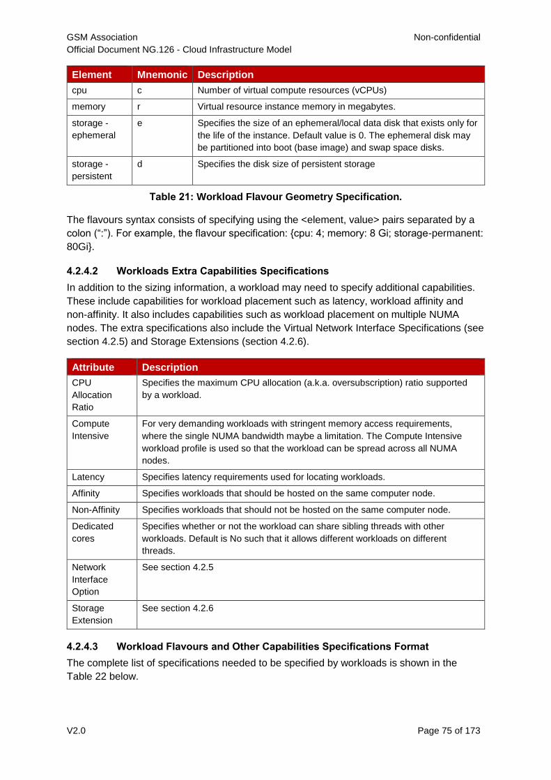
GSM Association Non-confidential
Official Document NG.126 - Cloud Infrastructure Model
V2.0 Page 75 of 173
Element Mnemonic Description
cpu c Number of virtual compute resources (vCPUs)
memory r Virtual resource instance memory in megabytes.
storage -
ephemeral
e Specifies the size of an ephemeral/local data disk that exists only for
the life of the instance. Default value is 0. The ephemeral disk may
be partitioned into boot (base image) and swap space disks.
storage -
persistent
d Specifies the disk size of persistent storage
Table 21: Workload Flavour Geometry Specification.
The flavours syntax consists of specifying using the <element, value> pairs separated by a
colon (“:”). For example, the flavour specification: {cpu: 4; memory: 8 Gi; storage-permanent:
80Gi}.
4.2.4.2 Workloads Extra Capabilities Specifications
In addition to the sizing information, a workload may need to specify additional capabilities.
These include capabilities for workload placement such as latency, workload affinity and
non-affinity. It also includes capabilities such as workload placement on multiple NUMA
nodes. The extra specifications also include the Virtual Network Interface Specifications (see
section 4.2.5) and Storage Extensions (section 4.2.6).
Attribute Description
CPU
Allocation
Ratio
Specifies the maximum CPU allocation (a.k.a. oversubscription) ratio supported
by a workload.
Compute
Intensive
For very demanding workloads with stringent memory access requirements,
where the single NUMA bandwidth maybe a limitation. The Compute Intensive
workload profile is used so that the workload can be spread across all NUMA
nodes.
Latency Specifies latency requirements used for locating workloads.
Affinity Specifies workloads that should be hosted on the same computer node.
Non-Affinity Specifies workloads that should not be hosted on the same computer node.
Dedicated
cores
Specifies whether or not the workload can share sibling threads with other
workloads. Default is No such that it allows different workloads on different
threads.
Network
Interface
Option
See section 4.2.5
Storage
Extension
See section 4.2.6
4.2.4.3 Workload Flavours and Other Capabilities Specifications Format
The complete list of specifications needed to be specified by workloads is shown in the
Table 22 below.
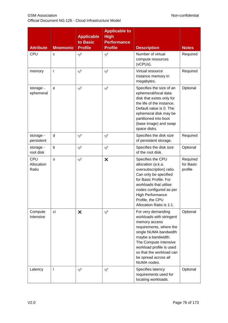
GSM Association Non-confidential
Official Document NG.126 - Cloud Infrastructure Model
V2.0 Page 76 of 173
Attribute Mnemonic
Applicable
to Basic
Profile
Applicable to
High
Performance
Profile Description Notes
CPU c ✅ ✅ Number of virtual
compute resources
(vCPUs).
Required
memory r ✅ ✅ Virtual resource
instance memory in
megabytes.
Required
storage -
ephemeral
e ✅ ✅ Specifies the size of an
ephemeral/local data
disk that exists only for
the life of the instance.
Default value is 0. The
ephemeral disk may be
partitioned into boot
(base image) and swap
space disks.
Optional
storage -
persistent
d ✅ ✅ Specifies the disk size
of persistent storage.
Required
storage -
root disk
b ✅ ✅ Specifies the disk size
of the root disk.
Optional
CPU
Allocation
Ratio
o ✅ ❌ Specifies the CPU
allocation (a.k.a.
oversubscription) ratio.
Can only be specified
for Basic Profile. For
workloads that utilise
nodes configured as per
High Performance
Profile, the CPU
Allocation Ratio is 1:1.
Required
for Basic
profile
Compute
Intensive
ci ❌ ✅ For very demanding
workloads with stringent
memory access
requirements, where the
single NUMA bandwidth
maybe a bandwidth.
The Compute Intensive
workload profile is used
so that the workload can
be spread across all
NUMA nodes.
Optional
Latency l ✅ ✅ Specifies latency
requirements used for
locating workloads.
Optional
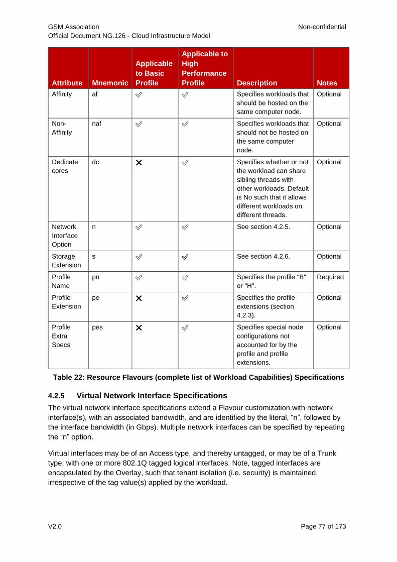
GSM Association Non-confidential
Official Document NG.126 - Cloud Infrastructure Model
V2.0 Page 77 of 173
Attribute Mnemonic
Applicable
to Basic
Profile
Applicable to
High
Performance
Profile Description Notes
Affinity af ✅ ✅ Specifies workloads that
should be hosted on the
same computer node.
Optional
Non-
Affinity
naf ✅ ✅ Specifies workloads that
should not be hosted on
the same computer
node.
Optional
Dedicate
cores
dc ❌ ✅ Specifies whether or not
the workload can share
sibling threads with
other workloads. Default
is No such that it allows
different workloads on
different threads.
Optional
Network
Interface
Option
n ✅ ✅ See section 4.2.5. Optional
Storage
Extension
s ✅ ✅ See section 4.2.6. Optional
Profile
Name
pn ✅ ✅ Specifies the profile "B"
or "H".
Required
Profile
Extension
pe ❌ ✅ Specifies the profile
extensions (section
4.2.3).
Optional
Profile
Extra
Specs
pes ❌ ✅ Specifies special node
configurations not
accounted for by the
profile and profile
extensions.
Optional
Table 22: Resource Flavours (complete list of Workload Capabilities) Specifications
4.2.5 Virtual Network Interface Specifications
The virtual network interface specifications extend a Flavour customization with network
interface(s), with an associated bandwidth, and are identified by the literal, “n”, followed by
the interface bandwidth (in Gbps). Multiple network interfaces can be specified by repeating
the “n” option.
Virtual interfaces may be of an Access type, and thereby untagged, or may be of a Trunk
type, with one or more 802.1Q tagged logical interfaces. Note, tagged interfaces are
encapsulated by the Overlay, such that tenant isolation (i.e. security) is maintained,
irrespective of the tag value(s) applied by the workload.
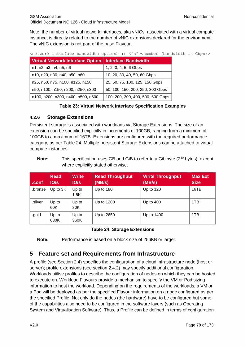
GSM Association Non-confidential
Official Document NG.126 - Cloud Infrastructure Model
V2.0 Page 78 of 173
Note, the number of virtual network interfaces, aka vNICs, associated with a virtual compute
instance, is directly related to the number of vNIC extensions declared for the environment.
The vNIC extension is not part of the base Flavour.
<network interface bandwidth option> :: <”n”><number (bandwidth in Gbps)>
Virtual Network Interface Option Interface Bandwidth
n1, n2, n3, n4, n5, n6 1, 2, 3, 4, 5, 6 Gbps
n10, n20, n30, n40, n50, n60 10, 20, 30, 40, 50, 60 Gbps
n25, n50, n75, n100, n125, n150 25, 50, 75, 100, 125, 150 Gbps
n50, n100, n150, n200, n250, n300 50, 100, 150, 200, 250, 300 Gbps
n100, n200, n300, n400, n500, n600 100, 200, 300, 400, 500, 600 Gbps
Table 23: Virtual Network Interface Specification Examples
4.2.6 Storage Extensions
Persistent storage is associated with workloads via Storage Extensions. The size of an
extension can be specified explicitly in increments of 100GB, ranging from a minimum of
100GB to a maximum of 16TB. Extensions are configured with the required performance
category, as per Table 24. Multiple persistent Storage Extensions can be attached to virtual
compute instances.
Note: This specification uses GB and GiB to refer to a Gibibyte (230 bytes), except
where explicitly stated otherwise.
.conf
Read
IO/s
Write
IO/s
Read Throughput
(MB/s)
Write Throughput
(MB/s)
Max Ext
Size
.bronze Up to 3K Up to
1.5K
Up to 180 Up to 120 16TB
.silver Up to
60K
Up to
30K
Up to 1200 Up to 400 1TB
.gold Up to
680K
Up to
360K
Up to 2650 Up to 1400 1TB
Table 24: Storage Extensions
Note: Performance is based on a block size of 256KB or larger.
5 Feature set and Requirements from Infrastructure
A profile (see Section 2.4) specifies the configuration of a cloud infrastructure node (host or
server); profile extensions (see section 2.4.2) may specify additional configuration.
Workloads utilise profiles to describe the configuration of nodes on which they can be hosted
to execute on. Workload Flavours provide a mechanism to specify the VM or Pod sizing
information to host the workload. Depending on the requirements of the workloads, a VM or
a Pod will be deployed as per the specified Flavour information on a node configured as per
the specified Profile. Not only do the nodes (the hardware) have to be configured but some
of the capabilities also need to be configured in the software layers (such as Operating
System and Virtualisation Software). Thus, a Profile can be defined in terms of configuration
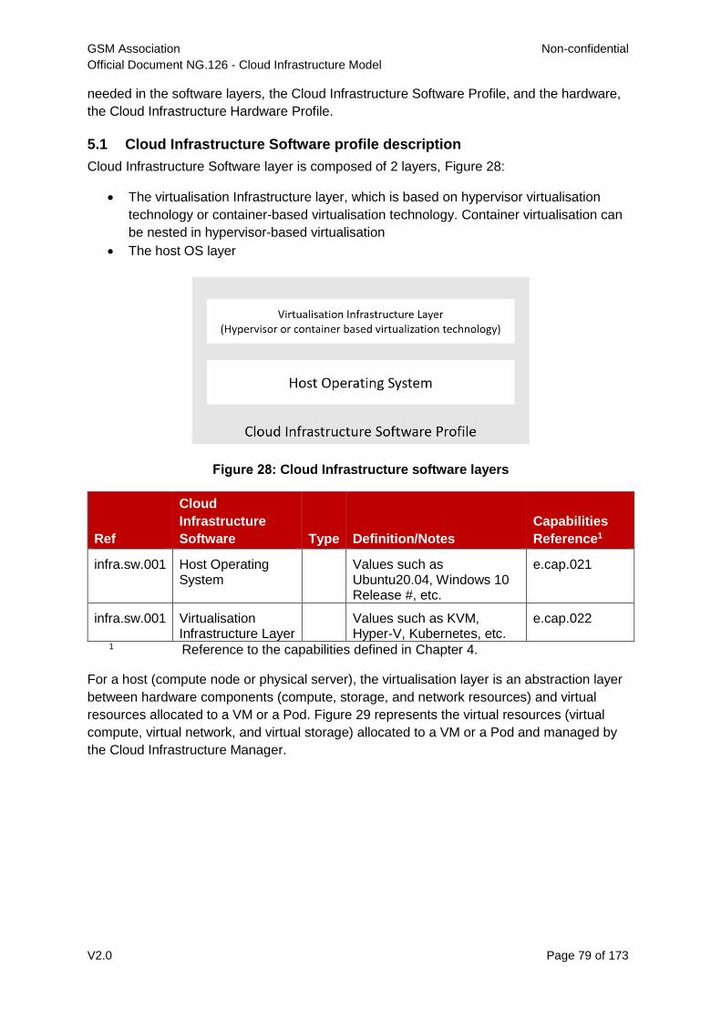
GSM Association Non-confidential
Official Document NG.126 - Cloud Infrastructure Model
V2.0 Page 79 of 173
needed in the software layers, the Cloud Infrastructure Software Profile, and the hardware,
the Cloud Infrastructure Hardware Profile.
5.1 Cloud Infrastructure Software profile description
Cloud Infrastructure Software layer is composed of 2 layers, Figure 28:
The virtualisation Infrastructure layer, which is based on hypervisor virtualisation
technology or container-based virtualisation technology. Container virtualisation can
be nested in hypervisor-based virtualisation
The host OS layer
Figure 28: Cloud Infrastructure software layers
Ref
Cloud
Infrastructure
Software Type Definition/Notes
Capabilities
Reference1
infra.sw.001 Host Operating System
Values such as Ubuntu20.04, Windows 10 Release #, etc.
e.cap.021
infra.sw.001 Virtualisation Infrastructure Layer
Values such as KVM, Hyper-V, Kubernetes, etc.
e.cap.022
1 Reference to the capabilities defined in Chapter 4.
For a host (compute node or physical server), the virtualisation layer is an abstraction layer
between hardware components (compute, storage, and network resources) and virtual
resources allocated to a VM or a Pod. Figure 29 represents the virtual resources (virtual
compute, virtual network, and virtual storage) allocated to a VM or a Pod and managed by
the Cloud Infrastructure Manager.
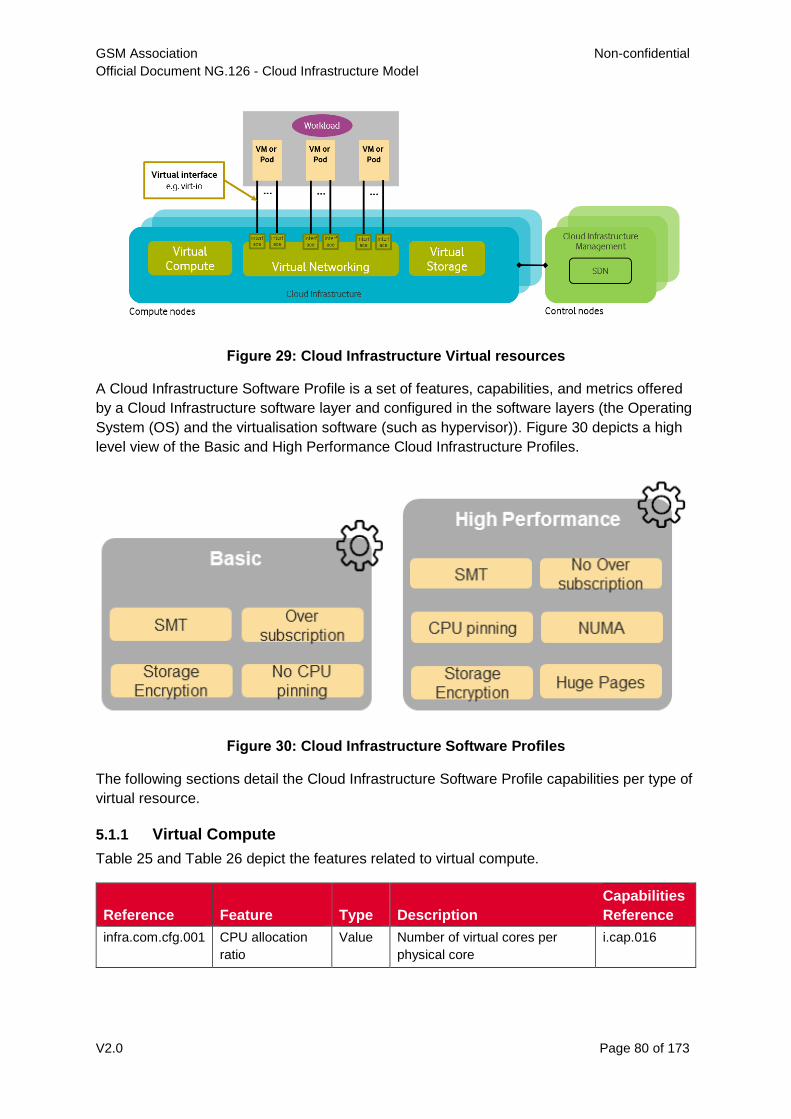
GSM Association Non-confidential
Official Document NG.126 - Cloud Infrastructure Model
V2.0 Page 80 of 173
Figure 29: Cloud Infrastructure Virtual resources
A Cloud Infrastructure Software Profile is a set of features, capabilities, and metrics offered
by a Cloud Infrastructure software layer and configured in the software layers (the Operating
System (OS) and the virtualisation software (such as hypervisor)). Figure 30 depicts a high
level view of the Basic and High Performance Cloud Infrastructure Profiles.
Figure 30: Cloud Infrastructure Software Profiles
The following sections detail the Cloud Infrastructure Software Profile capabilities per type of
virtual resource.
5.1.1 Virtual Compute
Table 25 and Table 26 depict the features related to virtual compute.
Reference Feature Type Description
Capabilities
Reference
infra.com.cfg.001 CPU allocation
ratio
Value Number of virtual cores per
physical core
i.cap.016
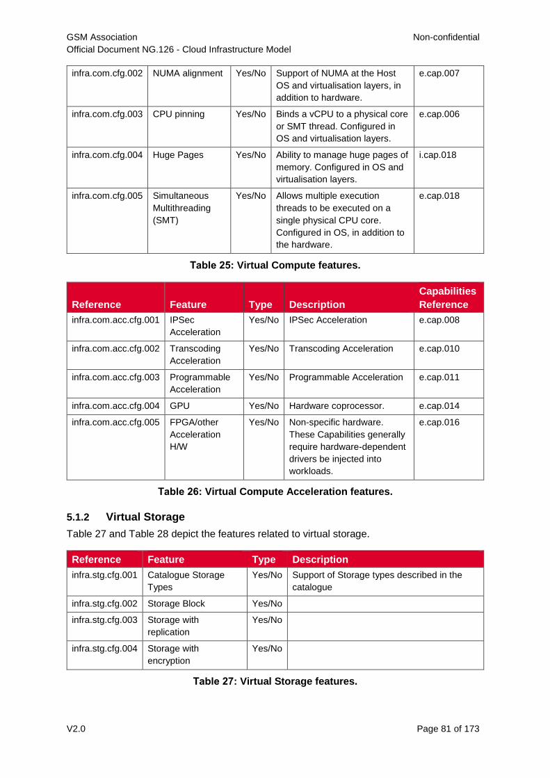
GSM Association Non-confidential
Official Document NG.126 - Cloud Infrastructure Model
V2.0 Page 81 of 173
infra.com.cfg.002 NUMA alignment Yes/No Support of NUMA at the Host
OS and virtualisation layers, in
addition to hardware.
e.cap.007
infra.com.cfg.003 CPU pinning Yes/No Binds a vCPU to a physical core
or SMT thread. Configured in
OS and virtualisation layers.
e.cap.006
infra.com.cfg.004 Huge Pages Yes/No Ability to manage huge pages of
memory. Configured in OS and
virtualisation layers.
i.cap.018
infra.com.cfg.005 Simultaneous
Multithreading
(SMT)
Yes/No Allows multiple execution
threads to be executed on a
single physical CPU core.
Configured in OS, in addition to
the hardware.
e.cap.018
Table 25: Virtual Compute features.
Reference Feature Type Description
Capabilities
Reference
infra.com.acc.cfg.001 IPSec
Acceleration
Yes/No IPSec Acceleration e.cap.008
infra.com.acc.cfg.002 Transcoding
Acceleration
Yes/No Transcoding Acceleration e.cap.010
infra.com.acc.cfg.003 Programmable
Acceleration
Yes/No Programmable Acceleration e.cap.011
infra.com.acc.cfg.004 GPU Yes/No Hardware coprocessor. e.cap.014
infra.com.acc.cfg.005 FPGA/other
Acceleration
H/W
Yes/No Non-specific hardware.
These Capabilities generally
require hardware-dependent
drivers be injected into
workloads.
e.cap.016
Table 26: Virtual Compute Acceleration features.
5.1.2 Virtual Storage
Table 27 and Table 28 depict the features related to virtual storage.
Reference Feature Type Description
infra.stg.cfg.001 Catalogue Storage
Types
Yes/No Support of Storage types described in the
catalogue
infra.stg.cfg.002 Storage Block Yes/No
infra.stg.cfg.003 Storage with
replication
Yes/No
infra.stg.cfg.004 Storage with
encryption
Yes/No
Table 27: Virtual Storage features.
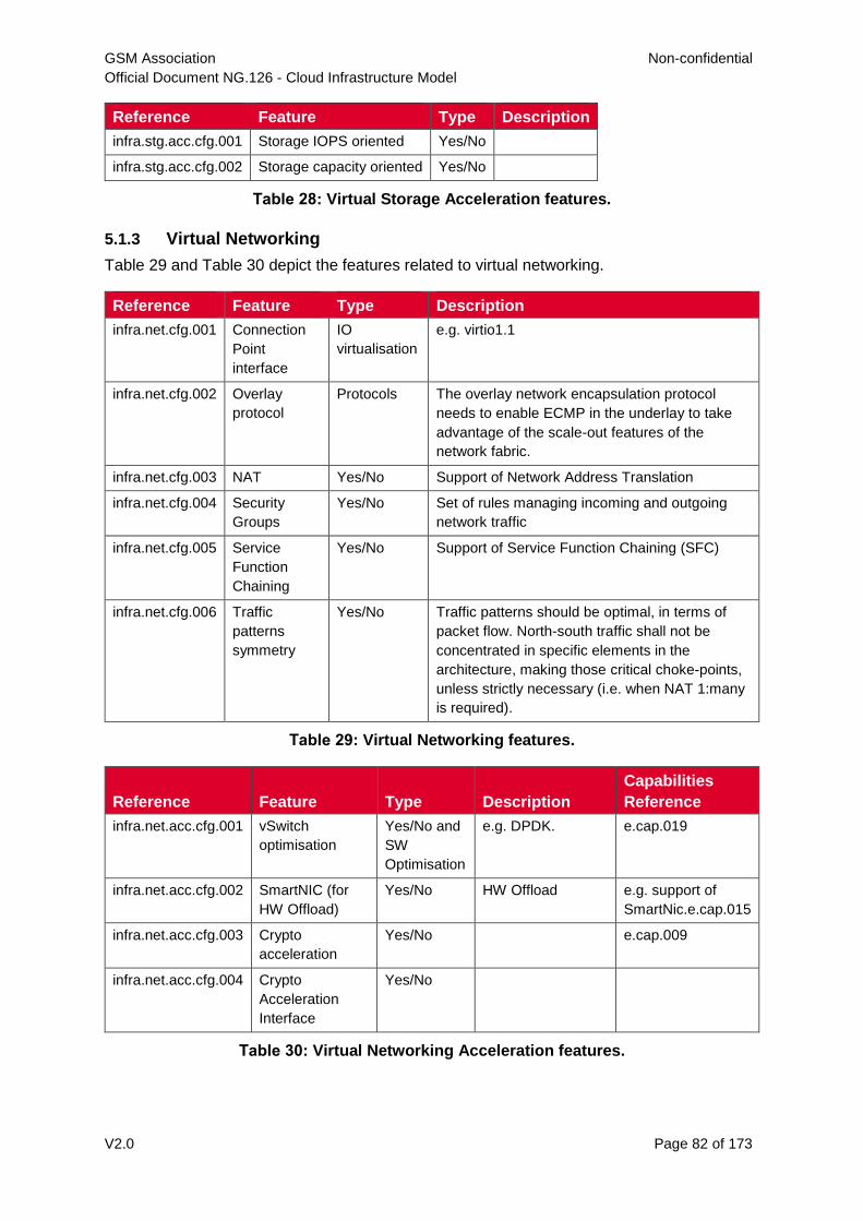
GSM Association Non-confidential
Official Document NG.126 - Cloud Infrastructure Model
V2.0 Page 82 of 173
Reference Feature Type Description
infra.stg.acc.cfg.001 Storage IOPS oriented Yes/No
infra.stg.acc.cfg.002 Storage capacity oriented Yes/No
Table 28: Virtual Storage Acceleration features.
5.1.3 Virtual Networking
Table 29 and Table 30 depict the features related to virtual networking.
Reference Feature Type Description
infra.net.cfg.001 Connection
Point
interface
IO
virtualisation
e.g. virtio1.1
infra.net.cfg.002 Overlay
protocol
Protocols The overlay network encapsulation protocol
needs to enable ECMP in the underlay to take
advantage of the scale-out features of the
network fabric.
infra.net.cfg.003 NAT Yes/No Support of Network Address Translation
infra.net.cfg.004 Security
Groups
Yes/No Set of rules managing incoming and outgoing
network traffic
infra.net.cfg.005 Service
Function
Chaining
Yes/No Support of Service Function Chaining (SFC)
infra.net.cfg.006 Traffic
patterns
symmetry
Yes/No Traffic patterns should be optimal, in terms of
packet flow. North-south traffic shall not be
concentrated in specific elements in the
architecture, making those critical choke-points,
unless strictly necessary (i.e. when NAT 1:many
is required).
Table 29: Virtual Networking features.
Reference Feature Type Description
Capabilities
Reference
infra.net.acc.cfg.001 vSwitch
optimisation
Yes/No and
SW
Optimisation
e.g. DPDK. e.cap.019
infra.net.acc.cfg.002 SmartNIC (for
HW Offload)
Yes/No HW Offload e.g. support of
SmartNic.e.cap.015
infra.net.acc.cfg.003 Crypto
acceleration
Yes/No e.cap.009
infra.net.acc.cfg.004 Crypto
Acceleration
Interface
Yes/No
Table 30: Virtual Networking Acceleration features.
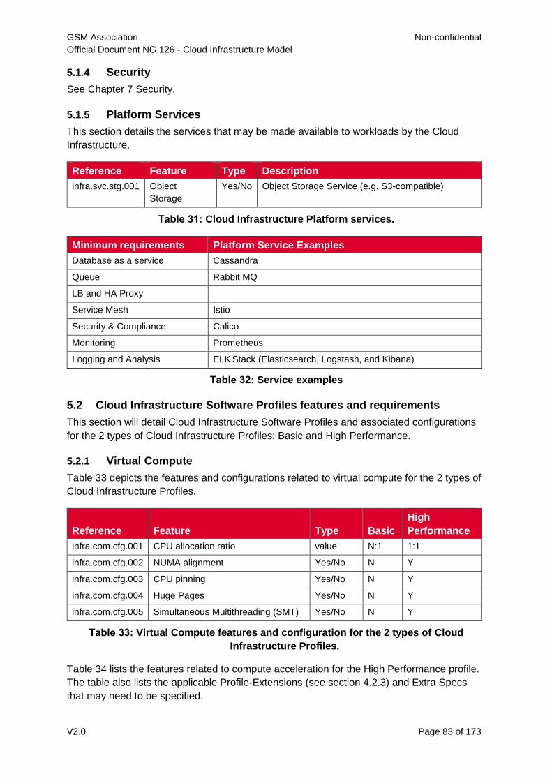
GSM Association Non-confidential
Official Document NG.126 - Cloud Infrastructure Model
V2.0 Page 83 of 173
5.1.4 Security
See Chapter 7 Security.
5.1.5 Platform Services
This section details the services that may be made available to workloads by the Cloud
Infrastructure.
Reference Feature Type Description
infra.svc.stg.001 Object
Storage
Yes/No Object Storage Service (e.g. S3-compatible)
Table 31: Cloud Infrastructure Platform services.
Minimum requirements Platform Service Examples
Database as a service Cassandra
Queue Rabbit MQ
LB and HA Proxy
Service Mesh Istio
Security & Compliance Calico
Monitoring Prometheus
Logging and Analysis ELK Stack (Elasticsearch, Logstash, and Kibana)
Table 32: Service examples
5.2 Cloud Infrastructure Software Profiles features and requirements
This section will detail Cloud Infrastructure Software Profiles and associated configurations
for the 2 types of Cloud Infrastructure Profiles: Basic and High Performance.
5.2.1 Virtual Compute
Table 33 depicts the features and configurations related to virtual compute for the 2 types of
Cloud Infrastructure Profiles.
Reference Feature Type Basic
High
Performance
infra.com.cfg.001 CPU allocation ratio value N:1 1:1
infra.com.cfg.002 NUMA alignment Yes/No N Y
infra.com.cfg.003 CPU pinning Yes/No N Y
infra.com.cfg.004 Huge Pages Yes/No N Y
infra.com.cfg.005 Simultaneous Multithreading (SMT) Yes/No N Y
Table 33: Virtual Compute features and configuration for the 2 types of Cloud
Infrastructure Profiles.
Table 34 lists the features related to compute acceleration for the High Performance profile.
The table also lists the applicable Profile-Extensions (see section 4.2.3) and Extra Specs
that may need to be specified.
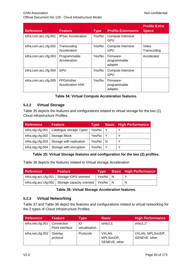
GSM Association Non-confidential
Official Document NG.126 - Cloud Infrastructure Model
V2.0 Page 84 of 173
Reference Feature Type Profile-Extensions
Profile Extra
Specs
infra.com.acc.cfg.001 IPSec Acceleration Yes/No Compute Intensive
GPU
infra.com.acc.cfg.002 Transcoding
Acceleration
Yes/No Compute Intensive
GPU
Video
Transcoding
infra.com.acc.cfg.003 Programmable
Acceleration
Yes/No Firmware-
programmable
adapter
Accelerator
infra.com.acc.cfg.004 GPU Yes/No Compute Intensive
GPU
infra.com.acc.cfg.005 FPGA/other
Acceleration H/W
Yes/No Firmware-
programmable
adapter
Table 34: Virtual Compute Acceleration features.
5.2.2 Virtual Storage
Table 35 depicts the features and configurations related to virtual storage for the two (2)
Cloud Infrastructure Profiles.
Reference Feature Type Basic High Performance
infra.stg.cfg.001 Catalogue storage Types Yes/No Y Y
infra.stg.cfg.002 Storage Block Yes/No Y Y
infra.stg.cfg.003 Storage with replication Yes/No N Y
infra.stg.cfg.004 Storage with encryption Yes/No Y Y
Table 35: Virtual Storage features and configuration for the two (2) profiles.
Table 36 depicts the features related to Virtual storage Acceleration
Reference Feature Type Basic High Performance
infra.stg.acc.cfg.001 Storage IOPS oriented Yes/No N Y
infra.stg.acc.cfg.002 Storage capacity oriented Yes/No N N
Table 36: Virtual Storage Acceleration features.
5.2.3 Virtual Networking
Table 37 and Table 38 depict the features and configurations related to virtual networking for
the 2 types of Cloud Infrastructure Profiles.
Reference Feature Type Basic High Performance
infra.net.cfg.001 Connection
Point interface
IO
virtualisation
virtio1.1 virtio1.1*
infra.net.cfg.002 Overlay
protocol
Protocols VXLAN,
MPLSoUDP,
GENEVE, other
VXLAN, MPLSoUDP,
GENEVE, other
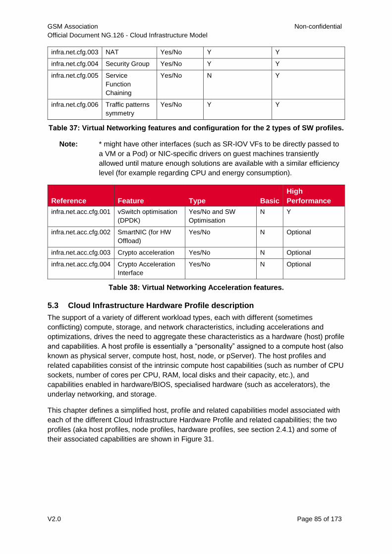
GSM Association Non-confidential
Official Document NG.126 - Cloud Infrastructure Model
V2.0 Page 85 of 173
infra.net.cfg.003 NAT Yes/No Y Y
infra.net.cfg.004 Security Group Yes/No Y Y
infra.net.cfg.005 Service
Function
Chaining
Yes/No N Y
infra.net.cfg.006 Traffic patterns
symmetry
Yes/No Y Y
Table 37: Virtual Networking features and configuration for the 2 types of SW profiles.
Note: * might have other interfaces (such as SR-IOV VFs to be directly passed to
a VM or a Pod) or NIC-specific drivers on guest machines transiently
allowed until mature enough solutions are available with a similar efficiency
level (for example regarding CPU and energy consumption).
Reference Feature Type Basic
High
Performance
infra.net.acc.cfg.001 vSwitch optimisation
(DPDK)
Yes/No and SW
Optimisation
N Y
infra.net.acc.cfg.002 SmartNIC (for HW
Offload)
Yes/No N Optional
infra.net.acc.cfg.003 Crypto acceleration Yes/No N Optional
infra.net.acc.cfg.004 Crypto Acceleration
Interface
Yes/No N Optional
Table 38: Virtual Networking Acceleration features.
5.3 Cloud Infrastructure Hardware Profile description
The support of a variety of different workload types, each with different (sometimes
conflicting) compute, storage, and network characteristics, including accelerations and
optimizations, drives the need to aggregate these characteristics as a hardware (host) profile
and capabilities. A host profile is essentially a “personality” assigned to a compute host (also
known as physical server, compute host, host, node, or pServer). The host profiles and
related capabilities consist of the intrinsic compute host capabilities (such as number of CPU
sockets, number of cores per CPU, RAM, local disks and their capacity, etc.), and
capabilities enabled in hardware/BIOS, specialised hardware (such as accelerators), the
underlay networking, and storage.
This chapter defines a simplified host, profile and related capabilities model associated with
each of the different Cloud Infrastructure Hardware Profile and related capabilities; the two
profiles (aka host profiles, node profiles, hardware profiles, see section 2.4.1) and some of
their associated capabilities are shown in Figure 31.
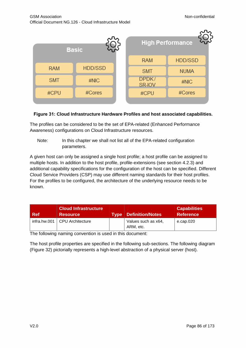
GSM Association Non-confidential
Official Document NG.126 - Cloud Infrastructure Model
V2.0 Page 86 of 173
Figure 31: Cloud Infrastructure Hardware Profiles and host associated capabilities.
The profiles can be considered to be the set of EPA-related (Enhanced Performance
Awareness) configurations on Cloud Infrastructure resources.
Note: In this chapter we shall not list all of the EPA-related configuration
parameters.
A given host can only be assigned a single host profile; a host profile can be assigned to
multiple hosts. In addition to the host profile, profile-extensions (see section 4.2.3) and
additional capability specifications for the configuration of the host can be specified. Different
Cloud Service Providers (CSP) may use different naming standards for their host profiles.
For the profiles to be configured, the architecture of the underlying resource needs to be
known.
Ref
Cloud Infrastructure
Resource Type Definition/Notes
Capabilities
Reference
infra.hw.001 CPU Architecture Values such as x64,
ARM, etc.
e.cap.020
The following naming convention is used in this document:
The host profile properties are specified in the following sub-sections. The following diagram
(Figure 32) pictorially represents a high-level abstraction of a physical server (host).
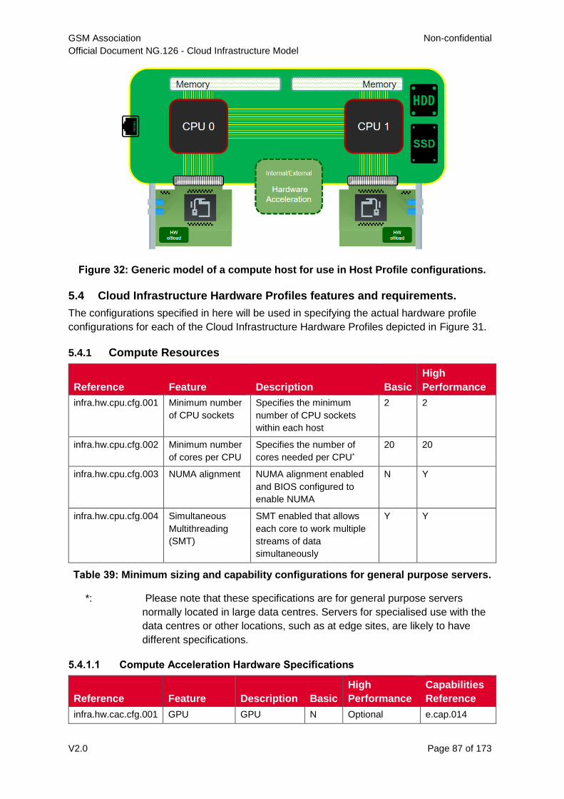
GSM Association Non-confidential
Official Document NG.126 - Cloud Infrastructure Model
V2.0 Page 87 of 173
Figure 32: Generic model of a compute host for use in Host Profile configurations.
5.4 Cloud Infrastructure Hardware Profiles features and requirements.
The configurations specified in here will be used in specifying the actual hardware profile
configurations for each of the Cloud Infrastructure Hardware Profiles depicted in Figure 31.
5.4.1 Compute Resources
Reference Feature Description Basic
High
Performance
infra.hw.cpu.cfg.001 Minimum number
of CPU sockets
Specifies the minimum
number of CPU sockets
within each host
2 2
infra.hw.cpu.cfg.002 Minimum number
of cores per CPU
Specifies the number of
cores needed per CPU*
20 20
infra.hw.cpu.cfg.003 NUMA alignment NUMA alignment enabled
and BIOS configured to
enable NUMA
N Y
infra.hw.cpu.cfg.004 Simultaneous
Multithreading
(SMT)
SMT enabled that allows
each core to work multiple
streams of data
simultaneously
Y Y
Table 39: Minimum sizing and capability configurations for general purpose servers.
*: Please note that these specifications are for general purpose servers
normally located in large data centres. Servers for specialised use with the
data centres or other locations, such as at edge sites, are likely to have
different specifications.
5.4.1.1 Compute Acceleration Hardware Specifications
Reference Feature Description Basic
High
Performance
Capabilities
Reference
infra.hw.cac.cfg.001 GPU GPU N Optional e.cap.014
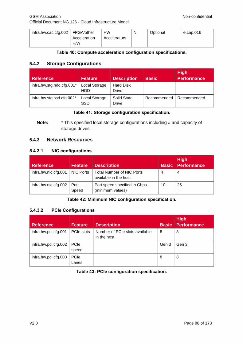
GSM Association Non-confidential
Official Document NG.126 - Cloud Infrastructure Model
V2.0 Page 88 of 173
infra.hw.cac.cfg.002 FPGA/other
Acceleration
H/W
HW
Accelerators
N Optional e.cap.016
Table 40: Compute acceleration configuration specifications.
5.4.2 Storage Configurations
Reference Feature Description Basic
High
Performance
infra.hw.stg.hdd.cfg.001* Local Storage
HDD
Hard Disk
Drive
infra.hw.stg.ssd.cfg.002* Local Storage
SSD
Solid State
Drive
Recommended Recommended
Table 41: Storage configuration specification.
Note: * This specified local storage configurations including # and capacity of
storage drives.
5.4.3 Network Resources
5.4.3.1 NIC configurations
Reference Feature Description Basic
High
Performance
infra.hw.nic.cfg.001 NIC Ports Total Number of NIC Ports
available in the host
4 4
infra.hw.nic.cfg.002 Port
Speed
Port speed specified in Gbps
(minimum values)
10 25
Table 42: Minimum NIC configuration specification.
5.4.3.2 PCIe Configurations
Reference Feature Description Basic
High
Performance
infra.hw.pci.cfg.001 PCIe slots Number of PCIe slots available
in the host
8 8
infra.hw.pci.cfg.002 PCIe
speed
Gen 3 Gen 3
infra.hw.pci.cfg.003 PCIe
Lanes
8 8
Table 43: PCIe configuration specification.
GSM Association Non-confidential
Official Document NG.126 - Cloud Infrastructure Model
V2.0 Page 89 of 173
5.4.3.3 Network Acceleration Configurations
Reference Feature Description Basic
High
Performan
ce
Capabilities
Reference
infra.hw.nac.cfg.001 Crypto
Acceleration
IPSec, Crypto N Optional e.cap.009
infra.hw.nac.cfg.002 SmartNIC offload
network
functionality
N Optional e.cap.015
infra.hw.nac.cfg.003 Compression Optional Optional
infra.hw.nac.cfg.004 SR-IOV over
PCI-PT
SR-IOV N Optional e.cap.013
Table 44: Network acceleration configuration specification.
6 External Interfaces
6.1 Introduction
In this document’s earlier chapters, the various resources and capabilities of the Cloud
Infrastructure have been catalogued and the workloads have been profiled with respect to
those capabilities. The intent behind this chapter and an “API Layer” is to similarly provide a
single place to catalogue and thereby codify, a common set of open APIs to access (i.e.
request, consume, control, etc.) the aforementioned resources, be them directly exposed to
the workloads, or purely internal to the Cloud Infrastructure.
It is a further intent of this chapter and this document to ensure the APIs adopted for the
Cloud Infrastructure implementations are open and not proprietary, in support of
compatibility, component substitution, and ability to realize maximum value from existing and
future test heads and harnesses.
While it is the intent of this chapter to catalogue the APIs, it is not the intent of this chapter to
reprint the APIs, as this would make maintenance of the chapter impractical and the length
of the chapter disproportionate within the Reference Model document. Instead, the APIs
selected for the Cloud Infrastructure implementations and specified in this chapter, will be
incorporated by reference and URLs for the latest, authoritative versions of the APIs,
provided in the References section of this document.
Although the document does not attempt to reprint the APIs themselves, where appropriate
and generally where the mapping of resources and capabilities within the Cloud
Infrastructure to objects in APIs would be otherwise ambiguous, this chapter shall provide
explicit identification and mapping.
In addition to the raw or base-level Cloud Infrastructure functionality to API and object
mapping, it is further the intent to specify an explicit, normalized set of APIs and mappings to
control the logical interconnections and relationships between these objects, notably, but not
limited to, support of SFC (Service Function Chaining) and other networking and network
management functionality.
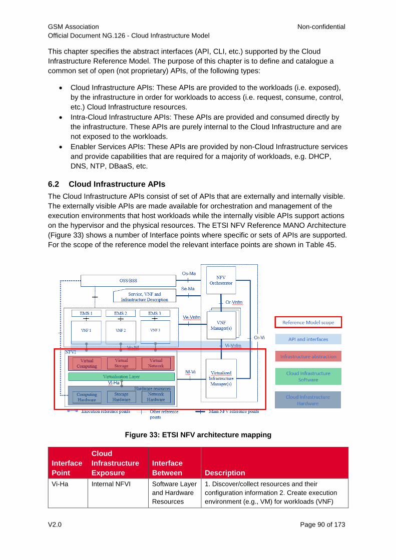
GSM Association Non-confidential
Official Document NG.126 - Cloud Infrastructure Model
V2.0 Page 90 of 173
This chapter specifies the abstract interfaces (API, CLI, etc.) supported by the Cloud
Infrastructure Reference Model. The purpose of this chapter is to define and catalogue a
common set of open (not proprietary) APIs, of the following types:
Cloud Infrastructure APIs: These APIs are provided to the workloads (i.e. exposed),
by the infrastructure in order for workloads to access (i.e. request, consume, control,
etc.) Cloud Infrastructure resources.
Intra-Cloud Infrastructure APIs: These APIs are provided and consumed directly by
the infrastructure. These APIs are purely internal to the Cloud Infrastructure and are
not exposed to the workloads.
Enabler Services APIs: These APIs are provided by non-Cloud Infrastructure services
and provide capabilities that are required for a majority of workloads, e.g. DHCP,
DNS, NTP, DBaaS, etc.
6.2 Cloud Infrastructure APIs
The Cloud Infrastructure APIs consist of set of APIs that are externally and internally visible.
The externally visible APIs are made available for orchestration and management of the
execution environments that host workloads while the internally visible APIs support actions
on the hypervisor and the physical resources. The ETSI NFV Reference MANO Architecture
(Figure 33) shows a number of Interface points where specific or sets of APIs are supported.
For the scope of the reference model the relevant interface points are shown in Table 45.
Figure 33: ETSI NFV architecture mapping
Interface
Point
Cloud
Infrastructure
Exposure
Interface
Between Description
Vi-Ha Internal NFVI Software Layer
and Hardware
Resources
1. Discover/collect resources and their
configuration information 2. Create execution
environment (e.g., VM) for workloads (VNF)
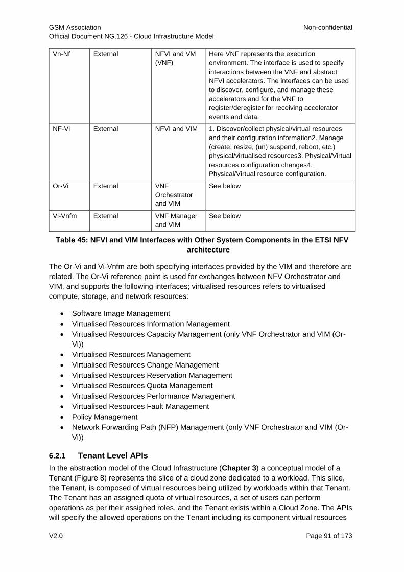
GSM Association Non-confidential
Official Document NG.126 - Cloud Infrastructure Model
V2.0 Page 91 of 173
Vn-Nf External NFVI and VM
(VNF)
Here VNF represents the execution
environment. The interface is used to specify
interactions between the VNF and abstract
NFVI accelerators. The interfaces can be used
to discover, configure, and manage these
accelerators and for the VNF to
register/deregister for receiving accelerator
events and data.
NF-Vi External NFVI and VIM 1. Discover/collect physical/virtual resources
and their configuration information2. Manage
(create, resize, (un) suspend, reboot, etc.)
physical/virtualised resources3. Physical/Virtual
resources configuration changes4.
Physical/Virtual resource configuration.
Or-Vi External VNF
Orchestrator
and VIM
See below
Vi-Vnfm External VNF Manager
and VIM
See below
Table 45: NFVI and VIM Interfaces with Other System Components in the ETSI NFV
architecture
The Or-Vi and Vi-Vnfm are both specifying interfaces provided by the VIM and therefore are
related. The Or-Vi reference point is used for exchanges between NFV Orchestrator and
VIM, and supports the following interfaces; virtualised resources refers to virtualised
compute, storage, and network resources:
Software Image Management
Virtualised Resources Information Management
Virtualised Resources Capacity Management (only VNF Orchestrator and VIM (Or-
Vi))
Virtualised Resources Management
Virtualised Resources Change Management
Virtualised Resources Reservation Management
Virtualised Resources Quota Management
Virtualised Resources Performance Management
Virtualised Resources Fault Management
Policy Management
Network Forwarding Path (NFP) Management (only VNF Orchestrator and VIM (Or-
Vi))
6.2.1 Tenant Level APIs
In the abstraction model of the Cloud Infrastructure (Chapter 3) a conceptual model of a
Tenant (Figure 8) represents the slice of a cloud zone dedicated to a workload. This slice,
the Tenant, is composed of virtual resources being utilized by workloads within that Tenant.
The Tenant has an assigned quota of virtual resources, a set of users can perform
operations as per their assigned roles, and the Tenant exists within a Cloud Zone. The APIs
will specify the allowed operations on the Tenant including its component virtual resources
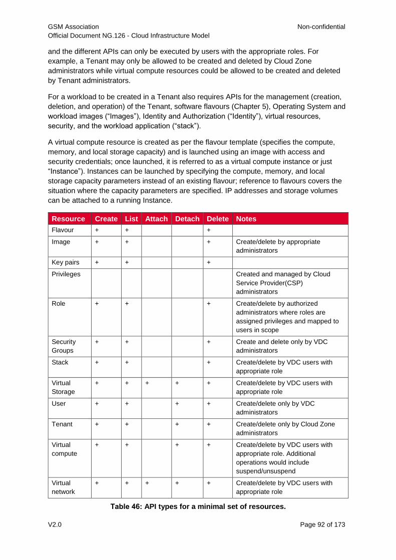
GSM Association Non-confidential
Official Document NG.126 - Cloud Infrastructure Model
V2.0 Page 92 of 173
and the different APIs can only be executed by users with the appropriate roles. For
example, a Tenant may only be allowed to be created and deleted by Cloud Zone
administrators while virtual compute resources could be allowed to be created and deleted
by Tenant administrators.
For a workload to be created in a Tenant also requires APIs for the management (creation,
deletion, and operation) of the Tenant, software flavours (Chapter 5), Operating System and
workload images (“Images”), Identity and Authorization (“Identity”), virtual resources,
security, and the workload application (“stack”).
A virtual compute resource is created as per the flavour template (specifies the compute,
memory, and local storage capacity) and is launched using an image with access and
security credentials; once launched, it is referred to as a virtual compute instance or just
“Instance”). Instances can be launched by specifying the compute, memory, and local
storage capacity parameters instead of an existing flavour; reference to flavours covers the
situation where the capacity parameters are specified. IP addresses and storage volumes
can be attached to a running Instance.
Resource Create List Attach Detach Delete Notes
Flavour + + +
Image + + + Create/delete by appropriate
administrators
Key pairs + + +
Privileges Created and managed by Cloud
Service Provider(CSP)
administrators
Role + + + Create/delete by authorized
administrators where roles are
assigned privileges and mapped to
users in scope
Security
Groups
+ + + Create and delete only by VDC
administrators
Stack + + + Create/delete by VDC users with
appropriate role
Virtual
Storage
+ + + + + Create/delete by VDC users with
appropriate role
User + + + + Create/delete only by VDC
administrators
Tenant + + + + Create/delete only by Cloud Zone
administrators
Virtual
compute
+ + + + Create/delete by VDC users with
appropriate role. Additional
operations would include
suspend/unsuspend
Virtual
network
+ + + + + Create/delete by VDC users with
appropriate role
Table 46: API types for a minimal set of resources.
GSM Association Non-confidential
Official Document NG.126 - Cloud Infrastructure Model
V2.0 Page 93 of 173
Table 46 specifies a minimal set of operations for a minimal set of resources that are needed
to orchestrate workloads. The actual APIs for the listed operations will be specified in the
Reference Architectures; each listed operation could have a number of associated APIs with
a different set of parameters. For example, create virtual resource using an image or a
device.
6.2.2 Hardware Acceleration Interfaces
Acceleration Interface Specifications ETSI GS NFV-IFA 002 [7] defines a technology and
implementation independent virtual accelerator, the accelerator interface requirements and
specifications that would allow a workload to leverage a Virtual Accelerator. The virtual
accelerator is modelled on extensible para-virtualised devices (EDP). ETSI GS NFV-IFA 002
[7] specifies the architectural model in Chapter 4 and the abstract interfaces for
management, configuration, monitoring, and Data exchange in Chapter 7.
ETSI NFV-IFA 019 3.1.1 [8] has defined a set of technology independent interfaces for
acceleration resource life cycle management. These operations allow: allocation, release,
and querying of acceleration resource, get and reset statistics, subscribe/unsubscribe
(terminate) to fault notifications, notify (only used by NFVI), and get alarm information.
These acceleration interfaces are summarized here in Table 47 only for convenience.
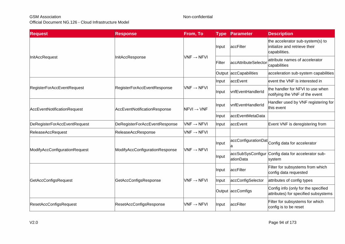
GSM Association Non-confidential
Official Document NG.126 - Cloud Infrastructure Model
V2.0 Page 94 of 173
Request Response From, To Type Parameter Description
InitAccRequest InitAccResponse VNF → NFVI
Input accFilter
the accelerator sub-system(s) to
initialize and retrieve their
capabilities.
Filter accAttributeSelector attribute names of accelerator
capabilities
Output accCapabilities acceleration sub-system capabilities
RegisterForAccEventRequest RegisterForAccEventResponse VNF → NFVI
Input accEvent event the VNF is interested in
Input vnfEventHandlerId the handler for NFVI to use when
notifying the VNF of the event
AccEventNotificationRequest AccEventNotificationResponse NFVI → VNF Input vnfEventHandlerId
Handler used by VNF registering for
this event
Input accEventMetaData
DeRegisterForAccEventRequest DeRegisterForAccEventResponse VNF → NFVI Input accEvent Event VNF is deregistering from
ReleaseAccRequest ReleaseAccResponse VNF → NFVI
ModifyAccConfigurationRequest ModifyAccConfigurationResponse VNF → NFVI
Input accConfigurationDat
a Config data for accelerator
Input accSubSysConfigur
ationData
Config data for accelerator sub-
system
GetAccConfigsRequest GetAccConfigsResponse VNF → NFVI
Input accFilter Filter for subsystems from which
config data requested
Input accConfigSelector attributes of config types
Output accComfigs Config info (only for the specified
attributes) for specified subsystems
ResetAccConfigsRequest ResetAccConfigsResponse VNF → NFVI Input accFilter Filter for subsystems for which
config is to be reset
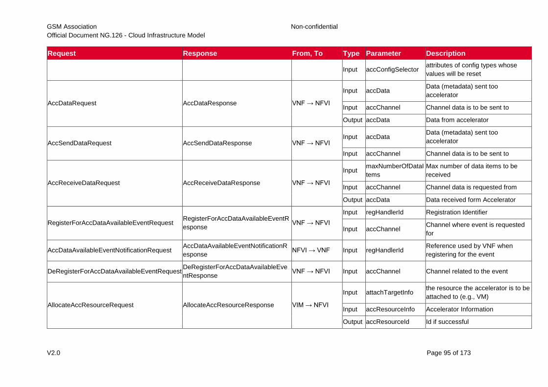
GSM Association Non-confidential
Official Document NG.126 - Cloud Infrastructure Model
V2.0 Page 95 of 173
Request Response From, To Type Parameter Description
Input accConfigSelector attributes of config types whose
values will be reset
AccDataRequest AccDataResponse VNF → NFVI
Input accData Data (metadata) sent too
accelerator
Input accChannel Channel data is to be sent to
Output accData Data from accelerator
AccSendDataRequest AccSendDataResponse VNF → NFVI Input accData
Data (metadata) sent too
accelerator
Input accChannel Channel data is to be sent to
AccReceiveDataRequest AccReceiveDataResponse VNF → NFVI
Input maxNumberOfDataI
tems
Max number of data items to be
received
Input accChannel Channel data is requested from
Output accData Data received form Accelerator
RegisterForAccDataAvailableEventRequest RegisterForAccDataAvailableEventR
esponse VNF → NFVI
Input regHandlerId Registration Identifier
Input accChannel Channel where event is requested
for
AccDataAvailableEventNotificationRequest AccDataAvailableEventNotificationR
esponse NFVI → VNF Input regHandlerId
Reference used by VNF when
registering for the event
DeRegisterForAccDataAvailableEventRequest DeRegisterForAccDataAvailableEve
ntResponse VNF → NFVI Input accChannel Channel related to the event
AllocateAccResourceRequest AllocateAccResourceResponse VIM → NFVI
Input attachTargetInfo the resource the accelerator is to be
attached to (e.g., VM)
Input accResourceInfo Accelerator Information
Output accResourceId Id if successful
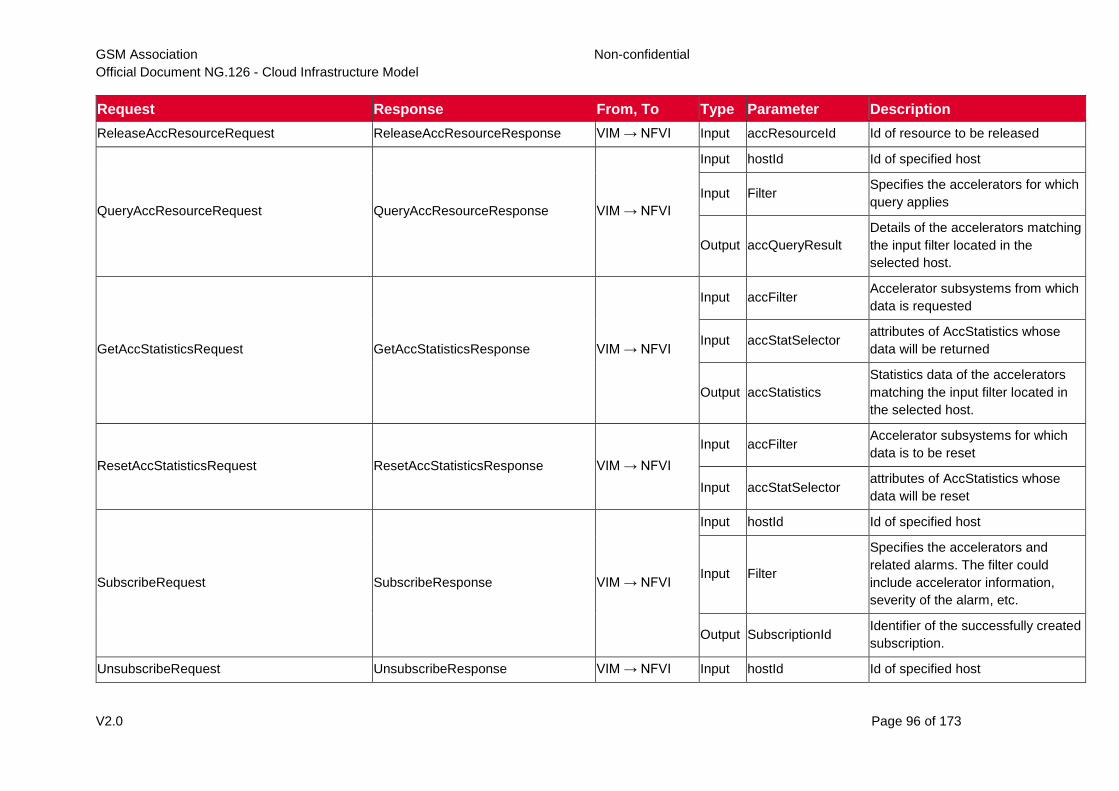
GSM Association Non-confidential
Official Document NG.126 - Cloud Infrastructure Model
V2.0 Page 96 of 173
Request Response From, To Type Parameter Description
ReleaseAccResourceRequest ReleaseAccResourceResponse VIM → NFVI Input accResourceId Id of resource to be released
QueryAccResourceRequest QueryAccResourceResponse VIM → NFVI
Input hostId Id of specified host
Input Filter Specifies the accelerators for which
query applies
Output accQueryResult
Details of the accelerators matching
the input filter located in the
selected host.
GetAccStatisticsRequest GetAccStatisticsResponse VIM → NFVI
Input accFilter Accelerator subsystems from which
data is requested
Input accStatSelector attributes of AccStatistics whose
data will be returned
Output accStatistics
Statistics data of the accelerators
matching the input filter located in
the selected host.
ResetAccStatisticsRequest ResetAccStatisticsResponse VIM → NFVI
Input accFilter Accelerator subsystems for which
data is to be reset
Input accStatSelector attributes of AccStatistics whose
data will be reset
SubscribeRequest SubscribeResponse VIM → NFVI
Input hostId Id of specified host
Input Filter
Specifies the accelerators and
related alarms. The filter could
include accelerator information,
severity of the alarm, etc.
Output SubscriptionId Identifier of the successfully created
subscription.
UnsubscribeRequest UnsubscribeResponse VIM → NFVI Input hostId Id of specified host
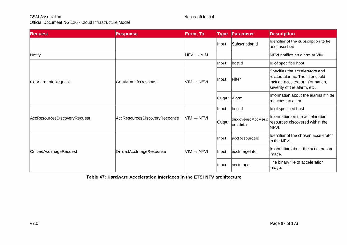
GSM Association Non-confidential
Official Document NG.126 - Cloud Infrastructure Model
V2.0 Page 97 of 173
Request Response From, To Type Parameter Description
Input SubscriptionId Identifier of the subscription to be
unsubscribed.
Notify NFVI → VIM NFVI notifies an alarm to VIM
GetAlarmInfoRequest GetAlarmInfoResponse VIM → NFVI
Input hostId Id of specified host
Input Filter
Specifies the accelerators and
related alarms. The filter could
include accelerator information,
severity of the alarm, etc.
Output Alarm Information about the alarms if filter
matches an alarm.
AccResourcesDiscoveryRequest AccResourcesDiscoveryResponse VIM → NFVI
Input hostId Id of specified host
Output discoveredAccReso
urceInfo
Information on the acceleration
resources discovered within the
NFVI.
OnloadAccImageRequest OnloadAccImageResponse VIM → NFVI
Input accResourceId Identifier of the chosen accelerator
in the NFVI.
Input accImageInfo Information about the acceleration
image.
Input accImage The binary file of acceleration
image.
Table 47: Hardware Acceleration Interfaces in the ETSI NFV architecture
GSM Association Non-confidential
Official Document NG.126 - Cloud Infrastructure Model
V2.0 Page 98 of 173
6.3 Intra-Cloud Infrastructure Interfaces
6.3.1 Hypervisor Hardware Interface
Table 45 lists a number of NFVI and VIM interfaces, including the internal VI-Ha interface.
The VI-Ha interface allows the hypervisor to control the physical infrastructure; the
hypervisor acts under VIM control. The VIM issues all requests and responses using the NF-
VI interface; requests and responses include commands, configuration requests, policies,
updates, alerts, and response to infrastructure results. The hypervisor also provides
information about the health of the physical infrastructure resources to the VM. All these
activities, on behalf of the VIM, are performed by the hypervisor using the VI-Ha interface.
While no abstract APIs have yet been defined for this internal VI-Ha interface, ETSI GS
NFV-INF 004 [9] defines a set of requirements and details of the information that is required
by the VIM from the physical infrastructure resources. Hypervisors utilize various programs
to get this data including BIOS, IPMI, PCI, I/O Adapters/Drivers, etc.
6.4 Enabler Services Interfaces
An operational cloud needs a set of standard services to function. Services such as NTP for
time synchronization, DHCP for IP address allocation, DNS for obtaining IP addresses for
domain names, and LBaaS (version 2) to distribute incoming requests amongst a pool of
designated resources.
7 Security
7.1 Introduction
Security vulnerabilities and attack vectors are everywhere. The Telecom industry and its
cloud infrastructures are even more vulnerable to potential attacks due to the ubiquitous
nature of the infrastructures and services combined with the vital role Telecommunications
play in the modern world. The attack vectors are many and varied, ranging from the potential
for exposure of sensitive data, both personal and corporate, to weaponized disruption to the
global telecommunications networks. The threats can take the form of a physical attack on
the locations the infrastructure hardware is housed, to network attacks such as denial of
service and targeted corruption of the network service applications themselves. Whatever
the source, any Cloud Infrastructure built needs to be able to withstand attacks in whatever
form they take.
This chapter examines multiple aspects of security as it relates to Cloud Infrastructure and
security aspects for workloads. After discussing security attack vectors, this chapter delves
into security requirements. Regarding security requirements and best practices,
specifications and documents are published by standards organizations. A selection of
standards of interest for Cloud Infrastructure security is listed in a dedicated section. The
chapter culminates with a consolidated set of “must” requirements and desired (should)
recommendations; it is suggested that operators carefully evaluate the recommendations for
possible implementation.
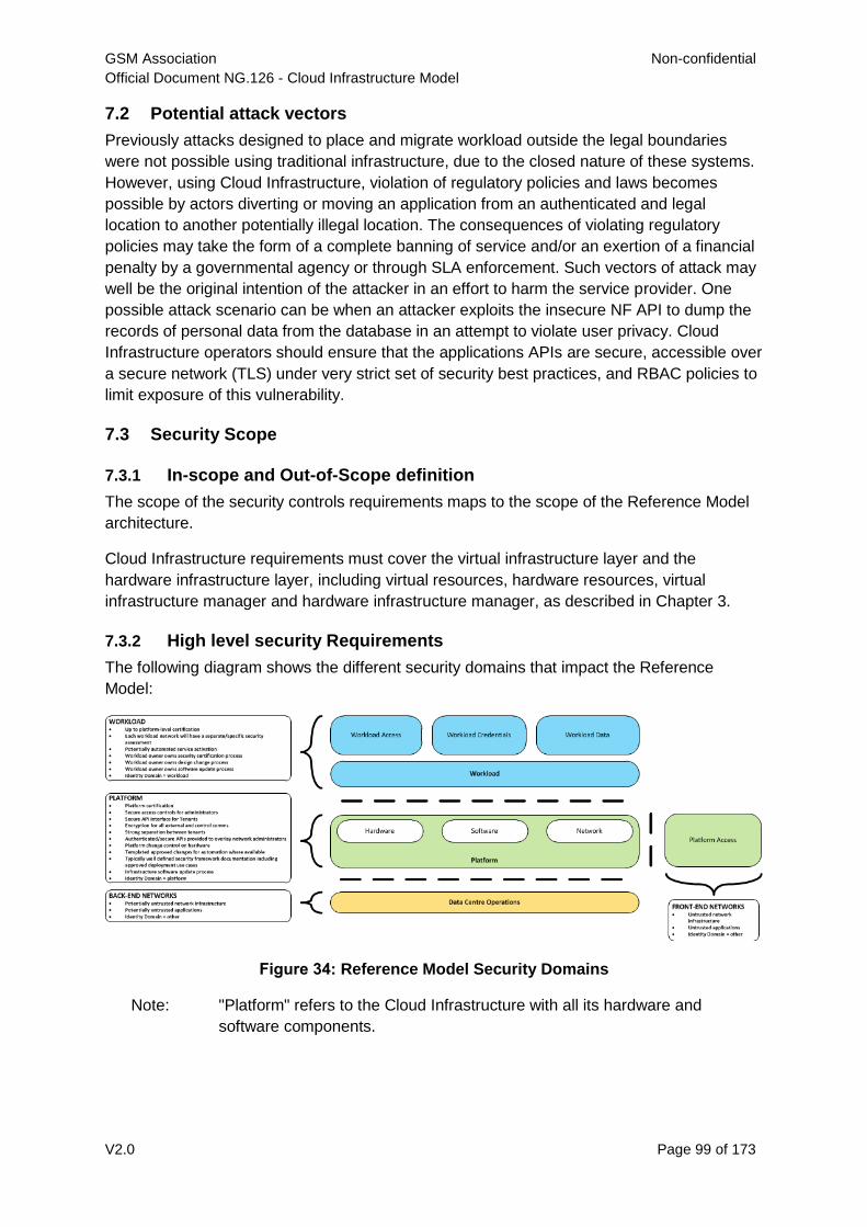
GSM Association Non-confidential
Official Document NG.126 - Cloud Infrastructure Model
V2.0 Page 99 of 173
7.2 Potential attack vectors
Previously attacks designed to place and migrate workload outside the legal boundaries
were not possible using traditional infrastructure, due to the closed nature of these systems.
However, using Cloud Infrastructure, violation of regulatory policies and laws becomes
possible by actors diverting or moving an application from an authenticated and legal
location to another potentially illegal location. The consequences of violating regulatory
policies may take the form of a complete banning of service and/or an exertion of a financial
penalty by a governmental agency or through SLA enforcement. Such vectors of attack may
well be the original intention of the attacker in an effort to harm the service provider. One
possible attack scenario can be when an attacker exploits the insecure NF API to dump the
records of personal data from the database in an attempt to violate user privacy. Cloud
Infrastructure operators should ensure that the applications APIs are secure, accessible over
a secure network (TLS) under very strict set of security best practices, and RBAC policies to
limit exposure of this vulnerability.
7.3 Security Scope
7.3.1 In-scope and Out-of-Scope definition
The scope of the security controls requirements maps to the scope of the Reference Model
architecture.
Cloud Infrastructure requirements must cover the virtual infrastructure layer and the
hardware infrastructure layer, including virtual resources, hardware resources, virtual
infrastructure manager and hardware infrastructure manager, as described in Chapter 3.
7.3.2 High level security Requirements
The following diagram shows the different security domains that impact the Reference
Model:
Figure 34: Reference Model Security Domains
Note: "Platform" refers to the Cloud Infrastructure with all its hardware and
software components.
GSM Association Non-confidential
Official Document NG.126 - Cloud Infrastructure Model
V2.0 Page 100 of 173
7.3.2.1 Platform security requirements
At a high level, the following areas/requirements cover platform security for a particular
deployment:
Platform certification
Secure access controls for administrators
Secure API interface for tenants
Encryption for all external and control communications
Strong separation between tenants - ensuring network, data, memory and runtime
process (CPU running core) isolation between tenants
Authenticated/secure APIs provided to overlay network administrators
Platform change control on hardware
Templated approved changes for automation where available
Typically well-defined security framework documentation including approved
deployment use cases
Infrastructure software update process
7.3.2.2 Workload security requirements
At a high level, the following areas/requirements cover workload security for a particular
deployment:
Up to platform-level certification
Each workload network will need to undertake its own security self-assessment and
accreditation, and not inherit a security accreditation from the platform
Potentially automated service activation
Workload owner owns workload security certification process
Workload owner owns workload design change process
Workload owner owns workload software update process
7.3.3 Common security standards
The Cloud Infrastructure Reference Model and the supporting architectures are not only
required to optimally support networking functions, but they must be designed with common
security principles and standards from inception. These best practices must be applied at all
layers of the infrastructure stack and across all points of interconnections (internal or with
outside networks), APIs and contact points with the NFV network functions overlaying or
interacting with that infrastructure. Standards organizations with recommendations and best
practices, and certifications that need to be taken into consideration include the following
examples. However this is by no means an exhaustive list, just some of the more important
standards in current use.
Center for Internet Security - https://www.cisecurity.org/
Cloud Security Alliance - https://cloudsecurityalliance.org/
Open Web Application Security Project https://www.owasp.org
The National Institute of Standards and Technology (NIST)
FedRAMP Certification https://www.fedramp.gov/
ETSI Cyber Security Technical Committee (TC CYBER) -
https://www.etsi.org/committee/cyber
GSM Association Non-confidential
Official Document NG.126 - Cloud Infrastructure Model
V2.0 Page 101 of 173
ETSI Industry Specification Group Network Functions Virtualisation (ISG NFV) -
https://www.etsi.org/technologies/nfv
ETSI ISG NFV SEC WG specifications
ISO (the International Organization for Standardization) and IEC (the International
Electrotechnical Commission) - www.iso.org. The following ISO standards are of
particular interest for NFVI
- ISO/IEC 27002:2013 - ISO/IEC 27001 are the international Standard for
best-practice information security management systems (ISMSs)
- ISO/IEC 27032 - ISO/IEC 27032 is the international Standard focusing
explicitly on cybersecurity
- ISO/IEC 27035 - ISO/IEC 27035 is the international Standard for incident
management
- ISO/IEC 27031 - ISO/IEC 27031 is the international Standard for ICT
readiness for business continuity
A good place to start to understand the requirements is to use the widely accepted
definitions developed by the OWASP – Open Web Application Security Project. These
include the following core principles:
Confidentiality – Only allow access to data for which the user is permitted.
Integrity – Ensure data is not tampered with or altered by unauthorized users.
Availability – ensure systems and data are available to authorized users when they
need it.
Additional Cloud Infrastructure security principles that need to be incorporated:
Authenticity – The ability to confirm the users are in fact valid users with the correct
rights to access the systems or data.
In mobile network field, the GSM Association (GSMA) and its Fraud and Security working
group of experts have developed a set of documents specifying how to secure the global
mobile ecosystem.
The document “Baseline Security controls”, FS.31 v2.0 [20], published in February
2020, is a practical guide intended for operators and stakeholders to check mobile
network’s internal security. It lists a set of security controls from business controls
(including security roles, organizational policies, business continuity management…)
to technological controls (for user equipment, networks, operations…) covering all
areas of mobile network, including Cloud Infrastructure. A checklist of questions
allows to improve the security of a deployed network.
The GSMA security activities are currently focussed around 5G services and the new
challenges posed by network functions virtualisation and open source software. The 2
following documents are in the scope of Cloud Infrastructure security:
The white paper “Open Networking & the Security of Open Source Software
deployment”, published in January 2021 [21], deals with open source software
security, it highlights the importance of layered security defences and lists
recommendations and security concepts able to secure deployments.
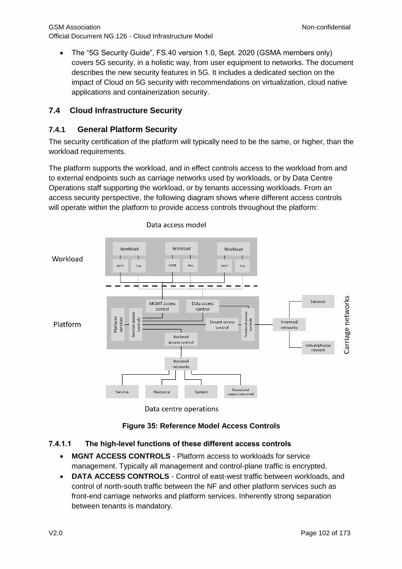
GSM Association Non-confidential
Official Document NG.126 - Cloud Infrastructure Model
V2.0 Page 102 of 173
The “5G Security Guide”, FS.40 version 1.0, Sept. 2020 (GSMA members only)
covers 5G security, in a holistic way, from user equipment to networks. The document
describes the new security features in 5G. It includes a dedicated section on the
impact of Cloud on 5G security with recommendations on virtualization, cloud native
applications and containerization security.
7.4 Cloud Infrastructure Security
7.4.1 General Platform Security
The security certification of the platform will typically need to be the same, or higher, than the
workload requirements.
The platform supports the workload, and in effect controls access to the workload from and
to external endpoints such as carriage networks used by workloads, or by Data Centre
Operations staff supporting the workload, or by tenants accessing workloads. From an
access security perspective, the following diagram shows where different access controls
will operate within the platform to provide access controls throughout the platform:
Figure 35: Reference Model Access Controls
7.4.1.1 The high-level functions of these different access controls
MGNT ACCESS CONTROLS - Platform access to workloads for service
management. Typically all management and control-plane traffic is encrypted.
DATA ACCESS CONTROLS - Control of east-west traffic between workloads, and
control of north-south traffic between the NF and other platform services such as
front-end carriage networks and platform services. Inherently strong separation
between tenants is mandatory.
GSM Association Non-confidential
Official Document NG.126 - Cloud Infrastructure Model
V2.0 Page 103 of 173
SERVICES ACCESS CONTROLS - Protects platform services from any platform
access
BACK-END ACCESS CONTROLS - Data Centre Operations access to the platform,
and subsequently, workloads. Typically stronger authentication requirements such as
(Two-Factor Authentication) 2FA, and using technologies such as Role-Based
Access Control (RBAC) and encryption. Application Programming Interface (API)
gateways may be required for automated/script-driven processes.
FRONT-END ACCESS CONTROLS - Protects the platform from malicious carriage
network access, and provides connectivity for specific workloads to specific carriage
networks. Carriage networks being those that are provided as public networks and
operated by carriers, and in this case with interfaces that are usually sub, or virtual
networks.
TENANT ACCESS CONTROLS - Provides appropriate tenant access controls to
specific platform services, and tenant workloads - including Role-Based Access
Control (RBAC), authentication controls as appropriate for the access arrangement,
and Application Programming Interface (API) gateways for automated/script-driven
processes.
7.4.1.2 The following general security requirements apply to the Cloud
Infrastructure
System Hardening
Adhering to the principle of least privilege, no login to root on any platform systems
(platform systems are those that are associated with the platform and include
systems that directly or indirectly affect the viability of the platform) when root
privileges are not required.
Ensure that all the platform's components (including hypervisors, VMs, etc.) are kept
up to date with the latest patch.
In order to tightly control access to resources and protect them from malicious access
and introspection, Linux Security Modules such as SELinux should be used to
enforce access rules.
Platform access
Restrict traffic to only traffic that is necessary, and deny all other traffic, including
traffic from and to 'Back-end'.
Provide protections between the Internet and any workloads including web and
volumetric attack preventions.
All host to host communications within the cloud provider network are to be
cryptographically protected in transit.
Use cryptographically-protected protocols for administrative access to the platform.
Data Centre Operations staff and systems must use management protocols that limit
security risk such as SNMPv3, SSH v2, ICMP, NTP, syslog, and TLS v1.2 or higher.
Processes for managing platform access control filters must be documented,
followed, and monitored.
Role-Based Access Control (RBAC) must apply for all platform systems access.
All APIs access must use TLS protocol, including back-end APIs.
GSM Association Non-confidential
Official Document NG.126 - Cloud Infrastructure Model
V2.0 Page 104 of 173
Workload security
Restrict traffic to (and from) the workload to only traffic that is necessary, and deny all
other traffic.
Support zoning within a tenant workload - using application-level filtering.
Not expose tenant internal IP address details to another tenant.
All production workloads must be separated from all non-production workloads
including separation between non-hosted non-production external networks.
Confidentiality and Integrity
All data persisted to primary, replica, or backup storage is to be encrypted.
Monitoring and security audit
All platform security logs are to be time synchronised.
Logs are to be regularly scanned for events of interest.
The cloud services must be regularly vulnerability and penetration tested.
Platform provisioning and LCM
A platform change management process that is documented, well communicated to
staff and tenants, and rigorously followed.
A process to check change management adherence that is implemented, and
rigorously followed.
An approved system or process for last resort access must exist for the platform.
Where there are multiple hosting facilities used in the provisioning of a service,
network communications between the facilities for the purpose of backup,
management, and workload communications are cryptographically protected in transit
between data centre facilities.
Continuous Cloud security compliance is mandatory.
An incident response plan must exist for the platform.
7.4.2 Platform ‘back-end’ access security
Validate and verify the integrity of resources management requests coming from a
higher orchestration layer to the Cloud Infrastructure manager.
7.4.3 Platform ‘front-end’ access security
Front-end network security at the application level will be the responsibility of the
workload, however the platform must ensure the isolation and integrity of tenant
connectivity to front-end networks.
The front-end network may provide (Distributed Denial Of Service) DDoS support.
7.4.4 Infrastructure as a Code security
Infrastructure as a Code (IaaC) (or equivalently called Infrastructure as Code, IaC) refers to
the software used for the declarative management of cloud infrastructure resources. In order
to dynamically address user requirements, release features incrementally, and deliver at a
faster pace, DevSecOps teams utilize best practices including continuous integration and
continuous delivery and integrate information security controls and scanning tools into these
GSM Association Non-confidential
Official Document NG.126 - Cloud Infrastructure Model
V2.0 Page 105 of 173
processes, with the aim of providing timely and meaningful feedback including identifying
vulnerabilities and security policy violations. With this automated security testing and
analysis capabilities it will be of critical value to detecting vulnerabilities early and
maintaining a consistent security policy.
Because of the extremely high complexity of modern telco cloud infrastructures, even minor
IaaC code changes may lead to disproportionate and sometime disastrous downstream
security and privacy impacts. Therefore, integration of security testing into the IaaC software
development pipeline requires security activities to be automated using security tools and
integrated with the native DevOps and DevSecOps tools and procedures.
The DevSecOps Automation best practice advocates implementing a framework for security
automation and programmatic execution and monitoring of security controls to identify,
protect, detect, respond, and recover from cyber threats. The framework used for the IaaC
security is based on, the joint publication of Cloud Security Alliance (CSA) and SAFECode,
"The Six Pillars of DevSecOps: Automation (2020)" [22]. The document utilises the base
definitions and constructs from ISO 27000 [23], and CSA's Information Security
Management through Reflexive Security [24].
The framework identifies the following five distinct stages:
1. Secure design and architecture
2. Secure coding (Developer IDE and Code Repository)
3. Continuous build, integration and test
4. Continuous delivery and deployment
5. Continuous monitoring and runtime defence
Triggers and checkpoints define transitions within stages. When designing DevSecOps
security processes, one needs to keep in mind, that when a trigger condition is met, one or
more security activities are activated. The outcomes of those security activities need to
determine whether the requirements of the process checkpoint are satisfied. If the outcome
of the security activities meets the requirements, the next set of security activities are
performed as the process transitions to the next checkpoint, or, alternatively, to the next
stage if the checkpoint is the last one in the current stage. If, on the other hand, the outcome
of the security activities does not meet the requirements, then the process should not be
allowed to advance to the next checkpoint. Table 56 to Table 60 in Section 7.9 define the
IaaC security activities presented as security requirements mapped to particular stages and
trigger points.
7.5 Workload Security - Vendor Responsibility
7.5.1 Software Hardening
No hard-coded credentials or clear text passwords. Software should support
configurable, or industry standard, password complexity rules.
Software should be independent of the infrastructure platform (no OS point release
dependencies to patch).
Software is code signed and all individual sub-components are assessed and verified
for EULA violations.
GSM Association Non-confidential
Official Document NG.126 - Cloud Infrastructure Model
V2.0 Page 106 of 173
Software should have a process for discovery, classification, communication, and
timely resolution of security vulnerabilities (i.e.; bug bounty, Penetration testing/scan
findings, etc.).
Software should support recognized encryption standards and encryption should be
decoupled from software.
Software should have support for configurable banners to display authorized use
criteria/policy.
7.5.2 Port Protection
Unused software and unused network ports should be disabled by default
7.5.3 Software Code Quality and Security
Vendors should use industry recognized software testing suites
o Static and dynamic scanning
o Automated static code review with remediation of Medium/High/Critical security
issues. The tool used for static code analysis and analysis of code being released
must be shared.
o Dynamic security tests with remediation of Medium/High/Critical security issues.
The tool used for Dynamic security analysis of code being released must be
shared
o Penetration tests (pen tests) with remediation of Medium/High/Critical security
issues.
o Methodology for ensuring security is included in the Agile/DevOps delivery
lifecycle for ongoing feature enhancement/maintenance.
7.5.4 Alerting and monitoring
Security event logging: all security events must be logged, including informational.
Privilege escalation must be detected.
7.5.5 Logging
Logging output should support customizable Log retention and Log rotation.
7.5.6 NF images
Image integrity – fingerprinting/validation.
Container Images.
- Container Management.
- Immutability.
7.5.7 Vulnerability Management
Security defect must be reported.
Cadence should aligned with Cloud Infrastructure vendors (OSSA for OpenStack).
Components should be analysed: mechanisms to validate components of the
platform stack by checking libraries and supporting code against the Common
Vulnerabilities and Exposures (CVE) databases to determine whether the code
contains any known vulnerabilities must be embedded into the NFVI architecture
GSM Association Non-confidential
Official Document NG.126 - Cloud Infrastructure Model
V2.0 Page 107 of 173
itself. Some of the components required include tools for checking common libraries
against CVE databases integrated into the deployment and orchestration pipelines.
7.6 Workload Security - Cloud Infrastructure Operator Responsibility
The Operator’s responsibility is to not only make sure that security is included in all the
vendor supplied infrastructure and NFV components, but it is also responsible for the
maintenance of the security functions from an operational and management perspective.
This includes but is not limited to securing the following elements:
Maintaining standard security operational management methods and processes.
Monitoring and reporting functions.
Processes to address regulatory compliance failure.
Support for appropriate incident response and reporting.
Methods to support appropriate remote attestation certification of the validity of the
security components, architectures, and methodologies used.
7.6.1 Remote Attestation/openCIT
Cloud Infrastructure operators must ensure that remote attestation methods are used to
remotely verify the trust status of a given Cloud Infrastructure platform. The basic concept is
based on boot integrity measurements leveraging the Trusted Platform Module (TPM) built
into the underlying hardware. Remote attestation can be provided as a service, and may be
used by either the platform owner or a consumer/customer to verify that the platform has
booted in a trusted manner. Practical implementations of the remote attestation service
include the Open Cloud Integrity Tool (Open CIT). Open CIT provides ‘Trust’ visibility of the
Cloud Infrastructure and enables compliance in Cloud Datacentres by establishing the root
of trust and builds the chain of trust across hardware, operating system, hypervisor, VM, and
container. It includes asset tagging for location and boundary control. The platform trust and
asset tag attestation information is used by Orchestrators and/or Policy Compliance
management to ensure workloads are launched on trusted and location/boundary compliant
platforms. They provide the needed visibility and auditability of infrastructure in both public
and private cloud environments.
7.6.2 Workload Image Scanning / Signing
It is easy to tamper with workload images. It requires only a few seconds to insert some
malware into a workload image file while it is being uploaded to an image database or being
transferred from an image database to a compute node. To guard against this possibility,
workload images can be cryptographically signed and verified during launch time. This can
be achieved by setting up a signing authority and modifying the hypervisor configuration to
verify an image’s signature before they are launched. To implement image security, the
workload operator must test the image and supplementary components verifying that
everything conforms to security policies and best practices.
Use of Image scanners such as OpenSCAP to determine security vulnerabilities is strongly
recommended.
GSM Association Non-confidential
Official Document NG.126 - Cloud Infrastructure Model
V2.0 Page 108 of 173
7.6.3 Networking Security Zoning
Network segmentation is important to ensure that applications can only communicate with
the applications they are supposed to. To prevent a workload from impacting other
workloads or hosts, it is a good practice to separate workload traffic and management traffic.
This will prevent attacks by VMs or containers breaking into the management infrastructure.
It is also best to separate the VLAN traffic into appropriate groups and disable all other
VLANs that are not in use. Likewise, workloads of similar functionalities can be grouped into
specific zones and their traffic isolated. Each zone can be protected using access control
policies and a dedicated firewall based on the needed security level.
Recommended practice to set network security policies following the principle of least
privileged, only allowing approved protocol flows. For example, set 'default deny' inbound
and add approved policies required for the functionality of the application running on the
NFV Infrastructure.
7.6.4 Volume Encryption
Virtual volume disks associated with workloads may contain sensitive data. Therefore, they
need to be protected. Best practice is to secure the workload volumes by encrypting them
and storing the cryptographic keys at safe locations. Encryption functions rely on a Cloud
Infrastructure internal key management service. Be aware that the decision to encrypt the
volumes might cause reduced performance, so the decision to encrypt needs to be
dependent on the requirements of the given infrastructure. The TPM module can also be
used to securely store these keys. In addition, the hypervisor should be configured to
securely erase the virtual volume disks in the event of application crashes or is intentionally
destroyed to prevent it from unauthorized access.
For sensitive data encryption, when data sovereignty is required, an external Hardware
Security Module (HSM) should be integrated in order to protect the cryptographic keys. A
HSM is a physical device which manages and stores secrets. Usage of a HSM strengthens
the secrets security. For 5G services, GSMA FASG strongly recommends the
implementation of a HSM to secure the storage of UICC (Universal Integrated Circuit Card)
credentials.
7.6.5 Root of Trust for Measurements (RTM)
The sections that follow define mechanisms to ensure the integrity of the infrastructure pre-
boot and post-boot (running). The following defines a set of terms used in those sections.
The hardware root of trust helps with the pre-boot and post-boot security issues.
Unified Extensible Firmware Interface (UEFI) adheres to standards defined by an
industry consortium. Vendors (hardware, software) and solution providers collaborate
to define common interfaces, protocols and structures for computing platforms.
Platform Configuration Register (PCR) is a memory location in the TPM used to store
TPM Measurements (hash values generated by the SHA-1 standard hashing
algorithm). PCRs are cleared only on TPM reset. UEFI defines 24 PCRs of which the
first 16, PCR 0 - PCR 15, are used to store measures created during the UEFI boot
process.
Root of Trust for Measurement (RTM) is a computing engine capable of making
integrity measurements.
GSM Association Non-confidential
Official Document NG.126 - Cloud Infrastructure Model
V2.0 Page 109 of 173
Core Root of Trust for Measurements (CRTM) is a set of instructions executed when
performing RTM.
Platform Attestation provides proof of validity of the platform’s integrity
measurements. Please see Section 7.6.1 Remote Attestation/openCIT.
Values stored in a PCR cannot be reset (or forged) as they can only be extended. Whenever
a measurement is sent to a TPM, the hash of the concatenation of the current value of the
PCR and the new measurement is stored in the PCR. The PCR values are used to encrypt
data. If the proper environment is not loaded which will result in different PCR values, the
TPM will be unable to decrypt the data.
7.6.5.1 Static Root of Trust for Measurement (SRTM)
Static RTM (SRTM) begins with measuring and verifying the integrity of the BIOS firmware. It
then measures additional firmware modules, verifies their integrity, and adds each
component’s measure to an SRTM value. The final value represents the expected state of
boot path loads. SRTM stores results as one or more values stored in PCR storage. In
SRTM, the CRTM resets PCRs 0 to 15 only at boot.
Using a Trusted Platform Module (TPM), as a hardware root of trust, measurements of
platform components, such as firmware, bootloader, OS kernel, can be securely stored and
verified. Cloud Infrastructure operators should ensure that the TPM support is enabled in the
platform firmware, so that platform measurements are correctly recorded during boot time.
A simple process would work as follows;
1. The BIOS CRTM (Bios Boot Block) is executed by the CPU and used to measure the
BIOS firmware.
1. The SHA1 hash of the result of the measurement is sent to the TPM.
2. The TPM stores this new result hash by extending the currently stored value.
3. The hash comparisons can validate settings as well as the integrity of the modules.
Cloud Infrastructure operators should ensure that OS kernel measurements can be recorded
by using a TPM-aware bootloader (e.g. tboot, see https://sourceforge.net/projects/tboot/ or
shim, see https://github.com/rhboot/shim), which can extend the root of trust up to the kernel
level.
The validation of the platform measurements can be performed by TPM’s launch control
policy (LCP) or through the remote attestation server.
7.6.5.2 Dynamic Root of Trust for Measurement (DRTM)
In Dynamic Root of Trust for Measurement (DRTM), the RTM for the running environment
are stored in PCRs starting with PCR 17.
If a remote attestation server is used to monitor platform integrity, the operators should
ensure that attestation is performed periodically or in a timely manner. Additionally, platform
monitoring can be extended to monitor the integrity of the static file system at run-time by
using a TPM aware kernel module, such as Linux IMA (Integrity Measurement Architecture),
see https://sourceforge.net/p/linux-ima/wiki/Home, or by using the trust policies (see
https://github.com/opencit/opencit/wiki/Open-CIT-3.2-Product-Guide#88-trust-policies)
functionality of OpenCIT.
GSM Association Non-confidential
Official Document NG.126 - Cloud Infrastructure Model
V2.0 Page 110 of 173
The static file system includes a set of important files and folders which do not change
between reboots during the lifecycle of the platform. This allows the attestation server to
detect any tampering with the static file system during the runtime of the platform.
7.6.6 Zero Trust Architecture (ZTA)
Remote attestation, section 7.6.1, and Root of trust for measurements, section 7.6.5, provide
methods to ensure the integrity of the infrastructure. The Zero Trust concept moves a step
forward enabling to build secure by design cloud infrastructure, from hardware to
applications. The adoption of Zero Trust principles mitigates the threats and attacks within
an enterprise, a network or an infrastructure, ensuring a fine grained segmentation between
each component of the system.
Zero Trust Architecture (ZTA), described in NIST SP 800-207 publication [25], assumes
there is no implicit trust granted to assets or user accounts whatever their location or
ownership. Zero trust approach focuses on protecting all types of resources: data, services,
devices, infrastructure components, virtual and cloud components. Trust is never granted
implicitly, and must be evaluated continuously.
ZTA principles applied to Cloud infrastructure components are the following:
Adopt least privilege configurations
Authentication and authorization required for each entity, service, or session
Fine grained segmentation
Separation of control plane and data plane
Secure internal and external communications
Monitor, test, and analyse security continuously
7.7 Open Source Software Security
Software supply chain safety is crucial and can be a complex task in virtualised and
containerized environments. Open source code is present in Cloud Infrastructure software
from host Operating System to virtualisation layer components, the most obvious being
represented by Linux, KVM, QEMU, OpenStack, and Kubernetes. Workloads components
can also be composed of open source code. The proportion of open source code to an
application source code can vary. It can be partial or total, visible or not. Open source code
can be upstream code coming directly from open source public repositories or code within a
commercial application or network function. To ensure the security of the whole system, all
software and hardware components must reach the same level of security by following best
security practices including secure lifecycle management. The SAFECode paper “Managing
Security Risks Inherent in the Use of Third-party Components” provides a detailed risk
management approach.
To secure software code, the following methods must be applied:
Use best practices coding such as design pattern recommended in the Twelve-Factor
App (see https://12factor.net/) or OWASP “Secure Coding Practices - Quick
Reference Guide” (see https://owasp.org/www-project-secure-coding-practices-quick-
reference-guide/migrated_content).
Require suppliers to provide a Software Bill of Materials to identify the open source
modules in their product’s software releases
GSM Association Non-confidential
Official Document NG.126 - Cloud Infrastructure Model
V2.0 Page 111 of 173
Use trusted, authenticated and identified software images that are provided by
authenticated software distribution portals
Do threat modelling, as described in the document “Tactical Threat Modeling”
published by SAFECode
Test the software in a pre-production environment to validate integration
Detect vulnerabilities using security tools scanning and CVE (Common Vulnerabilities
and Exposures), https://cve.mitre.org/
Actively monitor the open source software repositories to determine if new versions
have been released that address identified vulnerabilities discovered in the
community
Actively monitor the open source software repositories to determine if new versions
have been released that address identified vulnerabilities discovered in the
community
Report and remove vulnerabilities by upgrading components using authenticated
software update distribution portals
Adopt a DevSecOps approach and rely on testing automation throughout the
software build, integration, delivery, deployment, and runtime operation to perform
automatic security check, as described in section 7.4.4 ‘”Infrastructure as a Code
security”
The strength of open source code is the availability of code source developed by a
community which maintain and improve it. Open source code integration with application
source code helps to develop and produce applications faster. But, in return, it can introduce
security risks if a risk management DevSecOps approach is not implemented. The GSMA
white paper, “Open Networking & the Security of Open Source Software Deployment -
Future Networks”, alerts on these risks and addresses the challenges coming with open
source code usage. Amongst these risks for security, we can mention a poor quality code
containing security flaws, an obsolete code with known vulnerabilities, and the lack of
knowledge of open source communities’ branches activity. An active branch will come with
bugs fixes, it will not be the case with an inactive branch. The GSMA white paper develops
means to mitigate these security issues.
SBOM
To begin, it is highly recommended to identify the software components and their origins.
The Software Bill of Materials (SBOM), described by US NTIA (National
Telecommunications and Information Administration), is an efficient tool to identify software
components (see https://www.ntia.gov/SBOM). The SBOM is an inventory of software
components and the relationships between them. NTIA describes how to establish an SBOM
and provides SBOM standard data formats. In case of vulnerability detected for a
component, the SBOM inventory is an effective means to identify the impacted component
and provide remediation.
Code inspection
Poor code quality is a factor of risk. Open source code advantage is its transparency, code
can be inspected by tools with various capabilities such as open source software discovery
and static and dynamic code analysis.
GSM Association Non-confidential
Official Document NG.126 - Cloud Infrastructure Model
V2.0 Page 112 of 173
Vulnerability identification
Vulnerability management must be continuous: from development to runtime, not only on the
development process, but during all the life of the application or workload or service. When a
public vulnerability on a component is released, the update of the component must be
triggered. When an SBOM recording the code composition is provided, the affected
components will be easier to identify. It is essential to remediate the affected components as
soon as possible, because code transparency can also be exploited by attackers who can
take the benefit of vulnerabilities.
The CVE must be used to identify vulnerabilities and their severity rating. CVE identifies,
defines, and catalogues publicly disclosed cybersecurity vulnerabilities.
Various images scanning tools, such as Clair or Trivy, are useful to audit images from
security vulnerabilities. The results of vulnerabilities scan audit must be analysed carefully
when it is applied to vendor offering packaged solutions; as patches are not detected by
scanning tools, some components can be detected as obsolete.
Trusted repositories
A dedicated internal isolated repository separated from the production environment must be
used to store vetted open source content, which can include images, but also installer and
utilities. These software packages must be signed and the signature verified prior to
packages or images installation. Access to the repository must be granted by a dedicated
authorization. The code must be inspected and vulnerabilities identified as described
previously. After validating the software is risk free, it can be moved to the appropriate
production repository.
7.8 Testing & certification
7.8.1 Testing demarcation points
It is not enough to just secure all potential points of entry and hope for the best, any Cloud
Infrastructure architecture must be able to be tested and validated that it is in fact protected
from attack as much as possible. The ability to test the infrastructure for vulnerabilities on a
continuous basis is critical for maintaining the highest level of security possible. Testing
needs to be done both from the inside and outside of the systems and networks. Below is a
small sample of some of the testing methodologies and frameworks available.
OWASP testing guide
Penetration Testing Execution Standard, PTES
Technical Guide to Information Security Testing and Assessment, NIST 800-115
VULCAN, Vulnerability Assessment Framework for Cloud Computing, IEEE 2013
Penetration Testing Framework, VulnerabilityAssessment.co.uk
Information Systems Security Assessment Framework (ISSAF)
Open Source Security Testing Methodology Manual (OSSTMM)
FedRAMP Penetration Test Guidance (US Only)
CREST Penetration Testing Guide
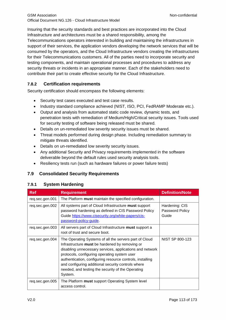
GSM Association Non-confidential
Official Document NG.126 - Cloud Infrastructure Model
V2.0 Page 113 of 173
Insuring that the security standards and best practices are incorporated into the Cloud
Infrastructure and architectures must be a shared responsibility, among the
Telecommunications operators interested in building and maintaining the infrastructures in
support of their services, the application vendors developing the network services that will be
consumed by the operators, and the Cloud Infrastructure vendors creating the infrastructures
for their Telecommunications customers. All of the parties need to incorporate security and
testing components, and maintain operational processes and procedures to address any
security threats or incidents in an appropriate manner. Each of the stakeholders need to
contribute their part to create effective security for the Cloud Infrastructure.
7.8.2 Certification requirements
Security certification should encompass the following elements:
Security test cases executed and test case results.
Industry standard compliance achieved (NIST, ISO, PCI, FedRAMP Moderate etc.).
Output and analysis from automated static code review, dynamic tests, and
penetration tests with remediation of Medium/High/Critical security issues. Tools used
for security testing of software being released must be shared.
Details on un-remediated low severity security issues must be shared.
Threat models performed during design phase. Including remediation summary to
mitigate threats identified.
Details on un-remediated low severity security issues.
Any additional Security and Privacy requirements implemented in the software
deliverable beyond the default rules used security analysis tools.
Resiliency tests run (such as hardware failures or power failure tests)
7.9 Consolidated Security Requirements
7.9.1 System Hardening
Ref Requirement Definition/Note
req.sec.gen.001 The Platform must maintain the specified configuration.
req.sec.gen.002 All systems part of Cloud Infrastructure must support
password hardening as defined in CIS Password Policy
Guide https://www.cisecurity.org/white-papers/cis-
password-policy-guide.
Hardening: CIS
Password Policy
Guide
req.sec.gen.003 All servers part of Cloud Infrastructure must support a
root of trust and secure boot.
req.sec.gen.004 The Operating Systems of all the servers part of Cloud
Infrastructure must be hardened by removing or
disabling unnecessary services, applications and network
protocols, configuring operating system user
authentication, configuring resource controls, installing
and configuring additional security controls where
needed, and testing the security of the Operating
System.
NIST SP 800-123
req.sec.gen.005 The Platform must support Operating System level
access control.
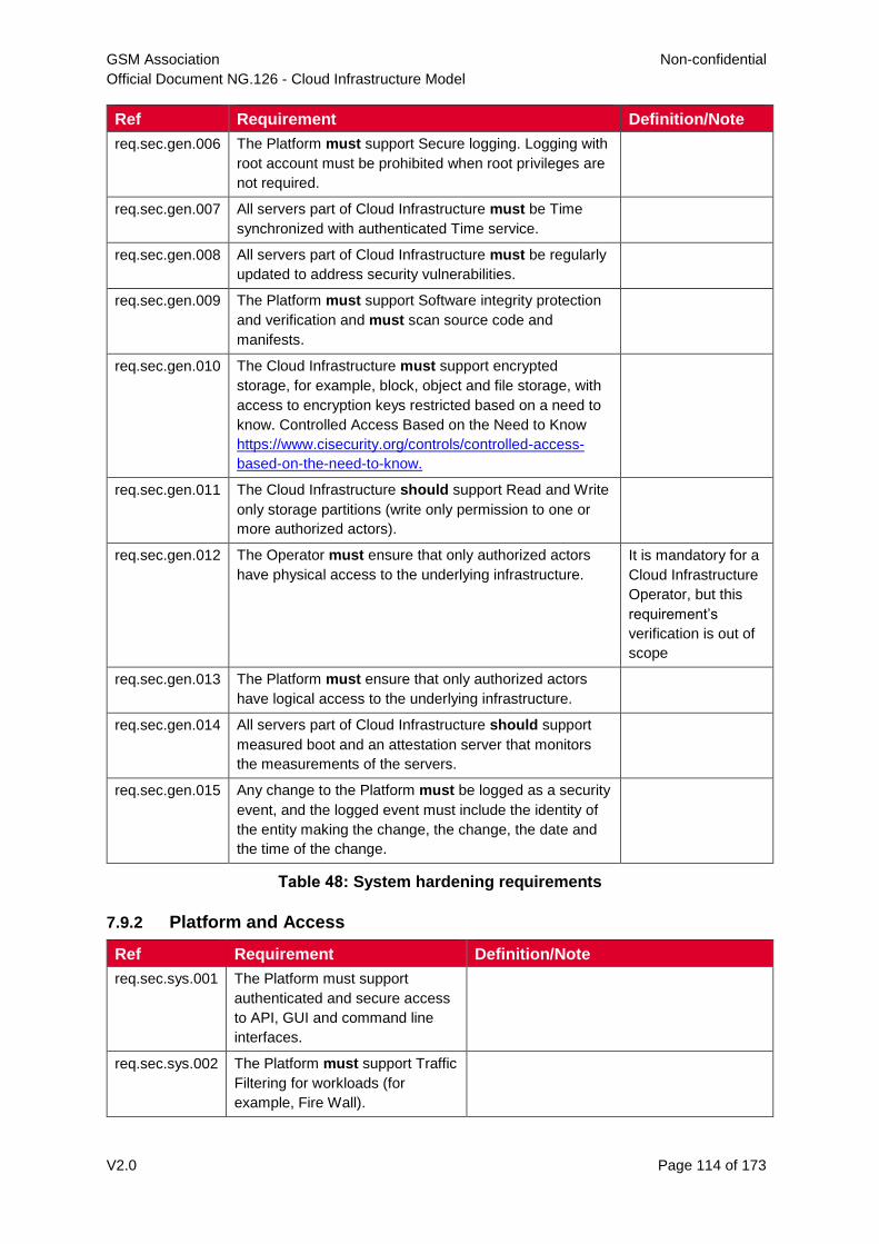
GSM Association Non-confidential
Official Document NG.126 - Cloud Infrastructure Model
V2.0 Page 114 of 173
Ref Requirement Definition/Note
req.sec.gen.006 The Platform must support Secure logging. Logging with
root account must be prohibited when root privileges are
not required.
req.sec.gen.007 All servers part of Cloud Infrastructure must be Time
synchronized with authenticated Time service.
req.sec.gen.008 All servers part of Cloud Infrastructure must be regularly
updated to address security vulnerabilities.
req.sec.gen.009 The Platform must support Software integrity protection
and verification and must scan source code and
manifests.
req.sec.gen.010 The Cloud Infrastructure must support encrypted
storage, for example, block, object and file storage, with
access to encryption keys restricted based on a need to
know. Controlled Access Based on the Need to Know
https://www.cisecurity.org/controls/controlled-access-
based-on-the-need-to-know.
req.sec.gen.011 The Cloud Infrastructure should support Read and Write
only storage partitions (write only permission to one or
more authorized actors).
req.sec.gen.012 The Operator must ensure that only authorized actors
have physical access to the underlying infrastructure.
It is mandatory for a
Cloud Infrastructure
Operator, but this
requirement’s
verification is out of
scope
req.sec.gen.013 The Platform must ensure that only authorized actors
have logical access to the underlying infrastructure.
req.sec.gen.014 All servers part of Cloud Infrastructure should support
measured boot and an attestation server that monitors
the measurements of the servers.
req.sec.gen.015 Any change to the Platform must be logged as a security
event, and the logged event must include the identity of
the entity making the change, the change, the date and
the time of the change.
Table 48: System hardening requirements
7.9.2 Platform and Access
Ref Requirement Definition/Note
req.sec.sys.001 The Platform must support
authenticated and secure access
to API, GUI and command line
interfaces.
req.sec.sys.002 The Platform must support Traffic
Filtering for workloads (for
example, Fire Wall).
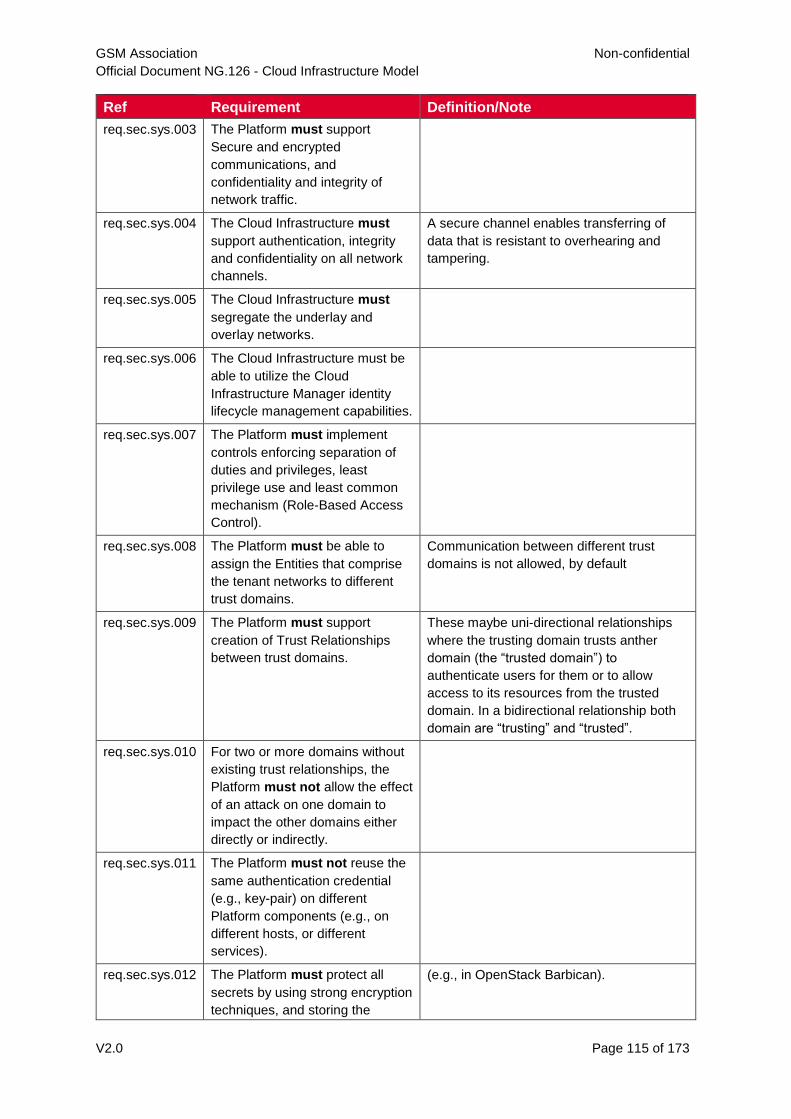
GSM Association Non-confidential
Official Document NG.126 - Cloud Infrastructure Model
V2.0 Page 115 of 173
Ref Requirement Definition/Note
req.sec.sys.003 The Platform must support
Secure and encrypted
communications, and
confidentiality and integrity of
network traffic.
req.sec.sys.004 The Cloud Infrastructure must
support authentication, integrity
and confidentiality on all network
channels.
A secure channel enables transferring of
data that is resistant to overhearing and
tampering.
req.sec.sys.005 The Cloud Infrastructure must
segregate the underlay and
overlay networks.
req.sec.sys.006 The Cloud Infrastructure must be
able to utilize the Cloud
Infrastructure Manager identity
lifecycle management capabilities.
req.sec.sys.007 The Platform must implement
controls enforcing separation of
duties and privileges, least
privilege use and least common
mechanism (Role-Based Access
Control).
req.sec.sys.008 The Platform must be able to
assign the Entities that comprise
the tenant networks to different
trust domains.
Communication between different trust
domains is not allowed, by default
req.sec.sys.009 The Platform must support
creation of Trust Relationships
between trust domains.
These maybe uni-directional relationships
where the trusting domain trusts anther
domain (the “trusted domain”) to
authenticate users for them or to allow
access to its resources from the trusted
domain. In a bidirectional relationship both
domain are “trusting” and “trusted”.
req.sec.sys.010 For two or more domains without
existing trust relationships, the
Platform must not allow the effect
of an attack on one domain to
impact the other domains either
directly or indirectly.
req.sec.sys.011 The Platform must not reuse the
same authentication credential
(e.g., key-pair) on different
Platform components (e.g., on
different hosts, or different
services).
req.sec.sys.012 The Platform must protect all
secrets by using strong encryption
techniques, and storing the
(e.g., in OpenStack Barbican).
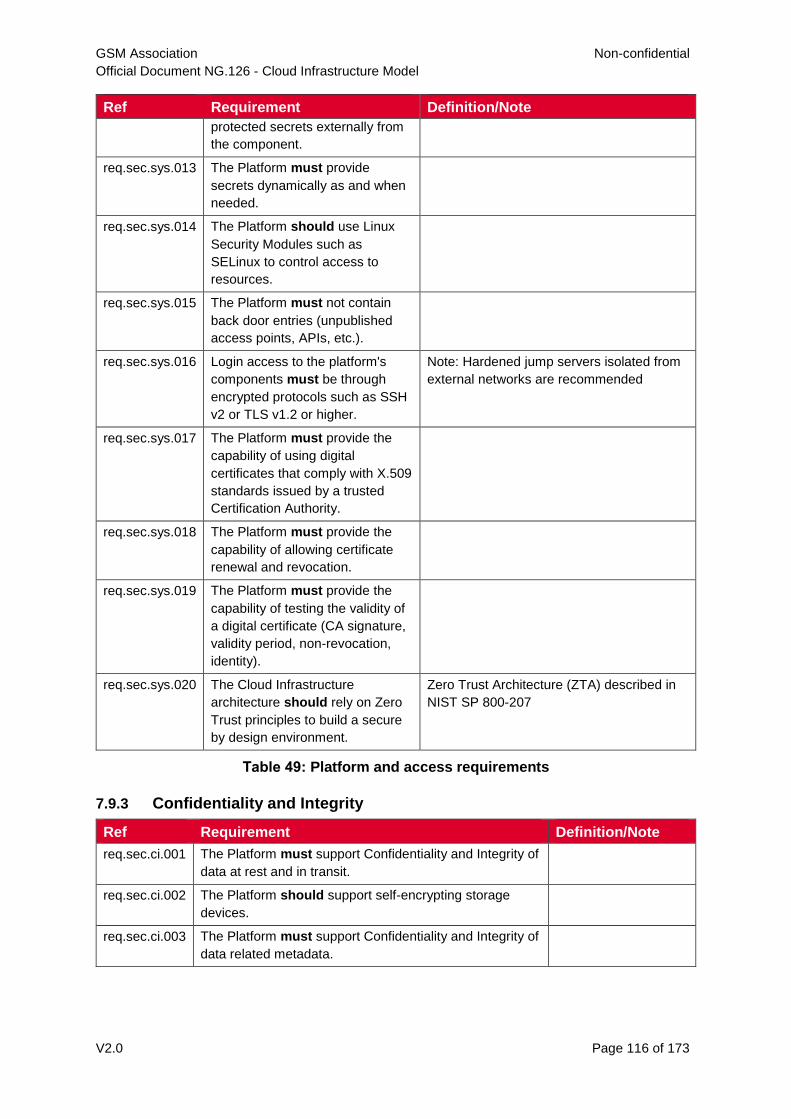
GSM Association Non-confidential
Official Document NG.126 - Cloud Infrastructure Model
V2.0 Page 116 of 173
Ref Requirement Definition/Note
protected secrets externally from
the component.
req.sec.sys.013 The Platform must provide
secrets dynamically as and when
needed.
req.sec.sys.014 The Platform should use Linux
Security Modules such as
SELinux to control access to
resources.
req.sec.sys.015 The Platform must not contain
back door entries (unpublished
access points, APIs, etc.).
req.sec.sys.016 Login access to the platform's
components must be through
encrypted protocols such as SSH
v2 or TLS v1.2 or higher.
Note: Hardened jump servers isolated from
external networks are recommended
req.sec.sys.017 The Platform must provide the
capability of using digital
certificates that comply with X.509
standards issued by a trusted
Certification Authority.
req.sec.sys.018 The Platform must provide the
capability of allowing certificate
renewal and revocation.
req.sec.sys.019 The Platform must provide the
capability of testing the validity of
a digital certificate (CA signature,
validity period, non-revocation,
identity).
req.sec.sys.020 The Cloud Infrastructure
architecture should rely on Zero
Trust principles to build a secure
by design environment.
Zero Trust Architecture (ZTA) described in
NIST SP 800-207
Table 49: Platform and access requirements
7.9.3 Confidentiality and Integrity
Ref Requirement Definition/Note
req.sec.ci.001 The Platform must support Confidentiality and Integrity of
data at rest and in transit.
req.sec.ci.002 The Platform should support self-encrypting storage
devices.
req.sec.ci.003 The Platform must support Confidentiality and Integrity of
data related metadata.
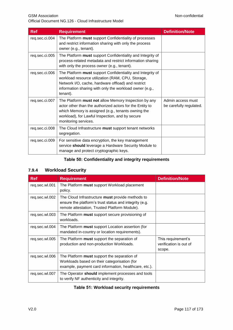
GSM Association Non-confidential
Official Document NG.126 - Cloud Infrastructure Model
V2.0 Page 117 of 173
Ref Requirement Definition/Note
req.sec.ci.004 The Platform must support Confidentiality of processes
and restrict information sharing with only the process
owner (e.g., tenant).
req.sec.ci.005 The Platform must support Confidentiality and Integrity of
process-related metadata and restrict information sharing
with only the process owner (e.g., tenant).
req.sec.ci.006 The Platform must support Confidentiality and Integrity of
workload resource utilization (RAM, CPU, Storage,
Network I/O, cache, hardware offload) and restrict
information sharing with only the workload owner (e.g.,
tenant).
req.sec.ci.007 The Platform must not allow Memory Inspection by any
actor other than the authorized actors for the Entity to
which Memory is assigned (e.g., tenants owning the
workload), for Lawful Inspection, and by secure
monitoring services.
Admin access must
be carefully regulated.
req.sec.ci.008 The Cloud Infrastructure must support tenant networks
segregation.
req.sec.ci.009 For sensitive data encryption, the key management
service should leverage a Hardware Security Module to
manage and protect cryptographic keys.
Table 50: Confidentiality and integrity requirements
7.9.4 Workload Security
Ref Requirement Definition/Note
req.sec.wl.001 The Platform must support Workload placement
policy.
req.sec.wl.002 The Cloud Infrastructure must provide methods to
ensure the platform’s trust status and integrity (e.g.
remote attestation, Trusted Platform Module).
req.sec.wl.003 The Platform must support secure provisioning of
workloads.
req.sec.wl.004 The Platform must support Location assertion (for
mandated in-country or location requirements).
req.sec.wl.005 The Platform must support the separation of
production and non-production Workloads.
This requirement’s
verification is out of
scope.
req.sec.wl.006 The Platform must support the separation of
Workloads based on their categorisation (for
example, payment card information, healthcare, etc.).
req.sec.wl.007 The Operator should implement processes and tools
to verify NF authenticity and integrity.
Table 51: Workload security requirements
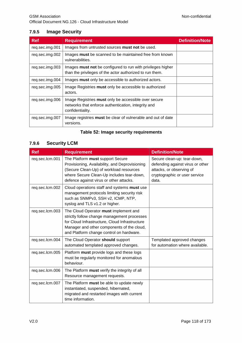
GSM Association Non-confidential
Official Document NG.126 - Cloud Infrastructure Model
V2.0 Page 118 of 173
7.9.5 Image Security
Ref Requirement Definition/Note
req.sec.img.001 Images from untrusted sources must not be used.
req.sec.img.002 Images must be scanned to be maintained free from known
vulnerabilities.
req.sec.img.003 Images must not be configured to run with privileges higher
than the privileges of the actor authorized to run them.
req.sec.img.004 Images must only be accessible to authorized actors.
req.sec.img.005 Image Registries must only be accessible to authorized
actors.
req.sec.img.006 Image Registries must only be accessible over secure
networks that enforce authentication, integrity and
confidentiality.
req.sec.img.007 Image registries must be clear of vulnerable and out of date
versions.
Table 52: Image security requirements
7.9.6 Security LCM
Ref Requirement Definition/Note
req.sec.lcm.001 The Platform must support Secure
Provisioning, Availability, and Deprovisioning
(Secure Clean-Up) of workload resources
where Secure Clean-Up includes tear-down,
defence against virus or other attacks.
Secure clean-up: tear-down,
defending against virus or other
attacks, or observing of
cryptographic or user service
data.
req.sec.lcm.002 Cloud operations staff and systems must use
management protocols limiting security risk
such as SNMPv3, SSH v2, ICMP, NTP,
syslog and TLS v1.2 or higher.
req.sec.lcm.003 The Cloud Operator must implement and
strictly follow change management processes
for Cloud Infrastructure, Cloud Infrastructure
Manager and other components of the cloud,
and Platform change control on hardware.
req.sec.lcm.004 The Cloud Operator should support
automated templated approved changes.
Templated approved changes
for automation where available.
req.sec.lcm.005 Platform must provide logs and these logs
must be regularly monitored for anomalous
behaviour.
req.sec.lcm.006 The Platform must verify the integrity of all
Resource management requests.
req.sec.lcm.007 The Platform must be able to update newly
instantiated, suspended, hibernated,
migrated and restarted images with current
time information.
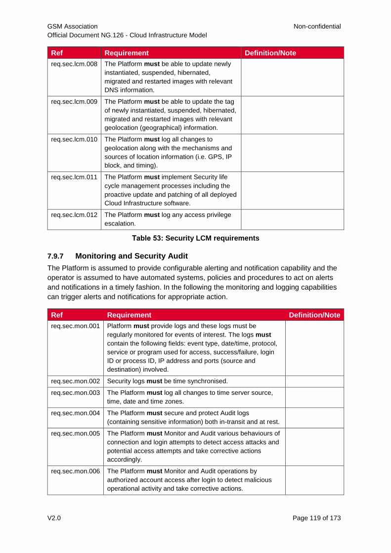
GSM Association Non-confidential
Official Document NG.126 - Cloud Infrastructure Model
V2.0 Page 119 of 173
Ref Requirement Definition/Note
req.sec.lcm.008 The Platform must be able to update newly
instantiated, suspended, hibernated,
migrated and restarted images with relevant
DNS information.
req.sec.lcm.009 The Platform must be able to update the tag
of newly instantiated, suspended, hibernated,
migrated and restarted images with relevant
geolocation (geographical) information.
req.sec.lcm.010 The Platform must log all changes to
geolocation along with the mechanisms and
sources of location information (i.e. GPS, IP
block, and timing).
req.sec.lcm.011 The Platform must implement Security life
cycle management processes including the
proactive update and patching of all deployed
Cloud Infrastructure software.
req.sec.lcm.012 The Platform must log any access privilege
escalation.
Table 53: Security LCM requirements
7.9.7 Monitoring and Security Audit
The Platform is assumed to provide configurable alerting and notification capability and the
operator is assumed to have automated systems, policies and procedures to act on alerts
and notifications in a timely fashion. In the following the monitoring and logging capabilities
can trigger alerts and notifications for appropriate action.
Ref Requirement Definition/Note
req.sec.mon.001 Platform must provide logs and these logs must be
regularly monitored for events of interest. The logs must
contain the following fields: event type, date/time, protocol,
service or program used for access, success/failure, login
ID or process ID, IP address and ports (source and
destination) involved.
req.sec.mon.002 Security logs must be time synchronised.
req.sec.mon.003 The Platform must log all changes to time server source,
time, date and time zones.
req.sec.mon.004 The Platform must secure and protect Audit logs
(containing sensitive information) both in-transit and at rest.
req.sec.mon.005 The Platform must Monitor and Audit various behaviours of
connection and login attempts to detect access attacks and
potential access attempts and take corrective actions
accordingly.
req.sec.mon.006 The Platform must Monitor and Audit operations by
authorized account access after login to detect malicious
operational activity and take corrective actions.
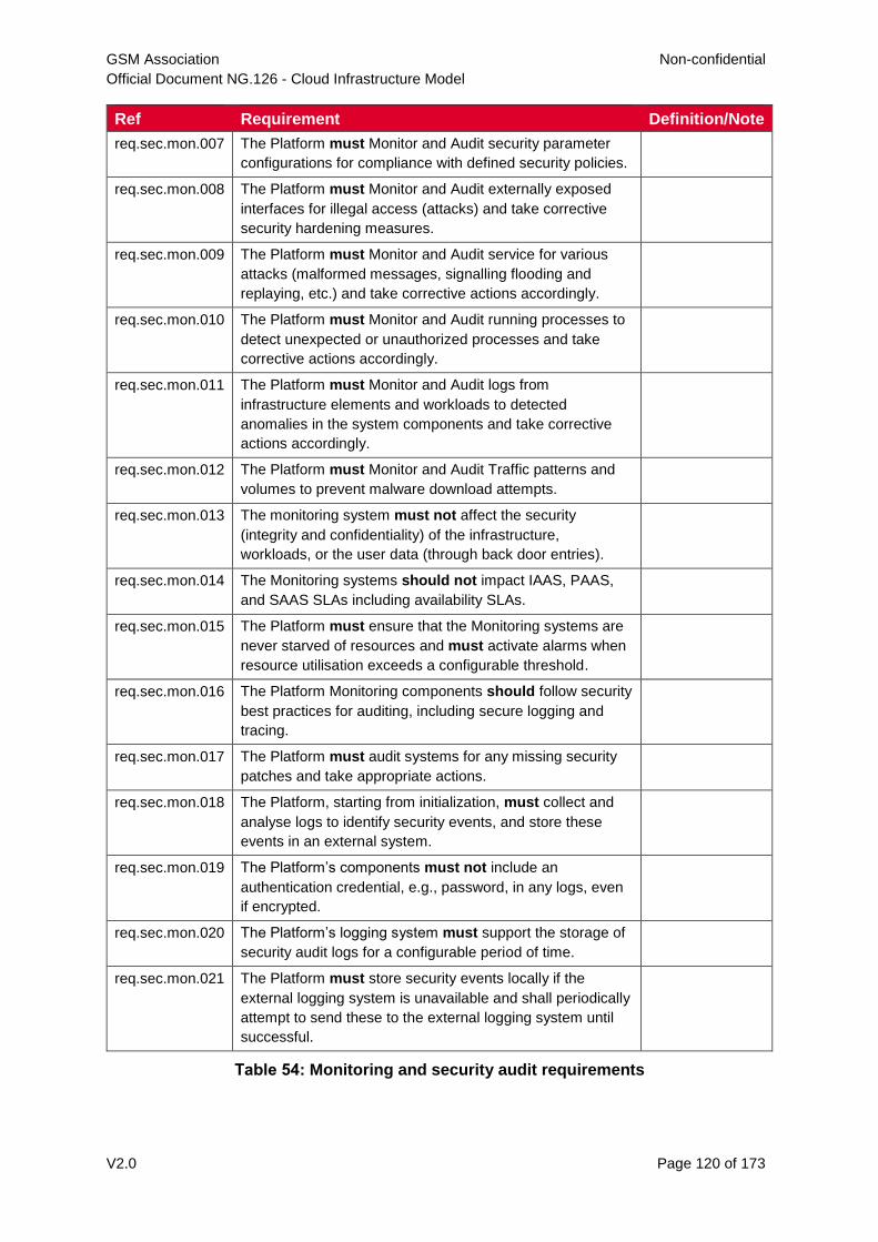
GSM Association Non-confidential
Official Document NG.126 - Cloud Infrastructure Model
V2.0 Page 120 of 173
Ref Requirement Definition/Note
req.sec.mon.007 The Platform must Monitor and Audit security parameter
configurations for compliance with defined security policies.
req.sec.mon.008 The Platform must Monitor and Audit externally exposed
interfaces for illegal access (attacks) and take corrective
security hardening measures.
req.sec.mon.009 The Platform must Monitor and Audit service for various
attacks (malformed messages, signalling flooding and
replaying, etc.) and take corrective actions accordingly.
req.sec.mon.010 The Platform must Monitor and Audit running processes to
detect unexpected or unauthorized processes and take
corrective actions accordingly.
req.sec.mon.011 The Platform must Monitor and Audit logs from
infrastructure elements and workloads to detected
anomalies in the system components and take corrective
actions accordingly.
req.sec.mon.012 The Platform must Monitor and Audit Traffic patterns and
volumes to prevent malware download attempts.
req.sec.mon.013 The monitoring system must not affect the security
(integrity and confidentiality) of the infrastructure,
workloads, or the user data (through back door entries).
req.sec.mon.014 The Monitoring systems should not impact IAAS, PAAS,
and SAAS SLAs including availability SLAs.
req.sec.mon.015 The Platform must ensure that the Monitoring systems are
never starved of resources and must activate alarms when
resource utilisation exceeds a configurable threshold.
req.sec.mon.016 The Platform Monitoring components should follow security
best practices for auditing, including secure logging and
tracing.
req.sec.mon.017 The Platform must audit systems for any missing security
patches and take appropriate actions.
req.sec.mon.018 The Platform, starting from initialization, must collect and
analyse logs to identify security events, and store these
events in an external system.
req.sec.mon.019 The Platform’s components must not include an
authentication credential, e.g., password, in any logs, even
if encrypted.
req.sec.mon.020 The Platform’s logging system must support the storage of
security audit logs for a configurable period of time.
req.sec.mon.021 The Platform must store security events locally if the
external logging system is unavailable and shall periodically
attempt to send these to the external logging system until
successful.
Table 54: Monitoring and security audit requirements
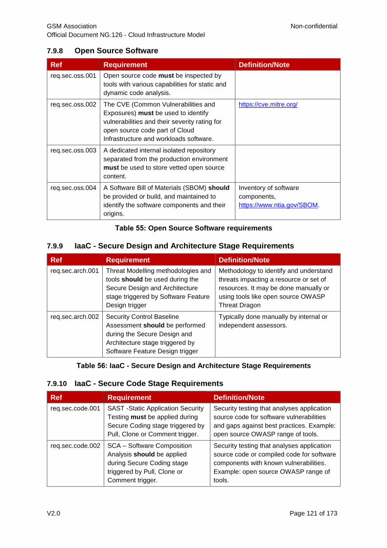
GSM Association Non-confidential
Official Document NG.126 - Cloud Infrastructure Model
V2.0 Page 121 of 173
7.9.8 Open Source Software
Ref Requirement Definition/Note
req.sec.oss.001 Open source code must be inspected by
tools with various capabilities for static and
dynamic code analysis.
req.sec.oss.002 The CVE (Common Vulnerabilities and
Exposures) must be used to identify
vulnerabilities and their severity rating for
open source code part of Cloud
Infrastructure and workloads software.
https://cve.mitre.org/
req.sec.oss.003 A dedicated internal isolated repository
separated from the production environment
must be used to store vetted open source
content.
req.sec.oss.004 A Software Bill of Materials (SBOM) should
be provided or build, and maintained to
identify the software components and their
origins.
Inventory of software
components,
https://www.ntia.gov/SBOM.
Table 55: Open Source Software requirements
7.9.9 IaaC - Secure Design and Architecture Stage Requirements
Ref Requirement Definition/Note
req.sec.arch.001 Threat Modelling methodologies and
tools should be used during the
Secure Design and Architecture
stage triggered by Software Feature
Design trigger
Methodology to identify and understand
threats impacting a resource or set of
resources. It may be done manually or
using tools like open source OWASP
Threat Dragon
req.sec.arch.002 Security Control Baseline
Assessment should be performed
during the Secure Design and
Architecture stage triggered by
Software Feature Design trigger
Typically done manually by internal or
independent assessors.
Table 56: IaaC - Secure Design and Architecture Stage Requirements
7.9.10 IaaC - Secure Code Stage Requirements
Ref Requirement Definition/Note
req.sec.code.001 SAST -Static Application Security
Testing must be applied during
Secure Coding stage triggered by
Pull, Clone or Comment trigger.
Security testing that analyses application
source code for software vulnerabilities
and gaps against best practices. Example:
open source OWASP range of tools.
req.sec.code.002 SCA – Software Composition
Analysis should be applied
during Secure Coding stage
triggered by Pull, Clone or
Comment trigger.
Security testing that analyses application
source code or compiled code for software
components with known vulnerabilities.
Example: open source OWASP range of
tools.
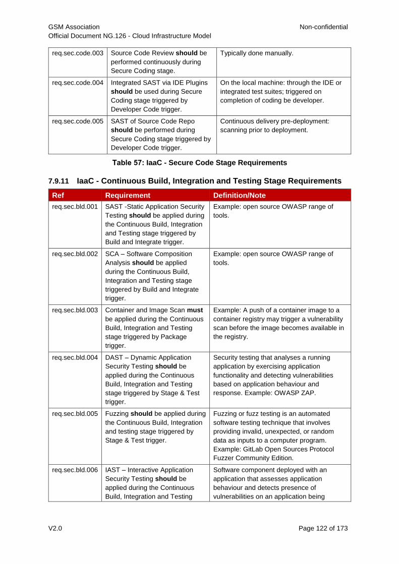
GSM Association Non-confidential
Official Document NG.126 - Cloud Infrastructure Model
V2.0 Page 122 of 173
req.sec.code.003 Source Code Review should be
performed continuously during
Secure Coding stage.
Typically done manually.
req.sec.code.004 Integrated SAST via IDE Plugins
should be used during Secure
Coding stage triggered by
Developer Code trigger.
On the local machine: through the IDE or
integrated test suites; triggered on
completion of coding be developer.
req.sec.code.005 SAST of Source Code Repo
should be performed during
Secure Coding stage triggered by
Developer Code trigger.
Continuous delivery pre-deployment:
scanning prior to deployment.
Table 57: IaaC - Secure Code Stage Requirements
7.9.11 IaaC - Continuous Build, Integration and Testing Stage Requirements
Ref Requirement Definition/Note
req.sec.bld.001 SAST -Static Application Security
Testing should be applied during
the Continuous Build, Integration
and Testing stage triggered by
Build and Integrate trigger.
Example: open source OWASP range of
tools.
req.sec.bld.002 SCA – Software Composition
Analysis should be applied
during the Continuous Build,
Integration and Testing stage
triggered by Build and Integrate
trigger.
Example: open source OWASP range of
tools.
req.sec.bld.003 Container and Image Scan must
be applied during the Continuous
Build, Integration and Testing
stage triggered by Package
trigger.
Example: A push of a container image to a
container registry may trigger a vulnerability
scan before the image becomes available in
the registry.
req.sec.bld.004 DAST – Dynamic Application
Security Testing should be
applied during the Continuous
Build, Integration and Testing
stage triggered by Stage & Test
trigger.
Security testing that analyses a running
application by exercising application
functionality and detecting vulnerabilities
based on application behaviour and
response. Example: OWASP ZAP.
req.sec.bld.005 Fuzzing should be applied during
the Continuous Build, Integration
and testing stage triggered by
Stage & Test trigger.
Fuzzing or fuzz testing is an automated
software testing technique that involves
providing invalid, unexpected, or random
data as inputs to a computer program.
Example: GitLab Open Sources Protocol
Fuzzer Community Edition.
req.sec.bld.006 IAST – Interactive Application
Security Testing should be
applied during the Continuous
Build, Integration and Testing
Software component deployed with an
application that assesses application
behaviour and detects presence of
vulnerabilities on an application being
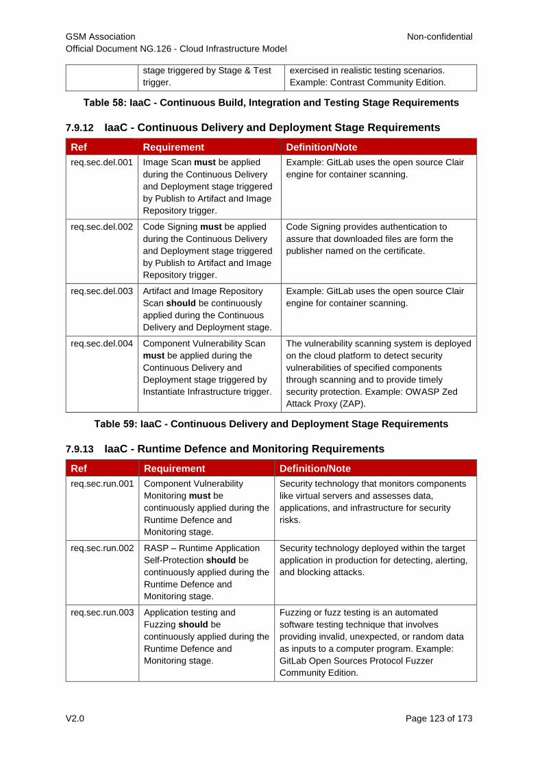
GSM Association Non-confidential
Official Document NG.126 - Cloud Infrastructure Model
V2.0 Page 123 of 173
stage triggered by Stage & Test
trigger.
exercised in realistic testing scenarios.
Example: Contrast Community Edition.
Table 58: IaaC - Continuous Build, Integration and Testing Stage Requirements
7.9.12 IaaC - Continuous Delivery and Deployment Stage Requirements
Ref Requirement Definition/Note
req.sec.del.001 Image Scan must be applied
during the Continuous Delivery
and Deployment stage triggered
by Publish to Artifact and Image
Repository trigger.
Example: GitLab uses the open source Clair
engine for container scanning.
req.sec.del.002 Code Signing must be applied
during the Continuous Delivery
and Deployment stage triggered
by Publish to Artifact and Image
Repository trigger.
Code Signing provides authentication to
assure that downloaded files are form the
publisher named on the certificate.
req.sec.del.003 Artifact and Image Repository
Scan should be continuously
applied during the Continuous
Delivery and Deployment stage.
Example: GitLab uses the open source Clair
engine for container scanning.
req.sec.del.004 Component Vulnerability Scan
must be applied during the
Continuous Delivery and
Deployment stage triggered by
Instantiate Infrastructure trigger.
The vulnerability scanning system is deployed
on the cloud platform to detect security
vulnerabilities of specified components
through scanning and to provide timely
security protection. Example: OWASP Zed
Attack Proxy (ZAP).
Table 59: IaaC - Continuous Delivery and Deployment Stage Requirements
7.9.13 IaaC - Runtime Defence and Monitoring Requirements
Ref Requirement Definition/Note
req.sec.run.001 Component Vulnerability
Monitoring must be
continuously applied during the
Runtime Defence and
Monitoring stage.
Security technology that monitors components
like virtual servers and assesses data,
applications, and infrastructure for security
risks.
req.sec.run.002 RASP – Runtime Application
Self-Protection should be
continuously applied during the
Runtime Defence and
Monitoring stage.
Security technology deployed within the target
application in production for detecting, alerting,
and blocking attacks.
req.sec.run.003 Application testing and
Fuzzing should be
continuously applied during the
Runtime Defence and
Monitoring stage.
Fuzzing or fuzz testing is an automated
software testing technique that involves
providing invalid, unexpected, or random data
as inputs to a computer program. Example:
GitLab Open Sources Protocol Fuzzer
Community Edition.
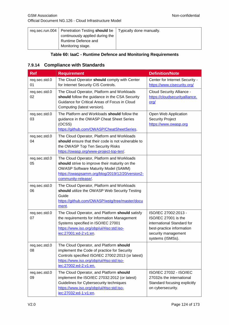
GSM Association Non-confidential
Official Document NG.126 - Cloud Infrastructure Model
V2.0 Page 124 of 173
req.sec.run.004 Penetration Testing should be
continuously applied during the
Runtime Defence and
Monitoring stage.
Typically done manually.
Table 60: IaaC - Runtime Defence and Monitoring Requirements
7.9.14 Compliance with Standards
Ref Requirement Definition/Note
req.sec.std.0
01
The Cloud Operator should comply with Center
for Internet Security CIS Controls.
Center for Internet Security -
https://www.cisecurity.org/
req.sec.std.0
02
The Cloud Operator, Platform and Workloads
should follow the guidance in the CSA Security
Guidance for Critical Areas of Focus in Cloud
Computing (latest version).
Cloud Security Alliance -
https://cloudsecurityalliance.
org/
req.sec.std.0
03
The Platform and Workloads should follow the
guidance in the OWASP Cheat Sheet Series
(OCSS)
https://github.com/OWASP/CheatSheetSeries.
Open Web Application
Security Project
https://www.owasp.org
req.sec.std.0
04
The Cloud Operator, Platform and Workloads
should ensure that their code is not vulnerable to
the OWASP Top Ten Security Risks
https://owasp.org/www-project-top-ten/.
req.sec.std.0
05
The Cloud Operator, Platform and Workloads
should strive to improve their maturity on the
OWASP Software Maturity Model (SAMM)
https://owaspsamm.org/blog/2019/12/20/version2-
community-release/.
req.sec.std.0
06
The Cloud Operator, Platform and Workloads
should utilize the OWASP Web Security Testing
Guide
https://github.com/OWASP/wstg/tree/master/docu
ment.
req.sec.std.0
07
The Cloud Operator, and Platform should satisfy
the requirements for Information Management
Systems specified in ISO/IEC 27001
https://www.iso.org/obp/ui/#iso:std:iso-
iec:27001:ed-2:v1:en.
ISO/IEC 27002:2013 -
ISO/IEC 27001 is the
international Standard for
best-practice information
security management
systems (ISMSs).
req.sec.std.0
08
The Cloud Operator, and Platform should
implement the Code of practice for Security
Controls specified ISO/IEC 27002:2013 (or latest)
https://www.iso.org/obp/ui/#iso:std:iso-
iec:27002:ed-2:v1:en.
req.sec.std.0
09
The Cloud Operator, and Platform should
implement the ISO/IEC 27032:2012 (or latest)
Guidelines for Cybersecurity techniques
https://www.iso.org/obp/ui/#iso:std:iso-
iec:27032:ed-1:v1:en.
ISO/IEC 27032 - ISO/IEC
27032is the international
Standard focusing explicitly
on cybersecurity.
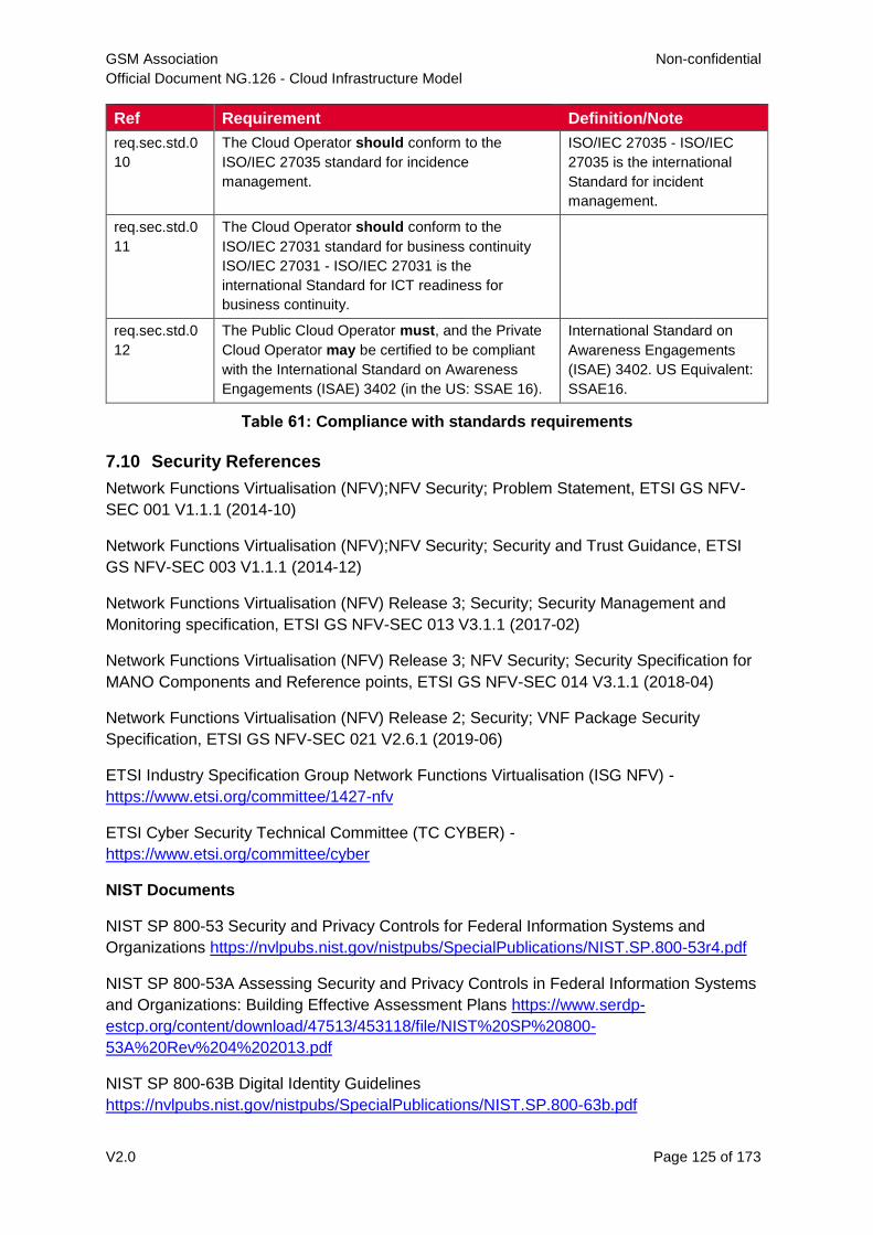
GSM Association Non-confidential
Official Document NG.126 - Cloud Infrastructure Model
V2.0 Page 125 of 173
Ref Requirement Definition/Note
req.sec.std.0
10
The Cloud Operator should conform to the
ISO/IEC 27035 standard for incidence
management.
ISO/IEC 27035 - ISO/IEC
27035 is the international
Standard for incident
management.
req.sec.std.0
11
The Cloud Operator should conform to the
ISO/IEC 27031 standard for business continuity
ISO/IEC 27031 - ISO/IEC 27031 is the
international Standard for ICT readiness for
business continuity.
req.sec.std.0
12
The Public Cloud Operator must, and the Private
Cloud Operator may be certified to be compliant
with the International Standard on Awareness
Engagements (ISAE) 3402 (in the US: SSAE 16).
International Standard on
Awareness Engagements
(ISAE) 3402. US Equivalent:
SSAE16.
Table 61: Compliance with standards requirements
7.10 Security References
Network Functions Virtualisation (NFV);NFV Security; Problem Statement, ETSI GS NFV-
SEC 001 V1.1.1 (2014-10)
Network Functions Virtualisation (NFV);NFV Security; Security and Trust Guidance, ETSI
GS NFV-SEC 003 V1.1.1 (2014-12)
Network Functions Virtualisation (NFV) Release 3; Security; Security Management and
Monitoring specification, ETSI GS NFV-SEC 013 V3.1.1 (2017-02)
Network Functions Virtualisation (NFV) Release 3; NFV Security; Security Specification for
MANO Components and Reference points, ETSI GS NFV-SEC 014 V3.1.1 (2018-04)
Network Functions Virtualisation (NFV) Release 2; Security; VNF Package Security
Specification, ETSI GS NFV-SEC 021 V2.6.1 (2019-06)
ETSI Industry Specification Group Network Functions Virtualisation (ISG NFV) -
https://www.etsi.org/committee/1427-nfv
ETSI Cyber Security Technical Committee (TC CYBER) -
https://www.etsi.org/committee/cyber
NIST Documents
NIST SP 800-53 Security and Privacy Controls for Federal Information Systems and
Organizations https://nvlpubs.nist.gov/nistpubs/SpecialPublications/NIST.SP.800-53r4.pdf
NIST SP 800-53A Assessing Security and Privacy Controls in Federal Information Systems
and Organizations: Building Effective Assessment Plans https://www.serdp-
estcp.org/content/download/47513/453118/file/NIST%20SP%20800-
53A%20Rev%204%202013.pdf
NIST SP 800-63B Digital Identity Guidelines
https://nvlpubs.nist.gov/nistpubs/SpecialPublications/NIST.SP.800-63b.pdf
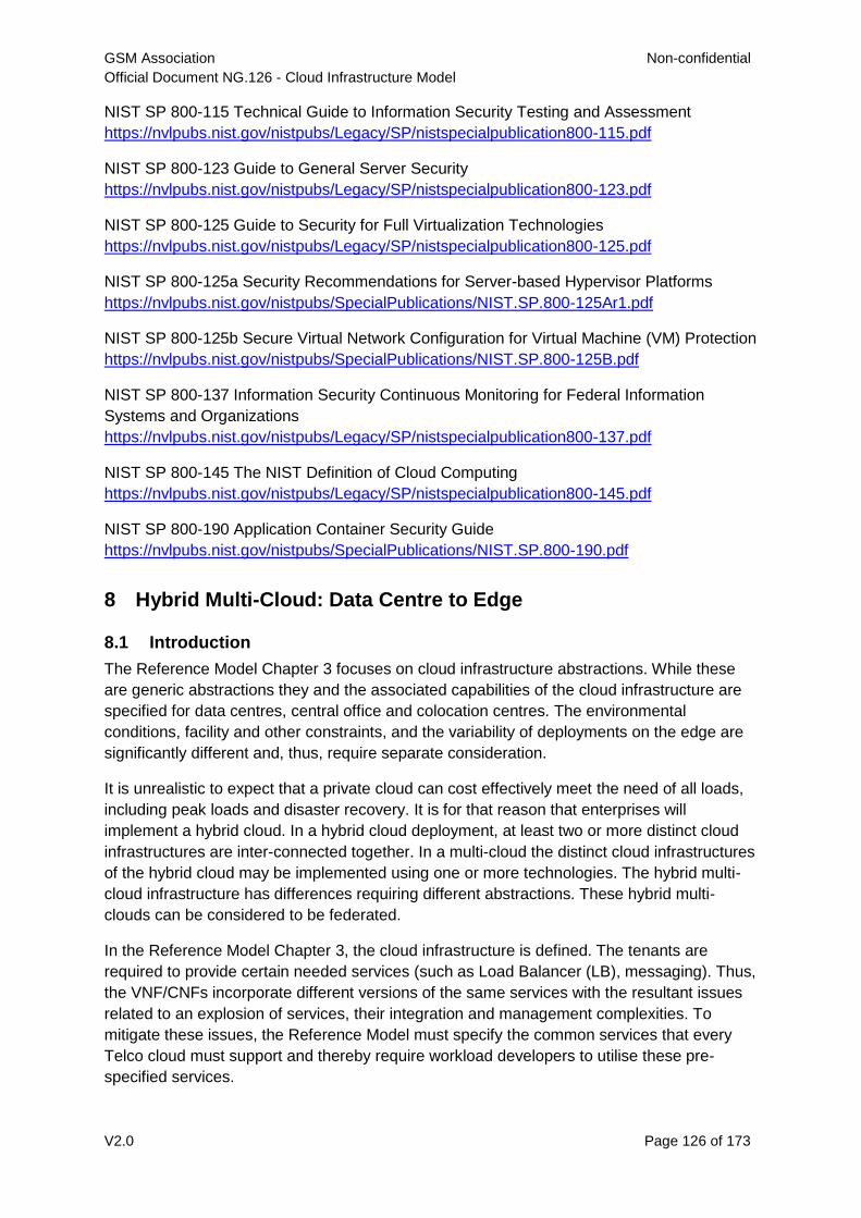
GSM Association Non-confidential
Official Document NG.126 - Cloud Infrastructure Model
V2.0 Page 126 of 173
NIST SP 800-115 Technical Guide to Information Security Testing and Assessment
https://nvlpubs.nist.gov/nistpubs/Legacy/SP/nistspecialpublication800-115.pdf
NIST SP 800-123 Guide to General Server Security
https://nvlpubs.nist.gov/nistpubs/Legacy/SP/nistspecialpublication800-123.pdf
NIST SP 800-125 Guide to Security for Full Virtualization Technologies
https://nvlpubs.nist.gov/nistpubs/Legacy/SP/nistspecialpublication800-125.pdf
NIST SP 800-125a Security Recommendations for Server-based Hypervisor Platforms
https://nvlpubs.nist.gov/nistpubs/SpecialPublications/NIST.SP.800-125Ar1.pdf
NIST SP 800-125b Secure Virtual Network Configuration for Virtual Machine (VM) Protection
https://nvlpubs.nist.gov/nistpubs/SpecialPublications/NIST.SP.800-125B.pdf
NIST SP 800-137 Information Security Continuous Monitoring for Federal Information
Systems and Organizations
https://nvlpubs.nist.gov/nistpubs/Legacy/SP/nistspecialpublication800-137.pdf
NIST SP 800-145 The NIST Definition of Cloud Computing
https://nvlpubs.nist.gov/nistpubs/Legacy/SP/nistspecialpublication800-145.pdf
NIST SP 800-190 Application Container Security Guide
https://nvlpubs.nist.gov/nistpubs/SpecialPublications/NIST.SP.800-190.pdf
8 Hybrid Multi-Cloud: Data Centre to Edge
8.1 Introduction
The Reference Model Chapter 3 focuses on cloud infrastructure abstractions. While these
are generic abstractions they and the associated capabilities of the cloud infrastructure are
specified for data centres, central office and colocation centres. The environmental
conditions, facility and other constraints, and the variability of deployments on the edge are
significantly different and, thus, require separate consideration.
It is unrealistic to expect that a private cloud can cost effectively meet the need of all loads,
including peak loads and disaster recovery. It is for that reason that enterprises will
implement a hybrid cloud. In a hybrid cloud deployment, at least two or more distinct cloud
infrastructures are inter-connected together. In a multi-cloud the distinct cloud infrastructures
of the hybrid cloud may be implemented using one or more technologies. The hybrid multi-
cloud infrastructure has differences requiring different abstractions. These hybrid multi-
clouds can be considered to be federated.
In the Reference Model Chapter 3, the cloud infrastructure is defined. The tenants are
required to provide certain needed services (such as Load Balancer (LB), messaging). Thus,
the VNF/CNFs incorporate different versions of the same services with the resultant issues
related to an explosion of services, their integration and management complexities. To
mitigate these issues, the Reference Model must specify the common services that every
Telco cloud must support and thereby require workload developers to utilise these pre-
specified services.
GSM Association Non-confidential
Official Document NG.126 - Cloud Infrastructure Model
V2.0 Page 127 of 173
A generic Telco cloud is a hybrid multi-cloud or a Federated cloud that has deployments in
large data centres, central offices or colocation facilities, and the edge. This chapter
discusses the characteristics of Telco Edge and hybrid multi-cloud.
8.2 Hybrid Multi-Cloud Architecture
The GSMA whitepaper on "Operator Platform Concept Phase 1: Edge Cloud Computing"
(January 2020) states, "Given the wide diversity of use cases that the operators will tasked
to address, from healthcare to industrial IoT, it seems logical for operators to create a
generic platform that can package the existing assets and capabilities (e.g., voice
messaging, IP data services, billing, security, identity management, etc. ...) as well as the
new ones that 5G makes available (e.g., Edge cloud, network slicing, etc.) in such a way as
to create the necessary flexibility required by this new breed of enterprise customers."
Cloud computing has evolved and matured since 2010 when NIST published its definition of
cloud computing (see http://csrc.nist.gov/publications/nistpubs/800-145/SP800-145.pdf), with
its 5 essential characteristics, 3 service models and 4 deployment models.
The generic model for an enterprise cloud has to be "hybrid" with the special cases of purely
private or public clouds as subsets of the generic hybrid cloud deployment model. In a hybrid
cloud deployment, at least two or more distinct cloud infrastructures are inter-connected
together.
Cloud deployments can be created using a variety of technologies (e.g., OpenStack,
Kubernetes) and commercial technologies (e.g., VMware, AWS, Azure, etc.). A multi-cloud
deployment can consist of the use of more than one technology.
A generic Telco cloud is a hybrid multi-cloud. A better designation would be a federation of
clouds - a federated cloud:
a collection of cooperating, interoperable autonomous component clouds
the component clouds perform their local operations (internal requests) while also
participating in the federation and responding to other component clouds (external
requests)
o the component clouds are autonomous in terms of, for example, execution
autonomy; please note that in a centralised control plane scenario (please see the
section "Centralised Control Plane" in the "Edge Computing: Next Steps in
Architecture, Design and Testing" whitepaper [26] the edge clouds do not have
total autonomy and are subject to constraints (e.g., workload LCM)
o execution autonomy is the ability of a component cloud to decide the order in
which internal and external requests are performed
the component clouds are loosely coupled where no changes are required to
participate in a federation
o also, a federation controller does not impose changes to the component cloud
except for running some central component(s) of the federated system (for
example, a broker agent – executes as a workload)
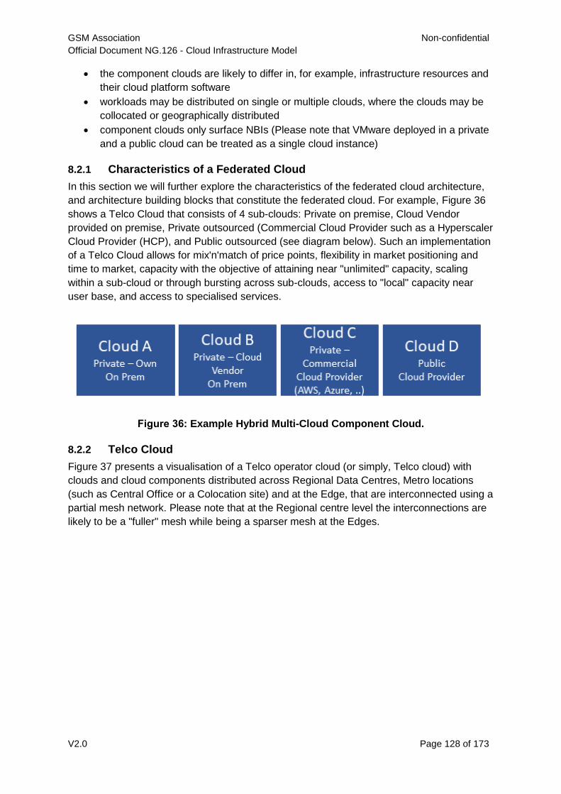
GSM Association Non-confidential
Official Document NG.126 - Cloud Infrastructure Model
V2.0 Page 128 of 173
the component clouds are likely to differ in, for example, infrastructure resources and
their cloud platform software
workloads may be distributed on single or multiple clouds, where the clouds may be
collocated or geographically distributed
component clouds only surface NBIs (Please note that VMware deployed in a private
and a public cloud can be treated as a single cloud instance)
8.2.1 Characteristics of a Federated Cloud
In this section we will further explore the characteristics of the federated cloud architecture,
and architecture building blocks that constitute the federated cloud. For example, Figure 36
shows a Telco Cloud that consists of 4 sub-clouds: Private on premise, Cloud Vendor
provided on premise, Private outsourced (Commercial Cloud Provider such as a Hyperscaler
Cloud Provider (HCP), and Public outsourced (see diagram below). Such an implementation
of a Telco Cloud allows for mix'n'match of price points, flexibility in market positioning and
time to market, capacity with the objective of attaining near "unlimited" capacity, scaling
within a sub-cloud or through bursting across sub-clouds, access to "local" capacity near
user base, and access to specialised services.
Figure 36: Example Hybrid Multi-Cloud Component Cloud.
8.2.2 Telco Cloud
Figure 37 presents a visualisation of a Telco operator cloud (or simply, Telco cloud) with
clouds and cloud components distributed across Regional Data Centres, Metro locations
(such as Central Office or a Colocation site) and at the Edge, that are interconnected using a
partial mesh network. Please note that at the Regional centre level the interconnections are
likely to be a "fuller" mesh while being a sparser mesh at the Edges.
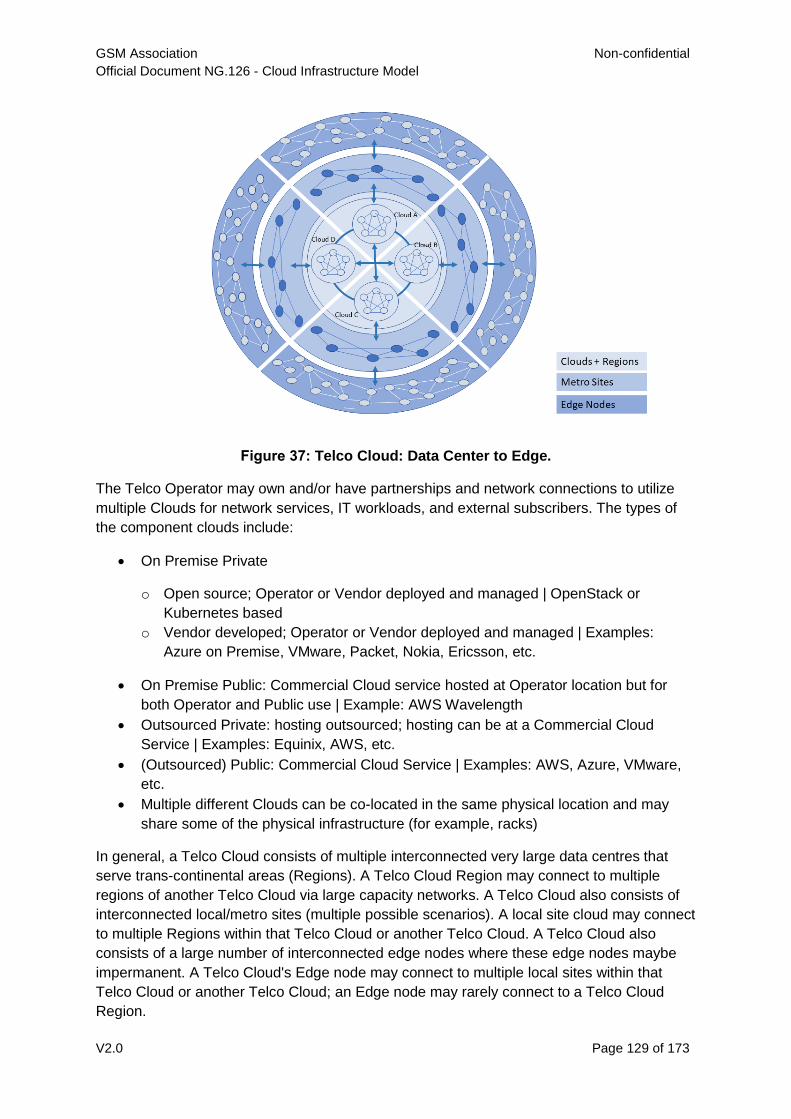
GSM Association Non-confidential
Official Document NG.126 - Cloud Infrastructure Model
V2.0 Page 129 of 173
Figure 37: Telco Cloud: Data Center to Edge.
The Telco Operator may own and/or have partnerships and network connections to utilize
multiple Clouds for network services, IT workloads, and external subscribers. The types of
the component clouds include:
On Premise Private
o Open source; Operator or Vendor deployed and managed | OpenStack or
Kubernetes based
o Vendor developed; Operator or Vendor deployed and managed | Examples:
Azure on Premise, VMware, Packet, Nokia, Ericsson, etc.
On Premise Public: Commercial Cloud service hosted at Operator location but for
both Operator and Public use | Example: AWS Wavelength
Outsourced Private: hosting outsourced; hosting can be at a Commercial Cloud
Service | Examples: Equinix, AWS, etc.
(Outsourced) Public: Commercial Cloud Service | Examples: AWS, Azure, VMware,
etc.
Multiple different Clouds can be co-located in the same physical location and may
share some of the physical infrastructure (for example, racks)
In general, a Telco Cloud consists of multiple interconnected very large data centres that
serve trans-continental areas (Regions). A Telco Cloud Region may connect to multiple
regions of another Telco Cloud via large capacity networks. A Telco Cloud also consists of
interconnected local/metro sites (multiple possible scenarios). A local site cloud may connect
to multiple Regions within that Telco Cloud or another Telco Cloud. A Telco Cloud also
consists of a large number of interconnected edge nodes where these edge nodes maybe
impermanent. A Telco Cloud's Edge node may connect to multiple local sites within that
Telco Cloud or another Telco Cloud; an Edge node may rarely connect to a Telco Cloud
Region.
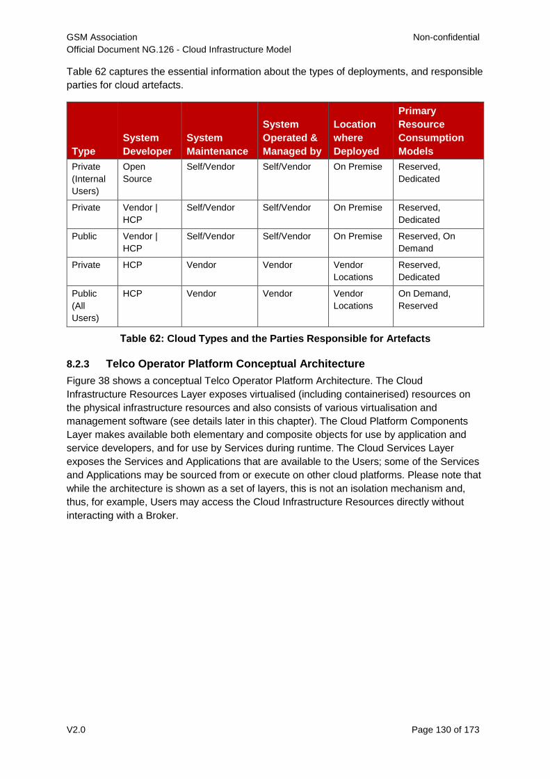
GSM Association Non-confidential
Official Document NG.126 - Cloud Infrastructure Model
V2.0 Page 130 of 173
Table 62 captures the essential information about the types of deployments, and responsible
parties for cloud artefacts.
Type
System
Developer
System
Maintenance
System
Operated &
Managed by
Location
where
Deployed
Primary
Resource
Consumption
Models
Private
(Internal
Users)
Open
Source
Self/Vendor Self/Vendor On Premise Reserved,
Dedicated
Private Vendor |
HCP
Self/Vendor Self/Vendor On Premise Reserved,
Dedicated
Public Vendor |
HCP
Self/Vendor Self/Vendor On Premise Reserved, On
Demand
Private HCP Vendor Vendor Vendor
Locations
Reserved,
Dedicated
Public
(All
Users)
HCP Vendor Vendor Vendor
Locations
On Demand,
Reserved
Table 62: Cloud Types and the Parties Responsible for Artefacts
8.2.3 Telco Operator Platform Conceptual Architecture
Figure 38 shows a conceptual Telco Operator Platform Architecture. The Cloud
Infrastructure Resources Layer exposes virtualised (including containerised) resources on
the physical infrastructure resources and also consists of various virtualisation and
management software (see details later in this chapter). The Cloud Platform Components
Layer makes available both elementary and composite objects for use by application and
service developers, and for use by Services during runtime. The Cloud Services Layer
exposes the Services and Applications that are available to the Users; some of the Services
and Applications may be sourced from or execute on other cloud platforms. Please note that
while the architecture is shown as a set of layers, this is not an isolation mechanism and,
thus, for example, Users may access the Cloud Infrastructure Resources directly without
interacting with a Broker.
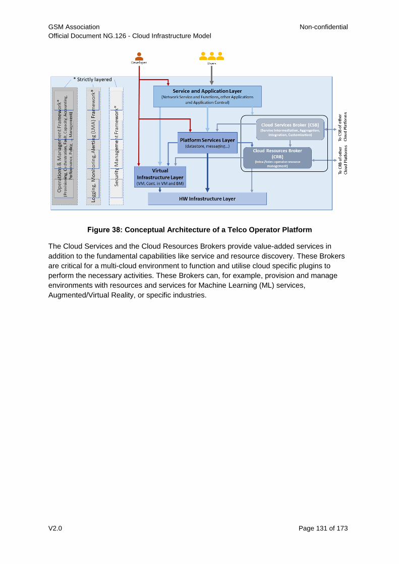
GSM Association Non-confidential
Official Document NG.126 - Cloud Infrastructure Model
V2.0 Page 131 of 173
Figure 38: Conceptual Architecture of a Telco Operator Platform
The Cloud Services and the Cloud Resources Brokers provide value-added services in
addition to the fundamental capabilities like service and resource discovery. These Brokers
are critical for a multi-cloud environment to function and utilise cloud specific plugins to
perform the necessary activities. These Brokers can, for example, provision and manage
environments with resources and services for Machine Learning (ML) services,
Augmented/Virtual Reality, or specific industries.
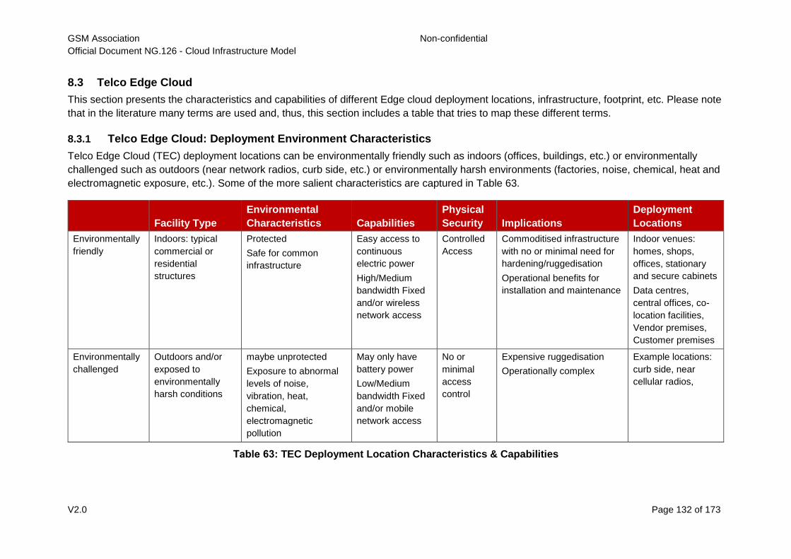
GSM Association Non-confidential
Official Document NG.126 - Cloud Infrastructure Model
V2.0 Page 132 of 173
8.3 Telco Edge Cloud
This section presents the characteristics and capabilities of different Edge cloud deployment locations, infrastructure, footprint, etc. Please note
that in the literature many terms are used and, thus, this section includes a table that tries to map these different terms.
8.3.1 Telco Edge Cloud: Deployment Environment Characteristics
Telco Edge Cloud (TEC) deployment locations can be environmentally friendly such as indoors (offices, buildings, etc.) or environmentally
challenged such as outdoors (near network radios, curb side, etc.) or environmentally harsh environments (factories, noise, chemical, heat and
electromagnetic exposure, etc.). Some of the more salient characteristics are captured in Table 63.
Facility Type
Environmental
Characteristics Capabilities
Physical
Security Implications
Deployment
Locations
Environmentally
friendly
Indoors: typical
commercial or
residential
structures
Protected
Safe for common
infrastructure
Easy access to
continuous
electric power
High/Medium
bandwidth Fixed
and/or wireless
network access
Controlled
Access
Commoditised infrastructure
with no or minimal need for
hardening/ruggedisation
Operational benefits for
installation and maintenance
Indoor venues:
homes, shops,
offices, stationary
and secure cabinets
Data centres,
central offices, co-
location facilities,
Vendor premises,
Customer premises
Environmentally
challenged
Outdoors and/or
exposed to
environmentally
harsh conditions
maybe unprotected
Exposure to abnormal
levels of noise,
vibration, heat,
chemical,
electromagnetic
pollution
May only have
battery power
Low/Medium
bandwidth Fixed
and/or mobile
network access
No or
minimal
access
control
Expensive ruggedisation
Operationally complex
Example locations:
curb side, near
cellular radios,
Table 63: TEC Deployment Location Characteristics & Capabilities
GSM Association Non-confidential
Official Document NG.126 - Cloud Infrastructure Model
V2.0 Page 133 of 173
8.3.2 Telco Edge Cloud: Infrastructure Characteristics
Commodity hardware is only suited for environmentally friendly environments. Commodity hardware have standardised designs and form
factors. Cloud deployments in data centres typically use such commodity hardware with standardised configurations resulting in operational
benefits for procurement, installation and ongoing operations.
In addition to the type of infrastructure hosted in data centre clouds, facilities with smaller sized infrastructure deployments, such as central
offices or co-location facilities, may also host non-standard hardware designs including specialised components. The introduction of specialised
hardware and custom configurations increases the cloud operations and management complexity.
At the edge, the infrastructure may further include ruggedised hardware for harsh environments and hardware with different form factors.
8.3.3 Telco Edge Cloud: Infrastructure Profiles
The section 4.2 Profiles and Workload Flavours specifies two infrastructure profiles:
The Basic cloud infrastructure profile is intended for use by both IT and Network Function workloads that have low to medium network
throughput requirements.
The High Performance cloud infrastructure profile is intended for use by applications that have high network throughput requirements (up to
50Gbps).
The High Performance profile can specify extensions for hardware offloading; please see section 3.8 Hardware Acceleration Abstraction. The
Reference Model High Performance profile includes an initial set of High Performance profile extensions (see section 4.2.3).
Based on the infrastructure deployed at the edge, Table 64 specifies the Infrastructure Profile features and requirements (see section 5) that
would need to be relaxed.
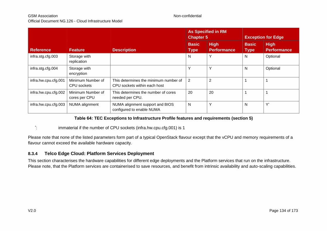
GSM Association Non-confidential
Official Document NG.126 - Cloud Infrastructure Model
V2.0 Page 134 of 173
Reference Feature Description
As Specified in RM
Chapter 5 Exception for Edge
Basic
Type
High
Performance
Basic
Type
High
Performance
infra.stg.cfg.003 Storage with
replication
N Y N Optional
infra.stg.cfg.004 Storage with
encryption
Y Y N Optional
infra.hw.cpu.cfg.001 Minimum Number of
CPU sockets
This determines the minimum number of
CPU sockets within each host
2 2 1 1
infra.hw.cpu.cfg.002 Minimum Number of
cores per CPU
This determines the number of cores
needed per CPU.
20 20 1 1
infra.hw.cpu.cfg.003 NUMA alignment NUMA alignment support and BIOS
configured to enable NUMA
N Y N Y*
Table 64: TEC Exceptions to Infrastructure Profile features and requirements (section 5)
*: immaterial if the number of CPU sockets (infra.hw.cpu.cfg.001) is 1
Please note that none of the listed parameters form part of a typical OpenStack flavour except that the vCPU and memory requirements of a
flavour cannot exceed the available hardware capacity.
8.3.4 Telco Edge Cloud: Platform Services Deployment
This section characterises the hardware capabilities for different edge deployments and the Platform services that run on the infrastructure.
Please note, that the Platform services are containerised to save resources, and benefit from intrinsic availability and auto-scaling capabilities.
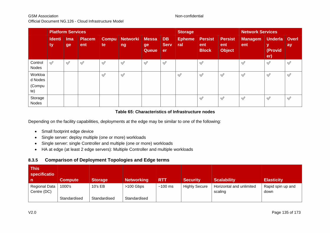
GSM Association Non-confidential
Official Document NG.126 - Cloud Infrastructure Model
V2.0 Page 135 of 173
Platform Services Storage Network Services
Identi
ty
Ima
ge
Placem
ent
Compu
te
Networki
ng
Messa
ge
Queue
DB
Serv
er
Epheme
ral
Persist
ent
Block
Persist
ent
Object
Managem
ent
Underla
y
(Provid
er)
Overl
ay
Control
Nodes
✅ ✅ ✅ ✅ ✅ ✅ ✅ ✅ ✅ ✅ ✅
Workloa
d Nodes
(Compu
te)
✅ ✅ ✅ ✅ ✅ ✅ ✅ ✅
Storage
Nodes
✅ ✅ ✅ ✅ ✅
Table 65: Characteristics of Infrastructure nodes
Depending on the facility capabilities, deployments at the edge may be similar to one of the following:
Small footprint edge device
Single server: deploy multiple (one or more) workloads
Single server: single Controller and multiple (one or more) workloads
HA at edge (at least 2 edge servers): Multiple Controller and multiple workloads
8.3.5 Comparison of Deployment Topologies and Edge terms
This
specificatio
n Compute Storage Networking RTT Security Scalability Elasticity
Regional Data
Centre (DC)
1000's
Standardised
10's EB
Standardised
>100 Gbps
Standardised
~100 ms Highly Secure Horizontal and unlimited
scaling
Rapid spin up and
down
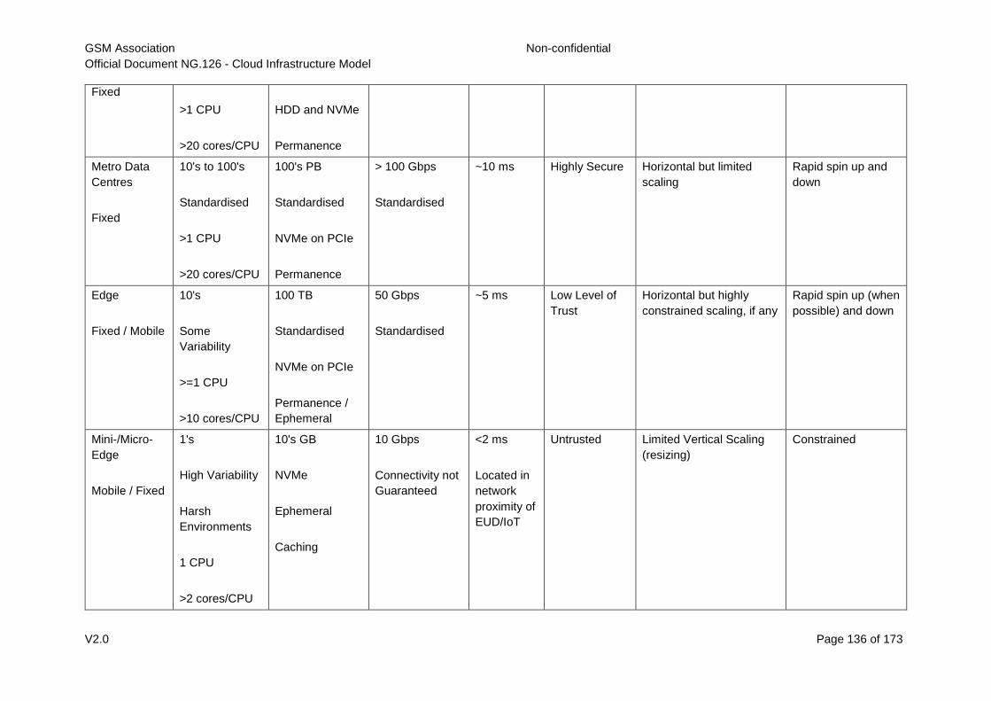
GSM Association Non-confidential
Official Document NG.126 - Cloud Infrastructure Model
V2.0 Page 136 of 173
Fixed
>1 CPU
>20 cores/CPU
HDD and NVMe
Permanence
Metro Data
Centres
Fixed
10's to 100's
Standardised
>1 CPU
>20 cores/CPU
100's PB
Standardised
NVMe on PCIe
Permanence
> 100 Gbps
Standardised
~10 ms Highly Secure Horizontal but limited
scaling
Rapid spin up and
down
Edge
Fixed / Mobile
10's
Some
Variability
>=1 CPU
>10 cores/CPU
100 TB
Standardised
NVMe on PCIe
Permanence /
Ephemeral
50 Gbps
Standardised
~5 ms Low Level of
Trust
Horizontal but highly
constrained scaling, if any
Rapid spin up (when
possible) and down
Mini-/Micro-
Edge
Mobile / Fixed
1's
High Variability
Harsh
Environments
1 CPU
>2 cores/CPU
10's GB
NVMe
Ephemeral
Caching
10 Gbps
Connectivity not
Guaranteed
<2 ms
Located in
network
proximity of
EUD/IoT
Untrusted Limited Vertical Scaling
(resizing)
Constrained
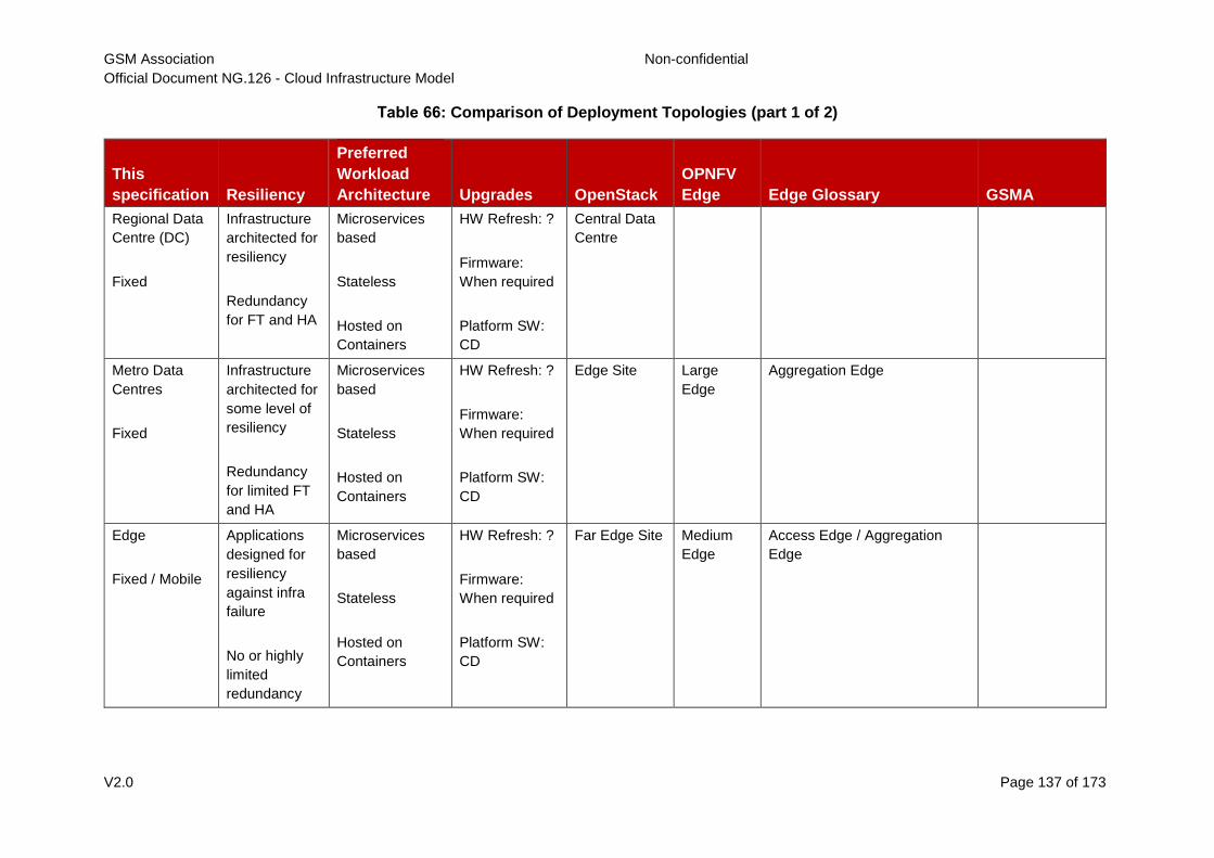
GSM Association Non-confidential
Official Document NG.126 - Cloud Infrastructure Model
V2.0 Page 137 of 173
Table 66: Comparison of Deployment Topologies (part 1 of 2)
This
specification Resiliency
Preferred
Workload
Architecture Upgrades OpenStack
OPNFV
Edge Edge Glossary GSMA
Regional Data
Centre (DC)
Fixed
Infrastructure
architected for
resiliency
Redundancy
for FT and HA
Microservices
based
Stateless
Hosted on
Containers
HW Refresh: ?
Firmware:
When required
Platform SW:
CD
Central Data
Centre
Metro Data
Centres
Fixed
Infrastructure
architected for
some level of
resiliency
Redundancy
for limited FT
and HA
Microservices
based
Stateless
Hosted on
Containers
HW Refresh: ?
Firmware:
When required
Platform SW:
CD
Edge Site Large
Edge
Aggregation Edge
Edge
Fixed / Mobile
Applications
designed for
resiliency
against infra
failure
No or highly
limited
redundancy
Microservices
based
Stateless
Hosted on
Containers
HW Refresh: ?
Firmware:
When required
Platform SW:
CD
Far Edge Site Medium
Edge
Access Edge / Aggregation
Edge
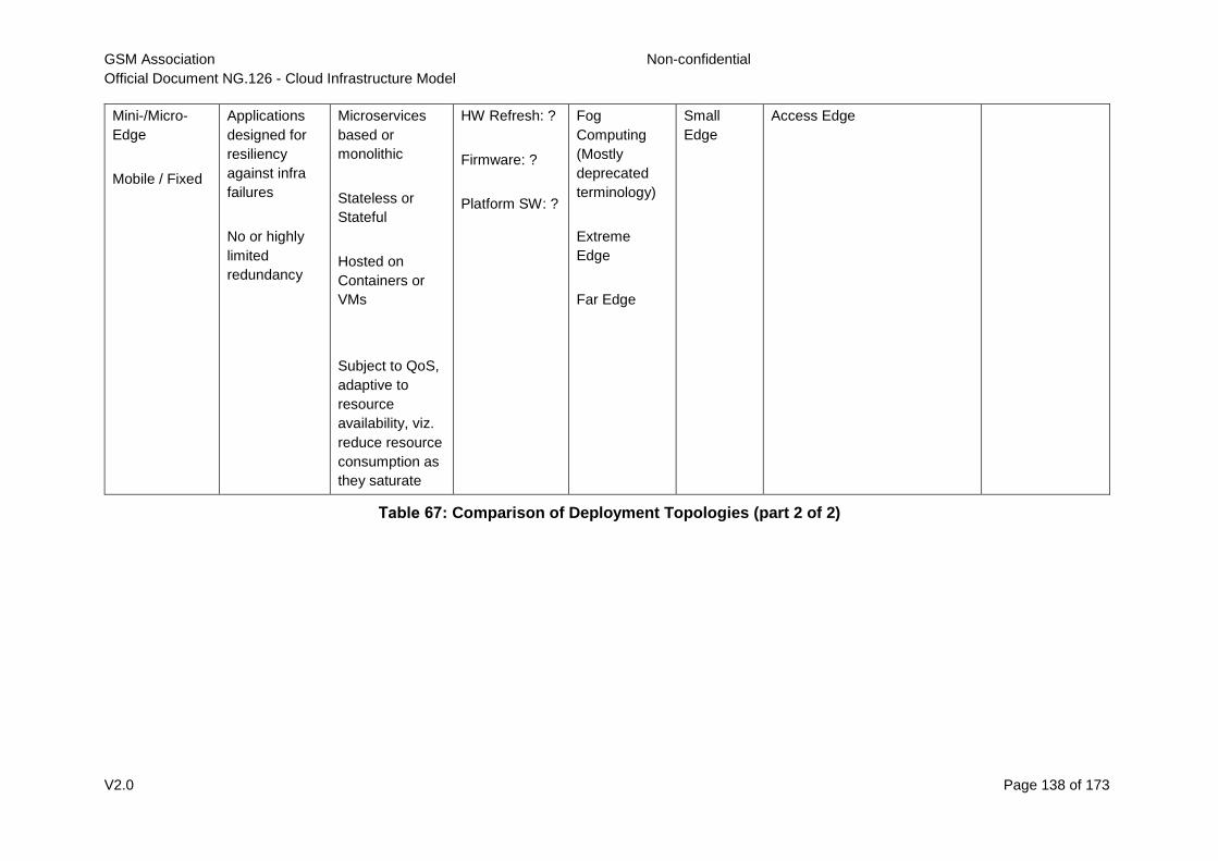
GSM Association Non-confidential
Official Document NG.126 - Cloud Infrastructure Model
V2.0 Page 138 of 173
Mini-/Micro-
Edge
Mobile / Fixed
Applications
designed for
resiliency
against infra
failures
No or highly
limited
redundancy
Microservices
based or
monolithic
Stateless or
Stateful
Hosted on
Containers or
VMs
Subject to QoS,
adaptive to
resource
availability, viz.
reduce resource
consumption as
they saturate
HW Refresh: ?
Firmware: ?
Platform SW: ?
Fog
Computing
(Mostly
deprecated
terminology)
Extreme
Edge
Far Edge
Small
Edge
Access Edge
Table 67: Comparison of Deployment Topologies (part 2 of 2)
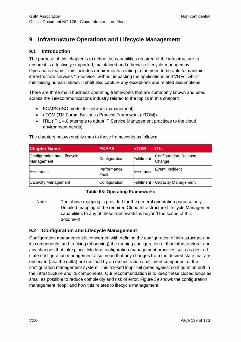
GSM Association Non-confidential
Official Document NG.126 - Cloud Infrastructure Model
V2.0 Page 139 of 173
9 Infrastructure Operations and Lifecycle Management
9.1 Introduction
The purpose of this chapter is to define the capabilities required of the infrastructure to
ensure it is effectively supported, maintained and otherwise lifecycle-managed by
Operations teams. This includes requirements relating to the need to be able to maintain
infrastructure services "in-service" without impacting the applications and VNFs, whilst
minimising human labour. It shall also capture any exceptions and related assumptions.
There are three main business operating frameworks that are commonly known and used
across the Telecommunications industry related to the topics in this chapter:
FCAPS (ISO model for network management)
eTOM (TM Forum Business Process Framework (eTOM))
ITIL (ITIL 4.0 attempts to adapt IT Service Management practices to the cloud
environment needs)
The chapters below roughly map to these frameworks as follows:
Chapter Name FCAPS eTOM ITIL
Configuration and Lifecycle
Management Configuration Fulfilment
Configuration, Release,
Change
Assurance Performance,
Fault Assurance
Event, Incident
Capacity Management Configuration Fulfilment Capacity Management
Table 68: Operating Frameworks
Note: The above mapping is provided for the general orientation purpose only.
Detailed mapping of the required Cloud Infrastructure Lifecycle Management
capabilities to any of these frameworks is beyond the scope of this
document.
9.2 Configuration and Lifecycle Management
Configuration management is concerned with defining the configuration of infrastructure and
its components, and tracking (observing) the running configuration of that infrastructure, and
any changes that take place. Modern configuration management practices such as desired
state configuration management also mean that any changes from the desired state that are
observed (aka the delta) are rectified by an orchestration / fulfilment component of the
configuration management system. This "closed loop" mitigates against configuration drift in
the infrastructure and its components. Our recommendation is to keep these closed loops as
small as possible to reduce complexity and risk of error. Figure 39 shows the configuration
management "loop" and how this relates to lifecycle management.
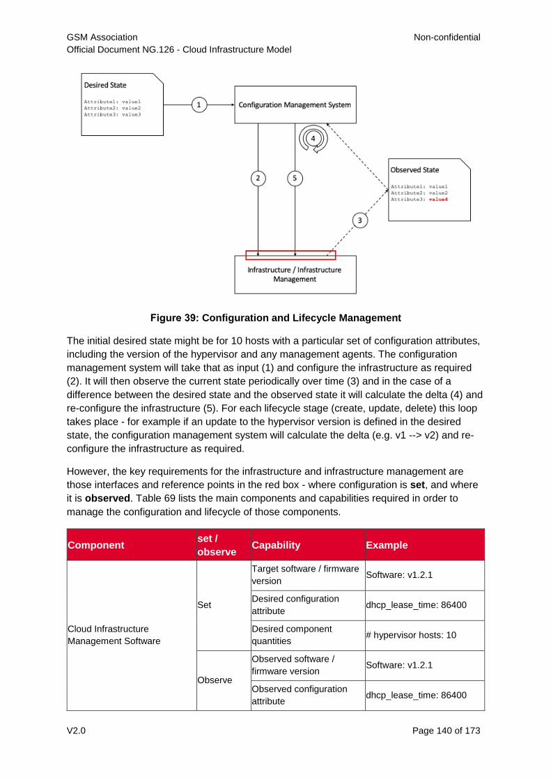
GSM Association Non-confidential
Official Document NG.126 - Cloud Infrastructure Model
V2.0 Page 140 of 173
Figure 39: Configuration and Lifecycle Management
The initial desired state might be for 10 hosts with a particular set of configuration attributes,
including the version of the hypervisor and any management agents. The configuration
management system will take that as input (1) and configure the infrastructure as required
(2). It will then observe the current state periodically over time (3) and in the case of a
difference between the desired state and the observed state it will calculate the delta (4) and
re-configure the infrastructure (5). For each lifecycle stage (create, update, delete) this loop
takes place - for example if an update to the hypervisor version is defined in the desired
state, the configuration management system will calculate the delta (e.g. v1 --> v2) and re-
configure the infrastructure as required.
However, the key requirements for the infrastructure and infrastructure management are
those interfaces and reference points in the red box - where configuration is set, and where
it is observed. Table 69 lists the main components and capabilities required in order to
manage the configuration and lifecycle of those components.
Component set /
observe Capability Example
Cloud Infrastructure
Management Software
Set
Target software / firmware
version Software: v1.2.1
Desired configuration
attribute dhcp_lease_time: 86400
Desired component
quantities # hypervisor hosts: 10
Observe
Observed software /
firmware version Software: v1.2.1
Observed configuration
attribute dhcp_lease_time: 86400
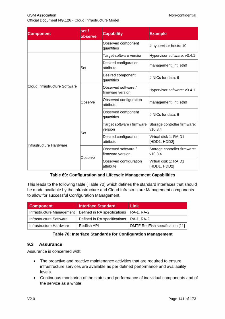
GSM Association Non-confidential
Official Document NG.126 - Cloud Infrastructure Model
V2.0 Page 141 of 173
Component set /
observe Capability Example
Observed component
quantities # hypervisor hosts: 10
Cloud Infrastructure Software
Set
Target software version Hypervisor software: v3.4.1
Desired configuration
attribute management_int: eth0
Desired component
quantities # NICs for data: 6
Observe
Observed software /
firmware version Hypervisor software: v3.4.1
Observed configuration
attribute management_int: eth0
Observed component
quantities # NICs for data: 6
Infrastructure Hardware
Set
Target software / firmware
version
Storage controller firmware:
v10.3.4
Desired configuration
attribute
Virtual disk 1: RAID1
[HDD1, HDD2]
Observe
Observed software /
firmware version
Storage controller firmware:
v10.3.4
Observed configuration
attribute
Virtual disk 1: RAID1
[HDD1, HDD2]
Table 69: Configuration and Lifecycle Management Capabilities
This leads to the following table (Table 70) which defines the standard interfaces that should
be made available by the infrastructure and Cloud Infrastructure Management components
to allow for successful Configuration Management.
Component Interface Standard Link
Infrastructure Management Defined in RA specifications RA-1, RA-2
Infrastructure Software Defined in RA specifications RA-1, RA-2
Infrastructure Hardware Redfish API DMTF RedFish specification [11]
Table 70: Interface Standards for Configuration Management
9.3 Assurance
Assurance is concerned with:
The proactive and reactive maintenance activities that are required to ensure
infrastructure services are available as per defined performance and availability
levels.
Continuous monitoring of the status and performance of individual components and of
the service as a whole.
GSM Association Non-confidential
Official Document NG.126 - Cloud Infrastructure Model
V2.0 Page 142 of 173
Collection and analysis of performance data, which is used to identify potential issues
including the ability to resolve the issue with no customer impact.
There are the following requirement types:
1. Data collection from all components, e.g.
o The ability to collect data relating to events (transactions, security events, physical
interface up/down events, warning events, error events, etc.)
o The ability to collect data relating to component status (up/down, physical
temperature, disk speed, etc.)
o The ability to collect data relating to component performance (used CPU
resources, storage throughput, network bandwidth in/out, API transactions,
transaction response times, etc.)
2. Capabilities of the Infrastructure Management Software to allow for in-service
maintenance of the Infrastructure Software and Hardware under its management, e.g.
o The ability to mark a physical compute node as being in some sort of
"maintenance mode" and for the Infrastructure Management Software to ensure
all running workloads are moved off or rescheduled on to other available nodes
(after checking that there is sufficient capacity) before marking the node as being
ready for whatever maintenance activity needs to be performed
o The ability to co-ordinate, automate, and allow the declarative input of in-service
software component upgrades - such as internal orchestration and scheduler
components in the Infrastructure Management Software
Note that the above only refers to components - it is expected that any "service" level
assurance doesn't add any further requirements onto the infrastructure, but rather takes the
data extracted and builds service models based on the knowledge it has of the services
being offered.
9.4 Capacity Management
Capacity Management is a potentially wide ranging process that includes taking demand
across lines of business, analysing data about the infrastructure that is running, and
calculating when additional infrastructure might be required, or when infrastructure might
need to be decommissioned.
As such the requirements for Capacity Management on the infrastructure are covered by the
Assurance and Configuration and Lifecycle Management sections above. The Assurance
section deals with the collection of data - there is no reason to consider that this would be
done by a different mechanism for Capacity Management as it is for Assurance - and the
Configuration and Lifecycle Management section deals with the changes being made to the
infrastructure hardware, software, and management components (e.g. changing of number
of hypervisor hosts from 10 to 12).
9.5 Automation
9.5.1 Infrastructure LCM Automation
To be covered in the next release.
GSM Association Non-confidential
Official Document NG.126 - Cloud Infrastructure Model
V2.0 Page 143 of 173
9.5.1.1 Hardware Configuration CI/CD
To be covered in the next release.
9.5.1.2 Networking Automation
To be covered in the next release.
9.5.1.3 Software Development CI/CD
To be covered in the next release.
9.5.2 Software Onboarding Automation and CI/CD Requirements
9.5.2.1 Software Onboarding Automation
For software deployment, as far as Cloud Infrastructure services or workloads are
concerned, automation is the core of DevOps concept. Automation allows to eliminate
manual processes, reducing human errors and speeding software deployments. The
prerequisite is to install CI/CD tools chain to:
Build, package, test application/software
Store environment's parameters and configurations
Automate the delivery and deployment
The CI/CD pipeline is used to deploy, test and update the Cloud Infrastructure services, and
also to onboard workloads hosted on the infrastructure. Typically, this business process
consists of the following key phases:
1. Tenant Engagement and Software Evaluation:
o In this phase the request from the tenant to host a workload on the Cloud
Infrastructure platform is assessed and a decision made on whether to proceed
with the hosting request.
o If the Cloud infrastructure software needs to be updated or installed, an evaluation
is made of the impacts (including to tenants) and if it is OK to proceed
o This phase may also involve the tenant accessing a pre-staging environment to
perform their own evaluation and/or pre-staging activities in preparation for later
onboarding phases.
2. Software Packaging:
o The main outcome of this phase is to produce the software deployable image and
the deployment manifests (such as TOSCA blueprints or HEAT templates or Helm
charts) that will define the Cloud Infrastructure service attributes.
o The software packaging can be automated or performed by designated personnel,
through self-service capabilities (for tenants) or by the Cloud Infrastructure
Operations team.
3. Software Validation and Certification:
o In this phase the software is deployed and tested to validate it against the service
design and other Operator specific acceptance criteria, as required.
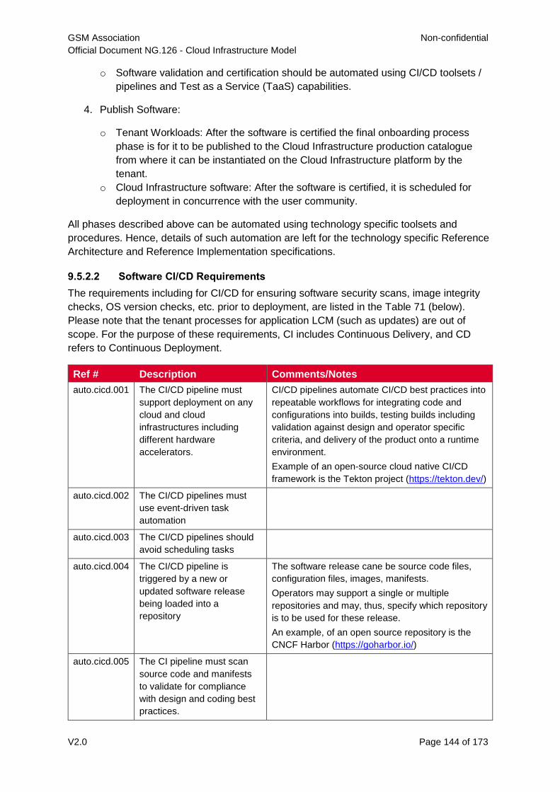
GSM Association Non-confidential
Official Document NG.126 - Cloud Infrastructure Model
V2.0 Page 144 of 173
o Software validation and certification should be automated using CI/CD toolsets /
pipelines and Test as a Service (TaaS) capabilities.
4. Publish Software:
o Tenant Workloads: After the software is certified the final onboarding process
phase is for it to be published to the Cloud Infrastructure production catalogue
from where it can be instantiated on the Cloud Infrastructure platform by the
tenant.
o Cloud Infrastructure software: After the software is certified, it is scheduled for
deployment in concurrence with the user community.
All phases described above can be automated using technology specific toolsets and
procedures. Hence, details of such automation are left for the technology specific Reference
Architecture and Reference Implementation specifications.
9.5.2.2 Software CI/CD Requirements
The requirements including for CI/CD for ensuring software security scans, image integrity
checks, OS version checks, etc. prior to deployment, are listed in the Table 71 (below).
Please note that the tenant processes for application LCM (such as updates) are out of
scope. For the purpose of these requirements, CI includes Continuous Delivery, and CD
refers to Continuous Deployment.
Ref # Description Comments/Notes
auto.cicd.001 The CI/CD pipeline must
support deployment on any
cloud and cloud
infrastructures including
different hardware
accelerators.
CI/CD pipelines automate CI/CD best practices into
repeatable workflows for integrating code and
configurations into builds, testing builds including
validation against design and operator specific
criteria, and delivery of the product onto a runtime
environment.
Example of an open-source cloud native CI/CD
framework is the Tekton project (https://tekton.dev/)
auto.cicd.002 The CI/CD pipelines must
use event-driven task
automation
auto.cicd.003 The CI/CD pipelines should
avoid scheduling tasks
auto.cicd.004 The CI/CD pipeline is
triggered by a new or
updated software release
being loaded into a
repository
The software release cane be source code files,
configuration files, images, manifests.
Operators may support a single or multiple
repositories and may, thus, specify which repository
is to be used for these release.
An example, of an open source repository is the
CNCF Harbor (https://goharbor.io/)
auto.cicd.005 The CI pipeline must scan
source code and manifests
to validate for compliance
with design and coding best
practices.
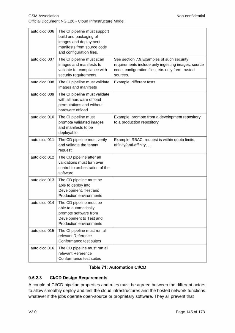
GSM Association Non-confidential
Official Document NG.126 - Cloud Infrastructure Model
V2.0 Page 145 of 173
auto.cicd.006 The CI pipeline must support
build and packaging of
images and deployment
manifests from source code
and configuration files.
auto.cicd.007 The CI pipeline must scan
images and manifests to
validate for compliance with
security requirements.
See section 7.9.Examples of such security
requirements include only ingesting images, source
code, configuration files, etc. only form trusted
sources.
auto.cicd.008 The CI pipeline must validate
images and manifests
Example, different tests
auto.cicd.009 The CI pipeline must validate
with all hardware offload
permutations and without
hardware offload
auto.cicd.010 The CI pipeline must
promote validated images
and manifests to be
deployable.
Example, promote from a development repository
to a production repository
auto.cicd.011 The CD pipeline must verify
and validate the tenant
request
Example, RBAC, request is within quota limits,
affinity/anti-affinity, …
auto.cicd.012 The CD pipeline after all
validations must turn over
control to orchestration of the
software
auto.cicd.013 The CD pipeline must be
able to deploy into
Development, Test and
Production environments
auto.cicd.014 The CD pipeline must be
able to automatically
promote software from
Development to Test and
Production environments
auto.cicd.015 The CI pipeline must run all
relevant Reference
Conformance test suites
auto.cicd.016 The CD pipeline must run all
relevant Reference
Conformance test suites
Table 71: Automation CI/CD
9.5.2.3 CI/CD Design Requirements
A couple of CI/CD pipeline properties and rules must be agreed between the different actors
to allow smoothly deploy and test the cloud infrastructures and the hosted network functions
whatever if the jobs operate open-source or proprietary software. They all prevent that
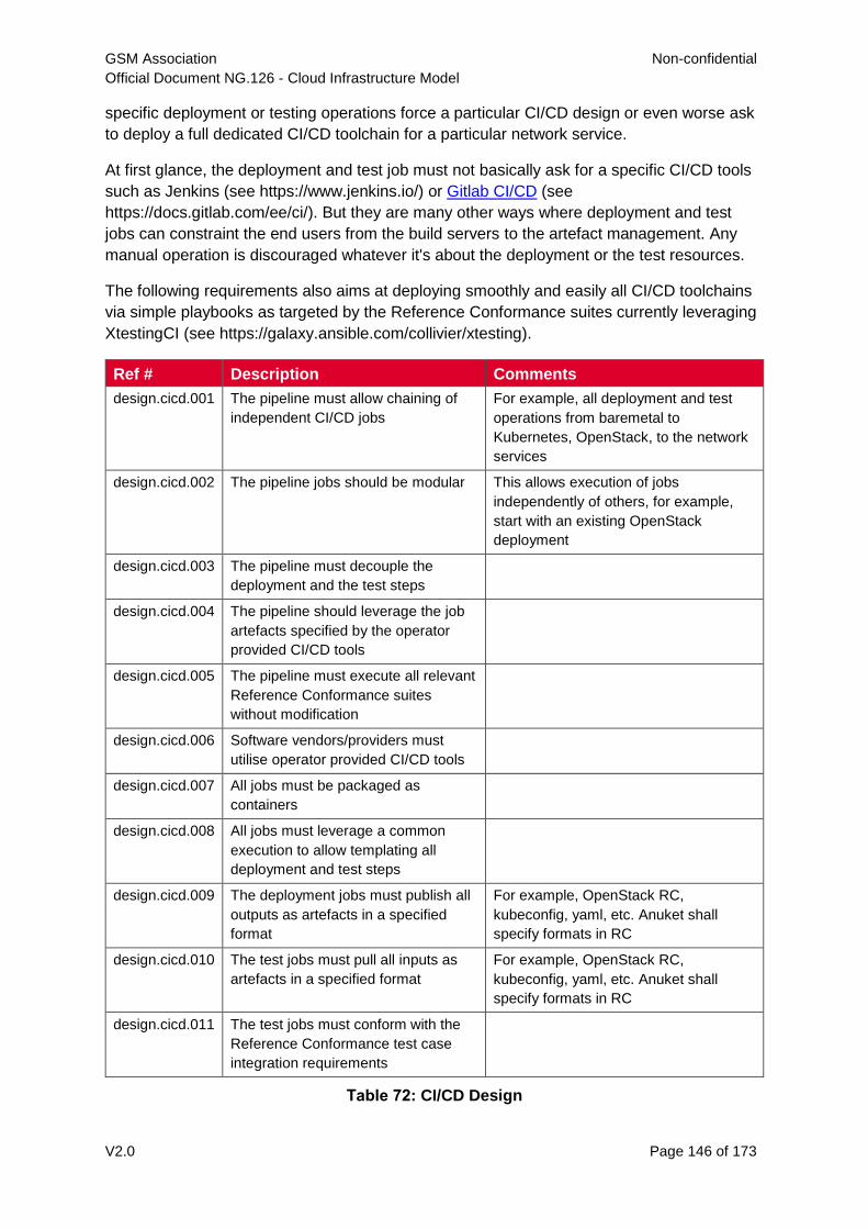
GSM Association Non-confidential
Official Document NG.126 - Cloud Infrastructure Model
V2.0 Page 146 of 173
specific deployment or testing operations force a particular CI/CD design or even worse ask
to deploy a full dedicated CI/CD toolchain for a particular network service.
At first glance, the deployment and test job must not basically ask for a specific CI/CD tools
such as Jenkins (see https://www.jenkins.io/) or Gitlab CI/CD (see
https://docs.gitlab.com/ee/ci/). But they are many other ways where deployment and test
jobs can constraint the end users from the build servers to the artefact management. Any
manual operation is discouraged whatever it's about the deployment or the test resources.
The following requirements also aims at deploying smoothly and easily all CI/CD toolchains
via simple playbooks as targeted by the Reference Conformance suites currently leveraging
XtestingCI (see https://galaxy.ansible.com/collivier/xtesting).
Ref # Description Comments
design.cicd.001 The pipeline must allow chaining of
independent CI/CD jobs
For example, all deployment and test
operations from baremetal to
Kubernetes, OpenStack, to the network
services
design.cicd.002 The pipeline jobs should be modular This allows execution of jobs
independently of others, for example,
start with an existing OpenStack
deployment
design.cicd.003 The pipeline must decouple the
deployment and the test steps
design.cicd.004 The pipeline should leverage the job
artefacts specified by the operator
provided CI/CD tools
design.cicd.005 The pipeline must execute all relevant
Reference Conformance suites
without modification
design.cicd.006 Software vendors/providers must
utilise operator provided CI/CD tools
design.cicd.007 All jobs must be packaged as
containers
design.cicd.008 All jobs must leverage a common
execution to allow templating all
deployment and test steps
design.cicd.009 The deployment jobs must publish all
outputs as artefacts in a specified
format
For example, OpenStack RC,
kubeconfig, yaml, etc. Anuket shall
specify formats in RC
design.cicd.010 The test jobs must pull all inputs as
artefacts in a specified format
For example, OpenStack RC,
kubeconfig, yaml, etc. Anuket shall
specify formats in RC
design.cicd.011 The test jobs must conform with the
Reference Conformance test case
integration requirements
Table 72: CI/CD Design
GSM Association Non-confidential
Official Document NG.126 - Cloud Infrastructure Model
V2.0 Page 147 of 173
9.5.3 Tenant Creation Automation
9.5.3.1 Pre-tenant Creation Requirements
Topics include:
1. Tenant Approval -- use, capacity, data centres, etc.
o Validate that the Tenant's (see section B.4) planned use meets the Operators
Cloud Use policies
o Validate that the capacity available within the requests cloud site(s) can satisfy the
Tenant requested quota for vCPU, RAM, Disk, Network Bandwidth
o Validate that the Cloud Infrastructure can meet Tenant's performance
requirements (e.g. I/O, latency, jitter, etc.)
o Validate that the Cloud Infrastructure can meet Tenant's resilience requirements
2. For environments that support Compute Flavours (see section 4.2.1):
o Verify that any requested private flavours have been created
o Verify that the metadata for these private flavours have been created
o Verify that the tenant has permissions to use the requested private flavours
o Validate that host aggregates are available for specified flavours (public and
private)
o Verify that the metadata matches for the requested new flavours and host
aggregates
3. Tenant Networks
o Verify that the networks requested by the tenant exist
o Verify that the security policies are correctly configured to only approved ingress
and egress
4. Tenant Admin, Tenant Member and other Tenant Role approvals for user by role
o Add all Tenant Members and configure their assigned roles in the Enterprise
Identity and Access management system (e.g., LDAP)
o Verify that these roles have been created for the Tenant
5. Tenant Images and manifests approvals
o Verify and Validate Tenant Images and manifests: virus scan, correct OS version
and patch, etc. (Please note that Tenants may also add other images or replace
existing images after their environments are created and will also be subjected to
image security measures.)
6. Create, Verify and Validate Tenant
o Create Tenant
o Using a proto- or Tenant provided HEAT-template/Helm-chart for a NF and
perform sanity test (e.g., using scripts test creation of VM/container, ping test,
etc.)
GSM Association Non-confidential
Official Document NG.126 - Cloud Infrastructure Model
V2.0 Page 148 of 173
9.6 Telemetry and Observability
Operating complex distributed systems, such as a Telco network, is a demanding and
challenging task that is continuously being increased as the network complexity and the
production excellence requirements grow. There are multiple reasons why it is so, but they
originate in the nature of the system concept. To reach the ability of providing Telco
services, a complex system is decomposed into multiple different functional blocks, called
network functions. Internal communication between the diverse network functions of a
distributed system is based on message exchange. To formalize this communication, clearly
defined interfaces are introduced, and protocols designed. Even though the architecture of a
Telco network is systematically formalized on the worldwide level, heterogeneity of services,
functions, interfaces, and protocols cannot be avoided. By adding the multi-vendor approach
in implementation of Telco networks, the outcome is indeed a system with remarkably high
level of complexity which requires significant efforts for managing and operating it.
To ensure proper support and flawless work in the large ecosystem of end user services, a
formalized approach directed towards high reliability and scalability of systems is required.
The discipline which applies well known practices of software engineering to operations is
called Site Reliability Engineering. It was conceived at Google, as a means to overcome
limitations of the common DevOps approach.
Common supporting system (OSS – Operation Support System, BSS – Business Support
System) requirements are redefined, driven by introduction of new technologies in
computing infrastructure and modern data centres with abstraction of resources – known as
virtualization and cloud computing. This brings many advantages – such as easy scaling,
error recovery, reaching a high level of operational autonomy etc., but also many new
challenges in the Telecom network management space. Those novel challenges are mostly
directed towards the dynamical nature of the system, orientation towards microservices
instead of a silo approach, and huge amounts of data which have to be processed in order to
understand the internal status of the system. Hence the need of improved ways to monitor
systems - observability.
9.6.1 Why Observability
Knowing the status of all services and functions at all levels in a cloud based service offering
is essential to act fast, ideally pro-actively before users notice and, most importantly, before
they call the help desk.
Common approach to understand the aforementioned Telco network status in conventional
non-cloud environments is referred to as monitoring. Usually it would include metric
information related to resources, such as CPU, memory, HDD, Network I/O, but also
business related technical key performance indicators (KPIs) such as number of active
users, number of registrations, etc. This monitoring data are represented as a time series,
retrieved in regular intervals, usually with granulation of 5 to 30 minutes. In addition,
asynchronous messages such as alarms and notifications are exposed by the monitored
systems in order to provide information about foreseen situations. It is worth noting that
metric data provide approximation of the health of the system, while the alarms and
notifications try to bring more information about the problem. In general, they provide
information about known unknowns - anticipated situations occurring at random time.
However, this would very rarely be sufficient information for understanding the problem
GSM Association Non-confidential
Official Document NG.126 - Cloud Infrastructure Model
V2.0 Page 149 of 173
(RCA - root cause analysis), therefore it is necessary to retrieve more data related to the
problem - logs and network signalization. Logs are application output information to get more
granular information about the code execution. Network packet captures/traces are useful
since telecommunication networks are distributed systems where components communicate
utilizing various protocols, and the communication can be examined to get details of the
problem.
As the transition towards cloud environments takes place simultaneously with the
introduction of DevOps mindset, the conventional monitoring approach becomes suboptimal.
Cloud environments allow greater flexibility as the microservice architecture is embraced to
bring improvements in operability, therefore the automation can be utilized to a higher extent
than ever before. Automation in telecom networks usually supposes actions based on
decisions derived from system output data (system observation). In order to derive useful
decisions, data with rich context are necessary. Obviously, the conventional monitoring
approach has to be improved in order to retrieve sufficient data, not only from the wider
context, but also without delays - as soon as data are produced or available. The new,
enhanced approach was introduced as a concept of observability, borrowed from the control
theory which states that it is possible to make conclusions about a system's internal state
based on external outputs.
This requires the collection of alarms and telemetry data from the physical layer (wires), the
cloud infrastructure up to the network, applications and services (virtualized network
functions (VNF)) running on top of the cloud infrastructure, typically isolated by tenants.
Long term trending data are essential for capacity planning purposes and typically collected,
aggregated and kept over the full lifespan. To keep the amount of data collected
manageable, automatic data reduction algorithms are typically used, e.g. by merging data
points from the smallest intervals to more granular intervals.
The telco cloud infrastructure typically consists of one or more regional data centres, central
offices, and edge sites. These are managed from redundant central management sites, each
hosted in their own data centres.
The network services and applications deployed on a Telco Cloud, and the Telco Cloud
infrastructure are usually managed by separate teams, and, thus, the monitoring solution
must be capable of keeping the access to the monitoring data isolated between tenants and
Cloud Infrastructure operations. Some monitoring data from the Cloud Infrastructure layer
must selectively be available to tenant monitoring applications in order to correlate, say, the
Network Functions/Services data with the underlying cloud infrastructure data.
What to observe
Typically, when it comes to data collection, three questions arise: 1. What data to collect?
2. Where to send the data?
3. Which protocol/interface/format to use?
9.6.1.1 What data to collect
Assessment on what data to collect should start by iterating over the physical and virtual
infrastructure components:
GSM Association Non-confidential
Official Document NG.126 - Cloud Infrastructure Model
V2.0 Page 150 of 173
Network Services across sites and tenants
Virtualized functions per site and tenant
Individual Virtual Machines and Containers
Virtualization infrastructure components
Physical servers (compute) and network elements
Tool servers with their applications (DNS, Identity Management, Zero Touch
Provisioning, etc.)
Cabling
Data categories
There are four main observability categories: metrics, events, logs and traces:
1. Metrics or telemetry report counters and gauge levels and can either be pulled
periodically e.g. via SNMP or REST, or pushed as streams using gRPC, NETCONF,
which receivers registered for certain sensors, or by registering as a publisher to a
message broker. These messages must be structured in order to get parsed
successfully.
2. Events indicate state variance beyond some specified threshold, are categorized by
severity, often with a description of what just happened. Most common transport
protocol is SNMP with its trap and inform messages). These messages are generated
by network elements (physical and logical). In addition, the messages can also be
generated by monitoring applications with statically configured thresholds or
dynamically by Machine Learning (ML) algorithms - generally, they are describing
anomalies.
3. Logs are a record messages generated by software for most devices (compute and
network) and virtual applications and transported over SYSLOG and tend to come in
high volumes.
4. Traces are end-to-end signalling messages (events) created to fulfil execution of
requests on the distributed system services. OTHER WORDS: Traces are all action
points executed in order to provide response to the request set to the distributed system
service. Even the call can be thought of as a request which starts by INVITE message
of the SIP protocol.
9.6.1.2 Where to send the data
If the observability data have to be sent from their sources (or producers) to specific
destinations (or consumers), then this creates high degree of dependency between
producers and consumers, and is extremely prone to errors, especially in case of
configuration changes. Ideally, the data producers must not be impacted with any change in
the data consumers and vice versa. This is achieved by decoupling data producers from
data consumers through the use of Brokers. The Producers always send their data to the
same endpoint - the Broker. While the Consumers register with the Broker for data that is of
interest to them and always receive their data from the Broker.
9.6.1.3 Which protocol, interface, and format to use
While protocols and interfaces are dictated by the selection of the message broker (common
data bus) system, data format is usually customizable according to the needs of users. The
GSM Association Non-confidential
Official Document NG.126 - Cloud Infrastructure Model
V2.0 Page 151 of 173
concept of Schema Registry mechanism, well known in the world of big data, is helpful here
to make sure that message structures and formats are consistently used.
9.6.2 The Architecture
In geographically dispersed large cloud deployments, a given telco cloud may have several
cloud infrastructure components as well a large set of virtualized workloads (VNF/CNFs). It
is important to monitor all of these workloads and infrastructure components. Furthermore, it
is even more important to be able to correlate between the metrics provided by these entities
to determine the performance and/or issues in such deployments.
The cloud deployment tends to shrink and expand based upon the customer demand.
Therefore, an architecture is required that can scale on demand and does not force a strong
tie between various entities. This means, the workloads and cloud infrastructure components
that provide telemetry and performance metrics must not be burdened to discover each
other. The capacity (e.g. speed, storage) of one component must not force overrun or
underrun situations that would cause critical data to be lost or delayed to a point to render
them useless.
Operators in charge of the cloud infrastructure (physical infra plus virtualization platform)
require very detailed alarms and metrics to efficiently run their platform. While they need
indicators about how well or poorly individual virtual machines and containers run, they don’t
need a view inside these workloads. In fact, what and how workloads do should not be
accessible to NFVI operators. The architecture must allow for different consumers to grant or
deny access to available resources.
Multiple workloads or network services can be deployed onto one or more sites. These
workloads require logical separation so that their metrics don’t mix by accident or simply
based on security and privacy requirements. This is achieved by deploying these workloads
within their own tenant space. All virtualization platforms offer such isolation down to virtual
networks per tenant.
9.6.2.1 Push vs. Pull
Two widely deployed models for providing telemetry data are pull and push.
9.6.2.1.1 Pull Model
Typical characteristics of a pull model are:
The consumers are required to discover the producers of the data
Once the producers are identified, there should be a tight relationship
(synchronization) between the producer and consumer. This makes the systems very
complex in terms of configuration and management. For example, if a producer
moves to a different location or reboots/restarts, the consumer must re-discover the
producer and bind their relationship again.
Data are pulled explicitly by the consumer. The consumer must have appropriate
bandwidth, compute power, and storage to deal with this data - example SNMP
pull/walks
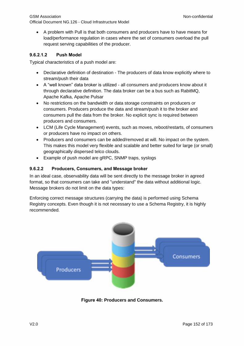
GSM Association Non-confidential
Official Document NG.126 - Cloud Infrastructure Model
V2.0 Page 152 of 173
A problem with Pull is that both consumers and producers have to have means for
load/performance regulation in cases where the set of consumers overload the pull
request serving capabilities of the producer.
9.6.2.1.2 Push Model
Typical characteristics of a push model are:
Declarative definition of destination - The producers of data know explicitly where to
stream/push their data
A “well known” data broker is utilized - all consumers and producers know about it
through declarative definition. The data broker can be a bus such as RabitMQ,
Apache Kafka, Apache Pulsar
No restrictions on the bandwidth or data storage constraints on producers or
consumers. Producers produce the data and stream/push it to the broker and
consumers pull the data from the broker. No explicit sync is required between
producers and consumers.
LCM (Life Cycle Management) events, such as moves, reboot/restarts, of consumers
or producers have no impact on others.
Producers and consumers can be added/removed at will. No impact on the system.
This makes this model very flexible and scalable and better suited for large (or small)
geographically dispersed telco clouds.
Example of push model are gRPC, SNMP traps, syslogs
9.6.2.2 Producers, Consumers, and Message broker
In an ideal case, observability data will be sent directly to the message broker in agreed
format, so that consumers can take and "understand" the data without additional logic.
Message brokers do not limit on the data types:
Enforcing correct message structures (carrying the data) is performed using Schema
Registry concepts. Even though it is not necessary to use a Schema Registry, it is highly
recommended.
Figure 40: Producers and Consumers.
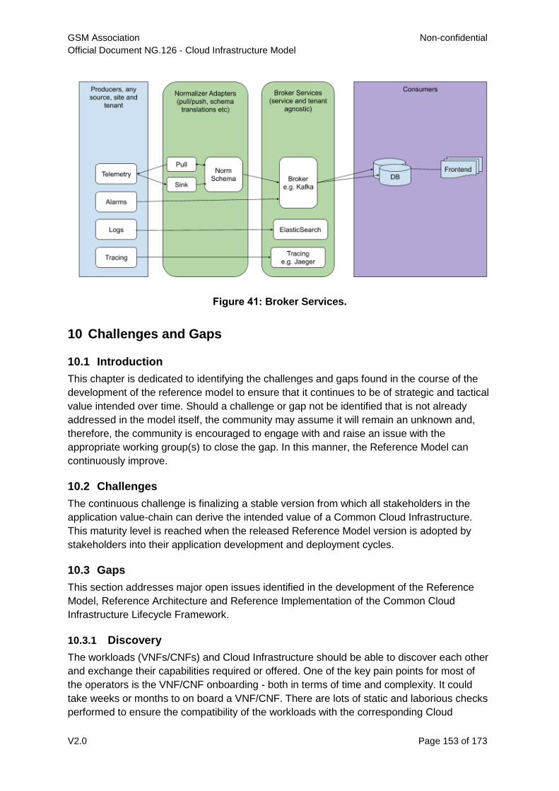
GSM Association Non-confidential
Official Document NG.126 - Cloud Infrastructure Model
V2.0 Page 153 of 173
Figure 41: Broker Services.
10 Challenges and Gaps
10.1 Introduction
This chapter is dedicated to identifying the challenges and gaps found in the course of the
development of the reference model to ensure that it continues to be of strategic and tactical
value intended over time. Should a challenge or gap not be identified that is not already
addressed in the model itself, the community may assume it will remain an unknown and,
therefore, the community is encouraged to engage with and raise an issue with the
appropriate working group(s) to close the gap. In this manner, the Reference Model can
continuously improve.
10.2 Challenges
The continuous challenge is finalizing a stable version from which all stakeholders in the
application value-chain can derive the intended value of a Common Cloud Infrastructure.
This maturity level is reached when the released Reference Model version is adopted by
stakeholders into their application development and deployment cycles.
10.3 Gaps
This section addresses major open issues identified in the development of the Reference
Model, Reference Architecture and Reference Implementation of the Common Cloud
Infrastructure Lifecycle Framework.
10.3.1 Discovery
The workloads (VNFs/CNFs) and Cloud Infrastructure should be able to discover each other
and exchange their capabilities required or offered. One of the key pain points for most of
the operators is the VNF/CNF onboarding - both in terms of time and complexity. It could
take weeks or months to on board a VNF/CNF. There are lots of static and laborious checks
performed to ensure the compatibility of the workloads with the corresponding Cloud
GSM Association Non-confidential
Official Document NG.126 - Cloud Infrastructure Model
V2.0 Page 154 of 173
Infrastructure. The onboarding of the workloads (network functions) should be automated as
much as possible. The workloads and Cloud Infrastructure should be able to discover and
negotiate their capabilities. Following should be supported:
Capabilities Discovery and Advertising
- Cloud Infrastructure should be able to publish the capabilities it offers to
workloads (network functions)
- workloads should be able to query the Cloud Infrastructure for specific
capabilities - such as number of cores, performance parameters
Capabilities Negotiation/Hand Shake API:
- workloads and Cloud Infrastructure should be able to negotiate on certain
capabilities. For instance, workload desires HW acceleration for high
throughput, but should be able to fall back to high throughput offered by
Cloud Infrastructure via DPDK offering, and vice-a-versa.
10.3.2 Support Load Balance of VNF/CNFs
The ability to dynamically scale a network function by load balancing across multiple
instances/replicas of the same VNF or CNF is essential. New architectures and application
patterns such as micro services is making this even more crucial. It must not only be
possible to load balance and scale each service layer independently, support to chain the
different layers together through "Service Function Chaining" is also needed.
The load balancing and scaling needed for typical enterprise applications is well supported in
OpenStack by the Octavia v2 API, the Octavia v2 API is a backwards compatible superset of
the old neutron LBaaS v2 API that it is replacing.
The built in mechanism in Kubernetes for scaling enterprise type of services and PODs is
also sufficient for applications that only use one interface.
What is not supported in either OpenStack or Kubernetes is to scale and load balance a
typical VNF and CNF. There is no support in OpenStack to scale stateful L3 applications
such as SCTP, QUIC, mTCP, and gRPC. In Kubernetes it is even worse. The built in
Kubernetes network support is tied to the first POD/container interface. Support for
secondary interfaces is managed through the Container Network Interface, CNI, and by CNI
plugins, such as Multus, that support the "Kubernetes Network Customs Resource
Definition" specified by the Kubernetes Network Plumbing Group. This specification supports
attachment of network endpoints to PODs, IP address management and the ability of define
interface specific static routes. There is no support for network orchestration and functions
such as load balancing, routing, ACL and firewalls.
10.3.3 Service Function Chain
Over the past few years there has been a significant move towards decomposing network
functions into smaller sub-functions that can be independently scaled and potentially reused
across multiple network functions. A service function chain allows composition of network
functions by passing selected packets through an ordered list of services. In order to support
this capability in a sustainable manner, there is a need to have the capability to model
GSM Association Non-confidential
Official Document NG.126 - Cloud Infrastructure Model
V2.0 Page 155 of 173
service chains as a high level abstraction. This is essential to ensure that the underlying
connection setup, and (re-)direction of traffic flows can be performed in an automated
manner. There is also a need to provide specialized tools aid troubleshooting of individual
services and the communication between them in order to investigate issues in the
performance of composed network functions.
10.3.4 Closed-loop automation
The state of a system is defined by a set of variables that fully describe the system and
determines the response of the system to any given set of inputs. A closed loop automation
system automatically maintains the specified desired state of the controlled system.
Closed-loop automation is evolving as a major advancement in the telecommunication
network automation. In the context of telecommunication systems, it means a system that in
a continuous loop programmatically validates the state of the cloud infrastructure against the
declared desired state, and in case of deviation from the desires state, it automatically takes
remediation actions necessary for bringing the actual state to the desired state. The
Reference Model specification will in its next releases address this important area.
10.3.5 Acceleration Abstraction
Many vRAN and some other domain's network functions require accelerators to meet
latency and throughput requirements. A large number of advanced ASICs, FPGAs, GPUs,
and Smart NIC have come to the market to address these needs but unfortunately there is a
lack of a common way to utilize them.
O-RAN Alliance (see https://www.o-ran.org/) is developing a common abstraction and
programming model for RAN application domain (see Acceleration Abstraction Layer
General Aspects an Principles 1.0 - November 2020 (O-RAN.WG6.AAL-GAnP-v01.00,
https://www.o-ran.org/specifications). P4 Language Consortium (see https://p4.org/) defines
specifications for switching and routing domains. There is, however, a lack of a common
programming model for accelerator applications development.
There is also a need for a seamless integration with platforms, Kubernetes and OpenStack
in particular. Kubernetes treats each device as unique HW and, hence, application
developers are forced to specify vendor specific labels and utilise vendor specific libraries in
their workload manifests as dependencies. OpenStack is attempting to address this gap with
their Cyborg project (see https://wiki.openstack.org/wiki/Cyborg).
GSM Association Non-confidential
Official Document NG.126 - Cloud Infrastructure Model
V2.0 Page 156 of 173
Annex A Principles
Any specification work created on the Cloud Infrastructure must conform to the following
principles:
A.1 Overall Principles
1. A top-level objective is to build a single, overarching Reference Model with the smallest
number of Reference Architectures tied to it as is practical. Two principles are
introduced in support of these objectives:
o Minimise Architecture proliferation by stipulating compatible features be
contained within a single Architecture as much as possible:
- Features which are compatible, meaning they are not mutually exclusive
and can coexist in the same cloud infrastructure instance, shall be
incorporated into the same Reference Architecture. For example, IPv4 and
IPv6 should be captured in the same Architecture, because they don't
interfere with each other
- Focus on the commonalities of the features over the perceived differences.
Seek an approach that allows small differences to be handled at either the
low-level design or implementation stage. For example, assume the use of
existing common APIs over new ones.
o Create an additional Architecture only when incompatible elements are
unavoidable:
- Creating additional Architectures is limited to when incompatible elements
are desired by Taskforce members. For example, if one member desires
KVM be used as the hypervisor, and another desires ESXi be used as the
hypervisor, and no compromise or mitigation* can be negotiated, the
Architecture could be forked, subject to community consensus, such that
one Architecture would be KVM-based and the other would be ESXi-
based.
Note: *Depending on the relationships and substitutability of the component(s) in
question, it may be possible to mitigate component incompatibility by
creating annexes to a single Architecture, rather than creating an additional
Architecture. With this approach, the infrastructure architecture designers
might implement the Architecture as described in the reference document,
however when there is a potential for incompatibility for particular
component, they would select their preferred option from one of the relevant
annexes. For example, if one member wanted to use Software-Defined
storage (SDS) as CEPH, and another member wanted to use Storage
Attached Network (SAN), assuming the components are equally compatible
with the rest of the Architecture, there could be one annex for the CEPH
implementation and one annex for the SAN implementation.
2. Cloud Infrastructure provides abstract and physical resources corresponding to:
o Compute resources
GSM Association Non-confidential
Official Document NG.126 - Cloud Infrastructure Model
V2.0 Page 157 of 173
o Storage resources
o Memory resources
o Networking resources (Limited to connectivity services only)
o Acceleration resources
3. Vendor independence of Cloud Infrastructure exposed resources.
4. Cloud Infrastructure Application Programming Interfaces (APIs) ensure Interoperability
(multi-vendor, components substitution), drive Simplification, and open source
implementations that have an open governance model (e.g. come from Open
Communities or Standards Development Organisations). These APIs support, for
example, cloud infrastructure resources discovery, monitoring by management entities,
configuration on behalf of workloads and consumption by workloads
5. Workloads are modular and designed to utilise the minimum resources required for the
service.
6. Workloads consume only the resources, capabilities and features provided by the
Cloud infrastructure.
7. Workload functional capabilities independence from Cloud Infrastructure (hardware
and software) accelerations.
8. Workload independence from Cloud Infrastructure (hardware and software) hardware-
dependent software
o This is in support of workload abstraction, enabling portability across the Infra and
simplification of workload design
o Use of critical features in this category are governed by technology specific
policies and exceptions in the RA specifications.
9. Abstraction of specific internal hardware details above the Infrastructure Cloud
Management layers unless managed through Hardware Infrastructure Manager
o This is in support of workload abstraction, enabling portability across the Infra and
simplification of workload design
o Use of critical features in this category are governed by technology specific
policies and exceptions in the RA specifications.
A.2 Requirements Principles
The agreed upon rules and recommendations to which a compliant workload or cloud
infrastructure must adhere.
All requirements will be hosted and maintained in the RM or relevant RA
All requirements must be assigned a requirements ID and not be embedded in
narrative text. This is to ensure that readers do not have to infer if a requirement
exists and is applicable
Requirements must have a unique ID for tracking and reference purposes
The requirement ID should include a prefix to delineate the source project
Requirements must state the level of compliance (ex: MUST, SHOULD, MAY) per
RFC 2119[2]
Mandatory requirements must be defined in such a way that they are unambiguously
verifiable via automated testing

GSM Association Non-confidential
Official Document NG.126 - Cloud Infrastructure Model
V2.0 Page 158 of 173
Requirements should be publishable or extractable into a machine readable format
such as JSON
Requirements should include information about the impact of non-conformance and
the rationale for their existence
A.3 Architectural Principles
Following are a number of key architectural principles that apply to all Reference
Architectures:
1. Open source preference: To ensure, by building on technology available in open
source projects, that suppliers’ and operators’ investment have a tangible pathway
towards a standard and production ready Cloud Infrastructure solution portfolio.
2. Open APIs: To enable interoperability and component substitution, and minimize
integration efforts by using openly published API definitions.
3. Separation of concerns: To promote lifecycle independence of different architectural
layers and modules (e.g. disaggregation of software from hardware).
4. Automated lifecycle management: To minimize costs of the end-to-end lifecycle,
maintenance downtime (target zero downtime), avoid errors and discrepancies
resulting from manual processes.
5. Automated scalability: To minimize costs and operational impacts through automated
policy-driven scaling of workloads by enabling automated horizontal scalability of
workloads.
6. Automated closed loop assurance: To minimize operational costs and simplify Cloud
Infrastructure platform operations by using automated fault resolution and performance
optimization.
7. Cloud nativeness: To optimise the utilization of resources and enable operational
efficiencies.
8. Security compliance: To ensure the architecture follows the industry best security
practices and is at all levels compliant to relevant security regulations.
9. Resilience and Availability: To allow High Availability and Resilience for hosted VNFs,
and to avoid Single Point of Failure.
Annex B Reference Model Glossary
B.1 Terminology
To help guide the reader, this glossary provides an introduction to the terminology used
within this document. These definitions are, with a few exceptions, based on the ETSI GR
NFV 003 V1.5.1 [1] definitions. In a few cases, they have been modified to avoid deployment
technology dependencies only when it seems necessary to avoid confusion.
B.2 Software Layer Terminology
Cloud Infrastructure: A generic term covering NFVI, IaaS and CaaS capabilities -
essentially the infrastructure on which a Workload can be executed.
Note: NFVI, IaaS and CaaS layers can be built on top of each other. In case of
CaaS some cloud infrastructure features (e.g.: HW management or
multitenancy) are implemented by using an underlying IaaS layer.
GSM Association Non-confidential
Official Document NG.126 - Cloud Infrastructure Model
V2.0 Page 159 of 173
Cloud Infrastructure Profile: The combination of the Cloud Infrastructure Software
Profile and the Cloud Infrastructure Hardware Profile that defines the capabilities and
configuration of the Cloud Infrastructure resources available for the workloads.
Cloud Infrastructure Software Configuration: a set of settings (Key:Value) that are
applied/mapped to cloud infrastructure SW deployment.
Cloud Infrastructure Software Profile: defines the behaviour, capabilities and
metrics provided by a Cloud Infrastructure Software Layer on resources available for
the workloads.
Cloud Native Network Function (CNF): A cloud native network function (CNF) is a
cloud native application that implements network functionality. A CNF consists of one
or more microservices. All layers of a CNF is developed using Cloud Native Principles
including immutable infrastructure, declarative APIs, and a “repeatable deployment
process”.
Note: This definition is derived from the Cloud Native Thinking for
Telecommunications Whitepaper (https://github.com/cncf/telecom-user-
group/blob/master/whitepaper/cloud_native_thinking_for_telecommunication
s.md#1.4) which also includes further detail and examples.
Compute flavour: defines the sizing of the virtualised resources (compute, memory,
and storage) required to run a workload.
Note: used to define the configuration/capacity limit of a virtualised container.
Hypervisor: a software that abstracts and isolates workloads with their own
operating systems from the underlying physical resources. Also known as a virtual
machine monitor (VMM).
Instance: is a virtual compute resource, in a known state such as running or
suspended, that can be used like a physical server.
Note: Can be used to specify VM Instance or Container Instance.
Network Function (NF): functional block or application that has well-defined external
interfaces and well-defined functional behaviour.
- Within NFV, a Network Function is implemented in a form of Virtualised
NF (VNF) or a Cloud Native NF (CNF).
Network Function Virtualisation (NFV): The concept of separating network
functions from the hardware they run on by using a virtual hardware abstraction layer.
Network Function Virtualisation Infrastructure (NFVI): The totality of all hardware
and software components used to build the environment in which a set of virtual
applications (VAs) are deployed; also referred to as cloud infrastructure.
Note: The NFVI can span across many locations, e.g. places where data centres
or edge nodes are operated. The network providing connectivity between
these locations is regarded to be part of the cloud infrastructure. NFVI and
VNF are the top-level conceptual entities in the scope of Network Function
Virtualisation. All other components are sub-entities of these two main
entities.
GSM Association Non-confidential
Official Document NG.126 - Cloud Infrastructure Model
V2.0 Page 160 of 173
Network Service (NS): composition of Network Function(s) and/or Network
Service(s), defined by its functional and behavioural specification, including the
service lifecycle.
Software Defined Storage (SDS): An architecture which consists of the storage
software that is independent from the underlying storage hardware. The storage
access software provides data request interfaces (APIs) and the SDS controller
software provides storage access services and networking.
Virtual Application (VA): A general term for software which can be loaded into a
Virtual Machine.
Note: a VNF is one type of VA.
Virtual CPU (vCPU): Represents a portion of the host's computing resources
allocated to a virtualised resource, for example, to a virtual machine or a container.
One or more vCPUs can be assigned to a virtualised resource.
Virtual Machine (VM): virtualised computation environment that behaves like a
physical computer/server.
Note: A VM consists of all of the components (processor (CPU), memory, storage,
interfaces/ports, etc.) of a physical computer/server. It is created using sizing
information or Compute Flavour.
Virtual Network Function (VNF): a software implementation of a Network
Function, capable of running on the Cloud Infrastructure.
- VNFs are built from one or more VNF Components (VNFC) and, in most
cases, the VNFC is hosted on a single VM or Container.
Virtual resources:
o Virtual Compute resource (a.k.a. virtualisation container): partition of a
compute node that provides an isolated virtualised computation environment.
o Virtual Storage resource: virtualised non-volatile storage allocated to a
virtualised computation environment hosting a VNFC.
o Virtual Networking resource: routes information among the network interfaces
of a virtual compute resource and physical network interfaces, providing the
necessary connectivity.
Workload: an application (for example VNF, or CNF) that performs certain task(s) for
the users. In the Cloud Infrastructure, these applications run on top of compute
resources such as VMs or Containers. Most relevant workload categories in the
context of the Cloud Infrastructure are:
- Data Plane Workloads: that perform tasks related to packet handling of
the end-to-end communication between applications. These tasks are
expected to be very I/O and memory read/write operations intensive.
- Control Plane Workloads: that perform tasks related to any other
communication between NFs that is not directly related to the end-to-end
data communication between applications. For example, this category
includes session management, routing or authentication.
GSM Association Non-confidential
Official Document NG.126 - Cloud Infrastructure Model
V2.0 Page 161 of 173
- Storage Workloads: that perform tasks related to disk storage (either SSD
or HDD or other). Examples range from non-intensive router logging to
more intensive database read/write operations.
B.3 Hardware Layer Terminology
Cloud Infrastructure Hardware Configuration: a set of settings (Key:Value) that
are applied/mapped to Cloud Infrastructure HW deployment.
Cloud Infrastructure Hardware Profile: defines the behaviour, capabilities,
configuration, and metrics provided by a cloud infrastructure hardware layer
resources available for the workloads.
- Host Profile: is another term for a Cloud Infrastructure Hardware Profile.
CPU Type: A classification of CPUs by features needed for the execution of
computer programs; for example, instruction sets, cache size, number of cores.
Hardware resources: Compute/Storage/Network hardware resources on which the
cloud infrastructure platform software, virtual machines and containers run on.
Physical Network Function (PNF): Implementation of a network function via tightly
coupled dedicated hardware and software system.
Note: This is a physical cloud infrastructure resource with the NF software.
Simultaneous Multithreading: Simultaneous multithreading (SMT) is a technique for
improving the overall efficiency of superscalar CPUs with hardware multithreading.
SMT permits multiple independent threads of execution on a single core to better
utilise the resources provided by modern processor architectures.
B.4 Operational and Administrative Terminology
Cloud service user: Natural person, or entity acting on their behalf, associated with
a cloud service customer that uses cloud services.
Note: Examples of such entities include devices and applications.
Compute Node: An abstract definition of a server.
Note: A compute node can refer to a set of hardware and software that support the
VMs or Containers running on it.
External Network: External networks provide network connectivity for a cloud
infrastructure tenant to resources outside of the tenant space.
Fluentd (https://www.fluentd.org/): An open source data collector for unified
logging layer, which allows data collection and consumption for better use and
understanding of data. Fluentd is a CNCF graduated project.
Kibana: An open source data visualisation system.
Multi-tenancy: feature where physical, virtual or service resources are allocated in
such a way that multiple tenants and their computations and data are isolated from
and inaccessible by each other.
Prometheus: An open-source monitoring and alerting system.
GSM Association Non-confidential
Official Document NG.126 - Cloud Infrastructure Model
V2.0 Page 162 of 173
Quota: An imposed upper limit on specific types of resources, usually used to
prevent excessive resource consumption by a given consumer (tenant, VM,
container).
Resource pool: A logical grouping of cloud infrastructure hardware and software
resources. A resource pool can be based on a certain resource type (for example,
compute, storage and network) or a combination of resource types. A Cloud
Infrastructure resource can be part of none, one or more resource pools.
Service Assurance (SA): collects alarm and monitoring data. Applications within SA
or interfacing with SA can then use this data for fault correlation, root cause analysis,
service impact analysis, SLA management, security, monitoring and analytic, etc.
Tenant: cloud service users sharing access to a set of physical and virtual resources,
ITU (https://www.itu.int/rec/dologin_pub.asp?lang=e&id=T-REC-Y.3500-201408-
I!!PDF-E&type=items).
Note: Tenants represent an independently manageable logical pool of compute,
storage and network resources abstracted from physical hardware.
Tenant Instance: refers to a single Tenant.
Tenant (Internal) Networks: Virtual networks that are internal to Tenant Instances.
B.5 Container Related Terminology
Note: Relevant terms are added here from RA2. Most of these term definitions are
taken from Kubernetes glossary
(https://kubernetes.io/docs/reference/glossary) but in some cases should be
made independent from Kubernetes as a specific container orchestration
engine.
CaaS Manager: A management plane function that manages the lifecycle
(instantiation, scaling, healing, etc.) of one or more CaaS instances, including
communication with VIM for master/node lifecycle management.
Container: A lightweight and portable executable image that contains software and
all of its dependencies.
Note: OCI defines Container as "An environment for executing processes with
configurable isolation and resource limitations. For example, namespaces,
resource limits, and mounts are all part of the container environment." A
Container provides operating-system-level virtualisation by abstracting the
“user space”. One big difference between Containers and VMs is that
unlike VMs, where each VM is self-contained with all the operating systems
components are within the VM package, containers "share" the host
system’s kernel with other containers.
Container Engine: Software components used to create, destroy, and manage
containers on top of an operating system.
Container Image: Stored instance of a container that holds a set of software needed
to run an application.
Container Runtime: The software that is responsible for running containers.
GSM Association Non-confidential
Official Document NG.126 - Cloud Infrastructure Model
V2.0 Page 163 of 173
Note: as explained in OCI Glossary (https://github.com/opencontainers/runtime-
spec/blob/master/glossary.md) it reads the configuration files for a
Container from a directory structure, uses that information to create a
container, launches a process inside the container, and performs other
lifecycle actions.
Container-as-a-Service (CaaS): A complete set of technologies to enable the
management of containerised software, including a Kubernetes cluster, container
networking, storage, routing, service mesh, etc.
Kubernetes Cluster: A set of machines, called nodes and master, that run
containerised applications managed by Kubernetes. A cluster has at least one worker
node and at least one master.
Note: adapted from Kubernetes Glossary
(https://kubernetes.io/docs/reference/glossary/?all=true#term-cluster).
Kubernetes Control Plane: The container orchestration layer that exposes the API
and interfaces to define, deploy, and manage the lifecycle of containers.
Kubernetes Master: Master(s) manage the worker nodes and the Pods in the
cluster. The master may run on a VM or a physical machine. Multiple masters can be
used to provide a cluster with failover and high availability.
Kubernetes Node: A node is a worker machine in Kubernetes. A worker node may
be a VM or physical machine, depending on the cluster. It has local daemons or
services necessary to run Pods and is managed by the control plane.
Kubernetes Service: An abstract way to expose an application running on a set of
Pods as a network service.
Note: This definition from Kubernetes Glossary
(https://kubernetes.io/docs/reference/glossary/?all=true#term-service) uses
the term "network service" differently than in ETSI NFV.
Pod: The smallest and simplest Kubernetes object. A Pod represents a set of running
containers on your cluster. A Pod is typically set up to run a single primary container.
It can also run optional sidecar containers that add supplementary features like
logging.
B.6 OpenStack Related Terminology
Note: The official OpenStack Glossary (https://docs.openstack.org/image-
guide/common/glossary.html) is an extensive list of OpenStack-related
concepts. Some additional terms used in the Reference Architecture RA-1 or
used to relate RA-1 terms with terms defined elsewhere.
Core (physical): An independent computer processing unit that can independently
execute CPU instructions and is integrated with other cores on a multiprocessor
(chip, integrated circuit die). Please note that the multiprocessor chip is also referred
to as a CPU that is placed in a socket of a computer motherboard.
Flavor Capability: The capability of the Cloud Infrastructure Profile, such as CPU
Pinning, NUMA or huge pages.
Flavor Geometry: Flavor sizing such as number of vCPUs, RAM, disk, etc.
GSM Association Non-confidential
Official Document NG.126 - Cloud Infrastructure Model
V2.0 Page 164 of 173
Hugepages: Physical memory is partitioned and accessed using the basic page unit
(in Linux default size of 4 KB). Hugepages, typically 2 MB and 1GB size, allows large
amounts of memory to be utilised with reduced overhead. In an NFV environment,
huge pages are critical to support large memory pool allocation for data packet
buffers. This results in fewer Translation Lookaside Buffers (TLB) lookups, which
reduces the virtual to physical pages address translations. Without huge pages
enabled high TLB miss rates would occur thereby degrading performance.
B.7 Cloud Platform Abstraction Related Terminology:
Abstraction: Process of removing concrete, fine-grained or lower level details or
attributes or common properties in the study of systems to focus attention on topics of
greater importance or general concepts. It can be the result of decoupling.
Adapted from Wikipedia:Abstraction
(https://en.wikipedia.org/wiki/Abstraction_(computer_science)),
Wikipedia:Generalization(https://en.wikipedia.org/wiki/Generalization)
Appliance deployment model: Application has tight coupling with underlying
Platform even if the application is virtualized or containerized.
Application Control: Any method or system of controlling applications (VNFs).
Depending on RA and technologies used, this can be a VNF Manager or NFV
Orchestrator provided as a VNF or Platform capability.
Cloud deployment model: Applications are decoupled from the platform provided by
Cloud operator.
Decomposition: Decomposition (also known as factoring) is breaking a complex
system into parts that are easier to program and maintain.
Adapted from Wikipedia:Decomposition
(https://en.wikipedia.org/wiki/Decomposition_(computer_science)
Decoupling, Loose Coupling: Loosely coupled system is one in which each of its
components has, or makes use of, little or no knowledge of the implementation
details of other separate components. Loose coupling is the opposite of tight
coupling.
Adapted from Wikipedia:Loose Coupling https://en.wikipedia.org/wiki/Loose_coupling.
Encapsulation: Restricting of direct access to some of an object's components.
Adapted from Wikipedia:Encapsulation
https://en.wikipedia.org/wiki/Encapsulation_(computer_programming)
Observability: Observability is a measure of how well internal states of a system can
be inferred from knowledge of its external outputs.
Adapted from Wikipedia:Observability https://en.wikipedia.org/wiki/Observability
Resilience: Resilience is the ability to provide and maintain an acceptable level of
service in the face of various faults and challenges to normal operation.
Adapted from Wikipedia:Resilience https://en.wikipedia.org/wiki/Resilience_(network)
B.8 Test Related Terminology
Calibration: The process of checking and/or adjusting a stimulus generation or
measurement device with a known reference value, to improve the overall quality of
the measured results. Calibration may be very simple, such as a comparison of the
configured traffic generator sending rate and measured rate using a simple SUT
GSM Association Non-confidential
Official Document NG.126 - Cloud Infrastructure Model
V2.0 Page 165 of 173
(System Under Test) such as loop-back cable between interfaces, such that the
known reference value is the published nominal interface rate.
Reference Value: A measured or established result or outcome for comparison with
new measurements. For example, the reference value or expected outcome of a
Functional Test is "PASS". The reference value or expected outcome of a
Performance Measurement or Benchmarking test may be the value measured for the
previous SUT release, or the published value or theoretical limit of a simple SUT.
API Testing: Testing against a protocol specification for conformance.
Functional Testing: The main objective of functional testing is the verification of
compliance against specific functional requirements using a specific stimulus /
response within the SUT, including the expected behaviour. These tests generally
result in a binary outcome, i.e. pass / fail. For example, verification of an "API call"
and its associated response, such as the instantiation of a VM (or container) and
verification of the VM's (or container's) existence (expected behaviour), or the ability
to activate a specific feature of the SUT (e.g. SR-IOV).
Performance Measurement: The procedure or set of operations having the objective
of determining a Measured Value or Measurement Result of an infrastructure in
operation according to a defined metric. In the context of telemetry, Performance
Measurements reflect data generated and collected within the cloud infrastructure
that reflects a performance aspect of the cloud infrastructure. For example, a count of
frames or packets traversing an interface per unit of time, memory usage information,
other resource usage and availability, etc. This data may be instantaneous or
accumulated, and made available (i.e. exposed) based on permissions and contexts
(e.g. workload vs. infra). Other Performance Measurements are designed to assess
the efficiency of SUT Functions, such as the time to successfully instantiate one or
more VMs or containers, or the percentage of failures in a set of many instantiation
attempts. Still other Performance Measurements are conducted under controlled
conditions using Calibrated test systems, such that the measured results are more
likely to comparable with other such measurements.
Performance Testing: The main objective of performance testing is to understand if
the SUT is able to achieve the expected performance, through conducting a series of
performance measurements and comparing those results against a reference value.
Performance testing is needed to help dimension a solution or to assess that a
platform (particular hardware + software combination) is configured correctly and
performing as expected i.e. as compared with capacity / performance claims made by
the infrastructure and VNF/CNF vendors. Performance Testing may be useful to
compare infrastructure capabilities between a particular SUT and a reference
implementation with well understood known good configurations and previously
established performance ranges. Performance testing for the purpose of comparing
between different commercial implementations is not a goal here and hence out of
scope for the purposes of this definition. Performance testing relies on well-
established benchmark specifications to help establish appropriate methodologies
and accuracy tolerances.
Benchmarking: Benchmarking is a type of performance test that assesses a key
aspect of the computing environment in its role as the infrastructure for network
functions, using calibrated test systems and controlled conditions. In general the
benchmark testing attempts to isolate the feature or parameter under test, to reduce
GSM Association Non-confidential
Official Document NG.126 - Cloud Infrastructure Model
V2.0 Page 166 of 173
the impact of other system components or operations on the test result. The
benchmark (and related metrics) have been agreed by the Industry and documented
in publications of an accredited standards body. As a result, benchmarks are a sub-
set of all possible performance tests and metrics i.e. they are selected measurements
which are more important than others. Example benchmarks include Zero-loss
Throughput, Latency, and Loss ratio (ref to ETSI NFV TST009, RFC 2544) of various
components of the environment, expressed in quantitative units to allow direct
comparison between different systems treated as a black box (vendor-
independence). Because the demands on a particular system may vary from
deployment to deployment, benchmarking assessments do not define acceptance
criteria or numerical performance requirements. Benchmark testing and conformance
testing intersect when a specific requirement in the reference architecture
specification is very important to the performance of the system. Correct execution of
the performance test with the valid result constitutes conformance. The completion
time for a single conforming execution, or the number of conforming executions per
second are potential benchmark metrics, and sources of known reference values.
B.9 Other Referenced Terminology
Carrier Grade: Carrier grade refers to network functions and infrastructure that are
characterised by all or some of the following attributes: High reliability allowing near
100% uptime, typically measured as better than “five nines”; Quality of Service (QoS)
allowing prioritization of traffic; High Performance optimized for low latency/packet
loss, and high bandwidth; Scalability to handle demand growth by adding virtual
and/or physical resources; Security to be able to withstand natural and man-made
attacks.
Monitoring (Capability): Monitoring capabilities are used for the passive observation
of workload-specific traffic traversing the Cloud Infrastructure. Note, as with all
capabilities, Monitoring may be unavailable or intentionally disabled for security
reasons in a given cloud infrastructure instance.
NFV Orchestrator (NFVO): Manages the VNF lifecycle and Cloud Infrastructure
resources (supported by the VIM) to ensure an optimised allocation of the necessary
resources and connectivity.
Platform: A cloud capabilities type in which the cloud service user can deploy,
manage and run customer-created or customer-acquired applications using one or
more programming languages and one or more execution environments supported by
the cloud service provider.
Adapted from ITU https://www.itu.int/rec/dologin_pub.asp?lang=e&id=T-REC-Y.3500-
201408-I!!PDF-E&type=items
Note: This includes the physical infrastructure, Operating Systems,
virtualisation/containerisation software and other orchestration, security,
monitoring/logging and life-cycle management software.
Virtualised Infrastructure Manager (VIM): Responsible for controlling and
managing the Network Function Virtualisation Infrastructure compute, storage
and network resources.
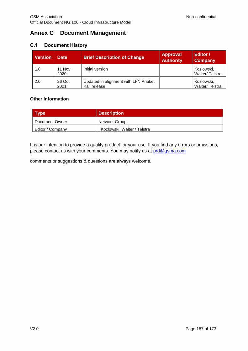
GSM Association Non-confidential
Official Document NG.126 - Cloud Infrastructure Model
V2.0 Page 167 of 173
Annex C Document Management
C.1 Document History
Version Date Brief Description of Change Approval
Authority
Editor /
Company
1.0 11 Nov 2020
Initial version Kozlowski, Walter/ Telstra
2.0 26 Oct 2021
Updated in alignment with LFN Anuket Kali release
Kozlowski, Walter/ Telstra
Other Information
It is our intention to provide a quality product for your use. If you find any errors or omissions,
please contact us with your comments. You may notify us at [email protected]
comments or suggestions & questions are always welcome.
Type Description
Document Owner Network Group
Editor / Company Kozlowski, Walter / Telstra


