Embed Size (px)
Citation preview
Nickel Electrodeposition on Electrophoretically Deposited Carbon Nanotube Films
Maria Federica De Riccardis1,a, Daniela Carbone1,b Virginia Martina1,c
Marilena Re1,d, Decheng Meng 2,e , Judith A. Roether2,f, Aldo R. Boccaccini 2,g
1 ENEA-Italian National Agency for New Technologies, Energy and the Environment, Department of Advanced Physical Technologies and New Materials, Brindisi Research Centre, SS 7 km 706,
72100 Brindisi, Italy 2 Department of Materials, Imperial College London, South Kensington Campus,
London SW7 2BP, UK a [email protected], b [email protected],
[email protected], d [email protected], [email protected], [email protected], g [email protected]
Keywords: electrodeposition, electrophoretic deposition, nickel, carbon nanotubes Abstract. Multi-walled carbon nanotubes (CNTs) were deposited by electrophoretic deposition on stainless steel substrates forming homogeneous porous CNT deposits. These CNT structures were then coated with a thin layer of Ni by electrodeposition. SEM and TEM observations confirmed that the Ni layer covered uniformly the CNT surfaces. This Ni coating treatment could facilitate the dispersion of CNTs in metal matrix composites leading to improved mechanical and thermal properties.
Introduction
The effective use of carbon nanotubes (CNTs) in composite materials is critically related to the quality of the interface bond between CNTs and the matrix material. In polymer matrix composites it is mandatory to functionalize the CNTs in order to avoid their agglomeration during composite processing as well as to improve their dispersion and their bonding to the polymer matrix [1]. Moreover, metal-based and ceramic-based CNT containing composites prepared by powder processing show lower mechanical properties than expected [2-3], which is attributed to CNT agglomeration or to the presence of porosity in the composites.
In this work we suggest to manipulate CNTs by electrochemical means prior to their use as reinforcement in a metal matrix composite in order to achieve a uniform distribution of CNTs in the matrix and to improve the infiltration of the metal into the spaces between CNTs thus reducing residual porosity. It is suggested that a metal coating applied on the surface of individual CNTs could improve the wetting behaviour of the metal phase as well as achieving strong bonding between CNTs and the matrix. This effect would lead to improved CNT dispersion and therefore CNTs would be more effectively exploited for achieving higher mechanical properties and thermal or electrical conductivity of the composites. The modification of CNT surfaces by applying a Ni thin film grown by electrodeposition (ELD) was investigated. The CNTs were previously deposited by electrophoretic deposition (EPD) on stainless steel substrate forming well adherent and homogeneous porous CNT films. The EPD of CNTs is considered a very convenient method to manipulate CNTs and to order them on rigid substrates [4-8]. EPD leads to well separated CNTs forming porous deposits with CNTs arranged in the plane parallel to the substrate surface.
Key Engineering Materials Vol. 412 (2009) pp 87-92online at http://www.scientific.net© (2009) Trans Tech Publications, Switzerland
All rights reserved. No part of contents of this paper may be reproduced or transmitted in any form or by any means without the written permission of thepublisher: Trans Tech Publications Ltd, Switzerland, www.ttp.net. (ID: 192.107.88.251-04/03/09,10:29:16)
Recently some papers have reported efforts made to decorate CNTs with metal [9-13] or oxide [14, 15] particles, principally for applications as electronic devices or sensing electrodes. The methods used to achieve decorated CNTs were physical deposition, chemical or electrochemical reduction, as well as EPD, and the obtained coating was seen to be discrete, e.g. formed by individual nanoparticles. As described in this paper, we were able to deposit a uniform Ni coating on CNT surfaces.
Experimental
Electrophoretic deposition of carbon nanotubes. A CNTs suspension was prepared by dispersing CNTs (0.0006 gml-1, Nanocyl®-3100, Nanocyl S. A., Belgium) in distilled water with Triton X-100 (0.0015 gml-1, Aldrich, USA) and iodine (0.00005 gml-1, 99.999%, Aldrich. USA) using a ultrasonic bath for 4-6 hours. The suspension was then centrifuged for 15 min at 3000 rev min-1 in order to remove the large CNTs agglomeration. The top layer of the resulting suspension in the centrifuge tube was then carefully extracted for EPD experiments. Stainless steel 316L (10 x 10 mm2) foils were used as electrodes. They were cleaned using ultrasonic bath in acetone, then washed with distilled water and dried with compressed air. The electrodes were connected to a DC power supply. Once the electrodes were immersed in the suspension, 55 V were applied for 4 min for EPD of CNTs. CNTs were negatively charged in the suspension, the anode was the deposition electrode. After deposition, the electrodes were slowly and carefully pull upwards from the suspension to avoid negative influence on the coating structure by the drag force between the suspension and the coating. The sample was then placed horizontally to dry in air at room temperature. The electrophoretically produced CNT films were used for electrodeposition (ELD) with Ni. Electrodeposition of ickel. Ni coating on individual CNTs was obtained by ELD, a technique able to reduce a metal film by starting with acidic ionic salt solution.
For the Ni electrodeposition, a solution of 0.5 M NiCl2•6H2O was prepared using ultrapure Milli-Q water (18 MΩcm-1). HCl was added to the solution until the pH reached about 3.0. The CNT coated stainless steel substrates were used as working electrode, faced with a Pt counter electrode. Cyclic voltammetry (CV), between 0.0 V and -1.5 V, and potentiostatic depositions at -1.2 V were performed by using a PAR potentiostat model 273A, in remote control; all the potentials were referred to Ag/AgCl electrode (saturated KCl). Before each CV acquisition or potentiostatic deposition, N2 was fluxed in the solution for almost 30 minutes. Electron microscopy characterisation. The microstructure of electrophoretically deposited CNTs on stainless steel substrates, both before and after the Ni electrodeposition, was analysed by scanning and transmission electron microscopy (SEM and TEM, respectively).
SEM images were obtained by using a LEO 1530 instrument. To characterise the morphology and microstructure of the Ni electrodeposit on electrophoretically deposited CNTs, TEM was performed by using a TECNAI G2 F30 microscope operating at 300 kV, equipped with an Energy Dispersive Spectrometer (EDS) with SiLi detector and Ultrathin Be window. For TEM observation the samples surface was scraped; the removed material was dispersed in ethanol and a small amount of such suspension was dropped directly on a C coated grid.
Results and Discussion
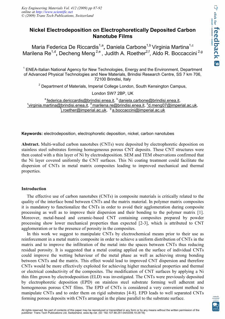
Figure 1 shows a top view of a CNT deposit obtained by EPD. The SEM image indicates that a fairly homogeneous deposit of CNTs oriented in the 2D plane parallel to the substrate surface has been achieved, in agreement with previous results [4]. CNT surfaces as shown in Figure 1 serve as substrate for deposition on Ni in electrodeposition experiments described next.
88 Electrophoretic Deposition
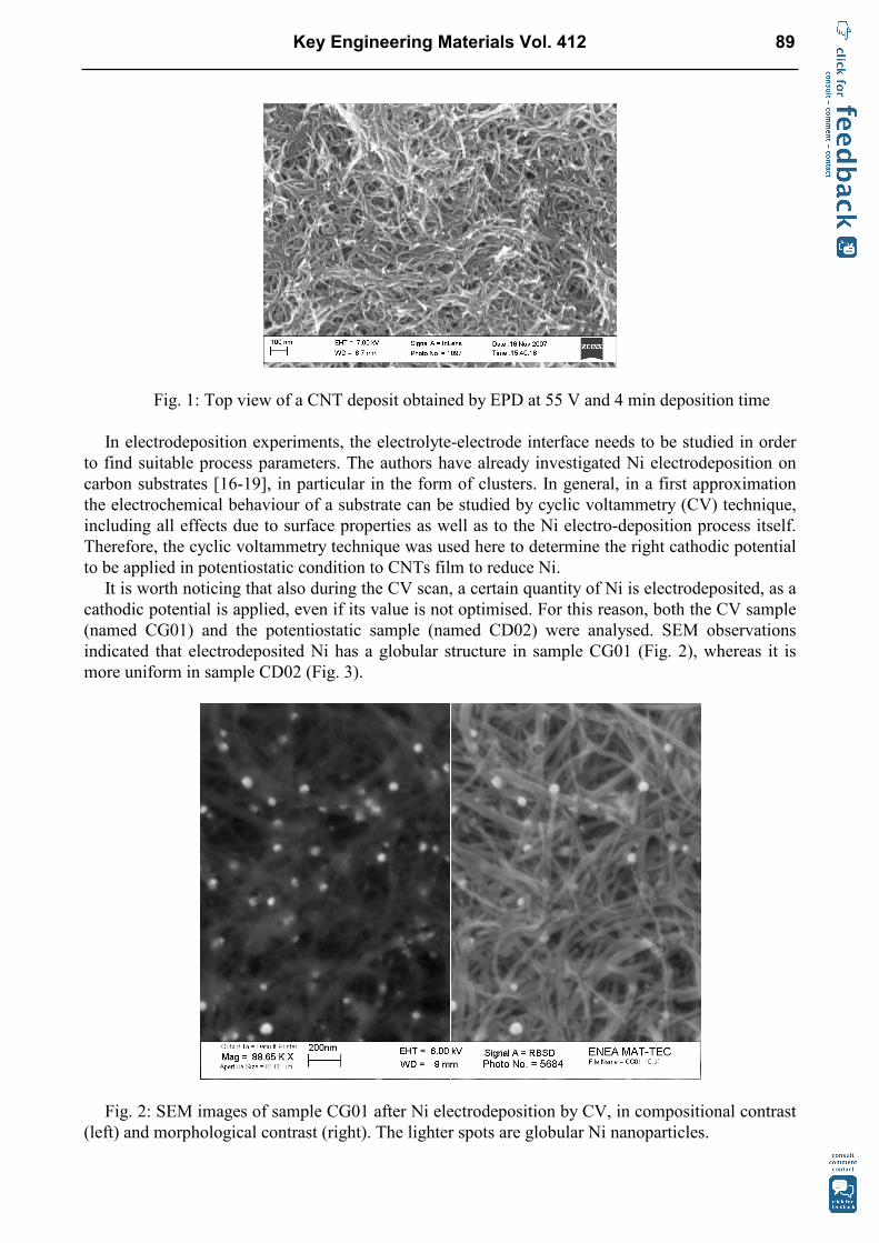
Fig. 1: Top view of a CNT deposit obtained by EPD at 55 V and 4 min deposition time
In electrodeposition experiments, the electrolyte-electrode interface needs to be studied in order to find suitable process parameters. The authors have already investigated Ni electrodeposition on carbon substrates [16-19], in particular in the form of clusters. In general, in a first approximation the electrochemical behaviour of a substrate can be studied by cyclic voltammetry (CV) technique, including all effects due to surface properties as well as to the Ni electro-deposition process itself. Therefore, the cyclic voltammetry technique was used here to determine the right cathodic potential to be applied in potentiostatic condition to CNTs film to reduce Ni.
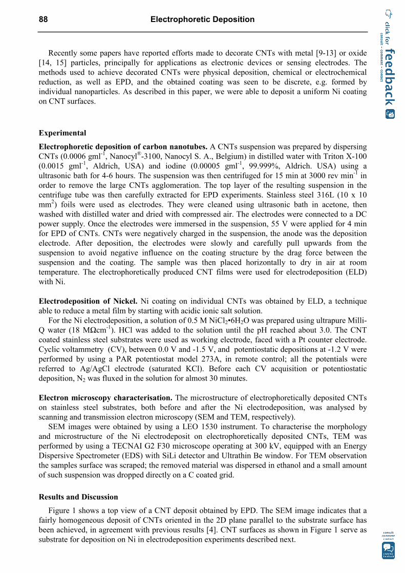
It is worth noticing that also during the CV scan, a certain quantity of Ni is electrodeposited, as a cathodic potential is applied, even if its value is not optimised. For this reason, both the CV sample (named CG01) and the potentiostatic sample (named CD02) were analysed. SEM observations indicated that electrodeposited Ni has a globular structure in sample CG01 (Fig. 2), whereas it is more uniform in sample CD02 (Fig. 3).
Fig. 2: SEM images of sample CG01 after Ni electrodeposition by CV, in compositional contrast
(left) and morphological contrast (right). The lighter spots are globular Ni nanoparticles.
Key Engineering Materials Vol. 412 89
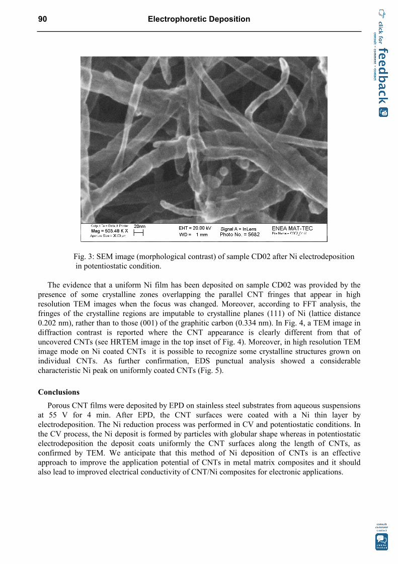
Fig. 3: SEM image (morphological contrast) of sample CD02 after Ni electrodeposition in potentiostatic condition.
The evidence that a uniform Ni film has been deposited on sample CD02 was provided by the
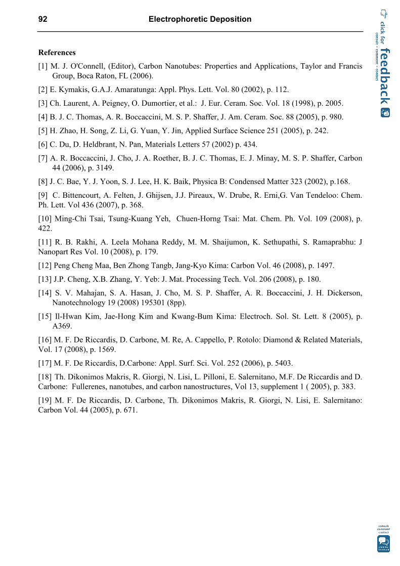
presence of some crystalline zones overlapping the parallel CNT fringes that appear in high resolution TEM images when the focus was changed. Moreover, according to FFT analysis, the fringes of the crystalline regions are imputable to crystalline planes (111) of Ni (lattice distance 0.202 nm), rather than to those (001) of the graphitic carbon (0.334 nm). In Fig. 4, a TEM image in diffraction contrast is reported where the CNT appearance is clearly different from that of uncovered CNTs (see HRTEM image in the top inset of Fig. 4). Moreover, in high resolution TEM image mode on Ni coated CNTs it is possible to recognize some crystalline structures grown on individual CNTs. As further confirmation, EDS punctual analysis showed a considerable characteristic Ni peak on uniformly coated CNTs (Fig. 5).
Conclusions
Porous CNT films were deposited by EPD on stainless steel substrates from aqueous suspensions at 55 V for 4 min. After EPD, the CNT surfaces were coated with a Ni thin layer by electrodeposition. The Ni reduction process was performed in CV and potentiostatic conditions. In the CV process, the Ni deposit is formed by particles with globular shape whereas in potentiostatic electrodeposition the deposit coats uniformly the CNT surfaces along the length of CNTs, as confirmed by TEM. We anticipate that this method of Ni deposition of CNTs is an effective approach to improve the application potential of CNTs in metal matrix composites and it should also lead to improved electrical conductivity of CNT/Ni composites for electronic applications.
90 Electrophoretic Deposition
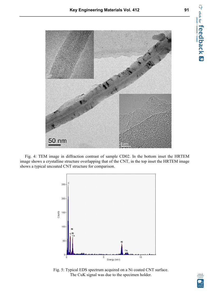
Fig. 4: TEM image in diffraction contrast of sample CD02. In the bottom inset the HRTEM
image shows a crystalline structure overlapping that of the CNT, in the top inset the HRTEM image shows a typical uncoated CNT structure for comparison.
Fig. 5: Typical EDS spectrum acquired on a Ni coated CNT surface. The CuK signal was due to the specimen holder.
Key Engineering Materials Vol. 412 91
References
[1] M. J. O'Connell, (Editor), Carbon Nanotubes: Properties and Applications, Taylor and Francis Group, Boca Raton, FL (2006).
[2] E. Kymakis, G.A.J. Amaratunga: Appl. Phys. Lett. Vol. 80 (2002), p. 112.
[3] Ch. Laurent, A. Peigney, O. Dumortier, et al.: J. Eur. Ceram. Soc. Vol. 18 (1998), p. 2005.
[4] B. J. C. Thomas, A. R. Boccaccini, M. S. P. Shaffer, J. Am. Ceram. Soc. 88 (2005), p. 980.
[5] H. Zhao, H. Song, Z. Li, G. Yuan, Y. Jin, Applied Surface Science 251 (2005), p. 242.
[6] C. Du, D. Heldbrant, N. Pan, Materials Letters 57 (2002) p. 434.
[7] A. R. Boccaccini, J. Cho, J. A. Roether, B. J. C. Thomas, E. J. Minay, M. S. P. Shaffer, Carbon 44 (2006), p. 3149.
[8] J. C. Bae, Y. J. Yoon, S. J. Lee, H. K. Baik, Physica B: Condensed Matter 323 (2002), p.168.
[9] C. Bittencourt, A. Felten, J. Ghijsen, J.J. Pireaux, W. Drube, R. Erni,G. Van Tendeloo: Chem. Ph. Lett. Vol 436 (2007), p. 368.
[10] Ming-Chi Tsai, Tsung-Kuang Yeh, Chuen-Horng Tsai: Mat. Chem. Ph. Vol. 109 (2008), p. 422.
[11] R. B. Rakhi, A. Leela Mohana Reddy, M. M. Shaijumon, K. Sethupathi, S. Ramaprabhu: J Nanopart Res Vol. 10 (2008), p. 179.
[12] Peng Cheng Maa, Ben Zhong Tangb, Jang-Kyo Kima: Carbon Vol. 46 (2008), p. 1497.
[13] J.P. Cheng, X.B. Zhang, Y. Yeb: J. Mat. Processing Tech. Vol. 206 (2008), p. 180.
[14] S. V. Mahajan, S. A. Hasan, J. Cho, M. S. P. Shaffer, A. R. Boccaccini, J. H. Dickerson, Nanotechnology 19 (2008) 195301 (8pp).
[15] Il-Hwan Kim, Jae-Hong Kim and Kwang-Bum Kima: Electroch. Sol. St. Lett. 8 (2005), p. A369.
[16] M. F. De Riccardis, D. Carbone, M. Re, A. Cappello, P. Rotolo: Diamond & Related Materials, Vol. 17 (2008), p. 1569.
[17] M. F. De Riccardis, D.Carbone: Appl. Surf. Sci. Vol. 252 (2006), p. 5403.
[18] Th. Dikonimos Makris, R. Giorgi, N. Lisi, L. Pilloni, E. Salernitano, M.F. De Riccardis and D. Carbone: Fullerenes, nanotubes, and carbon nanostructures, Vol 13, supplement 1 ( 2005), p. 383.
[19] M. F. De Riccardis, D. Carbone, Th. Dikonimos Makris, R. Giorgi, N. Lisi, E. Salernitano: Carbon Vol. 44 (2005), p. 671.
92 Electrophoretic Deposition

Electrophoretic Deposition doi:10.4028/3-908454-49-2Nickel Electrodeposition on Electrophoretically Deposited Carbon Nanotube Films doi:10.4028/3-908454-49-2.87
Key Engineering Materials Vol. 412 93


