Embed Size (px)
Citation preview
NIKOLA 3K/5K Efficient and Reliable Temperature Control for Plasma Etch
Product Manual
NIKOLA 3K/5K INSTALLATION OPERATION 52-13727-1
SOLID STATE COOLING SYSTEMS, 167 MYERS CORNERS ROAD, WAPPINGERS FALLS NY 12590 PAGE 2 TELEPHONE: (845) 296-1300 FAX: (845) 296-1303 WEB: WWW.SSCOOLING.COM VERSION M5
TABLE OF CONTENTS
Symbols Used on the Product .......................................................................... 5
Cautions ............................................................................................................. 5
1.0 General Information .................................................................................. 6
2.0 Specifications ............................................................................................... 7
2.1 NIKOLA 5K COOLING CAPACITY CURVES ............................................................................... 8
2.2 NIKOLA 3K COOLING CAPACITY CURVES ............................................................................. 10
2.3 PUMP PERFORMANCE CURVES ............................................................................................... 11
2.4 FRONT AND REAR VIEWS ...................................................................................................... 14
3.0 Installation ................................................................................................. 16
3.1 ELECTRICAL CONNECTIONS .................................................................................................. 16
3.2 TOOL INTERFACE CARDS ...................................................................................................... 17
3.3 PLUMBING CONNECTIONS ..................................................................................................... 17
3.4 WETTED MATERIAL COMPATIBILITY .................................................................................... 19
3.5 AIR CONSIDERATIONS ........................................................................................................... 19
4.0 Coolant Fill and Start-up ......................................................................... 19
4.1 COOLANT TYPE ..................................................................................................................... 19
4.2 FILL/START-UP ..................................................................................................................... 20
5.0 Operation ................................................................................................... 21
5.1 INTRODUCTION...................................................................................................................... 21
5.2 ALARMS/INTERLOCKS ........................................................................................................... 24
5.3 DRAINING THE COOLANT ...................................................................................................... 25
5.4 CLEANING THE NIKOLA 3K/5K ............................................................................................. 25
6.0 Tool Interface Options ............................................................................. 25
6.1 LAM INTERFACE CARD ........................................................................................................ 25
6.2 LAM DUAL CHANNEL OPTION............................................................................................... 27
6.3 ELECTRICAL HOOK-UP OF DUAL CHANNEL OPTION TO A LAM ETCHER ............................... 27
6.4 LAM ANALOG 2 INTERFACE CARD FOR LONWORKS® CONVERSION .................................... 29
6.5 APPLIED CHX INTERFACE CARD ....................................................................................... 33
6.6 AMAT ANALOG –A3 (P5000) INTERFACE CARD ................................................................. 35
6.7 AMAT ANALOG –A4 (J100) INTERFACE CARD .................................................................... 36
6.8 AMAT ANALOG WITH RESISTIVITY –A5 (J100) INTERFACE CARD ...................................... 38
6.9 TEL UNITY II (T1) OR UNITY M (T2) INTERFACE CARDS ..................................................... 40
6.10 TELIUS (T3) INTERFACE CARD ............................................................................................ 41
6.11 RS-232 COMMUNICATIONS OPTION .................................................................................... 44
7.0 Other Options ........................................................................................... 47
7.1 –1W DI WATER/ETHYLENE OR PROPYLENE GLYCOL COOLANT OPTION ........................... 47
7.2 –RF FRONT RTD OPTION ..................................................................................................... 47
NIKOLA 3K/5K INSTALLATION OPERATION 52-13727-1
SOLID STATE COOLING SYSTEMS, 167 MYERS CORNERS ROAD, WAPPINGERS FALLS NY 12590 PAGE 3 TELEPHONE: (845) 296-1300 FAX: (845) 296-1303 WEB: WWW.SSCOOLING.COM VERSION M5
8.0 Safety .......................................................................................................... 47
8.1 HAZARDS .............................................................................................................................. 47
8.2LIFTING THE NIKOLA 3K/5K .................................................................................................. 48
8.3 ELECTRICAL ENERGY ISOLATION .......................................................................................... 48
8.4 ELECTRICAL LOCK OUT/TAG OUT ......................................................................................... 48
8.5 ELECTRICAL DISCONNECT REQUIREMENTS ........................................................................... 48
8.6 LEAKS ................................................................................................................................... 49
8.7 PLANT COOLING WATER LEAKS ........................................................................................... 49
8.8 DISCONNECTING PLANT COOLING WATER ............................................................................ 50
8.9 COOLANT DISPOSAL.............................................................................................................. 50
8.10 SEISMIC PROTECTION .......................................................................................................... 51
8.11 MINIMUM PERSONAL PROTECTIVE ...................................................................................... 52
9.0 Maintenance .............................................................................................. 52
9.1 PRODUCT LIFE: ..................................................................................................................... 52
9.2 RECOMMENDED WEEKLY INSPECTION: ................................................................................. 52
9.3 RECOMMENDED ANNUAL INSPECTION: ................................................................................. 53
9.4 WIPE DOWN: ......................................................................................................................... 53
10.0 System Alarms and Troubleshooting ................................................... 53
11.0 Technical Support .................................................................................. 56
12.0 Safety Data Sheets .................................................................................. 57
12.1 3M™ FLUORINERT™ FC-3283 ELECTRONIC LIQUID SDS ................................................. 57
12.2 3M™ NOVEC™ 7100 ENGINEERED FLUID SDS ................................................................. 65
12.3 SOLVAY GALDEN® HT SDS ............................................................................................... 75
12.4 ETHYLENE GLYCOL ............................................................................................................ 84
Warranty ......................................................................................................... 91
NIKOLA 3K/5K INSTALLATION OPERATION 52-13727-1
SOLID STATE COOLING SYSTEMS, 167 MYERS CORNERS ROAD, WAPPINGERS FALLS NY 12590 PAGE 4 TELEPHONE: (845) 296-1300 FAX: (845) 296-1303 WEB: WWW.SSCOOLING.COM VERSION M5
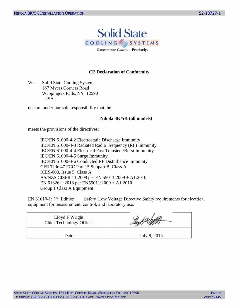
CE Declaration of Conformity
We: Solid State Cooling Systems
167 Myers Corners Road
Wappingers Falls, NY 12590
USA
declare under our sole responsibility that the
Nikola 3K/5K (all models)
meets the provisions of the directives:
IEC/EN 61000-4-2 Electrostatic Discharge Immunity
IEC/EN 61000-4-3 Radiated Radio Frequency (RF) Immunity
IEC/EN 61000-4-4 Electrical Fast Transient/Burst Immunity
IEC/EN 61000-4-5 Surge Immunity
IEC/EN 61000-4-6 Conducted RF Disturbance Immunity
CFR Title 47 FCC Part 15 Subpart B, Class A
ICES-003, Issue 5, Class A
AS/NZS CISPR 11:2009 per EN 55011:2009 + A1:2010
EN 61326-1:2013 per EN55011:2009 + A1:2010
Group 1 Class A Equipment
EN 61010-1: 3rd Edition Safety Low Voltage Directive Safety requirements for electrical
equipment for measurement, control, and laboratory use.
Lloyd F Wright
Chief Technology Officer
Date
July 8, 2015
NIKOLA 3K/5K INSTALLATION OPERATION 52-13727-1
SOLID STATE COOLING SYSTEMS, 167 MYERS CORNERS ROAD, WAPPINGERS FALLS NY 12590 PAGE 5 TELEPHONE: (845) 296-1300 FAX: (845) 296-1303 WEB: WWW.SSCOOLING.COM VERSION M5
SYMBOLS USED ON THE PRODUCT
SYMBOLS ON THE PRODUCT
Read the SDS for the coolant used and follow all safety precautions listed
in the SDS prior to removing coolant tubes or opening the fill cap as this
could result in contact with the coolant inside.
Caution! There is risk of electric shock. Disconnect the power cord prior
to servicing. This includes changing a fuse or opening the cover for any
reason.
SYMBOLS IN THE MANUAL
The red CAUTION equilateral triangle symbol appears throughout the
manual. Please follow the important instructions accompanying this
symbol to avoid significant damage to the chiller.
The red WARNING equilateral triangle symbol appears throughout the
manual accompanying certain maintenance and repair activities. Please
follow the important instructions accompanying this symbol to avoid
situations that could cause injury to the operator or other personnel.
The red DANGER equilateral triangle symbol appears throughout the
manual accompanying certain maintenance and repair activities. Please
follow the important instructions accompanying this symbol to avoid
injury to the operator. Only trained personnel should undertake any
activity marked by the red DANGER triangle.
CAUTIONS
Operation of the Nikola 3K/5K in any manner not recommended in this manual could compromise the
safety of operating personnel.
Never disassemble the Nikola 3K/5K unit as irreparable damage may occur.
Never store the Nikola 3K/5K Chiller over 50 °C.
Never operate the Nikola 3K/5K Chiller over 80 °C.
Never operate the coolant within 5°C above its freezing point.
Never ship the chiller with water inside the liquid cold plate as freezing temperatures may be encountered
which would damage the unit. For drainage information, see Section 5.3.
CAUTION
DANGER
WARNING
NIKOLA 3K/5K INSTALLATION OPERATION 52-13727-1
SOLID STATE COOLING SYSTEMS, 167 MYERS CORNERS ROAD, WAPPINGERS FALLS NY 12590 PAGE 6 TELEPHONE: (845) 296-1300 FAX: (845) 296-1303 WEB: WWW.SSCOOLING.COM VERSION M5
NIKOLA 3K/5K INSTALLATION OPERATION
1.0 GENERAL INFORMATION
The Nikola 3K/5K is a thermoelectric recirculating liquid chiller with full
Proportional Integral Derivative (PID) temperature control coolant for both
cooling and heating. Two cooling capacities are available: the 3K with 3,000
watts of cooling and the 3K/5K with 5,000 watts of cooling. Two pump are also
available: an energy efficient turbine pump capable of pressures up to 45 psig and
a high pressure turbine pump capable of pressures up to 110 psig.
The Nikola 3K/5K has several tool interface options, including Lam ADIO, Lam
Analog 2, AMAT CHX, AMAT analog, AMAT J100 analog, TEL Unity II, TEL
Unity M, TEL Telius, and RS-232. Contact SSCS for more details.
The system provides PID coolant pressure control allowing the customer to
optimize pump performance for their application. The Nikola 3K/5K is
environmentally friendly eliminating Freon or replacement refrigerants and
consuming up to 80% less power than comparable Freon-based chillers. It
reduces operating costs, saving on energy, water and air conditioning needs.
All internal wetted materials and the pump are compatible with DI water/glycol
coolants as well as fluorinated heat transfer oils such as Solvay’s Galden or 3M’s
Fluorinert and HFE products.
The system has been designed for long life and ease of use. The only moving
parts are one pump and two fans.
PRODUCT MANUAL
NIKOLA 3K/5K INSTALLATION OPERATION 52-13727-1
SOLID STATE COOLING SYSTEMS, 167 MYERS CORNERS ROAD, WAPPINGERS FALLS NY 12590 PAGE 7 TELEPHONE: (845) 296-1300 FAX: (845) 296-1303 WEB: WWW.SSCOOLING.COM VERSION M5
2.0 SPECIFICATIONS
Coolant Operating Temperature Range: -10°C to 80°C, (70 - 80°C operation requires Galden/Fluorinert
and -2 High Pressure Turbine Pump)
Coolant Type: Fluorinert FC fluids, NOVEC 7000 series fluids (HFE),
Galden HT fluids, ethylene/propylene glycol/water
or DI Water (requires DI water pump -2WA)
Set Point Range: -20°C to 80 °C
Control Accuracy: + 0.05 °C at constant load
Coolant Pump Type: Magnetically Coupled Peripheral Turbine
Coolant Flow Rate: Up to 10 gpm (see figure 1B)
Coolant Fluid Connections: 3/4” Swagelok, (316 stainless steel)
Drain Connection: 1/4” Swagelok (316 stainless steel)
Tank Volume: 2.6 gallons (10 liters)
Facility Cooling Water Required: 16-23 lpm (4-6 gpm), 7°C - 25C, filtered, treated
recirculating facility cooling water, pH 6.5 – 8.2
Facility Cooling Water Connections: 3/4” Swagelok (316 Stainless Steel)
N2/CDA Required: 500sccm -30°C dew-point or lower CDA or N2, 30-60 psig
(2-4 bar)
Power Required: 200-240V +/-5%, ~ 3 phase, 20A, 50/60 Hz
Circuit Breaker: 25 AMP 240VAC 3 Pole/30mA Ground Fault Leakage
Current Interrupt
Remote EMO: External dry contact
Dimensions: Height: 35.5”, 903mm (with casters)
Width: 22.5”, 572mm
Depth: 31.0”, 786mm
Weight: 300 lbs. (Dry)
External Tool Interface Options: LAM Research ADIO
Applied CHX, Applied analog and Applied J100 analog
TEL Unity II, TEL Unity M, TEL Telius
Safety Certifications: EN 61010-1: 3rd Edition, Semi S2
NIKOLA 3K/5K INSTALLATION OPERATION 52-13727-1
SOLID STATE COOLING SYSTEMS, 167 MYERS CORNERS ROAD, WAPPINGERS FALLS NY 12590 PAGE 8 TELEPHONE: (845) 296-1300 FAX: (845) 296-1303 WEB: WWW.SSCOOLING.COM VERSION M5
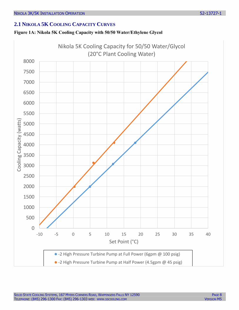
2.1 NIKOLA 5K COOLING CAPACITY CURVES
Figure 1A: Nikola 5K Cooling Capacity with 50/50 Water/Ethylene Glycol
0
500
1000
1500
2000
2500
3000
3500
4000
4500
5000
5500
6000
6500
7000
7500
8000
-10 -5 0 5 10 15 20 25 30 35 40
Co
olin
g C
apac
ity
(wat
ts)
Set Point (°C)
Nikola 5K Cooling Capacity for 50/50 Water/Glycol(20°C Plant Cooling Water)
-2 High Pressure Turbine Pump at Full Power (6gpm @ 100 psig)
-2 High Pressure Turbine Pump at Half Power (4.5gpm @ 45 psig)
NIKOLA 3K/5K INSTALLATION OPERATION 52-13727-1
SOLID STATE COOLING SYSTEMS, 167 MYERS CORNERS ROAD, WAPPINGERS FALLS NY 12590 PAGE 9 TELEPHONE: (845) 296-1300 FAX: (845) 296-1303 WEB: WWW.SSCOOLING.COM VERSION M5
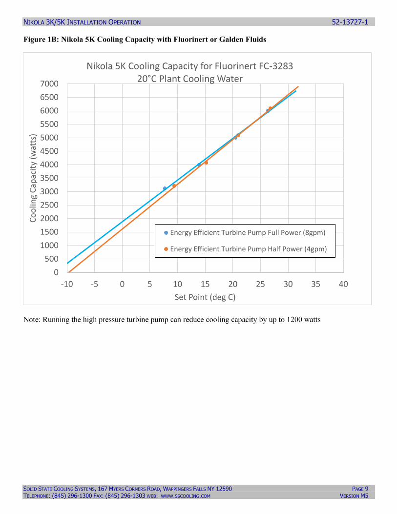
Figure 1B: Nikola 5K Cooling Capacity with Fluorinert or Galden Fluids
Note: Running the high pressure turbine pump can reduce cooling capacity by up to 1200 watts
0
500
1000
1500
2000
2500
3000
3500
4000
4500
5000
5500
6000
6500
7000
-10 -5 0 5 10 15 20 25 30 35 40
Co
olin
g C
apac
ity
(wat
ts)
Set Point (deg C)
Nikola 5K Cooling Capacity for Fluorinert FC-3283 20°C Plant Cooling Water
Energy Efficient Turbine Pump Full Power (8gpm)
Energy Efficient Turbine Pump Half Power (4gpm)
NIKOLA 3K/5K INSTALLATION OPERATION 52-13727-1
SOLID STATE COOLING SYSTEMS, 167 MYERS CORNERS ROAD, WAPPINGERS FALLS NY 12590 PAGE 10 TELEPHONE: (845) 296-1300 FAX: (845) 296-1303 WEB: WWW.SSCOOLING.COM VERSION M5
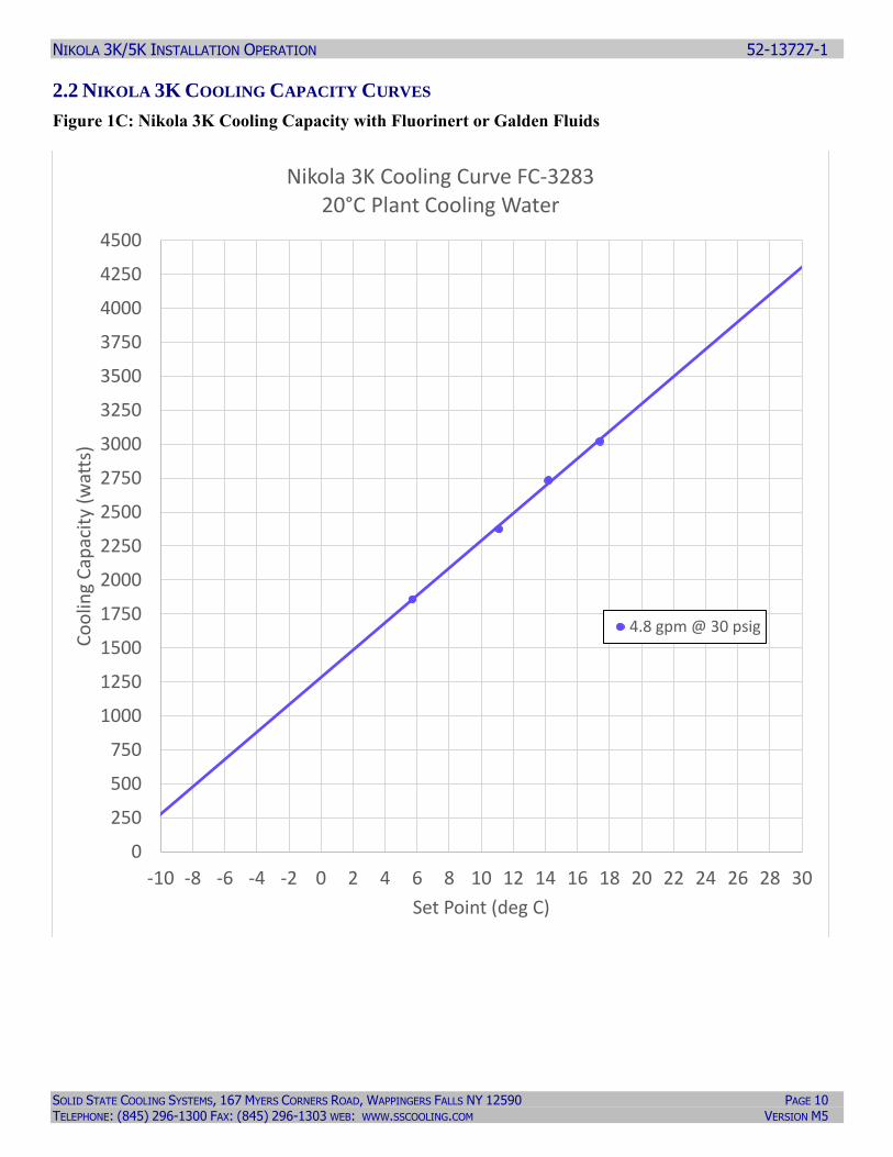
2.2 NIKOLA 3K COOLING CAPACITY CURVES
Figure 1C: Nikola 3K Cooling Capacity with Fluorinert or Galden Fluids
0
250
500
750
1000
1250
1500
1750
2000
2250
2500
2750
3000
3250
3500
3750
4000
4250
4500
-10 -8 -6 -4 -2 0 2 4 6 8 10 12 14 16 18 20 22 24 26 28 30
Co
olin
g C
apac
ity
(wat
ts)
Set Point (deg C)
Nikola 3K Cooling Curve FC-328320°C Plant Cooling Water
4.8 gpm @ 30 psig
NIKOLA 3K/5K INSTALLATION OPERATION 52-13727-1
SOLID STATE COOLING SYSTEMS, 167 MYERS CORNERS ROAD, WAPPINGERS FALLS NY 12590 PAGE 11 TELEPHONE: (845) 296-1300 FAX: (845) 296-1303 WEB: WWW.SSCOOLING.COM VERSION M5
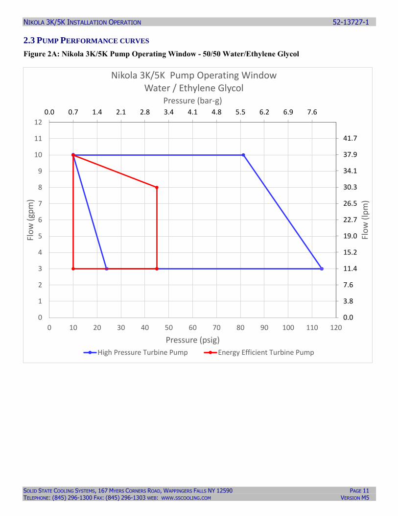
2.3 PUMP PERFORMANCE CURVES
Figure 2A: Nikola 3K/5K Pump Operating Window - 50/50 Water/Ethylene Glycol
0.0 0.7 1.4 2.1 2.8 3.4 4.1 4.8 5.5 6.2 6.9 7.6
0.0
3.8
7.6
11.4
15.2
19.0
22.7
26.5
30.3
34.1
37.9
41.7
0
1
2
3
4
5
6
7
8
9
10
11
12
0 10 20 30 40 50 60 70 80 90 100 110 120
Pressure (bar-g)
Flo
w (
lpm
)
Flo
w (
gpm
)
Pressure (psig)
Nikola 3K/5K Pump Operating Window Water / Ethylene Glycol
High Pressure Turbine Pump Energy Efficient Turbine Pump
NIKOLA 3K/5K INSTALLATION OPERATION 52-13727-1
SOLID STATE COOLING SYSTEMS, 167 MYERS CORNERS ROAD, WAPPINGERS FALLS NY 12590 PAGE 12 TELEPHONE: (845) 296-1300 FAX: (845) 296-1303 WEB: WWW.SSCOOLING.COM VERSION M5
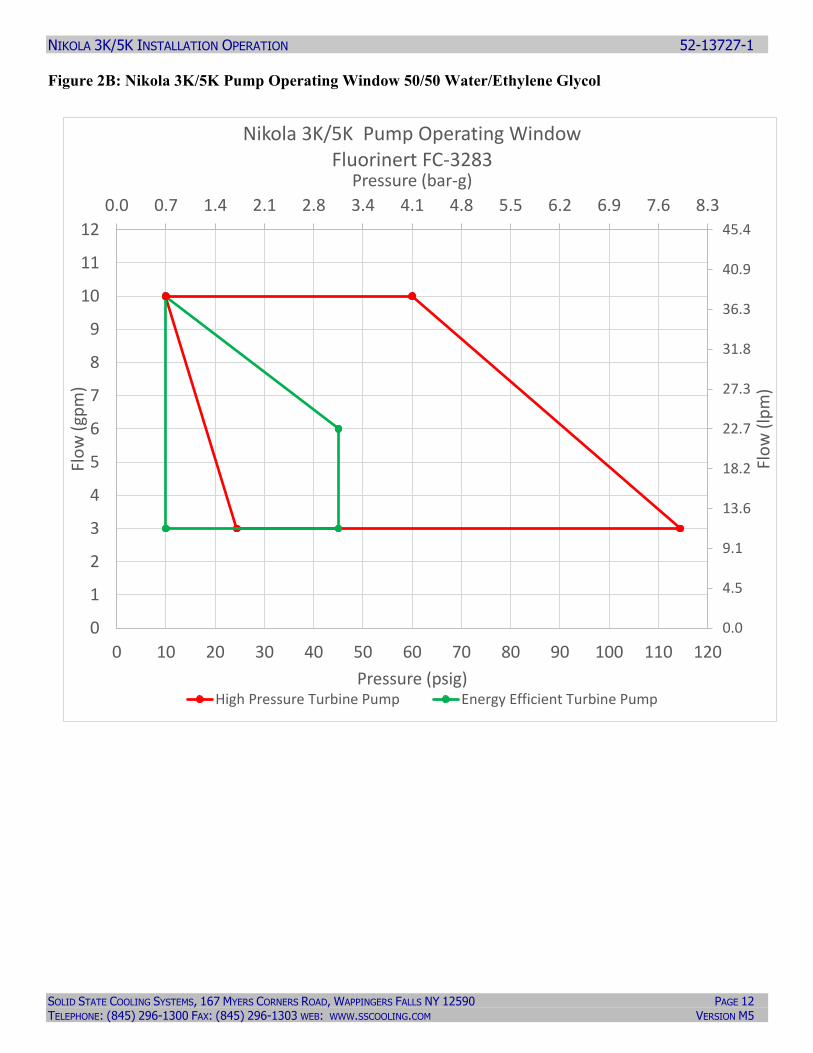
Figure 2B: Nikola 3K/5K Pump Operating Window 50/50 Water/Ethylene Glycol
0.0 0.7 1.4 2.1 2.8 3.4 4.1 4.8 5.5 6.2 6.9 7.6 8.3
0.0
4.5
9.1
13.6
18.2
22.7
27.3
31.8
36.3
40.9
45.4
0
1
2
3
4
5
6
7
8
9
10
11
12
0 10 20 30 40 50 60 70 80 90 100 110 120
Pressure (bar-g)
Flo
w (
lpm
)
Flo
w (
gpm
)
Pressure (psig)
Nikola 3K/5K Pump Operating Window Fluorinert FC-3283
High Pressure Turbine Pump Energy Efficient Turbine Pump
NIKOLA 3K/5K INSTALLATION OPERATION 52-13727-1
SOLID STATE COOLING SYSTEMS, 167 MYERS CORNERS ROAD, WAPPINGERS FALLS NY 12590 PAGE 13 TELEPHONE: (845) 296-1300 FAX: (845) 296-1303 WEB: WWW.SSCOOLING.COM VERSION M5
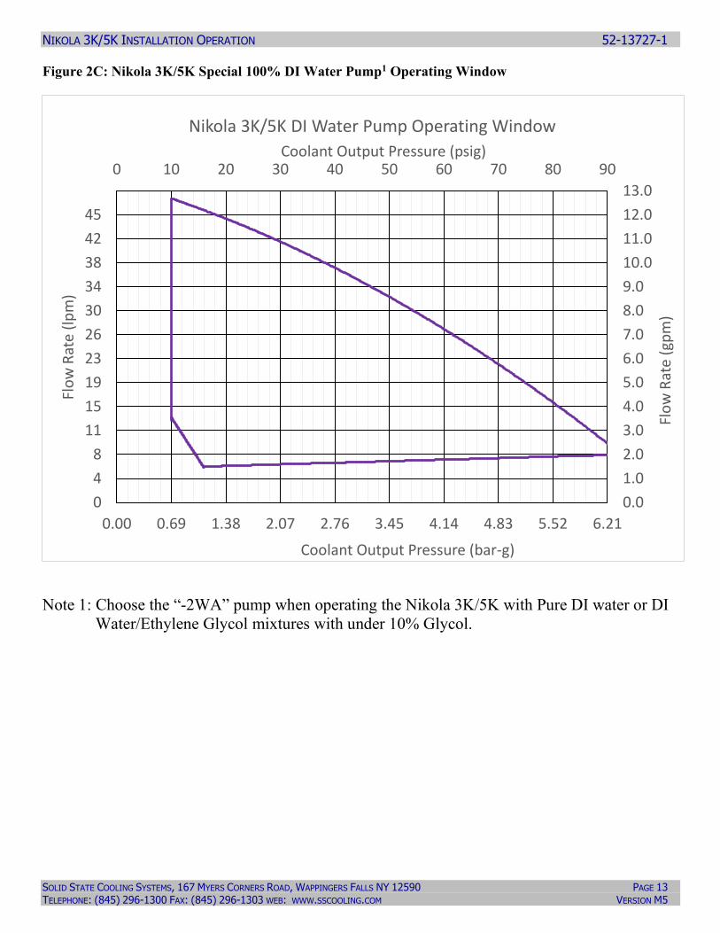
Figure 2C: Nikola 3K/5K Special 100% DI Water Pump1 Operating Window
Note 1: Choose the “-2WA” pump when operating the Nikola 3K/5K with Pure DI water or DI
Water/Ethylene Glycol mixtures with under 10% Glycol.
0.00 0.69 1.38 2.07 2.76 3.45 4.14 4.83 5.52 6.21
0
4
8
11
15
19
23
26
30
34
38
42
45
0 10 20 30 40 50 60 70 80 90
0.0
1.0
2.0
3.0
4.0
5.0
6.0
7.0
8.0
9.0
10.0
11.0
12.0
13.0
Coolant Output Pressure (bar-g)
Flo
w R
ate
(lp
m)
Coolant Output Pressure (psig)
Flo
w R
ate
(gp
m)
Nikola 3K/5K DI Water Pump Operating Window
NIKOLA 3K/5K INSTALLATION OPERATION 52-13727-1
SOLID STATE COOLING SYSTEMS, 167 MYERS CORNERS ROAD, WAPPINGERS FALLS NY 12590 PAGE 14 TELEPHONE: (845) 296-1300 FAX: (845) 296-1303 WEB: WWW.SSCOOLING.COM VERSION M5
2.4 FRONT AND REAR VIEWS
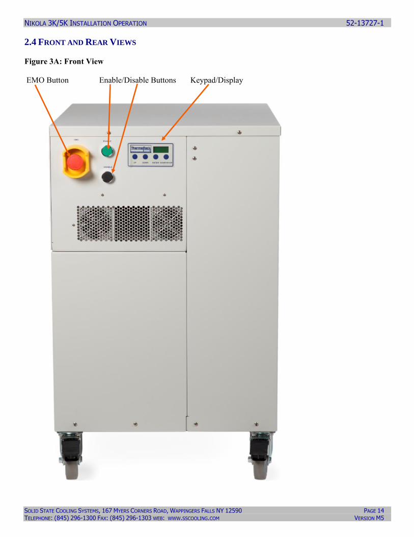
Figure 3A: Front View
EMO Button Enable/Disable Buttons Keypad/Display
NIKOLA 3K/5K INSTALLATION OPERATION 52-13727-1
SOLID STATE COOLING SYSTEMS, 167 MYERS CORNERS ROAD, WAPPINGERS FALLS NY 12590 PAGE 15 TELEPHONE: (845) 296-1300 FAX: (845) 296-1303 WEB: WWW.SSCOOLING.COM VERSION M5
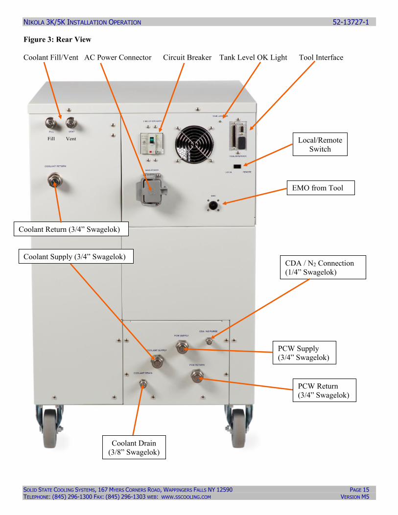
Figure 3: Rear View
Coolant Fill/Vent AC Power Connector Circuit Breaker Tank Level OK Light Tool Interface
Fill Vent
EMO from Tool
Local/Remote
Switch
CDA / N2 Connection
(1/4” Swagelok)
Coolant Return (3/4” Swagelok)
PCW Supply
(3/4” Swagelok)
Coolant Supply (3/4” Swagelok)
PCW Return
(3/4” Swagelok)
Coolant Drain
(3/8” Swagelok)
NIKOLA 3K/5K INSTALLATION OPERATION 52-13727-1
SOLID STATE COOLING SYSTEMS, 167 MYERS CORNERS ROAD, WAPPINGERS FALLS NY 12590 PAGE 16 TELEPHONE: (845) 296-1300 FAX: (845) 296-1303 WEB: WWW.SSCOOLING.COM VERSION M5
3.0 INSTALLATION
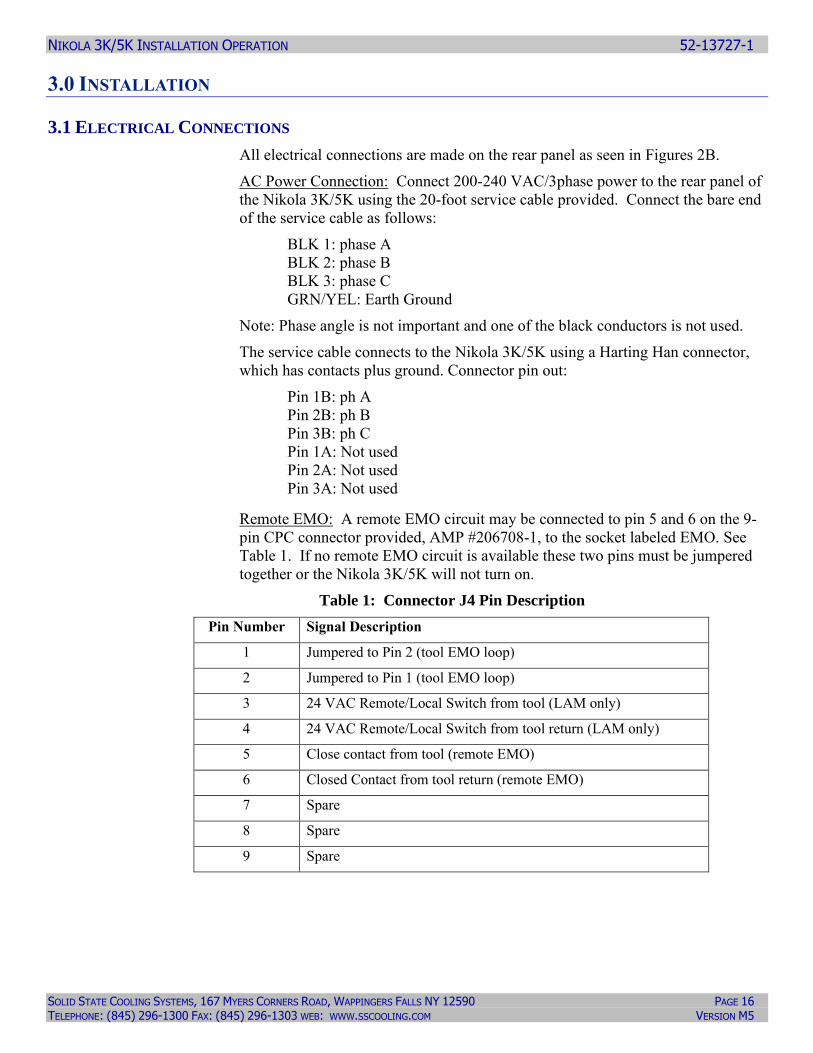
3.1 ELECTRICAL CONNECTIONS
All electrical connections are made on the rear panel as seen in Figures 2B.
AC Power Connection: Connect 200-240 VAC/3phase power to the rear panel of
the Nikola 3K/5K using the 20-foot service cable provided. Connect the bare end
of the service cable as follows:
BLK 1: phase A
BLK 2: phase B
BLK 3: phase C
GRN/YEL: Earth Ground
Note: Phase angle is not important and one of the black conductors is not used.
The service cable connects to the Nikola 3K/5K using a Harting Han connector,
which has contacts plus ground. Connector pin out:
Pin 1B: ph A
Pin 2B: ph B
Pin 3B: ph C
Pin 1A: Not used
Pin 2A: Not used
Pin 3A: Not used
Remote EMO: A remote EMO circuit may be connected to pin 5 and 6 on the 9-
pin CPC connector provided, AMP #206708-1, to the socket labeled EMO. See
Table 1. If no remote EMO circuit is available these two pins must be jumpered
together or the Nikola 3K/5K will not turn on.
Table 1: Connector J4 Pin Description
Pin Number Signal Description
1 Jumpered to Pin 2 (tool EMO loop)
2 Jumpered to Pin 1 (tool EMO loop)
3 24 VAC Remote/Local Switch from tool (LAM only)
4 24 VAC Remote/Local Switch from tool return (LAM only)
5 Close contact from tool (remote EMO)
6 Closed Contact from tool return (remote EMO)
7 Spare
8 Spare
9 Spare
NIKOLA 3K/5K INSTALLATION OPERATION 52-13727-1
SOLID STATE COOLING SYSTEMS, 167 MYERS CORNERS ROAD, WAPPINGERS FALLS NY 12590 PAGE 17 TELEPHONE: (845) 296-1300 FAX: (845) 296-1303 WEB: WWW.SSCOOLING.COM VERSION M5
Local/Remote Switching: The chiller set point temperature can be entered using
keys on the front user interface or remote using the tool interface card. The
method of switching from using a locally entered set point to a remote one
depends on the type of tool interface card used (this feature is not available in RS-
232 units). See section 7.0 for details.
Fuses: The Nikola 3K/5K 24V ~ transformer used in the EMO/input circuit is
protected by two (2) 1 Amp fast-acting fuses, located inside the electrical module
on the main DIN rail; labeled F1a & F1b. The fuse type is Littelfuse part number
312001.HXP.
The Allen-Bradley VFD motor controller is protected using three (3) 25 AMP
fuses across the AC lines located inside the electrical module on the aux DIN rail
and labeled F3. The fuse type is Ferraz Shawmut p/n HSJ10.
The 24VDC power supply is protected using two (2) 2 Amp fast-acting fuses,
located inside the electrical module on the aux DIN rail labeled F2a & F2b. The
fuse type is Littelfuse part number 312002.HXP.
3.2 TOOL INTERFACE CARDS
The Nikola 3K/5K can communicate with several different types of
semiconductor equipment using the tool interface card. The electrical installation
required, and the method of remote operation depends on the tool interface
purchased with the Nikola 3K/5K. Tool interfaces may be changed should the
Nikola 3K/5K be moved from one type of tool to another. Refer to Section 6 for
information regarding tool interface options.
3.3 PLUMBING CONNECTIONS
The plumbing connections for the tank fill and vent ports are on the front panel of
the system. All other plumbing connections are on the rear panel of the system.
See Figure 2B. Several open end wrench sizes are required:
▪ 1 1/8”, 1 3/16”, 9/16”, 5/8”, 19mm
Coolant Connections: The coolant supply and return connections are made using
¾” stainless steel Swagelok fittings. They require a 1 1/8” open-ended wrench
with a 1 3/16” open ended backing wrench. The coolant drain connection is made
using a ¼” stainless steel Swagelok fitting. It requires a 9/16” open-ended
wrench with a 5/8” backing wrench. These connections are located on the bottom
right of the rear panel. The use of a drain valve is recommended. Swagelok part
number SS-4P4T with port connector part number SS-401-PC.
NIKOLA 3K/5K INSTALLATION OPERATION 52-13727-1
SOLID STATE COOLING SYSTEMS, 167 MYERS CORNERS ROAD, WAPPINGERS FALLS NY 12590 PAGE 18 TELEPHONE: (845) 296-1300 FAX: (845) 296-1303 WEB: WWW.SSCOOLING.COM VERSION M5
Plant Cooling Water (PCW): Plant cooling water must be < 7-25 °C filtered and
treated plant cooling water with a pH of 6.5-8.2 treated against calcium deposits.
Plant cooling water connections are made using 3/4” stainless steel Swagelok
fittings located on the right bottom of the rear panel. They require a 1 1/8”” open-
ended wrench with a 1 3/16” back wrench. The PCW supply (in) connection is
to the left of the return (out) connection. The required cooling flow rate is 4 – 6
gpm.
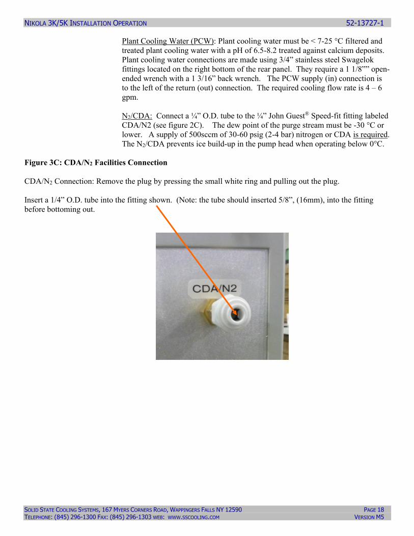
N2/CDA: Connect a ¼” O.D. tube to the ¼” John Guest® Speed-fit fitting labeled
CDA/N2 (see figure 2C). The dew point of the purge stream must be -30 °C or
lower. A supply of 500sccm of 30-60 psig (2-4 bar) nitrogen or CDA is required.
The N2/CDA prevents ice build-up in the pump head when operating below 0°C.
Figure 3C: CDA/N2 Facilities Connection
CDA/N2 Connection: Remove the plug by pressing the small white ring and pulling out the plug.
Insert a 1/4” O.D. tube into the fitting shown. (Note: the tube should inserted 5/8”, (16mm), into the fitting
before bottoming out.
NIKOLA 3K/5K INSTALLATION OPERATION 52-13727-1
SOLID STATE COOLING SYSTEMS, 167 MYERS CORNERS ROAD, WAPPINGERS FALLS NY 12590 PAGE 19 TELEPHONE: (845) 296-1300 FAX: (845) 296-1303 WEB: WWW.SSCOOLING.COM VERSION M5
3.4 WETTED MATERIAL COMPATIBILITY
Plant Cooling Water (PCW): The Nikola 3K/5K PCW lines are made from
stainless steel and aluminum coated with a Teflon impregnated anodization
corrosion resistant coating. The chiller is compatible with filtered plant cooling
water with a pH of 6.5-8.2 treated against calcium deposits.
Coolant: The Nikola 3K/5K process lines are made from stainless steel and
aluminum. The chiller is compatible with any Fluorinated heat transfer oil made
by 3M (Fluorinert or Novec Fluids) or San Gobain (Galden). In addition, the
chiller is compatible with de-ionized water or any combination of de-ionized
water and propylene or ethylene glycol with a resistivity between 0.1 meg-ohm
cm and 10 meg-ohm cm.
3.5 AIR CONSIDERATIONS
The Nikola 3K/5K requires one-foot clearance for proper air circulation to cool its
electronics and pump. Refer to Figure 2B.
4.0 COOLANT FILL AND START-UP
4.1 COOLANT TYPE
The Nikola 3K/5K is designed to run with a fluorinated heat transfer fluid (or DI
Water / Glycol mix) as the coolant. Selection is important to the proper operation
of the Nikola 3K/5K and is dependent on the fluid set point desired. Note that the
Nikola 3K/5K systems are configured for a specific fluid type, which is reflected
in the part number of the system. A "W" in the part number indicated the system
was configured for DI Water / Glycol. Operation with the wrong coolant can lead
to cavitation in the pump and premature failure. Table 2 below lists the
recommended coolant types:
Table 2: Recommended Cooling Types
Set Point
Temperature
3M Fluorinert®
Coolant Type
3M Novec®
Coolant Type
Galden®
Coolant Type
DI Water/Glycol
% Ethylene Glycol
-10 to 20 °C FC – 72 HFE-7100,
7200 or 7500
None Tested 50%
10 to 50°C FC-77 HFE – 7500 HT-110 0 - 50%
20 to 80°C FC-3283 HFE-7500 HT-200 Not Recommended
above 50°C due to
low resistivity
NIKOLA 3K/5K INSTALLATION OPERATION 52-13727-1
SOLID STATE COOLING SYSTEMS, 167 MYERS CORNERS ROAD, WAPPINGERS FALLS NY 12590 PAGE 20 TELEPHONE: (845) 296-1300 FAX: (845) 296-1303 WEB: WWW.SSCOOLING.COM VERSION M5
4.2 FILL/START-UP
Once installation has been completed as per Section 4, follow the instructions
below for filling the tank with coolant and starting the Nikola 3K/5K.
The Nikola 3K/5K has a 2.6 gallon (10 liter) tank.
1) Turn on the facility water flow (5-6 gpm recommended.)
2) Using 19mm (3/4”) open-ended wrench, remove the Swagelok cap on the
Tank Vent Fill ports.
3) Connect the funnel provided with the Nikola 3K/5K system to the Fill port,
hand tighten only.
4) Turn on power to the Nikola 3K/5K pressing the green ENABLE button
located on the front panel of the system. The front display will show “Tank
Level Empty”.
5) Fill the tank with 2½ - 3 gallons of coolant until the green Tank Level Ok
light comes on.
6) Turn off AC power for 30 seconds, then turn back on to clear the tank level
empty. Important note: If you do not wait 30 seconds prior to turning the
power back on, you may receive a VFD Fault alarm.
7) Check to see that all exterior valves attached to the coolant lines are open.
8) Press the ‘START’ button to begin operation.
9) If the Tank Level Ok light goes out, add more coolant through the funnel until
the Tank Level Ok light comes back on.
10) Remove the coolant funnel and replace the Swagelok cap on the fill port.
Tighten the cap ¼ turn past hand tight. Allow the chiller to operate at set-
point for two hours, then replace the Swagelok cap on the vent port. Tighten
the cap ¼ turn past hand tight.
Note: At the initial startup or when changing the set-point the Nikola 3K/5K tank
should be vented (by removing the cap) for a period of two hours to equalize the
pressure caused by dissolved gases. Tighten the caps ¼ turn past hand tight once
equilibrium has been reached.
NIKOLA 3K/5K INSTALLATION OPERATION 52-13727-1
SOLID STATE COOLING SYSTEMS, 167 MYERS CORNERS ROAD, WAPPINGERS FALLS NY 12590 PAGE 21 TELEPHONE: (845) 296-1300 FAX: (845) 296-1303 WEB: WWW.SSCOOLING.COM VERSION M5
5.0 OPERATION
5.1 INTRODUCTION
The Nikola 3K/5K is operated using a series of screens on the controller display
located on the front panel of the system as shown in Figure 2A. The screens are
manipulated by using the blue buttons beneath the display screen. Each button
function corresponds to the symbol displayed above it. Figure 4 below shows the
system status screen on the display with the blue buttons underneath that
manipulate the screen.
The Nikola 3K/5K controller has two menus: the Status Menu and the Parameter
Input Menu. The Status Menu shows the chiller operating status, (standby, heating,
or cooling), current temperature of coolant leaving the chiller, the coolant supply
(outlet) pressure, an indication of if the chiller operation is from the local keypad
or remote from the tool, and any alarms or warnings present. The Parameter Input
Menu allows input of the coolant pressure units, the pressure set-point, the coolant
type, the temperature units, the temperature alarm range, the temperature offset
(used to match the chiller temperature reading to the tool’s reading), the resistivity
warning levels (high and low) and the option of turning the display backlight on or
off or entering a new password.
NIKOLA 3K/5K INSTALLATION OPERATION 52-13727-1
SOLID STATE COOLING SYSTEMS, 167 MYERS CORNERS ROAD, WAPPINGERS FALLS NY 12590 PAGE 22 TELEPHONE: (845) 296-1300 FAX: (845) 296-1303 WEB: WWW.SSCOOLING.COM VERSION M5
PRESS AND HOLD ENTER KEY 3 SECONDS
PRESS AND HOLD
ENTER KEY 3 SECONDS
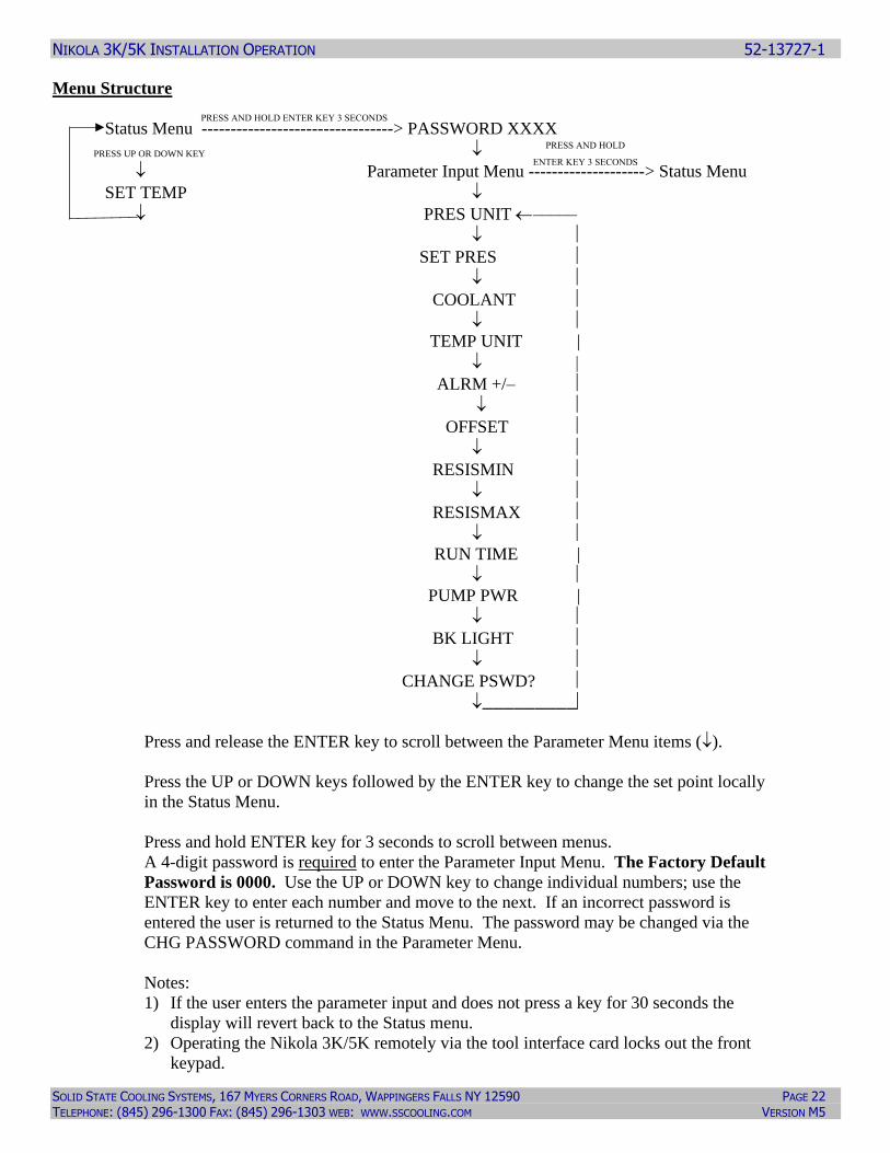
Menu Structure
Status Menu ---------------------------------> PASSWORD XXXX
PRESS UP OR DOWN KEY
Parameter Input Menu --------------------> Status Menu
SET TEMP
PRES UNIT –––––
SET PRES
COOLANT
TEMP UNIT |
ALRM +/–
OFFSET
RESISMIN
RESISMAX RUN TIME |
PUMP PWR |
BK LIGHT
CHANGE PSWD?
_________
Press and release the ENTER key to scroll between the Parameter Menu items ().
Press the UP or DOWN keys followed by the ENTER key to change the set point locally
in the Status Menu.
Press and hold ENTER key for 3 seconds to scroll between menus.
A 4-digit password is required to enter the Parameter Input Menu. The Factory Default
Password is 0000. Use the UP or DOWN key to change individual numbers; use the
ENTER key to enter each number and move to the next. If an incorrect password is
entered the user is returned to the Status Menu. The password may be changed via the
CHG PASSWORD command in the Parameter Menu.
Notes:
1) If the user enters the parameter input and does not press a key for 30 seconds the
display will revert back to the Status menu.
2) Operating the Nikola 3K/5K remotely via the tool interface card locks out the front
keypad.
NIKOLA 3K/5K INSTALLATION OPERATION 52-13727-1
SOLID STATE COOLING SYSTEMS, 167 MYERS CORNERS ROAD, WAPPINGERS FALLS NY 12590 PAGE 23 TELEPHONE: (845) 296-1300 FAX: (845) 296-1303 WEB: WWW.SSCOOLING.COM VERSION M5
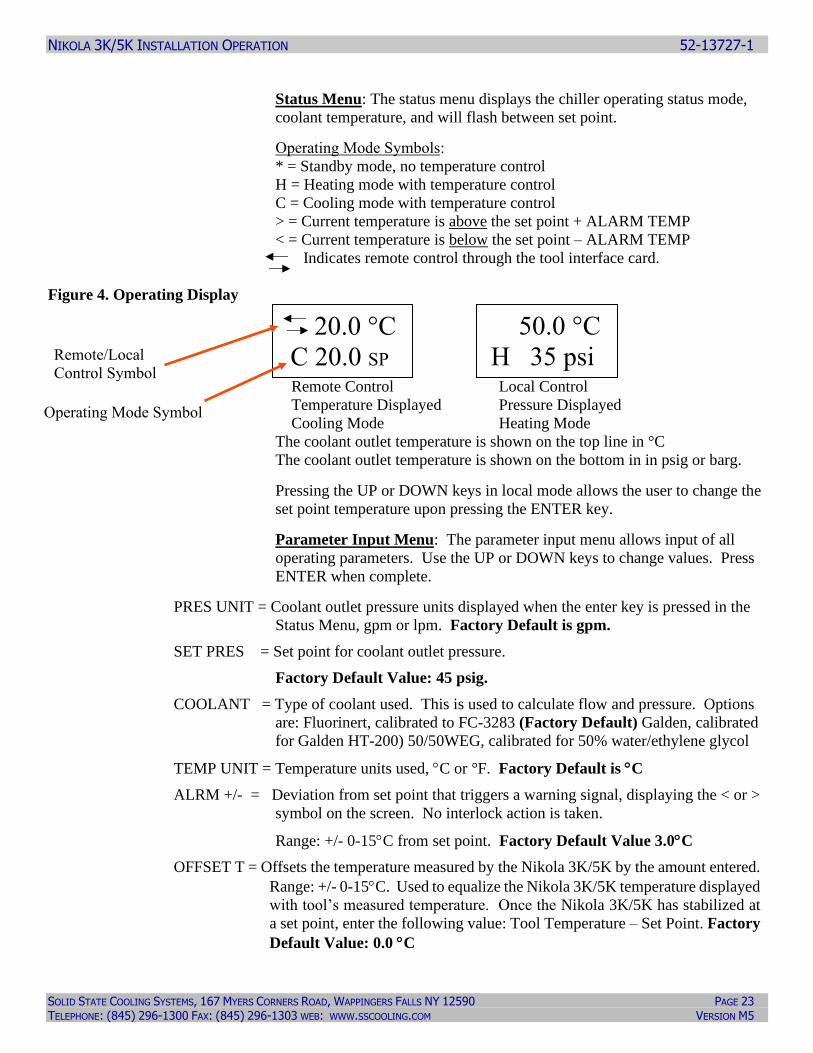
Status Menu: The status menu displays the chiller operating status mode,
coolant temperature, and will flash between set point.
Operating Mode Symbols:
* = Standby mode, no temperature control
H = Heating mode with temperature control
C = Cooling mode with temperature control
> = Current temperature is above the set point + ALARM TEMP
< = Current temperature is below the set point – ALARM TEMP
Indicates remote control through the tool interface card.
Figure 4. Operating Display
Remote Control Local Control
Temperature Displayed Pressure Displayed
Cooling Mode Heating Mode
The coolant outlet temperature is shown on the top line in °C
The coolant outlet temperature is shown on the bottom in in psig or barg.
Pressing the UP or DOWN keys in local mode allows the user to change the
set point temperature upon pressing the ENTER key.
Parameter Input Menu: The parameter input menu allows input of all
operating parameters. Use the UP or DOWN keys to change values. Press
ENTER when complete.
PRES UNIT = Coolant outlet pressure units displayed when the enter key is pressed in the
Status Menu, gpm or lpm. Factory Default is gpm.
SET PRES = Set point for coolant outlet pressure.
Factory Default Value: 45 psig.
COOLANT = Type of coolant used. This is used to calculate flow and pressure. Options
are: Fluorinert, calibrated to FC-3283 (Factory Default) Galden, calibrated
for Galden HT-200) 50/50WEG, calibrated for 50% water/ethylene glycol
TEMP UNIT = Temperature units used, C or °F. Factory Default is C
ALRM +/- = Deviation from set point that triggers a warning signal, displaying the < or >
symbol on the screen. No interlock action is taken.
Range: +/- 0-15C from set point. Factory Default Value 3.0C
OFFSET T = Offsets the temperature measured by the Nikola 3K/5K by the amount entered.
Range: +/- 0-15C. Used to equalize the Nikola 3K/5K temperature displayed
with tool’s measured temperature. Once the Nikola 3K/5K has stabilized at
a set point, enter the following value: Tool Temperature – Set Point. Factory
Default Value: 0.0 C
20.0 °C
C 20.0 SP
50.0 °C
H 35 psi
Operating Mode Symbol
Remote/Local
Control Symbol
NIKOLA 3K/5K INSTALLATION OPERATION 52-13727-1
SOLID STATE COOLING SYSTEMS, 167 MYERS CORNERS ROAD, WAPPINGERS FALLS NY 12590 PAGE 24 TELEPHONE: (845) 296-1300 FAX: (845) 296-1303 WEB: WWW.SSCOOLING.COM VERSION M5
RESISMIN = The DI water resistivity low level that trips a warning to the tool and the
front display, units in megohm-cm. Factory Default is 0.1M
RESISMAX= The DI water resistivity high level that trips a resistivity fault warning to the
tool and the front display, units in megohm-cm. Factory Default is 20M
RUN TIME = Displays the total time the Pump has been running since leaving the factory.
Note that the time increments by 10’s of hours. Therefore the last digit will
always be “0” and a number like 840 means the pump has been running for
> 840, but < 850 hours.
PUMP PWR = Displays the current power consumption of the Pump in kWatts.
BK LIGHT = Turns the display light ON or OFF. Factory Default is ON.
CHANGE PSWD? = Allows user to change the four digit password. Change the password by
toggling the N to a Y and then enter a new four-digit number.
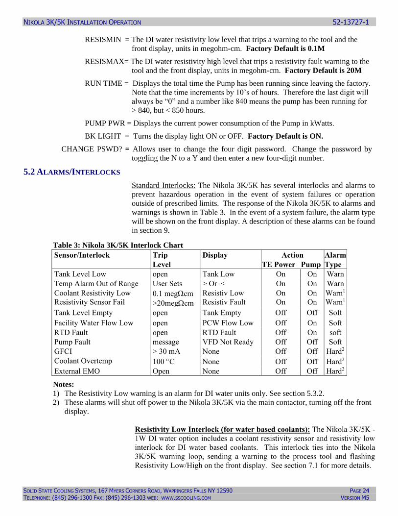
5.2 ALARMS/INTERLOCKS
Standard Interlocks: The Nikola 3K/5K has several interlocks and alarms to
prevent hazardous operation in the event of system failures or operation
outside of prescribed limits. The response of the Nikola 3K/5K to alarms and
warnings is shown in Table 3. In the event of a system failure, the alarm type
will be shown on the front display. A description of these alarms can be found
in section 9.
Table 3: Nikola 3K/5K Interlock Chart
Sensor/Interlock Trip Display Action Alarm
Level TE Power Pump Type
Tank Level Low open Tank Low On On Warn
Temp Alarm Out of Range User Sets > Or < On On Warn
Coolant Resistivity Low
Resistivity Sensor Fail 0.1 megcm
>20megcm
Resistiv Low
Resistiv Fault
On
On
On
On
Warn1
Warn1
Tank Level Empty open Tank Empty Off Off Soft
Facility Water Flow Low open PCW Flow Low Off On Soft
RTD Fault open RTD Fault Off On soft
Pump Fault message VFD Not Ready Off Off Soft
GFCI > 30 mA None Off Off Hard2
Coolant Overtemp 100 C None Off Off Hard2
External EMO Open None Off Off Hard2
Notes:
1) The Resistivity Low warning is an alarm for DI water units only. See section 5.3.2.
2) These alarms will shut off power to the Nikola 3K/5K via the main contactor, turning off the front
display.
Resistivity Low Interlock (for water based coolants): The Nikola 3K/5K -
1W DI water option includes a coolant resistivity sensor and resistivity low
interlock for DI water based coolants. This interlock ties into the Nikola
3K/5K warning loop, sending a warning to the process tool and flashing
Resistivity Low/High on the front display. See section 7.1 for more details.
NIKOLA 3K/5K INSTALLATION OPERATION 52-13727-1
SOLID STATE COOLING SYSTEMS, 167 MYERS CORNERS ROAD, WAPPINGERS FALLS NY 12590 PAGE 25 TELEPHONE: (845) 296-1300 FAX: (845) 296-1303 WEB: WWW.SSCOOLING.COM VERSION M5
5.3 DRAINING THE COOLANT
Use the following procedure to drain the Nikola 3K/5K of coolant:
1) Unscrew the tank vent cap (located on the front panel of the system.)
2) Connect a ¼” OD tube into the drain valve located to the left of the coolant
supply line (rear panel). If this is a bare tube, insert the tube fully into the
Swagelok nut on the valve and tighten clockwise 1¼ turns past hand tight.
3) Place the tube into a suitable container and open the drain valve.
4) A small amount of coolant will still remain in the tank and external coolant
lines when the coolant has stopped draining out. To recover the remaining
coolant, close the drain valve and connect a nitrogen line to the tank vent.
Pressurize the tank with 10-15 psig of nitrogen. Shut off the nitrogen and re-
open the drain valve. More coolant will drain out. Repeating this process
three times will normally remove 90% of the coolant.
Caution: Do not pressurize the Nikola 3K/5K tank over 20 psig.
5.4 CLEANING THE NIKOLA 3K/5K
The external surfaces of the Nikola 3K/5K may be cleaned with a clean, dry cloth
or a clean cloth with isopropyl alcohol. Do not clean the internal surfaces.
6.0 TOOL INTERFACE OPTIONS
The Nikola 3K/5K can communicate with several different types of
semiconductor equipment using the tool interface card. The electrical hookup
required and method of remote operation varies depending on the tool interface
purchased with the Nikola 3K/5K. Tool interface cards may be changed should
the Nikola 3K/5K be moved from one type of tool to another.
6.1 LAM INTERFACE CARD
The Lam Analog tool interface card is designed to operate with Lam Research
Corporation® plasma-etch tools. This interface card is the Nikola 3K/5K default
standard. The Lam Analog tool interface is through a 37-pin D-subminiature
located on the rear panel. Refer to Figure 3B.
NIKOLA 3K/5K INSTALLATION OPERATION 52-13727-1
SOLID STATE COOLING SYSTEMS, 167 MYERS CORNERS ROAD, WAPPINGERS FALLS NY 12590 PAGE 26 TELEPHONE: (845) 296-1300 FAX: (845) 296-1303 WEB: WWW.SSCOOLING.COM VERSION M5
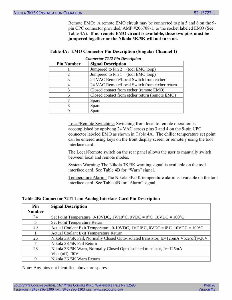
Remote EMO: A remote EMO circuit may be connected to pin 5 and 6 on the 9-
pin CPC connector provided, AMP #206708-1, to the socket labeled EMO (See
Table 4A). If no remote EMO circuit is available, these two pins must be
jumpered together or the Nikola 3K/5K will not turn on.
Table 4A: EMO Connector Pin Description (Singular Channel 1)
Connector 72J2 Pin Description
Pin Number Signal Description
1 Jumpered to Pin 2 (tool EMO loop)
2 Jumpered to Pin 1 (tool EMO loop)
3 24 VAC Remote/Local Switch from etcher
4 24 VAC Remote/Local Switch from etcher return
5 Closed contact from etcher (remote EMO)
6 Closed contact from etcher return (remote EMO)
7 Spare
8 Spare
9 Spare
Local/Remote Switching: Switching from local to remote operation is
accomplished by applying 24 VAC across pins 3 and 4 on the 9-pin CPC
connector labeled EMO as shown in Table 4A. The chiller temperature set point
can be entered using keys on the front display screen or remotely using the tool
interface card.
The Local/Remote switch on the rear panel allows the user to manually switch
between local and remote modes.
System Warning: The Nikola 3K/5K warning signal is available on the tool
interface card. See Table 4B for “Warn” signal.
Temperature Alarm: The Nikola 3K/5K temperature alarm is available on the tool
interface card. See Table 4B for “Alarm” signal.
Table 4B: Connector 72J1 Lam Analog Interface Card Pin Description
Pin
Number
Signal Description
24 Set Point Temperature, 0-10VDC, 1V/10C, 0VDC = 0C 10VDC = 100C
5 Set Point Temperature Return
20 Actual Coolant Exit Temperature, 0-10VDC, 1V/10C, 0VDC = 0C 10VDC = 100C
1 Actual Coolant Exit Temperature Return
26 Nikola 3K/5K Fail, Normally Closed Opto-isolated transistor, Ic=125mA Vbce(off)=30V
7 Nikola 3K/5K Fail Return
28 Nikola 3K/5K Warn, Normally Closed Opto-isolated transistor, Ic=125mA
Vbce(off)=30V
9 Nikola 3K/5K Warn Return
Note: Any pins not identified above are spares.
NIKOLA 3K/5K INSTALLATION OPERATION 52-13727-1
SOLID STATE COOLING SYSTEMS, 167 MYERS CORNERS ROAD, WAPPINGERS FALLS NY 12590 PAGE 27 TELEPHONE: (845) 296-1300 FAX: (845) 296-1303 WEB: WWW.SSCOOLING.COM VERSION M5
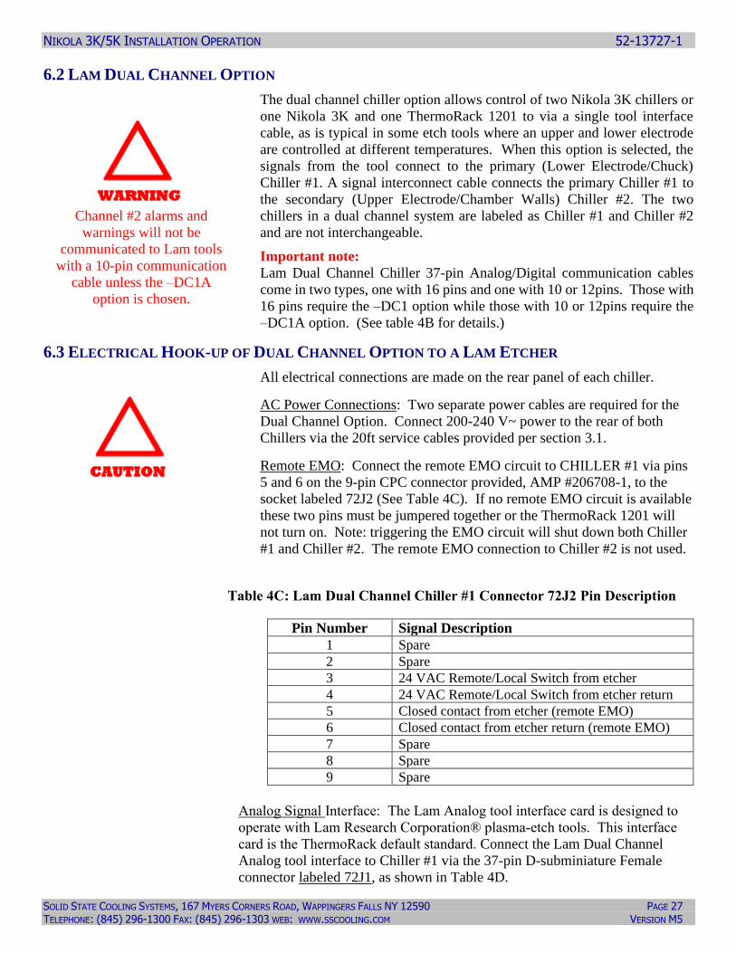
6.2 LAM DUAL CHANNEL OPTION
The dual channel chiller option allows control of two Nikola 3K chillers or
one Nikola 3K and one ThermoRack 1201 to via a single tool interface
cable, as is typical in some etch tools where an upper and lower electrode
are controlled at different temperatures. When this option is selected, the
signals from the tool connect to the primary (Lower Electrode/Chuck)
Chiller #1. A signal interconnect cable connects the primary Chiller #1 to
the secondary (Upper Electrode/Chamber Walls) Chiller #2. The two
chillers in a dual channel system are labeled as Chiller #1 and Chiller #2
and are not interchangeable.
Important note:
Lam Dual Channel Chiller 37-pin Analog/Digital communication cables
come in two types, one with 16 pins and one with 10 or 12pins. Those with
16 pins require the –DC1 option while those with 10 or 12pins require the
–DC1A option. (See table 4B for details.)
6.3 ELECTRICAL HOOK-UP OF DUAL CHANNEL OPTION TO A LAM ETCHER
All electrical connections are made on the rear panel of each chiller.
AC Power Connections: Two separate power cables are required for the
Dual Channel Option. Connect 200-240 V~ power to the rear of both
Chillers via the 20ft service cables provided per section 3.1.
Remote EMO: Connect the remote EMO circuit to CHILLER #1 via pins
5 and 6 on the 9-pin CPC connector provided, AMP #206708-1, to the
socket labeled 72J2 (See Table 4C). If no remote EMO circuit is available
these two pins must be jumpered together or the ThermoRack 1201 will
not turn on. Note: triggering the EMO circuit will shut down both Chiller
#1 and Chiller #2. The remote EMO connection to Chiller #2 is not used.
Table 4C: Lam Dual Channel Chiller #1 Connector 72J2 Pin Description
Pin Number Signal Description
1 Spare
2 Spare
3 24 VAC Remote/Local Switch from etcher
4 24 VAC Remote/Local Switch from etcher return
5 Closed contact from etcher (remote EMO)
6 Closed contact from etcher return (remote EMO)
7 Spare
8 Spare
9 Spare
Analog Signal Interface: The Lam Analog tool interface card is designed to
operate with Lam Research Corporation® plasma-etch tools. This interface
card is the ThermoRack default standard. Connect the Lam Dual Channel
Analog tool interface to Chiller #1 via the 37-pin D-subminiature Female
connector labeled 72J1, as shown in Table 4D.
CAUTION
WARNING
Channel #2 alarms and
warnings will not be
communicated to Lam tools
with a 10-pin communication
cable unless the –DC1A
option is chosen.
NIKOLA 3K/5K INSTALLATION OPERATION 52-13727-1
SOLID STATE COOLING SYSTEMS, 167 MYERS CORNERS ROAD, WAPPINGERS FALLS NY 12590 PAGE 28 TELEPHONE: (845) 296-1300 FAX: (845) 296-1303 WEB: WWW.SSCOOLING.COM VERSION M5
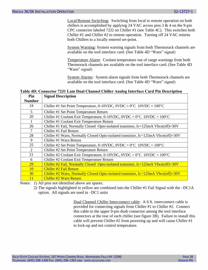
Local/Remote Switching: Switching from local to remote operation on both
chillers is accomplished by applying 24 VAC across pins 3 & 4 on the 9-pin
CPC connector labeled 72J2 on Chiller #1 (see Table 4C). This switches both
Chiller #1 and Chiller #2 to remote operation. Turning off 24 VAC returns
both Chillers to a locally entered set-point.
System Warning: System warning signals from both Thermorack channels are
available on the tool interface card. (See Table 4D “Warn” signal)
Temperature Alarm: Coolant temperature out of range warnings from both
Thermorack channels are available on the tool interface card. (See Table 4D
“Warn” signal)
System Alarms: System alarm signals from both Thermorack channels are
available on the tool interface card. (See Table 4D “Warn” signal)
Table 4D: Connector 72J1 Lam Dual Channel Chiller Analog Interface Card Pin Description
Pin
Number
Signal Description
24 Chiller #1 Set Point Temperature, 0-10VDC, 0VDC = 0C 10VDC = 100C
5 Chiller #1 Set Point Temperature Return
20 Chiller #1 Coolant Exit Temperature, 0-10VDC, 0VDC = 0C 10VDC = 100C
1 Chiller #1 Coolant Exit Temperature Return
26 Chiller #1 Fail, Normally Closed Opto-isolated transistor, Ic=125mA Vbce(off)=30V
7 Chiller #1 Fail Return
28 Chiller #1 Warn, Normally Closed Opto-isolated transistor, Ic=125mA Vbce(off)=30V
9 Chiller #1 Warn Return
25 Chiller #2 Set Point Temperature, 0-10VDC, 0VDC = 0C 10VDC = 100C
2 Chiller #2 Set Point Temperature Return
21 Chiller #2 Coolant Exit Temperature, 0-10VDC, 0VDC = 0C 10VDC = 100C
6 Chiller #2 Coolant Exit Temperature Return
29 Chiller #2 Fail, Normally Closed Opto-isolated transistor, Ic=125mA Vbce(off)=30V
10 Chiller #2 Fail Return
30 Chiller #2 Warn, Normally Closed Opto-isolated transistor, Ic=125mA Vbce(off)=30V
11 Chiller #2 Warn Return
Notes: 1) All pins not identified above are spares.
2) The signals highlighted in yellow are combined into the Chiller #1 Fail Signal with the –DC1A
option. All signals are used in –DC1 units
Dual Channel Chiller Interconnect cable: A 6 ft. interconnect cable is
provided for connecting signals from Chiller #1 to Chiller #2. Connect
this cable to the upper 9-pin dsub connector among the tool interface
connectors at the rear of each chiller (see figure 3B). Failure to install this
cable will prevent Chiller #2 from powering up and will cause Chiller #1
to lock-up and not control temperature.
NIKOLA 3K/5K INSTALLATION OPERATION 52-13727-1
SOLID STATE COOLING SYSTEMS, 167 MYERS CORNERS ROAD, WAPPINGERS FALLS NY 12590 PAGE 29 TELEPHONE: (845) 296-1300 FAX: (845) 296-1303 WEB: WWW.SSCOOLING.COM VERSION M5
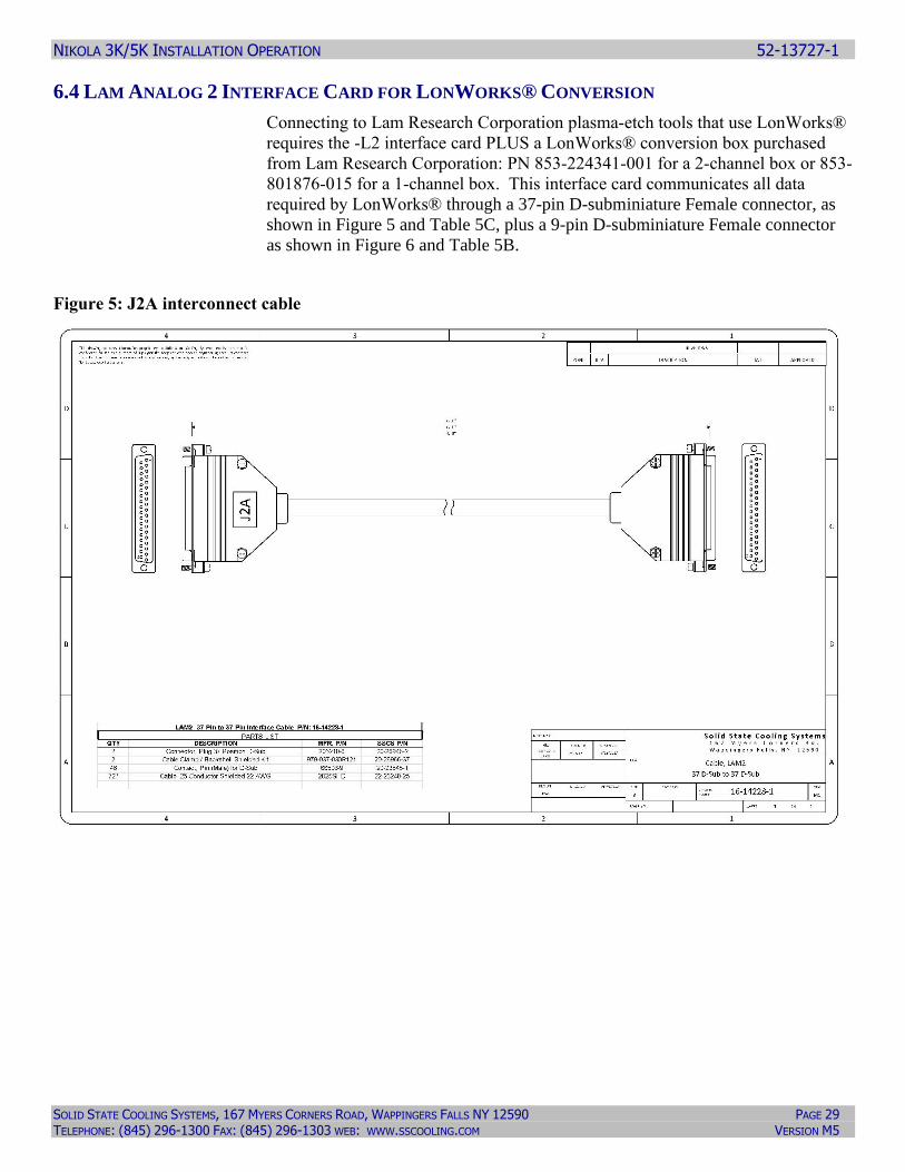
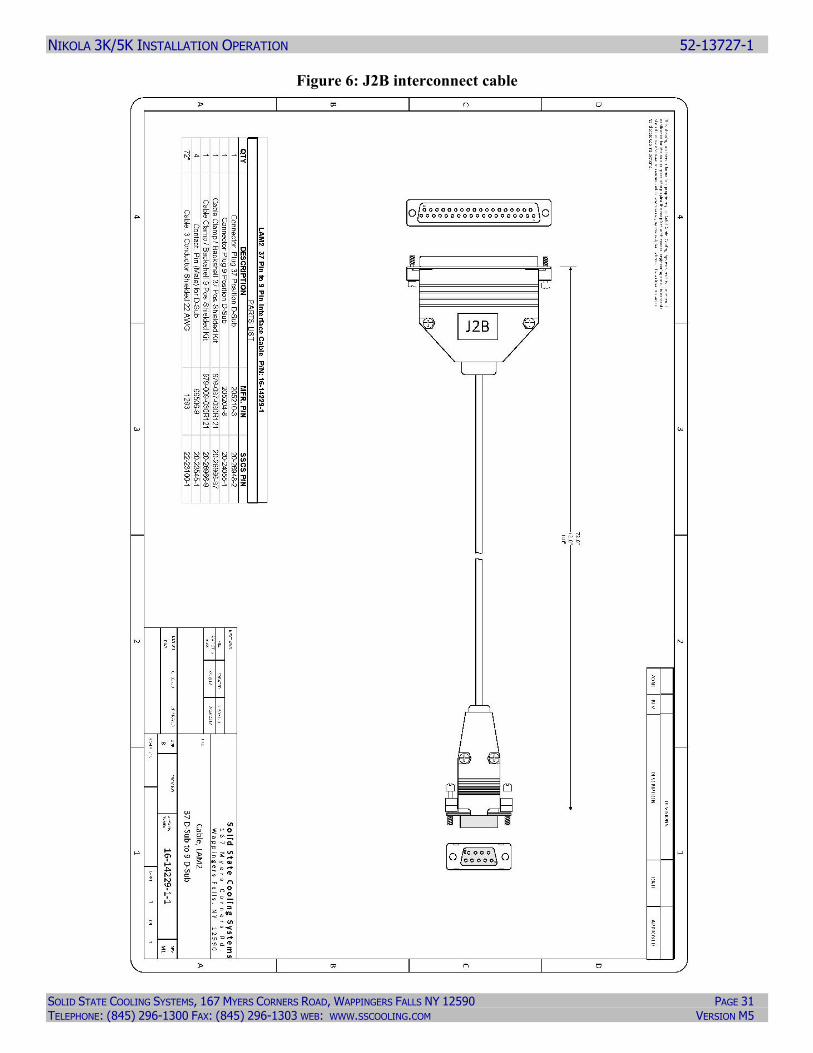
6.4 LAM ANALOG 2 INTERFACE CARD FOR LONWORKS® CONVERSION
Connecting to Lam Research Corporation plasma-etch tools that use LonWorks®
requires the -L2 interface card PLUS a LonWorks® conversion box purchased
from Lam Research Corporation: PN 853-224341-001 for a 2-channel box or 853-
801876-015 for a 1-channel box. This interface card communicates all data
required by LonWorks® through a 37-pin D-subminiature Female connector, as
shown in Figure 5 and Table 5C, plus a 9-pin D-subminiature Female connector
as shown in Figure 6 and Table 5B.
Figure 5: J2A interconnect cable

NIKOLA 3K/5K INSTALLATION OPERATION 52-13727-1
SOLID STATE COOLING SYSTEMS, 167 MYERS CORNERS ROAD, WAPPINGERS FALLS NY 12590 PAGE 30 TELEPHONE: (845) 296-1300 FAX: (845) 296-1303 WEB: WWW.SSCOOLING.COM VERSION M5
Table 5A: J2A Lam Analog to LonWorks® Converter 37-pin dsub connector
FUNCTION PIN SIGNAL NAME
Start / Stop Status 1 DI0
Remote / Local Status 2 DI1
Warning Status 3 DI2
Fail Status 4 DI3
Start / Stop Command 5 DO0
Remote / Local Command 6 DO1
Spare 7 DO2
Spare 8 DO3
Source Supply For Digital Inputs 9 24VDC
Source Supply For Digital Inputs 10 24VDC
Temperature Setpoint 1 Command 11 AOUT0
Temperature Setpoint 2 Command (For Dual Channel Only)
12 AOUT1
Spare 13 AOUT2
Spare 14 AOUT3
Temperature Setpoint 1 Readback 15 AIN0(+)
Temperature Setpoint 2 Readback (For Dual Channel Only)
16 AIN1(+)
Temperature Actual 1 17 AIN2(+)
Temperature Actual 2 (For Dual Channel Only)
18 AIN3(+)
Spare 19 AGND
Spare 20 24VRET
Spare 21 24VRET
Spare 22 24VRET
Spare 23 24VRET
Start / Stop Command Return 24 24VRET
Remote / Local Command Return 25 24VRET
Spare 26 24VRET
Spare 27 24VRET
Source Supply For Digital Inputs 28 24VDC
Not Used 29 NC
Temperature Setpoint 1 Command Return 30 AGND
Temperature Setpoint 2 Command Return (For Dual Channel Only)
31 AGND
Spare 32 AGND
Spare 33 AGND
Temperature Setpoint 1 Readback Return 34 AIN0(-)
Temperature Setpoint 2 Readback Return (For Dual Channel Only)
35 AIN1(-)
Temperature Actual 1 Return 36 AIN2(-)
Temperature Actual 2 Return 37 AIN3(-)
NIKOLA 3K/5K INSTALLATION OPERATION 52-13727-1
SOLID STATE COOLING SYSTEMS, 167 MYERS CORNERS ROAD, WAPPINGERS FALLS NY 12590 PAGE 31 TELEPHONE: (845) 296-1300 FAX: (845) 296-1303 WEB: WWW.SSCOOLING.COM VERSION M5
Figure 6: J2B interconnect cable
NIKOLA 3K/5K INSTALLATION OPERATION 52-13727-1
SOLID STATE COOLING SYSTEMS, 167 MYERS CORNERS ROAD, WAPPINGERS FALLS NY 12590 PAGE 32 TELEPHONE: (845) 296-1300 FAX: (845) 296-1303 WEB: WWW.SSCOOLING.COM VERSION M5
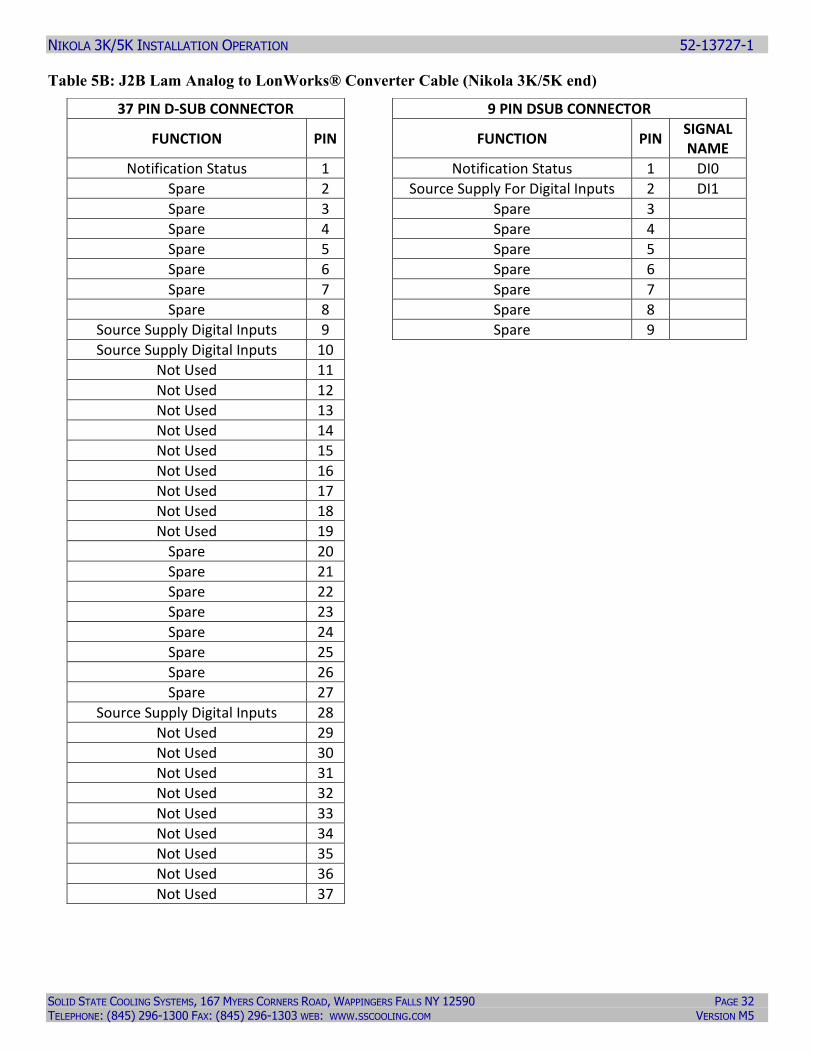
Table 5B: J2B Lam Analog to LonWorks® Converter Cable (Nikola 3K/5K end)
37 PIN D-SUB CONNECTOR 9 PIN DSUB CONNECTOR
FUNCTION PIN FUNCTION PIN SIGNAL NAME
Notification Status 1 Notification Status 1 DI0
Spare 2 Source Supply For Digital Inputs 2 DI1
Spare 3 Spare 3
Spare 4 Spare 4
Spare 5 Spare 5
Spare 6 Spare 6
Spare 7 Spare 7
Spare 8 Spare 8
Source Supply Digital Inputs 9 Spare 9
Source Supply Digital Inputs 10
Not Used 11
Not Used 12
Not Used 13
Not Used 14
Not Used 15
Not Used 16
Not Used 17
Not Used 18
Not Used 19
Spare 20
Spare 21
Spare 22
Spare 23
Spare 24
Spare 25
Spare 26
Spare 27
Source Supply Digital Inputs 28
Not Used 29
Not Used 30
Not Used 31
Not Used 32
Not Used 33
Not Used 34
Not Used 35
Not Used 36
Not Used 37
NIKOLA 3K/5K INSTALLATION OPERATION 52-13727-1
SOLID STATE COOLING SYSTEMS, 167 MYERS CORNERS ROAD, WAPPINGERS FALLS NY 12590 PAGE 33 TELEPHONE: (845) 296-1300 FAX: (845) 296-1303 WEB: WWW.SSCOOLING.COM VERSION M5
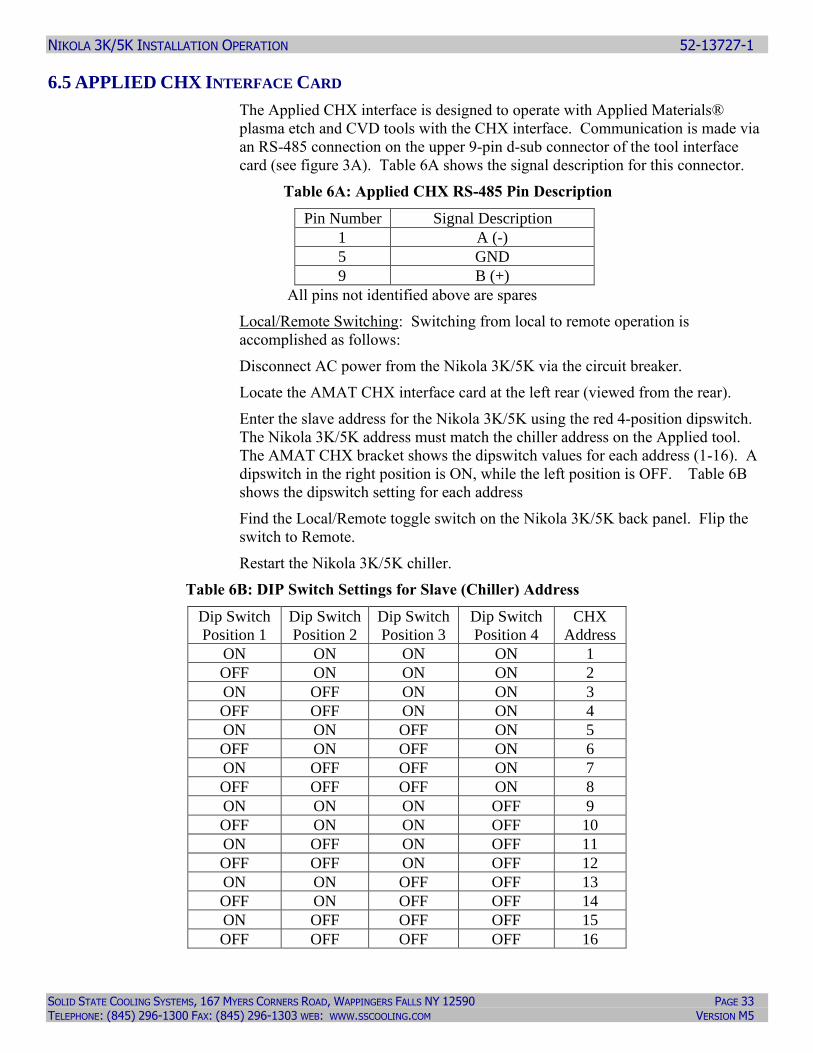
6.5 APPLIED CHX INTERFACE CARD
The Applied CHX interface is designed to operate with Applied Materials®
plasma etch and CVD tools with the CHX interface. Communication is made via
an RS-485 connection on the upper 9-pin d-sub connector of the tool interface
card (see figure 3A). Table 6A shows the signal description for this connector.
Table 6A: Applied CHX RS-485 Pin Description
Pin Number Signal Description
1 A (-)
5 GND
9 B (+)
All pins not identified above are spares
Local/Remote Switching: Switching from local to remote operation is
accomplished as follows:
Disconnect AC power from the Nikola 3K/5K via the circuit breaker.
Locate the AMAT CHX interface card at the left rear (viewed from the rear).
Enter the slave address for the Nikola 3K/5K using the red 4-position dipswitch.
The Nikola 3K/5K address must match the chiller address on the Applied tool.
The AMAT CHX bracket shows the dipswitch values for each address (1-16). A
dipswitch in the right position is ON, while the left position is OFF. Table 6B
shows the dipswitch setting for each address
Find the Local/Remote toggle switch on the Nikola 3K/5K back panel. Flip the
switch to Remote.
Restart the Nikola 3K/5K chiller.
Table 6B: DIP Switch Settings for Slave (Chiller) Address
Dip Switch
Position 1
Dip Switch
Position 2
Dip Switch
Position 3
Dip Switch
Position 4
CHX
Address
ON ON ON ON 1
OFF ON ON ON 2
ON OFF ON ON 3
OFF OFF ON ON 4
ON ON OFF ON 5
OFF ON OFF ON 6
ON OFF OFF ON 7
OFF OFF OFF ON 8
ON ON ON OFF 9
OFF ON ON OFF 10
ON OFF ON OFF 11
OFF OFF ON OFF 12
ON ON OFF OFF 13
OFF ON OFF OFF 14
ON OFF OFF OFF 15
OFF OFF OFF OFF 16
NIKOLA 3K/5K INSTALLATION OPERATION 52-13727-1
SOLID STATE COOLING SYSTEMS, 167 MYERS CORNERS ROAD, WAPPINGERS FALLS NY 12590 PAGE 34 TELEPHONE: (845) 296-1300 FAX: (845) 296-1303 WEB: WWW.SSCOOLING.COM VERSION M5
Important Note: The Nikola 3K/5K AMAT CHX interface card only transmits
“Required Data” (as defined by the AMAT CHX specification), not the “Optional
data” as defined by the same specification.
Required CHX information transmitted:
• Fault Summary (digital input)
• Warning Summary (digital input)
• Actual Temperature (analog input)
Optional CHX information transmitted:
• Fluid Resistivity (analog input)
• Fluid Level Fault (digital input)
Optional CHX information not transmitted:
• Fluid Flow (analog input)
• Fluid Flow Fault (digital input)
• Facility Water Fault (digital input)
When installing the Nikola 3K/5K configure the Centura Controller to ignore
optional data not transmitted on the heat exchanger configuration screen, located
as follows:
MISC: System Config: Config Heat Exchangers, page 3/3, sheet 2/3
Set all values to NO.
NIKOLA 3K/5K INSTALLATION OPERATION 52-13727-1
SOLID STATE COOLING SYSTEMS, 167 MYERS CORNERS ROAD, WAPPINGERS FALLS NY 12590 PAGE 35 TELEPHONE: (845) 296-1300 FAX: (845) 296-1303 WEB: WWW.SSCOOLING.COM VERSION M5
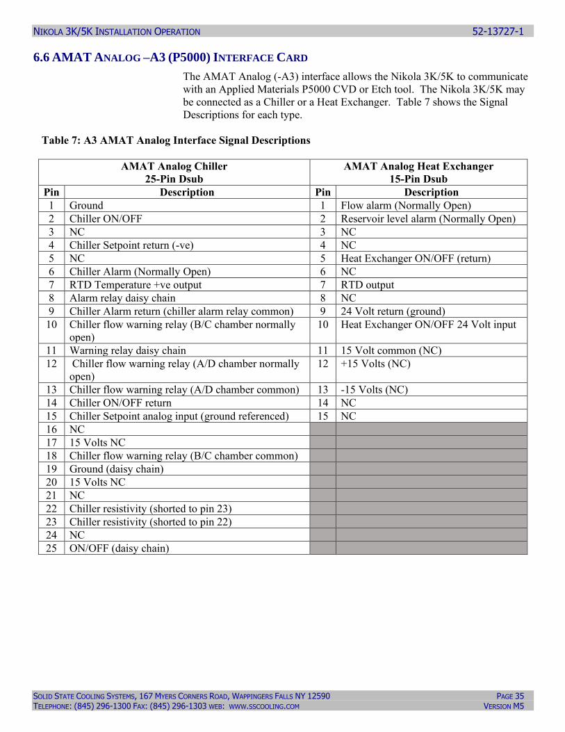
6.6 AMAT ANALOG –A3 (P5000) INTERFACE CARD
The AMAT Analog (-A3) interface allows the Nikola 3K/5K to communicate
with an Applied Materials P5000 CVD or Etch tool. The Nikola 3K/5K may
be connected as a Chiller or a Heat Exchanger. Table 7 shows the Signal
Descriptions for each type.
Table 7: A3 AMAT Analog Interface Signal Descriptions
AMAT Analog Chiller
25-Pin Dsub
AMAT Analog Heat Exchanger
15-Pin Dsub
Pin Description Pin Description
1 Ground 1 Flow alarm (Normally Open)
2 Chiller ON/OFF 2 Reservoir level alarm (Normally Open)
3 NC 3 NC
4 Chiller Setpoint return (-ve) 4 NC
5 NC 5 Heat Exchanger ON/OFF (return)
6 Chiller Alarm (Normally Open) 6 NC
7 RTD Temperature +ve output 7 RTD output
8 Alarm relay daisy chain 8 NC
9 Chiller Alarm return (chiller alarm relay common) 9 24 Volt return (ground)
10 Chiller flow warning relay (B/C chamber normally
open)
10 Heat Exchanger ON/OFF 24 Volt input
11 Warning relay daisy chain 11 15 Volt common (NC)
12 Chiller flow warning relay (A/D chamber normally
open)
12 +15 Volts (NC)
13 Chiller flow warning relay (A/D chamber common) 13 -15 Volts (NC)
14 Chiller ON/OFF return 14 NC
15 Chiller Setpoint analog input (ground referenced) 15 NC
16 NC
17 15 Volts NC
18 Chiller flow warning relay (B/C chamber common)
19 Ground (daisy chain)
20 15 Volts NC
21 NC
22 Chiller resistivity (shorted to pin 23)
23 Chiller resistivity (shorted to pin 22)
24 NC
25 ON/OFF (daisy chain)
NIKOLA 3K/5K INSTALLATION OPERATION 52-13727-1
SOLID STATE COOLING SYSTEMS, 167 MYERS CORNERS ROAD, WAPPINGERS FALLS NY 12590 PAGE 36 TELEPHONE: (845) 296-1300 FAX: (845) 296-1303 WEB: WWW.SSCOOLING.COM VERSION M5
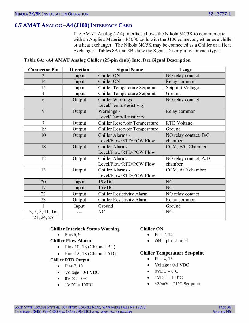
6.7 AMAT ANALOG –A4 (J100) INTERFACE CARD
The AMAT Analog (-A4) interface allows the Nikola 3K/5K to communicate
with an Applied Materials P5000 tools with the J100 connector, either as a chiller
or a heat exchanger. The Nikola 3K/5K may be connected as a Chiller or a Heat
Exchanger. Tables 8A and 8B show the Signal Descriptions for each type.
Table 8A: -A4 AMAT Analog Chiller (25-pin dsub) Interface Signal Description
Chiller Interlock Status Warning
• Pins 6, 9
Chiller Flow Alarm
• Pins 10, 18 (Channel BC)
• Pins 12, 13 (Channel AD)
Chiller RTD Output
• Pins 7, 19
• Voltage : 0-1 VDC
• 0VDC = 0°C
• 1VDC = 100°C
Chiller ON
• Pins 2, 14
• ON = pins shorted
Chiller Temperature Set-point
• Pins 4, 15
• Voltage : 0-1 VDC
• 0VDC = 0°C
• 1VDC = 100°C
• <30mV = 21°C Set-point
Connector Pin Direction Signal Name Usage
2 Input Chiller ON NO relay contact
14 Input Chiller ON Relay common
15 Input Chiller Temperature Setpoint Setpoint Voltage
4 Input Chiller Temperature Setpoint Ground
6 Output Chiller Warnings -
Level/Temp/Resistivity
NO relay contact
9 Output Warnings -
Level/Temp/Resistivity
Relay common
7 Output Chiller Reservoir Temperature RTD Voltage
19 Output Chiller Reservoir Temperature Ground
10 Output Chiller Alarms -
Level/Flow/RTD/PCW Flow
NO relay contact, B/C
chamber
18 Output Chiller Alarms -
Level/Flow/RTD/PCW Flow
COM, B/C Chamber
12 Output Chiller Alarms -
Level/Flow/RTD/PCW Flow
NO relay contact, A/D
chamber
13 Output Chiller Alarms -
Level/Flow/RTD/PCW Flow
COM, A/D chamber
20 Input 15VDC NC
17 Input 15VDC NC
22 Output Chiller Resistivity Alarm NO relay contact
23 Output Chiller Resistivity Alarm Relay common
1 Input Ground Ground
3, 5, 8, 11, 16,
21, 24, 25
--- NC NC
NIKOLA 3K/5K INSTALLATION OPERATION 52-13727-1
SOLID STATE COOLING SYSTEMS, 167 MYERS CORNERS ROAD, WAPPINGERS FALLS NY 12590 PAGE 37 TELEPHONE: (845) 296-1300 FAX: (845) 296-1303 WEB: WWW.SSCOOLING.COM VERSION M5
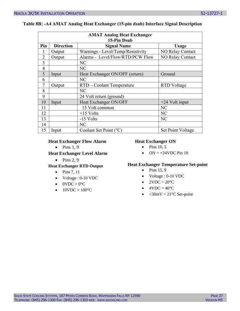
Table 8B: -A4 AMAT Analog Heat Exchanger (15-pin dsub) Interface Signal Description
AMAT Analog Heat Exchanger
15-Pin Dsub
Pin Direction Signal Name Usage
1 Output Warnings - Level/Temp/Resistivity NO Relay Contact
2 Output Alarms - Level/Flow/RTD/PCW Flow NO Relay Contact
3 NC
4 NC
5 Input Heat Exchanger ON/OFF (return) Ground
6 NC
7 Output RTD – Coolant Temperature RTD Voltage
8 NC
9 24 Volt return (ground)
10 Input Heat Exchanger ON/OFF +24 Volt input
11 15 Volt common NC
12 +15 Volts NC
13 -15 Volts NC
14 NC
15 Input Coolant Set Point (°C) Set Point Voltage
Heat Exchanger Flow Alarm
• Pins 1, 9
Heat Exchanger Level Alarm
• Pins 2, 9
Heat Exchanger RTD Output
• Pins 7, 11
• Voltage : 0-10 VDC
• 0VDC = 0°C
• 10VDC = 100°C
Heat Exchanger ON
• Pins 10, 5
• ON = +24VDC Pin 10
Heat Exchanger Temperature Set-point
• Pins 15, 9
• Voltage : 0-10 VDC
• 2VDC = 20°C
• 4VDC = 40°C
• <30mV = 21°C Set-point
NIKOLA 3K/5K INSTALLATION OPERATION 52-13727-1
SOLID STATE COOLING SYSTEMS, 167 MYERS CORNERS ROAD, WAPPINGERS FALLS NY 12590 PAGE 38 TELEPHONE: (845) 296-1300 FAX: (845) 296-1303 WEB: WWW.SSCOOLING.COM VERSION M5
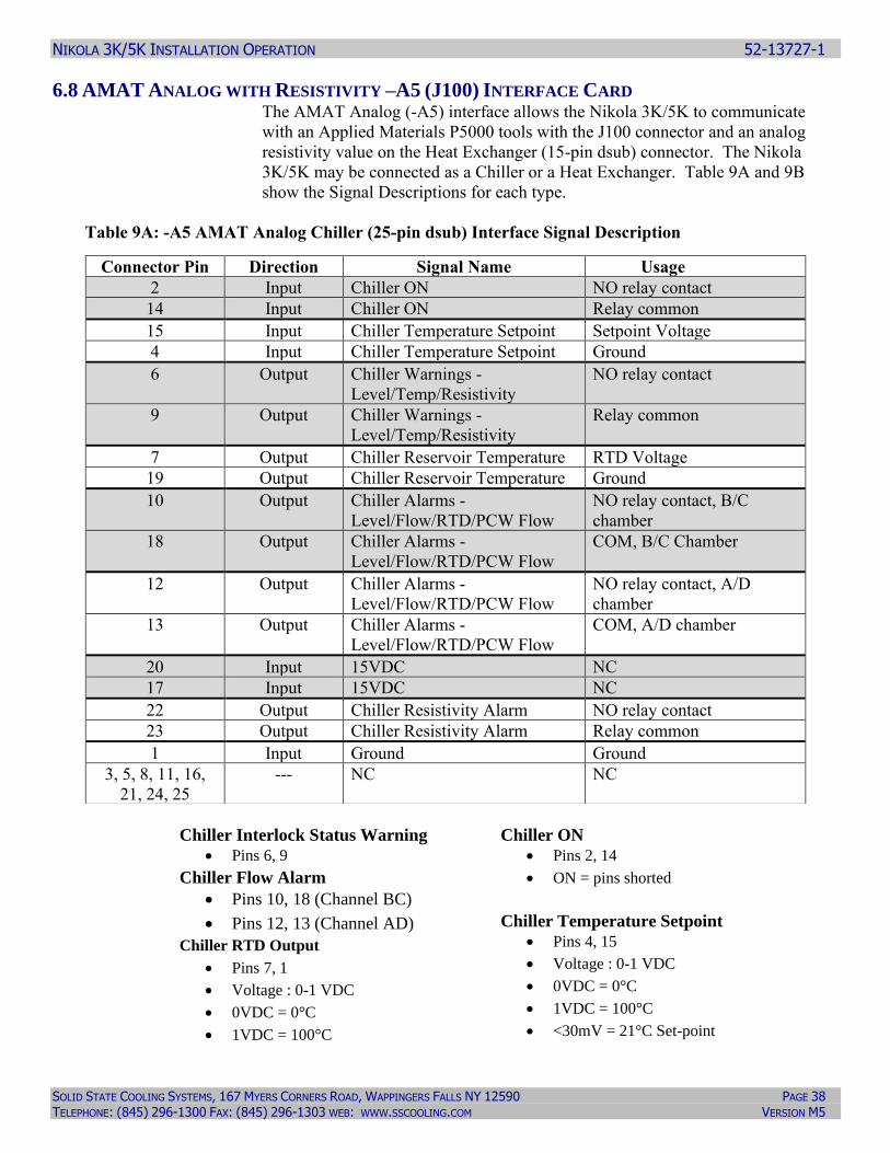
6.8 AMAT ANALOG WITH RESISTIVITY –A5 (J100) INTERFACE CARD The AMAT Analog (-A5) interface allows the Nikola 3K/5K to communicate
with an Applied Materials P5000 tools with the J100 connector and an analog
resistivity value on the Heat Exchanger (15-pin dsub) connector. The Nikola
3K/5K may be connected as a Chiller or a Heat Exchanger. Table 9A and 9B
show the Signal Descriptions for each type.
Table 9A: -A5 AMAT Analog Chiller (25-pin dsub) Interface Signal Description
Chiller Interlock Status Warning
• Pins 6, 9
Chiller Flow Alarm
• Pins 10, 18 (Channel BC)
• Pins 12, 13 (Channel AD)
Chiller RTD Output
• Pins 7, 1
• Voltage : 0-1 VDC
• 0VDC = 0°C
• 1VDC = 100°C
Chiller ON
• Pins 2, 14
• ON = pins shorted
Chiller Temperature Setpoint
• Pins 4, 15
• Voltage : 0-1 VDC
• 0VDC = 0°C
• 1VDC = 100°C
• <30mV = 21°C Set-point
Connector Pin Direction Signal Name Usage
2 Input Chiller ON NO relay contact
14 Input Chiller ON Relay common
15 Input Chiller Temperature Setpoint Setpoint Voltage
4 Input Chiller Temperature Setpoint Ground
6 Output Chiller Warnings -
Level/Temp/Resistivity
NO relay contact
9 Output Chiller Warnings -
Level/Temp/Resistivity
Relay common
7 Output Chiller Reservoir Temperature RTD Voltage
19 Output Chiller Reservoir Temperature Ground
10 Output Chiller Alarms -
Level/Flow/RTD/PCW Flow
NO relay contact, B/C
chamber
18 Output Chiller Alarms -
Level/Flow/RTD/PCW Flow
COM, B/C Chamber
12 Output Chiller Alarms -
Level/Flow/RTD/PCW Flow
NO relay contact, A/D
chamber
13 Output Chiller Alarms -
Level/Flow/RTD/PCW Flow
COM, A/D chamber
20 Input 15VDC NC
17 Input 15VDC NC
22 Output Chiller Resistivity Alarm NO relay contact
23 Output Chiller Resistivity Alarm Relay common
1 Input Ground Ground
3, 5, 8, 11, 16,
21, 24, 25
--- NC NC
NIKOLA 3K/5K INSTALLATION OPERATION 52-13727-1
SOLID STATE COOLING SYSTEMS, 167 MYERS CORNERS ROAD, WAPPINGERS FALLS NY 12590 PAGE 39 TELEPHONE: (845) 296-1300 FAX: (845) 296-1303 WEB: WWW.SSCOOLING.COM VERSION M5
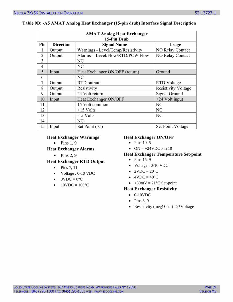
Table 9B: -A5 AMAT Analog Heat Exchanger (15-pin dsub) Interface Signal Description
AMAT Analog Heat Exchanger
15-Pin Dsub
Pin Direction Signal Name Usage
1 Output Warnings - Level/Temp/Resistivity NO Relay Contact
2 Output Alarms - Level/Flow/RTD/PCW Flow NO Relay Contact
3 NC
4 NC
5 Input Heat Exchanger ON/OFF (return) Ground
6 NC
7 Output RTD output RTD Voltage
8 Output Resistivity Resistivity Voltage
9 Output 24 Volt return Signal Ground
10 Input Heat Exchanger ON/OFF +24 Volt input
11 15 Volt common NC
12 +15 Volts NC
13 -15 Volts NC
14 NC
15 Input Set Point (°C) Set Point Voltage
Heat Exchanger Warnings
• Pins 1, 9
Heat Exchanger Alarms
• Pins 2, 9
Heat Exchanger RTD Output
• Pins 7, 11
• Voltage : 0-10 VDC
• 0VDC = 0°C
• 10VDC = 100°C
Heat Exchanger ON/OFF
• Pins 10, 5
• ON = +24VDC Pin 10
Heat Exchanger Temperature Set-point
• Pins 15, 9
• Voltage : 0-10 VDC
• 2VDC = 20°C
• 4VDC = 40°C
• <30mV = 21°C Set-point
Heat Exchanger Resistivity
• 0-10VDC
• Pins 8, 9
• Resistivity (meg-cm)= 2*Voltage
NIKOLA 3K/5K INSTALLATION OPERATION 52-13727-1
SOLID STATE COOLING SYSTEMS, 167 MYERS CORNERS ROAD, WAPPINGERS FALLS NY 12590 PAGE 40 TELEPHONE: (845) 296-1300 FAX: (845) 296-1303 WEB: WWW.SSCOOLING.COM VERSION M5
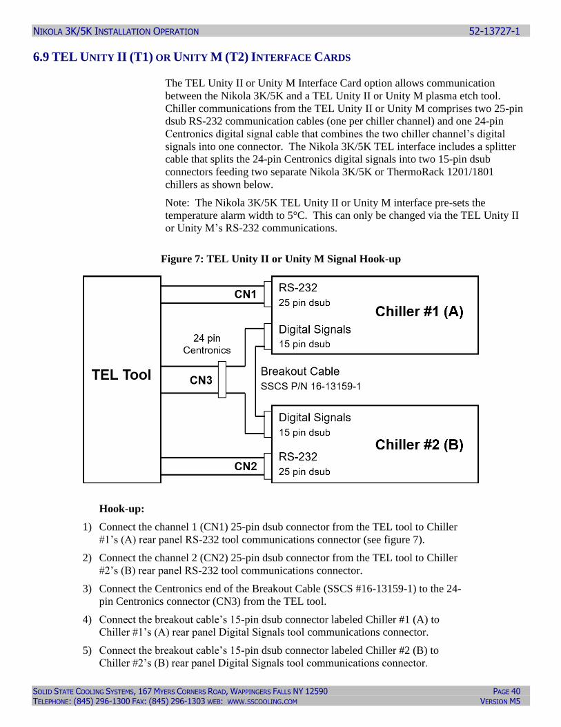
6.9 TEL UNITY II (T1) OR UNITY M (T2) INTERFACE CARDS
The TEL Unity II or Unity M Interface Card option allows communication
between the Nikola 3K/5K and a TEL Unity II or Unity M plasma etch tool.
Chiller communications from the TEL Unity II or Unity M comprises two 25-pin
dsub RS-232 communication cables (one per chiller channel) and one 24-pin
Centronics digital signal cable that combines the two chiller channel’s digital
signals into one connector. The Nikola 3K/5K TEL interface includes a splitter
cable that splits the 24-pin Centronics digital signals into two 15-pin dsub
connectors feeding two separate Nikola 3K/5K or ThermoRack 1201/1801
chillers as shown below.
Note: The Nikola 3K/5K TEL Unity II or Unity M interface pre-sets the
temperature alarm width to 5°C. This can only be changed via the TEL Unity II
or Unity M’s RS-232 communications.
Figure 7: TEL Unity II or Unity M Signal Hook-up
Hook-up:
1) Connect the channel 1 (CN1) 25-pin dsub connector from the TEL tool to Chiller
#1’s (A) rear panel RS-232 tool communications connector (see figure 7).
2) Connect the channel 2 (CN2) 25-pin dsub connector from the TEL tool to Chiller
#2’s (B) rear panel RS-232 tool communications connector.
3) Connect the Centronics end of the Breakout Cable (SSCS #16-13159-1) to the 24-
pin Centronics connector (CN3) from the TEL tool.
4) Connect the breakout cable’s 15-pin dsub connector labeled Chiller #1 (A) to
Chiller #1’s (A) rear panel Digital Signals tool communications connector.
5) Connect the breakout cable’s 15-pin dsub connector labeled Chiller #2 (B) to
Chiller #2’s (B) rear panel Digital Signals tool communications connector.
NIKOLA 3K/5K INSTALLATION OPERATION 52-13727-1
SOLID STATE COOLING SYSTEMS, 167 MYERS CORNERS ROAD, WAPPINGERS FALLS NY 12590 PAGE 41 TELEPHONE: (845) 296-1300 FAX: (845) 296-1303 WEB: WWW.SSCOOLING.COM VERSION M5
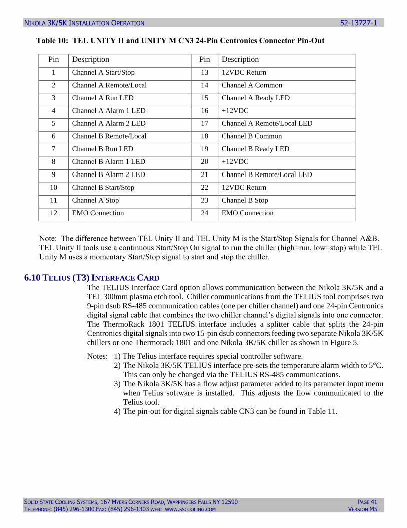
Table 10: TEL UNITY II and UNITY M CN3 24-Pin Centronics Connector Pin-Out
Pin Description Pin Description
1 Channel A Start/Stop 13 12VDC Return
2 Channel A Remote/Local 14 Channel A Common
3 Channel A Run LED 15 Channel A Ready LED
4 Channel A Alarm 1 LED 16 +12VDC
5 Channel A Alarm 2 LED 17 Channel A Remote/Local LED
6 Channel B Remote/Local 18 Channel B Common
7 Channel B Run LED 19 Channel B Ready LED
8 Channel B Alarm 1 LED 20 +12VDC
9 Channel B Alarm 2 LED 21 Channel B Remote/Local LED
10 Channel B Start/Stop 22 12VDC Return
11 Channel A Stop 23 Channel B Stop
12 EMO Connection 24 EMO Connection
Note: The difference between TEL Unity II and TEL Unity M is the Start/Stop Signals for Channel A&B.
TEL Unity II tools use a continuous Start/Stop On signal to run the chiller (high=run, low=stop) while TEL
Unity M uses a momentary Start/Stop signal to start and stop the chiller.
6.10 TELIUS (T3) INTERFACE CARD The TELIUS Interface Card option allows communication between the Nikola 3K/5K and a
TEL 300mm plasma etch tool. Chiller communications from the TELIUS tool comprises two
9-pin dsub RS-485 communication cables (one per chiller channel) and one 24-pin Centronics
digital signal cable that combines the two chiller channel’s digital signals into one connector.
The ThermoRack 1801 TELIUS interface includes a splitter cable that splits the 24-pin
Centronics digital signals into two 15-pin dsub connectors feeding two separate Nikola 3K/5K
chillers or one Thermorack 1801 and one Nikola 3K/5K chiller as shown in Figure 5.
Notes: 1) The Telius interface requires special controller software.
2) The Nikola 3K/5K TELIUS interface pre-sets the temperature alarm width to 5°C.
This can only be changed via the TELIUS RS-485 communications.
3) The Nikola 3K/5K has a flow adjust parameter added to its parameter input menu
when Telius software is installed. This adjusts the flow communicated to the
Telius tool.
4) The pin-out for digital signals cable CN3 can be found in Table 11.
NIKOLA 3K/5K INSTALLATION OPERATION 52-13727-1
SOLID STATE COOLING SYSTEMS, 167 MYERS CORNERS ROAD, WAPPINGERS FALLS NY 12590 PAGE 42 TELEPHONE: (845) 296-1300 FAX: (845) 296-1303 WEB: WWW.SSCOOLING.COM VERSION M5
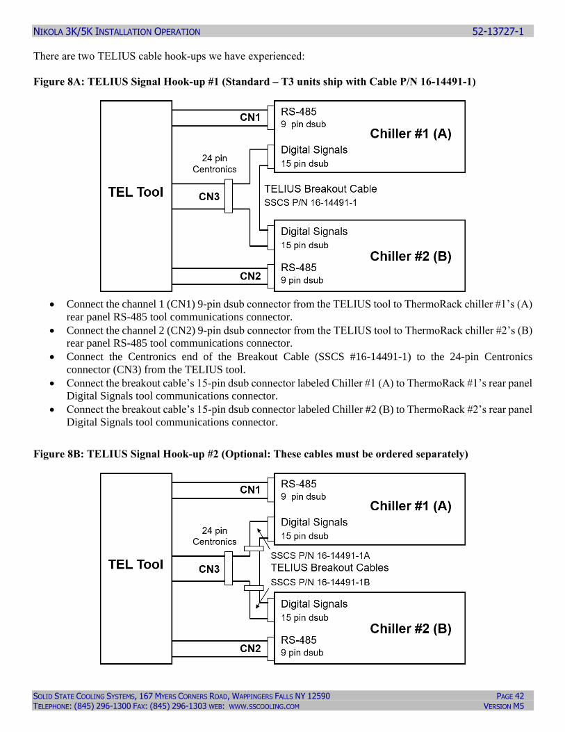
There are two TELIUS cable hook-ups we have experienced:
Figure 8A: TELIUS Signal Hook-up #1 (Standard – T3 units ship with Cable P/N 16-14491-1)
• Connect the channel 1 (CN1) 9-pin dsub connector from the TELIUS tool to ThermoRack chiller #1’s (A)
rear panel RS-485 tool communications connector.
• Connect the channel 2 (CN2) 9-pin dsub connector from the TELIUS tool to ThermoRack chiller #2’s (B)
rear panel RS-485 tool communications connector.
• Connect the Centronics end of the Breakout Cable (SSCS #16-14491-1) to the 24-pin Centronics
connector (CN3) from the TELIUS tool.
• Connect the breakout cable’s 15-pin dsub connector labeled Chiller #1 (A) to ThermoRack #1’s rear panel
Digital Signals tool communications connector.
• Connect the breakout cable’s 15-pin dsub connector labeled Chiller #2 (B) to ThermoRack #2’s rear panel
Digital Signals tool communications connector.
Figure 8B: TELIUS Signal Hook-up #2 (Optional: These cables must be ordered separately)
NIKOLA 3K/5K INSTALLATION OPERATION 52-13727-1
SOLID STATE COOLING SYSTEMS, 167 MYERS CORNERS ROAD, WAPPINGERS FALLS NY 12590 PAGE 43 TELEPHONE: (845) 296-1300 FAX: (845) 296-1303 WEB: WWW.SSCOOLING.COM VERSION M5
• Connect the channel 1 (CN1) 9-pin dsub connector from the TELIUS tool to chiller #1’s (A) rear panel
RS-485 tool communications connector.
• Connect the channel 2 (CN2) 9-pin dsub connector from the TELIUS tool to chiller #2’s (B) rear panel
RS-485 tool communications connector.
• Connect the Centronics end of the Breakout Cable (SSCS #16-13159-1A) to the 24-pin Centronics
connector (CN3 for Channel A) from the TELIUS tool and the other end to the 15-pin dsub connector on
Chiller #1 (A).
• Connect the Centronics end of the Breakout Cable (SSCS #16-13159-1B) to the 24-pin Centronics
connector (CN3 for Channel B) from the TELIUS tool and the other end to the 15-pin dsub connector on
Chiller #2 (B).
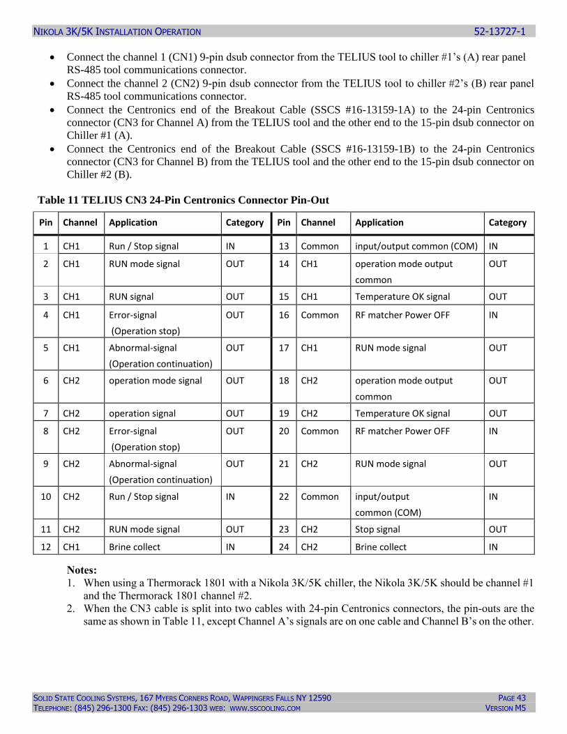
Table 11 TELIUS CN3 24-Pin Centronics Connector Pin-Out
Pin Channel Application Category Pin Channel Application Category
1 CH1 Run / Stop signal IN 13 Common input/output common (COM) IN
2 CH1 RUN mode signal OUT 14 CH1 operation mode output
common
OUT
3 CH1 RUN signal OUT 15 CH1 Temperature OK signal OUT
4 CH1 Error-signal
(Operation stop)
OUT 16 Common RF matcher Power OFF IN
5 CH1 Abnormal-signal
(Operation continuation)
OUT 17 CH1 RUN mode signal OUT
6 CH2 operation mode signal OUT 18 CH2 operation mode output
common
OUT
7 CH2 operation signal OUT 19 CH2 Temperature OK signal OUT
8 CH2 Error-signal
(Operation stop)
OUT 20 Common RF matcher Power OFF IN
9 CH2 Abnormal-signal
(Operation continuation)
OUT 21 CH2 RUN mode signal OUT
10 CH2 Run / Stop signal IN 22 Common input/output
common (COM)
IN
11 CH2 RUN mode signal OUT 23 CH2 Stop signal OUT
12 CH1 Brine collect IN 24 CH2 Brine collect IN
Notes:
1. When using a Thermorack 1801 with a Nikola 3K/5K chiller, the Nikola 3K/5K should be channel #1
and the Thermorack 1801 channel #2.
2. When the CN3 cable is split into two cables with 24-pin Centronics connectors, the pin-outs are the
same as shown in Table 11, except Channel A’s signals are on one cable and Channel B’s on the other.
NIKOLA 3K/5K INSTALLATION OPERATION 52-13727-1
SOLID STATE COOLING SYSTEMS, 167 MYERS CORNERS ROAD, WAPPINGERS FALLS NY 12590 PAGE 44 TELEPHONE: (845) 296-1300 FAX: (845) 296-1303 WEB: WWW.SSCOOLING.COM VERSION M5
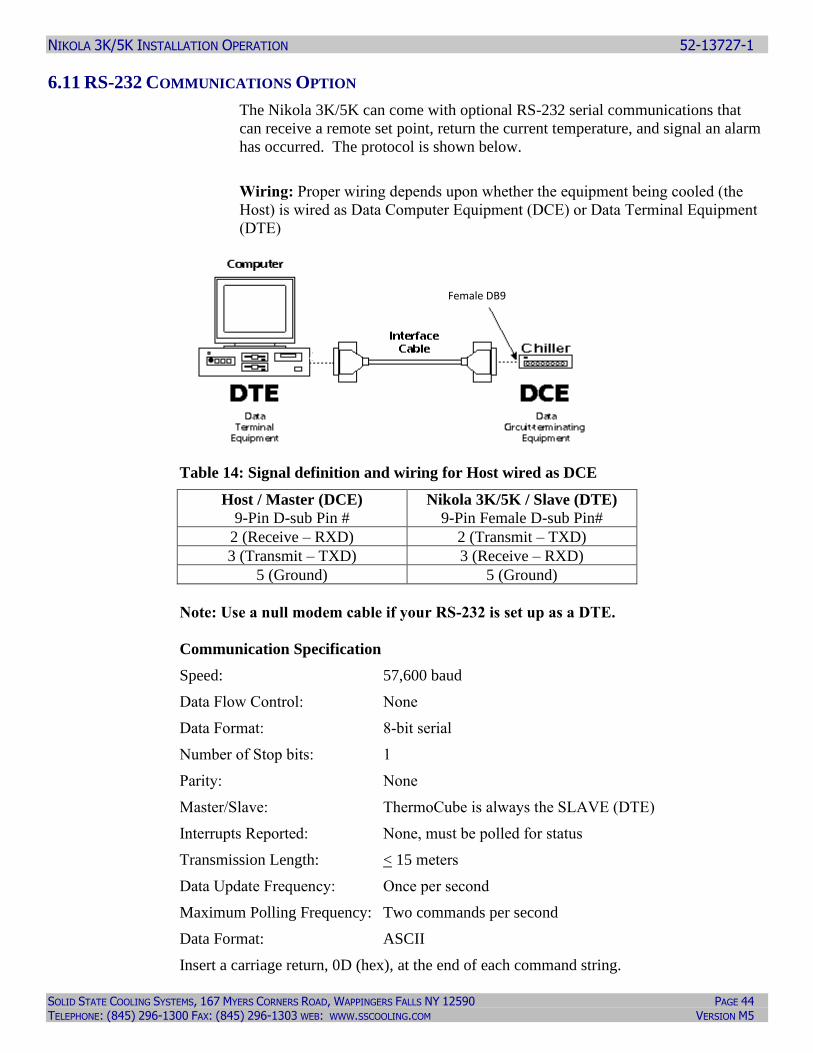
6.11 RS-232 COMMUNICATIONS OPTION
The Nikola 3K/5K can come with optional RS-232 serial communications that
can receive a remote set point, return the current temperature, and signal an alarm
has occurred. The protocol is shown below.
Wiring: Proper wiring depends upon whether the equipment being cooled (the
Host) is wired as Data Computer Equipment (DCE) or Data Terminal Equipment
(DTE)
Table 14: Signal definition and wiring for Host wired as DCE
Host / Master (DCE)
9-Pin D-sub Pin #
Nikola 3K/5K / Slave (DTE)
9-Pin Female D-sub Pin#
2 (Receive – RXD) 2 (Transmit – TXD)
3 (Transmit – TXD) 3 (Receive – RXD)
5 (Ground) 5 (Ground)
Note: Use a null modem cable if your RS-232 is set up as a DTE.
Communication Specification
Speed: 57,600 baud
Data Flow Control: None
Data Format: 8-bit serial
Number of Stop bits: 1
Parity: None
Master/Slave: ThermoCube is always the SLAVE (DTE)
Interrupts Reported: None, must be polled for status
Transmission Length: < 15 meters
Data Update Frequency: Once per second
Maximum Polling Frequency: Two commands per second
Data Format: ASCII
Insert a carriage return, 0D (hex), at the end of each command string.
Female DB9
NIKOLA 3K/5K INSTALLATION OPERATION 52-13727-1
SOLID STATE COOLING SYSTEMS, 167 MYERS CORNERS ROAD, WAPPINGERS FALLS NY 12590 PAGE 45 TELEPHONE: (845) 296-1300 FAX: (845) 296-1303 WEB: WWW.SSCOOLING.COM VERSION M5
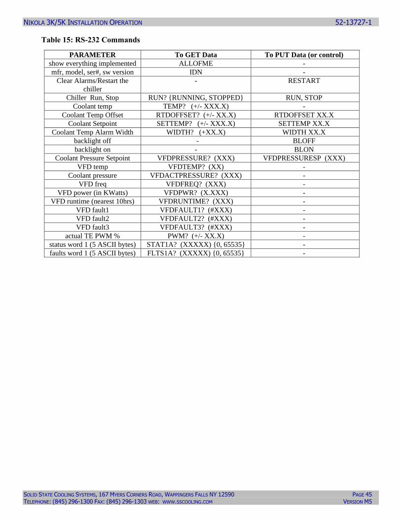
Table 15: RS-232 Commands
PARAMETER To GET Data To PUT Data (or control)
show everything implemented ALLOFME -
mfr, model, ser#, sw version IDN -
Clear Alarms/Restart the
chiller
- RESTART
Chiller Run, Stop RUN? {RUNNING, STOPPED} RUN, STOP
Coolant temp TEMP? (+/- XXX.X) -
Coolant Temp Offset RTDOFFSET? (+/- XX.X) RTDOFFSET XX.X
Coolant Setpoint SETTEMP? (+/- XXX.X) SETTEMP XX.X
Coolant Temp Alarm Width WIDTH? (+XX.X) WIDTH XX.X
backlight off - BLOFF
backlight on - BLON
Coolant Pressure Setpoint VFDPRESSURE? (XXX) VFDPRESSURESP (XXX)
VFD temp VFDTEMP? (XX) -
Coolant pressure VFDACTPRESSURE? (XXX) -
VFD freq VFDFREQ? (XXX) -
VFD power (in KWatts) VFDPWR? (X.XXX) -
VFD runtime (nearest 10hrs) VFDRUNTIME? (XXX) -
VFD fault1 VFDFAULT1? (#XXX) -
VFD fault2 VFDFAULT2? (#XXX) -
VFD fault3 VFDFAULT3? (#XXX) -
actual TE PWM % PWM? (+/- XX.X) -
status word 1 (5 ASCII bytes) STAT1A? (XXXXX) {0, 65535} -
faults word 1 (5 ASCII bytes) FLTS1A? (XXXXX) {0, 65535} -
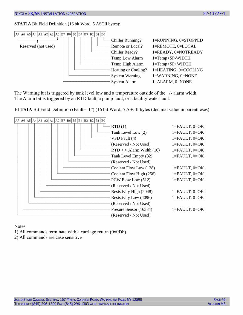
NIKOLA 3K/5K INSTALLATION OPERATION 52-13727-1
SOLID STATE COOLING SYSTEMS, 167 MYERS CORNERS ROAD, WAPPINGERS FALLS NY 12590 PAGE 46 TELEPHONE: (845) 296-1300 FAX: (845) 296-1303 WEB: WWW.SSCOOLING.COM VERSION M5
STAT1A Bit Field Definition (16 bit Word, 5 ASCII bytes):
A7 A6 A5 A4 A3 A2 A1 A0 B7 B6 B5 B4 B3 B2 B1 B0
Chiller Running? 1=RUNNING, 0=STOPPED
Reserved (not used)
Remote or Local? 1=REMOTE, 0=LOCAL
Chiller Ready? 1=READY, 0=NOTREADY
Temp Low Alarm 1=Temp<SP-WIDTH
Temp High Alarm 1=Temp>SP+WIDTH
Heating or Cooling? 1=HEATING, 0=COOLING
System Warning 1=WARNING, 0=NONE
System Alarm 1=ALARM, 0=NONE
The Warning bit is triggered by tank level low and a temperature outside of the +/- alarm width.
The Alarm bit is triggered by an RTD fault, a pump fault, or a facility water fault.
FLTS1A Bit Field Definition (Fault=”1”) (16 bit Word, 5 ASCII bytes (decimal value in parentheses)
A7 A6 A5 A4 A3 A2 A1 A0 B7 B6 B5 B4 B3 B2 B1 B0
RTD (1) 1=FAULT, 0=OK
Tank Level Low (2) 1=FAULT, 0=OK
VFD Fault (4) 1=FAULT, 0=OK
(Reserved / Not Used) 1=FAULT, 0=OK
RTD < > Alarm Width (16) 1=FAULT, 0=OK
Tank Level Empty (32) 1=FAULT, 0=OK
(Reserved / Not Used)
Coolant Flow Low (128) 1=FAULT, 0=OK
Coolant Flow High (256) 1=FAULT, 0=OK
PCW Flow Low (512) 1=FAULT, 0=OK
(Reserved / Not Used)
Resistivity High (2048) 1=FAULT, 0=OK
Resistivity Low (4096) 1=FAULT, 0=OK
(Reserved / Not Used)
Presure Sensor (16384) 1=FAULT, 0=OK
(Reserved / Not Used)
Notes:
1) All commands terminate with a carriage return (0x0Dh)
2) All commands are case sensitive
NIKOLA 3K/5K INSTALLATION OPERATION 52-13727-1
SOLID STATE COOLING SYSTEMS, 167 MYERS CORNERS ROAD, WAPPINGERS FALLS NY 12590 PAGE 47 TELEPHONE: (845) 296-1300 FAX: (845) 296-1303 WEB: WWW.SSCOOLING.COM VERSION M5
7.0 OTHER OPTIONS
7.1 –1W DI WATER/ETHYLENE OR PROPYLENE GLYCOL COOLANT OPTION
When this option is chosen SSCS will configure for and test the unit with
water/glycol. In addition, the unit will include a DI water resistivity sensor
installed in the coolant outlet plumbing. The Nikola 3K/5K will measure the DI
water/Ethylene Glycol resistivity and signal a warning if the measured resistivity
falls below 1 megohm-cm or it reads above 20 megohm-cm; these values can be
changed via the Parameter Input Menu (see section 5). This feature is only active
when coolant type 50/50 WEG is chosen from the parameter menu.
7.2 –RF FRONT RTD OPTION This option moves the temperature control RTD from the
Nikola 3K/5K coolant outlet to a location at the front of the Nikola 3K/5K,
between the pump and thermoelectric heat exchanger. This alternative RTD
location improves process control in some applications. Contact SSCS for details.
8.0 SAFETY
8.1 HAZARDS Electrical Hazards
The Nikola 3K/5K operates on 200-240 VAC 3-phase power. As a result, it has
hazardous voltage present inside its covers. Only qualified personnel should work
on the unit with the covers removed.
Chemical Hazards
The Nikola 3K/5K contains no hazardous chemicals except for the coolant chosen
by the customer. MSDS’s for coolants recommended by SSCS are included in
section 12 of this manual. The user should thoroughly read the MSDS of any
coolant chosen prior to filling and operating the Nikola 3K/5K. Only qualified
personnel should handle coolants used in the Nikola 3K/5K.
The user should contact SSCS prior to using any coolant not recommended in this
manual.
Spill Hazards
The Nikola 3K/5K’s recommended coolants present a slip hazard if spilled on the
floor. All coolant spills should be immediately wiped from the floor and disposed
of in accordance with local and national regulations and the guidelines found in
the coolant MSDS’s in section 12 of this manual.
WARNING
DANGER
DANGER
NIKOLA 3K/5K INSTALLATION OPERATION 52-13727-1
SOLID STATE COOLING SYSTEMS, 167 MYERS CORNERS ROAD, WAPPINGERS FALLS NY 12590 PAGE 48 TELEPHONE: (845) 296-1300 FAX: (845) 296-1303 WEB: WWW.SSCOOLING.COM VERSION M5
8.2LIFTING THE NIKOLA 3K/5K
The Nikola 3K/5K weighs 300 lbs. (136 kg) and is designed to be rolled into
position on its casters, do not lift with personnel. The front side of its shipping
crate is designed to act as a ramp to roll the unit out of its crate. If the unit must
be lifted, use a forklift or pallet jack, inserting the forks between the casters on the
either long side of the chiller.
8.3 ELECTRICAL ENERGY ISOLATION
For installations requiring adherence to SEMI S2 guidelines, the customer must
install a circuit breaker rated in accordance with UL 489, subject to local AHJ
(authorities having jurisdiction) and NEC requirements, with a minimum 10,000
amp interrupt rating on the AC power connecting to the Nikola 3K/5K.
8.4 ELECTRICAL LOCK OUT/TAG OUT
Lock Out
Lock out the main AC power via the following procedure:
1) Disconnect AC power by turning off the customer supplied electrical
disconnect device (see section 7.3).
2) Unlatch the main AC power plug (on the rear panel) and remove the plug.
3) Place a safety padlock through the Nikola 3K/5K’s main AC power connector
latch. AC power cannot be plugged into the Nikola 3K/5K AC power
receptacle with the padlock in place.
Tag Out
When locking out the main AC power receptacle, place a lockout tag through the
main AC power connector latch to identify contact person/phone number. Never
attach a lockout tag without first locking out the connector latch with a padlock.
8.5 ELECTRICAL DISCONNECT REQUIREMENTS
Unit Out of Service
When the Nikola 3K/5K is out of service, disconnect the main AC power via the
customer installed circuit breaker described in manual section 8.3. SSCS
recommends leaving the AC power cord connected unless the system’s covers are
to be removed.
Maintenance
When performing repairs or maintenance on the Nikola 3K/5K that require
removing one or more of the system’s covers, disconnect electrical power as
follows:
1) Open the user installed main AC power circuit breaker described in section 8.3.
2) Disconnect the main AC power plug.
3) Lockout main AC power as per section 8.4.
NIKOLA 3K/5K INSTALLATION OPERATION 52-13727-1
SOLID STATE COOLING SYSTEMS, 167 MYERS CORNERS ROAD, WAPPINGERS FALLS NY 12590 PAGE 49 TELEPHONE: (845) 296-1300 FAX: (845) 296-1303 WEB: WWW.SSCOOLING.COM VERSION M5
8.6 LEAKS
Coolant Leaks
Two types of coolant leaks can occur when operating the Nikola 3K/5K: internal
and external leaks. Internally, the Nikola 3K/5K utilizes stainless steel plumbing
with SAE-style o-ring sealed fittings to minimize the likelihood of leaks. Should
a coolant leak occur, it should be immediately wiped up and properly disposed of
as per sections 7.1.2 and 7.1.3 of this manual.
The Nikola 3K/5K chassis serves as secondary containment for the coolant tank
and holds up to 3 gallons, or 133% of the 2.25 gallon tank volume. If the leak
detection option is not chosen, the operator can use the Tank Level Low warning,
which display’s a warning on the front screen and notifies the etch tool controller
via the tool interface card, to indicate the presence of a leak somewhere in the
coolant loop. A Tank Level Low occurs when the coolant volume in the tank
falls to 1.6, indicating a leak of up to 0.6 gallons (2.3 liters) has occurred. The
chiller will continue to run normally when a Tank Level Low warning is present.
If the leak continues without action from the operator, the next alarm is Tank
Level Empty.
A Tank Level Empty alarm occurs when the tank level drops to 0.75 gallons,
indicating a leak of up to 1.5 gallons. A Tank Level Empty alarm will shut down
the Nikola 3K/5K.
Should a Tank Level Low warning or Tank Level Empty alarm occur, the
operator should immediately check for leaks. If the coolant is a fluorinated heat
transfer fluid, such as Fluorinert, Galden, or Novec, a halogen leak detector works
well for finding leaks. For water based coolants, visual inspection must suffice.
First check the external plumbing lines for leaks. If no leaks are found in the
external plumbing, then the open the Nikola 3K/5K’s plumbing access panel
(located on the left side) to find the leak. Only trained maintenance personnel
should remove plumbing access panel as hazardous voltages are present inside. If
coolant is found in the chassis, schedule maintenance on the chiller. Follow the
safety guidelines in section 8.4 prior to performing maintenance.
8.7 PLANT COOLING WATER LEAKS
Two types of plant cooling water (PCW) leaks can occur when operating the
Nikola 3K/5K: internal and external leaks. Internally, the Nikola 3K/5K utilizes
stainless steel plumbing with SAE-style o-ring sealed fittings to minimize the
likelihood of leaks. Should a PCW leak occur, it may contain treatment
chemicals and should be immediately wiped up as per sections 7.12 and 7.1.3 of
this manual. The Nikola 3K/5K has no means of detecting PCW leaks. As a
result, the leak will fill the Nikola 3K/5K’s secondary containment until the total
volume reaches 3 gallons. Once the leak has reached 3 gallons, PCW will flow
out of the Nikola 3K/5K onto the surrounding floor, creating a slip hazard.
The Nikola 3K/5K’s main circuit breaker does have a ground fault circuit
interrupt feature. Should a water leak come in contact with electrically live
components, this circuit breaker will disconnect the main AC power.
WARNING
DANGER
WARNING
NIKOLA 3K/5K INSTALLATION OPERATION 52-13727-1
SOLID STATE COOLING SYSTEMS, 167 MYERS CORNERS ROAD, WAPPINGERS FALLS NY 12590 PAGE 50 TELEPHONE: (845) 296-1300 FAX: (845) 296-1303 WEB: WWW.SSCOOLING.COM VERSION M5
To identify the source of an internal PCW leak, first disconnect main AC power
as per section 8.4 of this manual. (Leave the PCW flow on.) Open the Nikola
3K/5K plumbing access panel (located on the left side) and inspect the blue PCW
hoses and attached fittings. Once the leak is found, disconnect the PCW as per
section 8.6 and repair the leak.
External water leaks will also not be contained nor detected by the Nikola 3K/5K.
8.8 DISCONNECTING PLANT COOLING WATER
Plant cooling water (PCW) is often under high pressures on both the supply and
return sides, typically 100 psig (7 bar) on the supply side and 80 psig (5.5 bar) on
the return side. As a result, maintenance personnel should take care in
disconnecting (PCW) lines. SSCS recommends the use of single or double ended
shut off valves on PCW lines for easy and safe disconnection of plant cooling
water. See section 3.3 of this manual for details. If quick disconnect valves are
not employed, then prior to disconnecting PCW lines from the chiller, the user
must shut off and tag the factory’s cooling water shut-off valves.
Disconnecting plant cooling water using double-ended shut-off valves:
1) Unplug the supply side PCW quick-disconnect fitting.
2) Unplug the return side PCW quick disconnect fitting.
Disconnecting plant cooling water using single-ended shut-off valves:
1) Place a drip pan under the PCW quick-disconnect fittings.
2) Unplug the supply side PCW quick-disconnect fitting.
3) Unplug the return side PCW quick disconnect fitting.
Disconnecting plant cooling water using the facility’s shut-off valves:
1) Shut-off and tag the factory’s plant cooling water valves to the chiller.
2) Place a drip pan under the PCW fittings at the rear of the chiller.
3) Using a 11/8” wrench, disconnect the supply side PCW Swagelok® fitting.
4) Using a 11/8” wrench, disconnect the return side PCW Swagelok® fitting.
Note: Since PCW may contain hazardous treatment chemicals, dispose of any
spilled or drained PCW in accordance with MSDS (see section 13 of this manual).
8.9 COOLANT DISPOSAL
Dispose of any coolants spilled or drained from the Nikola 3K/5K in accordance
with national and local guidelines and the coolant’s MSDS found in section 13 of
this manual.
WARNING
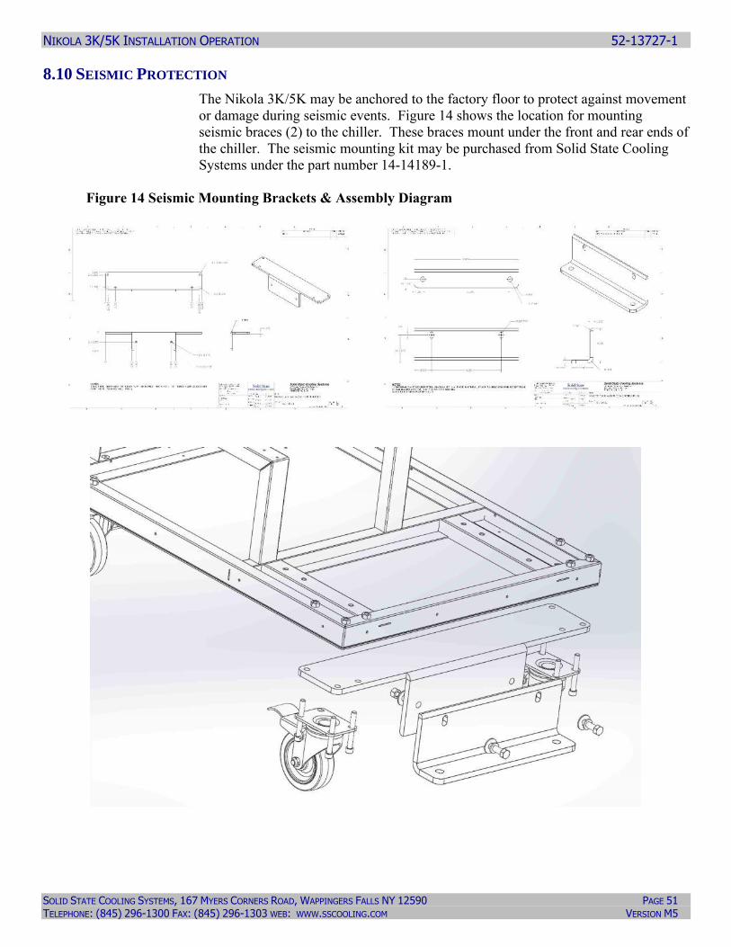
NIKOLA 3K/5K INSTALLATION OPERATION 52-13727-1
SOLID STATE COOLING SYSTEMS, 167 MYERS CORNERS ROAD, WAPPINGERS FALLS NY 12590 PAGE 51 TELEPHONE: (845) 296-1300 FAX: (845) 296-1303 WEB: WWW.SSCOOLING.COM VERSION M5
8.10 SEISMIC PROTECTION
The Nikola 3K/5K may be anchored to the factory floor to protect against movement
or damage during seismic events. Figure 14 shows the location for mounting
seismic braces (2) to the chiller. These braces mount under the front and rear ends of
the chiller. The seismic mounting kit may be purchased from Solid State Cooling
Systems under the part number 14-14189-1.
Figure 14 Seismic Mounting Brackets & Assembly Diagram
NIKOLA 3K/5K INSTALLATION OPERATION 52-13727-1
SOLID STATE COOLING SYSTEMS, 167 MYERS CORNERS ROAD, WAPPINGERS FALLS NY 12590 PAGE 52 TELEPHONE: (845) 296-1300 FAX: (845) 296-1303 WEB: WWW.SSCOOLING.COM VERSION M5
8.11 MINIMUM PERSONAL PROTECTIVE
Manual Operation Equipment
No personal protective equipment is required for normal operation of the Nikola
3K/5K.
Handling Coolant
When filling the tank with coolant, the operator should wear the proper protective
equipment recommended by the MSDS of the coolant used. See section 12 of this
manual.
PCW Spills
When handling PCW spills, always follow your factory spill handling procedures
Coolant Spills
When handling coolant spills, the operator must wear the personal protective
equipment recommended in the MSDS of the coolant spilled. See section 12 of
this manual.
9.0 MAINTENANCE
9.1 PRODUCT LIFE:
The Nikola 3K/5K requires no routine maintenance when operated in a dust free
environment. The only moving parts in the Nikola 3K/5K are the fan and the
pump. The fan has a B10 life of 70,000 hours (8 years) while the pump has an
estimated life of 5 years. The thermoelectric modules used for heating and
cooling have estimated lifetimes that exceed 200,000 hours (23 years). With
regular pump replacement every five years and fan replacement every 8 years, the
product should have a life of 20 years.
SSCS recommends the following regular inspections to verify the unit is
operating properly so its lifetime is not impaired:
9.2 RECOMMENDED WEEKLY INSPECTION:
1) Check the front display to verify the coolant level is ok. If the coolant level is
low, follow the procedure in section 4.2 to add coolant.
2) Vent the tank: using an 11/16” open ended wrench, loosen the tank vent nut to
vent the tank, then re-tighten ¼ turn past finger tight.
3) Check that the rear fan is rotating and free of dust. Blow off any dust with
compressed air or nitrogen.
NIKOLA 3K/5K INSTALLATION OPERATION 52-13727-1
SOLID STATE COOLING SYSTEMS, 167 MYERS CORNERS ROAD, WAPPINGERS FALLS NY 12590 PAGE 53 TELEPHONE: (845) 296-1300 FAX: (845) 296-1303 WEB: WWW.SSCOOLING.COM VERSION M5
9.3 RECOMMENDED ANNUAL INSPECTION:
1) Verify that the coolant outlet pressure is at set point +/- 3 psig (0.2 bar); a
coolant pressure lower than this is sign of pump wear while a coolant pressure
higher than this is a sign of a problem with the variable frequency drive (VFD).
2) Check that the rear fan is rotating and free of dust. Blow off any dust with
compressed air or nitrogen.
3) If using ethylene or propylene glycol/water mixtures, sample and analyze the
coolant annually to ensure no glycol degradation has occurred.
9.4 WIPE DOWN:
The Nikola 3K/5K exterior may be wiped down with IPA wetted clean room
wipes to remove any dust or dirt as desired.
10.0 SYSTEM ALARMS AND TROUBLESHOOTING
The Nikola 3K/5K has hardware interlocks and software warnings and faults to
prevent hazardous operation of the system in the event of failures or operation
outside the prescribed limits. These are shown on the display screen and can also
be seen on the Fault screen. If there is an action you can take listed in the table
below then do it, otherwise, call for service. Do not take the covers off of the
system. Table 16 shows and describes the hardware interlocks. Table 17 shows
and describes the warnings and alarms.
Table 16: Nikola 3K/5K Hardware Interlocks
Interlock Description Correction
GFCI Unit main power GFCI breaker
detects a ground current > 30mA
A short to ground has occurred
somewhere in the chiller.
Check for water leaks or a short in the
thermoelectric heat exchanger. Correct the leak
or replace the thermoelectric heat exchanger
EMO Emergency off activates the main
power shutoff
Rotate EMO button counter-clockwise and restart
the chiller.
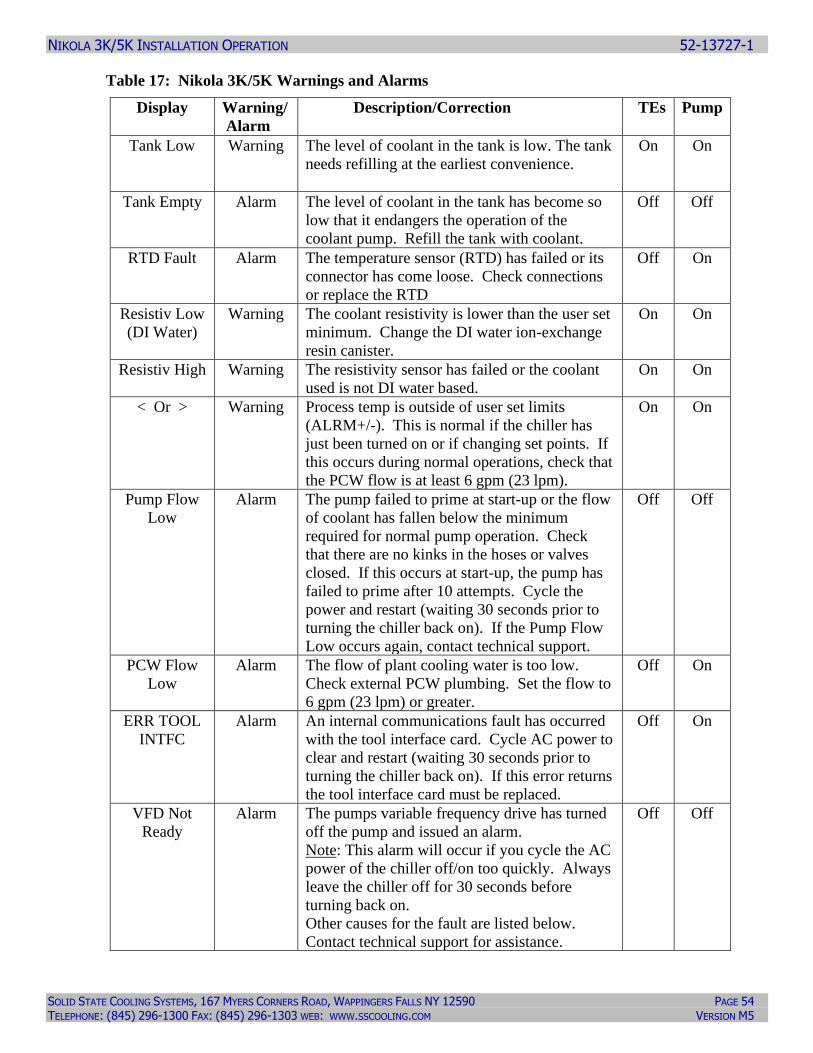
NIKOLA 3K/5K INSTALLATION OPERATION 52-13727-1
SOLID STATE COOLING SYSTEMS, 167 MYERS CORNERS ROAD, WAPPINGERS FALLS NY 12590 PAGE 54 TELEPHONE: (845) 296-1300 FAX: (845) 296-1303 WEB: WWW.SSCOOLING.COM VERSION M5
Table 17: Nikola 3K/5K Warnings and Alarms
Display Warning/
Alarm
Description/Correction TEs Pump
Tank Low Warning The level of coolant in the tank is low. The tank
needs refilling at the earliest convenience.
On On
Tank Empty Alarm The level of coolant in the tank has become so
low that it endangers the operation of the
coolant pump. Refill the tank with coolant.
Off Off
RTD Fault Alarm The temperature sensor (RTD) has failed or its
connector has come loose. Check connections
or replace the RTD
Off On
Resistiv Low
(DI Water)
Warning The coolant resistivity is lower than the user set
minimum. Change the DI water ion-exchange
resin canister.
On On
Resistiv High Warning The resistivity sensor has failed or the coolant
used is not DI water based.
On On
< Or > Warning Process temp is outside of user set limits
(ALRM+/-). This is normal if the chiller has
just been turned on or if changing set points. If
this occurs during normal operations, check that
the PCW flow is at least 6 gpm (23 lpm).
On On
Pump Flow
Low
Alarm The pump failed to prime at start-up or the flow
of coolant has fallen below the minimum
required for normal pump operation. Check
that there are no kinks in the hoses or valves
closed. If this occurs at start-up, the pump has
failed to prime after 10 attempts. Cycle the
power and restart (waiting 30 seconds prior to
turning the chiller back on). If the Pump Flow
Low occurs again, contact technical support.
Off Off
PCW Flow
Low
Alarm The flow of plant cooling water is too low.
Check external PCW plumbing. Set the flow to
6 gpm (23 lpm) or greater.
Off On
ERR TOOL
INTFC
Alarm An internal communications fault has occurred
with the tool interface card. Cycle AC power to
clear and restart (waiting 30 seconds prior to
turning the chiller back on). If this error returns
the tool interface card must be replaced.
Off On
VFD Not
Ready
Alarm The pumps variable frequency drive has turned
off the pump and issued an alarm.
Note: This alarm will occur if you cycle the AC
power of the chiller off/on too quickly. Always
leave the chiller off for 30 seconds before
turning back on.
Other causes for the fault are listed below.
Contact technical support for assistance.
Off Off
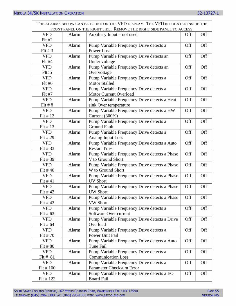
NIKOLA 3K/5K INSTALLATION OPERATION 52-13727-1
SOLID STATE COOLING SYSTEMS, 167 MYERS CORNERS ROAD, WAPPINGERS FALLS NY 12590 PAGE 55 TELEPHONE: (845) 296-1300 FAX: (845) 296-1303 WEB: WWW.SSCOOLING.COM VERSION M5
THE ALARMS BELOW CAN BE FOUND ON THE VFD DISPLAY. THE VFD IS LOCATED INSIDE THE
FRONT PANEL ON THE RIGHT SIDE. REMOVE THE RIGHT SIDE PANEL TO ACCESS.
VFD
Flt #2
Alarm Auxiliary Input – not used Off Off
VFD
Flt # 3
Alarm Pump Variable Frequency Drive detects a
Power Loss
Off Off
VFD
Flt #4
Alarm Pump Variable Frequency Drive detects an
Under voltage
Off Off
VFD
Flt#5
Alarm Pump Variable Frequency Drive detects an
Overvoltage
Off Off
VFD
Flt #6
Alarm Pump Variable Frequency Drive detects a
Motor Stalled
Off Off
VFD
Flt #7
Alarm Pump Variable Frequency Drive detects a
Motor Current Overload
Off Off
VFD
Flt # 8
Alarm Pump Variable Frequency Drive detects a Heat
sink Over temperature
Off Off
VFD
Flt # 12
Alarm Pump Variable Frequency Drive detects a HW
Current (300%)
Off Off
VFD
Flt # 13
Alarm Pump Variable Frequency Drive detects a
Ground Fault
Off Off
VFD
Flt # 29
Alarm Pump Variable Frequency Drive detects a
Analog Input Loss
Off Off
VFD
Flt # 33
Alarm Pump Variable Frequency Drive detects a Auto
Restart Tries
Off Off
VFD
Flt # 39
Alarm Pump Variable Frequency Drive detects a Phase
V to Ground Short
Off Off
VFD
Flt # 40
Alarm Pump Variable Frequency Drive detects a Phase
W to Ground Short
Off Off
VFD
Flt # 41
Alarm Pump Variable Frequency Drive detects a Phase
UV Short
Off Off
VFD
Flt # 42
Alarm Pump Variable Frequency Drive detects a Phase
UW Short
Off Off
VFD
Flt # 43
Alarm Pump Variable Frequency Drive detects a Phase
VW Short
Off Off
VFD
Flt # 63
Alarm Pump Variable Frequency Drive detects a
Software Over current
Off Off
VFD
Flt # 64
Alarm Pump Variable Frequency Drive detects a Drive
Overload
Off Off
VFD
Flt # 70
Alarm Pump Variable Frequency Drive detects a
Power Unit Fail
Off Off
VFD
Flt # 80
Alarm Pump Variable Frequency Drive detects a Auto
Tune Fail
Off Off
VFD
Flt # 81
Alarm Pump Variable Frequency Drive detects a
Communication Loss
Off Off
VFD
Flt # 100
Alarm Pump Variable Frequency Drive detects a
Parameter Checksum Error
Off Off
VFD
Flt # 122
Alarm Pump Variable Frequency Drive detects a I/O
Board Fail
Off Off
NIKOLA 3K/5K INSTALLATION OPERATION 52-13727-1
SOLID STATE COOLING SYSTEMS, 167 MYERS CORNERS ROAD, WAPPINGERS FALLS NY 12590 PAGE 56 TELEPHONE: (845) 296-1300 FAX: (845) 296-1303 WEB: WWW.SSCOOLING.COM VERSION M5
11.0 TECHNICAL SUPPORT
Delighting our customers is our highest priority. Please contact us immediately
for technical assistance whenever you have questions or concerns.
Hours: 8 a.m. to 5 p.m. E.S.T., weekdays
Telephone: (845) 296-1300
Fax: (845) 296-1303
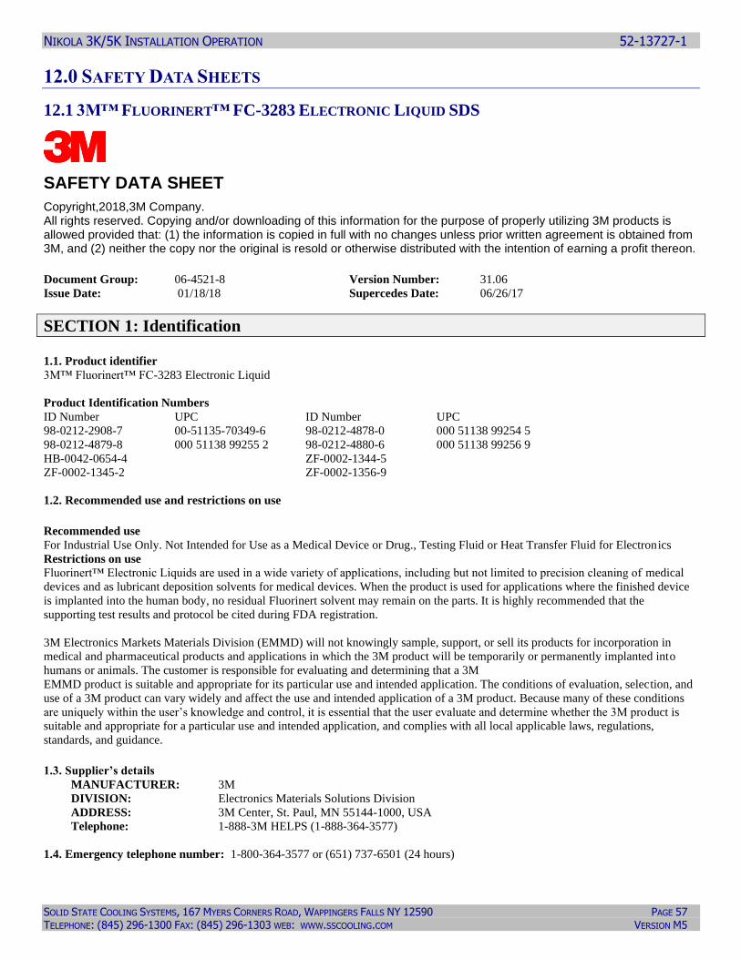
NIKOLA 3K/5K INSTALLATION OPERATION 52-13727-1
SOLID STATE COOLING SYSTEMS, 167 MYERS CORNERS ROAD, WAPPINGERS FALLS NY 12590 PAGE 57 TELEPHONE: (845) 296-1300 FAX: (845) 296-1303 WEB: WWW.SSCOOLING.COM VERSION M5
12.0 SAFETY DATA SHEETS
12.1 3M™ FLUORINERT™ FC-3283 ELECTRONIC LIQUID SDS
SAFETY DATA SHEET
Copyright,2018,3M Company. All rights reserved. Copying and/or downloading of this information for the purpose of properly utilizing 3M products is allowed provided that: (1) the information is copied in full with no changes unless prior written agreement is obtained from 3M, and (2) neither the copy nor the original is resold or otherwise distributed with the intention of earning a profit thereon.
Document Group: 06-4521-8 Version Number: 31.06
Issue Date: 01/18/18 Supercedes Date: 06/26/17
SECTION 1: Identification 1.1. Product identifier
3M™ Fluorinert™ FC-3283 Electronic Liquid
Product Identification Numbers
ID Number UPC ID Number UPC
98-0212-2908-7 00-51135-70349-6 98-0212-4878-0 000 51138 99254 5
98-0212-4879-8 000 51138 99255 2 98-0212-4880-6 000 51138 99256 9
HB-0042-0654-4 ZF-0002-1344-5
ZF-0002-1345-2 ZF-0002-1356-9
1.2. Recommended use and restrictions on use Recommended use
For Industrial Use Only. Not Intended for Use as a Medical Device or Drug., Testing Fluid or Heat Transfer Fluid for Electronics
Restrictions on use
Fluorinert™ Electronic Liquids are used in a wide variety of applications, including but not limited to precision cleaning of medical
devices and as lubricant deposition solvents for medical devices. When the product is used for applications where the finished device
is implanted into the human body, no residual Fluorinert solvent may remain on the parts. It is highly recommended that the
supporting test results and protocol be cited during FDA registration.
3M Electronics Markets Materials Division (EMMD) will not knowingly sample, support, or sell its products for incorporation in
medical and pharmaceutical products and applications in which the 3M product will be temporarily or permanently implanted into
humans or animals. The customer is responsible for evaluating and determining that a 3M
EMMD product is suitable and appropriate for its particular use and intended application. The conditions of evaluation, selection, and
use of a 3M product can vary widely and affect the use and intended application of a 3M product. Because many of these conditions
are uniquely within the user’s knowledge and control, it is essential that the user evaluate and determine whether the 3M product is
suitable and appropriate for a particular use and intended application, and complies with all local applicable laws, regulations,
standards, and guidance. 1.3. Supplier’s details
MANUFACTURER: 3M
DIVISION: Electronics Materials Solutions Division
ADDRESS: 3M Center, St. Paul, MN 55144-1000, USA
Telephone: 1-888-3M HELPS (1-888-364-3577)
1.4. Emergency telephone number: 1-800-364-3577 or (651) 737-6501 (24 hours)
NIKOLA 3K/5K INSTALLATION OPERATION 52-13727-1
SOLID STATE COOLING SYSTEMS, 167 MYERS CORNERS ROAD, WAPPINGERS FALLS NY 12590 PAGE 58 TELEPHONE: (845) 296-1300 FAX: (845) 296-1303 WEB: WWW.SSCOOLING.COM VERSION M5
SECTION 2: Hazard identification 2.1. Hazard classification
Not classified as hazardous according to OSHA Hazard Communication Standard, 29 CFR 1910.1200.
2.2. Label elements
Signal word
Not applicable.
Symbols
Not applicable.
Pictograms
Not applicable.
SECTION 3: Composition/information on ingredients
Ingredient C.A.S. No. % by Wt
PERFLUORO COMPOUNDS, C5-18 86508-42-1 100 (typically 100)
SECTION 4: First aid measures 4.1. Description of first aid measures
Inhalation:
No need for first aid is anticipated.
Skin Contact:
Wash with soap and water. If signs/symptoms develop, get medical attention.
Eye Contact:
Flush with large amounts of water. Remove contact lenses if easy to do. Continue rinsing. If signs/symptoms persist, get medical
attention.
If Swallowed:
Rinse mouth. If you feel unwell, get medical attention.
4.2. Most important symptoms and effects, both acute and delayed
See Section 11.1. Information on toxicological effects.
4.3. Indication of any immediate medical attention and special treatment required
Not applicable
SECTION 5: Fire-fighting measures 5.1. Suitable extinguishing media
Material will not burn. Use a fire fighting agent suitable for the surrounding fire.
5.2. Special hazards arising from the substance or mixture
Exposure to extreme heat can give rise to thermal decomposition.
Hazardous Decomposition or By-Products
Substance Condition
Carbon monoxide During Combustion
Carbon dioxide During Combustion
NIKOLA 3K/5K INSTALLATION OPERATION 52-13727-1
SOLID STATE COOLING SYSTEMS, 167 MYERS CORNERS ROAD, WAPPINGERS FALLS NY 12590 PAGE 59 TELEPHONE: (845) 296-1300 FAX: (845) 296-1303 WEB: WWW.SSCOOLING.COM VERSION M5
5.3. Special protective actions for fire-fighters
When fire fighting conditions are severe and total thermal decomposition of the product is possible, wear full protective clothing,
including helmet, self-contained, positive pressure or pressure demand breathing apparatus, bunker coat and pants, bands around arms,
waist and legs, face mask, and protective covering for exposed areas of the head.
SECTION 6: Accidental release measures 6.1. Personal precautions, protective equipment and emergency procedures
Evacuate area. Ventilate the area with fresh air. For large spill, or spills in confined spaces, provide mechanical ventilation to disperse
or exhaust vapors, in accordance with good industrial hygiene practice. Refer to other sections of this SDS for information regarding
physical and health hazards, respiratory protection, ventilation, and personal protective equipment.
6.2. Environmental precautions
Avoid release to the environment. For larger spills, cover drains and build dikes to prevent entry into sewer systems or bodies of
water.
6.3. Methods and material for containment and cleaning up
Contain spill. Working from around the edges of the spill inward, cover with bentonite, vermiculite, or commercially available
inorganic absorbent material. Mix in sufficient absorbent until it appears dry. Remember, adding an absorbent material does not
remove a physical, health, or environmental hazard. Collect as much of the spilled material as possible. Place in a closed container
approved for transportation by appropriate authorities. Clean up residue with an appropriate solvent selected by a qualified and
authorized person. Ventilate the area with fresh air. Read and follow safety precautions on the solvent label and SDS. Seal the
container. Dispose of collected material as soon as possible in accordance with applicable local/regional/national/international
regulations.
SECTION 7: Handling and storage 7.1. Precautions for safe handling
Do not breathe thermal decomposition products. Avoid skin contact with hot material. For industrial or professional use only. Store
work clothes separately from other clothing, food and tobacco products. Do not eat, drink or smoke when using this product. Wash
thoroughly after handling. Avoid release to the environment. No smoking: Smoking while using this product can result in
contamination of the tobacco and/or smoke and lead to the formation of hazardous decomposition products.
7.2. Conditions for safe storage including any incompatibilities
Store away from heat.
SECTION 8: Exposure controls/personal protection 8.1. Control parameters
Occupational exposure limits
No occupational exposure limit values exist for any of the components listed in Section 3 of this SDS.
8.2. Exposure controls
8.2.1. Engineering controls Provide appropriate local exhaust when product is heated.
8.2.2. Personal protective equipment (PPE)
Eye/face protection
None required.
NIKOLA 3K/5K INSTALLATION OPERATION 52-13727-1
SOLID STATE COOLING SYSTEMS, 167 MYERS CORNERS ROAD, WAPPINGERS FALLS NY 12590 PAGE 60 TELEPHONE: (845) 296-1300 FAX: (845) 296-1303 WEB: WWW.SSCOOLING.COM VERSION M5
Skin/hand protection
Select and use gloves and/or protective clothing approved to relevant local standards to prevent skin contact based on the results of an
exposure assessment. Selection should be based on use factors such as exposure levels, concentration of the substance or mixture,
frequency and duration, physical challenges such as temperature extremes, and other use conditions. Consult with your glove and/or
protective clothing manufacturer for selection of appropriate compatible gloves/protective clothing. Note: Nitrile gloves may be worn
over polymer laminate gloves to improve dexterity. Gloves made from the following material(s) are recommended: Polymer laminate
Respiratory protection
During heating:
Use a positive pressure supplied-air respirator if there is a potential for over exposure from an uncontrolled release, exposure
levels are not known, or under any other circumstances where air-purifying respirators may not provide adequate protection.
Thermal hazards
Wear heat insulating gloves when handling hot material to prevent thermal burns.
SECTION 9: Physical and chemical properties 9.1. Information on basic physical and chemical properties
General Physical Form: Liquid
Specific Physical Form: Liquid
Odor, Color, Grade: Colorless, odorless liquid.
Odor threshold No Data Available
pH Not Applicable
Melting point Not Applicable
Boiling Point 123 - 133 ºC
Flash Point No flash point
Evaporation rate < 1 [Ref Std:BUOAC=1]
Flammability (solid, gas) Not Applicable
Flammable Limits(LEL) None detected
Flammable Limits(UEL) None detected
Vapor Pressure 14 mmHg [@ 23 ºC]
Vapor Density 18 [@ 23 ºC] [Ref Std:AIR=1]
Density 1.8 g/ml
Specific Gravity 1.8 [Ref Std:WATER=1]
Solubility in Water Nil
Solubility- non-water No Data Available
Partition coefficient: n-octanol/ water No Data Available
Autoignition temperature No Data Available
Decomposition temperature Not Applicable
Viscosity 0.7 centistoke [@ 25 ºC ]
Molecular weight No Data Available
Volatile Organic Compounds [Details:Exempt]
Percent volatile 100 %
VOC Less H2O & Exempt Solvents [Details:Exempt]
SECTION 10: Stability and reactivity 10.1. Reactivity
This material may be reactive with certain agents under certain conditions - see the remaining headings in this section.
10.2. Chemical stability
Stable.
NIKOLA 3K/5K INSTALLATION OPERATION 52-13727-1
SOLID STATE COOLING SYSTEMS, 167 MYERS CORNERS ROAD, WAPPINGERS FALLS NY 12590 PAGE 61 TELEPHONE: (845) 296-1300 FAX: (845) 296-1303 WEB: WWW.SSCOOLING.COM VERSION M5
10.3. Possibility of hazardous reactions
Hazardous polymerization will not occur.
10.4. Conditions to avoid
Heat
10.5. Incompatible materials
Finely divided active metals
Alkali and alkaline earth metals
10.6. Hazardous decomposition products
Substance Condition
Hydrogen Fluoride At Elevated Temperatures - greater than 200 ºC
Perfluoroisobutylene (PFIB) At Elevated Temperatures - greater than 200 ºC
Refer to section 5.2 for hazardous decomposition products during combustion.
If the product is exposed to extreme condition of heat from misuse or equipment failure, toxic decomposition products that include
hydrogen fluoride and perfluoroisobutylene can occur.
SECTION 11: Toxicological information The information below may not be consistent with the material classification in Section 2 if specific ingredient classifications
are mandated by a competent authority. In addition, toxicological data on ingredients may not be reflected in the material
classification and/or the signs and symptoms of exposure, because an ingredient may be present below the threshold for
labeling, an ingredient may not be available for exposure, or the data may not be relevant to the material as a whole.
11.1. Information on Toxicological effects
Signs and Symptoms of Exposure
Based on test data and/or information on the components, this material may produce the following health effects:
Inhalation:
No known health effects.
Skin Contact:
Contact with the skin during product use is not expected to result in significant irritation.
Eye Contact:
Contact with the eyes during product use is not expected to result in significant irritation.
Ingestion: Ingestion: May be harmful if swallowed.
Additional Information:
A Material Toxicity Summary Sheet (MTSS) has been developed for this product. Please contact the address listed on the first page of
this SDS to obtain a copy of the MTSS for this product.
Toxicological Data
If a component is disclosed in section 3 but does not appear in a table below, either no data are available for that endpoint or the data
are not sufficient for classification.
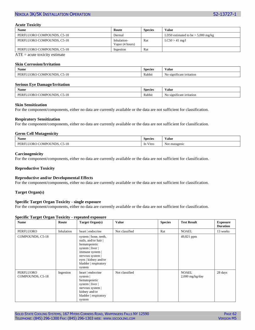
NIKOLA 3K/5K INSTALLATION OPERATION 52-13727-1
SOLID STATE COOLING SYSTEMS, 167 MYERS CORNERS ROAD, WAPPINGERS FALLS NY 12590 PAGE 62 TELEPHONE: (845) 296-1300 FAX: (845) 296-1303 WEB: WWW.SSCOOLING.COM VERSION M5
Acute Toxicity
Name Route Species Value
PERFLUORO COMPOUNDS, C5-18 Dermal LD50 estimated to be > 5,000 mg/kg
PERFLUORO COMPOUNDS, C5-18 Inhalation- Vapor (4 hours)
Rat LC50 > 41 mg/l
PERFLUORO COMPOUNDS, C5-18 Ingestion Rat
ATE = acute toxicity estimate
Skin Corrosion/Irritation
Name Species Value
PERFLUORO COMPOUNDS, C5-18 Rabbit No significant irritation
Serious Eye Damage/Irritation
Name Species Value
PERFLUORO COMPOUNDS, C5-18 Rabbit No significant irritation
Skin Sensitization
For the component/components, either no data are currently available or the data are not sufficient for classification.
Respiratory Sensitization
For the component/components, either no data are currently available or the data are not sufficient for classification.
Germ Cell Mutagenicity
Name Species Value
PERFLUORO COMPOUNDS, C5-18 In Vitro Not mutagenic
Carcinogenicity
For the component/components, either no data are currently available or the data are not sufficient for classification.
Reproductive Toxicity
Reproductive and/or Developmental Effects
For the component/components, either no data are currently available or the data are not sufficient for classification.
Target Organ(s)
Specific Target Organ Toxicity - single exposure
For the component/components, either no data are currently available or the data are not sufficient for classification.
Specific Target Organ Toxicity - repeated exposure
Name Route Target Organ(s) Value Species Test Result Exposure
Duration
PERFLUORO Inhalation heart | endocrine Not classified Rat NOAEL 13 weeks
COMPOUNDS, C5-18 system | bone, teeth, nails, and/or hair |
hematopoietic
system | liver |
immune system |
nervous system |
eyes | kidney and/or bladder | respiratory
system
49,821 ppm
PERFLUORO
COMPOUNDS, C5-18
Ingestion heart | endocrine
system | hematopoietic
system | liver |
nervous system | kidney and/or
bladder | respiratory
system
Not classified NOAEL
2,000 mg/kg/day
28 days
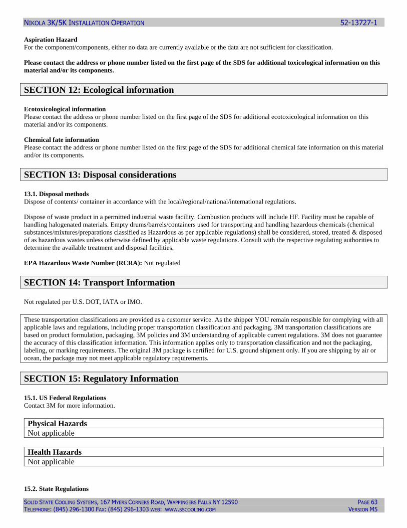
NIKOLA 3K/5K INSTALLATION OPERATION 52-13727-1
SOLID STATE COOLING SYSTEMS, 167 MYERS CORNERS ROAD, WAPPINGERS FALLS NY 12590 PAGE 63 TELEPHONE: (845) 296-1300 FAX: (845) 296-1303 WEB: WWW.SSCOOLING.COM VERSION M5
Aspiration Hazard
For the component/components, either no data are currently available or the data are not sufficient for classification.
Please contact the address or phone number listed on the first page of the SDS for additional toxicological information on this
material and/or its components.
SECTION 12: Ecological information Ecotoxicological information
Please contact the address or phone number listed on the first page of the SDS for additional ecotoxicological information on this
material and/or its components.
Chemical fate information
Please contact the address or phone number listed on the first page of the SDS for additional chemical fate information on this material
and/or its components.
SECTION 13: Disposal considerations 13.1. Disposal methods
Dispose of contents/ container in accordance with the local/regional/national/international regulations.
Dispose of waste product in a permitted industrial waste facility. Combustion products will include HF. Facility must be capable of
handling halogenated materials. Empty drums/barrels/containers used for transporting and handling hazardous chemicals (chemical
substances/mixtures/preparations classified as Hazardous as per applicable regulations) shall be considered, stored, treated & disposed
of as hazardous wastes unless otherwise defined by applicable waste regulations. Consult with the respective regulating authorities to
determine the available treatment and disposal facilities.
EPA Hazardous Waste Number (RCRA): Not regulated
SECTION 14: Transport Information Not regulated per U.S. DOT, IATA or IMO.
These transportation classifications are provided as a customer service. As the shipper YOU remain responsible for complying with all
applicable laws and regulations, including proper transportation classification and packaging. 3M transportation classifications are
based on product formulation, packaging, 3M policies and 3M understanding of applicable current regulations. 3M does not guarantee
the accuracy of this classification information. This information applies only to transportation classification and not the packaging,
labeling, or marking requirements. The original 3M package is certified for U.S. ground shipment only. If you are shipping by air or
ocean, the package may not meet applicable regulatory requirements.
SECTION 15: Regulatory Information 15.1. US Federal Regulations
Contact 3M for more information.
Physical Hazards
Not applicable
Health Hazards
Not applicable
15.2. State Regulations
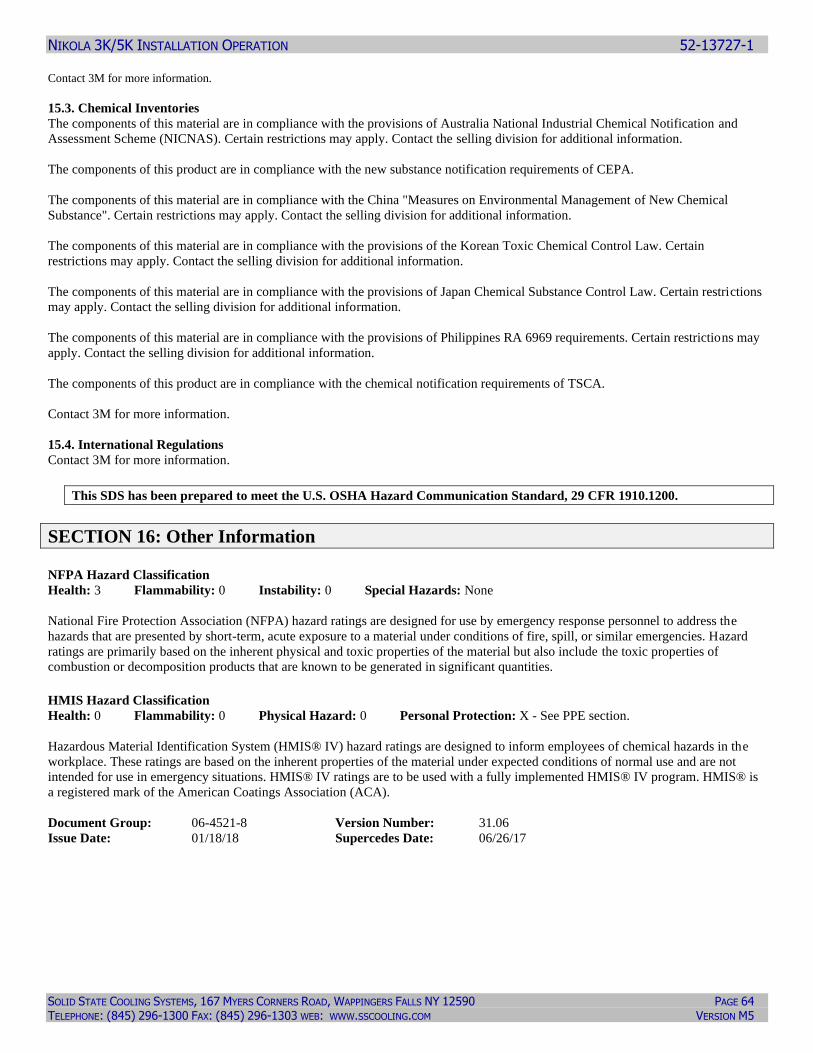
NIKOLA 3K/5K INSTALLATION OPERATION 52-13727-1
SOLID STATE COOLING SYSTEMS, 167 MYERS CORNERS ROAD, WAPPINGERS FALLS NY 12590 PAGE 64 TELEPHONE: (845) 296-1300 FAX: (845) 296-1303 WEB: WWW.SSCOOLING.COM VERSION M5
Contact 3M for more information.
15.3. Chemical Inventories
The components of this material are in compliance with the provisions of Australia National Industrial Chemical Notification and
Assessment Scheme (NICNAS). Certain restrictions may apply. Contact the selling division for additional information.
The components of this product are in compliance with the new substance notification requirements of CEPA.
The components of this material are in compliance with the China "Measures on Environmental Management of New Chemical
Substance". Certain restrictions may apply. Contact the selling division for additional information.
The components of this material are in compliance with the provisions of the Korean Toxic Chemical Control Law. Certain
restrictions may apply. Contact the selling division for additional information.
The components of this material are in compliance with the provisions of Japan Chemical Substance Control Law. Certain restrictions
may apply. Contact the selling division for additional information.
The components of this material are in compliance with the provisions of Philippines RA 6969 requirements. Certain restrictions may
apply. Contact the selling division for additional information.
The components of this product are in compliance with the chemical notification requirements of TSCA.
Contact 3M for more information.
15.4. International Regulations
Contact 3M for more information.
This SDS has been prepared to meet the U.S. OSHA Hazard Communication Standard, 29 CFR 1910.1200.
SECTION 16: Other Information NFPA Hazard Classification
Health: 3 Flammability: 0 Instability: 0 Special Hazards: None
National Fire Protection Association (NFPA) hazard ratings are designed for use by emergency response personnel to address the
hazards that are presented by short-term, acute exposure to a material under conditions of fire, spill, or similar emergencies. Hazard
ratings are primarily based on the inherent physical and toxic properties of the material but also include the toxic properties of
combustion or decomposition products that are known to be generated in significant quantities. HMIS Hazard Classification
Health: 0 Flammability: 0 Physical Hazard: 0 Personal Protection: X - See PPE section.
Hazardous Material Identification System (HMIS® IV) hazard ratings are designed to inform employees of chemical hazards in the
workplace. These ratings are based on the inherent properties of the material under expected conditions of normal use and are not
intended for use in emergency situations. HMIS® IV ratings are to be used with a fully implemented HMIS® IV program. HMIS® is
a registered mark of the American Coatings Association (ACA).
Document Group: 06-4521-8 Version Number: 31.06
Issue Date: 01/18/18 Supercedes Date: 06/26/17
NIKOLA 3K/5K INSTALLATION OPERATION 52-13727-1
SOLID STATE COOLING SYSTEMS, 167 MYERS CORNERS ROAD, WAPPINGERS FALLS NY 12590 PAGE 65 TELEPHONE: (845) 296-1300 FAX: (845) 296-1303 WEB: WWW.SSCOOLING.COM VERSION M5
Reason for Reissue
Conversion to GHS format SDS.
DISCLAIMER: The information in this Safety Data Sheet (SDS) is believed to be correct as of the date issued.3MMAKES NO
WARRANTIES, EXPRESSED OR IMPLIED, INCLUDING, BUT NOT LIMITED TO, ANY IMPLIED WARRANTY OF
MERCHANTABILITY OR FITNESS FOR A PARTICULAR PURPOSE OR COURSE OF PERFORMANCE OR USAGE OF
TRADE. User is responsible for determining whether the3Mproduct is fit for a particular purpose and suitable for user's method of use
or application. Given the variety of factors that can affect the use and application of a3Mproduct, some of which are uniquely within
the user's knowledge and control, it is essential that the user evaluate the3Mproduct to determine whether it is fit for a particular
purpose and suitable for user's method of use or application.
3M provides information in electronic form as a service to its customers. Due to the remote possibility that electronic transfer may
have resulted in errors, omissions or alterations in this information,3Mmakes no representations as to its completeness or accuracy. In
addition, information obtained from a database may not be as current as the information in the SDS available directly from 3M
3M USA SDSs are available at www.3M.com
End of SDS
12.2 3M™ NOVEC™ 7100 ENGINEERED FLUID SDS
SAFETY DATA SHEET
Copyright,2018,3M Company. All rights reserved. Copying and/or downloading of this information for the purpose of properly utilizing 3M products is allowed provided that: (1) the information is copied in full with no changes unless prior written agreement is obtained from 3M, and (2) neither the copy nor the original is resold or otherwise distributed with the intention of earning a profit thereon.
Document Group: 07-6378-9 Version Number: 69.03
Issue Date: 01/18/18 Supercedes Date: 09/06/16
SECTION 1: Identification 1.1. Product identifier
3M™ Novec™ 7100 Engineered Fluid
Product Identification Numbers
ID Number UPC ID Number UPC
98-0211-8940-6 00-51135-11037-9 98-0211-8941-4 00-51135-11038-6
98-0211-8946-3 00-51135-11043-0 98-0212-1011-1 00-51135-45035-2
98-0212-1102-8 00-51135-45124-3 98-0212-1128-3 00-51135-45146-5
98-0212-1148-1 00-51135-63012-9 98-0212-3554-8
98-0212-3635-5
1.2. Recommended use and restrictions on use Recommended use
For Industrial Use Only. Not Intended for Use as a Medical Device or Drug.,
NIKOLA 3K/5K INSTALLATION OPERATION 52-13727-1
SOLID STATE COOLING SYSTEMS, 167 MYERS CORNERS ROAD, WAPPINGERS FALLS NY 12590 PAGE 66 TELEPHONE: (845) 296-1300 FAX: (845) 296-1303 WEB: WWW.SSCOOLING.COM VERSION M5
Restrictions on use
Novec™ Engineered Fluids are used in a wide variety of applications, including but not limited to precision cleaning of medical
devices and as lubricant deposition solvents for medical devices. When the product is used for applications where the finished device
is implanted into the human body, no residual Novec solvent may remain on the parts. It is highly recommended that the supporting
test results and protocol be cited during FDA registration.
3M Electronics Markets Materials Division (EMMD) will not knowingly sample, support, or sell its products for incorporation in
medical and pharmaceutical products and applications in which the 3M product will be temporarily or permanently implanted into
humans or animals. The customer is responsible for evaluating and determining that a 3M EMMD product is suitable and appropriate
for its particular use and intended application. The conditions of evaluation, selection, and use of a 3M product can vary widely and
affect the use and intended application of a 3M product. Because many of these conditions are uniquely within the user’s knowledge
and control, it is essential that the user evaluate and determine whether the 3M product is suitable and appropriate for a particular use
and intended application, and complies with all local applicable laws, regulations, standards, and guidance. 1.3. Supplier’s details
MANUFACTURER: 3M
DIVISION: Electronics Materials Solutions Division
ADDRESS: 3M Center, St. Paul, MN 55144-1000, USA
Telephone: 1-888-3M HELPS (1-888-364-3577)
1.4. Emergency telephone number: 1-800-364-3577 or (651) 737-6501 (24 hours)
SECTION 2: Hazard identification 2.1. Hazard classification
Not classified as hazardous according to OSHA Hazard Communication Standard, 29 CFR 1910.1200.
2.2. Label elements
Signal word
Not applicable.
Symbols
Not applicable.
Pictograms
Not applicable.
SECTION 3: Composition/information on ingredients
Ingredient C.A.S. No. % by Wt
Methyl nonafluorobutyl ether 163702-07-6 20 - 80
Methyl nonafluoroisobutyl ether 163702-08-7 20 - 80
SECTION 4: First aid measures 4.1. Description of first aid measures
Inhalation:
Remove person to fresh air. If you feel unwell, get medical attention.
Skin Contact:
Wash with soap and water. If signs/symptoms develop, get medical attention.
NIKOLA 3K/5K INSTALLATION OPERATION 52-13727-1
SOLID STATE COOLING SYSTEMS, 167 MYERS CORNERS ROAD, WAPPINGERS FALLS NY 12590 PAGE 67 TELEPHONE: (845) 296-1300 FAX: (845) 296-1303 WEB: WWW.SSCOOLING.COM VERSION M5
Eye Contact:
Flush with large amounts of water. Remove contact lenses if easy to do. Continue rinsing. If signs/symptoms persist, get medical
attention.
If Swallowed:
Rinse mouth. If you feel unwell, get medical attention.
4.2. Most important symptoms and effects, both acute and delayed
See Section 11.1. Information on toxicological effects.
4.3. Indication of any immediate medical attention and special treatment required
Not applicable
SECTION 5: Fire-fighting measures 5.1. Suitable extinguishing media
Non-combustible. Use a fire fighting agent suitable for surrounding fire.
5.2. Special hazards arising from the substance or mixture
Exposure to extreme heat can give rise to thermal decomposition.
Hazardous Decomposition or By-Products
Substance Condition
Carbon monoxide During Combustion
Carbon dioxide During Combustion
Hydrogen Fluoride During Composition - at elevated temperatures
5.3. Special protective actions for fire-fighters
When fire fighting conditions are severe and total thermal decomposition of the product is possible, wear full protective clothing,
including helmet, self-contained, positive pressure or pressure demand breathing apparatus, bunker coat and pants, bands around arms,
waist and legs, face mask, and protective covering for exposed areas of the head.
SECTION 6: Accidental release measures 6.1. Personal precautions, protective equipment and emergency procedures
Ventilate the area with fresh air. For large spill, or spills in confined spaces, provide mechanical ventilation to disperse or exhaust
vapors, in accordance with good industrial hygiene practice. Refer to other sections of this SDS for information regarding physical and
health hazards, respiratory protection, ventilation, and personal protective equipment.
6.2. Environmental precautions
Avoid release to the environment. For larger spills, cover drains and build dikes to prevent entry into sewer systems or bodies of
water.
6.3. Methods and material for containment and cleaning up
Contain spill. Working from around the edges of the spill inward, cover with bentonite, vermiculite, or commercially available
inorganic absorbent material. Mix in sufficient absorbent until it appears dry. Remember, adding an absorbent material does not
remove a physical, health, or environmental hazard. Collect as much of the spilled material as possible. Place in a closed container
approved for transportation by appropriate authorities. Clean up residue with an appropriate solvent selected by a qualified and
authorized person. Ventilate the area with fresh air. Read and follow safety precautions on the solvent label and SDS. Seal the
container. Dispose of collected material as soon as possible in accordance with applicable local/regional/national/international
regulations.
NIKOLA 3K/5K INSTALLATION OPERATION 52-13727-1
SOLID STATE COOLING SYSTEMS, 167 MYERS CORNERS ROAD, WAPPINGERS FALLS NY 12590 PAGE 68 TELEPHONE: (845) 296-1300 FAX: (845) 296-1303 WEB: WWW.SSCOOLING.COM VERSION M5
SECTION 7: Handling and storage 7.1. Precautions for safe handling
Do not breathe thermal decomposition products. Avoid skin contact with hot material. For industrial or professional use only. Store
work clothes separately from other clothing, food and tobacco products. Avoid release to the environment. Avoid contact with
oxidizing agents (eg. chlorine, chromic acid etc.) No smoking: Smoking while using this product can result in contamination of the
tobacco and/or smoke and lead to the formation of hazardous decomposition products.
7.2. Conditions for safe storage including any incompatibilities
Keep container tightly closed. Store away from heat. Store away from acids. Store away from strong bases. Store away from oxidizing
agents.
SECTION 8: Exposure controls/personal protection
8.1. Control parameters
Occupational exposure limits
If a component is disclosed in section 3 but does not appear in the table below, an occupational exposure limit is not available for the
component.
Ingredient C.A.S. No. Agency Limit Type Additional Comments
Methyl nonafluorobutyl ether 163702-07-6 AIHA TWA: 750 ppm
Methyl nonafluoroisobutyl ether 163702-08-7 AIHA TWA: 750 ppm
ACGIH : American Conference of Governmental Industrial Hygienists
AIHA : American Industrial Hygiene Association
CMRG : Chemical Manufacturer's Recommended Guidelines
OSHA : United States Department of Labor - Occupational Safety and Health Administration
TWA: Time-Weighted-Average
STEL: Short Term Exposure Limit
CEIL: Ceiling
8.2. Exposure controls
8.2.1. Engineering controls Provide appropriate local exhaust when product is heated. Use general dilution ventilation and/or local exhaust ventilation to control
airborne exposures to below relevant Exposure Limits and/or control dust/fume/gas/mist/vapors/spray. If ventilation is not adequate,
use respiratory protection equipment.
8.2.2. Personal protective equipment (PPE)
Eye/face protection
Select and use eye/face protection to prevent contact based on the results of an exposure assessment. The following eye/face
protection(s) are recommended:
Safety Glasses with side shields
Skin/hand protection
No chemical protective gloves are required.
Respiratory protection
During heating:
Use a positive pressure supplied-air respirator if there is a potential for over exposure from an uncontrolled release, exposure
levels are not known, or under any other circumstances where air-purifying respirators may not provide adequate protection.
Thermal hazards
Wear heat insulating gloves when handling hot material to prevent thermal burns.
NIKOLA 3K/5K INSTALLATION OPERATION 52-13727-1
SOLID STATE COOLING SYSTEMS, 167 MYERS CORNERS ROAD, WAPPINGERS FALLS NY 12590 PAGE 69 TELEPHONE: (845) 296-1300 FAX: (845) 296-1303 WEB: WWW.SSCOOLING.COM VERSION M5
SECTION 9: Physical and chemical properties 9.1. Information on basic physical and chemical properties
General Physical Form: Liquid
Specific Physical Form: Liquid
Odor, Color, Grade: Clear colorless, odorless liquid with slight ether odor
Odor threshold No Data Available
pH Not Applicable
Melting point -135 ºC
Boiling Point 61 ºC [@ 760 mmHg]
Flash Point No flash point
Evaporation rate 49 [Ref Std:BUOAC=1]
Flammability (solid, gas) Not Applicable
Flammable Limits(LEL) None detected
Flammable Limits(UEL) None detected
Vapor Pressure 202 mmHg [@ 25 ºC]
Vapor Density 8.6 [Ref Std:AIR=1]
Density 1.5 g/ml
Specific Gravity 1.5 [Ref Std:WATER=1]
Solubility in Water , 12 ppm
Solubility- non-water No Data Available
Partition coefficient: n-octanol/ water 3.9 [Details:30 °C]
Autoignition temperature 405 ºC [Details:(ASTM E659-84)]
Decomposition temperature Not Applicable
Viscosity 0.6 centistoke [@ 23 ºC ]
Molecular weight No Data Available
Percent volatile 100 %
SECTION 10: Stability and reactivity 10.1. Reactivity
This material may be reactive with certain agents under certain conditions - see the remaining headings in this section.
10.2. Chemical stability
Stable.
10.3. Possibility of hazardous reactions
Hazardous polymerization will not occur.
10.4. Conditions to avoid
None known.
10.5. Incompatible materials
Strong acids
Strong bases
Strong oxidizing agents
10.6. Hazardous decomposition products
Substance Condition
Perfluoroisobutylene (PFIB) At Elevated Temperatures - extreme conditions of heat
Toxic Vapor, Gas, Particulate At Elevated Temperatures - extreme conditions of heat
Refer to section 5.2 for hazardous decomposition products during combustion.
If the product is exposed to extreme condition of heat from misuse or equipment failure, toxic decomposition products that include
hydrogen fluoride and perfluoroisobutylene can occur.
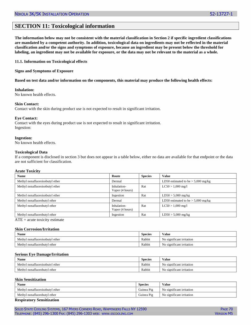
NIKOLA 3K/5K INSTALLATION OPERATION 52-13727-1
SOLID STATE COOLING SYSTEMS, 167 MYERS CORNERS ROAD, WAPPINGERS FALLS NY 12590 PAGE 70 TELEPHONE: (845) 296-1300 FAX: (845) 296-1303 WEB: WWW.SSCOOLING.COM VERSION M5
SECTION 11: Toxicological information The information below may not be consistent with the material classification in Section 2 if specific ingredient classifications
are mandated by a competent authority. In addition, toxicological data on ingredients may not be reflected in the material
classification and/or the signs and symptoms of exposure, because an ingredient may be present below the threshold for
labeling, an ingredient may not be available for exposure, or the data may not be relevant to the material as a whole.
11.1. Information on Toxicological effects
Signs and Symptoms of Exposure
Based on test data and/or information on the components, this material may produce the following health effects:
Inhalation:
No known health effects.
Skin Contact:
Contact with the skin during product use is not expected to result in significant irritation.
Eye Contact:
Contact with the eyes during product use is not expected to result in significant irritation.
Ingestion: Ingestion: No known health effects.
Toxicological Data
If a component is disclosed in section 3 but does not appear in a table below, either no data are available for that endpoint or the data
are not sufficient for classification.
Acute Toxicity
Name Route Species Value
Methyl nonafluoroisobutyl ether Dermal LD50 estimated to be > 5,000 mg/kg
Methyl nonafluoroisobutyl ether Inhalation-
Vapor (4 hours)
Rat LC50 > 1,000 mg/l
Methyl nonafluoroisobutyl ether Ingestion Rat LD50 > 5,000 mg/kg
Methyl nonafluorobutyl ether Dermal LD50 estimated to be > 5,000 mg/kg
Methyl nonafluorobutyl ether Inhalation- Vapor (4 hours)
Rat LC50 > 1,000 mg/l
Methyl nonafluorobutyl ether Ingestion Rat LD50 > 5,000 mg/kg
ATE = acute toxicity estimate
Skin Corrosion/Irritation
Name Species Value
Methyl nonafluoroisobutyl ether Rabbit No significant irritation
Methyl nonafluorobutyl ether Rabbit No significant irritation
Serious Eye Damage/Irritation
Name Species Value
Methyl nonafluoroisobutyl ether Rabbit No significant irritation
Methyl nonafluorobutyl ether Rabbit No significant irritation
Skin Sensitization
Name Species Value
Methyl nonafluoroisobutyl ether Guinea Pig No significant irritation
Methyl nonafluorobutyl ether Guinea Pig No significant irritation
Respiratory Sensitization
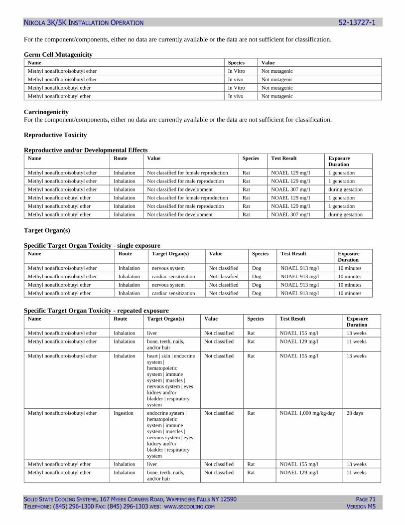
NIKOLA 3K/5K INSTALLATION OPERATION 52-13727-1
SOLID STATE COOLING SYSTEMS, 167 MYERS CORNERS ROAD, WAPPINGERS FALLS NY 12590 PAGE 71 TELEPHONE: (845) 296-1300 FAX: (845) 296-1303 WEB: WWW.SSCOOLING.COM VERSION M5
For the component/components, either no data are currently available or the data are not sufficient for classification.
Germ Cell Mutagenicity
Name Species Value
Methyl nonafluoroisobutyl ether In Vitro Not mutagenic
Methyl nonafluoroisobutyl ether In vivo Not mutagenic Methyl nonafluorobutyl ether In Vitro Not mutagenic Methyl nonafluorobutyl ether In vivo Not mutagenic
Carcinogenicity
For the component/components, either no data are currently available or the data are not sufficient for classification.
Reproductive Toxicity
Reproductive and/or Developmental Effects
Name Route Value Species Test Result Exposure
Duration
Methyl nonafluoroisobutyl ether Inhalation Not classified for female reproduction Rat NOAEL 129 mg/1 1 generation
Methyl nonafluoroisobutyl ether Inhalation Not classified for male reproduction Rat NOAEL 129 mg/1 1 generation Methyl nonafluoroisobutyl ether Inhalation Not classified for development Rat NOAEL 307 mg/1 during gestation Methyl nonafluorobutyl ether Inhalation Not classified for female reproduction Rat NOAEL 129 mg/1 1 generation Methyl nonafluorobutyl ether Inhalation Not classified for male reproduction Rat NOAEL 129 mg/1 1 generation Methyl nonafluorobutyl ether Inhalation Not classified for development Rat NOAEL 307 mg/1 during gestation
Target Organ(s)
Specific Target Organ Toxicity - single exposure
Name Route Target Organ(s) Value Species Test Result Exposure
Duration
Methyl nonafluoroisobutyl ether Inhalation nervous system Not classified Dog NOAEL 913 mg/l 10 minutes
Methyl nonafluoroisobutyl ether Inhalation cardiac sensitization Not classified Dog NOAEL 913 mg/l 10 minutes
Methyl nonafluorobutyl ether Inhalation nervous system Not classified Dog NOAEL 913 mg/l 10 minutes
Methyl nonafluorobutyl ether Inhalation cardiac sensitization Not classified Dog NOAEL 913 mg/l 10 minutes
Specific Target Organ Toxicity - repeated exposure
Name Route Target Organ(s) Value Species Test Result Exposure
Duration
Methyl nonafluoroisobutyl ether Inhalation liver Not classified Rat NOAEL 155 mg/l 13 weeks
Methyl nonafluoroisobutyl ether Inhalation bone, teeth, nails,
and/or hair
Not classified Rat NOAEL 129 mg/l 11 weeks
Methyl nonafluoroisobutyl ether Inhalation heart | skin | endocrine
system | hematopoietic
system | immune
system | muscles | nervous system | eyes |
kidney and/or
bladder | respiratory
system
Not classified Rat NOAEL 155 mg/l 13 weeks
Methyl nonafluoroisobutyl ether Ingestion endocrine system |
hematopoietic
system | immune system | muscles |
nervous system | eyes |
kidney and/or bladder | respiratory
system
Not classified Rat NOAEL 1,000 mg/kg/day 28 days
Methyl nonafluorobutyl ether Inhalation liver Not classified Rat NOAEL 155 mg/l 13 weeks
Methyl nonafluorobutyl ether Inhalation bone, teeth, nails,
and/or hair
Not classified Rat NOAEL 129 mg/l 11 weeks
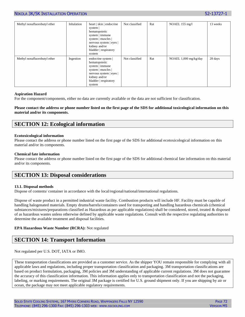
NIKOLA 3K/5K INSTALLATION OPERATION 52-13727-1
SOLID STATE COOLING SYSTEMS, 167 MYERS CORNERS ROAD, WAPPINGERS FALLS NY 12590 PAGE 72 TELEPHONE: (845) 296-1300 FAX: (845) 296-1303 WEB: WWW.SSCOOLING.COM VERSION M5
Methyl nonafluorobutyl ether Inhalation heart | skin | endocrine system |
hematopoietic
system | immune system | muscles |
nervous system | eyes |
kidney and/or bladder | respiratory
system
Not classified Rat NOAEL 155 mg/l 13 weeks
Methyl nonafluorobutyl ether Ingestion endocrine system |
hematopoietic system | immune
system | muscles |
nervous system | eyes | kidney and/or
bladder | respiratory
system
Not classified Rat NOAEL 1,000 mg/kg/day 28 days
Aspiration Hazard
For the component/components, either no data are currently available or the data are not sufficient for classification.
Please contact the address or phone number listed on the first page of the SDS for additional toxicological information on this
material and/or its components.
SECTION 12: Ecological information Ecotoxicological information
Please contact the address or phone number listed on the first page of the SDS for additional ecotoxicological information on this
material and/or its components.
Chemical fate information
Please contact the address or phone number listed on the first page of the SDS for additional chemical fate information on this material
and/or its components.
SECTION 13: Disposal considerations 13.1. Disposal methods
Dispose of contents/ container in accordance with the local/regional/national/international regulations.
Dispose of waste product in a permitted industrial waste facility. Combustion products will include HF. Facility must be capable of
handling halogenated materials. Empty drums/barrels/containers used for transporting and handling hazardous chemicals (chemical
substances/mixtures/preparations classified as Hazardous as per applicable regulations) shall be considered, stored, treated & disposed
of as hazardous wastes unless otherwise defined by applicable waste regulations. Consult with the respective regulating authorities to
determine the available treatment and disposal facilities.
EPA Hazardous Waste Number (RCRA): Not regulated
SECTION 14: Transport Information Not regulated per U.S. DOT, IATA or IMO.
These transportation classifications are provided as a customer service. As the shipper YOU remain responsible for complying with all
applicable laws and regulations, including proper transportation classification and packaging. 3M transportation classifications are
based on product formulation, packaging, 3M policies and 3M understanding of applicable current regulations. 3M does not guarantee
the accuracy of this classification information. This information applies only to transportation classification and not the packaging,
labeling, or marking requirements. The original 3M package is certified for U.S. ground shipment only. If you are shipping by air or
ocean, the package may not meet applicable regulatory requirements.
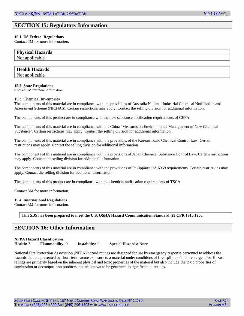
NIKOLA 3K/5K INSTALLATION OPERATION 52-13727-1
SOLID STATE COOLING SYSTEMS, 167 MYERS CORNERS ROAD, WAPPINGERS FALLS NY 12590 PAGE 73 TELEPHONE: (845) 296-1300 FAX: (845) 296-1303 WEB: WWW.SSCOOLING.COM VERSION M5
SECTION 15: Regulatory Information 15.1. US Federal Regulations
Contact 3M for more information.
Physical Hazards
Not applicable
Health Hazards
Not applicable
15.2. State Regulations Contact 3M for more information.
15.3. Chemical Inventories
The components of this material are in compliance with the provisions of Australia National Industrial Chemical Notification and
Assessment Scheme (NICNAS). Certain restrictions may apply. Contact the selling division for additional information.
The components of this product are in compliance with the new substance notification requirements of CEPA.
The components of this material are in compliance with the China "Measures on Environmental Management of New Chemical
Substance". Certain restrictions may apply. Contact the selling division for additional information.
The components of this material are in compliance with the provisions of the Korean Toxic Chemical Control Law. Certain
restrictions may apply. Contact the selling division for additional information.
The components of this material are in compliance with the provisions of Japan Chemical Substance Control Law. Certain restrictions
may apply. Contact the selling division for additional information.
The components of this material are in compliance with the provisions of Philippines RA 6969 requirements. Certain restrictions may
apply. Contact the selling division for additional information.
The components of this product are in compliance with the chemical notification requirements of TSCA.
Contact 3M for more information.
15.4. International Regulations
Contact 3M for more information.
This SDS has been prepared to meet the U.S. OSHA Hazard Communication Standard, 29 CFR 1910.1200.
SECTION 16: Other Information NFPA Hazard Classification
Health: 3 Flammability: 0 Instability: 0 Special Hazards: None
National Fire Protection Association (NFPA) hazard ratings are designed for use by emergency response personnel to address the
hazards that are presented by short-term, acute exposure to a material under conditions of fire, spill, or similar emergencies. Hazard
ratings are primarily based on the inherent physical and toxic properties of the material but also include the toxic properties of
combustion or decomposition products that are known to be generated in significant quantities.
NIKOLA 3K/5K INSTALLATION OPERATION 52-13727-1
SOLID STATE COOLING SYSTEMS, 167 MYERS CORNERS ROAD, WAPPINGERS FALLS NY 12590 PAGE 74 TELEPHONE: (845) 296-1300 FAX: (845) 296-1303 WEB: WWW.SSCOOLING.COM VERSION M5
HMIS Hazard Classification
Health: 0 Flammability: 0 Physical Hazard: 0 Personal Protection: X - See PPE section.
Hazardous Material Identification System (HMIS® IV) hazard ratings are designed to inform employees of chemical hazards in the
workplace. These ratings are based on the inherent properties of the material under expected conditions of normal use and are not
intended for use in emergency situations. HMIS® IV ratings are to be used with a fully implemented HMIS® IV program. HMIS® is
a registered mark of the American Coatings Association (ACA).
Document Group: 07-6378-9 Version Number: 69.03
Issue Date: 01/18/18 Supercedes Date: 09/06/16
Reason for Reissue
Conversion to GHS format SDS.
DISCLAIMER: The information in this Safety Data Sheet (SDS) is believed to be correct as of the date issued.3MMAKES NO
WARRANTIES, EXPRESSED OR IMPLIED, INCLUDING, BUT NOT LIMITED TO, ANY IMPLIED WARRANTY OF
MERCHANTABILITY OR FITNESS FOR A PARTICULAR PURPOSE OR COURSE OF PERFORMANCE OR USAGE OF
TRADE. User is responsible for determining whether the3Mproduct is fit for a particular purpose and suitable for user's method of use
or application. Given the variety of factors that can affect the use and application of a3Mproduct, some of which are uniquely within
the user's knowledge and control, it is essential that the user evaluate the3Mproduct to determine whether it is fit for a particular
purpose and suitable for user's method of use or application.
3M provides information in electronic form as a service to its customers. Due to the remote possibility that electronic transfer may
have resulted in errors, omissions or alterations in this information,3Mmakes no representations as to its completeness or accuracy. In
addition, information obtained from a database may not be as current as the information in the SDS available directly from 3M
3M USA SDSs are available at www.3M.com
End of SDS
NIKOLA 3K/5K INSTALLATION OPERATION 52-13727-1
SOLID STATE COOLING SYSTEMS, 167 MYERS CORNERS ROAD, WAPPINGERS FALLS NY 12590 PAGE 75 TELEPHONE: (845) 296-1300 FAX: (845) 296-1303 WEB: WWW.SSCOOLING.COM VERSION M5
12.3 SOLVAY GALDEN® HT SDS
SAFETY DATA SHEET
Revision Date 25.02.2014
SECTION 1. IDENTIFICATION OF THE SUBSTANCE/MIXTURE AND OF THE COMPANY/UNDERTAKING 1.1. Product identifier - Product name : GALDEN® HT LOW-BOILING (2) - Product grade(s) : HT80; HT110; HT135 - Chemical characterization : Perfluorinated polyethers 1.2. Relevant identified uses of the substance or mixture and uses advised against - Identified uses : - Heat transfer medium : - For industrial use only. 1.3. Details of the supplier of the safety data sheet - Company : SOLVAY : SPECIALTY POLYMERS JAPAN K.K. - Address : 7TH FL,ATAGO GREEN HILLS MORI TOWER ATAGO 2-5-1, MINATO-KU J- 105-6207 TOKYO - Telephone : +81354254330/4300 - Fax : +81354254321 - E-mail address : [email protected] 1.4. Emergency telephone number
- Emergency telephone number +44(0)1235 239 670 [CareChem 24] (Europe)
SECTION 2. HAZARDS IDENTIFICATION 2.1. Classification of the substance or mixture
2.1.1. European regulation (EC) 1272/2008, as amended Not classified as hazardous according to the European regulation (EC) 1272/2008, as amended 2.1.2. European Directive 67/548/EEC or 1999/45/EC, as amended Not classified as hazardous according to European Directive 67/548/EEC or 1999/45/EC, as amended 2.2. Label elements No labelling 2.3. Other hazards - Thermal decomposition can lead to release of toxic and corrosive gases.
NIKOLA 3K/5K INSTALLATION OPERATION 52-13727-1
SOLID STATE COOLING SYSTEMS, 167 MYERS CORNERS ROAD, WAPPINGERS FALLS NY 12590 PAGE 76 TELEPHONE: (845) 296-1300 FAX: (845) 296-1303 WEB: WWW.SSCOOLING.COM VERSION M5
SECTION 3. COMPOSITION/INFORMATION ON INGREDIENTS 3.1. Substances 3.1.1. Concentration
Substance name: Concentration
1-Propene, 1,1,2,3,3,3-hexafluoro-, oxidized, polymd. > 99.9 % CAS-No.: 69991-67-9 / EC-No.: - / Index-No.:-
SECTION 4. FIRST AID MEASURES 4.1. Description of first aid measures
4.1.1. If inhaled - Move to fresh air in case of accidental inhalation of fumes from overheating or combustion. - Oxygen or artificial respiration if needed.
4.1.2. In case of eye contact - Rinse immediately with plenty of water, also under the eyelids, for at least 15 minutes. - If eye irritation persists, consult a specialist.
4.1.3. In case of skin contact - Wash off with soap and water.
4.1.4. If swallowed - Drink 1 or 2 glasses of water. - Do NOT induce vomiting. - If symptoms persist, call a physician. 4.2. Most important symptoms and effects, both acute and delayed
4.2.1. Inhalation - No known effect.
4.2.2. Skin contact - Symptoms: Redness, Irritation
4.2.3. Eye contact - Contact with eyes may cause irritation. - Redness
4.2.4. Ingestion - Ingestion may provoke the following symptoms: - Symptoms: Nausea, Vomiting, Diarrhoea 4.3. Indication of any immediate medical attention and special treatment needed
SECTION 5. FIREFIGHTING MEASURES 5.1. Extinguishing media
5.1.1. Suitable extinguishing media - Water - powder - Foam - Dry chemical - Carbon dioxide (CO2)
5.1.2. Unsuitable extinguishing media - None.
NIKOLA 3K/5K INSTALLATION OPERATION 52-13727-1
SOLID STATE COOLING SYSTEMS, 167 MYERS CORNERS ROAD, WAPPINGERS FALLS NY 12590 PAGE 77 TELEPHONE: (845) 296-1300 FAX: (845) 296-1303 WEB: WWW.SSCOOLING.COM VERSION M5
5.2. Special hazards arising from the substance or mixture - The product is not flammable. - Not explosive - In case of fire hazardous decomposition products may be produced such as: Gaseous hydrogen fluoride (HF), Fluorophosgene 5.3. Advice for firefighters - Wear self-contained breathing apparatus and protective suit. - When intervention in close proximity wear acid resistant over suit. - Evacuate personnel to safe areas. - Approach from upwind. - Protect intervention team with a water spray as they approach the fire. - Keep containers and surroundings cool with water spray. - Keep product and empty container away from heat and sources of ignition.
SECTION 6. ACCIDENTAL RELEASE MEASURES 6.1. Personal precautions, protective equipment and emergency procedures
6.1.1. Advice for non-emergency personnel - Prevent further leakage or spillage if safe to do so.
6.1.2. Advice for emergency responders - Ensure adequate ventilation. - Material can create slippery conditions. - Sweep up to prevent slipping hazard. - Keep away from open flames, hot surfaces and sources of ignition. 6.2. Environmental precautions - Should not be released into the environment. - Do not flush into surface water or sanitary sewer system. 6.3. Methods and materials for containment and cleaning up - Soak up with inert absorbent material. - Suitable material for picking up - Dry sand - Earth - Shovel into suitable container for disposal. 6.4. Reference to other sections - Refer to protective measures listed in sections 7 and 8.
SECTION 7. HANDLING AND STORAGE 7.1. Precautions for safe handling - Ensure adequate ventilation. - Use personal protective equipment. - Keep away from heat and sources of ignition. - To avoid thermal decomposition, do not overheat. - Take measures to prevent the build up of electrostatic charge. - Clean and dry piping circuits and equipment before any operations. - Ensure all equipment is electrically grounded before beginning transfer operations.
NIKOLA 3K/5K INSTALLATION OPERATION 52-13727-1
SOLID STATE COOLING SYSTEMS, 167 MYERS CORNERS ROAD, WAPPINGERS FALLS NY 12590 PAGE 78 TELEPHONE: (845) 296-1300 FAX: (845) 296-1303 WEB: WWW.SSCOOLING.COM VERSION M5
7.2. Conditions for storage, including incompatibilities
7.2.1. Storage - Keep away from heat and sources of ignition. - Keep in properly labelled containers. - Keep away from combustible material. - Keep away from incompatible products - Provide tight electrical equipment well protected against corrosion. - Refer to protective measures listed in sections 7 and 8.
7.2.2. Packaging material 7.2.2.1. Suitable material - glass - Plastic material 7.3. Specific end use(s) - For further information, please contact: Supplier
SECTION 8. EXPOSURE CONTROLS/PERSONAL PROTECTION
8.1. Control parameters
8.1.1. Exposure Limit Values
Remarks: - Threshold limit values of by-products from thermal decomposition
Hydrogen fluoride anhydrous - UK. EH40 Workplace Exposure Limits (WELs) 12 2011 time weighted average = 1.8 ppm time weighted average = 1.5 mg/m3 Remarks: as F - UK. EH40 Workplace Exposure Limits (WELs) 12 2011 Short term exposure limit = 3 ppm Short term exposure limit = 2.5 mg/m3 Remarks: as F - US. ACGIH Threshold Limit Values 03 2013 time weighted average = 0.5 ppm Remarks: as F - US. ACGIH Threshold Limit Values 03 2013 Ceiling Limit Value = 2 ppm Remarks: as F - EU. Indicative Exposure Limit Values in Directives 91/322/EEC, 2000/39/EC, 2006/15/EC, 2009/161/EU 12 2009 time weighted average = 1.8 ppm time weighted average = 1.5 mg/m3 Remarks: Indicative - EU. Indicative Exposure Limit Values in Directives 91/322/EEC, 2000/39/EC, 2006/15/EC, 2009/161/EU 12 2009 Short term exposure limit = 3 ppm Short term exposure limit = 2.5 mg/m3 Remarks: Indicative - US. ACGIH Threshold Limit Values 03 2013 Remarks: as F, Can be absorbed through skin. Carbonyl difluoride - US. ACGIH Threshold Limit Values 03 2013 time weighted average = 2 ppm - US. ACGIH Threshold Limit Values 03 2013 Short term exposure limit = 5 ppm - UK. EH40 Workplace Exposure Limits (WELs) 12 2011 time weighted average = 2.5 mg/m3 Remarks: as F

NIKOLA 3K/5K INSTALLATION OPERATION 52-13727-1
SOLID STATE COOLING SYSTEMS, 167 MYERS CORNERS ROAD, WAPPINGERS FALLS NY 12590 PAGE 79 TELEPHONE: (845) 296-1300 FAX: (845) 296-1303 WEB: WWW.SSCOOLING.COM VERSION M5
- EU. Indicative Exposure Limit Values in Directives 91/322/EEC, 2000/39/EC, 2006/15/EC, 2009/161/EU 12 2009 time weighted average = 2.5 mg/m3 Remarks: Indicative 8.2. Exposure controls
8.2.1. Appropriate engineering controls - Provide local ventilation appropriate to the product decomposition risk (see section 10). - Refer to protective measures listed in sections 7 and 8. - Apply technical measures to comply with the occupational exposure limits.
8.2.2. Individual protection measures 8.2.2.1. Respiratory protection - In case of decomposition (see section 10), use an air breathing apparatus with face mask. - Use only respiratory protection that conforms to international/ national standards. 8.2.2.2. Hand protection - Wear protective gloves. - Suitable material: Nitrile rubber, PVC, Neoprene gloves, butyl-rubber - Take note of the information given by the producer concerning permeability and break through times, and of special workplace conditions (mechanical strain, duration of contact). 8.2.2.3. Eye protection - Tightly fitting safety goggles 8.2.2.4. Skin and body protection - Wear work overall and safety shoes. 8.2.2.5. Hygiene measures - Ensure that eyewash stations and safety showers are close to the workstation location. - When using, do not eat, drink or smoke. - Wash hands before breaks and at the end of workday. - Handle in accordance with good industrial hygiene and safety practice.
8.2.3. Environmental exposure controls - Dispose of rinse water in accordance with local and national regulations.
SECTION 9. PHYSICAL AND CHEMICAL PROPERTIES 9.1. Information on basic physical and chemical properties
9.1.1. General Information
▪ Appearance liquid ▪ Colour colourless ▪ Odour odourless ▪ Odour Threshold No data ▪ Molecular weight Range of values: 430 - 610
9.1.2. Important health safety and environmental information
▪ pH No data
▪ pKa No data
▪ Melting point/freezing point not applicable
▪ Boiling point/boiling range 80 - 135 °C
▪ Flash point The product is not flammable.
▪ Evaporation rate No data
▪ Flammability (solid, gas) No data
▪ Flammability The product is not flammable.
▪ Explosive properties Not explosive
▪ Vapour pressure ca. 10.5 - 140 hPa
NIKOLA 3K/5K INSTALLATION OPERATION 52-13727-1
SOLID STATE COOLING SYSTEMS, 167 MYERS CORNERS ROAD, WAPPINGERS FALLS NY 12590 PAGE 80 TELEPHONE: (845) 296-1300 FAX: (845) 296-1303 WEB: WWW.SSCOOLING.COM VERSION M5
▪ Vapour density No data
▪ Density 1.69 - 1.72 g/cm3 Temperature: 25 °C
▪ Relative density No data
▪ Bulk density No data
▪ Solubility(ies) insoluble, Water insoluble, fluorinated solvents
▪ Solubility/qualitative No data
▪ Partition coefficient: n- No data octanol/water
▪ Auto-ignition temperature No data
▪ Decomposition temperature > 290 °C
▪ Viscosity ca. 0.95 - 1.7 mPa.s
▪ Oxidizing properties Non oxidizer 9.2. Other information
Remarks No data
SECTION 10. STABILITY AND REACTIVITY 10.1. Reactivity
- No dangerous reaction known under conditions of normal use.
10.2. Chemical stability
- Stable under recommended storage conditions. - Metals promote and lower decomposition temperature - In presence of titanium and its alloys the decomposition temperature decreases to 260°C.
10.3. Possibility of hazardous reactions
- No dangerous reaction known under conditions of normal use.
10.4. Conditions to avoid
- Avoid to use in presence of high voltage electric arc and in absence of oxygen. - Keep away from flames. - To avoid thermal decomposition, do not overheat.
10.5. Incompatible materials
- non-aqueous alkalis, Lewis acids (Friedel-Crafts) above 100°C, Aluminum and magnesium in powder form above 200°C
10.6. Hazardous decomposition products
- Gaseous hydrogen fluoride (HF)., Fluorophosgene
SECTION 11. TOXICOLOGICAL INFORMATION 11.1. Acute toxicity
11.1.1. Acute oral toxicity
- LD50, rat, > 5,000 mg/kg
11.1.2. Acute inhalation toxicity
- LC50, rat , > 1,826 mg/l
NIKOLA 3K/5K INSTALLATION OPERATION 52-13727-1
SOLID STATE COOLING SYSTEMS, 167 MYERS CORNERS ROAD, WAPPINGERS FALLS NY 12590 PAGE 81 TELEPHONE: (845) 296-1300 FAX: (845) 296-1303 WEB: WWW.SSCOOLING.COM VERSION M5
11.1.3. Acute dermal toxicity
- LD50, rat, > 2,000 mg/kg
11.2. Skin corrosion/irritation
- rabbit, No skin irritation
11.3. Serious eye damage/eye irritation
- rabbit, No eye irritation
11.4. Respiratory or skin sensitisation
- guinea pig, Did not cause sensitisation on laboratory animals., Dermal
11.5. Germ cell mutagenicity
- Not mutagenic in Ames Test. - Chromosome aberration test in vitro, negative
11.6. Carcinogenicity
- no data available
11.7. Reproductive toxicity
- no data available
11.8. Specific target organ toxicity - single exposure
- Remarks: no data available
11.9. Specific target organ toxicity - repeated exposure
- Oral, 28 d, rats, > 1000 mg/kg, Remarks: NOEL - Remarks: Subacute toxicity
11.10. Aspiration hazard
- no data available
11.11. Other information
- Description of possible hazardous to health effects is based on experience and/or toxicological characteristics of several components. - The product is biologically inert. - Thermal decomposition can lead to release of toxic and corrosive gases. - Exposure to decomposition products - Causes severe irritation of eyes, skin and mucous membranes.
SECTION 12. ECOLOGICAL INFORMATION
12.1. Toxicity - no data available
12.2. Persistence and degradability
12.2.1. Abiotic degradation
- Result: no data available
12.2.2. Biodegradation
- no data available
12.3. Bioaccumulative potential
- Result: no data available
12.4. Mobility in soil - no data available
12.5. Results of PBT and vPvB assessment
- no data available
12.6. Other adverse effects
- Ecological injuries are not known or expected under normal use.
NIKOLA 3K/5K INSTALLATION OPERATION 52-13727-1
SOLID STATE COOLING SYSTEMS, 167 MYERS CORNERS ROAD, WAPPINGERS FALLS NY 12590 PAGE 82 TELEPHONE: (845) 296-1300 FAX: (845) 296-1303 WEB: WWW.SSCOOLING.COM VERSION M5
SECTION 13. DISPOSAL CONSIDERATIONS 13.1. Waste treatment methods
- Can be incinerated, when in compliance with local regulations. - The incinerator must be equipped with a system for the neutralisation or recovery of HF. - Dispose of in accordance with local regulations.
13.2. Contaminated packaging
- Empty containers can be landfilled, when in accordance with the local regulations.
SECTION 14. TRANSPORT INFORMATION International transport regulations - Sea (IMO/IMDG) - not regulated - Air (ICAO/IATA) - not regulated - European Road/Rail (ADR/RID) - not regulated - Inland waterway transport - not regulated
SECTION 15. REGULATORY INFORMATION 15.1. Safety, health and environmental regulations/legislation specific for the substance or mixture
- Regulation (EC) No 1272/2008 of the European Parliament and of the Council of 16 December 2008 on classification, labelling and packaging of substances and mixtures, as amended - Regulation (EC) No 1907/2006 of the European Parliament and of the Council of 18 December 2006 concerning the Registration, Evaluation, Authorisation and Restriction of Chemicals (REACH), as amended - European Waste Catalogue - Waste codes should be assigned by the user based on the application for which the product was used.
15.1.1. Notification status
Inventory Information Status
USA. Toxic Substances Control Act (TSCA) - Listed on inventory
Australia. Inventory of Chemical Substances (AICS) - Listed on inventory
Canada. Domestic Substances List (DSL) - Listed on inventory
Korea. Existing Chemicals Inventory (KECI (KR)) - Listed on inventory
China. Inventory of Existing Chemical Substances (IECSC) - Listed on inventory
Japan. Industrial Safety & Health Law Inventory (ISHL (JP)) - Listed on inventory
Japan. Inventory of Existing & New Chemical Substances (ENCS) - Listed on inventory
Philippine. Inventory of Chemicals and Chemical Substances (PICCS) - Listed on inventory
New Zealand. Inventory of Chemicals (NZIOC) - Listed on inventory
Taiwan. National Existing Chemical Substance Inventory (NECSI) - Listed on inventory
EU. European Registration, Evaluation, Authorisation and Restriction of Chemical (REACH)
- If product is purchased from Solvay in Europe it is in compliance with REACH, if not please contact the supplier.
15.2. Chemical Safety Assessment
- A Chemical Safety Assessment is not required for this substance.
NIKOLA 3K/5K INSTALLATION OPERATION 52-13727-1
SOLID STATE COOLING SYSTEMS, 167 MYERS CORNERS ROAD, WAPPINGERS FALLS NY 12590 PAGE 83 TELEPHONE: (845) 296-1300 FAX: (845) 296-1303 WEB: WWW.SSCOOLING.COM VERSION M5
SECTION 16. OTHER INFORMATION 16.1. Other information
- New (SDS) - Distribute new edition to clients This SDS is only intended for the indicated country to which it is applicable. The European SDS format compliant with the applicable European legislation is not intended for use nor distribution in countries outside the European Union with the exception of Norway and Switzerland. Safety datasheets applicable in other countries/regions are available upon request. The information given corresponds to the current state of our knowledge and experience of the product, and is not exhaustive. This applies to product which conforms to the specification, unless otherwise stated. In this case of combinations and mixtures one must make sure that no new dangers can arise. In any case, the user is not exempt from observing all legal, administrative and regulatory procedures relating to the product, personal hygiene, and protection of human welfare and the environment. Print Date: 28.10.2014
End of SDS
NIKOLA 3K/5K INSTALLATION OPERATION 52-13727-1
SOLID STATE COOLING SYSTEMS, 167 MYERS CORNERS ROAD, WAPPINGERS FALLS NY 12590 PAGE 84 TELEPHONE: (845) 296-1300 FAX: (845) 296-1303 WEB: WWW.SSCOOLING.COM VERSION M5
12.4 ETHYLENE GLYCOL
SAFETY DATA SHEET
Creation Date: 02-Feb-2010 Revision Date: 17-Jan-2018 Revision Number 4
1. Identification
Product Name Ethylene glycol
Cat No. : E177-4; E177-20 CAS-No 107-21-1 Synonyms Monoethylene glycol; 1,2-Ethanediol Recommended Use Laboratory chemicals. Uses advised against Not for food, drug, pesticide or biocidal product use Details of the supplier of the safety data sheet Company Fisher Scientific One Reagent Lane Fair Lawn, NJ 07410 Tel: (201) 796-7100 Emergency Telephone Number CHEMTRECÒ, Inside the USA: 800-424-9300 CHEMTRECÒ, Outside the USA: 001-703-527-3887
2. Hazard(s) Identification
Classification This chemical is considered hazardous by the 2012 OSHA Hazard Communication Standard (29 CFR 1910.1200)
Acute oral toxicity Category 4 Specific target organ toxicity (single exposure) Category 3 Target Organs - Central nervous system (CNS). Specific target organ toxicity - (repeated exposure) Category 2
Label Elements Signal Word Warning Hazard Statements Harmful if swallowed May cause drowsiness or dizziness May cause damage to organs through prolonged or repeated exposure
NIKOLA 3K/5K INSTALLATION OPERATION 52-13727-1
SOLID STATE COOLING SYSTEMS, 167 MYERS CORNERS ROAD, WAPPINGERS FALLS NY 12590 PAGE 85 TELEPHONE: (845) 296-1300 FAX: (845) 296-1303 WEB: WWW.SSCOOLING.COM VERSION M5
Precautionary Statements Prevention Wash face, hands and any exposed skin thoroughly after handling Do not eat, drink or smoke when using this product Do not breathe dust/fume/gas/mist/vapors/spray Use only outdoors or in a well-ventilated area Response Get medical attention/advice if you feel unwell Inhalation IF INHALED: Remove victim to fresh air and keep at rest in a position comfortable for breathing Call a POISON CENTER or doctor/physician if you feel unwell Ingestion IF SWALLOWED: Call a POISON CENTER or doctor/physician if you feel unwell Rinse mouth Storage Store in a well-ventilated place. Keep container tightly closed Store locked up Disposal Dispose of contents/container to an approved waste disposal plant Hazards not otherwise classified (HNOC) WARNING. Reproductive Harm - https://www.p65warnings.ca.gov/.
3. Composition/Information on Ingredients
Component CAS-No Weight %
Ethylene Glycol 107-21-1 >95
4. First-aid measures
Eye Contact Rinse immediately with plenty of water, also under the eyelids, for at least 15 minutes. Get medical attention.
Skin Contact Wash off immediately with plenty of water for at least 15 minutes. Get medical attention immediately if symptoms occur.
Inhalation Move to fresh air. Do not use mouth-to-mouth method if victim ingested or inhaled the substance; give artificial respiration with the aid of a pocket mask equipped with a one-way valve or other proper respiratory medical device. Get medical attention immediately if symptoms occur. If not breathing, give artificial respiration.
Ingestion Do not induce vomiting. Call a physician or Poison Control Center immediately.
Most important symptoms and effects Breathing difficulties.
Notes to Physician Treat symptomatically
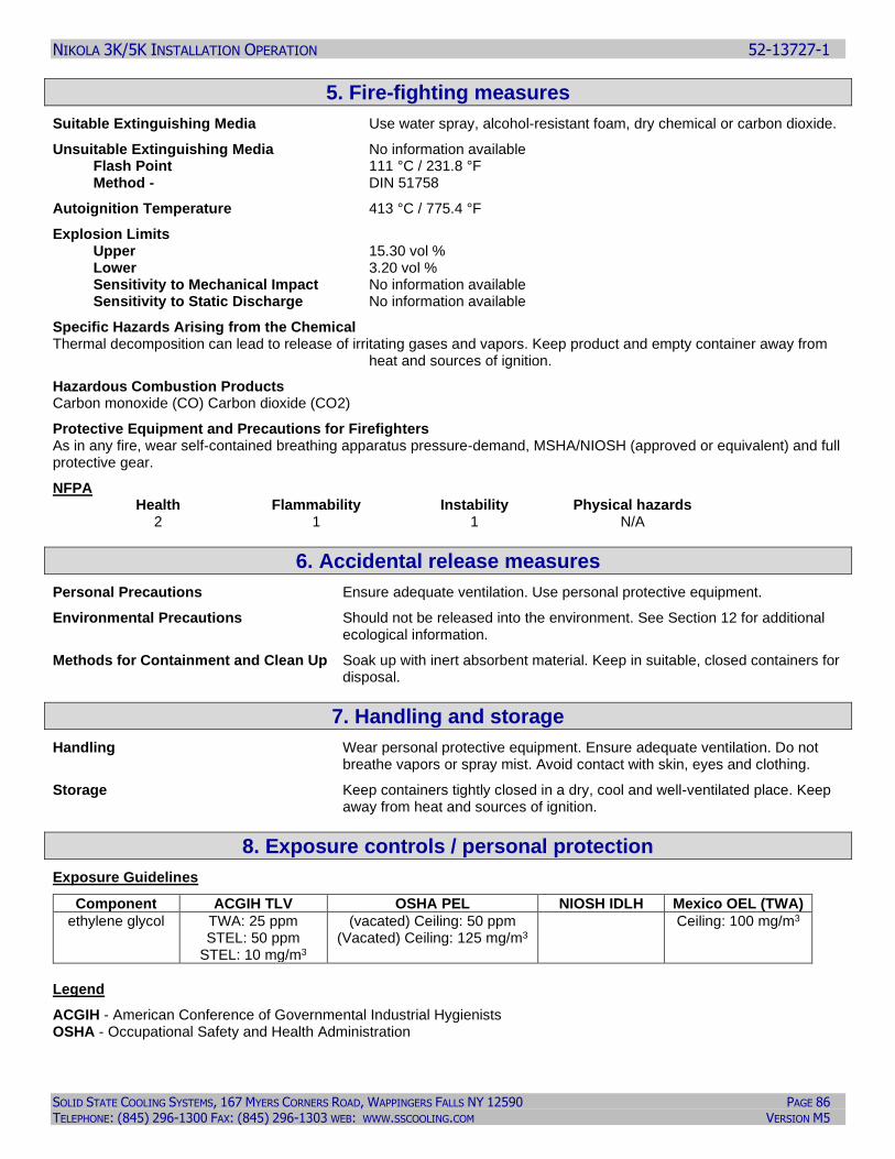
NIKOLA 3K/5K INSTALLATION OPERATION 52-13727-1
SOLID STATE COOLING SYSTEMS, 167 MYERS CORNERS ROAD, WAPPINGERS FALLS NY 12590 PAGE 86 TELEPHONE: (845) 296-1300 FAX: (845) 296-1303 WEB: WWW.SSCOOLING.COM VERSION M5
5. Fire-fighting measures
Suitable Extinguishing Media Use water spray, alcohol-resistant foam, dry chemical or carbon dioxide.
Unsuitable Extinguishing Media No information available Flash Point 111 °C / 231.8 °F Method - DIN 51758
Autoignition Temperature 413 °C / 775.4 °F
Explosion Limits Upper 15.30 vol % Lower 3.20 vol % Sensitivity to Mechanical Impact No information available Sensitivity to Static Discharge No information available
Specific Hazards Arising from the Chemical Thermal decomposition can lead to release of irritating gases and vapors. Keep product and empty container away from
heat and sources of ignition.
Hazardous Combustion Products Carbon monoxide (CO) Carbon dioxide (CO2)
Protective Equipment and Precautions for Firefighters As in any fire, wear self-contained breathing apparatus pressure-demand, MSHA/NIOSH (approved or equivalent) and full protective gear.
NFPA Health Flammability Instability Physical hazards 2 1 1 N/A
6. Accidental release measures
Personal Precautions Ensure adequate ventilation. Use personal protective equipment.
Environmental Precautions Should not be released into the environment. See Section 12 for additional ecological information.
Methods for Containment and Clean Up Soak up with inert absorbent material. Keep in suitable, closed containers for disposal.
7. Handling and storage
Handling Wear personal protective equipment. Ensure adequate ventilation. Do not breathe vapors or spray mist. Avoid contact with skin, eyes and clothing.
Storage Keep containers tightly closed in a dry, cool and well-ventilated place. Keep away from heat and sources of ignition.
8. Exposure controls / personal protection
Exposure Guidelines
Component ACGIH TLV OSHA PEL NIOSH IDLH Mexico OEL (TWA)
ethylene glycol TWA: 25 ppm STEL: 50 ppm
STEL: 10 mg/m3
(vacated) Ceiling: 50 ppm (Vacated) Ceiling: 125 mg/m3
Ceiling: 100 mg/m3
Legend
ACGIH - American Conference of Governmental Industrial Hygienists OSHA - Occupational Safety and Health Administration
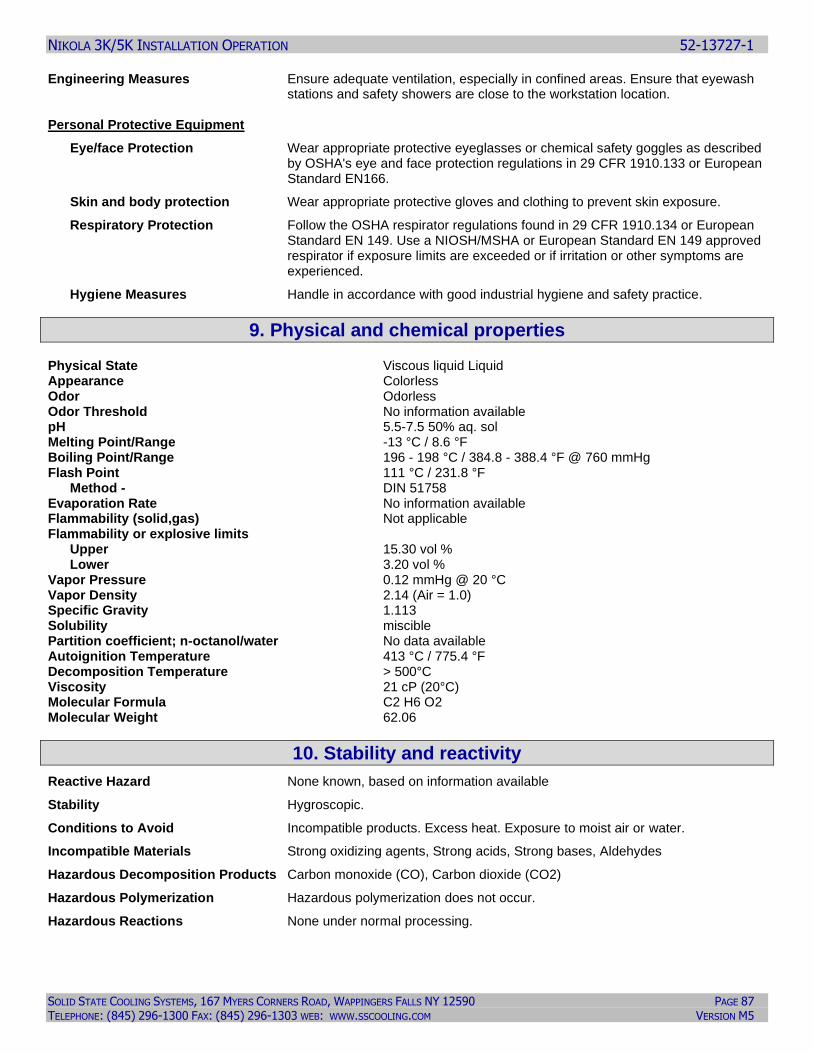
NIKOLA 3K/5K INSTALLATION OPERATION 52-13727-1
SOLID STATE COOLING SYSTEMS, 167 MYERS CORNERS ROAD, WAPPINGERS FALLS NY 12590 PAGE 87 TELEPHONE: (845) 296-1300 FAX: (845) 296-1303 WEB: WWW.SSCOOLING.COM VERSION M5
Engineering Measures Ensure adequate ventilation, especially in confined areas. Ensure that eyewash stations and safety showers are close to the workstation location.
Personal Protective Equipment
Eye/face Protection Wear appropriate protective eyeglasses or chemical safety goggles as described by OSHA's eye and face protection regulations in 29 CFR 1910.133 or European Standard EN166.
Skin and body protection Wear appropriate protective gloves and clothing to prevent skin exposure.
Respiratory Protection Follow the OSHA respirator regulations found in 29 CFR 1910.134 or European Standard EN 149. Use a NIOSH/MSHA or European Standard EN 149 approved respirator if exposure limits are exceeded or if irritation or other symptoms are experienced.
Hygiene Measures Handle in accordance with good industrial hygiene and safety practice.
9. Physical and chemical properties Physical State Viscous liquid Liquid Appearance Colorless Odor Odorless Odor Threshold No information available pH 5.5-7.5 50% aq. sol Melting Point/Range -13 °C / 8.6 °F Boiling Point/Range 196 - 198 °C / 384.8 - 388.4 °F @ 760 mmHg Flash Point 111 °C / 231.8 °F Method - DIN 51758 Evaporation Rate No information available Flammability (solid,gas) Not applicable Flammability or explosive limits Upper 15.30 vol % Lower 3.20 vol % Vapor Pressure 0.12 mmHg @ 20 °C Vapor Density 2.14 (Air = 1.0) Specific Gravity 1.113 Solubility miscible Partition coefficient; n-octanol/water No data available Autoignition Temperature 413 °C / 775.4 °F Decomposition Temperature > 500°C Viscosity 21 cP (20°C) Molecular Formula C2 H6 O2 Molecular Weight 62.06
10. Stability and reactivity
Reactive Hazard None known, based on information available
Stability Hygroscopic.
Conditions to Avoid Incompatible products. Excess heat. Exposure to moist air or water.
Incompatible Materials Strong oxidizing agents, Strong acids, Strong bases, Aldehydes
Hazardous Decomposition Products Carbon monoxide (CO), Carbon dioxide (CO2)
Hazardous Polymerization Hazardous polymerization does not occur.
Hazardous Reactions None under normal processing.
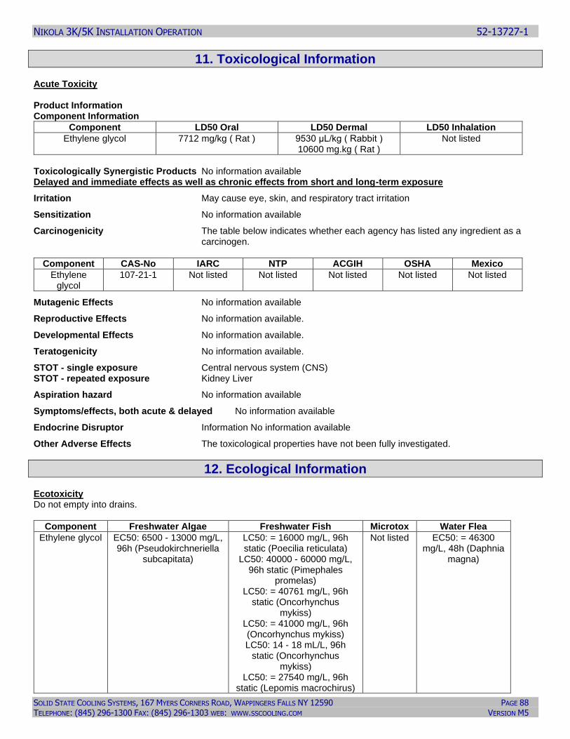
NIKOLA 3K/5K INSTALLATION OPERATION 52-13727-1
SOLID STATE COOLING SYSTEMS, 167 MYERS CORNERS ROAD, WAPPINGERS FALLS NY 12590 PAGE 88 TELEPHONE: (845) 296-1300 FAX: (845) 296-1303 WEB: WWW.SSCOOLING.COM VERSION M5
11. Toxicological Information Acute Toxicity Product Information Component Information
Component LD50 Oral LD50 Dermal LD50 Inhalation
Ethylene glycol 7712 mg/kg ( Rat ) 9530 μL/kg ( Rabbit ) 10600 mg.kg ( Rat )
Not listed
Toxicologically Synergistic Products No information available Delayed and immediate effects as well as chronic effects from short and long-term exposure
Irritation May cause eye, skin, and respiratory tract irritation
Sensitization No information available
Carcinogenicity The table below indicates whether each agency has listed any ingredient as a carcinogen.
Component CAS-No IARC NTP ACGIH OSHA Mexico
Ethylene glycol
107-21-1 Not listed Not listed Not listed Not listed Not listed
Mutagenic Effects No information available
Reproductive Effects No information available.
Developmental Effects No information available.
Teratogenicity No information available.
STOT - single exposure Central nervous system (CNS) STOT - repeated exposure Kidney Liver
Aspiration hazard No information available
Symptoms/effects, both acute & delayed No information available
Endocrine Disruptor Information No information available
Other Adverse Effects The toxicological properties have not been fully investigated.
12. Ecological Information Ecotoxicity Do not empty into drains.
Component Freshwater Algae Freshwater Fish Microtox Water Flea
Ethylene glycol EC50: 6500 - 13000 mg/L, 96h (Pseudokirchneriella
subcapitata)
LC50: = 16000 mg/L, 96h static (Poecilia reticulata)
LC50: 40000 - 60000 mg/L, 96h static (Pimephales
promelas) LC50: = 40761 mg/L, 96h
static (Oncorhynchus mykiss)
LC50: = 41000 mg/L, 96h (Oncorhynchus mykiss) LC50: 14 - 18 mL/L, 96h
static (Oncorhynchus mykiss)
LC50: = 27540 mg/L, 96h static (Lepomis macrochirus)
Not listed EC50: = 46300 mg/L, 48h (Daphnia
magna)
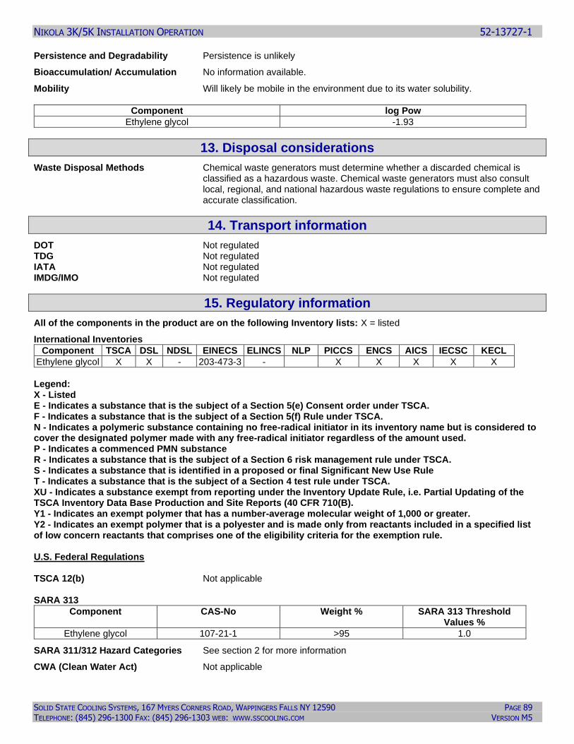
NIKOLA 3K/5K INSTALLATION OPERATION 52-13727-1
SOLID STATE COOLING SYSTEMS, 167 MYERS CORNERS ROAD, WAPPINGERS FALLS NY 12590 PAGE 89 TELEPHONE: (845) 296-1300 FAX: (845) 296-1303 WEB: WWW.SSCOOLING.COM VERSION M5
Persistence and Degradability Persistence is unlikely
Bioaccumulation/ Accumulation No information available.
Mobility Will likely be mobile in the environment due to its water solubility.
Component log Pow
Ethylene glycol -1.93
13. Disposal considerations
Waste Disposal Methods Chemical waste generators must determine whether a discarded chemical is classified as a hazardous waste. Chemical waste generators must also consult local, regional, and national hazardous waste regulations to ensure complete and accurate classification.
14. Transport information
DOT Not regulated TDG Not regulated IATA Not regulated IMDG/IMO Not regulated
15. Regulatory information
All of the components in the product are on the following Inventory lists: X = listed
International Inventories
Component TSCA DSL NDSL EINECS ELINCS NLP PICCS ENCS AICS IECSC KECL
Ethylene glycol X X - 203-473-3 - X X X X X
Legend: X - Listed E - Indicates a substance that is the subject of a Section 5(e) Consent order under TSCA. F - Indicates a substance that is the subject of a Section 5(f) Rule under TSCA. N - Indicates a polymeric substance containing no free-radical initiator in its inventory name but is considered to cover the designated polymer made with any free-radical initiator regardless of the amount used. P - Indicates a commenced PMN substance R - Indicates a substance that is the subject of a Section 6 risk management rule under TSCA. S - Indicates a substance that is identified in a proposed or final Significant New Use Rule T - Indicates a substance that is the subject of a Section 4 test rule under TSCA. XU - Indicates a substance exempt from reporting under the Inventory Update Rule, i.e. Partial Updating of the TSCA Inventory Data Base Production and Site Reports (40 CFR 710(B). Y1 - Indicates an exempt polymer that has a number-average molecular weight of 1,000 or greater. Y2 - Indicates an exempt polymer that is a polyester and is made only from reactants included in a specified list of low concern reactants that comprises one of the eligibility criteria for the exemption rule. U.S. Federal Regulations TSCA 12(b) Not applicable SARA 313
Component CAS-No Weight % SARA 313 Threshold Values %
Ethylene glycol 107-21-1 >95 1.0
SARA 311/312 Hazard Categories See section 2 for more information
CWA (Clean Water Act) Not applicable
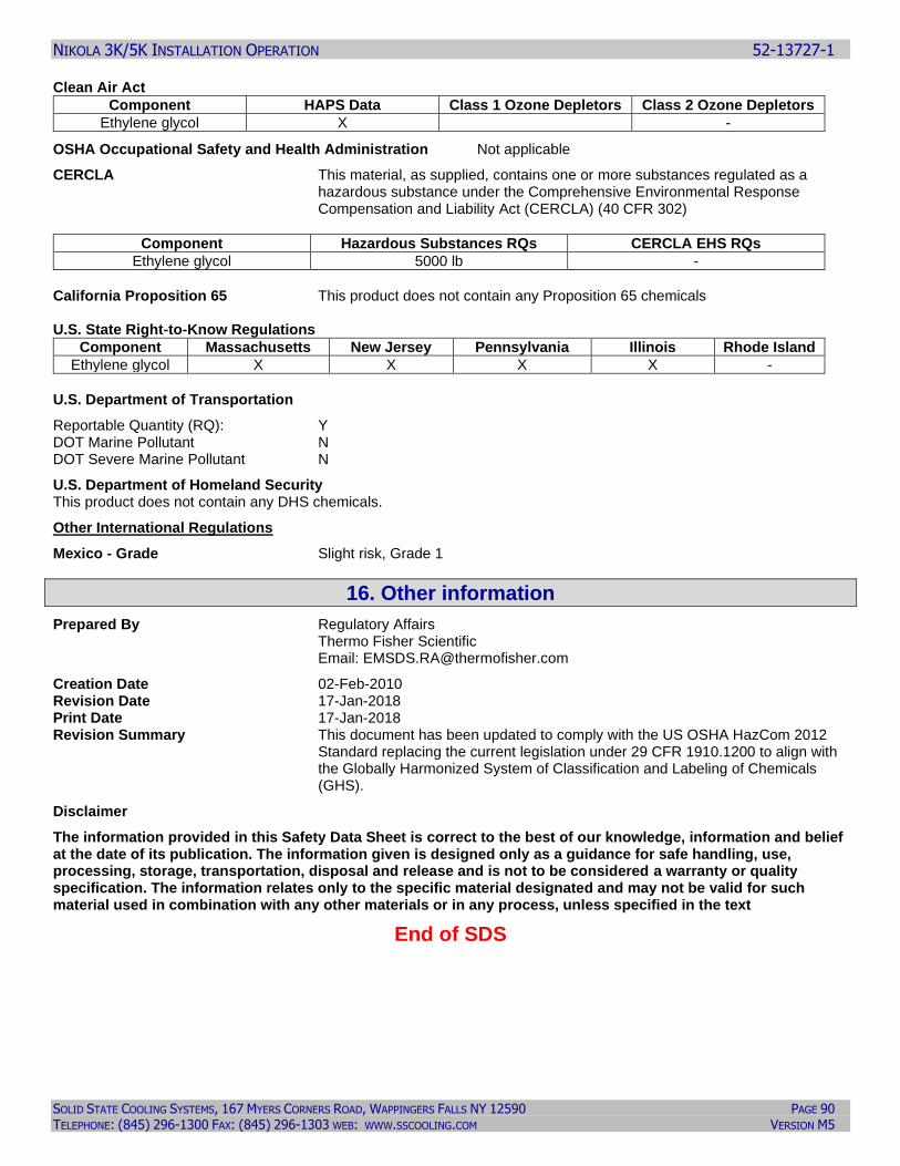
NIKOLA 3K/5K INSTALLATION OPERATION 52-13727-1
SOLID STATE COOLING SYSTEMS, 167 MYERS CORNERS ROAD, WAPPINGERS FALLS NY 12590 PAGE 90 TELEPHONE: (845) 296-1300 FAX: (845) 296-1303 WEB: WWW.SSCOOLING.COM VERSION M5
Clean Air Act
Component HAPS Data Class 1 Ozone Depletors Class 2 Ozone Depletors
Ethylene glycol X -
OSHA Occupational Safety and Health Administration Not applicable
CERCLA This material, as supplied, contains one or more substances regulated as a hazardous substance under the Comprehensive Environmental Response Compensation and Liability Act (CERCLA) (40 CFR 302)
Component Hazardous Substances RQs CERCLA EHS RQs
Ethylene glycol 5000 lb -
California Proposition 65 This product does not contain any Proposition 65 chemicals U.S. State Right-to-Know Regulations
Component Massachusetts New Jersey Pennsylvania Illinois Rhode Island
Ethylene glycol X X X X -
U.S. Department of Transportation
Reportable Quantity (RQ): Y DOT Marine Pollutant N DOT Severe Marine Pollutant N
U.S. Department of Homeland Security This product does not contain any DHS chemicals.
Other International Regulations
Mexico - Grade Slight risk, Grade 1
16. Other information
Prepared By Regulatory Affairs Thermo Fisher Scientific Email: [email protected]
Creation Date 02-Feb-2010 Revision Date 17-Jan-2018 Print Date 17-Jan-2018 Revision Summary This document has been updated to comply with the US OSHA HazCom 2012
Standard replacing the current legislation under 29 CFR 1910.1200 to align with the Globally Harmonized System of Classification and Labeling of Chemicals (GHS).
Disclaimer
The information provided in this Safety Data Sheet is correct to the best of our knowledge, information and belief at the date of its publication. The information given is designed only as a guidance for safe handling, use, processing, storage, transportation, disposal and release and is not to be considered a warranty or quality specification. The information relates only to the specific material designated and may not be valid for such material used in combination with any other materials or in any process, unless specified in the text
End of SDS
NIKOLA 3K/5K INSTALLATION OPERATION 52-13727-1
SOLID STATE COOLING SYSTEMS, 167 MYERS CORNERS ROAD, WAPPINGERS FALLS NY 12590 PAGE 91 TELEPHONE: (845) 296-1300 FAX: (845) 296-1303 WEB: WWW.SSCOOLING.COM VERSION M5
WARRANTY
This Solid State Cooling Systems Product is covered under a two-year parts and labor warranty from the date of
shipment, assuming proper use and maintenance of the unit. All warranty work shall be performed at Solid State
Cooling Systems’ facility, currently located in Wappingers Falls, NY, USA and requires pre-authorization by
SSCS. Malfunctioning products should be returned to Solid State Cooling Systems by the method described
below. Solid State Cooling Systems will provide a Failure Analysis Report to the customer and will determine if
the problem is covered under the warranty.
Warranty Coverage:
Products with defects in components or manufacturing which are reported to Solid State Cooling
Systems before the end of the warranty period will be repaired or replaced at no cost (see below for reporting
requirements). The warranty period begins on the date the product was initially shipped from Solid State Cooling
Systems’ factory.
Excluded from Warranty:
Excluded from warranty is any damage caused to the product occurring during, but not limited to, such events
as shipment, installation, storage, or usage occurring during a situation specifically cautioned against or noted in
the product manual.
Specific situations, which invalidate the warranty, include (but are not limited to):
▪ Removing the serial number label.
▪ Any disassembly (partial or complete) of the product.
▪ Changing any components of the product.
▪ Subjecting the product to temperatures below the freezing point of the coolant used.
▪ Subjecting any product to temperature, voltage, current, or pressure (internal or external) greater than that
specified in the product manual.
▪ Any actions prohibited in the "Caution" section of the product manual.
Returned Goods Procedure and Reporting Requirements
Before a failed product is returned to the factory, a Returned Materials Authorization (RMA) number must be
obtained from Customer Service at (845) 296-1300. The date the RMA is requested will be the reporting date
noted and relevant to the warranty. Products, which have received an RMA, must be received at SSCS’s factory,
within 30 days or the reporting date will be moved ahead 30 days and a new 30-day waiting period will begin.
Customers shall pay shipping cost of returning any unit to SSCS and SSCS shall pay shipping cost of returning
any unit repaired under warranty to the customer.
All out of warranty returned goods will require an evaluation purchase order prior to receipt at Solid State Cooling
Systems. The evaluation costs will depend on product model and will be deducted from the cost of any repairs
required.


