Embed Size (px)
Citation preview

Nf
J
a
b
Ic
a
ARRAA
KMMD
1
aCooapcr
ttttcie
(
0d
Journal of Power Sources 196 (2011) 8188– 8196
Contents lists available at ScienceDirect
Journal of Power Sources
jou rna l h omepa g e: www.elsev ier .com/ locate / jpowsour
ovel mesoporous carbon ceramics composites as electrodes for direct methanoluel cell
ean Marcel R. Galloa,b, Giorgio Gattib, Alessandro Graizzaroc, Leonardo Marcheseb,∗∗, Heloise O. Pastorea,∗
Grupo de Peneiras Moleculares Micro e Mesoporosas, Instituto de Química, UNICAMP, CP 6154, CEP 13083-970, Campinas, SP, BrazilDipartimento di Scienze e Tecnologie Avanzate and Centro Interdisciplinare Nano-SiSTeMI, Università del Piemonte Orientale “A. Avogadro”, Viale T. Michel 11, I-15121 Alessandria,
talyHySyLab, Environment Park, Via Livorno 60, 10144 Torino, Italy
r t i c l e i n f o
rticle history:eceived 28 February 2011eceived in revised form 3 May 2011ccepted 6 May 2011vailable online 17 May 2011
a b s t r a c t
In this work, a new family of materials for electrodes of direct methanol fuel cell (DMFC) is presented.Mesoporous carbon ceramics (MCCs) are obtained by the addition of commercial graphite into the syn-thesis gel of SBA-15 mesoporous silica with SiO2/C weight ratios of 1/1 and 1/3. X-ray diffraction confirmsboth the formation of organized silica and the presence of graphite, and nitrogen physisorption measure-ments show that the presence of a graphitic phase does not interfere in the silica pore diameter although
eywords:esoporous carbon ceramicesoporous molecular sieveirect methanol fuel cell
it diminishes the surface area. The MCCs modified with Pt or PtRu are tested as DMFC electrodes andcompared with the commercial support Vulcan XC-72R. When used as cathode, the system using MCC-SBA-15 with SiO2/C weight ratios of 1/1 presents a negligible performance, while the MCC-SBA-15 withSiO2/C weight ratios of 1/3 is 2.9 times less active than the commercial support. On the other side, whenused as anode, the MCC-SBA-15 with SiO2/C weight ratios of 1/3 displays performances comparable to
Vulcan XC-72R.. Introduction
Direct methanol fuel cell (DMFC) is today the third (after PEMFCnd SOFC) most researched fuel cell technology in industry [1].ompared with the other types, its advantages are the possibilityf size reduction and of using liquid combustible instead of gaseousnes. Although the DMFC is considered near to the commercialpplication [2], many efforts have been spent in developing newolymeric membranes, which ideally could diminish the methanolrossover; and new metal alloy catalysts, to improve the anodiceaction rate and yield.
Besides the catalytically active metal or alloy, the DMFC elec-rodes contain two more phases: (i) a proton conductive polymer,o decrease the interface resistance between electrode and elec-rolyte and; (ii) an electrical conductive support, responsible forhe electron conductivity from the metal site to the electrical cir-
uit [3]. Furthermore, the support, classically carbon, is not a merenert material: in a carbon-supported metal–catalyst system, forxample, it alters the system Galvani potential, raises the electronic∗ Corresponding author. Tel.: +55 19 35213095; fax: +55 19 35213023.∗∗ Corresponding author. Tel.: +39 0131 360262; fax: +39 0131 360250.
E-mail addresses: [email protected]. Marchese), [email protected] (H.O. Pastore).
378-7753/$ – see front matter © 2011 Elsevier B.V. All rights reserved.oi:10.1016/j.jpowsour.2011.05.008
© 2011 Elsevier B.V. All rights reserved.
density in the catalysts, and lowers the Fermi level, accelerating,then, the electrode processes [4].
For PEMFC and DMFC, metal particles are commonly supportedon Carbon Black, such as Acetylene Black, Vulcan XC-72, KetjenBlack, etc., which are usually manufactured by pyrolysis of hydro-carbons such as natural gas or oil fractions taken from petroleumprocessing [5]. Due to its low Ohmic resistance and high specificsurface area (ca. 250 m2 g−1), Vulcan XC-72 is the most used metalsupport on DMFC and PEMFC commercial catalysts [5]. Alterna-tive supports with surface area higher than Vulcan XC-72R, suchas nanostructured and mesoporous carbon have been proposed forDMFC and showed interesting results [5].
The research for new supports is not as intensive as the onefor membranes or metal alloys, but in recent years, a series ofnew nanostructured carbon materials were explored as catalystsupports. Carbon nanotubes (CNTs) are the most studied nanos-tructured carbons, and have shown promising results as catalystsupport for PEMFC and DMFC [5]. CNT-supported Pt catalyst with12 wt.% Pt loading as PEMFC anode presented a 10% higher volt-age, and twice the power density than that of Carbon Blacksupported with 29 wt.% Pt loading [6]. Pt supported on multi-
walled carbon nanotube (MWNT) was studied as an electrode formethanol oxidation and showed a mass activity at 0.7 V (vs. DHE) of14.7 mA mg−1 against 2.2 mA mg−1 for Pt/Vulcan XC-72 [7]. Otherexperiments show Pt/MWNT ca. 20 times more active than the
wer S
boc[
clo
Dsaracat
bm
cstitupiie
cpsTat
2
2(
s2osArmat
wtsfbao
b1
J.M.R. Gallo et al. / Journal of Po
ulk Pt electrode [8]. Pt supported on single-wall carbon nan-tube (SWNT) has also exhibited higher catalytic activity as DMFCathode and anode if compared to an unsupported Pt electrode9].
Although carbon nanotubes have shown promising results asatalyst supports for DMFCs, their syntheses still face some chal-enges, especially the ones linked to their high cost and to the lackf adequate large scale preparation [5].
Mesoporous carbons are also promising catalyst support forMFC anode catalysis [5]. Yu et al. [10] studied a series of PtRu
upported on porous carbons with pore diameters between 10nd 1000 nm and found that the material with pore size of 25 nmeaches a performance 43% higher than that of the commerciallyvailable PtRu/C catalyst. Spherical carbon capsules with a hollowore and mesoporous shell structures (HCMS) and microporousctive carbon microspheres have also shown to be better supportshan Vulcan XC-72 [11,12].
The research for new metal supports for DMFC is limited to car-on materials, since they have high stability in both acidic and basicedia and, mainly, good electric conductivity [5].In 1994, Lev and co-workers [13] published the synthesis of
arbon ceramics electrodes (CCE), based on the condensation ofol–gel silica around graphite particles. According to the authors,he composites benefit from the mechanical properties of the sil-ca backbone, from the electron percolation conductivity throughhe interconnected carbon particles and from the ability to manip-late the silica properties by incorporation of different monomerrecursors or sol–gel dopants [14]. The CCE described by Lev had
nteresting applications, however, the low surface area would limitts use in the fuel cell area. Hence, an alternative would be to makefforts in synthesizing carbon ceramics with high surface area.
In the present work, the synthesis of a high surface area carboneramic, the novel mesoporous carbon ceramics (MCCs), is pro-osed. The applied strategy was to add commercial graphite in theynthesis of the pure silica mesoporous molecular sieve SBA-15.he composites were prepared with a SiO2/C weight ratio of 1/1nd 1/3. The samples were also modified with Pt or PtRu alloy andested on DMFC cathode and anode, respectively.
. Experimental
.1. Synthesis of SBA-15 mesoporous carbon ceramicMCC-SBA-15)
The reaction was based on the pure silica SBA-15 originalynthesis [15]. In a 250 mL polypropylene beaker, 120.00 g of a
mol L−1 aqueous HCl solution were added to a solution of 4.00 gf Pluronic P123 (Aldrich) in 30.00 g of water and the solution wastirred for 1 h at 35 ◦C. Then, 8.50 g of tetraethyl orthosilicate (TEOS,lfa Aesar) and 2.35 or 7.05 g (for SiO2/C weight ratio = 1/1 or 1/3,espectively) of graphite (<45 �m, Aldrich) were added and theixture was stirred for 24 h at the same temperature. The gel was
ged for 24 h at 100 ◦C in an autoclave in static conditions. Finally,he solid was filtered and washed with 4 L of water.
Before the characterization, the organic template, Pluronic P123,as removed from the MCCs by heating the powders from room
emperature to 500 ◦C (1 ◦C min−1) under nitrogen flow, then, at theame temperature, the gas flow was switched to air and maintainedor 5 h. The graphite used for the composite syntheses was analyzedy thermogravimetric analysis (see supporting information, Fig. S1)nd showed to burn at temperatures higher than 600 ◦C under pure
xygen atmosphere.The MCC-SBA-15 with SiO2/C weight ratio of 1/1 or 1/3 wille named throughout the text as MCC-SBA-15(1/1) and MCC-SBA-5(1/3), respectively.
ources 196 (2011) 8188– 8196 8189
2.2. Pt and PtRu deposition
The deposition of 20 wt.% Pt on MCC or Vulcan XC-72R (Cabot)was carried out by stirring 0.30 g of the support in a solutionof 384 �mol of chloroplatinic acid hexahydrate (H2PtCl6·6H2O,Aldrich) in 3 mL of acetone for 1 h. The dispersion was dried for15 h at 60 ◦C. For Pt reduction, the powder was heated from roomtemperature to 300 ◦C (3 ◦C min−1) under pure hydrogen flow. Thistemperature was maintained for 3 h under vacuum [16].
The deposition of 60 wt.% of PtRu alloy was carried out by son-icating 0.050 g of MCC or Vulcan XC-72R in 30 mL of water for15 min, followed by the addition of a solution containing 2.53 mmolof chloroplatinic acid (H2PtCl6, Aldrich), and 2.53 mmol of ruthe-nium chloride (RuCl3, Aldrich) in 20 mL water. The mixture wasstirred for 30 min and then a solution of 400 mg of sodium boro-hydride (Aldrich) in 50 mL of water was added drop by drop undervigorous stirring. The mixture was stirred for over 2 h, filtered andwashed with 500 mL of water [17].
2.3. Characterization techniques
X-ray diffractograms were obtained on a Thermo ARL X-raydiffractometer, operating with CuK� X-ray radiation (X-ray gen-erator current and voltage set at 40 mA and 45 kV).
Nitrogen physisorption measurements were carried out at−196 ◦C in the relative pressure range from 10−6 to 1 P/P0 usinga Quantachrome Autosorb 1MP/TCD instrument. Prior to the anal-ysis the samples were outgassed (residual pressure p < 10−7 mbar)at 250 ◦C for 15 h. Specific surface areas were determined by usingBrunauer–Emmett–Teller (BET) equation. Pore size distributionswere obtained by applying the non-local density functional theory(NLDFT) method for cylindrical pores using the desorption branch.Microporous surface area and volume were estimated by t-plot. Thet-plot method employs reference curves obtained from a group ofdata obtained from nonporous adsorbents with surface similar tothe material analyzed.
The scanning electron microscopy (SEM) images were done in aFei Quanta 200 coupled to an energy dispersive spectrometer (EDS)attachment.
Transmission electron microscopy (TEM) images were per-formed with a JEOL 3010-UHR operating at 300 kV. Samples weredispersed in isopropanol by ultrasound and a drop of the suspen-sion was deposited on a copper grid with a lacey carbon film.
2.4. DMFC tests
Gas diffusion electrodes (GDEs) were prepared by painting theink (prepared with 30% of excess) in a carbon cloth (GORE) to obtain2 mg of platinum per square centimeter of GDE (painting methodis detailed elsewhere [18]).
The ink for a 6.25 cm2 cathode was obtained stirring for 2 h0.0878 g of 20 wt.% Pt on MCC or Vulcan XC-72R (Cabot), 0.367 gof water, 0.367 g of isopropanol and 0.864 g of Nafion (5% solu-tion in water/isopropanol, Aldrich). The ink for the cathode usingthe commercial Pt(50 wt.%)/Vulcan XC-72R (E-TEK), was preparedusing 0.035 g of catalyst, 0.147 g of water, 0.147 g of isopropanoland 0.346 g of Nafion (5% solution in water/isopropanol, Aldrich).
The ink for a 6.25 cm2 anode was obtained stirring for 2 h0.0448 g of 60 wt.% PtRu(1:1) on MCC or Vulcan XC-72R (Cabot) orthe commercial PtRu(60 wt.%, 1:1)/Vulcan XC-72R (E-TEK), 0.187 gof water, 0.187 g of isopropanol and 0.441 g of Nafion (5% solution
in water/isopropanol, Aldrich).The membrane and electrode assemblies (MEAs) were preparedby hot-pressing two electrodes on both sides of a Nafion® 117membrane (Aldrich) at 130 ◦C and 10 bar for 1.5 min.

8 ower Sources 196 (2011) 8188– 8196
vngaa
i
3
3
mmsiwew
cDmarm
X1Xiftt
1 2 3 4 25 26 27 28
10000 Cps
(c)
(b)
(a)
Inte
nsity
/ a.
u.
2θ / °
TT
190 J.M.R. Gallo et al. / Journal of P
The DMFC polarization experiments were carried out gal-anostatically. The cathode was fed with 300 mL min−1 of pureon-humidified air or 100 mL min−1 of pure non-humidified oxy-en at atmospheric pressure and the anode was fed with 1 mol L−1
queous methanol solution with 1 mL min−1 flow. Further detailsbout the test station used can be found elsewhere [18].
Internal cell resistance was monitored using the fixed frequencympedance meter HIOKI 3560.
. Results and discussion
.1. Synthesis and characterization
The syntheses of the MCC were carried out by adding com-ercial graphite to the mesoporous molecular sieves reactionedium. The graphite was added before the condensation of the
ilica in order to obtain a more homogeneous dispersion of the sil-ca/graphite mixture. The amount of graphite used in the composite
as based on previous works. Lev and co-workers used as the high-st SiO2/C weight ratio 1/3 [19], however, in the present work MCCith SiO2/C weight ratio of 1/1 was also synthesized.
In order to verify the formation of the SBA-15 structure on theomposites, they were characterized by X-ray diffraction (XRD).ue to the hexagonal organization of the mesoporous (P6mm sym-etry), the XRD pattern of SBA-15 is expected to present four peaks
t 2� < 4◦ related to (1 0 0) (most intense), (1 1 0), (2 0 0) and (2 1 0)eflections. If the first peak (1 0 0) appears on 2� = X, the other peaksust appear at (
√3)X [(1 1 0)], 2X [(2 0 0)] and (
√7)X [(2 1 0)] [20].
As it can be observed in Fig. 1a, pure silica SBA-15 presents aRD pattern with all the expected four peaks [15]. The MCC-SBA-5(1/1) (Fig. 1, curve b) and the MCC-SBA-15(1/3) (Fig. 1, curve c)RD patterns were similar to that of pure silica SBA-15 at 2� < 4◦,
ndicating that the addition of graphite does not interfere in theormation of a well ordered SBA-15 phase on the composites. Inhe MCCs (Fig. 1, curves b and c), an additional peak at 26.5 2� dueo the (0 0 1) plane of graphite is observed. This result is in agree-
0.0 0.2 0.4 0.6 0.8 1.00
200
400
600
800
(c)
(b)
(a)
Volu
me
/ cm
3 g-1
Relative Pressure / PP-10
A
Fig. 2. (A) Isotherms and (B) pore size distribution diagrams of (a) pur
able 1extural properties of graphite, SBA-15 and MCC-SBA-15.
Sample (SiO2/C ratio) SBETa (m2 g−1) SM
b (m2 g−1)
Graphite 4 –
SBA-15 805 179
MCC-SBA-15(1/1) 412 18
MCC-SBA-15(1/3) 203 –
a Specific surface area.b Microporous area.c Total volume.d Microporous volume.e Mesoporous diameter.
Fig. 1. X-ray patterns of (a) pure silica SBA-15, (b) MCC-SBA-15(1/1) and (c) MCC-SBA-15(1/3).
ment with that of Kónya and co-workers [21], who synthesized themesoporous molecular sieve of silica MCM-41 under acid mediumin the presence of graphite and carbon nanotubes and observed thatthe carbon sources do not influence the mesoporous silica structureformation.
The influence of the graphite addition on the textural proper-ties (especially in terms of surface area, pore diameters and porevolume) of the mesoporous solids was studied by using nitrogenphysisorption at −196 ◦C. The nitrogen physisorption isothermsobtained for the pure silica SBA-15, MCC-SBA-15(1/1) and MCC-SBA-15(1/3) are shown in Fig. 2A. The obtained data are reported
in Table 1.The pure silica SBA-15 (Fig. 2, curve a) presents a Type IVisotherm, typical for mesoporous molecular sieves [22], in whichthe adsorption branch is characterized by the formation of the
1 2 3 4 5 6 7 8 9 10 11 12
0.00
0.02
0.04
0.06
0.08
0.10
(c)
(b)
dV(r
)
Pore diameter / nm
(a)B
e silica SBA-15, (b) MCC-SBA-15(1/1) and (c) MCC-SBA-15(1/3).
VTc (cm3 g−1) VM
d (cm3 g−1) Dpe (nm)
0.006 – –1.08 0.08 8.60.54 0.003 8.60.20 – 8.6
J.M.R. Gallo et al. / Journal of Power Sources 196 (2011) 8188– 8196 8191
/3). A
nf0hTtc
((tiipoSf(tTSoMwf
tmcocswbtMcctiuim
ig
t
3.2. MCC-SBA-15 as cathode for DMFC
The first test of the MCCs in DMFC was carried out using theMCC composites as metal supports in the cathode. Hence, 20 wt.%
Pt(311)Pt(220)
Graphite(002)
Pt(200)
Pt(111)
(b)
(a)
Inte
nsity
/ a.
u.
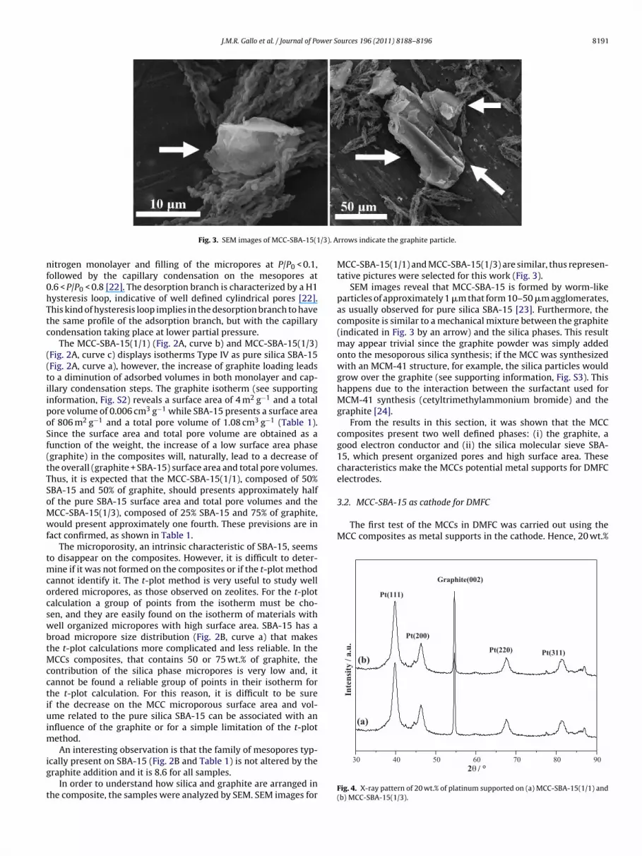
Fig. 3. SEM images of MCC-SBA-15(1
itrogen monolayer and filling of the micropores at P/P0 < 0.1,ollowed by the capillary condensation on the mesopores at.6 < P/P0 < 0.8 [22]. The desorption branch is characterized by a H1ysteresis loop, indicative of well defined cylindrical pores [22].his kind of hysteresis loop implies in the desorption branch to havehe same profile of the adsorption branch, but with the capillaryondensation taking place at lower partial pressure.
The MCC-SBA-15(1/1) (Fig. 2A, curve b) and MCC-SBA-15(1/3)Fig. 2A, curve c) displays isotherms Type IV as pure silica SBA-15Fig. 2A, curve a), however, the increase of graphite loading leadso a diminution of adsorbed volumes in both monolayer and cap-llary condensation steps. The graphite isotherm (see supportingnformation, Fig. S2) reveals a surface area of 4 m2 g−1 and a totalore volume of 0.006 cm3 g−1 while SBA-15 presents a surface areaf 806 m2 g−1 and a total pore volume of 1.08 cm3 g−1 (Table 1).ince the surface area and total pore volume are obtained as aunction of the weight, the increase of a low surface area phasegraphite) in the composites will, naturally, lead to a decrease ofhe overall (graphite + SBA-15) surface area and total pore volumes.hus, it is expected that the MCC-SBA-15(1/1), composed of 50%BA-15 and 50% of graphite, should presents approximately halff the pure SBA-15 surface area and total pore volumes and theCC-SBA-15(1/3), composed of 25% SBA-15 and 75% of graphite,ould present approximately one fourth. These previsions are in
act confirmed, as shown in Table 1.The microporosity, an intrinsic characteristic of SBA-15, seems
o disappear on the composites. However, it is difficult to deter-ine if it was not formed on the composites or if the t-plot method
annot identify it. The t-plot method is very useful to study wellrdered micropores, as those observed on zeolites. For the t-plotalculation a group of points from the isotherm must be cho-en, and they are easily found on the isotherm of materials withell organized micropores with high surface area. SBA-15 has a
road micropore size distribution (Fig. 2B, curve a) that makeshe t-plot calculations more complicated and less reliable. In the
CCs composites, that contains 50 or 75 wt.% of graphite, theontribution of the silica phase micropores is very low and, itannot be found a reliable group of points in their isotherm forhe t-plot calculation. For this reason, it is difficult to be suref the decrease on the MCC microporous surface area and vol-me related to the pure silica SBA-15 can be associated with an
nfluence of the graphite or for a simple limitation of the t-plotethod.An interesting observation is that the family of mesopores typ-
cally present on SBA-15 (Fig. 2B and Table 1) is not altered by theraphite addition and it is 8.6 for all samples.
In order to understand how silica and graphite are arranged inhe composite, the samples were analyzed by SEM. SEM images for
rrows indicate the graphite particle.
MCC-SBA-15(1/1) and MCC-SBA-15(1/3) are similar, thus represen-tative pictures were selected for this work (Fig. 3).
SEM images reveal that MCC-SBA-15 is formed by worm-likeparticles of approximately 1 �m that form 10–50 �m agglomerates,as usually observed for pure silica SBA-15 [23]. Furthermore, thecomposite is similar to a mechanical mixture between the graphite(indicated in Fig. 3 by an arrow) and the silica phases. This resultmay appear trivial since the graphite powder was simply addedonto the mesoporous silica synthesis; if the MCC was synthesizedwith an MCM-41 structure, for example, the silica particles wouldgrow over the graphite (see supporting information, Fig. S3). Thishappens due to the interaction between the surfactant used forMCM-41 synthesis (cetyltrimethylammonium bromide) and thegraphite [24].
From the results in this section, it was shown that the MCCcomposites present two well defined phases: (i) the graphite, agood electron conductor and (ii) the silica molecular sieve SBA-15, which present organized pores and high surface area. Thesecharacteristics make the MCCs potential metal supports for DMFCelectrodes.
30 40 50 60 70 80 902θ / °
Fig. 4. X-ray pattern of 20 wt.% of platinum supported on (a) MCC-SBA-15(1/1) and(b) MCC-SBA-15(1/3).

8192 J.M.R. Gallo et al. / Journal of Power Sources 196 (2011) 8188– 8196
ted on
oit(
sapt(defi(ptPa
m
paah
FXa
Fig. 5. TEM images of 20 wt.% of platinum suppor
f platinum (amount commonly used in literature) was insertedn the MCCs to provide catalytic activity. XRD was used to analyzehe Pt/MCC-SBA-15(1/1) (Fig. 4, curve a) and Pt/MCC-SBA-15(1/3)Fig. 4, curve b).
The XRD patterns of Pt/MCCs are very similar between them andhow five diffraction peaks at Bragg angles 39.8◦, 46.3◦, 67.6◦, 81.4◦
nd 86.9◦ 2� assigned to (1 1 1), (2 0 0), (2 2 0), (3 1 1) and (2 2 2)lanes respectively, of face-centered cubic (Fm3m) platinum crys-allites [25]. A further XRD peak at 54.6◦ 2� due to the graphite0 0 2) plane is also observed. The collected XRD data were used toetermine the average crystallite size by using the Debye–Scherrerquation (see supporting information) [26]. Although any of theve XRD peaks could be used for the calculation, the (1 1 1) and2 2 0) peaks are more often used for this purpose. In the casesresented in Fig. 4, the (1 1 1) peak is slightly convoluted withhe neighboring peak, thus the (2 2 0) peak was chosen. For botht/MCC-SBA-15(1/1) and Pt/MCC-SBA-15(1/3) the platinum aver-ge crystallite size was found to be 6.8 nm.
The MCCs were also studied by transmission electronicroscopy (TEM), as shown in Fig. 5.According to the TEM images (Fig. 5), platinum (black dots) is
resent predominantly in crystallites with dimension between 2
nd 3 nm, however, larger particles with dimensions between 10nd 20 nm are also present and this should be the reason of theigher average particle sizes determined by XRD.0.00 0.02 0.04 0.06 0.08 0.10 0.120.0
0.1
0.2
0.3
0.4
0.5
0.6
(c)(b)
A
Pote
ntia
l / V
Corrent Density / Acm-2
(a)
Pow
er D
ensi
ty /
Wcm
-2
ig. 6. (A) Polarization curves and (B) power density vs. current density curves for the 2C-72R as cathode for the DMFC. Anode was assembled with a commercial PtRu/Vulcanqueous methanol solution.
(A) MCC-SBA-15(1/1) and (B) MCC-SBA-15(1/3).
The MEA was prepared using the MCC-SBA-15(1/1), MCC-SBA-15(1/3) and the commercial support Vulcan XC-72R modified with20 wt.% of platinum as cathode. The anode was made with a com-mercial 60 wt.% PtRu(1:1) on Vulcan XC-72R (E-TEK); and Nafion117 as electrolyte. The cathode and the anode were fed, respec-tively, with 300 mL min−1 of non-humidified air and 1 mL min−1 ofa 1 mol L−1 aqueous methanol solution. For a first test, the polar-ization and power curves were obtained at 70 ◦C as shown in Fig. 6.
For the system using Pt/MCC-SBA-15(1/1) on the cathode,the cell performance reached a maximum of power density of0.6 mW cm−2 and current density of 3.0 mA cm−2 at 0.2 V. Thesevalues can be considered unsuitable if compared with that of thesystem using the commercial support, Vulcan XC-72R, on the cath-ode, which reached values 25 times higher (maximum of powerdensity of 15.4 mW cm−2 and current density of 76.4 mA cm−2 at0.2 V). On the other side, the system using Pt/MCC-SBA-15(1/3) onthe cathode presented performance only 2.9 times lower than thesystem using Pt/Vulcan XC-72R. Thus, the MCC-SBA-15(1/1) canbe considered as a material not suitable to be used on DMFC elec-trodes, while MCC-SBA-15(1/3) had promising results. Ambrosioet al. [27] have used the mesoporous carbon Pt/CMK-3 (inversereplica of SBA-15) on the PEMFC cathode at 70 ◦C and observed
that the performance was less than half of that of the system usingcommercial catalysts. One of the justification gave by the authorswas that the Pt/CMK-3 led to a higher internal cell resistance0.00 0.02 0.04 0.06 0.08 0.10 0.120.000
0.002
0.004
0.006
0.008
0.010
0.012
0.014
0.016
(c)
(b)
B
Corrent Density / Acm -2
(a)
0 wt.% Pt supported on (a) MCC-SBA-15(1/1), (b) MCC-SBA-15(1/3) and (c) Vulcan XC-72R (E-TEK). Conditions: 70 ◦C; 300 mL min−1 of air; 1 mL min−1 of a 1 mol L−1

J.M.R. Gallo et al. / Journal of Power Sources 196 (2011) 8188– 8196 8193
0.00 0.01 0.02 0.03 0.04 0.050.0
0.1
0.2
0.3
0.4
0.5
0.6 30 °C 40 °C 50 °C 60 °C 70 °C 80 °C 90 °C
Pote
ntia
l / V
Current Density / Acm-2
A
0.00 0.01 0.02 0.03 0.04 0.050.000
0.001
0.002
0.003
0.004
0.005
0.006
0.007
30 °C 40 °C 50 °C 60 °C 70 °C 80 °C 90 °C
A'
Pow
er D
ensi
ty /
Wcm
-2
Current Density / Acm-2
0.00 0.02 0.04 0.06 0.08 0.10 0.12 0.140.0
0.1
0.2
0.3
0.4
0.5
0.6 30 °C 40 °C 50 °C 60 °C 70 °C 80 °C 90 °C
Pote
ntia
l / V
Current Density / Acm-2
B
0.00 0.02 0.04 0.06 0.08 0.10 0.12 0.140.0000.0020.0040.0060.0080.0100.0120.0140.0160.0180.020
30 °C 40 °C 50 °C 60 °C 70 °C 80 °C 90 °C
Pow
er D
ensi
ty /
Wcm
-2
Current Density / Acm-2
B'
F SBA-1c y, with
cotu
1tt(
ctPola
F7
ig. 7. Polarization and power curves for the DMFC assembled with (A, A′) Pt/MCC-ommercial PtRu/Vulcan XC-72R (E-TEK). Cathode and anode were fed, respectivel
ompared to the commercial catalyst. A similar behavior isbserved in the present work. At 70 ◦C the internal resistance ofhe cells was 130 � for the MCCs-SBA-15(1/3), while for the systemsing Vulcan XC-72R it was 60 �.
Due to the promising results obtained for the Pt/MCC-SBA-5(1/3) on the DMFC cathode at 70 ◦C, a study varying theemperature from 30 to 90 ◦C was carried out (Fig. 7A and A′) andhe results compared with those obtained for the Pt/Vulcan XC-72RFig. 7B and B′).
For both samples it is observed a clear improvement in theell performance when the temperature is increased. Moreover,he difference between the performances of the system using
t/MCC-SBA-15(1/3) related to the Pt/Vulcan XC-72R on the cath-de diminishes as a function of the temperature, reaching theowest difference at 70 ◦C. This behavior could be due to a higherctivation temperature of the catalyst when supported on the MCC0.00 0.02 0.04 0.06 0.08 0.10 0.12 0.14 0.16 0.18 0.20
0.1
0.2
0.3
0.4
0.5
0.6
0.7
(b)
A
Pote
ntia
l / V
Corrent Density / Acm-2
(a) Pow
er D
ensi
ty /
Wcm
-2
ig. 8. (A) Polarization curves and (B) power density vs. current density curves for the (a) P0 ◦C; 100 mL min−1 of pure oxygen; 1 mL min−1 of a 1 mol L−1 aqueous methanol solutio
5(1/3) and (B, B′) Pt/Vulcan XC-72R on the cathode. Anode was prepared using the 300 mL min−1 of air and 1 mL min−1 of a 1 mol L−1 aqueous methanol solution.
matrix or due to a problem of water flow in the internal channelsof the SBA-15 at low temperatures.
Platinum supported on MCC-SBA-15(1/3) and Vulcan XC-72Rwas also tested feeding the cathode with pure non-humidified oxy-gen and the polarization and power curves obtained at 70 ◦C areshown in Fig. 8. For the cells using MCC-SBA-15(1/3) and Vul-can XC-72R on the cathode the maximum power density were13.8 and 26.0 mW cm−2 and current density at 0.2 V were 68.1 and128.7 mA cm−2, respectively.
When pure oxygen is used instead of air, the fuel cell can workwith a higher power. In this condition, it was observed that thefactor of performance difference between the systems using MCC
and Vulcan XC-72R on the cathode diminished to 2 (against 2.9,when the cathode was fed with air). The use of the pure oxy-gen leads to an increase of the reaction rate, as well as the masstransport (of water and proton, on the cathode). Probably the0.00 0.02 0.04 0.06 0.08 0.10 0.12 0.14 0.16 0.18 0.200.000
0.005
0.010
0.015
0.020
0.025
0.030
(b)
(a)
B
Corrent Density / Acm-2
t/MCC-SBA-15(1/3) and the Pt/Vulcan XC-72R as cathode for the DMFC. Conditions:n.

8194 J.M.R. Gallo et al. / Journal of Power S
30 35 40 45 50 55 60 65 70 75 80 85 90
Graph ite
( 002) Pt( 311)Pt( 220)
Ru( 010)
Pt(200 )
Pt(11 1)
Inte
nsity
/ u.
a.
2θ / °
F
om
3
ici6S3
1tX(Xfrfapi
ig. 9. X-ray pattern of 60 wt.% of PtRu(1:1) supported on MCC-SBA-15(1/3).
rganized porosity on the silica phase of the MCCs facilitates theass transport.
.3. MCC-SBA-15(1/3) as anode for DMFC
The diffusion of the liquid combustible through the catalyst layern the anode is more difficult than that of the gas oxidant in theathode, thus a porous support as the MCC-SBA-15 could be annteresting alternative. The anode catalyst was prepared supporting0 wt.% of platinum–ruthenium [5] (1/1 molar ratio) alloy on MCC-BA-15(1/3) and Vulcan XC-72R. The catalyst alloy is composed by9.26 wt.% of Pt, 21.74 wt.% of Ru and 40% of support.
The average size of the PtRu alloy crystallites on MCC-SBA-5(1/3) were determined as 3.6 nm by the Scherrer equation usinghe (2 2 0) diffraction peak (Fig. 9). The PtRu(1/1 molar ratio) alloyRD pattern, shown in Fig. 9, reveals peaks assigned to (1 1 1),
2 0 0), (2 2 0), (3 1 1) and (2 2 2) planes, as observed for platinumRD pattern, but slightly shifted to higher 2� values, indicating a
ace-centered cubic symmetry with lower lattice parameters. Thisesult is in accordance with the literature, where it is described that
or PtRu alloy up to about 0.7 Ru atomic fractions, Pt and Ru formsolid solution with Ru atoms replacing Pt atoms on the latticeoints of the face-centered cubic structure, leading to a decrease
n the lattice parameters [28]. Above this value, Pt atoms replacing
Fig. 10. TEM images of P
ources 196 (2011) 8188– 8196
Ru in a hexagonal close packed structure [28]. Another peak at 44◦
2� is assigned to ruthenium (0 1 0) plane indicating the presence ofnon-alloyed ruthenium [29]. The peak of graphite (0 0 2) plane isalso observed.
The PtRu alloy particles were also analyzed by TEM images(Fig. 10A) either in the raw state or upon occlusion in an epox-ide resin and lamination. This last procedure aimed at verifyingif alloy nanoparticles would be found inside the silica grains(Fig. 10B).
As shown in Fig. 10A, the PtRu particles (black dots) with dimen-sions between 2 and 5 nm were found inside the silica grains. InFig. 10B, it was confirmed that the metal particles (black regionsin the figure) are effectively supported inside the molecular sievechannels.
The 60 wt.% PtRu on MCC-SBA-15(1/3) was used as metal sup-port for the DMFC anode and its performance was compared withthat of the commercial support Vulcan XC-72R with the samemetal loading, as shown in Fig. 11. Although for the studied ofMCCs as DMFC cathode 20 wt.% Pt catalysts were used, it wasnot observed significant differences between catalysts with 20 or50 wt.% Pt loading (see supporting information, Fig. S4). Hence, forthe following tests, the cathode was prepared with the commer-cial Pt(50 wt.%)/Vulcan XC-72R (E-TEK). The cathode and the anodewere fed, respectively, with 300 mL min−1 of non-humidified airand the 1 mL min−1 of a 1 mol L−1 aqueous methanol solution; themeasurements were carried out at temperatures between 30 and90 ◦C. The results are shown in Fig. 11.
For both samples tested as anode for DMFC it is observed a clearincrease in the cell performance when the temperature is increasedup to 90 ◦C due to higher reaction rates and improvement of themass transport.
The results of current density at 0.2 V and maximum power den-sity showed that the MCC-SBA-15(1/3) presented performance 5and 10% lower than the commercial support Vulcan XC-72R at 30and 40 ◦C, respectively. At 50, 60, 70, 80 and 90 ◦C, it presents per-formances 10, 12, 21, 6 and 17% higher. This behavior of increasingthe MCC-SBA-15(1/3) performance as a function of the tempera-ture, reaching an optimum point at 70 ◦C was also observed whenthe support was used on the cathode, as discussed before.
It is interesting that when used as cathode the MCC-SBA-15(1/3)cannot reach performances comparable to the Vulcan XC-72R,while the performances are comparable, or even better, when it is
used as anodes. This is probably because the liquid combustible candiffuse better in the organized porous MCCs structure than in theVulcan XC-72R structure, thus, reaching the catalytic sites withoutdifficulty.tRu/MCC-SBA-15.

J.M.R. Gallo et al. / Journal of Power Sources 196 (2011) 8188– 8196 8195
0.00 0.02 0.04 0.06 0.08 0.10 0.120.0
0.1
0.2
0.3
0.4
0.5
0.6 30 °C 40 °C 50 °C 60 °C 70 °C 80 °C 90 °C
Pote
ntia
l / V
Current Density / Acm-2
A
0.00 0.02 0.04 0.06 0.08 0.10 0.120.000
0.002
0.004
0.006
0.008
0.010
0.012
0.014
0.016A'
30 °C 40 °C 50 °C 60 °C 70 °C 80 °C 90 °C
Pow
er D
ensi
ty /
Wcm
-2
Current Density / Acm-2
0.00 0.02 0.04 0.06 0.08 0.100.000.050.100.150.200.250.300.350.400.450.500.550.60
30 °C 40 °C 50 °C 60 °C 70 °C 80 °C 90 °C
Pote
ntia
l / V
Current Density / Acm-2
B
0.00 0.02 0.04 0.06 0.08 0.100.000
0.002
0.004
0.006
0.008
0.010
0.012
0.014
30 °C 40 °C 50 °C 60 °C 70 °C 80 °C 90 °C
B'
Pow
er D
ensi
ty /
Wcm
-2
Current Density / Acm-2
Fig. 11. Polarization and power curves obtained at different temperatures for the DMFC aXC-72R as metal support on the DMFC anode. Cathode was prepared using the commercwith 300 mL min−1 of air and 1 mL min−1 of a 1 mol L−1 aqueous methanol solution.
0.00 0.02 0.04 0.06 0.08 0.100.0
0.1
0.2
0.3
0.4
0.5
0.6
0.7
0.000
0.002
0.004
0.006
0.008
0.010
0.012
0.014
(b)
(b)
(a)
Pote
ntia
l / V
Current Density / Acm-2
(a) Power D
ensity / Wcm
-2
Fig. 12. Polarization (left hand side y axis) and power (right hand side y axis) curvesobtained at 70 ◦C feeding the cathode with 100 mL min−1 of oxygen. The DMFC wasassembled with (a) PtRu/MCC-SBA-15(1/3) and (b) PtRu/Vulcan XC-72R. Cathodeww
[wf
to1F
(
Acknowledgments
as prepared using the commercial Pt(50 wt.%)/Vulcan XC-72R (E-TEK). The anodeas fed with 1 mL min−1 of a 1 mol L−1 aqueous methanol solution.
These results are in accordance to those obtained by Yu et al.30]. They found that the silica-templated mesoporous carbonhen used on anode for DMFC carbon presents 16% higher per-
ormance than the Vulcan XC-72R.Alternatively, the experiment was carried out at 70 ◦C, feeding
he cathode with 100 mL min−1 of non-humidified oxygen insteadf 300 mL min−1 of air and the anode with a 1 mL min−1 of a
mol L−1 aqueous methanol solution. The results are shown in
ig. 12.When oxygen fed the cathode, the systems using MCC-SBA-15Fig. 12a) or Vulcan XC-72R (Fig. 12b) in the anode presented simi-
ssembled with (A, A′) PtRu(60 wt.%) MCC-SBA-15(1/3), (B, B′) PtRu(60 wt.%) Vulcanial Pt(50 wt.%)/Vulcan XC-72R (E-TEK). Cathode and anode were fed, respectively,
lar performances reaching 64.5 mA cm−1 of current density at 0.2 Vand 13.1 mW cm−1 of maximum power density. The use of the pureoxidant implies in an increase of the reaction rate on the cathodeand minimizes the anode effect.
4. Conclusions
A new family of MCC composites for electrodes designed to takethe advantages of the well ordered mesoporous silica structure andof the graphite high conductivity, is here presented for the firsttime. X-ray diffraction confirmed the ordered structure of the com-posites, and nitrogen adsorption at −196 ◦C showed a decrease ofthe pore volume and surface area of MCC composites in comparisonto the pure silica materials. Pore diameter of the silica counter-part in the composite was not affected by the graphite addition.SEM images revealed that in the composites with SBA-15 particlemorphology is similar to a mechanical mixture.
The MCC-SBA-15 with SiO2/C weight ratio of 1/3 was active onthe DMFC cathode. However, the performance was significantlylower than that obtained with Vulcan XC-72R. Otherwise, whenused as anode, the MCC-SBA-15 with SiO2/C weight ratio of 1/3showed performance comparable to (or somehow better than) thesystem using Vulcan XC-72R. This behavior can be explained by themore difficult diffusion of the liquid combustible if compared withthe gas oxidant. The fuel can diffuse better in the organized porousMCC structure than in the Vulcan XC-72R structure while for thediffusion of the oxidant the structure studied did not show to bedeterminant.
The authors acknowledge the Piedmont Region (MicrocellProject) and the “Fundac ão de Amparo à Pesquisa no Estado de São

8 ower S
PMf
A
t
R
[
[[
[[[
[
[[
[
[[
[
[
[
[[
196 J.M.R. Gallo et al. / Journal of P
aulo”, FAPESP, for the financial support to this work. JMRG thanksinistero dell’Istruzione, dell’Università e della Ricerca for the PhD
ellowship.
ppendix A. Supplementary data
Supplementary data associated with this article can be found, inhe online version, at doi:10.1016/j.jpowsour.2011.05.008.
eferences
[1] 2007 Worldwide Fuel Cell Industry Survey, US Fuel Cell Council, pp. 1–8,http://www.usfcc.com/resources/2007worldwide survey final low.pdf [lastaccess 05 December 2010].
[2] 2008 Energy Technology Perspectives, Scenarios & Strategies to 2050, Interna-tional Energy Agency, 2008, OECD Publishing, Paris, France, ebook version, p.267.
[3] S. Litster, G. McLean, J. Power Sources 130 (2004) 61.[4] X. Yu, S. Ye, J. Power Sources 172 (2007) 133.[5] H. Liu, C. Song, L. Zhang, J. Zhang, H. Wang, D.P Wilkinson, J. Power Sources 155
(2006) 95.[6] T. Matsumoto, T. Komatsu, K. Arai, T. Yamazaki, M. Kijima, H. Shimizu, Y. Taka-
sawa, J. Nakamura, Chem. Commun. (2004) 840;H. Tang, J.H. Chen, Z.P. Huang, D.Z. Wang, Z.F. Ren, L.H. Nie, Y.F. Kuang, S.Z. Yao,Carbon 42 (2004) 191.
[7] W. Li, C. Liang, J. Qiu, W. Zhou, H. Han, Z. Wei, G. Sun, Q. Xin, Carbon 40 (2002)791;
W. Li, C. Liang, J. Qiu, W. Zhou, A. Zhou, Z. Wei, G. Sun, Q. Xin, J. Phys. Chem. B107 (2003) 6292;W. Li, C. Liang, W. Zhou, J. Qiu, H. Li, G. Sun, Q. Xin, Carbon 42 (2004) 436.[8] G. Che, B.B. Lakshmi, C.R. Martin, E.R. Fisher, Langmuir 15 (1999) 750.[9] G. Girishkumar, K. Vinodgopal, P. Kamat, J. Phys. Chem. B 108 (2004) 19960.
[
[[[
ources 196 (2011) 8188– 8196
10] J.S. Yu, S. Kang, S.B. Yoon, G. Chai, J. Am. Chem. Soc. 124 (2002) 9382;G.S. Chai, S.B. Yoon, J.S. Yu, J.H. Choi, Y.E. Sung, J. Phys. Chem. B 108 (2004)7074.
11] G.S. Chai, S.B. Yoon, J.H. Kim, J.S. Yu, Chem. Commun. (2004) 2766.12] Y.C. Liu, X.P. Qiu, Y.Q. Huang, W.T. Zhu, J. Power Sources 111 (2002) 160;
Y.C. Liu, X.P. Qiu, Y.Q. Huang, W.T. Zhu, Carbon 40 (2002) 2375.13] M. Tsionsky, G. Gun, V. Giezer, O. Lev, Anal. Chem. 66 (1994) 1747.14] L. Rabinovich, O. Lev, Electroanalysis 13 (2001) 265.15] D. Zhao, Q. Huo, J. Feng, B.F. Chmelka, G.D. Stucky, J. Am. Chem. Soc. 120 (1998)
6024.16] S.H. Joo, S.J. Choi, I. Oh, J. Kwak, Z. Liu, O. Terasaki, R. Ryoo, Nature 412 (2001)
169.17] T.C. Deivaraj, J.Y. Lee, J. Power Sources 142 (2005) 43.18] J.M.R. Gallo, U.A. Icardi, V. Baglio, A. Coralli, A. Graizzaro, Int. J. Hydrogen Energy,
doi:10.1016/j.ijhydene.2011.01.051.19] J. Gun, M. Tsionsky, L. Rabinovich, Y. Golan, I. Rubinstein, O. Lev, J. Electroanal.
Chem. 395 (1995) 57.20] P. Alexandridis, U. Olsson, B. Lindman, Langmuir 14 (1998) 2627.21] A. Kukovecz, T. Kanyó, Z. Kónya, I. Kiricsi, Microporous Mesoporous Mater. 80
(2005) 85.22] S. Lowell, J.E. Shields, M.A. Thomas, M. Thommes, Characterization of porous
solids and powders: surface area, pore size and density, Particle TechnologySeries, Springer, Dordrecht, NE, 2006, pp. 12–14, 37–46, 112–121.
23] D.Y. Zhao, J.L. Feng, Q.S. Huo, N. Melosh, G.H. Fredrickson, B.F. Chmelka, G.D.Stucky, Science 279 (1998) 548.
24] S. Manne, J.P. Cleveland, H.E. Gaub, G.D. Stucky, P.K. Hansma, Langmuir 10(1994) 4409.
25] X.W. Teng, H. Yang, J. Am. Chem. Soc. 125 (2003) 14559.26] W. Li, W.J. Zhou, H.Q. Li, Z.H. Zhou, B. Zhou, G.Q. Sun, X. Qin, Electrochim. Acta
49 (2004) 1045.
27] E.P. Ambrosio, C. Francia, M. Manzoli, N. Penazzi, P. Spinelli, Int. J. HydrogenEnergy 33 (2008) 3142.28] E. Antolini, Mater. Chem. Phys. 78 (2003) 563–573.29] C. Roth, N. Martz, H. Fuess, Phys. Chem. Chem. Phys. 3 (2001) 315.30] J.-S. Yu, S. Kang, S.B. Yoon, G. Chai, J. Am. Chem. Soc. 124 (2002) 9382.


