Embed Size (px)
Citation preview

NovoClear465SeriesManual
BIFChem‐FreeFilter
New Style Parallel Tank Connector Read all instructions carefully before operation. Rev 0 May 17, 2017 #80150331-1

2
TABLE OF CONTENTS System Specifications .................................................................................................................. 3 How the System Works ............................................................................................................... 3 Main Valve functions ................................................................................................................... 5 Manual Regeneration .................................................................................................................. 5 Sizing Requirements .................................................................................................................... 5 Before Installation ....................................................................................................................... 7 General Installation ..................................................................................................................... 8 Start Up Instructions ................................................................................................................... 9 Plumbing System Clean‐Up ....................................................................................................... 10 Level I Programming ................................................................................................................. 11 Level II Programming ................................................................................................................ 12 System Configuration ................................................................................................................ 13 Maintenance ............................................................................................................................. 14 Valve Drive Assembly Exploded View ....................................................................................... 15 Control Valve Assembly Exploded View .................................................................................... 16 Trouble Shooting ....................................................................................................................... 18 Warranty ................................................................................................................................... 19

3
SystemSpecifications
Item # Model Media Cu Ft
Flow Rate USGPM Mineral Tank Size
Air Contact Tank
Pipe Size
Inches
Ship Weight Lbs Service Peak Backwash
15050051‐1 NVO465BIF‐100 1.0 3.0 5.0 5.0 10 x 44 8 x 44 3/4" 100
15050067‐1 NVO465BIF‐150 1.5 4.0 8.0 5.0 10 x 54 10 x 54 3/4" 201
Figure 1. System Specifications Caution: These water filters are not intended to be used for treating water that is microbiologically unsafe or of unknown quality without adequate disinfection before or after the system.
HowtheSystemWorks The chemical free iron filter consists of three major components which are: Control Valve, Air Tank, Media Tank. Natural oxidation removes iron, sulfur and manganese without chemicals, air pumps or a venturi. Incoming raw water passes through a pocket of air in the first tank. The oxygen in the air oxidizes the iron into a solid form and it removed when it passes through the second filter tank. The media in the second filter tank acts as a catalyst in the reaction between the iron and oxygen that causes the iron to precipitate into a solid so it can be filtered out of the water. As more water passes through the unit, the air becomes depleted in the first tank and the filter media in the second tank becomes over loaded with iron. A periodic automatic regeneration replenishes a supply of air and cleans the iron out of the filter tank. There are no chemicals used for this system to work. The filter media automatically adjusts the pH to neutral or higher on acid water without an acid neutralizer. The ability to raise pH when it is below neutral (7 or less) greatly enhances the filter’s ability to remove iron efficiently. The clean, filtered water then flows into your household water line. Depending on water use and the concentration of iron in your water, periodic backwashing is required to flush the entrapped iron from the system. The system can be set to regenerate as clock every 1 – 99 days or as meter delayed based on gallons between regenerations. Instructions for calculating the backwash frequency and setting the controls are in Section 5. Your filter is factory set to backwash at 12:00 a.m. during a period of little or no water use. The automatic regeneration cycle lasts approximately 60 minutes, after which filtered water service is restored. While backwashing is taking place raw water automatically bypasses the filter if required. If possible, avoid using water during backwashing to prevent iron‐laden water entering your household plumbing system. This valve is controlled with simple, user‐friendly electronics displayed on a large LCD screen. The main page displays the current date and time. In addition, the main page also shows key valve information and statistics including; current capacity setting, volume remaining, date of last regeneration, current flow rate, and peak flow rate.
• Peak flow rates are intended for intermittent use only and are for residential application only
• At the stated service flow rates, the pressure drop through these devices will not exceed 15 psig
• The manufacturer reserves the right to make product improvements which may deviate from the specifications and descriptions stated herein, without obligation to change previously manufactured products or to note the change
• Maximum Water Temperature = 110°F (43°C) • Maximum Operating Pressure = 100 PSIG
(689 kPa) • Voltage = 110 volts standard • Pipe Size = 3/4”

4
Figure 2. Main Page Displays
NOTE: REGEN DAYS and REMAINING DAYS are only shown in the CALENDAR CLOCK mode or METER OVERRIDE mode. Your automatic filter can be set to operate according to your needs by programming the appropriate settings. On the days your filter regenerates, the operating cycles will be automatically performed. In the service position, filtered water is supplied for household use.
Figure 3. Valve Button Configuration
MENU BUTTON “ ”: The function of this key is to enter the level one programming mode where the valve settings can be adjusted. SET / REGEN BUTTON“ ”: This button has two functions. The first is to initiate a manual regeneration by holding the button for 3 or more seconds. The second function is while in programming mode, pressing this key allows the user to change the value of each setting. UP / DOWN “ ”: These buttons are used to increase or decrease the value of the settings while in the programming mode. System Initialization When power is first supplied, the valve may take up to two minutes to initialize the valve. During this time the valve will show “INTIALIZING WAIT PLEASE”. Do not touch any buttons at this time. When the valve reaches the service position, it will display the current date and time.
Figure 4. Initializing Display
MAY 8, 20099:05 AM
VOLUME REMAINING1,125 GAL
REGENERATIONTIME 2:00 AM
LAST REGENMAY 4, 2009
CAPACITY1,350 GAL
CURRENT FLOW1.5 GPM
PEAK FLOW5.8 GPM
REGEN DAYS7 DAYS
REMAINING DAYS5 DAYS
5
MainValveFunctions Regeneration Mode There are four ways of initiating a regeneration. 1. METER DELAYED 2. METER IMMEDIATE 3. CALENDAR CLOCK (Factory Setting) 4. METER OVERRIDE Capacity Calculation The control can automatically calculate the capacity of the system using the parameters entered in Level I
programming. If you prefer to enter the capacity manually, choose the MANUAL option. 1. AUTOMATIC 2. MANUAL (Factory Setting) Adjustable Cycles All of the valve cycles are fully adjustable.
1. BACKWASH 2. BRINE (Air Draw) 3. RINSE 4. REFILL
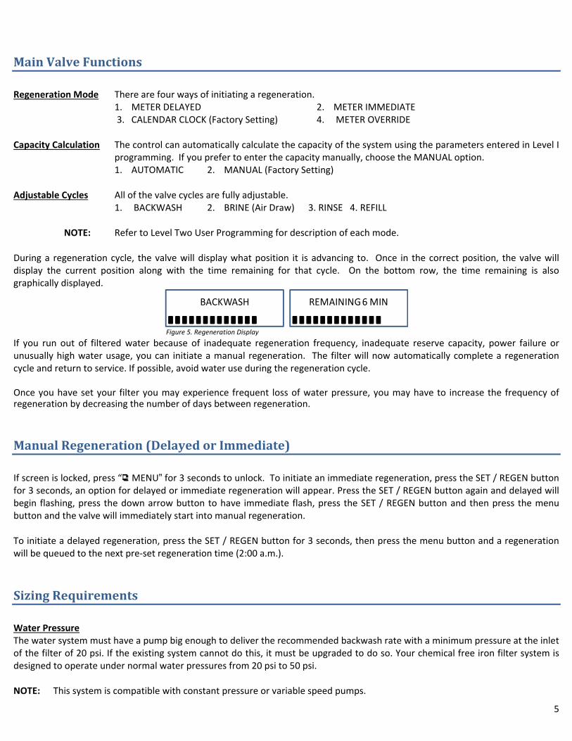
NOTE: Refer to Level Two User Programming for description of each mode. During a regeneration cycle, the valve will display what position it is advancing to. Once in the correct position, the valve will display the current position along with the time remaining for that cycle. On the bottom row, the time remaining is also graphically displayed.
Figure 5. Regeneration Display
If you run out of filtered water because of inadequate regeneration frequency, inadequate reserve capacity, power failure or unusually high water usage, you can initiate a manual regeneration. The filter will now automatically complete a regeneration cycle and return to service. If possible, avoid water use during the regeneration cycle. Once you have set your filter you may experience frequent loss of water pressure, you may have to increase the frequency of regeneration by decreasing the number of days between regeneration.
ManualRegeneration(DelayedorImmediate) If screen is locked, press “ MENU” for 3 seconds to unlock. To initiate an immediate regeneration, press the SET / REGEN button for 3 seconds, an option for delayed or immediate regeneration will appear. Press the SET / REGEN button again and delayed will begin flashing, press the down arrow button to have immediate flash, press the SET / REGEN button and then press the menu button and the valve will immediately start into manual regeneration. To initiate a delayed regeneration, press the SET / REGEN button for 3 seconds, then press the menu button and a regeneration will be queued to the next pre‐set regeneration time (2:00 a.m.).
SizingRequirements Water Pressure The water system must have a pump big enough to deliver the recommended backwash rate with a minimum pressure at the inlet of the filter of 20 psi. If the existing system cannot do this, it must be upgraded to do so. Your chemical free iron filter system is designed to operate under normal water pressures from 20 psi to 50 psi. NOTE: This system is compatible with constant pressure or variable speed pumps.
BACKWASH REMAINING 6 MIN

6
CHECK YOUR WATER PRESSURE AND PUMPING RATE Two water system conditions must be checked carefully to avoid unsatisfactory operation or equipment damage: 1. Minimum water pressure required at the filter tank inlet is 20 psi. 2. The pumping rate of your well pump must be at least 5 gallons per minute (gpm) for satisfactory back wash of the filter. To
measure the pumping rate of your pump, follow these instructions: a. Make certain no water is being drawn. Open spigot nearest pressure tank. When pump starts, close spigot and measure
time (in seconds) to refill pressure tank (when pump shuts off). This figure represents cycle time. b. With the pressure tank full, draw water into a container of known volume, and measure the number of gallons drawn until
the pump starts again. This is draw‐down. Divide this figure by cycle time and multiply the result by 60 to arrive at the pumping rate in gallons per minute (gpm). To aid in your calculation, insert the date in the following formula:
DRAW‐DOWN ______ ÷ CYCLE TIME _______ x 60 = PUMPING RATE ________ (gpm) EXAMPLE: CYCLE TIME is 53 secs.; DRAW‐DOWN is 6 gals.; then, PUMPING RATE equals: 6 gals. ÷ 53 secs. x 60 = 6.8 gpm NOTE: If your pumping rate is inadequate, do not install your filter until problem is corrected.
Backwash Flow Rates The most important criteria in sizing a filter is the capacity of the pump. The water must pass through the filter media at a service flow rate that allows it to operate properly. The filter must also be backwashed at a flow rate sufficient to dislodge and remove captured particulates. Failure to provide sufficient water will cause a build‐up of particulates in the filter media, impairing its filtration ability. In order for your filter to backwash and rinse properly, your pump must be capable of providing the backwash flow rates indicated in the above specification chart. Backwash Frequency This unit is factory set for backwash every 4 days. More frequent backwash may be required based on water conditions and amount of water used. Refer to Level II Master Programming to change the REGEN days (backwash frequency).
BeforeInstallation INSPECTION AND HANDLING Inspect the equipment for any visible shipping damage. If damaged, notify the transportation company and request a damage inspection. Damage to cartons should also be noted. Handle the filter unit with care. Damage can result if dropped or if set on sharp, uneven projections on the floor. Do not turn the filter unit upside down. NOTE: If a severe loss in water pressure is observed when the filter unit is initially placed in service, the filter tank may have been laid on its side during transit. If this occurs, manually backwash the filter to “reclassify” the media. IRON (Fe) Iron concentrations as low as 0.3 ppm will cause staining. The iron concentration, together with the flow rate demand and the consumption rate of the water determines the basic size filter system. The higher these factors are, the larger the required system. The filter system is capable of filtering out the three main types of iron found in water supplies: Soluble iron (also known as “clear water” or ferrous iron), precipitated iron (also known as “red water” or ferric iron) and bacterial iron (also known as iron bacteria). There is no apparent upper limit of iron concentration for the filter, but special care must be taken when selecting a filter model if your water has a combination of high iron, very low pH and/or manganese.

7
MANGANESE (Mn) The presence of manganese can be bothersome, even for a chemical free iron filter. As little as 0.05 ppm of manganese can produce a brownish or black stain. The ability of the filter to remove manganese depends on its concentration and the pH of the water. Manganese tends to “coat” the filter media, rendering it incapable of increasing the pH, and therefore ineffective in removing either the iron or the manganese. Manganese, however, will precipitate in the filter bed when the pH is increased. To accomplish this a special “MN” type media can be provided that contains additional quantities of the pH raising component (“MN adder”). The use of “MN” type media is for applications where the manganese is not more than 1.5 ppm, and the pH is at least 6.5. pH The pH of water measures its acidity or its alkalinity. Water with a pH of less than 7.0 is acidic, above 7.0 it is alkaline, and a pH of 7.0 is neutral. The lower the pH value is below 7.0 the greater the acidity, and the higher the pH value is above 7.0 the more alkaline. Acidic water (pH less than 7.0) is corrosive to pipes, appliances, etc. A pH of 7.0 or higher facilitates iron removal — which is why the filter is designed to increase the pH when it is less than 7.0. The pH increasing component of the media is “sacrificial,” it slowly dissolves during the process of increasing pH. The rate this occurs is proportional to the pH increase and the water consumption rate (i.e., the greater the pH increase and water consumption, the greater the sacrificial rate). Thus, when the pH is increased to 8.2 or more as is necessary when manganese is present, the sacrificial rate is even greater. Under the most severe conditions, the MN component of the media may have to be replenished two to four times per year. On the other hand, if the raw water pH is 7.0 or above and no manganese is present, the sacrificial rate is very slight. TANNINS (Humic Acid) Tannins (also known as humic acid) which are present in some water supplies, are the result of decaying vegetable matter. If the tannin concentration is above approximately 0.5 ppm, it will form a sticky coating on the media, thus rendering it incapable of filtering the iron. A chemical free iron filter is not recommended under this condition. If the tannin concentration is less than 0.5 ppm, a chemical free iron filter may be installed. HYDROGEN SULFIDE (H2S) Hydrogen sulphide (often referred to as “sulphur”), is easily detectable by its objectionable “rotten egg” odour. Sulphur corrodes iron, brass, copper and silver. A chemical free iron filter is capable of removing sulphur in concentrations of up to 3 to 5 ppm. Whenever hydrogen sulphide is present, backwashing must be performed at more frequent intervals. LOCATE WATER CONDITIONING EQUIPMENT CORRECTLY: (see drawings page 9) 1. Select the location of your filter tank with care. Various conditions which contribute to proper location are as follows: 1. Locate as close as possible to water supply source. 2. Locate as close as possible to a floor or laundry tub drain. 3. Locate in correct relationship to other water conditioning equipment. 4. Filters and softeners should be located in the supply line before the water heater. Temperatures above 120°F damage filters
and softeners, and will void the factory warranty. 5. Do not install a filter or softener in a location where freezing temperatures occur. Freezing may cause permanent damage to
this type of equipment, and will void the factory warranty. 6. Allow sufficient space around the unit for easy servicing.

8
GeneralInstallation
Water Pressure Minimum 25 PSI
Electrical Supply Uninterrupted AC 115V
Existing Plumbing Free of any deposits or build‐ups inside pipes.
Unit Location Locate close to drain and connect according to plumbing codes
Bypass Valves Always provide for bypass valve if unit is not equipped with one.
Plumbing Softener and or other water treatment equipment should be installed to local plumbing codes
CAUTION Do not exceed 120 psi water pressure. Do not exceed 110°F water temperature. Do not subject unit to freezing conditions.
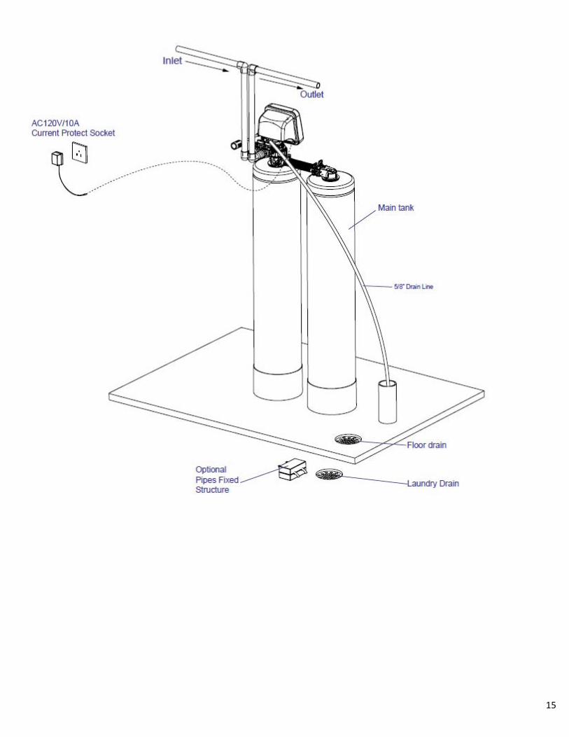
Figure 6.Tank Configuration Figure 7. Typical Installation 1. Locate the Air and Media Tank close to a drain where the system will be installed. The surface should be clean and level. 2. Shut off all water at main supply. On a private well system, turn off power to pump and drain pressure tank. Make certain
pressure is relieved from complete system by opening nearest faucet to drain the system. Shut off fuel supply to water heater. 3. Cut the main supply line as required to fit plumbing to the control valve with bypass. 4. Solder or solvent weld plumbing. Do not apply heat to any fitting connected to the control valve as damage may result to the
internal parts. Check to be certain water supply pipe is connected to the control valve inlet fitting and pipe connected to control valve outlet fitting is in direction of house service.
5. Perform all plumbing according to local plumbing codes. a. Use a ½” minimum pipe or tubing size for the drain line. b. Use a ¾” pipe or tubing for backwash flow rates that exceed 7 gpm or length that exceeds 20ft (6 m) NOTE: ON COPPER PLUMBING SYSTEMS BE SURE TO INSTALL A GROUNDING WIRE BETWEEN THE INLET AND OUTLET PIPING TO MAINTAIN GROUNDING.
6. Any solder joints near the valve must be done before connecting any piping to the valve. Always leave at least 6" (152 mm) between the valve and joints when soldering pipes that are connected to the valve. Failure to do this could cause damage to the valve.
7. Install ¾” check valve on inlet of bypass valve. 8. Connect the drain line to the valve. Only use Teflon tape on the drain fitting. 9. Place unit in the bypass position. 10. Slowly turn on the main water supply. 11. At the nearest cold treated water tap nearby remove the faucet screen, open the faucet and let water run a few minutes or
until the system is free of any air or foreign material resulting from the plumbing work. Close the water tap when water runs clean.
Water Heater Water Softener
Cold (Raw Water)
Cold (Raw Water)
To Outside Faucet
InIn
Out
Out
Hot (Soft Water)
Cold (Soft Water)
InOut
Cold (Filtered Water)
MediaTank
Air Tank
Check Valve

9
Start‐UpInstructions 1. Ensure inlet and outlet of bypass are in closed positions. 2. Plug the valve into an approved power source. When power is supplied to the control, the screen may display “INITIALIZING
WAIT PLEASE” while it finds the service position. 3. Press SET/REGEN “ ” button and hold for 3 seconds to initiate a manual regeneration and advance the valve to the Backwash
position. 4. Un‐plug power cord and open the inlet on the bypass valve slowly and allow water to enter the unit. Allow all air to escape
from the unit before turning the water on fully then allow water to run to drain for 25 to 30 minutes or until all media fines are washed out of the filter.
5. Plug power cord back into power source. When power is supplied to the control, the screen may display “INITIALIZING WAIT PLEASE” while it finds the service position. Press SET / REGEN“ ” button and hold for 3 seconds to initiate a manual regeneration and advance the valve to the Backwash position.
6. Press any button to advance to the BRINE (AIR DRAW) position. Check the drain line flow. Allow the water to run for entire BRINE (AIR DRAW) cycle.
7. Valve will automatically advance to the SERVICE position. Open the outlet valve of the bypass, then open the nearest treated water faucet and allow the water to run until clear, close the tap and replace the faucet screen.
PlumbingSystemClean‐Up The following procedures are guidelines only but have proven successful in most instances. Under no circumstances should any procedure outlined below be followed if contrary to the appliance manufacturer's instructions. Should there be any questions concerning the advisability of performing a procedure, it is strongly recommended the manufacturer's authorized service outlet be consulted prior to performing the procedure. The plumbing system and water using appliances that have been exposed, even for a short time, to iron‐fouled water need to be cleaned of the precipitated iron that has collected in them or iron bleed (staining) will continue to be a problem. Depending on the amount of iron in the water and the length of time the water system has been exposed to iron fouling, select from the following procedures those that apply to the type of system and appliances that need to be cleaned to assure iron‐free water at all points of use. Softener It isn't uncommon that the softener was installed in an effort to remove ferrous (clear water) iron from the water supply. Typically a softener will remove some ferrous iron until the resin bed becomes fouled to the extent that it will lose both hardness removal capacity and the limited capacity for iron removal. This is the condition to expect the softener to be in when planning a system clean‐up. Prior to closing the main supply valve or turning power off to a private well system and preparatory to installing the filter system, do the following: 1. Disconnect the brine draw line from the brine cabinet and place the loose end into a five gallon plastic pail filled with a solution
of warm water and 4 oz. of resin mineral cleaner. 2. Advance the control timer to the brine draw position (refer to instructions provided with your softener). Allow all the warm
mineral cleaner solution to be drawn into the mineral bed. 3. Then immediately close the main water supply valve or turn the power off to the pump and proceed with the filter installation.
During the time required to install the filter system, the iron‐fouled softener resin will be chemically cleaned.

10
4. After the filter installation is completed and final adjustments have been made, with the water turned on and the brine draw
tube reconnected, reposition the timer on the softener to the backwash position. Allow the timer to perform an automatic regeneration cycle. During backwash of the softener, all iron cleaned from the resin will be washed down the drain. It is advisable, after chemically cleaning the softener, to regenerate the system twice to fully restore capacity lost due to iron‐fouling.
Water Heater If the water heater has been exposed to both iron and hardness for a long period of time, replacement of the heater tank may be the only practical solution to prevent continued staining originating from this source. After completing the installation of the chemical free iron filter, clean the water heater by following these instructions: 1. Shut off the energy supply to the water heater and close the heater inlet water valve. 2. Drain hot water tank completely. Open inlet water valve, allowing heater tank to be refilled with iron‐free water. Continue
flushing until the water runs clear to the drain. 3. If, after approximately 30 minutes of flushing, water does not clear, terminate the flushing operation. Refill hot water heater
with water and pour approximately 1/2 gallon of household bleach into the top of the heater tank. Allow bleach solution to stand in tank for 20 to 30 minutes. Flush the tank again until water is clear at the drain. Turn energy supply on.
NOTE: If water does not clear in approximately 10 minutes, water heater should probably be replaced. Media Installation (When Necessary) 1. Remove the tank adaptor from the second mineral tank. 2. Temporarily plug the open end of the central pipe in the tank to insure that no resin or gravel falls down into the distribution. 3. Fill mineral tank one quarter full of water to protect distribution during gravel installation. 4. Slowly and carefully add the gravel support bed and the softener or filtration media leveling each layer as it is placed into the
tank. 5. Unplug the riser tube, carefully position the tank adaptor over it and turn it into the threads in the fiberglass tank, tightening
securely into tank. Note: Ensure that the internal O‐ring in the tank adaptor fits securely over the riser tube. Silicone grease or other food grade lubricant may be applied to the O‐ring to ease installation of the riser tube. DO NOT use petroleum based lubricants as they will cause swelling of O‐ring seals.

11
LevelIUserProgramming Setting Current Time 1. Press “ ” for 3 seconds to unlock screen. Press “ ” again to enter level one programming mode and adjust CURRENT TIME. 2. Press “ ” to adjust hours. When you have entered the change value mode, the curser will blink. Press “ or ”” arrows to
change the hour values. Press “ ” again to accept the hour value and advance to change the minutes value. Press ““ or ” arrows to change the minute values. Press “ ” again to accept the minute values and advance to adjust the AM/PM values. Press ““ or ” to change the AM/PM value. Press “ ” again to accept the AM/PM value and exit. When you have exited the change value mode, the curser will stop flashing.
Setting Current Date 1. Press “ ” to advance to CURRENT DATE. 2. Using the same procedure as setting the time, press “ ” to enter value change mode. Setting Vacation Mode 1. Press “ ” to advance to VACATION MODE.
2. Press the “ ” to change the value. Press ““ or ” to change the values. Exiting Level One User Program Mode 1. At any time, press the “ ” to accept all changes and return to main page display.
Figure 8. Level I Program Mode
Control Operation During A Power Failure In the event of power failure, the valve will keep track of the time and day for 48 hours. The programmed settings are stored in a non‐volatile memory and will not be lost during a power failure. If power fails while the unit is in regeneration, the valve will return to the service position once power is restored. However, since the unit did not complete its regeneration, it will queue another regeneration at the next scheduled regeneration time.
If the valve misses a scheduled regeneration due to a power failure, it will queue a regeneration at the next regeneration time once power is restored.
OPTIONS DESCRIPTION
1 CURRENT TIME This option is the current time of day.
2 CURRENT DATEThis option is the current date. The date is used to track the last time the system
regenerated.
Yes
No5 VACATION MODE
This function may be activated by the user during a prolonged absence such as vacation. The
system will perform a brief backwash and rinse based on the advanced setting. The purpose
is to keep the water fresh in the softener tank and plumbing system.
Level I User Program Mode (Filter)
PARAMETER

12
LevelIIMasterProgramming When the Level Two Master Programming Mode is entered, all available option setting displays may be viewed and set as needed. Depending on current option settings, some parameters cannot be viewed or set. 1. If screen is locked, press “ MENU” for 3 seconds to unlock screen. 2. Press and hold “ ” for three seconds to enter Level Two Master Programming.
Figure 9. Level II Program Mode
OPTIONS DESCRIPTION
ENGLISH
FRENCH
SPANISH
SOFTENER
FILTER
IRON FILTER
METER DELAYED
This is the most common setting. When the volume remaining reaches zero gallons, the system will
initiate a regeneration at the next pre‐set regeneration time.
METER IMMEDIATEThe unit will initiate a regeneration immediately after the volume remaining reaches zero.
CALENDAR CLOCKThe unit will initiate a regeneration at the next pre‐set regeneration time based on the interval of days
between regeneration days.
METER OVERRIDE
When the volume remaining reaches zero gallons, the system will initiate a regeneration at the next
pre‐set regeneration time. If the days between regeneration is reached before the remaining volume
reaches zero, the system will override the meter setting and initiate a regeneration.
4 REGENERATION TIME This setting controls the time of day when a regeneration cycle will start.
AUTOMATICThis option automatically calculates the capacity (in gallons for meter units), refill time (in minutes), or
regeneration day intervals (days for calendar clock mode).
MANUAL The user can manually enter values for capacity, refill time, or regeneration day intervals.
6 RESIN VOLUMEThis value should be the amount of resin in cubic feet that is loaded in to the tank. The value is used to
calculate the system capacity and refill time.
7 SALT SETTINGThis value is the salt dosage (pounds per cubic foot) to be used when regenerating the system.
8 REFILL FLOW RATE
This value is the flow rate(gallons per minute) of the brine line flow control (BLFC) button installed in
the valve and is used to calculate the refill time to precisely measure the amount of water into the
brine tank. (Note: This value is factory preset and should not be changed unless the BLFC button has
been changed to a different size.)
9 UNIT CAPACITYThis value (GRAINS for softeners, PPM for IRON FILTERS) is the total capacity of the system. It is used
to calculate the capacity of the system in gallons.
In MANUAL CAPACITY CALC. mode, the CAPACITY can be adjusted by the user. In AUTOMATIC
CAPACITY CALC. mode, the current calculated value is displayed but cannot be adjusted.
FORMULA CAPACITY = (UNIT CAPACITY / WATER HARDNESS) – (NUMBER PEOPLE * DAILY USAGE)
11 DAILY USAGEThis value is the average amount of water used per person per day. It is used to calculate the REGEN.
DAYS for calendar clocks.
12 RESERVE CAPACITYThis value is the amount of water per person in gallons to be saved for a reserve capacity. It is used to
calculate the CAPACITY of the system.
This value is the interval (days) between regenerations. It is used to determine how many days
between regenerations in the CALENDAR CLOCK mode. It is also used as the value for the METER
OVERRIDE mode. It can be set by the user in MANUAL CALC. MODE. In AUTOMATIC CAPACITY CALC.
mode, the current calculated value is displayed but cannot be adjusted.
FORMULAREGEN. DAYS = ((UNIT CAPACITY / WATER HARDNESS) / (NUMBER PEOPLE * DAILY USAGE)) ‐ 1
14 BACKWASHThis option controls the length of time in minutes for the unit to clean the bed by reversing the flow of
water upwards through the bed and out to the drain.
15 BRINE / RINSEThis option controls the length if time in minutes for the unit to draw regenerant (brine for softeners)
from the second tank and slowly rinse it from the top to bottom of the tank.
16 RINSEThis option controls the length of time to give the tank a final rinse from the top to the bottom in order
remove any last traces of the regenerant (brine) from the tank.
This option controls the length of time the brine valve will open to refill the second tank (brine tank for
softeners) with water in order to produce the regenerate solution (brine for softeners) for the next
regeneration cycle. The water is accurately measured through the valves brine line flow control to
make a precise quantity of regenerant solution. In MANUAL CAPACITY CALC. mode, the REFILL time
can be adjusted by the user. In AUTOMATIC CAPACITY CALC. mode, the current calculated value is
displayed but cannot be adjusted.
FORMULA REFILL = 0.45 * SALT SETTING * RESIN VOLUME / REFILL FLOW RATE
YES
NO
13
17
18 RESTORE DEFAULT
REGEN. DAYS
REFILL
This option allows the current settings to be erased and changed back to the default settings.
PARAMETER
1
2
3
5 CAPACITY CALC.
10
SYSTEM LANGUAGE
This option controls which language should be used in the valve display.
VALVE OPERATION
There are three basic operating modes to choose depending on the system application.
REGEN. MODE
CAPACITY

13
Diagnostics Mode 1. If screen is locked, press “ MENU” for 3 seconds to unlock. 2. Press and hold the “ “ DOWN button for three seconds to enter Level Diagnostics Mode. In this mode, key diagnostics can be viewed for trouble shooting and problem solving. In addition, the values can be reset to
zero individually by pressing “ SET/REGEN” for 3 seconds Vacation Settings Mode 1. Press “ ” for three seconds to unlock screen. 2. Press “ ” to advance to VACATION MODE. 3. Press and hold the “ UP” for three seconds to enter the Vacation Settings Mode. In this mode the length of time for
backwash and rinse along with the frequency are set while the valve is in vacation mode.
Figure 10. Vacation Mode Settings
SystemConfiguration
Figure 11. Valve Configurations
Model CYCLE TIME (MINUTES)
BACKWASH BRINE (AIR DRAW) RINSE REFILL
465BIF‐100 15.0 45.0 0.0 0.0
465BIF‐150 15.0 60.0 0.0 0.0
Figure 12. Suggested Cycle Time Settings
PARAMETER DESCRIPTION
REGEN. DAYSThis value is the frequency of how often the unit should perform a
brief backwash and rinse.
BACKWASH
This option controls the length of time in minutes for the unit to
briefly clean the bed by reversing the flow of water upwards through
the bed and out to the drain.
RINSE
This option controls the length of time to give the tank a brief rinse
from the top to the bottom in order to remove any stale or stagnant
water from the tank.
Tank Size (Diameter)Drain Line Flow
Control (DLFC)
8" #4 (3.5 GPM)
9" #6 (4.0 GPM)
10" #7 (5.0 GPM)
12" none
Suggested Filter Valve Configuration

14
BIF/BAF Regeneration Process Explained
Backwash: (minimum 30 psi inlet pressure required): During the backwash cycle, water enters tank #2 through the center of the distribution tube and flow upwards in the tank #2 expanding the media bed and carrying any precipitated contaminants trapped within the bed. It then travels to Tank #1 through the center of the distribution tube and flow upwards in tank #1 and then down to drain. At this point all of the air is evacuated from tanks #1 and #2.
Air Draw: The control valve draws the air from the atmosphere to Tank#1. There is a delay at the start of the cycle while the pressure of the air within the tank reaches the atmospheric pressure. During this time no air is drawn into the tank. Once the pressure has equalized air being drawn in to the unit will displace water in Tank #1 causing an air bubble to form at the top of Tank #1. At this time a small stream of water will run to the drain. While the unit is returning to the service position, a small amount of air will be released to the drain. THIS IS NORMAL.
Static Service: The unit returns to the Service position. The water compresses the air to the top of the tank#1. The actual size of the bubble in Tank #1 will vary depending on the on-site water pressure.
Flowing Service :During water consumption, the water will enter tank #1 causing the air bubble to expand allowing the oxidation process to begin. The water then enters Tank #2 and flow through the media for treatment. When the water flow stops the air bubble in Tank #1 will again compress.
Tank 1 Tank 2 Tank 1 Tank 2 Tank 1 Tank 2 Tank 1 Tank 2
15

16
Installation Of Bypass
Figure 13. Bypass Assembly View
Automatic Bypass Your filter is factory set to backwash at 12:00 a.m. during a period of little or no water use. The backwash
and air draw cycle lasts approximately 60 minutes, after which filtered water service is restored. While backwashing is taking place, raw water automatically bypasses the filter if required. If possible, avoid using water during backwashing to prevent iron‐laden water from entering your household plumbing system. The filter should not be allowed to regenerate at the same time as any other water treatment units. If adjustment is required, consult programming chart to adjust default regeneration time.)
New Sounds You may notice new sounds as your water filter operates. The regeneration cycle lasts approximately 1 hour. During this time, you may hear water running intermittently to the drain. Manual Bypass In the case of emergency, you can isolate your filter from the water supply using the bypass valve located
at the back of the control. In normal operation the bypass is open with the on/off knobs in line with the inlet and outlet pipes. To isolate the filter, simply rotate the knobs clockwise (as indicated by the word BYPASS and arrow) until they lock. You can use your water related fixtures and appliances as the water supply is bypassing the filter. However, the water you use will be untreated. To resume treated water service, open bypass valve by rotating the knobs counterclockwise.
Maintenance Maintenance of your new water filter requires very little time or effort but it is essential. Regular maintenance will ensure many years of efficient and trouble‐free operation. 1. Periodically make sure your pump is performing satisfactorily to ensure sufficient water is available for backwashing the filter. 2. Periodically test your raw and filtered water to ensure conditions are still the same for your original settings and that the unit is
working they way it is intended to. **Periodic water testing is the best way to determine when the filter media will require replacement, or to determine when replenishment of the MN component of the media is required.
3. Periodically check that the drain line is free from any obstructions.

17
ValveDriveAssemblyExplodedView
Item N o. P art N o. P art D iscription Q uantity Item N o. P art N o. P art D iscription Q uantity
B 01 05056523 B N T365 C over 1 B 21A 05056527 B nt465 Front C over 1
B 02 05056136 S crew -S T3.5×13(H exagon w ith W asher) 2 B 21B 05056531 B nt565 Front C over 1
B 03 05010045 P iston S tem H older 1 B 22 05056082 S crew -M 3×5 2
A 26 13000426 S crew -S T2.9×13(Large W afer) 1 B 23 05056510 M otor-12v/2rpm 1
B 04 05056139 W asher-3x13 1 05030014 M otor P ow er C able 1
B 05 05010037 S crew -S T2.9×10 8 11700005 W ire C onnector 2
B 06 05056005 M ain G ear 1 B 24 05056045 M otor M ounting P late 1
B 07 05030010 B nt85 M ain P cb 1 B 25 05056501 D rive G ear 1
B 08 05056083 S crew -M 4x14 1 A 04 05010081 B nt65 P iston R od 1
B 09 05056166 S crew -S T4.2×12(Large W afer) 1 B 26 05056002 Idler G ear 1
B 10 05056141 W asher-4x12 1 B 27 05010031 M eter A ssem bly 1
B 11 05056016 B rine R egulator 1 05010046 M eter S train R elief 1
B 12 05010023 M agnet-φ3×2.7 1 B 28 05056094 S pring Idler 1
B 13 05056015 B rine G ear 1 B 29 05056098 M otor P in 1
B 14 05056095 S pring D etent 2 B 30 05056502 S pring R etainer 1
B 15 05056089 N ut-M 4 1 B 31 05010029 P ow er C able 1
B 16 05056522 B nt365 H ousing 1 05056013 P ow er S train R elief 1
B 17 05056084 S crew -S T3.5x13 4 B 32 05056092 B all-1/4inch 2
B 18 05030020 B nt85-D isplay(N O V O ) 1 B 33 05056503 M agnet H older 1
05056536 B nt465 W iring H arness 1 B 34 05056554 Locking K nob 1
B 19 05056528 P cb C over 1 B 35 05056561 S crew -S T3.5×15(C S K ) 1
B 20 26010047 O -R ing-φ40×1.8 1 B 36 05056529 B nt465 B utton 4
18
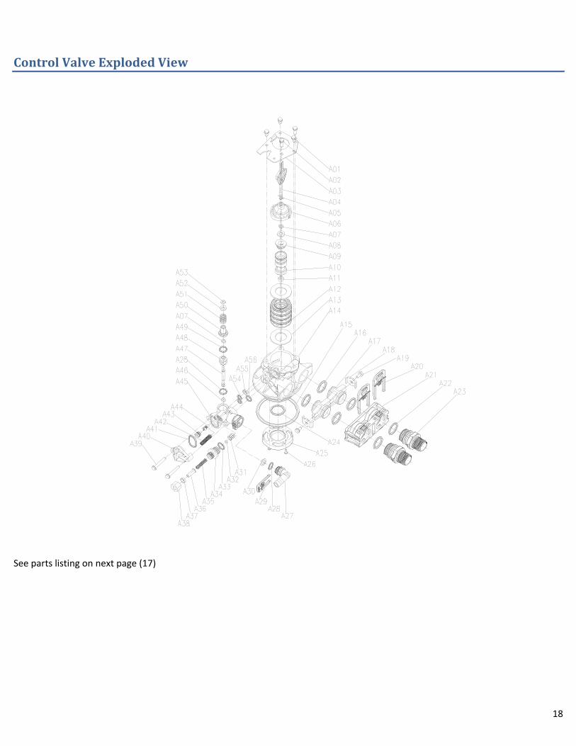
ControlValveExplodedView
See parts listing on next page (17)
19
Item No. Part No. Part Discription Quantity
A01 05056087 Screw-M5×12(Hexagon) 3
A02 05056088 Screw-M5×16(Hexagon with Washer) 2
A03 05056047 End Plug Retainer 1
A04 05010081 Bnt65 Piston Rod 1
A05 05056097 Piston Pin 1
A06 05056023 End Plug 1
A07 05056070 Quad Ring 2
A08 05056024 End Plug Washer 1
A09 05056022 Piston Retainer 1
A10 05056181 Piston (Electrical) 1
A11 05056104 Muffler 1
A12 05056021 Spacer 4
A13 05056073 Seal 5
A14 05056019 Bnt65 Valve Body 1
A15 05056063 O-ring-φ78.74×5.33 1
A16 05056129 O-ring-φ23×3 4
A17 05056025 Adaptor Coupling 2
A18 05056044 Adaptor Clip 2
A19 05056090 Screw-ST4.2×13(Hexagon with Washer) 2
A20 21709003 Secure Clip 2
A21 05056140 Valve Connector 1
A22 05056065 O-ring-φ23.6×2.65 2
A23 21319006 Screw Adaptor 2
A24 26010103 O-ring-φ25×3.55 1
A25 07060007 Valve Bottom Connector 1
A26 13000426 Screw-ST2.9×13(Large Wafer) 2
A27 05010082 Drain Fitting 1
A28 05056134 O-Ring-φ12×2 1
A29 05056172 Secure Clip-S 1
A30 05056186 DLFC-2# 1
A32 05056035 BLFC Button Retainer 1
A33 05056191 BLFC-2# 1
A34 05056138 O-Ring-φ14×1.8 1
A35 05056100B BLFC Fitting 1
A36 05056106 Brine Line Screen 1
A37 05056107 BLFC Tube Insert 1
A38 05056033 BLFC Ferrule 1
A39 05056108 BLFC Fitting Nut 1
A40 05056086 Screw-M5×30(Hexagon with Washer) 2
A41 05056029 Injector Cover 1
A42 05056072 O-Ring-φ24×2 1
A43 05056103 Injector Screen 1
A44 05056027 Injector Nozzle 1
A45 05056028 Injctor Throat 1
A46 05056177 Injector Body 1
A47 05056075 Injector Seat 1
A48 05056134 O-Ring-φ12×2 1
A49 05056054 Injector Stem 1
A50 05056031 Injector Spacer 1
A51 05056081 O-Ring-φ12.5×1.8 1
A52 05056030 Injector Cap 1
A53 05056093 Injector Screen 1
A54 05010049 Special Washer 1
A55 05056105 Retaining Ring 1
A56 05056067 O-Ring-φ7.8×1.9) 2
A57 05056037 Air Disperser 1
A58 05056066 O-Ring-φ11×2 1
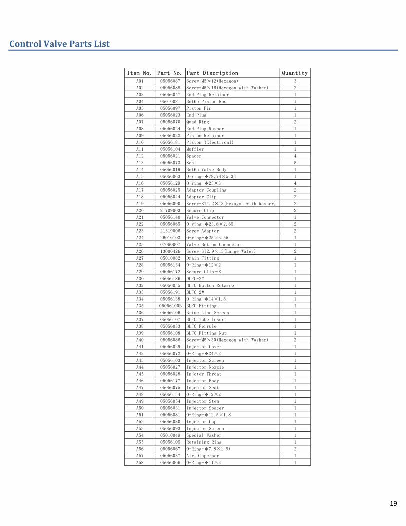
ControlValvePartsList

20
TroubleShooting Issue Possible Cause Possible Solution
A. Water clear when drawn; turns red upon standing (stain producing)
1. Insufficient air in air tank. a) Increase Brine Time (air draw) b) Check valve not working.
2. Bypass open or leaking Close bypass and/or repair as necessary.
3. Filter bed overloaded with precipitated iron due to insufficient backwash
Increase backwash frequency. Upon correction of problem, manually backwash until backwash water starts to clear. In more severe iron‐fouling cases, bed may chemical cleaning ‐ contact dealer.
4. Presence of manganese or tannins
Recheck water analysis
5. Flow rate excessive for model Reread "Sizing Requirements" Page 5‐6.
B. Water red when drawn from tap
1. Filter bed overloaded with precipitated iron due to insufficient backwash flow rate
a. Recheck well pumping rate for backwash and repair or replace as required. b. Check for obstructions or kink in drain line c. For improper drain line flow controller, see specs. Upon correction of this problem, if manually backwashing does not clear bed of iron, filter bed may need chemical cleaning ‐ contact dealer.
2. Filter bed overloaded with precipitated iron due to insufficient backwash
Increase backwash frequency. Upon correction of problem, manually backwash until backwash water starts to clear. In more severe iron‐fouling cases, bed may need chemical cleaning ‐ contact dealer.
3. Insufficient air in air tank. a) Increase Brine Time (air draw) b) Check valve not working.
C. Excessive pressure loss through filter
1. Filter bed overloaded with precipitated iron.
See problem above
2. Control inlet/outlet valve(s) not fully open
Open valves
3. Sand, silt or mud collecting in filter bed
Check well for these conditions
4. Filter bed not properly classified Manually backwash to reclassify
D. Milky or bubbly water (appears to contain small bubbles)
1. Common with this type of filter. None.
2. Excess gases in water (carbon dioxide, hydrogen sulphide, methane)
May require draining of water system or installation of air relief control ‐ contact dealer.
E. Unit fails to initiate a regeneration cycle.
1. No power supply. Check electrical service, fuse, etc.
2. Defective circuit board. Replace faulty parts.
3. Power failure. Reset time of day.
F. Low water pressure. 1. Iron or scale build up in line feeding unit.
Clean pipes.
2. Iron build up inside valve or tank. Clean control and add resin cleaner to clean bed. Increase regeneration frequency.
3. Inlet of control plugged due to foreign material.
Remove piston and clean control valve.
G. Filter media in drain line. 1. Air in water system. Check well system for proper air eliminator control.
2. Incorrect drain line flow control (DLFC) button.
Check for proper flow rate.
H. Valve continuously cycles.
1. Defective position sensor PCB. Replace faulty parts.
I. Flow to drain continuously.
1. Valve settings incorrect. Check valve settings.
2. Foreign material in control valve. Clean control.
3. Internal leak. Replace seals, spacers, and piston assembly.

21
NovoClear Warranty
Novo Water Conditioning Products guarantees that your new filter is built of quality material and workmanship. When properly installed and maintained, it will give years of trouble free service.
Seven Year Complete Parts Warranty Novo Water Conditioning Products will replace any part which fails within 84 months from date of manufacture, as indicated by the serial number, provided the failure is due to a defect in material or workmanship. The only exception shall be when proof of purchase or installation is provided and then the warranty period shall be from the date thereof.
Life Time Year Warranty on Mineral Tanks and Brine Tanks
Novo Water Conditioning Products will provide a replacement mineral tank or brine tank to any original equipment purchaser in possession of a tank that fails provided that the water conditioner is at all times operated in accordance with specifications and not subject to freezing.
General Provisions
Damage to any part of this water conditioner or filter as a result of misuse, misapplication, neglect, alteration,
accident, installation or operation contrary to our printed instructions, damage to ion exchange resin and seals
caused by chlorine / chloramines in the water supply, or damage caused by any force of nature is not covered in this
warranty. We will repair or replace defective parts if our warranty department determines it to be defective under
the terms of this warranty. Canature assumes no responsibility for consequential damage, la‐bour or expense
incurred as a result of a defect or failure.


![Introducing_LG_Chem_ENG[15].pdf - LG Chem](https://img.pdfslide.net/doc/110x75/632774b65c2c3bbfa8042f85/introducinglgchemeng15pdf-lg-chem.jpg)


![Chem Soc Rev - [ RSC ] Publishing](https://img.pdfslide.net/doc/110x75/6325d4986d480576770c7abb/chem-soc-rev-rsc-publishing.jpg)


