Embed Size (px)
Citation preview

Vo
l.31 No.9
NU
TS
& V
OLT
SIN
SU
LAT
ION
TE
ST
ER
•P
RO
TOTY
PE
TH
IS •
FLOW
ER
PO
WE
R •
FRE
Q S
YN
TH
ES
IZE
RS
eptem
ber 2010
U.S. $6.50 CANADA $7.50
Cover2.qxd 8/4/2010 11:31 AM Page 1
WWW.GiURUMELE.Hi2.RO
WWW.RADiOSCAMATORUL.Hi2.RO

Full Page.qxd 7/8/2009 9:14 AM Page 2
WWW.GiURUMELE.Hi2.RO
WWW.RADiOSCAMATORUL.Hi2.RO

JobNumber: SF-0015-PrintAd-10(Nuts&Volts,SERVOMagazines) TrimSize: 8.125”x10.75”Active Image Area: 7.125” x 9.75” Bleed: .125” Color: 4color Paper: (magazinestock,whtglossy) Printer: N/A
Let your geek shine.Meet Jen Lewin, creator of The Pool. Commissioned for the Burning Man Project, Jen’s creation features a combination of XBees, Arduinos, and LEDs fitted in custom enclosures. When the pads sense weight, they respond with a beautiful display of light and color that mimics rippling water.
Whether you’re searching for a new microcontroller, or building a room-sized interactive environment, the tools are out there. Create a work of art, and let your geek shine too.
©2010 SparkFun Electronics, Inc. All rights reserved. All other trademarks contained herein are the property of their respective owners. Read more about Jen Lewin’s Pool at http://tinyurl.com/232m54u or check out Burning Man at www.burningman.com. Have fun out in the desert, Jen!
Sharing IngenuityW W W. S P A R K F U N . C O M
SFE-0015-PrintAd10-SERVO.indd 1 6/25/10 11:13 AM
WWW.GiURUMELE.Hi2.RO
WWW.RADiOSCAMATORUL.Hi2.RO

Full Page.qxd 8/2/2010 8:50 PM Page 5
WWW.GiURUMELE.Hi2.RO
WWW.RADiOSCAMATORUL.Hi2.RO

Nuts & Volts (ISSN 1528-9885/CDN Pub Agree #40702530) is published monthly for$26.95 per year by T & L Publications, Inc., 430 Princeland Court, Corona, CA 92879.PERIODICALS POSTAGE PAID AT CORONA, CA AND AT ADDITIONAL MAILINGOFFICES. POSTMASTER: Send address changes to Nuts & Volts, P.O. Box 15277,North Hollywood, CA 91615 or Station A, P.O. Box 54,Windsor ON N9A 6J5;[email protected].
Projects & Features
Septemberwww.nutsvolts.com
10 TechKnowledgey 2010Events, Advances, and NewsThe return of the Nixie, molecular bot walks and decides, IBM tweaks Microsoft, laser generates bursts of nothing, plus other stuff you’ll find interesting.
14 The Spin ZoneAdventures in Propeller ProgrammingThe Joy of Joysticks.
24 Q & AReader Questions Answered HereHum detection, Video buffer, LCD backlight, game clock, plus more.
55 Smiley’s WorkshopProgramming • Hardware • ProjectsAVR Memory Part 4: Writing to AVR Flash!
61 The Design CycleAdvanced Techniques for Design EngineersGettin’ Jiggy with the Vinculum-II Hardware Design.
68 Near SpaceApproaching the Final FrontierThe Canon Hacker Development Kit.
30 Make the PLL Frequency Synthesizerwith PIC ControlThis project describes how to build a frequency synthesizer — a device which generates a stable waveform at a user-selected frequency. Frequency synthesizers are handy test instruments for digital circuits, and can also be used for audio signal generators or radio frequency mixing applications. This project is easy to build, easy to use, and a great way to learn more about how phase-locked loops work.■ By Dan Gravatt
36 Flower PowerYou too can power a device from a set of potted plants! However, in this case, the cells of the battery draw their energy directly from the plants, rather than from an electrochemical process.■ By Carlos Cossio
42 Build a Low Voltage Insulation TesterWire that we use on our projects is replaced when theinsulation starts to look bad. What about hidden wire that had been installed in a large building more than 20 years ago? This easy modification allows a low tech analog ohmmeter to detect insulation faults that a high tech digital ohmmeter fails to find. ■ By Douglas Krantz
50 The Projects of Prototype This!Joe Grand takes a closer look at the electronic aspectsof his different builds from the popular Discovery Channel show Prototype This! This month, go deep with a virtual sea adventure.■ With Joe Grand
Columns
2010Nuts & Volts
6 September 2010
Departments08 DEVELOPING
PERSPECTIVES28 NEW PRODUCTS29 SHOWCASE67 ELECTRO-NET
72 NV WEBSTORE76 CLASSIFIEDS78 TECH FORUM81 AD INDEX
Page 10
Page 14
Page 36
TOC Sep10.qxd 8/3/2010 4:04 PM Page 6
WWW.GiURUMELE.Hi2.RO
WWW.RADiOSCAMATORUL.Hi2.RO

Low-cost IndustrialSerial to Ethernet Solutions
SBL2e Chip SBL2e 200
SBL2e X
SBL2e XA
two (one RS-232)
SBL2e 100
Hardware Features
Software Features
Low Prices
,
9
Need a custom solution?
Information and Sales
Web Telephone
Full Page.qxd 8/2/2010 6:13 PM Page 7
WWW.GiURUMELE.Hi2.RO
WWW.RADiOSCAMATORUL.Hi2.RO

DEVELOPINGby Bryan Bergeron, Editorby Bryan Bergeron, Editor
When Water and Electronics Mix
This past May, the Cumberland River crested 12 feetabove flood stage, resulting in flash flooding of Nashville.
In addition to the lost lives and thousands left homeless, amajor instrument storage facility was completely flooded.Tens of millions of dollars worth of guitars, amplifiers, andsound equipment were submerged for days. Many of theacoustic instruments will never grace the stage again becausethe wood was split or otherwise ruined. The ultimate fate ofthe electronics is another matter, but odds are, much can besaved. The point of this editorial is that if you know whatyou’re doing, you can often resuscitate electronics that havebeen submerged. And, sooner or later, someone is going tobring you a piece of electronic equipment that was eithersubmerged or left out in the rain. So, how will you handle it?First, there are no guarantees — especially if the device waspowered up when it went for a dive. And, in general, theolder the device, the better.
The worst case I’ve had was an IBM ThinkPad that had abowl of cheerios and milk spilled into the keyboard. I’ve alsosaved a switching power supply and 2m transceiver that weresubmerged in salt water. I lost an inexpensive MP3 player to
the rain, despite valiant attempts to revive it. It is possible tosave an MP3 player or cell phone that’s been used in therain or dunked in a pool by mistake. However, you reallywant to get at the components and circuit board, and that’sdifficult with devices that have no obvious entry points.
The goal is to remove any water and, more importantly,any residue that was carried by the water or caused by waterinteracting with the electronics. So, if your AM radio took adip in the sea, you’ve got to get rid of the salt as well as thewater. Clean, fresh water is less problematic, but ponds,lakes, and toilets tend to be filled with something other thanclean and fresh liquid.
So, my solution for submerged electronics goessomething like this: First, remove all sources of power,including batteries. This includes the thin lithium cells used inlaptops, camcorders, and other handheld devices, and the 9Vbatteries used as backup for clock radios. Most laptops haveat least two batteries. Next, disassemble the unit if you can.Remove speaker cones and anything else that would bedamaged by additional contact with water. Next, spray thecomponents and board liberally with distilled water. Use ahand-pump sprayer on the highest setting — you want a
PERSPECTIVES
8 September 2010
DevPers-ReadFeed - Sep 10.qxd 8/2/2010 8:16 PM Page 8
WWW.GiURUMELE.Hi2.RO
WWW.RADiOSCAMATORUL.Hi2.RO

Published Monthly ByT & L Publications, Inc.
430 Princeland Ct.Corona, CA 92879-1300
(951) 371-8497FAX (951) 371-3052
Webstore orders only 1-800-783-4624www.nutsvolts.com
SubscriptionsToll Free 1-877-525-2539
Outside US 1-818-487-4545P.O. Box 15277
North Hollywood, CA 91615
FOUNDER/ASSOCIATE PUBLISHERJack Lemieux
PUBLISHERLarry Lemieux
ASSOCIATE PUBLISHER/VP OF SALES/MARKETING
Robin [email protected]
EDITORBryan Bergeron
CONTRIBUTING EDITORSJeff Eckert Russ KincaidJoe Pardue Fred EadyJon Williams Paul VerhageDan Gravatt Carlos CossioJoe Grand Douglas Krantz
CIRCULATION DIRECTORTracy Kerley
SHOW COORDINATORAudrey Lemieux
MARKETING COORDINATORWEBSTORE
Brian [email protected]
WEB CONTENTMichael Kaudze
ADMINISTRATIVE ASSISTANTDebbie Stauffacher
PRODUCTION/GRAPHICSShannon Christensen
Copyright © 2010 by T & L Publications, Inc.All Rights Reserved
All advertising is subject to publisher’s approval. Weare not responsible for mistakes, misprints, or typographical errors. Nuts & Volts Magazine assumesno responsibility for the availability or condition of advertised items or for the honesty of the advertiser.The publisher makes no claims for the legality of any item advertised in Nuts & Volts. This is the soleresponsibility of the advertiser. Advertisers and theiragencies agree to indemnify and protect the publisherfrom any and all claims, action, or expense arising fromadvertising placed in Nuts & Volts. Please send all editorial correspondence, UPS, overnight mail, and artwork to: 430 Princeland Court, Corona, CA 92879.
Printed in the USA on SFI & FSC stock.
EVERYTHING FOR ELECTRONICS
September 2010 9
powerful stream of water, not a fine mist. If the unit was immersed in salt water andit contains a power transformer, then dunk the part of the board containing thetransformer in distilled water. The idea is to dissolve any salt deposits that may beforming between the windings. Follow up with a rubbing alcohol chaser to displacethe water. Now, examine the board for deposits between the traces. If you spotany, remove them with Q-tips and either rubbing alcohol or an alcohol-basedcleaner. Dry the device with paper towels and place it in front of a fan in a warm(but not hot) room. Don’t use a heat gun or stick the board in your oven.
Physically check the device after four or five days. It should be bone dry. If itisn’t, then put it away and check it in another few days. When you’re satisfied thatthere’s no water in the device, drop in the batteries and power it up. Hopefully, allwill be in working order. If not, well, most warranties don’t cover water damageanyway. At least you’ve learned something from the teardown. If you have any talesof your own water rescue attempts, or you’ve developed a killer process for savingdunked electronics, please consider sharing them with our readers. NV
DevPers-ReadFeed - Sep 10.qxd 8/3/2010 4:08 PM Page 9
WWW.GiURUMELE.Hi2.RO
WWW.RADiOSCAMATORUL.Hi2.RO

MOLECULAR BOT WALKSAND DECIDES
You won't find any of these things welding car bodiesor mixing cocktails, but ongoing research is aimed at
creating molecular-scale automatons that could do repairwork on human cells or perform assembly functions on ananotech scale. One concept involves reprogrammingDNA molecules to perform specific tasks. The question —as posed by Mitra Basu, a program director at the NationalScience Foundation (www.nsf.gov) — is "Can you instructa biomolecule to move and function in a certain way?Researchers at the interface of computer science, chemistry,biology, and engineering are attempting to do just that."
As it turns out, investigators at Columbia, ArizonaState, Michigan, and Caltech (www.columbia.edu,www.asu.edu, www.umich.edu, and www.caltech.edu)have created and programmed robotic DNA moleculesthat briefly walk on spidery "legs" and move through aspecial two-dimensional landscape. The little bots haveproven to be capable of rudimentary robotic actionsconsisting of starting motion, walking, turning, andstopping. As shown in the artist's rendition, as a bot(green) walks along the substrate, it changes the little
vertical nubbins by breaking off their thin parts. If itreaches a spot where a previous traveler has alreadychopped one off, it moves along faster. When it reachesthe end of the track (red), it is captured and comes to ahalt. Note that we're not talking about long distances orrapid movement here; the 4 nm walkers plod along at100 to 200 nm per hour by taking about 100 steps.Previous versions conked out after only about three steps,so this is a big improvement. According to Basu, "Thiswork one day may lead to effective control of chronicdiseases such as diabetes or cancer." ▲
TECHKNOWLEDGEYEVENTS, ADVANCES, AND NEWS 20
10
■ BY JEFF ECKERT
■ Molecular robot moves along a special substrate,chopping off tiny elongations.
ADVANCED TECHNOLOGY
LASER GENERATES BURSTS OF NOTHING
Researchers at the National Institute of Standards and Technology (NIST; www.nist.gov) and JILA (jila.colorado.edu)recently reported the development of a new kind of semiconductor laser that "excels at not producing light." The
description seems a little contrived, as I'm pretty sure my shoe is even better at not producing light. But it is interesting, asthe "dark pulse" laser could conceivably be useful in measurements and communications. Because dark pulses — unliketheir bright counterparts — generally propagate without distortion, they might turn out to be useful in signal processingapplications. "Dark pulses might be used like a camera shutter for a continuous light beam in optical networks."
Basically, you inject electrical currents into a few million 10 nm quantum dots (qdots), causing them to emit light atthe same frequency. Thereafter, the "qdots recover energy from withinrapidly (in about 1 ps) but more slowly (in about 200 ps) from energyinputs originating outside the qdots in the laser cavity. This creates aprogression of overall energy gains gradually giving way to overall energylosses. Eventually, the laser reaches a steady state of repeated brief intensitydips — a drop of about 70 percent — from the continuous lightbackground." The new technology is said to be the first to generate darkpulses from the laser cavity, without any subsequent electrical or opticalpulse shaping. However, whether dark pulse communication systems willever become a reality is debatable. Purdue laser researcher Andy Weiner(having reviewed the concept) was quoted as saying, "Current practice anddirections in lightwave communications are such that I don't think it likelythere will be practical interest in dark pulse lightwave communicationsystems." Time will tell. ▲
Photo courtesy of Zina Deretsky, National Science Foundation.
■ Colorized trace of pulses from the “dark pulse” laser. Light output nearly shuts down about every 2.5 ns.
10 September 2010
Photo courtesy of NIST.
Tech2010 - Sep 10.qxd 8/2/2010 11:23 AM Page 10
WWW.GiURUMELE.Hi2.RO
WWW.RADiOSCAMATORUL.Hi2.RO

T E C H K N O W L E D G E Y 2 0 1 0
UPGRADE YOUR SOUND
Some of us old fossils fondly remember the old Altec Lansing Voiceof the Theatre speakers, first introduced in 1945. They were the
only speaker series to be approved by the Research Council of theAcademy of Motion Picture Arts and Science which made them thestandard for motion picture playback for decades, not to mention adream PA pair for rock bands everywhere. Oddly enough, theseamazing boxes were reintroduced a few years ago as the Legacy A7model. At $5,800 each, though, we may as well stop talking aboutthem. So we will.
However, if you want to upgrade your PC's audio output with asystem from the legendary company, you can get the equipment andstatus for a mere $79.95 in the form of the Octane Plus 2.1 system. It can also be hooked up to CD, DVD, and MP3players, and it's specifically tuned for music, movies, and gaming with a subwoofer, a pair of down-firing 3 inch mid-range speakers, and two 1 inch micro drivers. The down-firing concept involves blasting the sound waves downwardonto a hard surface from which they are reflected around the room. This is said to provide balanced sound from asmaller footprint. The bass comes from a 6.5 inch woofer. Separate bass and treble controls allow you to fine-tune thesound. As of this writing, you can get a pair directly from www.alteclansing.com or order from Amazon. ▲
COMPUTERS AND NETWORKING
■ Altec’s Octane Plus 2.1 speaker system.
NIST OFFERS FELLOWSHIPS
In February, the National Institute of Standards andTechnology (NIST; www.nist.gov) awarded $19.5 million to
the University of Maryland and the University of Colorado toadminister measurement science and engineering fellowshipsfor graduate, post-doctoral, and senior researchers.Applications are being accepted, so if you are interested in aposition at either the NIST campus in Gaithersburg, MD, orthe Hollings Marine Lab in Charleston, SC, it's time to bellyup to the trough. Funded by the American Recovery andReinvestment Act, positions are available for "highly qualifiedUS citizens and non-citizens from academic, industrial, andother organizations." For information on the University ofMaryland administered portion of the program, visitwww.nistfellows.umd.edu; for information on the onemanaged by the University of Colorado, go towww.colorado.edu/nistfellows. The program will continue in2011 and 2012, and will include undergraduates. ▲
IBM TWEAKS MICROSOFT
There was no official announcement, but thegrapevine has it that IBM has asked all of its
400,000 employees to set Mozilla's (www.mozilla.org)Firefox as their default Web browser. The switch is notmandatory, but all new computers in IBM installationswill come with it preloaded, so the policy is expectedto benefit Mozilla largely at the expense of Microsoft'sInternet Explorer. Firefox presently has a bit less than25% of the market, compared to about 60% for IE.Other browsers remain far behind, but it's a little earlyto gauge the impact of Google's Chrome. The moveprobably shouldn't be viewed as a direct swipe atMicrosoft. Although, among the cited reasons forIBM's decision are that Firefox is open source,standards compliant, secure, and extensible. ▲
FIRST 3D NOTEBOOK INTRODUCED
As previously noted here, the hot marketing craze in the world of electronics is 3D, and Toshiba (www.toshiba.com) hasjumped in with what it says is the industry's first notebook PC to support the Blu-ray 3D format. At press time, the
Dynabook TX/98MBL was still available only in Japan, but it could be in stores by the time you read this. The machine usesWinDVD® BD software to play back content in the Blu-ray 3D™ format and NVIDIA® 3D Vision™ software and hardwareto deliver the 3D experience. It uses the same active shutter technology as movie theaters in which the active shutter LCDglasses lighten and darken at the same 120 Hz rate as the LCD for an effective refresh rate of 60 Hz. Each of your eyes seesa slightly different image, so the overall picture is stereoscopic. The machine comes with a pair of wireless shutter glassesand incorporates Harman/Kardon speakers and Dolby audio. Other features include an Intel Core i7-740QM processor, a15.6 inch display, a 640 GB drive, and 4 GB of RAM. No official list price was announced by Toshiba, but word on thestreet is that it will drain your account by about $2,750. ▲
September 2010 11
INDUSTRY AND THE PROFESSION
Tech2010 - Sep 10.qxd 8/2/2010 11:24 AM Page 11
WWW.GiURUMELE.Hi2.RO
WWW.RADiOSCAMATORUL.Hi2.RO

XLR-TO-USB MIC CONVERTER
If you use your computer for serious audio applications(digital recording and mixing, podcasting, etc.), you may
have made the sad discovery that your collection of fineold studio microphones have an impedance mismatch withthe audio-in port on the computer and just don't work. Youmay also have discovered that good USB mics aren't cheap.Well, never fear, because the folks at Blue Microphones(www.bluemic.com) have created the Icicle — a USB converterand mic preamp combo that allows you to plug your
cherished Shure55S, EV 726, or anyother XLR-connected mic intoyour computer. It features a studio-quality preamp, 48Vphantom power, a balanced low noise front end, analoggain control, and driverless operation. The Icicle workswith both dynamic and condenser microphones, and withMac or PC. You just need Windows Vista or XP or OSXand a paltry 64 MB of spare RAM. Best of all, you canpick one up for about $40 if you shop around. ▲
■ The Icicle converterfrom Blue Microphones.
POT+ SWITCH OFFERS CONTROL OPTIONS
Electro-Mech Components (www.electromechcomp.com) is offeringa nifty potentiometer/switch assembly that offers dual control options. Aimed at applications
such as industrial/avionics displays, audio controls, instrument panel controls, and other highdensity panels, the SPDT SW44687 is an all-in-one unit that offers both rotary and push-onfunctionality along with a 10K resistance pot module. This allows users of the equipment to preset the pot level and openthe circuit by pressing the button. The unit weighs less than an ounce, measures less than 3/4 inches square, and requiresless than an inch of space behind the display panel. Interconnection is via wire leads, PC pins, or solder lug terminals. TheSW44687 is rated at 30 VDC or 120 VAC, and is rated for 100,000 minimum actuations. An edge-lit button is optional. ▲
■ Electro-Mech’sSW44687 offers dual
control options.
THE RETURN OF THE NIXIE
Most of us remember nixie tubes — the original cold-cathode digital displays widelyused in the old days in multimeters, frequency counters, calculators, and so on.
Now you can amaze your friends with a retro nixie clock, and you don't even haveto build it yourself. The device is offered by LNS Technologies through distributors andtheir www.techkits.com website. What you get is a fully assembled clock featuringside-view Z573M/Z574M tubes, 13 mm high, and factory coated with a red contrastfilter for sharpness enhancement. A DC/DC converter generates the voltage neededto drive the tubes, and the clock is encased in a clear Plexiglas cabinet. Power is drawn from a standard 12V wall adaptor.The colon in the center blinks every second, and the unit even features a battery backup. The only snag is the $99 pricetag, but nostalgia doesn't come cheap. Plus, you can tell your non-tech friends that it's a spectacular new technology. ▲
■ The nifty nixie clock fromLNS Technologies.
12 September 2010
CIRCUITS AND DEVICES
Tech2010 - Sep 10.qxd 8/2/2010 11:24 AM Page 12
WWW.GiURUMELE.Hi2.RO
WWW.RADiOSCAMATORUL.Hi2.RO

What is themissing component?
1-800-831-4242 | www.Jameco.com
Electronics instructor Ollie Circuits planned to show his class of freshman electrical engineering students how to use a super capacitor as a memory back-up capacitor,but first he wanted to show how the students could make their own super capacitor and demonstrate its charge/discharge cycles with the simple circuit above. Most of the components were already on his workbench, the homemade super capacitor would be made from several layers of lemon juice-soaked paper towels interleavedbetween several layers of a mystery material to form a multi-layer stack.The stacked layers would then be sandwiched between the two copper-clad PC boards and heldtogether with a rubber band. Ollie rushed to a nearby pet shop. What did he buy? Go to www.Jameco.com/search7 to see if you are correct and while you are there,sign-up for our free full-color catalog.
September 2010 13
Full Page.qxd 8/2/2010 8:55 PM Page 13
WWW.GiURUMELE.Hi2.RO
WWW.RADiOSCAMATORUL.Hi2.RO
GAME ON!If you’ve played on any video game console in the last
10 years, you’ve no doubt had the opportunity to placeyour thumbs on the controller’s mini joysticks and gocrazy with your friends. Until recently, those mini joystickswith their cute, mushroom-shaped caps weren’t very easyto come by and (when you could find them) they werepricey — a few years ago, I paid about $10 each.
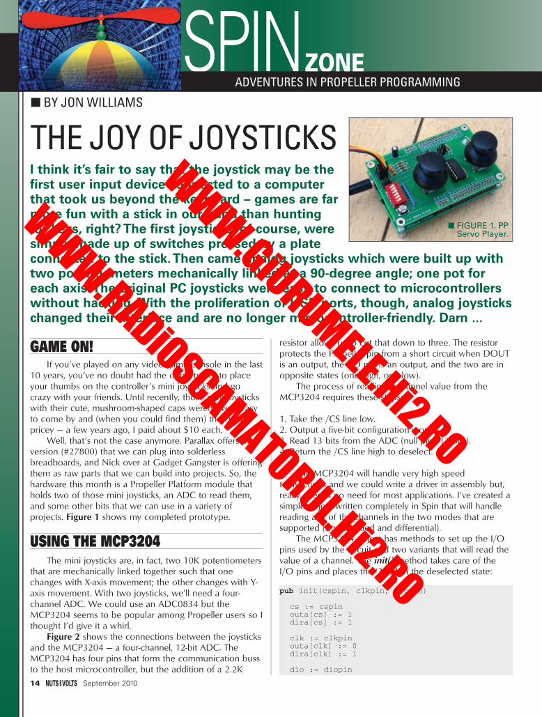
Well, that’s not the case anymore. Parallax offers aversion (#27800) that we can plug into solderlessbreadboards, and Nick over at Gadget Gangster is offeringthem as raw parts that we can build into projects. So, thehardware this month is a Propeller Platform module thatholds two of those mini joysticks, an ADC to read them,and some other bits that we can use in a variety ofprojects. Figure 1 shows my completed prototype.
USING THE MCP3204The mini joysticks are, in fact, two 10K potentiometers
that are mechanically linked together such that onechanges with X-axis movement; the other changes with Y-axis movement. With two joysticks, we’ll need a four-channel ADC. We could use an ADC0834 but theMCP3204 seems to be popular among Propeller users so Ithought I’d give it a whirl.
Figure 2 shows the connections between the joysticksand the MCP3204 — a four-channel, 12-bit ADC. TheMCP3204 has four pins that form the communication bussto the host microcontroller, but the addition of a 2.2K
resistor allows us to cut that down to three. The resistorprotects the Propeller pin from a short circuit when DOUTis an output, the I/O pin is an output, and the two are inopposite states (one high, one low).
The process of reading a channel value from theMCP3204 requires these steps:
1. Take the /CS line low.2. Output a five-bit configuration word.3. Read 13 bits from the ADC (null plus 12 bits).4. Return the /CS line high to deselect.
The MCP3204 will handle very high speedtransactions and we could write a driver in assembly but,really, there’s no need for most applications. I’ve created asimple object written completely in Spin that will handlereading any of the channels in the two modes that aresupported (single-ended and differential).
The MCP3204 object has methods to set up the I/Opins used by the circuit and two variants that will read thevalue of a channel. The init() method takes care of theI/O pins and places the ‘3204 in the deselected state:
pub init(cspin, clkpin, diopin)
cs := cspinouta[cs] := 1dira[cs] := 1
clk := clkpinouta[clk] := 0dira[clk] := 1
dio := diopin
SPIN ZONE■ BY JON WILLIAMS
ADVENTURES IN PROPELLER PROGRAMMING
I think it’s fair to say that the joystick may be thefirst user input device connected to a computerthat took us beyond the keyboard – games are farmore fun with a stick in our hand than huntingfor keys, right? The first joysticks, of course, weresimply made up of switches pressed by a plateconnected to the stick.Then came analog joysticks which were built up withtwo potentiometers mechanically linked at a 90-degree angle; one pot foreach axis.The original PC joysticks were easy to connect to microcontrollerswithout hacking. With the proliferation of USB ports, though, analog joystickschanged their interface and are no longer microcontroller-friendly. Darn ...
14 September 2010
■ FIGURE 1. PPServo Player.
THE JOY OF JOYSTICKS
Spin Zone - Sep 10.qxd 8/2/2010 11:34 AM Page 14
WWW.GiURUMELE.Hi2.RO
WWW.RADiOSCAMATORUL.Hi2.RO

As you can see, we pass the chip select pin,the clock pin, and the data I/O pin to the init()method. The /CS pin is set to output and highto deselect the ‘3204 while the clock pin is setto output and low; the data I/O pin is left ininput mode until we need it.
Astute readers (that would be you!) will ask,“Why do we need to pass pin numbers whenthey won’t change in a program? Can’t we justset them as constants?” We could, but it’s a badidea for reusable objects like this. If we usedconstants for the pin numbers, we’d be forcedto either: 1) always use the same pin numbersin every design (impractical); or 2) keepmultiple copies of the object with different pinnumbers which is also impractical when itcomes to maintenance and upgrades. So, thelesson here is this: When designing a Propellerobject, keep it concise yet flexible enough to bere-used in any of your designs. This will makeyour life simpler, and those downloading your code fromthe Object Exchange (ObEx) will thank you.
There are two variations of read methods and, in fact,one calls the other. The reason for two methods is toaccommodate different programming styles. The firstvariation expects the channel number (0 to 3) and themode (1 for single-ended; 0 for differential):
pub read(ch, m) | mux
mux := %1_0000 | ((m & 1) << 3) {} | (ch & %11)
return readx(mux)
The channel and mode settings are used to create afive-bit configuration word with masking and bit shifting;this value will be passed to the readx() method thatactually does the heavy lifting:
pub readx(mux) | level
outa[cs] := 0dira[dio] := 1
mux <<= constant(32-5)repeat 5
outa[dio] := (mux <-= 1) & 1outa[clk] := 1outa[clk] := 0
dira[dio] := 0level := 0repeat 13
outa[clk] := 1outa[clk] := 0level := (level << 1) | ina[dio]
outa[cs] := 1
return (level & $FFF)
If this code looks a little bit familiar, well, it should. It’sreally a combination of code that simulates the PBASICSHIFTOUT and SHIFTIN instructions; we used codeidentical in the latter portion when reading the 74x165shift-register on the encoder board (Nuts & Volts, May‘10). Just a note on my method of naming convention:
When I have two methods that are similar and one is asimplified interface into the other, the method that reallydoes the work tends to get appended with “x” (for explicit).
We start by taking the /CS line low to activate the‘3204. Remember that the init() method made this pin anoutput, so all we have to do is set the level by writing tothe outa[] register. The next step is to put the DIO lineinto output mode so that we can write the configurationword to the ‘3204.
The configuration word is shifted out MSB (MostSignificant Bit) first. The cleanest way to do this in Spin isto move the MSB of the configuration word into bit 31;we do this with a right shift (of 27 bits). Next, we dropinto a repeat loop that starts by rotating bit 31 into bit 0;bit 0 is then moved to the DIO pin, and the clock pulsedhigh then low to latch the bit into the ‘3204.
To receive the channel value from the ADC, weswitch the DIO line to input mode, clear the workspacevariable, and then drop into a repeat loop that shifts thebits in. As you can see, the loop runs 13 times; the reasonfor this is that the ‘3204 outputs a null bit before the firstbit (MSB) of the channel reading.
To shift the ADC, bits in the clock line are pulsed high,then low; we’ll sample the line after the clock pulse (MSBPOST).The bits arrive MSB first so the work value is shifted leftbefore the DIO line is sampled and copied into bit 0.
Finally, the /CS line is taken back high to deselect theADC, and we can return the value to the calling program.Note that while this code is set up for the ‘3204, a verysimple change will allow it to work with the MCP3208 aswell; both devices use a five-bit configuration word.
Okay then, let’s put it to use. I’m a very big believer increating hardware test programs before moving on to the actualapplication (more on this later), and part of the test programfor the board I made will read and display the analog joystickinputs. Figure 3 shows the output of this code in PST.
Do you see a problem? These readings are with thejoysticks at neutral, and in a perfect world all would read
S P I N Z O N E
September 2010 15
■ FIGURE 2. MCP3204 Circuit.
Spin Zone - Sep 10.qxd 8/2/2010 11:35 AM Page 15
WWW.GiURUMELE.Hi2.RO
WWW.RADiOSCAMATORUL.Hi2.RO

2048 as this is the half-way point for a 12-bit ADC. One ofmy desires is to control servos with the joysticks, so a littleextra effort will be required to make this work cleanly.
The first thing to do is nullify the neutral positionvalues; the autocal() method does this:
pub autocal | idx, raw
repeat idx from 0 to 3raw := adc.read(idx, adc#SE) >> 4ofs[idx] := JOY_CNTR - raw
There are actually two things happening here: thechannel is read (in single-ended mode) and then shiftedright by four bits to reduce the ADC resolution down toeight bits; the pots we’re using are not precision units and12 bits is excessive. By reducing the resolution, we cannearly eliminate the LSB “bouncing” of the input readings.The second step is to save the offset from expected center(128 for eight bits) in an array that can be applied tofuture readings.
So, let’s say that we want to control four servos withthe headers on the board: The final step would be toconvert the joystick channel reading to the range requiredby the servo driver. This value will usually be expressed inmicroseconds, and 1000 to 2000 is the standard range.The joy2servo() method takes an eight-bit joystick readingand, using algebra, converts it to a standard servo positionvalue:
pub joy2servo(jpos) | delta, spos
jpos := JOY_MIN #> jpos <# JOY_MAX
delta := (jpos - JOY_MIN) * 1000 {} / (JOY_MAX - JOY_MIN)
spos := ((SVO_MAX - SVO_MIN) {} * delta / 1000) + SVO_MIN
return spos
The first step ensures that the input value in jpos islegal, that is, it fits within the eight-bit range we shouldexpect from the joystick. With the variations in the pots, Idecided to truncate the readings by 15 on each end, so
jpos will fall between 15 (JOY_MIN) and 240 (JOY_MAX). The next step converts jpos to a percentage. For
example, if the joystick is in the neutral position (jpos =128), then delta will be 50%. Since we’re dealing withintegers, the percentage is multiplied by 1,000 to preventrounding errors.
The final step translates the input delta to a servoposition value, as defined by the minimum and maximumservo position constants. As you can see, the calculatedposition delta is applied to the span of the servo range andthen divided by 1,000 to get to the value within the span;this is added to the minimum value for the range to get theproper servo position value. Figure 4 shows the output fromjm_joystick_servo_demo.spin. As you can see, the calibrationhas taken care of getting the neutral position where it needsto be, and the center value for a typical servo is properlycalculated. The program includes a mini servo driverwhich allows us to control four servos from the joysticks.
PULSE POSITION MAGICA couple years ago, I was visiting my friend Dan at a
Hollywood special effects shop, and he showed me a boxof VEX transmitters that his company had purchased fromAll Electronics when the price was really low (about $30 —and you can still find these units on eBay). Dan was guttingthe joysticks from the transmitters for use in animatronicscontrols, but for many projects, there’s no need to do this.
Most RC transmitters — including the one from VEX —have a trainer connection that emits a pulse stream thatdefines the position data of the joysticks and buttons.Figure 5 shows the stream from the six-channel VEXtransmitter when it’s connected to a microcontroller. Theactual output of the VEX is open-collector, so the input tothe micro needs a pull-up.
In order to provide the greatest flexibility, I used thecircuit shown in Figure 6 on the project board. Twojumpers let me configure the three-pin PPM port; I canprovide power to the device (e.g., a VEX receiver) andconfigure the input as pulled up or pulled down asrequired. The purpose of the 2.2K series resistor is to limit
the current into thePropeller I/O pin forthose devices thatprovide a drivenoutput (5V max).
The VEX streambegins with a ninemillisecond syncpulse and is followedby six channel pulses.All of the pulses areseparated by an idleperiod of about 390microseconds. Thevalue for a channel is
16 September 2010
■ FIGURE 4.Joystick to Servo.
■ FIGURE 3. Reading Joysticks.
Spin Zone - Sep 10.qxd 8/2/2010 11:36 AM Page 16
WWW.GiURUMELE.Hi2.RO
WWW.RADiOSCAMATORUL.Hi2.RO

determined by measuring the period from one fallingedge, through the idle period, to the next falling edge. Inthe past, I’ve measured pulses with the Propeller counters,but this time we’ll need to measure the low and highportions of the signal, and we’ll want to ensure that ashorted input or disconnected cable does not cause thevalues into the system to become corrupted.
The only way to measure the PPM pulse stream withprecision is to use assembly code. I’ll admit that it is a littleinvolved, but really not too bad when broken down pieceby piece. Let’s jump in.
At the very top, we’re going to start by writing a flagindicating there is no detected PPM stream, then we’llmonitor the input for a valid sync pulse:
vexin mov dira, #0wrlong NO, flagpntr
findsync mov pwidth, #0mov timer, US_001waitpne pmask, pmaskadd timer, cnt
:loop waitcnt timer, US_001add pwidth, #1test pmask, ina wz
if_z jmp #:loopcmp pwidth, SYNC wc, wz
if_b jmp #vexin
At findsync, the pulse width variable is cleared and atimer is set up for one microsecond delays with waitcnt.Then, we wait for the input to be low using waitpne. Notethat this is the only place in the code where we will use apin wait instruction; from this point forward, we willmanually scan the input so that we can do it on a timedinterval (one us).
Once a low on the input is detected, the timer isstarted and drops into a loop, incrementing the pulsewidth measurement every microsecond until the line goesback high. We scan the PPM input using the testinstruction with a mask for the input pin (pmask) and thepin input’s register (ina). The test instruction works exactlylike the and instruction but it doesn’t affect the variable inthe destination field. The Z flag is updated with the stateof the PPM input and as long as it remains true (Z = line islow), the code will loop and increment the pulsemeasurement variable. When the input goes high (duringthe inter-pulse idleperiod), the Z flagwill be cleared andthe code dropsinto a comparisonto check the widthof the pulse. If thepulse we justmeasured is not avalid sync pulse(for example, westarted the code inthe middle of anoutput stream),then the code
jumps back to the top and tries again.The next section of code monitors and measures the
idle period between the sync pulse and the first channelpulse. The reason we bother measuring is to prevent adisconnected device from locking the program (sincewe’re waiting for a low-going leading edge for the channelmeasurement):
mov pwidth, #0 chwait test pmask, ina wz
if_z jmp #getch1 waitcnt timer, US_001 add pwidth, #1 cmp pwidth, #425 wc, wz
if_b jmp #chwait jmp #vexin
As before, the pulse width variable is cleared and thecode drops into a small loop that tests the state of thePPM line. When the line is idle, the Z flag will be clearedand we drop through the first jump into a onemicrosecond delay. The idle pulse width is incrementedand a comparison is done to ensure that we haven’t lost
S P I N Z O N E
September 2010 17
■ FIGURE 5. VEX PPM Stream.
■ FIGURE 6. PPMInput Circuit.
■ FIGURE 7. Reading the PPM Stream.
Spin Zone - Sep 10.qxd 8/2/2010 11:37 AM Page 17
WWW.GiURUMELE.Hi2.RO
WWW.RADiOSCAMATORUL.Hi2.RO
the signal. If the PPM signal is lost, the input will remainhigh and code is redirected back to the top of theprogram where we’ll wait for reconnection and a validsync pulse.
When things are working as they should, the PPMinput will drop after about 390 microseconds — this iswhere we start the channel position measurement. Thiscode looks — and is — very easy; it’s actually just a call toa subroutine and a check on an error flag (stored in C)that can be set by that routine:
getch1 call #getchif_c jmp #vexin
mov ch1us, pwidth
As you can see, this section calls a subroutine called
getch which performs the actual channel measurementand will set the C flag if a measurement error is detected.After returning from the measurement routine, we checkthe C flag and if it’s set, jump right back to the very top ofthe program where the PPM stream detection flag is set toNO (false). This flag can be used by our application todetermine the presence or absence of the PPM streamand take some action based on that status. Assuming agood measurement, though, we save the channel timing ina holding register and then do the same operation for therest of the channels.
The hard work is performed by the getch subroutine:
getch mov pwidth, #0:looplo waitcnt timer, US_001
add pwidth, #1cmp pwidth, LO_MAX wc, wz
if_a jmp #badchtest pmask, ina wz
if_z jmp #:looplo
:loophi waitcnt timer, US_001add pwidth, #1cmp pwidth, CH_MAX wc, wz
if_a jmp #badchtest pmask, ina wz
if_nz jmp #:loophi
goodch cmp pwidth, CH_MIN wc, wzjmp #getch_ret
badch test $, #1 wcgetch_ret ret
Yeah, this does look a little bit hairy, but as youexamine it closely, you’ll find it’s divided into two sections:the first to measure the low portion of the period; thesecond to measure the idle period which completes thechannel timing.
Again, we start by clearing the timing measurementvariable (pwidth) and then doing a one microseconddelay. The pulse timing is incremented and then comparedto a constant that defines the longest valid low period. Wedo this so that a short on the PPM input can be detected.If this happens, the C flag gets set and we abort back tothe calling code.
This usually won’t happen, though, and we continuetiming until the PPM line goes back high for the idleperiod. Now, we time this while waiting for the line to goback low (the start of the next channel); again, testingagainst an established limit. The test during the highperiod will detect a disconnection of the VEX device fromthe circuit. When we return to the calling section, thevariable called pwidth will contain the channel value andwhen all is well the C flag will be cleared.
After all of the channels have been measured, we canwrite the values to the hub for access by the application:
report mov pntr, pospntrwrword ch1us, pntradd pntr, #2wrword ch2us, pntradd pntr, #2wrword ch3us, pntradd pntr, #2wrword ch4us, pntradd pntr, #2wrword ch5us, pntr
18 September 2010
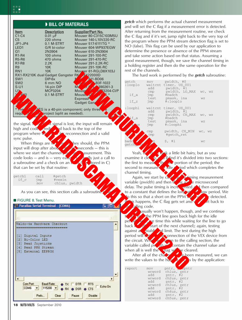
■ FIGURE 8. Test Menu.
Item Description Supplier/Part No.C1-C4 0.01 µF Mouser 80-C315C103M5UC5 220 ohms Mouser 140-L10V220-RCJP1-JP4 0.1 M-STRT Mouser 517-6111TG *LED1 G/R bi-color Mouser 604-WP937EGWQ1 2N3904 Mouser 610-2N3904R1-R4 100 ohms Mouser 291-100-RCR5-R6 470 ohms Mouser 291-470-RCR7-R8 2.2K Mouser 291-2.2K-RCR9 10K Mouser 291-10K-RCRN1 10K Mouser 81-RGLD8X103JRX1-RX210K dual Gadget Gangster RKJXK122000DSW1 DIP-6x Mouser 611-BD06SW2 6 mm NO Mouser 653-B3F-1022S-U1 14-pin DIP Mouser 571-1-390261-3U1 MCP3204 Mouser 579-MCP3204-CI/PX1-X10 0.1 M-STRT Mouser 517-6111TG *PCB ExpressPCBParts Kit Gadget Gangster
* The 517-6111TG is a 40-pin component; only three arerequired for the project (split as needed).
◗ BILL OF MATERIALS
Spin Zone - Sep 10.qxd 8/2/2010 11:37 AM Page 18
WWW.GiURUMELE.Hi2.RO
WWW.RADiOSCAMATORUL.Hi2.RO

add pntr, #2wrword ch6us, pntr
wrlong YES, flagpntrjmp #findsync
This is pretty straightforward. We set up a pointer tothe hub array (of words) that holds the channel values andthen transfer the readings from the cog. At the end, wewrite YES (true) to the flag that indicates PPM status toalert the application that the stream is present and theposition values are fresh.
Figure 7 shows the output from a test program thatreads and displays the PPM streamstatus and channel values.
TESTING 1, 2, 3 ...I often see posts in the Propeller
support forum that go something likethis: “I built my hardware, I wrote mysoftware — it doesn’t work. What do I do?”
Test. Test. Test. The good news isthat the Propeller architecture helpsus. Earlier this year, my friend and Icreated and released a Propeller-based WAV audio player (the EFX-TEKAP-16+) that is designed for museums,theme parks, and attraction-basedindustries like Halloween. It’s a beast.Because of the variability of the userbase, it has lots of flexibility in itsdesign which means lots of I/O and afairly tricky PCB.
While John (who also worked forParallax) was creating the PCB for thefirst prototype, I wrote a test programto check each section of the board —this was well before a single line ofapplication code was written. Ofcourse, that’s a bit of a fib, isn’t it?You see, a large portion of the codeused in testing moved right into thefinal application. In fact, as I refinedthe test program I was refiningportions of the application code.
The ability to program thePropeller through a serial port meansthat we can create a self-hosted testprogram that uses a simple terminal.As an example for you to play with, Icreated a test program for thismonth’s project board. When thatprogram starts, it presents a menuusing PST (see Figure 8) that lets usaccess/test each section of theboard. Here’s the main programloop:
pub main | cterm.start(RX, TX, %0000, 115_200)rgled.initx(R_LED, G_LED, 50, OFF)adc.init(CS, CLK, DIO)ppm.init(PPM_IN, 1500)eeprom.init(SCL, SDA)
pause(1)
repeatterm.tx(CLS)term.str(@Menu)term.rxflushc := term.rxcase c
“1” : showdigins“2” : demoled
S P I N Z O N E
September 2010 19
The Newest Products forYour Newest Designs™
Industry’s only full-featured online catalog
•Browse •Search •Check Stock •Buy
Over 1.6 MILLION productsavailable online!
ttoock •••BBBBuuykk
mouser.com (800) 346-6873
WARNING: Designing with Hot, New Products
May Cause A Time-to-Market Advantage.
Mouser and Mouser Electronics are registered trademarks of Mouser Electronics, Inc. Other products, logos, and company names mentioned herein, may be trademarks of their respective owners.
Try It Now at mouser.com
Spin Zone - Sep 10.qxd 8/2/2010 11:38 AM Page 19
WWW.GiURUMELE.Hi2.RO
WWW.RADiOSCAMATORUL.Hi2.RO
“3” : readjoysticks“4” : readppm“5” : testeeprom
Once the objects used by the board are initialized, wedrop into a loop that displays the main menu and waits forinput. Based on that input, the program will jump to oneof the test routines.
The menu is defined as a string and is stored in a datsection of the program like this:
Menu byte “Waldo-4x Hardware Checkout”, CRbyte “==========================”, CRbyte CR
byte “[1] Digital Inputs “, CRbyte “[2] Bi-Color LED “, CRbyte “[3] Read Joysticks “, CRbyte “[4] Read PPM Stream “, CRbyte “[5] External EEPROM “, CRbyte 0
Note that the menu string can be spread across lineswhich allows us to “see” it in the listing. Note, too, that itmust be terminated with a zero; we’re actually definingthe menu as a single z-string and if we omit this, thedisplay could end up a mess. The listing above shows thatdisplaying the menu is simply a matter of passing theaddress (@) of the menu data to the str() method of the
terminal object. We can have sub-menus in the
test sections or run code in a simpleloop; like this code that displays thevalues from the VEX PPM stream:
pub readppm | idx, c
term.rxflushterm.tx(CLS)term.str(string(“PPM Stream”, CR, {
} “— press X to quit”))
repeatterm.str(string(HOME,LF, LF, LF))term.str(string(“Active “))if (ppm.status == false)
term.str(string(“No “, CR))
elseterm.str(string(“Yes “, CR, CR))repeat idx from 1 to 6term.str(string(“Ch”))term.tx(“0” + idx)term.str(string(“ “))term.dec(ppm.read(idx))term.tx(CLREOL)term.tx(CR)
c := term.rxtime(50)if (ucase(c) == “X”)
quit
At the top, we clear the terminalRX buffer to remove extraneous keys,remove the main menu, and thendisplay a title string for this test (andnote on how to exit back to the mainmenu). The rest of the code iscontained in a loop that displays theVEX connection status and channelvalues.
At the bottom, you’ll see a neattrick with the rxtime() method. Thismethod lets us check for input fromthe user, but only for a specifiedperiod (in milliseconds). If no key ispressed in this time, the methodreturns with a value of -1 (not a validkey). We check the return value for“X” and when that’s detected, abortback to the main menu. Until thattime, the rxtime() method provides a
20 September 2010
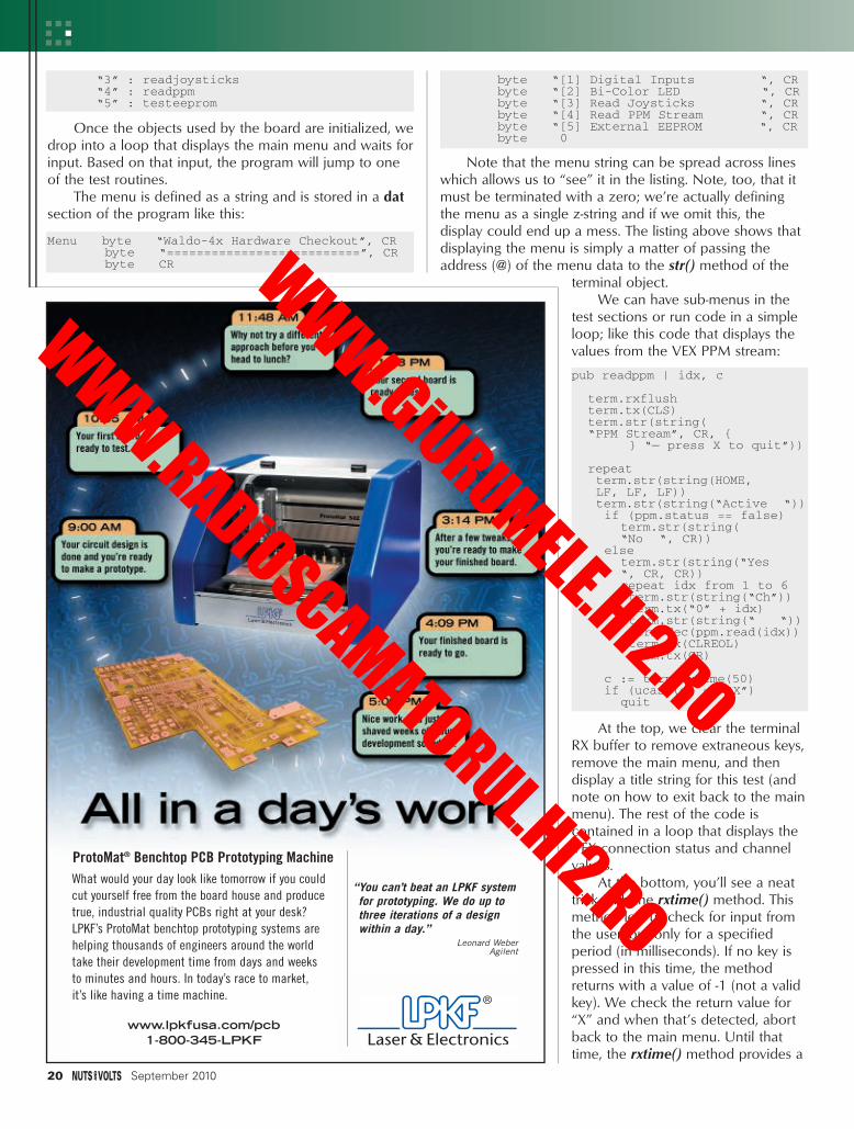
ProtoMat® Benchtop PCB Prototyping MachineWhat would your day look like tomorrow if you couldcut yourself free from the board house and producetrue, industrial quality PCBs right at your desk?LPKF’s ProtoMat benchtop prototyping systems arehelping thousands of engineers around the worldtake their development time from days and weeksto minutes and hours. In today’s race to market,it’s like having a time machine.
www.lpkfusa.com/pcb1-800-345-LPKF
“You can’t beat an LPKF systemfor prototyping. We do up tothree iterations of a designwithin a day.”
Leonard WeberAgilent
Spin Zone - Sep 10.qxd 8/3/2010 2:09 PM Page 20
WWW.GiURUMELE.Hi2.RO
WWW.RADiOSCAMATORUL.Hi2.RO

nice 50 millisecond update rate for the display — it’s a 2-for-1 deal.
Study the test program and put it to use with yourown projects. Remember, the time you spend working ontest code is not wasted because this code checks yourhardware (you need this) and can then be moved intoyour final application.
That test program I created for the AP-16+ prototypeis now used on the other end of the product cycle as aunit tester that is run before we load the application codeand ship to our customer.
CODING AND PUBLISHING ARE DIFFICULT!
My friends at Nuts & Volts do aspectacular job publishing this (andother) magazines for people like youand me. It’s very hard work, takingthe frequently wacky style ofprogrammers and putting it into print.
I mention this because after mylast column a misguided young man(ah, to be young and a newbie ...)took me to task for not providingcomments in my code (as it appearsin print).
Of course, I comment all of mycode. In fact, like most professionalprogrammers, I take pride in thequality of my work and theinformation that goes into it. Thatsaid, the two-column format that ispreferred by Nuts & Volts and otherpublications just doesn’t lend itself tolong program lines so, out ofnecessity, I strip out the inlinecomments for the code that isembedded in the article text.
I realize that this stuff can attimes get a little heavy, especially theassembly sections. So, those of youreally wanting to study the code asyou read my column (or others, forthat matter), you should open thecode that can be downloaded fromthe Nuts & Volts website(www.nutsvolts.com) in yourprogramming editor as you’re readingthe magazine. Studying the codecomments along with the article textwill really help solidify yourunderstanding of the project.
Until next time, then, keepspinning and winning with thePropeller. NV
RESOURCESJON “JONNYMAC” WILLIAMS
PARALLAX, INC.www.parallax.com
GADGET GANGSTERPropeller Platform kits and accessories
www.gadgetgangster.com
S P I N Z O N E
September 2010 21
ElectronicSurplus
Relay 12VDCSPST-2A
33A / 1600VN-MOSFET
2-Bit RotaryEncoder
5KHz PiezoSounder.Pkg of 3
Transformer240/24V0.5VA
sales1@electronicsurplus comToll free: 1-800-642-1123
8755 Munson RdCleveland, OH 44060
electronicsurplus.com/specials.cstm
$4.95
$2.95
$1.19$18.
95
$1.88
7-DigitHour Meter10-50VDC
$14.95
Spin Zone - Sep 10.qxd 8/3/2010 2:09 PM Page 21
WWW.GiURUMELE.Hi2.RO
WWW.RADiOSCAMATORUL.Hi2.RO

✔ Build It!✔ Learn It!✔ Achieve It!✔ Enjoy It!
Where Electronics...
Is Always Fun!
September means it’s time for the kids to head back to school.You can get kids of all ages ahead of the learning curve andexcited about science, health, and electronics with the ECG1C fromRamsey! Not only will putting it together teach them about building theirown electronics, but the completed kit is a hands on demonstration of the rela-tionship between electrical activity and the human body. Each time the humanheart beats, the heart muscle causes small electrical changes across your skin. Bymonitoring and amplifying these changes, the ECG1C detects the heartbeat andallows you to accurately display it, giving you a window into the inner workings ofthe body!
Use the ECG1C to astound your physician with your knowledge of ECG/EKG systems.Enjoy learning about the inner workings of the heart while, at the same time, cover-ing the stage-by-stage electronic circuit theory used in the kit to monitor it. Thethree probe wire pick-ups allow for easy application and experimentation withoutthe cumbersome harness normally associated with ECG monitors.
The documentation with the ECG1C covers everything from the circuitdescription of the kit to the circuit description of the heart! Multiple“beat” indicators include a bright front panel LED that flashes with theactions of the heart along with an adjustable level audio speaker outputthat supports both mono and stereo hook-ups. In addition a monitor out-put is provided to connect to any standard oscilloscope to view the tradi-tional style ECG/EKG waveforms just like you see on ER... or in the ER!
See the display above? That’s one of our engineers, hooked up to the ECG1C after an engineering meeting!
The fully adjustable gain control on the front panel allows the user to custom tune the differential signal pickedup by the probes giving you a perfect reading and display every time! 10 hospital grade re-usable probe patchesare included together with the matching custom case set shown. Additional patches are available in 10-packs.
Operates on a standard 9VDC battery (not included) for safe and simple operation. Note, while the ECG1C pro-fessionally monitors and displays your heart rhythms and functions, it is intended for hobbyist usage only. If youexperience any cardiac symptoms, seek proper medical help immediately!
✔ Visible and audible display of your heart rhythm!✔ Bright LED “Beat” indicator for easy viewing!✔ Re-usable hospital grade sensors included!✔ Monitor output for professional scope display✔ Simple and safe 9V battery operation
ECG1C Electrocardiogram Heart Monitor Kit With Case & Patches $44.95ECG1WT Electrocardiogram Heart Monitor, Factory Assembled & Tested $89.95ECGP10 Electrocardiogram Re-Usable Probe Patches, 10-Pack $7.95
Fun Electronic Learning Labs
Starting out our “All in One” series, the PL130A, givesyou 130 different electronic projects, together with acomprehensive 162 page learning manual. A greatstart for the kids...young and old! Next, check out thePL200, that gives you 200 very creative and fun proj-ects, and includes a neat interactive front panel with 2controls, speaker, LED display and a meter. Fromthere, step up to our PL300, which gives you 300 sep-arate electronic projects along with 165 page learningand theory manual. The PL300 walks you throughthe learning phase of digital electronics. If you’relooking for the ultimate lab kit, check out our PL500.It includes a whopping 500 separate projects, a 152page starter course manual, a 78 page advancedcourse manual, and a 140 page programming coursemanual! The PL500 covers everything from the basicsto digital programming!
If you are looking to either learn or hone up on yourthrough hole or SMT soldering skills check our SP3Band SM200K Practical Soldering Labs. You will be asoldering master in no time!
We make it easy to learn IC’s while at the same time,building a neat AM/FM radio with our AMFM108KAM/FM IC lab kit. You will have a blast AND learn!
PL130A 130-In-One Lab Kit $39.95PL200 200-In-One Lab Kit $69.95PL300 300-In-One Lab Kit $89.95PL500 500-In-One Lab Kit $219.95SP1A Through Hold Soldering Lab $9.95SM200K SMT Practical Soldering Lab $22.95AMFM108K AM/FM IC Lab Kit & Course $34.95
✔ Learn and build!✔ 130, 200, 300, & 500 in one labs!✔ Practical through hole and SMT soldering labs!✔ Integrated circuit AM/FM radio lab!✔ Super comprehensive training manuals!
Pocket Audio GeneratorA perfect test source for stereo line inputs onany amplifier or mixer. Provides 50Hz, 100Hz,1kHz, 10kHz, & 20kHz tones, plus 32 bit digi-tal pink noise. Great to help you identifycables or left/right reversals! Stereo RCA linelevel outputs. Uses 2xCR2025, not included.
K8065 Pocket Audio Generator Kit $32.95
Pocket Vu MeterHand held audio level meter that fits in yourpocket! Built-in mic picks up music and audioand displays it on an LED bargraph. Includesenclosure shown. Runs on one 3V Li-Ion but-ton cell, not included. If you ever wanted aneasy way to measure audio levels, this is it!
MK146 Pocket Vu Meter Kit $8.95
Mini LED Light ChaserThis little kit flashes six high intensi-ty LEDs sequentially in order. Justlike the K8032 to the right does withincandescent lights. Makes a greatmini attention getter for signs, model trains, and evenRC cars. Runs on a standard 9V battery.
MK173 Mini LED Light Chaser Kit $15.95
Running Light ControllerControls and powers 4 incandescentlights so they appear to “travel” backand forth (Like the hood on KITT!).Great for the dance floor or promo-tional material attention getters,exhibits, or shows. Runs on 112-240VAC.
K8032 4-Channel Running Light Kit $38.95
Digital Voice ChangerThis voice changer kit is a riot! Justlike the expensive units you hear theDJ’s use, it changes your voice with a multitude ofeffects! You can sound just like a robot, you can evenad vibrato to your voice! 1.5W speaker output plus aline level output! Runs on a standard 9V battery.
MK171 Voice Changer Kit $14.95
Steam Engine & WhistleSimulates the sound of a vintage steamengine locomotive and whistle! Also pro-vides variable “engine speed” as well asvolume, and at the touch of a button thesteam whistle blows! Includes speaker.Runs on a standard 9V battery.
MK134 Steam Engine & Whistle Kit $11.95
Electronic Watch DogA barking dog on a PC board! And you don’thave to feed it! Generates 2 different selec-table barking dog sounds. Plus a built-in micsenses noise and can be set to bark when ithears it! Adjustable sensitivity! Unlike mySaint, eats 2-8VAC or 9-12VDC, it’s not fussy!
K2655 Electronic Watch Dog Kit $39.95
Laser Trip Senser Alarm
LTS1 Laser Trip Sensor Alarm Kit $29.95
Stereo Ear Super AmplifierUltra high gain amp boosts audio 50times and it does it in stereo with itsdual directional stereo microphones!Just plug in your standard earphone orheadset and point towards the source.Incredible gain and perfect stereo separation!
MK136 Stereo Ear Amp Kit $9.95
Liquid Level ControllerNot just an alarm, but gives you aLED display of low, middle, or highlevels! You can also set it to soundan alarm at the high or low condi-tion. Provides a 2A 240VAC ratedrelay output. Runs on 12-14VAC or 16-18VDC.
K2639 Liquid Level Controller Kit $23.95
High Power LED DriverHigh power LED’s have finallyfound their way into the hobbyistbudget, but now you need a driver!This little board provides the accurateand constant current need to drive them.Delivers 350mA or 700mA at a constant current
K8071 High Power LED Driver Kit $14.95
Electrocardiogram ECG Heart Monitor
True laser protects over 500yards! At last within thereach of the hobbyist, this neat kit uses a standardlaser pointer (included) to provide both audible andvisual alert of a broken path. 5A relay makes it simpleto interface! Breakaway board to separate sections.
Back To SchoolSpotlight!
Follow Us and SAVE $$Follow us on your favorite network site andlook for a lot of super deals posted frequently...exclusively for our followers!
PL500
PL300
PL200
PL130A
AMFM108K
SP3B
SM200K
One of our engineers/guineapigs, checking his heart!
201009.qxd 7/27/2010 3:36 PM Page 22
WWW.GiURUMELE.Hi2.RO
WWW.RADiOSCAMATORUL.Hi2.RO

Get the new 2010 Ramsey Hobby Catalog!96 value packed pages of the neatestgoodies around! Order yours today online or give us a call... Or download thePDF at www.ramseykits.com/catalog!
RAMSEY ELECTRONICS, LLC590 Fishers Station Drive
Victor, NY 14564(800) 446-2295(585) 924-4560Prices, availability, and specifications are subject to change. According to Robin we are not responsible for typos, stupids, printer’s
bleed, or back to school blues. Possession of this ad will not guarantee you acceptance into Harvard! Visit www.ramseykits.com forthe latest pricing, specials, terms and conditions. Copyright 2010 Ramsey Electronics, LLC... so there!
800-446-2295www.ramseykits.com
Vintage Battery EliminatorCollectors come across some greatdeals on antique battery-poweredradios, but how to power them is areal problem. Many classic radiosoperated on batteries only, and inmany cases a series of three batteries foreach radio were required!
The new ABCE1 Battery Eliminator gives you an easyway to replace all these batteries with a simple house-hold AC power connection and resurrect your vintage
antique radios! Provides “A” filiment, “B”plate, and “C” control grid supplies,
which are all isolated fromeach other. Complete withaluminum case. Runs on
110-240VAC.ABCE1 Vintage Radio Battery Elim Kit $199.95
Digital Message SystemThe third generation ofRamsey digital voice storagekits! We started with the lat-est digital voice storage technol-ogy. It provides up to 8 minutes of digital storage at afrequency response up to 3.5 KHz. (Total messagetime and frequency response is dependant on selectedinternal sampling rate.) Once recorded, messages areavailable for playback on-demand or automatic contin-uous looping. Standard RCA unbalanced line leveloutput is provided for easy connection to any amplifi-er, amplified speaker, mixer, or sound system. In addi-tion, a standard 4-8 ohm speaker output is provided todirectly drive a monitor speaker. Can be remote con-trolled via 3-wire BCD with our interface options.Check www.ramseykits.com for all options!DVMS8 Digital Voice Message 8Ch Kit $99.95DVMS8WT Assembled DVMS8 $149.95
Ultimate 555 TimersThis new series builds onthe classic UT5 kit,but takes it to awhole new level!You can configureit on the fly with easy-to-use jumper settings, driverelays, and directly interface all timer functions withonboard controls or external signals.
All connections are easily made though terminalblocks. Plus, we've replaced the ceramic capacitor ofother timer kits with a Mylar capacitor which keepsyour timings stable over a much wider range of volt-ages! Available in through hole or surface mount ver-sions! Visit www.ramseykits.com for version details.UT5A Through Hole 555 Timer/Osc Kit $24.95UT5AS SMT 555 Timer/Osc Kit $26.95
Passive Aircraft MonitorThe hit of the decade! Our patented receiverhears the entire aircraft band without any tun-ing! Passive design has no LO, therefore canbe used on board aircraft! Perfect for air-shows, hears the active traffic as it happens!Available kit or factory assembled.
ABM1 Passive Aircraft Receiver Kit $89.95
Voice Activated SwitchVoice activated (VOX) provides aswitched output when it hears asound. Great for a hands free PTTswitch or to turn on a recorder or light!Directly switches relays or low voltage loads up to100mA. Runs on 6-12 VDC.
VS1 Voice Switch Kit $9.95
OBDII CarChip ProThe incredible OBDII plug-in monitorthat has everyone talking! Onceplugged into your vehicle it monitorsup to 300 hours of trip data, from speed, braking,acceleration, RPM and a whole lot more. Reads andresets your check engine light, and more!
8226 CarChip Pro OBDII Monitor-Asmb $99.95
RF PreamplifierThe famous RF preamp that’s beenwritten up in the radio & electronicsmagazines! This super broadband preampcovers 100 KHz to 1000 MHz! Unconditionally stablegain is greater than 16dB while noise is less than 4dB!50-75 ohm input. Runs on 12-15 VDC.
SA7 RF Preamp Kit $19.95
Touch SwitchTouch on, touch off, or momentarytouch hold, it’s your choice with thislittle kit! Uses CMOS technology.Actually includes TWO totally separate touch circuitson the board! Drives any low voltage load up to100mA. Runs on 6-12 VDC.
TS1 Touch Switch Kit $9.95
Doppler Direction FinderTrack down jammers and hiddentransmitters with ease! 22.5 degreebearing indicator with adjustabledamping, phase inversion, scan andmore. Includes 5 piece antenna kit.Runs on 12VDC vehicle or battery power.
DDF1 Doppler Direction Finder Kit $169.95
Mad Blaster Warble AlarmIf you need to simply get atten-tion, the “Mad Blaster” is theanswer, producing a LOUD earshattering raucous racket! Super forcar and home alarms as well. Drivesany speaker. Runs on 9-12VDC.
MB1 Mad Blaster Warble Alarm Kit $9.95
Laser Light ShowJust like the big concerts, youcan impress your friends withyour own laser light show!Audio input modulates thelaser display to your favorite music!Adjustable pattern & speed. Runs on 6-12VDC.
LLS1 Laser Light Show Kit $49.95
Water Sensor AlarmThis little $7 kit can really “bail you out”!Simply mount the alarm where you want todetect water level problems (sump pump)!When the water touches the contacts thealarm goes off! Sensor can even be remotelylocated. Runs on a standard 9V battery.
MK108 Water Sensor Alarm Kit $6.95
USB DMX InterfaceControl DMX fixtures with your PC viaUSB! Controls up to 512 DMX channelseach with 256 different levels! Usesstandard XLR cables. Multiple fixturescan be simply daisy chained. Includes Light Playersoftware for easy control. Runs on USB or 9V power.
K8062 USB DMX Interface Controller Kit $67.95
HV Plasma GeneratorGenerate 2” sparks to a handheldscrewdriver! Light fluorescent tubeswithout wires! This plasma genera-tor creates up to 25kV at 20kHz from asolid state circuit! Build plasma bulbs fromregular bulbs and more! Runs on 16VAC or 5-24VDC.
PG13 HV Plasma Generator Kit $64.95
Air Blasting Ion GeneratorGenerates negative ions along with ahefty blast of fresh air, all without anynoise! The steady state DC voltagegenerates 7.5kV DC negative at 400uA,and that’s LOTS of ions! Includes 7 windtubes for max air! Runs on 12-15VDC.
IG7 Ion Generator Kit $64.95
Speedy Speed Radar GunOur famous Speedy radar gunteaches you doppler effect thefun way! Digital readout dis-plays in MPH, KPH, or FPS. Yousupply two coffee cans! Runs on12VDC or our AC125 supply.
SG7 Speed Radar Gun Kit $69.95
Tri-Field Meter Kit“See” electrical, magnetic, and RF fields asa graphical LED display on the front panel!Use it to detect these fields in yourhouse, find RF sources, you name it.Featured on CBS’s Ghost Whisperer todetect the presence of ghosts! Req’s 4 AAA batteries.
TFM3C Tri-Field Meter Kit $74.95
USB Experimenter’s KitGet hands-on experience devel-oping USB interfaces! 5 digitalinputs, 8 digital outputs, 2 analogI/O’s! Includes diagnostic software and DLL for usewith Windows based systems. The mystery is solvedwith this kit!
K8055 USB Experimenter’s Kit $49.95
Tickle-Stick ShockerThe kit has a pulsing 80 volt tickleoutput and a mischievous blink-ing LED. And who can resist ablinking light and an unlabeledswitch! Great fun for your desk,“Hey, I told you not to touch!” Runs on 3-6 VDC.
TS4 Tickle Stick Kit $12.95
Retro Nixie Tube ClockGenuine Nixie tubes popular inthe 50’s brought back in one ofthe neatest digital clocks aroundtoday! Hand made teak maple base, 12/24 hour for-mat, soft fade-out, auto-dim, and a crystal time base at20ppm! Tube kits also available.
IN14TM Teak Maple Nixie Clock Kit $329.95
UT5AUT5AS
3-In-1 Multifunction LabThe handiest item for yourbench! Includes a RoHScompliant temp controlledsoldering station, digital mul-timeter, and a regulated lab power supply! All in onesmall unit for your bench! It can’t be beat!
LAB1U 3-In1 Multifunction Solder Lab $129.95
Electret Condenser MicThis extremely sensitive 3/8” michas a built-in FET preamplifier! It’sa great replacement mic, or a perfectanswer to add a mic to your project.Powered by 3-15VDC, and we even include couplingcap and a current limiting resistor! Extremely popular!
MC1 Mini Electret Condenser Mic Kit $3.95
Sniff-It RF Detector ProbeMeasure RF with your standardDMM or VOM! This extremely sensi-tive RF detector probe connects toany voltmeter and allows you tomeasure RF from 100kHz to over 1GHz! So sensitive itcan be used as a RF field strength meter!
RF1 Sniff-It RF Detector Probe Kit $27.95
Broadband RF PreampNeed to “perk-up” your counter orother equipment to read weak sig-nals? This preamp has low noise andyet provides 25dB gain from 1MHz to wellover 1GHz. Output can reach 100mW! Runs on12 volts AC or DC or the included 110VAC PS. Assmb.
PR2 Broadband RF Preamp $69.95
201009.qxd 7/27/2010 3:40 PM Page 23
WWW.GiURUMELE.Hi2.RO
WWW.RADiOSCAMATORUL.Hi2.RO

● Video Buffer
● Game Clock
● LCD Backlight
✓
✓
✓
HUM DETECTION
QFor more than 30 years, I was a design engineer in the electroniccommunications industry,
so I feel I should be able toundertake most projects when soinclined. However, the problem we(my family and I) now have has mestumped. For some time, we haveexperienced a low-level lowfrequency hum (say 20 Hz to 60 Hzrange) which pervades the house24/7. This sometimes makes sleepingproblematic for us.
Having carried out someinvestigation and ruled out internalsources, I now realize this is anational (if not worldwide) problemwith sources as esoteric as theRussian VLF submarinecommunications, gravitational waves,overhead power lines, andsubterranean gas distribution beingsuggested.
However, I believe the source/sto be more prosaic such as
machinery at a local industrial site orbeat frequencies created byventilation fans at local chickenproducers.
The latter types of source arelocated several miles away and thusthe higher frequencies in the noisespectrum are attenuated leaving onlythe LF component (which if capturedon a spectrum analyzer couldbecome a ‘signature’).
The difficult problem is todetermine the source direction at areasonable cost. In principle, amobile detector could direction-findthe source from two/three locationsand a map could be used todetermine the point source. Thelatter would be difficult because thehum is mysteriously only detectedinside the house.
Perhaps the house acts as a typeof resonant cavity. Allegedly,churches with their high ceilings areeven better hum detectors.
Any practical ideas from you orthe readers would be helpful.
— John Hobday
ASince the hum is onlyaudible inside the house,the noise must be travelingthrough the ground.
Therefore, seismic sensors should beused to find the direction. Theprocedure would be to place twosensors in the ground, connected tothe two inputs of a dual channeloscilloscope. When the signals of thetwo channels coincide, the sounddirection is at right angles to the linebetween the sensors.
If that is not enough to find thesource, move the sensors until thereis a significant difference in thedirection of the sound. A USGeological Survey map will behelpful in this endeavor (availablefrom most camping and hiking supplystores). Oops, I see you are in theUK but I am sure similar maps areavailable.
This URL shows how to makeyour own seismic sensor from aspeaker with a weight glued to thecone: www.techlib.com/electronics/seismic.htm. You can use the circuitshown on the site, or I think Figure 1will be more sensitive.
In Figure 1, I used an LM358 op-amp because it’s cheap andcommonly available but if circuitnoise is a problem, the SSM2135 op-amp is low noise and available fromDigi-Key. The first stage should give60 to 80 dB gain and the secondstage has 40 dB available if you needit. I suspect the seismic hum is highlevel so you won’t need maximumgain. With so much gain, the layout
Q&A■ WITH RUSSELL KINCAID
WHAT’S UP:Join us as we delve into thebasics of electronics as appliedto every day problems, like:
In this column, I answer questions about allaspects of electronics, including computer hardware,software, circuits, electronic theory, troubleshooting,and anything else of interest to the hobbyist. Feelfree to participate with your questions, comments, or suggestions.Send all questions and comments to:Q&[email protected]
24 September 2010
■ FIGURE 1
Q&A - Sep 10.qxd 8/2/2010 12:11 PM Page 24
WWW.GiURUMELE.Hi2.RO
WWW.RADiOSCAMATORUL.Hi2.RO

will have to provide isolation or it willoscillate. The web article suggestsgluing a post to the speaker coneand attaching it to the cover of aglass jar. You can put the circuit andbattery in the jar to make a sensorthat can be partially buried in theground for good sonic conductivity.
BAND SAW BLADEWELDER CIRCUIT
QI’m looking for a circuit thatuses a 12 VDC car batteryto butt weld 1/2” band sawblades.
I’m not sure if it can be used toweld bi-metal blades, but the carbonsteel should work fine.
There is a commercial unitshown at http://advancecarmover.thomasnet.com/item/band-saw-blade-welder/band-saw-blade-welder-2/item-1017?&forward=1and PDF manuals there fordownloading and viewing. The priceseems a bit high for this unit.
Do you have any ideas on acircuit that would allow me to safelyduplicate this blade welder?
— Larry Kraemer
AThere is no circuit; all youneed is a switch capable of500 amps to connect thebattery to the blade. The jig
that keeps everything in alignment isthe key that makes it work.
LCD BACKLIGHT
QI’m repairing a portableDVD player and I want toreplace the defective LCDscreen.
I found that a 7” LCD displayfrom a digital photo frame 480 x 234works great and will replace thedefective display in the DVD unit. Ibelieve that the photo frame LEDbacklight works on approx. 12 VDC@ 80 MADC and the DVD playerworks on approx. 22 VDC @ 40MADC. The problem is the originalLED backlight has 21 LEDs in seriesand the replacement LED backlightonly has 15 LEDs in series.
My issue is that when the unit isturned off, the power for running theLEDs is 12 volts DC so the backlightis lit up even when it’s off. When youturn the unit on, the power goes toapproximately 22 volts DC (that’s thereason the original LED stayed off). Isthere a circuit I could add that wouldnot allow 12 volts DC when it’sturned off? And when it’s turned onit would supply anywhere from 12volts DC to 22 volts DC? This circuitwould have to be small as there isn’tmuch room to add a lot ofcomponents.
Thanks in advance.— Jeff Miller
AThe circuit in Figure 2should do the job. Sincethe emitter and base are atthe same potential when
the power is off, the transistor will beoff. When the voltage drive goes to
22 volts, 40 mA will be sent to theLCD backlight. R2 allows thebacklight to go above 12 volts andyou can short it out to save room.
VIDEO BUFFER
QI have what seems to bea simple problem, but mysearch for an answer hasnot given me good results.
I have six security cameras aroundmy yard and they all feed a DVR.Every couple of years, I lose atleast one camera and the DVR tolightning strikes. While replacing acamera or two does not break thebank, the cost of a DVR is quite adifferent matter.
Although I could probably justuse MOVs or some other passivedevice, I thought a simple,inexpensive, low power video bufferwould be in order; a sacrificial deviceas it were. I say low power becausemy electric bill is already high and Iam working to reduce it, not increaseit. The cameras are strictly video, nomodulation involved. Any ideas?
— Joe Heck
AI think metal oxidevaristors at the camerapower input and videooutput, plus another MOV
at the DVR video input would
QUESTIONS & ANSWERS
September 2010 25
■ FIGURE 2 ■ FIGURE 3
Q&A - Sep 10.qxd 8/2/2010 12:10 PM Page 25
WWW.GiURUMELE.Hi2.RO
WWW.RADiOSCAMATORUL.Hi2.RO

protect everything in most cases.However, I found the circuit of Figure3 (which I modified a little) on theworld wide web which will fit yourrequirement. I simulated the circuit(see Figure 4) for the response; the
gain is 2 dB and thebandwidth is 10 MHz.The maximum outputis one volt p/p and ifthat is exceeded, therewill be distortion dueto saturation delay inQ2.
GAME CLOCK
QI’d like tomake a gameclock similarto the ones
used for basketballgames for my daughter.Can you help me withhow I couldaccomplish this?
— Les Manis
ANot having playedbasketball or paid attentionwhen watching, I don’t knowif the clock counts down or
up, so I will wing it and assume acount down clock with four quarters.High school games have eight minutequarters, so two digits countingtenths of minutes will suffice.
Hold on, a tenth of a minute issix seconds — that is too long. I willhave to have three digits, countinghundredths of a minute. A secondcounter will keep track of quarters.Single digit LCDs are not available, soI will use a 2-1/2 digit display and usethe middle digit for the quarternumber.
In Figure 5, I have a 555oscillator producing 100 pulses perminute (1.67 Hz). IC2 is a flip-flop tostop and start the clock. I could haveused a 4011 quad NAND with twogates left over; you can do that if youwant.
I show DIP switches to set thestarting time for the count downcounters but if you know the time isgoing to be the same all the time,you can hard-wire it. When all three
26 September 2010
■ FIGURE 5
■ FIGURE 4
Q&A - Sep 10.qxd 8/3/2010 10:04 PM Page 26
WWW.GiURUMELE.Hi2.RO
WWW.RADiOSCAMATORUL.Hi2.RO

counters (IC4, IC3, and IC7) have reached zero,IC9A clocks the quarter counter, IC10. When thequarter count reaches 5, IC13A decodes thatnumber, resets all the counters, and stops theclock via D1.
There is no power-up reset so the gamemaster will have to press the “new game” buttonto start. The new game button can be pressed atany time to terminate a game and start over. IC11is a 555 oscillator running at 60 Hz to drive theLCD displays.
If you build this, let me know how it turns out.The LCD runs on five volts, but there is nomaximum specified so I think it will work on ninevolts. I did not breadboard this, so if anyone findsa flaw in my logic, please let me know.
BLINKING TAILLIGHT REVISITED
QIn addition to that blinking taillight brakementioned in the June ‘10 Q&A, howabout increasing the blink rate and lightintensity in proportion to the car’s
deceleration?Perhaps using one of those accelerator
sensing chips I see advertised and anadditional/optional circuit for externalsuper bright LEDs?
A timer/op-amp hardwaresolution seems possible (well, forsomeone much cleverer than I itmight seem possible!!).
— Brian Stoller
AIncreasing the blink ratewith deceleration is a goodidea. However, eventhough the acceleration IC
is cheap, the development hardwareand software is expensive, so I won’tgo there.
Besides, I subscribe to the KISSprinciple and a rheostat with aweighted knob will do the trick.Replace R3 in Figure 5 of the Juneissue with a 50K rheostat(potentiometer) oriented so that the weight swings forward andconnected to reduce the resistance.You can rotate the rheostat to get thedesired resting blink rate.
A similar, lower resistancerheostat in series with the taillightcould be used to change thebrightness; although the restingbrightness would be reduced. NV
QUESTIONS & ANSWERS
September 2010 27
www.frontpanelexpress.com
(206) 768 - 0602
Customized front panels can be easily
designed with our free software
Front Panel Designer
FRONT PANELS & ENCLOSURES
New Version 4.0New functions include dxf importfor inner and outer shapes. Linux,Windows, and Mac OS X compatible.
Q&A - Sep 10.qxd 8/3/2010 2:50 PM Page 27
WWW.GiURUMELE.Hi2.RO
WWW.RADiOSCAMATORUL.Hi2.RO

HANDHELDDSO/DMM WITHBUILT-IN USB PORTANDDATALOGGER
An upgraded,advanced
version of Protek’shandheld, 60 MHzDSO/DMM nowincludes as standarda 2.0 USB hostport, a 3.8” color
LCD display, and real-time datalogging. Other features include
Wavelink™ Software for remotecontrol via PC, 125 KB recordlength, and up to 200 Ms/Ssampling rates. Priced at$1,449 and complete with anAC/DC adaptor, USB cable,and rechargeable batterypack, the dual channel Model860FC has a 60 MHz analogbandwidth; high resolution3.8” LCD color display; autoset-up and horizontal zoom;2.5 Gs/S equivalent samplingrate; dual channel waveformmath and FFT; plus horizontalzoom function with auto set-up. In addition, it provides 22
automatic waveform measurements.The USB host port connects with aFlash memory drive enabling massstorage of waveforms and data loggerCSV files. All future firmware updatescan be installed via the USB port.
The 6000 count DMM includes adata logger that records and plots themeasurement values versus time onthe LCD for up to 20 days using aninnovative compressible time axis.The data logged values may bestored in a Flash RAM which attachesto the USB host port. In adherence toCATIII 600V standards, the newDSO/DMM is delivered with aHolster, two (2) scope probes, andoperator’s manual. The 20 MHz and40 MHz models with upgraded
P R O D U C T SNEW
■ HARDWARE■ SOFTWARE■ GADGETS■ TOOLS
* Quality Quick Turn Sheet Metal Products &Precision Machined Parts
* No Minimum Quantity Restrictions
* Quote in 24 Hours or Less!
* Several Metallic & Non-Metallic Materials in Stock
Visit www.iitmetalfab.comtoday for your free, noobligation quote!
28 September 2010
SEP10 - NewProducts.qxd 8/3/2010 4:00 PM Page 28
WWW.GiURUMELE.Hi2.RO
WWW.RADiOSCAMATORUL.Hi2.RO

features are available as part of thefirm’s Series 800 handheldDSO/DMM group.
NEW MODULEFAMILY
Wireless solutions developerRadiometrix has announced
the introduction of the CXT/CXRmodule family. This transmitter/receiver pair provides a completeremote control switch function in amodule format, delivering reliable,
SHOWCASESHOWCASE
Dealers Wanted
MIAC is an industrial grade PICmicro controller which
retails at $180. Features include direct USB download, 8
analog/digital inputs, 4 relays, 4 motor outputs, integrated
CAN bus and a free copy of Flowcode V3. We are looking
for commercial partners for MIAC – if you are interested
then please call us in the UK on +44 1422 252380.
Open Source HardwareArduino DuemilanoveArduino MEGA
Freeduino - Seeeduino
Arduino Shields - Ethernet -XBee
Zeroplus LAP-C 16032Logic Analyzer
16-channel - 100MHz - USB 2.0SPI - i2c - UART - 7-segment2 free additional protocols
d
2
2.0t
http://www.NKCelectronics.coml
Rigol DS1052E DSO50MHz - up to 1GSa/s
1 Meg mem - TFT LCD - USBAdvanced triggering: Edge,Pulse, Video, Slope, Alt
For more information, contact:Protek Test &Measurement
45 Smith StreetEnglewood, NJ 07631
Tel: 201-227-1161Web: www.protektest.com
Continued on page 77
SEP10 - NewProducts.qxd 8/3/2010 2:52 PM Page 29
WWW.GiURUMELE.Hi2.RO
WWW.RADiOSCAMATORUL.Hi2.RO

Frequency Magic
A phase-locked loop (PLL) can be used for manyapplications, including frequency multiplication. In a typical
application, a PLL continually attempts to synchronize itsinternal voltage-controlled oscillator (VCO) with an externalfrequency applied to the PLL. A phase comparator in the PLLcompares the two frequencies and generates an error voltagewhich is applied to the VCO to “lock” the VCO frequencyand phase to the external frequency and phase. This is a prettyneat trick all by itself, but it becomes more interesting if weplace a frequency divider between the PLL’s VCO output andits phase comparator input. This makes the phase comparatorthink the VCO is oscillating much slower than the externalfrequency, by a factor equal to the frequency division ratio.The phase comparator then outputs an error voltage to the VCOwhich raises its frequency to equal the external frequencymultiplied by the frequency division ratio. Once the PLL locksonto this multiplied frequency, we have a very accuratemultiple of the external frequency with a 50% duty cycle.
Component Selection
I selected the 74HC4059 programmable divide-by-Ncounter/divider to set the frequency division ratio for thePLL. This chip can divide its input frequency by anynumber up to 15,999 and has 16 frequency-setting “Jam”inputs which are easily interfaced to a microcontroller.
I settled on using the CD74HC7046 PLL for thisproject. This chip has a wide frequency range (up to 38MHz), a good “lock” range, and also has a “lock detect”
●●●●
30 September 2010
■ FIGURE 1. The PLL-based synthesizer (top) in operation, withfrequency counter and oscilloscope measurements of its output.
A frequency synthesizer (signal generator) is a device which generates a very stablewaveform at a user-selected frequency.They are very handy when you need such awaveform as an input to another circuit such as an audio mixer, a radio transmitter, ordigital logic.This design is optimized for use with digital circuits but can easily be adaptedto audio or radio frequency applications.The short list of requirements I had for thissynthesizer included a wide frequency range (up to 30 MHz), small frequency steps (1 kHz), high accuracy, 50% duty cycle output, and a simple user interface for selecting the frequency.The end result (Figure 1) met all these requirements at a cost of around $70 including the custom-made circuit board.There are some ready-made synthesizerchips on the market including the LTC6904 — a neat little eight-pin device with an I2Cinterface — but these didn’t have the frequency steps I wanted or had insufficientaccuracy.
MAKE THE PLL FREQUENCYSYNTHESIZER WITH
PIC CONTROL BY DANGRAVATT
Gravatt - PLL Frequency Synthesizer.qxd 8/3/2010 2:44 PM Page 30
WWW.GiURUMELE.Hi2.RO
WWW.RADiOSCAMATORUL.Hi2.RO

output which provides confirmationthat the PLL has indeed locked at thedesired frequency. The lock detectoutput was the main reason I pickedthis PLL, as it enables the synthesizerto operate over a frequency rangemuch larger than the PLL lock range –more on this later. The accuracy of theentire synthesizer is dependent on theaccuracy of the external frequencyapplied to the PLL, and for this Iselected a 1.000000 MHz TTL clockoscillator. A trio of 74HC390 dualdecade dividers are used to scale theoscillator frequency down to 100 kHz,10 kHz, 1 kHz, 100 Hz, 10 Hz, and 1Hz, and a 74HC151 8-to-1 multiplexeris used to select which frequency is applied to the PLL.During prototyping, I discovered that I could achieve theentire frequency range I wanted using only the 10 kHzand 1 kHz inputs, but I left the 8-to-1 multiplexer and thethird dual decade divider in the design in case you need adifferent frequency range or frequency step size for yourapplication. The user interface I selected consists of a 16character LCD to display the frequency, a 12 buttonmatrix keypad for direct frequency entry, and a singlepotentiometer to adjust the PLL’s VCO frequency. Afteradding up all the I/O lines required to control the74HC4059 divider, the 74HC151 multiplexer, the LCD,and the keypad, I selected the PIC16F877A 40-pinmicrocontroller as the brains of the synthesizer. All 33 ofits I/O lines are used in this project.
I wanted the output of the synthesizer to be able todrive pretty much any reasonable circuit that might need afrequency input, but the VCO output of the PLL can’t dealwith much of a load before it begins to affect itsfrequency stability and accuracy. An op-amp buffer wasrequired, and I wanted a really good one with more thanenough gain-bandwidth product at the 30 MHz maximumfrequency. I also wanted single-supply operation with rail-to-rail outputs and a decent output current capability. Isettled on the Analog Devices AD8044 quad op-ampwhich meets all of these requirements and then some.Figure 2 is a block diagram of the entire synthesizer.
I deliberately selected through-hole (DIP) componentsfor this project to ease assembly for folks who aren’tcomfortable with surface-mount parts; however, all ofthese components are also available in surface-mountpackages.
PLL Multiplier Operation
The PLL frequency multiplier consists of the74HC7046 PLL, the 74HC4059 divider, a resistor andcapacitor to set the PLL’s VCO frequency, a resistor andcapacitor to filter and smooth the PLL’s phase detectorerror voltage (referred to as the loop filter), and a
capacitor to filter the lock detect output of the PLL. All ofthese passive components should be optimized for thefrequency range over which the PLL is expected to lock,and since the synthesizer range is relatively large (300 kHzto 30 MHz), I had to make some compromises.
I selected the loop filter capacitor and the lock detectoutput capacitor values to be large enough to filtereffectively at the low end of the frequency range. They arefar larger than necessary for the high end of the frequencyrange, and as a result it may take the PLL a significantfraction of a second to lock at high frequencies due to thecharging time of these capacitors. The loop filtercomponent values also determine the amount of dampingof the VCO output, so the amount of “ringing” in thewaveform depends in part on these values.
The large frequency range I wanted posed a particularproblem for the resistor and capacitor setting the VCOfrequency, as there just isn’t any one combination whichwill work across the entire range. One of thesecomponents has to be variable, so I chose to use avariable resistor and a fixed, small-value capacitor. I foundthat a capacitor value of 27 pF was necessary to ensureoperation up to 30 MHz. This capacitor should be a high-stability ceramic or silver-mica type. To make this smallcapacitance work at the low end of the frequency range, alarge resistance is needed. The 74HC7046 PLL datasheetspecifies a minimum of 3K ohms for this resistor, and Iused a 250K pot. I also placed a small fixed-value resistorin series with the pot so the resistance can never go to zero.
Now that the PLL relies on the user to set thisresistance manually in order to lock onto the desiredfrequency, there has to be a way for the PLL to tell theuser when they have made the proper adjustment. This isthe purpose of the PLL’s lock detect output which consistsof an irregular stream of pulses when the PLL is out oflock, and a constant logic-high when the PLL is locked. Idecided to use the PIC’s Timer0 external counter input(pin RA.4) to constantly look for pulses on the lock detectoutput. If the Timer0 count is zero, we know the PLL islocked, and “LOCK” will be displayed on the LCD.
September 2010 31
■ FIGURE 2. Blockdiagram of the
frequency synthesizer.
Gravatt - PLL Frequency Synthesizer.qxd 8/2/2010 12:51 PM Page 31
WWW.GiURUMELE.Hi2.RO
WWW.RADiOSCAMATORUL.Hi2.RO

The 74HC4059 divider has a number of counting“modes” which are described in a rather confusingmanner in the datasheet. The one I used for this project isMode 10 with a maximum division ratio of 9,999 — morethan adequate for this application. I selected this modebecause it offers the simplest way for the PIC to send thedivision ratio data to the divider. In Mode 10, the 16 Jaminputs are grouped into four four-bit binary-coded-decimaldigit inputs representing the four digits of the divisionratio. The PIC only needs to do a little arithmetic andsome bit manipulations to calculate this ratio and send theBCD data to the divider.
PIC Code
The code for this project is written in PICBASIC PRO(available from microEngineering Labs at www.melabs.com and is included with the downloads for this article atwww.nutsvolts.com). It consists primarily of a loop to scanthe keypad for input, record key presses into an arrayvariable, display the frequency on the LCD, and monitorthe Timer0 count to check if the PLL is locked.Frequencies must be entered in Hertz — not kiloHertz orMegaHertz. Once a frequency is entered, the code jumpsto a subroutine which parses the contents of the arrayvariable. If the frequency is within the range of thesynthesizer, the code selects the necessary externalfrequency on the 74HC151 multiplexer, then calculatesand sends the divide ratio to the 74HC4059. The codethen returns to the main loop.
The frequency resolution is set by the externalfrequency (the step size, either 10 kHz or 1 kHz), so if afrequency with finer resolution than this step size is entered,the extra resolution will be ignored. For example, with a 1kHz step size, a frequency entry of 123,456 Hz will betruncated to 123,000 Hz. If the entered frequency is outsidethe range of the synthesizer, an error will be displayed,and the display will be blanked to accept a new entry. Thelast valid entered frequency will continue to be outputwhile waiting for the new entry. Because the frequency isstored, calculated, and displayed as an array of characters(rather than one numeric value), the code isn’t subject tothe limitations of a 16-bit word-sized variable.
When first powered up, the synthesizer frequencydefaults to 200 kHz (a holdover from my early tests withthe 74HC4059) because the PLL can’t and shouldn’t beforced to output 0 Hz. However, this default frequencywill not be displayed. Since the position of the VCOadjustment pot is unknown, the actual output frequency isundefined until the user inputs a valid frequency and thenadjusts the pot to achieve frequency lock.
The frequency entry keypad is laid out just like atelephone keypad, with the Enter key where the # key ison a telephone. Only 11 of the 12 keys on our keypad areneeded, so the * key is unused. To prevent unpredictablecharacters from being entered if the * key is accidentallypressed, this key acts like another 0 key.
Make sure to look at the code listing for more insightsinto how the keypad is scanned for inputs, the frequencyinput is parsed, the divide ratio calculations areperformed, and the display is updated. I put in plenty of
comments to make functions clear and tofacilitate any modifications you mightwant to make. Note that this code farexceeds the 31-line limit of the demoversion of PICBASIC PRO (the first of myprojects to do so), so if you want tomodify and recompile it, you’ll need thefully functional version of the compiler.
Construction
Building this circuit (Figure 3) isimpractical without a custom printedcircuit board (PCB), though I didbreadboard the circuit during prototypingwith predictably messy results (Figure 4).A good quality circuit board with aground plane is essential for clean, stableoperation at the high frequency end ofthe synthesizer’s range. The layout of thePLL, divider, and op-amp circuitry on theboard was done with this in mind,minimizing trace lengths and keepingcomponent spacing tight. The groundplane is kept away from the op-amp
32 September 2010
PARTS LIST ITEM PART NUMBERPIC16F877A microcontroller, DIP-40 PIC16F877A-I/P-ND74HC4059 programmable divider, DIP-24 568-1550-5-ND74HC7046A phase-locked loop, DIP-16 296-9237-5-ND74HC151 multiplexer, DIP-16 296-8236-5-ND(3) 74HC390 dual decade counter, DIP-16 296-9199-5-NDAD8044 quad op-amp, DIP-14 AD8044ANZ-ND74HC14 hex Schmitt trigger DIP-14 (optional) 296-1577-5-ND1.000000 MHz half-size TTL oscillator XC229-ND4 MHz ceramic resonator with caps 445-1638-ND1N5401 diode 1N5401-TPCT-ND(5) 2.2 µF tantalum capacitors 478-1868-ND27 pF NP0 ceramic capacitor 399-4171-ND0.001 µF ceramic capacitor 399-4201-ND(2) 0.1 µF surface-mount (1206 chip) capacitors 478-1556-1-ND(7) 10K ohm 1/8 watt resistors 10KEBK-ND2.2K ohm 1/8 watt resistor 2.2KEBK-ND(5) 1K ohm 1/8 watt resistors 1.0KEBK-ND250K ohm potentiometer CT2209-ND12-key matrix keypad All Electronics KP-2216 character by 1 line parallel-interface LCD All Electronics LCD-161140-pin DIP socket A35062-ND
(Digi-Key part numbers, except where noted)
Dan Gravatt can be reached at [email protected] PIC16F877A chips and circuit boards for thisproject are available from the author.
Gravatt - PLL Frequency Synthesizer.qxd 8/2/2010 12:52 PM Page 32
WWW.GiURUMELE.Hi2.RO
WWW.RADiOSCAMATORUL.Hi2.RO

inputs and VCO pins on the PLL to minimize straycapacitance at these sensitive high frequency circuitnodes. I recommend against using sockets for any of the chips except the 16F877 due to the high frequencysignals present in the circuit. The ExpressPCB file for thePC board I designed (Figure 5) is also available atwww.nutsvolts.com.
Power supply bypass capacitors are distributed acrossthe board to prevent glitches and minimize ringing on theoutput signal. The datasheet for the AD8044 also recommendsinstalling a surface-mount (chip) capacitor directly fromthe op-amp’s positive supply (pin 4) to the adjacentground plane to further enhance stability. I installed chipcapacitors on the back side of the circuit board at thepositive supply pins for the op-amp and the PLL. Ashielded enclosure is highly recommended, as well as agood, high frequency output connector such as a BNC.
The voltage dividers formed by resistors R7-R8 andR11-R12 are necessary to prevent the VCO output voltageswing (zero to five volts) from exceeding the maximum inputvoltage rating of the op-amps. The gain of the op-amps isthen set by feedback resistors R9-R10 and R13-R14 to restore
September 2010 33
■ FIGURE 3. Schematic ofthe frequency synthesizer.
■ FIGURE 4. Breadboard prototype of the frequency synthesizer. The PLL and op-amp circuits were built
on the general-purpose PC board (at top) for stability.
Gravatt - PLL Frequency Synthesizer.qxd 8/2/2010 12:52 PM Page 33
WWW.GiURUMELE.Hi2.RO
WWW.RADiOSCAMATORUL.Hi2.RO

the five volt voltage swing at the output of the synthesizer.Any unused op-amp inputs should be tied to ground.
Modifications
I designed a fair amount of flexibility into the schematic
and PCB to make this project as useful as possible. Asstated earlier, the third 74HC390 dual decade dividerwhich provides 10 Hz and 1 Hz signals is optionaland can be left out if desired. All of the decadedivider outputs are connected to the 74HC151multiplexer so the PIC code can be modified to useany of them as the PLL’s external frequency. Thiscould be helpful if you need lower frequencies orsmaller frequency steps than the “stock” design. Forexample, you could create a 20-20,000 Hz audiofrequency generator with a 1 or 10 Hz step size byincreasing C1 to 1 µF or so, adjusting the loop filterand lock detect filter component values, and addinga few lines of code in the SELECT CASE argument toaccept frequency entries that are two, three, or fourdigits long.
Two additional op-amps in the AD8044 areavailable for use as filters or wave shapers, and padsare provided for connecting components to thoseop-amps. Active filters can be used to convert the
square wave output to a sine or triangle wave. Thesedifferent waveforms are particularly useful for audio mixerwork as each has a different spectral (harmonic) content.A sine wave is a single frequency with no harmonics.Square waves and triangle waves contain a singlefrequency plus an infinite number of odd harmonics of
34 September 2010
■ FIGURE 5. PCB for the frequency synthesizer mounted in its enclosure.
Gravatt - PLL Frequency Synthesizer.qxd 8/2/2010 12:53 PM Page 34
WWW.GiURUMELE.Hi2.RO
WWW.RADiOSCAMATORUL.Hi2.RO

that frequency, but the relative amplitudes of theharmonics in a square wave are different fromthose in a triangle wave.
R4 through R6 are pull-up resistors for thecolumn scan lines on the keypad; these can beomitted if the keypad you use has built-in pull-upresistors.
I had hoped to include a high quality triangle waveoutput from the 74HC7046 PLL in addition to the squarewave output, but design trade-offs prevented this. This PLLhas two different phase comparator circuits, but the lockdetector only works with phase comparator 2, and thiscomparator does not produce triangle waves. Phasecomparator 1 produces a nice triangle wave in addition tothe square wave.
If you plan to use the synthesizer over a smallerfrequency range that is within the PLL’s lock range andyou need the triangle wave output more than the lockdetector output, you can re-route the 74HC4059 divideroutput to phase comparator 1. The triangle wave outputwill be available at the PLL’s VCOin pin.
If you intend to use the synthesizer only as a squarewave signal source for digital circuits, the AD8044 op-ampisn’t absolutely necessary. However, I still highlyrecommend a digital buffer between the PLL’s VCOoutput and the outside world. This can be accomplished
by installing a 74HC14 hex Schmitt trigger in place of theAD8044, with the following modifications:
• Clip off pin 4 of the 74HC14, then solder the 74HC14to the board in the same orientation as the AD8044(pin 1 is the square pad).
• Place a wire jumper from the trace on pin 7 to ground,and a jumper from the trace on pin 14 to the pad forpin 4. This establishes power and ground connections tothe 74HC14.
• Place a wire jumper across the pads for resistor R11,and a jumper from the trace on pin 4 of the 74HC7046to the trace on pin 9 of the 74HC14. Omit resistors R7-R10 and R12-R14.
The buffered output of the PLL’s VCO is then availableat the trace on pin 8 of the 74HC14, and the bufferedoutput of the external frequency input to the PLL isavailable at the trace on pin 6. NV
September 2010 35
REFERENCES
Garage Access Goes Digital by Jay Carter, N&V, February 2009
Counting Pulses With Timer0 by Chuck Hellebuyck, N&V, May 2009
www.analog.com/static/imported-files/Data_Sheets/AD8044.pdf
focus.ti.com/docs/prod/folders/print/cd74hc7046a.html
www.standardics.nxp.com/products/hc/datasheet/74hc4059.pdf
Gravatt - PLL Frequency Synthesizer.qxd 8/2/2010 12:53 PM Page 35
WWW.GiURUMELE.Hi2.RO
WWW.RADiOSCAMATORUL.Hi2.RO

There is no question that our plant battery supplies freeenergy. It may not be a lot, but it is still energy. As
stated, this energy is generated directly by the plants andwill continue to supply energy as long as they remainalive. The operating principle of our potted plant battery iscurrently the subject of study at several research centers.These voltages have recently been attributed to a pHdifference between xylem tissue and soil content.
A potential difference of approximately 400 mV canbe measured between the plant and the soil it grows in.This voltage source can supply a power of approximately0.8 microwatts, regardless of whether it’s a small
houseplant or a large bush.
Serial Connection
Certainly, this is far too little power for mostapplications, but it is enough to operate a simple LCDtimer. Of course, this requires connecting several plants inseparate pots in series to form a battery. It is important tostate that the series connection would not work if theplants were all in the same pot, since in that case the potsoil shared by the plants would act as a sort of ‘commonground’ in the literal sense. The pots must also be locatedon an electrically non-conductive surface. The schematic inFigure 1 shows how five potted plants can be connected
in series to form a bio-energy batterywith five cells.
Five plants are enough to power anultra-low power MSP430F2013 availablefrom Texas Instruments. Just like astandard battery cell, each plant has twoterminals. The first terminal is located ona branch of the plant and is formed bysticking a needle or small pin throughthe branch, then connecting an alligatorclip to it. (See Photo 1.) The other
●●●●
36 September 2010
As incredible as it may sound,the purpose of this project is topower a device from a set ofpotted plants. A ‘bio-energybattery’ of this sort may remindyou of the well-known potatoand lemon batteries where twoelectrodes made from differentmetals (typically copper and zinc)are stuck into a piece of fruit to forma sort-of simple galvanic cell. However, in this case the cells of the battery draw their energy directly from the plants,rather than from an electrochemical process.
BY CARLOS COSSIO
FLOWER
POWER
■ PHOTO 2. A closer view of the groundterminal. A long metal rod inserted inthe soil of the plant, then connected withan alligator clip works as the negativeterminal of the battery.
■ FIGURE 1. Block diagram showing the serial connectionprocedure among several plants. Like any standard battery,
every plant has a positive and negative terminal.
■ PHOTO 1. A needle stuck into a plant branch works asthe positive terminal of the potted plant battery.
Cossio - Flower Power.qxd 8/3/2010 1:29 PM Page 36
WWW.GiURUMELE.Hi2.RO
WWW.RADiOSCAMATORUL.Hi2.RO

terminal is in contact with the pot soil. A relatively longmetal rod stuck into the dirt — also connected with analligator clip — is sufficient for this purpose (Photo 2).
Five potted plants are connected together in this wayto build a series circuit like the one shown in Photo 3. Thevoltage supplied is around 3.2 volts in open circuit. Now,the MSP430 LCD timer with ultra-low power consumptioncan be connected to the outer terminals of this battery.The positive terminal of the LCD timer is connected to afree branch of the first plant in the series, while thenegative terminal is connected to the soil of the last plant inthe series. As soon as the power is connected, the LCDtimer starts counting up from zero to nine every secondover and over again (see Photo 4).
Good for the Environment
Most remote environmental sensing networks(for climatic and wildlife monitoring) rely on batterieswhich must be maintained and replaced on a regularbasis. These networks would benefit from self-sustainingpower sources. By using the bioelectric properties of livingplants, it is possible to tap a natural source of energy topower electronic circuits, thus eliminating the need forconventional chemical batteries. This energy source could
foster the development of new applications for electronicsand expand the number of locations in which theyoperate. As an example, Voltree Power (www.voltreepower.com) is now deploying the first applications of thisnovel technology from forest fire detection and predictionto agricultural monitoring using ultra-low power wirelessmesh networks with built-in sensors.
The Perfect Plant
It is well known that during Thomas A. Edison’s processof inventing the incandescent light bulb, he and his teamtravelled around the world to find the right kind of filament.He tried thousands of different ones and sometimes exoticmaterials until he discovered exactly what he needed. Well,I almost had the same experience. Not all plants exhibit thesame bioelectric properties. I put different kinds of officeand house plants under test until I found the right one formy project. Its scientific name is ‘crassula arborescens’and it’s originally from South Africa. Fortunately, it is quitecommon and very easy to find in any flower shop.
Most office and house plants supply a voltage in therange of 200 mV to 400 mV, but our succulent plant isable to supply up to 800 mV in open circuit as shown inPhoto 5. This is ideal since it reduces the number of
September 2010 37
■ PHOTO 4. The LCD timer running solely with the energy supplied by theplants. Most of the time, the microcontroller is in deep sleep mode andwakes up every second only to update the LCD display.
■ PHOTO 3. To test the voltage supplied to the circuit, I connected avoltmeter to the rightmost and leftmost terminals of the battery. Thevoltage supplied by the five potted plants was around 3.2 volts inopen circuit.
■ PHOTO 5. The “crassula arborescens”plant exhibits very good bioelectric
properties. Every ‘single cell’ of the plantbattery is able to supply up to 800
millivolts in open circuit. Connectingmore cells in series will increase the
voltage supplied.
Cossio - Flower Power.qxd 8/2/2010 2:24 PM Page 37
WWW.GiURUMELE.Hi2.RO
WWW.RADiOSCAMATORUL.Hi2.RO

potted plants required to form a battery.
Hardware Design
As mentioned, the hardware design isbuilt around the MSP430F230microcontroller. It has an impressive ultralow-power operation mode and a Dual-In-Line (DIP) package very suitable to the hobbyist (see Photo 6).
The MSP430F2013 lacks an LCD controller, so thistask is done by software with the help of a watchdogworking as an interval timer. The VIKAY LCD I1045 is atwo digit static LCD, which means each segment must bedriven by a dedicated I/O line. Since the number ofavailable outputs in the MSP430F2013 is quite limited,only the least significant digit is driven requiring port P1 ofthe microcontroller to be dedicated to drive the LCD.
The main advantage of static drive is that it is simpleto implement. You only have to worry about whichsegment line to turn on and off, while activating thecommon signal all the time. Another advantage is that
voltage levels can go from rail to rail and do not requiremultiple intermediate levels as is needed when drivingmultiplexed LCDs.
The disadvantage is that it requires more pins. Everysegment must have a segment line tied to it, and segmentlines are connected to pins on the microcontroller. It isimportant to connect all unused segments (mostsignificant digit of the LCD) to the backplane and notallow them to float to prevent the appearance or partialactivation of an OFF segment (also known as “ghosting”).
Figure 2 shows an example of static LCD waveforms.If the segment waveform equals acommon waveform, then thesegment is in the OFF state. If thesegment waveform equals aninverted common waveform, thesegment is in the ON state.
In regards to the clock sourceof the MSP430F2013, there is not acrystal or external resonator. This isbecause (in order to keep powerconsumption to a minimum) thebuilt-in very low power oscillator(VLO) is used. Finally, there is a SpyBi-Wire connector for programmingand debugging purposes. Figure 3
38 September 2010
■ PHOTO 6. Close-up view of the LCD timerhardware. Simplicity is the key to be able torun an electronic circuit with such a tinyamount of energy.
■ FIGURE 2. Waveforms of a static LCD driver. Althoughthe MSP430F2013 lacks the LCD controller hardware, this
feature can easily be implemented in software, minimizingpower consumption.
■ FIGURE 3. Schematic of the LCDtimer based on the ultra-low powerMSP430F2013 microcontroller.
Cossio - Flower Power.qxd 8/2/2010 2:25 PM Page 38
WWW.GiURUMELE.Hi2.RO
WWW.RADiOSCAMATORUL.Hi2.RO
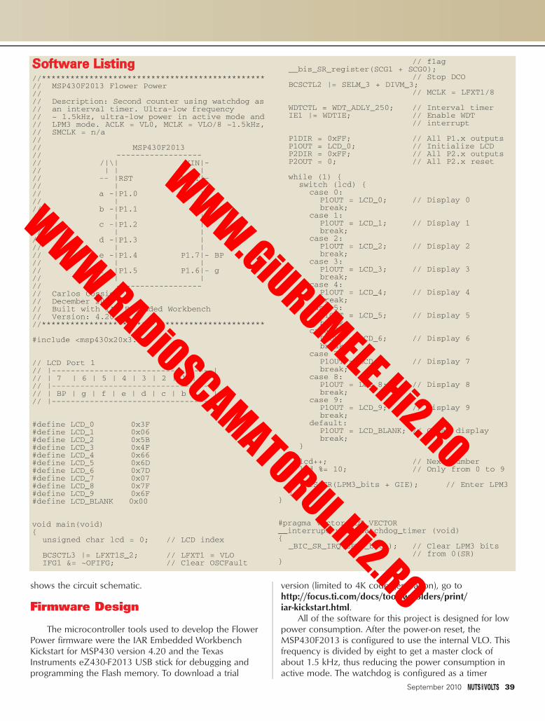
shows the circuit schematic.
Firmware Design
The microcontroller tools used to develop the FlowerPower firmware were the IAR Embedded WorkbenchKickstart for MSP430 version 4.20 and the TexasInstruments eZ430-F2013 USB stick for debugging andprogramming the Flash memory. To download a trial
version (limited to 4K code generation), go tohttp://focus.ti.com/docs/toolsw/folders/print/iar-kickstart.html.
All of the software for this project is designed for lowpower consumption. After the power-on reset, theMSP430F2013 is configured to use the internal VLO. Thisfrequency is divided by eight to get a master clock ofabout 1.5 kHz, thus reducing the power consumption inactive mode. The watchdog is configured as a timer
September 2010 39
Software Listing//***********************************************// MSP430F2013 Flower Power//// Description: Second counter using watchdog as// an interval timer. Ultra-low frequency // ~ 1.5kHz, ultra-low power in active mode and // LPM3 mode. ACLK = VL0, MCLK = VLO/8 ~1.5kHz, // SMCLK = n/a//// MSP430F2013// ------------------// /|\| XIN|-// | | |// -- |RST XOUT|-// | |// a -|P1.0 |// | |// b -|P1.1 |// | |// c -|P1.2 |// | |// d -|P1.3 |// | |// e -|P1.4 P1.7|- BP// | |// f -|P1.5 P1.6|- g// | |// ------------------// Carlos Cossio// December 2009// Built with IAR Embedded Workbench // Version: 4.20//***********************************************
#include <msp430x20x3.h>
// LCD Port 1// |----------------------------------|// | 7 | 6 | 5 | 4 | 3 | 2 | 1 | 0 |// |----------------------------------|// | BP | g | f | e | d | c | b | a |// |----------------------------------
#define LCD_0 0x3F#define LCD_1 0x06#define LCD_2 0x5B#define LCD_3 0x4F#define LCD_4 0x66#define LCD_5 0x6D#define LCD_6 0x7D#define LCD_7 0x07#define LCD_8 0x7F#define LCD_9 0x6F#define LCD_BLANK 0x00
void main(void){
unsigned char lcd = 0; // LCD index
BCSCTL3 |= LFXT1S_2; // LFXT1 = VLOIFG1 &= ~OFIFG; // Clear OSCFault
// flag__bis_SR_register(SCG1 + SCG0);
// Stop DCOBCSCTL2 |= SELM_3 + DIVM_3;
// MCLK = LFXT1/8
WDTCTL = WDT_ADLY_250; // Interval timerIE1 |= WDTIE; // Enable WDT
// interrupt
P1DIR = 0xFF; // All P1.x outputsP1OUT = LCD_0; // Initialize LCDP2DIR = 0xFF; // All P2.x outputsP2OUT = 0; // All P2.x reset
while (1) { switch (lcd) {
case 0:P1OUT = LCD_0; // Display 0break;
case 1:P1OUT = LCD_1; // Display 1break;
case 2:P1OUT = LCD_2; // Display 2break;
case 3:P1OUT = LCD_3; // Display 3break;
case 4:P1OUT = LCD_4; // Display 4break;
case 5:P1OUT = LCD_5; // Display 5break;
case 6:P1OUT = LCD_6; // Display 6break;
case 7:P1OUT = LCD_7; // Display 7break;
case 8:P1OUT = LCD_8; // Display 8break;
case 9:P1OUT = LCD_9; // Display 9break;
default:P1OUT = LCD_BLANK; // Clear displaybreak;
}
lcd++; // Next numberlcd %= 10; // Only from 0 to 9
_BIS_SR(LPM3_bits + GIE); // Enter LPM3}
}
#pragma vector=WDT_VECTOR__interrupt void watchdog_timer (void){
_BIC_SR_IRQ(LPM3_bits); // Clear LPM3 bits // from 0(SR)
}
Cossio - Flower Power.qxd 8/2/2010 2:25 PM Page 39
WWW.GiURUMELE.Hi2.RO
WWW.RADiOSCAMATORUL.Hi2.RO
interval to wake up the microcontroller approximatelyevery second, so most of the microcontroller’s time is
spent in Low Power Mode 3 (LPM3)which reduces the powerconsumption even further.
When the MSP430F2013 wakesup, it displays the next counter valuefrom zero to nine in the LCD andgoes to sleep again. This process isendless.
Next Steps
So, now you know how topower an ultra-low powermicrocontroller, by using thebioelectricity supplied by the plants.Unfortunately, since it’s necessaryto connect several potted plantstogether in series to get enoughenergy to activate themicrocontroller, this reduces itspractical use on a grand scale.The minimum voltage necessaryto activate a transistor in thecurrent CMOS technology isapproximately 0.7 volts. However,thanks to new developments inenergy harvesting technology, a newgeneration of oscillator circuits areemerging that are able to run from0.3 volts.
Since the oscillator is the mainbuilding block of a charge pump, itmay soon be possible to design acircuit able to store that tiny amountof energy for later use. It would thenbe possible to power an ultra-lowpower microcontroller with just oneplant instead of several. Now, thatwould be a novel type of greenenergy! NV
40 September 2010
Carlos Cossio can be reached [email protected].
AUTHOR’S NOTEThe project described in this article was awarded the
third prize in the international MSP430 Ultra-Low PowerDesign Challenge 2010 sponsored by Texas Instruments.If you’d like to see a video of the winning project, pointyour browser to www.designmsp430.com/displayVideo.aspx?id=29e378ef-e65b-4e79-8dfa-91dc8e84dbe3.
RESOURCESMSP430x20x1, MSP430x20x2, MSP430x20x3
Mixed Signal Microcontroller (Rev. D)Texas Instruments, 2007
MSP430x2xx Family User’s Guide (Rev. E)Texas Instruments, 2008
Ultra-Low Voltage Nanoelectronics Powered Directly andSolely from a Tree, Carlton Himes, Eric Carlson, Ryan J.
Ricchiuti, Brian P. Otis, Babak A. Parviz, IEEE Transactions on Nanotechnology, 2009
I would like to thank Sonia Riveirofor her assistance with this article.
Cossio - Flower Power.qxd 8/2/2010 2:25 PM Page 40
WWW.GiURUMELE.Hi2.RO
WWW.RADiOSCAMATORUL.Hi2.RO

MANUFACTURERS - We Purchase EXCESS INVENTORIES... Call, Write, E-MAIL or Fax YOUR LIST.
NO MINIMUM ORDER • All Orders Can Be Charged to Visa, Mastercard, American Express or Discover • Checks and Money Orders Accepted by Mail •Orders Delivered in the State of California must include California State Sales Tax • NO C.O.D • Shipping and Handling $7.00 for the 48 Continental UnitedStates - ALL OTHERS including Alaska, Hawaii, P.R. and Canada Must Pay Full Shipping • Quantities Limited • Prices Subject to change without notice.
MAIL ORDERS TO:ALL ELECTRONICS CORP.
14928 OXNARD ST., VAN NUYS, CA 91411-2610
FAX (818) 781-2653 • INFO (818) 904-0524
E-MAIL [email protected]
Shop ON-LINE www.allelectronics.comORDER TOLL FREE 1-800-826-5432
QUALITY Parts FAST Shipping
DISCOUNT PricingCALL, WRITE, FAX or E-MAILfor a FREE 96 page catalog.
Outside the U.S.A. send $3.00 postage.
ALLELECTRONICSALLELECTRONICSC O R P O R A T I O N
SOLAR CELLOutput: approximately 3 Volts @ 40 mA. 60mm square x 2.5mm thick epoxy-encapsul-ated silicon photovoltaic cell. Solid, almost-unbreakable module with sol-derable foil strips on backside. Ideal for solar-powered battery chargers and other projects.CAT# SPL-61
$375each100 for $3.25 each
$2595
150W INVERTER
DOOR LOCK ACTUATOR
12 VDC 58 RPM MINI-MOTOR12Vdc gearhead motor.58RPM, @ 12Vdc,20mA (no-load). 12mm diameter x 35mmlong. Solder-lug terminals. 2mm diameter x6mm long flatted shaft. CAT# DCM-318 $1295
each
Converts vehicle's 12 volt power to household 110 volt power. Dual 110 volt outlets. Also has 12 volt outlet, iPod quick charge adapter, USB portto power and recharge cell phones, digitalcameras and mp3 players. CAT# INV-150 each
21MM PIEZO ELEMENT50mm wire leads.CAT# PE-56
$100each 10 for 85¢ each
VIBRATING MINI-MOTOR
$125each
Designed to vibrate in cell phones or pagers, this tiny 1.5-4.5Vdc motor has an offset weighted shaft. Overalllength, including terminals and shaft, 18mm.Body is 4.5mm x 5.5mm x 11mm long. Flat,surface-mount solder tabs.CAT# DCM-382
10 for $1.10 each • 100 for 95¢ each
12 Vdc motor-drive actuator for auto-motive door locks. Nylon plunger moves 0.75". Push or pull, depending on polarity. Includes mounting hardware anda 10" metal extension rod which fits throughthe hole in the end of the plunger. Overalldimensions of actuator assembly (retracted):8.42" x 2.35" x 1.15". Rubber boot protectsagainst moisture and dust. Pigtail leads.CAT# DLA-1
$550each
12VDC 750MA POWER SUPPLYLiteOn#PA-1090-1.2.5mm coax power plug, center +. Detachable, 2-conductor power cord. cULus, CE.CAT# PS-12751 $850
each40 for $7.75 each
NIMH AA CELL, 2600 MAHHigh energy, high capacity recharge-able NiMH battery. 1.2V. 2600mAH. 14.5mm diameter x 50mm long. CAT# NMH-AA
$295each
8 for $2.75 each60 for $2.40 each
HIGH-POWER COOL-WHITELED EMITTER
40 CHARACTER X 2 LINE LCD W/ LED BACKLIGHT#UMSH-3077JD-YG. STN Transflective LCD. Yellow-green LED backlight. Module size: 182 x 33.5 x13.6mm. Viewing area: 154.4 x 16.5mm.Character size: 3.2 x 5.55mm CAT# LCD-3077
10 for $7.50 each$850
each
Luxeon Lumiled(TM) LXHL-PW01.Cool-white, Lambertian emitter. 3.42Vdc (typical), 350mA. 30.6 Lumens. 8mm diameter x 6mm high.Surface-mount leads. Spec sheet available.CAT# LED-145
$285each
10 for $2.75 each100 for $2.55 each250 for $2.20 each
2.25A SWITCHING POWERSUPPLY, REGULATED Perfect for small appliances and breadboard projects. Provides 3 / 4.5 / 5 / 6 / 7.5 / 9 or 12 Vdc, and it's regulated, so the voltage doesn't fluctuate when the load varies. Includes a set of seven of the most popular power connectors. CAT# PS-22 $2195
each
PIERCING HIGH-DECIBELINSTANT ALARMS, 4-PACK
Instantly alarm four windows or doors.Piercing ultra decibel alarm. Installs in sec-onds. Just peel and stick. No tools or wiringneeded. Includes: 4 x Instant Perfect Windowand Door Alarms. Each unit has an On/Offswitch. Batteries included.CAT# ALM-420 $850
per pack
September 2010 41
Full Page.qxd 8/2/2010 8:57 PM Page 41
WWW.GiURUMELE.Hi2.RO
WWW.RADiOSCAMATORUL.Hi2.RO

It was perplexing. I was trying to repair a fire alarmsystem in a school. The air outside was warm andhumid, but inside it was air-conditioned. A light on thefire alarm panel indicated “ground fault” somewhere in
the wiring in the building, but my digital ohmmeterclaimed there wasn’t any continuity to ground. How was Igoing to find this conductive path if my ohmmetercouldn’t detect it?
After trying several means of detection, I decided togive my ohmmeter a voltage boost. A couple of 12 voltbatteries from my service stock in series with the negativelead of my ohmmeter did that. Now, using about 27 voltsof oomph to drive the current of my ohmmeter, itindicated the continuity and I could follow the wiring tofind the ground fault. It turned out to be water condensedon a fire alarm pull station in the gym. The humidity fromthe warm air leaking from the outside through the wallwas condensing on the cool air-conditioned switch on theinside. So, why didn’t my ohmmeter show any continuityuntil it got that extra voltage boost from the batteries?
I was dealing with a voltage based non-linearresistance; a resistance that changes value as voltagechanges so current doesn’t seem to follow Ohm’s Law.The resistance of the water condensation was almostinfinite for the three volt internal battery of my ohmmeter,but the resistance dropped down to a few thousand ohmswhen the voltage was increased by the addition of theextra batteries (see Figure 1).
Insulation Tester
What I had come up with was not a new invention. Itwas a test instrument used by electricians called aninsulation tester which is an ohmmeter with a high
●●●●
42 September 2010
Resis
tance
3 Volt Battery Ohm Meter -Measures a Very High Resistance
3 Volts from the Internal Batteryof the Ohm Meter Plus the 36 Voltsof the Added Batteries -Measures a Lower Resistance
Non-LinearResistanceof BadInsulation
3 Volts 9 Volts 39 Volts
Voltage
Typical Non-Linear Resistance Curve
■ FIGURE 1. This chart shows how a non-linear resistancegoes down as voltage goes up. The voltage shown herewould be the battery voltage of the ohmmeter.
BUILD A LOW VOLTAGE
INSULATIONTESTERGround faults are a curse to firealarm systems. Even a small amountof current leaking to groundsomewhere in the building can cause an unscheduled fire drill.Worse yet, a second ground faultsomewhere else in the building canshort out the whole system.That’swhy all fire alarm systems haveground fault detection circuits, so theattached building wiring can be fixedbefore there is a fire.
BYDOUGLAS
KRANTZ
Krantz - Low Voltage Insulation Tester.qxd 8/3/2010 11:42 AM Page 42
WWW.GiURUMELE.Hi2.RO
WWW.RADiOSCAMATORUL.Hi2.RO

voltage internal battery. Inthe case of the meterassembly I had come upwith, the voltage of all thebatteries combined wasabout 27 volts: the threevolts of the battery insidemy ohmmeter, plus the 24volts from the two added12 volt batteries.
I really needed to haveone of these testers to carry around with me for this kindof troubleshooting, but nothing was available that I couldafford. I would have to craft my own. At first, I tried thedigital ohmmeter that I normally used for troubleshooting,and put batteries in series with its leads. When I tested theresistance of the same type of trouble I had encountered— water on the surface of the insulator — the numbers onthe display kept changing and were hard to read. It turnedout that water is transient so the resistance of water keepschanging slightly up and down. I am a troubleshooter andI wanted to concentrate on troubleshooting, not spendtime trying to read the meter, so using the digital meterwasn’t going to work for me.
Next, I tried an old fashioned analog meter that I hadlying around. With the extra batteries, the numbers on theohm scale weren’t accurate anymore, but I could dealwith that. At least the needle on the meter didn’t moveback and forth very much, and I could get a somewhatstable reading. Then, I thought about voltage. In general,fire alarm systems use 24 volts and I needed to test thewiring at voltages that were higher than that. The 36 voltsfrom four nine-volt batteries seemed to be a reasonablevoltage, and the four batteries could be strapped to the
back of the meter, so that’s what I used.The one real worry was that the meter movement
would be damaged with excessive current when the leadsof the meter — along with the added batteries — wereshorted together. To prevent this meltdown, a limitingresistor of a yet unknown value would have to be insertedin series with the added batteries (see Figures 7 and 8).Just to make it easier to calibrate the meter, the value ofthis resistor would have to be chosen so the meter wouldread zero ohms when the leads were shorted together —like a normal ohmmeter.
Construction
Start out with the battery clips. Solder the battery clipwires red to black so the batteries are in series. Just don’tcut the leads short. The extra wire will allow for flexingwhen the batteries wear out and need to be replaced.Individually tape or heat shrink the connections.
For neatness and organization, tape all four batteriestogether. Connect the clips to the batteries and use tapeto make a pigtail of the loose battery clip leads (seeFigure 7 again).
September 2010 43
OhmMeter
AddedLimitingResistor
Added36 VoltBoost
Battery
NegativeLead
PositiveLead
+ -
-
+
+
InternalLimitingResistor
InternalBattery
-
ResistanceBeingTested
■ FIGURE 4. Simplifiedschematic of an ohmmetershowing the addition of the 36 volt batteriesand a limitingresistor.
■ FIGURE 3. Batteries, battery clips,and resistor needed for the project.
■ FIGURE 2. Inexpensive multimeter.
Non-Linear ResistanceWire insulation doesn’t have to be smoking
before it’s considered bad; it can be slowly breaking down. According to Megger — one ofthe many manufacturers of insulation testers —causes of insulation breakdown can be electricalstress, mechanical stress, chemical attacks, thermal stress, and environmental contaminations(water condensing on the insulated side of aswitch, for instance).
All of these irritants cause voltage-based non-linear resistance — at least at voltages belowthe smoking stage. The low voltages common todigital ohmmeters show high resistance becausethe low voltage isn’t enough to drive the currentthrough the insulation. The higher voltage in aninsulation tester, on the other hand, is enough todrive the current through the partially broken-down insulation, and the measured resistance islower. (Refer to Figure 1.)
Krantz - Low Voltage Insulation Tester.qxd 8/3/2010 2:34 PM Page 43
WWW.GiURUMELE.Hi2.RO
WWW.RADiOSCAMATORUL.Hi2.RO

Calculating the Value of theLimiting Resistor
The limiting resistor (see Figure 4) makes up for theextra voltage of the batteries. That way, when the test
leads are shorted together the ohmmeter will readzero ohms (like a normal ohmmeter). Beforeproceeding, make sure the ohmmeter is set to thehighest ohm scale: RX100 or greater. This is the scalethat is going to be used for all future measurements.
There are two methods of determining the valueof the limiting resistor. One is to measure the currentthat the ohmmeter uses to measure zero ohms, andthe other is to experiment to find the value. Bothmethods work.
Current Method
Measure the current generated by the ohmmeterby placing a digital milliamp meter in series (seeFigure 6). The current measured on the ammeter isthe current that the ohmmeter calls zero ohms.
My meter requires approximately 3 milliamps toindicate zero ohms. The Ohm’s Law formula (E / I = R) works out to be the 36 volt batteries
divided by the .003 amps (3 milliamps) generated by theohmmeter which equals 12,000 ohms for the limitingresistor.
You can confirm this method has found the propervalue for the limiting resistor by temporarily inserting theresistor into the meter circuit as shown in Figures 7 and 8.
44 September 2010
■ FIGURE 5. Solderedtest lead, battery clips,and resistor.
R X 100
+
-
Ohm
mAmps
-
mAmp
Meter Settings:Zero Ohm AdjustRx100 Scale
+
Ammeter Ohmmeter
■ FIGURE 7. Meter, batteries,battery clips, and the shorted test leads.
■ FIGURE 6. Setup to measure the current of theohmmeter.
PARTS LIST QTY DESCRIPTION/PART NUMBER
1 Meter* – Sperry Instruments HSP10 multitester from Home Depot or equivalent
1 Resistor Kit** – Digi-Key RS125-ND – 1/4W(.25W), 5%, carbon film, axial lead, 365 pieces (5ea of 1.0 ~ 1.0M ohms)
4 Nine-volt batteries4 Clips with leads for the batteries – Digi-Key
377-1549-ND or equivalentElectrical tapeSolder and soldering ironChart paper to make a cross reference table
Cost: Meter - about $18Mixed Resistor Kit – about $15Batteries, Clips for the Batteries & Miscellaneous– about $10Plus Shipping
*If you have an old analog meter that isn’t being usedfor anything anymore, you can use it instead ofpurchasing a new one. All the meter needs is its internalbattery and its test leads.** Most of the resistors in the kit won’t be used exceptto calibrate the meter, and the resistors can be reused infuture projects. If you have a variety of resistors already,the resistor kit isn’t needed.
Krantz - Low Voltage Insulation Tester.qxd 8/3/2010 11:43 AM Page 44
WWW.GiURUMELE.Hi2.RO
WWW.RADiOSCAMATORUL.Hi2.RO

If the meter can’t be zeroed with the ohm adjustment onthe meter, the resistance of the limiting resistor may haveto be adjusted using the experimental method.
Experimental Method
Center the ohms adjustment knob on the meter. Thiswill allow the knob to be adjusted either way at a latertime. Start out with a 20,000 ohm limiting resistor andinsert the resistor into the circuit (refer again to Figures 7and 8). The needle probably won’t indicate zero ohms, sotry a resistor whose value is a little different. Remember, alower value of resistance will move the needle to the right.
Look at the ohmmeter again. Keep changing the valueof the limiting resistor until the needle is close to zeroohms. This will become the limiting resistor. The ohmsadjustment on the meter can be used to touch up theneedle to point at zero ohms.
Cutting the Negative Test Lead
Use the black probe wire that comes with themeter; it already has connectors. Cut it about seveninches from the end that goes into the meter, and stripthe loose ends (see Figure 5). Seven inches should beenough to secure the soldered end to the batteries andstill plug into the meter.
Solder this short lead to one end of the limitingresistor and the other end of the resistor to the positivebattery clip lead. Tape or heat shrink the connections.
Solder the stripped end of the long probe wire tothe negative battery clip lead (see Figure 5). Tape orheat shrink this connection.
Final Assembly
Tape the limiting resistor and both soldered blacktest lead ends to the pigtail to give all solderconnections mechanical strength. This meter is going torattle around with the other tools in the tool box, and
September 2010 45
Worst Ground Fault
They tried to use a regular ohmmeter to find theground fault. I watched them. Right after sunset, whilethere was enough light to see the cityscape and the litstreetlights, I stood on top of the hill overlooking Duluth,MN. They were power company linemen and they had justdriven up to a three-phase, 13,800 volt power pole acrossthe street from a TV station which was off the air becauseof a power blackout. The lineman in the cherry picker usedhis ohmmeter to check for shorts in the underground line. A nine-volt battery won’t find much of a problem on a13,800 volt power line, and that’s what was found — notmuch of a problem. Well, they put in a new fuse at the topof the pole, turned on the switch, and with the sound of ashotgun and a 15 foot shower of sparks, the fuse blew. Allof the city of Duluth went black. There really was a short. Aproper insulation tester using a 15,000 volt power sourcewould have detected the problem.
CALIBRATING A STANDARDOHMMETER
(VOM, OR VOLT-OHM-MILLIAMP METER)
There are only two things to keep in mind whencalibrating an analog ohmmeter: the two ends of the scale.The needle points to the left showing infinite ohms (themeter is at rest) when the probes aren’t touching anything,or all the way to the right showing zero ohms (maximummeasuring current) when the probes are shorted together.When the two ends are calibrated, the numbers inbetween take care of themselves. Take a look at the figure.
Step one: Place the meter “at rest” by separating theprobes. Turn the mechanical adjustment screw either wayto adjust the needle to show infinite ohms.
Step two: Set the selection switch to the desiredresistance scale: RX1 (resistance times 1), RX10 (times 10),or RX100 (times 100). In the case of the insulation tester,always use the RX100 scale. Now, short the test leadstogether. Turn the ohms adjustment knob one way or theother until the needle is exactly over the zero ohms on themeter faceplate.
The meter is now calibrated. This calibrationadjustment should be done each time the meter is used tomeasure resistance, or each time the selection switch is setto a different RX position.
Zero Ohms Adjustment KnobUse to adjust the needle to zero ohms.
R X 100
+
-
OhmSelection SwitchSet to the Rx100 Scale.
Shorted Together
Mechanical Adjustment Screw
■ Method for calibrating an analog ohmmeter.
9 Volt
-+
9 Volt
-+
9 Volt
-+
9 Volt
-+
Set the ohm calibration knob on the meter to the middle position.
R X 100
+
-
Ohm
Select the value of the limiting resistor for full deflection of the meter when the leads are shorted together.
Set meter to the Rx100 Scale.
■ FIGURE 8. Electro-mechanical layout of all componentsin the insulation tester.
Krantz - Low Voltage Insulation Tester.qxd 8/3/2010 11:43 AM Page 45
WWW.GiURUMELE.Hi2.RO
WWW.RADiOSCAMATORUL.Hi2.RO

the solderconnectionsneed to beprotected sothey do notmove andbreak.
This assembly of the batteries and pigtail can be putin a plastic chassis box and then attached to the meter.Personally, I never found a commercial box that was bothbig enough to house the whole battery assembly and
small enough to fit on the back of the meter, so I just usedcopious amounts of electrical tape to attach the assemblyto the back of the meter.
Ohmmeter
Ohmmeters use Ohm’s Law (Resistance = Voltage ÷Amperage) to figure out the resistance of the device beingmeasured. The voltage is provided by the meter’s internalbattery and remains relatively constant. The amperage isthe current through the device being tested; in this case,insulation on wire.
On an analog meter (a meter that has a mechanicalmeter movement), the needle actually shows the amountof current through the device. It moves to the right as theresistance goes down and the current goes up. When the
46 September 2010
100 Ohms
200 Ohms
470 Ohms
1000 Ohms
2 kOhms
4.7 kOhms
10 kOhms
20 kOhms
47 kOhms
100 kOhms
200 kOhms
470 kOhms
1 Mohms
2 Mohms
.05
.1
.25
.5
1
2.5
5
10
25
50
250
500Barely moves themeter needle
100
ResistanceMeter Readings
Insulation Meter Cross Reference
■ FIGURE 9.Cross referencechart.
microCAM
SOMO-14D
UNIQUE PRODUCTS + SUPPORT!
1-888-772-3544
SPI Bus Analyzer
.NET Board
Compact compressed-serial output
camera module for any host system.
JPEG OmniVision™ CMOS VGA
color camera for embedded imaging.
uCAM TTL or 232 $58
6 in 1 Signal Generator
EMC Spectrum Analyzers
2-ch 10-bit 2MHz scope/spectrum-
analyzer, 3MHz 8-bit wfm gen; 16 x
I/O; Network Analyzer; Noise
Generator; PWM. Windows/Linux
/Mac compatible! USB-powered,
great for toolbox, education, etc.
CGR-101™ $199
PC-based SPI protocol exerciser/analyzer
for standard/non-standard interfaces
<50 Mbps. Monitor serial traffic;
test/debug parameters & custom
variations for embedded system/IC
dev’t and validation. $739
CleverScope - 100MHz Scope,
Spectrum/Logic Analyzer.for PCs. 4 or
8 M/sample storage! Easy A-B, math,
& filters! 2 ch x 10, 12 or 14-bit, 8 dig.
I/P. (Opt. 0-10 MHz SigGen. - $299)
CS328A-4 (4MS Buffer) $1259
CS328A-8 (8MS Buffer) $1474
60 - 300MHz DSOsMixed-Signal Scope7 in 1 USB Scope
Handheld Palm PC-based 2.7GHz
Spectrum Analyzer. Multiple
sweep settings – store wfms,
set-ups, etc. Use WiFi PC for
email, reports, calculations.
PSA2701T $1989
Six signal generators in one small,
USB package: AWG, Event/freq,
Pulse, Pattern, Noise. 130MS/s 0.1Hz
to 3MHz (10MHz sine). Open source
s/w runs on Windows, Linux, Mac.
WGM-201 $227
14-pin Tiny Audio-Sound Module
plays back pre-stored audio files
(voice and music) from micro-
SD card - ideal for embedded
audio output.
SOMO-14D $25
60/100/200/300MHz 2 ch, 2GS/s
DSO 2000 wfm/s refresh rate. High
quality, ultra Compact Design with
small footprint. Totally new price.
DS1052E $399
• • thru • •
DS1302CA $1995FreeCase!
FEZ Domino (Arduino) & FEZ Mini (BS2)
are tiny open source boards using
USBizi chipset: USB host + SD interface,
NETMF (.NET). 72Mhz NXP ARM with
runtime debug (bkpts, stepping, etc.)
Use Visual C#. Starter Kits $98
360 697-3472 voice
360 697-7717 fax
Pioneer Hill Software
24460 Mason Rd
Poulsbo WA 98370PHS
Turn Your PC into a Real-Time
Audio Spectrum Analyzer
FeaturesFFT to 1048576 pts
24 bit, 192kHz
1/96 Octave
Dual Channel
3-D Surface Plot
Spectrogram Plot
Digital Filtering
Signal Generation
RT-60, Leq, Delay
THD, IMD, SNR
DDE, Logging
Vibration Analysis
SpectraPLUS 5.0FFT Spectral Analysis System
Download 30 day FREE trial!
www.spectraplus.com
Starting at $295
IDEAS FOR THE FUTURESwitch contacts get dirty and one way of making sure dirty contacts don’tcause a problem is to solder the switch contacts. Of course, this will dedicatethe meter and prevent it from ever being used for anything else.
Replacing the internal batteries when the case is taped together can be a realpain. One idea is to remove the battery and replace it with a soldered-injumper. Then, there is no internal battery to replace.
For those who have real energy, the meter can be backwards engineered andthe internal resistors recalculated so the meter can be used on all scales(RX1, RX10, RX100). The resistance scale on the face of the meter will still beoff so a cross reference table will be needed, but the meter will be a littlemore versatile.
Krantz - Low Voltage Insulation Tester.qxd 8/3/2010 11:44 AM Page 46
WWW.GiURUMELE.Hi2.RO
WWW.RADiOSCAMATORUL.Hi2.RO

resistance reaches zero ohms (the leads shorted together),the current through the meter is at maximum and theneedle is all the way to the right. The numbers on the faceof the meter make up a conversion table or crossreference table. It converts the current flowing through thedevice being measured to the resistance of that device.The numbers on the meter’s face are then multiplied bythe switch setting of RX1, RX10, or RX100 to calculate thetotal resistance being measured. A digital ohmmeter does
this cross reference automatically; it converts the testcurrent to resistance to give a direct reading on the display.
Creating a Cross Reference Table
With the added batteries and limiting resistor, thenumbers on the face of the meter are no longer factorycalibrated. For instance, a resistor under test with myohmmeter may show 25 on the ohms scale. Normally, this
September 2010 47
Try This At HomeWill the insulation tester detect
problems that a regular digital ohmmeterwon’t? Find out! Try this on one type ofinsulation problem: water on the wiring.
Spill a little tap water on a cleancounter. The puddle should be about oneor two inches in diameter. Just don’t addany salt or other contaminants to thewater. Measure the resistance of thewater using a regular digital ohmmeter,keeping the tips of the probes at least1/2 inch apart as shown in Figure A.Write down the resistance indicated onthe ohmmeter. Some digital ohmmeterswill measure infinite resistance, and if that is measured,that’s what should be written down. As a control, find aresistor of about the same value and measure itsresistance. Write down that measurement.
Use the insulation tester to measure the same water.Look up the actual resistance on the cross reference tableand write down that resistance. The resistance measured
by the digital ohmmeter and theresistance measured by the insulationtester will be quite different.
To check the accuracy of theinsulation tester, use it to measure theresistance of the control resistor. (Makesure to keep your fingers off the leadsbecause they will corrupt the readings.)Look up the true resistance of theresistor on the cross reference table.
The measured resistance of thecontrol resistor should be about thesame whether the digital ohmmeter isused or the insulation tester is used.Water, on the other hand, has a voltage-based, non-linear resistance. That helps
explain why the insulation tester — with its high voltagebattery — detects a definite problem the water on theinsulation, while the digital ohmmeter — with its lowvoltage battery — shows uncertain readings.
If you really want to have fun with this experiment, tryshaking a bunch of salt into the puddle of water andmeasure the water’s resistance again with both meters.
■ FIGURE A. Testing the resistanceof a puddle of water. The probeshere are about 1/2 inch apart andboth of them are in the water.
Krantz - Low Voltage Insulation Tester.qxd 8/3/2010 8:56 PM Page 47
WWW.GiURUMELE.Hi2.RO
WWW.RADiOSCAMATORUL.Hi2.RO

number would be multiplied by 100 (RX100) to represent2,500 ohms. My meter has been modified, so using across reference table I see that this resistor is a 47,000ohm resistor.
The question: “How do I obtain this cross referencetable?” The answer: “Make it.” Each meter is different, soeach meter requires its own chart.
To make the chart, choose the values for resistorsshown in Figure 9. Then, measure the resistors one at atime, making sure to zero the meter between eachmeasurement. Write down the meter reading for each
resistor next to its value. When the table is filled out, it isready to be used as a cross reference chart.
Just remember to use the RX100 setting on the meterfor all resistance measurements. Also, keep in mind thatthe meter is now applying over 36 volts to whatever isbeing tested, so make sure there aren’t any delicateelectronics in the circuit being measured.
Conclusion
This modified meter is no longer a regular ohmmeter;it’s an “insulation tester.” With ameter like this, I have found wireswhere the insulation was partiallyrubbed off; I found a leaky lightningarrestor; I found wire to wire faultsinside walls; and I found manyinstances of water damage. Any faultor conduction that a fire alarm paneldetects with its ground faultdetection circuit I can now find withthis insulation tester.
My old inexpensive analog meterhas a use again, and I can easily findwiring faults in a building that can’tbe found with a regular ohmmeter.NV
DOWNLOAD the HIDmaker FS Test Drive today!
www.TraceSystemsInc.com
301-262-0300
NEW! HIDmaker FS for Full Speed FLASH PIC18F4550
Creates complete PC and Peripheralprograms that talk to each other overUSB. Ready to compile and run!
• Large data Reports• 64,000 bytes/sec per Interface• Easily creates devices with multiple
Interfaces, even multiple Identities!• Automatically does MULTITASKING• Makes standard or special USB HID
devices
NEW! “Developers Guide for USB HIDPeripherals” shows you how to makedevices for special requirements.
Both PC and Peripheral programsunderstand your data items (even oddsized ones), and give you convenientvariables to handle them.
PIC18F Compilers: PICBASIC Pro,MPASM, C18, Hi-Tech C.
PIC16C Compilers: PICBASIC Pro,MPASM, Hi-Tech C, CCS C.
PC Compilers: Delphi, C++ Builder,Visual Basic 6.
HIDmaker FS Combo: Only $599.95
REFERENCESEC&M: Insulation
Resistance Testing: How and Why?; John A. DeDad
http://ecmweb.com/mag/electric_insulation_resistance_testing_3/
Megger: A Guide To DiagnosticInsulation Testing Above 1 kV
www.biddlemegger.com/biddle/5kV-DiagnosticTesting.pdf
Megger: A Stitch In Timewww.omnicontrols.com/
articles/Megger-A_Stich_in_Time.pdf
Princeton University:Supplemental Instructions:
XP – DC Circuit – Non-Linear Resistor
www.princeton.edu/~gschmidt/Rider/Lab200/nonlinear_resist
ance/nonlinearresistance01.htm
Hyperphysics: Moving Coil Metershttp://hyperphysics.
phy-astr.gsu.edu/hbase/magnetic/movcoil.html
48 September 2010
Krantz - Low Voltage Insulation Tester.qxd 8/3/2010 2:42 PM Page 48
WWW.GiURUMELE.Hi2.RO
WWW.RADiOSCAMATORUL.Hi2.RO

September 2010 49
Page 49 Sep10.qxd 8/2/2010 8:23 PM Page 49
WWW.GiURUMELE.Hi2.RO
WWW.RADiOSCAMATORUL.Hi2.RO

With Joe Grand
50 September 2010
The Projects of
Virtual SeaAdventure
Prototype This, an engineering entertainmentprogram on Discovery Channel, offered aview into the real-life process of designingand building unique prototypes. In this 13episode series which was filmed over thecourse of 18 months and aired starting inOctober 2008, we set out to tackle theproblems of today by creating crazy, one-of-a-kind inventions of tomorrow. I was theteam’s electrical engineer and hardwarehacker, and shared the screen with ZozBrooks, a roboticist and software designerspecializing in human-machine interaction;Mike North, a material scientist andmechanical engineer; and Terry Sandin, aspecial effects veteran. We were challenged tobuild things that had never been done before,looked cool on TV, and could be completedwithin the extremely tight financial and timeconstraints of television production. It was afantastic adventure and great experience tosay the least! This quarterly series of articles will cover theelectronic aspects of some of my favoriteprojects from the show. My hope is that youwill be inspired, learn something new, or usemy work as a building block for your ownopen source project. Let’s begin!
What the Heck is a Virtual Sea Adventure!?
The Virtual Sea Adventure episode followed theprocess of our most arcane invention in which we set outto build a remotely-operated virtual scuba divingexperience. The goal was to allow a scuba diver in SanFrancisco, for example, to feel like they are swimming withthe sharks in the Bahamas. We used an off-the-shelfSeaBotix (www.seabotix.com) LBV150SE ROV (RemotelyOperated Vehicle) controlled by the "player" using customcontrol circuitry. The ROV would send back high-definitionvideo that would be projected onto an underwater displaylocated directly in front of the player. All player-to-ROVand ROV-to-player communications would take place overa network. In theory, the player and ROV could belocated in two completely disparate locations anywhere inthe world. Sound crazy? It was. And, we only had a fewweeks to design, build, and test the whole thing!
This article focuses only on the magnetic positionsensor circuitry used by the player to control the ROV. Ifelt that it was one of the cooler aspects of the build andsomething that could be ported to lots of other hobbyistand robotics applications. For those who want to divedeeper (no pun intended!), the technical documentation I
THISPROTOTYPE Joe experiencing the Virtual Sea Adventure —
fully submerged in water and controlling theROV using magnetic position sensors.
Joe Grand is an electrical engineer, hardware hacker, and president of Grand Idea Studio, Inc. (www.grandideastudio.com), where he specializes in the invention, design, and licensing of consumer products and modules for electronicshobbyists. He can be reached at [email protected].
Grand - Virtual Sea Adventure Sep 10.qxd 8/3/2010 12:37 PM Page 50
WWW.GiURUMELE.Hi2.RO
WWW.RADiOSCAMATORUL.Hi2.RO
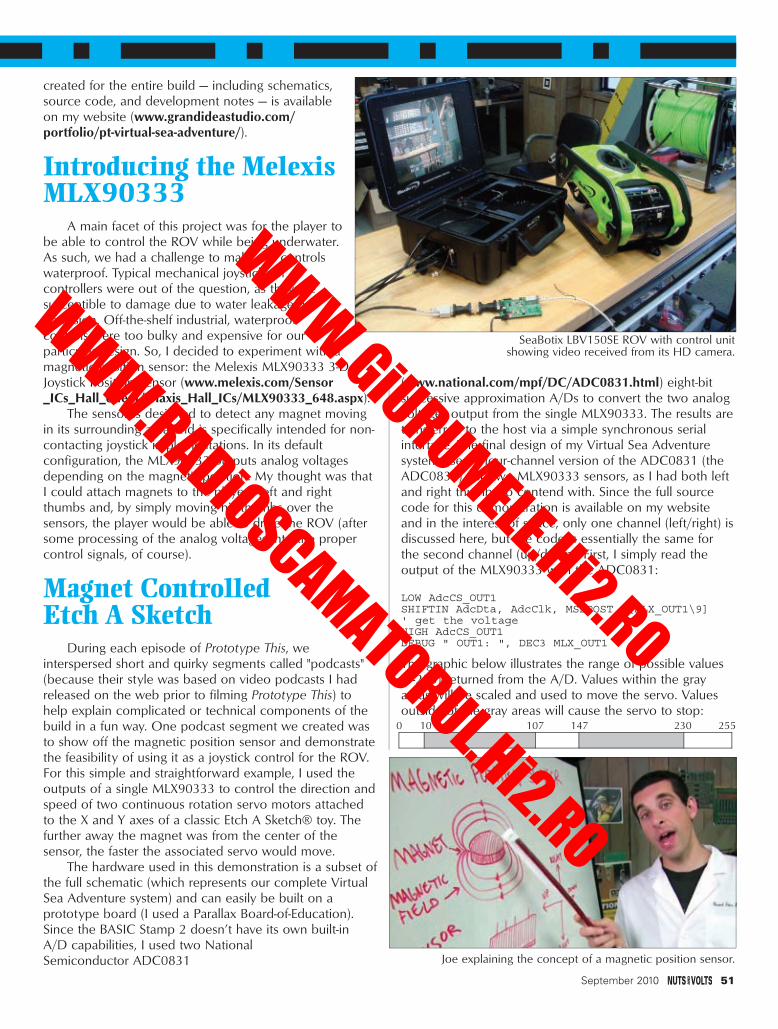
created for the entire build — including schematics,source code, and development notes — is availableon my website (www.grandideastudio.com/portfolio/pt-virtual-sea-adventure/).
Introducing the MelexisMLX90333
A main facet of this project was for the player tobe able to control the ROV while being underwater.As such, we had a challenge to make the controlswaterproof. Typical mechanical joysticks orcontrollers were out of the question, as they aresusceptible to damage due to water leakage orcorrosion. Off-the-shelf industrial, waterproofcontrols were too bulky and expensive for ourparticular design. So, I decided to experiment with amagnetic position sensor: the Melexis MLX90333 3-DJoystick Position Sensor (www.melexis.com/Sensor_ICs_Hall_effect/Triaxis_Hall_ICs/MLX90333_648.aspx).
The sensor is designed to detect any magnet movingin its surrounding area and is specifically intended for non-contacting joystick implementations. In its defaultconfiguration, the MLX90333 outputs analog voltagesdepending on the magnet's position. My thought was thatI could attach magnets to the player's left and rightthumbs and, by simply moving his thumbs over thesensors, the player would be able to drive the ROV (aftersome processing of the analog voltages into the propercontrol signals, of course).
Magnet Controlled Etch A Sketch
During each episode of Prototype This, weinterspersed short and quirky segments called "podcasts"(because their style was based on video podcasts I hadreleased on the web prior to filming Prototype This) tohelp explain complicated or technical components of thebuild in a fun way. One podcast segment we created wasto show off the magnetic position sensor and demonstratethe feasibility of using it as a joystick control for the ROV.For this simple and straightforward example, I used theoutputs of a single MLX90333 to control the direction andspeed of two continuous rotation servo motors attachedto the X and Y axes of a classic Etch A Sketch® toy. Thefurther away the magnet was from the center of thesensor, the faster the associated servo would move.
The hardware used in this demonstration is a subset ofthe full schematic (which represents our complete VirtualSea Adventure system) and can easily be built on aprototype board (I used a Parallax Board-of-Education).Since the BASIC Stamp 2 doesn’t have its own built-inA/D capabilities, I used two NationalSemiconductor ADC0831
(www.national.com/mpf/DC/ADC0831.html) eight-bitsuccessive approximation A/Ds to convert the two analogvoltages output from the single MLX90333. The results aretransferred to the host via a simple synchronous serialinterface. The final design of my Virtual Sea Adventuresystem used a four-channel version of the ADC0831 (theADC0834) and two MLX90333 sensors, as I had both leftand right thumbs to contend with. Since the full sourcecode for this demonstration is available on my websiteand in the interest of space, only one channel (left/right) isdiscussed here, but the code is essentially the same forthe second channel (up/down). First, I simply read theoutput of the MLX90333 with the ADC0831:
LOW AdcCS_OUT1SHIFTIN AdcDta, AdcClk, MSBPOST, [MLX_OUT1\9]' get the voltageHIGH AdcCS_OUT1DEBUG " OUT1: ", DEC3 MLX_OUT1
The graphic below illustrates the range of possible values(0-255) returned from the A/D. Values within the grayareas will be scaled and used to move the servo. Valuesoutside of the gray areas will cause the servo to stop:
September 2010 51
Joe explaining the concept of a magnetic position sensor.
SeaBotix LBV150SE ROV with control unit showing video received from its HD camera.
0 10 107 147 230 255
Grand - Virtual Sea Adventure Sep 10.qxd 8/3/2010 9:19 PM Page 51
WWW.GiURUMELE.Hi2.RO
WWW.RADiOSCAMATORUL.Hi2.RO

In my experiments with the sensor, I noticedthat values less than IDLE_LOW or greater thanIDLE_HIGH usually meant there was no magnetdetected. So, I’d check the returned value(MLX_OUT1) to make sure it was within range. Ialso checked to make sure that MLX_OUT1 wasoutside of my pre-defined deadband (set byDEADBAND_LOW and DEADBAND_HIGH) whichwas put in place to prevent jitter around the centerposition of the sensor.
IF (MLX_OUT1 < IDLE_LOW OR MLX_OUT1 >IDLE_HIGH OR (MLX_OUT1 > DEADBAND_LOW AND
MLX_OUT1 < DEADBAND_HIGH)) THEN result_x = 750 ‘ stop moving servo
Next, if the value of MLX_OUT1 is within thevalid (gray) area, we continue with the rest of theIF...ELSE statement:
ELSE ' there is a magnet in range, so let'sscale it and set the servo speed
IF (MLX_OUT1 >= IDLE_LOW AND MLX_OUT1 <= DEADBAND_LOW) THEN
DEBUG “ X: CW”result_x = ((MLX_OUT1 - IDLE_LOW) / 6)+ 730
ELSEIF (MLX_OUT1 >= DEADBAND_HIGH ANDMLX_OUT1 <= IDLE_HIGH) THEN
DEBUG “ X: CCW”result_x = ((MLX_OUT1 - DEADBAND_HIGH)/ 6) + 754
ENDIFDEBUG “ SERVO_X: “, DEC result_x, CR
ENDIF
The value of MLX_OUT1 determines the speed anddirection that the servo will move (for example, movingthe magnet left over the sensor would cause the servo torotate counter-clockwise as seen from the back of theservo). Simple scaling is performed to fit MLX_OUT1 intoa valid value to be used with the standard BS2 PULSOUTcommand to drive the servo. On the BS2, the outputpulse generated with the PULSOUT command is twice thevalue of result_x.
PULSOUT Servo_X, result_x
For example, if result_x is set to 750, the output pulseis 1.5 ms (1,500 µs) which will stop the movement of acontinuous rotation digital servo. A 1 ms pulse representsfull speed in one direction and a 2 ms pulse represents fullspeed in the other direction. Any pulse in between willcorrespond to a speed between full on and full off.
That’s it! The code repeats in a loop, continuouslychecking the output value of the MLX90333 and movingthe servo accordingly.
Swimming with the FishesThe final end-to-end system used the MLX90333
52 September 2010
Close-up of finalcontrol circuitry.
Waterproof thumbcontrol housing withintegrated MLX90333sensor.
Complete Etch A Sketch demonstration with MLX90333sensor and BS2 circuitry.
Grand - Virtual Sea Adventure Sep 10.qxd 8/3/2010 3:12 PM Page 52
WWW.GiURUMELE.Hi2.RO
WWW.RADiOSCAMATORUL.Hi2.RO

sensors to determine positions (in two axes) of the left andright thumbs on the handle of a modified XRACER SeaScooter (which was gutted and replaced with our customcircuitry). The data is formed into a command packet perthe SeaBotix LBV150SE ROV specifications andtransmitted over the network in a UDP broadcast packetusing a Lantronix XPORT module. A Lantronix XPORT TestBoard receives the packet on the other end of thenetwork and outputs the data in RS-232 (9600 baud) tothe actual ROV which interprets the packet and movesaccordingly.
Going DeepThough not without its trials and tribulations (you’ll
have to watch the episode for all the details), our buildwas a complete success. We held the finale at Six FlagsDiscovery Kingdom in Vallejo, CA. I was chosen as theplayer and was submerged in a tank normally reserved fordolphins (who graciously moved to a different location forour filming).
One thousand feet away across the theme park wasDiscovery Kingdom’s Shark Experience, most famous forbeing featured in the movie 50 First Dates with AdamSandler and Drew Barrymore. The ROV was plopped intothe water along with Zoz (who helped keep the ROV’stether from getting snagged on coral or stuck in the sand)and a shark trainer (who helped protect Zoz).
None of us had any idea how well the illusion wouldwork being fully clad in SCUBA gear, staring at a domedprojector monitor under the water, and controlling theROV with magnets inserted into the thumbs of divinggloves. But, it worked, and I actually felt like I was in theshark tank swimming with the fishes. It truly was a virtualsea adventure! NV
September 2010 53
12
P3Header2
-VIN2
+VOUT 13+VIN1
+VIN22
+VIN23 +VOUT 14
+VOUT 15
-VIN3
-VIN24
-VOUT 11
-VOUT 12
-VOUT 16
U4
NVS0.7EG-M6
5V
C1110uF, 100V
5V
D3Red LED
470R5
VIN
D2Red LED
3.3kR4
VIN
0.1uFC10
5V
CP1 6
CP2 7
CP3 8
R 1VCC10
TX2
RX3
GND 9
SOUT4
SIN5
U2
XP1001001-03R
5V5V
P8 13P9 14P10 15P11 16P12 17P13 18P14 19P15 20VDD 21RES 22VSS 23VIN 24SOUT1
SIN2
ATN3
VSS4
P05
P16
P27
P38
P49
P510
P611
P712
U1
BS2
RXD
TXD
DSR
RTS
0.1uFC1
1
2
3
4
5
6
7
8
9
11
10
J1
D Connector9F
DTR
0.1uFC2
SysReady
D1Green LED
470R1
0.1uFC9
5V
AdcDioAdcCSAdcClk
231
J2PJ-202A
0.1uFC8
5V
V+ 1
CS 2
CH03
CH14
CH25
CH36
DGND7 AGND8 VREF 9
DO 10
SARS 11
CLK12
DI 13
VCC 14
U3
ADC0834CCWM
10kR3
5V
5V3.3uFC3
1kR2
AdcSars
0.1uFC4
0.1uFC5
0.1uFC6
0.1uFC7
Left_OUT1Left_OUT2Right_OUT1Right_OUT2
1234
P1
Header4
5V
1234
P2
Header4
5V
Joystick/Magnetic Position Sensors(Wired from Sea Scooter Handle
Power Supply Input (18-75VDC)
Power Indicators
Network Interface
System Ready
Left Thumb
Right Thumb
Adjust for VREF =5V
SCHEMATIC 1: Virtual Sea Adventuremain schematic.
NU3
TEST12
TEST26
VDD1
OUT15
OUT24
VDIG7
VSS8
U5
MLX90333KDC
0.1uFC12
5VLeft Thumb
NU3
TEST12
TEST26
VDD1
OUT15
OUT24
VDIG7
VSS8
U6
MLX90333KDC
0.1uFC13
5VRight Thumb
Left_OUT1Left_OUT2
Right_OUT1Right_OUT2
1234
P4
Header 4
5V
1234
P5
Header 4
5V
SCHEMATIC 2: Virtual Sea Adventure thumb controls schematic.
Grand - Virtual Sea Adventure Sep 10.qxd 8/3/2010 9:55 PM Page 53
WWW.GiURUMELE.Hi2.RO
WWW.RADiOSCAMATORUL.Hi2.RO

HOW TO ORDEROrder Value Cost$25 - $49.99 $7.50$50 - $99.99 $20$100 - $199.99 $40$200 - $499.99 $60$500+ $75
Note: Products are dispatched from Australia, solocal customs duty & taxes may apply.Prices valid until 30/09/2010
WEB: www.jaycar.comPHONE: 1-800-784-0263*FAX: +61 2 8832 3118*EMAIL: [email protected]: P.O. Box 107, Rydalmere NSW 2116 Australia
• ALL PRICING IN US DOLLARS• MINIMUM ORDER ONLY $25
Max weight 12lb (5kg).
Heavier parcels POA.
Minimum order $25.
*Australian Eastern Standard Time (Monday - Friday 09.00 to 17.30 GMT + 10 hours)Note: 10-14 days for air parcel delivery
POST & PACKING CHARGES
Order onl ine: www.jaycar.com
NEW SOLARKITS!
KC-5434 $10.00 plus postage & packingAn extremely useful and versatile kitthat enables you to use a tiny trigger current - as low as400μA at 12V to switch up to 30A at 50VDC. It has anisolated input, and is suitable for a variety of triggeringoptions. The kit includes PCB with overlay and allelectronic components with clear English instructions.
Emergency 12V Lighting ControllerKC-5456 $40.75 plus postage & packingAutomatically supplies powerfor 12V emergency lightingduring a blackout. Thesystem has its own 7.5AhSLA battery which ismaintained via an externalsmart charger. Includes manual override and over-dischargeprotection for the battery. Kit supplied with all electroniccomponents, screen printed PCB, front panel and case.Charger and SLA battery available separately.
Battery Zapper Mk IIIKC-5479 $46.50 pluspostage & packingThe popular battery zapper kit hasgone through a couple of upgrades and this is the latesteasier-to-build version. Like the original project from2005, it attacks a common cause of failure in lead acidbatteries: sulfation, which can send a battery to an earlygrave. The circuit produces short bursts of high levels ofenergy to reverse the sulfation effect. The batterycondition checker is no longer included and the circuithas been updated and revamped to provide morereliable, long-term operation. It still includes test pointsfor a DMM and binding posts for a battery charger.
• Not recommended for use with gel batteries• PCB with solder mask and overlay • Components• Screen printed machined case• 6, 12 & 24VDC
SLA Battery Health Checker KitKC-5482 $46.50 plus postage & packingThe first versions of the battery zapperincluded a checker circuit. The Mk III batteryzapper (KC-5479) has a separate checkercircuit - and this is it. It checks the health ofSLA batteries prior to charging or zapping with asimple LED condition indication of fair, poor, good etc.
• Overlay PCB and electronic components• Case with machined and silk-screened front panel• PCB: 185 x 101mm
Fast Ni-MH Battery Charger KitKC-5453 $25.00 plus postage & packingCapable of handling up to 15 of the same type of Ni-MHor Ni-Cd cells. Build it to suit any size cells or cellcapacity and set your own fast or trickle charge rate. Italso has overcharge protection including temperaturesensing. Kit includes solder mask & overlay PCB,programmed micro and all specified electroniccomponents. Case, heatsink andbattery holder not included.
PCB: 98 x 53mm
3V to 9V DC to DCConverter KitKC-5391 $9.50 plus postage & packingThis great little converter allows you to use regular Ni-Cdor Ni-MH 1.2V cells, or Alkaline 1.5V cells for 9Vapplications. Using low cost, high capacity rechargeablecells, the kit will pay for itself in no-time! You can use any1.2-1.5V cells you desire. Kit supplied withPCB, and all electronic components.
PCB: 59 x 29mm
Motor and Lamp ControllerAA-0347 $27.50 plus postage & packingContinuously controls the speed of 12VAC motors and canalso be used as a dimmer for incandescentlamps. With the addition of a rectifier,it can also be used to control DCmotors and if you add a 100k or200k pot, you can control 24 or48V devices. Suitable for ironcore transformers only.
• Mode of operation: Phase control• Control range: approx. 0 - 90 %• Loading capacity: for resistive or
inductive loads up to 10A max• Dimensions: approx. 87(L) x 60(W) x 32(H)mm
3-In-1 Solar Robot KitKJ-8928 $14.50 plus postage & packing
A 3-in-1 solar robot kit that
easily transforms into
three intergalactic robotic
designs. See how solar
power drives the motor
forcing three robots to make
different movements. On a
cloudy day, have some indoor
fun and use a 50W halogen light. Projects include
a tank, robot and a scorpion.
DC RELAY SWITCH KITBATTERY KITS
POWER KITS
KC-5377 $19.25 plus postage & packingThis is a universal module whichcan be adapted to suit a range ofdifferent applications. It will tripa relay when a preset voltage isreached. It can be configured totrip with a rising or falling voltage,so it is suitable for a wide variety of voltage outputtingdevices eg., throttle position sensor, air flow sensor, EGOsensor. It also features adjustable hysteresis (the differencebetween trigger on/off voltage), making it extremelyversatile. You could use it to trigger an extra fuel pumpunder high boost, anti-lag wastegate shutoff, & muchmore. Kit supplied with PCB, & all electronic components.
PCB Dimensions: 105 x 60mm
UNIVERSAL VOLTAGE SWITCH
KC-5490 $46.50 plus postage & packingThis kit intercepts and alters the signal from enginesensors that supply a voltage signal to the engine controlunit (ECU). Restore correct air/fuel ratios after enginemodifications, prevent engine boost cuts or alter sensorsignals for improved drivability. Requires handcontroller for programming, RS-232cable and a suitable input signal.Kit includes PCB, case & electroniccomponents.
• 12VDC
VOLTAGE MODIFIER KIT
AA-0364 $20.50 plus postage & packingA versatile and useful timer module that can be set forperiods of 2 seconds to 10 minutes. If you add a 500k potyou can extend the time period to 30 minutes. The startand stop functions are controlled by simple switch inputsand the relay output can control a device of upto 3A.
• Operating voltage: 12V• Current consumption: 20mA• Time adjustment: 30 sec to 10 min• Dimensions: 60(L) x 45(W) x 20(H)mm
12V 3A TIMER MODULE
Solar Powered PlanetariumKJ-8927 $14.50 plus postage & packing
Young astronomers will love this mini solar kit.
With real solar energy, the planets
orbit around the solar paneled sun.
Easy to build and loads of fun,
take it outside and under direct
sunlight then watch the Solar system
come to life. May also be
operated by a 50Whalogen bulb.
Kit Includes:• 6 colors of opaque acrylic paints and paint brush
• Planets including Earth, Mars and Jupiter
• Solar panel with motor
• Detailed instruction manual
Suitable forages 10+ FREE
JAYCAR 2010
Log in for your free copy
www.jaycar.com/catalogOVER 480
PAGES
CATALOG
Nuts & Volts Sept 10 9/7 2-30pm 12/7/10 11:32 AM Page 54
WWW.GiURUMELE.Hi2.RO
WWW.RADiOSCAMATORUL.Hi2.RO

RecapLast month, we continued our AVR Memory series and
discussed reading the program memory in Flash. We learnedhow to store constants in Flash to avoid unnecessarilycluttering SRAM and we learned how to read data fromFlash. This month, we will learn how to write to Flashusing C functions from avrlibc. This will be the basis forour final article in the memory series (next month) wherewe apply what we’ve learned to building a bootloader.
My Big Fat BSODFYI, I got a Vista BSOD (Blue Screen Of Death) while
testing this code. Figure 2 shows the message I got after Irebooted. You’ll note that it gave me the option to eithercancel or check later, but no option to check now. Ah,Vista … you gotta love it.
I think my big fat BSOD was because an error in theAVR code caused the serial port to be blasted with datawhile I was using Bray’s Terminal. Well, at least Bray’s wasbeing blasted with data when I got the BSOD. Everythingrecovered okay and I fixed the code to be blast free. Butyou never know …
Writing To FlashFlash is easy to read, but hard to write.
In previous articles, we’ve seen that the AVR usesthree main types of memory: SRAM, EEPROM, andFlash. We learned that SRAM is the most expensive andonly used to storedata that changesa lot when theCPU is running;that EEPROM ischeaper and isuseful for storingbyte-sized constantsthat changeoccassionally; andfinally, that Flash is
cheapest of all and is used to store the program code thatrarely changes. Flash and EEPROM use similar technology,but EEPROM can be programmed in individual bytes whileFlash is programmed in pages. This reduces the circuitrynecessary to program Flash, thus making it cheaper. Flashpage size varies depending on the particular AVR device.
Flash is addressed by words, not bytes.One additional noteworthy feature of Flash versus the
other memory is that Flash stores data as 16-bit words,meaning that eight-bit byte data is stored in either the highor low part of a word. For me, this creates a conceptualproblem because for the AVR — which is an eight-bitsystem — we think in terms of bytes. So, why is the memorynow considered in words? Well, that is because the Flashmemory itself is a peripheral (something outside the CPU)that is erased and written to in pages with word-sizedboundaries. I find this confusing and suggest that you justdo what I do: Try to remember that when the CPU isreading Flashmemory, it isdoing it inbytes but thatwhen we aretalking aboutactuallyerasing orwriting tothe Flashmemory, weare doing that
#26
Follow along with this
series! Joe’s book & kits
are available at
www.nutsvolts.com
by Joe Pardue
September 2010 55
■ FIGURE 2. After the BSOD.
■ FIGURE 1. ATmega644 Flash memory.
AVR Memory Part 4:Writing to AVR Flash
Smileys Workshop 26 - Sep 10.qxd 8/2/2010 2:31 PM Page 55
WWW.GiURUMELE.Hi2.RO
WWW.RADiOSCAMATORUL.Hi2.RO

56 September 2010
in page-sized chunks that are defined in words.The Arduino (ATmega328p) and the Butterfly (ATmega169)
both have pages of 64 words, while the BeAVR40(ATmega644p) has 128 word pages. Later when we look at bootsection addresses, we might notice things like the ATmega644boot section that begins at 0x7E00, and if we translatethat into decimal we might wonder why the bootsectionbegins at 32256 when we are using a 65535 (64K bytes)memory. The answer is, of course, that we are actually usinga 32K word memory and that the boot section is a wordaddress that corresponds to a byte address of 0xFC00 (64512).It can sometimes be confusing whether you are talkingabout words or bytes in Flash memory, so pay attention.
How Flash is written.When we write to Flash on the ATmega644, we first
fill a SRAM temporary buffer page with 128 words and thenlet the Flash circuitry write that whole page to Flash. Evenif all we wanted to do in Flash is change a single byte, wehave to find what page it is in, copy that whole page of 256bytes (128 words) to SRAM, and then wait while the SRAMgets written to Flash. As we’ve said before, you can writeto Flash but you can also wear it out. So, it isn’t somethingwe want to do a lot. We don’t use it to store frequentlychanging data, but only to store occasionally changingthings like the program code itself. Most microcontrollersonly have the program written once and they run it to theend of time. We, of course, are learning about these things,so will write the program code many times to both learnnew stuff and to correct the inevitable mistakes we make.
Would you change code while it is running? (Hint: NO!)A computer loads a sequence of instructions from the
program memory and performs operations based on thatcode. We assume there is some logic to the design of thatsequence so that, for instance, if we add two numbers thenthe result is used for some later instruction in the sequence.But what if we could change the program sequence whileit is running? We might get lucky and change a section thatwon’t be used for a while, but then we might get unlucky andchange something that is being used right now. Since that isa risk we don’t want to take, we try to assure that the computerwon’t be running code that is in the process of being changed.We don’t want to be reading code while writing to it.
As we introduced in Workshop 22, bootloaders writecode to program memory. A bootloader is a module ofcode that writes code while it is running. You see the potential
problem here? You’ve got to have a mechanism that preventsyou from writing over code you are running. The AVR hasspecial features that make it easier to safely use bootloaders.One of these is to divide the program memory into twosections: a RRW (Read While Write) and NRWW (No ReadWhile Write) section as shown in Figure 1. This allows usto designate a section of memory that will not allow theCPU to read the program memory while writing to programmemory. This assures that code running in the NRWW sectionwon’t overwrite itself. [We use an external ISP programmerto write to the NRWW section which is done without theCPU running.] As you can see in Figure 1, the NRWWsection is divided into subsections that mark boundries thatyou can set for your bootloader. These boundaries are setby fuses that tell the AVR to run code beginning at thatindicated address when coming out of reset. In our Flashwriting example [see Figure 3], we will use the smallestsection available that begins at address 0x7E00 [rememberthat Flash is measured in words]. This means we have 512words or 1,024 bytes to store in our bootloader. We willlearn how to use this to write data to Flash and next monthwe will apply what we learn to developing a bootloader.
When an NRWW section is being written to, the CPU isstopped to make sure it doesn’t try to run a page of code thatis in the midst of being changed. We can continue to executecode in the NRWW section while parts of that section arebeing written to. This allows our application to continue to runcritical code while the rest of the program is being updated.This is an advanced topic that we won’t look at further here.
Preventing Flash Corruption.You should never initiate a Flash write if there is a chance
that you’ll run out of power in the midst of it. This couldcorrupt that page of Flash and when the power is restored,the program may be corrupted. One way to deal with this is toenable the internal BOD (Brown-Out Detector) to preventthe CPU from operating below a certain voltage. We will dothis by setting the BODLEVEL fuse to “Brown-out detectionat VCC=2.7V.” We’ll see how to set fuses in a few minutes.
Flash Read/Write FunctionsFrom AVRLIBC
Writing to Flash requires using the assembly instructionSPM, but we are writing our code in C so we will usesome C library functions and let them handle the low levelstuff. Avrlibc is included in your WinAVR installation. Youcan find the manual for it under the WinAVR directorydoc\avrlibc\avr-libc-user-manual.pdf. This library provides alot of useful tools and we will use some of the bootloadersupport utilities available to us by including <avr/boot.h>in our program. We use the following functions:
boot_page_erase(address); Determines the Flashpage that contains the ‘address’ and erases that page.
boot_spm_busy_wait(); Checks to see if the SPM
■ FIGURE 3. ATmega644 boot size.
Boot Memory Sections
Smileys Workshop 26 - Sep 10.qxd 8/3/2010 2:07 PM Page 56
WWW.GiURUMELE.Hi2.RO
WWW.RADiOSCAMATORUL.Hi2.RO

instruction is busy. This sits around blocking further actionuntil the Flash has finished writing.
boot_page_fill(address,tempWord); Used to fill thetemporary page buffer. It is odd in that it uses a byteaddress but writes a word, so you have to load the highand low bytes of the tempWord and then add two to theaddress to load the next word. The algorithm is shown inthe blockFlashLoad function we’ll discuss in a moment .
boot_page_write(address); Writes the temporarypage buffer to the Flash page containing the address.
boot_rww_enable(); Enables the read while writesection after you are finished with your writing.
We will demonstrate how to use these function in aprogram that lets us write data to Flash.
SmileyFlashTest.cOur demonstration program — SmileyFlashTest.c
[available in Workshop26.zip from Nuts & Volts] is built ontop of last month’s pgmtest.c program and contains somecommunication and logic code that were discussed in thatworkshop. For this discussion, we will focus on using theavrlibc boot functions to write Flash data.
We will test these concepts by letting the user write 16bytes to address 0x2000. There are two versions of this write:one will write the sequence 0 to 15 and the other will writethe sequence 15 to 0. We write the first sequence by usingBray’s Terminal to send ‘w’ and the second sequence bysending ‘W.’ We test that the write has actually occurredby reading 16 bytes from address 0x2000 by sending ‘r.’
The action we are interested in occurs in theblockFlashLoad function that follows:
void blockFlashLoad(uint16_t size){
// address is global and set elsewhereuint16_t tempAddress = address;uint16_t i,tempWord;
// Perform page eraseboot_page_erase(address);
// Wait until the memory is erasedboot_spm_busy_wait(); .
// fill the flash page buffer with the datafor(i = 0; i < size; i+=2){
// load the little end byte from the wordtempWord = pageBuffer[i];
// load the big end bytetempWord += (pageBuffer[i+1] << 8);
// put the word into the page butterboot_page_fill(address,tempWord);;
// incrememnt the word address
address = address + 2;}
// write the page to flash
boot_page_write(tempAddress);
// wait until finished writingboot_spm_busy_wait();
// Re-enable the RWW section boot_rww_enable();
// send ! to shown you are donesendByte(‘!’);
}
We see from this that we first erase the Flash page,wait until the erase is finished, load our data into a pagebuffer, write that page buffer, wait until the write is finished,re-enable the read while write section, then finally send an‘!’ because we are amazed that this actually worked.
One source for multiple AVRs.At this point, we are going to go off on a tangent
unrelated to memory but important for our current andfuture Workshops, and that is the concept of creating onesource code module that can be easily compiled for severaldifferent AVRs. It is common when writing software to wantto run it on different devices. For instance, I might want toprovide the reader with the opportunity to run the test codeon an AVR Butterfly [ATmega169], or an Arduino board[ATmega328], or the BeAVR40 [ATmega644 discussed inSmiley’s Workshop 22: Busy as a BeAVR]. I could producethree different source code files for this and that wouldprobably be the easiest for the reader to use. But for me,it would be a lot harder since most of the code would becommon for all three sets and I’d have to make sure that Imade every little change or error correction to all three files.
Many implementations of C use a preprocessor that isrun before the compilation. We can include macros usingthe #define statement that tells the compiler to substituteone set of text for another. We can also have conditionalinclusion using the #if preprocessor statements (rememberthis isn’t the C program ‘#’ or ‘if’ — it is a preprocessor ‘#if’).We will use the #define and #if preprocessor statements togenerate code that can be made to compile for one of ourthree systems, depending on which system is defined. Nearthe top of the SmileyFlashTest.h header file, you will see:
//#define Butterfly // ATmega169//#define Arduino // ATmega328#define BeAVR40 // ATmega644
You can get the compiler to generate code for yourparticular system by removing the // comment directivefrom the #define while making sure all the remainingdefines have // in front of them. In the case above, theATmega644 is selected. Later in the code, we will use thepreprocessor #if directive to select the code for theindicated device as we see in the following:
// Constants used to calculate the register// settings for each device baudrate#if defined(Butterfly)
#include <avr/interrupt.h>#define F_CPU 8000000#define BAUD 19200
September 2010 57
SMILEY’S WORKSHOP ☺
Smileys Workshop 26 - Sep 10.qxd 8/3/2010 2:07 PM Page 57
WWW.GiURUMELE.Hi2.RO
WWW.RADiOSCAMATORUL.Hi2.RO

58 September 2010
#elif (defined(Arduino) || defined(BeAVR40))#define F_CPU 16000000L#define BAUD 57600
#else#error “F_CPU and BAUD undefined”
#endif
These #if conditions set the bootloader baud rate. Ifnone of the devices are defined, it causes the compiler togenerate the following error:
../SmileyFlashTest.h:105:3: error: #error “F_CPUand BAUD undefined”
The F_CPU and BAUD are used to calculate thebaudrate in the USARTInit() function in the source code.This function also uses the #if #elif preprocessor directivesto select and set other device-specific USART registers.
IMHO you have to be careful how you use thepreprocessor or you can get nearly unreadable sourcecode. I have at times had to go through other people’scode and delete all the conditional statements that
weren’t relevant to thedevice I was using justso I could follow thelogic of their code. TheArduino bootloader[http://code.google.com/p/arduino/source/browse/#svn/trunk/hardware/bootloaders]is a bit like this IMHO,though not nearly as badas some I’ve come across.
Since I plan to keep future Workshops to the three deviceslisted, we can hope that the code won’t get too cluttered.
Using AVRStudio To CompileAnd Load FlashWriter
AVRStudio now has features that allow you to compileprograms without having to mess with a Makefile. We willset some Project Options and will make sure that thecorrect fuses are set in our AVR Programmer.
Settings for Project Options.In the AVRStudio Project menu, open Configuration
Options. In Figure 4, we see the General page set for theATmega644p used in the BeAVR40.
Setting the Memory Settings.Open the Memory Settings panel and click on the Add
button. In the Add New Memory Segment dialog shown inFigure 5, select Flash, type in the name “.text” making sureto include the preceding dot in .text, then set the address to
■ FIGURE 4. Project Options - General.
■ FIGURE 5. Add NewMemory Segment.
■ FIGURE 8. Select AVR Programmer.
■ FIGURE 6. Project Options - Memory.
■ FIGURE 7. Display Connect Dialog.
Smileys Workshop 26 - Sep 10.qxd 8/2/2010 2:33 PM Page 58
WWW.GiURUMELE.Hi2.RO
WWW.RADiOSCAMATORUL.Hi2.RO

0x7E00 (the beginningof our bootloadermemory segment).The results should beas shown in Figure 6.
Settings for fuses.We want this code
to write to Flash so itmust reside in thebootloader section.We want to tell theAVR that it should runthis code when thedevice comes out ofreset, and we shouldtell it where the codeis located. Click theDisplay the ‘ConnectDialog’ button asshown in Figure 7. Thiswill open the dialogin Figure 8 on which you click connect. [Note that in Workshop22, we used the AVRDragon rather than the STK500 forthe programmer, but the details shown here are the same.]
The ISP programmer window will open as shown in Figure9, and in the Main tab you can click onthe ‘Read Signature’ to verify that you arecommunicating with the ATmega644p.Next, click the Fuses Tab and changethe settings to those shown in Figure10. Then, click the Program button toset the fuses. We mentioned earlier thatwe’d set a fuse to help prevent writingwhen we are running out of power. Weset the BODLEVEL fuse to “Brown-out detection at VCC=2.7V” as shown.
Finally, click the Program Tabshown in Figure11, then you ‘Browse’to select the directory containing theSmileyFlashTest.hex file. Click the‘Program’ button and your bootloadershould upload to your ATmega644.
Using SmileyFlashWriterThis is a simple program with three
commands to read and write thesequence discussed above: ‘r’ to readthe bytes; ‘w’ to write them in increasingorder; and ‘W’ to write them to 0. Whenyou first open the program, type in ‘r’and you’ll see 16 zeros; type ‘w’ then‘r’ and you’ll see the hex bytes 00 to0F. Then, try ‘W’ and ‘r’ and you’llsee 16 zeros. The output is shown inBray’s Terminal in Figure 15. But hey,
it does demonstrate that we are writing to Flash. Fun, huh!?
Reality Check – Did it REALLY write the data?Yeah, we used ‘r’ to read the data we wrote to Flash,
September 2010 59
SMILEY’S WORKSHOP
■ FIGURE 9. STK500 Main tab. ■ FIGURE 10. STK500 Fuses tab.
Smileys Workshop 26 - Sep 10.qxd 8/3/2010 9:33 PM Page 59
WWW.GiURUMELE.Hi2.RO
WWW.RADiOSCAMATORUL.Hi2.RO
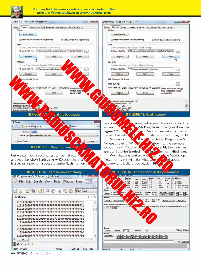
but we can add a second test to see if it really happenedand read the whole Flash using AVRStudio. This is useful sinceit gives us a tool to inspect the entire Flash memory, which
can come in handy in some debugging situations. To do this,we want to reopen the AVR Programmer dialog as shown inFigure 12, then click ‘Read.’ We are then asked to namethe file that will hold the saved data, as shown in Figure 13.
Now we can open the test.hex file in Programmer’sNotepad [part of WinAVR], scroll down to the memorylocation for 0x2000 as shown in Figure 14, then we cansee our 16 bytes (nested in the Intel Hex formatted line).
Well, that was entirely too much for one Workshop.Next month, we will take what we’ve learned aboutmemory and build a bootloader. NV
■ FIGURE 11. Upload the bootloader. ■ FIGURE 12. Read memory.
■ FIGURE 15. Output shown in Bray’s Terminal.
■ FIGURE 13. Save memory to file.
■ FIGURE 14. Examine saved memory.
60 September 2010
You can find the source code and supplements for thisarticle in Workshop26.zip at www.nutsvolts.com.
Smileys Workshop 26 - Sep 10.qxd 8/2/2010 2:39 PM Page 60
WWW.GiURUMELE.Hi2.RO
WWW.RADiOSCAMATORUL.Hi2.RO

A MINOR DESIGN CHANGE
If you compare Schematic 1 with last month’s EDTPVinculum-II debug module schematic, you’ll see that thefuse component has been replaced. If you are ahead ofthe game and have already built up a version of the EDTPVinculum-II debug module, no worries as the new fusecomponent has the same footprint as the fuse unit itreplaces. The fuse that has been replaced was not rated topass the maximum amount of current that a USB portalcan provide. The PSMF020X is designed to hold at 200mA and trip at 500 mA. The PSMF020X’s amperage rangeis just fine for most low power circuitry. However, thereplacement fuse — a PSMFX050X — holds at 500 mA andtrips at 1,000 mA. Thus, if your external circuitry drawsmore than 200 mA and teeters at the maximum currentdrain of 500 mA, you won’t be as likely to inadvertentlytrip the replacement resettable fuse. The host USB portalcontains a similar over-current protection circuit and
should not allow more than 500 mA of current flow for anextended period of time. However, my advice is to useyour good judgment as to how not to invoke your circuit’smagic smoke.
THE PRINTED CIRCUIT BOARD DESIGNI remember the very first time I designed a circuit
using 1/8 watt through-hole resistors. I recall worryingabout how I was going to hand-mount those — at thattime — tiny parts. Well, I did and the parts in my through-hole designs got progressively smaller. A similar evolutionhas taken place with our SMT designs. Our Vinculum IIdesign here rests on a 1.975 x 0.85 piece of copper-laminated fiberglass and is full of 0603 SMT parts.
The debug module is constructed on a standarddouble-sided printed circuit board (PCB). From a purelytrace layout point of view, the physical PCB design couldhave been simplified if we placed components on bothsides of it. However, using the power of the PCB via our
GETTIN’ JIGGY WITH THEVINCULUM-II HARDWARE DESIGN
DESIGN■ BY FRED EADY
CYCLETHEADVANCED TECHNIQUES FOR DESIGN ENGINEERS
Heat up your soldering iron. It’s time to forge some solder, silicon, ceramics,plastic, metal, and fiberglass into an electronic instrument capable of
transferring our ideas to a piece of silicon we know as the FTDI Vinculum-II.The first order of business is to pick up where we left off last month.
NOTES:
1. FB1 - MOUSER MI0805K400R-10
2. U1 - FT232RL
3. F1 - MOUSER 652-MF-PSMF050X-2
4. J1 - MOUSER 538-67503-1020
5. ALL PARTS 0603 SMT UNLESS OTHERWISE NOTED
TXEN
TXRXLED#RESET#PROG#PWREN#
DEBUG
INTERFACE
RESET#PROG#
TARGET VCCVBUS
VTARGET
U1 VCC U1 VCCIO U2 VCC
VCCIO
R2 100C44.7uF
C5100nF
C110nF
F1
0.5A
C247pF
C347pF
R310K
R8100K
R72K
Q1
DMP2123L-7
g
ds
U2
74LVC2G241
632
57
1
4
8
1Y2Y1A
2A2OE
1OE
GND
VCC
R110K
C7100nF
C6100nF
C9100nF
R4470
U1
17
1615
19
27
28
26
25
7 18
21
1214132223
6101139251
420
824
3V3OUT
USBDMUSBDP
RESET
OSCI
OSCO
TEST AG
ND
GN
DG
ND
GN
D
CBUS4CBUS3CBUS2CBUS1CBUS0
RIDCDCTSRTSDSRDTRRXDTXD
VCCIOVCC
NCNC
LED1
TX/RX
C8100nF
R9470
LED2
PWR
R510K
R610K
J1
MINI-B USB RECPT
6
32
54
1
SHIELD
D+D-
GNDID
VBUS
FB1
■ SCHEMATIC 1. The F1resettable fuse part waschanged to allow the maxi-mum amount of current tobe drawn from the USB hostportal.
September 2010 61
Design Cycle - Sep 10.qxd 8/3/2010 10:37 PM Page 61
WWW.GiURUMELE.Hi2.RO
WWW.RADiOSCAMATORUL.Hi2.RO

62 September 2010
debug module PCB design here fits all of the electronicand mechanical components on a single side of the PCB.
The bottom layer copper, and top and bottom filledcopper planes are filtered out in Screenshot 1. You caneasily associate each of the electronic components withtheir graphical counterparts shown in Schematic 1.Components R8 and LED2 are not identified by silkscreenlegends due to space restrictions. Our PCB is a product ofthe ExpressPCB generation process. So, you can identifyeach electronic component by simply clicking on it whichwill display the component’s property window. Within thisproperty window, you will find the size and value of thecomponent, and if the component is not identified with asilkscreen legend component ID.
Between Schematic 1 and the ExpressPCB layout, youcan easily identify and correctly mount the electroniccomponents and mechanical connectors that make up thedebug module. Note the silkscreen dot that is associatedwith LED1. This dot represents the cathode of the LED. Asyou can see in Screenshot 1, the cathode of LED1 is tiedto the cathode of LED2 with a copper trace. LED2 islocated directly to the right of LED1 and is not identifiedwith a silkscreen legend. LED2’s current limiting resistor,R8, is mounted directly above LED2.
Screenshot 2 adds the bottom layer traces andlegends under the component layer. Notice that some ofthe component layer vias don’t have any bottom or toplayer traces connected to them. These are pass-throughvias that electrically connect the top and bottom groundplanes. In some areas of the PCB, pockets are formed thatisolate a grounded component lead from electricalground. So, to complete the ground circuit, we simplyplace a via inside of the ground-less pocket whichconnects the upper and lower ground planes. The bottom
side plane, traces, and legends are shown in Screenshot 3.ExpressPCB does not offer bottom-side silkscreen. So, thelegends that associate with the debug interface pins areetched into the bottom side copper. Over the years doinghundreds of PCBs, I’ve discovered that using labels of anykind is always a good practice. The pass-through viasappear as holes in this screen capture because the vias aredefined as solid pads instead of thermal pads. To see whata thermal pad looks like, look at pin 3 of the debuginterface connector. The bottom side plane you see inScreenshot 3 was constructed in the same way as the topside plane shown in Screenshot 4. Both the top andbottom planes are grounded, and you can see the thermalpads on some of the components that provide theelectrical contact to ground. If you are from the planetKrypton, the debug module looks like Screenshot 5 whenyou kick in your x-ray vision. The graphics that make upScreenshot 5 come to life in Photo 1. Now that we havesome programmer/ debugger hardware, the next logicalstep is to design and assemble a basic Vinculum-IIembedded dual USB host controller circuit.
A BASIC HARDWARE DESIGNOur host controller can act as both a host and a
downstream device. So, we must design the Vinculum-IIpower supply circuitry with that in mind. To meet thatrequirement, our power supply design needs to be flexibleas far as its inputs are concerned.
VINCULUM-II POWER SUPPLY DESIGNWe’ve successfully used the Microchip TC1262-3.3
LDO voltage regulator in a number of Design Cycle
■ SCREENSHOT 3. The legend associates directly with thepins of the interface connector that is located at the far rightof the board.
■ SCREENSHOT 4. The use of ground planes greatly reduces the complexity of the printed circuit board by
reducing the number of individual ground traces.
■ SCREENSHOT 1. This screen capture is filtered to showonly the component bearing pads and the supportingcomponent-side traces.
■ SCREENSHOT 2. This is a composite view of the top andbottom trace routing. No rocket science here.
Design Cycle - Sep 10.qxd 8/3/2010 10:04 AM Page 62
WWW.GiURUMELE.Hi2.RO
WWW.RADiOSCAMATORUL.Hi2.RO

projects. The TC1262-3.3 LDO is capable of supplyingloads up to 500 mA with a typical dropout voltage of 350mV at full load. Designed for use in battery-poweredapplications, this voltage regulator can operate reliablywith a pair of 1.0 µF ceramic capacitors attached to itsinput and output pins. Recall my First Law of EmbeddedComputing which states, “Nothing is free.” There is a“price” to pay for the TC1262-3.3 LDO voltage regulator’sfeature set. In this case, the price is cheap as it only costsus 80 µA of power supply current to use it in our designs.
The TC1262-3.3 LDO input must be able to acceptvoltage from the USB portal and from an external source.If we decide to run the Vinculum-II in host mode, we’llneed to supply the VBUS voltage at the host USBconnector in the same manner your PC USB portalssupply VBUS power to downstream devices. Our voltageregulator design is laid out in Schematic 2.
HOST INTERFACE DESIGN
If you study Schematics 2 and 3, you will concludethat any host USB interface has the ability to supply VBUSpower to the TC1262-3.3 LDO. However, it is notpolitically correct to power a host USB portal externally.For instance, you wouldn’t want to attempt to force VBUSpower from an external downstream USB device into theUSB portal of your thousand-dollar laptop. So, whenoperating as a host, the presence of the HOST JMPR xprovides an electrical path to provide 5.0 volts to thedownstream USB device. Since the host provides VBUSvia its USB interface, 5.0 volts will probably be suppliedexternally. That means we need to provide an electricalpath between the external 5.0 volt power supplyand the input of the voltage regulator. This is easilyaccomplished by installing the 5V0 JMPR. Note thatthe VBUS JMPR and 5V0 JMPR are mutuallyexclusive as it pertains to having those jumpersinstalled. Our embedded dual USB host controllersupports a pair of USB host portals which areidentified as P0 and P1. The USB portals drawn upin Schematic 3 are standard fare for most FTDIparts. ESD suppressors CR1, CR2, CR3, and CR4 are
included to keep those nasty little sparks that tend tobridge electronic components and your fingertips fromdoing some unwanted soldering inside of the Vinculum-IIIC. The ferrite beads FB1 and FB2 are in position to thwartEMI that may try to creep into the 5 volt supply.
VINCULUM-II CORE DESIGNLike many of today’s low voltage core microcontrollers,
the Vinculum-II needs supporting electrical componentsfor its internal voltage regulators. Pins 3 and 7 of theVinculum-II IC grinning in Photo 2 form the businessend of the Vinculum-II’s internal 1.8 volt power system.The 1.8V VCC PLL IN (pin 3) acts as the +1.8 volt supplyto the internal clock multiplier. A 100 nF capacitor mustbe attached between this pin and ground. The output ofthe internal +1.8 volt regulator emanates from pin 7 of theVinculum-II. Schematic 3 shows a pair of filter capacitorshanging from the +1.8 volt output pin. Take another lookat Schematic 3 and you’ll see a ferrite bead standingguard on the internal clock multiplier +1.8 volt input pin.
3V35V05V0 JMPR R1 470
C14.7uF
C24.7uF
VR1 TC1262-3.3
1 3
2
IN OUT
CO
M
VBUS JMPR
PWR
VBUS
5V0
■ PHOTO 1. Rising from concept to reality, the EDTP Vinculum-II debug module.
■ SCHEMATIC 2.If you’re a regular
Nuts & VoltsDesign Cycle
reader, there’sno rocket
science portrayedhere either. The
TC1262-3.3 LDOvoltage regulator
is a solid andproven electronicpart shown herein a field tested
design.
September 2010 63
■ SCREENSHOT 5. Folks from the planet Krypton have anadvantage over us Earthlings as they can check the top
and bottom of their ExpressPCB layouts simultaneously.
Vinculum-II Embedded Dual USB Host Controller IC;Vinculum-II IDE; FT232RL: www.ftdichip.com
Design Cycle - Sep 10.qxd 8/3/2010 10:05 AM Page 63
WWW.GiURUMELE.Hi2.RO
WWW.RADiOSCAMATORUL.Hi2.RO

64 September 2010
Ferrite beads are popular components in this Vinculum-IIdesign. The good news is that a single type of ferrite beadis used throughout the design. The whole +1.8 volt thingbegins with the 3.3 volts entering at the Vinculum-II’spin 2 which happens to be the Vinculum-II’s internalvoltage regulator input. A basis for the Vinculum-II’s logicvoltage levels must be set to allow its I/O pins to interface
with external logic devices. That’swhere the Vinculum-II’s VCCIO pinscome in. The voltage applied to pins21, 38, and 54 establish the logiclevel of the Vinculum-II’s I/Osubsystem. As you can see inSchematic 4, the Vinculum-II is a 3.3volt device utilizing 3.3 volt logiclevels. These days, 3.3 volt and 5.0volt logic levels coexist more oftenthan not. So, the Vinculum-IIarchitects added 5.0 volt tolerance toall of the inputs.
If the debug module is attachedto the Vinculum-II, there’s no needfor pull-up resistors on the active-lowRESET and PROG lines as the pull-upresistors are mounted on the debugmodule PCB. If you’re consideringrunning the base system we’vedesigned without the debug moduleattached, you’ll want to pull up theVinculum-II’s RESET and PROG pinswith a pair of 10K resistors just aswe’ve done with R6 and R7.
Good power supply bypassingtechniques are essential to properlyoperating microcontroller circuitry.
So, power supply bypass capacitors C16, C17, C18, andC19 need to be mounted as close as possible to theVinculum-II’s power pins that are directly connected to thesource power supply’s 3.3 volt output. The Vinculum-II’sinternal clocks and timers are driven from a clock signalderived from an external 12 MHz crystal. For this design,I’ve chosen a FOX resin-sealed crystal. The 12 MHzencapsulated crystal can be had from Mouser byspecifying part number 559-FQ5032B-12.
COLLECTING THE PARTSNow that our design is committed to a set of
schematics, we can begin the process of converting thegraphics to silicon and fiberglass. Whenever possible, we’lluse 0603 SMT components as they are more easily placedinto tight trace-rich spaces. All of the electroniccomponents that make up our Vinculum-II design can behad from Mouser.com. Rather than assemble a Vinculum-II unit that is locked into a specific application set, ourhardware will take the shape of a portable module thatcan be plugged into an application-specific circuit. The pinassignments in Schematic 4 represent the default I/Ofunction set. If you had the opportunity to eyeball lastmonth’s Design Cycle, you know that we can configurethese default I/O pin assignments to appear on alternate
■ PHOTO 2. It looks like a microcontroller. It acts like a mi-crocontroller. It programs like a microcontroller. It is totallyUSB. This is the 64-pin version of the Vinculum-II. You canalso get this IC in 32- and 48-pin variants.
■ SCHEMATIC 3. This circuit is primarily used inhost mode applications.For instance, a massstorage applicationwould have this USBcircuitry interface to aUSB thumb drive.
Design Cycle - Sep 10.qxd 8/3/2010 10:05 AM Page 64
WWW.GiURUMELE.Hi2.RO
WWW.RADiOSCAMATORUL.Hi2.RO

pins. So, instead of identifying each pin on the PCB withits default value, we will label each of the Vinculum-II’sI/O pins according to its IO BUS number. The USBconnectors I’ve had the pleasure of meeting don’t cottonto the 0.1 inch pitch holes found on common perfboardsand solderless breadboards. So, we’ll put all of the USBand similarly “difficult” to mount connectors on theVinculum-II PCB module. Basically, any component thatwon’t naturally fit into a 0.1 inch hole pattern will bemounted on the PCB.
Multi-microfarad SMT ceramic capacitors will be usedwhenever possible. The Vinculum-II reference designs I
have seen don’t use SMT ceramics in the 1.8 voltregulator filter. Instead, the 4.7 µF capacitor filter you seein Schematic 4 is a tantalum. However, you can be sureI’ll experiment with a similarly valued ceramic capacitor inplace of the tantalum. I’ll also attempt to replace the 10 µFtantalums in Schematic 3 with their SMT ceramiccounterparts. To accommodate my (and your)experimentation, the PCB design will include dual padshapes at the tantalum part locations that can accept bothtantalum and ceramic footprints. My gut feeling is that theceramic capacitors will work just fine. As far as ourVinculum-II design is concerned, the advantages of using
September 2010 65
J1 D+
J1 D-
J2 D+
J2 D-
DEBUG_IFINPUT_1INPUT_2INPUT_3FIFO_DATA_0FIFO_DATA_1FIFO_DATA_2FIFO_DATA_3FIFO_DATA_4FIFO_DATA_5FIFO_DATA_6
INPUT_7
FIFO_TXE#
INPUT_5
UART_TXD
INPUT_4
FIFO_RXF#
UART_RXD
FIFO_WR#FIFO_RD#
FIFO_DATA_7
INPUT_6
SPI_S0_SS#
UART_DTR#
UART_RTS#UART_CTS#
SPI_M_MOSI
SPI_S0_CLK
UART_DCD#
SPI_S1_MOSI
INPUT_9
SPI_S0_MISO
UART_TX_ACTIVE
SPI_S1_MISO
SPI_M_MISO
UART_RI#
SPI_S0_MOSI
SPI_S1_SS#SPI_M_CLK
SPI_M_SS_0#
INPUT_8
SPI_S1_CLK
INPUT_10
UART_DSR#
3V3
3V3
3V3
U1
12
3
4
5
6
7
8
910
11121314151617181920
21
2223242526272829
30
3132
33
34
35
36
37
38
3940 41
4243444546474849505152
53
54
55565758596061626364
GN
D C
OR
E3.3
VR
EG
IN
1.8V VCC PLL IN
XTIN
XTOUT
GN
D P
LL
1.8V VREG OUT
TE
ST
RESETPROG
IO BUS0IO BUS1IO BUS2IO BUS3IO BUS4IO BUS5IO BUS6IO BUS7IO BUS8IO BUS9
VC
CIO
3.3
V
IO BUS10IO BUS11IO BUS12IO BUS13IO BUS14IO BUS15IO BUS16IO BUS17
GN
D IO
IO BUS18IO BUS19
USB1DP
USB1DM
GN
D C
OR
E
USB2DP
USB2DM
VC
CIO
3.3
V
IO BUS20IO BUS21 IO BUS22
IO BUS23IO BUS24IO BUS25IO BUS26IO BUS27IO BUS28IO BUS29IO BUS30IO BUS31IO BUS32IO BUS33
GN
D C
OR
E
VC
CIO
3.3
V
IO BUS34IO BUS35IO BUS36IO BUS37IO BUS38IO BUS39IO BUS40IO BUS41IO BUS42IO BUS43
C19CAP NP
R610K
R710K
FB1
C11100nF
+ C124.7uF
C13100nF
Y1
12MHz
C1420pF
C1520pF
C16100nF
C17100nF
C18100nF
R2 27
R3 27
R4 27
R5 27
■ SCHEMATIC 4. Here’s a basic Vinculum-IIembedded dual USB host controller core circuit layout. The contents of this schematiccombined with Schematics 2 and 3 form abase Vinculum-II system.
Design Cycle - Sep 10.qxd 8/3/2010 9:28 PM Page 65
WWW.GiURUMELE.Hi2.RO
WWW.RADiOSCAMATORUL.Hi2.RO

ceramic over tantalum capacitors are lower cost and conservation of PCB space.
DESIGN CHECKPOINT
As our Vinculum-II base hardware is yet to become a physical entity, at thisjuncture of our design process I can only smoke-test the debug module. So, assoon as the solder cooled, I plugged it into a PC USB portal and observed a verybrief blink of the debugger’s LED indicators followed by absolutely nothing. Inour case, that’s a good thing. The magic smoke contained within the electroniccomponents was not released. The PC USB portal also retained its magic smokeand the computer suffered no electrical damage due to its connection to thedebug module.
The FT232RL’s GPIO pins can be configured with commands embeddedwithin the incoming USB data stream. However, before the FT232RL’s GPIO canbe configured for use by the Vinculum-II IDE, the debug module and the targetcircuitry must be powered up. Once all of the hardware is under power, theVinculum-II IDE reads the EEPROM of the debug module’s FT232RL whichcontains the FT232RL’s USB description and serial number strings. The Vinculum-II IDE also needs the Vinculum-II IC’s chip type information. This data harvestingarrangement allows multiple debugging devices to be attached. The Vinculum-IIinformation and FT232RL EEPROM data are used by the Vinculum-II IDE todetermine what types of debugger/programmers are attached and whichVinculum-II IC is targeted by the attached debugger/programmer device ordevices. The desired debugging device can then be selected via the Vinculum-IIIDE. That explains why the IDE returns a “No Debugger Available” message andthe debug module hardware seems dead when no target Vinculum-II circuitry ispresent. During this process, the Vinculum-II IDE does not attempt to program
the FT232RL’sEEPROM.
ONWARDKeep that
soldering ironhandy. We’ll havemore hardware toassemble whenwe reconvene. In the meantime,I’ll get theVinculum-II corePCB laid out andmanufactured.After we assemblethe Vinculum-IIcore, we’ll mate itup with the debugmodule. Whilethat soldering ironis cooling off, we’ll whip upsome Vinculum-IIapplication code.NV
66 September 2010
www.ftdichip.comUSB MADE EASY
Vinculum VNC2
A programmable system-on-chip USB 2.0 Host / Slave controller
- Dual channel USB 2.0 interface, handles all USB host and data transfer functions in single IC.
- On-chip 16-bit Harvard architecture MCU core with 256 Kbyte Flash and 16kbyte RAM.
- External UART, FIFO, SPI Slave, SPI Master, GPIO and PWM interfaces.
- Vinculum-II software development tools available for user application development.
- Multiple package size options including VNC1L backwards compatible package option.
- Targeted for range of USB applications, from portable media devices and cell phones to industrial and automotive applications.
Vinculum-II evaluation modules- V2DIP1/2 - Miniature VNC2
Development Module with Single or Dual USB Connectors
- V2-EVAL - Complete Evaluation & Development Kit for VNC2
- VNC2 Debug Module
SPEED.FLEXIBILITY.PERFORMANCE.
Fred Eady can be reached at [email protected].
Design Cycle - Sep 10.qxd 8/4/2010 1:24 PM Page 66
WWW.GiURUMELE.Hi2.RO
WWW.RADiOSCAMATORUL.Hi2.RO

WWW.POLOLU.COM
AM/FM Broadcasters • Hobby KitsLearnng Kits • Test Equipment...AND LOTS OF NEAT STUFF!
For modules, kits and components for your next microcontroller project, your
embedded adventure starts here.
ELECTRONET
September 2010 67
For the ElectroNet online, go towww.nutsvolts.com
click Electro-Net
Electronic Parts & Supplies Since 1967
Electronet Sep10.qxd 8/4/2010 9:53 AM Page 67
WWW.GiURUMELE.Hi2.RO
WWW.RADiOSCAMATORUL.Hi2.RO

68 September 2010
When I began this near space business in 1995, if Iwanted to take pictures during a mission, I’d have to
perform a little surgery to the camera to allow the flightcomputer to control its shutter. Essentially, I’d bypass theelectric switch of the shutter and re-route it to a relaycontrolled by the flight computer. Modifying an electricallytriggered camera this way entailed a small amount of risk,as there was always the possibility that it could result in adamaged or inoperable camera. This was especially truewhen it was a tiny switch soldered to a plastic ribbon.
THE CANON HACKERDEVELOPMENT KIT (CHDK)
Today, embedded microcontrollers and firmwarecontrol the operation of cameras. No longer do buttonsand dials mechanically adjust mechanisms within acamera. Now, buttons just apply electrical signals to themicrocontroller to change menus and adjust settings.When the shutter button is pushed, firmware determinesthe proper exposure time based on inputted data andlighting conditions. Embedded systems let point and shootcameras take a lot of the guess work out of takingpictures.
CHDK is software that controls a point and shootcamera the same way you can control a more expensivedigital single lens reflex (DSLR) camera. CHDK — which isdesigned only for Canon cameras — uses scripts written in
a simple programming language called uBASIC. Thecommands grant control over features of the camera,making it possible to do things such as:
• Work with images in RAW format (RAW format isusually only available in DSLRs).
• Change shutter speeds to longer or shorter values thanare normally available.
• Change aperture settings.• Change zoom settings.• Take bursts of photographs while changing exposure
and aperture settings. • Change focus settings.• Use high speed flash.• Take pictures when motion is detected (this includes
detecting lightning flashes).• Use the camera’s USB cable as a remote shutter.• Create new menus and screens for the camera’s LCD.• Add new video features to a camera.• Change the camera’s file size limits.• Use file utilities on the camera’s SD card.• Create games for use on a camera.
Software commands for the camera are saved inscripts on the camera’s SD card. The camera then bootsoff the card and runs the script you select. Best of all,scripts don’t change the camera’s firmware. After runninga script, you can escape out of it or remove the SD cardfrom the camera. The camera will continue to function like
SPACE■ BY L. PAUL VERHAGE
APPROACHING THE FINAL FRONTIER
NEAR
THE CANON HACKERDEVELOPMENT KITThe Canon Hacker Development Kit is a“bootable camera operating system”with a simple scripting language thatsignificantly increases the power andflexibility of Canon “point and shoot”digital cameras. A simple script can give aCanon camera its own intervalometer while more complex programs allow acamera to vary settings like zoom, f-stop, shutter speed, and exposure timewhile it’s taking pictures. A big thanks goes to Mark Conner and the folks onthe GPSL Yahoo! groups for making me aware of this fantastic camera system.
NearSpace - Sep 10.qxd 8/2/2010 2:44 PM Page 68
WWW.GiURUMELE.Hi2.RO
WWW.RADiOSCAMATORUL.Hi2.RO
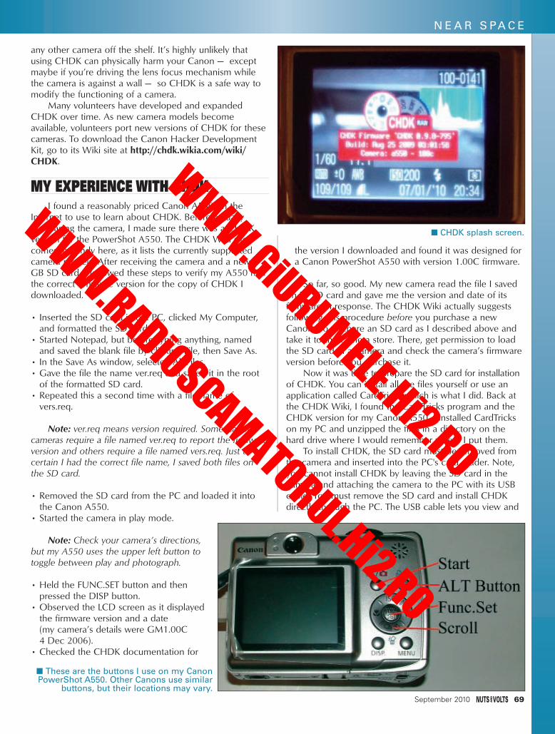
any other camera off the shelf. It’s highly unlikely thatusing CHDK can physically harm your Canon — exceptmaybe if you’re driving the lens focus mechanism whilethe camera is against a wall — so CHDK is a safe way tomodify the functioning of a camera.
Many volunteers have developed and expandedCHDK over time. As new camera models becomeavailable, volunteers port new versions of CHDK for thesecameras. To download the Canon Hacker DevelopmentKit, go to its Wiki site at http://chdk.wikia.com/wiki/CHDK.
MY EXPERIENCE WITH CHDKI found a reasonably priced Canon A550 on the
Internet to use to learn about CHDK. Before actuallypurchasing the camera, I made sure there was a CHDKversion for the PowerShot A550. The CHDK Wiki sitecomes in handy here, as it lists the currently supportedcamera models. After receiving the camera and a new 2GB SD card, I followed these steps to verify my A550 hadthe correct firmware version for the copy of CHDK Idownloaded.
• Inserted the SD card into a PC, clicked My Computer,and formatted the SD card.
• Started Notepad, but before typing anything, namedand saved the blank file by clicking File, then Save As.
• In the Save As window, selected All Files.• Gave the file the name ver.req and saved it in the root
of the formatted SD card. • Repeated this a second time with a file name of
vers.req.
Note: ver.req means version required. Some Canoncameras require a file named ver.req to report the firmwareversion and others require a file named vers.req. Just to becertain I had the correct file name, I saved both files onthe SD card.
• Removed the SD card from the PC and loaded it intothe Canon A550.
• Started the camera in play mode.
Note: Check your camera’s directions,but my A550 uses the upper left button totoggle between play and photograph.
• Held the FUNC.SET button and thenpressed the DISP button.
• Observed the LCD screen as it displayedthe firmware version and a date (my camera’s details were GM1.00C 4 Dec 2006).
• Checked the CHDK documentation for
the version I downloaded and found it was designed fora Canon PowerShot A550 with version 1.00C firmware.
So far, so good. My new camera read the file I savedon its SD card and gave me the version and date of itsfirmware in response. The CHDK Wiki actually suggestsfollowing this procedure before you purchase a newCanon. So, prepare an SD card as I described above andtake it to the camera store. There, get permission to loadthe SD card in a camera and check the camera’s firmwareversion before you purchase it.
Now it was time to prepare the SD card for installationof CHDK. You can install all the files yourself or use anapplication called CardTricks which is what I did. Back atthe CHDK Wiki, I found the CardTricks program and theCHDK version for my Canon A550. I installed CardTrickson my PC and unzipped the files in a directory on thehard drive where I would remember where I put them.
To install CHDK, the SD card must be removed fromthe camera and inserted into the PC's card reader. Note,you cannot install CHDK by leaving the SD card in thecamera and attaching the camera to the PC with its USBcable. You must remove the SD card and install CHDKdirectly through the PC. The USB cable lets you view and
■ These are the buttons I use on my CanonPowerShot A550. Other Canons use similar
buttons, but their locations may vary.
■ CHDK splash screen.
September 2010 69
N E A R S PA C E
NearSpace - Sep 10.qxd 8/2/2010 2:45 PM Page 69
WWW.GiURUMELE.Hi2.RO
WWW.RADiOSCAMATORUL.Hi2.RO
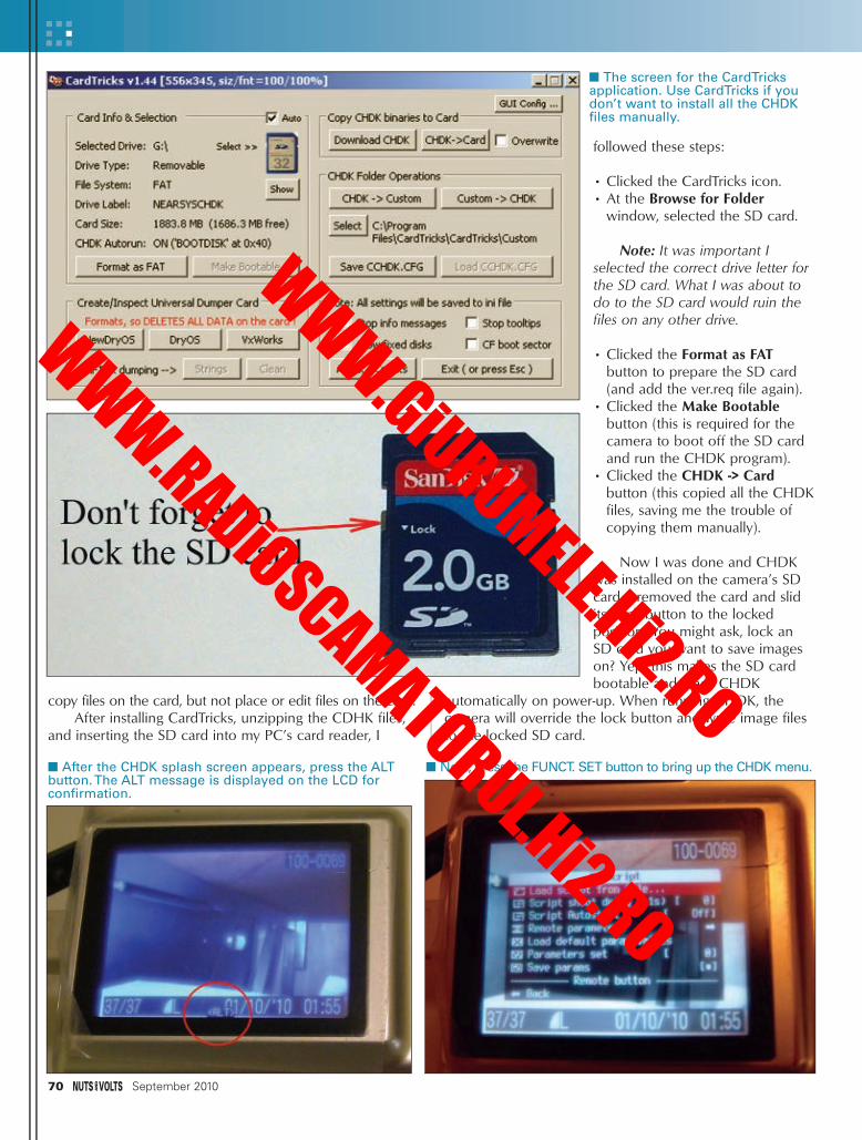
70 September 2010
copy files on the card, but not place or edit files on the card.After installing CardTricks, unzipping the CDHK files,
and inserting the SD card into my PC’s card reader, I
followed these steps:
• Clicked the CardTricks icon.• At the Browse for Folder
window, selected the SD card.
Note: It was important Iselected the correct drive letter forthe SD card. What I was about todo to the SD card would ruin thefiles on any other drive.
• Clicked the Format as FATbutton to prepare the SD card(and add the ver.req file again).
• Clicked the Make Bootablebutton (this is required for thecamera to boot off the SD cardand run the CHDK program).
• Clicked the CHDK -> Cardbutton (this copied all the CHDKfiles, saving me the trouble ofcopying them manually).
Now I was done and CHDKwas installed on the camera’s SDcard. I removed the card and slidits Lock button to the lockedposition. You might ask, lock anSD card you want to save imageson? Yep, this makes the SD cardbootable and loads CHDK
automatically on power-up. When running CHDK, thecamera will override the lock button and write image filesto the locked SD card.
■ The screen for the CardTricksapplication. Use CardTricks if youdon’t want to install all the CHDKfiles manually.
■ Next, press the FUNCT. SET button to bring up the CHDK menu.■ After the CHDK splash screen appears, press the ALTbutton. The ALT message is displayed on the LCD forconfirmation.
NearSpace - Sep 10.qxd 8/2/2010 2:46 PM Page 70
WWW.GiURUMELE.Hi2.RO
WWW.RADiOSCAMATORUL.Hi2.RO
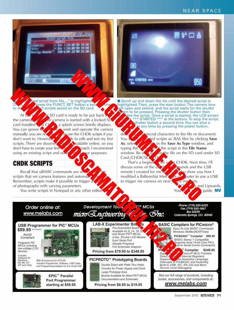
At this point, the SD card is ready to be put back intothe camera. When the camera is started with a locked SDcard installed with CHDK, a splash screen briefly displays.You can ignore CHDK if you wish and operate the cameramanually; you are not required to use the CHDK scripts if youdon’t want to. However, I was ready to edit and test my firstscripts. There are dozens of scripts available online, so youdon’t have to create your first script from scratch. I recommendusing an existing script and editing it for your purposes.
CHDK SCRIPTSRecall that uBASIC commands are written into the
scripts that set camera features and automate functions.Remember, scripts make it possible to trigger a sequenceof photographs with varying parameters.
You write scripts in Notepad or any other editor that
does not add special characters to the file or document.You save completed scripts as .BAS files by clicking SaveAs, selecting All files in the Save As Type window, andtyping the full name of the script in the File Namewindow. Be sure to save the file on the SD card under SDCard:/CHDK/SCRIPTS.
That’s a beginning for using CHDK. Next time, I’lldiscuss some of the uBASIC commands and the USBremote I created for my A550. I’ll also show you how Imodified a BalloonSat Mini flight computer to use a USBto trigger my camera on near space missions.
Onwards and Upwards,Your near space guide NV
■ While “Load script from file…” is highlighted in theCHDK menu, press the FUNCT. SET button a second timeto display a list of scripts saved on the SD card.
■ Scroll up and down the list until the desired script ishighlighted. Then, press the start button. The camera lenswill open and extend, and the script waits for the shutterbutton to be pressed. Pressing the shutter button thenactivates the script. Once a script is started, the LCD screendisplays *** STARTED *** at the bottom. To stop the script,press the shutter button a second time. You can shut acamera off at any time by pressing the power button.
September 2010 71
N E A R S PA C E
Development Tools for PIC® MCUs
microEngineering Labs, Inc.Phone: (719) 520-5323
Fax: (719) 520-1867Box 60039
Colorado Springs, CO 80960
Order online at:
www.melabs.com
Pre-Assembled BoardAvailable for 8, 14, 18, 28, and 40-pin PIC® MCUs2-line, 20-char LCD Module9-pin Serial PortSample ProgramsFull Schematic Diagram
Pricing from $79.95 to $349.95
PICPROTO™ Prototyping BoardsDouble-Sided with Plate-Thru Holes
Circuitry for Power Supply and Clock
Large Prototype Area
Boards Available for Most PIC® MCUs
Documentation and Schematic
Pricing from $8.95 to $19.95
LAB-X Experimenter Boards BASIC Compilers for PICmicro®
PICBASIC PRO™ Compiler $249.95
Easy-To-Use BASIC CommandsWindows 98/Me/2K/XP/Vista
BASIC Stamp 1 CompatibleSupports most 14-bit Core PICsBuilt-In Serial Comm Commands
Supports most PICmicro® MCU FamiliesDirect Access to Internal RegistersSupports In-Line Assembly LanguageInterrupts in PICBASIC and AssemblyBuilt-In USB, I2C, RS-232 and MoreSource Level Debugging
See our full range of products, includingbooks, accessories, and components at:
www.melabs.com
EPIC™ ParallelPort Programmerstarting at $59.95
PICBASIC™ Compiler $99.95
USB Programmer for PIC® MCUs(as shown)$89.95
RoHSCompliant
Programs PICMCUs includinglow-voltage (3.3V)devices
IncludesSoftware forWindows98, Me, NT,XP, and Vista.
With Accessories for $119.95:Includes Programmer, Software, USB Cable,and Programming Adapter for 8 to 40-pin DIP.
NearSpace - Sep 10.qxd 8/2/2010 2:47 PM Page 71
WWW.GiURUMELE.Hi2.RO
WWW.RADiOSCAMATORUL.Hi2.RO

The Nuts & Volts WEBSTORE
ELECTRONICS
For a comple te pr oduct de t ai l v is i t our webs tore!!
TRON.IX Book 1 by Gary Gibson
Hands-On Electronics Experiments!
This is the beautiful,fully-illustrated manual for ahands-on lab tohelp you build 40of the most interesting experiments youhave ever seen on a solderless circuit board, andas you do, youlearn how the basic components work in acircuit.You will enjoy hours of fun creatingall kinds of sounds and light displays.$14.95
Programming 16-Bit PICMicrocontrollers in C
by Lucio Di Jasio
This book teachesreaders everything theyneed to know aboutthese chips: how toprogram them, how totest them, and how todebug them in order totake full advantage ofthe capabilities of thenew PIC24 microcontroller architecture.Author Lucio Di Jasio offers unique insightinto this revolutionary technology, guidingthe reader step-by-step from 16-bit archi-tecture basics through even the mostsophisticated programming scenarios.Reg Price $55.95 Sale Price $45.95
Programming and Customizing theMulticore Propeller Microcontroller
by Parallax
Written by a team ofPropeller experts, thisauthoritative guideshows you how torealize your designconcepts by takingfull advantage of themulticore Propeller microcontroller'sunique architecture.The book begins with a review of thePropeller hardware, software, and Spin language so you can get started right awayand is filled with a wide variety of step-by-step, hands-on projects.Reg Price $49.95 Sale Price $45.95
Programming the Propeller with Spin
by Harprit Singh Sandhu
Programming thePropeller with Spin:A Beginner's Guide toParallel Processing walksyou through the essential skills youneed to build and control devices usingthe Propeller chip andits parallel processing environment. Findout how to use each of the identical 32-bitprocessors — known as cogs — and makethe eight cogs effectively interact with eachother.The book covers Propeller hardwareand software setup, memory, and the Spinlanguage.$29.95
An Arduino Workshopby Joe Pardue
The Arduino —designed for thenovice — hasbecome so popularthat there is now anembarrassment ofriches when it comesto the amount ofinformation and hardware available.So much stuff is outthere that some folkshave trouble puzzle piecing out what theyneed to just get started.The author isknown for his breezy writing style andlucid illustrations that help folks understand complex technical topics.$44.95
Holography Projects for the Evil Genius
by Gavin D J HarperCreate your own 3-D hologram!
New in the best selling EvilGenius series, this isa step-by-step guideto the improved artand science of holography, completewith explanations ofthe techniques,materials, processes,and tools needed tocreate impressive holograms.The book features more than a dozen distinct projects with morethan 100 hologramsposted on an associated website.$24.95
TEARDOWNSLearn How Electronics Work by Taking Them Apart
by Bryan Bergeron
“The text is written as if Dr. Bergeron, who is a highly experienced electronics practitioner, is speaking directly tothe reader with a point-by-point commentary about eachteardown, complete with clear explanations of the operationand function of every component. By the time the product iscompletely disassembled, the reader understands the designtricks, component selection, and packaging choices thatenabled the product to reach the market.” From the Foreword by Forrest M. Mims III
Amp up your knowledge of electronics by deconstructingcommon devices and analyzing the revealed componentsand circuitry. Teardowns: Learn How Electronics Work by TakingThem Apart contains 14 projects that expose the inner
workings of household appliances, workbench measuring instruments, and musical equipment. Discover how resistors, capacitors, sensors, transducers, and transistorsfunction in real circuitry.Reg Price $24.95 Subscriber Price $21.95
NNEEW!W!
72 September 2010
NNEEW!W!
NNEEW!W!
WWe also have e also have 26 other Evil Genius26 other Evil Genius
titles in stock!titles in stock!
Build Your Own Electronics Workshop by Thomas Petruzzellis
BUILD YOUR OWNDREAM
ELECTRONICS LAB!This value-packedresource provideseverything needed toput together a fullyfunctioning home electronics workshop!From finding space to stocking it withcomponents, to putting the shop intoaction — building, testing, and trou-bleshooting systems.The best part is, thisbook will save you money.Reg Price $29.95 Sale Price $24.95
NV Webstore Sept Working.qxd 8/2/2010 9:25 PM Page 72
WWW.GiURUMELE.Hi2.RO
WWW.RADiOSCAMATORUL.Hi2.RO

CD ROM SPECIALSBOOK & KIT COMBOS
Or CALL 1-800-783-4624 today!Order online @ www.nutsvolts.com
September 2010 73
From the Smiley Workshop
An ArduinoWorkshop
by Joe Pardue
The book An Arduino Workshop and the associated hardware projectskit bring all the pieces of the puzzle together in one place.With this,
you will learn to: blink eight LEDs (Cylon Eyes); read a pushbutton and 8-bit DIP switch; sense voltage, light, and temperature; make music ona piezo element; sense edges and gray levels; optically isolate voltages;
fade an LED with PWM; control motor speed; and more!An Arduino Workshop Combo
Reg Price $ 124.95 Subscriber’s Price $119.95 Plus S/H
From the Smiley Workshop
C Programming forMicrocontrollers by Joe Pardue
Do you want a low cost way to learn C programming formicrocontrollers? This 300 page book and software CD show you howto use ATMEL’s AVR Butterfly board and the FREE WinAVR C compiler
to make a very inexpensive system for using C to develop microcontroller projects.Combo Price $99.95 Plus S/H
Book $44.95 Kit $66.95
This great littlebook is a concise
all-purpose reference featuring
hundreds oftables, maps,
formulas,constants, andconversions.
AND it still fits inyour shirt pocket! OnlOnlyy
$12.95!$12.95!
This lab — from the good people at GSS TechEd — will show you 40 of the most simple andinteresting experiments and lessons you haveever seen on a solderless circuit board.As you
do each experiment, you learn how basic components work in a circuit.Along with thepurchase of the lab, you will receive a special
password to access the fantastic online interactive software to help you fully
understand all the electronic principles. For acomplete product description and sample
software, please visit our webstore.Reg Price $79.95 Subscriber’s Price $75.95
NV Webstore Sept Working.qxd 8/2/2010 9:26 PM Page 73
WWW.GiURUMELE.Hi2.RO
WWW.RADiOSCAMATORUL.Hi2.RO

WE ACCEPT VISA, MC, AMEX, and DISCOVER. Prices do not include shipping and may be subject to change.
74 September 2010
Or Order online @ www.nutsvolts.com
CALL 1-800-783-4624 today!
Nixie tube clocks fuse the spirit, drama,and eerie beauty of cold war technology
with modern inner works to createuncommon handcrafted timepieces.Now with optional case choices! Get more info @ our webstore.
Kit includes article reprint, complete instructions, and parts list
Subscriber’s Price $146.95Non-Subscriber’s Price $159.95
October 2006
Using Neon and Nixie bulbs, this clock displays the precision movement of timeand is programmable to display “Time
Chaos” at different intervals.TheNixieNeon Clock then resets itself to thecorrect time in an eye-catching ballet ofluminosity.The PCB is 7.25"x 7.25" and
consists of over 400 components.Reg Price $195.95 Sale Price $159.95
NoNow Ww WithithNeNew Code!w Code!
16-Bit Micro Experimenter Board
Magic Box Kit
Ready to move on from 8-bit to 16-bitmicrocontrollers? Well, you’re in luck!
In the December 2009 Nuts & Volts issue,you’re introduced to
“the 16-Bit Micro Experimenter.”The kit comes with a CD-ROM that
contains details on assembly, operation, aswell as an assortment of ready-made
applications. New applications will be addedin upcoming months.
Subscriber’s Price $55.95Non-Subscriber’s Price $59.95
128x64 Graphics Display Kit
New application for the 16-Bit Micro Experimenter
LCD displays ... they have been around forquite some time, but what if you could haveboth characters as well as graphic displays
at the same time? With this kit, we willshow you how easy and inexpensive this
technology can be using the 16-Bit Micro Experimenter.Subscriber’s Price $45.95
Non-Subscriber’s Price $48.95
FFreeree
SofSoftwaretware
LibrarLibrar y!y!
NoNow w
available!
available!
Assembled
Assembled
boards!boards!
As seen on theAugust 2010
cover
As seenon the
May 2010cover
As seen on theApril 2007 cover
Build your ownindoor shooting
range! With a littlepart-customizing foryour own weapon
and components from your favorite partshouse, you'll be firing photon bullets in notime.We have the printed circuit boards
and the two programmed chips necessaryfor this great project
available for your convenience.Includes an article reprint.Subscriber’s Price $48.95
Non-Subscriber’s Price $51.95
rCube Talking Alarm Clock KitAs seen on the
May 2009 cover
Available in blue, black, red, and green.All components are pre-cut and pre-bent
for easier assembly and the microcon-trollers are pre-programmed with thesoftware. Kits also include PCB, AC
adapter, and instructions on CD-ROM.Subscriber’s Price $49.95
Non-Subscriber’s Price $54.00
Nixie Tube Clock Kit
Indoor Shooting RangePCB & Programmed Chips
PROJECTSWireless Taillight KitBike Blinker Plus Kit
NixieNeon Clock Kit
As seen on the cover of the July 2010issue of Nuts & Volts.
Never wire trailer lights again! Just mountthe taillights and plug in the transmitter,
and you’re ready to tow.For complete kit details,please visit the webstore.
Includes an article reprint.Subscriber’s Price $139.95
Non-Subscriber’s Price $149.95 A partial kit is also available.
This unique DIY construction projectblends electronics technology with
carefully planned handcraftsmanship.This clever trick has the observer removeone of six pawns while you are out of theroom and upon re-entering you indicate
the missing pawn without ever opening the box.
Includes an article reprint.
Subscriber’s Price $39.95Non-Subscriber’s Price $45.95
From the atricle "Bike Blinker Plus," by DAVID G. BODNAR
The kit is a unique helmet-mounted LEDlighting system that not only alerts driversthat you are on the road, but provides theuser and fellow cyclists with some useful
information as you ride. Includes construction plans and helpful
SMT soldering hints.Subscriber’s Price $39.95
Non-Subscriber’s Price $42.95
NNEEW!W!
NV Webstore Sept Working.qxd 8/3/2010 2:02 PM Page 74
WWW.GiURUMELE.Hi2.RO
WWW.RADiOSCAMATORUL.Hi2.RO

The Nuts & Volts WEBSTORE
Run Your Diesel Vehicle onBiofuels
A Do-It-Yourself Manualby Jon Starbuck, Gavin D J
HarperCONVERT TOBIODIESEL FOR A MORE ENVIRONMENTALLYFRIENDLY RIDE!Run Your Diesel Vehicle onBiofuels has everythingyou need to make theswitch from expensive,environment-damagingcarbon fuel to cheap (and, in many cases,free), clean fuel for your vehicle. Practicaland decidedly apolitical, this unique guidefocuses on technical details, parts, andinstructions.$24.95
The Whirlybird Three-Phase Wind TurbineKit is one of the great projects from the
series of articles by John Gavlik,"Experimenting with Alternative Energy."In Parts 6 and 7, he teaches you how
to produce the most electricity utilizing the wind.For kit details, please visit
our webstore.
Subscriber’s Price $75.95Non-Subscriber’s Price $79.95
50 Green Projects for the Evil Genius
by Jamil Shariff Using easy-to-findparts and tools, thisdo-it-yourself guideoffers a wide varietyof environmentallyfocused projects youcan accomplish onyour own.Topics covered include transportation,alternative fuels, solar,wind, and hydro power, home insulation,construction, and more.The projects inthis unique guide range from easy tomore complex and are designed to optimize your time and simplify your life!$24.95
Fuel Cell Projects for the Evil Genius
by Gavin D J Harper
FUEL YOUR EVILURGES WHILE YOUBUILD GREENENERGY PROJECTS!
Go green as youamass power! FuelCell Projects for theEvil Genius broadensyour knowledge ofthis important, rapidly developing technology and shows you how to buildpractical, environmentally conscious projects using the three most popularand widely accessible fuel cells!$24.95
Solar Energy Projects for theEvil Genius
by Gavin D J HarperLet the sun shine onyour evil side — andhave a wicked amountof fun on your way tobecoming a solarenergy master! InSolar Energy Projectsfor the Evil Genius,high-tech guru GavinHarper gives youeverything you needto build more than 30 thrilling solarenergy projects.You'll find complete,easy-to-follow plans, with clear diagramsand schematics, so you know exactlywhat's involved before you begin.$24.95
ALTERNATIVE ENERGYSECTION
At ten t ion Subscr ibe r s ask abou t your d iscoun t on pr ices mar ked wi t h an *
The Complete Idiot’s Guide toSolar Power for Your Home
by Dan Ramsey / David Hughes
The perfectsource for solarpower — fullyillustrated.Thisbook helps readers under-stand the basics ofsolar power andother renewableenergy sources,explore whethersolar powermakes sense for them, what their optionsare, and what’s involved with installingvarious on- and off-grid systems.$19.95
B3-Phase Wind Turbine Kit
The Hydrocar is used in a couple of greatprojects from the series of articles by John
Gavlik, "Experimenting with AlternativeEnergy." In Parts 10 and 11, he teaches youthe operation of the Polymer ElectrolyteMembrane "reversible" fuel cell. For kit
details and a demo video,please visit our webstore.
Subscriber’s Price $79.95Non-Subscriber’s Price $84.95
Hydrocar Kit Windpitch Kit
The WindPitch Wind Turbine Kit is a miniature real-working wind turbine and
is one of the great projects from theseries of articles by John Gavlik,
"Experimenting with Alternative Energy." In Parts 8 and 9, he teaches you how toproduce the most power by evaluating
the pitch (setting angle) of the profiled blades. For kit details,
please visit our webstore.Subscriber’s Price $84.95
Non-Subscriber’s Price $89.95
September 2010 75
NV Webstore Sept Working.qxd 8/5/2010 10:34 AM Page 75
WWW.GiURUMELE.Hi2.RO
WWW.RADiOSCAMATORUL.Hi2.RO

KITS/PLANS
CLASSIFIEDS
YOUR COMPLETE SOLUTION!
• PCB Design• PCB Simulation• CAD/CAM Menu121747, Hobby Vers., $175121743, Pro. Version, $275
www.KELVIN.com
EXCLUSIVE U.S. DISTRIBUTOR
PCB SOFTWARE
SURPLUS
MICROCONTROLLERS
PROFESSIONALSERVICES
• Industrial packaging
•Weather resistant
• Standard ¾” fitting
• Quality narrow beam
MaxSonarUltrasonic Ranging is EZ
www.maxbotix.com
• Beam pattern choice
• Tiny size
• Real-time calibration
•High acoustic power
• Power-up calibration
• Smallest MaxSonar
• 1 inch resolution
•Low power, 2.5V-5.5V
XL-MaxSonar-EZ
LV-MaxSonar-EZ
MaxSonar-WR (IP67)
MaxSonar-WRC (IP67)
• Compact packaging
•Weather resistant
• Standard ¾” fitting
• Quality narrow beam
tix.com
(IP67))
ROBOTICS
SOLAR PRODUCTS/KITS
Looking for solarstuff and kits?
www.nutsvolts.com
76 September 2010
DEC EQUIPMENTWANTED!!!
Digital Equipment Corp.and compatibles.Buy - Sell - Trade
CALL KEYWAYS 937-847-2300or email [email protected]
HARDWAREWANTED
DESIGN/ENGSERVICES
www.servomagazine.com
Classifieds Sep10.qxd 8/3/2010 1:57 PM Page 76
WWW.GiURUMELE.Hi2.RO
WWW.RADiOSCAMATORUL.Hi2.RO

long range operation in situations where existing wideband solutions cannot offer adequate range, or whereband congestion requires multiple channel operation.
Thanks to the inclusion of easy to use, single-functioncontrollers/actuators, the CXT and CXR modules aresuited to tasks that just call for a simple on/off controlfunction (such as flood light control, machine overrideshutdown, etc.), without the need for any additionalexternal circuitry (such as a microprocessor or dedicatedencoder/decoder IC). This keeps the size, bill of materialscost, and software overhead associated with systemdesigns that employ these modules to a minimum.
Supporting data rates of up to 5 kbps, the modulesare built on the radio hardware of the company’ssuccessful LM series. Like the LM series, they provide 32frequency channel operation (12.5 kHz or 25 kHzchannels) in any of the 173.200 MHz - 173.325 MHz(UK), 150.825 MHz - 152.450 MHz (Australia), 433.875MHz - 434.650 MHz (EU), or 458.525 MHz - 459.1 MHz(UK) frequency bands (plus other custom VHF bands onrequest), allowing them to meet the RF requirements ofmany different geographical regions.
The CXR receiver has a better than -118 dBm usablecalling sensitivity while drawing only 20 mA from a 3.1V-15V rail. The matching CXT transmitter can be offered in10 mW (35 mA from 3.1V-15V) or 100 mW (95 mA from4.1V-15V) versions, depending on specific bandregulations.
The integrated control coder/decoder uses a highly
noise-tolerant biphase coded data stream, includinggenerous preamble/framing sequences, CRC errordetection to minimize false activations, and a 16-bit userprogrammable address. All operating parameters (channel,address, frequency table setup) can be easily programmedby the user, via a simple serial interface. Put together,these features give the user a reliable remote actuator with an operating range of up to 1 km.
The CXT and CXR come in compact shieldedhousings, measuring 33 mm x 23 mm x 9 mm and 46 mm x 23 mm x 9 mm, respectively, with pins for PCBmounting. The modules have an operating temperaturerange of -20°C to +55°C and conform fully with EN 300220-3 and EN 301 489-3 standards. Class one (to EN300-220-v2.3.1) receiver versions are also available.
Key applications for this transmitter/receiver pairinclude lighting control, security/fire/lone-worker alarms,‘machine stop’ systems, and generic industrial qualityon/off switching mechanisms.
HIGH POWER FLEXIBLELED LIGHT STRIPS
The NFLS-300X3 series strips from superbrightleds.com use high power three-chip 5050SMD LEDs and are
great for accent and other special application lightingdesigns. Available in cool, warm, and natural white colortemperatures, these 12 VDC strips produce up to 350lumens per foot while drawing just 0.3 amps per foot.Other colors available include blue, green, red, and amber.They can be cut in three-LED (2 in) segments and have anadhesive backing to easily handle contoured installations.
September 2010 77
CLASSIFIEDSCOMPONENTS
Nixie Power
www.tayloredge.com/nixie
2-16V In, 4-8W / 150-200VDC Out0.95" x 0.95" x 0.35"
$9.95 (Shipping included)
continued from page 29
New full featured Compiler
Floating Point Coprocessor
www.micromegacorp.com
Extensive floating point support, GPS input, FFT, 12-bit A/D, matrix operations, user-defined functions.
uM-FPU V3.1
32-bit IEEE 754SPI or I2C
DIP-18, SOIC-18
For more information, contact:SuperBrightLEDs
Web: www.superbrightleds.com
For more information, contact:Lemos International Co., Inc.
1275 Post Road, Suite A-12Fairfield, CT 06824
Tel: 866-345-3667 Fax: 203-254-7442Email: [email protected]
Web: www.lemosint.com/radiometrix
SEP10 - NewProducts.qxd 8/3/2010 1:49 PM Page 77
WWW.GiURUMELE.Hi2.RO
WWW.RADiOSCAMATORUL.Hi2.RO

78 September 2010
R E A D E R - T O - R E A D E R TECHFORUM
>>> QUESTIONSMilwaukee Screwdriver Battery Chargers
I am a soon to be retired industrial electrician. At work, we usemany cordless screwdrivers, mostlyMilwaukee and Dewalt. I have severalno longer functional 48-59-0180chargers. It looks like a relatively simple circuit. I haven't indentified anin-line chip. Can anyone help withschematics and components?
Replacement 48-59-180s are nolonger available. Replacement 48-59-300s are available, but at half the costof an entire screwdriver kit.#9101 Marv Steinhagen
Davenport, IA
Automatic Door LocksI have a 1984 Cadillac that the
automatic door locks do not work.The doors lock from a 12 volt
positive pulse from the gear selectorswitch as it crosses the reverse position. This also sends a signal to theback-up lights which work fine.
Does anyone have a circuit tolock and unlock the doors?#9102 Frederick Rembetski
via email
Electric Fence MonitoringI currently operate a small 10 acre
hobby goat farm, protected by a commercial 16 KV, high impedance,pulsed charge, electric fence spanningacross rolling hills which are "not visible" from the house. Some of ourgoats are natural born escape artists —as determined to get out as coyotesand wildcat predators are to get in. Ineed a "smart circuit" that can detectwhether: (1) animal fence contact wasjust a "one time" brief encounter(resulting in a successful rebuff); (2)there are multiple successive contactswithin a set time period (as would bethe case of a determined assailant);(3) there is a persistent reduced fencecharge (from an entangled animal); or
(4) there is a total fence failure (due toa break in or total grounding of the system). Most importantly, the circuit must be able to identify which specific fence segment/zone the problem is located at for fast response.In the past, predators have patrolledjust outside the fence eventually digging underneath it or jumping overit without contacting it, so some formof zone based non-contact perimetersensing (possibly using air to wirecapacitive couplings) would allow forearly warning of a potential problem.#9103 Sebastian Sullivan
Makanda, IL
Auto Audio AdjustEvery time I slow down to an
intersection, I turn my stereo downslighty. I need a device to work with the brakes and final output;something with a delay and that slowly fades back up. #9104 Steve McKennon
via email
HD Reception on FM TunersIs there an HD adapter that can
be added to an existing FM stereotuner, similar to the circuits we added years ago to receive stereo ona monaural tuner?#9105 John R. Seeley
Palm Bay, FL
Power Supply for Optional DC or AC Input
How can I design a simple circuitthat allows me to have the option ofsupplying 120 VAC or 15 VDC?Currently, I have two fixtures: one usesa LPS24+15V/1.7A 25W input andthe other an external 15V supply.
Other than that, the fixtures are thesame. I would like to have the optionto plug in AC or to plug in a 15 VDCsupply.#9106 Chuck Moskowitz
Ann Arbor, MI
Keystone Jack WiringI need data/instructions on how to
wire a keystone jack per specs 368A/B.#9107 Harry Campbell
Wind Gap, PA
Voltage DroppingI have two circuits in the same
enclosure: one works on 12 VDC andthe other on 9 VDC. I have a 12 VDCtransformer for the one. I need a 9 VDC for the other. I tried with resistors to lower the voltage to 9 VDCwith no success.#9108 Pete Theodoulou
Durham, NC
[#4103 - April 2010]
Cat RFID We have four indoor/outdoor cats.
My plan is to have each of themimplanted with an RFID chip and tohave a sensor over the cat door whichwill read them. The door is alreadywired to indicate "a cat has gone in" or"a cat has gone out." Now I want toknow which cat, and also possiblyhave the cat door remain locked untila known cat approaches.
I purchased an RFID reader module from Parallax and although thisworked okay with the tags supplied,there was no response from the RFIDchip borrowed from our friendly vet.
Does anybody have a suggestion
All questions AND answers are submittedby Nuts & Volts readers and are intendedto promote the exchange of ideas and provide assistance for solving technicalproblems. Questions are subject to editing and will be published on a space available basis if deemed suitable by the publisher. Answers are submitted
by readers and NO GUARANTEES WHATSOEVER are made by the publisher.The implementation of any answer printedin this column may require varying degreesof technical experience and should only beattempted by qualified individuals.
Always use common sense and goodjudgment!
>>> ANSWERS
TechForum.qxd 8/2/2010 8:58 PM Page 78
WWW.GiURUMELE.Hi2.RO
WWW.RADiOSCAMATORUL.Hi2.RO

for (a) what type of RFID chip to use (there are more than one); and (b) where I can obtain a bare-bonesscanner. I want to capture the tag IDusing my own microprocessor when acat is in range of the sensor.
RFID systems operate at differentfrequencies. For the system to workcorrectly, the frequency of the readermust be tuned to the frequency of thetag. The operation frequency of thesystem made by Parallax may be different from the frequency at whichthe animal tag identification operates.Even if both of them operate in the LFrange, one may be operating at 125kHz and the other one at 134 kHz.Moreover, even at the same operatingfrequency, the communications proto-col that they use may be different, asthese are not standard in the LF range.
You may want to experiment withother low-cost readers for hobbyists. Agood source is here: www.trossenrobotics.com/c/usb-serial-rfid-readers-tags-kits.aspx.
The popular website Instructables.com has several projects relatedto RFID systems (search for RFID).From all of them, you may be interest-ed in this one: www.instructables.com/id/RFID_Reader_Detector_and_Tilt_Sensitive_RFID_Tag/.
Finally, there is a website that notonly describes in detail the chips usedby veterinarians, but it also givesdetails to construct a reader. This maybe the closest to what you are lookingfor. This website is www.maxmicrochip.com/.
Albert LozanoShavertown, PA
[#4104 - April 2010]
Flame RectificationI would like to put together a
flame sensor using flame rectification. Iam familiar with how it works however,I need some ideas for the sensing electronics. The furnace I have uses ahot surface ignitor.
A simple flame rectification circuitcan be easily made with an operational amplifier and a few discreet components. Choosing thepopular '741 op-amp and onemegohm resistor for feedback, I wasable to breadboard a working circuit;the output from the amplifier drove aLED through a 330 ohm resistor. Theinput from the sensing rod (wire, in my case) went directly to the non-inverting (+) input of the op-amp; theinverting input (-) fed back to the output through the one meg resistor.Powered with five volts, it readilysensed the flame. In this case, I"grounded" the test flame with anotherwire. You can use this circuit to drive arelay or input to your favorite microcontroller. The very high inputimpedance of the op-amp allows forreliable low voltage operation.
Having said that, do not attemptto alter or modify the existing ignitionand safety system in your gas furnace.The hot surface igniter on the domestic gas furnace works in conjunction with a very clever infraredflame detection system. It's designedfor safety and has to meet theapproval of various agencies before itcan be sold to the public.
Carl,AE6NOLemon Grove, CA
[#4109 - April 2010]
PIC Micro and USBLong ago, I was competent
programming in Microsoft QBasic.Now most/all articles use either assembly or C. Do any of the popularmicrocontrollers program in some version of Basic? I am not into a "C"level of retraining at age 67.Suggestions ... I’m looking for serioushow-to articles — or worst case —books on using some microcontrollerthat includes interfaces to USB ports.
#1 I am an older techie like yourselftinkering with microcontrollers. Likeyou, I have used Basic for several years
and have not bothered to learn C or itsderivatives. Lucky for us, there are sev-eral well established companies thatbuild microcontrollers programmed inBasic. Parallax (www.parallax.com)sells the BASIC Stamp that is availablein several versions, depending on features you need and how much youare willing to spend. The unit comes ina 24-pin DIP package that you willneed to mount on a perf or bread-board to ease interfacing to. You canalso purchase a complete develop-ment board with USB interface. BasicMicro (www.basicmicro.com) offersthe Basic Atom which is also availablein several versions. Both companiesoffer free downloads of an IntegratedDevelopment Environment (IDE) thatallows editing, debugging, and compiling of programs on a PC orMac. I have used both successfully inseveral projects. If your preference isthe PIC line of microcontrollers fromMicrochip, microEngineering Labs(www.melabs.com) offers a completeline of Basic development systems for this product line. All of these companies have tutorials you candownload or literature you can purchase to assist you in learning howto use their products. There is also a wealth of third-party informationavailable and forums you can enter toassist you. P.S. I recently purchased anArduino which is programmed with alanguage that is a subset of C in thehopes of disproving the theory thatyou can't teach an old dog new tricks!
Doug Foreman via email
#2 I've been using the mikroBasic software from mikroElektronika (www.mikroe.com) for years now and amextremely satisfied. Good news is thatyou don't even have to buy the software if your projects can compileunder 2K of code space. This is morethan sufficient for all beginner levelprojects. I think they probably makemost of their profit selling their
>>>YO U R EL ECTRO N ICS QUEST I ONS ANSWERED HERE BY N&V READERS
September 2010 79
Send all questions and answers by email to [email protected] at www.nutsvolts.com for tips and info on submitting to the forum.
TechForum.qxd 8/2/2010 8:58 PM Page 79
WWW.GiURUMELE.Hi2.RO
WWW.RADiOSCAMATORUL.Hi2.RO

EasyPIC development board which iswhat I recommend for anyone just getting into PIC programming.
They also sell dozens of add-onboards that are designed to connectto their development board. Thesecan be used to greatly reduce yourdevelopment time. Then, if you later decide you want to build thatcomponent yourself instead of usingan add-on board, they'll even provideyou the schematic.
Their website also has free onlinebooks that are terrific tutorials for thebeginner and a great reference for therest of us.
The mikroBasic software itselfcomes with templates to demonstratejust about every feature on a PIC chip.So, you can quickly jump-start yournew project by building up from theirexamples.
Alternatively, there is alsoPICBasic, but when I compared it tothe features and cost of mikroBasic,there was, in my humble opinion, nocontest.
Joe KissellGardner, KS
#3 The Atmel AVR family of micro-processors has long been popular inprofessional, education, and hobbyistcircles. As to Basic, arguably the verybest structured Basic, very similar toMicrosoft's Visual Basic 6, is the com-piler called ZBasic (www.zbasic.net,and the user forum www.zbasic.net/forum.) This compiler targets thecompany's AVR chip based inexpen-sive microprocessor "stamp" products,with both byte-code and native codeversions. Another Basic compiler foreight-bit microprocessors is fromwww.mcselec.com; it's an "old school"Basic which may bring back memoriesof spaghetti code! Finally, it's worthnoting the Teensy micros fromwww.pjrc.com/teensy/ make a goodtarget for most any compiler produc-ing standard .hex downloadable files.The excellent and unrestrictedWinAVR (GNY/GCC) with Atmel'sfree AVR Studio is very popular — dueto the price: $0. Of late, the dozens ofArduino variations have surged in useby those without a desire to muck
about in the details of the C language,at least as a starter.
SteveSan Diego, CA
[#41010 - April 2010]
DC MotorsHow does an interpole winding
work in a DC motor?
#1 In a DC motor, as one commutatorsegment moves out from under abrush and another makes contact witha brush, the result is that sparking canoccur at the commutator. To reducethe sparking, interpoles can be placedin the DC motor to help prevent brush sparking at the commutator.Interpoles are additional field wind-ings placed on poles located midwaybetween the field poles. The interpolecoils are connected in series with thearmature; therefore, the current theycarry is proportional to the armaturecurrent. The interpole coils are woundso as to produce a magnetic field witha polarity opposite to the polarity ofthe magnetic field created by the arma-ture current (thus, the magnetic fieldcreated by the interpoles is opposite tothe magnetic field that is created by thearmature). Interpoles aid the regularfield windings in pulling the armaturecoils to and past the magnetic poles ofthe field windings.
Ralph J. KurtzOld Forge, PA
#2 Irving Gottlieb explains the operation of interpoles very nicely inhis book Electric Motors And ControlTechniques. A thorough answer is toolong to print here, but to summarize:Interpoles are small poles (electromag-nets) positioned half way between themain poles (permanent magnets) in abrushed DC motor. The interpoles arewired in series with the commutatorand are "intended to combat theeffects of self-induction and mutualinduction in the armature inductors ...and improve commutation." If you'regoing to dive into motor theory, this book is worth the $14 onAmazon.com.
Dan DanknickSanta Ana, CA
[#5103 - May 2010]
Load Controller, Micro HydroI built a 3,000W, 220V, micro
hydro machine and installed it for afamily of five living near a stream. Ineed a load controller to offset theextra power whenever something isturned off. When the real load goesdown, the frequency and voltage goup. The design should monitor the frequency (50 Hz) and dump someload to resistors whenever the frequen-cy starts going up, and dump less ofthat load when the frequency goesdown. If there is a better idea please letme know. Is PWM a good option?
It appears that this is a stand-alonegenerator, not connected to any otherpower. Throwing a resistive load on tohold the output voltage and frequencyin spec might be okay if you have aneed for a lot of hot water or steam.Otherwise, it is wasteful.
My first choice would be to havea couple of control loops: The firstloop is a speed stabilization loop tohold the speed relatively constant andgive the desired 50Hz ± a few Hz. Thisprobably means controlling waterflow/pressure to the turbine. The second loop involves controlling excitation of the generator to regulatevoltage. Controlling excitation is veryeffective because exciter power ismuch lower than the output power ofthe generator. Stability and responsetime of the loops can be enhanced by sensing the load current on thegenerator and using that informationto alter the loop signals before muchspeed or voltage change has actuallyoccured.
This may sound like a lot of trouble, but it saves water and will givebetter control than the shunt loadresponding to actual voltage or speedchanges.
If you insist on the shunt load, thecheapest load is water itself. Use acontroller to raise and lower a pair ofiron plates in a big drum of water as avariable load. Use the stream waterflowing through the drum to keep it cool.
Jon WexlerLos Angeles, CA
R E A D E R - T O - R E A D E R TECHFORUM
80 September 2010
TechForum.qxd 8/2/2010 8:58 PM Page 80
WWW.GiURUMELE.Hi2.RO
WWW.RADiOSCAMATORUL.Hi2.RO

ADvertiser INDEX■ L O O K F O R ■ S E A R C H F O R ■ F I N D
Find your favorite advertisers here!
Abacom Technologies ...............66
All Electronics Corp. ..................41
AP Circuits ................................49
BaneBots .....................................9
Cana Kit Corp. ...........................59
Circuit Specialists, Inc. .........82-83
Command Productions ..............27
Cunard Associates ....................29
DesignNotes.com, Inc. ...............29
Dimension Engineering ................9
Electronic Surplus .....................21
Electronix Express ....................12
ExpressPCB ..............................40
Front Panel Express LLC ..........27
Future Technology Devices ......66
Fun Gizmos ...............................29
Futurlec .....................................34
Integrated Ideas & Tech. ...........28
Jameco ......................................13
Jaycar Electronics ......................54
LeCroy..........................................5
Lemos International Co., Inc. ......8
Linx Technologies .....................49
Lynxmotion, Inc. ........................49
Matrix Multimedia .......................29
microEngineering Labs ..............71
MikroElektronika ..........................3
Mouser Electronics ....................19
NetBurner ....................................7
Net Media ....................................2
NKC Electronics ........................29
Parallax, Inc. ...............Back Cover
PCB Pool .....................................8
Pioneer Hill Software .................46
PolarisUSA Video, Inc. ..............35
Pololu Robotics & Electronics ....47
QKITS ........................................29
Ramsey Electronics, Inc. .....22-23
Robot Power .............................29
Saelig Company, Inc. ................46
Solarbotics/HVW .......................48
SparkFun Electronics ..................4
Technological Arts .....................29
Trace Systems, Inc. ..................48
V-Module ...................................34
AMATEURRADIO AND TVPolarisUSA Video, Inc. .........................35
Ramsey Electronics, Inc. ................22-23
V-Module ..............................................34
BATTERIES/CHARGERSCunard Associates ...............................29
BUYING ELECTRONICSURPLUSJaycar Electronics.................................54
CCD CAMERAS/VIDEOCircuit Specialists, Inc. ....................82-83
PolarisUSA Video, Inc. .........................35
Ramsey Electronics, Inc. ................22-23
CIRCUIT BOARDSAP Circuits ...........................................49
Cunard Associates ...............................29
Dimension Engineering...........................9
Electronic Surplus ................................21
ExpressPCB .........................................40
Futurlec ................................................34
PCB Pool ...............................................8
Saelig Company, Inc. ...........................46
V-Module ..............................................34
COMPONENTSCana Kit Corp. .....................................59
Electronix Express ...............................12
Front Panel Express LLC .....................27
Fun Gizmos ..........................................29
Future Technology Devices .................66
Futurlec ................................................34
Jameco ................................................13
Linx Technologies ................................49
Mouser Electronics ..............................19
SparkFun Electronics .............................4
V-Module ..............................................34
COMPUTERHardware
Electronic Surplus ................................21
Future Technology Devices .................66
Matrix Multimedia..................................29
Microcontrollers / I/O Boards
Abacom Technologies .........................66
Fun Gizmos ..........................................29
Matrix Multimedia..................................29
microEngineering Labs .........................71
MikroElektronika ....................................3
Mouser Electronics ..............................19
Net Media ...............................................2
Parallax, Inc. ..........................Back Cover
Pololu Robotics & Electronics ...............47
Solarbotics/HVW ..................................48
Technological Arts ...............................29
Trace Systems, Inc. .............................48
Software
Matrix Multimedia..................................29
DESIGN/ENGINEERING/REPAIR SERVICESCana Kit Corp. .....................................59
ExpressPCB .........................................40
Front Panel Express LLC .....................27
PCB Pool ...............................................8
Trace Systems, Inc. .............................48
EDUCATIONBaneBots ...............................................9
Command Productions ........................27
NKC Electronics ...................................29
Technological Arts ...............................29
EMBEDDED TOOLSMouser Electronics ..............................19
NetBurner ...............................................7
ENCLOSURESFront Panel Express LLC .....................27
Integrated Ideas & Tech. ......................28
KITS & PLANSCana Kit Corp. .....................................59
DesignNotes.com, Inc. ..........................29
Future Technology Devices .................66
Jaycar Electronics.................................54
NetBurner ...............................................7
NKC Electronics ...................................29
QKITS ...................................................29
Ramsey Electronics, Inc. ................22-23
Solarbotics/HVW ..................................48
MISC./SURPLUSAll Electronics Corp. .............................41
Electronic Surplus ................................21
Front Panel Express LLC .....................27
MOTORS
BaneBots ...............................................9
Electronic Surplus ................................21
Jameco ................................................13
PROGRAMMERSFuturlec ................................................34
microEngineering Labs .........................71
MikroElektronika ....................................3
RF TRANSMITTERS/RECEIVERSAbacom Technologies .........................66
Linx Technologies ................................49
ROBOTICSBaneBots ...............................................9
Fun Gizmos ..........................................29
Jameco ................................................13
Lemos International Co., Inc. .................8
Lynxmotion, Inc. ...................................49
Net Media ...............................................2
Pololu Robotics & Electronics ...............47
Robot Power ........................................29
Solarbotics/HVW ..................................48
SparkFun Electronics .............................4
SATELLITELemos International Co., Inc. .................8
SECURITYPolarisUSA Video, Inc. .........................35
Technological Arts ...............................29
TEST EQUIPMENTCircuit Specialists, Inc. ....................82-83
DesignNotes.com, Inc. ..........................29
Dimension Engineering...........................9
Jaycar Electronics.................................54
LeCroy ....................................................5
NKC Electronics ...................................29
Pioneer Hill Software ...........................46
Saelig Company, Inc. ...........................46
Trace Systems, Inc. .............................48
TOOLSMikroElektronika ....................................3
NetBurner ...............................................7
WIRE, CABLEAND CONNECTORSDesignNotes.com, Inc. ..........................29
Jameco ................................................13
SparkFun Electronics .............................4
September 2010 81
Index Sep10.qxd 8/4/2010 12:56 PM Page 81
WWW.GiURUMELE.Hi2.RO
WWW.RADiOSCAMATORUL.Hi2.RO

USB DigitUSB Digital Sal Storage Oscilloscopestorage Oscilloscopes
* High performance: * USB connected: Uses USB and supports plug'n play,
with 12Mbp communication speed.* Best performance for your dollar: Thease units have
many features that are comparable to the highspeedah
stand-alone DSOs. But costs a fraction of the price.* No external power required: Bus-powered from the
host computers USB port.* Probes & USB cable included.* Easy to use: Intuitive and easy to understand.* Various data formats: Can save wavrfrom in the
following formats: .txt .jpg .bmp & MS excel/word
40MHz DSO-2090 DSO-2090 $169.00$169.00www.circuitspecialists.com/DSO-2090
60MHz DSO-2150DSO-2150 $194.00$194.00www.circuitspecialists.com/DSO-2150
100HMz DSO-2250DSO-2250 $249.00$249.00www.circuitspecialists.com/DSO-2250
200MHz DSO-5200DSO-5200 $289.00$289.00www.circuitspecialists.com/DSO-5200
200MHz DSO-5200ADSO-5200A $355.00$355.00www.circuitspecialists.com/DSO-5200A
See It!Clearly in narrow spots,even in total darkness orunderwater.
Find It!Fast. No more strugglingwith a mirror & flash light.
Solve It!Easily, speed up the solutionwith extended accessories.
Record It!With the 3.5" LCD recordablemonitor, you can capturepictures or record video fordocumentation.
Full specifications atwww.CircuitSpecialists.com/Aardvark
The Aardvark Wireless Inspection Camera is the only dual camera video borescope on the market today. With both
a 17mm camera head that includes three atachable accessories and a 9mm camera head for tighter locations. Both
cameras are mounted on 3ft flexible shafts. The flexible shaft makes the Aardvark great for inspecting hard to reach
or confined areas like sink drains, AC Vents, engine compartments or anywhere space is limited. The Aardvark II
comes with with a 3.5 inch color LCD monitor. The monitor is wireless and may be separated from the main unit for
ease of operation. Still pictures or video can also be recorded and stored on a 2GB MicroSD card (included). The
Aardvark’s monitor also has connections for composite video output for a larger monitor/recorder and USB interface
for computer connection. Also included is an AC adapter/charger, video cable and USB cable. Optional 3 ft flexible
extensions are available to extend the Aardvark’s reach (Up to 5 may be added for a total reach of 18 feet!).
3ft Extension AARDVARK-EXT $24.95
CCiirrccuuiittSSppeecciiaall iissttss..ccoomm11000000’’ss ooff II tteemmss OOnnll iinnee!! 11--880000--552288--11441177 FFaaxx:: 448800--446644--55882244 SSiinnccee 11997711
CCiirrccuuiitt SSppeecciiaall iissttss,, IInncc..
PPhhoonnee:: 880000--552288--11441177 // 448800--446644--22448855 // FFaaxx:: 448800--446644--55882244
$249.00$249.00Item #
AARDVAARDVARKARK
RECORDSStill Pictures& Video
3.5”TFT
COLOR
Probes
Probes
Inclu
ded
Inclu
ded
Ideal for Law Enforcement,
Post Fire Inspection, Plumbing,
Facilities Maintenence,
Security Companies, & Many
Other UsesI
Aardvark IIIIDual CameraDual Camera
Wireless Inspection CameraWith Color 3.5" LCD Recordable Monitor
Your Extended Eyes & Hands!
17mm17mm
9mm9mm
Panel MetersPanel MetersDon't let the prices fool you. These digital panel meters are notsurplus, These high quality digital panel meters are available attremendous savings over competing models. Check out outComplete selection at: www.circuitspecialists.com/Panel_Meters
3-1/2 Digit LCD Panel MeterPM-128A
1+ 10+ 25+ 100+ 250+$10.25ea $7.49ea $6.69ea $6.19ea $5.50ea
www.circuitspecialists.com/PM-128A
3-1/2 Digit Advanced LCD Panel MeterPM-128E
1+ 10+ 25+ 100+ 250+$12.25ea $9.39ea $7.99ea $6.19ea $6.99ea
www.circuitspecialists.com/PM-128E
3-1/2 Digit Backlit Advanced LCD Panel MeterPM-128E-BACKLIT
1+ 10+ 25+ 100+ 250+$14.95ea $11.90ea $9.89ea $9.39ea $8.29ea
www.circuitspecialists.com/PM-128E-BACKLIT
3-1/2 Digit Digital LCD Panel MeterPM-138
1+ 10+ 25+ 100+ 250+$10.90ea $7.85ea $6.85ea $6.45ea $5.90ea
www.circuitspecialists.com/PM-138
3-1/2 Digit Digital LCD Panel MeterPM-188BL
1+ 10+ 25+ 100+ 250+$12.50ea $8.90ea $7.90ea $7.45ea $6.70ea
www.circuitspecialists.com/PM-188BL
3-1/2 Digit Digital LCD Panel MeterPM-228
1+ 10+ 25+ 100+ 250+$12.50ea $8.90ea $7.90ea $7.45ea $6.70ea
www.circuitspecialists.com/PM-228
3-1/2 Digit Digital LCD Panel MeterPM-328
1+ 10+ 25+ 100+ 250+$19.88ea $16.40ea $14.90ea $13.66ea $11.93ea
www.circuitspecialists.com/PM-328
3-1/2 Digit Digital LCD Panel MeterPM-438
1+ 10+ 25+ 100+ 250+$10.95ea $7.90ea $6.90ea $6.50ea $5.95ea
www.circuitspecialists.com/PM-438
3-1/2 LCD 5V Common Ground Panel MeterPM-1028A
1+ 10+ 100+ 250+$13.95ea $11.84ea $8.89ea $7.15ea
www.circuitspecialists.com/PM-1028A
3-1/2 Backlit LCD 5V Com Ground Panel MeterPM-1028B
1+ 10+ 100+ 250+$15.95ea $13.89ea $10.49ea $9.65ea
www.circuitspecialists.com/PM-1028B
3-1/2 LCD Backlit 5V Com Ground Panel MeterPM-1028B-BACKLIT
1+ 10+ 100+ 250+$13.95ea $11.84ea $8.89ea $7.15ea
www.circuitspecialists.com/PM-1028B-BACKLIT
9V Miniature LCD Digital Panel MeterCX101A
1+ 10+ 25+ 100+ 250+$13.50ea $10.90ea $9.80ea $8.95ea $7.90ea
www.circuitspecialists.com/PM-1028B
5V Miniature LCD Digital Panel MeterCX101B
1+ 10+ 25+ 100+ 250+$13.50ea $10.90ea $9.80ea $8.95ea $7.90ea
www.circuitspecialists.com/CX101B
5V Miniature LCD Digital Panel MeterCX101BG
1+ 10+ 25+ 100+ 250+$13.50ea $10.90ea $9.80ea $8.95ea $7.90ea
www.circuitspecialists.com/CX101BG
LED 9V Independent Ground Panel MeterPM-129A
1+ 10+ 25+ 100+ 250+$13.49ea $9.85ea $8.95ea $9.80ea $7.29ea
www.circuitspecialists.com/PM-129A
LED 5V Common Ground Panel Meter PM-129B
1+ 10+ 25+ 100+ 250+$12.95ea $10.49ea $9.55ea $8.35ea $7.89ea
www.circuitspecialists.com/PM-1028B
3LED 9V Independent Ground Panel MeterPM-1029A
1+ 10+ 100+ 250+$14.95ea $12.50ea 9.95ea $7.89ea
www.circuitspecialists.com/PM-1029A
LED 5V Common Ground Panel MeterPM-1029B
1+ 10+ 100+ 250+$15.95ea $13.40ea $10.79ea $8.65ea
www.circuitspecialists.com/PM-1029B
3-1/2 Digit LED Digital Panel MeterCX102A
1+ 10+ 25+ 100+ 250+$11.49ea $9.54ea $8.67ea $7.95ea $6.95ea
www.circuitspecialists.com/CX102A
3-1/2 Digit LED 5V Common Ground Panel MeterCX102B
1+ 10+ 25+ 100+ 250+$14.95ea $10.49ea $9.58ea $8.59ea $7.59ea
www.circuitspecialists.com/CX102B
Check out out complete selection at www.circuitspecialists.com/Panel_Meters
Specifications DSO-2090 DSO-2150 DSO-2250 DSO-5200 /5200A
Channels 2 Channels
Impedence 1M 25pF
Coupling AC/DC/GND
Vertical resolution 8 Bit 9 Bit
Gain Range 10mV-5V, 9 Steps 10mV-10V, 10Steps
DC Accuracy +/- 3%
Timebase Range 4ns - 1h 38 Steps 2ns-1h, 39 Steps
Vertical adjustable Yes
Input protection Diode clamping
X-Y Yes
Autoset 30Hz~40MHz 30Hz~60MHz 30Hz~100MHz 30Hz~200MHz
EXT. input Yes
Trigger Mode Auto / Normal / Single
Trigger Slope +/-
Trigger Level Adj. Yes
Trigger Type Rising edge / Falling Edge
Trigger Source Ch1 / Ch2 / EXT
Pre/Post trigger 0-100%
Buffer size 10K-32K per ch 10K-512KB per ch
Shot Bandwidth DC to 40MHz DC to 60MHz DC to 100MHz 100MHz
Max Sanple Rate 100MS/s 150MS/s 250MS/s 200MS/s / 250MS/s
Sampling Selection Yes
Waveform Display port/line, waveform average, persistence, intensity
Network open / close
Vertical Mode Ch1, Ch2, Dual, Add
CursorMeasurement Yes
Spectrum Analyzer
Channels 2 Channels
Math FFT, addition, subtraction, multiplication, division.
Bandwidth 40 MHz 60 MHz 100MHz 200 MHz
Cursor Frequency, Voltage
Data Samples 10K-32K/Ch 10K-1M/Ch
Full Page.qxd 8/2/2010 9:08 PM Page 82
WWW.GiURUMELE.Hi2.RO
WWW.RADiOSCAMATORUL.Hi2.RO

Includes1 Year USAWarranty
You get both a 200 MHzOscilloscope and a multi func-tion digital multimeter, all inone convenient lightweightrechargeable battery poweredpackage. This power packedpackage comes complete withscopemeter, test leeds, twoscope probes, charger, PC soft-ware, USB cable and a conven-
ient nylon carrying case.
• 200MHz Handheld Digital Scopemeter with integrated DigitalMultimeter Support
• 200MHz Bandwidth with 2 Channels• 500MSa/s Real-Time Sampling Rate• 50Gsa/s Equivalent-Time Sampling Rate• 6,000-Count DMM resolution with AC/DC at 600V/800V, 10A• Large 5.7 inch TFT Color LCD Display• USB Host/Device 2.0 full-speed interface connectivity• Multi Language Support• Battery Power Operation (Installed)
www.circuitspecialists.com/DSO1200
60MHz Hand Held Scopemeter60MHz Hand Held Scopemeterwith Oscilloscope & DMM Functionswith Oscilloscope & DMM Functions
• 60MHz Handheld Digital Scopemeter with integrated Digital Multimeter Support
• 60MHz Bandwidth with 2 Channels• 150MSa/s Real-Time Sampling Rate• 50Gsa/s Equivalent-Time Sampling Rate• 6,000-Count DMM resolution with AC/DC
at 600V/800V, 10A• Large 5.7 inch TFT Color LCD Display• USB Host/Device 2.0 full-speed interface
connectivity• Multi Language Support• Battery Power Operation (Installed)
www.circuitspecialists.com/DSO1200
60MHz Hand Held Scopemeter60MHz Hand Held Scopemeterw/Oscilloscope, DMM Functions &w/Oscilloscope, DMM Functions &25 MHz Arbitrary Waveform Generator25 MHz Arbitrary Waveform Generator
• All the features of the DSO1060 plus a 25 MHz ArbitraryWaveform.Generator.
• Waveforms can be saved in the following formats: jpg/bmp graphic file, .MS excel/word file
• Can record and save 1000 waveforms • DC to 25 MHz Arbitrary Waveform Generator
www.circuitspecialists.com/DSO-8060
CCiirrccuuiittSSppeecciiaall iissttss..ccoomm11000000’’ss ooff II tteemmss OOnnll iinnee!! 11--880000--552288--11441177 FFaaxx:: 448800--446644--55882244 SSiinnccee 11997711
CCiirrccuuiitt SSppeecciiaall iissttss,, IInncc.. 222200 SS.. CCoouunnttrr yy CClluubb DDrr.. ,, MMeessaa,, AAZZ 8855221100PPhhoonnee:: 880000--552288--11441177 // 448800--446644--22448855 // FFaaxx:: 448800--446644--55882244
We carry a LARGE selection of Power Supplies, Soldering Equipment, Test Equipment,Oscilloscopes, Digital Multimeters, Electronic Components, Metal and Plastic Project Boxes,
Electronic Chemicals, PC Based Digital I/O Cards, Panel Meters, Breadboards, DeviceProgrammers, and many other interesting items. Check out our website at:
www.CircuitSpecialists.com
0-30V / 0-5A0-30V / 0-5A . DC Power Supply. DC Power Supply
The CSI530S is a regulated DC power supply which you can
adjust the current and the voltage continuously. An LED display
is used to show the current and voltage values. The output ter-
minals are safe 4mm banana jacks. This power supply can be
used in electronic circuits such as operational amplifiers, digital
logic circuits and so on. Users include researchers, techni-
cians, teachers and electronics enthusiasts. A 3 ½ digit LED is
used to display the voltage and current values.
ww.circuitspecialists.com/csi530s
Programmable DC Electronic LoadsProgrammable DC Electronic Loads
Thease devices can be used with supplies up
to 360VDC and 30A. It features a rotary
selection switch and a numeric keypad used
to input the maximum voltage, current and
power settings. These electronic DC loads
are perfect for use in laboratory environments
and schools, or for testing DC power supplies
or high-capacity batteries. It also features
memory, and can also be connected to a PC,
to implement remote control and supervision.
360V/150W (CSI3710A) $349.00www.circuitspecialists.com/csi3710a
360V/300W (CSI3711A) $499.00www.circuitspecialists.com/csi3711a
$84.95$84.95Item #
CSI530SCSI530S
•Up to 10 settings stored in memory
•Optional RS-232, USB, RS-485 adapters
•May be used in series or parallel modes
wi th addi t ional supplies.
•Low output ripple .& noise
•LCD display with .backlight
•High resolution at .1mV
Programmable DC PowerProgrammable DC PowerSuppliesSupplies
Model CSI3644A CSI3645A CSI3646A
DC Voltage 0-18V 0-36V 0-72V
DC Current 5A 3A 1.5A
Power (max) 90W 108W 108W
Price $199.00$199.00 $199.00$199.00 $199.00$199.00
Item #DSO1200DSO1200
$739.00$739.00
Item #DSO1060DSO1060 $529.00$529.00
BlacBlackJkJacack SolderWk SolderWererksksOur Premium Line Up for Soldering, Repair & Rework
Rugged design at an affordable price..BlackJack SolderWerks fromCircuit Specialists Inc. is the industry cost/performance leader and con-tinues our reputation of providing high value products to our customers.
BK2000Compact Soldering Station
$39.95$39.95
BK2000+ Compact Soldering Station
with Digital Display
$54.95$54.95
BK2050+70 Watt Soldering Station
$79.00$79.00
BK3000LFCompact Lead Free
Soldering Station
$59.95$59.95
BK4000Thermostatically controlleddesoldering station
$119.00$119.00
BK4050HotAir System w/Vacuum IChandler & Mechanical Arm
$119.00$119.00
BK5000Hot Air System w SolderingIron & Mechanical Arm
$119.00$119.00
BK6000Premium All-In-One
Repairing Solder System
$229.00$229.00
www.circuitspecialists.com/blackjack
Item #DSO-8060DSO-8060 $659.00$659.00
19inch Rack Mount Switch-Mode19inch Rack Mount Switch-Mode
Power Supply with 3 Output ModesPower Supply with 3 Output Modes
The BTI-150 is a high efficency switching power supply. For use where mul-
tiple voltage continous power output is needed. Ideal for use in Technical
Product Research, Laboratory, Educational Institutions, Telecommunication
Industry, etc.
The Rack Mount Design makes it easy to stack multiple power supplies for
high use areas.
OutputVoltage
OutputCurrent
V/CDisplay
Resolution
0~15V 0~10A Digital 0.1+/-2digit
0~30V 0~5A Digital 0.1+/-2digit
0~60V 0~2.5A Digital 0.1+/-2digit
Item #BTI-150BTI-150 $189.00$189.00
www.circuitspecialists.com/BTI-150
200MHz Hand Held Scopemeter200MHz Hand Held Scopemeterwith Oscilloscope & DMM Functionswith Oscilloscope & DMM Functions
Full Page 2.qxd 8/2/2010 9:10 PM Page 83
WWW.GiURUMELE.Hi2.RO
WWW.RADiOSCAMATORUL.Hi2.RO

backcvr.qxd 8/2/2010 4:49 PM Page 84
WWW.GiURUMELE.Hi2.RO
WWW.RADiOSCAMATORUL.Hi2.RO