Embed Size (px)
Citation preview

Observation of the vortex structure of a non-integervortex beam
Jonathan Leach, Eric Yao and Miles J PadgettDepartment of Physics and Astronomy, Kelvin Bld, University Ave,University of Glasgow, Glasgow G12 8QQ, UKE-mail: [email protected]
New Journal of Physics 6 (2004) 71Received 30 April 2004Published 5 July 2004Online at http://www.njp.org/doi:10.1088/1367-2630/6/1/071
Abstract. An optical beam with an eil! phase structure carries an orbital angularmomentum of lh̄ per photon. For integer l values, the phase fronts of such beamsform perfect helices with a single screw-phase dislocation, or vortex, on the beamaxis. For non-integer l values, Berry (2004 J. Opt. A: Pure Appl. Opt. 6 259)predicts a complex-phase structure comprising many vortices at differingpositions within the beam cross-section. Using a spatial light modulator weproduce eil! beams with varying l. We examine the phase structure of such beamsafter propagation through an interference-based phase-measurement technique.As predicted, we observe that for half-integer l values, a line of alternating chargevortices is formed near the radial dislocation.
It is now well appreciated that light beams with helical phase fronts described by an azimuthalphase term of eil! carry an orbital angular momentum of lh̄ per photon [1]. Examples of suchbeams include the Laguerre–Gaussian modes and high-order Bessel beams. For integer l values,the phase fronts for a given phase, comprise l intertwined helical surfaces giving a screwdislocation along the beam axis, and a resulting annular intensity cross-section. This screw-phase dislocation along the axis is an optical vortex of charge l. Initially, for non-integer lvalues, there is a phase discontinuity, in our case, radially along the ! = 0 direction, which onpropagation gives rise to a line of low intensity. Recently, Berry [2] has theoretically analysedsuch beams showing that after propagation, they have intricate-phase structures comprising chainof alternating charge vortices along the direction of the initial radial discontinuity. In this studywe experimentally produce such beams and confirm the general nature of Berry’s predictions.
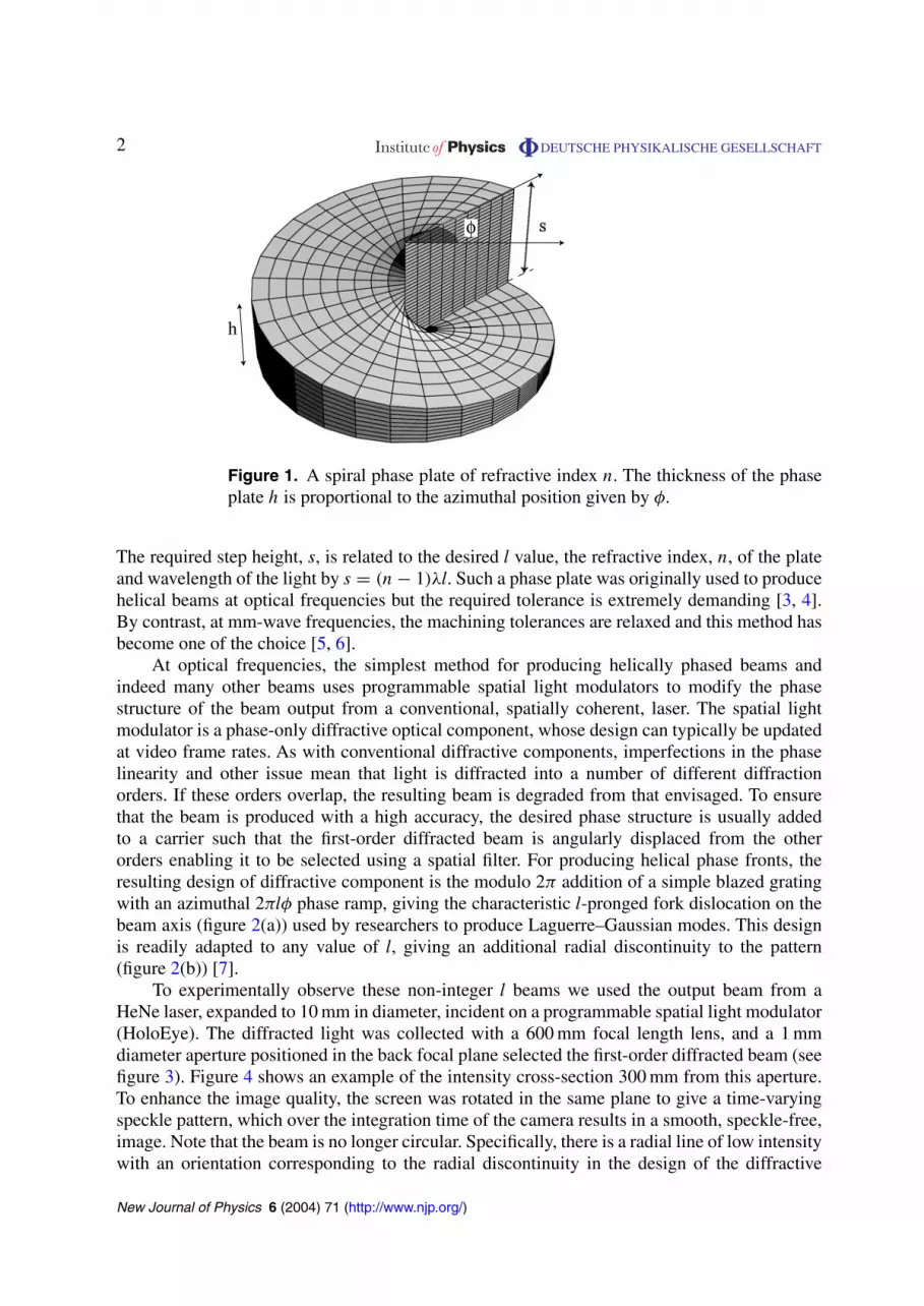
One conceptually easy way to produce a helically phased beam is to pass a plane-wavedbeam through a spiral phase plate. A phase plate is formed from a transparent disc whosethickness is proportional to the azimuthal position, with a step at the ! = 0 position; see figure 1.
New Journal of Physics 6 (2004) 71 PII: S1367-2630(04)80050-81367-2630/04/010071+8$30.00 © IOP Publishing Ltd and Deutsche Physikalische Gesellschaft
2 DEUTSCHE PHYSIKALISCHE GESELLSCHAFT
Figure 1. A spiral phase plate of refractive index n. The thickness of the phaseplate h is proportional to the azimuthal position given by !.
The required step height, s, is related to the desired l value, the refractive index, n, of the plateand wavelength of the light by s = (n ! 1)"l. Such a phase plate was originally used to producehelical beams at optical frequencies but the required tolerance is extremely demanding [3, 4].By contrast, at mm-wave frequencies, the machining tolerances are relaxed and this method hasbecome one of the choice [5, 6].
At optical frequencies, the simplest method for producing helically phased beams andindeed many other beams uses programmable spatial light modulators to modify the phasestructure of the beam output from a conventional, spatially coherent, laser. The spatial lightmodulator is a phase-only diffractive optical component, whose design can typically be updatedat video frame rates. As with conventional diffractive components, imperfections in the phaselinearity and other issue mean that light is diffracted into a number of different diffractionorders. If these orders overlap, the resulting beam is degraded from that envisaged. To ensurethat the beam is produced with a high accuracy, the desired phase structure is usually addedto a carrier such that the first-order diffracted beam is angularly displaced from the otherorders enabling it to be selected using a spatial filter. For producing helical phase fronts, theresulting design of diffractive component is the modulo 2# addition of a simple blazed gratingwith an azimuthal 2#l! phase ramp, giving the characteristic l-pronged fork dislocation on thebeam axis (figure 2(a)) used by researchers to produce Laguerre–Gaussian modes. This designis readily adapted to any value of l, giving an additional radial discontinuity to the pattern(figure 2(b)) [7].
To experimentally observe these non-integer l beams we used the output beam from aHeNe laser, expanded to 10 mm in diameter, incident on a programmable spatial light modulator(HoloEye). The diffracted light was collected with a 600 mm focal length lens, and a 1 mmdiameter aperture positioned in the back focal plane selected the first-order diffracted beam (seefigure 3). Figure 4 shows an example of the intensity cross-section 300 mm from this aperture.To enhance the image quality, the screen was rotated in the same plane to give a time-varyingspeckle pattern, which over the integration time of the camera results in a smooth, speckle-free,image. Note that the beam is no longer circular. Specifically, there is a radial line of low intensitywith an orientation corresponding to the radial discontinuity in the design of the diffractive
New Journal of Physics 6 (2004) 71 (http://www.njp.org/)

3 DEUTSCHE PHYSIKALISCHE GESELLSCHAFT
l=0.5 l=2.7 l=3.5l=1.0
+ =
(a)
(b)
0!
2!
Figure 2. Phase patterns represented in grey scale. (a) The addition of a carrierto the azimuthal phase such that the diffraction orders are spatially separated.(b) Examples of different patterns corresponding to different step heights.
Figure 3. The experimental configuration. The zero- and first-order diffractedlight, a distance d from the spatial light modulator, was imaged onto a screen formeasurement.
component. These images are similar to those reported in the first use of a spiral phase plate[3] when the phase step height did not correspond to an integer number of wavelengths of theilluminating light.
The detailed predictions of Berry do not, however, relate only to the intensity distributionbut also to the detailed phase structure. To observe the phase structure of our beam we utilizeone of the additional diffraction orders from the spatial light modulator. The zero-order beamis identical in form to the illumination beam, i.e. a plane wave. By adjusting the positionof the spatial filter both the first- and zero-order beams are transmitted and interfere at thescreen.
New Journal of Physics 6 (2004) 71 (http://www.njp.org/)

4 DEUTSCHE PHYSIKALISCHE GESELLSCHAFT
Figure 4. Intensity cross-section of the first-order diffracted light, 300 mm fromthe spatial light modulator. The step height in this case is l = 2.5.
Determining the phase difference between two light beams can be problematic, particularlyin regions of low optical intensity. In principle, three or four images taken at different phaseoffsets are sufficient. We can change the phase offset between the zero- and first-order beamsby shifting the phase of the carrier with respect to the azimuthal phase ramp programmed tothe spatial light modulator. In this study, we developed an alternative technique to determinethe phase of the first-order beam which is less sensitive to noise in any one of the recordedimages. For each value of l, 20 images were acquired with different phase offsets in intervalsof #/10. At each pixel position, the 20 values of intensity were Fourier-transformed to give acomplex spectrum, the argument of the lowest frequency component giving the phase differencebetween the beams. Plotting this angle for each pixel position gives an image corresponding tothe phase difference between the zero- and first-order beams. Subtracting the carrier-phase rampcorresponding to the intersection angle of the beams gives the phase structure of the first-orderbeam produced by the spatial light modulator.
The details of the predicted phase structure critically depends on a number of factorsincluding the size of the illuminating beam and the propagation distance from the phase plate.For our particular experiment, we used a 10 mm Gaussian beam and observed the phase structure300 mm behind the phase plate. In all cases, however, there are a number of key features. Forl values greater than 1.5, multiple vortices of the same sign are present near the beam axis, butare only coincident for integer l values. For half-integer l values, the radial dislocation in thephase plate gives a radial line of low intensity which is associated with a string of single changevortices of alternating sign. It is this last feature of Berry’s prediction which is most striking andwhich we seek primarily to observe.
To verify our experimental observations, we compare our results with a numerical model ofthe same experimental configuration. Our model is based on a Fourier decomposition of beaminto its plane-wave components, equivalent to the analytical expressions of Berry [2]. Propagationof this beam is modelled by multiplication of each component by the appropriate phase factorand an inverse Fourier transform gives the new distribution [8, 9]. To aid interpretation of boththe modelled and observed data, we adopted a full-colour representation of the beam’s phasestructure. Relative phase values of 0, #/8, #/4, 3#/8, . . . are coloured as red, orange, yellow, etc.
New Journal of Physics 6 (2004) 71 (http://www.njp.org/)

5 DEUTSCHE PHYSIKALISCHE GESELLSCHAFT
0!
2!
Figure 5. Modelled (top) and experimental (bottom) results corresponding tointeger l step heights. The absolute phase of the experimental results was chosento match that of the modelled results. Here, the phase is represented by colourand the red circular arrow indicates a charge +1 vortex.
A single change vortex is recognized in the figures as a meeting of all eight colours at a singlepoint, the handedness of the vortex corresponding the handedness of the colours. Multiple-chargevortices appear as the convergence of 16, 24, . . . phase lines.
Figures 5–7 show the observed and modelled phase distributions for various l values froml = 1 to l = 3.5. The corresponding intensity distributions are also displayed. Note specificallythat vortices of charge greater than one are only observed for exact integer values of l (e.g. seel = 3 in figure 5). As has been widely recognized and observed these multiple-charge vorticesare unstable and slight astigmatism or other experimental defects leads to splitting into severalsingle-charge vortices. For non-integer l values greater than 1.5, the number of same-sign vorticesnear the beam axis is equal to the value of l rounded to the nearest integer (see e.g. l = 2.7). Moststrikingly, however, is for exact half-integer values of l, we confirm the presence of a string ofsingle-charge vortices of alternating sign extending near the line of the initial radial discontinuity(see e.g. l = 3.5). Although we do not observe the ringing in the intensity that is predicted, thisfeature is observed in the phase.
These features can be observed in the two movies; one for the modelled results and one forthe experimental results (figure 8). These both show the evolution of the phase and intensity as thestep height is increased from l = 0 to l = 4 in steps of l = 0.025. Note the chain of alternatingsign vortices and the splitting of the vortices at the centre of the beam at half-integer stepheights.
New Journal of Physics 6 (2004) 71 (http://www.njp.org/)

6 DEUTSCHE PHYSIKALISCHE GESELLSCHAFT
Line of alternating charge vortices
Figure 6. Modelled (top) and experimental (bottom) results corresponding tonon-integer l step heights. The red and green circular arrows indicate the first twoalternating sign vortices along the line of the initial radial discontinuity.
Figure 7. Detail of modelled (left) and experimental (right) patterns. The line ofalternating sign vortices along the dislocation for a step height corresponding tol = 3.5 can be seen in both patterns.
The same phase measurements used to identify the nature of the vortex structure can becombined with the intensity measurements to give the transverse momentum distribution thelight beam, i.e. the local inclination of the phase front multiplied by the corresponding intensity.These transverse components can then be multiplied by the radius vector to give the z-componentof the orbital angular momentum density of the beam [1]:
jz = (r " p)z =!r " i$
%0
2(u#$u ! u$u#)
"
z.
New Journal of Physics 6 (2004) 71 (http://www.njp.org/)

7 DEUTSCHE PHYSIKALISCHE GESELLSCHAFT
Figure 8. Screen shots from the movies for modelled results (left) andexperimental results (right). Both movies show the evolution of the phase andintensity as the step height is increased from l = 0 to l = 4.
ModelExperiment
Orb
ital a
ngul
ar
mom
entu
m p
er p
hoto
n (h
)
Step height of phase plate
Figure 9. The relationship between the step height of the phase plate and theorbital angular momentum content of the beam.
Integrating this over the beam cross-section gives the total orbital angular momentum. It isusual to divide this by the energy in the beam and express the result as the angular momentumper photon [10, 11].
Clearly, this analysis depends upon both the direction and position of the axis about whichthe calculation is performed. As has been previously identified [12], providing the directionof the calculation axis (i.e. the z-direction) is the one for which the net transverse momentum ofthe beam is zero, the calculated value of the orbital angular momentum is invariant to transversedisplacement of the axis, i.e. in this situation, the orbital angular momentum is intrinsic.
We find that, when the angular momentum is calculated about the z-axis, it is onlyproportional to the step height for integer and half-integer values. The predicted value ofthe angular momentum per photon is given by l ! sin 2#l/2# [13]. This agrees with ourexperimentally observed values, derived from the phase measurements and calculated usingthe above equation. This deviation away from a linear dependence of angular momentum on step
New Journal of Physics 6 (2004) 71 (http://www.njp.org/)

8 DEUTSCHE PHYSIKALISCHE GESELLSCHAFT
height arises due to the fact that for non-integer values of step height, the transverse momentumas defined with respect to the fixed z-axis is no longer zero. This non-zero transverse momentumresults in an extrinsic contribution to the total orbital angular momentum and the observeddeviation (see figure 9).
Although, as predicted, the vortex structure of these beams is complicated, one shouldnot confuse this with the nature of the beams’ orbital angular momentum. As these vorticesoccur at regions of zero intensity they carry no linear or angular momentum in themselves.Rather the momentum is associated with the bright areas of the beams that surround thesevortices. Irrespective of the evolving vortex structure, in free space, the orbital angular momentumintegrated over the whole beam is invariant under propagation. As has been noted [11, 14] eventhe inversion of the vortex sign after focussing by a cylindrical lens does not change the orbitalangular momentum of the beam.
Acknowledgments
We thank Professor M Berry and Dr M Dennis for helpful discussions.
References
[1] Allen L, Beijersbergen M W, Spreeuw R J C and Woerdman J P 1992 Phys. Rev. A 45 8185[2] Berry M V 2004 J. Opt. A: Pure Appl. Opt. 6 259[3] Beijersbergen M W, Coerwinkel R P C, Kristensen M and Woerdman J P 1994 Opt. Commun. 112 321[4] Oemrawsingh S S R, Eliel E R, Woerdman J P, Verstegen E J K, Kloosterboer J G and Hooft G W ’t 2004
J. Opt. A: Pure Appl. Opt. 6 S288[5] Turnbull G A, Robertson D A, Smith G M, Allen L and Padgett M J 1996 Opt. Commun. 127 183[6] Courtial J, Robertson D A, Dholakia K, Allen L and Padgett M J 1998 Phys. Rev. Lett. 81 4828[7] Basistiy I V, Pas’ko V A, Slyusar V V, Soskin M S and Vasnetsov M V 2004 J. Opt. A: Pure Appl. Opt. 6 S166[8] Sziklas E A and Siegman A E 1975 Appl. Opt. 14 1874[9] Courtial J and Padgett M J 1999 Opt. Commun. 159 13
[10] O’Neil A, McVicar I, Allen L and Padgett M J 2002 Phys. Rev. Lett. 88 053601[11] Padgett M J and Allen L 2002 J. Opt. B: Quantum Semiclass. Opt. 4 S17[12] Berry M V 1998 Singular Opt. SPIE 3487 6[13] Berry M V 2004 private communication[14] Molina-Terriza G, Recolons J, Torres J P, Torner L and Wright E M 2001 Phys. Rev. Lett. 87 023902
New Journal of Physics 6 (2004) 71 (http://www.njp.org/)


