Embed Size (px)
Citation preview
gearsolutions.comFEBRUARY 2015
DISTORTION-FREE M
EASUREMEN
TS OF HOBS
FEBRUARY 2015GEAR SOLUTIONS M
AGAZINE
COMPANY PROFILE:United Tool Supply Company
3-D MEASURING TECHNOLOGY
Your Resource for Machines, Services, and Tooling for the Gear Industry
POSSIBLE APPLICATIONS FOR SPIRAL FACE GEARS
DISTORTION-FREE MEASUREMENTS OF HOBS

The most interesting man in the gear world
He once climbed the Matterhorn and attended a machine run off, in Germany, on the same afternoon
Stay productive, my friends
1921 Miller DriveLongmont, CO 80501
303-776-6212www.toolink-eng.com
He has been known to hand carry parts to his
secret manufacturing plant, in an unknown location
But, when it comes to workholding, He
always prefers König

No room for error?
For gears they can rely on, partner with a heat treater that you can rely on.
At Solar Atmospheres, your critical specs get the specialized expertise they deserve. From stress relief to case hardening, we’ll help assure that your gears can go the distance. Precise carbon control and aerospace-qualified pyrometry produce uncompromised quality. Harness our leading-edge vacuum technology to improve the uniformity of your case depths, minimize distortion
and enjoy clean parts with no IGO (intergranular oxidation). ISO 9001 / AS 9100, Nadcap accredited.
Vacuum Heat treating Brazing CarBurizing nitriding
www.solaratm.com 1-855-WE-HEAT-IT
FEBRUARY 2015 3
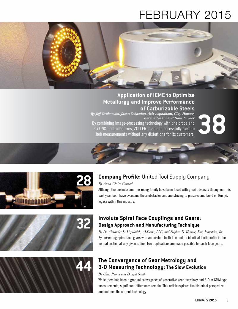
Application of ICME to Optimize Metallurgy and Improve Performance
of Carburizable SteelsBy Jeff Grabowski, Jason Sebastian, Aziz Asphahani, Clay Houser,
Kerem Taskin and Dave SnyderBy combining image-processing technology with one probe and six CNC-controlled axes, ZOLLER is able to sucessfully execute
hob measurements without any distortions for its customers. 38
FEBRUARY 2015
Company Profile: United Tool Supply CompanyBy Anna Claire ConradAlthough the business and the Young family have been faced with great adversity throughout this
past year, both have overcome those obstacles and are striving to preserve and build on Rusty’s
legacy within this industry.
28
Involute Spiral Face Couplings and Gears: Design Approach and Manufacturing TechniqueBy Dr. Alexander L. Kapelevich, AKGears, LLC, and Stephen D. Korosec, Koro Industries, Inc.By presenting spiral face gears with an involute tooth line and an identical tooth profile in the
normal section at any given radius, two applications are made possible for such face gears.
32
The Convergence of Gear Metrology and 3-D Measuring Technology: The Slow Evolution By Chris Pumm and Dwight SmithWhile there has been a gradual convergence of generative gear metrology and 3-D or CMM type
measurements, significant differences remain. This article explores the historical perspective
and outlines the current technology.
44
BroachmasterFP.indd 4 12/20/11 2:36:20 PM
FEBRUARY 2015 5
DEPARTMENTS
Gear Solutions (ISSN 1933 - 7507) is published monthly by Media Solutions, Inc., 266D Yeager Parkway Pelham, AL 35124. Phone (205) 380-1573 Fax (205) 380-1580 International subscription rates: $72.00 per year. Periodicals Postage Paid at Pelham AL and at additional mailing offices. Printed in the USA. POSTMASTER: Send address changes to Gear Solutions magazine, P.O. Box 1210 Pelham AL 35124. Publications mail agreement No. 41395015 return undeliverable Canadian addresses to P.O. Box 503 RPO West Beaver Creek Richmond Hill, ON L4B4R6. Copyright®© 2006 by Media Solutions, Inc. All rights reserved.
No part of this publication may be reproduced or transmitted in any form or by any means, electronic or mechanical, including photocopy, recording, or any information storage-and-retrieval system without permission in writing from the publisher. The views expressed by those not on the staff on Gear Solutions magazine, or who are not specifically employed by Media Solutions, Inc., are purely their own. All "Industry News" material has either been submitted by the subject company or pulled directly from their corporate web site, which is assumed to be cleared for release. Comments and submissions are welcome, and can be submitted to [email protected].
American Gear ManufacturersAssociation
In this section, the premier supporter of gear manufacturing in the United States and beyond shares news of the organization’s activities, upcoming educational
and training opportunities, technical meetings and seminars, standards development, and the actions of AGMA councils and committees. 17
In an age where putting information out first seems to be valued over insuring that information is correct, it’s important to take the time to execute a quality product or service both for the customers’ benefit and your own.
TOOTHTIPS
David Senkfor
24
26Vacuum pumps and nitrogen can equally achieve low ppm oxygen levels. However, pumps are slow to remove water vapor while an inert gas purge is time consuming.
Jack Titus
HOTSEAT
When Master Gears are designed properly, errors can be deantified, and, with more discrimination, that type of error can be mapped out to indicate specific performance issues within the application itself.
MATERIALSMATTER
Fred Eberle
22
27Now that we’ve kicked off 2015, there’s one thing on everyone’s minds—making more money this year than what was made in 2014. In the gear manufacturing industry, there’s a sure fire way to ensure that will happen… increasing sales.
Anna Claire Conrad
TRENDTALKS
50 PRODUCTSHOWCASE
Marvin Nicholson,Pentagear Products LLC
56 Q&A
VOLUME 13 / NO. 02
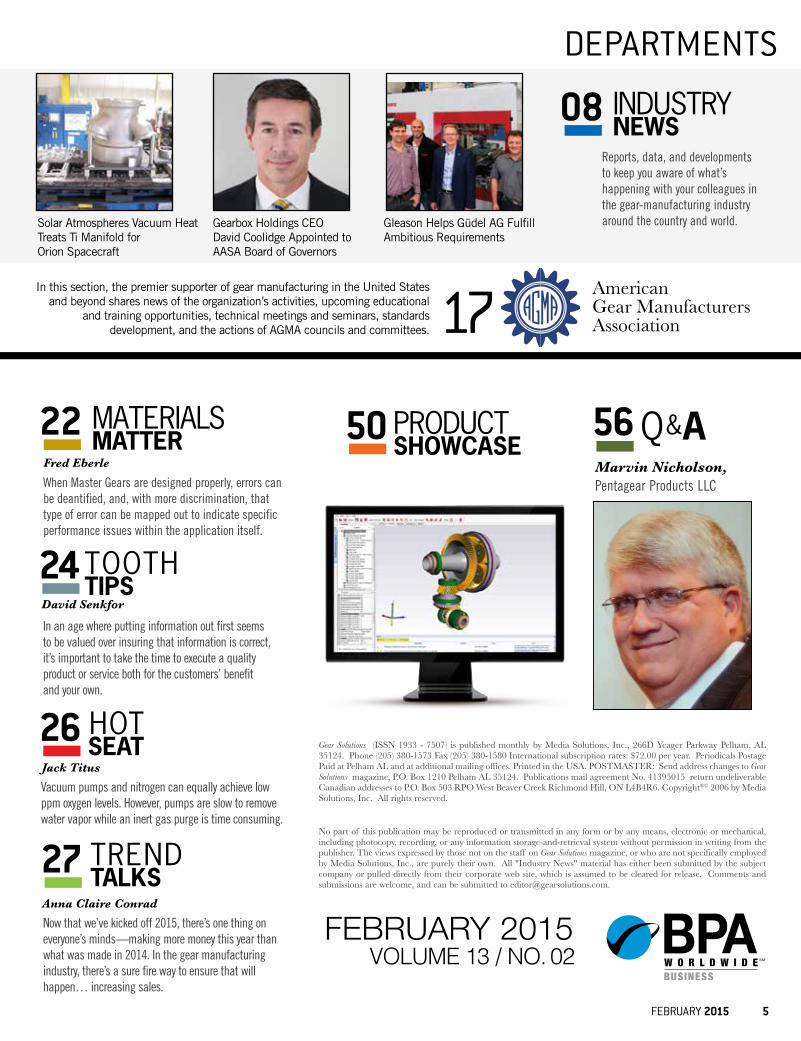
Reports, data, and developments to keep you aware of what’s happening with your colleagues in the gear-manufacturing industry around the country and world.
INDUSTRYNEWS08
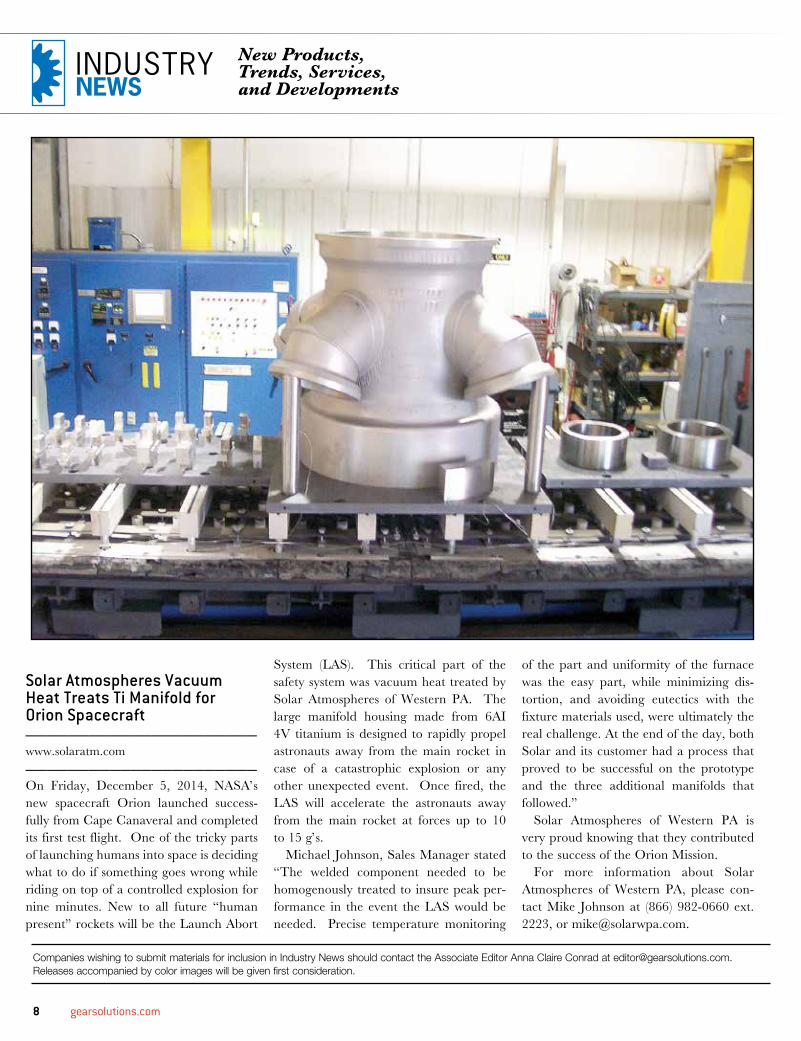
Solar Atmospheres Vacuum Heat Treats Ti Manifold for Orion Spacecraft
Gearbox Holdings CEO David Coolidge Appointed to AASA Board of Governors
Gleason Helps Güdel AG Fulfill Ambitious Requirements
FEBRUARY 2015
Last month, I talked about how quickly the new year snuck up on me, and even now, in February, my face still stings from the whiplash.
I mean, wasn’t I in college, like, yesterday? Didn’t I adopt my now 2-year-old puppy yesterday? And didn’t I get engaged two months ago as opposed to only having two months to go till the big day? It seems as though the better and more exciting my life gets, the more of a blur it becomes. Time has flown by these past few months, and I’m running at full-speed to keep up.
Thankfully, I’ve adjusted to all of these new challenges and opportunities well, and I’ve finally come up with a routine that keeps me productive and sane, which—let’s be real—benefits every-body.
Said routine requires a lot of exercise, good food, sleep, time spent with my family and friends, and, overall, TLC. That’s what fuels me. Similarily, the gear industry must be properly cared for if it’s expected to operate at its best.
This issue, we’ll explore a variety of ways to grow your business and have it flourish in 2015. Our company profile on United Tool Supply Company describes the man Rusty Young was as
both a family man and a professional, what he meant to this industry, and the legacy he left behind after passing away last February at the age of 69. We’ll also highlight what his son, Jeff, has done since taking over for his dad and what he has planned for United Tool throughout the year.
In this month’s Q&A, we spoke with Marvin Nicholson, founder and president of Pentagear Products LLC in Ohio. There, you’ll learn about the different ways he created a healthy, strong, and successful family business and what to expect from Pentagear in 2015.
And, as it is with every issue, our Hot Seat, Materials Matter, and Tooth Tips columnists are here to explain different ways to operate specific equipment and apply certain techniques in a real-world environment and how it can benefit you and make your operations and shop floor run more smoothly.
You may even learn a thing or two from what I have to say in Trend Talks about various methods of sales and how to market your business. We even dive into our how United Tool and Pentagear were able to do so at their respective operations. I’ll give you a hint... Higher quality of products and a more streamlined, efficient means of external and internal communication will result in a more successful business that yields higher sales numbers.
As always, the information you’ll read about in this issue will also be available online at www.gearsolutions.com, in the Gear Solutions app, and on our 2015 calendar.
In the midst of your New Year’s resolutions, make sure to make yourself a priority. Do what you need to do to operate at your best, and, consequentially, your gear business will follow suit.
Thanks for reading!
Anna Claire Conrad
Anna Claire Conrad
Associate editorGear Solutions magazine
[email protected](800) 366-2185 x205
6 gearsolutions.com
LETTER FROM THE EDITOR
PUBLISHED BY MEDIA SOLUTIONS, INC.P. O. BOX 1987 • PELHAM, AL 35124
(800) 366-2185 • (205) 380-1580 FAX
David C. CooperPUBLISHER
Chad MorrisonASSOCIATE PUBLISHER
Dav id C . C o operPRESIDENT
C had Mor r i s on VICE PRESIDENT
Ter e sa C o operOPERATIONS
EDITORIALStephen Sisk
EDITOR
Anna Claire ConradASSOCIATE EDITOR
SALESChad Morrison
ASSOCIATE PUBLISHER
CIRCULATIONTeresa Cooper
MANAGER
Kassie BogganCOORDINATOR
Jamie WillettASSISTANT
ARTJeremy Allen
CREATIVE DIRECTOR
Michele HallGRAPHIC DESIGNER
CONTRIBUTING WRITERSFRED EBERLE
DR. ALEXANDER L. KAPELEVICHSTEPHEN D. KOROSEC
CHRIS PUMMDAVID SENKFORDWIGHT SMITH
JACK TITUSE. ZOLLER GMBH & CO. KG
Coop wants to use this one for the website
Vertical Logo Horizontal Logo
New England Gear 343 John Downey Dr.
New Britain, CT 06051 p. 860-223-7778 • f. 860-223-7776 www.newenglandgear.com
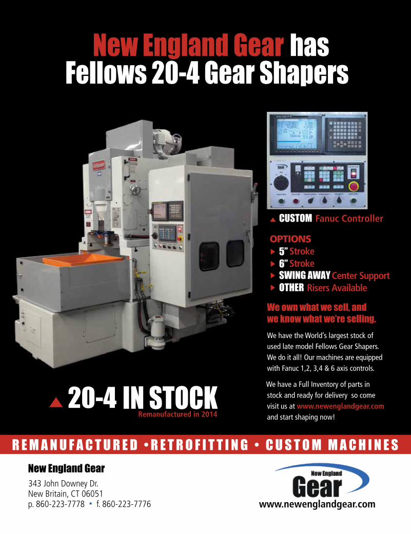
20-4
CUSTOM Fanuc Controller
OPTIONS5” Stroke6” StrokeSWING AWAY Center SupportOTHER Risers Available
We have the World’s largest stock of used late model Fellows Gear Shapers. We do it all! Our machines are equipped with Fanuc 1,2, 3,4 & 6 axis controls.
We have a Full Inventory of parts in stock and ready for delivery so come visit us at www.newenglandgear.com
and start shaping now!
We own what we sell, and
we know what we’re selling.
New England Gear has Fellows 20-4 Gear Shapers
R E M A N U F A C T U R E D • R E T R O F I T T I N G • C U S T O M M A C H I N E S
IN STOCKRemanufactured in 2014
NEG_Ad final_03.14.pdf 1 4/11/14 10:19 AM
8 gearsolutions.com
Companies wishing to submit materials for inclusion in Industry News should contact the Associate Editor Anna Claire Conrad at [email protected]. Releases accompanied by color images will be given first consideration.
Solar Atmospheres Vacuum Heat Treats Ti Manifold for Orion Spacecraft______________________www.solaratm.com______________________On Friday, December 5, 2014, NASA’s new spacecraft Orion launched success-fully from Cape Canaveral and completed its first test flight. One of the tricky parts of launching humans into space is deciding what to do if something goes wrong while riding on top of a controlled explosion for nine minutes. New to all future “human present” rockets will be the Launch Abort
System (LAS). This critical part of the safety system was vacuum heat treated by Solar Atmospheres of Western PA. The large manifold housing made from 6AI 4V titanium is designed to rapidly propel astronauts away from the main rocket in case of a catastrophic explosion or any other unexpected event. Once fired, the LAS will accelerate the astronauts away from the main rocket at forces up to 10 to 15 g’s.
Michael Johnson, Sales Manager stated “The welded component needed to be homogenously treated to insure peak per-formance in the event the LAS would be needed. Precise temperature monitoring
of the part and uniformity of the furnace was the easy part, while minimizing dis-tortion, and avoiding eutectics with the fixture materials used, were ultimately the real challenge. At the end of the day, both Solar and its customer had a process that proved to be successful on the prototype and the three additional manifolds that followed.”
Solar Atmospheres of Western PA is very proud knowing that they contributed to the success of the Orion Mission.
For more information about Solar Atmospheres of Western PA, please con-tact Mike Johnson at (866) 982-0660 ext. 2223, or [email protected].
New Products, Trends, Services, and Developments
INDUSTRYNEWS
FEBRUARY 2015 9
Motion Industries Announces Agreement to Acquire Miller Bearings Inc._____________________www.motionindustries.com _____________________Motion Industries, Inc. a completely owned subsidiary of Genuine Parts Company, has entered into a definitive agreement whereby Motion Industries has agreed to acquire Miller Bearings, Inc., headquartered in Orlando, Florida in the first quarter of 2015.
Miller Bearings is one of the leading inde-pendent distributors in the state of Florida for industrial MRO products, including bearings, power transmission products, fluid power, electrical and automation compo-nents, as well as safety and industrial sup-plies. Miller’s customers represent a broad cross-section of industries in the state, which are presently being served from 17 locations.
According to William “Bill” Bieberbach, President and CEO of Miller Bearings, “Miller has been in business for 67 years, employing more than 130 people. We are very excited to become part of Motion Industries and the opportunities for growth that will be available to our talented team.”
Tim Breen, President and CEO of Motion Industries, stated, “The addition of Miller Bearings better positions Motion Industries for continued growth in the Southeast. We want to welcome all of the Miller Bearings employees to the Motion family and we look forward to the contributions they will make to our Company in the years ahead.”
With annual sales of $4.5 billion, Motion Industries is a leading industrial parts dis-tributor of bearings, mechanical power trans-mission, electrical and industrial automation, hydraulic and industrial hose, hydraulic and pneumatic components, industrial products,
safety products, and material handling. Motion Industries has over 550 operations including 15 distribution centers through-out North America and serves more than 150,000 customers from the food and bever-age, pulp and paper, iron and steel, chemical, mining and aggregate, petrochemical, auto-motive, wood and lumber, and pharmaceuti-cal industries.
Motion Industries is a wholly owned subsidiary of Genuine Parts Company (NYSE: GPC). You can contact them toll-free at (800) 526-9328.
Gearbox Holdings CEO David Coolidge Appointed to AASA Board of Governors _____________________www.raybestospowertrain.com_____________________The Automotive Aftermarket Suppliers Association (AASA) has elected Gearbox Holdings CEO, David Coolidge, to a
three-year term on its Board of Governors. Coolidge re-joins the AASA with sev-eral years of experience, having served as Chairman of the Board in 2011.
“I am honoured to once again be a part of the AASA and to serve alongside an esteemed group of executives in such an influential automotive aftermarket organization,” said Coolidge.
10 gearsolutions.com
The AASA (www.aftermarketsuppli-ers.org) exclusively serves manufacturers of automotive aftermarket components, tools, equipment and related products in support of 710,000 employees in the United States. The AASA is recognized as an industry change agent that pro-
motes a collaborative industry envi-ronment through providing a forum to address issues and serving as a valued resource for its members.
Based in Oakbrook Terrace, Ill., Gearbox Holdings, Inc., designs, man-ufactures and distributes transmission, wet-wheel braking and steering compo-nents under the Raybestos Powertrain, Allomatic and Steel Parts brand names. These components provide solutions for automotive OEMs, auto and industrial suppliers, heavy-duty transmission and wet-wheel brake manufacturers.
For more information, contact Al Avila at (765) 359-2861 or by email at [email protected].
Climate-KIC Accelerator in Germany Opens for New Start-ups_____________________www.climate-kic.org_____________________Climate-KIC’s centre in Germany are calling for new applications to their clean-tech incubation program. Start-
ups with a business idea tackling climate change can apply for the Climate-KIC Accelerator until 16 February 2015.
The Climate-KIC Accelerator supports entrepreneurs to transform their climate innovations into sustainable business mod-els and marketable products or services. It helps the most promising start-ups to con-nect with the right experts, to formulate their business plans, develop their entre-preneurial skills and fund their businesses through the early stages.
The incubation programme consists of three stages of six months offering an overall package worth up to €95,000. Accepted start-ups get professional pitch training and business coaching, substan-tial financial support, office space at a clean-tech incubator in Berlin or Munich and access to the exclusive European and international Climate-KIC network to help find investors and first customers.
How to applyClimate-KIC is looking for entrepre-neurs with scalable and technological-
NEW RELEASE 03/2014
KISSsoft Highlights● Strength calculation and 3D models of beveloid gears● Simulation of flank wear based on iterative calculation● Enhanced sizing for gear modifications● 3D display of shafts and bearings● Efficiency and thermal rating in KISSsys● And many more ...
Get your free trial version atwww.KISSsoft.com
KISSsoft USA, LLC3719 N. Spring Grove Road
Johnsburg, Illinois 60051Phone (815) 363 8823
GearSol_KISSsoft_Rel_03_2014_Highlights_92_25x123_83mm.indd 1 5/5/2014 10:57:35 AM
Unite-A-Matic™
P.D. GEAR INSPECTION
0-12” OD CAPACITY • 0-9” ID CAPACITY • SHAFT CAPABLE SHOP HARDENED • LOWEST COST IN THE INDUSTRY
+/- .001 MM REPEATABILITY
UNITE-A-MATIC.COM
FEBRUARY 2015 11
ly promising business ideas that have high impact on climate change. Start-up teams of at least two persons can apply here.
Applications are open from January, 1 through Febraury 16, 2015. A selection round with live pitches will be held in March, before the new program starts on April 1, 2015.
Information and ContactFor further information on the German Accelerator programme click here or contact Maura Kessel, Manager of the Accelerator programme at Climate-KIC Germany.
Interested start-ups also have the opportunity to meet the Accelerator team at following dates:
• Open office hours on Thursdays 9:30 – 11:30 am at Climate-KIC Germany, EUREF-Campus, Berlin-Schöneberg
• Open office hours on Tuesdays 2:00 – 4:00 pm at UnternehmerTUM GmbH, Garching, Munich
• Climate Hackathon, 23 – 25 January 2015, at Green Garage, EUREF-Campus, Berlin-Schöneberg (details)
• UnternehmerTUM Network Meeting “Entrepreneurs’ Night”, 28 January 2015, 7 pm, at Oskar von Miller Forum, Oskar-von-Miller-Ring 25, 80333 Munich
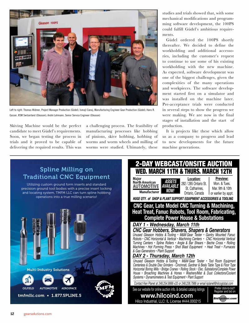
Gleason Helps Güdel AG Fulfill Ambitious Requirements_____________________www.gleason.com_____________________The new Gleason 100PS Power Skiving Machine: first results are in with an installation at Güdel AG, Langenthal, Switzerland, a leading worldwide manufac-turer of machinery and factory equipment, with particularly strong manufacturing and process automation capabilities.
Güdel and Gleason-Pfauter Studen have long cultivated a relationship as suppliers and users of each other’s prod-ucts. Currently, Güdel is producing gear components on Gleason machines, and we are integrating Güdel automation systems in our products. In February,
2013 a team of management, purchas-ing and sales personnel from Gleason Pfauter Studen visited Güdel in order to exchange information and discuss vari-ous subjects of mutual interest. In these discussions we learned that Güdel was facing serious problems with one of their old hobbing machines, and had started a project to replace it. In the course of
further meetings it became clear that the machine Güdel was looking for had to cover a wide range of components, produced with different processes. No single ‘off-the-shelf’ machine was suit-able. The most important application was the skiving of worm shafts, ranging from 1 to 10 starts. It became clear to us that our new Gleason 100PS Power
12 gearsolutions.com
Skiving Machine would be the perfect candidate to meet Güdel’s requirements. Soon, we began testing the process in trials and it proved to be capable of delivering the required results. This was
a challenging process. The feasibility of manufacturing processes like hobbing of pinions, skive hobbing, hobbing of worms and worm wheels and milling of worms were studied. Ultimately, these
studies and trials showed that, with some mechanical modifications and program-ming software development, the 100PS could fulfill Güdel’s ambitious require-ments.
Güdel ordered the 100PS shortly thereafter. We decided to define the workholding and additional accesso-ries, including the customer’s request to continue to use some of his existing workholding with the new machine. As expected, software development was one of the biggest challenges, given the complexities of the many operations and workpieces. The software develop-ment started first on a simulator and was installed on the machine later. Pre-acceptance trials were conducted in several steps to show the progress we were making. We are now in the final stages of installation and the start of production.
It is projects like these which allow us as a company to progress and lead to new developments for the future machine generations.
Left to right: Thomas Widmer, Project Manager Production (Güdel); Ismajl Canaj, Manufacturing Engineer Gear Production (Güdel); Hans R.
Gasser, RSM Switzerland (Gleason); André Lehmann, Senior Service Engineer (Gleason)
Spline Milling on Traditional CNC Equipment
Utilizing custom ground form inserts and standard precision ground tool bodies with a precise insert locking and locating system, TMFM LLC can turn spline hobbing
operations into a true milling scenario!
tmfmllc.com • 1.877.SPLINE.5
Multi-Industry Solutions
OILFIELD AUTOMOTIVE AEROSPACE
CLIENT: GM_St_ Cath
AD SIZE: 3.75 X 4.875” (Marketplace)
INSERTION #: HI-5393
PUBLICATION: Gear Solutions
DATE: Feb.
CONTACT: Chad M.
2-Day WEbcaSt/OnSitE aUctiOn
Contact Ken Planet at 248.254.9999 x33 or 248.238.7988 or email [email protected]
Location:282 / 285 Ontario St.
St. Catharines, Ontario, Canada
Preview:Mon. & Tues.
Mar. 9th & 10th or earlier by appt.
CNC Gear, Late Model CNC Turning & Machining,Heat Treat, Fanuc Robots, Tool Room, Fabricating,
Complete Power House & SubstationsDAY 1 - Wednesday, March 11th
DAY 2 - Thursday, March 12thUnused Gleason Hobbs & Tooling • M&M Gear Tester • Tool Room Equipment Centerless & Double Disc Grinders - Cincinnati, Gardner & Besly Table Type & Floor TypeHorizontal Boring Mills • Bridge Cranes • Rolling Stock • Elec. Substations/Complete Power House • Broaching Machines & Hones • Washers/Mist & Dust Collectors/Coolant Systems • Dynamometers & Test Equipment • Plant Support
CNC Gear Hobbers, Shavers, Shapers & Generators Unused Gleason Hobbs & Tooling • M&M Gear Tester • Gantry Mounted Fanuc Robots • CNC Horizontal & Vertical • Machining Centers • CNC Horizontal VerticalTurning Centers • Spline Rollers • Angle & Bar Shears • Beche Cross • Rolling Machines • Hot Forming Press • Shot Blast Equipment • Heat Treat • Furnaces & Gas Generators • Plant Support
Prefer click-to-bid? Register and bid onSee our website for online auction info. & detailed catalog listings
Hilco Industrial, LLC: IL License #444.000215www.hilcoind.com
HUGE QTY. of SHOP & PLANT SUPPORT EQUIPMENT ACCESSORIES & TOOLING
ASSETS AVAILABLE
NOW!
WED. March 11th & thUrS. March 12th
FEBRUARY 2015 13
Ipsen Announces New Vice President of Sales, Patrick McKenna_____________________www.ispenusa.com_____________________
Ipsen USA is pleased to welcome the newest member of the Ipsen Team, Patrick McKenna as Vice President of Sales. He is replacing Art Tsubaki, who is now Managing Director of Ipsen Japan. Reporting to Geoffrey Somary, CEO of Ipsen USA and COO of Ipsen Group, McKenna is responsible for all new equipment and aftermarket sales. He is also a member of the Ipsen USA Executive Team and the global Ipsen Group Management Committee.
McKenna earned his bachelor’s degree in mechanical engineering (BSME) from the University of Illinois at Chicago and a master’s degree in manufacturing engineer-ing (MME) from Northwestern University. Previously, McKenna was Vice President of the renowned Nevada Heat Treating, Inc. (including California Brazing), which special-izes in the heat treating and brazing of critical components found at the heart of complex machines. As an active member of the compa-ny’s board of directors since 2002, McKenna was instrumental in their growth, helping the company increase revenues more than 15 times over.
McKenna has also served on the Metal Treating Institute (MTI) Board of Trustees since 2006 and has held the following posi-tions: President Elect (2015), Treasurer (2014) and Membership Committee Chairperson
(2008-2014). In addition, he was selected to serve on the MTI Furnaces North America Technical Program Committee in 2008 and 2010, during which he was chosen both years to be a moderator for their technical sessions. McKenna has received several awards from the MTI, including the President’s Award (2014) and the Heat Treater of the Year/Master Craftsman award (2011).
At Ipsen, McKenna’s responsibilities include managing the sales and distribution chan-nels of all Ipsen equipment and aftermarket into the North and South American markets. McKenna’s vast heat-treating knowledge and industry experience, along with his proven ability to drive results and create growth, will be instrumental in continuing Ipsen’s mission to be a partner in their customers’ success.
14 gearsolutions.com
U.S. Cutting Tool Consumption Down 18.9% in November_____________________www.amtonline.org_____________________November U.S. cutting tool consumption totaled $156.9 million, according to the U.S. Cutting Tool Institute (USCTI) and AMT – The Association For Manufacturing Technology. This total, as reported by companies participating in the Cutting Tool Market Report (CTMR) collaboration, was down 18.9% from October’s total and up 0.4% from November 2013.
These numbers and all data in this report are based on the totals actually reported by the companies participating in the CTMR pro-gram. The totals here represent about 80 percent of the U.S. market for cutting tools.
“Although this month registered the lowest volume of cutting tool shipments we’ve seen since 2013, this 18.9% decrease is in part due to the record breaking sales we had in October,” said Brad Lawton, chairman of AMT’s Cutting Tool Product Group. “Year-to-date ship-ments are on par with 2013. As manufacturers’ backlogs continue to grow, we expect shipments to rebound before the end of the year.”
The Cutting Tool Market Report is jointly compiled by AMT and USCTI, two trade associations representing the development, production and distribution of cutting tool technology and products. It provides a monthly statement on U.S. manufacturers’ consumption of the primary consumable in the manufacturing process – the cutting tool. Analysis of cutting tool consumption is a leading indicator of both upturns and downturns in U.S. manufacturing activity, as it is a true measure of actual production levels.
Historical data for the Cutting Tool Market Report is available dat-ing back to January 2012. This collaboration of AMT and USCTI is the first step in the two associations working together to promote and support U.S.-based manufacturers of cutting tool technology.
AMT – The Association For Manufacturing Technology repre-sents and promotes U.S.-based manufacturing technology and its members—those who design, build, sell, and service the continuously evolving technology that lies at the heart of manufacturing. Founded in 1902 and based in Virginia, the association specializes in providing targeted business assistance, extensive global support, and business intelligence systems and analysis. AMT is the voice that communicates the importance of policies and programs that encourage research and innovation, and the development of educational initiatives to cre-ate tomorrow’s Smartforce. AMT owns and manages IMTS – The International Manufacturing Technology Show, which is the premier manufacturing technology event in North America. The USMTO report is compiled by AMT and all data in the report is based on the totals of actual data reported by companies participating in the USMTO program.
The United States Cutting Tool Institute (USCTI) was formed in 1988 and resulted from a merger of the two national associations representing the cutting tool manufacturing industry. USCTI works to represent, promote, and expand the U.S. cutting tool industry and to promote the benefits of buying American-made cutting tools manu-factured by its members. The Institute recently expanded its by-laws to include any North American manufacturer and/or remanufacturer
305-691-6300800-248-5152
At Southern Gear & Machine, your parts are in the capable hands of our machinists and engineers who have an average of 25 years of experience in gear manufacturing.
When you place your order with Southern Gear, you can rest assured that experienced engineers and machinists are creating your part, at our facility, under our quality control, and with our outstanding customer service.
Can your current gear manufacturer make these same guarantees?
Our machinists and engineers have an average of • 25 years experience in gear manufacturing.
Our employees have been with our company an• average of 13 years.
We have more the 50 gear cutting machines alone.•
We outsource only plating, heat treating and NDT.•
We have been manufacturing precision gears for • 58 years.
We have invested close to one million dollars in• equipment each year for the past five years.
SouthernGearFeb2015GearSolutionsad.indd 1 1/15/15 1:31:06 PM
FEBRUARY 2015 15
of cutting tools, as well as post-fabrication tool surface treatment providers. Members, which number over 80, belong to seven product divisions: Carbide Tooling, Drill & Reamer, Milling Cutter, PCD & PCBN, Tap & Die, Tool Holder and All Other Tooling. A wide range of activities includes a compre-hensive statistics program, human resources surveys and forums, development of product specifications and standards, and semi-annual meetings to share ideas and receive informa-tion on key industry trends.
UTC Aerospace Systems Recognized as Gold Supplier by the Defense Logistics Agency_____________________www.utc.com_____________________United Technologies Corp.’s Aerospace Systems has been recognized as a Gold Tier supplier for the Defense Logistics Agency (DLA) as part of the Department of Defense’s Superior Supplier Incentive Program (SSIP). The Gold Tier includes the DLA’s highest performing suppliers for 2013-2014 mea-sured in areas such as cost, schedule, per-formance, quality, and business relations. UTC Aerospace Systems is a unit of United Technologies Corp. (NYSE: UTX).
The DLA evaluated 153 of its suppliers as part of the SSIP. Forty suppliers were selected as superior suppliers, of which only 15 were identified in the highest tier as Gold suppli-ers. Suppliers were selected based on the fol-lowing criteria: performance against current contracts with the DLA, ratings in the federal Contractor’s Performance Reporting System (CPARS), and established partnerships with the DLA that focus on cost-saving initiatives.
“UTC Aerospace Systems is laser-focused on meeting our customers’ requirements, so we are delighted that the Defense Logistics Agency sees us as a sup-plier performing at the highest levels,” said Vice President of UTC Aerospace Systems Customer Service Raffaele Virgili. “We have put a tremendous amount of effort into building our relationship with the DLA, including dedicated, on-site sup-port and delivering on our cost, quality and performance commitments. This rec-ognition acknowledges those efforts and the great work and commitment of our employees.”
UTC Aerospace Systems currently has spare parts contracts with the DLA that span all UTC Aerospace Systems’ segments, including actuation and propeller, nacelle, air management, electric, ejection seats, sensing, landing gear, engine, sensors, wheels, and brakes.
UTC Aerospace Systems designs, manufactures and services integrated sys-
tems and components for the aerospace and defense industries. UTC Aerospace Systems supports a global customer base with significant worldwide manufacturing and customer service facilities.
UTC, based in Hartford, Connecticut, provides high technology products and services to the building and aerospace industries.
Engineered Tools CorporationETC1307 E. Maple Rd., Suite “G”, Troy, MI 48083PH: (248) 619-1616 | FAX: (248) 619-1717
2710 West Caro Rd., Caro, MI 48723PH: (989) 673-8733 | FAX: (989) 673-5886
– Complete line of Bevel Gear Tooling– Cutter Body Reconditioning to O.E.M. Specifications
and Cutter Body Maintenance Program– Precise Wire EDM Forms for Stick Blades
Choose the stick that works, cause work doesn’t stop
Cutter body hardware
HSS Blade Sets & solid body cutters for Spiral Bevel Gears
HSS straight bevel gear cutting tools
Spring loaded Cutter body screws
NEW and RECONDITIONED CUTTER BODIES for Sale.
WE PURCHASE USED CUTTER BODIES IN ANY CONDITION engineeredtools.com
FEBRUARY 2015 17
Justin SikorskiAGMA Staff Engineer
American Gear ManufacturersAssociation
AGMA Technical Committees Complete Active 2014 By Justin Sikorski, AGMA Staff Engineer
Over the course of the past year, AGMA technical committees have been hard at work producing the standards and infor-mation sheets that help the gear industry operate effectively and efficiently. In 2014, AGMA published new revisions of three standards, a brand new information sheet, and adopted an ISO standard. The de-velopment of these documents would not have been possible without the dedicated support and expertise that the AGMA membership provides to the association. The staff of the AGMA Technical Division thanks each individual, and their compa-nies, for all of this hard work.
AGMA has always relied on the dedi-cated support and expertise of our mem-bership to develop the technical standards and information sheets that continually move the gear industry forward. However, the benefits of participation on a techni-cal committee are not only enjoyed by the readers of the published documents. The members of AGMA technical committees are the authors of the standards that the gear industry follows. Technical commit-tee members, and their companies, find this opportunity very beneficial profession-ally and intellectually. Each member of a technical committee has the opportunity to interact with, and learn from, their coun-terparts from all around the gear industry, as well as, gain an intimate understanding
of the information contained within the document being developed. The major-ity of technical committee meetings take place via web conferences allowing par-ticipants to attend the meetings without significant disruptions to their day-to-day responsibilities.
The following is a list of documents that AGMA technical committees published in 2014: • ANSI/AGMA 1010-F14, Appearance of
Gear Teeth - Terminology of Wear and Failure;
• ANSI/AGMA 6011-J14, Specification for High Speed Helical Gear Units;
• ANSI/AGMA 2011-B14, Cylindrical Wormgearing Tolerance and Inspection Methods;
• ANSI/AGMA ISO 1328-1-B14, Cylin-drical Gears – ISO System of Flank Tol-erance Classification - Part 1: Definitions and Allowable Values of Deviations Rel-evant to Flanks of Gear Teeth;
• AGMA 919-1-A14, Condition Monitor-ing and Diagnostics of Gear Units and
Open Gears: Part 1 – Basics.In addition to the standards and informa-tion sheets, AGMA has also released new versions of two of its most popular soft-ware offerings, Gear Rating Suite v. 3.1 and Bevel Gear Rating Suite v. 1.3. The new versions of the software include up-
dates to the latest applicable standards as well as fixes of several bugs found in previ-ous versions.
Looking forward to 2015, there are several exciting projects that are going to get under-way. The first is a revision of AGMA 925-A03, Effect of Lubrication on Gear Surface Distress. The current version AGMA 925 provides methods for calculating elastohy-drodynamic lubrication (EHL) film thickness and contact temperature. It also provides methods for predicting the probability of un-wanted surface distresses such as wear and scuffing. As part of the revision, the commit-tee is planning to update these methods and will attempt to develop a method for predict-ing the probability of micropitting.
Another project that will be getting un-derway in the new year is the second part of AGMA 919. Part two of AGMA 919 will look at the application of diagnostic tools and instrumentation to analyze vibration, acoustics, motor current signature, and lu-brication. The information sheet will also discuss the methods for condition monitor-ing, performing diagnostics, monitoring tem-perature, establishing baseline data for trend analysis, and non-destructive testing of in-service gear units and open gearing.
The Metallurgy and Materials Commit-tee will also be starting a revision of AGMA 923-B05, Metallurgical Specifications for Steel Gearing. This document identi-
18 gearsolutions.com
This year’s Annual Meeting will address the key issues facing manufacturing and offer opportunities to network, make memories, forge relationships, and build on future partnerships. We look forward to welcoming you to Napa Valley — one of the most picturesque areas of the world. Join us for the 2015 AGMA/ABMA Annual Meeting at The Meritage Hotel and Spa, April 29 - May 1, 2015.
The general sessions at the 2015 AGMA/ABMA Annual Meeting feature speakers who will address current issues of importance for our industries. The speakers will provide expertise and inspiration.
Complete Champion Leadership: How Fast Can You Get Fast?Derek Daly, international racing champion, best-selling author, and television’s face of motor sports
If the speed of doing business will continue to increase in the next 10 years, ask yourself, how fast can we get fast? Daly will demonstrate that “fast” is having the right people in the right places doing the right things, but more importantly, it is removing the speed bumps that slow them down. Daly, and Irish driving legend, is the epitome of the complete champion. From the victory circle to the announcer’s desk, the Hall of Fame Race Car Driver and network television anchor has spent nearly three decades as the face of the motorsport world. Born and
raised in Dublin, Ireland, Daly’s career path was set at the age of 12 when he attended his first auto race. Daly has shared these timeless speed-related busi-ness principles with a diverse group of companies in the private sector and the U.S. government. They have all shared in Daly’s complete championship model to motivate, inspire and enlighten their teams.
Rethink, and ThriveMichael Rogers, author and futurist-in-residence, The New York Times
More and more of how we work is moving into the virtual world — our work process, how we collaborate
with partners and how we manage our employees. Virtual organization, global connectivity, smart objects, cloud-based intelligence all will shape the rest of this decade. And the next generation of workers will bring even more digital skills and demands. What will the work and production envi-ronment of 2020 look like? What steps should we take now to make sure our businesses move in the right direction?
Rogers is a best-selling author, technology pio-neer and futurist. He regularly speaks to audiences worldwide at Fortune 500 companies about imple-menting the future in useful ways. Rogers earned his degree in physics and worked in the technology field before branching off as a futurist.
Looking at the Reshoring InitiativeHarry Moser, President, The Reshoring Initiative
fies metallurgical quality characteristics which are important to the performance of steel gearing, and performance levels of gearing by heat treatment method and grade number. For each heat treatment method and AGMA grade number, ac-ceptance criteria are given for the various
metallurgical characteristics identified in this document. With this revision, the committee is looking to ensure the docu-ment’s continued compatibility with the latest industry practices.
A full listing of AGMA technical com-mittees, including a scope of their activi-
ties, can be found in the Technical Commit-tees section of the AGMA website, www.agma.org. For additional information about AGMA technical committees, standards, and information sheets, or about AGMA software, please contact the AGMA Techni-cal Division at [email protected].
Annual Meeting Speakers Provide Business Intelligence

FEBRUARY 2015 19
CALENDAR OF EVENTSWhether you’re looking for technical education, networking opportunities, or a way for your voice to be heard in the standards process, AGMA has something to offer you. If you would like more information on any of the following events visit www.agma.org or send email to [email protected].
**Events are open to AGMA members only. Not a member? Send e-mail to [email protected].
Epicyclic Enclosed Drives Committee Meeting – February 3, 2015 WebEx
Lubrication Committee Meeting – February 5, 2015 WebEx
Aerospace Committee Meeting – February 9-10, 2015 Reno, NV
Metallurgy & Materials Committee Meeting – February 17, 2015 WebEx
Gear Materials: Selection, Metallurgy, Heat Treatment, and Quality Control – February 18-20, 2015 Clearwater Beach, FL
Wind Turbine Committee Meeting – February 19-20, 2015 Denver, CO
Worm gearing Committee Meeting – February 24, 2015 WebEx
Powder Metallurgy Committee Meeting – March 3, 2015 WebEx
Helical Gear Rating Committee Meeting – March 10-11, 2015 Chicago, IL
Metallurgy & Materials Committee Meeting – March 12-13, 2015 Chicago, IL
Cutting Tools Committee Meeting – March 16-17, 2015 Charleston, SC
Vehicle Gearing Committee Meeting – March 24-25, 2015
Gearbox CSI: Forensic Analysis of Gear & Bearing Failures March 24-26, 2015 WebEx
Vehicle Gearing Committee Meeting March 31, 2015 WebEx
MA
RC
HFE
BR
UA
RY
The increasing advantages of producing in America for the North American market are driving compa-nies to reevaluate offshoring. A high percentage of the jobs reshored are in gear and bearing intense mechanical product industries such as appliances, machinery and automotive components. During this session, you will be exposed to the statistics regard-ing the current trends. Learn the what, where, and the why of reshoring and how it can be applied to your company. Harry will provide tools for comparing the economics of offshoring to reshoring.
Harry is in a unique position to provide advice on this subject. Prior to starting the Reshoring Initiative, he worked for GF AgieCharmilles, start-ing as President in 1985 and retiring in 2010 as Chairman Emeritus. He now devotes his time fully to the Reshoring Initiative, whose goal is to bring manufacturing jobs back to the United States.
Economic and Market Outlook – Getting Old or Starting Fresh?James P. Meil, Principal, Industry Analysis, ACT Research
By the summer of 2015, the economic recovery and expansion will be six years old. However, its slow pace leads some observers to think that even now, we are still in a lingering recession. The statistics show that it has been the slowest, least dynamic economic rebound of the post-1945 experience. Jim Meil returns to answer the most important ques-tion - will 2015 and 2016 bring a change, or more of the same?
Returning AGMA/ABMA Annual Meeting attendees will remember Meil’s previous presentations he gave as the Chief Economist from Eaton Corporation. After retiring from Eaton, Jim joined ACT Research in 2014 and now will continue to share his views on the U.S. economy. He will add insights to the domestic and international markets and discuss how the energy environment and exchange rates will affect the key machinery market outlook overall.
20 gearsolutions.com
John Cross: President, ASI Technologies
Kenneth J. Flowers: Owner and Vice President, Machine Tool Builders, Inc.
Bill Gornicki: Vice President Sales & Marketing, ALD Holcroft Vacuum Technologies Co., Inc.
John E. Grazia: President, GearTec Inc.
Sulaiman Jamal: Managing Director, Bevel Gears India
Steve Janke: President, Brelie Gear Company, Inc.
Jan Klingelnberg: CEO/CFO, Klingelnberg
Justin McCarthy: Vice President , Sales, Scot Forge Company
Mark Michaud: President, REM Surface Engineering
Brian L. Schultz: President, Great Lakes Industry, Inc.
Dylan Smith: President, VanGear
Wendy Young: President, Forest City Gear Company
AGMA LEADERSHIP
BO
AR
D O
F D
IREC
TOR
S
Lou Ertel: ChairmanOverton Chicago Gear Corporation
Matt Mondek: Chairman EmeritusPresident/CEO, Reliance Gear Corporation
Dean Burrows: TreasurerPresident,Nixon Gear
John Strickland, Jr.: Chairman, BMECFairfield Manufacturing Co.
Buzz Maiuri: Chairman, TDECSenior Product Manager, The Gleason WorksE
XEC
UTI
VE C
OM
MIT
TEE
Joe T. Franklin, Jr.: President
Amir Aboutaleb: Vice President , Technical Division
Jill Johnson: Director, Member Services
STA
FF
1001 N. Fairfax Street | Suite 500 Alexandria, VA 22314
(703) 684-0211 | www.agma.org
General requests: [email protected] | Membership questions: [email protected] | Gear Expo information: [email protected] Technical/Standards information: [email protected] | AGMA Foundation: [email protected]
American Gear ManufacturersAssociation
AGMA OFFERS EDUCATION PROGRAMS FOR ALL LEVELS OF EMPLOYEES
Whether you are new to the gear industry, or are a vet-eran gear engineer, AGMA offers a variety of programs that can help you. Gain an edge over the competition this year with new opportunities from AGMA.
These are only a few of the many choices available to you this year. To learn more about each one, visit AGMA’s website.
Gearbox CSI: Forensic Analysis of Gear & Bearing FailuresMarch 24-26, 2015 | 8:00 am - 5:00 pm dailyConcordville, PA
This seminar teaches the forensic analysis of failed gearboxes. Learn about the limitation and capabilities of rolling element bearings and the gears that they support so you can properly apply the best gear-bearing combination to any gearbox, whether simple or complex. Following this seminar, participants will be able to –
• Apply their understanding of forensic analysis of gearbox failures in future gearbox designs
• Discuss bearing and gear types• Explain how bearing selection is influenced by gear
type and loading• Select appropriate bearing types and configurations
as influenced by gear type and loading• Explain how to optimize bearing and gear
combinations• Identify seven material and manufacturing related
defectsComplete information is available on the AGMA website.
Basic Training for Gear ManufacturingApril 13-17, 2015 | 8:00 am - 4:00 pm dailyDaley College, Chicago, IL
Students learn the fundamentals of gear manufacturing in this classroom and hands-on course. In the class-room this course offers training in gearing and nomen-
clature, principles of inspection, gear manufacturing methods, and hobbing and shaping. In the hands-on gear lab, using manual machines, students can see the interaction between the cutting tool and the workpiece. They understand the process and the physics of making a gear and can apply this knowledge in working with CNC equipment commonly in use.Following this seminar, participants will be able to –
• Demonstrate understanding of the evolution, history, and function of gears
• Show and describe 14 gear tooth features• Describe six typical gear characteristics that are
measured• Demonstrate knowledge of gauging vs. measurement• Utilize and describe a variety of analysis methods• Troubleshoot many of their own problems, because
they fully understand the process
Complete information is available on the AGMA website.

of the Trade
Throughout the manufacturing process, heat treatment is consistently viewed as a critical step for adding value to the parts produced. A part expensively manufactured by melting, hot rolling or forging, annealing, rough machining, teeth cutting and grinding is essentially useless and of little to no value without heat treatment. In addition, without reliable and repeatable heat treatment, it is impossible to achieve competitive overall manufacturing costs.
Amazingly, the cost for a manufacturing step that adds such a high value is only a fraction of the total production costs – generally in the range of no more than 5%. This percentage, however, increases to roughly 15% of the costs per part if all further post-treatment process steps inherent with, or caused by, heat treatment – such as cleaning, blasting, straightening and/or grinding – are taken into account. Therefore, a noticeable reduction of the manufacturing costs is only possible by minimizing the distortion of parts. For this, all the influencing parameters like steel melting, forming of the parts, uniformity of microstructure and hardenability, as well as ...
Make Your Atmosphere Furnace Work for You:
Call Our Sales Team
800.727.7625Ask for Rene, ext. 2695
www.IpsenUSA.com/AtmosphereFurnaceTips
Read the full technical articlefor tips on making the most of your atmosphere furnace:
www.IpsenUSA.com
for Carburizing and Quenching
From system integration to energy efficiency, Ipsen’s batch atmosphere ATLAS® furnace has the answers.
The ATLAS features …
• Single-chain furnace model that integrates into existing lines with ease • Intuitive, user-friendly Carb-o-Prof® control software that delivers time- and cost-saving simulation functions and adaptive control
• Recon® III Burners that increase thermal efficiency up to 75%
• Resilient refractory lining that uses insulating fibers and rigid firebricks
• Consistent uniformity
®
22 gearsolutions.com
When Master Gears are designed properly, certain errors can be identified, and, with more discrimination, that type of error can be mapped out to indicate specific performance issues within the application itself.
Fred EberleTechnical Engineer Hi-Lex Automotive Center
USING MASTER GEARS In the design of generated and molded gears, it is common to specify a total composite error (TCE) tolerance for in-process inspection, especially for high volume production. TCE is defined as variation in center distance when rolled in tight mesh with a highly accurate master gear on a floating spring arbor. Highly accurate means that the errors in the master gear are negligible in comparative magnitude to the test gear. The purpose of roll testing is to assess attributes of gear quality in a production gear against a highly accurate master gage. The measurement itself is reflected back as composite error in the production or work gear. Even though composite error is an accumulation of diverse errors, the results can give indications as to whether the production gear is consistent with design intent. In some cases, the specific errors can be mapped to specific application performance issues.
MASTER GEAR DESIGN QUESTIONS• For helical masters, given the total
operating profile length and its location in degrees of roll: how is the number of teeth determined for the master gear?
• What is the effect of a helical overlap ratio on composite measurement?
• For helical masters, what is the right face width specification of the master relative to the production gear?
• For high-contact gears, where mating mesh contact ratio of the production gear with the master is greater than 2.0, how do you insure that the master will not span more than one tooth and will give a true double flank composite reading?
• Can a Gage R&R be done on double flank composite inspection equipment?
MASTER GEAR DESIGN CONSIDERATIONSMaster gears used in double flank composite measurements must meet the following design criteria in order to mesh properly with a test gear:• The tip of the master gear must not contact
the test gear below the form diameter of the test gear. This applies to initial contact and to any type of secondary contact in the fillet zone due to inadequate clearance.
• The tip of the test gear must not contact the master gear below the form diameter of the master gear. This applies to initial contact and to any type of secondary contact in the fillet zone due to inadequate clearance.
• The minimum contact ratio of the double flank test must not be less than 1.0 when taking into account the maximum tooth thickness, minimum outside diameter, maximum root diameter, and maximum tip radius of the test gear. If the contact ratio drops below 1.0, then the meshing action of the gears on the test will generate an immediate jump in the double flank result for every tooth meshing cycle. This happens when the spring of the slide on the composite tester compensates for the loss of mesh force by abruptly pushing the gears together.
• The master gear and the test gear must have the same normal base pitch. In most cases, this is when the normal module and normal pressure angle match between the master and the test gear. However, mathematically, it is possible to mesh a
master gear with a different normal module and normal pressure angle than the test gear if the following equation is satisfied:
where:mnw is the normal module of the test gear, mm;mn3 is the normal module of the master gear, mm;anw is the normal pressure angle of the test
gear, degrees or radians;an3 is the normal pressure angle of the master
gear, degrees or radians.
This may be useful in some special circumstances depending on product design.• For parallel axis helical gear double flank
arrangements, the master gear must have an equal helix angle to the test gear. However, it must be of opposite hand.
In addition, the following recommendations for good master gear practice may also be useful.• The maximum contact ratio of the double
flank test should be less than 2.0 when taking into account minimum tooth thickness, maximum outside diameter, minimum root diameter, and minimum tip radius of the test gear. High contact ratios on the double flank tester promote more overlapping of the mesh and may hide errors in the test gear than may otherwise existDue to their face widths, helical gears may
have an overall contact ratio greater than 2.0 when run against a master gear covering its full face width. In such cases, a decision should be made to either accept the possible smoothing out of errors that would result with this high
The author would like give special thanks to Ernie Reiter (Web Gear Services) for his expertise and collaboration on master gear design and
double flank composite testing.
ABOUT THE AUTHOR: Fred Eberle is a technical specialist in the development of gearing, drive motors, and power closure devices in the
automotive industry. He currently serves on the AGMA Plastic and PM Gearing Committees. Eberle has authored several papers on gearing,
measurement system analysis and process statistics. He can be reached at [email protected].
MATERIALSMATTER
FEBRUARY 2015 23
contact ratio or to possibly reduce the face width of the master gear and measure the helical gear in different contact zones along the test gears axis while maintaining an overall contact ratio of less than 2.0.
• In the case of when crossed axis helical double flank meshes where the driver is a worm, a worm can also be considered for the master gear. This may provide an advantage for the test gear in that only the functional zone is measured and other tooth errors that will not even be seen in the actual product mesh will be ignored. In some cases, a narrow face width helical gear master may provide a similar result in a parallel axis arrangement.
In applications where a worm master is used, it may be necessary to add lubrication to the double flank mesh to assist sliding action in the mesh without causing reading errors.
• The extent of the master gear’s reach (i.e., the master gears outside diameter) into the test gear should be carefully chosen. Although the mesh under test must have a minimum contact ratio of 1.0 and a maximum contact ratio of less than 2.0, there must also be no contact of the master beyond the form diameter of the test gear. Therefore, there may be a wide range of choices in between those requirements when establishing the outside diameter of the master gear.
The decision on what master design to use may be based on the cost and availability of existing or commercially available master gears, or it may be based on measuring a test gear to at least its start of active profile location in the actual application.• Every combination of master gear and test gear should be
checked at all tolerance levels to make sure the mesh meets the criteria described here. Just because an off the shelf master gear is commercially available does not mean it will mesh properly with a specific test gear.
• In order to machine and produce high quality master gears by grinding, the bore on the master would need to be sufficiently large enough for a stable mandrel to hold the master gear during machining. Ground master gears with bores less than 6 mm should be carefully considered for the effect on master gear precision from a small diameter machining mandrel.
ANSWERING THE QUESTIONSConsiderations of the number of teeth in a master gear are determined by the tight mesh analysis of the master and work gear it is to be rolled with. An evaluation of profile contact between the master and work gear from the start to the end of the active profile is the first priority in order to error check the entire active flank. Secondly, total profile contact ratio and overlap in helical gears is a concern. The greater the contact ratio, the greater the amalgamation of error is blended, mixed, or fused into the composite result. The best design will optimally balance these considerations. Tight mesh contact ratios greater than 2.0 tend to hide errors that could be seen with lower contact ratios.
At a higher angle, helical gears overlap ratio can be a concern. In order to reduce the total contact ratio (and this is true for any spur or helical), a thinner master can be made at ¼ or ½ the face with of the work gear. However, in order to check the entire work gear face, the master must be rolled at more than one level to check error across the entire face width.
Gage R&R’s of double flank composite testing is very difficult due to the fact that composite rolling is a dynamic process rather than a static process. A Gage R&R done with double flank composite test process is rarely successful, and other methods are required to validate the accuracy and consistency of the measurement equipment.
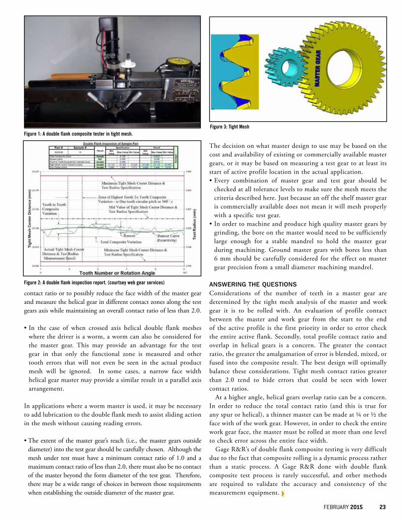
Figure 1: A double flank composite tester in tight mesh.
Figure 2: A double flank inspection report. (courtsey web gear services)
Figure 3: Tight Mesh
24 gearsolutions.com
In an age where putting information out first seems to be valued over insuring that information is correct, it’s important to take the time to execute a quality product or service both for the customers’ benefit and your own.
AS A FORMER OWNER OF A MID-SIZED GEAR MANUFACTURING FACILITY, I understand the pressures that owners and their staffs endure to satisfy their customers. I’m also a practical guy who has been involved with manufacturing for over 30 years. As part of my current manufacturing consult-ing practice, I see many businesses struggle with the various challenges that arise daily.
One of latest challenges is that of time. With the advent of email and portable communication devices, time, as they say, is of the essence. These advances allow almost instant delivery of messages, orders, and, as I call it, the “request for quote.”
The RFQ is the first step in the order process that engages your manufacturing brilliance to the needs of your customer. The main problem is that the customers that we desire are in a hurry. Chances are that the parts you’ve been asked to quote were put into their system late, held up by scheduling issues, or the customer is just shopping the parts around. Whatever the reason, the response is requested to be delivered on a rush basis. Sound familiar?
Since the customer is always right, and what they want is paramount to our success, many compa-nies will jump through any imaginable hoop to satisfy their customers. What these same companies forget is that they are not in business to satisfy customers. They are in business to make money. By rushing around like the proverbial chicken with its head cutoff, they guarantee lower profits and less satisfaction for the most important entity—themselves.
Customer satisfaction is a means to an end, and before you throw this magazine against the wall, I believe that the companies who satisfy their customers are, generally, more successful. However, in the rush to quote, many issues can be overlooked and cost you money.
So, what am I referring to? Well, I have to admit that I’m not a good guesser of prices for outside services. I also know that if you don’t know what your costs are, you cannot quote accurately or make intelligent business decisions. Guessing at what a heat-treater will charge you or what the steel cost will be for a job are two common areas where people make assumptions. What about the machine cycle times? In gear cutting, there are many programs that you can use that are fairly accurate and allow a great degree of customization to nail down cutting times. Turning, milling, and grinding are a bit more difficult but can be handled by getting outside costs for operations.
But there’s that issue of time hanging over our heads that forces people to take shortcuts. These shortcuts shortchange your profit margins. You must take time and make time to completely evalu-ate and insure that what you quote is what you can and will make on the job.
However, there are other profit bleeds in this process. In our haste to make it to the quote finish line, we may not take the time to fully understand what is on the blueprint or purchase order. For instance, I recently looked at a print that called for sand blasting of specified areas. Pretty simple, right? Wrong. Turns out it’s not sand blasting at all. The customer actually wanted a specific brand and size of glass bead used at a specific pressure for a specific blasting time. Also, it is not a typical size or type of glass bead that many manufacturers use in their everyday blast cabinets. You’d have to buy this special glass bead, change out your regular media, and blast away. Did I forget to tell you about the masking requirement as well?
How was this all found out? Someone took the time to the customer a question. Do you think you’ll look stupid or show that you don’t know how to make parts? Think again. The only certain
ABOUT THE AUTHOR: David Senkfor is the president of TopGun Consulting, a manufacturing consultancy with a focus on helping companies improve their practices
and processes to increase the profitability and satisfaction of the owners of those companies. David has over 30 years of experience in manufacturing, more
specifically in the gear industry. Using his experience, David is able to quickly assess difficulties and recommend simple, yet effective, solutions to those issues. For
more information, contact David Senkfor at [email protected] or (602) 510-5998, or visit Top Gun’s website at www.topgunconsulting.com.
TOOTHTIPS
thing is that the parts will not be made cor-rectly and will not satisfy your customer. And, most importantly, you will not make money. As the saying goes, “if you don’t take the time to make it right the first time, you’ll always find the time the second time around.”
These questions can be asked during quot-ing or order processing after you get the order. Obviously, the best time would be before you quote so you can include these hidden costs in the quote. But there’s that time thing again, and the guessing and ignoring of seem-ingly harmless specifications comes into play. Does your customer have internal or cite industry standards on their prints? Missing or impossible-to-make dimensions? Ignore them at your own risk. You may even discover that the purchasing agent is happy to hear from you. It also gives you an opportunity to interact with them and their engineers.
Clearly, it takes time to clear up these issues, but, in the end, you’ll end up making quality parts that the customer will gladly pay for the first time around. Over time, you’ll build a relationship with the customer and become a trusted vendor. By not quot-ing certain jobs due to tight quote cutoff dates, you will make more money and your satisfaction will be higher than ever. You need to question the value of customers who do not buy into this type of process. Dealing with vendors who don’t understand their parts is a direct route to supply chain disasters.
Time is of the essence, but your time and money need to be at the forefront of your mind to effectively manage your business. Remember, the only person who really cares about your business is you.
David SenkforPresidentTop Gun Consulting
METROLOGY SOLUTIONS FOR CYLINDRICAL AND BEVEL GEARS OF ALL TYPES, UP TO 3,000 MM IN DIAMETER
For worldwide sales locations and additional information, visit:
www.gleason.com • [email protected]
Dollar for dollar, a Gleason GMS® system is your best inspection investment:3 Complete inspection of all types of gears and gear cutting tools; contact pattern analysis; surface
roughness measurement.3 CMM-type inspection of non-gear, rotationally symmetrical parts with CAPPS DMIS GD&T software.
3 ...All easily performed with powerful GAMA™ 3, Windows® 7 compatible applications software.
Gleason GMS. Your single best inspection investment. Visit www.gleason.com/GMS.
gleason gms® inspection systems...you’ll like how they measure up
CMM-type measurementof non-gears with CAPPS.
Contact pattern analysis. Surface finish inspection.
26 gearsolutions.com
Vacuum pumps and nitrogen purge can equally achieve low ppm oxygen levels. However, pumps are slow to remove water vapor while an inert gas purge is time consuming.
Jack TitusDirector of Process and Developmental EngineeringAFC-Holcroft
VACUUM FURNACES rely on the lack of an atmosphere to protect heat-treated parts from surface oxidation or decarburization. The quality of the atmosphere required for a given process is defined by the quantity of residuals remaining after evacuation. Therefore, the ultimate pressure determines the composition of gasses (lower pressure produces fewer mol-ecules of oxygen, nitrogen, and constituents such as CO2, argon, and several trace ele-ments). The one variable is water vapor. Since most high-temperature vacuum furnaces are constructed with a water jacket called a cold wall, they have a separate thin inner insulated hot zone as opposed to insulation applied directly to the furnace case or a hot-wall style.
Typically, a vacuum furnace’s hot zone or inner chamber will have only two or three inches (50 to 75 mm) of insulation wherein vacuum heat loss is reduced, thereby enabling a shorter pump down time due to less out-gassing. Nitrogen and oxygen can be evacu-ated without concern. However, water vapor within the vessel exists in two forms—as a gas or vapor and as a condensed liquid adhering to the inner side of the water jacket. On a humid day, huge quantities of water can reside on the water jacket via adsorption as well as being absorbed into the microscopic porous surface layers of the mill scale on the steel wall. This phenomenon can be somewhat mitigated by painting the inner wall with specific materials designed for such a purpose. Although the absorbed water is reduced, the adsorbed surface layer will always be present when the cooling water temperature drops below the dew point of the ambient air. Vacuum pumps are notoriously deficient in removing water quickly. When initial evacua-tion begins, the sudden reduction in pressure
causes the release of heat via evaporation and reduces the temperature of the surface water and surrounding environment, in some cases, to the point of creating a thin layer of ice. Once it is formed, this layer is difficult to remove until the steel wall heats up or until the pressure drops low enough to enable the heating system.
In many ways, the internal materials of construction used in vacuum furnaces dictate the pressure required for a given process. For example, a moly lined (radiation shields) insu-lation with moly heating elements will require lower pressures, sub-10 microns (.0133 mil-libar) to remove enough oxygen and water vapor to eliminate oxidation in steel (iron). If the same vacuum furnace has graphite insula-tion and graphite heating elements a pressure of 100 microns (.133 millibar) or higher would suffice because graphite will act as an oxygen “getter” reacting with oxygen at ele-vated temperature and is evacuated from the vessel. When very oxidation sensitive materi-als, such as titanium or aluminum, are heat treated, much lower pressures are required.
Generally, three stiles of vacuum pumps are required to achieve the selected pressure.
The basic first-stage vacuum pump can be a piston type or a rotary vane. These are used when the vessel is smaller and or when the pressure required is between 100 and 500 microns (0.133 and .66 millibar).
A second stage is a roots-type booster blower that usually has a pumping speed five to 10 times that of the first stage. These are employed when a much faster pump down is required or when pressures below 50 microns, but no less than five microns, are needed.
The third stage when pressures below one to five microns are required is called a dif-
fusion pump. For decades, diffusion pumps employed distilled fossil fuel oils. Today, fossil oils have been replaced by nonflammable sili-cone based oils. Simply, the oil in the absence of air removed by the first and second stage pumps is boiled creating a vapor that is direct-ed at high velocity through downforce jets trapping gas molecules that are subsequently evacuated from the system. Although these are called oil diffusion pumps, they don’t actually pump the molecules. Since the first and second stage pumps reduce the number of molecules to trace quantities (the “mean free path”), the distance a molecule travels to collide with another molecule is so long that only by accident do gas molecules find their way into the inlet of the diffusion pump. Thus, the inlet of diffusion pumps must be very large and positioned as close to the internal volume of the vacuum vessel as possible.
To achieve an inert atmosphere equiva-lent to that produced by vacuum pumps, atmosphere heat-treat furnaces require a generated atmosphere of nitrogen or argon. Liquid nitrogen at its source will usually have oxygen levels of <10 ppm. A vacuum level of 100 microns (0.133 mbar) will reduce the oxygen level to 27 ppm. To achieve 27-ppm oxygen in an atmosphere system, approxi-mately nine (9) volume changes of nitrogen are required. Unlike vacuum pumps water vapor is removed rather quickly due to the extremely dry -70°F (-56°C) dew point of liquid nitrogen. The majority of atmosphere furnaces have warm wall construction where the internal/external wall will typically run between 100°F to 150°F (38°C to 66°C) at elevated temperatures, eliminating the forma-tion of water altogether.
ABOUT THE AUTHOR: Hot Seat columnist Jack Titus has an additional column in Thermal Processing for Gear Solutions in which he discusses
scheduled maintenance of furnaces, distortion control, and low-pressure carburizing. Jack Titus can be reached at (248) 668-4040 or
[email protected]. More information can be found online at www.afc-holcroft.com or www.ald-holcroft.com.
HOTSEAT

FEBRUARY 2015 27
Now that we’ve kicked off 2015, there’s one thing on everyone’s minds—making more money this year than what was made in 2014. In the gear manufacturing industry, there’s a sure fire
way to ensure that will happen… increasing sales.
IN ANY BUSINESS where a product is made available for consumers, that company’s liveli-hood, longevity, and wellbeing all come down to one thing—successful sales.
And no matter how much it pangs me to say it, money does make the world go ‘round.
I consider myself a romantic of sorts. I love to travel and make connections with people all over the world. I love to read, write, and cook. I look forward to both exciting new adventures and lazy days spent at home with my fiancé and our dog. And on any given sunny day, I’d much rather spend my day outdoors than cramped in an office cubicle.
Luckily, I’m able to do most of those things when I please, but the only way I’m able to enjoy a few of my favorite things is by going to work every week day and doing my best to put out the best quality product I can.
The same goes for a company’s sales depart-ment.
At the core of any successful business is a strong sales department, and at the heart of any strong sales department is a collection of salespeople who can push what they’re trying to sell. In an industry as niched and tight-knit as ours, sales are especially important, whether it’s the sale of machines, services, tooling equipment, or even a single gear.
There are several ways that salespeople go about pushing their product. Some practices have been around for decades, such as adver-tisements, emails and email blasts, regular snail mail, and telemarketing. Others may even take a page out of the boy scouts’ book of business by going door to door to meet their quota.
And, then, there are some methods that have only come about over the past 10 years or so, namely utilizing social media to pro-mote a business. This can get tricky, though,
because you don’t want to flood current or potential customers’ Facebook, LinkedIn, Pinterest, or Twitter feeds with a lot of white noise, aka irrelevant or annoying information. Even with the safety blanket of a computer screen, you have to maintain a personal relationship with the people on the other side of the World Wide Web. As sales people know, the fastest way to kill a potential sale is to come across as overbear-ing, even online.
Others may rely on their products and research to speak for themselves at events such as the annual Gear Expo, where you’ll be able to witness some of the new products United Tool Supply Company is debuting in the later part of 2015, or the annual Fall Technical Meeting hosted by the AGMA, where scholars come together to share their knowledge of the gear industry.
Then, there are some manufacturers who have been around for so long that their reputation for quality products and customer service do the selling for them.
Companies such as these can keep customers for generations if their business is handled appropriately. Two prime examples of suc-cessful family businesses can be found in our Q&A with Marvin Nicholson of Pentagear Products LLC, where Nicholson describes the history of his veteran-owned family company and how it got to where it is today, and in our company profile on United Tool, where we discuss the company Rusty Young built and the legacy he left behind.
Ultimately, the best way to boost your sales revenue is to provide a quality product. That’s how United Tool made a name for themselves with the model 8600 Unite-A-Matic, which, even after 42 years, is still their most popular product. You can learn more about how United Tool made a name for itself in this industry by reading our company profile and learning about the legacy Rusty Young left behind.
Just remember these suggestions on how to improve your sales going into this new year, and good luck!
ABOUT THE AUTHOR: Contact Anna Claire, associate editor, Gear Solutions at [email protected] or at (205) 380-1573 ext. 205.
TRENDTALKS
Anna Claire ConradAssociate Editor
Gear Solutions Magazine
28 gearsolutions.com
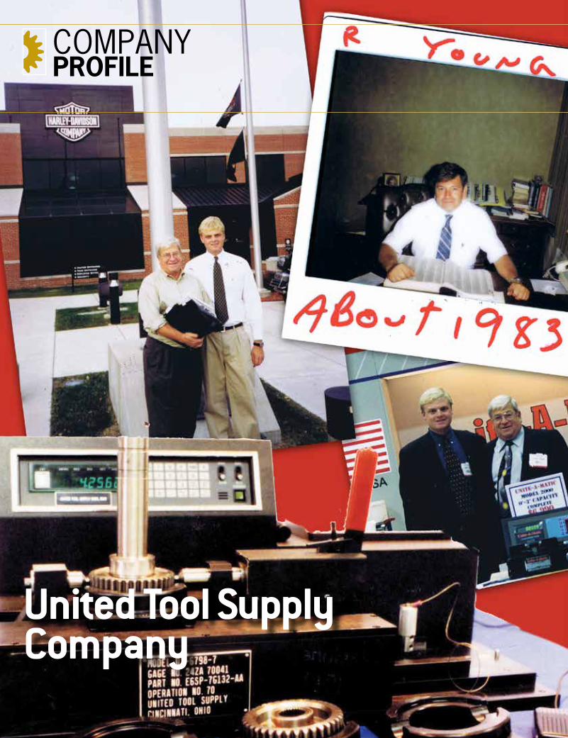
United Tool Supply Company
COMPANYPROFILE
FEBRUARY 2015 29
By Anna Claire Conrad
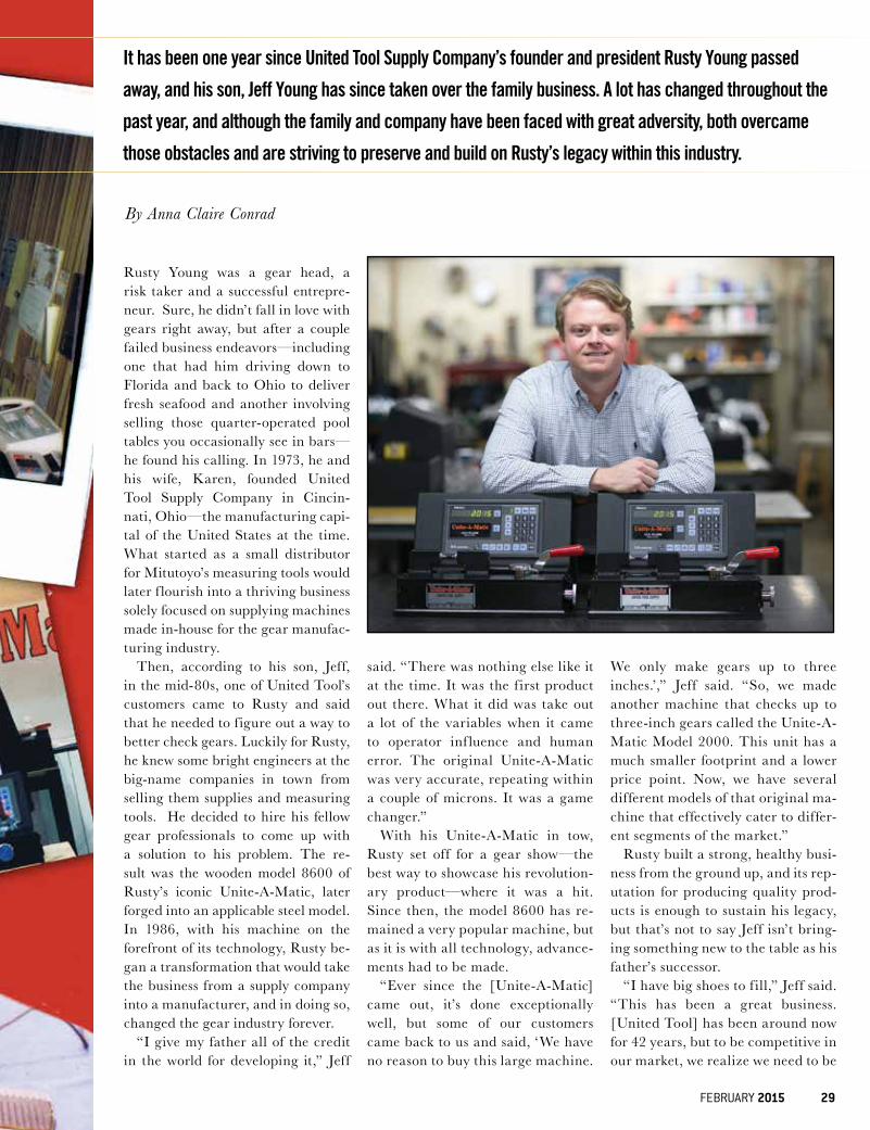
Rusty Young was a gear head, a risk taker and a successful entrepre-neur. Sure, he didn’t fall in love with gears right away, but after a couple failed business endeavors—including one that had him driving down to Florida and back to Ohio to deliver fresh seafood and another involving selling those quarter-operated pool tables you occasionally see in bars—he found his calling. In 1973, he and his wife, Karen, founded United Tool Supply Company in Cincin-nati, Ohio—the manufacturing capi-tal of the United States at the time. What started as a small distributor for Mitutoyo’s measuring tools would later f lourish into a thriving business solely focused on supplying machines made in-house for the gear manufac-turing industry.
Then, according to his son, Jeff, in the mid-80s, one of United Tool’s customers came to Rusty and said that he needed to f igure out a way to better check gears. Luckily for Rusty, he knew some bright engineers at the big-name companies in town from selling them supplies and measuring tools. He decided to hire his fellow gear professionals to come up with a solution to his problem. The re-sult was the wooden model 8600 of Rusty’s iconic Unite-A-Matic, later forged into an applicable steel model. In 1986, with his machine on the forefront of its technology, Rusty be-gan a transformation that would take the business from a supply company into a manufacturer, and in doing so, changed the gear industry forever.
“I give my father all of the credit in the world for developing it,” Jeff
said. “There was nothing else like it at the time. It was the f irst product out there. What it did was take out a lot of the variables when it came to operator inf luence and human error. The original Unite-A-Matic was very accurate, repeating within a couple of microns. It was a game changer.”
With his Unite-A-Matic in tow, Rusty set off for a gear show—the best way to showcase his revolution-ary product—where it was a hit. Since then, the model 8600 has re-mained a very popular machine, but as it is with all technology, advance-ments had to be made.
“Ever since the [Unite-A-Matic] came out, it’s done exceptionally well, but some of our customers came back to us and said, ‘We have no reason to buy this large machine.
We only make gears up to three inches.’,” Jeff said. “So, we made another machine that checks up to three-inch gears called the Unite-A-Matic Model 2000. This unit has a much smaller footprint and a lower price point. Now, we have several different models of that original ma-chine that effectively cater to differ-ent segments of the market.”
Rusty built a strong, healthy busi-ness from the ground up, and its rep-utation for producing quality prod-ucts is enough to sustain his legacy, but that’s not to say Jeff isn’t bring-ing something new to the table as his father’s successor.
“I have big shoes to f ill,” Jeff said. “This has been a great business. [United Tool] has been around now for 42 years, but to be competitive in our market, we realize we need to be
It has been one year since United Tool Supply Company’s founder and president Rusty Young passed
away, and his son, Jeff Young has since taken over the family business. A lot has changed throughout the
past year, and although the family and company have been faced with great adversity, both overcame
those obstacles and are striving to preserve and build on Rusty’s legacy within this industry.
30 gearsolutions.com
more dynamic. There are always areas of our business that we are changing, and aspects we’re trying to improve.”
Jeff ’s no rookie, either. He grew up on United Tool’s shop f loor watching every move his father made and began working there when he was 16 and ev-ery summer throughout high school
and college. He went full-time after graduating from the University of Col-orado in 2004 and took over the role of running the company last February after his father passed away at the age of 69. For Jeff, United Tool isn’t just a family business; it was a part of his family.
“There’s no better way for me to think that I’m making my father proud than me taking over and growing his busi-ness,” Jeff said. “This company has al-ways been part of my life and to honor my father, we are working hard to pre-serve his legacy.
Since Jeff took over the daily opera-tions, he’s had one major focus—up-holding the values of his family’s busi-ness while meeting the modern needs of its customers.
“My father was great at what he did, but he was not well-versed in the com-puter age,” Jeff said. “Therefore, lots of things are in the process of changing. Internally, we have changed the way that orders are processed by implement-ing an automated system. We now use a new process to insure that our custom-er’s drawings are drafted correctly and meet their specif ications. We also have a completely brand new, original website. There are many ways to improve eff i-ciencies with today’s technology. De-sign, orders, tracking, and sales are just some of the areas where we are focusing.
“The majority of our customers are still automotive, and we do a fair amount with agricultural, aerospace, and some marine-based applications, but I would like to continue to expand that reach. We have also conducted more busi-ness in foreign markets over the past 10 years, which through actively hiring sales representatives in those markets, we plan to continue that trend.”
Jeff has also made it his mission to improve United Tool’s customer ser-vice by improving their documentation techniques and creating a more eff icient method for how they operate day-to-day.
“We want our customers to know that we’re still trying to grow the business,” Jeff said. “We may be a 42-year-old company, but there are still a lot of op-portunities for advancement and growth out there, and it all comes back to cus-tomer service. I’ve been very focused on that.”
However, among all of these advance-ments and improvements, Jeff said some things will remain constant thanks to his father.
FEBRUARY 2015 31
“One of the main things that keeps our customers coming back to us is that we have a 30-year track record of doing what we do well,” Jeff said. “So, even when companies can go to one of our competitors, they come to us because they know what they’re going to get. That makes us always focus on quality, which means everything we send out has to be perfect. I personally check ev-ery machine that goes out. It’s not like this is something we only do to make a living. This is something we do because we actually enjoy it, and we take a lot of pride in it.”
In addition to improving internal affairs, Jeff also plans to follow in his father’s footsteps by bringing advance-ments and modern innovations to the place where it all started—the Gear Expo.
“We have several advancements to our product that will be on display at the Gear Expo in October,” Jeff said. “We’re modernizing our product to the point that will make us more com-petitive and will set us apart from other companies in the industry. With that being said, there are also new products that we are working on bringing to the table. Rusty made a great product that provided a healthy business, but there are other opportunities that we are ac-tively pursuing. [The Unite-A-Matic] hasn’t changed much since 1986 be-cause it works. Even if we modernize it so that it would fall into a different class, we’ll still keep our standard prod-uct available because there are custom-ers out there that like to use a tried and true Unite-A-Matic. For us to grow the business, focusing on the needs of our customers is crucial.”
Jeff certainly does have big shoes to f ill, but he has risen to the occasion, all the while keeping in mind what his fa-ther taught him and the legacy Rusty left behind.
“My father just did things different-ly,” Jeff said. “At times, I didn’t follow what he was doing or agree with him about it, but now looking back, I under-stand why he did things the way he did. My dad was a little eccentric, and he was extremely intelligent. In my opin-
ion, he was a mechanical genius. He created a great product, which lead to a healthy family business, and that is a huge achievement.”
Jeff and his team’s respect for his fa-ther and the company he forged are at the core of his guarantee to propel United Tool into 2015 with a commit-
ment to customer service, growth, and new products.
FOR MORE INFORMATION, Contact Jeff Young at (513) 752-6000 and visit United Tool’s new website at www.united-tool.com and also at www.unite-a-matic.com.
6days 8
days
12days
14days16
days
18days
20days
Why wait...5 days! IN AS FEW ASORDERS SHIPPING
10days
TYPICAL MARKET LEAD TIMES
When you need it now, trust McInnes.
STILL WAITING ON YOUR DELIVERY?At McInnes Rolled Rings, we take pride in the high level of speed
and service provided to each of our customers, large or small.
Seamless rolled Rings · 4”-144”OD CARBON • ALLOY • STAINLESS
1.800.569.1420 www.McInnesRolledRings.com
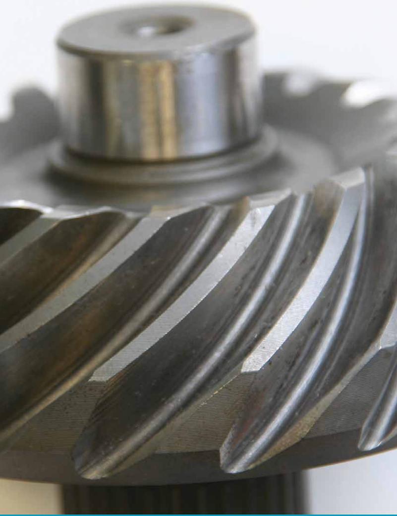
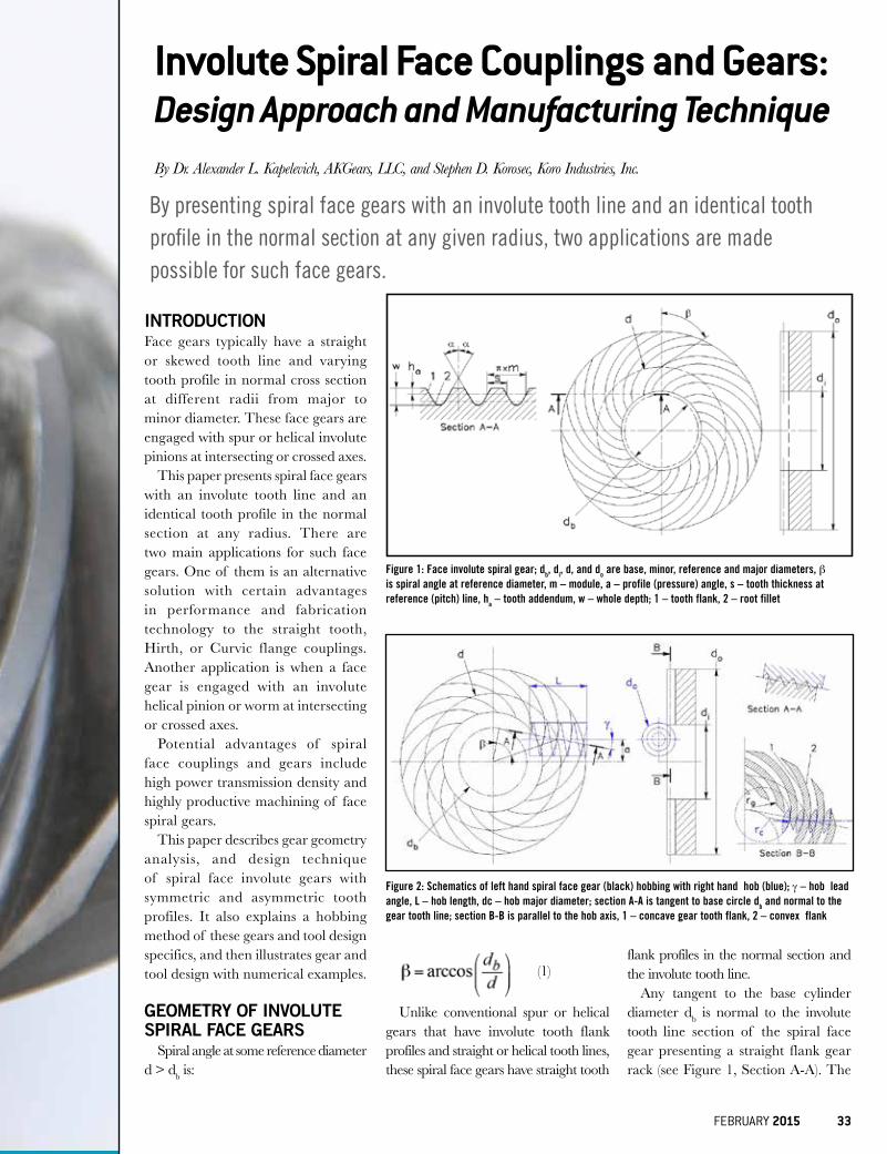
INTRODUCTIONFace gears typically have a straight or skewed tooth line and varying tooth profile in normal cross section at different radii from major to minor diameter. These face gears are engaged with spur or helical involute pinions at intersecting or crossed axes.
This paper presents spiral face gears with an involute tooth line and an identical tooth profile in the normal section at any radius. There are two main applications for such face gears. One of them is an alternative solution with certain advantages in performance and fabrication technology to the straight tooth, Hirth, or Curvic flange couplings. Another application is when a face gear is engaged with an involute helical pinion or worm at intersecting or crossed axes.
Potential advantages of spiral face couplings and gears include high power transmission density and highly productive machining of face spiral gears.
This paper describes gear geometry analysis, and design technique of spiral face involute gears with symmetric and asymmetric tooth profiles. It also explains a hobbing method of these gears and tool design specifics, and then illustrates gear and tool design with numerical examples.
GEOMETRY OF INVOLUTE SPIRAL FACE GEARS
Spiral angle at some reference diameter d > db is:
(1)
Unlike conventional spur or helical gears that have involute tooth flank profiles and straight or helical tooth lines, these spiral face gears have straight tooth
flank profiles in the normal section and the involute tooth line.
Any tangent to the base cylinder diameter db is normal to the involute tooth line section of the spiral face gear presenting a straight flank gear rack (see Figure 1, Section A-A). The
Involute Spiral Face Couplings and Gears: Design Approach and Manufacturing Technique
By presenting spiral face gears with an involute tooth line and an identical tooth profile in the normal section at any given radius, two applications are made possible for such face gears.
By Dr. Alexander L. Kapelevich, AKGears, LLC, and Stephen D. Korosec, Koro Industries, Inc.
Figure 1: Face involute spiral gear; db, di, d, and do are base, minor, reference and major diameters, β is spiral angle at reference diameter, m – module, a – profile (pressure) angle, s – tooth thickness at reference (pitch) line, ha – tooth addendum, w – whole depth; 1 – tooth flank, 2 – root fillet
Figure 2: Schematics of left hand spiral face gear (black) hobbing with right hand hob (blue); γ – hob lead angle, L – hob length, dc – hob major diameter; section A-A is tangent to base circle db and normal to the gear tooth line; section B-B is parallel to the hob axis, 1 – concave gear tooth flank, 2 – convex flank
FEBRUARY 2015 33
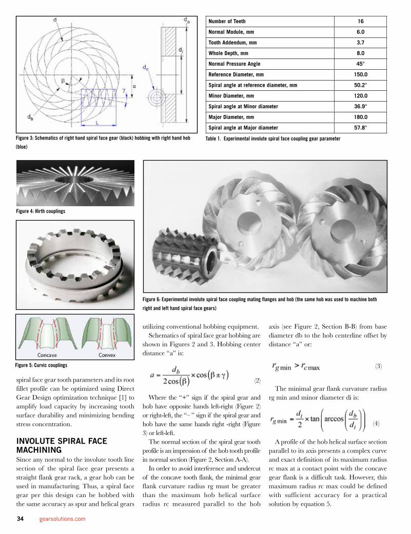
spiral face gear tooth parameters and its root fillet profile can be optimized using Direct Gear Design optimization technique [1] to amplify load capacity by increasing tooth surface durability and minimizing bending stress concentration.
INVOLUTE SPIRAL FACE MACHININGSince any normal to the involute tooth line section of the spiral face gear presents a straight flank gear rack, a gear hob can be used in manufacturing. Thus, a spiral face gear per this design can be hobbed with the same accuracy as spur and helical gears
utilizing conventional hobbing equipment.Schematics of spiral face gear hobbing are
shown in Figures 2 and 3. Hobbing center distance “a” is:
(2)
Where the “+” sign if the spiral gear and hob have opposite hands left-right (Figure 2) or right-left, the “– ” sign if the spiral gear and hob have the same hands right -right (Figure 3) or left-left.
The normal section of the spiral gear tooth profile is an impression of the hob tooth profile in normal section (Figure 2, Section A-A).
In order to avoid interference and undercut of the concave tooth flank, the minimal gear flank curvature radius rg must be greater than the maximum hob helical surface radius rc measured parallel to the hob
axis (see Figure 2, Section B-B) from base diameter db to the hob centerline offset by distance “a” or:
(3)
The minimal gear flank curvature radius rg min and minor diameter di is:
(4)
A profile of the hob helical surface section parallel to its axis presents a complex curve and exact definition of its maximum radius rc max at a contact point with the concave gear flank is a difficult task. However, this maximum radius rc max could be defined with sufficient accuracy for a practical solution by equation 5.
Number of Teeth 16
Normal Module, mm 6.0
Tooth Addendum, mm 3.7
Whole Depth, mm 8.0
Normal Pressure Angle 45°
Reference Diameter, mm 150.0
Spiral angle at reference diameter, mm 50.2°
Minor Diameter, mm 120.0
Spiral angle at Minor diameter 36.9°
Major Diameter, mm 180.0
Spiral angle at Major diameter 57.8°
Figure 3: Schematics of right hand spiral face gear (black) hobbing with right hand hob
(blue)
Figure 6: Experimental involute spiral face coupling mating flanges and hob (the same hob was used to machine both
right and left hand spiral face gears)
Figure 4: Hirth couplings
Figure 5: Curvic couplings
Table 1. Experimental involute spiral face coupling gear parameter
34 gearsolutions.com
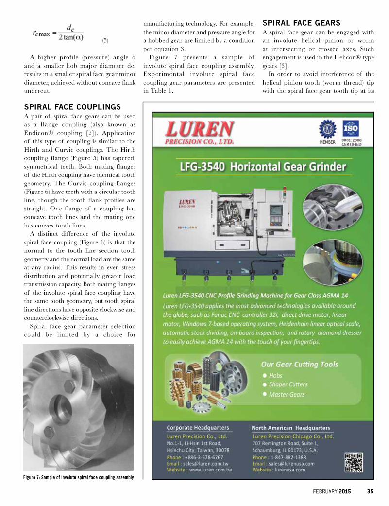
(5)
A higher profile (pressure) angle α and a smaller hob major diameter dc, results in a smaller spiral face gear minor diameter, achieved without concave flank undercut.
SPIRAL FACE COUPLINGSA pair of spiral face gears can be used as a flange coupling (also known as Endicon® coupling [2]). Application of this type of coupling is similar to the Hirth and Curvic couplings. The Hirth coupling flange (Figure 5) has tapered, symmetrical teeth. Both mating flanges of the Hirth coupling have identical tooth geometry. The Curvic coupling flanges (Figure 6) have teeth with a circular tooth line, though the tooth flank profiles are straight. One flange of a coupling has concave tooth lines and the mating one has convex tooth lines.
A distinct difference of the involute spiral face coupling (Figure 6) is that the normal to the tooth line section tooth geometry and the normal load are the same at any radius. This results in even stress distribution and potentially greater load transmission capacity. Both mating flanges of the involute spiral face coupling have the same tooth geometry, but tooth spiral line directions have opposite clockwise and counterclockwise directions.
Spiral face gear parameter selection could be limited by a choice for
manufacturing technology. For example, the minor diameter and pressure angle for a hobbed gear are limited by a condition per equation 3.
Figure 7 presents a sample of involute spiral face coupling assembly. Experimental involute spiral face coupling gear parameters are presented in Table 1.
SPIRAL FACE GEARSA spiral face gear can be engaged with an involute helical pinion or worm at intersecting or crossed axes. Such engagement is used in the Helicon® type gears [3].
In order to avoid interference of the helical pinion tooth (worm thread) tip with the spiral face gear tooth tip at its
Figure 7: Sample of involute spiral face coupling assembly
FEBRUARY 2015 35
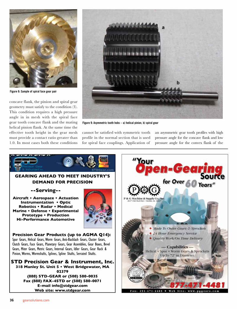
concave flank, the pinion and spiral gear geometry must satisfy to the condition (3). This condition requires a high pressure angle in in mesh with the spiral face gear tooth concave flank and the mating helical pinion flank. At the same time the effective tooth height in the gear mesh must provide a contact ratio greater than 1.0. In most cases both these conditions
cannot be satisfied with symmetric tooth profile in the normal section that is used for spiral face couplings. Application of
an asymmetric gear tooth profiles with high pressure angle for the concave flank and low pressure angle for the convex flank of the
Figure 8: Sample of spiral face gear pair
Figure 9: Asymmetric tooth hobs – a) helical pinion, b) spiral gear
GEARING AHEAD TO MEET INDUSTRY'S DEMAND FOR PRECISION
--Serving--Aircraft • Aerospace • Actuation
Instrumentation • OpticRobotics • Radar • Medical
Marine • Defense • ExperimentalPrototype • Production
Hi-Performance Automotive
Precision Gear Products (up to AGMA Q14):Spur Gears, Helical Gears, Worm Gears, Anti-Backlash Gears, Cluster Gears, Clutch Gears, Face Gears, Planetary Gears, Gear Assemblies, Gear Boxes, Bevel Gears, Miter Gears, Metric Gears, Internal Gears, Idler Gears, Gear Rack & Pinion, Worms, Wormshafts, Splines, Spline Shafts, Serrated Shafts.
STD Precision Gear & Instrument, Inc. 318 Manley St. Unit 5 • West Bridgewater, MA
02379 (888) STD-GEAR or (508) 580-0035
Fax (888) FAX-4STD or (508) 580-0071 E-mail [email protected]
Web site: www.stdgear.com
36 gearsolutions.com
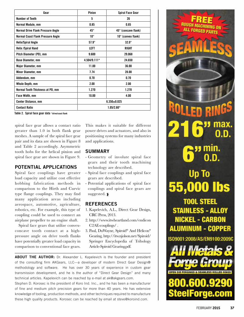
Gear Pinion Spiral Face Gear
Number of Teeth 5 26
Normal Module, mm 0.85 0.85
Normal Drive Flank Pressure Angle 45° 45° (concave flank)
Normal Coast Flank Pressure Angle 10° 10° (convex flank)
Helix/Spiral Angle 57.9° 32.0°
Helix /Spiral Hand LEFT RIGHT
Pitch Diameter (PD), mm 9.600 29.068
Base Diameter, mm 4.504/9.111* 24.650
Major Diameter, mm 11.00 36.00
Minor Diameter, mm 7.74 28.00
Addendum, mm 0.70 0.70
Whole Depth, mm 2.00 2.00
Normal Tooth Thickness at PD, mm 1.270 1.270
Face Width, mm 10.00 4.00
Center Distance, mm 6.350±0.025
Contact Ratio 1.05/2.60*
ABOUT THE AUTHOR: Dr. Alexander L. Kapelevich is the founder and president
of the consulting firm AKGears, LLC—a developer of modern Direct Gear Design®
methodology and software. He has over 30 years of experience in custom gear
transmission development, and he is the author of “Direct Gear Design” and many
technical articles. Kapelevich can be reached by e-mail at [email protected].
Stephen D. Korosec is the president of Koro Ind. Inc., and he has been a manufacturer
of fine and medium pitch precision gears for more than 40 years. He has extensive
knowledge of tooling, production methods, and other techniques required to manufacture
these high quality products. Korosec can be reached by email at [email protected].
Table 2. Spiral face gear data *drive/coast flank
spiral face gear allows a contact ratio greater than 1.0 in both flank gear meshes. A sample of the spiral face gear pair and its data are shown in Figure 8 and Table 2 accordingly. Asymmetric tooth hobs for the helical pinion and spiral face gear are shown in Figure 9.
POTENTIAL APPLICATIONSSpiral face couplings have greater load capacity and utilize cost effective hobbing fabrication methods in comparison to the Hirth and Curvic type flange couplings. They may find many application areas including aerospace, automotive, agriculture, robotics, etc. For example, this type of coupling could be used to connect an airplane propeller to an engine shaft.
Spiral face gears that utilize convex-concave tooth contact at a high-pressure angle on drive tooth flanks have potentially greater load capacity in comparison to conventional face gears.
This makes it suitable for different power drives and actuators, and also in positioning systems for many industries and applications.
SUMMARY- Geometry of involute spiral face
gears and their tooth machining technology are described.
- Spiral face couplings and spiral face gears are described.
- Potential applications of spiral face couplings and spiral face gears are suggested.
REFERENCES1. Kapelevich, A.L., Direct Gear Design,
CRC Press, 2013.2. http://www.itwheartland.com/endicon
C2AE-couplings/ .3. Paul, DuWayne, Spiroid® And Helicon®
Gearing, http://itw.njolson.net/Spiroid/Springer Encyclopedia of Tribology Article-Spiroid Gearing.pdf.
FEBRUARY 2015 37
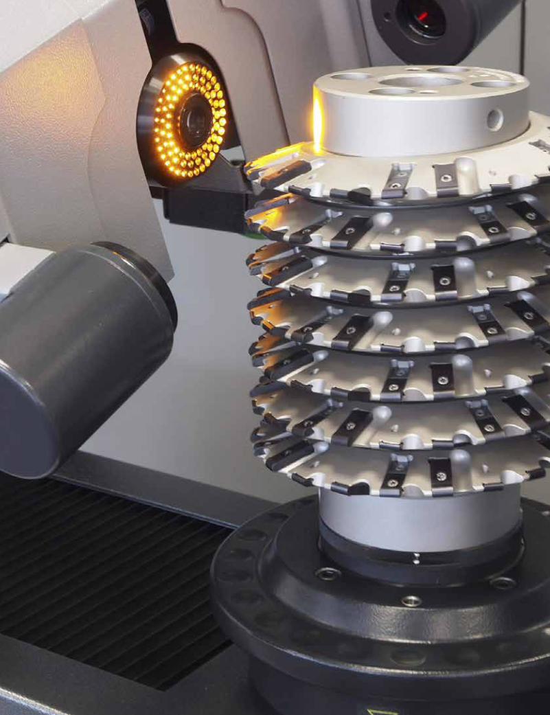
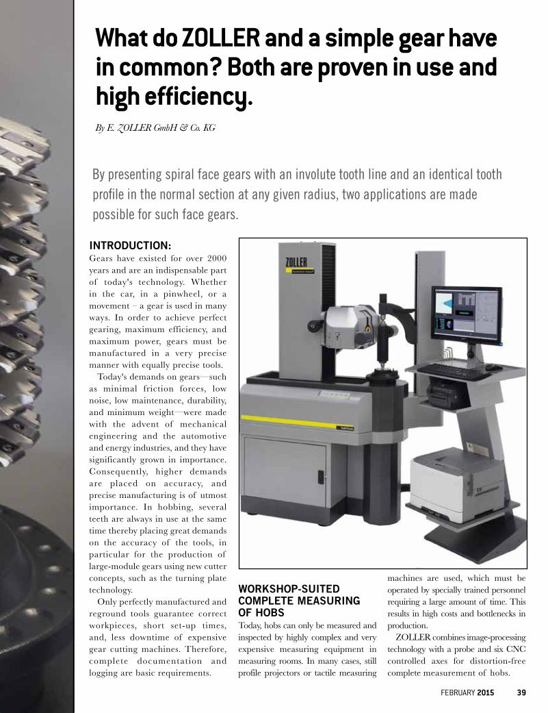
INTRODUCTION:Gears have existed for over 2000 years and are an indispensable part of today's technology. Whether in the car, in a pinwheel, or a movement – a gear is used in many ways. In order to achieve perfect gearing, maximum efficiency, and maximum power, gears must be manufactured in a very precise manner with equally precise tools.
Today's demands on gears—such as minimal friction forces, low noise, low maintenance, durability, and minimum weight—were made with the advent of mechanical engineering and the automotive and energy industries, and they have significantly grown in importance. Consequently, higher demands are placed on accuracy, and precise manufacturing is of utmost importance. In hobbing, several teeth are always in use at the same time thereby placing great demands on the accuracy of the tools, in particular for the production of large-module gears using new cutter concepts, such as the turning plate technology.
Only perfectly manufactured and reground tools guarantee correct workpieces, short set-up times, and, less downtime of expensive gear cutting machines. Therefore, complete documentation and logging are basic requirements.
WORKSHOP-SUITED COMPLETE MEASURING OF HOBSToday, hobs can only be measured and inspected by highly complex and very expensive measuring equipment in measuring rooms. In many cases, still profile projectors or tactile measuring
machines are used, which must be operated by specially trained personnel requiring a large amount of time. This results in high costs and bottlenecks in production.
ZOLLER combines image-processing technology with a probe and six CNC controlled axes for distortion-free complete measurement of hobs.
What do ZOLLER and a simple gear have in common? Both are proven in use and high efficiency.
By presenting spiral face gears with an involute tooth line and an identical tooth profile in the normal section at any given radius, two applications are made possible for such face gears.
By E. ZOLLER GmbH & Co. KG
FEBRUARY 2015 39
ZOLLER »HOBCHECK« - CHECK YOUR HOBS EFFICIENTLY:ZOLLER measures the tooth profile directly on the cutting edge with the time-tested software function for contour measurement called “lasso” of the image processing technology “pilot.” This is a significant advantage over tactile
measuring machines that measure over probe only along the surfaces of the tooth flanks and then calculate the actual cutting edge theoretically. The measuring machine »hobCheck« delivers due to the ability of pivoting the optical carrier into the cutter pitch distortion-free contours and accurate pictures of the tooth profiles. This means it meets all the
requirements for optimal measurement and inspection of high-precision hobs. It’s quick and easy to use - on a machine completely suitable for workshops. With the »hobCheck«, ZOLLER delivers the first suitable system for the complete measurement of hobs that is suitable for workshop yet economical.
WITH VARIATION, COMPLEXITY INCREASES.Over time, complexity increases, which, in turn, increases quality demands in the production of gears place new demands on the tools. There are more variants of gears that require specially adapted tools. This presents increasing challenges for both tool manufacturers as well as for those who develop and deploy the metrology of these tools. Flexibility is required, and this is provided by the ZOLLER »hobCheck«.
COMPLETE MEASURING MACHINE:The »hobCheck« not only solves the challenge to measure hobs economically and with high precision, but it also includes all of the standard features of a professional measuring machine. Therefore, it is also possible to measure standard and special tools (drills, step drills, form cutters, and routers) completely. This is an added value in particular for regrinding companies.
EASY OPERATION:In terms of technical matters and beyond, everything must run smoothly. Also, in view of remaining economical, companies must stay on the ball to be the decisive step ahead of the competitor. Process costs must be reduced with falling numbers of pieces, which in turn requires increasing flexibility and short reaction times. For the measuring technology, this means that the process must be simple and safe to use and the measurement can be taken by the machine operators.
AS PROVEN AS THE GEARTHE ZOLLER IMAGE: PROCESSING »PILOT 3.0«With the image processing »pilot 3.0« complete measurements as well
LXRDWIDEBODY
LXRDSTANDARD
LXRDMODULAR MAPPING
iXRDSTANDARD
mXRDULTRA PORTABLE
Choose from one of our portable or laboratory systems, or utilize our ISO 17025 laboratories for accurate and effi cient contract measurement services.
For more information contact us at [email protected] or 1-313-965-2900
40 gearsolutions.com
as re-measurements of individual parameters are easily implemented by anyone. Additionally, the measurement
results are automatically recorded in accordance with DIN 3968, as well as the classification according to quality
providing safety for both the tool manufacturer and the customer. The quality evaluation of the parameters including graphical display on the monitor and creation of a test report allows to repeat the measurement of individual parameters in tolerance overstepping. For this purpose, due to the software intelligence on the ZOLLER »hobCheck« new complete measurement is not required. The individual measurement is completely recalculated depending on the context in which it is to other metrics.
CUSTOMIZED ALSO FOR REGRINDING FACTORIES:In addition to the complete and partial measurement of tools and their logging, ZOLLER »hobCheck« especially allows for regrinding the automatic detection of any number of teeth on the periphery or in the chest on the high-resolution incident light camera to find the tooth with the greatest wear afterwards. This greatest wear detection is entered into the grinder for repositioning of the breast
www.tru-volute.com
Precision Gear ProductsSTOCK : HOBS : HSS & CARBIDE
STOCK : SHAPERS : Disc & ShankSTOCK : MASTER GEARS
RFQ on specials gear tools welcomeDiametral Pitch 12 and finer
STOCK AVAILABLE
RUSSELL,HOLBROOK&HENDERSON, INC.25 E Spring Valley Ave., Maywood, New Jersey 07607P: 201-226-9000 F: 201-226-9004 E: [email protected]
CELEBRATING 100 YEARS IN BUSINESSwww.storloc.com
1-800-786-7562
1-800-storloc
the boxthinkoutside
Made by aMerican craftsMen in the Usa
FEBRUARY 2015 41
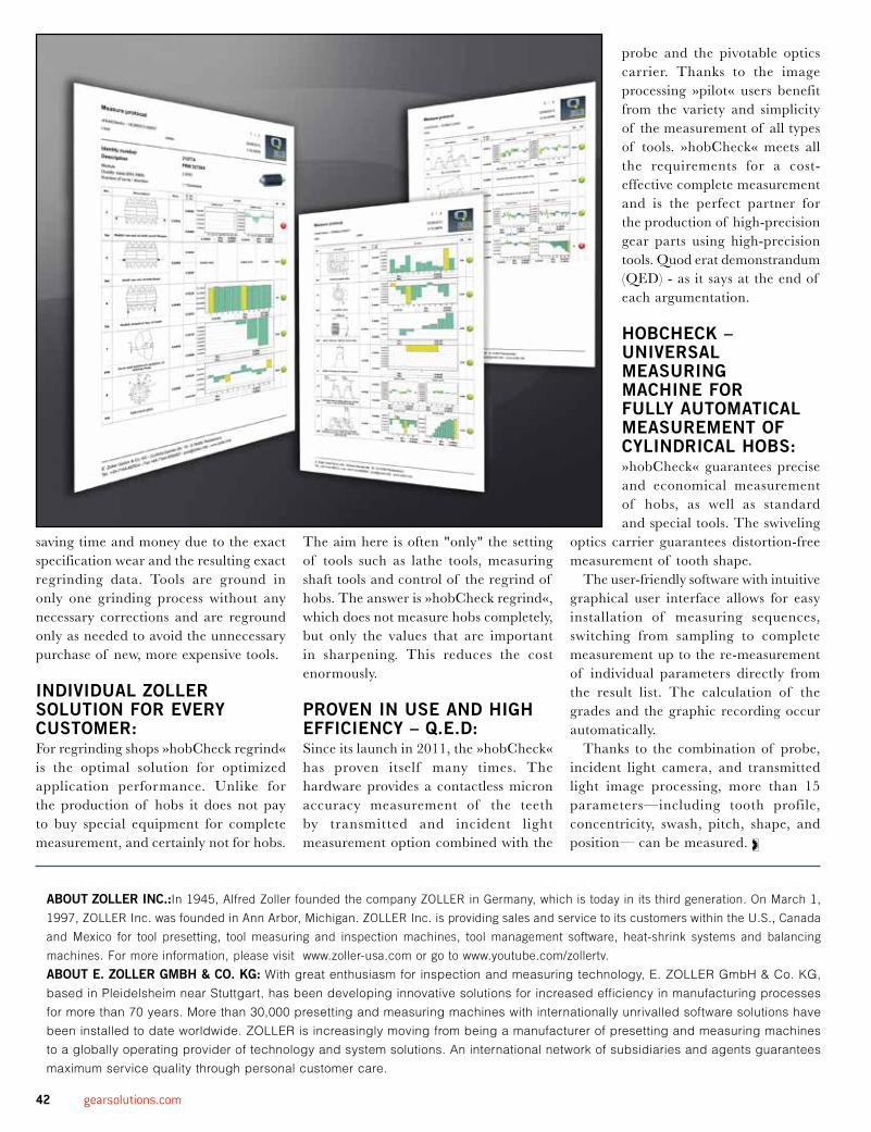
saving time and money due to the exact specification wear and the resulting exact regrinding data. Tools are ground in only one grinding process without any necessary corrections and are reground only as needed to avoid the unnecessary purchase of new, more expensive tools.
INDIVIDUAL ZOLLER SOLUTION FOR EVERY CUSTOMER:For regrinding shops »hobCheck regrind« is the optimal solution for optimized application performance. Unlike for the production of hobs it does not pay to buy special equipment for complete measurement, and certainly not for hobs.
The aim here is often "only" the setting of tools such as lathe tools, measuring shaft tools and control of the regrind of hobs. The answer is »hobCheck regrind«, which does not measure hobs completely, but only the values that are important in sharpening. This reduces the cost enormously.
PROVEN IN USE AND HIGH EFFICIENCY – Q.E.D:Since its launch in 2011, the »hobCheck« has proven itself many times. The hardware provides a contactless micron accuracy measurement of the teeth by transmitted and incident light measurement option combined with the
probe and the pivotable optics carrier. Thanks to the image processing »pilot« users benefit from the variety and simplicity of the measurement of all types of tools. »hobCheck« meets all the requirements for a cost-effective complete measurement and is the perfect partner for the production of high-precision gear parts using high-precision tools. Quod erat demonstrandum (QED) - as it says at the end of each argumentation.
HOBCHECK – UNIVERSAL MEASURING MACHINE FOR FULLY AUTOMATICAL MEASUREMENT OF CYLINDRICAL HOBS:»hobCheck« guarantees precise and economical measurement of hobs, as well as standard and special tools. The swiveling
optics carrier guarantees distortion-free measurement of tooth shape.
The user-friendly software with intuitive graphical user interface allows for easy installation of measuring sequences, switching from sampling to complete measurement up to the re-measurement of individual parameters directly from the result list. The calculation of the grades and the graphic recording occur automatically.
Thanks to the combination of probe, incident light camera, and transmitted light image processing, more than 15 parameters—including tooth profile, concentricity, swash, pitch, shape, and position— can be measured.
ABOUT ZOLLER INC.:In 1945, Alfred Zoller founded the company ZOLLER in Germany, which is today in its third generation. On March 1,
1997, ZOLLER Inc. was founded in Ann Arbor, Michigan. ZOLLER Inc. is providing sales and service to its customers within the U.S., Canada
and Mexico for tool presetting, tool measuring and inspection machines, tool management software, heat-shrink systems and balancing
machines. For more information, please visit www.zoller-usa.com or go to www.youtube.com/zollertv.
ABOUT E. ZOLLER GMBH & CO. KG: With great enthusiasm for inspection and measuring technology, E. ZOLLER GmbH & Co. KG,
based in Pleidelsheim near Stuttgart, has been developing innovative solutions for increased efficiency in manufacturing processes
for more than 70 years. More than 30,000 presetting and measuring machines with internationally unrivalled software solutions have
been installed to date worldwide. ZOLLER is increasingly moving from being a manufacturer of presetting and measuring machines
to a globally operating provider of technology and system solutions. An international network of subsidiaries and agents guarantees
maximum service quality through personal customer care.
42 gearsolutions.com

geoilandgas/lufkin.com
Failure is not an optionYou need a precision-engineered product that delivers power, performance and reliability. With Lufkin as your partner, our highly experienced and trained teams will provide you solutions manufactured with the quality, durability and precision that is essential for your critical gearing application.
Contact us at +1 (936) 634 2211 or [email protected]
Expertise that powers possible.
GEAD307-01 PowerAd_R3.indd 1 1/13/15 2:10 PM
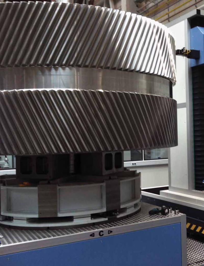
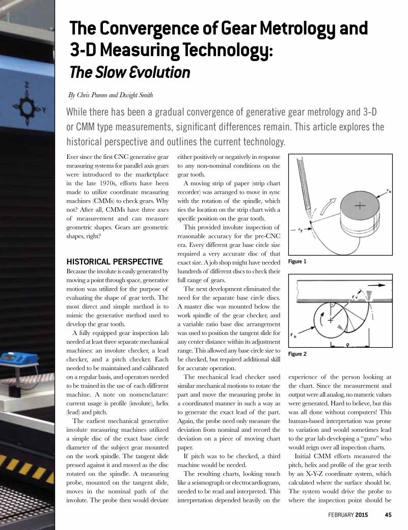
Ever since the first CNC generative gear measuring systems for parallel axis gears were introduced to the marketplace in the late 1970s, efforts have been made to utilize coordinate measuring machines (CMMs) to check gears. Why not? After all, CMMs have three axes of measurement and can measure geometric shapes. Gears are geometric shapes, right?
HISTORICAL PERSPECTIVEBecause the involute is easily generated by moving a point through space, generative motion was utilized for the purpose of evaluating the shape of gear teeth. The most direct and simple method is to mimic the generative method used to develop the gear tooth.
A fully equipped gear inspection lab needed at least three separate mechanical machines: an involute checker, a lead checker, and a pitch checker. Each needed to be maintained and calibrated on a regular basis, and operators needed to be trained in the use of each different machine. A note on nomenclature: current usage is profile (involute), helix (lead) and pitch.
The earliest mechanical generative involute measuring machines utilized a simple disc of the exact base circle diameter of the subject gear mounted on the work spindle. The tangent slide pressed against it and moved as the disc rotated on the spindle. A measuring probe, mounted on the tangent slide, moves in the nominal path of the involute. The probe then would deviate
either positively or negatively in response to any non-nominal conditions on the gear tooth.
A moving strip of paper (strip chart recorder) was arranged to move in sync with the rotation of the spindle, which ties the location on the strip chart with a specific position on the gear tooth.
This provided involute inspection of reasonable accuracy for the pre-CNC era. Every different gear base circle size required a very accurate disc of that exact size. A job shop might have needed hundreds of different discs to check their full range of gears.
The next development eliminated the need for the separate base circle discs. A master disc was mounted below the work spindle of the gear checker, and a variable ratio base disc arrangement was used to position the tangent slide for any center distance within its adjustment range. This allowed any base circle size to be checked, but required additional skill for accurate operation.
The mechanical lead checker used similar mechanical motions to rotate the part and move the measuring probe in a coordinated manner in such a way as to generate the exact lead of the part. Again, the probe need only measure the deviation from nominal and record the deviation on a piece of moving chart paper.
If pitch was to be checked, a third machine would be needed.
The resulting charts, looking much like a seismograph or electrocardiogram, needed to be read and interpreted. This interpretation depended heavily on the
experience of the person looking at the chart. Since the measurement and output were all analog, no numeric values were generated. Hard to believe, but this was all done without computers! This human-based interpretation was prone to variation and would sometimes lead to the gear lab developing a “guru” who would reign over all inspection charts.
Initial CMM efforts measured the pitch, helix and profile of the gear teeth by an X-Y-Z coordinate system, which calculated where the surface should be. The system would drive the probe to where the inspection point should be
The Convergence of Gear Metrology and 3-D Measuring Technology: The Slow Evolution
While there has been a gradual convergence of generative gear metrology and 3-D or CMM type measurements, significant differences remain. This article explores the historical perspective and outlines the current technology.
By Chris Pumm and Dwight Smith
Figure 1
Figure 2
FEBRUARY 2015 45
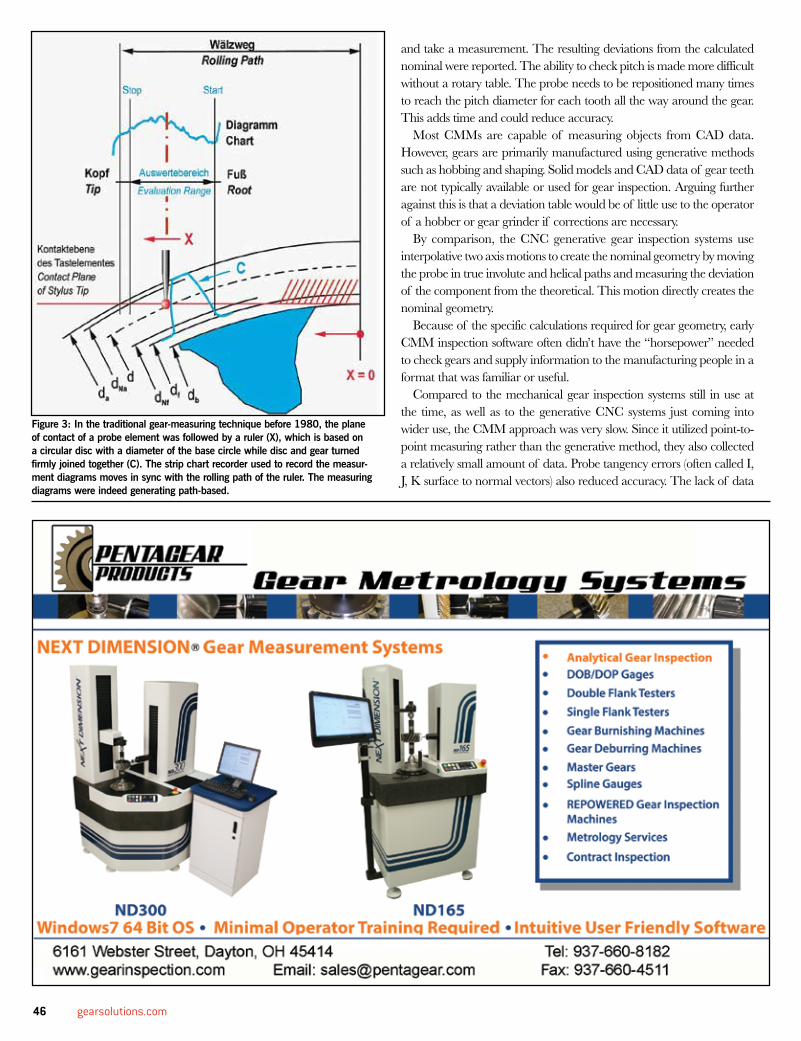
and take a measurement. The resulting deviations from the calculated nominal were reported. The ability to check pitch is made more difficult without a rotary table. The probe needs to be repositioned many times to reach the pitch diameter for each tooth all the way around the gear. This adds time and could reduce accuracy.
Most CMMs are capable of measuring objects from CAD data. However, gears are primarily manufactured using generative methods such as hobbing and shaping. Solid models and CAD data of gear teeth are not typically available or used for gear inspection. Arguing further against this is that a deviation table would be of little use to the operator of a hobber or gear grinder if corrections are necessary.
By comparison, the CNC generative gear inspection systems use interpolative two axis motions to create the nominal geometry by moving the probe in true involute and helical paths and measuring the deviation of the component from the theoretical. This motion directly creates the nominal geometry.
Because of the specific calculations required for gear geometry, early CMM inspection software often didn’t have the “horsepower” needed to check gears and supply information to the manufacturing people in a format that was familiar or useful.
Compared to the mechanical gear inspection systems still in use at the time, as well as to the generative CNC systems just coming into wider use, the CMM approach was very slow. Since it utilized point-to-point measuring rather than the generative method, they also collected a relatively small amount of data. Probe tangency errors (often called I, J, K surface to normal vectors) also reduced accuracy. The lack of data
Figure 3: In the traditional gear-measuring technique before 1980, the plane of contact of a probe element was followed by a ruler (X), which is based on a circular disc with a diameter of the base circle while disc and gear turned firmly joined together (C). The strip chart recorder used to record the measur-ment diagrams moves in sync with the rolling path of the ruler. The measuring diagrams were indeed generating path-based.
46 gearsolutions.com
density and industry acceptable analysis further prevented acceptance by the gear industry.
Adding to the challenge for CMMs was the difficulty of programming. Since CMMs are typically general purpose systems, every move and measuring point needs to be painstakingly programmed by a skilled programmer. In contrast, dedicated gear inspection machine software has the programming for gear inspection already in the machine. The user need only enter basic gear data from the engineering drawing and the machine uses this data to measure the gear. The typical commodity level CMM of the time was never capable of the accuracy and repeatability
necessary for gear inspection. Using the old toolmakers rule of thumb, typical gear tolerances in the .005mm (.0002”) range require inspection accuracy much greater than the tolerance. With the large volumetric inspection cube, standard accuracy CMMs are often not accurate or repeatable enough for the task of gear metrology.
Early CNC controllers didn’t have the speed needed for gear inspection. The axis drives created internal heat that effected accuracy as well. Bridge type CMMs, with scales mounted at the slides, made measurements by reading those scales which are far away from the gear. Without a rotary table, a CMM needs to be much larger than the subject gear to provide sufficient travel in all axes to reach the entire gear. This makes the footprint of the machine much larger, requiring a larger inspection facility, and further positioning the measuring scales even further from the gear tooth. All this meant that companies whose main endeavor was gear manufacturing almost always had dedicated, four axis, CNC, generative gear inspection machines.
If a gear producing company was checking gears for their own products, the output from the CMM was often useful. However, if the gears produced were for outside customers, there were often correlation issues. The inability of most CMMs of that vintage to measure a certified and calibrated master artifact, and make adjustments to match the known values, made the CMM reports unacceptable to many customers.
THE NEED FOR CALIBRATIONMost manufacturers have quality standards that require inspection to be traceable to a calibrated artifact. In the gear industry, it is an accepted
Figure 4
FEBRUARY 2015 47
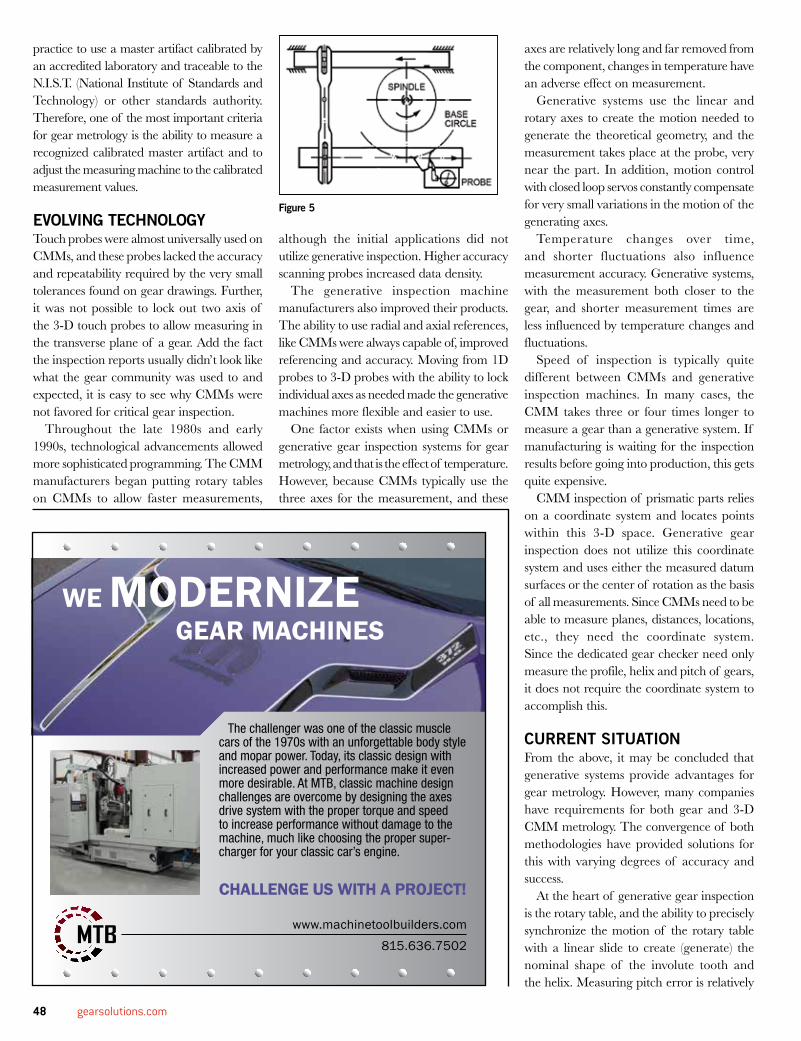
practice to use a master artifact calibrated by an accredited laboratory and traceable to the N.I.S.T. (National Institute of Standards and Technology) or other standards authority. Therefore, one of the most important criteria for gear metrology is the ability to measure a recognized calibrated master artifact and to adjust the measuring machine to the calibrated measurement values.
EVOLVING TECHNOLOGYTouch probes were almost universally used on CMMs, and these probes lacked the accuracy and repeatability required by the very small tolerances found on gear drawings. Further, it was not possible to lock out two axis of the 3-D touch probes to allow measuring in the transverse plane of a gear. Add the fact the inspection reports usually didn’t look like what the gear community was used to and expected, it is easy to see why CMMs were not favored for critical gear inspection.
Throughout the late 1980s and early 1990s, technological advancements allowed more sophisticated programming. The CMM manufacturers began putting rotary tables on CMMs to allow faster measurements,
although the initial applications did not utilize generative inspection. Higher accuracy scanning probes increased data density.
The generative inspection machine manufacturers also improved their products. The ability to use radial and axial references, like CMMs were always capable of, improved referencing and accuracy. Moving from 1D probes to 3-D probes with the ability to lock individual axes as needed made the generative machines more flexible and easier to use.
One factor exists when using CMMs or generative gear inspection systems for gear metrology, and that is the effect of temperature. However, because CMMs typically use the three axes for the measurement, and these
axes are relatively long and far removed from the component, changes in temperature have an adverse effect on measurement.
Generative systems use the linear and rotary axes to create the motion needed to generate the theoretical geometry, and the measurement takes place at the probe, very near the part. In addition, motion control with closed loop servos constantly compensate for very small variations in the motion of the generating axes.
Temperature changes over time, and shorter fluctuations also influence measurement accuracy. Generative systems, with the measurement both closer to the gear, and shorter measurement times are less influenced by temperature changes and fluctuations.
Speed of inspection is typically quite different between CMMs and generative inspection machines. In many cases, the CMM takes three or four times longer to measure a gear than a generative system. If manufacturing is waiting for the inspection results before going into production, this gets quite expensive.
CMM inspection of prismatic parts relies on a coordinate system and locates points within this 3-D space. Generative gear inspection does not utilize this coordinate system and uses either the measured datum surfaces or the center of rotation as the basis of all measurements. Since CMMs need to be able to measure planes, distances, locations, etc., they need the coordinate system. Since the dedicated gear checker need only measure the profile, helix and pitch of gears, it does not require the coordinate system to accomplish this.
CURRENT SITUATIONFrom the above, it may be concluded that generative systems provide advantages for gear metrology. However, many companies have requirements for both gear and 3-D CMM metrology. The convergence of both methodologies have provided solutions for this with varying degrees of accuracy and success.
At the heart of generative gear inspection is the rotary table, and the ability to precisely synchronize the motion of the rotary table with a linear slide to create (generate) the nominal shape of the involute tooth and the helix. Measuring pitch error is relatively
Figure 5
The challenger was one of the classic muscle cars of the 1970s with an unforgettable body style and mopar power. Today, its classic design with increased power and performance make it even more desirable. At MTB, classic machine design challenges are overcome by designing the axes drive system with the proper torque and speed to increase performance without damage to the machine, much like choosing the proper super-charger for your classic car’s engine.
WE MODERNIZE GEAR MACHINES
CHALLENGE US WITH A PROJECT!
www.machinetoolbuilders.com815.636.7502
48 gearsolutions.com
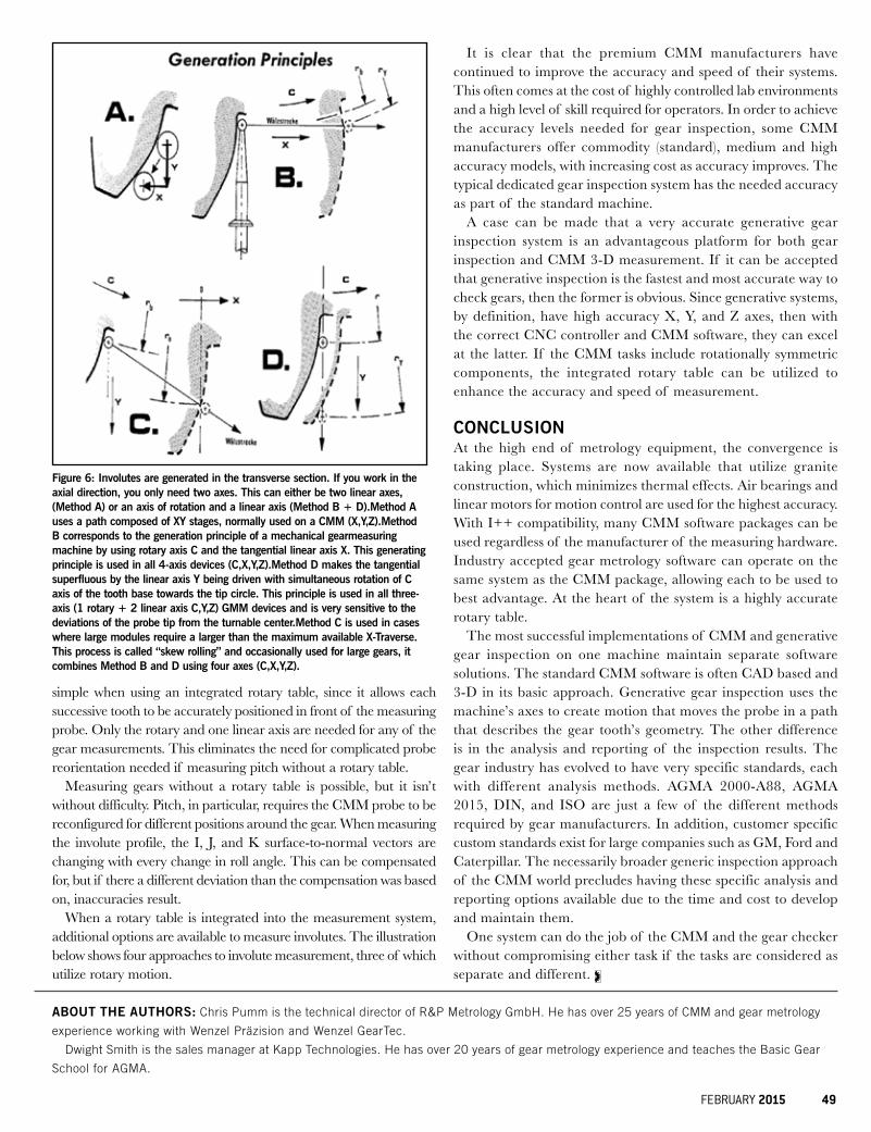
simple when using an integrated rotary table, since it allows each successive tooth to be accurately positioned in front of the measuring probe. Only the rotary and one linear axis are needed for any of the gear measurements. This eliminates the need for complicated probe reorientation needed if measuring pitch without a rotary table.
Measuring gears without a rotary table is possible, but it isn’t without difficulty. Pitch, in particular, requires the CMM probe to be reconfigured for different positions around the gear. When measuring the involute profile, the I, J, and K surface-to-normal vectors are changing with every change in roll angle. This can be compensated for, but if there a different deviation than the compensation was based on, inaccuracies result.
When a rotary table is integrated into the measurement system, additional options are available to measure involutes. The illustration below shows four approaches to involute measurement, three of which utilize rotary motion.
It is clear that the premium CMM manufacturers have continued to improve the accuracy and speed of their systems. This often comes at the cost of highly controlled lab environments and a high level of skill required for operators. In order to achieve the accuracy levels needed for gear inspection, some CMM manufacturers offer commodity (standard), medium and high accuracy models, with increasing cost as accuracy improves. The typical dedicated gear inspection system has the needed accuracy as part of the standard machine.
A case can be made that a very accurate generative gear inspection system is an advantageous platform for both gear inspection and CMM 3-D measurement. If it can be accepted that generative inspection is the fastest and most accurate way to check gears, then the former is obvious. Since generative systems, by definition, have high accuracy X, Y, and Z axes, then with the correct CNC controller and CMM software, they can excel at the latter. If the CMM tasks include rotationally symmetric components, the integrated rotary table can be utilized to enhance the accuracy and speed of measurement.
CONCLUSIONAt the high end of metrology equipment, the convergence is taking place. Systems are now available that utilize granite construction, which minimizes thermal effects. Air bearings and linear motors for motion control are used for the highest accuracy. With I++ compatibility, many CMM software packages can be used regardless of the manufacturer of the measuring hardware. Industry accepted gear metrology software can operate on the same system as the CMM package, allowing each to be used to best advantage. At the heart of the system is a highly accurate rotary table.
The most successful implementations of CMM and generative gear inspection on one machine maintain separate software solutions. The standard CMM software is often CAD based and 3-D in its basic approach. Generative gear inspection uses the machine’s axes to create motion that moves the probe in a path that describes the gear tooth’s geometry. The other difference is in the analysis and reporting of the inspection results. The gear industry has evolved to have very specific standards, each with different analysis methods. AGMA 2000-A88, AGMA 2015, DIN, and ISO are just a few of the different methods required by gear manufacturers. In addition, customer specific custom standards exist for large companies such as GM, Ford and Caterpillar. The necessarily broader generic inspection approach of the CMM world precludes having these specific analysis and reporting options available due to the time and cost to develop and maintain them.
One system can do the job of the CMM and the gear checker without compromising either task if the tasks are considered as separate and different.
ABOUT THE AUTHORS: Chris Pumm is the technical director of R&P Metrology GmbH. He has over 25 years of CMM and gear metrology
experience working with Wenzel Präzision and Wenzel GearTec.
Dwight Smith is the sales manager at Kapp Technologies. He has over 20 years of gear metrology experience and teaches the Basic Gear
School for AGMA.
Figure 6: Involutes are generated in the transverse section. If you work in the axial direction, you only need two axes. This can either be two linear axes, (Method A) or an axis of rotation and a linear axis (Method B + D).Method A uses a path composed of XY stages, normally used on a CMM (X,Y,Z).Method B corresponds to the generation principle of a mechanical gearmeasuring machine by using rotary axis C and the tangential linear axis X. This generating principle is used in all 4-axis devices (C,X,Y,Z).Method D makes the tangential superfluous by the linear axis Y being driven with simultaneous rotation of C axis of the tooth base towards the tip circle. This principle is used in all three-axis (1 rotary + 2 linear axis C,Y,Z) GMM devices and is very sensitive to the deviations of the probe tip from the turnable center.Method C is used in cases where large modules require a larger than the maximum available X-Traverse. This process is called “skew rolling” and occasionally used for large gears, it combines Method B and D using four axes (C,X,Y,Z).
FEBRUARY 2015 49
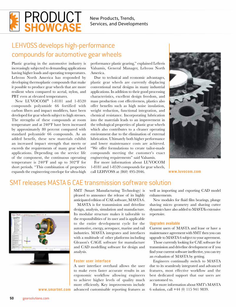
50 gearsolutions.com
Plastic gearing in the automotive industry is increasingly subjected to demanding applications having higher loads and operating temperatures. Lehvoss North America has responded by developing thermoplastic compounds that make it possible to produce gear wheels that are more resilient when compared to acetal, nylon, and PBT even at elevated temperatures.
New LUVOCOM® 1-8181 and 1-8520 compounds polyamide 66 fortified with carbon fibers and impact modifiers, have been developed for gear wheels subject to high stresses. The strengths of these compounds at room temperature and at 240°F have been increased by approximately 80 percent compared with standard polyamide 66 compounds. As an added benefit, these new materials exhibit an increased impact strength that meets or exceeds the requirements of many gear wheel applications. Depending on the service life of the component, the continuous operating temperature is 240°F and up to 302°F for short periods. “This combination of properties expands the engineering envelope for ultra-high
performance plastic gearing,” explained Lefteris Valsamis, General Manager, Lehvoss North America.
Due to technical and economic advantages, plastic gear wheels are currently displacing conventional metal designs in many industrial applications. In addition to their good processing characteristics, excellent design freedom, and mass production cost effectiveness, plastics also offer benefits such as high noise insulation, weight reduction, functional integration, and chemical resistance. Incorporating lubrication into the materials leads to an improvement in the tribological properties of plastic gear wheels which also contributes to a cleaner operating environment due to the elimination of external lubrication. Ultimately both higher performance and lower maintenance costs are achieved. “We offer formulations to create tailor-made compounds meeting the customer’s exact engineering requirements” said Valsamis.
For more information about LUVOCOM 1-8181 and 1-8520 compounds for gear wheels, call LEHVOSS at (860) 495-2046.
LEHVOSS develops high-performance compounds for automotive gear wheels
SMT releases MASTA 6 CAE transmission software solutionSMT (Smart Manufacturing Technology) is pleased to announce the release of its highly anticipated edition of CAE software, MASTA 6.
MASTA is for transmission and driveline design, analysis, simulation and manufacture. Its modular structure makes it tailorable to the responsibilities of its user and is applicable to the entire development cycle for the automotive, energy, aerospace, marine and rail industries. MASTA integrates and interfaces with a multitude of other platforms including Gleason’s CAGE software for manufacture and CAD modelling software for design and analysis.
Faster user interfaceA user interface overhaul allows the user to make even faster accurate results in an ergonomic workflow allowing engineers to achieve higher levels of quality much more efficiently. Key improvements include advanced customisable reporting features as
well as importing and exporting CAD model enhancements.
New modules for fluid film bearings, plunge shaving micro geometry and shaving cutter dynamics have also added to MASTA’s extensive repertoire.
Upgrades availableCurrent users of MASTA and lease or have a maintenance agreement with SMT then you can upgrade to MASTA 6 subject to your agreement.
Those currently looking for CAE software for transmission and driveline development or if you find your current software ineffective, you can try an evaluation of MASTA by getting.
Engineers continually switch to MASTA due to its seamlessly integrated and advanced features, most effective workflow and the best dedicated support that our users are accustomed to.
For more information about SMT’s MASTA 6 solution, call +44 (0) 115 941 9839.
www.luvocom.com
www.smartmt.com
PRODUCTSHOWCASE
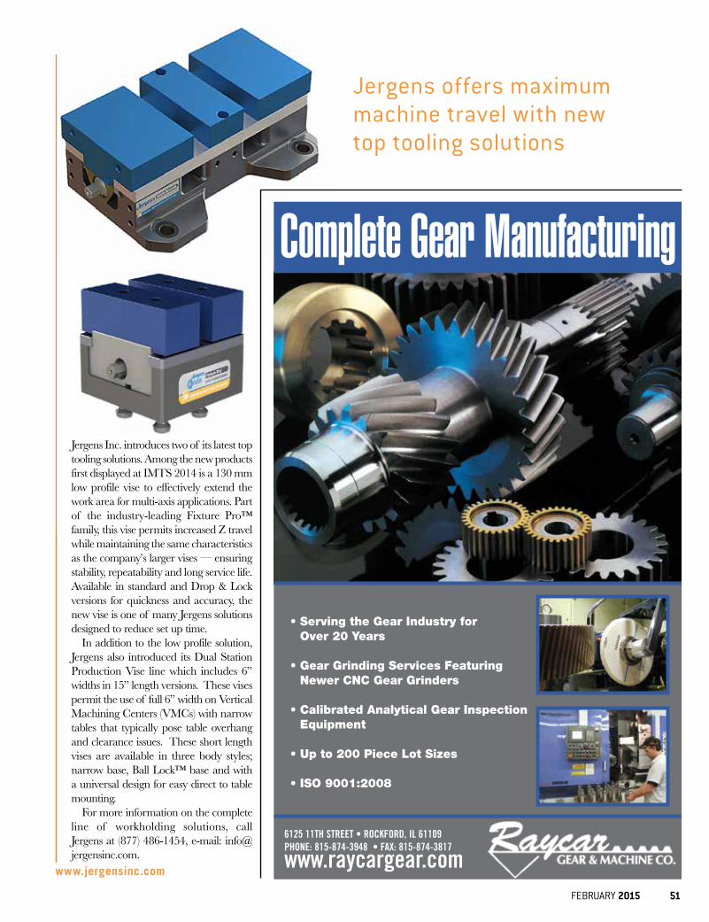
FEBRUARY 2015 51
Jergens offers maximum machine travel with new top tooling solutions
Jergens Inc. introduces two of its latest top tooling solutions. Among the new products first displayed at IMTS 2014 is a 130 mm low profile vise to effectively extend the work area for multi-axis applications. Part of the industry-leading Fixture Pro™ family, this vise permits increased Z travel while maintaining the same characteristics as the company’s larger vises — ensuring stability, repeatability and long service life. Available in standard and Drop & Lock versions for quickness and accuracy, the new vise is one of many Jergens solutions designed to reduce set up time.
In addition to the low profile solution, Jergens also introduced its Dual Station Production Vise line which includes 6” widths in 15” length versions. These vises permit the use of full 6” width on Vertical Machining Centers (VMCs) with narrow tables that typically pose table overhang and clearance issues. These short length vises are available in three body styles; narrow base, Ball Lock™ base and with a universal design for easy direct to table mounting.
For more information on the complete line of workholding solutions, call Jergens at (877) 486-1454, e-mail: [email protected].
www.jergensinc.com
• Serving the Gear Industry for Over 20 Years
• Gear Grinding Services Featuring
Newer CNC Gear Grinders • Calibrated Analytical Gear Inspection
Equipment • Up to 200 Piece Lot Sizes • ISO 9001:2008
6125 11TH STREET • ROCKFORD, IL 61109PHONE: 815-874-3948 • FAX: 815-874-3817
www.raycargear.com
Complete Gear Manufacturing
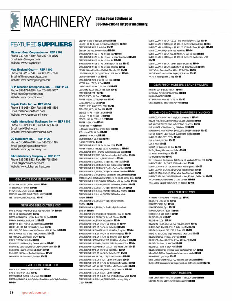
52 gearsolutions.com
GEAR ACCESSORIES, PARTS & TOOLING
FELLOWS Model #10-4/10-2, All Parts Available REF#102Tilt Tables for 10-2/10-4, Qty 2 REF#102FELLOWS Parts Available For All Models REF#103BARBER-COLMAN – PARTS AVAILABLE FOR ALL MODELS REF#103 G&E – PARTS AVAILABLE FOR ALL MODELS REF#103
GEAR HOBBERS/CUTTERS CNC
PFAUTER #PE-150, 6-Axis CNC, 6” Dia, 5 DP, 6” Face, Fanuc 18MI REF#103G&E #60 S-2 CNC Gasher/Hobber REF#103BARBER-COLMAN #16-36, 16” Dia, 4-Axis, 6 DP, 36” Face REF#103MUIR CNC Gear Hobber, 4-Axis, 118” Dia REF#103LIEBHERR #L-252 3-Axis, 9.8” Dia, recontrolled 2008 REF#103LIEBHERR #ET-1802 CNC – 98” Dia Internal, 3-Axis REF#103G&E #120GH, CNC, Gasher/Hobber, Twin Stanchion, 1/2 DP, 42” Face, ‘94 REF#103PFAUTER P400H, 5-Axis, 18” Dia, 1 DP, Recontrolled ‘03 REF#103G&E #96GH, CNC, Gasher/Hobber, New ‘09 REF#103PFAUTER PE 300 AW CNC 6-Axis REF#103Pfauter PE150, 15MB Fanuc, Chip Conveyor, Auto Load REF#107Pfauter PE150, Siemens 3M, Magnetic Chip Conveyor, Oil Chiller REF#107Pfauter PE150, Fanuc 15, with light hob slide 8” REF#107Pfauter PE80, 15MB Control, Auto Load, Light Curtain REF#107Liebherr LC82 15M Fanuc Control, Auto Load REF#107
GEAR HOBBERS/CUTTERSPFAUTER P1251 Hobbers s/n 25-276 and 25-277 REF#102PFAUTER (1) RS-00 s/n 17593 REF#102BARBER COLEMAN (1) 16-36 multi cycle s/n 4404 REF#102BARBER-COLMAN #16-16, Multi-Cycle, Dual Thread Worm and/or Single Thread Worm REF#103
G&E #48H 48” Dia, 18” Face 2 DP, Universal REF#103G&E #48H, 48” Dia, 35” Face, 3 DP, Gooseneck Attachment REF#103BARBER-COLMAN #6-16, 6 Multi-Cycle REF#103G&E #36H Differential, Excellent Condition REF#103BARBER-COLMAN #14-30, 14” Dia, 30” Face, 3.5DP REF#103BARBER-COLMAN #14-15, 14” Dia, 15” Face, 1 to 4 Start Worm, Several REF#103BARBER-COLMAN #16-16, 16” Dia, 16” Face, 6DP REF#103BARBER-COLMAN #16-36, 24” Dia, C-Frame Style, 4 1/8” Bore REF#103BARBER-COLMAN #16-56, 16” Dia, 56” Face, Differential REF#103G&E #24H Universal Head, Infeed, Tailstock, Differential, ‘50’s REF#103LIEBHERR #L-650, 26" Dia Cap, 14.5" Face, 2.5 DP, New ‘70’s REF#103G&E #16H Gear Hobber, 16"Dia REF#103BARBER-COLMAN #6-10, 6” Dia, 10” Face, 16 DP REF#103KOEPFER #140 , 2.75” DIa, 4” Face REF#103 LANSING #GH-50, 50” Dia, 17.75” Face, 2 DP REF#103LIEBHERR #L-252, 9.8” Dia, 7.9” Face, 4.2 DP REF#103BARBER-COLMAN TYPE T REF#103G&E #36HS 36”Dia, 14” Face 3 DP REF#103PFAUTER #P-3000, 120” Dia, Single Index REF#103SCHIESS RFW-10-S 55” Dia REF#103SCHIESS 1 RF-10, Dia 60” 150” L, .50 DP REF#103G&E #40TWG, 48” Dia, 18” Face, 3 DP REF#103G&E #60S, 72” Dia, 14” Face, 1.25 DP REF#103G&E #72H, 72” Dia, 24” Face, 1 DP REF#103 G&E #96H, 104” Dia, .50 Face, 1.25 DP REF#103PFAUTER #P-630, 25” Dia REF#103 PFAUTER P250 10” Dia REF#103GE/Fitchburg Hobber 32” Dia, 72” Face 1.25DP REF#103JF Reinecker 40” Dia 35” Face REF#103LIEBHERR L-160-R 6.5” Dia REF#103MIKRON #102.04 , 4’ Dia, 5” Face REF#103PFAUTER P-900 36” Dia REF#103BARBER-COLMAN #25-15 25” Dia, 15” Face, 2.5 DP REF#103PFAUTER #P-630R, 25" Max. Spur Dia, 12" Max Rotor Dia. 12" REF#103BARBER-COLMAN 2 1/2 -4, S/N 119, ’62 Hi-Production Spur Gear REF#104BARBER-COLMAN 6-10 SYKES, Triple Thrd w/Lever Operated Collet Assy REF#104BARBER-COLMAN 6-10 B&C Ltd, S/N 8079, Triple Thrd REF#104BARBER-COLMAN 6-10, S/N 4626, ’57 Triple Thrd 3” Hob Slide REF#104BARBER-COLMAN 6-10, S/N 4659R, ’56 Triple Thrd Adj Ctr Assy REF#104BARBER-COLMAN 6-10, S/N 4665, ’57 Fine Pitch Prec Triple Thrd REF#104BARBER-COLMAN 6-10, S/N 4701, ’58 Triple Thrd w/Power Down Feed REF#104BARBER-COLMAN 6-10 M/C, S/N 4755, ’59 Triple Thrd w/MC Conversion REF#104BARBER-COLMAN 6-10 Multicycle, S/N 4778R87, ’60 (’87 Rebuild), Sgl Thrd Hi-Spd REF#104BARBER-COLMAN 6-10 M/C, S/N 4913, ’63 Triple Thrd w/90 Deg Hob Slide REF#104BARBER-COLMAN 6-10 Multicycle, S/N 5055, ’66 Triple Thrd, 800 RPM REF#104BARBER-COLMAN 6-10, S/N 5141, ’67 Triple Thrd w/Prec Hob Shift REF#104BARBER-COLMAN 6-10 Multicycle, S/N 5148, ’68 Triple Thrd, 800 RPM REF#104BARBER-COLMAN 6-10 Multicycle, S/N 5259, ’75 Triple Thrd w/Auto Hob Shift REF#104BARBER-COLMAN 6-10, S/N 5353, ’77 Triple Thrd w/3” Hob Slide, 800 RPM REF#104BARBER-COLMAN 6-10, S/N 5394, ’81 Fine Pitch Triple Thrd w/Dwell & Hob Rev REF#104BARBER-COLMAN 6-16 M/C, S/N 5238, ’70 Triple Thrd, Recon ‘02 REF#104BARBER-COLMAN 6-10, S/N 5407, ’82 Auto w/PLC Control REF#104BARBER-COLMAN DHM, S/N 105, ’42 Double Thrd REF#104BARBER-COLMAN 14-15, S/N 635R, ’53 Dbl Thrd, Fact Reb REF#104BARBER-COLMAN 14-15, S/N 745, ’55 Dbl Thrd w/Dwell REF#104BARBER-COLMAN 14-15 Dual Fd, S/N 938, ’62 Dbl Thrd, Comp Reco REF#104BARBER-COLMAN 14-15, S/N 1055, ’65 Dbl Thrd w/New Hyd Sys REF#104BARBER-COLMAN 14-15, S/N 1131, ’66 Dbl Thrd w/Hyd Tailctr REF#104BARBER-COLMAN 14-15 Dual Fd, S/N 1261, ’67 Dbl Thrd w/Hyd Live Ctr REF#104BARBER-COLMAN 14-15 Dbl Cut, S/N 1278, ’68 Dbl Thrd w/4-1/8” Bore REF#104BARBER-COLMAN 14-30 Dual Fd, S/N 1371, ’71 4-Thrd w/Sizing Cycle REF#104BARBER-COLMAN 22-15, S/N 923, ’62 Dbl Thrd, Dbl Cut REF#104BARBER-COLMAN 16-11, S/N 184, ’50 Dbl Thrd w/Vert DRO REF#104BARBER-COLMAN AHM, S/N 1896, ’42 Sgl Thrd w/3 Jaw Chuck REF#104BARBER-COLMAN 16-16, S/N 2745, ’51 Sgl Thrd w/90 Deg Hd REF#104BARBER-COLMAN 16-16, S/N 3171, ’53 Dbl Thrd, Spanish Nameplates REF#104BARBER-COLMAN 16-16, S/N 3580, ’59 Dbl Thrd w/Diff & Auto Hobshift REF#104BARBER-COLMAN 16-16 Multicycle, S/N 3641, ’60 Dbl Thrd w/Diff REF#104BARBER-COLMAN 16-16, S/N 3660, ’57 Sgl Thrd REF#104BARBER-COLMAN 16-16, S/N 4136, Dbl Thrd, “C” Style End Brace w/Diff REF#104BARBER-COLMAN 16-16 Multicycle, S/N 4170, Dbl Thrd w/Jump Cut Cycle “C” Style REF#104
BARBER-COLMAN 16-16, S/N 4473, ’73 4-Thrd w/Workclamp Cyl “C” Style REF#104BARBER-COLMAN 16-16 Multicycle, S/N 4520, ’75 Dbl Thrd w/Gooseneck Slide REF#104BARBER-COLMAN 16-16 Multicycle, S/N 4631, ’79 “C” Style End Brace, 4W Adj Ctr REF#104BARBER-COLMAN AHM (36”), S/N 1152, ’42 Dbl Thrd REF#104BARBER-COLMAN 16-36, S/N 4090, ’66 Dbl Thrd, “C” Style End Brace REF#104BARBER-COLMAN 16-36 Multicycle, S/N 4232, ’68 Dbl Thrd “C” Style End Brace w/Diff REF#104BARBER-COLMAN 16-56, S/N 3136R84, ’53 (Reb ’84), Dbl Thrd REF#104BARBER-COLMAN 10-20, S/N 6700045890, ’76 Dbl Thrd w/2 Cut Cycle REF#104TOS OFA Series Conventional Gear Hobbers, 12” & 40” Dia REF#105TOS OHA Series Conventional Gear Shapers, 12” & 40” Dia REF#105TOS FO-16 with single index 72” cap. REF#106
GEAR PINION HOBBERS & SPLINE MILLERS
HURTH #KF-32A 15” Dia, 59” Face, ‘67 REF#103GE/Fitchuburg Pinion Hob 32” Dia, 72” Face REF#103MICHIGAN Tool #3237 REF#103FITCHBURG Pinion Hobber 42” Dia, 72” Dia REF#103Craven horizontal 36” dia 96” length 73/4” hole REF#106
GEAR HOB & CUTTER SHARPENERS (incl CNC)
BARBER-COLMAN #6-5, 6" Dia, 5" Length, Manual Dresser, ‘57 REF#103FELLOWS #6SB, Helical Cutter Sharpener, 6” Dia, up to 50 Degrees REF#103KAPP #AS-305GT, 1 DP, 28" Grind Length, 10" Diam., Str. & Spiral REF#103KAPP #AS204GT, 10” Dia, Wet Grinding, CBN Wheels, ‘82 REF#103REDRING MODEL #SGH "PREIFORM" SHAVE CUTTER GRINDER/SHARPENER REF#103STAR 6X8 HOB SHARPENER PRECISION GEAR & SPLINE HOBBER REF#103BARBER-COLMAN 2-2 1/2 , 2.5” Dia REF#103KAPP #AST-305B, 27.5” Dia, REF#103KAPP AS-410B REF#103GLEASON #12 Sharpener, 3-18” Cone REF#103Red Ring Shaving Cutter sharpener Periform REF#103Star #6 Gear Cutter Sharpener REF#103Star 4HS Hob sharpener REF#103Star HHS Horizontal Hob Sharpener CNC, Max Dia 10” Max length 12” New 1990 REF#103BARBER-COLMAN 2 1/2-2, S/N 16, ’66 Wet w/Auto Feed REF#104BARBER-COLMAN 6-5, S/N 110R, ’55 Wet w/Auto Dress & Sparkout REF#104BARBER-COLMAN 6-5, S/N 396, ’66 Wet w/Auto Dress & Sparkout REF#104BARBER-COLMAN 6-5, S/N 433, ’69 Wet w/Auto Dress & Sparkout REF#104BARBER-COLMAN 10-12, S/N 643R83, Wet w/Auto Dress, PC Control, Fact Reb ‘83 REF#104TOS OHA Series CNC Gear Shapers, 12” & 40” Diameter REF#105 TOS OFA Series CNC Gear Hobbers, 12” & 40” Diameter REF#105
GEAR SHAPERS CNC
36” Shapers, 14” Throat Risers, 53” of Swing, Qty 3 REF#102FELLOWS #10-4/10-2, Qty 150 REF#102HYDROSTROKE #50-8, Qty 2 REF#102HYDROSTROKE #20-8, Qty 5 REF#102HYDROSTROKE #FS630-125, Qty 1 REF#102HYDROSTROKE #FS400-90, Qty 2 REF#102FELLOWS #20-4, Qty 6 REF#102FELLOWS #48-8Z, Qty 1 REF#102FELLOWS #FS-180, 3-5 Axis, 7” Dia, 1.25” Face., 6 DP, New ‘88 REF#103LIEBHERR #WS-1, 4-Axis CNC, 8" OD, 2" Stroke, Fanuc 18MI REF#103LORENZ # LS-180, 4-Axis CNC, 11” OD, 2” Stroke, 5 DP REF#103LORENZ #LS-304 CNC Gear Shaper 5-Axis Heckler & Koch Control REF#103FELLOWS FS400-125, 16” Dia, 3.5 DP 5” Face REF#103FELLOWS #10-4 3-Axis (A/B), 10" Dia, 4" Face, 4 DP New .’09 REF#103 FELLOWS #10-4 2-Axis, 10” Dia 4” Face REF#103FELLOWS #20-4 3-Axis 10” Dia, 4” Face REF#103FELLOWS FS400-90 Hydro-stroke Gear Shaper CNC Nominal Pitch 15.7" REF#103Fellows 20-8, CNC Gear Shaper, Remanufactured and recontrolled REF#103Fellows Model Z gear Shaper REF#103Lorenz SN4 Gear Shaper, Max OD 7”, 2” Face, Max 6 DP with Loader REF#103RP/ Stanko 48-8 Remanufactured Gear Shaper, Fanuc 3 Axis, 18i M Control, new 2010 REF#103
GEAR HOBBERS
Barber Colman Model 4-4HRS, Hob Sharpener 4” Max OD, 4” Length REF#103Fellows FH 200 Gear hobber, universal hobbing Machine REF#103
FEATUREDSUPPLIERSMidwest Gear Corporation — REF #101Phone: 330-425-4419 • Fax: 330-425-8600Email: [email protected]: www.mwgear.com
New England Gear — REF #102Phone: 860-223-7778 • Fax: 860-223-7776Email: [email protected]: www.newenglandgear.com
R. P. Machine Enterprises, Inc. — REF #103Phone: 704-872-8888 • Fax: 704-872-5777Email: [email protected]: www.rpmachine.com
Repair Parts, Inc. — REF #104Phone: 815-968-4499 • Fax: 815-968-4694Email: [email protected] Website: www.repair-parts-inc.com
Havlik International Machinery, Inc. — REF #105Phone: 519-624-2100 • Fax: 519-624-6994Email: [email protected]: www.havlikinternational.com
GQ Machinery Inc. — REF #106Phone: 516-867-4040 • Fax: 516-223-1195Email: [email protected]: www.gqmachinery.com
Gibbs Machinery Company — REF #107Phone: 586-755-5353 Fax: 586-755-0304Email: [email protected]: www.gibbsmachinery.com
Contact Gear Solutions at 800-366-2185 to list your machinery.MACHINERY

FEBRUARY 2015 53
Barber Colman 6-10, CNC, CRt 5 Axis, 6” Dia, 10.5” travel, 6 DP REF#103Barber Colman Hobber Type T REF#103Barber Colman model #14-15 Gear Hobber, horizontal Heavy Duty REF#103Barber Colman Model #16-36 GearHobber REF#103Barber Colman Model #16-56, 16” dia, 56” Face, adj. Air Tailstock REF#103Barber Colman Model 2.5-2 gear hobber, 2” length Manual Dresser REF#103G&E Model 5.2 CNC Internal Gear gashing head REF#103Jeil JDH-3, Gear hobber, Max Dia 31.5”, 3DP, 22.8 Table Diameter REF#103Jeil JDP-2, Gear hobber, Max Dia 26”, 4 DP, 19.5” Table Dia, Differential and tailstock REF#103Liebherr ET 1802, Internal Gashing head, Fanuc 16i Control, 98”Max dist 17” Face REF#103Liebherr L-402 Gear hobbing Machine, New 1977 REF#103Liebherr LC 752, 6 Axis CNC Hobber, Max OD 29.5”, Max Face width 23.6” REF#103Micron Model 120.01 w/bevel Cutting Attachment, New 1975, 1.6” dia, 25.4 DP REF#103Nihon Kakai Model NTM-3000, Spline Hobbing Machine, Max dia 400mm, 3150mm between Center REF#103Pfauter P900 Reman and Recontrolled, Max OD 120” REF#103Pfauter Model PE125 CNC Gear hobber REF#103Pfauter model PE300 CNC, Max OD 12”, Max gear face 15”, 3 DP, 6 Axis REF#103Reinecker Heavy Duty Gear Hobber REF#103Scheiss Model RF10 Horizontal Hobber, 60” dia, 144” face, 180”cc, 8 DP REF#103G&E 96H, roughing & finishing 104” dia. REF#106TOS FO-16 single index 80” dia. Yr 1980 REF#106Craven spline & pinion hobber 36” x 96” REF#106G & E 48H 48” dia. Diff, OB, change gears REF#106Pfauter hobber P-1800 70” dia. 29” face yr 1980 REF#106Lees Bradner 7VH, 8”PD, 10” Face, , Magnetic Chip Conveyor , Hob Shift REF#107Lees Bradner 7VH, 8”PD, 4PD, Magnetic Chip Conveyor, Hob Shift REF#107Mitsubishi Model GH300, 15.7”, 3 DP, Differential, 2 Cut REF#107Tos 32A, 320mm Gear Dia.,3.6 DP, Differential, 2 Cut REF#107Gleason 775 8”PD, High Helix Head, Infeed, Very Light Use REF#107Barber C. 16-15, 7 ½” Hob, Crowning, Differential, 2 Cut REF#107Barber Colman 14-15, 2 Cut, Fast Approach, 4” Bore REF#107Barber Colman 16-36, Type A – Very Good, Double Thread Index REF#107G & E Model 48HS 48”PD, 18” Face, 2.5 DP REF#107
GEAR SHAPERS
FELLOWS #10-2, (10” Dia), 2” Face REF#102FELLOWS #10-4, (10” Dia), 4” Face REF#102FELLOWS (200) 10-4 / 10-2 Shapers REF#102FELLOWS (1) 50-8 Hydrostroke Shaper s/n 36607 w/ 6 axis 16iMB Fanuc (2009) REF#102FELLOWS (1) 20-8 Hydrostroke Shaper s/n 35932 w/ 6 axis 16iMB Fanuc (2009 REF#102 FELLOWS (1) #7 125A Face Gear Machine REF#102FELLOWS (2) #3 Face Gear Machine REF#102(1) 4ags with adjustable Helical Guide s/n 30634 REF#102(1) #7 125A adjustable Helical Guide REF#102FELLOWS (1) FS630-200 Hydrostroke Shaper s/n 36943 w/ 6 axis 16iMB Fanuc (2009) REF#102FELLOWS (3) Tilt Table 10-4 / 10-2 w/ 4 axis 21i Fanuc Controller (2009) REF#102FELLOWS (2) Swing-away center support for 10-2 / 10-4 REF#102FELLOWS (1) FS630-170 Hydrostroke Shaper s/n 36732 w/ 6 axis 16iMB Fanuc (2009) REF#102FELLOWS (2) FS400-170 Hydrostroke Shaper w/ 6 axis 16iMB Fanuc (2009) REF#102FELLOWS (4) FS400-125 Hydrostroke Shaper w/ 6 axis 16iMB Fanuc (2009) REF#102FELLOWS (1) 20-4 Shaper s/n 35687 w/ 4 axis 21i Fanuc Controller (2009) REF#102FELLOWS (1) 48-8Z Shaper w/ 14” throated riser (53” of swing) REF#102FELLOWS (1) Horizontal Z Shaper s/n 21261 REF#102FELLOWS (1) 4-B Steering Sector Gear Shaper w/ 18iMB 4 axis Fanuc controller s/n 34326 REF#102FELLOWS (1) 36-10 Gear Shaper REF#102FELLOWS (1) 10x6 Horizontal Z Shaper REF#102FELLOWS (1) 36-6 Gear Shaper w/ 13” riser s/n 27364 REF#102FELLOWS (1) 10-4 Shaper w/ 3” riser w/ 4 axis 21i Fanuc Controller (2009) REF#102All Parts for 10-4/10-2 Fellows Gear Shapers REF#102FELLOWS #36-8, 36” Dia, 8” Face REF#103FELLOWS #100-8 100” Dia, 8” Face REF#103FELLOWS #612A, 615A, #645A REF#103FELLOWS #10-4, 10” Dia, 4” Face, 4 DP REF#103FELLOWS #4A Versa, 10” Dia, 3” Face, 4 DP, New ‘70’s REF#103FELLOWS #10-2, 10” Dia, 4” Face, 4 DP REF#103FELLOWS #20-4, 20” Dia, 4” Face, 4 DP, ‘70’s REF#103FELLOWS #3-1,/3GS, 3” Max Dia, 1” Face, Pinion Supp, High Precision REF#103FELLOWS #48-6 INTERNAL GEAR SHAPER ONLY,0-72"OD,6" Face REF#103MAAG #SH-150, 57" Dia.12.6" Face REF#103
PFAUTER #SH-180 Shobber 7" capacity hobbing, 9.45" cap REF#103FELLOWS #36-6 Max Dia 36” 6” Face, 3 DP REF#103FELLOWS #HORZ Z SHAPER, 10 x 6 Dia 27.6 Face 8.5” REF#103FELLOWS #4GS & 4AGS, 6” Dia, 2” Face, 4DP, ’68, Ref.# Several REF#103FELLOWS #624A, 18” Max Dia, 5” Face REF#103FELLOWS #7, #7A, #715,# 75A, #715, #725A, 7” Dia, 0-12” Risers, Several Avail REF#103MICHIGAN #18106 SHEAR-SPEED GEAR SHAPER,14" Dia, 6"Face REF#103FELLOWS Model Z Shaper, 5" Stroke, ‘50’s REF#103STAEHELY SHS-605, Gear Shaper REF#103FELLOWS #6, #6A, #61S, From 18”-35” Dia, 0-12” Risers REF#103FELLOWS #8AGS Vertical Gear Shaper, 8” Dia, 2” Face, 6-7 DP REF#103TOS OHA50 CNC 5 20” Dia 5” Face REF#105Fellows 36-6 Shaper (2) 12.5" Risers 6" Stroke Mint YR 1969 id 3616 REF#106Fellows 36-6, shaper W/6” riser, change gears REF#106Magg shaper SH4580-500S, 206”dia. 26” face REF#106Magg shaper SH250, 98” dia. 26” face REF#106Fellows #10-4,7” riser yr 1980 REF#106Fellows 3”, 6”, 7”, 10”, 18”, 42”, 100, Some CNC REF#107
GEAR DEBURRING/CHAMFERING/POINTING
CROSS #50 Gear Tooth Chamferer, 18” Dia, Single Spindle REF#103REDIN #20D, 20” Dia, Twin Spindle, Deburrer/Chamfer REF#103SAMPUTENSILI #SCT-3, Chamf/Deburrer, 14” Dia, 5” Face, ‘82 REF#103SAMPUTENSILI #SM2TA Gear Chamfering Mach, 10” Max Dia, (3) New ‘96 REF#103REDIN #24 CNC Dia 4” Setup Gear Deburring REF#103 CROSS #60 Gear Tooth Chamferer, 10” Dia, Single Spindle REF#103FELLOWS #100-180/60 CNC Max Dia 180”, Single Spindle REF#103CIMTEC #50 Finisher REF#103CROSS #54 Gear Deburrer, 30” Dia, 18” Face REF#103RED RING #24 Twin Spindle Dia 4” REF#103GLEASON GTR-250 VG CNC 5-Axis REF#103Gleason- Hurth Model ZEA 4, Max Dia 250mm, Max Module 5mm REF#103Redin Model 36 universal Chamfering and Deburring Machine, Max OD 36”, Twin spindle, Tilt table REF#103Samputensili SCT3 13.7”, SM2TA 10”, (5), 2003 REF#107Mitsubishi MA30 CNC, 11”PD, Fanuc, Powermate, 1999 (2) REF#107
GEAR HONERS
Kapp #CX120 Coroning 4.7” Dia REF#103Red Ring GHD-12, 12” Dia, 5.5 Stroke REF#103Red Ring GHG, 12” Dia, 5.5 Stroke REF#103Kapp #VAC65 Coroning 10” Dia REF#103
GEAR SHAVERS
Red Ring #GCX-24" Shaver, 24” Dia, 33” Stroke REF#103Red Ring #GCU-12, 12” Dia, 5” Stroke REF#103 Red Ring #GCY-12, 12” Dia, 5” Stroke REF#103Red Ring GCI 24, 12.75” Dia, 5” Stroke REF#103Kanzaki model GSP 320 Gear shaver REF#103Red Ring GCU 12 Crowning, 1956 to 1988 (6) REF#107Mitsubishi FB30, 12.2 CNC Fanuc, 1997 REF#107Sicmat Raso 100, CNC Fanuc 16M, New, Guarantee REF#107
GEAR GENERATORS
GLEASON #37 Str. Bevel Planer, 6” Dia REF#103GLEASON #496 Straight.& Spiral. 7.5” Dia REF#103GLEASON 725-Revacycle, 6” Dia REF#103GLEASON 726-Revacycle, 5” Dia REF#103Farrel Sykes Model 12C herringbone max dia 264”, max face width 60” REF#103Farrel Model 5B herringbone gear generator. REF#103Gleason 529 gear quench press, Auto cycle 16” Diam, New 1980 REF#103Gleason 614 hypoid finishing machine, 10.5” pitch, dia 5.25” Max cone dist REF#103Oerlikon/klingelnburg Model C28, Max dia 320 mm, Max Module 7.5 mm REF#103Gleason Model 26 Quench press and Hypoid Generator Max OD 16”, Max face Width Air Cylinder REF#103Gleason Model 36 Gear Quenching Press, Max Ring 28” OD, 8” Face, Universal REF#103 Gleason Model 450 HC CNC Hypoid Cutter, Face width 2.6”, fanuc 150 Controls REF#103Gleason 24 Rougher, Gears, Finishing Tool Holder REF#10712” Gleason, Gears, Gauges Tool Blocks REF#107Gleason 116 Rougher & Finisher (6) REF#107Gleason Phoenix 175HC CNC – 1994 REF#107Gleason 22 Rougher & Finisher (8) REF#107Gleason 610 Combination Rougher & Finisher, 1988 REF#107Gleason 608 & 609 Rougher & Finisher REF#107Gleason 7A, 7”PD Helical Motion, Gears & Cams REF#107Gleason Cutters, 3” to 25” in stock, 1000 REF#107
GEAR GRINDERS#27, #137, and #463 Gleason Hypoid Spiral Bevel gear grinder
generating Cams (2 full sets) REF#102Springfield Vertical Grinder, 62" Table, #62AR/2CS, 3.5A Rail Type, 70" Swing REF#102REISHAUER ZA, Gear Grinder, 13" Dia, 6" Face, Strait & Helix REF#103GLEASON #463, 15” Dia REF#103Hofler model Rapid 2000L, CNC Grinder, Max OD 78”, CNC Dressing REF#103Matrix model 78, Reman CNC Thread grinder, 24” Dia, 86” grind Length, 106 between centers REF#103Mitsu Seiki Model GSW-1000 Gear Grinder REF#103Reishauer RZ 362 AS, CNC Grinder, Max Dia 360mm REF#103Sundstrand/Arter Model D12 Grinder REF#103Teledyne-Landis Gear Roll Finishing Machine, 5” Diam, 42k lbs Rolling Force REF#103Reishauer RZ301AS CNC, 13” Measuring System (3) REF#107Reishauer ZB, 27.5” PD Gears, Coolant REF#107
GEAR RACK MILLERS/SHAPERSMIKRON #134 Rack Shaper, 17.4" Length, 1.1" Width, 16.9 DP REF#103SYKES VR-72 Vert Rack Shaper, 72" Cut Length, 4DP, 4" Stroke, ‘80 REF#103Fellows 4 – 60 Rapid Traverse, 2 Cut REF#107
GEAR THREAD & WORM, MILLERS/GRINDERSBARBER-COLMAN #10-40, 10" Dia., 40" Length, 4 DP REF#103EXCELLO #31L, External Thread Grinder, 5" OD, 20" Grind Length REF#103EXCELLO #33 Thread Grinder 6” Dia 18” Length REF#103HURTH #KF-33A Multi-Purpose Auto-Milling Machine 88” REF#103LEES BRADNER #HT12x102, Extra Large Capacity REF#103LEES BRADNER #HT 12"x 144" Thread Mill, 12" Dia, REF#103
LEES BRADNER # LT 8” x 24” 8” Dia REF#103
HOLROYD 5A 24.8 “ Dia REF#103 LEES BRADBER WORM MILLER REF#103
Dranke CNC Internal Ball Nut Grinder REF#107
GEAR TESTERS/CHECKERS (INCL CNC)FELLOWS (1) RL-600 Roll Tester s/n 35814 REF#102FELLOWS (1) 24H Lead Checker s/n 32289 REF#102GLEASON (1) #14 Tester s/n 31907 REF#102GLEASON (1) #6 Tester s/n 19316 REF#102FELLOWS (1) 20 M Roller Checker REF#102FELLOWS (1) 20 M w/ 30” Swing Roller Checker REF#102FELLOWS (1) #8 Micaodex s/n 36279 REF#102David Brown #24 Worm Tester REF#103Gleason #4, #6, #13 and #17 Testers REF#103Hofler EMZ-2602 Int/Ext Gear Tester 102” REF#103Klingelnberg #PFSU-1600 Gear Tester-2001 REF#103Kapp Hob Checker WM 410 REF#103Maag #ES-430 Gear Tester REF#103Maag #SP-130 Lead and Involute Tester REF#103National Broach Gear Tester GSJ-12 REF#103Oerlikon #ST2-004 Soft Tester REF#103Maag #SP-60- Electronic Tester REF#103Parkson #42N Worm Gear Tester REF#103Vinco Dividing Head Optical Inspection REF#103Gleason model 511 Hypoid tester Max Dia 20”, max spindle centerline 3.5” REF#103Klingelnberg Model PFSU-1600 63” Dia, 1.02 DP, Rebuilt REF#103MAAG ES401 Pitch tester With Process Computer REF#103Fellows 12 & 24M Involute, 12 & 24 Lead REF#107Fellows 36” Space Tester, Hot Pen Guaranteed REF#107Gleason 17A Running or Rebuilt Guaranteed REF#107Gleason 511, 20” Reconditioned in 2010 Guaranteed REF#107Gleason 27, 26”, Guaranteed REF#107Gleason 515, 24” REF#107Gleason 523, 20” Reconditioned, 2010 REF#107
MISCELLANEOUSWARNER & SWAYSEY #4A M-3580 Turret Lathe, 28 1/4 Swing, 80” Centers, 12” Spindle Hole
50/25 Motors, 480/3 Phase, Year 1965 REF#101Springfield Vertical Grinder, 62" Table, #62AR/2CS, 3.5A Rail Type, 70" Swing REF#102GLEASON #529 Quench, 16" Diameter REF#103Klingelnberg Model LRK-631 Gear Lapper REF#103VERTICAL TURNING LATHES AND MORE - Please Check Our
Website To View Our Entire Inventory REF#103TOS SU & SUS Series Conv Lathes REF#105TOS SUA Series CNC Flat-Bed Lathes REF#105Change gears for G & E hobber REF#106
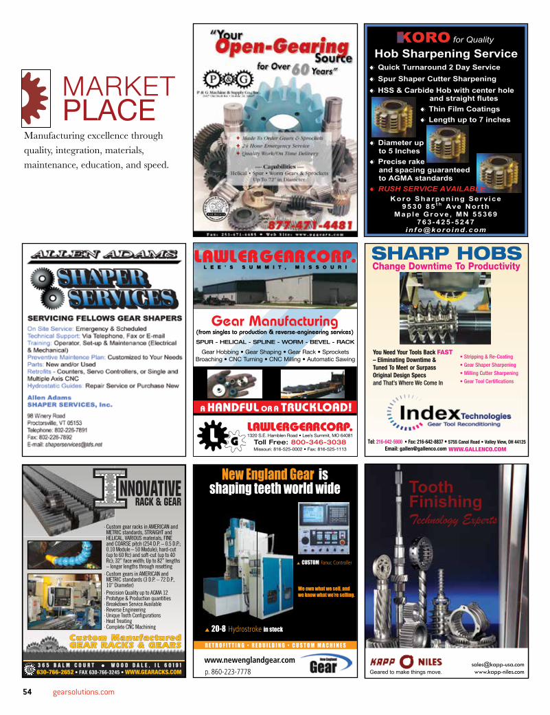
54 gearsolutions.com
Manufacturing excellence through quality, integration, materials, maintenance, education, and speed.
MARKETPLACE
p. 860-223-7778
www.newenglandgear.com
R E T R O F I T T I N G • R E B U I L D I N G • C U S T O M M A C H I N E S
· Custom gear racks in AMERICAN and METRIC standards, STRAIGHT and HELICAL, VARIOUS materials, FINE and COARSE pitch (254 D.P. – 0.5 D.P.; 0.10 Module – 50 Module); hard-cut (up to 60 Rc) and soft-cut (up to 40 Rc); 32” face width; Up to 82” lengths – longer lengths through resetting
· Custom gears in AMERICAN and METRIC standards (3 D.P. – 72 D.P., 10” Diameter)
· Precision Quality up to AGMA 12· Prototype & Production quantities· Breakdown Service Available· Reverse Engineering · Unique Tooth Confi gurations· Heat Treating· Complete CNC Machining
KORO for Quality Hob Sharpening Service
Quick Turnaround 2 Day Service Spur Shaper Cutter Sharpening HSS & Carbide Hob with center hole
Koro Sharpen ing Ser vice 95 30 85 t h Ave Nor t h
Ma ple Grove , MN 55369 76 3 -425 -5247
i n f o@k oroind.c om
and straight flutes Thin Film Coatings Length up to 7 inches
Diameter up to 5 Inches Precise rake and spacing guaranteed to AGMA standards RUSH SERVICE AVAILABLE
SHARP HOBSChange Downtime To Productivity
You Need Your Tools Back FAST– Eliminating Downtime &Tuned To Meet or Surpass Original Design Specsand That’s Where We Come In
• Stripping & Re-Coating
• Gear Shaper Sharpening
• Milling Cutter Sharpening
• Gear Tool Certifications
Tel: 216-642-5900 • Fax: 216-642-8837 • 5755 Canal Road • Valley View, OH 44125Email: [email protected] WWW.GALLENCO.COM
ToothFinishing Technology Experts
[email protected] Geared to make things move.
FEBRUARY 2015 55
COMPANY NAME PAGE NO.ALD Thermal Treatment Inc.................................................................30
All Metals & Forge Group ....................................................................37
Allen Adams Shaper Services Inc .......................................................54
Bourn & Koch Inc ................................................................................55
Circle Gear & Machine Co Inc .............................................................55
Encoder Products Co ..........................................................................47
Engineered Tools Corp ........................................................................16
Gleason Corp ......................................................................................25
Hilco Industrial LLC .............................................................................12
Index Technologies..............................................................................54
Ingersoll Cutting Tools ............................................................9,11,13,15
Innovative Rack & Gear .......................................................................54
Ipsen International ...............................................................................21
KAPP Technologies ...................................................................... IFC,54
KISSsoft USA LLC ..............................................................................10
Koro Sharpening Service ....................................................................54
Lawler Gear Corp ................................................................................54
Lufkin (Part of GE Oil & Gas) ...............................................................43
Luren Precision Co Ltd .......................................................................35
Machine Tool Builders .........................................................................48
McInnes Rolled Rings .........................................................................31
Mitsubishi Heavy Industries America Inc ...........................................BC
New England Gear ...........................................................................7,54
P&G Machine & Supply Co Inc ......................................................36,54
Pentagear Products ............................................................................46
Proto Manufacturing............................................................................40
Raycar Gear & Machine Co ................................................................51
Repair Parts Inc ...................................................................................47
RP Machine Enterprises Inc ..............................................................IBC
Russell, Holbrook & Henderson Inc ....................................................41
Solar Atmospheres ................................................................................2
Southern Gear & Machine ...................................................................14
STD Precision Gear & Instrument Inc .................................................36
Stor-Loc ...............................................................................................41
The Broach Masters Inc ........................................................................4
TMFM LLC ..........................................................................................12
Toolink Engineering Inc .........................................................................1
United Tool Supply ..............................................................................10
ADVERTISERINDEX
Since 1951 Circle Gear has served Chicago land as a full service gear manufacturing facility. In addition to bevel gears Circle Gear also provides spur gears, helical gears, herringbone gears, worm and gear sets, internal gears, splines, racks and sprockets.
CIRCLE GEAR and MACHINESTRAIGHT BEVEL GEARS
SPIRAL BEVEL GEARS
.25” to 34 ½” Diameter
32 DP to 1.5 DP
.5 Module to 16 Module
.25” to 33” Diameter
32 DP to 2 DP
.5 Module to 12 Module
56 gearsolutions.com
Would you please provide a brief history of your company?I started my career in the gear industry in 1983, and I created Pentagear in 2005. I had been working in the gauging industry for many years. However, I always felt that there was better way to design the products than what I was using. There was nothing wrong with them, but I felt that there was just a better way to do it. For example, we have a digital display. I developed a digital display that was web-based. You can put data in the digital read out, and you can extract data. I wanted to take that to the next step because everything is about data. The more we collect, the more we can control our process. So, I started developing that product. I was putting it on other machines, but realized that I really didn’t like the way they did things because they relied heavily on the operator to mechanically move it in and take a measurement. I thought that I could automate this so that the operator just pushes a button and have it come in to measure the parts. That means consistency and repeatability. It really takes the gauge to an objective position.
We also developed roll testers and double flank systems, again with that same process by looking at what was out there and how we could improve on it. With our double flank systems, many customers have to record the pressure that they’re pushing against the two gears. In the past, they would have to use hand gauges to measure that force. So, I found a company in Virginia, and they integrated that into the system so that I could document that information electronically and allow you to change it. It’s very accurate and calibrated. It has integrated the system. It’s not just something a guy is holding by hand.
In 2012, Process Equipment Company made an offer for me to come run their gear division. Part of that deal was that they purchased my products because they saw the synergies. Process Equipment made an analytical gear machine, and I was making what I call “functional gauges.” They’re shop gauges. They’re in the floor, and they’re doing day-to-day operations.
So, I came to Process Equipment, and we continued building my gauges as well as their
own gauges, and we integrated that entire process inside the division at Process Equipment. Then, in June 2014, the owner of Process Equipment decided he didn’t want to be in the gear business anymore, and I made him an offer. They accepted, and I purchased that product line from them. I moved to our current location in Ohio, maintained all of my current employees, and we are making products. We are manufacturing new Analytical Gear Inspection machines as well as “REPOWERING,” or remanufacturing our competitor’s machines.
What made you want to start your own company?I started my career at John Deere, and I worked there for 10 years. Then, I went to work for Reishauer until 1989, and then Klingelnberg hired me, and I became the product manager of the bevel division there. Then, I started my first company, Nicholson Gear, and I started representing big companies. I liked the fact that I worked for myself, and I had the opportunity to develop what I wanted. My two sons work for me now, Joshua and Shaun. One is a service engineer, and the other is a sales engineer. It’s a family business, for sure. I treat my 10 employees like family. We sit down and discuss the positives and negatives of what we’re doing, and everybody in the company is aware of our overall goal.
What would your customers say about your company, and how can people benefit from doing business with Pentagear?For me, business is personal. Finding the customers’ solution to their specific problem is a quest, and it’s what drives me to keep developing improvements and new products. I’m committed to stay with them to insure that they have 100% satisfaction. Being a family company, they know I’m attainable. If my customer brings a good idea to me, he’ll benefit from that because I’ll incorporate that into our product. The thing that I possess that people really get is that I’m really passionate about my craft. It’s a privilege that I’ve been able to work in this business that challenges me every day to think through a process and
try to develop a better way to analyze and create a solution for a customer. We’re also a veteran-owned company. I’m a veteran, my oldest son is a veteran, and so is my wife. My wife and I have been married 37 years, and we have raised eight children. So, we understand the value of family and commitment.
What are some new products you have coming out this year? We have a new double-flank tester that is extremely robust and is controlled by the digital readout I mentioned before. In the past, this was only done with a computer. The problem with the computer on the floor, environmentally, it is designed to fail. It’s got a hard drive, a fan, software, and viruses—anything can happen. So, we use this digital readout where it’s all an embedded system. So, when an operator runs this part, he really just needs a pass or a fail. He doesn’t need a fancy report every time. Again, we start with a really strong system from the design up. This is a gauge that’s going to last 20-30 years, at least. The REPOWERING of our competitors machine bases has offered an alternative solution to our customers. We are excited to provide the service and solutions our customers require.
Marvin NicholsonPresident and Founder Pentagear Products LLC
Q&A
FOR MORE INFORMATION: Visit Pentagear Product’s website at www.gearinspection.com or call (937) 660-8182.
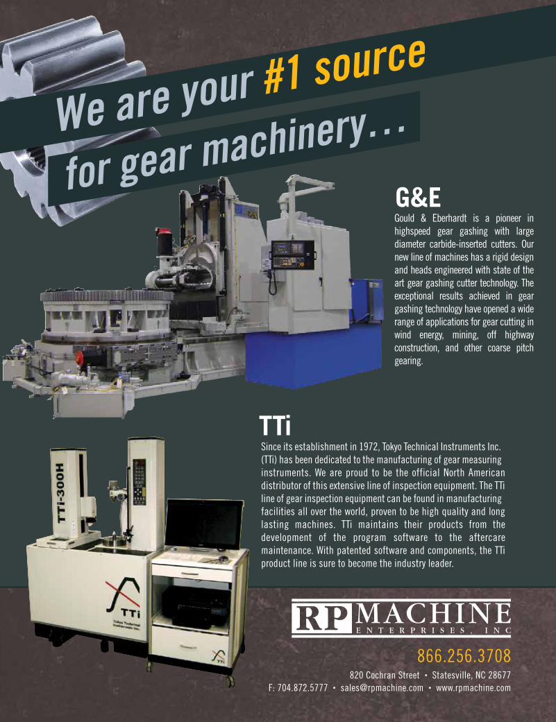
820 Cochran Street • Statesville, NC 28677F: 704.872.5777 • [email protected] • www.rpmachine.com
866.256.3708
Since its establishment in 1972, Tokyo Technical Instruments Inc. (TTi) has been dedicated to the manufacturing of gear measuring instruments. We are proud to be the official North American distributor of this extensive line of inspection equipment. The TTi line of gear inspection equipment can be found in manufacturing facilities all over the world, proven to be high quality and long lasting machines. TTi maintains their products from the development of the program software to the aftercare maintenance. With patented software and components, the TTi product line is sure to become the industry leader.
TTi
Gould & Eberhardt is a pioneer in highspeed gear gashing with large diameter carbide-inserted cutters. Our new line of machines has a rigid design and heads engineered with state of the art gear gashing cutter technology. The exceptional results achieved in gear gashing technology have opened a wide range of applications for gear cutting in wind energy, mining, off highway construction, and other coarse pitch gearing.
G&E
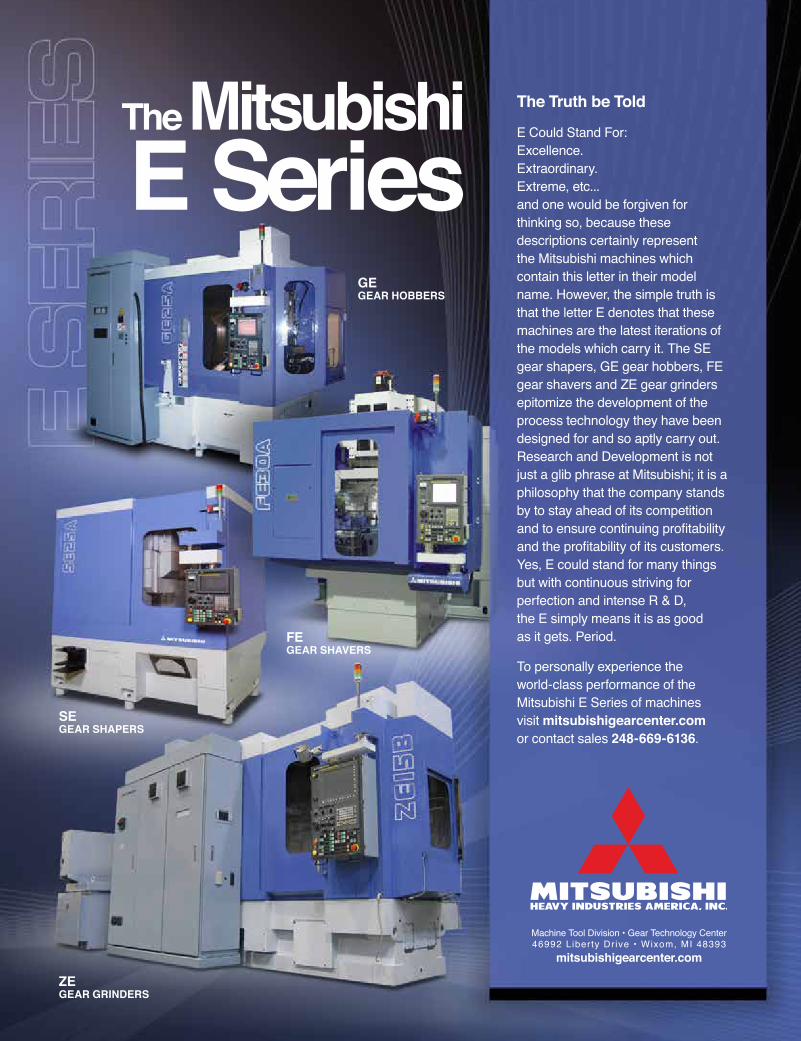
The Mitsubishi E Series
Machine Tool Division • Gear Technology Center46992 Liberty Drive • Wixom, MI 48393
mitsubishigearcenter.com
The Truth be Told
E Could Stand For: Excellence. Extraordinary. Extreme, etc... and one would be forgiven for thinking so, because these descriptions certainly represent the Mitsubishi machines which contain this letter in their model name. However, the simple truth is that the letter E denotes that these machines are the latest iterations of the models which carry it. The SE gear shapers, GE gear hobbers, FE gear shavers and ZE gear grinders epitomize the development of the process technology they have been designed for and so aptly carry out. Research and Development is not just a glib phrase at Mitsubishi; it is a philosophy that the company stands by to stay ahead of its competition and to ensure continuing profitability and the profitability of its customers. Yes, E could stand for many things but with continuous striving for perfection and intense R & D, the E simply means it is as good as it gets. Period.
To personally experience the world-class performance of the Mitsubishi E Series of machines visit mitsubishigearcenter.com or contact sales 248-669-6136.
GE GEAR HOBBERS
ZE GEAR GRINDERS
SE GEAR SHAPERS
FE GEAR SHAVERS
E_Series_Ad.indd 1 9/14/11 2:32 PM