Embed Size (px)
Citation preview

rotary draw bending bending tools mandrels wiper dies end forming tools
O M N I - X G U I D E T O R O T A R Y D R A W B E N D I N G
W O R L D W I D E L E A D E R I N T U B E B E N D I N G T E C H N O L O G Y
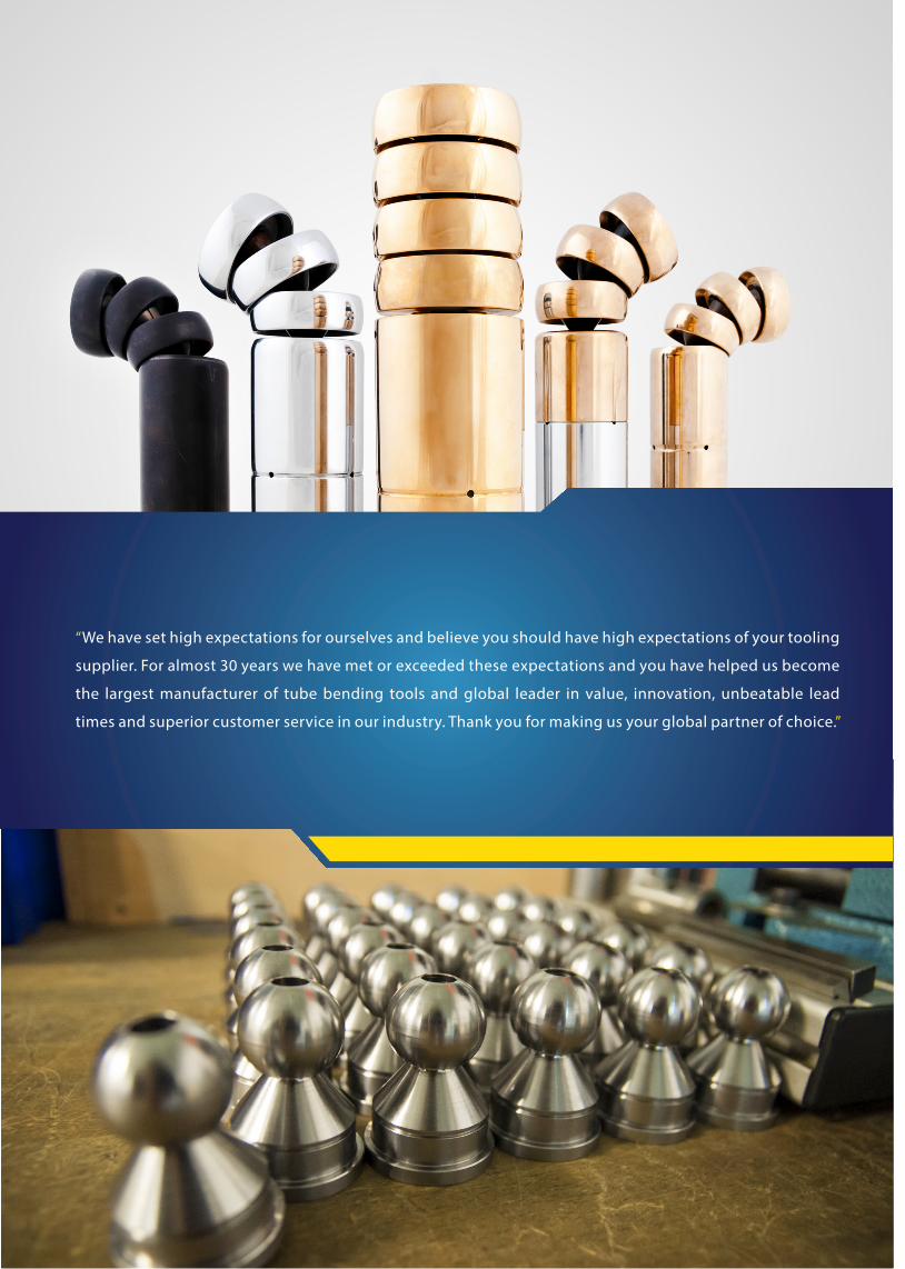
“We have set high expectations for ourselves and believe you should have high expectations of your tooling
supplier. For almost 30 years we have met or exceeded these expectations and you have helped us become
the largest manufacturer of tube bending tools and global leader in value, innovation, unbeatable lead
times and superior customer service in our industry. Thank you for making us your global partner of choice.”
C O N T E N T
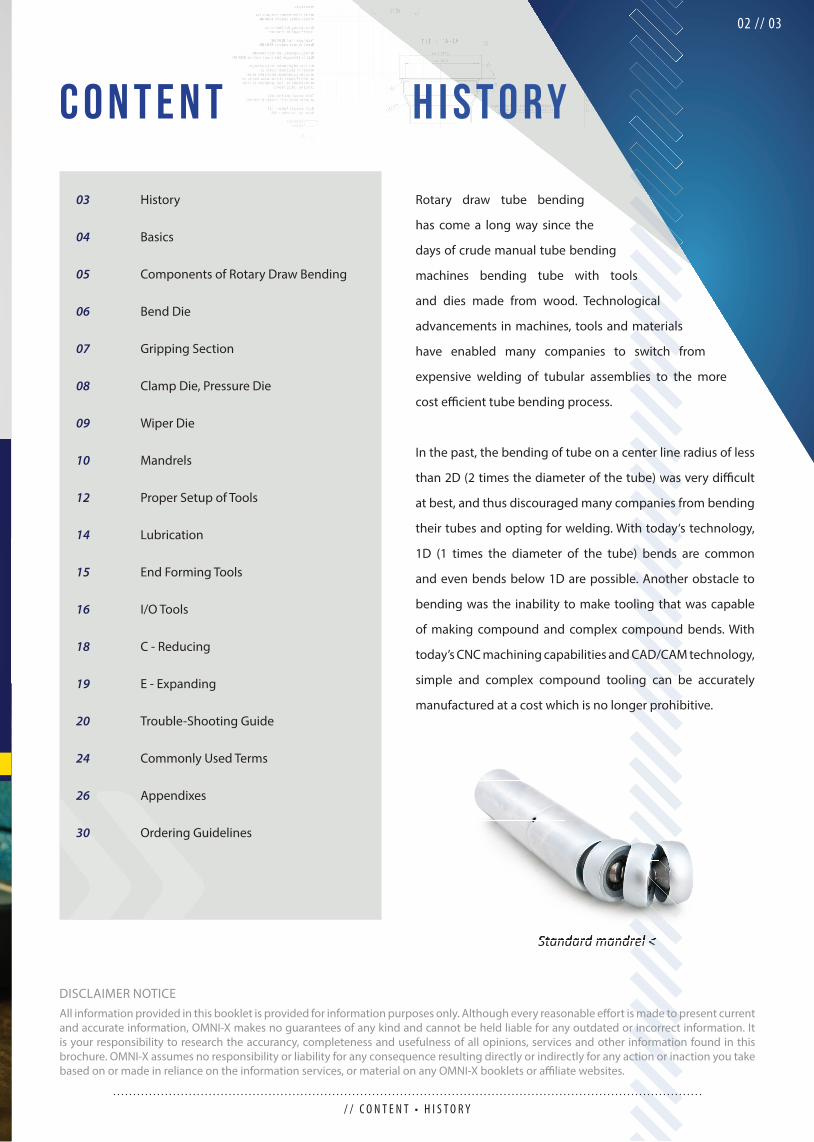
Rotary draw tube bending
has come a long way since the
days of crude manual tube bending
machines bending tube with tools
and dies made from wood. Technological
advancements in machines, tools and materials
have enabled many companies to switch from
expensive welding of tubular assemblies to the more
cost effi cient tube bending process.
In the past, the bending of tube on a center line radius of less
than 2D (2 times the diameter of the tube) was very diffi cult
at best, and thus discouraged many companies from bending
their tubes and opting for welding. With today‘s technology,
1D (1 times the diameter of the tube) bends are common
and even bends below 1D are possible. Another obstacle to
bending was the inability to make tooling that was capable
of making compound and complex compound bends. With
today’s CNC machining capabilities and CAD/CAM technology,
simple and complex compound tooling can be accurately
manufactured at a cost which is no longer prohibitive.
H I S T O R Y
Standard mandrel <
/ / C O N T E N T • H I S T O R Y
02 // 03
History
Basics
Components of Rotary Draw Bending
Bend Die
Gripping Section
Clamp Die, Pressure Die
Wiper Die
Mandrels
Proper Setup of Tools
Lubrication
End Forming Tools
I/O Tools
C - Reducing
E - Expanding
Trouble-Shooting Guide
Commonly Used Terms
Appendixes
Ordering Guidelines
03
04
05
06
07
08
09
10
12
14
15
16
18
19
20
24
26
30
DISCLAIMER NOTICEAll information provided in this booklet is provided for information purposes only. Although every reasonable eff ort is made to present current and accurate information, OMNI-X makes no guarantees of any kind and cannot be held liable for any outdated or incorrect information. It is your responsibility to research the accurancy, completeness and usefulness of all opinions, services and other information found in this brochure. OMNI-X assumes no responsibility or liability for any consequence resulting directly or indirectly for any action or inaction you take based on or made in reliance on the information services, or material on any OMNI-X booklets or affi liate websites.
Standard mandrel <Standard mandrel <
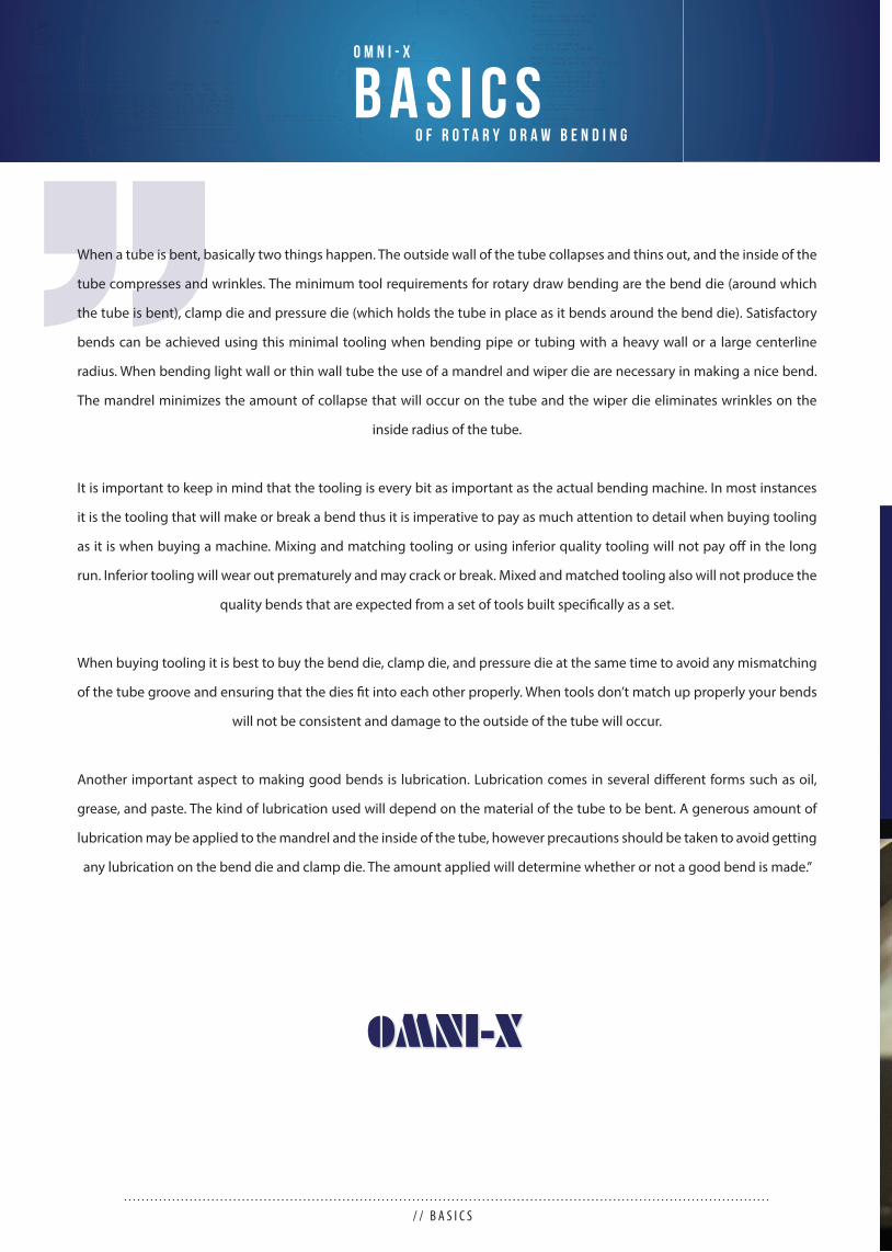
When a tube is bent, basically two things happen. The outside wall of the tube collapses and thins out, and the inside of the
tube compresses and wrinkles. The minimum tool requirements for rotary draw bending are the bend die (around which
the tube is bent), clamp die and pressure die (which holds the tube in place as it bends around the bend die). Satisfactory
bends can be achieved using this minimal tooling when bending pipe or tubing with a heavy wall or a large centerline
radius. When bending light wall or thin wall tube the use of a mandrel and wiper die are necessary in making a nice bend.
The mandrel minimizes the amount of collapse that will occur on the tube and the wiper die eliminates wrinkles on the
inside radius of the tube.
It is important to keep in mind that the tooling is every bit as important as the actual bending machine. In most instances
it is the tooling that will make or break a bend thus it is imperative to pay as much attention to detail when buying tooling
as it is when buying a machine. Mixing and matching tooling or using inferior quality tooling will not pay off in the long
run. Inferior tooling will wear out prematurely and may crack or break. Mixed and matched tooling also will not produce the
quality bends that are expected from a set of tools built specifi cally as a set.
When buying tooling it is best to buy the bend die, clamp die, and pressure die at the same time to avoid any mismatching
of the tube groove and ensuring that the dies fi t into each other properly. When tools don’t match up properly your bends
will not be consistent and damage to the outside of the tube will occur.
Another important aspect to making good bends is lubrication. Lubrication comes in several diff erent forms such as oil,
grease, and paste. The kind of lubrication used will depend on the material of the tube to be bent. A generous amount of
lubrication may be applied to the mandrel and the inside of the tube, however precautions should be taken to avoid getting
any lubrication on the bend die and clamp die. The amount applied will determine whether or not a good bend is made.”
/ / B A S I C S
B A S I C SO M N I - X
O F R O T A R Y D R A W B E N D I N G

C o m p o n e n t s o f R o ta r y D r a w B e n d i n g
1-ball mandrel3-ball mandrelPlug mandrelFormed-end plug mandrel
<<<< <<<
<< <
/ / C O M P O N E N T E S O F R O T A R Y D R A W B E N D I N G
04 // 05
When a tube is bent, basically two things happen. The outside wall of the tube collapses and thins out and the inside of the tube
compresses and wrinkles. The minimum tool requirements for rotary draw bending are the bend die (around which the tube is
bent), clamp die (which holds the tube in place as it bends around the bend die) and pressure die (second part of keeping the
tube in place as it bends). Satisfactory bends can be achieved using this minimal tooling when bending pipe or tubing with
a heavy wall or a large centerline radius. When bending light wall or thin wall tubes the use of a mandrel and wiper die are
necessary to make a nice bend. The mandrel minimizes the amount of collapse that will occur on the tube and the wiper die
eliminates wrinkles on the inside radius of the tube.
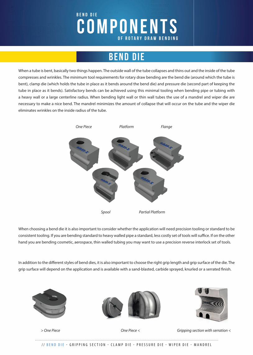
When choosing a bend die it is also important to consider whether the application will need precision tooling or standard to be
consistent tooling. If you are bending standard to heavy walled pipe a standard, less costly set of tools will suffi ce. If on the other
hand you are bending cosmetic, aerospace, thin walled tubing you may want to use a precision reverse interlock set of tools.
In addition to the diff erent styles of bend dies, it is also important to choose the right grip length and grip surface of the die. The
grip surface will depend on the application and is available with a sand-blasted, carbide sprayed, knurled or a serrated fi nish.
One Piece Platform
Partial PlatformSpool
Flange
One Piece <> One Piece Gripping section with serration <
/ / B E N D D I E - G R I P P I N G S E C T I O N - C L A M P D I E - P R E S S U R E D I E - W I P E R D I E - M A N D R E L
C O M P O N E N T SB E N D D I E
O F R O T A R Y D R A W B E N D I N G
B E N D D I E
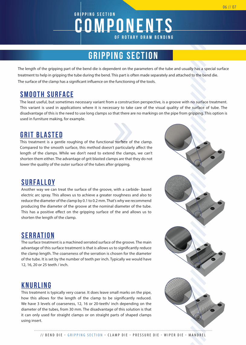
The length of the gripping part of the bend die is dependent on the parameters of the tube and usually has a special surface
treatment to help in gripping the tube during the bend. This part is often made separately and attached to the bend die.
The surface of the clamp has a signifi cant infl uence on the functioning of the tools.
G R I P P I N G S E C T I O N
This treatment is a gentle roughing of the functional surface of the clamp. Compared to the smooth surface, this method doesn’t particularly aff ect the length of the clamps. While we don’t need to extend the clamps, we can’t shorten them either. The advantage of grit blasted clamps are that they do not lower the quality of the outer surface of the tubes after gripping.
Another way we can treat the surface of the groove, with a carbide- based electric arc spray. This allows us to achieve a greater roughness and also to reduce the diameter of the clamp by 0.1 to 0.2 mm. That’s why we recommend producing the diameter of the groove at the nominal diameter of the tube. This has a positive eff ect on the gripping surface of the and allows us to shorten the length of the clamp.
The surface treatment is a machined serrated surface of the groove. The main advantage of this surface treatment is that is allows us to signifi cantly reduce the clamp length. The coarseness of the serration is chosen for the diameter of the tube. It is set by the number of teeth per inch. Typically we would have 12, 16, 20 or 25 teeth / inch.
This treatment is typically very coarse. It does leave small marks on the pipe, how this allows for the length of the clamp to be signifi cantly reduced. We have 3 levels of coarseness, 12, 16 or 20-teeth/ inch depending on the diameter of the tubes, from 30 mm. The disadvantage of this solution is that it can only used for straight clamps or on straight parts of shaped clamps using insert.
The least useful, but sometimes necessary variant from a construction perspective, is a groove with no surface treatment. This variant is used in applications where it is necessary to take care of the visual quality of the surface of tube. The disadvantage of this is the need to use long clamps so that there are no markings on the pipe from gripping. This option is used in furniture making, for example.
/ / B E N D D I E - G R I P P I N G S E C T I O N - C L A M P D I E - P R E S S U R E D I E - W I P E R D I E - M A N D R E L
C O M P O N E N T SG R I P P I N G S E C T I O N
O F R O T A R Y D R A W B E N D I N G
06 // 07
This treatment is a gentle roughing of the functional surface of the clamp. This treatment is a gentle roughing of the functional surface of the clamp.
K N U R L I N G
S E R R AT I O N
S u r f a l l o y
g r i t b l a s t e d
S M O O T H S U R F A C E
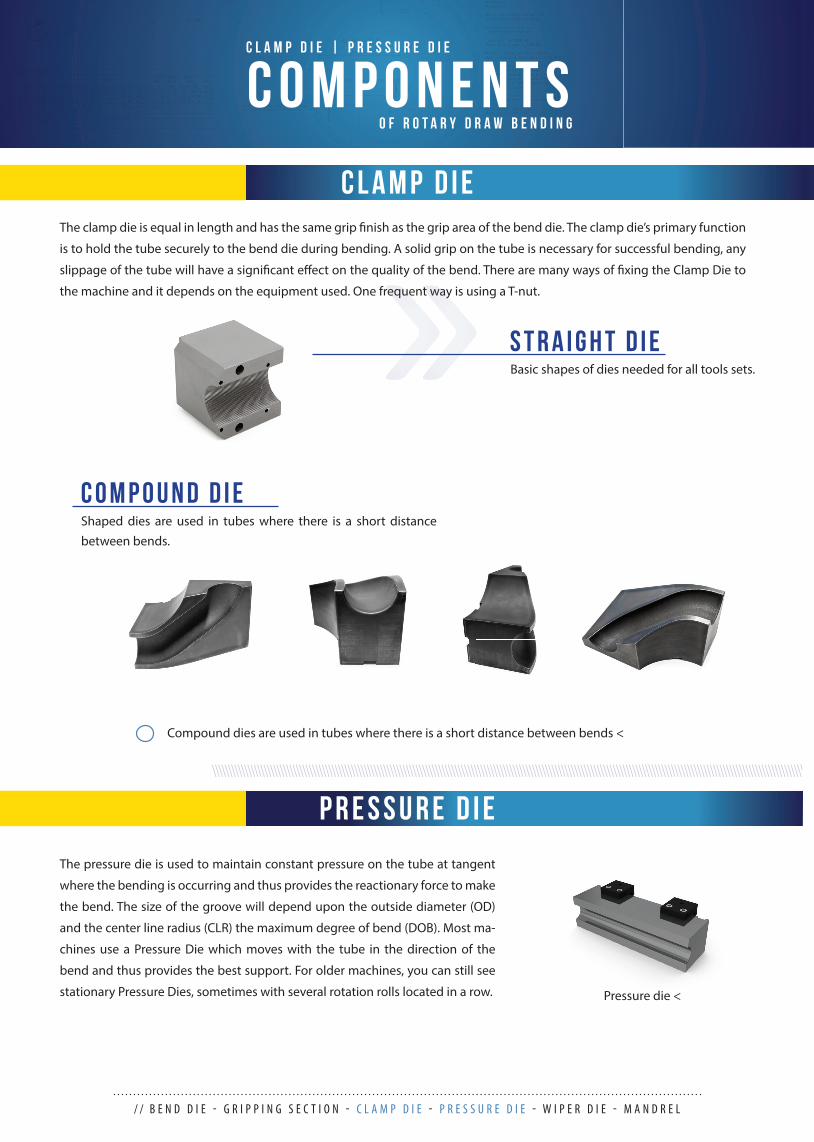
Basic shapes of dies needed for all tools sets.
Shaped dies are used in tubes where there is a short distance between bends.
/ / B E N D D I E - G R I P P I N G S E C T I O N - C L A M P D I E - P R E S S U R E D I E - W I P E R D I E - M A N D R E L
C O M P O N E N T SC L A M P D I E | P R E S S U R E D I E
O F R O T A R Y D R A W B E N D I N G
S T R A I G H T D I E
C O M P O U N D D I E
C L A M P D I E
The pressure die is used to maintain constant pressure on the tube at tangent
where the bending is occurring and thus provides the reactionary force to make
the bend. The size of the groove will depend upon the outside diameter (OD)
and the center line radius (CLR) the maximum degree of bend (DOB). Most ma-
chines use a Pressure Die which moves with the tube in the direction of the
bend and thus provides the best support. For older machines, you can still see
stationary Pressure Dies, sometimes with several rotation rolls located in a row. Pressure die <
P R E S S U R E D I E
The clamp die is equal in length and has the same grip fi nish as the grip area of the bend die. The clamp die’s primary function
is to hold the tube securely to the bend die during bending. A solid grip on the tube is necessary for successful bending, any
slippage of the tube will have a signifi cant eff ect on the quality of the bend. There are many ways of fi xing the Clamp Die to
the machine and it depends on the equipment used. One frequent way is using a T-nut.
Compound dies are used in tubes where there is a short distance between bends <
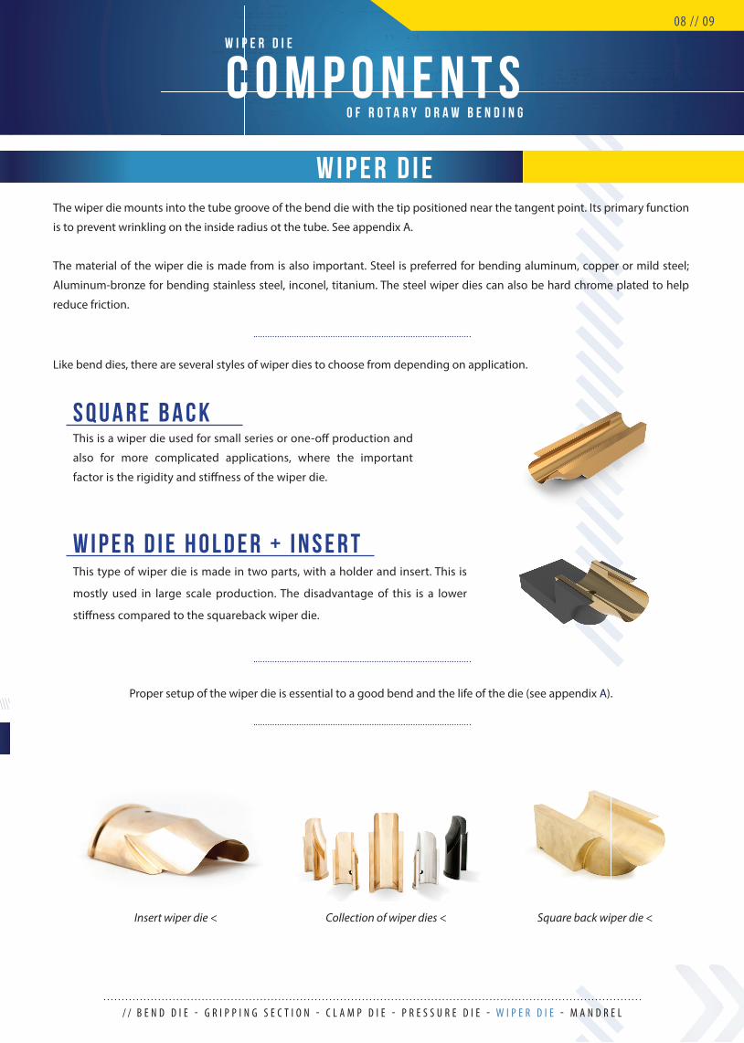
The wiper die mounts into the tube groove of the bend die with the tip positioned near the tangent point. Its primary function
is to prevent wrinkling on the inside radius ot the tube. See appendix A.
The material of the wiper die is made from is also important. Steel is preferred for bending aluminum, copper or mild steel;
Aluminum-bronze for bending stainless steel, inconel, titanium. The steel wiper dies can also be hard chrome plated to help
reduce friction.
Like bend dies, there are several styles of wiper dies to choose from depending on application.
C O M P O N E N T SW I P E R D I E
O F R O T A R Y D R A W B E N D I N G
08 // 09
This is a wiper die used for small series or one-off production and
also for more complicated applications, where the important
factor is the rigidity and stiff ness of the wiper die.
S Q U A R E B A C K
W I P E R D I E
Collection of wiper dies <Insert wiper die < Square back wiper die <
Proper setup of the wiper die is essential to a good bend and the life of the die (see appendix A).
/ / B E N D D I E - G R I P P I N G S E C T I O N - C L A M P D I E - P R E S S U R E D I E - W I P E R D I E - M A N D R E L
This type of wiper die is made in two parts, with a holder and insert. This is
mostly used in large scale production. The disadvantage of this is a lower
stiff ness compared to the squareback wiper die.
W I P E R D I E H O L D E R + I N S E R T
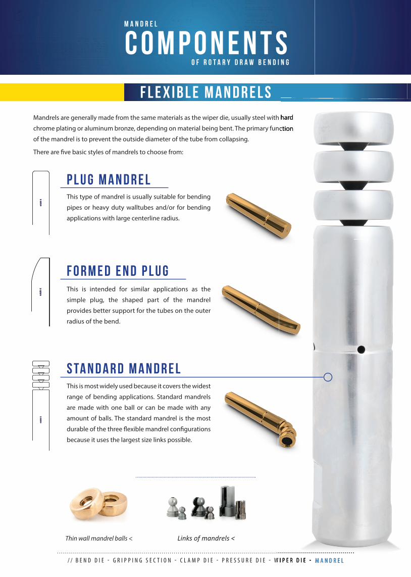
Thin wall mandrel balls < Links of mandrels <
Mandrels are generally made from the same materials as the wiper die, usually steel with hard
chrome plating or aluminum bronze, depending on material being bent. The primary function
of the mandrel is to prevent the outside diameter of the tube from collapsing.
There are fi ve basic styles of mandrels to choose from:
/ / B E N D D I E - G R I P P I N G S E C T I O N - C L A M P D I E - P R E S S U R E D I E - W I P E R D I E - M A N D R E L
C O M P O N E N T SM A N D R E L
O F R O T A R Y D R A W B E N D I N G
F L E X I B L E M A N D R E L S
OM
NI-X
This is most widely used because it covers the widest
range of bending applications. Standard mandrels
are made with one ball or can be made with any
amount of balls. The standard mandrel is the most
durable of the three fl exible mandrel confi gurations
because it uses the largest size links possible.
S TA N D A R D M A N D R E L
OM
NI-X This is intended for similar applications as the
simple plug, the shaped part of the mandrel
provides better support for the tubes on the outer
radius of the bend.
F O R M E D E N D P L U G
OM
NI-X
This type of mandrel is usually suitable for bending
pipes or heavy duty walltubes and/or for bending
applications with large centerline radius.
P L U G M A N D R E L
Mandrels are generally made from the same materials as the wiper die, usually steel with hard
chrome plating or aluminum bronze, depending on material being bent. The primary function
B E N D D I E - G R I P P I N G S E C T I O N - C L A M P D I E - P R E S S U R E D I E - W I P E R D I E - M A N D R E L
C O M P O N E N T SM A N D R E L
O F R O T A R Y D R A W B E N D I N G
10 // 11
F L E X I B L E M A N D R E L S
OM
NI-X
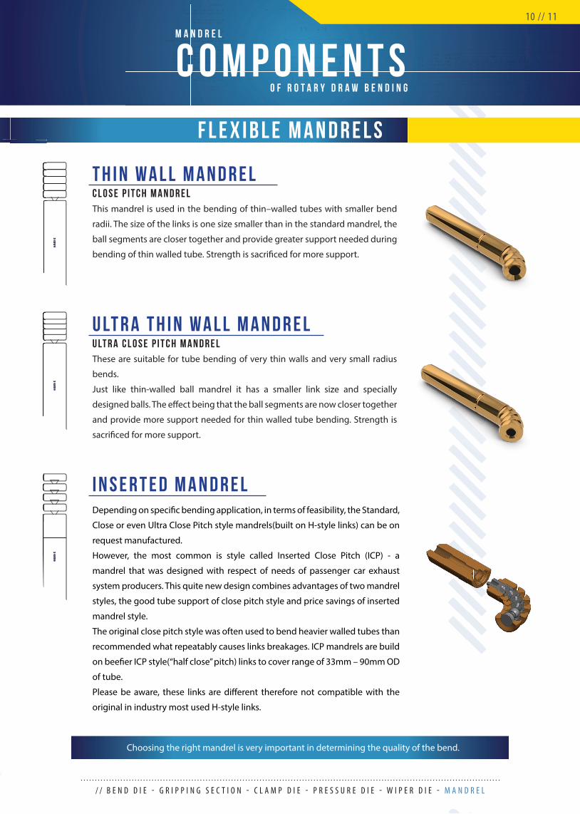
Depending on specifi c bending application, in terms of feasibility, the Standard,
Close or even Ultra Close Pitch style mandrels(built on H-style links) can be on
request manufactured.
However, the most common is style called Inserted Close Pitch (ICP) - a
mandrel that was designed with respect of needs of passenger car exhaust
system producers. This quite new design combines advantages of two mandrel
styles, the good tube support of close pitch style and price savings of inserted
mandrel style.
The original close pitch style was often used to bend heavier walled tubes than
recommended what repeatably causes links breakages. ICP mandrels are build
on beefi er ICP style(“half close” pitch) links to cover range of 33mm – 90mm OD
of tube.
Please be aware, these links are diff erent therefore not compatible with the
original in industry most used H-style links.
I N S E R T E D M A N D R E L
OM
NI-X
These are suitable for tube bending of very thin walls and very small radius
bends.
Just like thin-walled ball mandrel it has a smaller link size and specially
designed balls. The eff ect being that the ball segments are now closer together
and provide more support needed for thin walled tube bending. Strength is
sacrifi ced for more support.
U LT R A T H I N W A L L M A N D R E LU LT R A C L O S E P I T C H M A N D R E L
OM
NI-X
This mandrel is used in the bending of thin–walled tubes with smaller bend
radii. The size of the links is one size smaller than in the standard mandrel, the
ball segments are closer together and provide greater support needed during
bending of thin walled tube. Strength is sacrifi ced for more support.
T H I N W A L L M A N D R E LC L O S E P I T C H M A N D R E L
/ / B E N D D I E - G R I P P I N G S E C T I O N - C L A M P D I E - P R E S S U R E D I E - W I P E R D I E - M A N D R E L
Choosing the right mandrel is very important in determining the quality of the bend.
/ / P R O P E R S E T U P O F R O T A R Y D R A W B E N D I N G T O O L S
When it comes to making the perfect bend on a consistent basis, several factors come into play, any one of which may make or
break the bend.
The fi rst step to take before making any bends is to determine that the bender you will be using is operating properly. Make sure
that the clamping and unclamping of dies, the rotation of the swing arm and the extracting of the mandrel are all occurring in
the proper sequence.
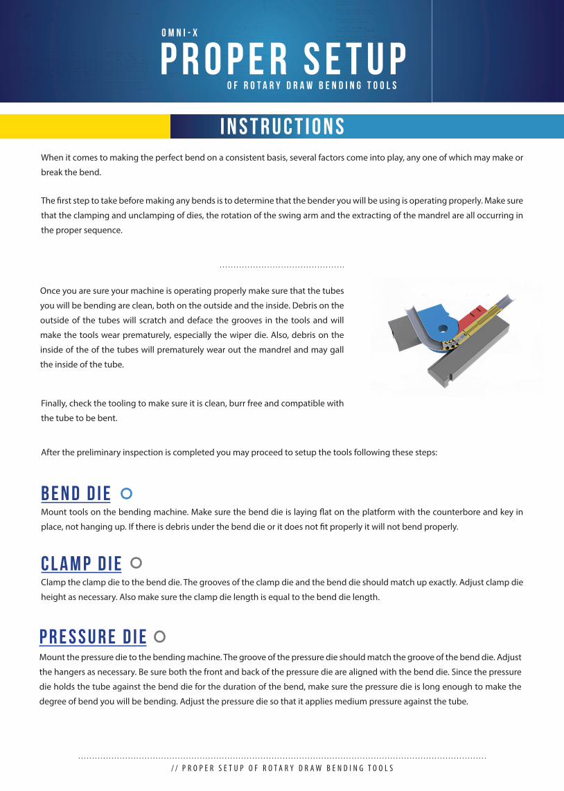
Once you are sure your machine is operating properly make sure that the tubes
you will be bending are clean, both on the outside and the inside. Debris on the
outside of the tubes will scratch and deface the grooves in the tools and will
make the tools wear prematurely, especially the wiper die. Also, debris on the
inside of the of the tubes will prematurely wear out the mandrel and may gall
the inside of the tube.
Finally, check the tooling to make sure it is clean, burr free and compatible with
the tube to be bent.
After the preliminary inspection is completed you may proceed to setup the tools following these steps:
Mount tools on the bending machine. Make sure the bend die is laying fl at on the platform with the counterbore and key in
place, not hanging up. If there is debris under the bend die or it does not fi t properly it will not bend properly.
B E N D D I E
Clamp the clamp die to the bend die. The grooves of the clamp die and the bend die should match up exactly. Adjust clamp die
height as necessary. Also make sure the clamp die length is equal to the bend die length.
C L A M P D I E
Mount the pressure die to the bending machine. The groove of the pressure die should match the groove of the bend die. Adjust
the hangers as necessary. Be sure both the front and back of the pressure die are aligned with the bend die. Since the pressure
die holds the tube against the bend die for the duration of the bend, make sure the pressure die is long enough to make the
degree of bend you will be bending. Adjust the pressure die so that it applies medium pressure against the tube.
P R E S S U R E D I E
P R O P E R S E T U PO m n i - X
O F R O T A R Y D R A W B E N D I N G T O O L S
I N S T R U C T I O N S
/ / I N S T R U C T I O N W H E N B E N D I N G W I T H T O O L S
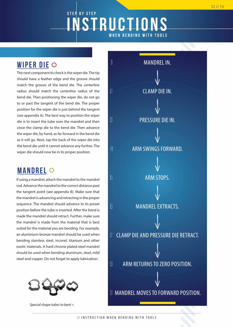
MANDREL IN.
ARM STOPS.
PRESSURE DIE IN.
CLAMP DIE AND PRESSURE DIE RETRACT.
CLAMP DIE IN.
MANDREL EXTRACTS.
ARM SWINGS FORWARD.
ARM RETURNS TO ZERO POSITION.
MANDREL MOVES TO FORWARD POSITION.
1
4
7
2
5
8
3
6
9
The next component to check is the wiper die. The tip
should have a feather edge and the groove should
match the groove of the bend die. The centerline
radius should match the centerline radius of the
bend die. Then positioning the wiper die, do not go
to or past the tangent of the bend die. The proper
position for the wiper die is just behind the tangent
(see appendix A). The best way to position the wiper
die is to insert the tube over the mandrel and then
close the clamp die to the bend die. Then advance
the wiper die, by hand, as far forward in the bend die
as it will go. Next, tap the back of the wiper die into
the bend die until it cannot advance any further. The
wiper die should now be in its proper position.
W i p e r D i e
If using a mandrel, attach the mandrel to the mandrel
rod. Advance the mandrel to the correct distance past
the tangent point (see appendix B). Make sure that
the mandrel is advancing and retracting in the proper
sequence. The mandrel should advance to its preset
position before the tube is inserted. After the bend is
made the mandrel should retract. Further, make sure
the mandrel is made from the material that is best
suited for the material you are bending. For example,
an aluminium-bronze mandrel should be used when
bending stainless steel, inconel, titanium and other
exotic materials. A hard chrome plated steel mandrel
should be used when bending aluminum, steel, mild
steel and copper. Do not forget to apply lubrication.
M a n d r e l
12 // 13
I N S T R U C T I O N SS T E P B Y S T E P
W H E N B E N D I N G W I T H T O O L S
Special shape tubes to bent <

/ / L U B R I C A T I O N
W O R K F L O WO U R
W H E N D E S I G N I N G P R O D U C T SL U B R I C AT I O N
IN NUMBERS:- 3X times easier cleanability
- 2x cost reduction- 1.25x tool life extention
XXClear, pale-yellow appearance liquid. Core-8X lubricant for extreme
bending and metalforming operations. Can be used also as a spray.
Dilutable by water. Can be used on aluminium material.
Core - 8 XHeavy duty bending
and metalformingl iquid
• state:
• material:
• application:
• dilution
liquid
steel, stainless steel, aluminium
internal, external
possible (maximum ratio 1:1)
ALC series products designed to work with various material range
(stainless steel, aluminium, titanium, etc.). Liquid of high viscosity. Can
be pumped through mandrel or applied manually.
ALCHeavy duty bending
and metalformingl iquid
• state:
• material:
• application:
• dilution
liquid
steel, stainless steel, aluminium, aluminized tubes
internal, external
possible (maximum ratio 1:1)
Clear, yellowish gel. It does not drip or run from the components. Good
for general and difficult bending. Can be used also for fabricating. Light
to heavy duty bends. Application through mandrel, brush and roller.Nirol
General purpose and heavy duty bending
gel
• state:
• material:
• application:
• dilution
gel
steel, stainless steel
external
not possible
Dense, milky white non-pour paste. Light to heavy duty bends. Bending
and also fabricating process. Applicable by brush.MEDELANGeneral purpose and
heavy duty bendingpaste
• state:
• material:
• application:
• dilution
paste
steel, stainless steel
external
not possible
Lubrication is an essential part of the rotary draw bending operation. Products of BBLubricants are clean, non-oil alternatives to mineral, vegetable and animal oil for the demanding mandrel bending operations. Lubricants do not contain any harmful pollutants (no chlorines, nitrides, paraffi ns of formaldehydes). Products are gentle to skin and environmentally friendly. As it is washable with warm water this can result in a total cost reduction of up to 50%. A clean thin fi lm provides excellent protection while keeping surface no resistant for welding (no washing is needed).Lubrication in combination with right set of tools from OMNI-X can extend average tool life by 25%.
BIODEGRADABLE
extend tool life easy clean up with water
DILUTABLE WITH WATER
WELDing readyOIL-FREEB E N E F I T S
W H Y L U B R I C A T E ?
B B L u b r i c a n t s
/ / P R O P E R S E T U P O F R O T A R Y D R A W B E N D I N G T O O L S
14 // 15
E N D F O R M I N G
E N D F O R M I N GO m n i - X
T O O L S
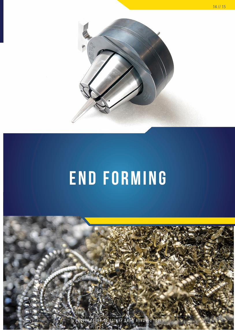
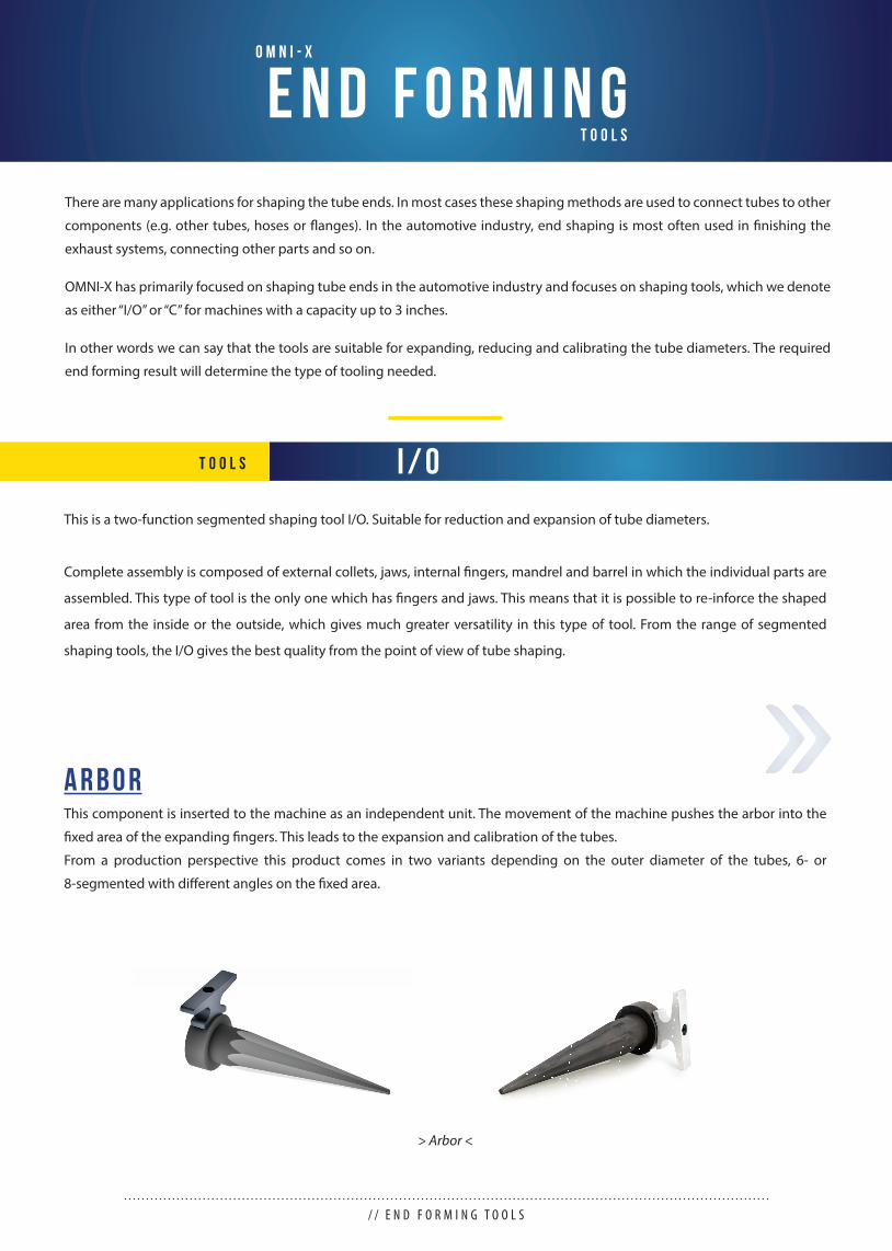
There are many applications for shaping the tube ends. In most cases these shaping methods are used to connect tubes to other
components (e.g. other tubes, hoses or fl anges). In the automotive industry, end shaping is most often used in fi nishing the
exhaust systems, connecting other parts and so on.
OMNI-X has primarily focused on shaping tube ends in the automotive industry and focuses on shaping tools, which we denote
as either “I/O” or “C” for machines with a capacity up to 3 inches.
In other words we can say that the tools are suitable for expanding, reducing and calibrating the tube diameters. The required
end forming result will determine the type of tooling needed.
This is a two-function segmented shaping tool I/O. Suitable for reduction and expansion of tube diameters.
Complete assembly is composed of external collets, jaws, internal fi ngers, mandrel and barrel in which the individual parts are
assembled. This type of tool is the only one which has fi ngers and jaws. This means that it is possible to re-inforce the shaped
area from the inside or the outside, which gives much greater versatility in this type of tool. From the range of segmented
shaping tools, the I/O gives the best quality from the point of view of tube shaping.
This component is inserted to the machine as an independent unit. The movement of the machine pushes the arbor into the
fi xed area of the expanding fi ngers. This leads to the expansion and calibration of the tubes.
From a production perspective this product comes in two variants depending on the outer diameter of the tubes, 6- or
8-segmented with diff erent angles on the fi xed area.
A r b o r
> Arbor <
/ / E N D F O R M I N G T O O L S
I / OT O O L S
E N D F O R M I N GI / O
T O O L S
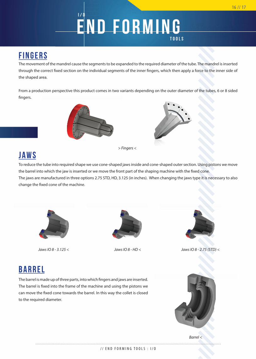
The movement of the mandrel cause the segments to be expanded to the required diameter of the tube. The mandrel is inserted
through the correct fi xed section on the individual segments of the inner fi ngers, which then apply a force to the inner side of
the shaped area.
From a production perspective this product comes in two variants depending on the outer diameter of the tubes, 6 or 8 sided
fi ngers.
To reduce the tube into required shape we use cone-shaped jaws inside and cone-shaped outer section. Using pistons we move
the barrel into which the jaw is inserted or we move the front part of the shaping machine with the fi xed cone.
The jaws are manufactured in three options 2.75 STD, HD, 3.125 (in inches). When changing the jaws type it is necessary to also
change the fi xed cone of the machine.
The barrel is made up of three parts, into which fi ngers and jaws are inserted.
The barrel is fi xed into the frame of the machine and using the pistons we
can move the fi xed cone towards the barrel. In this way the collet is closed
to the required diameter.
F i n g e r s
J a w s
B a r r e l
Jaws IO 8 - 2.75 (STD) <Jaws IO 8 - HD <
> Fingers <
Barrel <
Jaws IO 8 - 3.125 <
/ / E N D F O R M I N G T O O L S : I / O
16 // 17
E N D F O R M I N GC - R E D U C I N G
T O O L S
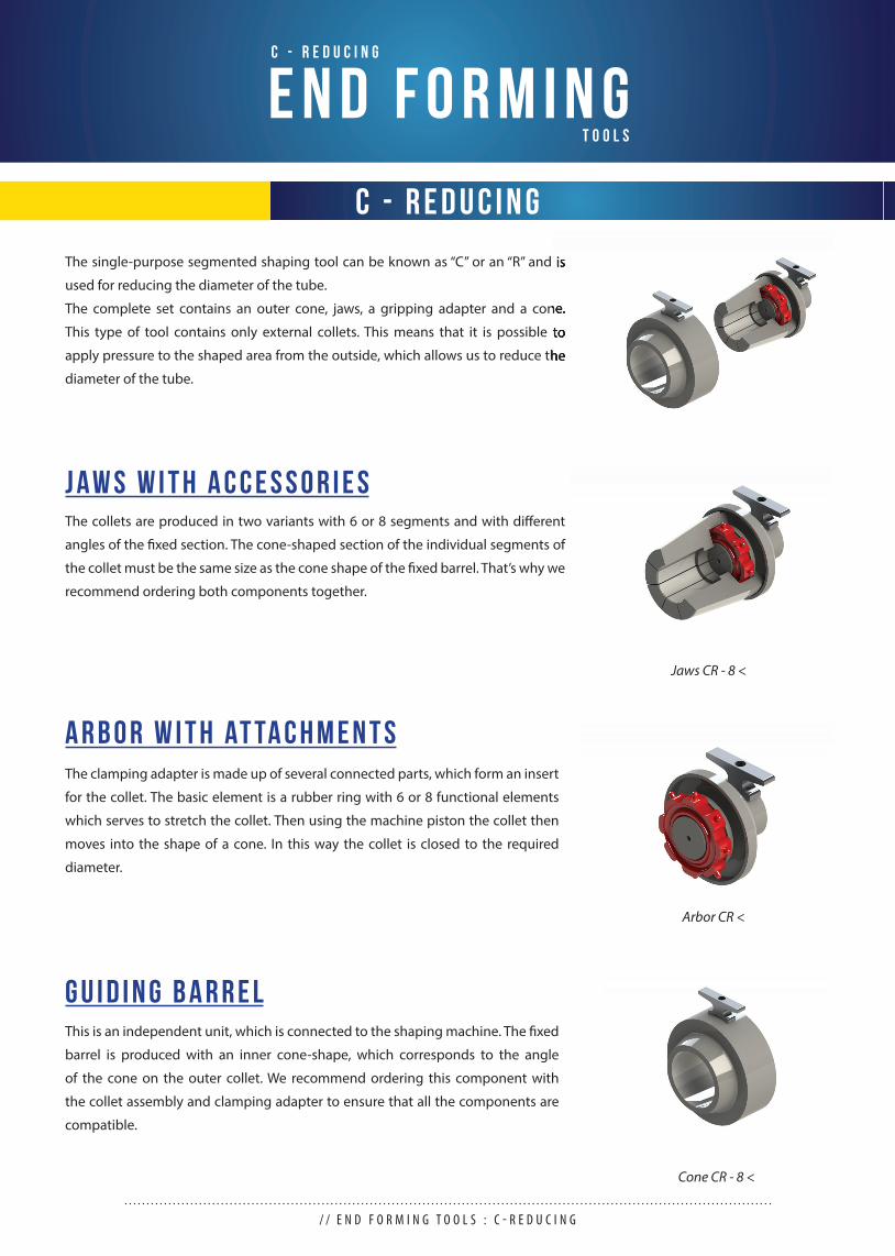
The collets are produced in two variants with 6 or 8 segments and with diff erent
angles of the fi xed section. The cone-shaped section of the individual segments of
the collet must be the same size as the cone shape of the fi xed barrel. That’s why we
recommend ordering both components together.
The clamping adapter is made up of several connected parts, which form an insert
for the collet. The basic element is a rubber ring with 6 or 8 functional elements
which serves to stretch the collet. Then using the machine piston the collet then
moves into the shape of a cone. In this way the collet is closed to the required
diameter.
J a w s w i t h A c c e s s o r i e s
A r b o r w i t h at ta c h m e n t s
Jaws CR - 8 <
Arbor CR <
The single-purpose segmented shaping tool can be known as “C” or an “R” and is
used for reducing the diameter of the tube.
The complete set contains an outer cone, jaws, a gripping adapter and a cone.
This type of tool contains only external collets. This means that it is possible to
apply pressure to the shaped area from the outside, which allows us to reduce the
diameter of the tube.
The single-purpose segmented shaping tool can be known as “C” or an “R” and is
The complete set contains an outer cone, jaws, a gripping adapter and a cone.
This type of tool contains only external collets. This means that it is possible to
apply pressure to the shaped area from the outside, which allows us to reduce the
This is an independent unit, which is connected to the shaping machine. The fi xed
barrel is produced with an inner cone-shape, which corresponds to the angle
of the cone on the outer collet. We recommend ordering this component with
the collet assembly and clamping adapter to ensure that all the components are
compatible.
G u i d i n g b a r r e l
Cone CR - 8 <
/ / E N D F O R M I N G T O O L S : C - R E D U C I N G
C - R e d u c i n g
E N D F O R M I N GC - E X P A N D I N G
T O O L S
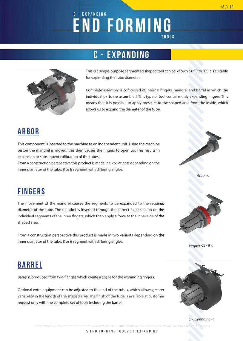
The movement of the mandrel causes the segments to be expanded to the required
diameter of the tube. The mandrel is inserted through the correct fi xed section on the
individual segments of the inner fi ngers, which then apply a force to the inner side of the
shaped area.
From a construction perspective this product is made in two variants depending on the
inner diameter of the tube, 8 or 6 segment with diff ering angles.
Barrel is produced from two fl anges which create a space for the expanding fi ngers.
Optional extra equipment can be adjusted to the end of the tubes, which allows greater
variability in the length of the shaped area. The fi nish of the tube is available at customer
request only with the complete set of tools including the barrel.
F i n g e r s
B a r r e l
The movement of the mandrel causes the segments to be expanded to the required
diameter of the tube. The mandrel is inserted through the correct fi xed section on the
individual segments of the inner fi ngers, which then apply a force to the inner side of the
From a construction perspective this product is made in two variants depending on the
Fingers CE - 8 <
C - Expanding <
This component is inserted to the machine as an independent unit. Using the machine
piston the mandrel is moved, this then causes the fi ngers to open up. This results in
expansion or subsequent calibration of the tubes.
From a construction perspective this product is made in two variants depending on the
inner diameter of the tube, 8 or 6 segment with diff ering angles.
A r b o r
Arbor <
C - E x p a n d i n g
This is a single-purpose segmented shaped tool can be known as “C” or “E”. It is suitable
for expanding the tube diameter.
Complete assembly is composed of internal fi ngers, mandrel and barrel in which the
individual parts are assembled. This type of tool contains only expanding fi ngers. This
means that it is possible to apply pressure to the shaped area from the inside, which
allows us to expand the diameter of the tube.
/ / E N D F O R M I N G T O O L S : C - E X P A N D I N G
18 // 19
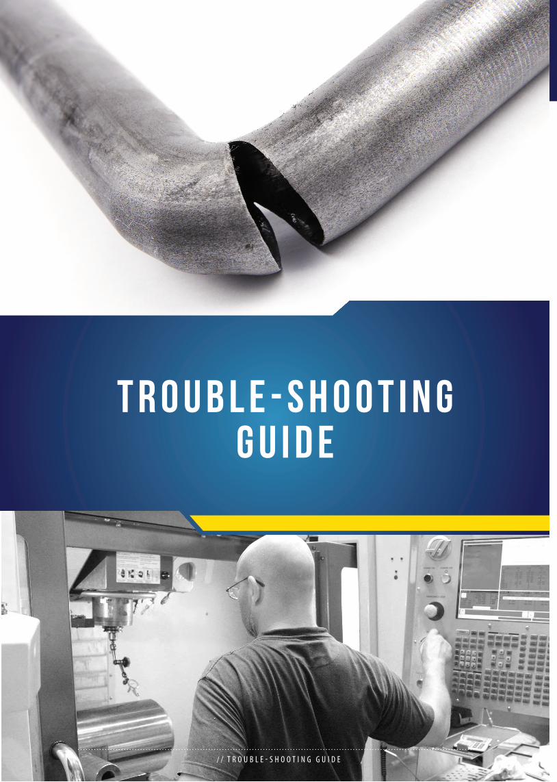
T R O U B L E - S H O O T I N G G U I D E
/ / T R O U B L E - S H O O T I N G G U I D E
T R O U B L E - S H O O T I N GR E C O M M E N D E D
G u i d e
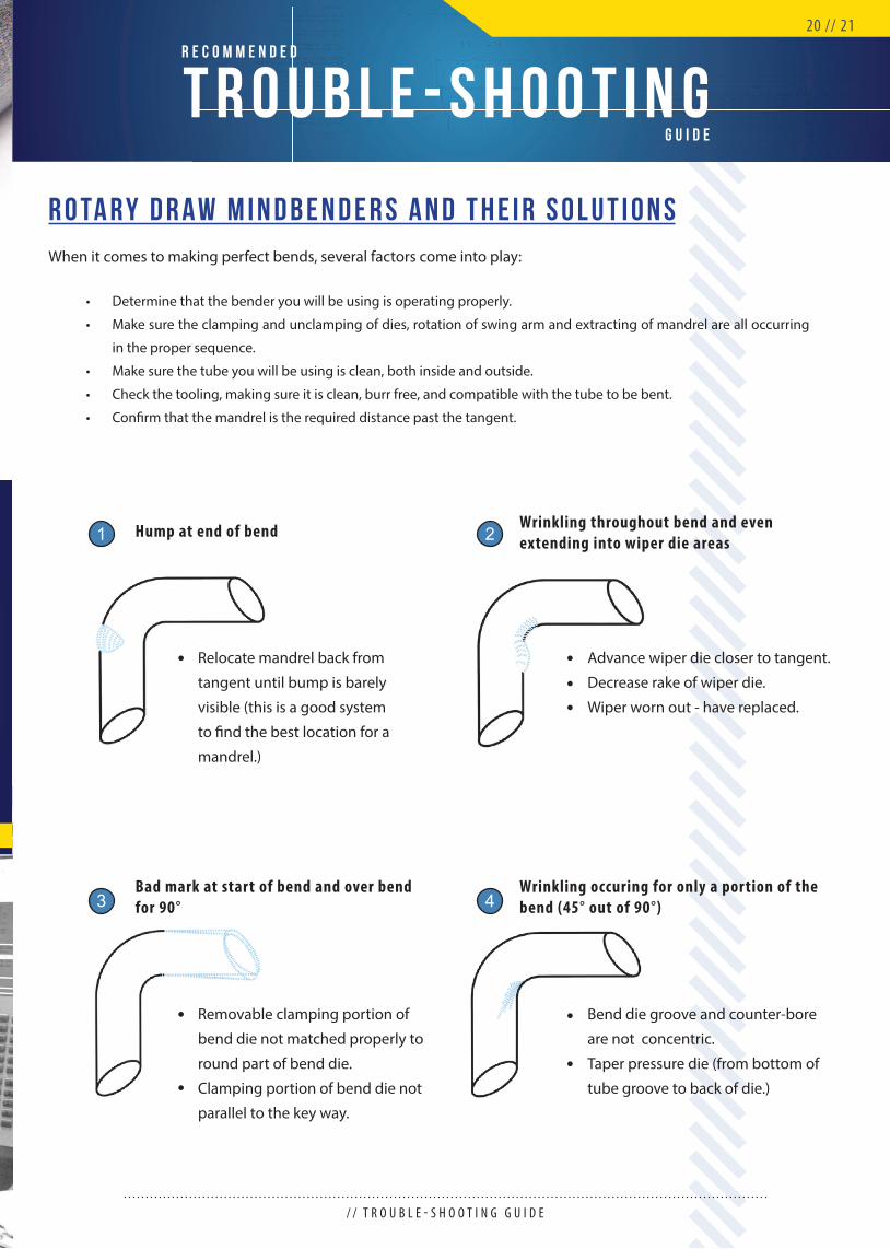
When it comes to making perfect bends, several factors come into play:
R o ta r y D r a w M i n d b e n d e r s a n d T h e i r S o l u t i o n s
• Determine that the bender you will be using is operating properly.
• Make sure the clamping and unclamping of dies, rotation of swing arm and extracting of mandrel are all occurring
in the proper sequence.
• Make sure the tube you will be using is clean, both inside and outside.
• Check the tooling, making sure it is clean, burr free, and compatible with the tube to be bent.
• Confi rm that the mandrel is the required distance past the tangent.
Advance wiper die closer to tangent.
Decrease rake of wiper die.
Wiper worn out - have replaced.
Bend die groove and counter-bore
are not concentric.
Taper pressure die (from bottom of
tube groove to back of die.)
Wrinkling throughout bend and even extending into wiper die areas
Wrinkling occuring for only a portion of the bend (45° out of 90°)
2
4
/ / T R O U B L E - S H O O T I N G G U I D E
Relocate mandrel back from
tangent until bump is barely
visible (this is a good system
to fi nd the best location for a
mandrel.)
Removable clamping portion of
bend die not matched properly to
round part of bend die.
Clamping portion of bend die not
parallel to the key way.
Hump at end of bend
Bad mark at start of bend and over bend for 90°
1
3
20 // 21
T R O U B L E - S H O O T I N GR E C O M M E N D E D
G u i d e
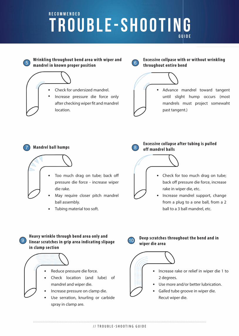
Too much drag on tube; back off
pressure die force - increase wiper
die rake.
May require closer pitch mandrel
ball assembly.
Tubing material too soft.
Check for too much drag on tube;
back off pressure die force, increase
rake in wiper die, etc.
Increase mandrel support, change
from a plug to a one ball, from a 2
ball to a 3 ball mandrel, etc.
Excessive collapse after tubing is pulledoff mandrel ballsMandrel ball humps7 8
Check for undersized mandrel.
Increase pressure die force only
after checking wiper fi t and mandrel
location.
Advance mandrel toward tangent
until slight hump occurs (most
mandrels must project somewaht
past tangent.)
Excessive collpase with or without wrinkling throughout entire bend
Wrinkling throughout bend area with wiper and mandrel in known proper position5 6
/ / T R O U B L E - S H O O T I N G G U I D E
Reduce pressure die force.
Check location (and lube) of
mandrel and wiper die.
Increase pressure on clamp die.
Use serration, knurling or carbide
spray in clamp are.
Increase rake or relief in wiper die 1 to
2 degrees.
Use more and/or better lubrication.
Galled tube groove in wiper die.
Recut wiper die.
Deep scratches throughout the bend and in wiper die area
Heavy wrinkle through bend area only and linear scratches in grip area indicating slipage in clamp section
9 10
T R O U B L E - S H O O T I N GR E C O M M E N D E D
G u i d e
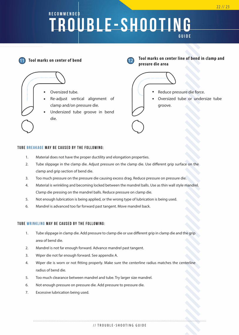
Oversized tube.
Re-adjust vertical alignment of
clamp and/on pressure die.
Undersized tube groove in bend
die.
Reduce pressure die force.
Oversized tube or undersize tube
groove.
Tool marks on center line of bend in clamp and presure die area
Tool marks on center of bend11 12
T u b e b r e a k a g e m ay b e c a u s e d b y t h e f o l l o w i n g :
Material does not have the proper ductility and elongation properties.
Tube slippage in the clamp die. Adjust pressure on the clamp die. Use diff erent grip surface on the
clamp and grip section of bend die.
Too much pressure on the pressure die causing excess drag. Reduce pressure on pressure die.
Material is wrinkling and becoming locked between the mandrel balls. Use as thin wall style mandrel.
Clamp die pressing on the mandrel balls. Reduce pressure on clamp die.
Not enough lubrication is being applied, or the wrong type of lubrication is being used.
Mandrel is advanced too far forward past tangent. Move mandrel back.
1.
2.
3.
4.
5.
6.
T u b e w r i n k l i n g m ay b e c a u s e d b y t h e f o l l o w i n g :
Tube slippage in clamp die. Add pressure to clamp die or use diff erent grip in clamp die and the grip
area of bend die.
Mandrel is not far enough forward. Advance mandrel past tangent.
Wiper die not far enough forward. See appendix A.
Wiper die is worn or not fi tting properly. Make sure the centerline radius matches the centerline
radius of bend die.
Too much clearance between mandrel and tube. Try larger size mandrel.
Not enough pressure on pressure die. Add pressure to pressure die.
Excessive lubrication being used.
1.
2.
3.
4.
5.
6.
7.
/ / T R O U B L E - S H O O T I N G G U I D E
22 // 23
C O M M O N LY - U S E D T E R M SO M N I - X
W H E N B E N D I N G T O O L S
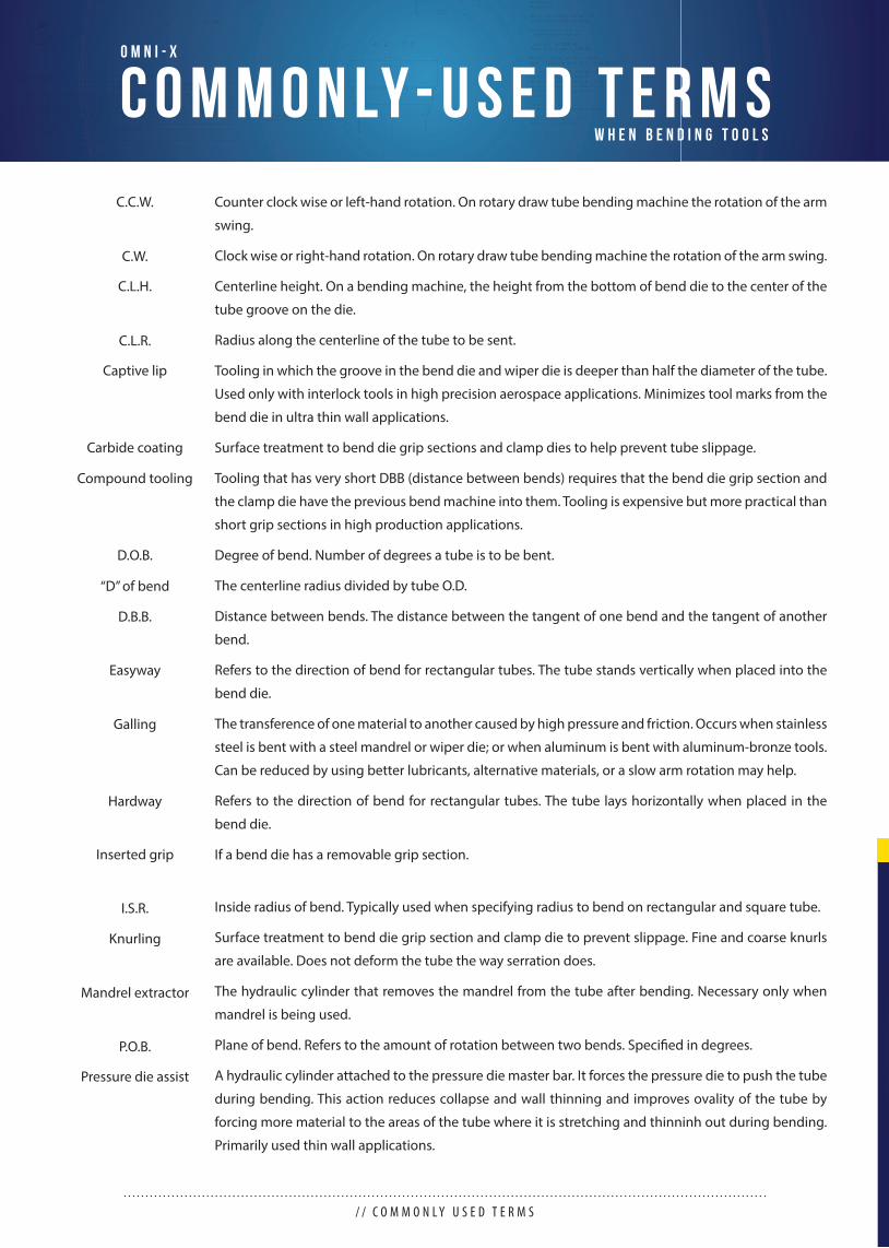
Counter clock wise or left-hand rotation. On rotary draw tube bending machine the rotation of the arm
swing.
Clock wise or right-hand rotation. On rotary draw tube bending machine the rotation of the arm swing.
Centerline height. On a bending machine, the height from the bottom of bend die to the center of the
tube groove on the die.
Radius along the centerline of the tube to be sent.
Tooling in which the groove in the bend die and wiper die is deeper than half the diameter of the tube.
Used only with interlock tools in high precision aerospace applications. Minimizes tool marks from the
bend die in ultra thin wall applications.
Surface treatment to bend die grip sections and clamp dies to help prevent tube slippage.
Tooling that has very short DBB (distance between bends) requires that the bend die grip section and
the clamp die have the previous bend machine into them. Tooling is expensive but more practical than
short grip sections in high production applications.
Degree of bend. Number of degrees a tube is to be bent.
The centerline radius divided by tube O.D.
Distance between bends. The distance between the tangent of one bend and the tangent of another
bend.
Refers to the direction of bend for rectangular tubes. The tube stands vertically when placed into the
bend die.
The transference of one material to another caused by high pressure and friction. Occurs when stainless
steel is bent with a steel mandrel or wiper die; or when aluminum is bent with aluminum-bronze tools.
Can be reduced by using better lubricants, alternative materials, or a slow arm rotation may help.
Refers to the direction of bend for rectangular tubes. The tube lays horizontally when placed in the
bend die.
If a bend die has a removable grip section.
Inside radius of bend. Typically used when specifying radius to bend on rectangular and square tube.
Surface treatment to bend die grip section and clamp die to prevent slippage. Fine and coarse knurls
are available. Does not deform the tube the way serration does.
The hydraulic cylinder that removes the mandrel from the tube after bending. Necessary only when
mandrel is being used.
Plane of bend. Refers to the amount of rotation between two bends. Specifi ed in degrees.
A hydraulic cylinder attached to the pressure die master bar. It forces the pressure die to push the tube
during bending. This action reduces collapse and wall thinning and improves ovality of the tube by
forcing more material to the areas of the tube where it is stretching and thinninh out during bending.
Primarily used thin wall applications.
/ / C O M M O N L Y U S E D T E R M S
C.C.W.
C.W.
C.L.H.
C.L.R.
Captive lip
Carbide coating
Compound tooling
D.O.B.
“D” of bend
D.B.B.
Easyway
Galling
Hardway
In serted grip
I.S.R.
Knurling
Mandrel extractor
P.O.B.
Pressure die assist
C O M M O N LY - U S E D T E R M SO M N I - X
W H E N B E N D I N G T O O L S
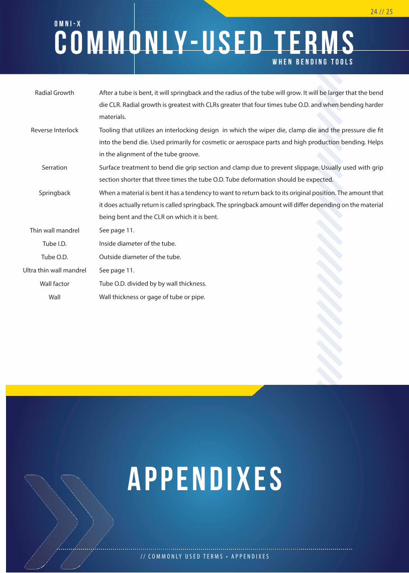
After a tube is bent, it will springback and the radius of the tube will grow. It will be larger that the bend
die CLR. Radial growth is greatest with CLRs greater that four times tube O.D. and when bending harder
materials.
Tooling that utilizes an interlocking design in which the wiper die, clamp die and the pressure die fi t
into the bend die. Used primarily for cosmetic or aerospace parts and high production bending. Helps
in the alignment of the tube groove.
Surface treatment to bend die grip section and clamp due to prevent slippage. Usually used with grip
section shorter that three times the tube O.D. Tube deformation should be expected.
When a material is bent it has a tendency to want to return back to its original position. The amount that
it does actually return is called springback. The springback amount will diff er depending on the material
being bent and the CLR on which it is bent.
See page 11.
Inside diameter of the tube.
Outside diameter of the tube.
See page 11.
Tube O.D. divided by by wall thickness.
Wall thickness or gage of tube or pipe.
/ / C O M M O N L Y U S E D T E R M S • A P P E N D I X E S
24 // 25
A P P E N D I X E S
Radial Growth
Reverse Interlock
Serration
Springback
Thin wall mandrel
Tube I.D.
Tube O.D.
Ultra thin wall mandrel
Wall factor
Wall
A P P E N D I X A
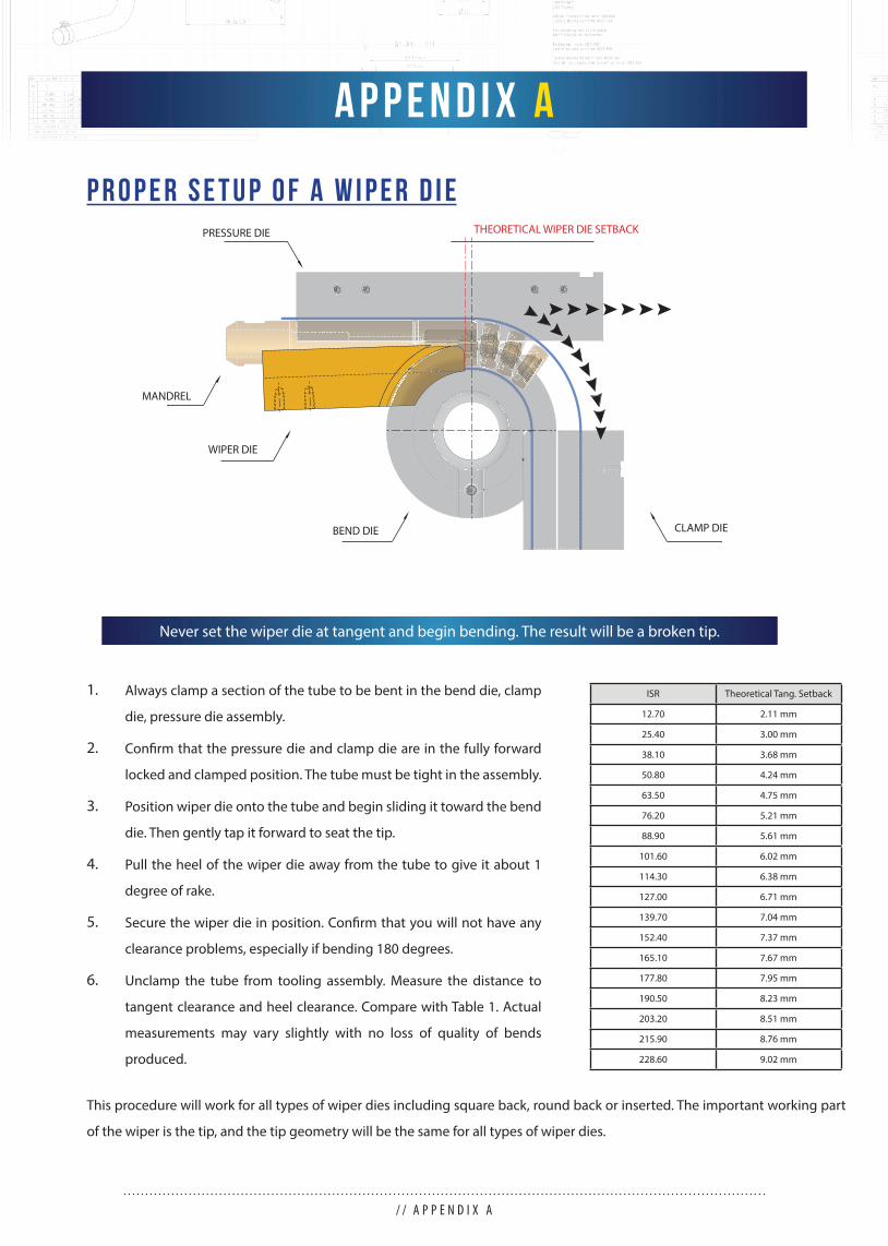
P R O P E R S E T U P O F A W I P E R D I E
This procedure will work for all types of wiper dies including square back, round back or inserted. The important working part
of the wiper is the tip, and the tip geometry will be the same for all types of wiper dies.
Always clamp a section of the tube to be bent in the bend die, clamp
die, pressure die assembly.
Confi rm that the pressure die and clamp die are in the fully forward
locked and clamped position. The tube must be tight in the assembly.
Position wiper die onto the tube and begin sliding it toward the bend
die. Then gently tap it forward to seat the tip.
Pull the heel of the wiper die away from the tube to give it about 1
degree of rake.
Secure the wiper die in position. Confi rm that you will not have any
clearance problems, especially if bending 180 degrees.
Unclamp the tube from tooling assembly. Measure the distance to
tangent clearance and heel clearance. Compare with Table 1. Actual
measurements may vary slightly with no loss of quality of bends
produced.
1.
2.
3.
4.
5.
6.
/ / A P P E N D I X A
ISR Theoretical Tang. Setback
12.70 2.11 mm
25.40 3.00 mm
38.10 3.68 mm
50.80 4.24 mm
63.50 4.75 mm
76.20 5.21 mm
88.90 5.61 mm
101.60 6.02 mm
114.30 6.38 mm
127.00 6.71 mm
139.70 7.04 mm
152.40 7.37 mm
165.10 7.67 mm
177.80 7.95 mm
190.50 8.23 mm
203.20 8.51 mm
215.90 8.76 mm
228.60 9.02 mm
Never set the wiper die at tangent and begin bending. The result will be a broken tip.
THEORETICAL WIPER DIE SETBACK
BEND DIE CLAMP DIE
PRESSURE DIE
MANDREL
WIPER DIE
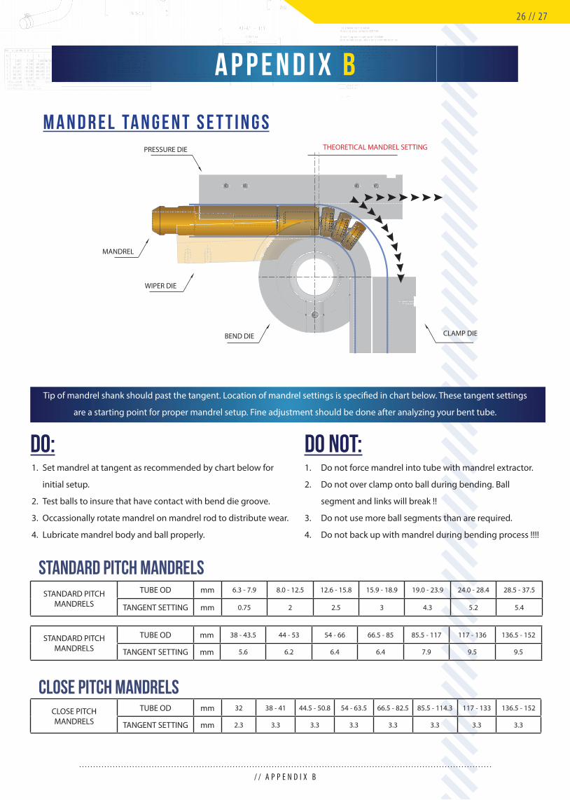
M A N D R E L TA N G E N T S E T T I N G S
Tip of mandrel shank should past the tangent. Location of mandrel settings is specifi ed in chart below. These tangent settings
are a starting point for proper mandrel setup. Fine adjustment should be done after analyzing your bent tube.
A P P E N D I X B
/ / A P P E N D I X B
STANDARD PITCH MANDRELS
TUBE OD mm 6.3 - 7.9 8.0 - 12.5 12.6 - 15.8 15.9 - 18.9 19.0 - 23.9 24.0 - 28.4 28.5 - 37.5
TANGENT SETTING mm 0.75 2 2.5 3 4.3 5.2 5.4
STANDARD PITCH MANDRELS
TUBE OD mm 38 - 43.5 44 - 53 54 - 66 66.5 - 85 85.5 - 117 117 - 136 136.5 - 152
TANGENT SETTING mm 5.6 6.2 6.4 6.4 7.9 9.5 9.5
CLOSE PITCH MANDRELS
TUBE OD mm 32 38 - 41 44.5 - 50.8 54 - 63.5 66.5 - 82.5 85.5 - 114.3 117 - 133 136.5 - 152
TANGENT SETTING mm 2.3 3.3 3.3 3.3 3.3 3.3 3.3 3.3
STANDARD PITCH MANDRELS
CLOSE PITCH MANDRELS
BEND DIE
THEORETICAL MANDREL SETTING
CLAMP DIE
PRESSURE DIE
MANDREL
WIPER DIE
26 // 27
DO: DO NOT:Set mandrel at tangent as recommended by chart below for
initial setup.
Test balls to insure that have contact with bend die groove.
Occassionally rotate mandrel on mandrel rod to distribute wear.
Lubricate mandrel body and ball properly.
1.
2.
3.
4.
1.
2.
3.
4.
Do not force mandrel into tube with mandrel extractor.
Do not over clamp onto ball during bending. Ball
segment and links will break !!
Do not use more ball segments than are required.
Do not back up with mandrel during bending process !!!!
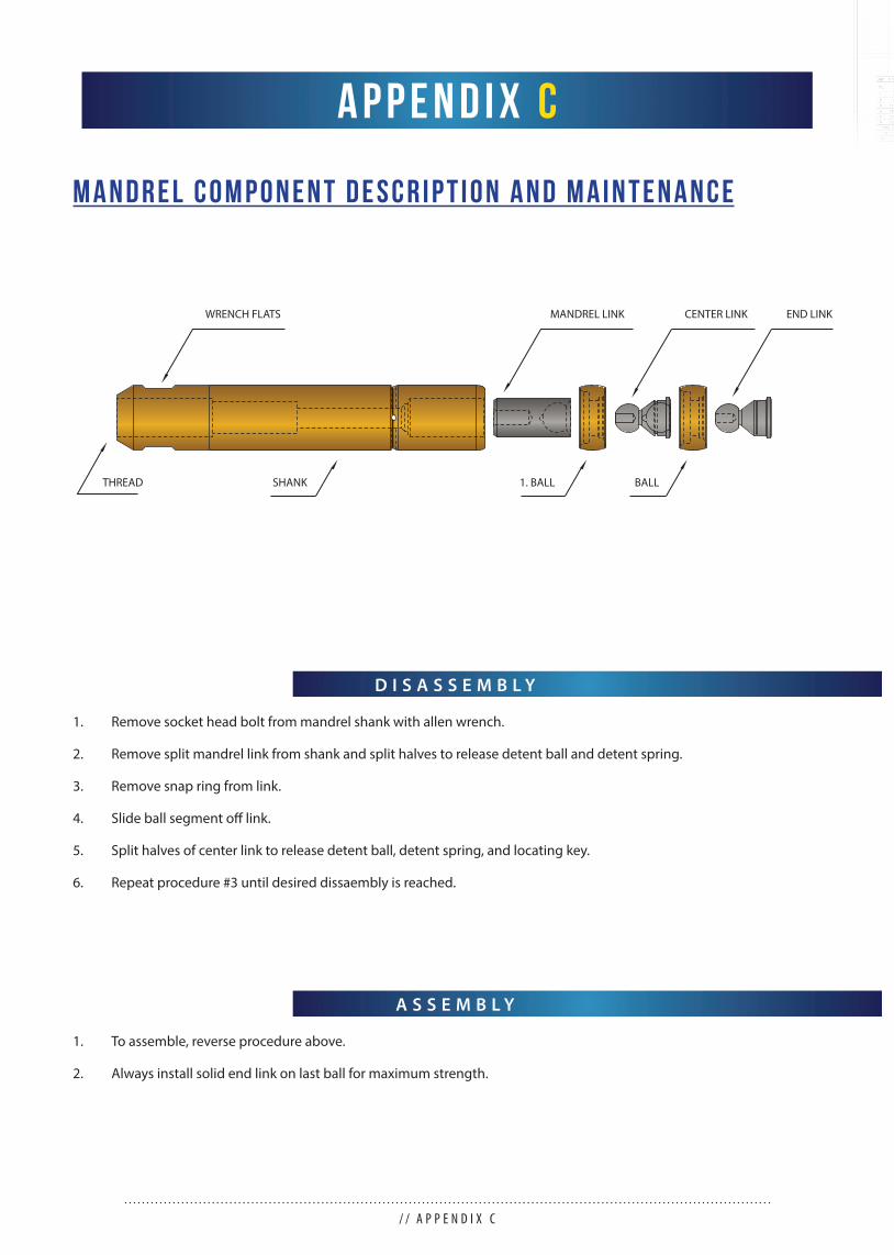
M A N D R E L C O M P O N E N T D E S C R I P T I O N A N D M A I N T E N A N C E
D I S A S S E M B L Y
A S S E M B L Y
Remove socket head bolt from mandrel shank with allen wrench.
Remove split mandrel link from shank and split halves to release detent ball and detent spring.
Remove snap ring from link.
Slide ball segment off link.
Split halves of center link to release detent ball, detent spring, and locating key.
Repeat procedure #3 until desired dissaembly is reached.
To assemble, reverse procedure above.
Always install solid end link on last ball for maximum strength.
1.
2.
3.
4.
5.
6.
1.
2.
A P P E N D I X C
/ / A P P E N D I X C
MANDREL LINKWRENCH FLATS
SHANKTHREAD 1. BALL BALL
CENTER LINK END LINK
END LINK
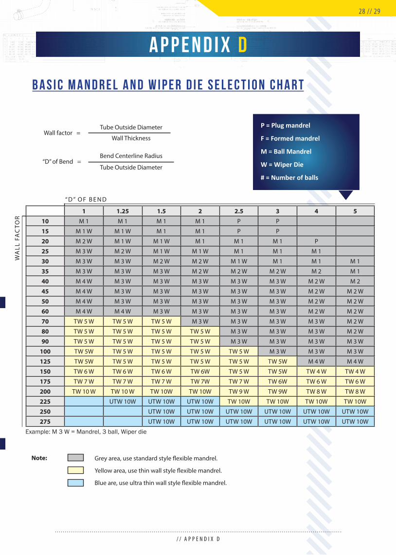
B A S I C M A N D R E L A N D W I P E R D I E S E L E C T I O N C H A R T
P = Plug mandrel
F = Formed mandrel
M = Ball Mandrel
W = Wiper Die
# = Number of balls
1 1.25 1.5 2 2.5 3 4 5
10 M 1 M 1 M 1 M 1 P P
15 M 1 W M 1 W M 1 M 1 P P
20 M 2 W M 1 W M 1 W M 1 M 1 M 1 P
25 M 3 W M 2 W M 1 W M 1 W M 1 M 1 M 1
30 M 3 W M 3 W M 2 W M 2 W M 1 W M 1 M 1 M 1
35 M 3 W M 3 W M 3 W M 2 W M 2 W M 2 W M 2 M 1
40 M 4 W M 3 W M 3 W M 3 W M 3 W M 3 W M 2 W M 2
45 M 4 W M 3 W M 3 W M 3 W M 3 W M 3 W M 2 W M 2 W
50 M 4 W M 3 W M 3 W M 3 W M 3 W M 3 W M 2 W M 2 W
60 M 4 W M 4 W M 3 W M 3 W M 3 W M 3 W M 2 W M 2 W
70 TW 5 W TW 5 W TW 5 W M 3 W M 3 W M 3 W M 3 W M 2 W
80 TW 5 W TW 5 W TW 5 W TW 5 W M 3 W M 3 W M 3 W M 2 W
90 TW 5 W TW 5 W TW 5 W TW 5 W M 3 W M 3 W M 3 W M 3 W
100 TW 5W TW 5 W TW 5 W TW 5 W TW 5 W M 3 W M 3 W M 3 W
125 TW 5W TW 5 W TW 5 W TW 5 W TW 5 W TW 5W M 4 W M 4 W
150 TW 6 W TW 6 W TW 6 W TW 6W TW 5 W TW 5W TW 4 W TW 4 W
175 TW 7 W TW 7 W TW 7 W TW 7W TW 7 W TW 6W TW 6 W TW 6 W
200 TW 10 W TW 10 W TW 10W TW 10W TW 9 W TW 9W TW 8 W TW 8 W
225 UTW 10W UTW 10W UTW 10W TW 10W TW 10W TW 10W TW 10W
250 UTW 10W UTW 10W UTW 10W UTW 10W UTW 10W UTW 10W
275 UTW 10W UTW 10W UTW 10W UTW 10W UTW 10W UTW 10W
Example: M 3 W = Mandrel, 3 ball, Wiper die
Wall factor =Tube Outside Diameter
Bend Centerline Radius
Wall Thickness
Tube Outside Diameter“D” of Bend =
“ D ” O F B E N D
WA
LL F
AC
TOR
Grey area, use standard style fl exible mandrel.
Yellow area, use thin wall style fl exible mandrel.
Blue are, use ultra thin wall style fl exible mandrel.
Note:
A P P E N D I X D
/ / A P P E N D I X D
28 // 29
we need the following information:For engineering and manufacturing of tool set
When ordering tooling it is very important to provide as much information as possible about the tube that will be bent, the
machine that will be used to make the bend and if known, the type of tooling you prefer to use. If you have made this bend in
the past and are satisfi ed with the results you have been getting with your previous tools, we can make your new tooling to
your specs. If on the other hand you are not familiar with tooling design and don’t know what would work best and still be cost
eff ective, we will use our expertise and many years of experience to provide you with such tools.
Below is checklist of information you should provide to get the best possible results from your tools and to avoid
misunderstandings. If you are not sure of about what information to provide or how to measure your machine we can help by
sending you drawings to fi ll in or by going to your facility to make the measurements for you. Once we have the information
we will store it in our database for future tool orders so that you only need to provide the machine information once. If needed,
we can also provide assistance in improving the quality of your bends and the effi ciency of your bending process as well as
off er solutions to reduce your inventory of tools by making the tools so that they fi t all your benders if you have more than one
bender model.
Tube Outside Diameter (OD)
Wall thickness (WT)
Centerline Radius (CLR)
Material of tube
Max. degree of bend (DOB)
Machine make and model
Application of bent tube
(automotive exhaust, aircraft, heat exchanger, furniture)
O R D E R I N G G U I D E L I N E S
/ / O R D E R I N G G U I D E L I N E S
For quote on set of tools
Mounting for the bend die, clamp die, pressure die, etc.
Rotation of swing arm (C.W., C.C.W.)
Grip length (If preferred) (L)
Any special adapters needed
we may need more specifi c information about your bender:
Please write this information to Quote / Order forms or call us to stop by your facility to discuss.
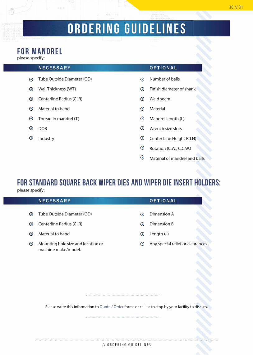
we may need more specifi c information about your bender:For Standard Square Back wiper dies and wiper die insert holders:
Tube Outside Diameter (OD)
Wall Thickness (WT)
Centerline Radius (CLR)
Material to bend
Thread in mandrel (T)
DOB
Industry
Number of balls
Finish diameter of shank
Weld seam
Material
Mandrel length (L)
Wrench size slots
Center Line Height (CLH)
Rotation (C.W., C.C.W.)
Material of mandrel and balls
Dimension A
Dimension B
Length (L)
Any special relief or clearances
N E C E S S A R Y
N E C E S S A R Y O P T I O N A L
O P T I O N A L
O R D E R I N G G U I D E L I N E S
/ / O R D E R I N G G U I D E L I N E S
please specify:
please specify:
F o r M A N D R E L
30 // 31
Please write this information to Quote / Order forms or call us to stop by your facility to discuss.
Tube Outside Diameter (OD)
Centerline Radius (CLR)
Material to bend
Mounting hole size and location ormachine make/model.

W O R L D W I D E L E A D E R I N B E N D I N G T E C H N O L O G Y
OMNI-X will be honest and responsible in our dealings with customers, suppliers, and employees. We will provide
products and service that meets or exceeds the expectations of our customers. We will relentlessly pursue contin-
uous improvement and innovation in everything we do to create a significant competitive advantage compared to
world standards.
OUR MISSION
O M N I - X G U I D E T O R O T A R Y D R A W B E N D I N G
O U R P A R T N E R S
Tel.: +420 548 212 817Fax: +420 548 212 804Email: [email protected]
OMNI-X CZ s.r.o.Šámalova 60aBrno - Židenice615 00Czech republic
European Sales and Manufacturing
OMNI-X MX S, de R.L. de C.V.Acceso II Num 1 Bodega 19Zona Industrial Benito JuarezCP, 76120 Queretaro, QROMexico
Tel./Fax: +442 224 05 77Mobile: +442 181 79 70Email: [email protected]
Mexico Sales and Manufacturing
Tel.: +1 (303) 789-3575Fax: +1 (303) 789-4755Email: [email protected]
OMNI-X, Inc.2751 W. Mansfi eld Ave.Englewood, CO 80110USA
Headquarters and Manufacturing


