Embed Size (px)
Citation preview
On Demand Network-wide VPN Deployment in GPRS
Christos Xenakis and Lazaros Merakos
Communication Networks Laboratory Department of Informatics & Telecommunications
University of Athens, 15784 Athens, Greece. Tel. +30 10 7275418, +30 10 727 5323, Fax. +30 10 7275601
e-mail: {xenakis,merakos}@di.uoa.gr
ABSTRACT The Mobile Internet requires enhanced security services available to all mobile subscribers in a dynamic fashion. A network-wide Virtual Private Network (VPN) deployment scenario over the General Packet Radio Service (GPRS) is proposed and analyzed from a security viewpoint. The proposed security scheme improves the level of protection that is currently supported in GPRS and facilitates the realization of Mobile Internet. It secures data transmission over the entire network route from a mobile user to a remote server by utilizing the default GPRS ciphering over the radio interface, and by deploying an IP VPN over the GPRS core, as well as on the public Internet. Thus, on-demand VPN services are made available for all GPRS network subscribers and roaming users. The VPN functionality, which is based on the IPsec framework, is outsourced to the network infrastructure so as to eliminate the potential computational overhead on the mobile device. The VPN initialization and key agreement procedures are based on an Internet Key Exchange (IKE) protocol proxy scheme, which enables the mobile station to initiate a VPN establishment, while shifting the complex key negotiation to the network infrastructure. The deployed VPN operates transparently to the mobile subscribers’ movement. The required enhancements for security service provision can be integrated in the existing network infrastructure, and therefore, the proposed security scheme can be employed as an add-on feature to the GPRS standard. Keywords – Security, Virtual Private Network (VPN), General Packet Radio Service (GPRS), IP Security (IPsec), Internet Key Exchange (IKE), Network Address Translation (NAT).
1 INTRODUCTION
Mobile systems free their users from being tied to the office workstation encouraging distributed working practices. They allow for users of mobile devices to access remote networked resources realizing the “ubiquitous computing” and the “Mobile Internet” concepts. In such a communication model, where clients are connecting to ever growing networks in an ad-hoc fashion, and data transfer is carried out using mobile devices, security is considered paramount. Furthermore, the introduction of IP-based transport technology to the core of the mobile data network brings along new vulnerabilities and potential threats [2]. It is therefore increasingly important that the evolving mobile data networks provide their services in an efficient and secure manner.
The most widely deployed public mobile data network, which enables the integration of IP world with mobile networks, and constitutes a migration step toward third-generation communication systems, is the General Packet Radio Service (GPRS) [3]. The GPRS technology supports a set of security mechanisms to protect the network operation and the data transfer through it. Such mechanisms protect mainly the air interface between the mobile devices and the base stations, however, the IP-based core network and the interconnection points are potentially vulnerable, and they are likely points for attacks [11].
A key element of secure networking is the proper design and configuration of Virtual Private Networks (VPNs) [12]. VPNs were originally conceived to address network security issues such as authentication, confidentiality, and integrity in fixed networks. Nevertheless, the increased user/device mobility, and the new emerging integration trend between the mobile and fixed networks have introduced a whole new realm of security concerns that were not previously foreseen. VPNs are deployed following two general schemes: the first is based on customer premises equipment, where the communicating endpoints negotiate and apply
1
security; the second pertains to a network-based approach, where the VPN functionality is outsourced to the network operator or the service provider.
Currently, GPRS supports static VPN deployment between the border gateway of the GPRS core network and a remote corporate security gateway. This means that VPNs are realized under certain circumstances, and cannot satisfy the new emerging security requirements that the Mobile Internet introduces. Furthermore, this security scheme permits the flow of unprotected data over the GPRS backbone exposing them to various attacks [2].
In this paper, a dynamic network-wide VPN deployment scenario over the GPRS network is proposed and analyzed from a security point of view. The proposed security scheme, which is based on the IPsec [1] protocol suite, improves the level of protection that is currently supported in GPRS. The mobile user initiates a VPN establishment between the involved Serving GPRS Support Node (SGSN) and a corporate security gateway or another SGSN, outsourcing the complex key negotiation and encryption/decryption functionality to the network infrastructure. Thus, on-demand VPN services are available for all GPRS network subscribers and roaming users. The proposed security scheme provides maximal security services by employing the existing GPRS security over the radio interface, and protecting data transmission over the GPRS backbone and the public Internet. Network Address Translation (NAT) [5] is also used since the mobile users utilize private unregistered IP addresses. The required enhancements for the VPN establishment and maintenance can be integrated within the existing network infrastructure, and the deployed VPN operates transparently to the GPRS functionality.
The rest of this paper is organized as follows. Section 2 introduces the GPRS mobile system. Section 3 presents IP security focusing on the incompatibilities that may arise from the simultaneous use of IPsec and NAT technologies. Section 4 describes the VPN deployment, and analyzes the required network enhancements, the IPsec protocol configuration and operation, as well as the assumed trust model. Section 5 presents a qualitative evaluation of the proposed network-wide VPN scheme, and section 6 contains the conclusions.
2 GPRS NETWORK
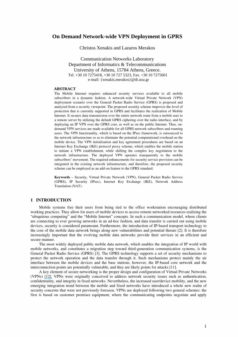
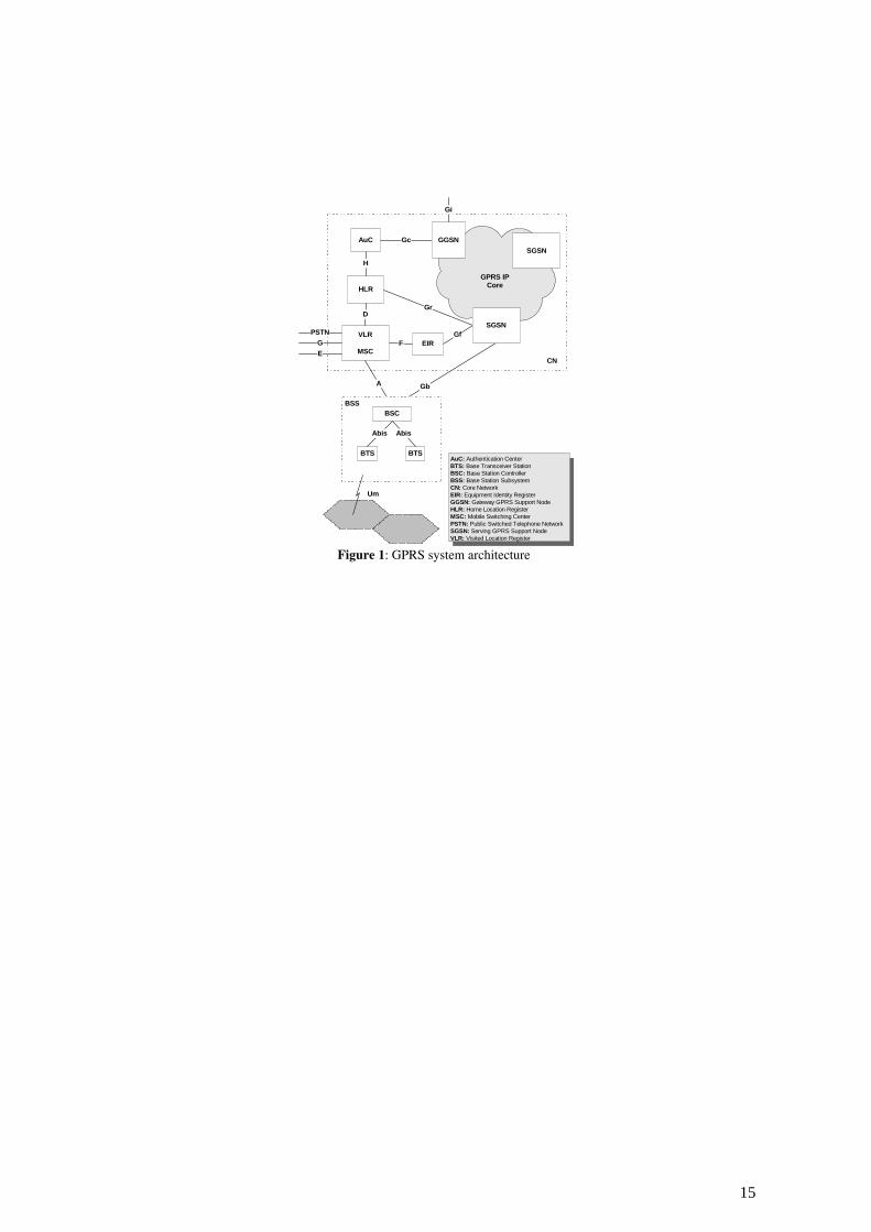
The Mobile Internet is becoming available with the deployment of the enhanced version of second-generation mobile communication systems, such as GPRS. GPRS attempts to reuse the existing Global System for Mobile communication (GSM) network elements as much as possible, but in order to effectively build a packet-based mobile cellular network, some new network elements, interfaces, and protocols are required [3]. The new network nodes are called GPRS Support Nodes (GSN). SGSN is responsible for the delivery of data packets from and to the Mobile Station (MS) within its service area. Gateway GSN (GGSN) acts as an interface between the GPRS backbone network and the external packet data network. The communication between the GSNs is based on IP tunnels through the use of the GPRS Tunneling Protocol (GTP) [3]. The GPRS network architecture is illustrated in Fig. 1.
AuC: Authentication CenterBTS: Base Transceiver StationBSC: Base Station ControllerBSS: Base Station SubsystemCN: Core NetworkEIR: Equipment Identity RegisterGGSN: Gateway GPRS Support NodeHLR: Home Location RegisterMSC: Mobile Switching CenterPSTN: Public Switched Telephone NetworkSGSN: Serving GPRS Support NodeVLR: Visited Location Register
H
VLR
MSCEIR
HLR
AuC
FGf
DGr
Gc
Gi
CN
PSTNGE
A Gb
GGSNSGSN
SGSN
GPRS IPCore
BSC
BTS BTS
Abis Abis
Um
BSS
Figure 1: GPRS system architecture
2
2.1 GPRS Security
Given that the GPRS is built on the GSM infrastructure, it employs the same security functions being used in GSM [4], slightly modified to adapt to the packet-oriented traffic nature and the GPRS network components. These functions aim at two goals: a) to protect user privacy, and b) to protect the network against unauthorized access [4].
The confidentiality of user data and signaling information is based on the GPRS ciphering algorithm (GPRS-A5), which is similar to the GSM A5 algorithm [3, 4]. The GPRS ciphering function, which is built into the network layers that are not under the end-user control, has been extended up to the SGSN, supporting signaling and user data encryption over the Um, Abis and Gb interfaces.
The GPRS backbone network utilizes private IP addressing and NAT to restrict unauthorized access to it. Furthermore, firewalls guard the traffic to and from other networks, protecting the GPRS backbone from IP spoofing.
Since the GPRS core network is based on IP, and is connected to the public Internet, data in transit are subject to various security threats, such as interception, unauthorized disclosure, and malicious alteration. The GPRS encryption/decryption mechanisms do not extend far enough towards the core network, resulting in the clear-text transmission of user and signaling data [11]. The border firewalls and the private IP addressing attempt to protect the clear-text transmitted data within the GPRS core from external attacks. However, these measures are inadequate against attacks that originate from malicious mobile network subscribers, as well as third parties that get access to the GPRS core network.
2.2 VPN services in GPRS
Currently, VPN services for GPRS subscribers are established in a static manner between the GGSN, which resides at the border of the GPRS backbone network, and a remote corporate security gateway. This makes the realization of VPN services feasible only between the border gateway of a large organization and the GGSN of a mobile operator, when a considerable amount of traffic requires protection. Thus, if the static VPN parameters or the VPN topology have to be changed, then the network administrators in both ends must reconfigure it. Furthermore, the aforementioned security scheme can provide VPN service neither to individual mobile users, who may require on demand VPN establishment, nor to enterprise users that may roam internationally. In such cases, the only way to accomplish secure access to a remote server is either to make an expensive phone call, or to establish an end-to-end security scheme [10], which requires from the mobile device to have full security functionality, and introduces considerable traffic overhead over the “expensive” radio interface.
Mobile devices are designed to be portable with small screen size, limited input capabilities, and limited battery power and energy. The computing power of the processor is typically small, and the operating system’s capabilities limited; thus, demanding computations will be slow. In order to conserve energy, processing speeds need to be slower, and processor cycles and data transmissions must be reduced. These constraints impose limitations on the potential deployment of full IP security functionality at the mobile device level, due to the computational complexity of the encryption algorithms, and the number of messages exchanged in the involved security protocols [13].
3. IP SECURITY
A number of different security mechanisms, which are used in VPN deployment, for IP networks have been proposed [12]. From these technologies, the IPsec protocol suite aims at securing the network layer, and guarantees security services for any application that uses it [1].
3.1 IPsec
IPsec grants two choices of security service: Authentication Header (AH), and Encapsulation Security Payload (ESP). AH provides support for connectionless integrity, data origin authentication, and protection against replays, but does not provide secrecy. On the other hand, ESP supports confidentiality, connectionless integrity, anti-replay protection, and optional data origin authentication.
A key concept that appears in both security services is the Security Association (SA). A SA is a one-way relationship between a sender and a receiver that affords security services. In order to establish a SA between two hosts, they must first agree to apply compatible policies and cryptographic algorithms. They must also share a secure mechanism for determining keying material over an insecure channel. The default IPsec method for secure key negotiation is the Internet Key Exchange (IKE) protocol [14].
3
IKE consists of two sequential phases. Phase 1 creates an Internet Security Association and Key Management Protocol (ISAKMP) SA (or IKE SA) that establishes a bi-directional secure channel between the security endpoints. Phase 2 negotiates an IPsec SA using the pre-established channel. Multiple IPsec SAs can be established from a single ISAKMP SA, which may be considered as a “control channel”, where IKE is the control protocol.
Both AH and ESP support two modes of use: transport and tunnel mode [1]. The transport mode mainly provides end-to-end protection, where the IP packet’s payload is encrypted. On the other hand, the tunnel mode encapsulates an entire IP packet (including the IP header) within a new IP packet to ensure that no part of the original packet is visible, or may be changed as it moves through a network.
Even though there is some criticism on IPsec, it is commonly admitted that it is the best IP security protocol available today [8]. It facilitates the authentication of the communicating entities, and the transparent encryption and integrity protection of the transmitted packets in both IPv4 and IPv6 networks. It is especially useful for implementing VPNs, and remote access to private networks. Because of its flexibility, the IPsec enables security service deployment across any existing IP network. On the other hand, the main drawback of IPsec is its complexity, as it incorporates a considerable number of independent protocols, which operate in multiple modes [8].
3.2 IPsec and NAT
A principal issue that has to be considered in the IPsec-based VPN deployment, is the use of NAT. NAT maps an isolated address realm with private unregistered addresses to an external realm with globally unique registered addresses. Furthermore, a variation known as Network Address Port Translation (NAPT) [5], which allows many hosts to share a single IP address by multiplexing streams differentiated by TCP/UDP port numbers, is employed. The interworking of the NAT and IPsec raises many incompatibilities, since the later either hides private addresses through encryption and thus lets them escape translation, or experiences integrity violations as a consequence of the NAT manipulating on protected IP addresses [5, 9].
One of the main features of IPsec is the integrity control of the transmitted packets, which prevents unauthorized modification, source spoofing, and man-in-the-middle attacks. AH protects the entire IP packet including the header fields. Hence, AH integrity cannot be met when a NAT device processes a protected packet, and rewrites its IP addresses. As far as IPsec is concerned, the operation of NAT constitutes a violation of its security policy.
Moreover, when TCP is involved in ESP protected data transfer, then, another incompatibility problem between TCP and NAT occurs. Because NAT modifies the TCP packet, it must also recalculate the TCP checksum used to verify integrity. If NAT updates the TCP checksum, the ESP authentication will fail. If NAT does not update the checksum, then, TCP verification will fail.
The IPsec-based VPNs use the IKE to automate a SA setup and authenticate endpoints. The most widely used method of authentication is the pre-shared key. Unfortunately, this method depends on the source IP address of the security peers. If NAT is inserted between the security endpoints, the source IP address will be translated into the address of the NAT router, and, thus, authentication cannot be performed.
Additionally, a problem may occur when multiple hosts behind a NAT initiate IKE SA to the same responder. In this case, a NAPT is used to demultiplex and discriminate the incoming IKE packets, but this may result in unpredictable behavior when dealing with re-keys. When a SA expires, one security host will send a re-key request to the other. This type of requests uses the same IP port, and when more than one security hosts lie behind a NAPT router, the incoming re-key is possible to be misrouted.
4. NETWORK-WIDE VPN DEPLOYMENT
In the sequel, the proposed network-wide VPN deployment scenario is presented and analyzed. Specifically, the employed network architecture is presented, and the required enhancements on the existing GPRS network infrastructure are described. Furthermore, the proposed IKE-proxy scheme for VPN establishment, and the VPN operation are elaborated. The incompatibilities that arise by the NAT employment, as well as the impact of user mobility on the VPN operation are considered, and detailed solutions are proposed. Finally, the assumed trust model among the involved communicating parties is examined.
4.1 Architecture
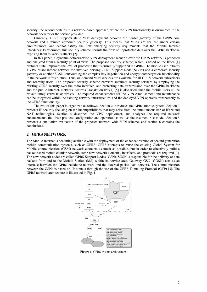
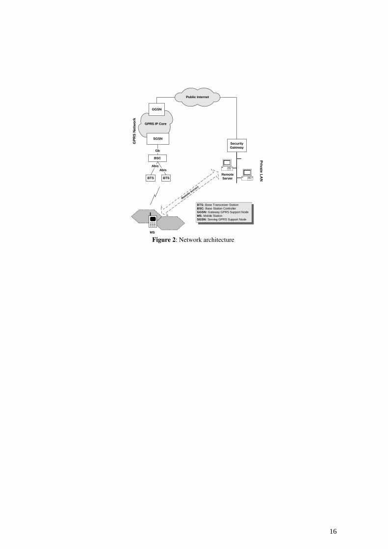
Consider a mobile subscriber with a MS attempting to establish a secure remote connection to a corporate Local Area Network (LAN), and access a remote server through a GPRS infrastructure, as shown in Fig. 2. The Security Gateway (SG) that resides between the LAN and the Internet, functions as a proxy device providing security services to the private network nodes.
4
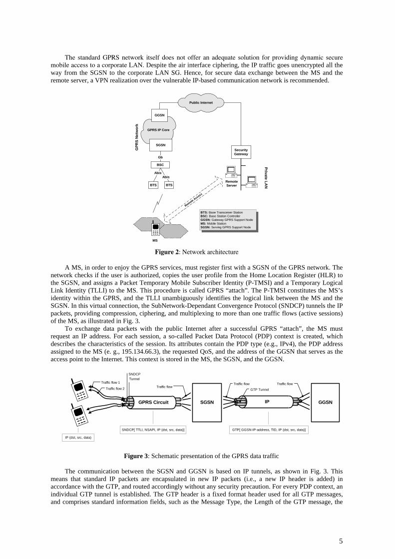
The standard GPRS network itself does not offer an adequate solution for providing dynamic secure mobile access to a corporate LAN. Despite the air interface ciphering, the IP traffic goes unencrypted all the way from the SGSN to the corporate LAN SG. Hence, for secure data exchange between the MS and the remote server, a VPN realization over the vulnerable IP-based communication network is recommended.
GPRS IP Core
Public Internet
SecurityGateway
Private LANBTS
BSC
Abis
Gb
SGSN
GGSN
Remote Access
GPR
S N
etw
ork
BTS
Abis
MS
BTS: Base Transceiver StationBSC: Base Station ControllerGGSN: Gateway GPRS Support NodeMS: Mobile StationSGSN: Serving GPRS Support Node
RemoteServer
Figure 2: Network architecture
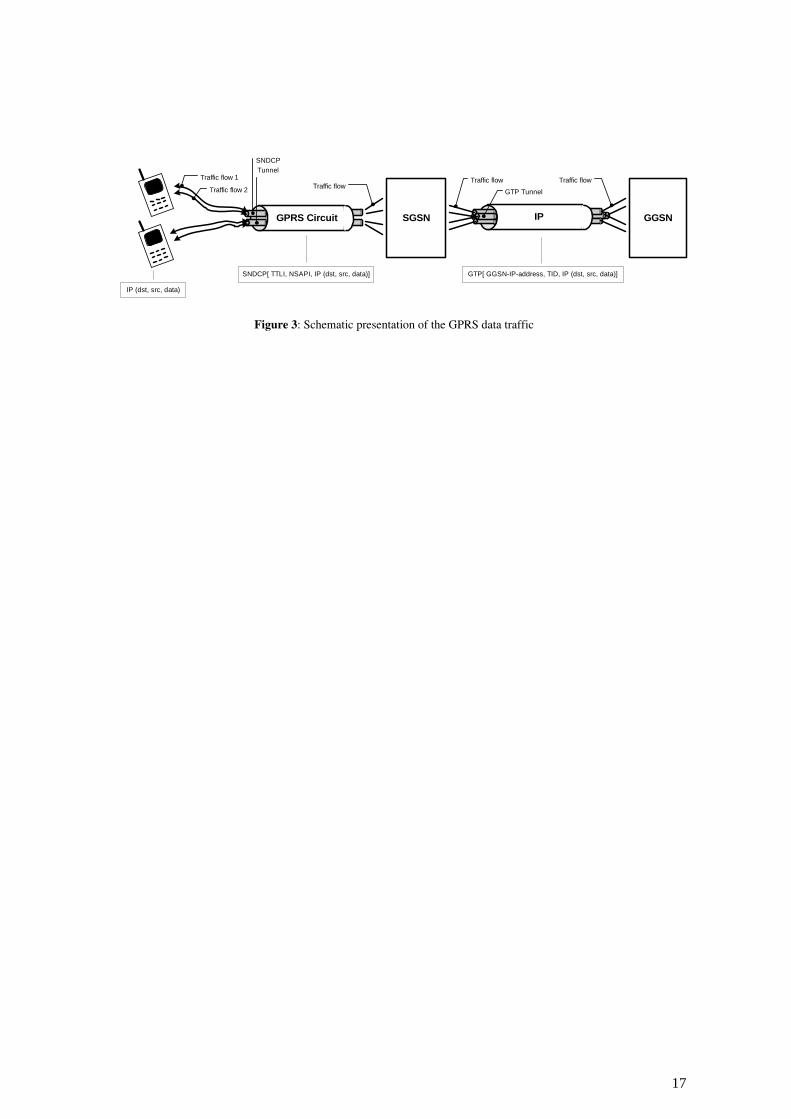
A MS, in order to enjoy the GPRS services, must register first with a SGSN of the GPRS network. The network checks if the user is authorized, copies the user profile from the Home Location Register (HLR) to the SGSN, and assigns a Packet Temporary Mobile Subscriber Identity (P-TMSI) and a Temporary Logical Link Identity (TLLI) to the MS. This procedure is called GPRS “attach”. The P-TMSI constitutes the MS’s identity within the GPRS, and the TLLI unambiguously identifies the logical link between the MS and the SGSN. In this virtual connection, the SubNetwork-Dependant Convergence Protocol (SNDCP) tunnels the IP packets, providing compression, ciphering, and multiplexing to more than one traffic flows (active sessions) of the MS, as illustrated in Fig. 3.
To exchange data packets with the public Internet after a successful GPRS “attach”, the MS must request an IP address. For each session, a so-called Packet Data Protocol (PDP) context is created, which describes the characteristics of the session. Its attributes contain the PDP type (e.g., IPv4), the PDP address assigned to the MS (e. g., 195.134.66.3), the requested QoS, and the address of the GGSN that serves as the access point to the Internet. This context is stored in the MS, the SGSN, and the GGSN.
SGSN GGSN GPRS Circuit IP
Traffic flow 1
Traffic flow 2
SNDCPTunnel
Traffic flowTraffic flow
GTP Tunnel
Traffic flow
IP (dst, src, data)
SNDCP[ TTLI, NSAPI, IP (dst, src, data)] GTP[ GGSN-IP-address, TID, IP (dst, src, data)]
Figure 3: Schematic presentation of the GPRS data traffic
The communication between the SGSN and GGSN is based on IP tunnels, as shown in Fig. 3. This means that standard IP packets are encapsulated in new IP packets (i.e., a new IP header is added) in accordance with the GTP, and routed accordingly without any security precaution. For every PDP context, an individual GTP tunnel is established. The GTP header is a fixed format header used for all GTP messages, and comprises standard information fields, such as the Message Type, the Length of the GTP message, the
5
Sequence Number, and the Tunnel Identifier (TID). TID is used to uniquely identify a PDP context, and consists of the International Mobile Subscriber Identity (IMSI), and the Network layer Service Access Point Identifier (NSAPI) [3].
The result of the GPRS “attach” and the PDP context “activation” procedures is that the MS is “visible” to the external network, and is capable of sending and receiving data packets. For this purpose, two bi-directional tunnels are set up: a) one between the MS and the SGSN (SNDCP), which supports security protection, and b) one between the SGSN and the GGSN (GTP) without any security precaution. The TID identifies the GTP tunnel and the pair NSAPI/TLLI the SNDCP tunnel. In this paper, it is assumed that the Internet and the GPRS backbone are based on IPv4, and that both the GGSN and the SG use NAT.
4.2 GPRS network enhancements
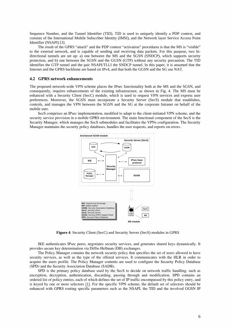
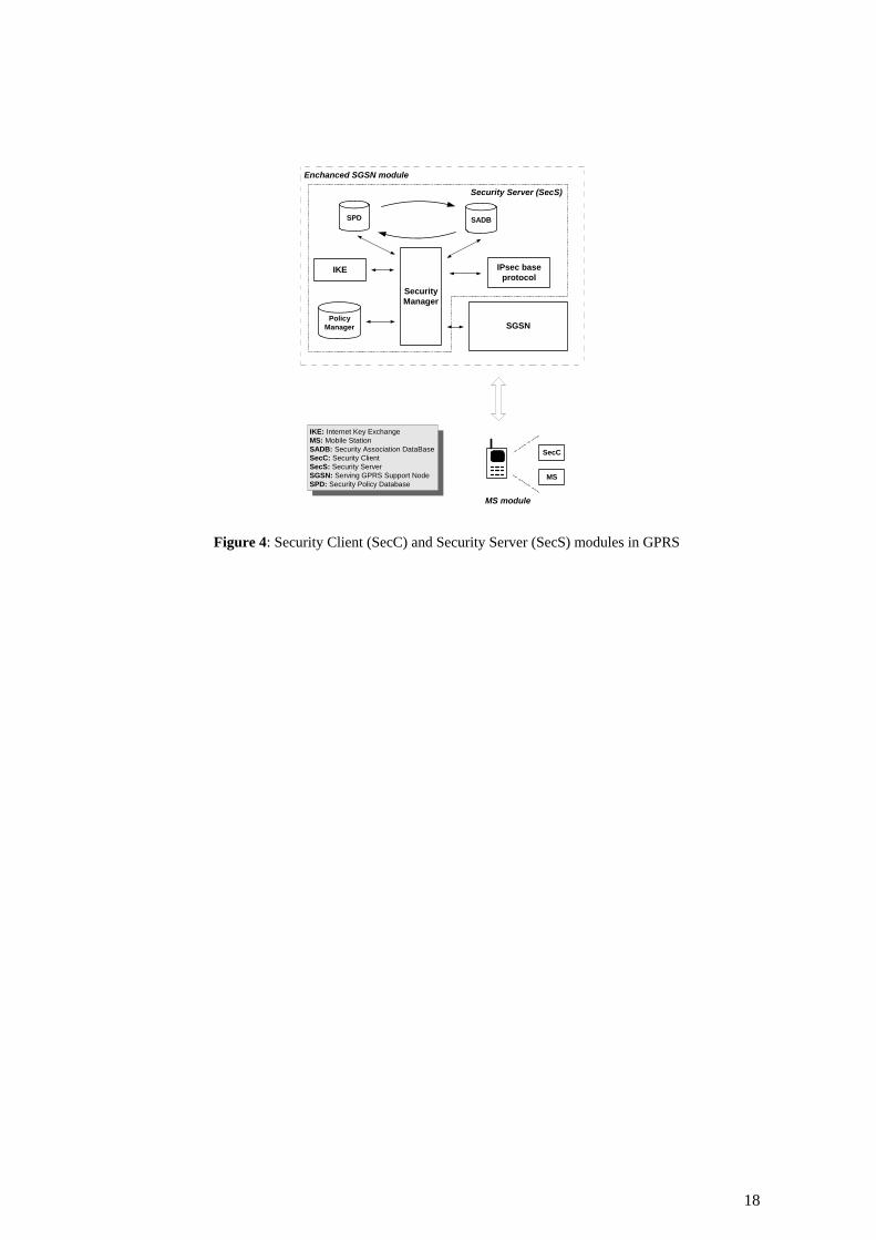
The proposed network-wide VPN scheme places the IPsec functionality both at the MS and the SGSN, and consequently, requires enhancements of the existing infrastructure, as shown in Fig. 4. The MS must be enhanced with a Security Client (SecC) module, which is used to request VPN services and express user preferences. Moreover, the SGSN must incorporate a Security Server (SecS) module that establishes, controls, and manages the VPN between the SGSN and the SG at the corporate Intranet on behalf of the mobile user.
SecS comprises an IPsec implementation, modified to adapt to the client-initiated VPN scheme, and the security service provision in a mobile GPRS environment. The main functional component of the SecS is the Security Manager, which manages the SecS submodules and facilitates the VPNs configuration. The Security Manager maintains the security policy databases, handles the user requests, and reports on errors.
IKE: Internet Key ExchangeMS: Mobile StationSADB: Security Association DataBaseSecC: Security ClientSecS: Security ServerSGSN: Serving GPRS Support NodeSPD: Security Policy Database
SGSN
IPsec baseprotocol
SecurityManager
IKE
PolicyManager
Enchanced SGSN module
Security Server (SecS)
SPD SADB
MS
SecC
MS module
Figure 4: Security Client (SecC) and Security Server (SecS) modules in GPRS
IKE authenticates IPsec peers, negotiates security services, and generates shared keys dynamically. It provides secure key determination via Diffie-Hellman (DH) exchanges.
The Policy Manager contains the network security policy that specifies the set of users allowed to have security services, as well as the type of the offered services. It communicates with the HLR in order to acquire the users profile. The Policy Manager contents are used to configure the Security Policy Database (SPD) and the Security Association Database (SADB).
SPD is the primary policy database used by the SecS to decide on network traffic handling, such as encryption, decryption, authentication, discarding, passing through and modification. SPD contains an ordered list of policy entries, each of which defines the set of IP traffic encompassed by this policy entry, and is keyed by one or more selectors [1]. For the specific VPN scheme, the default set of selectors should be enhanced with GPRS routing specific parameters such as the NSAPI, the TID and the involved GGSN IP
6
address. The Security Manager is responsible for filling out the contents of this database and sharing them with the other SecS submodule.
SADB maintains the contents of all active SAs used by the SecS for IPsec formatting. A SA is a management feature used to enforce a security policy. It represents all the necessary parameters (including protocols, modes, algorithms, etc) that have been agreed between the IPsec peers. The Security Manager is responsible for filling out the contents of each entry in SADB.
Finally, the IPsec base protocol processes the authentication and encryption transformation defined in the IPsec framework. It handles all the network layer functions, such as fragmentation and path maximum transfer unit, and ensures that all traffic passing through the SGSN is secure and authorized, providing firewall capabilities.
4.3 Security management
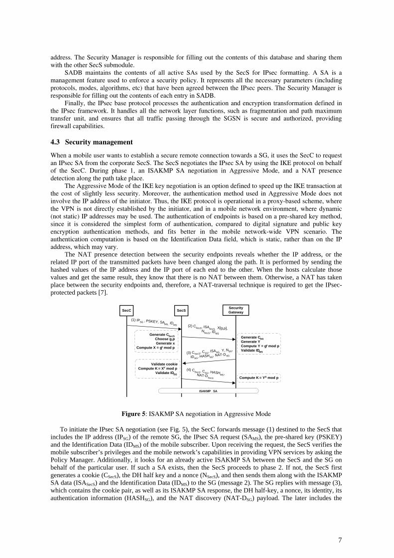
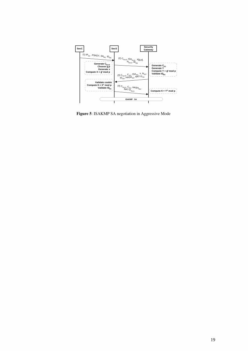
When a mobile user wants to establish a secure remote connection towards a SG, it uses the SecC to request an IPsec SA from the corporate SecS. The SecS negotiates the IPsec SA by using the IKE protocol on behalf of the SecC. During phase 1, an ISAKMP SA negotiation in Aggressive Mode, and a NAT presence detection along the path take place.
The Aggressive Mode of the IKE key negotiation is an option defined to speed up the IKE transaction at the cost of slightly less security. Moreover, the authentication method used in Aggressive Mode does not involve the IP address of the initiator. Thus, the IKE protocol is operational in a proxy-based scheme, where the VPN is not directly established by the initiator, and in a mobile network environment, where dynamic (not static) IP addresses may be used. The authentication of endpoints is based on a pre-shared key method, since it is considered the simplest form of authentication, compared to digital signature and public key encryption authentication methods, and fits better in the mobile network-wide VPN scenario. The authentication computation is based on the Identification Data field, which is static, rather than on the IP address, which may vary.
The NAT presence detection between the security endpoints reveals whether the IP address, or the related IP port of the transmitted packets have been changed along the path. It is performed by sending the hashed values of the IP address and the IP port of each end to the other. When the hosts calculate those values and get the same result, they know that there is no NAT between them. Otherwise, a NAT has taken place between the security endpoints and, therefore, a NAT-traversal technique is required to get the IPsec-protected packets [7].
Generate CSecSChoose g,pGenerate x
Compute X = gx mod p
(2) CSecS, ISASecS, X[g,p], NSecS, IDMS
(3) CSecS, CSG, ISASG, Y, NSG,
IDSG, HASHSG, NAT-DSG
Validate cookieCompute K = XY mod p
Validate IDSG
(4) CSecS, CSG, HASHMS,NAT-DSecS
SecC
(1) IPSG , PSKEY, SAMS, IDMS
SecSSecurityGateway
Generate CSGGenerate YCompute Y = gy mod pValidate IDMS
Compute K = YX mod p
ISAKMP SA
Figure 5: ISAKMP SA negotiation in Aggressive Mode
To initiate the IPsec SA negotiation (see Fig. 5), the SecC forwards message (1) destined to the SecS that includes the IP address (IPSG) of the remote SG, the IPsec SA request (SAMS), the pre-shared key (PSKEY) and the Identification Data (IDMS) of the mobile subscriber. Upon receiving the request, the SecS verifies the mobile subscriber’s privileges and the mobile network’s capabilities in providing VPN services by asking the Policy Manager. Additionally, it looks for an already active ISAKMP SA between the SecS and the SG on behalf of the particular user. If such a SA exists, then the SecS proceeds to phase 2. If not, the SecS first generates a cookie (CSecS), the DH half key and a nonce (NSecS), and then sends them along with the ISAKMP SA data (ISASecS) and the Identification Data (IDMS) to the SG (message 2). The SG replies with message (3), which contains the cookie pair, as well as its ISAKMP SA response, the DH half-key, a nonce, its identity, its authentication information (HASHSG), and the NAT discovery (NAT-DSG) payload. The later includes the
7
hashed values of the IP address and the IP port of both IKE peers. The first NAT-D field contains the remote end hash, and the rest contains the local end hash. The hash is calculated as follows:
HASH = hashfunc (CSecS |1 CSG | IP | Port) using the negotiated hash algorithm. The CSecS and CSG are included in the hash to make precomputation attacks for the IP address and IP port
impossible [7]. Finally, with message (4), the SecS transmits the MS’s authentication information (HASHMS) and the NAT-DSecS payload to the SG along with the cookie pair.
Having established an ISAKMP SA between the SecS and the SG on behalf of the MS, the communicating parties know whether a NAT device mediates between them, and have agreed on the following security attributes [14]:
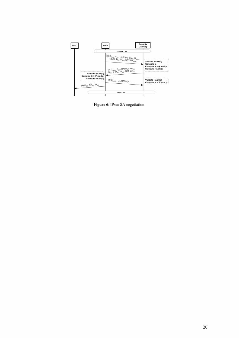
• the encryption algorithm • the hash algorithm for signing • the authentication method for signing • the Diffie-Hellman exchange Following the successful completion of phase 1, the IKE phase 2 is performed to establish the IPsec SA
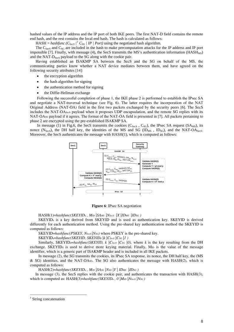
and negotiate a NAT-traversal technique (see Fig. 6). The latter requires the incorporation of the NAT Original Address (NAT-OA) field in the first two packets exchanged by the security peers [6]. The SecS includes the NAT-OASecS payload when it proposes UDP encapsulation, and the remote SG replies with its NAT-OASG payload if it agrees. The format of the NAT-OA field is presented in [7]. All packets pertaining to phase 2 are encrypted using the pre-established ISAKMP SA.
In message (1) in Fig.6, the SecS transmits the cookies (CSecS , CSG), the IPsec SA request (SAMS), its nonce (NSecS), the DH half key, the identities of the MS and SG (IDMS , IDSG), and the NAT-OASecS. Moreover, the SecS authenticates the message with HASH(1), which is computed as follows:
SecC SecS
(4) IPSG SASG IDSG
(1) CSecS, CSG, HASH(1), SAMS, NSecS,X[g,p], IDMS IDSG , NAT-OASecS Validate HASH(1)Generate YCompute Y = gy mod pCompute HASH(2)(2) CSecS, CSG, HASH(2) SASG,
NSG, Y IDMS, IDSG , NAT-OASGValidate HASH(2)
Compute K = XY mod pCompute HASH(3) (3) CSecS, CSG, HASH(3)
Validate HASH(3)Compute K = XY mod p
SecurityGateway
ISAKMP SA
IPsec SA
Figure 6: IPsec SA negotiation
HASH(1)=hashfunc(SKEYIDa , MID |SAMS |NSecS |X |IDMS |IDSG ) SKEYIDa is a key derived from SKEYID and is used as authentication key. SKEYID is derived
differently for each authentication method. Using the pre-shared key authentication method the SKEYID is computed as follows:
SKEYID=hashfunc(PSKEY, NSecS |NSG) where PSKEY is the pre-shared key. SKEYIDa=hashfunc(SKEYID, SKEYIDd |k |CSecS |CSG |1 ) Similarly, SKEYIDd=hashfunc(SKEYID, k |CSecS |CSG |0), where k is the key resulting from the DH
exchange. SKEYIDd is used to derive more keying material. Finally, MID is the value of the message identifier, which is a generic part of ISAKMP header and is included in all IKE packets.
In message (2), the SG transmits the cookies, its IPsec SA response, its nonce, the DH half key, the (MS & SG) identities, and the NAT-OASG. The SG also authenticates the message with HASH(2), which is computed as follows:
HASH(2)=hashfunc(SKEYIDa , MID |SASG |NSG |Y | IDMS |IDSG ) In message (3), the SecS replies with the cookie pair, and authenticates the transaction with HASH(3),
which is computed as: HASH(3)=hashfunc(SKEYIDa , 0 |MID |NSecS |NSG )
1 String concatenation
8
Finalizing this dialog, the SecS with message (4) informs the SecC about the successful completion of the IPsec SA. As an IPsec SA is used only in one direction, for bi-directional communications between the SecS and the SG, two SAs are required.
4.4 NAT traversal
Although the coexistence of NAT with IPsec is quite troublesome, both mechanisms can be configured to co-operate in the particular mobile scenario for VPN services provision.
Specifically, there are two points (GGSN and SG) where NAT is applied. In the SG at the private network, both IPsec and NAT functionality are combined in the same device. By placing the IPsec endpoint in the public address space, the incompatibility problems that arise from their coexistence can be avoided [5]. On the other hand, the NAT at the GGSN takes place between the VPN termination points (SGSN and SG), and therefore, the incompatibilities presented in section 3.2 should be resolved.
The ESP protocol is proposed for VPN services because it provides confidentiality and integrity protection, as well [8]. Unlike the AH protocol, the ESP creates a message digest for packet authentication excluding the IP header, and, thus, allows NAT to modify the protected IP packet’s header, without experiencing an IPsec integrity failure.
However, the most important incompatibility issue that has to be considered in this scenario derives from the coexistence of TCP with NAT. A promising solution to this inconsistency is based on the use of UDP encapsulation. Wrapping the IPsec-protected packets inside a UDP/IP header lets NAT modifications without leveraging the encapsulated packet [6]. The receiver is allowed to discard the UDP header, disregarding also the NAT alternation. The only requisite is that both IPsec peers have to support UDP encapsulation/decapsulation functionality.
Concerning the incompatibility between the IKE address identifier and NAT, the proposed VPN scheme employs the IKE in Aggressive Mode, because it uses identification data instead of IP addresses for end-node authentication. The same authentication method is also used during the IPsec SA negotiation.
Finally, in the proposed scenario all IKE packets are destined to the SecS. Thus, based on the carried information (e.g., cookies) the IKE and the re-keying packets can be assigned to the appropriate SA.
4.5 VPN operation
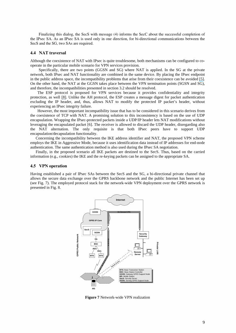
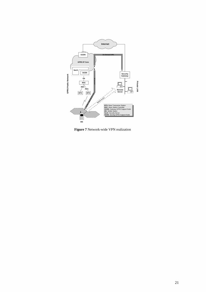
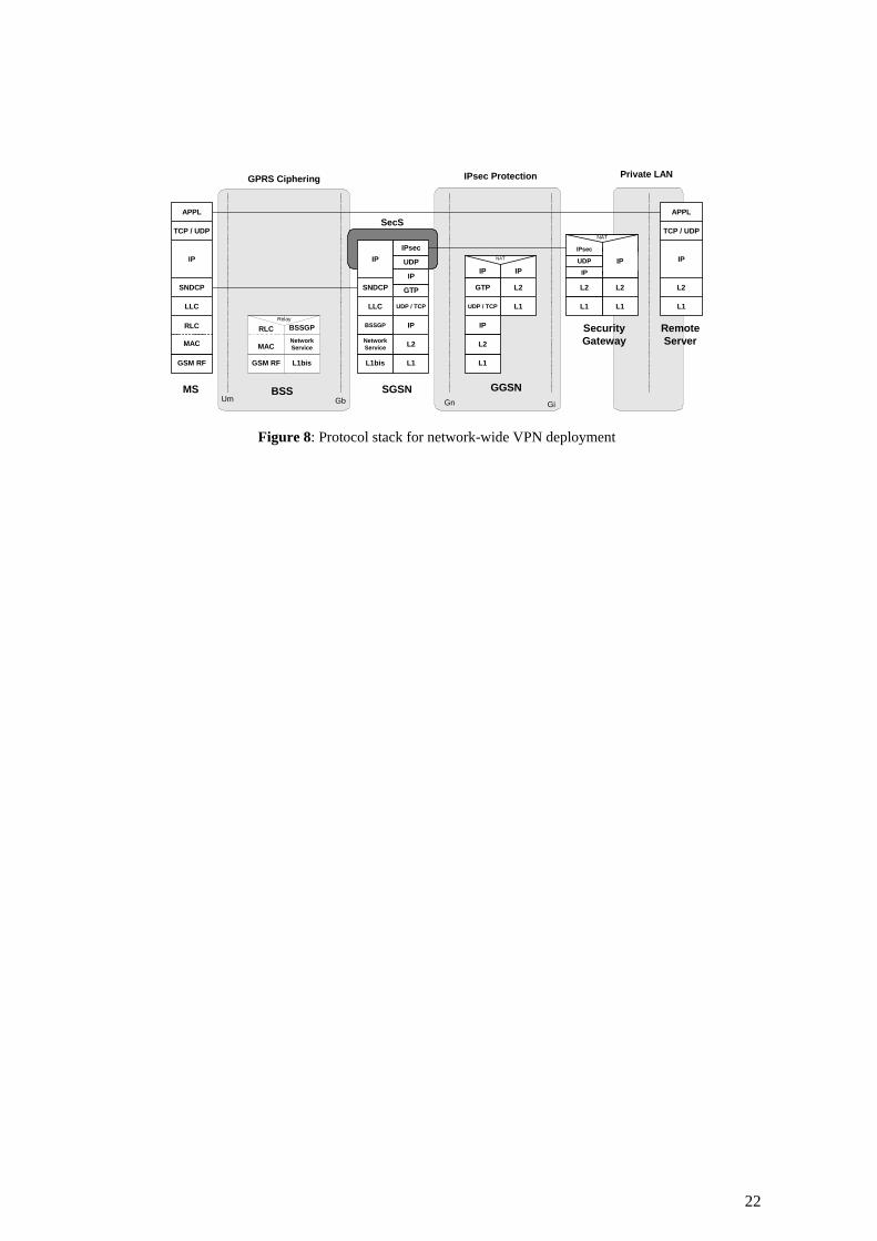
Having established a pair of IPsec SAs between the SecS and the SG, a bi-directional private channel that allows the secure data exchange over the GPRS backbone network and the public Internet has been set up (see Fig. 7). The employed protocol stack for the network-wide VPN deployment over the GPRS network is presented in Fig. 8.
GPRS IP Core
CI
PH
ER
IN
G
Internet
SecurityGateway
Private LAN
Gb
GGSN
Remote Access
GPR
S Pu
blic
Net
wor
k
BTS
BSC
Abis
BTS
Abis
SecSSGSN
GPRS
On Demand VPN
MS
RemoteServer
BTS: Base Transceiver StationBSC: Base Station ControllerGGSN: Gateway GPRS Support NodeMS: Mobile StationSecS: Security ServerSGSN: Serving GPRS Support Node
Figure 7 Network-wide VPN realization
9
The IP packets, which originate at the MS and are destined to the remote server, are encapsulated into the SNDCP tunnel using the NSAPI, are ciphered (GPRS ciphering), and are forwarded to the SGSN using the TLLI. The SGSN deciphers the packets, terminates the tunnel, and acquires the active PDP context based on TLLI and NSAPI parameter values. The PDP context comprises the TID and the IP address of the involved GGSN.
BSSUm
GSM RF L1bis
RLC
MACNetworkService
BSSGPRelay
Gb
GSM RF
RLC
MAC
LLC
SNDCP
IP
TCP / UDP
APPL
MS SGSNGn
L1
L2
BSSGP
L1bis
NetworkService
LLC
IP
UDP / TCP
GGSN
L1
L2
IP
L1
L2
UDP / TCP
IP IP
NAT
GTP
SecurityGateway
L1
L2
IP
TCP / UDP
APPL
RemoteServer
Gi
IP
L1
L2L2
L1
IPsec
NAT
IPUDP
GTPSNDCP
IP
IP
UDP
IPsec
SecS
GPRS Ciphering IPsec Protection Private LAN
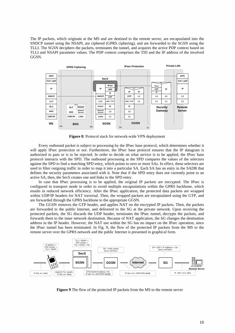
Figure 8: Protocol stack for network-wide VPN deployment
Every outbound packet is subject to processing by the IPsec base protocol, which determines whether it will apply IPsec protection or not. Furthermore, the IPsec base protocol ensures that the IP datagram is authorized to pass or is to be rejected. In order to decide on what service is to be applied, the IPsec base protocol interacts with the SPD. The outbound processing at the SPD compares the values of the selectors against the SPD to find a matching SPD entry, which points to zero or more SAs. In effect, these selectors are used to filter outgoing traffic in order to map it into a particular SA. Each SA has an entry in the SADB that defines the security parameters associated with it. Note that if the SPD entry does not currently point to an active SA, then, the SecS creates one and links to the SPD entry.
In case that IPsec processing is to be applied, the original IP packets are encrypted. The IPsec is configured in transport mode in order to avoid multiple encapsulations within the GPRS backbone, which results in reduced network efficiency. After the IPsec application, the protected data packets are wrapped within UDP/IP headers for NAT traversal. Then, the wrapped packets are encapsulated using the GTP, and are forwarded through the GPRS backbone to the appropriate GGSN.
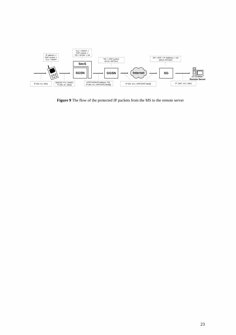
The GGSN removes the GTP header, and applies NAT on the encrypted IP packets. Then, the packets are forwarded to the public Internet, and delivered to the SG at the private network. Upon receiving the protected packets, the SG discards the UDP header, terminates the IPsec tunnel, decrypts the packets, and forwards them to the inner network destination. Because of NAT application, the SG changes the destination address in the IP header. However, the NAT use within the SG has no impact on the IPsec operation, since the IPsec tunnel has been terminated. In Fig. 9, the flow of the protected IP packets from the MS to the remote server over the GPRS network and the public Internet is presented in graphical form.
SGSN GGSN Internet SG
Remote Server
IP (dst, src, data)
IP address ->PDP context ->TLLI + NSAPI
SNDCP[ TTLI, NSAPI,IP (dst, src, data)]
TLLI + NSAPI ->PDP context ->
TID + GGSN -> SA
GTP[ GGSN-IP-address, TID,IP (dst, src, UDP[ ESP[ data]])]
TID -> PDP context(src1)= NAT(src)
IP (dst, src1, UDP[ ESP[ data]]) IP (dst1, src1, data)
SecS
SPI + ESP + IP Adddress -> SA(dst1)= NAT(dst)
Figure 9 The flow of the protected IP packets from the MS to the remote server
10
Whenever the remote server sends IP datagrams to the MS, the SG receives these packets, changes their source IP address (NAT), maps them to the appropriate SA, and then, wraps the encrypted packets with UDP/IP header for NAT traversal. The protected packets are forwarded through the Internet, and are routed to the GGSN. The latter queries the HLR to obtain the current location of the MS, and tunnels them to the appropriate SGSN.
Prior to performing any IPsec processing, the GTP encapsulation and the UDP header are removed. Each IPsec-protected datagram is identified by the appearance of the ESP value in the IP next protocol field. In order to determine the IPsec SA that is to be applied, a lookup in the SADB is performed. If the SA lookup fails, then, the packet is dropped, and an error is reported. Otherwise, based on the SA found, the IPsec base protocol authenticates and decrypts the packet. Then, it matches the packet's selectors to these encompassed within the SA, and finds the incoming policy in the SPD. Finally, it checks whether the required IPsec processing has been applied, and forwards the original IP packet to its destination.
4.6 Mobility implications
The MS may freely move within the GPRS coverage area maintaining network connectivity thanks to the Mobility Management (MM) procedures.
A cell update takes place when the MS enters a new cell inside the current routing area that is administered by the same SGSN, and has at least one active PDP context. By performing a cell update, the MS informs the SGSN of the new cell identity that currently controls it [3]. Since none of the GPRS routing parameters (NSAPI and TID) that are also involved in the VPN operation is changed, the VPN between the SGSN and the SG remains the same.
When the MS moves to a new routing area that is assigned to the same SGSN, then, an Intra routing area update procedure is performed. The SGSN, which has already stored the user’s profile, validates the MS’s presence, and may assign a new P-TMSI to it [3]. However, this has no impact on the GPRS routing context, and, thus, the proposed set of selectors remains unchanged, resulting in MS movement transparency to the VPN services.
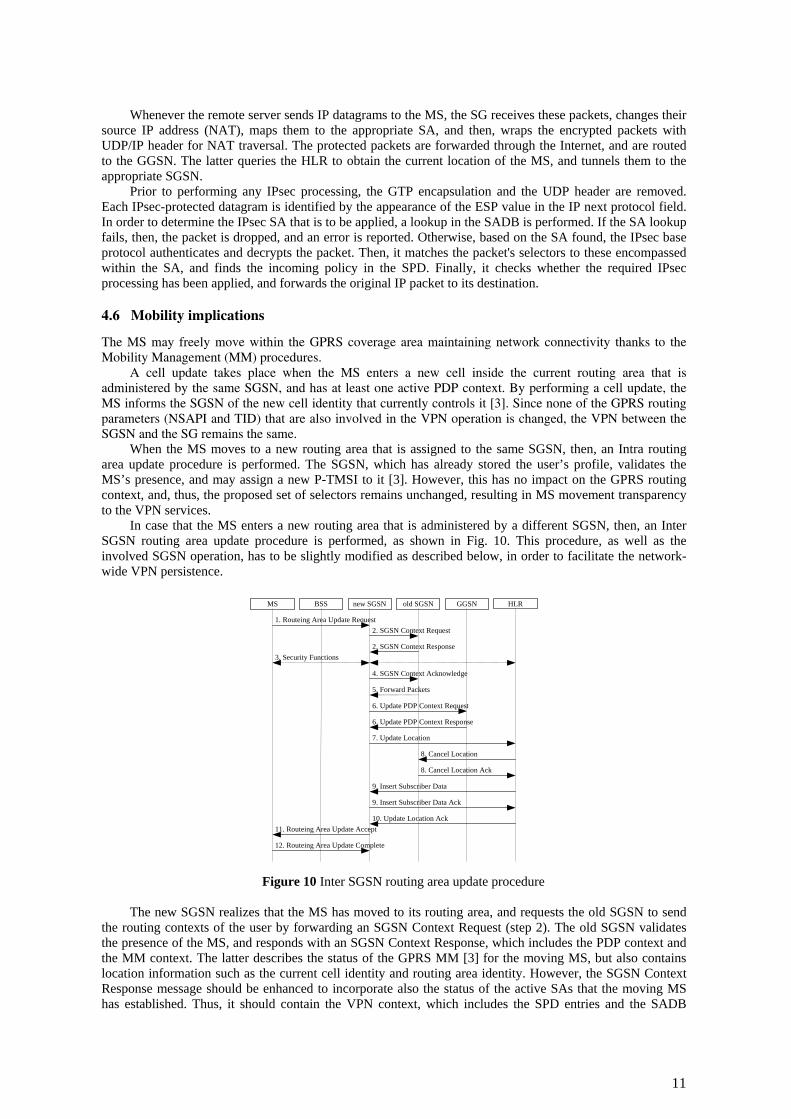
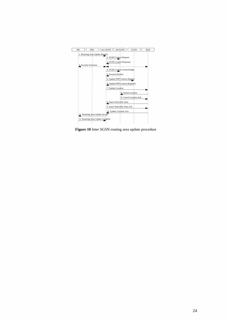
In case that the MS enters a new routing area that is administered by a different SGSN, then, an Inter SGSN routing area update procedure is performed, as shown in Fig. 10. This procedure, as well as the involved SGSN operation, has to be slightly modified as described below, in order to facilitate the network-wide VPN persistence.
MS BSS new SGSN HLR GGSN old SGSN
2. SGSN Context Response 3. Security Functions
1. Routeing Area Update Request 2. SGSN Context Request
6. Update PDP Context Request
6. Update PDP Context Response
7. Update Location
10. Update Location Ack 11. Routeing Area Update Accept
8. Cancel Location
8. Cancel Location Ack
9. Insert Subscriber Data Ack
9. Insert Subscriber Data
12. Routeing Area Update Complete
5. Forward Packets
4. SGSN Context Acknowledge
Figure 10 Inter SGSN routing area update procedure
The new SGSN realizes that the MS has moved to its routing area, and requests the old SGSN to send the routing contexts of the user by forwarding an SGSN Context Request (step 2). The old SGSN validates the presence of the MS, and responds with an SGSN Context Response, which includes the PDP context and the MM context. The latter describes the status of the GPRS MM [3] for the moving MS, but also contains location information such as the current cell identity and routing area identity. However, the SGSN Context Response message should be enhanced to incorporate also the status of the active SAs that the moving MS has established. Thus, it should contain the VPN context, which includes the SPD entries and the SADB
11
entries referring to the MS. The VPN context transfer will facilitate the new SGSN to construct a copy of the security relations that currently exist between the old SGSN and remote SGs on behalf of the MS.
Furthermore, the old SGSN stores the address of the new SGSN, and thus, is capable of forwarding data packets that are in transit and are destined to the MS, to the new SGSN. The new SGSN acknowledges the contexts’ transfer, and informs the old SGSN that is ready to receive data packets belonging to the activated PDP contexts (step 4). The latter then, starts tunnelling buffered data that are destined to the MS to the new SGSN (step 5).
Afterwards, the new SGSN updates the activated PDP context with the new SGSN address (step 6), and informs the HLR about the SGSN change, which triggers the appropriate verification and network configuration procedures (step 7 – 10). If all checks are successful, then, the new SGSN constructs the MM context, the PDP context, and the VPN context to serve the moving MS. For the VPN context construct the new SGSN first verifies its availability in providing VPN services, and then, updates its SPD and SADB with the relative IPsec SAs contents. Finally, the new SGSN establishes a new logical link between itself and the MS, and the latter acknowledges the new P-TMSI, and returns a routing area Update Complete (step 11–12).
4.7 Trust model
The considered communication model for VPN deployment involves two separate security domains (i.e., radio access network, and IP-based backbone), and, thus, requires an explicit level of trusted relations between them. In general, network-based VPNs require from the communicating end-points to trust the security service provider [12]. The mobile subscribers and the remote server administrators have to trust the mobile network operator, which performs the SA negotiation, user authentication, key exchange and encryption/decryption processes on behalf of the MS for the deployment of the VPN. Specifically, none of the communicating end-points can be sure that the connection behind the SecS/SGSN mediation is continued in a secure manner. The transaction contents are encrypted/decrypted in the SecS, which resides in the SGSN, relying on the mobile network operator security policy. Additionally, no end-to-end authentication is possible.
However, a trusted association between the mobile user and the mobile network operator already exists, since the later controls the security issues for standard GPRS services. Moreover, the proposed communication model is compatible with the legal interception option, which requires that public authorities be able to gain access on the traversing data within the mobile network for legal purposes.
5. VPN SERVICE SCENARIO EVALUATION
The proposed on-demand network-wide VPN deployment in GPRS improves the security services that are currently supported, extends the usability of mobile data networks, and facilitates the realization of Mobile Internet and the convergence of fixed and mobile networks. In the sequel, a qualitative evaluation of the proposed scenario is presented, focusing on the particular advantages, as well as the potential drawbacks that such service provision may lead to.
5.1 Advantages
The main advantage of the proposed scheme is that it enables a mobile subscriber to initiate, dynamically, a VPN establishment between itself and a corporate LAN SG, while shifting complex key negotiation and encryption/decryption functionality to the mobile network infrastructure. The deployed VPN provides maximal security services to end-users, operates transparently to the MS movement, and is compatible with the legal interception option.
This security scheme minimizes the configuration and the computation cost associated with the mobile devices. More specifically, the use of IPsec imposes computational costs on the hosts that implement these protocols. These costs are associated with the memory needed for IPsec code and data structures, and the computation of integrity check values, encryption and decryption, which is added in a per-packet fashion [1]. Considering the constraints imposed by the nature of the mobile devices (low CPU processing power, limited battery power, and limited memory capabilities), it can be perceived that mobile subscribers can obtain significant advantages from outsourcing the operation and the management of their VPNs to the network operator.
Network operators have solid network management expertise, and more resources to effectively create, deploy, and manage VPN services that originate from the mobile subscribers. They can offer security services at a lower cost, by consolidating them over a common infrastructure. This enables the utilization of specific hardware accelerator modules for faster and more efficient IPsec deployment. Furthermore, the
12
network-based implementation can continuously evolve, in order to cater for the new emerging end-user requirements, and allows for the network operators to enforce generic security strategies.
The required network enhancements for the security services provision can be integrated in the existing SGSN, supporting collaboration with the GPRS network functionality. The network-wide VPN operates transparently to the GPRS network management, mobility management and routing functions, and therefore, can be employed as an add-on feature to the GPRS standard. By providing network-based VPN services, a network operator differentiates itself in an open competitive market, and has the opportunity to attract new subscribers. Reducing the operational and maintenance cost enables faster and more efficient VPN services, and eliminates the specialized technical knowledge required by the end-user. An end-station simply initiates the VPN establishment, and does not require the end-user to have any security skills. Generally, in this scenario, the SA configuration is transparent to the mobile user.
Additionally, GPRS uses specific authentication and ciphering procedures between the MS and the SGSN [4], which are optimised for packet data transmission the over radio interface. The proposed VPN scheme utilizes the security services provided by the GPRS standard, and avoids applying duplicate encryption (packet encapsulation) over the expensive radio interface. Therefore, the VPN deployment has no impact on the radio access network efficiency, as happens in an end-to-end security scheme [10].
Finally, compared to the static VPN deployment that is currently supported by GPRS, the proposed scheme provides on-demand VPN services, which are available to the entire population of mobile subscribers. Dynamic, client-initiated VPN services are well suited to mobile users who require access to remote networks, “anywhere – anytime”. The proposed scenario secures data transmission over the GPRS backbone network protecting against IP spoofing that originate from malicious MSs, as well as third parties that have access on the IP-based GPRS backbone. Furthermore, the network-wide VPN can be employed in cases of communication between MSs.
5.2 Drawbacks
The main drawback of the proposed security scheme is that the VPN is not directly under the end-user control. This model, which is already used in wired terrestrial networks, assumes that the involved communicating parties trust the mobile network operator.
In order to provide network-based VPNs, the existing GPRS network infrastructure must be enhanced. Specifically, the MS requires the introduction of the lightweight module (SecC) that initiates the VPN establishment and expresses end-user preferences. Moreover, the SGSN needs to incorporate the SecS, which is responsible for VPN establishment and operation. However, the enhancements referring to the GPRS core network require additional investment from the network operator, and their functionality is expected to increase the network signaling overhead.
Finally, the multi-protocol encapsulation, which takes place in the GPRS backbone for data encryption, NAT traversal, and GPRS mobility management (IPsec, UDP, GTP), reduces the user data size below the maximum transfer unit. Furthermore, the tunneling and detunneling overheads will degrade the overall network efficiency and performance.
6. CONCLUSIONS
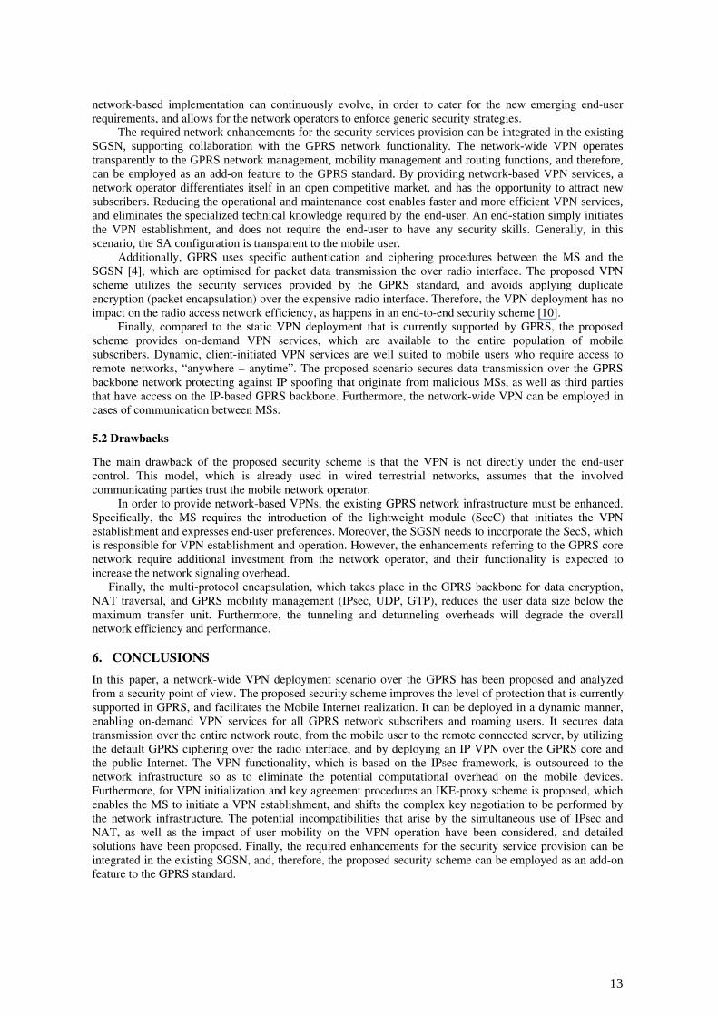
In this paper, a network-wide VPN deployment scenario over the GPRS has been proposed and analyzed from a security point of view. The proposed security scheme improves the level of protection that is currently supported in GPRS, and facilitates the Mobile Internet realization. It can be deployed in a dynamic manner, enabling on-demand VPN services for all GPRS network subscribers and roaming users. It secures data transmission over the entire network route, from the mobile user to the remote connected server, by utilizing the default GPRS ciphering over the radio interface, and by deploying an IP VPN over the GPRS core and the public Internet. The VPN functionality, which is based on the IPsec framework, is outsourced to the network infrastructure so as to eliminate the potential computational overhead on the mobile devices. Furthermore, for VPN initialization and key agreement procedures an IKE-proxy scheme is proposed, which enables the MS to initiate a VPN establishment, and shifts the complex key negotiation to be performed by the network infrastructure. The potential incompatibilities that arise by the simultaneous use of IPsec and NAT, as well as the impact of user mobility on the VPN operation have been considered, and detailed solutions have been proposed. Finally, the required enhancements for the security service provision can be integrated in the existing SGSN, and, therefore, the proposed security scheme can be employed as an add-on feature to the GPRS standard.
13
ACKNOWLEDGMENTS
The authors would like to thank Nikos Loukas and Stathes Hadjiefthymiades for their comments and suggestions.
REFERENCES
[1] S. Kent and R. Atkinson, “Security Architecture for the Internet Protocol,” RFC 2401, Nov. 1998. [2] 3GPP, “A Guide to 3G Security,” 3G TR 33.900 v. 1.2.0, Jan. 2000. [3] GSM 03.60, “GPRS Service Description,” Stage 2, 1998. [4] GSM 03.20, “Security Related Network Functions,” 1998. [5] L. Phifer, “The Trouble with NAT,” Cisco The Internet Protocol Journal, vol. 3, no. 4, Dec. 2000, pp 2-13. [6] A. Huttunen et al., “UDP Encapsulation of IPsec Packets,” draft-ietf-ipsec-udp-encaps-01.txt, Internet Draft, Oct.
2001. [7] T. Kivinen et al., “Negotiation of NAT-Traversal in the IKE,” draft-ietf-ipsec-t-ike-00.txt, Internet Draft, June
2001. [8] N. Ferguson and B. Schneier, “A cryptographic evaluation of IPsec,” Jan. 2000, available from
http://www.counterpane.com/ipsec.html. [9] B. Adoba, “IPSec-NAT, Compatibility Requirements,” draft-ietf-ipsec-nat-reqts-00.txt, Internet Draft, June 2001. [10] C. Xenakis, E. Gazis and L. Merakos, “Secure VPN Deployment in GPRS Mobile Network,” Proc. European
Wireless 2002, Florence Italy, Feb. 2002, pp. 293-300. [11] 3GPP, “3G Security; Security Principles and Objectives,” 3G TS 33.120, May 1999. [12] B. Gleeson, A. Lin, J. Heinanen, G. Armitage, and A. Malis, “A Framework for IP Based Virtual Private
Networks,” RFC 2764, Feb. 2000. [13] Samantha Donovan, et al., “VPN and lightweight clients,” Elsevier Science Information Security Technical Report,
vol. 6, no. 1, March 2000, pp. 49-64 [14] D. Harkins and D. Carrel, “The Internet Key Exchange (IKE),” RFC 2409, Nov. 1998.
BIOGRAPHIES
Christos Xenakis ([email protected]) received the B.Sc degree in computer science in 1993, and the M.Sc degree in 1996, both from the Department of Informatics and Telecommunications, University of Athens, Greece. From 1998 to 2000 he was with Teletel S.A., where he was involved in the design and development of advanced telecommunications subsystems for ISDN, ATM, GSM, and GPRS. Since 1996 he has been a member of the Communication Networks Laboratory of the University of Athens. He has participated in numerous projects realized in the context of EU Programs (ACTS, ESPRIT, IST). His research interests are in the field of mobile/wireless networks, security and distributed network management. Lazaros Merakos received the Diploma in electrical and mechanical engineering from the National Technical University of Athens, Greece, in 1978, and the M.S. and Ph.D. degrees in electrical engineering from the State University of New York, Buffalo, in 1981 and 1984, respectively. From 1983 to 1986, he was on the faculty of Electrical Engineering and Computer Science at the University of Connecticut, Storrs. From 1986 to 1994 he was on the faculty of the Electrical and Computer Engineering Department at Northeastern University, Boston, MA. During the period 1993-1994 he served as Director of the Communications and Digital Signal Processing Research Center at Northeastern University. During the summers of 1990 and 1991, he was a Visiting Scientist at the IBM T. J. Watson Research Center, Yorktown Heights, NY. In 1994, he joined the faculty of the University of Athens, Athens, Greece, where he is presently a Professor in the Department of Informatics and Telecommunications, and Director of the Communication Networks Laboratory (UoA-CNL) and the Networks Operations and Management Center. His research interests are in the design and performance analysis of broadband networks, and wireless/mobile communication systems and services. He has authored more than 140 papers in the above areas. Since 1995, he is leading the research activities of UoA-CNL in the area of mobile communications, in the framework of the Advanced Communication Technologies & Services (ACTS) and Information Society Technologies (IST) programmes funded by the European Union (projects RAINBOW, Magic WAND, WINE, MOBIVAS, POLOS). He is President of the Board of the Greek Universities Network (GUnet) and of the Greek Schools Network (EDUnet), and member of the board of the Greek Research Network (GRnet). In 1994, he received the Guanella Award for the Best Paper presented at the International Zurich Seminar on Mobile Communications.
14
AuC: Authentication CenterBTS: Base Transceiver StationBSC: Base Station ControllerBSS: Base Station SubsystemCN: Core NetworkEIR: Equipment Identity RegisterGGSN: Gateway GPRS Support NodeHLR: Home Location RegisterMSC: Mobile Switching CenterPSTN: Public Switched Telephone NetworkSGSN: Serving GPRS Support NodeVLR: Visited Location Register
H
VLR
MSCEIR
HLR
AuC
FGf
DGr
Gc
Gi
CN
PSTNGE
A Gb
GGSNSGSN
SGSN
GPRS IPCore
BSC
BTS BTS
Abis Abis
Um
BSS
Figure 1: GPRS system architecture
15
GPRS IP Core
Public Internet
SecurityGateway
Private LANBTS
BSC
Abis
Gb
SGSN
GGSN
Remote Access
GPR
S N
etw
ork
BTS
Abis
MS
BTS: Base Transceiver StationBSC: Base Station ControllerGGSN: Gateway GPRS Support NodeMS: Mobile StationSGSN: Serving GPRS Support Node
RemoteServer
Figure 2: Network architecture
16
SGSN GGSN GPRS Circuit IP
Traffic flow 1
Traffic flow 2
SNDCPTunnel
Traffic flowTraffic flow
GTP Tunnel
Traffic flow
IP (dst, src, data)
SNDCP[ TTLI, NSAPI, IP (dst, src, data)] GTP[ GGSN-IP-address, TID, IP (dst, src, data)]
Figure 3: Schematic presentation of the GPRS data traffic
17
IKE: Internet Key ExchangeMS: Mobile StationSADB: Security Association DataBaseSecC: Security ClientSecS: Security ServerSGSN: Serving GPRS Support NodeSPD: Security Policy Database
SGSN
IPsec baseprotocol
SecurityManager
IKE
PolicyManager
Enchanced SGSN module
Security Server (SecS)
SPD SADB
MS
SecC
MS module
Figure 4: Security Client (SecC) and Security Server (SecS) modules in GPRS
18
Generate CSecSChoose g,pGenerate x
Compute X = gx mod p
(2) CSecS, ISASecS, X[g,p], NSecS, IDMS
(3) CSecS, CSG, ISASG, Y, NSG,
IDSG, HASHSG, NAT-DSG
Validate cookieCompute K = XY mod p
Validate IDSG
(4) CSecS, CSG, HASHMS,NAT-DSecS
SecC
(1) IPSG , PSKEY, SAMS, IDMS
SecSSecurityGateway
Generate CSGGenerate YCompute Y = gy mod pValidate IDMS
Compute K = YX mod p
ISAKMP SA
Figure 5: ISAKMP SA negotiation in Aggressive Mode
19
SecC SecS
(4) IPSG SASG IDSG
(1) CSecS, CSG, HASH(1), SAMS, NSecS,X[g,p], IDMS IDSG , NAT-OASecS Validate HASH(1)Generate YCompute Y = gy mod pCompute HASH(2)(2) CSecS, CSG, HASH(2) SASG,
NSG, Y IDMS, IDSG , NAT-OASGValidate HASH(2)
Compute K = XY mod pCompute HASH(3) (3) CSecS, CSG, HASH(3)
Validate HASH(3)Compute K = XY mod p
SecurityGateway
ISAKMP SA
IPsec SA
Figure 6: IPsec SA negotiation
20
GPRS IP Core
CI
PH
ER
IN
G
Internet
SecurityGateway
Private LAN
Gb
GGSN
Remote Access
GPR
S Pu
blic
Net
wor
k
BTS
BSC
Abis
BTS
Abis
SecSSGSN
GPRS
On Demand VPN
MS
RemoteServer
BTS: Base Transceiver StationBSC: Base Station ControllerGGSN: Gateway GPRS Support NodeMS: Mobile StationSecS: Security ServerSGSN: Serving GPRS Support Node
Figure 7 Network-wide VPN realization
21
BSSUm
GSM RF L1bis
RLC
MACNetworkService
BSSGPRelay
Gb
GSM RF
RLC
MAC
LLC
SNDCP
IP
TCP / UDP
APPL
MS SGSNGn
L1
L2
BSSGP
L1bis
NetworkService
LLC
IP
UDP / TCP
GGSN
L1
L2
IP
L1
L2
UDP / TCP
IP IP
NAT
GTP
SecurityGateway
L1
L2
IP
TCP / UDP
APPL
RemoteServer
Gi
IP
L1
L2L2
L1
IPsec
NAT
IPUDP
GTPSNDCP
IP
IP
UDP
IPsec
SecS
GPRS Ciphering IPsec Protection Private LAN
Figure 8: Protocol stack for network-wide VPN deployment
22
SGSN GGSN Internet SG
Remote Server
IP (dst, src, data)
IP address ->PDP context ->TLLI + NSAPI
SNDCP[ TTLI, NSAPI,IP (dst, src, data)]
TLLI + NSAPI ->PDP context ->
TID + GGSN -> SA
GTP[ GGSN-IP-address, TID,IP (dst, src, UDP[ ESP[ data]])]
TID -> PDP context(src1)= NAT(src)
IP (dst, src1, UDP[ ESP[ data]]) IP (dst1, src1, data)
SecS
SPI + ESP + IP Adddress -> SA(dst1)= NAT(dst)
Figure 9 The flow of the protected IP packets from the MS to the remote server
23
MS BSS new SGSN HLR GGSN old SGSN
2. SGSN Context Response 3. Security Functions
1. Routeing Area Update Request 2. SGSN Context Request
6. Update PDP Context Request
6. Update PDP Context Response
7. Update Location
10. Update Location Ack 11. Routeing Area Update Accept
8. Cancel Location
8. Cancel Location Ack
9. Insert Subscriber Data Ack
9. Insert Subscriber Data
12. Routeing Area Update Complete
5. Forward Packets
4. SGSN Context Acknowledge
Figure 10 Inter SGSN routing area update procedure
24


