Embed Size (px)
Citation preview

On the Injection Molding of Nanostructured PolymerSurfaces
Henrik Pranov, Henrik Koblitz RasmussenDepartment of Manufacturing Engineering and Management, Danish Polymer Centre, Technical University ofDenmark, DK-2800 Kgs. Lyngby, Denmark
Niels Bent LarsenDanish Polymer Centre, Risø National Laboratory, 4000 Roskilde, Denmark
Nikolaj GadegaardCentre for Cell Engineering, Department of Electronics and Electrical Engineering, University of Glasgow,Glasgow G12 8LT, United Kingdom
Well-defined nano-topographies were prepared by elec-tron-beam lithography and electroplated to form nickel-shims. The surface pattern consisted of square pillarsrepeated equidistantly within the plane of the surface ina perpendicular arrangement. The width and distancebetween the squares both ranged from 310 to 3100 nm.All the pillars were 220 nm high. The nickel-shim wasused as a surface-template during injection molding ofpolycarbonate. Secondly, a nickel shim, with a surfacepattern consisted of a squared sine with a period of 700nm and amplitude of 450 nm, was mounted on, and itwas in good thermal contact with the upper plate in ahot-press. Polycarbonate/polystyrene was melted onthe lower plate while the temperature of the shim waskept below the glass transition temperature. The upperplate was lowered until the shim was in contact with themelt. Experiments were carried out with a clean shimand a shim coated with a monolayer of fluorocarbonsi-lane. As a result of the surface coating, the amplitude ofthe replicated grating decreased from about 350 nm inpolycarbonate and 100 nm in polystyrene to less than 10nm. The experiments strongly suggest that the possi-bility to injection mold sub-micrometer surface struc-tures in polymers mainly relates to adhesive energybetween polymer and shim. POLYM. ENG. SCI., 46:160 –171, 2006. © 2005 Society of Plastics Engineers
INTRODUCTION
Recent years have shown an ever-increasing interest intopographically nanostructured polymer surfaces. Their cur-rent and projected applications include mass storage (CompactDisc/Digital Versatile Disc), nanolithography (sub-100 nmstructuring of electronics and photonics), diffractive optics(authentication and integrated optical processing) [1, 2], andbiochemistry (sensing, separation, and catalysis) [3]. The nextgeneration of ultra high density optical storage, Blu-Ray Discs,is now extending well into the nanometric region with a trackpitch of 320 nm and a pit length of 138 nm. This is about threetimes smaller than DVDs, which is the dominating technologywith surface features below 1 �m. An upcoming use of suchnanostructures is in biomedical materials for cell culturing andtissue engineering purposes [4]. All of these different applica-tions have as a prerequisite the ability to fabricate polymernanostructures with high accuracy, good reproducibility inhigh numbers and at low cost. Large-scale replication of po-tentially precious “master” nanostructures into polymer sur-faces is the most obvious solution to the said requirements.
Most effort in the past has been devoted to demonstrationof lower limits in the injection molding process. Macintyreand Thoms [5] demonstrated features as small as 50 nmpillars using a titanium shim and polystyrene (PS). Gade-gaard et al. [6] demonstrated the successful replication ofthe natural nanotopography of collagen molecules in a rangeof different thermoplastic polymers. They found that thesmallest features replicated were the grain structure fromthe sputter layer prior to electroplating. Schift et al. [7]demonstrated features as small as 25 nm. Some work hasbeen done identifying the importance of the process param-eters [8], though in a quite narrow parameter range.
Correspondence to: H.K. Rasmussen; e-mail: [email protected] grant sponsors: Technical University of Denmark, DanishTechnical Research Council, Royal Society of Edinburgh.DOI 10.1002/pen.20459Published online in Wiley InterScience (www.interscience.wiley.com).© 2005 Society of Plastics Engineers
POLYMER ENGINEERING AND SCIENCE—2006

To gain a yet deeper insight to the physical mechanismsresponsible for the creation of nanostructured polymer sur-faces by injection molding, we have, in this work, examinedthe influence of processing conditions for the quality of thereplicas. This includes injection velocity, melt and moldtemperature, the structure size, and relative contact area ofthe shim to the melt. In our research, we have also inves-tigated the replication of sub-micrometer structures in acompression molding process similar to the conditions ininjection molding.
The issue of replication of surface microstructures hasbeen studied previously. Some of these studies also includethe discussion of sub-micrometer structures. Yoshii et al. [9]assumed that a vitrified layer initially covers the structure.This frozen layer is thus deformed into the structure by thecavity pressure. Though this is not a rigorous paper, Bus-chko et al. [10] suggested that the polymer flows into thestructure, driven by the cavity pressure, before it solidifies.
EXPERIMENTAL
Experimental Methods
We have investigated the replication of polymer surfacesusing both injection molding and a modified compressionmolding process.
Injection Molding.The polymeric surfaces are replicated from a nickel
shim, which is produced from a master structure. Both thepreparation of master structure and nickel shim was per-formed with well-established technologies.
Master structures with nanometric dimension were fab-ricated by electron beam lithography, using a Leica beamwriter (5HR100) operated at 50 kV. Silicon wafers werecoated with 220 nm of positive electron beam resist (ZEP),exposed, and developed in o-xylene. The surface topogra-phy of the master structures were transferred to nickel shimsby electroplating. The resist masters were sputter coatedwith 50 nm of nickel vanadium alloy and electroplated up toa final thickness of 300 �m.
The polymeric replicas were injection molded (Fig. 1) onan Engel 25 tonnes injection molding machine. The ma-chine was fitted with a mold with replaceable nickel shim(Fig. 2). The dimensions of the shim are 39 � 44 mm2 andthe thickness is 0.3 mm. The shim is supported by a highlyheat-conducting backplate. The mold is water cooled, andcan be heated by electric heating in the backplate supportingthe shim. The temperature of the cooling water is externallyregulated, while the temperature of the heating elements inthe backplate is regulated by a feedback loop from a ther-mistor between the two elements.
The polymer melt is injected with an achievable injectionvelocity of the screw between 10 and 160 mm/s, dependingon the polymer and temperature. As the barrel containingthe screw has a diameter of 18 mm, the actual velocity of the
melt flow front in the square shaped cavity is �3.5 timeshigher than the velocity of the cylinder, resulting in amaximum melt flow front velocity (W) of 0.56 m/s in thecavity. The distance between the two mold plates (2H) inthe cavity is 2 mm.
The melt temperature (Tm) in the presented experimentswas set to 250°C, in the feeding zone increasing between253 and 320°C at the nozzle. The temperature of the moldwas controlled by a water flow between 15 and 85°C, givingan effective temperature of 25–95°C of the mold, respec-tively. The mold temperature was measured using a ther-
FIG. 1. Schematic view of the injection molding mold. A polymer meltis injected at the melt inlet into the closed mold, followed by solidification.The mold is opened and the solid polymer replica is removed. The surfaceof the shim contains the nanostructures (not drawn to scale) whose fillingis investigated in this work. The temperature of the mold is monitored bya thermistor placed in the backplate, approximately 3 mm from the shimsurface.
FIG. 2. Sketch of the surface of the shim containing elevated squaresrelative to the inflowing polymer melt. The size of the squared structuresranges from 310 to 3100 nm and the distance in the lateral directionsbetween the squared structures also ranges from 310 to 3100 nm. Theheight of the structures is 220 nm.
DOI 10.1002/pen POLYMER ENGINEERING AND SCIENCE—2006 161
mistor placed at 3 mm from the cavity surface. The tem-perature was recorded as the maximal observedtemperatures during an injection cycle. This temperature isvery close to the almost constant interface temperature (Tw)between polymer melt and shim. Table 1 illustrates theprocess window in the injection molding of the used poly-carbonate (PC).
For the injection molding, we have manufactured a pat-tern in the nickel shim, consisting of square pillars repeatedequidistantly along perpendicular directions (Fig. 2). Thenickel shim was then used for injection molding of poly-meric replicas. The width and the distance between thesquares of the patterns both ranged from 310 to 3100 nm, allsquares were 220 nm high. The shim and the polymericreplicas were examined by atomic force microscopy(AFM), using a Nanoscope Dimension 3000 in tappingmode. An example is shown in Fig. 3. The depth of theholes in the polymer replica ranges from a few nanometersto a few hundreds of nanometers, depending on the processconditions.
Note that AFM microscopy cannot determine the correctheights near vertical walls, as a small probe or needle scansthe surface. There is a critical angle for which there is nocorrect measurement, depending on the shape of needle. Wehave ensured that the presented measurements are wellinside the measurement range where the AFM measurescorrectly.
Compression Molding.The second experimental setting is a compression mold-
ing using a hydraulic hot-press. A sketch of the setup is
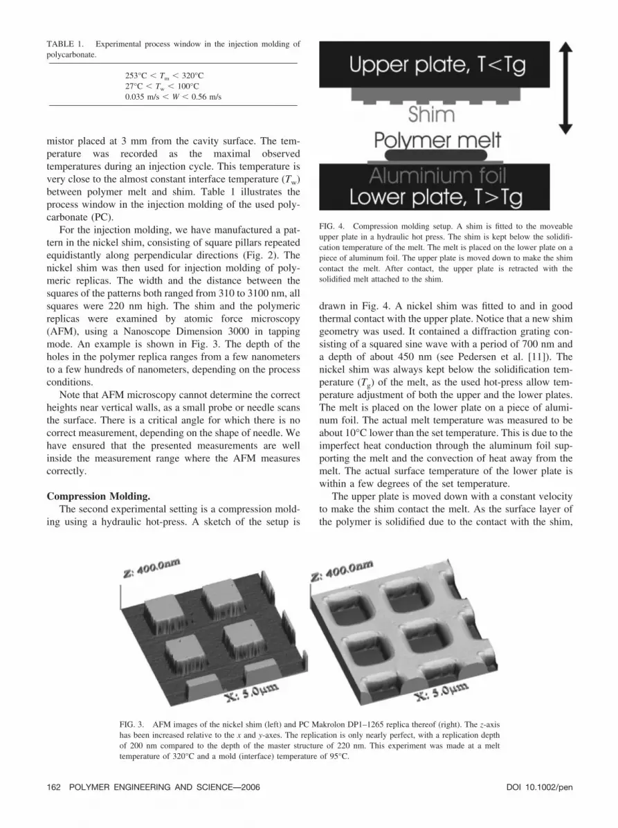
drawn in Fig. 4. A nickel shim was fitted to and in goodthermal contact with the upper plate. Notice that a new shimgeometry was used. It contained a diffraction grating con-sisting of a squared sine wave with a period of 700 nm anda depth of about 450 nm (see Pedersen et al. [11]). Thenickel shim was always kept below the solidification tem-perature (Tg) of the melt, as the used hot-press allow tem-perature adjustment of both the upper and the lower plates.The melt is placed on the lower plate on a piece of alumi-num foil. The actual melt temperature was measured to beabout 10°C lower than the set temperature. This is due to theimperfect heat conduction through the aluminum foil sup-porting the melt and the convection of heat away from themelt. The actual surface temperature of the lower plate iswithin a few degrees of the set temperature.
The upper plate is moved down with a constant velocityto make the shim contact the melt. As the surface layer ofthe polymer is solidified due to the contact with the shim,
TABLE 1. Experimental process window in the injection molding ofpolycarbonate.
253°C � Tm � 320°C27°C � Tw � 100°C0.035 m/s � W � 0.56 m/s
FIG. 3. AFM images of the nickel shim (left) and PC Makrolon DP1–1265 replica thereof (right). The z-axishas been increased relative to the x and y-axes. The replication is only nearly perfect, with a replication depthof 200 nm compared to the depth of the master structure of 220 nm. This experiment was made at a melttemperature of 320°C and a mold (interface) temperature of 95°C.
FIG. 4. Compression molding setup. A shim is fitted to the moveableupper plate in a hydraulic hot press. The shim is kept below the solidifi-cation temperature of the melt. The melt is placed on the lower plate on apiece of aluminum foil. The upper plate is moved down to make the shimcontact the melt. After contact, the upper plate is retracted with thesolidified melt attached to the shim.
162 POLYMER ENGINEERING AND SCIENCE—2006 DOI 10.1002/pen

the movement of the upper plate is stopped, followed by aretraction of the plate. The solidifying melt is now attachedto the shim. The vertical velocity of the upper plate to bringthe shim in contact with the melt is kept at about 1 mm/s.Using a velocity of 1 mm/s, the movement of the upper platefrom the first contact between the melt and the shim, untilthe surface of the melt has solidified, can be estimated to beless than 10 nm, as discussed later. During the solidificationof the polymer surface the contact pressure between thepolymer melt and shim is almost zero.
Experiments have been performed not only using thenickel shim, but also using a shim coated with a monolayerof fluorocarbonsilane. The fluorocarbonsilanation of the ox-ygen-plasma-cleaned shim was performed in a vacuumchamber evaporating silane (C8F13H4SiCl3) onto the shim.The fluorocarbonsilanated shim was examined by XPS totest for adhered silane. Notice that the silane layer was ableto withstand only one polymer replication in the compres-sion molding and is not useable for injection molding.
Polymer Materials
The polymer used in the injection molding was a DVDgrade PC (Makrolon DPI-1265 from Bayer AG). This typeof polymer has good flow properties and is known for itscapabilities of replicating very fine details [7]. The polymerwas dried for 4 h at 110°C to remove the absorbed water.For the study of the compression molding, we also used aPS (CAS 0993–53-6 from Aldrich). The PC and PS haveglass transition temperatures of 144 and 94°C, respectively.The molecular weight of the PS is Mw � 230,000 and Mn �130,000.
Melt Viscoelasticity.We performed small amplitude oscillatory shear experi-
ments using plate–plate geometry on an AR2000 rheometerfrom TA Instruments to obtain an accurate determination ofthe linear viscoelastic properties of the PC melt. The mea-surements were performed at a temperature range from 170to 320°C. The data were shifted to a single master curve at320°C using the time–temperature superposition procedure(Fig. 5). The linear viscoelastic time–temperature shift fac-tor, aT, can be described by an Arrhenius equation above210°C as
aT exp[15000K�1/593.15K � 1/T�] (1)
where T is the absolute temperature.The deformation behavior of polymer melts is viscoelas-
tic. In the following, we will not address the general ques-tion of which constitutive equation is able to describe theflow behavior of polymer melts and more specific the meltsused here. This is due to the present crisis (see [12, 13]) inconstitutive modeling of polymer melts originating from thepublished elongational measurements [13, 14], using therecently developed filament stretch rheometer (FSR) with
temperature control [15]. We will only address well-estab-lished knowledge as the previously presented mechanicalspectroscopy in the following.
Deborah Number.To characterize a melt deformation in a polymer process-
ing operation, a nondimensional measure of the overalldeformation rate (Deborah number) is needed. The Deborahnumber, De, can be defined in several ways. A commonlyused definition is the multiplication of a characteristic larg-est time constant of the fluid with a characteristic deforma-tion or strain rate of the system. This definition of theDeborah number is for instance not correlated to the cross-over point of a polymer and therefore not related to thegeneral linear viscoelastic properties of the polymer melts.The crossover point is defined as the angular frequencywhere the linear viscoelastic storage modulus (G�) and lossmodulus (G�) are identical. Another possibility is to use acharacteristic time scale defined as G�(�)/(G�(�)�), wherethe angular frequency � is replaced with the characteristicdeformation rates of the flow. The Deborah number can thenbe defined as
De �G����
G����. (2)
The crossover point framed in the above definition corre-sponds to a Deborah number of unity.
The Deborah number basically characterizes the (linear)viscoelastic properties of the material during the flow. TheDeborah number is applicable to different melts and allowsa comparison between experiments with different polymermelts. Notice that there is a strong relation between linearviscoelastic properties and shear viscosity in polymer melts,for instance through the well-known empirical Cox-Merzrule. In shear flow dominated problems, Eq. 2 would there-
FIG. 5. Linear viscoelastic data for PC Makrolon DP1–1265 in which themeasurements were time–temperature shifted to 320°C. G� and G� are thestorage modulus and the loss modulus, respectively. � is the angularfrequency in rad/s.
DOI 10.1002/pen POLYMER ENGINEERING AND SCIENCE—2006 163

fore be universally applicable to different melts. We have toemphasize that a corresponding relation between elonga-tional properties and the linear viscoelasticity is unlikely.
Here we use the characteristic deformation or shear ratesW/H for the flow between the mold plates. For the PC melt,at 320°C, this Deborah number stays below 0.05, corre-sponding almost to Newtonian flow behavior. The Deborahnumber may reach a value of about 0.1 at the lowesttemperature (253°C) and highest injection velocity pre-sented here.
As a characteristic deformation rate for the deformationinto the nano- and microstructures, we use the inverse of themaximal time (1/ts) needed to reach the solidificationtemperature (Tg) in the surface of the polymer. The timedifference ts is initiated (zero) at the first contact betweenthe melt and the structure in the nickel shim.
Experimental Observations
To this point, we have been concerned with the reportingon equipment, methodology, and materials. Here, we willaddress the experimental observations in both injection andcompression molding. In this section, the influence of theprocessing conditions on the replication of the polymersurface will be examined. We will not address the effect ofholding pressure on the processes in the follow sections,because changes in the holding pressure did not affect thestructure development in the polymer surface. The pressureduring the processing is reflected in the reported injection orcompression velocity and melt temperature.
Injection Molding.In injection molding, it is not unusual to observe surface
irregularities. Amongst other, small irregularities on thesurface of the produced plastic parts, with a wavelength inthe scale of several micrometers, sometime occurs. Thesewaves are thermally induced and originate from the rapidcooling of the polymer, as the flow front of the polymer getsin contact with the cold mold surface. These types ofinstabilities limit the possibility to injection mold sub-mi-crometer size structures with a regular structure as seen inFig. 6. It is immediately evident from Fig. 6 that the flowfront instability does not suppress the development of thesurface structures. The irregularities in PC surface are per-pendicular to the flow front, though we have also observedsimilar structures on PS oriented parallel to the flow front.
In general, there is a lower limit on the injection velocitywhere the structures does not replicate uniformly due to thisthermally induced flow front instability. In our experiments,this lower limit depends mainly on the melt temperature(Tm). High melt temperatures develop a large temperaturegradient and therefore a large gradient in the viscosities ofthe melt. This seems to facilitate the instability. We have notobserved these thermal instabilities at melt temperaturesbelow 280°C in the PC at the lowest achievable injectionvelocity. In the following, we present only measurements
from injection molding in which all the shim structure isreplicated (almost) uniformly.
The 3D AFM image of a replica is data processed toyield a single number reflecting the replication depth. Thisnumber is obtained by making several line profiles throughthe middle of the square structures from one side of theimage to the other. The maximal difference in height at thetransition from the exterior to the interior of the square isthen measured. These differences are then averaged to yieldthe replication depth. Typically 5–20 transitions are used toreduce noise. An example is given in Fig. 7. Only smallvariations (about 5%) were observed in between differentsamples, and even smaller variations were observed withinone sample.
An examination of the replication depth as function ofstructure size has been conducted at different injectionvelocities. All the examined structures are placed on thesame shim to ensure almost the same process condition.
Figure 8 shows the coupling between injections or flowfront velocities (W) to the structure size. These experimentshave been made at a PC melt temperature of Tm � 320°Cand at an interfacial temperature between mold and shim ofTw � 95°C. The lower limit in the injection velocity is setby the appearance of the before mentioned instability andthe higher limit is set by the capability of our injectionmolding machine. Note that we have labeled the structuresby the square size (width) and distance (spacing) betweensquares in nanometer (width/spacing).
At high injection velocities, there seem to be a constantreplication independent of the flow front velocity. This isnot due to complete filling of the shim, as the average (andnot maximal as shown in Fig. 8) depth achieved is signifi-cantly lesser than can be contributed to thermal shrinkage ofthe melt. An exception is the 1000/1000 series. This is theonly replication that reaches the bottom of the nickel shim.
FIG. 6. PC replica of 1000 nm elevated squares with 1000 nm spacingand 220 nm height at low injection velocity. Notice that the waves areparallel to the x-axis (perpendicular to the polymer melt inflow direction).
164 POLYMER ENGINEERING AND SCIENCE—2006 DOI 10.1002/pen

This constant and not complete replication is very clear forthe 3100/3100 series.
The most remarkable feature of the observations is thatby changing the injection velocity about a factor of 3, theevolution of the surface pattern obtained changes from a flatsurface (within the uncertainty of the AFM of about a fewnanometers) to a maximal, though mostly not complete,replication. This shows a dramatic growth of the polymersurface structures as a function of the flow front velocity. Asdiscussed in the “Boundary Condition” subsection, the ve-locity of the flow front is linked to the cooling (and solid-ifying) of the polymer through one nondimensional group.
Notice that the aspect ratio, defined as the structureheight in the replica divided by the distance between thenickel squares on the shim, stays nearly constant during theincrease in replication size, within the same type of geom-
etry. Though not shown, this was also mentioned by Schiftet al. [7]. They investigated the degree of injection moldingof replicated V groove structures. The aspect ratio of themolded structures, using the same PC grade as in this work,stayed nearly constant, independent of structure size.
The replication depth is sensitive to fraction of the shim(the relative surface area) being in contact with the inflow-ing polymer. A larger fraction of the shim being in contactwith the inflowing polymer clearly reduces the possibility toreplicate a structure as the replication curves are shiftedtoward higher injection velocities.
As discussed previously, the replication depth has astrong dependence of both the injection velocity and thestructure dimensions. However, the other process parame-ters, in particular, the melt (Tm) and mold (or interface, Tw)temperatures also influence the replication
In Figs. 9 and 10, the replication depth for the 3100/3100structure is shown. In Fig. 9, the replication depth for the3100/3100 structure conducted at a fixed dimensionless
FIG. 7. Replication depth extractionfrom an AFM image on a PC replica. Aline profile (right figure) is made over thetransitions of the AFM image (left figure).The replication depth is found as the aver-age of multiple measurements of the tran-sition heights. A transition height found asthe minimum value (B) is subtracted fromthe maximum value (A) near the transition.Five to twenty transitions are used to de-termine the replication depth, dependingon the variation.
FIG. 8. Replication depth on PC replica, as function of injection velocityfor differently sized surface structures on the nickel shim. The first numberis the width of the elevated squares in nm and the second number is thedistance between elevated squares in nm on the nickel shim. The height ofthe squares is 220 nm. This experiment was made at a melt temperature of320°C and a mold (interface) temperature of 95°C. The uncertainty of themeasurements is on the order of about 1 nm (due to the uncertainty of theAFM) Each data point is based upon 5–20 measurements on the sameinjection molded replica. The variations between different replicas at thesame processing conditions are about 5 percent.
FIG. 9. Replication depth for the 3100/3100 structure in PC, conducted ata dimensionless glass transition temperature of Tg* � (Tg Tw)/(Tm Tw)� 0.213. Note that the width of the elevated squares in this structure is3100 nm, and the distance between the elevated squares is 3100 nm on thenickel shim. The height of the squares is 220 nm. The curves labeled aT
correspond to a temperature in agreement with Eq. 1. The lines areguides-to-the-eye.
DOI 10.1002/pen POLYMER ENGINEERING AND SCIENCE—2006 165

glass transition temperature of T*g � (Tg Tw)/(Tm Tw)� 0.213 is shown as a function of the injection velocity.Hence, if the melt temperature (Tm) is lowered, the moldtemperature (or interface temperature, Tw) is increased.Note that the curves labeled aT correspond to a temperaturein agreement with Eq. 1. Hence a change from aT � 1 to aT
� 10 corresponds to a change in the zero shear rate (orNewtonian) viscosity of a factor of 10 in the melt. Figure 10shows the replication depth of the 3100/3100 structure as afunction of dimensionless glass transition temperature, T*g� (Tg Tw)/(Tm Tw). It is varied from 0.2 to 0.4 atdifferent injection velocities. Note that all experiments havebeen performed using a fixed melt temperature of 320°C.The observation that the replication depth increases as theT*g decreases (corresponding to a higher mold temperature)are in good agreement with previous observations by Schiftet al. [7], their Fig. 4.
Compression Molding.The compression molding experiments, using PC, were
conducted at an initial melt temperature of about 320°C and
at a shim temperature of 60 and 90°C. Here we use thenickel shim containing a diffraction grating consisting of asquared sinus wave with a period of 700 nm and a depth ofabout 450 nm. The results of the two replications are shownin Figs. 11 and 12. It is seen that the replication of the shimat a shim temperature of 90°C is almost perfect, though theshim temperature of 60°C still allows replication depthsbetween 300 and 400 nm.
To investigate the importance of the change of adhesiveenergy in the interface between the polymer melt and theshim, an experiment was performed with a fluorocarbonsi-lanized shim. Here, we define the adhesive energy as thework obtained at a reversible contact between two surfaces.The adhesive energy is zero in repelling surfaces.
The adhesive energy between the polymer and the shimis greatly reduced because of the oliophobic behavior offluorocarbonsilane. We performed only the PC experimentat a (maximal) shim temperature of 60°C to avoid damageto the fluorocarbonsilane. Higher temperatures partiallydamage the fluorocarbonsilane. AFM images of the resultsof the replication are shown in Fig. 13. By coating thesurface with fluorocarbonsilane, the replication decreasesfrom 300 to 400 nm to less than 10 nm, using the sameprocessing condition. Notice that the local 10 nm partialreplication in the PS case may be due to a local imperfectfluorocarbonsilanation of the shim. In general, the height ofthe measured surface structures is less than 1 nm, whichcorresponds to the uncertainty of the AFM.
It has not been possible to get a perfect replication usingPS. The conditions found to give an acceptable replication,in this context defined to be considerably larger than thepossible replication by an applied pressure (expected to bebelow of 10 nm), using a noncoated (nickel) shim were at amelt temperature of about 250°C and at a shim (upper plate)temperature of 50°C. These temperatures avoided signifi-cant thermal degradation of the PS and damage of thefluorocarbonsilane monolayer on the fluorocarbonsilanizedshim. The results of the PS replication using the nickel shimwith and without fluorocarbonsilane coating are shown inFigs. 14 and 15, respectively. By coating the surface withfluorocarbonsilane, the replication decreases from about
FIG. 11. AFM image (left) of a PC Mak-rolon DP1–1265 replica made by compres-sion molding on a nickel shim. A melttemperature of 320°C and a shim temper-ature of 90°C are used. A line profile (rightfigure) is made over the transitions of theAFM image of the replica (left figure). Weused the nonsilanized nickel shim contain-ing a diffraction grating consisting of asquared sinus wave with a period of 700nm and a depth of about 450 nm. A repli-cation depth of about 450 nm is observed,corresponding to full replication of theshim used.
FIG. 10. Replication depth for structure 3100/3100 in PC as function ofdimensionless glass transition temperature Tg* � (Tg Tw)/(Tm Tw).Note that the width of the elevated squares in this nickel structure is 3100nm and the distance between the elevated squares is 3100 nm on the nickelshim. The height of the squares is 220 nm. The experiment has beenconducted at a shift factor of aT � 1, corresponding to a melt temperatureof 320°C, in agreement with Eq. 1. The lines are guides-to-the-eye.
166 POLYMER ENGINEERING AND SCIENCE—2006 DOI 10.1002/pen

100 nm to less than 10 nm, using the same process condi-tion.
To this point we have been concerned with the reportingof experimental techniques and observations. There are anumber of questions to be answered regarding the physicalmechanisms responsible for the development of nano- orsubmicrometer surface structure in injection molding. Toour knowledge, this process is not completely understood.These physical mechanisms may include the deformation ofa frozen layer or the flow of a viscoelastic fluid, both drivenby the cavity pressure, as discussed in the Introduction.Adhesive energy or surface tension may modify the poly-mer surface. The thermally induced contraction, during thecooling of the hot polymer, may deform the material into thestructure. These at least serve as limiting factors and alldepends on the heat transfer in the surface layer of thepolymer during the injection. Hence, we would particularlylike to address the heat transfer in the following section.
Heat Transfer
The swift cooling of a hot polymeric melt in suddencontact with a colder metal plate is a very important factorin the ability of the melt to fill any small structure in a moldsurface during processing. The heat conduction in the melt
is relatively insensitive to the deformation of the polymer.In this section, we numerically investigate the heat conduc-tion in a simplified system, similar to the actual heat transferin the surface layer of the melt. Details on the numericalmethod used to solve the following Eq. 3 are in the appen-dix.
The classical Fourier’s law of heat conduction may beformulated in a Lagranges–Euler kinematics description asfollows:
�C���T
�t� �v � w� � �T� � � � k�T. (3)
Here, T is the temperature at the time t, � is the local particlevelocity, and w is the velocity of the (moving) observationpoint. The gradient is defined as � � �i�1
3 i�/� xi , wherei are the unit vectors associated with the axis in rectangularcoordinates, (x1, x2, x3). Equation 3 contains the three ma-terial parameters: density (�), heat capacity (Cp), and ther-mal conductivity (k).
Nondimensionality.In amorphous polymers, similar to PC and PS, it is a
good approximation to assume that the material has a con-
FIG. 13. AFM image (left) of a PC Mak-rolon DP1–1265 replica made by compres-sion molding on a fluorocarbonsilanizednickel shim. A melt temperature of 320°Cand a shim temperature of 60°C are used.A line profile (right figure) is made overcontamination of the replica surface (leftfigure). We used the silanized nickel shimcontaining a diffraction grating consistingof a squared sinus wave with a period of700 nm and a depth of about 450 nm. Notethat the line profile shows contamination ofthe surface rather than a replicated pattern,which are not present.
FIG. 12. AFM image (left) of a PC Mak-rolon DP1–1265 replica made by compres-sion molding on a nickel shim. A melttemperature of 320°C and a shim temper-ature of 60°C are used. A line profile (rightfigure) is made over the transitions of theAFM image of the replica (left figure). Weused the nonsilanized nickel shim contain-ing a diffraction grating consisting of asquared sinus wave with a period of 700nm and a depth of about 450 nm. A repli-cation depth of about 350 nm is observed,corresponding to an incomplete replica-tion.
DOI 10.1002/pen POLYMER ENGINEERING AND SCIENCE—2006 167

stant thermal conductivity (k) and �Cp. Hence, the Fourier’slaw of heat conduction, Eq. 3, can be written as
�T
�t� �v � w� � �T � �2T (4)
where the thermal diffusivity is � k/(�Cp). We have acharacteristic length scale of our structure B. This is thelength of the repetitions unit of the nano- and microstruc-tures (see Fig. 2 for more details). Introducing the nondi-mensional temperature T* � (T Tw)/(Tm Tw), time t*� t/B2 and velocities �* � �B/ and w* � wB/, theFourier’s law is written as
�T*
�t*� �v* � w*� � �*T* � �*2T* (5)
in nondimensional variables, where the nondimensionalgradient is defined as ƒ*. The variables supplied with an *are all nondimensional quantity of the variable. Notice thatthis Eq. 5 do not contain any dimensionless parameters orgroups. Nondimensional groups originate from the bound-ary conditions.
Boundary Conditions.In the thermal analysis, we assume that the bend-out of
the polymer into the surface structure in the nickel shim isrelatively limited, as it is in most of the replications pre-sented here. This allows us to expect that the polymer has aflat surface toward the nickel shim (or mold) before andduring the cooling. Secondly, the points or line of contactbetween the free surface of the polymer and the polymer incontact with the nickel mold is assumed to move with theconstant flow front or injection velocity W across the nickelshim. Notice that this is not a valid assumption below thelower limit on the injection velocity, where the structuresreplicate nonuniformly, because of the thermally inducedflow instabilities at the melt-shim interface, as seen in Fig.6. The points or line of contact is assumed to be a straightline parallel to the flowfront.
We expect a neglectable heat loss at the free polymersurface and that the polymer surface temperature immedi-ately is equal to the largest measured mold temperature (Tw)as it gets in contact with the nickel surface.
Furthermore, as the initial condition in time, we use thesteady temperature field, relative to the contact line (with afixed velocity of the observation point w � W in Eq. 3),originating from the flow across a flat (without structures)
FIG. 14. AFM image (left) of a PS rep-lica made by compression molding on anickel shim. A melt temperature of 250°Cand a shim temperature of 50°C are used.A line profile (right figure) is made overthe transitions of the AFM image of thereplica (left figure). We used the nonsi-lanized nickel shim containing a diffrac-tion grating consisting of a squared sinuswave with a period of 700 nm with a depthof about 450 nm. A replication depth ofabout 100 nm is observed, correspondingto an incomplete replication.
FIG. 15. AFM image (left) of a PS rep-lica made by compression molding on afluorocarbonsilanized nickel shim. A melttemperature of 250°C and a shim temper-ature of 50°C are used. A line profile (rightfigure) is made over a partially replicatedarea of a PS replica (left figure). We usedthe silanized nickel shim containing a dif-fraction grating consisting of a squared si-nus wave with a period of 700 nm with adepth of about 450 nm. Only small parts ofthe surface have been replicated, and thoseareas have only replicated less than 10 nm.
168 POLYMER ENGINEERING AND SCIENCE—2006 DOI 10.1002/pen

nickel mold surface. This is the temperature field in thepolymer before it reaches the area in the nickel shim withstructures.
Only one nondimensional group, W* � WB/, originatesfrom the boundary conditions. This nondimensional grouplinks the velocity of the flow front to the cooling of thepolymer.
In Fig. 16, we show the maximal nondimensional time(t*) needed to reach a selected nondimensional tempera-ture (T*) in the surface of the polymer. This nondimensionaltime is defined as t* � t/B2 where the time differencet is zero or initiated at the line of contact between the flowfront and the nickel shim.
Surface Tension and Adhesion
As the dimension of the nickel structure reduces, surfaceor interfacial (e.g. adhesive) forces also influence the sur-face development in the polymer. Surface tension is ex-pected to prevent the development of structures.
Spiegelberg and McKinley [16] and Rasmussen and Has-sager [17] suggested that the relevant, nondimensional mea-sure of the nondimensional surface tension in the viscoelas-tic flow is the surface elasticity number, �. Using thesolidification times in Fig. 16 and the definition of theDeborah number in Eq. 2, it can be shown that the defor-mation into the structure is highly (visco)elastic. The sur-face elasticity number is the ratio of the surface tension (�)stresses to the elastic modulus (GN
0 ) of the polymer melt. Wewrite the surface elasticity number as � � �/((B0/2) � GN
0 ),where B0 is the smallest distance between two nickel struc-tures. Using the fixed values GN
0 � 2.7 MPa s (Fetters et al.
[18]) and � � 0.04 N/m for PC, the surface elasticitynumber is � � 30 nm/B0. � is less than 0.1 in all theexperiments, which means that the effect of surface tensionon the free developing surface is small compared to the bulkelasticity, though it may have a modifying effect on thesurface appearance at length on the scale of 30 nm (Table2). Notice that for PS, the surface elasticity number is about10 times higher.
The energy in the adhesion between the polymer andnickel may result in the deformation of the polymer into thestructure. The size of the deformation will depend highly onthe amount of adhesive energy, which is transferred to workon the (elastic) polymer. Though, as in this work and almostall injection molding processes of amorphous polymers, thetemperature of the polymer in the interface layer is lowerthan the glass transition temperature (Tg) and the material isthen normally expected to be solid. This is probably not thecase for all the interfaces, as most thermal transitions re-quire time to occur. Therefore, we would expect the adhe-sive energy to have an influence, scaling similarly as do thesurface elasticity number, �. Hence, it is theoretically pos-sible that the adhesive energy may bend out the structure tosome degree.
DISCUSSION
The adhesive energy between the fluorocarbonsilanatedshim and the melt is very low, as a fluorocarbonsilanatedsurface almost repels PC and PS melts. On the contrary, PCand PS melts adheres strongly to a clean nickel shim. In theprevious “Compression Molding” subsection, it was imme-diately evident that reducing the adhesive energy to almostzero (using a fluorocarbonsilanated shim surface) the devel-opment of sub-micrometer structures in the polymers almostvanish. Hence, a high level of the adhesive energy is a veryimportant factor in the molding of sub-micrometer struc-tures in polymers. On the other hand, these experiments inthe Compression Molding subsection rule out that the ther-mally induced contraction during the nonuniform cooling ofthe polymer may deform the material into the structure. Anydeformation above 10 nm was not observed in replication ofthe fluorocarbonsilanated shim. Furthermore, though notshown here, we have also performed numerical simulationbased on the thermally induced bend-out of an ideal andlinear elastic material. They show that the relative bend-outof the polymer into the structure is in the region of 0.5% ofthe width of the structure.
The compression molding experiments in the Compres-sion Molding sections were performed in such a way that
FIG. 16. The maximal nondimensional time (t* � t/B2) needed toreach a selected nondimensional temperature (T*) in the surface of thepolymer, as a function of the nondimensional (injection or) flow frontvelocity (W* � WB/). The geometry of the shim surface corresponds to(elevated) squares with the same size of their width as the distance betweenthe (elevated) squares. Note that t* � t/B2 is multiplied with 10 on thenondimensional temperature T* � 0.7 curve to get a proper scaling.
TABLE 2. Used polycarbonate properties at the processingtemperature T.
Tg (°C) ln aT
(mm2/s)
GN0
(MPa s)�
(N/m)
144 15,000K (1/593.15K 1/T) 0.137 2.7 0.04
DOI 10.1002/pen POLYMER ENGINEERING AND SCIENCE—2006 169

neither the molten nor the solidified polymer could havebeen pressed into the structure. On the contrary, this may bethe case in injection molding.
In Fig. 9, the injection molded replication of the 3100/3100 structure was shown at a fixed dimensionless glasstransition temperature, T*g. The time to reach the glasstransition temperature is then exactly the same at a giveninjection velocity. See the Heat Transfer section for moredetails. Note that a change from aT � 1 to aT � 10corresponds to a change in the zero shear rate (or Newto-nian) viscosity of a factor of 10 in the melt. This means thatthe pressure on the surface increases the same factor, and anincreased bend-out of the solidified polymer into the struc-ture is then expected with increasing aT. Notice that if themelt temperature (Tm) is lowered (aT and pressure in-creased), the temperature of the interface (Tw) and thesolidified polymer skin layer of the polymer increases, be-cause of the constant dimensionless glass transition temper-ature, T*g. This results in a relatively softer polymer skinlayer, and an expected increased bend-out of the polymerinto the structure. Furthermore, a decreasing melt tempera-ture (increasing aT) results in a lower temperature gradientin the melt, which allows more flow of molten polymer intothe structure. As seen in Fig. 9, is the increasing in aT andtherefore the pressure, not sufficient to provoke or sustainthe growth of the replication. In fact, at the low injectionvelocities, the heights of the replications decrease rapidlywith increasing aT. Furthermore, the experimental observa-tions in Fig. 8 show that the replication height is indepen-dent (and incomplete) of the injection velocities at highinjection velocities. It agrees with the assumption that theadhesive energy develops sub-micrometer polymer struc-tures in injection molding. There is no velocity dependencein the surface elasticity number.
Note that the 3100/3100 structure is a relatively largeshim structure. Severe impact of the adhesive energy andless impact of the pressure on the replication of smallerstructures are expected.
Eriksson and Rasmussen [19] investigated the ability ofthe polymers to flow isothermally into small structures in amold surface. This work was based on both viscoelasticnumerical simulations and experiment using the same poly-mers as in our work. One of the conclusions was that thetime needed to fill a structure, with neglectable effect ofsurface tension, depends on the Deborah number for theflow between the mold plates, the inverse shear rate in thecavity H/W, and the relative geometry of the structure. Inour experiments, the flow of the PC melt between the moldplates behaves almost Newtonian. Therefore, based on thework by Eriksson and Rasmussen [19], a structure of widthB0 is expected to flow isothermally to a depth in the scale ofB0tW/H. A nondimensional temperature of 0.7 corre-sponds to a change of the viscosity (or aT) of about a factorof 10. This is expected effectively to block the flow into thestructure. Notice that we have used � 0.137 mm2/s for thePC. The time to reach a nondimensional temperature of 0.7(Fig. 16) is 0.2, 3, and 30 �s for the 310/310, 1000/1000,
and 3100/3100 structures, respectively. Hence, a maximalreplication height of 0.03, 2, and 50 nm, respectively, for the310/310, 1000/1000, and 3100/3100 structure is expected.This is clearly a neglectable height at structures from 1 �mand below, and is not sufficient to explain the deformationinto the 3100/3100 structure.
CONCLUSIONS
In our research, we investigated the nonisothermal rep-lication of complex nano and micro surface structures ininjection and compression molding. The presented experi-ments strongly suggest that the possibility to produce sub-micrometer surface structures in polymers, using either in-jection or compression molding, is related mainly to theadhesive energy. The adhesive energy is the work obtainedat a reversible contact between the melt and the moldsurface. The relevant group is the ratio of the adhesiveenergy between polymer and mold surface to the elasticenergy in the bend-out of the polymer melt into the surfacestructures of the mold. Furthermore, the experiments andnumerical simulations suggest that the lack of replication isassociated with the cooling of the material and the size ofthe surface elasticity number, �.
APPENDIX
The discretization of Eq. 3 follows the well-establishedGalerkin finite element method: multiplication of Eq. 3 withthe (arbitrary) weight functions, i, followed by an integra-tion over a three-dimensional volume, �, and the applica-tion of the Gauss–Ostrogradskii theorem. Note that thetemperature is discretized as
T � �i�1
N
Ti i (6)
where the total number of nodes is N. The variable suppliedwith a hat is the (spatial) approximated quantity of the exactvariable. In the present implementation the i are tri-linearshape functions, obtaining second order convergence in thespatial discretization.
The discretization in time are performed using the sec-ond order scheme
dTi
dt� �Ti�t� � Ti�t � t1��
t1 � t2
t1t2
� �Ti�t� � Ti�t � t1 � t2��t1
�t1 � t2�t2(7)
where Ti (t) is the temperature at the present time t in nodenumber i. Ti�t t1� and Ti�t t1 t2� are thetemperatures in the node points known from the two previ-
170 POLYMER ENGINEERING AND SCIENCE—2006 DOI 10.1002/pen

ous time steps. Notice that the two previous time steps (t1and t2) are not necessarily equal.
ACKNOWLEDGMENTS
We are grateful to John Pedersen SDC Denmark A/S forthe preparation of the nickel shims. The optical grating shimwas a kind gift from Dr. Henrik C. Pedersen from from RisøNational Laboratories, Denmark.
NOMENCLATURE
Thermal diffusivity
aT Time–temperature superposition shift factor
B Length of one repetition unit of the nanostructures
B0 Smallest distance between the square pillars on thenanostructured shim
Cp Heat capacity
De Deborah number (De � G�/G�)
i Unit vectors associated with the axis in rectangularcoordinates
t Maximal time to reach the temperature T in thepolymer surface
t* Nondimensional t (t* � t/B2)
ts Maximal time to reach glass transition temperaturein the polymer surface
� Gradient operator (� � �i�13 104i�/� xi)
�* Nondimensional gradient operator
G� Linear viscoelastic storage modulus
G� Linear viscoelastic loss modulus
GN0 Elastic modulus of the polymer melt
H Half the distance between the two mold plates inthe cavity
� Thermal conductivity
Mn Number–average molecular weight
Mw Weight–average molecular weight
� Density
� Surface tension
t Time
t* Nondimensional time (t* � t/B2)
T Temperature
T* Nondimensional temperature (T* � (T Tw)/(Tm
Tw))
Tg Glass transition temperature
T*g Nondimensional glass transition temperature (T*g �(Tg Tw)/(Tm Tw))
Tm Polymer melt temperature
Tw Interface temperature between polymer melt andmold (shim) surface
� Surface elasticity number of the polymer melt (� �2�/(B0 � GN
0 ))
� Local particle velocity
�* Nondimensional particle velocities (�* � �B/)
w Velocity of the observation point
w* Nondimensional observation point velocities (w* �wB/)
W Flow front velocity of the melt in the cavity
W* Nondimensional flow front velocity (W* � WB/)
xi Rectangular coordinates
� Angular frequencies (rad/s)
REFERENCES
1. M.T. Gale, Microelectron. Eng., 34, 321 (1997).
2. J. Stensborg, Pharmaceut. Med. Packag., 8, 20 (1998)
3. H. Shi, W.-B. Tsai, M.D. Garrison, S. Ferrari, and B.D.Ratner, Nature, 1398, 593 (1999).
4. A. Curtis and C. Wilkinson, Trends Biotechnol., 19, 97(2001).
5. D. Macintyre and S. Thoms, Microelectron. Eng., 41, 211(1998).
6. N. Gadegaard, S. Mosler, and N.B. Larsen, Macromol. Mater.Eng., 288, 76 (2003).
7. H. Schift, C. David, J. Gobrecht, A. D’Amore, D. Simoneta,and W. Kaiser, J. Vac. Sci. Technol. B, 18, 3564 (2000).
8. K. Monkkonen, J. Hietala, P. Paakonen, E.J. Paakkonen, T.Kaikuranta, T.T. Pakkanen, and T. Jaaskelainen, Polym. Eng.Sci., 42, 1600 (2002).
9. M. Yoshii, H. Kuramoto, and Y. Ochiai, Polym. Eng. Sci., 38,1587 (1998).
10. W.C. Buschko, I. Dris, and A. Avagliano, “Effects of Materialand Process Parameters on the Degree of Groove Replicationin DVD Discs,” in The 59th Annual Technical Conference ofthe Society of Plastics Engineers ANTEC 2001, May 6–10(2001).
11. H.C. Pedersen, W.Y. Zong, M.H. Sorensen, and C. Thirstrup,Opt. Eng., 43, 2505 (2004).
12. G. Marrucci and G. Ianniruberto, Macromolecules, 37, 3934(2004).
13. H.K. Rasmussen, J.K. Nielsen, A. Bach, and O. Hassager,J. Rheol., 49, 369 (2005).
14. A. Bach, K. Almdal, H.K. Rasmussen, and O. Hassager,Macromolecules, 36, 5174 (2003).
15. A. Bach, H.K. Rasmussen, O. Hassager, J. Rheol., 47, 429(2003).
16. S.H. Spiegelberg and G.H. McKinley, J. Non-NewtonianFluid Mech., 64, 229 (1996).
17. H.K. Rasmussen, O. Hassager, J. Rheol., 45, 527 (2001).
18. L.J. Fetters, D.J. Lohse, D. Richter, T.A. Witten, and A.Zirkel, Macromolecules, 27, 4639 (1994).
19. T. Eriksson and H.K. Rasmussen, J. Non-Newtonian FluidMech., 127, 191 (2005).
DOI 10.1002/pen POLYMER ENGINEERING AND SCIENCE—2006 171


