Embed Size (px)
Citation preview
TPCODL/P&S/1000000173/2021-22
Property of TPCODL – Not to be reproduced without prior written permission of TPCODL Page 1 of 90
OPEN TENDER NOTIFICATION
FOR
Supply and Installation of 11kV & LT lines and DTs for providing power supply to Un-electrified households (UEHHs) under PMAY-G & BGJY scheme on turnkey basis.
Tender No.: TPCODL/P&S/1000000173/21-22
Due Date for Bid Submission: 29.04.2022 [15:00 hrs.]
TP Central Odisha Distribution Limited (A TATA Power and Odisha Government Joint Venture)
Procurement & Stores Department, 2nd Floor, IDCO Towers, Janpath, Bhubaneswar – 751022
TPCODL/P&S/1000000173/2021-22
Property of TPCODL – Not to be reproduced without prior written permission of TPCODL Page 2 of 90
PREAMBLE
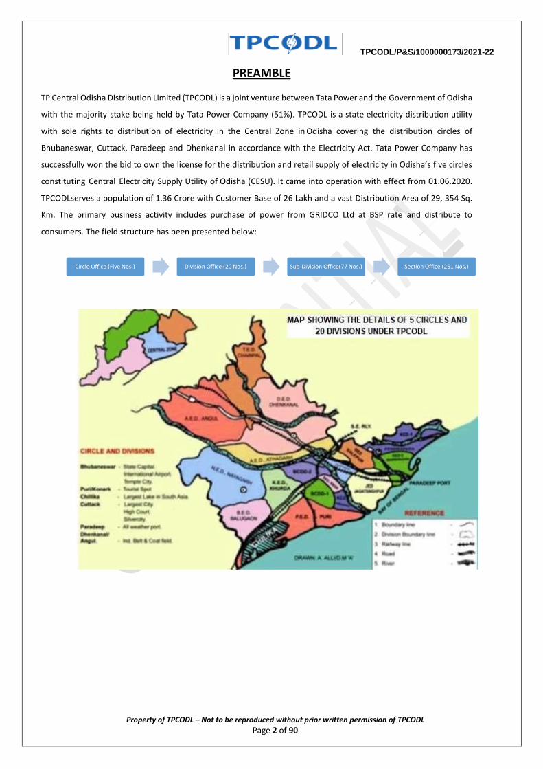
TP Central Odisha Distribution Limited (TPCODL) is a joint venture between Tata Power and the Government of Odisha
with the majority stake being held by Tata Power Company (51%). TPCODL is a state electricity distribution utility
with sole rights to distribution of electricity in the Central Zone in Odisha covering the distribution circles of
Bhubaneswar, Cuttack, Paradeep and Dhenkanal in accordance with the Electricity Act. Tata Power Company has
successfully won the bid to own the license for the distribution and retail supply of electricity in Odisha’s five circles
constituting Central Electricity Supply Utility of Odisha (CESU). It came into operation with effect from 01.06.2020.
TPCODL serves a population of 1.36 Crore with Customer Base of 26 Lakh and a vast Distribution Area of 29, 354 Sq.
Km. The primary business activity includes purchase of power from GRIDCO Ltd at BSP rate and distribute to
consumers. The field structure has been presented below:
Circle Office (Five Nos.) Division Office (20 Nos.) Sub-Division Office(77 Nos.) Section Office (251 Nos.)
TPCODL/P&S/1000000173/2021-22
Property of TPCODL – Not to be reproduced without prior written permission of TPCODL Page 3 of 90
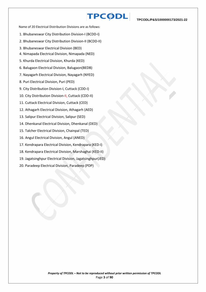
Name of 20 Electrical Distribution Divisions are as follows:
1. Bhubaneswar City Distribution Division-I (BCDD-I)
2. Bhubaneswar City Distribution Division-II (BCDD-II)
3. Bhubaneswar Electrical Division (BED)
4. Nimapada Electrical Division, Nimapada (NED)
5. Khurda Electrical Division, Khurda (KED)
6. Balugaon Electrical Division, Balugaon(BEDB)
7. Nayagarh Electrical Division, Nayagarh (NYED)
8. Puri Electrical Division, Puri (PED)
9. City Distribution Division-I, Cuttack (CDD-I)
10. City Distribution Division-II, Cuttack (CDD-II)
11. Cuttack Electrical Division, Cuttack (CED)
12. Athagarh Electrical Division, Athagarh (AED)
13. Salipur Electrical Division, Salipur (SED)
14. Dhenkanal Electrical Division, Dhenkanal (DED)
15. Talcher Electrical Division, Chainpal (TED)
16. Angul Electrical Division, Angul (ANED)
17. Kendrapara Electrical Division, Kendrapara (KED-I)
18. Kendrapara Electrical Division, Marshaghai (KED-II)
19. Jagatsinghpur Electrical Division, Jagatsinghpur(JED)
20. Paradeep Electrical Division, Paradeep (PDP)
TPCODL/P&S/1000000173/2021-22
Property of TPCODL – Not to be reproduced without prior written permission of TPCODL Page 4 of 90
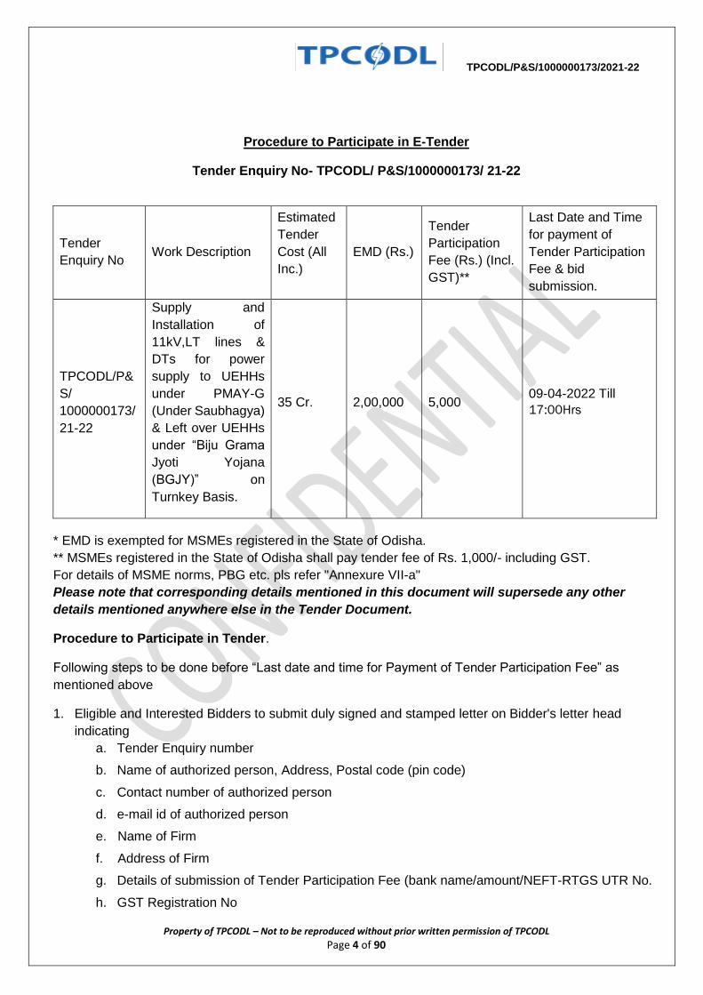
Procedure to Participate in E-Tender
Tender Enquiry No- TPCODL/ P&S/1000000173/ 21-22
Tender
Enquiry No Work Description
Estimated
Tender
Cost (All
Inc.)
EMD (Rs.)
Tender
Participation
Fee (Rs.) (Incl.
GST)**
Last Date and Time
for payment of
Tender Participation
Fee & bid
submission.
TPCODL/P&
S/
1000000173/
21-22
Supply and
Installation of
11kV,LT lines &
DTs for power
supply to UEHHs
under PMAY-G
(Under Saubhagya)
& Left over UEHHs
under “Biju Grama
Jyoti Yojana
(BGJY)” on
Turnkey Basis.
35 Cr. 2,00,000 5,000 09-04-2022 Till
17:00Hrs
* EMD is exempted for MSMEs registered in the State of Odisha.
** MSMEs registered in the State of Odisha shall pay tender fee of Rs. 1,000/- including GST.
For details of MSME norms, PBG etc. pls refer "Annexure VII-a"
Please note that corresponding details mentioned in this document will supersede any other
details mentioned anywhere else in the Tender Document.
Procedure to Participate in Tender.
Following steps to be done before “Last date and time for Payment of Tender Participation Fee” as
mentioned above
1. Eligible and Interested Bidders to submit duly signed and stamped letter on Bidder's letter head
indicating
a. Tender Enquiry number
b. Name of authorized person, Address, Postal code (pin code)
c. Contact number of authorized person
d. e-mail id of authorized person
e. Name of Firm
f. Address of Firm
g. Details of submission of Tender Participation Fee (bank name/amount/NEFT-RTGS UTR No.
h. GST Registration No
TPCODL/P&S/1000000173/2021-22
Property of TPCODL – Not to be reproduced without prior written permission of TPCODL Page 5 of 90
i. MSME Certificate, wherever applicable
j. Details of Bank Account for refund of EMD
k. Postal Address for refund of EMD
2. Non-Refundable Tender Participation Fee, as indicated in table above, to be submitted in the form of
Direct deposit in the following bank account and submit the receipt along with a covering letter clearly
indicating the Tender Reference/ Enquiry Number –
Beneficiary Name – TP Central Odisha Distribution Ltd.
Bank Name – STATE BANK OF INDIA
Branch Name – IDCO Towers, Bhubaneshwar
Address – PO- Sahidnagar, Janapath, Bhubaneswar.
Branch Code – 7891
Account No – 10835304915
IFSC Code – SBIN0007891
E-mail with necessary attachment of 1 and 2 above to be sent to [email protected]
with copy to [email protected] before last date and time for payment of Tender
Participation Fee.
Interested bidders to submit Tender Participation Fee and Authorization Letter before Last date and
time as indicated above after which link from TPCODL E-Tender system (Ariba) will be shared for
further communication and bid submission
Please note all future correspondence regarding the tender, bid submission, bid submission date
extension, Pre-bid query etc will happen only through TPCODL E-Tender system (Ariba). User manual
to guide the bidders to submit the bid through E-Tender system (Ariba) is also enclosed.
All communication will be done strictly with the bidders who have done the above step to participate in
the Tender.
Also it may be strictly noted that once date of “Last date and time for Payment of Tender Participation
Fee” is lapsed no Bidder will be sent link from TPCODL E-Tender System (Ariba). Without this link
vendor will not be able to participate in the tender. Any last moment request to participate in tender will
not be entertained.
Also all future corrigendum’s to the said tender will be informed on Tender section on website
https://www.tpcentralodisha.com.
Step 1: The bidder can get primary information about the tender from the NEWSPAPER advertisement /
TPCODL website (in case of open tender) / invitation through e-mail (in case of limited tenders).
Step 2: First the prospective Bidder who intends to participate in an open tender should deposit the requisite
tender fee as mentioned in the tender document trough NEFT/ RTGS in the a/c of TPCODL as mentioned in the
tender document. Deposit of the Tender fee should be made within the scheduled time for such deposit as
indicated in the Tender document.
Step 3: After deposit of the tender fee, the bidder should furnish the following information through e-mail to
the contact person indicated in the tender document.
TPCODL/P&S/1000000173/2021-22
Property of TPCODL – Not to be reproduced without prior written permission of TPCODL Page 6 of 90
Step 4: After receipt of the above information through e-mail, Vendor will get an invitation email from ARIBA
System which is the e-tendering platform of TPCODL. In this mail there will be an online link as Click Here to
participate in the tender.
Step 5: Click “Click Here” to access this event.
Step 6: If you are bidding first time for TPCODL through ARIBA site then please "Sign UP by creating User
Name and password as mentioned in Sign Up page. Please follow the process, as mentioned in the Sign Up
page, during creation of User Name and password.
Those who are already having User Name and password for accessing TPCODL events, they can LOGIN using
same User Name and password.
Step 7: Click Continue. The simple one-page registration screen will open for first time user. All * mark
mandatory field to be filled in.
Step 8: You will be able to see the RFQ ( i.e Detail Tender document).
Step 9: After review and downloading of all documents click on “Accept Review Prerequisites” i.e acceptance
of terms and conditions.
Step 10: Review and accept “Bidder Agreement”.
Step 11: You can see attached tender document in PDF format against clause no 1.1.1 (Introduction).
Step 12: Vendor has to attach PDF version of technical bid in clause no. 2.1 and 2.2. (In this field do not attach
any price document.)
Step 13: Uploading of Price Bid
(a) Price schedule is attached in envelope.3.1 of ARIBA. Same has to be downloaded and price and tax details
to be filled in as per the format given, print to be taken in vendor's letter head and signature and seal to be
made by authorised person. PDF version of this price bid to be attached. For Price Bid put all the unit price and
taxes and duties in provided field. Put "0" (ZERO) in not applicable field.
(b) In addition, the bidder has to upload the editable form of the price bid in EXCEL format in envelope 3.2 of
ARIBA system.
Step 14: After uploading successfully Techno commercial offer and price part then click on "Submit Entire
Response".
Note: Once user ID and password created, bidder can also login to ARIBA site through the following URL:
https://service.ariba.com/Sourcing.aw/124997008/aw?awh=r&awssk=oxt0s1BN&dard=1
TPCODL/P&S/1000000173/2021-22
Property of TPCODL – Not to be reproduced without prior written permission of TPCODL Page 7 of 90
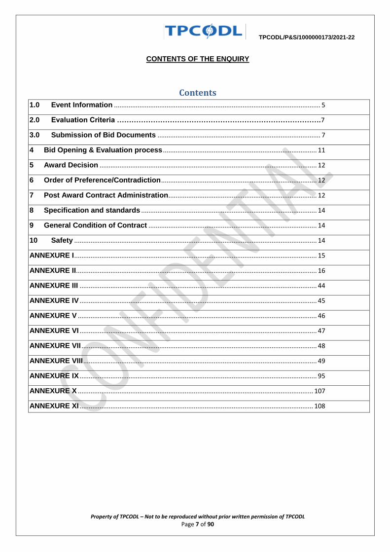
CONTENTS OF THE ENQUIRY
Contents
1.0 Event Information .................................................................................................................. 5
2.0 Evaluation Criteria ………………………………………………………………………….7
3.0 Submission of Bid Documents .......................................................................................... 7
4 Bid Opening & Evaluation process ..................................................................................... 11
5 Award Decision ........................................................................................................................ 12
6 Order of Preference/Contradiction ...................................................................................... 12
7 Post Award Contract Administration .................................................................................. 12
8 Specification and standards ................................................................................................. 14
9 General Condition of Contract ............................................................................................. 14
10 Safety ...................................................................................................................................... 14
ANNEXURE I ...................................................................................................................................... 15
ANNEXURE II..................................................................................................................................... 16
ANNEXURE III ................................................................................................................................... 44
ANNEXURE IV ................................................................................................................................... 45
ANNEXURE V .................................................................................................................................... 46
ANNEXURE VI ................................................................................................................................... 47
ANNEXURE VII .................................................................................................................................. 48
ANNEXURE VIII ................................................................................................................................. 49
ANNEXURE IX ................................................................................................................................... 95
ANNEXURE X .................................................................................................................................. 107
ANNEXURE XI ................................................................................................................................. 108
TPCODL/P&S/1000000173/2021-22
Property of TPCODL – Not to be reproduced without prior written permission of TPCODL Page 8 of 90
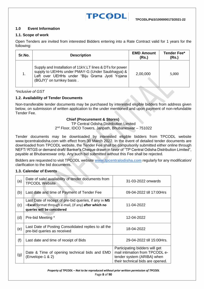
1.0 Event Information
1.1. Scope of work
Open Tenders are invited from interested Bidders entering into a Rate Contract valid for 1 years for the following:
Sr.No. Description EMD Amount
(Rs.) Tender Fee*
(Rs.)
1.
Supply and Installation of 11kV,LT lines & DTs for power supply to UEHHs under PMAY-G (Under Saubhagya) & Left over UEHHs under “Biju Grama Jyoti Yojana (BGJY)” on turnkey basis .
2,00,000 5,000
*inclusive of GST
1.2. Availability of Tender Documents
Non-transferable tender documents may be purchased by interested eligible bidders from address given below, on submission of written application to the under mentioned and upon payment of non-refundable Tender Fee.
Chief (Procurement & Stores) TP Central Odisha Distribution Limited
2nd Floor, IDCO Towers, Janpath, Bhubaneswar – 751022
Tender documents may be downloaded by interested eligible bidders from TPCODL website www.tpcentralodisha.com with effect from 30 March 2022. In the event of detailed tender documents are downloaded from TPCODL website, the Tender Fee shall be compulsorily submitted either online through NEFT/ RTGS or demand draft/ Banker’s Cheque drawn in favor of “TP Central Odisha Distribution Limited”, payable at Bhubaneswar only. Any such bid submitted without this Fee shall be rejected.
Bidders are requested to visit TPCODL website www.tpcentralodisha.com regularly for any modification/ clarification to the bid documents.
1.3. Calendar of Events
(a) Date of sale/ availability of tender documents from TPCODL Website
31-03-2022 onwards
(b) Last date and time of Payment of Tender Fee 09-04-2022 till 17:00Hrs
(c)
Last Date of receipt of pre-bid queries, if any in MS – Excel format through e-mail, (if any) after which no queries will be considered
11-04-2022
(d) Pre-bid Meeting * 12-04-2022
(e) Last Date of Posting Consolidated replies to all the pre-bid queries as received
18-04-2022
(f) Last date and time of receipt of Bids 29-04-2022 till 15:00Hrs.
(g) Date & Time of opening technical bids and EMD (Envelope-1 & 2)
Participating bidders will get mail intimation from TPCODL e-tender system (ARIBA) when their technical bids are opened.
TPCODL/P&S/1000000173/2021-22
Property of TPCODL – Not to be reproduced without prior written permission of TPCODL Page 9 of 90
(h) Date & Time of opening of price bid of qualified bidders
Participating bidders will get mail intimation from TPCODL e-tender system (ARIBA) when their technical bids are opened.
*Pre-bid meeting time and venue will be shared later.
Note: In the event of last date specified for submission of bids and date of opening of bids is declared as a closed holiday for TPCODL’s office, the last date of submission of bids and date of opening of bids will be the day following working day at appointed times.
1.4 Mandatory documents required along with the Bid
1.4.1 EMD of requisite value and validity 1.4.2 Tender Fee in case the tender is downloaded from website 1.4.3 Requisite Documents for compliance to Qualification Criteria mentioned in Clause 1.7.
1. Audited P & L account for last Three Finance Years. 2. Copies of the last purchase orders/work orders executed by the bidder in last 5 years to meet the
minimum supply experience specified in Qualifying Criteria. 3. Performance certificate from the concerned clients to meet the Qualifying Criteria. 4. Self Attested copy of valid Electrical License of Odisha Govt.
1.4.4 Drawing, Type Test details along with a sample of each item as specified at Annexure I (as
applicable)
1.4.5 Duly signed and stamped ‘Schedule of Deviations’ as per Annexure III on bidder’s letter head. 1.4.6 Duly signed and stamped ‘Schedule of Commercial Specifications’ as per Annexure IV on bidder’s
letter head. 1.4.7 Proper authorization letter/ Power of Attorney to sign the tender on the behalf of bidder. 1.4.8 Copy of PAN, GST, PF and ESI Registration (In case any of these documents is not available with
the bidder, same to be explicitly mentioned in the ‘Schedule of Deviations’)
Please note that in absence of any of the above documents, the bid submitted by a bidder shall be liable for rejection.
1.5. Deviation from Tender
Normally, the deviations to tender terms are not admissible and the bids with deviation are liable for rejection. Hence, the bidders are advised to refrain from taking any deviations on this Tender. Still in case of any deviations, all such deviations shall be set out by the Bidders, clause by clause in the ‘Annexure III - Schedule of Deviations’ and same shall be submitted as a part of the Technical Bid.
1.6. Right of Acceptance/Rejection
Bids are liable for rejection in absence of following documents:
i. EMD of requisite value and validity ii. Tender fee of requisite value iii. Price Bid as per the Price Schedule mentioned in Annexure I (BOQ) iv. Necessary documents against compliance to Qualification Requirements mentioned at Clause 1.7 of
this Tender Document v. Filled in Schedule of Deviations as per Annexure III vi. Filled in Schedule of Commercial Specifications as per Annexure IV vii. Receipt of Bid within the due date and time
TPCODL reserves the right to accept/reject any or all the bids without assigning any reason thereof.
TPCODL/P&S/1000000173/2021-22
Property of TPCODL – Not to be reproduced without prior written permission of TPCODL Page 10 of 90
1.7 Qualification Criteria
a) The average annual turnover of the bidder shall be a minimum of Rs. 3 Cr. in the last three financial
years i.e. FY- 2018-19, 2019-20 & 2020-21. Copy of audited Balance Sheet and P&L Account to be
submitted in this regard.
b) Bidder should have successfully completed Electrical HT, LT line and DT works value
worth Rs 5 Cr. during the last three financial years. Copy of work order / completion
certificate to be submitted in this regard.
c) Bidder should have Performance Certificates for satisfactory performance of having
rendered similar services from at least one reputed company. The services against
these issued certificates should have be carried out in last five years from the date of
bid submission.
In case the bidder has a previous association with TPCODL or other Tata Power group companies for
similar services, the performance feedback for that bidder by User Group of TPCODL or other Tata Power
group companies shall only be considered irrespective of performance certificates issued by any other
organization.
(Performance Certificate to be submitted)
d) Bidder must have all statutory compliance such as valid PAN, ESI registration, EPF registration,
GSTN registration
e) Bidder has to furnish a copy of valid statutory Electrical License from ELBO, Govt. of Odisha
to carryout tendered works. In case, the bidder has executed similar works in last 5 years, but
does not possess Valid Electrical License, have to furnish an undertaking to submit the same
within 30 days of submission of Bid. However, under such circumstances, the bidder should
attach a copy of such application & treasury challan for fees deposited before the concerned
Authority & copy of his expired license.
1.8. Marketing Integrity
We have a fair and competitive marketplace. The rules for bidders are outlined in the General Condition of Contracts. Bidders must agree to these rules prior to participating. In addition to other remedies available, TPCODL reserves the right to exclude a bidder from participating in future markets due to the bidder’s violation of any of the rules or obligations contained in the General Condition of Contracts. A bidder who violates the market place rules or engages in behavior that disrupts the fair execution of the marketplace, may result in restriction of a bidder from further participation in the marketplace for a length of time, depending upon the seriousness of the violation. Examples of violations include, but are not limited to:
Failure to honor prices submitted to the marketplace Breach of terms as published in TENDER/NIT
1.9. Supplier Confidentiality
All information contained in this tender is confidential and shall not be disclosed, published or advertised in any manner without written authorization from TPCODL. This includes all bidding information submitted to TPCODL. All tender documents remain the property of TPCODL and all suppliers are required to return these documents to TPCODL upon request. Suppliers who do not honor these confidentiality provisions will be excluded from participating in future bidding events.
2.0 Evaluation Criteria
The bids will be evaluated technically on the compliance to tender terms and conditions.
TPCODL/P&S/1000000173/2021-22
Property of TPCODL – Not to be reproduced without prior written permission of TPCODL Page 11 of 90
Price bids of all Qualified Bidders shall be evaluated on Total Boq Price offered, so as to arrive at Lowest evaluated price [Annexure I].TPCODL reserves the right to split the order line item wise and / or quantity wise, among more than one Bidder for each Division / Circle. Hence all the bidders are advised to quote their most competitive rates.
It is mandatory for the bidder to quote for all line items of total BOQ. The line item offered rates will be taken for calculation of price quoted for each division as per the division wise BOQ attached in Annexure-X for award of division wise contract.
Generally, each successfully qualified BA shall be awarded 2 nos. of Divisions. TPCODL reserves the right to increase or decrease the award of divisions to the BAs as per field requirement, financial capability, execution capability, performance etc. The TPCODL also reserves the right to allocate the division to successful BA as per its requirements and to cancel the RC /PO, forfeit the EMD / invoke PBG of any BA post award of RC/PO, in case of underperformance & reallocate the same work to other performing BA
The bids will be evaluated on Safety Parameters as mentioned in Annexure-VIII. Bidders have to submit all the documents related to safety bid.
NOTE: In case a new bidder is not registered with TPCODL, factory/work inspection and evaluation shall be carried out to ascertain the bidder’s manufacturing / erection capability and quality procedures. However, TPCODL reserves the right to carry out factory / work inspection and evaluation for any bidder prior to technical qualification.
In case a bidder is found as Disqualified in the factory / work evaluation, their bid shall not be evaluated any further and shall be summarily rejected. The decision of TPCODL shall be final and binding on the bidder in this regard.
2.1 Price Variation Clause: The prices shall remain firm during the entire contract period.
3.0 Submission of Bid Documents
3.1 Bid Submission
Bidders are requested to submit their offer in line with this Tender document through e-tendering process.
Please note all future correspondence regarding the tender, bid submission, bid submission date extension, Pre-bid query etc. will happen only through TPCODL E-Tender system (Ariba).
No e-mail or verbal correspondence will be responded. All communication will be done strictly with the bidder who have done the above step to participate in the Tender.
Bids shall be submitted in 3 (three) parts:
FIRST PART: “EMD” as applicable shall be submitted. The EMD shall be valid for 210 days from the due date of bid submission in the form of Bank Guarantee / Bank Draft / Bankers Pay Order (issued from a Scheduled Bank) online NEFT/ RTGS transfer favoring ‘TP Central Odisha Distribution Limited’ payable at Bhubaneswar. The EMD has to be strictly in the format as mentioned in General Condition of Contract, failing which it shall not be accepted by TPCODL and the bid as submitted shall be liable for rejection. A separate non-refundable tender fee of stipulated amount also needs to be transferred online through NEFT/ RTGS in case the tender document is downloaded from our website.
TPCODL Bank Details for transferring Tender Fee and EMD is as below:
Account Name: TP CENTRAL ODISHA DISTRIBUTION LIMITED
Bank Name: SBI, IDCO Towers, Bhubaneswar
Bank Account No.: 10835304915
IFSC Code: SBIN0007891
Note- EMD is preferred in form of Bank Guarantee and to be delivered at the following address. However, in view of present situation if Bidder is finding it difficult to make and submit BG for EMD amount, they can do online transfer of EMD amount in the above mentioned Account and submit proof of the same as part of Bid Submission.
TPCODL/P&S/1000000173/2021-22
Property of TPCODL – Not to be reproduced without prior written permission of TPCODL Page 12 of 90
Please note that in such case, Tender Fee and EMD should be strictly 2 separate transactions.
Please note as return of EMD from Bank Account is non-standard practice the same may take more time than return of EMD BG.
EMD Original Hard Copy shall be delivered at the following address in Envelope clearly indicating Tender Reference/ Enquiry Number, Name of Tender and Bidder Name
Chief (Procurement & Stores)
TP Central Odisha Distribution Limited
2nd Floor, IDCO Towers, Janapath, Bhubaneswar- 751022
SECOND PART: “TECHNICAL BID” shall contain the following documents:
a) Documentary evidence in support of qualifying criteria b) Technical literature/GTP/Type test report etc. (if applicable) c) Qualified manpower (if available) d) Testing facilities (if applicable) e) No Deviation Certificate as per the Annexure III – Schedule of Deviations f) Acceptance to Commercial Terms and Conditions viz. Delivery schedule/period, payment terms
etc. as per the Annexure IV – Schedule of Commercial Specifications. g) Quality Assurance Plan/Inspection Test Plan for supply items (if applicable) h) Bidder shall mention the details as required in the safety bid form (As mentioned in annexure- IX).
Bidder also has to submit the relevant documents for the same as required by TPCODL
The technical bid shall be properly indexed and is to be submitted through TPCODL E-tender System (Ariba) only. Hard Copy of Technical Bids need not be submitted.
THIRD PART: “PRICE BID” shall contain only the price details and strictly in format as mentioned in Annexure I along with explicit break up of basic prices, Taxes & duties, Freight etc. In case any discrepancy is observed between the item description stated in Schedule of Items mentioned in the tender and the price bid submitted by the bidder, the item description as mentioned in the tender document (to the extent modified through Corrigendum issued if any) shall prevail.
Price Bid is to be submitted in soft copy through TPCODL E-Tendering system (Ariba) only. Hard copy of Price Bid not be submitted.
The EMD in the form of Bank Draft / BG / Bankers Pay Order shall be submitted in original hard copy and then placed in sealed envelope which shall be clearly marked as below:
EMD
Supply and Installation of 11kV & LT lines and DTs for providing power supply to Un-electrified households (UEHHs) under PMAY-G & BGJY scheme on turnkey basis.
The Bid prepared by the Bidder, and all correspondence and documents relating to the Bid exchanged by the Bidder and the TPCODL, shall be written in the English Language. Any printed literature furnished by the Bidder may be written in another Language, provided that this literature is accompanied by an English translation, in which case, for purposes of interpretation of the Bid, the English translation shall govern.
SIGNING OF BID DOCUMENTS:
The bid must contain the name, residence and place of business of the person or persons making the bid and must be signed and sealed by the Bidder with his usual signature. The names of all persons signing should also be typed or printed below the signature.
The Bid being submitted must be signed by a person holding a Power of Attorney authorizing him to do so, certified copies of which shall be enclosed.
The Bid submitted on behalf of companies registered with the Indian Companies Act, for the time being in force, shall be signed by persons duly authorized to submit the Bid on behalf of the Company and shall be accompanied by certified true copies of the resolutions, extracts of Articles of Association, special or general Power of Attorney etc. to show clearly the title, authority and designation of persons signing the
TPCODL/P&S/1000000173/2021-22
Property of TPCODL – Not to be reproduced without prior written permission of TPCODL Page 13 of 90
Bid on behalf of the Company. Satisfactory evidence of authority of the person signing on behalf of the Bidder shall be furnished with bid.
A bid by a person who affixes to his signature the word ‘President’, ‘Managing Director’, ‘Secretary’, ‘Agent’ or other designation without disclosing his principal will be rejected.
The Bidder’s name stated on the Proposal shall be the exact legal name of the firm.
3.2 Contact Information
All the bidders are requested to send their pre-bid queries (if any) against this tender through e-mail within the stipulated timelines. The consolidated reply to all the queries received shall be posted on TPCODL website by the stipulated timelines as detailed in calendar of events.
Communication Details:
Handling Team Lead for this Tender:
Name: Gaurav Singh (Procurement) Contact No.: 9205190016 E-Mail ID: [email protected]
Senior General Manager (Procurement):
Name: Mr. Sudhakar Behera Contact No.: 9437282663 E-Mail ID: [email protected]
3.3 Bid Prices
Bidders shall quote for the entire Scope of Supply/ work with a break up of prices for individual items and Taxes & duties. The bidder shall complete the appropriate Price Schedules included herein, stating the Unit Price for each item & total price with taxes, duties & freight up to destination at various sites of TPCODL. The all-inclusive prices offered shall be inclusive of all costs as well as Duties, Taxes and Levies paid or payable during the execution of the supply work, breakup of price constituents.
Applicable GST to be specified clearly.
The quantity break up shown else-where other than Price Schedule is tentative. The bidder shall ascertain himself regarding material required for completeness of the entire work. Any items not indicated in the price schedule but which are required to complete the job as per the Technical Specifications/ Scope of Work/ SLA mentioned in the tender, shall be deemed to be included in prices quoted.
3.4 Bid Currencies
Prices shall be quoted in Indian Rupees Only.
3.5 Period of Validity of Bids
Bids shall remain valid for 180 days from the due date of submission of the bid.
Notwithstanding clause above, the TPCODL may solicit the Bidder’s consent to an extension of the Period of Bid Validity. The request and responses thereto shall be made in writing.
RC Validity: - The validity of this rate contract shall be one year from the date of issuance.
3.6 Alternative Bids
Bidders shall submit Bids, which comply with the Bidding documents. Alternative bids will not be considered. The attention of Bidders is drawn to the provisions regarding the rejection of Bids in the terms and conditions, which are not substantially responsive to the requirements of the bidding documents.
3.7 Modifications and Withdrawal of Bids
The bidder is not allowed to modify or withdraw its bid after the Bid’s submission. The EMD as submitted along with the bid shall be liable for forfeiture in such event.
3.8 Earnest Money Deposit (EMD)
TPCODL/P&S/1000000173/2021-22
Property of TPCODL – Not to be reproduced without prior written permission of TPCODL Page 14 of 90
The bidder shall furnish, as part of its bid, an EMD amounting as specified in the tender. The EMD is required to protect TPCODL against the risk of bidder’s conduct, which would warrant forfeiture.
The EMD shall be denominated in any of the following form:
Banker’s Cheque/ Demand Draft/ Pay order drawn in favor of TP Central Odisha Distribution
Limited payable at Bhubaneswar.
Online transfer of requisite amount through NEFT/ RTGS. Bank Guarantee valid for 210 days after due date of submission.
The EMD shall be forfeited in case:
a) The bidder withdraws its bid during the period of specified bid validity.
Or
b) The successful Bidder does not a) accept the Purchase Order, or b) furnish the required Performance Security Bank Guarantee
3.9 Type Tests (if applicable)
The type tests specified in TPCODL specifications should have been carried out within five years prior to the date of opening of technical bids and test reports are to be submitted along with the bids. If type tests carried out are not within the five years prior to the date of bidding, the bidder will arrange to carry out type tests specified, at his cost. The decision to accept/ reject such bids rests with TPCODL.
4 Bid Opening & Evaluation process
4.1. Process to be confidential
Information relating to the examination, clarification, evaluation and comparison of Bids and recommendations for the award of a contract shall not be disclosed to Bidders or any other persons not officially concerned with such process. Any effort by a Bidder to influence the TPCODL's processing of Bids or award decisions may result in rejection of the Bidder's Bid.
4.2. Technical Bid Opening
Bids will be opened at TPCODL Office, Bhubaneswar. All tender bids shall be opened internally by TPCODL with intimation to BA through Ariba Platform. Technical bid must not contain any cost information whatsoever.
First the envelope marked “EMD” will be opened. Bids without EMD/cost of tender (if applicable) of required amount/ validity in prescribed format, shall be rejected.
Next, the technical bid of the bidders who have furnished the requisite EMD will be opened, one by one.
4.3. Preliminary Examination of Bids/Responsiveness
TPCODL will examine the Bids to determine whether they are complete, whether any computational errors have been made, whether required sureties have been furnished, whether the documents have been properly signed, and whether the Bids are generally in order. TPCODL may ask for submission of original documents in order to verify the documents submitted in support of qualification criteria.
Arithmetical errors will be rectified on the following basis: If there is a discrepancy between the unit price and the total price per item that is obtained by multiplying the unit price and quantity, the unit price shall prevail and the total price per item will be corrected. If there is a discrepancy between the Total Amount and the sum of the total price per item, the sum of the total price per item shall prevail and the Total Amount will be corrected.
Prior to the detailed evaluation, TPCODL will determine the substantial responsiveness of each Bid to the Bidding Documents including production capability and acceptable quality of the Goods offered. A substantially responsive Bid is one, which conforms to all the terms and conditions of the Bidding Documents without material deviation.
TPCODL/P&S/1000000173/2021-22
Property of TPCODL – Not to be reproduced without prior written permission of TPCODL Page 15 of 90
Bid determined as not substantially responsive will be rejected by the TPCODL and may not subsequently be made responsive by the Bidder by correction of the non-conformity.
4.4. Techno Commercial Clarifications
Bidders need to ensure that the bids submitted by them are complete in all respects. To assist in the examination, evaluation and comparison of Bids, TPCODL may, at its discretion, ask the Bidder for a clarification on its Bid for any deviations with respect to the TPCODL specifications and attempt will be made to bring all bids on a common footing. All responses to requests for clarification shall be in writing and no change in the price or substance of the Bid shall be sought, offered or permitted owing to any clarifications sought by TPCODL.
4.5. Price Bid Opening
Price bids will be opened internally with intimation to bidders through Ariba platform. The EMD of the bidder withdrawing or substantially altering his offer at any stage after the technical bid opening will be forfeited at the sole discretion of TPCODL without any further correspondence in this regard.
4.6. Reverse Auctions
TPCODL reserves the right to conduct the reverse auction (instead of public opening of price bids) for the products/ services being asked for in the tender. The terms and conditions for such reverse auction events shall be as per the Acceptance Form attached as Annexure VI of this document. The bidders along with the tender document shall mandatorily submit a duly signed copy of the Acceptance Form attached as Annexure VI as a token of acceptance for the same.
5 Award Decision
TPCODL will award the contract to the successful bidder whose bid has been determined to be the lowest-evaluated responsive bid as per the Evaluation Criterion mentioned at Clause 2.0. The Cost for the said calculation shall be taken as the all-inclusive cost quoted by bidder in Annexure I (Schedule of Items) subject to any corrections required in line with Clause 3.2 above. The decision to place purchase order/LOI solely depends on TPCODL on the cost competitiveness across multiple lots, quality, delivery and bidder’s capacity, in addition to other factors that TPCODL may deem relevant.
TPCODL reserves the rights to award contract to one or more bidders so as to meet the delivery requirement or nullify award decision without assigning any reason thereof.
In case any supplier is found unsatisfactory during delivery process, the award will be cancelled and TPCODL reserves right to award contract to other suppliers who are found fit.
6 Order of Preference/Contradiction
In case of contradiction in any part of various documents in tender, following shall prevail in order of preference:
1. Schedule of Items (Annexure I) 2. Post Award Contract Administration (Clause 7.0) 3. Submission of Bid Documents (Clause 3.0) 4. Scope of Work and SLA (Annexure VII)
5. Technical Specifications (Annexure II)
6. Inspection Test Plan (if any)
7. Acceptance Form for Participation in Reverse Auction (Annexure VI) 8. General Conditions of Contract (Annexure VIII)
7 Post Award Contract Administration
7.1. Special Conditions of Contract
After finalization of tender, Rate Contract shall be issued on successful bidder with a validity period of One Year. Prices shall remain “FIRM” till validity of issued rate contract. Within the validity of rate contract and as per requirement of material, release order shall be issued time to time.
TPCODL/P&S/1000000173/2021-22
Property of TPCODL – Not to be reproduced without prior written permission of TPCODL Page 16 of 90
Capacity for order handling within stipulated delivery period, shall be submitted by the bidder and the same shall be utilized and decided by TPCODL for placement of Release Order (RO).
If any addition of new item ( Supply / Installation or both) in the scope of work during the contract period, the price shall be mutually agreed on the basis of TPCODL existing Benchmarking rate/ approved Cost Data rate with a provision of escalation thereon as prescribed by the Govt. Undertaking shall be provided.
During emergency, Bidder need to mobilize the manpower with material to execute the job at any location under the jurisdiction of TPCODL.
Bidder needs to quote mandatorily for each line item of the BoQ.
Business Associate (BA) shall submit applicable Performance Bank Guarantee as per GCC within 15 days of issuance of rate contract. PBG applicable shall be 5% of order value. PBG submitted, shall be released after completion of applicable guarantee period plus one months claim period.
TPCODL shall short close the issued Release Order / Rate contract, in case of any work performance or quality issue or work is not found satisfactorily.
Bidder shall submit valid Electrical License issued from Govt. of Odisha.
Any change in statutory taxes, duties and levies within the contract period shall be borne by TPCODL. However, in case of delay in work execution owing to reasons not attributable to TPCODL, any increase in total liability shall be passed on the Bidder, whereas any benefits arising owing to such statutory variation in taxes and duties shall be passed on TPCODL.
All other terms and conditions of TPCODL GCC shall be applicable.
Statutory Variations: Any changes in existing taxes/ Duties and levies, Introduction of new taxes and
duties etc. during the period of the contract shall be paid at actuals to BA, provide the BA submits
the tax break up in details in their invoice. The date of issue of MDCC shall be used for this purpose.
However, where BA has quoted the all-inclusive prices and not shown the tax break-up, this clause
will not be applicable & any variation in Taxes & Duties during execution of the contract shall be
borne by the BA.
All the costs pertaining to ROW is included in the scope of BA. Accordingly the BA needs to consider
this cost while submitting their Price Bids. However, TPCODL shall reimburse any statutory Fees
paid by the BA to any Govt. Agency for such clearance, subject to production of documentary
evidence.
Before commencement of work BA may be required to conduct the detail Survey for allotted work at
his cost submit the same to the Engineer-in-Charge for approval. Since such type of Survey is in the
scope of BA, the bidder may consider this while offering their Price Bid.
All other terms and conditions of TPCODL General Conditions of Contract shall be applicable.
7.2 Drawing Submission and Approval
The relevant drawings and GTPs need to be submitted within two weeks of receipt of order by the successful bidder to TPCODL for approval. In case, re-submission of drawings is required on request of TPCODL, same needs to be submitted back to TPCODL within 5 days of such request. 7.3 Delivery Timelines
Release Orders shall be placed against the awarded post placement of Rate Contracts by TPCODL as
and when the requirements arise. The awarded work is to be completed within 60 days or as prescribed in
the PO / WO from the date of issue.
7.4 Warranty Period
24 months from the date of commissioning & handover. 7.5 Payment Terms

TPCODL/P&S/1000000173/2021-22
Property of TPCODL – Not to be reproduced without prior written permission of TPCODL Page 17 of 90
Once in a month (preferably end of the month), BA shall submit details of work completed within the month
and handed over to TPCODL in good condition along with certification of acceptance by certified official.
Associate shall submit the Bills/ Invoices for the certified works in the name of TPCODL to Invoice/Bill Desk
(BIRD).
The payment shall be released within 30 days from the date of submission of certified bills/ invoices.
7.6 Climate Change
Significant quantities of waste are generated during the execution of project and an integrated approach for effective handling, storage, transportation and disposal of the same shall be adopted. This would ensure the minimization of environmental and social impact in order to combat the climate change. Please refer attached Environment Policy and Sustainability Policy, Annexure-XI for more details.
7.7 Ethics
TPCODL is an ethical organization and as a policy TPCODL lays emphasis on ethical practices across its entire domain. Bidder should ensure that they should abide by all the ethical norms and in no form either directly or indirectly be involved in unethical practice.
TPCODL work practices are governed by the Tata Code of Conduct which emphasizes on the following:
We shall select our suppliers and service providers fairly and transparently.
We seek to work with suppliers and service providers who can demonstrate that they share similar
values. We expect them to adopt ethical standards comparable to our own.
Our suppliers and service providers shall represent our company only with duly authorized written
permission from our company. They are expected to abide by the Code in their interactions with, and
on behalf of us, including respecting the confidentiality of information shared with them.
We shall ensure that any gifts or hospitality received from, or given to, our suppliers or service providers
comply with our company’s gifts and hospitality policy.
We respect our obligations on the use of third party intellectual property and data.
Bidder is advised to refer Tata Code of Conduct (TCOC) attached at Annexure X for more information.
Any ethical concerns with respect to this tender can be reported to the following e-mail ID:
[email protected] / [email protected]/
8 Specification and standards
As per Annexure II
9 General Condition of Contract
Any condition not mentioned above shall be applicable as per GCC Annexure-VIII attached along with this tender.
10 Safety
All jobs are this tender have to be executed strictly in compliance to the Safety terms and Conditions of TP Central Odisha Distribution Limited. Please refer attached Safety terms and conditions, Annexure-IX, for details. Violation of Safety norms will result in Penalty as mentioned in the above document.
TPCODL/P&S/1000000173/2021-22
Property of TPCODL – Not to be reproduced without prior written permission of TPCODL Page 18 of 90
TPCODL/P&S/1000000173/2021-22
Property of TPCODL – Not to be reproduced without prior written permission of TPCODL Page 19 of 90
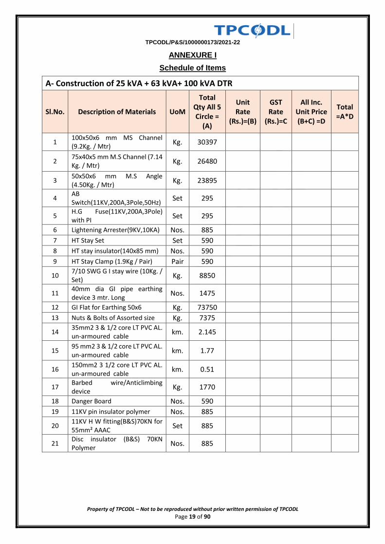
ANNEXURE I
Schedule of Items
A- Construction of 25 kVA + 63 kVA+ 100 kVA DTR
Sl.No. Description of Materials UoM
Total Qty All 5 Circle =
(A)
Unit Rate
(Rs.)=(B)
GST Rate
(Rs.)=C
All Inc. Unit Price (B+C) =D
Total =A*D
1 100x50x6 mm MS Channel (9.2Kg. / Mtr)
Kg. 30397
2 75x40x5 mm M.S Channel (7.14 Kg. / Mtr)
Kg. 26480
3 50x50x6 mm M.S Angle (4.50Kg. / Mtr)
Kg. 23895
4 AB Switch(11KV,200A,3Pole,50Hz)
Set 295
5 H.G Fuse(11KV,200A,3Pole) with PI
Set 295
6 Lightening Arrester(9KV,10KA) Nos. 885
7 HT Stay Set Set 590
8 HT stay insulator(140x85 mm) Nos. 590
9 HT Stay Clamp (1.9Kg / Pair) Pair 590
10 7/10 SWG G I stay wire (10Kg. / Set)
Kg. 8850
11 40mm dia GI pipe earthing device 3 mtr. Long
Nos. 1475
12 GI Flat for Earthing 50x6 Kg. 73750
13 Nuts & Bolts of Assorted size Kg. 7375
14 35mm2 3 & 1/2 core LT PVC AL. un-armoured cable
km. 2.145
15 95 mm2 3 & 1/2 core LT PVC AL. un-armoured cable
km. 1.77
16 150mm2 3 1/2 core LT PVC AL. un-armoured cable
km. 0.51
17 Barbed wire/Anticlimbing device
Kg. 1770
18 Danger Board Nos. 590
19 11KV pin insulator polymer Nos. 885
20 11KV H W fitting(B&S)70KN for 55mm² AAAC
Set 885
21 Disc insulator (B&S) 70KN Polymer
Nos. 885
TPCODL/P&S/1000000173/2021-22
Property of TPCODL – Not to be reproduced without prior written permission of TPCODL Page 20 of 90
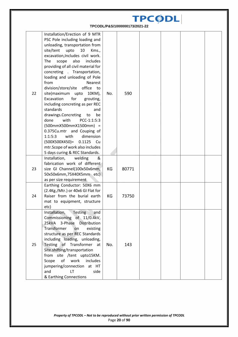
22
Installation/Erection of 9 MTR PSC Pole including loading and unloading, transportation from site/tent upto 10 Kms., excavation,Includes civil work. The scope also includes providing of all civil material for concreting . Transportation, loading and unloading of Pole from Nearest division/store/site office to site(maximum upto 10KM), Excavation for grouting, including concreting as per REC standards and drawings.Concreting to be done with PCC-1:1:5:3 (500mmX500mmX1500mm) = 0.375Cu.mtr and Couping of 1:1:5:3 with dimension (500X500X450)= 0.1125 Cu mtr.Scope of work also includes 5 days curing & REC Standards.
No. 590
23
Installation, welding & fabrication work of different size GI Channel(100x50x6mm, 50x50x6mm,75X40X5mm etc) as per size requirement
KG 80771
24
Earthing Conductor: 50X6 mm (2.4Kg./Mtr.) or 40x6 GI Flat for Raiser from the burial earth mat to equipment, structure etc)
KG 73750
25
Installation, Testing and Commissioning of 11/0.4kV, 25kVA 3-Phase Distribution Transformer on existing structure as per REC Standards including loading, unloading, Testing of Transformer at Site.shifting/transportation from site /tent upto15KM. Scope of work includes jumpering/connection at HT and LT side & Earthing Connections
No. 143
TPCODL/P&S/1000000173/2021-22
Property of TPCODL – Not to be reproduced without prior written permission of TPCODL Page 21 of 90
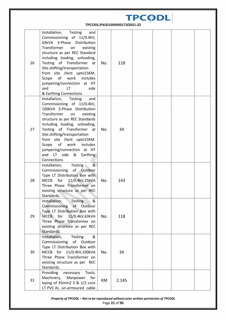
26
Installation, Testing and Commissioning of 11/0.4kV, 63kVA 3-Phase Distribution Transformer on existing structure as per REC Standard including loading, unloading, Testing of Transformer at Site.shifting/transportation from site /tent upto15KM. Scope of work includes jumpering/connection at HT and LT side & Earthing Connections
No. 118
27
Installation, Testing and Commissioning of 11/0.4kV, 100kVA 3-Phase Distribution Transformer on existing structure as per REC Standards including loading, unloading, Testing of Transformer at Site.shifting/transportation from site /tent upto15KM. Scope of work includes jumpering/connection at HT and LT side & Earthing Connections
No. 34
28
Installation, Testing & Commissioning of Outdoor Type LT Distribution Box with MCCB for 11/0.4kV,25kVA Three Phase Transformer on existing structure as per REC Standards.
No. 143
29
Installation, Testing & Commissioning of Outdoor Type LT Distribution Box with MCCB for 11/0.4kV,63kVA Three Phase Transformer on existing structure as per REC Standards.
No. 118
30
Installation, Testing & Commissioning of Outdoor Type LT Distribution Box with MCCB for 11/0.4kV,100kVA Three Phase Transformer on existing structure as per REC Standards.
No. 34
31
Providing necessary Tools, Machinery, Manpower for laying of 35mm2 3 & 1/2 core LT PVC AL. un-armoured cable
KM 2.145
TPCODL/P&S/1000000173/2021-22
Property of TPCODL – Not to be reproduced without prior written permission of TPCODL Page 22 of 90
in Trench / HDPE Pipe/ Hum pipe
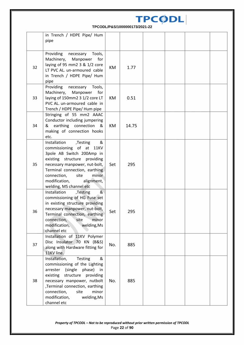
32
Providing necessary Tools, Machinery, Manpower for laying of 95 mm2 3 & 1/2 core LT PVC AL. un-armoured cable in Trench / HDPE Pipe/ Hum pipe
KM 1.77
33
Providing necessary Tools, Machinery, Manpower for laying of 150mm2 3 1/2 core LT PVC AL. un-armoured cable in Trench / HDPE Pipe/ Hum pipe
KM 0.51
34
Stringing of 55 mm2 AAAC Conductor including jumpering & earthing connection & making of connection hooks etc.
KM 14.75
35
Installation ,Testing & commissioning of at 11KV 3pole AB Switch 200Amp in existing structure providing necessary manpower, nut-bolt, Terminal connection, earthing connection, site minor modification, alignment, welding, MS channel etc
Set 295
36
Installation ,Testing & commissioning of HG Fuse set in existing structure providing necessary manpower, nut-bolt, Terminal connection, earthing connection, site minor modification, welding,Ms channel etc
Set 295
37
Installation of 11KV Polymer Disc Insulator 70 KN (B&S) along with Hardware fitting for 11KV line.
No. 885
38
Installation, Testing & commissioning of the Lighting arrester (single phase) in existing structure providing necessary manpower, nutbolt ,Terminal connection, earthing connection, site minor modification, welding,Ms channel etc
No. 885
TPCODL/P&S/1000000173/2021-22
Property of TPCODL – Not to be reproduced without prior written permission of TPCODL Page 23 of 90
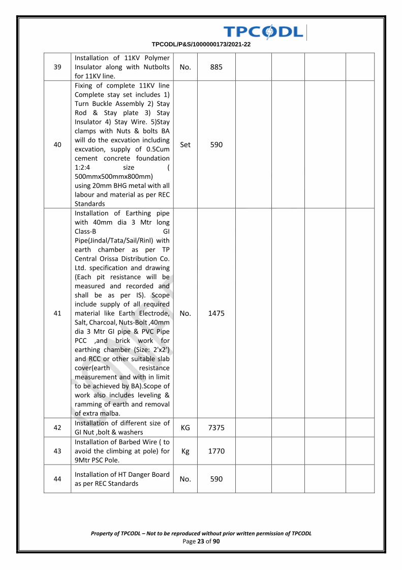
39 Installation of 11KV Polymer Insulator along with Nutbolts for 11KV line.
No. 885
40
Fixing of complete 11KV line Complete stay set includes 1) Turn Buckle Assembly 2) Stay Rod & Stay plate 3) Stay Insulator 4) Stay Wire. 5)Stay clamps with Nuts & bolts BA will do the excvation including excvation, supply of 0.5Cum cement concrete foundation 1:2:4 size ( 500mmx500mmx800mm) using 20mm BHG metal with all labour and material as per REC Standards
Set 590
41
Installation of Earthing pipe with 40mm dia 3 Mtr long Class-B GI Pipe(Jindal/Tata/Sail/Rinl) with earth chamber as per TP Central Orissa Distribution Co. Ltd. specification and drawing (Each pit resistance will be measured and recorded and shall be as per IS). Scope include supply of all required material like Earth Electrode, Salt, Charcoal, Nuts-Bolt ,40mm dia 3 Mtr GI pipe & PVC Pipe PCC ,and brick work for earthing chamber (Size: 2'x2') and RCC or other suitable slab cover(earth resistance measurement and with in limit to be achieved by BA).Scope of work also includes leveling & ramming of earth and removal of extra malba.
No. 1475
42 Installation of different size of GI Nut ,bolt & washers
KG 7375
43 Installation of Barbed Wire ( to avoid the climbing at pole) for 9Mtr PSC Pole.
Kg 1770
44 Installation of HT Danger Board as per REC Standards
No. 590
TPCODL/P&S/1000000173/2021-22
Property of TPCODL – Not to be reproduced without prior written permission of TPCODL Page 24 of 90
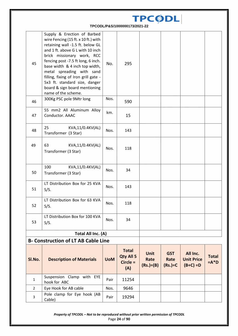
45
Supply & Erection of Barbed wire Fencing (15 ft. x 10 ft.) with retaining wall -1.5 ft. below GL and 1 ft. above G L with 10 inch brick missionary work, RCC fencing post -7.5 ft long, 6 inch. base width & 4 inch top width, metal spreading with sand filling, fixing of Iron grill gate - 5x3 ft. standard size, danger board & sign board mentioning name of the scheme.
No. 295
46 300Kg PSC pole 9Mtr long
Nos.
590
47 55 mm2 All Aluminum Alloy Conductor. AAAC
km.
15
48 25 KVA,11/0.4KV(AL) Transformer (3 Star)
Nos. 143
49
63 KVA,11/0.4KV(AL)
Transformer (3 Star) Nos. 118
50 100 KVA,11/0.4KV(AL)
Transformer (3 Star) Nos. 34
51 LT Distribution Box for 25 KVA
S/S. Nos. 143
52
LT Distribution Box for 63 KVA
S/S. Nos. 118
53 LT Distribution Box for 100 KVA
S/S. Nos. 34
Total All Inc. (A)
B- Construction of LT AB Cable Line
Sl.No. Description of Materials UoM
Total Qty All 5 Circle =
(A)
Unit Rate
(Rs.)=(B)
GST Rate
(Rs.)=C
All Inc. Unit Price (B+C) =D
Total =A*D
1 Suspension Clamp with EYE hook for ABC
Pair 11254
2 Eye Hook for AB cable Nos. 9646
3 Pole clamp for Eye hook (AB Cable)
Pair 19294
TPCODL/P&S/1000000173/2021-22
Property of TPCODL – Not to be reproduced without prior written permission of TPCODL Page 25 of 90
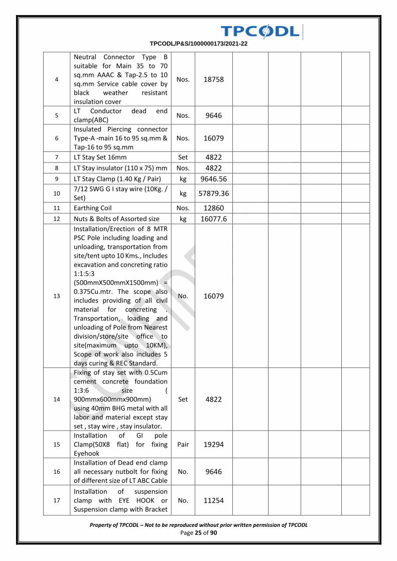
4
Neutral Connector Type B suitable for Main 35 to 70 sq.mm AAAC & Tap-2.5 to 10 sq.mm Service cable cover by black weather resistant insulation cover
Nos. 18758
5 LT Conductor dead end clamp(ABC)
Nos. 9646
6
Insulated Piercing connector Type-A -main 16 to 95 sq.mm & Tap-16 to 95 sq.mm
Nos. 16079
7 LT Stay Set 16mm Set 4822
8 LT Stay insulator (110 x 75) mm Nos. 4822
9 LT Stay Clamp (1.40 Kg / Pair) kg 9646.56
10 7/12 SWG G I stay wire (10Kg. / Set)
kg 57879.36
11 Earthing Coil Nos. 12860
12 Nuts & Bolts of Assorted size kg 16077.6
13
Installation/Erection of 8 MTR PSC Pole including loading and unloading, transportation from site/tent upto 10 Kms., Includes excavation and concreting ratio 1:1:5:3 (500mmX500mmX1500mm) = 0.375Cu.mtr. The scope also includes providing of all civil material for concreting . Transportation, loading and unloading of Pole from Nearest division/store/site office to site(maximum upto 10KM), Scope of work also includes 5 days curing & REC Standard.
No. 16079
14
Fixing of stay set with 0.5Cum cement concrete foundation 1:3:6 size ( 900mmx600mmx900mm) using 40mm BHG metal with all labor and material except stay set , stay wire , stay insulator.
Set 4822
15
Installation of GI pole Clamp(50X8 flat) for fixing Eyehook
Pair 19294
16
Installation of Dead end clamp all necessary nutbolt for fixing of different size of LT ABC Cable
No. 9646
17
Installation of suspension clamp with EYE HOOK or Suspension clamp with Bracket
No. 11254
TPCODL/P&S/1000000173/2021-22
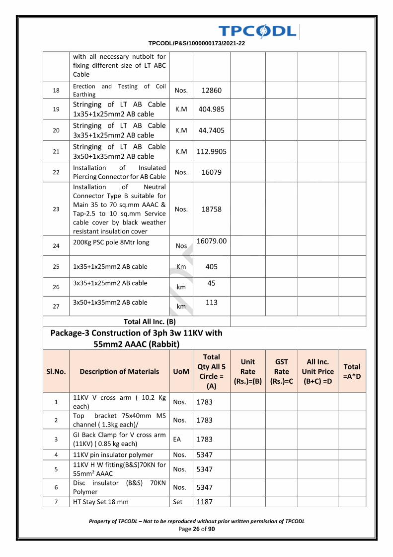
Property of TPCODL – Not to be reproduced without prior written permission of TPCODL Page 26 of 90
with all necessary nutbolt for fixing different size of LT ABC Cable
18 Erection and Testing of Coil Earthing
Nos. 12860
19 Stringing of LT AB Cable 1x35+1x25mm2 AB cable
K.M 404.985
20 Stringing of LT AB Cable 3x35+1x25mm2 AB cable
K.M 44.7405
21 Stringing of LT AB Cable 3x50+1x35mm2 AB cable
K.M 112.9905
22 Installation of Insulated Piercing Connector for AB Cable
Nos. 16079
23
Installation of Neutral Connector Type B suitable for Main 35 to 70 sq.mm AAAC & Tap-2.5 to 10 sq.mm Service cable cover by black weather resistant insulation cover
Nos. 18758
24 200Kg PSC pole 8Mtr long
Nos 16079.00
25 1x35+1x25mm2 AB cable Km 405
26 3x35+1x25mm2 AB cable
km 45
27 3x50+1x35mm2 AB cable
km 113
Total All Inc. (B)
Package-3 Construction of 3ph 3w 11KV with 55mm2 AAAC (Rabbit)
Sl.No. Description of Materials UoM
Total Qty All 5 Circle =
(A)
Unit Rate
(Rs.)=(B)
GST Rate
(Rs.)=C
All Inc. Unit Price (B+C) =D
Total =A*D
1 11KV V cross arm ( 10.2 Kg each)
Nos. 1783
2 Top bracket 75x40mm MS channel ( 1.3kg each)/
Nos. 1783
3 GI Back Clamp for V cross arm (11KV) ( 0.85 kg each)
EA 1783
4 11KV pin insulator polymer Nos. 5347
5 11KV H W fitting(B&S)70KN for 55mm² AAAC
Nos. 5347
6 Disc insulator (B&S) 70KN Polymer
Nos. 5347
7 HT Stay Set 18 mm Set 1187
TPCODL/P&S/1000000173/2021-22
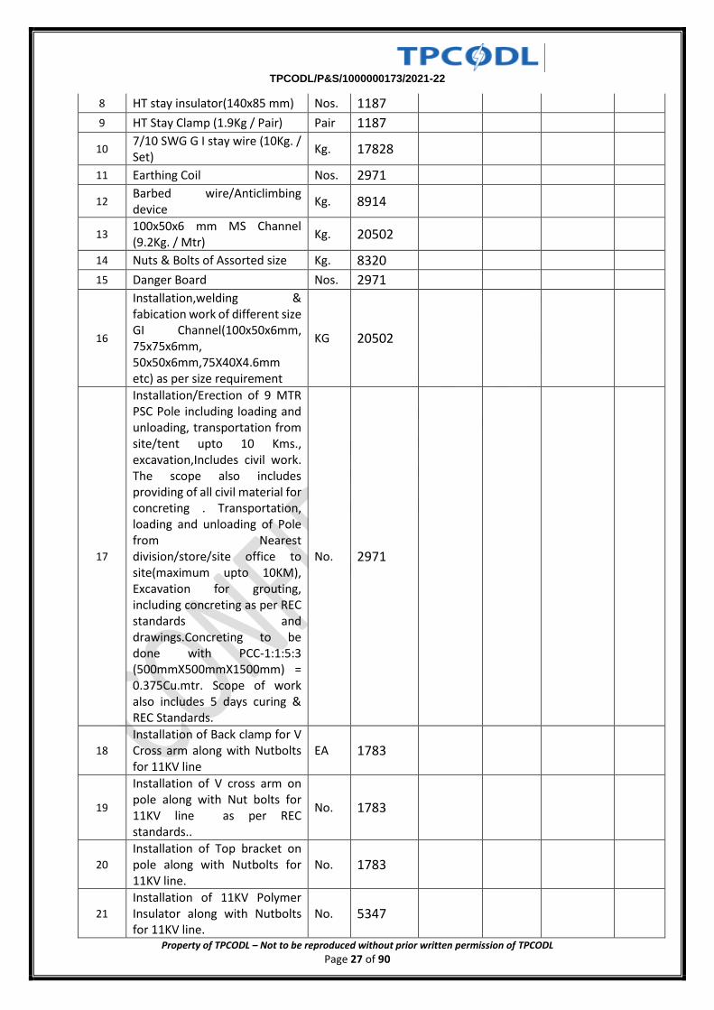
Property of TPCODL – Not to be reproduced without prior written permission of TPCODL Page 27 of 90
8 HT stay insulator(140x85 mm) Nos. 1187
9 HT Stay Clamp (1.9Kg / Pair) Pair 1187
10 7/10 SWG G I stay wire (10Kg. / Set)
Kg. 17828
11 Earthing Coil Nos. 2971
12 Barbed wire/Anticlimbing device
Kg. 8914
13 100x50x6 mm MS Channel (9.2Kg. / Mtr)
Kg. 20502
14 Nuts & Bolts of Assorted size Kg. 8320
15 Danger Board Nos. 2971
16
Installation,welding & fabication work of different size GI Channel(100x50x6mm, 75x75x6mm, 50x50x6mm,75X40X4.6mm etc) as per size requirement
KG 20502
17
Installation/Erection of 9 MTR PSC Pole including loading and unloading, transportation from site/tent upto 10 Kms., excavation,Includes civil work. The scope also includes providing of all civil material for concreting . Transportation, loading and unloading of Pole from Nearest division/store/site office to site(maximum upto 10KM), Excavation for grouting, including concreting as per REC standards and drawings.Concreting to be done with PCC-1:1:5:3 (500mmX500mmX1500mm) = 0.375Cu.mtr. Scope of work also includes 5 days curing & REC Standards.
No. 2971
18
Installation of Back clamp for V Cross arm along with Nutbolts for 11KV line
EA 1783
19
Installation of V cross arm on pole along with Nut bolts for 11KV line as per REC standards..
No. 1783
20
Installation of Top bracket on pole along with Nutbolts for 11KV line.
No. 1783
21
Installation of 11KV Polymer Insulator along with Nutbolts for 11KV line.
No. 5347
TPCODL/P&S/1000000173/2021-22
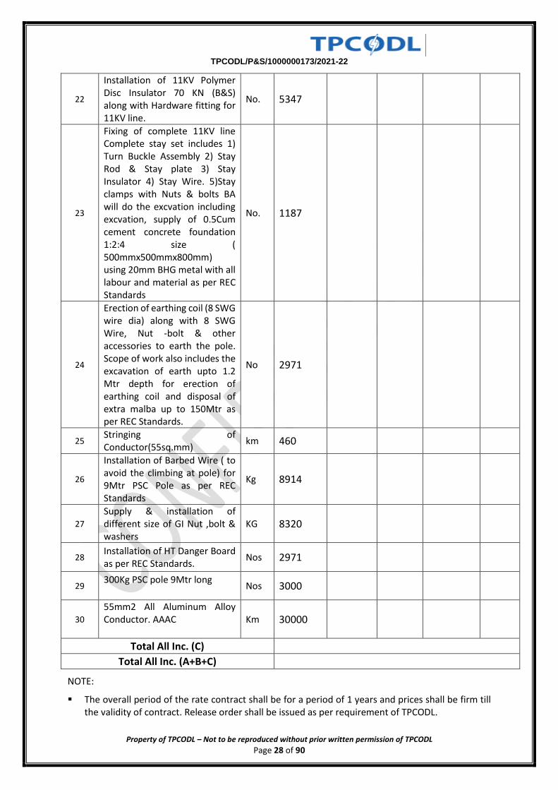
Property of TPCODL – Not to be reproduced without prior written permission of TPCODL Page 28 of 90
22
Installation of 11KV Polymer Disc Insulator 70 KN (B&S) along with Hardware fitting for 11KV line.
No. 5347
23
Fixing of complete 11KV line Complete stay set includes 1) Turn Buckle Assembly 2) Stay Rod & Stay plate 3) Stay Insulator 4) Stay Wire. 5)Stay clamps with Nuts & bolts BA will do the excvation including excvation, supply of 0.5Cum cement concrete foundation 1:2:4 size ( 500mmx500mmx800mm) using 20mm BHG metal with all labour and material as per REC Standards
No. 1187
24
Erection of earthing coil (8 SWG wire dia) along with 8 SWG Wire, Nut -bolt & other accessories to earth the pole. Scope of work also includes the excavation of earth upto 1.2 Mtr depth for erection of earthing coil and disposal of extra malba up to 150Mtr as per REC Standards.
No 2971
25 Stringing of Conductor(55sq.mm)
km 460
26
Installation of Barbed Wire ( to avoid the climbing at pole) for 9Mtr PSC Pole as per REC Standards
Kg 8914
27
Supply & installation of different size of GI Nut ,bolt & washers
KG 8320
28 Installation of HT Danger Board as per REC Standards.
Nos 2971
29 300Kg PSC pole 9Mtr long
Nos 3000
30
55mm2 All Aluminum Alloy Conductor. AAAC
Km 30000
Total All Inc. (C)
Total All Inc. (A+B+C)
NOTE:
The overall period of the rate contract shall be for a period of 1 years and prices shall be firm till the validity of contract. Release order shall be issued as per requirement of TPCODL.
TPCODL/P&S/1000000173/2021-22
Property of TPCODL – Not to be reproduced without prior written permission of TPCODL Page 29 of 90
The bids will be evaluated commercially on the overall lowest BOQ cost .
The unit price with GST in column no. 7, is landed price for TPCODL at their store Bhubaneswar / Cuttack / Project Site within TPCODL. Refer CLAUSE 3.3 Bid Price.
The bidders are advised to quote prices strictly in the above format. Failing to do so, bids are liable for rejection.
Bidder needs to quote mandatorily for each line item of the BOQ. Offered rate for similar line items must be same across all division of TPCODL. However, the bidder can submit their preference to work, division wise as per format attached as Annexure-A. Please refer Annexure-A2 of the Bid Document.
The bidder must fill each column of the above format. Mentioning “extra/inclusive” in any of the column may lead for rejection of the price bid.
No cutting/ overwriting in the prices is permissible
Division wise BOQ is enclosed in Annexure-A1 for reference of the Prospective bidder.
TPCODL/P&S/1000000173/2021-22
Property of TPCODL – Not to be reproduced without prior written permission of TPCODL Page 30 of 90
ANNEXURE II
Technical Specification
Attached in Last Page of Tender Document
TPCODL/P&S/1000000173/2021-22
Property of TPCODL – Not to be reproduced without prior written permission of TPCODL Page 31 of 90
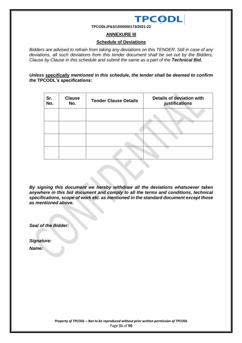
ANNEXURE III
Schedule of Deviations
Bidders are advised to refrain from taking any deviations on this TENDER. Still in case of any deviations, all such deviations from this tender document shall be set out by the Bidders, Clause by Clause in this schedule and submit the same as a part of the Technical Bid.
Unless specifically mentioned in this schedule, the tender shall be deemed to confirm the TPCODL’s specifications:
Sr. No.
Clause No.
Tender Clause Details Details of deviation with
justifications
By signing this document we hereby withdraw all the deviations whatsoever taken anywhere in this bid document and comply to all the terms and conditions, technical specifications, scope of work etc. as mentioned in the standard document except those as mentioned above.
Seal of the Bidder:
Signature:
Name:
TPCODL/P&S/1000000173/2021-22
Property of TPCODL – Not to be reproduced without prior written permission of TPCODL Page 32 of 90
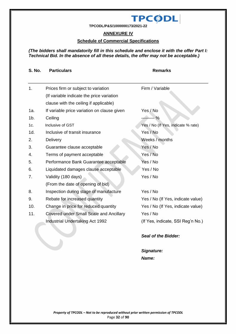
ANNEXURE IV
Schedule of Commercial Specifications
(The bidders shall mandatorily fill in this schedule and enclose it with the offer Part I: Technical Bid. In the absence of all these details, the offer may not be acceptable.)
S. No. Particulars Remarks
1. Prices firm or subject to variation Firm / Variable
(If variable indicate the price variation
clause with the ceiling if applicable)
1a. If variable price variation on clause given Yes / No
1b. Ceiling --------- %
1c. Inclusive of GST Yes / No (If Yes, indicate % rate)
1d. Inclusive of transit insurance Yes / No
2. Delivery Weeks / months
3. Guarantee clause acceptable Yes / No
4. Terms of payment acceptable Yes / No
5. Performance Bank Guarantee acceptable Yes / No
6. Liquidated damages clause acceptable Yes / No
7. Validity (180 days) Yes / No
(From the date of opening of bid)
8. Inspection during stage of manufacture Yes / No
9. Rebate for increased quantity Yes / No (If Yes, indicate value)
10. Change in price for reduced quantity Yes / No (If Yes, indicate value)
11. Covered under Small Scale and Ancillary Yes / No
Industrial Undertaking Act 1992 (If Yes, indicate, SSI Reg’n No.)
Seal of the Bidder:
Signature:
Name:
TPCODL/P&S/1000000173/2021-22
Property of TPCODL – Not to be reproduced without prior written permission of TPCODL Page 33 of 90
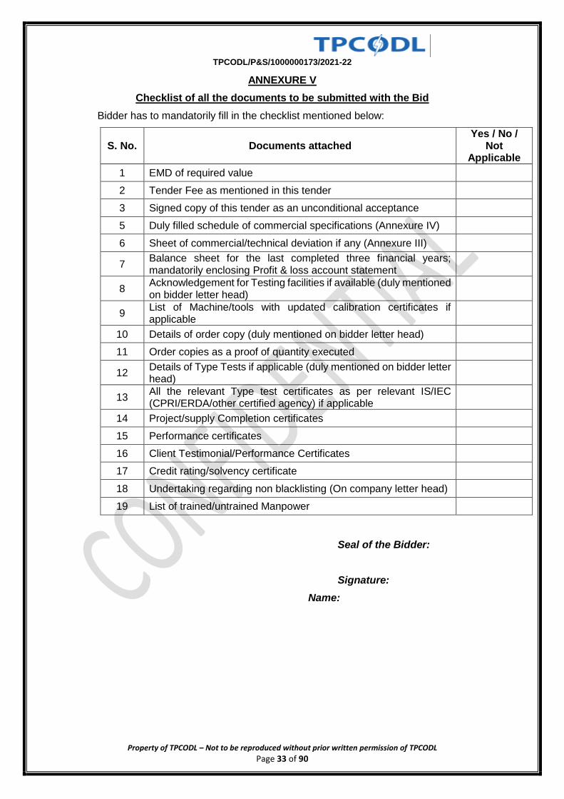
ANNEXURE V
Checklist of all the documents to be submitted with the Bid
Bidder has to mandatorily fill in the checklist mentioned below:
S. No. Documents attached Yes / No /
Not Applicable
1 EMD of required value
2 Tender Fee as mentioned in this tender
3 Signed copy of this tender as an unconditional acceptance
5 Duly filled schedule of commercial specifications (Annexure IV)
6 Sheet of commercial/technical deviation if any (Annexure III)
7 Balance sheet for the last completed three financial years; mandatorily enclosing Profit & loss account statement
8 Acknowledgement for Testing facilities if available (duly mentioned on bidder letter head)
9 List of Machine/tools with updated calibration certificates if applicable
10 Details of order copy (duly mentioned on bidder letter head)
11 Order copies as a proof of quantity executed
12 Details of Type Tests if applicable (duly mentioned on bidder letter head)
13 All the relevant Type test certificates as per relevant IS/IEC (CPRI/ERDA/other certified agency) if applicable
14 Project/supply Completion certificates
15 Performance certificates
16 Client Testimonial/Performance Certificates
17 Credit rating/solvency certificate
18 Undertaking regarding non blacklisting (On company letter head)
19 List of trained/untrained Manpower
Seal of the Bidder:
Signature:
Name:
TPCODL/P&S/1000000173/2021-22
Property of TPCODL – Not to be reproduced without prior written permission of TPCODL Page 34 of 90
ANNEXURE VI
ACCEPTANCE FORM FOR PARTICIPATION IN REVERSE AUCTION EVENT
(To be signed and stamped by the bidder)
In a bid to make our entire procurement process more fair and transparent, TPCODL intends to use the reverse auctions as an integral part of the entire tendering process. All the bidders who are found as technically qualified based on the tender requirements shall be eligible to participate in the reverse auction event.
The following terms and conditions are deemed as accepted by the bidder on participation in the bid event:
1. TPCODL shall provide the user id and password to the authorized representative of the bidder. (Authorization Letter in lieu of the same shall be submitted along with the signed and stamped Acceptance Form).
2. TPCODL will make every effort to make the bid process transparent. However, the award decision by TPCODL would be final and binding on the supplier.
3. The bidder agrees to non-disclosure of trade information regarding the purchase, identity of TPCODL, bid process, bid technology, bid documentation and bid details.
4. The bidder is advised to understand the auto bid process to safeguard themselves against any possibility of non-participation in the auction event.
5. In case of bidding through Internet medium, bidders are further advised to ensure availability of the entire infrastructure as required at their end to participate in the auction event. Inability to bid due to telephone line glitch, internet response issues, software or hardware hangs, power failure or any other reason shall not be the responsibility of TPCODL.
6. In case of intranet medium, TPCODL shall provide the infrastructure to bidders. Further, TPCODL has sole discretion to extend or restart the auction event in case of any glitches in infrastructure observed which has restricted the bidders to submit the bids to ensure fair & transparent competitive bidding. In case of an auction event is restarted, the best bid as already available in the system shall become the start price for the new auction.
7. In case the bidder fails to participate in the auction event due any reason whatsoever, it shall be presumed that the bidder has no further discounts to offer and the initial bid as submitted by the bidder as a part of the tender shall be considered as the bidder’s final no regret offer. Any offline price bids received from a bidder in lieu of non-participation in the auction event shall be out-rightly rejected by TPCODL.
8. The bidder shall be prepared with competitive price quotes on the day of the bidding event.
9. The prices as quoted by the bidder during the auction event shall be inclusive of all the applicable taxes, duties and levies and shall be FOR at TPCODL site.
10. The prices submitted by a bidder during the auction event shall be binding on the bidder.
11. No requests for time extension of auction event shall be considered by TPCODL.
12. The original price bids of the bidders shall be reduced on pro-rata basis against each line item based on the final all-inclusive prices offered during conclusion of the auction event for arriving at Contract amount.
Signature & Seal of the Bidder
TPCODL/P&S/1000000173/2021-22
Property of TPCODL – Not to be reproduced without prior written permission of TPCODL Page 35 of 90
ANNEXURE VII
Scope of Work
To carry our site survey, supply and services for Supply and Installation of 11kV & LT lines and DTs of network as per items mentioned in Annexure-I. Division-wise BOQ is attached. The quantity mentioned is tentative and TPCODL reserves to modify the same as per organizational requirements. Payment shall be made as per actual quantity executed at site.
TPCODL/P&S/1000000173/2021-22
Property of TPCODL – Not to be reproduced without prior written permission of TPCODL Page 36 of 90
Guidelines for Geo Tagging of assets created under the Scheme up to DTR level.
While traversing in the field, the vendor MUST start from a Power Sub -Station (PSS)
Traversing along all the poles through the Segments of a feeder sequentially until the end
of it, terminating at a DTR. To start with capturing of geo tagging data of assets created
under the Scheme , onetime details for the selected Power Sub Station (PSS) needs to be
recorded as below:-
1. Substation Name
2. Substation Code
3. Voltage (In/Out) (viz. 33/11 KV or 66/11 KV)
4. Number of Incoming feeders
5. Number of Outgoing feeders
6. DISCOM Name
7. District Name
8. Contact details of Field officer conducting the Geotagging
a. Officer Name
b. Designation
c. Mobile Number
Vendor is required to create separate excel file (as per the template provided) for each
Power Substation (PSS) including respective outgoing 11KV Feeders. The excel file for a
PSS shall be saved as DISCOMNAME_DISTRICTNAME_ PSSNAME.xlsx. The Vendor to
submit the excel file and PDF copy of excel duly signed by respective Field officer and
Nodal officer.
Instruction to fill Excel Template:
Please refer to the sample Single Line Diagram attached.
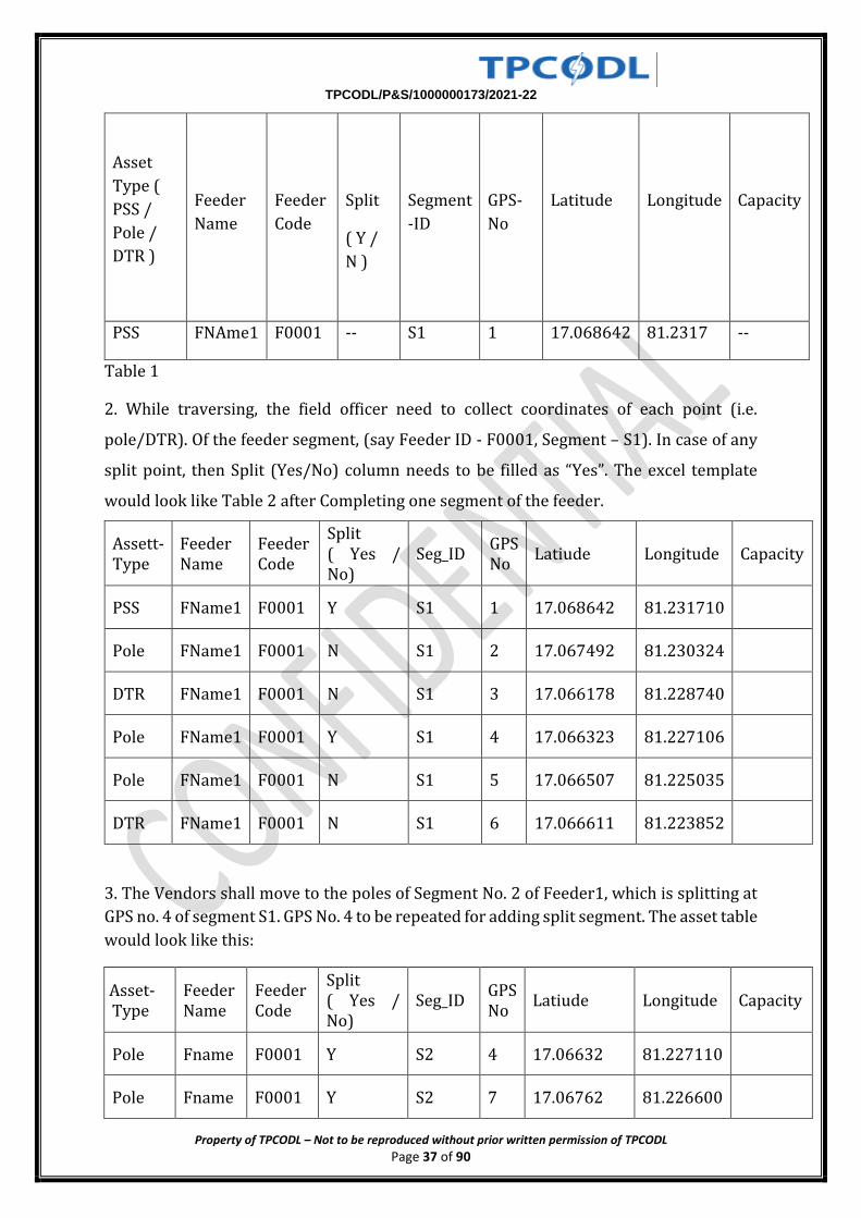
1. In order to collect Geotagging data, the Field officer should start from the Power Sub
Station (PSS). After capturing the PSS coordinates, the excel template would look as per
the table 1
below:-
TPCODL/P&S/1000000173/2021-22
Property of TPCODL – Not to be reproduced without prior written permission of TPCODL Page 37 of 90
Asset
Type (
PSS /
Pole /
DTR )
Feeder
Name
Feeder
Code
Split
( Y /
N )
Segment
-ID
GPS-
No
Latitude
Longitude
Capacity
PSS FNAme1 F0001 -- S1 1 17.068642 81.2317 --
Table 1
2. While traversing, the field officer need to collect coordinates of each point (i.e.
pole/DTR). Of the feeder segment, (say Feeder ID - F0001, Segment – S1). In case of any
split point, then Split (Yes/No) column needs to be filled as “Yes”. The excel template
would look like Table 2 after Completing one segment of the feeder.
Assett-Type
Feeder Name
Feeder Code
Split ( Yes / No)
Seg_ID GPS No
Latiude Longitude Capacity
PSS FName1 F0001 Y S1 1 17.068642 81.231710
Pole FName1 F0001 N S1 2 17.067492 81.230324
DTR FName1 F0001 N S1 3 17.066178 81.228740
Pole FName1 F0001 Y S1 4 17.066323 81.227106
Pole FName1 F0001 N S1 5 17.066507 81.225035
DTR FName1 F0001 N S1 6 17.066611 81.223852
3. The Vendors shall move to the poles of Segment No. 2 of Feeder1, which is splitting at
GPS no. 4 of segment S1. GPS No. 4 to be repeated for adding split segment. The asset table
would look like this:
Asset-Type
Feeder Name
Feeder Code
Split ( Yes / No)
Seg_ID GPS No
Latiude Longitude Capacity
Pole Fname F0001 Y S2 4 17.06632 81.227110
Pole Fname F0001 Y S2 7 17.06762 81.226600
TPCODL/P&S/1000000173/2021-22
Property of TPCODL – Not to be reproduced without prior written permission of TPCODL Page 38 of 90
DTR Fname F0001 N S2 8 17.06825 81.225380
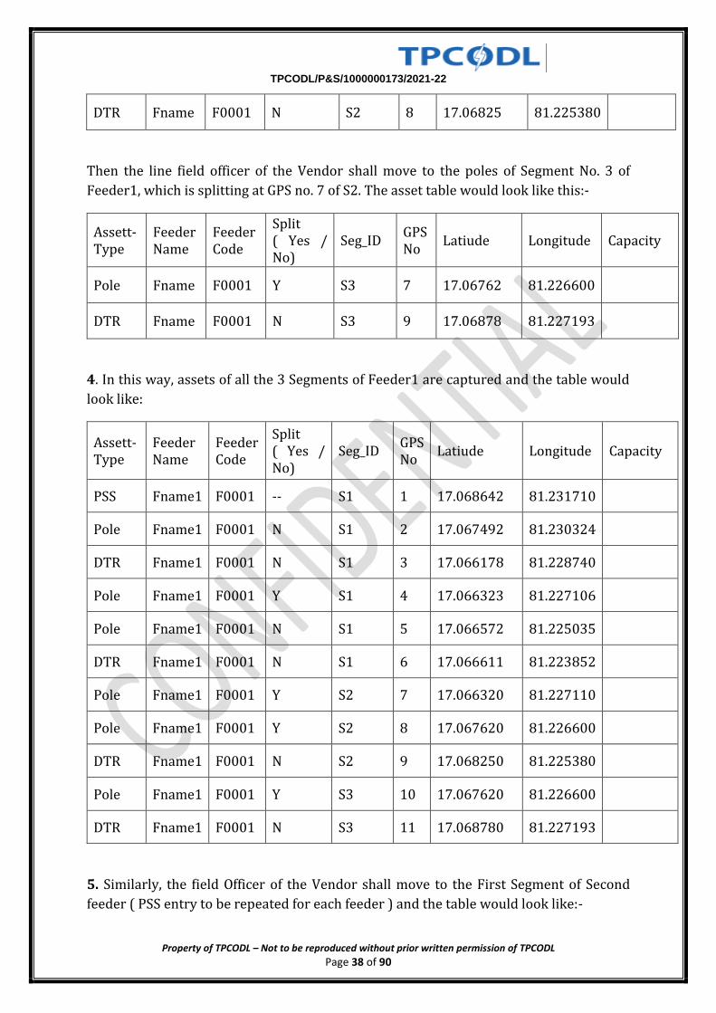
Then the line field officer of the Vendor shall move to the poles of Segment No. 3 of
Feeder1, which is splitting at GPS no. 7 of S2. The asset table would look like this:-
Assett-Type
Feeder Name
Feeder Code
Split ( Yes / No)
Seg_ID GPS No
Latiude Longitude Capacity
Pole Fname F0001 Y S3 7 17.06762 81.226600
DTR Fname F0001 N S3 9 17.06878 81.227193
4. In this way, assets of all the 3 Segments of Feeder1 are captured and the table would
look like:
Assett-Type
Feeder Name
Feeder Code
Split ( Yes / No)
Seg_ID GPS No
Latiude Longitude Capacity
PSS Fname1 F0001 -- S1 1 17.068642 81.231710
Pole Fname1 F0001 N S1 2 17.067492 81.230324
DTR Fname1 F0001 N S1 3 17.066178 81.228740
Pole Fname1 F0001 Y S1 4 17.066323 81.227106
Pole Fname1 F0001 N S1 5 17.066572 81.225035
DTR Fname1 F0001 N S1 6 17.066611 81.223852
Pole Fname1 F0001 Y S2 7 17.066320 81.227110
Pole Fname1 F0001 Y S2 8 17.067620 81.226600
DTR Fname1 F0001 N S2 9 17.068250 81.225380
Pole Fname1 F0001 Y S3 10 17.067620 81.226600
DTR Fname1 F0001 N S3 11 17.068780 81.227193
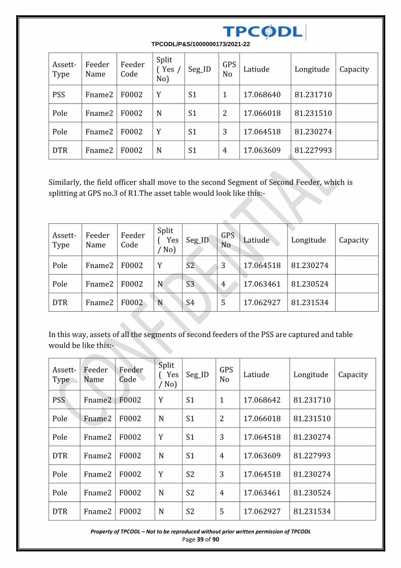
5. Similarly, the field Officer of the Vendor shall move to the First Segment of Second
feeder ( PSS entry to be repeated for each feeder ) and the table would look like:-
TPCODL/P&S/1000000173/2021-22
Property of TPCODL – Not to be reproduced without prior written permission of TPCODL Page 39 of 90
Assett-Type
Feeder Name
Feeder Code
Split ( Yes / No)
Seg_ID GPS No
Latiude Longitude Capacity
PSS Fname2 F0002 Y S1 1 17.068640 81.231710
Pole Fname2 F0002 N S1 2 17.066018 81.231510
Pole Fname2 F0002 Y S1 3 17.064518 81.230274
DTR Fname2 F0002 N S1 4 17.063609 81.227993
Similarly, the field officer shall move to the second Segment of Second Feeder, which is
splitting at GPS no.3 of R1.The asset table would look like this:-
Assett-Type
Feeder Name
Feeder Code
Split ( Yes / No)
Seg_ID GPS No
Latiude Longitude Capacity
Pole Fname2 F0002 Y S2 3 17.064518 81.230274
Pole Fname2 F0002 N S3 4 17.063461 81.230524
DTR Fname2 F0002 N S4 5 17.062927 81.231534
In this way, assets of all the segments of second feeders of the PSS are captured and table
would be like this:-
Assett-Type
Feeder Name
Feeder Code
Split ( Yes / No)
Seg_ID GPS No
Latiude Longitude Capacity
PSS Fname2 F0002 Y S1 1 17.068642 81.231710
Pole Fname2 F0002 N S1 2 17.066018 81.231510
Pole Fname2 F0002 Y S1 3 17.064518 81.230274
DTR Fname2 F0002 N S1 4 17.063609 81.227993
Pole Fname2 F0002 Y S2 3 17.064518 81.230274
Pole Fname2 F0002 N S2 4 17.063461 81.230524
DTR Fname2 F0002 N S2 5 17.062927 81.231534
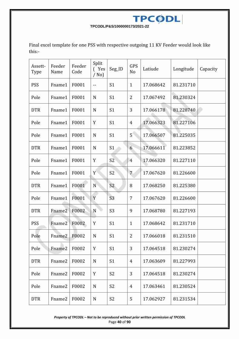
TPCODL/P&S/1000000173/2021-22
Property of TPCODL – Not to be reproduced without prior written permission of TPCODL Page 40 of 90
Final excel template for one PSS with respective outgoing 11 KV Feeder would look like
this:-
Assett-Type
Feeder Name
Feeder Code
Split ( Yes / No)
Seg_ID GPS No
Latiude Longitude Capacity
PSS Fname1 F0001 -- S1 1 17.068642 81.231710
Pole Fname1 F0001 N S1 2 17.067492 81.230324
DTR Fname1 F0001 N S1 3 17.066178 81.228740
Pole Fname1 F0001 Y S1 4 17.066323 81.227106
Pole Fname1 F0001 N S1 5 17.066507 81.225035
DTR Fname1 F0001 N S1 6 17.066611 81.223852
Pole Fname1 F0001 Y S2 4 17.066320 81.227110
Pole Fname1 F0001 Y S2 7 17.067620 81.226600
DTR Fname1 F0001 N S2 8 17.068250 81.225380
Pole Fname1 F0001 Y S3 7 17.067620 81.226600
DTR Fname2 F0002 N S3 9 17.068780 81.227193
PSS Fname2 F0002 Y S1 1 17.068642 81.231710
Pole Fname2 F0002 N S1 2 17.066018 81.231510
Pole Fname2 F0002 Y S1 3 17.064518 81.230274
DTR Fname2 F0002 N S1 4 17.063609 81.227993
Pole Fname2 F0002 Y S2 3 17.064518 81.230274
Pole Fname2 F0002 N S2 4 17.063461 81.230524
DTR Fname2 F0002 N S2 5 17.062927 81.231534
TPCODL/P&S/1000000173/2021-22
Property of TPCODL – Not to be reproduced without prior written permission of TPCODL Page 41 of 90
The above excel sheet should be filled by the Vendor & after counter signature of the
conceded SDO / DM should be furnished to Corporate Nodal Officer along with the single
line diagram as per the sample given in next page.
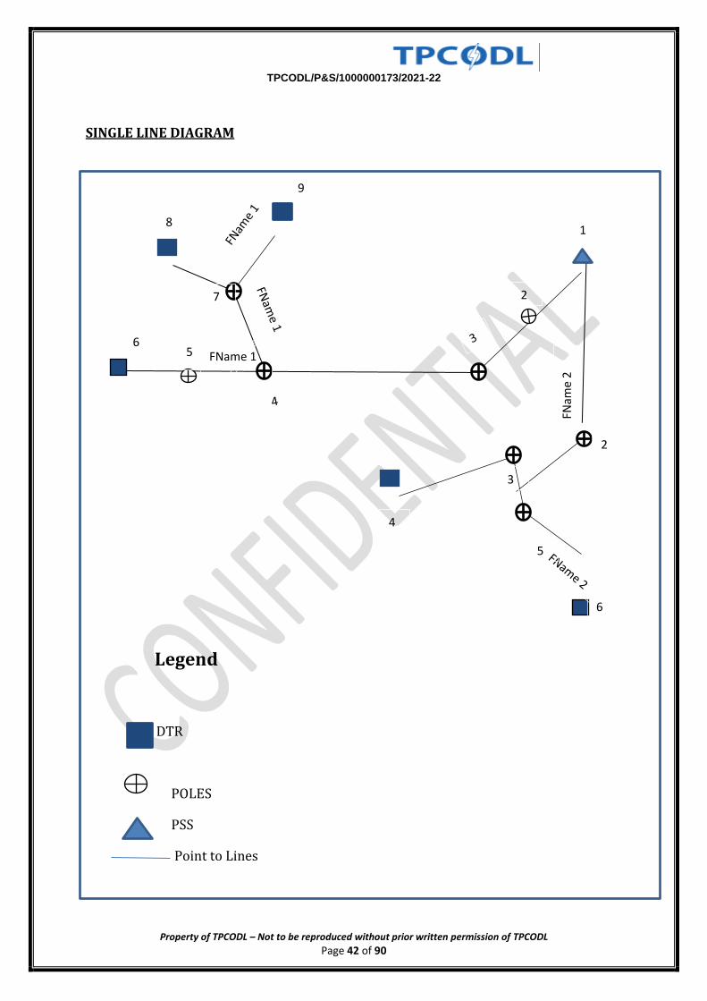
TPCODL/P&S/1000000173/2021-22
Property of TPCODL – Not to be reproduced without prior written permission of TPCODL Page 42 of 90
SINGLE LINE DIAGRAM
Legend
DTR
POLES
PSS
Point to Lines
FName 1
FNam
e 2
6
8
9
1
2
3
5
6
4
5
7 2
TPCODL/P&S/1000000173/2021-22
Property of TPCODL – Not to be reproduced without prior written permission of TPCODL Page 43 of 90
QUALITY CONTROL MECHANISM & INSPECTION PLAN OVERVIEW OF METHODOLOGY
1.In order to ensure proper Quality of materials as well as in installations in Govt. Aided
Scheme , the following comprehensive Quality Control Mechanism (QCM) has been
developed and to be meticulously adhered to by TPCODL and BAs ( Turnkey contractors)
for ensuring creation of Quality Infrastructure under the project.
TIER-I
The E & Q Team under Head- NEG & EQ designated as Project Implementing Agency’s
Quality Control Coordinator (PQCC). PIA shall prepare a detailed Quality Assurance
Program, which should ensure quality checks as below:-
a) TURNKEY CONTRACTOR
Inspections of all material as per MQP/Drawings/Technical Specifications
All villages to be inspected as per FQP basing on REC construction Manual and
Standards.
All 33/11 kV sub stations for quality of material as per MQP/Drawings/Technical
Specifications and works in the field asper FQP.
100% verification of Service BPL connections to UEHHs.
b) PROJECT IMPLEMENTING AGENCY (TPCODL)
Inspections of material as stipulated in MQP for all major materials/equipment i.e
PSC Poles, Conductors/Cables, DTR, LA and LTDBs. For other items,
inspections/testing/ witnessing of acceptance tests shall be as per
Drawings/Technical Specifications.
All villages to be inspected as per FQP.
All 33/11 kV sub stations for quality of material as per MQP/Drawings/Technical
Specifications and works in the field as per FQP.
100% verification of service connections to Households.
c) THIRD PARTY INSPCTION AGENCY (TPIA)
10% randomly selected inspections as per MQP for Distribution transformers,
conductors, energy meters & poles at pre-shipment stage at vendors’
works/testing labs.
TPCODL/P&S/1000000173/2021-22
Property of TPCODL – Not to be reproduced without prior written permission of TPCODL Page 44 of 90
50 % Villages on random sampling basis including 100% verification of HH
connections in 10% of 50% of villages inspected i.e. 5% villages and in each of the
remaining villages inspected i.e. 45% villages, at least 5 HH connections shall be
verified randomly selected from the list of connections provided till the date
of inspection.
33/11 kV sub stations for quality of works in the field on random sampling basis
100 % new sub stations along with associated HT/LT lines.
50 % augmentation of sub stations.
QUALITY CONTROL METHODOLOGY
2.1. Tier – I quality control involves parallel quality control checks by the turnkey
contractor,PIA & Independent Third party inspection agency (TPIA).
2.2 The Project Implementing agency shall be responsible for quality checks through
turnkey contractor & independent third party inspection agency. PIA Quality Control
Coordinator
(PQCC) nominated by PIA, shall be responsible for ensuring implementation of all quality
control checks under the first tier. PQCC shall be the nodal officer for any information
regarding inspection, testing and quality control under first tier.
2.3. PQCC shall ensure inspection of material to be supplied by various sub-vendors, at
their works, in line with Manufacturing Quality Plans (MQP) as finalized & agreed by PIA
with turnkey contractor. He shall inform the third party inspection agency & REC quality
coordinator (RQCC) of all the programs of testing of equipment at sub-vendors works so
that RQCC can also depute their representatives for witnessing pre-dispatch inspection
at the manufacturer’s works on sample-basis. In exceptional cases, where due to no
availability of inspector from PIA/TPIA/RQCC, witnessing of testing may be waived by
PIA and inform to RQCC. However, testing shall be carried out in line with
MQP/IS/Specification and report shall be submitted to PQCC for approval.
2.4. Quality in the field shall be controlled in line with the Field quality plans (FQP) to be
finalized & agreed by PIA with turnkey contractor.
2.5. PQCC shall be the custodian of all manufacturing and field-quality plans. He shall
ensure that field-quality plan is available at all project sites, so that PIA/turnkey
contractor/TPIA shall carryout testing and checks as per field quality plan. The site
personnel shall maintain proper records of testing and checks made by them. The same
TPCODL/P&S/1000000173/2021-22
Property of TPCODL – Not to be reproduced without prior written permission of TPCODL Page 45 of 90
shall be made available to RQCC & NQM whenever required. The PQCC shall ensure that
Quality Control Manual and all the guidelines are strictly followed.
Turnkey contractor’s set up for Quality Assurance and Audit
3.1 The turnkey contractor shall be primarily responsible for ensuring the quality of
material supplied & quality of works at site.
3.2 He shall submit all MQP and FQP to PQCC for approval and establish a proper
procedure to ensure checks as indicated in MQP & FQP for the materials.
3.3 Turnkey contractor shall designate an experienced & qualified engineer as quality
Engineer (QE) who shall be responsible for ensuring that all the quality checks required
are carried-out and shall ensure to keep proper records for quality maintained at site.
3.4 Quality Assurance shall be undertaken in the following areas of the project
implementation:-
a) Quality of material/equipment being supplied.
b) Quality of works in the field.
3.5 Quality of material/equipment being supplied:- For ensuring quality of material
/equipment, the following system/procedure shall be adopted:-
3.5.1:- A standard manufacturing quality plan shall be agreed with the turnkey contractor
for every equipment/material as which shall include the Stage Inspection during the
process of manufacturing, sourcing of raw-materials, quality checks of raw-material,
testing of final product –both type tests and routine/acceptance tests.
3.5.2 The turnkey contractor shall select the sub-vendors of various equipment based on
a process, which ensures quality material in the project.
3.5.3 QE shall ensure the presence of their qualified representative during
routine/acceptance tests, either at manufacturer’s premises or at independent
laboratories.
3.5.4 The type tests of DTR, Cable & LA shall be carried out only at CPRI/ERDA
laboratories and for other materials, CPRI / ERDA or at any Govt. testing laboratories.
Manufacturers may carry out type tests at their works however in such cases testing shall
be carried out in presence of representative of TPIA or RQCC or PQCC.
3.5.5 All the major materials shall be tested before dispatch in line with
MQP/Drawings/Technical specifications.
TPCODL/P&S/1000000173/2021-22
Property of TPCODL – Not to be reproduced without prior written permission of TPCODL Page 46 of 90
3.5.6 Assurance of Quality at field- The turnkey contractor shall establish a procedure
for quality checks during execution of the project by finalizing field quality plans (FQP)
with the PIA. The detailed field quality plan shall be made available and the same shall be
explained to all the field engineers & supervisors of the Turnkey contractor.
The Turnkey contractor shall submit quality audit reports, on periodic basis to the PIA.
Following checks shall be carried out in the field:
All villages to be inspected as per FQP
All 33/11kV sub-stations for quality of material as per MQP/Drawings/Technical
Specifications and works in the field as per FQP.
100% verification of HH connections.
100 % verification of materials at site prior to utilisation.
3.6 PIA’s set up for Quality Assurance and Audit
3.6.1 PIA shall also depute its own teams to undertake quality audit for material and field
execution. PIA shall be fully responsible for ensuring the quality of material supplied &
quality of works at site. He shall put in place a proper procedure to ensure checks as per
MQP & FQP.
3.6.2 PIA shall designate an experienced & qualified engineer as Quality Control
Coordinator (PQCC) along with a dedicated team who shall be responsible for ensuring
that all the quality checks are carried-out and shall ensure to keep proper records for
quality maintained at site.
3.6.3 Third-party inspection agency, RQCC and NQM shall be given free access to all
technical records by PIA through PQCC.
3.6.4 Quality Assurance shall be undertaken in the following areas of the project
implementation:-
a) Quality of material/equipment being supplied.
b) Quality of works in the field.
3.7.Quality of material/equipment being supplied- For ensuring quality of material
/equipment, the following system/procedure shall be adopted:-
3.7.1 A standard manufacturing quality plan shall be agreed with the vendors for every
major equipment/material as listed in Appendix-I which shall include the Stage
Inspection during the process of manufacturing, sourcing of raw-materials, quality
TPCODL/P&S/1000000173/2021-22
Property of TPCODL – Not to be reproduced without prior written permission of TPCODL Page 47 of 90
checks of raw-material, testing of final product –both type tests and routine/acceptance
tests.
3.7.2 The turnkey contractor shall select the sub-vendors of various equipment based on
a process, which ensures quality material in the project. All sub-vendors shall be
approved by PIA.
3.7.3 PQCC shall ensure presence of their qualified representative during
routine/acceptance tests, either at manufacturer’s premises or at independent
laboratories.
3.7.4 The type tests of DTR, Cable & LA shall be carried out only at CPRI/ERDA
laboratories and for other materials, CPRI / ERDA or at any Govt. testing laboratories.
Manufacturers may carry out type tests at their works however in such cases testing shall
be carried out in presence of representative of TPIA or RQCC or PQCC.
3.7.5 All materials shall be tested before dispatch in line with MQP/Drawings/Technical
specifications.
3.8. Assurance of Quality at field- The PIA shall establish a procedure for quality checks
during execution of the project by finalizing field quality plans (FQP) with the turn-key
contractor. The detailed field quality plan shall be made available and the same shall be
explained to all the field engineers & supervisors of PIA. The field quality document shall
clearly describe requirements for various raw materials used like steel, cement and sand
etc.
3.8.1 Following checks shall be carried out in the field:
• All villages to be inspected as per FQP.
• All 11 kV sub stations with associated HT/LT lines for quality of material as per
MQP/Drawings/Technical Specifications and works in the field as per FQP.
• 100% verification of Service connections to HHs.
3.8.2. Proper records shall be maintained at field office of PIA for all the checks and
tests made by the PIA and TPIA and will be shown to RQM during their inspection, if
asked for.
3.9. Third Party inspection agency (TPIA) shall be engaged by Govt / OPTCL for carrying
out independent quality checks. Their responsibility will be to inspect material at
manufacturers’ works before dispatch and to ensure that the works in the field are
carried-out as per norms and standard engineering practices in line with the
TPCODL/P&S/1000000173/2021-22
Property of TPCODL – Not to be reproduced without prior written permission of TPCODL Page 48 of 90
manufacturing and field quality plans. TPIA shall depute their personnel on receipt of
notice from PQCC.
3.9.1 Quality of material/equipment being supplied.
PIA shall ensure presence of their qualified representative in 10% randomly selected
inspections as per MQP for Distribution transformers, conductors, energy meters, poles
and insulators at pre-shipment stage at vendors ‘works/testing labs.
3.9.2 Assurance of Quality at field- The detailed field quality plan shall be made
available and the same shall be explained to all the field engineers & E&Q Team.
Quality of works shall be verified with reference to FQP.
Reports of Field Quality checks shall be supported by photographs.
The PQCC shall submit a report certifying satisfactory quality assurance for every
project on completion of all quality checks.
3.9.3. Wherever works carried out are found unsatisfactory, compliance with respect to
rectification shall be submitted by PQCC to PIA and the same may be re-inspected by
TPIA, if required. Recurrent adverse reports about quality of works in any project will
entail withholding of release of funds.
3.10. The turn-key contractor shall make necessary arrangements at site for checking of
earth-resistance, conductor size, route-length etc.
3.11 PQCC shall submit a monthly report about the progress and quality checks carried-
out.
4.0 FIELD INSPECTION 4.1 Contractor shall fill the Format-A, Format-B and Format-C as enclosed in Annexure
and may get verified by representative of PIA/TPIA/RQM/NQM whoever be available.
4.2 Turnkey Contractor shall furnish all records of Quality of material/equipment and
inspection report of Field checks performed during execution/installation by him to
PQCC. The record must include at least followings:-
a) FQP
b) List of sub-vendors
c) Acceptance tests report of equipment
d) Type tests reports of equipment
e) Routine tests reports of equipment
f) Field inspections reports as per FQP and in FORMAT-A, B and C
4.3 PQCC shall maintain the records of tests witnessed by them and furnish report in
TPCODL/P&S/1000000173/2021-22
Property of TPCODL – Not to be reproduced without prior written permission of TPCODL Page 49 of 90
Format-D.
5.0 GUIDELINES FOR QUALITY CONTROL DURING CONSTRUCTION
5.1 Documents required - The supervision and inspection shall be carried out based on
the following documents to be provided by the project implementing agency (PIA) :-
(i) Approved route map with pole schedule.
(ii) Quality assurance plan agreed upon by the PIA and the executing agency (turnkey
contractor)
(iii) Contract documents/Letter of award & special conditions of the contract
(iv) Technical specifications of the turnkey contract, for supply and erection of all
equipment and materials.
(v) Sanctioned detailed project report (DPR) for the project district with all revisions/
modifications.
(vi) Relevant drawings/ blue prints, area distribution maps and schematic diagrams.
(vii) REC Specifications and Construction Standards.
(viii) Booklet of the Amendments to REC Specification and Construction Standards
(ix) CEA construction standard Regulatuions.
(x) L2 network/bar chart/PERT network
5.2 PROJECT MONITORING & SUPERVISION
5.2.1 Physical verification: Physical verification has to be carried out in project
villages, in each sanctioned project, in which electrification works & HH services have
been reported by the PIA to have been completed or carried out.
5.2.2 Monitoring teams: The project is to be monitored by a dedicated monitoring team.
The verification will be based on the village wise progress reported which will be
provided periodically at the end of each month by the Divisions / Project Team.
TABLE-I EQUIPMENT SPECIFICATIONS
Sl. No. Particulars REC Code BIS code
A. Pre-stressed cement concrete poles [PCC]
1 For 11 KV and LT overhead lines 15/1979 IS: 1678/2905/7321
2 For 33 KV overhead lines 24/1987 IS: 1678/2905/7321
3 High tensile steel wires for PCC poles 62/1993 IS: 6003 or 1785
B. Bare conductors, insulated cables & wires
1 Bare Conductors – ACSR & AAC 1/1993 IS: 398
2 Bare Conductors – AAAC 33/1994 IS: 398
3 Aerial bunched cables (ABC) for 11 KV lines 64/1993 IS: 7098/8130/ 398/ ST-3 of IEC 502
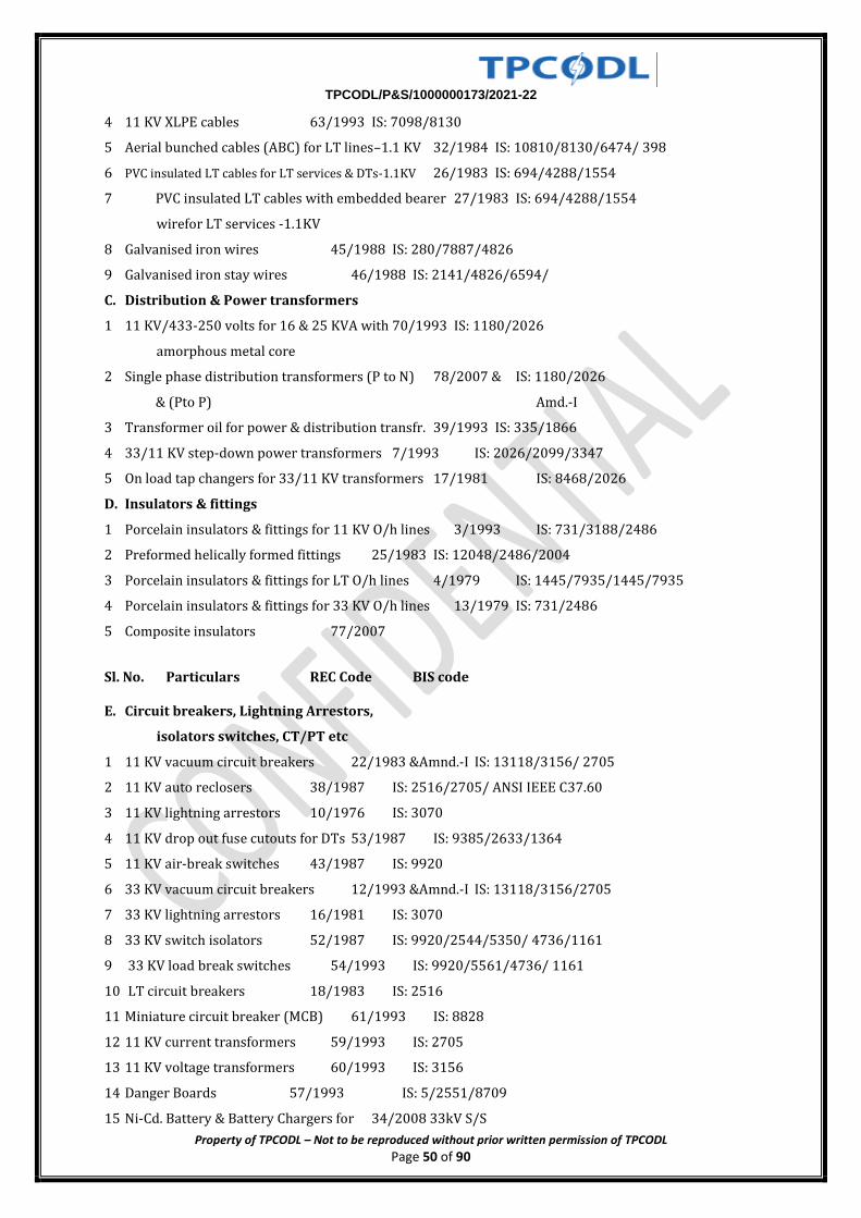
TPCODL/P&S/1000000173/2021-22
Property of TPCODL – Not to be reproduced without prior written permission of TPCODL Page 50 of 90
4 11 KV XLPE cables 63/1993 IS: 7098/8130
5 Aerial bunched cables (ABC) for LT lines–1.1 KV 32/1984 IS: 10810/8130/6474/ 398
6 PVC insulated LT cables for LT services & DTs-1.1KV 26/1983 IS: 694/4288/1554
7 PVC insulated LT cables with embedded bearer 27/1983 IS: 694/4288/1554
wirefor LT services -1.1KV
8 Galvanised iron wires 45/1988 IS: 280/7887/4826
9 Galvanised iron stay wires 46/1988 IS: 2141/4826/6594/
C. Distribution & Power transformers
1 11 KV/433-250 volts for 16 & 25 KVA with 70/1993 IS: 1180/2026
amorphous metal core
2 Single phase distribution transformers (P to N) 78/2007 & IS: 1180/2026
& (Pto P) Amd.-I
3 Transformer oil for power & distribution transfr. 39/1993 IS: 335/1866
4 33/11 KV step-down power transformers 7/1993 IS: 2026/2099/3347
5 On load tap changers for 33/11 KV transformers 17/1981 IS: 8468/2026
D. Insulators & fittings
1 Porcelain insulators & fittings for 11 KV O/h lines 3/1993 IS: 731/3188/2486
2 Preformed helically formed fittings 25/1983 IS: 12048/2486/2004
3 Porcelain insulators & fittings for LT O/h lines 4/1979 IS: 1445/7935/1445/7935
4 Porcelain insulators & fittings for 33 KV O/h lines 13/1979 IS: 731/2486
5 Composite insulators 77/2007
Sl. No. Particulars REC Code BIS code E. Circuit breakers, Lightning Arrestors,
isolators switches, CT/PT etc
1 11 KV vacuum circuit breakers 22/1983 &Amnd.-I IS: 13118/3156/ 2705
2 11 KV auto reclosers 38/1987 IS: 2516/2705/ ANSI IEEE C37.60
3 11 KV lightning arrestors 10/1976 IS: 3070
4 11 KV drop out fuse cutouts for DTs 53/1987 IS: 9385/2633/1364
5 11 KV air-break switches 43/1987 IS: 9920
6 33 KV vacuum circuit breakers 12/1993 &Amnd.-I IS: 13118/3156/2705
7 33 KV lightning arrestors 16/1981 IS: 3070
8 33 KV switch isolators 52/1987 IS: 9920/2544/5350/ 4736/1161
9 33 KV load break switches 54/1993 IS: 9920/5561/4736/ 1161
10 LT circuit breakers 18/1983 IS: 2516
11 Miniature circuit breaker (MCB) 61/1993 IS: 8828
12 11 KV current transformers 59/1993 IS: 2705
13 11 KV voltage transformers 60/1993 IS: 3156
14 Danger Boards 57/1993 IS: 5/2551/8709
15 Ni-Cd. Battery & Battery Chargers for 34/2008 33kV S/S
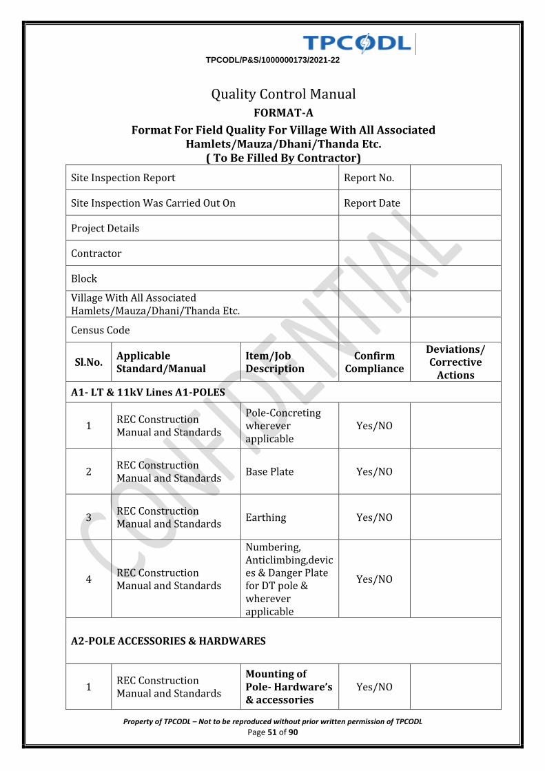
TPCODL/P&S/1000000173/2021-22
Property of TPCODL – Not to be reproduced without prior written permission of TPCODL Page 51 of 90
Quality Control Manual
FORMAT-A
Format For Field Quality For Village With All Associated Hamlets/Mauza/Dhani/Thanda Etc.
( To Be Filled By Contractor)
Site Inspection Report Report No.
Site Inspection Was Carried Out On Report Date
Project Details
Contractor
Block
Village With All Associated Hamlets/Mauza/Dhani/Thanda Etc.
Census Code
Sl.No. Applicable Standard/Manual
Item/Job Description
Confirm Compliance
Deviations/ Corrective
Actions
A1- LT & 11kV Lines A1-POLES
1 REC Construction Manual and Standards
Pole-Concreting wherever applicable
Yes/NO
2 REC Construction Manual and Standards
Base Plate Yes/NO
3 REC Construction Manual and Standards
Earthing Yes/NO
4 REC Construction Manual and Standards
Numbering, Anticlimbing,devices & Danger Plate for DT pole & wherever applicable
Yes/NO
A2-POLE ACCESSORIES & HARDWARES
1 REC Construction Manual and Standards
Mounting of Pole- Hardware’s & accessories
Yes/NO
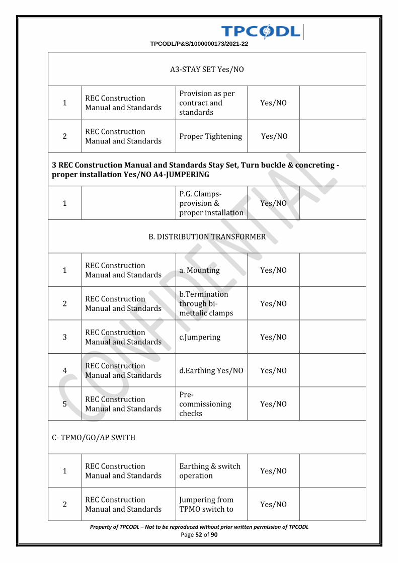
TPCODL/P&S/1000000173/2021-22
Property of TPCODL – Not to be reproduced without prior written permission of TPCODL Page 52 of 90
A3-STAY SET Yes/NO
1 REC Construction Manual and Standards
Provision as per contract and standards
Yes/NO
2 REC Construction Manual and Standards
Proper Tightening Yes/NO
3 REC Construction Manual and Standards Stay Set, Turn buckle & concreting -proper installation Yes/NO A4-JUMPERING
1 P.G. Clamps-provision & proper installation
Yes/NO
B. DISTRIBUTION TRANSFORMER
1 REC Construction Manual and Standards
a. Mounting Yes/NO
2 REC Construction Manual and Standards
b.Termination through bi-mettalic clamps
Yes/NO
3 REC Construction Manual and Standards
c.Jumpering Yes/NO
4 REC Construction Manual and Standards
d.Earthing Yes/NO Yes/NO
5 REC Construction Manual and Standards
Pre-commissioning checks
Yes/NO
C- TPMO/GO/AP SWITH
1 REC Construction Manual and Standards
Earthing & switch operation
Yes/NO
2 REC Construction Manual and Standards
Jumpering from TPMO switch to
Yes/NO
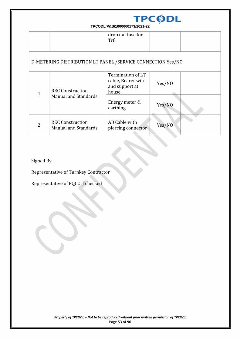
TPCODL/P&S/1000000173/2021-22
Property of TPCODL – Not to be reproduced without prior written permission of TPCODL Page 53 of 90
drop out fuse for Trf.
D-METERING DISTRIBUTION LT PANEL /SERVICE CONNECTION Yes/NO
1 REC Construction Manual and Standards
Termination of LT cable, Bearer wire and support at house
Yes/NO
Energy meter & earthing
Yes/NO
2 REC Construction Manual and Standards
AB Cable with piercing connector
Yes/NO
Signed By
Representative of Turnkey Contractor
Representative of PQCC if checked
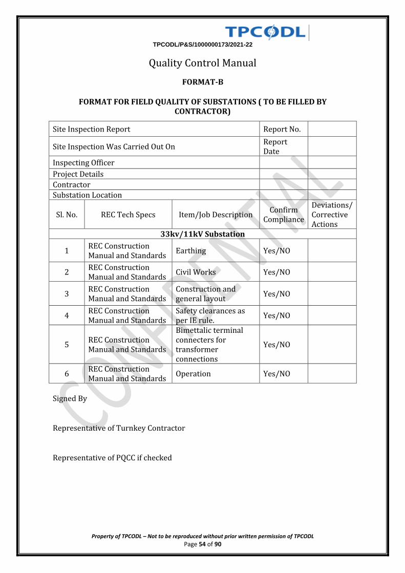
TPCODL/P&S/1000000173/2021-22
Property of TPCODL – Not to be reproduced without prior written permission of TPCODL Page 54 of 90
Quality Control Manual
FORMAT-B
FORMAT FOR FIELD QUALITY OF SUBSTATIONS ( TO BE FILLED BY CONTRACTOR)
Site Inspection Report Report No.
Site Inspection Was Carried Out On Report Date
Inspecting Officer
Project Details
Contractor
Substation Location
Sl. No. REC Tech Specs Item/Job Description Confirm
Compliance
Deviations/ Corrective Actions
33kv/11kV Substation
1 REC Construction Manual and Standards
Earthing Yes/NO
2 REC Construction Manual and Standards
Civil Works Yes/NO
3 REC Construction Manual and Standards
Construction and general layout
Yes/NO
4 REC Construction Manual and Standards
Safety clearances as per IE rule.
Yes/NO
5 REC Construction Manual and Standards
Bimettalic terminal connecters for transformer connections
Yes/NO
6 REC Construction Manual and Standards
Operation Yes/NO
Signed By
Representative of Turnkey Contractor
Representative of PQCC if checked
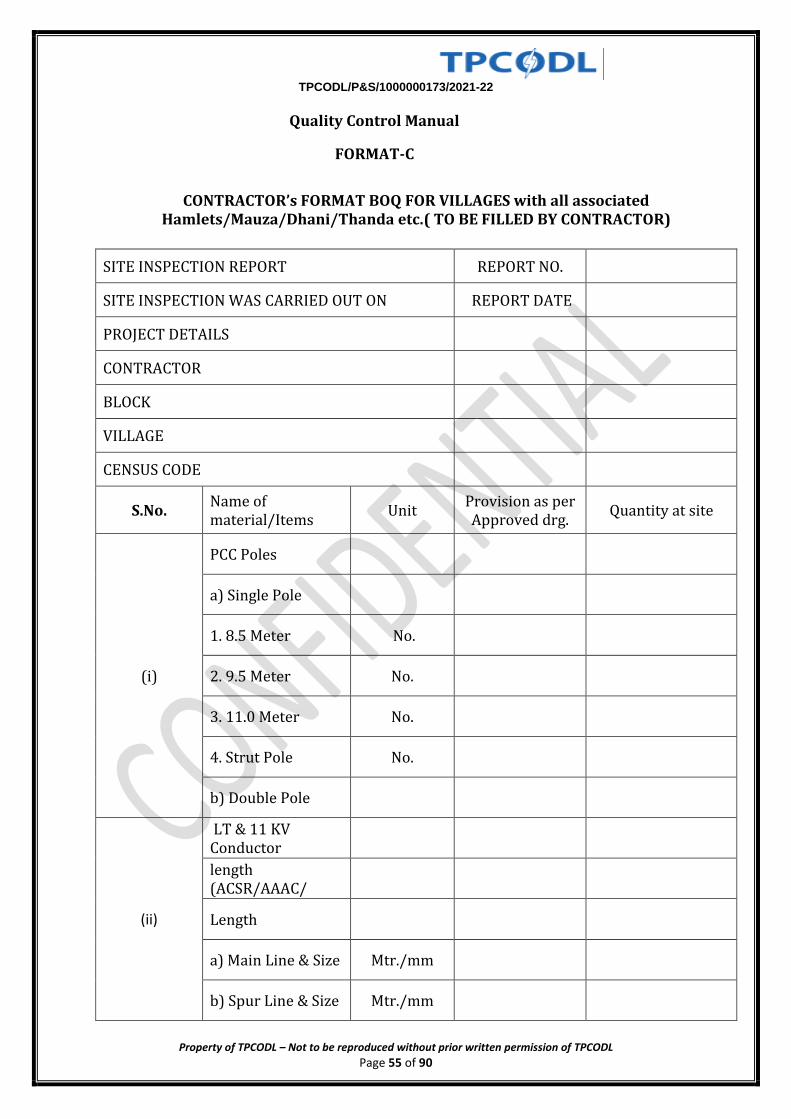
TPCODL/P&S/1000000173/2021-22
Property of TPCODL – Not to be reproduced without prior written permission of TPCODL Page 55 of 90
Quality Control Manual
FORMAT-C
CONTRACTOR’s FORMAT BOQ FOR VILLAGES with all associated Hamlets/Mauza/Dhani/Thanda etc.( TO BE FILLED BY CONTRACTOR)
SITE INSPECTION REPORT REPORT NO.
SITE INSPECTION WAS CARRIED OUT ON REPORT DATE
PROJECT DETAILS
CONTRACTOR
BLOCK
VILLAGE
CENSUS CODE
S.No. Name of material/Items
Unit Provision as per Approved drg.
Quantity at site
(i)
PCC Poles
a) Single Pole
1. 8.5 Meter No.
2. 9.5 Meter No.
3. 11.0 Meter No.
4. Strut Pole No.
b) Double Pole
(ii)
LT & 11 KV Conductor
length (ACSR/AAAC/
Length
a) Main Line & Size Mtr./mm
b) Spur Line & Size Mtr./mm
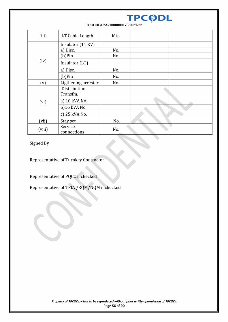
TPCODL/P&S/1000000173/2021-22
Property of TPCODL – Not to be reproduced without prior written permission of TPCODL Page 56 of 90
(iii) LT Cable Length Mtr.
(iv)
Insulator (11 KV) a) Disc. No. (b)Pin No.
Insulator (LT)
a) Disc. No.
(b)Pin No.
(v) Ligthening arrester No.
(vi)
Distribution Transfm.
a) 10 kVA No.
b)16 kVA No.
c) 25 kVA No.
(vii) Stay set No.
(viii) Service connections
No.
Signed By
Representative of Turnkey Contractor
Representative of PQCC if checked
Representative of TPIA /RQM/NQM if checked
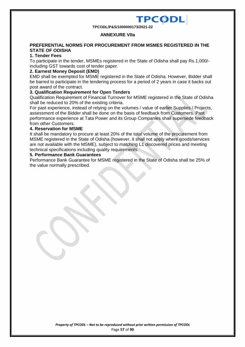
TPCODL/P&S/1000000173/2021-22
Property of TPCODL – Not to be reproduced without prior written permission of TPCODL Page 57 of 90
ANNEXURE VIIa PREFERENTIAL NORMS FOR PROCUREMENT FROM MSMES REGISTERED IN THE STATE OF ODISHA 1. Tender Fees To participate in the tender, MSMEs registered in the State of Odisha shall pay Rs.1,000/- including GST towards cost of tender paper. 2. Earnest Money Deposit (EMD) EMD shall be exempted for MSME registered in the State of Odisha. However, Bidder shall be barred to participate in the tendering process for a period of 2 years in case it backs out post award of the contract. 3. Qualification Requirement for Open Tenders Qualification Requirement of Financial Turnover for MSME registered in the State of Odisha shall be reduced to 20% of the existing criteria. For past experience, instead of relying on the volumes / value of earlier Supplies / Projects, assessment of the Bidder shall be done on the basis of feedback from Customers. Past performance experience at Tata Power and its Group Companies shall supersede feedback from other Customers. 4. Reservation for MSME It shall be mandatory to procure at least 20% of the total volume of the procurement from MSME registered in the State of Odisha (however, it shall not apply where goods/services are not available with the MSME), subject to matching L1 discovered prices and meeting technical specifications including quality requirements. 5. Performance Bank Guarantees Performance Bank Guarantee for MSME registered in the State of Odisha shall be 25% of the value normally prescribed.
TPCODL/P&S/1000000173/2021-22
Property of TPCODL – Not to be reproduced without prior written permission of TPCODL Page 58 of 90
SAFETY POLICY AND SAFETY TERMS AND CONDITIONS
1. Objective
The Tata Power engages contractor workforce to execute, run and maintain various operating sites and facilities across locations for various business verticals including Generation, Transmission, Distribution and Renewable. The activities range from project execution, operation, maintenance to facilities management.
The management of contractor safety represents a significant challenge for management. Tata Power has a responsibility to ensure that contractors are provided with enough information and support to enable them to conduct their roles safely and without endangering health and safety of their own workforce or that of our staff.
To ensure reduction in reportable injuries and achieve goal of zero accidents, first edition of contractor safety code of conduct was launched successfully in the year 2014. Since last four years after the launch of CSCC, Tata Power could achieve the objective of reduction in reportable injuries and fatalities.
Over the period, as the system was being matured, a need was felt to make second revision of the CSCC process. Objective of second revision is improve existing CSCC system and make it user friendly.
2. Scope: This procedure applies to all operating and project sites of The Tata Power Company Ltd and Group companies including new businesses like EV charging, Home Automation etc.
3. Definitions
3.1. Order Manager: Order Manager is the Tata Power representative, who has the ownership of the given job.
3.2. Site Safety Management Plan: It is the safety plan agreed between Contractor and Tata Power. It will contain the entire job specific safety requirement and will be signed by the contractor.
3.3. Contractor: An individual or a company that provides services to Tata Power
under a signed contract.
3.4. Emergency: a serious, unexpected or dangerous situation requiring immediate action, which may result in loss of revenue/property, business discontinuity. In case of Emergency*, services may be procured by selecting the qualified vendor based on the vendor category without the safety bid evaluation. It must be approved by MB level and above.
3.5. Expert Service jobs: Jobs which needs expert services of contractor which
does not involve direct exposure to the potential risk or work which involves
only supervisory work such as expert for turbine overhaul, expert for boiler
overhaul, expert for pump and motor, expert for compressor overhaul.
3.6. Head of the Division: Business in charge of the division who is overall
custodian of the generating station or transmission division or distribution
division.
3.7. Category A Vendor: Vendor eligible to carry out Very High & High risk (as
per Tata Power Hazard Identification and Risk Analysis Procedure) and /or
TPCODL/P&S/1000000173/2021-22
Property of TPCODL – Not to be reproduced without prior written permission of TPCODL Page 59 of 90
Long-Term Contract related to operation and maintenance (O&M) of plant.
Vendors must fulfil the requirement specified for Category A in Appendix 12-
CSMF-5 of this document.
3.8. Category B Vendor: Vendors eligible to carry out technical jobs, that are
classified under Medium /low risk. Vendors must fulfil the requirement
specified for Category B in Appendix 12-CSMF-5 of this document.
3.9. Category C Vendor: Vendors eligible for to carry out low or very low risk administrative and office jobs. For this he must fulfil the requirement specified for Category C in Appendix 12-CSMF-5 of this document.
3.10. Category D Vendor: All Consultants, Medical Practitioners or vendors taking job from Tata Power and working from their own premises (e.g. motor rewinding at vendor’s shop floor, equipment sent for repair to vendor’s works etc.) are classified as Category D Vendor
3.11. High Risk Jobs: A Job or its activities are considered as Very High or
High Risk when Order manager apply the “Tata Power Hazard
Identification and Risk Analysis” procedure and found safety risk
associated with are under Very High or High category. Indicative lists of
jobs are given in appendix 15 of this document.
3.12. Medium Risk Jobs: Jobs or its activities are considered as medium risk
when Order manager apply “Tata Power Hazard Identification and Risk
Analysis” procedure and found the same as Medium Risk.
3.13. Low Risk Jobs: Any job or its activities are considered as Low or Very
low risk while Order manager, calculate it by applying “Tata Power
Hazard Identification and Risk Analysis” procedure and found it under
Low or Very Low category.
3.14. Long Duration Jobs: When the duration of job is 12 months or more, it is
considered as Long duration job
3.15. High Value Jobs: When the value of the job contract is Rs. One Crore or more it
will be considered as High value job.
4. Responsibilities
4.1 Order Manager: Order Manager is the Tata Power representative, who is responsible for:
4.1.1 Finalizing the Site Safety Management Plan along with Contractor, Safety
Concurrences Group, Divisional Safety Head and Expert (External or Internal) if
required.
4.1.2 Supervise and ensure work is carried out as per the Site Safety Management Plan
including agreed Risk Assessment (HIRA/JSA) and Method Statement.
4.1.3 Conduct audit and evaluate Safety Performance of contractor.
4.1.4 Ensure contractors adhere to all statutory provisions.
TPCODL/P&S/1000000173/2021-22
Property of TPCODL – Not to be reproduced without prior written permission of TPCODL Page 60 of 90
4.1.5 In case any deviation is needed in agreed safety management plan or in CSCC
process for execution of job, Management of Change procedure will be applicable,
and approval may be obtained from divisional head /Cluster head.
4.2 Contractor: The person, entity or organisation who is executing the job for Tata Power
under a contractual agreement and will be responsible for the following
4.2.1 To follow all Tata Power Critical Safety Procedure, Rules and guidelines given in
Safety Terms and Conditions
4.2.2 Undertake job as per Site Safety Management Plan CSM-F10 and method statements agreed with Tata Power.
4.2.3 Raise any concerns with regard to their work and its safety with the Tata Power Order Manager.
4.2.4 Report all injuries, near misses, unsafe acts/conditions, and occurrences to the Tata Power Order Manager immediately.
4.2.5 Ensure that all sub-contractors follow the Tata Power Safety Procedure and agreed Site Safety Management Plan CSM-F10.
4.2.6 To follow all statutory requirements as per the laws of the land. 4.2.7 All vendors applying for A category jobs or submitting quote for high risk jobs shall
obtain certificates of ISO 9001, ISO14001 and ISO45001 before submitting quote for high risk Jobs.
4.3 Safety Concurrence Group: It is Cross Functional Team constituted by Corporate
Safety Team, which will have representatives from Execution department, Divisional
safety and Corporate / Divisional contracts. SCG will be responsible for the following
4.3.1 Assessment of Safety Potential of new vendor before registration as per CSM-F1-Safety Category Qualification Form.
4.3.2 Safety Evaluation of the bids as per evaluation format CSM-F-9 Safety Bid Evaluation Criteria
4.3.3 Finalization of the Site Safety Management Plan CSM-F-10 submitted by the contractor.
4.3.4 Corporate Safety Team / Cluster Safety Head will be part of SCG during Safety Bid Evaluation for following types of jobs 4.3.4.1 High-Risk jobs to be carried out in Annual Overhaul / Major Shutdowns and Outages. 4.3.4.2 Capex jobs of High-Risk Category
5.1 Vendor Registration
For Vendor Registration, Corporate Contract will issue following documents for evaluation
of contractor’s safety capability
1) CSM-F1 –Safety Category Qualification Form
2) Safety Terms and Conditions
The document Safety Terms and Conditions provides the information about Tata Power
safety System to the contractor. Contractor will submit the CSM-F1- Safety Category
Qualification Form with all relevant details and documents to Vendor Registration Initiator,
which will in turn forward it to Safety Concurrence Group (SCG) for evaluation. The SCG
will evaluate the details submitted by the contractor based on a predetermined criteria CSM-
F-5 Safety Potential Evaluation Criteria for Vendor Registration and will determine the
category (Category A/B/C/D) for which the contractor will be registered. As mentioned in
the above criteria, a site visit may also be organized by SCG prior to registration under
Category A and B. In case, the contractor does not qualify the safety criteria, the contractor
TPCODL/P&S/1000000173/2021-22
Property of TPCODL – Not to be reproduced without prior written permission of TPCODL Page 61 of 90
will not be registered. However, he may apply afresh for registration after 6 months. Please
refer Appendix 1: Process Flow Chart for Vendor Registration.
5.2 Bid evaluation
At the time of placing the Purchase Requisition (PR), Order Manager is required to declare
the risk involved in the of the job (i.e. High Risk / Medium Risk / Low Risk jobs, based on
the RPN in HIRA. If the Job is “High Risk” or “Long Duration”, then RFQ will be attached
with following documents:
1) CSM-F7- Blank Safety Competency Form
2) CSM-F8 PPE requirements
3) Safety Terms and Conditions
4) Job Specific Safety Requirement (Educational and Professional Qualification, Skill &
Experience Manpower, Tools and Tackles (e.g. man lifter, use of drone, use &
availability of rescue kit), Work Methodology etc.)
Otherwise the RFQ will be attached only with Safety Terms and Conditions. Long term and
low value jobs (see definition) are exempted from the CSCC process.
Corporate Contracts will collect duly filledCSM-F7 Safety Competency Form along with the
bid. All other stakeholders will also put their efforts to get all relevant safety data during
meeting / discussions with the vendor. SCG will evaluate the document as per the CSM-F9
Safety bid evaluation criteria. If any specific condition related to Contract is required to
convey to contractor, Site safety team will attach the same as Annexure for specific
conditions of job and submit it to contract team along with safety bid evaluation form.
Commercial bid of contractor will be considered for evaluation by contract team only if
contractor is qualified in safety bid. Site Safety Management Plan, defining the complete
procedure of executing the job at site will be signed by the contractor and SCG after mutual
agreement. CC will attach a copy of site safety Management Plan and any specific condition
of contract along with PO to the successful bidder. Please refer Appendix 6: Process Flow
Chart for issuing RFQ and PO significant health and safety risk associated with it.
5.3 Safety Performance Evaluation
During the time of job execution, regular site inspection will be carried out by the Tata Power
officials and violations will be dealt as per CSM–F4 Safety Violation Penalty Criteria. Apart
from this, monthly safety performance of the contractor will be evaluated based on the
predetermined criteria as per CSM-F11 safety Performance Score and monthly score will
be maintained by the Order Manager. Certain percentage of each running bill will be
retained as Safety Retention amount and will be released on the basis of Safety
Performance Score at certain intervals as defined in CSM- F-3- Safety Performance
Evaluation Criteria. Please refer Appendix 10: Process Flow Chart for Safety Performance
Evaluation. Percentage of retention amount is mentioned in safety terms and conditions.
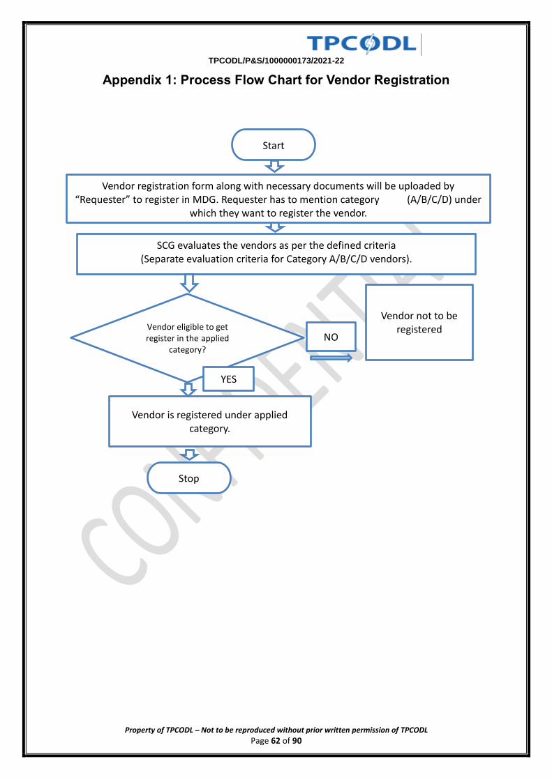
TPCODL/P&S/1000000173/2021-22
Property of TPCODL – Not to be reproduced without prior written permission of TPCODL Page 62 of 90
Appendix 1: Process Flow Chart for Vendor Registration
Vendor eligible to get register in the applied
category?
Start
Vendor registration form along with necessary documents will be uploaded by “Requester” to register in MDG. Requester has to mention category (A/B/C/D) under
which they want to register the vendor.
SCG evaluates the vendors as per the defined criteria (Separate evaluation criteria for Category A/B/C/D vendors).
YES
NO
Vendor is registered under applied category.
Vendor not to be registered
Stop
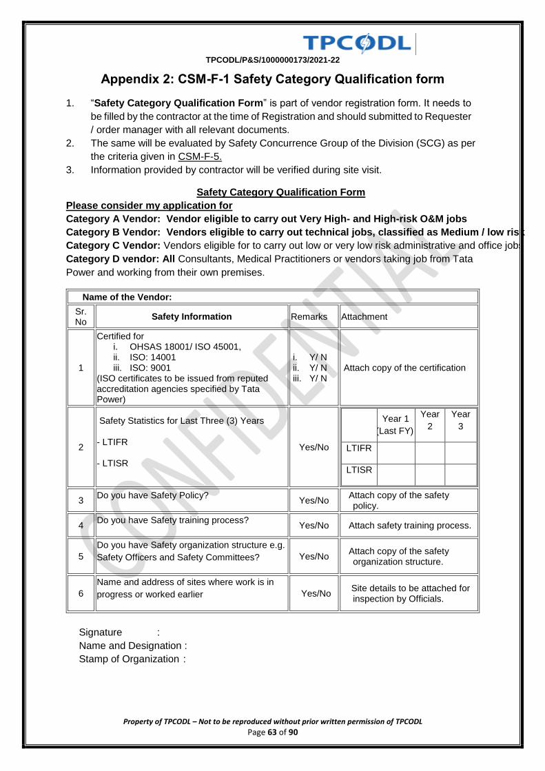
TPCODL/P&S/1000000173/2021-22
Property of TPCODL – Not to be reproduced without prior written permission of TPCODL Page 63 of 90
Appendix 2: CSM-F-1 Safety Category Qualification form
1. “Safety Category Qualification Form” is part of vendor registration form. It needs to
be filled by the contractor at the time of Registration and should submitted to Requester
/ order manager with all relevant documents.
2. The same will be evaluated by Safety Concurrence Group of the Division (SCG) as per
the criteria given in CSM-F-5.
3. Information provided by contractor will be verified during site visit.
Safety Category Qualification Form
Please consider my application for
Category A Vendor: Vendor eligible to carry out Very High- and High-risk O&M jobs
Category B Vendor: Vendors eligible to carry out technical jobs, classified as Medium / low risk
Category C Vendor: Vendors eligible for to carry out low or very low risk administrative and office jobs
Category D vendor: All Consultants, Medical Practitioners or vendors taking job from Tata
Power and working from their own premises.
Name of the Vendor:
Sr. No
Safety Information Remarks Attachment
1
Certified for i. OHSAS 18001/ ISO 45001, ii. ISO: 14001 iii. ISO: 9001
(ISO certificates to be issued from reputed accreditation agencies specified by Tata Power)
i. Y/ N ii. Y/ N iii. Y/ N
Attach copy of the certification
2
Safety Statistics for Last Three (3) Years
- LTIFR
- LTISR
Yes/No
Year 1
(Last FY)
Year
2
Year
3
LTIFR
LTISR
3 Do you have Safety Policy?
Yes/No Attach copy of the safety policy.
4 Do you have Safety training process?
Yes/No Attach safety training process.
5
Do you have Safety organization structure e.g.
Safety Officers and Safety Committees? Yes/No Attach copy of the safety organization structure.
6
Name and address of sites where work is in
progress or worked earlier Yes/No Site details to be attached for inspection by Officials.
Signature :
Name and Designation :
Stamp of Organization :
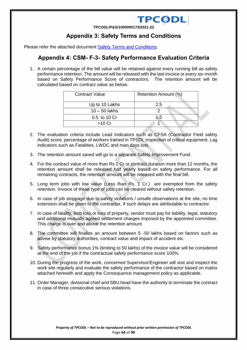
TPCODL/P&S/1000000173/2021-22
Property of TPCODL – Not to be reproduced without prior written permission of TPCODL Page 64 of 90
Appendix 3: Safety Terms and Conditions
Please refer the attached document Safety Terms and Conditions.
Appendix 4: CSM- F-3- Safety Performance Evaluation Criteria
1. A certain percentage of the bill value will be retained against every running bill as safety performance retention. The amount will be released with the last invoice or every six-month based on Safety Performance Score of contractors. The retention amount will be calculated based on contract value as below.
Contract Value Retention Amount (%)
Up to 10 Lakhs 2.5
10 – 50 lakhs 2
0.5 to 10 Cr 1.5
>10 Cr 1
2. The evaluation criteria include Lead Indicators such as CFSA (Contractor Field safety Audit) score, percentage of workers trained in TPSDI, inspection of critical equipment. Lag indicators such as Fatalities, LWDC and man days lost.
3. The retention amount saved will go to a separate Safety Improvement Fund.
4. For the contract value of more than Rs 1 Cr or contract duration more than 12 months, the retention amount shall be released half yearly based on safety performance. For all remaining contracts, the retention amount will be released with the final bill.
5. Long term jobs with low value (Less than Rs. 1 Cr.) are exempted from the safety retention. Invoice of these type of jobs can be cleared without safety retention.
6. In case of job stoppage due to safety violations / unsafe observations at the site, no time extension shall be given to the contractor, if such delays are attributable to contractor.
7. In case of fatality, limb loss or loss of property, vendor must pay for liability, legal, statutory and additional mutually agreed settlement charges imposed by the appointed committee. This charge is over and above the retention amount.
8. The committee will finalize an amount between 5 -50 lakhs based on factors such as advise by statutory authorities, contract value and impact of accident etc.
9. Safety performance bonus 1% (limiting to 50 lakhs) of the invoice value will be considered at the end of the job if the contractual safety performance score 100%.
10. During the progress of the work, concerned Supervisor/Engineer will visit and inspect the work site regularly and evaluate the safety performance of the contractor based on matrix attached herewith and apply the Consequence management policy as applicable.
11. Order Manager, divisional chief and SBU head have the authority to terminate the contract in case of three consecutive serious violations.
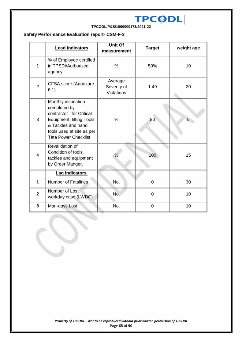
TPCODL/P&S/1000000173/2021-22
Property of TPCODL – Not to be reproduced without prior written permission of TPCODL Page 65 of 90
Safety Performance Evaluation report- CSM-F-3
Lead Indicators Unit Of
measurement Target weight age
1
% of Employee certified
in TPSDI/Authorized
agency
% 50% 10
2 CFSA score (Annexure
6.1)
Average
Severity of
Violations
1.49 20
3
Monthly inspection
completed by
contractor for Critical
Equipment, lifting Tools
& Tackles and hand
tools used at site as per
Tata Power Checklist
% 80 5
4
Revalidation of
Condition of tools,
tackles and equipment
by Order Manger.
% 100 15
Lag Indicators
1 Number of Fatalities No. 0 30
2 Number of Lost
workday case (LWDC) No. 0 10
3 Man-days Lost No. 0 10
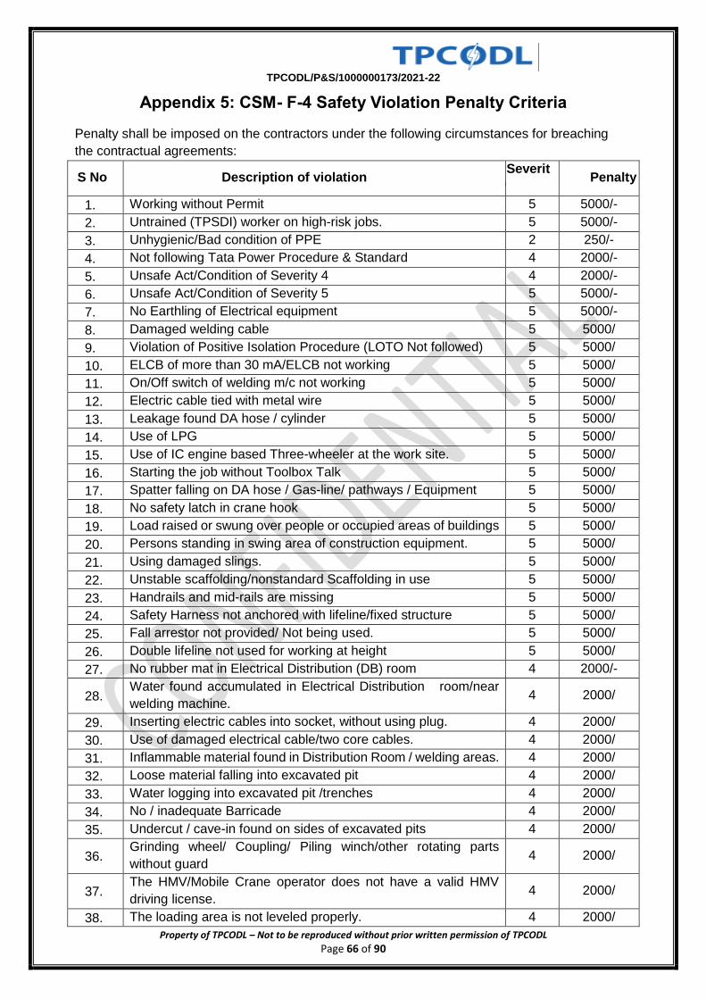
TPCODL/P&S/1000000173/2021-22
Property of TPCODL – Not to be reproduced without prior written permission of TPCODL Page 66 of 90
Appendix 5: CSM- F-4 Safety Violation Penalty Criteria
Penalty shall be imposed on the contractors under the following circumstances for breaching
the contractual agreements:
S No Description of violation Severit
y Penalty /
1. Working without Permit 5 5000/-
2. Untrained (TPSDI) worker on high-risk jobs. 5 5000/-
3. Unhygienic/Bad condition of PPE 2 250/-
4. Not following Tata Power Procedure & Standard 4 2000/-
5. Unsafe Act/Condition of Severity 4 4 2000/-
6. Unsafe Act/Condition of Severity 5 5 5000/-
7. No Earthling of Electrical equipment 5 5000/-
8. Damaged welding cable 5 5000/
9. Violation of Positive Isolation Procedure (LOTO Not followed) 5 5000/
10. ELCB of more than 30 mA/ELCB not working 5 5000/
11. On/Off switch of welding m/c not working 5 5000/
12. Electric cable tied with metal wire 5 5000/
13. Leakage found DA hose / cylinder 5 5000/
14. Use of LPG 5 5000/
15. Use of IC engine based Three-wheeler at the work site. 5 5000/
16. Starting the job without Toolbox Talk 5 5000/
17. Spatter falling on DA hose / Gas-line/ pathways / Equipment 5 5000/
18. No safety latch in crane hook 5 5000/
19. Load raised or swung over people or occupied areas of buildings 5 5000/
20. Persons standing in swing area of construction equipment. 5 5000/
21. Using damaged slings. 5 5000/
22. Unstable scaffolding/nonstandard Scaffolding in use 5 5000/
23. Handrails and mid-rails are missing 5 5000/
24. Safety Harness not anchored with lifeline/fixed structure 5 5000/
25. Fall arrestor not provided/ Not being used. 5 5000/
26. Double lifeline not used for working at height 5 5000/
27. No rubber mat in Electrical Distribution (DB) room 4 2000/-
28. Water found accumulated in Electrical Distribution room/near
welding machine. 4 2000/
29. Inserting electric cables into socket, without using plug. 4 2000/
30. Use of damaged electrical cable/two core cables. 4 2000/
31. Inflammable material found in Distribution Room / welding areas. 4 2000/
32. Loose material falling into excavated pit 4 2000/
33. Water logging into excavated pit /trenches 4 2000/
34. No / inadequate Barricade 4 2000/
35. Undercut / cave-in found on sides of excavated pits 4 2000/
36. Grinding wheel/ Coupling/ Piling winch/other rotating parts
without guard 4 2000/
37. The HMV/Mobile Crane operator does not have a valid HMV
driving license. 4 2000/
38. The loading area is not leveled properly. 4 2000/
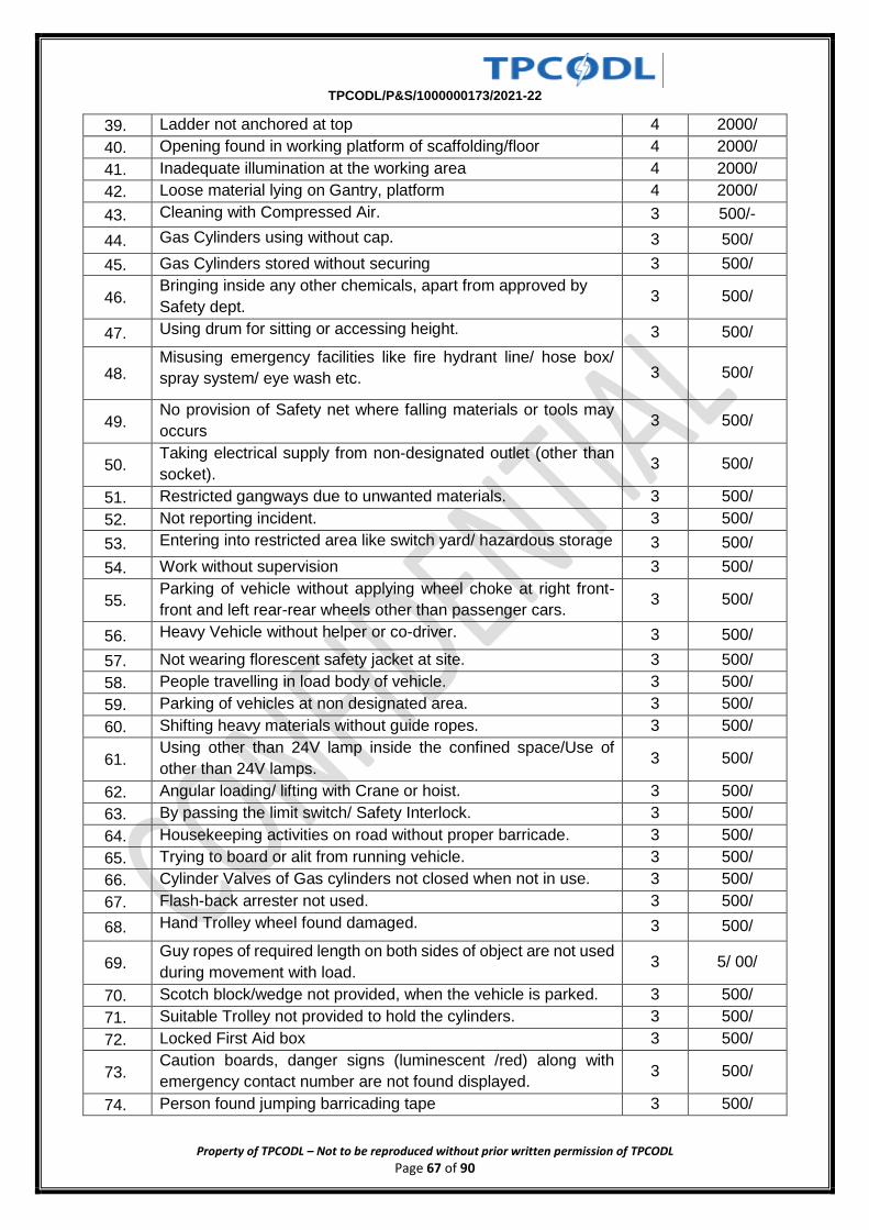
TPCODL/P&S/1000000173/2021-22
Property of TPCODL – Not to be reproduced without prior written permission of TPCODL Page 67 of 90
39. Ladder not anchored at top 4 2000/
40. Opening found in working platform of scaffolding/floor 4 2000/
41. Inadequate illumination at the working area 4 2000/
42. Loose material lying on Gantry, platform 4 2000/
43. Cleaning with Compressed Air. 3 500/-
44. Gas Cylinders using without cap. 3 500/
45. Gas Cylinders stored without securing 3 500/
46. Bringing inside any other chemicals, apart from approved by
Safety dept. 3 500/
47. Using drum for sitting or accessing height. 3 500/
48. Misusing emergency facilities like fire hydrant line/ hose box/
spray system/ eye wash etc. 3 500/
49. No provision of Safety net where falling materials or tools may
occurs 3 500/
50. Taking electrical supply from non-designated outlet (other than
socket). 3 500/
51. Restricted gangways due to unwanted materials. 3 500/
52. Not reporting incident. 3 500/
53. Entering into restricted area like switch yard/ hazardous storage 3 500/
54. Work without supervision 3 500/
55. Parking of vehicle without applying wheel choke at right front-
front and left rear-rear wheels other than passenger cars. 3 500/
56. Heavy Vehicle without helper or co-driver. 3 500/
57. Not wearing florescent safety jacket at site. 3 500/
58. People travelling in load body of vehicle. 3 500/
59. Parking of vehicles at non designated area. 3 500/
60. Shifting heavy materials without guide ropes. 3 500/
61. Using other than 24V lamp inside the confined space/Use of
other than 24V lamps. 3 500/
62. Angular loading/ lifting with Crane or hoist. 3 500/
63. By passing the limit switch/ Safety Interlock. 3 500/
64. Housekeeping activities on road without proper barricade. 3 500/
65. Trying to board or alit from running vehicle. 3 500/
66. Cylinder Valves of Gas cylinders not closed when not in use. 3 500/
67. Flash-back arrester not used. 3 500/
68. Hand Trolley wheel found damaged. 3 500/
69. Guy ropes of required length on both sides of object are not used
during movement with load. 3 5/ 00/
70. Scotch block/wedge not provided, when the vehicle is parked. 3 500/
71. Suitable Trolley not provided to hold the cylinders. 3 500/
72. Locked First Aid box 3 500/
73. Caution boards, danger signs (luminescent /red) along with
emergency contact number are not found displayed. 3 500/
74. Person found jumping barricading tape 3 500/
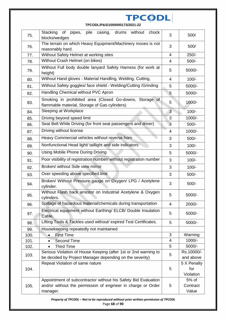
TPCODL/P&S/1000000173/2021-22
Property of TPCODL – Not to be reproduced without prior written permission of TPCODL Page 68 of 90
75. Stacking of pipes, pile casing, drums without chock
blocks/wedges 3 500/
76. The terrain on which Heavy Equipment/Machinery moves is not
reasonably hard. 3 500/
77. Without Safety Helmet at working sites 4 250/-
78. Without Crash Helmet (on bikes) 4 500/-
79. Without Full body double lanyard Safety Harness (for work at
height) 5 5000/-
80. Without Hand gloves - Material Handling, Welding, Cutting, 4 100/-
81. Without Safety goggles/ face shield - Welding/Cutting /Grinding 5 5000/-
82. Handling Chemical without PVC Apron 5 5000/-
83. Smoking in prohibited area (Closed Go-downs, Storage of
flammable material, Storage of Gas cylinders) 5 1000/-
84. Sleeping at Workplace 3 100/-
85. Driving beyond speed limit 3 1000/-
86. Seat Belt While Driving (for front seat passengers and driver) 3 500/-
87. Driving without license 4 1000/-
88. Heavy Commercial vehicles without reverse horn 3 500/-
89. Nonfunctional Head light/ taillight and side indicators 3 100/-
90. Using Mobile Phone During Driving 5 5000/-
91. Poor visibility of registration number/ without registration number 3 100/-
92. Broken/ without Side view mirror 3 100/-
93. Over speeding above specified limit 3 500/-
94. Broken/ Without Pressure gauge on Oxygen/ LPG / Acetylene
cylinder. 3 500/-
95. Without Flash back arrestor on Industrial Acetylene & Oxygen
cylinders. 5 5000/-
96. Spillage of hazardous material/chemicals during transportation 4 2000/-
97. Electrical equipment without Earthing/ ELCB/ Double Insulation
Cable. 5 5000/-
98. Lifting Tools & Tackles used without/ expired Test Certificates. 5 5000/-
99. Housekeeping repeatedly not maintained
100. First Time 3 Warning
101. Second Time 4 1000/-
102. Third Time 5 5000/-
103. Serious Violation of House Keeping (after 1st or 2nd warning to
be decided by Project Manager depending on the severity) 5
Rs.10000/-
and above
104.
Repeat Violation of same nature
5
5 X Penalty
for
Violation
105.
Appointment of subcontractor without his Safety Bid Evaluation
and/or without the permission of engineer in charge or Order
manager.
5
5% of
Contract
Value
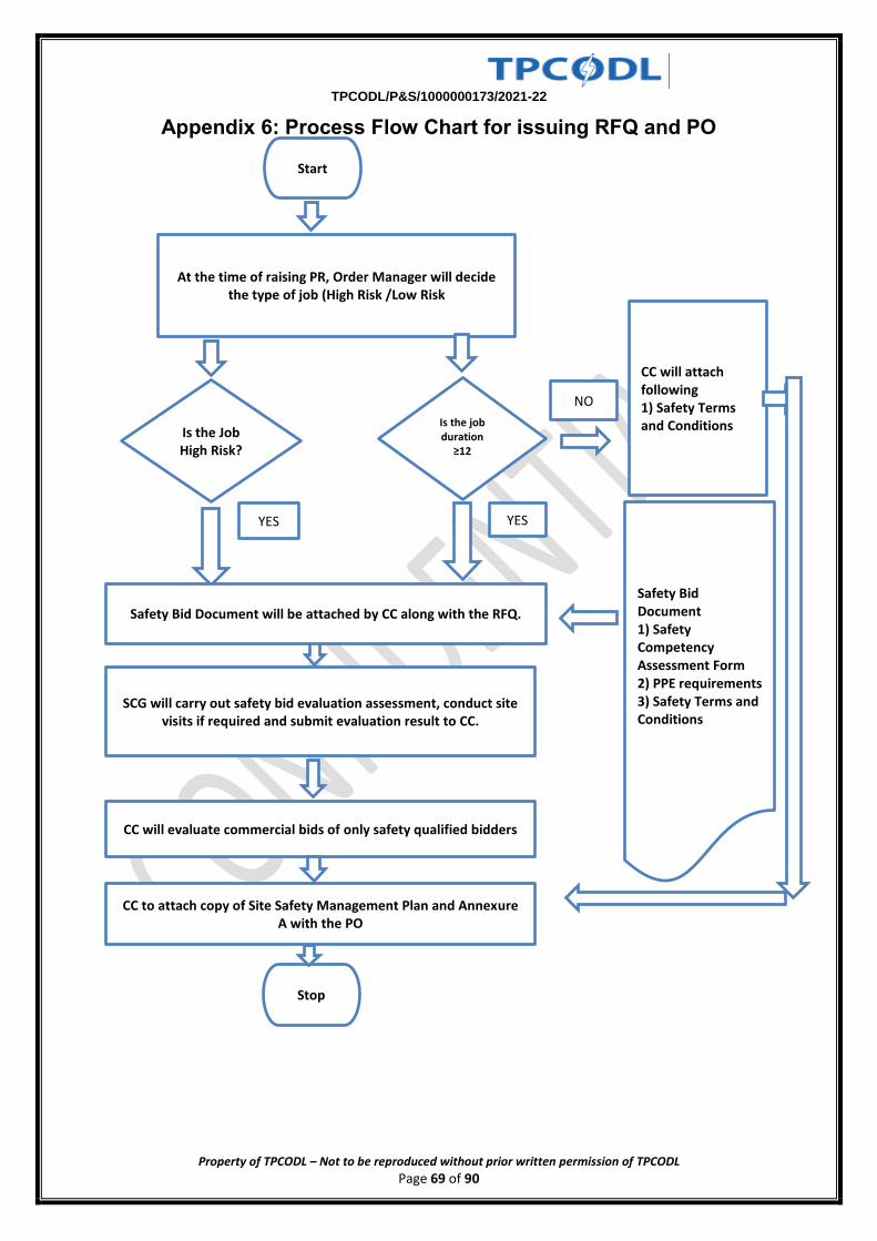
TPCODL/P&S/1000000173/2021-22
Property of TPCODL – Not to be reproduced without prior written permission of TPCODL Page 69 of 90
Appendix 6: Process Flow Chart for issuing RFQ and PO
At the time of raising PR, Order Manager will decide the type of job (High Risk /Low Risk
Start
CC will evaluate commercial bids of only safety qualified bidders
CC to attach copy of Site Safety Management Plan and Annexure A with the PO
Stop
CC will attach following 1) Safety Terms and Conditions
YES
Is the Job High Risk?
NO
Safety Bid Document will be attached by CC along with the RFQ.
Safety Bid Document 1) Safety Competency Assessment Form 2) PPE requirements 3) Safety Terms and Conditions
YES
SCG will carry out safety bid evaluation assessment, conduct site visits if required and submit evaluation result to CC.
Is the job duration
≥12 month?
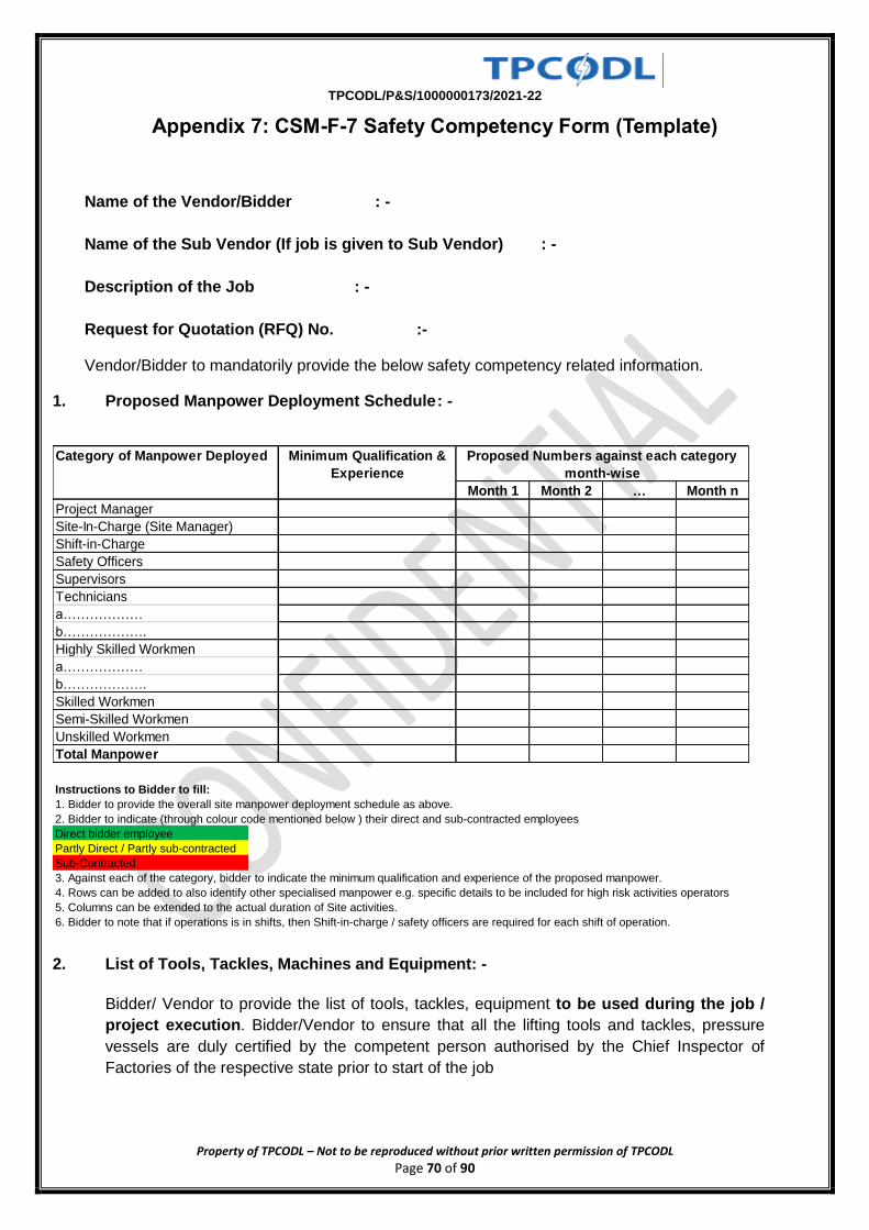
TPCODL/P&S/1000000173/2021-22
Property of TPCODL – Not to be reproduced without prior written permission of TPCODL Page 70 of 90
Appendix 7: CSM-F-7 Safety Competency Form (Template)
Name of the Vendor/Bidder : -
Name of the Sub Vendor (If job is given to Sub Vendor) : -
Description of the Job : -
Request for Quotation (RFQ) No. :-
Vendor/Bidder to mandatorily provide the below safety competency related information.
1. Proposed Manpower Deployment Schedule : -
2. List of Tools, Tackles, Machines and Equipment: -
Bidder/ Vendor to provide the list of tools, tackles, equipment to be used during the job /
project execution. Bidder/Vendor to ensure that all the lifting tools and tackles, pressure
vessels are duly certified by the competent person authorised by the Chief Inspector of
Factories of the respective state prior to start of the job
Month 1 Month 2 … Month n
Project Manager
Site-In-Charge (Site Manager)
Shift-in-Charge
Safety Officers
Supervisors
Technicians
a………………
b……………….
Highly Skilled Workmen
a………………
b……………….
Skilled Workmen
Semi-Skilled Workmen
Unskilled Workmen
Total Manpower
Proposed Numbers against each category
month-wise
Category of Manpower Deployed Minimum Qualification &
Experience
Instructions to Bidder to fill:
1. Bidder to provide the overall site manpower deployment schedule as above.
2. Bidder to indicate (through colour code mentioned below ) their direct and sub-contracted employees
Direct bidder employee
Partly Direct / Partly sub-contracted
Sub-Contracted
3. Against each of the category, bidder to indicate the minimum qualification and experience of the proposed manpower.
4. Rows can be added to also identify other specialised manpower e.g. specific details to be included for high risk activities operators
5. Columns can be extended to the actual duration of Site activities.
6. Bidder to note that if operations is in shifts, then Shift-in-charge / safety officers are required for each shift of operation.
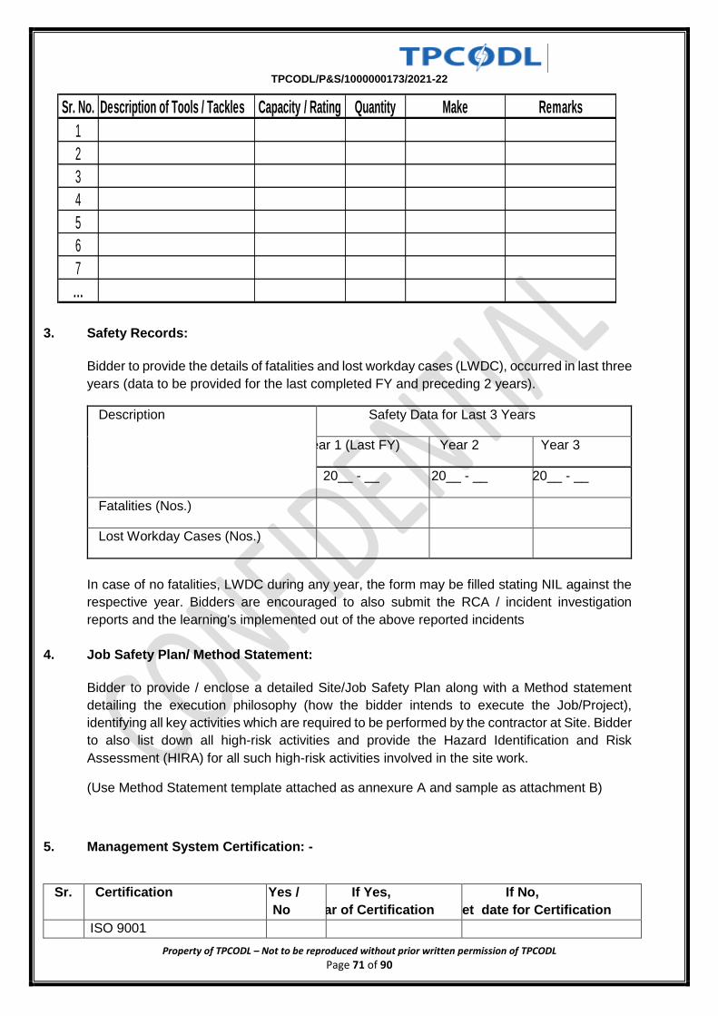
TPCODL/P&S/1000000173/2021-22
Property of TPCODL – Not to be reproduced without prior written permission of TPCODL Page 71 of 90
3. Safety Records:
Bidder to provide the details of fatalities and lost workday cases (LWDC), occurred in last three
years (data to be provided for the last completed FY and preceding 2 years).
Description Safety Data for Last 3 Years
Year 1 (Last FY) Year 2 Year 3
20__ - __ 20__ - __ 20__ - __
Fatalities (Nos.)
Lost Workday Cases (Nos.)
In case of no fatalities, LWDC during any year, the form may be filled stating NIL against the
respective year. Bidders are encouraged to also submit the RCA / incident investigation
reports and the learning's implemented out of the above reported incidents
4. Job Safety Plan/ Method Statement:
Bidder to provide / enclose a detailed Site/Job Safety Plan along with a Method statement
detailing the execution philosophy (how the bidder intends to execute the Job/Project),
identifying all key activities which are required to be performed by the contractor at Site. Bidder
to also list down all high-risk activities and provide the Hazard Identification and Risk
Assessment (HIRA) for all such high-risk activities involved in the site work.
(Use Method Statement template attached as annexure A and sample as attachment B)
5. Management System Certification: -
Sr. Certification Yes /
No
If Yes,
Year of Certification
If No,
Target date for Certification
1. ISO 9001
Sr. No. Description of Tools / Tackles Capacity / Rating Quantity Make Remarks
1
2
3
4
5
6
7
…
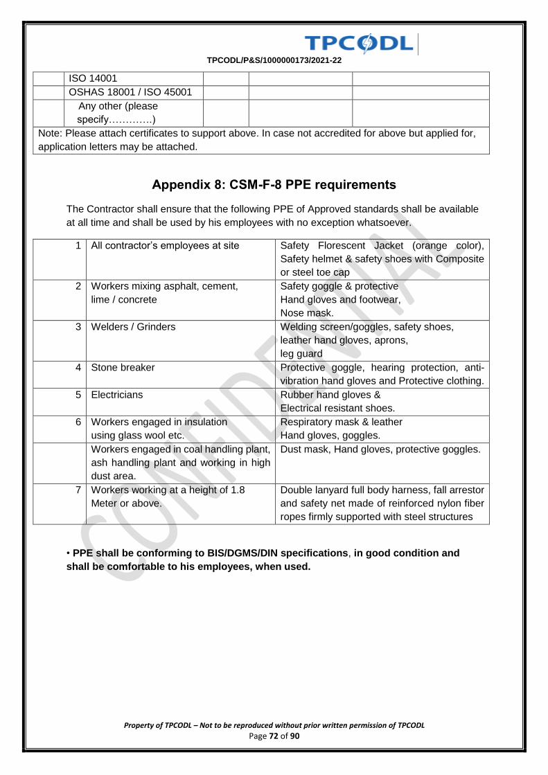
TPCODL/P&S/1000000173/2021-22
Property of TPCODL – Not to be reproduced without prior written permission of TPCODL Page 72 of 90
2. ISO 14001
3. OSHAS 18001 / ISO 45001
4. Any other (please
specify………….)
Note: Please attach certificates to support above. In case not accredited for above but applied for,
application letters may be attached.
Appendix 8: CSM-F-8 PPE requirements
The Contractor shall ensure that the following PPE of Approved standards shall be available
at all time and shall be used by his employees with no exception whatsoever.
1 All contractor’s employees at site Safety Florescent Jacket (orange color),
Safety helmet & safety shoes with Composite
or steel toe cap
2 Workers mixing asphalt, cement,
lime / concrete
Safety goggle & protective
Hand gloves and footwear,
Nose mask.
3 Welders / Grinders Welding screen/goggles, safety shoes,
leather hand gloves, aprons,
leg guard
4 Stone breaker Protective goggle, hearing protection, anti-
vibration hand gloves and Protective clothing.
5 Electricians Rubber hand gloves &
Electrical resistant shoes.
6 Workers engaged in insulation
using glass wool etc.
Respiratory mask & leather
Hand gloves, goggles.
Workers engaged in coal handling plant,
ash handling plant and working in high
dust area.
Dust mask, Hand gloves, protective goggles.
7 Workers working at a height of 1.8
Meter or above.
Double lanyard full body harness, fall arrestor
and safety net made of reinforced nylon fiber
ropes firmly supported with steel structures
• PPE shall be conforming to BIS/DGMS/DIN specifications, in good condition and
shall be comfortable to his employees, when used.
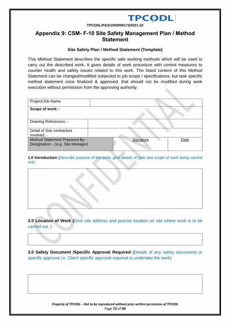
TPCODL/P&S/1000000173/2021-22
Property of TPCODL – Not to be reproduced without prior written permission of TPCODL Page 73 of 90
Appendix 9: CSM- F-10 Site Safety Management Plan / Method Statement
Site Safety Plan / Method Statement (Template)
This Method Statement describes the specific safe working methods which will be used to
carry out the described work. It gives details of work procedure with control measures to
counter health and safety issues related to this work. The listed content of this Method
Statement can be changed/modified subjected to job scope / specifications, but task specific
method statement once finalized & approved, that should not be modified during work
execution without permission from the approving authority.
Project/Job Name
Scope of work: -
Drawing References: -
Detail of Sub contractors involved: -
Method Statement Prepared By: - Designation: - (e.g. Site Manager)
Signature
Date
1.0 Introduction (Describe purpose of the work, give details of type and scope of work being carried out);
2.0 Location of Work (Give site address and precise location on site where work is to be
carried out. )
3.0 Safety Document /Specific Approval Required (Details of any safety documents or
specific approval i.e. Client specific approval required to undertake the work)
TPCODL/P&S/1000000173/2021-22
Property of TPCODL – Not to be reproduced without prior written permission of TPCODL Page 74 of 90
5.0 Role & Responsibilities of Personnel/Parties Involved in activities: -Clearly define
role and responsibilities of all personnel involved in activity i.e. Site management staff
including subcontractors’ parties- Main contractor Project/Site Manager, Sub Contractor Site
Manager, Project Engineer, Safety officer, Competent Supervisory Staff)
6.0 Working/Activity Description: - It is important that all operatives should have clear idea of those operational sequences and responsible supervisor must verify their competency prior to their engagement in operation.
6.1 Pre-Working Checks
6.2 Resources (Equipment, tools including manpower) Details i.e. Equipment and Tools, specific
operational equipment, test kits, lifting resources, Details of materials to be used in operation,
including any reference to COSHH assessments in case of use of any chemicals, Details of
the manpower allocated to the task, e.g. titles, qualifications, competences, direct manpower,
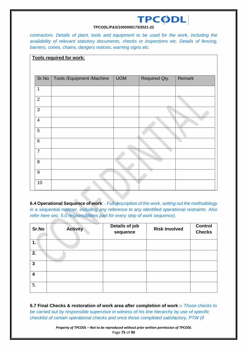
TPCODL/P&S/1000000173/2021-22
Property of TPCODL – Not to be reproduced without prior written permission of TPCODL Page 75 of 90
contractors. Details of plant, tools and equipment to be used for the work, including the
availability of relevant statutory documents, checks or inspections etc. Details of fencing,
barriers, cones, chains, dangers notices, warning signs etc.
Tools required for work:
Sr.No Tools /Equipment /Machine UOM Required Qty. Remark
1
2
3
4
5
6
7
8
9
10
6.4 Operational Sequence of work: - Full description of the work, setting out the methodology
in a sequential manner, including any reference to any identified operational restraints. Also
refer here sec. 5.0 responsibilities part for every step of work sequence).
Sr.No Activity Details of job
sequence Risk Involved
Control
Checks
1. 1.
2.
3
4
5.
6.7 Final Checks & restoration of work area after completion of work :- Those checks to
be carried out by responsible supervisor in witness of his line hierarchy by use of specific
checklist of certain operational checks and once those completed satisfactory, PTW (if
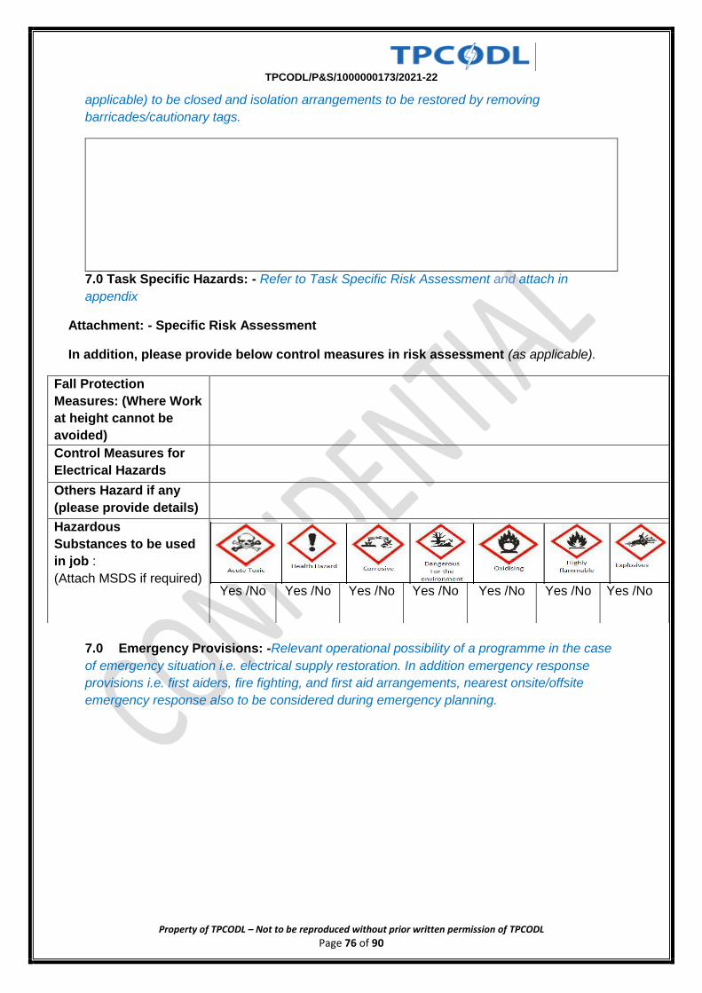
TPCODL/P&S/1000000173/2021-22
Property of TPCODL – Not to be reproduced without prior written permission of TPCODL Page 76 of 90
applicable) to be closed and isolation arrangements to be restored by removing
barricades/cautionary tags.
7.0 Task Specific Hazards: - Refer to Task Specific Risk Assessment and attach in
appendix
Attachment: - Specific Risk Assessment
In addition, please provide below control measures in risk assessment (as applicable).
7.0 Emergency Provisions: -Relevant operational possibility of a programme in the case
of emergency situation i.e. electrical supply restoration. In addition emergency response
provisions i.e. first aiders, fire fighting, and first aid arrangements, nearest onsite/offsite
emergency response also to be considered during emergency planning.
Fall Protection
Measures: (Where Work
at height cannot be
avoided)
Control Measures for
Electrical Hazards
Others Hazard if any
(please provide details)
Hazardous
Substances to be used
in job :
(Attach MSDS if required)
Yes /No Yes /No Yes /No Yes /No Yes /No Yes /No Yes /No
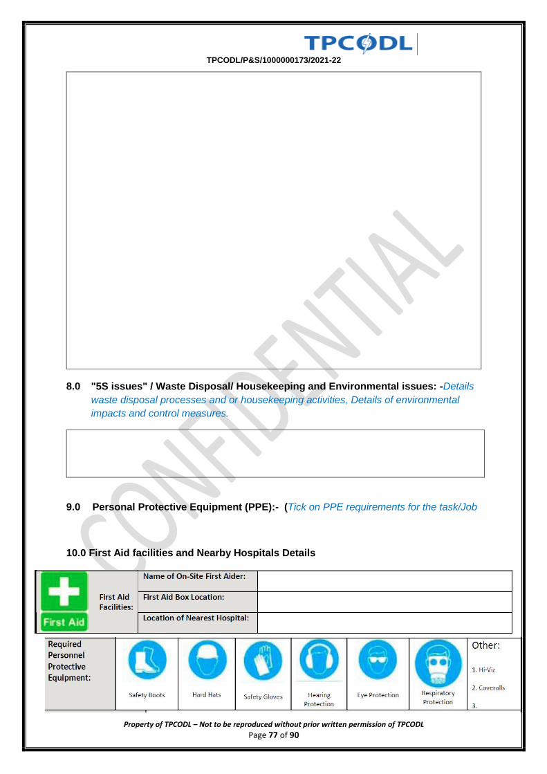
TPCODL/P&S/1000000173/2021-22
Property of TPCODL – Not to be reproduced without prior written permission of TPCODL Page 77 of 90
8.0 "5S issues" / Waste Disposal/ Housekeeping and Environmental issues: -Details
waste disposal processes and or housekeeping activities, Details of environmental
impacts and control measures.
9.0 Personal Protective Equipment (PPE):- (Tick on PPE requirements for the task/Job
10.0 First Aid facilities and Nearby Hospitals Details
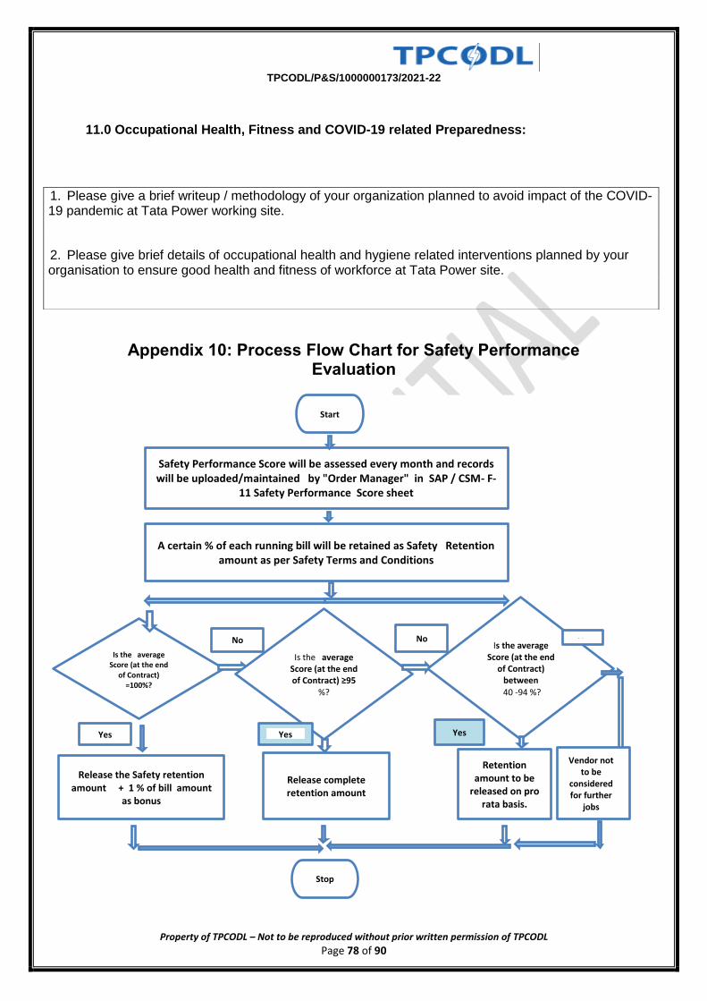
TPCODL/P&S/1000000173/2021-22
Property of TPCODL – Not to be reproduced without prior written permission of TPCODL Page 78 of 90
11.0 Occupational Health, Fitness and COVID-19 related Preparedness:
Appendix 10: Process Flow Chart for Safety Performance Evaluation
1. Please give a brief writeup / methodology of your organization planned to avoid impact of the COVID-19 pandemic at Tata Power working site.
2. Please give brief details of occupational health and hygiene related interventions planned by your organisation to ensure good health and fitness of workforce at Tata Power site.
Start
Safety Performance Score will be assessed every month and records will be uploaded/maintained by "Order Manager" in SAP / CSM- F-
11 Safety Performance Score sheet
A certain % of each running bill will be retained as Safety Retention amount as per Safety Terms and Conditions
Is the average Score (at the end
of Contract) =100%?
Yes
Release the Safety retention amount + 1 % of bill amount
as bonus
No
Release complete retention amount
Stop
Is the average Score (at the end of Contract) ≥95
%?
Is the average Score (at the end
of Contract) between
40 -94 %?
No
Retention amount to be
released on pro rata basis.
Vendor not to be
considered for further
jobs
No
Yes Yes
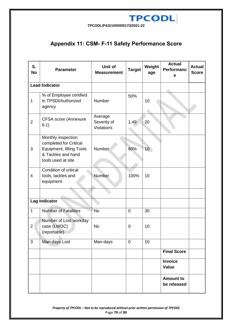
TPCODL/P&S/1000000173/2021-22
Property of TPCODL – Not to be reproduced without prior written permission of TPCODL Page 79 of 90
Appendix 11: CSM- F-11 Safety Performance Score
S.
No Parameter
Unit of
Measurement Target
Weight
age
Actual
Performanc
e
Actual
Score
Lead Indicator
1
% of Employee certified
in TPSDI/Authorized
agency
Number 50%
10
2 CFSA score (Annexure
6.1)
Average
Severity of
Violations
1.49 20
3
Monthly inspection
completed for Critical
Equipment, lifting Tools
& Tackles and hand
tools used at site
Number 80% 10
4
Condition of critical
tools, tackles and
equipment
Number 100% 10
Lag Indicator
1 Number of Fatalities No 0 30
2
Number of Lost workday
case (LWDC)
(reportable)
No 0 10
3 Man-days Lost Man-days 0 10
Final Score
Invoice
Value
Amount to
be released
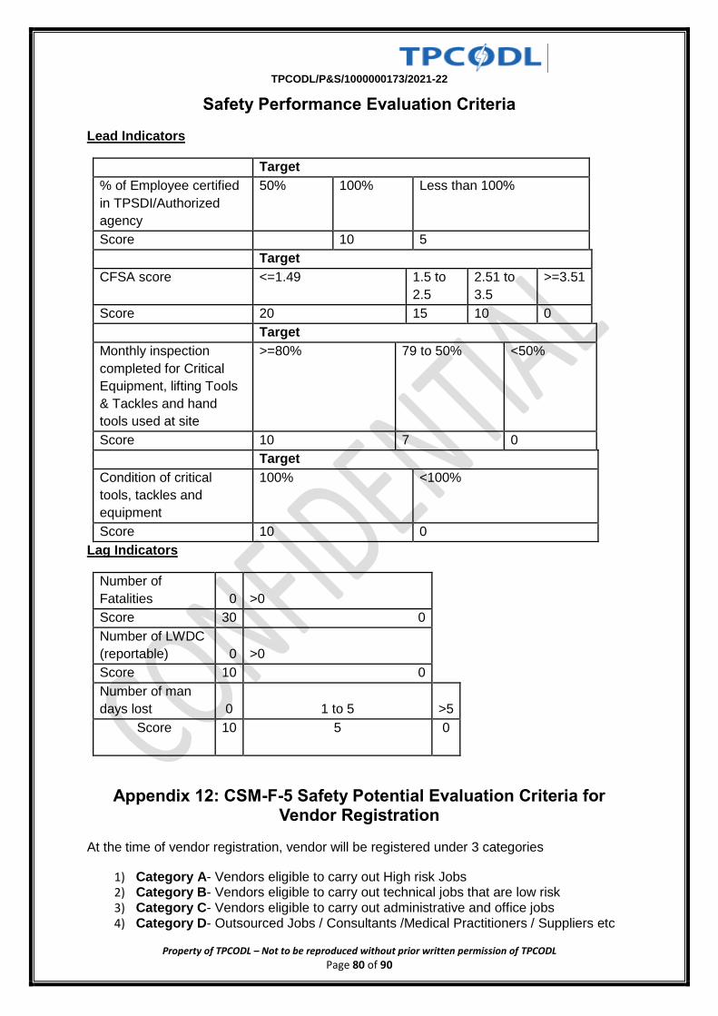
TPCODL/P&S/1000000173/2021-22
Property of TPCODL – Not to be reproduced without prior written permission of TPCODL Page 80 of 90
Safety Performance Evaluation Criteria
Lead Indicators
Target
% of Employee certified
in TPSDI/Authorized
agency
50% 100% Less than 100%
Score
10 5
Target
CFSA score <=1.49 1.5 to
2.5
2.51 to
3.5
>=3.51
Score 20 15 10 0
Target
Monthly inspection
completed for Critical
Equipment, lifting Tools
& Tackles and hand
tools used at site
>=80% 79 to 50% <50%
Score 10 7 0
Target
Condition of critical
tools, tackles and
equipment
100% <100%
Score 10 0
Lag Indicators
Number of
Fatalities 0 >0
Score 30 0
Number of LWDC
(reportable) 0 >0
Score 10 0
Number of man
days lost 0 1 to 5 >5
Score 10 5 0
Appendix 12: CSM-F-5 Safety Potential Evaluation Criteria for Vendor Registration
At the time of vendor registration, vendor will be registered under 3 categories
1) Category A- Vendors eligible to carry out High risk Jobs 2) Category B- Vendors eligible to carry out technical jobs that are low risk 3) Category C- Vendors eligible to carry out administrative and office jobs 4) Category D- Outsourced Jobs / Consultants /Medical Practitioners / Suppliers etc
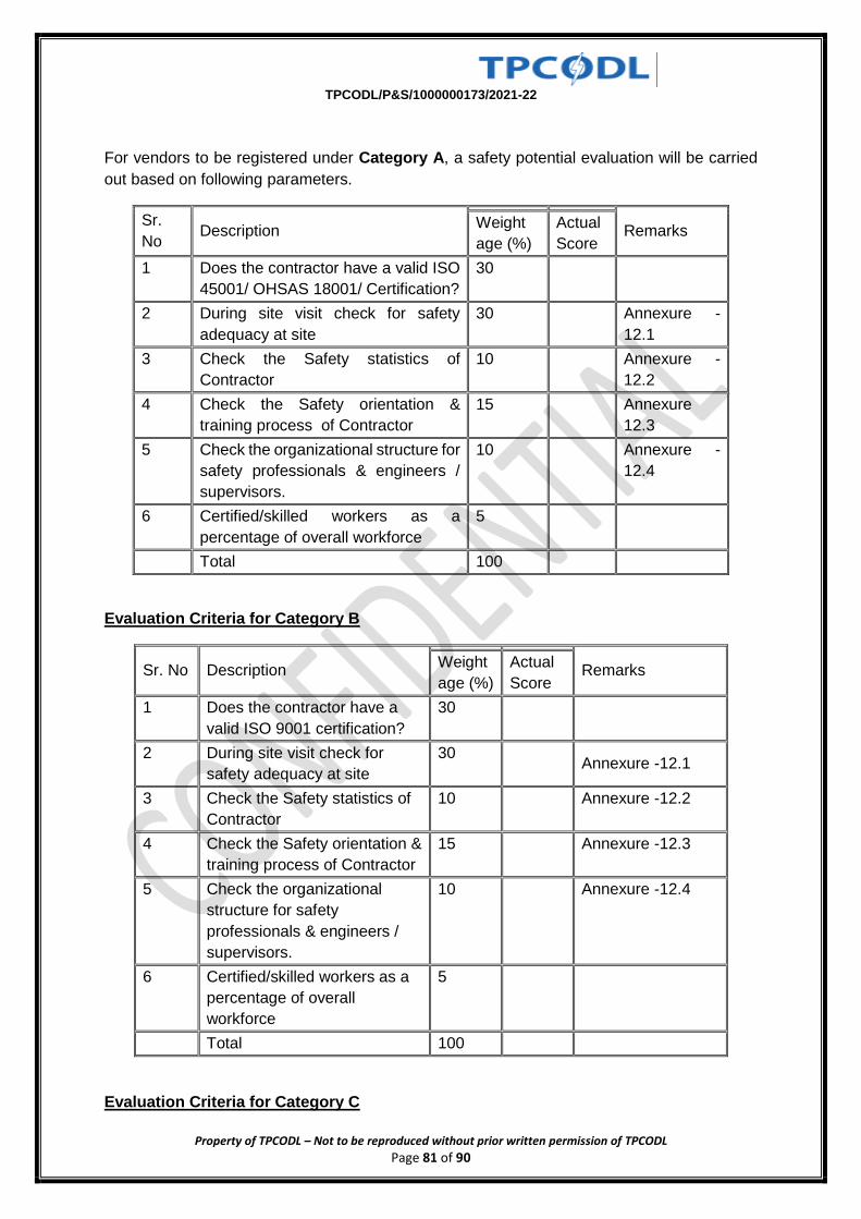
TPCODL/P&S/1000000173/2021-22
Property of TPCODL – Not to be reproduced without prior written permission of TPCODL Page 81 of 90
For vendors to be registered under Category A, a safety potential evaluation will be carried
out based on following parameters.
Sr.
No Description
Remarks Weight
age (%)
Actual
Score
1 Does the contractor have a valid ISO
45001/ OHSAS 18001/ Certification?
30
2 During site visit check for safety
adequacy at site
30
Annexure -
12.1
3 Check the Safety statistics of
Contractor
10
Annexure -
12.2
4 Check the Safety orientation &
training process of Contractor
15
Annexure
12.3
5 Check the organizational structure for
safety professionals & engineers /
supervisors.
10
Annexure -
12.4
6 Certified/skilled workers as a
percentage of overall workforce
5
Total 100
Evaluation Criteria for Category B
Sr. No Description
Remarks Weight
age (%)
Actual
Score
1 Does the contractor have a
valid ISO 9001 certification?
30
2 During site visit check for
safety adequacy at site
30
Annexure -12.1
3 Check the Safety statistics of
Contractor
10
Annexure -12.2
4 Check the Safety orientation &
training process of Contractor
15
Annexure -12.3
5 Check the organizational
structure for safety
professionals & engineers /
supervisors.
10
Annexure -12.4
6 Certified/skilled workers as a
percentage of overall
workforce
5
Total 100
Evaluation Criteria for Category C
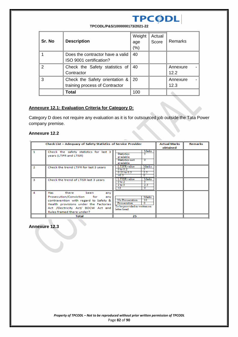
TPCODL/P&S/1000000173/2021-22
Property of TPCODL – Not to be reproduced without prior written permission of TPCODL Page 82 of 90
Sr. No Description
Remarks Weight
age
(%)
Actual
Score
1 Does the contractor have a valid
ISO 9001 certification?
40
2 Check the Safety statistics of
Contractor
40
Annexure -
12.2
3 Check the Safety orientation &
training process of Contractor
20
Annexure -
12.3
Total 100
Annexure 12.1: Evaluation Criteria for Category D:
Category D does not require any evaluation as it is for outsourced job outside the Tata Power
company premise.
Annexure 12.2
Annexure 12.3
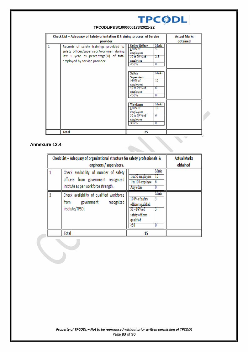
TPCODL/P&S/1000000173/2021-22
Property of TPCODL – Not to be reproduced without prior written permission of TPCODL Page 83 of 90
Annexure 12.4
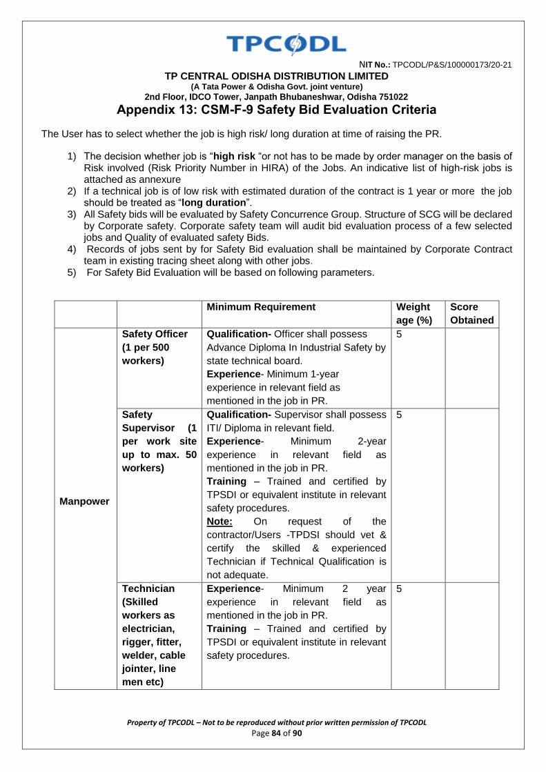
NIT No.: TPCODL/P&S/100000173/20-21
TP CENTRAL ODISHA DISTRIBUTION LIMITED (A Tata Power & Odisha Govt. joint venture)
2nd Floor, IDCO Tower, Janpath Bhubaneshwar, Odisha 751022
Property of TPCODL – Not to be reproduced without prior written permission of TPCODL Page 84 of 90
Appendix 13: CSM-F-9 Safety Bid Evaluation Criteria
The User has to select whether the job is high risk/ long duration at time of raising the PR.
1) The decision whether job is “high risk “or not has to be made by order manager on the basis of Risk involved (Risk Priority Number in HIRA) of the Jobs. An indicative list of high-risk jobs is attached as annexure
2) If a technical job is of low risk with estimated duration of the contract is 1 year or more the job should be treated as “long duration”.
3) All Safety bids will be evaluated by Safety Concurrence Group. Structure of SCG will be declared by Corporate safety. Corporate safety team will audit bid evaluation process of a few selected jobs and Quality of evaluated safety Bids.
4) Records of jobs sent by for Safety Bid evaluation shall be maintained by Corporate Contract team in existing tracing sheet along with other jobs.
5) For Safety Bid Evaluation will be based on following parameters.
Minimum Requirement Weight
age (%)
Score
Obtained
Manpower
Safety Officer
(1 per 500
workers)
Qualification- Officer shall possess
Advance Diploma In Industrial Safety by
state technical board.
Experience- Minimum 1-year
experience in relevant field as
mentioned in the job in PR.
5
Safety
Supervisor (1
per work site
up to max. 50
workers)
Qualification- Supervisor shall possess
ITI/ Diploma in relevant field.
Experience- Minimum 2-year
experience in relevant field as
mentioned in the job in PR.
Training – Trained and certified by
TPSDI or equivalent institute in relevant
safety procedures.
Note: On request of the
contractor/Users -TPDSI should vet &
certify the skilled & experienced
Technician if Technical Qualification is
not adequate.
5
Technician
(Skilled
workers as
electrician,
rigger, fitter,
welder, cable
jointer, line
men etc)
Experience- Minimum 2 year
experience in relevant field as
mentioned in the job in PR.
Training – Trained and certified by
TPSDI or equivalent institute in relevant
safety procedures.
5
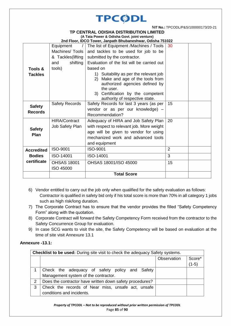
NIT No.: TPCODL/P&S/100000173/20-21
TP CENTRAL ODISHA DISTRIBUTION LIMITED (A Tata Power & Odisha Govt. joint venture)
2nd Floor, IDCO Tower, Janpath Bhubaneshwar, Odisha 751022
Property of TPCODL – Not to be reproduced without prior written permission of TPCODL Page 85 of 90
Tools &
Tackles
Equipment /
Machines/ Tools
& Tackles(lifting
and shifting
tools)
The list of Equipment /Machines / Tools
and tackles to be used for job to be
submitted by the contractor.
Evaluation of the list will be carried out
based on
1) Suitability as per the relevant job 2) Make and age of the tools from
authorized agencies defined by the user.
3) Certification by the competent authority of respective state.
30
Safety
Records
Safety Records Safety Records for last 3 years (as per
vendor or as per our knowledge) –
Recommendation?
15
Safety
Plan
HIRA/Contract
Job Safety Plan
Adequacy of HIRA and Job Safety Plan
with respect to relevant job. More weight
age will be given to vendor for using
mechanized work and advanced tools
and equipment
20
Accredited
Bodies
certificate
ISO-9001 ISO-9001 2
ISO-14001 ISO-14001 3
OHSAS 18001
ISO 45000
OHSAS 18001/ISO 45000 15
Total Score
6) Vendor entitled to carry out the job only when qualified for the safety evaluation as follows:
Contractor is qualified in safety bid only if his total score is more than 70% in all category 1 jobs
such as high risk/long duration.
7) The Corporate Contract has to ensure that the vendor provides the filled “Safety Competency
Form” along with the quotation.
8) Corporate Contract will forward the Safety Competency Form received from the contractor to the
Safety Concurrence Group for evaluation.
9) In case SCG wants to visit the site, the Safety Competency will be based on evaluation at the
time of site visit Annexure 13.1
Annexure -13.1:
Checklist to be used: During site visit to check the adequacy Safety systems.
Observation Score*
(1-5)
1 Check the adequacy of safety policy and Safety
Management system of the contractor.
2 Does the contractor have written down safety procedures?
3 Check the records of Near miss, unsafe act, unsafe
conditions and incidents.
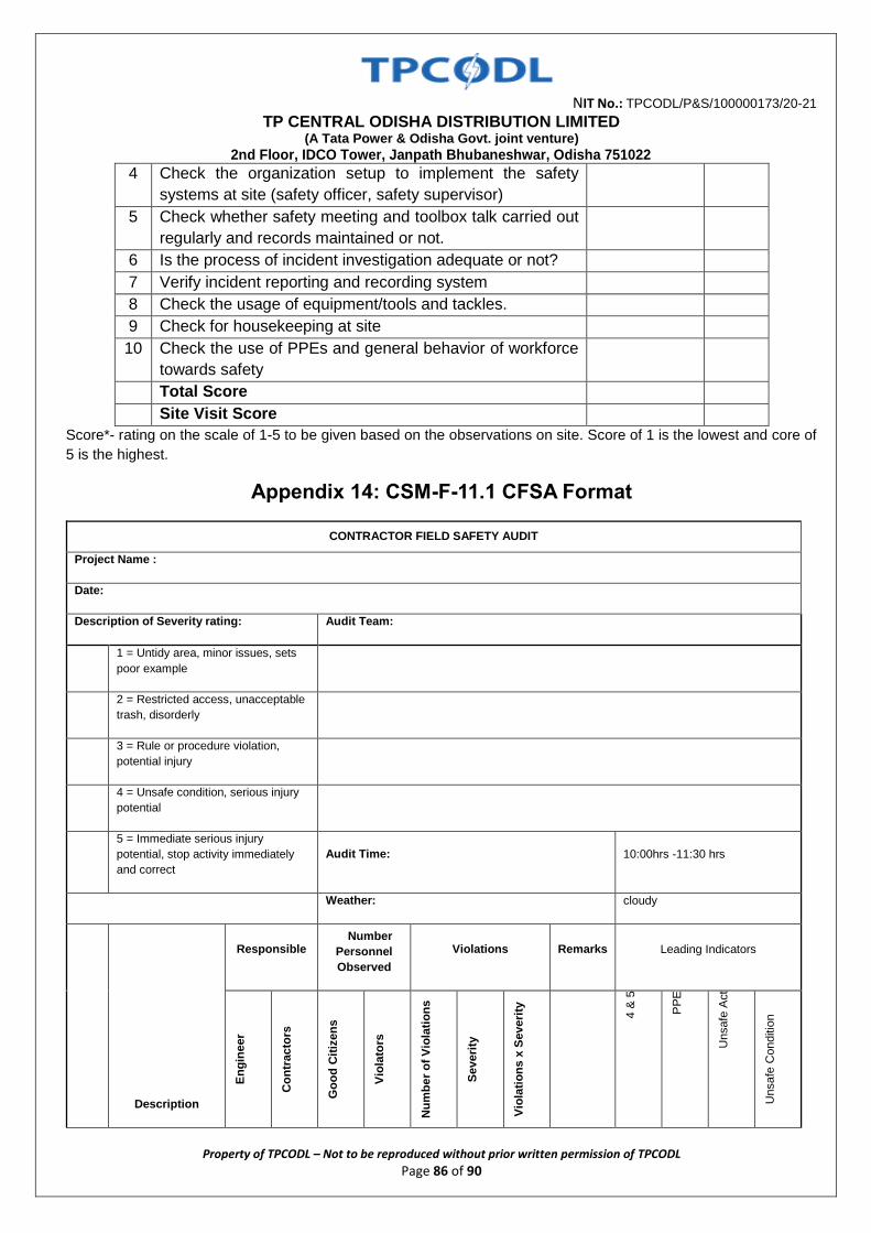
NIT No.: TPCODL/P&S/100000173/20-21
TP CENTRAL ODISHA DISTRIBUTION LIMITED (A Tata Power & Odisha Govt. joint venture)
2nd Floor, IDCO Tower, Janpath Bhubaneshwar, Odisha 751022
Property of TPCODL – Not to be reproduced without prior written permission of TPCODL Page 86 of 90
4 Check the organization setup to implement the safety
systems at site (safety officer, safety supervisor)
5 Check whether safety meeting and toolbox talk carried out
regularly and records maintained or not.
6 Is the process of incident investigation adequate or not?
7 Verify incident reporting and recording system
8 Check the usage of equipment/tools and tackles.
9 Check for housekeeping at site
10 Check the use of PPEs and general behavior of workforce
towards safety
Total Score
Site Visit Score
Score*- rating on the scale of 1-5 to be given based on the observations on site. Score of 1 is the lowest and core of
5 is the highest.
Appendix 14: CSM-F-11.1 CFSA Format
CONTRACTOR FIELD SAFETY AUDIT
Project Name :
Date:
Description of Severity rating: Audit Team:
1 = Untidy area, minor issues, sets
poor example
2 = Restricted access, unacceptable
trash, disorderly
3 = Rule or procedure violation,
potential injury
4 = Unsafe condition, serious injury
potential
5 = Immediate serious injury
potential, stop activity immediately
and correct
Audit Time: 10:00hrs -11:30 hrs
Weather: cloudy
Description
Responsible Number
Personnel
Observed
Violations Remarks Leading Indicators
En
gin
eer
Co
ntr
acto
rs
Go
od
Cit
izen
s
Vio
lato
rs
Nu
mb
er
of
Vio
lati
on
s
Severi
ty
Vio
lati
on
s x
Severi
ty
4 &
5
PP
E
Unsafe
Act
Unsafe
Conditio
n
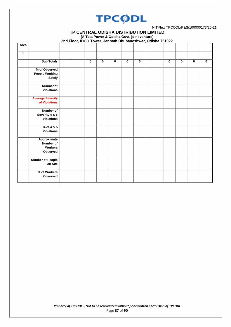
NIT No.: TPCODL/P&S/100000173/20-21
TP CENTRAL ODISHA DISTRIBUTION LIMITED (A Tata Power & Odisha Govt. joint venture)
2nd Floor, IDCO Tower, Janpath Bhubaneshwar, Odisha 751022
Property of TPCODL – Not to be reproduced without prior written permission of TPCODL Page 87 of 90
Area
1
Sub Totals 0 0 0 0 0 0 0 0 0
% of Observed
People Working
Safely
Number of
Violations
Average Severity
of Violations
Number of
Severity 4 & 5
Violations
% of 4 & 5
Violations
Approximate
Number of
Workers
Observed
Number of People
on Site
% of Workers
Observed
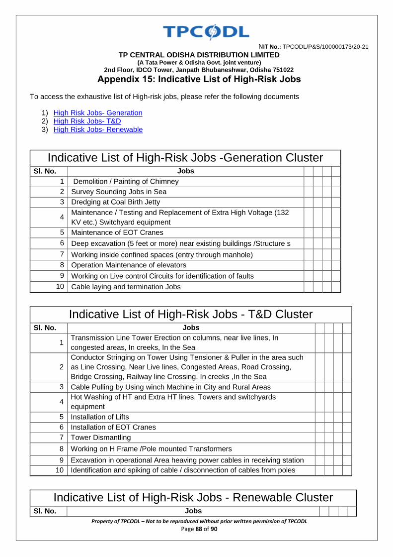
NIT No.: TPCODL/P&S/100000173/20-21
TP CENTRAL ODISHA DISTRIBUTION LIMITED (A Tata Power & Odisha Govt. joint venture)
2nd Floor, IDCO Tower, Janpath Bhubaneshwar, Odisha 751022
Property of TPCODL – Not to be reproduced without prior written permission of TPCODL Page 88 of 90
Appendix 15: Indicative List of High-Risk Jobs
To access the exhaustive list of High-risk jobs, please refer the following documents
1) High Risk Jobs- Generation 2) High Risk Jobs- T&D 3) High Risk Jobs- Renewable
Indicative List of High-Risk Jobs -Generation Cluster Sl. No. Jobs
1 Demolition / Painting of Chimney
2 Survey Sounding Jobs in Sea
3 Dredging at Coal Birth Jetty
4 Maintenance / Testing and Replacement of Extra High Voltage (132
KV etc.) Switchyard equipment
5 Maintenance of EOT Cranes
6 Deep excavation (5 feet or more) near existing buildings /Structure s
7 Working inside confined spaces (entry through manhole)
8 Operation Maintenance of elevators
9 Working on Live control Circuits for identification of faults
10 Cable laying and termination Jobs
Indicative List of High-Risk Jobs - T&D Cluster Sl. No. Jobs
1 Transmission Line Tower Erection on columns, near live lines, In
congested areas, In creeks, In the Sea
2
Conductor Stringing on Tower Using Tensioner & Puller in the area such
as Line Crossing, Near Live lines, Congested Areas, Road Crossing,
Bridge Crossing, Railway line Crossing, In creeks ,In the Sea
3 Cable Pulling by Using winch Machine in City and Rural Areas
4 Hot Washing of HT and Extra HT lines, Towers and switchyards
equipment
5 Installation of Lifts
6 Installation of EOT Cranes
7 Tower Dismantling
8 Working on H Frame /Pole mounted Transformers
9 Excavation in operational Area heaving power cables in receiving station
10 Identification and spiking of cable / disconnection of cables from poles
Indicative List of High-Risk Jobs - Renewable Cluster Sl. No. Jobs
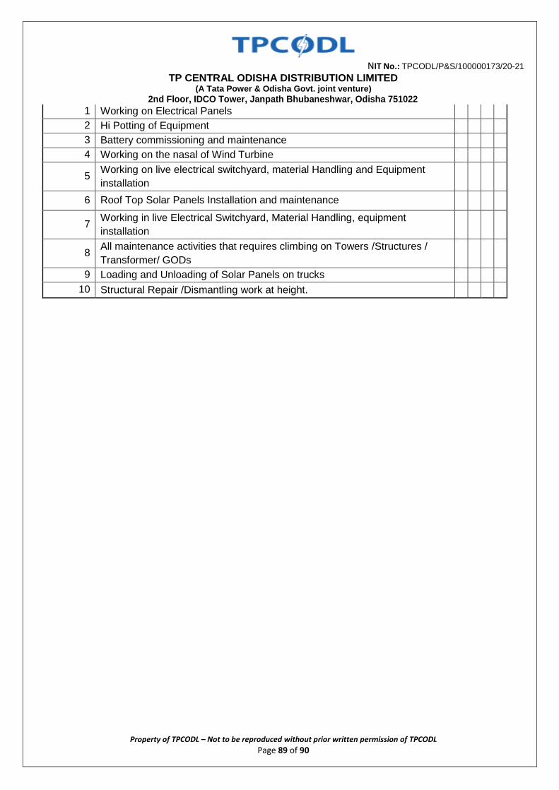
NIT No.: TPCODL/P&S/100000173/20-21
TP CENTRAL ODISHA DISTRIBUTION LIMITED (A Tata Power & Odisha Govt. joint venture)
2nd Floor, IDCO Tower, Janpath Bhubaneshwar, Odisha 751022
Property of TPCODL – Not to be reproduced without prior written permission of TPCODL Page 89 of 90
1 Working on Electrical Panels
2 Hi Potting of Equipment
3 Battery commissioning and maintenance
4 Working on the nasal of Wind Turbine
5 Working on live electrical switchyard, material Handling and Equipment
installation
6 Roof Top Solar Panels Installation and maintenance
7 Working in live Electrical Switchyard, Material Handling, equipment
installation
8 All maintenance activities that requires climbing on Towers /Structures /
Transformer/ GODs
9 Loading and Unloading of Solar Panels on trucks
10 Structural Repair /Dismantling work at height.
NIT No.: TPCODL/P&S/100000173/20-21
TP CENTRAL ODISHA DISTRIBUTION LIMITED (A Tata Power & Odisha Govt. joint venture)
2nd Floor, IDCO Tower, Janpath Bhubaneshwar, Odisha 751022
Property of TPCODL – Not to be reproduced without prior written permission of TPCODL Page 90 of 90
ANNEXURE X TATA CODE OF CONDUCT The Owner abides by the Tata Code of Conduct in all its dealing with stake holders and the same shall be binding on the Owner and the Contractor for dealings under this Order/ Contract. A copy of the Tata Code of Conduct is available a tour website:
https://www.tatapower.com/pdf/aboutus/Tata-Code-of-Conduct.pdf The Contractor is requested to bring any concerns regarding this to the notice of our Chief
Procurement & Stores e-mail ID: [email protected].
TP CENTRAL ODISHA DISTRIBUTION LIMITED WORK INSTRUCTION /OPERATING GUIDELINES
Doc. Title GENERAL CONDITIONS OF CONTRACT- COMPOSITE ORDERS Rev. No 0 Page 1 of 104
CONTENTS CLAUSE NO. DESCRIPTION
1.0 ORGANIZATIONAL VALUES 2.0 ETHICS 3.0 CONTRACT PARAMETERS 3.1 Issue/ Award of Contract 3.2 Contract Commencement Date 3.3 Contract Completion Date 3.4 Contract Period/Time 3.5 Contract Execution Completion Date 3.6 Contract Execution Period/Time 3.7 Contract Price /Value 3.8 Contract Document 3.9 Contract Language 3.10 Reverse Auction 4.0 SCOPE OF WORK 4.1 Technical Evaluation 4.2 Indemnity 4.3 Display of notice boards at work site 4.4 Disposal of waste at site 4.5 Deployment of workforce 4.6 Damage of Properties 4.7 Issuance of material 4.8 Company's right to use works 4.9 Rights of TPCODL to vary the scope work 5.0 PRICES/RATES/TAXES 5.1 For Supply part of Contract 5.2 For Service part of Contract 5.3 Changes in statutory Tax Structure
Doc. Title GENERAL CONDITIONS OF CONTRACT - COMPOSITE WORKS Rev. No 0 Page 2 of 104
CONTENTS CLAUSE NO. DESCRIPTION
6.0 TERMS OF PAYMENT 6.1 Pre-Requisites for Payment 6.2 Bills & Invoices 6.3 Payment & Statutory Deductions 6.4 Guidelines for Raising Running/Final Bills 6.5 Quantity Variation 6.6 Full and Final Payment 7.0 MODE OF PAYMENT 8.0 SECURITY CUM PERFORMANCE DEPOSIT 9.0 STATUTORY COMPLIANCE 9.1 Compliance to Various Acts 9.2 SA 8000 9.3 Affirmative Action 9.4 Compliance to Labour Laws 9.5 Compliance to C&D Waste Management Rules & Environment
(Protection) Amendment Rules 10.0 QUALITY 10.1 Knowledge of Requirements 10.2 Material/Equipment/Works Quality 10.3 Adherence to Rules & Regulations 10.4 Specifications and Standards 11.0 SAFETY 12.0 INSPECTION/PARTICIPATION 12.1 Right to Carry Out Inspection 12.2 Facilitating Inspection 12.3 Third Party Nomination 12.4 Waiver of Inspections 12.5 Incorrect Inspection Call 13.0 MDCC & DELIVERY OF MATERIALS 13.1 Material Dispatch Clearance Certificate
Doc. Title GENERAL CONDITIONS OF CONTRACT - COMPOSITE WORKS Rev. No 0 Page 3 of 104
CONTENTS CLAUSE NO. DESCRIPTION
13.2 Right to Rejection on Receipt 13.3 Consignee 13.4 Submission of Mandatory Documents on delivery 13.5 Dispatch and Delivery Instructions 14.0 GUARANTEE 14.1 Guarantee of Performance 14.2 Guarantee period 14.3 Failure in Guarantee period (GP) 14.4 Cost of repairs on failure in GP 14.5 Guarantee Period for Goods Outsourced 14.6 Latent Defect 14.7 Support beyond the Guarantee Period 15.0 LIQUIDATED DAMAGES 15.1 LD Waiver Request 15.2 Material Recovery 16.0 ASSIGNMENT OR SUBCONTRACTING 17.0 UNLAWFUL ACTIVITIES 18.0 CONFIDENTIALITY 18.1 Documents 18.2 Geographical Data 18.3 Associate’s Processes 18.4 Exclusions 18.5 Violation 19 INTELLECTUAL PROPERTY RIGHTS 20 INDEMNITY 21 LIABILITY & LIMITATIONS
21.1 Liability 21.2 Limitation of Liability 22.0 FORCE MAJEURE
Doc. Title GENERAL CONDITIONS OF CONTRACT - COMPOSITE WORKS Rev. No 0 Page 4 of 104
CONTENTS CLAUSE NO. DESCRIPTION
23.0 SUSPENSION OF CONTRACT 23.1 Suspension for Convenience 23.2 Suspension for Breach of Contract Conditions 23.3 Compensation in lieu of Suspension 24.0 TERMINATION OF CONTRACTS 24.1 Termination for default/breach of contract 24.2 Termination for convenience of associate 24.3 Termination for Convenience of TPCODL 25.0 Dispute resolution and Arbitration 25.1 Governing laws and jurisdiction 26.0 ATTRIBUTES OF GCC 26.1 Cancellation 26.2 Severability 26.3 Order of Priority 27.0 INSURANCE 28.0 ERRORS AND OMISSIONS 29.0 TRANSFER OF TITLES 30.0 SUGGESTIONS & FEEDBACK 31.0 CONTACT POINTS 32.0 LIST OF ANNEXURES
Doc. Title GENERAL CONDITIONS OF CONTRACT - COMPOSITE WORKS Rev. No 0 Page 5 of 104 1.0 ORGANIZATIONAL VALUES The Tata Group has always been a value driven organization. These values continue to direct the Group’s growth and businesses. The Six core Tata Values underpinning the way we do business are: Integrity - We must conduct our business fairly, with honesty and transparency. Everything we do must stand the test of public scrutiny. Understanding - We must be caring, respectful, compassionate and humanitarian towards our colleagues and customers around the world and always work for the benefit of India. Excellence - We must constantly strive to achieve the highest possible standards in our day to day work and in the quality of goods and services we provide. Unity - We must work cohesively with our colleagues across the group and with our customers and partners around the world to build strong relationships based on tolerance, understanding and mutual co-operation. Responsibility - We must continue to be responsible and sensitive to the countries, communities and environments in which we work, always ensuring that what comes from the people goes back to the people many times over. Agility - We must work in a speedy and responsive manner and be proactive and innovative in our approach. 2.0 ETHICS In our effort towards Excellence and in Management of Business Ethics at TPCODL, an Ethics Management Team is constituted. The main objective of the Ethics Management Team is to: 1. Record, address and allay the issues and concerns on ethics raised by different
stakeholders like employees, consumers, vendors, Associates etc. by initiating immediate corrective actions.
2. Ensure proper communication of the ethics policies and guidelines through prominent displays at all offices of TPCODL and through printed declarations in all concerned documents where external stakeholders are involved.
3. Ensure proper framework of policies as preventive measures against any ethics violation recorded by them.
4. Prepare and submit MIS of all issues and concerns, corrective and preventive actions on monthly basis to the top management for their information.
All members of Team TPCODL, Associates and Stakeholders are requested to register any grievance on ethics violation on Central Control Telephone No. 011-66404040. 3.0 CONTRACT PARAMETERS 3.1 Issue/Award of Contract TPCODL awards the contract to the Associate in writing in the form of Purchase order or Rate Contract (RC) hereafter referred as Contract, through in any or all of following modes-physical handover / post / e-mail / web document / fax with all the attachments/enclosures which shall be part of the contract document
Doc. Title GENERAL CONDITIONS OF CONTRACT - COMPOSITE WORKS Rev. No 0 Page 6 of 104 On receipt of the contract, the associate shall return to TPCODL copy of the contract document duly signed by legally authorized representative of associate, within two days of Effective Date of Contract for contracts having contract execution time less than 30 days and within five days for all other contracts. 3.2 Contract Commencement Date The date of issue/award of contract shall be the Effective Date of Contract or Contract Commencement date. 3.3 Contract Completion Date The date of expiry of Guarantee Period (detailed in section 12 of this document) shall be deemed as the Contract Completion Date. 3.4 Contract Period/Time The period from Contract Commencement Date to Contract Completion Date shall be deemed as the Contract Period/Time. 3.5 Contract Execution Completion Date The stipulated date for completing the execution of all items in the schedule of quantities (Supply, Service and or both as applicable) shall be deemed as the Contract Execution Completion Date. 3.6 Contract Execution Period/Time The Period from Contract Commencement Date to Contract Execution Completion Date shall be the Contract Execution Period/Time. Timely Completion of Works/Timely Delivery of Materials is the essence of the contract. The period from effective date of contract to the date stipulated for completion of delivery of all items/completion of all the works/services, as per schedule of quantities of the contract is defined as contract execution completion time. The Delivery of Materials /The Completion of Works, as applicable, should be achieved in all respects as per schedules of quantities and all the terms and conditions of the contract, in the contract execution time.
Any revision/amendment in the originally stipulated contract execution time has to be approved by authorized representative of TPCODL. 3.7 Contract Price /Value The total all inclusive price/value mentioned in the LOI/PO/RC of the contract document is the Contract Price/Value and is based on the quantity, unit rates and prices quoted and awarded and shall be subject to adjustment based on actual quantities supplied/actual measurement of work done and accepted and certified by the authorized representative of the company unless otherwise specified in schedule of quantities or in contract documents. 3.8 Contract Document The Contract Document shall mean and include but not limited to the following: NIT/Tender Enquiry, QR, Instruction to Bidders, Special Condition of Contract (SCC) of
tender, GCC, Technical & Commercial Specifications including relevant annexure and attachments).
Bids & Proposals Received from Associate including relevant annexure/attachments.
Doc. Title GENERAL CONDITIONS OF CONTRACT - COMPOSITE WORKS Rev. No 0 Page 7 of 104 Letter of Intent (LOI/RC/PO) with agreed deviations from the tender/bid documents. All the Inspection and Test reports, Detailed Engineering Drawings. Material Dispatch Clearance Certificate (MDCC). Minutes of Meeting (MoM) 3.9 Contract Language All documents, instructions, catalogues, brochures, pamphlets, design data, norms and calculations, drawings, operation, maintenance and safety manuals, reports, labels, on deliveries and any other data shall be in English Language. The Contract documents and all correspondence between the TPCODL, Third Parties associated with the contract, and the Associate shall be in English language. However, all signboards required indicating "Danger" and/or security at site and otherwise statutory required shall be in English, Hindi, and local languages. 3.10 Reverse Auction TPCODL reserves the right to conduct the reverse auction (instead of public opening of price bids) for the products / services being asked for in the tender. The terms and conditions for such reverse auction events shall be as per the Acceptance Form attached in Annexure J. The bidders along with the tender document shall mandatorily submit a duly signed copy of the Acceptance Form as mentioned in the Annexure J as a token of acceptance for the same. 4.0 SCOPE OF WORK All the activities that are to be undertaken by the Associate to realize the contractual deliverables in completeness form Scope of Work. Following clauses list, but not limited to, major requirements of the scope of work. The associate shall satisfy himself and undertake fully the technical/commercial requirements of items to be supplied as listed in the Schedule of Quantities together with the tests to be performed /test reports to be furnished before dispatch, arrangement of stage and final inspections during manufacturing as per terms and conditions of contract, technical parameters & delivery terms and conditions including transit insurance to be met in order to fully meet TPCODL’s requirements. Completeness: Any supplies and services which might have not been specifically mentioned in the Contract but are necessary for the scope mentioned in Special Terms & Conditions and/or completeness of the works at the highest possible level, including any royalties, licence fees & compensation to be paid, whether incurred by the associates or by a third party for the work covered in the scope, regardless of when incurred, shall be supplied/provided by the associate without any extra cost and within the time schedule for efficient , smooth and satisfactory operation and maintenance of the works at the highest possible level under Indian conditions (but according to international standards for facility of this type), unless expressly excluded from the scope of supplies and services in this Contract. TPCODL have the right, during the performance of the Contract, to change the scope and/or technical character of the Project and/or of the supplies and services stipulated in the
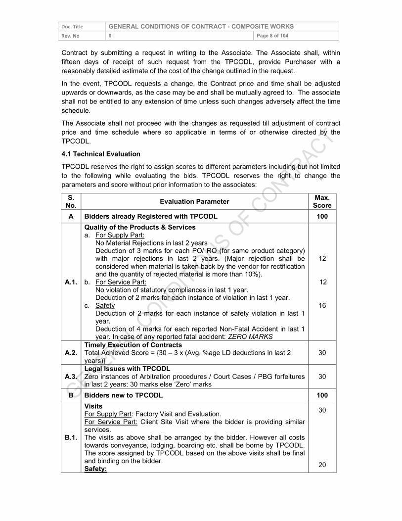
Doc. Title GENERAL CONDITIONS OF CONTRACT - COMPOSITE WORKS Rev. No 0 Page 8 of 104 Contract by submitting a request in writing to the Associate. The Associate shall, within fifteen days of receipt of such request from the TPCODL, provide Purchaser with a reasonably detailed estimate of the cost of the change outlined in the request. In the event, TPCODL requests a change, the Contract price and time shall be adjusted upwards or downwards, as the case may be and shall be mutually agreed to. The associate shall not be entitled to any extension of time unless such changes adversely affect the time schedule. The Associate shall not proceed with the changes as requested till adjustment of contract price and time schedule where so applicable in terms of or otherwise directed by the TPCODL. 4.1 Technical Evaluation TPCODL reserves the right to assign scores to different parameters including but not limited to the following while evaluating the bids. TPCODL reserves the right to change the parameters and score without prior information to the associates:
S. No. Evaluation Parameter Max.
Score A Bidders already Registered with TPCODL 100
A.1.
Quality of the Products & Services a. For Supply Part:
No Material Rejections in last 2 years Deduction of 3 marks for each PO/ RO (for same product category) with major rejections in last 2 years. (Major rejection shall be considered when material is taken back by the vendor for rectification and the quantity of rejected material is more than 10%).
b. For Service Part: No violation of statutory compliances in last 1 year. Deduction of 2 marks for each instance of violation in last 1 year.
c. Safety Deduction of 2 marks for each instance of safety violation in last 1 year. Deduction of 4 marks for each reported Non-Fatal Accident in last 1 year. In case of any reported fatal accident: ZERO MARKS
12 12
16
A.2. Timely Execution of Contracts Total Achieved Score = {30 – 3 x (Avg. %age LD deductions in last 2 years)}
30
A.3. Legal Issues with TPCODL Zero instances of Arbitration procedures / Court Cases / PBG forfeitures in last 2 years: 30 marks else ‘Zero’ marks 30
B Bidders new to TPCODL 100
B.1.
Visits For Supply Part: Factory Visit and Evaluation. For Service Part: Client Site Visit where the bidder is providing similar services. The visits as above shall be arranged by the bidder. However all costs towards conveyance, lodging, boarding etc. shall be borne by TPCODL. The score assigned by TPCODL based on the above visits shall be final and binding on the bidder. Safety:
30
20
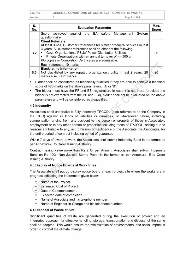
Doc. Title GENERAL CONDITIONS OF CONTRACT - COMPOSITE WORKS Rev. No 0 Page 9 of 104
S. No. Evaluation Parameter Max.
Score Score achieved against the BA safety Management System questionnaire.
B.2.
Client Referrals At least 3 nos. Customer References for similar products/ services in last 3 years. All customer references shall be either of the following: Govt. Organizations/ PSUs/ Power Distribution Utilities. Private Organizations with an annual turnover of >= 500 cr. PO copies or Completion Certificates are admissible. Each reference: 10 marks
30
B.3. Blacklisting Information Not blacklisted by any reputed organization / utility in last 2 years: 20 marks else ‘Zero’ marks. 20
Bidder shall be considered as technically qualified if they are able to achieve a technical score of >70 marks on the above parameters. ‘A’ or ‘B’.
The bidder must have the PF and ESI registration. In case it is not there (provided the bidder is not exempted from the PF and ESI), bidder shall not be evaluated on the above parameters and will be considered as disqualified.
4.2 Indemnity Associates shall undertake to fully indemnify TPCODL (also referred to as the Company in the GCC) against all kinds of liabilities or damages, of whatsoever nature, including compensation arising from any accident to the person or property of those in Associate’s employment or to any other person or properties including those of TPCODL, arising due to reasons attributable to any, act, omission or negligence of the Associate the Associates, for the entire period of contract including period of guarantee. Within 7 days of award of work, the Associates shall submit Indemnity Bond in the format as per Annexure-E to Order Issuing Authority. Contract having value more than Rs 2 Cr per Annum, Associates shall submit Indemnity Bond on Rs 100/- Non Judicial Stamp Paper in the format as per Annexure- E to Order Issuing Authority. 4.3 Display of Notice Boards at Work Sites The Associate shall put up display notice board at each project site where the works are in progress indicating the information given below:
Name of the Project. Estimated Cost of Project. Date of Commencement. Expected date of completion. Name of Associate and his telephone number. Name of Engineer-in-Charge and his telephone number.
4.4 Disposal of Waste at Site Significant quantities of waste are generated during the execution of project and an integrated approach for effective handling, storage, transportation and disposal of the same shall be adopted. This would ensure the minimization of environmental and social impact in order to combat the climate change.
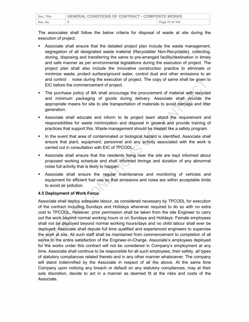
Doc. Title GENERAL CONDITIONS OF CONTRACT - COMPOSITE WORKS Rev. No 0 Page 10 of 104 The associates shall follow the below criteria for disposal of waste at site during the execution of project. Associate shall ensure that the detailed project plan include the waste management,
segregation of all designated waste material (Recyclable/ Non-Recyclable), collecting, storing, disposing and transferring the same to pre-arranged facility/destination in timely and safe manner as per environmental legislations during the execution of project. The project plan shall also include the innovative construction practice to eliminate or minimize waste, protect surface/ground water, control dust and other emissions to air and control noise during the execution of project. The copy of same shall be given to EIC before the commencement of project.
The purchase policy of BA shall encourage the procurement of material with recycled and minimum packaging of goods during delivery. Associate shall provide the appropriate means for site to site transportation of materials to avoid damage and litter generation.
Associate shall educate and inform to its project team about the requirement and responsibilities for waste minimization and disposal in general and provide training of practices that support this. Waste management should be treated like a safety program.
In the event that area of contaminated or biological hazard is identified, Associate shall ensure that plant, equipment, personnel and any activity associated with the work is carried out in consultation with EIC of TPCODL.
Associate shall ensure that the residents living near the site are kept informed about proposed working schedule and shall informed timings and duration of any abnormal noise full activity that is likely to happen.
Associate shall ensure the regular maintenance and monitoring of vehicles and equipment for efficient fuel use so that emissions and noise are within acceptable limits to avoid air pollution.
4.5 Deployment of Work Force Associate shall deploy adequate labour, as considered necessary by TPCODL for execution of the contract including Sundays and Holidays whenever required to do so with no extra cost to TPCODL. However, prior permission shall be taken from the site Engineer to carry out the work beyond normal working hours or on Sundays and Holidays. Female employees shall not be deployed beyond normal working hours/days and no child labour shall ever be deployed. Associate shall depute full time qualified and experienced engineers to supervise the work at site. All such staff shall be maintained from commencement to completion of all works to the entire satisfaction of the Engineer-in-Charge. Associate’s employees deployed for the works under this contract will not be considered in Company’s employment at any time. Associate shall continue to be responsible for all such employees, their safety, all types of statutory compliances related thereto and in any other manner whatsoever. The company will stand indemnified by the Associate in respect of all the above. At the same time Company upon noticing any breach or default on any statutory compliances, may at their sole discretion, decide to act in a manner as deemed fit at the risks and costs of the Associate.

Doc. Title GENERAL CONDITIONS OF CONTRACT - COMPOSITE WORKS Rev. No 0 Page 11 of 104 TPCODL shall have the right to instruct the Associate to change the Sub- Associates or skilled /unskilled workers in case the conduct, the workmanship or speed of the work is not satisfactory. Associates shall submit duly signed undertaking regarding engagement of competent staff / employee commensurate to the nature of job to Engineer–in–charge in the format attached as Annexure – H. 4.6 Damages to Properties The Associates shall take necessary steps to ensure that the equipment and installations of the Company, Third parties, including other utility services like water supply pipelines; open drains telephone cables etc. are not damaged during execution of the works. The Associates shall be responsible for all such damages and shall have to repair/ replace and/or compensate for the entire claims in respect of such damages at its own cost. 4.7 Issuance of Material The material issued to the Associate shall be in the custody of the Associates who shall be fully responsible for the same. After completion of the works, the Associates will reconcile the material. Any cost of material which is short or damaged/lost will be deducted from Associate bill/ deposits. 4.8 Company’s Right To Use Works If Taking Over Certificate is delayed for any reason, for which TPCODL’s decision shall be final and binding upon the Associate, the Company shall be entitled to use the works or portion thereof without affecting Associate’s responsibility and liability to complete the balance works as per company’s directives from time to time, though Associate shall be afforded reasonable opportunity by the company to enable Associates to complete all balance works required for issuance of ‘Taking Over Certificate’ by the company. 4.9 Rights of TPCODL to vary the scope work TPCODL shall have the right, during the performance of the Contract, to change the scope and/or technical character of the Project and/or of the supplies and services stipulated in the Contract by communicating the intent to do so in writing to the Associate. On receipt of such communication the Associate shall, within the time frame specified in the contract shall provide TPCODL with a reasonably detailed estimate of the cost of the change in scope outlined in the TPCODL communication. The change in the Contract price and time shall be revised upwards or downwards, as the case may be, and shall be mutually agreed to. The Associate shall not be entitled to any extension of time unless such changes adversely affect the time schedule. The Associate shall not proceed with the changes in the scope of work till such time revision of Contract price and time schedule are approved and communicated to the associate by TPCODL. Any change in the Scope of Work and/or Terms & Conditions of the order shall be intimated by TPCODL through an amendment to the contract. The amendment shall be treated valid only if signed by the authorized signatory of the original contract. 5.0 PRICES/ RATES/ TAXES 5.1 For Supply part of Contract
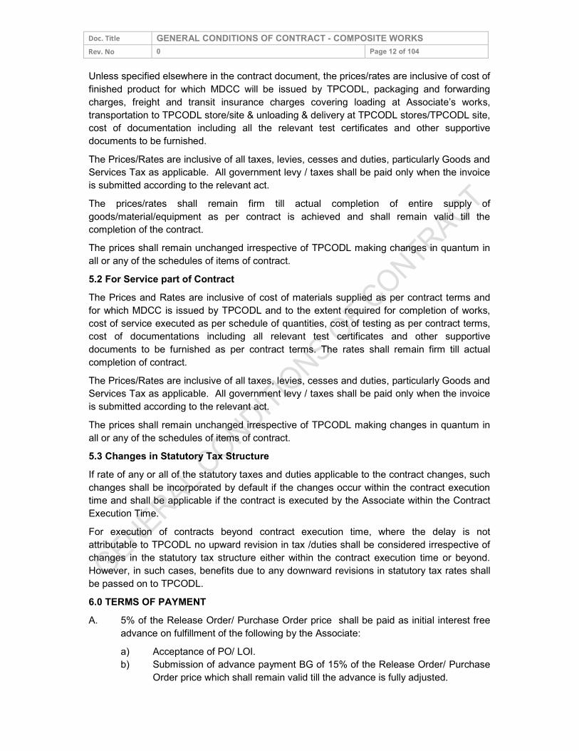
Doc. Title GENERAL CONDITIONS OF CONTRACT - COMPOSITE WORKS Rev. No 0 Page 12 of 104 Unless specified elsewhere in the contract document, the prices/rates are inclusive of cost of finished product for which MDCC will be issued by TPCODL, packaging and forwarding charges, freight and transit insurance charges covering loading at Associate’s works, transportation to TPCODL store/site & unloading & delivery at TPCODL stores/TPCODL site, cost of documentation including all the relevant test certificates and other supportive documents to be furnished. The Prices/Rates are inclusive of all taxes, levies, cesses and duties, particularly Goods and Services Tax as applicable. All government levy / taxes shall be paid only when the invoice is submitted according to the relevant act. The prices/rates shall remain firm till actual completion of entire supply of goods/material/equipment as per contract is achieved and shall remain valid till the completion of the contract. The prices shall remain unchanged irrespective of TPCODL making changes in quantum in all or any of the schedules of items of contract. 5.2 For Service part of Contract The Prices and Rates are inclusive of cost of materials supplied as per contract terms and for which MDCC is issued by TPCODL and to the extent required for completion of works, cost of service executed as per schedule of quantities, cost of testing as per contract terms, cost of documentations including all relevant test certificates and other supportive documents to be furnished as per contract terms. The rates shall remain firm till actual completion of contract. The Prices/Rates are inclusive of all taxes, levies, cesses and duties, particularly Goods and Services Tax as applicable. All government levy / taxes shall be paid only when the invoice is submitted according to the relevant act. The prices shall remain unchanged irrespective of TPCODL making changes in quantum in all or any of the schedules of items of contract. 5.3 Changes in Statutory Tax Structure If rate of any or all of the statutory taxes and duties applicable to the contract changes, such changes shall be incorporated by default if the changes occur within the contract execution time and shall be applicable if the contract is executed by the Associate within the Contract Execution Time. For execution of contracts beyond contract execution time, where the delay is not attributable to TPCODL no upward revision in tax /duties shall be considered irrespective of changes in the statutory tax structure either within the contract execution time or beyond. However, in such cases, benefits due to any downward revisions in statutory tax rates shall be passed on to TPCODL. 6.0 TERMS OF PAYMENT A. 5% of the Release Order/ Purchase Order price shall be paid as initial interest free
advance on fulfillment of the following by the Associate: a) Acceptance of PO/ LOI. b) Submission of advance payment BG of 15% of the Release Order/ Purchase
Order price which shall remain valid till the advance is fully adjusted.
Doc. Title GENERAL CONDITIONS OF CONTRACT - COMPOSITE WORKS Rev. No 0 Page 13 of 104
c) Submission of Contract Performance Bank Guarantee of 5/10% of the RC/ PO price valid till 30 days after taking over of the works.
B. 10% of the Release Order/ Purchase Order price shall be paid as interest free advance against approval of drawings under Category-1 of major drawings, Quality Plans, Pert Chart, Field Quality Plan, posting of Project Manager and commencement of the first mile stone of the work mutually agreed including C-3 Form, and submission of a true copy of ‘Erection All Risk Insurance Policy’ taken for the awarded jobs. The drawing list shall be mutually agreed at the time of award of work.
C. 50% on account payment of the total of item wise cost of material Release Order/ Purchase Order shall be paid against receipt of material at site in good condition and certification by TPCODL along with bills complete in all respects viz. MDCCs etc.
D. 20% on account payment of the actual executed value shall be paid against mechanical completion of erection on prorate basis against monthly bills and 70% on account of the actual executed value shall be paid against the service line item including composite line item. In case this milestone is not completed beyond 120 days for reasons attributable to TPCODL, the payment corresponding to supply part shall be released subject to submission of BG of equivalent amount by the BA valid for a period of further 12 months. If required, it shall be extended by the BA on request of TPCODL.
E. 15% payment of the actual executed Release Order/ Purchase Order shall be paid after completion of acceptance test and Taking Over of the complete systems specified in the enquiry, including clearance of Electrical Inspection, compliance of final punch point and after reconciliation & adjustment of payments, if any, towards Quantities of materials issued from purchaser’s stock and consumed by the contractor for expeditious completion of the job. In case this milestone is not completed beyond 120 days beyond schedule for reasons attributable to TPCODL, the payment corresponding to supply part shall be released subject to submission of BG of equivalent amount by the BA valid for a period of further 12 months. If required, it shall be extended by the BA on request of TPCODL. The Contractor shall submit all Operation & Maintenance manuals and “As Built Drawings” etc. and shall also submit Equipment Warranty Bank Guarantee (EWBG) equivalent to 5/10% of actual executed contract price before the release of this last payment and return of CPBG. The validity of EWBG shall be for a period of 15 months from the date of taking over of the works or specified guarantee period in drawing/tender/technical specification documents etc. whichever is later. The associate shall also submit ‘No Demand Certificate’ at the time of receipt of full and final payment.
6.1 Pre-Requisites for Payment Associate should have completed execution of that part of contract, for which payment is
sought, to the satisfaction of TPCODL’s Engineer-in-Charge responsible for the contract and obtained certification for execution of the work.
Associate has undertaken joint measurement of the work executed along with TPCODL’s Engineer-in-charge
Doc. Title GENERAL CONDITIONS OF CONTRACT - COMPOSITE WORKS Rev. No 0 Page 14 of 104 Associate’s bills/invoices submitted have been certified by Engineer-In-Charge. 6.2 Bills & Invoices Unless specified otherwise in the special conditions of contract, Associate shall raise not more than one invoice/contract per month for the services rendered in the prescribed Tax Format and the invoice shall be submitted within 15 days of the following month at Bill Inward Receipt Desk (BIRD) located at Civil Lines III Office, TPCODL. All Bills shall be supported by joint measurement of work done, quality test report and a copy of wage sheet, if applicable (showing proof of having disbursed wages as per applicable law) and a copy of statement substantiating that statutory payments having been affected. Bills/ invoices shall mention Associate’s ‘Sales, Service, WCT Tax Registration Number, PAN number as applicable. Final bill submission after completion of project or execution of job must be within 30 days from the actual date of completion/execution of work awarded. 6.3 Payment & Statutory Deductions Payment shall be released within 30 days from the submission of the bills. The associate shall submit “No Demand Certificate” in the format as per Annexure-D at the time of receipt of full and final payment. In case any non-compliance to contract conditions comes to TPCODL’s notice, TPCODL will be entitled to deduct 30% of estimated wages plus 20% of wages as TPCODL’s overheads. Associates would be obliged to provide the copy of monthly wage sheet in any case, failing which no payment shall be made. TPCODL at their sole discretion may deposit the PF etc. with statutory authorities. TPCODL will deduct the amounts of TDS as per statutory requirement under the income tax act and the DVAT Act and certificates (wherever applicable) will be issued to associate accordingly. In case of non-submission of PAN No TDS @ 20% shall be deducted from all payable amounts for which no TDS certificate shall be issued. TDS once deducted as above shall not be revised in any condition. 6.3.1 Statutory Deductions TPCODL will deduct the amounts of TDS, TCS as per statutory requirement under the income tax act, the Goods and Services tax act, BOCW Act, or any other applicable tax act and certificates (wherever applicable) will be issued to associate accordingly. For consumption of TPCODL’s Water and Electricity by Associate for execution of Contract, Associate shall pay 0.5% & 1.0% respectively of contract value and it shall be deducted from the running bills. The Engineer-in-Charge as stated in the Order shall be responsible for certification of the work executed and the bills. Bills (including original) shall be submitted in triplicate at Bill Inward Receipt Desk (BIRD) located at Civil lines-III, Near Vidhan Sabha, TPCODL. 6.4 Guidelines for Raising Running/Final Bills
Contract Value Up to 5 Lakhs One Final Bill Contract Value More than 5 lakhs Monthly Running Bill & One Final Bill
All Bills shall be processed only when all bank Guarantees are in place and before payments of Final Bill Associate have to furnish NDC.
Doc. Title GENERAL CONDITIONS OF CONTRACT - COMPOSITE WORKS Rev. No 0 Page 15 of 104 6.5 Quantity Variation Payment will be made on the basis of actual quantity of supplies/actual measurement of works accepted by TPCODL and not on the basis of contract quantity. 6.6 Full and Final Payment Full & Final Payment in all contracts shall be made subject to the associate submitting “No Demand Certificate” in the format as per Annexure-D. 7.0 MODE OF PAYMENT Payment shall be made through RTGS mode for which Business Associated shall submit the details of Bank Account and other details as per annexure K. Further, for any payments made, TPCODL is not responsible for any consequences/disputes Associate have among the owners channel partners, sub-Associates and all such dispute/concerns shall be settled solely by the Associate. The quantities of items indicated are estimated and preliminary. However, payments shall be made on the basis of actual quantity of work carried out and measured jointly by the Company and the Associate. Associates shall be responsible to organize joint measurements of works with TPCODL Engineer-in-Charge before raising any bill of work done. In the event Associate fails to do so, TPCODL at their sole discretion, may take measurements of work done and proceed as deemed fit and in such an event Associate’s right to lodge any subsequent claim shall stand forfeited. 8.0 SECURITY CUM PERFORMANCE DEPOSIT Associates shall submit within 15 days from the effective date of issue of PO/RC, Security cum Performance Guarantee (SPBG) in the format as per Annexure B of this document from banks acceptable to TPCODL for: (a) 5% of the PO value if purchase order value is more than Rs 5 Crores. (b) 10% of the PO value if purchase order value is less than Rs 5 Crores. This shall remain valid till the end of the Guarantee Period of contract, plus one month. (c) 5% of the RC value in case of Rate Contract. This shall remain valid till the Guarantee period plus one month. For PO/RC values less than Rs. 5 lacs, Associate may request for deduction of amount
equivalent to SPBG value from their first invoice. Such amount shall be withheld by TPCODL while processing the invoice and shall be released after completion of Guarantee Period plus one month.
For PO/RC values less than Rs. 3 lacs, the clause (8.0) for Security cum Performance Bank Guarantee (SPBG) shall not be applicable..
In case of RC (Rate Contract) after the expiry of RC validity, Associate shall have to submit SPBG. However, the Associate has the option to re-submit the SPBG as per actual RO (Release Order) value issued against the RC, valid for Guarantee Period plus one month. The Guarantee Period shall be considered as per the last RO issued against the said RC. The original SPBG as submitted against the RC shall be released on submission of the new SPBG to TPCODL. Alternatively, Associate may extend the
Doc. Title GENERAL CONDITIONS OF CONTRACT - COMPOSITE WORKS Rev. No 0 Page 16 of 104
validity of original SPBG only till the requisite period, i.e. Guarantee Period plus one month.
9.0 STATUTORY COMPLIANCE 9.1 Compliance to Various Acts Associate should ensure adherence to all applicable laws, rules and regulation applicable under this contract from time to time. In case of violation any risk, costs etc shall be in associates account and keep TPCODL indemnified always till completion of contracts. 9.2 SA 8000 Further being TPCODL is SA 8000 complied and expects its Associates to follow guidelines of SA8000: 2014 on the following aspects 1. Child Labour 2. Forced or Compulsory Labour 3. Health & Safety 4. Freedom of Association & Right to Collective Bargaining 5. Discrimination 6. Disciplinary Practices 7. Working Hours 8. Remuneration 9. Management System 9.3 Affirmative Action TPCODL appreciate and welcome the engagement/employment of persons from SC/ST community or any other deprived section of society by their business associates. Relaxation in Contract Clauses under Affirmative Action for SC/ ST Business Associates** TPCODL believes that inclusive growth is the key to sustainable development, and to promote the same Policy on Affirmative Action for Scheduled Caste & Scheduled Tribe Communities has been adopted across the company. Under the same pre-text, and to promote entrepreneurship among SC/ST community TPCODL has taken initiative by proposing relaxations in contract clauses as per below:
S. No. Initiative for SC/ ST BA’s Guideline
Document 1 Tender Fees 100% waiver for SC/ST community All Open Tenders 2 Earnest Money
Deposit 50 % relaxation of estimated EMD value
All limited and Open Tenders
3 Performance Bank Guarantee
25% relaxation in PBG for order value above 50 lacs else 50% relaxation
All limited and Open tenders
4 Turnover 25% relaxation in company turnover under qualifying requirement criteria All Open Tenders
Doc. Title GENERAL CONDITIONS OF CONTRACT - COMPOSITE WORKS Rev. No 0 Page 17 of 104 **Classification of BA s under SC/ST shall be governed under following guidelines: Proprietorship/ Single Ownership Firm: Proprietor of the firm should be from SC/ST
community. Governing document shall be duly audited balance Sheet for the last FY bearing the name of proprietor.
Partnership Firm: Only such firms shall qualify which have SC/ST partners holding equal to or more than 50% of the total ownership pattern of the firm. Governing document shall be Partnership Deed and audited balance sheet/ ITR for last FY.
Private limited company: Only such firms shall qualify which have SC/ST directors holding equal to or more than 50% of the total ownership pattern of the firm. Governing document shall be Memorandum of Understanding (MoU) and/or Article of Association (AoA).
## Certification from SC/ST commission shall be required for deciding upon SC/ST status of a person. 9.4 Compliance to Labour Laws Bidder needs to ensure compliance to applicable labour laws including timely disbursement of wages. In case wages are not disbursed as per the stipulated timelines, then TPCODL shall pay the wages to BA employees on behalf of BA. Apart from deducting the amount of wages paid, TPCODL shall deduct an additional service charge equivalent to 25% of the wages paid from the payment due to BA. 9.5 Compliance to Construction and Demolition Waste Management Rules & Environment (Protection) Amendment Rules BA is liable to follow the Construction and Demolition Waste Management Rules- 2016, Environment (Protection) Amendment Rules- 2018 and Guidelines on dust mitigation measures in handling construction material and C&D wastes issued by CPCB. Following are some main points of above Rules/Guidelines for Construction work, cable laying jobs etc.
1. Barricading to be provided at site to cover complete area. 2. Construction material and waste should be inside the closed area made by using
barricading. 3. Water sprinkling/fine spray from nozzles to be done to suppress the dust. 4. The board of Dust mitigation measures shall be displayed at site for public viewing
with required details. 5. Loose sand or soil and construction material that causes dust shall be covered. 6. Transport material that are easily wind borne need to be covered by a sheet made of
either jute, tarpaulin, plastic or any other effective material. 7. All areas for storing C&D waste/construction material to be demarcated and
preferably barricaded particularly those materials that have potential to be dust borne. 8. Grinding and cutting of building materials in open area shall be prohibited.
9. Construction material and waste should be stored only within earmarked area and road side storage of construction material and waste shall be prohibited. 10. No uncovered vehicles carrying construction material and waste shall be permitted.
11. Construction and demolition waste processing and disposal site shall be identified and required dust mitigation measures to be notified at the site.
Doc. Title GENERAL CONDITIONS OF CONTRACT - COMPOSITE WORKS Rev. No 0 Page 18 of 104
10.0 QUALITY 10.1 Knowledge of Requirements The Associate shall be deemed to have carefully examined and to have knowledge of the equipment, the general and other conditions, specifications, schedules, drawings, etc. forming part of the Contract and also to have satisfied himself as to the nature and character of the work to be executed and the type of the equipment and duties required including wherever necessary of the site conditions and relevant matters and details. Any information thus procured or otherwise obtained from TPCODL/Consultants shall not in any way relieve the Associate from his responsibility and executing the works in accordance with the terms of contract. 10.2 Material/Equipment/Works Quality The items / works under the scope of the Associate shall be of the best quality and workmanship according to the latest engineering practice and shall be manufactured from materials of best quality considering strength and durability for their best performance and, in any case, in accordance with the specifications set forth in this Contract. All material shall be new. Substitution of specified material or variation from the process of fabrication/construction/manufacture may be permitted but only with the prior written approval of the TPCODL. 10.3 Adherence to Rules & Regulations The Associate shall procure and/or fabricate/erect all materials and equipment in accordance with all requirements of Central and State enactment, rules and regulations governing such work in India and at site. This shall not be construed as relieving the Associate from complying with any requirement of TPCODL as enumerated in the Contract which may be more rigid than and not contrary to the above mentioned rules, nor providing such construction as may be required by the above mentioned rules and regulations. In case of variance of the Technical Specification from the laws, ordinance, rules and regulations governing the work, the Associate shall immediately notify the same to the TPCODL. It is the sole responsibility of the Associate, however, to determine that such variance exists. Wherever required by rules and regulations, the Associate shall also obtain the statutory authorities' approval for the plant, machinery and equipment to be supplied by the Associate. 10.4 Specifications and Standards The Associate shall follow all codes and standards referred in the Contract Document. Codes and standards of other may be followed by the Associate with the prior written approval of TPCODL, provided materials, supplies and equipment according to the standard are equal to or better than the corresponding standards specified in the Contract. Brand names mentioned in the Contract documents are for the purpose of establishing the type and quality of products to be used. The Associate shall not change the brand name and qualities of the bought out items without the prior written approval of the TPCODL. All such products and equipment shall be used or installed in strict accordance with original manufacturer's recommendations, unless otherwise directed by the TPCODL. In any
Doc. Title GENERAL CONDITIONS OF CONTRACT - COMPOSITE WORKS Rev. No 0 Page 19 of 104 circumstances the codes, specimen and standards prescribed by any government agency should not be violated. 11.0 SAFETY All Associates shall strictly abide by the guidelines provided in TPCODL’s Contractor Safety Management System (CSMS) as applicable at all stages during the contract period. Associate shall execute the contracts ensuring the following in and as order of priority: Safety of Human Beings. Safety of equipment/Assets. Timely Completion of Contract. Safety related requirements as mentioned in our Contractor Safety Management System is attached as annexure L and is an integral part of this GCC. 12.0 INSPECTION/PARTICIPATION 12.1 Right to Carry Out Inspection TPCODL reserves the right to send its representatives for inspection or participation at various stages of contract execution listed below, applicable as per contract construction. During basic design and detail engineering of material/ Equipment carried out by
Associate /Outsourced Agencies. During manufacturing stages of the product at Associate’s/Associate’s Outsourced
Agency’s Plant/Facility. During Pre-dispatch Inspection and Testing of finished/manufactured product at
Associate’s/Associate’s outsourced Agency’s Plant/Facility. During Installation & Commissioning Activities/Stages. Prior to Clearing of the completed installation for commissioning. Any other stage as find appropriate by TPCODL during contract execution time. All inspections and participations shall be carried out within maximum of two weeks of TPCODL giving written intimation to the Associate or receiving appropriate advance written inspection call from the Associate, unless otherwise specified elsewhere in the contract document. 12.2 Facilitating Inspection The Associate shall provide all opportunities and information to TPCODL’s engineers to get acquainted with the technical know-how and the methods and practices adopted by the Associate in basic and detail engineering. The Associate shall provide documents, drawings, calculations etc. as may be required by TPCODL’s Engineers. The Associate shall provide free of charge office accommodation, office facilities, secretarial services, communication facilities, general and drawing office stationary, etc. as may be reasonably required by the TPCODL’s engineers. Similarly, facilities shall also be provided by Associate's outsource agencies/partners/authorized dealers (collectively termed as sub-associates) if such basic and detail engineering activities are carried out in the design offices of sub-Associates.
Doc. Title GENERAL CONDITIONS OF CONTRACT - COMPOSITE WORKS Rev. No 0 Page 20 of 104 The Associate shall be responsible for the safety of employees of TPCODL/Third Party Agency when they are at the Associate’s /Associate’s outsource agency’s plant or facility for carrying out/witnessing inspection/testing. All statutory safety precautions as applicable shall be followed by the Associate during Inspection Testing. If TPCODL inspectors are not satisfied with the safety arrangements at the plant, TPCODL have the right to call off inspection till such time corrective action is taken by the Associate. Before raising the call for pre-dispatch final inspection and testing, the Associate shall conduct all the tests—type tests, routine tests etc-as specified in the contract document and submit copies of the test certificates to TPCODL along with the inspection call, for scrutiny of TPCODL. The Associate and TPCODL shall jointly document all the observations, comments and action points after completion of inspection and it shall be binding on the Associate to provide compliance on all the points requiring compliance and furnish the compliance report to the designated authority of TPCODL for receiving clearance for dispatch of materials. 12.3 Third Party Nomination TPCODL also may nominate a third party for the purpose of carrying out the inspection and such an agency shall be entitled to all the rights and privileges of TPCODL as far as conducting the inspection. 12.4 Waiver of Inspections TPCODL on its own discretion shall chose to waive off any inspection and ask the Associate to submit all the test reports as applicable as per contract specifications, related to inspection and testing of the goods ordered for scrutiny and clearance for dispatch. 12.5 Incorrect Inspection Call In case it is observed that the material offered for inspection is not ready at the time of TPCODL inspection visit rendering it as futile, all costs towards such inspection shall be recovered from the BA. Taxes as applicable on such recoveries shall be borne by the BA. 13.0 MDCC & DELIVERY OF MATERIALS 13.1 Material Dispatch Clearance Certificate Associate shall deliver material/goods/equipment against Supply Contracts or Supply Part of Composite/Service Contracts only after receiving Material Dispatch Clearance Certificate (hereafter termed as MDCC) issued by designated authority of TPCODL. Material delivered at TPCODL stores or at project site without a valid MDCC issued by the designated official of TPCODL shall be rejected. MDCC shall be issued to associate furnishing compliance report on the action points documented during pre-dispatch inspection and testing at Associate’s/ Sub-Associate’s plant/ facility. In case Pre-dispatch inspection is waived at the discretion of TPCODL, then, MDCC shall be issued on receiving all the test reports-routine& type-from the Associate and finding them in order. The associate shall include and provide for securely protecting and packing the materials so as to avoid loss or damage during handling and transport by air, sea, rail and road or any other means. All such packing shall allow to the extent possible for easy removal and checking at Site. The associate shall take special precautions to prevent rusting of steel and iron parts during
Doc. Title GENERAL CONDITIONS OF CONTRACT - COMPOSITE WORKS Rev. No 0 Page 21 of 104 transit by sea. Gas seals or other materials shall be utilised by the associate for protection against moisture during transit of all Plant and Equipment. Each Equipment or parts of Equipment shall be tagged with reference to the assembly drawings and corresponding part numbers. Each bale or package shall contain a packing note quoting specifically the name of the associate, item description, quantity, item / package identification. All packing cases, containers, packing and other similar materials shall be new and supplied free by the associate and it shall not be required to be returned to the associate. Notwithstanding anything stated in this clause, the associate shall be entirely responsible for loss, damage or depreciation or deterioration to the materials and supplies due to faulty and/or insecure packing or otherwise during transportation to the Site until otherwise provided herein. In case of the consignments dispatched by road, the associate shall ensure that it or its sub-contractors: i) Identify and obtain the correct type of trucks/trailers, keeping in view the nature of consignments to be dispatched. ii) Take such actions as may be necessary to avoid all possible chances of damages during transit and to ensure that all packages are firmly secured. Timelines for inspection and MDCC is as below:
S. No. Inspection MDCC issuance time including
inspection time (max.) 1 Outside Bhubaneswar 12 days 2 Within Bhubaneswar 5 days 3 Waiver* 3 working days
* Associate is expected to raise the inspection call assuming that Inspection shall be carried out by TPCODL. The decision for waiver of inspection shall be on sole discretion of TPCODL. 13.2 Right to Rejection on Receipt Goods/Material/Equipment delivered in condition physically damaged & incomplete as a product ordered, or not packed and transported as per the terms and conditions of the contract is liable to be rejected. Such item shall be lifted back by Associates within 15 days from receipt of rejection note from TPCODL and have to supply back the material within next 30 days or within the timeframe mutually decided by Associate and TPCODL. If delivery of the material is beyond the agreed time, Liquidated damage clause, mentioned in this GCC separately shall be applicable; but the period for levy of LD shall be considered as per the original delivery schedule and not from the agreed timelines for material rectification. 13.3 Consignee Unless otherwise specified in the Contract Document, Materials/Goods/Equipment shall be consigned to “Stores-In-Charge”, TPCODL Bhubaneswar. 13.4 Submission of mandatory documents on Delivery
Doc. Title GENERAL CONDITIONS OF CONTRACT - COMPOSITE WORKS Rev. No 0 Page 22 of 104 Following documents shall be mandatorily submitted by BA along with supply of material to TPCODL stores/site: S. No. Documents Requisite
1 Invoice copy in original With all consignments 2 LR copy Wherever required 3 Packing list With all consignments 4 MDCC With all consignments 5 Purchase order / Release order Signed copy 6 Test certificates With all consignments 7 Inspection/JVR report In case pre-dispatch inspection is
conducted 8 Device data in CD as per template
for metering items Wherever applicable 13.5 Dispatch and Delivery Instructions S. No. Instructions
1 Purchase order/ Release order no. shall be mentioned on invoice and on material 2 TPCODL material code and material description shall be mentioned in invoice and
on material. 3 “Property of TPCODL” shall be embossed on material. 4 The material shall be properly sealed and packed in standard packing as per
purchase order terms & conditions. 5 The weight and quantity of material shall be mentioned wherever applicable 6 The material supplied shall be co-related with the packing list.
7 The name plate detail on equipment shall include Material code, Material description, specification detail of material [as applicable], Serial No. Year of manufacturing, PO/RO no. and date, “PROPERTY OF TPCODL, Bhubaneswar”, Guarantee period and Associate’s name.
8 In case of manual unloading, supplier / transporter shall deploy sufficient Labour for unloading the material at TPCODL central store. For heavy item(s), crane will be provided by TPCODL [unloading cost will be recovered from the associate].
9 The driver should have valid License and one helper in truck. All the documents of truck like registration papers, PUC etc should be available in Truck.
10 BA representative should accompany the material and get it unloaded / stacked in his presence wherever possible.
14.0 GUARANTEE 14.1 Guarantee of Performance Associates shall stand guarantee that the equipment and material supplied/service or work rendered under the contract is free from design, manufacturing, material, construction, erection & installation and workmanship & quality defects and is capable of its due, rated and intended quality performance, as an integrated product delivered under the contract. for a specific period termed as Guarantee Period(as elaborated elsewhere in this clause) The
Doc. Title GENERAL CONDITIONS OF CONTRACT - COMPOSITE WORKS Rev. No 0 Page 23 of 104 Associate should also guarantee that the equipment/material is new and unused except for the usage required for the tests and checks required as part of quality assurance. 14.2 Guarantee Period The Guarantee Period will be equipment/service/work specific and shall be as specified in the Standard Specifications of TPCODL for the equipment/material/service/work and where standard specifications are not part of contract documents or guarantee period is not specified in the standard specifications,, the guarantee period shall be as per the Special Terms and Conditions of the Contract. In case of no mention of the guarantee period in standard specifications or SCC Guarantee Period will be 15 Months from the Date of Commissioning or 24 months from the date of delivery of final lot of supplies made, whichever is earlier. 14.3 Failure in Guarantee Period (GP) If the equipment and material supplied/service or work rendered under the contract fails to perform its due, rated & intended quality performance, during the Guarantee period, the associate is liable to undertake repair/rectify/replace the equipment and material supplied/service or work rendered under the contract within time frame specified in the SCC or elsewhere in the contract documents at associate’s cost to make the equipment and material supplied/service or work rendered under the contract of performing its due, rated and intended quality performance. If Associate fails to repair/rectify/replace the equipment or material supplied/service or work rendered under the contract, failed in Guarantee Period, TPCODL will be at liberty to get the same done at Associate’s risks and costs and recover all such expenses plus the TPCODL’s own charges (@ 20% of expenses incurred), from the Associate or from the “Security cum Performance Deposit” as the case may be. If during the Warranty/ Guarantee period some parts of the supplies are replaced owing to the defects/ damages under the Warranty, the Warranty period for such replaced parts shall be until the expiry of twelve months from the date of such replacement or renewal or until the end of original Guarantee period, whichever is later. Any repairs during the Guarantee Period shall be carried out by the Associate within 30 days of reporting the issue to Associate by TPCODL. However, if replacement of the Equipment is required, Associate shall notify the same to TPCODL within 7 days of reporting the issue by TPCODL. Thereafter, the total time for supply of new equipment/ material shall be equal to the original delivery period of that equipment/ material as specified in the Contract. In case the Associate is not able to rectify/ replace the faulty equipment/ material within the stipulated timelines as mentioned above, penalty shall be levied as per the Liquidated Damages clause mentioned in this document. The penalty amount shall be recovered from the payment due to the vendor or by encashment of the SPBG as the case may be. 14.4 Cost of repairs on failure in GP The cost of repairs/rectification /replacement, apart from the actual cost of repairs/rectification/replacement is also inclusive of all associate costs of required transportation, site inspection /mobilization/dismantling and re-installation costs as applicable, to be borne by the Associate. The Associate has to ensure that the interruption in the usage of intended purpose of the equipment is minimized to the maximum extent In lieu of the time taken for repairs/rectification/replacement.
Doc. Title GENERAL CONDITIONS OF CONTRACT - COMPOSITE WORKS Rev. No 0 Page 24 of 104 14.5 Guarantee period for Goods Outsourced If the Associate outsources partly equipment/materials/services from third party as mutually agreed upon at the pre award stage of contract, TPCODL shall have the benefit of any additional guarantee period if provided by the third party for the part supplied/executed by them. 14.6 Latent Defect Hidden defects in manufacturing or design of the product supplied and which could not be identified by the tests conducted but later manifested during operation of the equipment are termed as latent defects. Associates shall further be responsible for ‘free replacement’ for another period of THREE years from the end of the guarantee period for any ‘Latent Defects’ if noticed and reported by the Company. 14.7 Support beyond the Guarantee Period The Associate shall ensure availability of spares and necessary support for a period of at least 10 years post completion of guarantee period of equipment supplied against the contract. 15.0 LIQUIDATED DAMAGES Liquidated damages @1% of the total executed contract value per week or part thereof, for the period of delay in integrated completion, subject to maximum 10% of the value of the contract shall become leviable without prejudice to other rights of the TPCODL. This amount shall be recoverable from any amount due or becoming due to the Business Associates under this or any other contract. In specific cases, TPCODL reserves the right to apply LD only on the unexecuted portion of the supply and works for standalone use, provided full quantity is executed within a maximum 30% additional time. Deduction of LD shall be on landed cost i.e contract value inclusive of taxes and in pursuant statutory compliance GST would be applicable at the stipulated rate and the same shall be borne by Business Associate. In case of LD deduction, a GST invoice shall be issued by TPCODL as a proof of deduction/ recovery. 15.1 LD Waiver Request Any request of LD waiver shall be submitted within thirty (30) days of deducting LD. Request submitted beyond the timeline shall not be entertained. 15.2 Material Recovery In case of any recoveries for materials or services (for material free issued by TPCODL and not reconciled by BA or for services claimed and paid in excess at the time of running bills), the total cost which shall be recovered from the BA, shall be the gross amount of material or services (i.e. including taxes) plus applicable taxes as prevailing at the time of such recoveries. 16.0 ASSIGNMENT OR SUBCONTRACTING Associates shall not assign/subcontract/outsource the schedule of activities of contract TPCODL enters with the associate, in part or full, without TPCODL’s prior written approval.
Doc. Title GENERAL CONDITIONS OF CONTRACT - COMPOSITE WORKS Rev. No 0 Page 25 of 104 However outsourcing of materials/equipment/services by Associate to make the integrated product for which TPCODL’s has placed the contract with the associate from suppliers, makes and agencies which have been mutually agreed upon during contract pre-award stage is permitted subject to following conditions. In such cases where outsourcing is done by the Associate Shall ensure that outsourced suppliers comply with the technical and financial
qualification requirements specified by TPCODL in the contract document Shall furnish all particulars about the proposed outsourcing agencies and the details of
the goods/services/work outsourced to the Associate while seeking approval of TPCODL for inclusion for outsourcing. The Associate shall give approval or shall refuse approval in writing within thirty (30) days of receipt of such request. However the Associate shall not be entitled for any additional contract execution time whatsoever in lieu of the process for approval for outsourcing agencies, and shall be held responsible for any delay in the project execution time.
Shall remain jointly and severally liable for any action, deficiency, and/or negligence on the part of his outsourcing agencies. The approval extended by the Associate to outsourcing agencies recommended by the Associate shall not discharge the later from his Contract obligations.
Shall submit to the Associate unpriced copies of purchase orders with technical specifications included in the orders, placed on outsourcing agencies as soon as the respective orders have been placed by the Associate. 17.0 UNLAWFUL ACTIVITIES The Associate shall have to ensure that none of its employees are engaged in any unlawful activities (whether covered under the scope of the present GCC or not) subversive of the TPCODL’s interest failing which appropriate action (legal or otherwise) may be taken against the Associate by the TPCODL, in accordance with the terms of the present GCC. 18.0 CONFIDENTIALITY Associate and its employees or representatives thereof shall strictly maintain the confidentiality of various information they come across while executing the contract as detailed below. 18.1 Documents All maps, plans, drawings, specifications, schemes and other documents or information related to the Contract/Project and the subject matter contained therein and all other information given to the Associate by the TPCODL in connection with the performance of the contract shall be held confidential by the Associate and shall remain the property of the TPCODL and shall not be used or disclosed to third parties by the Associate for any purpose other than for which they have been supplied or prepared. The Associate may disclose to third parties, upon execution of confidentiality agreements, such part of the drawings, specifications or information if such disclosure is necessary for the performance of the Work provided such third parties agree in writing to keep such information confidential to the same extent and degree as provided herein, for the benefit of the TPCODL. 18.2 Geographical Data
Doc. Title GENERAL CONDITIONS OF CONTRACT - COMPOSITE WORKS Rev. No 0 Page 26 of 104 Maps, layouts and photographs of the unit/plant including its surrounding regions showing vital installation for national security of country or those of TPCODL shall not be published or disclosed to the third parties or taken out of the country without prior written approval of the TPCODL and upon execution of confidentiality agreements satisfactory to the TPCODL with such third parties prior to disclosure. 18.3 Associate’s Processes Title to secret processes if any developed by the Associate on an exclusive basis and employed in the design of the equipment shall remain with the Associate. TPCODL shall hold in confidence such processes and shall not disclose such processes to the third parties without prior approval of the Associate and execution by such third parties of secrecy agreements satisfactory to the Associate prior to disclosure. Upon completion of contract, such processes shall become the property of the TPCODL. Title to technical specifications, drawings, flow sheets, norms, calculations, diagrams, interpretations of test results, schematics, layouts and such other information, which the Associate has supplied to the TPCODL under the Contract shall be passed on to the TPCODL. The TPCODL shall have the right to use these for construction, erection, start-up, Trial Run, operation, maintenance, modifications and/or expansion of the works including for the manufacture of spare parts. 18.4 Exclusions The provision of Clauses 16.1 to 16.3 shall not apply to information: Which at the time of disclosure are in the public domain which later on become part of
public domain through no fault of the party concerned, or Which were in the possession of the party concerned prior to disclosure to him by the
other party, or Which were received by the party concerned after the time of disclosure without
restriction on disclosure or use, from a third party who did not acquire such information directly or indirectly from the other party or has no obligation of confidentiality for such information.
18.5 Violation In case of violation of this clause, the Associate is liable to pay compensation and damages as may be determined by the competent authority of TPCODL. 19.0 INTELLECTUAL PROPERTY RIGHTS If, in the course of performance of its functions and duties as envisaged by the scope of the present GCC, the Associate acquires or develops, any unique knowledge or information which would be covered, or, is likely to be covered within the definition of a trademark, copyright, patent, business secret, geographical indication or any other form of intellectual property right, it shall be obliged, under the terms of this present GCC, to share such knowledge or information with the TPCODL. All rights, with respect to, or arising from such intellectual property, as afore mentioned, shall solely vest in TPCODL. Moreover, the Associate undertakes not to breach any intellectual property right vesting in a third party/parties, whether by breach of statutory provision, passing off, or otherwise. In the event of any such breach, the Associate shall be wholly liable to compensate, indemnify or make good any loss suffered by such third party/parties, or any compensation/damages
Doc. Title GENERAL CONDITIONS OF CONTRACT - COMPOSITE WORKS Rev. No 0 Page 27 of 104 arising from any legal proceeding/s, or otherwise. No liability of TPCODL shall arise in this respect, and any costs, damages, expenses, compensation payable by TPCODL in this regard to a third party/parties, arising from a legal proceeding/s or otherwise, shall be recoverable from the Associate. 20.0 INDEMNITY The Associate shall at all times indemnify, keep indemnified and hold harmless the TPCODL and its officers, directors, employees, affiliates, agents, successors and assigns against all actions, claims, demands, costs, charges and expenses arising from or incurred by reason of any infringement of patent, trade mark, registered design, copy rights and/or industrial property rights by manufacture, sale or use of the equipment supplied by the Associate whether or not the TPCODL is held liable for by any court judgement. In this connection, the TPCODL shall pass on all claims made against him to the Associate for settlement. The Associate assumes responsibility for and shall indemnify and save harmless the TPCODL from all liability, claims, costs, expenses, taxes and assessments including penalties, punitive damages, attorney's fees and court costs which are or may be required to be paid by the TPCODL and its officers, directors, employees, affiliates, agents, successors and assigns arising from any breach of the Associate’s obligations under the Contract or for which the Associate has assumed responsibilities under the Contract including those imposed under any local or national law or laws, or in respect to all salaries, wages or other compensation for all persons employed by the Associate or his Sub-Associates or suppliers in connection with the performance of any work covered by the Contract. The Associate shall execute, deliver and shall cause his Sub-Associate and suppliers to execute and deliver, such other further instruments and to comply with all the requirements of such laws and regulation as may be necessary there under to conform and effectuate the Contract and to protect the TPCODL. The TPCODL shall not be held responsible for any accident or damages incurred or claims arising, due to the Associate’s error there from prior to completion of work. The Associate shall be liable for such accidents and after completion of work for such accidents as the case may be due to negligence on his part to carry out Work in accordance with Indian laws and regulations and the specifications set forth herein. 21.0 LIABILITY & LIMITATIONS 21.1 Liability Except for any specific liability which may be identified in the Contract and which may be payable hereunder, Associate shall not be liable for any special, incidental, indirect, or consequential Damages or any loss of business Contracts, revenues or other financial loss (or equivalents thereof no matter how claimed, computed or characterized) arising out of or in connection with the Performance of the Work or supply of Goods unless caused by Associate’s negligence, willful misconduct or breach of contract. TPCODL shall have no liability or any special, incidental, indirect or consequential Damages for any loss of Business Contracts, revenues or other financial loss arising out of this Contract. 21.2 Limitation of Liability
Doc. Title GENERAL CONDITIONS OF CONTRACT - COMPOSITE WORKS Rev. No 0 Page 28 of 104 The total liability of Associate against any contract shall be limited to the Total All Inclusive Contract Value. 22.0 FORCE MAJEURE Force Majeure applies if the performance by either Party ("the Affected Party") of its obligations under Contract is materially and adversely affected. “Force Majeure” shall mean any event or circumstance or combination of events or circumstances referred below and their consequences that wholly or partly prevents or unavoidably delays any Party in the performance of its obligations under this Agreement, but only and to the extent that such events and circumstances are not within the reasonable control, directly or indirectly, of the Affected Party and could not have been avoided even if the Affected Party had taken reasonable care: Act of war (whether declared or undeclared), invasion, armed conflict or act of foreign
enemy, embargo, blockade, revolution, riot, bombs, religious strife or civil commotion, etc.
Politically motivated sabotage, or terrorism, etc. Action or Act of Government or Governmental agency for which remedy is beyond the
control of the affected parties. Any act of God. Note: Causes like power breakdown/ shortages/fire/strikes, accidents etc do not fall under Force Majeure. Time being the essence of the Contract, if either party is prevented from the performance of its obligations in whole or in part due to an event of Force Majeure, then provided Notice of happening of any event by the Affected Party is given to the other party within seven (7) days from the date of occurrence of such event, which DIRECTLY has impact on works and submitted details and quantum of resulting effect, but at the same time had made all possible efforts to mitigate and overcome effects thereof, the Affected Party’s performance under this Contract shall be suspended until such event ceases and the Scheduled Completion shall be delayed accordingly. If Force Majeure event(s) continue for a period of more than three months, the parties shall hold consultation to discuss the further course of action. Neither party shall be considered to be in default or in breach of its obligation under the Contract to the extent that performance of such obligation by either party is prevented by any circumstances of Force Majeure which arise after effective date of Contract. Neither party can claim any compensation from the other party on account of Force Majeure. 23.0 SUSPENSION Of CONTRACT 23.1 Suspension for Convenience TPCODL may, at any time and at its sole option, suspend execution of all or any portions of the schedule of items of contract to be supplied/work to executed by Associate under the contract by providing to the Associate atleast two business days written notice for contracts having contract completion period less than sixty days and atleast seven business days’ notice for all other contracts.
Doc. Title GENERAL CONDITIONS OF CONTRACT - COMPOSITE WORKS Rev. No 0 Page 29 of 104 Upon receipt of any such notice, the Associate shall respond as follows as applicable as per contract construction. Immediately discontinue further supply of material/goods specified in the suspension
notice for supply contracts Immediately discontinue further service/work and supply of materials of those
services/materials/work specified in the suspension notice for service /composite contract
Promptly make every reasonable effort to obtain suspension, upon terms satisfactory to TPCODL, of all orders, outsourcing arrangements, and rental Contracts to the extent that they relate to performance of the portion of Work suspended by the notice.
Protect and maintain the portion of the service/Work already completed, including the portion of the Work suspended hereunder, unless otherwise specifically stated in the notice.
Continue delivering/carrying out the supply/service/work items as per contract conditions, which do not fall under purview of the suspension notice.
On receipt of resumption notice from TPCODL, the Associate shall resume execution of contract as specified in the resumption notice, within the time frame specified in the resumption notice,
23.2 Suspension for Breach of Contract conditions. TPCODL shall suspend execution of whole/or part thereof the contract till such time Associate complies with the conditions stipulated under section clause 27 for breach/default of contract conditions. 23.3 Compensation in lieu of Suspension If the suspension of the contract in whole or in part is for convenience of TPCODL and not due to any breach of contract conditions by the associate, TPCODL at its discretion shall consider compensating all reasonable additional costs incurred by Associate in lieu of suspension of whole or part of contract, on representation of the Associate providing justified estimates of such additional costs and such estimates are found acceptable and approved by competent authority of TPCODL. If the suspension of contract in whole or part thereof is due to breach of contract conditions (refer clause 24.3) by the Associate, Associate shall not be entitled for any compensation for any cost incurred in lieu of suspension of whole or part of contract and also shall be liable for compensating all the losses arising to TPCODL in lieu of suspension of contract. Resumption notice shall be subject to the Associate taking corrective action for the breach of contract conditions within the time frame and as per the terms specified in the suspension notice. 24 TERMINATION OF CONTRACTS 24.1 Termination for Default/Breach of Contract The contract / PO shall be subject to termination by TPCODL in case of breach of the contract by the Associate which shall include but not be limited to the following:
Doc. Title GENERAL CONDITIONS OF CONTRACT - COMPOSITE WORKS Rev. No 0 Page 30 of 104 a. Withdrawal or intimation by the Associate of its intent to withdraw or surrender the
execution / completion of the contracted work /PO or failure in ensuring adherence to any delivery schedules, in deviation of the contract/ PO.
b. Refusal or neglect on the part of the Associate to supply material/equipment of quantity or quality as specified by TPCODL and within the timeframe as specified in the contract document or refusal or neglect to execute the services/work in terms of the agreed standards of quantity or quality and/or within the timeframe specified in the contract/PO.
c. Failure in any respect to perform any portion of the Work contracted with promptness, diligence, or in accordance with the terms of the contract.
d. Failure to furnish guarantees as specified and /or failure to comply with the terms thereof.
e. Failure to furnish such relevant documents or information within the time specified which may be necessary for due execution / completion of the works and documentation.
f. Liquidation, bankruptcy either voluntary or involuntary OR entering into any composition or compromise with its creditors, or Insolvency.
g. In case any reasonable information has been received by TPCODL that Associate has adopted/ or attempted to adopt any unethical conduct, action in award of the contract /PO or at any time thereafter.
h. Failure to comply with applicable statutory provisions as contained in the contract or failure to comply with the applicable laws.
i. Failure to comply with safety regulations/clauses stipulated in the contract or as may be generally instructed by TPCODL.
If the default or breach as specified under clause 24 (except sub clause g thereof) be committed by the associate for the first time, TPCODL shall issue, along the with notice of default or breach, a warning notice instructing the associate to take remedial/corrective action within the time frame stipulated in the warning notice and not to repeat the same in future. The timeframe for corrective action by the associate shall be specific to the nature of breach of contract and the same shall not be objected to by the Associate. If the Associate fails to comply with the instructions in the warning notice or in taking corrective action to the satisfaction of TPCODL then TPCODL may terminate the entire or part of contract at its discretion by issuing termination notice without incurring any liability on this ground. In case the contract is terminated for any breach of the nature specified in clause 24 g stated above, TPCODL shall have the right to terminate all the contracts TPCODL is having with the Associate by issuing termination notice which shall be without prejudice to the other rights of TPCODL available to it under law. Without prejudice to its right to terminate for breach of contract, TPCODL may, without assigning any reason, terminate the Contract in whole or in part at any time at its discretion while the contract is in force by serving a written notice of two weeks to the Associate. In the event of TPCODL having proceeded with termination of the contract the associate shall comply and proceed further in the following manner: i) Associate shall discontinue the supply, on the expiry of the said period of two weeks.
Doc. Title GENERAL CONDITIONS OF CONTRACT - COMPOSITE WORKS Rev. No 0 Page 31 of 104 ii) Associate shall ensure that no further steps are being taken towards discharge of the obligations, terms and conditions as contained in the contract/PO. This shall include initiation of actions not limited to discontinuation of other allied and associated arrangements which the associate might have entered into with third parties for due discharge of its obligations under the contract with TPCODL. iii) The Associate shall perform thereafter such tasks as may be necessary to preserve and protect the terminated portion of the material/service/work in progress and the materials and equipment at TPCODL sites or in transit thereto. However the associate shall continue to fulfill its contractual obligations with regard to the part of contract not terminated. iv) It shall be open for TPCODL to conduct a joint assessment with the associate of the material ,supplies, equipment ,works or in general as to the subject matter of the contract in regard to which the associate claims having completed its obligations before or during such termination. v) It shall be open to TPCODL to seek invocation of the performance bank guarantee or any other guarantee or other security deposit by whatever name called submitted by the associate, which shall not be objected to or protested against by the associate. In case of termination of the contract the parties agree to be governed inter alia by the following: a) In case TPCODL exercises its right of termination as stated above the associate shall not dispute or object to the same. b) The Associate shall be entitled to receive and claim only such payments OR sums of money from TPCODL as may be found payable to it in regard to works executed by it under the terms of the contract and no other claim of any nature whatsoever shall be made by the Associate. c) All such provisions which the parties have agreed to survive and prevail even after termination of the contract shall remain effective despite the termination. In the event of such termination, TPCODL may finish the Work by whatever method it may deem expedient, including the hiring of services and /or purchase of material equipment from such third parties as TPCODL may deem fit or may itself provide any labor or materials and perform any part of the Work. The associate undertakes to bear the incremental costs if any paid by TPCODL in such a case attributable to failure on the part of the associate. The Associate in such a case shall not be entitled to receive any further payments and any sums found payable to it may be adjusted by TPCODL against the amount recoverable from him on this ground. The same shall be without prejudice to other rights available to TPCODL under law against the associate. Upon the termination of any of the contract due to occurrence of any circumstances provided in clauses stated above and constituting repeated breach or misconduct , TPCODL shall be entitled to bar the associates its agents , affiliates from undertaking any negotiation / tendering, bidding, participation activities concerning TPCODL for a period of two years from date of such termination. The same shall be without prejudice to other rights available to TPCODL. 24.2 Termination for convenience of Associate
Doc. Title GENERAL CONDITIONS OF CONTRACT - COMPOSITE WORKS Rev. No 0 Page 32 of 104 Associate at its convenience may request for termination of contract, clearly assigning the reason for such request. TPCODL has full right to accept, reject or partially accept such request. This convenience will be available to associate only after one year from the contract effective date. For this purpose, associate will provide a notice period of 90 days to TPCODL, Associate will have to pay TPCODL a ‘termination convenience fee’ equivalent to 5% of unexecuted contract value. 24.3 Termination for Convenience of TPCODL TPCODL at its sole discretion may terminate the contract by giving 30 days prior notice in writing or through email to the Associate. TPCODL shall pay the Associate for all the supplies/ services rendered till the actual date of contract termination against submission of invoice by the Associate to that effect. 25.0 DISPUTE RESOLUTION & ARBITRATION In case of any dispute or difference the parties shall endeavor to resolve the same through conciliatory and amicable measures within 15 Days failing which the matter may be referred by either party for resolution by the sole arbitrator to be appointed mutually by both the parties. The arbitral proceedings shall be conducted in accordance with Arbitration and Conciliation Act 1996 and the place of arbitration shall be Bhubaneswar. The language to be used at proceedings shall be English and the award of the arbitrator shall be final and binding on the parties. The parties shall bear their respective costs of arbitration. The associate shall continue to discharge its obligations towards due performance of the works as per the terms of the contract during the arbitration proceedings unless otherwise directed in writing by TPCODL or suspended by the arbitrator. Further, TPCODL shall continue making such payments as may be found due and payable to the associate for such works. 25.1 Governing law and jurisdiction The parties shall be subject to the jurisdiction of the courts of law in Bhubaneswar and any matter arising here from shall be subject to applicable law in force in India. 26.0 ATTRIBUTES OF GCC 26.1 Cancellation The Company reserves the right to cancel, add, delete at its sole discretion, all or any terms of this GCC or any contract, order or terms agreed between the parties in pursuance without assigning any reasons and without any compensation to the Associates. 26.2 Severability If any portion of this GCC is held to be void, invalid, or otherwise unenforceable, in whole or part, the remaining portions of this GCC shall remain in effect. 26.3 Order of Priority In case of any discrepancies between the stipulations in General Conditions of the Contract (GCC) and Special Conditions of Contract (SCC), the GCC shall stand superseded by the SCC to the extent stipulated hereinabove while balance portion of respective clauses of GCC shall continue to be applicable. 27.0 INSURANCE
Doc. Title GENERAL CONDITIONS OF CONTRACT - COMPOSITE WORKS Rev. No 0 Page 33 of 104 The Associate shall arrange accident insurance policy for his foreign experts/specialists/personnel deputed to Site and Associate's/his sub-Associates' manufacturing works as well as for his Indian engineers and supervisory staff. The Associate shall also take out for his Indian workmen, where applicable, a separate policy as required under Workmen's Compensation Act. Associates shall be responsible to suitably insure their entire work-force (to the extent of at least meeting requirements under Workmen Compensation Act) Tools, Plant, Third party liability at the project site, All Risk comprehensive insurance for the entire works (insurance for free issue items will be in TPCODL scope) for total contract (PO/RO) value or any other such risks during execution of works, till the works are handed over to the company, in consultation with TPCODL and shall submit copies of such insurances to the Engineer-in-Charge for review / acceptance before commencing the work. Engineer-in-charge must ensure compliance to insurance requirement by Associate before commencement of works. TPCODL shall stand fully indemnified in this respect. 28.0 ERRORS AND OMISSIONS The Associate shall be responsible for all discrepancies, errors and omissions in the drawings, documents or other information submitted by him, irrespective of whether these have been approved, reviewed or otherwise accepted by the TPCODL or not. However any error in design/drawing arising out of any incorrect data/written information from TPCODL will not be considered as error and omissions on part of the Associate. 29.0 TRANSFER OF TITLES The title of ownership and property to all equipment, installations, erections, constructions materials, drawings & documents shall pass to the TPCODL after Commissioning and complete handing over-taking over. However, such passing of title of ownership and property to the TPCODL shall not in any way absolve, dilute or diminish the responsibility and obligations of the Associate under this Contract including loss or damages and all risks, which shall vest with the Associate. The Associate shall take all corrective measures arising out of discrepancies, errors and omissions in drawings and other information within the time schedule and without extra cost to the TPCODL. The Associate shall also be responsible for any delay and/or extra cost if any, in carrying out engineering, and site works by other agencies arising out of discrepancies, errors and omissions stated in as well as of any late revision/s of drawings and information submitted by the Associate. 30.0 SUGGESTIONS & FEEDBACK We welcome all our Business Associates to write to us about their experience with TPCODL; be it our Company, our services or our people. Each and every concern, issue, query and suggestion from you will help us to become a better company to work with and shall help us develop a strong bonding of trust and a long term relationship with you. You may send your feedback by filling up our Business Associate Feedback Form enclosed herewith as Annexure-I. You can also log on to our website www.tpcentralodisha.com to provide your feedback according to the guidelines mentioned below:
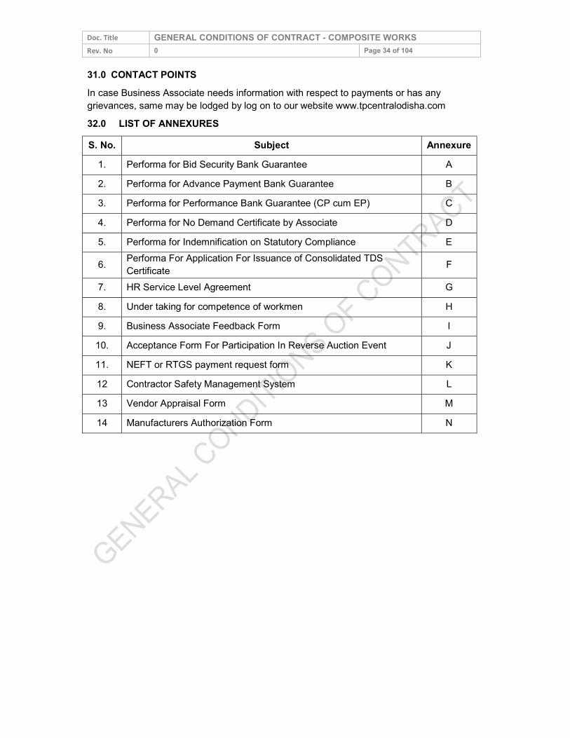
Doc. Title GENERAL CONDITIONS OF CONTRACT - COMPOSITE WORKS Rev. No 0 Page 34 of 104 31.0 CONTACT POINTS In case Business Associate needs information with respect to payments or has any grievances, same may be lodged by log on to our website www.tpcentralodisha.com 32.0 LIST OF ANNEXURES S. No. Subject Annexure
1. Performa for Bid Security Bank Guarantee A 2. Performa for Advance Payment Bank Guarantee B 3. Performa for Performance Bank Guarantee (CP cum EP) C 4. Performa for No Demand Certificate by Associate D 5. Performa for Indemnification on Statutory Compliance E 6. Performa For Application For Issuance of Consolidated TDS
Certificate F 7. HR Service Level Agreement G 8. Under taking for competence of workmen H 9. Business Associate Feedback Form I
10. Acceptance Form For Participation In Reverse Auction Event J 11. NEFT or RTGS payment request form K 12 Contractor Safety Management System L 13 Vendor Appraisal Form M 14 Manufacturers Authorization Form N
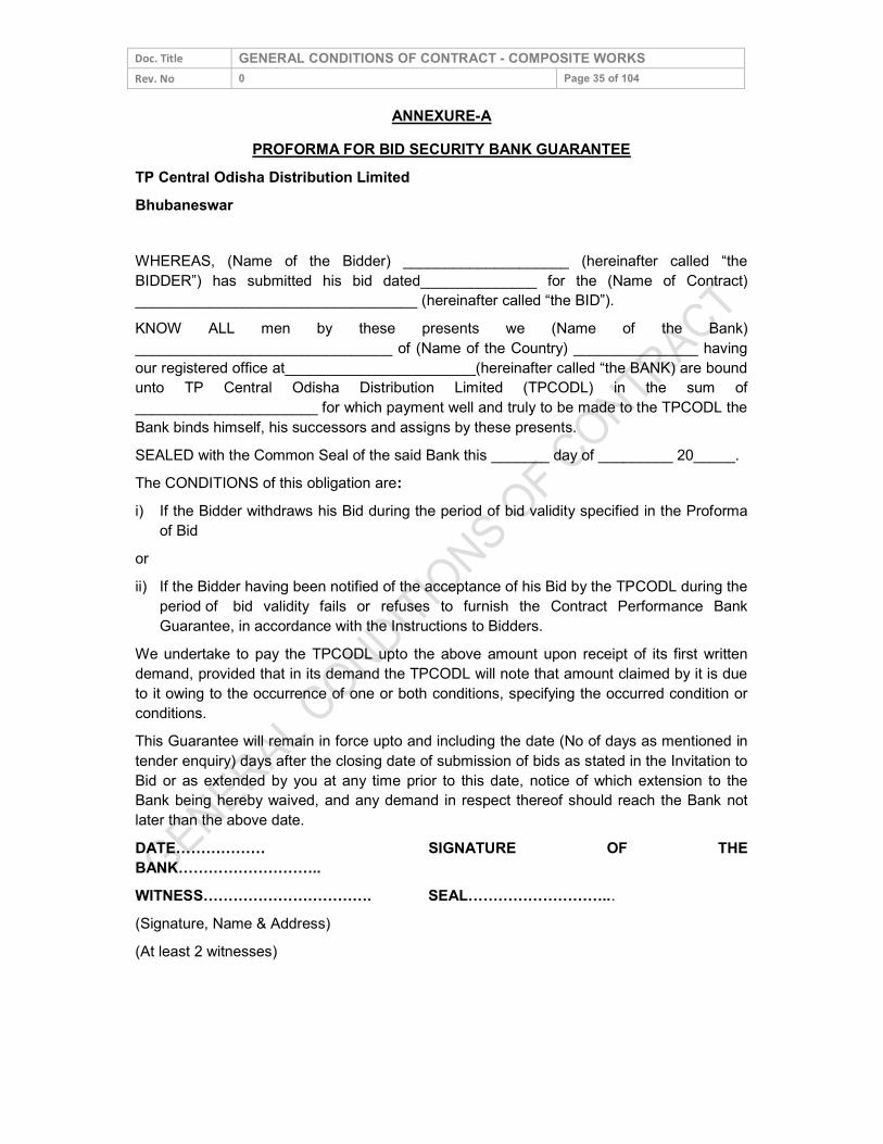
Doc. Title GENERAL CONDITIONS OF CONTRACT - COMPOSITE WORKS Rev. No 0 Page 35 of 104
ANNEXURE-A PROFORMA FOR BID SECURITY BANK GUARANTEE
TP Central Odisha Distribution Limited Bhubaneswar WHEREAS, (Name of the Bidder) ____________________ (hereinafter called “the BIDDER”) has submitted his bid dated______________ for the (Name of Contract) __________________________________ (hereinafter called “the BID”). KNOW ALL men by these presents we (Name of the Bank) _______________________________ of (Name of the Country) _______________ having our registered office at_______________________(hereinafter called “the BANK) are bound unto TP Central Odisha Distribution Limited (TPCODL) in the sum of ______________________ for which payment well and truly to be made to the TPCODL the Bank binds himself, his successors and assigns by these presents. SEALED with the Common Seal of the said Bank this _______ day of _________ 20_____. The CONDITIONS of this obligation are: i) If the Bidder withdraws his Bid during the period of bid validity specified in the Proforma
of Bid or ii) If the Bidder having been notified of the acceptance of his Bid by the TPCODL during the
period of bid validity fails or refuses to furnish the Contract Performance Bank Guarantee, in accordance with the Instructions to Bidders.
We undertake to pay the TPCODL upto the above amount upon receipt of its first written demand, provided that in its demand the TPCODL will note that amount claimed by it is due to it owing to the occurrence of one or both conditions, specifying the occurred condition or conditions. This Guarantee will remain in force upto and including the date (No of days as mentioned in tender enquiry) days after the closing date of submission of bids as stated in the Invitation to Bid or as extended by you at any time prior to this date, notice of which extension to the Bank being hereby waived, and any demand in respect thereof should reach the Bank not later than the above date. DATE……………… SIGNATURE OF THE BANK……………………….. WITNESS……………………………. SEAL………………………... (Signature, Name & Address) (At least 2 witnesses)
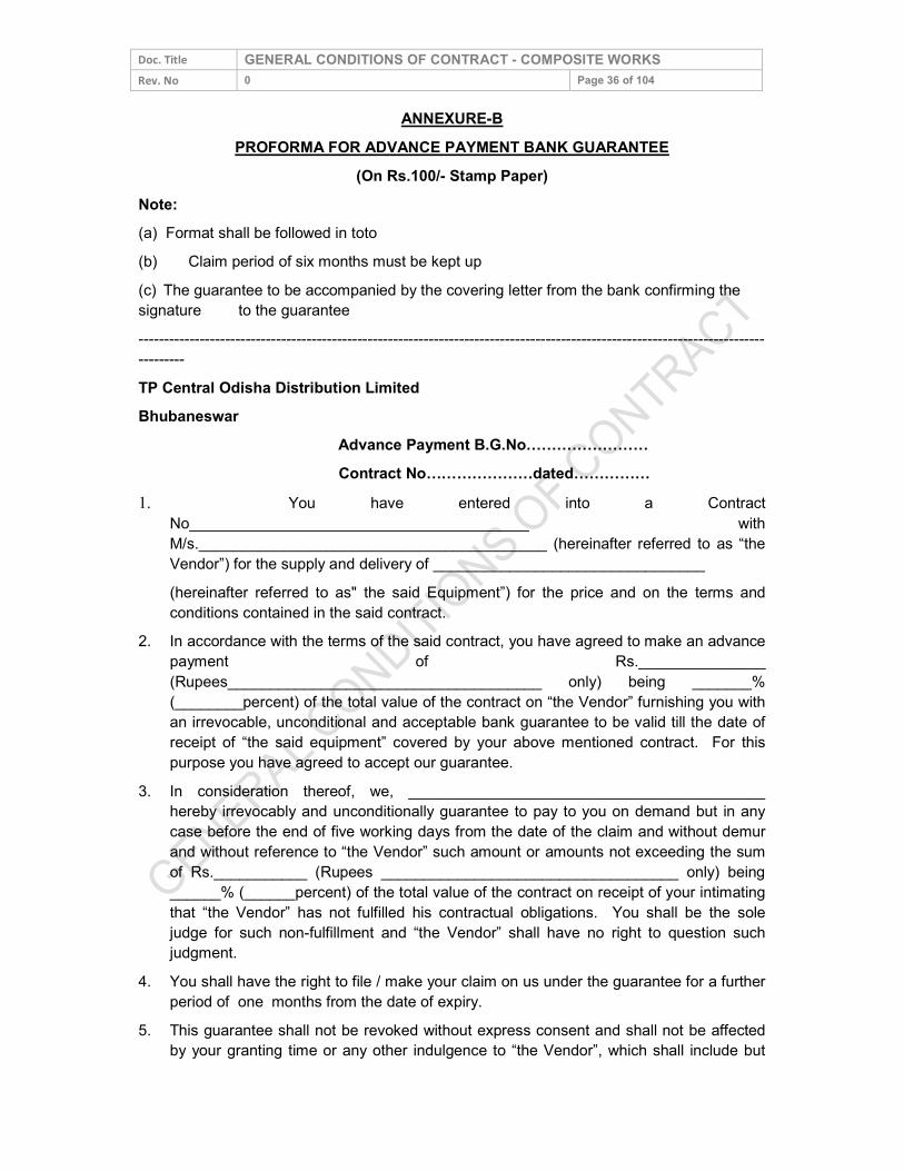
Doc. Title GENERAL CONDITIONS OF CONTRACT - COMPOSITE WORKS Rev. No 0 Page 36 of 104
ANNEXURE-B PROFORMA FOR ADVANCE PAYMENT BANK GUARANTEE
(On Rs.100/- Stamp Paper) Note: (a) Format shall be followed in toto (b) Claim period of six months must be kept up (c) The guarantee to be accompanied by the covering letter from the bank confirming the signature to the guarantee ------------------------------------------------------------------------------------------------------------------------------------ TP Central Odisha Distribution Limited Bhubaneswar Advance Payment B.G.No…………………… Contract No…………………dated…………… 1. You have entered into a Contract
No________________________________________ with M/s._________________________________________ (hereinafter referred to as “the Vendor”) for the supply and delivery of ________________________________
(hereinafter referred to as" the said Equipment”) for the price and on the terms and conditions contained in the said contract.
2. In accordance with the terms of the said contract, you have agreed to make an advance payment of Rs._______________ (Rupees_____________________________________ only) being _______% (________percent) of the total value of the contract on “the Vendor” furnishing you with an irrevocable, unconditional and acceptable bank guarantee to be valid till the date of receipt of “the said equipment” covered by your above mentioned contract. For this purpose you have agreed to accept our guarantee.
3. In consideration thereof, we, __________________________________________ hereby irrevocably and unconditionally guarantee to pay to you on demand but in any case before the end of five working days from the date of the claim and without demur and without reference to “the Vendor” such amount or amounts not exceeding the sum of Rs.___________ (Rupees ___________________________________ only) being ______% (______percent) of the total value of the contract on receipt of your intimating that “the Vendor” has not fulfilled his contractual obligations. You shall be the sole judge for such non-fulfillment and “the Vendor” shall have no right to question such judgment.
4. You shall have the right to file / make your claim on us under the guarantee for a further period of one months from the date of expiry.
5. This guarantee shall not be revoked without express consent and shall not be affected by your granting time or any other indulgence to “the Vendor”, which shall include but
Doc. Title GENERAL CONDITIONS OF CONTRACT - COMPOSITE WORKS Rev. No 0 Page 37 of 104
not be limited to, postponement from time to time of the exercise the same in you or any right which you may have against “the Vendor” and to exercise the same in any covenant contained or implied in the said contract or any other course or remedy or security available to you, and our Bank shall not be released from its obligations under this guarantee by your exercising any of your rights with reference to matters aforesaid or any of them or by reasons of any other act or forbearance or other acts of omission or commission on your part or any other indulgence shown by you or by any other matter or thing whatsoever which under the law would, but for this provision have the effect of relieving our bank from its obligation under this guarantee.
6. We also agree that you shall be entitled at your option to enforce this guarantee against our bank as a principal debtor, in the first instance, notwithstanding any other security or guarantee that you may have in relation to “the Vendor’s” liabilities in respect of the premises
7. This guarantee shall not be affected by any change in the constitution of our Bank or “the Vendor” or for any other reason whatsoever.
8. Any claim / extension under the guarantee can be lodge-able at outstation banks or at Bhubaneswar branch and claim will also be payable at Bhubaneswar Branch (to be confirmed by Bhubaneswar Branch by a letter to that effect)
9. Notwithstanding anything herein contained, our liability under this guarantee is limited to Rs.___________________ (Rupees___________________________________________ only) and the guarantee will remain in force upto and including _________(Date) and shall be extended from time to time for such period or period as may be desired by “the Vendor”.
10. Unless a demand or claim under this guarantee is received by us in writing within one month from____________ (expiry date) i.e. on or before _____________ (claim period end date), we shall be discharged from all liabilities under this guarantee thereafter.
Dated at ___________________this _______________ day of ___________ 200_____ Witness Bank’s rubber stamp 1. ________________________ Banks full address Designation of Signatory 2. ________________________ Bank official number
Doc. Title GENERAL CONDITIONS OF CONTRACT - COMPOSITE WORKS Rev. No 0 Page 38 of 104
ANNEXURE- C PROFORMA FOR PERFORMANCE BANK GUARANTEE (CP cum EP)
(On Rs.100/- Stamp Paper) Note: (a) Format shall be followed in toto (b) Claim period of one month must be kept up (c) The guarantee to be accompanied by the covering letter from the bank confirming the signature to the guarantee ----------------------------------------------------------------------------------------------------------------------------------- TP Central Odisha Distribution Limited Bhubaneswar CP cum EP BG No.……………………………. Order/Contract No…………………dated…………… 1. You have entered into a Contract No _____________________________________ with
M/s._____________________________________________ (hereinafter referred to as “the Vendor”) for the supply cum erection / civil work of ___________________________________ (hereinafter referred to as" the said Equipment”) for the price and on the terms and conditions contained in the said contract.
2. In accordance with the terms of the said contract, “the Vendor” agreed to furnish you with an irrevocable, unconditional and acceptable bank guarantee for 10% of the value of contract and to be valid till the end of Guarantee period plus one month towards “Contract cum Equipment performance”. For this purpose you have agreed to accept the guarantee.
3. In consideration thereof, we, ______________________________________________ hereby irrevocably and unconditionally guarantee to pay to you on demand but in any case before the end of five working days from the date of the claim and without demur and without reference to “the Vendor” such amount or amounts not exceeding the sum of Rs.___________ (Rupees _______________________________________________________ only) being _______% (_______ percent) of the total value of the contract on receipt of your intimating that “the Vendor” has not fulfilled his contractual obligations. You shall be the sole judge for such non-fulfillment and “the Vendor” shall have no right to question such judgment.
4. You shall have the right to file / make your claim on us under the guarantee for a further period of one month from the date of expiry.
5. This guarantee shall not be revoked without express consent and shall not be affected by your granting time or any other indulgence to “the Vendor”, which shall include but not be limited to, postponement from time to time of the exercise the same in you or any right which you may have against “the Vendor” and to exercise the same in any covenant contained or implied in the said contract or any other course or remedy or security
Doc. Title GENERAL CONDITIONS OF CONTRACT - COMPOSITE WORKS Rev. No 0 Page 39 of 104
available to you, and our Bank shall not be released from its obligations under this guarantee by your exercising any of your rights with reference to matters aforesaid or any of them or by reasons of any other act or forbearance or other acts of omission or commission on your part or any other indulgence shown by you or by any other matter or thing whatsoever which under the law would, but for this provision have the effect of relieving our bank from its obligation under this guarantee.
6. We also agree that you shall be entitled at your option to enforce this guarantee against our bank as a principal debtor, in the first instance, notwithstanding any other security or guarantee that you may have in relation to “the Vendor’s” liabilities in respect of the premises
7. This guarantee shall not be affected by any change in the constitution of our Bank or “the Vendor” or for any other reason whatsoever.
8. Any claim / extension under the guarantee can be lodge-able at outstation banks or at Bhubaneswar branch and claim will also be payable at Bhubaneswar Branch (to be confirmed by Bhubaneswar Branch by a letter to that effect in case BG is from the branch outside Bhubaneswar)
9. Notwithstanding anything herein contained, our liability under this guarantee is limited to Rs.___________________ (Rupees________________________________________ only and the guarantee will remain in force upto and including _________(Date) and shall be extended from time to time for such period or period as may be desired by “the Vendor”.
10. Unless a demand or claim under this guarantee is received by us in writing within one months from____________ (expiry date) i.e. on or before _____________ (claim period end date), we shall be discharged from all liabilities under this guarantee thereafter.
Dated at___________________ this_______________ day of ___________ 200__ Witness Bank’s rubber stamp 1. ________________________ Banks full address Designation of Signatory 2. ________________________ Bank official number
Doc. Title GENERAL CONDITIONS OF CONTRACT - COMPOSITE WORKS Rev. No 0 Page 40 of 104
ANNEXURE-D PROFORMA FOR “NO DEMAND CERTIFICATE” BY ASSOCIATE
(On Company’s Letter head or with Company Seal) (To be submitted by the Associate to TPCODL Accounts Department at the time of
receipt of full and final payment) (Certificate No. CCP/002)
Name of the Project Order/ Contract No. Dated Name of the Associate Scheme No. / Job No. We, M/s.____________________________________________ (Associate) do hereby acknowledge and confirm that we have received the full and final payment due and payable to us from TPCODL, in respect of our aforesaid Order No _____________ dated___________ including amendments, if any, issued by TPCODL to our entire satisfaction and we further confirm that we have no claim whatsoever pending with TPCODL under the said contract / W.O. Notwithstanding any protest recorded by us in any correspondence, documents, measurement books and / or final bills etc., we waive all our rights to lodge any claim or protest in future under this contract. We are issuing this “NO DEMAND CERTIFICATE” in favour of TPCODL, with full knowledge and with our free consent without any undue influence, misrepresentation, coercion etc. Dated Signature Place Name Designation (Company Seal)
Doc. Title GENERAL CONDITIONS OF CONTRACT - COMPOSITE WORKS Rev. No 0 Page 41 of 104
ANNEXURE – E
PROFORMA FOR “INDEMNIFICATION ON STATUTORY COMPLIANCES” (To be submitted by the successful Bidder within seven days of award of work)
(Certificate No. CCP/001) Name of the Project Letter of Award / Contract No. Dated Name of the Associate Scheme No. / Job No. By this confirmation we, ___________________________________________________ (Associate) are formally bound to M/s. TPCODL towards any sum which may be imposed, levied or hereinafter recovered by the Provident Fund Organization under the provisions of the Employees of the Provident Fund and Miscellaneous Provisions Act 1952 in respect of employees employed by us. We well and truly bind ourselves and our heirs executors administrators and representatives jointly severely and respectively for the above payment only to be paid to M/s. TPCODL. AND WHEREAS we, _______________________________________________ (Associate) is making compliance of the Employees Provident Fund and Miscellaneous Provisions Act 1952, have entered into the above written bond for the indemnity to M/s. TPCODL against all losses from the acts or default of the said Associate in respect of compliance of the Provident Fund Act. Similarly we hereby confirm that we have complied with all statutory and local laws and nothing is outstanding with regard to Local Sales Tax, Labour Laws, Local Municipal dues, Electricity dues etc. We have entered into the above written bond for the indemnity to M/s. TPCODL against all losses from the acts or default of the said Associate in respect of compliance of the Local Sales Tax Laws, Local Laws, Labour Laws, Local Municipal Dues, Electricity dues etc. NOW THE CONDITION, of the above written bond is as such that if the Associate during the period of this contract commits any default or fails to make payment of Contributions in respect of his employees to the Employees Provident Fund Organization, he shall indemnify the Principal Employer M/s. TPCODL from all and every loss and damage caused to them from any act, omissions or negligence of the said Associate in respect of compliances under the Employees Provident Fund and Miscellaneous Provisions Act, 1952. IN WITNESS to the above written bond we have here to set our hands, with our free consent. Dated Signature Place Name Designation (Company Seal)
Doc. Title GENERAL CONDITIONS OF CONTRACT - COMPOSITE WORKS Rev. No 0 Page 42 of 104
ANNEXURE-F PROFORMA FOR APPLICATION FOR ISSUANCE OF CONSOLIDATED TDS
CERTIFICATE To be printed on the letterhead
To, TP Central Odisha Distribution Limited, Bhubaneswar Sub: Application for issuance of Consolidated TDS Certificate for the FY _________ Dear Sir, I / we hereby request / authorize you to issue me / us a consolidate TDS Certificate for the financial year _______ against tax deducted at source by you from my / our payments / bills during the said year from time to time under Chapter XVII – B of the Income Tax Act, 1961. For and on behalf of Signature Name Address Contact No. (Land Line) (Mobile) PAN # Assessing authority ATTACH THE COPY OF PAN CARD
Doc. Title GENERAL CONDITIONS OF CONTRACT - COMPOSITE WORKS Rev. No 0 Page 43 of 104
ANNEXURE - G SERVICE LEVEL AGREEMENT
(To be adhered to by Business Associates (BAs) in TPCODL on Human Resource Issues) 1.0 The following shall be adhered to by the Business Associates during his / its
association with TPCODL: Shall Abide by TPCODL Core Values:
a) Integrity – We must conduct our business fairly, with honesty and transparency. Everything we do must stand the test of public scrutiny.
b) Understanding – We must be caring, show respect, compassion and humanity to our colleagues and customers and always work for the benefit of the communities we serve.
c) Excellence – We must constantly strive to achieve the highest possible standards in our day to day work and in the quality of services we provide.
d) Unity – We must work cohesively with our colleagues across the group and with our customers and partners to build strong relationships based on tolerance, understanding and mutual co-operation.
e) Responsibility – We must continue to be responsible and sensitive to the communities and environments in which we work and always ensuring that what comes from the people; goes back to the people many times over.
f) Agility- We must work in a speedy and responsive manner and be proactive and innovative in our approach.
2.0 The Business Associate / his manager / supervisor who is responsible for managing the project site / performance contract etc. in TPCODL would also ensure adherence of these values by his employees / persons deployed by him in connection with his works undertaken in TPCODL.
3.0 TPCODL is a signatory to the United Nation Global Compact as an integral part of its Governance principles / business. The Business Associates are required to:
a) Support and respect the protection of human rights and make sure that they are not complicit in human right abuses.
b) Respect freedom of association and effective recognition of the right to collective bargaining.
c) Not to resort to any form of forced and compulsory labour. d) Shall ensure abolition of child labour in his area of work. e) There is no discrimination in respect of employment and occupation in respect of his
employees. f) Support precautionary approach to environmental challenges. g) Promote greater environmental responsibility by himself and his employees in his areas of
work. h) Deploy and defuse environmental friendly technologies while carrying out the works. i) Work against corruptions in all its form including extortion and bribery by himself and his
employees. 4.0 The Business Associates are required to adhere to all applicable Labour Laws with
special reference to the following:

Doc. Title GENERAL CONDITIONS OF CONTRACT - COMPOSITE WORKS Rev. No 0 Page 44 of 104
a) No person below the age of 18 years and no child labour will be engaged directly or indirectly for executing the work connected with the business of TPCODL.
b) Minimum wages along with other statutory dues like PF, ESI, etc. as applicable to the workers shall be made within the prescribed period of 7th / 10th day of the following month.
c) Deduction / deposit / record keeping and all other requirements under Employees PF Act 1952, Employees State Insurance Act 1948 and other applicable acts (if any) shall be adhered to.
d) Only statutorily authorized deductions (if any) shall be made in accordance with the relevant statutes.
e) All the provisions of Contract Labour (R&A) Act 1970 shall be complied with in respect of the workers engaged for TPCODL work. The work will be commenced only after completing necessary formalities for obtaining Labour License (if applicable).
f) Necessary registers / records, filing of returns etc. shall be maintained for verification by Statutory / TPCODL authorities.
g) Payment of wages shall be made only in presence of and with certification of authorized representative of TPCODL or shall be made in the form of cheque / bank transfer to the employee.
h) During the period of contract, the Business Associate will arrange for deployment of his supervisor / manager for total supervision and control of the work and their manpower. All the activities related to their manpower e.g. attendance, leave, wage disbursement etc. will be done under the supervision & control of Business Associates, While adhering to the prescribed standard / norms of production / productivity & quality. During execution of the work, Business Associate shall engage only such qualified / skilled manpower as may be envisaged / required for ensuring level of production / service into the contract / work order.
i) Clearances as follows shall be obtained from IR & Welfare Group: i. Clearance for commencement (before start of the work). ii. No Objection Certificate (after completion / before final settlement). iii. Copies of PF / ESI Challans shall be deposited with IR & Welfare Group every month
j) The Business Associate shall indemnify TPCODL from any liabilities under applicable Labour Statutes.
k) The Business Associate shall ensure safety and health of his employees and shall also maintain hygienic working environment / condition in his area of work.
l) The Business Associate and his employee shall abide by Laws of Land and shall not violate any applicable provisions.
m) The Business Associate appreciates with and acquiesces to the right of TPCODL as principal employer to fulfil any of his legal obligations, if he fails to do so under applicable labour laws and deduct the same from his running bills / final payments / enchasing security deposit / Bank Guarantee as the case may be. If there is any further shortfall TPCODL has the right to recover the same from the Business Associate.
n) The Business Associate ensures that person employed by him adhere to the moral and legal conduct and shall not violate any standard conduct envisaged in the premise of
Doc. Title GENERAL CONDITIONS OF CONTRACT - COMPOSITE WORKS Rev. No 0 Page 45 of 104 TPCODL by all such as, Transparency, Safety, Discipline, Integrity etc. The Business Associate or his employees should refrain from corrupt practices, giving or taking bribe in connection with any TPCODL business.
5.0 The ‘Statutory Compliance Enforcement System’ in TPCODL is detailed below for adherence by all concerned. Corporate IR & Welfare Group will be the process owner for implementation of the system with the help of concerned Engineer I/c or Officer I/c.
a) Statutory Compliance being a professed value in TPCODL Code of Conduct, the concerned Engineer / Officer in charges are requested to adhere to the provisions and advise respective Business Associates in their domain to comply in letter and spirit.
b) Immediately after issuance of letter of intent, the authorized representative of the Business Associate will report to Corporate IR & Welfare group for completion of statutory requirements.
c) Normally, the work will be started only after ‘Clearance for Commencement of Work (CCW) is issued by IR & W group to the Business associate. However in exceptional exigencies in engineer I/c / Officer I/c may direct the Business Associate to start the work and inform IR & W group about the same. Statutory requirements in this case may be completed parallely.
d) First monthly bill will be released only after producing CCW to the finance department. Similarly closure of work and final settlement will be affected after issuance of no objection certificate from IR & W group.
6.0 Requirements for ‘Clearance for Commencement of Work’ (CCW): a) Submission of filled up Form ‘A’ for database (Annexure-1). b) Copy of PF Code allocation letter. c) Copy of ESI Code allocation letter. d) Submission of duly filled up Form IV CL(R&A) act (In case more than or equals to 20
workers during the period of contract). e) Submission of duly filled up Form VI A (Notice of Commencement). f) Copy of insurance cover note under WC Act 1923 (if applicable). g) Copy of Contract Agreement. h) Copy of indemnity bond (if applicable). i) Affidavit with regard to payment of wages through cheque / bank transfer only.
7.0 Requirements during execution of work: a) Copy of receipt of application for license / license (if applicable). b) Copy of PF Challan (latest by 26th day of every Month). c) Copy of ESI Challan (latest by 26th day of every Month). d) Copy of Wage disbursement sheet / Bank statement. e) Filing / Maintenance of all statutory registers / reports / returns for inspection by Statutory/
TPCODL authorities. f) Certification of wage disbursement by authorized representative of TPCODL. g) Copy of ‘Labour Welfare Fund’ deposit certificate / Challan. h) Insuring safe working practices at the work place.
8.0 Requirements for ‘No Objection Certificate’ (NOC) for closure of work: a) Submission of duly filled up Form VI A (Notice of Completion).
Doc. Title GENERAL CONDITIONS OF CONTRACT - COMPOSITE WORKS Rev. No 0 Page 46 of 104
b) Copy of Half yearly / Annual return for ESI / PF / CL(R&A). c) Consolidated copy of wage sheet of last month indicating full & final settlement of all dues
like retrenchment benefit, bonus, leave encashment etc. Copy of individual declaration by employees in Form X regarding termination of employment.
d) Confirmation certificate regarding filling up of form for transfer / withdrawal of PF by the concerned workers. In case any of the above are deviated / not complied with the Letter of Award/Order shall be liable to be withdrawn / cancelled. Enclosure:
1) Form A 2) Form X 3) Form XI 4) Form VI A 5) Form XXIV
Doc. Title GENERAL CONDITIONS OF CONTRACT - COMPOSITE WORKS Rev. No 0 Page 47 of 104
FORM (A) [To be submitted by the Business Associate to the Principal Employer within a week from LoA
issuance]
A. Details of the Agency 1. Name of Agency : 2. Nature of work : 3. Local Address with Ph.No. : (With Father’s name) : 4. Permanent Address (Full) : 5. PF code no. & Place : 6. ESI Code no. & Place : 7. Name and address of : Sub-contractor (if any) B. Details of Work 8. Name of work (as specified in LOI/LOA) : 9. LOI/LOA Nos. & Dates : 10. Period of contract (Specify Dates) : [Including Extension period, if any] : 11. Work Area [Department / Location] : 12. Name / Cell no. of Officer I/c : 13. Maximum No. of workers and staff to be engaged on any day during the year.
Supervisory Staff : Workers :
14. Do you have any other contract in TPCODL : Yes/No If yes, furnish details:
Doc. Title GENERAL CONDITIONS OF CONTRACT - COMPOSITE WORKS Rev. No 0 Page 48 of 104
15. Details of Workmen’s compensation Policy, if applicable Name of Insurance Company ……………………………………………………………………………... ………………………………………Policy No ……………………………… Number of persons covered …………… Period of coverage: From ……………………. To …………………….….. If no, I hereby undertake the liability arising out of Workmen’s Compensation Act and Rules made there under. C. Details of workers to be engaged No. of Workers
S. No. Unskilled* Semi-skilled* Skilled* Clerical / Supervisory
* Number to be indicated I/We shall fulfill all obligations arising from and under all relevant law in force from time to time. I/We undertake to keep the TPCODL indemnified against any loss or liability arising out of failure of my / our abiding the relevant laws. The name of my / our representatives is …………………………………………… to enter the TPCODL Premises on my behalf. Date:
(Signature of the Business Associate or his Authorized Representative)
This Business Associate is / will be engaged in TPCODL. (Signature and seal of Officer I/c of the Work)
Doc. Title GENERAL CONDITIONS OF CONTRACT - COMPOSITE WORKS Rev. No 0 Page 49 of 104
Form X Undertaking
I _________________________________________________ hereby undertake that all the dues in respect of my employment with M/s ____________________________________ for the period of _______________________________ to __________________________have been settled and final payments including retrenchment benefit have been made to me in full.
( ) ______________________________
Date:
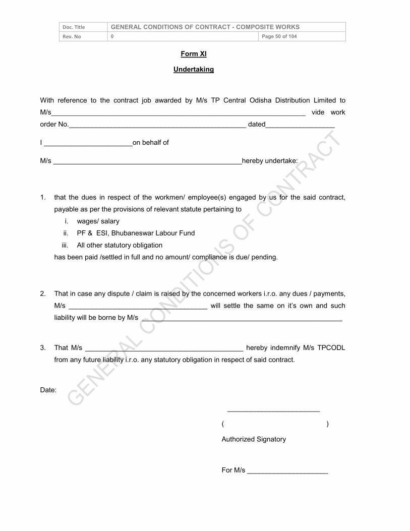
Doc. Title GENERAL CONDITIONS OF CONTRACT - COMPOSITE WORKS Rev. No 0 Page 50 of 104
Form XI Undertaking
With reference to the contract job awarded by M/s TP Central Odisha Distribution Limited to M/s__________________________________________________________________ vide work order No.______________________________________________ dated__________________ I _______________________on behalf of M/s _________________________________________________hereby undertake: 1. that the dues in respect of the workmen/ employee(s) engaged by us for the said contract,
payable as per the provisions of relevant statute pertaining to i. wages/ salary ii. PF & ESI, Bhubaneswar Labour Fund iii. All other statutory obligation
has been paid /settled in full and no amount/ compliance is due/ pending. 2. That in case any dispute / claim is raised by the concerned workers i.r.o. any dues / payments,
M/s ____________________________________ will settle the same on it’s own and such liability will be borne by M/s ____________________________________________________
3. That M/s _________________________________________ hereby indemnify M/s TPCODL
from any future liability i.r.o. any statutory obligation in respect of said contract. Date: ________________________ ( )
Authorized Signatory
For M/s _____________________
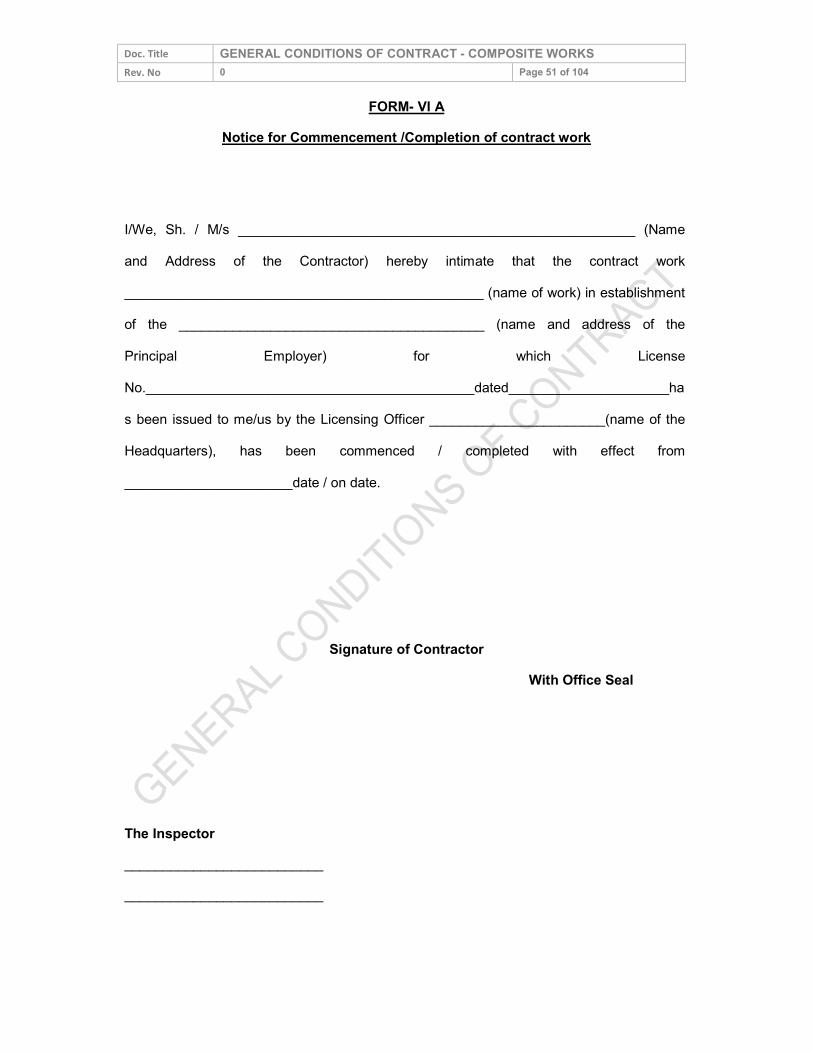
Doc. Title GENERAL CONDITIONS OF CONTRACT - COMPOSITE WORKS Rev. No 0 Page 51 of 104
FORM- VI A Notice for Commencement /Completion of contract work
I/We, Sh. / M/s ____________________________________________________ (Name and Address of the Contractor) hereby intimate that the contract work _______________________________________________ (name of work) in establishment of the ________________________________________ (name and address of the Principal Employer) for which License No.___________________________________________dated_____________________has been issued to me/us by the Licensing Officer _______________________(name of the Headquarters), has been commenced / completed with effect from ______________________date / on date.
Signature of Contractor
With Office Seal The Inspector __________________________ __________________________
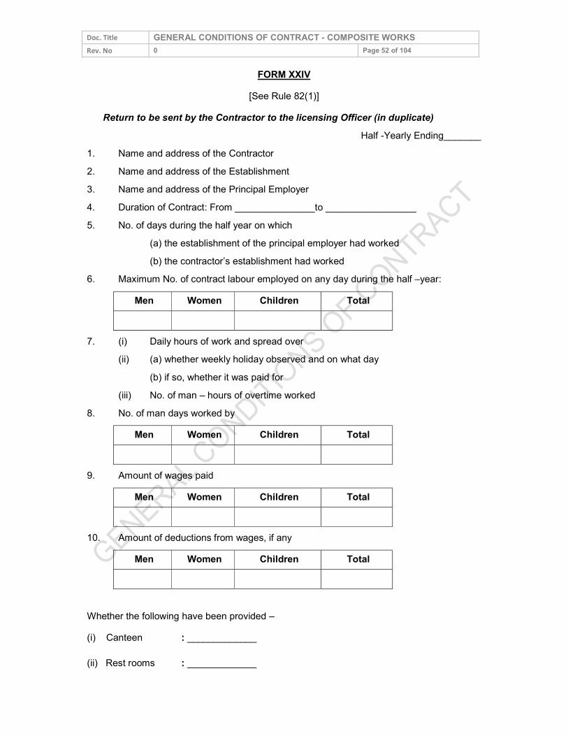
Doc. Title GENERAL CONDITIONS OF CONTRACT - COMPOSITE WORKS Rev. No 0 Page 52 of 104
FORM XXIV [See Rule 82(1)]
Return to be sent by the Contractor to the licensing Officer (in duplicate) Half -Yearly Ending_______
1. Name and address of the Contractor 2. Name and address of the Establishment 3. Name and address of the Principal Employer 4. Duration of Contract: From _______________to _________________ 5. No. of days during the half year on which (a) the establishment of the principal employer had worked (b) the contractor’s establishment had worked 6. Maximum No. of contract labour employed on any day during the half –year:
Men Women Children Total
7. (i) Daily hours of work and spread over (ii) (a) whether weekly holiday observed and on what day (b) if so, whether it was paid for (iii) No. of man – hours of overtime worked 8. No. of man days worked by
Men Women Children Total
9. Amount of wages paid Men Women Children Total
10. Amount of deductions from wages, if any Men Women Children Total
Whether the following have been provided – (i) Canteen : _____________ (ii) Rest rooms : _____________
Doc. Title GENERAL CONDITIONS OF CONTRACT - COMPOSITE WORKS Rev. No 0 Page 53 of 104 (iii) Drinking water : _____________ (iv) Crèches : _____________ (v) First Aid : _____________ Signature of contractor Place _________________ Date __________________
Doc. Title GENERAL CONDITIONS OF CONTRACT - COMPOSITE WORKS Rev. No 0 Page 54 of 104
ANNEXURE – H UNDERTAKING FOR COMPETENCE OF WORKMEN
Name of Associate : Tender No. : Item : With reference to the tender mentioned above, I/We _______________________________, hereby undertake that the workmen/ employee(s) engaged by M/s __________________________ for the job against said tender shall be competent in all respect, commensurate to the nature of job. Date: _____________________________ ( ) Authorized Signatory For M/s Seal
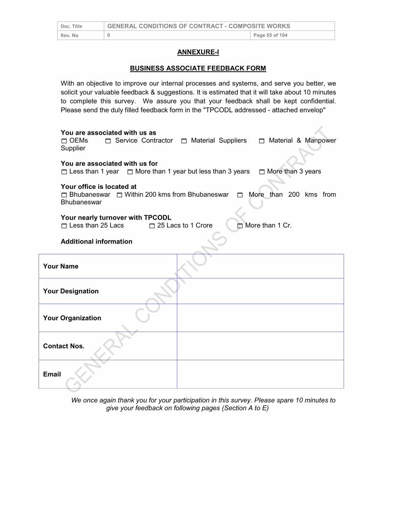
Doc. Title GENERAL CONDITIONS OF CONTRACT - COMPOSITE WORKS Rev. No 0 Page 55 of 104
ANNEXURE-I BUSINESS ASSOCIATE FEEDBACK FORM
With an objective to improve our internal processes and systems, and serve you better, we solicit your valuable feedback & suggestions. It is estimated that it will take about 10 minutes to complete this survey. We assure you that your feedback shall be kept confidential. Please send the duly filled feedback form in the "TPCODL addressed - attached envelop" You are associated with us as OEMs Service Contractor Material Suppliers Material & Manpower Supplier You are associated with us for Less than 1 year More than 1 year but less than 3 years More than 3 years Your office is located at Bhubaneswar Within 200 kms from Bhubaneswar More than 200 kms from Bhubaneswar Your nearly turnover with TPCODL Less than 25 Lacs 25 Lacs to 1 Crore More than 1 Cr. Additional information
Your Name
Your Designation
Your Organization
Contact Nos.
Email We once again thank you for your participation in this survey. Please spare 10 minutes to
give your feedback on following pages (Section A to E)
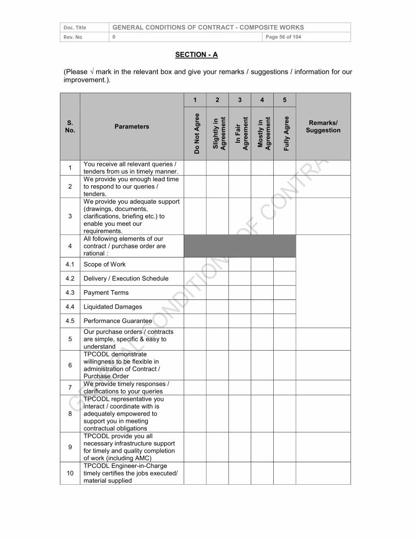
Doc. Title GENERAL CONDITIONS OF CONTRACT - COMPOSITE WORKS Rev. No 0 Page 56 of 104
SECTION - A (Please √ mark in the relevant box and give your remarks / suggestions / information for our improvement.).
S. No. Parameters
1 2 3 4 5
Remarks/ Suggestion
Do No
t Agre
e
Sligh
tly in
Ag
reeme
nt In
Fair
Agree
ment
Mostl
y in
Agree
ment
Fully
Agree
1 You receive all relevant queries / tenders from us in timely manner.
2 We provide you enough lead time to respond to our queries / tenders.
3 We provide you adequate support (drawings, documents, clarifications, briefing etc.) to enable you meet our requirements.
4 All following elements of our contract / purchase order are rational :
4.1 Scope of Work 4.2 Delivery / Execution Schedule 4.3 Payment Terms 4.4 Liquidated Damages 4.5 Performance Guarantee
5 Our purchase orders / contracts are simple, specific & easy to understand
6 TPCODL demonstrate willingness to be flexible in administration of Contract / Purchase Order
7 We provide timely responses / clarifications to your queries
8 TPCODL representative you interact / coordinate with is adequately empowered to support you in meeting contractual obligations
9 TPCODL provide you all necessary infrastructure support for timely and quality completion of work (including AMC)
10 TPCODL Engineer-in-Charge timely certifies the jobs executed/ material supplied
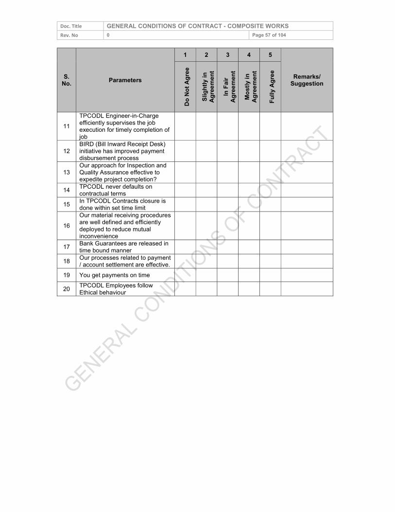
Doc. Title GENERAL CONDITIONS OF CONTRACT - COMPOSITE WORKS Rev. No 0 Page 57 of 104
S. No. Parameters
1 2 3 4 5
Remarks/ Suggestion
Do No
t Agre
e
Sligh
tly in
Ag
reeme
nt In
Fair
Agree
ment
Mostl
y in
Agree
ment
Fully
Agree
11 TPCODL Engineer-in-Charge efficiently supervises the job execution for timely completion of job
12 BIRD (Bill Inward Receipt Desk) initiative has improved payment disbursement process
13 Our approach for Inspection and Quality Assurance effective to expedite project completion?
14 TPCODL never defaults on contractual terms
15 In TPCODL Contracts closure is done within set time limit
16 Our material receiving procedures are well defined and efficiently deployed to reduce mutual inconvenience
17 Bank Guarantees are released in time bound manner
18 Our processes related to payment / account settlement are effective.
19 You get payments on time 20 TPCODL Employees follow
Ethical behaviour
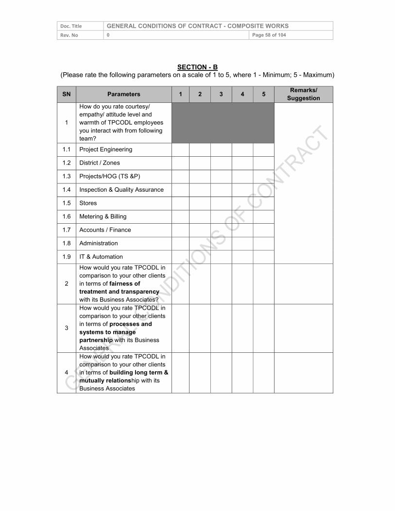
Doc. Title GENERAL CONDITIONS OF CONTRACT - COMPOSITE WORKS Rev. No 0 Page 58 of 104
SECTION - B (Please rate the following parameters on a scale of 1 to 5, where 1 - Minimum; 5 - Maximum)
SN Parameters 1 2 3 4 5 Remarks/
Suggestion
1 How do you rate courtesy/ empathy/ attitude level and warmth of TPCODL employees you interact with from following team?
1.1 Project Engineering 1.2 District / Zones 1.3 Projects/HOG (TS &P) 1.4 Inspection & Quality Assurance 1.5 Stores 1.6 Metering & Billing 1.7 Accounts / Finance 1.8 Administration 1.9 IT & Automation
2 How would you rate TPCODL in comparison to your other clients in terms of fairness of treatment and transparency with its Business Associates?
3
How would you rate TPCODL in comparison to your other clients in terms of processes and systems to manage partnership with its Business Associates
4 How would you rate TPCODL in comparison to your other clients in terms of building long term & mutually relationship with its Business Associates
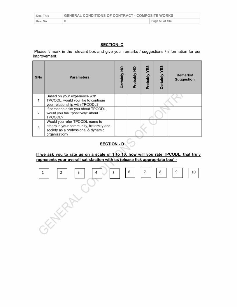
Doc. Title GENERAL CONDITIONS OF CONTRACT - COMPOSITE WORKS Rev. No 0 Page 59 of 104
SECTION–C Please √ mark in the relevant box and give your remarks / suggestions / information for our
improvement.
SNo Parameters
Certa
inly N
O
Proba
bly NO
Proba
bly YE
S
Certa
inly Y
ES
Remarks/ Suggestion
1 Based on your experience with TPCODL, would you like to continue your relationship with TPCODL?
2 If someone asks you about TPCODL, would you talk “positively” about TPCODL?
3 Would you refer TPCODL name to others in your community, fraternity and society as a professional & dynamic organization?
SECTION - D If we ask you to rate us on a scale of 1 to 10, how will you rate TPCODL, that truly represents your overall satisfaction with us (please tick appropriate box) -
1 2 3 4 5 6 7 8 9 10
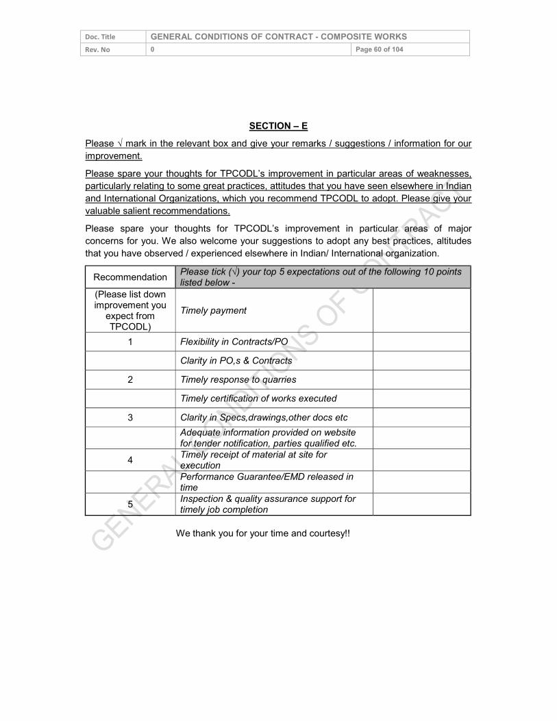
Doc. Title GENERAL CONDITIONS OF CONTRACT - COMPOSITE WORKS Rev. No 0 Page 60 of 104
SECTION – E Please √ mark in the relevant box and give your remarks / suggestions / information for our improvement. Please spare your thoughts for TPCODL’s improvement in particular areas of weaknesses, particularly relating to some great practices, attitudes that you have seen elsewhere in Indian and International Organizations, which you recommend TPCODL to adopt. Please give your valuable salient recommendations. Please spare your thoughts for TPCODL’s improvement in particular areas of major concerns for you. We also welcome your suggestions to adopt any best practices, altitudes that you have observed / experienced elsewhere in Indian/ International organization.
Recommendation Please tick (√) your top 5 expectations out of the following 10 points listed below -
(Please list down improvement you
expect from TPCODL)
Timely payment
1 Flexibility in Contracts/PO Clarity in PO,s & Contracts
2 Timely response to quarries Timely certification of works executed
3 Clarity in Specs,drawings,other docs etc Adequate information provided on website
for tender notification, parties qualified etc. 4 Timely receipt of material at site for
execution Performance Guarantee/EMD released in
time 5 Inspection & quality assurance support for
timely job completion We thank you for your time and courtesy!!
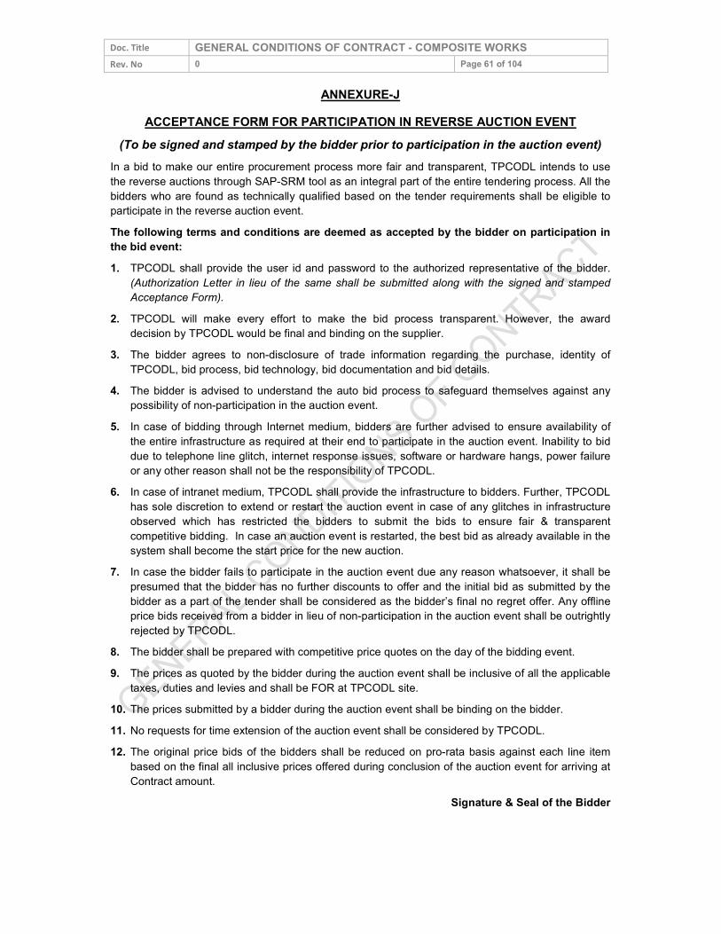
Doc. Title GENERAL CONDITIONS OF CONTRACT - COMPOSITE WORKS Rev. No 0 Page 61 of 104
ANNEXURE-J ACCEPTANCE FORM FOR PARTICIPATION IN REVERSE AUCTION EVENT
(To be signed and stamped by the bidder prior to participation in the auction event) In a bid to make our entire procurement process more fair and transparent, TPCODL intends to use the reverse auctions through SAP-SRM tool as an integral part of the entire tendering process. All the bidders who are found as technically qualified based on the tender requirements shall be eligible to participate in the reverse auction event. The following terms and conditions are deemed as accepted by the bidder on participation in the bid event: 1. TPCODL shall provide the user id and password to the authorized representative of the bidder.
(Authorization Letter in lieu of the same shall be submitted along with the signed and stamped Acceptance Form).
2. TPCODL will make every effort to make the bid process transparent. However, the award decision by TPCODL would be final and binding on the supplier.
3. The bidder agrees to non-disclosure of trade information regarding the purchase, identity of TPCODL, bid process, bid technology, bid documentation and bid details.
4. The bidder is advised to understand the auto bid process to safeguard themselves against any possibility of non-participation in the auction event.
5. In case of bidding through Internet medium, bidders are further advised to ensure availability of the entire infrastructure as required at their end to participate in the auction event. Inability to bid due to telephone line glitch, internet response issues, software or hardware hangs, power failure or any other reason shall not be the responsibility of TPCODL.
6. In case of intranet medium, TPCODL shall provide the infrastructure to bidders. Further, TPCODL has sole discretion to extend or restart the auction event in case of any glitches in infrastructure observed which has restricted the bidders to submit the bids to ensure fair & transparent competitive bidding. In case an auction event is restarted, the best bid as already available in the system shall become the start price for the new auction.
7. In case the bidder fails to participate in the auction event due any reason whatsoever, it shall be presumed that the bidder has no further discounts to offer and the initial bid as submitted by the bidder as a part of the tender shall be considered as the bidder’s final no regret offer. Any offline price bids received from a bidder in lieu of non-participation in the auction event shall be outrightly rejected by TPCODL.
8. The bidder shall be prepared with competitive price quotes on the day of the bidding event. 9. The prices as quoted by the bidder during the auction event shall be inclusive of all the applicable
taxes, duties and levies and shall be FOR at TPCODL site. 10. The prices submitted by a bidder during the auction event shall be binding on the bidder. 11. No requests for time extension of the auction event shall be considered by TPCODL. 12. The original price bids of the bidders shall be reduced on pro-rata basis against each line item
based on the final all inclusive prices offered during conclusion of the auction event for arriving at Contract amount.
Signature & Seal of the Bidder
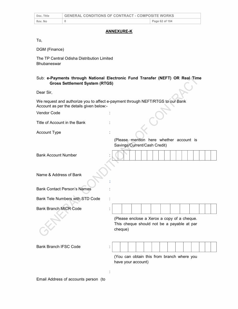
Doc. Title GENERAL CONDITIONS OF CONTRACT - COMPOSITE WORKS Rev. No 0 Page 62 of 104
ANNEXURE-K To, DGM (Finance) The TP Central Odisha Distribution Limited Bhubaneswar Sub: e-Payments through National Electronic Fund Transfer (NEFT) OR Real Time Gross Settlement System (RTGS) Dear Sir, We request and authorize you to affect e-payment through NEFT/RTGS to our Bank Account as per the details given below:- Vendor Code : Title of Account in the Bank : Account Type :
(Please mention here whether account is Savings/Current/Cash Credit)
Bank Account Number : Name & Address of Bank
:
Bank Contact Person’s Names : Bank Tele Numbers with STD Code : Bank Branch MICR Code : (Please enclose a Xerox a copy of a cheque.
This cheque should not be a payable at par cheque)
Bank Branch IFSC Code : (You can obtain this from branch where you
have your account)
Email Address of accounts person (to
:
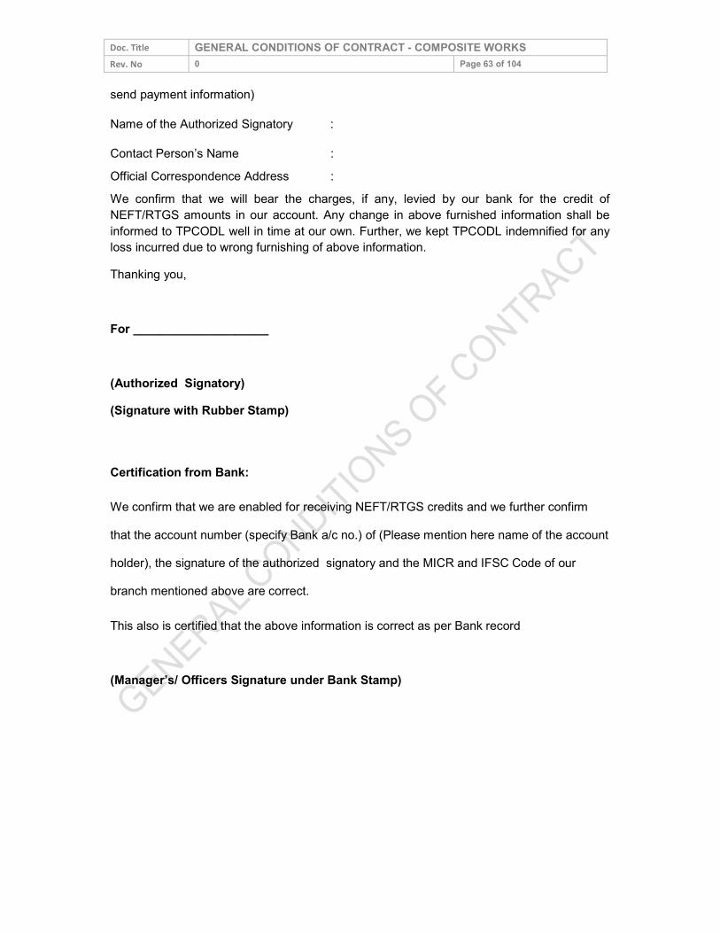
Doc. Title GENERAL CONDITIONS OF CONTRACT - COMPOSITE WORKS Rev. No 0 Page 63 of 104 send payment information) Name of the Authorized Signatory : Contact Person’s Name Official Correspondence Address
: :
We confirm that we will bear the charges, if any, levied by our bank for the credit of NEFT/RTGS amounts in our account. Any change in above furnished information shall be informed to TPCODL well in time at our own. Further, we kept TPCODL indemnified for any loss incurred due to wrong furnishing of above information. Thanking you, For ____________________ (Authorized Signatory) (Signature with Rubber Stamp) Certification from Bank: We confirm that we are enabled for receiving NEFT/RTGS credits and we further confirm that the account number (specify Bank a/c no.) of (Please mention here name of the account holder), the signature of the authorized signatory and the MICR and IFSC Code of our branch mentioned above are correct. This also is certified that the above information is correct as per Bank record (Manager’s/ Officers Signature under Bank Stamp)
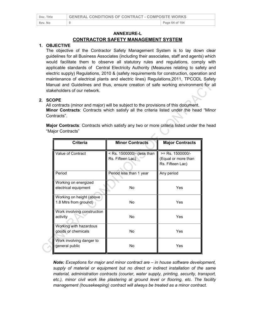
Doc. Title GENERAL CONDITIONS OF CONTRACT - COMPOSITE WORKS Rev. No 0 Page 64 of 104
ANNEXURE-L CONTRACTOR SAFETY MANAGEMENT SYSTEM
1. OBJECTIVE The objective of the Contractor Safety Management System is to lay down clear guidelines for all Business Associates (including their associates, staff and agents) which would facilitate them to observe all statutory rules and regulations, comply with applicable standards of Central Electricity Authority (Measures relating to safety and electric supply) Regulations, 2010 & (safety requirements for construction, operation and maintenance of electrical plants and electric lines) Regulations,2011, TPCODL Safety Manual and Guidelines and thus, ensure creation of safe working environment for all stakeholders of our network.
2. SCOPE All contracts (minor and major) will be subject to the provisions of this document. Minor Contracts: Contracts which satisfy all the criteria listed under the head “Minor Contracts”. Major Contracts: Contracts which satisfy any two or more criteria listed under the head “Major Contracts”
Criteria Minor Contracts Major Contracts Value of Contract < Rs. 1500000/- (less than
Rs. Fifteen Lac) >= Rs. 1500000/- (Equal or more than Rs. Fifteen Lac)
Period Period less than 1 year Any period Working on energized electrical equipment No Yes Working on height (above 1.8 Mtrs from ground) No Yes Work involving construction activity No Yes Working with hazardous goods or chemicals No Yes Work involving danger to general public No Yes
Note: Exceptions for major and minor contract are – in house software development, supply of material or equipment but no direct or indirect installation of the same material, administration contracts (courier, water supply, printing, security, transport, etc.), minor civil work like plastering at ground level or flooring, etc. The facility management (housekeeping) contract will always be treated as a minor contract.
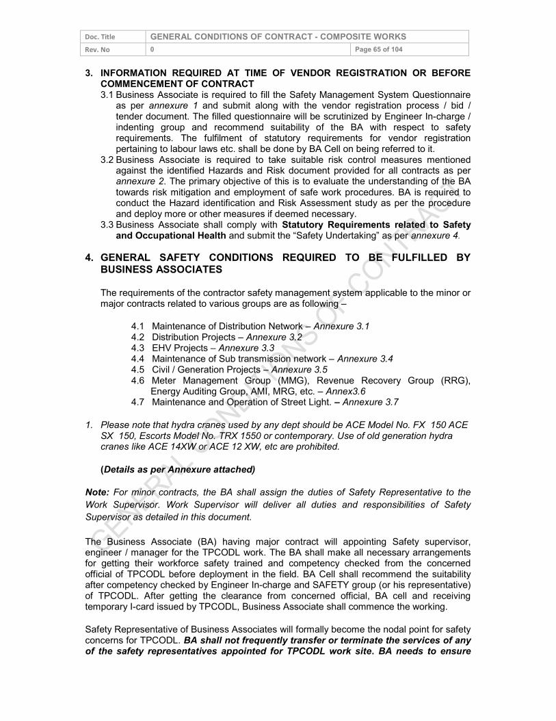
Doc. Title GENERAL CONDITIONS OF CONTRACT - COMPOSITE WORKS Rev. No 0 Page 65 of 104 3. INFORMATION REQUIRED AT TIME OF VENDOR REGISTRATION OR BEFORE
COMMENCEMENT OF CONTRACT 3.1 Business Associate is required to fill the Safety Management System Questionnaire as per annexure 1 and submit along with the vendor registration process / bid /
tender document. The filled questionnaire will be scrutinized by Engineer In-charge / indenting group and recommend suitability of the BA with respect to safety requirements. The fulfilment of statutory requirements for vendor registration pertaining to labour laws etc. shall be done by BA Cell on being referred to it.
3.2 Business Associate is required to take suitable risk control measures mentioned against the identified Hazards and Risk document provided for all contracts as per annexure 2. The primary objective of this is to evaluate the understanding of the BA towards risk mitigation and employment of safe work procedures. BA is required to conduct the Hazard identification and Risk Assessment study as per the procedure and deploy more or other measures if deemed necessary.
3.3 Business Associate shall comply with Statutory Requirements related to Safety and Occupational Health and submit the “Safety Undertaking” as per annexure 4. 4. GENERAL SAFETY CONDITIONS REQUIRED TO BE FULFILLED BY
BUSINESS ASSOCIATES The requirements of the contractor safety management system applicable to the minor or major contracts related to various groups are as following –
4.1 Maintenance of Distribution Network – Annexure 3.1 4.2 Distribution Projects – Annexure 3.2 4.3 EHV Projects – Annexure 3.3 4.4 Maintenance of Sub transmission network – Annexure 3.4 4.5 Civil / Generation Projects – Annexure 3.5 4.6 Meter Management Group (MMG), Revenue Recovery Group (RRG),
Energy Auditing Group, AMI, MRG, etc. – Annex3.6 4.7 Maintenance and Operation of Street Light. – Annexure 3.7 1. Please note that hydra cranes used by any dept should be ACE Model No. FX 150 ACE
SX 150, Escorts Model No. TRX 1550 or contemporary. Use of old generation hydra cranes like ACE 14XW or ACE 12 XW, etc are prohibited. (Details as per Annexure attached)
Note: For minor contracts, the BA shall assign the duties of Safety Representative to the Work Supervisor. Work Supervisor will deliver all duties and responsibilities of Safety Supervisor as detailed in this document. The Business Associate (BA) having major contract will appointing Safety supervisor, engineer / manager for the TPCODL work. The BA shall make all necessary arrangements for getting their workforce safety trained and competency checked from the concerned official of TPCODL before deployment in the field. BA Cell shall recommend the suitability after competency checked by Engineer In-charge and SAFETY group (or his representative) of TPCODL. After getting the clearance from concerned official, BA cell and receiving temporary I-card issued by TPCODL, Business Associate shall commence the working. Safety Representative of Business Associates will formally become the nodal point for safety concerns for TPCODL. BA shall not frequently transfer or terminate the services of any of the safety representatives appointed for TPCODL work site. BA needs to ensure
Doc. Title GENERAL CONDITIONS OF CONTRACT - COMPOSITE WORKS Rev. No 0 Page 66 of 104 that Safety representative is available at all points of time; failing which the work being carried out in the interim (period when Safety representative is not available) shall be treated as working under improper supervision and due penal provisions shall be initiated against the BA. BA will be required to provide all applicable infrastructure and power to ensure smooth working of the safety representative to maintain a sound safety management system. In all contracts safety representative will not be assigned any other activity at site apart from the works related to safety management. The duties are detailed in clause 5.5 of this document. TPCODL will be auditing the facilities provided to the BA`s safety team time to time. The Safety Representative of the BA shall be required to meet and follow the instructions of the Engineer In-charge and SAFETY Group of TPCODL. He shall be responsible for providing the MIS and/or any other relevant information, as and when desired, within the stipulated time frame as per the requirements of TPCODL. Any non-conformance to safety will lead to the negative marking or issue of safety violation challan/ tokens which shall affect the monthly evaluation and performance of BA. All contracts where BA has to depute vehicle for their staff and equipment to move from one location to other, the BA shall ensure that vehicle complies all required statutory clearances and requirement as per The Motor Vehicle Act, 1988 as well as TPCODL Road Safety Policy and are in good & safe state of working. 5. QUALIFICATION AND EXPERIENCE OF THE SAFETY AND SITE
PERSONNEL Qualification and experience required for the safety and site personnel are as following: 5.1 Safety Supervisor: It is mandatory that educational qualification of safety supervisor be
ITI (of relevant trade) / Diploma (Any branch of engineering) and he has a working experience on electrical system / relevant field of work at least 5 yrs for ITI and 3 years for Diploma holder. Having formal experience of the safety systems will be an added advantage
5.2 Safety Engineer: It is mandatory that educational qualification of safety engineer be at least Diploma (relevant branch) and he has working experience on electrical system of at least 3 yrs. Having the formal experience of the safety systems will be an added advantage.
5.3 Safety Manager: The educational qualification of safety manager should be graduate engineer with working experience on electrical system / network of at least 3 yrs. OR Diploma in Industrial Safety with working experience of 05 years including at least 02 years on electrical network. However, clause 5.1, 5.2 and 5.3 are not applicable for minor contracts. In such cases, BA shall assign the duties of Safety Representative to the Work Supervisor. Work Supervisor will deliver required duties of Safety Representative (as per clause 5.5) in addition to other duties without diluting the importance of safety.
5.4 Site Skilled Personnel: For all responsibility related to site activities and operations, the BA shall employ only qualified and skilled persons and shall comply the provisions of section 19 & 29 of Central Electricity Authority (Measures relating to safety and electric supply) Regulations, 2010. Persons holding valid approvals only by any Government approved agency or a competency assessment panel or a team set up by TPCODL
Doc. Title GENERAL CONDITIONS OF CONTRACT - COMPOSITE WORKS Rev. No 0 Page 67 of 104
shall be allowed to perform the High Risk / High Hazard activities (refer page 1). The skill / qualification required for the electrician and electrical supervisor are given in annexure 5. The contracts related to maintenance of Distribution Network, Distribution Projects, EHV Projects, maintenance of Sub-Transmission Network, MMG & EAG, maintenance and operation of street lights, shall preferably have at least 20 per cent of ITI qualified electricians in the first year of the contract. This figure shall preferably be incremented by 15 per cent every subsequent year.
Note: For the competency assessment may please refer the work instructions. An employee shall have to necessarily undergo the competency assessment check once in every eighteen months. 5.5 Requirements from the Safety Representative(s) of the Business Associate:
5.5.1 Safety training of 2 hrs/employee/month and one day of safety induction training to all new employees joining the BA will be conducted by the BA as per Safety training modules of TPCODL.
5.5.2 Safety Talk / tool box talk before start of shift to BA employees. 5.5.3 Ensuring the availability & proper usage of the standard safety equipment (PPE) 5.5.4 Periodic inspection of PPE to ensure their serviceability and maintaining the
10% buffer stock of standard PPEs. 5.5.5 Ensuring the adherence to standard operating procedures of TPCODL as mentioned in TPCODL Safety standard and O & M and concerned function’s
manual. 5.5.6 Safety inspections / audits as per the process of TPCODL 5.5.7 Working in close coordination SAFETY Group of TPCODL. 5.5.8 Reporting of unsafe acts, unsafe conditions, near miss, incident or accident to
Engineer In-Charge and SAFETY Group of TPCODL immediately after its occurrence. 5.5.9 Regular HIRA at site and comply the control measures as stated in the detailed
HIRA as per the annexure 2. Also deployment of JSA based checklist shall be ensured.
5.5.10 Ensuring compliance with safety and other laws as may be applicable and providing for safety assurance. 5.6 Training and Syllabus: The BA shall not deploy any person at work place / site or
send newly recruited personnel directly to concerned official for competency assessment without Safety Induction Training. 5.6.1 All new BA employees have to necessarily undergo one and half days Safety training and Competency assessment at training centre of BA cell. This training will be conducted once in a week. After the completion of Safety training & Competency assessment I-card will be issued to all competent BA employees 5.6.2 BA is expected to initially train and judge the capability of the workman at his own end before further recommending the workmen for Competency assessment. If any BA workman sent for competency assessment. In case any BA workman fails in the Competency test at concerned official, it will be deemed that BA has not imparted sufficient training at his end and actual cost of training ₹ 7500/ BA employee/ failed attempt will be recovered. 5.6.3 The workers who have imparted Safety Training and issued I-Cards of TPCODL, are not deployed at TPCODL worksites/ voluntarily left the job by workers/ used somewhere else other than TPCODL by the BA, in that case Management reserves the rights to intervene and recover the actual cost of training i.e. ₹ 7500/BA employee. (Exempted for attrition rate of BA workers less than or equal to 10% of total workforce deployed at TPCODL)
Doc. Title GENERAL CONDITIONS OF CONTRACT - COMPOSITE WORKS Rev. No 0 Page 68 of 104 5.7 It is desired that Safety representative of the BA to impart the general safety training to
each employee of duration 2 hrs per month. The training will be organized at BA level and the record to be sent to engineer in-charge and SAFETY group of TPCODL every month. Please refer schedule and syllabus in annexure 6.
List of Personal Protective Equipment (PPE) and Maintenance schedule: BA shall commence the project or any work only when the required PPE are made available to the team of employees involved in the work. Each PPE of BA shall be checked / inspected by the safety representative / supervisor at zone before the work start or as prescribed in the list. Safety representative shall regularly check the healthiness of each PPE allocated to lineman. Suitable record shall be maintained at zone. Defective PPE shall be immediately replaced or within 24 hours by the BA. In no case linemen or any other official of BA may be allowed to work with defective PPE. It is preferred that BA ensures minimum stock of each PPE at zone for immediate replacement with defective one. The PPE shall be IS / BS / CE marked and exactly as per the standard or specification mentioned in the annexure 7. Working without PPE / non-standard PPE shall be treated as safety violation and penalty as stated in section 6.0 of this document. If TPCODL finds that BA has not provided the adequate / appropriate PPE to their staff, TPCODL reserves the rights to stop the work and call the BA to provide appropriate PPEs at the risk. If the BA fails to provide the required PPEs at the risk then the same shall be provided by TPCODL at the actual cost of the PPE. The amount shall be charged to BA and same shall be first recovered from the current bill of BA or any future payment to be made to BA. In the event of any balance amount still left for recovery, the same shall be adjusted against retention amount or by invoking bank guarantee submitted by BA. 5.8 Safety Audit / Inspection & HIRA: The BA shall get the required safety inspection /
audit conducted by his technical team comprising of safety representative as per the annexure 8. The safety representative will be required to conduct the HIRA (Hazard Identification and Risk Assessment) as per annexure 2 of the process and work undertaken at least two times in a year or every time if a new process / activity / machine is introduced or whenever an accident take place. The risk identified to be addressed suitably with –
Engineering Control Management Control, and Personal Protective Equipment. The safety representative of BA shall inform and educate for the identified risk
and hazard control methods to employees, supervisor and engineer as well as the engineer in-charge and SAFETY group of TPCODL.
5.9 Safety Performance and Safety MIS: The BA shall maintain good practice of safety all through the contract duration. Safety shall always be of paramount importance during the contract period. Safety performance will be monitored on yearly basis throughout the period and no relaxation will be given for bad performance. BA with good track record and excellent performance will be rewarded suitably as per clause 6.0 of this document. The BA has to provide monthly “Performance Report – Safety” to engineer in-charge and SAFETY group TPCODL this shall be part of monthly bill along with training details. Performa of the report is enclosed as annexure 9.
5.10 Pre – Employment Medical Check-up and Fitness of employees engaged for the critical works: The BA shall submit the health fitness certificate for all those workers
involved in climbing the pole or working at height for following diseases: 5.10.2 Epilepsy
Doc. Title GENERAL CONDITIONS OF CONTRACT - COMPOSITE WORKS Rev. No 0 Page 69 of 104
5.10.3 Colour blindness 5.10.4 Deafness 5.10.5 Vertigo & height phobia
Every year BA will give an undertaking stating that all the employees are fit to work and have not developed aforesaid diseases. The Record of such medical check-ups shall be submitted to BA Cell before issue of temporary identity card. The records shall be maintained at BA Cell. All such medical check-ups shall be repeated once in a year for all workers involved in climbing the pole or working on electrical network. 6. REWARD AND PUNITIVE MEASURES 6.1 To support the enforcement of good SHE & DM practices by the Business Associate and to eliminate repeated or continuing safety violations, use of appropriate reward and punitive measures shall be made. Each unsafe act or violation of the safety guidelines as described in the Safety Manual of the TPCODL will be audit criteria of this system. Broadly the measures identified are following:
6.1.1 Working without PPE/ Safety Gadgets 6.1.2 Working without proper tools and tackles, barricading, Poor condition of
Crane / Hydra / Vehicle, using without certification / Licence, Incompetent driver/ Helper
6.1.3 Working without creation of effective safety zone 6.1.4 Improper Supervision at worksite, Lineman/ Supervisor working without
competency 6.1.5 Working without adherence to PTW process or authorization/ not
adherence to SOPs / W.I. of TPCODL. 6.1.6 Improper Working at height equal to or above 1.8 mtrs without taking proper fall protection measures/ Poor condition of Ladder
6.2 Measures of Reward and Punitive Measures The Engineer In-Charge, NSO, SC, ASOs, CSI / SIs and SHE &DM group will conduct the surprise audits of the work / project and if any non-conformance is found the same will be booked and entered in the format “Safety Violation Record” annexure 10. The flow of the information is given below:
Safety Violation Escalation & Monitoring process Action Responsibility
Safety Violation form has been filled and counter foil sent to SAFETY team for information. The main form is to be given to BA supervisor / Engineer in-charge. (Automatically generated if Site audit done through Mobile App.)
Engineer In-charge/ NSO / SC / SAFETY Group /CSI/ ASO/ Any authorised TPCODL official.
↓ Entry of the violation in the master record and sending the information to concerned Manager, HoG, HoD, Head and Chief (O &S). (Automatically generated if Site audit done through Mobile App.).
SAFETY Group
↓ Forwarding the information Centralized Account Payable (CAPS) for amount deduction from the current bill of the BA,
Engineer In-charge
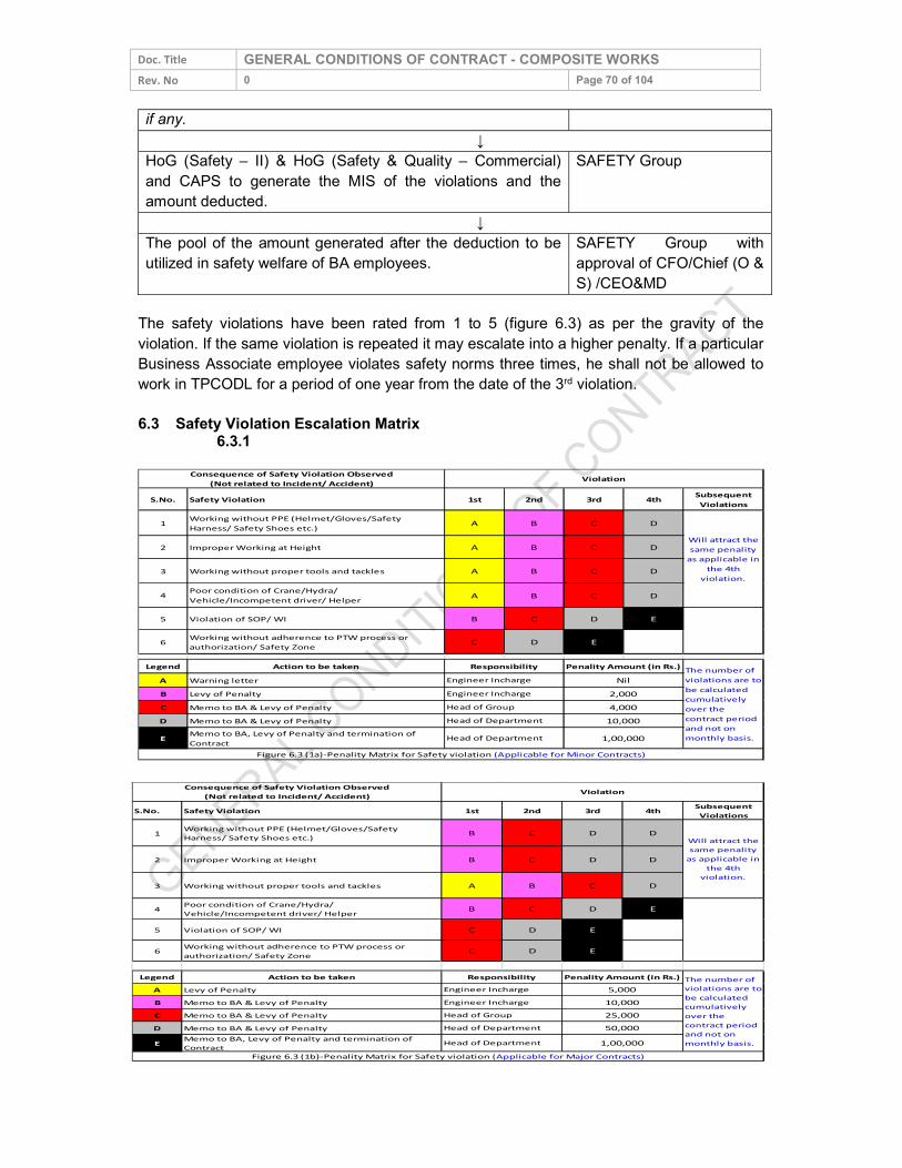
Doc. Title GENERAL CONDITIONS OF CONTRACT - COMPOSITE WORKS Rev. No 0 Page 70 of 104 if any.
↓ HoG (Safety – II) & HoG (Safety & Quality – Commercial) and CAPS to generate the MIS of the violations and the amount deducted.
SAFETY Group
↓ The pool of the amount generated after the deduction to be utilized in safety welfare of BA employees.
SAFETY Group with approval of CFO/Chief (O & S) /CEO&MD
The safety violations have been rated from 1 to 5 (figure 6.3) as per the gravity of the violation. If the same violation is repeated it may escalate into a higher penalty. If a particular Business Associate employee violates safety norms three times, he shall not be allowed to work in TPCODL for a period of one year from the date of the 3rd violation. 6.3 Safety Violation Escalation Matrix
6.3.1
S.No. Safety Violation 1st 2nd 3rd 4th Subsequent Violations
1 Working without PPE (Helmet/Gloves/Safety Harness/ Safety Shoes etc.) A B C D
2 Improper Working at Height A B C D3 Working without proper tools and tackles A B C D4 Poor condition of Crane/Hydra/
Vehicle/Incompetent driver/ Helper A B C D5 Violation of SOP/ WI B C D E6 Working without adherence to PTW process or
authorization/ Safety Zone C D E
Legend Action to be takenA Warning letterB Levy of PenaltyC Memo to BA & Levy of PenaltyD Memo to BA & Levy of PenaltyE Memo to BA, Levy of Penalty and termination of
ContractFigure 6.3 (1a)-Penality Matrix for Safety violation (Applicable for Minor Contracts)
10,000Head of Department 1,00,000
Consequence of Safety Violation Observed(Not related to Incident/ Accident) Violation
Will attract the same penality
as applicable in the 4th
violation.
Responsibility Penality Amount (in Rs.) The number of violations are to be calculated cumulatively over the contract period and not on monthly basis.
Engineer Incharge NilEngineer Incharge 2,000Head of Group 4,000Head of Department
S.No. Safety Violation 1st 2nd 3rd 4th Subsequent Violations
1 Working without PPE (Helmet/Gloves/Safety Harness/ Safety Shoes etc.) B C D D
2 Improper Working at Height B C D D
3 Working without proper tools and tackles A B C D
4 Poor condition of Crane/Hydra/Vehicle/Incompetent driver/ Helper B C D E
5 Violation of SOP/ WI C D E6 Working without adherence to PTW process or
authorization/ Safety Zone C D E
Legend Action to be takenA Levy of PenaltyB Memo to BA & Levy of PenaltyC Memo to BA & Levy of PenaltyD Memo to BA & Levy of PenaltyE Memo to BA, Levy of Penalty and termination of
ContractFigure 6.3 (1b)-Penality Matrix for Safety violation (Applicable for Major Contracts)
Engineer Incharge 10,000Head of Group 25,000Head of Department 50,000
Consequence of Safety Violation Observed(Not related to Incident/ Accident) Violation
Will attract the same penality
as applicable in the 4th
violation.
Responsibility Penality Amount (in Rs.) The number of violations are to be calculated cumulatively over the contract period and not on monthly basis.
Engineer Incharge 5,000
Head of Department 1,00,000
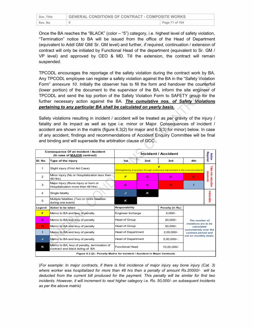
Doc. Title GENERAL CONDITIONS OF CONTRACT - COMPOSITE WORKS Rev. No 0 Page 71 of 104 Once the BA reaches the “BLACK” (color – “5”) category, i.e. highest level of safety violation, “Termination” notice to BA will be issued from the office of the Head of Department (equivalent to Addl GM/ GM/ Sr. GM level) and further, if required, continuation / extension of contract will only be initiated by Functional Head of the department (equivalent to Sr. GM / VP level) and approved by CEO & MD. Till the extension, the contract will remain suspended. TPCODL encourages the reportage of the safety violation during the contract work by BA. Any TPCODL employee can register a safety violation against the BA in the “Safety Violation Form” annexure 10. Initially the observer has to fill the form and handover the counterfoil (lower portion) of the document to the supervisor of the BA, inform the site engineer of TPCODL and send the top portion of the Safety Violation Form to SAFETY group for the further necessary action against the BA. The cumulative nos. of Safety Violations pertaining to any particular BA shall be calculated on yearly basis. Safety violations resulting in incident / accident will be treated as per gravity of the injury / fatality and its impact as well as type i.e. minor or Major. Consequences of incident / accident are shown in the matrix (figure 6.3(2) for major and 6.3(3) for minor) below. In case of any accident, findings and recommendations of Accident Enquiry Committee will be final and binding and will supersede the arbitration clause of GCC.
Sl. No Type of the injury 1st 2nd 3rd 4th1 Slight injury (First Aid Case)
2 Minor injury (No or Hospitalization less then 48 Hrs) F G G H
3 Major injury (Bone injury or burn or Hospitalization more then 48 Hrs) G G H I
4 Single fatality J K
5 Multiple fatalities (Two or more fatalities during one event) K
Legend Action to be taken Penalty (in Rs.)F Memo to BA and levy of penalty 5,000/-G Memo to BA and levy of penalty 20,000/- H Memo to BA and levy of penalty 50,000/-I Memo to BA and levy of penalty 2,00,000/-J Memo to BA and levy of penalty 5,00,000/-.
K Memo to BA, levy of penalty, termination of contract and black listing of BA 10,00,000/-
Figure 6.3 (2) - Penalty Matrix for Incident / Accident in Major Contracts
Responsibility
The number of violations are to be
calculated cumulatively over the contract period and
not on monthly basis.
Engineer InchargeHead of GroupHead of GroupHead of DepartmentHead of Department
Functional Head
Consequence Of an Incident / Accident (In case of MAJOR contract) Incident / Accident Action
Required
F(Strengthening of process through continuous improvement in the w ork procedure)
Take risk reduction measures
Intolerable
(For example: In major contracts, if there is first incidence of major injury say bone injury (Cat. 3) where worker was hospitalized for more than 48 hrs then a penalty of amount Rs.20000/- will be deducted from the current bill produced for the payment. This penalty will be similar for first two incidents. However, it will increment to next higher category i.e. Rs. 50,000/- on subsequent incidents as per the above matrix)
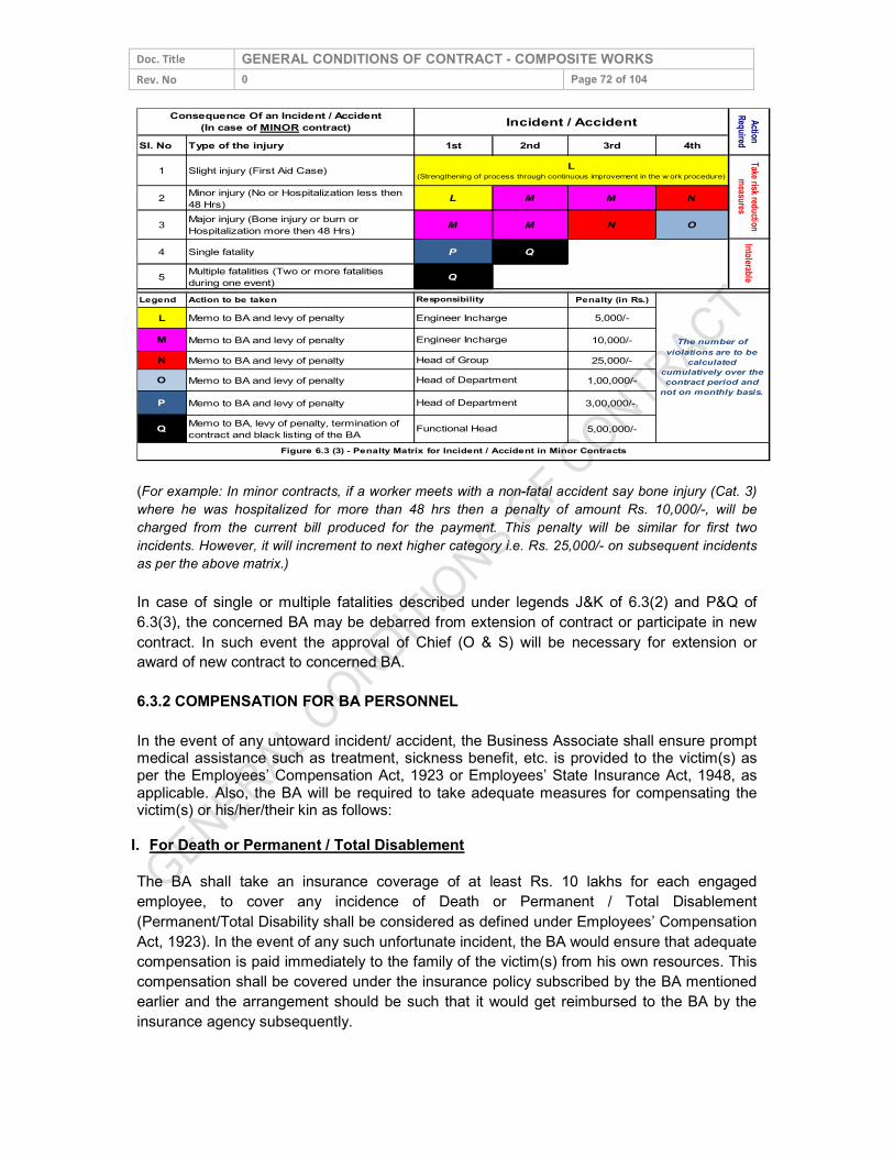
Doc. Title GENERAL CONDITIONS OF CONTRACT - COMPOSITE WORKS Rev. No 0 Page 72 of 104 Sl. No Type of the injury 1st 2nd 3rd 4th
1 Slight injury (First Aid Case)
2 Minor injury (No or Hospitalization less then 48 Hrs) L M M N
3 Major injury (Bone injury or burn or Hospitalization more then 48 Hrs) M M N O
4 Single fatality P Q
5 Multiple fatalities (Two or more fatalities during one event) Q
Legend Action to be taken Penalty (in Rs.)L Memo to BA and levy of penalty 5,000/-M Memo to BA and levy of penalty 10,000/- N Memo to BA and levy of penalty 25,000/-O Memo to BA and levy of penalty 1,00,000/-P Memo to BA and levy of penalty 3,00,000/-.
Q Memo to BA, levy of penalty, termination of contract and black listing of the BA 5,00,000/-
Engineer InchargeEngineer InchargeHead of GroupHead of DepartmentHead of Department
Functional HeadFigure 6.3 (3) - Penalty Matrix for Incident / Accident in Minor Contracts
The number of violations are to be
calculated cumulatively over the contract period and
not on monthly basis.
Responsibility
IntolerableTake risk reduction
measures
Consequence Of an Incident / Accident (In case of MINOR contract) Incident / Accident Action
RequiredL
(Strengthening of process through continuous improvement in the w ork procedure)
(For example: In minor contracts, if a worker meets with a non-fatal accident say bone injury (Cat. 3) where he was hospitalized for more than 48 hrs then a penalty of amount Rs. 10,000/-, will be charged from the current bill produced for the payment. This penalty will be similar for first two incidents. However, it will increment to next higher category i.e. Rs. 25,000/- on subsequent incidents as per the above matrix.) In case of single or multiple fatalities described under legends J&K of 6.3(2) and P&Q of 6.3(3), the concerned BA may be debarred from extension of contract or participate in new contract. In such event the approval of Chief (O & S) will be necessary for extension or award of new contract to concerned BA. 6.3.2 COMPENSATION FOR BA PERSONNEL In the event of any untoward incident/ accident, the Business Associate shall ensure prompt medical assistance such as treatment, sickness benefit, etc. is provided to the victim(s) as per the Employees’ Compensation Act, 1923 or Employees’ State Insurance Act, 1948, as applicable. Also, the BA will be required to take adequate measures for compensating the victim(s) or his/her/their kin as follows:
I. For Death or Permanent / Total Disablement The BA shall take an insurance coverage of at least Rs. 10 lakhs for each engaged employee, to cover any incidence of Death or Permanent / Total Disablement (Permanent/Total Disability shall be considered as defined under Employees’ Compensation Act, 1923). In the event of any such unfortunate incident, the BA would ensure that adequate compensation is paid immediately to the family of the victim(s) from his own resources. This compensation shall be covered under the insurance policy subscribed by the BA mentioned earlier and the arrangement should be such that it would get reimbursed to the BA by the insurance agency subsequently.
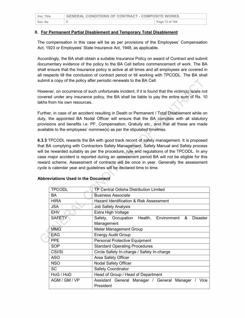
Doc. Title GENERAL CONDITIONS OF CONTRACT - COMPOSITE WORKS Rev. No 0 Page 73 of 104
II. For Permanent Partial Disablement and Temporary Total Disablement The compensation in this case will be as per provisions of the Employees’ Compensation Act, 1923 or Employees’ State Insurance Act, 1948, as applicable. Accordingly, the BA shall obtain a suitable Insurance Policy on award of Contract and submit documentary evidence of the policy to the BA Cell before commencement of work. The BA shall ensure that the Insurance policy is active at all times and all employees are covered in all respects till the conclusion of contract period or till working with TPCODL. The BA shall submit a copy of the policy after periodic renewals to the BA Cell. However, on occurrence of such unfortunate incident, if it is found that the victim(s) is/are not covered under any insurance policy, the BA shall be liable to pay the entire sum of Rs. 10 lakhs from his own resources. Further, in case of an accident resulting in Death or Permanent / Total Disablement while on duty, the appointed BA Nodal Officer will ensure that the BA complies with all statutory provisions and benefits i.e. PF, Compensation, Gratuity etc., and that all these are made available to the employees’ nominee(s) as per the stipulated timelines. 6.3.3 TPCODL rewards the BA with good track record of safety management. It is proposed that BA complying with Contractors Safety Management, Safety Manual and Safety process will be rewarded suitably as per the procedure, rule and regulations of the TPCODL. In any case major accident is reported during an assessment period BA will not be eligible for this reward scheme. Assessment of contracts will be once in year. Generally the assessment cycle is calendar year and guidelines will be declared time to time. Abbreviations Used in the Document
TPCODL TP Central Odisha Distribution Limited BA Business Associate HIRA Hazard Identification & Risk Assessment JSA Job Safety Analysis EHV Extra High Voltage SAFETY Safety, Occupation Health, Environment & Disaster
Management MMG Meter Management Group EAG Energy Audit Group PPE Personal Protective Equipment SOP Standard Operating Procedures CSI/SI Circle Safety In-charge / Safety In-charge ASO Area Safety Officer NSO Nodal Safety Officer SC Safety Coordinator HoG / HoD Head of Group / Head of Department AGM / GM / VP Assistant General Manager / General Manager / Vice
President
Doc. Title GENERAL CONDITIONS OF CONTRACT - COMPOSITE WORKS Rev. No 0 Page 74 of 104
CFO / Chief (O & S)/ CEO & MD
Chief Finance Officer / Chief (Operating & Safety) / Chief Executive Officer & Managing Director
COS Corporate Operation Services CAP Centralized Account Payable System PTW Permit To Work GCC General Conditions of Contract.
- END -
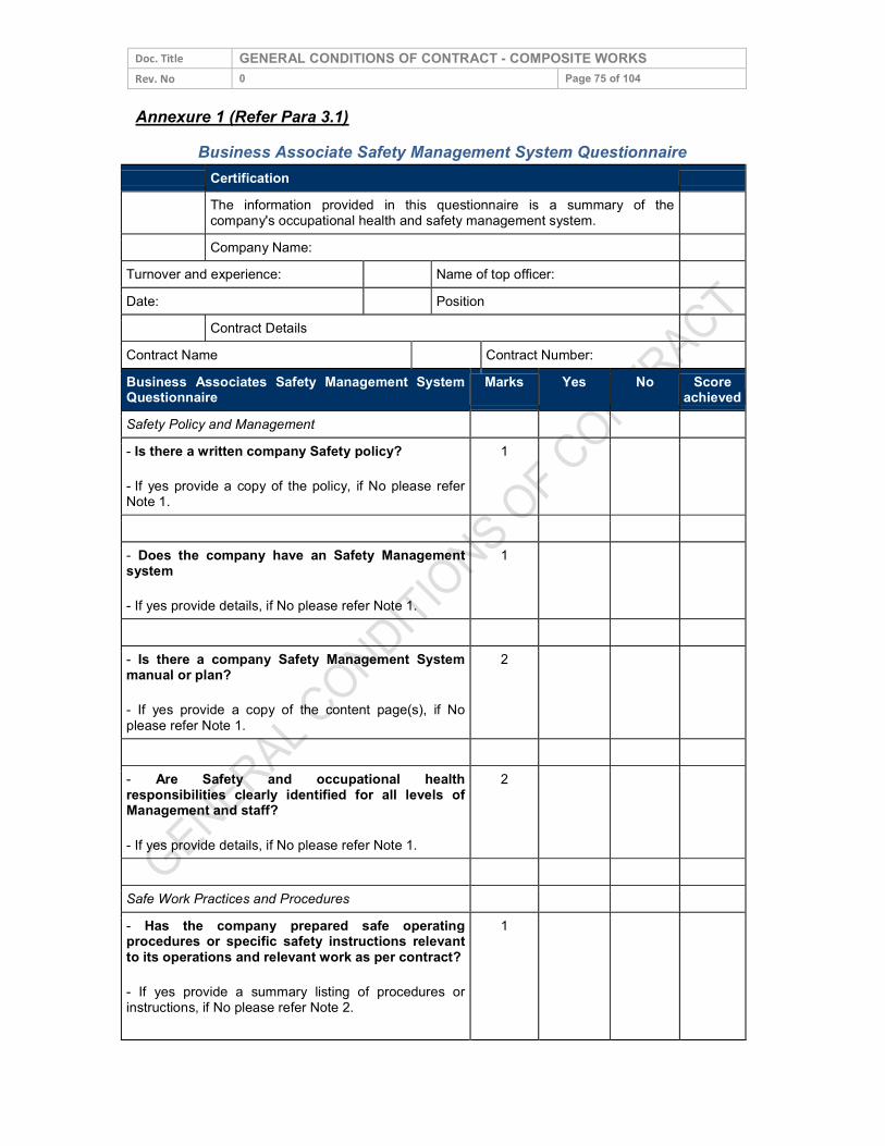
Doc. Title GENERAL CONDITIONS OF CONTRACT - COMPOSITE WORKS Rev. No 0 Page 75 of 104 Annexure 1 (Refer Para 3.1)
Business Associate Safety Management System Questionnaire Certification The information provided in this questionnaire is a summary of the
company's occupational health and safety management system.
Company Name: Turnover and experience: Name of top officer: Date: Position
Contract Details Contract Name Contract Number: Business Associates Safety Management System Questionnaire Marks Yes No Score achieved Safety Policy and Management - Is there a written company Safety policy? - If yes provide a copy of the policy, if No please refer Note 1.
1
- Does the company have an Safety Management system - If yes provide details, if No please refer Note 1.
1
- Is there a company Safety Management System manual or plan? - If yes provide a copy of the content page(s), if No please refer Note 1.
2
- Are Safety and occupational health responsibilities clearly identified for all levels of Management and staff? - If yes provide details, if No please refer Note 1.
2
Safe Work Practices and Procedures - Has the company prepared safe operating procedures or specific safety instructions relevant to its operations and relevant work as per contract? - If yes provide a summary listing of procedures or instructions, if No please refer Note 2.
1
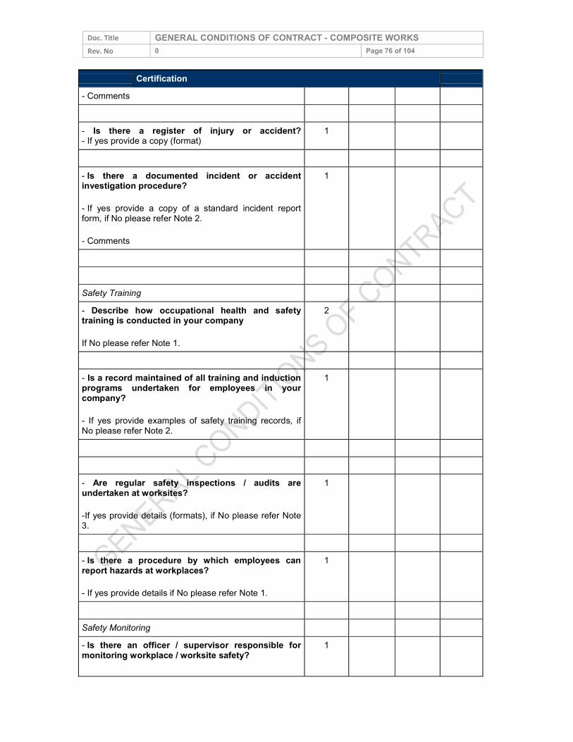
Doc. Title GENERAL CONDITIONS OF CONTRACT - COMPOSITE WORKS Rev. No 0 Page 76 of 104
Certification - Comments - Is there a register of injury or accident? - If yes provide a copy (format) 1
- Is there a documented incident or accident investigation procedure? - If yes provide a copy of a standard incident report form, if No please refer Note 2. - Comments
1
Safety Training - Describe how occupational health and safety training is conducted in your company If No please refer Note 1.
2
- Is a record maintained of all training and induction programs undertaken for employees in your company? - If yes provide examples of safety training records, if No please refer Note 2.
1
- Are regular safety inspections / audits are undertaken at worksites? -If yes provide details (formats), if No please refer Note 3.
1
- Is there a procedure by which employees can report hazards at workplaces? - If yes provide details if No please refer Note 1.
1
Safety Monitoring - Is there an officer / supervisor responsible for monitoring workplace / worksite safety?
1
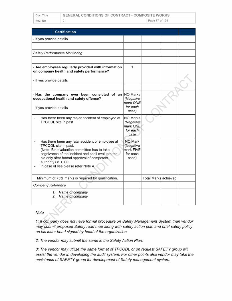
Doc. Title GENERAL CONDITIONS OF CONTRACT - COMPOSITE WORKS Rev. No 0 Page 77 of 104
Certification - If yes provide details Safety Performance Monitoring - Are employees regularly provided with information on company health and safety performance? - If yes provide details
1
- Has the company ever been convicted of an occupational health and safety offence? - If yes provide details
NO Marks (Negative mark ONE for each
case)
- Has there been any major accident of employee at TPCODL site in past
NO Marks (Negative mark ONE for each case
- Has there been any fatal accident of employee at TPCODL site in past.
- (Note: Bid evaluation committee has to take cognizance of the incident and shall evaluate the bid only after formal approval of competent authority i.e. CTO.
- In case of yes please refer Note 4.
NO Mark (Negative mark FIVE for each
case)
Minimum of 75% marks is required for qualification. Total Marks achieved Company Reference
1. Name of company 2. Name of company
Note 1: If company does not have formal procedure on Safety Management System than vendor may submit proposed Safety road map along with safety action plan and brief safety policy on his letter head signed by head of the organization. 2: The vendor may submit the same in the Safety Action Plan. 3: The vendor may utilize the same format of TPCODL or on request SAFETY group will assist the vendor in developing the audit system. For other points also vendor may take the assistance of SAFETY group for development of Safety management system.
Doc. Title GENERAL CONDITIONS OF CONTRACT - COMPOSITE WORKS Rev. No 0 Page 78 of 104 4: The vendor may submit the Safety Improvement Plan and Safety Action Plan for his employees based on following points.
i. Action plan for enhancing safety awareness ii. Action plan for safety training of employee iii. Action plan for increasing safety audit in field iv. Action plan for provision and utilization of safety PPE. v. Action plan for fatality reduction. vi. Action plan for enhanced supervision at site vii. Action plan for making employee more responsible and accountable for
safety. viii. Action plan for availability and utilization of all required tool and equipment. ix. Safety Improvement done in last two years, specially highlighting those which
have been taken after the fatal accident along with results. x. Safety initiatives planed or started recently. xi. Any other point.
Based on above points and documentary evidences vendor will be required to submit a detailed report in support of his bid. The bid evaluation committee and competent authority will scrutinize the facts and the evidence submitted. If found satisfactory competent authority i.e. CTO may accord his approval for bid opening otherwise his tender shall be disqualified.
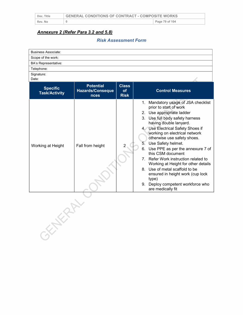
Doc. Title GENERAL CONDITIONS OF CONTRACT - COMPOSITE WORKS Rev. No 0 Page 79 of 104 Annexure 2 (Refer Para 3.2 and 5.8)
Risk Assessment Form
Specific Task/Activity
Potential Hazards/Conseque
nces Class
of Risk
Control Measures
Working at Height Fall from height 2
1. Mandatory usage of JSA checklist prior to start of work
2. Use appropriate ladder 3. Use full body safety harness
having double lanyard. 4. Use Electrical Safety Shoes if
working on electrical network otherwise use safety shoes.
5. Use Safety helmet. 6. Use PPE as per the annexure 7 of
this CSM document 7. Refer Work instruction related to
Working at Height for other details 8. Use of metal scaffold to be ensured in height work (cup lock
type) 9. Deploy competent workforce who
are medically fit
Business Associate: Scope of the work: BA’s Representative: Telephone: Signature: Date:
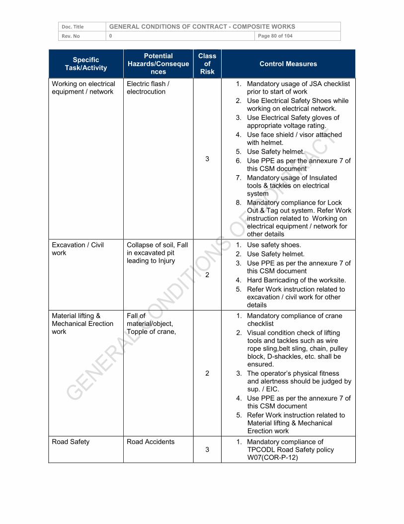
Doc. Title GENERAL CONDITIONS OF CONTRACT - COMPOSITE WORKS Rev. No 0 Page 80 of 104
Specific Task/Activity
Potential Hazards/Conseque
nces Class
of Risk Control Measures
Working on electrical equipment / network
Electric flash / electrocution
3
1. Mandatory usage of JSA checklist prior to start of work 2. Use Electrical Safety Shoes while
working on electrical network. 3. Use Electrical Safety gloves of
appropriate voltage rating. 4. Use face shield / visor attached
with helmet. 5. Use Safety helmet. 6. Use PPE as per the annexure 7 of
this CSM document 7. Mandatory usage of Insulated
tools & tackles on electrical system
8. Mandatory compliance for Lock Out & Tag out system. Refer Work instruction related to Working on electrical equipment / network for other details
Excavation / Civil work
Collapse of soil, Fall in excavated pit leading to Injury
2
1. Use safety shoes. 2. Use Safety helmet. 3. Use PPE as per the annexure 7 of this CSM document 4. Hard Barricading of the worksite. 5. Refer Work instruction related to excavation / civil work for other
details Material lifting & Mechanical Erection work
Fall of material/object, Topple of crane,
2
1. Mandatory compliance of crane checklist
2. Visual condition check of lifting tools and tackles such as wire rope sling,belt sling, chain, pulley block, D-shackles, etc. shall be ensured.
3. The operator’s physical fitness and alertness should be judged by sup. / EIC.
4. Use PPE as per the annexure 7 of this CSM document
5. Refer Work instruction related to Material lifting & Mechanical Erection work
Road Safety Road Accidents 3 1. Mandatory compliance of
TPCODL Road Safety policy W07(COR-P-12)
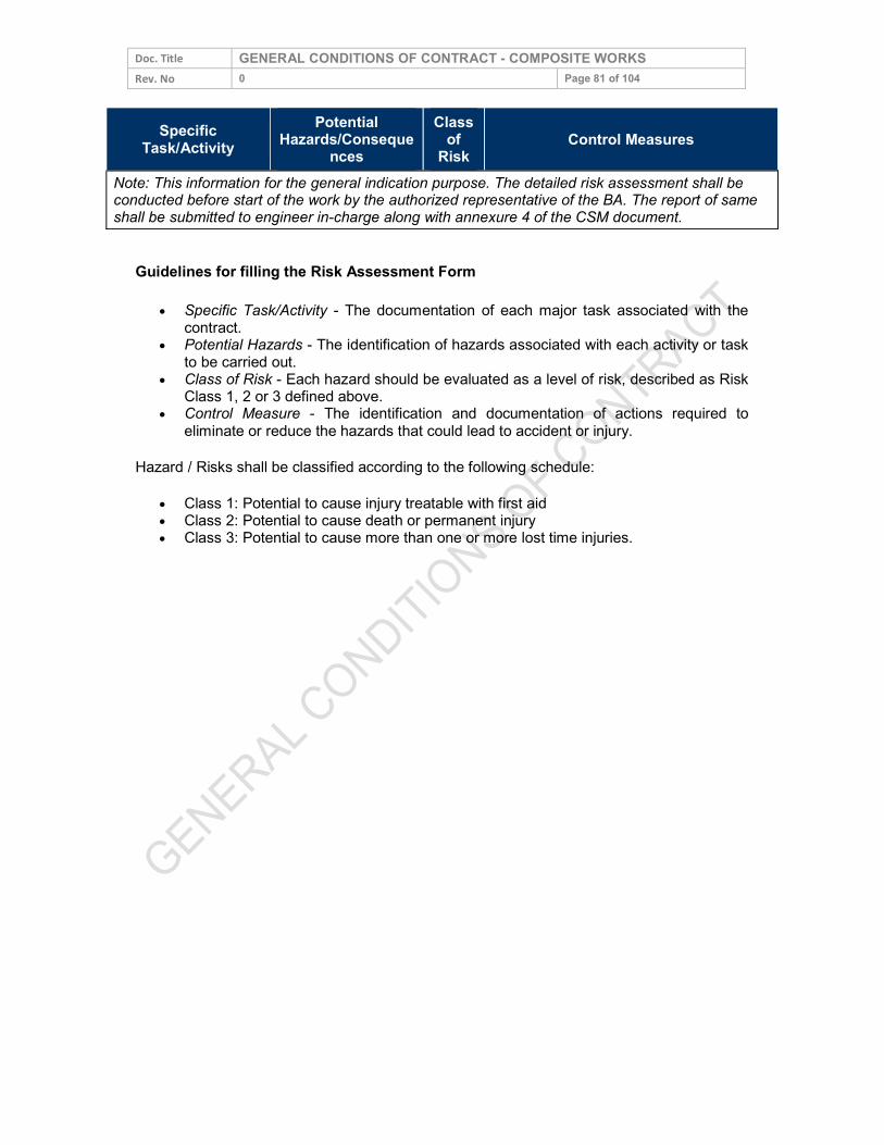
Doc. Title GENERAL CONDITIONS OF CONTRACT - COMPOSITE WORKS Rev. No 0 Page 81 of 104
Specific Task/Activity
Potential Hazards/Conseque
nces Class
of Risk Control Measures
Note: This information for the general indication purpose. The detailed risk assessment shall be conducted before start of the work by the authorized representative of the BA. The report of same shall be submitted to engineer in-charge along with annexure 4 of the CSM document.
Guidelines for filling the Risk Assessment Form
Specific Task/Activity - The documentation of each major task associated with the contract.
Potential Hazards - The identification of hazards associated with each activity or task to be carried out.
Class of Risk - Each hazard should be evaluated as a level of risk, described as Risk Class 1, 2 or 3 defined above.
Control Measure - The identification and documentation of actions required to eliminate or reduce the hazards that could lead to accident or injury.
Hazard / Risks shall be classified according to the following schedule: Class 1: Potential to cause injury treatable with first aid Class 2: Potential to cause death or permanent injury Class 3: Potential to cause more than one or more lost time injuries.
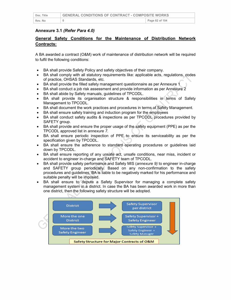
Doc. Title GENERAL CONDITIONS OF CONTRACT - COMPOSITE WORKS Rev. No 0 Page 82 of 104 Annexure 3.1 (Refer Para 4.0) General Safety Conditions for the Maintenance of Distribution Network Contracts: A BA awarded a contract (O&M) work of maintenance of distribution network will be required to fulfil the following conditions: BA shall provide Safety Policy and safety objectives of their company. BA shall comply with all statutory requirements like: applicable acts, regulations, codes
of practice, OHSAS Standards, etc. BA shall provide the filled safety management questionnaire as per Annexure 1 BA shall conduct a job risk assessment and provide information as per Annexure 2 BA shall abide by Safety manuals, guidelines of TPCODL. BA shall provide its organisation structure & responsibilities in terms of Safety Management to TPCODL. BA shall document the work practices and procedures in terms of Safety Management. BA shall ensure safety training and induction program for the employees BA shall conduct safety audits & inspections as per TPCODL procedures provided by SAFETY group. BA shall provide and ensure the proper usage of the safety equipment (PPE) as per the TPCODL approved list in annexure 7. BA shall ensure periodic inspection of PPE to ensure its serviceability as per the specification given by TPCODL. BA shall ensure the adherence to standard operating procedures or guidelines laid down by TPCODL. BA shall ensure reporting of any unsafe act, unsafe conditions, near miss, incident or accident to engineer in-charge and SAFETY team of TPCODL. BA shall provide safety performance and Safety MIS (annexure 9) to engineer in-charge and SAFETY group periodically. Based on any non-confirmation to the safety procedures and guidelines, BA is liable to be negatively marked for his performance and suitable penalty will be imposed. BA shall ensure to depute a Safety Supervisor for managing a complete safety management system in a district. In case the BA has been awarded work in more than one district, then the following safety structure will be adopted.
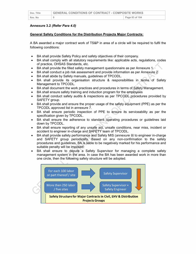
Doc. Title GENERAL CONDITIONS OF CONTRACT - COMPOSITE WORKS Rev. No 0 Page 83 of 104 Annexure 3.2 (Refer Para 4.0) General Safety Conditions for the Distribution Projects Major Contracts: A BA awarded a major contract work of TS&P in area of a circle will be required to fulfil the following conditions: BA shall provide Safety Policy and safety objectives of their company. BA shall comply with all statutory requirements like: applicable acts, regulations, codes
of practice, OHSAS Standards, etc. BA shall provide the filled safety management questionnaire as per Annexure 1. BA shall conduct a job risk assessment and provide information as per Annexure 2 BA shall abide by Safety manuals, guidelines of TPCODL. BA shall provide its organisation structure & responsibilities in terms of Safety Management to TPCODL. BA shall document the work practices and procedures in terms of Safety Management. BA shall ensure safety training and induction program for the employees BA shall conduct safety audits & inspections as per TPCODL procedures provided by SAFETY group. BA shall provide and ensure the proper usage of the safety equipment (PPE) as per the TPCODL approved list in annexure 7. BA shall ensure periodic inspection of PPE to ensure its serviceability as per the specification given by TPCODL. BA shall ensure the adherence to standard operating procedures or guidelines laid down by TPCODL. BA shall ensure reporting of any unsafe act, unsafe conditions, near miss, incident or accident to engineer in-charge and SAFETY team of TPCODL. BA shall provide safety performance and Safety MIS (annexure 9) to engineer in-charge and SAFETY group periodically. Based on any non-confirmation to the safety procedures and guidelines, BA is liable to be negatively marked for his performance and suitable penalty will be imposed. BA shall ensure to depute a Safety Supervisor for managing a complete safety management system in the area. In case the BA has been awarded work in more than one circle, then the following safety structure will be adopted.
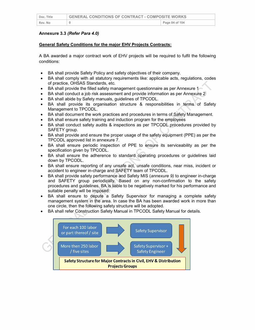
Doc. Title GENERAL CONDITIONS OF CONTRACT - COMPOSITE WORKS Rev. No 0 Page 84 of 104 Annexure 3.3 (Refer Para 4.0) General Safety Conditions for the major EHV Projects Contracts: A BA awarded a major contract work of EHV projects will be required to fulfil the following conditions: BA shall provide Safety Policy and safety objectives of their company. BA shall comply with all statutory requirements like: applicable acts, regulations, codes
of practice, OHSAS Standards, etc. BA shall provide the filled safety management questionnaire as per Annexure 1 BA shall conduct a job risk assessment and provide information as per Annexure 2 BA shall abide by Safety manuals, guidelines of TPCODL. BA shall provide its organisation structure & responsibilities in terms of Safety Management to TPCODL. BA shall document the work practices and procedures in terms of Safety Management. BA shall ensure safety training and induction program for the employees BA shall conduct safety audits & inspections as per TPCODL procedures provided by SAFETY group. BA shall provide and ensure the proper usage of the safety equipment (PPE) as per the TPCODL approved list in annexure 7. BA shall ensure periodic inspection of PPE to ensure its serviceability as per the specification given by TPCODL. BA shall ensure the adherence to standard operating procedures or guidelines laid down by TPCODL. BA shall ensure reporting of any unsafe act, unsafe conditions, near miss, incident or accident to engineer in-charge and SAFETY team of TPCODL. BA shall provide safety performance and Safety MIS (annexure 9) to engineer in-charge and SAFETY group periodically. Based on any non-confirmation to the safety procedures and guidelines, BA is liable to be negatively marked for his performance and suitable penalty will be imposed. BA shall ensure to depute a Safety Supervisor for managing a complete safety management system in the area. In case the BA has been awarded work in more than one circle, then the following safety structure will be adopted. BA shall refer Construction Safety Manual in TPCODL Safety Manual for details.
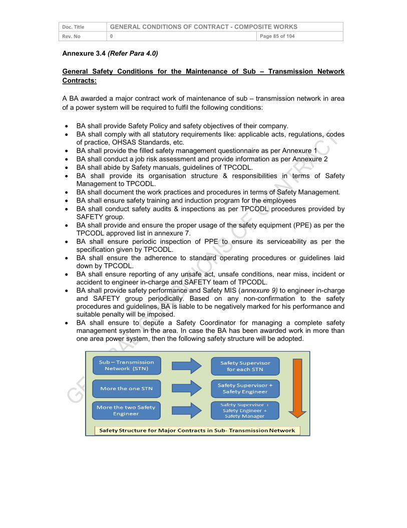
Doc. Title GENERAL CONDITIONS OF CONTRACT - COMPOSITE WORKS Rev. No 0 Page 85 of 104 Annexure 3.4 (Refer Para 4.0) General Safety Conditions for the Maintenance of Sub – Transmission Network Contracts: A BA awarded a major contract work of maintenance of sub – transmission network in area of a power system will be required to fulfil the following conditions: BA shall provide Safety Policy and safety objectives of their company. BA shall comply with all statutory requirements like: applicable acts, regulations, codes
of practice, OHSAS Standards, etc. BA shall provide the filled safety management questionnaire as per Annexure 1 BA shall conduct a job risk assessment and provide information as per Annexure 2 BA shall abide by Safety manuals, guidelines of TPCODL. BA shall provide its organisation structure & responsibilities in terms of Safety Management to TPCODL. BA shall document the work practices and procedures in terms of Safety Management. BA shall ensure safety training and induction program for the employees BA shall conduct safety audits & inspections as per TPCODL procedures provided by SAFETY group. BA shall provide and ensure the proper usage of the safety equipment (PPE) as per the TPCODL approved list in annexure 7. BA shall ensure periodic inspection of PPE to ensure its serviceability as per the specification given by TPCODL. BA shall ensure the adherence to standard operating procedures or guidelines laid down by TPCODL. BA shall ensure reporting of any unsafe act, unsafe conditions, near miss, incident or accident to engineer in-charge and SAFETY team of TPCODL. BA shall provide safety performance and Safety MIS (annexure 9) to engineer in-charge and SAFETY group periodically. Based on any non-confirmation to the safety procedures and guidelines, BA is liable to be negatively marked for his performance and suitable penalty will be imposed. BA shall ensure to depute a Safety Coordinator for managing a complete safety management system in the area. In case the BA has been awarded work in more than one area power system, then the following safety structure will be adopted.
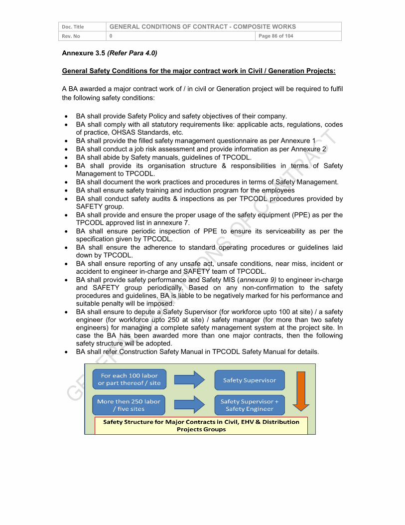
Doc. Title GENERAL CONDITIONS OF CONTRACT - COMPOSITE WORKS Rev. No 0 Page 86 of 104 Annexure 3.5 (Refer Para 4.0) General Safety Conditions for the major contract work in Civil / Generation Projects: A BA awarded a major contract work of / in civil or Generation project will be required to fulfil the following safety conditions: BA shall provide Safety Policy and safety objectives of their company. BA shall comply with all statutory requirements like: applicable acts, regulations, codes
of practice, OHSAS Standards, etc. BA shall provide the filled safety management questionnaire as per Annexure 1 BA shall conduct a job risk assessment and provide information as per Annexure 2 BA shall abide by Safety manuals, guidelines of TPCODL. BA shall provide its organisation structure & responsibilities in terms of Safety Management to TPCODL. BA shall document the work practices and procedures in terms of Safety Management. BA shall ensure safety training and induction program for the employees BA shall conduct safety audits & inspections as per TPCODL procedures provided by SAFETY group. BA shall provide and ensure the proper usage of the safety equipment (PPE) as per the TPCODL approved list in annexure 7. BA shall ensure periodic inspection of PPE to ensure its serviceability as per the specification given by TPCODL. BA shall ensure the adherence to standard operating procedures or guidelines laid down by TPCODL. BA shall ensure reporting of any unsafe act, unsafe conditions, near miss, incident or accident to engineer in-charge and SAFETY team of TPCODL. BA shall provide safety performance and Safety MIS (annexure 9) to engineer in-charge and SAFETY group periodically. Based on any non-confirmation to the safety procedures and guidelines, BA is liable to be negatively marked for his performance and suitable penalty will be imposed. BA shall ensure to depute a Safety Supervisor (for workforce upto 100 at site) / a safety engineer (for workforce upto 250 at site) / safety manager (for more than two safety engineers) for managing a complete safety management system at the project site. In case the BA has been awarded more than one major contracts, then the following safety structure will be adopted. BA shall refer Construction Safety Manual in TPCODL Safety Manual for details.
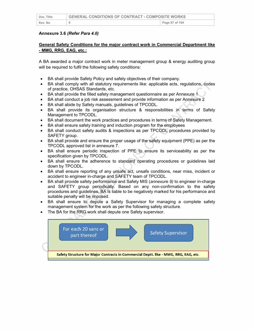
Doc. Title GENERAL CONDITIONS OF CONTRACT - COMPOSITE WORKS Rev. No 0 Page 87 of 104 Annexure 3.6 (Refer Para 4.0) General Safety Conditions for the major contract work in Commercial Department like - MMG, RRG, EAG, etc.: A BA awarded a major contract work in meter management group & energy auditing group will be required to fulfil the following safety conditions: BA shall provide Safety Policy and safety objectives of their company. BA shall comply with all statutory requirements like: applicable acts, regulations, codes
of practice, OHSAS Standards, etc. BA shall provide the filled safety management questionnaire as per Annexure 1 BA shall conduct a job risk assessment and provide information as per Annexure 2 BA shall abide by Safety manuals, guidelines of TPCODL. BA shall provide its organisation structure & responsibilities in terms of Safety Management to TPCODL. BA shall document the work practices and procedures in terms of Safety Management. BA shall ensure safety training and induction program for the employees BA shall conduct safety audits & inspections as per TPCODL procedures provided by SAFETY group. BA shall provide and ensure the proper usage of the safety equipment (PPE) as per the TPCODL approved list in annexure 7. BA shall ensure periodic inspection of PPE to ensure its serviceability as per the specification given by TPCODL. BA shall ensure the adherence to standard operating procedures or guidelines laid down by TPCODL. BA shall ensure reporting of any unsafe act, unsafe conditions, near miss, incident or accident to engineer in-charge and SAFETY team of TPCODL. BA shall provide safety performance and Safety MIS (annexure 9) to engineer in-charge and SAFETY group periodically. Based on any non-confirmation to the safety procedures and guidelines, BA is liable to be negatively marked for his performance and suitable penalty will be imposed. BA shall ensure to depute a Safety Supervisor for managing a complete safety management system for the work as per the following safety structure. The BA for the RRG work shall depute one Safety supervisor.
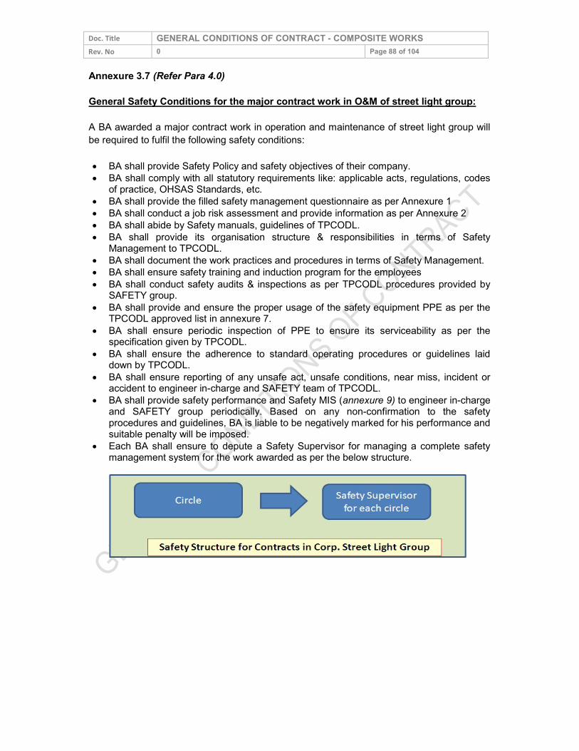
Doc. Title GENERAL CONDITIONS OF CONTRACT - COMPOSITE WORKS Rev. No 0 Page 88 of 104 Annexure 3.7 (Refer Para 4.0) General Safety Conditions for the major contract work in O&M of street light group: A BA awarded a major contract work in operation and maintenance of street light group will be required to fulfil the following safety conditions: BA shall provide Safety Policy and safety objectives of their company. BA shall comply with all statutory requirements like: applicable acts, regulations, codes
of practice, OHSAS Standards, etc. BA shall provide the filled safety management questionnaire as per Annexure 1 BA shall conduct a job risk assessment and provide information as per Annexure 2 BA shall abide by Safety manuals, guidelines of TPCODL. BA shall provide its organisation structure & responsibilities in terms of Safety Management to TPCODL. BA shall document the work practices and procedures in terms of Safety Management. BA shall ensure safety training and induction program for the employees BA shall conduct safety audits & inspections as per TPCODL procedures provided by SAFETY group. BA shall provide and ensure the proper usage of the safety equipment PPE as per the TPCODL approved list in annexure 7. BA shall ensure periodic inspection of PPE to ensure its serviceability as per the specification given by TPCODL. BA shall ensure the adherence to standard operating procedures or guidelines laid down by TPCODL. BA shall ensure reporting of any unsafe act, unsafe conditions, near miss, incident or accident to engineer in-charge and SAFETY team of TPCODL. BA shall provide safety performance and Safety MIS (annexure 9) to engineer in-charge and SAFETY group periodically. Based on any non-confirmation to the safety procedures and guidelines, BA is liable to be negatively marked for his performance and suitable penalty will be imposed. Each BA shall ensure to depute a Safety Supervisor for managing a complete safety management system for the work awarded as per the below structure.
Doc. Title GENERAL CONDITIONS OF CONTRACT - COMPOSITE WORKS Rev. No 0 Page 89 of 104 Annexure 4 (Refer Para 3.3)
Safety Undertaking by way of Affidavit I_______________ s/o_______R/o________ (AUTHORIZED REPRESENTATIVE/PARTNER/DIRECTOR/PROPRIETOR ) of M/S ___________(name of company/firm)__ having its office at (Complete address of Company), authorized vide power of attorney dated ------/Board resolution dated----/letter of authority dated----, hereinafter referred to as Contractor [or Business Associate (BA)] which expression shall, unless it be repugnant to or inconsistent with the meaning or context thereof, be deemed to include its heirs, executors, administrators, and assigns do hereby affirm and undertake as under :
1. The present undertaking shall remain in force from the date of execution of contract awarded by TPCODL and shall be valid till the date of termination of the said contract by either parties. The undertaking is binding on me (contractor) as well as my sub-contractor and its employees, representatives etc.
2. That I(the contractor) will be responsible and liable to comply and abide by all the safety rules, instructions and regulations as may be specified and laid down by The TP Central Odisha Distribution Limited (TPCODL) so as enable TPCODL to achieve its goal of Zero On site incidences.
3. That the Contractor shall be fully responsible for ensuring occupational health and safety of its employees, representatives, agents as well as of its subcontractor’s employees, at all times during the discharge of their respective obligations under the contract including any methods adopted for performance of their tasks / work.
4. That Contractor shall ensure ,at its own expense to arrange for and procure, implement all requisite accident prevention tools, first aid boxes, personal protective equipment, fire extinguisher, safety training, Material Safety Data Sheet, pre-employment medical test, etc. for operations & activities including as & when so specified by TPCODL specifically. , failing which TPCODL shall be entitled, but not obliged, to provide the same and recover the actual cost thereof from the Contractor’s payments.
5. That the Contractor shall engage adequate and competent Safety – Supervisor / Engineer / Manager / Skilled persons at site as per the Para 5 (Qualification and experience of safety personnel) and Annexure 3 of Contract Safety Management.
6. That the Contractor shall engage the competent Site – Supervisor with each group of workers for safe and correct workmanship, proper co-ordination of material and site work as per contract.
Doc. Title GENERAL CONDITIONS OF CONTRACT - COMPOSITE WORKS Rev. No 0 Page 90 of 104
7. That the Contractor shall immediately replace supervisor in case it is found to be not up to the level of skill and experience required as in skill and experience required in annexure 5 of this document, but any such replacement shall be only with the prior concurrence of TPCODL .
8. That the Contractor and its subcontractors shall abide by all the safety guidelines as per Safety Manual, Contract Safety Management and other guidelines issued from time to time by TPCODL during the contract period.
9. That in case the Contractor and/or any of its Subcontractor fail to ensure the compliance as required in terms of this undertaking the Contractor shall keep and hold TPCODL / its directors / officers / employees indemnified against any / all losses / damage / expense / liability / fines / compensation / claims / action / prosecutions or the like which might be suffered by TPCODL or to which TPCODL might get exposed to as a result of any breach /wilful negligence /deliberate default on the part of the Contractor /Subcontractor in complying with the same. Contractor shall also furnish any press release, clarification etc. if sought by TPCODL for any near miss or safety violations, accidents, which are attributable to fault of Contractor. DEPONENT VERIFICATION Verified at Bhubaneswar on this _Day of _______20__ that the contents of the above affidavit are true and correct and nothing material has been concealed therefrom
DEPONENT
Doc. Title GENERAL CONDITIONS OF CONTRACT - COMPOSITE WORKS Rev. No 0 Page 91 of 104 Annexure 5 (Refer Para 5.4) SKILL / QUALIFICATION REQUIRED FOR ELECTRICIAN AND ELECTRICAL SUPERVISOR Skill / Qualifications Required for Electrician (Certificate of Competency Class-II):
1. Formal education in ITI – Wireman/ Electrician trade. OR
2. Working experience of minimum three years of practical wiring. OR
3. Have completed three years apprenticeship course through Apprenticeship Advisor, Govt. of Odisha / other state Govt. in the trade of Lineman / Wireman / Electrician.
4. A candidate must have attained the age of Eighteen years.
Skill / Qualifications Required for Electrical Supervisor (Certificate of Competency Class-I):
1. Have at least five years’ experience of practical wiring after passing the certificate of competency class-II i.e. electrician.
OR 2. Recognized Degree or Diploma or equivalent qualification in Electrical
Engineering from any Technical institute / College or University recognized by the Board.
AND Must have completed the training/job in rectifying the common defects in electrical line and power installation for a period of one and three years after passing Degree or Diploma respectively OR
3. Possessing the valid certificate of certificate of competency class – 1 (Electrical Supervisor)
Doc. Title GENERAL CONDITIONS OF CONTRACT - COMPOSITE WORKS Rev. No 0 Page 92 of 104 Annexure 6 (Refer Para 5.6)
Training Module for BAs Worker & Supervisor Training for BA Supervisor Duration – 02 Hrs / Month Methodology: Lecture and Practical Demonstration of Safety Zone Creation
Session: 1 Topic: Electrical Safety Aspects Sub Topics:
1. Learning specifics of HT & LT Network of zone 2. Major type of HT / LT / service lines / street light maintenance works 3. Understanding the need of Safety 4. Understanding the safe process of maintenance : Planning of the maintenance job Availability of men, material & machine, PPEs, Safety gear and approved PTW Briefing of the job by the supervisor of the TPCODL Identification of Risks associated with the maintenance work and planning for
controlling measures by TPCODL supervisor Creation of safety zone by TPCODL supervisor and satisfying that the network is dead – Use of Neon Tester, Shorting Chain and Safety Tagging Start of the work – Right person for the right job Alert supervision Completion of the job – Check points Energization of network Actions to be taken in case of some accident
Session: 2
Topic: Use of Electrical Testing Equipment Methodology: Lecture and Practical Demonstration Sub Topics:
1. Meggar, Hi Pot, Clamp On Meter, Neon Tester, Discharge Rod, Line tester etc. Session: 3
Topic: Awareness of Electrical Safety Aspects A. Understanding the need of this Training and Safety B. Learning specifics of HT & LT Network C. Major type of work to be carried out in zones D. Switching Operations (Do’s & Don’ts) including Street Light Switching E. Working on Height (practical demo also) F. Understanding the Safe Process of Maintenance / Working: Planning of the job Availability of men, material & machine, PPEs, Safety gear and approved PTW Briefing of the job by the supervisor Permit to Work Safety Tagging and Lock Out Tag out
Doc. Title GENERAL CONDITIONS OF CONTRACT - COMPOSITE WORKS Rev. No 0 Page 93 of 104
Identification of Risks associated with the work to be carried out and planning for controlling measures by proper supervision Concept of “Safety Zone” Identification and use of Neon Tester, Shorting Chain, Clamp On Meter, Hi Pot, Meggar etc. Completion of the job – Check points Accident Theory & Incident Reporting Actions to be taken in case of some accident Session: 4
Topic: Identification, Demonstration and Usages of Tools, PPEs and other Safety Gears and demonstration of working on HT pole
Session: 5
Topic: Practical demonstration of Safety Zone creation
FREQUENCY Regular Safety Training Program
It will be conducted for all field & supervisor staff of BA in such a manner that all BA Personnel attend at least two hours safety training during every month. One Day Induction Safety Training Programs:
This training will be for the new BA’s personnel, who have been cleared by the Cross Functional Panel to undergo Safety training and who are likely to be deployed at various work sites of TPCODL by the BA, as a part of AMC / Work Contract.
Duration / Periodicity: Duration and periodicity has been defined above. However, this is subject to change
at the discretion of TPCODL.
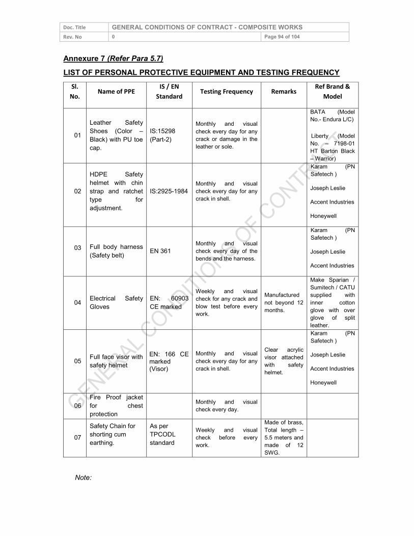
Doc. Title GENERAL CONDITIONS OF CONTRACT - COMPOSITE WORKS Rev. No 0 Page 94 of 104 Annexure 7 (Refer Para 5.7) LIST OF PERSONAL PROTECTIVE EQUIPMENT AND TESTING FREQUENCY
Sl. No. Name of PPE IS / EN
Standard Testing Frequency Remarks Ref Brand & Model
01 Leather Safety Shoes (Color – Black) with PU toe cap.
IS:15298 (Part-2)
Monthly and visual check every day for any crack or damage in the leather or sole.
BATA (Model No.- Endura L/C)
Liberty (Model No. – 7198-01 HT Barton Black – Warrior)
02 HDPE Safety helmet with chin strap and ratchet type for adjustment.
IS:2925-1984 Monthly and visual check every day for any crack in shell.
Karam (PN Safetech ) Joseph Leslie Accent Industries Honeywell
03 Full body harness (Safety belt) EN 361
Monthly and visual check every day of the bends and the harness.
Karam (PN Safetech ) Joseph Leslie Accent Industries
04 Electrical Safety Gloves
EN: 60903 CE marked
Weekly and visual check for any crack and blow test before every work.
Manufactured not beyond 12 months.
Make Sparian / Sumitech / CATU supplied with inner cotton glove with over glove of split leather.
05 Full face visor with safety helmet
EN: 166 CE marked (Visor)
Monthly and visual check every day for any crack in shell.
Clear acrylic visor attached with safety helmet.
Karam (PN Safetech ) Joseph Leslie Accent Industries Honeywell
06 Fire Proof jacket for chest protection
Monthly and visual check every day.
07 Safety Chain for shorting cum earthing.
As per TPCODL standard
Weekly and visual check before every work.
Made of brass, Total length – 5.5 meters and made of 12 SWG.
Note:
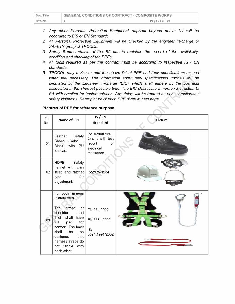
Doc. Title GENERAL CONDITIONS OF CONTRACT - COMPOSITE WORKS Rev. No 0 Page 95 of 104
1. Any other Personal Protection Equipment required beyond above list will be according to BIS or EN Standards.
2. All Personal Protection Equipment will be checked by the engineer in-charge or SAFETY group of TPCODL.
3. Safety Representative of the BA has to maintain the record of the availability, condition and checking of the PPEs.
4. All tools required as per the contract must be according to respective IS / EN standards.
5. TPCODL may revise or add the above list of PPE and their specifications as and when feel necessary. The information about new specifications /models will be circulated by the Engineer In-charge (EIC), which shall adhere by the business associated in the shortest possible time. The EIC shall issue a memo / instruction to BA with timeline for implementation. Any delay will be treated as non- compliance / safety violations. Refer picture of each PPE given in next page.
Pictures of PPE for reference purpose. Sl.
No. Name of PPE IS / EN Standard Picture
01 Leather Safety Shoes (Color – Black) with PU toe cap.
IS:15298(Part-2) and with test report of electrical resistance.
02 HDPE Safety helmet with chin strap and ratchet type for adjustment.
IS:2925-1984
03
Full body harness (Safety belt) The straps at shoulder and thigh shall have full pad for comfort. The back shall be so designed that harness straps do not tangle with each other.
EN 361:2002 EN 358 : 2000 IS: 3521:1991/2002
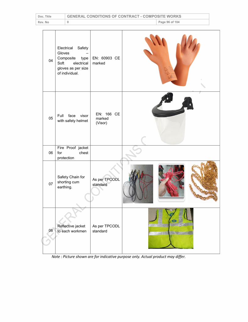
Doc. Title GENERAL CONDITIONS OF CONTRACT - COMPOSITE WORKS Rev. No 0 Page 96 of 104
04
Electrical Safety Gloves – Composite type Soft electrical gloves as per size of individual.
EN: 60903 CE marked
05 Full face visor with safety helmet
EN: 166 CE marked (Visor)
06
Fire Proof jacket for chest protection
07 Safety Chain for shorting cum earthing.
As per TPCODL standard
08 Reflective jacket to each workmen
As per TPCODL standard
Note : Picture shown are for indicative purpose only. Actual product may differ.
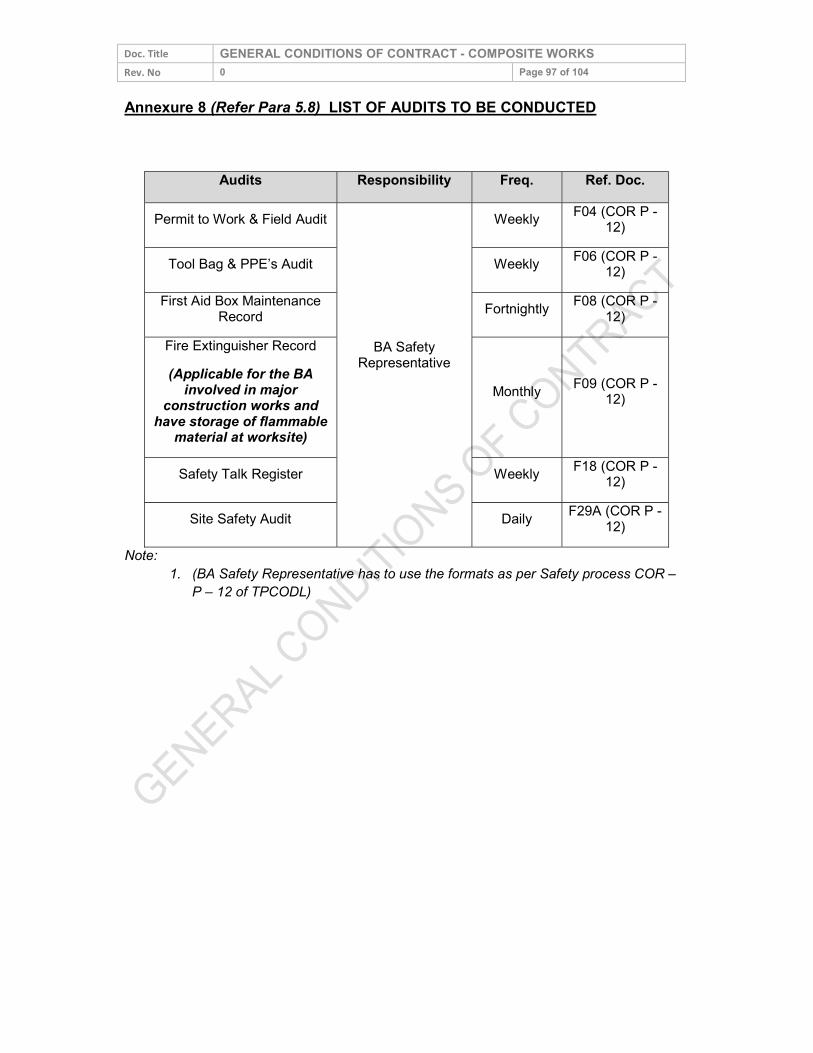
Doc. Title GENERAL CONDITIONS OF CONTRACT - COMPOSITE WORKS Rev. No 0 Page 97 of 104 Annexure 8 (Refer Para 5.8) LIST OF AUDITS TO BE CONDUCTED
Note: 1. (BA Safety Representative has to use the formats as per Safety process COR –
P – 12 of TPCODL)
Audits Responsibility Freq. Ref. Doc. Permit to Work & Field Audit
BA Safety Representative
Weekly F04 (COR P -12) Tool Bag & PPE’s Audit Weekly F06 (COR P -12)
First Aid Box Maintenance Record Fortnightly F08 (COR P -
12) Fire Extinguisher Record (Applicable for the BA
involved in major construction works and
have storage of flammable material at worksite)
Monthly F09 (COR P -12)
Safety Talk Register Weekly F18 (COR P -12) Site Safety Audit Daily F29A (COR P -
12)
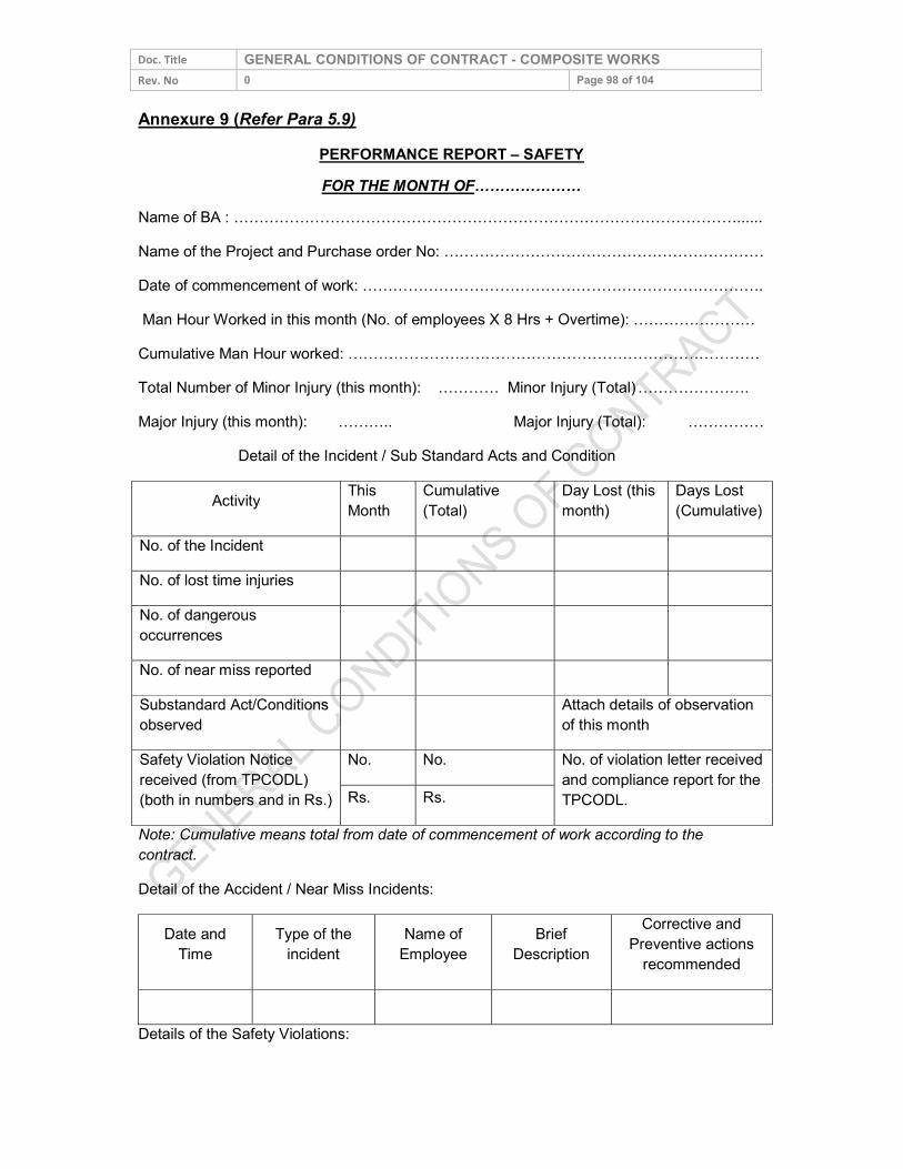
Doc. Title GENERAL CONDITIONS OF CONTRACT - COMPOSITE WORKS Rev. No 0 Page 98 of 104 Annexure 9 (Refer Para 5.9)
PERFORMANCE REPORT – SAFETY FOR THE MONTH OF…………………
Name of BA : ………………………………………………………………………………………...... Name of the Project and Purchase order No: ……………………………………………………… Date of commencement of work: ……………………………………………………………………. Man Hour Worked in this month (No. of employees X 8 Hrs + Overtime): …………………… Cumulative Man Hour worked: ……………………………………………………………………… Total Number of Minor Injury (this month): ………… Minor Injury (Total) …………………. Major Injury (this month): ……….. Major Injury (Total): ……………
Detail of the Incident / Sub Standard Acts and Condition
Activity This Month
Cumulative (Total)
Day Lost (this month)
Days Lost (Cumulative)
No. of the Incident No. of lost time injuries No. of dangerous occurrences
No. of near miss reported Substandard Act/Conditions observed Attach details of observation
of this month Safety Violation Notice received (from TPCODL) (both in numbers and in Rs.)
No. No. No. of violation letter received and compliance report for the TPCODL. Rs. Rs.
Note: Cumulative means total from date of commencement of work according to the contract. Detail of the Accident / Near Miss Incidents:
Date and Time
Type of the incident
Name of Employee
Brief Description
Corrective and Preventive actions
recommended
Details of the Safety Violations:
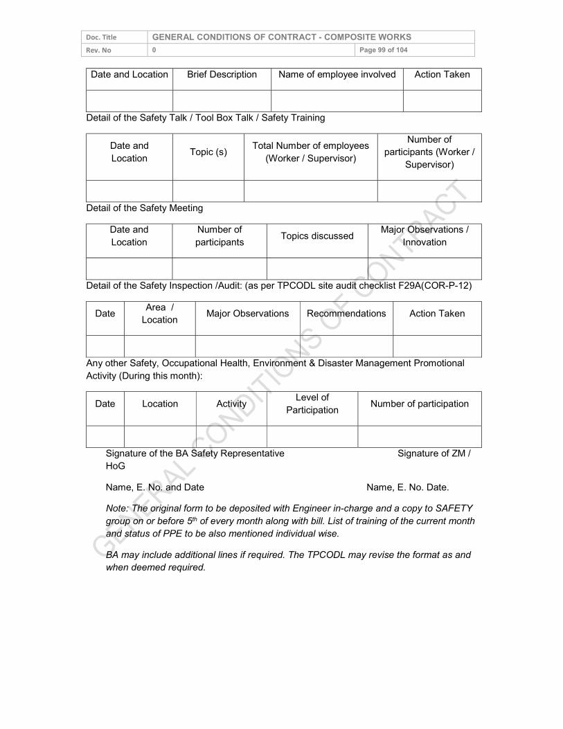
Doc. Title GENERAL CONDITIONS OF CONTRACT - COMPOSITE WORKS Rev. No 0 Page 99 of 104 Date and Location Brief Description Name of employee involved Action Taken
Detail of the Safety Talk / Tool Box Talk / Safety Training
Date and Location Topic (s) Total Number of employees
(Worker / Supervisor) Number of
participants (Worker / Supervisor)
Detail of the Safety Meeting
Date and Location
Number of participants Topics discussed Major Observations /
Innovation
Detail of the Safety Inspection /Audit: (as per TPCODL site audit checklist F29A(COR-P-12)
Date Area / Location Major Observations Recommendations Action Taken
Any other Safety, Occupational Health, Environment & Disaster Management Promotional Activity (During this month):
Date Location Activity Level of Participation Number of participation
Signature of the BA Safety Representative Signature of ZM / HoG Name, E. No. and Date Name, E. No. Date. Note: The original form to be deposited with Engineer in-charge and a copy to SAFETY group on or before 5th of every month along with bill. List of training of the current month and status of PPE to be also mentioned individual wise. BA may include additional lines if required. The TPCODL may revise the format as and when deemed required.
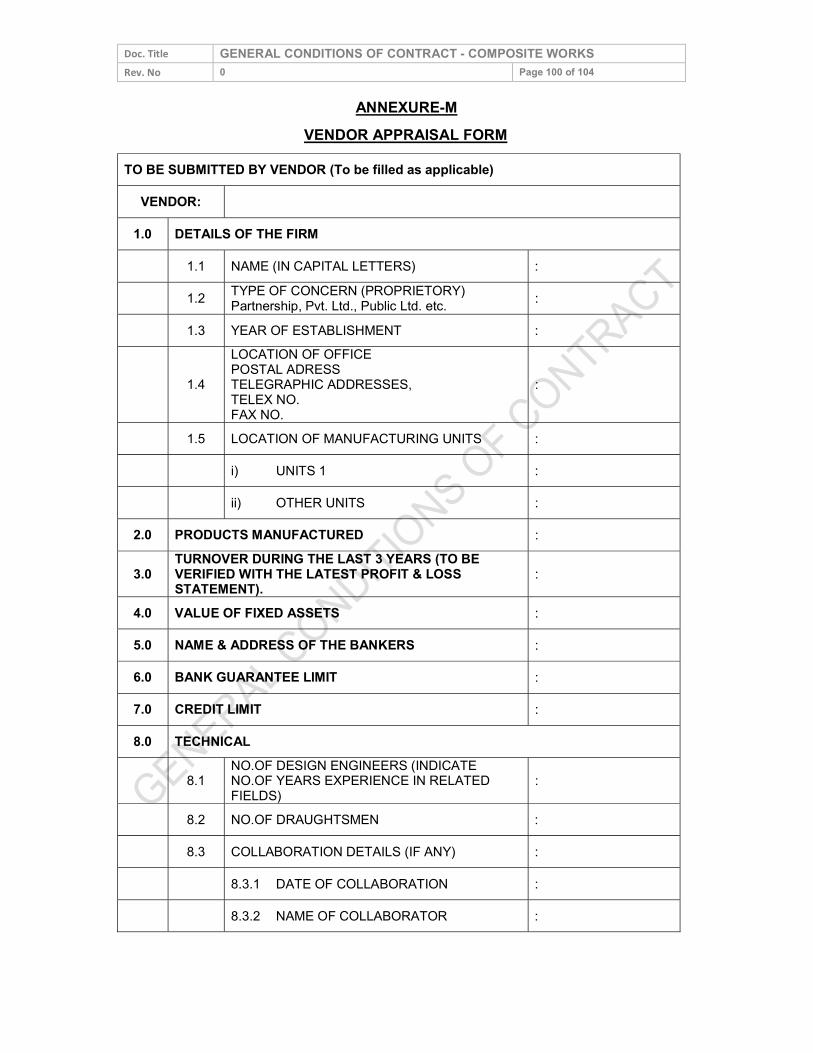
Doc. Title GENERAL CONDITIONS OF CONTRACT - COMPOSITE WORKS Rev. No 0 Page 100 of 104
ANNEXURE-M VENDOR APPRAISAL FORM
TO BE SUBMITTED BY VENDOR (To be filled as applicable) VENDOR:
1.0 DETAILS OF THE FIRM 1.1 NAME (IN CAPITAL LETTERS) : 1.2 TYPE OF CONCERN (PROPRIETORY)
Partnership, Pvt. Ltd., Public Ltd. etc. : 1.3 YEAR OF ESTABLISHMENT :
1.4 LOCATION OF OFFICE POSTAL ADRESS TELEGRAPHIC ADDRESSES, TELEX NO. FAX NO.
:
1.5 LOCATION OF MANUFACTURING UNITS : i) UNITS 1 : ii) OTHER UNITS :
2.0 PRODUCTS MANUFACTURED :
3.0 TURNOVER DURING THE LAST 3 YEARS (TO BE VERIFIED WITH THE LATEST PROFIT & LOSS STATEMENT). :
4.0 VALUE OF FIXED ASSETS : 5.0 NAME & ADDRESS OF THE BANKERS : 6.0 BANK GUARANTEE LIMIT : 7.0 CREDIT LIMIT : 8.0 TECHNICAL
8.1 NO.OF DESIGN ENGINEERS (INDICATE NO.OF YEARS EXPERIENCE IN RELATED FIELDS)
:
8.2 NO.OF DRAUGHTSMEN : 8.3 COLLABORATION DETAILS (IF ANY) : 8.3.1 DATE OF COLLABORATION : 8.3.2 NAME OF COLLABORATOR :
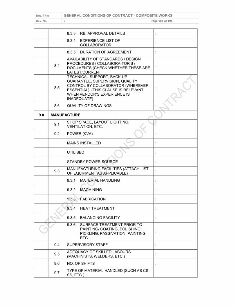
Doc. Title GENERAL CONDITIONS OF CONTRACT - COMPOSITE WORKS Rev. No 0 Page 101 of 104
8.3.3 RBI APPROVAL DETAILS : 8.3.4 EXPERIENCE LIST OF
COLLABORATOR : 8.3.5 DURATION OF AGREEMENT :
8.4 AVAILABILITY OF STANDARDS / DESIGN PROCEDURES / COLLABORA-TOR’S / DOCUMENTS (CHECK WHETHER THESE ARE LATEST/CURRENT
:
8.5 TECHNICAL SUPPORT, BACK-UP GUARANTEE, SUPERVISION, QUALITY CONTROL BY COLLABORATOR (WHEREVER ESSENTIAL). (THIS CLAUSE IS RELEVANT WHEN VENDOR’S EXPERIENCE IS INADEQUATE)
:
8.6 QUALITY OF DRAWINGS : 9.0 MANUFACTURE
9.1 SHOP SPACE, LAYOUT LIGHTING, VENTILATION, ETC. :
9.2 POWER (KVA) : MAINS INSTALLED : UTILISED : STANDBY POWER SOURCE : 9.3 MANUFACTURING FACILITIES (ATTACH LIST
OF EQUIPMENT AS APPLICABLE) : 9.3.1 MATERIAL HANDLING : 9.3.2 MACHINING : 9.3.3 FABRICATION : 9.3.4 HEAT TREATMENT : 9.3.5 BALANCING FACILITY :
9.3.6 SURFACE TREATMENT PRIOR TO PAINTING/ COATING, POLISHING,
PICKLING, PASSIVATION, PAINTING, ETC.
:
9.4 SUPERVISORY STAFF : 9.5 ADEQUACY OF SKILLED LABOURS
(MACHINISTS, WELDERS, ETC.) : 9.6 NO. OF SHIFTS : 9.7 TYPE OF MATERIAL HANDLED (SUCH AS CS,
SS, ETC.)
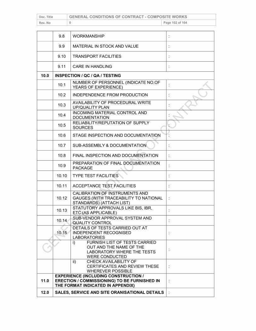
Doc. Title GENERAL CONDITIONS OF CONTRACT - COMPOSITE WORKS Rev. No 0 Page 102 of 104
9.8 WORKMANSHIP : 9.9 MATERIAL IN STOCK AND VALUE : 9.10 TRANSPORT FACILITIES : 9.11 CARE IN HANDLING :
10.0 INSPECTION / QC / QA / TESTING 10.1 NUMBER OF PERSONNEL (INDICATE NO.OF YEARS OF EXPERIENCE) : 10.2 INDEPENDENCE FROM PRODUCTION : 10.3 AVAILABILITY OF PROCEDURAL WRITE
UP/QUALITY PLAN : 10.4 INCOMING MATERIAL CONTROL AND
DOCUMENTATION : 10.5 RELIABILITY/REPUTATION OF SUPPLY
SOURCES : 10.6 STAGE INSPECTION AND DOCUMENTATION : 10.7 SUB-ASSEMBLY & DOCUMENTATION : 10.8 FINAL INSPECTION AND DOCUMENTATION : 10.9 PREPARATION OF FINAL DOCUMENTATION
PACKAGE : 10.10 TYPE TEST FACILITIES : 10.11 ACCEPTANCE TEST FACILITIES :
10.12 CALIBRATION OF INSTRUMENTS AND GAUGES (WITH TRACEABILITY TO NATIONAL STANDARDS) (ATTACH LIST) :
10.13 STATUTORY APPROVALS LIKE BIS, IBR, ETC.(AS APPLICABLE) : 10.14 SUB-VENDOR APPROVAL SYSTEM AND QUALITY CONTROL :
10.15 DETAILS OF TESTS CARRIED OUT AT INDEPENDENT RECOGNISED LABORATORIES
:
i) FURNISH LIST OF TESTS CARRIED
OUT AND THE NAME OF THE LABORATORY WHERE THE TESTS WERE CONDUCTED
:
ii) CHECK AVAILABILITY OF
CERTIFICATES AND REVIEW THESE WHEREVER POSSIBLE :
11.0 EXPERIENCE (INCLUDING CONSTRUCTION / ERECTION / COMMISSIONING) TO BE FURNISHED IN THE FORMAT INDICATED IN APPENDIX) :
12.0 SALES, SERVICE AND SITE ORANISATIONAL DETAILS :
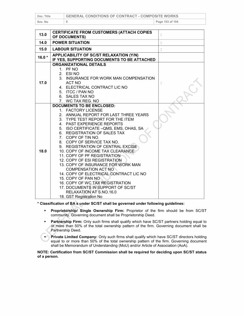
Doc. Title GENERAL CONDITIONS OF CONTRACT - COMPOSITE WORKS Rev. No 0 Page 103 of 104 13.0 CERTIFICATE FROM CUSTOMERS (ATTACH COPIES
OF DOCUMENTS) : 14.0 POWER SITUATION : 15.0 LABOUR SITUATION :
16.0 * APPLICABILITY OF SC/ST RELAXATION (Y/N) IF YES, SUPPORTING DOCUMENTS TO BE ATTACHED
17.0
ORGANIZATIONAL DETAILS 1. PF NO 2. ESI NO 3. INSURANCE FOR WORK MAN COMPENSATION ACT NO 4. ELECTRICAL CONTRACT LIC NO 5. ITCC / PAN NO 6. SALES TAX NO 7. WC TAX REG. NO
:
18.0
DOCUMENTS TO BE ENCLOSED: 1. FACTORY LICENSE 2. ANNUAL REPORT FOR LAST THREE YEARS 3. TYPE TEST REPORT FOR THE ITEM 4. PAST EXPERIENCE REPORTS 5. ISO CERTIFICATE –QMS, EMS, OHAS, SA 6. REGISTRATION OF SALES TAX 7. COPY OF TIN NO. 8. COPY OF SERVICE TAX NO. 9. REGISTRATION OF CENTRAL EXCISE 10. COPY OF INCOME TAX CLEARANCE. 11. COPY OF PF REGISTRATION 12. COPY OF ESI REGISTRATION 13. COPY OF INSURANCE FOR WORK MAN COMPENSATION ACT NO 14. COPY OF ELECTRICAL CONTRACT LIC NO 15. COPY OF PAN NO 16. COPY OF WC TAX REGISTRATION 17. DOCUMENTS IN SUPPORT OF SC/ST RELAXATION AT S.NO.16.0 18. GST Registration No
* Classification of BA s under SC/ST shall be governed under following guidelines: Proprietorship/ Single Ownership Firm: Proprietor of the firm should be from SC/ST
community. Governing document shall be Proprietorship Deed. Partnership Firm: Only such firms shall qualify which have SC/ST partners holding equal to or more than 50% of the total ownership pattern of the firm. Governing document shall be
Partnership Deed. Private Limited Company: Only such firms shall qualify which have SC/ST directors holding
equal to or more than 50% of the total ownership pattern of the firm. Governing document shall be Memorandum of Understanding (MoU) and/or Article of Association (AoA).
NOTE: Certification from SC/ST Commission shall be required for deciding upon SC/ST status of a person.
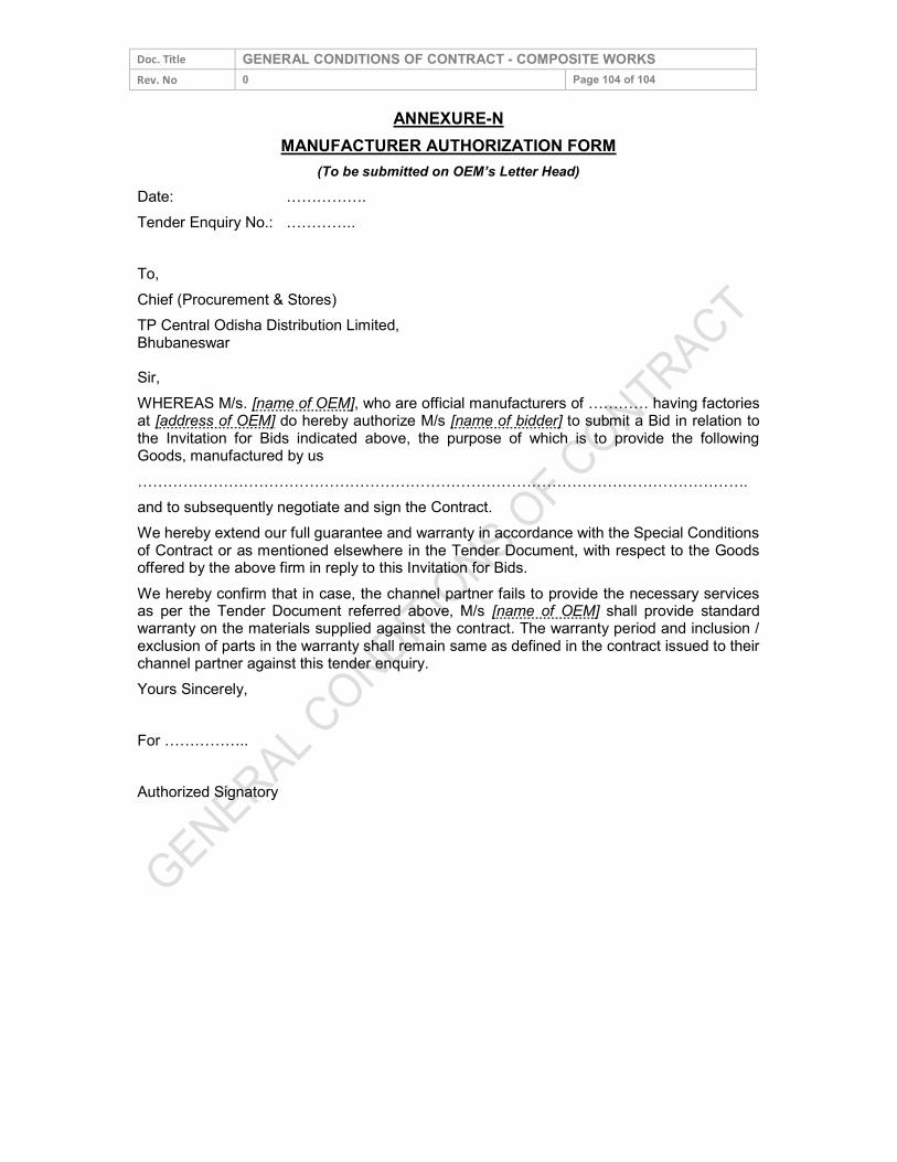
Doc. Title GENERAL CONDITIONS OF CONTRACT - COMPOSITE WORKS Rev. No 0 Page 104 of 104
ANNEXURE-N MANUFACTURER AUTHORIZATION FORM
(To be submitted on OEM’s Letter Head) Date: ……………. Tender Enquiry No.: ………….. To, Chief (Procurement & Stores) TP Central Odisha Distribution Limited, Bhubaneswar Sir, WHEREAS M/s. [name of OEM], who are official manufacturers of ………… having factories at [address of OEM] do hereby authorize M/s [name of bidder] to submit a Bid in relation to the Invitation for Bids indicated above, the purpose of which is to provide the following Goods, manufactured by us …………………………………………………………………………………………………………. and to subsequently negotiate and sign the Contract. We hereby extend our full guarantee and warranty in accordance with the Special Conditions of Contract or as mentioned elsewhere in the Tender Document, with respect to the Goods offered by the above firm in reply to this Invitation for Bids. We hereby confirm that in case, the channel partner fails to provide the necessary services as per the Tender Document referred above, M/s [name of OEM] shall provide standard warranty on the materials supplied against the contract. The warranty period and inclusion / exclusion of parts in the warranty shall remain same as defined in the contract issued to their channel partner against this tender enquiry. Yours Sincerely, For …………….. Authorized Signatory
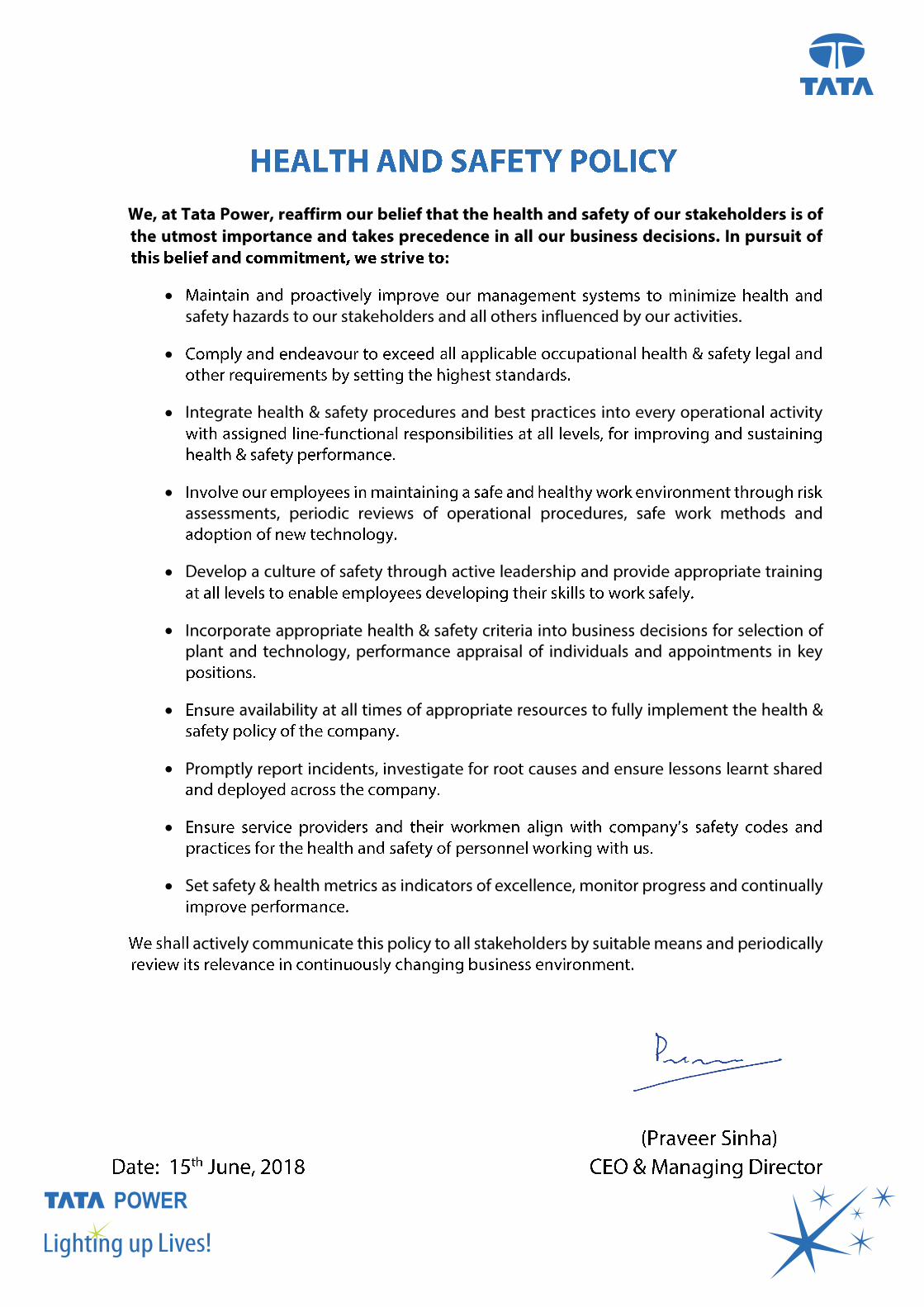

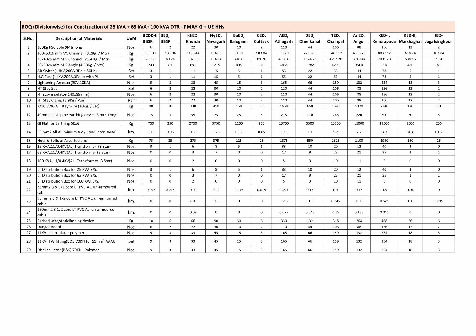
S.No. Description of Materials UoMBCDD-II, BBSR
BED, BBSR
KhED, Khurda
NyED, Nayagarh
BaED, Balugaon
CED, Cuttack
AED, Athagarh
DED, Dhenkanal
TED, Chainpal
AnED, Angul
KED-I, Kendrapada
KED-II, Marshaghai
JED-Jagatsinghpur
1 300Kg PSC pole 9Mtr long Nos. 6 2 22 30 10 2 110 44 106 88 156 12 2
2 100x50x6 mm MS Channel (9.2Kg. / Mtr) Kg. 309.12 103.04 1133.44 1545.6 515.2 103.04 5667.2 2266.88 5461.12 4533.76 8037.12 618.24 103.04
3 75x40x5 mm M.S Channel (7.14 Kg. / Mtr) Kg. 269.28 89.76 987.36 1346.4 448.8 89.76 4936.8 1974.72 4757.28 3949.44 7001.28 538.56 89.76
4 50x50x6 mm M.S Angle (4.50Kg. / Mtr) Kg. 243 81 891 1215 405 81 4455 1782 4293 3564 6318 486 81
5 AB Switch(11KV,200A,3Pole,50Hz) Set 3 1 11 15 5 1 55 22 53 44 78 6 1
6 H.G Fuse(11KV,200A,3Pole) with PI Set 3 1 11 15 5 1 55 22 53 44 78 6 1
7 Lightening Arrester(9KV,10KA) Nos. 9 3 33 45 15 3 165 66 159 132 234 18 3
8 HT Stay Set Set 6 2 22 30 10 2 110 44 106 88 156 12 2
9 HT stay insulator(140x85 mm) Nos. 6 2 22 30 10 2 110 44 106 88 156 12 2
10 HT Stay Clamp (1.9Kg / Pair) Pair 6 2 22 30 10 2 110 44 106 88 156 12 2
11 7/10 SWG G I stay wire (10Kg. / Set) Kg. 90 30 330 450 150 30 1650 660 1590 1320 2340 180 30
12 40mm dia GI pipe earthing device 3 mtr. Long Nos. 15 5 55 75 25 5 275 110 265 220 390 30 5
13 GI Flat for Earthing 50x6 Kg. 750 250 2750 3750 1250 250 13750 5500 13250 11000 19500 1500 250
14 55 mm2 All Aluminium Aloy Conductor. AAAC km. 0.15 0.05 0.55 0.75 0.25 0.05 2.75 1.1 2.65 2.2 3.9 0.3 0.05
15 Nuts & Bolts of Assorted size Kg. 75 25 275 375 125 25 1375 550 1325 1100 1950 150 25
16 25 KVA,11/0.4KV(AL) Transformer (3 Star) Nos. 3 1 6 8 5 1 33 10 20 12 40 4 0
17 63 KVA,11/0.4KV(AL) Transformer (3 Star) Nos. 0 0 3 7 0 0 17 9 23 21 35 2 1
18 100 KVA,11/0.4KV(AL) Transformer (3 Star) Nos. 0 0 2 0 0 0 5 3 10 11 3 0 0
19 LT Distribution Box for 25 KVA S/S. Nos. 3 1 6 8 5 1 33 10 20 12 40 4 0
20 LT Distribution Box for 63 KVA S/S. Nos. 0 0 3 7 0 0 17 9 23 21 35 2 1
21 LT Distribution Box for 100 KVA S/S. Nos. 0 0 2 0 0 0 5 3 10 11 3 0 0
2235mm2 3 & 1/2 core LT PVC AL. un-armoured cable
km. 0.045 0.015 0.09 0.12 0.075 0.015 0.495 0.15 0.3 0.18 0.6 0.06 0
2395 mm2 3 & 1/2 core LT PVC AL. un-armoured cable
km. 0 0 0.045 0.105 0 0 0.255 0.135 0.345 0.315 0.525 0.03 0.015
24150mm2 3 1/2 core LT PVC AL. un-armoured cable
km. 0 0 0.03 0 0 0 0.075 0.045 0.15 0.165 0.045 0 0
25 Barbed wire/Anticlimbing device Kg. 18 6 66 90 30 6 330 132 318 264 468 36 6
26 Danger Board Nos. 6 2 22 30 10 2 110 44 106 88 156 12 2
27 11KV pin insulator polymer Nos. 9 3 33 45 15 3 165 66 159 132 234 18 3
28 11KV H W fitting(B&S)70KN for 55mm² AAAC Set 9 3 33 45 15 3 165 66 159 132 234 18 3
29 Disc insulator (B&S) 70KN Polymer Nos. 9 3 33 45 15 3 165 66 159 132 234 18 3
BOQ (Divisionwise) for Construction of 25 kVA + 63 kVA+ 100 kVA DTR - PMAY-G + UE HHs
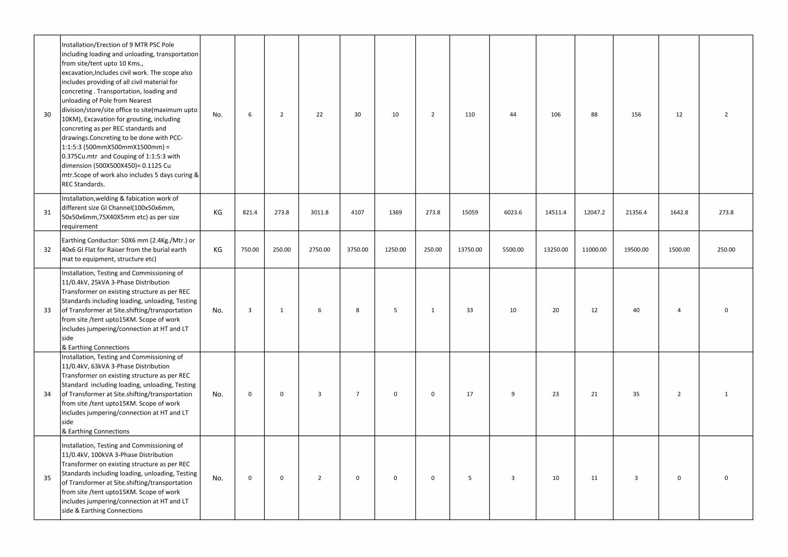
30
Installation/Erection of 9 MTR PSC Pole including loading and unloading, transportation from site/tent upto 10 Kms., excavation,Includes civil work. The scope also includes providing of all civil material for concreting . Transportation, loading and unloading of Pole from Nearest division/store/site office to site(maximum upto 10KM), Excavation for grouting, including concreting as per REC standards and drawings.Concreting to be done with PCC-1:1:5:3 (500mmX500mmX1500mm) = 0.375Cu.mtr and Couping of 1:1:5:3 with dimension (500X500X450)= 0.1125 Cu mtr.Scope of work also includes 5 days curing & REC Standards.
No. 6 2 22 30 10 2 110 44 106 88 156 12 2
31
Installation,welding & fabication work of different size GI Channel(100x50x6mm, 50x50x6mm,75X40X5mm etc) as per size requirement
KG 821.4 273.8 3011.8 4107 1369 273.8 15059 6023.6 14511.4 12047.2 21356.4 1642.8 273.8
32Earthing Conductor: 50X6 mm (2.4Kg./Mtr.) or 40x6 GI Flat for Raiser from the burial earth mat to equipment, structure etc)
KG 750.00 250.00 2750.00 3750.00 1250.00 250.00 13750.00 5500.00 13250.00 11000.00 19500.00 1500.00 250.00
33
Installation, Testing and Commissioning of 11/0.4kV, 25kVA 3-Phase Distribution Transformer on existing structure as per REC Standards including loading, unloading, Testing of Transformer at Site.shifting/transportation from site /tent upto15KM. Scope of work includes jumpering/connection at HT and LT side& Earthing Connections
No. 3 1 6 8 5 1 33 10 20 12 40 4 0
34
Installation, Testing and Commissioning of 11/0.4kV, 63kVA 3-Phase Distribution Transformer on existing structure as per REC Standard including loading, unloading, Testing of Transformer at Site.shifting/transportation from site /tent upto15KM. Scope of work includes jumpering/connection at HT and LT side& Earthing Connections
No. 0 0 3 7 0 0 17 9 23 21 35 2 1
35
Installation, Testing and Commissioning of 11/0.4kV, 100kVA 3-Phase Distribution Transformer on existing structure as per REC Standards including loading, unloading, Testing of Transformer at Site.shifting/transportation from site /tent upto15KM. Scope of work includes jumpering/connection at HT and LT side & Earthing Connections
No. 0 0 2 0 0 0 5 3 10 11 3 0 0
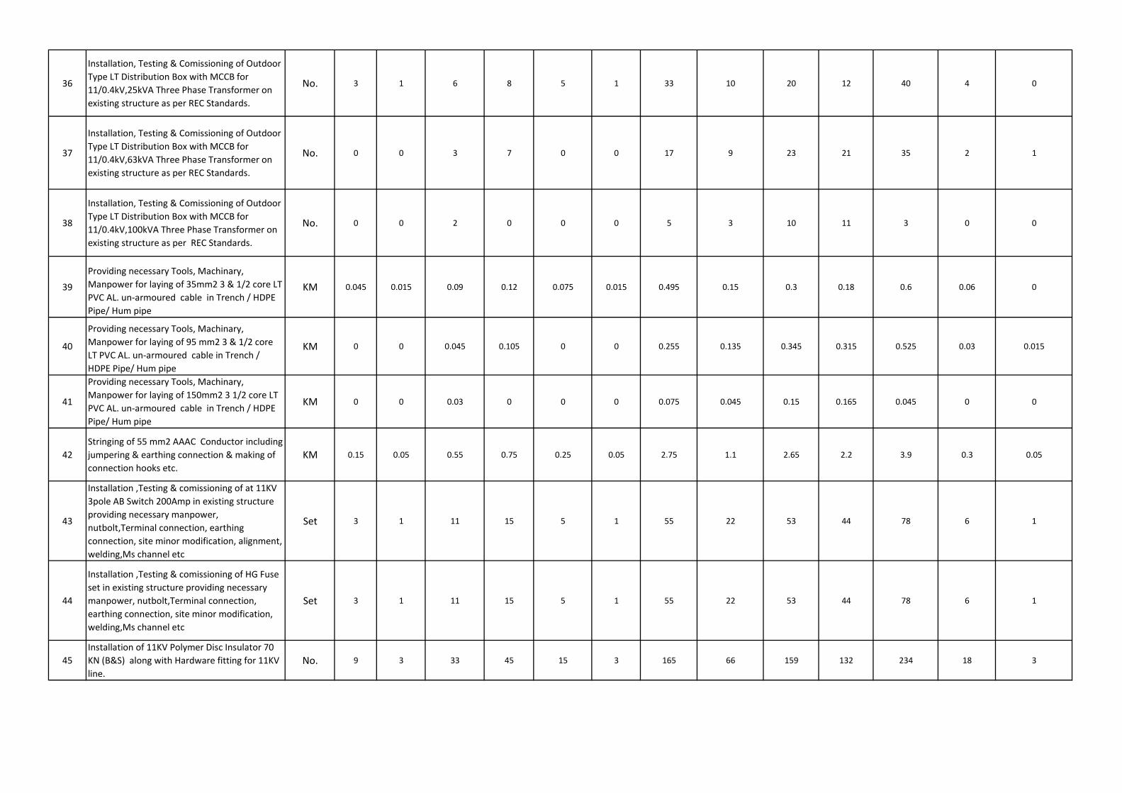
36
Installation, Testing & Comissioning of Outdoor Type LT Distribution Box with MCCB for 11/0.4kV,25kVA Three Phase Transformer on existing structure as per REC Standards.
No. 3 1 6 8 5 1 33 10 20 12 40 4 0
37
Installation, Testing & Comissioning of Outdoor Type LT Distribution Box with MCCB for 11/0.4kV,63kVA Three Phase Transformer on existing structure as per REC Standards.
No. 0 0 3 7 0 0 17 9 23 21 35 2 1
38
Installation, Testing & Comissioning of Outdoor Type LT Distribution Box with MCCB for 11/0.4kV,100kVA Three Phase Transformer on existing structure as per REC Standards.
No. 0 0 2 0 0 0 5 3 10 11 3 0 0
39
Providing necessary Tools, Machinary, Manpower for laying of 35mm2 3 & 1/2 core LT PVC AL. un-armoured cable in Trench / HDPE Pipe/ Hum pipe
KM 0.045 0.015 0.09 0.12 0.075 0.015 0.495 0.15 0.3 0.18 0.6 0.06 0
40
Providing necessary Tools, Machinary, Manpower for laying of 95 mm2 3 & 1/2 core LT PVC AL. un-armoured cable in Trench / HDPE Pipe/ Hum pipe
KM 0 0 0.045 0.105 0 0 0.255 0.135 0.345 0.315 0.525 0.03 0.015
41
Providing necessary Tools, Machinary, Manpower for laying of 150mm2 3 1/2 core LT PVC AL. un-armoured cable in Trench / HDPE Pipe/ Hum pipe
KM 0 0 0.03 0 0 0 0.075 0.045 0.15 0.165 0.045 0 0
42Stringing of 55 mm2 AAAC Conductor including jumpering & earthing connection & making of connection hooks etc.
KM 0.15 0.05 0.55 0.75 0.25 0.05 2.75 1.1 2.65 2.2 3.9 0.3 0.05
43
Installation ,Testing & comissioning of at 11KV 3pole AB Switch 200Amp in existing structure providing necessary manpower, nutbolt,Terminal connection, earthing connection, site minor modification, alignment, welding,Ms channel etc
Set 3 1 11 15 5 1 55 22 53 44 78 6 1
44
Installation ,Testing & comissioning of HG Fuse set in existing structure providing necessary manpower, nutbolt,Terminal connection, earthing connection, site minor modification, welding,Ms channel etc
Set 3 1 11 15 5 1 55 22 53 44 78 6 1
45Installation of 11KV Polymer Disc Insulator 70 KN (B&S) along with Hardware fitting for 11KV line.
No. 9 3 33 45 15 3 165 66 159 132 234 18 3
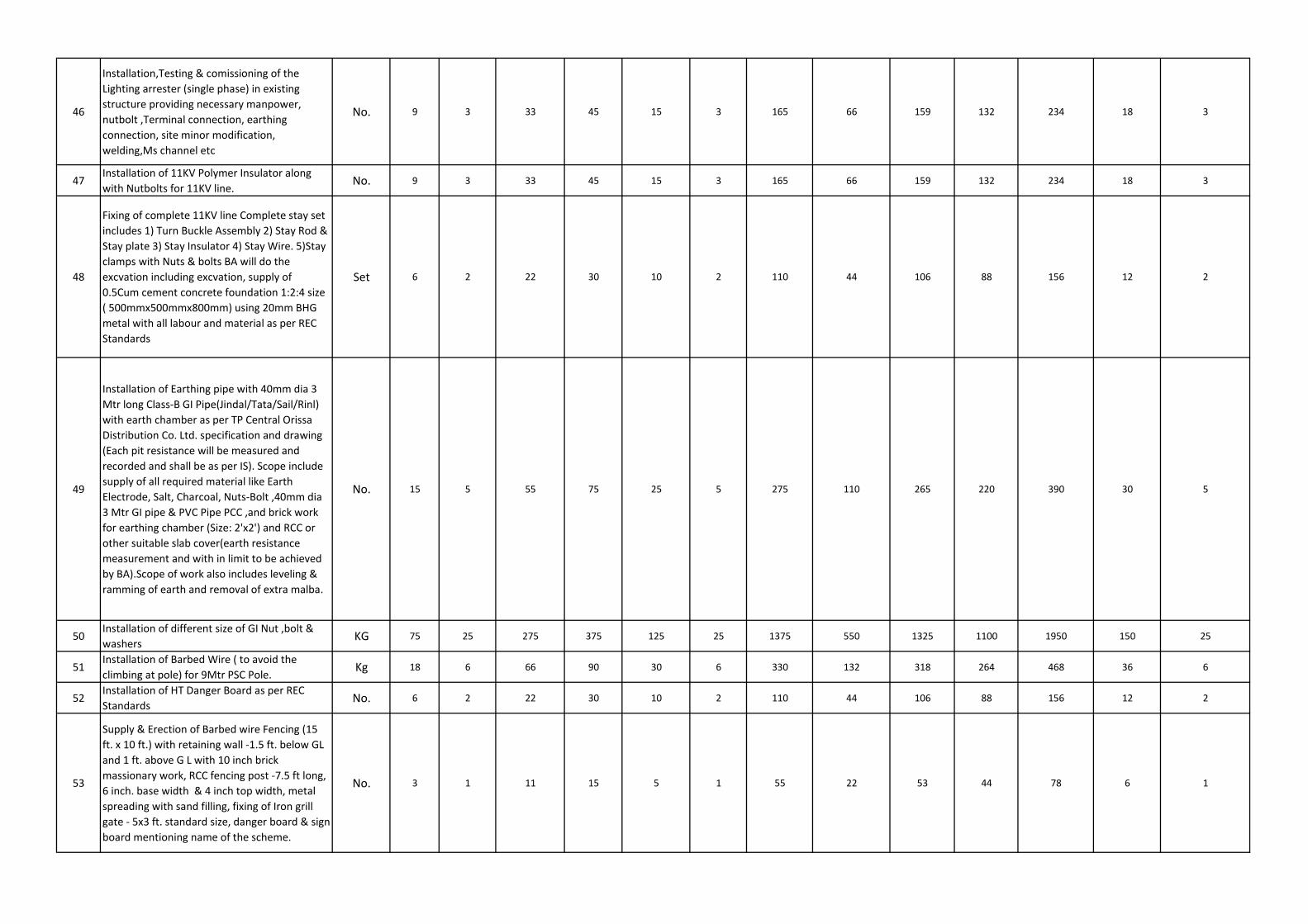
46
Installation,Testing & comissioning of the Lighting arrester (single phase) in existing structure providing necessary manpower, nutbolt ,Terminal connection, earthing connection, site minor modification, welding,Ms channel etc
No. 9 3 33 45 15 3 165 66 159 132 234 18 3
47Installation of 11KV Polymer Insulator along with Nutbolts for 11KV line.
No. 9 3 33 45 15 3 165 66 159 132 234 18 3
48
Fixing of complete 11KV line Complete stay set includes 1) Turn Buckle Assembly 2) Stay Rod & Stay plate 3) Stay Insulator 4) Stay Wire. 5)Stay clamps with Nuts & bolts BA will do the excvation including excvation, supply of 0.5Cum cement concrete foundation 1:2:4 size ( 500mmx500mmx800mm) using 20mm BHG metal with all labour and material as per REC Standards
Set 6 2 22 30 10 2 110 44 106 88 156 12 2
49
Installation of Earthing pipe with 40mm dia 3 Mtr long Class-B GI Pipe(Jindal/Tata/Sail/Rinl) with earth chamber as per TP Central Orissa Distribution Co. Ltd. specification and drawing (Each pit resistance will be measured and recorded and shall be as per IS). Scope include supply of all required material like Earth Electrode, Salt, Charcoal, Nuts-Bolt ,40mm dia 3 Mtr GI pipe & PVC Pipe PCC ,and brick work for earthing chamber (Size: 2'x2') and RCC or other suitable slab cover(earth resistance measurement and with in limit to be achieved by BA).Scope of work also includes leveling & ramming of earth and removal of extra malba.
No. 15 5 55 75 25 5 275 110 265 220 390 30 5
50Installation of different size of GI Nut ,bolt & washers
KG 75 25 275 375 125 25 1375 550 1325 1100 1950 150 25
51Installation of Barbed Wire ( to avoid the climbing at pole) for 9Mtr PSC Pole.
Kg 18 6 66 90 30 6 330 132 318 264 468 36 6
52Installation of HT Danger Board as per REC Standards
No. 6 2 22 30 10 2 110 44 106 88 156 12 2
53
Supply & Erection of Barbed wire Fencing (15 ft. x 10 ft.) with retaining wall -1.5 ft. below GL and 1 ft. above G L with 10 inch brick massionary work, RCC fencing post -7.5 ft long, 6 inch. base width & 4 inch top width, metal spreading with sand filling, fixing of Iron grill gate - 5x3 ft. standard size, danger board & sign board mentioning name of the scheme.
No. 3 1 11 15 5 1 55 22 53 44 78 6 1
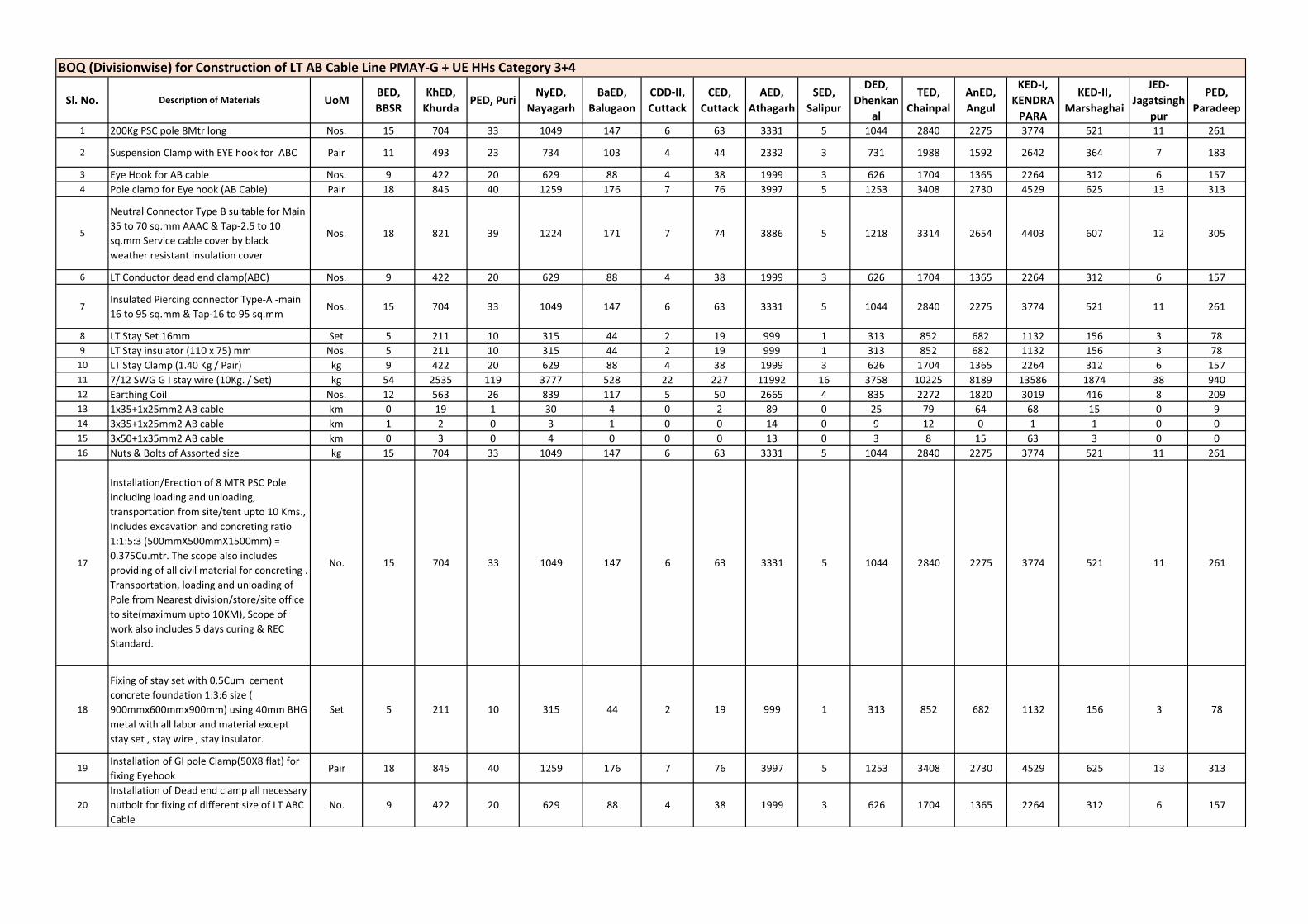
Sl. No. Description of Materials UoMBED, BBSR
KhED, Khurda
PED, PuriNyED,
NayagarhBaED,
BalugaonCDD-II, Cuttack
CED, Cuttack
AED, Athagarh
SED, Salipur
DED, Dhenkan
al
TED, Chainpal
AnED, Angul
KED-I, KENDRA
PARA
KED-II, Marshaghai
JED-Jagatsingh
pur
PED, Paradeep
1 200Kg PSC pole 8Mtr long Nos. 15 704 33 1049 147 6 63 3331 5 1044 2840 2275 3774 521 11 261
2 Suspension Clamp with EYE hook for ABC Pair 11 493 23 734 103 4 44 2332 3 731 1988 1592 2642 364 7 183
3 Eye Hook for AB cable Nos. 9 422 20 629 88 4 38 1999 3 626 1704 1365 2264 312 6 1574 Pole clamp for Eye hook (AB Cable) Pair 18 845 40 1259 176 7 76 3997 5 1253 3408 2730 4529 625 13 313
5
Neutral Connector Type B suitable for Main 35 to 70 sq.mm AAAC & Tap-2.5 to 10 sq.mm Service cable cover by black weather resistant insulation cover
Nos. 18 821 39 1224 171 7 74 3886 5 1218 3314 2654 4403 607 12 305
6 LT Conductor dead end clamp(ABC) Nos. 9 422 20 629 88 4 38 1999 3 626 1704 1365 2264 312 6 157
7Insulated Piercing connector Type-A -main 16 to 95 sq.mm & Tap-16 to 95 sq.mm
Nos. 15 704 33 1049 147 6 63 3331 5 1044 2840 2275 3774 521 11 261
8 LT Stay Set 16mm Set 5 211 10 315 44 2 19 999 1 313 852 682 1132 156 3 789 LT Stay insulator (110 x 75) mm Nos. 5 211 10 315 44 2 19 999 1 313 852 682 1132 156 3 78
10 LT Stay Clamp (1.40 Kg / Pair) kg 9 422 20 629 88 4 38 1999 3 626 1704 1365 2264 312 6 15711 7/12 SWG G I stay wire (10Kg. / Set) kg 54 2535 119 3777 528 22 227 11992 16 3758 10225 8189 13586 1874 38 94012 Earthing Coil Nos. 12 563 26 839 117 5 50 2665 4 835 2272 1820 3019 416 8 20913 1x35+1x25mm2 AB cable km 0 19 1 30 4 0 2 89 0 25 79 64 68 15 0 914 3x35+1x25mm2 AB cable km 1 2 0 3 1 0 0 14 0 9 12 0 1 1 0 015 3x50+1x35mm2 AB cable km 0 3 0 4 0 0 0 13 0 3 8 15 63 3 0 016 Nuts & Bolts of Assorted size kg 15 704 33 1049 147 6 63 3331 5 1044 2840 2275 3774 521 11 261
17
Installation/Erection of 8 MTR PSC Pole including loading and unloading, transportation from site/tent upto 10 Kms., Includes excavation and concreting ratio 1:1:5:3 (500mmX500mmX1500mm) = 0.375Cu.mtr. The scope also includes providing of all civil material for concreting . Transportation, loading and unloading of Pole from Nearest division/store/site office to site(maximum upto 10KM), Scope of work also includes 5 days curing & REC Standard.
No. 15 704 33 1049 147 6 63 3331 5 1044 2840 2275 3774 521 11 261
18
Fixing of stay set with 0.5Cum cement concrete foundation 1:3:6 size ( 900mmx600mmx900mm) using 40mm BHG metal with all labor and material except stay set , stay wire , stay insulator.
Set 5 211 10 315 44 2 19 999 1 313 852 682 1132 156 3 78
19Installation of GI pole Clamp(50X8 flat) for fixing Eyehook
Pair 18 845 40 1259 176 7 76 3997 5 1253 3408 2730 4529 625 13 313
20Installation of Dead end clamp all necessary nutbolt for fixing of different size of LT ABC Cable
No. 9 422 20 629 88 4 38 1999 3 626 1704 1365 2264 312 6 157
BOQ (Divisionwise) for Construction of LT AB Cable Line PMAY-G + UE HHs Category 3+4
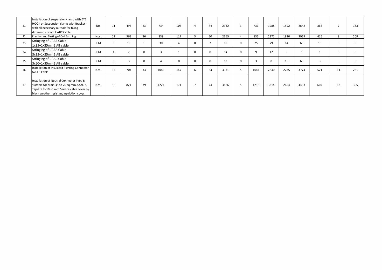
21
Installation of suspension clamp with EYE HOOK or Suspension clamp with Bracket with all necessary nutbolt for fixing different size of LT ABC Cable
No. 11 493 23 734 103 4 44 2332 3 731 1988 1592 2642 364 7 183
22 Erection and Testing of Coil Earthing Nos. 12 563 26 839 117 5 50 2665 4 835 2272 1820 3019 416 8 209
23Stringing of LT AB Cable 1x35+1x25mm2 AB cable
K.M 0 19 1 30 4 0 2 89 0 25 79 64 68 15 0 9
24Stringing of LT AB Cable 3x35+1x25mm2 AB cable
K.M 1 2 0 3 1 0 0 14 0 9 12 0 1 1 0 0
25Stringing of LT AB Cable 3x50+1x35mm2 AB cable
K.M 0 3 0 4 0 0 0 13 0 3 8 15 63 3 0 0
26Installation of Insulated Piercing Connector for AB Cable
Nos. 15 704 33 1049 147 6 63 3331 5 1044 2840 2275 3774 521 11 261
27Installation of Neutral Connector Type B suitable for Main 35 to 70 sq.mm AAAC & Tap-2.5 to 10 sq.mm Service cable cover by black weather resistant insulation cover
Nos. 18 821 39 1224 171 7 74 3886 5 1218 3314 2654 4403 607 12 305
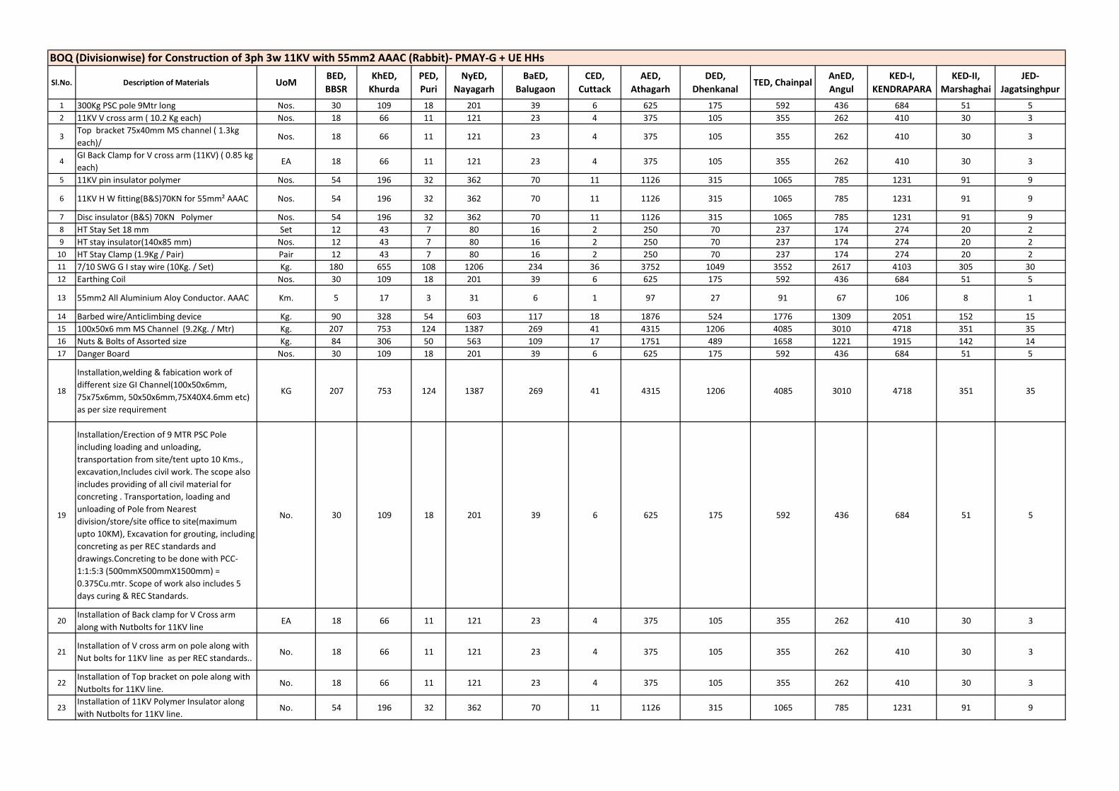
Sl.No. Description of Materials UoMBED, BBSR
KhED, Khurda
PED, Puri
NyED, Nayagarh
BaED, Balugaon
CED, Cuttack
AED, Athagarh
DED, Dhenkanal
TED, ChainpalAnED, Angul
KED-I, KENDRAPARA
KED-II, Marshaghai
JED-Jagatsinghpur
1 300Kg PSC pole 9Mtr long Nos. 30 109 18 201 39 6 625 175 592 436 684 51 52 11KV V cross arm ( 10.2 Kg each) Nos. 18 66 11 121 23 4 375 105 355 262 410 30 3
3Top bracket 75x40mm MS channel ( 1.3kg each)/
Nos. 18 66 11 121 23 4 375 105 355 262 410 30 3
4GI Back Clamp for V cross arm (11KV) ( 0.85 kg each)
EA 18 66 11 121 23 4 375 105 355 262 410 30 3
5 11KV pin insulator polymer Nos. 54 196 32 362 70 11 1126 315 1065 785 1231 91 9
6 11KV H W fitting(B&S)70KN for 55mm² AAAC Nos. 54 196 32 362 70 11 1126 315 1065 785 1231 91 9
7 Disc insulator (B&S) 70KN Polymer Nos. 54 196 32 362 70 11 1126 315 1065 785 1231 91 98 HT Stay Set 18 mm Set 12 43 7 80 16 2 250 70 237 174 274 20 29 HT stay insulator(140x85 mm) Nos. 12 43 7 80 16 2 250 70 237 174 274 20 2
10 HT Stay Clamp (1.9Kg / Pair) Pair 12 43 7 80 16 2 250 70 237 174 274 20 211 7/10 SWG G I stay wire (10Kg. / Set) Kg. 180 655 108 1206 234 36 3752 1049 3552 2617 4103 305 3012 Earthing Coil Nos. 30 109 18 201 39 6 625 175 592 436 684 51 5
13 55mm2 All Aluminium Aloy Conductor. AAAC Km. 5 17 3 31 6 1 97 27 91 67 106 8 1
14 Barbed wire/Anticlimbing device Kg. 90 328 54 603 117 18 1876 524 1776 1309 2051 152 1515 100x50x6 mm MS Channel (9.2Kg. / Mtr) Kg. 207 753 124 1387 269 41 4315 1206 4085 3010 4718 351 3516 Nuts & Bolts of Assorted size Kg. 84 306 50 563 109 17 1751 489 1658 1221 1915 142 1417 Danger Board Nos. 30 109 18 201 39 6 625 175 592 436 684 51 5
18
Installation,welding & fabication work of different size GI Channel(100x50x6mm, 75x75x6mm, 50x50x6mm,75X40X4.6mm etc) as per size requirement
KG 207 753 124 1387 269 41 4315 1206 4085 3010 4718 351 35
19
Installation/Erection of 9 MTR PSC Pole including loading and unloading, transportation from site/tent upto 10 Kms., excavation,Includes civil work. The scope also includes providing of all civil material for concreting . Transportation, loading and unloading of Pole from Nearest division/store/site office to site(maximum upto 10KM), Excavation for grouting, including concreting as per REC standards and drawings.Concreting to be done with PCC-1:1:5:3 (500mmX500mmX1500mm) = 0.375Cu.mtr. Scope of work also includes 5 days curing & REC Standards.
No. 30 109 18 201 39 6 625 175 592 436 684 51 5
20Installation of Back clamp for V Cross arm along with Nutbolts for 11KV line
EA 18 66 11 121 23 4 375 105 355 262 410 30 3
21Installation of V cross arm on pole along with Nut bolts for 11KV line as per REC standards..
No. 18 66 11 121 23 4 375 105 355 262 410 30 3
22Installation of Top bracket on pole along with Nutbolts for 11KV line.
No. 18 66 11 121 23 4 375 105 355 262 410 30 3
23Installation of 11KV Polymer Insulator along with Nutbolts for 11KV line.
No. 54 196 32 362 70 11 1126 315 1065 785 1231 91 9
BOQ (Divisionwise) for Construction of 3ph 3w 11KV with 55mm2 AAAC (Rabbit)- PMAY-G + UE HHs
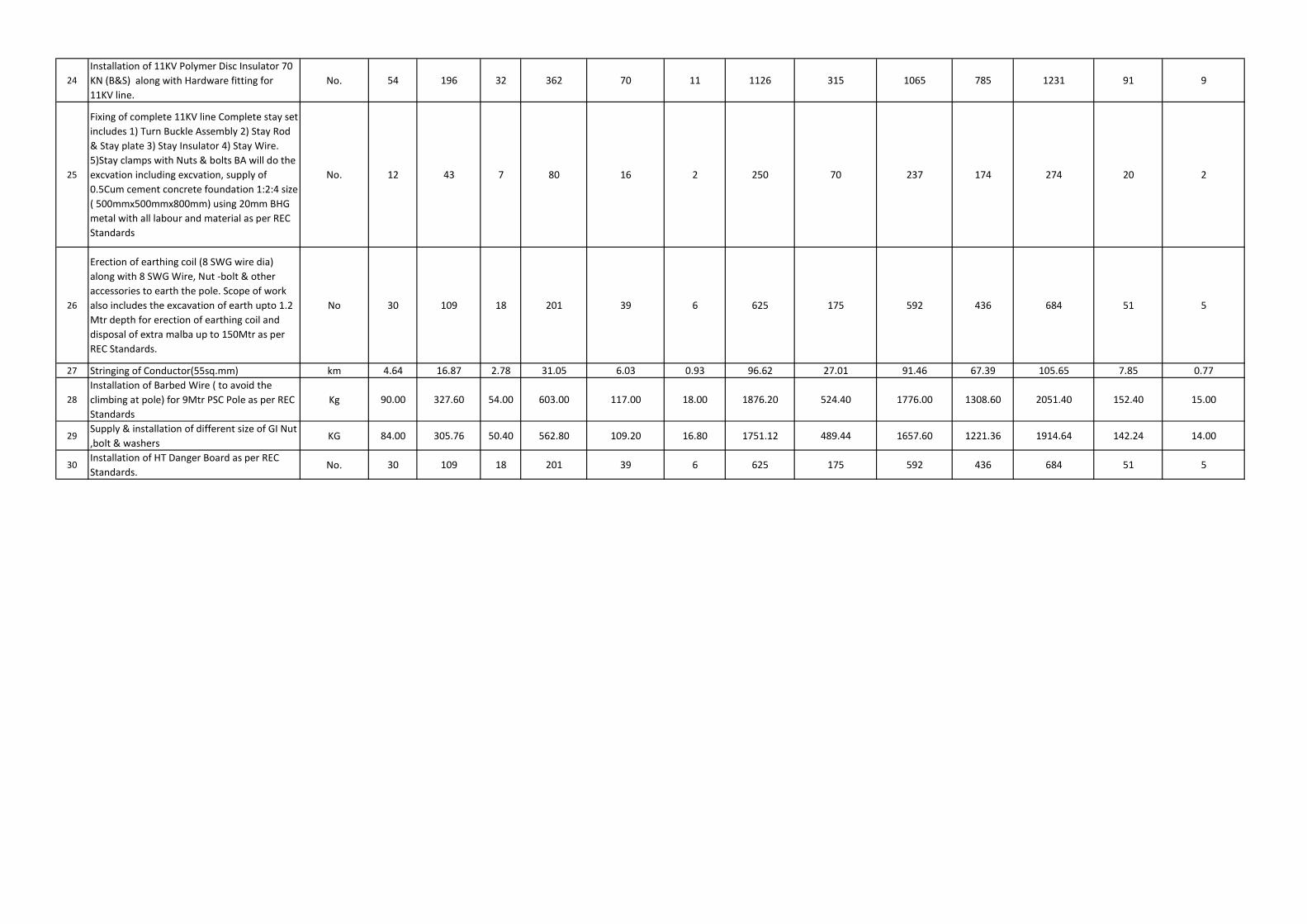
24Installation of 11KV Polymer Disc Insulator 70 KN (B&S) along with Hardware fitting for 11KV line.
No. 54 196 32 362 70 11 1126 315 1065 785 1231 91 9
25
Fixing of complete 11KV line Complete stay set includes 1) Turn Buckle Assembly 2) Stay Rod & Stay plate 3) Stay Insulator 4) Stay Wire. 5)Stay clamps with Nuts & bolts BA will do the excvation including excvation, supply of 0.5Cum cement concrete foundation 1:2:4 size ( 500mmx500mmx800mm) using 20mm BHG metal with all labour and material as per REC Standards
No. 12 43 7 80 16 2 250 70 237 174 274 20 2
26
Erection of earthing coil (8 SWG wire dia) along with 8 SWG Wire, Nut -bolt & other accessories to earth the pole. Scope of work also includes the excavation of earth upto 1.2 Mtr depth for erection of earthing coil and disposal of extra malba up to 150Mtr as per REC Standards.
No 30 109 18 201 39 6 625 175 592 436 684 51 5
27 Stringing of Conductor(55sq.mm) km 4.64 16.87 2.78 31.05 6.03 0.93 96.62 27.01 91.46 67.39 105.65 7.85 0.77
28Installation of Barbed Wire ( to avoid the climbing at pole) for 9Mtr PSC Pole as per REC Standards
Kg 90.00 327.60 54.00 603.00 117.00 18.00 1876.20 524.40 1776.00 1308.60 2051.40 152.40 15.00
29Supply & installation of different size of GI Nut ,bolt & washers
KG 84.00 305.76 50.40 562.80 109.20 16.80 1751.12 489.44 1657.60 1221.36 1914.64 142.24 14.00
30Installation of HT Danger Board as per REC Standards.
No. 30 109 18 201 39 6 625 175 592 436 684 51 5
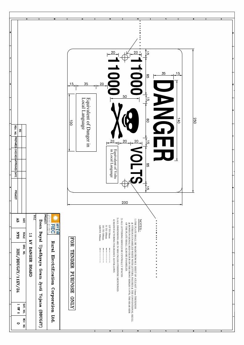
Equivalent of V
oltsin L
ocal Language
Equivalent of D
anger inL
ocal Language
4) MA
NU
FAC
TU
RIN
G T
OL
ER
AN
CE
AS
FO
LL
OW
S
NO
TE
S:-
1) TH
E P
LA
TE
SHA
LL
BE
MA
DE
FR
OM
M.S. S
HE
ET
OF
AT
LE
AS
T 1.6m
m T
HIC
KN
ES
S
& V
ITR
EO
US
EN
AM
EL
ED
WH
ITE
WIT
H L
ET
TE
RS
, FIGU
RE
S &
TH
E C
ON
VE
NT
ION
AL
SK
UL
L&
BO
NE
S IN
SIG
NA
L R
ED
CO
LO
UR
ON
TH
E F
RO
NT
SID
E(IS
5-1978). TH
E R
EA
R S
IDE
OF T
HE
PLA
TE
SH
AL
L A
LSO
BE
EN
AM
EL
ED
.
2) AL
L L
ET
TE
RIN
G S
HO
UL
D B
E C
EN
TR
AL
LY
SP
AC
ED
.
3) AL
L D
IME
NSIO
NS A
RE
IN M
M U
NL
ES
S O
TH
ER
WISE
ME
NT
ION
ED
.
UP T
O 50m
m51 T
O 100m
m101 T
O 300m
mA
BO
VE
300mm
•••••
••
••
••••
•••
••
••
•••••
••
••
••••
•••
••
••
••
•••••
••••
••
••
••
••
••
•
••
•••••
••••
••
••
••
••
••
•
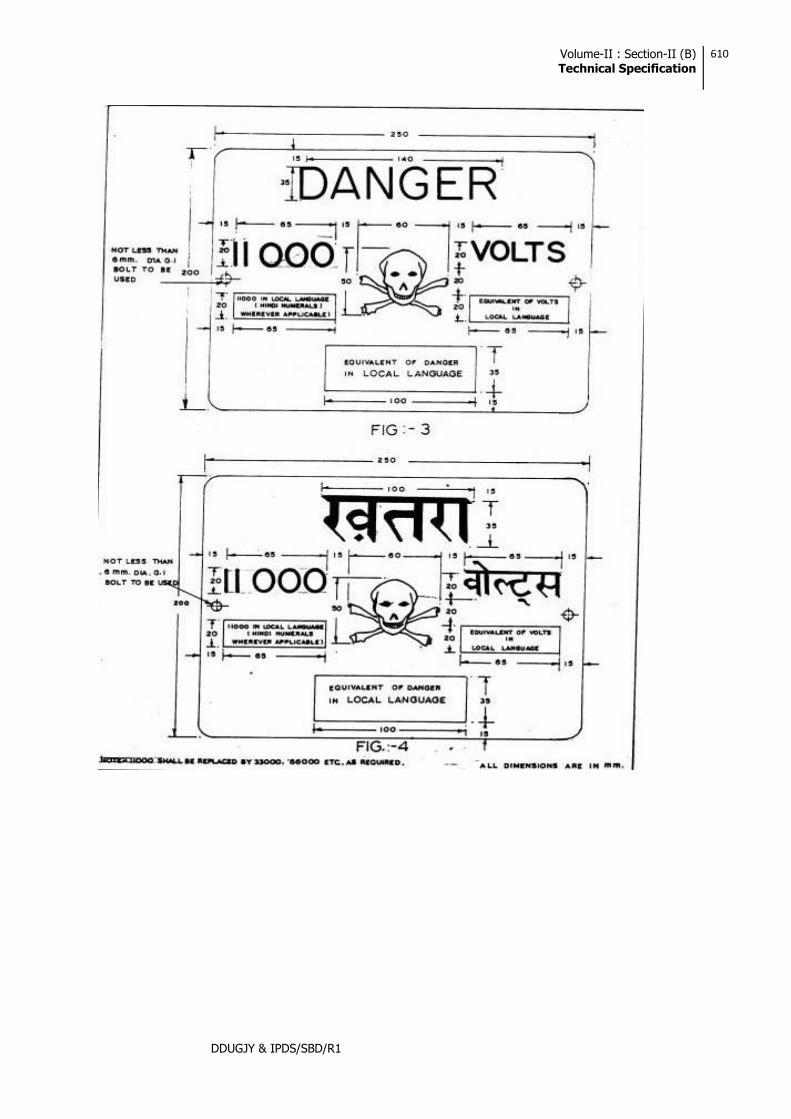
Volume-II : Section-II (B) Technical Specification
610
DDUGJY & IPDS/SBD/R1
Volume-III: Section-ITechnical Specifications
504
DDUGJY & IPDS/SBD/R1
2.1. INTRODUCTION This section covers the specification of 11kV voltage station Surge Arrestors for installation on outdoor type
11kV switchgear, transmission lines, transformers etc. 11kV side of which is not enclosed in a cable box. Station class surge arrestors shall be complete with fasteners for stacking units.
2.2. STANDARDS The design, manufacture and performance of Surge Arrestors shall comply with IS: 3070 Part-3 and
other specific requirements stipulated in the specification. Unless otherwise specified, the equipment, material & processes shall conform to the latest amendments of the following:
IS:2071-1993 (Part-1) Methods of High Voltage Testing General Definitions &
Test Requirements. IS:2071-1974 (Part-2) Test Procedures. IS: 2629-1985 Recommended Practice for hot dip galvanizing on Iron &
Steel. IS: 2633-1986 Method for Testing uniformity of coating of zinc coated
Articles. IS:3070-1993 (Part 3) Specification for surge arrestor for alternating current
systems. Metal-Oxide lightening Arrestors without gaps.
IS: 4759-1996 Specification for hot dip zinc coating on structural steel and other allied products.
IS: 5621-1980 Hollow Insulators for use in Electrical Equipment. IS: 6209-1982 Methods of Partial discharge measurement. IS: 6745 Method for determination of mass of zinc coating on zinc
coated iron and steel articles. ANSI/IEEE-C.62.11 Metal oxide, Surge Arrestor for AC Power Circuits. IEC 60099-4 Surge Arrestors.
The equipment complying with any other internationally accepted standards shall also be considered
if it ensures performance equivalent to or superior to the Indian Standards. 2.3. GENERAL REQUIREMENT 2.3.1. The metal oxide gap less Surge Arrestor without any series or shunt gap shall be suitable for protection of
11 kV side of power transformers, associated equipment and 11kV lines from voltage surges resulting from natural disturbance like lightning as well as system disturbances.
2.3.2. The surge arrestor shall draw negligible current at operating voltage and at the same time offer
least resistance during the flow of surge current. 2.3.3. The surge arrestor shall consist of non-linear resistor elements placed in series and housed in electrical
grade porcelain housing / silicon polymeric of specified Creepage distance. 2.3.4. The assembly shall be hermetically sealed with suitable rubber gaskets with effective sealing system
arrangement to prevent ingress of moisture.
Volume-III: Section-ITechnical Specifications
505
DDUGJY & IPDS/SBD/R1
2.3.5. The surge arrestor shall be provided with line and earth terminals of suitable size. The ground side terminal of surge arrestor shall be connected with 25x6 mm galvanized strip, one end connected to the surge arrestor and second end to a separate ground electrode. The bidder shall also recommend the procedure which shall be followed in providing the earthing system to the Surge Arrestor.
2.3.6. The surge arrestor shall not operate under power frequency and temporary over voltage conditions but
under surge conditions, the surge arrestor shall change over to the conducting mode. 2.3.7. The surge arrestor shall be suitable for circuit breaker performing 0-0.3 min-CO-3 min-CO- duty in the
system. 2.3.8. Surge arrestors shall have a suitable pressure relief system to avoid damage to the porcelain/ silicon
polymeric housing and providing path for flow of rated fault currents in the event of arrestor failure. 2.3.9. The reference current of the arrestor shall be high enough to eliminate the influence of grading and stray
capacitance on the measured reference voltage. 2.3.10. The Surge Arrestor shall be thermally stable and the bidder shall furnish a copy of thermal stability test
with the bid. 2.3.11. The arrestor shall be capable of handling terminal energy for high surges, external pollution and transient
over voltage and have low losses at operating voltages. 2.3.12. The surge arrestor shall be provided with line and earth terminals of suitable size. 2.4. ARRESTOR HOUSING 2.4.1. The arrestor housing shall be made up of porcelain/silicon polymeric housing and shall be homogenous,
free from laminations, cavities and other flaws of imperfections that might affect the mechanical and dielectric quality. The housing shall be of uniform brown (for porcelain)/Grey (for silicon polymeric) colour, free from blisters, burrs and other similar defects.
Arrestors shall be complete with fasteners for stacking units together and terminal connectors. 2.4.2. The housing shall be so coordinated that external flashover shall not occur due to application of any
impulse or switching surge voltage upto the maximum design value for arrestor. The arrestors shall not fail due to contamination. The 11kV arrestors housing shall be designed for pressure relief class as given in Technical Parameters of the specification.
2.4.3. Sealed housings shall exhibit no measurable leakage. 2.5. ARRESTOR MOUNTING The arrestors shall be suitable for mounting on 4 pole/2 pole structure used for pole/plinth mounted
transformer and for incoming and outgoing lines. Arrestor may also be required to be mounted on a bracket provided in the Transformers.
2.6. FITTINGS & ACCESSORIES 2.6.1. The surge arrestor shall be complete with fasteners and terminal connectors.
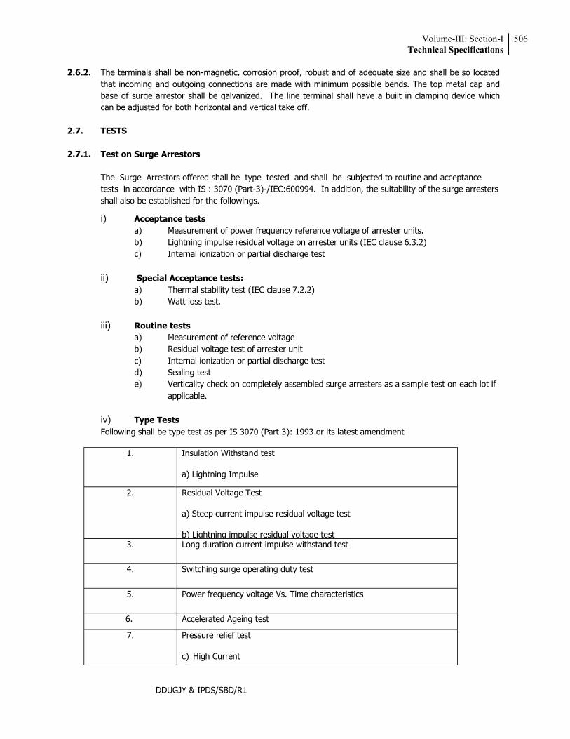
Volume-III: Section-ITechnical Specifications
506
DDUGJY & IPDS/SBD/R1
2.6.2. The terminals shall be non-magnetic, corrosion proof, robust and of adequate size and shall be so located that incoming and outgoing connections are made with minimum possible bends. The top metal cap and base of surge arrestor shall be galvanized. The line terminal shall have a built in clamping device which can be adjusted for both horizontal and vertical take off.
2.7. TESTS 2.7.1. Test on Surge Arrestors The Surge Arrestors offered shall be type tested and shall be subjected to routine and acceptance
tests in accordance with IS : 3070 (Part-3)-/IEC:600994. In addition, the suitability of the surge arresters shall also be established for the followings.
i) Acceptance tests a) Measurement of power frequency reference voltage of arrester units. b) Lightning impulse residual voltage on arrester units (IEC clause 6.3.2) c) Internal ionization or partial discharge test
ii) Special Acceptance tests:
a) Thermal stability test (IEC clause 7.2.2) b) Watt loss test.
iii) Routine tests
a) Measurement of reference voltage b) Residual voltage test of arrester unit c) Internal ionization or partial discharge test d) Sealing test e) Verticality check on completely assembled surge arresters as a sample test on each lot if
applicable.
iv) Type Tests Following shall be type test as per IS 3070 (Part 3): 1993 or its latest amendment
1. Insulation Withstand test
a) Lightning Impulse
2. Residual Voltage Test
a) Steep current impulse residual voltage test
b) Lightning impulse residual voltage test 3. Long duration current impulse withstand test
4. Switching surge operating duty test
5. Power frequency voltage Vs. Time characteristics
6. Accelerated Ageing test
7. Pressure relief test
c) High Current d) Low Current
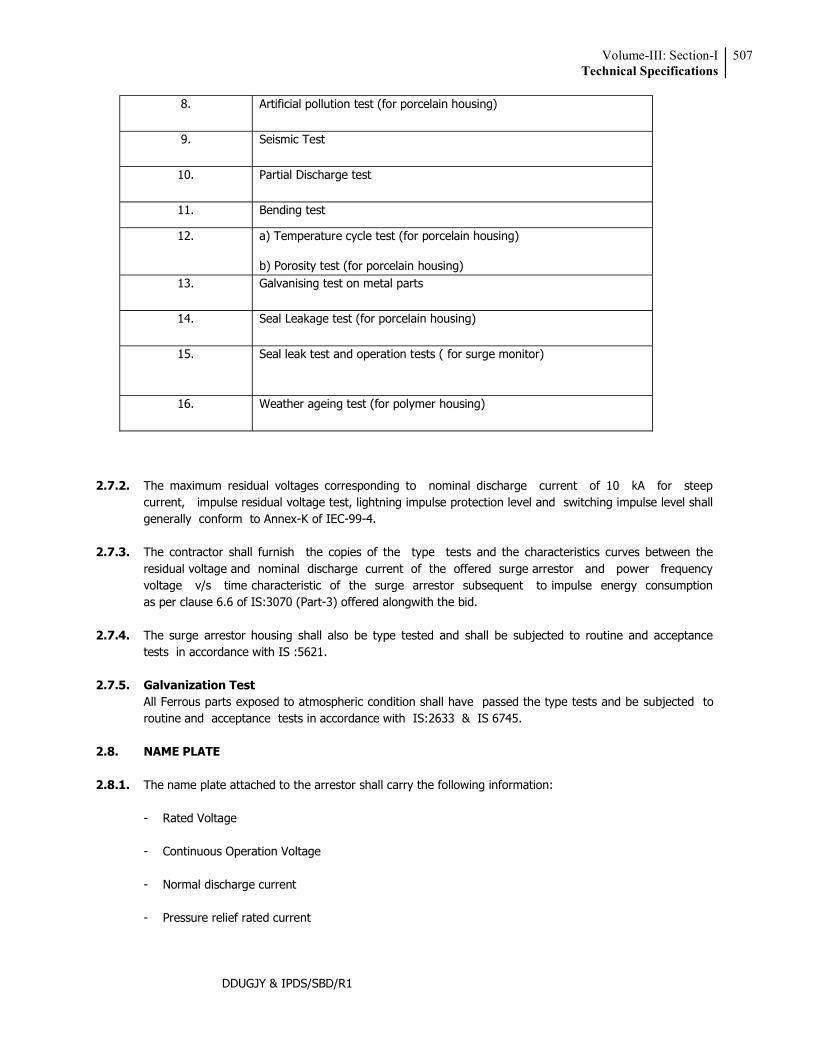
Volume-III: Section-ITechnical Specifications
507
DDUGJY & IPDS/SBD/R1
8. Artificial pollution test (for porcelain housing)
9. Seismic Test
10. Partial Discharge test
11. Bending test
12. a) Temperature cycle test (for porcelain housing)
b) Porosity test (for porcelain housing) 13. Galvanising test on metal parts
14. Seal Leakage test (for porcelain housing)
15. Seal leak test and operation tests ( for surge monitor)
16. Weather ageing test (for polymer housing)
2.7.2. The maximum residual voltages corresponding to nominal discharge current of 10 kA for steep
current, impulse residual voltage test, lightning impulse protection level and switching impulse level shall generally conform to Annex-K of IEC-99-4.
2.7.3. The contractor shall furnish the copies of the type tests and the characteristics curves between the
residual voltage and nominal discharge current of the offered surge arrestor and power frequency voltage v/s time characteristic of the surge arrestor subsequent to impulse energy consumption as per clause 6.6 of IS:3070 (Part-3) offered alongwith the bid.
2.7.4. The surge arrestor housing shall also be type tested and shall be subjected to routine and acceptance
tests in accordance with IS :5621. 2.7.5. Galvanization Test All Ferrous parts exposed to atmospheric condition shall have passed the type tests and be subjected to
routine and acceptance tests in accordance with IS:2633 & IS 6745. 2.8. NAME PLATE 2.8.1. The name plate attached to the arrestor shall carry the following information: - Rated Voltage - Continuous Operation Voltage - Normal discharge current - Pressure relief rated current
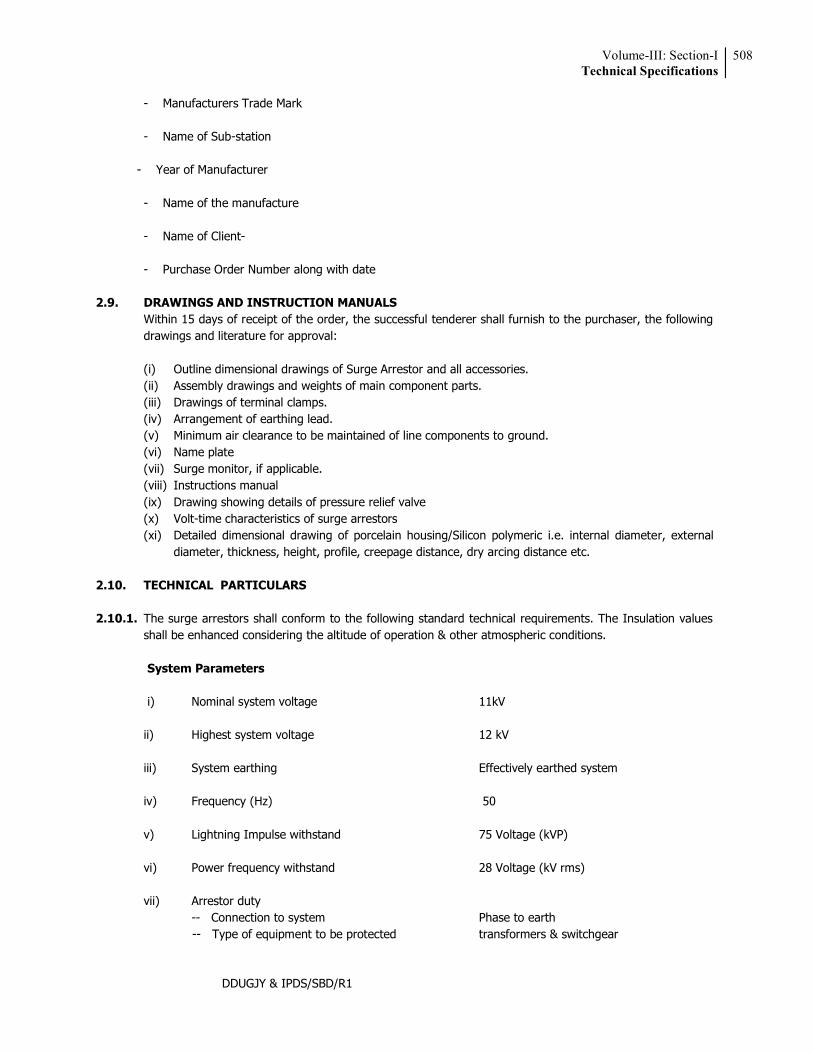
Volume-III: Section-ITechnical Specifications
508
DDUGJY & IPDS/SBD/R1
- Manufacturers Trade Mark - Name of Sub-station - Year of Manufacturer - Name of the manufacture - Name of Client- - Purchase Order Number along with date 2.9. DRAWINGS AND INSTRUCTION MANUALS Within 15 days of receipt of the order, the successful tenderer shall furnish to the purchaser, the following
drawings and literature for approval:
(i) Outline dimensional drawings of Surge Arrestor and all accessories. (ii) Assembly drawings and weights of main component parts. (iii) Drawings of terminal clamps. (iv) Arrangement of earthing lead. (v) Minimum air clearance to be maintained of line components to ground. (vi) Name plate (vii) Surge monitor, if applicable. (viii) Instructions manual (ix) Drawing showing details of pressure relief valve (x) Volt-time characteristics of surge arrestors (xi) Detailed dimensional drawing of porcelain housing/Silicon polymeric i.e. internal diameter, external
diameter, thickness, height, profile, creepage distance, dry arcing distance etc. 2.10. TECHNICAL PARTICULARS 2.10.1. The surge arrestors shall conform to the following standard technical requirements. The Insulation values
shall be enhanced considering the altitude of operation & other atmospheric conditions. System Parameters
i) Nominal system voltage 11kV ii) Highest system voltage 12 kV iii) System earthing Effectively earthed system iv) Frequency (Hz) 50 v) Lightning Impulse withstand 75 Voltage (kVP) vi) Power frequency withstand 28 Voltage (kV rms) vii) Arrestor duty -- Connection to system Phase to earth -- Type of equipment to be protected transformers & switchgear
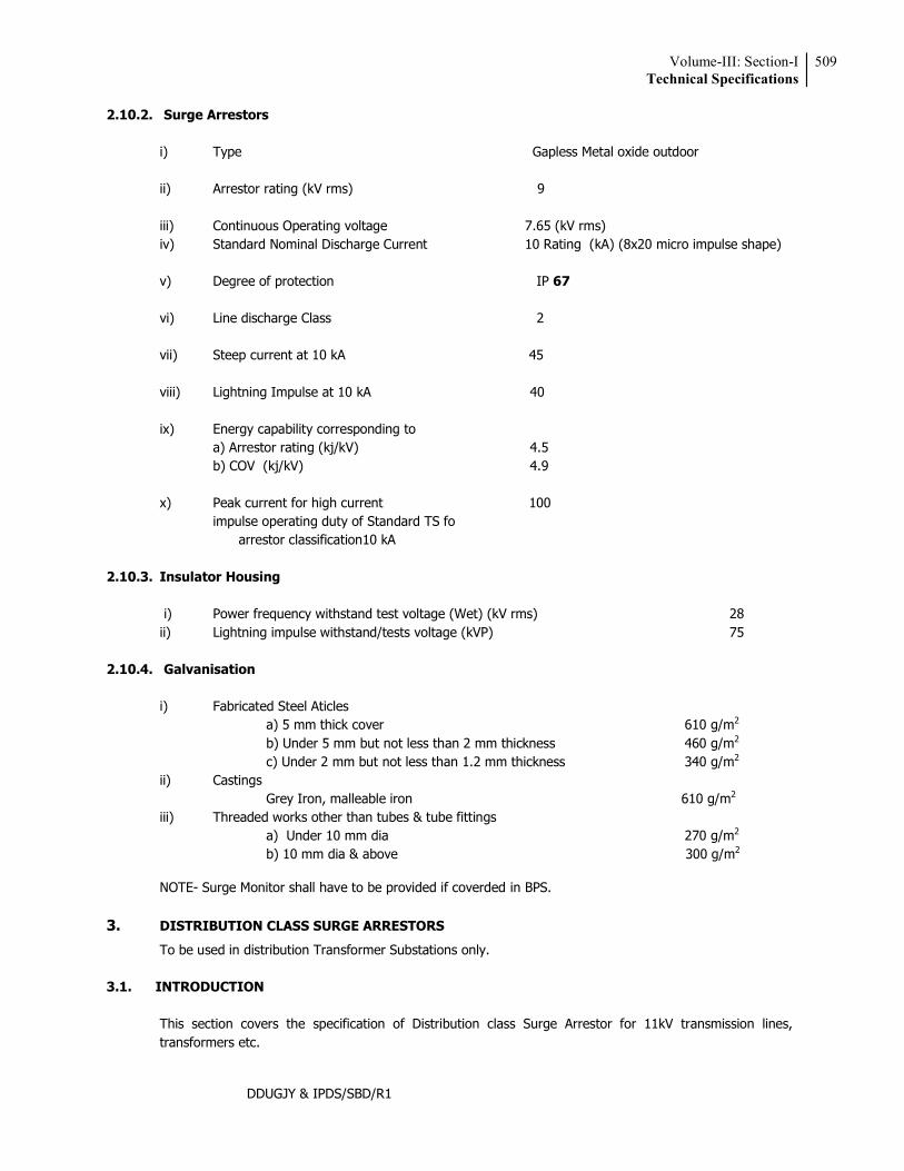
Volume-III: Section-ITechnical Specifications
509
DDUGJY & IPDS/SBD/R1
2.10.2. Surge Arrestors
i) Type Gapless Metal oxide outdoor ii) Arrestor rating (kV rms) 9 iii) Continuous Operating voltage 7.65 (kV rms) iv) Standard Nominal Discharge Current 10 Rating (kA) (8x20 micro impulse shape) v) Degree of protection IP 67 vi) Line discharge Class 2 vii) Steep current at 10 kA 45 viii) Lightning Impulse at 10 kA 40 ix) Energy capability corresponding to a) Arrestor rating (kj/kV) 4.5 b) COV (kj/kV) 4.9 x) Peak current for high current 100 impulse operating duty of Standard TS fo arrestor classification10 kA
2.10.3. Insulator Housing
i) Power frequency withstand test voltage (Wet) (kV rms) 28 ii) Lightning impulse withstand/tests voltage (kVP) 75
2.10.4. Galvanisation
i) Fabricated Steel Aticles a) 5 mm thick cover 610 g/m2 b) Under 5 mm but not less than 2 mm thickness 460 g/m2
c) Under 2 mm but not less than 1.2 mm thickness 340 g/m2
ii) Castings Grey Iron, malleable iron 610 g/m2
iii) Threaded works other than tubes & tube fittings a) Under 10 mm dia 270 g/m2
b) 10 mm dia & above 300 g/m2
NOTE- Surge Monitor shall have to be provided if coverded in BPS. 3. DISTRIBUTION CLASS SURGE ARRESTORS
To be used in distribution Transformer Substations only.
3.1. INTRODUCTION This section covers the specification of Distribution class Surge Arrestor for 11kV transmission lines,
transformers etc.
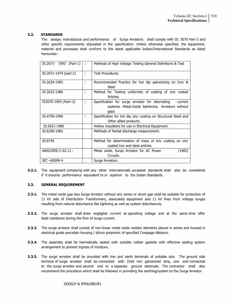
Volume-III: Section-ITechnical Specifications
510
DDUGJY & IPDS/SBD/R1
3.2. STANDARDS The design, manufacture and performance of Surge Arrestors shall comply with IS: 3070 Part-3 and
other specific requirements stipulated in the specification. Unless otherwise specified, the equipment, material and processes shall conform to the latest applicable Indian/International Standards as listed hereunder:
IS:2071- 1993 (Part-1)
: Methods of High Voltage Testing General Definitions & Test
IS:2071-1974 (part-2) : Test Procedures
IS:2629-1985 : Recommended Practice for hot dip galvanizing on Iron & Steel
IS:2633-1986 : Method for Testing uniformity of coating of zinc coated Articles.
IS3070-1993 (Part 3) : Specification for surge arrestor for alternating current systems. Metal-Oxide lightening Arrestors without gaps
IS:4759-1996 : Specification for hot dip zinc coating on Structural Steel and Other allied products.
IS:5621-1980 Hollow Insulators for use in Electrical Equipment. IS:6209-1982
Methods of Partial discharge measurement.
IS:6745
Method for determination of mass of zinc coating on zinc coated iron and steel articles
ANSI/IEEE-C.62.11 : Metal oxide, Surge Arrestor for AC Power (1982) Circuits.
IEC 60099-4 Surge Arrestors 3.2.1. The equipment complying with any other internationally accepted standards shall also be considered
if it ensures performance equivalent to or superior to the Indian Standards. 3.3. GENERAL REQUIREMENT 3.3.1. The metal oxide gap less Surge Arrestor without any series or shunt gap shall be suitable for protection of
11 kV side of Distribution Transformers, associated equipment and 11 kV lines from voltage surges resulting from natural disturbance like lightning as well as system disturbances.
3.3.2. The surge arrestor shall draw negligible current at operating voltage and at the same time offer
least resistance during the flow of surge current. 3.3.3. The surge arrestor shall consist of non-linear metal oxide resistor elements placed in series and housed in
electrical grade porcelain housing / silicon polymeric of specified Creepage distance. 3.3.4. The assembly shall be hermetically sealed with suitable rubber gaskets with effective sealing system
arrangement to prevent ingress of moisture. 3.3.5. The surge arrestor shall be provided with line and earth terminals of suitable size. The ground side
terminal of surge arrestor shall be connected with 25x6 mm galvanized strip, one end connected to the surge arrestor and second end to a separate ground electrode. The contractor shall also recommend the procedure which shall be followed in providing the earthing/system to the Surge Arrestor.
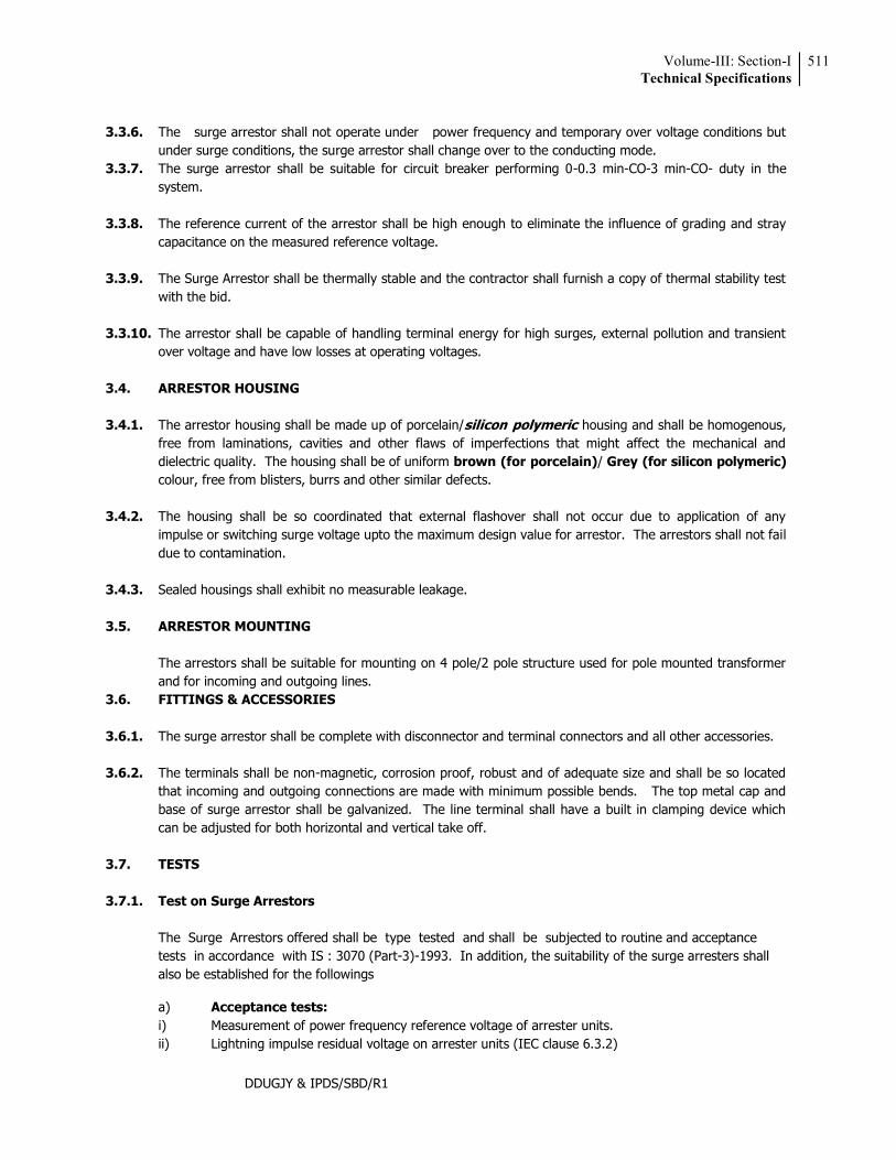
Volume-III: Section-ITechnical Specifications
511
DDUGJY & IPDS/SBD/R1
3.3.6. The surge arrestor shall not operate under power frequency and temporary over voltage conditions but
under surge conditions, the surge arrestor shall change over to the conducting mode. 3.3.7. The surge arrestor shall be suitable for circuit breaker performing 0-0.3 min-CO-3 min-CO- duty in the
system. 3.3.8. The reference current of the arrestor shall be high enough to eliminate the influence of grading and stray
capacitance on the measured reference voltage. 3.3.9. The Surge Arrestor shall be thermally stable and the contractor shall furnish a copy of thermal stability test
with the bid. 3.3.10. The arrestor shall be capable of handling terminal energy for high surges, external pollution and transient
over voltage and have low losses at operating voltages. 3.4. ARRESTOR HOUSING 3.4.1. The arrestor housing shall be made up of porcelain/ housing and shall be homogenous,
free from laminations, cavities and other flaws of imperfections that might affect the mechanical and dielectric quality. The housing shall be of uniform brown (for porcelain)/ Grey (for silicon polymeric) colour, free from blisters, burrs and other similar defects.
3.4.2. The housing shall be so coordinated that external flashover shall not occur due to application of any
impulse or switching surge voltage upto the maximum design value for arrestor. The arrestors shall not fail due to contamination.
3.4.3. Sealed housings shall exhibit no measurable leakage. 3.5. ARRESTOR MOUNTING The arrestors shall be suitable for mounting on 4 pole/2 pole structure used for pole mounted transformer
and for incoming and outgoing lines. 3.6. FITTINGS & ACCESSORIES 3.6.1. The surge arrestor shall be complete with disconnector and terminal connectors and all other accessories. 3.6.2. The terminals shall be non-magnetic, corrosion proof, robust and of adequate size and shall be so located
that incoming and outgoing connections are made with minimum possible bends. The top metal cap and base of surge arrestor shall be galvanized. The line terminal shall have a built in clamping device which can be adjusted for both horizontal and vertical take off.
3.7. TESTS 3.7.1. Test on Surge Arrestors The Surge Arrestors offered shall be type tested and shall be subjected to routine and acceptance
tests in accordance with IS : 3070 (Part-3)-1993. In addition, the suitability of the surge arresters shall also be established for the followings
a) Acceptance tests: i) Measurement of power frequency reference voltage of arrester units. ii) Lightning impulse residual voltage on arrester units (IEC clause 6.3.2)
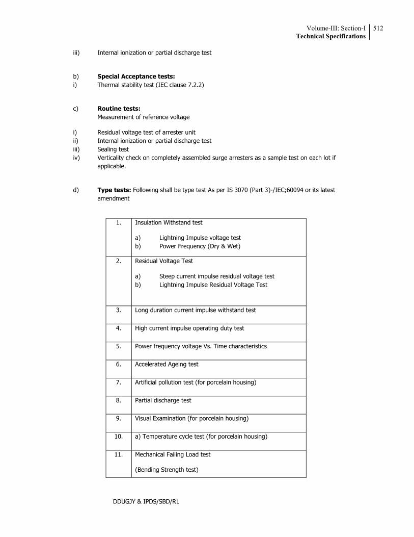
Volume-III: Section-ITechnical Specifications
512
DDUGJY & IPDS/SBD/R1
iii) Internal ionization or partial discharge test
b) Special Acceptance tests: i) Thermal stability test (IEC clause 7.2.2)
c) Routine tests: Measurement of reference voltage
i) Residual voltage test of arrester unit ii) Internal ionization or partial discharge test iii) Sealing test iv) Verticality check on completely assembled surge arresters as a sample test on each lot if applicable.
d) Type tests: Following shall be type test As per IS 3070 (Part 3)-/IEC;60094 or its latest amendment
1. Insulation Withstand test
a) Lightning Impulse voltage test b) Power Frequency (Dry & Wet)
2. Residual Voltage Test
a) Steep current impulse residual voltage test b) Lightning Impulse Residual Voltage Test
3. Long duration current impulse withstand test
4. High current impulse operating duty test
5. Power frequency voltage Vs. Time characteristics
6. Accelerated Ageing test
7. Artificial pollution test (for porcelain housing)
8. Partial discharge test
9. Visual Examination (for porcelain housing)
10. a) Temperature cycle test (for porcelain housing)
11. Mechanical Failing Load test
(Bending Strength test)

Volume-III: Section-ITechnical Specifications
513
DDUGJY & IPDS/SBD/R1
12. Uniformity of Zinc coating, Mass of zinc coating
13. Time versus current curve (for disconnector)
14. Weather ageing test (for polymer housing)
3.7.2. The maximum residual voltages corresponding to nominal discharge current of 5 kA for steep current,
impulse residual voltage test, lightning impulse protection level and switching impulse level shall generally conform to Annex-K of IEC-99-4.
3.7.3. The contractor shall furnish the copies of the type tests and the characteristics curves between the
residual voltage and nominal discharge current of the offered surge arrestor and power frequency voltage v/s time characteristic of the surge arrestor subsequent to impulse energy consumption as per clause 6.6.7 of IS:3070 (Part-3) offered alongwith the GTP.
3.7.4. The surge arrestor housing shall also be type tested and shall be subjected to routine and acceptance tests
in accordance with IS: 5621 3.7.5. GALVANIZATION TEST All Ferrous parts exposed to atmospheric condition shall have passed the type tests and be subjected to
routine and acceptance tests in accordance with IS:2633 & IS 6745. 3.7.6. TEST ON SURGE ARRESTOR DISCONNECTORS The test shall be performed on surge arrestors which are fitted with arrestor disconnector or on the
disconnector assembly alone if its design is such as to be un-affected by the heating of adjacent parts of the arrestor in its normally installed portion in accordance with IS:3070 (Part-3)
3.8. NAME PLATE
3.8.1. The name plate attached to the arrestor shall carry the following information: - Rated Voltage - Continuous Operation Voltage - Normal discharge current - Manufacturers Trade Mark - Year of Manufacturer - Name of the manufacture - Name of Client- - Purchase Order Number along with date 3.9. DRAWINGS AND INSTRUCTION MANUALS The successful bidder shall furnish to the purchaser the following drawings and literature for approval:
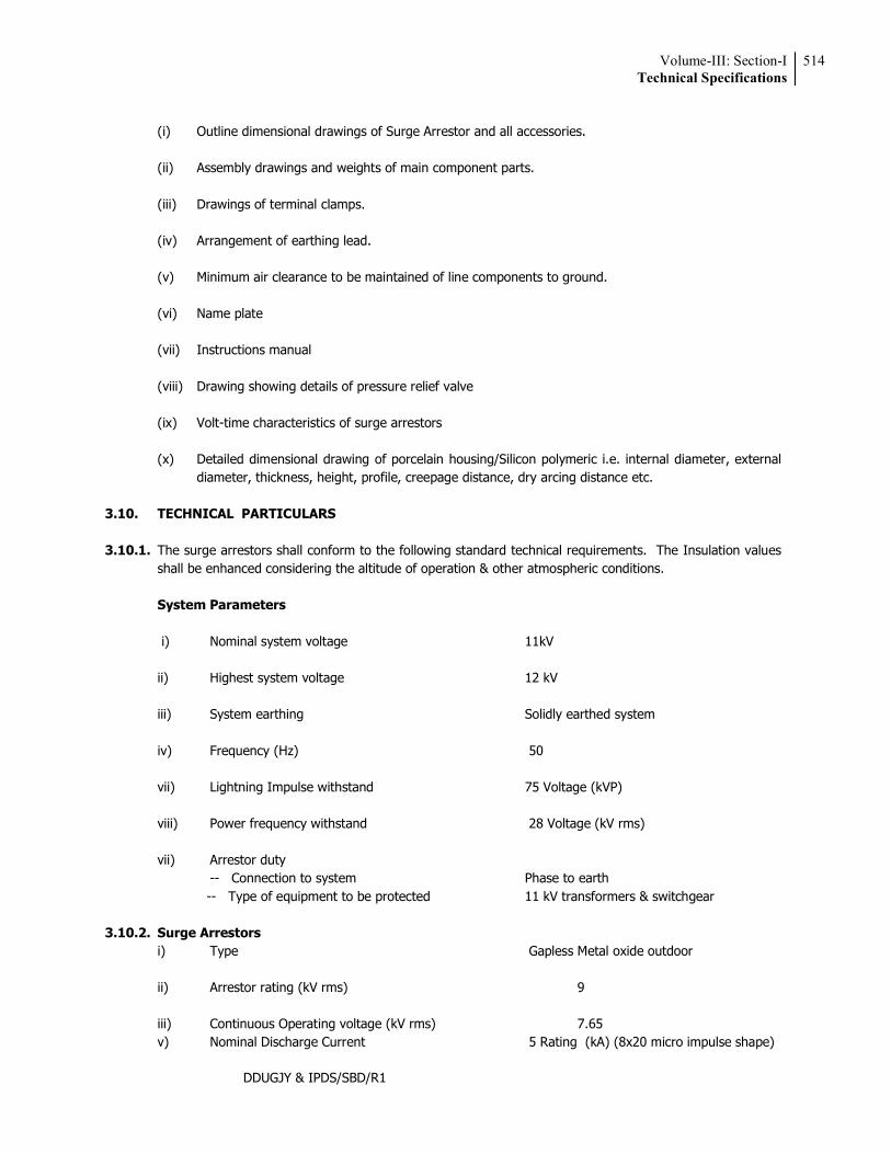
Volume-III: Section-ITechnical Specifications
514
DDUGJY & IPDS/SBD/R1
(i) Outline dimensional drawings of Surge Arrestor and all accessories. (ii) Assembly drawings and weights of main component parts. (iii) Drawings of terminal clamps. (iv) Arrangement of earthing lead. (v) Minimum air clearance to be maintained of line components to ground. (vi) Name plate (vii) Instructions manual (viii) Drawing showing details of pressure relief valve (ix) Volt-time characteristics of surge arrestors (x) Detailed dimensional drawing of porcelain housing/Silicon polymeric i.e. internal diameter, external
diameter, thickness, height, profile, creepage distance, dry arcing distance etc. 3.10. TECHNICAL PARTICULARS 3.10.1. The surge arrestors shall conform to the following standard technical requirements. The Insulation values
shall be enhanced considering the altitude of operation & other atmospheric conditions. System Parameters
i) Nominal system voltage 11kV ii) Highest system voltage 12 kV iii) System earthing Solidly earthed system iv) Frequency (Hz) 50 vii) Lightning Impulse withstand 75 Voltage (kVP) viii) Power frequency withstand 28 Voltage (kV rms) vii) Arrestor duty -- Connection to system Phase to earth -- Type of equipment to be protected 11 kV transformers & switchgear
3.10.2. Surge Arrestors
i) Type Gapless Metal oxide outdoor ii) Arrestor rating (kV rms) 9 iii) Continuous Operating voltage (kV rms) 7.65 v) Nominal Discharge Current 5 Rating (kA) (8x20 micro impulse shape)
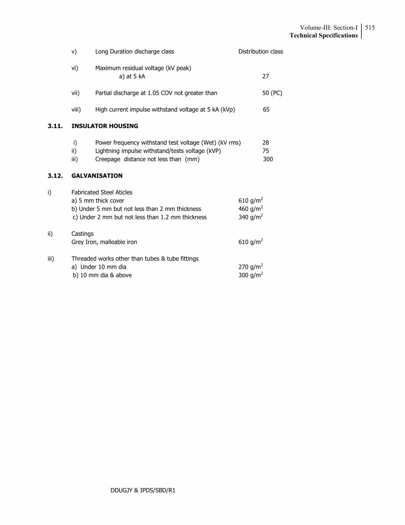
Volume-III: Section-ITechnical Specifications
515
DDUGJY & IPDS/SBD/R1
v) Long Duration discharge class Distribution class vi) Maximum residual voltage (kV peak) a) at 5 kA 27 vii) Partial discharge at 1.05 COV not greater than 50 (PC) viii) High current impulse withstand voltage at 5 kA (kVp) 65
3.11. INSULATOR HOUSING
i) Power frequency withstand test voltage (Wet) (kV rms) 28 ii) Lightning impulse withstand/tests voltage (kVP) 75 iii) Creepage distance not less than (mm) 300
3.12. GALVANISATION i) Fabricated Steel Aticles a) 5 mm thick cover 610 g/m2 b) Under 5 mm but not less than 2 mm thickness 460 g/m2
c) Under 2 mm but not less than 1.2 mm thickness 340 g/m2
ii) Castings Grey Iron, malleable iron 610 g/m2
iii) Threaded works other than tubes & tube fittings a) Under 10 mm dia 270 g/m2
b) 10 mm dia & above 300 g/m2
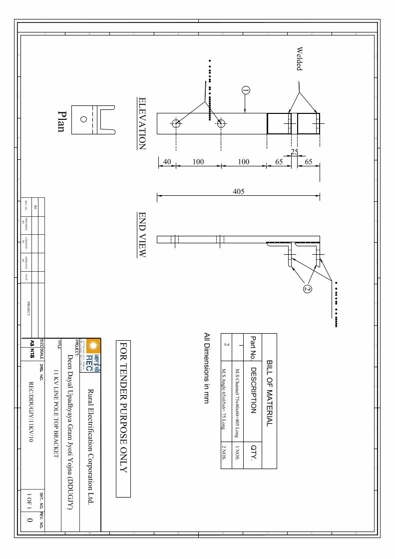
•••••••
•••••••••••••••
•••••••
•••••••••••••
EN
D V
IEW
EL
EV
AT
ION
405
40 100 100
Welded
2565
Plan
65
2
1
BIL
L OF
MA
TE
RIA
L
M.S C
hannel 75x40x60=405 L
ong
Part N
o.
DE
SC
RIP
TIO
N
1
QT
Y.
1 NO
S.
M.S A
ngle 65x65x6= 75 L
ong2
2 NO
S.
All D
ime
nsio
ns in m
m
12
HGFEDCB
12
A
46
57
3 34
65
78
910
11
89
1011
12
HGFEDCBA
12
RE
V. N
O.
R0
PR
EP
AR
ED
BY
CH
EC
KE
DB
YA
PPR
OV
ED
BY
DA
TE
PRO
JEC
T0
1 OF
1
FOR
TE
ND
ER
PUR
POS
E O
NL
Y
Rural E
lectrification Corporation L
td.
RE
C/D
DU
GJY
/11KV
/10
11 KV
LIN
E PO
LE
TO
P B
RA
CK
ET
Deen D
ayal Upadhyaya G
ram Jyoti Y
ojna (DD
UG
JY)
Volume-III: Section-ITechnical Specifications
450
DDUGJY & IPDS/SBD/R1
27 Insulation Piercing Connectors, Anchor (Dead End) & Suspension Accessories & Other Accessories for Aerial Bunched Cables for Working Voltage upto and including 1100 Volts
1.0 SCOPE This specification covers the design, manufacture, assembly, testing and supply of Accessories for
anchoring, suspending & making connections to Aerial Bunched Cables rated 1100 volts and insulated with cross-linked polyethylene.
2.0 STANDARD The design, performance and test requirements shall confirm to this specification and the following
standards. However in case of any conflict, the requirements of this specification shall prevail.
NFC 33-020 Insulation Piercing Connectors NFC 33-209 LV Aerial Bunched Cables NFC 20-540 Environment Testing for Outdoor NFC 33-004 Electrical Ageing Test NFC 33-040 Suspension Equipments NFC 33-041 Anchoring Devices IS 14255 LV Aerial Bunched Cables
The Devices shall also be compatible with the cables of sizes & dimensions as defined in the Cable
Specifications for the cables with which they are intended to be used. 3.0 CLIMATIC CONDITIONS For the purpose of designing the climatic conditions as specified in annexure-1 shall be considered. 4.0 CABLE DATA The standard sizes and characteristics of the phase and street lighting conductors, messenger wires shall
be as specified in IS: 14255-1995. The Accessories of LT XLPE Insulated Aerial Bunched Cables (ABC) with insulated bare messenger cum
neutral are specified below:
a) The ABC accessories should be of proven design with minimum 2 years record of satisfactory operation with a major utility. Order copies and Performance Certificates should be enclosed with the offer.
b) Since ABC accessories are to be used with insulated bare neutral-cum-messenger, their design should incorporate specific features to prevent damage to the insulation which meeting the required electrical, mechanical & thermal requirements.
c) All mechanical, electrical & thermal ratings should meet or exceed 90% of the corresponding ratings of the cable, or the values specified herein, whichever are more stringent.
d) result in the system tripping.
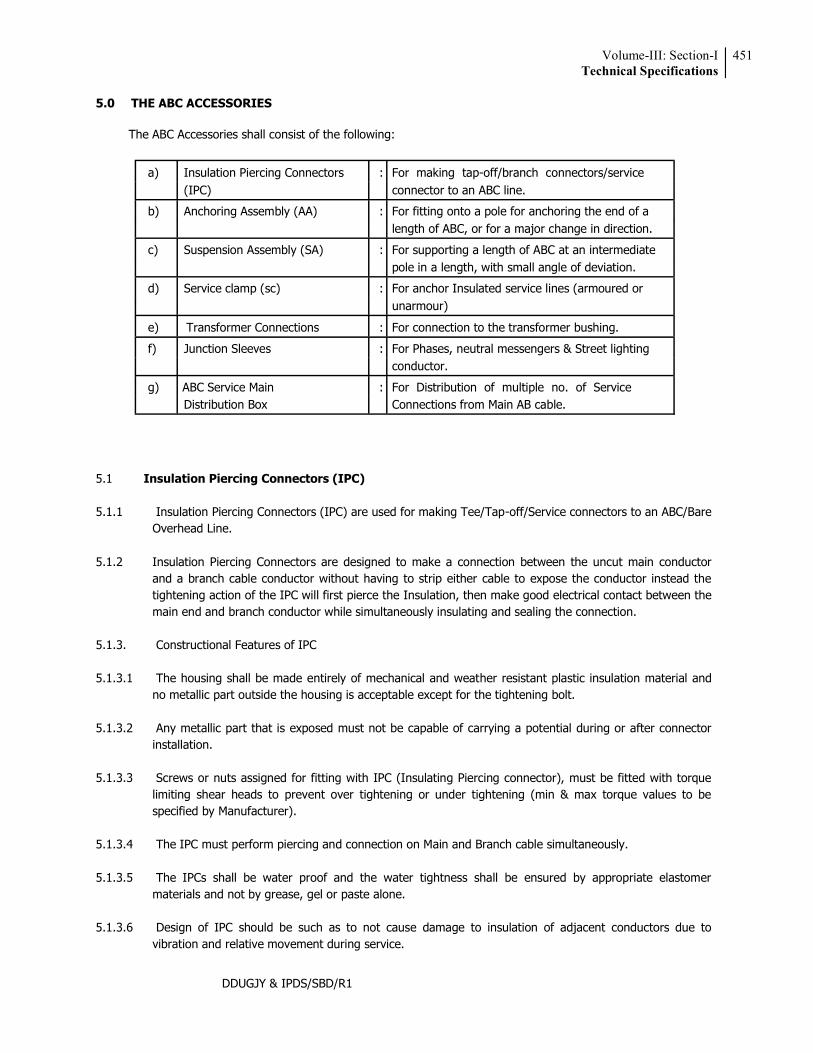
Volume-III: Section-ITechnical Specifications
451
DDUGJY & IPDS/SBD/R1
5.0 THE ABC ACCESSORIES
The ABC Accessories shall consist of the following:
a) Insulation Piercing Connectors : For making tap-off/branch connectors/service (IPC) connector to an ABC line.
b) Anchoring Assembly (AA) : For fitting onto a pole for anchoring the end of a length of ABC, or for a major change in direction.
c) Suspension Assembly (SA) : For supporting a length of ABC at an intermediate pole in a length, with small angle of deviation.
d) Service clamp (sc) : For anchor Insulated service lines (armoured or unarmour)
e) Transformer Connections : For connection to the transformer bushing.
f) Junction Sleeves : For Phases, neutral messengers & Street lighting conductor.
g) ABC Service Main : For Distribution of multiple no. of Service Distribution Box Connections from Main AB cable.
5.1 Insulation Piercing Connectors (IPC) 5.1.1 Insulation Piercing Connectors (IPC) are used for making Tee/Tap-off/Service connectors to an ABC/Bare
Overhead Line. 5.1.2 Insulation Piercing Connectors are designed to make a connection between the uncut main conductor
and a branch cable conductor without having to strip either cable to expose the conductor instead the tightening action of the IPC will first pierce the Insulation, then make good electrical contact between the main end and branch conductor while simultaneously insulating and sealing the connection.
5.1.3. Constructional Features of IPC 5.1.3.1 The housing shall be made entirely of mechanical and weather resistant plastic insulation material and
no metallic part outside the housing is acceptable except for the tightening bolt. 5.1.3.2 Any metallic part that is exposed must not be capable of carrying a potential during or after connector
installation. 5.1.3.3 Screws or nuts assigned for fitting with IPC (Insulating Piercing connector), must be fitted with torque
limiting shear heads to prevent over tightening or under tightening (min & max torque values to be specified by Manufacturer).
5.1.3.4 The IPC must perform piercing and connection on Main and Branch cable simultaneously. 5.1.3.5 The IPCs shall be water proof and the water tightness shall be ensured by appropriate elastomer
materials and not by grease, gel or paste alone. 5.1.3.6 Design of IPC should be such as to not cause damage to insulation of adjacent conductors due to
vibration and relative movement during service.
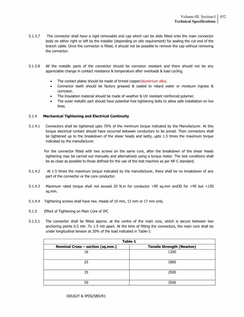
Volume-III: Section-ITechnical Specifications
452
DDUGJY & IPDS/SBD/R1
5.1.3.7 The connector shall have a rigid removable end cap which can be slide fitted onto the main connector
body on either right or left by the installer (depending on site requirement) for sealing the cut end of the branch cable. Once the connector is fitted, it should not be possible to remove the cap without removing the connector.
5.1.3.8 All the metallic parts of the connector should be corrosion resistant and there should not be any
appreciable change in contact resistance & temperature after overloads & load cycling.
The contact plates should be made of tinned copper/aluminium alloy. Connector teeth should be factory greased & sealed to retard water or moisture ingress &
corrosion. The Insulation material should be made of weather & UV resistant reinforced polymer. The outer metallic part should have potential free tightening bolts to allow safe installation on live
lines. 5.1.4 Mechanical Tightening and Electrical Continuity 5.1.4.1 Connectors shall be tightened upto 70% of the minimum torque indicated by the Manufacturer. At this
torque electrical contact should have occurred between conductors to be joined. Then connectors shall be tightened up to the breakdown of the shear heads and lastly, upto 1.5 times the maximum torque indicated by the manufacturer.
For the connector fitted with two screws on the same core, after the breakdown of the shear heads
tightening may be carried out manually and alternatively using a torque meter. The test conditions shall be as close as possible to those defined for the use of the test machine as per NF-C standard.
5.1.4.2 At 1.5 times the maximum torque indicated by the manufacturer, there shall be no breakdown of any
part of the connector or the core conductor. 5.1.4.3 Maximum rated torque shall not exceed 20 N.m for conductor <95 sq.mm and30 for >95 but <150
sq.mm. 5.1.4.4 Tightening screws shall have hex. Heads of 10 mm, 13 mm or 17 mm only. 5.1.5 Effect of Tightening on Main Core of IPC 5.1.5.1 The connector shall be fitted approx. at the centre of the main core, which is secure between two
anchoring points 0.5 mtr. To 1.5 mtr.apart. At the time of fitting the connectors, the main core shall be under longitudinal tension at 20% of the load indicated in Table-1:
Table-1
Nominal Cross section (sq.mm.) Tensile Strength (Newton) 16
1200
25
1800
35 2500
50 3500
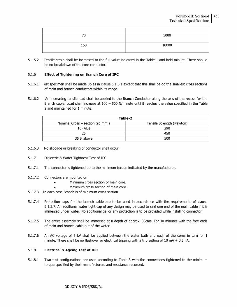
Volume-III: Section-ITechnical Specifications
453
DDUGJY & IPDS/SBD/R1
70 5000
150 10000
5.1.5.2 Tensile strain shall be increased to the full value indicated in the Table 1 and held minute. There should
be no breakdown of the core conductor. 5.1.6 Effect of Tightening on Branch Core of IPC 5.1.6.1 Test specimen shall be made up as in clause 5.1.5.1 except that this shall be do the smallest cross sections
of main and branch conductors within its range. 5.1.6.2 An increasing tensile load shall be applied to the Branch Conductor along the axis of the recess for the
Branch cable. Load shall increase at 100 500 N/minute until it reaches the value specified in the Table 2 and maintained for 1 minute.
Table-2
Nominal Cross section (sq.mm.) Tensile Strength (Newton) 16 (Alu) 290
25 450 35 & above 500
5.1.6.3 No slippage or breaking of conductor shall occur. 5.1.7 Dielectric & Water Tightness Test of IPC 5.1.7.1 The connector is tightened up to the minimum torque indicated by the manufacturer. 5.1.7.2 Connectors are mounted on
Minimum cross section of main core. Maximum cross section of main core.
5.1.7.3 In each case Branch is of minimum cross section. 5.1.7.4 Protection caps for the branch cable are to be used in accordance with the requirements of clause
5.1.3.7. An additional water tight cap of any design may be used to seal one end of the main cable if it is immersed under water. No additional gel or any protection is to be provided while installing connector.
5.1.7.5 The entire assembly shall be immersed at a depth of approx. 30cms. For 30 minutes with the free ends
of main and branch cable out of the water. 5.1.7.6 An AC voltage of 6 kV shall be applied between the water bath and each of the cores in turn for 1
minute. There shall be no flashover or electrical tripping with a trip setting of 10 mA + 0.5mA. 5.1.8 Electrical & Ageing Test of IPC 5.1.8.1 Two test configurations are used according to Table 3 with the connections tightened to the minimum
torque specified by their manufacturers and resistance recorded.
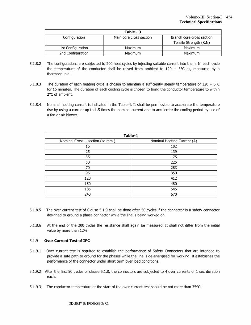
Volume-III: Section-ITechnical Specifications
454
DDUGJY & IPDS/SBD/R1
Table - 3 Configuration Main core cross section Branch core cross section
Tensile Strength (K.N) 1st Configuration Maximum Maximum 2nd Configuration Maximum Maximum
5.1.8.2 The configurations are subjected to 200 heat cycles by injecting suitable current into them. In each cycle
the temperature of the conductor shall be raised from ambient to 120 + 5°C as, measured by a thermocouple.
5.1.8.3 The duration of each heating cycle is chosen to maintain a sufficiently steady temperature of 120 + 5°C
for 15 minutes. The duration of each cooling cycle is chosen to bring the conductor temperature to within 2°C of ambient.
5.1.8.4 Nominal heating current is indicated in the Table-4. It shall be permissible to accelerate the temperature
rise by using a current up to 1.5 times the nominal current and to accelerate the cooling period by use of a fan or air blower.
Table-4 Nominal Cross section (sq.mm.) Nominal Heating Current (A)
16 102 25 139 35 175 50 225 70 283 95 350 120 412 150 480 185 545 240 670
5.1.8.5 The over current test of Clause 5.1.9 shall be done after 50 cycles if the connector is a safety connector
designed to ground a phase connector while the line is being worked on. 5.1.8.6 At the end of the 200 cycles the resistance shall again be measured. It shall not differ from the initial
value by more than 12%. 5.1.9 Over Current Test of IPC 5.1.9.1 Over current test is required to establish the performance of Safety Connectors that are intended to
provide a safe path to ground for the phases while the line is de-energised for working. It establishes the performance of the connector under short term over load conditions.
5.1.9.2 After the first 50 cycles of clause 5.1.8, the connectors are subjected to 4 over currents of 1 sec duration
each. 5.1.9.3 The conductor temperature at the start of the over current test should be not more than 35ºC.
Volume-III: Section-ITechnical Specifications
455
DDUGJY & IPDS/SBD/R1
5.1.9.4 Current density during over current shall be 100 A/sq.mm for Aluminium and 95 A/sq.mm for Aluminium Alloy Conductor.
5.1.9.5 Variation in time of over current is permissible between 0.85 sec & 1.15 sec., provided if maintains the
relationship I2 t = K where,
I = rms value of over current in Amps. t = time in seconds K = Constant
5.1.9.6 After the over current test the electrical ageing test of clause 5.1.8 shall be resumed. 5.1.10 Type Test of IPC 5.1.10.1 Type Test Reports should be submitted from an Independent Laboratory of Repute or the Works
Laboratory in case of a foreign manufacturer covering the following (on any convenient size of fitting of same design made from the same materials).
5.1.10.2 The installation of the connectors shall be done by the laboratory following instructions provided by the
manufacturer.
5.1.10.3 The Test report shall record the embossing and marking on the connector. 5.1.10.4 The following shall constitute Type Tests for IPC :
Electrical Ageing Test Dielectric and Water Tightness Test. Mechanical Tightening Test Effect of Tightening on main Core Effect of Tightening on Branch core Over-current Test (Applicable as per relevant clause of latest version of NFC 33020)*
The following shall be Type Test for Suspension Assembly (SA)
Mechanical Test Voltage Test Climatic Aging Test Corrosion Test Endurance Test under Thermal & Mechanical Stresses (optional till testing facilities are available in India)*
The following shall be Type Tests for Anchoring Assemblies (AA) Mechanical Test Voltage Test Dynamic Test (Applicable for areas having subzero minimum temperature) * Climatic Aging Test Corrosion Test Endurance Test under Thermal & Mechanical Stresses
5.2 Anchoring Clamp for Insulated Messenger:
The clamps should be designed to Anchor LT-AB cable with insulated messenger. The clamp should consists of an Aluminium alloy corrosion resistant castled body, bail of stainless steel and self adjusting plastic wedges which shall anchor/hold the neutral messenger without damaging the insulation. *Amendment issued vide letter No. REC/DDUGJY/SBD/2017-18/609 dated 05.10.2018
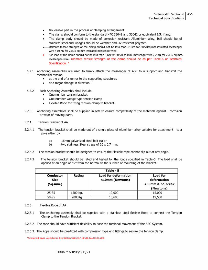
Volume-III: Section-ITechnical Specifications
456
DDUGJY & IPDS/SBD/R1
No losable part in the process of clamping arrangement The clamp should conform to the standard NFC 33041 and 33042 or equivalent I.S. if any. The clamp body should be made of corrosion resistant Alluminium alloy, bail should be of
stainless steel and wedges should be weather and UV resistant polymer. Ultimate tensile strength of the clamp should not be less than 15 km for 50/70sq.mm insulated messenger
wire / 10 KN for 25/35 sq.mm insulated messenger wire. Slip load of the clamp should not be less than 3 KN for 50/70 sq.mm. messenger wire / 2 KN for 25/35 sq.mm.
messenger wire. Ultimate tensile strength of the clamp should be as per Table-6 of Technical Specification. *
5.2.1 Anchoring assemblies are used to firmly attach the messenger of ABC to a support and transmit the
mechanical tension. at the end of a run or to the supporting structures at a major change in direction.
5.2.2 Each Anchoring Assembly shall include.
One number tension bracket. One number wedge type tension clamp Flexible Rope for fixing tension clamp to bracket.
5.2.3 Anchoring assemblies shall be supplied in sets to ensure compatibility of the materials against corrosion
or wear of moving parts.
5.2.1 Tension Bracket of AA
5.2.4.1 The tension bracket shall be made out of a single piece of Aluminium alloy suitable for attachment to a pole either by
a) 16mm galvanized steel bolt (s) or
b) two stainless Steel straps of 20 x 0.7 mm.
5.2.4.2 The tension bracket should be designed to ensure the Flexible rope cannot slip out at any angle.
5.2.4.3 The tension bracket should be rated and tested for the loads specified in Table-5. The load shall be applied at an angle of 45º from the normal to the surface of mounting of the bracket.
Table - 5
Conductor Size
(Sq.mm.)
Rating Load for deformation <10mm (Newtons)
Load for deformation
<30mm & no-break (Newtons)
25-35 1500 Kg. 12,000 15,000 50-95 2000Kg 15,600 19,500
5.2.5 Flexible Rope of AA
5.2.5.1 The Anchoring assembly shall be supplied with a stainless steel flexible Rope to connect the Tension
Clamp to the Tension Bracket.
5.2.5.2 The rope should have sufficient flexibility to ease the torsional movement of the ABC System.
5.2.5.3 The Rope should be pre-fitted with compression type end fittings to secure the tension clamp.
*Amendment issued vide letter No. REC/DDUGJY/SBD/2017-18/609 dated 05.10.2018
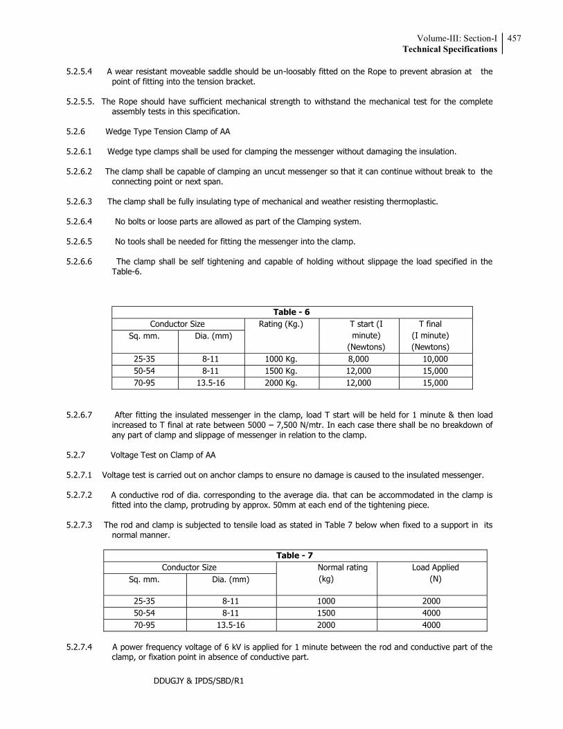
Volume-III: Section-ITechnical Specifications
457
DDUGJY & IPDS/SBD/R1
5.2.5.4 A wear resistant moveable saddle should be un-loosably fitted on the Rope to prevent abrasion at the point of fitting into the tension bracket.
5.2.5.5. The Rope should have sufficient mechanical strength to withstand the mechanical test for the complete
assembly tests in this specification.
5.2.6 Wedge Type Tension Clamp of AA
5.2.6.1 Wedge type clamps shall be used for clamping the messenger without damaging the insulation.
5.2.6.2 The clamp shall be capable of clamping an uncut messenger so that it can continue without break to the connecting point or next span.
5.2.6.3 The clamp shall be fully insulating type of mechanical and weather resisting thermoplastic.
5.2.6.4 No bolts or loose parts are allowed as part of the Clamping system.
5.2.6.5 No tools shall be needed for fitting the messenger into the clamp.
5.2.6.6 The clamp shall be self tightening and capable of holding without slippage the load specified in the
Table-6.
Table - 6 Conductor Size Rating (Kg.) T start (I
minute) (Newtons)
T final (I minute) (Newtons)
Sq. mm. Dia. (mm)
25-35 8-11 1000 Kg. 8,000 10,000 50-54 8-11 1500 Kg. 12,000 15,000 70-95 13.5-16 2000 Kg. 12,000 15,000
5.2.6.7 After fitting the insulated messenger in the clamp, load T start will be held for 1 minute & then load increased to T final at rate between 5000 7,500 N/mtr. In each case there shall be no breakdown of any part of clamp and slippage of messenger in relation to the clamp.
5.2.7 Voltage Test on Clamp of AA
5.2.7.1 Voltage test is carried out on anchor clamps to ensure no damage is caused to the insulated messenger.
5.2.7.2 A conductive rod of dia. corresponding to the average dia. that can be accommodated in the clamp is
fitted into the clamp, protruding by approx. 50mm at each end of the tightening piece.
5.2.7.3 The rod and clamp is subjected to tensile load as stated in Table 7 below when fixed to a support in its normal manner.
Table - 7
Conductor Size Normal rating (kg)
Load Applied (N) Sq. mm. Dia. (mm)
25-35 8-11 1000 2000 50-54 8-11 1500 4000 70-95 13.5-16 2000 4000
5.2.7.4 A power frequency voltage of 6 kV is applied for 1 minute between the rod and conductive part of the
clamp, or fixation point in absence of conductive part.
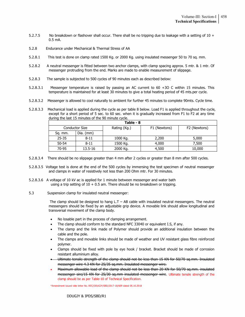
Volume-III: Section-ITechnical Specifications
458
DDUGJY & IPDS/SBD/R1
5.2.7.5 No breakdown or flashover shall occur. There shall be no tripping due to leakage with a setting of 10 +
0.5 mA.
5.2.8 Endurance under Mechanical & Thermal Stress of AA
5.2.8.1 This test is done on clamp rated 1500 Kg. or 2000 Kg. using insulated messenger 50 to 70 sq. mm.
5.2.8.2 A neutral messenger is fitted between two anchor clamps, with clamp spacing approx. 5 mtr. & 1 mtr. Of messenger protruding from the end. Marks are made to enable measurement of slippage.
5.2.8.3 The sample is subjected to 500 cycles of 90 minutes each as described below:
5.2.8.3.1 Messenger temperature is raised by passing an AC current to 60 +3O C within 15 minutes. This
temperature is maintained for at least 30 minutes to give a total heating period of 45 mts.per cycle.
5.2.8.3.2 Messenger is allowed to cool naturally to ambient for further 45 minutes to complete 90mts. Cycle time.
5.2.8.3.3 Mechanical load is applied during the cycle as per table 8 below. Load F1 is applied throughout the cycle, except for a short period of 5 sec. to 60 sec. when it is gradually increased from F1 to F2 at any time during the last 15 minutes of the 90 minute cycle.
Table - 8 Conductor Size Rating (Kg.) F1 (Newtons) F2 (Newtons)
Sq. mm. Dia. (mm) 25-35 8-11 1000 Kg. 2,200 5,000 50-54 8-11 1500 Kg. 4,000 7,500 70-95 13.5-16 2000 Kg. 4,500 10,000
5.2.8.3.4 There should be no slippage greater than 4 mm after 2 cycles or greater than 8 mm after 500 cycles.
5.2.8.3.5 Voltage test is done at the end of the 500 cycles by immersing the test specimen of neutral messenger
and clamps in water of resistively not less than 200 Ohm mtr. For 30 minutes.
5.2.8.3.6 A voltage of 10 kV ac is applied for 1 minute between messenger and water bath using a trip setting of 10 + 0.5 am. There should be no breakdown or tripping.
5.3 Suspension clamp for insulated neutral messenger:
The clamp should be designed to hang L.T AB cable with insulated neutral messengers. The neutral messengers should be fixed by an adjustable grip device. A movable link should allow longitudinal and transversal movement of the clamp body.
No losable part in the process of clamping arrangement. The clamp should conform to the standard NFC 33040 or equivalent I.S, if any. The clamp and the link made of Polymer should provide an additional insulation between the
cable and the pole. The clamps and movable links should be made of weather and UV resistant glass fibre reinforced
polymer. Clamps should be fixed with pole by eye hook / bracket. Bracket should be made of corrosion
resistant alluminium alloy. Ultimate tensile strength of the clamp should not be less than 15 KN for 50/70 sq.mm. Insulated
messenger wire 4.3 KN for 25/35 sq.mm. Insulated messenger wire. Maximum allowable load of the clamp should not be less than 20 KN for 50/70 sq.mm. insulated
messenger sire/15 KN for 25/30 sq.mm insulated messenger wire. Ultimate tensile strength of the clamp should be as per Table-10 of Technical Specification.
*Amendment issued vide letter No. REC/DDUGJY/SBD/2017-18/609 dated 05.10.2018
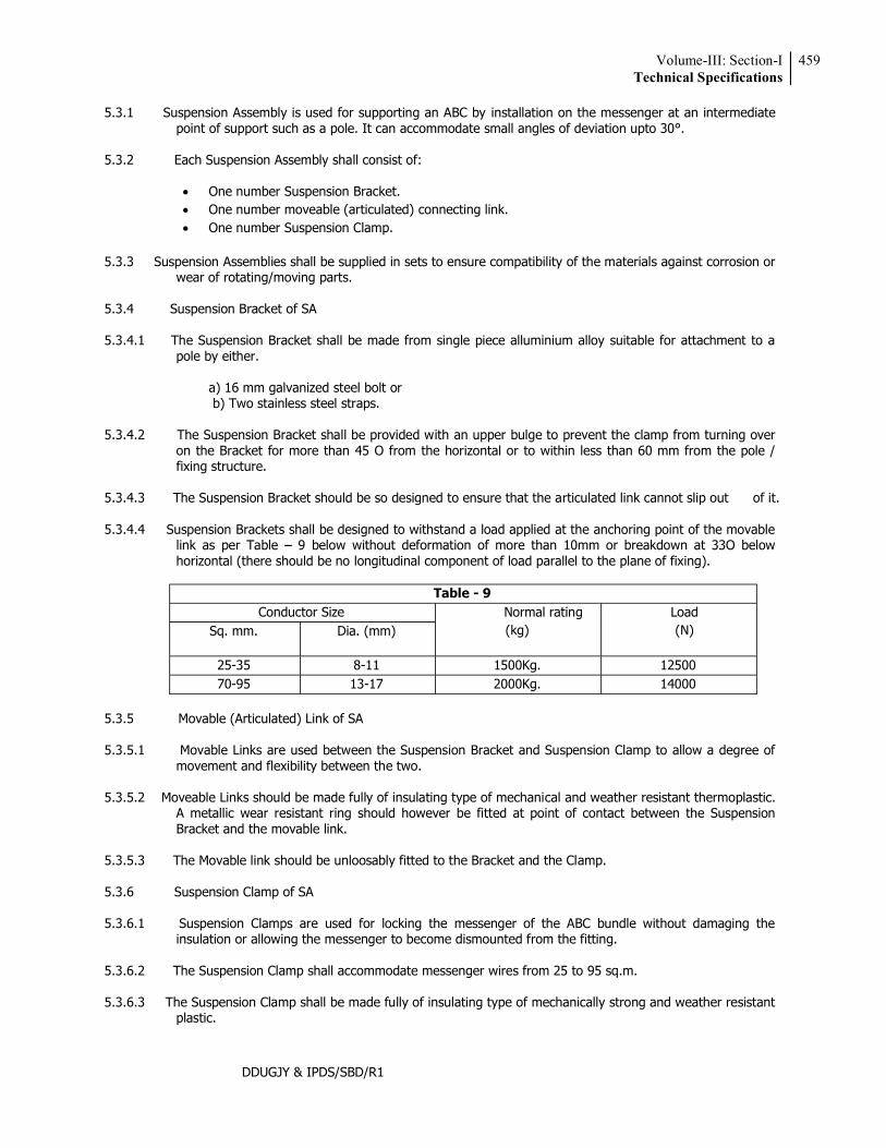
Volume-III: Section-ITechnical Specifications
459
DDUGJY & IPDS/SBD/R1
5.3.1 Suspension Assembly is used for supporting an ABC by installation on the messenger at an intermediate point of support such as a pole. It can accommodate small angles of deviation upto 30°.
5.3.2 Each Suspension Assembly shall consist of:
One number Suspension Bracket. One number moveable (articulated) connecting link. One number Suspension Clamp.
5.3.3 Suspension Assemblies shall be supplied in sets to ensure compatibility of the materials against corrosion or
wear of rotating/moving parts.
5.3.4 Suspension Bracket of SA
5.3.4.1 The Suspension Bracket shall be made from single piece alluminium alloy suitable for attachment to a pole by either.
a) 16 mm galvanized steel bolt or b) Two stainless steel straps.
5.3.4.2 The Suspension Bracket shall be provided with an upper bulge to prevent the clamp from turning over
on the Bracket for more than 45 O from the horizontal or to within less than 60 mm from the pole / fixing structure.
5.3.4.3 The Suspension Bracket should be so designed to ensure that the articulated link cannot slip out of it.
5.3.4.4 Suspension Brackets shall be designed to withstand a load applied at the anchoring point of the movable
link as per Table 9 below without deformation of more than 10mm or breakdown at 33O below horizontal (there should be no longitudinal component of load parallel to the plane of fixing).
Table - 9
Conductor Size Normal rating (kg)
Load (N) Sq. mm. Dia. (mm)
25-35 8-11 1500Kg. 12500 70-95 13-17 2000Kg. 14000
5.3.5 Movable (Articulated) Link of SA
5.3.5.1 Movable Links are used between the Suspension Bracket and Suspension Clamp to allow a degree of
movement and flexibility between the two.
5.3.5.2 Moveable Links should be made fully of insulating type of mechanical and weather resistant thermoplastic. A metallic wear resistant ring should however be fitted at point of contact between the Suspension Bracket and the movable link.
5.3.5.3 The Movable link should be unloosably fitted to the Bracket and the Clamp.
5.3.6 Suspension Clamp of SA
5.3.6.1 Suspension Clamps are used for locking the messenger of the ABC bundle without damaging the
insulation or allowing the messenger to become dismounted from the fitting.
5.3.6.2 The Suspension Clamp shall accommodate messenger wires from 25 to 95 sq.m.
5.3.6.3 The Suspension Clamp shall be made fully of insulating type of mechanically strong and weather resistant plastic.
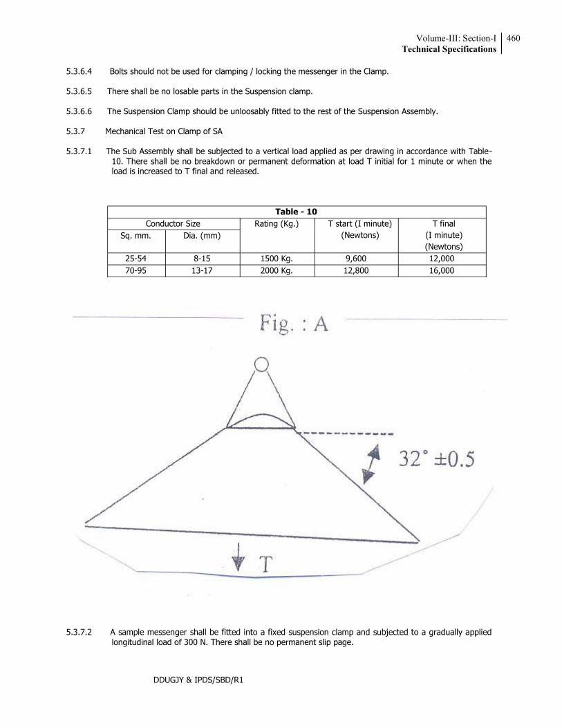
Volume-III: Section-ITechnical Specifications
460
DDUGJY & IPDS/SBD/R1
5.3.6.4 Bolts should not be used for clamping / locking the messenger in the Clamp.
5.3.6.5 There shall be no losable parts in the Suspension clamp.
5.3.6.6 The Suspension Clamp should be unloosably fitted to the rest of the Suspension Assembly.
5.3.7 Mechanical Test on Clamp of SA
5.3.7.1 The Sub Assembly shall be subjected to a vertical load applied as per drawing in accordance with Table-10. There shall be no breakdown or permanent deformation at load T initial for 1 minute or when the load is increased to T final and released.
Table - 10 Conductor Size Rating (Kg.) T start (I minute)
(Newtons) T final
(I minute) (Newtons)
Sq. mm. Dia. (mm)
25-54 8-15 1500 Kg. 9,600 12,000 70-95 13-17 2000 Kg. 12,800 16,000
5.3.7.2 A sample messenger shall be fitted into a fixed suspension clamp and subjected to a gradually applied longitudinal load of 300 N. There shall be no permanent slip page.
Volume-III: Section-ITechnical Specifications
461
DDUGJY & IPDS/SBD/R1
5.3.8 Voltage Test of SA A copper foil is wrapped at the clamping point around the maximum size of messenger allowed in that
clamp. An ac voltage of 6 KV is applied between the copper foil and nearest conductive point of the clamp or into its absence to the point of fixation. The voltage should be withstood for 1 minute without breakdown or flashover.
5.3.9 Test Under Mechanical & Thermal Stress 5.3.9.1 The test specimen is made up of approx. 10mts. Of messenger wire strung between two anchor clamps
with a Suspension Clamp fixed in the middle. Masses of 40 Kg. are suspended at a distance of 1-2mtr. On either side of the Suspension Clamp with a fixing mechanism of mass 2 + 1 Kg.
5.3.9.2 The specimen is subjected to 500 cycles of 90 minutes each. Each cycle consists of the following:
a) For first 75 minutes a constant longitudinal tension of 4000 N is applied to the messenger for rating
of 1500 Kg. and of 4500 N rating of 2000 Kg. while 64cycles right and left oscillation are produced on the clamp 32ºon either side of the vertical.
b) During the first 45 minutes an intermittent current of 4-5 A/sq.mm is applied to maintain the
conductor temp at 60 + 3º C. c) During the next 45 minutes of the cycle the conductor is allowed to cool down naturally to the
ambient. d) At the 75th minute, after having completed 64 oscillations, the oscillations are stopped and the
longitudinal tension is increased to 7500 N for 1500 kg. Rating and 10000 N for 2000 Kg. Rating. 3.9.3 No messenger slippage should occur within the Suspension Clamp during the 500cycles. 5.3.9.4 At the end of the 500 cycles, the messenger is immersed in water for 30 minutes. It is then tested to
withstand 10 kV ac for 1 minute with a trip setting of 10 + 0.5 mA. There should be no breakdown or flashover.
5.4 Acceptance Tests 5.4.1 The following shall constitute Acceptance Tests for Insulation Piercing Connectors(IPC) :
Visual * Dimensional (as per SCD and overall dimensions submitted with Tender Offer)* Electrical Ageing Test *** Dielectric and Water Tightness Test. ** Mechanical Tightening Test ** Effect of Tightening on Main Core ** Effect of Tightening on Branch Core **
The above tests are to be carried out as per sampling plan below. However electrical geing test on IPC
(market***) is to be done on only one connector of each type and size. In case of random failure/defect, double the sample lot is to be drawn and there should be no
failure/defect exceeding half the permissible defects (rounded down) shown in the chart.
Volume-III: Section-ITechnical Specifications
462
DDUGJY & IPDS/SBD/R1
Lot Size For tests Marked* For tests Marked**
Sample Size Max. permissible
Defects
Sample Size Max. permissible
Defects Upto 100 2 nil 2 nil
101 to 1000 6 nil 4 nil >1001 0.01%
subject to min. 6 pieces
0.1% of pieces checked
4 nil
5.4.2 The following shall constitute acceptance tests for Anchor Assemblies:
Visual * Dimensional (as per SCD and overall dimensions submitted with Tender Offer)* Mechanical Test on Bracket** Mechanical Test on Clamp ** Voltage Test *
5.4.3 The following shall constitute acceptance tests for Suspension Assemblies:
Visual * Dimensional (as per SCD and overall dimensions submitted with Tender Offer)* Mechanical Test on Bracket** Mechanical Test on Clamp ** Voltage Test *
The above tests (for AA & SA) are to be carried out as per sampling plan below. In case of random
failure/defect, double the sample lot is to be drawn and there should be no failure/defect exceeding half the permissible defects (rounded down) shown in the chart.
Lot Size For tests Marked* For tests Marked**
Sample Size Max. permissible
Defects
Sample Size Max. permissible
Defects Upto 100 2 nil 1 nil 101 - 500 5 1 2 nil 501 - 2500 10 2 2 nil
2501 & above
10 + 0.2 %
2 + 10% pf addl. Sample quantity
4 1
6.0 SERVICE CLAMP The clamps should be designed to anchor insulated service lines (armoured or unarmoured) with 2/4
conductors.
The clamps should be made of weather and UV resistant polymer. No losable part in the process of clamping arrangement The clamp should conform to the standard NFC 33042 or equivalent I.S., if any. No losable Breaking Load of the clamp should not be less than 3 KN.
Volume-III: Section-ITechnical Specifications
463
DDUGJY & IPDS/SBD/R1
7.0 TRANSFORMER CONNECTION
The connection to the transformer should be made with Pre-Insulated lugs for phase and street lighting conductors and with an Aluminum Lug for neutral Messenger. If the Bus-bars-bars are of copper, the Lugs should be preferably Bi-metallic type.
The Barrel of the lug normally insulated with an Anti-UV black Thermoplastic tube sealed with a flexible ring. Die reference, size and strip length are to be indicated on the plastic.
Sizes covered 16-70 & upto 150 m2 Aluminium XLPE insulated cable. Reference standard NFC 33021 or equivalent I.S. if any.
8.0 JUNCTION SLEEVES
The sleeves should be Pre-Insulated for phases, neutral messengers and street lighting conductors.
Sleeve should be made of Aluminum, insulated with an Anti-UV black thermoplastic tube hermetically sealed two ends with 2 flexible rings.
Die reference, size and strip length are indicated on the sleeve itself. Sizes needed : 16-70 & upto 150 mm2 for Aluminum XLPE insulated cable. Reference standard : NFC 33021 or equivalent I.S. if any. Design as per furnished drawing.
9.0 EYE HOOKS
Eye looks should be designed as to hold suspension clamps and Dead end clamps and to be installed with the pole clamp.
Eye-hooks should be made of forged Galvanized steel. The clamps corrosion resistance should conform the standards I.S. 2629 & I.S.2633. Bolts and nuts should be made of hot dip Galvanized steel according to VDE 0210 and VDE 0212. Ultimate Tensile strength (UTs) of the clamp should 20 KN. Design as per furnished drawing.
10.0 SERVICE MAIN DISTRIBUTION BOXES 10.1 Scope
This Distribution Box should be Weather & Moisture Proof with Spring loaded/Bolt& Nut type Bus Bar system & should be able to carry a current according to specified capacity. It can have 1/3-phase input & provision of 4 to 6 nos. of 3-phase or 1-phase outputs. The box should have the provision for special key for locking & Proper arrangement of sealing. The boxes should be assembled on the pole using Metal Tapes & Buckles or Bolts. No. of Boxes per pole may vary with supporting arrangement for more no. of service connections. The Spring used should be of stainless steel having required capacity to provide suitable pressure in the connector.
10.2 Construction
Distribution Boxes should be designed with Bus Bars with spring action contact, or screw-bolt technique. For spring action contact only insertion of the conductor into the specified groove of the Busbar is sufficient for proper connection whereas for Nut Bolt type proper washers & other accessories are to be provided for connections. It should be used for multiple connections (3-phase or 1-phase) in low voltage Distribution Network. The boxes should be suitable for 1/3-phase (4 crores) inputs &provision for 4 to 6 nos. of 3-phase or 1-phase outputs. Bus bars should be with a continuous pair of contact bars with colour code to facilitate the identification of the correct energy phase.
Volume-III: Section-ITechnical Specifications
464
DDUGJY & IPDS/SBD/R1
The box should be able to incorporate the input or output cable dia. Of maximum16mm. (Equivalent to 120Sq.mm.). The Boxes should consist of special type Lock & key system as well as provision for sealing for complete protection of the service connection contacts.
10.3 Current Ratings
The maximum current rating should be 140A/200A/250A & concerned authority should have the liberty to choose among the above ratings as per their requirement.
10.4 Voltage Ratings:
The maximum voltage withstand capacity should be 600V. 10.5 Working Temp
Safe working temperature should be around 80 C for Outer Box & 100OC for metallic Bus bars.
10.6 Materials
Material used in the manufacturing process of the components of this product should be specified in the respective product drawings & can be summarized as follows :
Outer Box (Base & Cap) : With UV protection & Flame retardant characteristics(HB, as per UL 94-
Tests for Flammability of Plastic materials) & preferably made up of ASA (Achylonitrile Styrene Acrylate).
Cable Grommets : Ethyelene-Propylene Rubber : Safety Key : PA 6.6 (Nylon). Safety Screw : Stainless Steel or Plating Finished steel. Insulation protection as per IP 44. Bus bars or Terminal Blocks : PA 6.6 (Nylon), Stainless Steel & Copper. Button & Cable Holder : PA 6.6 (Nylon) with 50% Glass Fibre. Busbar Insulation :Polymide.
10.7 Locking System
The boxes should consist of Special type Lock & Key arrangement as well as provision for sealing for complete protection of the service connection contacts.
11.0 G.A. DRAWINGS ETC. 11.1 A drawing / picture clearly showing principal parts & dimensions for all products should be submitted
along with the offer. 11.2 The principal outer dimensions of each item, l x b x w in mm and weight in gms should be submitted
along with the offer. 11.3 The Employer may call for samples for verification & evaluation purposes.
Volume-III: Section-ITechnical Specifications
465
DDUGJY & IPDS/SBD/R1
12.0 GENERAL CONDITIONS OF MANUFACTURE 13.0 GTP The Guaranteed Technical Particulars should be filled up in the given format of GTP. 14.0 TESTING STANDARD Given in Annexure 2 & 3. Note : 1) Any specific meteorological data other than those listed above applicable for a particular equipment/item
will be available in the technical specification for that equipment/item. 2) When values specified above contradicts with respective equipment TS, the later will prevail for that
equipment. 3) The atmosphere in the area is laden with industrial and town gases and smoke with dust in
suspension during the dry months and subject to tough colder months. 4) Heavy lightning is usual in the area during the months from May to November.
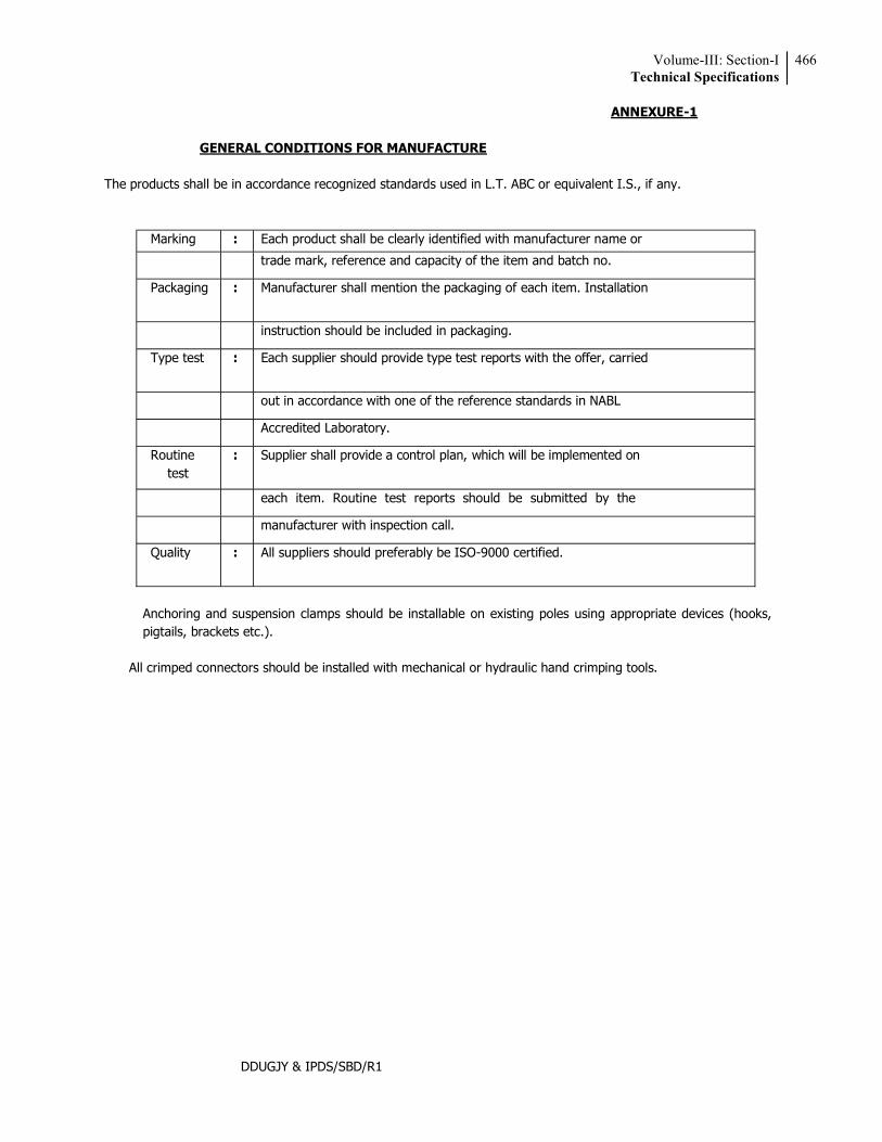
Volume-III: Section-ITechnical Specifications
466
DDUGJY & IPDS/SBD/R1
ANNEXURE-1
GENERAL CONDITIONS FOR MANUFACTURE The products shall be in accordance recognized standards used in L.T. ABC or equivalent I.S., if any.
Marking : Each product shall be clearly identified with manufacturer name or
trade mark, reference and capacity of the item and batch no.
Packaging : Manufacturer shall mention the packaging of each item. Installation
instruction should be included in packaging.
Type test : Each supplier should provide type test reports with the offer, carried
out in accordance with one of the reference standards in NABL
Accredited Laboratory.
Routine test
: Supplier shall provide a control plan, which will be implemented on
each item. Routine test reports should be submitted by the
manufacturer with inspection call.
Quality : All suppliers should preferably be ISO-9000 certified.
Anchoring and suspension clamps should be installable on existing poles using appropriate devices (hooks, pigtails, brackets etc.).
All crimped connectors should be installed with mechanical or hydraulic hand crimping tools.
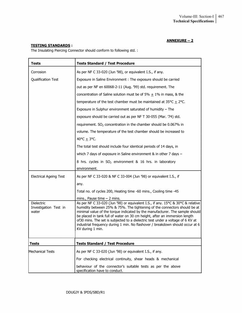
Volume-III: Section-ITechnical Specifications
467
DDUGJY & IPDS/SBD/R1
ANNEXURE 2
TESTING STANDARDS : The Insulating Piercing Connector should conform to following std. :
Tests Tests Standard / Test Procedure
Corrosion As per NF C 33-
Qualification Test Exposure in Saline Environment : The exposure should be carried
out as per NF en 60068-2-
concentration of Saline solution must be of 5% + 1% in mass, & the
temperature of the test chamber must be maintained at 35°C + 2°C.
Exposure in Sulphur environment saturated of humidity The
exposure should be carried out as per NF T 30-
requirement. SO2 concentration in the chamber should be 0.067% in
volume. The temperature of the test chamber should be increased to
40°C + 3°C.
The total test should include four identical periods of 14 days, in
which 7 days of exposure in Saline environment & in other 7 days
8 hrs. cycles in SO2 environment & 16 hrs. in laboratory
environment.
Electrical Ageing Test As per NF C 33-020 & NF C 33-
any.
Total no. of cycles 200, Heating time -60 mins., Cooling time -45
mins., Pause time 2 mins. Dielectric Investigation Test in water
As per NF C 33- equivalent I.S., if any. 15°C & 30°C & relative humidity between 25% & 75%. The tightening of the connectors should be at minimal value of the torque indicated by the manufacturer. The sample should be placed in tank full of water on 30 cm height, after an immersion length of30 mins. The set is subjected to a dielectric test under a voltage of 6 KV at industrial frequency during 1 min. No flashover / breakdown should occur at 6 KV during 1 min.
Tests Tests Standard / Test Procedure
Mechanical Tests As per NF C 33-
For checking electrical continuity, shear heads & mechanical
specification have to conduct.
Volume-III: Section-ITechnical Specifications
468
DDUGJY & IPDS/SBD/R1
Capacity needed :
For ABC 16 to 95 mm2
Model 1 for customer service Main 16 to 95 mn2
Tap 2.5 to 10 mm2 (For Street lighting/service connection)
Design as per furnished drawing
Model 2 for customer service Main 16 to 95 mm2
Tap 04 to 35 mm2 (for distribution box charging)
Design as per furnished drawing
Model 3 for customer service Main 25 to 95 mm2
Tap 25 to 95 mm2 (For ABC to ABC Tee Joint)
Design as per furnished drawing.
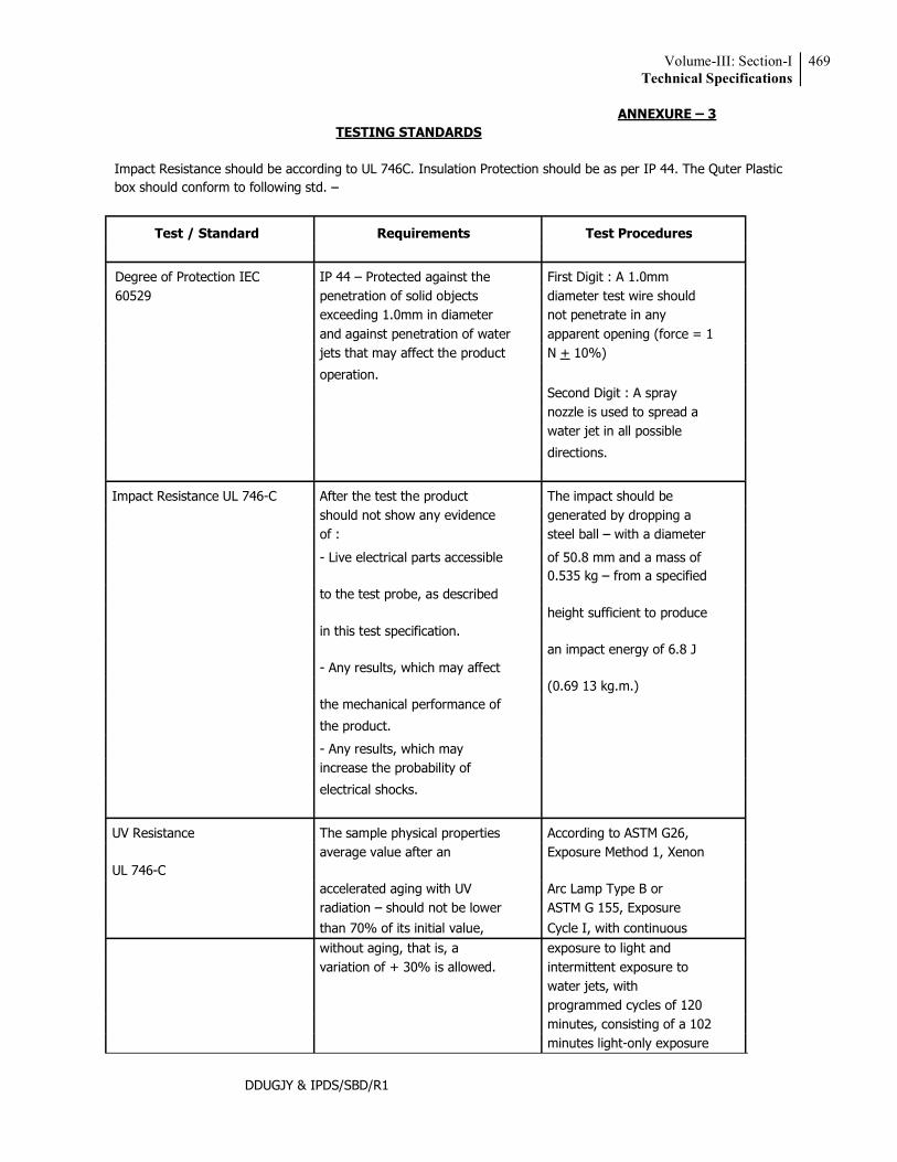
Volume-III: Section-ITechnical Specifications
469
DDUGJY & IPDS/SBD/R1
ANNEXURE 3 TESTING STANDARDS
Impact Resistance should be according to UL 746C. Insulation Protection should be as per IP 44. The Quter Plastic box should conform to following std.
Test / Standard Requirements Test Procedures
Degree of Protection IEC IP 44 Protected against the First Digit : A 1.0mm 60529 penetration of solid objects diameter test wire should
exceeding 1.0mm in diameter not penetrate in any and against penetration of water apparent opening (force = 1 jets that may affect the product N + 10%)
operation. Second Digit : A spray
nozzle is used to spread a water jet in all possible
directions.
Impact Resistance UL 746-C After the test the product The impact should be should not show any evidence generated by dropping a of : steel ball with a diameter
- Live electrical parts accessible of 50.8 mm and a mass of
to the test probe, as described 0.535 kg from a specified
height sufficient to produce
in this test specification.
an impact energy of 6.8 J
- Any results, which may affect
(0.69 13 kg.m.)
the mechanical performance of
the product.
- Any results, which may increase the probability of
electrical shocks.
UV Resistance The sample physical properties According to ASTM G26,
UL 746-C average value after an Exposure Method 1, Xenon
accelerated aging with UV Arc Lamp Type B or
radiation should not be lower ASTM G 155, Exposure
than 70% of its initial value, Cycle I, with continuous without aging, that is, a exposure to light and variation of + 30% is allowed. intermittent exposure to water jets, with programmed cycles of 120 minutes, consisting of a 102 minutes light-only exposure
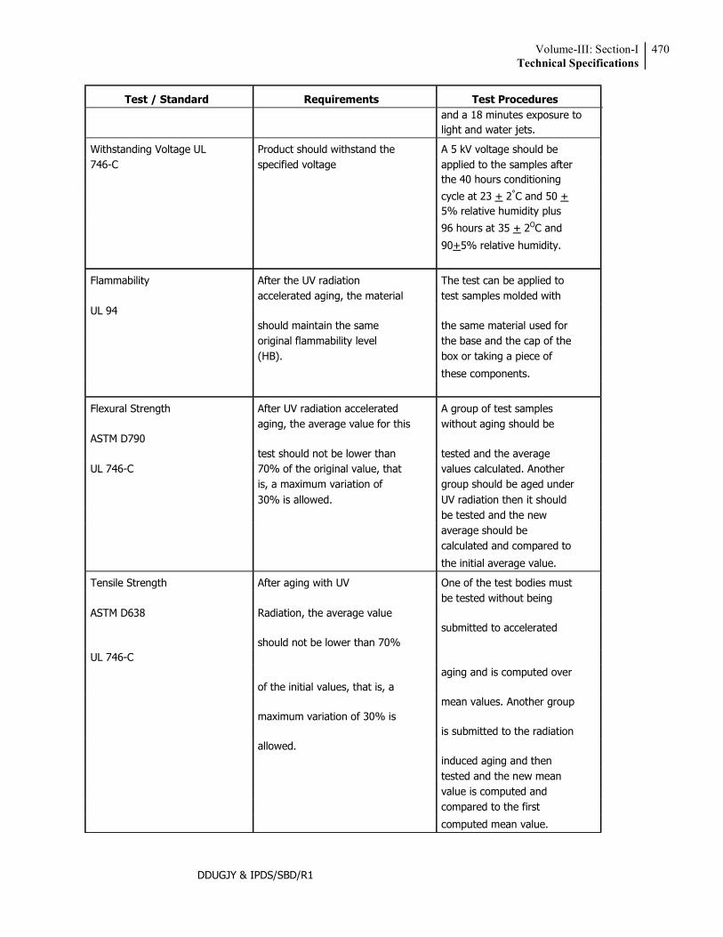
Volume-III: Section-ITechnical Specifications
470
DDUGJY & IPDS/SBD/R1
Test / Standard Requirements Test Procedures
and a 18 minutes exposure to light and water jets.
Withstanding Voltage UL Product should withstand the A 5 kV voltage should be 746-C specified voltage applied to the samples after
the 40 hours conditioning
cycle at 23 + 2°C and 50 + 5% relative humidity plus
96 hours at 35 + 2OC and
90+5% relative humidity.
Flammability After the UV radiation The test can be applied to
UL 94 accelerated aging, the material test samples molded with
should maintain the same the same material used for
original flammability level the base and the cap of the (HB). box or taking a piece of
these components.
Flexural Strength After UV radiation accelerated A group of test samples
ASTM D790 aging, the average value for this without aging should be
test should not be lower than tested and the average
UL 746-C
70% of the original value, that values calculated. Another is, a maximum variation of group should be aged under 30% is allowed. UV radiation then it should be tested and the new average should be calculated and compared to
the initial average value.
Tensile Strength After aging with UV One of the test bodies must
ASTM D638 Radiation, the average value be tested without being
submitted to accelerated
UL 746-C should not be lower than 70%
aging and is computed over
of the initial values, that is, a
mean values. Another group
maximum variation of 30% is
is submitted to the radiation
allowed.
induced aging and then
tested and the new mean value is computed and compared to the first
computed mean value.
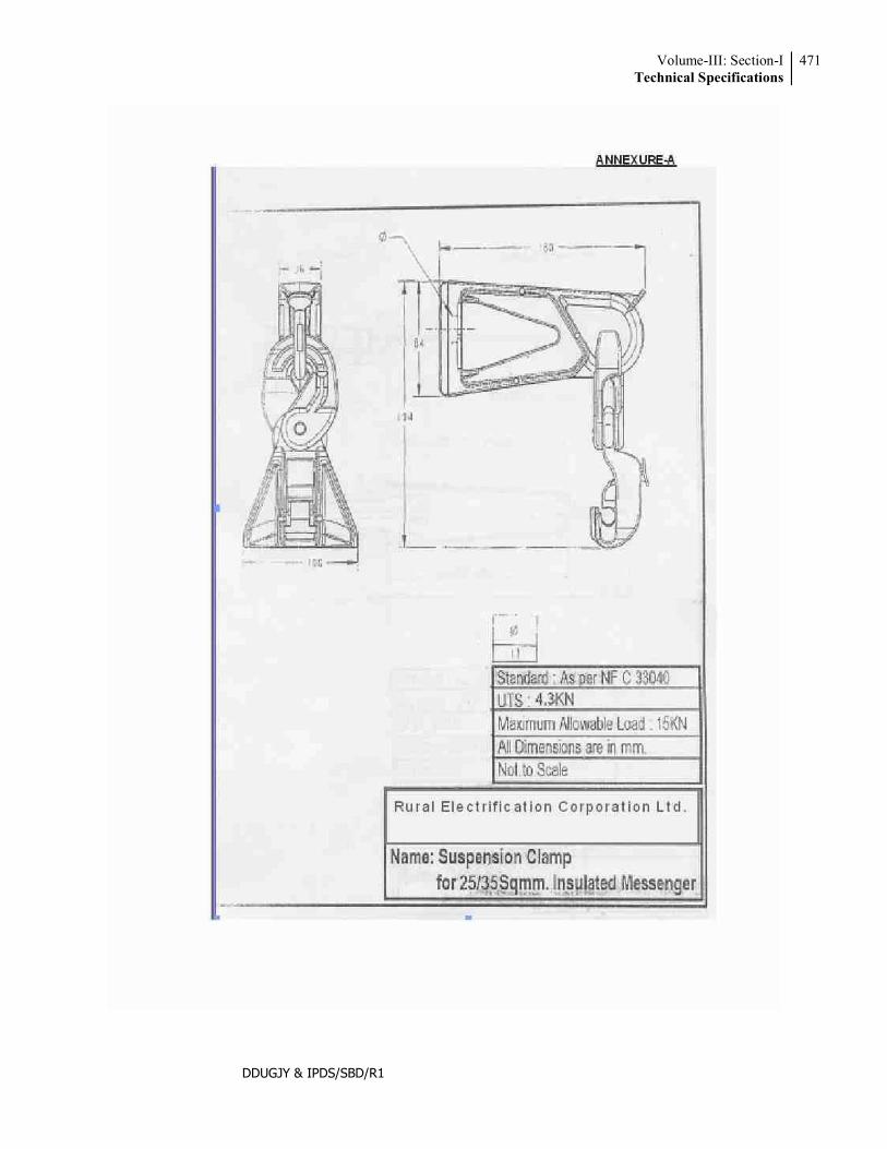
Volume-III: Section-ITechnical Specifications
471
DDUGJY & IPDS/SBD/R1
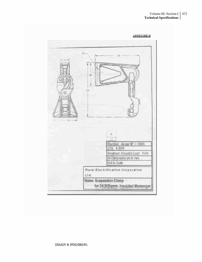
Volume-III: Section-ITechnical Specifications
472
DDUGJY & IPDS/SBD/R1
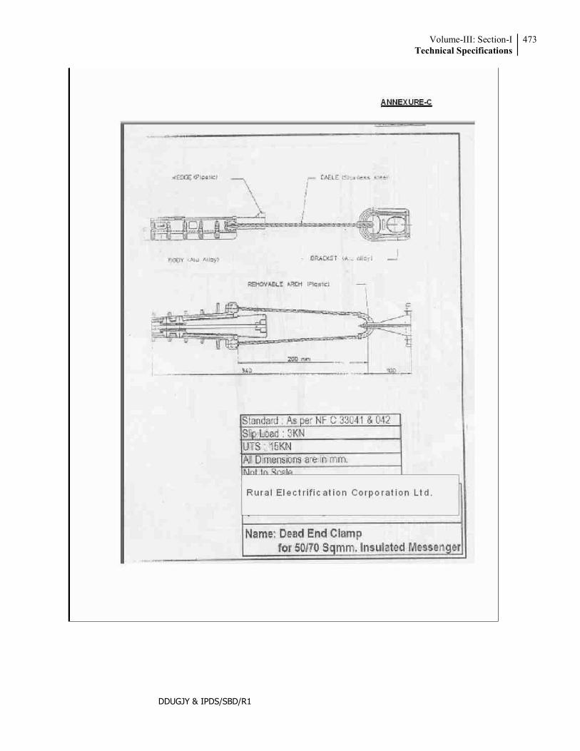
Volume-III: Section-ITechnical Specifications
473
DDUGJY & IPDS/SBD/R1

Volume-III: Section-ITechnical Specifications
474
DDUGJY & IPDS/SBD/R1
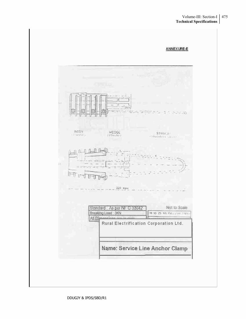
Volume-III: Section-ITechnical Specifications
475
DDUGJY & IPDS/SBD/R1
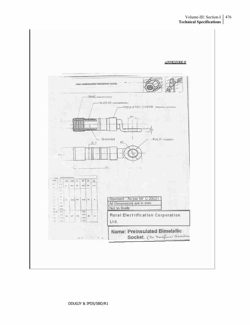
Volume-III: Section-ITechnical Specifications
476
DDUGJY & IPDS/SBD/R1
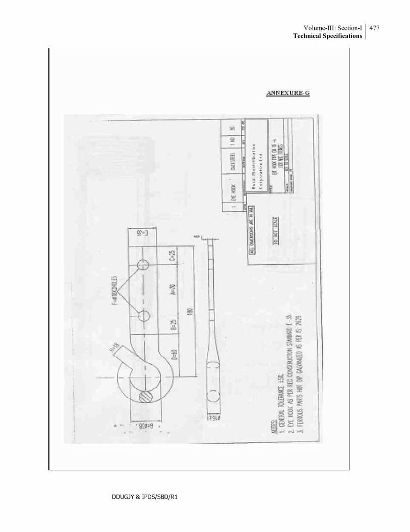
Volume-III: Section-ITechnical Specifications
477
DDUGJY & IPDS/SBD/R1
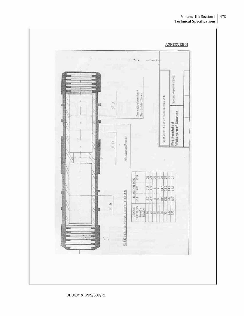
Volume-III: Section-ITechnical Specifications
478
DDUGJY & IPDS/SBD/R1
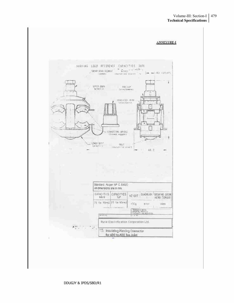
Volume-III: Section-ITechnical Specifications
479
DDUGJY & IPDS/SBD/R1
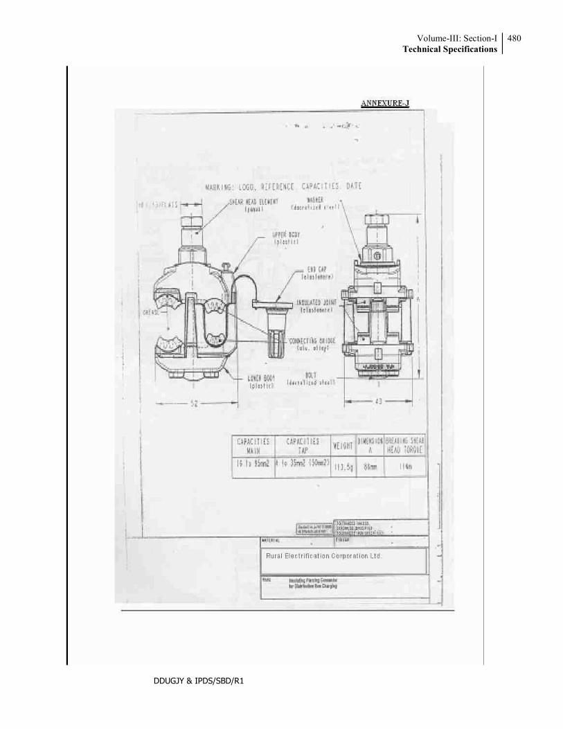
Volume-III: Section-ITechnical Specifications
480
DDUGJY & IPDS/SBD/R1
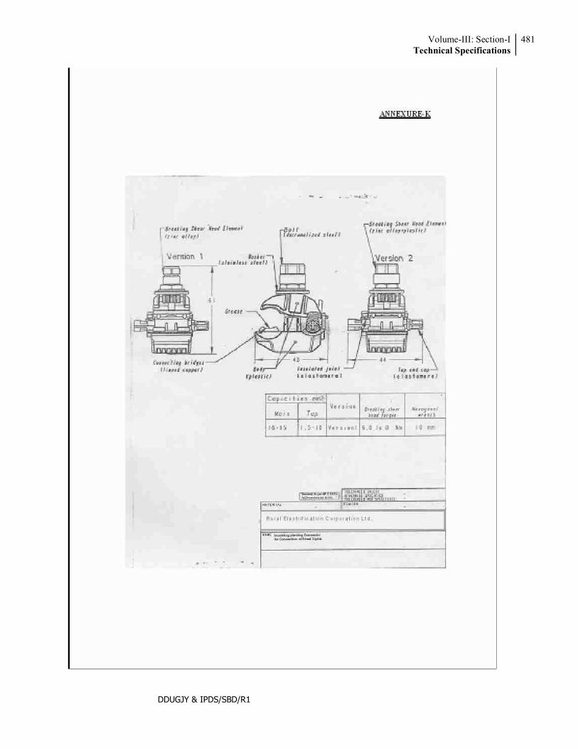
Volume-III: Section-ITechnical Specifications
481
DDUGJY & IPDS/SBD/R1
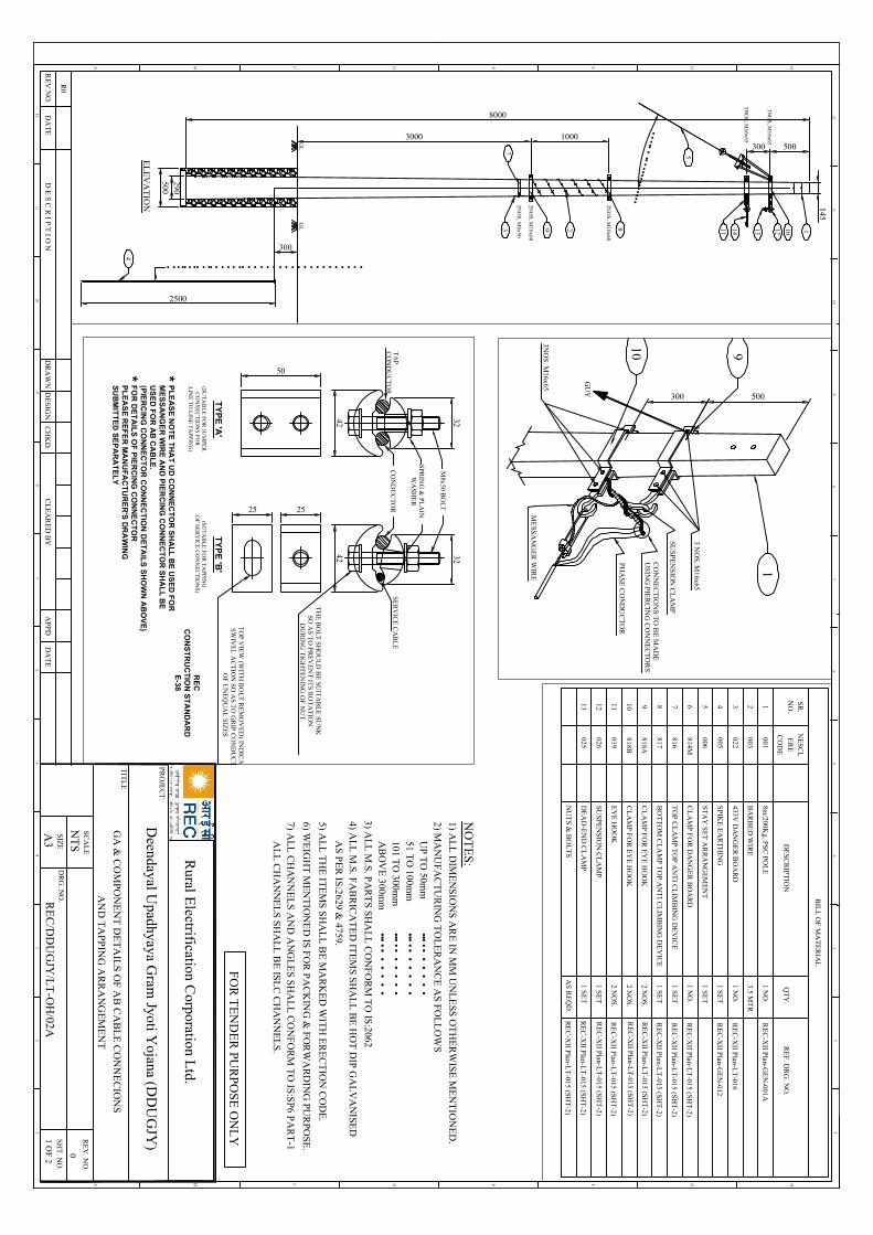
145
500
2500
4
• • • •• • •• • •• • • • • •• • • • • • • • • • • • • • • • • • • •
GL
GL 189 2 1012133
7
8000
500
3000 1000
300
290
EL
EV
AT
ION 2N
OS
, M10x60
2NO
S, M
10x60
2NO
S, M
8x50
3NO
S, M
16x65
5
••••••
••••••••••••••
3001411
3NO
S, M
16x65
BIL
L O
F MA
TE
RIA
L
8m/200K
g. PSC PO
LE
DE
SCR
IPT
ION
001
QT
Y.
RE
F. DR
G. N
O.
1 NO
.
BA
RB
ED
WIR
E003
3.5 MT
R
1 NO
.
STA
Y S
ET
AR
RA
NG
EM
EN
T006
1 SE
T
TO
P CL
AM
P T
OP A
NT
I CL
IMB
ING
DE
VIC
E816
1 SE
T
SPIK
E E
AR
TH
ING
0051 S
ET
433V D
AN
GE
R B
OA
RD
022
1 SE
TB
OT
TO
M C
LA
MP T
OP A
NT
I CL
IMB
ING
DE
VIC
E817
2 NO
S.C
LA
MP
FO
R E
YE
HO
OK
818A
2 NO
S.C
LA
MP
FO
R E
YE
HO
OK
818B
RE
C-X
II Plan-G
EN
-001A
RE
C-X
II Plan-G
EN
-012
RE
C-X
II Plan-L
T-016
RE
C-X
II Plan-L
T-015 (SH
T-2)
ER
E
CO
DE
NE
SCL
NO
.SR
.
12345678910
NU
TS
& B
OL
TS
AS
RE
QD
.
2 NO
S.E
YE
HO
OK
01911
1 SE
TSU
SPEN
SIO
N C
LA
MP
02612
1 SE
TD
EA
D-E
ND
CL
AM
P025
13
CL
AM
P F
OR
DA
NG
ER
BO
AR
D814M
1 NO
.R
EC
-XII P
lan-LT
-015 (SHT
-2)
RE
C-X
II Plan-L
T-015 (SH
T-2)
RE
C-X
II Plan-L
T-015 (SH
T-2)
RE
C-X
II Plan-L
T-015 (SH
T-2)
RE
C-X
II Plan-L
T-015 (SH
T-2)
RE
C-X
II Plan-L
T-015 (SH
T-2)
RE
C-X
II Plan-L
T-015 (SH
T-2)
RE
C-X
II Plan-L
T-015 (SH
T-2)
1
CO
NN
EC
TIO
NS T
O B
E M
AD
EU
SIN
G PIE
RC
ING
CO
NN
EC
TO
RS
PHA
SE C
ON
DU
CT
OR
SUSPE
NS
ION
CL
AM
P
ME
SSA
NG
ER
WIR
E
3 NO
S. M16x65
GU
Y
3NO
S. M16x65
500300
910
42 32
50
2525
42 32
M8x50 B
OL
T
SPR
ING
& PL
AIN
WA
SH
ER
CO
ND
UC
TO
RS
ER
VIC
E C
AB
LE
TA
PC
ON
DU
CT
OR
TH
E B
OL
T S
HO
UL
D B
E SU
ITA
BL
E SU
NK
SO
AS T
O P
RE
VE
NT
ITS
RO
TA
TIO
ND
UR
ING
TIG
HT
EN
ING
OF
NU
T
TO
P V
IEW
(WIT
H B
OL
T R
EM
OV
ED
) IND
ICA
TIN
GS
WIV
EL
AC
TIO
N S
O A
S TO
GR
IP C
ON
DU
CT
OR
SO
F U
NE
QU
AL
SIZE
S
RE
CC
ON
ST
RU
CT
ION
ST
AN
DA
RD
E-38
TY
PE
'A'
(SUT
AB
LE
FOR
JUM
PER
CO
NN
EC
TIO
NS
FOR
LIN
E T
O L
INE
TA
PPIN
G)
TY
PE
'B'
(SUT
AB
LE
FOR
TA
PPIN
GO
F SE
RV
ICE
CO
NN
EC
TIO
NS)
PL
EA
SE
NO
TE
TH
AT
UD
CO
NN
EC
TO
R S
HA
LL
BE
US
ED
FO
RM
ES
SA
NG
ER
WIR
E A
ND
PIE
RC
ING
CO
NN
EC
TO
R S
HA
LL
BE
US
ED
FO
R A
B C
AB
LE
.(P
IER
CIN
G C
ON
NE
CT
OR
CO
NN
EC
TIO
N D
ET
AIL
S S
HO
WN
AB
OV
E)
FO
R D
ET
AIL
S O
F P
IER
CIN
G C
ON
NE
CT
OR
PL
EA
SE
RE
FE
R M
AN
UF
AC
TU
RE
R'S
DR
AW
ING
SU
BM
ITT
ED
SE
PA
RA
TE
LY
**
12
HGFEDCB
12
A
46
57
3 34
65
78
910
11
89
1011
12
HGFEDCBA
12
Rural E
lectrification Corporation L
td.
PR
OJE
CT
:
TIT
LE
SC
AL
E
SIZ
E
RE
V. N
O.
SH
T. N
O.
1 OF 2
GA
& C
OM
PON
EN
T D
ET
AIL
S O
F AB
CA
BL
E C
ON
NE
CIO
NS
A3
NT
S0
AN
D T
APP
ING
AR
RA
NG
EM
EN
T
D E
S C
R I P T
I O N
RE
V.N
O.
AP
PD
CH
KD
.D
RA
WN
DE
SIG
NC
LE
AR
ED
BY
DA
TE
DA
TE
R0
DR
G. N
O.R
EC
/DD
UG
JY/L
T-O
H/02A
2) MA
NU
FAC
TU
RIN
G T
OL
ER
AN
CE
AS
FOL
LO
WS
NO
TE
S:1) A
LL
DIM
EN
SION
S A
RE
IN M
M U
NL
ESS O
TH
ER
WIS
E M
EN
TIO
NE
D.
UP
TO
50mm
51 TO
100mm
101 TO
300mm
AB
OV
E 300m
m
••••••
••
••
••••••
••
••
••••••
••
••
••••••
••
••
4) AL
L M
.S. F
AB
RIC
AT
ED
ITE
MS S
HA
LL
BE
HO
T D
IP GA
LV
AN
ISED
5) AL
L T
HE
ITE
MS
SH
AL
L B
E M
AR
KE
D W
ITH
ER
EC
TIO
N C
OD
E.
6) WE
IGH
T M
EN
TIO
NE
D IS
FO
R P
AC
KIN
G &
FO
RW
AR
DIN
G PU
RPO
SE.
AS
PE
R IS:2629 &
4759.
7) AL
L C
HA
NN
EL
S AN
D A
NG
LE
S SH
AL
L C
ON
FOR
M T
O IS:S
P6 PA
RT
-1A
LL
CH
AN
NE
LS
SHA
LL
BE
ISL
C C
HA
NN
EL
S.
3) AL
L M
.S. P
AR
TS
SH
AL
L C
ON
FO
RM
TO
IS:2062
FO
R T
EN
DE
R PU
RP
OS
E O
NL
Y
Deendayal U
padhyaya Gram
Jyoti Yojana (D
DU
GJY
)
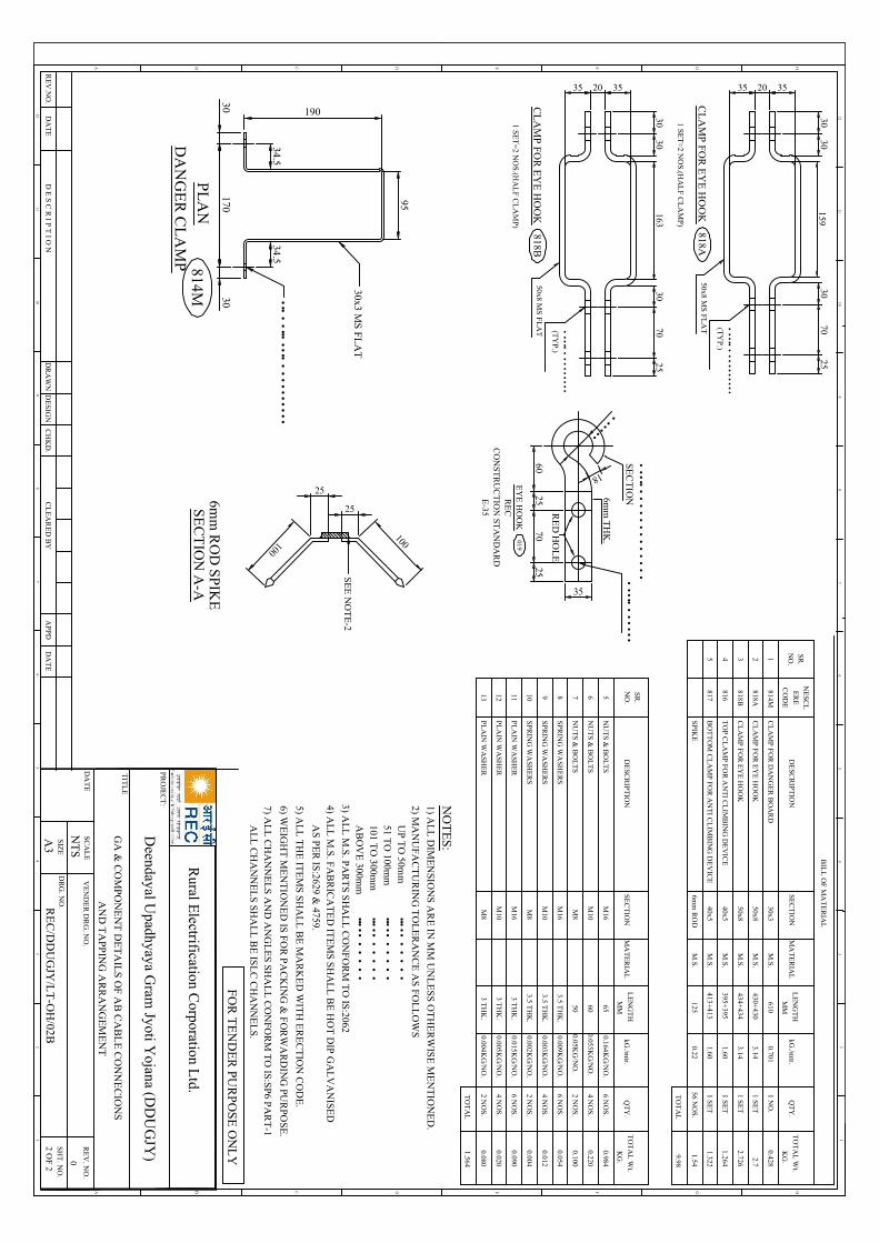
BIL
L O
F MA
TE
RIA
L
ER
E
CO
DE
NE
SCL
NO
.SR
.
1234
QT
Y.
SEC
TIO
NL
EN
GT
HkG
./mtr.
TO
TA
L W
t.
KG
.M
MM
AT
ER
IAL
CL
AM
P F
OR
DA
NG
ER
BO
AR
D814M
TO
P CL
AM
P FO
R A
NT
I CL
IMB
ING
DE
VIC
E816
BO
TT
OM
CL
AM
P FOR
AN
TI C
LIM
BIN
G D
EV
ICE
817
SPIK
E6m
m R
OD
12556 N
OS.
30x3
40x5
40x5
0.701M
.S.
M.S.
M.S.
M.S.
1 NO
.
1.60
1.60
1 SE
T
1 SE
T
0.221.54
610
395+395
413+413
0.428
1.322
1.264
DE
SCR
IPT
ION
TO
TA
L9.98
CL
AM
P F
OR
EY
E H
OO
K818A
50x83.14
M.S.
1 SE
T430+
4302.7
CL
AM
P F
OR
EY
E H
OO
K818B
50x83.14
M.S.
1 SE
T434+
4342.726
5
5678910
TO
TA
L1.564
SPR
ING
WA
SHE
RS
PLA
IN W
ASH
ER
NU
TS
& B
OL
TS
M16
650.164K
G/N
O.
6 NO
S.
NU
TS
& B
OL
TS
M8
502 N
OS.
SPR
ING
WA
SHE
RS
PLA
IN W
ASH
ER
M16
M8
M16
M8
0.05KG
/NO
.0.100
NU
TS
& B
OL
TS
M10
600.055K
G/N
O.
4 NO
S.
0.984
0.220
SPR
ING
WA
SHE
RS
M10
PLA
IN W
ASH
ER
M10
3.5 TH
K.
0.009KG
/NO
.6 N
OS.
0.054
3.5 TH
K.
0.003KG
/NO
.4 N
OS.
0.012
3.5 TH
K.
0.002KG
/NO
.2 N
OS.
0.004
3 TH
K.
3 TH
K.
3 TH
K.
6 NO
S.
4 NO
S.
2 NO
S.
0.015KG
/NO
.
0.005KG
/NO
.
0.004KG
/NO
.
0.090
0.020
0.080
NO
.SR
.
QT
Y.
SEC
TIO
NL
EN
GT
HkG
./mtr.
TO
TA
L W
t.
KG
.M
MM
AT
ER
IAL
DE
SCR
IPT
ION
111213
35
3030
16370
3025
35
3030
15970
3025
CL
AM
P FO
R E
YE
HO
OK
818A
2035
50x8 MS
FLA
T
1 SET
=2 N
OS.(H
AL
F CL
AM
P)
2035
•••••
••
••
•••
••••
••(T
YP.)
CL
AM
P FO
R E
YE
HO
OK
818B
1 SET
=2 N
OS.(H
AL
F CL
AM
P)
50x8 MS
FLA
T •••••
••
••
•••
••••
••(T
YP.)
95
34.5
30x3 MS
FLA
T
30
34.5
30170
814MP
LA
N
DA
NG
ER
CL
AM
P
190
••••
••••••••
••
••
••••••
•••••
•••••
7025
2560
35
••••••
18
•••••
••
••
•••••
••••
6mm
TH
K.
•••••
••
••
••
••
••
••
•SE
CT
ION
EY
E H
OO
KR
EC
CO
NST
RU
CT
ION
STA
ND
AR
DE
-35
019
RE
D H
OL
E
25
25100100
SEC
TIO
N A
-A6m
m R
OD
SP
IKE
SE
E N
OT
E-2
12
HGFEDCB
12
A
46
57
3 34
65
78
910
11
89
1011
12
HGFEDCBA
12
Rural E
lectrification Corporation L
td.
PR
OJE
CT
:
TIT
LE
SC
AL
EV
EN
DE
R D
RG
. NO
.
SIZ
E
RE
V. N
O.
SH
T. N
O.
2 OF 2
A3
NT
S0
DA
TE
D E
S C
R I P T
I O N
RE
V.N
O.
AP
PD
CH
KD
.D
RA
WN
DE
SIG
NC
LE
AR
ED
BY
DA
TE
DA
TE
DR
G. N
O.
GA
& C
OM
PON
EN
T D
ET
AIL
S O
F AB
CA
BL
E C
ON
NE
CIO
NS
AN
D T
APP
ING
AR
RA
NG
EM
EN
T
RE
C/D
DU
GJY
/LT
-OH
/02B
FO
R T
EN
DE
R PU
RP
OS
E O
NL
Y
Deendayal U
padhyaya Gram
Jyoti Yojana (D
DU
GJY
)
2) MA
NU
FAC
TU
RIN
G T
OL
ER
AN
CE
AS
FOL
LO
WS
NO
TE
S:1) A
LL
DIM
EN
SION
S A
RE
IN M
M U
NL
ESS O
TH
ER
WIS
E M
EN
TIO
NE
D.
UP
TO
50mm
51 TO
100mm
101 TO
300mm
AB
OV
E 300m
m
••••••
••
••
••••••
••
••
••••••
••
••
••••••
••
••
4) AL
L M
.S. F
AB
RIC
AT
ED
ITE
MS S
HA
LL
BE
HO
T D
IP G
AL
VA
NISE
D
5) AL
L T
HE
ITE
MS
SH
AL
L B
E M
AR
KE
D W
ITH
ER
EC
TIO
N C
OD
E.
6) WE
IGH
T M
EN
TIO
NE
D IS
FO
R P
AC
KIN
G &
FO
RW
AR
DIN
G PU
RPO
SE.
AS
PE
R IS:2629 &
4759.
7) AL
L C
HA
NN
EL
S AN
D A
NG
LE
S SH
AL
L C
ON
FOR
M T
O IS:S
P6 PA
RT
-1A
LL
CH
AN
NE
LS
SHA
LL
BE
ISL
C C
HA
NN
EL
S.
3) AL
L M
.S. P
AR
TS
SH
AL
L C
ON
FO
RM
TO
IS:2062
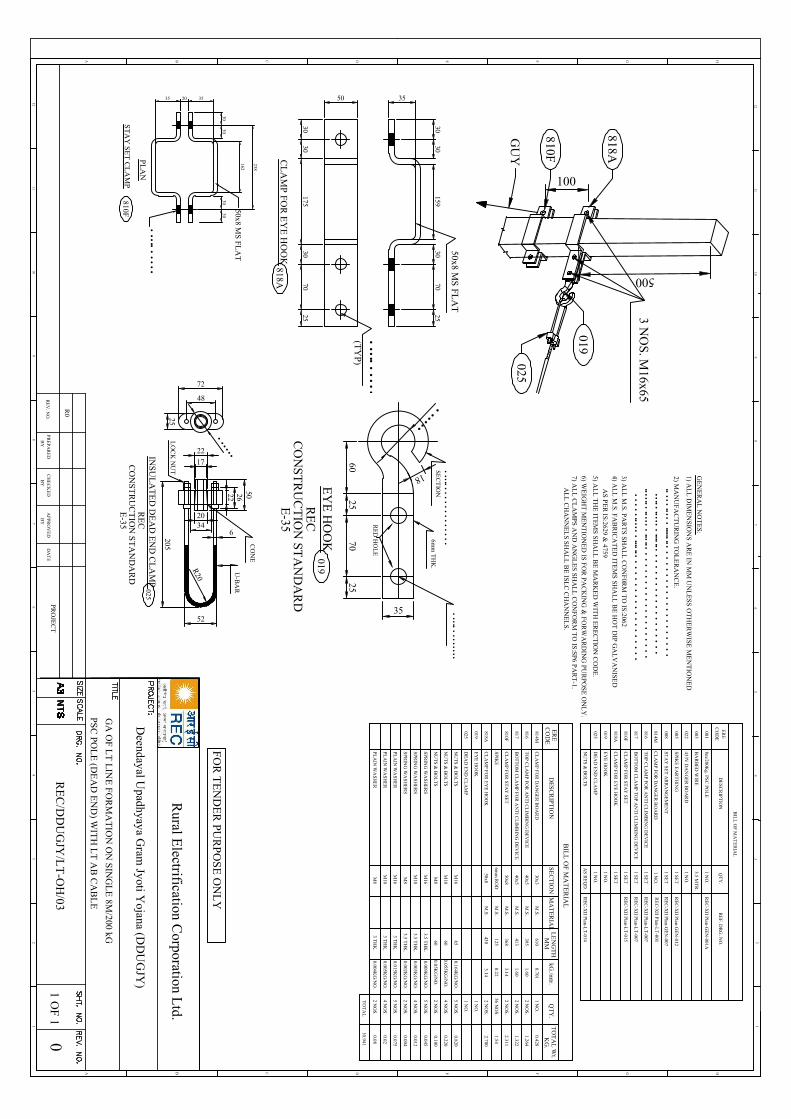
500
818A
3 NO
S. M16x65
025
019
100
810F
GU
Y
3030
17530
7025
35
3030
15970
3025
CL
AM
P FO
R E
YE
HO
OK
818A
50
•••••
••
••
••
••
••
•(T
YP)
50x8 MS
FLA
T
7025
2560
35
••••••
18
•••••
••
••••••
••••
•
6mm
TH
K.
•••••
••
••
••
••
••
••
•SE
CT
ION
EY
E H
OO
KR
EC
CO
NST
RU
CT
ION
STA
ND
AR
DE
-35
019
RE
D H
OL
E
BIL
L O
F MA
TE
RIA
L
CL
AM
P FOR
EY
E H
OO
K
ER
EC
OD
ED
ES
CR
IPTIO
N
818A
QT
Y.
2 NO
S.
SEC
TIO
N
50x8
LE
NG
TH
kG./m
tr.T
OT
AL
Wt.
4303.14
2.700
TO
TA
L
M.S
.
KG
.
10.941
MM
MA
TE
RIA
L
EY
E H
OO
K1 N
O.
DE
AD
EN
D C
LA
MP
1 NO
.
BIL
L O
F MA
TE
RIA
L
8m/200K
g. PSC
POL
E
ER
EC
OD
ED
ES
CR
IPTIO
N
001
QT
Y.
RE
F. DR
G. N
O.
1 NO
.
BA
RB
ED
WIR
E003
3.5 MT
R.
1 NO
.
TO
P C
LA
MP FO
R A
NT
I CL
IMB
ING
DE
VIC
E816
1 SET
RE
C-X
II Plan-G
EN
-001A
BO
TT
OM
CL
AM
P TO
P A
NT
I CL
IMB
ING
DE
VIC
E817
1 SET
SPIKE
EA
RT
HIN
G005
1 SET
NU
TS &
BO
LT
SA
S R
EQ
D.
433V D
AN
GE
R B
OA
RD
022
1 SET
CL
AM
P FOR
EY
E H
OO
K818A
1 NO
.E
YE
HO
OK
019
1 NO
.D
EA
D E
ND
CL
AM
P025
CL
AM
P FOR
DA
NG
ER
BO
AR
D814M
TO
P C
LA
MP FO
R A
NT
I CL
IMB
ING
DE
VIC
E816
BO
TT
OM
CL
AM
P FOR
AN
TI C
LIM
BIN
G D
EV
ICE
817
SPIKE
6mm
RO
D125
56 NO
S.
30x3
40x5
40x5
6100.701
M.S
.
M.S
.
M.S
.
M.S
.
1 NO
.0.428
395
413
1.60
1.60
2 NO
S.
2 NO
S.1.322
1.264
0.221.54
SPRIN
G W
ASH
ER
S
PLA
IN W
ASH
ER
NU
TS &
BO
LT
SM
1665
0.164KG
/NO
.5 N
OS.
NU
TS &
BO
LT
SM
860
2 NO
S.
SPRIN
G W
ASH
ER
S
PLA
IN W
ASH
ER
M16
M8
M16
M8
0.05KG
/NO
.0.100
NU
TS &
BO
LT
SM
1060
0.055KG
/NO
.4 N
OS.
0.820
0.220
SPRIN
G W
ASH
ER
SM
10
PLA
IN W
ASH
ER
M10
3.5 TH
K.
0.009KG
/NO
.5 N
OS.
0.045
3.5 TH
K.
0.003KG
/NO
.4 N
OS.
0.012
3.5 TH
K.
0.002KG
/NO
.2 N
OS.
0.004
3 TH
K.
3 TH
K.
3 TH
K.
5 NO
S.
4 NO
S.
2 NO
S.
0.015KG
/NO
.
0.005KG
/NO
.
0.004KG
/NO
.
0.075
0.02
0.08
019
025
STA
Y SE
T A
RR
AN
GE
ME
NT
0081 SE
TR
EC
-XII P
lan-GE
N-007
CL
AM
P FOR
STA
Y SE
T50x8
M.S
.3.14
2 NO
S.810F
3682.311
CL
AM
P FOR
STA
Y SE
T810F
1 SET
RE
C-X
II Plan-L
T-007
RE
C-X
II Plan-L
T-007
RE
C-X
II Plan-G
EN
-012
RE
C-X
II Plan-L
T-015
RE
C-X
II Plan-L
T-014
CL
AM
P FOR
DA
NG
ER
BO
AR
D814M
1 NO
.R
EC
-XII P
lan-LT
-001
20552
R20
6
2034
5022
17
22
48
72
25
•• • • • •
U-B
AR
CO
NE
INS
UL
AT
ED
DE
AD
EN
D C
LA
MP
RE
CC
ON
STR
UC
TIO
N S
TA
ND
AR
DE
-35
025
26
LO
CK
NU
T
162
35
50x8 MS
FL
AT
PL
AN
20
810FS
TA
Y S
ET
CL
AM
P
•••••
••
••
••
••
••
•
3030
3030
238
35
12
HGFEDCB
12
A
46
57
3 34
65
78
910
11
89
1011
12
HGFEDCBA
12
GA
OF L
T L
INE
FO
RM
AT
ION
ON
SIN
GL
E 8M
/200 kG
PSC
POL
E (D
EA
D E
ND
) WIT
H L
T A
B C
AB
LE
GE
NE
RA
L N
OT
ES
:
1) AL
L D
IME
NS
ION
S A
RE
IN M
M U
NL
ES
S O
TH
ER
WISE
ME
NT
ION
ED
4) AL
L M
.S. F
AB
RIC
AT
ED
ITE
MS
SHA
LL
BE
HO
T D
IP G
AL
VA
NISE
D
5) AL
L T
HE
ITE
MS S
HA
LL
BE
MA
RK
ED
WIT
H E
RE
CT
ION
CO
DE
.
AS
PER
IS:2629 &
4759
3) AL
L M
.S. P
AR
TS
SH
AL
L C
ON
F0R
M T
O IS:2062
6) WE
IGH
T M
EN
TIO
NE
D IS
FO
R P
AC
KIN
G &
FO
RW
AR
DIN
G P
UR
PO
SE
ON
LY
.7) A
LL
CL
AM
PS
AN
D A
NG
LE
S SH
AL
L C
ON
FO
RM
TO
IS:S
P6 PA
RT
-1.
2) MA
NU
FA
CT
UR
ING
TO
LE
RA
NC
E.
••••
•••••
•••••••
••••
••
••
••
••
••
••
••
••
••
•••••
••••••
•••••••
••
••
••
••
••
••
••
••
••
•••••••
••••••
•••••••
••
••
••
••
••
••
••
••
••
••
••
••••••
•••••
••••
••
••
••
••
••
••
••
••
•
AL
L C
HA
NN
EL
S S
HA
LL
BE
ISLC
CH
AN
NE
LS
.
RE
V. N
O.
R0
PR
EP
AR
ED
BY
CH
EC
KE
DB
YA
PPR
OV
ED
BY
DA
TE
PRO
JEC
TR
EC
/DD
UG
JY/L
T-O
H/03
01 O
F 1
FO
R T
EN
DE
R PU
RP
OS
E O
NL
Y
Rural E
lectrification Corporation L
td.
Deendayal U
padhyaya Gram
Jyoti Yojana (D
DU
GJY
)
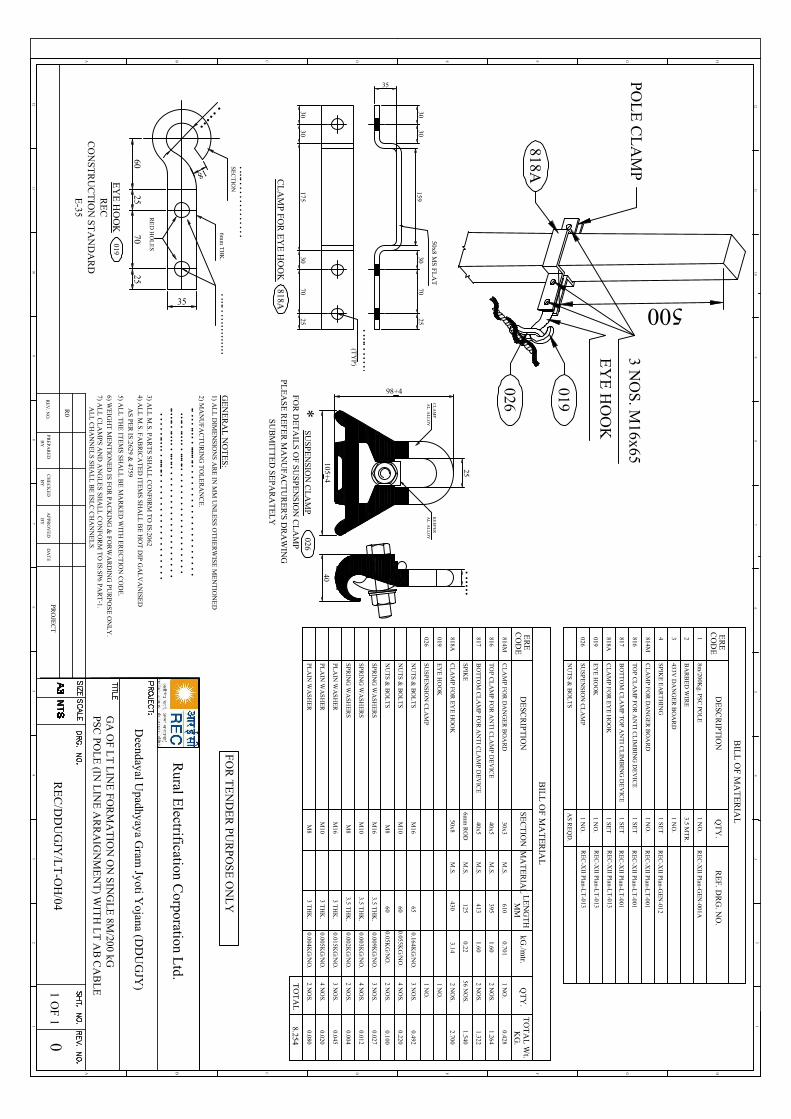
EY
E H
OO
K
500
PO
LE
CL
AM
P
818A
3 NO
S. M
16x65
019
026
3030
17530
7025
35
3030
15970
3025
CL
AM
P FO
R E
YE
HO
OK
•••••
••
••
••
••
••
•
818A
(TY
P)
50x8 MS
FL
AT
7025
2560
35
••••••
18
•••••
••
•••
•••••
•••6m
m T
HK
.
•••••
••
••
••
••
••
••
•SE
CT
ION
EY
E H
OO
KR
EC
CO
NST
RU
CT
ION
ST
AN
DA
RD
E-35
019
RE
D H
OL
ES
BIL
L O
F M
AT
ER
IAL
CL
AM
P FOR
EY
E H
OO
K
ER
EC
OD
ED
ESC
RIP
TIO
N
818A
QT
Y.
2 NO
S.
SE
CT
ION
50x8
LE
NG
TH
kG./m
tr.T
OT
AL
Wt.
3.14
TO
TA
L
M.S.
KG
.
8.254
MM
MA
TE
RIA
L
EY
E H
OO
K1 N
O.
SUS
PE
NSIO
N C
LA
MP
1 NO
.
BIL
L O
F M
AT
ER
IAL
8m/200K
g. PS
C PO
LE
ER
EC
OD
ED
ESC
RIP
TIO
N
1
QT
Y.
RE
F. D
RG
. NO
.
1 NO
.
BA
RB
ED
WIR
E2
3.5 MT
R.
1 NO
.
CL
AM
P FOR
DA
NG
ER
BO
AR
D814M
1 NO
.
TO
P C
LA
MP
FO
R A
NT
I CL
IMB
ING
DE
VIC
E816
1 SET
BO
TT
OM
CL
AM
P T
OP A
NT
I CL
IMB
ING
DE
VIC
E817
1 SET
SPIKE
EA
RT
HIN
G4
1 SET
NU
TS &
BO
LT
SA
S RE
QD
.
433V D
AN
GE
R B
OA
RD
3
1 SET
CL
AM
P FOR
EY
E H
OO
K818A
1 NO
.E
YE
HO
OK
019
1 NO
.SU
SP
EN
SION
CL
AM
P026
CL
AM
P FOR
DA
NG
ER
BO
AR
D814M
TO
P C
LA
MP
FO
R A
NT
I CL
AM
P DE
VIC
E816
BO
TT
OM
CL
AM
P FO
R A
NT
I CL
AM
P DE
VIC
E817
SPIKE
6mm
RO
D125
56 NO
S.
30x3
40x5
40x5
0.701M
.S.
M.S.
M.S.
M.S.
1 NO
.
1.60
1.60
2 NO
S.
2 NO
S.
0.221.540
SPRIN
G W
ASH
ER
S
PLA
IN W
AS
HE
R
NU
TS &
BO
LT
SM
1665
0.164KG
/NO
.3 N
OS.
NU
TS &
BO
LT
SM
860
2 NO
S.
SPRIN
G W
ASH
ER
S
PLA
IN W
AS
HE
R
M16
M8
M16
M8
0.05KG
/NO
.0.100
NU
TS &
BO
LT
SM
1060
0.055KG
/NO
.4 N
OS.
0.492
0.220
SPRIN
G W
ASH
ER
SM
10
PLA
IN W
AS
HE
RM
10
3.5 TH
K.
0.009KG
/NO
.3 N
OS.
0.027
3.5 TH
K.
0.003KG
/NO
.4 N
OS.
0.012
3.5 TH
K.
0.002KG
/NO
.2 N
OS.
0.004
3 TH
K.
3 TH
K.
3 TH
K.
3 NO
S.
4 NO
S.
2 NO
S.
0.015KG
/NO
.
0.005KG
/NO
.
0.004KG
/NO
.
0.045
0.020
0.080
019
026
610
395
413
0.428
1.322
1.264
4302.700
RE
C-X
II Plan-GE
N-001A
RE
C-X
II Plan-LT
-013
RE
C-X
II Plan-LT
-013
RE
C-X
II Plan-LT
-013
RE
C-X
II Plan-GE
N-012
RE
C-X
II Plan-LT
-001
RE
C-X
II Plan-LT
-001
RE
C-X
II Plan-LT
-001
25
98+4
105+4
KE
EPE
R
AL
. AL
LO
Y
CL
AM
P
AL
. AL
LO
Y
••••••
40
026S
USP
EN
SIO
N C
LA
MP
FO
R D
ET
AIL
S OF
SU
SPE
NS
ION
CL
AM
PP
LE
AS
E R
EF
ER
MA
NU
FA
CT
UR
ER
'S D
RA
WIN
G
*
SU
BM
ITT
ED
SE
PA
RA
TE
LY
12
HGFEDCB
12
A
46
57
3 34
65
78
910
11
89
1011
12
HGFEDCBA
12
GA
OF L
T L
INE
FO
RM
AT
ION
ON
SIN
GL
E 8M
/200 kGPSC
POL
E (IN
LIN
E A
RR
AIG
NM
EN
T) W
ITH
LT
AB
CA
BL
E
RE
V. N
O.
R0
PR
EP
AR
ED
BY
CH
EC
KE
DB
YA
PPR
OV
ED
BY
DA
TE
PRO
JEC
TR
EC
/DD
UG
JY/L
T-O
H/04
01 O
F 1
GE
NE
RA
L N
OT
ES
:1) A
LL
DIM
EN
SIO
NS
AR
E IN
MM
UN
LE
SS
OT
HE
RW
ISE M
EN
TIO
NE
D
4) AL
L M
.S. F
AB
RIC
AT
ED
ITE
MS
SHA
LL
BE
HO
T D
IP G
AL
VA
NISE
D
5) AL
L T
HE
ITE
MS S
HA
LL
BE
MA
RK
ED
WIT
H E
RE
CT
ION
CO
DE
.
AS
PER
IS:2629 &
4759
3) AL
L M
.S. P
AR
TS
SH
AL
L C
ON
F0R
M T
O IS:2062
6) WE
IGH
T M
EN
TIO
NE
D IS
FO
R P
AC
KIN
G &
FO
RW
AR
DIN
G P
UR
PO
SE
ON
LY
.7) A
LL
CL
AM
PS
AN
D A
NG
LE
S SH
AL
L C
ON
FO
RM
TO
IS:S
P6 PA
RT
-1.
2) MA
NU
FA
CT
UR
ING
TO
LE
RA
NC
E.
••••
•••••
•••••••
••••
••
••
••
••
••
••
••
••
••
•••••
••••••
•••••••
••
••
••
••
••
••
••
••
••
•••••••
••••••
•••••••
••
••
••
••
••
••
••
••
••
••
••
••••••
•••••
••••
••
••
••
••
••
••
••
••
•
AL
L C
HA
NN
EL
S S
HA
LL
BE
ISLC
CH
AN
NE
LS
.
FO
R T
EN
DE
R PU
RP
OS
E O
NL
Y
Rural E
lectrification Corporation L
td.
Deendayal U
padhyaya Gram
Jyoti Yojana (D
DU
GJY
)
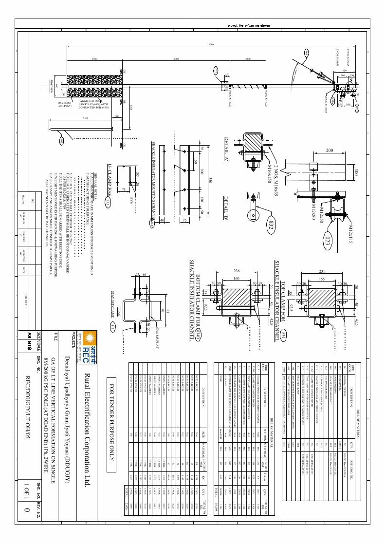
8000
GL
600
SID
E V
IEW
GL
AGGREGATES ORRCC BASE
BRICK BAT (60%) WITHCOMPACTED SOIL (40%)450x450x75
022
2NO
S, M
10x60
2NO
S, M
10x60D
AN
GE
R433
VO
LT
SN[kR
kjk433
•••••
••
•••••••••
008
2NO
S, M
16x65
90
10003000
150
1500
••••••
••••••••••••••
600
200A
023
300150
B
2 NO
S. M16x65
300
2 NO
S. M16x65
831A
GL
1200
3002500
• •• • •• • •• • •• • • • • •• • • • • • • • • • • • • • • • • • • • •005
90B
ILL
OF M
AT
ER
IAL
8M/200K
g. PSC PO
LE
ER
EC
OD
ED
ES
CR
IPT
ION
001
QT
Y.
RE
F. DR
G. N
O.
1 NO
.
BA
RB
ED
WIR
E003
3.5MT
R
415V D
AN
GE
R B
OA
RD
0221 N
O.
831A
CL
AM
P FOR
DA
NG
ER
BO
AR
D814M
1 NO
.
TO
P CL
AM
P FO
R A
NT
I CL
IMB
ING
DE
VIC
E816
1 NO
.
RE
C-X
II Plan-GE
N-001A
BO
TT
OM
CL
AM
P FO
R A
NT
I CL
IMB
ING
DE
VIC
E817
1 NO
.
BIL
L O
F MA
TE
RIA
L
ER
EC
OD
ED
ES
CR
IPT
ION
QT
Y.
SEC
TIO
NL
EN
GT
HkG
./mtr.
TO
TA
L W
t.
1 NO
.75x40
5505.7
3.135
CL
AM
P FOR
DA
NG
ER
BO
AR
D
TO
P C
LA
MP
FOR
AN
TI C
LIM
BIN
G D
EV
ICE
BO
TT
OM
CL
AM
P FO
R A
NT
I CL
IMB
ING
DE
VIC
E
TO
TA
L
SPRIN
G W
ASH
ER
S
PLA
IN W
ASH
ER
NU
TS &
BO
LT
SM
1665
0.1646 N
OS.
NU
TS &
BO
LT
SM
860
2 NO
S.
SPRIN
G W
ASH
ER
S
PLA
IN W
ASH
ER
M16
M8
M16
M8
0.0500.100
30x3
40x5
40x5
6100.701
M.S.
M.S.
M.S.
M.S.
DE
SC
RIP
TIO
NQ
TY
.SIZ
EK
G.
MA
TE
RIA
L
1 NO
.0.428
395
413
1.60
1.60
2 NO
S.
2 NO
S.1.322
1.264
KG
.
16.199
MM
TO
TA
L2.976
NU
TS &
BO
LT
SM
1060
0.0554 N
OS.
LE
NG
TH
TO
TA
L W
t.K
G.
MM
0.984
0.220
SPRIN
G W
ASH
ER
SM
10
PLA
IN W
ASH
ER
M10
MA
TE
RIA
L
3.5 TH
K.
0.0098 N
OS.
0.072
3.5 TH
K.
0.0034 N
OS.
0.012
3.5 TH
K.
0.0022 N
OS.
0.004
3 TH
K.
3 TH
K.
3 TH
K.
8 NO
S.
4 NO
S.
2 NO
S.
0.015
0.005
0.004
0.120
0.020
0.080
SHA
CK
LE
INSU
LA
TO
R M
OU
NT
ING
CH
AN
NE
L1 N
O.
STA
Y SE
T A
RR
AN
GE
ME
NT
0081 SE
TR
EC
-XII Plan-G
EN
-007
STA
Y SE
T C
LA
MP
8111 SE
T
CL
AM
P FOR
STA
Y SE
TM
.S.363
2 NO
S.
2.30450x8
3.14
SHA
CK
LE
INSU
LA
TO
R M
OU
NT
ING
CH
AN
NE
L
834M
.S.837
1 SET
2.62850x8
3.14 T
OP C
LA
MP F
OR
SHA
CK
LE
INSU
LA
TO
R C
HA
NN
EL
NU
TS &
BO
LT
SM
12115
0.1342 N
OS.
0.268
SPRIN
G W
ASH
ER
SM
123.5 T
HK
.0.009
6 NO
S.0.054
NU
TS &
BO
LT
SM
1250
0.0752 N
OS.
0.150
PLA
IN W
ASH
ER
M12
3 TH
K.
6 NO
S.0.015
0.090
SPIKE
6mm
RO
D125
56 NO
S.M
.S.0.22
1.540
833U
-CL
AM
PM
.S.2 N
OS.
0.91930x6
1.415325
NU
TS &
BO
LT
SM
1280
0.1022 N
OS.
0.204
NU
TS &
BO
LT
SM
16150
0.2992 N
OS.
0.598
LT
SHA
CK
LE
INSU
LA
TO
R (T
YP
E-1)
0232 N
OS.
SPIKE
EA
RT
HIN
G005
1 SET
RE
C-X
II Plan-GE
N-012
831A
814M
816
817
833U
-CL
AM
P FO
R S
HA
CK
LE
INS
UL
AT
OR
2 NO
S.
BO
TT
OM
CL
AM
P FO
R S
HA
CK
LE
INSU
LA
TO
R C
HA
NN
EL
834D1 SE
T
TO
P CL
AM
P FO
R S
HA
CK
LE
INSU
LA
TO
R C
HA
NN
EL
8341 SE
T
811
834DM
.S.847
1 SE
T2.659
50x83.14
BO
TT
OM
CL
AM
P FO
R SH
AC
KL
E IN
SUL
AT
OR
CH
AN
NE
L
RE
C-X
II Plan-LT
-001
RE
C-X
II Plan-LT
-001
RE
C-X
II Plan-LT
-001
100
DE
TA
IL `A
'
023
DE
TA
IL `B
'
200
M12x80
832 M12x115
M12x50
M16x150
2 NO
S. M16x65
95
66
50x8 MS
FL
AT
PL
AN
25811
ST
AY
SE
T C
LA
MP
•••••
••
••
••
••
••
•
3030
3030
171
150
550
50300
150
7540
•••••
••
••
••
••
••
••
•••••
••
••
••
••
••
•••••
••
••
••
••
••
•
831AS
HA
CK
LE
INS
UL
AT
OR
MO
UN
TIN
G C
HA
NN
EL
50
•••••
••
••
••
••
••
•
834T
OP
CL
AM
P FOR
SHA
CK
LE
INS
UL
AT
OR
CH
AN
NE
L
231
3592,5
155
2030 30 3030
42,550
•••••
••
••
••
••
••
•
•••••
••
••
••
••
••
•
834DB
OT
TO
M C
LA
MP F
OR
SHA
CK
LE
INS
UL
AT
OR
CH
AN
NE
L
236
3592,5
160
2030 30 3030
42,550
•••••
••
••
••
••
••
•
20105
75
•••••
••
••
••
••
••
•(T
YP)
833U
- CL
AM
P 30x6
12
HGFEDCB
12
A
46
57
3 34
65
78
910
11
89
1011
12
HGFEDCBA
12
GA
OF
LT
LIN
E V
ER
TIC
AL
FO
RM
AT
ION
ON
SIN
GL
E8M
/200 kG PS
C PO
LE
(AT
DE
AD
EN
D) 1P
h, 2WIR
E
RE
V. N
O.
R0
PR
EP
AR
ED
BY
CH
EC
KE
DB
YA
PPR
OV
ED
BY
DA
TE
PRO
JEC
T0
1 OF
1
GE
NE
RA
L N
OT
ES
:1) A
LL
DIM
EN
SIO
NS
AR
E IN
MM
UN
LE
SS O
TH
ER
WIS
E M
EN
TIO
NE
D
4) AL
L M
.S. FA
BR
ICA
TE
D IT
EM
S SH
AL
L B
E H
OT
DIP G
AL
VA
NISE
D
5) AL
L T
HE
ITE
MS
SH
AL
L B
E M
AR
KE
D W
ITH
ER
EC
TIO
N C
OD
E.
AS
PE
R IS:2629 &
4759
3) AL
L M
.S. PA
RT
S SHA
LL
CO
NF
0RM
TO
IS:2062
6) WE
IGH
T M
EN
TIO
NE
D IS F
OR
PAC
KIN
G &
FOR
WA
RD
ING
PUR
POS
E.
7) AL
L C
LA
MPS
AN
D A
NG
LE
S SHA
LL
CO
NF
OR
M T
O IS
:SP 6 PA
RT
-1.
2) MA
NU
FAC
TU
RIN
G T
OL
ER
AN
CE
••
••
•••••
•••••••
••
••
••
••
••
••
••
••
•••••
••••••
••••••••
••
••
••
••
••
••
••
••
••••••
••••••
••••••••
••
••
••
••
••
••
••
••
••
••
••
••
••••••
•••••••
••
••
••
••
••
••
••
••
••
AL
L C
HA
NN
EL
S SHA
LL
BE
ISLC
CH
AN
NE
LS.
RE
C/D
DU
GJY
/LT
-OH
/05
FO
R T
EN
DE
R PU
RP
OS
E O
NL
Y
Rural E
lectrification Corporation L
td.
Deendayal U
padhyaya Gram
Jyoti Yojana (D
DU
GJY
)
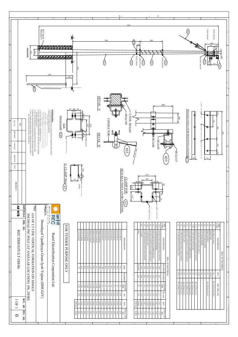
290
8000
GL
GL
EL
EV
AT
ION
1200
500
1000
003
816
817
814M
3000
150
2NO
S, M
8x60
2NO
S, M
10x60
2NO
S, M
10x60
022
001
RC
C B
ASE
450x450x75
145
200A
023
300150
B
2 NO
S. M16x65
300
008
2NO
S, M
16x65
600
2 NO
S. M16x65
831A
GL
300
2500
• •• • •• • •• • •• • • • • •• • • • • • • • • • • • • • • • • • • • •005
BIL
L O
F MA
TE
RIA
L
8M/200K
g. PSC
POL
E
ER
EC
OD
ED
ES
CR
IPTIO
N
001
QT
Y.
RE
F. D
RG
. NO
.
1 NO
.
BA
RB
ED
WIR
E003
3.5MT
R
415V D
AN
GE
R B
OA
RD
0221 N
O.
831A
CL
AM
P FO
R D
AN
GE
R B
OA
RD
814M1 N
O.
TO
P C
LA
MP
FO
R A
NT
I CL
IMB
ING
DE
VIC
E816
1 NO
.
BO
TT
OM
CL
AM
P FO
R A
NT
I CL
IMB
ING
DE
VIC
E817
1 NO
.
BIL
L O
F MA
TE
RIA
L
ER
EC
OD
ED
ES
CR
IPTIO
NQ
TY
.S
EC
TIO
NL
EN
GT
HkG
./mtr.
TO
TA
L W
t.
831A1 N
O.
75x40550
5.73.135
CL
AM
P FO
R D
AN
GE
R B
OA
RD
814M
TO
P C
LA
MP
FO
R A
NT
I CL
IMB
ING
DE
VIC
E816
BO
TT
OM
CL
AM
P FO
R A
NT
I CL
IMB
ING
DE
VIC
E817
TO
TA
L
SPR
ING
WA
SH
ER
S
PL
AIN
WA
SHE
R
NU
TS &
BO
LT
SM
1665
0.1646 N
OS.
NU
TS &
BO
LT
SM
860
2 NO
S.
SPR
ING
WA
SH
ER
S
PL
AIN
WA
SHE
R
M16
M8
M16
M8
0.0500.100
30x3
40x5
40x5
6100.701
M.S
.
M.S
.
M.S
.
M.S
.
DE
SC
RIPT
ION
QT
Y.
SIZ
EK
G.
MA
TE
RIA
L
1 NO
.0.428
395
413
1.60
1.60
2 NO
S.
2 NO
S.1.322
1.264
KG
.
16.081
MM
TO
TA
L2.976
NU
TS &
BO
LT
SM
1060
0.0554 N
OS.
LE
NG
TH
TO
TA
L W
t.K
G.
MM
0.984
0.220
SPR
ING
WA
SH
ER
SM
10
PL
AIN
WA
SHE
RM
10
MA
TE
RIA
L
3.5 TH
K.
0.0098 N
OS.
0.072
3.5 TH
K.
0.0034 N
OS.
0.012
3.5 TH
K.
0.0022 N
OS.
0.004
3 TH
K.
3 TH
K.
3 TH
K.
8 NO
S.
4 NO
S.
2 NO
S.
0.015
0.005
0.004
0.120
0.020
0.080
SH
AC
KL
E IN
SU
LA
TO
R M
OU
NT
ING
CH
AN
NE
L1 N
O.
ST
AY
SE
T A
RR
AN
GE
ME
NT
0081 S
ET
ST
AY
SE
T C
LA
MP
810F1 S
ET
CL
AM
P FO
R ST
AY
SET
M.S
.368
2 NO
S.2.311
50x83.14
CL
AM
P FO
R SH
AC
KL
E IN
SU
LA
TO
R C
HA
NN
EL
8322 S
ET
SH
AC
KL
E IN
SU
LA
TO
R M
OU
NT
ING
CH
AN
NE
L
832M
.S.
8222 S
ET
5.16250x8
3.14 C
LA
MP
FO
R S
HA
CK
LE
INSU
LA
TO
R C
HA
NN
EL
NU
TS &
BO
LT
SM
12115
0.1342 N
OS.
0.268
SPR
ING
WA
SH
ER
SM
123.5 T
HK
.0.009
6 NO
S.0.054
NU
TS &
BO
LT
SM
1250
0.0752 N
OS.
0.150
PL
AIN
WA
SHE
RM
123 T
HK
.6 N
OS.
0.0150.090
833U
-CL
AM
P F
OR
SH
AC
KL
E IN
SUL
AT
OR
2 NO
S.
SPIK
E6m
m R
OD
12556 N
OS.
M.S
.0.22
1.540
833U
-CL
AM
PM
.S.
2 NO
S.0.919
30x61.415
325
NU
TS &
BO
LT
SM
1280
0.1022 N
OS.
0.204
NU
TS &
BO
LT
SM
16150
0.2992 N
OS.
0.598
LT
SH
AC
KL
E IN
SUL
AT
OR
(TY
PE
-1)023
2 NO
S.
SPIK
E E
AR
TH
ING
0051 S
ET
810F
RE
C-X
II Plan-G
EN
-001A
RE
C-X
II Plan-G
EN
-012
RE
C-X
II Plan-L
T-011
RE
C-X
II Plan-L
T-001
RE
C-X
II Plan-L
T-001
RE
C-X
II Plan-L
T-001
RE
C-X
II Plan-L
T-011
RE
C-X
II Plan-L
T-011
RE
C-X
II Plan-L
T-011
100
DE
TA
IL `A
'
023
DE
TA
IL `B
'
200
M12x80832 M
12x115
M12x50
M16x150
•••••
•••••••••••••
CO
ND
UC
TO
R
2 NO
S. M16x65
150
550
50300
150
7540
•••••
••
••
••
••
••
••
•••••
••
••
••
••
••
•••••
••
••
••
••
••
•
831AS
HA
CK
LE
INS
UL
AT
OR
MO
UN
TIN
G C
HA
NN
EL
50
162
35
50x8 MS
FL
AT
PL
AN
20
810FS
TA
Y S
ET
CL
AM
P
•••••
••
••
••
••
••
•
3030
3030
238
35
171
65115
95
20
30 30 3030
832 C
LA
MP
FOR
SHA
CK
LE
INSU
LA
TO
R C
HA
NN
EL
4174
•••••
••
••
••
••
••
•
•••••
••
••
••
••
••
•
20105
75
•••••
••
••
••
••
••
•(T
YP)
833U
- CL
AM
P 30x6
12
HGFEDCB
12
A
46
57
3 34
65
78
910
11
89
1011
12
HGFEDCBA
12
GA
OF
LT
LIN
E V
ER
TIC
AL
FO
RM
AT
ION
ON
SIN
GL
E8M
/200 kG PS
C PO
LE
(AT
AN
GU
LA
R L
OC
AT
ION
) 1Ph, 2W
IRE
ED
RE
V. N
O.
R0
PR
EP
AR
ED
CH
EC
KE
DA
PPR
OV
ED
DA
TE
PRO
JEC
T0
1 OF
1
GE
NE
RA
L N
OT
ES
:1) A
LL
DIM
EN
SION
S AR
E IN
MM
UN
LE
SS
OT
HE
RW
ISE
ME
NT
ION
ED
4) AL
L M
.S. F
AB
RIC
AT
ED
ITE
MS
SH
AL
L B
E H
OT
DIP
GA
LV
AN
ISE
D
5) AL
L T
HE
ITE
MS
SHA
LL
BE
MA
RK
ED
WIT
H E
RE
CT
ION
CO
DE
.A
S PE
R IS
:2629 & 4759
3) AL
L M
.S. P
AR
TS S
HA
LL
CO
NF
0RM
TO
IS:2062
6) WE
IGH
T M
EN
TIO
NE
D IS
FO
R P
AC
KIN
G &
FOR
WA
RD
ING
PU
RP
OS
E.
7) AL
L C
LA
MP
S AN
D A
NG
LE
S S
HA
LL
CO
NFO
RM
TO
IS:SP 6 P
AR
T-1.
2) MA
NU
FA
CT
UR
ING
TO
LE
RA
NC
E•
•••
•••••
•••••••
••
••
••
••
••
••
••
••
•••••
••••••
••••••••
••
••
••
••
••
••
••
••
••••••
••••••
••••••••
••
••
••
••
••
••
••
••
••
••
••
••
••••••
•••••••
••
••
••
••
••
••
••
••
••
AL
L C
HA
NN
EL
S S
HA
LL
BE
ISL
C C
HA
NN
EL
S.
RE
C/D
DU
GJY
/LT
-OH
/06
FO
R T
EN
DE
R PU
RP
OS
E O
NL
Y
Rural E
lectrification Corporation L
td.
Deendayal U
padhyaya Gram
Jyoti Yojana (D
DU
GJY
)
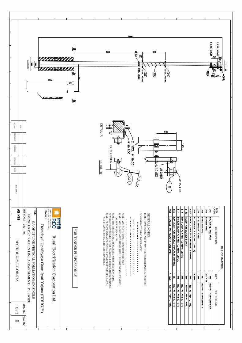
EL
EV
AT
ION
BIL
L O
F M
AT
ER
IAL
ER
EC
OD
ED
ES
CR
IPT
ION
QT
Y.
RE
F. D
RG
. NO
.
DE
TA
IL `A
'D
ET
AIL
`B'
12
HGFEDCB
12
A
46
57
3 34
65
78
910
11
89
1011
12
HGFEDCBA
12
GA
OF L
T L
INE
VE
RT
ICA
L FO
RM
AT
ION
ON
SING
LE
8M/200 kG
PSC P
OL
E (IN
LIN
E A
RR
AN
GE
ME
NT
) 1Ph, 2WIR
E
RE
V. N
O.
R0
PR
EP
AR
ED
CH
EC
KE
DA
PPR
OV
ED
DA
TE
PRO
JEC
TR
EC
/DD
UG
JY/L
T-O
H/07A
01 O
F 2
GE
NE
RA
L N
OT
ES:
1) AL
L D
IME
NSIO
NS A
RE
IN M
M U
NL
ES
S O
TH
ER
WISE
ME
NT
ION
ED
4) AL
L M
.S. FA
BR
ICA
TE
D IT
EM
S S
HA
LL
BE
HO
T D
IP G
AL
VA
NIS
ED
5) AL
L T
HE
ITE
MS
SHA
LL
BE
MA
RK
ED
WIT
H E
RE
CT
ION
CO
DE
.
AS P
ER
IS:2629 &
4759
3) AL
L M
.S. PA
RT
S S
HA
LL
CO
NF
0RM
TO
IS:2062
6) WE
IGH
T M
EN
TIO
NE
D IS
FO
R P
AC
KIN
G &
FO
RW
AR
DIN
G P
UR
POS
E.
7) AL
L C
LA
MP
S AN
D A
NG
LE
S SH
AL
L C
ON
FOR
M T
O IS
:SP 6 P
AR
T-1.
2) MA
NU
FAC
TU
RIN
G T
OL
ER
AN
CE
•••
•••••
••••••••
••
••
••
••
••
••
••
••
•••••
••••••
••••••••
••
••
••
••
••
••
••
••
•
••••••
••••••
••••••••
••
••
••
••
••
••
••
••
••
••
••
••••••
••••••••
••
••
••
••
••
••
••
••
••
AL
L C
HA
NN
EL
S SH
AL
L B
E IS
LC
CH
AN
NE
LS.
FO
R T
EN
DE
R PU
RP
OS
E O
NL
Y
Rural E
lectrification Corporation L
td.
Deendayal U
padhyaya Gram
Jyoti Yojana (D
DU
GJY
)
Volume-III: Section-ITechnical Specifications
487
DDUGJY & IPDS/SBD/R1
29 11 kV and 33 kV Air Break Switches
1) SCOPE
This specification provides for manufacture, testing at works and supply of 11KV & 33KV AB switches. The 11KV and 33 KV AB switches shall conform to IS: 9920 (Part-I to IV)
2) AB SWITCHES
The 11KV & 33KV Air Break Switches are required with two poles in each phase. The AB Switches shall be supplied complete with phase coupling shaft, operating rod and operating handle. It shall be manually gang operated and vertically break and horizontal mounting type.
The equipment offered by the bidder shall be designed for a normal current rating of 200 Amps and for continuous service at the system voltage specified as under:
i) 11 KV AB Switch : 11KV + 10% continuous 50 C/s solidly grounded earthed neutral
system
ii) 33KV AB Switch : 33 kV + 10% -do-
The length of break in the air shall not be less than 400 mm for 11KV AB Switches and 500 mm for 33 KV AB Switches.
The 11KV & 33KV AB Switches are required with post insulators. The AB switches should be suitable for mounting on the structure. The mounting structure will be arranged by the bidder. However, the AB Switches shall be supplied with base channel for mounting on the structure which will be provided by the owner. The phase to phase spacing shall be 750mm in case of 11KV AB Switches & 1200mm in case of33KV AB Switches.
3) POST INSULATORS
The complete set of three phase AB Switches shall have stacks of post insulators.
11KV AB Switches : 3 No. 11KV Post Insulator per stack* (1 No. 11kV post insulator per stack shall be permitted)
33KV AB Switches : 3 No. 33KV Post Insulator per stack* (2 No. 22kV or 3 No. 11kV post insulator shall be permitted in each stack).
The post insulators should conform to the latest applicable Indian standards IS: 2544 Specification for Porcelain Post insulator of compact solid core or long rod insulators are also acceptable. Creepage distance should be adequate for highly polluted outdoor atmosphere in open atmosphere. The porcelain used for manufacture of AB Switches should be homogeneous free from flaws or imperfections that might affect the mechanical dielectric quality. They shall be thoroughly vitrified, tough and impervious to moisture. The glazing of the porcelain shall be of uniform brown in colour, free from blisters, burns and other similar defects. Insulators of the same rating and type shall be interchangeable.
* Amendment issued vide letter No. REC/DDUGJY/SBD/TS/2017-18D. No.3091 Dated 25.08.2017.
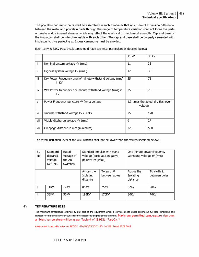
Volume-III: Section-ITechnical Specifications
488
DDUGJY & IPDS/SBD/R1
The porcelain and metal parts shall be assembled in such a manner that any thermal expansion differential between the metal and porcelain parts through the range of temperature variation shall not loose the parts or create undue internal stresses which may affect the electrical or mechanical strength. Cap and base of the insulators shall be interchangeable with each other. The cap and base shall be properly cemented with insulators to give perfect grip. Excess cementing must be avoided.
Each 11KV & 33KV Post Insulators should have technical particulars as detailed below:
11 kV 33 kV
i Nominal system voltage kV (rms) 11 33
ii Highest system voltage kV (rms.) 12 36
iii Dry Power Frequency one kV minute withstand voltage (rms) in KV
35 75
iv Wet Power frequency one minute withstand voltage (rms) in KV
35 75
v Power Frequency puncture kV (rms) voltage 1.3 times the actual dry flashover voltage
vi Impulse withstand voltage kV (Peak) 75 170
vii Visible discharge voltage kV (rms) 9 27
viii Creepage distance in mm (minimum) 320 580
The rated insulation level of the AB Switches shall not be lower than the values specified below:-
Sl. No
Standard declared voltage KV/RMS
Rated Voltage of the AB Switches
Standard impulse with stand voltage (positive & negative polarity kV (Peak)
One Minute power frequency withstand voltage kV (rms)
Across the Isolating distance
To earth & between poles
Across the Isolating distance
To earth & between poles
i 11KV 12KV 85KV 75KV 32KV 28KV
ii 33KV 36KV 195KV 170KV 80KV 70KV
4) TEMPERATURE RISE
The maximum temperature attained by any part of the equipment when in service at site under continuous full load conditions and
exposed to the direct rays of Sun shall not exceed 45 degree above ambient. Maximum permitted temperature rise over ambient temperature will be as per Table-4 of IS 9921 (Part-2). *
Amendment issued vide letter No. REC/DDUGJY/SBD/TS/2017-18D. No.3091 Dated 25.08.2017.
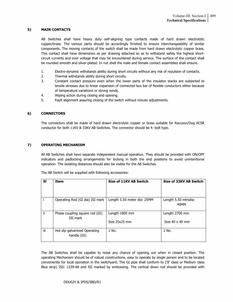
Volume-III: Section-ITechnical Specifications
489
DDUGJY & IPDS/SBD/R1
5) MAIN CONTACTS
AB Switches shall have heavy duty self-aligning type contacts made of hard drawn electrolytic copper/brass. The various parts should be accordingly finished to ensure interchangeability of similar components. The moving contacts of the switch shall be made from hard drawn electrolytic copper brass. This contact shall have dimensions as per drawing attached so as to withstand safely the highest short-circuit currents and over voltage that may be encountered during service. The surface of the contact shall be rounded smooth and silver-plated. In nut shell the male and female contact assemblies shall ensure.
1. Electro-dynamic withstands ability during short circuits without any risk of repulsion of contacts. 2. Thermal withstands ability during short circuits. 3. Constant contact pressure even when the lower parts of the insulator stacks are subjected to
tensile stresses due to linear expansion of connected bus bar of flexible conductors either because of temperature variations or strong winds.
4. Wiping action during closing and opening. 5. Fault alignment assuring closing of the switch without minute adjustments.
6) CONNECTORS
The connectors shall be made of hard drawn electrolytic copper or brass suitable for Raccoon/Dog ACSR conductor for both 11KV & 33KV AB Switches. The connector should be 4 -bolt type.
7) OPERATING MECHANISM
All AB Switches shall have separate independent manual operation. They should be provided with ON/OFF indicators and padlocking arrangements for locking in both the end positions to avoid unintentional operation. The isolating distances should also be visible for the AB Switches.
The AB Switch will be supplied with following accessories:
Sl Item Size of 11KV AB Switch Size of 33KV AB Switch
i Operating Rod (GI dia) ISI mark Length 5.50 meter dia: 25MM Length 5.50 mtrsdia: 40MM
ii Phase coupling square rod (GI) ISI mark
Length 1800 mm
Size 25x25 mm
Length 2700 mm
Size 40 x 40 mm
iii Hot dip galvanized Operating handle (GI)
1 No. 1 No.
The AB Switches shall be capable to resist any chance of opening out when in closed position. The operating Mechanism should be of robust constructions, easy to operate by single person and to be located conveniently for local operation in the switchyard. The GI pipe shall conform to Blue strip) ISS: 1239-68 and ISI marked by embossing. The vertical down rod should be provided with
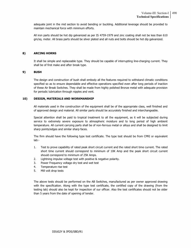
Volume-III: Section-ITechnical Specifications
490
DDUGJY & IPDS/SBD/R1
adequate joint in the mid section to avoid bending or buckling. Additional leverage should be provided to maintain mechanical force with minimum efforts.
All iron parts should be hot dip galvanized as per IS 4759-1979 and zinc coating shall not be less than 610 gm/sq. meter. All brass parts should be silver plated and all nuts and bolts should be hot dip galvanized.
8) ARCING HORNS
It shall be simple and replaceable type. They should be capable of interrupting line-charging current. They shall be of first make and after break type.
9) BUSH
The design and construction of bush shall embody all the features required to withstand climatic conditions specified so as to ensure dependable and effective operations specified even after long periods of inaction of these Air Break Switches. They shall be made from highly polished Bronze metal with adequate provision for periodic lubrication through nipples and vent.
10) DESIGN, MATERIALS AND WORKMANSHIP
All materials used in the construction of the equipment shall be of the appropriate class, well finished and of approved design and material. All similar parts should be accurately finished and interchangeable.
Special attention shall be paid to tropical treatment to all the equipment, as it will be subjected during service to extremely severe exposure to atmospheric moisture and to long period of high ambient temperature. All current carrying parts shall be of non-ferrous metal or alloys and shall be designed to limit sharp points/edges and similar sharp faces.
The firm should have the following type test certificate. The type test should be from CPRI or equivalent lab:-
1. Test to prove capability of rated peak short circuit current and the rated short time current. The rated short time current should correspond to minimum of 10K Amp and the peak short circuit current should correspond to minimum of 25K Amps.
2. Lightning impulse voltage test with positive & negative polarity. 3. Power Frequency voltage dry test and wet test 4. Temperature rise test 5. Mill volt drop tests
The above tests should be performed on the AB Switches, manufactured as per owner approved drawing with the specification. Along with the type test certificate, the certified copy of the drawing (from the testing lab) should also be kept for inspection of our officer. Also the test certificates should not be older than 5 years from the date of opening of tender.
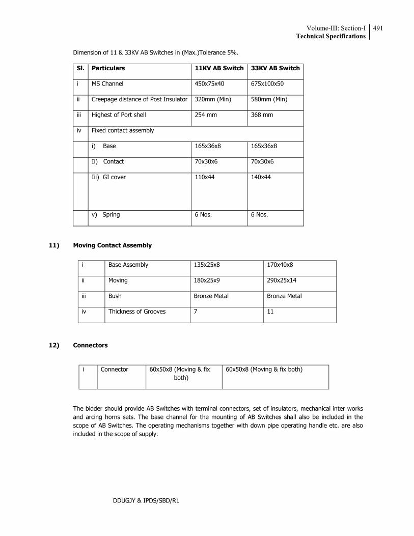
Volume-III: Section-ITechnical Specifications
491
DDUGJY & IPDS/SBD/R1
Dimension of 11 & 33KV AB Switches in (Max.)Tolerance 5%.
Sl. Particulars 11KV AB Switch 33KV AB Switch
i MS Channel 450x75x40 675x100x50
ii Creepage distance of Post Insulator 320mm (Min) 580mm (Min)
iii Highest of Port shell 254 mm 368 mm
iv Fixed contact assembly
i) Base 165x36x8 165x36x8
Ii) Contact 70x30x6 70x30x6
Iii) GI cover 110x44 140x44
v) Spring 6 Nos. 6 Nos.
11) Moving Contact Assembly
12) Connectors
i Connector 60x50x8 (Moving & fix both)
60x50x8 (Moving & fix both)
The bidder should provide AB Switches with terminal connectors, set of insulators, mechanical inter works and arcing horns sets. The base channel for the mounting of AB Switches shall also be included in the scope of AB Switches. The operating mechanisms together with down pipe operating handle etc. are also included in the scope of supply.
i Base Assembly 135x25x8 170x40x8
ii Moving 180x25x9 290x25x14
iii Bush Bronze Metal Bronze Metal
iv Thickness of Grooves 7 11
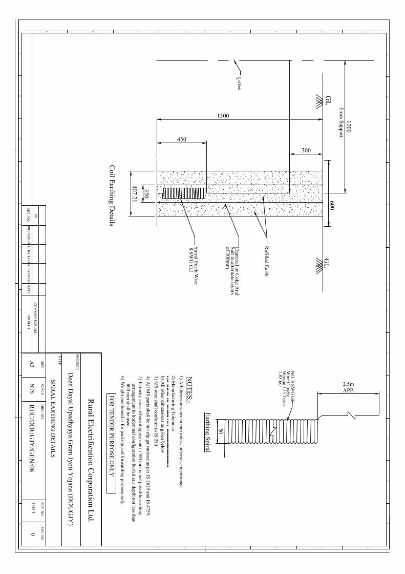
GL
1200
GL
407.21
350
Refilled E
arth
Charcoal or C
oke And
Salt in alternate layers
of 300mm
Spiral E
arth Wire
8 SW
G G
.I
450
1500
300
C of Pole
L
600
From
Support
Coil E
arthing Details
NO
. 8 SWG
GI
Wire C
losely
50
Wound 115 T
urns
Earthing S
piral
1.85 kG 2.5mAPP.
12
HGFEDCB
12
A
46
57
3 34
65
78
910
11
89
1011
12
HGFED
12
SPIR
AL
EA
RT
HIN
G D
ET
AIL
S
2) Manufacturing T
olerance.
NO
TE
S:-1) A
ll dimensions are in m
m unless otherw
ise mentioned.
Rural E
lectrification Corporation L
td.
PR
OJE
CT
:
TIT
LE
SC
AL
ED
RG
. NO
.S
IZE
RE
V. N
O.
SH
T. N
O.
1 OF 1
A3
NT
S0
RE
C/D
DU
GJY
/GE
N/08
RE
V. N
O.
R0
PR
EP
AR
ED
CH
EC
KE
DA
PPR
OV
ED
DA
TE
PR
OJE
CT
CO
MM
ON
FO
R A
LL
•••••••••••
••••••••••••••••
•••••••••••••••••••••••••••••••b) A
ll other dimensions as given below
3) MS
wire shall conform
to IS 280
4) All M
S parts shall be hot dip galvanised as per IS 2629 and IS
4759.
5) In rocky areas where digging upto 1500 m
m is not possible,earthing
arrangement in horizontal configuration buried at a depth not less than
800 mm
shall be used.6) W
eight mentioned is for packing and forw
arding purpose only.
FO
R T
EN
DE
R PU
RP
OS
E O
NL
Y
Deen D
ayal Upadhyaya G
ram Jyoti Y
ojana (DD
UG
JY)
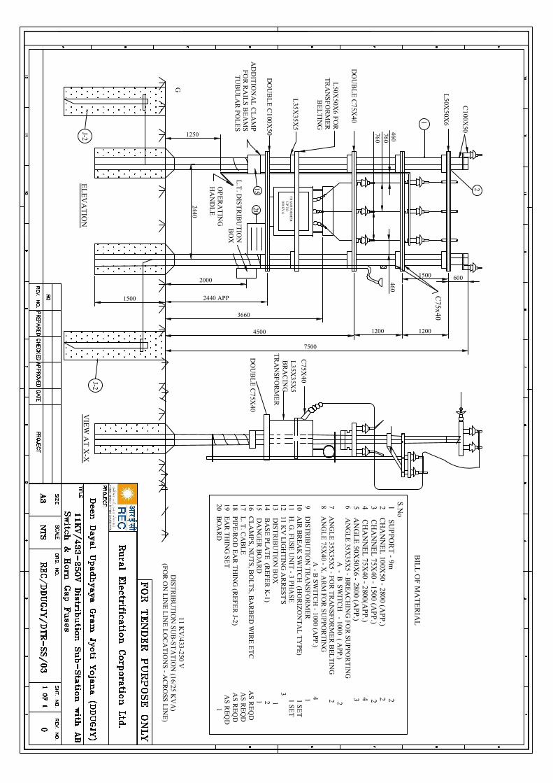
TR
AN
SF
OR
ME
R
7500
DO
UB
LE
C100X
50
3660
4500
AD
DIT
ION
AL
CL
AM
PF
OR
RA
ILS
BE
AM
ST
UB
UL
AR
POL
ES
1500
EL
EV
AT
ION
15
L.T
. DIS
TR
IBU
TIO
NB
OX
2440
1250
OP
ER
AT
ING
HA
ND
LE
2000
2440 APP
L35X
35X5
L50X
50X6 F
OR
TR
AN
SF
OR
ME
RB
EL
TIN
G
C100X
50
L50X
50X6
DO
UB
LE
C75X
40
1200
1500
460
TR
AN
SFO
RM
ER
UP T
O 100 K
VA
460760760
1200
C75x40
600
BIL
L O
F M
AT
ER
IAL
S.No
1 SU
PPO
RT
- 9m 2
2 CH
AN
NE
L 100X
50 - 2800 (APP.) 2
3 CH
AN
NE
L 75X
40 - 1500 (AP
P.) 2 4 C
HA
NN
EL
75X40 - 2800(A
PP.) 4
5 AN
GL
E 50X
50X6 - 2800 (A
PP.) 3
6 AN
GL
E 35X
35X5 - B
RE
AC
HIN
G FO
R SU
PPO
RT
ING
A - B
SW
ITC
H - 1000 ( A
PP.) 2
7 AN
GL
E 35X
35X5 - F
OR
TR
AN
SFO
RM
ER
BE
LT
ING
2 8 A
NG
LE
75X40 - X
. AR
M FO
R S
UP
POR
TIN
G A
- B SW
ITC
H - 1000 (A
PP.) 4
9 DIST
RIB
UT
ION
TR
AN
SFO
RM
ER
1 10 A
IR B
RE
AK
SW
ITC
H (H
OR
IZO
NT
AL
TY
PE
) 1 SE
T 11 H
. G. F
US
E U
NIT
- 3 PH
AS
E 1 SE
T 12 11 K
V L
IGH
TIN
G A
RR
EST
'S 3
13 DIS
TR
IBU
TIO
N B
OX
1 14 B
ASE
PL
AT
E (R
EF
ER
K-1) 2
15 DA
NG
ER
BO
AR
D 1
16 CL
AM
PS, N
UT
S, BO
LT
S, B
AR
BE
D W
IRE
ET
C A
S R
EQ
D 17 L
. T. C
AB
LE
AS
RE
QD
18 PIPE
/RO
D E
AR
TH
ING
(RE
FE
R J-2) A
S RE
QD
19 EA
R T
HIN
G S
ET
AS
RE
QD
20 BO
AR
D 1
11 KV
/433-250 VD
ISTR
IBU
TIO
N S
UB
-ST
AT
ION
(16/25 KV
A)
(FO
R O
N L
INE
LIN
E L
OC
AT
ION
S - A
CR
OSS
LIN
E)
L35X
35X5
BR
AC
ING
C75X
40
G
J-2
J-2V
IEW
AT
X-X
DO
UB
LE
C75X
4020
1
2
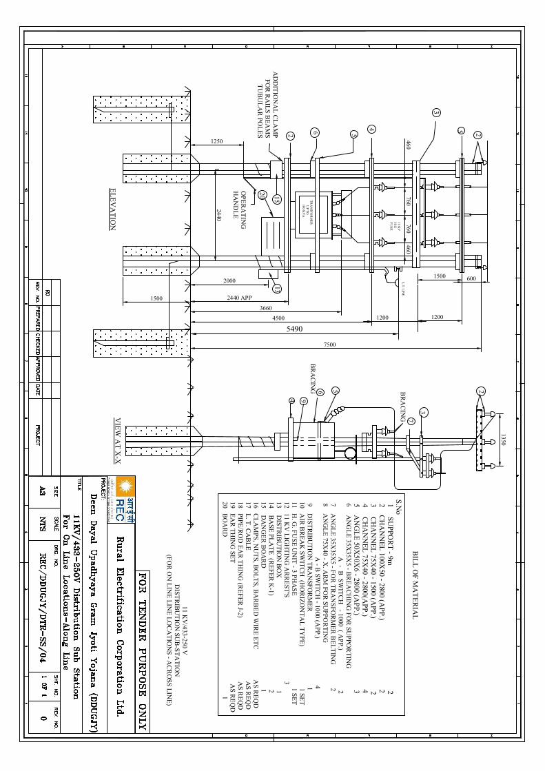
94
7500
2
3660
4500
AD
DIT
ION
AL
CL
AM
PF
OR
RA
ILS
BE
AM
ST
UB
UL
AR
POL
ES
1500
EL
EV
AT
ION
15 13
2440
1250
OP
ER
AT
ING
HA
ND
LE
2000
2440 APP
6 5 254
1200
1500
460
TR
AN
SFO
RM
ER
UP T
O 100 K
VA
460760
760
1200
3
600
11 KV
/433-250 VD
IST
RIB
UT
ION
SUB
-ST
AT
ION
(FO
R O
N L
INE
LIN
E L
OC
AT
ION
S - AC
RO
SS LIN
E)
VIE
W A
T X
-X
56B
RA
CIN
G
7B
RA
CIN
G
3
1350
2
11 KV
H.G
FU
SE
L.T
. LIN
E
5490
BIL
L O
F M
AT
ER
IAL
S.N
o 1 S
UP
POR
T - 9m
2 2 C
HA
NN
EL
100X50 - 2800 (A
PP
.) 2 3 C
HA
NN
EL
75X40 - 1500 (A
PP
.) 2 4 C
HA
NN
EL
75X40 - 2800(A
PP
.) 4 5 A
NG
LE
50X50X
6 - 2800 (AP
P.) 3 6 A
NG
LE
35X35X
5 - BR
EA
CH
ING
FOR
SU
PP
OR
TIN
G A
- B S
WIT
CH
- 1000 ( AP
P.) 2 7 A
NG
LE
35X35X
5 - FO
R T
RA
NS
FOR
ME
R B
EL
TIN
G 2
8 AN
GL
E 75X
40 - X. A
RM
FO
R S
UP
POR
TIN
G A
- B SW
ITC
H - 1000 (A
PP
.) 4 9 D
IST
RIB
UT
ION
TR
AN
SFO
RM
ER
1 10 A
IR B
RE
AK
SWIT
CH
(HO
RIZ
ON
TA
L T
YPE
) 1 SE
T 11 H
. G. F
US
E U
NIT
- 3 PH
AS
E 1 S
ET
12 11 KV
LIG
HT
ING
AR
RE
ST
'S 3
13 DIST
RIB
UT
ION
BO
X 1
14 BA
SE
PL
AT
E (R
EF
ER
K-1) 2
15 DA
NG
ER
BO
AR
D 1
16 CL
AM
PS, N
UT
S, BO
LT
S, BA
RB
ED
WIR
E E
TC
AS
RE
QD
17 L. T
. CA
BL
E A
S R
EQ
D 18 P
IPE/R
OD
EA
R T
HIN
G (R
EF
ER
J-2) AS
RE
QD
19 EA
R T
HIN
G SE
T A
S RE
QD
20 BO
AR
D 1
20
Volume-II : Section-II (B) Technical Specification
558
DDUGJY & IPDS/SBD/R1
10.0 Acceptance Tests for CMRI and PC Software
All CMRI after final assembly and before dispatch from Bidder's/Manufacturer's works shall be duly tested to verify that they are suitable for supply to the Employer. In particular, each and every CMRI shall be subjected to the following acceptance test:
(i) Functional Checks (ii) Downloading Meter Data from the Meter(s) (iii) Compatibility with PC software (iv) Downloading the meter data on PC (v) Functioning of advance and retard time commands (vi) Per meter downloading time verification (vii) Capacity of CMRI for data storage
35 Earthing Coil
Earthing Coils shall be fabricated from soft GI Wire Hot Dip Galvanized. The Hot Dip galvanized wire shall have clean surface and shall be free from paint enamel or any other poor conducting material. The coil shall be made as per REC constructions standard (Refer tender drawing No. REC-XI Plan-Gen-005). The Hot Dip galvanizing shall conform to IS:2629/1966, 2633/1972 and 4826/1969 with latest amendments. Galvanizing should be heavily coated and should stand for the following tests.
Galvanizing Tests
i) Minimum Mass of Zinc
a) ON GI Wire used 280 cm/m2 b) After Coiling 266 gm/m2. The certificate from recognized laboratory shall be submitted
towards mass of zinc.
ii) Dip TestShall stand 3 dips of 1 minute and one dip of ½ minute before coiling and 43 dips of 1 minute after coiling as per IS : 4826/1979.
THE DIMENSIONAL REQUIREMENT SHALL BE AS FOLLOWS
a) Nominal dia of GI Wire 4 mm (Tolerance + 2.5%) b) Minimum no. of turns 115 Nos. c) External dia of Coil (Min) 50 mm d) Length of Coil (Min) 460 mm e) Free length of GI Wire at one end coil (Min.) 2500 mm
The turns should be closely bound. Weight of one finished Earthing Coils (min.) 1.850 Kg.
Adhesion test As per ISS 4826 1979.
Volume-II : Section-II (B) Technical Specification
571
DDUGJY & IPDS/SBD/R1
42 Earthing (AS PER IS 3043-1987)
Earthing shall generally be carried out in accordance with the requirements of Indian Electricity Rules 2003 amended from time to time and relevant regulations under Electricity Supply Authority concerned.
In case of high and extra high voltages, the neutral points shall be earthed by not less than two separate distinct connections with earth, each having its own electrodes sub-station and will be earthed at any other point provided no interference is caused by such earthing. If necessary, the neutral may be earthed through suitable impedance.
As far as possible, all earth connections should be visible for inspection. Each earthing system shall be so designed, that, the testing of individual earth electrodes is possible. It is recommended that the value of any earth system resistance shall be such as to conform to the degree of shock protection desired.
It is recommended, that a drawing showing the main earth connections and earth electrodes be prepared for each installation and submitted to Employer.
No addition to the current carrying system, either temporary or permanent, shall be made which will increase the maximum available fault current on its duration until it has been ascertained that the existing arrangement of earth electrodes, earth bus-bar etc., are capable of carrying the new value of earth fault current which may be obtained by this addition.
All materials, fittings etc., used in earthing shall conform to Indian Standard Specifications, wherever they exist.
GENERAL REQUIREMENTS AND PROCEDURES FOR EARTHING AT SUB-STATIONS.
The ground resistance for sub-stations should not exceed a value 2(two) ohms. The joints/connections in the earthling, system shall be welded only, except the connections, which require opening for testing/maintenance. Such connections should be bolted tightly, using spring and ring washers for proper contact pressure. The G.S. flats to be provided for the horizontally laid earth grid should have overlap welded joints, with length of welding at least twice the width of the flat, e.g., 100 MM for 50x6 MM G.S. flats. There should not be any dirt, grease, oil, enamel, paint or any such non-conductive coatings on the surfaces being joined/ connected. Only the finished joints/connections above ground may be provided with red-oxide or any other protective coating. Underground earth electrodes and earth grid elements, when laid, should have a clean metallic surface, free from paint, enamel, grease or any such non-conductive coatings.
As far as possible, all earth connections should be accessible for visual inspection. No cut-outs, links or switches, other than linked switches arranged to operate simultaneously on the earthed or earthed neutral conductor and the live wire shall be inserted in the supply system. Earth electrodes or mate should not be installed in close proximity to metal fence to avoid possibility of fence becoming live. Separate earth electrodes, isolated from the earth grid, are to be provided for grounding the fence wires.
Pipes or rods used as electrodes should be in one piece, as far as possible, with a minimum allowable length of 3 mtrs. Except where rock or hard stratum is encountered, the pipe/rod electrodes should be driven into the ground to a minimum depth of 3 mtrs. The strip electrodes, forming the horizontal gild, should be buried underground to a minimum depth of 0.5 mtrs. The path of earth wire should be out of normal reach of any person, as far as possible.
For high resistivity soils, above 100 Ohm-mtrs., attempts should be made to bring the soil resistivity in the range of 50 to 60 Ohm-mtrs. By digging and treating the soil mass around the earth grid/electrodes with a mixture of salt and charcoal.
Volume-II : Section-II (B) Technical Specification
572
DDUGJY & IPDS/SBD/R1
In case of rocky top soil and sub-stratum, having very high resistivity, with no scope of improvement by other means, the procedure given below should be followed:
1. At least two bores of diameter little less than 40 mm, with a minimum distance of 10 mtrs. between them, should be made in the ground at suitable locations inside the S/S yard. The boring should be done until soil sub-stratum rich in moisture and low in resistivity is encountered. G.I. pipes of 40 MM dia. should be descended in each bore, such that, the soil mass around the pipes grips them tightly, Back filling of bores, if required, with wet soil/clay may be done to ensure this condition. The G.I. pipes in these deep bores should be interconnected with the main earthing grid of the S/S through 50x6 mm G.S. flat, with all the joints/connections and terminations being either fully welded, or clamped/bolted and welded simultaneously. The G.I. pipes in the bores should also be interconnected with each other. In extreme cases, the bores may have to be made at remote locations i.e. outside the S/S yard, with inter-connections, through 50x6 MM flats, as explained before.
2. The procedures to be observed stringently for making connections and joints between various elements of the earthing system are as follows:
a. G.S. flat to Structure/flat - The G.S. flat should be welded to the metallic portion (leg) of the structure after thoroughly cleaning the surfaces to be welded. The length of the welding should be at least twice the width of the G.S. flat, e.g.-minimum 100 mm for 50x6 mm G.S. flat. Exactly similar procedure is to be adopted for joints between two G.S. flats.
b. G.I. wire to structure. The G.I. wire should be bolted to the structure after making an eye formation and kept tight with the help of spring and ring washer. Then, the entire arrangement should be welded.
c. G.I. wire to G.S. flat- The G.I. wire should be bolted and then welded to G.S. flat, as explained above.
d. G.I. rod to G.S. flat- The G.I. rod should be securely clamped to the G.S. flat with the help of bolts and washers and the entire arrangement should then be welded.
e. G.I. wire to G.I. pipe GI wire should be bolted to the G.I. pipe and then welded, keeping in view the relevant precautions, mentioned before.
f. G.I. flat to G.I pipe The GI flat should be bolted tightly to the G.I. pipe and then the connection should be welded.
Before making connections and joints, it should be ensured that, the elements to be joined have a clean metallic contact surface without any non-conductive coating.
EARTH GRID SYSTEM
Grid system of interconnected conductors forming a closed loop mesh is to be installed using 75x8 mm MS flat for peripheral and branch conductors. Interconnections are made by welding them. This earth grid will be laid at a depth of about 0.5 mtr. bonded to general mass of the earth by 3 mtrs. long earth electrode of solid MS rod (or pipe) of dia 25mm. The G.I. pipe 40 mm. dia 3 mtrs. long in the earthing pits, driven vertically.
It is to this earth grid that the transformer neutral, apparatus, frame work and other non-current carrying metal work associated like transformer tank, switchgear frame etc. are to be connected. All these connections should be made in such a way that reliable and good electrical connection is ensured.
Volume-II : Section-II (B) Technical Specification
573
DDUGJY & IPDS/SBD/R1
Aluminum/ other paint, enamel, grease and scale should be removed from the point of contact before connections are made. No part of the ground connection leads should be embedded in concrete.
Arrangement of connection of earth connection shall be as follow:
1. STRUCTURES:
Structures including frames, metal supports within the substation grid at least two legs, preferably diagonally opposite (where more than two legs are provided) on each metal structure shall be connected to earth grid with GI wire of 4mm dia or 6 mm dia.
2. ISOLATORS/ SWITCHES:
The operating handle shall be connected to earth grid independent of the structure earthing or through the steel mounting structure, through 4 mm dia G.I. wire.
3. LIGHTNING ARRESTOR:
The bases of lightning arrestors shall be directly connected to the earth electrodes by 4 or 6 SWG G.I. wires as short and as straight as practicable, to ensure minimum impedance. Separate earth leads should be used for L.A. in each phase. In addition there shall be as direct connections as practicable from the earthed side of the lightning arrestors to the frame of the apparatus being protected. Surge counters, could also be inserted in the circuit where lightning incidences are high, but in such cases, the lightning arrestor should be mounted on insulated base. Invariably, earth connections for lightning arrestors should be separate, and in no case should they be joined looped or meshed with other conductors. For lightning arrestors mounted near transformers, earthing connections shall be done with the earthing pits and earthing leads shall be laid clear of the tank and collars in order to avoid possible oil leakage caused by arcing. The earth connection should not pass through iron pipes, as it would increase the reactive impedance of the connection.
4. POWER TRANSFORMER:
The tank of the transformer shall be directly connected to the main earth grid. In addition there shall be a separate and as direct a connection as practicable from the tank to the earth side of protecting LA using 4 or 6 SWG GI wire.
The earthing of the neutral shall be by two separate, distinct and direct connections of 50x6 mm GS flat to earth pits, which form a part of the earth grid, and shall be run clear of the tank and collars.
The transformer track rails shall be connected to earth
5. OUT DOOR VCB:
At least two legs, preferably diagonally opposite of the supporting structure frame work of each circuit breaker unit shall be connected to the earth grid, through 50x6 mm G.S. flats.
6. FENCING:
Fencing and gate should be earthed separately.
Volume-II : Section-II (B) Technical Specification
574
DDUGJY & IPDS/SBD/R1
7. CURRENT TRANSFORMERS / POTENTIAL TRANSFORMERS:
The bases of the current transformers should be directly connected to the earth grid through 4 or 6 SWG G.I. wires. The base (neural side) of the P.Ts. should be directly connected to the earth grid through 4 or 6 SWG G.I. wires. Separate earth leads should be used for P.Ts. in each phase. The termination of leads on the P.T. neutral should be bolted/clamped and not welded, to facilitate opening of the earth connection for testing purposes. In addition, all bolted cover plates to which bushings are attached, should be connected to the earth grid, both in case of C.Ts. and P.Ts.
8. Armoring of armored metal-sheathed cables within the station grid area shall be connected to the earth grid.
9. Substation L.T. Supply Transformer: Same as above except that the neutral earthing conductor
used shall be 4 or 6 SWG G.I. wire.
Volume-II : Section-II (B) Technical Specification
575
DDUGJY & IPDS/SBD/R1
43 Gi Earthing Pipe
Earthing pipe should be made of 40 mm diameter ISI marked B class GI Pipe. 12 mm dia suitable holes on its circumference shall be made as per approved drawing. The pipe should be in one piece. No joints or welding would be allowed on its length. Clamps made of 50x6mm GI flat duly drilled with 12 mm size holes should be welded at the top end for connection of earth conductor.
Pipe used shall be 40mm NB diameter, ISI marked Galvanized Mild Steel Tubes continuously welded Electric Resistance Welded ERW/High Frequency Induction welded (HFIW)/Hot finished welded (HFW) type, conforming to IS-554-1985 with latest amendment of MEDIUM quality (Class B).
1. MANUFACTURE:
GI earth pipe (40 mm diameter & 3 metre long) shall be made of tubes which shall be made from tested quality steel manufactured by any approved process as follows:
a) Electric Resistance Welded (ERW). b) High Frequency Induction Welded (HFIW) and c) Hot finished Welded (HFW).
Tubes made by manual welding are not acceptable.
2. DIMENSIONS:
The dimensions and weights of tubes shall be in accordance with Table-I and Table-II of IS: 1239 (Part-I)/1990 with latest amendments, subject to tolerance permitted therein. Necessary 12 mm diameter holes across the circumference shall be provided as per approved drawing. Drawings shall be approved by the owner before start of the manufacturing work. The tube, earthing pipe shall be provided with 50x6mm GS clamps on one end, one clamp is to be welded with the pipe and another is removable to enable measurement of earth resistance of the pit. Other end of the earth pipe should be cut half in slop to make it a sharp.
3. GALVANIZING:
Tubes shall be galvanized in accordance with IS-4736-1986 with latest amendment for not dip zinc coating of Mild Steel Tubes. The minimum mass of zinc coating on the tubes shall be in accordance with clause 5.1 of IS-4736-1986 (specification for hot dip zinc) and when determined on a 100mm long test piece in accordance with IS: 6745:1972 shall be 400 g/m2. The zinc coating shall be uniform adherent reasonably smooth and free from such imperfections as flux, ash and dross inclusions, bare patches, black spots, pimples, lumpiness, rust, stains, bulky white deposits and blisters.
4. HYDRAULIC TEST:
(Before applying holes) Each tube shall withstand a test pressure of 5 M Pa maintained for at least 3 seconds without showing defects of any kind. The pressure shall be applied by approved means and maintained sufficiently long for proof and inspection. The testing apparatus shall be fitted with an accurate pressure indicator
5. TEST ON FINISHED TUBES AND SOCKETS:
The following tests shall be conducted by the manufacturer of finished tubes and sockets.
a) The tensile strength of length of strip cut from selected tubes when tested in accordance with IS-1894-1972, (Method for tensile testing of steel tubes), shall be at least 320N/mm2.
Volume-II : Section-II (B) Technical Specification
576
DDUGJY & IPDS/SBD/R1
b) The elongation percentage on a gauge length of 5.65/so (where so is the original cross-sectional area of test specimen) shall not be less than 20%.
c) When tested in accordance with IS-2329-1985 (Method for Bend test on Metallic tubes) the finished tube shall be capable of with standing the bend test without showing any sign of fracture or failure. Welded tubes shall be bent with the weld at 90 degree to the plane of bending. The tubes shall not be filled for this test.
d) Galvanized tubes shall be capable of being bent cold without cracking of the steel, through 90 degree round a former having a radius at the bottom of the groove equal to 8 times the outside diameter of tube.
e) Flattening Test on Tubes above 50 mm Nominal Bore: Rings not less than 40 mm in length cut from the ends of selected tubes shall be flattered between parallel plates with the weld, if any, at 90 degree (point of maximum bending) in accordance with IS-2328-1983. No opening should occur by fracture in the weld unless the distance between the plate is less than 75 percent of the original outside diameter of the pipe and no cracks or breaks in the metal elsewhere than in the weld shall occur, unless the distance between the plates is less than 60% of the original outside diameter. The test rings may have the inner and outer edges rounded.
f) GALVANISHING TEST: Weight of zinc Coating: For tubes thickness upto 6 mm the minimum weight of zinc coating,
when determined on a 100 mm long test piece in accordance with IS-4736-1986 shall be 400 grm/m2.
The weight of the coating expressed in gram/m2 shall be calculated by dividing the total weight of the zinc (inside plus outside) by the total area (inside plus outside) of the coated surface.
Test specimen for this test shall be cut approximately 100 mm in length from opposite ends of
the length of tubes selected for testing. Before cutting the test specimen, 50 mm from both ends of the samples shall be discarded.
g) Free Bore Test: A rod 230mm long and of appropriate diameter shall be passed through relevant
nominal bore of the sample tubes to ensure a free bore.
h) Uniformity of Galvanized Coating: The galvanized coating when determined on a 100 mm long test piece [see V (a) (iii)] in accordance with IS-2633-1986 (Method for testing uniformity of coating on zinc coated articles) shall with stand 4 one minute dips.
6. WORKMANSHIP:
The tubes shall be cleanly finished and reasonably free from injurious defects. They shall be reasonably straight, free from cracks, surface flaws, laminations, and other defects, both internally and externally. The screw tubes and sockets shall be clean and well-cut. The ends shall be cut cleanly and square with the axis of tube.
7. MARKING:
The medium class of tubes shall be distinguished by Blue colour bands which shall be applied before the
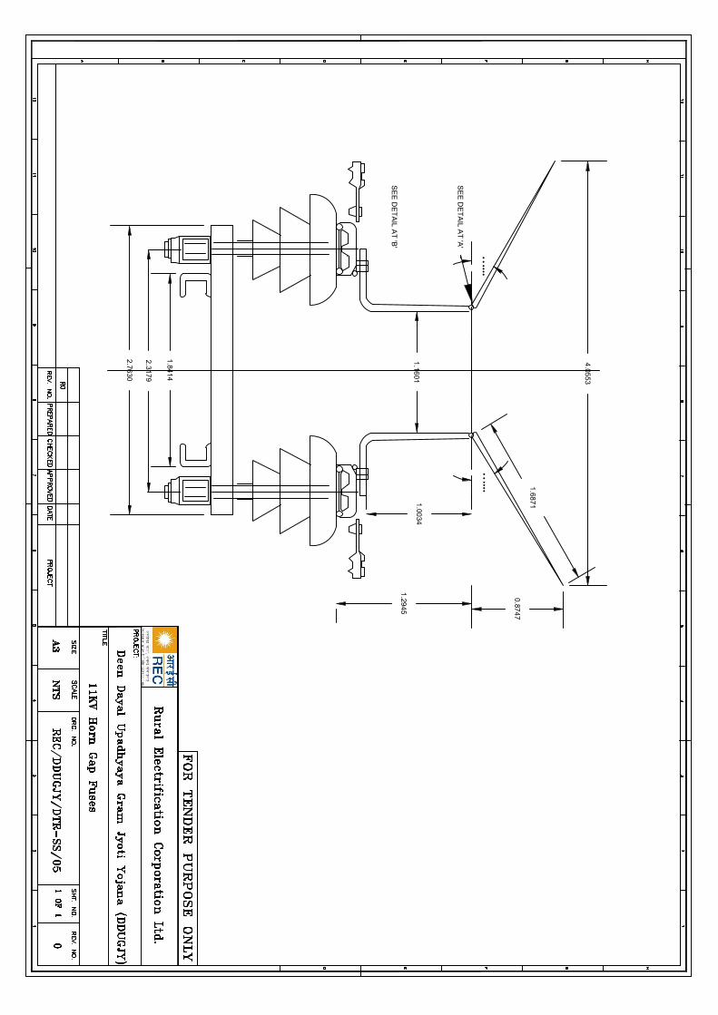
SE
E D
ET
AIL
AT
'A'
••
••••
SE
E D
ET
AIL
AT
'B'
••
••••
1.84
14
2.31
79
2.76
30
1.00
34
1.68
71
0.87
47
1.29
45
1.16
01
4.05
53
C:\U
sers\u
ser\De
sktop
\RE
C_
Lo
go
.jpg
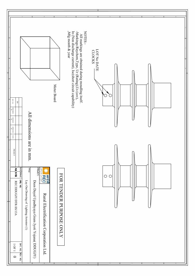
12
HGFEDCB
12
A
46
57
3
1011
89
1011
12
HGFEDCBA
All dim
ensions are in mm
.
RE
V. N
O.
R0
PR
EP
AR
ED
BY
CH
EC
KE
DB
YA
PPR
OV
ED
BY
DA
TE
PRO
JEC
T0
1 OF
1
FOR
TE
ND
ER
PUR
POS
E O
NL
Y
Rural E
lectrification Corporation L
td.
NO
TE
S:-
All m
arkings are obtained during moudling itself.
-Markings:R
aychem,T
ype, Ur (R
ating),Us (cov),
In (Non discharge current), Isc(short circuit capability)
,Mfg m
onth & year
LO
T N
o DA
TE
CL
OC
KS
Meter B
oard
Deen D
ayal Upadhyaya G
ram Jyoti Y
ojana( DD
UG
JY)
RE
C/D
DU
GJY
/DT
R-SS
/13A
Lay O
ut Draw
ing of Lighting A
rrestor (1)
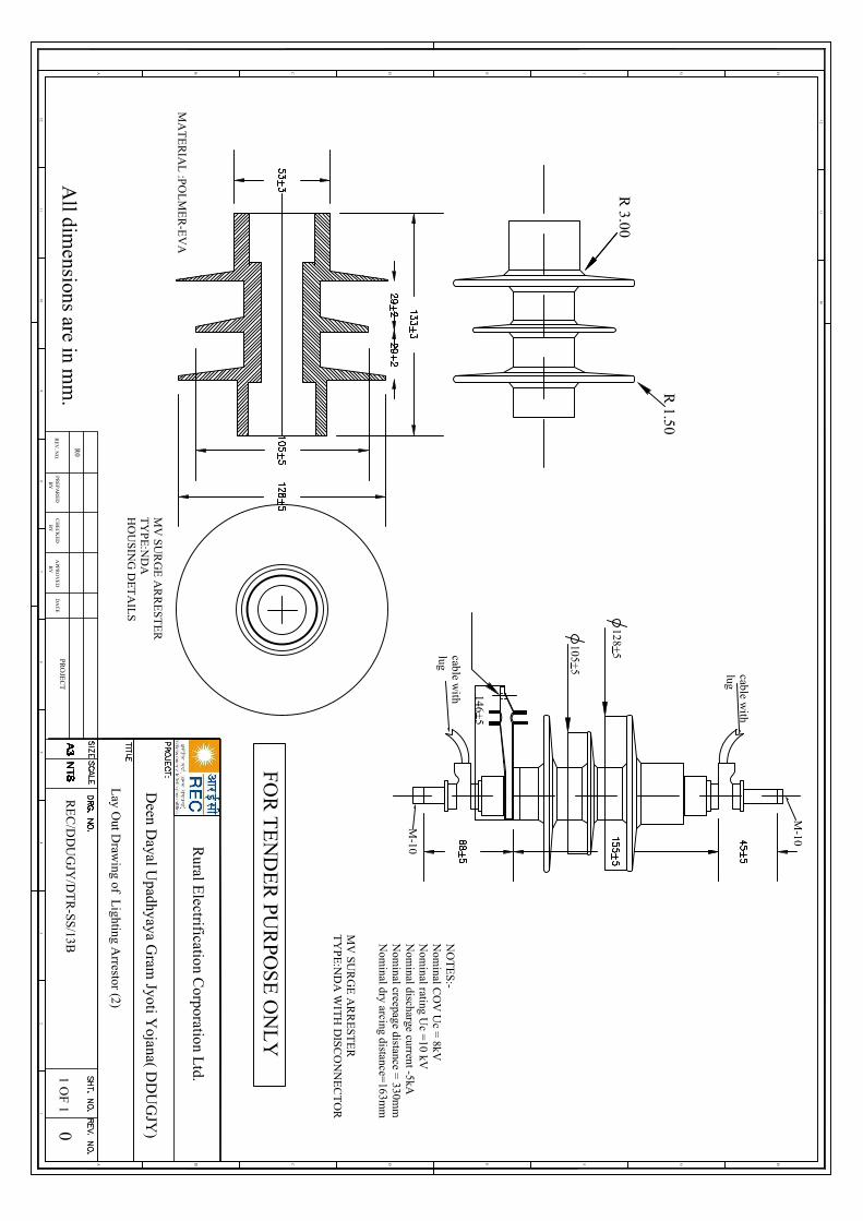
12
HGFEDCB
12
A
46
57
3
1011
89
1011
12
HGFEDCBA
All dim
ensions are in mm
.R
EV
. NO
.
R0
PR
EP
AR
ED
BY
CH
EC
KE
DB
YA
PPR
OV
ED
BY
DA
TE
PRO
JEC
T0
1 OF
1
FOR
TE
ND
ER
PUR
POS
E O
NL
Y
Rural E
lectrification Corporation L
td.
NO
TE
S:-N
ominal C
OV
Uc =
8kVN
ominal rating U
c =10 kV
Nom
inal discharge current -5kAN
ominal creepage distance =
330mm
Nom
inal dry arcing distance=163m
m
MV
SUR
GE
AR
RE
STE
RT
YP
E:N
DA
WIT
H D
ISC
ON
NE
CT
OR
MV
SUR
GE
AR
RE
STE
RT
YP
E:N
DA
HO
US
ING
DE
TA
ILS
MA
TE
RIA
L :P
OL
ME
R-E
VA
M-10
M-10
cable with
lug
cable with
lug
128+5
105+5
146+5
R 3.00
R 1.50
Deen D
ayal Upadhyaya G
ram Jyoti Y
ojana( DD
UG
JY)
RE
C/D
DU
GJY
/DT
R-SS
/13B
Lay O
ut Draw
ing of Lighting A
rrestor (2)
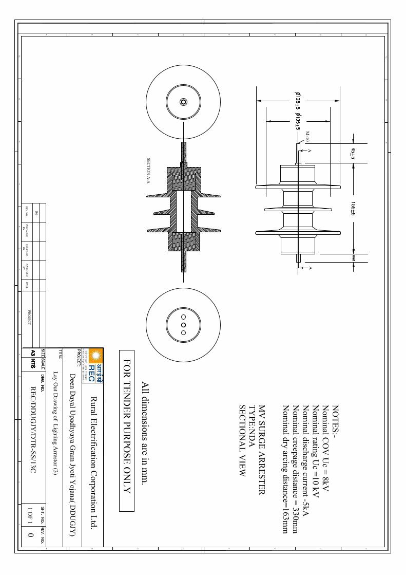
12
HGFEDCB
12
A
46
57
3
1011
89
1011
12
HGFEDCBA
All dim
ensions are in mm
.
RE
V. N
O.
R0
PR
EP
AR
ED
BY
CH
EC
KE
DB
YA
PPR
OV
ED
BY
DA
TE
PRO
JEC
T0
1 OF
1
FOR
TE
ND
ER
PUR
POS
E O
NL
Y
Rural E
lectrification Corporation L
td.
NO
TE
S:-N
ominal C
OV
Uc =
8kVN
ominal rating U
c =10 kV
Nom
inal discharge current -5kAN
ominal creepage distance =
330mm
Nom
inal dry arcing distance=163m
m
MV
SU
RG
E A
RR
EST
ER
TY
PE
:ND
ASE
CT
ION
AL
VIE
W
SE
CT
ION
A-A
M-10
AA
Deen D
ayal Upadhyaya G
ram Jyoti Y
ojana( DD
UG
JY)
RE
C/D
DU
GJY
/DT
R-S
S/13C
Lay O
ut Draw
ing of Lighting A
rrestor (3)

Volume-II : Section-II (B) Technical Specification
577
DDUGJY & IPDS/SBD/R1
44 GS Stay Sets (16 mm AND 20 mm)
1. 16MM DIA STAY SETS (GALVANIZED)
The stay sets (Line Guy set) will consist of the following components:-
a) ANCHOR ROD WITH ONE WASHER AND NUT: Overall length of rod should be 1800 mm to be made out of 16 mm dia GS Rod, one end threaded upto 40mm length with a pitch of 5 threads per cm and provided with one square GS washer of size 40x40x1.6mm and one GS hexagonal nut conforming to IS:1367:1967 & IS:1363:1967. Both washer and nut to suit threaded rod of 16mm dia. The other end of the rod to be made into a round eye having an inner dia of 40mm with best quality welding.
b) ANCHOR PLATE SIZE 200x200x6MM: To be made out of GS plate of 6mm thickness. The anchor plate should have at its centre 18mm dia hole.
c) TURN BUCKLE & EYE BOLT WITH 2 NUTS: To be made of 16mm dia GS Rod having an overall length of 450 mm, one end of the rod to be threaded upto 300 mm length with a pitch of 5 threads per cm and provided with two GS Hexagonal nuts of suitable size conforming to IS:1363:1967 & IS:1367:1967. The other end of rod shall be rounded into a circular eye of 40mm inner dia with proper and good quality welding.
d) BOW WITH WELDED ANGLE: To be made out of 16mm dia GS rod. The finished bow shall have an overall length of 995mm and height of 450 mm, the apex or top of the bow shall be bent at an angle of 10 R. The other end shall be welded with proper and good quality welding to a GS angle 180mm long having a dimension of 50x50x6mm. The angle shall have 3 holes of 18mm dia each.
e) THIMBLE: To be made on 1.5 mm thick GS sheet into a size of 75x22x40mm and shape as per standard shall be supplied.
f) Galvanizing: The complete assembly shall be hot dip galvanized.
g) WELDING: The minimum strength of welding provided on various components of 16mm dia stay sets shall be 3100 kg. Minimum 6 mm fillet weld or its equivalent weld area should be deposited in all positions of the job i.e. at any point of the weld length. The welding shall be conforming to relevant IS: 823/1964 or its latest amendment. Minimum length of weld to be provided at various places in the stay sets shall be indicated by the bidder. Welding if, found short in lengths as per final approved drawings shall be rejected.
h) THREADING: The threads on the Anchor Rod, Eye Bolt & Nuts shall be as per specification IS: 4218:1967 (ISO Metric Screw Threads). The nuts shall be conforming to the requirement of IS: 1367:1967 & have dimensions as per IS; 163:1967. The mechanical property requirement of fasteners shall conform to property clause 4.6 each for anchor rod & Eye bolt and property clause 4 for nuts as per IS: 1367:1967.
AVERAGE WEIGHT OF FINISHED 16MM STAY SETS 7.702 KG. (MINIMUM) (EXCLUDING NUTS THIMBLES AND WASHERS) 8.445 KG. (MAXIMUM)
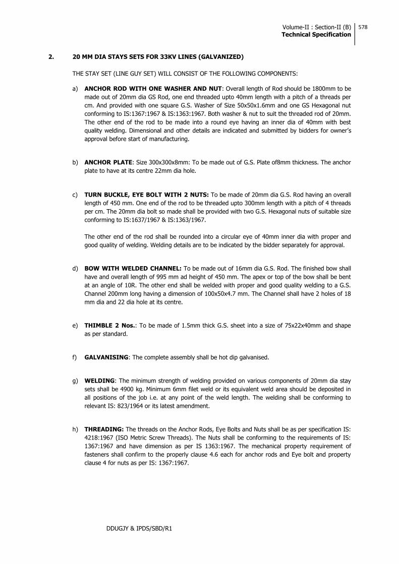
Volume-II : Section-II (B) Technical Specification
578
DDUGJY & IPDS/SBD/R1
2. 20 MM DIA STAYS SETS FOR 33KV LINES (GALVANIZED)
THE STAY SET (LINE GUY SET) WILL CONSIST OF THE FOLLOWING COMPONENTS:
a) ANCHOR ROD WITH ONE WASHER AND NUT: Overall length of Rod should be 1800mm to be made out of 20mm dia GS Rod, one end threaded upto 40mm length with a pitch of a threads per cm. And provided with one square G.S. Washer of Size 50x50x1.6mm and one GS Hexagonal nut conforming to IS:1367:1967 & IS:1363:1967. Both washer & nut to suit the threaded rod of 20mm. The other end of the rod to be made into a round eye having an inner dia of 40mm with best
s approval before start of manufacturing.
b) ANCHOR PLATE: Size 300x300x8mm: To be made out of G.S. Plate of8mm thickness. The anchor plate to have at its centre 22mm dia hole.
c) TURN BUCKLE, EYE BOLT WITH 2 NUTS: To be made of 20mm dia G.S. Rod having an overall length of 450 mm. One end of the rod to be threaded upto 300mm length with a pitch of 4 threads per cm. The 20mm dia bolt so made shall be provided with two G.S. Hexagonal nuts of suitable size conforming to IS:1637/1967 & IS:1363/1967.
The other end of the rod shall be rounded into a circular eye of 40mm inner dia with proper and good quality of welding. Welding details are to be indicated by the bidder separately for approval.
d) BOW WITH WELDED CHANNEL: To be made out of 16mm dia G.S. Rod. The finished bow shall have and overall length of 995 mm ad height of 450 mm. The apex or top of the bow shall be bent at an angle of 10R. The other end shall be welded with proper and good quality welding to a G.S. Channel 200mm long having a dimension of 100x50x4.7 mm. The Channel shall have 2 holes of 18 mm dia and 22 dia hole at its centre.
e) THIMBLE 2 Nos.: To be made of 1.5mm thick G.S. sheet into a size of 75x22x40mm and shape as per standard.
f) GALVANISING: The complete assembly shall be hot dip galvanised.
g) WELDING: The minimum strength of welding provided on various components of 20mm dia stay sets shall be 4900 kg. Minimum 6mm filet weld or its equivalent weld area should be deposited in all positions of the job i.e. at any point of the weld length. The welding shall be conforming to relevant IS: 823/1964 or its latest amendment.
h) THREADING: The threads on the Anchor Rods, Eye Bolts and Nuts shall be as per specification IS: 4218:1967 (ISO Metric Screw Threads). The Nuts shall be conforming to the requirements of IS: 1367:1967 and have dimension as per IS 1363:1967. The mechanical property requirement of fasteners shall confirm to the properly clause 4.6 each for anchor rods and Eye bolt and property clause 4 for nuts as per IS: 1367:1967.

Volume-II : Section-II (B) Technical Specification
579
DDUGJY & IPDS/SBD/R1
AVERAGE WEIGHT OF FINISHED 20MM STAYS SET: 14.523 KG. (MIN.) (EXCLUDING NUTS THIMBLE & WASHER): 15.569 KG. (MAX.)
3. TEST CERTIFICATE: The contractor shall be required to conduct testing of materials at Govt./Recognized testing laboratory during pre dispatch inspection for Tensile Load of 3100 Kg/4900 Kg. applied for one minute on the welding & maintained for one minute for 16 mm and 20 mm dia stay sets respectively.
4. IDENTIFICATION MARK: All stay sets should carry the identification mark of word DDUGJY and size of the stay set. This should be engraved on the stay plate and on stay rods to ensure proper identification of the materials.
The nuts should be of a size compatible with threaded portion of rods and there should be no play or slippage of nuts.
Welding wherever required should be perfect and should not give way after erection.
5. TOLERANCES: The tolerances for various components of the stay sets are indicated below subject to the condition that the average weight of finished stay sets of 16mm dia excluding nuts, thimbles and washers shall not be less than the weight specified above :-
No. Item Section
Tolerances Fabrication Tolerances Material
1 Anchor Plate
6mm thick + 12.5% - 5%
200x200mm + 1% GS plate 6mm thick
8mm thick + 12.5% - 5%
300x300mm + 1% GS plate 8mm thick
2 Anchor Rod
16mm dia + 5%- 3%
Length 1800mm + 0.5% GS Round 16mm dia
Rounded Eye 40 mm inside dia + 3%. Threading 40mm+11% - 5
GS Round 16mm dia
20mm dia +
3%- 2% Length 1800mm + 0.5%
GS Round 20mm dia
Round Eye 40mm inside dia + 3%. Threading 40mm +11% -5%
GS Found 20mm dia
3 Turn Buckle Bow
16 mm dia +
5%- 3% Length 995mm + 1% 16mm dia
GS Round 16mm dia
Length 180mm + 1% 50x50x6mm GS Angle
Channel length 200mm + 1% GS Channel 100x50x4.7mm
4 Eye Bolt Rod 16mm dia + Length 450mm + 1% GS Round

Volume-II : Section-II (B) Technical Specification
580
DDUGJY & IPDS/SBD/R1
5%- 3% Threading 300mm + 1%
Round Eye 40mm inside dia + 3%
16mm dia
20mm dia +
3%- 2%
Length 450mm + 1%
Threading 300mm + 1%
Round Eye 40mm inside dia + 3%
GS Round 20mm dia

Volume-II : Section-II (B) Technical Specification
581
DDUGJY & IPDS/SBD/R1
45 GI Stay Wires
1. SCOPE
This Specification covers details of G.I. stranded stay wires for use in rural distribution system.
2. APPLICABLE STANDARDS
Except when they conflict with the specific requirements of this specification, the G.I. Stranded Wires shall comply with the specific requirements of IS:2141-1979. IS:4826-1979 & IS:6594-1974 or the latest versions thereof.
3. APPLICATION AND SIZES
3.1 The G.I. stranded wires covered in this Specification are intended for use on the overhead power line poles, distribution transformer structures etc.
3.2 The G.I. stranded wires shall be of 7/2.5mm, 7/3.15mm and 7/4.0mm standard sizes.
4. MATERIAL
The wires shall be drawn from steel made by the open hearth basic oxygen or electric furnace process and of such quality that when drawn to the size of wire specified and coated with zinc, the finished strand and the individual wires shall be of uniform quality and have the properties and characteristics as specified in this specification. The wires shall not contain sulphur and phosphorus exceeding 0.060% each.
5. TENSILE GRADE
The wires shall be of tensile grade 4, having minimum tensile strength of 700 N/mm2 conforming to IS:2141.
6. GENERAL REQUIREMENTS
6.1 The outer wire of strands shall have a right-hand lay.
6.2 The lay length of wire strands shall be 12 to 18 times the strand diameter.
7. MINIMUM BREAKING LOAD
The minimum breaking load of the wires before and after stranding shall be as follows :
No. of wires & const.
Wire dia (mm)
Min. breaking load of Single wire before stranding (KN)
Min. breaking load of the standard wire (KN)
7(6/1) 2.5 3.44 22.86
7(6/1) 3.15 5.45 36.26
7(6/1) 4.0 8.79 58.45
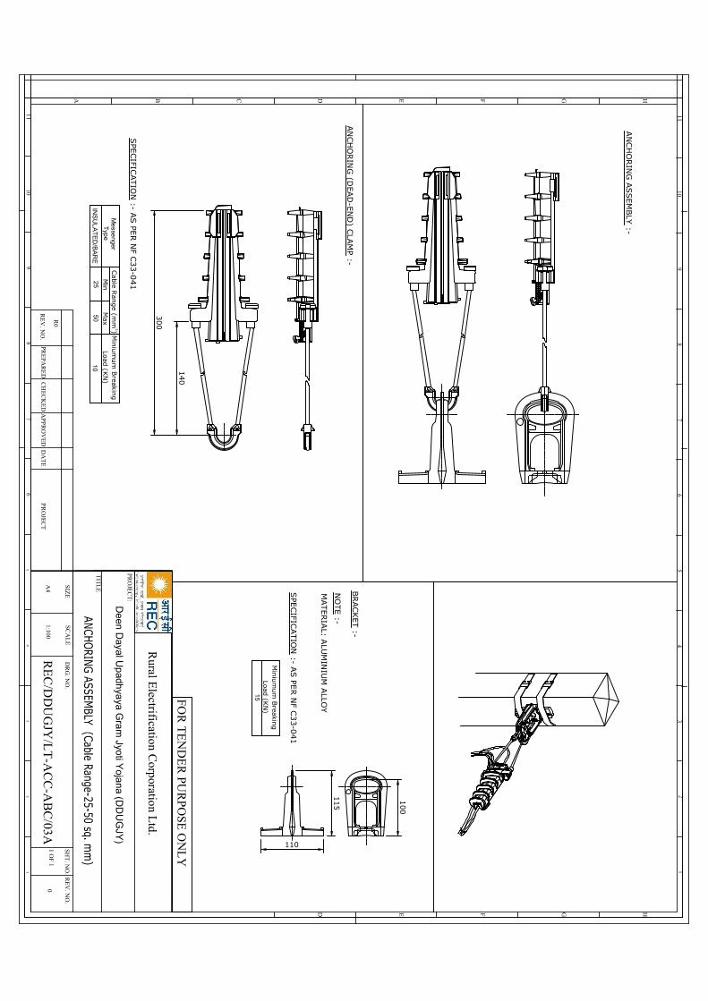
AN
CH
ORIN
G A
SSEM
BLY
:-
AN
CH
ORIN
G (D
EAD
-EN
D) C
LAM
P :-
SPE
CIFIC
ATIO
N :- A
S PE
R N
F C33-0
41
Min
Cab
le Ran
ge (m
m )
25
INS
UL
AT
ED
/BA
RE
Me
sseng
erT
ype
10
Min
ium
um
Breakin
gLoad
(KN
)M
ax5
0
2
MATERIA
L: ALU
MIN
IUM
ALLO
Y
NO
TE :-
SPE
CIFIC
ATIO
N :- A
S PE
R N
F C33-0
41
BRACKET :-
100
110
115
Min
ium
um
Breakin
gLoad
(KN
)
140
300
15
HGFEDCBA
46
57
3 34
65
78
910
11
89
1011
12
HGFED
12
Rural E
lectrification Corporation L
td.
PRO
JEC
T:
TIT
LE
SCA
LE
DR
G. N
O.
SIZE
RE
V. N
O.
SHT
. NO
.
1 OF 1
A4
1:1000
RE
V. N
O.
R0
PRE
PAR
ED
CH
EC
KE
DA
PPR
OV
ED
DA
TE
PRO
JEC
T
FOR
TE
ND
ER
PUR
PO
SE O
NL
Y
C:\D
ocu
ments an
d S
ettin
gs\R
el\Desk
top\do
wnlo
ad.jp
g
De
en D
ayal Up
adhya
ya G
ram
Jyoti Y
oja
na (DD
UG
JY)
RE
C/D
DU
GJY
/LT
-AC
C-A
BC
/03A
C:\D
ocu
ments an
d S
ettin
gs\R
el\Desk
top\do
wnlo
ad.jp
gC
:\Docu
ments an
d S
ettin
gs\R
el\Desk
top\do
wnlo
ad.jp
g
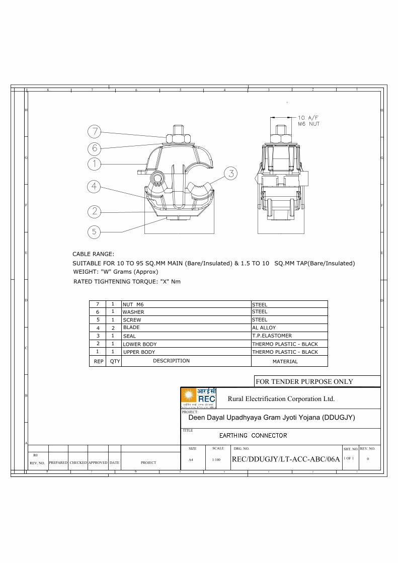
CABLE RANGE:
SUITABLE FOR 10 TO 95 SQ.MM MAIN (Bare/Insulated) & 1.5 TO 10 SQ.MM TAP(Bare/Insulated)WEIGHT: "W" Grams (Approx)
RATED TIGHTENING TORQUE: "X" Nm
7
6
5
4
3
2
1 1
1
1
2
1
11
QTY DESCRIPITION MATERIAL
NUT M6
WASHER
SCREWBLADE
SEAL
LOWER BODY
UPPER BODY
STEEL
T.P.ELASTOMER
REP
AL ALLOY
STEEL
STEEL
THERMO PLASTIC - BLACK
THERMO PLASTIC - BLACK
H
G
F
E
D
C
B
A
46 57 3
346 578
8 12
H
G
F
E
D
12
Rural Electrification Corporation Ltd.
PROJECT:
TITLE
SCALE DRG. NO.SIZE REV. NO.SHT. NO.
1 OF 1A4 1:100 0REV. NO.
R0
PREPARED CHECKED APPROVED DATE PROJECT
FOR TENDER PURPOSE ONLY
C:\Documents and Settings\Rel\Desktop\download.jpg
Deen Dayal Upadhyaya Gram Jyoti Yojana (DDUGJY)
REC/DDUGJY/LT-ACC-ABC/06A
C:\Documents and Settings\Rel\Desktop\download.jpg
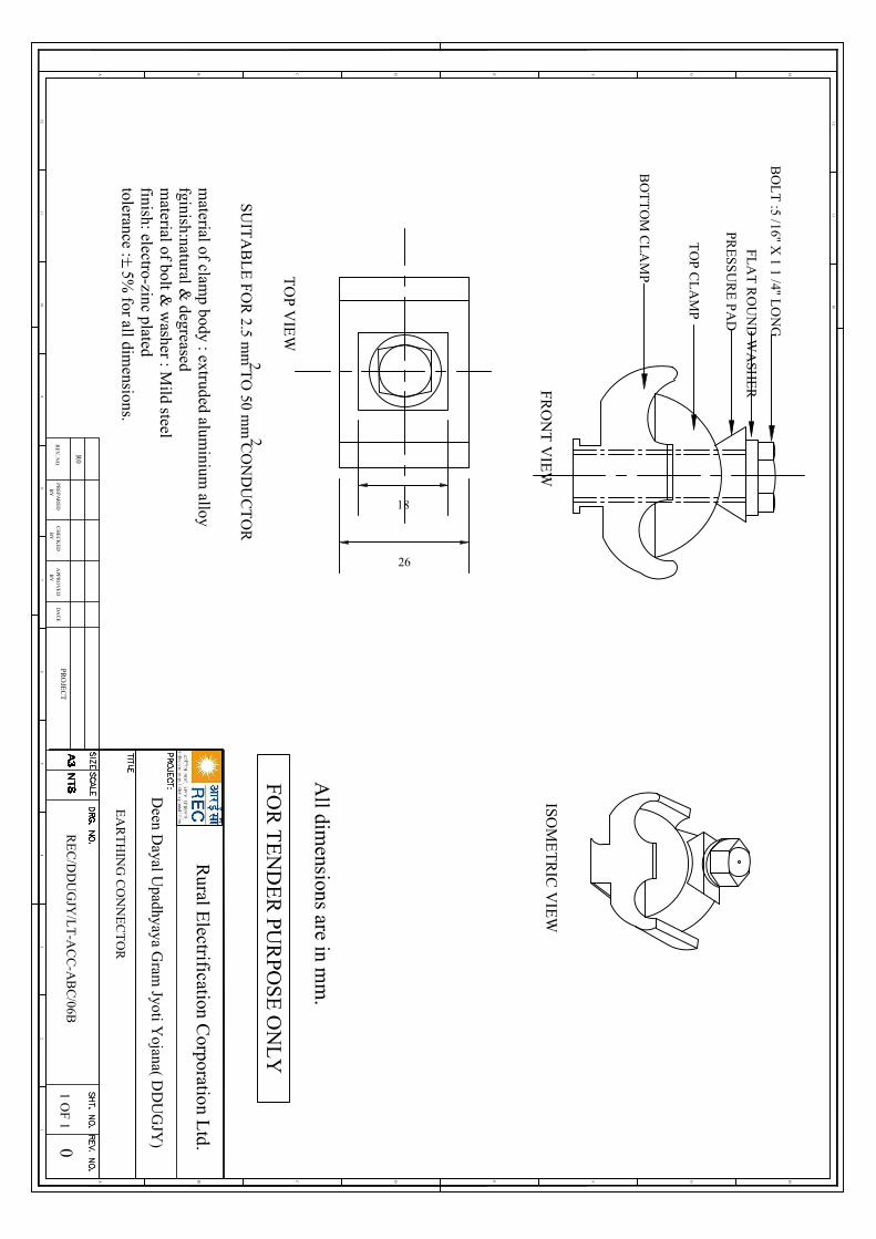
12
HGFEDCB
12
A
46
57
3
1011
89
1011
12
HGFEDCBA
All dim
ensions are in mm
.
RE
V. N
O.
R0
PR
EP
AR
ED
BY
CH
EC
KE
DB
YA
PPR
OV
ED
BY
DA
TE
PRO
JEC
T0
1 OF
1
FOR
TE
ND
ER
PUR
POS
E O
NL
Y
Rural E
lectrification Corporation L
td.
EA
RT
HIN
G C
ON
NE
CT
OR
TO
P VIE
W
FRO
NT
VIE
WISO
ME
TR
IC V
IEW
BO
TT
OM
CL
AM
P
TO
P CL
AM
P
PRE
SSU
RE
PA
D
FLA
T R
OU
ND
WA
SH
ER
BO
LT
:5 /16'' X 1 1 /4'' L
ON
G
SUIT
AB
LE
FO
R 2.5 m
m T
O 50 m
m C
ON
DU
CT
OR
22
material of clam
p body : extruded aluminium
alloyfginish:natural &
degreasedm
aterial of bolt & w
asher : Mild steel
finish: electro-zinc platedtolerance :+
5% for all dim
ensions.
Deen D
ayal Upadhyaya G
ram Jyoti Y
ojana( DD
UG
JY)
RE
C/D
DU
GJY
/LT
-AC
C-A
BC
/06B
18
26
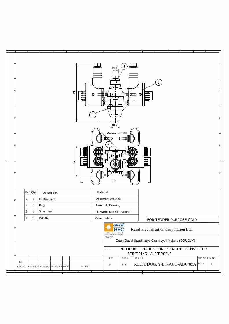
Plug
H
G
F
E
D
C
B
A
46 57 3
346 578
8 12
H
G
F
E
D
12
Rural Electrification Corporation Ltd.
PROJECT:
TITLE
SCALE DRG. NO.SIZE REV. NO.SHT. NO.
1 OF 1A4 1:100 0
REV. NO.
R0
PREPARED CHECKED APPROVED DATE PROJECT
FOR TENDER PURPOSE ONLY
C:\Documents and Settings\Rel\Desktop\download.jpg
Deen Dayal Upadhyaya Gram Jyoti Yojana (DDUGJY)
REC/DDUGJY/LT-ACC-ABC/05A
Rep Description Material
Assembly Drawing
Ploycarbonate GF- natural
Colour WhiteMaking
Shearhead
Central part1
1
1
14
3
2
1
Qty.
Assembly Drawing
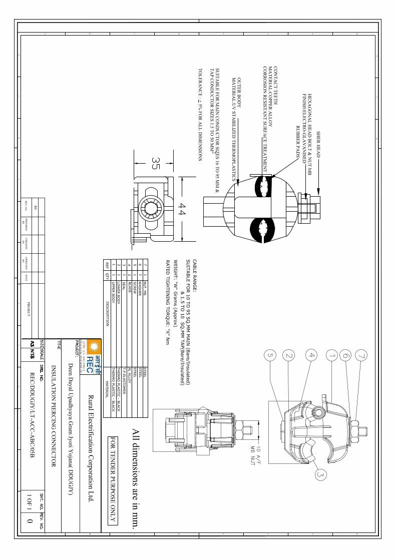
12
HGFEDCB
12
A
46
57
3
1011
89
1011
12
HGFEDCBA
All dim
ensions are in mm
.
RE
V. N
O.
R0
PR
EP
AR
ED
BY
CH
EC
KE
DB
YA
PPR
OV
ED
BY
DA
TE
PRO
JEC
T0
1 OF
1
FO
R T
EN
DE
R P
UR
POS
E O
NL
Y
Rural E
lectrification Corporation L
td.
INS
UL
AT
ION
PIE
RC
ING
CO
NN
EC
TO
R
SH
ER
HE
AD
HE
XA
GO
NA
L H
EA
D B
OL
T &
NU
T M
BF
INISH
:EL
EC
TR
O-G
LA
VA
NIS
ED
RU
BB
ER
PA
DS
CO
NT
AC
T T
EE
TH
MA
TE
RIA
L:C
OP
PE
R A
LL
OY
CO
RR
OS
ION
RE
SIS
TA
NT
SU
RF
AC
E T
RE
AT
ME
NT
OU
TE
R B
OD
YM
AT
ER
IAL
:UV
STA
BIL
IZE
D T
HE
RM
OP
LA
ST
ICS
SU
ITA
BL
E F
OR
MA
IN C
ON
DU
CT
OR
SIZ
ES
16 TO
95 MM
&T
AP C
ON
DU
CT
OR
SIZ
ES 1.5 T
O 50 M
M2
TO
LE
RA
NC
E : +
5% F
OR
AL
L D
IME
NS
ION
S
Deen D
ayal Upadhyaya G
ram Jyoti Y
ojana( DD
UG
JY)
RE
C/D
DU
GJY
/LT
-AC
C-A
BC
/05B
CABLE
RAN
GE:
SU
ITABLE
FOR 1
0 T
O 9
5 S
Q.M
M M
AIN
(Bare/In
sula
ted)
& 1
.5 T
O 1
0SQ
.MM
TAP(B
are/In
sulated
)
WEIG
HT: "W
" Gram
s (Approx)
RATED
TIG
HTEN
ING
TO
RQ
UE: "X
" Nm
76543211 1 1 2 1 1 1QTY
DESCR
IPIT
ION
MATERIA
L
NU
T M
6
WASH
ER
SC
REW
BLA
DE
SEAL
LOW
ER B
OD
Y
UPPE
R B
OD
Y
STEEL
T.P
.ELA
STO
MER
REP
AL A
LLOY
STEEL
STEEL
TH
ERM
O PLA
STIC
- BLA
CK
TH
ERM
O PLA
STIC
- BLA
CK

Volume-II : Section-II (B) Technical Specification
577
DDUGJY & IPDS/SBD/R1
44 GS Stay Sets (16 mm AND 20 mm)
1. 16MM DIA STAY SETS (GALVANIZED)
The stay sets (Line Guy set) will consist of the following components:-
a) ANCHOR ROD WITH ONE WASHER AND NUT: Overall length of rod should be 1800 mm to be made out of 16 mm dia GS Rod, one end threaded upto 40mm length with a pitch of 5 threads per cm and provided with one square GS washer of size 40x40x1.6mm and one GS hexagonal nut conforming to IS:1367:1967 & IS:1363:1967. Both washer and nut to suit threaded rod of 16mm dia. The other end of the rod to be made into a round eye having an inner dia of 40mm with best quality welding.
b) ANCHOR PLATE SIZE 200x200x6MM: To be made out of GS plate of 6mm thickness. The anchor plate should have at its centre 18mm dia hole.
c) TURN BUCKLE & EYE BOLT WITH 2 NUTS: To be made of 16mm dia GS Rod having an overall length of 450 mm, one end of the rod to be threaded upto 300 mm length with a pitch of 5 threads per cm and provided with two GS Hexagonal nuts of suitable size conforming to IS:1363:1967 & IS:1367:1967. The other end of rod shall be rounded into a circular eye of 40mm inner dia with proper and good quality welding.
d) BOW WITH WELDED ANGLE: To be made out of 16mm dia GS rod. The finished bow shall have an overall length of 995mm and height of 450 mm, the apex or top of the bow shall be bent at an angle of 10 R. The other end shall be welded with proper and good quality welding to a GS angle 180mm long having a dimension of 50x50x6mm. The angle shall have 3 holes of 18mm dia each.
e) THIMBLE: To be made on 1.5 mm thick GS sheet into a size of 75x22x40mm and shape as per standard shall be supplied.
f) Galvanizing: The complete assembly shall be hot dip galvanized.
g) WELDING: The minimum strength of welding provided on various components of 16mm dia stay sets shall be 3100 kg. Minimum 6 mm fillet weld or its equivalent weld area should be deposited in all positions of the job i.e. at any point of the weld length. The welding shall be conforming to relevant IS: 823/1964 or its latest amendment. Minimum length of weld to be provided at various places in the stay sets shall be indicated by the bidder. Welding if, found short in lengths as per final approved drawings shall be rejected.
h) THREADING: The threads on the Anchor Rod, Eye Bolt & Nuts shall be as per specification IS: 4218:1967 (ISO Metric Screw Threads). The nuts shall be conforming to the requirement of IS: 1367:1967 & have dimensions as per IS; 163:1967. The mechanical property requirement of fasteners shall conform to property clause 4.6 each for anchor rod & Eye bolt and property clause 4 for nuts as per IS: 1367:1967.
AVERAGE WEIGHT OF FINISHED 16MM STAY SETS 7.702 KG. (MINIMUM) (EXCLUDING NUTS THIMBLES AND WASHERS) 8.445 KG. (MAXIMUM)

Volume-II : Section-II (B) Technical Specification
578
DDUGJY & IPDS/SBD/R1
2. 20 MM DIA STAYS SETS FOR 33KV LINES (GALVANIZED)
THE STAY SET (LINE GUY SET) WILL CONSIST OF THE FOLLOWING COMPONENTS:
a) ANCHOR ROD WITH ONE WASHER AND NUT: Overall length of Rod should be 1800mm to be made out of 20mm dia GS Rod, one end threaded upto 40mm length with a pitch of a threads per cm. And provided with one square G.S. Washer of Size 50x50x1.6mm and one GS Hexagonal nut conforming to IS:1367:1967 & IS:1363:1967. Both washer & nut to suit the threaded rod of 20mm. The other end of the rod to be made into a round eye having an inner dia of 40mm with best
s approval before start of manufacturing.
b) ANCHOR PLATE: Size 300x300x8mm: To be made out of G.S. Plate of8mm thickness. The anchor plate to have at its centre 22mm dia hole.
c) TURN BUCKLE, EYE BOLT WITH 2 NUTS: To be made of 20mm dia G.S. Rod having an overall length of 450 mm. One end of the rod to be threaded upto 300mm length with a pitch of 4 threads per cm. The 20mm dia bolt so made shall be provided with two G.S. Hexagonal nuts of suitable size conforming to IS:1637/1967 & IS:1363/1967.
The other end of the rod shall be rounded into a circular eye of 40mm inner dia with proper and good quality of welding. Welding details are to be indicated by the bidder separately for approval.
d) BOW WITH WELDED CHANNEL: To be made out of 16mm dia G.S. Rod. The finished bow shall have and overall length of 995 mm ad height of 450 mm. The apex or top of the bow shall be bent at an angle of 10R. The other end shall be welded with proper and good quality welding to a G.S. Channel 200mm long having a dimension of 100x50x4.7 mm. The Channel shall have 2 holes of 18 mm dia and 22 dia hole at its centre.
e) THIMBLE 2 Nos.: To be made of 1.5mm thick G.S. sheet into a size of 75x22x40mm and shape as per standard.
f) GALVANISING: The complete assembly shall be hot dip galvanised.
g) WELDING: The minimum strength of welding provided on various components of 20mm dia stay sets shall be 4900 kg. Minimum 6mm filet weld or its equivalent weld area should be deposited in all positions of the job i.e. at any point of the weld length. The welding shall be conforming to relevant IS: 823/1964 or its latest amendment.
h) THREADING: The threads on the Anchor Rods, Eye Bolts and Nuts shall be as per specification IS: 4218:1967 (ISO Metric Screw Threads). The Nuts shall be conforming to the requirements of IS: 1367:1967 and have dimension as per IS 1363:1967. The mechanical property requirement of fasteners shall confirm to the properly clause 4.6 each for anchor rods and Eye bolt and property clause 4 for nuts as per IS: 1367:1967.

Volume-II : Section-II (B) Technical Specification
579
DDUGJY & IPDS/SBD/R1
AVERAGE WEIGHT OF FINISHED 20MM STAYS SET: 14.523 KG. (MIN.) (EXCLUDING NUTS THIMBLE & WASHER): 15.569 KG. (MAX.)
3. TEST CERTIFICATE: The contractor shall be required to conduct testing of materials at Govt./Recognized testing laboratory during pre dispatch inspection for Tensile Load of 3100 Kg/4900 Kg. applied for one minute on the welding & maintained for one minute for 16 mm and 20 mm dia stay sets respectively.
4. IDENTIFICATION MARK: All stay sets should carry the identification mark of word DDUGJY and size of the stay set. This should be engraved on the stay plate and on stay rods to ensure proper identification of the materials.
The nuts should be of a size compatible with threaded portion of rods and there should be no play or slippage of nuts.
Welding wherever required should be perfect and should not give way after erection.
5. TOLERANCES: The tolerances for various components of the stay sets are indicated below subject to the condition that the average weight of finished stay sets of 16mm dia excluding nuts, thimbles and washers shall not be less than the weight specified above :-
No. Item Section
Tolerances Fabrication Tolerances Material
1 Anchor Plate
6mm thick + 12.5% - 5%
200x200mm + 1% GS plate 6mm thick
8mm thick + 12.5% - 5%
300x300mm + 1% GS plate 8mm thick
2 Anchor Rod
16mm dia + 5%- 3%
Length 1800mm + 0.5% GS Round 16mm dia
Rounded Eye 40 mm inside dia + 3%. Threading 40mm+11% - 5
GS Round 16mm dia
20mm dia +
3%- 2% Length 1800mm + 0.5%
GS Round 20mm dia
Round Eye 40mm inside dia + 3%. Threading 40mm +11% -5%
GS Found 20mm dia
3 Turn Buckle Bow
16 mm dia +
5%- 3% Length 995mm + 1% 16mm dia
GS Round 16mm dia
Length 180mm + 1% 50x50x6mm GS Angle
Channel length 200mm + 1% GS Channel 100x50x4.7mm
4 Eye Bolt Rod 16mm dia + Length 450mm + 1% GS Round

Volume-II : Section-II (B) Technical Specification
580
DDUGJY & IPDS/SBD/R1
5%- 3% Threading 300mm + 1%
Round Eye 40mm inside dia + 3%
16mm dia
20mm dia +
3%- 2%
Length 450mm + 1%
Threading 300mm + 1%
Round Eye 40mm inside dia + 3%
GS Round 20mm dia
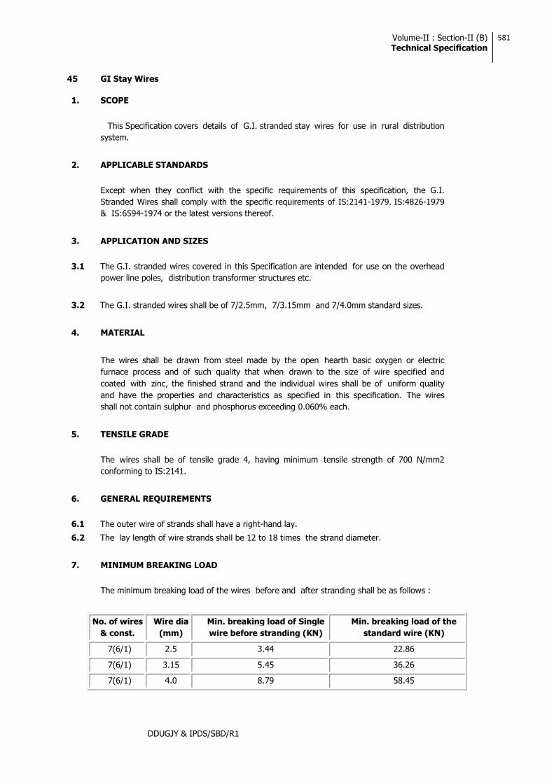
Volume-II : Section-II (B) Technical Specification
581
DDUGJY & IPDS/SBD/R1
45 GI Stay Wires
1. SCOPE
This Specification covers details of G.I. stranded stay wires for use in rural distribution system.
2. APPLICABLE STANDARDS
Except when they conflict with the specific requirements of this specification, the G.I. Stranded Wires shall comply with the specific requirements of IS:2141-1979. IS:4826-1979 & IS:6594-1974 or the latest versions thereof.
3. APPLICATION AND SIZES
3.1 The G.I. stranded wires covered in this Specification are intended for use on the overhead power line poles, distribution transformer structures etc.
3.2 The G.I. stranded wires shall be of 7/2.5mm, 7/3.15mm and 7/4.0mm standard sizes.
4. MATERIAL
The wires shall be drawn from steel made by the open hearth basic oxygen or electric furnace process and of such quality that when drawn to the size of wire specified and coated with zinc, the finished strand and the individual wires shall be of uniform quality and have the properties and characteristics as specified in this specification. The wires shall not contain sulphur and phosphorus exceeding 0.060% each.
5. TENSILE GRADE
The wires shall be of tensile grade 4, having minimum tensile strength of 700 N/mm2 conforming to IS:2141.
6. GENERAL REQUIREMENTS
6.1 The outer wire of strands shall have a right-hand lay.
6.2 The lay length of wire strands shall be 12 to 18 times the strand diameter.
7. MINIMUM BREAKING LOAD
The minimum breaking load of the wires before and after stranding shall be as follows :
No. of wires & const.
Wire dia (mm)
Min. breaking load of Single wire before stranding (KN)
Min. breaking load of the standard wire (KN)
7(6/1) 2.5 3.44 22.86
7(6/1) 3.15 5.45 36.26
7(6/1) 4.0 8.79 58.45
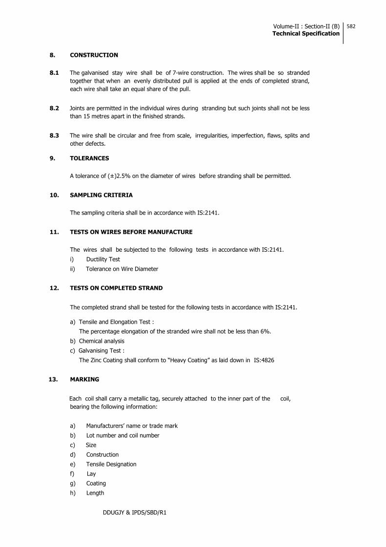
Volume-II : Section-II (B) Technical Specification
582
DDUGJY & IPDS/SBD/R1
8. CONSTRUCTION
8.1 The galvanised stay wire shall be of 7-wire construction. The wires shall be so stranded together that when an evenly distributed pull is applied at the ends of completed strand, each wire shall take an equal share of the pull.
8.2 Joints are permitted in the individual wires during stranding but such joints shall not be less than 15 metres apart in the finished strands.
8.3 The wire shall be circular and free from scale, irregularities, imperfection, flaws, splits and other defects.
9. TOLERANCES
A tolerance of (±)2.5% on the diameter of wires before stranding shall be permitted.
10. SAMPLING CRITERIA
The sampling criteria shall be in accordance with IS:2141.
11. TESTS ON WIRES BEFORE MANUFACTURE
The wires shall be subjected to the following tests in accordance with IS:2141.
i) Ductility Test
ii) Tolerance on Wire Diameter
12. TESTS ON COMPLETED STRAND
The completed strand shall be tested for the following tests in accordance with IS:2141.
a) Tensile and Elongation Test :
The percentage elongation of the stranded wire shall not be less than 6%.
b) Chemical analysis
c) Galvanising Test :
IS:4826
13. MARKING
Each coil shall carry a metallic tag, securely attached to the inner part of the coil, bearing the following information:
a)
b) Lot number and coil number
c) Size
d) Construction
e) Tensile Designation
f) Lay
g) Coating
h) Length

Volume-II : Section-II (B) Technical Specification
583
DDUGJY & IPDS/SBD/R1
i) Mass
j) ISI certification mark, if any
14. PACKING
The wires shall be supplied in 75-100 Kg. coils. The packing should be done in accordance with the provisions of IS:6594.
Volume-III: Section-ITechnical Specifications
209
DDUGJY & IPDS/SBD/R1
4. Mild Steel Channel, Angle And Flat
1) APPLICABLE STANDARDS:
for steel materials, documents for which shall be made available at representative.
2) GENERAL REQUIREMENTS:
Material shall be supplied as per the following sizes:
Standard having length ranging from 5.5 to 13.5 meters. 75x40 ISMC channel conforming to IS: 2062 grade
meters.
50x50x8 mm or 6 mm ISA angles conforming to IS: 2062 grade international standard having length ranging from 5.5 to 13.5 meters.
standard having length ranging from 5.5 to 13.5 meters.
standard having length ranging from 5.5 to 13.5 meters.
25X3mm, 50X6mm, 50x8mm, 75X8mm and 80X8 flats conforming to IS: 2062 grade or its equivalent international standard having length ranging from 5.5 to 9.5 meters.
3) GALVANISATION: All above steel members shall be fabricated as per approved drawing having smooth edge, drilled circular/elliptical holes of suitable measurements.
All structural steel members and bolts shall be galvanized as per IS:4759 and zinc coating shall not be less than 610gm/sq. meter for all structural steel members. All weld shall be 6mm filled weld unless specified otherwise. All nuts and bolt shall be of property class 5.6 of IS 1367. Plain washers shall be as per IS 2016 and spring washers shall be IS:3063
4) INSPECTION:
All inspection/test will be carried out by representative of owner.
All tests and inspection shall be made at the place of manufacturer unless otherwise specially agreed upon by the manufacturer and the owner. The manufacturer shall provide all reasonable facilities, without charge to satisfy him that the material is being supplied in accordance with the specification.
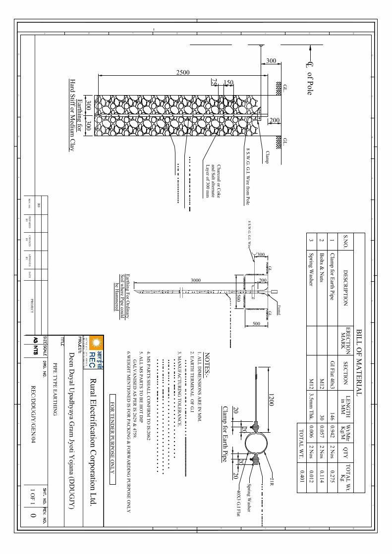
2500
300300
300
200
150
75
GL
.G
L.
Clam
p
8 S.W.G
. G.I. W
ire from Pole
Charcoal or C
okeand Salt alternateL
ayer of 300 mm
••••
••••
•••••••••••••••
•••••••••••••••••••••••••
••••••
••••••••••••••
Earthing for
Hard S
tiff or Medium
Clay
of Pole
L C2 N
os0.006
3.5mm
Thk.
M12
3S
pring Washer
S.N
O.
DE
SCR
IPT
ION
SE
CT
ION
QT
Y
2 Nos
0.942146
GI F
lat 40x3C
lamp for E
arth Pipe
1
BIL
L O
F M
AT
ER
IAL
2B
olts & N
utsM
1230
0.0572 N
os
ER
EC
TIO
NM
AR
Kin M
ML
EN
GT
HW
t/Mtr
Kg/M
Kg
TO
TA
L W
t.
0.114
0.275
0.012
0.401T
OT
AL
WT
.
••••
••••
•••••••••••••••
•••••••••••••••••••••••••
500
300
500
8 S.W.G
. G.I. W
ire
GL
.G
L.
Earthing For O
rdinary S
oil where Pipe could
be Ham
mered
3000 200
Funnel
••••••
••••••••
••••••••••••••••••••
21RSpring Washer
40X3 G
.I Flat20
2020
20
1200Clam
p for Earth Pipe
12
HGFEDCB
12
A
46
57
3 34
65
78
910
11
89
1011
12
HGFED
12
PIPE
TY
PE
EA
RT
HIN
G
NO
TE
S:-
2. EA
RT
H T
ER
MIN
AL
OF
G.I
1. AL
L D
IME
NS
ION
S A
RE
IN M
M.
•••••
•••••••••
•••••
•••••••
••••
••••••••••••••••••••••••••••••••••••
4. MS
PAR
TS
SH
AL
L C
ON
FIRM
TO
IS:2062
5. AL
L M
S P
AR
TS
TO
BE
HO
T D
IP G
AL
VA
NISE
D A
S P
ER
IS 2629 & 4759.
6.WE
IGH
T M
EN
TIO
NE
D IS F
OR
PAC
KIN
G &
FO
RW
AR
DIN
G P
UR
POS
E O
NL
Y
RE
V. N
O.
R0
PR
EP
AR
ED
BY
CH
EC
KE
DB
YA
PPR
OV
ED
BY
DA
TE
PRO
JEC
TR
EC
/DD
UG
JY/G
EN
/040
1 OF
1
3. MA
NU
FA
CT
UR
ING
TO
LE
RA
NC
E.
•••
•••••
••••••••
••
••
••
••
••
••
••
••
•••••
••••••
••••••••
••
••
••
••
••
••
••
••
••••••
••••••
••••••••
••
••
••
••
••
••
••
••
••
••
••
•••••••
•••••
••••
••
••
••
••
••
••
••
••
•
FO
R T
EN
DE
R PU
RP
OS
E O
NL
Y
Deen D
ayal Upadhyaya G
ram Jyoti Y
ojana (DD
UG
JY)
Rural E
lectrification Corporation L
td.
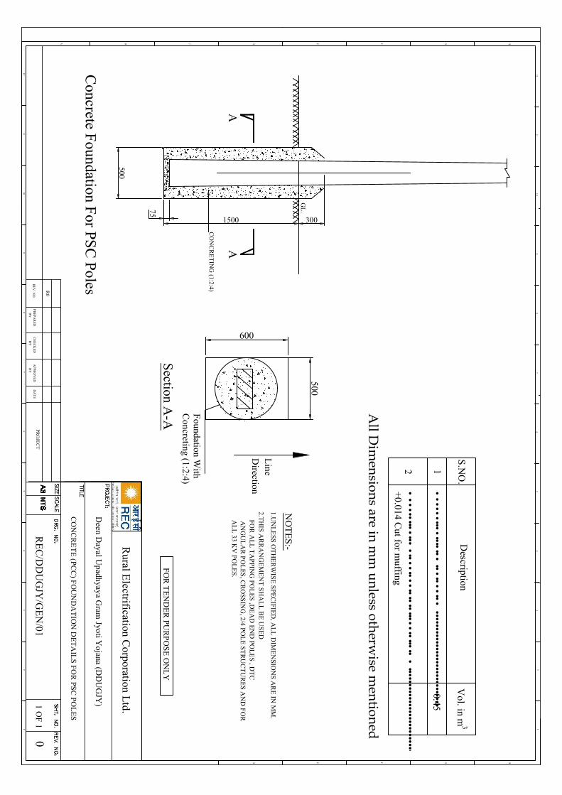
CO
NC
RE
TIN
G (1:2:4)
75
500
1500 300
GL
.
AA
Concrete F
oundation For PS
C Poles
•••••••••••••
••••••••••••••••••••••••••••
•••••••••••••••••••••••••••••••••••••••••••••2
3
0.45
Vol. in m
S.N
O.
1
Description
•••••••••••••••••
•••••••••••••••••••••••••••••••••••••••
+0.014 C
ut for muffing
All D
imensions are in m
m unless otherw
ise mentioned
Foundation W
ithC
oncreting (1:2:4)
600
500
Line
Direction
Section A
-A
12
HGFEDCB
12
A
46
57
3 34
65
78
910
11
89
1011
12
HGFED
12
CO
NC
RE
TE
(PCC
) FO
UN
DA
TIO
N D
ET
AIL
S FOR
PSC
POL
ES
NO
TE
S:-
2.TH
IS AR
RA
NG
EM
EN
T S
HA
LL
BE
USE
D
1.UN
LE
SS O
TH
ER
WIS
E S
PEC
IFIED
, AL
L D
IME
NSIO
NS A
RE
IN M
M.
FOR
AL
L T
AP
PING
POL
ES ,D
EA
D E
ND
POL
ES , D
TC
AN
GU
LA
R P
OL
ES
, CR
OSS
ING
, 2/4 POL
E ST
RU
CT
UR
ES A
ND
FO
R
Deen D
ayal Upadhyaya G
ram Jyoti Y
ojana (DD
UG
JY)
RE
V. N
O.
R0
PR
EP
AR
ED
BY
CH
EC
KE
DB
YA
PPR
OV
ED
BY
DA
TE
PRO
JEC
TR
EC
/DD
UG
JY/G
EN
/010
1 OF
1
AL
L 33 K
V P
OL
ES
.
FO
R T
EN
DE
R PU
RP
OS
E O
NL
Y
Rural E
lectrification Corporation L
td.
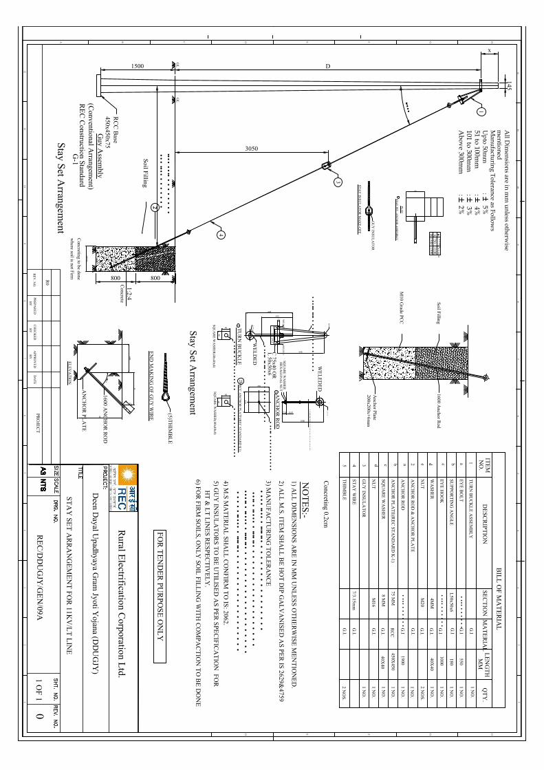
GL
145
GL
3050
1
3
4
2
Guy A
ssembly
(Conventional A
rrangement)
RE
C C
onstruction StandardG
-1
x
D1500
••••••••
••
••
••
••
•••
•••••
••
••
••
RC
C B
ase450x450x75
Soil Filling ST
AY
INS
UL
AT
OR
MA
KE
-OF
F
GU
Y IN
SUL
AT
OR
• •• •
600
PL
AN
45
ST
AY
PIT - A
NC
HO
R A
SSE
MB
LY
0AB
••••••••••••750
11001500
1300
6
2
800800
500X500
1:2:4C
oncrete
Concreting to be done
where soil is not F
irm
Stay Set A
rrangement
All D
imensions are in m
m unless otherw
isem
entionedM
anufacturing Tolerance as Follows
Upto 50m
m :
5%51 to 100m
m :
4%101 to 300m
m :
3%A
bove 300mm
: 2%
EN
D M
AK
ING
OF G
UY
WIR
E
600
A
150
B
••••1600 A
NC
HO
R R
OD
AN
CH
OR
PLA
TE
EL
EV
AT
ION
(5)TH
IMB
LE
BIL
L O
F MA
TE
RIA
L
TU
RN
BU
CK
LE
ASS
EM
BL
Y
ITE
MN
O.
DE
SCR
IPT
ION
QT
Y.
SEC
TIO
NL
EN
GT
H
EY
E B
OL
T1 N
O.
••••
••
••
••
550
SU
PP
OR
TIN
G A
NG
LE
1 NO
.L
50x50x6180
EY
E H
OO
K
WA
SH
ER
NU
T
AN
CH
OR
RO
D1900
••••
••
••
••
4MM
1000
G.I
1 NO
.
2 NO
S.
MM
MA
TE
RIA
L
1
1 NO
.
M20
••••
••
••
••
1 NO
.
AN
CH
OR
PLA
TE
(RE
C ST
AN
DA
RD
K-1)
450X450
75 MM
1 NO
.
SQ
UA
RE
WA
SH
ER
1 NO
.
NU
T1 N
O.
8 MM
M16
AN
CH
OR
RO
D &
AN
CH
OR
PLA
TE
2
GU
Y IN
SUL
AT
OR
31 N
O.
ST
AY
WIR
E4
G.I.
7/3.15mm
G.I
G.I
G.I
RC
C
G.I.
G.I.
G.I.
G.I.
G.I.
G.I
1 NO
.
1 NO
.
TH
IMB
LE
5G
.I.2 N
OS.
abcdeabcd
40X40
40X40
648
432
259,2
648
••••••••••
WE
LD
ED
WE
LD
ED
HE
XA
GO
NA
L N
UT
SQU
AR
E W
AS
HE
R
•••••••••
•••••
••
••
••
••
••
••
••
••
8,64
450
450
1800
57,6
•••••
•••••
••
••
••
••
••
••
••
••••••
•••••
••
••
••
••
••
••
•
RC
C A
NC
HO
R P
LA
TE
(RE
C ST
AN
DA
RD
K1)
TU
RN
BU
CK
LE
25
116
40
40SQ
UA
RE
WA
SH
ER
(40x40x4)
WE
LD
ED
WE
LE
DE
D
R10
C 75x40 O
RL
50x50x6•
•••••
••••••••••
•••••
•••••••••••
••••••
12b
40
40
SQU
AR
E W
AS
HE
R(40x40x8)
•••••
•••••••••••
AN
CH
OR
RO
D2a
Stay Set A
rrangement
Soil Filling
M10 G
rade PCC
1600 Anchor R
od
Anchor Plate
200x200x+6m
m
12
HGFEDCB
12
A
46
57
3 34
65
78
910
11
89
1011
12
HGFED
12
STA
Y SE
T A
RR
AN
GE
ME
NT
FOR
11KV
/LT
LIN
E
NO
TE
S:-1) A
LL
DIM
EN
SIO
NS
AR
E IN
MM
UN
LE
SS O
TH
ER
WISE
ME
NT
ION
ED
.
2) AL
L M
.S. ITE
M SH
AL
L B
E H
OT
DIP
GA
LV
AN
ISED
AS PE
R IS 2629&
4759
4) M.S
MA
TE
RIA
L SH
AL
L C
ON
FIRM
TO
IS: 2062.
5) GU
Y IN
SU
LA
TO
RS T
O B
E U
TIL
ISE
D A
S PE
R S
PEC
IFICA
TIO
N FO
R
HT
& L
T L
INE
S RE
SPEC
TIV
EL
Y.
RE
V. N
O.
R0
PR
EP
AR
ED
BY
CH
EC
KE
DB
YA
PPR
OV
ED
BY
DA
TE
PRO
JEC
TR
EC
/DD
UG
JY/G
EN
/09A0
1 OF
1
3) MA
NU
FA
CT
UR
ING
TO
LE
RA
NC
E•
•••
•••••
••••••••
••
••
••
••
••
••
••
•••••
••••••
••••••••
••
••
••
••
••
••
••
••
••
••••••
••••••
••••••••
••
••
••
••
••
••
••
••
••
•••
•••••••
••••••••
••
••
••
••
••
••
••
••
••
6) FOR
FIRM
SO
ILS, O
NL
Y SO
IL FIL
LIN
G W
ITH
CO
MP
AC
TIO
N T
O B
E D
ON
E
FO
R T
EN
DE
R PU
RP
OS
E O
NL
Y
Deen D
ayal Upadhyaya G
ram Jyoti Y
ojana (DD
UG
JY)
Rural E
lectrification Corporation L
td.
Concreting 0.2cm

450300
180
450
••••••
WE
LD
ED
WE
LD
ED
HE
XA
GO
NA
L N
UT
SQ
UA
RE
WA
SHE
R
••••••
•••••
••
••
••
••
••
••
•
6
450
450
1800
40
•••••
•••••
••
••
••
••
••
••
••
••••••
•••••
••
••
••
••
••
••
•
RC
C A
NC
HO
R P
LA
TE
(RE
C S
TA
ND
AR
D K
1)T
UR
N B
UC
KL
E
25
11640
40
SQ
UA
RE
WA
SHE
R(40x40x4)
WE
LD
ED
WE
LE
DE
D
R10
C 75x40 O
RL
50x50x6•
•••••
••••••••••
•••••
•••••••••••
••••••
12b
40
40
SQ
UA
RE
WA
SHE
R(40x40x8)
•••••
•••••••••••
AN
CH
OR
RO
D2a
ST
AY
INSU
LA
TO
R M
AK
E-O
FF
EN
D M
AK
ING
OF G
UY
WIR
E
GU
Y IN
SUL
AT
OR
(5)TH
IMB
LE
GL
145
GL
3050
1
3
4
2
GU
Y A
SSE
MB
LY
(CO
NV
EN
TIO
NA
L A
RR
AN
GE
ME
NT
)R
EC
CO
NS
TR
UC
TIO
N ST
AN
DA
RD
G-1
x
D1500
d=D
xTA
N0
RC
C B
AS
E450x450x75
SO
IL F
ILL
ING
• •• •
2
800800500X500
1:2:4C
ON
CR
ET
E
CO
NC
RE
TIN
G T
O B
E D
ON
E
WH
ER
E SO
IL IS N
OT
FIR
M
0V
AR
IES
FR
OM
30 TO
45 DE
G(S
EE
NO
TE
-6)
12
HGFEDCB
12
A
46
57
3 34
65
78
910
11
89
1011
12
HGFED
12
STA
Y SE
T A
RR
AN
GE
ME
NT
ON
8M/140K
G/PC
C PO
LE
NO
TE
S:-1) A
LL
DIM
EN
SION
S AR
E IN
MM
UN
LE
SS O
TH
ER
WIS
E M
EN
TIO
NE
D.
2) AL
L M
.S. IT
EM
SHA
LL
BE
HO
T D
IP G
AL
VA
NISE
D A
S PER
IS 2629&4759
4) M.S
MA
TE
RIA
L S
HA
LL
CO
NF
IRM
TO
IS: 2062.
5) GU
Y IN
SUL
AT
OR
S TO
BE
UT
ILISE
D A
S PER
SP
EC
IFICA
TIO
N F
OR
H
T &
LT
LIN
ES
RE
SPE
CT
IVE
LY
.
RE
V. N
O.
R0
PR
EP
AR
ED
BY
CH
EC
KE
DB
YA
PPR
OV
ED
BY
DA
TE
PRO
JEC
T0
1 OF
1
3) MA
NU
FA
CT
UR
ING
TO
LE
RA
NC
E•
•••
•••••
•••••••
••
••
••
••
••
••
••
••
•••••
••••••
•••••••
••
••
••
••
••
••
••
••
••
••••••
••••••
•••••••
••
••
••
••
••
••
••
••
••
••
••
•••••••
••••••••
••
••
••
••
••
••
••
••
••
6) FOR
FIR
M SO
ILS
, ON
LY
SOIL
FILL
ING
WIT
H C
OM
PA
CT
ION
TO
BE
DO
NE
FO
R T
EN
DE
R PU
RP
OS
E O
NL
Y
Rural E
lectrification Corporation L
td.
Deen D
ayal Upadhyaya G
ram Jyoti Y
ojana( DD
UG
JY)
RE
C/D
DU
GJY
/GE
N/09B
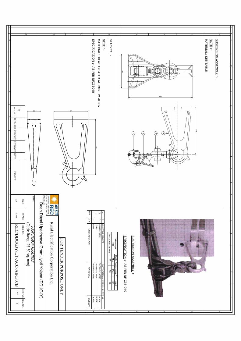
BLA
CK
BLA
CK
BLA
CK
NACO
LOU
R
MO
UN
TIN
G B
RACK
ET
4
35 87
121
321
MATER
IAL
DESC
RIPIT
ION
QTY
REP
HEAT T
REATED
ALU
MIN
IUM
ALLO
Y
TH
ERM
O PLA
STIC
1
MO
VABLE
LINK
LEVER
BO
DY
1 2 3 4
MATERIA
L: HEAT T
REATED
ALU
MIN
IUM
ALLO
Y
NO
TE :-
SPECIFIC
ATIO
N :- A
S PE
R N
FC33040
SU
SPE
NSIO
N A
SSEM
BLY
:-
BRACKET :-
SPECIFIC
ATIO
N :- A
S PE
R N
F C33-0
40
140
100
140
NO
TE :-
MATERIA
L: SEE T
ABLE
TH
ERM
O PLA
STIC
TH
ERM
O PLA
STIC
SU
SPE
NSIO
N A
SSEM
BLY
:-
185
2
50
Max
Typ
eM
esse
nger
INS
UL
AT
ED
/BA
RE
25
Cab
le Ran
ge (m
m )
Min
12
KN
Load
HGFEDCBA
46
57
3 34
65
78
910
11
89
1011
12
HGFED
12
Rural E
lectrification Corporation L
td.
PRO
JEC
T:
TIT
LE
SCA
LE
DR
G. N
O.
SIZE
RE
V. N
O.
SHT
. NO
.
1 OF 1
A4
1:1000
RE
V. N
O.
R0
PRE
PAR
ED
CH
EC
KE
DA
PPR
OV
ED
DA
TE
PRO
JEC
T
FOR
TE
ND
ER
PUR
PO
SE O
NL
Y
De
en D
ayal U
pad
hyaya
Gram
Jyoti Y
oja
na (D
DU
GJY
)
RE
C/D
DU
GJY
/LT
-AC
C-A
BC
/07B
C:\D
ocuments and
Settings\R
el\Desktop\dow
nload.jpg

•••••••
•••••••••••••••
•••••••
•••••••••••••
EN
D V
IEW
EL
EV
AT
ION
405
40 100 100
Welded
2565
Plan
65
2
1
BIL
L OF
MA
TE
RIA
L
M.S C
hannel 75x40x60=405 L
ong
Part N
o.
DE
SC
RIP
TIO
N
1
QT
Y.
1 NO
S.
M.S A
ngle 65x65x6= 75 L
ong2
2 NO
S.
All D
ime
nsio
ns in m
m
12
HGFEDCB
12
A
46
57
3 34
65
78
910
11
89
1011
12
HGFEDCBA
12
RE
V. N
O.
R0
PR
EP
AR
ED
BY
CH
EC
KE
DB
YA
PPR
OV
ED
BY
DA
TE
PRO
JEC
T0
1 OF
1
FOR
TE
ND
ER
PUR
POS
E O
NL
Y
Rural E
lectrification Corporation L
td.
RE
C/D
DU
GJY
/11KV
/10
11 KV
LIN
E PO
LE
TO
P B
RA
CK
ET
Deen D
ayal Upadhyaya G
ram Jyoti Y
ojna (DD
UG
JY)

Volume-II : Section-II (B) Technical Specification
558
DDUGJY & IPDS/SBD/R1
10.0 Acceptance Tests for CMRI and PC Software
All CMRI after final assembly and before dispatch from Bidder's/Manufacturer's works shall be duly tested to verify that they are suitable for supply to the Employer. In particular, each and every CMRI shall be subjected to the following acceptance test:
(i) Functional Checks (ii) Downloading Meter Data from the Meter(s) (iii) Compatibility with PC software (iv) Downloading the meter data on PC (v) Functioning of advance and retard time commands (vi) Per meter downloading time verification (vii) Capacity of CMRI for data storage
35 Earthing Coil
Earthing Coils shall be fabricated from soft GI Wire Hot Dip Galvanized. The Hot Dip galvanized wire shall have clean surface and shall be free from paint enamel or any other poor conducting material. The coil shall be made as per REC constructions standard (Refer tender drawing No. REC-XI Plan-Gen-005). The Hot Dip galvanizing shall conform to IS:2629/1966, 2633/1972 and 4826/1969 with latest amendments. Galvanizing should be heavily coated and should stand for the following tests.
Galvanizing Tests
i) Minimum Mass of Zinc
a) ON GI Wire used 280 cm/m2 b) After Coiling 266 gm/m2. The certificate from recognized laboratory shall be submitted
towards mass of zinc.
ii) Dip TestShall stand 3 dips of 1 minute and one dip of ½ minute before coiling and 43 dips of 1 minute after coiling as per IS : 4826/1979.
THE DIMENSIONAL REQUIREMENT SHALL BE AS FOLLOWS
a) Nominal dia of GI Wire 4 mm (Tolerance + 2.5%) b) Minimum no. of turns 115 Nos. c) External dia of Coil (Min) 50 mm d) Length of Coil (Min) 460 mm e) Free length of GI Wire at one end coil (Min.) 2500 mm
The turns should be closely bound. Weight of one finished Earthing Coils (min.) 1.850 Kg.
Adhesion test As per ISS 4826 1979.

Volume-II : Section-II (B) Technical Specification
575
DDUGJY & IPDS/SBD/R1
43 Gi Earthing Pipe
Earthing pipe should be made of 40 mm diameter ISI marked B class GI Pipe. 12 mm dia suitable holes on its circumference shall be made as per approved drawing. The pipe should be in one piece. No joints or welding would be allowed on its length. Clamps made of 50x6mm GI flat duly drilled with 12 mm size holes should be welded at the top end for connection of earth conductor.
Pipe used shall be 40mm NB diameter, ISI marked Galvanized Mild Steel Tubes continuously welded Electric Resistance Welded ERW/High Frequency Induction welded (HFIW)/Hot finished welded (HFW) type, conforming to IS-554-1985 with latest amendment of MEDIUM quality (Class B).
1. MANUFACTURE:
GI earth pipe (40 mm diameter & 3 metre long) shall be made of tubes which shall be made from tested quality steel manufactured by any approved process as follows:
a) Electric Resistance Welded (ERW). b) High Frequency Induction Welded (HFIW) and c) Hot finished Welded (HFW).
Tubes made by manual welding are not acceptable.
2. DIMENSIONS:
The dimensions and weights of tubes shall be in accordance with Table-I and Table-II of IS: 1239 (Part-I)/1990 with latest amendments, subject to tolerance permitted therein. Necessary 12 mm diameter holes across the circumference shall be provided as per approved drawing. Drawings shall be approved by the owner before start of the manufacturing work. The tube, earthing pipe shall be provided with 50x6mm GS clamps on one end, one clamp is to be welded with the pipe and another is removable to enable measurement of earth resistance of the pit. Other end of the earth pipe should be cut half in slop to make it a sharp.
3. GALVANIZING:
Tubes shall be galvanized in accordance with IS-4736-1986 with latest amendment for not dip zinc coating of Mild Steel Tubes. The minimum mass of zinc coating on the tubes shall be in accordance with clause 5.1 of IS-4736-1986 (specification for hot dip zinc) and when determined on a 100mm long test piece in accordance with IS: 6745:1972 shall be 400 g/m2. The zinc coating shall be uniform adherent reasonably smooth and free from such imperfections as flux, ash and dross inclusions, bare patches, black spots, pimples, lumpiness, rust, stains, bulky white deposits and blisters.
4. HYDRAULIC TEST:
(Before applying holes) Each tube shall withstand a test pressure of 5 M Pa maintained for at least 3 seconds without showing defects of any kind. The pressure shall be applied by approved means and maintained sufficiently long for proof and inspection. The testing apparatus shall be fitted with an accurate pressure indicator
5. TEST ON FINISHED TUBES AND SOCKETS:
The following tests shall be conducted by the manufacturer of finished tubes and sockets.
a) The tensile strength of length of strip cut from selected tubes when tested in accordance with IS-1894-1972, (Method for tensile testing of steel tubes), shall be at least 320N/mm2.

Volume-II : Section-II (B) Technical Specification
576
DDUGJY & IPDS/SBD/R1
b) The elongation percentage on a gauge length of 5.65/so (where so is the original cross-sectional area of test specimen) shall not be less than 20%.
c) When tested in accordance with IS-2329-1985 (Method for Bend test on Metallic tubes) the finished tube shall be capable of with standing the bend test without showing any sign of fracture or failure. Welded tubes shall be bent with the weld at 90 degree to the plane of bending. The tubes shall not be filled for this test.
d) Galvanized tubes shall be capable of being bent cold without cracking of the steel, through 90 degree round a former having a radius at the bottom of the groove equal to 8 times the outside diameter of tube.
e) Flattening Test on Tubes above 50 mm Nominal Bore: Rings not less than 40 mm in length cut from the ends of selected tubes shall be flattered between parallel plates with the weld, if any, at 90 degree (point of maximum bending) in accordance with IS-2328-1983. No opening should occur by fracture in the weld unless the distance between the plate is less than 75 percent of the original outside diameter of the pipe and no cracks or breaks in the metal elsewhere than in the weld shall occur, unless the distance between the plates is less than 60% of the original outside diameter. The test rings may have the inner and outer edges rounded.
f) GALVANISHING TEST: Weight of zinc Coating: For tubes thickness upto 6 mm the minimum weight of zinc coating,
when determined on a 100 mm long test piece in accordance with IS-4736-1986 shall be 400 grm/m2.
The weight of the coating expressed in gram/m2 shall be calculated by dividing the total weight of the zinc (inside plus outside) by the total area (inside plus outside) of the coated surface.
Test specimen for this test shall be cut approximately 100 mm in length from opposite ends of
the length of tubes selected for testing. Before cutting the test specimen, 50 mm from both ends of the samples shall be discarded.
g) Free Bore Test: A rod 230mm long and of appropriate diameter shall be passed through relevant
nominal bore of the sample tubes to ensure a free bore.
h) Uniformity of Galvanized Coating: The galvanized coating when determined on a 100 mm long test piece [see V (a) (iii)] in accordance with IS-2633-1986 (Method for testing uniformity of coating on zinc coated articles) shall with stand 4 one minute dips.
6. WORKMANSHIP:
The tubes shall be cleanly finished and reasonably free from injurious defects. They shall be reasonably straight, free from cracks, surface flaws, laminations, and other defects, both internally and externally. The screw tubes and sockets shall be clean and well-cut. The ends shall be cut cleanly and square with the axis of tube.
7. MARKING:
The medium class of tubes shall be distinguished by Blue colour bands which shall be applied before the
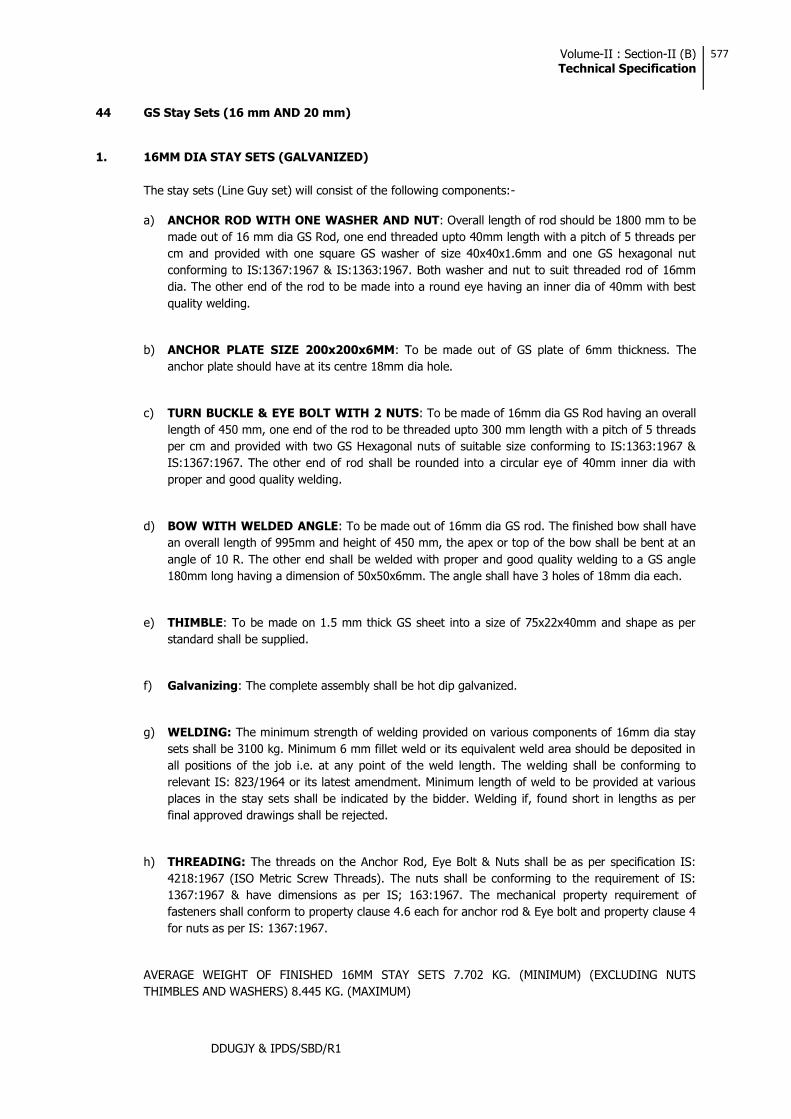
Volume-II : Section-II (B) Technical Specification
577
DDUGJY & IPDS/SBD/R1
44 GS Stay Sets (16 mm AND 20 mm)
1. 16MM DIA STAY SETS (GALVANIZED)
The stay sets (Line Guy set) will consist of the following components:-
a) ANCHOR ROD WITH ONE WASHER AND NUT: Overall length of rod should be 1800 mm to be made out of 16 mm dia GS Rod, one end threaded upto 40mm length with a pitch of 5 threads per cm and provided with one square GS washer of size 40x40x1.6mm and one GS hexagonal nut conforming to IS:1367:1967 & IS:1363:1967. Both washer and nut to suit threaded rod of 16mm dia. The other end of the rod to be made into a round eye having an inner dia of 40mm with best quality welding.
b) ANCHOR PLATE SIZE 200x200x6MM: To be made out of GS plate of 6mm thickness. The anchor plate should have at its centre 18mm dia hole.
c) TURN BUCKLE & EYE BOLT WITH 2 NUTS: To be made of 16mm dia GS Rod having an overall length of 450 mm, one end of the rod to be threaded upto 300 mm length with a pitch of 5 threads per cm and provided with two GS Hexagonal nuts of suitable size conforming to IS:1363:1967 & IS:1367:1967. The other end of rod shall be rounded into a circular eye of 40mm inner dia with proper and good quality welding.
d) BOW WITH WELDED ANGLE: To be made out of 16mm dia GS rod. The finished bow shall have an overall length of 995mm and height of 450 mm, the apex or top of the bow shall be bent at an angle of 10 R. The other end shall be welded with proper and good quality welding to a GS angle 180mm long having a dimension of 50x50x6mm. The angle shall have 3 holes of 18mm dia each.
e) THIMBLE: To be made on 1.5 mm thick GS sheet into a size of 75x22x40mm and shape as per standard shall be supplied.
f) Galvanizing: The complete assembly shall be hot dip galvanized.
g) WELDING: The minimum strength of welding provided on various components of 16mm dia stay sets shall be 3100 kg. Minimum 6 mm fillet weld or its equivalent weld area should be deposited in all positions of the job i.e. at any point of the weld length. The welding shall be conforming to relevant IS: 823/1964 or its latest amendment. Minimum length of weld to be provided at various places in the stay sets shall be indicated by the bidder. Welding if, found short in lengths as per final approved drawings shall be rejected.
h) THREADING: The threads on the Anchor Rod, Eye Bolt & Nuts shall be as per specification IS: 4218:1967 (ISO Metric Screw Threads). The nuts shall be conforming to the requirement of IS: 1367:1967 & have dimensions as per IS; 163:1967. The mechanical property requirement of fasteners shall conform to property clause 4.6 each for anchor rod & Eye bolt and property clause 4 for nuts as per IS: 1367:1967.
AVERAGE WEIGHT OF FINISHED 16MM STAY SETS 7.702 KG. (MINIMUM) (EXCLUDING NUTS THIMBLES AND WASHERS) 8.445 KG. (MAXIMUM)

Volume-II : Section-II (B) Technical Specification
578
DDUGJY & IPDS/SBD/R1
2. 20 MM DIA STAYS SETS FOR 33KV LINES (GALVANIZED)
THE STAY SET (LINE GUY SET) WILL CONSIST OF THE FOLLOWING COMPONENTS:
a) ANCHOR ROD WITH ONE WASHER AND NUT: Overall length of Rod should be 1800mm to be made out of 20mm dia GS Rod, one end threaded upto 40mm length with a pitch of a threads per cm. And provided with one square G.S. Washer of Size 50x50x1.6mm and one GS Hexagonal nut conforming to IS:1367:1967 & IS:1363:1967. Both washer & nut to suit the threaded rod of 20mm. The other end of the rod to be made into a round eye having an inner dia of 40mm with best
s approval before start of manufacturing.
b) ANCHOR PLATE: Size 300x300x8mm: To be made out of G.S. Plate of8mm thickness. The anchor plate to have at its centre 22mm dia hole.
c) TURN BUCKLE, EYE BOLT WITH 2 NUTS: To be made of 20mm dia G.S. Rod having an overall length of 450 mm. One end of the rod to be threaded upto 300mm length with a pitch of 4 threads per cm. The 20mm dia bolt so made shall be provided with two G.S. Hexagonal nuts of suitable size conforming to IS:1637/1967 & IS:1363/1967.
The other end of the rod shall be rounded into a circular eye of 40mm inner dia with proper and good quality of welding. Welding details are to be indicated by the bidder separately for approval.
d) BOW WITH WELDED CHANNEL: To be made out of 16mm dia G.S. Rod. The finished bow shall have and overall length of 995 mm ad height of 450 mm. The apex or top of the bow shall be bent at an angle of 10R. The other end shall be welded with proper and good quality welding to a G.S. Channel 200mm long having a dimension of 100x50x4.7 mm. The Channel shall have 2 holes of 18 mm dia and 22 dia hole at its centre.
e) THIMBLE 2 Nos.: To be made of 1.5mm thick G.S. sheet into a size of 75x22x40mm and shape as per standard.
f) GALVANISING: The complete assembly shall be hot dip galvanised.
g) WELDING: The minimum strength of welding provided on various components of 20mm dia stay sets shall be 4900 kg. Minimum 6mm filet weld or its equivalent weld area should be deposited in all positions of the job i.e. at any point of the weld length. The welding shall be conforming to relevant IS: 823/1964 or its latest amendment.
h) THREADING: The threads on the Anchor Rods, Eye Bolts and Nuts shall be as per specification IS: 4218:1967 (ISO Metric Screw Threads). The Nuts shall be conforming to the requirements of IS: 1367:1967 and have dimension as per IS 1363:1967. The mechanical property requirement of fasteners shall confirm to the properly clause 4.6 each for anchor rods and Eye bolt and property clause 4 for nuts as per IS: 1367:1967.
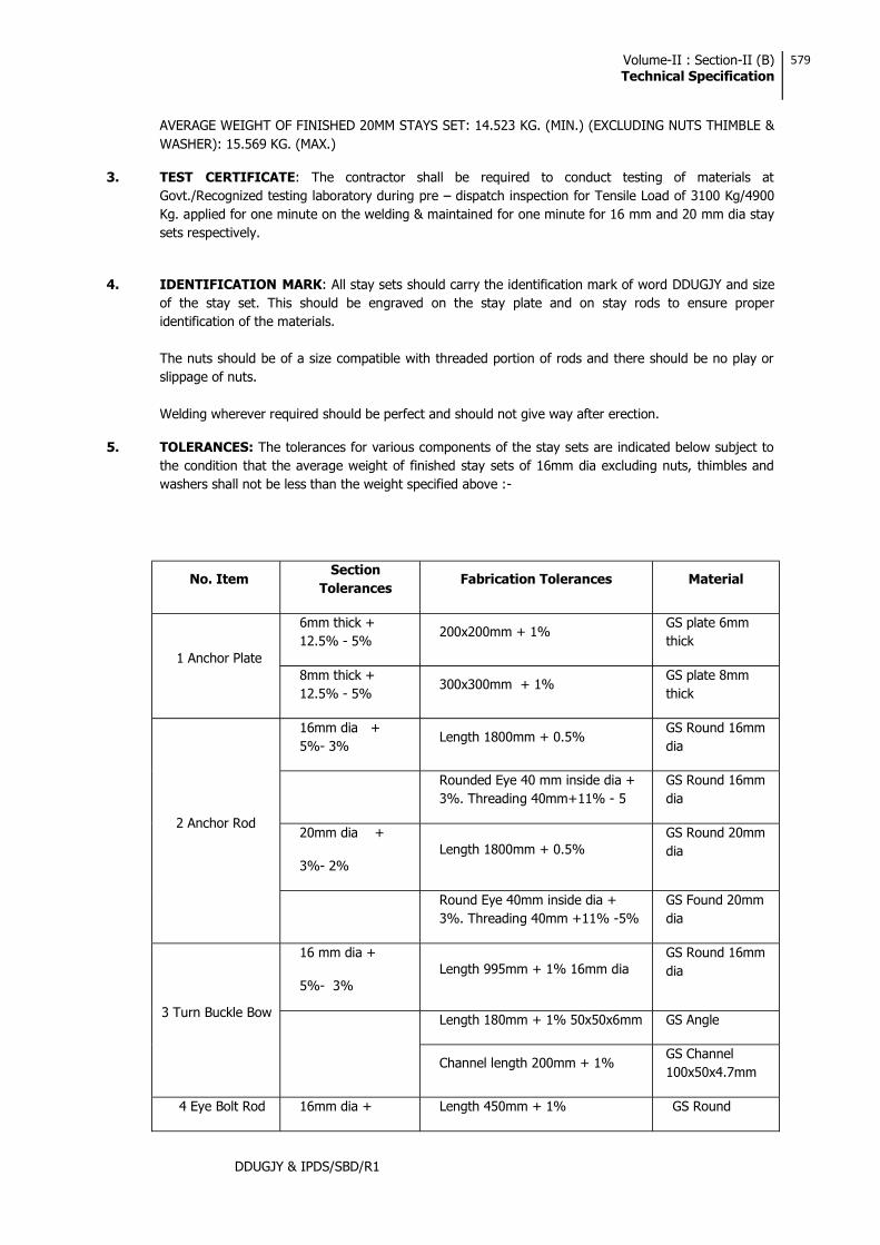
Volume-II : Section-II (B) Technical Specification
579
DDUGJY & IPDS/SBD/R1
AVERAGE WEIGHT OF FINISHED 20MM STAYS SET: 14.523 KG. (MIN.) (EXCLUDING NUTS THIMBLE & WASHER): 15.569 KG. (MAX.)
3. TEST CERTIFICATE: The contractor shall be required to conduct testing of materials at Govt./Recognized testing laboratory during pre dispatch inspection for Tensile Load of 3100 Kg/4900 Kg. applied for one minute on the welding & maintained for one minute for 16 mm and 20 mm dia stay sets respectively.
4. IDENTIFICATION MARK: All stay sets should carry the identification mark of word DDUGJY and size of the stay set. This should be engraved on the stay plate and on stay rods to ensure proper identification of the materials.
The nuts should be of a size compatible with threaded portion of rods and there should be no play or slippage of nuts.
Welding wherever required should be perfect and should not give way after erection.
5. TOLERANCES: The tolerances for various components of the stay sets are indicated below subject to the condition that the average weight of finished stay sets of 16mm dia excluding nuts, thimbles and washers shall not be less than the weight specified above :-
No. Item Section
Tolerances Fabrication Tolerances Material
1 Anchor Plate
6mm thick + 12.5% - 5%
200x200mm + 1% GS plate 6mm thick
8mm thick + 12.5% - 5%
300x300mm + 1% GS plate 8mm thick
2 Anchor Rod
16mm dia + 5%- 3%
Length 1800mm + 0.5% GS Round 16mm dia
Rounded Eye 40 mm inside dia + 3%. Threading 40mm+11% - 5
GS Round 16mm dia
20mm dia +
3%- 2% Length 1800mm + 0.5%
GS Round 20mm dia
Round Eye 40mm inside dia + 3%. Threading 40mm +11% -5%
GS Found 20mm dia
3 Turn Buckle Bow
16 mm dia +
5%- 3% Length 995mm + 1% 16mm dia
GS Round 16mm dia
Length 180mm + 1% 50x50x6mm GS Angle
Channel length 200mm + 1% GS Channel 100x50x4.7mm
4 Eye Bolt Rod 16mm dia + Length 450mm + 1% GS Round

Volume-II : Section-II (B) Technical Specification
580
DDUGJY & IPDS/SBD/R1
5%- 3% Threading 300mm + 1%
Round Eye 40mm inside dia + 3%
16mm dia
20mm dia +
3%- 2%
Length 450mm + 1%
Threading 300mm + 1%
Round Eye 40mm inside dia + 3%
GS Round 20mm dia

Volume-II : Section-II (B) Technical Specification
581
DDUGJY & IPDS/SBD/R1
45 GI Stay Wires
1. SCOPE
This Specification covers details of G.I. stranded stay wires for use in rural distribution system.
2. APPLICABLE STANDARDS
Except when they conflict with the specific requirements of this specification, the G.I. Stranded Wires shall comply with the specific requirements of IS:2141-1979. IS:4826-1979 & IS:6594-1974 or the latest versions thereof.
3. APPLICATION AND SIZES
3.1 The G.I. stranded wires covered in this Specification are intended for use on the overhead power line poles, distribution transformer structures etc.
3.2 The G.I. stranded wires shall be of 7/2.5mm, 7/3.15mm and 7/4.0mm standard sizes.
4. MATERIAL
The wires shall be drawn from steel made by the open hearth basic oxygen or electric furnace process and of such quality that when drawn to the size of wire specified and coated with zinc, the finished strand and the individual wires shall be of uniform quality and have the properties and characteristics as specified in this specification. The wires shall not contain sulphur and phosphorus exceeding 0.060% each.
5. TENSILE GRADE
The wires shall be of tensile grade 4, having minimum tensile strength of 700 N/mm2 conforming to IS:2141.
6. GENERAL REQUIREMENTS
6.1 The outer wire of strands shall have a right-hand lay.
6.2 The lay length of wire strands shall be 12 to 18 times the strand diameter.
7. MINIMUM BREAKING LOAD
The minimum breaking load of the wires before and after stranding shall be as follows :
No. of wires & const.
Wire dia (mm)
Min. breaking load of Single wire before stranding (KN)
Min. breaking load of the standard wire (KN)
7(6/1) 2.5 3.44 22.86
7(6/1) 3.15 5.45 36.26
7(6/1) 4.0 8.79 58.45

GL
145
GL
3050
1
3
4
2
Guy A
ssembly
(Conventional A
rrangement)
RE
C C
onstruction StandardG
-1
x
D1500
••••••••
••
••
••
••
•••
•••••
••
••
••
RC
C B
ase450x450x75
Soil Filling ST
AY
INS
UL
AT
OR
MA
KE
-OF
F
GU
Y IN
SUL
AT
OR
• •• •
600
PL
AN
45
ST
AY
PIT - A
NC
HO
R A
SSE
MB
LY
0AB
••••••••••••750
11001500
1300
6
2
800800
500X500
1:2:4C
oncrete
Concreting to be done
where soil is not F
irm
Stay Set A
rrangement
All D
imensions are in m
m unless otherw
isem
entionedM
anufacturing Tolerance as Follows
Upto 50m
m :
5%51 to 100m
m :
4%101 to 300m
m :
3%A
bove 300mm
: 2%
EN
D M
AK
ING
OF G
UY
WIR
E
600
A
150
B
••••1600 A
NC
HO
R R
OD
AN
CH
OR
PLA
TE
EL
EV
AT
ION
(5)TH
IMB
LE
BIL
L O
F MA
TE
RIA
L
TU
RN
BU
CK
LE
ASS
EM
BL
Y
ITE
MN
O.
DE
SCR
IPT
ION
QT
Y.
SEC
TIO
NL
EN
GT
H
EY
E B
OL
T1 N
O.
••••
••
••
••
550
SU
PP
OR
TIN
G A
NG
LE
1 NO
.L
50x50x6180
EY
E H
OO
K
WA
SH
ER
NU
T
AN
CH
OR
RO
D1900
••••
••
••
••
4MM
1000
G.I
1 NO
.
2 NO
S.
MM
MA
TE
RIA
L
1
1 NO
.
M20
••••
••
••
••
1 NO
.
AN
CH
OR
PLA
TE
(RE
C ST
AN
DA
RD
K-1)
450X450
75 MM
1 NO
.
SQ
UA
RE
WA
SH
ER
1 NO
.
NU
T1 N
O.
8 MM
M16
AN
CH
OR
RO
D &
AN
CH
OR
PLA
TE
2
GU
Y IN
SUL
AT
OR
31 N
O.
ST
AY
WIR
E4
G.I.
7/3.15mm
G.I
G.I
G.I
RC
C
G.I.
G.I.
G.I.
G.I.
G.I.
G.I
1 NO
.
1 NO
.
TH
IMB
LE
5G
.I.2 N
OS.
abcdeabcd
40X40
40X40
648
432
259,2
648
••••••••••
WE
LD
ED
WE
LD
ED
HE
XA
GO
NA
L N
UT
SQU
AR
E W
AS
HE
R
•••••••••
•••••
••
••
••
••
••
••
••
••
8,64
450
450
1800
57,6
•••••
•••••
••
••
••
••
••
••
••
••••••
•••••
••
••
••
••
••
••
•
RC
C A
NC
HO
R P
LA
TE
(RE
C ST
AN
DA
RD
K1)
TU
RN
BU
CK
LE
25
116
40
40SQ
UA
RE
WA
SH
ER
(40x40x4)
WE
LD
ED
WE
LE
DE
D
R10
C 75x40 O
RL
50x50x6•
•••••
••••••••••
•••••
•••••••••••
••••••
12b
40
40
SQU
AR
E W
AS
HE
R(40x40x8)
•••••
•••••••••••
AN
CH
OR
RO
D2a
Stay Set A
rrangement
Soil Filling
M10 G
rade PCC
1600 Anchor R
od
Anchor Plate
200x200x+6m
m
12
HGFEDCB
12
A
46
57
3 34
65
78
910
11
89
1011
12
HGFED
12
STA
Y SE
T A
RR
AN
GE
ME
NT
FOR
11KV
/LT
LIN
E
NO
TE
S:-1) A
LL
DIM
EN
SIO
NS
AR
E IN
MM
UN
LE
SS O
TH
ER
WISE
ME
NT
ION
ED
.
2) AL
L M
.S. ITE
M SH
AL
L B
E H
OT
DIP
GA
LV
AN
ISED
AS PE
R IS 2629&
4759
4) M.S
MA
TE
RIA
L SH
AL
L C
ON
FIRM
TO
IS: 2062.
5) GU
Y IN
SU
LA
TO
RS T
O B
E U
TIL
ISE
D A
S PE
R S
PEC
IFICA
TIO
N FO
R
HT
& L
T L
INE
S RE
SPEC
TIV
EL
Y.
RE
V. N
O.
R0
PR
EP
AR
ED
BY
CH
EC
KE
DB
YA
PPR
OV
ED
BY
DA
TE
PRO
JEC
TR
EC
/DD
UG
JY/G
EN
/09A0
1 OF
1
3) MA
NU
FA
CT
UR
ING
TO
LE
RA
NC
E•
•••
•••••
••••••••
••
••
••
••
••
••
••
•••••
••••••
••••••••
••
••
••
••
••
••
••
••
••
••••••
••••••
••••••••
••
••
••
••
••
••
••
••
••
•••
•••••••
••••••••
••
••
••
••
••
••
••
••
••
6) FOR
FIRM
SO
ILS, O
NL
Y SO
IL FIL
LIN
G W
ITH
CO
MP
AC
TIO
N T
O B
E D
ON
E
FO
R T
EN
DE
R PU
RP
OS
E O
NL
Y
Deen D
ayal Upadhyaya G
ram Jyoti Y
ojana (DD
UG
JY)
Rural E
lectrification Corporation L
td.
Concreting 0.2cm
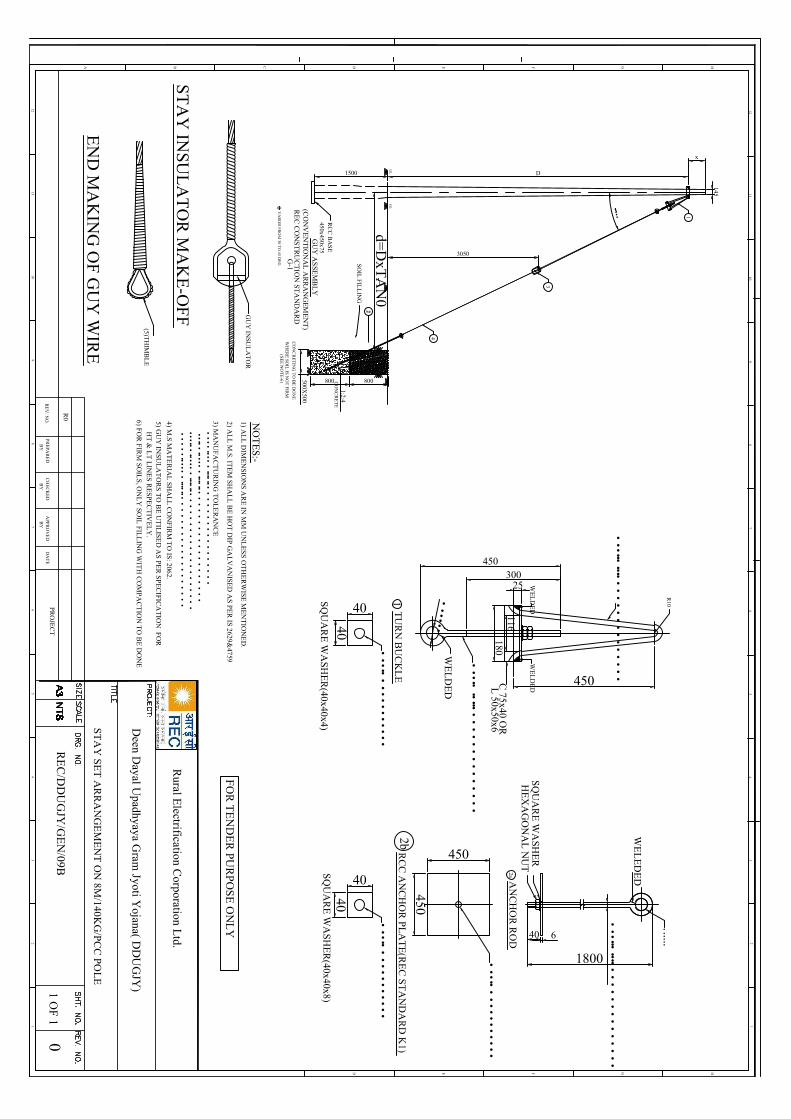
450300
180
450
••••••
WE
LD
ED
WE
LD
ED
HE
XA
GO
NA
L N
UT
SQ
UA
RE
WA
SHE
R
••••••
•••••
••
••
••
••
••
••
•
6
450
450
1800
40
•••••
•••••
••
••
••
••
••
••
••
••••••
•••••
••
••
••
••
••
••
•
RC
C A
NC
HO
R P
LA
TE
(RE
C S
TA
ND
AR
D K
1)T
UR
N B
UC
KL
E
25
11640
40
SQ
UA
RE
WA
SHE
R(40x40x4)
WE
LD
ED
WE
LE
DE
D
R10
C 75x40 O
RL
50x50x6•
•••••
••••••••••
•••••
•••••••••••
••••••
12b
40
40
SQ
UA
RE
WA
SHE
R(40x40x8)
•••••
•••••••••••
AN
CH
OR
RO
D2a
ST
AY
INSU
LA
TO
R M
AK
E-O
FF
EN
D M
AK
ING
OF G
UY
WIR
E
GU
Y IN
SUL
AT
OR
(5)TH
IMB
LE
GL
145
GL
3050
1
3
4
2
GU
Y A
SSE
MB
LY
(CO
NV
EN
TIO
NA
L A
RR
AN
GE
ME
NT
)R
EC
CO
NS
TR
UC
TIO
N ST
AN
DA
RD
G-1
x
D1500
d=D
xTA
N0
RC
C B
AS
E450x450x75
SO
IL F
ILL
ING
• •• •
2
800800500X500
1:2:4C
ON
CR
ET
E
CO
NC
RE
TIN
G T
O B
E D
ON
E
WH
ER
E SO
IL IS N
OT
FIR
M
0V
AR
IES
FR
OM
30 TO
45 DE
G(S
EE
NO
TE
-6)
12
HGFEDCB
12
A
46
57
3 34
65
78
910
11
89
1011
12
HGFED
12
STA
Y SE
T A
RR
AN
GE
ME
NT
ON
8M/140K
G/PC
C PO
LE
NO
TE
S:-1) A
LL
DIM
EN
SION
S AR
E IN
MM
UN
LE
SS O
TH
ER
WIS
E M
EN
TIO
NE
D.
2) AL
L M
.S. IT
EM
SHA
LL
BE
HO
T D
IP G
AL
VA
NISE
D A
S PER
IS 2629&4759
4) M.S
MA
TE
RIA
L S
HA
LL
CO
NF
IRM
TO
IS: 2062.
5) GU
Y IN
SUL
AT
OR
S TO
BE
UT
ILISE
D A
S PER
SP
EC
IFICA
TIO
N F
OR
H
T &
LT
LIN
ES
RE
SPE
CT
IVE
LY
.
RE
V. N
O.
R0
PR
EP
AR
ED
BY
CH
EC
KE
DB
YA
PPR
OV
ED
BY
DA
TE
PRO
JEC
T0
1 OF
1
3) MA
NU
FA
CT
UR
ING
TO
LE
RA
NC
E•
•••
•••••
•••••••
••
••
••
••
••
••
••
••
•••••
••••••
•••••••
••
••
••
••
••
••
••
••
••
••••••
••••••
•••••••
••
••
••
••
••
••
••
••
••
••
••
•••••••
••••••••
••
••
••
••
••
••
••
••
••
6) FOR
FIR
M SO
ILS
, ON
LY
SOIL
FILL
ING
WIT
H C
OM
PA
CT
ION
TO
BE
DO
NE
FO
R T
EN
DE
R PU
RP
OS
E O
NL
Y
Rural E
lectrification Corporation L
td.
Deen D
ayal Upadhyaya G
ram Jyoti Y
ojana( DD
UG
JY)
RE
C/D
DU
GJY
/GE
N/09B

Volume-III: Section-ITechnical Specifications
209
DDUGJY & IPDS/SBD/R1
4. Mild Steel Channel, Angle And Flat
1) APPLICABLE STANDARDS:
for steel materials, documents for which shall be made available at representative.
2) GENERAL REQUIREMENTS:
Material shall be supplied as per the following sizes:
Standard having length ranging from 5.5 to 13.5 meters. 75x40 ISMC channel conforming to IS: 2062 grade
meters.
50x50x8 mm or 6 mm ISA angles conforming to IS: 2062 grade international standard having length ranging from 5.5 to 13.5 meters.
standard having length ranging from 5.5 to 13.5 meters.
standard having length ranging from 5.5 to 13.5 meters.
25X3mm, 50X6mm, 50x8mm, 75X8mm and 80X8 flats conforming to IS: 2062 grade or its equivalent international standard having length ranging from 5.5 to 9.5 meters.
3) GALVANISATION: All above steel members shall be fabricated as per approved drawing having smooth edge, drilled circular/elliptical holes of suitable measurements.
All structural steel members and bolts shall be galvanized as per IS:4759 and zinc coating shall not be less than 610gm/sq. meter for all structural steel members. All weld shall be 6mm filled weld unless specified otherwise. All nuts and bolt shall be of property class 5.6 of IS 1367. Plain washers shall be as per IS 2016 and spring washers shall be IS:3063
4) INSPECTION:
All inspection/test will be carried out by representative of owner.
All tests and inspection shall be made at the place of manufacturer unless otherwise specially agreed upon by the manufacturer and the owner. The manufacturer shall provide all reasonable facilities, without charge to satisfy him that the material is being supplied in accordance with the specification.

Volume-II : Section-II (B) Technical Specification
577
DDUGJY & IPDS/SBD/R1
44 GS Stay Sets (16 mm AND 20 mm)
1. 16MM DIA STAY SETS (GALVANIZED)
The stay sets (Line Guy set) will consist of the following components:-
a) ANCHOR ROD WITH ONE WASHER AND NUT: Overall length of rod should be 1800 mm to be made out of 16 mm dia GS Rod, one end threaded upto 40mm length with a pitch of 5 threads per cm and provided with one square GS washer of size 40x40x1.6mm and one GS hexagonal nut conforming to IS:1367:1967 & IS:1363:1967. Both washer and nut to suit threaded rod of 16mm dia. The other end of the rod to be made into a round eye having an inner dia of 40mm with best quality welding.
b) ANCHOR PLATE SIZE 200x200x6MM: To be made out of GS plate of 6mm thickness. The anchor plate should have at its centre 18mm dia hole.
c) TURN BUCKLE & EYE BOLT WITH 2 NUTS: To be made of 16mm dia GS Rod having an overall length of 450 mm, one end of the rod to be threaded upto 300 mm length with a pitch of 5 threads per cm and provided with two GS Hexagonal nuts of suitable size conforming to IS:1363:1967 & IS:1367:1967. The other end of rod shall be rounded into a circular eye of 40mm inner dia with proper and good quality welding.
d) BOW WITH WELDED ANGLE: To be made out of 16mm dia GS rod. The finished bow shall have an overall length of 995mm and height of 450 mm, the apex or top of the bow shall be bent at an angle of 10 R. The other end shall be welded with proper and good quality welding to a GS angle 180mm long having a dimension of 50x50x6mm. The angle shall have 3 holes of 18mm dia each.
e) THIMBLE: To be made on 1.5 mm thick GS sheet into a size of 75x22x40mm and shape as per standard shall be supplied.
f) Galvanizing: The complete assembly shall be hot dip galvanized.
g) WELDING: The minimum strength of welding provided on various components of 16mm dia stay sets shall be 3100 kg. Minimum 6 mm fillet weld or its equivalent weld area should be deposited in all positions of the job i.e. at any point of the weld length. The welding shall be conforming to relevant IS: 823/1964 or its latest amendment. Minimum length of weld to be provided at various places in the stay sets shall be indicated by the bidder. Welding if, found short in lengths as per final approved drawings shall be rejected.
h) THREADING: The threads on the Anchor Rod, Eye Bolt & Nuts shall be as per specification IS: 4218:1967 (ISO Metric Screw Threads). The nuts shall be conforming to the requirement of IS: 1367:1967 & have dimensions as per IS; 163:1967. The mechanical property requirement of fasteners shall conform to property clause 4.6 each for anchor rod & Eye bolt and property clause 4 for nuts as per IS: 1367:1967.
AVERAGE WEIGHT OF FINISHED 16MM STAY SETS 7.702 KG. (MINIMUM) (EXCLUDING NUTS THIMBLES AND WASHERS) 8.445 KG. (MAXIMUM)

Volume-II : Section-II (B) Technical Specification
578
DDUGJY & IPDS/SBD/R1
2. 20 MM DIA STAYS SETS FOR 33KV LINES (GALVANIZED)
THE STAY SET (LINE GUY SET) WILL CONSIST OF THE FOLLOWING COMPONENTS:
a) ANCHOR ROD WITH ONE WASHER AND NUT: Overall length of Rod should be 1800mm to be made out of 20mm dia GS Rod, one end threaded upto 40mm length with a pitch of a threads per cm. And provided with one square G.S. Washer of Size 50x50x1.6mm and one GS Hexagonal nut conforming to IS:1367:1967 & IS:1363:1967. Both washer & nut to suit the threaded rod of 20mm. The other end of the rod to be made into a round eye having an inner dia of 40mm with best
s approval before start of manufacturing.
b) ANCHOR PLATE: Size 300x300x8mm: To be made out of G.S. Plate of8mm thickness. The anchor plate to have at its centre 22mm dia hole.
c) TURN BUCKLE, EYE BOLT WITH 2 NUTS: To be made of 20mm dia G.S. Rod having an overall length of 450 mm. One end of the rod to be threaded upto 300mm length with a pitch of 4 threads per cm. The 20mm dia bolt so made shall be provided with two G.S. Hexagonal nuts of suitable size conforming to IS:1637/1967 & IS:1363/1967.
The other end of the rod shall be rounded into a circular eye of 40mm inner dia with proper and good quality of welding. Welding details are to be indicated by the bidder separately for approval.
d) BOW WITH WELDED CHANNEL: To be made out of 16mm dia G.S. Rod. The finished bow shall have and overall length of 995 mm ad height of 450 mm. The apex or top of the bow shall be bent at an angle of 10R. The other end shall be welded with proper and good quality welding to a G.S. Channel 200mm long having a dimension of 100x50x4.7 mm. The Channel shall have 2 holes of 18 mm dia and 22 dia hole at its centre.
e) THIMBLE 2 Nos.: To be made of 1.5mm thick G.S. sheet into a size of 75x22x40mm and shape as per standard.
f) GALVANISING: The complete assembly shall be hot dip galvanised.
g) WELDING: The minimum strength of welding provided on various components of 20mm dia stay sets shall be 4900 kg. Minimum 6mm filet weld or its equivalent weld area should be deposited in all positions of the job i.e. at any point of the weld length. The welding shall be conforming to relevant IS: 823/1964 or its latest amendment.
h) THREADING: The threads on the Anchor Rods, Eye Bolts and Nuts shall be as per specification IS: 4218:1967 (ISO Metric Screw Threads). The Nuts shall be conforming to the requirements of IS: 1367:1967 and have dimension as per IS 1363:1967. The mechanical property requirement of fasteners shall confirm to the properly clause 4.6 each for anchor rods and Eye bolt and property clause 4 for nuts as per IS: 1367:1967.

Volume-II : Section-II (B) Technical Specification
579
DDUGJY & IPDS/SBD/R1
AVERAGE WEIGHT OF FINISHED 20MM STAYS SET: 14.523 KG. (MIN.) (EXCLUDING NUTS THIMBLE & WASHER): 15.569 KG. (MAX.)
3. TEST CERTIFICATE: The contractor shall be required to conduct testing of materials at Govt./Recognized testing laboratory during pre dispatch inspection for Tensile Load of 3100 Kg/4900 Kg. applied for one minute on the welding & maintained for one minute for 16 mm and 20 mm dia stay sets respectively.
4. IDENTIFICATION MARK: All stay sets should carry the identification mark of word DDUGJY and size of the stay set. This should be engraved on the stay plate and on stay rods to ensure proper identification of the materials.
The nuts should be of a size compatible with threaded portion of rods and there should be no play or slippage of nuts.
Welding wherever required should be perfect and should not give way after erection.
5. TOLERANCES: The tolerances for various components of the stay sets are indicated below subject to the condition that the average weight of finished stay sets of 16mm dia excluding nuts, thimbles and washers shall not be less than the weight specified above :-
No. Item Section
Tolerances Fabrication Tolerances Material
1 Anchor Plate
6mm thick + 12.5% - 5%
200x200mm + 1% GS plate 6mm thick
8mm thick + 12.5% - 5%
300x300mm + 1% GS plate 8mm thick
2 Anchor Rod
16mm dia + 5%- 3%
Length 1800mm + 0.5% GS Round 16mm dia
Rounded Eye 40 mm inside dia + 3%. Threading 40mm+11% - 5
GS Round 16mm dia
20mm dia +
3%- 2% Length 1800mm + 0.5%
GS Round 20mm dia
Round Eye 40mm inside dia + 3%. Threading 40mm +11% -5%
GS Found 20mm dia
3 Turn Buckle Bow
16 mm dia +
5%- 3% Length 995mm + 1% 16mm dia
GS Round 16mm dia
Length 180mm + 1% 50x50x6mm GS Angle
Channel length 200mm + 1% GS Channel 100x50x4.7mm
4 Eye Bolt Rod 16mm dia + Length 450mm + 1% GS Round
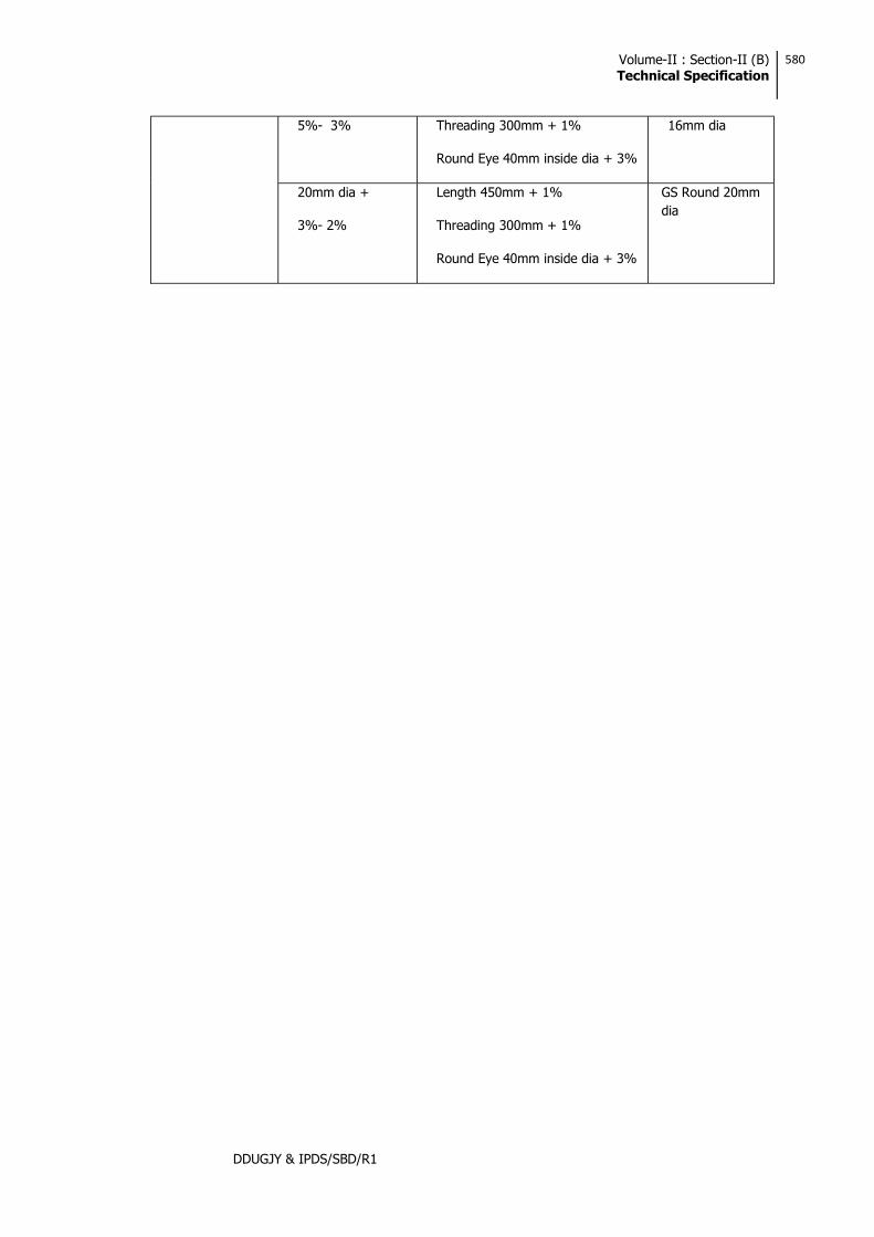
Volume-II : Section-II (B) Technical Specification
580
DDUGJY & IPDS/SBD/R1
5%- 3% Threading 300mm + 1%
Round Eye 40mm inside dia + 3%
16mm dia
20mm dia +
3%- 2%
Length 450mm + 1%
Threading 300mm + 1%
Round Eye 40mm inside dia + 3%
GS Round 20mm dia

Volume-II : Section-II (B) Technical Specification
581
DDUGJY & IPDS/SBD/R1
45 GI Stay Wires
1. SCOPE
This Specification covers details of G.I. stranded stay wires for use in rural distribution system.
2. APPLICABLE STANDARDS
Except when they conflict with the specific requirements of this specification, the G.I. Stranded Wires shall comply with the specific requirements of IS:2141-1979. IS:4826-1979 & IS:6594-1974 or the latest versions thereof.
3. APPLICATION AND SIZES
3.1 The G.I. stranded wires covered in this Specification are intended for use on the overhead power line poles, distribution transformer structures etc.
3.2 The G.I. stranded wires shall be of 7/2.5mm, 7/3.15mm and 7/4.0mm standard sizes.
4. MATERIAL
The wires shall be drawn from steel made by the open hearth basic oxygen or electric furnace process and of such quality that when drawn to the size of wire specified and coated with zinc, the finished strand and the individual wires shall be of uniform quality and have the properties and characteristics as specified in this specification. The wires shall not contain sulphur and phosphorus exceeding 0.060% each.
5. TENSILE GRADE
The wires shall be of tensile grade 4, having minimum tensile strength of 700 N/mm2 conforming to IS:2141.
6. GENERAL REQUIREMENTS
6.1 The outer wire of strands shall have a right-hand lay.
6.2 The lay length of wire strands shall be 12 to 18 times the strand diameter.
7. MINIMUM BREAKING LOAD
The minimum breaking load of the wires before and after stranding shall be as follows :
No. of wires & const.
Wire dia (mm)
Min. breaking load of Single wire before stranding (KN)
Min. breaking load of the standard wire (KN)
7(6/1) 2.5 3.44 22.86
7(6/1) 3.15 5.45 36.26
7(6/1) 4.0 8.79 58.45

Volume-II : Section-II (B) Technical Specification
582
DDUGJY & IPDS/SBD/R1
8. CONSTRUCTION
8.1 The galvanised stay wire shall be of 7-wire construction. The wires shall be so stranded together that when an evenly distributed pull is applied at the ends of completed strand, each wire shall take an equal share of the pull.
8.2 Joints are permitted in the individual wires during stranding but such joints shall not be less than 15 metres apart in the finished strands.
8.3 The wire shall be circular and free from scale, irregularities, imperfection, flaws, splits and other defects.
9. TOLERANCES
A tolerance of (±)2.5% on the diameter of wires before stranding shall be permitted.
10. SAMPLING CRITERIA
The sampling criteria shall be in accordance with IS:2141.
11. TESTS ON WIRES BEFORE MANUFACTURE
The wires shall be subjected to the following tests in accordance with IS:2141.
i) Ductility Test
ii) Tolerance on Wire Diameter
12. TESTS ON COMPLETED STRAND
The completed strand shall be tested for the following tests in accordance with IS:2141.
a) Tensile and Elongation Test :
The percentage elongation of the stranded wire shall not be less than 6%.
b) Chemical analysis
c) Galvanising Test :
IS:4826
13. MARKING
Each coil shall carry a metallic tag, securely attached to the inner part of the coil, bearing the following information:
a)
b) Lot number and coil number
c) Size
d) Construction
e) Tensile Designation
f) Lay
g) Coating
h) Length
Volume-II : Section-II (B) Technical Specification
583
DDUGJY & IPDS/SBD/R1
i) Mass
j) ISI certification mark, if any
14. PACKING
The wires shall be supplied in 75-100 Kg. coils. The packing should be done in accordance with the provisions of IS:6594.

Equivalent of V
oltsin L
ocal Language
Equivalent of D
anger inL
ocal Language
4) MA
NU
FAC
TU
RIN
G T
OL
ER
AN
CE
AS
FO
LL
OW
S
NO
TE
S:-
1) TH
E P
LA
TE
SHA
LL
BE
MA
DE
FR
OM
M.S. S
HE
ET
OF
AT
LE
AS
T 1.6m
m T
HIC
KN
ES
S
& V
ITR
EO
US
EN
AM
EL
ED
WH
ITE
WIT
H L
ET
TE
RS
, FIGU
RE
S &
TH
E C
ON
VE
NT
ION
AL
SK
UL
L&
BO
NE
S IN
SIG
NA
L R
ED
CO
LO
UR
ON
TH
E F
RO
NT
SID
E(IS
5-1978). TH
E R
EA
R S
IDE
OF T
HE
PLA
TE
SH
AL
L A
LSO
BE
EN
AM
EL
ED
.
2) AL
L L
ET
TE
RIN
G S
HO
UL
D B
E C
EN
TR
AL
LY
SP
AC
ED
.
3) AL
L D
IME
NSIO
NS A
RE
IN M
M U
NL
ES
S O
TH
ER
WISE
ME
NT
ION
ED
.
UP T
O 50m
m51 T
O 100m
m101 T
O 300m
mA
BO
VE
300mm
•••••
••
••
••••
•••
••
••
•••••
••
••
••••
•••
••
••
••
•••••
••••
••
••
••
••
••
•
••
•••••
••••
••
••
••
••
••
•

Volume-II : Section-II (B) Technical Specification
610
DDUGJY & IPDS/SBD/R1


