Embed Size (px)
Citation preview

Operating Instructions
Cultivator
Topas 140 A
Lemken GmbH & Co. KGWeseler Straße 5, D-46519 Alpen / Postfach 11 60, D-46515 Alpen
Telefon (0 28 02) 81-0, Telex 8 12 838, Telefax (0 28 02) 81-220eMail: [email protected], Internet: http://www.lemken.com
Art.-Nr.: 175 1228GB-3/07.00
SAFETY IS OUR CONCERN!


Dear customer!
We would like to thank you for the confidence in buying this implement.
The advantages of this implement will be shown, only, when operated andused with due care and attention.
When handing over this implement your dealer has already instructed youwith regard to operation, adjustment and maintenance. But this short intro-duction requires an additional detailed study of the instruction book.
Therefore read this instruction book carefully before the first use. Please payattention to the safety instructions mentioned in this instruction book.
Any changes and modifications carried out not being mentioned expressly inthis instruction book, may only be carried out with a written agreement of themanufacturer.
Ordering spare-parts
When ordering spare-parts please state type and serial No. of the implement.This information will be found on the identification plate.
Put down this data on the following table so that it is always available.
Only use genuine Lemken spare-parts. Spurious parts negatively influencethe function of the implement, show a shorter lifetime and increase in nearlyall cases additional maintenance.
We trust that you will understand that LEMKEN is unable to guarantee pooroperation and damage caused by using spurious parts!
Type of implement: ________________
Fabrication No.: ___________________
1

2
DEFINED USE
•Please familiarise yourself with the LEMKEN Topas 140 A andits operations before putting the implement to work. Thereforeuse this instruction book with the „General Health- and Safetyprecautions“!
• The LEMKEN Topas 140 A have been designed purely for the agriculturaluse!
• Any use beyond the one stipulated above is no longer considered as defi-ned use!
• Under „defined use“ the manufacturer’s prescribed operation-, mainte-nance- and repair conditions are to be adhered to!
• The LEMKEN Topas 140 A may only be operated, maintained and re-paired by such persons who have been made acquainted with it and whohave been advised about the dangers!
• The applicable accident prevention advice as well as the generally accept-ed safety technical, working, medical and road traffic rules should be ad-hered to!
CONTENTS
DEFINED USE ........................................................................................ 3
CONTENTS ............................................................................................ 3
1 SAFETY INSTRUCTIONS ...............................................................6
2 WARNING STICKERS ..................................................................10
2.1 General Instructions ............................................................10
2.2 Understanding the decals ...................................................10
3 LIST OF VARIANTS ......................................................................11
4 PREPARATION OF THE TRACTOR ............................................12
4.1 Topas as rear mounted implement ....................................124.1.1 Tyres ............................................................................124.1.2 Lift rods ........................................................................124.1.3 Check chains or sway blocks .......................................12
3
4.1.4 Tractor hydraulics ....................................................... 124.1.5 Steerability of the tractor ............................................. 124.1.6 Axle loads ................................................................... 12
4.2 Topas as front mounted implement .................................. 134.2.1 Distance between the driver and the front of the Topas 134.2.2 Hydraulics ................................................................... 13
5 ATTACHING AND DETACHING THE IMPLEMENT ................... 14
5.1 Attaching to the tractor....................................................... 14
5.2 Detaching from the tractor ................................................. 14
6 ATTACHING AND DETACHING A POWER HARROW .............. 15
6.1 Attaching a power harrow to the Topas............................ 15
6.2 Detaching the power harrow from the Topas ................... 15
7 ADJUSTMENTS ............................................................................ 17
7.1 General Instructions ........................................................... 17
7.2 Working depth ..................................................................... 177.2.1 Working depth of the Topas ........................................ 177.2.2 Working depth ot the power harrow fitted to the Topas 18
7.3 Lateral position of the tines ............................................... 19
7.4 Share position ..................................................................... 19
8 SHEARBOLT DEVICE .................................................................. 20
9 SHARES ........................................................................................ 21
9.1 General Instruction ............................................................. 21
9.2 Wing shares......................................................................... 21
9.3 Flat shares ........................................................................... 21
10 PTO DRIVE AND PTO SHAFT ..................................................... 22
10.1 General Instruction ............................................................. 22
10.2 Adapting the PTO shaft to the tractor ............................... 23
11 THREE POINT LINKAGE ............................................................. 24
11.1 General Instruction ............................................................. 24
4

11.2 Adjustment ...........................................................................24
12 TOPAS AS FRONT MOUNTED IMPLEMENT ..............................25
12.1 General Instructions ............................................................25
12.2 Push-linkage device ............................................................25
12.3 Tail wheels............................................................................26
13 HOLLOW DISCS AND TUBE BAR ROLLER ...............................27
13.1 General Instructions ............................................................27
13.2 Working depth adjustment of the tines ............................27
13.3 Working depth of the hollow discs ....................................28
14 LATERAL SHIELDS ......................................................................29
14.1 General Instruction ..............................................................29
14.2 Height adjustment................................................................29
14.3 Lateral adjustment ...............................................................29
15 DEPTH WHEELS ...........................................................................30
16 DRIVING ON PUBLIC ROADS .....................................................31
16.1 Warning boards with lighting equipment ..........................31
16.2 Transport width....................................................................31
16.3 Push-linkage device ............................................................31
16.4 Axle loads .............................................................................31
17 MAINTENANCE .............................................................................32
18 WEIGHTS ......................................................................................33
19 NOTES ...........................................................................................33
20 NOISE, AIRBORNE SOUND .........................................................33
21 PRODUCT REGISTRATION / GUARANTEE ................................33
EC CERTIFICATE OF CONFORMITY ................................................. 34
5
1 SAFETY INSTRUCTIONS
General Safety Instructions
•Before using the machine, always check both it and the tractorfor roadworthiness and operational safety!
•As well as the notes in these instructions the operator is ad-vised to comply with the generally applicable safety at work reg-
ulations and those relating to use of the public highway!
• The implement may only be operated, maintained and repaired by suchpersons who have been made acquainted with it and who have been ad-vised about the dangers!
• When driving on public roads with a raised machine the lifting control levershould be locked against unintentional lowering!
• The fitted warning and advisory plates give important information for safeoperation; adhering to these increases your own security!
• When using public roads adhere to applicable traffic rules!
• The operator should familiarise him-/herself with all controls and their func-tions before starting work. During work could be too late!
• The clothing of the operator should fit tight. Avoid wearing any loose cloth-ing!
• To avoid danger of fire keep the implement clean!
• Before beginning to drive check surroundings area (children)!
• Sitting or standing on the implement during operation or during transportis not permissible.
• Attach implements as advised and only to the stipulated positions!
• Special care should be taken when the implement is coupled to or uncou-pled from the tractor.
• When coupling or uncoupling the implement bring the supporting standsinto the corresponding position (standing safety)!
• Fit weights only to the fixing points provided for that purposes!
• Adhere to the maximum permissible axle loads, total weights and transportwidth!
• Fit and check transport gear, road lights and warning guards!
• The release ropes for quick coupler latches should hang freely and in thelowered position must not release the quick coupling by themselves.
• Never leave the driver's seat whilst in motion!
6
• Handling behaviour, steerability and braking are influenced by mountedimplements, trailers and ballast weights. Check for sufficient steerabilityand braking!
• When driving round bends note the width of the machine and/or changingcentre of gravity of the implement.
• Put implement into operation only when all guards are fixed in position!
• Never stay or allow anyone to stay within the operating area!
• Never stay in the turning and slew area of the implement!
• Do not operate any hydraulic controls while anybody is in the operating ar-ea!
• On all pivoting parts actuated by power assistance (e.g. hydraulics) existsdanger of injury by bruising and crushing!
• Before leaving the tractor lower the machine to the ground. Apply the park-ing brake, stop the engine and remove the ignition key!
• Do not allow anybody between the tractor and implement if the parkingbrakes are not applied!
Attached implements
• Before mounting or dismounting implements on/from the three-point link-age, move the raise / lower control to the position at which accidental rais-ing or lowering cannot take place!
• In the case of three-point linkage mounting, ensure that the tractor ballsand the mounting pins of the implement are of the same category!
• There is the risk of injury from pinch and shear points in the three-pointlinkage area!
• When operating the external lift controls for the three-point linkage, do notstand between the tractor and implement!
• Always ensure sufficient lateral limitation for the three-point linkage of thetractor in the transport position of the implement!
• When driving on roads with the implement raised, the raise/lower controlmust be locked to prevent lowering!
7
Power take-off shaft operation
• Only drive shafts stipulated by the manufacturer may be used!
• Both halves of the protective tube of the PTO shaft must be anchored toprevent rotation - and be in working order!
• At PTO shafts always see to the advised tube overlapping in transport- andworking position!
• Fit and remove the PTO shaft only when the power take-off drive is discon-nected, the engine is switched off and the ignition key has been removed!
• Always ensure the correct assembly and safety of the PTO shaft!
• Prevent PTO guard from spinning by fixing the provided chain to a nearbystatic part!
• Before engaging the power take-off drive, ensure that the selected speedof the tractor's power take-off shaft matches the permissible speed of thepower harrow!
• Never connect the power take-off shaft when the engine is switched on!
• When working with the power take-off shaft, nobody must stand in the areaof the rotating power take-off shaft.
• Always disengage the power take-off drive if excessive angular displace-ments occur.
• Caution: After disengaging the power take-off drive, the rotors take a fewseconds to come to rest. Do not approach the power harrow too closelyduring this time. Work must not be carried out upon it until it comes to acomplete standstill!
• Clean, lubricate or adjust the appliance driven by the power take-off shaftonly when the power take-off shaft is disconnected, the engine is switchedoff and the ignition key has been removed!
• Retain the uncoupled PTO shaft on the mount provided!
• After removing the PTO shaft replace the screw-on guard over the tractorPT0.
• In the event of damage, rectify it prior to continuation of work.
Tyres
• When working on the tyres make sure that the implement has been placedon the ground safely and that it is secured by chocks against unintentionalrolling!
• Fitting tyres requires knowledge and special tools!
8
• Repairwork on tyres may only be conducted by trained staff and with suit-able tools!
• Check air pressure regularly and adhere to the advised air pressure!
Maintenance
• Repair-, maintenance- and cleaning operations as well as adjustmentsand remedy of function faults should principally be conducted with enginestopped and brakes applied. Remove ignition key!
• Check and tighten nuts and bolts regularly!
• When conducting maintenance work on a lifted implement always placesuitable supports underneath!
• For replacing any tools with cutting edges always use suitable tools andgloves!
• Dispose of old oils, grease and filters as prescribed by law.
• Before working on the electric gear disconnect battery cables!
• When conducting electrical welding operations on the tractor or on themounted implement remove cable from the generator and the battery!
• Any spare parts fitted must meet with the implement manufacturer's fixedtechnical standards! This is for example ensured by using genuine spareparts!
9
2 WARNING STICKERS
2.1 General Instructions
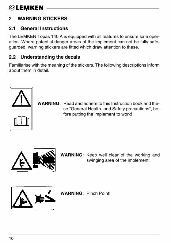
The LEMKEN Topas 140 A is equipped with all features to ensure safe oper-ation. Where potential danger areas of the implement can not be fully safe-guarded, warning stickers are fitted which draw attention to these.
2.2 Understanding the decals
Familiarise with the meaning of the stickers. The following descriptions informabout them in detail.
WARNING: Read and adhere to this Instruction book and the-se "General Health- and Safety precautions", be-fore putting the implement to work!
WARNING: Keep well clear of the working andswinging area of the implement!
WARNING: Pinch Point!
10
3 LIST OF VARIANTS
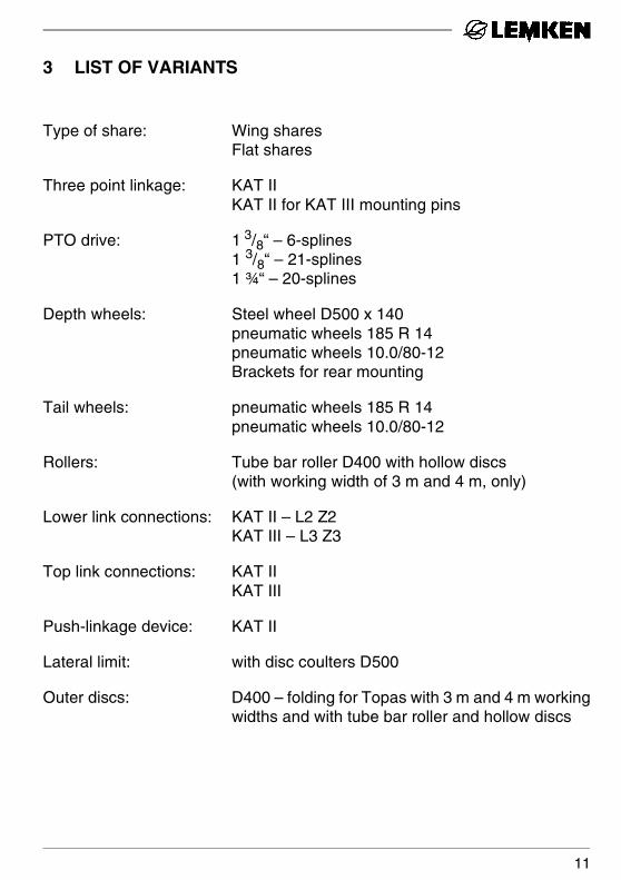
Type of share: Wing sharesFlat shares
Three point linkage: KAT IIKAT II for KAT III mounting pins
PTO drive: 1 3/8“ – 6-splines1 3/8“ – 21-splines1 ¾“ – 20-splines
Depth wheels: Steel wheel D500 x 140pneumatic wheels 185 R 14pneumatic wheels 10.0/80-12Brackets for rear mounting
Tail wheels: pneumatic wheels 185 R 14pneumatic wheels 10.0/80-12
Rollers: Tube bar roller D400 with hollow discs(with working width of 3 m and 4 m, only)
Lower link connections: KAT II – L2 Z2KAT III – L3 Z3
Top link connections: KAT IIKAT III
Push-linkage device: KAT II
Lateral limit: with disc coulters D500
Outer discs: D400 – folding for Topas with 3 m and 4 m workingwidths and with tube bar roller and hollow discs
11
4 PREPARATION OF THE TRACTOR
4.1 Topas as rear mounted implement
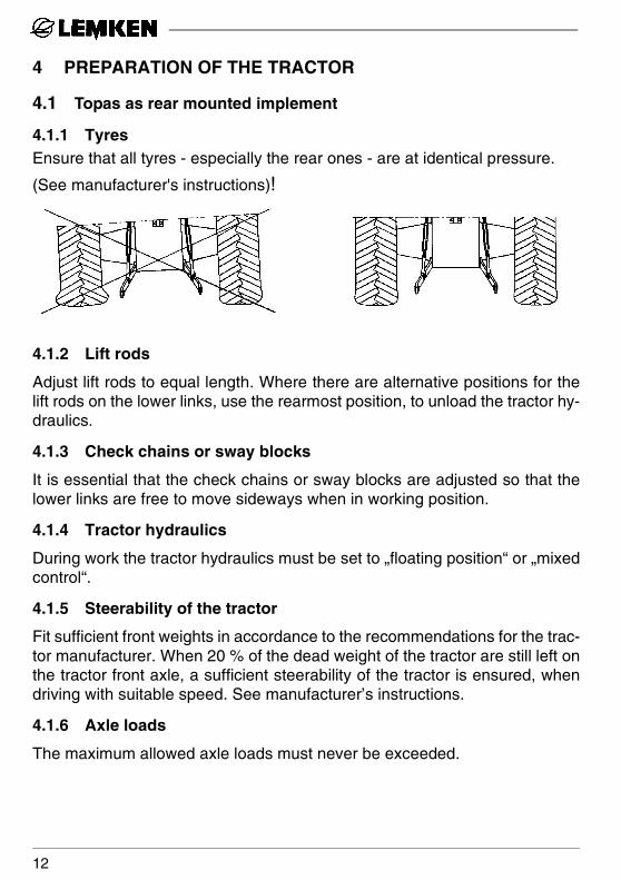
4.1.1 TyresEnsure that all tyres - especially the rear ones - are at identical pressure.
(See manufacturer's instructions)!
4.1.2 Lift rods
Adjust lift rods to equal length. Where there are alternative positions for thelift rods on the lower links, use the rearmost position, to unload the tractor hy-draulics.
4.1.3 Check chains or sway blocks
It is essential that the check chains or sway blocks are adjusted so that thelower links are free to move sideways when in working position.
4.1.4 Tractor hydraulics
During work the tractor hydraulics must be set to „floating position“ or „mixedcontrol“.
4.1.5 Steerability of the tractor
Fit sufficient front weights in accordance to the recommendations for the trac-tor manufacturer. When 20 % of the dead weight of the tractor are still left onthe tractor front axle, a sufficient steerability of the tractor is ensured, whendriving with suitable speed. See manufacturer’s instructions.
4.1.6 Axle loads
The maximum allowed axle loads must never be exceeded.
12
4.2 Topas as front mounted implement
4.2.1 Distance between the driver and the front of the Topas
When the distance between the driver and the front of the Topas is larger than3,5 meters, the Topas mounted in front may only be transported on publicroads when a safe transport is ensured. This is the case e.g. when an additio-nal directer is available. Otherwise the Topas must be transported fitted at therear.
4.2.2 Hydraulics
During work the front tractor hydraulics must be set to „floating position“!
13
5 ATTACHING AND DETACHING THE IMPLEMENT
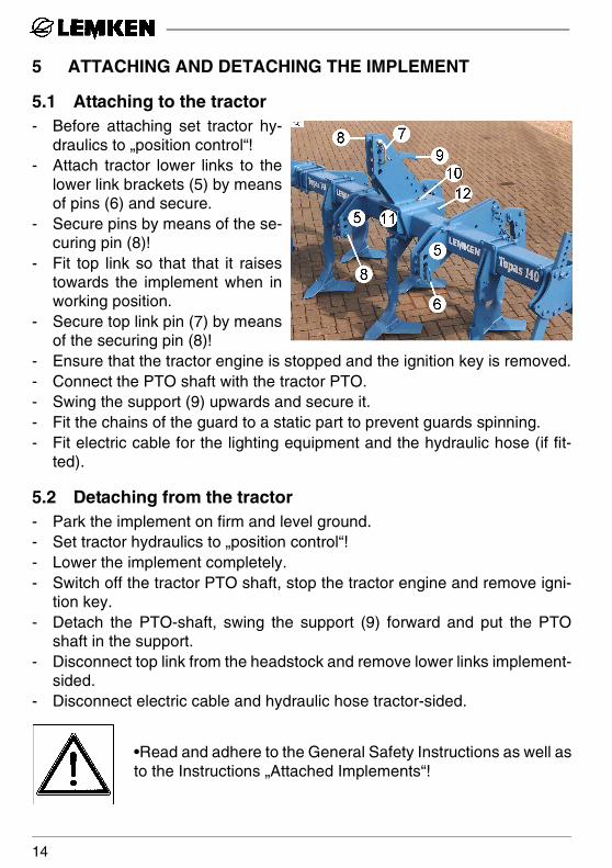
5.1 Attaching to the tractor- Before attaching set tractor hy-
draulics to „position control“!- Attach tractor lower links to the
lower link brackets (5) by meansof pins (6) and secure.
- Secure pins by means of the se-curing pin (8)!
- Fit top link so that that it raisestowards the implement when inworking position.
- Secure top link pin (7) by meansof the securing pin (8)!
- Ensure that the tractor engine is stopped and the ignition key is removed.- Connect the PTO shaft with the tractor PTO. - Swing the support (9) upwards and secure it.- Fit the chains of the guard to a static part to prevent guards spinning.- Fit electric cable for the lighting equipment and the hydraulic hose (if fit-
ted).
5.2 Detaching from the tractor- Park the implement on firm and level ground.- Set tractor hydraulics to „position control“!- Lower the implement completely.- Switch off the tractor PTO shaft, stop the tractor engine and remove igni-
tion key.- Detach the PTO-shaft, swing the support (9) forward and put the PTO
shaft in the support. - Disconnect top link from the headstock and remove lower links implement-
sided.- Disconnect electric cable and hydraulic hose tractor-sided.
•Read and adhere to the General Safety Instructions as well asto the Instructions „Attached Implements“!
14
6 ATTACHING AND DETACHING A POWER HARROW
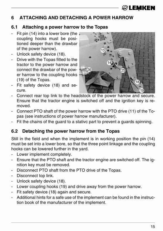
6.1 Attaching a power harrow to the Topas- Fit pin (14) into a lower bore (the
coupling hooks must be posi-tioned deeper than the drawbarof the power harrow).
- Unlock safety device (18).- Drive with the Topas fitted to the
tractor to the power harrow andconnect the drawbar of the pow-er harrow to the coupling hooks(19) of the Topas.
- Fit safety device (18) and se-cure.
- Connect rear top link to the headstock of the power harrow and secure.Ensure that the tractor engine is switched off and the ignition key is re-moved.
- Connect PTO shaft of the power harrow with the PTO drive (11) of the To-pas (see instructions of power harrow manufacturer).
- Fit the chains of the guard to a stativc part to prevent a guards spinning.
6.2 Detaching the power harrow from the Topas
Still in the field and when the implement is in working position the pin (14)must be set into a lower bore, so that the three point linkage and the couplinghooks can be lowered further in the yard.- Lower implement completely.- Ensure that the PTO shaft and the tractor engine are switched off. The ig-
nition key must be removed. - Disconnect PTO shaft from the PTO drive of the Topas.- Disconnect top link.- Unlock safety device (18).- Lower coupling hooks (19) and drive away from the power harrow.- Fit safety device (18) again and secure.- Additional hints for a safe use of the implement can be found in the instruc-
tion book of the manufacturer of the implement.
15

•Read and adhere to the General Safety Instructions as well asto the Instructions „Attached Implements“!
16
7 ADJUSTMENTS
7.1 General Instructions
Depending on the shares, the working speed of the Topas as solo-implementshould be between 5 and 9 km/h.
In connection with a power harrow the working speed must be chosen ac-cording to the instructions of the power harrow manufacturer. Usually thespeed should be between 4 and 7 km/h depending on the rotor speed and thesoil condition.
7.2 Working depth
7.2.1 Working depth of the Topas
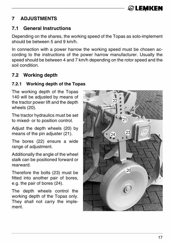
The working depth of the Topas140 will be adjusted by means ofthe tractor power lift and the depthwheels (20).
The tractor hydraulics must be setto mixed- or to position control.
Adjust the depth wheels (20) bymeans of the pin adjuster (21).
The bores (22) ensure a widerange of adjustment.
Additionally the angle of the wheelstalk can be positioned forward orrearward.
Therefore the bolts (23) must befitted into another pair of bores,e.g. the pair of bores (24).
The depth wheels control theworking depth of the Topas only.They shall not carry the imple-ment.
17
7.2.2 Working depth ot the power harrow fitted to the Topas
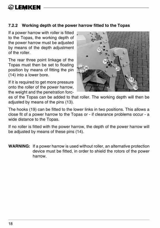
If a power harrow with roller is fittedto the Topas, the working depth ofthe power harrow must be adjustedby means of the depth adjustmentof the roller.
The rear three point linkage of theTopas must then be set to floatingposition by means of fitting the pin(14) into a lower bore.
If it is required to get more pressureonto the roller of the power harrow,the weight and the penetration forc-es of the Topas can be added to that roller. The working depth will then beadjusted by means of the pins (13).
The hooks (19) can be fitted to the lower links in two positions. This allows aclose fit of a power harrow to the Topas or - if clearance problems occur - awide distance to the Topas.
If no roller is fitted with the power harrow, the depth of the power harrow willbe adjusted by means of these pins (14).
WARNING: If a power harrow is used without roller, an alternative protectiondevice must be fitted, in order to shield the rotors of the powerharrow.
18
7.3 Lateral position of the tines
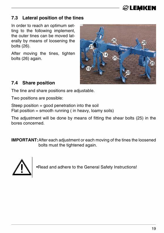
In order to reach an optimum set-ting to the following implement,the outer tines can be moved lat-erally by means of loosening thebolts (26).
After moving the tines, tightenbolts (26) again.
7.4 Share position
The tine and share positions are adjustable.
Two positions are possible:
Steep position = good penetration into the soilFlat position = smooth running ( in heavy, loamy soils)
The adjustment will be done by means of fitting the shear bolts (25) in thebores concerned.
IMPORTANT:After each adjustment or each moving of the tines the loosenedbolts must the tightened again.
•Read and adhere to the General Safety Instructions!
19
8 SHEARBOLT DEVICE
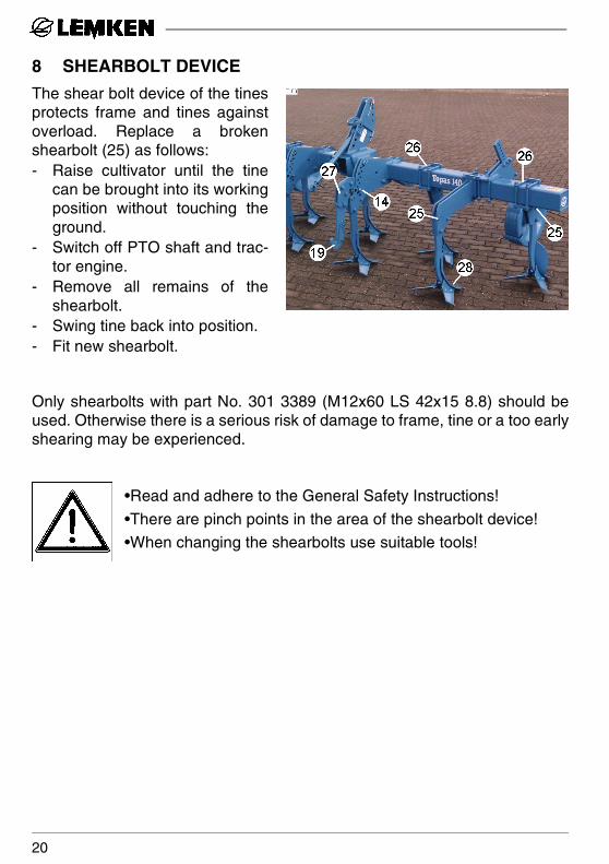
The shear bolt device of the tinesprotects frame and tines againstoverload. Replace a brokenshearbolt (25) as follows:- Raise cultivator until the tine
can be brought into its workingposition without touching theground.
- Switch off PTO shaft and trac-tor engine.
- Remove all remains of theshearbolt.
- Swing tine back into position.- Fit new shearbolt.
Only shearbolts with part No. 301 3389 (M12x60 LS 42x15 8.8) should beused. Otherwise there is a serious risk of damage to frame, tine or a too earlyshearing may be experienced.
•Read and adhere to the General Safety Instructions!
•There are pinch points in the area of the shearbolt device!
•When changing the shearbolts use suitable tools!
20
9 SHARES
9.1 General Instruction
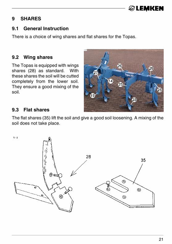
There is a choice of wing shares and flat shares for the Topas.
9.2 Wing shares
The Topas is equipped with wingsshares (28) as standard. Withthese shares the soil will be cuttedcompletely from the lower soil.They ensure a good mixing of thesoil.
9.3 Flat shares
The flat shares (35) lift the soil and give a good soil loosening. A mixing of thesoil does not take place.
21
10 PTO DRIVE AND PTO SHAFT
10.1 General Instruction
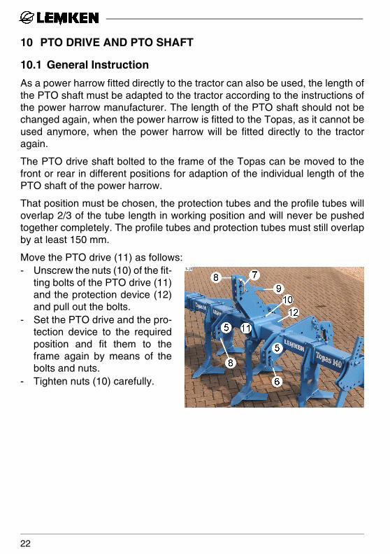
As a power harrow fitted directly to the tractor can also be used, the length ofthe PTO shaft must be adapted to the tractor according to the instructions ofthe power harrow manufacturer. The length of the PTO shaft should not bechanged again, when the power harrow is fitted to the Topas, as it cannot beused anymore, when the power harrow will be fitted directly to the tractoragain.
The PTO drive shaft bolted to the frame of the Topas can be moved to thefront or rear in different positions for adaption of the individual length of thePTO shaft of the power harrow.
That position must be chosen, the protection tubes and the profile tubes willoverlap 2/3 of the tube length in working position and will never be pushedtogether completely. The profile tubes and protection tubes must still overlapby at least 150 mm.
Move the PTO drive (11) as follows:- Unscrew the nuts (10) of the fit-
ting bolts of the PTO drive (11)and the protection device (12)and pull out the bolts.
- Set the PTO drive and the pro-tection device to the requiredposition and fit them to theframe again by means of thebolts and nuts.
- Tighten nuts (10) carefully.
22
10.2 Adapting the PTO shaft to the tractor
Only when the length of the PTO shaft of the power harrow has been adaptedas described, the length of the PTO shaft of the Topas has to be adapted tothe tractor. This will be done as follows:- Attach the Topas to the tractor.- Pull the two halves apart and fit them separately to the tractor and Topas.- Hold both halves next to each other when raised, lowered into working po-
sition and when in horizontal position.
Both halves must show a minimum overlap of 2/3 of the profile tubes and pro-tection tubes in working position and must never been pushed completely to-gether or separated in any position. A minimum overlap of 15 cm must alwaysbe ensured.
WARNING: When fitting the Topas to another tractor, it must be checkedagain to ensure that the above requirements exist.
Only when the PTO shaft is too long, the PTO shaft must be shortened as fol-lows:- Shorten both halves of both the profile and protection tubes by the same
amount!- De-burr the newly cut face! - Lubricate the profile tubes slightly and push the two halves together, en-
suring that they slide together and come apart freely!- Attach the PTO shaft to the tractor and Topas!
•Read and adhere to the General Safety Instructions as well asto the Instructions „PTO shaft operation“!
23
11 THREE POINT LINKAGE
11.1 General Instruction
If it is required to fit the Topas to an additional implement lika a power harrow,the Topas can be equipped with a three point linkage.
11.2 Adjustment
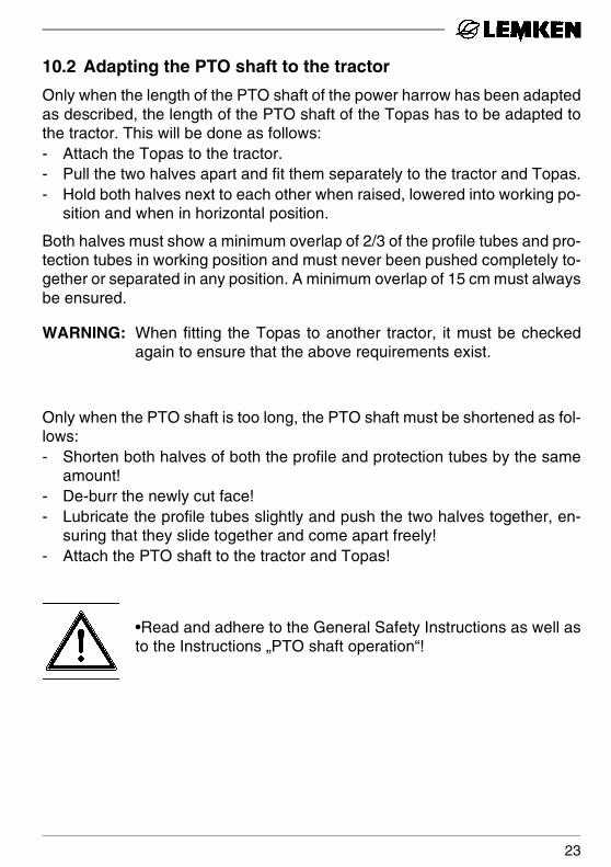
The three point linkage (27) is in-dividually adjustable in height bymeans of pins (14).
Additionally the coupling hooks(19) of the three point linkage canbe repositioned so that the imple-ment fitted to the cultivator ismore or less close to the Topas.
This adjustment possibility will beused, if a mounting of an addition-al implement with a positive cen-tre of gravity is desired or if therange of adjustments of the PTO drive is insufficient, e.g. when a power driv-en implement should be fitted to the Topas wihtout changing the length of thePTO shaft. See instructions of the power harrow manufaturer.
24
12 TOPAS AS FRONT MOUNTED IMPLEMENT
12.1 General Instructions
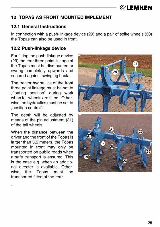
In connection with a push-linkage device (29) and a pair of spike wheels (30)the Topas can also be used in front.
12.2 Push-linkage device
For fitting the push-linkage device(29) the rear three point linkage ofthe Topas must be dismounted orswung completely upwards andsecured against swinging back.
The tractor hydraulics of the frontthree point linkage must be set to„floating position“ during workwhen tail wheels are fitted. Other-wise the hydraulics must be set to„position control“.
The depth will be adjusted bymeans of the pin adjustment (31)of the tail wheels.
When the distance between thedriver and the front of the Topas islarger than 3,5 meters, the Topasmounted in front may only betransported on public roads whena safe transport is ensured. Thisis the case e.g. when an additio-nal directer is available. Other-wise the Topas must betransported fitted at the rear.
.
25
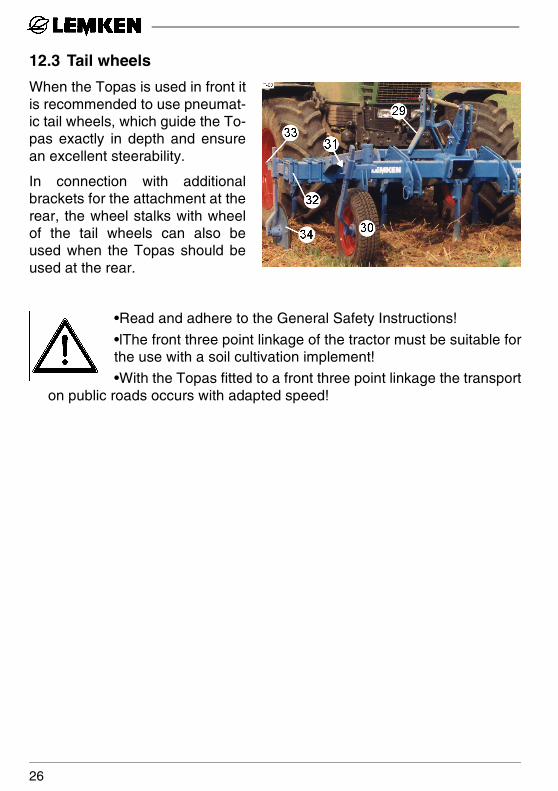
12.3 Tail wheels
When the Topas is used in front itis recommended to use pneumat-ic tail wheels, which guide the To-pas exactly in depth and ensurean excellent steerability.
In connection with additionalbrackets for the attachment at therear, the wheel stalks with wheelof the tail wheels can also beused when the Topas should beused at the rear.
•Read and adhere to the General Safety Instructions!
•lThe front three point linkage of the tractor must be suitable forthe use with a soil cultivation implement!
•With the Topas fitted to a front three point linkage the transporton public roads occurs with adapted speed!
26
13 HOLLOW DISCS AND TUBE BAR ROLLER
13.1 General Instructions
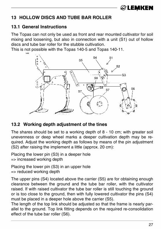
The Topas can not only be used as front and rear mounted cultivator for soilmixing and loosening, but also in connection with a unit (S1) out of hollowdiscs and tube bar roller for the stubble cultivation. This is not possible with the Topas 140-5 and Topas 140-11.
13.2 Working depth adjustment of the tines
The shares should be set to a working depth of 8 - 10 cm; with greater soilunevenness or deep wheel marks a deeper cultivation depth may be re-quired. Adjust the working depth as follows by means of the pin adjustment(S2) after raising the implement a little (approx. 20 cm):
Placing the lower pin (S3) in a deeper hole => increased working depth
Placing the lower pin (S3) in an upper hole => reduced working depth
The upper pins (S4) located above the carrier (S5) are for obtaining enoughclearance between the ground and the tube bar roller, with the cultivatorraised. If with raised cultivator the tube bar roller is still touching the groundor is too close to the ground, then with fully lowered cultivator the pins (S4)must be placed in a deeper hole above the carrier (S5).The length of the top link should be adjusted so that the frame is nearly par-allel to the ground. Top link fitting depends on the required re-consolidationeffect of the tube bar roller (S6).
27
13.3 Working depth of the hollow discs
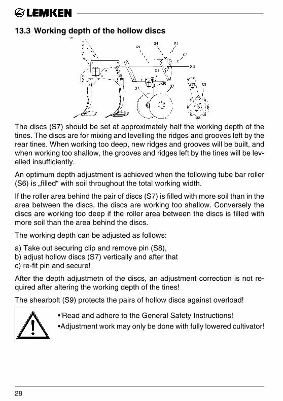
The discs (S7) should be set at approximately half the working depth of thetines. The discs are for mixing and levelling the ridges and grooves left by therear tines. When working too deep, new ridges and grooves will be built, andwhen working too shallow, the grooves and ridges left by the tines will be lev-elled insufficiently.
An optimum depth adjustment is achieved when the following tube bar roller(S6) is „filled“ with soil throughout the total working width.
If the roller area behind the pair of discs (S7) is filled with more soil than in thearea between the discs, the discs are working too shallow. Conversely thediscs are working too deep if the roller area between the discs is filled withmore soil than the area behind the discs.
The working depth can be adjusted as follows:
a) Take out securing clip and remove pin (S8),b) adjust hollow discs (S7) vertically and after thatc) re-fit pin and secure!
After the depth adjustmetn of the discs, an adjustment correction is not re-quired after altering the working depth of the tines!
The shearbolt (S9) protects the pairs of hollow discs against overload!
•'Read and adhere to the General Safety Instructions!
•Adjustment work may only be done with fully lowered cultivator!
28
14 LATERAL SHIELDS
14.1 General Instruction
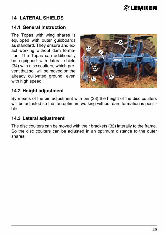
The Topas with wing shares isequipped with outer guidboardsas standard. They ensure and ex-act working without dam forma-tion. The Topas can additionallybe equipped with lateral shield(34) with disc coulters, which pre-vent that soil will be moved on thealready culitvated ground, evenwith high speed.
14.2 Height adjustment
By means of the pin adjustment with pin (33) the height of the disc coulterswill be adjusted so that an optimum working without dam formation is possi-ble.
14.3 Lateral adjustment
The disc coulters can be moved with their brackets (32) laterally to the frame.So the disc coulters can be adjusted in an optimum distance to the outershares.
29
15 DEPTH WHEELS
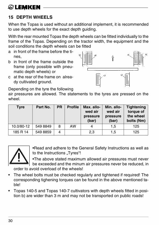
When the Topas is used without an additional implement, it is recommendedto use depth wheels for the exact depth guiding.
With the rear mounted Topas the depth wheels can be fitted individually to theframe of the Topas. Depending on the tractor width, the equipment and thesoil conditions the depth wheels can be fitted a in front of the frame before the ti-
nes,b in front of the frame outside the
frame (only possible with pneu-matic depth wheels) or
c at the rear of the frame on alrea-dy cultivated ground.
Depending on the tyre the followingair pressures are allowed. The statements to the tyres are pressed on thewheel.
•Read and adhere to the General Safety Instructions as well asto the Instructions „Tyres“!
•The above stated maximum allowed air pressures must neverbe exceeded and the minum air pressures never be reduced, in
order to avoid overload of the wheels!
• The wheel bolts must be checked regularly and tightened if required! Thecorresponding tighening torques can be found in the above mentioned ta-ble!
• Topas 140-5 and Topas 140-7 cultivators with depth wheels fitted in posi-tion b) are wider than 3 m and may not be transported on public roads!
Tyre Part No. PR Profile Max. allo-wed air
pressure (bar)
Min. allo-wed air
pressure (bar)
Tightening torque of the wheel bolts (Nm)
10.0/80-12 549 8849 8 AW 4 1,5 125
185 R 14 549 8859 4 2,3 1,5 125
30

16 DRIVING ON PUBLIC ROADS
16.1 Warning boards with lighting equipment
If it is required to drive on public roads with the cultivator, fit warning boardsand lighting equipment.
As option rear light carriers (order No. 84 1635L) and warning boards withlighting equipment for the front and rear (order No. 80 2011L) are available.
They ensure an orderly „marking“ of the cultivator.
The warning boards with lighting equipment must be detached before work,so that they cannot be damaged.
16.2 Transport width
The Topas 140-9 and Topas 140-11 cultivators are wider than 3 meters andfitted to the tractor must not be transported on public roads due to their over-size.
The regulations and laws concerned must be abided by.
16.3 Push-linkage device
When the Topas 140 A with fitted push-linkage device in front should betransported on public roads, a safe transport must be ensured. This is thecase e.g. when an additional directer is available.
16.4 Axle loads
The Topas 140 A cultivator shows a short distance of the centre of gravity.Due to that the rear axle load of the tractor will be increased between 2,1 to2,4 times of the weight of the implement.
Weigh your tractor with mounted and lifted implement to get the real informa-tion about the rear axle loading and the front axle unloading.
31
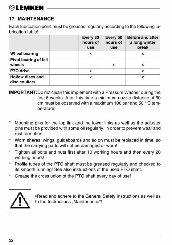
17 MAINTENANCE
Each lubrication point must be greased regularly according to the following lu-brication table!
IMPORTANT:Do not clean this implement with a Pressure Washer during thefirst 6 weeks. After this time a minimum nozzle distance of 60cm must be observed with a maximum 100 bar and 50 ° C tem-perature!
* Mounting pins for the top link and the lower links as well as the adjusterpins must be provided with some oil regularly, in order to prevent wear andrust formation.
* Worn shares, wings, guideboards and so on must be replaced in time, sothat the carrying parts will not be damaged or worn!
* Tighten all bolts and nuts first after 10 working hours and then every 20working hours!
* Profile tubes of the PTO shaft must be greased regularly and checked toits smooth running! See also instructions of the used PTO shaft.
* Grease the cross union of the PTO shaft every day of use!
•Read and adhere to the General Safety Instructions as well asto the Instructions „Maintenance“!
Every 20 hours of
use
Every 50 hours of
use
Before and after a long winter
break
Wheel bearing x x
Pivot bearing of tail wheels x x
PTO drive x x
Hollow discs and disc coulters
x x
32

18 WEIGHTS
19 NOTES
As the version of equipment is depending from the order, the equipment ofyour implement and its description concerned may deviate in some cases. Toensure a continuously updating of the technical features, we reserve the rightto modify the design, equipment and technique.
20 NOISE, AIRBORNE SOUND
The noise level of the LEMKEN Topas 140 A does not exceed 70 dB (A) dur-
ing work.
21 PRODUCT REGISTRATION / GUARANTEE
We would like to point out that the guarantee period starts, only when thecompletely filled-in and signed product registration has been returned to us .
Type Working width (ca. cm)
Weight(ca. kg)
TOPAS 140 - 5 250 381
TOPAS 140 - 7 300 415
TOPAS 140 – 9 400 540
TOPAS 140 - 11 450 646
33

34
EC Certificate of Conformityconforming to EEC Directions 89/392
EF-overensstemmelseserklaering i henhold til EF-direktiv 89/392/EØF
Certificato Di Conformita' Comunitario rispondente alla normativa CEE 89/392 Comunità Economica Europea
We, Lemken GmbH & Co. KGVi, Weseler Str. 5Moi, D-46519 Alpen,
declare in sole responsibility, that the producterklaerer som eneansvarlig, at produktet,dichiariano sotto la nostra piena responsabilità che il prodotto
LEMKEN TOPAS 140 A ___ ___ ___ ___ ___ _______________________________________________________________________________________________________________________________________________________________________________________________________________________________________________________________________________________________________________________________________________
Make, model / maerke, type / marca, tipo) (No.)
to which this certificate applies, conforms to the basic safety and health requirements of EECDirections 89/392.som denne erklaering vedrører, overholder de grundlaeggende sikkerheds- og sundhedskravI EF-directiv 89/392/EØF samt.cui la presente dichiarazione si riferisce, risponde alla normativa CEE/392 in materia di sicu-rezza e sanità.
To effect correct application of the safety and health requirements stated in the EEC Directions,the following standards and/or technical specifications were consulted:Til gennemførelse af de I EF-direktivet naevnte sikkerheds- og sundhedskrav er følgende stan-darder og/eller tekniske specifikationer anvendt:Per un'appropriato riscontro nell'ambito della normativa CEE delle norme die sicurezza e sa-nitarie sopra citate, è staté consultate le seguenti norme e/o specificache technicache:
EN 292 - 1 (11.91), EN 292 - 2 (11.91).
____________________________________________________________________________________________________________________________________________________________________________________________________________________________________________________________________________________________________________________________________________
(Title and/or number and date of issue of the other EEC Directions / titel og/eller nummer samt udgivelsesdato pa standardenerne og/ellerdende tekniske specifikationer / titolo e/o numero, data di promulgazione delle norme e/o specificache tecnicache.)
Alpen, den ___________________________(Place and date of issue / Sted og dato / (Name of authorized person / Bemyndigedes navn/ Luogo et data del rilascio) nome dell'incaricato)


