Embed Size (px)
Citation preview
1753-27
4875.99.03.04 04.04from year of manufacture 2004
OPERATING MANUAL
E-LINK and BC IIIDOUBLE ACTION
RP 220 PROFI

PREFACE
BALERCONTROL III + E-LINK 3
PREFACEPREFACEPREFACEPREFACE
PLEASE READ THIS OPERATING MANUAL! � This operating manual provides you with important
information for the safe operation of your machine. � Pass on this operating manual to every user of this
machine! � This manual must always be available wherever the
machine is in use. READ THE OPERATING MANUAL " WELGER DOUBLE ACTION WITH RP 220 PROFI" � Observe all safety instructions!
IMPRINT
4 BALERCONTROL III + E-LINK
IMPRINTIMPRINTIMPRINTIMPRINT
Reprinting without express written approval is not permitted – all rights reserved and subject to technical alterations. Illustrations are not binding on form and design of the machine. © 2004 by Welger Maschinenfabrik GmbH Wolfenbüttel Made in Germany. 4875.99.03.04 Rev 04.04 Print 04.04
Maschinenfabrik GmbH Gebrüder-Welger-Straße 3 • D-38304 Wolfenbüttel Fon: (+49) 53 31 / 404-142 • Fax: (+49) 53 31 / 404-143 eMail: [email protected]
IMPRINT
BALERCONTROL III + E-LINK 5
CONTENTS
WARNING SYMBOLS 7
SAFETY 8 Proper use 8 General Information 9 Electrical equipment/Electronics 10 Welding work 10 Electromagnetic compatibility (EMC) 11
E-LINK 12 General Information 12 E-LINK 12 Display 13
THE E-LINK MENUS 14 General Information 14 Menu 14
E-LINK MENU MONITORMONITORMONITORMONITOR 15 Operating mode Automatic 15 Operating mode: Semiautomatic 25 Operating mode: Manual 32
E-LINK MENU SETUPSETUPSETUPSETUP 36 SETUP 1/4 38 SETUP 2/4 39 SETUP 3/4 39 SETUP 4/4 41
E-LINK MENU SYSTEMINFOSYSTEMINFOSYSTEMINFOSYSTEMINFO 43
E-LINK MENU DIAGNOSISDIAGNOSISDIAGNOSISDIAGNOSIS 44 Standard diagnosis 45
E-LINK MENU STATISTICSSTATISTICSSTATISTICSSTATISTICS 52
E-LINK ERROR MESSAGES 54 System error messages 55 Standard error messages 56
EXTENDED DIAGNOSIS 63
E-LINK MENU SYSTEM SERVICESYSTEM SERVICESYSTEM SERVICESYSTEM SERVICE 64 System Service menu call 64 MONITOR submenu 65 SYSTEM SETUP submenu 65 EEPROM CONTENTS submenu 66 SELF-TEST submenu 66
E-LINK SCOPE 68
IMPRINT
6 BALERCONTROL III + E-LINK
BALERCONTROL III 73 General Information 73 BALERCONTROL III 74 Display 75
BALERCONTROL MENUS 76 General Information 76 Menu selection 76
BALERCONTROL MENU MONITORMONITORMONITORMONITOR 77 Operating modes 77 Actuation of the units 79 Baling 82 Tying 82 Opening the tail gate 83 Tail gate opened 83 Close tail gate 84 Machine standstill 84 Setting the bale density 84
BALERCONTROL MENU SETUPSETUPSETUPSETUP 87 Language 88 Machine type 88 Beep 88 Delay (tying) 88
BALERCONTROL MENU SYSTEMINFOSYSTEMINFOSYSTEMINFOSYSTEMINFO 90
BALERCONTROL MENU DIAGNOSIS 92 Standard diagnosis 93
BALERCONTROL MENU STATISTICSSTATISTICSSTATISTICSSTATISTICS 98
BALERCONTROL ERROR MESSAGES 100 System error messages 101 Standard error messages 102
EXTENDED DIAGNOSIS 107
BALERCONTROL MENU SETUPSETUPSETUPSETUP 108 CAN module 108
BALERCONTROL MENU SYSTEM SERVICESYSTEM SERVICESYSTEM SERVICESYSTEM SERVICE 110 System Service menu call 110 MONITOR submenu 111 SYSTEM SETUP submenu 111 EEPROM CONTENTS submenu 112 SELF-TEST submenu 112
BALERCONTROL SCOPE 114
INDEX 120
WARNING SYMBOLS
BALERCONTROL III + E-LINK 7
WARNING SYMBOLSWARNING SYMBOLSWARNING SYMBOLSWARNING SYMBOLS
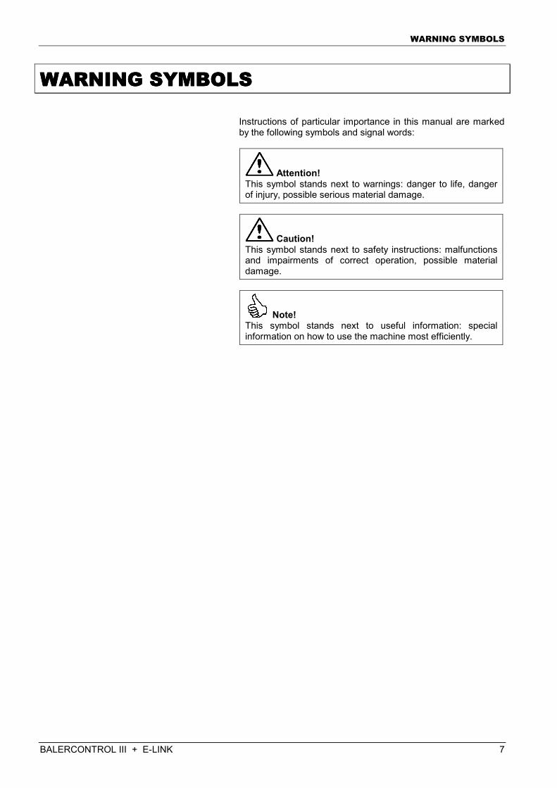
Instructions of particular importance in this manual are marked by the following symbols and signal words:
Attention! This symbol stands next to warnings: danger to life, danger of injury, possible serious material damage.
Caution! This symbol stands next to safety instructions: malfunctions and impairments of correct operation, possible material damage.
Note! This symbol stands next to useful information: special information on how to use the machine most efficiently.
Safety
8 BALERCONTROL III + E-LINK
SSSSAFETYAFETYAFETYAFETY
Proper use The E-Link and BALERCONTROL III control boxes are exclusively intended for use on the following machine:
WELGER DOUBLE ACTION RP 220 PROFI Using the machine for any other purposes does not constitute proper use. The manufacturer cannot be held liable for any damage resulting from such use; the risk of improper use lies entirely with the user. Operating the machine within the limits of its proper use also involves complying with the operating, maintenance and servicing conditions prescribed by the manufacturer. These E-LINK and BALERCONTROL III systems may only be operated by persons who are familiar with such work and instructed on the dangers involved. The relevant accident prevention regulations and the generally accepted safety rules must be observed. Attachment of additional devices is not permitted. Unauthorised modifications and installation of non-approved parts and equipment preclude any liability of the manufacturer for any damage resulting therefrom.
Safety
BALERCONTROL III + E-LINK 9
General Information Even if all warnings and safety instructions are observed the machine involves secondary hazards which cannot be eliminated by constructional measures. Always handle the machine with care to avoid danger to yourself and others! � Read the operating manual for the machine. In case of
difficulties in understanding please contact the customer service department.
� Before starting work perform a visual inspection of the
machine. Check whether any device has been changed or is missing and pay attention to any unusual noise or leaks which occur during operation.
� Prior to maintenance works at the machine (adjustment,
repair, servicing): switch off power take-off shaft and tractor motor. Disconnect cardan shaft from the power take-off shaft end. Switch off hydraulic system; detach the hydraulic and electrical connections to the tractor; disconnect control box from power supply, maintenance work may be carried out by trained persons only.
� Never remove any harvested crop material from the
machine while the drive is still running while the machine switched off is running out. Switch off first power take-off shaft and tractor motor and disconnect then the cardan shaft from the power take-off shaft end. Turn off and secure the hydraulic system against unintentional turning-on.
� Passengers are not allowed to ride on the machine! � During operation: do not climb the machine. Keep sufficient
distance to the range of action of the machine.
� Do not put any matal part near the machine whilst the electric control is switched on (e.g. tools, safety boots with metal caps). Cause: unintentional triggering of proximity switches and thus unexpected machine moves.
� Prior to inserting the net rolls and film reels: Turn off and
secure the hydraulic system against unintentional turning-on.
� Never operate the machine with defective or removed
protective devices (e. g.: safety bracket)!
� Keep fire extinguisher within reach.
Safety
10 BALERCONTROL III + E-LINK
Electrical equipment/Electronics � E-Link and BALERCONTROL III are exclusively designed
for operation with 12 volts. Operation with other on-board power supplies is not permissible! Prior to any assembly, adjustment and maintenance work, the E-LINK and BALERCONTROL III must be disconnected from power supply.
� Check correct position of all sensors regularly and check
that all sensors and actors are tightened properly.
� Power supply of the electronics must only be switched on when the machine is to be operated. After the end of work, the control system must immediately be disconnected from power supply.
� It is not permissible to enter the working range of the
machine or to approach the working range of the machine as long as the electronics are supplied with power.
� During cleaning work, the electronics must not be exposed
to a direct water jet (in particular: high-pressure cleaning machine or steam cleaner).
� The existing wiring of the E-LINK and of the
BALERCONTROL III may only be used for the electrical consumers installed in the factory and approved by the manufacturer.
Welding work � Do not let any welding current flow through the E-LINK or
the BALERCONTROL III.
� Provide for all-polo disconnection of the power supply to the machine (disconnect battery).
� Interrupt power supply between tractor and machine. � Take strong heat generation at welding points into account.
Dismount sensitive parts (cables, sensors, plastic parts) before welding.
Safety
BALERCONTROL III + E-LINK 11
Electromagnetic compatibility (EMC) The machine is equipped with electronic components and modules; the function of these electronic components and modules can be influenced by electromagnetic emissions of other equipment. Such influences can cause risks to persons, if the following safety instructions are not observed: In case of subsequent installation of electrical and electronic equipment and/or components into the machine, with connection to the central mains, it is the user's responsibility to check whether the installation impairs the vehicle electronics or any other components. Ensure above all that the electrical and electronic components subsequently installed are in conformity with the EMC directive 89/336/EEC as amended, and that they are provided with the CE.
E-LINK
12 E-LINK DOUBLE ACTION
EEEE----LINKLINKLINKLINK
General Information
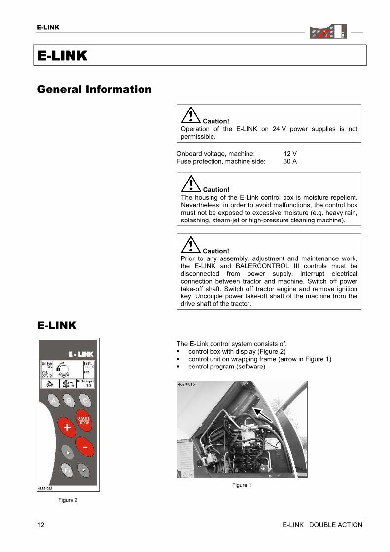
Caution! Operation of the E-LINK on 24 V power supplies is not permissible.
Onboard voltage, machine: 12 V Fuse protection, machine side: 30 A
Caution! The housing of the E-Link control box is moisture-repellent. Nevertheless: in order to avoid malfunctions, the control box must not be exposed to excessive moisture (e.g. heavy rain, splashing, steam-jet or high-pressure cleaning machine).
Caution! Prior to any assembly, adjustment and maintenance work, the E-LINK and BALERCONTROL III controls must be disconnected from power supply. interrupt electrical connection between tractor and machine. Switch off power take-off shaft. Switch off tractor engine and remove ignition key. Uncouple power take-off shaft of the machine from the drive shaft of the tractor.
E-LINK The E-Link control system consists of: � control box with display (Figure 2) � control unit on wrapping frame (arrow in Figure 1) � control program (software)
Figure 1
Figure 2
E-LINK
E-LINK DOUBLE ACTION 13
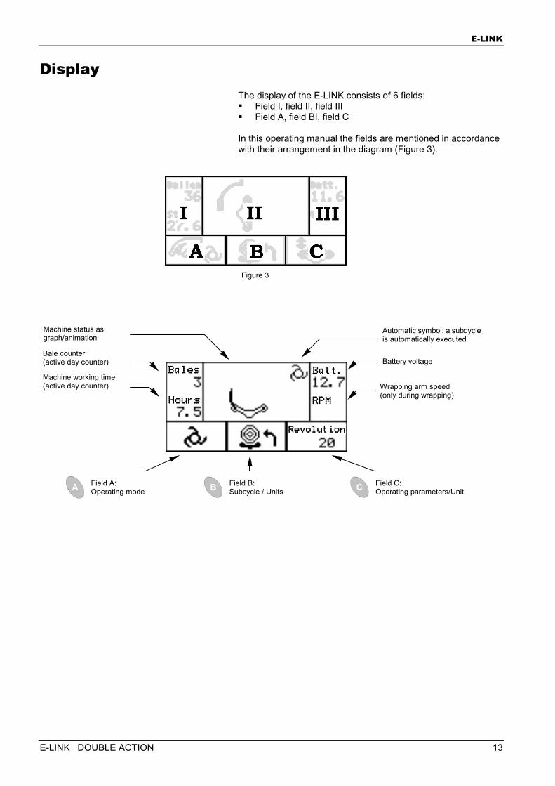
Display The display of the E-LINK consists of 6 fields: � Field I, field II, field III � Field A, field BI, field C In this operating manual the fields are mentioned in accordance with their arrangement in the diagram (Figure 3).
Field A: Operating mode
Field B: Subcycle / Units
Field C: Operating parameters/Unit
Figure 3
Battery voltage
Wrapping arm speed (only during wrapping)
Bale counter (active day counter)
Machine working time (active day counter)
Machine status as graph/animation
Automatic symbol: a subcycleis automatically executed
BalesBalesBalesBales
HoursHoursHoursHours
Batt.Batt.Batt.Batt.
RPMRPMRPMRPM
RevolutionRevolutionRevolutionRevolution
The E-LINK menus
14 E-LINK DOUBLE ACTION
TTTTHE HE HE HE EEEE----LINK LINK LINK LINK MENUSMENUSMENUSMENUS
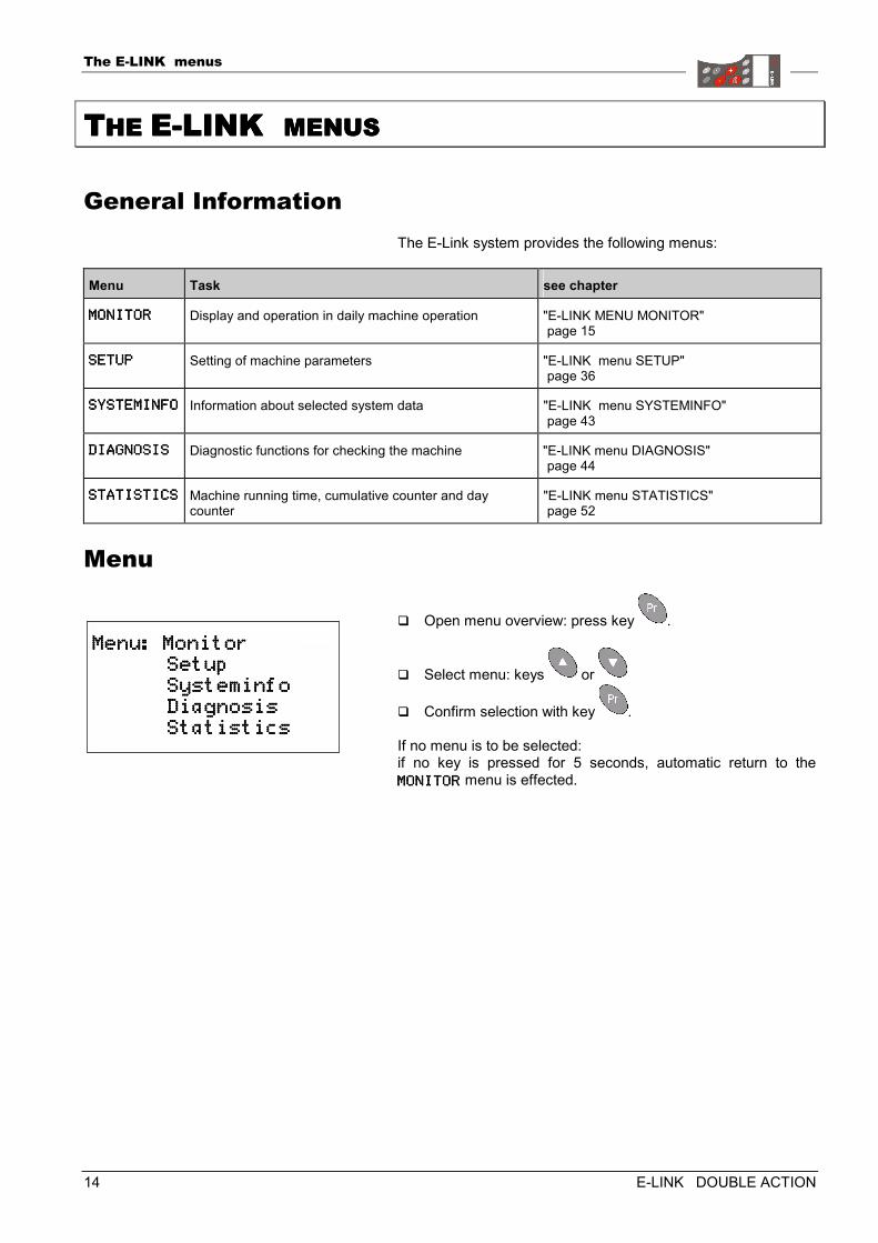
General Information The E-Link system provides the following menus:
Menu Task see chapter
MONITORMONITORMONITORMONITOR Display and operation in daily machine operation "E-LINK MENU MONITOR" page 15
SETUPSETUPSETUPSETUP Setting of machine parameters "E-LINK menu SETUP" page 36
SYSTEMINFOSYSTEMINFOSYSTEMINFOSYSTEMINFO Information about selected system data "E-LINK menu SYSTEMINFO" page 43
DIAGNOSISDIAGNOSISDIAGNOSISDIAGNOSIS Diagnostic functions for checking the machine "E-LINK menu DIAGNOSIS" page 44
STATISTICSSTATISTICSSTATISTICSSTATISTICS Machine running time, cumulative counter and day counter
"E-LINK menu STATISTICS" page 52
Menu
� Open menu overview: press key .
� Select menu: keys or
� Confirm selection with key . If no menu is to be selected: if no key is pressed for 5 seconds, automatic return to the MONITORMONITORMONITORMONITOR menu is effected.
Menu: MonitorMenu: MonitorMenu: MonitorMenu: Monitor Setup Setup Setup Setup Systeminfo Systeminfo Systeminfo Systeminfo Diagnosis Diagnosis Diagnosis Diagnosis Statistics Statistics Statistics Statistics
E-LINK MENU MONITOR
E-LINK DOUBLE ACTION 15
EEEE----LINK MENU LINK MENU LINK MENU LINK MENU MONITORMONITORMONITORMONITOR
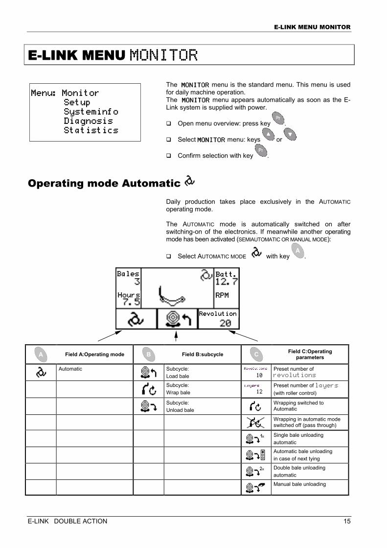
The MONITORMONITORMONITORMONITOR menu is the standard menu. This menu is used for daily machine operation. The MONITORMONITORMONITORMONITOR menu appears automatically as soon as the E-Link system is supplied with power.
� Open menu overview: press key .
� Select MONITORMONITORMONITORMONITOR menu: keys or
� Confirm selection with key .
Operating mode Automatic Daily production takes place exclusively in the AUTOMATIC operating mode. The AUTOMATIC mode is automatically switched on after switching-on of the electronics. If meanwhile another operating mode has been activated (SEMIAUTOMATIC OR MANUAL MODE):
� Select AUTOMATIC MODE with key .
Field A:Operating mode
Field B:subcycle
Field C:Operating
parameters
Automatic
Subcycle: Load bale
Preset number of revolutions
Subcycle: Wrap bale
Preset number of layers (with roller control)
Subcycle: Unload bale
Wrapping switched to Automatic
Wrapping in automatic mode switched off (pass through)
Single bale unloading automatic
Automatic bale unloading in case of next tying
Double bale unloading automatic
Manual bale unloading
Menu: MonitorMenu: MonitorMenu: MonitorMenu: Monitor Setup Setup Setup Setup Systeminfo Systeminfo Systeminfo Systeminfo Diagnosis Diagnosis Diagnosis Diagnosis Statistics Statistics Statistics Statistics
BBBBalesalesalesales
HoursHoursHoursHours
Batt.Batt.Batt.Batt.
RPMRPMRPMRPM
RevolutionRevolutionRevolutionRevolution
E-LINK MENU MONITOR
16 E-LINK DOUBLE ACTION
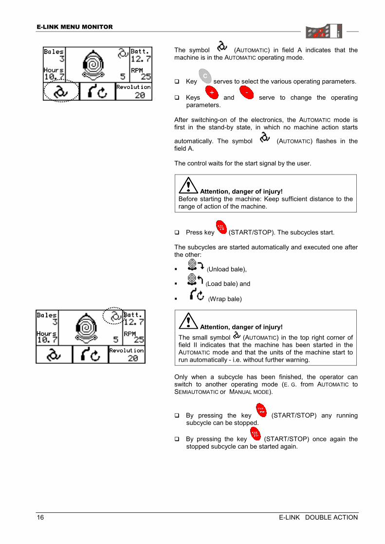
The symbol (AUTOMATIC) in field A indicates that the machine is in the AUTOMATIC operating mode.
� Key serves to select the various operating parameters.
� Keys and serve to change the operating parameters.
After switching-on of the electronics, the AUTOMATIC mode is first in the stand-by state, in which no machine action starts
automatically. The symbol (AUTOMATIC) flashes in the field A. The control waits for the start signal by the user.
Attention, danger of injury! Before starting the machine: Keep sufficient distance to the range of action of the machine.
� Press key (START/STOP). The subcycles start. The subcycles are started automatically and executed one after the other:
� (Unload bale),
� (Load bale) and
� (Wrap bale)
Attention, danger of injury! The small symbol (AUTOMATIC) in the top right corner of field II indicates that the machine has been started in the AUTOMATIC mode and that the units of the machine start to run automatically - i.e. without further warning.
Only when a subcycle has been finished, the operator can switch to another operating mode (E. G. from AUTOMATIC to SEMIAUTOMATIC or MANUAL MODE).
� By pressing the key (START/STOP) any running subcycle can be stopped.
� By pressing the key (START/STOP) once again the stopped subcycle can be started again.
BalesBalesBalesBales
HoursHoursHoursHours
Batt.Batt.Batt.Batt.
RPMRPMRPMRPM
RevolutionRevolutionRevolutionRevolution
BalesBalesBalesBales
HoursHoursHoursHours
Batt.Batt.Batt.Batt.
RPMRPMRPMRPM
RevolutionRevolutionRevolutionRevolution
E-LINK MENU MONITOR
E-LINK DOUBLE ACTION 17
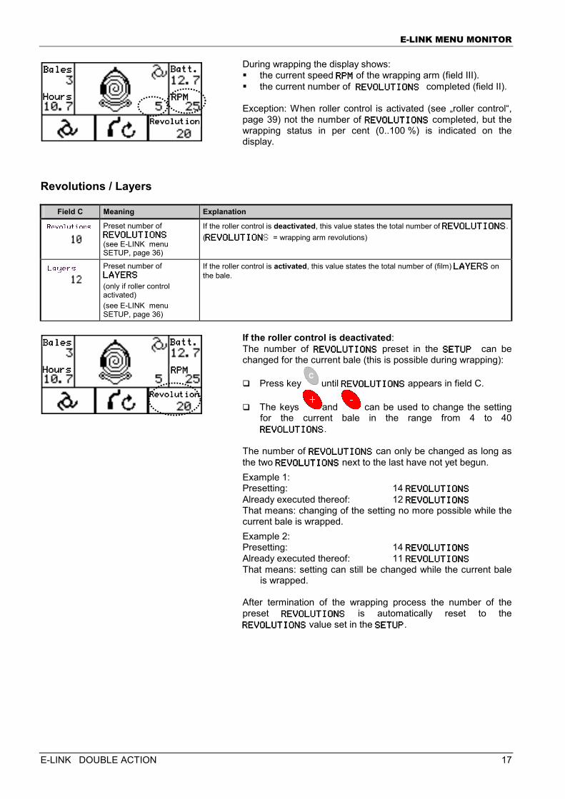
During wrapping the display shows: � the current speed RPMRPMRPMRPM of the wrapping arm (field III). � the current number of REVOLUTIONS REVOLUTIONS REVOLUTIONS REVOLUTIONS completed (field II). Exception: When roller control is activated (see „roller control“, page 39) not the number of REVOLREVOLREVOLREVOLUTIONSUTIONSUTIONSUTIONS completed, but the wrapping status in per cent (0..100 %) is indicated on the display.
Revolutions / Layers
Field C Meaning Explanation
Preset number of REVOLUTIONSREVOLUTIONSREVOLUTIONSREVOLUTIONS (see E-LINK menu SETUP, page 36)
If the roller control is deactivated, this value states the total number of REVOLUTIONSREVOLUTIONSREVOLUTIONSREVOLUTIONS.(REVOLUTIONREVOLUTIONREVOLUTIONREVOLUTIONS = wrapping arm revolutions)
Preset number of LAYERSLAYERSLAYERSLAYERS (only if roller control activated) (see E-LINK menu SETUP, page 36)
If the roller control is activated, this value states the total number of (film) LAYERSLAYERSLAYERSLAYERS on the bale.
If the roller control is deactivated: The number of REVOLUTIONSREVOLUTIONSREVOLUTIONSREVOLUTIONS preset in the SETUPSETUPSETUPSETUP can be changed for the current bale (this is possible during wrapping):
� Press key until REVOLUTIONSREVOLUTIONSREVOLUTIONSREVOLUTIONS appears in field C.
� The keys and can be used to change the setting for the current bale in the range from 4 to 40 REVOLUTIONSREVOLUTIONSREVOLUTIONSREVOLUTIONS.
The number of REVOLUTIONSREVOLUTIONSREVOLUTIONSREVOLUTIONS can only be changed as long as the two REVOLUTIONSREVOLUTIONSREVOLUTIONSREVOLUTIONS next to the last have not yet begun. Example 1: Presetting: 14 REVOLUTIONSREVOLUTIONSREVOLUTIONSREVOLUTIONS Already executed thereof: 12 REVOLUTIONSREVOLUTIONSREVOLUTIONSREVOLUTIONS That means: changing of the setting no more possible while the current bale is wrapped. Example 2: Presetting: 14 REVOLUTIONSREVOLUTIONSREVOLUTIONSREVOLUTIONS Already executed thereof: 11 REVOLUTIONSREVOLUTIONSREVOLUTIONSREVOLUTIONS That means: setting can still be changed while the current bale
is wrapped. After termination of the wrapping process the number of the preset REVOLUTIONSREVOLUTIONSREVOLUTIONSREVOLUTIONS is automatically reset to the REVOLUTIONSREVOLUTIONSREVOLUTIONSREVOLUTIONS value set in the SETUPSETUPSETUPSETUP.
BalesBalesBalesBales
HoursHoursHoursHours
Batt.Batt.Batt.Batt.
RPMRPMRPMRPM
RevolutionRevolutionRevolutionRevolution
BalesBalesBalesBales
HoursHoursHoursHours
Batt.Batt.Batt.Batt.
RPMRPMRPMRPM
RevolutionRevolutionRevolutionRevolution
E-LINK MENU MONITOR
18 E-LINK DOUBLE ACTION
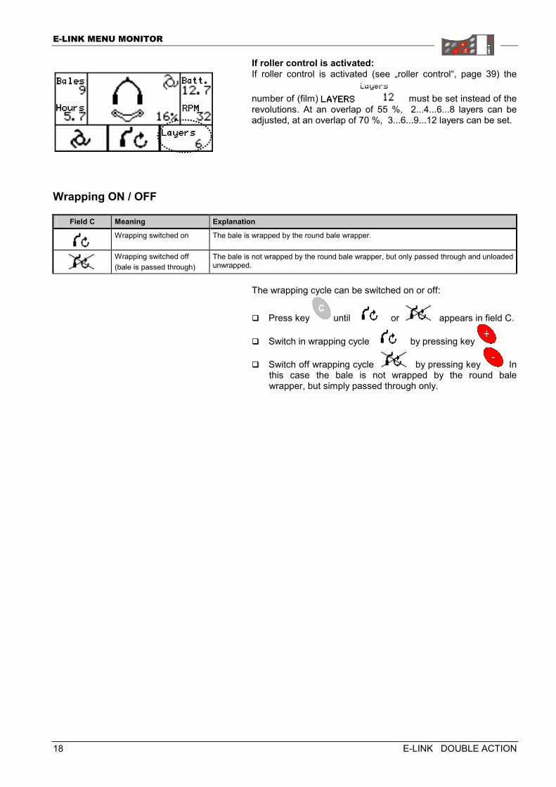
If roller control is activated: If roller control is activated (see „roller control“, page 39) the
number of (film) LAYERSLAYERSLAYERSLAYERS must be set instead of the revolutions. At an overlap of 55 %, 2...4...6...8 layers can be adjusted, at an overlap of 70 %, 3...6...9...12 layers can be set.
Wrapping ON / OFF
Field C Meaning Explanation
Wrapping switched on The bale is wrapped by the round bale wrapper.
Wrapping switched off (bale is passed through)
The bale is not wrapped by the round bale wrapper, but only passed through and unloaded unwrapped.
The wrapping cycle can be switched on or off:
� Press key until or appears in field C.
� Switch in wrapping cycle by pressing key
� Switch off wrapping cycle by pressing key In this case the bale is not wrapped by the round bale wrapper, but simply passed through only.
BalesBalesBalesBales
HoursHoursHoursHours
Batt.Batt.Batt.Batt.
RPMRPMRPMRPM
LayersLayersLayersLayers
E-LINK MENU MONITOR
E-LINK DOUBLE ACTION 19
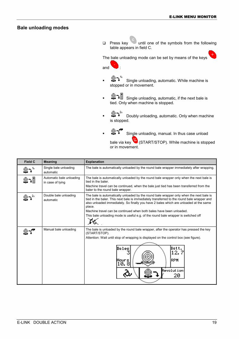
Bale unloading modes
� Press key until one of the symbols from the following table appears in field C.
The bale unloading mode can be set by means of the keys
and :
� Single unloading, automatic. While machine is stopped or in movement.
� Single unloading, automatic, if the next bale is tied. Only when machine is stopped.
� Doubly unloading, automatic. Only when machine is stopped.
� Single unloading, manual. In thus case unload
bale via key (START/STOP). While machine is stopped or in movement.
Field C Meaning Explanation
Single bale unloading automatic
The bale is automatically unloaded by the round bale wrapper immediately after wrapping.
Automatic bale unloading in case of tying
The bale is automatically unloaded by the round bale wrapper only when the next bale is tied in the baler. Machine travel can be continued, when the bale just tied has been transferred from the baler to the round bale wrapper.
Double bale unloading automatic
The bale is automatically unloaded by the round bale wrapper only when the next bale is tied in the baler. This next bale is immediately transferred to the round bale wrapper and also unloaded immediately. So finally you have 2 bales which are unloaded at the same place. Machine travel can be continued when both bales have been unloaded. This bale unloading mode is useful e.g. of the round bale wrapper is switched off
.
Manual bale unloading The bale is unloaded by the round bale wrapper, after the operator has pressed the key
(START/STOP). Attention: Wait until stop of wrapping is displayed on the control box (see figure).
BalesBalesBalesBales
HouHouHouHoursrsrsrs
Batt.Batt.Batt.Batt.
RPMRPMRPMRPM
RevolutionRevolutionRevolutionRevolution
E-LINK MENU MONITOR
20 E-LINK DOUBLE ACTION
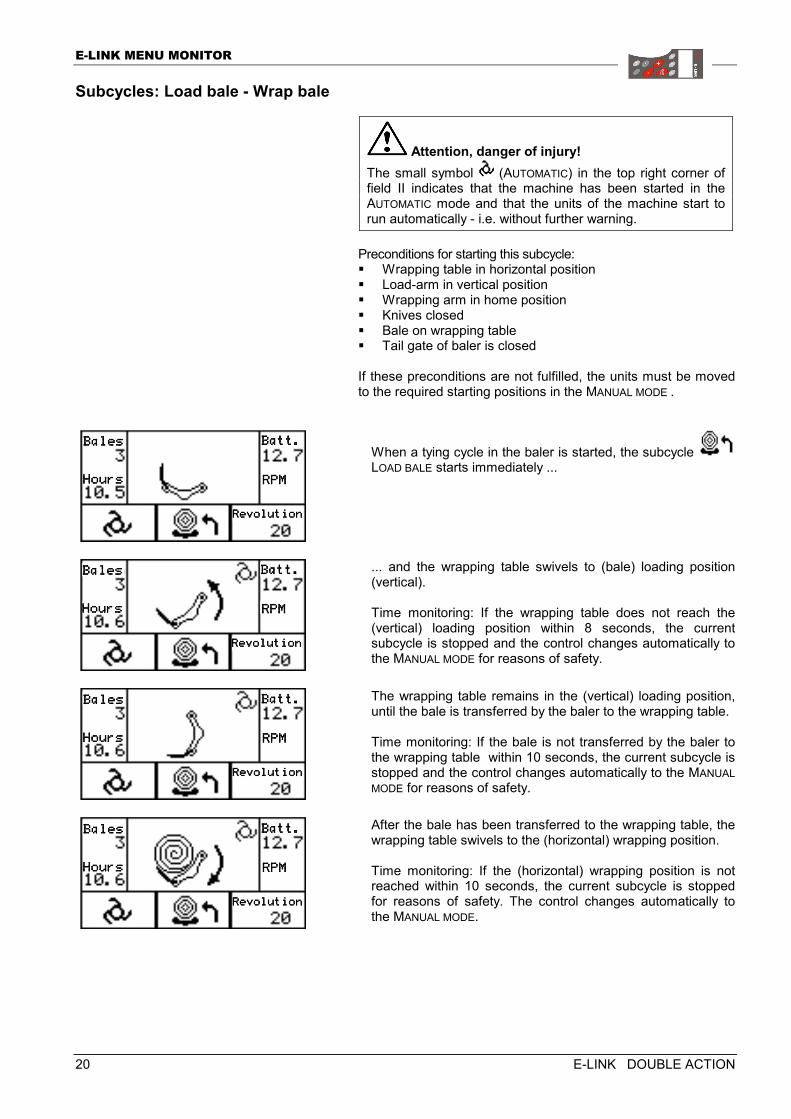
Subcycles: Load bale - Wrap bale
Attention, danger of injury! The small symbol (AUTOMATIC) in the top right corner of field II indicates that the machine has been started in the AUTOMATIC mode and that the units of the machine start to run automatically - i.e. without further warning.
Preconditions for starting this subcycle: � Wrapping table in horizontal position � Load-arm in vertical position � Wrapping arm in home position � Knives closed � Bale on wrapping table � Tail gate of baler is closed If these preconditions are not fulfilled, the units must be moved to the required starting positions in the MANUAL MODE .
When a tying cycle in the baler is started, the subcycle LOAD BALE starts immediately ...
... and the wrapping table swivels to (bale) loading position (vertical). Time monitoring: If the wrapping table does not reach the (vertical) loading position within 8 seconds, the current subcycle is stopped and the control changes automatically to the MANUAL MODE for reasons of safety.
The wrapping table remains in the (vertical) loading position, until the bale is transferred by the baler to the wrapping table. Time monitoring: If the bale is not transferred by the baler to the wrapping table within 10 seconds, the current subcycle is stopped and the control changes automatically to the MANUAL MODE for reasons of safety.
After the bale has been transferred to the wrapping table, the wrapping table swivels to the (horizontal) wrapping position. Time monitoring: If the (horizontal) wrapping position is not reached within 10 seconds, the current subcycle is stopped for reasons of safety. The control changes automatically to the MANUAL MODE.
BalesBalesBalesBales
HoursHoursHoursHours
Batt.Batt.Batt.Batt.
RPMRPMRPMRPM
RevolutionRevolutionRevolutionRevolution
BalesBalesBalesBales
HoursHoursHoursHours
Batt.Batt.Batt.Batt.
RPMRPMRPMRPM
RevolutionRevolutionRevolutionRevolution
BalesBalesBalesBales
HoursHoursHoursHours
Batt.Batt.Batt.Batt.
RPMRPMRPMRPM
RevolutionRevolutionRevolutionRevolution
BalesBalesBalesBales
HoursHoursHoursHours
Batt.Batt.Batt.Batt.
RPMRPMRPMRPM
RevolutionRevolutionRevolutionRevolution
E-LINK MENU MONITOR
E-LINK DOUBLE ACTION 21
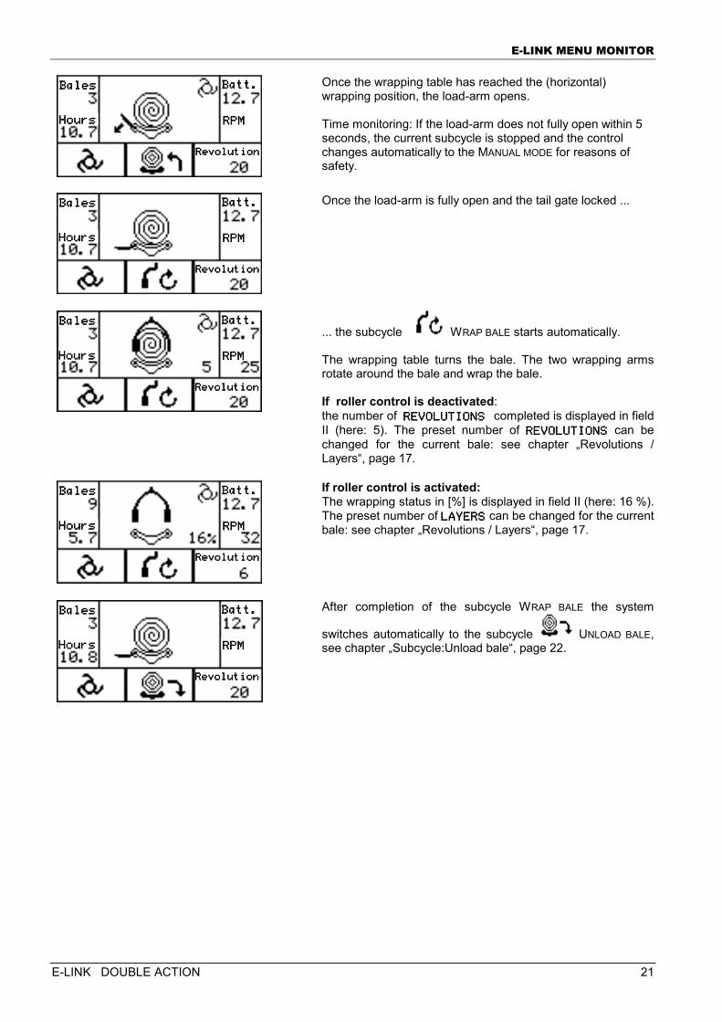
Once the wrapping table has reached the (horizontal) wrapping position, the load-arm opens. Time monitoring: If the load-arm does not fully open within 5 seconds, the current subcycle is stopped and the control changes automatically to the MANUAL MODE for reasons of safety.
Once the load-arm is fully open and the tail gate locked ...
... the subcycle WRAP BALE starts automatically. The wrapping table turns the bale. The two wrapping arms rotate around the bale and wrap the bale. If roller control is deactivated: the number of REVOLUTIONS REVOLUTIONS REVOLUTIONS REVOLUTIONS completed is displayed in field II (here: 5). The preset number of REVOLUTIONSREVOLUTIONSREVOLUTIONSREVOLUTIONS can be changed for the current bale: see chapter „Revolutions / Layers“, page 17.
If roller control is activated: The wrapping status in [%] is displayed in field II (here: 16 %). The preset number of LAYERSLAYERSLAYERSLAYERS can be changed for the current bale: see chapter „Revolutions / Layers“, page 17.
After completion of the subcycle WRAP BALE the system
switches automatically to the subcycle UNLOAD BALE, see chapter „Subcycle:Unload bale“, page 22.
BalesBalesBalesBales
HoursHoursHoursHours
Batt.Batt.Batt.Batt.
RPMRPMRPMRPM
RevolutionRevolutionRevolutionRevolution
BalesBalesBalesBales
HoursHoursHoursHours
Batt.Batt.Batt.Batt.
RPMRPMRPMRPM
RevolutionRevolutionRevolutionRevolution
BalesBalesBalesBales
HoursHoursHoursHours
Batt.Batt.Batt.Batt.
RPMRPMRPMRPM
RevolutionRevolutionRevolutionRevolution
BalesBalesBalesBales
HoursHoursHoursHours
Batt.Batt.Batt.Batt.
RPMRPMRPMRPM
RevolutionRevolutionRevolutionRevolution
BalesBalesBalesBales
HoursHoursHoursHours
Batt.Batt.Batt.Batt.
RPMRPMRPMRPM
RevolutionRevolutionRevolutionRevolution
E-LINK MENU MONITOR
22 E-LINK DOUBLE ACTION
Subcycle:Unload bale
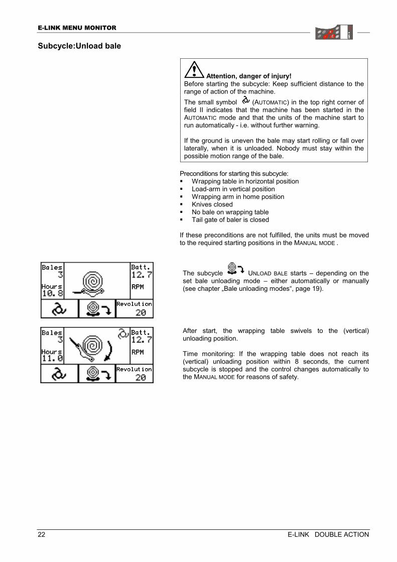
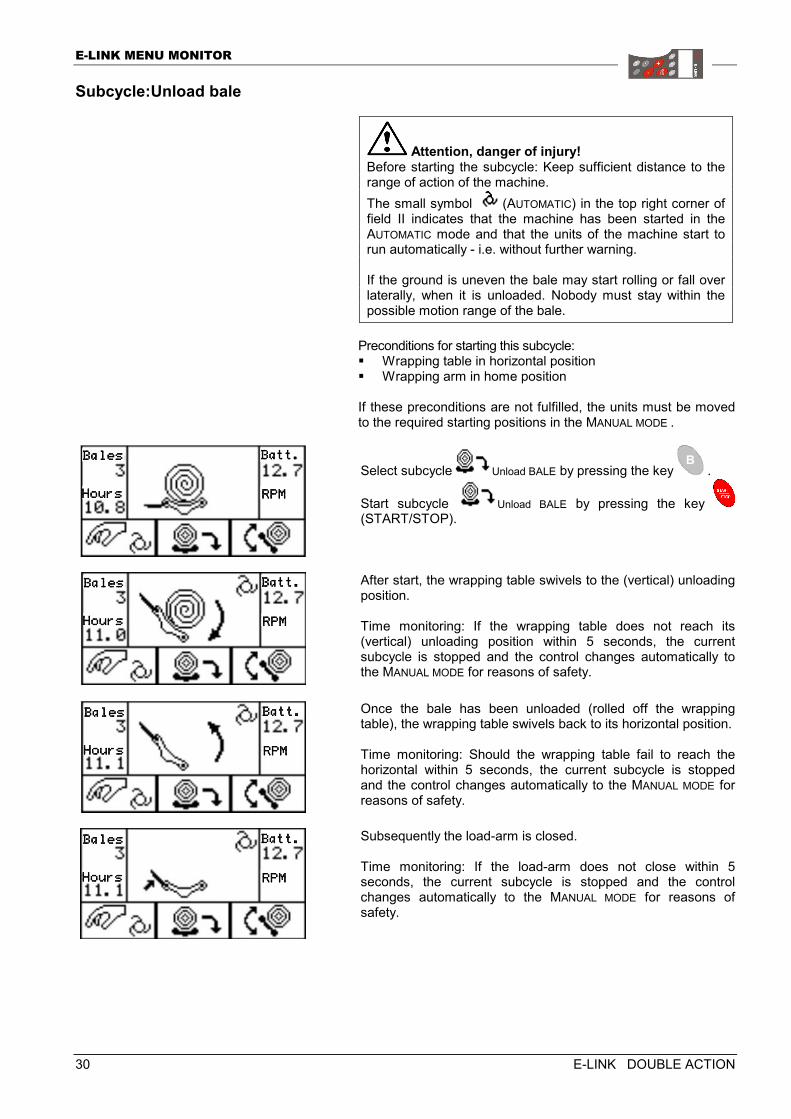
Attention, danger of injury! Before starting the subcycle: Keep sufficient distance to the range of action of the machine. The small symbol (AUTOMATIC) in the top right corner of field II indicates that the machine has been started in the AUTOMATIC mode and that the units of the machine start to run automatically - i.e. without further warning. If the ground is uneven the bale may start rolling or fall over laterally, when it is unloaded. Nobody must stay within the possible motion range of the bale.
Preconditions for starting this subcycle: � Wrapping table in horizontal position � Load-arm in vertical position � Wrapping arm in home position � Knives closed � No bale on wrapping table � Tail gate of baler is closed If these preconditions are not fulfilled, the units must be moved to the required starting positions in the MANUAL MODE .
The subcycle UNLOAD BALE starts – depending on the set bale unloading mode – either automatically or manually (see chapter „Bale unloading modes“, page 19).
After start, the wrapping table swivels to the (vertical) unloading position. Time monitoring: If the wrapping table does not reach its (vertical) unloading position within 8 seconds, the current subcycle is stopped and the control changes automatically to the MANUAL MODE for reasons of safety.
BalesBalesBalesBales
HoursHoursHoursHours
Batt.Batt.Batt.Batt.
RPMRPMRPMRPM
RevolutionRevolutionRevolutionRevolution
BalesBalesBalesBales
HoursHoursHoursHours
Batt.Batt.Batt.Batt.
RPMRPMRPMRPM
RevolutionRevolutionRevolutionRevolution
E-LINK MENU MONITOR
E-LINK DOUBLE ACTION 23
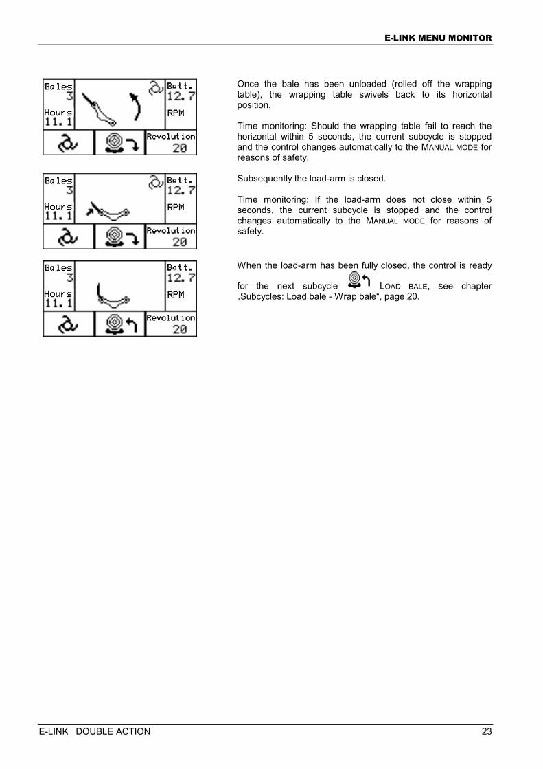
Once the bale has been unloaded (rolled off the wrapping table), the wrapping table swivels back to its horizontal position. Time monitoring: Should the wrapping table fail to reach the horizontal within 5 seconds, the current subcycle is stopped and the control changes automatically to the MANUAL MODE for reasons of safety.
Subsequently the load-arm is closed. Time monitoring: If the load-arm does not close within 5 seconds, the current subcycle is stopped and the control changes automatically to the MANUAL MODE for reasons of safety.
When the load-arm has been fully closed, the control is ready
for the next subcycle LOAD BALE, See chapter „Subcycles: Load bale - Wrap bale“, page 20.
BalesBalesBalesBales
HoursHoursHoursHours
Batt.Batt.Batt.Batt.
RPMRPMRPMRPM
RevolutionRevolutionRevolutionRevolution
BalesBalesBalesBales
HoHoHoHoursursursurs
Batt.Batt.Batt.Batt.
RPMRPMRPMRPM
RevolutionRevolutionRevolutionRevolution
BalesBalesBalesBales
HoursHoursHoursHours
Batt.Batt.Batt.Batt.
RPMRPMRPMRPM
RevolutionRevolutionRevolutionRevolution
E-LINK MENU MONITOR
24 E-LINK DOUBLE ACTION
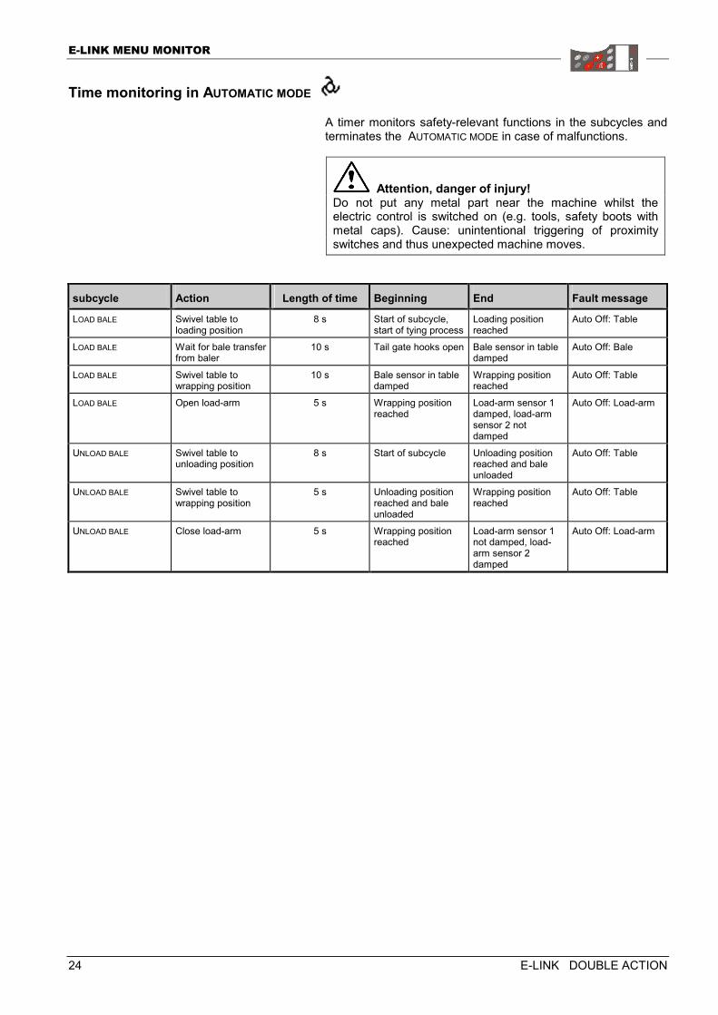
Time monitoring in AUTOMATIC MODE
A timer monitors safety-relevant functions in the subcycles and terminates the AUTOMATIC MODE in case of malfunctions.
Attention, danger of injury! Do not put any metal part near the machine whilst the electric control is switched on (e.g. tools, safety boots with metal caps). Cause: unintentional triggering of proximity switches and thus unexpected machine moves.
subcycle Action Length of time Beginning End Fault message
LOAD BALE Swivel table to loading position
8 s Start of subcycle, start of tying process
Loading position reached
Auto Off: Table
LOAD BALE Wait for bale transfer from baler
10 s Tail gate hooks open Bale sensor in table damped
Auto Off: Bale
LOAD BALE Swivel table to wrapping position
10 s Bale sensor in table damped
Wrapping position reached
Auto Off: Table
LOAD BALE Open load-arm 5 s Wrapping position reached
Load-arm sensor 1 damped, load-arm sensor 2 not damped
Auto Off: Load-arm
UNLOAD BALE Swivel table to unloading position
8 s Start of subcycle Unloading position reached and bale unloaded
Auto Off: Table
UNLOAD BALE Swivel table to wrapping position
5 s Unloading position reached and bale unloaded
Wrapping position reached
Auto Off: Table
UNLOAD BALE Close load-arm 5 s Wrapping position reached
Load-arm sensor 1 not damped, load-arm sensor 2 damped
Auto Off: Load-arm
E-LINK MENU MONITOR
E-LINK DOUBLE ACTION 25
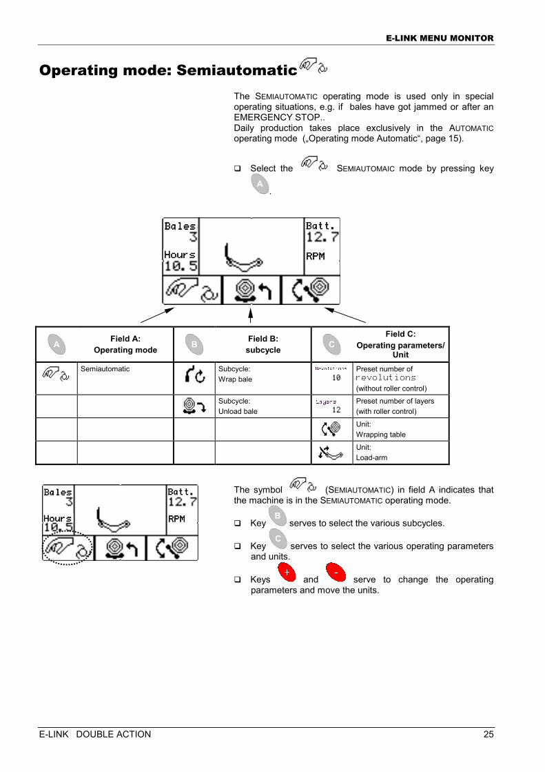
Operating mode: Semiautomatic The SEMIAUTOMATIC operating mode is used only in special operating situations, e.g. if bales have got jammed or after an EMERGENCY STOP.. Daily production takes place exclusively in the AUTOMATIC operating mode („Operating mode Automatic“, page 15).
� Select the SEMIAUTOMAIC mode by pressing key
.
Field A:
Operating mode Field B:
subcycle
Field C: Operating parameters/
Unit
Semiautomatic
Subcycle: Wrap bale
Preset number of revolutions (without roller control)
Subcycle: Unload bale
Preset number of layers (with roller control)
Unit: Wrapping table
Unit: Load-arm
The symbol (SEMIAUTOMATIC) in field A indicates that the machine is in the SEMIAUTOMATIC operating mode.
� Key serves to select the various subcycles.
� Key serves to select the various operating parameters and units.
� Keys and serve to change the operating parameters and move the units.
BalesBalesBalesBales
HoursHoursHoursHours
Batt.Batt.Batt.Batt.
RPMRPMRPMRPM
BalesBalesBalesBales
HoursHoursHoursHours
Batt.Batt.Batt.Batt.
RPMRPMRPMRPM
E-LINK MENU MONITOR
26 E-LINK DOUBLE ACTION
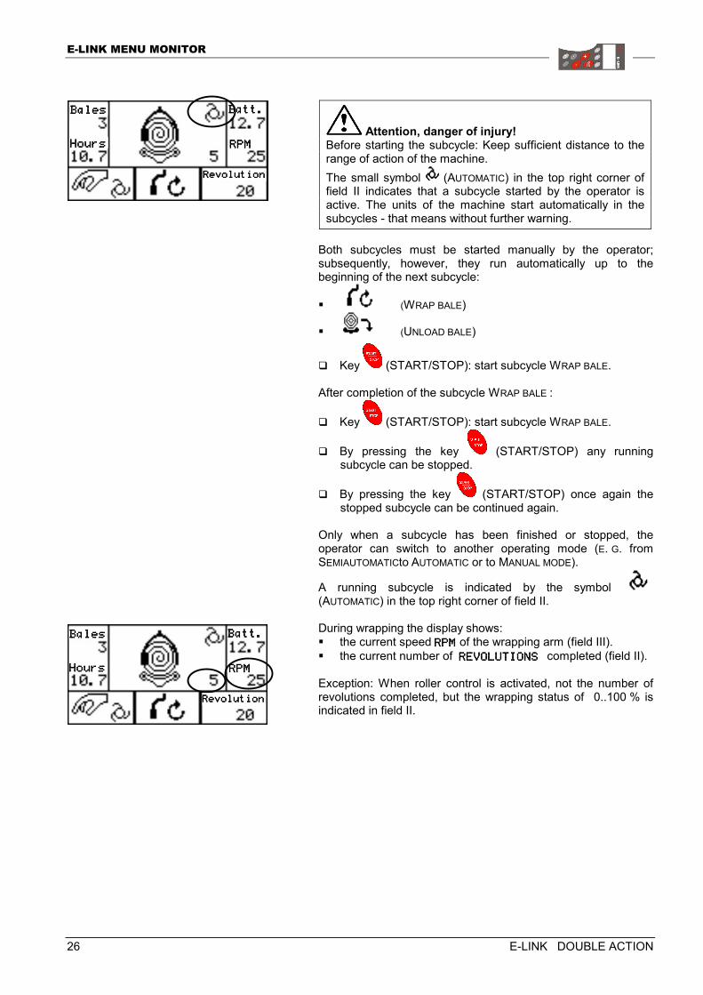
Attention, danger of injury! Before starting the subcycle: Keep sufficient distance to the range of action of the machine. The small symbol (AUTOMATIC) in the top right corner of field II indicates that a subcycle started by the operator is active. The units of the machine start automatically in the subcycles - that means without further warning.
Both subcycles must be started manually by the operator; subsequently, however, they run automatically up to the beginning of the next subcycle:
� (WRAP BALE)
� (UNLOAD BALE)
� Key (START/STOP): start subcycle WRAP BALE. After completion of the subcycle WRAP BALE :
� Key (START/STOP): start subcycle WRAP BALE.
� By pressing the key (START/STOP) any running subcycle can be stopped.
� By pressing the key (START/STOP) once again the stopped subcycle can be continued again.
Only when a subcycle has been finished or stopped, the operator can switch to another operating mode (E. G. from SEMIAUTOMATICto AUTOMATIC or to MANUAL MODE).
A running subcycle is indicated by the symbol (AUTOMATIC) in the top right corner of field II. During wrapping the display shows: � the current speed RPMRPMRPMRPM of the wrapping arm (field III). � the current number of REVOLUTIONS REVOLUTIONS REVOLUTIONS REVOLUTIONS completed (field II). Exception: When roller control is activated, not the number of revolutions completed, but the wrapping status of 0..100 % is indicated in field II.
BalesBalesBalesBales
HoursHoursHoursHours
Batt.Batt.Batt.Batt.
RPMRPMRPMRPM
RevolutionRevolutionRevolutionRevolution
BalesBalesBalesBales
HoursHoursHoursHours
Batt.Batt.Batt.Batt.
RPMRPMRPMRPM
RevolutionRevolutionRevolutionRevolution
E-LINK MENU MONITOR
E-LINK DOUBLE ACTION 27
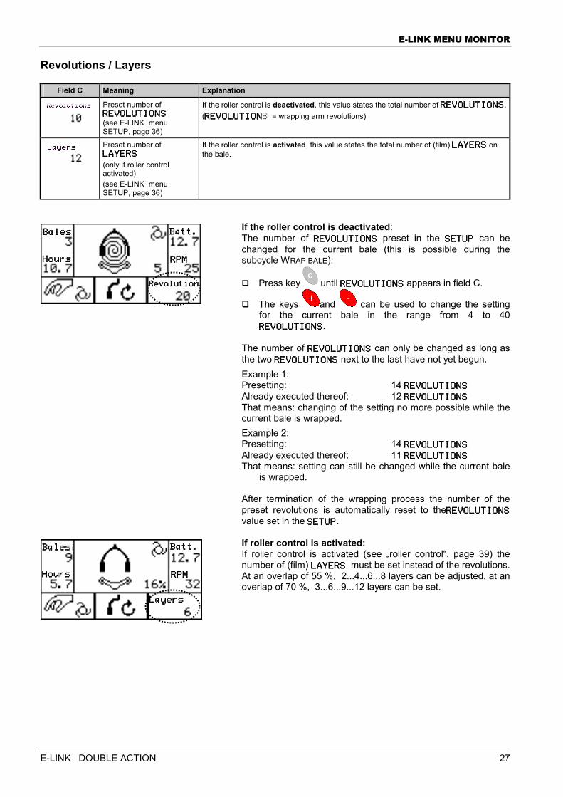
Revolutions / Layers
Field C Meaning Explanation
Preset number of REVOLUTIONSREVOLUTIONSREVOLUTIONSREVOLUTIONS (see E-LINK menu SETUP, page 36)
If the roller control is deactivated, this value states the total number of REVOLUTIONSREVOLUTIONSREVOLUTIONSREVOLUTIONS.(REVOLUTIONREVOLUTIONREVOLUTIONREVOLUTIONS = wrapping arm revolutions)
Preset number of LAYERSLAYERSLAYERSLAYERS (only if roller control activated) (see E-LINK menu SETUP, page 36)
If the roller control is activated, this value states the total number of (film) LAYERSLAYERSLAYERSLAYERS on the bale.
If the roller control is deactivated: The number of REVOLUTIONSREVOLUTIONSREVOLUTIONSREVOLUTIONS preset in the SETUPSETUPSETUPSETUP can be changed for the current bale (this is possible during the subcycle WRAP BALE):
� Press key until REVOLUTIONSREVOLUTIONSREVOLUTIONSREVOLUTIONS appears in field C.
� The keys and can be used to change the setting for the current bale in the range from 4 to 40 REVOLUTIONSREVOLUTIONSREVOLUTIONSREVOLUTIONS.
The number of REVOLUTIONSREVOLUTIONSREVOLUTIONSREVOLUTIONS can only be changed as long as the two REVOLUTIONSREVOLUTIONSREVOLUTIONSREVOLUTIONS next to the last have not yet begun. Example 1: Presetting: 14 REVOLUTIONSREVOLUTIONSREVOLUTIONSREVOLUTIONS Already executed thereof: 12 REVOLUTIONSREVOLUTIONSREVOLUTIONSREVOLUTIONS That means: changing of the setting no more possible while the current bale is wrapped. Example 2: Presetting: 14 REVOLUTIONSREVOLUTIONSREVOLUTIONSREVOLUTIONS Already executed thereof: 11 REVOLUTIONSREVOLUTIONSREVOLUTIONSREVOLUTIONS That means: setting can still be changed while the current bale
is wrapped. After termination of the wrapping process the number of the preset revolutions is automatically reset to theREVOLUTIONSREVOLUTIONSREVOLUTIONSREVOLUTIONS value set in the SETUPSETUPSETUPSETUP. If roller control is activated: If roller control is activated (see „roller control“, page 39) the number of (film) LAYERSLAYERSLAYERSLAYERS must be set instead of the revolutions. At an overlap of 55 %, 2...4...6...8 layers can be adjusted, at an overlap of 70 %, 3...6...9...12 layers can be set.
BalesBalesBalesBales
HoursHoursHoursHours
Batt.Batt.Batt.Batt.
RPMRPMRPMRPM
RevolutionRevolutionRevolutionRevolution
BalesBalesBalesBales
HoursHoursHoursHours
Batt.Batt.Batt.Batt.
RPMRPMRPMRPM
LayersLayersLayersLayers
E-LINK MENU MONITOR
28 E-LINK DOUBLE ACTION
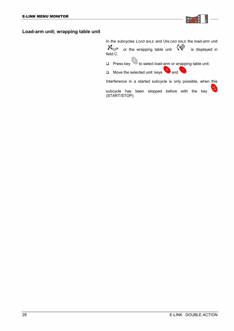
Load-arm unit; wrapping table unit
In the subcycles LOAD BALE and UNLOAD BALE the load-arm unit
or the wrapping table unit is displayed in field C.
� Press key to select load-arm or wrapping table unit.
� Move the selected unit: keys and Interference in a started subcycle is only possible, when this
subcycle has been stopped before with the key (START/STOP).
E-LINK MENU MONITOR
E-LINK DOUBLE ACTION 29
Subcycle:Wrap bale
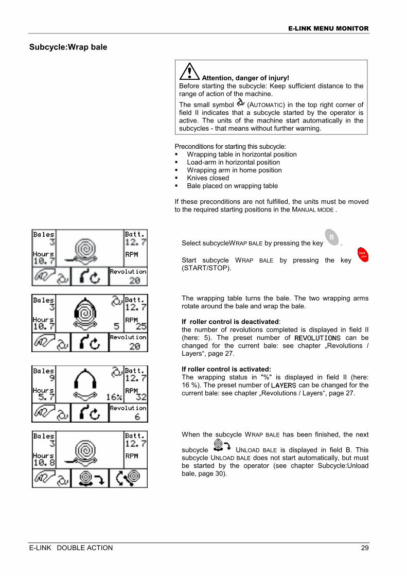
Attention, danger of injury! Before starting the subcycle: Keep sufficient distance to the range of action of the machine. The small symbol (AUTOMATIC) in the top right corner of field II indicates that a subcycle started by the operator is active. The units of the machine start automatically in the subcycles - that means without further warning.
Preconditions for starting this subcycle: � Wrapping table in horizontal position � Load-arm in horizontal position � Wrapping arm in home position � Knives closed � Bale placed on wrapping table If these preconditions are not fulfilled, the units must be moved to the required starting positions in the MANUAL MODE .
Select subcycleWRAP BALE by pressing the key .
Start subcycle WRAP BALE by pressing the key (START/STOP).
The wrapping table turns the bale. The two wrapping arms rotate around the bale and wrap the bale. If roller control is deactivated: the number of revolutions completed is displayed in field II (here: 5). The preset number of REVOLUTIONSREVOLUTIONSREVOLUTIONSREVOLUTIONS can be changed for the current bale: see chapter „Revolutions / Layers“, page 27.
If roller control is activated: The wrapping status in "%" is displayed in field II (here: 16 %). The preset number of LAYERSLAYERSLAYERSLAYERS can be changed for the current bale: see chapter „Revolutions / Layers“, page 27.
When the subcycle WRAP BALE has been finished, the next
subcycle UNLOAD BALE is displayed in field B. This subcycle UNLOAD BALE does not start automatically, but must be started by the operator (see chapter Subcycle:Unload bale, page 30).
BalesBalesBalesBales
HoursHoursHoursHours
Batt.Batt.Batt.Batt.
RPMRPMRPMRPM
RevolutionRevolutionRevolutionRevolution
BalesBalesBalesBales
HoursHoursHoursHours
Batt.Batt.Batt.Batt.
RPMRPMRPMRPM
RevolutionRevolutionRevolutionRevolution
BalesBalesBalesBales
HoursHoursHoursHours
Batt.Batt.Batt.Batt.
RPMRPMRPMRPM
RevolutionRevolutionRevolutionRevolution
BalesBalesBalesBales
HoursHoursHoursHours
Batt.Batt.Batt.Batt.
RPMRPMRPMRPM
E-LINK MENU MONITOR
30 E-LINK DOUBLE ACTION
Subcycle:Unload bale
Attention, danger of injury! Before starting the subcycle: Keep sufficient distance to the range of action of the machine. The small symbol (AUTOMATIC) in the top right corner of field II indicates that the machine has been started in the AUTOMATIC mode and that the units of the machine start to run automatically - i.e. without further warning. If the ground is uneven the bale may start rolling or fall over laterally, when it is unloaded. Nobody must stay within the possible motion range of the bale.
Preconditions for starting this subcycle: � Wrapping table in horizontal position � Wrapping arm in home position If these preconditions are not fulfilled, the units must be moved to the required starting positions in the MANUAL MODE .
Select subcycle Unload BALE by pressing the key .
Start subcycle Unload BALE by pressing the key (START/STOP).
After start, the wrapping table swivels to the (vertical) unloading position. Time monitoring: If the wrapping table does not reach its (vertical) unloading position within 5 seconds, the current subcycle is stopped and the control changes automatically to the MANUAL MODE for reasons of safety.
Once the bale has been unloaded (rolled off the wrapping table), the wrapping table swivels back to its horizontal position. Time monitoring: Should the wrapping table fail to reach the horizontal within 5 seconds, the current subcycle is stopped and the control changes automatically to the MANUAL MODE for reasons of safety.
Subsequently the load-arm is closed. Time monitoring: If the load-arm does not close within 5 seconds, the current subcycle is stopped and the control changes automatically to the MANUAL MODE for reasons of safety.
BalesBalesBalesBales
HoursHoursHoursHours
Batt.Batt.Batt.Batt.
RPMRPMRPMRPM
BalesBalesBalesBales
HoursHoursHoursHours
Batt.Batt.Batt.Batt.
RPMRPMRPMRPM
BalesBalesBalesBales
HoursHoursHoursHours
Batt.Batt.Batt.Batt.
RPMRPMRPMRPM
BalesBalesBalesBales
HoursHoursHoursHours
Batt.Batt.Batt.Batt.
RPMRPMRPMRPM
E-LINK MENU MONITOR
E-LINK DOUBLE ACTION 31
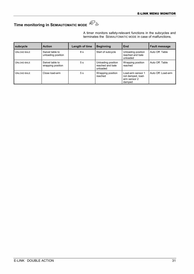
Time monitoring in SEMIAUTOMATIC MODE
A timer monitors safety-relevant functions in the subcycles and terminates the SEMIAUTOMATIC MODE in case of malfunctions.
subcycle Action Length of time Beginning End Fault message
UNLOAD BALE Swivel table to unloading position
8 s Start of subcycle Unloading position reached and bale unloaded
Auto Off: Table
UNLOAD BALE Swivel table to wrapping position
5 s Unloading position reached and bale unloaded
Wrapping position reached
Auto Off: Table
UNLOAD BALE Close load-arm 5 s Wrapping position reached
Load-arm sensor 1 not damped, load-arm sensor 2 damped
Auto Off: Load-arm
E-LINK MENU MONITOR
32 E-LINK DOUBLE ACTION
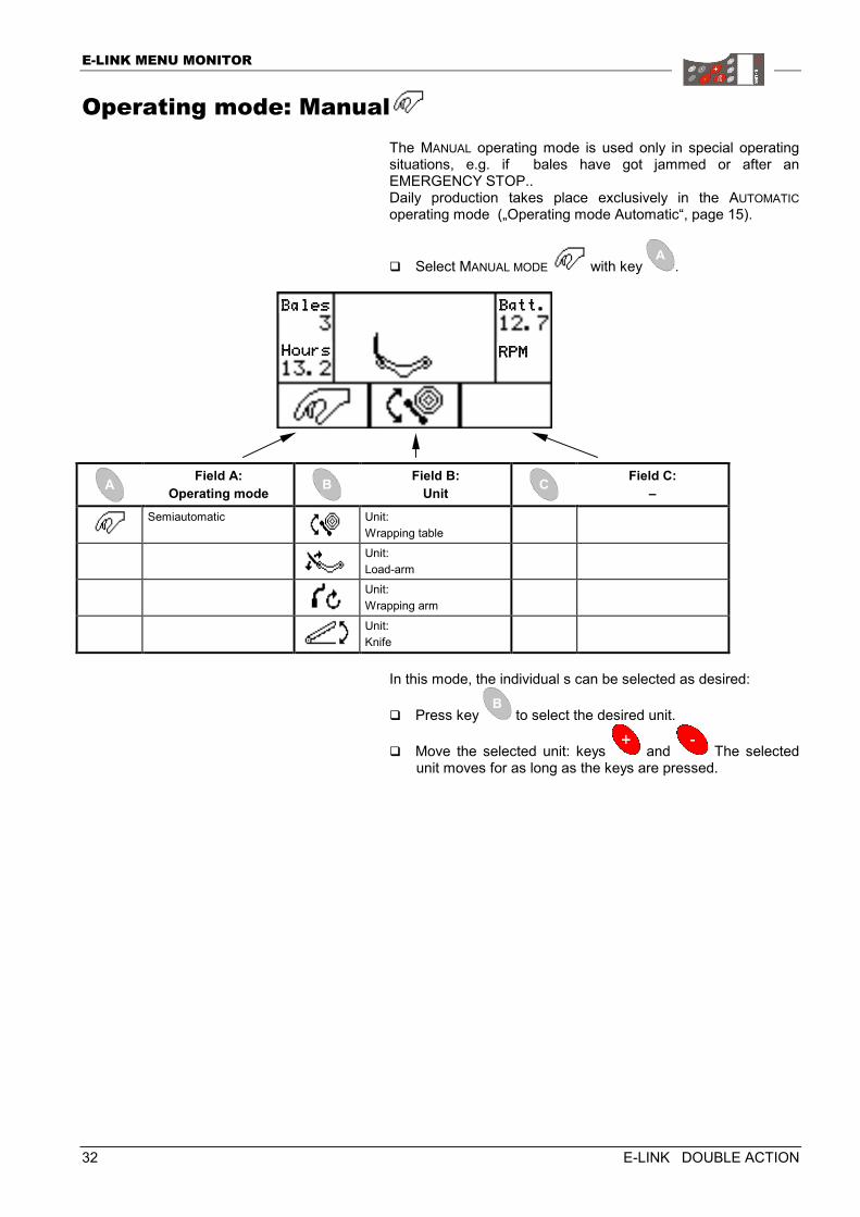
Operating mode: Manual The MANUAL operating mode is used only in special operating situations, e.g. if bales have got jammed or after an EMERGENCY STOP.. Daily production takes place exclusively in the AUTOMATIC operating mode („Operating mode Automatic“, page 15).
� Select MANUAL MODE with key .
Field A:
Operating mode Field B:
Unit Field C:
–
Semiautomatic
Unit: Wrapping table
Unit: Load-arm
Unit: Wrapping arm
Unit: Knife
In this mode, the individual s can be selected as desired:
� Press key to select the desired unit.
� Move the selected unit: keys and The selected unit moves for as long as the keys are pressed.
BalesBalesBalesBales
HoursHoursHoursHours
Batt.Batt.Batt.Batt.
RPMRPMRPMRPM
E-LINK MENU MONITOR
E-LINK DOUBLE ACTION 33
Manual mode with collision monitoring
The units:
� wrapping table
� load-arm and
� wrapping arm are subject to collision monitoring. If the sensors recognise a possible collision, the selected unit cannot be moved and a fault message ACTION NOT ALLOWEDACTION NOT ALLOWEDACTION NOT ALLOWEDACTION NOT ALLOWED is output. The wrapping table unit and the load arm unit can only be moved if the wrapping arm is in its home position. If the wrapping arm is not in its home position:
� Press key to select the wrapping arm .
� Press key (START/STOP) to move the wrapping arm to home position. This operation can be stopped by pressing
the key (START/STOP) once again .
Manual mode without collision monitoring
Caution, danger of collision! When the units are moved WITHOUT collision monitoring, there is the risk of collisions between machine components.
Should the machine be blocked as a result of collision monitoring, an emergency operation is possible. In this case the wrapping table unit and the load-arm unit can be moved without collision monitoring. (The wrapping arm cannot be moved.)
� Press key to select the wrapping table or the load-arm.
� Keep key <START/STOP> pressed.
� Move the selected unit by means of the key or . The actions without collision monitoring are indicated by the message NO IMPACT MONITOR!NO IMPACT MONITOR!NO IMPACT MONITOR!NO IMPACT MONITOR!. This message serves only for information and does not interrupt the movement of the selected unit.
E-LINK MENU MONITOR
34 E-LINK DOUBLE ACTION
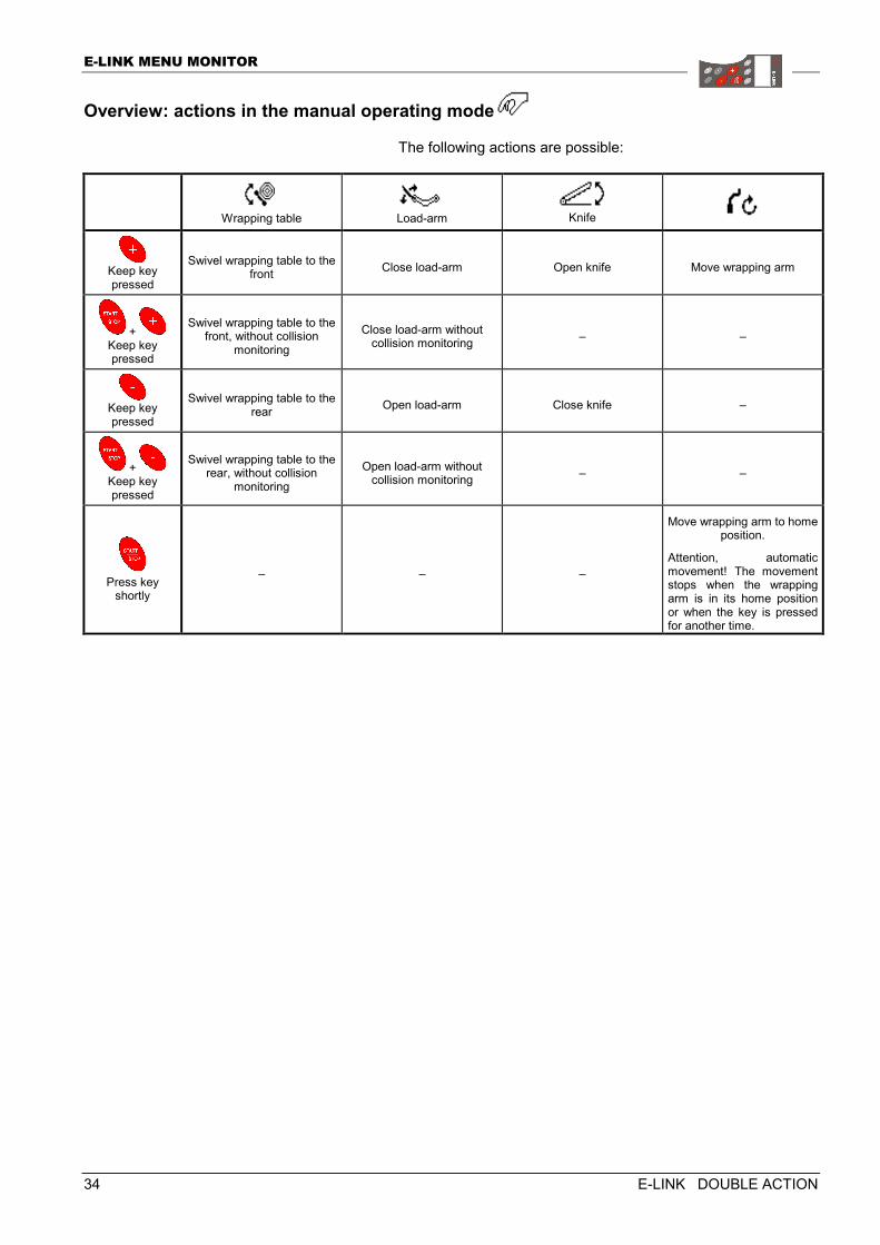
Overview: actions in the manual operating mode
The following actions are possible:
Wrapping table
Load-arm
Knife
Keep key pressed
Swivel wrapping table to the front Close load-arm Open knife Move wrapping arm
+ Keep key pressed
Swivel wrapping table to the front, without collision
monitoring Close load-arm without
collision monitoring – –
Keep key pressed
Swivel wrapping table to the rear Open load-arm Close knife –
+ Keep key pressed
Swivel wrapping table to the rear, without collision
monitoring Open load-arm without
collision monitoring – –
Press key
shortly
– – –
Move wrapping arm to home position.
Attention, automatic movement! The movement stops when the wrapping arm is in its home position or when the key is pressed for another time.
E-LINK MENU MONITOR
E-LINK DOUBLE ACTION 35
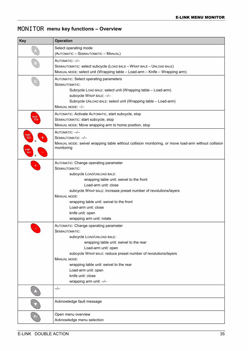
MONITOR MONITOR MONITOR MONITOR menu key functions – Overview
Key Operation
Select operating mode (AUTOMATIC – SEMIAUTOMATIC – MANUAL)
AUTOMATIC: –/– SEMIAUTOMATIC: select subcycle (LOAD BALE – WRAP BALE – UNLOAD BALE) MANUAL MODE: select unit (Wrapping table – Load-arm – Knife – Wrapping arm)
AUTOMATIC: Select operating parameters SEMIAUTOMATIC:
Subcycle LOAD BALE: select unit (Wrapping table – Load-arm) subcycle WRAP BALE: –/– Subcycle UNLOAD BALE: select unit (Wrapping table – Load-arm)
MANUAL MODE: –/–
AUTOMATIC: Activate AUTOMATIC, start subcycle, stop SEMIAUTOMATIC: start subcycle, stop MANUAL MODE: Move wrapping arm to home position, stop
+
+
AUTOMATIC: –/– SEMIAUTOMATIC: –/– MANUAL MODE: swivel wrapping table without collision monitoring, or move load-arm without collision monitoring
AUTOMATIC: Change operating parameter SEMIAUTOMATIC:
subcycle LOAD/UNLOAD BALE: wrapping table unit: swivel to the front Load-arm unit: close
subcycle WRAP BALE: increase preset number of revolutions/layers MANUAL MODE:
wrapping table unit: swivel to the front Load-arm unit: close knife unit: open wrapping arm unit: rotate
AUTOMATIC: Change operating parameter SEMIAUTOMATIC:
subcycle LOAD/UNLOAD BALE: wrapping table unit: swivel to the rear Load-arm unit: open
subcycle WRAP BALE: reduce preset number of revolutions/layers MANUAL MODE:
wrapping table unit: swivel to the rear Load-arm unit: open knife unit: close wrapping arm unit: –/–
–/–
Acknowledge fault message
Open menu overview Acknowledge menu selection

E-LINK menu SETUP
36 E-LINK DOUBLE ACTION
EEEE----LINK LINK LINK LINK MENU MENU MENU MENU SETUPSETUPSETUPSETUP
The SETUPSETUPSETUPSETUP menu serves for setting various machine parameters (Language, Machine type, Beep ...).
� Open menu overview : press key .
� Select SETUPSETUPSETUPSETUP menu: keys or
� Confirm selection with key .
� Select parameter: keys and
� Change parameter: keys and
� Either return to menu selection: press key .
� Or return to MONITORMONITORMONITORMONITORmenu: press key for 3 sec.
Menu: MonitorMenu: MonitorMenu: MonitorMenu: Monitor Setup Setup Setup Setup Systeminfo Systeminfo Systeminfo Systeminfo Diagnosis Diagnosis Diagnosis Diagnosis StatisticsStatisticsStatisticsStatistics
E-LINK menu SETUP
E-LINK DOUBLE ACTION 37
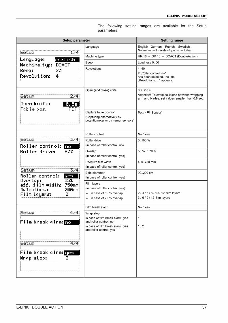
The following setting ranges are available for the Setup parameters:
Setup parameter Setting range
Language English– German – French – Swedish – Norwegian – Finnish – Spanish – Italian
Machine type HR 16 – SR 16 – DOACT (DoubleAction)
Beep Loudness 0..50
Revolutions
4..40 If „Roller control: no“ has been selected, the line „Revolutions: ...“ appears
Open (and close) knife 0.2..2.0 s Attention! To avoid collisions between wrapping arm and blades: set values smaller than 0.8 sec.
Capture table position (Capturing alternatively by potentiometer or by namur sensors)
Pot / (Sensor)
Roller control No / Yes
Roller drive (in case of roller control: no)
0..100 %
Overlap (in case of roller control: yes)
55 % / 70 %
Effective film width (in case of roller control: yes)
400..750 mm
Bale diameter (in case of roller control: yes)
90..200 cm
Film layers (in case of roller control: yes): • in case of 55 % overlap • in case of 70 % overlap
2 / 4 / 6 / 8 / 10 / 12 film layers 3 / 6 / 9 / 12 film layers
Film break alarm No / Yes
Wrap stop in case of film break alarm: yes and roller control: no in case of film break alarm: yes and roller control: yes
1 1 / 2
Language:Language:Language:Language:
Machine typ: DOACTMachine typ: DOACTMachine typ: DOACTMachine typ: DOACT
Beep: 20Beep: 20Beep: 20Beep: 20
Revolution: 4Revolution: 4Revolution: 4Revolution: 4
englishenglishenglishenglish
Roller control:Roller control:Roller control:Roller control:
Roller drive: 80%Roller drive: 80%Roller drive: 80%Roller drive: 80% nononono
Film break alrm:Film break alrm:Film break alrm:Film break alrm:
Wrap stop:Wrap stop:Wrap stop:Wrap stop: 2 2 2 2 yesyesyesyes
Film break alrm:Film break alrm:Film break alrm:Film break alrm:
nononono
Roller control:Roller control:Roller control:Roller control: Overlap: 55%Overlap: 55%Overlap: 55%Overlap: 55% eff. film width: 750mmeff. film width: 750mmeff. film width: 750mmeff. film width: 750mm Bale diam.: 200cmBale diam.: 200cmBale diam.: 200cmBale diam.: 200cm Film layers: 2Film layers: 2Film layers: 2Film layers: 2
yesyesyesyes
Open knife: Open knife: Open knife: Open knife:
Table pos. POT 0.5s0.5s0.5s0.5s
E-LINK menu SETUP
38 E-LINK DOUBLE ACTION
SETUP 1/4
Language
The language in the control box display can be adjusted. � German � English � French Dependent on the configuration further languages can be available: � Swedish � Norwegian � Finnish � Spanish � Italian
Note! Before changing the following settings: contact the service department in case of questions or doubts.
Machine type
Attention! Correct machine type is set by manufacturer. A wrong setting can disturb the correct function of the machine. Then: contact customer service.
Set machine type: � HR 16 = ATTIS HR 16 � SR 16 = ATTIS SR 16 � Double Action = Double Action Round Bale Wrapper
Beep
The beep indicates audibly that a key on the control box has been pressed. The loudness of the beep can be adjusted: 0..50 0 = beep off 50 = beep maximum loudness
Revolutions
(only in case of „roller control: no") The number of wrapping arm revolutions around the bale can be adjusted: 4..40 revolutions
E-LINK menu SETUP
E-LINK DOUBLE ACTION 39
SETUP 2/4
Open knife
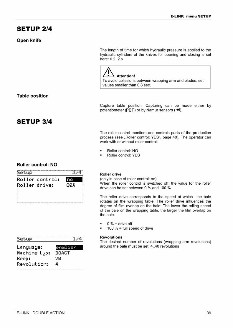
The length of time for which hydraulic pressure is applied to the hydraulic cylinders of the knives for opening and closing is set here: 0.2..2 s
Attention! To avoid colissions between wrapping arm and blades: set values smaller than 0.8 sec.
Table position
Capture table position. Capturing can be made either by potentiometer (POTPOTPOTPOT) or by Namur sensors ( ).
SETUP 3/4 The roller control monitors and controls parts of the production process (see „Roller control: YES“, page 40). The operator can work with or without roller control: � Roller control: NO � Roller control: YES
Roller control: NO
Roller drive (only in case of roller control: no) When the roller control is switched off, the value for the roller drive can be set between 0 % and 100 %. The roller drive corresponds to the speed at which the bale rotates on the wrapping table. The roller drive influences the degree of film overlap on the bale: The lower the rolling speed of the bale on the wrapping table, the larger the film overlap on the bale. � 0 % = drive off � 100 % = full speed of drive Revolutions The desired number of revolutions (wrapping arm revolutions) around the bale must be set: 4..40 revolutions
Roller control:Roller control:Roller control:Roller control:
Roller drive: 80%Roller drive: 80%Roller drive: 80%Roller drive: 80%
nononono
Language:Language:Language:Language:
Machine typ: DOACTMachine typ: DOACTMachine typ: DOACTMachine typ: DOACT
Beep: 20Beep: 20Beep: 20Beep: 20
Revolution: 4Revolution: 4Revolution: 4Revolution: 4
englishenglishenglishenglish
E-LINK menu SETUP
40 E-LINK DOUBLE ACTION
Roller control: YES
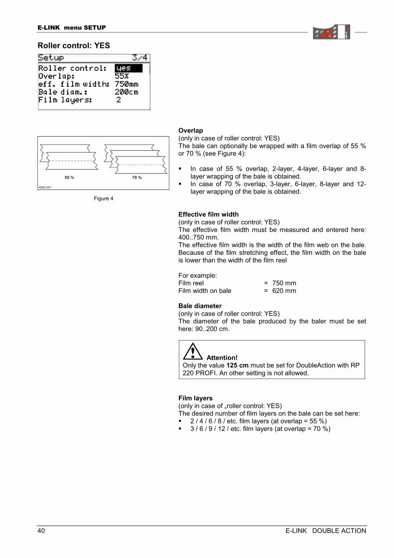
Overlap (only in case of roller control: YES) The bale can optionally be wrapped with a film overlap of 55 % or 70 % (see Figure 4): � In case of 55 % overlap, 2-layer, 4-layer, 6-layer and 8-
layer wrapping of the bale is obtained. � In case of 70 % overlap, 3-layer, 6-layer, 8-layer and 12-
layer wrapping of the bale is obtained.
Effective film width (only in case of roller control: YES) The effective film width must be measured and entered here: 400..750 mm. The effective film width is the width of the film web on the bale. Because of the film stretching effect, the film width on the bale is lower than the width of the film reel For example: Film reel = 750 mm Film width on bale = 620 mm Bale diameter (only in case of roller control: YES) The diameter of the bale produced by the baler must be set here: 90..200 cm.
Attention! Only the value 125 cm must be set for DoubleAction with RP 220 PROFI. An other setting is not allowed.
Film layers (only in case of „roller control: YES) The desired number of film layers on the bale can be set here: � 2 / 4 / 6 / 8 / etc. film layers (at overlap = 55 %) � 3 / 6 / 9 / 12 / etc. film layers (at overlap = 70 %)
Figure 4
Roller control:Roller control:Roller control:Roller control: Overlap: Overlap: Overlap: Overlap: 55% 55% 55% 55% eff. film width: 750mmeff. film width: 750mmeff. film width: 750mmeff. film width: 750mm Bale diam.: 200cmBale diam.: 200cmBale diam.: 200cmBale diam.: 200cm Film layers: 2Film layers: 2Film layers: 2Film layers: 2
yesyesyesyes
E-LINK menu SETUP
E-LINK DOUBLE ACTION 41
SETUP 4/4 The film break monitoring unit checks whether: � either of the two film webs is broken. � either of the two film reels is empty. The operator can work with or without film break alarm: � Film break alarm: NO � Film break alarm: YES
Film break alarm:NO
The film break alarm is switched off. Any film break (of one or both films) is not recognised by the machine.
Film break alarm:YES
The film break alarm is switched on. The machine stops when one or the two films break (see next section).
Wrap stop
(Film break alarm: YES/ Roller control = YES) � If you want the machine to stop after a break of either of the
two films the following setting must be made here: Wrap stop 1.
� If you want the machine to stop only after breaking of both films the following setting must be made here: Wrap stop 2.
If, in case of „Wrap stop: 2“, either of the films breaks (or a film reel runs empty) wrapping of the bale is automatically finished properly by means of the remaining film. (Film break alarm: YES / Roller control = NO) � If you want the machine to stop after a break of either of the
two films the following setting must be made here: Wrap stop 1.
E-LINK menu SETUP
42 E-LINK DOUBLE ACTION
SETUPSETUPSETUPSETUP menu key functions – Overview
Key Operation
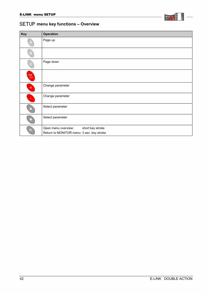
Page up
Page down
Change parameter
Change parameter
Select parameter
Select parameter
Open menu overview: short key stroke Return to MONITOR menu: 3 sec. key stroke
E-LINK menu SYSTEMINFO
E-LINK DOUBLE ACTION 43
EEEE----LINK LINK LINK LINK MENU MENU MENU MENU SYSTEMINFOSYSTEMINFOSYSTEMINFOSYSTEMINFO
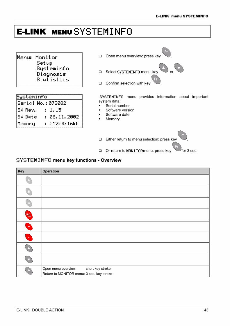
� Open menu overview: press key .
� Select SYSTEMINFOSYSTEMINFOSYSTEMINFOSYSTEMINFO menu: key or
� Confirm selection with key . SYSTEMINFOSYSTEMINFOSYSTEMINFOSYSTEMINFO menu provides information about important system data: � Serial number � Software version � Software date � Memory
� Either return to menu selection: press key .
� Or return to MONITORMONITORMONITORMONITORmenu: press key for 3 sec.
SYSTEMINFOSYSTEMINFOSYSTEMINFOSYSTEMINFO menu key functions - Overview
Key Operation
Open menu overview: short key stroke Return to MONITOR menu: 3 sec. key stroke
Menu: MonitorMenu: MonitorMenu: MonitorMenu: Monitor Setup Setup Setup Setup Systeminfo Systeminfo Systeminfo Systeminfo Diagnosis Diagnosis Diagnosis Diagnosis Statistics Statistics Statistics Statistics
Serial No.:072082Serial No.:072082Serial No.:072082Serial No.:072082
SW Rev. : 1.15SW Rev. : 1.15SW Rev. : 1.15SW Rev. : 1.15
SW Date : 08.11.2002SW Date : 08.11.2002SW Date : 08.11.2002SW Date : 08.11.2002
Memory : 512Memory : 512Memory : 512Memory : 512kB/16kbkB/16kbkB/16kbkB/16kb
E-LINK menu DIAGNOSIS
44 E-LINK DOUBLE ACTION
EEEE----LINK LINK LINK LINK MENU MENU MENU MENU DIAGNOSISDIAGNOSISDIAGNOSISDIAGNOSIS
The E-Link system offers extensive diagnostic functions for checking the electrical equipment. There are two diagnostic routines:
Standard diagnosis
Diagnostic functions with machine stopped. Machine functions completely switched off. In addition, a fully automatic actor test is possible.
Attention, danger of injury! Standard diagnosis may only be performed after the machine has been stopped: Switch off tractor engine, wait until machine has stopped, disconnect hydraulic supply to the machine.
Extended diagnosis
Diagnostic functions while machine is in operation. Observation of all sensor channels and actor channels possible. Selection via special key combination.
Attention, danger of injury! Extended diagnosis is executed while the machine is running. For trained and instructed service personnel only!
See „Extended diagnosis“, page 63.
E-LINK menu DIAGNOSIS
E-LINK DOUBLE ACTION 45
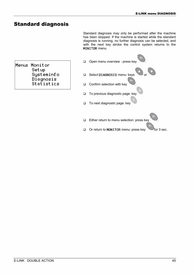
Standard diagnosis Standard diagnosis may only be performed after the machine has been stopped. If the machine is started while the standard diagnosis is running, no further diagnosis can be selected, and with the next key stroke the control system returns to the MONITORMONITORMONITORMONITOR menu.
� Open menu overview : press key .
� Select DIAGNOSISDIAGNOSISDIAGNOSISDIAGNOSIS menu: keys or
� Confirm selection with key .
� To previous diagnostic page: key
� To next diagnostic page: key
� Either return to menu selection: press key .
� Or return to MONITORMONITORMONITORMONITOR menu: press key for 3 sec.
Menu: MonitorMenu: MonitorMenu: MonitorMenu: Monitor Setup Setup Setup Setup Systeminfo Systeminfo Systeminfo Systeminfo Diagnosis Diagnosis Diagnosis Diagnosis Statistics Statistics Statistics Statistics
E-LINK menu DIAGNOSIS
46 E-LINK DOUBLE ACTION
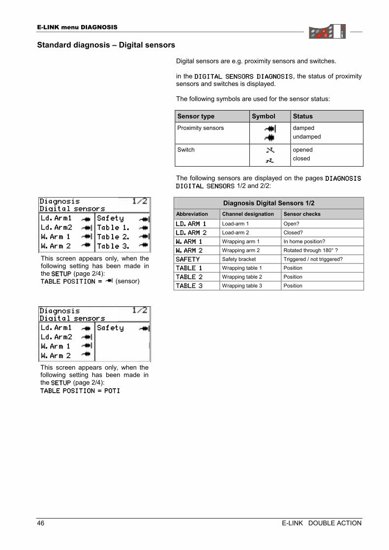
Standard diagnosis – Digital sensors
Digital sensors are e.g. proximity sensors and switches. in the DIGITAL SENSORS DIAGDIGITAL SENSORS DIAGDIGITAL SENSORS DIAGDIGITAL SENSORS DIAGNOSISNOSISNOSISNOSIS, the status of proximity sensors and switches is displayed. The following symbols are used for the sensor status: Sensor type Symbol Status Proximity sensors
damped undamped
Switch
opened closed
The following sensors are displayed on the pages DIAGNOSIS DIAGNOSIS DIAGNOSIS DIAGNOSIS
DIGITAL SENSORSDIGITAL SENSORSDIGITAL SENSORSDIGITAL SENSORS 1/2 and 2/2:
Diagnosis Digital Sensors 1/2 Abbreviation Channel designation Sensor checks
LD.ARM 1LD.ARM 1LD.ARM 1LD.ARM 1 Load-arm 1 Open?
LD.ARM 2LD.ARM 2LD.ARM 2LD.ARM 2 Load-arm 2 Closed?
W.ARM 1W.ARM 1W.ARM 1W.ARM 1 Wrapping arm 1 In home position?
W.ARM 2W.ARM 2W.ARM 2W.ARM 2 Wrapping arm 2 Rotated through 180° ?
SAFETYSAFETYSAFETYSAFETY Safety bracket Triggered / not triggered? TABLE 1TABLE 1TABLE 1TABLE 1 Wrapping table 1 Position
TABLE 2TABLE 2TABLE 2TABLE 2 Wrapping table 2 Position
TABLE 3TABLE 3TABLE 3TABLE 3 Wrapping table 3 Position
DiagnosisDiagnosisDiagnosisDiagnosis Digital sensorsDigital sensorsDigital sensorsDigital sensors Ld.Arm1Ld.Arm1Ld.Arm1Ld.Arm1
Ld.Arm2Ld.Arm2Ld.Arm2Ld.Arm2
W.Arm 1W.Arm 1W.Arm 1W.Arm 1
W.Arm 2W.Arm 2W.Arm 2W.Arm 2
SafetySafetySafetySafety
Table 1.Table 1.Table 1.Table 1.
Table 2.Table 2.Table 2.Table 2.
Table 3.Table 3.Table 3.Table 3.
This screen appears only, when thefollowing setting has been made inthe SETUPSETUPSETUPSETUP (page 2/4): TABLE POSITION = TABLE POSITION = TABLE POSITION = TABLE POSITION = (sensor)
This screen appears only, when thefollowing setting has been made inthe SETUPSETUPSETUPSETUP (page 2/4): TABLE POSITION = POTTABLE POSITION = POTTABLE POSITION = POTTABLE POSITION = POTIIII
E-LINK menu DIAGNOSIS
E-LINK DOUBLE ACTION 47
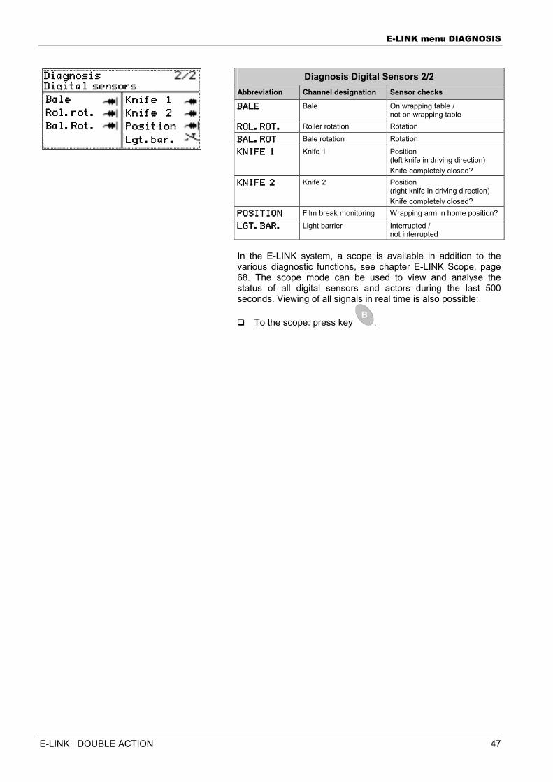
Diagnosis Digital Sensors 2/2
Abbreviation Channel designation Sensor checks
BALEBALEBALEBALE Bale On wrapping table / not on wrapping table
ROL.ROT.ROL.ROT.ROL.ROT.ROL.ROT. Roller rotation Rotation BAL.ROTBAL.ROTBAL.ROTBAL.ROT Bale rotation Rotation
KNIFE 1KNIFE 1KNIFE 1KNIFE 1 Knife 1 Position (left knife in driving direction) Knife completely closed?
KNIFE 2KNIFE 2KNIFE 2KNIFE 2 Knife 2 Position (right knife in driving direction) Knife completely closed?
POSITIONPOSITIONPOSITIONPOSITION Film break monitoring Wrapping arm in home position?
LGT.BAR.LGT.BAR.LGT.BAR.LGT.BAR. Light barrier Interrupted / not interrupted
In the E-LINK system, a scope is available in addition to the various diagnostic functions, see chapter E-LINK Scope, page 68. The scope mode can be used to view and analyse the status of all digital sensors and actors during the last 500 seconds. Viewing of all signals in real time is also possible:
� To the scope: press key .
DiagnosisDiagnosisDiagnosisDiagnosis Digital sensorsDigital sensorsDigital sensorsDigital sensors Bale Bale Bale Bale
RoRoRoRol.rot.l.rot.l.rot.l.rot.
Bal.Rot.Bal.Rot.Bal.Rot.Bal.Rot.
Knife 1Knife 1Knife 1Knife 1
Knife 2Knife 2Knife 2Knife 2
PositionPositionPositionPosition
Lgt.bar.Lgt.bar.Lgt.bar.Lgt.bar.
E-LINK menu DIAGNOSIS
48 E-LINK DOUBLE ACTION
Standard diagnosis – Analog sensors
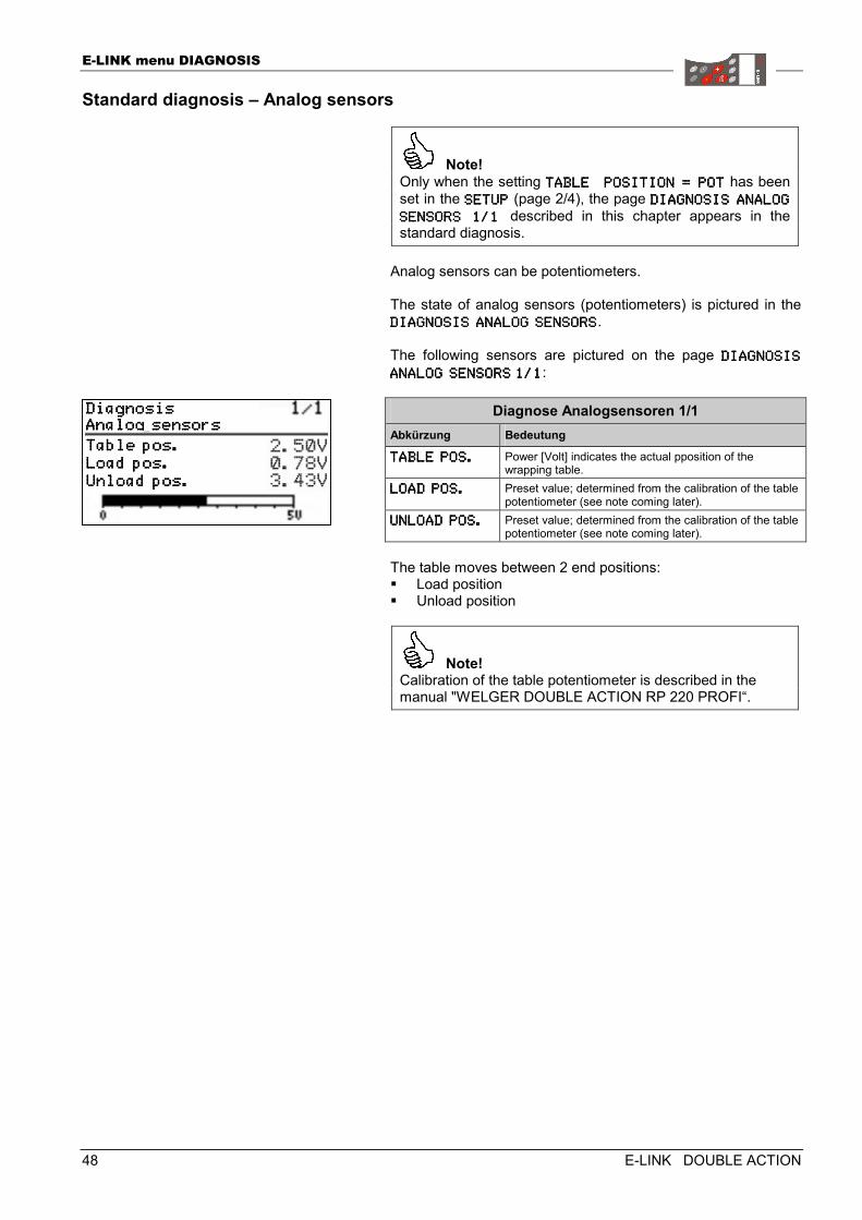
Note! Only when the setting TABLE POSITION = POTABLE POSITION = POTABLE POSITION = POTABLE POSITION = POTTTT has been set in the SETUPSETUPSETUPSETUP (page 2/4), the page DIAGNOSIS ANALOG DIAGNOSIS ANALOG DIAGNOSIS ANALOG DIAGNOSIS ANALOG
SENSORS 1/1 SENSORS 1/1 SENSORS 1/1 SENSORS 1/1 described in this chapter appears in the standard diagnosis.
Analog sensors can be potentiometers. The state of analog sensors (potentiometers) is pictured in the DIAGNOSIS ANALOG SENDIAGNOSIS ANALOG SENDIAGNOSIS ANALOG SENDIAGNOSIS ANALOG SENSORSSORSSORSSORS. The following sensors are pictured on the page DIAGNOSIS DIAGNOSIS DIAGNOSIS DIAGNOSIS
ANALOG SENSANALOG SENSANALOG SENSANALOG SENSORSORSORSORS 1/11/11/11/1:
Diagnose Analogsensoren 1/1 Abkürzung Bedeutung
TABLE POS.TABLE POS.TABLE POS.TABLE POS. Power [Volt] indicates the actual pposition of the wrapping table.
LOAD POS.LOAD POS.LOAD POS.LOAD POS. Preset value; determined from the calibration of the table potentiometer (see note coming later).
UNLOAD UNLOAD UNLOAD UNLOAD POS.POS.POS.POS. Preset value; determined from the calibration of the table potentiometer (see note coming later).
The table moves between 2 end positions: � Load position � Unload position
Note! Calibration of the table potentiometer is described in the manual "WELGER DOUBLE ACTION RP 220 PROFI“.
DiagnosisDiagnosisDiagnosisDiagnosis Analog sensorsAnalog sensorsAnalog sensorsAnalog sensors Table pos.Table pos.Table pos.Table pos. Load pos.Load pos.Load pos.Load pos. Unload pos.Unload pos.Unload pos.Unload pos.
E-LINK menu DIAGNOSIS
E-LINK DOUBLE ACTION 49
Standard diagnosis – Actors
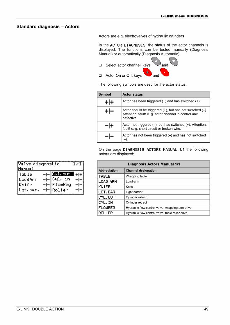
Actors are e.g. electrovalves of hydraulic cylinders In the ACTOR DIAGNOSISACTOR DIAGNOSISACTOR DIAGNOSISACTOR DIAGNOSIS, the status of the actor channels is displayed. The functions can be tested manually (Diagnosis Manual) or automatically (Diagnosis Automatic):
� Select actor channel: keys and
� Actor On or Off: keys and The following symbols are used for the actor status: Symbol Actor status
Actor has been triggered (+) and has switched (+).
Actor should be triggered (+), but has not switched (–). Attention, fault! e. g. actor channel in control unit defective.
Actor not triggered (–), but has switched (+). Attention, fault! e. g. short circuit or broken wire.
Actor has not been triggered (–) and has not switched (–).
On the page DIAGNOSIS ACTORS MANDIAGNOSIS ACTORS MANDIAGNOSIS ACTORS MANDIAGNOSIS ACTORS MANUALUALUALUAL 1/1 the following actors are displayed:
Diagnosis Actors Manual 1/1 Abbreviation Channel designation
TABLETABLETABLETABLE Wrapping table
LOAD ARMLOAD ARMLOAD ARMLOAD ARM Load-arm
KNIFEKNIFEKNIFEKNIFE Knife
LGT.BARLGT.BARLGT.BARLGT.BAR Light barrier
CYL.OUTCYL.OUTCYL.OUTCYL.OUT Cylinder extend
CYL.CYL.CYL.CYL.ININININ Cylinder retract
FLOWREGFLOWREGFLOWREGFLOWREG Hydraulic flow control valve, wrapping arm drive
ROLLERROLLERROLLERROLLER Hydraulic flow control valve, table roller drive
Valve diagnosticValve diagnosticValve diagnosticValve diagnostic ManualManualManualManual Table Table Table Table
LoadArmLoadArmLoadArmLoadArm
KnifeKnifeKnifeKnife
Lgt.bar.Lgt.bar.Lgt.bar.Lgt.bar.
Cyl. inCyl. inCyl. inCyl. in
FlowRegFlowRegFlowRegFlowReg
RollerRollerRollerRoller
Cyl.outCyl.outCyl.outCyl.out
E-LINK menu DIAGNOSIS
50 E-LINK DOUBLE ACTION
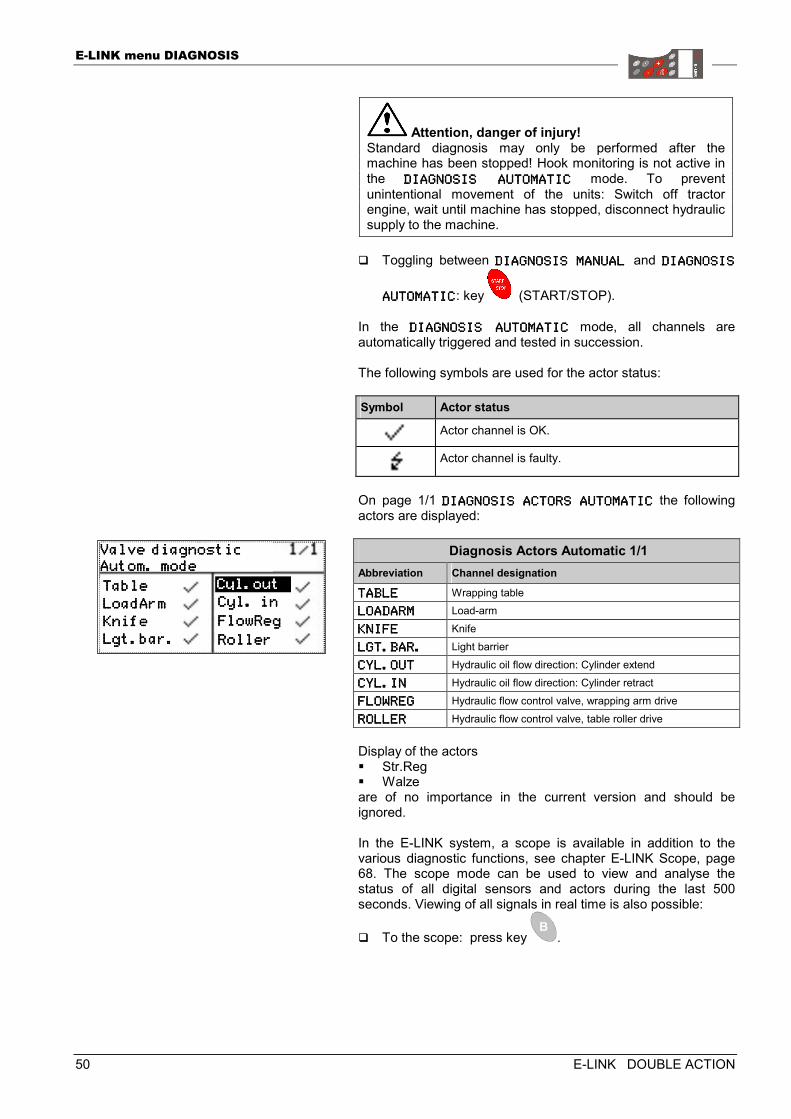
Attention, danger of injury! Standard diagnosis may only be performed after the machine has been stopped! Hook monitoring is not active in the DIAGNOSIS AUTOMATICDIAGNOSIS AUTOMATICDIAGNOSIS AUTOMATICDIAGNOSIS AUTOMATIC mode. To prevent unintentional movement of the units: Switch off tractor engine, wait until machine has stopped, disconnect hydraulic supply to the machine.
� Toggling between DIAGNOSIS MANUAL DIAGNOSIS MANUAL DIAGNOSIS MANUAL DIAGNOSIS MANUAL and DIAGNOSIS DIAGNOSIS DIAGNOSIS DIAGNOSIS
AUTAUTAUTAUTOMATICOMATICOMATICOMATIC: key (START/STOP). In the DIAGNOSIS AUTOMATICDIAGNOSIS AUTOMATICDIAGNOSIS AUTOMATICDIAGNOSIS AUTOMATIC mode, all channels are automatically triggered and tested in succession. The following symbols are used for the actor status: Symbol Actor status
Actor channel is OK.
Actor channel is faulty.
On page 1/1 DIAGNOSIS ACTORS AUTDIAGNOSIS ACTORS AUTDIAGNOSIS ACTORS AUTDIAGNOSIS ACTORS AUTOMATICOMATICOMATICOMATIC the following actors are displayed:
Diagnosis Actors Automatic 1/1 Abbreviation Channel designation
TABLETABLETABLETABLE Wrapping table LOADARMLOADARMLOADARMLOADARM Load-arm
KNIFEKNIFEKNIFEKNIFE Knife
LGT.BAR.LGT.BAR.LGT.BAR.LGT.BAR. Light barrier
CYL.OUTCYL.OUTCYL.OUTCYL.OUT Hydraulic oil flow direction: Cylinder extend
CYL.INCYL.INCYL.INCYL.IN Hydraulic oil flow direction: Cylinder retract
FLOWREGFLOWREGFLOWREGFLOWREG Hydraulic flow control valve, wrapping arm drive
ROLLERROLLERROLLERROLLER Hydraulic flow control valve, table roller drive Display of the actors � Str.Reg � Walze are of no importance in the current version and should be ignored. In the E-LINK system, a scope is available in addition to the various diagnostic functions, see chapter E-LINK Scope, page 68. The scope mode can be used to view and analyse the status of all digital sensors and actors during the last 500 seconds. Viewing of all signals in real time is also possible:
� To the scope: press key .
Valve diagnosticValve diagnosticValve diagnosticValve diagnostic Autom. modeAutom. modeAutom. modeAutom. mode
Table Table Table Table
LoadArmLoadArmLoadArmLoadArm
KnifeKnifeKnifeKnife
Lgt.bar.Lgt.bar.Lgt.bar.Lgt.bar.
Cyl. inCyl. inCyl. inCyl. in
FlowRegFlowRegFlowRegFlowReg
RollerRollerRollerRoller
Cyl.outCyl.outCyl.outCyl.out
E-LINK menu DIAGNOSIS
E-LINK DOUBLE ACTION 51
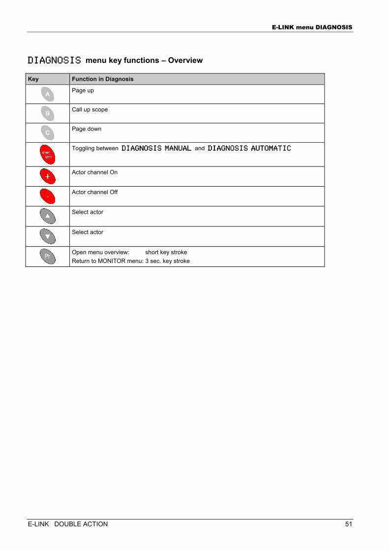
DIAGNOSIS DIAGNOSIS DIAGNOSIS DIAGNOSIS menu key functions – Overview
Key Function in Diagnosis
Page up
Call up scope
Page down
Toggling between DIAGNOSIS MANUAL DIAGNOSIS MANUAL DIAGNOSIS MANUAL DIAGNOSIS MANUAL and DIAGNOSIS AUTOMATICDIAGNOSIS AUTOMATICDIAGNOSIS AUTOMATICDIAGNOSIS AUTOMATIC
Actor channel On
Actor channel Off
Select actor
Select actor
Open menu overview: short key stroke Return to MONITOR menu: 3 sec. key stroke
E-LINK menu STATISTICS
52 E-LINK DOUBLE ACTION
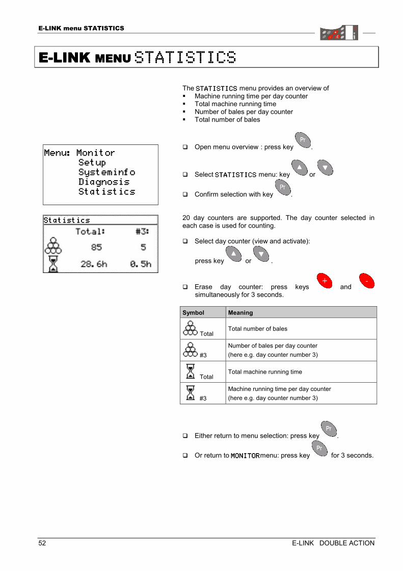
EEEE----LINK LINK LINK LINK MENU MENU MENU MENU STATISTICSSTATISTICSSTATISTICSSTATISTICS
The STATISTICSSTATISTICSSTATISTICSSTATISTICS menu provides an overview of � Machine running time per day counter � Total machine running time � Number of bales per day counter � Total number of bales
� Open menu overview : press key .
� Select STATISTICSSTATISTICSSTATISTICSSTATISTICS menu: key or
� Confirm selection with key .
20 day counters are supported. The day counter selected in each case is used for counting. � Select day counter (view and activate):
press key or .
� Erase day counter: press keys and simultaneously for 3 seconds.
Symbol Meaning
Total Total number of bales
#3 Number of bales per day counter (here e.g. day counter number 3)
Total Total machine running time
#3 Machine running time per day counter (here e.g. day counter number 3)
� Either return to menu selection: press key .
� Or return to MONITORMONITORMONITORMONITORmenu: press key for 3 seconds.
Menu: MonitorMenu: MonitorMenu: MonitorMenu: Monitor Setup Setup Setup Setup Systeminfo Systeminfo Systeminfo Systeminfo Diagnosis Diagnosis Diagnosis Diagnosis Statistics Statistics Statistics Statistics
StatisticsStatisticsStatisticsStatistics
E-LINK menu STATISTICS
E-LINK DOUBLE ACTION 53
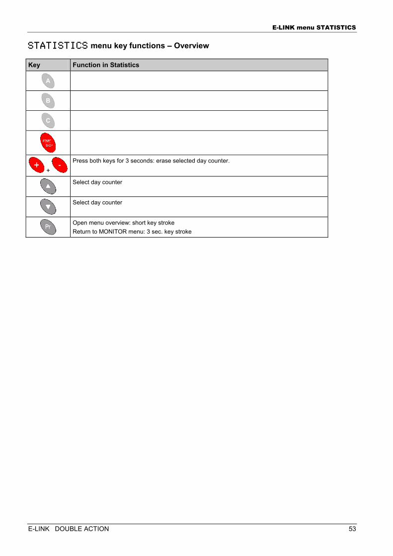
STATISTICSSTATISTICSSTATISTICSSTATISTICS menu key functions – Overview
Key Function in Statistics
+ Press both keys for 3 seconds: erase selected day counter.
Select day counter
Select day counter
Open menu overview: short key stroke Return to MONITOR menu: 3 sec. key stroke
E-LINK error messages
54 E-LINK DOUBLE ACTION
EEEE----LINK LINK LINK LINK ERROR MESSAGESERROR MESSAGESERROR MESSAGESERROR MESSAGES
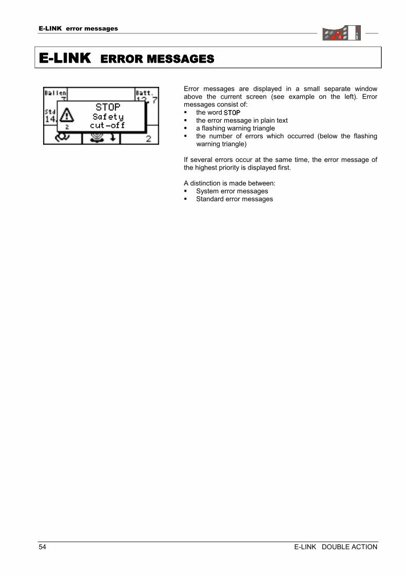
Error messages are displayed in a small separate window above the current screen (see example on the left). Error messages consist of: � the word STOPSTOPSTOPSTOP � the error message in plain text � a flashing warning triangle � the number of errors which occurred (below the flashing
warning triangle) If several errors occur at the same time, the error message of the highest priority is displayed first. A distinction is made between: � System error messages � Standard error messages
STOPSTOPSTOPSTOP Safety Safety Safety Safety cutcutcutcut----offoffoffoff
E-LINK error messages
E-LINK DOUBLE ACTION 55
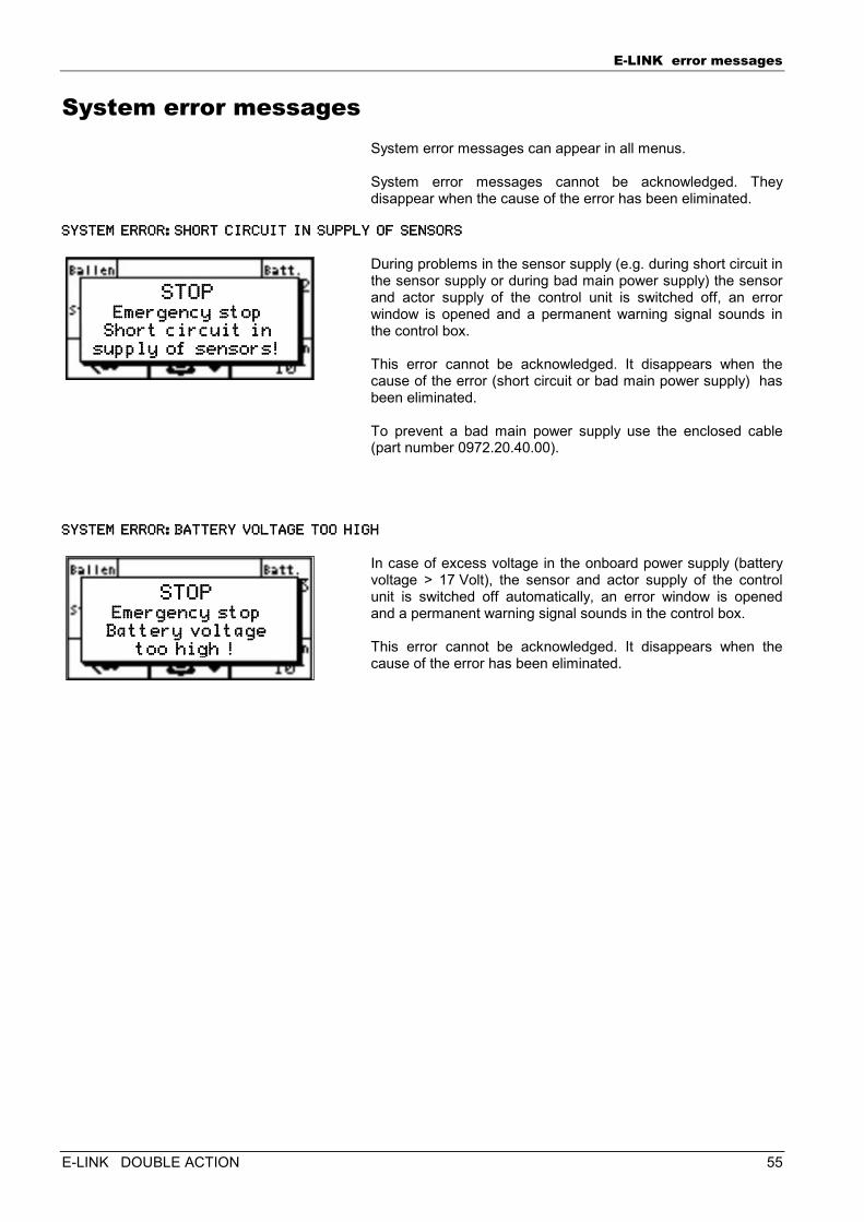
System error messages System error messages can appear in all menus. System error messages cannot be acknowledged. They disappear when the cause of the error has been eliminated.
SYSTEM ERROR:SHORT CSYSTEM ERROR:SHORT CSYSTEM ERROR:SHORT CSYSTEM ERROR:SHORT CIRCUIT IN SUPPLY OF IRCUIT IN SUPPLY OF IRCUIT IN SUPPLY OF IRCUIT IN SUPPLY OF SENSORSSENSORSSENSORSSENSORS
During problems in the sensor supply (e.g. during short circuit in the sensor supply or during bad main power supply) the sensor and actor supply of the control unit is switched off, an error window is opened and a permanent warning signal sounds in the control box. This error cannot be acknowledged. It disappears when the cause of the error (short circuit or bad main power supply) has been eliminated. To prevent a bad main power supply use the enclosed cable (part number 0972.20.40.00).
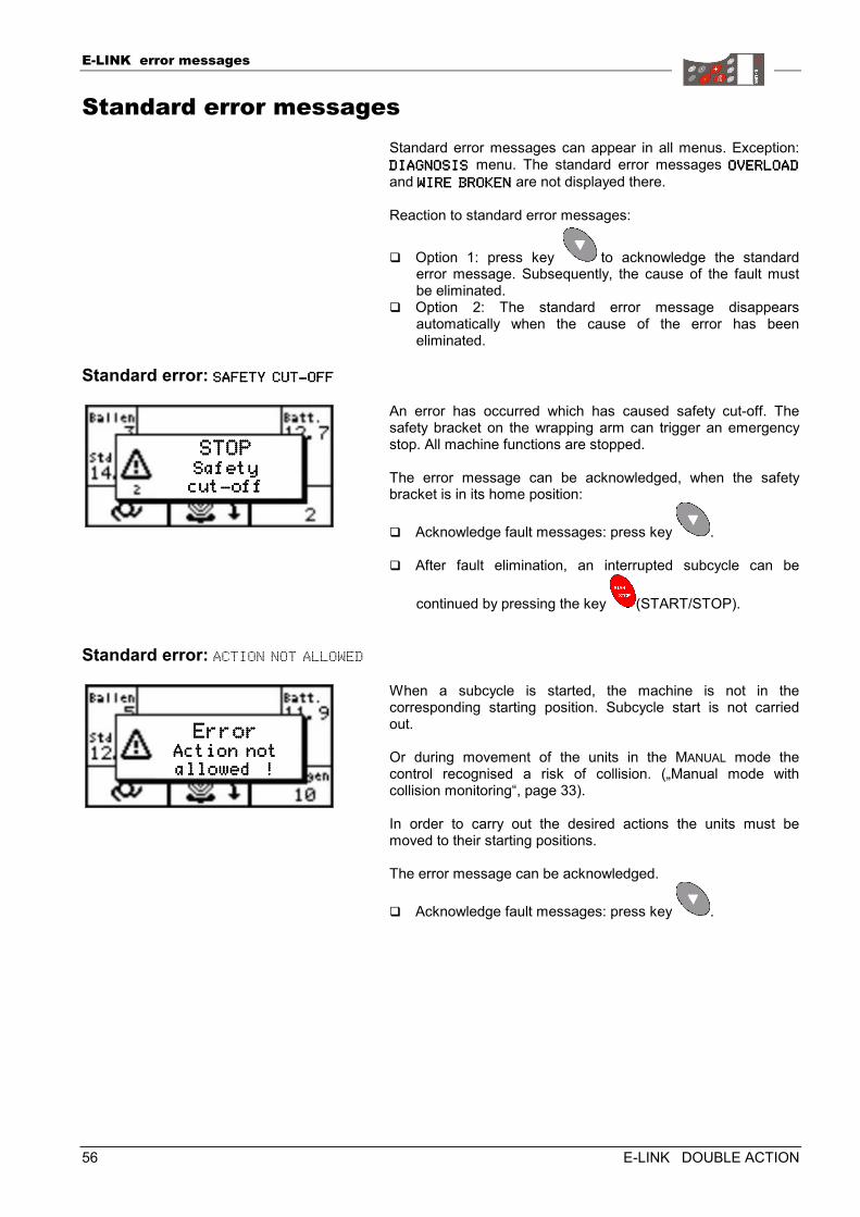
SYSTEM ERROR:BATTERYSYSTEM ERROR:BATTERYSYSTEM ERROR:BATTERYSYSTEM ERROR:BATTERY VOLTAGE TOO HIGH VOLTAGE TOO HIGH VOLTAGE TOO HIGH VOLTAGE TOO HIGH
In case of excess voltage in the onboard power supply (battery voltage > 17 Volt), the sensor and actor supply of the control unit is switched off automatically, an error window is opened and a permanent warning signal sounds in the control box. This error cannot be acknowledged. It disappears when the cause of the error has been eliminated.
STOPSTOPSTOPSTOP Emergency stopEmergency stopEmergency stopEmergency stop
Short circuit inShort circuit inShort circuit inShort circuit in supply of sensors!supply of sensors!supply of sensors!supply of sensors!
STOPSTOPSTOPSTOP Emergency stopEmergency stopEmergency stopEmergency stop Battery voltageBattery voltageBattery voltageBattery voltage
too high !too high !too high !too high !
E-LINK error messages
56 E-LINK DOUBLE ACTION
Standard error messages Standard error messages can appear in all menus. Exception: DIAGNOSISDIAGNOSISDIAGNOSISDIAGNOSIS menu. The standard error messages OVERLOADOVERLOADOVERLOADOVERLOAD and WIRE BROKENWIRE BROKENWIRE BROKENWIRE BROKEN are not displayed there. Reaction to standard error messages:
� Option 1: press key to acknowledge the standard error message. Subsequently, the cause of the fault must be eliminated.
� Option 2: The standard error message disappears automatically when the cause of the error has been eliminated.
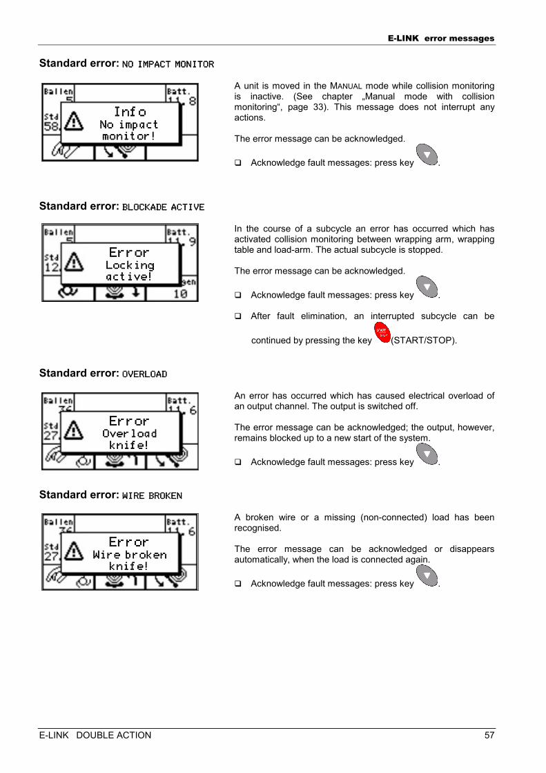
Standard error: SAFETY CUTSAFETY CUTSAFETY CUTSAFETY CUT----OFFOFFOFFOFF
An error has occurred which has caused safety cut-off. The safety bracket on the wrapping arm can trigger an emergency stop. All machine functions are stopped. The error message can be acknowledged, when the safety bracket is in its home position:
� Acknowledge fault messages: press key . � After fault elimination, an interrupted subcycle can be
continued by pressing the key (START/STOP).
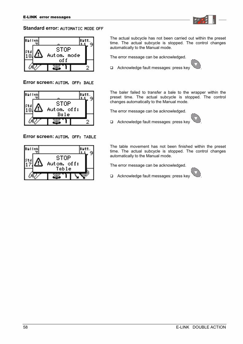
Standard error: ACTION NOT ALLOWED
When a subcycle is started, the machine is not in the corresponding starting position. Subcycle start is not carried out. Or during movement of the units in the MANUAL mode the control recognised a risk of collision. („Manual mode with collision monitoring“, page 33). In order to carry out the desired actions the units must be moved to their starting positions. The error message can be acknowledged.
� Acknowledge fault messages: press key .
STOPSTOPSTOPSTOP Safety Safety Safety Safety cutcutcutcut----offoffoffoff
ErrorErrorErrorError Action notAction notAction notAction not allowed !allowed !allowed !allowed !
E-LINK error messages
E-LINK DOUBLE ACTION 57
Standard error: NO IMPACT MONITORNO IMPACT MONITORNO IMPACT MONITORNO IMPACT MONITOR
A unit is moved in the MANUAL mode while collision monitoring is inactive. (See chapter „Manual mode with collision monitoring“, page 33). This message does not interrupt any actions. The error message can be acknowledged.
� Acknowledge fault messages: press key .
Standard error: BLOCKADE ACTIVEBLOCKADE ACTIVEBLOCKADE ACTIVEBLOCKADE ACTIVE
In the course of a subcycle an error has occurred which has activated collision monitoring between wrapping arm, wrapping table and load-arm. The actual subcycle is stopped. The error message can be acknowledged.
� Acknowledge fault messages: press key . � After fault elimination, an interrupted subcycle can be
continued by pressing the key (START/STOP).
Standard error: OVERLOADOVERLOADOVERLOADOVERLOAD
An error has occurred which has caused electrical overload of an output channel. The output is switched off. The error message can be acknowledged; the output, however, remains blocked up to a new start of the system.
� Acknowledge fault messages: press key .
Standard error: WIRE BROKENWIRE BROKENWIRE BROKENWIRE BROKEN
A broken wire or a missing (non-connected) load has been recognised.
The error message can be acknowledged or disappears automatically, when the load is connected again.
� Acknowledge fault messages: press key .
InfoInfoInfoInfo No impact No impact No impact No impact monitor!monitor!monitor!monitor!
ErrorErrorErrorError Locking Locking Locking Locking active!active!active!active!
ErrorErrorErrorError Overload Overload Overload Overload knife!knife!knife!knife!
ErrorErrorErrorError Wire brokenWire brokenWire brokenWire broken
knife!knife!knife!knife!
E-LINK error messages
58 E-LINK DOUBLE ACTION
Standard error: AUTOMATIC MODE OFFAUTOMATIC MODE OFFAUTOMATIC MODE OFFAUTOMATIC MODE OFF
The actual subcycle has not been carried out within the preset time. The actual subcycle is stopped. The control changes automatically to the Manual mode. The error message can be acknowledged.
� Acknowledge fault messages: press key .
Error screen: AUTOM. OFF: BALEAUTOM. OFF: BALEAUTOM. OFF: BALEAUTOM. OFF: BALE
The baler failed to transfer a bale to the wrapper within the preset time. The actual subcycle is stopped. The control changes automatically to the Manual mode. The error message can be acknowledged.
� Acknowledge fault messages: press key .
Error screen: AUTOM. OFF:AUTOM. OFF:AUTOM. OFF:AUTOM. OFF: TABLE TABLE TABLE TABLE
The table movement has not been finished within the preset time. The actual subcycle is stopped. The control changes automatically to the Manual mode. The error message can be acknowledged.
� Acknowledge fault messages: press key .
STOPSTOPSTOPSTOP Autom. mode Autom. mode Autom. mode Autom. mode
offoffoffoff
STOPSTOPSTOPSTOP Autom. off: Autom. off: Autom. off: Autom. off:
BaleBaleBaleBale
STOPSTOPSTOPSTOP Autom. off: Autom. off: Autom. off: Autom. off:
TableTableTableTable
E-LINK error messages
E-LINK DOUBLE ACTION 59
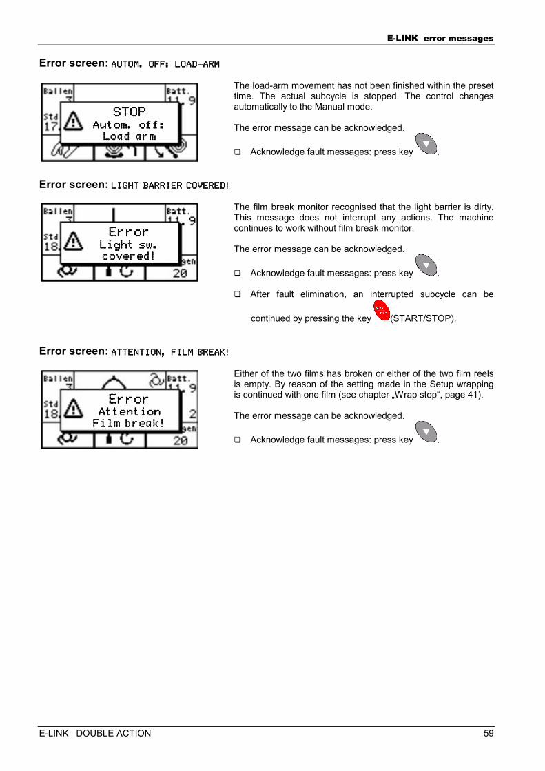
Error screen: AUTOM. OFF: LOADAUTOM. OFF: LOADAUTOM. OFF: LOADAUTOM. OFF: LOAD----ARMARMARMARM
The load-arm movement has not been finished within the preset time. The actual subcycle is stopped. The control changes automatically to the Manual mode. The error message can be acknowledged.
� Acknowledge fault messages: press key .
Error screen: LIGHT BARRIER COVERELIGHT BARRIER COVERELIGHT BARRIER COVERELIGHT BARRIER COVERED!D!D!D!
The film break monitor recognised that the light barrier is dirty. This message does not interrupt any actions. The machine continues to work without film break monitor. The error message can be acknowledged.
� Acknowledge fault messages: press key . � After fault elimination, an interrupted subcycle can be
continued by pressing the key (START/STOP).
Error screen: ATTENTION, FILM BREAATTENTION, FILM BREAATTENTION, FILM BREAATTENTION, FILM BREAK!K!K!K!
Either of the two films has broken or either of the two film reels is empty. By reason of the setting made in the Setup wrapping is continued with one film (see chapter „Wrap stop“, page 41). The error message can be acknowledged.
� Acknowledge fault messages: press key .
STOPSTOPSTOPSTOP Autom. off: Autom. off: Autom. off: Autom. off:
Load armLoad armLoad armLoad arm
ErrorErrorErrorError Light sw. Light sw. Light sw. Light sw. covered!covered!covered!covered!
ErrorErrorErrorError Attention Attention Attention Attention
Film break!Film break!Film break!Film break!
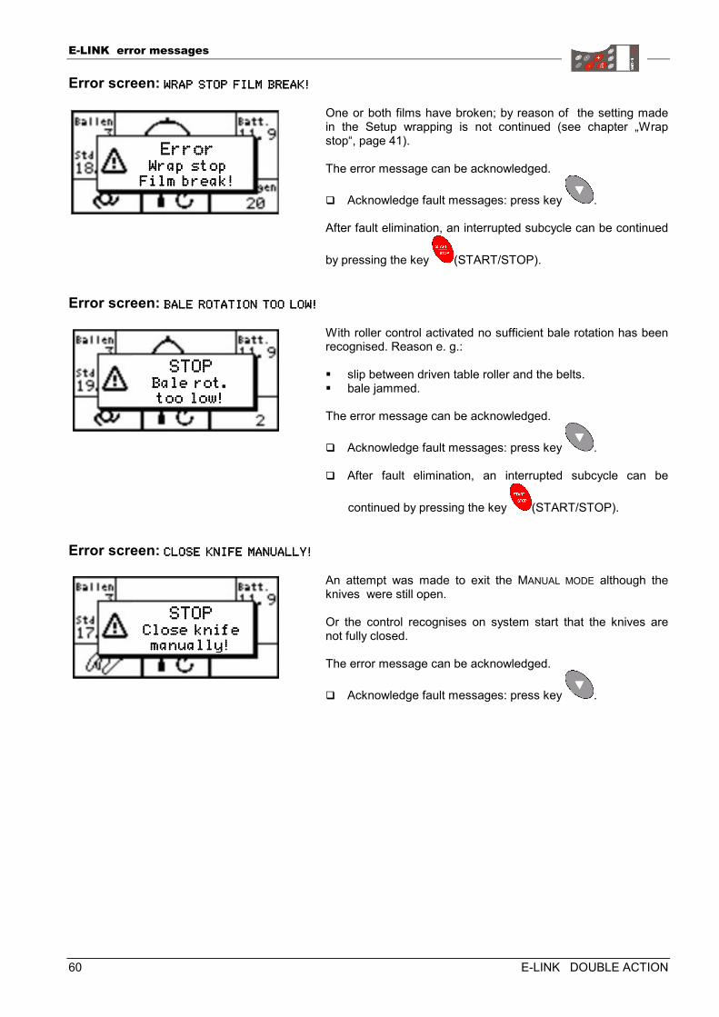
E-LINK error messages
60 E-LINK DOUBLE ACTION
Error screen: WRAP STOP FILM BREAKWRAP STOP FILM BREAKWRAP STOP FILM BREAKWRAP STOP FILM BREAK!!!!
One or both films have broken; by reason of the setting made in the Setup wrapping is not continued (see chapter „Wrap stop“, page 41). The error message can be acknowledged.
� Acknowledge fault messages: press key . After fault elimination, an interrupted subcycle can be continued
by pressing the key (START/STOP).
Error screen: BALE ROTATION TOO LOBALE ROTATION TOO LOBALE ROTATION TOO LOBALE ROTATION TOO LOW!W!W!W!
With roller control activated no sufficient bale rotation has been recognised. Reason e. g.: � slip between driven table roller and the belts. � bale jammed. The error message can be acknowledged.
� Acknowledge fault messages: press key . � After fault elimination, an interrupted subcycle can be
continued by pressing the key (START/STOP).
Error screen: CLOSE KNIFE MANUALLYCLOSE KNIFE MANUALLYCLOSE KNIFE MANUALLYCLOSE KNIFE MANUALLY!!!!
An attempt was made to exit the MANUAL MODE although the knives were still open. Or the control recognises on system start that the knives are not fully closed. The error message can be acknowledged.
� Acknowledge fault messages: press key .
ErrorErrorErrorError Wrap stop Wrap stop Wrap stop Wrap stop
Film break!Film break!Film break!Film break!
STOPSTOPSTOPSTOP Bale rot.Bale rot.Bale rot.Bale rot. too low!too low!too low!too low!
STOPSTOPSTOPSTOP Close knife Close knife Close knife Close knife manually!manually!manually!manually!

E-LINK error messages
E-LINK DOUBLE ACTION 61
E-LINK error messages
62 E-LINK DOUBLE ACTION
The following chapters are intended exclusively for trained and instructed service personnel!
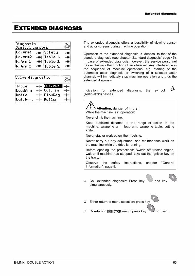
Extended diagnosis
E-LINK DOUBLE ACTION 63
EEEEXTENDED DIAGNOSISXTENDED DIAGNOSISXTENDED DIAGNOSISXTENDED DIAGNOSIS
The extended diagnosis offers a possibility of viewing sensor and actor screens during machine operation. Operation of the extended diagnosis is identical to that of the standard diagnosis (see chapter „Standard diagnosis“ page 45). In case of extended diagnosis, however, the service personnel has exclusively the function of an observer. Any interference in the sequence of machine operations, e.g. starting of the automatic actor diagnosis or switching of a selected actor channel, will immediately stop machine operation and thus the extended diagnosis.
Indication for extended diagnosis: the symbol (AUTOMATIC) flashes.
Attention, danger of injury! While the machine is in operation:
Never climb the machine.
Keep sufficient distance to the range of action of the machine: wrapping arm, load-arm, wrapping table, cutting knife.
Never stay or work below the machine.
Never carry out any adjustment and maintenance work on the machine while the drive is running.
Before opening the protections: Switch off tractor engine, wait until machine has stopped, take out the ignition key on the tractor.
Observe the safety instructions, chapter "General Information", page 9.
� Call extended diagnosis: Press key and key simultaneously.
� Either return to menu selection: press key .
� Or return to MONITORMONITORMONITORMONITOR menu: press key for 3 sec.
DiagnosisDiagnosisDiagnosisDiagnosis Digital sensorsDigital sensorsDigital sensorsDigital sensors Ld.Arm1Ld.Arm1Ld.Arm1Ld.Arm1
Ld.Arm2Ld.Arm2Ld.Arm2Ld.Arm2
W.Arm 1W.Arm 1W.Arm 1W.Arm 1
W.Arm 2W.Arm 2W.Arm 2W.Arm 2
SafetySafetySafetySafety
Table 1.Table 1.Table 1.Table 1.
Table 2.Table 2.Table 2.Table 2.
Table 3.Table 3.Table 3.Table 3.
Valve diagnosticValve diagnosticValve diagnosticValve diagnostic
Table Table Table Table
LoadArmLoadArmLoadArmLoadArm
KnifeKnifeKnifeKnife
Lgt.bar.Lgt.bar.Lgt.bar.Lgt.bar.
Cyl. inCyl. inCyl. inCyl. in
FlowRegFlowRegFlowRegFlowReg
RollerRollerRollerRoller
Cyl.outCyl.outCyl.outCyl.out
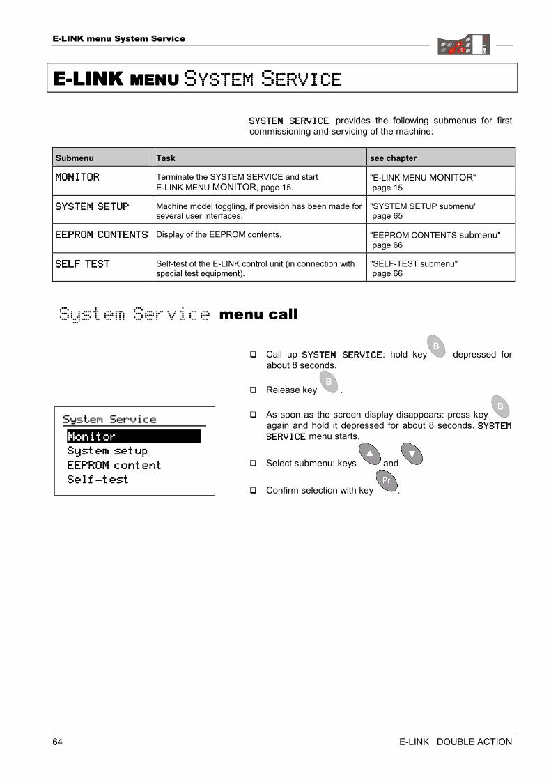
E-LINK menu System Service
64 E-LINK DOUBLE ACTION
EEEE----LINK LINK LINK LINK MENU MENU MENU MENU SSSSYSTEMYSTEMYSTEMYSTEM SSSSERVICEERVICEERVICEERVICE
SYSTEM SERVICE SYSTEM SERVICE SYSTEM SERVICE SYSTEM SERVICE provides the following submenus for first commissioning and servicing of the machine:
Submenu Task see chapter
MONITORMONITORMONITORMONITOR Terminate the SYSTEM SERVICE and start E-LINK MENU MONITOR, page 15.
"E-LINK MENU MONITOR" page 15
SYSTEM SETUPSYSTEM SETUPSYSTEM SETUPSYSTEM SETUP Machine model toggling, if provision has been made for several user interfaces.
"SYSTEM SETUP submenu" page 65
EEPROM CONTENTSEEPROM CONTENTSEEPROM CONTENTSEEPROM CONTENTS Display of the EEPROM contents. "EEPROM CONTENTS submenu" page 66
SELF TESTSELF TESTSELF TESTSELF TEST Self-test of the E-LINK control unit (in connection with special test equipment).
"SELF-TEST submenu" page 66
System Service menu call
� Call up SYSTEM SERVICESYSTEM SERVICESYSTEM SERVICESYSTEM SERVICE: hold key depressed for about 8 seconds.
� Release key .
� As soon as the screen display disappears: press key again and hold it depressed for about 8 seconds. SYSTEM SYSTEM SYSTEM SYSTEM
SERVICESERVICESERVICESERVICE menu starts.
� Select submenu: keys and
� Confirm selection with key .
System setup System setup System setup System setup
EEPROM coEEPROM coEEPROM coEEPROM connnntenttenttenttent
SelSelSelSelffff----testtesttesttest
MonitorMonitorMonitorMonitor
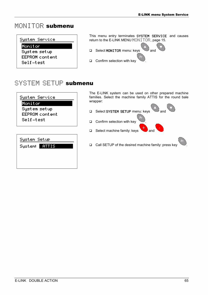
E-LINK menu System Service
E-LINK DOUBLE ACTION 65
MONITOR submenu This menu entry terminates SYSTEM SERVICE SYSTEM SERVICE SYSTEM SERVICE SYSTEM SERVICE and causes return to the E-LINK MENU MONITOR, page 15.
� Select MONITORMONITORMONITORMONITOR menu: keys and
� Confirm selection with key .
SYSTEM SETUP submenu The E-LINK system can be used on other prepared machine families. Select the machine family ATTIS for the round bale wrapper:
� Select SYSTEM SETUPSYSTEM SETUPSYSTEM SETUPSYSTEM SETUP menu: keys and
� Confirm selection with key .
� Select machine family: keys and
� Call SETUP of the desired machine family: press key .
System setup System setup System setup System setup
EEPROM coEEPROM coEEPROM coEEPROM connnntenttenttenttent
SelfSelfSelfSelf----testtesttesttest
MonitorMonitorMonitorMonitor
System setup System setup System setup System setup
EEPROM coEEPROM coEEPROM coEEPROM connnntenttenttenttent
SelfSelfSelfSelf----testtesttesttest
MonitorMonitorMonitorMonitor
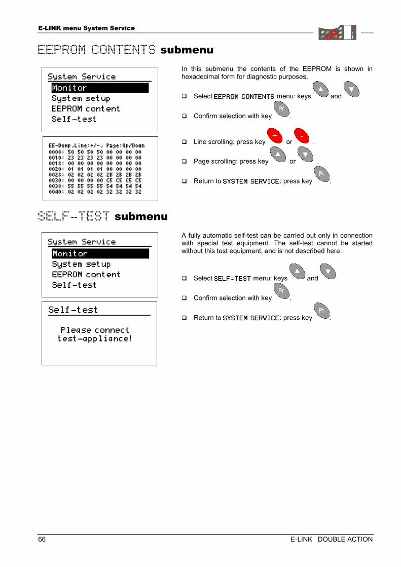
E-LINK menu System Service
66 E-LINK DOUBLE ACTION
EEPROM CONTENTS submenu In this submenu the contents of the EEPROM is shown in hexadecimal form for diagnostic purposes.
� Select EEPROM CONTENTSEEPROM CONTENTSEEPROM CONTENTSEEPROM CONTENTS menu: keys and
� Confirm selection with key .
� Line scrolling: press key or .
� Page scrolling: press key or .
� Return to SYSTEM SERVICESYSTEM SERVICESYSTEM SERVICESYSTEM SERVICE: press key .
SELF-TEST submenu A fully automatic self-test can be carried out only in connection with special test equipment. The self-test cannot be started without this test equipment, and is not described here.
� Select SELFSELFSELFSELF----TESTTESTTESTTEST menu: keys and
� Confirm selection with key .
� Return to SYSTEM SERVICESYSTEM SERVICESYSTEM SERVICESYSTEM SERVICE: press key .
System setup System setup System setup System setup
EEPROM coEEPROM coEEPROM coEEPROM connnntenttenttenttent
SelfSelfSelfSelf----testtesttesttest
MonitorMonitorMonitorMonitor
System sSystem sSystem sSystem setup etup etup etup
EEPROM coEEPROM coEEPROM coEEPROM connnntenttenttenttent
SelfSelfSelfSelf----testtesttesttest
MonitorMonitorMonitorMonitor
SelfSelfSelfSelf----testtesttesttest
Please connectPlease connectPlease connectPlease connect testtesttesttest----appliance!appliance!appliance!appliance!
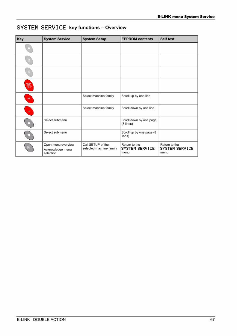
E-LINK menu System Service
E-LINK DOUBLE ACTION 67
SYSTEM SERVICE SYSTEM SERVICE SYSTEM SERVICE SYSTEM SERVICE key functions – Overview
Key System Service System Setup EEPROM contents Self test
Select machine family Scroll up by one line
Select machine family Scroll down by one line
Select submenu Scroll down by one page (8 lines)
Select submenu Scroll up by one page (8 lines)
Open menu overview Acknowledge menu selection
Call SETUP of the selected machine family
Return to the SYSTEM SERVICE SYSTEM SERVICE SYSTEM SERVICE SYSTEM SERVICE menu
Return to the SYSTEM SERVICE SYSTEM SERVICE SYSTEM SERVICE SYSTEM SERVICE menu
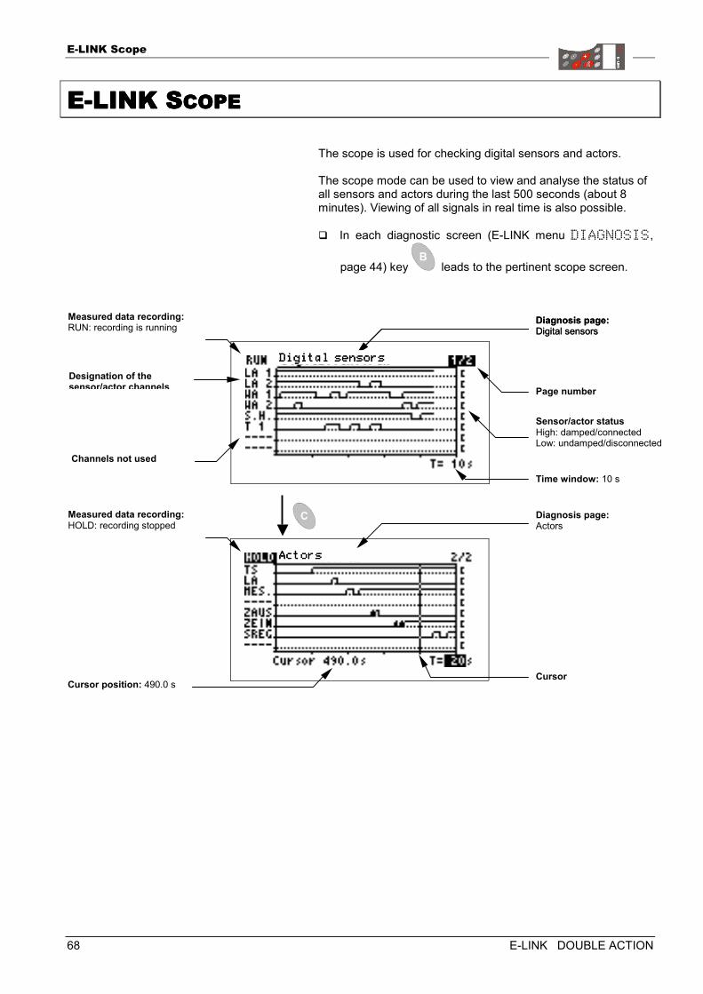
E-LINK Scope
68 E-LINK DOUBLE ACTION
EEEE----LINK SLINK SLINK SLINK SCOPECOPECOPECOPE
The scope is used for checking digital sensors and actors. The scope mode can be used to view and analyse the status of all sensors and actors during the last 500 seconds (about 8 minutes). Viewing of all signals in real time is also possible. � In each diagnostic screen (E-LINK menu DIAGNOSIS,
page 44) key leads to the pertinent scope screen.
Measured data recording: RUN: recording is running
Diagnosis page:Digital sensors
Channels not used
Sensor/actor statusHigh: damped/connected Low: undamped/disconnected
Diagnosis page:Digital sensors
Page number Designation of the sensor/actor channels
Time window: 10 s
Measured data recording: HOLD: recording stopped
Cursor position: 490.0 s
Diagnosis page:Actors
Cursor
Digital seDigital seDigital seDigital sennnnsorssorssorssors
ActorsActorsActorsActors
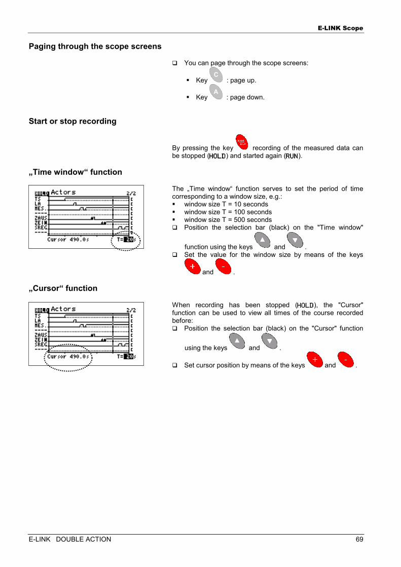
E-LINK Scope
E-LINK DOUBLE ACTION 69
Paging through the scope screens
� You can page through the scope screens:
� Key : page up.
� Key : page down.
Start or stop recording
By pressing the key recording of the measured data can be stopped (HOLDHOLDHOLDHOLD) and started again (RUNRUNRUNRUN).
„Time window“ function
The „Time window“ function serves to set the period of time corresponding to a window size, e.g.: � window size T = 10 seconds � window size T = 100 seconds � window size T = 500 seconds � Position the selection bar (black) on the "Time window"
function using the keys and . � Set the value for the window size by means of the keys
and .
„Cursor“ function
When recording has been stopped (HOLDHOLDHOLDHOLD), the "Cursor" function can be used to view all times of the course recorded before: � Position the selection bar (black) on the "Cursor" function
using the keys and .
� Set cursor position by means of the keys and .
ActorsActorsActorsActors ActorsActorsActorsActors
ActorsActorsActorsActors
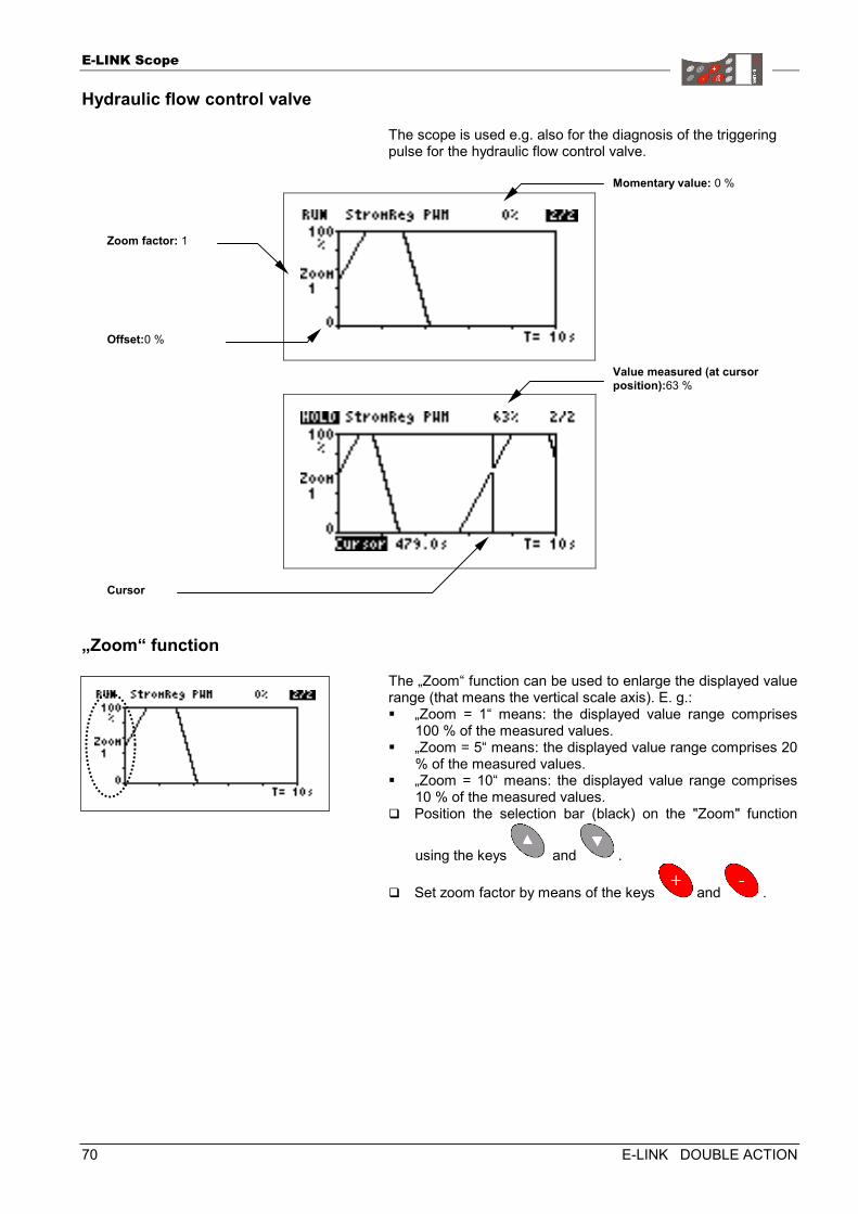
E-LINK Scope
70 E-LINK DOUBLE ACTION
Hydraulic flow control valve
The scope is used e.g. also for the diagnosis of the triggering pulse for the hydraulic flow control valve.
„Zoom“ function
The „Zoom“ function can be used to enlarge the displayed value range (that means the vertical scale axis). E. g.: � „Zoom = 1“ means: the displayed value range comprises
100 % of the measured values. � „Zoom = 5“ means: the displayed value range comprises 20
% of the measured values. � „Zoom = 10“ means: the displayed value range comprises
10 % of the measured values. � Position the selection bar (black) on the "Zoom" function
using the keys and .
� Set zoom factor by means of the keys and .
Value measured (at cursorposition):63 %
Cursor
Momentary value: 0 %
Offset:0 %
Zoom factor: 1
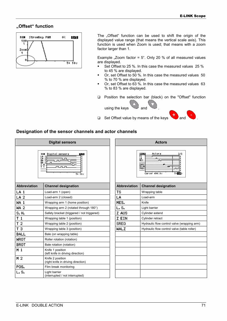
E-LINK Scope
E-LINK DOUBLE ACTION 71
„Offset“ function
The „Offset“ function can be used to shift the origin of the displayed value range (that means the vertical scale axis). This function is used when Zoom is used; that means with a zoom factor larger than 1. Example „Zoom factor = 5“. Only 20 % of all measured values are displayed. � Set Offset to 25 %. In this case the measured values 25 %
to 45 % are displayed. � Or, set Offset to 50 %. In this case the measured values 50
% to 70 % are displayed. � Or, set Offset to 63 %. In this case the measured values 63
% to 83 % are displayed.
� Position the selection bar (black) on the "Offset" function
using the keys and .
� Set Offset value by means of the keys and .
Designation of the sensor channels and actor channels
Digital sensors Actors
Abbreviation Channel designation Abbreviation Channel designation LA 1LA 1LA 1LA 1 Load-arm 1 (open) TSTSTSTS Wrapping table
LA 2LA 2LA 2LA 2 Load-arm 2 (closed) LALALALA Load-arm
WA 1WA 1WA 1WA 1 Wrapping arm 1 (home position) MES.MES.MES.MES. Knife
WA 2WA 2WA 2WA 2 Wrapping arm 2 (rotated through 180°) L.S.L.S.L.S.L.S. Light barrier
S.H.S.H.S.H.S.H. Safety bracket (triggered / not triggered) Z AUSZ AUSZ AUSZ AUS Cylinder extend
T 1T 1T 1T 1 Wrapping table 1 (position) Z EINZ EINZ EINZ EIN Cylinder retract
T 2T 2T 2T 2 Wrapping table 2 (position) SREGSREGSREGSREG Hydraulic flow control valve (wrapping arm)
T 3T 3T 3T 3 Wrapping table 3 (position) WALZWALZWALZWALZ Hydraulic flow control valve (table roller)
BALLBALLBALLBALL Bale (on wrapping table)
WROTWROTWROTWROT Roller rotation (rotation)
BROTBROTBROTBROT Bale rotation (rotation)
M 1M 1M 1M 1 Knife 1 position (left knife in driving direction)
M 2M 2M 2M 2 Knife 2 position (right knife in driving direction)
POS.POS.POS.POS. Film break monitoring
L.S.L.S.L.S.L.S. Light barrier (interrupted / not interrupted)
Digital seDigital seDigital seDigital sennnnsorssorssorssors ActorsActorsActorsActors
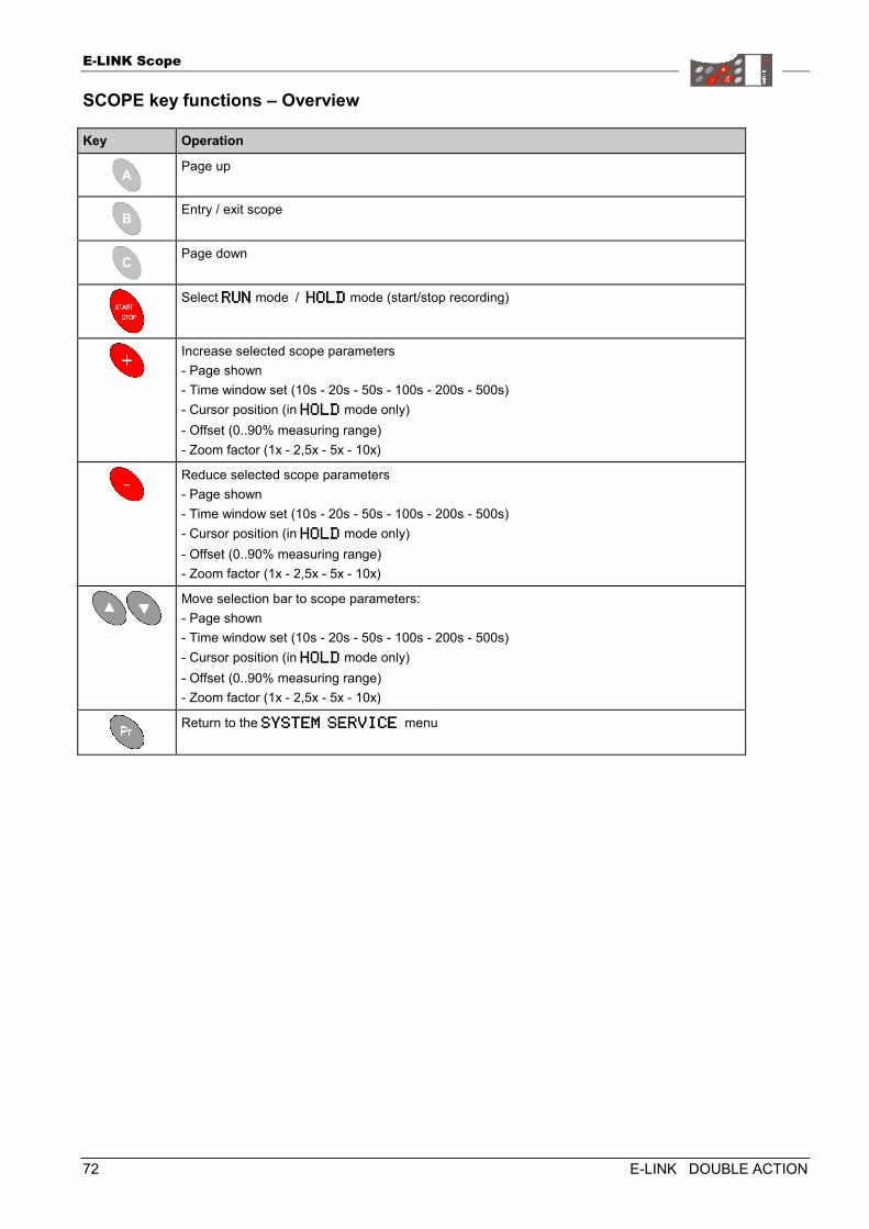
E-LINK Scope
72 E-LINK DOUBLE ACTION
SCOPE key functions – Overview
Key Operation
Page up
Entry / exit scope
Page down
Select RUNRUNRUNRUN mode / HOLDHOLDHOLDHOLD mode (start/stop recording)
Increase selected scope parameters - Page shown - Time window set (10s - 20s - 50s - 100s - 200s - 500s) - Cursor position (in HOLDHOLDHOLDHOLD mode only) - Offset (0..90% measuring range) - Zoom factor (1x - 2,5x - 5x - 10x)
Reduce selected scope parameters - Page shown - Time window set (10s - 20s - 50s - 100s - 200s - 500s) - Cursor position (in HOLDHOLDHOLDHOLD mode only) - Offset (0..90% measuring range) - Zoom factor (1x - 2,5x - 5x - 10x)
Move selection bar to scope parameters: - Page shown - Time window set (10s - 20s - 50s - 100s - 200s - 500s) - Cursor position (in HOLDHOLDHOLDHOLD mode only) - Offset (0..90% measuring range) - Zoom factor (1x - 2,5x - 5x - 10x)
Return to the SYSTEM SERVICE SYSTEM SERVICE SYSTEM SERVICE SYSTEM SERVICE menu
BALERCONTROL III
BALERCONTROL III DOUBLE ACTION 73
BALERCONTROL IIIBALERCONTROL IIIBALERCONTROL IIIBALERCONTROL III
General Information
Caution! Operation of the BALERCONTROL III on 24 V power supplies is not permissible.
Onboard voltage, machine: 12 V Fuse protection, machine side: 30 A
Caution! The housing of the BALERCONTROL III control box is moisture-repellent. Nevertheless: in order to avoid malfunctions, the control box must not be exposed to excessive moisture (e.g. heavy rain, splashing, steam-jet or high-pressure cleaning machine).
Caution! Prior to any assembly, adjustment and maintenance work, the E-LINK and BALERCONTROL III controls must be disconnected from power supply. interrupt electrical connection between tractor and machine. Switch off power take-off shaft. Switch off tractor engine and remove ignition key. Uncouple power take-off shaft of the machine from the drive shaft of the tractor.
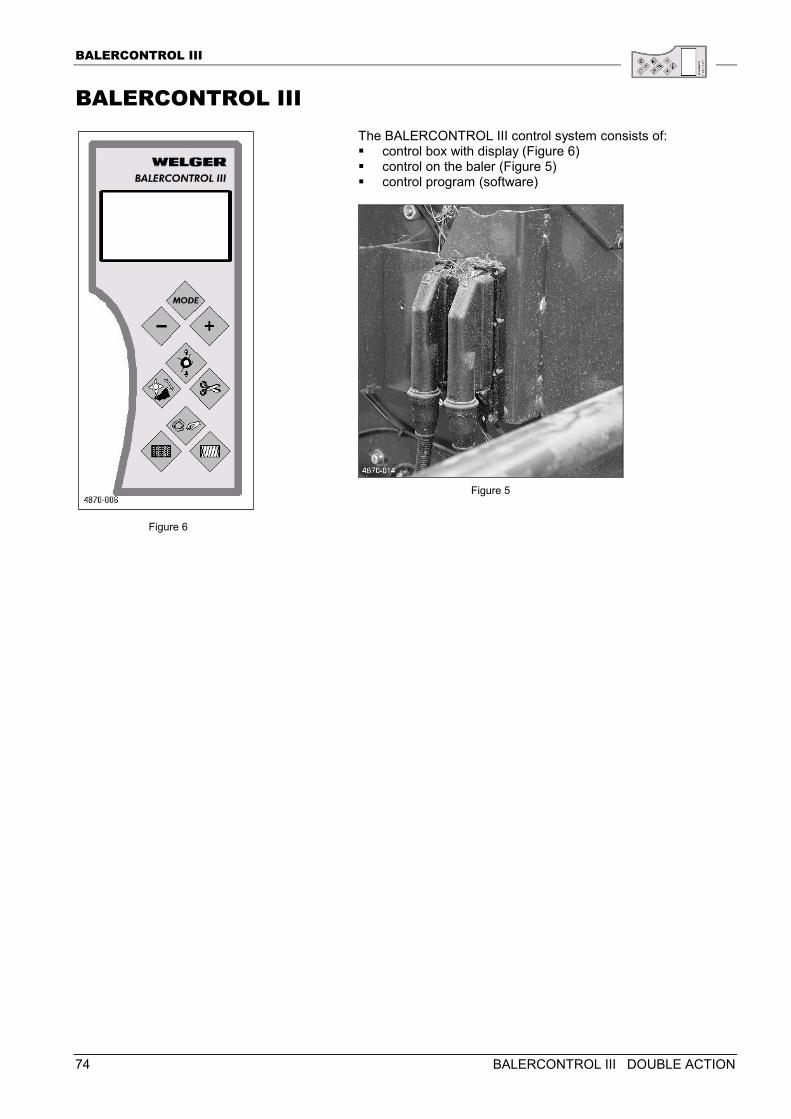
BALERCONTROL III
74 BALERCONTROL III DOUBLE ACTION
BALERCONTROL III The BALERCONTROL III control system consists of: � control box with display (Figure 6) � control on the baler (Figure 5) � control program (software)
Figure 6
Figure 5
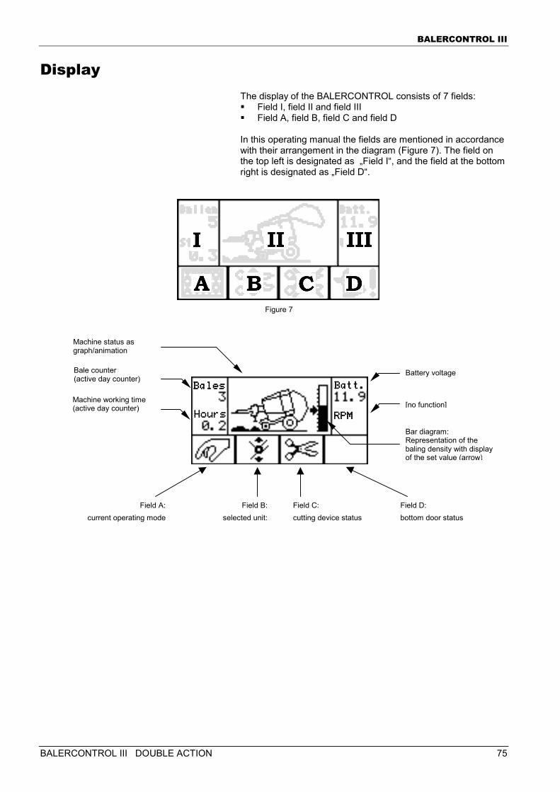
BALERCONTROL III
BALERCONTROL III DOUBLE ACTION 75
Display The display of the BALERCONTROL consists of 7 fields: � Field I, field II and field III � Field A, field B, field C and field D In this operating manual the fields are mentioned in accordance with their arrangement in the diagram (Figure 7). The field on the top left is designated as „Field I“, and the field at the bottom right is designated as „Field D“.
Field A:current operating mode
Field B:selected unit:
Field C: cutting device status
Field D: bottom door status
Figure 7
Battery voltage
[no function]
Bale counter (active day counter)
Machine working time (active day counter)
Machine status as graph/animation
Bar diagram: Representation of the baling density with display of the set value (arrow)
BalesBalesBalesBales
HoHoHoHoursursursurs
Batt.Batt.Batt.Batt.
RPMRPMRPMRPM
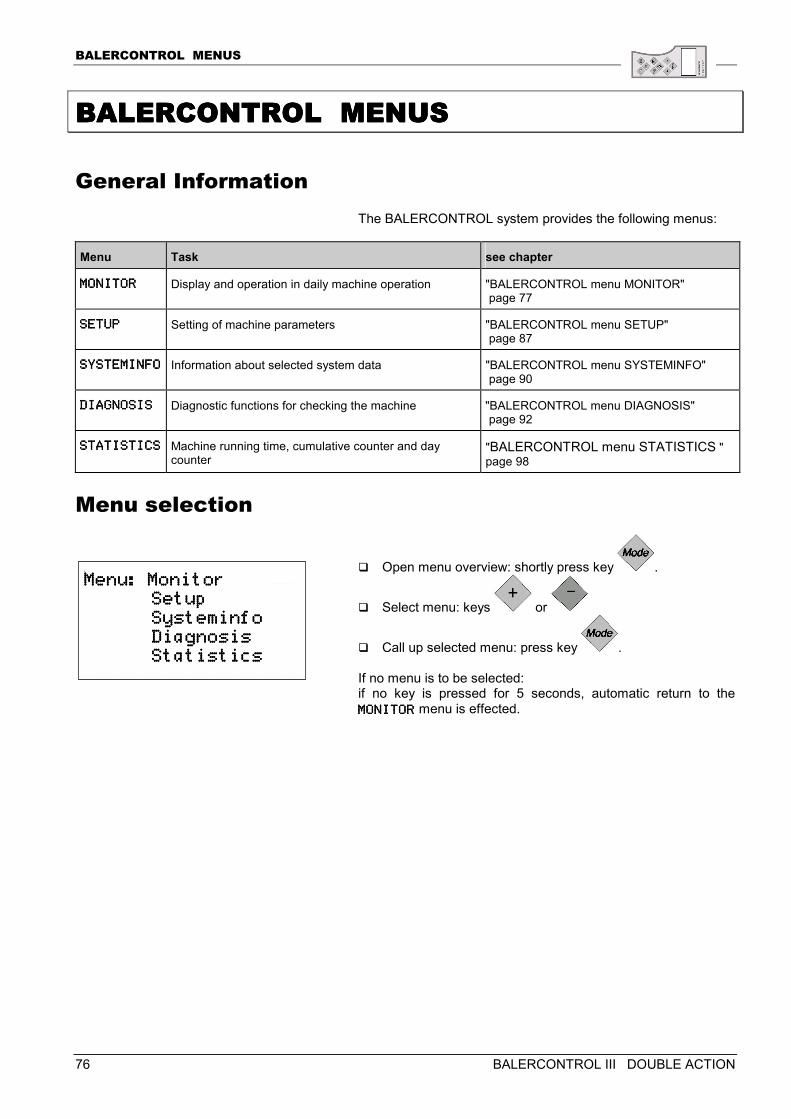
BALERCONTROL MENUS
76 BALERCONTROL III DOUBLE ACTION
BALERCONTBALERCONTBALERCONTBALERCONTROL MENUSROL MENUSROL MENUSROL MENUS
General Information The BALERCONTROL system provides the following menus:
Menu Task see chapter
MONITORMONITORMONITORMONITOR Display and operation in daily machine operation "BALERCONTROL menu MONITOR" page 77
SETUPSETUPSETUPSETUP Setting of machine parameters "BALERCONTROL menu SETUP" page 87
SYSTEMINFOSYSTEMINFOSYSTEMINFOSYSTEMINFO Information about selected system data "BALERCONTROL menu SYSTEMINFO" page 90
DIAGNOSISDIAGNOSISDIAGNOSISDIAGNOSIS Diagnostic functions for checking the machine "BALERCONTROL menu DIAGNOSIS" page 92
STATISTICSSTATISTICSSTATISTICSSTATISTICS Machine running time, cumulative counter and day counter
"BALERCONTROL menu STATISTICS " page 98
Menu selection
� Open menu overview: shortly press key .
� Select menu: keys or
� Call up selected menu: press key . If no menu is to be selected: if no key is pressed for 5 seconds, automatic return to the MONITORMONITORMONITORMONITOR menu is effected.
Menu: MonitorMenu: MonitorMenu: MonitorMenu: Monitor Setup Setup Setup Setup Systeminfo Systeminfo Systeminfo Systeminfo Diagnosis Diagnosis Diagnosis Diagnosis Statistics Statistics Statistics Statistics
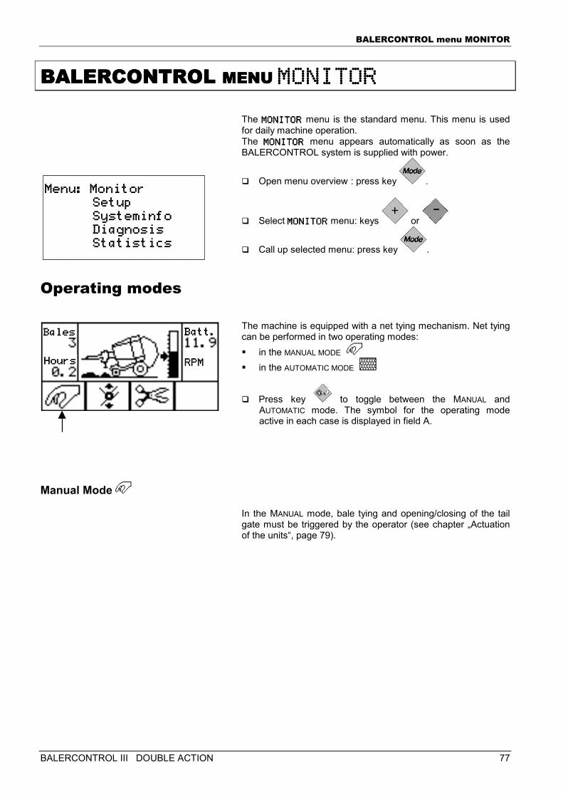
BALERCONTROL menu MONITOR
BALERCONTROL III DOUBLE ACTION 77
BALERCONTROL BALERCONTROL BALERCONTROL BALERCONTROL MENU MENU MENU MENU MONITORMONITORMONITORMONITOR
The MONITORMONITORMONITORMONITOR menu is the standard menu. This menu is used for daily machine operation. The MONITORMONITORMONITORMONITOR menu appears automatically as soon as the BALERCONTROL system is supplied with power.
� Open menu overview : press key .
� Select MONITORMONITORMONITORMONITOR menu: keys or
� Call up selected menu: press key .
Operating modes The machine is equipped with a net tying mechanism. Net tying can be performed in two operating modes: � in the MANUAL MODE � in the AUTOMATIC MODE
� Press key to toggle between the MANUAL and AUTOMATIC mode. The symbol for the operating mode active in each case is displayed in field A.
Manual Mode
In the MANUAL mode, bale tying and opening/closing of the tail gate must be triggered by the operator (see chapter „Actuation of the units“, page 79).
Menu: MonitorMenu: MonitorMenu: MonitorMenu: Monitor Setup Setup Setup Setup Systeminfo Systeminfo Systeminfo Systeminfo Diagnosis Diagnosis Diagnosis Diagnosis Statistics Statistics Statistics Statistics
BalesBalesBalesBales
HoursHoursHoursHours
Batt.Batt.Batt.Batt.
RPMRPMRPMRPM
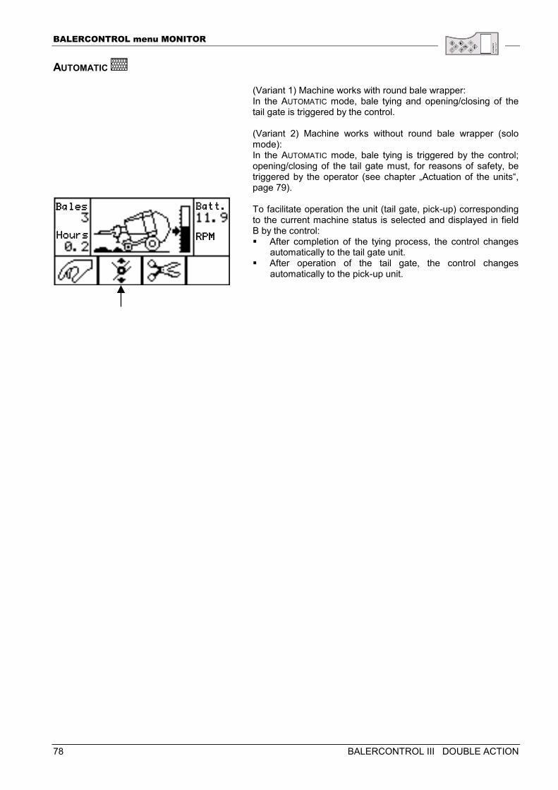
BALERCONTROL menu MONITOR
78 BALERCONTROL III DOUBLE ACTION
AUTOMATIC
(Variant 1) Machine works with round bale wrapper: In the AUTOMATIC mode, bale tying and opening/closing of the tail gate is triggered by the control. (Variant 2) Machine works without round bale wrapper (solo mode): In the AUTOMATIC mode, bale tying is triggered by the control; opening/closing of the tail gate must, for reasons of safety, be triggered by the operator (see chapter „Actuation of the units“, page 79). To facilitate operation the unit (tail gate, pick-up) corresponding to the current machine status is selected and displayed in field B by the control: � After completion of the tying process, the control changes
automatically to the tail gate unit. � After operation of the tail gate, the control changes
automatically to the pick-up unit.
BalesBalesBalesBales
HoursHoursHoursHours
Batt.Batt.Batt.Batt.
RPMRPMRPMRPM
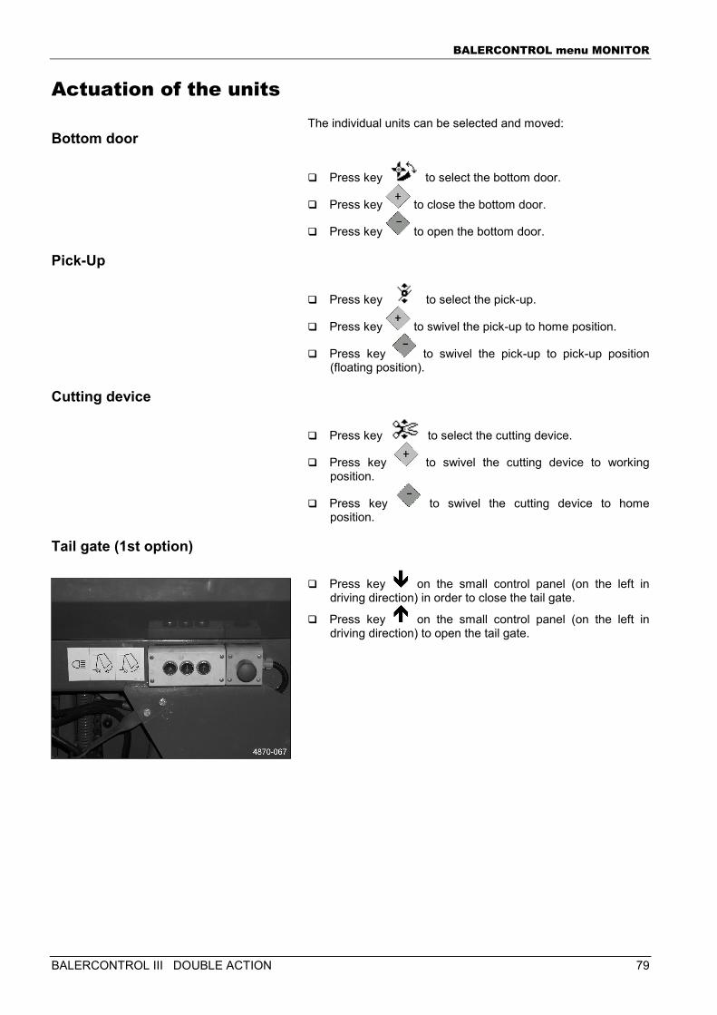
BALERCONTROL menu MONITOR
BALERCONTROL III DOUBLE ACTION 79
Actuation of the units The individual units can be selected and moved:
Bottom door
� Press key to select the bottom door.
� Press key to close the bottom door.
� Press key to open the bottom door.
Pick-Up
� Press key to select the pick-up.
� Press key to swivel the pick-up to home position.
� Press key to swivel the pick-up to pick-up position (floating position).
Cutting device
� Press key to select the cutting device.
� Press key to swivel the cutting device to working position.
� Press key to swivel the cutting device to home position.
Tail gate (1st option)
� Press key on the small control panel (on the left in driving direction) in order to close the tail gate.
� Press key on the small control panel (on the left in driving direction) to open the tail gate.
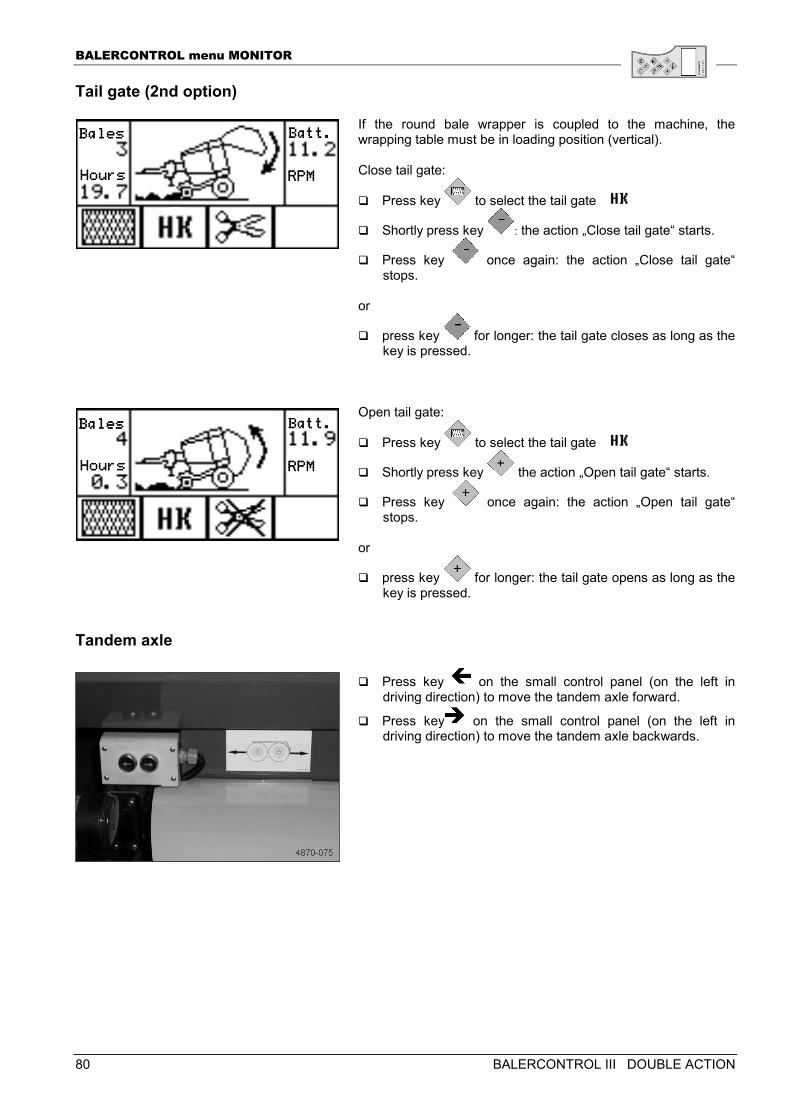
BALERCONTROL menu MONITOR
80 BALERCONTROL III DOUBLE ACTION
Tail gate (2nd option)
If the round bale wrapper is coupled to the machine, the wrapping table must be in loading position (vertical). Close tail gate:
� Press key to select the tail gate
� Shortly press key : the action „Close tail gate“ starts.
� Press key once again: the action „Close tail gate“ stops.
or
� press key for longer: the tail gate closes as long as the key is pressed.
Open tail gate:
� Press key to select the tail gate
� Shortly press key the action „Open tail gate“ starts.
� Press key once again: the action „Open tail gate“ stops.
or
� press key for longer: the tail gate opens as long as the key is pressed.
Tandem axle
� Press key on the small control panel (on the left in driving direction) to move the tandem axle forward.
� Press key on the small control panel (on the left in driving direction) to move the tandem axle backwards.
BalesBalesBalesBales
HoursHoursHoursHours
Batt.Batt.Batt.Batt.
RPMRPMRPMRPM
BalesBalesBalesBales
HoursHoursHoursHours
Batt.Batt.Batt.Batt.
RPMRPMRPMRPM
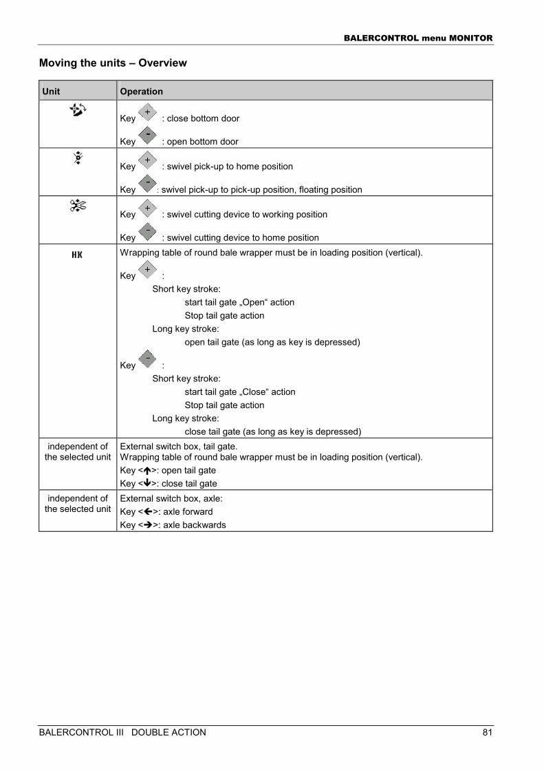
BALERCONTROL menu MONITOR
BALERCONTROL III DOUBLE ACTION 81
Moving the units – Overview
Unit Operation
Key : close bottom door
Key : open bottom door
Key : swivel pick-up to home position
Key : swivel pick-up to pick-up position, floating position
Key : swivel cutting device to working position
Key : swivel cutting device to home position
Wrapping table of round bale wrapper must be in loading position (vertical).
Key : Short key stroke:
start tail gate „Open“ action Stop tail gate action
Long key stroke: open tail gate (as long as key is depressed)
Key : Short key stroke:
start tail gate „Close“ action Stop tail gate action
Long key stroke: close tail gate (as long as key is depressed)
independent of the selected unit
External switch box, tail gate. Wrapping table of round bale wrapper must be in loading position (vertical). Key <�>: open tail gate Key <�>: close tail gate
independent of the selected unit
External switch box, axle: Key <�>: axle forward Key <�>: axle backwards
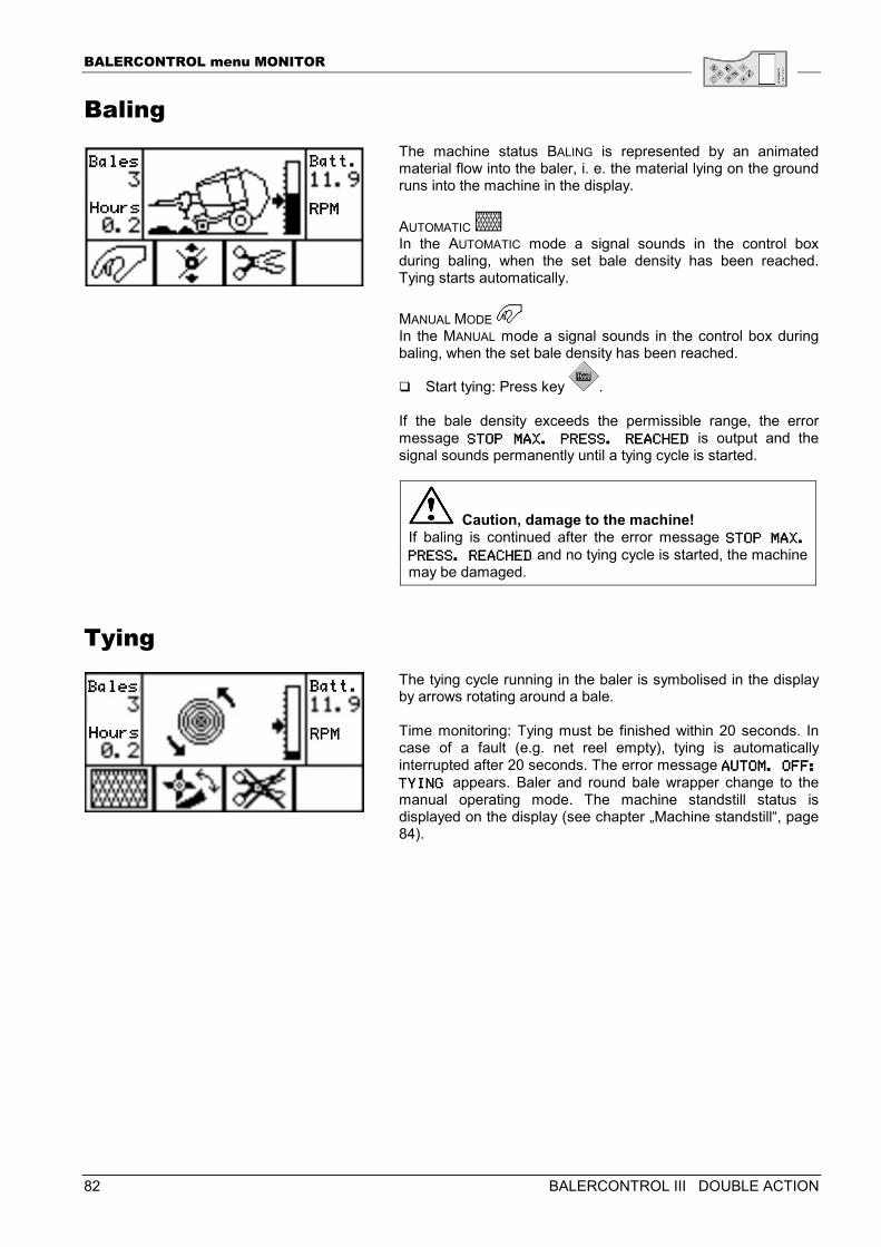
BALERCONTROL menu MONITOR
82 BALERCONTROL III DOUBLE ACTION
Baling The machine status BALING is represented by an animated material flow into the baler, i. e. the material lying on the ground runs into the machine in the display. AUTOMATIC In the AUTOMATIC mode a signal sounds in the control box during baling, when the set bale density has been reached. Tying starts automatically. MANUAL MODE In the MANUAL mode a signal sounds in the control box during baling, when the set bale density has been reached.
� Start tying: Press key . If the bale density exceeds the permissible range, the error message STOP MAX. PRESS. REASTOP MAX. PRESS. REASTOP MAX. PRESS. REASTOP MAX. PRESS. REACHEDCHEDCHEDCHED is output and the signal sounds permanently until a tying cycle is started.
Caution, damage to the machine! If baling is continued after the error message STOP MAX. STOP MAX. STOP MAX. STOP MAX.
PRESS. REACHEDPRESS. REACHEDPRESS. REACHEDPRESS. REACHED and no tying cycle is started, the machine may be damaged.
Tying The tying cycle running in the baler is symbolised in the display by arrows rotating around a bale. Time monitoring: Tying must be finished within 20 seconds. In case of a fault (e.g. net reel empty), tying is automatically interrupted after 20 seconds. The error message AUTOM. OFF: AUTOM. OFF: AUTOM. OFF: AUTOM. OFF:
TYING TYING TYING TYING appears. Baler and round bale wrapper change to the manual operating mode. The machine standstill status is displayed on the display (see chapter „Machine standstill“, page 84).
BalesBalesBalesBales
HoursHoursHoursHours
Batt.Batt.Batt.Batt.
RPMRPMRPMRPM
BalesBalesBalesBales
HouHouHouHoursrsrsrs
Batt.Batt.Batt.Batt.
RPMRPMRPMRPM
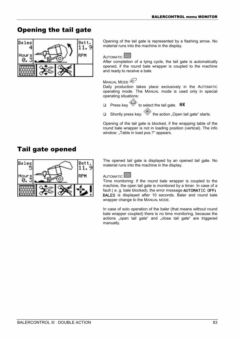
BALERCONTROL menu MONITOR
BALERCONTROL III DOUBLE ACTION 83
Opening the tail gate Opening of the tail gate is represented by a flashing arrow. No material runs into the machine in the display. AUTOMATIC After completion of a tying cycle, the tail gate is automatically opened, if the round bale wrapper is coupled to the machine and ready to receive a bale. MANUAL MODE Daily production takes place exclusively in the AUTOMATIC operating mode. The MANUAL mode is used only in special operating situations:
� Press key to select the tail gate.
� Shortly press key: the action „Open tail gate“ starts. Opening of the tail gate is blocked, if the wrapping table of the round bale wrapper is not in loading position (vertical). The info window: „Table in load pos.?“ appears.
Tail gate opened The opened tail gate is displayed by an opened tail gate. No material runs into the machine in the display. AUTOMATIC Time monitoring: if the round bale wrapper is coupled to the machine, the open tail gate is monitored by a timer. In case of a fault ( e. g. bale blocked), the error message AUTOMATIC OFF: AUTOMATIC OFF: AUTOMATIC OFF: AUTOMATIC OFF:
BALESBALESBALESBALES is displayed after 10 seconds. Baler and round bale wrapper change to the MANUAL MODE. In case of solo operation of the baler (that means without round bale wrapper coupled) there is no time monitoring, because the actions „open tail gate“ and „close tail gate“ are triggered manually.
BalesBalesBalesBales
HoursHoursHoursHours
Batt.Batt.Batt.Batt.
RPMRPMRPMRPM
BalesBalesBalesBales
HoursHoursHoursHours
Batt.Batt.Batt.Batt.
RPMRPMRPMRPM
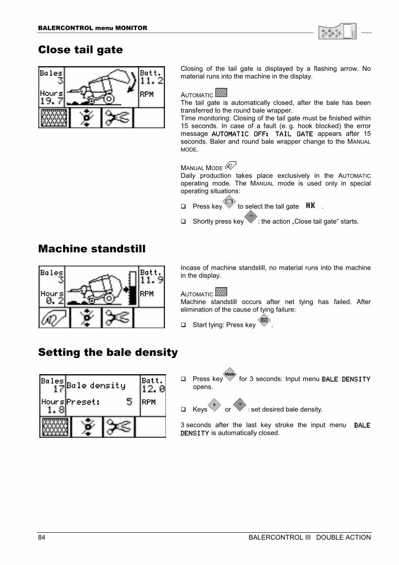
BALERCONTROL menu MONITOR
84 BALERCONTROL III DOUBLE ACTION
Close tail gate Closing of the tail gate is displayed by a flashing arrow. No material runs into the machine in the display. AUTOMATIC The tail gate is automatically closed, after the bale has been transferred to the round bale wrapper. Time monitoring: Closing of the tail gate must be finished within 15 seconds. In case of a fault (e. g. hook blocked) the error message AUTOMATIAUTOMATIAUTOMATIAUTOMATIC OFF: TAIL GATEC OFF: TAIL GATEC OFF: TAIL GATEC OFF: TAIL GATE appears after 15 seconds. Baler and round bale wrapper change to the MANUAL MODE. MANUAL MODE Daily production takes place exclusively in the AUTOMATIC operating mode. The MANUAL mode is used only in special operating situations:
� Press key to select the tail gate .
� Shortly press key : the action „Close tail gate“ starts.
Machine standstill Incase of machine standstill, no material runs into the machine in the display. AUTOMATIC Machine standstill occurs after net tying has failed. After elimination of the cause of tying failure:
� Start tying: Press key .
Setting the bale density
� Press key for 3 seconds: Input menu BALE DENSITY BALE DENSITY BALE DENSITY BALE DENSITY
opens.
� Keys or : set desired bale density. 3 seconds after the last key stroke the input menu BALE BALE BALE BALE
DENSITYDENSITYDENSITYDENSITY is automatically closed.
BalesBalesBalesBales
HoursHoursHoursHours
Batt.Batt.Batt.Batt.
RPMRPMRPMRPM
BalesBalesBalesBales
HoursHoursHoursHours
Batt.Batt.Batt.Batt.
RPMRPMRPMRPM
BalesBalesBalesBales
HoursHoursHoursHours
Batt.Batt.Batt.Batt.
RPMRPMRPMRPM
Bale deBale deBale deBale densitynsitynsitynsity
Preset:Preset:Preset:Preset:
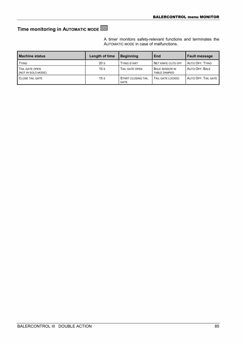
BALERCONTROL menu MONITOR
BALERCONTROL III DOUBLE ACTION 85
Time monitoring in AUTOMATIC MODE
A timer monitors safety-relevant functions and terminates the AUTOMATIC MODE in case of malfunctions.
Machine status Length of time Beginning End Fault message
TYING 20 S TYING START NET KNIFE CUTS OFF AUTO OFF: TYING
TAIL GATE OPEN (NOT IN SOLO MODE)
10 S TAIL GATE OPEN BALE SENSOR IN TABLE DAMPED
AUTO OFF: BALE
CLOSE TAIL GATE 15 S START CLOSING TAIL GATE
TAIL GATE LOCKED AUTO OFF: TAIL GATE
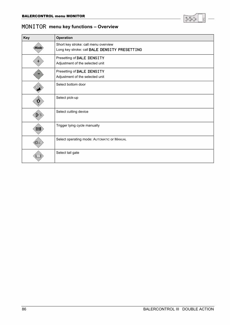
BALERCONTROL menu MONITOR
86 BALERCONTROL III DOUBLE ACTION
MONITOR MONITOR MONITOR MONITOR menu key functions – Overview
Key Operation
Short key stroke: call menu overview Long key stroke: call BALE DENSITY PRESETTBALE DENSITY PRESETTBALE DENSITY PRESETTBALE DENSITY PRESETTINGINGINGING
Presetting of BALE DENSITYBALE DENSITYBALE DENSITYBALE DENSITY Adjustment of the selected unit
Presetting of BALE DENSITYBALE DENSITYBALE DENSITYBALE DENSITY Adjustment of the selected unit
Select bottom door
Select pick-up
Select cutting device
Trigger tying cycle manually
Select operating mode: AUTOMATIC or MANUAL
Select tail gate
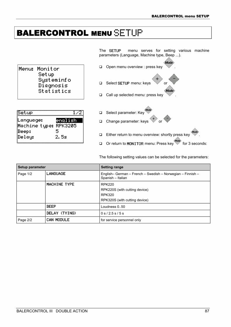
BALERCONTROL menu SETUP
BALERCONTROL III DOUBLE ACTION 87
BALERCONTROL BALERCONTROL BALERCONTROL BALERCONTROL MENU MENU MENU MENU SETUPSETUPSETUPSETUP
The SETUPSETUPSETUPSETUP menu serves for setting various machine parameters (Language, Machine type, Beep ...).
� Open menu overview : press key .
� Select SETUPSETUPSETUPSETUP menu: keys or
� Call up selected menu: press key .
� Select parameter: Key
� Change parameter: keys or
� Either return to menu overview: shortly press key .
� Or return to MONITORMONITORMONITORMONITOR menu: Press key for 3 seconds: The following setting values can be selected for the parameters:
Setup parameter Setting range
Page 1/2 LANGUAGELANGUAGELANGUAGELANGUAGE English– German – French – Swedish – Norwegian – Finnish – Spanish – Italian
MACHINE TYPEMACHINE TYPEMACHINE TYPEMACHINE TYPE RPK220 RPK220S (with cutting device) RPK320 RPK320S (with cutting device)
BEEPBEEPBEEPBEEP Loudness 0..50
DELAY (TYING)DELAY (TYING)DELAY (TYING)DELAY (TYING) 0 s / 2.5 s / 5 s
Page 2/2 CAN MODULECAN MODULECAN MODULECAN MODULE for service personnel only
Menu: MonitorMenu: MonitorMenu: MonitorMenu: Monitor Setup Setup Setup Setup Systeminfo Systeminfo Systeminfo Systeminfo Diagnosis Diagnosis Diagnosis Diagnosis Statistics Statistics Statistics Statistics
Language:Language:Language:Language:
Machine type:Machine type:Machine type:Machine type: RPK3205RPK3205RPK3205RPK3205
Beep: 5Beep: 5Beep: 5Beep: 5
Delay: Delay: Delay: Delay: 2.5s2.5s2.5s2.5s
englishenglishenglishenglish
BALERCONTROL menu SETUP
88 BALERCONTROL III DOUBLE ACTION
Language The language in the control box display can be adjusted. � German � English � French Dependent on the configuration further languages can be available: � Swedish � Norwegian � Finnish � Spanish � Italian
Note! Before changing the following settings: contact the service department in case of questions or doubts.
Machine type The machine type can be adjusted: � RP 220 � RP 220 S (with cutting device) � RP 320 � RP 320 S (with cutting device)
Beep The beep indicates audibly that a key on the control box has been pressed. The loudness of the beep can be adjusted: 0..50 0 = beep off 50 = beep maximum loudness
Delay (tying) The tying delay is the time between the beep (baling density reached) and the start of the net tying cycle. During this time: � the tractor with the machine can stop. � the pick-up can feed in residual material. The delay can be set to the following values: � 0 seconds � 2.5 seconds � 5 seconds
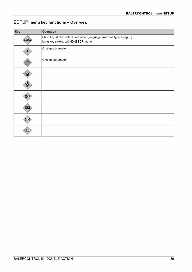
BALERCONTROL menu SETUP
BALERCONTROL III DOUBLE ACTION 89
SETUPSETUPSETUPSETUP menu key functions – Overview
Key Operation
Short key stroke: select parameter (language, machine type, beep ...) Long key stroke: call MONITORMONITORMONITORMONITOR menu
Change parameter
Change parameter
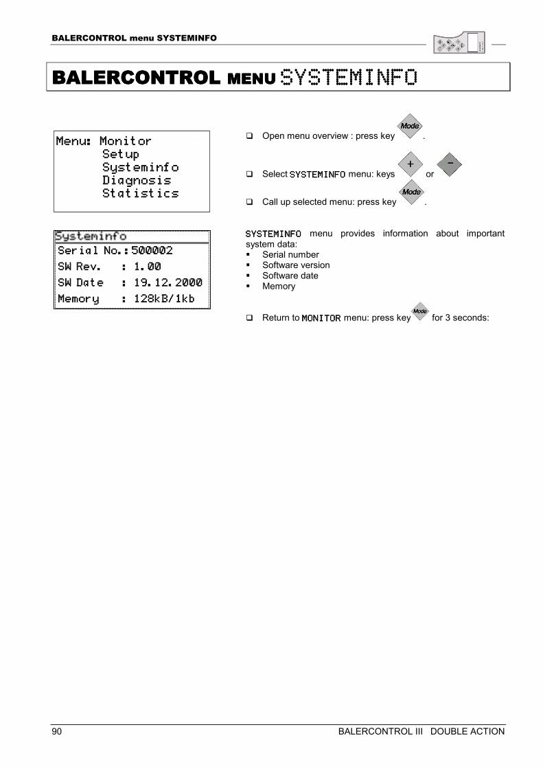
BALERCONTROL menu SYSTEMINFO
90 BALERCONTROL III DOUBLE ACTION
BALERCONTROL BALERCONTROL BALERCONTROL BALERCONTROL MENU MENU MENU MENU SYSTEMINFOSYSTEMINFOSYSTEMINFOSYSTEMINFO
� Open menu overview : press key .
� Select SYSTEMINFOSYSTEMINFOSYSTEMINFOSYSTEMINFO menu: keys or
� Call up selected menu: press key . SYSTEMINFOSYSTEMINFOSYSTEMINFOSYSTEMINFO menu provides information about important system data: � Serial number � Software version � Software date � Memory
� Return to MONITORMONITORMONITORMONITOR menu: press key for 3 seconds:
Menu: MonitorMenu: MonitorMenu: MonitorMenu: Monitor Setup Setup Setup Setup Systeminfo Systeminfo Systeminfo Systeminfo Diagnosis Diagnosis Diagnosis Diagnosis Statistics Statistics Statistics Statistics
Serial No.:500002Serial No.:500002Serial No.:500002Serial No.:500002
SW Rev. : 1.00SW Rev. : 1.00SW Rev. : 1.00SW Rev. : 1.00
SW Date : 19.12.2000SW Date : 19.12.2000SW Date : 19.12.2000SW Date : 19.12.2000
Memory : 128kB/1kbMemory : 128kB/1kbMemory : 128kB/1kbMemory : 128kB/1kb
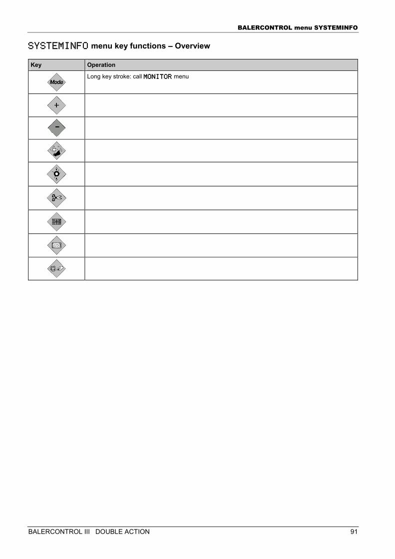
BALERCONTROL menu SYSTEMINFO
BALERCONTROL III DOUBLE ACTION 91
SYSTEMINFOSYSTEMINFOSYSTEMINFOSYSTEMINFO menu key functions – Overview
Key Operation
Long key stroke: call MONITORMONITORMONITORMONITOR menu
BALERCONTROL menu DIAGNOSIS
92 BALERCONTROL III DOUBLE ACTION
BALERCONTROL BALERCONTROL BALERCONTROL BALERCONTROL MENU MENU MENU MENU DIAGNOSISDIAGNOSISDIAGNOSISDIAGNOSIS
The BALERCONTROL system offers extensive diagnostic functions for checking the electrical equipment. There are two diagnostic routines:
Standard diagnosis
Diagnostic functions with machine stopped. Machine functions completely switched off. Digital sensors and actors can be tested. The actors can optionally be tested manually or fully automatically.
Attention, danger of injury! Standard diagnosis may only be performed after the machine has been stopped: Switch off tractor engine, wait until machine has stopped, disconnect hydraulic supply to the machine.
Extended diagnosis
Diagnostic functions while machine is in operation. All digital sensors and all actors can be tested. Selection via special key combination.
Attention, danger of injury! Extended diagnosis is executed while the machine is running. For trained and instructed service personnel only!
See „Extended diagnosis“, page 107.
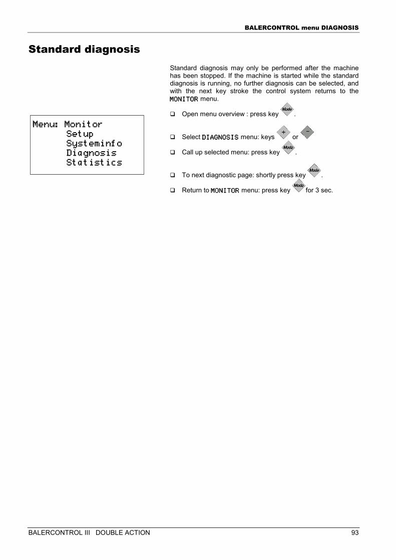
BALERCONTROL menu DIAGNOSIS
BALERCONTROL III DOUBLE ACTION 93
Standard diagnosis Standard diagnosis may only be performed after the machine has been stopped. If the machine is started while the standard diagnosis is running, no further diagnosis can be selected, and with the next key stroke the control system returns to the MONITORMONITORMONITORMONITOR menu.
� Open menu overview : press key .
� Select DIAGNOSISDIAGNOSISDIAGNOSISDIAGNOSIS menu: keys or
� Call up selected menu: press key .
� To next diagnostic page: shortly press key .
� Return to MONITORMONITORMONITORMONITOR menu: press key for 3 sec.
Menu: MonitorMenu: MonitorMenu: MonitorMenu: Monitor Setup Setup Setup Setup Systeminfo Systeminfo Systeminfo Systeminfo Diagnosi Diagnosi Diagnosi Diagnosis s s s Statistics Statistics Statistics Statistics
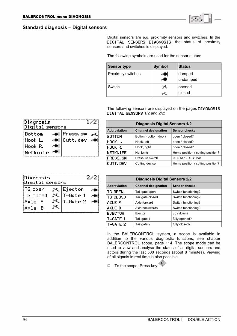
BALERCONTROL menu DIAGNOSIS
94 BALERCONTROL III DOUBLE ACTION
Standard diagnosis – Digital sensors
Digital sensors are e.g. proximity sensors and switches. In the DIGDIGDIGDIGITAL SENSORS DIAGNOSITAL SENSORS DIAGNOSITAL SENSORS DIAGNOSITAL SENSORS DIAGNOSIS IS IS IS the status of proximity sensors and switches is displayed. The following symbols are used for the sensor status: Sensor type Symbol Status
Proximity switches
damped undamped
Switch
opened closed
The following sensors are displayed on the pages DIAGNOSIS DIAGNOSIS DIAGNOSIS DIAGNOSIS
DIGITAL SENSORSDIGITAL SENSORSDIGITAL SENSORSDIGITAL SENSORS 1/2 and 2/2:
Diagnosis Digital Sensors 1/2 Abbreviation Channel designation Sensor checks
BOTTOMBOTTOMBOTTOMBOTTOM Bottom (bottom door) open / closed?
HOOK L.HOOK L.HOOK L.HOOK L. Hook, left open / closed?
HOOK R.HOOK R.HOOK R.HOOK R. Hook, right open / closed?
NETKNIFENETKNIFENETKNIFENETKNIFE Net knife Home position / cutting position?
PRESS.SWPRESS.SWPRESS.SWPRESS.SW Pressure switch < 35 bar / > 35 bar
CUTT.DEVCUTT.DEVCUTT.DEVCUTT.DEV Cutting device Home position / cutting position?
Diagnosis Digital Sensors 2/2 Abbreviation Channel designation Sensor checks
TTTTG OPENG OPENG OPENG OPEN Tail gate open Switch functioning? TG CLOSDTG CLOSDTG CLOSDTG CLOSD Tail gate closed Switch functioning?
AXLE FAXLE FAXLE FAXLE F Axle forward Switch functioning?
AXLE BAXLE BAXLE BAXLE B Axle backwards Switch functioning?
EJECTOREJECTOREJECTOREJECTOR Ejector up / down?
TTTT----GATE 1GATE 1GATE 1GATE 1 Tail gate 1 fully opened?
TTTT----GATE 2GATE 2GATE 2GATE 2 Tail gate 2 fully closed? In the BALERCONTROL system, a scope is available in addition to the various diagnostic functions, see chapter BALERCONTROL scope, page 114. The scope mode can be used to view and analyse the status of all digital sensors and actors during the last 500 seconds (about 8 minutes). Viewing of all signals in real time is also possible.
� To the scope: Press key .
DiagnosisDiagnosisDiagnosisDiagnosis Digital sensorsDigital sensorsDigital sensorsDigital sensors BottomBottomBottomBottom
Hook L.Hook L.Hook L.Hook L.
Hook R.Hook R.Hook R.Hook R.
NetknifeNetknifeNetknifeNetknife
Press.swPress.swPress.swPress.sw
Cutt.devCutt.devCutt.devCutt.dev
DiagnosisDiagnosisDiagnosisDiagnosis Digital sensorsDigital sensorsDigital sensorsDigital sensors TG openTG openTG openTG open
TG closdTG closdTG closdTG closd
Axle FAxle FAxle FAxle F
AxleAxleAxleAxle B B B B
EjectorEjectorEjectorEjector
TTTT----Gate 1Gate 1Gate 1Gate 1
TTTT----Gate 2Gate 2Gate 2Gate 2
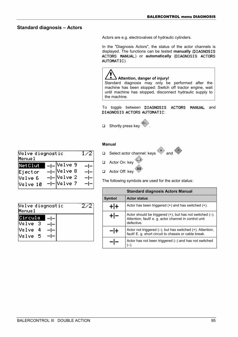
BALERCONTROL menu DIAGNOSIS
BALERCONTROL III DOUBLE ACTION 95
Standard diagnosis – Actors
Actors are e.g. electrovalves of hydraulic cylinders. In the "Diagnosis Actors", the status of the actor channels is displayed. The functions can be tested manually (DIAGNOSIS DIAGNOSIS DIAGNOSIS DIAGNOSIS
ACTORS MANUALACTORS MANUALACTORS MANUALACTORS MANUAL) or automatically (DIAGNOSIS ACTORS DIAGNOSIS ACTORS DIAGNOSIS ACTORS DIAGNOSIS ACTORS
AUTOMATICAUTOMATICAUTOMATICAUTOMATIC).
Attention, danger of injury! Standard diagnosis may only be performed after the machine has been stopped: Switch off tractor engine, wait until machine has stopped, disconnect hydraulic supply to the machine.
To toggle between DIAGNOSIS ACTORS MANDIAGNOSIS ACTORS MANDIAGNOSIS ACTORS MANDIAGNOSIS ACTORS MANUALUALUALUAL and DIAGNOSIS ACTORS AUTDIAGNOSIS ACTORS AUTDIAGNOSIS ACTORS AUTDIAGNOSIS ACTORS AUTOMATICOMATICOMATICOMATIC:
� Shortly press key . Manual
� Select actor channel: keys and
� Actor On: key
� Actor Off: key The following symbols are used for the actor status:
Standard diagnosis Actors Manual Symbol Actor status
Actor has been triggered (+) and has switched (+).
Actor should be triggered (+), but has not switched (–). Attention, fault! e. g. actor channel in control unit defective.
Actor not triggered (–), but has switched (+). Attention, fault! E. g. short circuit to chassis or cable break.
Actor has not been triggered (–) and has not switched (–).
Valve diagnosticValve diagnosticValve diagnosticValve diagnostic ManualManualManualManual
Valve 9Valve 9Valve 9Valve 9
Valve 8Valve 8Valve 8Valve 8
Valve 2Valve 2Valve 2Valve 2 Valve 7Valve 7Valve 7Valve 7
EjectorEjectorEjectorEjector
Valve 6Valve 6Valve 6Valve 6
Valve 10Valve 10Valve 10Valve 10
NetClutNetClutNetClutNetClut
Valve diagnosticValve diagnosticValve diagnosticValve diagnostic ManualManualManualManual
Valve 3Valve 3Valve 3Valve 3
Valve 4Valve 4Valve 4Valve 4
Valve 5Valve 5Valve 5Valve 5
CirculaCirculaCirculaCircula
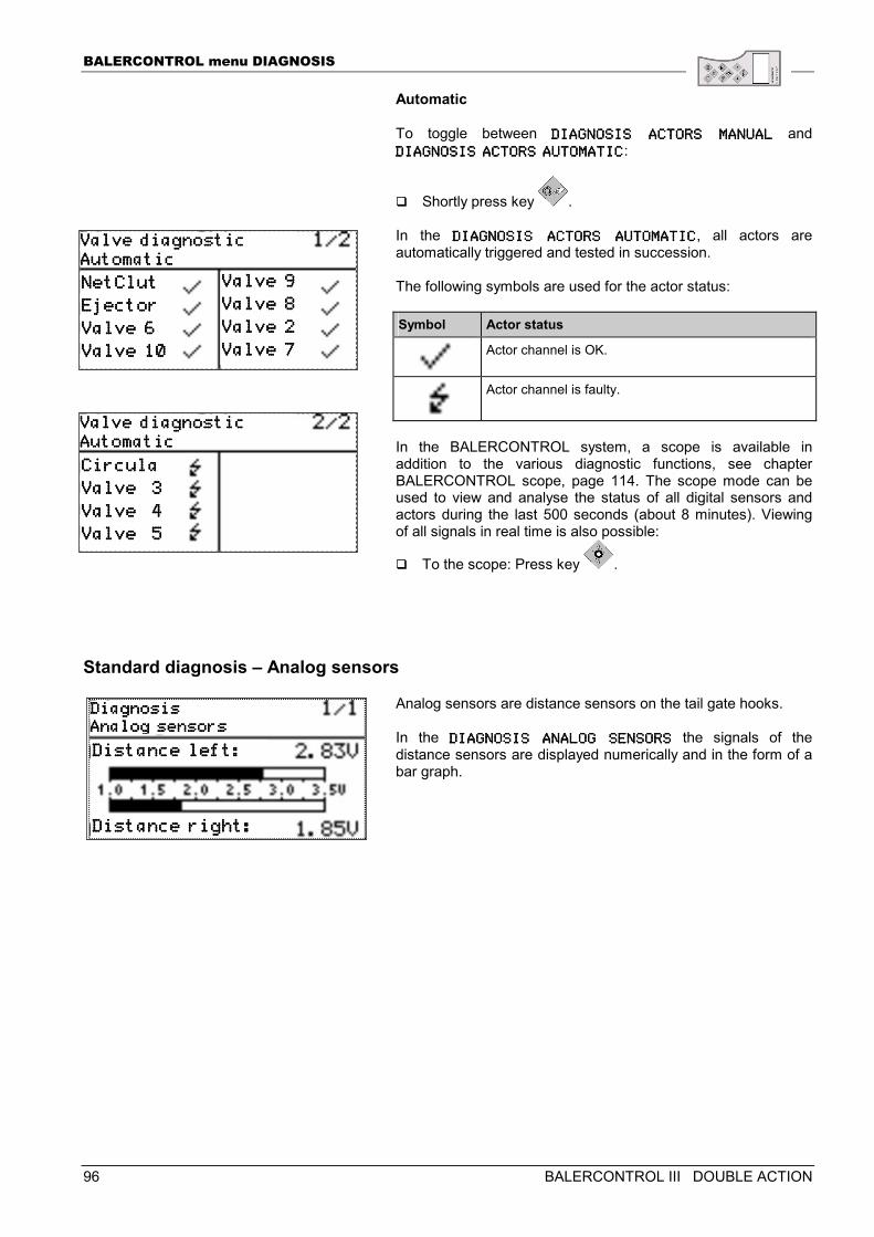
BALERCONTROL menu DIAGNOSIS
96 BALERCONTROL III DOUBLE ACTION
Automatic To toggle between DIAGNOSIS ACTORS MANDIAGNOSIS ACTORS MANDIAGNOSIS ACTORS MANDIAGNOSIS ACTORS MANUALUALUALUAL and DIAGNOSIS ACTORS AUTDIAGNOSIS ACTORS AUTDIAGNOSIS ACTORS AUTDIAGNOSIS ACTORS AUTOMATICOMATICOMATICOMATIC:
� Shortly press key . In the DIAGNOSIDIAGNOSIDIAGNOSIDIAGNOSIS ACTORS AUTOMATICS ACTORS AUTOMATICS ACTORS AUTOMATICS ACTORS AUTOMATIC, all actors are automatically triggered and tested in succession. The following symbols are used for the actor status: Symbol Actor status
Actor channel is OK.
Actor channel is faulty.
In the BALERCONTROL system, a scope is available in addition to the various diagnostic functions, see chapter BALERCONTROL scope, page 114. The scope mode can be used to view and analyse the status of all digital sensors and actors during the last 500 seconds (about 8 minutes). Viewing of all signals in real time is also possible:
� To the scope: Press key .
Standard diagnosis – Analog sensors
Analog sensors are distance sensors on the tail gate hooks. In the DIAGNOSIS ANALOG SENDIAGNOSIS ANALOG SENDIAGNOSIS ANALOG SENDIAGNOSIS ANALOG SENSORSSORSSORSSORS the signals of the distance sensors are displayed numerically and in the form of a bar graph.
ValveValveValveValve diagnostic diagnostic diagnostic diagnostic AutomaticAutomaticAutomaticAutomatic
Valve 9Valve 9Valve 9Valve 9
Valve 8Valve 8Valve 8Valve 8
Valve 2Valve 2Valve 2Valve 2 Valve 7Valve 7Valve 7Valve 7
NetClutNetClutNetClutNetClut
EjectorEjectorEjectorEjector
Valve 6Valve 6Valve 6Valve 6
Valve 10Valve 10Valve 10Valve 10
Valve diagnosticValve diagnosticValve diagnosticValve diagnostic AutomaticAutomaticAutomaticAutomatic
Distance left:Distance left:Distance left:Distance left:
DiagnosisDiagnosisDiagnosisDiagnosis Analog sensorsAnalog sensorsAnalog sensorsAnalog sensors
Distance right:Distance right:Distance right:Distance right:
CircCircCircCirculaulaulaula
Valve 3Valve 3Valve 3Valve 3
Valve 4Valve 4Valve 4Valve 4
Valve 5Valve 5Valve 5Valve 5
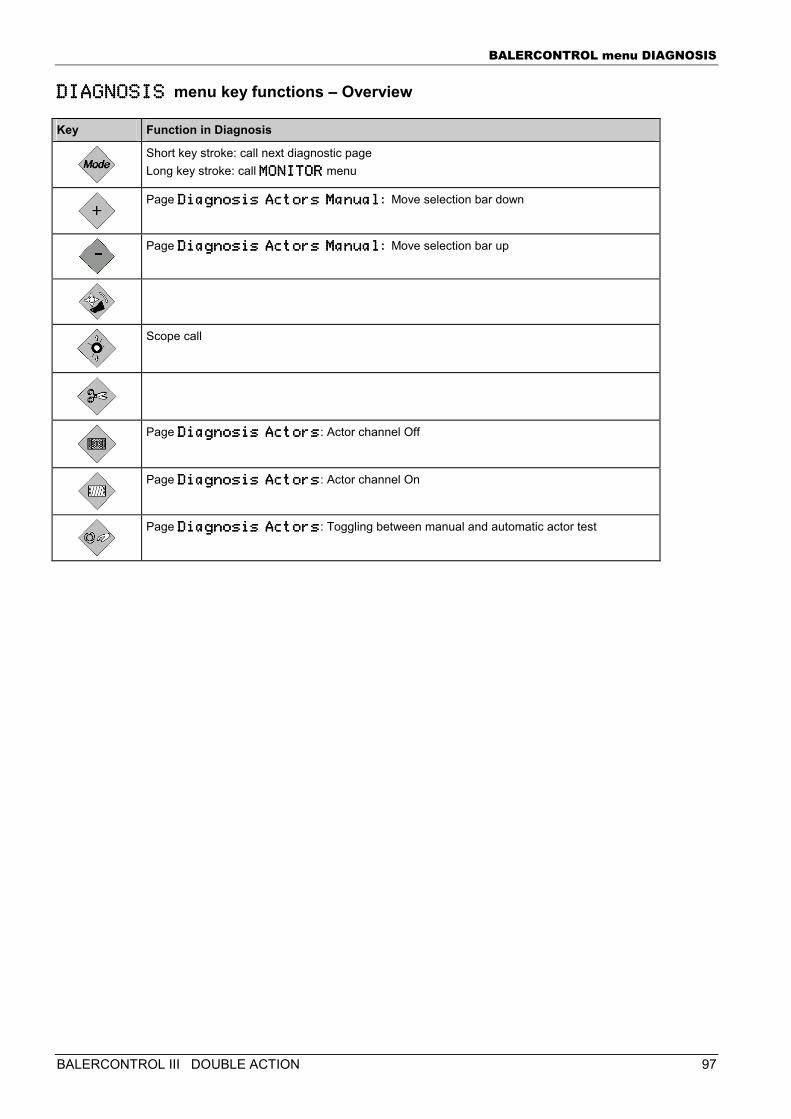
BALERCONTROL menu DIAGNOSIS
BALERCONTROL III DOUBLE ACTION 97
DIAGNOSIS DIAGNOSIS DIAGNOSIS DIAGNOSIS menu key functions – Overview
Key Function in Diagnosis
Short key stroke: call next diagnostic page Long key stroke: call MONITORMONITORMONITORMONITOR menu
Page Diagnosis Actors ManualDiagnosis Actors ManualDiagnosis Actors ManualDiagnosis Actors Manual: Move selection bar down
Page Diagnosis Actors ManualDiagnosis Actors ManualDiagnosis Actors ManualDiagnosis Actors Manual: Move selection bar up
Scope call
Page Diagnosis ActorsDiagnosis ActorsDiagnosis ActorsDiagnosis Actors: Actor channel Off
Page Diagnosis ActorsDiagnosis ActorsDiagnosis ActorsDiagnosis Actors: Actor channel On
Page Diagnosis ActorsDiagnosis ActorsDiagnosis ActorsDiagnosis Actors: Toggling between manual and automatic actor test
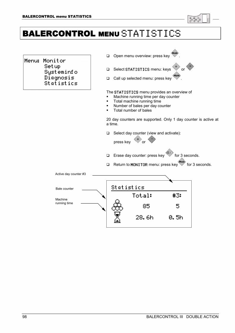
BALERCONTROL menu STATISTICS
98 BALERCONTROL III DOUBLE ACTION
BALERCONTROL BALERCONTROL BALERCONTROL BALERCONTROL MENU MENU MENU MENU STATISTICSSTATISTICSSTATISTICSSTATISTICS
� Open menu overview: press key .
� Select STATISTICSSTATISTICSSTATISTICSSTATISTICS menu: keys or
� Call up selected menu: press key . The STATISTICSSTATISTICSSTATISTICSSTATISTICS menu provides an overview of � Machine running time per day counter � Total machine running time � Number of bales per day counter � Total number of bales
20 day counters are supported. Only 1 day counter is active at a time. � Select day counter (view and activate):
press key or
� Erase day counter: press key for 3 seconds.
� Return to MONITORMONITORMONITORMONITOR menu: press key for 3 seconds.
Bale counter
Machine running time
Active day counter #3
Menu: MonitorMenu: MonitorMenu: MonitorMenu: Monitor Setup Setup Setup Setup Systemi Systemi Systemi Systeminfonfonfonfo Diagnosis Diagnosis Diagnosis Diagnosis Statistics Statistics Statistics Statistics
StatisticsStatisticsStatisticsStatistics
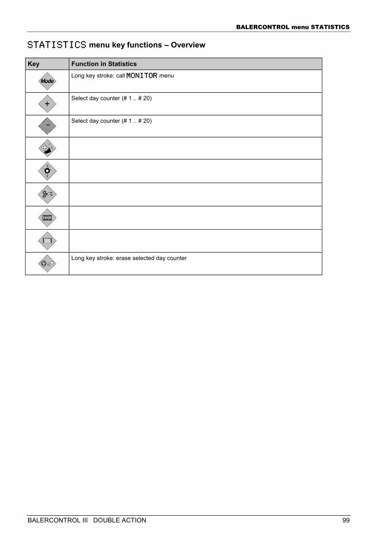
BALERCONTROL menu STATISTICS
BALERCONTROL III DOUBLE ACTION 99
STATISTICSSTATISTICSSTATISTICSSTATISTICS menu key functions – Overview
Key Function in Statistics
Long key stroke: call MONITORMONITORMONITORMONITOR menu
Select day counter (# 1 .. # 20)
Select day counter (# 1 .. # 20)
Long key stroke: erase selected day counter
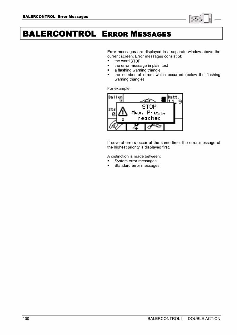
BALERCONTROL Error Messages
100 BALERCONTROL III DOUBLE ACTION
BALERCONTROL EBALERCONTROL EBALERCONTROL EBALERCONTROL ERROR RROR RROR RROR MMMMESSAGESESSAGESESSAGESESSAGES
Error messages are displayed in a separate window above the current screen. Error messages consist of: � the word STOPSTOPSTOPSTOP � the error message in plain text � a flashing warning triangle � the number of errors which occurred (below the flashing
warning triangle) For example:
If several errors occur at the same time, the error message of the highest priority is displayed first. A distinction is made between: � System error messages � Standard error messages
STOPSTOPSTOPSTOP Max. Press. Max. Press. Max. Press. Max. Press.
reachedreachedreachedreached
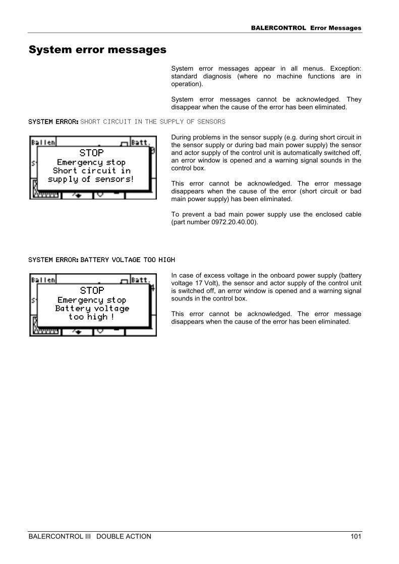
BALERCONTROL Error Messages
BALERCONTROL III DOUBLE ACTION 101
System error messages System error messages appear in all menus. Exception: standard diagnosis (where no machine functions are in operation). System error messages cannot be acknowledged. They disappear when the cause of the error has been eliminated.
SYSTEM ERROR:SYSTEM ERROR:SYSTEM ERROR:SYSTEM ERROR:SHORT CIRCUIT IN THE SUPPLY OF SENSORS
During problems in the sensor supply (e.g. during short circuit in the sensor supply or during bad main power supply) the sensor and actor supply of the control unit is automatically switched off, an error window is opened and a warning signal sounds in the control box. This error cannot be acknowledged. The error message disappears when the cause of the error (short circuit or bad main power supply) has been eliminated. To prevent a bad main power supply use the enclosed cable (part number 0972.20.40.00).
SYSTEM ERROR:BATTERYSYSTEM ERROR:BATTERYSYSTEM ERROR:BATTERYSYSTEM ERROR:BATTERY VOLTAGE TOO HIGH VOLTAGE TOO HIGH VOLTAGE TOO HIGH VOLTAGE TOO HIGH
In case of excess voltage in the onboard power supply (battery voltage 17 Volt), the sensor and actor supply of the control unit is switched off, an error window is opened and a warning signal sounds in the control box. This error cannot be acknowledged. The error message disappears when the cause of the error has been eliminated.
STOPSTOPSTOPSTOP Emergency stopEmergency stopEmergency stopEmergency stop
Short circuit inShort circuit inShort circuit inShort circuit in supply of sensors!supply of sensors!supply of sensors!supply of sensors!
STOPSTOPSTOPSTOP Emergency stopEmergency stopEmergency stopEmergency stop Battery voltageBattery voltageBattery voltageBattery voltage
too high !too high !too high !too high !
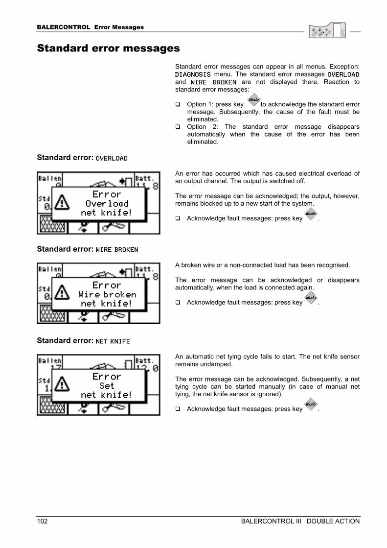
BALERCONTROL Error Messages
102 BALERCONTROL III DOUBLE ACTION
Standard error messages Standard error messages can appear in all menus. Exception: DIAGNOSISDIAGNOSISDIAGNOSISDIAGNOSIS menu. The standard error messages OVERLOADOVERLOADOVERLOADOVERLOAD and WIRE BROKENWIRE BROKENWIRE BROKENWIRE BROKEN are not displayed there. Reaction to standard error messages:
� Option 1: press key to acknowledge the standard error message. Subsequently, the cause of the fault must be eliminated.
� Option 2: The standard error message disappears automatically when the cause of the error has been eliminated.
Standard error: OVERLOADOVERLOADOVERLOADOVERLOAD
An error has occurred which has caused electrical overload of an output channel. The output is switched off. The error message can be acknowledged; the output, however, remains blocked up to a new start of the system.
� Acknowledge fault messages: press key .
Standard error: WIRE BROKENWIRE BROKENWIRE BROKENWIRE BROKEN
A broken wire or a non-connected load has been recognised.
The error message can be acknowledged or disappears automatically, when the load is connected again.
� Acknowledge fault messages: press key .
Standard error: NET KNIFENET KNIFENET KNIFENET KNIFE
An automatic net tying cycle fails to start. The net knife sensor remains undamped. The error message can be acknowledged. Subsequently, a net tying cycle can be started manually (in case of manual net tying, the net knife sensor is ignored).
� Acknowledge fault messages: press key .
ErrorErrorErrorError OverloadOverloadOverloadOverload
net knife!net knife!net knife!net knife!
ErrorErrorErrorError Wire broken Wire broken Wire broken Wire broken net knife!net knife!net knife!net knife!
ErrorErrorErrorError SetSetSetSet
net knife!net knife!net knife!net knife!
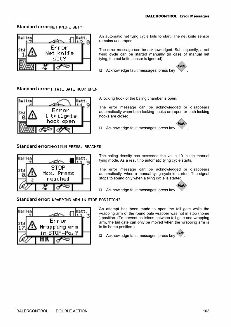
BALERCONTROL Error Messages
BALERCONTROL III DOUBLE ACTION 103
Standard error:NET KNNET KNNET KNNET KNIFE SET?IFE SET?IFE SET?IFE SET?
An automatic net tying cycle fails to start. The net knife sensor remains undamped. The error message can be acknowledged. Subsequently, a net tying cycle can be started manually (in case of manual net tying, the net knife sensor is ignored).
� Acknowledge fault messages: press key .
Standard error:1 TAIL GATE HOOK OPE1 TAIL GATE HOOK OPE1 TAIL GATE HOOK OPE1 TAIL GATE HOOK OPENNNN
A locking hook of the baling chamber is open. The error message can be acknowledged or disappears automatically when both locking hooks are open or both locking hooks are closed.
� Acknowledge fault messages: press key .
Standard error:MAXIMUM PRESS. REACHMAXIMUM PRESS. REACHMAXIMUM PRESS. REACHMAXIMUM PRESS. REACHEDEDEDED
The baling density has exceeded the value 10 in the manual tying mode. As a result no automatic tying cycle starts. The error message can be acknowledged or disappears automatically, when a manual tying cycle is started. The signal stops to sound only when a tying cycle is started.
� Acknowledge fault messages: press key .
Standard error: WRAPPING ARM IN STO WRAPPING ARM IN STO WRAPPING ARM IN STO WRAPPING ARM IN STOP POSITION?P POSITION?P POSITION?P POSITION?
An attempt has been made to open the tail gate while the wrapping arm of the round bale wrapper was not in stop (home ) position. (To prevent collisions between tail gate and wrapping arm, the tail gate can only be moved when the wrapping arm is in its home position.)
� Acknowledge fault messages: press key .
ErrorErrorErrorError Net knife Net knife Net knife Net knife
set?set?set?set?
ErrorErrorErrorError 1 tailgate 1 tailgate 1 tailgate 1 tailgate hook openhook openhook openhook open
STOPSTOPSTOPSTOP Max. Press Max. Press Max. Press Max. Press
reachedreachedreachedreached
ErrorErrorErrorError Wrapping armWrapping armWrapping armWrapping arm
in STOPin STOPin STOPin STOP----Po.?Po.?Po.?Po.?
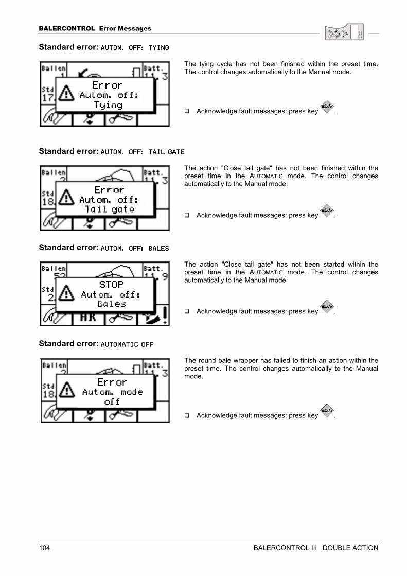
BALERCONTROL Error Messages
104 BALERCONTROL III DOUBLE ACTION
Standard error: AUTOM. OFF: TYINGAUTOM. OFF: TYINGAUTOM. OFF: TYINGAUTOM. OFF: TYING
The tying cycle has not been finished within the preset time. The control changes automatically to the Manual mode.
� Acknowledge fault messages: press key .
Standard error: AUTOM. OFF: TAIL GATAUTOM. OFF: TAIL GATAUTOM. OFF: TAIL GATAUTOM. OFF: TAIL GATEEEE
The action "Close tail gate" has not been finished within the preset time in the AUTOMATIC mode. The control changes automatically to the Manual mode.
� Acknowledge fault messages: press key .
Standard error: AUTOM. OFF: BALESAUTOM. OFF: BALESAUTOM. OFF: BALESAUTOM. OFF: BALES
The action "Close tail gate" has not been started within the preset time in the AUTOMATIC mode. The control changes automatically to the Manual mode.
� Acknowledge fault messages: press key .
Standard error: AUTOMATIC AUTOMATIC AUTOMATIC AUTOMATIC OFFOFFOFFOFF
The round bale wrapper has failed to finish an action within the preset time. The control changes automatically to the Manual mode.
� Acknowledge fault messages: press key .
ErrorErrorErrorError Autom. off: Autom. off: Autom. off: Autom. off:
Tying Tying Tying Tying
STOPSTOPSTOPSTOP Autom. off: Autom. off: Autom. off: Autom. off:
BalesBalesBalesBales
ErrorErrorErrorError Autom. off: Autom. off: Autom. off: Autom. off: Tail gateTail gateTail gateTail gate
ErrorErrorErrorError Autom. mode Autom. mode Autom. mode Autom. mode
off off off off
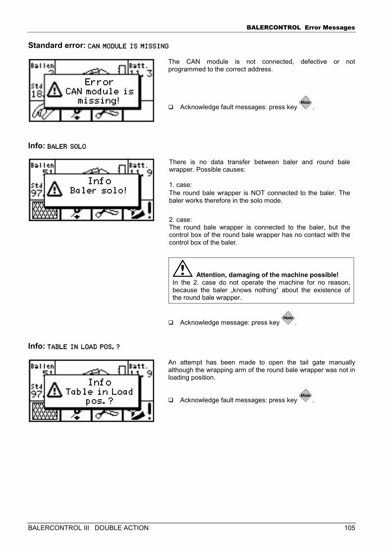
BALERCONTROL Error Messages
BALERCONTROL III DOUBLE ACTION 105
Standard error: CAN MODULE IS MISSINCAN MODULE IS MISSINCAN MODULE IS MISSINCAN MODULE IS MISSINGGGG
The CAN module is not connected, defective or not programmed to the correct address.
� Acknowledge fault messages: press key .
Info: BALER SOLOBALER SOLOBALER SOLOBALER SOLO
There is no data transfer between baler and round bale wrapper. Possible causes: 1. case: The round bale wrapper is NOT connected to the baler. The baler works therefore in the solo mode.
2. case: The round bale wrapper is connected to the baler, but the control box of the round bale wrapper has no contact with the control box of the baler.
Attention, damaging of the machine possible! In the 2. case do not operate the machine for no reason, because the baler „knows nothing“ about the existence of the round bale wrapper.
� Acknowledge message: press key .
Info: TABLE IN LOAD POS.?TABLE IN LOAD POS.?TABLE IN LOAD POS.?TABLE IN LOAD POS.?
An attempt has been made to open the tail gate manually although the wrapping arm of the round bale wrapper was not in loading position.
� Acknowledge fault messages: press key .
ErrorErrorErrorError CAN module isCAN module is CAN module isCAN module is
missing!missing!missing!missing!
InfoInfoInfoInfo Baler solo!Baler solo!Baler solo!Baler solo!
InfoInfoInfoInfo Table in Load Table in Load Table in Load Table in Load
pos.?pos.?pos.?pos.?
BALERCONTROL Error Messages
106 BALERCONTROL III DOUBLE ACTION
The following chapters are intended exclusively for trained and instructed service personnel!
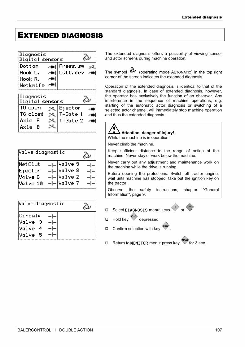
Extended diagnosis
BALERCONTROL III DOUBLE ACTION 107
EEEEXTENDED DIAGNOSISXTENDED DIAGNOSISXTENDED DIAGNOSISXTENDED DIAGNOSIS
The extended diagnosis offers a possibility of viewing sensor and actor screens during machine operation.
The symbol (operating mode AUTOMATIC) in the top right corner of the screen indicates the extended diagnosis. Operation of the extended diagnosis is identical to that of the standard diagnosis. In case of extended diagnosis, however, the operator has exclusively the function of an observer. Any interference in the sequence of machine operations, e.g. starting of the automatic actor diagnosis or switching of a selected actor channel, will immediately stop machine operation and thus the extended diagnosis.
Attention, danger of injury! While the machine is in operation:
Never climb the machine.
Keep sufficient distance to the range of action of the machine. Never stay or work below the machine.
Never carry out any adjustment and maintenance work on the machine while the drive is running.
Before opening the protections: Switch off tractor engine, wait until machine has stopped, take out the ignition key on the tractor.
Observe the safety instructions, chapter "General Information", page 9.
� Select DIAGNOSISDIAGNOSISDIAGNOSISDIAGNOSIS menu: keys or
� Hold key depressed.
� Confirm selection with key .
� Return to MONITORMONITORMONITORMONITOR menu: press key for 3 sec.
DiagnosisDiagnosisDiagnosisDiagnosis Digital sensorsDigital sensorsDigital sensorsDigital sensors BottomBottomBottomBottom
Hook L.Hook L.Hook L.Hook L.
Hook R.Hook R.Hook R.Hook R.
NetknifeNetknifeNetknifeNetknife
Press.swPress.swPress.swPress.sw
Cutt.devCutt.devCutt.devCutt.dev
DiagnosisDiagnosisDiagnosisDiagnosis Digital sensorsDigital sensorsDigital sensorsDigital sensors TG openTG openTG openTG open
TG closdTG closdTG closdTG closd
Axle FAxle FAxle FAxle F
Axle BAxle BAxle BAxle B
EjectorEjectorEjectorEjector
TTTT----Gate 1Gate 1Gate 1Gate 1
TTTT----Gate 2Gate 2Gate 2Gate 2
Valve diagnosticValve diagnosticValve diagnosticValve diagnostic
Valve 9Valve 9Valve 9Valve 9
Valve 8Valve 8Valve 8Valve 8
Valve 2Valve 2Valve 2Valve 2 Valve 7Valve 7Valve 7Valve 7
NetClutNetClutNetClutNetClut
EjectorEjectorEjectorEjector
Valve 6Valve 6Valve 6Valve 6
Valve 10Valve 10Valve 10Valve 10
Valve diagnosticValve diagnosticValve diagnosticValve diagnostic
CirculaCirculaCirculaCircula
Valve 3Valve 3Valve 3Valve 3
Valve 4Valve 4Valve 4Valve 4
Valve 5Valve 5Valve 5Valve 5
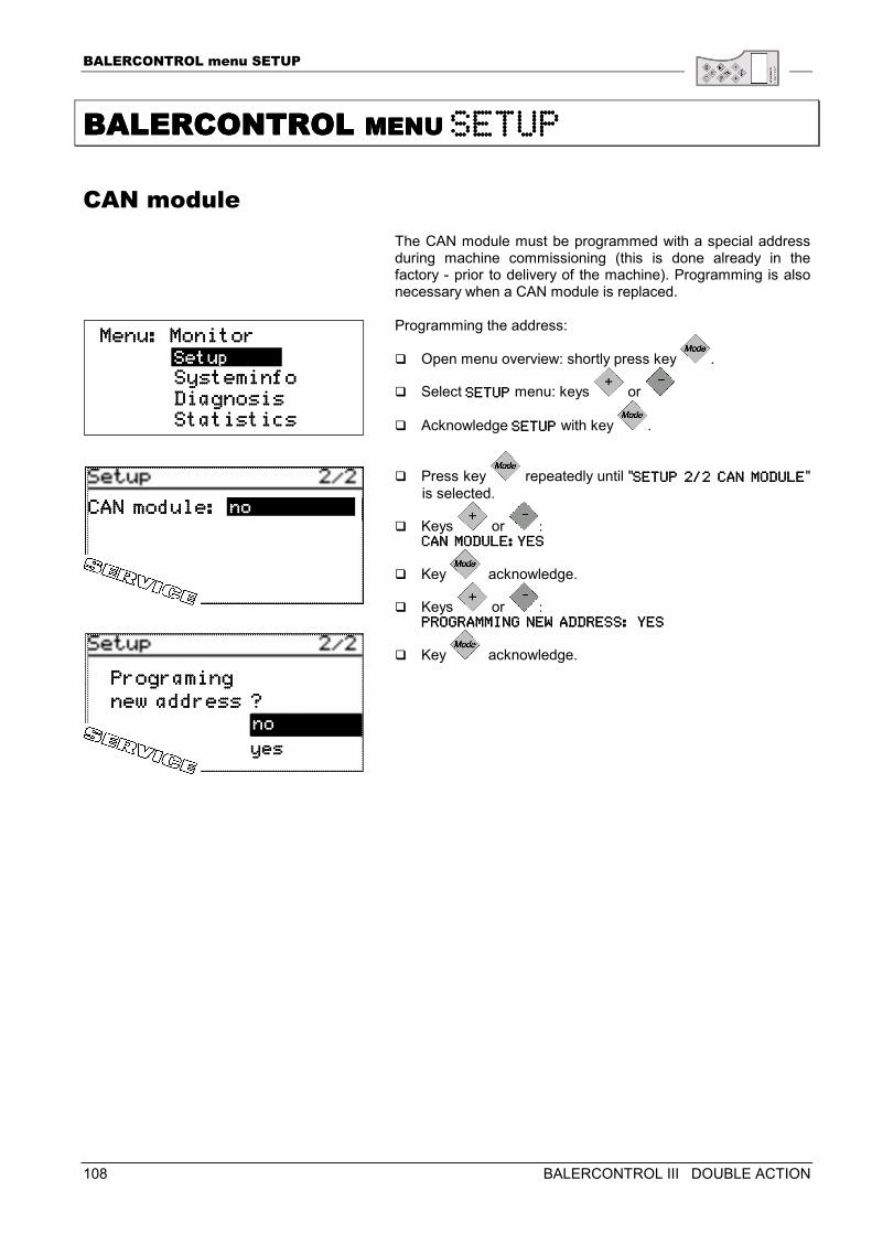
BALERCONTROL menu SETUP
108 BALERCONTROL III DOUBLE ACTION
BALERCONTROL BALERCONTROL BALERCONTROL BALERCONTROL MENU MENU MENU MENU SETUPSETUPSETUPSETUP
CAN module The CAN module must be programmed with a special address during machine commissioning (this is done already in the factory - prior to delivery of the machine). Programming is also necessary when a CAN module is replaced. Programming the address:
� Open menu overview: shortly press key .
� Select SETUPSETUPSETUPSETUP menu: keys or
� Acknowledge SETUPSETUPSETUPSETUP with key .
� Press key repeatedly until "SETUP 2/2 CAN MODULESETUP 2/2 CAN MODULESETUP 2/2 CAN MODULESETUP 2/2 CAN MODULE" is selected.
� Keys or : CAN MODULE:YESCAN MODULE:YESCAN MODULE:YESCAN MODULE:YES
� Key acknowledge.
� Keys or : PROGRAMMING NEW ADDRPROGRAMMING NEW ADDRPROGRAMMING NEW ADDRPROGRAMMING NEW ADDRESS: YESESS: YESESS: YESESS: YES
� Key acknowledge.
Menu: MonitorMenu: MonitorMenu: MonitorMenu: Monitor Systeminfo Systeminfo Systeminfo Systeminfo Diagnosis Diagnosis Diagnosis Diagnosis Statistics Statistics Statistics Statistics
SetupSetupSetupSetup
CAN module:CAN module:CAN module:CAN module: nononono
nononono
Programing Programing Programing Programing
new address ?new address ?new address ?new address ?
yesyesyesyes
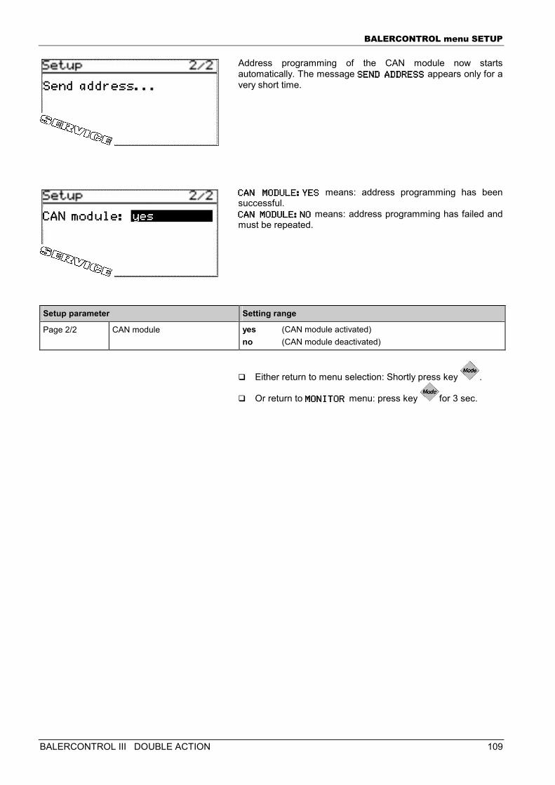
BALERCONTROL menu SETUP
BALERCONTROL III DOUBLE ACTION 109
Address programming of the CAN module now starts automatically. The message SEND ADDRESSSEND ADDRESSSEND ADDRESSSEND ADDRESS appears only for a very short time. CAN MODULE:YESCAN MODULE:YESCAN MODULE:YESCAN MODULE:YES means: address programming has been successful. CAN MODULE:NOCAN MODULE:NOCAN MODULE:NOCAN MODULE:NO means: address programming has failed and must be repeated.
Setup parameter Setting range
Page 2/2 CAN module yes (CAN module activated) no (CAN module deactivated)
� Either return to menu selection: Shortly press key .
� Or return to MONITOR MONITOR MONITOR MONITOR menu: press key for 3 sec.
CANCANCANCAN module: module: module: module: yesyesyesyes
Send address...Send address...Send address...Send address...
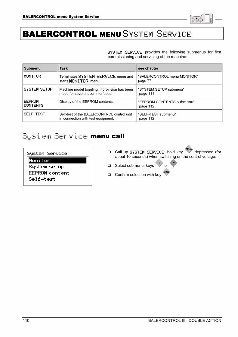
BALERCONTROL menu System Service
110 BALERCONTROL III DOUBLE ACTION
BALERCONTROL BALERCONTROL BALERCONTROL BALERCONTROL MENU MENU MENU MENU SSSSYSTEM YSTEM YSTEM YSTEM SSSSERVICEERVICEERVICEERVICE
SYSTEM SSYSTEM SSYSTEM SSYSTEM SERVICE ERVICE ERVICE ERVICE provides the following submenus for first commissioning and servicing of the machine:
Submenu Task see chapter
MONITORMONITORMONITORMONITOR Terminates SYSTEM SERVICESYSTEM SERVICESYSTEM SERVICESYSTEM SERVICE menu and starts MONITOR MONITOR MONITOR MONITOR menu.
"BALERCONTROL menu MONITOR“ page 77
SYSTEM SETUPSYSTEM SETUPSYSTEM SETUPSYSTEM SETUP Machine model toggling, if provision has been made for several user interfaces.
"SYSTEM SETUP submenu" page 111
EEPROM EEPROM EEPROM EEPROM CCCCONTENTSONTENTSONTENTSONTENTS
Display of the EEPROM contents. "EEPROM CONTENTS submenu" page 112
SELF TESTSELF TESTSELF TESTSELF TEST Self-test of the BALERCONTROL control unit in connection with test equipment.
"SELF-TEST submenu" page 112
System Service menu call
� Call up SYSTEM SERVICESYSTEM SERVICESYSTEM SERVICESYSTEM SERVICE: hold key depressed (for about 10 seconds) when switching on the control voltage.
� Select submenu: keys or
� Confirm selection with key .
System setup System setup System setup System setup
EEPROM coEEPROM coEEPROM coEEPROM connnntenttenttenttent
SelfSelfSelfSelf----testtesttesttest
MonitorMonitorMonitorMonitor
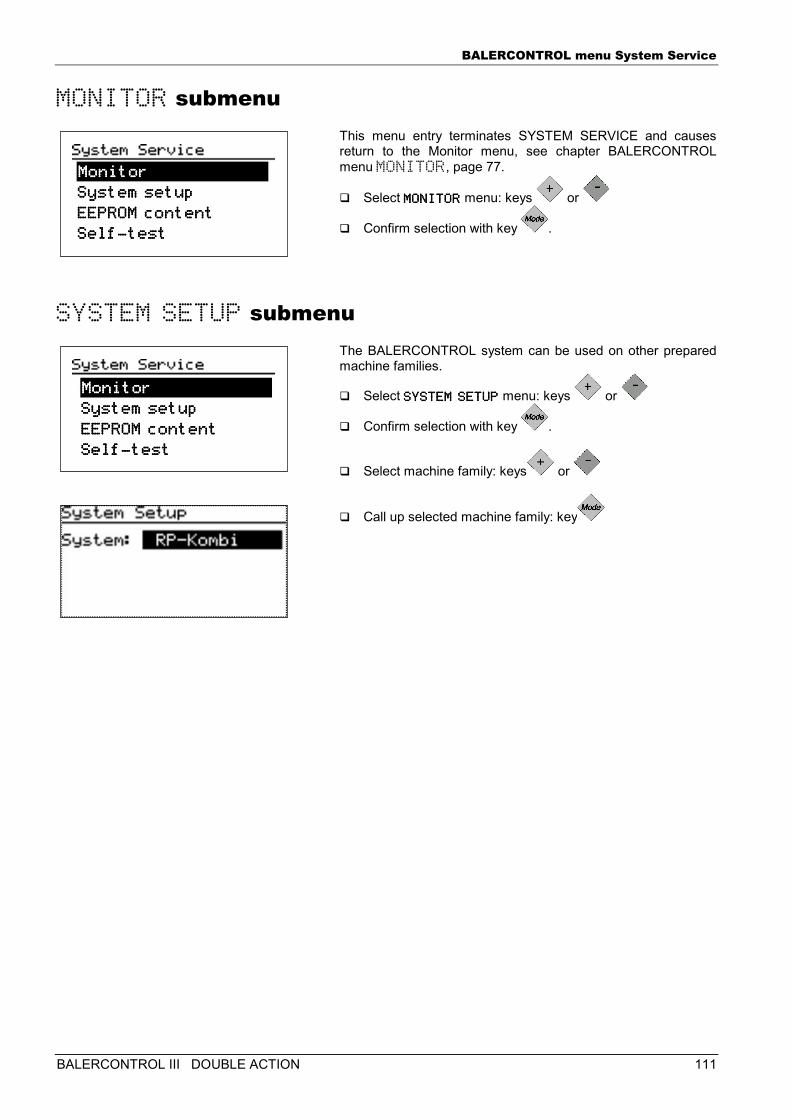
BALERCONTROL menu System Service
BALERCONTROL III DOUBLE ACTION 111
MONITOR submenu This menu entry terminates SYSTEM SERVICE and causes return to the Monitor menu, see chapter BALERCONTROL menu MONITOR, page 77.
� Select MONITORMONITORMONITORMONITOR menu: keys or
� Confirm selection with key .
SYSTEM SETUP submenu The BALERCONTROL system can be used on other prepared machine families.
� Select SYSTEM SETUPSYSTEM SETUPSYSTEM SETUPSYSTEM SETUP menu: keys or
� Confirm selection with key .
� Select machine family: keys or
� Call up selected machine family: key
System setup System setup System setup System setup
EEPROM coEEPROM coEEPROM coEEPROM connnntenttenttenttent
SelfSelfSelfSelf----testtesttesttest
MonitorMonitorMonitorMonitor
System setup System setup System setup System setup
EEPROM coEEPROM coEEPROM coEEPROM connnntenttenttenttent
SelfSelfSelfSelf----testtesttesttest
MonitorMonitorMonitorMonitor
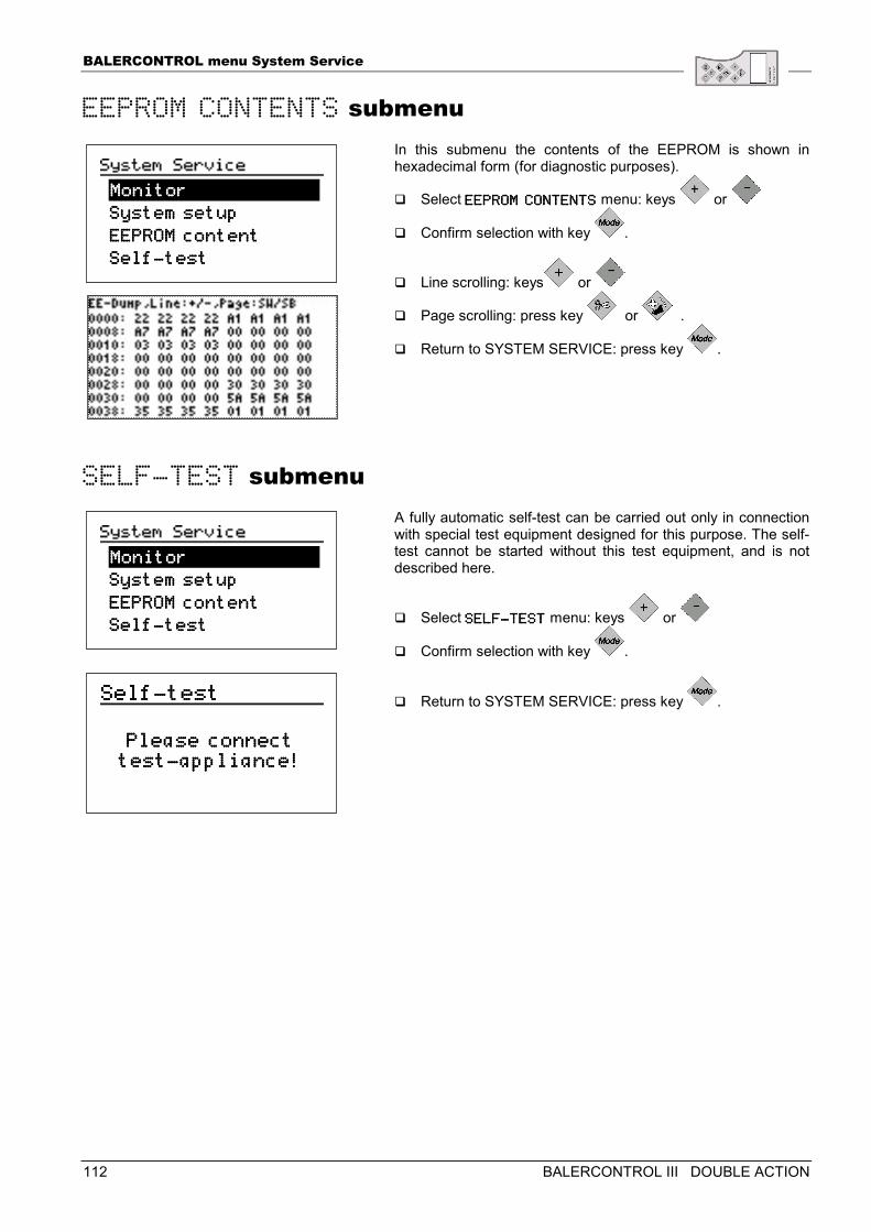
BALERCONTROL menu System Service
112 BALERCONTROL III DOUBLE ACTION
EEPROM CONTENTS submenu In this submenu the contents of the EEPROM is shown in hexadecimal form (for diagnostic purposes).
� Select EEPROM CONTENTEEPROM CONTENTEEPROM CONTENTEEPROM CONTENTSSSS menu: keys or
� Confirm selection with key .
� Line scrolling: keys or
� Page scrolling: press key or .
� Return to SYSTEM SERVICE: press key .
SELF-TEST submenu A fully automatic self-test can be carried out only in connection with special test equipment designed for this purpose. The self-test cannot be started without this test equipment, and is not described here.
� Select SELFSELFSELFSELF----TESTTESTTESTTEST menu: keys or
� Confirm selection with key .
� Return to SYSTEM SERVICE: press key .
System setup System setup System setup System setup
EEPROM coEEPROM coEEPROM coEEPROM connnntenttenttenttent
SelfSelfSelfSelf----testtesttesttest
MonitorMonitorMonitorMonitor
SysteSysteSysteSystem setup m setup m setup m setup
EEPROM coEEPROM coEEPROM coEEPROM connnntenttenttenttent
SelfSelfSelfSelf----testtesttesttest
MonitorMonitorMonitorMonitor
SelfSelfSelfSelf----testtesttesttest
Please connectPlease connectPlease connectPlease connect testtesttesttest----appliance!appliance!appliance!appliance!
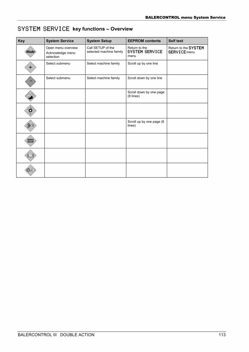
BALERCONTROL menu System Service
BALERCONTROL III DOUBLE ACTION 113
SYSTEM SERVICE SYSTEM SERVICE SYSTEM SERVICE SYSTEM SERVICE key functions – Overview
Key System Service System Setup EEPROM contents Self test
Open menu overview Acknowledge menu selection
Call SETUP of the selected machine family
Return to the SYSTEM SERVICE SYSTEM SERVICE SYSTEM SERVICE SYSTEM SERVICE menu
Return to the SYSTEM SYSTEM SYSTEM SYSTEM SERVICESERVICESERVICESERVICEmenu
Select submenu Select machine family Scroll up by one line
Select submenu Select machine family Scroll down by one line
Scroll down by one page (8 lines)
Scroll up by one page (8 lines)
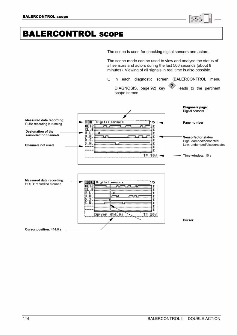
BALERCONTROL scope
114 BALERCONTROL III DOUBLE ACTION
BALERCONTROL BALERCONTROL BALERCONTROL BALERCONTROL SCOPESCOPESCOPESCOPE
The scope is used for checking digital sensors and actors. The scope mode can be used to view and analyse the status of all sensors and actors during the last 500 seconds (about 8 minutes). Viewing of all signals in real time is also possible. � In each diagnostic screen (BALERCONTROL menu
DIAGNOSIS, page 92) key leads to the pertinent scope screen.
Measured data recording: RUN: recording is running
Diagnosis page:Digital sensors
Channels not used
Sensor/actor statusHigh: damped/connected Low: undamped/disconnected
Diagnosis page:Digital sensors
Page number
Designation of the sensor/actor channels
Time window: 10 s
1/5
Cursor position: 414.0 s
1/5 Measured data recording: HOLD: recording stopped
Cursor
Digital seDigital seDigital seDigital sennnnsorssorssorssors
Digital seDigital seDigital seDigital sennnnsorssorssorssors
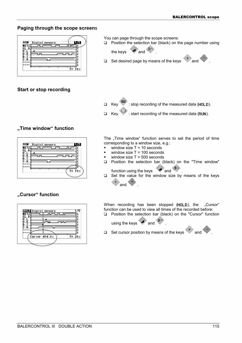
BALERCONTROL scope
BALERCONTROL III DOUBLE ACTION 115
Paging through the scope screens
You can page through the scope screens: � Position the selection bar (black) on the page number using
the keys and .
� Set desired page by means of the keys and .
Start or stop recording
� Key : stop recording of the measured data (HOLDHOLDHOLDHOLD).
� Key : start recording of the measured data (RUNRUNRUNRUN).
„Time window“ function
The „Time window“ function serves to set the period of time corresponding to a window size, e.g.: � window size T = 10 seconds � window size T = 100 seconds � window size T = 500 seconds � Position the selection bar (black) on the "Time window"
function using the keys and . � Set the value for the window size by means of the keys
and .
„Cursor“ function
When recording has been stopped (HOLDHOLDHOLDHOLD), the „Cursor“ function can be used to view all times of the recorded before: � Position the selection bar (black) on the "Cursor" function
using the keys and .
� Set cursor position by means of the keys and .
Digital seDigital seDigital seDigital sennnnsorssorssorssors
Digital seDigital seDigital seDigital sennnnsorssorssorssors
Digital seDigital seDigital seDigital sennnnsorssorssorssors
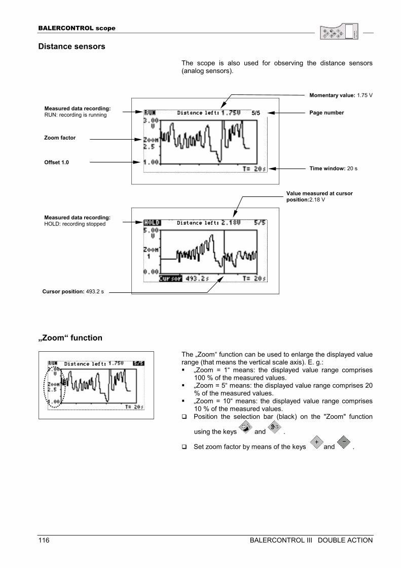
BALERCONTROL scope
116 BALERCONTROL III DOUBLE ACTION
Distance sensors
The scope is also used for observing the distance sensors (analog sensors).
„Zoom“ function
The „Zoom“ function can be used to enlarge the displayed value range (that means the vertical scale axis). E. g.: � „Zoom = 1“ means: the displayed value range comprises
100 % of the measured values. � „Zoom = 5“ means: the displayed value range comprises 20
% of the measured values. � „Zoom = 10“ means: the displayed value range comprises
10 % of the measured values. � Position the selection bar (black) on the "Zoom" function
using the keys and .
� Set zoom factor by means of the keys and .
Offset 1.0
Zoom factor
5/5
Momentary value: 1.75 V
Cursor position: 493.2 s
Value measured at cursor position:2.18 V
Measured data recording: RUN: recording is running
Measured data recording: HOLD: recording stopped
Page number
Time window: 20 s
Distance left:Distance left:Distance left:Distance left:
Distance left:Distance left:Distance left:Distance left:
Distance left:Distance left:Distance left:Distance left:
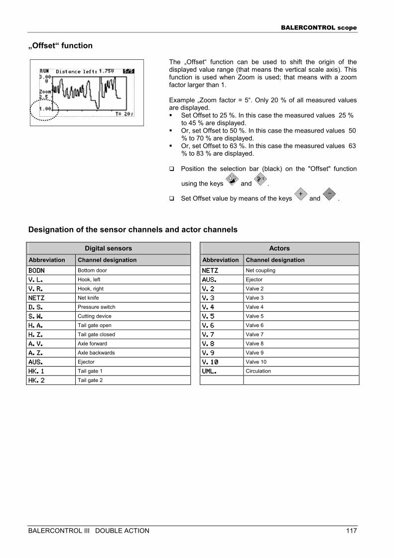
BALERCONTROL scope
BALERCONTROL III DOUBLE ACTION 117
„Offset“ function
The „Offset“ function can be used to shift the origin of the displayed value range (that means the vertical scale axis). This function is used when Zoom is used; that means with a zoom factor larger than 1. Example „Zoom factor = 5“. Only 20 % of all measured values are displayed. � Set Offset to 25 %. In this case the measured values 25 %
to 45 % are displayed. � Or, set Offset to 50 %. In this case the measured values 50
% to 70 % are displayed. � Or, set Offset to 63 %. In this case the measured values 63
% to 83 % are displayed.
� Position the selection bar (black) on the "Offset" function
using the keys and .
� Set Offset value by means of the keys and .
Designation of the sensor channels and actor channels
Digital sensors Actors Abbreviation Channel designation Abbreviation Channel designation BODNBODNBODNBODN Bottom door NETZNETZNETZNETZ Net coupling
V.L.V.L.V.L.V.L. Hook, left AUS.AUS.AUS.AUS. Ejector
V.R.V.R.V.R.V.R. Hook, right V.2V.2V.2V.2 Valve 2
NETZNETZNETZNETZ Net knife V.3V.3V.3V.3 Valve 3
D.S.D.S.D.S.D.S. Pressure switch V.4V.4V.4V.4 Valve 4
S.W.S.W.S.W.S.W. Cutting device V.5V.5V.5V.5 Valve 5
H.A.H.A.H.A.H.A. Tail gate open V.6V.6V.6V.6 Valve 6
H.Z.H.Z.H.Z.H.Z. Tail gate closed V.7V.7V.7V.7 Valve 7
A.V.A.V.A.V.A.V. Axle forward V.8V.8V.8V.8 Valve 8
A.Z.A.Z.A.Z.A.Z. Axle backwards V.9V.9V.9V.9 Valve 9
AUS.AUS.AUS.AUS. Ejector V.10V.10V.10V.10 Valve 10
HK.1HK.1HK.1HK.1 Tail gate 1 UML.UML.UML.UML. Circulation
HK.2HK.2HK.2HK.2 Tail gate 2
Distance left:Distance left:Distance left:Distance left:
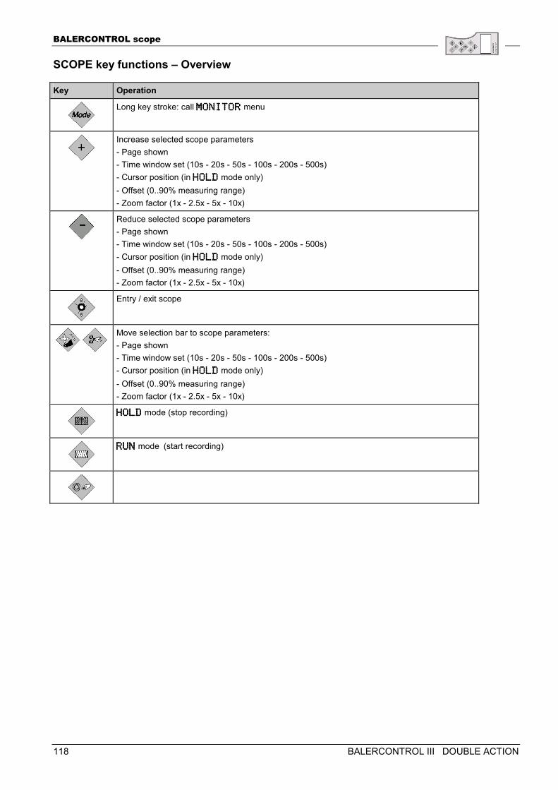
BALERCONTROL scope
118 BALERCONTROL III DOUBLE ACTION
SCOPE key functions – Overview
Key Operation
Long key stroke: call MONITORMONITORMONITORMONITOR menu
Increase selected scope parameters - Page shown - Time window set (10s - 20s - 50s - 100s - 200s - 500s) - Cursor position (in HOLDHOLDHOLDHOLD mode only) - Offset (0..90% measuring range) - Zoom factor (1x - 2.5x - 5x - 10x)
Reduce selected scope parameters - Page shown - Time window set (10s - 20s - 50s - 100s - 200s - 500s) - Cursor position (in HOLDHOLDHOLDHOLD mode only) - Offset (0..90% measuring range) - Zoom factor (1x - 2.5x - 5x - 10x)
Entry / exit scope
Move selection bar to scope parameters: - Page shown - Time window set (10s - 20s - 50s - 100s - 200s - 500s) - Cursor position (in HOLDHOLDHOLDHOLD mode only) - Offset (0..90% measuring range) - Zoom factor (1x - 2.5x - 5x - 10x)
HOLDHOLDHOLDHOLD mode (stop recording)
RUNRUNRUNRUN mode (start recording)

BALERCONTROL scope
BALERCONTROL III DOUBLE ACTION 119
INDEX
120 BALERCONTROL III DOUBLE ACTION
INDEXINDEXINDEXINDEX
E-LINK Display 13 EEPROM CONTENTS submenu 66 Electrical equipment/Electronics 10 Electromagnetic compatibility (EMC) 11 ERROR MESSAGES 54 EXTENDED DIAGNOSIS 63 MENU DIAGNOSIS 44 MENU MONITOR 15 MENU SETUP 36 MENU STATISTICS 52 MENU SYSTEM SERVICE 64 MENU SYSTEMINFO 43 Menu 14 MONITOR submenu 65 Operating mode Automatic 15 Operating mode: Manual 32 Operating mode: Semiautomatic 25 Proper use 8 SAFETY 8 SCOPE 68 SELF-TEST submenu 66 SETUP 1/4 38 SETUP 2/4 39 SETUP 3/4 39 SETUP 4/4 41 Standard diagnosis 45 Standard error messages 56 System error messages 55 System Service menu call 64 SYSTEM SETUP submenu 65 THE E-LINK MENUS 14 WARNING SYMBOLS 7 Welding work 10
BALERCONTROL III Actuation of the units 79 BALERCONTROL ERROR MESSAGES 100 BALERCONTROL MENUS 76 BALERCONTROL III 73 BALERCONTROL III 74 BALERCONTROL MENU DIAGNOSIS 92 BALERCONTROL MENU MONITOR 77 BALERCONTROL MENU SETUP 108 BALERCONTROL MENU SETUP 87 BALERCONTROL MENU STATISTICS 98 BALERCONTROL MENU SYSTEM SERVICE 110 BALERCONTROL MENU SYSTEMINFO 90 BALERCONTROL SCOPE 114 Baling 82 Beep 88 CAN module 108 Close tail gate 84 Delay (tying) 88 Display 75 EEPROM CONTENTS submenu 112 EXTENDED DIAGNOSIS 107 Language 88 Machine standstill 84 Machine type 88 Menu selection 76 MONITOR submenu 111 Opening the tail gate 83 Operating modes 77 SELF-TEST submenu 112 Setting the bale density 84 Standard diagnosis 93 Standard error messages 102 System error messages 101 System Service menu call 110 SYSTEM SETUP submenu 111 Tail gate opened 83 Tying 82


