Embed Size (px)
Citation preview
INSTITUTE OF PHYSICS PUBLISHING MEASUREMENT SCIENCE AND TECHNOLOGY
Meas. Sci. Technol. 14 (2003) R49–R61 PII: S0957-0233(03)55184-0
REVIEW ARTICLE
Optical fibre long-period grating sensors:characteristics and applicationStephen W James and Ralph P Tatam
Optical Sensors Group, Centre for Photonics and Optical Engineering, School of Engineering,Cranfield University, Cranfield, Bedford MK43 OAL, UK
E-mail: [email protected]
Received 24 October 2002, accepted for publication 13 November 2002Published 26 March 2003Online at stacks.iop.org/MST/14/R49
AbstractRecent research on fibre optic long-period gratings (LPGs) is reviewed withemphasis placed upon the characteristics of LPGs that make them attractivefor applications in sensing strain, temperature, bend radius and externalindex of refraction. The prospect of the development of multi-parametersensors, capable of simultaneously monitoring a number of thesemeasurands will be discussed.
Keywords: fibre optics, fibre sensors, fibre gratings, long period gratings,strain, temperature, bend sensor, refractive index
(Some figures in this article are in colour only in the electronic version)
1. Introduction
The development of fibre gratings has had a significantimpact on research and development in telecommunicationsand fibre optic sensing. Fibre gratings are intrinsic devicesthat allow control over the properties of light propagatingwithin the fibre—they are used as spectral filters, asdispersion compensating components and in wavelengthdivision multiplexing systems. The sensitivity of theirproperties to perturbation of the fibre by the surroundingenvironmental conditions has led to extensive study of theiruse as fibre sensor elements.
Fibre gratings consist of a periodic perturbation of theproperties of the optical fibre, generally of the refractive indexof the core, and fall into two general classifications basedupon the period of the grating. Short-period fibre gratings,or fibre Bragg gratings (FBGs), have a sub-micron period andact to couple light from the forward-propagating mode of theoptical fibre to a backward, counterpropagating mode [1]. Thiscoupling occurs at a specific wavelength, defined by the Braggcondition for the fibre grating, with the FBG acting as a narrow-band reflection filter and as a narrow-band channel-droppingfilter when operated in transmission. The Bragg wavelength isgoverned by the period of the FBG and the effective index
of the propagating mode, with the result that a change ineither of these parameters, induced for example by a changein temperature or strain, changes the wavelength, forming thebasis of the many reported FBG sensing schemes. Typically,FBGs deployed as sensors have lengths of the order of 5 mm,with sensitivities to temperature and strain of 13 pm K−1 and1 pm µε−1 respectively, for FBGs operating at 1300 nm [2].
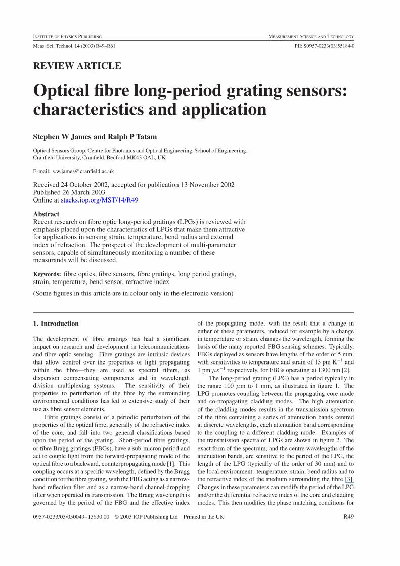
The long-period grating (LPG) has a period typically inthe range 100 µm to 1 mm, as illustrated in figure 1. TheLPG promotes coupling between the propagating core modeand co-propagating cladding modes. The high attenuationof the cladding modes results in the transmission spectrumof the fibre containing a series of attenuation bands centredat discrete wavelengths, each attenuation band correspondingto the coupling to a different cladding mode. Examples ofthe transmission spectra of LPGs are shown in figure 2. Theexact form of the spectrum, and the centre wavelengths of theattenuation bands, are sensitive to the period of the LPG, thelength of the LPG (typically of the order of 30 mm) and tothe local environment: temperature, strain, bend radius and tothe refractive index of the medium surrounding the fibre [3].Changes in these parameters can modify the period of the LPGand/or the differential refractive index of the core and claddingmodes. This then modifies the phase matching conditions for
0957-0233/03/050049+13$30.00 © 2003 IOP Publishing Ltd Printed in the UK R49
Review Article
Figure 1. Schematic of an LPG.
coupling to the cladding modes, and results in a change in thecentral wavelengths of the attenuation bands.
The sensitivity to a particular measurand is dependentupon the composition of the fibre and upon the order of thecladding mode to which the guided optical power is coupled,and is thus different for each attenuation band. This rangeof responses makes them particularly attractive for sensorapplications, with the prospect for multi-parameter sensingusing a single sensor element [3].
This review will discuss the properties of LPGs and themethods employed in their fabrication. This will be followedby an examination of the theoretical background of LPGs, adiscussion of their sensitivities to a range of measurands witha review of their implementation as sensor elements and adiscussion of current trends in LPG sensor research.
2. LPG fabrication
The fabrication of LPGs relies upon the introduction of aperiodic modulation of the optical properties of the fibre. Thismay be achieved by permanent modification of the refractiveindex of the core of the optical fibre or by physical deformationof the fibre.
The modulation of the core refractive index hasbeen achieved by ultraviolet (UV) irradiation [4–7], ionimplantation [8], irradiation by femtosecond pulses in theinfrared [9], irradiation by CO2 lasers [10, 11], diffusionof dopants into the core [12, 13], relaxation of mechanicalstress [14] and electrical discharges [15, 16]. The deformationof the fibre has been achieved mechanically [17, 18], bytapering the fibre [19] or by deformation of the core [20, 21] orcladding [22]. LPGs have been fabricated in photonic crystalfibre by periodically collapsing the holes of the fibre using CO2
laser heat treatment [23].The UV-induced index modulation is typically achieved
in Ge-doped silica fibres using wavelengths between 193 and266 nm [24]. This is the most widely utilized method for thefabrication of LPGs. The refractive index change is associatedwith the formation of Ge-related glass defects. Fibres with highphotosensitivity have been developed by co-doping the corewith boron and germanium [25] and by hydrogen loading [26].The refractive index modulation may be built up on a point bypoint basis—a very flexible technique—or the entire lengthof the LPG may be formed simultaneously by exposure ofthe fibre though an amplitude mask [27], via a patternedmirror [28] or using a microlens array [29]—facilitating rapidand reproducible LPG fabrication.
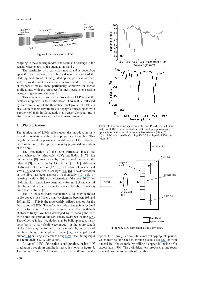
A typical LPG fabrication configuration, using UVirradiation through an amplitude mask, is shown in figure 3.The output from a UV laser source is used to illuminate the
800 850 900 950 1000 1050 110010
20
30
4050
60
7080
90
Tra
nsm
issi
on %
Wavelength (nm)
100
(a)
(b)
Figure 2. Transmission spectrum of (a) an LPG of length 40 mmand period 400 µm, fabricated in B–Ge co-doped photosensitiveoptical fibre with a cut-off wavelength of 644 nm (after [55]).(b) An LPG fabricated in Corning SMF-28 with period 320 µm(after [44]).
UV
cylindricallens
amplitudemask
spectrometer
V groove
optical fibre
laser
V groove
broadbandoptical source
Figure 3. LPG fabrication using a UV laser.
optical fibre through an amplitude mask of appropriate period,which may be fabricated in chrome-plated silica [27] or froma metal foil, for example by milling a copper foil using a Cuvapour laser [30]. The cylindrical lens produces a line focusoriented parallel to the axis of the fibre.
R50
Review Article
The use of UV exposure is well established, due to itswidespread use in the fabrication of FBGs [31]. Its use hasimplications for the spectral characteristics and stability ofthe LPG spectrum. UV exposure of optical fibres is knownto induce birefringence, which can produce a polarizationsplitting in the attenuation bands for LPGs fabricated in non-polarization-maintaining fibres [32]. The refractive indexchange is known to contain an unstable component, whichdecays in time causing a significant change in the centralwavelengths of the attenuation bands and in the couplingstrength [27]. This unstable component may be removed bythermal annealing, but needs to be taken into account whendesigning an LPG for a particular application. The use ofhydrogen loading of fibres to enhance their photosensitivitycan result in further changes to the central wavelength andpeak loss of the attenuation bands occurring after fabrication,as the hydrogen diffuses out of the fibre [6]. LPGs fabricatedin hydrogen-loaded fibre by irradiation at 193 nm have beenobserved to exhibit a growth in the peak loss of up to 14 dBand an increase in central wavelength of 40 nm over the first20 h following UV exposure, followed by a slow reduction ofthe peak loss and decrease in central wavelength of 50 nm overthe following 450 h [6]. The effect is attributed to depletionof hydrogen in the exposed regions of the core. The diffusionof hydrogen from unexposed to exposed regions then acts toincrease the amplitude of the refractive index modulation, asthe refractive index increases further in the exposed regions(increasing hydrogen concentration) and decreases in theunexposed region (decreasing hydrogen concentration). Thusthe strength of the LPG grows. This is followed by a slow out-diffusion whereby the refractive index of the core decreases,causing a decrease in wavelength. Similar effects have beenobserved for LPGs fabricated in hydrogen-loaded fibres using248 nm irradiation [33]. These effects limit the ability tofabricate LPGs with precisely defined characteristics withinhydrogen-loaded fibre. It has been shown that pre-exposureof a hydrogen-loaded fibre to a uniform UV beam locks inthe photosensitivity enhancement provided by the hydrogenloading procedure [34]. The UV pre-exposure of the hydrogen-loaded fibre increases the number of defect sites believed tobe responsible for photosensitivity, and these remain afterthe hydrogen has diffused out of the fibre. If an LPG isfabricated in pre-exposed fibre after the hydrogen has diffusedout of the fibre, typically 2 weeks after removal from thehydrogen atmosphere at room temperature, the fibre maintainsthe photosensitivity, but does not suffer from the changesin attenuation band central wavelength and extinction [34].Such effects have been observed using continuous-wave (CW)pre-exposure at 244 nm [34] and using pulsed irradiation at157 nm [35] and 193 nm.
Post-fabrication tuning of the characteristics of an LPG’stransmission spectrum is possible by reducing the fibrediameter by etching. The reduction in cladding diameterchanges the effective index of the cladding modes, resultingin an increase in the central wavelengths of the attenuationbands. The etching also changes the electric field profileof the cladding modes, resulting in a change in the overlapintegral and a concomitant change in the coupling efficiencyand minimum transmission of the attenuation bands [36, 37].
Other UV wavelengths are being investigated for LPGformation, including 157 nm from F2 lasers which offers the
Fixed Point Stretching andtwisting point
Cladding
Core
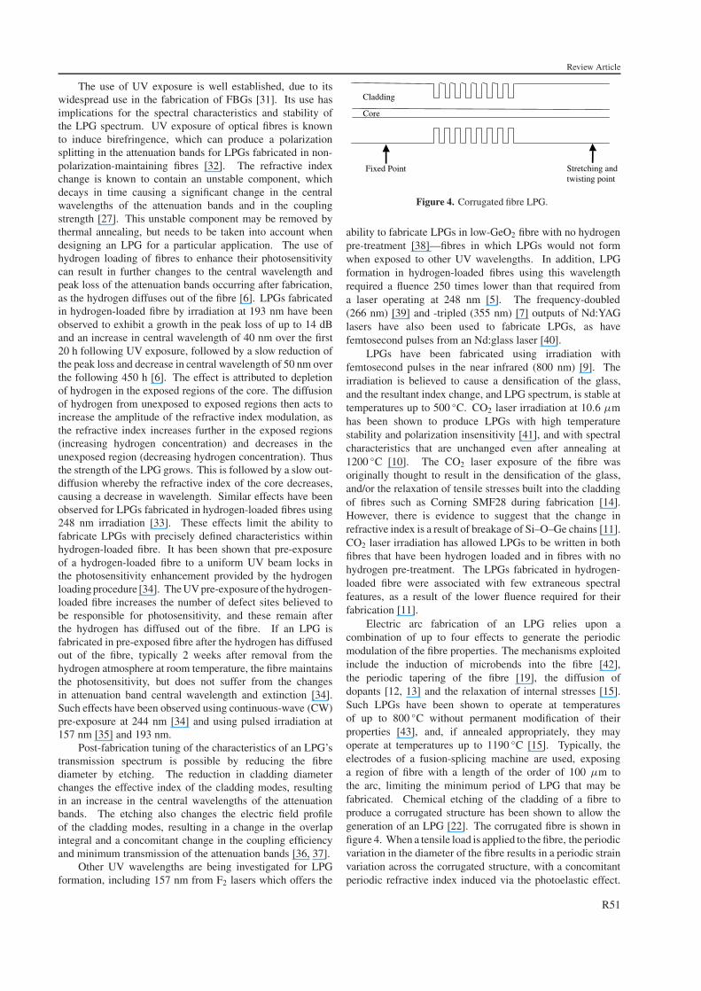
Figure 4. Corrugated fibre LPG.
ability to fabricate LPGs in low-GeO2 fibre with no hydrogenpre-treatment [38]—fibres in which LPGs would not formwhen exposed to other UV wavelengths. In addition, LPGformation in hydrogen-loaded fibres using this wavelengthrequired a fluence 250 times lower than that required froma laser operating at 248 nm [5]. The frequency-doubled(266 nm) [39] and -tripled (355 nm) [7] outputs of Nd:YAGlasers have also been used to fabricate LPGs, as havefemtosecond pulses from an Nd:glass laser [40].
LPGs have been fabricated using irradiation withfemtosecond pulses in the near infrared (800 nm) [9]. Theirradiation is believed to cause a densification of the glass,and the resultant index change, and LPG spectrum, is stable attemperatures up to 500 ◦C. CO2 laser irradiation at 10.6 µmhas been shown to produce LPGs with high temperaturestability and polarization insensitivity [41], and with spectralcharacteristics that are unchanged even after annealing at1200 ◦C [10]. The CO2 laser exposure of the fibre wasoriginally thought to result in the densification of the glass,and/or the relaxation of tensile stresses built into the claddingof fibres such as Corning SMF28 during fabrication [14].However, there is evidence to suggest that the change inrefractive index is a result of breakage of Si–O–Ge chains [11].CO2 laser irradiation has allowed LPGs to be written in bothfibres that have been hydrogen loaded and in fibres with nohydrogen pre-treatment. The LPGs fabricated in hydrogen-loaded fibre were associated with few extraneous spectralfeatures, as a result of the lower fluence required for theirfabrication [11].
Electric arc fabrication of an LPG relies upon acombination of up to four effects to generate the periodicmodulation of the fibre properties. The mechanisms exploitedinclude the induction of microbends into the fibre [42],the periodic tapering of the fibre [19], the diffusion ofdopants [12, 13] and the relaxation of internal stresses [15].Such LPGs have been shown to operate at temperaturesof up to 800 ◦C without permanent modification of theirproperties [43], and, if annealed appropriately, they mayoperate at temperatures up to 1190 ◦C [15]. Typically, theelectrodes of a fusion-splicing machine are used, exposinga region of fibre with a length of the order of 100 µm tothe arc, limiting the minimum period of LPG that may befabricated. Chemical etching of the cladding of a fibre toproduce a corrugated structure has been shown to allow thegeneration of an LPG [22]. The corrugated fibre is shown infigure 4. When a tensile load is applied to the fibre, the periodicvariation in the diameter of the fibre results in a periodic strainvariation across the corrugated structure, with a concomitantperiodic refractive index induced via the photoelastic effect.
R51
Review Article
Thus the coupling strength increases with applied load, with asmall change in wavelength of the attenuation bands [22].
Generally, LPGs have been fabricated to operate attelecommunications wavelengths (1300 and 1550 nm), and thespectrum is monitored by coupling light from superfluorescentfibre sources or superluminescent diodes in the fibre andrecording the transmission using an optical spectrum analyser.There have been reports of the use of fibres with lower cut-off wavelengths, 650 nm, allowing the operation of the LPGwithin the response of silicon detectors, facilitating the use oflow-cost CCD spectrometers [39].
3. LPG theory
The fibre itself consists of two waveguide structures—onebeing the high-index core surrounded by the lower-indexcladding, the other being the cladding, surrounded by air.Phase matching between the mode propagating in the core ofthe fibre and a forward-propagating cladding mode is achievedat the wavelength, λ, where the expression
λ = [nef f (λ) − niclad(λ)]� (1)
is satisfied [44], where nef f (λ) is the effective refractive indexof the propagating core mode at wavelength λ, ni
clad(λ) is therefractive index of the i th cladding mode and � is the periodof the LPG.
The minimum transmission of the attenuation bands isgoverned by the expression [1]
Ti = 1 − sin2(κi L) (2)
where L is the length of the LPG and κi is the couplingcoefficient for the i th cladding mode, which is determined bythe overlap integral of the core and cladding mode and by theamplitude of the periodic modulation of the mode propagationconstants.
Since the cladding generally has a large radius, it supportsa large number of cladding modes. Theoretical analysis hasshown that efficient coupling is possible only between core andcladding modes that have a large overlap integral, i.e. modesthat have similar electric field profiles [45]. Thus coupling isobserved between the core and circularly symmetric claddingmodes of odd order. This is because the electric field profileof the even-order modes is such that the field amplitude is lowwithin the core, whereas the electric field profiles of the oddmodes have a peak located within the core [45].
The modelling of LPGs requires the calculation of therefractive indices of the core and cladding modes to allow thecentral wavelengths of the attenuation bands to be determined,and the calculation of the mode electric field profiles tofacilitate determination of the coupling strength and the formof the spectrum. The refractive index of the propagating coremode of the fibre is generally determined using the weaklyguided field approximation of Gloge [46]. A simple three-layerslab waveguide model to determine the cladding mode indiceshas been presented, allowing an approximate determination ofthe coupling wavelengths [27]. However, it has been shownthat the effect of the core upon the effective indices and modeprofiles of the cladding mode cannot be ignored for accuratesimulation of LPG characteristics [45].
100
200
300
400
500
600
700
800
9001234
56789
LP
G p
erio
d (
µm)
wavelength (µm)0.7 0.75 0.8 0.85 0.9 0.95 1 1.05 1.1 1.15
40
50
60
70
80
90
100
110
120
130
1.11.0510.950.90.850.80.750.7 1.15
18
19
2021222324252627
LP
G p
erio
d (
µm)
wavelength (µm)
(a)
(b)
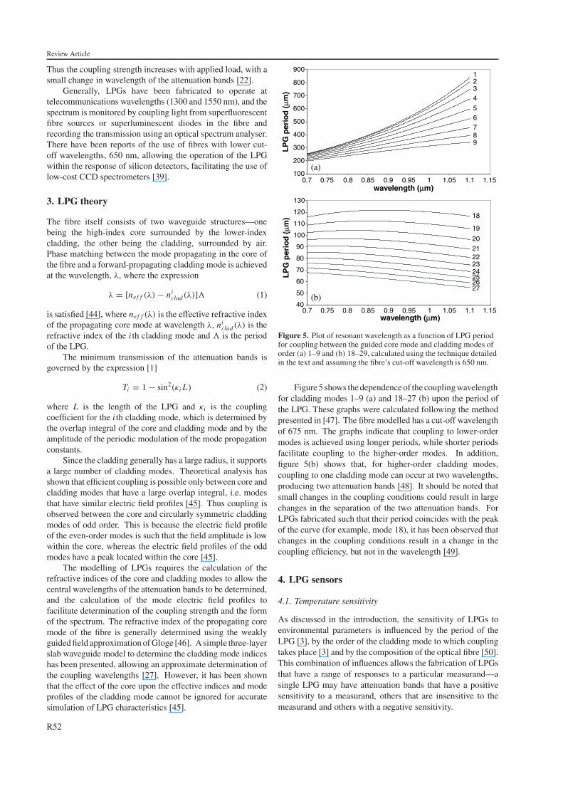
Figure 5. Plot of resonant wavelength as a function of LPG periodfor coupling between the guided core mode and cladding modes oforder (a) 1–9 and (b) 18–29, calculated using the technique detailedin the text and assuming the fibre’s cut-off wavelength is 650 nm.
Figure 5 shows the dependence of the coupling wavelengthfor cladding modes 1–9 (a) and 18–27 (b) upon the period ofthe LPG. These graphs were calculated following the methodpresented in [47]. The fibre modelled has a cut-off wavelengthof 675 nm. The graphs indicate that coupling to lower-ordermodes is achieved using longer periods, while shorter periodsfacilitate coupling to the higher-order modes. In addition,figure 5(b) shows that, for higher-order cladding modes,coupling to one cladding mode can occur at two wavelengths,producing two attenuation bands [48]. It should be noted thatsmall changes in the coupling conditions could result in largechanges in the separation of the two attenuation bands. ForLPGs fabricated such that their period coincides with the peakof the curve (for example, mode 18), it has been observed thatchanges in the coupling conditions result in a change in thecoupling efficiency, but not in the wavelength [49].
4. LPG sensors
4.1. Temperature sensitivity
As discussed in the introduction, the sensitivity of LPGs toenvironmental parameters is influenced by the period of theLPG [3], by the order of the cladding mode to which couplingtakes place [3] and by the composition of the optical fibre [50].This combination of influences allows the fabrication of LPGsthat have a range of responses to a particular measurand—asingle LPG may have attenuation bands that have a positivesensitivity to a measurand, others that are insensitive to themeasurand and others with a negative sensitivity.
R52
Review Article
This property has been widely exploited for controlling thetemperature sensitivity of LPGs. For many telecommunica-tions applications spectral stability is of prime importance, andthe ability to fabricate an LPG with an inherently temperature-insensitive attenuation band is an attractive feature. This isalso attractive for forming temperature-insensitive strain sen-sors. On the other hand, for forming temperature sensors, orthermally tuned filters, a high temperature sensitivity (of eithersign) is required.
The origin of the temperature sensitivity may beunderstood by differentiating equation (1) [44].
dλ
dT= dλ
d(δne f f )
(dne f f
dT− dncl
dT
)+ �
dλ
d�
1
L
dL
dT(3)
where λ is the central wavelength of the attenuation band,T is the temperature, nef f is the effective refractive index of thecore mode, ncl is the effective refractive index of the claddingmode, δne f f = (nef f − ncl), L is the length of the LPG and �
is the period of the LPG.The first term on the right-hand side of equation (3) is
the material contribution, and is related to the change in thedifferential refractive index of the core and cladding arisingfrom the thermo-optic effect. This contribution is dependentupon the composition of the fibre and is strongly dependentupon the order of the cladding mode. For coupling to low-order cladding modes (accessed using longer periods, � >
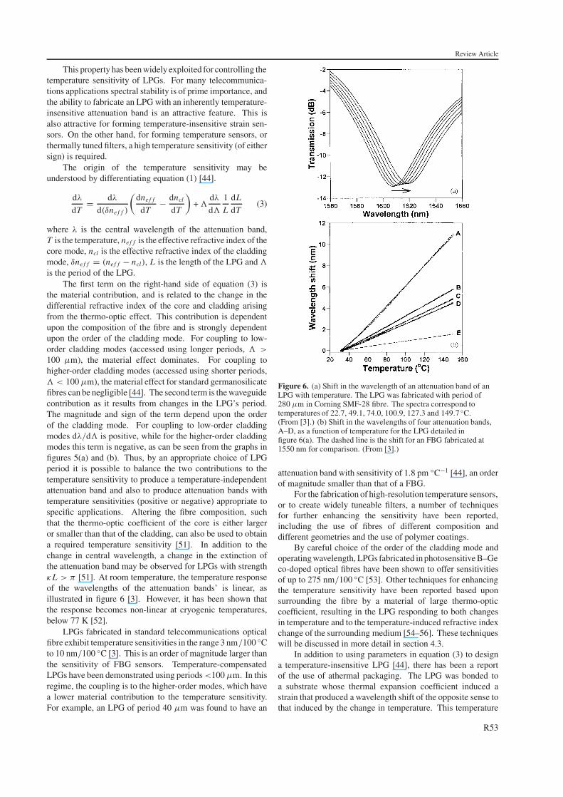
100 µm), the material effect dominates. For coupling tohigher-order cladding modes (accessed using shorter periods,� < 100 µm), the material effect for standard germanosilicatefibres can be negligible [44]. The second term is the waveguidecontribution as it results from changes in the LPG’s period.The magnitude and sign of the term depend upon the orderof the cladding mode. For coupling to low-order claddingmodes dλ/d� is positive, while for the higher-order claddingmodes this term is negative, as can be seen from the graphs infigures 5(a) and (b). Thus, by an appropriate choice of LPGperiod it is possible to balance the two contributions to thetemperature sensitivity to produce a temperature-independentattenuation band and also to produce attenuation bands withtemperature sensitivities (positive or negative) appropriate tospecific applications. Altering the fibre composition, suchthat the thermo-optic coefficient of the core is either largeror smaller than that of the cladding, can also be used to obtaina required temperature sensitivity [51]. In addition to thechange in central wavelength, a change in the extinction ofthe attenuation band may be observed for LPGs with strengthκL > π [51]. At room temperature, the temperature responseof the wavelengths of the attenuation bands’ is linear, asillustrated in figure 6 [3]. However, it has been shown thatthe response becomes non-linear at cryogenic temperatures,below 77 K [52].
LPGs fabricated in standard telecommunications opticalfibre exhibit temperature sensitivities in the range 3 nm/100 ◦Cto 10 nm/100 ◦C [3]. This is an order of magnitude larger thanthe sensitivity of FBG sensors. Temperature-compensatedLPGs have been demonstrated using periods <100 µm. In thisregime, the coupling is to the higher-order modes, which havea lower material contribution to the temperature sensitivity.For example, an LPG of period 40 µm was found to have an
Figure 6. (a) Shift in the wavelength of an attenuation band of anLPG with temperature. The LPG was fabricated with period of280 µm in Corning SMF-28 fibre. The spectra correspond totemperatures of 22.7, 49.1, 74.0, 100.9, 127.3 and 149.7 ◦C.(From [3].) (b) Shift in the wavelengths of four attenuation bands,A–D, as a function of temperature for the LPG detailed infigure 6(a). The dashed line is the shift for an FBG fabricated at1550 nm for comparison. (From [3].)
attenuation band with sensitivity of 1.8 pm ◦C−1 [44], an orderof magnitude smaller than that of a FBG.
For the fabrication of high-resolution temperature sensors,or to create widely tuneable filters, a number of techniquesfor further enhancing the sensitivity have been reported,including the use of fibres of different composition anddifferent geometries and the use of polymer coatings.
By careful choice of the order of the cladding mode andoperating wavelength, LPGs fabricated in photosensitive B–Geco-doped optical fibres have been shown to offer sensitivitiesof up to 275 nm/100 ◦C [53]. Other techniques for enhancingthe temperature sensitivity have been reported based uponsurrounding the fibre by a material of large thermo-opticcoefficient, resulting in the LPG responding to both changesin temperature and to the temperature-induced refractive indexchange of the surrounding medium [54–56]. These techniqueswill be discussed in more detail in section 4.3.
In addition to using parameters in equation (3) to designa temperature-insensitive LPG [44], there has been a reportof the use of athermal packaging. The LPG was bonded toa substrate whose thermal expansion coefficient induced astrain that produced a wavelength shift of the opposite sense tothat induced by the change in temperature. This temperature
R53
Review Article
compensation technique reduced the thermal sensitivity ofthe LPG by approximately 45% by bonding the LPG in analuminium cylinder [57]. Alternatively, recoating the fibrewith a material with a negative thermo-optic coefficient hasbeen shown to permit the temperature sensitivity to be reducedto 0.07 nm/100 ◦C [58]. In addition to the use of the refractiveindex dependence of the LPG to compensate for the thermalresponse, the bend sensitivity (section 4.4) has also beenexploited, resulting in a reduction in the temperature sensitivityby two orders of magnitude [59].
Metal-coated LPGs have been used to develop low-powertuneable filters based upon resistive heating. The depositionof thin films of copper [60] and platinum [61] of thicknessapproximately 300 nm, in each case with an initial 15 nmtitanium layer to give good adhesion, was found to produce asmall (1 nm) wavelength shift and small reduction in couplingefficiency. The Cu-coated fibre exhibited a 4 nm wavelengthshift for an electrical power of 0.5 W [60], while the Pt-basedfilter offered 11 nm for 0.67 W, with a linear efficiency of16 nm W−1 [61]. The metal coating was observed to make theperformance of the LPG insensitive to the refractive index ofthe medium surrounding the coating [61].
4.2. Strain sensitivity
The axial strain sensitivity of LPGs may be assessed bydifferentiating equation (1) [44]
dλ
dε= dλ
d(δne f f )
(dnef f
dε− dncl
dε
)+ �
dλ
d�. (4)
Again, the sensitivity comprises material and waveguideeffects, the material effects being the change in dimension ofthe fibre and the strain-optic effect, with the waveguide effectsarising from the slope of the dispersion term dλ/d�. ForLPGs with periodicity >100 µm, the material contributionis negative, while the waveguide contribution is positive.Appropriate choice of grating period and fibre composition willthus allow the generation of attenuation bands with positive,negative or zero sensitivity to strain [44].
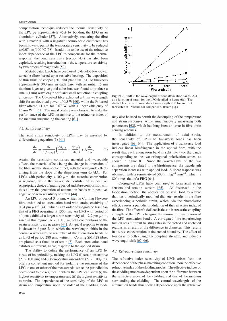
An LPG of period 340 µm, written in Corning Flexcorefibre, exhibited an attenuation band with strain sensitivity of0.04 pm µε−1 [44], which is an order of magnitude less thanthat of a FBG operating at 1300 nm. An LPG with period of40 µm exhibited a larger strain sensitivity of −2.2 pm µε−1,since in this regime, � < 100 µm, both contributions to thestrain sensitivity are negative [44]. A typical response to strainis shown in figure 7, in which the wavelength shifts in thecentral wavelengths of a number of the attenuation bands ofan LPG of period 280 µm, written in Corning SMF 28 fibre,are plotted as a function of strain [3]. Each attenuation bandexhibits a different, linear, response to the applied strain.
The ability to define the performance of an LPG byvirtue of its periodicity, making the LPG (i) strain insensitive(� > 100 µm) and (ii) temperature insensitive (� < 100 µm),offers a convenient method for isolating the response of theLPG to one or other of the measurands, since the periodicitiescorrespond to the regimes in which the LPG can show (i) thehighest sensitivity to temperature and (ii) the highest sensitivityto strain. The dependence of the sensitivity of the LPG tostrain and temperature upon the order of the cladding mode
Figure 7. Shift in the wavelengths of four attenuation bands, A–D,as a function of strain for the LPG detailed in figure 6(a). Thedashed line is the strain-induced wavelength shift for an FBGfabricated at 1550 nm for comparison. (From [3].)
may also be used to permit the decoupling of the temperatureand strain responses, while simultaneously measuring bothparameters [62], which has long been an issue in fibre opticsensing schemes.
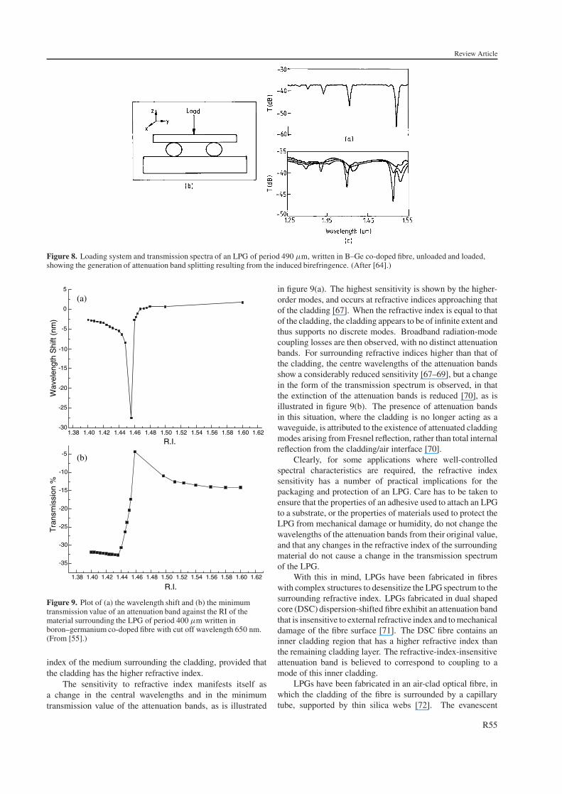
In addition to the measurement of axial strain,the sensitivity of LPGs to transverse loads has beeninvestigated [63, 64]. The application of a transverse loadinduces linear birefringence in the optical fibre, with theresult that each attenuation band is split into two, the bandscorresponding to the two orthogonal polarization states, asshown in figure 8. Since the wavelengths of the twocomponents are related to the birefringence, the wavelengthseparation increases with applied load. A linear response wasobtained, with a sensitivity of 500 nm kg−1 mm−1, which is800 times that of a FBG [64].
Corrugated LPGs have been used to form axial strainsensors and torsion sensors [65]. As discussed in thefabrication section, the application of axial load to a fibrethat has a periodically modified diameter results in the fibreexperiencing a periodic strain, which, via the photoelasticeffect, causes a periodic modulation of the refractive index ofthe fibre. The effect of axial load is thus to increase the couplingstrength of the LPG, changing the minimum transmission ofthe LPG attenuation bands. A corrugated fibre experiencingtorsion sees different twisting rates in the etched and unetchedregions as a result of the difference in diameter. This resultsin a stress concentration at the etched boundary. The effect oftorsion is to both change the coupling strength, and induce awavelength shift [65, 66].
4.3. Refractive index sensitivity
The refractive index sensitivity of LPGs arises from thedependence of the phase matching condition upon the effectiverefractive index of the cladding modes. The effective indices ofthe cladding modes are dependent upon the difference betweenthe refractive index of the cladding and that of the mediumsurrounding the cladding. The central wavelengths of theattenuation bands thus show a dependence upon the refractive
R54
Review Article
Figure 8. Loading system and transmission spectra of an LPG of period 490 µm, written in B–Ge co-doped fibre, unloaded and loaded,showing the generation of attenuation band splitting resulting from the induced birefringence. (After [64].)
1.38 1.40 1.42 1.44 1.46 1.48 1.50 1.52 1.54 1.56 1.58 1.60 1.62-30
-25
-20
-15
-5
0
5
Wav
elen
gth
Shi
ft (n
m)
-10
R.I.
1.38 1.40 1.42 1.44 1.46 1.48 1.50 1.52 1.54 1.56 1.58 1.60 1.62
-35
-30
-25
-20
-15
-10
-5
Tra
nsm
issi
on %
R.I.
(a)
(b)
Figure 9. Plot of (a) the wavelength shift and (b) the minimumtransmission value of an attenuation band against the RI of thematerial surrounding the LPG of period 400 µm written inboron–germanium co-doped fibre with cut off wavelength 650 nm.(From [55].)
index of the medium surrounding the cladding, provided thatthe cladding has the higher refractive index.
The sensitivity to refractive index manifests itself asa change in the central wavelengths and in the minimumtransmission value of the attenuation bands, as is illustrated
in figure 9(a). The highest sensitivity is shown by the higher-order modes, and occurs at refractive indices approaching thatof the cladding [67]. When the refractive index is equal to thatof the cladding, the cladding appears to be of infinite extent andthus supports no discrete modes. Broadband radiation-modecoupling losses are then observed, with no distinct attenuationbands. For surrounding refractive indices higher than that ofthe cladding, the centre wavelengths of the attenuation bandsshow a considerably reduced sensitivity [67–69], but a changein the form of the transmission spectrum is observed, in thatthe extinction of the attenuation bands is reduced [70], as isillustrated in figure 9(b). The presence of attenuation bandsin this situation, where the cladding is no longer acting as awaveguide, is attributed to the existence of attenuated claddingmodes arising from Fresnel reflection, rather than total internalreflection from the cladding/air interface [70].
Clearly, for some applications where well-controlledspectral characteristics are required, the refractive indexsensitivity has a number of practical implications for thepackaging and protection of an LPG. Care has to be taken toensure that the properties of an adhesive used to attach an LPGto a substrate, or the properties of materials used to protect theLPG from mechanical damage or humidity, do not change thewavelengths of the attenuation bands from their original value,and that any changes in the refractive index of the surroundingmaterial do not cause a change in the transmission spectrumof the LPG.
With this in mind, LPGs have been fabricated in fibreswith complex structures to desensitize the LPG spectrum to thesurrounding refractive index. LPGs fabricated in dual shapedcore (DSC) dispersion-shifted fibre exhibit an attenuation bandthat is insensitive to external refractive index and to mechanicaldamage of the fibre surface [71]. The DSC fibre contains aninner cladding region that has a higher refractive index thanthe remaining cladding layer. The refractive-index-insensitiveattenuation band is believed to correspond to coupling to amode of this inner cladding.
LPGs have been fabricated in an air-clad optical fibre, inwhich the cladding of the fibre is surrounded by a capillarytube, supported by thin silica webs [72]. The evanescent
R55
Review Article
field of the cladding modes does not extend beyond thecapillary, with the result that all of the attenuation bands areinsensitive to the external refractive index. A similar fibrestructure, but in which the space between the capillary andthe inner cladding is filled with a liquid crystal material,has been used to create a tuneable filter. In this case, therefractive index of a dye doped nematic liquid crystal wascontrolled by realignment of the molecules using polarizedlaser illumination [73]. Similar systems could be controlledusing electrical or thermal techniques.
The refractive index sensitivity of LPGs has been exploitedto form refractive index sensors, chemical concentrationsensors [74–76], a liquid level sensor [77] and as a meansof forming a tuneable spectral filter [73]. While LPGs aresensitive over only a limited refractive index range, and theirresponse is not species specific, it has been shown that LPGsmay be used for on-line monitoring of the concentration ofaqueous solutions of materials or of materials in inaccessiblelocations for industrial production quality control [76].Concentrations of solutions of sodium chloride [76], calciumchloride [76] and ethylene glycol [67, 76] have been measured,with sensitivities equal to, or better than, that of conventionalAbbe refractometry [76]. The use of LPGs to monitor therefining of kerosene, which requires that the concentration oforganic aromatics such as benzene and xylene is measured,has been proposed. To demonstrate the feasibility, theconcentration of a binary solution of xylene in heptane wasmeasured with a minimum detectable volumetric concentrationof 0.04%, corresponding to a refractive index change of6 × 10−5 [75]. This is comparable to the accuracyof the standard technique of liquid chromatography andUV spectroscopy. The use of two cascaded LPGs, withperiods chosen such that one LPG had an attenuation bandthat was insensitive to temperature while the other hada band that was insensitive to refractive index, has beenshown to allow simultaneous, independent measurementof these two parameters. This potentially allows thetemperature-independent monitoring of chemical solutionswith temperature-dependent refractive indices [78].
The majority of studies to date have concentrated uponthe bulk immersion of the LPG into a solution. It is attractiveto consider the prospect of depositing overlay materials thatexhibit changes in their refractive index in response to theirlocal environment. In this way, the LPG may be used toform, for example, a tuneable loss filter [61], a temperature-insensitive filter [58] or a species-specific chemical sensor [79].
LPG-based biosensors have been investigated byimmobilizing antibodies on the surface of the fibre andmonitoring the change in refractive index that occurs when anantigen bonds with the antibody [79]. This is the first reportedexample of the use of an LPG to form a species-specificchemical sensor, again offering comparable performance toother techniques including surface plasmon resonance andinterferometry, but with the prospect for on-line monitoring.
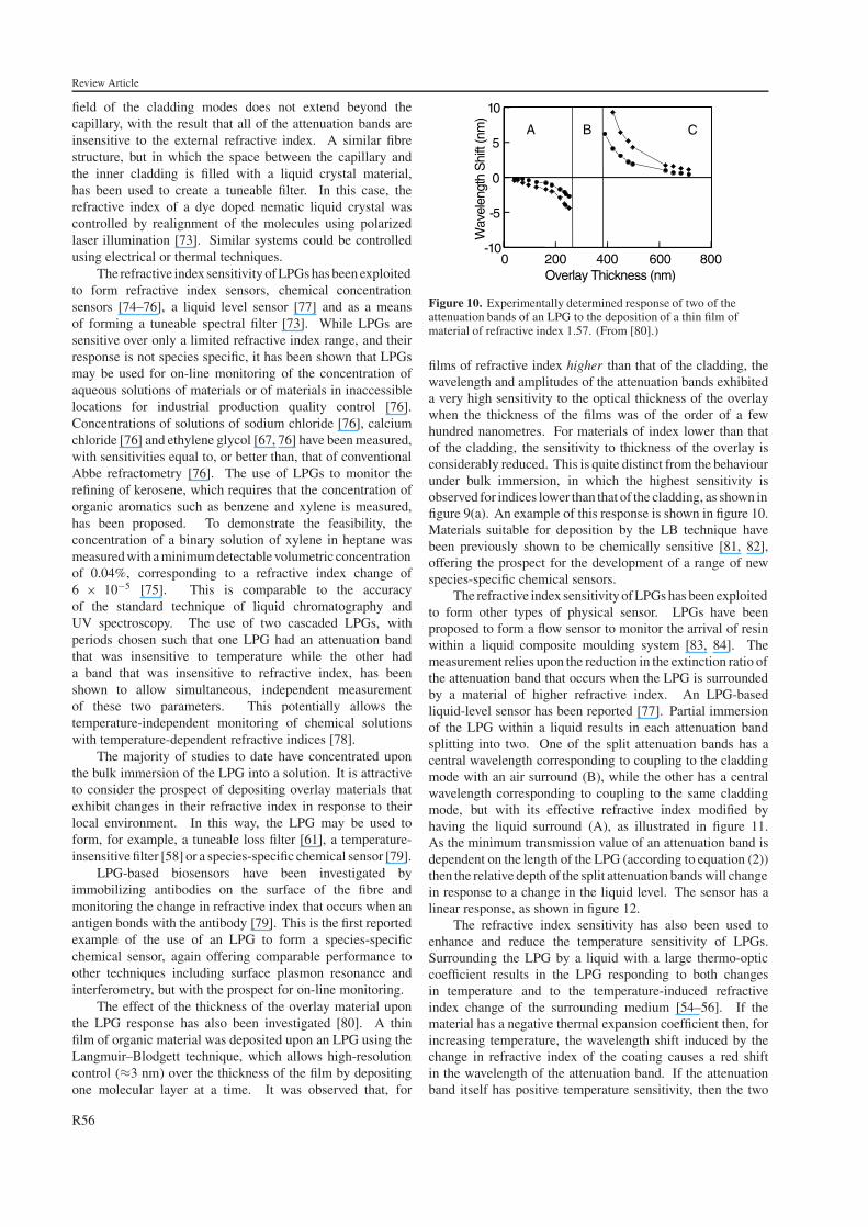
The effect of the thickness of the overlay material uponthe LPG response has also been investigated [80]. A thinfilm of organic material was deposited upon an LPG using theLangmuir–Blodgett technique, which allows high-resolutioncontrol (≈3 nm) over the thickness of the film by depositingone molecular layer at a time. It was observed that, for
0 200 400 600 800-10
-5
0
5
10
CBA
Wav
elen
gth
Shi
ft (n
m)
Overlay Thickness (nm)
Figure 10. Experimentally determined response of two of theattenuation bands of an LPG to the deposition of a thin film ofmaterial of refractive index 1.57. (From [80].)
films of refractive index higher than that of the cladding, thewavelength and amplitudes of the attenuation bands exhibiteda very high sensitivity to the optical thickness of the overlaywhen the thickness of the films was of the order of a fewhundred nanometres. For materials of index lower than thatof the cladding, the sensitivity to thickness of the overlay isconsiderably reduced. This is quite distinct from the behaviourunder bulk immersion, in which the highest sensitivity isobserved for indices lower than that of the cladding, as shown infigure 9(a). An example of this response is shown in figure 10.Materials suitable for deposition by the LB technique havebeen previously shown to be chemically sensitive [81, 82],offering the prospect for the development of a range of newspecies-specific chemical sensors.
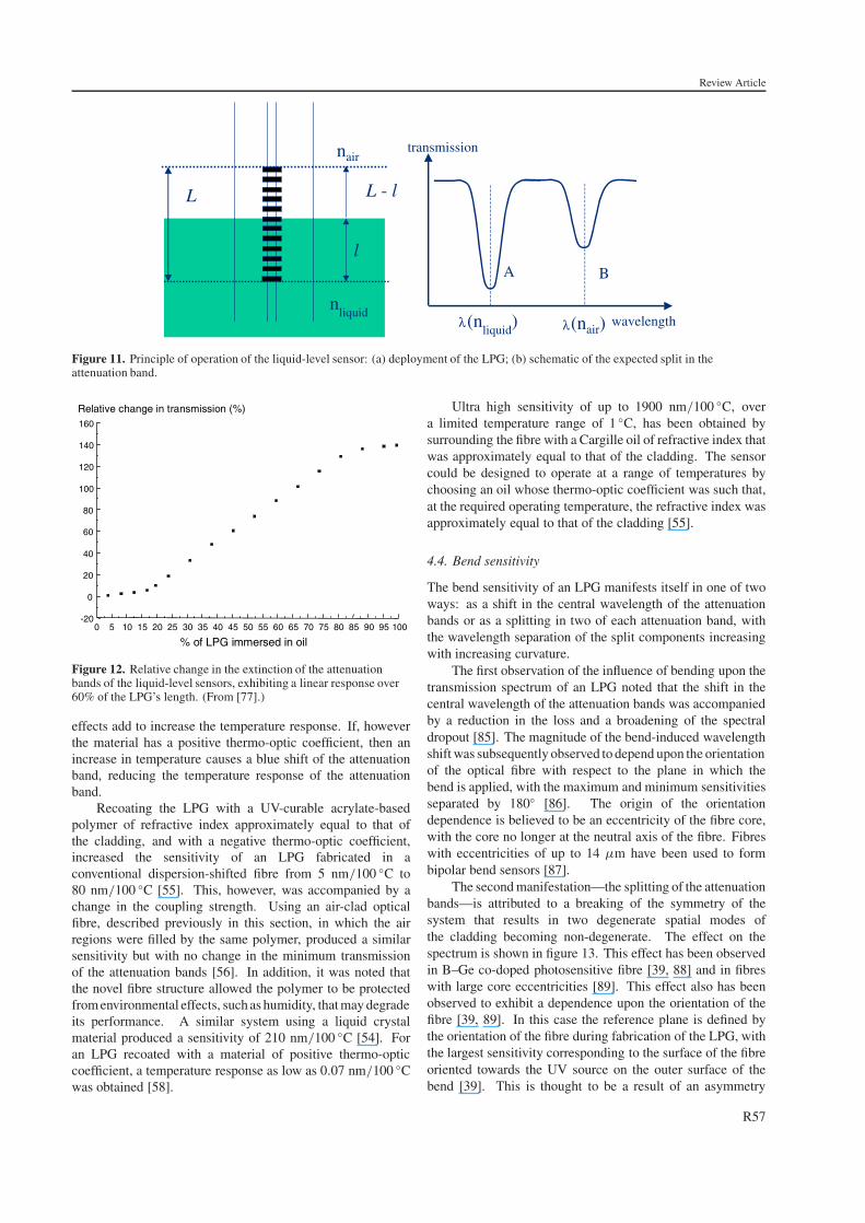
The refractive index sensitivity of LPGs has been exploitedto form other types of physical sensor. LPGs have beenproposed to form a flow sensor to monitor the arrival of resinwithin a liquid composite moulding system [83, 84]. Themeasurement relies upon the reduction in the extinction ratio ofthe attenuation band that occurs when the LPG is surroundedby a material of higher refractive index. An LPG-basedliquid-level sensor has been reported [77]. Partial immersionof the LPG within a liquid results in each attenuation bandsplitting into two. One of the split attenuation bands has acentral wavelength corresponding to coupling to the claddingmode with an air surround (B), while the other has a centralwavelength corresponding to coupling to the same claddingmode, but with its effective refractive index modified byhaving the liquid surround (A), as illustrated in figure 11.As the minimum transmission value of an attenuation band isdependent on the length of the LPG (according to equation (2))then the relative depth of the split attenuation bands will changein response to a change in the liquid level. The sensor has alinear response, as shown in figure 12.
The refractive index sensitivity has also been used toenhance and reduce the temperature sensitivity of LPGs.Surrounding the LPG by a liquid with a large thermo-opticcoefficient results in the LPG responding to both changesin temperature and to the temperature-induced refractiveindex change of the surrounding medium [54–56]. If thematerial has a negative thermal expansion coefficient then, forincreasing temperature, the wavelength shift induced by thechange in refractive index of the coating causes a red shiftin the wavelength of the attenuation band. If the attenuationband itself has positive temperature sensitivity, then the two
R56
Review Article
L
l
L - l
A B
λ λ
nairtransmission
nliquid
wavelength(nliquid
) (nair)
Figure 11. Principle of operation of the liquid-level sensor: (a) deployment of the LPG; (b) schematic of the expected split in theattenuation band.
0 5 10 15 20 25 30 35 40 45 50 55 60 65 70 75 80 85 90 95 100-20
0
20
40
60
80
100
120
140
160
% of LPG immersed in oil
Relative change in transmission (%)
Figure 12. Relative change in the extinction of the attenuationbands of the liquid-level sensors, exhibiting a linear response over60% of the LPG’s length. (From [77].)
effects add to increase the temperature response. If, howeverthe material has a positive thermo-optic coefficient, then anincrease in temperature causes a blue shift of the attenuationband, reducing the temperature response of the attenuationband.
Recoating the LPG with a UV-curable acrylate-basedpolymer of refractive index approximately equal to that ofthe cladding, and with a negative thermo-optic coefficient,increased the sensitivity of an LPG fabricated in aconventional dispersion-shifted fibre from 5 nm/100 ◦C to80 nm/100 ◦C [55]. This, however, was accompanied by achange in the coupling strength. Using an air-clad opticalfibre, described previously in this section, in which the airregions were filled by the same polymer, produced a similarsensitivity but with no change in the minimum transmissionof the attenuation bands [56]. In addition, it was noted thatthe novel fibre structure allowed the polymer to be protectedfrom environmental effects, such as humidity, that may degradeits performance. A similar system using a liquid crystalmaterial produced a sensitivity of 210 nm/100 ◦C [54]. Foran LPG recoated with a material of positive thermo-opticcoefficient, a temperature response as low as 0.07 nm/100 ◦Cwas obtained [58].
Ultra high sensitivity of up to 1900 nm/100 ◦C, overa limited temperature range of 1 ◦C, has been obtained bysurrounding the fibre with a Cargille oil of refractive index thatwas approximately equal to that of the cladding. The sensorcould be designed to operate at a range of temperatures bychoosing an oil whose thermo-optic coefficient was such that,at the required operating temperature, the refractive index wasapproximately equal to that of the cladding [55].
4.4. Bend sensitivity
The bend sensitivity of an LPG manifests itself in one of twoways: as a shift in the central wavelength of the attenuationbands or as a splitting in two of each attenuation band, withthe wavelength separation of the split components increasingwith increasing curvature.
The first observation of the influence of bending upon thetransmission spectrum of an LPG noted that the shift in thecentral wavelength of the attenuation bands was accompaniedby a reduction in the loss and a broadening of the spectraldropout [85]. The magnitude of the bend-induced wavelengthshift was subsequently observed to depend upon the orientationof the optical fibre with respect to the plane in which thebend is applied, with the maximum and minimum sensitivitiesseparated by 180◦ [86]. The origin of the orientationdependence is believed to be an eccentricity of the fibre core,with the core no longer at the neutral axis of the fibre. Fibreswith eccentricities of up to 14 µm have been used to formbipolar bend sensors [87].
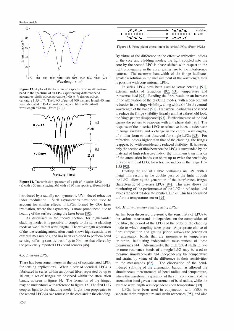
The second manifestation—the splitting of the attenuationbands—is attributed to a breaking of the symmetry of thesystem that results in two degenerate spatial modes ofthe cladding becoming non-degenerate. The effect on thespectrum is shown in figure 13. This effect has been observedin B–Ge co-doped photosensitive fibre [39, 88] and in fibreswith large core eccentricities [89]. This effect also has beenobserved to exhibit a dependence upon the orientation of thefibre [39, 89]. In this case the reference plane is defined bythe orientation of the fibre during fabrication of the LPG, withthe largest sensitivity corresponding to the surface of the fibreoriented towards the UV source on the outer surface of thebend [39]. This is thought to be a result of an asymmetry
R57
Review Article
990980 1010 10200
20
40
60
80
100
1000 1030 1040970 1050 1060 1070
Tra
nsm
issi
on %
Wavelength (nm)
Figure 13. A plot of the transmission spectrum of an attenuationband in the spectrum of an LPG experiencing different bendcurvatures. Solid curve, curvature 0.00 m−1; dashed curve,curvature 1.55 m−1. The LPG of period 400 µm and length 40 mmwas fabricated in B–Ge co-doped optical fibre with cut-offwavelength 650 nm. (From [39].)
Figure 14. Transmission spectrum of a pair of in-series LPGs:(a) with a 50 mm spacing; (b) with a 190 mm spacing. (From [64].)
introduced by a radially non-symmetric UV-induced refractiveindex modulation. Such asymmetries have been used toaccount for similar effects in LPGs formed by CO2 laserirradiation, where the asymmetry is more pronounced due toheating of the surface facing the laser beam [90].
As discussed in the theory section, for higher-ordercladding modes it is possible to couple to the same claddingmode at two different wavelengths. The wavelength separationof the two resulting attenuation bands shows high sensitivity toexternal measurands, and has been exploited to perform bendsensing, offering sensitivities of up to 50 times that offered bythe previously reported LPG bend sensors [48].
4.5. In-series LPGs
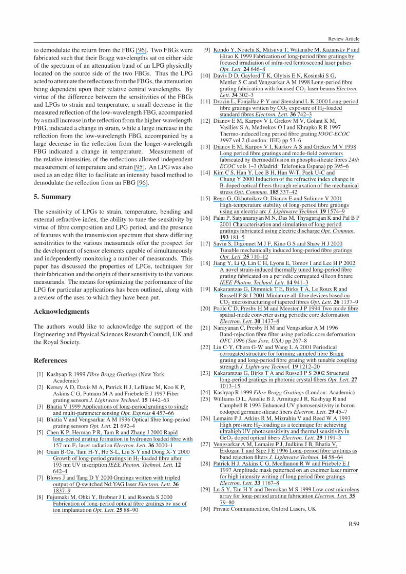
There has been some interest in the use of concatenated LPGsfor sensing applications. When a pair of identical LPGs isfabricated in series within an optical fibre, separated by up to10 cm, a set of fringes are observed within the attenuationbands, as seen in figure 14. The formation of the fringesmay be understood with reference to figure 15. The first LPGcouples light to the cladding mode. Light then propagates tothe second LPG via two routes: in the core and in the cladding.
claddingcore
Figure 15. Principle of operation of in-series LPGs. (From [92].)
By virtue of the difference in the effective refractive indicesof the core and cladding modes, the light coupled into thecore by the second LPG is phase shifted with respect to thelight propagating in the core, giving rise to the interferencepattern. The narrower bandwidth of the fringe facilitatesgreater resolution in the measurement of the wavelength thanis possible with conventional LPGs.
In-series LPGs have been used to sense bending [91],external index of refraction [92, 93], temperature andtransverse load [93]. Bending the fibre results in an increasein the attenuation of the cladding modes, with a concomitantreduction in the fringe visibility, along with a shift in the centralwavelength of the band [91]. Transverse loading was observedto reduce the fringe visibility linearly until, at a threshold load,the fringe pattern disappeared [93]. Further increase of the loadcauses the pattern to reappear with a π phase shift [93]. Theresponse of the in-series LPGs to refractive index is a decreasein fringe visibility and a change in the central wavelengths,of similar form to that observed for single LPGs [93]. Forrefractive indices higher than that of the cladding, the fringesreappear, but with considerably reduced visibility. If, however,only the section of fibre between the LPGs is surrounded by thematerial of high refractive index, the minimum transmissionof the attenuation bands can show up to twice the sensitivityof a conventional LPG, for refractive indices in the range 1.5–1.55 [92].
Coating the end of a fibre containing an LPG with ametal film results in the double pass of the light throughthe LPG, allowing the generation of the interference fringescharacteristic of in-series LPGs [94]. This also allows themonitoring of the performance of the LPG in reflection, andavoids the need to fabricate identical LPGs. This has been usedto form a temperature sensor [94].
4.6. Multi-parameter sensing using LPGs
As has been discussed previously, the sensitivity of LPGs tothe various measurands is dependent on the composition ofthe fibre, the period of the LPG and the order of the claddingmode to which coupling takes place. Appropriate choice offibre composition and grating period allows the generationof attenuation bands that are insensitive to temperatureor strain, facilitating independent measurement of thesemeasurands [44]. Alternatively, the differential shifts in twoor more resonance bands of a single LPG may be used tomeasure simultaneously and independently the temperatureand strain, by virtue of the difference in their sensitivitiesto the measurands [62]. The observation of the bend-induced splitting of the attenuation bands has allowed thesimultaneous measurement of bend radius and temperature,where the wavelength separation of the split components of theattenuation band gave a measurement of bend radius, while theaverage wavelength was dependent upon temperature [39].
LPGs have been used in conjunction with FBGs toseparate their temperature and strain responses [95], and also
R58
Review Article
to demodulate the return from the FBG [96]. Two FBGs werefabricated such that their Bragg wavelengths sat on either sideof the spectrum of an attenuation band of an LPG physicallylocated on the source side of the two FBGs. Thus the LPGacted to attenuate the reflections from the FBGs, the attenuationbeing dependent upon their relative central wavelengths. Byvirtue of the difference between the sensitivities of the FBGsand LPGs to strain and temperature, a small decrease in themeasured reflection of the low-wavelength FBG, accompaniedby a small increase in the reflection from the higher-wavelengthFBG, indicated a change in strain, while a large increase in thereflection from the low-wavelength FBG, accompanied by alarge decrease in the reflection from the longer-wavelengthFBG indicated a change in temperature. Measurement ofthe relative intensities of the reflections allowed independentmeasurement of temperature and strain [95]. An LPG was alsoused as an edge filter to facilitate an intensity based method todemodulate the reflection from an FBG [96].
5. Summary
The sensitivity of LPGs to strain, temperature, bending andexternal refractive index, the ability to tune the sensitivity byvirtue of fibre composition and LPG period, and the presenceof features with the transmission spectrum that show differingsensitivities to the various measurands offer the prospect forthe development of sensor elements capable of simultaneouslyand independently monitoring a number of measurands. Thispaper has discussed the properties of LPGs, techniques fortheir fabrication and the origin of their sensitivity to the variousmeasurands. The means for optimizing the performance of theLPG for particular applications has been outlined, along witha review of the uses to which they have been put.
Acknowledgments
The authors would like to acknowledge the support of theEngineering and Physical Sciences Research Council, UK andthe Royal Society.
References
[1] Kashyap R 1999 Fibre Bragg Gratings (New York:Academic)
[2] Kersey A D, Davis M A, Patrick H J, LeBlanc M, Koo K P,Askins C G, Putnam M A and Friebele E J 1997 Fibergrating sensors J. Lightwave Technol. 15 1442–63
[3] Bhatia V 1999 Applications of long-period gratings to singleand multi-parameter sensing Opt. Express 4 457–66
[4] Bhatia V and Vengsarkar A M 1996 Optical fibre long-periodgrating sensors Opt. Lett. 21 692–4
[5] Chen K P, Herman P R, Tam R and Zhang J 2000 Rapidlong-period grating formation in hydrogen loaded fibre with157 nm F2 laser radiation Electron. Lett. 36 2000–1
[6] Guan B-Ou, Tam H-Y, Ho S-L, Liu S-Y and Dong X-Y 2000Growth of long-period gratings in H2-loaded fibre after193 nm UV inscription IEEE Photon. Technol. Lett. 12642–4
[7] Blows J and Tang D Y 2000 Gratings written with tripledoutput of Q-switched Nd:YAG laser Electron. Lett. 361837–9
[8] Fujumaki M, Ohki Y, Brebner J L and Roorda S 2000Fabrication of long-period optical fibre gratings by use ofion implantation Opt. Lett. 25 88–90
[9] Kondo Y, Nouchi K, Mitsuyu T, Watanabe M, Kazansky P andHirao K 1999 Fabrication of long-period fibre gratings byfocused irradiation of infra-red femtosecond laser pulsesOpt. Lett. 24 646–8
[10] Davis D D, Gaylord T K, Glytsis E N, Kosinski S G,Mettler S C and Vengsarkar A M 1998 Long-period fibregrating fabrication with focused CO2 laser beams Electron.Lett. 34 302–3
[11] Drozin L, Fonjallaz P-Y and Stensland L K 2000 Long-periodfibre gratings written by CO2 exposure of H2-loadedstandard fibres Electron. Lett. 36 742–3
[12] Dianov E M, Karpov V I, Grekov M V, Golant K M,Vasiliev S A, Medvekov O I and Khrapko R R 1997Thermo-induced long period fibre grating IOOC-ECOC1997 vol 2 (London: IEE) pp 53–6
[13] Dianov E M, Karpov V I, Kurkov A S and Grekov M V 1998Long period fibre gratings and mode-field convertersfabricated by thermodiffusion in phosphosilicate fibres 24thECOC vols 1–3 (Madrid: Telefonica Espana) pp 395–6
[14] Kim C S, Han Y, Lee B H, Han W-T, Paek U-C andChung Y 2000 Induction of the refractive index change inB-doped optical fibers through relaxation of the mechanicalstress Opt. Commun. 185 337–42
[15] Rego G, Okhotnikov O, Dianov E and Sulimov V 2001High-temperature stability of long-period fibre gratingsusing an electric arc J. Lightwave Technol. 19 1574–9
[16] Palai P, Satyanarayan M N, Das M, Thyagarajan K and Pal B P2001 Characterisation and simulation of long periodgratings fabricated using electric discharge Opt. Commun.193 181–5
[17] Savin S, Digonnet M J F, Kino G S and Shaw H J 2000Tunable mechanically induced long-period fibre gratingsOpt. Lett. 25 710–12
[18] Jiang Y, Li Q, Lin C H, Lyons E, Tomov I and Lee H P 2002A novel strain-induced thermally tuned long-period fibregrating fabricated on a periodic corrugated silicon fixtureIEEE Photon. Technol. Lett. 14 941–3
[19] Kakarantzas G, Dimmick T E, Birks T A, Le Roux R andRussell P St J 2001 Miniature all-fibre devices based onCO2 microstructuring of tapered fibres Opt. Lett. 26 1137–9
[20] Poole C D, Presby H M and Meester J P 1994 Two mode fibrespatial-mode converter using periodic core deformationElectron. Lett. 30 1437–8
[21] Narayanan C, Presby H M and Vengsarkar A M 1996Band-rejection fibre filter using periodic core deformationOFC 1996 (San Jose, USA) pp 267–8
[22] Lin C-Y, Chern G-W and Wang L A 2001 Periodicalcorrugated structure for forming sampled fibre Bragggrating and long-period fibre grating with tunable couplingstrength J. Lightwave Technol. 19 1212–20
[23] Kakarantzas G, Birks T A and Russell P S 2002 Structurallong-period gratings in photonic crystal fibers Opt. Lett. 271013–15
[24] Kashyap R 1999 Fibre Bragg Gratings (London: Academic)[25] Williams D L, Ainslie B J, Armitage J R, Kashyap R and
Campbell R 1993 Enhanced UV photosensitivity in boroncodoped germanosilicate fibers Electron. Lett. 29 45–7
[26] Lemaire P J, Atkins R M, Mizrahiu V and Reed W A 1993High pressure H2-loading as a technique for achievingultrahigh UV photosensitivity and thermal sensitivity inGeO2 doped optical fibers Electron. Lett. 29 1191–3
[27] Vengsarkar A M, Lemaire P J, Judkins J B, Bhatia V,Erdogan T and Sipe J E 1996 Long-period fibre gratings asband rejection filters J. Lightwave Technol. 14 58–64
[28] Patrick H J, Askins C G, Mcelhanon R W and Friebele E J1997 Amplitude mask patterned on an excimer laser mirrorfor high intensity writing of long period fibre gratingsElectron. Lett. 33 1167–8
[29] Lu S Y, Tan H Y and Demokan M S 1999 Low-cost microlensarray for long-period grating fabrication Electron. Lett. 3579–80
[30] Private Communication, Oxford Lasers, UK
R59
Review Article
[31] Bennion I, Williams J A R, Zhang L, Sugden K andDoran N 1996 UV-written in-fibre Bragg gratings Opt.Quantum Electron. 28 93–135
[32] Duhem O and Douay M 2000 Effect of UV-inducedbirefringence on long-period grating couplingcharacteristics Electron. Lett. 36 416–17
[33] Jang J N, Kim H G, Shin S G, Kim M S, Lee S B andKwack K H 1999 Effects of hydrogen molecule diffusionon LP0m mode coupling of long-period gratingsJ. Non-Cryst. Solids 259 156–64
[34] Kawano H, Muentz H, Sato Y, Nishimae J and Sugitatsu A2001 Reduction of transmission spectrum shift of longperiod fibre gratings by a UV-preexposure methodJ. Lightwave Technol. 19 1221–8
[35] Chen K P, Wei X and Herman P R 2002 Strong 157 nmF2-laser photosensitivity locking of hydrogen loadedtelecommunication fibre for 248 nm fabrication oflong-period gratings Electron. Lett. 38 17–18
[36] Vasiliev S A, Dianov E M, Varelas D, Limberger H G andSalathe R P 1996 Post-fabrication resonance peakpositioning of long period cladding-mode-coupled gratingsOpt. Lett. 21 1830–2
[37] Zhou K, Liu H and HU X 2001 Tuning the resonantwavelength of long period fibre gratings by etching thefibre’s cladding Opt. Commun. 197 295–9
[38] Chen K P, Herman P R, Zhang J and Tam R 2001 Fabricationof strong long-period gratings in hydrogen free fibers with157 nm F2-laser radiation Opt. Lett. 26 771–3
[39] Ye C C, James S W and Tatam R P 2000 Simultaneoustemperature and bend sensing using long-period fibregratings Opt. Lett. 25 1007–9
[40] Dragomir A, Nikogosyan D N, Ruth A A, Zagorul’ko K A andKryukov P G 2002 Long-period fibre grating formation with264 nm femtosecond radiation Electron. Lett. 38 269–71
[41] Davis D D, Gaylord T K, Glytsis E N and Mettler S C 1998CO2 laser induced long-period fibre gratings: spectralcharacteristic, cladding modes and polarisationindependence Electron. Lett. 34 1416–17
[42] Hwang I K, Yun S H and Kim B Y 1999 Long period fibregrating based upon periodic microbends Opt. Lett. 241263–5
[43] Humbert G and Malki A 2002 Electric-arc-induced gratings innon-hydrogenated fibres: fabrication and high-temperaturecharacterizations J. Opt. A: Pure Appl. Opt. 4 194–8
[44] Bhatia V, Campbell D K, Sherr D, D’Alberto T G,Zabaronick N A, Ten Eyck G A, Murphy K A andClaus R O 1997 Temperature-insensitive and straininsensitive long-period grating sensors for smart structuresOpt. Eng. 36 1872–6
[45] Erdogan T 1997 Cladding mode resonances in short and longperiod fibre grating filters J. Opt. Soc. Am. 14 1760–73
Erdogan T 2000 Cladding mode resonances in short and longperiod fibre grating filters: errata J. Opt. Soc. Am. 17 2113
[46] Gloge D 1971 Weakly guiding fibres Appl. Opt. 10 2252–8[47] Patrick H J, Kersey A D and Bucholtz F 1998 Analysis of the
response of long period fibre gratings to external index ofrefraction J. Lightwave Technol. 16 1606–42
[48] Han Y G, Lee B H, Han W T, Paek U C and Chung Y 2001Resonance peak shift and dual peak separation of longperiod fibre gratings for sensing applications IEEE Photon.Technol. Lett. 13 699–701
[49] Grubsky V and Feinberg J 2000 Long period fibre gratingswith variable coupling for real-time sensing applicationsOpt. Lett. 25 203–5
[50] Shima K, Himeno K, Sakai T, Okude S and Wada A 1997A novel temperature-insensitive long-period grating using aboron-codoped germanosilicate core-fibre Tech. Dig.OFC’97 pp 347–8
[51] Ng M N and Chiang K S 2002 Thermal effects on thetransmission spectra of long-period fiber gratings Opt.Commun. 208 321–7
[52] James S W, Tatam R P, Bateman R, Twin A andNoonan P 2003 Cryogenic temperature response of fibreoptic long period gratings Electron. Lett. submitted
[53] Shu X, Allsop T, Gwandu B, Zhang L and Bennion I 2001High temperature sensitivity of long-period gratings inB–Ge codoped fibre IEEE Photon. Technol. Lett. 13 818–20
[54] Yin S, Chung K-W and Zhu X 2001 A highly sensitivity longperiod grating based tuneable filter using a unique doublecladding layer structure Opt. Commun. 188 301
[55] Khaliq S, James S W and Tatam R P 2002 Enhancedsensitivity fibre optic long period grating temperaturesensor Meas. Sci. Technol. 13 792–5
[56] Abramov A A, Hale A, Windeler R S and Strasser T A 1999Widely tunable long-period fibre gratings Electron. Lett. 3581–2
[57] Qin L, Wei Z X, Wang Q Y, Li H P, Zheng W, Zhang Y S andGao D S 2000 Compact temperature compensating packagefor long period fibre gratings Opt. Met. 14 239–42
[58] Jang J N, Kim S Y, Kim S W and Kim M S 1999 Temperatureinsensitive long-period fibre gratings Electron. Lett. 352134
[59] Ng M N, Chen Z H and Chiang K S 2002 Temperaturecompensation of long-period fiber grating forrefractive-index sensing with bending effect IEEE Photon.Technol. Lett. 14 361–2
[60] Duhem O, CaCosta A, Henninot J F and Douay M 1999 Longperiod copper coated grating as an electrically tuneablewavelength selective filter Electron. Lett. 351014–15
[61] Constantini D M, Muller C A P, Vasiliev S A, Limberger H Gand Salathe R P 1999 Tunable loss filter based on metalcoated long-period fibre grating IEEE Photon. Technol.Lett. 11 1458–60
[62] Bhatia V, Campbell D, Claus R O and Vengsarkar A M 1997Simultaneous strain and temperature measurement withlong-period gratings Opt. Lett. 22 648–50
[63] Liu Y, Zhang L and Bennion I 1999 Fibre optic load sensorswith high transverse strain sensitivity based on long-periodgratings in B/Ge co-doped fibre Electron. Lett. 35 661–2
[64] Zhang L, Liu Y, Williams J A R and Bennion I 1999 Designand realisation of long-period grating devices inconventional and high birefringence fibers and their novelapplications as fibre optic load sensors IEEE J. Sel. Top.Quantum Electron. 5 1371–8
[65] Lin C-Y, Wang L A and Chern G-W 2001 Corrugatedlong-period fibre gratings as strain, torsion and bendingsensors J. Lightwave Technol. 19 1159–68
[66] Wang L A, Lin C Y and Chern G W 2001 A torsion sensormade of a corrugated long period fibre grating Meas. Sci.Technol. 12 793–9
[67] Patrick H J, Kersey A D and Bucholtz F 1998 Analysis of theresponse of long period fibre gratings to external index ofrefraction J. Lightwave Technol. 16 1606–42
[68] Hou R, Ghassemlooy Z, Hassan A, Lu C and Dowker K P2001 Modelling of long-period fibre grating response torefractive index higher than that of cladding Meas. Sci.Technol. 12 1709–13
[69] Lee B H, Liu Y, Lee S B, Choi S S and Jang J N 1997Displacements of the resonant peaks of a long-period fibregrating induced by a change of ambient refractive indexOpt. Lett. 22 1769–71
[70] Duhem O, Henninot J-F, Warenghem M and Douay M 1998Demonstration of long-period grating efficient couplingswith an external medium of a refractive index higher thanthat of silica Appl. Opt. 37 7223–8
[71] Lee B H and Nishii J 1998 Cladding surrounding interfaceinsensitive long-period grating Electron. Lett. 34 1129–30
[72] Espindola R P, Windeler R S, Abramov A A, Eggerton B J,Strasser T A and DiGiovanni D J 1999 External refractiveindex insensitive air-clad long period fibre grating Electron.Lett. 35 327–8
R60
Review Article
[73] Yin S, Chung K-W and Zhu X 2001 A novel all-optic tuneablelong period grating using a unique double cladding layerOpt. Commun. 196 181–6
[74] Shu X and Huang D 1999 Highly sensitive chemical sensorbased on the measurement of the separation of dualresonant peaks in a 100 µm period fibre grating Opt.Commun. 171 65–9
[75] Allsop T, Zhang L and Bennion I 2001 Detection of organicaromatic compounds by a long period fibre grating opticalsensor with optimised sensitivity Opt. Commun. 191181–90
[76] Falciai R, Mignani A G and Vannini A 2001 Long periodgratings as solution concentration sensors SensorsActuators B 74 74–7
[77] Khaliq S, James S W and Tatam R P 2001 Fibre-optic liquidlevel sensor using a long-period grating Opt. Lett. 261224–6
[78] Gwandu B A L, Shu X, Allsop T D P, Zhang W, Zhang L andBennion I 2002 Simultaneous refractive index andtemperature measurement using cascaded long-periodgrating in double-cladding fibre Electron. Lett. 38 695–6
[79] DeLisa M P, Zhang Z, Shiloach M, Pilevar S, Davis C C,Sirkis J S and Bentley W E 2000 Evanescent wave longperiod fiber Bragg grating as an immobilized antibodybiosensor Anal. Chem. 72 2895–900
[80] James S W, Rees N D, Ashwell G J and Tatam R P 2002Optical fibre long period gratings with Langmuir Blodgettthin film overlays Opt. Lett. 9 686–8
[81] Flannery D, James S W, Tatam R P and Ashwell G J 1997 ApH sensor using Langmuir–Blodgett overlays on polishedoptical fibres Opt. Lett. 22 567–9
[82] Flannery D, James S W, Tatam R P and Ashwell G J 1999Fibre optic chemical sensing using Langmuir–Blodgettoverlay waveguides Appl. Opt. 38 7370–4
[83] Dankers J P, Lenhart J L, Kueh S R, van Zanten J H,Advani S G and Parnas R S 2001 Fibre optic flow and curesensing for liquid composite molding Opt. Lasers Eng. 3591–104
[84] Kueh S R M, Parnas R S and Advani S G 2002 A methodologyfor using long-period gratings and mold-filling simulationsto minimize the intrusiveness of flow sensors in liquidcomposite molding Compos. Sci. Technol. 62 311–27
[85] Xu M G, Maaskant R, Ohn M M and Alavie A T 1997Independent tuning of cascaded long period fibre gratingsfor spectral shaping Electron. Lett. 33 1893–4
[86] Patrick H J, Chang C C and Vohra S T 1998 Long period fibregratings for structural bend sensing Electron. Lett. 181773–4
[87] Patrick H J 2000 Self-aligning bipolar bend transducer basedon long period grating written in eccentric core fibreElectron. Lett. 36 1763–4
[88] Liu Y, Zhang L, Williams J A R and Bennion I 2000 Opticalbend sensor based on measurement of resonance modesplitting of long-period fibre grating IEEE Photon. Technol.Lett. 12 531–3
[89] Rathje J, Kristensen M and Hubner J 2000 Effects of fibercore concentricity error and UV illumination direction onthe bend direction asymmetry of long-period gratingsBragg Gratings, Photosensitivity and Poling in GlassWaveguides (OSA Trends in Optics and Photonics vol 33)ed T Erodogan, E J Friebele and R Kashyap pp 210–28
[90] VanWiggeren G D, Gaylord T K, Davies D D,Anemogiannis E, Garrett B D, Braiwish M I andGlytsis E N 2000 Axial rotation dependence of resonancesin curved CO2 laser induced long-period fibre gratingsElectron. Lett. 36 1354–5
[91] Lee B H and Nishii J 1998 Bending sensitivity of in-serieslong period fibre gratings Opt. Lett. 23 1624–6
[92] Duhem O, Henninot J F and Douay M 2000 Study of a fibreMach–Zehnder interferometer based on two spaced 3 dBlong period gratings surrounded by a refractive index higherthan that of silica Opt. Commun. 180 225–62
[93] Han Y G, Lee B H, Han W T, Paek U C and Chung Y 2001Fibre optic sensing applications of a pair of long periodfibre gratings Meas. Sci. Technol. 12 778–81
[94] Lee B H and Nishii J 1998 Self-interference of long-periodfibre grating and its application as temperature sensorElectron. Lett. 34 2059–60
[95] Patrick H J, Williams G M, Kersey A D, Pedrazzani J R andVengsarkar A M 1996 Hybrid fibre Bragg grating/longperiod grating sensor for strain/temperature discriminationIEEE Photon. Technol. Lett. 8 1223–5
[96] Fallon R W, Zhang L, Williams J A R and Bennion I 1998All-fibre optical sensing system: Bragg grating sensorinterrogated by a long period grating Meas. Sci. Technol. 91969–73
R61


