Embed Size (px)
Citation preview
Optical forces on cylinders nearsubwavelength slits: effects of
extraordinary transmission andexcitation of Mie resonances
F. J. Valdivia-Valero and M. Nieto-Vesperinas∗
Instituto de Ciencia de Materiales de Madrid, C.S.I.C., Campus de Cantoblanco28049 Madrid, Spain∗[email protected]
Abstract: We study the optical forces on particles, either dielectricor metallic, in or out their Mie resonances, near a subwavelength slit inextraordinary transmission regime. Calculations are two-dimensional, sothat those particles are infinite cylinders. Illumination is with p-polarization.We show that the presence of the slit enhances by two orders of magnitudethe transversal forces of optical tweezers from a beam alone. In addition,a drastically different effect of these particle resonances on the opticalforces that they experience; namely, we demonstrate an enhancement ofthese forces, also of binding nature, at plasmon resonance wavelengthson metallic nanocylinders, whereas dielectric cylinders experience opticalforces that decrease at wavelengths exciting their whispering gallery modes.Particles located at the entrance of the slit are easily bound to aperturesdue to the coincidence in the forward direction of scattering and gradientforces, but those particles at the exit of the slit suffer a competition betweenforward scattering force components and backward gradient forces whichmake more complex the bonding or antibonding nature of the resultingmechanical action.
© 2012 Optical Society of America
OCIS codes: (050.1940) Diffraction; (050.1220) Apertures; (350.4855) Optical tweezers oroptical manipulation; (230.5750) Resonators; (240.6680) Surface plasmons.
References and links1. A. Ashkin, J. M. Dziedzic, J. E. Bjorkholm, and S. Chu, “Observation of a single-beam gradient force optical
trap for dielectric particles,” Opt. Lett.11, 288–290 (1986).2. K. Okamoto and S. Kawata, “Radiation force exerted on subwavelength particles near a nanoaperture,” Phys.
Rev. Lett.83, 4534–4537 (1999).3. M. L. Juan, R. Gordon, Y. Pang, F. Eftekhari, and R. Quidant, “Self-induced back-action optical trapping of
dielectric nanoparticles,” Nat. Phys.5, 915–919 (2009).4. M. L. Juan, M. Righini, and R. Quidant, “Plasmon nano-optical tweezers,” Nat. Photonics5, 349–356 (2011).5. Y. Liu, G. J. Sonek, M. W. Berns, and B. J. Tromberg, “Physiological monitoring of optically trapped cells:
assessing the effects of confinement by 1,064nm laser tweezers using microfluorometry,” Biophys. J.71, 2158–2167 (1996).
6. H. Yin, M. D. Wang, K. Svoboda, R. Landick, S. M. Block, and J. Gelles, “Transcripting against an appliedforce,” Science270, 1653–1657 (1995).
7. T. T. Perkins, D. E. Smith, R. G. Larson, and S. Chu, “,Stretching of a single tethered polymer in a uniform flow”Science268, 83–87 (1990).
#165256 - $15.00 USD Received 22 Mar 2012; revised 25 Apr 2012; accepted 25 Apr 2012; published 30 May 2012(C) 2012 OSA 4 June 2012 / Vol. 20, No. 12 / OPTICS EXPRESS 13368

8. M. Nieto-Vesperinas, P. C. Chaumet, and A. Rahmani, “Near-field photonic forces,” Phil. Trans. R. Soc. Lond.A 362, 719–737 (2004).
9. K. Dholakia, P. Reece, and M. Gu, “Optical micromanipulation,” Chem. Soc. Rev.37, 42–55 (2008).10. P. Chaumet and M. Nieto-Vesperinas, “Time-averaged total force on a dipolar sphere in an electromagnetic field,”
Opt. Lett.25, 1065–1067 (2000).11. F. J. Garcıa-Vidal, L. Martın-Moreno, T. W. Ebbesen, and L. Kuipers, “Light passing through subwavelength
apertures,” Rev. Mod. Phys.82, 729–787 (2010).12. T. W. Ebbesen, H. J. Lezec, H. F. Ghaemi, T. Thio, and P. A. Wolff, “Extraordinary optical transmission through
sub-wavelength hole arrays,” Nature391, 667–669 (1998).13. N. Garcıa, V. Celli, and M. Nieto-Vesperinas, “Exact multiple scattering of light from surfaces,” Opt. Commun.
30, 279–281 (1979).14. A. Garcıa-Martın, J. A. Torres, J. J. Saenz, and M. Nieto-Vesperinas, “Transition from diffusive to localized
regimes in surface-corrugated waveguides,” Appl. Phys. Lett.71, 1912–1914 (1997).15. A. Degiron, H. J. Lezec, N. Yamamoto, and T. W. Ebbesen, “Optical transmission properties of a single sub-
wavelength aperture in a real metal,” Opt. Commun.239, 61–66 (2004).16. H. Lezec and T. Thio, “Diffracted evanescent wave model for enhanced and suppressed optical transmission
through subwavelength hole arrays,” Opt. Express12, 3629–3651 (2004).17. A. Alu, F. Bilotti, N. Engheta, and L. Vegni, “Metamaterial covers over a small aperture,” IEEE Trans. Antennas
Propag.54, 1632–1643 (2006).18. H. J. Lezec, A. Degiron, E. Devaux, R. A. Linke, L. Martın-Moreno, F. J. Garcıa-Vidal, and T. W. Ebbesen,
“Beaming light from a subwavelength aperture,” Science297, 820–822 (2002).19. F. J. Garcıa-Vidal, E. Moreno, J. A. Porto, and L. Martın-Moreno, “Transmission of light through a single rect-
angular hole,” Phys. Rev. Lett.95, 103901 (2005).20. J. Gomez-Rivas, C. Schotsch, P. H. Bolivar, and H. Kurz, “Enhanced transmission of THz radiation through
subwavelength holes,” Phys. Rev. B68, 201306 (2003).21. A. O. Cakmak, K. Aydin, E. Colak, Z. Li, F. Bilotti, L. Vegni, and E. Ozbay, “Enhanced transmission through a
subwavelength aperture using metamaterials,” Appl. Phys. Lett.95, 052103 (2009).22. K. Aydin, A. O. Cakmak, L. Sahin, Z. Li, F. Bilotti, L. Vegni, and E. Ozbay, “Split-ring-resonator-coupled
enhanced transmission through a single subwavelength aperture,” Phys. Rev. Lett.102, 013904 (2009).23. D. Ates, A. O. Cakmak, E. Colak, R. Zhao, C. M. Soukoulis, and E. Ozbay, “Transmission enhancement through
deep subwavelength apertures using connected split ring resonators,” Opt. Express18, 3952–3966 (2010).24. Y. Q. Ye and Y. Jin, “Enhanced transmission of transverse electric waves through subwavelength slits in a thin
metallic film,” Phys. Rev. E80, 036606 (2009).25. E. Di Gennaro, I. Gallina, A. Andreone, G. Castaldi, and V. Galdi, “Experimental evidence of cut-wire-induced
enhanced transmission of transverse-electric fields through sub-wavelength slits in a thin metallic screen,” Opt.Express18, 26769–26774 (2010).
26. B. R. Johnson, “Theory of morphology-dependent resonances: shape resonances and width formulas,” J. Opt.Soc. Am. A10, 343–352 (1993).
27. B. R. Johnson, “Morphology-dependent resonances of a dielectric sphere on a conducting plane,” J. Opt. Soc.Am. A 11, 2055–2064 (1994).
28. K. J. Vahala, “Optical microcavities,” Nature424, 839–846 (2003).29. J. R. Arias-Gonzalez and M. Nieto-Vesperinas, “Near-field distributions of resonant modes in small dielectric
objects on flat surfaces,” Opt. Lett.25, 782–784 (2000).30. J. R. Arias-Gonzalez and M. Nieto-Vesperinas, “Resonant near-field eigenmodes of nanocylinders on flat surfaces
under both homogeneous and inhomogeneous lightwave excitation,” J. Opt. Soc. Am. A18, 657–665 (2001).31. V. N. Astratov, J. P. Franchak, and S. P. Ashili, “Optical coupling and transport phenomena in chains of spherical
dielectric microresonators with size disorder,” Appl. Phys. Lett.85, 5508–5510 (2004).32. Z. Chen, A. Taflove, and V. Backman, “Highly efficient optical coupling and transport phenomena in chains of
dielectric microspheres,” Opt. Lett.31, 389–391 (2006).33. S. Deng, W. Cai, and V. N. Astratov, “Numerical study of light propagation via whispering gallery modes in
microcylinder coupled resonator optical waveguides,” Opt. Express12, 6468–6480 (2004).34. S. V. Boriskina, “Theoretical prediction of a dramatic Q-factor enhancement and degeneracy removal of whis-
pering gallery modes in symmetrical photonic molecules,” Opt. Lett.31, 338–340 (2006).35. S. A. Maier and H. A. Atwater, “Plasmonics: localization and guiding of electromagnetic energy in
metal/dielectric structures,” J. Appl. Phys.98, 011101 (2005).36. S. E. Sburlan, L. A. Blanco, and M. Nieto-Vesperinas, “Plasmon excitation in sets of nanoscale cylinders and
spheres,” Phys. Rev. B73, 035403 (2006).37. S. A. Maier,Plasmonics: Fundamentals and Applications (Springer Science + Business Media LLC, New York,
2007).38. M. Pelton, J. Aizpurua, and G. Bryant, “Metal-nanoparticle plasmonics,” Laser Photon. Rev.2, 136–159 (2008).39. F. J. Valdivia-Valero and M. Nieto-Vesperinas, “Enhanced transmission through subwavelength apertures by
excitation of particle localized plasmons and nanojets,” Opt. Express19, 11545–11557 (2011).
#165256 - $15.00 USD Received 22 Mar 2012; revised 25 Apr 2012; accepted 25 Apr 2012; published 30 May 2012(C) 2012 OSA 4 June 2012 / Vol. 20, No. 12 / OPTICS EXPRESS 13369

40. F. J. Valdivia-Valero and M. Nieto-Vesperinas, “Resonance excitation and light concentration in sets of dielectricnanocylinders in front of a subwavelength aperture. Effects on extraordinary transmission,” Opt. Express18,6740–6754 (2010).
41. F. J. Valdivia-Valero and M. Nieto-Vesperinas, “Propagation of particle plasmons in sets of metallic nanocylindersat the exit of subwavelength slits,” J. Nanophotonics5, 053520 (2011).
42. J. R. Arias-Gonzalez, M. Nieto-Vesperinas, and M. Lester, “Modeling photonic force microscopy with metallicparticles under plasmon eigenmode excitation,” Phys. Rev. B65, 115402 (2002).
43. P. C. Chaumet and M. Nieto-Vesperinas, “Coupled dipole method determination of the electromagnetic force ona particle over a flat dielectric substrate,” Phys. Rev. B61, 14119–14127 (2000).
44. P. C. Chaumet and A. Rahmani, “Electromagnetic force and torque on magnetic and negative-index scatterers,”Opt. Express17, 2224–2234 (2009).
45. M. Nieto-Vesperinas, J. J. Saenz, R. Gomez-Medina, and L. Chantada, “Optical forces on small magnetodielectricparticles,” Opt. Express18, 11428–11443 (2010).
46. L. A. Blanco and M. Nieto-Vesperinas, “Optical forces near subwavelength apertures in metal discs,” J. Opt. A:Pure Appl. Opt.9, S235–S238 (2007).
47. S. Albaladejo, M. I. Marques, M. Laroche, and J. J. Saenz, “Scattering forces from the curl of the spin angularmomentum of a light field,” Phys. Rev. Lett.102, 113602 (2009).
48. J. L. Garcıa-Pomar and M. Nieto-Vesperinas, “Waveguiding, collimation and subwavelength concentration inphotonic crystals,” Opt. Express13, 7997–8007 (2005).
49. N. Garcia, V. Celli, and M. Nieto-Vesperinas, “Exact multiple scattering of waves from random rough surfaces,”Opt. Commun.30, 279–281 (1979).
50. A. Madrazo, M. Nieto-Vesperinas, and N. Garcıa, “Exact calculation of Maxwell equations for a tip-metallic in-terface configuration: application to atomic resolution by photon emission,” Phys. Rev. B53, 3654–3657 (1996).
51. A. Garcıa-Martın, J. A. Torres, J. J. Saenz, and M. Nieto-Vesperinas, “Transition from diffusive to localizedregimes in surface corrugated optical waveguides,” Appl. Phys. Lett.71, 1912–1914 (1997).
52. P. B. Johnson and R. W. Christy, “Optical constants of the noble metals,” Phys. Rev. B6, 4370–4379 (1972).53. E. D. Palik,Handbook of Optical Constants of Solids (Academic Press, New York, 1998).54. H. Rigneault, J. Capoulade, J. Dintinger, J. Wenger, N. Bonod, E. Popov, T. W. Ebbesen, and P. F. Lenne, “En-
hancement of single-molecule fluorescence detection in subwavelength apertures,” Phys. Rev. Lett.95, 117401(2005).
55. J. D. Jackson,Classical Electrodynamics (Wiley, New York, 1999).56. J. A. Porto, F. J. Garcıa-Vidal, and J. B. Pendry, “Transmission resonances on metallic gratings with very narrow
slits,” Phys. Rev. Lett.83, 2845–2848 (1999).57. N. Garcıa and M. Nieto-Vesperinas, “Theory of electromagnetic wave transmission through metallic gratings of
subwavelenght slits,” J. Opt. A: Pure Appl. Opt.9, 490–495 (2007).58. N. Garcıa and M. Bai, “Theory of transmission of light by subwavelenght cylindrical holes in metallic films,”
Opt. Express14, 10028–10042 (2006).59. X. Cui, D. Erni, and C. Hafner, “Optical forces on metallic nanoparticles induced by a photonic nanojet,” Opt.
Express16, 13560–13568 (2008).60. D. C. Kohlgraf-Owens, S. Sukhov, and A. Dogariu, “Mapping the mechanical action of light,” Phys. Rev. A84,
011807(R) (2011).61. M. L. Povinelli, S. G. Johnson, M. Loncar, M. Ibanescu, E. J. Smythe, F. Capasso, and J. D. Joannopoulos, “High-
Q enhancement of attractive and repulsive optical forces between coupled whispering gallery-mode resonators,”Opt. Express13, 8286–8295 (2005).
62. J. Chen, J. Ng, Z. Lin and, C. T. Chan, “Optical pulling force,” Nat. Photonics5, 531–534 (2011).63. J. J. Saenz, “Laser tractor beams,” Nat. Photonics5, 514–515 (2011).64. A. Novitsky, C. W. Qiu, and H. Wang, “Single gradientless light beam drags particles as tractor beams,” Phys.
Rev. Lett.107, 203601 (2011).65. L. Shi, E. Xifr-Prez, F. J. Garca de Abajo, and F. Meseguer, “Looking through the mirror: optical microcavity-
mirror image photonic interaction,” Opt. Express20, 11247–11255 (2012).66. M. Lester, J. R. Arias-Gonzalez, and M. Nieto-Vesperinas, “Fundamentals and model of photonic-force mi-
croscopy,” Opt. Lett.26, 707–709 (2001).67. M. Born and E. Wolf,Principles of Optics: Electromagnetic Theory of Propagation, Interference and Diffraction
of Light (Cambridge University Press, Cambridge, 2005).
1. Introduction
The manipulation of nano-objects by means of the mechanical action of light constitutes arefinement of the development of optical tweezers, with a potential in physics and biology[1–10]. Extending optical trapping to the nanoscale requires coping with very small gradientforces and large thermal movement of the particles [3,4]. A possibility suggested in [3] to make
#165256 - $15.00 USD Received 22 Mar 2012; revised 25 Apr 2012; accepted 25 Apr 2012; published 30 May 2012(C) 2012 OSA 4 June 2012 / Vol. 20, No. 12 / OPTICS EXPRESS 13370

it feasible, uses the morphology dependent resonances (MDR) of a subwavelength aperture inpresenceof a nanoparticle. This allows stronger gradient forces with lower illuminating power.
However, apart from that work, and in spite of the large amount of research on the phe-nomenon of extraordinary transmission, (or supertransmission), by subwavelength apertures[11–25], very few studies exist, as far as we know, [2,3], on the control of optical forces on par-ticles near apertures. Using these systems as probes, it is of paramount interest in nano-opticsto investigate this phenomenon at the subwavelength scale for e.g. sensing of nanostructures orestimation of adhesion between cell components in biology [8]. For instance, it was recentlyshown that the excitation of nano-object MDRs [26–28], e. g. of whispering gallery modes(WGM) [29–34] in dielectric particles or of localized surface plasmons (LSP) [35–38] in noblemetal ones, placed either at the exit or at the entrance of a subwavelength aperture, contributesto enhance the supertransmission of the latter [39–41]. The excitation wavelengths of the par-ticle resonances governs the range in which this supertransmission phenomenon works, e. g.near infrared wavelengths for high index (e. g. Silicon) dielectric particles and ultraviolet forthose that are metallic.
Therefore, the high localization of energy involved in this phenomenon suggests that thesesystems are interesting candidates to investigate the optical forces on the resonant particles atthe nanoscale. This is the purpose of this paper. We shall present a study of the photonic forcesexerted on either a Silicon (Si) particle or on a metallic particle, placed at the entrance or at theexit of a subwavelength slit in a metallic slab under extraordinary transmission illumination.We show that the optical force on dielectric nanoparticles with their Mie resonance excited isquite different to that of metallic ones in the same circumstances. In this way, resonantly illumi-nated dielectric nanoparticles near nanoapertures, experience optical forces that are generallyweaker than using wavelengths out of their Mie resonance; this being due to the lower inten-sity distribution in their neighborhoods as a result of its localization inside as WGMs. On theother hand, metallic nanoparticles near subwavelength apertures suffer optical forces that arestronger in resonance than out of resonance; this stemming from the intensity enhancement andlocalization corresponding to their LSPs in the near field zone. In addition the forces betweenthe aperture and the resonant metallic particle may be enhanced and attractive, contrary to whatoccurs on dielectric particles, specially when these latter are placed on the aperture exit.
Calculations are done by using the Maxwell stress tensor (MST) [2, 8, 42–47]. In Section 2we present a detail of the configuration and illumination conditions, as well as a brief descrip-tion of the computations of intensities whose details were given in our previous works [40,48].The geometry is 2D, so that the particles are cylinders with cross section in the plane of calcu-lations. It is well-known that this accounts for the main features of the phenomenon, except fordepolarization effects [49–51].
In order to obtain supertransmission, the incident wave is p-polarized. Since, however, theFEMLAB procedure that we use does not straightforwardly yield the complex values of thespace-dependent electric and magnetic fields, required for the evaluation of the MST, we reportin the Appendix the details on the obtention of these complex quantities.
Subsequently, Section 3 contains the study of the optical forces exerted on aSi cylinder,placed either at the exit or at the entrance of the slit. This particle being in or out from resonanceexcitation conditions. (Of course, when the slit is also present, the resonance of the particleshifts. We shall then refer to an illumination as ”resonant” when the particle MDR is excited inpresence of the slit). In particular, when only the aperture MDR appears, we confirm the resultsof force enhancement reported on a dielectric particle in [3]. In addition, we investigate theseforces when two of these particles are placed: one both above and one below the aperture.
Finally, Section 4 investigates the photonic forces in the same configurations as in Section 3,but now when the particles are of Silver (Ag) so that LSPs may be excited. We shall see that due
#165256 - $15.00 USD Received 22 Mar 2012; revised 25 Apr 2012; accepted 25 Apr 2012; published 30 May 2012(C) 2012 OSA 4 June 2012 / Vol. 20, No. 12 / OPTICS EXPRESS 13371

to the different effect of the excitation of a LSP from that of a WGM upon the transmitted lightby the slit, the optical forces exerted on the particle are very different depending on whetherthis is at the entrance or at the exit of the aperture.
2. Numerical calculations
Maxwell equations are solved by using a finite element method (FE), (FEMLAB 3.0a of COM-SOL), for a 2D configuration of particles located near a slit practiced in a metallic slab. Apartfrom polarization effects, the essential features are like those obtained in 3D. Details of themeshing geometry and convergence which leads to accurate results are given elsewhere [40,48].
Hereafter, all refractive indices under the different wavelengths on use are taken from [52,53].All particles in this study are considered of eitherSi or Silver (Ag), because of their rich Mieresonance spectrum in the near infrared and near ultraviolet, respectively. However, it shouldbe stressed here that this is done for the sake of illustrating the effects, and that other materialscan be chosen.
Since the slab is thick, in order to have as small as possible skin depth and losses, its metalis assumed to be Aluminium (Al) [54]. It should be remarked in this connection that, ideally, amaterial which is as close as possible to a perfect conductor would exhibit the most pronouncedsupertransmission effects under study. For experiments with thinner slabs, other materials likenoble metals: Gold (Au) orAg may be employed.
Fig. 1. Schematic illustration of the geometry of the slit transmission and force calcula-tions: An incident p-polarized Gaussian beam, (see main text), with magnetic vectorHzand Poynting vectorSy impinges from below anAl slab of widthD and thicknessh, con-taining and aperture of widthd. Notice thatD is the horizontal size of the window of thesimulation space, in whose boundaries low reflection conditions are set. At those bound-aries that coincide with the exterior limit of the metallic slab, a conductor condition isselected, (see [40]). When a cylinder of radiusr is placed, the transmitted intensity is eval-uated as follows: For dielectric (Si) particles, the time averaged energy flow norm|< Sy > |is calculated inside the cylinder circle cross section. For metallic (Ag) cylinders, one de-termines| < Sy > | in an annulus of exterior and interior radii:re andr, respectively. ThecircumferenceΣ of radiusre, is also used to perform the integration of Eq. (1), no matterwhether the cylinder is dielectric or metallic. An analogous procedure applies if the particleis placed below the aperture entrance.
In the 2D geometry dealt with here, we have employed an incident wave, linearly p-polarized, namely with its magnetic vectorHz perpendicular to the geometry of the XY-plane (i. e. the plane of the images shown in this work), and propagating in the Y-axis di-
#165256 - $15.00 USD Received 22 Mar 2012; revised 25 Apr 2012; accepted 25 Apr 2012; published 30 May 2012(C) 2012 OSA 4 June 2012 / Vol. 20, No. 12 / OPTICS EXPRESS 13372

rection, as shown in Fig. 1. For such a 2D geometry, it is well known that this choice of p-polarization(in contrast with s-polarization) is the one under which the subwavelength slitpresents homogeneous eigenmodes, i. e. which transmit and may lead to extraordinary trans-mission [39, 40, 55–58]. In all cases the incident wave has a Gaussian profile at its focus:Hz(x,y) = |Hz0|exp(−x2/2σ2)exp(i((2π/λ )y−ωt)), |Hz0| being the modulus, 21/2σ corre-sponding to the half width at half maximum (HWHM) of the beam, andλ standing for itswavelength. In this way, the particles are cylinders with OZ axis. The geometrical parameters ofthe particles and the slab with the slit have been adjusted so that the excitation of morphology-dependent resonances, of the slit and of the particles, match in presence of each other.
The physical quantities studied areHz(x,y) and the time-averaged energy flow< S(x,y) >.The light transmitted by the slit, and the energy concentrated in and on the cylinders, are ob-tained by integrating| < S(x,y) > | either in a circle which coincides with the cylinder crosssection, or in an annulus surrounding it, depending on whether such a dielectric or metallicparticle is placed near the slit, respectively. (Notice that if the particle is dielectric, the intensitytransmitted by the slit, that couples to the particle WGM, is concentrated inside the cylinder,whereas when the nanoparticle is metallic, this transmitted intensity, coupled to a LSP, remainson the particle surface. This motivates our choice of domains of integration to estimate the in-tensity transmitted into the particle). On the other hand, when the slit is alone, the transmittedintensity is calculated by integrating| < Sy > | in the following form: (1) Inside a circle ofradiusr that coincides with the cross section of the dielectric cylinder that will subsequentlybe placed near the slit. (2) In an annulus limited by the radiir andre that coincides with theaforementioned annulus made on the metallic cylinder that will subsequently be placed nearthe slit.
These intensity values are in all cases normalized to the maximum intensity of the incidentGaussian beam| < Smax > | = (1/π)mW/µm2. The time-averaged force on the particle iscalculated by means of the time-averaged Maxwell stress tensor (MST). Its expression in SIunits is [10,59]:
< Fem > =
∫ ∫∑[ε/2·Re{(E ·n)E∗}− ε/4· (E ·E∗) ·n+ µ/2·Re{(H ·n)H∗}
−µ/4· (H ·H∗) ·n] ·dA, (1)
where the surface of integrationΣ surrounds the particle as seen in Fig. 1 andn stands for theoutward unit normal. In our 2D geometry,Σ is the circumference of radiusre, (see Fig. 1).
In Eq. (1),E,H andE∗,H∗ stand for the values of the fields and their complex conjugates,ε andµ being the electric permittivity and magnetic permeability of the surrounding medium(assumed here to be vacuum). Since the calculation with the complex valuesE(r) andH(r) ofthe real physical fields:ER(r, t) = R[E(r)exp(−iωt)] andHR(r, t) = R[H(r)exp(−iωt)] is notstraightforward with FEMLAB variables, we show in the Appendix how to implement Eq. (1).
Finally, the nomenclature followed to classify both the surface localized plasmon (LSP) andwhispering gallery mode (WGM) resonances of the cylinders will use the subscripts(i, j), i andj standing for their angulari-th and radialj-th orders, respectively. In the case of the supertrans-mission resonances of the slit alone the subscripts(u, v) will be used,u andv standing for theirlongitudinalu-th and transversalv-th orders.
#165256 - $15.00 USD Received 22 Mar 2012; revised 25 Apr 2012; accepted 25 Apr 2012; published 30 May 2012(C) 2012 OSA 4 June 2012 / Vol. 20, No. 12 / OPTICS EXPRESS 13373

3. Response in extraordinary transmission of a slit-cylinder system due to the excitationof WGMs
3.1. Effects due to a WGM excited in a cylinder located either at the exit or at the entrance ofthe slit
Due to the potential as light concentrators thatWGMs have, we first briefly study the energytransmission effects in a subwavelength slit in the infrared region, by adding dielectric cylindersat its entrance and exit planes. This will have important consequences for the understanding ofthe optical forces exerted on the particle, subsequently studied.
Fig. 2. (a) Detail of the time-averaged energy flux (<S(r) > in arrows and| < S(r) > | inthe color spatial distribution) concentrated in the slit exit practiced in anAl slab, (slab widthD = 19.920µm, slab thicknessh = 857.6nm, slit widthd = 428.8nm) and in aSi cylinder(radiusr = 200nm) tangent to the exit plane of the slit. The Gaussian beam at wavelengthλ = 1170nm, withσ = 3µm, incides from below. (b) Time-averaged energy flow norm| < S(r) > | versus wavelengthλ transmitted by the slit alone (black curve with squares)and in presence of the dielectric cylinder (red curve with circles). The calculations of theseintensities, with and without cylinder, are explained in Fig. 1 and in the main text above.
The distribution of time-averaged energy flux< S(r) > in Fig. 2(a) shows how a Si cylinderof radiusr = 200nmconcentrates the field transmitted by a slit of widthd = 428.8nm practicedin an Al slab of thicknessh = 857.6nm. The typical pattern of hot spots for the< S(r) >distribution at the slit exit corners due to charge concentration is seen. As shown in Fig. 2(b),the slit alone works near a supertransmission peak atλ = 1185nm(black curve with squares),which is close to theλ that excites aWGH2,1 resonance in the above cylinder when it is isolated(λ = 1195nm). The presence of the cylinder on the slit exit plane enhances and blue-shiftsits transmission (red curve with circles), its maximum being now atλ = 1170nm, [its energydistribution is shown in Fig. 2(a)].
If the cylinder is instead located tangent to the entrance plane of the slit (which is the op-timized distance for field enhancement in this configuration), itsWGH2,1 is again excited atλ = 1200nm, but now there is no supertransmission peak by this particle-slit system. Instead,an almost linear transmittance growth appears asλ increases. This is seen in the black curvewith squares of Fig. 3(a). Now the cylinder blocks the slit supertransmission due to its resonantbehavior at aλ near that of the slit transmittance peak, (cf. red curve with circles of Fig. 3(a)).Hence, the cylinder WGM excitation “steals” a large portion of the incident energy that, in itsabsence, would have been transmitted by the slit.
However, the suppression of transmission due to the excitation of a WGM at the entrance ofthe slit is partially thwarted by the presence of another WGM above the aperture exit plane. In
#165256 - $15.00 USD Received 22 Mar 2012; revised 25 Apr 2012; accepted 25 Apr 2012; published 30 May 2012(C) 2012 OSA 4 June 2012 / Vol. 20, No. 12 / OPTICS EXPRESS 13374

Fig. 3. (a) TheSi cylinder is now tangent to the entrance plane of the slit. All parame-ters are like in Figs. 2(a) and 2(b). Time-averaged energy flow norm| < S(r) > | againstwavelengthλ : transmitted by the slit (black curve with squares), and concentrated in thecylinder (red curve with circles). (b) Two cylinders are now present: one above the slitexit, like in Fig. 2(a), and another tangent to the entrance plane of the slit, like in Fig.3(a). Time-averaged energy flow norm| < S(r) > | versus wavelengtλ concentrated in thelower cylinder (black curve with squares) and in the upper one (red curve with circles).
this case, the lower particle resonance peak in absence of upper particle, namely atλ = 1200nm,slightly redshifts toλ = 1235nmdue to the presence of the upper cylinder, [compare the squarecurve of Fig. 3(b) with the red circle line of Fig. 3(a)]. However, the resonance peak of theupper particle is largely redshifted in Fig. 3(b) with respect to its value of Fig. 2(b). The widelower particle resonance lineshape is not splitted by the presence of the slit. When light excitesthis lower WGM, there is light concentration in the lower particle and therefore does not reachthe upper cylinder. Only when the lower particle allows the light to be transmitted through theslit, and due to the width of its resonance lineshape, [cf. curve with squares in Fig. 3(b)], theupper cylinder acquires a maximum intensity concentration.
3.2. Optical forces on WGMs. Excited dielectric cylinder located either at the exit or at theentrance of the slit
Next, we analyze the behavior of the electromagnetic forces that the presence of the slit exertson each of the above addressed cylinders.
First, we consider theSi cylinder either above or below the slit as shown in Figs. 4(a) and4(b), tangent to its exit or entrance plane, respectively. The electromagnetic forces are obtainedfrom Eq. (1) by evaluating the integrand on a circle of radiusre = 210nm surrounding thecylinder section, (see Fig. 1). As an example, the local force distribution on this circle is shownby the white arrows of Fig. 4(a) when this particle is horizontally shifted fromx = 0 towards theright corner (or edge) of the slit. The resulting horizontal total force is stronger as it approachesthe slit corners, where the electromagnetic energy acquires high values, [cf. Figs. 2(a) and 4(a)].
The variations of the X- and Y-components of these forces as the cylinder in Fig. 4(a) movesto the right from the aperture centerx = 0 is shown in Figs. 5(a) and 5(b), respectively. Asx increases, the particle is more and more horizontally attracted by the slit right corner. Thegrowth of this attractive force magnitude is almost linear versus the lateral position when theparticle is not resonant [see Fig. 5(a)]. The effect of the excitation of theWGH2,1 in the particleis better appreciated in the repulsive vertical forces. As seen in Fig. 5(b), this Y-component ofthe force pushes the particle off the slit exit, slightly more atx = 0 than in the corners. This issurely due to the superposition of radiation pressure Y-components when the particle is in the
#165256 - $15.00 USD Received 22 Mar 2012; revised 25 Apr 2012; accepted 25 Apr 2012; published 30 May 2012(C) 2012 OSA 4 June 2012 / Vol. 20, No. 12 / OPTICS EXPRESS 13375

Fig. 4. (a) Detail of the spatial distribution of| < S(r) > | (colors) and local forces (whitearrows) exerted on the surface of the upper dielectric cylinder of Fig. 2(a), at the sameillumination (λ = 1170nm). The forces are evaluated on the circle of radiusre = 210nmsurrounding the cylinder section, (see Fig. 1). The particle is tangent to the exit plane of theslit, and horizontally shifted 135nmfrom the center towards the right edge. (b) The samefor the cylinder below the slit, tangent to its entrance plane and 135nmhorizontally movedtowards the right. The illumination is the same as in (a), (λ = 1170nm).
Fig. 5. (a) X-component< FTx > of the time-averaged total electromagnetic force exerted
on theSi cylinder above the slit [shown in Fig. 4(a)], as it moves fromx = 0 to the right.Left vertical axis, black square and red circle curves stand for the case in which the cylinderin presence of the slit is out (λ = 1280nm) or in [λ = 1170nm, see Fig. 2(b)] resonance,respectively. These values are compared to those for theSi cylinder illuminated by thesame Gaussian beam in absence of slit, (see the right vertical axis). The non-resonant andresonant cases are shown by the green up- and blue down-triangle curves, respectively. (b)The same study for the Y-component< FT
y > of the time-averaged total electromagneticforce.
#165256 - $15.00 USD Received 22 Mar 2012; revised 25 Apr 2012; accepted 25 Apr 2012; published 30 May 2012(C) 2012 OSA 4 June 2012 / Vol. 20, No. 12 / OPTICS EXPRESS 13376

center of the slit, case in which the configuration is symmetric with respect to the X-directionandhence the particle presents the larger scattering cross section to the energy flow exiting theslit.
As clearly seen in Fig. 5(a), the lateral forces exerted on theSi rod by the light pattern atthe slit exit (black squared and red circled curves, respectively) are about 102 times strongerthan those exerted by the Gaussian beam alone. This is illustrated by the green up- and bluedown-triangle lines of Fig. 5(a) corresponding to a non-resonant and to a resonant cylinder,respectively. Notice that the green up-triangle stright line of Fig. 5(a) illustrates the Hooke’s lawnegative gradient force, with spring constant(2/σ2)|Hz0|
2, of a conventional optical tweezer,whose difference with the positive horizontal force when a WGM is excited, is remarkable. Onthe other hand, Fig. 5(b) shows that the vertical force exerted by the beam on the non-resonantparticle, in absence of slit, (green up-triangle curve), is characteristic of a radiation pressure,and hugely becomes reduced when the resonance is present, (blue down-triangle line).
Hence, the presence of the slit enhances the transversal forces with respect to those of aconventional optical tweezer. This allows lower incident energy to obtain the same force mag-nitude. Also, there is a difference in the magnitude of the vertical force depending on whetheror not a Mie resonance is excited. The existence of a WGM couples the evanescent modes ofthe supertransmitting slit and takes a momentum in the direction opposite to that of the incidentlight beam. Under this p-polarized illumination, theWGH2,1 particle mode concentrates muchof the field energy in the cylinder interior; lowering it outside. This causes the MST integrandof Eq. (1) to be smaller in the surrounding circle of radiusra than when there is no WGM;hence the electromagnetic forces become weaker. The result is therefore that the resonancecounteracts the expelling force on the particle exerted by the light transmitted by the slit. Thishas consequences in photonic force microscopy of raster scanned topographies [42,60].
Fig. 6. (a) X-component< FTx > of the time-averaged total electromagnetic force exerted
on theSi cylinder below the slit (shown in Fig. 4(b)), as it moves to the right fromx = 0.Black square and red circle curves stand for the case in which the cylinder in presence ofthe slit is out (λ = 1305nm) or in (λ = 1200nm) resonance, respectively. (b) The same forthe Y-component< FT
y > of the time-averaged total electromagnetic force.
If the Si cylinder is below the slit, Fig. 4(b) shows the distribution of forces obtained analo-gously as before. Now, Fig. 6(a) shows that the horizontal force grows as the particle approachesthe slit corner. The effect of the resonance excitation extracting energy from the particle exterioris now clear for this X-component of the force, consequently being stronger when the cylin-der is non-resonant than when it is. The reason is the same as that argumented before for thecylinder being above the slit. There is, though, no appreciable difference in the behavior of theY-component of the forces whether or not there is resonance excitation, [see Fig. 6(b)], be-
#165256 - $15.00 USD Received 22 Mar 2012; revised 25 Apr 2012; accepted 25 Apr 2012; published 30 May 2012(C) 2012 OSA 4 June 2012 / Vol. 20, No. 12 / OPTICS EXPRESS 13377

cause of the contribution of the the pushing radiation pressure added to the effect of the pullingcomponenttowards the slit corner.
In particular, although we do not illustrate it here with figures for the sake of brevity, we haveobserved that this trapping force on the lower dielectric cylinder is larger at the transmissionMDR wavelength of the slit, (slightly shifted in presence of this cylinder), than out from it.This confirms the so-called SIBA (self induced back action) effect observed in [3] when theilluminating wavelength excites a supertransmission resonance of the aperture but not a MDRof the particle. Also, a comparison of these aperture forces with those of an optical tweezer,as discussed in Figs. 5(a) and 5(b) when a beam alone illuminates the particle, highlights theirenhancement by some order of magnitude due to the presence of the aperture.
Fig. 7. (a) X-component< FTx > of the time-averaged total electromagnetic force exerted
on the lowerSi cylinder in presence of the slit and of the upper cylinder. The lower particlemoves horizontally towards the right corner of the slit. Black square and red circle curvesstand for the case in which the lower cylinder is out (λ = 1290nm) or in (λ = 1200nm) res-onance, respectively. (b) The same study for the Y-component< FT
y > of the time-averagedtotal electromagnetic force. (c) Spatial distribution ofHz(r) in the configuration analyzedin (a) and (b) when the lower cylinder is resonant (λ = 1200nm). (d) The same as in (c) forthe case in which no cylinder is resonant (λ = 1290nm).
To complete this part of our study, calculations of electromagnetic forces have been madefor the configuration of a slit with twoSi cylinders: one at its entrance and one at its exit. Weaddress the forces acting on each cylinder separately. Figure 7(a) displays the variation of theX-component of the force exerted by the field on the lower particle, in presence of the upperone. The values of these curves (black squared and red circled curves standing for the caseof non-resonant and resonant lower particle, respectively) against the variation in horizontal
#165256 - $15.00 USD Received 22 Mar 2012; revised 25 Apr 2012; accepted 25 Apr 2012; published 30 May 2012(C) 2012 OSA 4 June 2012 / Vol. 20, No. 12 / OPTICS EXPRESS 13378

particle position look like those of Fig. 6(a) for the lower particle without the upper one. Bycontrastwith the vertical force on the lower particle when there is no upper cylinder, [cf. Fig.6(b)], we now see in Fig. 7(b) a stronger Y-component of the force on the lower particle onillumination at a resonant resonant wavelength. Thus, the pushing effect of the incident lightbeam, enhanced near the slit corners, on the lower particle is reinforced by the excitation of itsWGH2,1 resonance.
Figure 7(c) presents an instantaneous map of the spatial distribution ofHz(r) in the con-figuration studied in Figs. 7(a) and 7(b) with bothSi cylinders atx = 0nm. The illuminationwavelength isλ = 1200nm, which corresponds to the resonance peak of the lower cylinder,exhibited by the black square curve of Fig. 3(b). This pattern is useful to explain the antibond-ing nature of the pair: upper particle-slit, in contrast with the bonding characteristic of the set:lower cylinder-slit. We observe that in the former pair there is a sudden change, from positiveto negative, in the sign ofHz(r) as one goes from inside the upper cylinder to the outside regionwhich is in the exit of the slit. However, in the latter pair this sign is kept positive as one goesfrom inside the lower cylinder to the outside region in the slit entrance. Moreover, the result-ing oscillation along OY of this magnetic vector inside the slit manifests the excitation of thislatter cavity mode. Figure 7(d) presents a snapshot of the spatial distribution ofHz(r) in thesame configuration, concentrating less light than in Fig. 7(c) because both cylinders are nowilluminated out of resonance (λ = 1290nm).
Whereas the force Y-component is attractive on the lowerSi cylinder, Figs. 8(a) and 8(b) thatshow these forces on the upper cylinder, manifest that the force Y-component is repulsive. Thisvariation of the sign ofHz(r) between pair of objects resembles that observed between pairs ofparticles in photonic molecules [61]: the same sign of the field in the WGM oscillations, facingeach other in the zone where both particles are closer, is associated to a bonding force betweenboth particles, whereas opposite signs of the field in those WGM oscillations is related to anantibonding force.
We observe that the vertical force on the upperSi cylinder is one order of magnitude weakerthan that on the lower one (1.18fN/nm versus 0.19fN/nm); this is due to the light power con-centration from the resonance excited in the latter, which, as mentioned above, suppresses partof the light to be transmitted through the aperture.
Fig. 8. (a) X-component< FTx > of the time-averaged total electromagnetic force exerted
on the upperSi cylinder, in presence of the slit and of the lower cylinder. The upper par-ticle moves horizontally towards the right corner of the slit. Black square and red circlecurves stand for the upper cylinder being out (λ = 1290nm) or in (λ = 1235nm) reso-nance, respectively. (b) The same for the Y-component< FT
y > of the time-averaged totalelectromagnetic forces.
#165256 - $15.00 USD Received 22 Mar 2012; revised 25 Apr 2012; accepted 25 Apr 2012; published 30 May 2012(C) 2012 OSA 4 June 2012 / Vol. 20, No. 12 / OPTICS EXPRESS 13379

Notice that the force components on the upperSi cylinder, shown in Figs. 8(a) and 8(b),look like those of Figs. 5(a) and 5(b) when there is no lower particle, but now with the effectsof the presence or absence of particle resonance stronger and exchanged. The inclusion of thetwo cylinders simultaneously, adds complexity to the momentum transfer in this configuration;as we have just seen, there is no binding effect between the upper particle and the slit. Thehorizontal force, [cf. Fig. 8(a)], grows more in resonance of this upper particle as it moves tothe right, than out of it; and the same happens for the vertical decay of the vertical force.
4. Response in extraordinary transmission of a slit-cylinder system due to the excitationof LSPs
4.1. Effects due to a LSP excited on a metallic cylinder located either at the exit or at theentrance of the slit
Next, we study the effects on a slit supertransmitting in the ultraviolet when metallic cylindersand excitation of theirLSPs are addressed. This will underline the optical forces on plasmonicnanoparticles. Those cylinders are, as before, located either at the exit or at the entrance of theslit. The illuminating Gaussian beam hasσ = 1.3µm.
Figure 9(a) shows the variation of the time-averaged energy flow norm| < S(r) > | of thelight transmitted through a slit of widthd = 109.7nm practiced in a slab of thicknessh =219.4nm exciting a LSP of anAg cylinder of radiusr = 30nm, placed at the slab exit. Thistime, it is known that the particle resonance concentrates and enhances the transmitted lighton its surface. The cylinder resonance isLSP2,1, associated to a dipolar distribution of light,and presents a peak atλ = 335.1nm in this slit-particle system, (red curve with triangles),which occurs atλ = 335.1nm, slightly blue-shifted with respect to that from the slit alone,(which appears atλ = 339.7nm, as seen in this figure). This transmittance peak is significativelynarrower than that of the slit alone, because of the sharpLSP2,1 lineshape [39].
We recall that according to Fig. 1, the intensity is now calculated on integration of| < S(r) > | in an annulus of radiir andre, either with or without this metallic cylinder. Thisannulus is shown in all the images shown from now on, and has radii:r = 30nmandre = 35nm.The circumference with this radiusre is the curveΣ over which the force on the metallic cylin-der is calculated according to Eq. (1).
However, when the sameAg cylinder is placed below the slit entrance at an optimized dis-tance for transmittance, (i. e. 40nmfrom the entrance plane of the slit), a huge enhancement inslit supertransmission is reached. This can be seen in Fig. 9(b), where a sharp peak of the time-averaged energy flow norm at the exit of the slit appears (black curve with squares). This effectwas discussed in Ref. [39], where we demonstrated that LSPs excited on metallic particles be-low the entrance of subwavelength slits couple with the aperture MDR modes, reinforcing thetransmission by several orders of magnitude.
To further analyze the transmittance enhancement by the presence ofAg plasmonic cylinders,both are now simultaneously placed at the exit and at the entrance of the slit. This is seen in Fig.9(c), where the black square and red circle curves stand for the total energy in the annulus onthe lower and on the upper cylinder, respectively. The shift between the resonant peaks of eachcylinder are atλ = 326.3nm andλ = 330.6nm for the upper and lower particle, respectively.This shift is smaller than in the case of two dielectric cylinders shown in Fig. 3(b), because nowthe lower metallic cylinder does not ”extract” incident light energy as the WGM did; but, onthe contrary, it enhances and localizes the field energy around its surface via the excited LSPand, consequently, reinforces the aperture transmittance on coupling with the slit mode.
#165256 - $15.00 USD Received 22 Mar 2012; revised 25 Apr 2012; accepted 25 Apr 2012; published 30 May 2012(C) 2012 OSA 4 June 2012 / Vol. 20, No. 12 / OPTICS EXPRESS 13380

Fig. 9. (a) AnAg cylinder is placed tangent to the exit plane of a slit practiced in anAlslab, (slab widthD = 5.096µm, slab thicknessh = 219.4nm, slit widthd = 109.7nm). Theradius of the cylinder isr = 30nm. The curves show the time-averaged energy flow norm| < S(r) > | against wavelengthλ , transmitted by the slit alone (black curve with squares),and that concentrated on the cylinder cross-section (red curve with triangles) when thelatter is placed as explained above. (cf. Fig. 1 and the text explaining the evaluation ofthe transmitted| < S(r) > |. The incident beam hasσ = 1.3µm. (b) The cylinder is nowplaced below, at 40nm from the entrance plane of the slit. The curves show: time-averagedenergy flow norm| < S(r) > | versus wavelengthλ transmitted by the slit (black curvewith squares), and| < S(r) > | concentrated on the lower cylinder surface (red curve withcircles). Notice that while the circle curve is obtained on integration of| < S(r) > | in theannulus of radii:r = 30nm and re = 35nm surrounding the lower cylinder, the annulusleading to the square curve is drawn in vacuum above the slit. (c) BothAg cylinders aresimultaneously placed with the slit. The curves show: Time-averaged energy flow norm| < S(r) > | versus wavelengthλ concentrated on the surface of the lower cylinder (blackcurve with squares) and that on the surface of the upper cylinder (red curve with circles),respectively.
#165256 - $15.00 USD Received 22 Mar 2012; revised 25 Apr 2012; accepted 25 Apr 2012; published 30 May 2012(C) 2012 OSA 4 June 2012 / Vol. 20, No. 12 / OPTICS EXPRESS 13381

4.2. Electromagnetic forces on a LSP. Excited cylinder located either above or below the slit
From now on we study the effect of the wavefields discussed in Section 4.1 in presence ofmetallic cylinders and the aperture, on the forces exerted over these plasmonic particles nearthe entrance and / or exit of the subwavelength slit.
Fig. 10. Detail of the spatial distribution of| < S(r) > | (color) and of the local forces(arrows) exerted on the upperAg cylinder, resonantly illuminated by a Gaussian beam ofσ = 1.3µm atλ = 335.1nm, evaluated on the circumference of radiusre = 35nmsurround-ing its cross section. The cylinder is tangent to the exit plane of the slit and moved to theright 35nm from x = 0 . (b) The same for the lowerAg cylinder, at the same illuminationwavelength, now 40nm down from the entrance plane of the slit and moved 20nm towardsits right corner.
Figures 10(a) and 10(b) show the distribution of energy flow, and of forces on the circleof radiusre = 35nm surrounding the cylinder section, when this particle is at the exit and atthe entrance of the slit, respectively. The calculation of forces according to Eq. (1) is like inthe previous case of dielectric particles. These images also show that| < S(r) > | exhibits thedipolar characteristics of the plasmonic resonanceLSP2,1. The same comments can be madeabout the magnitude variation of the local forces around the particles as those made concerningFigs. 4(a) and 4(b).
We plot in Figs. 11(a) and 11(b) the horizontal and vertical components of the total electro-magnetic force on theAg cylinder above the slit, [cf. Fig. 10(a)], as it is laterally displaced fromx = 0. The different behavior of the forces< FT
x > and< FTy > on the cylinder illuminated
in resonance is interesting. Due to the distribution of scattered light around the cylinder, thetransversal force on the resonant particle drags it to the center of the slit as it laterally moves,with a magnitude which is maximum at a certain distance from the slit axis at which this forceis counteracted by an attractive force towards the slit corner which dominates as the particlecontinues approaching it, [see the red curve with circles of Fig. 11(a)]. The radiation pressureof the field emerging from the slit pushes the particle when located at the slit center, this push-ing force diminishing gradually in magnitude till, again, becomes a pulling force which attractsthe particle to the slit corner, [cf. red curve in Fig. 11(b)].
It should be remarked that the transversal and vertical forces exerted by the Gaussian beamalone on thisAg cylinder illuminated out of resonance, are in a range similar to those shown inFigs. 11(a) and 11(b). However, when the resonance is excited (λ = 339.7nm), while the lateralforce varies in a similar range, the vertical force is ”negative” i.e. it points against the sense ofpropagation of the beam, and varies between 1 and 2f N/nm as the particle is displaced acrossthe beam. This negative radiation pressure is a consequence of the interplay of the excited LSPon the cylinder with the scattered field surrounding it, similar to other pulling scattering forces
#165256 - $15.00 USD Received 22 Mar 2012; revised 25 Apr 2012; accepted 25 Apr 2012; published 30 May 2012(C) 2012 OSA 4 June 2012 / Vol. 20, No. 12 / OPTICS EXPRESS 13382

Fig. 11. (a) X-component< FTx > of the time-averaged total electromagnetic force exerted
on the upperAg cylinder in presence of the slit [cf. Fig. 10(a)], as the cylinder moves fromx = 0 towards the right edge of the slit. Black square and red circle curves stand for thecylinder out (λ = 500.0nm) or in (λ = 335.1nm) resonance, respectively. (b) The same forthe Y-component< FT
y > of the time-averaged total electromagnetic force.
recently found [62–64]. The graphs are not shown for the sake of brevity.
Fig. 12. (a) X-component< FTx > of the time-averaged total electromagnetic force exerted
on the lowerAg cylinder, in presence of the slit [cf. Fig. 10(b)], as it moves fromx = 0 to theright. Black square and red circle curves stand for the cylinder illuminated out (λ = 500nm)or in (λ = 335.1nm) resonance, respectively. (b) The same for the Y-component< FT
y > ofthe time-averaged total electromagnetic force.
The behavior of the X- and Y-components of the electromagnetic forces on theAg particlewhen it is placed below the slit and shifted from its center, is shown in Figs. 12(a) and 12(b).When the particle is illuminated out of resonance, shown by the black curves with squares, theforce keeps practically constant with the lateral distance, and is somewhat similar to that foundon the upper particle [cf. black curves with squares of Figs. 11(a) and 11(b)]. But once again,important variations of the forces appear when theLSP2,1 mode is excited. Then, the variationof < FT
x > and< FTy > is remarkable. The particle is strongly pushed horizontally more and
more towards the slit right corner until a distance of maximum force is reached, then graduallydiminishing as the particle is closer to this right corner, [this is shown by the red curve withcircles of Fig. 12(a)]. The behavior of this force component is opposite to that on the upperAgparticle, [compare with Fig. 11(a)]. The particle is also vertically pushed towards the slit by
#165256 - $15.00 USD Received 22 Mar 2012; revised 25 Apr 2012; accepted 25 Apr 2012; published 30 May 2012(C) 2012 OSA 4 June 2012 / Vol. 20, No. 12 / OPTICS EXPRESS 13383
the incident light beam, being repelled by the slit corners as it gradually approaches them, asshown by the red curve with circles in Fig. 12(b).
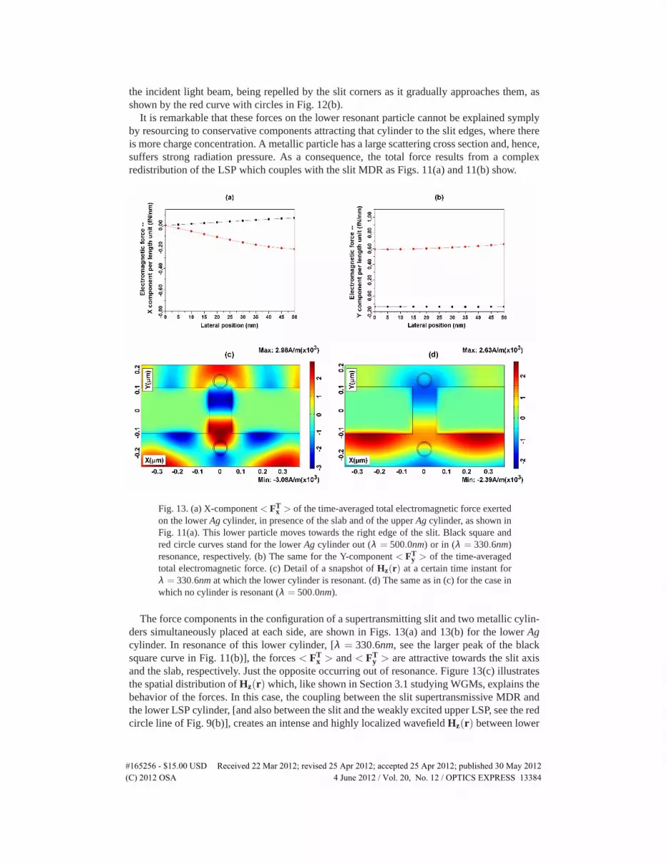
It is remarkable that these forces on the lower resonant particle cannot be explained symplyby resourcing to conservative components attracting that cylinder to the slit edges, where thereis more charge concentration. A metallic particle has a large scattering cross section and, hence,suffers strong radiation pressure. As a consequence, the total force results from a complexredistribution of the LSP which couples with the slit MDR as Figs. 11(a) and 11(b) show.
Fig. 13. (a) X-component< FTx > of the time-averaged total electromagnetic force exerted
on the lowerAg cylinder, in presence of the slab and of the upperAg cylinder, as shown inFig. 11(a). This lower particle moves towards the right edge of the slit. Black square andred circle curves stand for the lowerAg cylinder out (λ = 500.0nm) or in (λ = 330.6nm)resonance, respectively. (b) The same for the Y-component< FT
y > of the time-averagedtotal electromagnetic force. (c) Detail of a snapshot ofHz(r) at a certain time instant forλ = 330.6nmat which the lower cylinder is resonant. (d) The same as in (c) for the case inwhich no cylinder is resonant (λ = 500.0nm).
The force components in the configuration of a supertransmitting slit and two metallic cylin-ders simultaneously placed at each side, are shown in Figs. 13(a) and 13(b) for the lowerAgcylinder. In resonance of this lower cylinder, [λ = 330.6nm, see the larger peak of the blacksquare curve in Fig. 11(b)], the forces< FT
x > and< FTy > are attractive towards the slit axis
and the slab, respectively. Just the opposite occurring out of resonance. Figure 13(c) illustratesthe spatial distribution ofHz(r) which, like shown in Section 3.1 studying WGMs, explains thebehavior of the forces. In this case, the coupling between the slit supertransmissive MDR andthe lower LSP cylinder, [and also between the slit and the weakly excited upper LSP, see the redcircle line of Fig. 9(b)], creates an intense and highly localized wavefieldHz(r) between lower
#165256 - $15.00 USD Received 22 Mar 2012; revised 25 Apr 2012; accepted 25 Apr 2012; published 30 May 2012(C) 2012 OSA 4 June 2012 / Vol. 20, No. 12 / OPTICS EXPRESS 13384

Fig. 14. (a) X-component< FTx > of the time-averaged total electromagnetic force exerted
on the upperAg cylinder, in presence of the slab and of the lower cylinder, as shown inFig. 11(a), as the upper particle moves fromx = 0 to the right. Black square and red circlecurves stand for the case in which the upper cylinder is illuminated out (λ = 500.0nm) orin (λ = 326.3nm) resonance, respectively. (b) The same for the Y-component< FT
y > ofthe time-averaged total electromagnetic force.
cylinder and the slit, thus giving rise to an attractive force towards the aperture on both cylin-ders, i. e. like that of a bonding state of a photonic molecule. The vertical forces on the lowerand upper cylinders are 0.59f N/nm and−0.07f N/nm, respectively. Figure 13(d) presents thespatial distribution ofHz(r) in the same configuration at a certain time, both cylinders beingnow out of resonance.
As seen in Fig. 14(a), the upper cylinder, when this nanoparticle is out of resonance, suffersa weak transversal force as it moves to the right, being pushed towards the slit right corner, butit suffers a pulling force towardsx = 0 in resonance, [see black square and red circle curves,respectively, in Fig. 14(a)]. Concerning the vertical force, the slit attracts the upper non-resonantcylinder, an effect that is enhanced on exciting a resonance of this upper cylinder, [as shownby the black square and red circle curves, respectively, in Fig. 14(b)]. This suggests that inresonance the slit allows a binding of both the upper and lower particles; the explanation isthe same as that given above pertaining to theHz(r) pattern of Fig. 13(c). The vertical forcesexerted over the cylinders are now: 0.15f N/nm on the lower one and−0.27f N/nm on theresonant upper one.
5. Discussion and conclusions
In this paper we have carried out a study of the mechanical action of light on nanoparticles neara subwavelength slit illuminated in its supertransmission regime. Special emphasis has beenmade in comparing the force on the particles when a Mie resonance is excited with that onnon-resonant particles. The study has been carried out in two dimensions, so that these objectsare cylinders. In order to excite the transmission modes of the slit, a p-polarized incident beamhas been used. However, we believe that these results also hold for spheres in 3D.
First, we have found that the presence of the slit enhances by two orders of magnitude thetransversal optical forces on non-resonant cylinders, that would be obtained from an opticalbeam in a conventional optical tweezer configuration.
Further, we have proven that whereas the morphological resonance of the slit, causing su-pertransmission, enhances the fields surrounding these cylinders and hence the optical forcesexerted upon them, the excitation of a particle resonance has a quite different effect on these
#165256 - $15.00 USD Received 22 Mar 2012; revised 25 Apr 2012; accepted 25 Apr 2012; published 30 May 2012(C) 2012 OSA 4 June 2012 / Vol. 20, No. 12 / OPTICS EXPRESS 13385

forces, depending on whether the cylinder is dielectric or metallic.The electromagnetic force on the particle is highly dependent on the field surrounding it.
This means that WGMs excited in dielectric nanocylinders under p-polarization, either at theentrance or at the exit of the slit, have no great impact on the optical force; and even the highlocalization of these WGMs inside the cylinder may decrease its strength as a consequence ofthe very weak intensity distribution surrounding this particle.
On the contrary, the excitation of LSPs in metallic nanocylinders, (whether at the entrance orexit of the slit), produce localized field energy enhancement around the cylinder surface; thisreinforces the optical force, and even can produce a bonding pair: slit-cylinder. This bondingsystem may even be extended to one more metallic cylinder placed at the other side of the slit;then the aperture mediates between the two particles with a binding force.
In this connection, it should be remarked that both the WGM and the LSP addressed inthis study are electric dipole modes. This means that in principle, illuminating such a particlein front of a metallic thick slab should give rise to an attractive force, as a consequence of thedistribution of charges induced in this particle as well as in its image [65]. This is the case with ametallic cylinder, then the strong external field intensity associated to a LSP helps to producingsuch a binding interaction. By contrast, the weak intensity surrounding a dielectric cylinderwhen a WGM is excited at p-polarization, should prevent this attractive force. Enhanced opticalforces on dielectric cylinders are only obtained under s-polarization [66], which is the situationin which the generated WGM extends to the near field surrounding the cylinder.
We believe that these results should stimulate further experiments to obtain systems in whichmanipulation by the mechanical action of light on nano-objects may be done taking into ac-count their MDR resonances. Also this has consequences for raster scanning photonic forcemicroscopy with nanometric tips-supertransmitting aperture devices.
6. Appendix
A generic time-harmonic field is dealt with as a complex fieldV(r, t) = V0(r)exp(−iωt), (Vmay be eitherE or H), ω being the frequency andt the time. Also,V0(r) = VR
0 (r)− iVI0(r) =
|V0(r)|exp(−iφ(r)) stands for the value of the complex field, whent = 0, which in generalwould have a phaseφ 6= 0. The real part|V0(r)|cos(φ(r)− iωt) of V(r, t) is the only observ-able quantity, whose value can be obtained fromV0(r) and V∗
0(r) by means ofVR(r, t) =Re{V0(r)exp(−iωt)} = 1/2[V0(r)exp(−iωt) + V∗
0(r)exp(iωt)], which is a useful equationto express time-averaged quantities from their complex values, (see the corresponding expres-sions developed in [67] for the electric and magnetic fields). In our calculations, we need boththe complex electricE0(r) and magneticH0(r) fields, and their complex conjugatesE∗
0(r)andH∗
0(r), in order to calculate the time-averaged value of the electromagnetic force exertedon a particle as shown in Eq. (1). Even though FEMLAB only plots real values, it allows towork with the complex values of these fields as internal variables, in such a way that a com-plex variableA0(r) can be isolated by using[A(r, t)](t=0) as explained in the section “THEPHASOR VARIABLE” in the FEMLAB Documentation/User’s Guide/Modeling Physics andEquations/Variables and Expressions/Special variables, to be found in e.g. FEMLAB 3.0a ver-sion.
All particles here studied are 2D (infinite cylinders), hence the integration of time-averagedlocal forces, previously decomposed into their components along the X and Y axis,< Fl
x >and<Fl
y >, is made along a circumference that surrounds the cross section of the cylinder, asseen in Fig. 15. Hence, by line integrating, a force per axial length unit is obtained.
First, the integration surface embedding the particle is generated as close as field calculationconvergence allows. Also keeping the symmetry to facilitate the computations. As seen in Eq.(1), it is important to correctly define the outwards normal to the integration curve. Once the
#165256 - $15.00 USD Received 22 Mar 2012; revised 25 Apr 2012; accepted 25 Apr 2012; published 30 May 2012(C) 2012 OSA 4 June 2012 / Vol. 20, No. 12 / OPTICS EXPRESS 13386

Fig. 15. Schematic illustration of the geometry for the calculations of the force when acylinder of radiusr is placed near the slit. The components of the local electromagneticforce,< Fl
x > and< Fly >, are evaluated along the exterior circle of radiusre (red curve).
In our calculationsre = 210nmandre = 35nm whenr = 200nm (dielectric cylinder) andr = 30nm (metallic cylinder), respectively. The integration of these local forces over thefour segments into which the exterior circle is divided, yields the total electromagneticforce Cartesian components (<FT
x > and< FTy >).
values of the fields and their complex conjugates are known, in order to correctly performthe calculations,n must be decomposed in its componentsnx andny, taking into account thatFEMLAB divides the circumference into four curved segments, equivalent to Bezier curves asFig. 15 shows. The direction of parameterization for each curve, namely, the direction in whichthe parameterization variables takes values from 0 to 1, is denoted by the arrows.
The sense that FEMLAB assigns ton is always that pointing to the left relative to the parame-terization direction of the segment. Hence, the orientation of the normal relative to the enclosedarea, which FEMLAB initially defines for each segment, depends on which of them we areconsidering for the integration in Eq. (1). FEMLAB offers two additional variables, namednd andnu (the subindexd andu standing for down and up), which keep unchanged and invert,respectively, the sense of the normal. This is thoroughly explained in the sections “Normal Vari-ables” and “Direction of the Normal Component on Interior Boundaries” in FEMLAB Docu-mentation/User’s Guide/Modeling Physics and Equations/Variables and Expresions/GeometricVariables/TANGENT AND NORMAL VARIABLES, to be found in FEMLAB 3.0a version.Namely, for the upper segments, the normal vector which FEMLAB uses points outwards theclose curve (nor nd must be used), while for the lower ones, it points inward. Thus, when Eq.(1) is evaluated over these lower segments, the sense of thisn must be changed (i. e.−n or nu
must be used), for the sake of physical significance.To illustrate this, we address the expressions to be evaluated in the integral of Eq. (1) over
the segments of the imaginary line outside the 2D particle (c. f. the red curve in Fig. 15). Tocalculate the components of time-averaged local electromagnetic force< Fl
x > and < Fly >
per axial unit length in p-polarization, only the field quantitiesEx(x,y, t = 0), Ey(x,y, t = 0),|E(x,y)| and|H(x,y)| are needed. Then the computation of the integrand in Eq. (1) reads:
#165256 - $15.00 USD Received 22 Mar 2012; revised 25 Apr 2012; accepted 25 Apr 2012; published 30 May 2012(C) 2012 OSA 4 June 2012 / Vol. 20, No. 12 / OPTICS EXPRESS 13387

< Flx >(E) =0.5Re[εrε0(Ex ·nd,u
x +Ey ·nd,uy )Con j[Ex]−0.5εrε0|E|2nd,u
x ],
< Flx >(H) =0.5Re[−0.5µrµ0|H|2nd,u
x ],
< Flx > =< Fl
x >(E)+< Flx >(H).
< Fly >(E) =0.5Re[εrε0(Ex ·nd,u
x +Ey ·nd,uy )Con j[Ey]−0.5εrε0|E|2nd,u
y ],
< Fly >(H) =0.5Re[−0.5µrµ0|H|2nd,u
y ],
< Fly > =< Fl
y >(E)+< Fly >(H).
(2)
Notice that sinceH · n = 0, the third term of Eq. (1) does not contribute in Eq. (2). Thesuperindexl denotes locality and the subindicesx, y stand for the Cartesian components. Thesuperindexd andu means that we choosend or nu depending on whether we are integratingover the upper or lower segments, respectively.
The equivalence between physical quantities and FEMLAB parameters are shown in Table1,
Table 1. Physical operators and variables needed to calculate the local forces and theirequivalence in FEMLAB language.
Physical significance FEMLAB variable notationRe[] real()Conj[] conj()εr epsilonrwhε0 epsilon0whµr mur whµ0 mu0 whEx(x,y, t = 0) Ex whEy(x,y, t = 0) Ey wh|E(x,y)| normEwh|H(x,y)| normH whnd
x(x,y),noutx (x,y) dnx (for upper segments)
ndy(x,y),nout
y (x,y) dny (for upper segments)nu
x(x,y),noutx (x,y) unx (for lower segments)
nuy(x,y),nout
y (x,y) uny (for lower segments)< Fl
x >(E) Fxav tE polp< Fl
x >(H) Fxav tH polp< Fl
x > = < Flx >(E)+< Fl
x >(H) Fxav polp< Fl
y >(E) Fyav tE polp< Fl
y >(H) Fyav tH polp< Fl
y > = < Fly >(E)+< Fl
y >(H) Fyav polp
wherereal() and con j() are FEMLAB commands to get the real part and the conjugate ofany complex expression. The FEMLAB variable names for< Fl
x >(E), < Flx >(H), < Fl
x >,< Fl
y >(E), < Fly >(H) and< Fl
y > are imposed by the user.The quantities of Eq. (2) are inserted as user-made functions into the box “Boundary Expres-
sions...” of the label Options/Expressions/ in the Toolbar before FEMLAB develops its field
#165256 - $15.00 USD Received 22 Mar 2012; revised 25 Apr 2012; accepted 25 Apr 2012; published 30 May 2012(C) 2012 OSA 4 June 2012 / Vol. 20, No. 12 / OPTICS EXPRESS 13388

calculations. Then, once FEMLAB has run, the integration of the expressions of Eq. (2) ismadeto calculate Eq. (1) byactivating the close line segments surrounding the particle, (as inthe red curve of Fig. 15), in the box “Boundary Integration” of the label Postprocessing/ in theToolbar and inserting into it the name of the corresponding variable, either< Fl
x > or < Fly >,
and then selecting the solution at angle 0. The latter is done for these quantities to be first cal-culated with the complex fields at a temporal phasor valueωt = 0. Then they are integratedover the corresponding segments. Only after this is done, the X- and Y-components of the totaltime-averaged electromagnetic force< FT
x > or < FTy > per axial unit length are, in the end,
calculated. One can even obtain a graphical distribution of the local forces on the integrationline by entering the user-given names of< Fl
x > and< Fly > in the box “Plot Parameters...” of
the label Postprocessing/ in the Toolbar, as an “Arrow Plot in Boundaries”.
Acknowledgments
We acknowledge useful discussions on the subject with J. J. Saenz, R. Quidant and F.Messeguer. Work supported by the Spanish MEC through FIS2009–13430–C02–C01 and Con-solider NanoLight (CSD2007–00046) research grants, FJVV is supported by the last grant.
#165256 - $15.00 USD Received 22 Mar 2012; revised 25 Apr 2012; accepted 25 Apr 2012; published 30 May 2012(C) 2012 OSA 4 June 2012 / Vol. 20, No. 12 / OPTICS EXPRESS 13389


