Embed Size (px)
Citation preview
ELSEVIER
Applied Acowfics, Vol. 50, No. 1, pp. 3M3, 1997 Crown Copyright 01997. Published by Elswier Science Ltd. All rights reserved
Printed in Great Britain 0003-682X/97/$17.00 + .oO
PII: SOOO3-682X(96)00034-5
Optical Microphone Transduction Techniques
Nykolai Bilaniuk
Institute for Microstructural Sciences, National Research Council of Canada, Ottawa, Canada KlA OR6
(Received 14 March 1996; revised version received 29 July 1996; accepted 2 August 1996)
ABSTRACT
Optical microphone technology is reviewed. A classtjkation scheme is introduced which utilizes the transduction mechanism as the primary sorting criterion. The principles of operation and characteristics of various device types are described. A discussion of performance criteria follows, with an emphasis on sensitivity. Crown Copyright 0 1997. Published by Elsevier Science Ltd
Keywords: Optical microphones, transducers, acoustic-optical sensors.
INTRODUCTION
In the last two decades optical sensor technology has advanced to the point that some types of optical sensors are already being routinely deployed. This is not yet true of optical microphones, but the volume of world-wide research activity in recent years suggests that the idea is promising. ‘Optical micro- phones’ are devices in which the transduction of airborne sound signals to lightwave signals is achieved without intermediary electronics. All optical microphones are light-modulating acoustical sensors rather than direct con- verters of sound energy to light: the energy is supplied by the light but the signal information is supplied by the acoustic wave. Beyond this common ground, optical microphone transduction techniques vary widely in detail. In most cases, the optical output is transmitted via fibre rather than free space. The performance of existing optical microphone prototypes does not com- pare favourably with conventional microphones in most respects, but improvement to a competitive level appears possible with some types. Progress will depend in part on identifying the most promising approaches.
35
36 N. Biluniuk
The idea of acousto-optical transducers has existed since A. G. Bell patented the ‘photophone’ in 1880.’ The first practical optical microphone proposal was one in which an interferometer would sense the vibration of a membrane, suggested by von Ohain, ’ but its realization was not technologi- cally feasible at that time. There have been many new developments since then. The most comprehensive existing survey of optical microphones known to the present author is the report of Herber.3 It was published in German and emphasizes fibre sensors, as does the same author’s earlier report.4 Occasionally surveys of integrated microphones also mention optical devi- ces.5y6 The present work reviews modern (post-1977) published work on optical microphones. The intent is to give an impression of the scope of research activity world-wide in recent decades, to identify the current state of the art with respect to the various transduction mechanisms, and to examine their relative strengths.
Proposed optical microphones do not exploit unassisted optical fibre as a sensing element even though many hydrophone designs do exactly that, and it is tempting to try it with microphones too. The idea dates at least as far back as 1977. Culshaw et al7 discuss the acoustic sensitivity of optical fibre. The basic sensing mechanism is that sound incident on a single mode fibre shifts the refractive index n, which in turn shifts the phase of the optical sig- nal. The discussion of Culshaw et al. is largely theoretical; no demodulation scheme is described. However, it does make clear that fibre sensitivity to airborne sound is poor because of the acoustic impedance mismatch between air, fibre jacket and fibre. The transducer must therefore involve a membrane or other low-mass structure to mediate the difference in impedance. All pro- posed optical microphones do this in some form. In the end, the relative insensitivity of optical fibre to sound is actually beneficial because it permits fibre to be used as a conduit for sound-modulated light.
The present study includes several components: a system of classification for optical microphone transduction principles, a comprehensive survey of prototype and proposed optical microphones, some suggestions for new devices, and a discussion of optical microphone performance. In the text that follows, the expression ‘optical microphone’ is used so often that the acro- nym OM is substituted.
CLASSIFICATION OF OM TRANSDUCTION MECHANISMS
Given the large variety of OMs that have been proposed, it is difficult to survey them systematically without a classification scheme. Such a taxonomy could be approached from a variety of different perspectives: modulation principle, enabling technology (materials system and fabrication method),
Optical microphone transduction techniques 37
nature of the signal and energy paths (integrated vs fibre vs free space optics), suitability for known particular applications, and so on. The classi- fication used here is based on modulation principle. The choice of modula- tion principle as the prime basis for classification suggests itself because it groups together devices with similar physical underpinnings and operating characteristics, including sensitivity.
Light has three properties that can be modulated: intensity (or amplitude), phase (or frequency) and polarization. Eventually all modulation must be reduced to intensity, because that is the only property to which photodiodes or photomultipliers can respond directly. Phase modulated OMs need an interferometer to perform this reduction, while polarization modulated OMs require a polarizer (analyser) or birefringent element. These reduction schemes may be integral to the device itself or be external to it, but they must be considered part of the OM when comparing the performance of devices.
Intensity modulation in an OM implies selective removal of part of the energy from the optical path. One may distinguish two general types of approaches. In radiated wave methods, energy is shed either by radiating all the energy out of a controlled optical path and recapturing part of it, or mechanically backscattering part of the energy toward the source. The alternative evanescent wave methods rely on mode coupling in some form, or on absorption from the evanescent field. The delineation between the two categories is not always completely clear. For example, in microbend trans- ducers displacement results in light being coupled from modes confined to the waveguide to radiative modes. Coupled waveguide transducers are another grey area. It seems natural to group them together under the eva- nescent wave category, however, if the optical waveguides are of the anti- resonant reflecting type, then strictly speaking the coupling is between radiative modes. Within the constraints imposed by their waveguides, radia- tive OMs may use incoherent and even broadband light sources, while eva- nescent wave devices typically require narrowband but not necessarily coherent sources. Generally all may work with multimode fibres or wave- guides.
There are two general types of OMs in which the phase of wavefronts plays a key role, namely those that rely on gratings and those that use interferometers. In the most general sense gratings need not be periodic, but in this context ‘grating’ refers to a periodic structure intended to alter the transmission or reflection of light through a medium. The exit path(s) are the directions in which there occurs constructive interference due to the multiple discontinuities of the grating. The magnitude and direction of the transmis- sion or reflection path(s) depends on the periodicity of the grating as well as the wavelength and phase of the incident light. There are many types of optical gratings, several of which have been considered for use in OMs.
38 N. Bilaniuk
Interferometric phase modulated OMs operate by changing either the phy- sical length or the refractive index of an optical test path and recombining the result with the signal from a reference path. The total phase 4 of a wave with wavenumber k along an optical path of length L and refractive index n is
2nL 2nnL 4=kL=-
A = - = k,,nL
A0
where A0 and k. are the free space wavelength and wavenumber, respectively. The phase change due to a perturbation of the environment is
A4 = koA(nL) = ko(nAL + LAn) (2)
In general, changes in index and length are not independent; for example, stretching a fibre would be expected to increase L and reduce n. When the test arm of the interferometer lies in free space, then the situation is simpler because n is constant independent of variations in L. The type of interferometer is a convenient basis for further classification. Other things being equal, double-pass interferometers such as the Michelson are twice as sensitive as single-pass Mach-Zehnder types. The behaviour of multipass Fabry-Perot interferometers is complicated further by the reflectivity of the surfaces.
Phase modulating OMs are strongly affected by optical phase noise, must use a coherent light source, and (in the case of integrated or fibre designs) single-mode waveguides. If the interferometer is not located at the device itself, and is instead positioned at the terminus of a lengthy fibre loop, then the microphone is sensitive to phase along the entire loop, including sec- ondary factors such as temperature, pressure and tension changes. Sensitivity to environmental factors in turn depends on the jacket and cladding as well as the intrinsic properties of the core. The detection scheme (homodyne or heterodyne, single-detector or differential) used to extract the signal also varies from device to device, and could serve as an additional sorting criterion.
The use of optical polarization as the modulated property in OMs is rare, and thus an elaborate classification scheme is superfluous. Devices based on liquid crystals and differential index shifting are described in the literature.
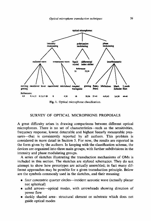
The classification scheme resulting from these considerations is shown in Fig. 1. The scheme is not unique: even with the property of light being modulated representing the main branches of the tree, alternative classifica- tions are possible.
Optical microphone transduction techniques 39
king cantil&cr lcvcr nlllcr&nd ml&bend co&ai .Pw waveguide
BndogFFllbr&Mic& Mach 2midc ahdcriitaz
References: 48 8.14.15 8.13.17-28 8 4.30 18 35.36 3741 4.4243 3.4.30 44-M
Fig. 1. Optical microphone classification.
SURVEY OF OPTICAL MICROPHONE PROPOSALS
A great difficulty arises in drawing comparisons between different optical microphones. There is no set of characteristics-such as the sensitivities, frequency response, lowest detectable and highest linearly measurable pres- sures-that is consistently reported by all authors. This problem is considered in more detail in Section 5. For now, the results are reported in the form given by the authors. In keeping with the classification scheme, the devices are organized into three main groups, with further subdivisions in the intensity and phase modulating groups.
A series of sketches illustrating the transduction mechanisms of OMs is included in this section. The sketches are stylized schematics. They do not attempt to show how prototypes are actually assembled; in fact many dif- ferent approaches may be possible for a given transduction principle. Below are the symbols commonly used in the sketches, and their meaning:
four concentric quarter circles-incident acoustic wave (actually planar not spherical) solid arrows-optical modes, with arrowheads showing direction of power flow darkly shaded area-structural element or substrate which does not guide optical modes
40
0
0
N. Bilaniuk
lightly shaded area--integrated optical waveguide or optical fibre unshaded waveguiding area-free-space optical path or hollow wave- guide
Depending on whether the details are important to the transduction prin- ciple, membranes are shown either as a line, or as an assembly of waveguid- ing and/or structural layers.
Intensity modulating
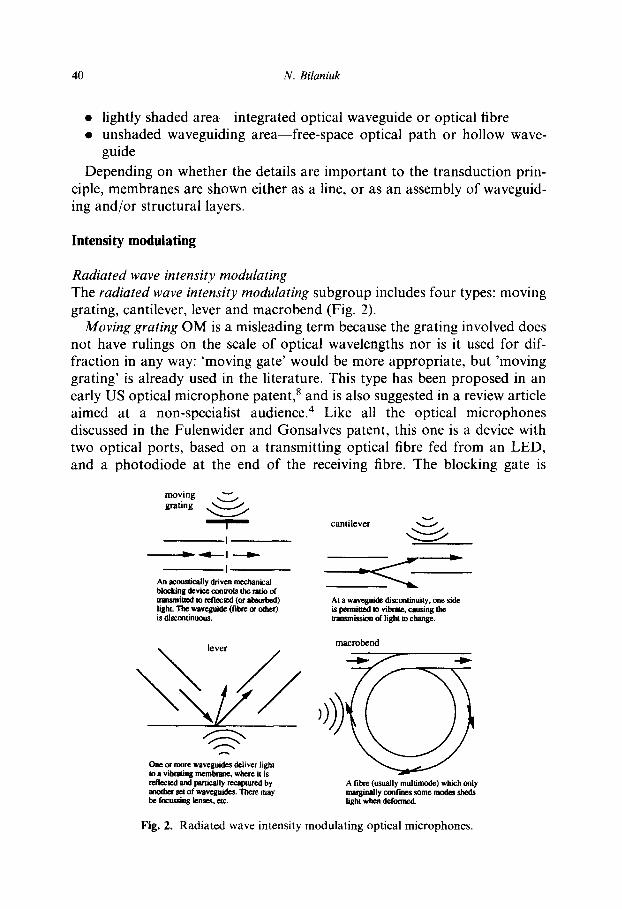
Radiated wave intensity modulating The radiated wave intensity modulating subgroup includes four types: moving grating, cantilever, lever and macrobend (Fig. 2).
Moving grating OM is a misleading term because the grating involved does not have rulings on the scale of optical wavelengths nor is it used for dif- fraction in any way: ‘moving gate’ would be more appropriate, but ‘moving grating’ is already used in the literature. This type has been proposed in an early US optical microphone patent,8 and is also suggested in a review article aimed at a non-specialist audience. 4 Like all the optical microphones discussed in the Fulenwider and Gonsalves patent, this one is a device with two optical ports, based on a transmitting optical fibre fed from an LED, and a photodiode at the end of the receiving fibre. The blocking gate is
I An aEmsticauy driven mechanical bkckinghvimmnmistherataof trmsma to tefk?ctcd (or absuIbed) ligk llte wmguide (film a other) is discmtinoms.
At a waveguide discmtinuity, me side ispmniaed*,vibne.cmsingthe trmsmissii of light to change.
One M more waveguides deliver light to a vibrating membnnc. where it is ntlectcd and paniully refaptured by anotha se4 of waveguides. Then may be focussing lenses. ac.
macrobend
A fibrc (usually mttbimcde) which only marginally cantiis some modes sheds tight when deformed.
Fig. 2. Radiated wave intensity modulating optical microphones.
Optical microphone transduction techniques 41
attached to a diaphragm which vibrates in sympathy with the acoustic field and interrupts the transmission of light between the two fibre tips. The author is not aware of a moving grating OM having been built in the way depicted in Fig. 2, and no performance data for actual samples are available. The basic design has however been implemented as a hydrophone,g*10 where a large mass in the gate is not a serious hinderance. A variation on this type in which the moving gate is a l-mm diameter spherical lens that refracts light from the input to the output multimode fibre has received a more recent US patent.” Implementation of this variant is being investigated by private industry in the USA with sponsorship from the US Air Force.12 A prototype with a 22-mm diameter diaphragm and a vacuum resonance of approxi- mately 850 Hz is claimed to have a 3.6 times greater sensitivity than the lever type OM of Hu et al. l3 Jost and Stec also report noise cancelling variants of the same basic design.12
Cantilever OMs have attracted more attention. The old US patent offers a version* in which the exposed flat ends of the two fibres face each other, and one of them is actuated. Another early form appears in a disclosure paper from Germany. l4 The device uses a short length of fibre attached to a mem- brane, such that there is a discontinuity at both ends. The design assembled by a group in Nanjing, China l5 follows the Fulenwider and Gonsalves lay- out. The authors describe a cantilever microphone in which one arm is attached to a membrane. Multimode fibres are used. An A-weighted signal- to-noise ratio (SNR) of 43 dB (re 20 uPa) is claimed for a 1 kHz input signal of 0.1 Pa. Interesting variations on the cantilever theme have been proposed as hydrophones. gylo These include a conventional cantilever assigned the title ‘moving fibre hydrophone’, and more sophisticated variants based on the use of specially polished and tapered fibre ends: the ‘critical angle acoustic sen- sor’ and the ‘frustrated total internal reflection’ sensor.
Lever OMs are one of the most studied types. The idea was proposed at an optical computing conference in London,16 and almost simultaneously in the US patent.* It is mentioned often in reviews.4-6 In the lever OM, light is reflected from a membrane and the changing position and curvature of the membrane change the amount of light captured on exit. Beyond that, parti- cular implementations differ markedly.
A group at the Technical University of Darmstadt (Germany) has con- centrated on single guide in, single guide out topologies with monomode fibre, and has proposed several variants even within that model. One involves a focusing lens before the membrane.17,18 This device is claimed to have a transfer coefficient of 8.5%, a sensitivity of 0.5%/Pa, and A-weighted equivalent noise levels of 44 and 29 dB without and with laser noise cancel- lation, respectively. The second Darmstadt variation uses a single graded index lens for coupling to both fibres. 18-21 It uses a laser diode source at
42 N. Bilaniuk
830 nm. The insertion loss is not given, but the sensitivity is 0.3%/Pa and the membrane resonance 4.3 kHz. The A-weighted equivalent noise level of 62 or 64 dB is dominated by laser amplitude noise. Detector shot noise is 33 dB lower. Using a differential detector comparing the laser output with the microphone output (thus rejecting common mode noise) the equivalent noise improved by 20-42 dB. By the 1993 paper, that had been improved still further to 38 dB. The third Darmstadt lever OM design makes use of two integrated waveguides on a single substrate which is positioned very close to the membrane without any additional lenses, greatly simplifying alignment. The substrates are either glass18,20,22 or polymethylmethacrylate (PMMA).21 The waveguide-on-glass design is fabricated by liquid phase Ag+/Na+ ion exchange. The resulting OM transfer coefficient is on the order of 6% at the chosen membrane-chip separation. The device achieved a depth of modula- tion of 2% of output/Pa, but with a membrane resonance frequency of only 300 Hz. If the resonance were pushed higher (by means of higher tension) the response would be reduced. Still in early stages of development as of 199321 the PMMA microphone was delivering a poor coupling coefficient of 0.05%.
A collaborative effort between the University of Rhode Island and the National Aeronautics and Space Administration (NASA) has gone in a dif- ferent direction, using fibre bundles to improve the recapture of light. One design was specifically intended for high sound pressure levels (SPLs) in very high-temperature (2000°F) applications.23 In that device the minimum detectable SPL is 130 dB, the maximum 190 dB. The optical transmission is about 0.001 (i.e. insertion loss is 30 dB). From the data, the sensitivity can be estimated as 4x lo-* Pa-‘. To date, a single fibre version of this high-tem- perature lever OM is apparently the only optical microphone of any kind that has gone beyond being a laboratory curiosity and undergone extensive field tests.24 The Rhode Island/NASA group has also performed theoretical work on lever OMs. Their studies predict that fibre bundle levers could achieve performance ‘comparable to a condenser microphone’. For a micro- phone of 1.6 mm radius, which they describe as equivalent to a l/S” Bruel & Kjaer (B&K) measurement microphone, sensitivity should be 64 dB re 1 V/ Pa, minimum detectable SPL 70 dB re 1 uPa. They have also conducted a thorough study of noise in lever OMs. 26 Two iterations on an experimental fibre bundle lever OM aimed at general applications yielded sensitivities of 36.5 and 23.0 mV/Pa, but the latter had a flatter frequency response.13
There have been other efforts to make OMs based on the lever principle, some of them predating the work at the universities in Darmstadt and Rhode Island. Some very original early work was done in the former Soviet Union. Klimashin describes a Golay cell inspired lever type OM in which the curvature of the mirrored membrane is used to change the focal point of the reflected beam. Its unusual features include an incandescent illumination
Optical microphone transduction techniques 43
source and differential mode diode detection in which the detectors are pur- posely placed not on but to either side of the focal plane. The author reports a sensitivity of 7.5 mV/Pa at 1 kHz, and an inherent noise of 20-22 dB dominated by the thermal noise of the membrane-air gap structure and shot noise in the detectors.27 Another group has proposed a lever type micro- phone with fibre-in-fibre-out connnections, in which the light makes multiple reflections between the membrane and backplate. The authors claim an insertion loss of 12 dB and a sensitivity of 1.3 x low3 Pa-‘. No noise figure is given.28 A more recent specialized lever acoustic sensor is reported from Brazil. It is designed for use in photoacoustic spectroscopy. A pellicule is mounted inside a vacuum chamber with the sample to be tested. The probe beam is from a He-Ne laser, which is reflected off the pellicule and is incident on a ‘position sensing detector’. A lock-in amplifier (referenced to the chop- per which modulates the illumination beam) is used to extract the signal. A noise figure of order of lo-* W/,/Hz is reported.29 The reliance on lock-in detection in this last design limits its usefulness to continuous signals for which a reference is available.
The Macrobend OM appears in the early US OM patent.* This transducer type has been further developed in the context of hydrophones,9*10 but no microphone prototype is known to have been built.
Evanescent wave intensity modulating The evanescent wave intensity modulating subgroup includes two basic types, the microbend and coupled waveguide. However, the latter includes several variants based on whether the directly modulated parameter is refractive index, separation, or width of the waveguides (Fig. 3).
Microbend OMs are closely related to the macrobend type, the difference being that the microbend variety uses propagating optical modes confined to the waveguide, and a wavelength-related periodicity in the deformation is exploited for scattering. This transduction mechanism originated in hydro- phone work,9T10 and has been extended to microphones.4>30 Bucaro et ~1.~~ built a prototype OM and give some experimental data, but not the absolute sensitivity or equivalent noise figure.
Coupled waveguide OMs as a class rely on mode coupling between a guided mode in one waveguide, and a similar guided mode in another. Momentum conservation requires that for the energy transfer to take place, the optical wavevectors k must be the same or at least harmonically related. The same idea underlies the optical directional coupler. Within this general OM type, further differentiation is based on the method used to vary the strength of the coupling. Garthe at the Technical Uiversity of Darmstadt proposed a design in which an integrated channel waveguide built into a membrane is suspended a fraction of a micron above a similar fixed waveguide.‘*

44 N. Bilaniuk
Construction of this device was not attempted because of the perceived dif- ficulties in microfabricating such a device. In a theoretical study, a group in Jena (Germany) suggested using twin antiresonant reflecting optical wave- guides (ARROWS) in an optical switch operating in the non-linear regime.3’ ARROWS rely on antiresonant Fabry-Perot action rather than total internal reflection for waveguiding, meaning that the resulting device is strictly speaking of the radiated wave type. The dependence on wavevector matching suggests the possibility of a coupled waveguide OM with modulation by refractive index shift, but the shift would be small, resulting in unacceptably low sensitivity.
Polarization modulating
This group includes two types: liquid crystal and the differential index shifter (Fig. 4).
Liquid crystal OMs have been proposed by a Soviet group.32 A polarizer is used to detect variations in the polarization of light transmitted through the
microbend -
A fibre is defamed by a periodii structu~. the treswe exerted by which is a function of&e acouttic field. ‘The &fomIatiM causes lealrqgcfKNllthP,WaVCgtd&WhenthCFOUiCr specvum of dx spatial &fomwions matches the
coupled waveguide: modulation by waveguide separation
coupled waveguide: modulation by waveguide index shift
Two wanguides are micmf%kated one above dne &ICY, on a atembruu. Ftexure of the membrane caases chmges in dte r&xXive indices OT the wave- gukks, modulating the coupling between them.
One wavegaide is mic~fabticated on a rigid subswamwhiiethec&xis@na~ a fraction of a micron above it. They am coupkd by tlte cvane~rmf fold fmm whiichever waveguide is illamiaated. The strength of that coupling is cut~lkd by the diitaau beween the waveguides. aad thus tk. vibratioa of tk membrane.
Fig. 3. Evanescent wave intensity modulating optical microphones.
Optical microphone transduction techniques 45
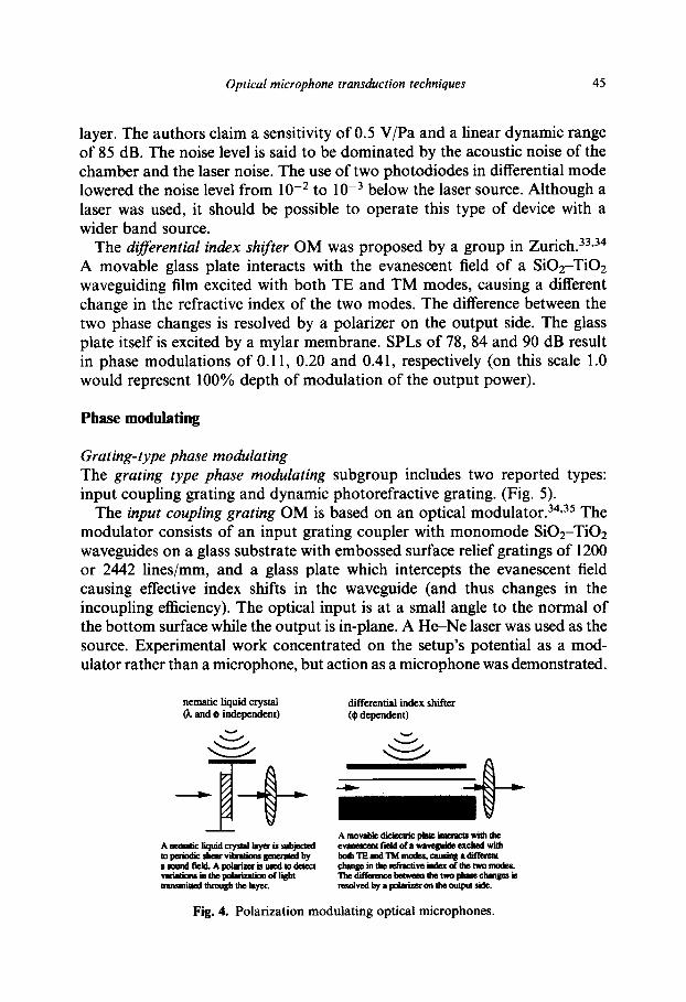
layer. The authors claim a sensitivity of 0.5 V/Pa and a linear dynamic range of 85 dB. The noise level is said to be dominated by the acoustic noise of the chamber and the laser noise. The use of two photodiodes in differential mode lowered the noise level from 10e2 to 10e3 below the laser source. Although a laser was used, it should be possible to operate this type of device with a wider band source.
The dljkential index shifter OM was proposed by a group in Zurich.33p34 A movable glass plate interacts with the evanescent field of a Si02-Ti02 waveguiding film excited with both TE and TM modes, causing a different change in the refractive index of the two modes. The difference between the two phase changes is resolved by a polarizer on the output side. The glass plate itself is excited by a mylar membrane. SPLs of 78, 84 and 90 dB result in phase modulations of 0.11, 0.20 and 0.41, respectively (on this scale 1 .O would represent 100% depth of modulation of the output power).
Phase modulating
Grating-type phase modulating The grating type phase modulating subgroup includes two reported types: input coupling grating and dynamic photorefractive grating. (Fig. 5).
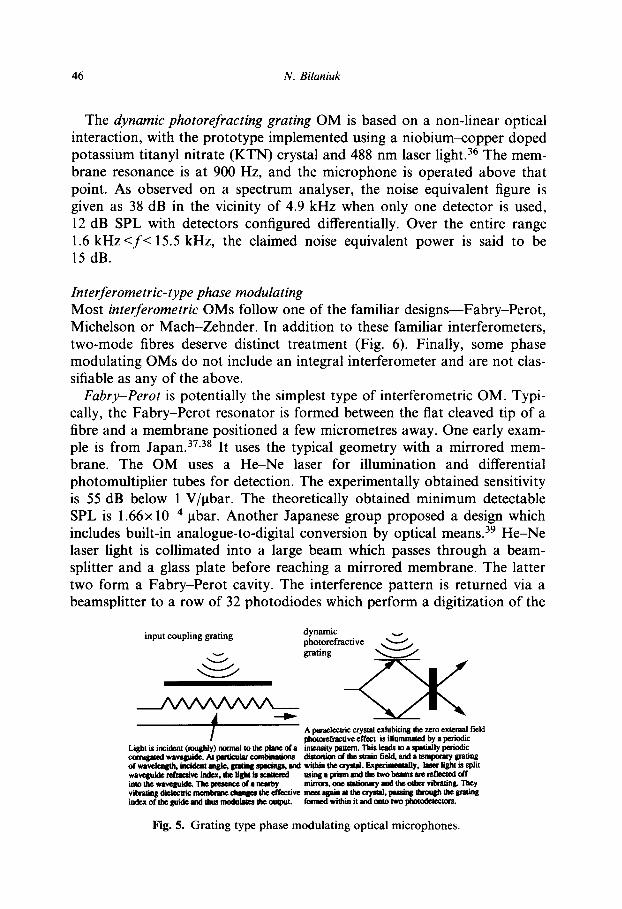
The input coupling grating OM is based on an optical modulator.34*35 The modulator consists of an input grating coupler with monomode SiOz-TiO2 waveguides on a glass substrate with embossed surface relief gratings of 1200 or 2442 lines/mm, and a glass plate which intercepts the evanescent field causing effective index shifts in the waveguide (and thus changes in the incoupling efficiency). The optical input is at a small angle to the normal of the bottom surface while the output is in-plane. A H+Ne laser was used as the source. Experimental work concentrated on the setup’s potential as a mod- ulator rather than a microphone, but action as a microphone was demonstrated.
nematic liquid crystal (I. and $ independent)
differential index shifter (I$ dependent)
- Amovabkdkkcuicpph*inWmXswithlhc
AIHUiCliQlid~llryaiSsubjXU!d evMmcuNficklofrwvcyidccxciledwilh a,puindicshavibntMnr~by b&TEmdTMmlxks.~rdifIaaY llrwndficldApdari8crLurcdrodaccl changeintkr&aivecfnctivecdthetwm&s. . . muowiathcpdrizuonoflight Ihediffw&!cbc4wmlmetwopIlnechm#cdic uansmiaed Uuough the layex. lLTsLdvcdbyapolrimonhoulpittsidc.
Fig. 4. Polarization modulating optical microphones.
46 N. Bilaniuk
The dynamic photorefracting grating OM is based on a non-linear optical interaction, with the prototype implemented using a niobium-copper doped potassium titanyl nitrate (KTN) crystal and 488 nm laser light.36 The mem- brane resonance is at 900 Hz, and the microphone is operated above that point. As observed on a spectrum analyser, the noise equivalent figure is given as 38 dB in the vicinity of 4.9 kHz when only one detector is used, 12 dB SPL with detectors configured differentially. Over the entire range 1.6 kHz <f< 15.5 kHz, the claimed noise equivalent power is said to be 15 dB.
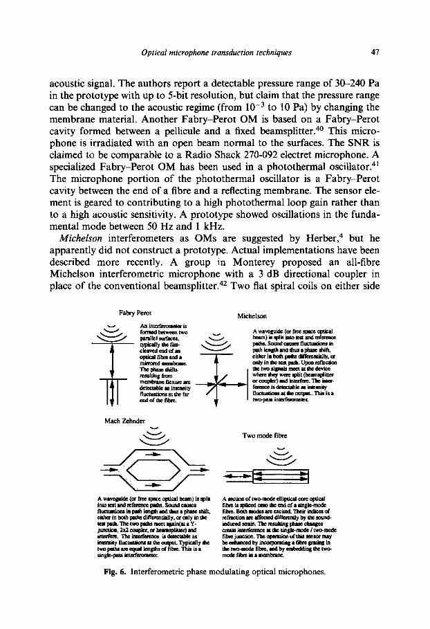
Interferometric-type phase modulating Most interferometric OMs follow one of the familiar designs-Fabry-Perot, Michelson or Mach-Zehnder. In addition to these familiar interferometers, two-mode fibres deserve distinct treatment (Fig. 6). Finally, some phase modulating OMs do not include an integral interferometer and are not clas- sifiable as any of the above.
Fabry-Perot is potentially the simplest type of interferometric OM. Typi- cally, the Fabry-Perot resonator is formed between the flat cleaved tip of a fibre and a membrane positioned a few micrometres away. One early exam- ple is from Japan. 37,38 It uses the typical geometry with a mirrored mem- brane. The OM uses a He-Ne laser for illumination and differential photomultiplier tubes for detection. The experimentally obtained sensitivity is 55 dB below 1 V/ubar. The theoretically obtained minimum detectable SPL is 1.66x lop4 ubar. Another Japanese group proposed a design which includes built-in analogue-to-digital conversion by optical means.39 He-Ne laser light is collimated into a large beam which passes through a beam- splitter and a glass plate before reaching a mirrored membrane. The latter two form a Fabry-Perot cavity. The interference pattern is returned via a beamsplitter to a row of 32 photodiodes which perform a digitization of the
input coupling grating
Fig. 5. Grating type phase modulating optical microphones.
Optical microphone transduction techniques 41
acoustic signal. The authors report a detectable pressure range of 30-240 Pa in the prototype with up to 5-bit resolution, but claim that the pressure range can be changed to the acoustic regime (from 10V3 to 10 Pa) by changing the membrane material. Another Fabry-Perot OM is based on a Fabry-Perot cavity formed between a pellicule and a fixed beamsplitter. This micro- phone is irradiated with an open beam normal to the surfaces. The SNR is claimed to be comparable to a Radio Shack 270-092 electret microphone. A specialized Fabry-Perot OM has been used in a photothermal oscillator.4’ The microphone portion of the photothermal oscillator is a Fabry-Perot cavity between the end of a fibre and a reflecting membrane. The sensor ele- ment is geared to contributing to a high photothermal loop gain rather than to a high acoustic sensitivity. A prototype showed oscillations in the funda- mental mode between 50 Hz and 1 kHz.
Michelson interferometers as OMs are suggested by Herber,4 but he apparently did not construct a prototype. Actual implementations have been described more recently. A group in Monterey proposed an all-fibre Michelson interferometric microphone with a 3 dB directional coupler in place of the conventional beamsplitter. 42 Two flat spiral coils on either side
Fahry Perot Michelson
Mach Zehnder
Two mode fibre
U
Fig. 6. Interferometric phase modulating optical microphones.
48 N. Bilaniuk
of a 3 mm thick aluminium plate are to be used to double the sensitivity, but only a single-sided prototype with 10 m of fibre was built. Its dynamic sen- sitivity is given as 0.21 rad/Pa. A more conventional non-integrated and non-fibre topology has been developed in Japan.43 By means of acousto- optic tunable filters and a Wollaston prism, a Michelson interferometer with a polarizing beamsplitter is driven by two optical frequencies. The source is a 0.78 urn laser diode. The test arm contains a piezo-driven mirror or a con- ventional microphone membrane. The FM output is collected on a single avalanche photodiode and displayed on a spectrum analyser or sent to an FM demodulator. With a fibre coupled 1” B&K microphone in the test arm, the sensitivity was 42.7 mV/Pa.
Mach-Zehnder interferometers should lend themselves well to both fibre and integrated acoustic sensors, but have attracted less experimental activity than one might expect. Practical implementations are discussed in the hydrophone literature in both all-fibre and other forms.9*‘0 Adapting these for use as microphones has been considered at least since 1986.3,4.30 The ideas are further considered in some reviews.s,6 In Ref. 5, the author notes that the A-weighted equivalent noise of optical microphones with band- widths of 5 kHz or more is typically in the range of 40-50 dB. The sensitivities of optical microphones are deemed not directly comparable with conven- tional microphones. An experimental realization of a Mach-Zehnder OM with fibre coils mounted on opposite sides of two diaphragms joined together by 3 dB couplers shows a relatively flat frequency response from 300 Hz to 10 kHz and an equivalent noise of 60 dB (equivalent to A-weighted 50 dB).
Two-modejibre sensors have not yet been demonstrated as OMs, but work on strain gauges of this type suggests this may be a possibility. There have been two variants reported. In one the mode of operation is a hybrid between a Fabry-Perot interferometer and a fibre Bragg grating: the two modes interfere at the point where the two-mode fibre is spliced on the single mode access fibre, and the two-mode fibre may be patterned with a grating. A group in Virginia has been working on this type of device.44 The permanent refractive index change is induced in two-mode elliptical-core germano- silicate fibre by means of a high-intensity argon laser. The resulting fibre gratings show differential phase modulation between the Lpi0 and LPI ieVe” modes. Applications to strain sensing are considered. In a second paper, the use of fibre gratings in two-mode elliptical fibre is extended to vibration sensing in a cantilever. 45 A similar approach but without the grating has been tried at the US Naval Research Laboratory.46 The sensing element is an elliptical core two-mode fibre which acts like a Fabry-Perot cavity. The sensor is accessed via a single mode fibre. A laser, single mode 2x2 coupler, and modulation/demodulation circuit complete the system. The phase dif- ference between the two modes (Lpi0 and LPI 1 even) is resolved at the splice of
Optical microphone transduction techniques 49
the two fibres. Wrapped on a mandril, the elliptical-core fibre was tested as a strain sensor by means of a piezo-actuator. Performance as a microphone is untested.
Other interferometric types. Recently two phase modulating OMs have been reported which defy classification because the necessary interferometers are not part of the devices. The OM designed by Schneider and Schellin uses two silicon chips. 47 One has vent holes on a surface metallized with gold, the other a gold-on-silicon-nitride membrane. The device is assembled with the two gold surfaces facing each other at a separation of 5 urn, forming a hol- low planar waveguide. Flexure of the membrane changes the effective index of the waveguide, causing a phase shift in the output. The external demodu- lation scheme is not described, but a Mach-Zehnder interferometer may be a suitable choice. Experimental results with this microphone have not yet been reported. The other device uses a SiOz-TiOz waveguide on a silicon substrate and a second silicon chip carrying a membrane. 48 The transduction principle is similar. In this case, the waveguide itself is not deformed by the acoustic wave, but the presence of the membrane varies the effective index of the waveguide.
Interferometers suffer from the shortcoming that one cannot distinguish whether the optical path length is increasing or decreasing by merely moni- toring the light intensity. This is especially important in the case of devices that may go through more than one fringe as the membrane is flexed. A solution has been proposed in the form of a Fabry-Perot interferometer based on a single mode fibre with an auxilliary multimode fibre to detect the intensity of scattered light. 49 The prototype has a 12-mm diameter Mylar membrane with a first resonance frequency of 5 kHz and a frequency response that is flat from 20 Hz to 3 kHz. The authors report a background equivalent noise of 55 dB re 20 nPa, a minimum detectable sound pressure of 60 dB, a dynamic range of more than 65 dB, and a sensitivity of 1.6 rad/Pa.
SOME ADDITIONAL POSSIBILITIES
The range of optical microphone designs that have been proposed or built, then reported in the literature, by no means exhausts all possibilities. The following are new ideas which originated in the course of the present inves- tigation, usually with inspiration from another type of optical microphone or a closely related field of research.
Evanescent wave intensity modulating
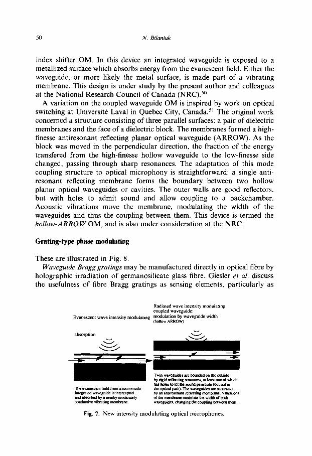
These two devices are illustrated in Fig. 7. The absorption OM is a design inspired by the coupled waveguide type with
modulation by waveguide separation, and to some extent by the differential
50 N. Bilaniuk
index shifter OM. In this device an integrated waveguide is exposed to a metallized surface which absorbs energy from the evanescent field. Either the waveguide, or more likely the metal surface, is made part of a vibrating membrane. This design is under study by the present author and colleagues at the National Research Council of Canada (NRC).5o
A variation on the coupled waveguide OM is inspired by work on optical switching at Universite Lava1 in Quebec City, Canada.51 The original work concerned a structure consisting of three parallel surfaces: a pair of dielectric membranes and the face of a dielectric block. The membranes formed a high- finesse antiresonant reflecting planar optical waveguide (ARROW). As the block was moved in the perpendicular direction, the fraction of the energy transfered from the high-finesse hollow waveguide to the low-finesse side changed, passing through sharp resonances. The adaptation of this mode coupling structure to optical microphony is straightforward: a single anti- resonant reflecting membrane forms the boundary between two hollow planar optical waveguides or cavities. The outer walls are good reflectors, but with holes to admit sound and allow coupling to a backchamber. Acoustic vibrations move the membrane, modulating the width of the waveguides and thus the coupling between them. This device is termed the hollow-ARROW OM, and is also under consideration at the NRC.
Grating-type phase modulating
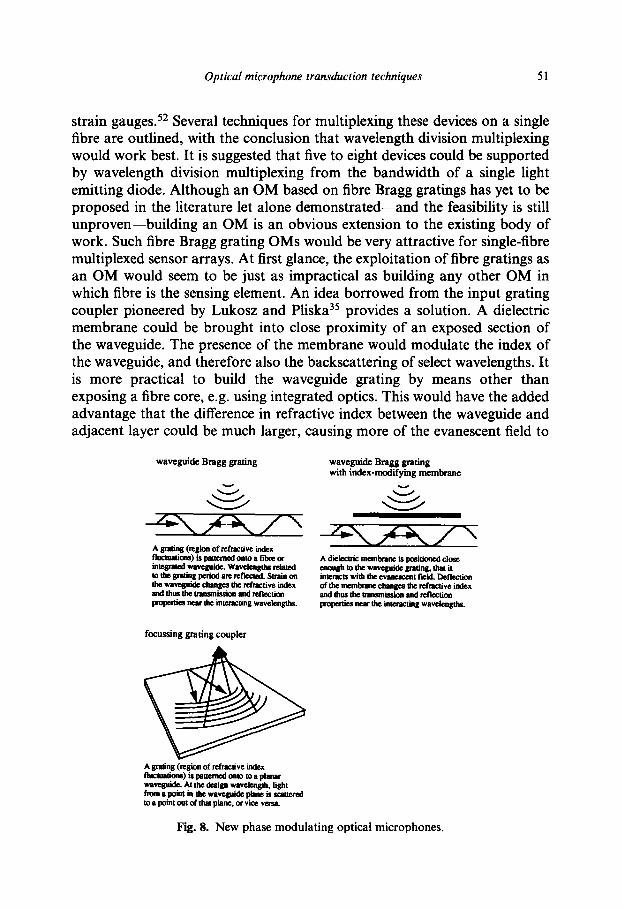
These are illustrated in Fig. 8. Waveguide Bragg gratings may be manufactured directly in optical fibre by
holographic irradiation of germanosilicate glass fibre. Giesler et al. discuss the usefulness of fibre Bragg gratings as sensing elements, particularly as
Radiated wave intensity modulating coupled waveRuide:
Evanescent wave intensity modulating modulation by waveguide width (hollow ARROW)
Twin waveguides BIG bounded on the outi&
llw evanescent field from a monomode integrated waveguide is intetce~ and absorbed by a nearby moderately c4mductivc vibrating membrane.
by rigid r&lecting smctums, at least one d which haslKllestotelthesouodpeaeuate(tnJtnotin the optical path). The waveguides an separated by M aadresmmnt nfkctiag membrane. Vibrations ofdwmembraaemodulatethewidthofbc4h waveguides. changing the coupling between them.
Fig. 7. New intensity modulating optical microphones.
Optical microphone transduction techniques 51
strain gauges. 52 Several techniques for multiplexing these devices on a single fibre are outlined, with the conclusion that wavelength division multiplexing would work best. It is suggested that five to eight devices could be supported by wavelength division multiplexing from the bandwidth of a single light emitting diode. Although an OM based on fibre Bragg gratings has yet to be proposed in the literature let alone demonstrated-and the feasibility is still unproven-building an OM is an obvious extension to the existing body of work. Such fibre Bragg grating OMs would be very attractive for single-fibre multiplexed sensor arrays. At first glance, the exploitation of fibre gratings as an OM would seem to be just as impractical as building any other OM in which fibre is the sensing element. An idea borrowed from the input grating coupler pioneered by Lukosz and Pliska35 provides a solution. A dielectric membrane could be brought into close proximity of an exposed section of the waveguide. The presence of the membrane would modulate the index of the waveguide, and therefore also the backscattering of select wavelengths. It is more practical to build the waveguide grating by means other than exposing a fibre core, e.g. using integrated optics. This would have the added advantage that the difference in refractive index between the waveguide and adjacent layer could be much larger, causing more of the evanescent field to
waveguide Bragg grating waveguide Bragg grating with index-modifying membrane
focusing grating coupler
A gatins (m&n of r&ac(ive index fltmmations)*pnttemdtmmmspl~ waveguide. At Um design wavehgth. light fmmrpoinththewaveguidepbeis~ mapointoutofth8tpkne.orvicevasa
Fig. 8. New phase modulating optical microphones.
52 N. Bilaniuk
be directed into the air gap between the waveguide and membrane. A device with this topology would be similar to the input grating coupler OM, but simpler to build and use because the light need not be steered in from a direction out of the grating plane.
Proposed for such applications as heads in magneto-optic disk drives,53 focusing grating couplers are integrated gratings similar to the integrated grating coupler in that they involve steering a light beam out of the wave- guide plane. Instead of coupling between a plane guided mode and a colli- mated beam in free space, these gratings are designed to couple the guided mode to a focused spot out of the plane. Typically the focus point is hun- dreds of micrometres to several millimetres from the chip plane. In principle the grating (and thus the aperture) can be as large as the chip die, and should allow a large numerical aperture and fine focusing of the beam. The wave- length must be exactly matched to the grating, and the grating itself must be patterned with great precision. Wavelength mismatch leads to shifts in the location of the focus point, defocusing and a rapid falloff of coupling into or out of the out-of-plane beam. The use of focusing grating couplers in OMs has yet to be explored at all. They may be useful in a variety of ways. Two uses might be injecting light into a hollow ARROW OM and collecting it. Another possibility is that a focusing grating coupler used bidirectionally could form the sensing element in an integrated lever microphone with greater sensitivity and lower insertion loss than current lever designs, with the added possibility of wavelength selectivity. Validation of this concept requires further theoretical and experimental investigation.
DISCUSSION
The large variety of optical microphone transduction techniques described in Sections 3 and 4 does not include still others which are possible but have not yet appeared in the literature. The variety is grounds for optimism in that at least some of these may show long-term promise. However, the lack of uni- formity in reporting experimental results makes comparison of techniques and individual devices more difficult than necessary.
Performance criteria
The basic criteria applicable to all microphones include sensitivity, frequency response and the minimum detectable and maximum linearly measurable acoustic pressures. The last may also be expressed as a dynamic range above the minimum detectable pressure. Application of these criteria to optical ver- sus conventional microphones differs in practice. Also, different specifications
Optical microphone transduction techniques 53
can be used to highlight particular device attributes, for example to distin- guish between properties inherent to the modulation principle, and those dependent on its implementation.
Conventional microphones are two stage transducers: (1) acoustic pressure + membrane displacement, and (2) membrane displacement + electrical signal. The first stage describes the mechanical behaviour of the microphone, and the second its electrical properties. The first stage is largely responsible for the frequency response and substantially influences sensitivity. The var- ious conventional microphone transduction principles+lynamic, condenser, electret, piezoelectric-are critical to the second stage. Comparisons between different conventional microphones are facilitated by the fact that there are accepted ways of presenting the information: sensitivity is given with dimensions of voltage/pressure, and so on.
Optical microphones present more complications. Obtaining a voltage output involves at least three transduction stages: (1) acoustic pressure ==+- membrane displacement, (2) membrane displacement + optical intensity, and (3) optical intensity + electrical signal. The first stage again concerns the mechanical properties of the device, as in conventional microphones. Stage (2) is the mechano-optical transduction. Stage (3), the opto-electrical signal conversion, is not normally a part of the optical microphone itself. It is per- formed by separate, usually remote, photodetectors and preamplifiers. Phase modulating transducers involve the phase shift 4 as another intermediate variable, splitting the second stage into two parts: (2a) membrane displace- ment =+ phase shift and (2b) phase shift + optical intensity. Thus the signal passes in stages through as many as five domains: acoustic (pressure), mechanical (displacement), (in some cases) phase, optical (intensity) and finally electrical (voltage).
There is no uniform method for presenting experimental results. Sensitivity (or small-signal transfer function) illustrates the problem. Sensitivity is usually published as a single figure, which may include one or all of the transduction stages. Both acoustic pressure (p) and membrane centre dis- placement (q) are often quoted as the input variable. The output variable cited may be the displacement, radians of optical phase shift (#), fractional optical power switching (AP,/P,) where P, is the quiescent optical power on the output port of the microphone or voltage (I’). Limiting discussion to this list, seven incompatible ways of specifying sensitivity are possible, of which four appear frequently in the literature: db/dp, d(AP,/P,)/dp, d(AP,/P,)/dn, and dv/dp, typically in units of rad/Pa, Pa-‘, m-l and mV/Pa, respectively. Often the sound pressure level expressed in decibels re 20 PPa is used in place of the pressure in Pa.
The most suitable sensitivity specification to use varies depending on the task at hand. In order to achieve maximum flexibility for comparisons, it is
54 N. Bilaniuk
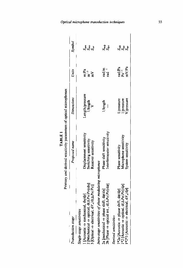
suggested that the three individual stage sensitivities should be reported for all OMs, so that all additional sensitivity figures-of-merit may be calculated. For phase modulating OMs, four sensitivities would be necessary for a complete description. All these fundamental sensitivities and some common derived ones are tabulated in Table 1. The symbols are chosen for con- sistency and ease of use. Sensitivity is designated as S with a two-character subscript indicating the domains of the signal’s origin and destination: acoustic, mechanical, optical, electrical or phase.
Frequency response curves have the same meaning for all microphone types. They are not usually reported for optical microphones, but when they are, they follow the usual format. More often one finds the membrane resonance frequency which gives a clue to the bandwidth, It is evident that most optical microphones are not designed to operate over the full audio spectrum. As a result when experimental noise figures are given, it is often unclear whether the noise figure is as-measured for the operational band- width of the device, or whether it is the equivalent for a standardized passband such as ‘A-weighting’. The measurement bandwidth should be specified with the noise figure.
Noise in lever type optical microphones has been investigated in detail by He and Cuomo.26 Most of the analysis is portable to other optical micro- phone types. As with sensitivity, any attempt to compare microphone noise must take care to include the same range of transduction stages for all devi- ces under study. One may choose to compare the ‘intrinsic’ noise of micro- phones from stages 1 and 2, or the noise in whole microphone ‘systems’ including the electronics of stage 3. Thus a condenser microphone system includes the microphone itself, plus the biasing circuit and preamplifier, while an optical microphone system includes the optical source, its power supply, the microphone, detector diode(s) and transresistance preamplifier. Assuming a diode detector is employed, the quiescent output voltage of an optical microphone is I’, = qdP,A R, where L&j =dId/dPo is the photodiode responsivity at the operating wavelength, and AR= vo/&j is the transimpe- dance gain of the photodetector preamplifier, which is often controlled by a feedback resistor R. 1, is the photocurrent. Thus the receiver sensitivity of an optical microphone system (i.e. the stage 3 sensitivity) is usually S,, = P,qdR.
In the design of an OM, one key consideration is the desirability of bal- ancing the optical and mechanical noise contributions. Also important is the effect of transforming noise contributions between different points in the transducer: between the acoustical and electrical domains, the conversion factor is the system sensitivity S,, = S,,S,,,,S,,; between the acoustical and optical domains, the microphone sensitivity S,, = S,,S,, applies. High microphone sensitivity suppresses the importance of optical noise sources relative to mechanical ones. Ordinarily the switching sensitivity S,, is
TA
BL
E
1 g
Prim
ary
and
deri
ved
sens
itivi
ty
para
met
ers
of o
ptic
al
mic
roph
ones
2 0’
Tra
nsdu
ctio
n st
age
Pro
pose
d n
ame
Dim
ensi
ons
Uni
ts
Sym
bol
e 3
Sing
le-s
tage
se
nsiti
vitie
s
-.
3 G
1 [A
cous
tic
+ m
echa
nica
l, dq
/dp]
D
ispl
acem
ent
sens
itivi
ty
Len
gth/
pres
sure
m
/Pa
SllW
l $
2 [M
echa
nica
l +
optic
al,
d(A
Po/P
o)/d
n]
Switc
hing
se
nsiti
vity
1 /
leng
th
m-t
S
x
3 [O
ptic
al
+ el
ectr
ical
, dV
,/d(A
Po/P
o)]
Rec
eive
r se
nsiti
vity
m
o V
m
V
S oe
z
Znt
ra-s
tage
se
nsiti
vitie
s o
f ph
ase
mod
ulat
ing
mic
roph
ones
5 B
2a
[m
echa
nica
l +
phas
e sh
ift,
d4/d
n]
Phas
e sh
ift
sens
itivi
ty
1 /le
ngth
ra
d/m
S
r?
2b [
Phas
e +
optic
al
int.,
d(
APo
/Po)
/d#]
4
Inte
rfer
omet
er
sens
itivi
ty
8’
rad-
’ S4
0 3
Der
ived
se
nsiti
vitie
s z %
1*2a
[A
cous
tic
+ ph
ase
shif
t, d#
/dp]
Ph
ase
sens
itivi
ty
1 /pr
essu
re
5.
rad/
Pa
S 1*
2 [A
cous
tic
+ op
tical
, d(
APo
/Po)
/dp]
4
9 M
icro
phon
e se
nsiti
vity
l/p
ress
ure
Pa-’
S
E
1*2*
3 [A
cous
tic
+ el
ectr
ical
, dV
,/dp]
Sy
stem
sen
sitiv
ity
lw
V/p
ress
ure
mV
/Pa
S oe
56 N. Bilaniuk
substantially determined by the transduction mechanism, while the displace- ment sensitivity S,, is highly dependent on the details of the implementa- tion+.g. membrane size, tension, etc. Changing the quiescent optical insertion loss L changes the relative importance of opto-electronic noise upstream of the microphone (power supply and laser noise) compared to noise downstream (detector and preamplifier noise), but it is never beneficial to have a high insertion loss because P, also drops off as L.
Authors in the OM literature usually report that optoelectronic sources dominate the noise in their devices, even if top-quality electronics and signal extraction methods are used. This is particularly true of phase modulating OMs (which are susceptible to phase noise in addition to amplitude noise), and is also evident in intensity modulating lever optical microphones where the use of differential detection schemes results in improvement. Differential detection may be an impractical approach in applications involving long lengths of fibre or wavelength division multiplexing of several transducers on one fibre.
It can be seen that choosing a transduction mechanism with a large S,, is important to designing a successful OM since it allows sacrificing S,,,, to achieve noise and bandwidth objectives. For example, if it is necessary to extend the frequency response of a given OM design, one way this may be achieved is by decreasing the membrane size. This change raises the reso- nance frequency and thus extends the response, but it also decreases the dis- placement sensitivity, and increases the mechanical noise. The insertion loss may or may not be affected.
Comparison of experimental results
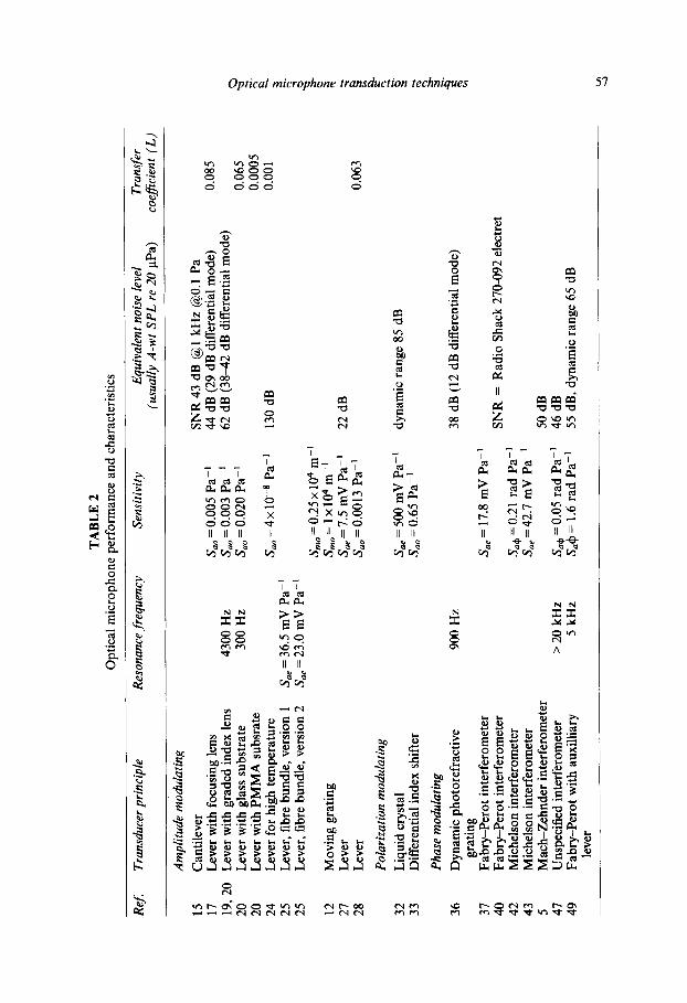
In Table 2, some experimental results on devices discussed in Section 3 are tabulated in a way that presents the data in as consistent a form as possible. All sensitivities of a given form are converted to identical units, for example. The table does not include all the devices discussed in Section 3, and further there are many gaps in the table, because of the already discussed difficulties in collecting and collating information. Nevertheless this table provides some useful insights.
Acoustic resonance frequencies are controlled by the implementation rather than the transduction technique, thus microphones with the same mechanism can have very different resonances. This directly influences other characteristics, e.g. the differences between the two devices from Garthe with resonances of 4300 and 300 Hz are a good illustration of the trade-off between bandwidth and sensitivity. The equivalent noise level or lowest detectable acoustic pressure are similarly implementation dependent; a large device tends to show a lower noise figure and higher sensitivity, inevitably at
TA
BL
E
2 O
ptic
al
mic
roph
one
perf
orm
ance
an
d ch
arac
teri
stic
s
ReJ
T
rans
duce
r pr
inci
ple
Res
onan
ce f
requ
ency
Se
nsit
ivit
y E
quiv
alen
t no
ise
leve
l T
rans
fer
(usu
ally
A
-wt
SPL
re 2
0 pP
a)
coef
icie
n t
(L)
Am
plit
ude
mod
ulat
ing
15
Can
tilev
er
SNR
43
dB @
1 k
Hz
@O
.l Pa
17
L
ever
with
foc
usin
g le
ns
S,,
= 0.
005
Pa-’
44
dB
(29
dB
dif
fere
ntia
l m
ode)
0.
085
19, 2
0 L
ever
with
gra
ded
inde
x le
ns
4300
Hz
S,,
= 0.
003
Pa-’
62
dB
(38
-42
dB d
iffe
rent
ial
mod
e)
20
Lev
er w
ith g
lass
sub
stra
te
300
Hz
S,,
= 0.
020
Pa-’
0.
065
20
Lev
er w
ith P
MM
A
subs
rate
0.
0005
24
L
ever
for
hig
h te
mpe
ratu
re
S,,=
4~10
-~
Pa-’
13
0 dB
0.
001
25
Lev
er,
fibr
e bu
ndle
, ve
rsio
n 1
S,
= 36
.5 m
V P
a-’
25
Lev
er,
fibr
e bu
ndle
, ve
rsio
n 2
S,,
= 23
.0 m
V P
a-’
&,=
0.25
x 10
4 m
-’
12
Mov
ing
grat
ing
S,,=
lx10
4m-’
27
L
ever
S,
,=
7.5
mV
Pa-
’ 22
dB
28
L
ever
S,
,=O
.O01
3 Pa
-’
0.06
3
Pol
ariz
atio
n m
odul
atin
g
32
Liq
uid
crys
tal
S,,
= 50
0 m
V P
a-’
dyna
mic
ra
nge
85 d
B
33
Dif
fere
ntia
l in
dex
shif
ter
S,,
= 0.
65 P
a-’
Pha
se m
odul
atin
g
36
Dyn
amic
ph
otor
efra
ctiv
e 90
0 H
z 38
dB
(12
dB
dif
fere
ntia
l m
ode)
gr
atin
g 37
Fa
bry-
Pero
t in
terf
erom
eter
S,
,=
17.8
mV
Pa-
’ 40
Fa
bry-
Pero
t in
terf
erom
eter
SN
R
= R
adio
Sh
ack
270-
092
elec
tret
42
M
iche
lson
in
terf
erom
eter
S,
,+ =
0.21
ra
d Pa
-’
43
Mic
hels
on
inte
rfer
omet
er
S,,
= 42
.7 m
V P
a-’
5 M
ach-
Zeh
nder
in
terf
erom
eter
50
dB
47
U
nspe
cifi
ed
inte
rfer
omet
er
> 20
kH
z Sa
+ =
0.0
5 ra
d Pa
-’
46 d
B
49
Fabr
y-Pe
rot
with
aux
illia
ry
5 kH
z S,
& =
1.6
rad
Pa-
’ 55
dB
, dy
nam
ic
rang
e 65
dB
le
ver
3
58 N. Bilaniuk
the cost of a limited frequency response. The lever microphones can be seen to have a transfer coefficient consistently well below unity, although they do differ by as much as two orders of magnitude.
The most interesting specification in Table 2 as far as comparison of transduction techniques is concerned is the sensitivity. It is difficult compare system sensitivities, S,,, because of differences in the OMs’ electronics. Microphone sensitivities, S,,, are reported for several lever microphones and the differential index shifter microphone. The differential index shifter33 has a sensitivity two orders greater than is typical of the levers. When the trans- duction mechanisms are considered, this result is predictable.
Radiative intensity modulating optical microphones, including levers, typically rely on the spread and collection of light by the tips of multimode fibres, which have a diameter of order 100 urn, and thus one would expect 100% switching in a lever to require a membrane motion of this magnitude or greater. The switching sensitivities S,, reported by Hu et &.,I3 and Jost and Stec12 are consistent with this expectation. The use of single mode fibres with core diameters of order 10 urn would increase sensitivity typically by an order, but at the cost of increased insertion loss and more challenging assembly constraints.
On the other hand, evanescent field intensity modulating OMs should obtain their maximal switching with a membrane motion of the order of the range over which the evanescent field decays at a waveguide-air interface, i.e. about one wavelength or 1 urn. The same holds for the differential index shifter, which, although a polarization modulating device, is also based on evanescent waves. Thus, given similar membranes and displacement sensi- tivities, a lever OM and differential index shifter OM should have micro- phone sensitivities that differ by two orders of magnitude.
The switching sensitivity of grating type optical microphones depends on the mechanism that alters the wavevector-grating periodicity relationship in the waveguide. Devices that take advantage of the varying proximity of a refractive index altering membrane (or other surface) to the waveguide should exhibit better sensitivity than those that rely on waveguide flexure alone. The former’s advantage becomes clear when one considers that typical microphone membrane deflections are in the submicrometre range. The membrane interaction with the evanescent field from the waveguide acts over a distance of order 1 micron, almost comparable to the scale of the deflec- tion, but at the same time, the membrane itself (and any waveguide on it) experiences only a very small strain.
Switching sensitivities are not readily available for experimental interfero- metric optical microphones, but again typical characteristics can be pre- dicted. Those that radiate light from a fibre tip onto a perpendicular membrane may be expected to have switching sensitivities comparable to
Optical microphone transduction techniques 59
evanescent field devices, but with the high optical insertion losses typical of lever microphones. The Fabry-Perot OM of Zhou et al. is of this type.49 Designs that place a nonradiating waveguide (e.g. fibre coils) onto a mem- brane and rely on strain in the waveguide are more difficult to judge. With these devices sensitivity for a given membrane deflection improves with increasing path length, but increasing the length of the fibre coil also increa- ses the membrane mass and thus leads to a decrease in the dynamic deflec- tion. The optimal compromise is implementation dependent. The Michelson interferometer of Brown et al. is of this latter fibre-optical type,42 and deli- vers a phase sensitivity a factor of eight smaller than the device of Zhou et al.
(0.21 vs 1.6 rad/Pa).
CONCLUSIONS
A classification scheme for OM transduction techniques has been presented, which uses the modulated property of light-intensity, phase and polariza- tion-for the first tier of the sorting. Non-uniformity in the methods used to report results in the literature complicates comparison of optical microphone transduction techniques and hinders identification of the most promising approaches. It is suggested that, whenever possible, experimental reports include the sensitivity of each transduction stage, the frequency response, and the maximum and minimum linearly measurable acoustic pressures. Despite the difficulties with making comparisons, some general observations are possible.
The design of an optical microphone capable of performance competitive with conventional microphones stands to benefit from high optical switching sensitivity. Existing and proposed optical microphones mostly suffer from excessive opto-electronic noise, and high sensitivity suppresses the relative importance of optoelectronic noise compared to mechanical thermal noise. Even so, devices with poor switching sensitivity may have advantages in particular niches, such as the high temperature lever microphone of Zucker- war et ~1.~~ Improvements in optical microphone technology should not count on improvements in optoelectronics, since shot noise limits place hard barriers to this approach.
Evidently, use of the evanescent wave from the optical waveguide to modulate the microphone output benefits the switching sensitivity regardless of whether optical intensity or phase is being modulated. This claim probably applies to polarization as well. The improvement in switching sen- sitivity is an order or more compared to devices which modulate the same optical property in a different way. This switching sensitivity advantage can be harnessed in a variety of ways, of which improving the noise floor and
60 N. Bilaniuk
microphone sensitivity are only two possibilities. One may instead trade away displacement sensitivity to extend the frequency response, for example, while retaining adequate overall microphone sensitivity.
However, evanescent-wave based optical microphones pose a significant fabrication challenge because it is necessary to build a waveguide that resides within a fraction of a micron from a vibrating membrane, or on the mem- brane itself similarly close to a fixed substrate. The spacing must be main- tained over distances on the scale of a membrane diameter. This proximity demanded by the optics must be reconciled with the need dictated by acous- tical considerations for a membrane-substrate gap of tens of micrometres, often with holes in the substrate for coupling to a backchamber. A variety of solutions to this dilemma are possible, most involving the techniques of micromachining. One approach is the topology proposed by Pliska and Lukosz,48 in which the vibrating membrane has a ridge while the waveguide is a flat plane. Other possibilities are under consideration at the NRC, and no doubt still others will be devised in the future.
ACKNOWLEDGEMENTS
The author is indebted to several colleagues at the Institute for Microstruc- tural Sciences of the National Research Council of Canada for helpful dis- cussions, including Richard Normandin, Gilles Daigle, David Havelock, and Michael Stinson. Especially meaningful were the contributions of Andre Delage, who carried out optical modeling that helped to frame the ideas in this paper. The work was supported in part by the Department of National Defence of Canada (DREV, DRDCS), and the Solid State Optoelectronics Consortium (SSOC).
REFERENCES
1. Hecht, J., Victorian experiments and optical communications. IEEE Spectrum, February (1985) 69973.
2. Pabst von Ohain, H. J., Ein Interferenzlightrelais fur weibes Licht. Annalen der Physik, 1935, 431441.
3. Herber, R., Faseroptische Sensoren fur Luftschallanwendungen. VDZ For- tschritt Berichte Reihe, 10, No. 125, VDI Verlag, Dusseldorf, 1990.
4. Herber, R., Faseroptische Mikrophone. Fernseh- und Kino- Technik, 1986, 40, 309-312.
5. Sessler, G. M., Acoustic sensors. Sensors and Actuators A, (1991) 2517, 323-330. 6. Sessler, G. M., New acoustic sensors. Journal de Physique IV, 1992, 2, C1413-
c1419.
Optical microphone transduction techniques 61
7. Culshaw, B., Davies, D. E. N. and Kingsley, S. A., Acoustic sensitivity of opti- cal-fibre waveguides. Electron. Lett,., 1977, 13, 76&761.
8. Fulenwider and Gonsalves, J., Transducer for converting acoustic energy directly into optical energy. US Patent No. 4,071,753, 31 January 1978, Int Cl G02B 5/14.
9. Bucaro, J. A., Lagakos, N., Cole, J. H. and Giallorenzi, T. G., Fiber optic acoustic transduction. In Physical Acoustics, Vol. 16, eds W. P. Mason and R. N. Thurston. Academic Press, New York, 1982.
10. Giallorenzi, T. G., Bucaro, J. A., Dandridge, A., Sigel, G. H., Cole, J. H., Rashleigh, S. C. and Priest, R. G., Optical fiber sensor technology. IEEE J. Quantum Electron., 1982, QE-18, 62&664.
11. Buchholz, J. C., Optical microphone with vibrating optical element. US Patent No. 5,262,884, 1993.
12. Jost, B. M. and Stec, J. P., Refractive fiber optic microphones with ambient acoustic noise-canceling capabilities. J. Acoust. Sot. Am., 1995, 98, 1612-1617.
13. Hu, A., Cuomo, F. W. and Zuckerwar, A. J., Theoretical and experimental study of a fiber optic microphone. J. Acoust. Sot. Am., 1992,91,3049-3056.
14. Sander, A., Optisches Mikrofon. Offenlegungsschrift 28 53 336, 1980. 15. Ziming, H., Jing, C. and Qioujing, Q., Fiber-optic microphone. Proc. SPZE,
1990, 1230, 551-552. 16. Fromm, I. and Unterberger, H., Direct modulation of light by sound. Znter-
national Optical Computing Conference, London, pp. S40-2, 1978. 17. Garthe, D., Realisierung eines faser-optischen Mikrofons. Forschritte der
Akustik, DAGA ‘89, 1989, pp. 175-178. 18. Garthe, D., Ein rein optisches Mikrophon. Acustica, 1991, 73, 72-89. 19. Garthe, D. and Schneider, U., Realisierung eines faser-optischen Mikrofons mit
Gradientenindexlinse. Forschritte der Akustik, DAGA ‘90, 1990, pp. 277-280. 20. Garthe, D., A fiber-optic microphone. Sensors andActuators A, 1991,25/7,341-345. 21. Garthe, D., Fiber- and integrated-optical microphones based on intensity mod-
ulation by beam deflection at a moving membrane. Sensors and Actuators, 1993, 3718, 484488.
22. Garthe, D. and Morweiser, M., Integriert-optisches Mikrophon. Forschritte der Akustik, DAGA ‘90, 1990, pp. 281-284.
23. Zuckerwar, A. J. and Cuomo, F. W. Fiber optic sensor for measurement of pressure fluctuations at high temperatures. IEEE CH2762-3/89,1989, pp. 503-509.
24. Zuckerwar, A. J., Cuomo, F. W., Nguyen, T. D., Rizzi, S. A., Cleve and Cle- venson, S. A., High temperature fibre-optic lever microphone. J. Acoust. Sot. Am., 1995,97,3605-3616.
25. He, G. and Cuomo, F. W., Displacement response, detection limit, and dynamic range of fiber-optic lever sensors. IEEE J. Lightwnve Tech., 1991,9, 1618-1625.
26. He, G. and Cuomo, F. W., The analysis of noises in a fiber optic microphone. J. Acoust. Sot. Am., 1992,92,2521-2526.
27. Klimashin, V. P. Optical Microphone. Plenum Press, pp. 688-690, 1981. 28. Dublenskiy, S. V., Abdeyev, I. P. and Kovarskiy, Ye. A., Fiber-optic micro-
phones for optical communications systems. Scripta Technica, (1988) 32-37. 29. De Paula, M. H., Vinha, C. A. and Badini, R. G., High-sensitivity optical
microphone for photoacoustics. Rev. Sci. Znstrum., 1992, 63, 3487-3491. 30. Bucaro, J. A., Cole, J. H., Dandridge, A., Giallorenzi, T. G. and Lagakos, N.,
Fiber optic acoustic sensors. Proc. SPIE, 1986, 661, 182-188.
62 N. Bilaniuk
31. Trutschel, U., Mann, M., Lederer, F., Wachter, C. and Boardman, A. D., Nonlinear switching in coupled antiresonant reflecting optical waveguides. A&. Phys. Lett., 1991, 59, 1940-1942.
32. Vinogradova, E. L., Kapustina, 0. A., Reshetov, V. N., Svet, V. D. and Yako- venko, G. N., Characteristics of an optical microphone using a nematic liquid crystal. Sov. Phys. Acoust., 1985, 31, l&12.
33. Lukosz, W. and Pliska, P., Integrated optical interferometer as a light modula- tor and microphone. Sensors and Actuators A, 1991, 2517, 337-340.
34. Lukosz, W. and Pliska, P., Integrated optical nanomechanical light modulators and microphones. Sensors and Materials, 1992, 3, 261-280.
35. Lukosz, W. and Pliska, P., Nanomechano-grating-coupler-modulator and inte- grated optical microphone. Proc. SPIE, 1989, 1141, 201-207.
36. Hofmeister, R. and Yariv, A., Vibration detection using dynamic photorefrac- tive gratings in KTN/KLTN crystals. Appl. Phys. Lett., 1992, 61, 2395-2397.
37. Ohba, R., Optical probe for narrow sound fields. Acta Zmeko, 1982,453-462. 38. Ohba, R., Development of fiber probe microphone (in Japanese). Oyo Butsuri,
1983,52,429432. 39. Mada, H. and Koide, K., Optical direct analog-to-digital conversion for micro-
phones. Appl. Optics, 1983, 22, 3411-3413. 40. Park, S. M. and Diebold, G. J., Interferometric microphone for optoacoustic
spectroscopy. Rev. Sci. Instrum., 1987, 58, 772-775. 41. Langdon, R. M. and Dowe, D. L., Photoacoustic oscillator sensors. Proc. SPZE,
1987,798,8693. 42. Brown, D. A., Hofler, T. and Garrett, S. L., Fiber optic flexural disk micro-
phone. Proc. SPIE, 1988, 985, 172-182. 43. Takehashi, H., Masuda, C., Gotoh, Y. and Koyama, J., Laser diode interfe-
rometer for vibration and sound pressure measurements. IEEE Trans. Instrum. Meas., 1989,38, 584587.
44. Vengsarkar, A. M., Greene, J. A. and Murphy, K. A., Photoinduced refractive- index changes in two-mode, elliptical-core fibers: sensing applications. Optics Lett., 1991, 16, 1541-1543.
45. Vengsarkar, A. M., Greene, J. A., Fogg, B. R. and Murphy, K. A., Spatially weighted, grating-based, two-mode, elliptical-core optical fiber vibration sen- sors. Optics Lett., 1991, 16, 1707-1709.
46. Berkoff, T. A. and Kersey, A. D., Reflectometric two-mode elliptical-core fibre strain sensor with remote interrogation. Electron. Lett., 1992, 28, 562.
47. Schneider, U. and Schellin, R., A phase modulating microphone utilizing inte- grated optics and micromachining in silicon. Sensors and Actuators, 1994, 4112, 695698.
48. Pliska, P. and Lukosz, W. , Integrated-optical acoustical sensors. Sensors and Actuators, 1994, 4112, 93-97.
49. Zhou, C., Letcher, S. V. and Shukla, A., Fiber-optic microphone based on a combination of Fabry-Perot interferometry and intensity modulation. J. Acoust. Sot. Am., 1995,98, 1042-1046.
50. Bilaniuk, N. and Delage, A., Modeling of optical microphone performance. J. Acoust. Sot. Am., 1995, 97, 3409.
51. Cantin, M., Carignan, C., Cot&, R., Duguay, M. A., Larose, R., LeBel, P. and Ouellette, F., Remotely switched hollow-core antiresonant reflecting optical waveguide. Optics Lett., 1991, 16(11), 1738-1740.
Optical microphone transduction techniques 63
52. Giesler, L. E., Murphy, J. R., Morey, W. W., Meltz, G. and Glenn, W., Instrumentation concepts for multiplexed Bragg grating sensors. Proc. SPZE, 1991,1480, 138-141.
53. Ura, S., Suhara, T., Nishihara, H. and Koyama, J., An integrated-optic disk pickup device. J. Lightwave Tech., 1986, LT-4, 913-918.


