Embed Size (px)
Citation preview

Optical study of CdS- and ZnS-passivated CdSe nanocrystals in gelatin films
This article has been downloaded from IOPscience. Please scroll down to see the full text article.
2007 J. Phys.: Condens. Matter 19 386237
(http://iopscience.iop.org/0953-8984/19/38/386237)
Download details:
IP Address: 152.78.98.19
The article was downloaded on 03/04/2010 at 16:10
Please note that terms and conditions apply.
The Table of Contents and more related content is available
Home Search Collections Journals About Contact us My IOPscience
IOP PUBLISHING JOURNAL OF PHYSICS: CONDENSED MATTER
J. Phys.: Condens. Matter 19 (2007) 386237 (9pp) doi:10.1088/0953-8984/19/38/386237
Optical study of CdS- and ZnS-passivated CdSenanocrystals in gelatin films
A E Raevskaya1, A L Stroyuk1, S Ya Kuchmiy1, V M Dzhagan2,M Ya Valakh2 and D R T Zahn3
1 Institute of Physical Chemistry, National Academy of Sciences of Ukraine, prospekt Nauky 31,Kyiv 03028, Ukraine2 Institute of Semiconductors Physics of National Academy of Sciences of Ukraine, prospektNauky 41, Kyiv 03028, Ukraine3 Institut fur Physik, Technische Universitat, D-09107 Chemnitz, Germany
E-mail: [email protected]
Received 12 February 2007, in final form 24 May 2007Published 6 September 2007Online at stacks.iop.org/JPhysCM/19/386237
AbstractCdSe nanocrystals were synthesized in aqueous solutions using gelatin as astabilizer. An appreciable improvement of photoluminescence efficiency ofnanocrystal-containing polymeric films was achieved by passivation of as-formed nanocrystals in solutions with CdS and ZnS. The passivation-inducedvariation of the photoluminescence efficiency and its maximum position wasfound to be dependent on the total volume of the passivating material and thesequence of the reagents involved. The photoluminescence of both unpassivatedand passivated nanocrystals was noticeably (∼200 meV) red-shifted fromthe first absorption maxima. A possible origin of the emission observed isdiscussed.
1. Introduction
Semiconductor nanocrystalline materials have been intensively studied within the past twodecades, and unique physical properties due to quantum confinement effects have beenreported [1]. In nano-sized systems with the portion of the surface atoms of up to 70–90%compared to that of the corresponding bulk, surface states play a crucial role in determiningtheir physical properties. The surface of nanocrystals (NCs) is constituted by atoms that are notfully coordinated and, hence, are highly active. These surface atoms act like defect states unlessthey are passivated by either organic ligands or wider-bandgap semiconductor materials [1, 2].In the latter case so-called ‘core–shell’ NCs are obtained [1]. Organic ligands cannot passivateboth cationic and anionic surface sites of the core [3]. Nanoparticles passivated by inorganicshell structures are more robust than organic-passivated nanocrystals and, therefore, havegreater tolerance with respect to the processing conditions necessary for incorporation intosolid structures [4].
0953-8984/07/386237+09$30.00 © 2007 IOP Publishing Ltd Printed in the UK 1

J. Phys.: Condens. Matter 19 (2007) 386237 A E Raevskaya et al
For efficient surface passivation, core nanoparticles are capped with a wider-bandgapmaterial, with the conduction band energy of the shell being usually higher than that of thecore material and with the valence band energy of a capping material being lower (type-I heterostructure [1]). Due to the presence of the wider-bandgap capping material, thephotogenerated excitons remain localized and are forced to recombine while spatially confinedin the core. As non-radiative decay channels through surface states are not accessible forcharge carriers in the core–shell structures, these structures show higher photoluminescence(PL) quantum yield [2, 3, 5–10], lower fluorescence lifetime [9], and many other benefits relatedto the tuning of the bandgap in two materials.
In the present paper we discuss the synthesis of aqueous CdSe sols with tuneable NCsize and size distribution from sodium selenosulfate and subsequent passivation of the surfaceof CdSe NCs with cadmium or zinc sulfide. Absorption and PL spectral measurementswere performed at room temperature for the characterization of the obtained core–shellnanostructures.
2. Experimental details
Reagent grade CdSO4, Zn(NO3)2, Na2SO3, Na2S, Se and gelatin were purchased from Aldrichand used without further purification. Aqueous sodium selenosulfate solutions (0.2 M) wereprepared via dissolution of powdered selenium in hot (80–90 ◦C) aqueous Na2SO3 solution,while maintaining the molar ratio [Se]:[Na2SO3] = 1:3.
2.1. CdSe nanocrystal synthesis
A solution containing cadmium sulfate (0.06 M) and gelatin (5 mass%) was added dropwise atroom temperature to the solution of 0.06 M sodium selenosulfate and 5 mass% of gelatin. Theresulting mixture was then placed into a refrigerator at 4 ◦C for gelation and left for ageing andCdSe nanocrystal formation. Diffusion restriction in the gelatin gels favours the formation ofsmall NCs with narrow size distribution. Nanocrystal growth stopped usually after 20–24 h ofgel ageing. Aged gels were then cut into small pieces and immersed in distilled water at 4–10 ◦C for 14–18 days, so that all water-soluble salt residues were removed from the gels. Afterthe dialysis and filtration the gels were dissolved in a measured water volume at 30 ◦C to give0.01 M colloidal CdSe solution stabilized by 5 mass% of gelatin. Detailed characterization ofthe gelatin-capped CdSe nanocrystals, synthesized from Na2SeSO3, can be found in [11, 12].
2.2. Surface passivation of CdSe NCs with CdS or ZnS
Measured volumes of 0.01 M CdSO4 or Zn(NO3)2 solutions were added to the gelatin-stabilized CdSe colloids. The colloids were kept with intense stirring for 5–10 min and then anamount of the sodium sulfide 0.1 M solution equimolar to the metal ion was added dropwisewhile stirring the colloidal solution. A number of samples was prepared where sodium sulfidewas added prior to the metal salt addition (table 1).
2.3. Preparation of the films with CdSe NCs
Glass-anchored films were prepared from each reference colloidal solution in the followingway: 2.5 ml of a colloidal solution were deposited onto a previously cleaned 2.0 cm2 glassplate and left for drying at 18–20 ◦C for several days.
2
J. Phys.: Condens. Matter 19 (2007) 386237 A E Raevskaya et al
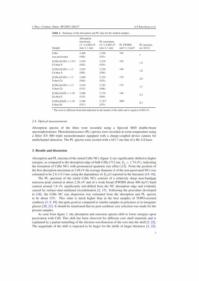
Table 1. Summary of the absorption and PL data for the studied samples.
Sample
Absorptionmaximum,eV ± 0.002 eV(nm ± 1 nm)
PL maximum,eV ± 0.002 eV(nm ± 1 nm)
PL FWHM,meV ± 2 meV
PL intensity,au (±0.2)
CdSe 2.490 2.250 1951
non-passivated (498) (551)
[CdSe]:[CdS] = 1:0.5 2.470 2.238 1921.4
Cd then S (502) (554)
[CdSe]:[CdS] = 1:1 2.455 2.230 1901.8
Cd then S (505) (556)
[CdSe]:[CdS] = 1:1 2.460 2.234 1702.8
S then Cd (504) (555)
[CdSe]:[CdS] = 1:3 2.410 2.183 1751.7
S then Cd (515) (568)
[CdSe]:[ZnS] = 1:10 2.408 2.179 1404.2
Zn then S (515) (569)
[CdSe]:[ZnS] = 1:10 2.398 2.157a 200a0.3
S then Zn (517) (575)
a The error is different from that indicated in the header of the table and is equal to 0.005 eV.
2.4. Optical measurements
Absorption spectra of the films were recorded using a Specord M40 double-beamspectrophotometer. Photoluminescence (PL) spectra were recorded at room temperature usinga Dilor XY 800 triple monochromator equipped with a charge-coupled device camera formultichannel detection. The PL spectra were excited with a 441.7 nm line of a He–Cd laser.
3. Results and discussion
Absorption and PL maxima of the initial CdSe NCs (figure 1) are significantly shifted to higherenergies, as compared to the absorption edge of bulk CdSe (712 nm, Eg = 1.74 eV), indicatingthe formation of CdSe NCs with pronounced quantum size effect [13]. From the position ofthe first absorption maximum at 2.49 eV the average diameter d of the non-passivated NCs wasestimated to be 2.6 ± 0.3 nm, using the dependence of Eg(d) reported in the literature [14–16].
The PL spectrum of the initial CdSe NCs consists of a relatively sharp near-bandgapemission peak centred at about 2.26 eV and of a weak broad (FWHM about 400 meV) bandcentred around 1.8 eV, significantly red-shifted from the NC absorption edge and evidentlycaused by surface-state-mediated recombination [2, 17]. Following the procedure developedin [18], the CdSe NC size dispersion was estimated from the absorption and PL spectrato be about 15%. This value is much higher than in the best samples of TOPO-assistedsynthesis [3, 5, 19], but quite good as compared to similar samples in polymers or in inorganicglasses [20, 21]. It should be mentioned that no post-synthesis size selection was made for thepresent samples.
As seen from figure 1, the absorption and emission spectra shift to lower energies uponpassivation with CdS. This shift has been observed for different core–shell materials and isexplained by a partial tunnelling of the electron wavefunction of the core into the shell [3, 22].The magnitude of the shift is expected to be larger for the shells of larger thickness [3, 22].
3

J. Phys.: Condens. Matter 19 (2007) 386237 A E Raevskaya et al
Figure 1. Normalized absorption and PL spectra of CdSe and CdSe/CdS NCs obtained by the ‘Sthen Cd’ scheme, with final ratio of [CdSe]:[CdS] = 1:1 (dotted) and 1:3 (thick solid). The initialconcentration of CdSe in all cases was 1.0 × 10⁻³ M.
It is clearly seen in figure 1 for the samples with different thicknesses of the CdS shell, whenreagents containing sulfur atoms were added before those containing cadmium (‘S then Cd’-scheme). The shifts of both the absorption threshold and emission maximum are proportionalto the volume of the passivating material (table 1). The addition of CdS according to the ‘Cdthen S’ scheme with concentration of [CdSe]:[CdS] = 1:0.5 and [CdSe]:[CdS] = 1:1 causesvery close shifts in the absorption and emission spectra (table 1), evidently because of smalldifferences in the volume of passivating material added in these two samples. The addition ofequal volumes (1.0 × 10⁻³ M) of CdS results in nearly the same shift for both ‘S then Cd’ and‘Cd then S’ schemes (table 1).
The effect of ZnS passivation on the optical spectra of CdSe NCs is illustrated in figure 2.The same volume of ZnS ([CdSe]:[ZnS] = 1:10) added to the solution in the above two schemesresults, similarly to the CdS shell, in almost identical shifts of the absorption and PL maximum,but the difference in the PL intensity is dramatic and will be discussed below.
Figure 2 also illustrates the effect of the bandgap of the shell material on the optical spectra.The shifts in the spectra for the samples with concentration ratios of [CdSe]:[CdS] = 1:3 and[CdSe]:[ZnS] = 1:10 are very close. This is quite understandable in view of the band structureof both kinds of core–shell NCs. As ZnS possesses a bandgap much larger (3.7 eV) than CdS(2.4 eV), a much thicker ZnS shell is required to obtain a comparable spreading of the electronwavefunctions into the shell, and, therefore, a comparable shift in the optical spectra.
Note that the formation of the passivating shells was additionally confirmed by resonantRaman scattering experiments reported elsewhere [24, 41]. The shifts in the absorption andemission spectra of the passivated samples, attributed to changes in the shell thickness, correlatewith the frequency and intensity of the Raman peak caused by lattice vibrations within thepassivating layer. Additionally, based on a higher Raman frequency, the higher PL intensity forthe ‘Zn then S’ sample, compared to the ‘S then Zn’ one, can be explained by a less intermixedand more strained shell in the former case [41].
Although very close shifts in PL and absorption spectra were found for two passivationschemes applied within the present synthesis, this is not generally the case when comparingdifferent preparation techniques. A large scatter of the shifts can be found in the literaturefor both CdSe/CdS and CdSe/ZnS NCs (figure 3). These observations indicate the effect of a
4

J. Phys.: Condens. Matter 19 (2007) 386237 A E Raevskaya et al
Figure 2. Normalized absorption and PL spectra of CdSe and CdSe/ZnS NCs passivated accordingto ‘Zn then S’ and ‘S then Zn’ schemes with final ratio of [CdSe]:[ZnS] = 1:10 in both cases.The corresponding spectra for CdSe/CdS with [CdSe]:[CdS] = 1:3 are shown for comparison (thePL spectrum for ‘S then Zn’ was not scaled because of insufficient intensity in the as-measuredspectrum).
Figure 3. CdS- (a) and ZnS- (b) passivation-induced shift of absorption and PL maxima forCdSe NCs observed in present experiment and by other authors. Filled symbols denote absorptionand open denote PL shifts, d stands for CdSe core diameter. •, ◦—d = 2 nm [22]; ,
—d = 2.3 nm [1]; , —d = 3 nm [1]; , —d = 2.1 nm [33]; , , —d = 1.8,2.1, 2.8 nm [33]; , —d = 3.5 nm [34]; , —d = 3.8 nm [35]; , —d = 4 nm [23];
, —d = 3.8 nm [35]; , —present work, d = 2.6 nm. Dependencies calculated in [22] forabsorption (solid lines) and PL (dashed line) and d = 2 nm are shown as well.
synthetic route and medium applied on the value of resultant red-shift PL or absorption. Notethat a comparison of different passivation procedures is reasonable only for NCs with the same(or very close) diameter d of the core and shell thickness. Among possible reasons for largedeviations observed may be the following: initial charge and strain state of the bare CdSe NCsurface; structure of the shell formed (defects, strain); core–shell alloying. The experimentalproofs of the alloying, in particular, and its effect on the PL intensity and FWHM in presentCdSe/ZnS NCs were obtained from a Raman spectroscopy study [41].
The effect of the shell formation on the PL spectra is revealed, along with the red-shift, ina remarkable increase in the intensity of the near-bandgap emission—by a factor of 1.4 up to4.2. This effect is sensitive to the volume of the passivating material. Thus, for the ‘Cd then S’scheme the intensity increases proportionally to the shell thickness (table 1). Simultaneously,
5

J. Phys.: Condens. Matter 19 (2007) 386237 A E Raevskaya et al
Figure 4. Absorption and PL spectra of CdSe and CdSe/CdS NCs passivated according to ‘Cd thenS’ and ‘S then Cd’ schemes with a final ratio of [CdSe]:[CdS] = 1:1 in both cases.
increasing the shell volume from 1:1 to 1:3 in the ‘S then Cd’ scheme, a drop in intensity isobserved by a factor of 1.6.
Another important factor is which sort of atoms is added first—metal or sulfur. For thesame volume of the shell-forming reagents (1:1) in the case ‘Cd then S’ much higher PLintensity is achieved than in the case when the scheme ‘S then Cd’ is applied (figure 4), whilethe shift of the absorption and emission maxima is very close in both cases (table 1).
From these results and a number of other studies [3, 22, 25], it follows that there exists anoptimal, in view of the light emission properties, thickness of the shell, which is different forevery particular method of NC preparation and passivation.
The ‘right’ reagent addition sequence seems to be even more important for the case of theZnS shell. Thus, the ‘Zn then S’ addition scheme gives a PL increase by a factor of 4.2 whilethe opposite sequence quenches the PL by a factor of 3 (see table 1). The latter fact may also bea consequence of the existence of the optimal thickness for every passivation scheme (sequenceof reagents), as in the above case of CdS shells. A different sequence of addition of reagentscan cause a different number or even nature of defects to be created in the shell, leading to asignificant difference in the PL efficiency as for the pair of CdSe/ZnS samples in the presentstudy. Raman spectroscopy study on the present CdSe/ZnS NCs shows that the drop in PLintensity after ‘S then Zn’ passivation may be a result of a strong intermixing between the coreand shell during the shell formation [41].
Along with the increase of the near-bandgap PL, the shell growth leads to a decrease ofthe relative intensity of the surface-related PL band. The effect is most pronounced for the‘Zn then S’ passivation, when this band is completely eliminated (figure 2). The increase ofthe overall PL intensity from the samples indicates a reduction of the number of non-radiativerecombination routes. The quenching of the defect PL with a simultaneous increase of thenear-bandgap PL is an evidence of the efficient passivation of the defect states involved in the‘red’ emission from the CdSe NCs. No observable change in the position of the remainingsurface-related band was detected after the passivation.
The procedure of shell deposition is usually observed to induce some broadening of thePL bands, which is supposed to result from the non-homogenous shell thickness distributionboth among the NCs and on the surface of each NC [22, 25]. We observed passivation of theCdSe NCs to result in a narrowing of the excitonic emission bands. The decrease of the PL
6

J. Phys.: Condens. Matter 19 (2007) 386237 A E Raevskaya et al
band width in this case reaches up to 25% for the CdSe/ZnS sample using the ‘Zn then S’ shelldeposition scheme. A possible reason for the narrowing of excitonic PL bands may be the cubicstructure of the NCs prepared by the given synthetic route, which was confirmed in an earlierwork by x-ray measurements [11]. In wurtzite-type NCs, studied in [3, 22, 25], the oppositetrend was observed for the PL band width, namely an FWHM increase after the shell deposition.The zinc-blende (cubic) structure is more symmetrical compared to wurtzite (hexagonal) andcan give more homogenous shell thickness. The observed band narrowing can alternativelyarise when not all NCs are uniformly passivated and their contribution to the PL spectrum isweaker. This assumption was partially confirmed by selective sampling of the larger NCs withan excitation wavelength λexc = 514.5 nm. Under this (resonant) excitation the PL spectrumexhibits a near-bandgap emission band narrowing by a factor of about two, as compared to thenon-resonant excitation using 441.7 nm light. Another difference under resonant excitation oflarge NCs is that the FWHM of the PL band slightly increases for the capped NCs, similarly towhat is commonly reported in the literature [23]. Thus the narrower PL bands of the passivatedsamples compared to unpassivated at 441.7 nm excitation may be evidence of the size-selectivepassivation procedure involved. However, the maxima of the emission peaks for both excitationwavelengths are very close for all the samples. Only at λexc = 530 nm was a shift of the PLmaximum noticed.
Under non-resonant excitation, the value of the Stokes shift �S of the near-bandgap PLmaximum from the absorption maximum was found to be quite large—about 200 meV for allsamples. The �S values usually observed are within 100 meV, but very large shifts (up to300 meV) were also reported [26, 20, 27].
The origin of the Stokes shift in CdSe NCs is mostly explained based on a ‘dark exciton’model [19, 28, 29], although the model involving recombination through surface traps wasextensively applied, especially to explain large �S values [17, 28, 30–32]. The reason fora large �S value could, therefore, be found from establishing the nature of the processesresponsible for the observed near-band-edge PL.
The fact that the PL intensity can be increased by appropriate passivation with CdS or ZnScan hardly be a proof for either intrinsic (excitonic) or surface-related origin of the PL. Whensuch a passivation (partially) reduces the channel(s) of non-radiative recombination, this canresult in an enhancement of any kind of radiative recombination channels—either excitonic ormediated by (shallow) traps.
The preliminary time-resolved PL measurements, which will be reported in detail in theforthcoming paper, revealed an increase of a mean decay time in the NCs after passivation,in agreement with the increase of absolute PL intensity after shell deposition. From fittingthe decays with four exponentials, decay components of 0.5–0.6, 2.5–3.0, 10–15 and 40–70 ns were derived. The first two components are obviously related to the matrix emission,which also contributes to the spectrum in the spectral region of the NC-related PL, as theywere also derived from the PL decay of gelatin film without NCs. Only the third and fourthcomponents changed noticeably after passivation, and can, therefore, be related to the NC PL.Relatively long decay times at a relatively low PL efficiency may be evidence of the radiativerecombination occurring through the shallow traps [36, 37]. This could easily explain a largeStokes shift of the NC emission [36]. However, a quite broad range of both excitonic and trapemission decay times was reported in the literature [36–40]; this time is obviously stronglydependent on the NC size, the kind of stabilizer and surfactant used and other factors.
Moreover, a solid argument given in [19] for the possibility of large Stokes shifts of theexcitonic PL does not allow us to exclude such a possibility in our case. Note that according tothe model [19] the magnitude of �S increases with a decrease of the mean NC size and with anincrease of the size dispersion. The dependence �S(d) becomes extremely steep for d below
7

J. Phys.: Condens. Matter 19 (2007) 386237 A E Raevskaya et al
3 nm and could evidently reach values close to 200 meV for the present NCs with a mean sizeof 2.6 nm and size dispersion of around 15% (see figure 11 in [19]).
Further time-resolved and low-temperature steady state PL measurements will beperformed for better understanding of the physical processes involved in the photoluminescenceof the CdSe NCs reported here.
4. Conclusions
CdSe NCs possessing quite narrow near-bandgap emission bands were synthesized in aqueoussolution under relatively mild conditions from sodium selenosulfate with gelatin as a stabilizer.In order to further improve the luminescence properties of the NCs, they were passivated withCdS or ZnS. Passivation results in a shift of the absorption and photoluminescence maxima ofthe NCs towards longer wavelengths. The shift is explained by partial tunnelling of electronwavefunction into the shell formed. The improvement of the photoluminescence parametersof the passivated NCs was found to be dependent on the total volume of the passivatingmaterial and the order of addition of Cd- (Zn-) and S-containing reagents. The maximumenhancement of the PL intensity by a factor of four was achieved for ZnS-passivated NCs.A considerable Stokes shift of the near-bandgap emission band was observed and its possibleorigin is discussed.
Acknowledgments
V Dzhagan is grateful to the Alexander von Humboldt Foundation for financial support duringhis research stay at Chemnitz University of Technology. The work was also partially supportedby the Fundamental Researches State Fund of Ukraine.
References
[1] Peng X, Schlamp M C, Kadavanich A V and Alivisatos A P 1997 J. Am. Chem. Soc. 119 7019[2] Schmid G (ed) 2004 Nanocrystals: From Theory to Application (Weinheim: Wiley–VCH) and references therein[3] Spanhel L, Haase M, Weller H and Henglein A 1987 J. Am. Chem. Soc. 109 5649[4] Wilson W L, Szajowski P J and Brus L E 1993 Science 262 1242[5] Kortan A R, Hull R, Opila R L, Bawendi M G, Steigerwald M L, Carroll P J and Brus L E 1990 J. Am. Chem.
Soc. 112 1327[6] Hoener C F, Allan K A, Bard A J, Campion A, Fox M A, Mallouk T E, Webber S E and White J M 1992 J. Phys.
Chem. 96 3812[7] Mews A, Eychmuller A, Giersig M, Schooss D and Weller H J 1994 Phys. Chem. 98 934[8] Danek M, Jensen K F, Murray B C and Bawendi G M 1996 Chem. Mater. 8 173[9] Hines M A and Sionnest P G 1996 J. Phys. Chem. 100 468
[10] Pradhan N, Katz B and Efrima S 2003 J. Phys. Chem. B 107 13843[11] Raevskaya A E, Stroyuk A L, Kuchmiy S Ya, Azhnyuk Yu M, Dzhagan V M and Valakh M Ya 2006 Theor. Exp.
Chem. 42 150[12] Raevskaya A E, Stroyuk A L, Kuchmiy S Ya, Azhniuk Yu M, Dzhagan V M, Yukhymchuk V O and Valakh M
Ya 2006 Colloids Surf. A 290 304[13] Brus L 1986 J. Phys. Chem. 90 2555[14] Yu W W, Qu L, Guo W and Peng X 2003 Chem. Mater. 15 2854[15] Rogach A L, Kornowski A, Gao M, Eychmuller A and Weller H J 1999 Phys. Chem. B 103 3065[16] Schooss D, Mews A, Eychmuller A and Weller H 1994 Phys. Rev. B 49 17072[17] Chestnoy N, Harris T D, Hull R and Brus L E 1986 J. Phys. Chem. 90 3393[18] Pesika N S, Stebe K J and Searson P C 2003 J. Phys. Chem. B 107 10412[19] Kuno M, Lee J K, Dabbousi B O, Mikulec F V and Bawendi M G 2003 J. Chem. Phys. B 106 9869[20] Ma X-D, Qian X-F, Yin J, Xi H-A and Zhu1 Z-K 2002 J. Colloid Interface Sci. 252 77
8
J. Phys.: Condens. Matter 19 (2007) 386237 A E Raevskaya et al
[21] Ivanda M, Bischof T, Lemann G, Materny A and Kiefer W 1997 J. Appl. Phys. 82 3116[22] Dabbousi B O, Rodriguez-Viejo J, Mikulec F V, Heine J R, Mattoussi H, Ober R, Jensen K F and Bawendi M
G 1997 J. Phys. Chem. B 101 9463[23] Baranov A V, Rakovich Yu P, Donegan J F, Perova T S, Moore R A, Talapin D V, Rogach A L, Masumoto Y and
Nabiev I 2003 Phys. Rev. B 68 165306[24] Dzhagan V M, Valakh M Ya, Raevskaya A E, Stroyuk A L, Kuchmiy S Ya and Zahn D R T 2007 Nanotechnology
at press[25] Xu L, Wang L, Huang X, Zhu J, Chen H and Chen K 2000 Physica E 8 129[26] Yu Z, Li J, O’Connor D B, Wang L-W and Barbara P F 2003 J. Phys. Chem. B 107 5670[27] Liu S-M, Guo H-Q, Zhang Z-H, Li R, Chen W and Wang Z-G 2000 Physica E 8 174[28] Efros Al L, Rosen M, Kuno M, Nirmal M, Norris D J and Bawendi M G 1996 Phys. Rev. B 54 4843[29] Norris D J, Efros Al L, Rosen M and Bawendi M G 1996 Phys. Rev. B 53 16347[30] Nirman M, Murray C B and Bawendi M G 1994 Phys. Rev. B 50 2293[31] Norris D J, Nirman M, Murray C B, Sacra A and Bawendi M G 1993 Z. Phys. D 26 355[32] Maly P, Kudrna J, Trojanek F, Mikes D, Nemec P, Maciel A C and Ryan J F 2000 Appl. Phys. Lett. 77 2352[33] Wang Q, Pan D, Jiang S, Ji X, An L and Jiang B 2006 J. Lumin. 118 91[34] Li J J, Wang Y A, Guo W, Keay J C, Mishima T D, Johnson M B and Peng X 2003 J. Am. Chem. Soc. 125 12567[35] Talapin D V, Rogach A L, Kornowski A, Haase M and Weller H 2001 Nano Lett. 1 207[36] Bawendi M G, Carroll P J, Wilson W L and Brus L E 1992 J. Chem. Phys. 96 946[37] Wang X, Qu L, Zhang J, Peng X and Xiao M 2003 Nano Lett. 3 1103[38] Lodahl P, van Driel A F, Nikolaev I S, Irman A, Overgaag K, Vanmaekelbergh D and Vos W L 2004 Nature
430 654[39] Woggon U, Herz E, Schops O, Artemyev M V, Arens Ch, Rousseau N, Schikora D, Lischka K, Litvinov D and
Gerthsen D 2005 Nano Lett. 5 483[40] Petrov E P, Cichos F and von Borczyskowski C 2006 J. Lumin. 119/120 412[41] Dzhagan V M, Valakh M Ya, Raevskaya A E, Stroyuk A L, Kuchmiy S Ya and Zahn D R T 2007 Appl. Surf. Sci.
at press
9


