Embed Size (px)
Citation preview
Optimization of reinforcements in plan panels with standard
beams using discrete optimization methods for stiffness criteria
Jose Miguel Candeias Santos Marecomareco [email protected]
Instituto Superior Tecnico, Lisboa, Portugal
May 2016
Abstract
The purpose of this work is to develop a computational model to optimize the reinforcement ofplan panels with standard beams, using, for this, discrete optimization methods, subject to differentloadings and boundary conditions, in order to increase its stiffness. For this, it is necessary to developa computational model that allows determining the optimal location of these reinforcements, as well asthe type of beams to be used, satisfying constraints of volume/weight of the reinforcements. Beforedesigning the program, it was necessary to define the formulation of the problem of optimization,including the objective function (the total elastic strain energy), design variables and constraints. Itwas used ANSYS, Inc. for finite element analysis, the GLODS (global and local optimization usingdirect search) as optimization algorithm, and MATLAB, The MathWorks, Inc., to create an interfacebetween them. This model has been tested for several sets of reinforcement beams, and it determinedthe best solutions in a wide range of case studies, which arose from two main groups of configurations(configurations in schemes of 24 and 32 positions of beams to be introduced). The results concludedthat the discrete optimization program of 32 positions were, in general, more effective. However, thereare areas where it is advantageous to use the discrete optimization program of 24 positions.Keywords: Finite Element Method, Optimization Algorithm, Totology Optimization, StructuralAnalysis, Plate Theory
1. Introdution
The purpose of this work is to develop a com-putational model to optimize the reinforcement ofplan panels with standard beams through discreteoptimization methods. It is intended to reinforce aflat panel with beams of standard dimensions, sub-ject to different loads and boundary conditions, inorder to increase its stiffness. For this, it is neces-sary to develop a computational model that allowsdetermining the optimal location of these reinforce-ments, as well as the type of beams to be used,satisfying constraints of volume/weight of the rein-forcement.
2. Motivation
The process of design and manufacture of rein-forcements systems in structures have been devel-oped over the last few centuries. In the complexconstruction of most of metal structures of vehi-cles, both in the aerospace and naval and in the au-tomobile industry, the reinforcement of plates is aconstant need. The use of reinforcements on platesaims to increase their stiffness and, thus, to obtainan improvement of their mechanical characteristics.This technique can significantly reduce the amount
of material used and reduce the weight/power ratioof each vehicle in question. The optimization tech-niques are widespread, have a wide range of applica-bility in various fields and they are only limited bythe imagination or creativity of the engineers whouse them. The creation of the desired design, whichdepends on the skills of the engineers, can some-times lead to incorrect results in synthesizing com-plex systems. In order to improve this critical phaseof the project, systems of computational methodsare being developed to optimize the topology of re-inforcements on plates, using numerical and analyt-ical methods for structural analysis.[2],[5]
3. Objectives
To achieve the goals, it is necessary to find themost appropriate formulation for this study. Byusing the finite element software (ANSYS, Inc.),a computational model is built to simulate thestructural analysis. Through an iterative software(MATLAB, The MathWorks, Inc.), a computa-tional model is created to perform the optimiza-tion. Finally, it is necessary to create an interfacebetween the structural part and numerical calcula-tion to obtain the desired control and optimization.
1
4. Optimization
Optimization is a peculiar concept in humanity,who, by instinct and at any time, makes strate-gic decisions in order to take full advantage of theavailable resources without compromising the effec-tiveness of the work performed. In basic terms, op-timization is a mathematical discipline which con-cerns the discovery of extremes (minimum and max-imum) in numbers, functions or systems. Theresolution of problems of global optimization is achallenging task, with additional difficulties whenderivatives are not available for use. However, thereare a number of practical applications in the realworld where a derivative-free global optimization isrequired. The work of Custodio and Madeira wasthe first attempt of global optimization by patternsearch (or direct search): GLODS (or global and lo-cal optimization using direct search) [4]. The directsearch is a family of numerical methods of optimiza-tion which does not require calculation of deriva-tives. Therefore, it can be used in functions thatare not continuous or differentiable [6]. GLODSis a new algorithm developed for single optimiza-tion, suitable for limited constraints, global opti-mization, and it’s free from derivatives. By us-ing directional direct search, the method switchesbetween search step, where potentially good areasare located, and poll step, where previously local-ized regions are explored. This exploration is donethrough the launch of several standard search meth-ods (pattern search), one in each region of interest.Differently from a multistart strategy, the severalmethods of pattern search are going to fuse be-tween each one when they are sufficiently close toeach other. The goal of GLODS is to eliminate thelargest number of active pattern searches, such asthe number of local minima, which easily would al-low the location of the possible value of the globalextreme.
5. Structural optimization
The structural optimization is completely re-lated to the improvement of its structural and me-chanical characteristics, while minimizing the ma-terial consumption and the final cost of the project.
5.1. Types of problems of structural optimization
The structural optimization problems are clas-sified depending on their geometric feature. Theycan be classified into three classes: dimensional op-timization, geometrical optimization and topologyoptimization. Subsequently, it is presented brieflythe most comprehensive optimization in structuralprojects.
5.1.1 Topological optimization
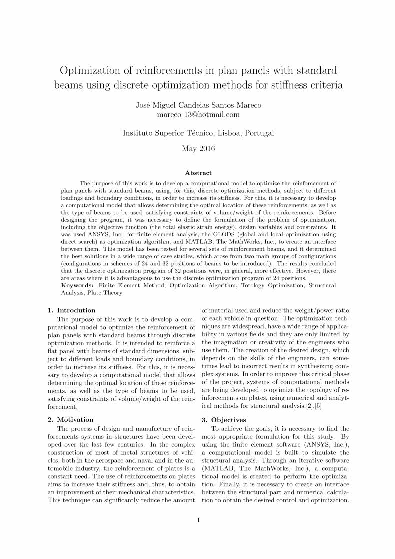
In this method, the design variables are numer-ical parameters that can change the distribution ofmaterial throughout the structure in order to econ-omize material in regions with reduced applicationthereof. There are two types of design variables,continuous or discrete; however, much of this workwas performed with discrete variables. In a discretecase, e.g., a truss with cross-sectional areas of thebars as design variables, one can allow these can godown to zero, which makes it possible to remove thetruss bars which do not make no effort, as shown inFigure 1.
Figure 1: Topology optimization
6. Stages of the formulation of the optimiza-tion problemThe formulation of an optimization project aims
the translation of the description of the problem ina well-defined math instruction. In most problems,it is used a procedure of tasks to be performed ineach of the following stages [2]:
• 1st stage – objectives of the optimization prob-lem;
• 2nd stage – data and information from theproblem;
• 3rd stage – identification and definition of thedesign variables;
• 4th stage – identification of the objective func-tion;
• 5th stage – identification of the constraints.
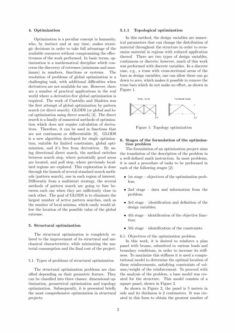
6.1. Objectives of the optimization problemIn this work, it is desired to reinforce a plan
panel with beams, submitted to various loads andboundary conditions, in order to increase its stiff-ness. To maximize this stiffness it is used a compu-tational model to determine the optimal location ofthese reinforcements, satisfying constraints of vol-ume/weight of the reinforcement. To proceed withthe analysis of the problem, a base model was cre-ated for the structure. This model consists of asquare panel, shown in Figure 2.
As shown in Figure 2, the panel is 5 meters inside and its thickness is 2 centimeters. It was cre-ated in this form to obtain the greatest number of
2
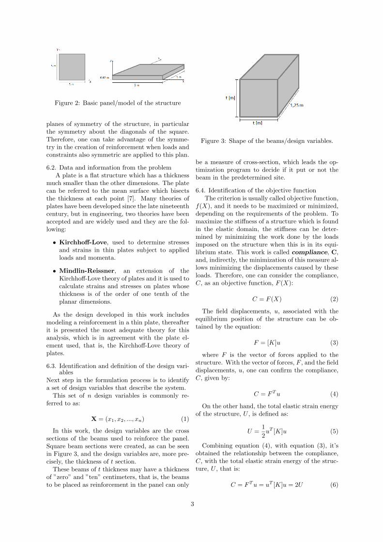
Figure 2: Basic panel/model of the structure
planes of symmetry of the structure, in particularthe symmetry about the diagonals of the square.Therefore, one can take advantage of the symme-try in the creation of reinforcement when loads andconstraints also symmetric are applied to this plan.
6.2. Data and information from the problemA plate is a flat structure which has a thickness
much smaller than the other dimensions. The platecan be referred to the mean surface which bisectsthe thickness at each point [7]. Many theories ofplates have been developed since the late nineteenthcentury, but in engineering, two theories have beenaccepted and are widely used and they are the fol-lowing:
• Kirchhoff-Love, used to determine stressesand strains in thin plates subject to appliedloads and momenta.
• Mindlin-Reissner, an extension of theKirchhoff-Love theory of plates and it is used tocalculate strains and stresses on plates whosethickness is of the order of one tenth of theplanar dimensions.
As the design developed in this work includesmodeling a reinforcement in a thin plate, thereafterit is presented the most adequate theory for thisanalysis, which is in agreement with the plate el-ement used, that is, the Kirchhoff-Love theory ofplates.
6.3. Identification and definition of the design vari-ables
Next step in the formulation process is to identifya set of design variables that describe the system.
This set of n design variables is commonly re-ferred to as:
X = (x1, x2, ..., xn) (1)
In this work, the design variables are the crosssections of the beams used to reinforce the panel.Square beam sections were created, as can be seenin Figure 3, and the design variables are, more pre-cisely, the thickness of t section.
These beams of t thickness may have a thicknessof ”zero” and ”ten” centimeters, that is, the beamsto be placed as reinforcement in the panel can only
Figure 3: Shape of the beams/design variables.
be a measure of cross-section, which leads the op-timization program to decide if it put or not thebeam in the predetermined site.
6.4. Identification of the objective functionThe criterion is usually called objective function,
f(X), and it needs to be maximized or minimized,depending on the requirements of the problem. Tomaximize the stiffness of a structure which is foundin the elastic domain, the stiffness can be deter-mined by minimizing the work done by the loadsimposed on the structure when this is in its equi-librium state. This work is called compliance, C,and, indirectly, the minimization of this measure al-lows minimizing the displacements caused by theseloads. Therefore, one can consider the compliance,C, as an objective function, F (X):
C = F (X) (2)
The field displacements, u, associated with theequilibrium position of the structure can be ob-tained by the equation:
F = [K]u (3)
where F is the vector of forces applied to thestructure. With the vector of forces, F , and the fielddisplacements, u, one can confirm the compliance,C, given by:
C = FTu (4)
On the other hand, the total elastic strain energyof the structure, U , is defined as:
U =1
2uT [K]u (5)
Combining equation (4), with equation (3), it’sobtained the relationship between the compliance,C, with the total elastic strain energy of the struc-ture, U , that is:
C = FTu = uT [K]u = 2U (6)
3
where the compliance, C, is linearly related tothe total elastic strain energy of the structure, U[3].
In a work with these features, both the compli-ance and elastic strain energy can be treated asthe objective function. However, in carrying outthis project, to optimize the reinforcement of thepanel, the total elastic strain energy of thestructure, U, was chosen as the objective func-tion. Keeping this, it can be said that the equationfor the objective function, f(X), to be treated isgiven as:
f(X) = U (7)
7. Computational modelThe structural analysis is performed by the fi-
nite element software (ANSYS) and the optimiza-tion algorithm is the GLODS, which functions im-plemented in the MATLAB.
7.1. Construction of the panel modelIn order to shape the panel according to the ob-
jectives of the optimization problem previously de-scribed in section 6.1, the panel was built in APDLcode (designated codigo.txt),so that it can accessthe data sent by MATLAB (Constante.txt)and theuser can also change its dimensions if he wants. Thedimensions are defined in the codigo.txt file, likewidth (a), length (b) and thickness (espessura).
The properties of the material used in the elementare shown in Table 1.
Properties of the materialElastic modulus 290 GPaPoisson’s ratio 0.3
Table 1: Properties of the material used.
The mesh is created in order to generate quadran-gular elements, and their refining was established inorder to combine two important points, that is, toget a good solution in the finite element analysis(convergence of the solution), and, secondly, be aprocess of calculation not too heavy computation-ally.
7.1.1 Selection of the types of element
Analyzing the application of some types of ele-ments, and the respective solutions envisaged, thetype of elements chosen to be used for computa-tional modeling of the panel and beam were, re-spectively, the SHELL93 and BEAM189 [1].
7.1.2 Defining panel reinforcements
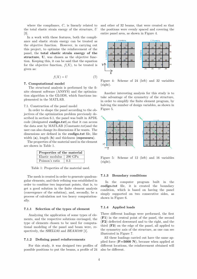
For this study, it was designed two profiles ofpossible positions to put the beams, a profile of 24
and other of 32 beams, that were created so thatthe positions were evenly spaced and covering theentire panel area, as shown in Figure 4.
Figure 4: Scheme of 24 (left) and 32 variables(right).
Another interesting analysis for this study is totake advantage of the symmetry of the structure,in order to simplify the finite element program, byhalving the number of design variables, as shown inFigure 5.
Figure 5: Scheme of 12 (left) and 16 variables(right).
7.1.3 Boundary conditions
In the computer program built in thecodigo.txt file, it is created the boundarycondition, which is based on having the panelsimply supported on two consecutive sides, asshown in Figure 6.
7.1.4 Applied loads
Three different loadings were performed, the first(F1) in the central point of the panel, the second(F2) deflected downward and to the right, and thethird (F3) on the edge of the panel, all applied tothe symmetry axis of the structure, as one can seeillustrated in Figure 7.
All these loadings carried out have the same ap-plied force (F=5000 N), because when applied atdifferent locations, the reinforcement obtained willalso be different.
4
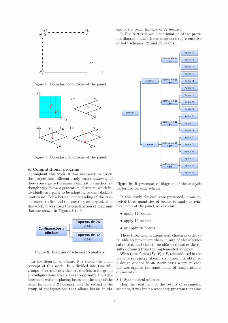
Figure 6: Boundary conditions of the panel.
Figure 7: Boundary conditions of the panel.
8. Computational programThroughout this work, it was necessary to dividethe project into different study cases; however, allthese converge to the same optimization method al-though they follow a generation of results, which in-dividually are going to be adapting to their distinctlimitations. For a better understanding of the vari-ous cases studied and the way they are organized inthis work, it was used the construction of diagramsthat are shown in Figures 8 to 9.
Figure 8: Diagram of schemes to analysis.
In the diagram of Figure 8 is shown the mainconcept of this work. It is divided into two sub-groups of assessments; the first consists in the groupof configurations that allows to optimize the rein-forcement without placing beams on the edge of thepanel (scheme of 24 beams), and the second is thegroup of configurations that allows beams in the
end of the panel (scheme of 32 beams).In Figure 9 is shown a continuation of the previ-
ous diagram, in which this diagram is representativeof both schemes (24 and 32 beams).
Figure 9: Representative diagram of the analysisperformed on each scheme.
In this study, for each case presented, it was se-lected three quantities of beams to apply as rein-forcement of the panel, ie, one can:
• apply 12 beams;
• apply 16 beams;
• or apply 20 beams.
These three enumerations were chosen in order tobe able to implement them in any of the schemessubmitted, and then to be able to compare the re-sults obtained from the implemented schemes.
With these forces (F1, F2 e F3), introduced in theplane of symmetry of each structure, it is obtaineda design divided in 36 study cases where in eachone was applied the same model of computationaloptimization.
8.1. Symmetrical schemesFor the treatment of the results of symmetric
schemes, it was built a secondary program that aims
5
to select the best and the worst set of solutions ineach evaluated scheme.
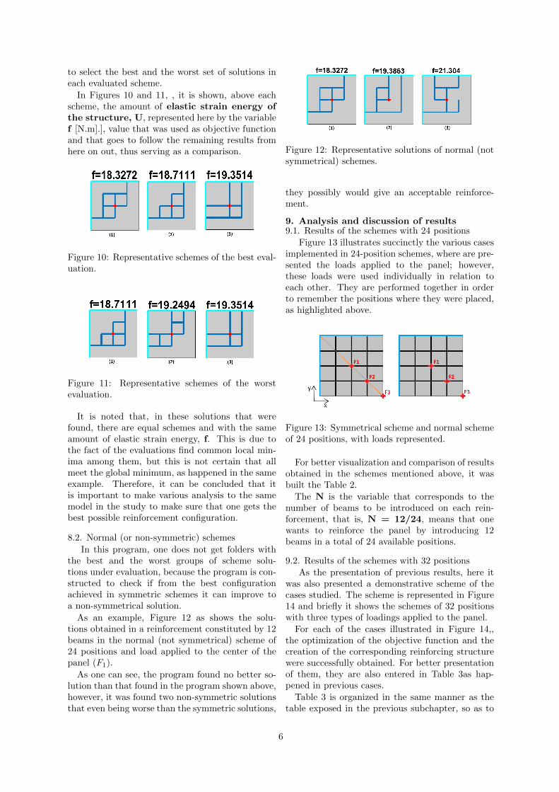
In Figures 10 and 11, , it is shown, above eachscheme, the amount of elastic strain energy ofthe structure, U, represented here by the variablef [N.m].], value that was used as objective functionand that goes to follow the remaining results fromhere on out, thus serving as a comparison.
Figure 10: Representative schemes of the best eval-uation.
Figure 11: Representative schemes of the worstevaluation.
It is noted that, in these solutions that werefound, there are equal schemes and with the sameamount of elastic strain energy, f. This is due tothe fact of the evaluations find common local min-ima among them, but this is not certain that allmeet the global minimum, as happened in the sameexample. Therefore, it can be concluded that itis important to make various analysis to the samemodel in the study to make sure that one gets thebest possible reinforcement configuration.
8.2. Normal (or non-symmetric) schemes
In this program, one does not get folders withthe best and the worst groups of scheme solu-tions under evaluation, because the program is con-structed to check if from the best configurationachieved in symmetric schemes it can improve toa non-symmetrical solution.
As an example, Figure 12 as shows the solu-tions obtained in a reinforcement constituted by 12beams in the normal (not symmetrical) scheme of24 positions and load applied to the center of thepanel (F1).
As one can see, the program found no better so-lution than that found in the program shown above,however, it was found two non-symmetric solutionsthat even being worse than the symmetric solutions,
Figure 12: Representative solutions of normal (notsymmetrical) schemes.
they possibly would give an acceptable reinforce-ment.
9. Analysis and discussion of results9.1. Results of the schemes with 24 positions
Figure 13 illustrates succinctly the various casesimplemented in 24-position schemes, where are pre-sented the loads applied to the panel; however,these loads were used individually in relation toeach other. They are performed together in orderto remember the positions where they were placed,as highlighted above.
Figure 13: Symmetrical scheme and normal schemeof 24 positions, with loads represented.
For better visualization and comparison of resultsobtained in the schemes mentioned above, it wasbuilt the Table 2.
The N is the variable that corresponds to thenumber of beams to be introduced on each rein-forcement, that is, N = 12/24, means that onewants to reinforce the panel by introducing 12beams in a total of 24 available positions.
9.2. Results of the schemes with 32 positionsAs the presentation of previous results, here it
was also presented a demonstrative scheme of thecases studied. The scheme is represented in Figure14 and briefly it shows the schemes of 32 positionswith three types of loadings applied to the panel.
For each of the cases illustrated in Figure 14,,the optimization of the objective function and thecreation of the corresponding reinforcing structurewere successfully obtained. For better presentationof them, they are also entered in Table 3as hap-pened in previous cases.
Table 3 is organized in the same manner as thetable exposed in the previous subchapter, so as to
6
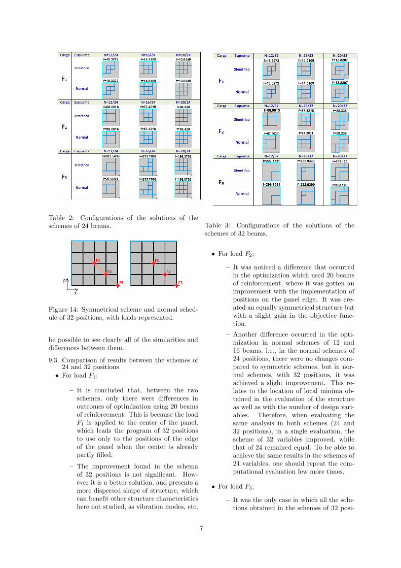
Table 2: Configurations of the solutions of theschemes of 24 beams.
Figure 14: Symmetrical scheme and normal sched-ule of 32 positions, with loads represented.
be possible to see clearly all of the similarities anddifferences between them.
9.3. Comparison of results between the schemes of24 and 32 positions
• For load F1;
– It is concluded that, between the twoschemes, only there were differences inoutcomes of optimization using 20 beamsof reinforcement. This is because the loadF1 is applied to the center of the panel,which leads the program of 32 positionsto use only to the positions of the edgeof the panel when the center is alreadypartly filled.
– The improvement found in the schemaof 32 positions is not significant. How-ever it is a better solution, and presents amore dispersed shape of structure, whichcan benefit other structure characteristicshere not studied, as vibration modes, etc.
Table 3: Configurations of the solutions of theschemes of 32 beams.
• For load F2;
– It was noticed a difference that occurredin the optimization which used 20 beamsof reinforcement, where it was gotten animprovement with the implementation ofpositions on the panel edge. It was cre-ated an equally symmetrical structure butwith a slight gain in the objective func-tion.
– Another difference occurred in the opti-mization in normal schemes of 12 and16 beams, i.e., in the normal schemes of24 positions, there were no changes com-pared to symmetric schemes, but in nor-mal schemes, with 32 positions, it wasachieved a slight improvement. This re-lates to the location of local minima ob-tained in the evaluation of the structureas well as with the number of design vari-ables. Therefore, when evaluating thesame analysis in both schemes (24 and32 positions), in a single evaluation, thescheme of 32 variables improved, whilethat of 24 remained equal. To be able toachieve the same results in the schemes of24 variables, one should repeat the com-putational evaluation few more times.
• For load F3;
– It was the only case in which all the solu-tions obtained in the schemes of 32 posi-
7
tions gave rise to different solutions com-pared to the schemes of 24 positions. Itis easy to understand why this event. Asalready mentioned, this was due to thefact that the load is applied to a vertex ofthe panel, where schemas of 24 beams donot have access to the placement of thesebeams.
– In nearly all evaluations in schemes of 32positions, there was improvement of theobjective function in view of the analy-sis carried out in the schemes of 24 vari-ables, except in the normal scheme ofN=12/24 in which the solution obtainedwas not won. As in the previous exam-ple (load F2), here also should make somemore evaluations, and it could possiblybe found the same solution in the normalscheme of 32 variables.
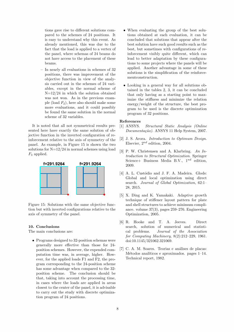
It is noted that all not symmetrical results pre-sented here have exactly the same solution of ob-jective function in the inverted configuration of re-inforcement relative to the axis of symmetry of thepanel. As example, in Figure 15 is shown the twosolutions for N=12/24 in normal schemes using loadF3 applied.
Figure 15: Solutions with the same objective func-tion but with inverted configurations relative to theaxis of symmetry of the panel.
10. ConclusionsThe main conclusions are:
• Programs designed to 32-position schemas weregenerally more effective than those for 24-position schemes. However, the expended com-putation time was, in average, higher. How-ever, for the applied loads F1 and F2, the pro-gram corresponding to the 24-position schemehas some advantage when compared to the 32-position scheme. The conclusion should bethat, taking into account the processing time,in cases where the loads are applied in areasclosest to the center of the panel, it is advisableto carry out the study with discrete optimiza-tion program of 24 positions.
• When evaluating the group of the best solu-tions obtained at each evaluation, it can beconcluded that solutions that appear after thebest solution have such good results such as thebest, but sometimes with configurations of re-inforcement visibly quite different, which canlead to better adaptation by these configura-tions to some projects where the panels will beapplied. Another advantage in some of thesesolutions is the simplification of the reinforce-mentconstruction.
• Looking in a general way for all solutions ob-tained in the tables 2, 3, it can be concludedthat only having as a starting point to max-imize the stiffness and minimize the relationenergy/weight of the structure, the best pro-gram to be used is the discrete optimizationprogram of 32 positions.
References[1] ANSYS. Structural Static Analysis (Online
Documentacao). ANSYS 11 Help System, 2007.
[2] J. S. Arora. Introduction to Optimum Design.Elsevier, 2nd edition, 2004.
[3] P. W. Christensen and A. Klarbring. An In-troduction to Structural Optimization. SpringerScience+ Business Media B.V., 1nd edition,2009.
[4] A. L. Custodio and J. F. A. Madeira. Glods:Global and local optimization using directsearch. Journal of Global Optimization, 62:1–28, 2015.
[5] X. Ding and K. Yamakaki. Adaptive growthtechnique of stiffener layout pattern for plateand shell structures to achieve minimum compli-ance. volume 37(3), pages 259–276. EngineeringOptimization, 2005.
[6] R. Hooke and T. A. Jeeves. Directsearch, solution of numerical and statisti-cal problems. Journal of the Associationfor Computing Machinery, 8(2):212–229, 1961.doi:10.1145/321062.321069.
[7] C. A. M. Soares. Teorias e analises de placas:Metodos analıticos e aproximados. pages 1–14.Technical report, 1982.
8


