Embed Size (px)
Citation preview

Oracle® Fusion Middleware
Integration Adapter for SAP R/3 User's Guide for Oracle WebLogic Server
12c Release (12.2.1.1.0)
E76076-03
April 2017
Provides information on how to integrate with SAP R/3 systems and develop applications.

Oracle® Fusion Middleware Integration Adapter for SAP R/3 User's Guide for Oracle WebLogic Server, 12c Release (12.2.1.1.0) E76076-03 Copyright © 2017, Oracle and/or its affiliates. All rights reserved. Primary Author: Vishal Bhardwaj Contributor: Tientien Li, Robert May, Amit Maheshwari, Shalabh Gupta, Amanpreet Wraich, Nitin Agarwal, Prashant Singh, K Rajendra Prasad, Meenakshi Sharma, Harshdev Singh and Prashant Kesarvani. This software and related documentation are provided under a license agreement containing restrictions on use and disclosure and are protected by intellectual property laws. Except as expressly permitted in your license agreement or allowed by law, you may not use, copy, reproduce, translate, broadcast, modify, license, transmit, distribute, exhibit, perform, publish, or display any part, in any form, or by any means. Reverse engineering, disassembly, or decompilation of this software, unless required by law for interoperability, is prohibited. The information contained herein is subject to change without notice and is not warranted to be error-free. If you find any errors, please report them to us in writing. If this is software or related documentation that is delivered to the U.S. Government or anyone licensing it on behalf of the U.S. Government, then the following notice is applicable: U.S. GOVERNMENT END USERS: Oracle programs, including any operating system, integrated software, any programs installed on the hardware, and/or documentation, delivered to U.S. Government end users are "commercial computer software" pursuant to the applicable Federal Acquisition Regulation and agency-specific supplemental regulations. As such, use, duplication, disclosure, modification, and adaptation of the programs, including any operating system, integrated software, any programs installed on the hardware, and/or documentation, shall be subject to license terms and license restrictions applicable to the programs. No other rights are granted to the U.S. Government. This software or hardware is developed for general use in a variety of information management applications. It is not developed or intended for use in any inherently dangerous applications, including applications that may create a risk of personal injury. If you use this software or hardware in dangerous applications, then you shall be responsible to take all appropriate fail-safe, backup, redundancy, and other measures to ensure its safe use. Oracle Corporation and its affiliates disclaim any liability for any damages caused by use of this software or hardware in dangerous applications. Oracle and Java are registered trademarks of Oracle and/or its affiliates. Other names may be trademarks of their respective owners. Intel and Intel Xeon are trademarks or registered trademarks of Intel Corporation. All SPARC trademarks are used under license and are trademarks or registered trademarks of SPARC International, Inc. AMD, Opteron, the AMD logo, and the AMD Opteron logo are trademarks or registered trademarks of Advanced Micro Devices. UNIX is a registered trademark of The Open Group. This software or hardware and documentation may provide access to or information about content, products, and services from third parties. Oracle Corporation and its affiliates are not responsible for and expressly disclaim all warranties of any kind with respect to third-party content, products, and services unless otherwise set forth in an applicable agreement between you and Oracle. Oracle Corporation and its affiliates will not be responsible for any loss, costs, or damages incurred due to your access to or use of third-party content, products, or services, except as set forth in an applicable agreement between you and Oracle.
iii
Content
Content ................................................................................................................................................................. iii
Preface ................................................................................................................................................................... ix
Audience ...................................................................................................................................................... ix
Documentation Accessibility ....................................................................................................................... ix
Related Documents ..................................................................................................................................... ix
Conventions .................................................................................................................................................. x
1 Understanding of the Adapter for SAP ....................................................................................................... 1-1
1.1 Overview ...................................................................................................................................... 1-1
1.2 Business Design Using Adapter for SAP...................................................................................... 1-1
1.3 Adapter Components .................................................................................................................... 1-2
1.4 Supported Versions and Platforms............................................................................................... 1-2
1.5 Supported SAP ABAP Technologies ............................................................................................ 1-3
2 Working with Adapter for SAP ................................................................................................................... 2-1
2.1 Prerequisites ................................................................................................................................ 2-1 2.1.1 JDeveloper ..................................................................................................................................... 2-1 2.1.2 SAP Java Connector (JCo) ............................................................................................................ 2-1 2.1.3 Verify WebLogic and SOA ........................................................................................................... 2-4 2.1.4 Adapter Components ..................................................................................................................... 2-5 2.1.5 Update the Default JNDI with the SAP Login Parameters ............................................................ 2-6 2.1.6 SAP Login Parameters ................................................................................................................... 2-8
2.2 SAP Connection Configuration Parameters ................................................................................ 2-8 2.2.1 Login Parameters ........................................................................................................................... 2-8
2.2.1.1 Direct Connection ................................................................................................................. 2-9 2.2.1.2 Load Balanced .................................................................................................................... 2-10
2.2.2 Server Parameters (for Inbound) .................................................................................................. 2-11 2.2.3 Trace Parameters ......................................................................................................................... 2-11 2.2.4 Connection Pool Parameters ....................................................................................................... 2-11 2.2.5 SAP Connection Security Parameters (SNC ) ............................................................................. 2-12 2.2.6 Additional Connection Parameters .............................................................................................. 2-13 2.2.7 Additional JCO Connection Properties ........................................................................................ 2-14
2.3 Create a Composite in Design-time ........................................................................................... 2-15
2.4 Setting up JNDI for Adapter for SAP at Run-time ..................................................................... 2-18
2.5 Deployment of the Composite on Run-time Environment .......................................................... 2-20
iv
2.5.1 Create Application Server in JDeveloper ..................................................................................... 2-20 2.5.2 How to Deploy ............................................................................................................................. 2-20
2.6 Testing the Deployed Projects .................................................................................................... 2-20
3 Supported SAP Interfaces ............................................................................................................................. 3-1
3.1 Business Application Programming Interfaces (BAPI) ................................................................ 3-1 3.1.1 Standard BAPI ............................................................................................................................... 3-1 3.1.2 Custom BAPI ................................................................................................................................. 3-2
3.2 Remote Enabled Function Modules (RFCs) ................................................................................. 3-2 3.2.1 Standard RFC ................................................................................................................................. 3-3 3.2.2 Custom RFC .................................................................................................................................. 3-3
3.3 Intermediate Document (IDoc ) ................................................................................................... 3-3 3.3.1 Standard IDoc ................................................................................................................................ 3-3 3.3.2 Custom IDoc .................................................................................................................................. 3-3 3.3.3 Extended IDoc ............................................................................................................................... 3-3
4 SAP Java Connector 3.x ................................................................................................................................ 4-1
4.1 Supported Systems and Platforms ................................................................................................ 4-1
4.2 Performance ................................................................................................................................. 4-1 4.2.1 Connection Management ............................................................................................................... 4-2 4.2.2 Connection Pooling ........................................................................................................................ 4-2 4.2.3 Caching of Metadata ...................................................................................................................... 4-4
4.3 RFC Server Threads ..................................................................................................................... 4-4
4.4 Trace Level Parameter ................................................................................................................. 4-4
4.5 JCo Supported SAP Data types .................................................................................................... 4-5
5 Oracle Adapter for SAP Features ................................................................................................................ 5-1
5.1 tRFC/qRFC/bgRFC Support ........................................................................................................ 5-1 5.1.1 Modeling the tRFC SAP Endpoint: ............................................................................................... 5-2 5.1.2 Testing the tRFC SAP Endpoint .................................................................................................... 5-5 5.1.3 Modeling the qRFC SAP Endpoint ................................................................................................ 5-6 5.1.4 Testing the qRFC SAP Endpoint ................................................................................................... 5-9 5.1.5 Modeling the bgRFC SAP Endpoint ............................................................................................ 5-10 5.1.6 Testing the bgRFC SAP Endpoint ............................................................................................... 5-15
5.2 Design-Time Test Functionality ................................................................................................. 5-16 5.2.1 Using the Design-Time Test Functionality .................................................................................. 5-16
5.3 Exception Filter .......................................................................................................................... 5-21 5.3.1 Create an Exception Filter Project ............................................................................................... 5-21 5.3.2 Testing the Exception Filter Project ............................................................................................. 5-22
5.4 Schema Validation...................................................................................................................... 5-25 5.4.1 Create a Project with Schema Validation: ................................................................................... 5-25 5.4.2 Testing the Schema Validation Project: ....................................................................................... 5-26
5.5 AutoSYSTAT Feature for RFC ................................................................................................... 5-27 5.5.1 Creating a Project with AutoSYSTAT01 Property ...................................................................... 5-27
5.5.2 Test the Project with AutoSystat Property ................................................................................... 5-28
5.6 Encode IDoc............................................................................................................................... 5-30 5.6.1 Create a Project for Flat File IDoc ............................................................................................... 5-30 5.6.2 Test the Flat File IDoc Project ..................................................................................................... 5-31
5.7 Generic IDoc Support ................................................................................................................ 5-32 5.7.1 Create Generic IDoc Inbound Endpoint ...................................................................................... 5-33 5.7.2 Test the Generic IDoc Inbound Endpoint .................................................................................... 5-34 5.7.3 Create Generic IDoc Outbound Endpoint .................................................................................... 5-35 5.7.4 Test the Generic IDoc Outbound Endpoint ................................................................................. 5-36
5.8 Revision IDoc Support ............................................................................................................... 5-37
5.9 Sharing Program ID Feature ..................................................................................................... 5-38 5.9.1 Create a Sharing Program ID Project: ......................................................................................... 5-38
5.10 Multiple IDoc Support ............................................................................................................... 5-39 5.10.1 Create a project for Multiple IDoc Support: ............................................................................ 5-39
5.11 Credential Mapping for Oracle SOA Suite (BPEL, Mediator, BPM or OSB) ........................... 5-40 5.11.1 Setup Credential Mapping for the Adapter.............................................................................. 5-40 5.11.2 Setup Credential Mapping for SOA ........................................................................................ 5-44
5.11.2.1 Creating SOA Project for Credential Mapping ................................................................... 5-44
5.12 Stateful Interaction ..................................................................................................................... 5-49 5.12.1 Create a Stateful BAPI project ................................................................................................ 5-50 5.12.2 Test the Stateful BAPI Project: ............................................................................................... 5-53
5.13 Error Handling .......................................................................................................................... 5-53
5.14 SOA Debugger Support .............................................................................................................. 5-54 5.14.1 SOA Debugger for Inbound .................................................................................................... 5-54 5.14.2 SOA Debugger for Outbound .................................................................................................. 5-58
5.15 Non_Xml Characters Handling Feature .................................................................................... 5-65
5.16 Error Document Support ........................................................................................................... 5-66
5.17 Payload Threshold Support ....................................................................................................... 5-68 5.17.1 Inbound Project with payloadSizeThreshold support .............................................................. 5-69 5.17.2 Outbound Project with payloadSizeThreshold Support .......................................................... 5-70
5.18 TID Backstore Support............................................................................................................... 5-73
5.19 Large payload support-AsAttachment ........................................................................................ 5-76
5.20 Resiliency Support ..................................................................................................................... 5-80 5.20.1 Inbound Project with Resilience support ................................................................................. 5-80
5.21 Segment Release Design Time and Runtime Support ................................................................. 5-84
5.22 Special Character Support for Inbound IDoc ............................................................................ 5-86
6 Complete Walkthrough of the Adapter Configuration Wizard .............................................................. 6-87
6.1 Overview .................................................................................................................................... 6-87
6.2 The Adapter Wizard in JDeveloper ............................................................................................ 6-87
6.3 Specifying the Service Name ...................................................................................................... 6-88
vi
6.4 Connecting to SAP ..................................................................................................................... 6-88 6.4.1 Define a Connection Name .......................................................................................................... 6-90 6.4.2 Define the Connection Parameters to the Connection Name ....................................................... 6-90 6.4.3 Connect to a Defined SAP connection ......................................................................................... 6-93
6.5 Select SAP Objects from Objects Selection .............................................................................. 6-104 6.5.1 Object Panel ............................................................................................................................... 6-105 6.5.2 Selected BAPI /RFC functions or IDoc messages panel .......................................................... 6-110 6.5.3 Definition panel ......................................................................................................................... 6-111
6.6 JCA Properties Page ............................................................................................................... 6-112 6.6.1 Interaction of JCA Properties (Outbound to the Adapter) ......................................................... 6-113 6.6.2 Activation of JCA Properties (Inbound to the Adapter) ControlCharacter ............................... 6-115 6.6.3 Generation of Corresponding (JCA) Artifacts (WSDL/XML Schemas) ................................... 6-116
6.7 Finishing with Adapter Configuration Wizard ......................................................................... 6-116
7 Configuring the Adapter Run-Time Parameters on the WebLogic Server .......................................... 7-118
7.1 Adapter Integration with Oracle WebLogic Server .................................................................. 7-118 7.1.1 Configure Run-time Parameters for the Adapter for SAP ......................................................... 7-118
8 Integration Scenarios in Oracle SOA Suite ............................................................................................. 8-123
8.1 Integration Overview ................................................................................................................ 8-123
8.2 The Adapter Integration With SOA Service Components ......................................................... 8-123 8.2.1 Create a New Application Server Connection ........................................................................... 8-123 8.2.2 Create an Empty Composite for SOA ........................................................................................ 8-130 8.2.3 Design an Outbound BPEL Process for BAPI/RFC/IDOC ........................................................ 8-133 8.2.4 Design an Inbound BPEL Process for BAPI/RFC/IDoc ............................................................ 8-154 8.2.5 Deploy the Composite with Inbound BPEL Process.................................................................. 8-167 8.2.6 Generate an Event in SAP R/3 and Process It by the SOA Composite ...................................... 8-167 8.2.7 Define an Outbound Mediator Process ...................................................................................... 8-168 8.2.8 Define an Inbound Mediator Process ......................................................................................... 8-178 8.2.9 Deployment of Inbound Mediator Process ................................................................................ 8-191 8.2.10 Generate an Event in SAP R/3 for Testing Mediator Inbound and Outbound Process.......... 8-191
8.3 The Adapter Integration with BPM Service Components ......................................................... 8-191 8.3.1 Deployment of Adapter .............................................................................................................. 8-191 8.3.2 Create an Empty Composite for BPM ....................................................................................... 8-192 8.3.3 Define a BPM Outbound Process .............................................................................................. 8-194 8.3.4 Design a BPM Inbound Process ................................................................................................. 8-213
8.4 The Adapter Integration with Oracle Service Bus (OSB) ......................................................... 8-224 8.4.1 Create an Empty Composite for OSB ........................................................................................ 8-224 8.4.2 Define an OSB Outbound Process ............................................................................................. 8-227 8.4.3 Define an OSB Inbound Process ................................................................................................ 8-245
8.5 Deploy the Defined Process ..................................................................................................... 8-262
8.6 Test the Deployed Process ....................................................................................................... 8-268 8.6.1 Test the Outbound Process ......................................................................................................... 8-268
8.6.1.1 Invoking the Input XML Document in the Oracle Enterprise Manager Console .............. 8-269 8.6.2 Test the Inbound Process ........................................................................................................... 8-274
8.6.2.1 Generate an Event in SAP R/3 .......................................................................................... 8-275
9 Adapter for SAP Performance Tuning ............................................................................................................ 1
9.1 Tuning and Performance ................................................................................................................ 1 9.1.1 Tuning Parameters ............................................................................................................................. 1
9.1.1.1 SAP JCo Parameter Tuning ...................................................................................................... 1 9.1.1.2 BPEL Infrastructure Tuning Parameters (These are provided at Enterprise Management (EM)
level): 1 9.1.2 System Configuration ........................................................................................................................ 3
9.1.2.1 Oracle Linux Server .................................................................................................................. 3 9.1.2.2 Hardware ................................................................................................................................... 3
9.1.3 Outbound Performance ...................................................................................................................... 4 9.1.3.1 Performance Summary.............................................................................................................. 4 9.1.3.2 Enhanced Performance ............................................................................................................. 5
9.2 Inbound Performance ..................................................................................................................... 5 9.2.1 Performance Summary ...................................................................................................................... 6
10 SOA Reports Integration ................................................................................................................................ 8
10.1 Adapter Health Report .................................................................................................................... 8 10.1.1 Configuration Report ..................................................................................................................... 9
10.1.1.1 EIS Connectivity ..................................................................................................................... 10 10.1.2 Monitoring reports....................................................................................................................... 11 10.1.3 Snapshot Reports ......................................................................................................................... 11
11 Troubleshooting and Error Messages ......................................................................................................... 13
11.1 Log file Information ...................................................................................................................... 13
11.2 Oracle Adapter for SAP Design-Time JDeveloper ....................................................................... 13
11.3 Oracle Adapter for SAP Run-Time ............................................................................................... 15
11.4 SAP R/3 ......................................................................................................................................... 17
11.5 Known Issues ................................................................................................................................ 18
12 Migration Support ......................................................................................................................................... 19
12.1 Migration of SAP Endpoints in SOA Projects ............................................................................... 19
12.2 Migration of SAP Endpoints in OSB Projects ............................................................................... 22
12.3 Deploying the Adapter Migrated Project ...................................................................................... 28
12.4 Updating JCA file in Migrated Projects ....................................................................................... 28
12.5 Execution Steps for Deployed Migrated Projects ......................................................................... 28 12.5.1 Inbound Project ........................................................................................................................... 28 12.5.2 Outbound Project......................................................................................................................... 28
A SAP System Configurations for Remote Processing ..................................................................................... 29
A.1 Roles and Authorizations ..................................................................................................................... 29
A.2 RFC Authorization Object ................................................................................................................... 29
A.3 SAP Inbound Communication ....................................................................................................... 30 A.3.1 Configure a Logical System ..................................................................................................... 31 A.3.2 Configure a Partner Profile ...................................................................................................... 33
viii
A.3.3 Configure Inbound Process Code .....................................................................................................35 A.3.4 Configure a Distribution Model .......................................................................................................36
A.4 SAP Outbound Communication ..................................................................................................... 38 A.4.1 Configure RFC Destination and Program ID ..................................................................................38 A.4.2 Configure a Port .............................................................................................................................40 A.4.3 Configure a Logical System ............................................................................................................42 A.4.4 Configure a Distribution Model ......................................................................................................42 A.4.5 Configure Partner Profile ................................................................................................................42
A.5 SAP User Authorizations for Adapter ........................................................................................... 44
A.6 SAP BGRFC Configuration........................................................................................................... 45
Glossary ................................................................................................................................................................48
Index .....................................................................................................................................................................49
Preface
Audience
Documentation Accessibility
Related Documents
Conventions
Audience
Oracle Fusion Middleware User's Guide for Adapter for SAP is intended for anyone who is
interested in using these adapters.
Documentation Accessibility
For information about Oracle's commitment to accessibility, visit the Oracle
Accessibility Program website at http://www.oracle.com/pls/topic/lookup?ctx=acc&id=docacc.
Access to Oracle Support
Oracle customers have access to electronic support through My Oracle Support. For information,
visit
http://www.oracle.com/pls/topic/lookup?ctx=acc&id=info or visit
http://www.oracle.com/pls/topic/lookup?ctx=acc&id=trs if you are hearing
impaired.
Related Documents
For more information, see the following documents in the Oracle Fusion Middleware 12c Release
(12.2.1.0.0) documentation set:
Oracle Fusion Middleware Programming Resource Adapters for Oracle WebLogic Server
Oracle Fusion Middleware Adapter for Oracle Applications User's Guide
Oracle Fusion Middleware Developer's Guide for Oracle SOA Suite
Oracle Fusion Middleware Administrator's Guide
Oracle Fusion Middleware Administrator's Guide for Oracle SOA Suite and Oracle
Business Process Management Suite
Oracle Fusion Middleware Administrator's Guide for Oracle Service Bus
Oracle Application Server Installation Guide for Legacy Adapters
x
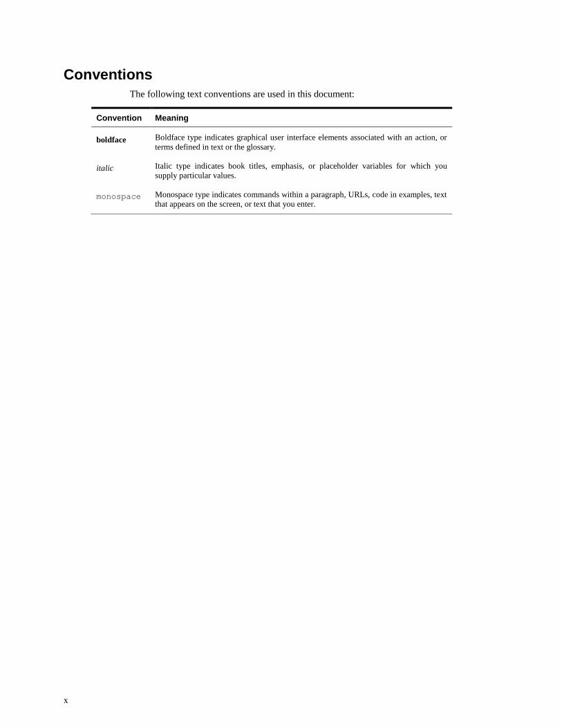
Conventions
The following text conventions are used in this document:
Convention Meaning
boldface
italic
monospace
Boldface type indicates graphical user interface elements associated with an action, or
terms defined in text or the glossary.
Italic type indicates book titles, emphasis, or placeholder variables for which you
supply particular values.
Monospace type indicates commands within a paragraph, URLs, code in examples, text
that appears on the screen, or text that you enter.
Understanding of Adapter for SAP 1-1
1
Understanding of the Adapter for SAP
This chapter provides an introduction to the Oracle Integration Adapter for SAP R/3. It contains
the following topics:
Section 1.1, "Overview"
Section 1.2, "Business Design Using Adapter for SAP"
Section 1.3, "Adapter Components"
Section 1.4, "Supported Versions and Platforms "
Section 1.5, "Supported SAP ABAP Technologies"
1.1 Overview
The Adapter for SAP is used for the integration of Oracle products with SAP Enterprise to
exchange the real-time data. It is developed in the Oracle JCA framework. It is based on the SAP
Java Connector 3.0 (SAP JCo) and is used for the inbound and outbound interaction with SAP
using message types RFC/BAPI/IDOC.
Outbound interaction: When an application uses the Adapter for SAP to invoke an SAP
R/3 business object or business operation, the interaction is termed as Outbound interaction.
Inbound interaction: When an SAP R/3 system triggers an event and the event is listened
by an application using Adapter for SAP as a result of which the application receives SAP
R/3 data, the interaction is termed as Inbound interaction.
Adapter for SAP allows different types of connection methods including secure connection and
message server communication method, with both Unicode and Non-unicode SAP systems.
It offers organizations a service-oriented approach to unlock the information assets that have
evolved in most IT environments. It provides tighter integration with both the design-time and
run-time components of SOA suite and also with other Oracle products which helps customer for
better business data integration.
1.2 Business Design Using Adapter for SAP
Adapter for SAP provides seamless integration between SAP R/3 systems and non-SAP systems.
It supports xml communication as standard business message format which is useful in
integrating different platforms. Adapter run-time provides access to an SAP System and control
secure communication, connection management and function execution. Adapter design-time
module comes as an integral part of Oracle SOA Suite and OSB products. This helps you to
design business integration scenarios with SAP R/3 systems.
Adapter for SAP run-time supports bi-directional communication to an SAP system. You can
add, update or receive business data to and from SAP. The Adapter for SAP supports multiple
1-2 User's Guide for Adapter for SAP
SAP interfaces like BAPI/RFC/IDoc to perform such operations. As an end user, you only need
to know which RFC/IDoc/BAPI of SAP system would be used and which type of communication
would be required in the business use case. Security and connection management is handled by
the adapter itself. Before starting integration with Adapter for SAP, you should have SAP user
credentials for communication. The SAP user should have minimum required permissions to
execute BAPI/RFC/IDOC. To receive any data from SAP system, you should take help of SAP
admin to define logical systems in SAP side.
Adapter for SAP encapsulates most of the complex data types supported by SAP R/3 systems in
the form of xml standard type which ease the integration for end user by avoiding the complexity
of data mapping at the time of process design.
1.3 Adapter Components
Components of Adapter for SAP are defined in two parts:
1. Design-time Component (JDeveloper extension)
2. Run-time Component (WebLogic application)
Design-time component for Adapter comes with Oracle JDeveloper as a part of SOA, OSB, and
BPM Oracle integration products. Adapter design-time provides wizard based design flow which
contains pages categorized to support step-by-step procedure to create an SAP reference/service
in the SOA/OSB composites. JCA artifacts are created as a result of the Adapter design.
The Adapter Run-time component comes with Oracle SOA/OSB release as a JCA connector. This
component is implemented using j2EE Connector Architecture Framework. Adapter run-time
must be deployed to the WebLogic Server as a resource adapter before deploying any SOA/OSB
projects using Adapter for SAP. This adapter component executes a native call to SAP and sends
back result as an xml in case of outbound execution. It takes care of the native call to SAP and
creates abstraction of SAP related execution complexities from the user.
1.4 Supported Versions and Platforms
Oracle Integration Adapter for SAP R/3 supports the below mentioned versions of the
interacting/underlying systems:
Operating System (OS) Versions:
Oracle Integration Adapter for SAP R/3 supports all the versions of operating systems that are
supported by SAP JCo 3.0. Below is the list of the OS platforms.
For more information about the versions supported by SAP JCo 3.x, refer to SAP Note #1077727
in the SAP service Market Place.
Windows (2008 R2)
Linux (Oracle Linux 6 and Redhat Linux 6)
SAP Versions:
SAP R/3 4.7
SAP ECC 5.0
Understanding of Adapter for SAP 1-3
SAP ECC 6.0
SAP ECC 6.0 EhP 6
SAP ECC 6.0 EhP 7
JAVA Versions:
Oracle Integration Adapter for SAP R/3 supports all java version supported by SAP JCo 3
API
JCo Versions:
SAP JCo 3.X
Oracle SOA Versions:
Oracle Fusion Middleware 12.2.1
For more information on the Adapter Certification Matrix, refer the below link:
http://www.oracle.com/technetwork/middleware/adapters/documentation/index.html
For more information on the Oracle Fusion Middleware Certification Matrix, refer the below link:
http://www.oracle.com/technetwork/middleware/fusion-middleware/documentation/fmw-
122110certmatrix-3050412.xlsx
1.5 Supported SAP ABAP Technologies
Oracle Integration Adapter for SAP R/3 provides access to the following SAP ABAP interfaces:
1. RFC (Remote Function Call)
2. BAPI (Business Application Programming Interface)
3. IDocs (Intermediate Documents)
Remote Function Call (RFC) is a standard SAP interface for communication within SAP systems
and with external non-SAP systems. RFC calls a function to be executed in a remote system.
Business Application Programming Interfaces (BAPIs) are defined as API methods of SAP
business object types. A BAPI is implemented as a function module that is stored and described
in the Function Builder. BAPIs are remotely enabled functions which mean that these can be
invoked from remote programs like standalone Java programs or Web services. This attribute of
the BAPIs help to facilitate the integration of third-party systems with the SAP proprietary R/3
products. BAPI is usually a self-contained business function.
Intermediate Document (IDoc) is an SAP document format for business transaction data transfers.
As the name suggests, these documents act as intermediate storage of information, which can be sent bi-directionally for exchange of data between SAP R/3 and non-R/3 systems.
An IDoc is made up of the following parts:

1-4 User's Guide for Adapter for SAP
Control record: This section contains control information regarding the IDoc. Its
constituents are Sender’s name, Receiver name, Message type, and IDoc type. The
format of the control record is similar for all the IDoc types.
Data records: It consists of a header that contains the identity of the IDoc. Its
constituents include a sequential segment number, a segment type description, and field
containing the actual data of the segment.
Status records: The status record shows the information regarding already processed
stages and remaining processing stages of the IDoc. It has an identical format for each
IDoc type.
Working with Adapter for SAP 2-1
2
Working with Adapter for SAP
This section provides a quick start guide to use the Oracle Integration Adapter for SAP R/3. This
chapter contains the following topics:
Section 2.1, "Prerequisites"
Section 2.2, "SAP Connection Configuration Parameters"
Section 2.3, "Create a Composite in Design-time"
Section 2.4, "Setting up JNDI for Adapter for SAP at Run-time"
Section 2.5, "Deployment of the Composite on Run-time Environment"
Section 2.6, "Testing the Deployed Projects"
2.1 Prerequisites
This section lists the prerequisites for using Adapter for SAP in design-time and run-time
environment.
2.1.1 JDeveloper
Installation of the appropriate version of JDeveloper is required for developing the components at
design-time. For more information on installation steps of JDeveloper, refer to Oracle Fusion
Middleware Installation Guide for Oracle JDeveloper.
2.1.2 SAP Java Connector (JCo)
SAP JCo is a middleware component which is used for communication between the Adapter and
the SAP system. This component has to be installed in both design-time and run-time
environments of Adapter for SAP. Below are the details which will help you to install and
validate the SAP JCo.
1. JCo version supports SAP Java Connector 3.x. The latest version available is SAP JCo
3.0.13. More details on the supported operating systems and platforms, is provided in chapter
SAP Java Connector 3.x". The Adapter does not support the platforms which are not
supported by the SAP JCo 3.x.
2. JCo Files: Below are the required SAP JCo installation files:
i. Microsoft Windows
a. sapjco3.jar
b. sapjco3.dll
2-2 User's Guide for Adapter for SAP
c. sapidoc3.jar
ii. Linux
a. sapjco3.jar
b. libsapjco3.so
c. sapidoc3.jar
3. Source for SAP JCo files:
These files are provided by SAP administrator or you can download the installation files from
SAP service market place under service.sap.com/connectors.
Verify Path and ClassPath for SAPJCo files :
For Windows :
1. SAPJCo3 library should be in CLASSPATH and PATH variable .
2. Extract SAPJCO zip in a folder location and now this folder should contain
sapjco3.jar,sapjco3.dll and sapidoc3.jar
3. Provide this folder location in to the PATH
4. Provide location of sapjco3 and sapidoc3 jars in to CLASSPATH
For Linux :
1. SAPJCo3 library should be in CLASSPATH and PATH variable
2. Extract SAPJCO in a folder location like /oracle/SAPJCo3 and now this
folder should contain sapjco3.jar, libsapjco3.so and sapidoc3.jar
3. Keep libsapjco3.so file in to LD_LIBRARY_PATH or make sure
libsapjco3.jar is installed as system library
4. LD_LIBRARY_PATH can be set using following command
Export LD_LIBRARY_PATH=/oracle/SAPJCo3
4. Check for the compatibility:
After downloading the SAP JCo files, place it in the directory of the system where these
libraries need to be validated. Perform the following steps to validate SAP JCo:
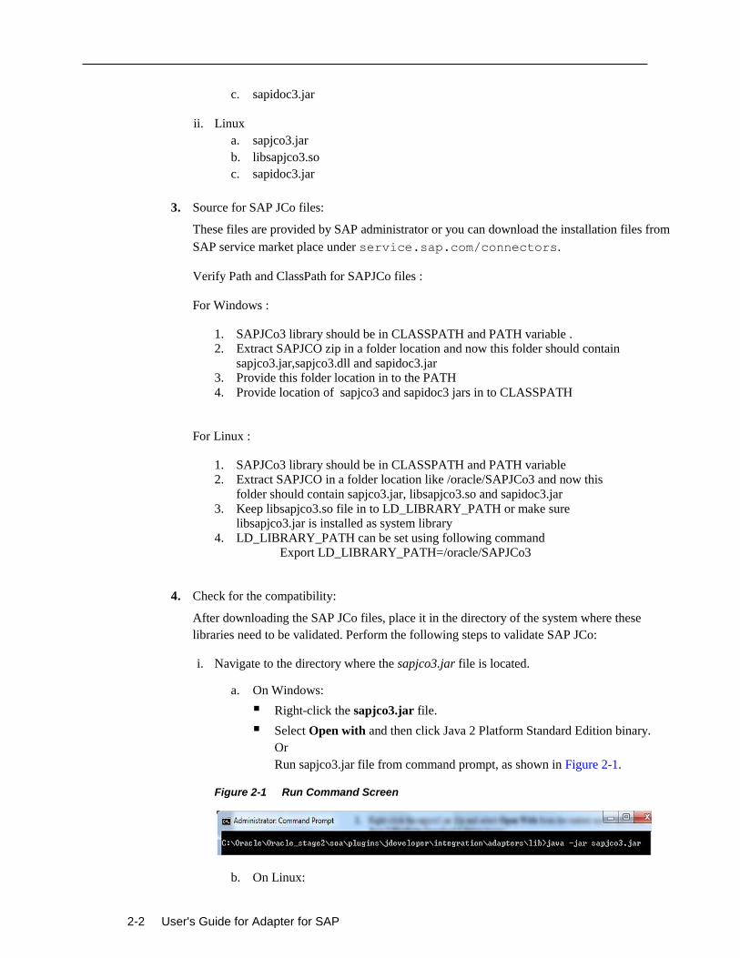
i. Navigate to the directory where the sapjco3.jar file is located.
a. On Windows:
Right-click the sapjco3.jar file.
Select Open with and then click Java 2 Platform Standard Edition binary.
Or
Run sapjco3.jar file from command prompt, as shown in Figure 2-1.
Figure 2-1 Run Command Screen
b. On Linux:
Working with Adapter for SAP 2-3
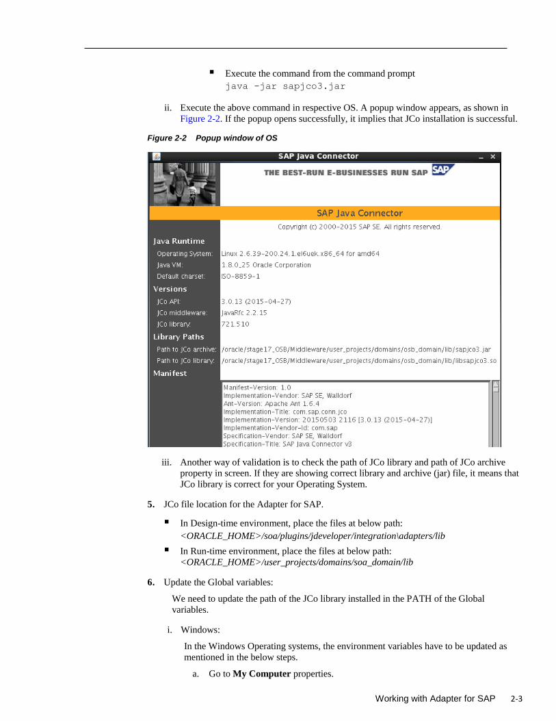
Execute the command from the command prompt
java -jar sapjco3.jar
ii. Execute the above command in respective OS. A popup window appears, as shown in
Figure 2-2. If the popup opens successfully, it implies that JCo installation is successful.
Figure 2-2 Popup window of OS
iii. Another way of validation is to check the path of JCo library and path of JCo archive
property in screen. If they are showing correct library and archive (jar) file, it means that
JCo library is correct for your Operating System.
5. JCo file location for the Adapter for SAP.
In Design-time environment, place the files at below path:
<ORACLE_HOME>/soa/plugins/jdeveloper/integration\adapters/lib
In Run-time environment, place the files at below path:
<ORACLE_HOME>/user_projects/domains/soa_domain/lib
6. Update the Global variables:
We need to update the path of the JCo library installed in the PATH of the Global
variables.
i. Windows:
In the Windows Operating systems, the environment variables have to be updated as
mentioned in the below steps.
a. Go to My Computer properties.
2-4 User's Guide for Adapter for SAP
b. Navigate to Advanced Properties -> Environment variables, and update the
PATH and CLASSPATH variables as below:
PATH=$PATH;
<ORACLE_HOME>\soa\plugins\jdeveloper\integration\adapters\lib
ii. Linux:
In the Linux Operating systems, the environment variables have to be updated as
mentioned in the below steps.
a. Navigate to the Bash profile with the below command, using the same SOA
Installation.
vi ~/.bash_profile
b. Press “i” for insertion and add the below entries in the bash_profile file
PATH=$PATH;
<ORACLE_HOME>\soa\plugins\jdeveloper\integrati
on\adapters\lib
c. Press <Esc> and then press <Ctrl+Shft+x> to save.
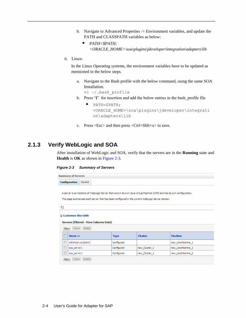
2.1.3 Verify WebLogic and SOA
After installation of WebLogic and SOA, verify that the servers are in the Running state and
Health is OK as shown in Figure 2-3.
Figure 2-3 Summary of Servers
Working with Adapter for SAP 2-5
2.1.4 Adapter Components
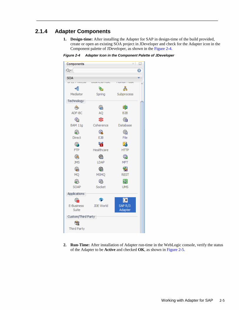
1. Design-time: After installing the Adapter for SAP in design-time of the build provided,
create or open an existing SOA project in JDeveloper and check for the Adapter icon in the
Component palette of JDeveloper, as shown in the Figure 2-4.
Figure 2-4 Adapter Icon in the Component Palette of JDeveloper
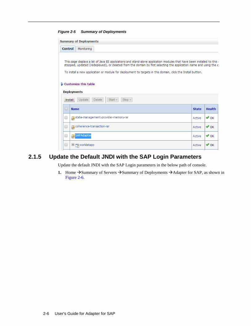
2. Run-Time: After installation of Adapter run-time in the WebLogic console, verify the status
of the Adapter to be Active and checked OK, as shown in Figure 2-5.
2-6 User's Guide for Adapter for SAP
Figure 2-5 Summary of Deployments
2.1.5 Update the Default JNDI with the SAP Login Parameters
Update the default JNDI with the SAP Login parameters in the below path of console.
1. Home Summary of Servers Summary of Deployments Adapter for SAP, as shown in
Figure 2-6.
Working with Adapter for SAP 2-7
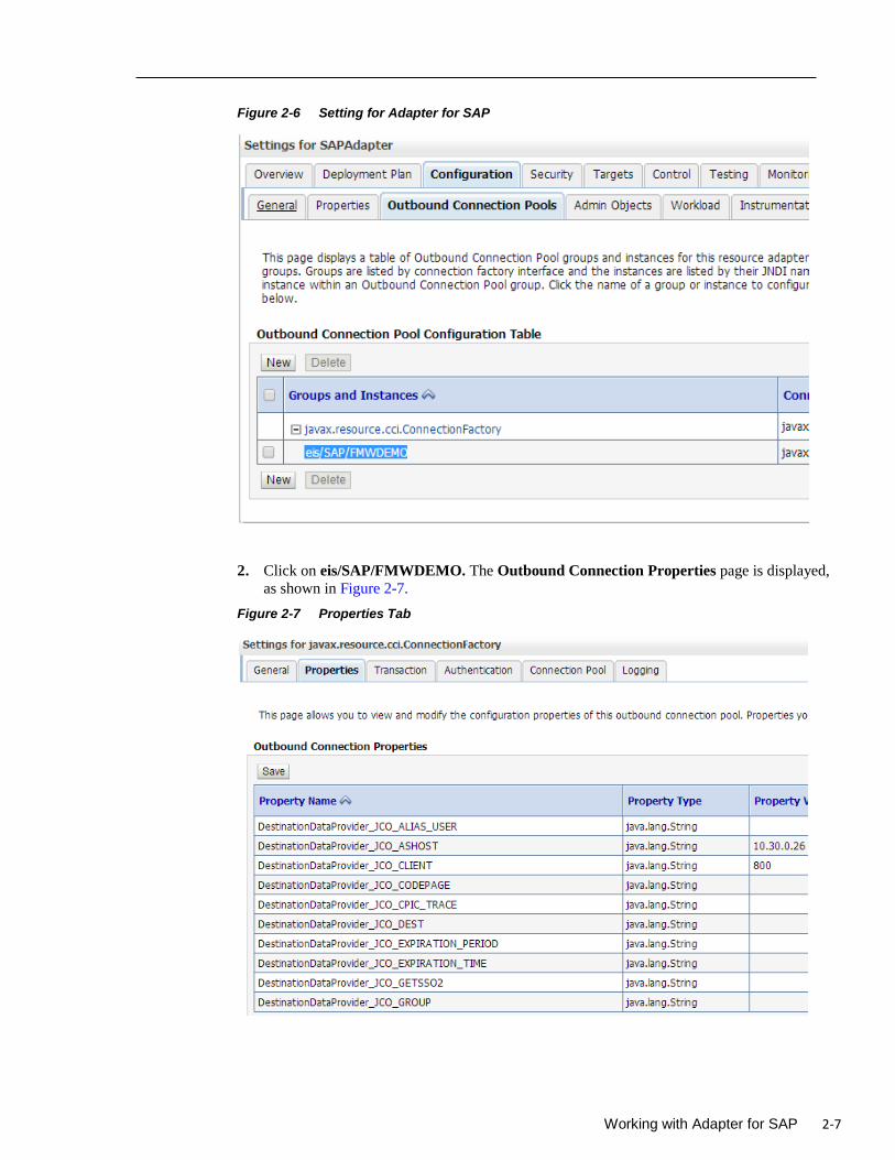
Figure 2-6 Setting for Adapter for SAP
2. Click on eis/SAP/FMWDEMO. The Outbound Connection Properties page is displayed,
as shown in Figure 2-7.
Figure 2-7 Properties Tab
2-8 User's Guide for Adapter for SAP
2.1.6 SAP Login Parameters
You need to have SAP R/3 logon parameters for making the connection to the SAP system from
DT wizard or RT (JNDI). These are provided by the SAP System Administrator. Below ia the list
of mandatory connection parameters which are required for making a simple outbound
connection to the SAP system.
1. Client: This is the client number of the SAP system. This is a 3 digit numeric character. For
example, Client = 100.
2. User name: This is the SAP user. Dialog or Communication type of SAP user can be used
here.
3. Password: Password of SAP user.
4. Language: SAP Logon language. The language provided here should be one of the installed
languages provided by the SAP administrator. In case of language dependent data, the
response data text is returned based on the language passed in this parameter. This is a 2 digit
character. For example, ‘EN’, ‘DE’.
5. Application Server: A fully qualified domain name or IP of the SAP Application Server.
6. System Number: Instance number of the Application Server.
There are various other SAP Connection Parameters which are part of connection configuration
and used for the inbound and outbound connection to SAP. Below is the list of different type of
parameters. For more information, refer to the section “SAP Connection Configuration
Parameters”.
1. Direct Application Server Connection parameters.
2. Message Server Connection parameters.
3. Server parameters for inbound.
4. Tracing parameters.
5. Connection pool parameters.
6. SAP secured connection parameters.
7. Additional connection parameters.
2.2 SAP Connection Configuration Parameters
This section contains the SAP R/3 logon parameters, which are used to configure a connection to
SAP R/3 using the Oracle Application Adapter.
2.2.1 Login Parameters
Table 2-1 lists and describes user login parameters
`
Working with Adapter for SAP 2-9
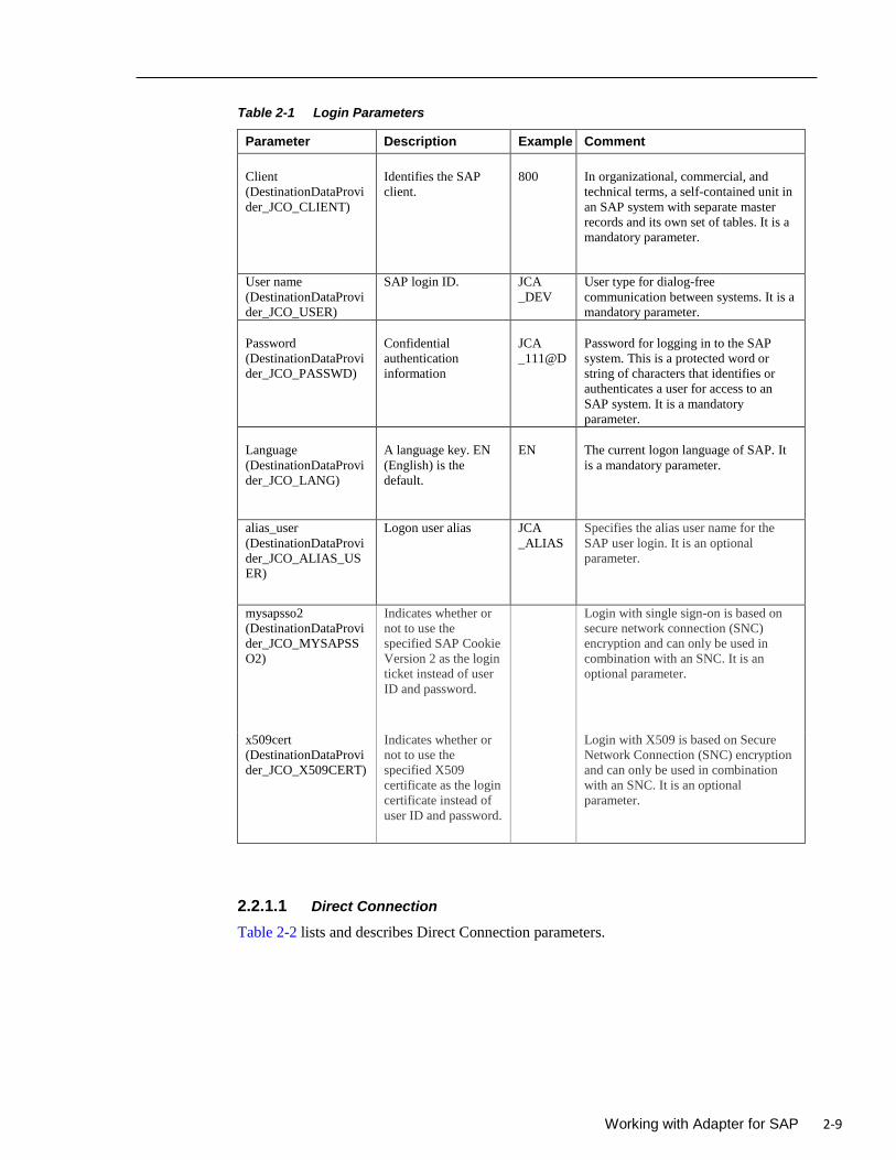
Table 2-1 Login Parameters
Parameter Description Example Comment
Client
(DestinationDataProvi
der_JCO_CLIENT)
Identifies the SAP
client.
800
In organizational, commercial, and
technical terms, a self-contained unit in
an SAP system with separate master
records and its own set of tables. It is a
mandatory parameter.
User name
(DestinationDataProvi
der_JCO_USER)
SAP login ID. JCA
_DEV
User type for dialog-free
communication between systems. It is a
mandatory parameter.
Password
(DestinationDataProvi
der_JCO_PASSWD)
Confidential
authentication
information
JCA
_111@D
Password for logging in to the SAP
system. This is a protected word or
string of characters that identifies or
authenticates a user for access to an
SAP system. It is a mandatory
parameter.
Language
(DestinationDataProvi
der_JCO_LANG)
A language key. EN
(English) is the
default.
EN
The current logon language of SAP. It
is a mandatory parameter.
alias_user
(DestinationDataProvi
der_JCO_ALIAS_US
ER)
Logon user alias JCA
_ALIAS
Specifies the alias user name for the
SAP user login. It is an optional
parameter.
mysapsso2
(DestinationDataProvi
der_JCO_MYSAPSS
O2)
Indicates whether or
not to use the
specified SAP Cookie
Version 2 as the login
ticket instead of user
ID and password.
Login with single sign-on is based on
secure network connection (SNC)
encryption and can only be used in
combination with an SNC. It is an
optional parameter.
x509cert
(DestinationDataProvi
der_JCO_X509CERT)
Indicates whether or
not to use the
specified X509
certificate as the login
certificate instead of
user ID and password.
Login with X509 is based on Secure
Network Connection (SNC) encryption
and can only be used in combination
with an SNC. It is an optional
parameter.
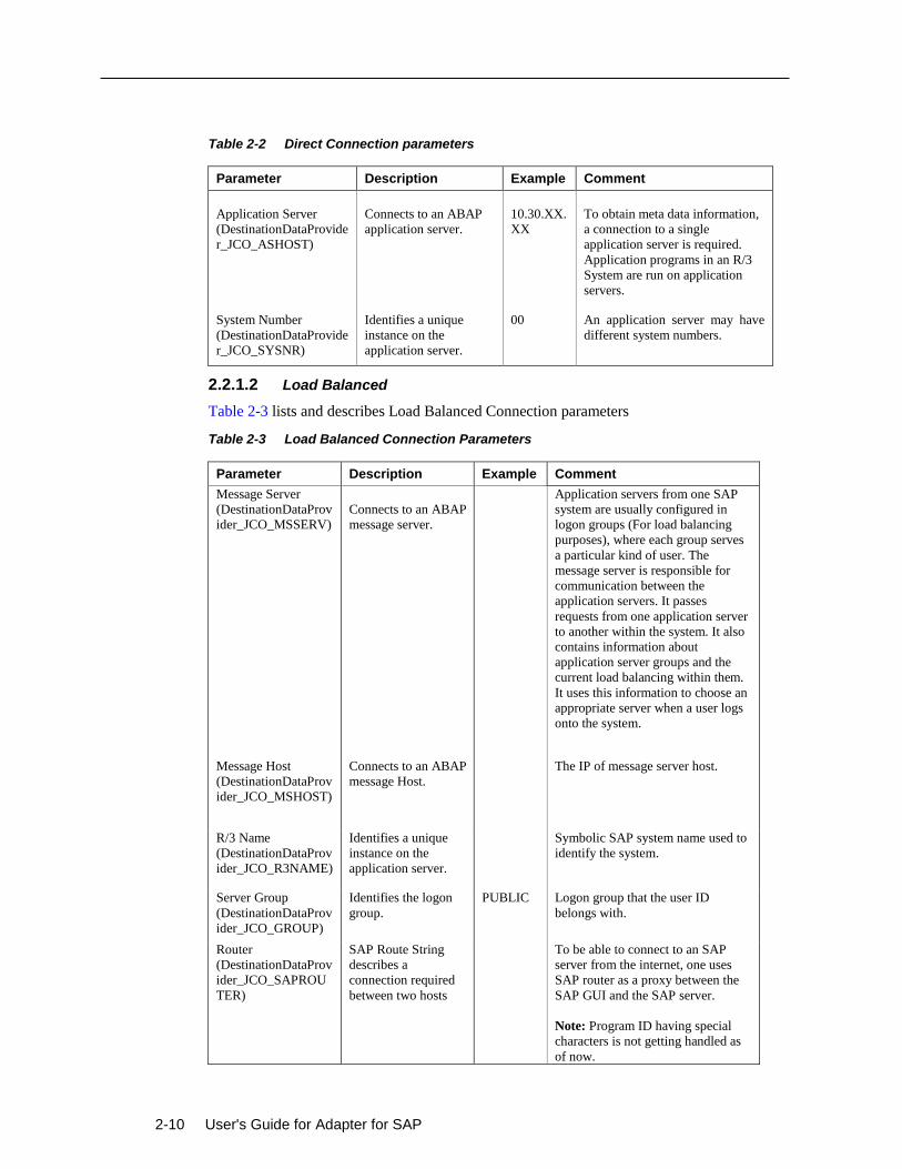
2.2.1.1 Direct Connection
Table 2-2 lists and describes Direct Connection parameters.
2-10 User's Guide for Adapter for SAP
Table 2-2 Direct Connection parameters
Parameter Description Example Comment
Application Server
(DestinationDataProvide
r_JCO_ASHOST)
Connects to an ABAP
application server.
10.30.XX.
XX
To obtain meta data information,
a connection to a single
application server is required.
Application programs in an R/3
System are run on application
servers.
System Number
(DestinationDataProvide
r_JCO_SYSNR)
Identifies a unique
instance on the
application server.
00 An application server may have
different system numbers.
2.2.1.2 Load Balanced
Table 2-3 lists and describes Load Balanced Connection parameters
Table 2-3 Load Balanced Connection Parameters
Parameter Description Example Comment
Message Server
(DestinationDataProv
ider_JCO_MSSERV)
Connects to an ABAP
message server.
Application servers from one SAP
system are usually configured in
logon groups (For load balancing
purposes), where each group serves
a particular kind of user. The
message server is responsible for
communication between the
application servers. It passes
requests from one application server
to another within the system. It also
contains information about
application server groups and the
current load balancing within them.
It uses this information to choose an
appropriate server when a user logs
onto the system.
Message Host
(DestinationDataProv
ider_JCO_MSHOST)
Connects to an ABAP
message Host.
The IP of message server host.
R/3 Name
(DestinationDataProv
ider_JCO_R3NAME)
Identifies a unique
instance on the
application server.
Symbolic SAP system name used to
identify the system.
Server Group
(DestinationDataProv
ider_JCO_GROUP)
Identifies the logon
group.
PUBLIC Logon group that the user ID
belongs with.
Router
(DestinationDataProv
ider_JCO_SAPROU
TER)
SAP Route String
describes a
connection required
between two hosts
To be able to connect to an SAP
server from the internet, one uses
SAP router as a proxy between the
SAP GUI and the SAP server.
Note: Program ID having special
characters is not getting handled as
of now.
Working with Adapter for SAP 2-11
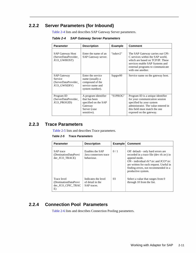
2.2.2 Server Parameters (for Inbound)
Table 2-4 lists and describes SAP Gateway Server parameters.
Table 2-4 SAP Gateway Server Parameters
Parameter Description Example Comment
SAP Gateway Host
(ServerDataProvider_
JCO_GWHOST)
Enter the name of an
SAP Gateway server.
"isdsrv2"
The SAP Gateway carries out CPI-
C services within the SAP world,
which are based on TCP/IP. These
services enable SAP Systems and
external programs to communicate
with one another.
SAP Gateway
Service
(ServerDataProvider_
JCO_GWSERV)
Enter the service
name (usually a
compound of the
service name and
system number).
Sapgw00 Service name on the gateway host.
Program ID
(ServerDataProvider_
JCO_PROGID)
A program identifier
that has been
specified on the SAP
Gateway
Server (case
sensitive).
"S1PROG" Program ID is a unique identifier
for your communication session
specified by your system
administrator. The value entered in
this field must match the one
exposed on the gateway.
2.2.3 Trace Parameters
Table 2-5 lists and describes Trace parameters.
Table 2-5 Trace Parameters
Parameter Description Example Comment
SAP trace
(DestinationDataProvi
der_JCO_TRACE)
Enables the SAP
Java connectors trace
behaviour.
0 / 1
Off default - only hard errors are
recorded in a trace file (dev rfc.trc) in
append mode.
ON - individual rfc*.trc and JCO*.trc
are written for each request. Useful in
finding errors, not recommended in a
productive system.
Trace level
(DestinationDataProvi
der_JCO_CPIC_TRAC
E)
Indicates the level
of detail in the
SAP traces.
03 Select a value that ranges from 0
through 10 from the list.
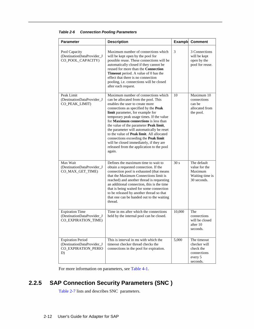
2.2.4 Connection Pool Parameters
Table 2-6 lists and describes Connection Pooling parameters.
2-12 User's Guide for Adapter for SAP
Table 2-6 Connection Pooling Parameters
Parameter Description Example Comment
Pool Capacity
(DestinationDataProvider_J
CO_POOL_CAPACITY)
Maximum number of connections which
will be kept open by the pool for
possible reuse. These connections will be
automatically closed if they cannot be
reused for more than the Connection
Timeout period. A value of 0 has the
effect that there is no connection
pooling, i.e. connections will be closed
after each request.
3
3 Connections
will be kept
open by the
pool for reuse.
Peak Limit
(DestinationDataProvider_J
CO_PEAK_LIMIT)
Maximum number of connections which
can be allocated from the pool. This
enables the user to create more
connections as specified by the Peak
limit parameter, for example for
temporary peak usage times. If the value
for Maximum connections is less than
the value of the parameter Peak limit,
the parameter will automatically be reset
to the value of Peak limit. All allocated
connections exceeding the Peak limit
will be closed immediately, if they are
released from the application to the pool
again.
10 Maximum 10
connections
can be
allocated from
the pool.
Max Wait
(DestinationDataProvider_J
CO_MAX_GET_TIME)
Defines the maximum time to wait to
obtain a requested connection. If the
connection pool is exhausted (that means
that the Maximum Connections limit is
reached) and another thread is requesting
an additional connection, this is the time
that is being waited for some connection
to be released by another thread so that
that one can be handed out to the waiting
thread.
30 s The default
value for the
Maximum
Waiting time is
30 seconds.
Expiration Time
(DestinationDataProvider_J
CO_EXPIRATION_TIME)
Time in ms after which the connections
held by the internal pool can be closed.
10,000 The
connections
will be closed
after 10
seconds.
Expiration Period
(DestinationDataProvider_J
CO_EXPIRATION_PERIO
D)
This is interval in ms with which the
timeout checker thread checks the
connections in the pool for expiration.
5,000 The timeout
checker will
check the
connections
every 5
seconds.
For more information on parameters, see Table 4-1.
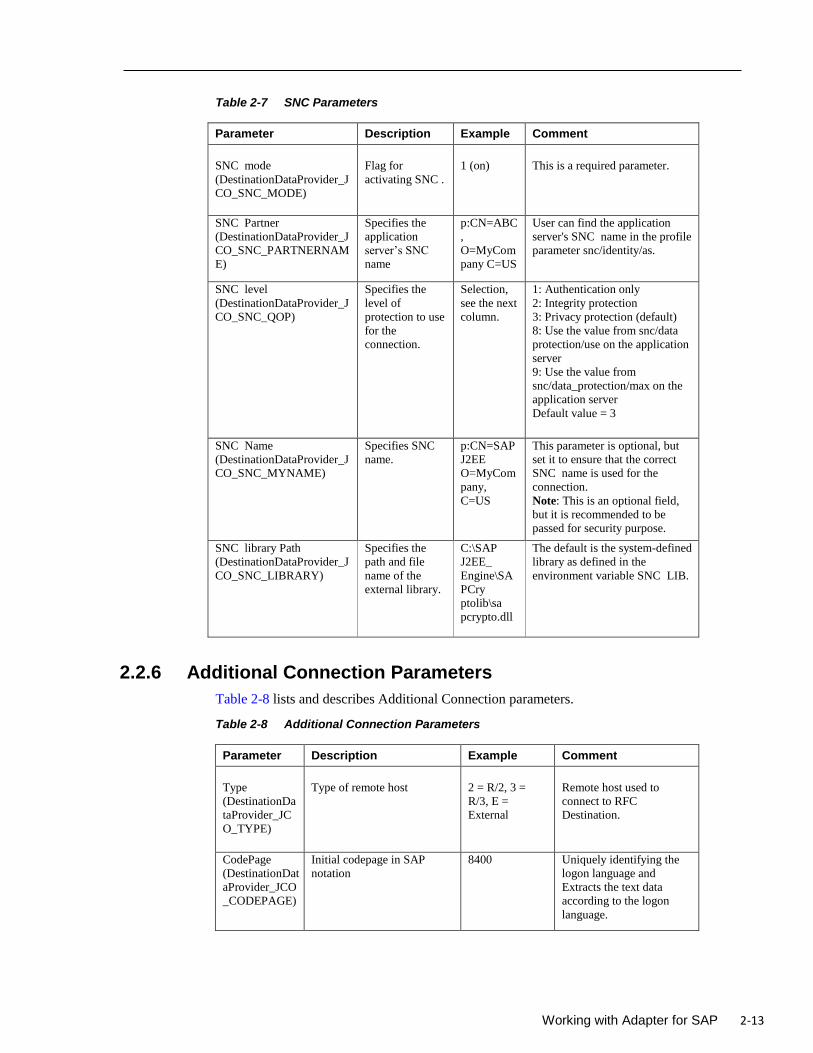
2.2.5 SAP Connection Security Parameters (SNC )
Table 2-7 lists and describes SNC parameters.
Working with Adapter for SAP 2-13
Table 2-7 SNC Parameters
Parameter Description Example Comment
SNC mode
(DestinationDataProvider_J
CO_SNC_MODE)
Flag for
activating SNC .
1 (on)
This is a required parameter.
SNC Partner
(DestinationDataProvider_J
CO_SNC_PARTNERNAM
E)
Specifies the
application
server’s SNC
name
p:CN=ABC
,
O=MyCom
pany C=US
User can find the application
server's SNC name in the profile
parameter snc/identity/as.
SNC level
(DestinationDataProvider_J
CO_SNC_QOP)
Specifies the
level of
protection to use
for the
connection.
Selection,
see the next
column.
1: Authentication only
2: Integrity protection
3: Privacy protection (default)
8: Use the value from snc/data
protection/use on the application
server
9: Use the value from
snc/data_protection/max on the
application server
Default value = 3
SNC Name
(DestinationDataProvider_J
CO_SNC_MYNAME)
Specifies SNC
name.
p:CN=SAP
J2EE
O=MyCom
pany,
C=US
This parameter is optional, but
set it to ensure that the correct
SNC name is used for the
connection.
Note: This is an optional field,
but it is recommended to be
passed for security purpose.
SNC library Path
(DestinationDataProvider_J
CO_SNC_LIBRARY)
Specifies the
path and file
name of the
external library.
C:\SAP
J2EE_
Engine\SA
PCry
ptolib\sa
pcrypto.dll
The default is the system-defined
library as defined in the
environment variable SNC LIB.
2.2.6 Additional Connection Parameters
Table 2-8 lists and describes Additional Connection parameters.
Table 2-8 Additional Connection Parameters
Parameter Description Example Comment
Type
(DestinationDa
taProvider_JC
O_TYPE)
Type of remote host
2 = R/2, 3 =
R/3, E =
External
Remote host used to
connect to RFC
Destination.
CodePage
(DestinationDat
aProvider_JCO
_CODEPAGE)
Initial codepage in SAP
notation
8400 Uniquely identifying the
logon language and
Extracts the text data
according to the logon
language.
2-14 User's Guide for Adapter for SAP
Parameter Description Example Comment
Repository_des
tination
(DestinationDat
aProvider_JCO
_DEST)
Specifies which destination
should be used as repository.
10.32.32.XX
SAP Repository
destination to connect.
Repository
User
(DestinationDat
aProvider_JCO
_REPOSITOR
Y_USER)
If repository destination is
not set, and this property is
set, it will be used as user for
repository calls. This allows
using a different user for
repository lookups.
MYSAPREPO Repository user having
only access to connect to
specified SAP Repository
only.
Repository
Password
(DestinationDat
aProvider_JCO
_REPOSITOR
Y_PASSWD)
The password for a repository
user. Mandatory, if a
repository user should be
used.
MYPASS Connect to the destination
successfully with valid
repository user and
Repository Password .
Note: If the user is a Repository user and has no authorization on particular
RFC/BAPI/IDoc. The returned error message will not be Repository specific.
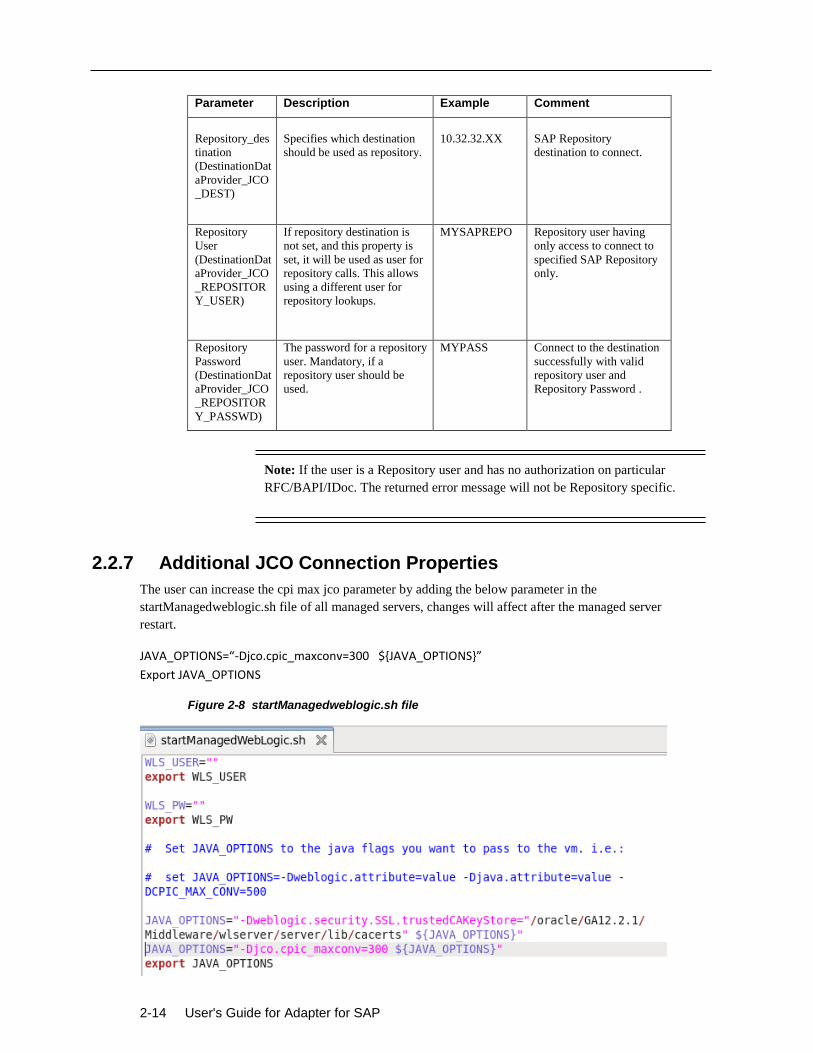
2.2.7 Additional JCO Connection Properties
The user can increase the cpi max jco parameter by adding the below parameter in the
startManagedweblogic.sh file of all managed servers, changes will affect after the managed server
restart.
JAVA_OPTIONS=“-Djco.cpic_maxconv=300 ${JAVA_OPTIONS}”
Export JAVA_OPTIONS
Figure 2-8 startManagedweblogic.sh file
Working with Adapter for SAP 2-15
2.3 Create a Composite in Design-time
1. Open the JDeveloper installed from the below path:
<ORACLE_HOME>/jdeveloper/jdev/bin /jdev
2. Create a new SOA application and corresponding project. For more information, refer to the
section “Create an Empty Composite for SOA”.
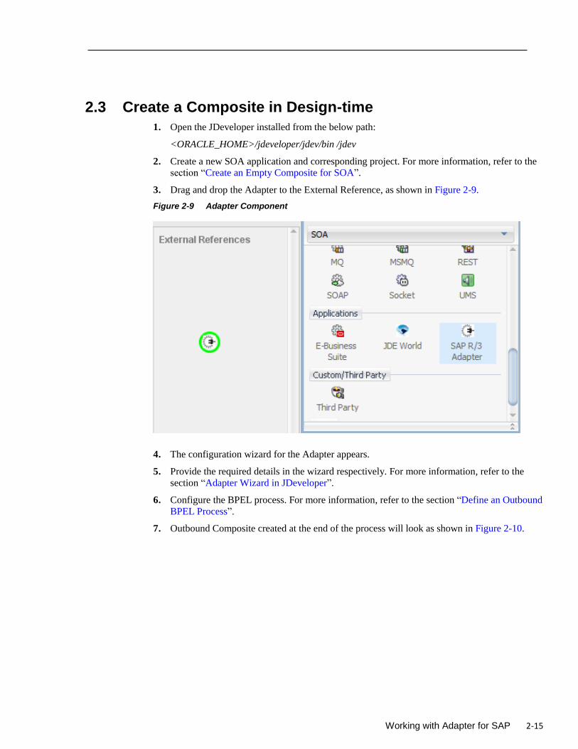
3. Drag and drop the Adapter to the External Reference, as shown in Figure 2-9.
Figure 2-9 Adapter Component
4. The configuration wizard for the Adapter appears.
5. Provide the required details in the wizard respectively. For more information, refer to the
section “Adapter Wizard in JDeveloper”.
6. Configure the BPEL process. For more information, refer to the section “Define an Outbound
BPEL Process”.
7. Outbound Composite created at the end of the process will look as shown in Figure 2-10.
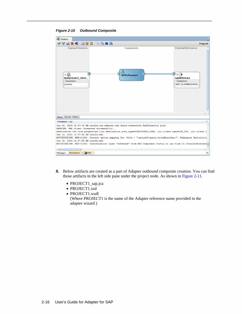
2-16 User's Guide for Adapter for SAP
Figure 2-10 Outbound Composite
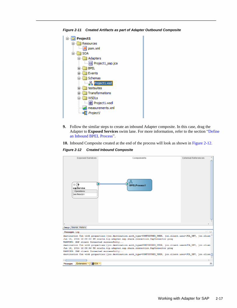
8. Below artifacts are created as a part of Adapter outbound composite creation. You can find
those artifacts in the left side pane under the project node. As shown in Figure 2-11.
PROJECT1_sap.jca
PROJECT1.xsd
PROJECT1.wsdl
(Where PROJECT1 is the name of the Adapter reference name provided in the
adapter wizard )
Working with Adapter for SAP 2-17
Figure 2-11 Created Artifacts as part of Adapter Outbound Composite
9. Follow the similar steps to create an inbound Adapter composite. In this case, drag the
Adapter to Exposed Services swim lane. For more information, refer to the section “Define
an Inbound BPEL Process”.
10. Inbound Composite created at the end of the process will look as shown in Figure 2-12.
Figure 2-12 Created Inbound Composite
2-18 User's Guide for Adapter for SAP
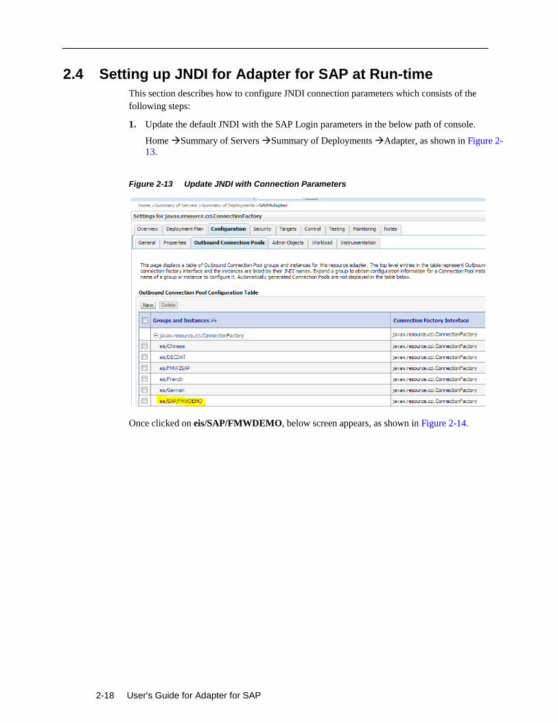
2.4 Setting up JNDI for Adapter for SAP at Run-time
This section describes how to configure JNDI connection parameters which consists of the
following steps:
1. Update the default JNDI with the SAP Login parameters in the below path of console.
Home Summary of Servers Summary of Deployments Adapter, as shown in Figure 2-
13.
Figure 2-13 Update JNDI with Connection Parameters
Once clicked on eis/SAP/FMWDEMO, below screen appears, as shown in Figure 2-14.
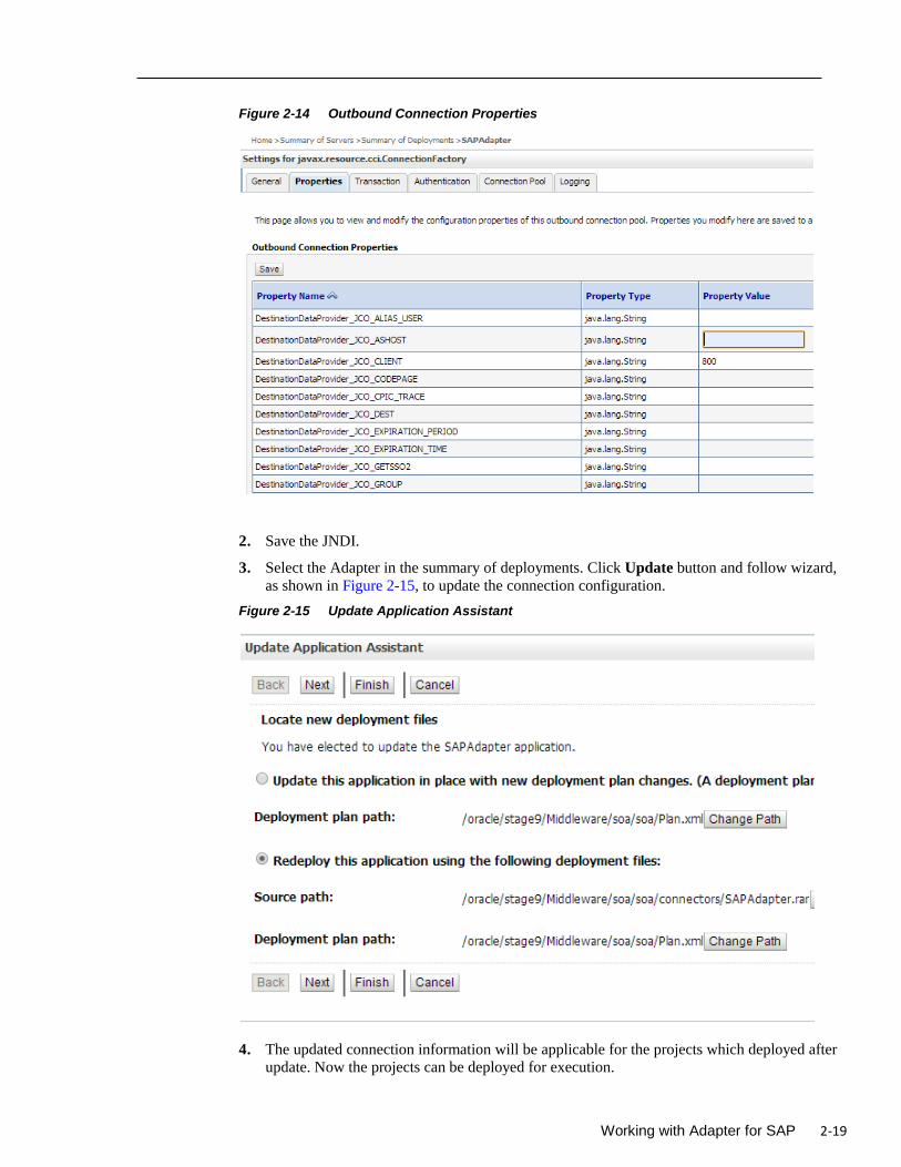
Working with Adapter for SAP 2-19
Figure 2-14 Outbound Connection Properties
2. Save the JNDI.
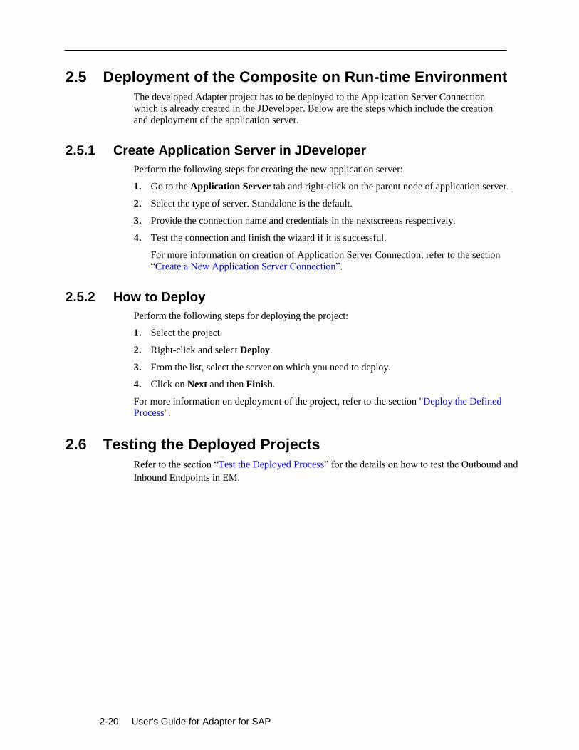
3. Select the Adapter in the summary of deployments. Click Update button and follow wizard,
as shown in Figure 2-15, to update the connection configuration.
Figure 2-15 Update Application Assistant
4. The updated connection information will be applicable for the projects which deployed after
update. Now the projects can be deployed for execution.
2-20 User's Guide for Adapter for SAP
2.5 Deployment of the Composite on Run-time Environment
The developed Adapter project has to be deployed to the Application Server Connection
which is already created in the JDeveloper. Below are the steps which include the creation
and deployment of the application server.
2.5.1 Create Application Server in JDeveloper
Perform the following steps for creating the new application server:
1. Go to the Application Server tab and right-click on the parent node of application server.
2. Select the type of server. Standalone is the default.
3. Provide the connection name and credentials in the nextscreens respectively.
4. Test the connection and finish the wizard if it is successful.
For more information on creation of Application Server Connection, refer to the section
“Create a New Application Server Connection”.
2.5.2 How to Deploy
Perform the following steps for deploying the project:
1. Select the project.
2. Right-click and select Deploy.
3. From the list, select the server on which you need to deploy.
4. Click on Next and then Finish.
For more information on deployment of the project, refer to the section "Deploy the Defined
Process".
2.6 Testing the Deployed Projects
Refer to the section “Test the Deployed Process” for the details on how to test the Outbound and
Inbound Endpoints in EM.
Supported SAP Interfaces 3-1
3
Supported SAP Interfaces
Adapter for SAP provides access to SAP R/3 interfaces such as Remote Enabled Function
Modules (RFC), Business Application Programming Interfaces (BAPI) and Intermediate
Documents (IDoc).
This section contains the following topics:
Section 3.1, "Business Application Programming Interfaces (BAPI) "
Section 3.2, "Remote Enabled Function Modules (RFCs) "
Section 3.3, "Intermediate Document (IDoc) "
3.1 Business Application Programming Interfaces (BAPI)
BAPI’s (Business Application Programming Interface) are a set of interfaces to object-oriented
programming methods in SAP. They enable a programmer to integrate third-party software into
the proprietary R/3 product from SAP. These interfaces can be used by external applications
developed by customers and complementary software partners as well as by other SAP
applications. For specific business tasks such as uploading transactional data, BAPIs are
implemented and stored in the R/3 system as Remote Function Call (RFC) modules.
BAPIs provide the client with an object-oriented view of the application objects without needing
to know the implementation details. BAPIs are always developed by defining scenarios which are
used to map and implement system-wide business processes.
Note: Online BAPIs(which call SAP screens) were not supported by Adapter for
SAP.
3.1.1 Standard BAPI
Some BAPIs and methods provide basic functions and can be used for most SAP Business
Objects. Such BAPIs are known as Standardized BAPIs. For example, Some BAPIs are used for
replicating business object instances: They enable specific instances of an object type to be
copied to one or more different systems. These BAPIs are used mainly to transfer data between
distributed systems within the context of Application Link Enabling (ALE).
A number of service BAPIs provide basic help functions. Service BAPIs provide information or services for the BAPIs from Individual Business Components. Service BAPIs are created in the
Business Object Repository (BOR) under the application component hierarchy shown below:
Cross-Application Components
3-2 User's Guide for Adapter for SAP
Business Framework Architecture
There are some parameters that can be created for various BAPIs because they contain the same
or equivalent data in all BAPIs. Such parameters are known as "standardized parameters". They
should be implemented in the same way in all BAPIs.
Return Parameters: Each BAPI must have an export return parameter for returning messages to
the calling application. To provide application programmers with a consistent error handling
process for BAPI calls, all Return Parameters must be implemented in the same standardized
way.
Change Parameters: For the BAPIs that cause database changes (for example, Change and
Create BAPIs), you must be able to distinguish between parameter fields that contain modified
values and parameter fields that have not been modified. This diffrentiationis made through the
use of standardized parameters.
3.1.2 Custom BAPI
Though SAP provides a bunch of ready-to-use BAPI's but you can also create your own BAPI(s)
easily if required.
Custom BAPIs can be created as per the business requirement of the Customer / Project.
Generally, the option of using the Standard BAPIs is explored to see if the requirement can be
satisfied, otherwise Custom BAPI can be used.
Custom BAPI’s code can always be updated according to the business requirements, at any point
of time, unlike Standard BAPI’s which you cannot change. Information about the updated BAPI
can be retrieve by Adapter for SAP at any point of time.
3.2 Remote Enabled Function Modules (RFCs)
RFC is the protocol used by SAP for remote communication, that is, for communications between
remote (independent) systems.
A Remote Function Call (RFC) is the call or remote execution of a Remote Function Module in
an external system.
RFC is used for communications between two independent SAP systems, or for communications
between an SAP system and a non-SAP system, such as an external application. It can also be
used for communications between modules on the same system.
Using the RFC interfaces, you can extend the functionality of R/3 applications from an external
program.
Compared to using the GUI interfaces, using RFC interfaces requires more knowledge of the
business logic of the R/3 applications with which you are integrating the external application.
RFC is the standard SAP interface for communication between SAP systems. RFC calls a
function to be executed in a remote system.
Note: The Oracle Adapter for SAP supports all datatype and parameter types including
Import, Export, Table and Changing Parameter.
Supported SAP Interfaces 3-3
3.2.1 Standard RFC
SAP provides a range of ready-to-use RFCs based on different business requirements.
Standard RFC can be called and executed remotely by an external system like Adapter for SAP.
For example, RFC_READ_TABLE is a standard SAP function module available within R/3 SAP
systems. This returns the details of the fields present within an SAP table.
3.2.2 Custom RFC
If Standard RFCs are not enough to meet business/customer requirements then Custom RFCs are
created. You can later update the custom RFC according to the requirement. Adapter for SAP can
then use the updated custom RFC.
3.3 Intermediate Document (IDoc )
Intermediate Document (IDoc) is a standard SAP document format. IDocs enable the connection
of different application systems using a message-based interface. The use of IDocs has three main
aims:
Structured exchange and automatic posting of application documents.
Reduction of the varying complex structures of different application systems to one simple
structure. For example, the structure of an SAP application document and the structure of the
corresponding Electronic Data Interchange (EDI) message according to the UN/EDIFACT
standard.
Detailed error handling before the data is posted in the application. IDocs can be regarded
and defined on two levels: On a technical level and on an application level. The technical
level enables the support of cross-application functions such as routing and technical error
handling.
Intermediate Documents (IDocs) are the “logical messages” that correspond to different
business processes. They enable different application systems to be linked by a message-
based interface. The IDoc type indicates the SAP format to use to transfer the data for a
business transaction. An IDoc is a real business process in the form of an IDoc type that can
transfer several message types.
3.3.1 Standard IDoc
Standard IDocs are available in SAP for meeting most of the business requirements. Standard
IDocs can be used for exchanging and automatic posting of application documents. For example,
MATMAS01 is a standard IDoc available in the SAP Form Material Master data.
3.3.2 Custom IDoc
Custom IDocs are created according to the special business/customer requirements for which
standard IDoc is not already available. If later some changes are required in IDoc, it can be done
in Custom IDocs. The Adapter for SAP will be able to use the latest updated IDoc.
3.3.3 Extended IDoc
When the Standard IDocs provided by SAP are not sufficient for a business process, you can use
Extended IDoc. Extension of an IDoc can take place whenever dictionary table has a new
structure appended, as required by the business process.
Extension of an IDoc takes place when extra fields are required for the business process. For
instance, when you already have a predefined IDoc type say “INVOIC02”, but the requirement is

3-4 User's Guide for Adapter for SAP
to transfer additional structure containing VBRK-KTGRD (Account assignment group for this
customer) and VBRK-MANSP (Dunning block). To meet the requirement, you will have to
create a segment structure by adding segment with two additional fields as an extension to the
existing IDoc type ‘INVOIC02’. Thus IDoc extension is adding extra functionality to the existing
message type.
SAP Java Connectors 3.x 4-1
4
SAP Java Connector 3.x
This chapter describes the SAP JCo 3.x library. SAP Java Connector 3.x is a standalone java
library to connect with any SAP R/3 system. SAP JCo supports communication with the AS
ABAP (Application server for ABAP) in both directions: Inbound (Java calls ABAP) and
Outbound calls (ABAP calls Java).
You can find further information on the communication between SAP Java applications and the
ABAP environment in the SAP Library: http://help.sap.com
The section contains the following topics:
Section 4.1, "Supported Systems and Platforms"
Section 4.2, "Performance"
Section 4.3, "RFC Server Threads"
Section 4.4, "Trace Level Parameter"
Section 4.5, "JCo Supported SAP Data types "
4.1 Supported Systems and Platforms
SAP JCo 3.0 is supported by SAP JVM 5 and 6 versions as well as for Java 5, 6, and 7 Standard
Editions of the corresponding platform vendor. You should use the SAP JVM 5 or 6, because it
adds further diagnostic support features and it is also not subject to the end-of-maintenance
restrictions of the JVMs of other vendors.
The JCo 3.0 release is supported for the operating systems mentioned in the following link (SAP
Note #1077727) in combination with the SAP JVM 5 or Java 5 Standard Edition of the
corresponding platform vendor.
SAP R/3 does not support the particular JVM if that is not included in the list of supported JVMs.
Generally a new patch level is downwards compatible to the previous patch levels of the same
release. So the files of an old JCo 3.0 installation may simply be replaced with the latest ones.
SAP JCo 3.0 is replacing SAP JCo 2.0 and SAP JCo 2.1 and is released for Java 5, 6, and 7
version.
SAP JCo 3 with combination of SAP JVM 5/6 or JAVA 5/6 supports 64 and 32 bit operating
system. From SAP JCo 3 onwards, it does not support 32 bit UNIX system.
4.2 Performance
This section describes the Connection configuration in detail like Connection pooling and
thread related management and caching of metadata for faster performance.
4-2 User's Guide for Adapter for SAP
4.2.1 Connection Management
SAP JCo 3 initiate many useful changes in Connection Management rather than just creating
direct connections to the SAP system. SAP JCo provides connection pooling and thread related
management. This Pool is managed by JCo; JCo is responsible for creating and removing
connections from pool. This improves JCo throughput performance.
This allows reusing of connections without having to go through the expensive logon process
again. If a connection that is not part of the internal array is returned to the pool. (This is only
possible if maximum connection is larger than maximum pool size).
Make connection peak limit large enough so that the limit is never reached. An exception to this
would be the small pools used for individual named user. Here a small maximum connection is a
suitable way to ensure that the same user does not have an inordinate number of sessions with the
SAP system.
4.2.2 Connection Pooling
In SAP JCo 3.0, the connection setup is no longer implemented explicitly using a single or pooled
connection, Instead the type of connection is determined only by the connection properties
(properties) that define a single or pooled connection implicitly. Besides making direct
connection, you can use pool connection to make it available instead of creating a connection
every time. There is a limit to the maximum number of connections that can be active in pool and
their timeout in JCo Destination connection parameters. Below are the parameters that are defined
to configure connection pool, as shown in Figure 4-1.
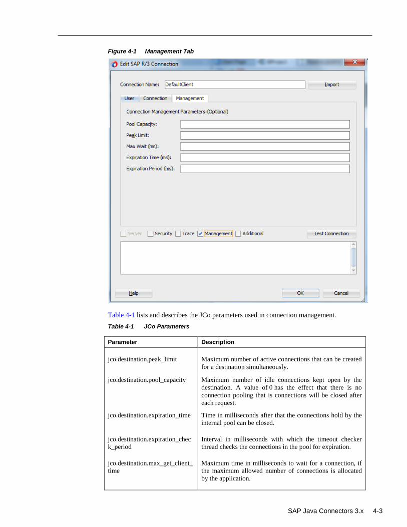
SAP Java Connectors 3.x 4-3
Figure 4-1 Management Tab
Table 4-1 lists and describes the JCo parameters used in connection management.
Table 4-1 JCo Parameters
Parameter Description
jco.destination.peak_limit
Maximum number of active connections that can be created
for a destination simultaneously.
jco.destination.pool_capacity Maximum number of idle connections kept open by the
destination. A value of 0 has the effect that there is no
connection pooling that is connections will be closed after
each request.
jco.destination.expiration_time Time in milliseconds after that the connections hold by the
internal pool can be closed.
jco.destination.expiration_chec
k_period
Interval in milliseconds with which the timeout checker
thread checks the connections in the pool for expiration.
jco.destination.max_get_client_
time
Maximum time in milliseconds to wait for a connection, if
the maximum allowed number of connections is allocated
by the application.
4-4 User's Guide for Adapter for SAP
Note: The Management tab is not supported for the current release , it will be
introduced in the future releases.nline BAPIs(which call SAP screens) were not
supported by Adapter for SAP.
4.2.3 Caching of Metadata
SAP Java connector API cache repository metadata into local cache to avoid number of calls to
the SAP system. This feature improves performance of SAP JCo. Metadata for functions and
parameters will be fetched at the first request and will be stored in the repository cache. SAP JCo
3 handles object caching itself and hence the developers do not need to take care of that. API
provides some method to clear cached metadata.
4.3 RFC Server Threads
SAP JCo 3.0 provides RFC Server module that helps to run an RFC function module on non-
SAP system. The SAP ABAP program can invoke this function module. These java programs
register using a program ID in SAP R/3 Gateway using server threads.
After connection, these RFC programs wait for incoming calls from the SAP system. Server
threads listen for any incoming messages from the SAP system on a particular program ID. For
this, the program ID should be registered with the SAP system. If RFC Connection once
interrupted, JCo server automatically registers itself again with the SAP Gateway.
Configuration parameters can be used to make the throughput more efficient. This configuration
can be changed in the Adapter through the WebLogic console.
If program ID with the same name is registered multiple times from different RFC servers, IDoc
sent on that program ID from SAP system get transferred to one of the registered RFC server
based on default Load Balancing scenarios. You can modify load balancing scenario based on
your requirement. For modification, consult with your SAP system administrator.
4.4 Trace Level Parameter
SAP JCo 3 uses the RFC and CPIC API. Traces generated by these components include JCo API
calls, RFC traces, and CPIC traces. You can trace JCo API calls by enabling the JCo traces and
setting the appropriate trace level in the Adapter configuration.
The Trace level property specifies the level of detail in the traces produced by JCo. The amount
of trace data increases with trace level, and each level contains all of the trace data from the lower
levels. If you choose one of the higher trace levels, you need to ensure that you have enough free
disk space available.
SAP JCo 3 provides trace configuration to trace information. JCo 3 defines parameters for
different type of logging. jco.client.trace parameter is used to define logging level for RFC logs.
Possible values are 0 (disable) or 1(enable). jco.client.cpic_trace parameter is used for CPIC trace
logs. Possible values for CPIC trace is given in Table 4-2.
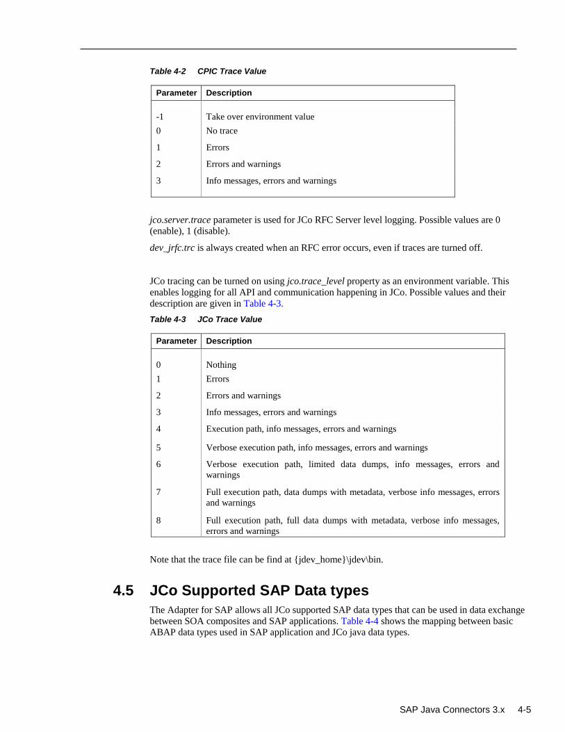
SAP Java Connectors 3.x 4-5
Table 4-2 CPIC Trace Value
Parameter Description
-1
Take over environment value
0 No trace
1 Errors
2 Errors and warnings
3 Info messages, errors and warnings
jco.server.trace parameter is used for JCo RFC Server level logging. Possible values are 0
(enable), 1 (disable).
dev_jrfc.trc is always created when an RFC error occurs, even if traces are turned off.
JCo tracing can be turned on using jco.trace_level property as an environment variable. This
enables logging for all API and communication happening in JCo. Possible values and their
description are given in Table 4-3.
Table 4-3 JCo Trace Value
Parameter Description
0
Nothing
1 Errors
2 Errors and warnings
3 Info messages, errors and warnings
4 Execution path, info messages, errors and warnings
5 Verbose execution path, info messages, errors and warnings
6 Verbose execution path, limited data dumps, info messages, errors and
warnings
7 Full execution path, data dumps with metadata, verbose info messages, errors
and warnings
8 Full execution path, full data dumps with metadata, verbose info messages,
errors and warnings
Note that the trace file can be find at {jdev_home}\jdev\bin.
4.5 JCo Supported SAP Data types
The Adapter for SAP allows all JCo supported SAP data types that can be used in data exchange
between SOA composites and SAP applications. Table 4-4 shows the mapping between basic
ABAP data types used in SAP application and JCo java data types.
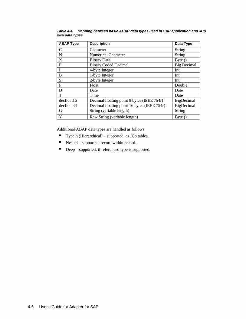
4-6 User's Guide for Adapter for SAP
Table 4-4 Mapping between basic ABAP data types used in SAP application and JCo java data types
ABAP Type Description Data Type
C Character String
N Numerical Character String
X Binary Data Byte ()
P Binary Coded Decimal Big Decimal
I 4-byte Integer Int
B 1-byte Integer Int
S 2-byte Integer Int
F Float Double
D Date Date
T Time Date
decfloat16 Decimal floating point 8 bytes (IEEE 754r) BigDecimal
decfloat34 Decimal floating point 16 bytes (IEEE 754r) BigDecimal
G String (variable length) String
Y Raw String (variable length) Byte ()
Additional ABAP data types are handled as follows:
Type h (Hierarchical) – supported, as JCo tables.
Nested – supported, record within record.
Deep – supported, if referenced type is supported.
Integration Scenarios in Oracle SOA Suite 5-1
5
Oracle Adapter for SAP Features
The latest 12.2.1 Release provides new features for the Oracle Adapter for SAP, which is
described in this chapter. This chapter contains the following sections:
Section 5.1, "tRFC/qRFC/bgRFC Support"
Section 5.2, "Design-Time Test Functionality"
Section 5.3, "Exception Filter"
Section 5.4, "Schema Validation"
Section 5.5, "AutoSYSTAT Feature for RFC "
Section 5.6, "Encode IDoc "
Section 5.7, "Generic IDoc Support "
Section 5.8, " Revision IDoc Support"
Section 5.9, "Sharing Program ID Feature "
Section 5.10, "Multiple IDoc Support"
Section 5.11, "Credential Mapping for Oracle SOA Suite (BPEL, Mediator, BPM or OSB)"
Section 5.12, "Stateful Interaction"
Section 5.13, "Error Handling"
Section 5.14, "SOA Debugger Support"
Section 5.15, “Non-XML Characters Handling Support”
Section 5.16, “Error Document Support”
Section 5.17, “Payload Threshold Support”
Section 5.18, “TID Backstore Support”
5.1 tRFC/qRFC/bgRFC Support
These are the SAP communication methods which are supported by the Adapter for SAP in the
outbound processing.
Transactional RFC (tRFC): This is an asynchronous communication method that manages to
execute the called function in the target system only once. The listener to the port need not to be
available at the time when the RFC client program SAP is executing a tRFC. The tRFC component stores the called RFC function together with the corresponding data, in the SAP
database under a unique transaction ID (TID).
Queued RFC (qRFC): This is also an asynchronous communication method which guarantees
that multiple requests are processed in the order, specified by the sender. tRFC can be serialized
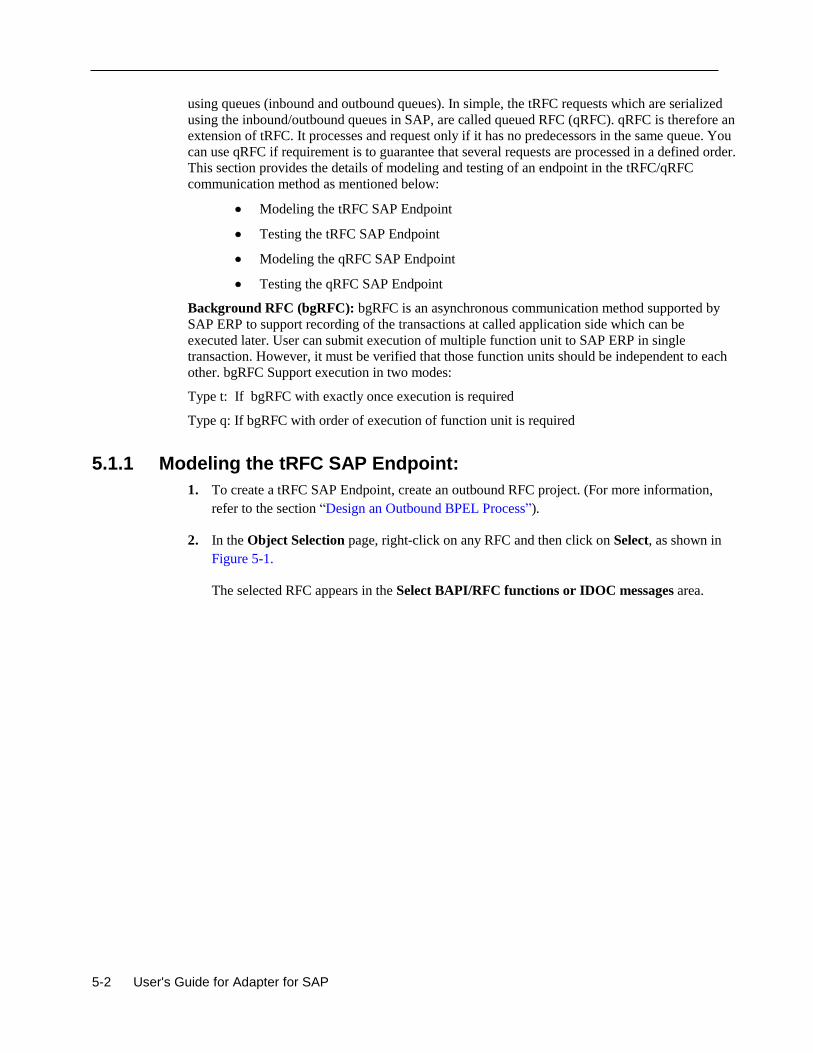
5-2 User's Guide for Adapter for SAP
using queues (inbound and outbound queues). In simple, the tRFC requests which are serialized
using the inbound/outbound queues in SAP, are called queued RFC (qRFC). qRFC is therefore an
extension of tRFC. It processes and request only if it has no predecessors in the same queue. You
can use qRFC if requirement is to guarantee that several requests are processed in a defined order.
This section provides the details of modeling and testing of an endpoint in the tRFC/qRFC
communication method as mentioned below:
Modeling the tRFC SAP Endpoint
Testing the tRFC SAP Endpoint
Modeling the qRFC SAP Endpoint
Testing the qRFC SAP Endpoint
Background RFC (bgRFC): bgRFC is an asynchronous communication method supported by
SAP ERP to support recording of the transactions at called application side which can be
executed later. User can submit execution of multiple function unit to SAP ERP in single
transaction. However, it must be verified that those function units should be independent to each
other. bgRFC Support execution in two modes:
Type t: If bgRFC with exactly once execution is required
Type q: If bgRFC with order of execution of function unit is required
5.1.1 Modeling the tRFC SAP Endpoint:
1. To create a tRFC SAP Endpoint, create an outbound RFC project. (For more information,
refer to the section “Design an Outbound BPEL Process”).
2. In the Object Selection page, right-click on any RFC and then click on Select, as shown in
Figure 5-1.
The selected RFC appears in the Select BAPI/RFC functions or IDOC messages area.

Integration Scenario in Oracle SOA Suite 5-3
Figure 5-1 Object Selection Page
3. Right-click on the selected RFC and select RFC Options, as shown in Figure 5-2.
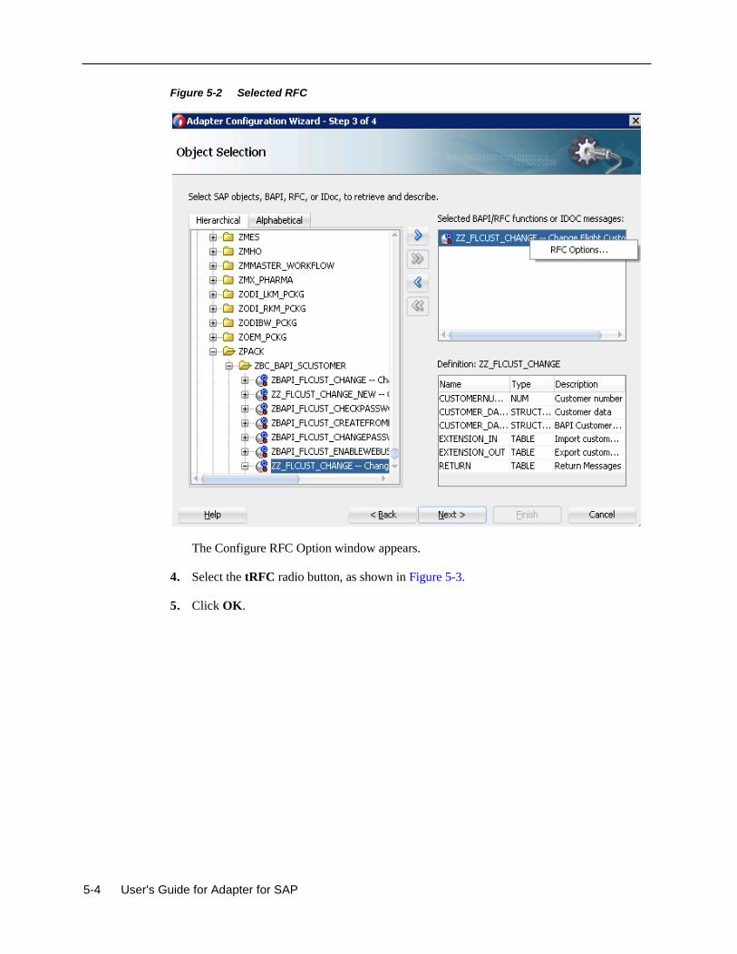
5-4 User's Guide for Adapter for SAP
Figure 5-2 Selected RFC
The Configure RFC Option window appears.
4. Select the tRFC radio button, as shown in Figure 5-3.
5. Click OK.
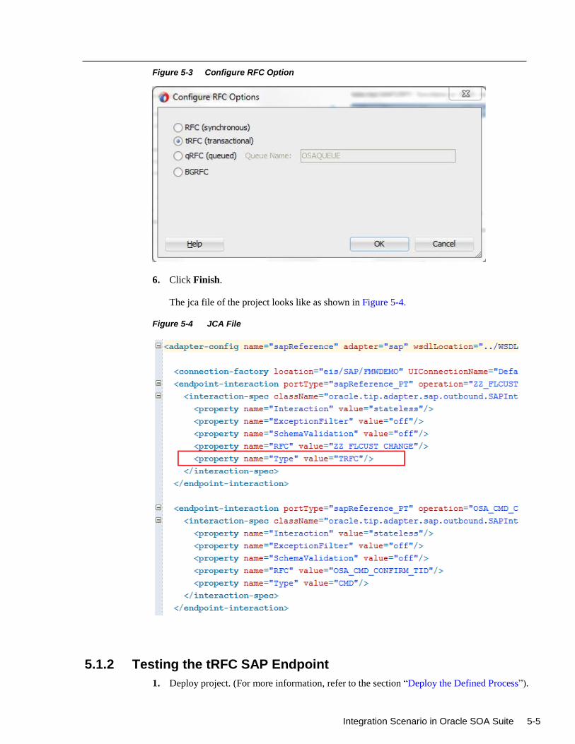
Integration Scenario in Oracle SOA Suite 5-5
Figure 5-3 Configure RFC Option
6. Click Finish.
The jca file of the project looks like as shown in Figure 5-4.
Figure 5-4 JCA File
5.1.2 Testing the tRFC SAP Endpoint
1. Deploy project. (For more information, refer to the section “Deploy the Defined Process”).
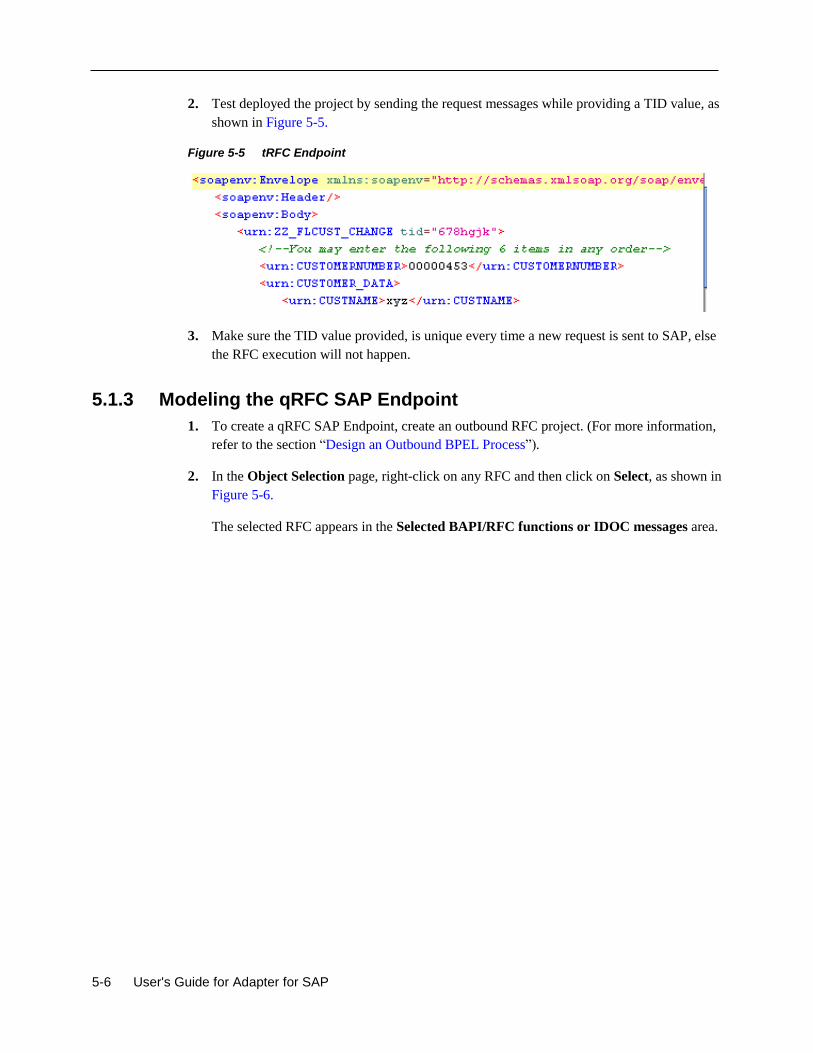
5-6 User's Guide for Adapter for SAP
2. Test deployed the project by sending the request messages while providing a TID value, as
shown in Figure 5-5.
Figure 5-5 tRFC Endpoint
3. Make sure the TID value provided, is unique every time a new request is sent to SAP, else
the RFC execution will not happen.
5.1.3 Modeling the qRFC SAP Endpoint
1. To create a qRFC SAP Endpoint, create an outbound RFC project. (For more information,
refer to the section “Design an Outbound BPEL Process”).
2. In the Object Selection page, right-click on any RFC and then click on Select, as shown in
Figure 5-6.
The selected RFC appears in the Selected BAPI/RFC functions or IDOC messages area.

Integration Scenario in Oracle SOA Suite 5-7
Figure 5-6 Object Selection Page
3. Right-click on the selected RFC and select RFC Options, as shown in Figure 5-7.

5-8 User's Guide for Adapter for SAP
Figure 5-7 Select RFC
The Configure RFC Options window appears.
4. Select the qRFC radio button, as shown in Figure 5-8.
5. Enter the queue name in the Queue Name field. This queue should exist in the SAP system.
6. Click OK.
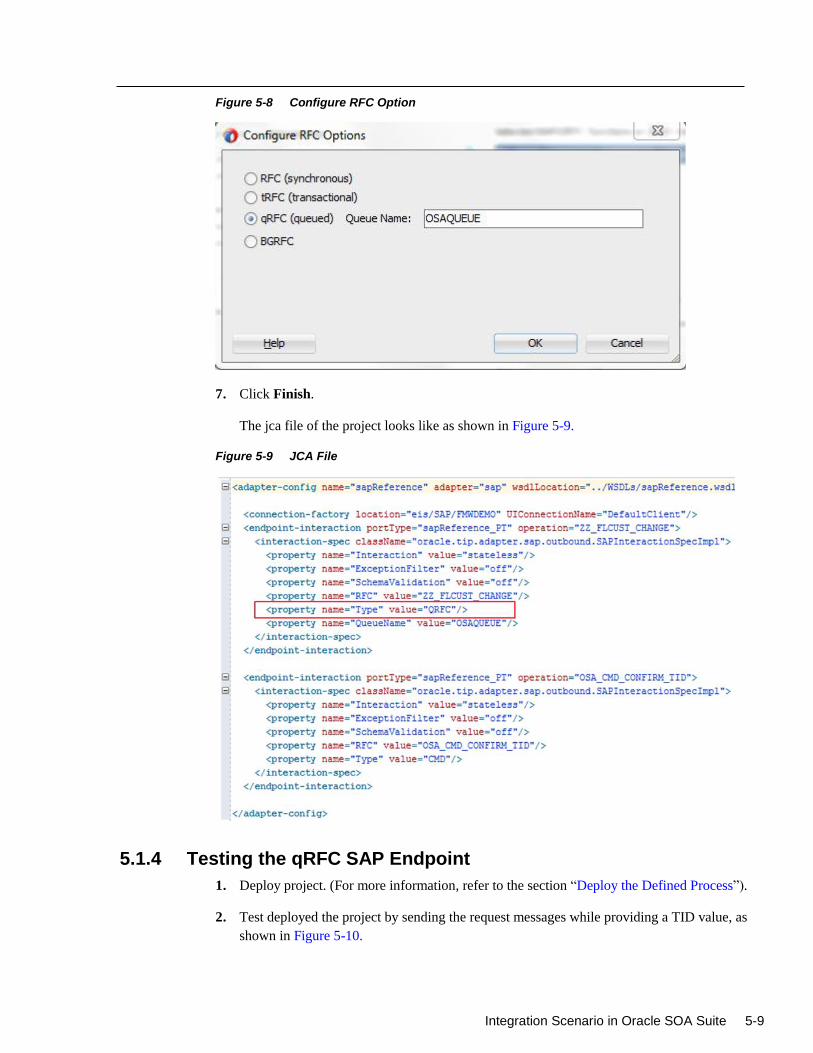
Integration Scenario in Oracle SOA Suite 5-9
Figure 5-8 Configure RFC Option
7. Click Finish.
The jca file of the project looks like as shown in Figure 5-9.
Figure 5-9 JCA File
5.1.4 Testing the qRFC SAP Endpoint
1. Deploy project. (For more information, refer to the section “Deploy the Defined Process”).
2. Test deployed the project by sending the request messages while providing a TID value, as
shown in Figure 5-10.
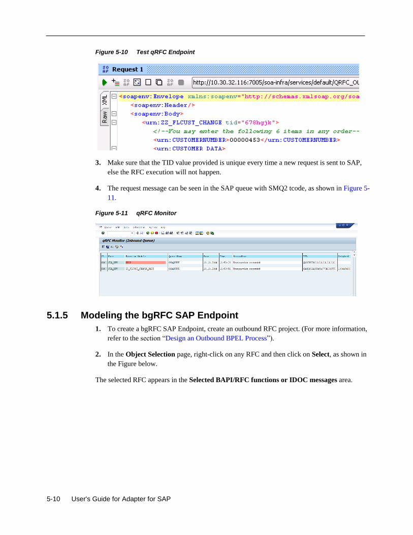
5-10 User's Guide for Adapter for SAP
Figure 5-10 Test qRFC Endpoint
3. Make sure that the TID value provided is unique every time a new request is sent to SAP,
else the RFC execution will not happen.
4. The request message can be seen in the SAP queue with SMQ2 tcode, as shown in Figure 5-
11.
Figure 5-11 qRFC Monitor
5.1.5 Modeling the bgRFC SAP Endpoint
1. To create a bgRFC SAP Endpoint, create an outbound RFC project. (For more information,
refer to the section “Design an Outbound BPEL Process”).
2. In the Object Selection page, right-click on any RFC and then click on Select, as shown in
the Figure below.
The selected RFC appears in the Selected BAPI/RFC functions or IDOC messages area.
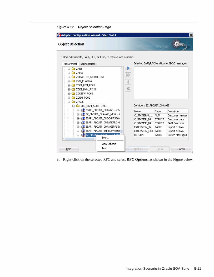
Integration Scenario in Oracle SOA Suite 5-11
Figure 5-12 Object Selection Page
3. Right-click on the selected RFC and select RFC Options, as shown in the Figure below.
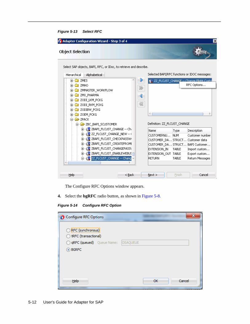
5-12 User's Guide for Adapter for SAP
Figure 5-13 Select RFC
The Configure RFC Options window appears.
4. Select the bgRFC radio button, as shown in Figure 5-8.
Figure 5-14 Configure RFC Option
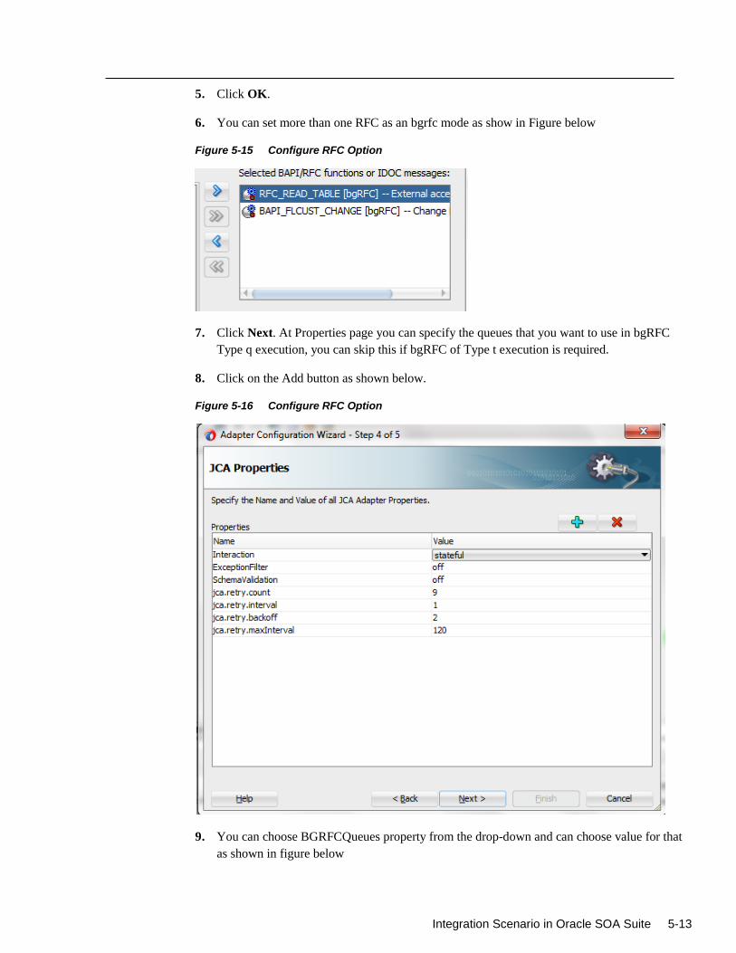
Integration Scenario in Oracle SOA Suite 5-13
5. Click OK.
6. You can set more than one RFC as an bgrfc mode as show in Figure below
Figure 5-15 Configure RFC Option
7. Click Next. At Properties page you can specify the queues that you want to use in bgRFC
Type q execution, you can skip this if bgRFC of Type t execution is required.
8. Click on the Add button as shown below.
Figure 5-16 Configure RFC Option
9. You can choose BGRFCQueues property from the drop-down and can choose value for that
as shown in figure below
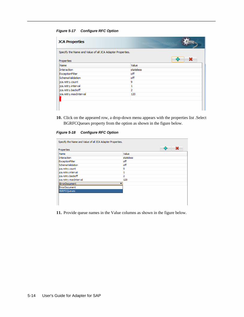
5-14 User's Guide for Adapter for SAP
Figure 5-17 Configure RFC Option
10. Click on the appeared row, a drop-down menu appears with the properties list .Select
BGRFCQueues property from the option as shown in the figure below.
Figure 5-18 Configure RFC Option
11. Provide queue names in the Value columns as shown in the figure below.
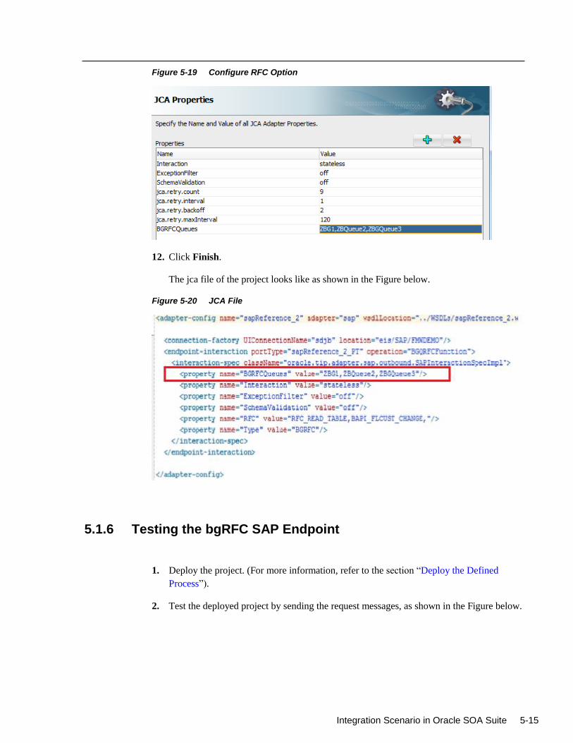
Integration Scenario in Oracle SOA Suite 5-15
Figure 5-19 Configure RFC Option
12. Click Finish.
The jca file of the project looks like as shown in the Figure below.
Figure 5-20 JCA File
5.1.6 Testing the bgRFC SAP Endpoint
1. Deploy the project. (For more information, refer to the section “Deploy the Defined
Process”).
2. Test the deployed project by sending the request messages, as shown in the Figure below.
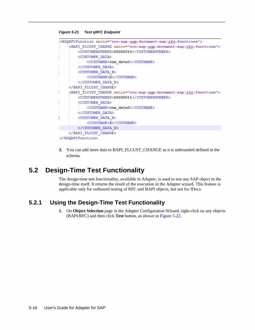
5-16 User's Guide for Adapter for SAP
Figure 5-21 Test qRFC Endpoint
3. You can add more data to BAPI_FLCUST_CHANGE as it is unbounded defined in the
schema.
5.2 Design-Time Test Functionality
The design-time test functionality, available in Adapter, is used to test any SAP object in the
design-time itself. It returns the result of the execution in the Adapter wizard. This feature is
applicable only for outbound testing of RFC and BAPI objects, but not for IDocs.
5.2.1 Using the Design-Time Test Functionality
1. On Object Selection page in the Adapter Configuration Wizard, right-click on any objects
(BAPI/RFC) and then click Test button, as shown in Figure 5-22.
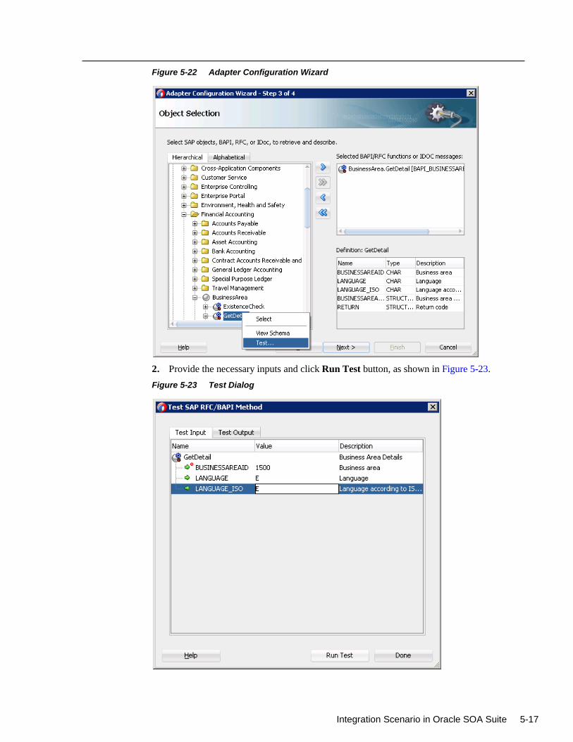
Integration Scenario in Oracle SOA Suite 5-17
Figure 5-22 Adapter Configuration Wizard
2. Provide the necessary inputs and click Run Test button, as shown in Figure 5-23.
Figure 5-23 Test Dialog
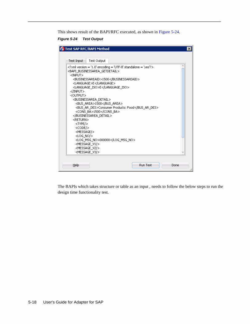
5-18 User's Guide for Adapter for SAP
This shows result of the BAPI/RFC executed, as shown in Figure 5-24.
Figure 5-24 Test Output
The BAPIs which takes structure or table as an input , needs to follow the below steps to run the
design time functionality test.
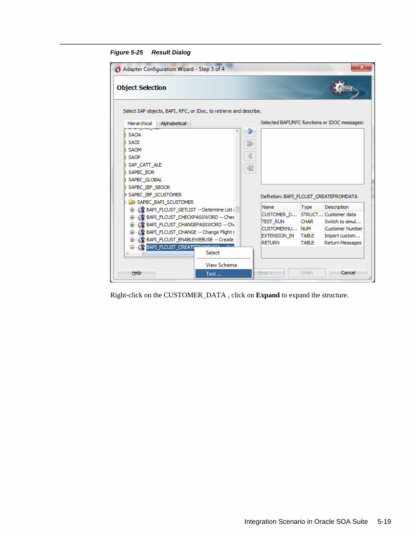
Integration Scenario in Oracle SOA Suite 5-19
Figure 5-25 Result Dialog
Right-click on the CUSTOMER_DATA , click on Expand to expand the structure.
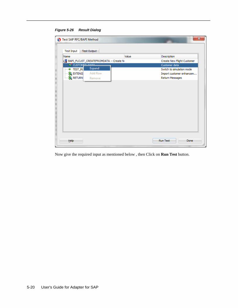
5-20 User's Guide for Adapter for SAP
Figure 5-26 Result Dialog
Now give the required input as mentioned below , then Click on Run Test button.
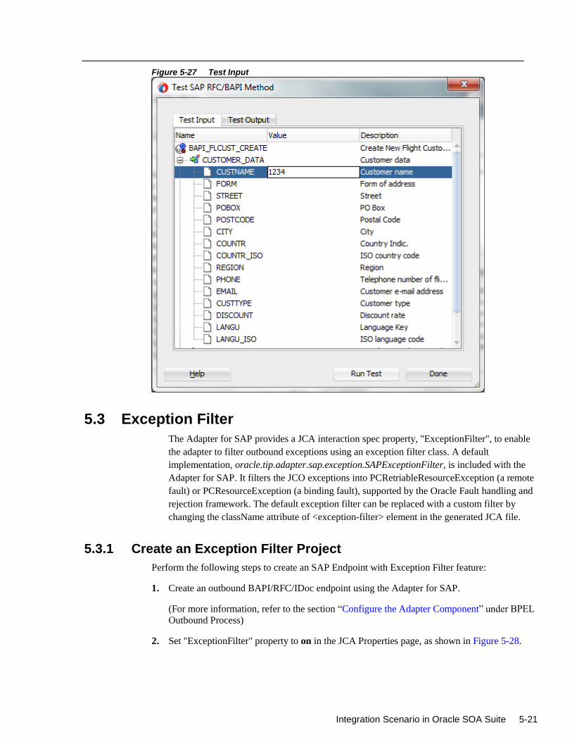
Integration Scenario in Oracle SOA Suite 5-21
Figure 5-27 Test Input
5.3 Exception Filter
The Adapter for SAP provides a JCA interaction spec property, "ExceptionFilter", to enable
the adapter to filter outbound exceptions using an exception filter class. A default
implementation, oracle.tip.adapter.sap.exception.SAPExceptionFilter, is included with the
Adapter for SAP. It filters the JCO exceptions into PCRetriableResourceException (a remote
fault) or PCResourceException (a binding fault), supported by the Oracle Fault handling and
rejection framework. The default exception filter can be replaced with a custom filter by
changing the className attribute of <exception-filter> element in the generated JCA file.
5.3.1 Create an Exception Filter Project
Perform the following steps to create an SAP Endpoint with Exception Filter feature:
1. Create an outbound BAPI/RFC/IDoc endpoint using the Adapter for SAP.
(For more information, refer to the section “Configure the Adapter Component” under BPEL
Outbound Process)
2. Set "ExceptionFilter" property to on in the JCA Properties page, as shown in Figure 5-28.
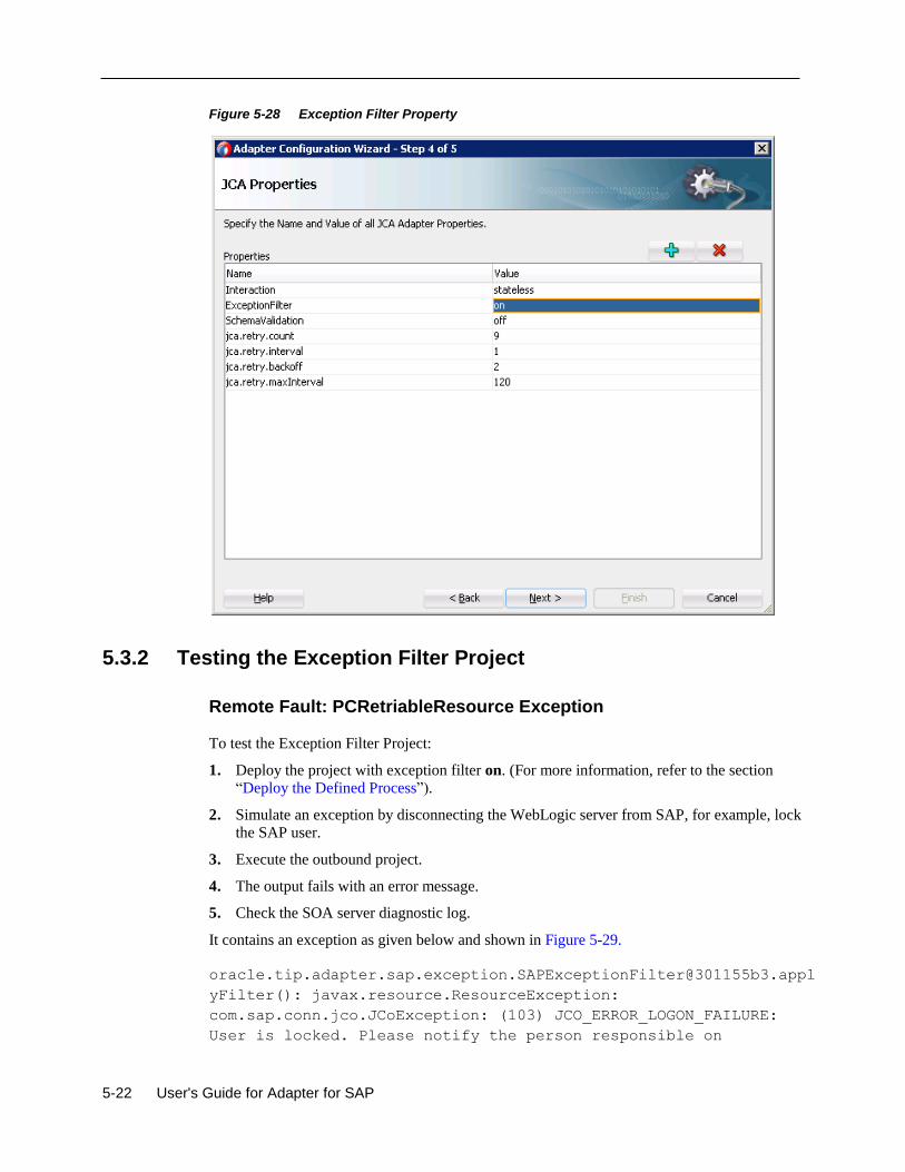
5-22 User's Guide for Adapter for SAP
Figure 5-28 Exception Filter Property
5.3.2 Testing the Exception Filter Project
Remote Fault: PCRetriableResource Exception
To test the Exception Filter Project:
1. Deploy the project with exception filter on. (For more information, refer to the section
“Deploy the Defined Process”).
2. Simulate an exception by disconnecting the WebLogic server from SAP, for example, lock
the SAP user.
3. Execute the outbound project.
4. The output fails with an error message.
5. Check the SOA server diagnostic log.
It contains an exception as given below and shown in Figure 5-29.
oracle.tip.adapter.sap.exception.SAPExceptionFilter@301155b3.appl
yFilter(): javax.resource.ResourceException:
com.sap.conn.jco.JCoException: (103) JCO_ERROR_LOGON_FAILURE:
User is locked. Please notify the person responsible on
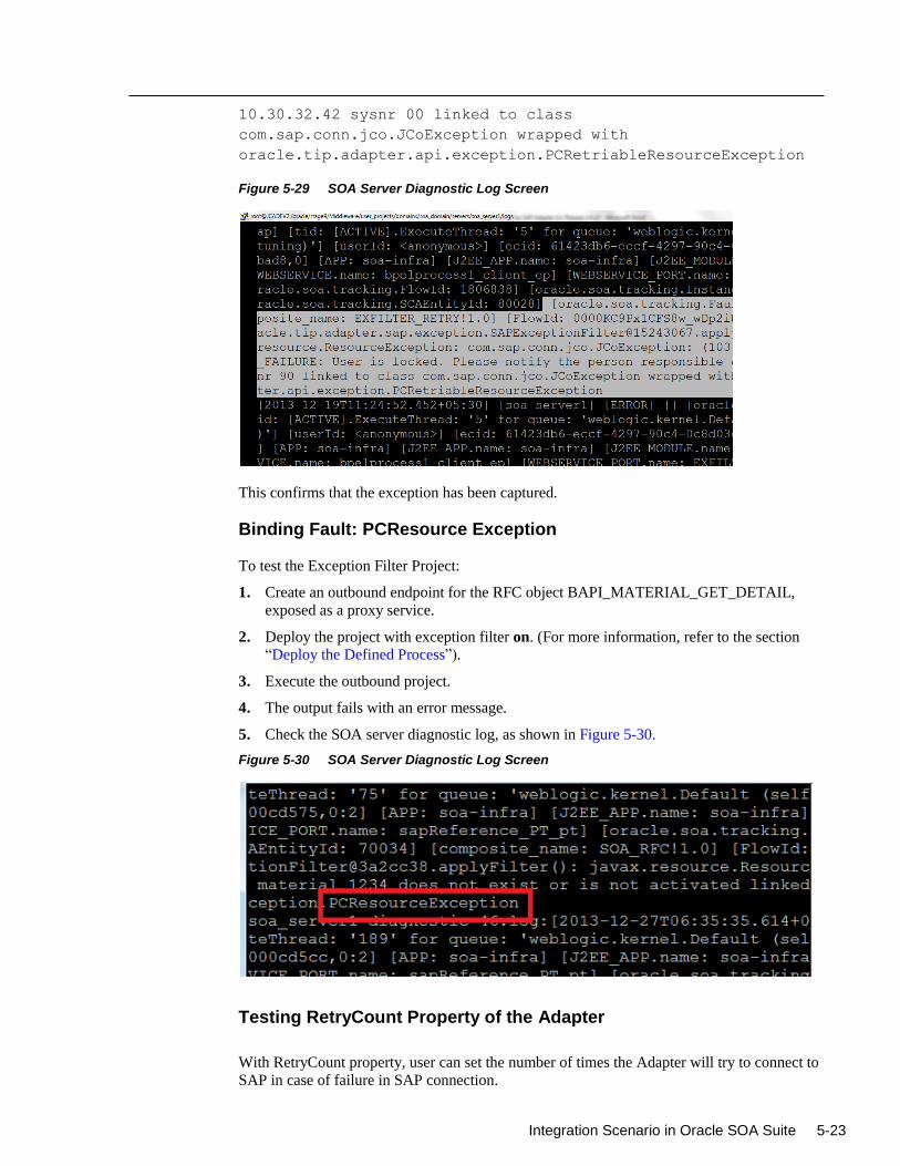
Integration Scenario in Oracle SOA Suite 5-23
10.30.32.42 sysnr 00 linked to class
com.sap.conn.jco.JCoException wrapped with
oracle.tip.adapter.api.exception.PCRetriableResourceException
Figure 5-29 SOA Server Diagnostic Log Screen
This confirms that the exception has been captured.
Binding Fault: PCResource Exception
To test the Exception Filter Project:
1. Create an outbound endpoint for the RFC object BAPI_MATERIAL_GET_DETAIL,
exposed as a proxy service.
2. Deploy the project with exception filter on. (For more information, refer to the section
“Deploy the Defined Process”).
3. Execute the outbound project.
4. The output fails with an error message.
5. Check the SOA server diagnostic log, as shown in Figure 5-30.
Figure 5-30 SOA Server Diagnostic Log Screen
Testing RetryCount Property of the Adapter
With RetryCount property, user can set the number of times the Adapter will try to connect to
SAP in case of failure in SAP connection.
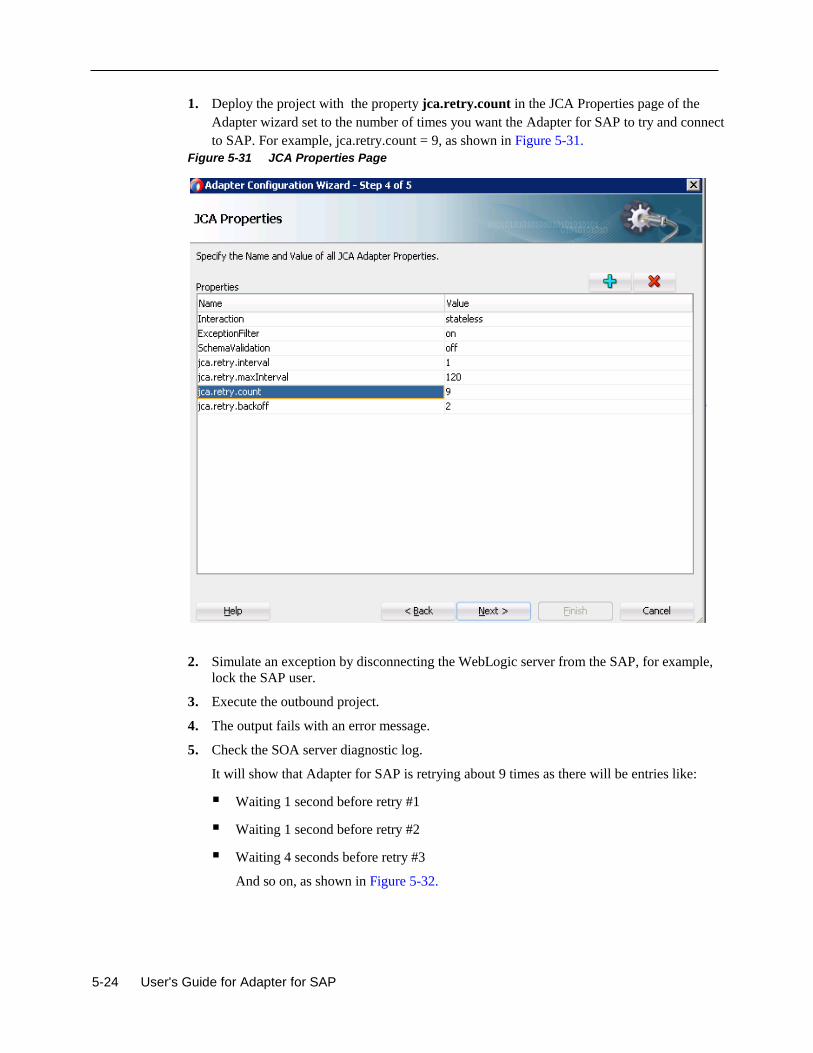
5-24 User's Guide for Adapter for SAP
1. Deploy the project with the property jca.retry.count in the JCA Properties page of the
Adapter wizard set to the number of times you want the Adapter for SAP to try and connect
to SAP. For example, jca.retry.count = 9, as shown in Figure 5-31.
Figure 5-31 JCA Properties Page
2. Simulate an exception by disconnecting the WebLogic server from the SAP, for example,
lock the SAP user.
3. Execute the outbound project.
4. The output fails with an error message.
5. Check the SOA server diagnostic log.
It will show that Adapter for SAP is retrying about 9 times as there will be entries like:
Waiting 1 second before retry #1
Waiting 1 second before retry #2
Waiting 4 seconds before retry #3
And so on, as shown in Figure 5-32.
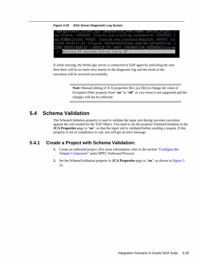
Integration Scenario in Oracle SOA Suite 5-25
Figure 5-32 SOA Server Diagnostic Log Screen
If while retrying, the WebLogic server is connected to SAP again by unlocking the user
then there will be no more retry entries in the diagnostic log and the result of the
execution will be received successfully.
Note: Manual editing of JCA properties file (.jca file) to change the value of
Exception Filter property from “on” to “off” or vice-versa is not supported and the
changes will not be reflected.
5.4 Schema Validation
The SchemaValidation property is used to validate the input xml during run-time execution
against the xsd created for the SAP Object. You need to set the property SchemaValidation in the
JCA Properties page to “on”, so that the input xml is validated before sending a request. If this
property is not in compliance to xsd, you will get an error message.
5.4.1 Create a Project with Schema Validation:
1. Create an outbound project. (For more information, refer to the section “Configure the
Adapter Component” under BPEL Outbound Process)
2. Set the SchemaValidation property in JCA Properties page to “on”, as shown in Figure 5-
33.
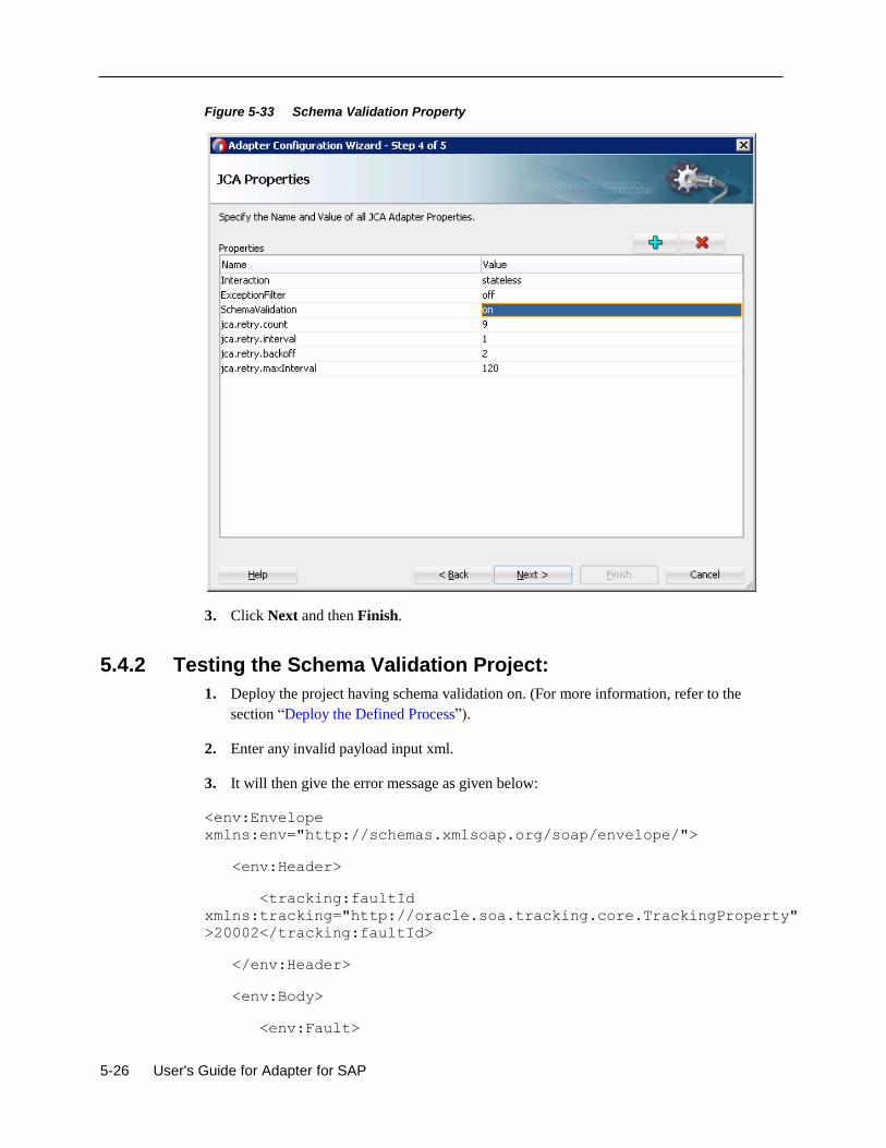
5-26 User's Guide for Adapter for SAP
Figure 5-33 Schema Validation Property
3. Click Next and then Finish.
5.4.2 Testing the Schema Validation Project:
1. Deploy the project having schema validation on. (For more information, refer to the
section “Deploy the Defined Process”).
2. Enter any invalid payload input xml.
3. It will then give the error message as given below:
<env:Envelope
xmlns:env="http://schemas.xmlsoap.org/soap/envelope/">
<env:Header>
<tracking:faultId
xmlns:tracking="http://oracle.soa.tracking.core.TrackingProperty"
>20002</tracking:faultId>
</env:Header>
<env:Body>
<env:Fault>
Integration Scenario in Oracle SOA Suite 5-27
<faultcode>env:Server</faultcode>
<faultstring>Exception occurred when binding was invoked.
Exception occurred during invocation of JCA binding: "JCA Binding execute of Reference
operation 'HOLIDAY_CHECK_AND_GET_INFO' failed due to:
javax.resource.ResourceException: Invalid Input XML".
The invoked JCA adapter raised a resource exception.
Please examine the above error message carefully to determine aresolution.</faultstring>
<faultactor/>
<detail>
<exception>Invalid Input XML</exception>
</detail>
</env:Fault>
</env:Body>
</env:Envelope>
5.5 AutoSYSTAT Feature for RFC
The Adapter for SAP is able to send SYSTAT01 upon a successful reception of an IDoc message.
For this, the AutoSYSTAT01 property in the JCA Properties page must be set to “yes”. The
Adapter for SAP is able to auto return SYSTAT01, based on the successful message receiving
status in SAP.
5.5.1 Creating a Project with AutoSYSTAT01 Property
1. Create Inbound Endpoint for IDOC. For more information, refer to the section “Design an
Inbound BPEL Process”.
2. In the JCA Properties page, set the AutoSYSTAT01 property to “yes”, as shown in Figure
5-34.
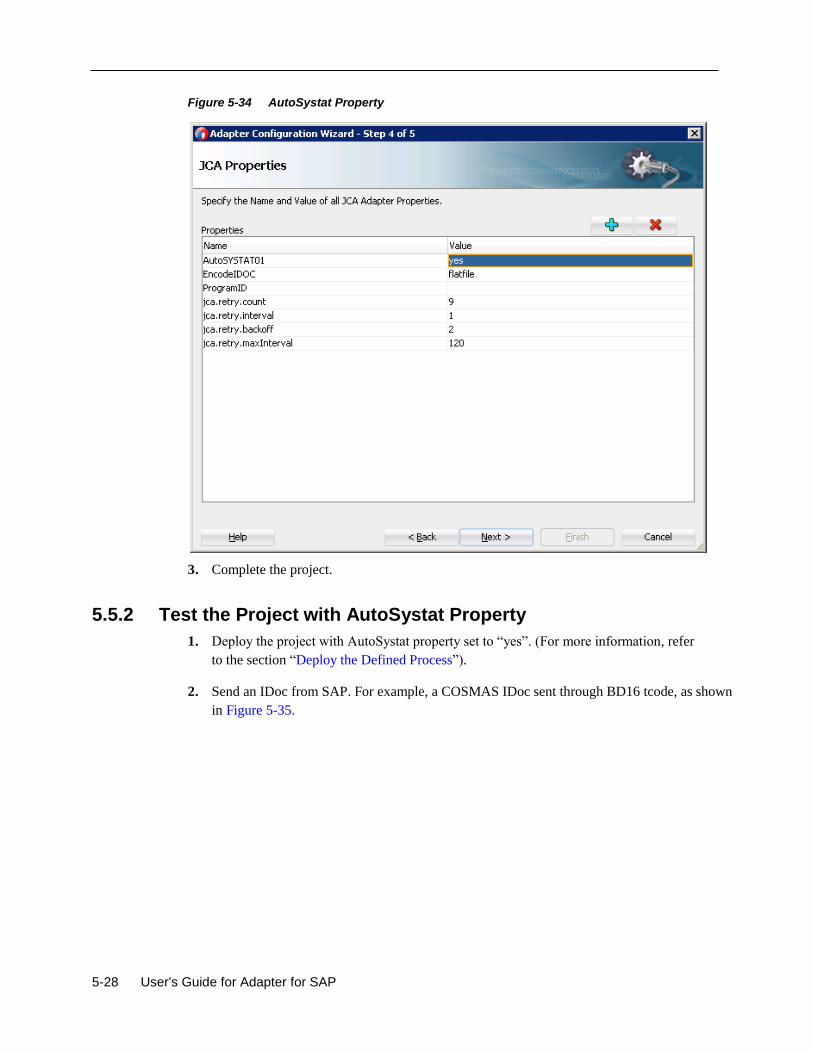
5-28 User's Guide for Adapter for SAP
Figure 5-34 AutoSystat Property
3. Complete the project.
5.5.2 Test the Project with AutoSystat Property
1. Deploy the project with AutoSystat property set to “yes”. (For more information, refer
to the section “Deploy the Defined Process”).
2. Send an IDoc from SAP. For example, a COSMAS IDoc sent through BD16 tcode, as shown
in Figure 5-35.
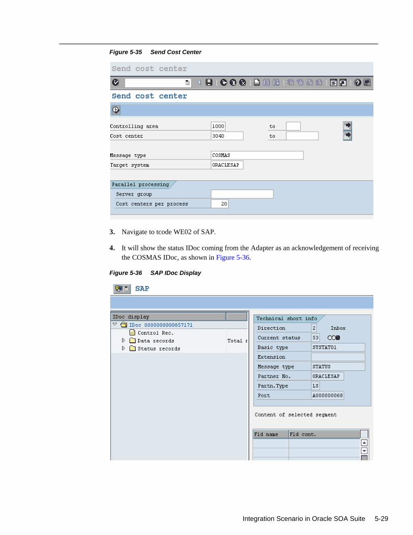
Integration Scenario in Oracle SOA Suite 5-29
Figure 5-35 Send Cost Center
3. Navigate to tcode WE02 of SAP.
4. It will show the status IDoc coming from the Adapter as an acknowledgement of receiving
the COSMAS IDoc, as shown in Figure 5-36.
Figure 5-36 SAP IDoc Display
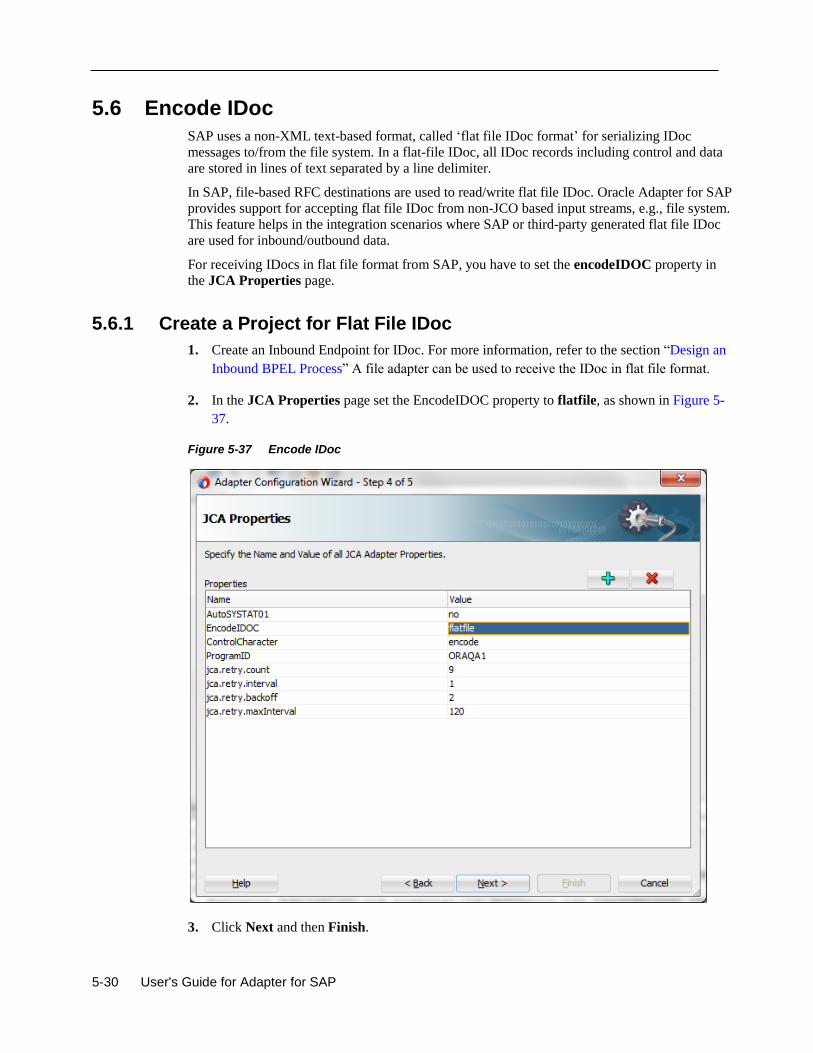
5-30 User's Guide for Adapter for SAP
5.6 Encode IDoc
SAP uses a non-XML text-based format, called ‘flat file IDoc format’ for serializing IDoc
messages to/from the file system. In a flat-file IDoc, all IDoc records including control and data
are stored in lines of text separated by a line delimiter.
In SAP, file-based RFC destinations are used to read/write flat file IDoc. Oracle Adapter for SAP
provides support for accepting flat file IDoc from non-JCO based input streams, e.g., file system.
This feature helps in the integration scenarios where SAP or third-party generated flat file IDoc
are used for inbound/outbound data.
For receiving IDocs in flat file format from SAP, you have to set the encodeIDOC property in
the JCA Properties page.
5.6.1 Create a Project for Flat File IDoc
1. Create an Inbound Endpoint for IDoc. For more information, refer to the section “Design an
Inbound BPEL Process” A file adapter can be used to receive the IDoc in flat file format.
2. In the JCA Properties page set the EncodeIDOC property to flatfile, as shown in Figure 5-
37.
Figure 5-37 Encode IDoc
3. Click Next and then Finish.
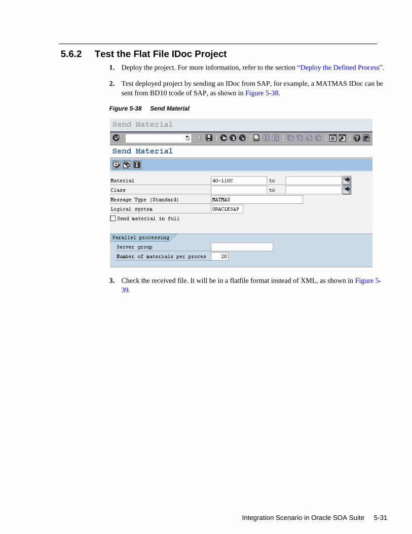
Integration Scenario in Oracle SOA Suite 5-31
5.6.2 Test the Flat File IDoc Project
1. Deploy the project. For more information, refer to the section “Deploy the Defined Process”.
2. Test deployed project by sending an IDoc from SAP, for example, a MATMAS IDoc can be
sent from BD10 tcode of SAP, as shown in Figure 5-38.
Figure 5-38 Send Material
3. Check the received file. It will be in a flatfile format instead of XML, as shown in Figure 5-
39.
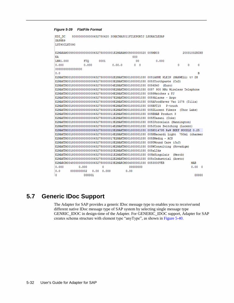
5-32 User's Guide for Adapter for SAP
Figure 5-39 FlatFile Format
5.7 Generic IDoc Support
The Adapter for SAP provides a generic IDoc message type to enables you to receive\send
different native IDoc message type of SAP system by selecting single message type
GENRIC_IDOC in design-time of the Adapter. For GENERIC_IDOC support, Adapter for SAP
creates schema structure with element type “anyType”, as shown in Figure 5-40.
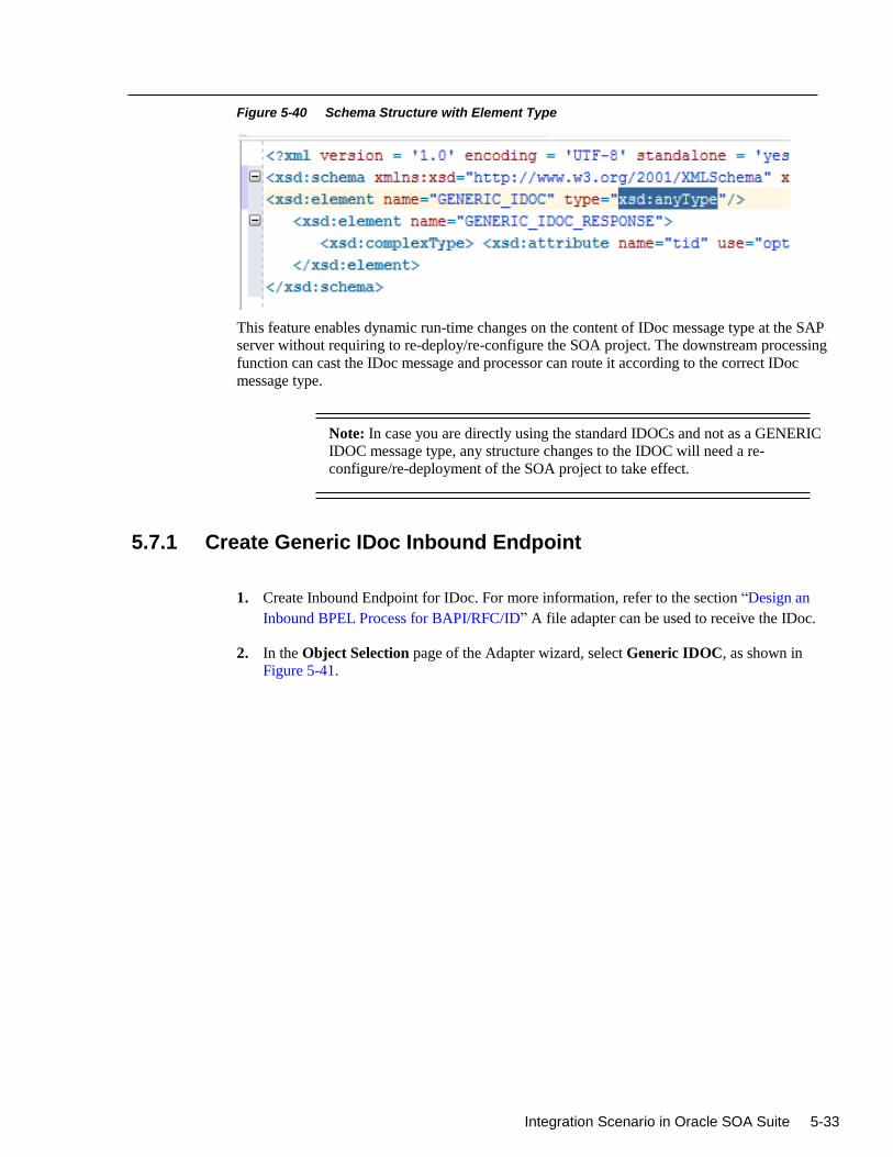
Integration Scenario in Oracle SOA Suite 5-33
Figure 5-40 Schema Structure with Element Type
This feature enables dynamic run-time changes on the content of IDoc message type at the SAP
server without requiring to re-deploy/re-configure the SOA project. The downstream processing
function can cast the IDoc message and processor can route it according to the correct IDoc
message type.
Note: In case you are directly using the standard IDOCs and not as a GENERIC
IDOC message type, any structure changes to the IDOC will need a re-
configure/re-deployment of the SOA project to take effect.
5.7.1 Create Generic IDoc Inbound Endpoint
1. Create Inbound Endpoint for IDoc. For more information, refer to the section “Design an
Inbound BPEL Process for BAPI/RFC/ID” A file adapter can be used to receive the IDoc.
2. In the Object Selection page of the Adapter wizard, select Generic IDOC, as shown in
Figure 5-41.
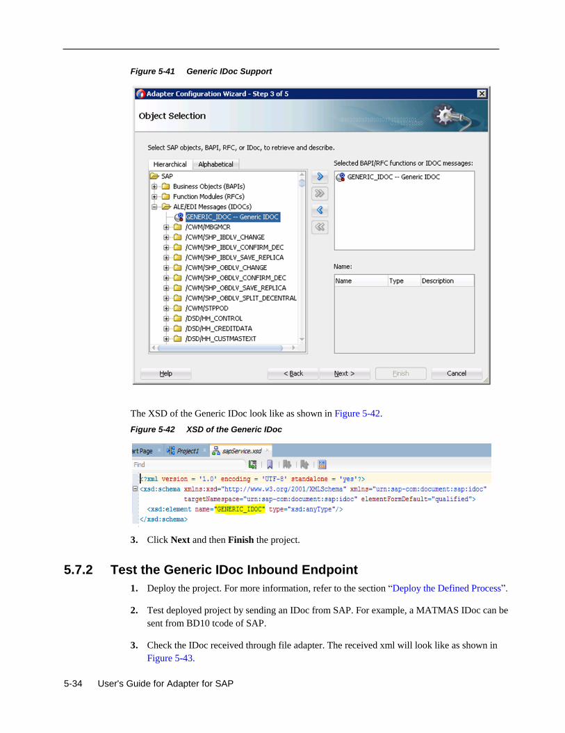
5-34 User's Guide for Adapter for SAP
Figure 5-41 Generic IDoc Support
The XSD of the Generic IDoc look like as shown in Figure 5-42.
Figure 5-42 XSD of the Generic IDoc
3. Click Next and then Finish the project.
5.7.2 Test the Generic IDoc Inbound Endpoint
1. Deploy the project. For more information, refer to the section “Deploy the Defined Process”.
2. Test deployed project by sending an IDoc from SAP. For example, a MATMAS IDoc can be
sent from BD10 tcode of SAP.
3. Check the IDoc received through file adapter. The received xml will look like as shown in
Figure 5-43.
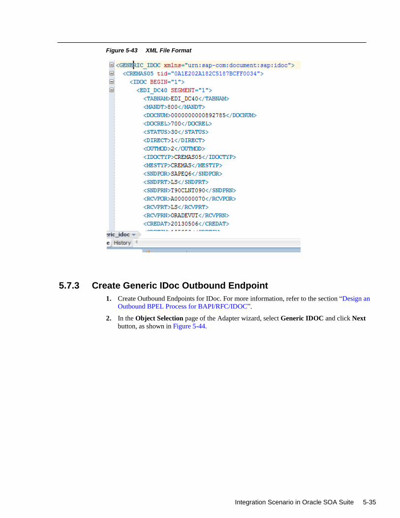
Integration Scenario in Oracle SOA Suite 5-35
Figure 5-43 XML File Format
5.7.3 Create Generic IDoc Outbound Endpoint
1. Create Outbound Endpoints for IDoc. For more information, refer to the section “Design an
Outbound BPEL Process for BAPI/RFC/IDOC”.
2. In the Object Selection page of the Adapter wizard, select Generic IDOC and click Next
button, as shown in Figure 5-44.
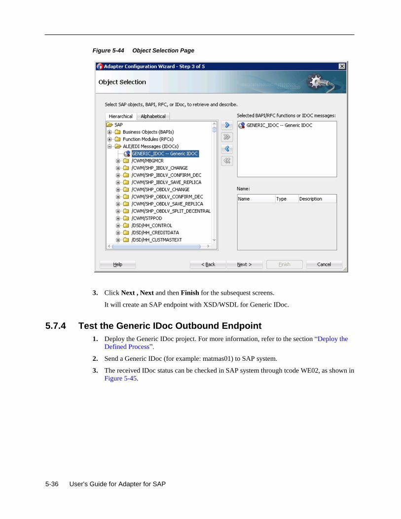
5-36 User's Guide for Adapter for SAP
Figure 5-44 Object Selection Page
3. Click Next , Next and then Finish for the subsequest screens.
It will create an SAP endpoint with XSD/WSDL for Generic IDoc.
5.7.4 Test the Generic IDoc Outbound Endpoint
1. Deploy the Generic IDoc project. For more information, refer to the section “Deploy the
Defined Process”.
2. Send a Generic IDoc (for example: matmas01) to SAP system.
3. The received IDoc status can be checked in SAP system through tcode WE02, as shown in
Figure 5-45.
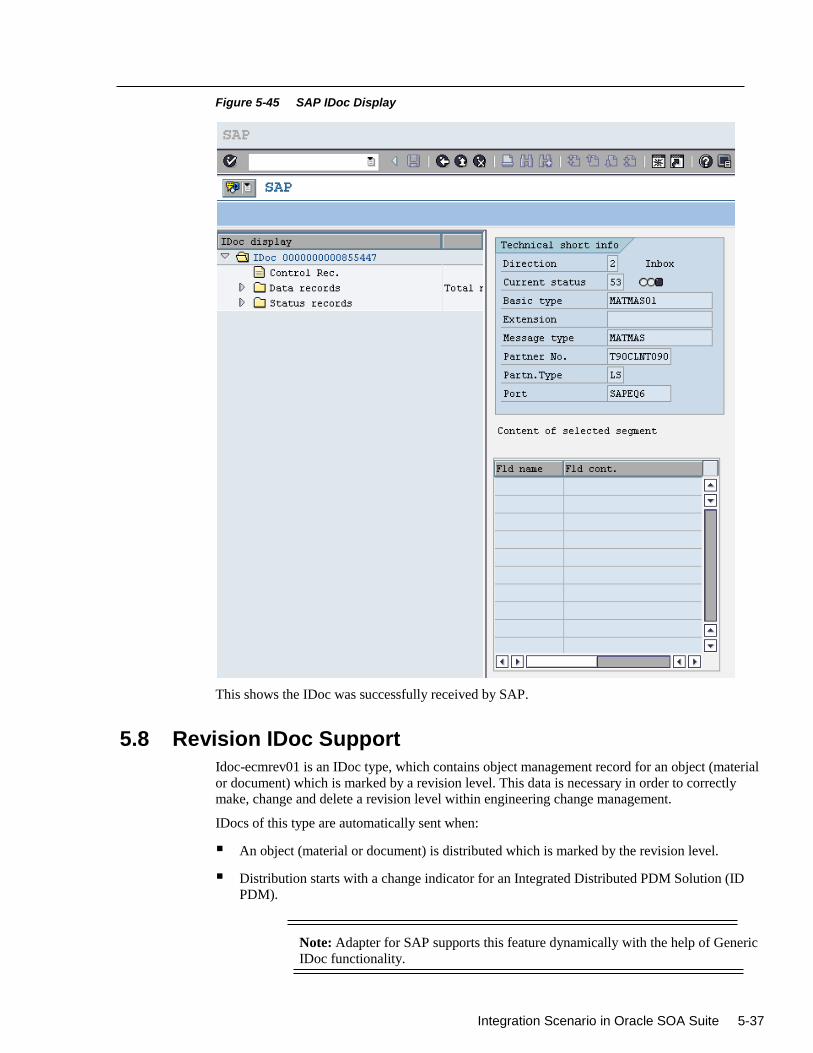
Integration Scenario in Oracle SOA Suite 5-37
Figure 5-45 SAP IDoc Display
This shows the IDoc was successfully received by SAP.
5.8 Revision IDoc Support
Idoc-ecmrev01 is an IDoc type, which contains object management record for an object (material
or document) which is marked by a revision level. This data is necessary in order to correctly
make, change and delete a revision level within engineering change management.
IDocs of this type are automatically sent when:
An object (material or document) is distributed which is marked by the revision level.
Distribution starts with a change indicator for an Integrated Distributed PDM Solution (ID
PDM).
Note: Adapter for SAP supports this feature dynamically with the help of Generic
IDoc functionality.
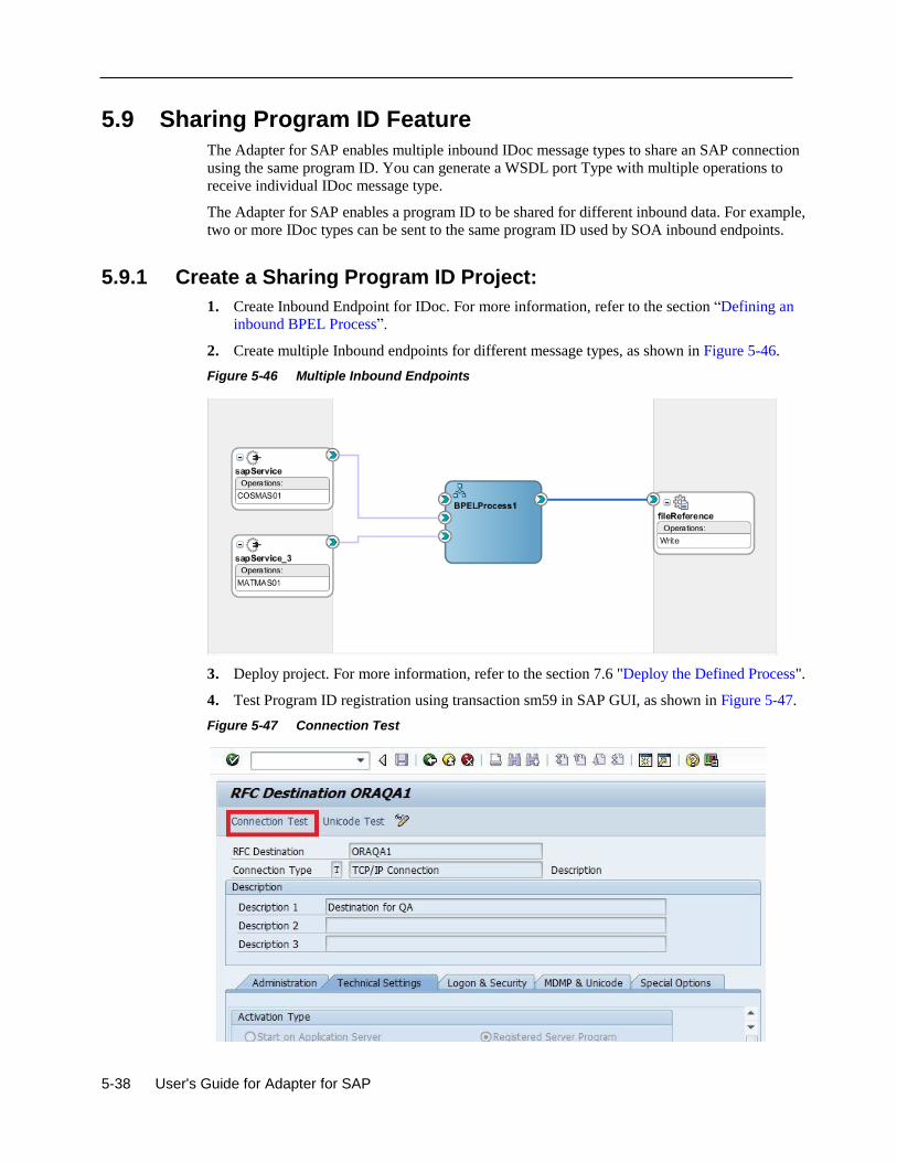
5-38 User's Guide for Adapter for SAP
5.9 Sharing Program ID Feature
The Adapter for SAP enables multiple inbound IDoc message types to share an SAP connection
using the same program ID. You can generate a WSDL port Type with multiple operations to
receive individual IDoc message type.
The Adapter for SAP enables a program ID to be shared for different inbound data. For example,
two or more IDoc types can be sent to the same program ID used by SOA inbound endpoints.
5.9.1 Create a Sharing Program ID Project:
1. Create Inbound Endpoint for IDoc. For more information, refer to the section “Defining an
inbound BPEL Process”.
2. Create multiple Inbound endpoints for different message types, as shown in Figure 5-46.
Figure 5-46 Multiple Inbound Endpoints
3. Deploy project. For more information, refer to the section 7.6 "Deploy the Defined Process".
4. Test Program ID registration using transaction sm59 in SAP GUI, as shown in Figure 5-47.
Figure 5-47 Connection Test
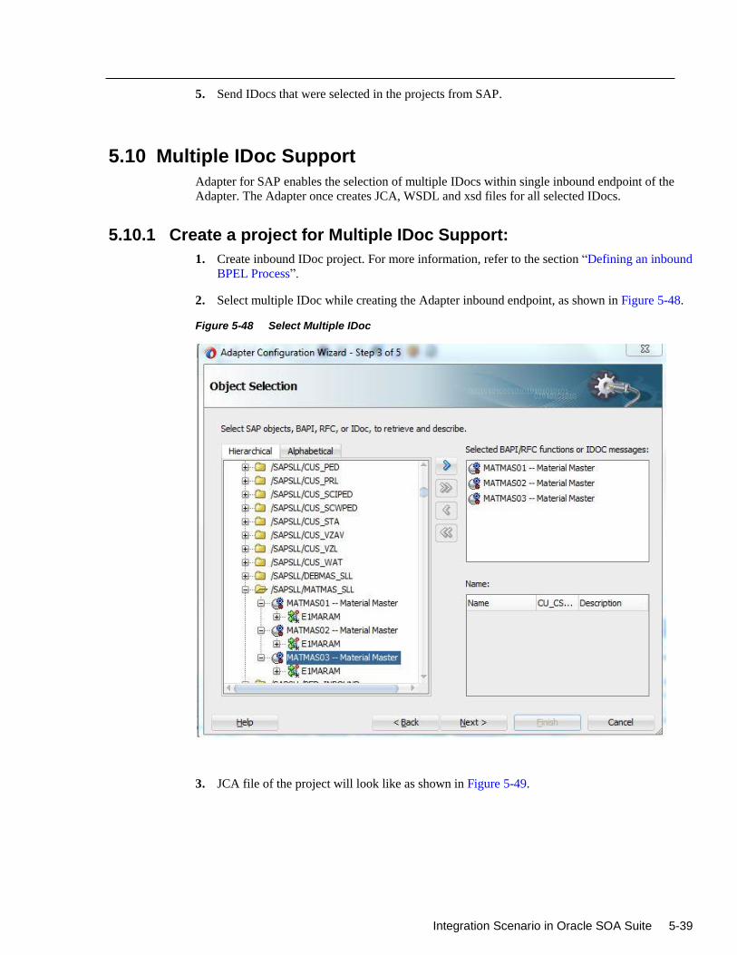
Integration Scenario in Oracle SOA Suite 5-39
5. Send IDocs that were selected in the projects from SAP.
5.10 Multiple IDoc Support
Adapter for SAP enables the selection of multiple IDocs within single inbound endpoint of the
Adapter. The Adapter once creates JCA, WSDL and xsd files for all selected IDocs.
5.10.1 Create a project for Multiple IDoc Support:
1. Create inbound IDoc project. For more information, refer to the section “Defining an inbound
BPEL Process”.
2. Select multiple IDoc while creating the Adapter inbound endpoint, as shown in Figure 5-48.
Figure 5-48 Select Multiple IDoc
3. JCA file of the project will look like as shown in Figure 5-49.
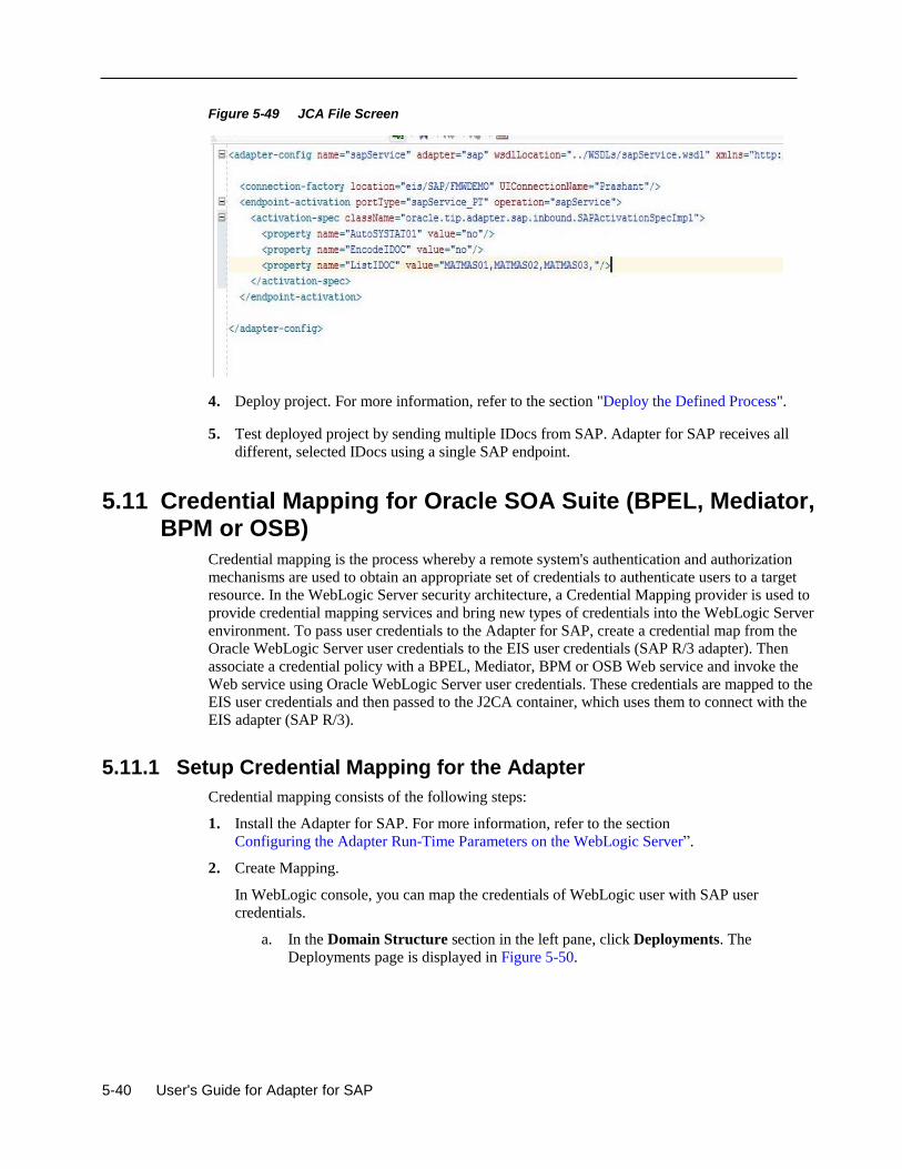
5-40 User's Guide for Adapter for SAP
Figure 5-49 JCA File Screen
4. Deploy project. For more information, refer to the section "Deploy the Defined Process".
5. Test deployed project by sending multiple IDocs from SAP. Adapter for SAP receives all
different, selected IDocs using a single SAP endpoint.
5.11 Credential Mapping for Oracle SOA Suite (BPEL, Mediator, BPM or OSB)
Credential mapping is the process whereby a remote system's authentication and authorization
mechanisms are used to obtain an appropriate set of credentials to authenticate users to a target
resource. In the WebLogic Server security architecture, a Credential Mapping provider is used to
provide credential mapping services and bring new types of credentials into the WebLogic Server
environment. To pass user credentials to the Adapter for SAP, create a credential map from the
Oracle WebLogic Server user credentials to the EIS user credentials (SAP R/3 adapter). Then
associate a credential policy with a BPEL, Mediator, BPM or OSB Web service and invoke the
Web service using Oracle WebLogic Server user credentials. These credentials are mapped to the
EIS user credentials and then passed to the J2CA container, which uses them to connect with the
EIS adapter (SAP R/3).
5.11.1 Setup Credential Mapping for the Adapter
Credential mapping consists of the following steps:
1. Install the Adapter for SAP. For more information, refer to the section
Configuring the Adapter Run-Time Parameters on the WebLogic Server”.
2. Create Mapping.
In WebLogic console, you can map the credentials of WebLogic user with SAP user
credentials.
a. In the Domain Structure section in the left pane, click Deployments. The
Deployments page is displayed in Figure 5-50.
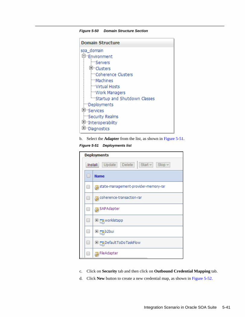
Integration Scenario in Oracle SOA Suite 5-41
Figure 5-50 Domain Structure Section
b. Select the Adapter from the list, as shown in Figure 5-51.
Figure 5-51 Deployments list
c. Click on Security tab and then click on Outbound Credential Mapping tab.
d. Click New button to create a new credential map, as shown in Figure 5-52.
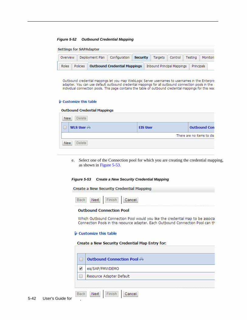
5-42 User's Guide for Adapter for SAP
Figure 5-52 Outbound Credential Mapping
e. Select one of the Connection pool for which you are creating the credential mapping,
as shown in Figure 5-53.
Figure 5-53 Create a New Security Credential Mapping
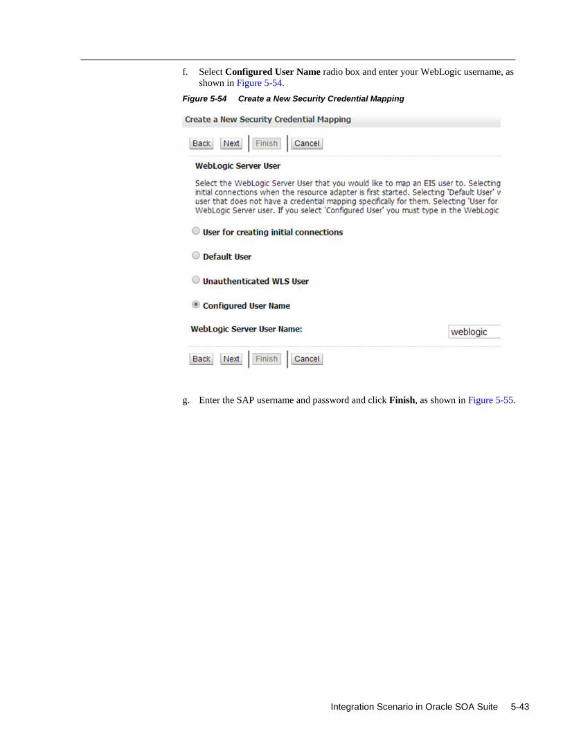
Integration Scenario in Oracle SOA Suite 5-43
f. Select Configured User Name radio box and enter your WebLogic username, as
shown in Figure 5-54.
Figure 5-54 Create a New Security Credential Mapping
g. Enter the SAP username and password and click Finish, as shown in Figure 5-55.
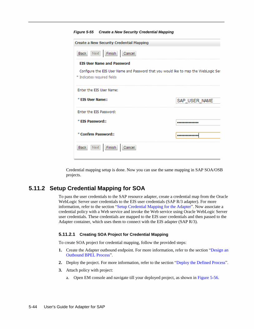
5-44 User's Guide for Adapter for SAP
Figure 5-55 Create a New Security Credential Mapping
Credential mapping setup is done. Now you can use the same mapping in SAP SOA/OSB
projects.
5.11.2 Setup Credential Mapping for SOA
To pass the user credentials to the SAP resource adapter, create a credential map from the Oracle
WebLogic Server user credentials to the EIS user credentials (SAP R/3 adapter). For more
information, refer to the section “Setup Credential Mapping for the Adapter”. Now associate a
credential policy with a Web service and invoke the Web service using Oracle WebLogic Server
user credentials. These credentials are mapped to the EIS user credentials and then passed to the
Adapter container, which uses them to connect with the EIS adapter (SAP R/3).
5.11.2.1 Creating SOA Project for Credential Mapping
To create SOA project for credential mapping, follow the provided steps:
1. Create the Adapter outbound endpoint. For more information, refer to the section “Design an
Outbound BPEL Process”.
2. Deploy the project. For more information, refer to the section “Deploy the Defined Process”.
3. Attach policy with project:
a. Open EM console and navigate till your deployed project, as shown in Figure 5-56.
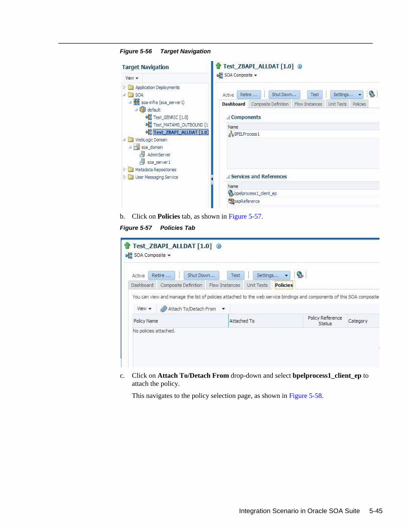
Integration Scenario in Oracle SOA Suite 5-45
Figure 5-56 Target Navigation
b. Click on Policies tab, as shown in Figure 5-57.
Figure 5-57 Policies Tab
c. Click on Attach To/Detach From drop-down and select bpelprocess1_client_ep to
attach the policy.
This navigates to the policy selection page, as shown in Figure 5-58.

5-46 User's Guide for Adapter for SAP
Figure 5-58 Policies Tab
d. Search policy with name oracle/wss_username_token_service_policy in the policy
page.
The oracle/wss_username_token_service_policy policy appears in the search result
area, as shown in Figure 5-59.
Figure 5-59 Search Policy
e. Select the searched policy and click Attach to button.
f. Click Ok button.
g. Click Test button to start testing this project, as shown in Figure 5-60.
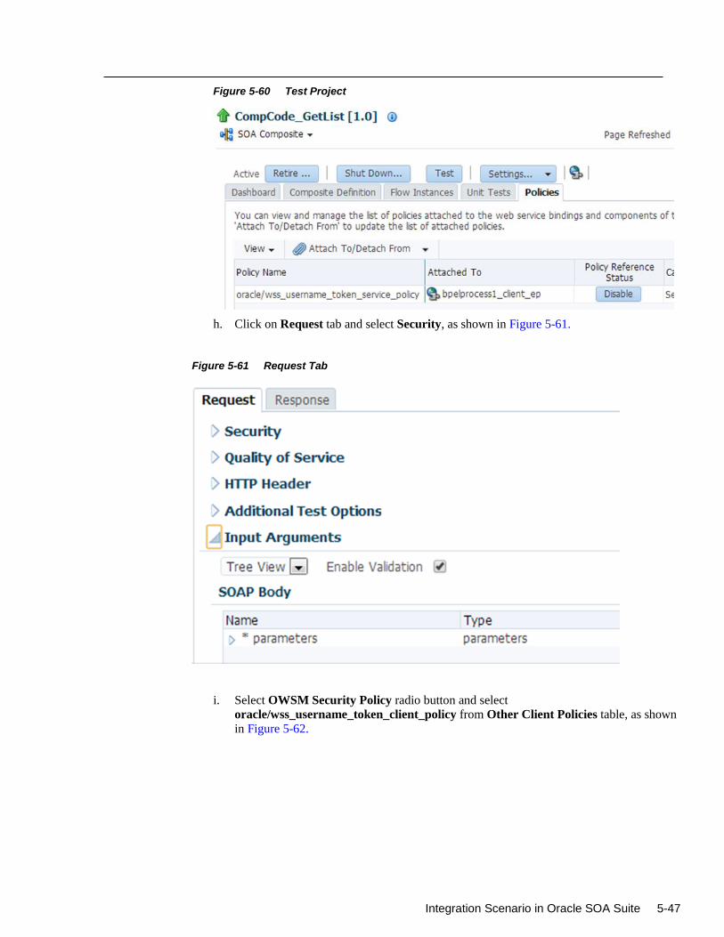
Integration Scenario in Oracle SOA Suite 5-47
Figure 5-60 Test Project
h. Click on Request tab and select Security, as shown in Figure 5-61.
Figure 5-61 Request Tab
i. Select OWSM Security Policy radio button and select
oracle/wss_username_token_client_policy from Other Client Policies table, as shown
in Figure 5-62.
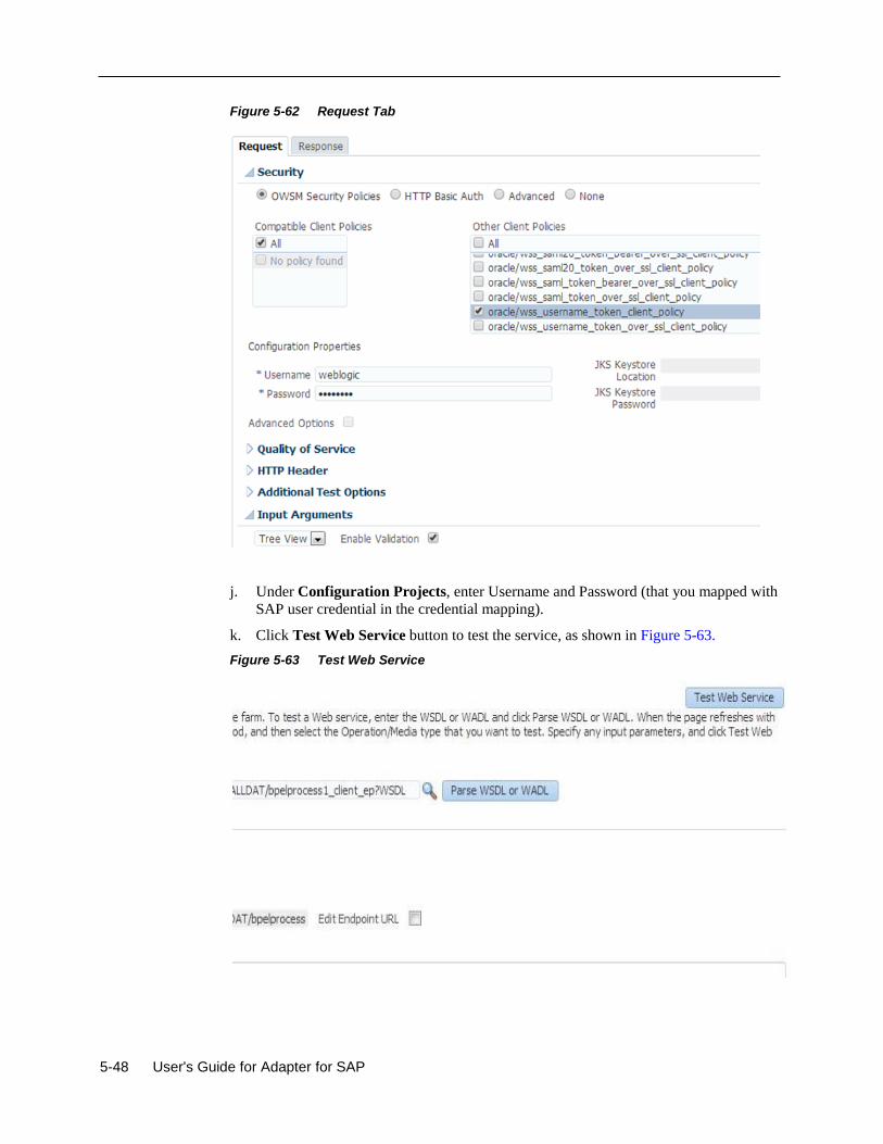
5-48 User's Guide for Adapter for SAP
Figure 5-62 Request Tab
j. Under Configuration Projects, enter Username and Password (that you mapped with
SAP user credential in the credential mapping).
k. Click Test Web Service button to test the service, as shown in Figure 5-63.
Figure 5-63 Test Web Service
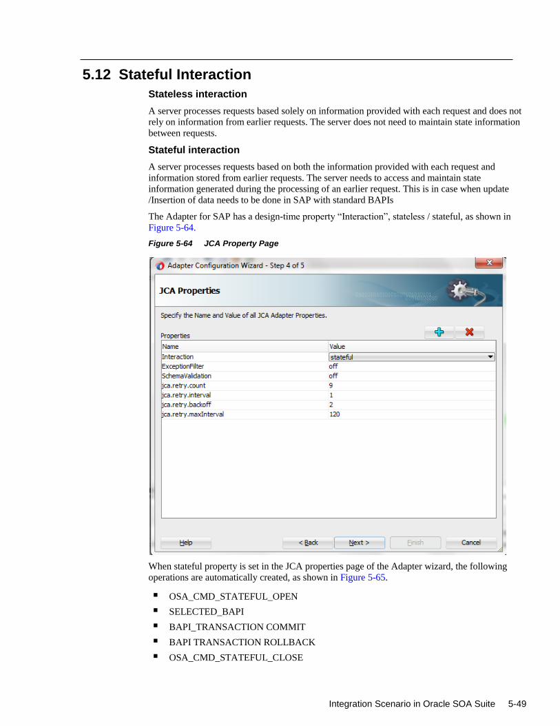
Integration Scenario in Oracle SOA Suite 5-49
5.12 Stateful Interaction
Stateless interaction
A server processes requests based solely on information provided with each request and does not
rely on information from earlier requests. The server does not need to maintain state information
between requests.
Stateful interaction
A server processes requests based on both the information provided with each request and
information stored from earlier requests. The server needs to access and maintain state
information generated during the processing of an earlier request. This is in case when update
/Insertion of data needs to be done in SAP with standard BAPIs
The Adapter for SAP has a design-time property “Interaction”, stateless / stateful, as shown in
Figure 5-64.
Figure 5-64 JCA Property Page
When stateful property is set in the JCA properties page of the Adapter wizard, the following
operations are automatically created, as shown in Figure 5-65.
OSA_CMD_STATEFUL_OPEN
SELECTED_BAPI
BAPI_TRANSACTION COMMIT
BAPI TRANSACTION ROLLBACK
OSA_CMD_STATEFUL_CLOSE
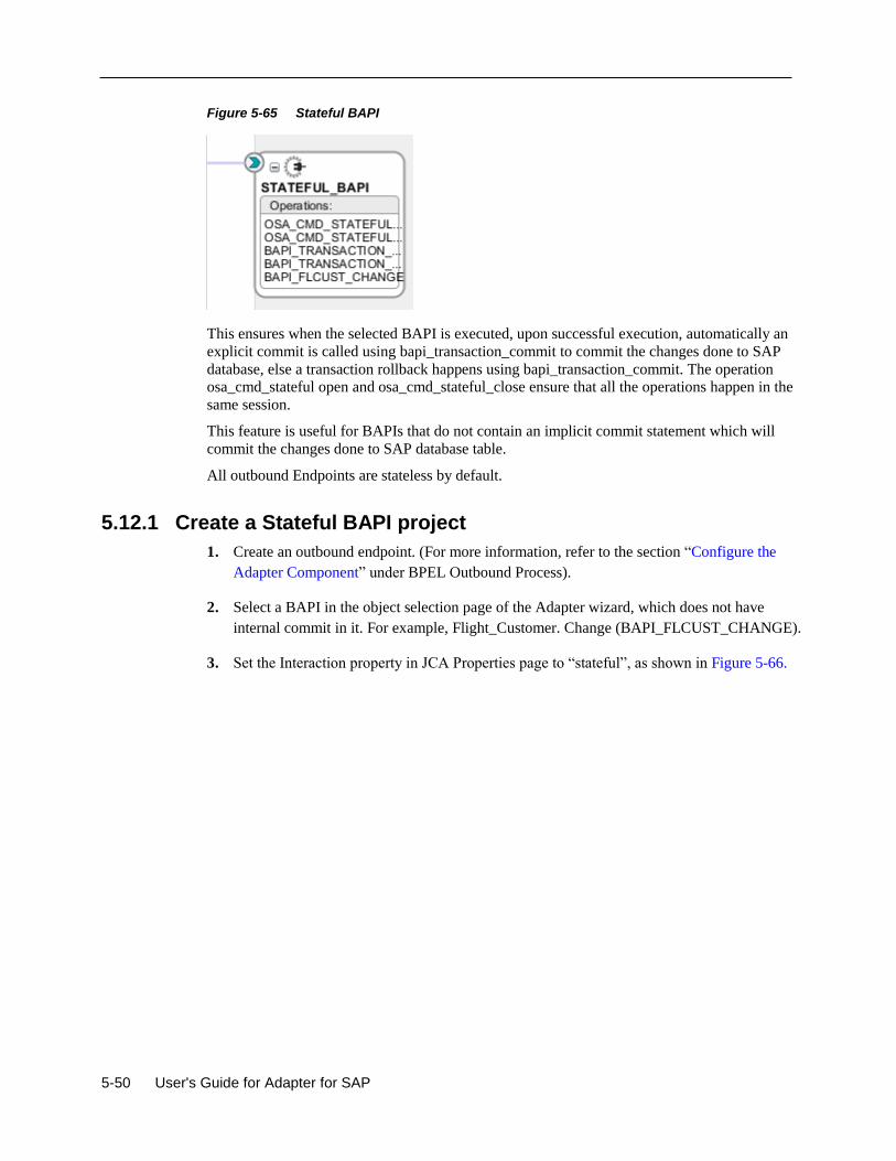
5-50 User's Guide for Adapter for SAP
Figure 5-65 Stateful BAPI
This ensures when the selected BAPI is executed, upon successful execution, automatically an
explicit commit is called using bapi_transaction_commit to commit the changes done to SAP
database, else a transaction rollback happens using bapi_transaction_commit. The operation
osa_cmd_stateful open and osa_cmd_stateful_close ensure that all the operations happen in the
same session.
This feature is useful for BAPIs that do not contain an implicit commit statement which will
commit the changes done to SAP database table.
All outbound Endpoints are stateless by default.
5.12.1 Create a Stateful BAPI project
1. Create an outbound endpoint. (For more information, refer to the section “Configure the
Adapter Component” under BPEL Outbound Process).
2. Select a BAPI in the object selection page of the Adapter wizard, which does not have
internal commit in it. For example, Flight_Customer. Change (BAPI_FLCUST_CHANGE).
3. Set the Interaction property in JCA Properties page to “stateful”, as shown in Figure 5-66.
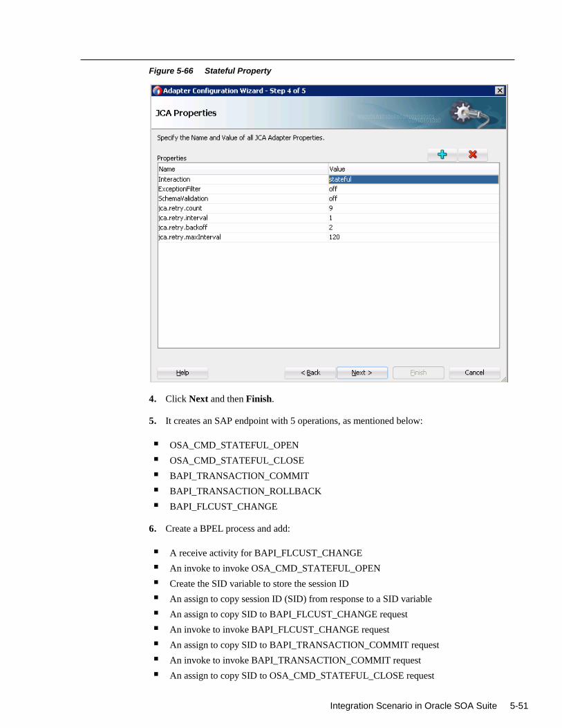
Integration Scenario in Oracle SOA Suite 5-51
Figure 5-66 Stateful Property
4. Click Next and then Finish.
5. It creates an SAP endpoint with 5 operations, as mentioned below:
OSA_CMD_STATEFUL_OPEN
OSA_CMD_STATEFUL_CLOSE
BAPI_TRANSACTION_COMMIT
BAPI_TRANSACTION_ROLLBACK
BAPI_FLCUST_CHANGE
6. Create a BPEL process and add:
A receive activity for BAPI_FLCUST_CHANGE
An invoke to invoke OSA_CMD_STATEFUL_OPEN
Create the SID variable to store the session ID
An assign to copy session ID (SID) from response to a SID variable
An assign to copy SID to BAPI_FLCUST_CHANGE request
An invoke to invoke BAPI_FLCUST_CHANGE request
An assign to copy SID to BAPI_TRANSACTION_COMMIT request
An invoke to invoke BAPI_TRANSACTION_COMMIT request
An assign to copy SID to OSA_CMD_STATEFUL_CLOSE request
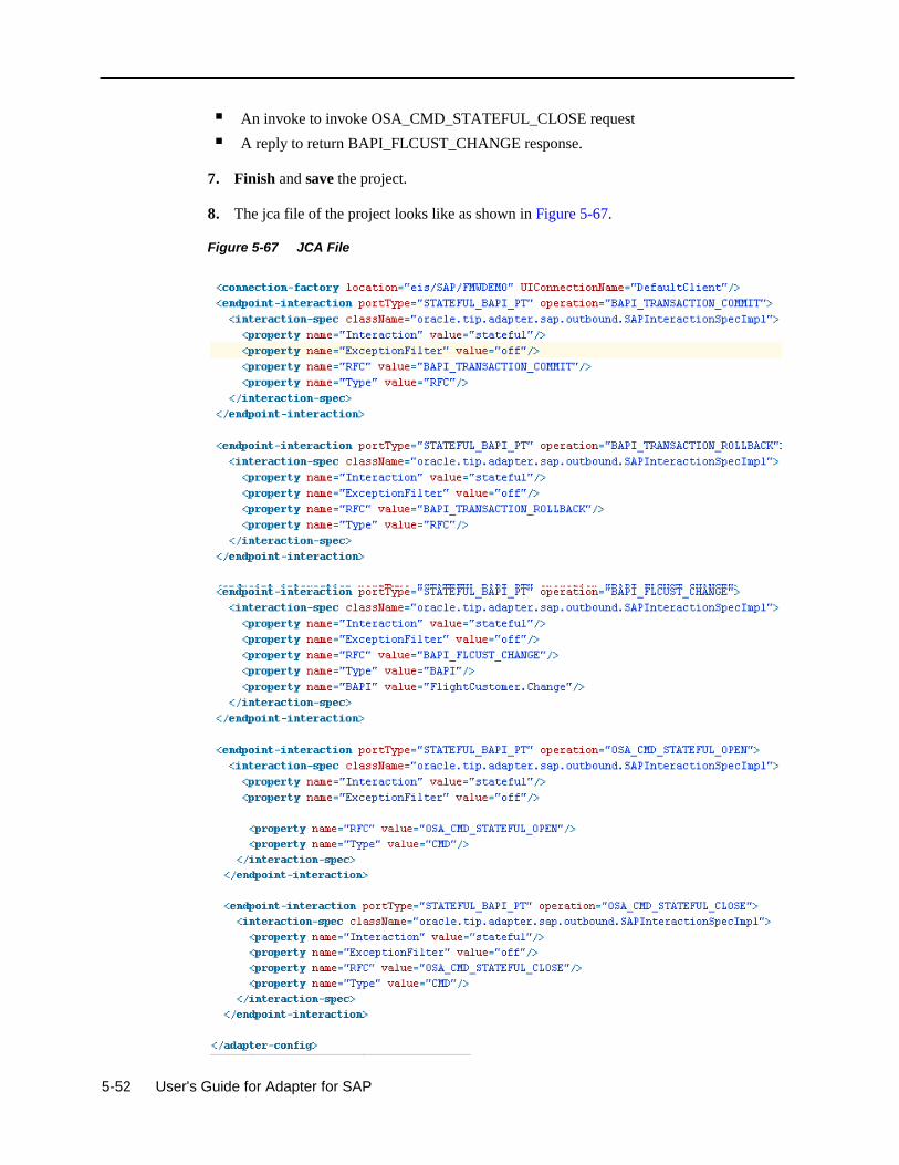
5-52 User's Guide for Adapter for SAP
An invoke to invoke OSA_CMD_STATEFUL_CLOSE request
A reply to return BAPI_FLCUST_CHANGE response.
7. Finish and save the project.
8. The jca file of the project looks like as shown in Figure 5-67.
Figure 5-67 JCA File
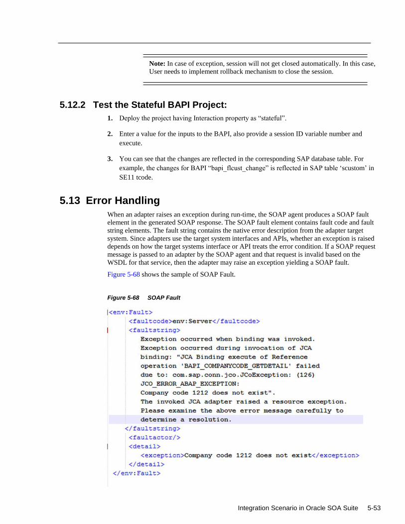
Integration Scenario in Oracle SOA Suite 5-53
Note: In case of exception, session will not get closed automatically. In this case,
User needs to implement rollback mechanism to close the session.
5.12.2 Test the Stateful BAPI Project:
1. Deploy the project having Interaction property as “stateful”.
2. Enter a value for the inputs to the BAPI, also provide a session ID variable number and
execute.
3. You can see that the changes are reflected in the corresponding SAP database table. For
example, the changes for BAPI “bapi_flcust_change” is reflected in SAP table ‘scustom’ in
SE11 tcode.
5.13 Error Handling
When an adapter raises an exception during run-time, the SOAP agent produces a SOAP fault
element in the generated SOAP response. The SOAP fault element contains fault code and fault
string elements. The fault string contains the native error description from the adapter target
system. Since adapters use the target system interfaces and APIs, whether an exception is raised
depends on how the target systems interface or API treats the error condition. If a SOAP request
message is passed to an adapter by the SOAP agent and that request is invalid based on the
WSDL for that service, then the adapter may raise an exception yielding a SOAP fault.
Figure 5-68 shows the sample of SOAP Fault.
Figure 5-68 SOAP Fault
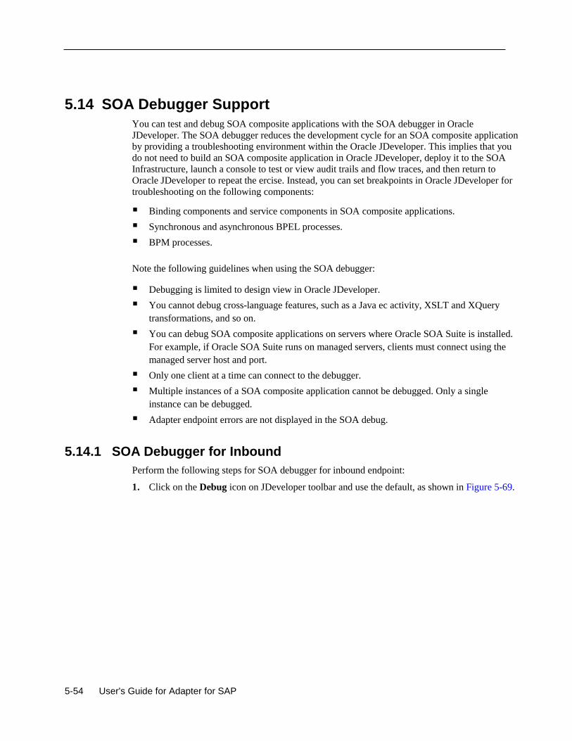
5-54 User's Guide for Adapter for SAP
5.14 SOA Debugger Support
You can test and debug SOA composite applications with the SOA debugger in Oracle
JDeveloper. The SOA debugger reduces the development cycle for an SOA composite application
by providing a troubleshooting environment within the Oracle JDeveloper. This implies that you
do not need to build an SOA composite application in Oracle JDeveloper, deploy it to the SOA
Infrastructure, launch a console to test or view audit trails and flow traces, and then return to
Oracle JDeveloper to repeat the ercise. Instead, you can set breakpoints in Oracle JDeveloper for
troubleshooting on the following components:
Binding components and service components in SOA composite applications.
Synchronous and asynchronous BPEL processes.
BPM processes.
Note the following guidelines when using the SOA debugger:
Debugging is limited to design view in Oracle JDeveloper.
You cannot debug cross-language features, such as a Java ec activity, XSLT and XQuery
transformations, and so on.
You can debug SOA composite applications on servers where Oracle SOA Suite is installed.
For example, if Oracle SOA Suite runs on managed servers, clients must connect using the
managed server host and port.
Only one client at a time can connect to the debugger.
Multiple instances of a SOA composite application cannot be debugged. Only a single
instance can be debugged.
Adapter endpoint errors are not displayed in the SOA debug.
5.14.1 SOA Debugger for Inbound
Perform the following steps for SOA debugger for inbound endpoint:
1. Click on the Debug icon on JDeveloper toolbar and use the default, as shown in Figure 5-69.
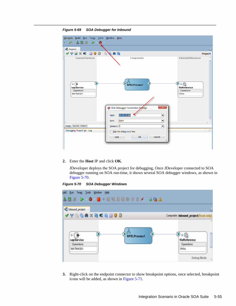
Integration Scenario in Oracle SOA Suite 5-55
Figure 5-69 SOA Debugger for Inbound
2. Enter the Host IP and click OK.
JDeveloper deploys the SOA project for debugging, Once JDeveloper connected to SOA
debugger running on SOA run-time, it shows several SOA debugger windows, as shown in
Figure 5-70.
Figure 5-70 SOA Debugger Windows
3. Right-click on the endpoint connector to show breakpoint options, once selected, breakpoint
icons will be added, as shown in Figure 5-71.
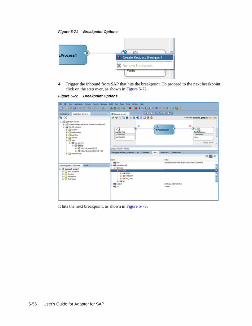
5-56 User's Guide for Adapter for SAP
Figure 5-71 Breakpoint Options
4. Trigger the inbound from SAP that hits the breakpoint. To proceed to the next breakpoint,
click on the step over, as shown in Figure 5-72.
Figure 5-72 Breakpoint Options
It hits the next breakpoint, as shown in Figure 5-73.
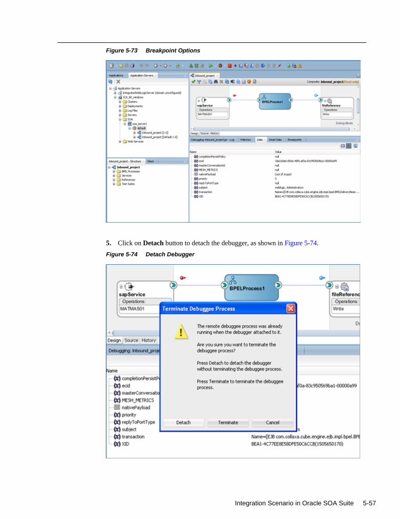
Integration Scenario in Oracle SOA Suite 5-57
Figure 5-73 Breakpoint Options
5. Click on Detach button to detach the debugger, as shown in Figure 5-74.
Figure 5-74 Detach Debugger
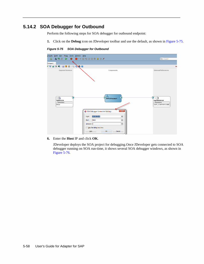
5-58 User's Guide for Adapter for SAP
5.14.2 SOA Debugger for Outbound
Perform the following steps for SOA debugger for outbound endpoint:
1. Click on the Debug icon on JDeveloper toolbar and use the default, as shown in Figure 5-75.
Figure 5-75 SOA Debugger for Outbound
6. Enter the Host IP and click OK.
JDeveloper deploys the SOA project for debugging.Once JDeveloper gets connected to SOA
debugger running on SOA run-time, it shows several SOA debugger windows, as shown in
Figure 5-76.
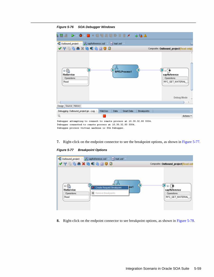
Integration Scenario in Oracle SOA Suite 5-59
Figure 5-76 SOA Debugger Windows
7. Right-click on the endpoint connector to see the breakpoint options, as shown in Figure 5-77.
Figure 5-77 Breakpoint Options
8. Right-click on the endpoint connector to see breakpoint options, as shown in Figure 5-78.
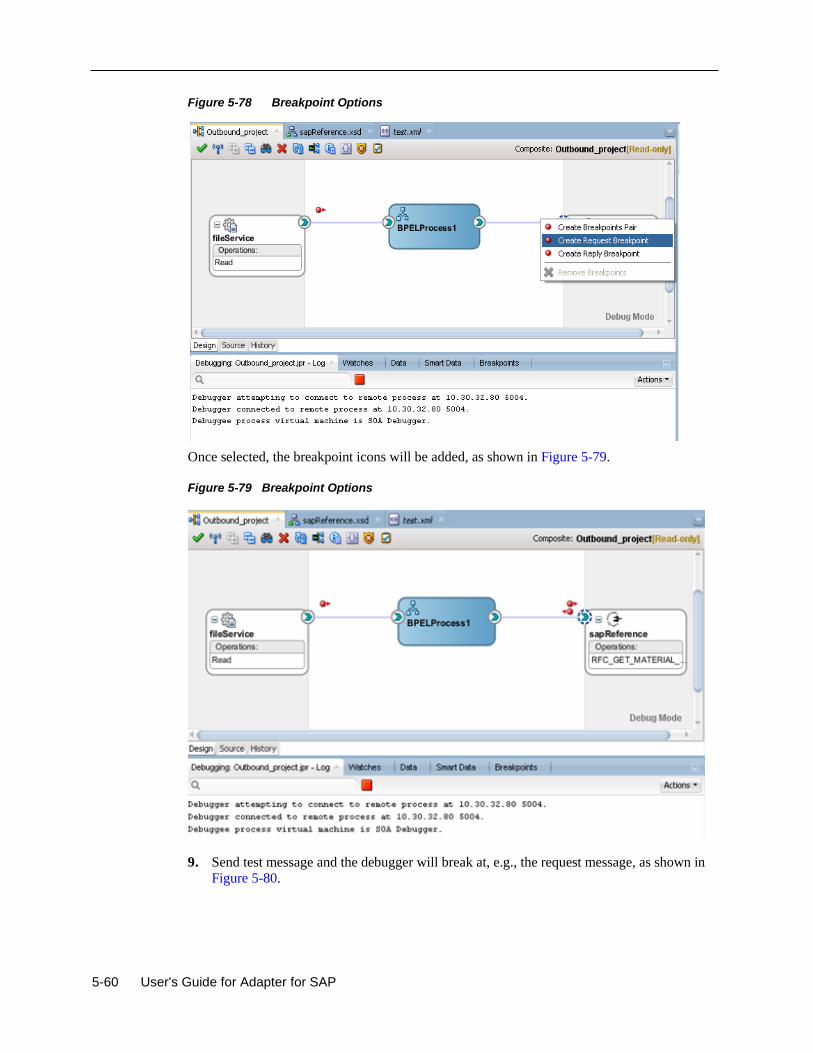
5-60 User's Guide for Adapter for SAP
Figure 5-78 Breakpoint Options
Once selected, the breakpoint icons will be added, as shown in Figure 5-79.
Figure 5-79 Breakpoint Options
9. Send test message and the debugger will break at, e.g., the request message, as shown in
Figure 5-80.
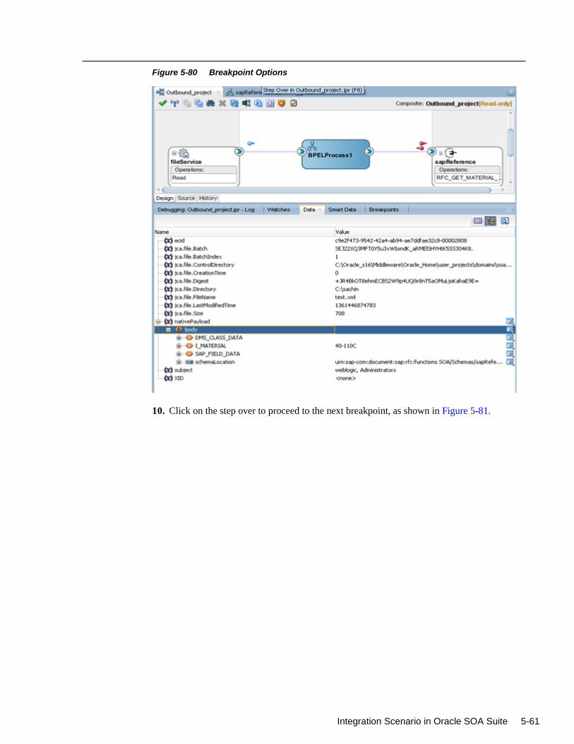
Integration Scenario in Oracle SOA Suite 5-61
Figure 5-80 Breakpoint Options
10. Click on the step over to proceed to the next breakpoint, as shown in Figure 5-81.
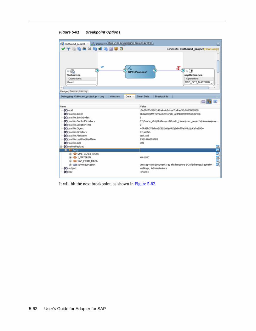
5-62 User's Guide for Adapter for SAP
Figure 5-81 Breakpoint Options
It will hit the next breakpoint, as shown in Figure 5-82.
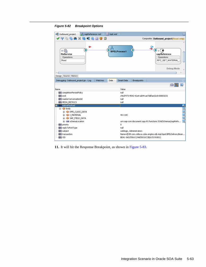
Integration Scenario in Oracle SOA Suite 5-63
Figure 5-82 Breakpoint Options
11. It will hit the Response Breakpoint, as shown in Figure 5-83.
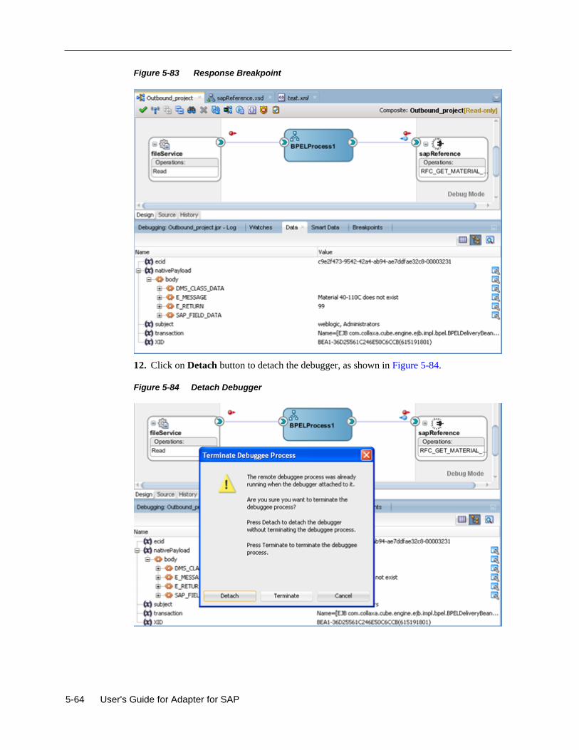
5-64 User's Guide for Adapter for SAP
Figure 5-83 Response Breakpoint
12. Click on Detach button to detach the debugger, as shown in Figure 5-84.
Figure 5-84 Detach Debugger
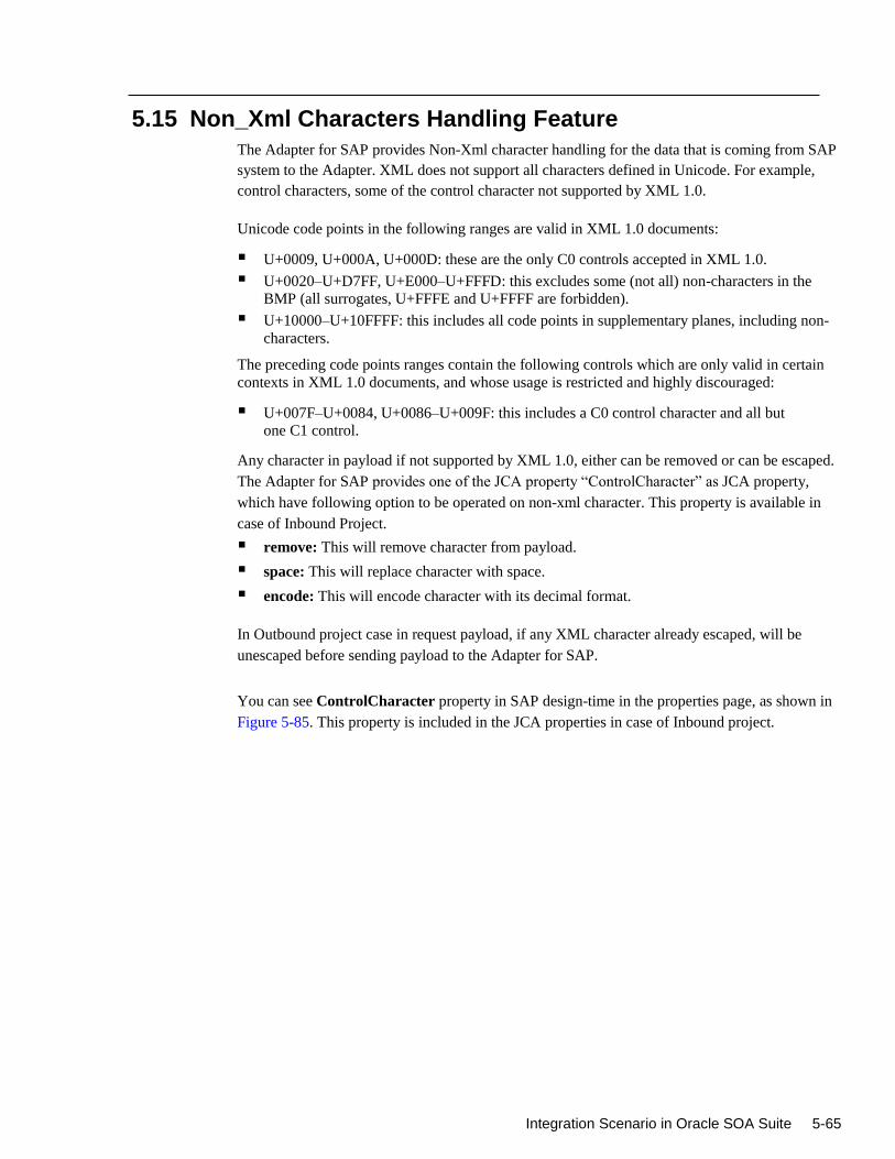
Integration Scenario in Oracle SOA Suite 5-65
5.15 Non_Xml Characters Handling Feature
The Adapter for SAP provides Non-Xml character handling for the data that is coming from SAP
system to the Adapter. XML does not support all characters defined in Unicode. For example,
control characters, some of the control character not supported by XML 1.0.
Unicode code points in the following ranges are valid in XML 1.0 documents:
U+0009, U+000A, U+000D: these are the only C0 controls accepted in XML 1.0.
U+0020–U+D7FF, U+E000–U+FFFD: this excludes some (not all) non-characters in the
BMP (all surrogates, U+FFFE and U+FFFF are forbidden).
U+10000–U+10FFFF: this includes all code points in supplementary planes, including non-
characters.
The preceding code points ranges contain the following controls which are only valid in certain
contexts in XML 1.0 documents, and whose usage is restricted and highly discouraged:
U+007F–U+0084, U+0086–U+009F: this includes a C0 control character and all but
one C1 control.
Any character in payload if not supported by XML 1.0, either can be removed or can be escaped.
The Adapter for SAP provides one of the JCA property “ControlCharacter” as JCA property,
which have following option to be operated on non-xml character. This property is available in
case of Inbound Project.
remove: This will remove character from payload.
space: This will replace character with space.
encode: This will encode character with its decimal format.
In Outbound project case in request payload, if any XML character already escaped, will be
unescaped before sending payload to the Adapter for SAP.
You can see ControlCharacter property in SAP design-time in the properties page, as shown in
Figure 5-85. This property is included in the JCA properties in case of Inbound project.
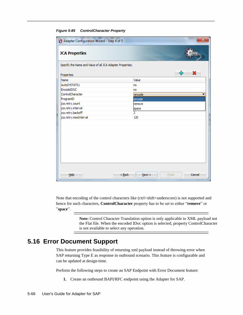
5-66 User's Guide for Adapter for SAP
Figure 5-85 ControlCharacter Property
Note that encoding of the control characters like (ctrl+shift+underscore) is not supported and
hence for such characters, ControlCharacter property has to be set to either “remove” or
”space”.
Note: Control Character Translation option is only applicable to XML payload not
the Flat file. When the encoded IDoc option is selected, property ControlCharacter
is not available to select any operation.
5.16 Error Document Support
This feature provides feasibility of returning xml payload instead of throwing error when
SAP returning Type E as response in outbound scenario. This feature is configurable and
can be updated at design-time.
Perform the following steps to create an SAP Endpoint with Error Document feature:
1. Create an outbound BAPI/RFC endpoint using the Adapter for SAP.
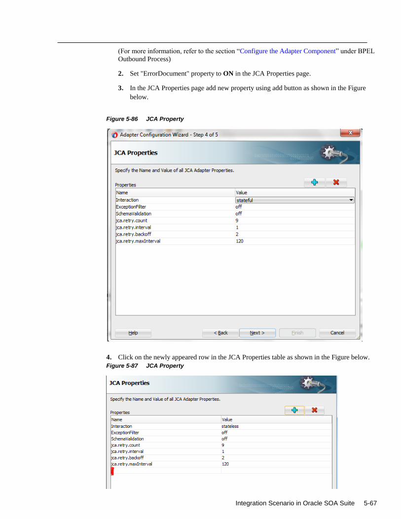
Integration Scenario in Oracle SOA Suite 5-67
(For more information, refer to the section “Configure the Adapter Component” under BPEL
Outbound Process)
2. Set "ErrorDocument" property to ON in the JCA Properties page.
3. In the JCA Properties page add new property using add button as shown in the Figure
below.
Figure 5-86 JCA Property
4. Click on the newly appeared row in the JCA Properties table as shown in the Figure below.
Figure 5-87 JCA Property
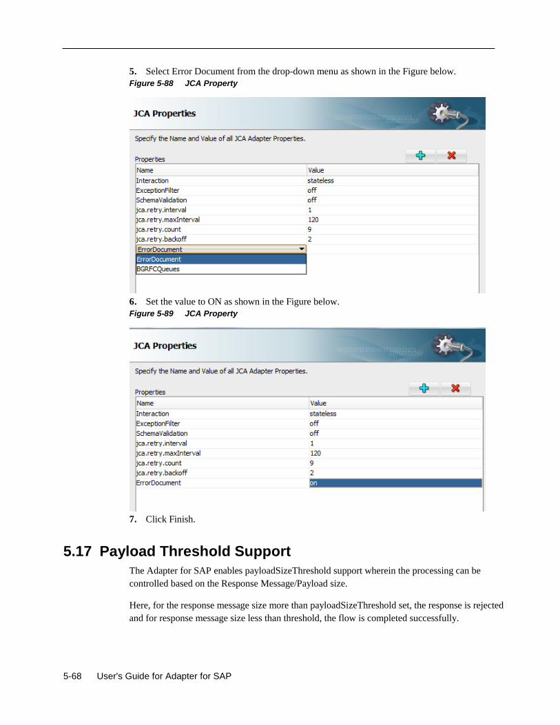
5-68 User's Guide for Adapter for SAP
5. Select Error Document from the drop-down menu as shown in the Figure below.
Figure 5-88 JCA Property
6. Set the value to ON as shown in the Figure below.
Figure 5-89 JCA Property
7. Click Finish.
5.17 Payload Threshold Support
The Adapter for SAP enables payloadSizeThreshold support wherein the processing can be
controlled based on the Response Message/Payload size.
Here, for the response message size more than payloadSizeThreshold set, the response is rejected
and for response message size less than threshold, the flow is completed successfully.
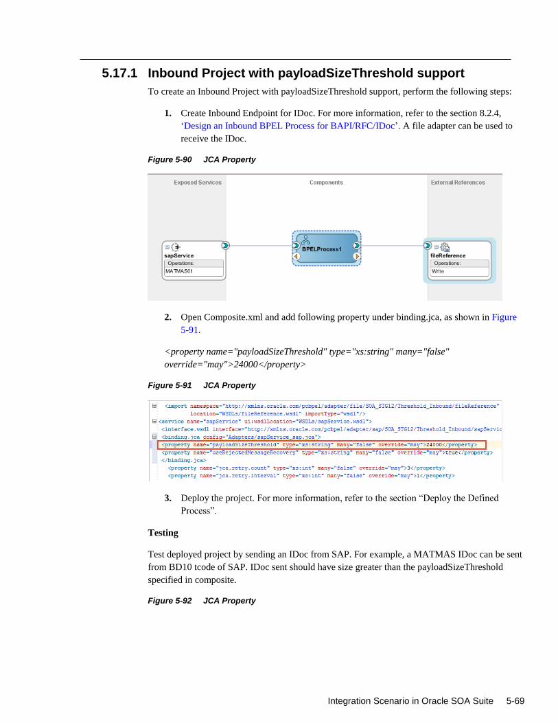
Integration Scenario in Oracle SOA Suite 5-69
5.17.1 Inbound Project with payloadSizeThreshold support
To create an Inbound Project with payloadSizeThreshold support, perform the following steps:
1. Create Inbound Endpoint for IDoc. For more information, refer to the section 8.2.4,
‘Design an Inbound BPEL Process for BAPI/RFC/IDoc’. A file adapter can be used to
receive the IDoc.
Figure 5-90 JCA Property
2. Open Composite.xml and add following property under binding.jca, as shown in Figure
5-91.
<property name="payloadSizeThreshold" type="xs:string" many="false"
override="may">24000</property>
Figure 5-91 JCA Property
3. Deploy the project. For more information, refer to the section “Deploy the Defined
Process”.
Testing
Test deployed project by sending an IDoc from SAP. For example, a MATMAS IDoc can be sent
from BD10 tcode of SAP. IDoc sent should have size greater than the payloadSizeThreshold
specified in composite.
Figure 5-92 JCA Property
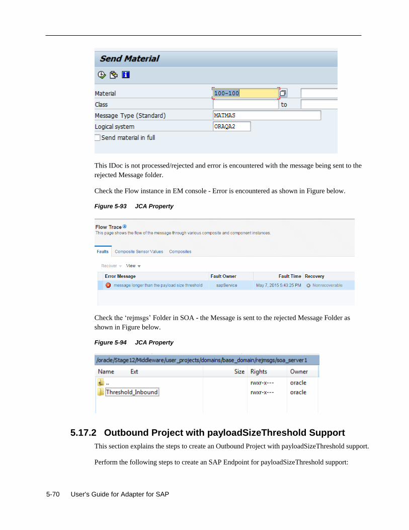
5-70 User's Guide for Adapter for SAP
This IDoc is not processed/rejected and error is encountered with the message being sent to the
rejected Message folder.
Check the Flow instance in EM console - Error is encountered as shown in Figure below.
Figure 5-93 JCA Property
Check the ‘rejmsgs’ Folder in SOA - the Message is sent to the rejected Message Folder as
shown in Figure below.
Figure 5-94 JCA Property
5.17.2 Outbound Project with payloadSizeThreshold Support
This section explains the steps to create an Outbound Project with payloadSizeThreshold support.
Perform the following steps to create an SAP Endpoint for payloadSizeThreshold support:
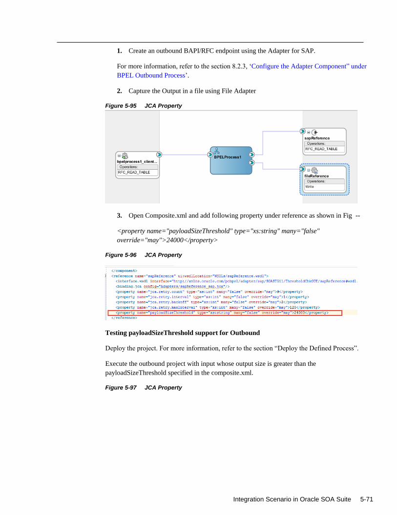
Integration Scenario in Oracle SOA Suite 5-71
1. Create an outbound BAPI/RFC endpoint using the Adapter for SAP.
For more information, refer to the section 8.2.3, ‘Configure the Adapter Component” under
BPEL Outbound Process’.
2. Capture the Output in a file using File Adapter
Figure 5-95 JCA Property
3. Open Composite.xml and add following property under reference as shown in Fig --
<property name="payloadSizeThreshold" type="xs:string" many="false"
override="may">24000</property>
Figure 5-96 JCA Property
Testing payloadSizeThreshold support for Outbound
Deploy the project. For more information, refer to the section “Deploy the Defined Process”.
Execute the outbound project with input whose output size is greater than the
payloadSizeThreshold specified in the composite.xml.
Figure 5-97 JCA Property
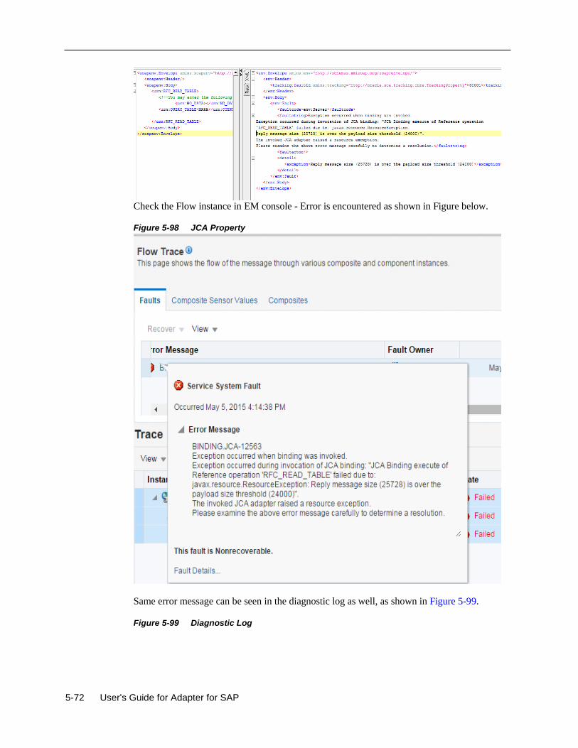
5-72 User's Guide for Adapter for SAP
Check the Flow instance in EM console - Error is encountered as shown in Figure below.
Figure 5-98 JCA Property
Same error message can be seen in the diagnostic log as well, as shown in Figure 5-99.
Figure 5-99 Diagnostic Log
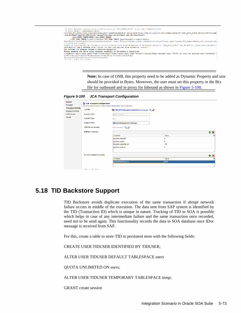
Integration Scenario in Oracle SOA Suite 5-73
Note: In case of OSB, this property need to be added as Dynamic Property and size
should be provided in Bytes. Moreover, the user must set this property in the Bix
file for outbound and in proxy for Inbound as shown in Figure 5-100.
Figure 5-100 JCA Transport Configuration
5.18 TID Backstore Support
TID Backstore avoids duplicate execution of the same transaction if abrupt network
failure occurs in middle of the execution. The data sent from SAP system is identified by
the TID (Transaction ID) which is unique in nature. Tracking of TID in SOA is possible
which helps in case of any intermediate failure and the same transaction once recorded,
need not to be send again. This functionality records the data in SOA database once IDoc
message is received from SAP.
For this, create a table to store TID in persistent store with the following fields:
CREATE USER TIDUSER IDENTIFIED BY TIDUSER;
ALTER USER TIDUSER DEFAULT TABLESPACE users
QUOTA UNLIMITED ON users;
ALTER USER TIDUSER TEMPORARY TABLESPACE temp;
GRANT create session
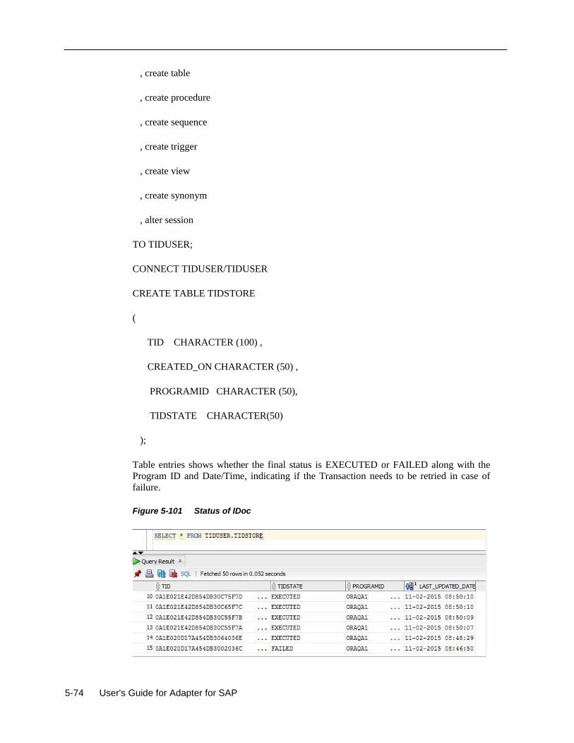
5-74 User's Guide for Adapter for SAP
, create table
, create procedure
, create sequence
, create trigger
, create view
, create synonym
, alter session
TO TIDUSER;
CONNECT TIDUSER/TIDUSER
CREATE TABLE TIDSTORE
(
TID CHARACTER (100) ,
CREATED_ON CHARACTER (50) ,
PROGRAMID CHARACTER (50),
TIDSTATE CHARACTER(50)
);
Table entries shows whether the final status is EXECUTED or FAILED along with the
Program ID and Date/Time, indicating if the Transaction needs to be retried in case of
failure.
Figure 5-101 Status of IDoc
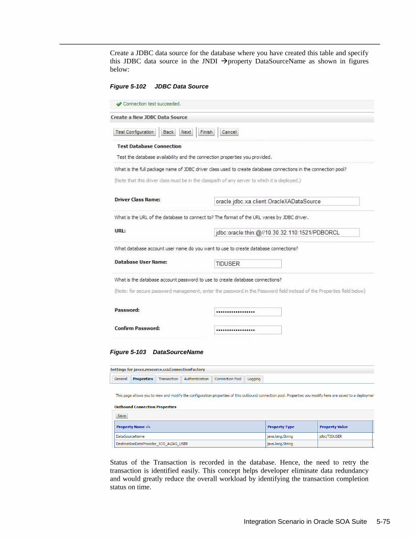
Integration Scenario in Oracle SOA Suite 5-75
Create a JDBC data source for the database where you have created this table and specify
this JDBC data source in the JNDI property DataSourceName as shown in figures
below:
Figure 5-102 JDBC Data Source
Figure 5-103 DataSourceName
Status of the Transaction is recorded in the database. Hence, the need to retry the
transaction is identified easily. This concept helps developer eliminate data redundancy
and would greatly reduce the overall workload by identifying the transaction completion
status on time.
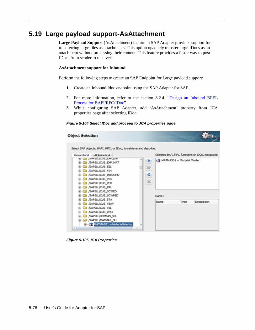
5-76 User's Guide for Adapter for SAP
5.19 Large payload support-AsAttachment
Large Payload Support (AsAttachment) feature in SAP Adapter provides support for
transferring large files as attachments. This option opaquely transfer large IDocs as an
attachment without processing their content. This feature provides a faster way to post
IDocs from sender to receiver.
AsAttachment support for Inbound
Perform the following steps to create an SAP Endpoint for Large payload support:
1. Create an Inbound Idoc endpoint using the SAP Adapter for SAP.
2. For more information, refer to the section 8.2.4, “Design an Inbound BPEL
Process for BAPI/RFC/IDoc”.
3. While configuring SAP Adapter, add ‘AsAttachment’ property from JCA
properties page after selecting IDoc.
Figure 5-104 Select IDoc and proceed to JCA properties page
Figure 5-105 JCA Properties
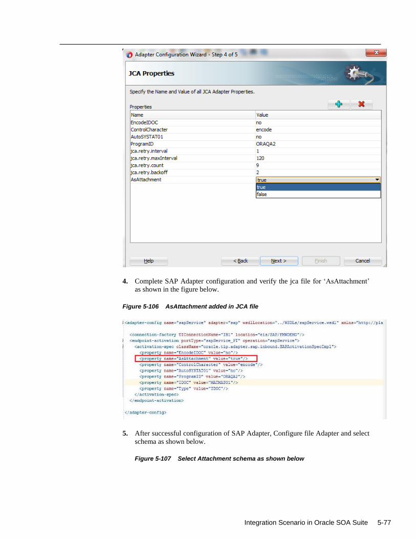
Integration Scenario in Oracle SOA Suite 5-77
4. Complete SAP Adapter configuration and verify the jca file for ‘AsAttachment’
as shown in the figure below.
Figure 5-106 AsAttachment added in JCA file
5. After successful configuration of SAP Adapter, Configure file Adapter and select
schema as shown below.
Figure 5-107 Select Attachment schema as shown below
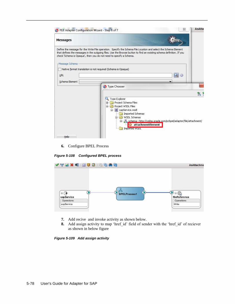
5-78 User's Guide for Adapter for SAP
6. Configure BPEL Process
Figure 5-108 Configured BPEL process
7. Add recive and invoke activity as shown below.
8. Add assign activity to map ‘href_id’ field of sender with the ‘href_id’ of reciever
as shown in below figure
Figure 5-109 Add assign activity
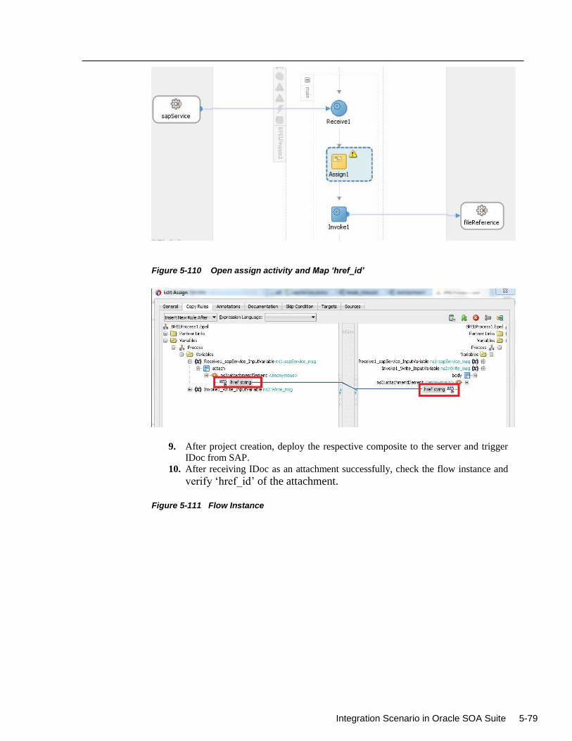
Integration Scenario in Oracle SOA Suite 5-79
Figure 5-110 Open assign activity and Map ‘href_id’
9. After project creation, deploy the respective composite to the server and trigger
IDoc from SAP.
10. After receiving IDoc as an attachment successfully, check the flow instance and
verify ‘href_id’ of the attachment.
Figure 5-111 Flow Instance
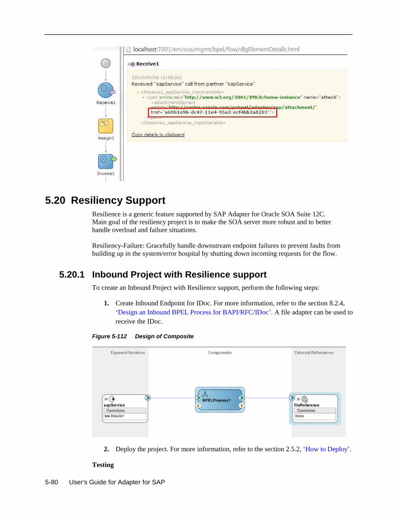
5-80 User's Guide for Adapter for SAP
5.20 Resiliency Support
Resilience is a generic feature supported by SAP Adapter for Oracle SOA Suite 12C.
Main goal of the resiliency project is to make the SOA server more robust and to better
handle overload and failure situations.
Resiliency-Failure: Gracefully handle downstream endpoint failures to prevent faults from
building up in the system/error hospital by shutting down incoming requests for the flow.
5.20.1 Inbound Project with Resilience support
To create an Inbound Project with Resilience support, perform the following steps:
1. Create Inbound Endpoint for IDoc. For more information, refer to the section 8.2.4,
‘Design an Inbound BPEL Process for BAPI/RFC/IDoc’. A file adapter can be used to
receive the IDoc.
Figure 5-112 Design of Composite
2. Deploy the project. For more information, refer to the section 2.5.2, ‘How to Deploy’.
Testing
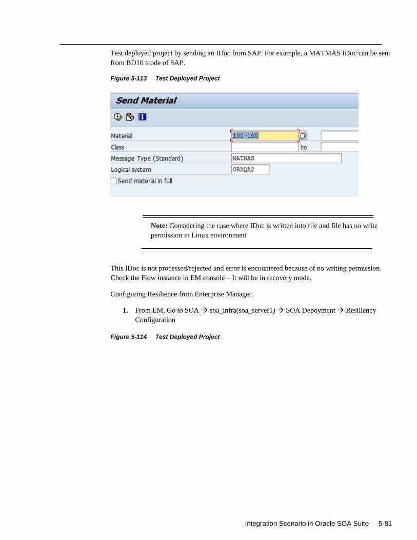
Integration Scenario in Oracle SOA Suite 5-81
Test deployed project by sending an IDoc from SAP. For example, a MATMAS IDoc can be sent
from BD10 tcode of SAP.
Figure 5-113 Test Deployed Project
Note: Considering the case where IDoc is written into file and file has no write
permission in Linux environment
This IDoc is not processed/rejected and error is encountered because of no writing permission.
Check the Flow instance in EM console – It will be in recovery mode.
Configuring Resilience from Enterprise Manager.
1. From EM, Go to SOA soa_infra(soa_server1) SOA Depoyment Resiliency
Configuration
Figure 5-114 Test Deployed Project
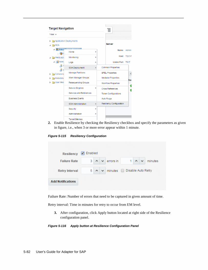
5-82 User's Guide for Adapter for SAP
2. Enable Resilience by checking the Resiliency checkbox and specify the parameters as given
in figure, i.e., when 3 or more error appear within 1 minute.
Figure 5-115 Resiliency Configuration
Failure Rate: Number of errors that need to be captured in given amount of time.
Retry interval: Time in minutes for retry to occur from EM level.
3. After configuration, click Apply button located at right side of the Resilience
configuration panel.
Figure 5-116 Apply button at Resilience Configuration Panel
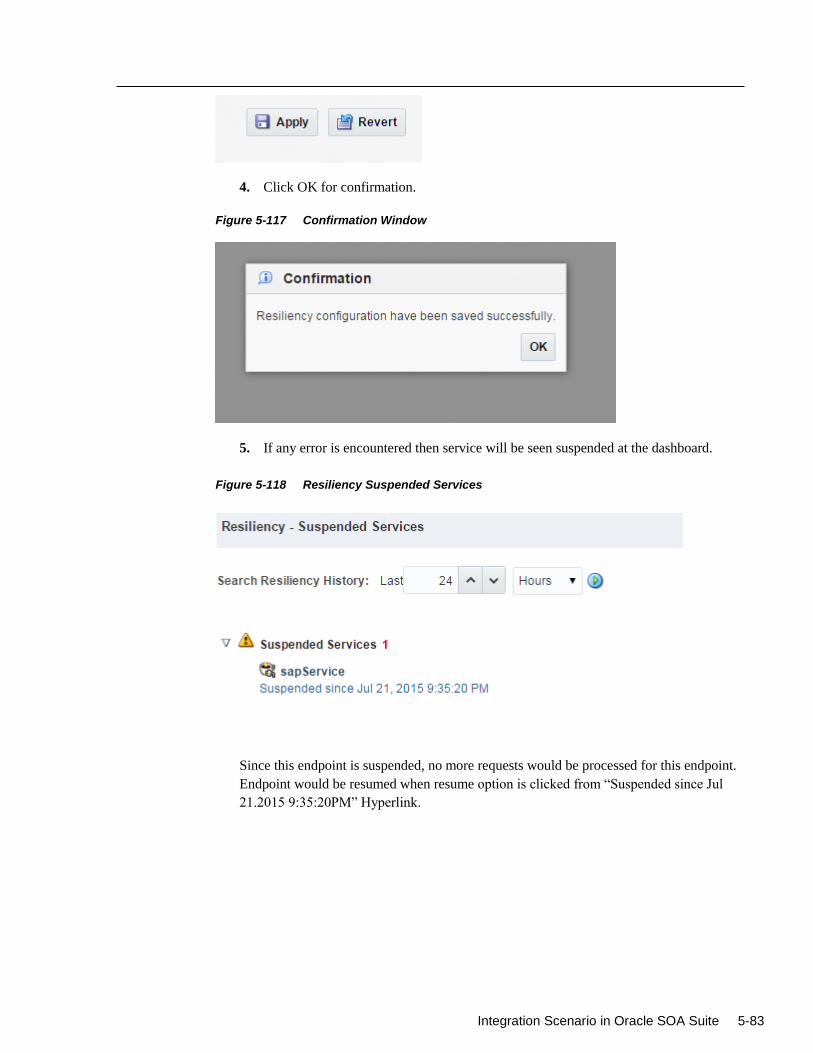
Integration Scenario in Oracle SOA Suite 5-83
4. Click OK for confirmation.
Figure 5-117 Confirmation Window
5. If any error is encountered then service will be seen suspended at the dashboard.
Figure 5-118 Resiliency Suspended Services
Since this endpoint is suspended, no more requests would be processed for this endpoint.
Endpoint would be resumed when resume option is clicked from “Suspended since Jul
21.2015 9:35:20PM” Hyperlink.
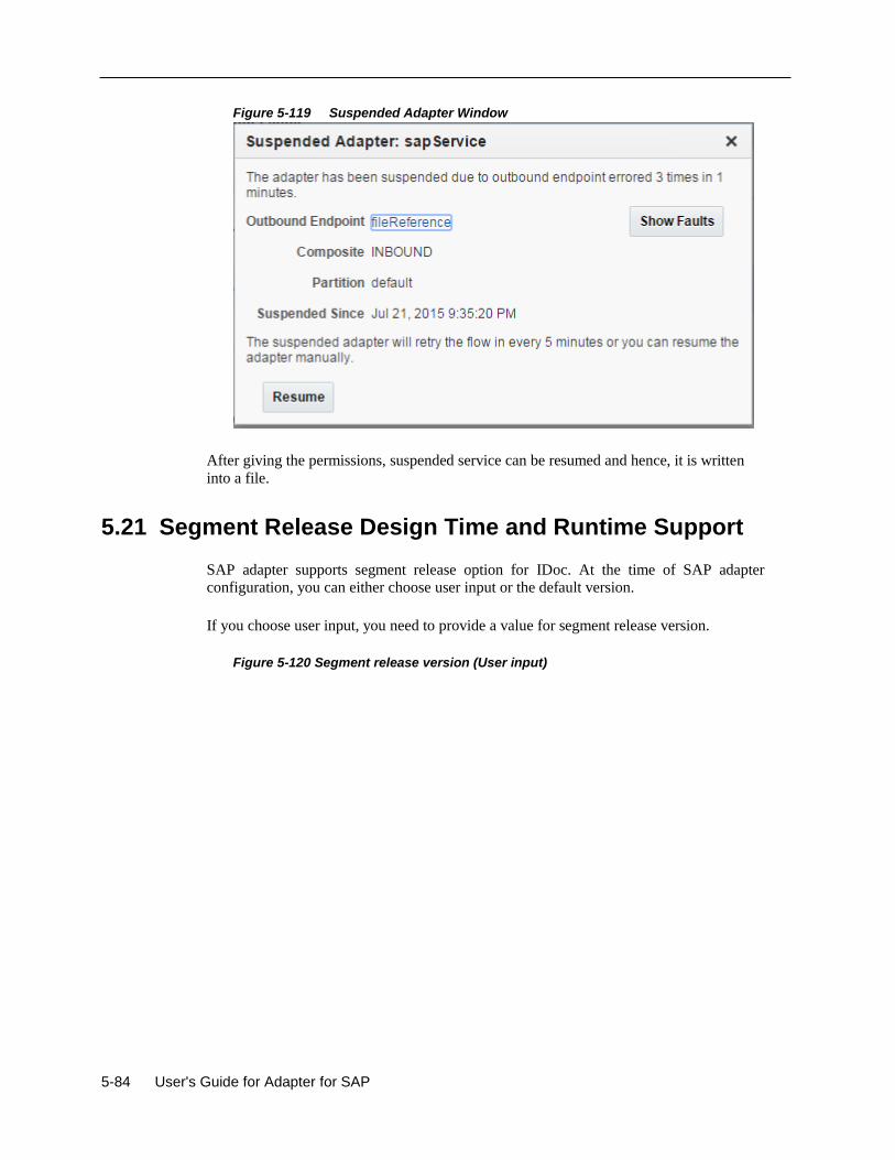
5-84 User's Guide for Adapter for SAP
Figure 5-119 Suspended Adapter Window
After giving the permissions, suspended service can be resumed and hence, it is written
into a file.
5.21 Segment Release Design Time and Runtime Support
SAP adapter supports segment release option for IDoc. At the time of SAP adapter
configuration, you can either choose user input or the default version.
If you choose user input, you need to provide a value for segment release version.
Figure 5-120 Segment release version (User input)
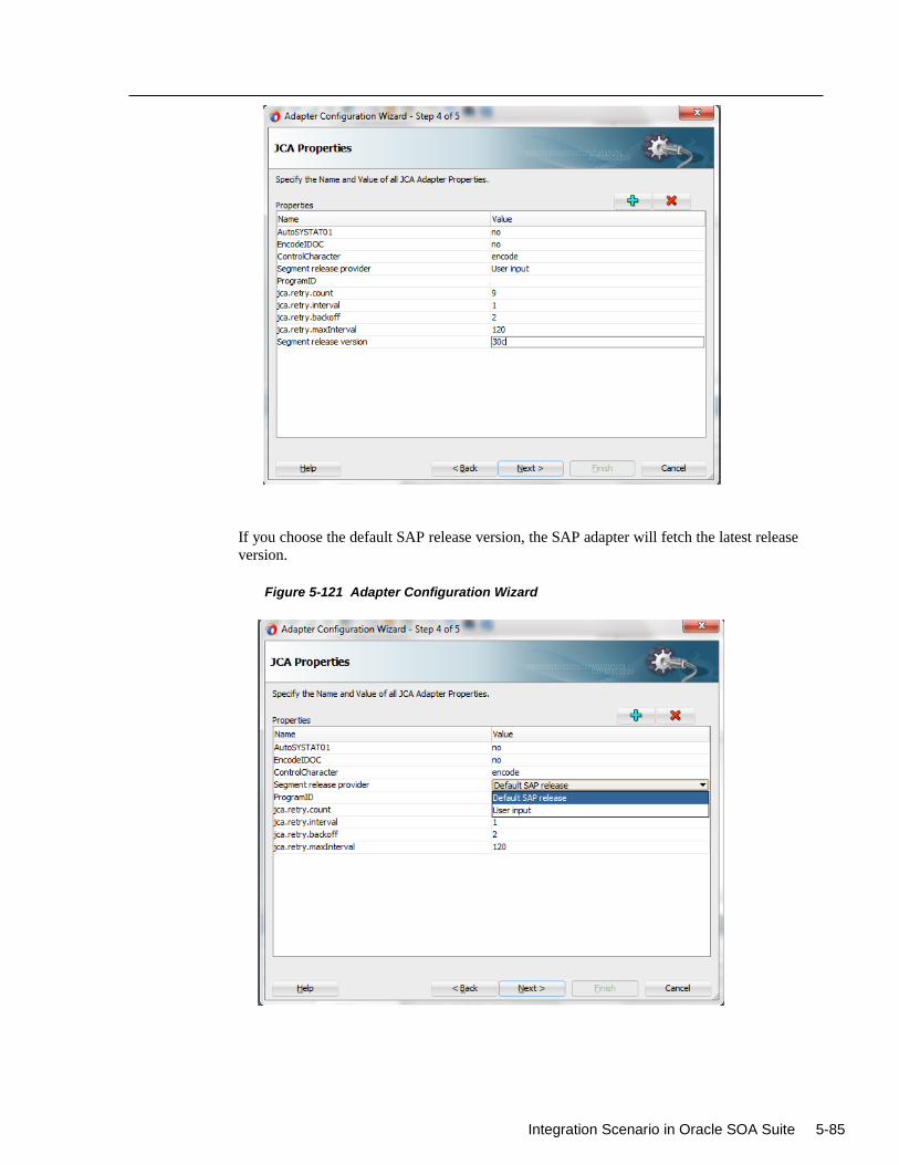
Integration Scenario in Oracle SOA Suite 5-85
If you choose the default SAP release version, the SAP adapter will fetch the latest release
version.
Figure 5-121 Adapter Configuration Wizard

5-86 User's Guide for Adapter for SAP
5.22 Special Character Support for Inbound IDoc
Previous release of the SAP Adapter had support only for few set of html characters. In this release
SAP adapter supports valid as well as invalid characters, which include special characters emoji's
and all HTML characters in ASCII format.
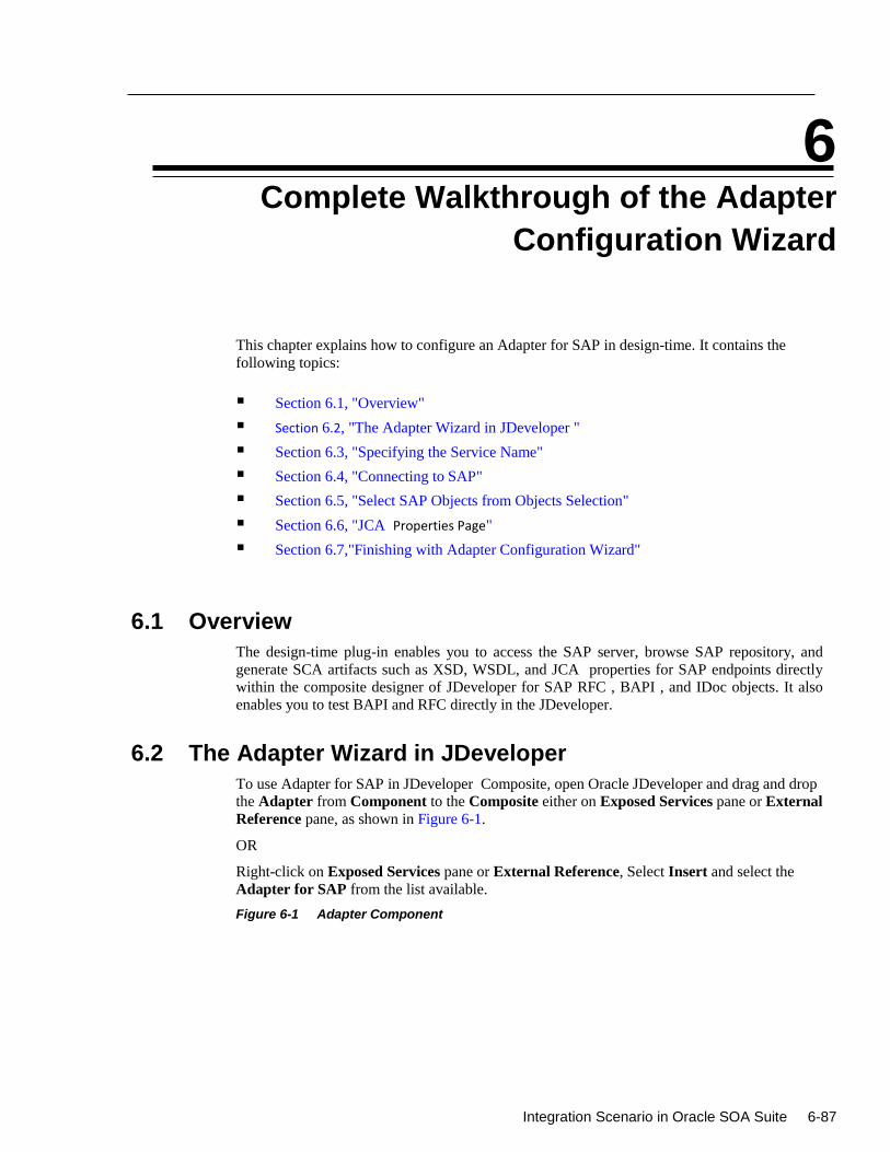
Integration Scenario in Oracle SOA Suite 6-87
6
Complete Walkthrough of the Adapter
Configuration Wizard
This chapter explains how to configure an Adapter for SAP in design-time. It contains the
following topics:
Section 6.1, "Overview"
Section 6.2, "The Adapter Wizard in JDeveloper "
Section 6.3, "Specifying the Service Name"
Section 6.4, "Connecting to SAP"
Section 6.5, "Select SAP Objects from Objects Selection"
Section 6.6, "JCA Properties Page"
Section 6.7,"Finishing with Adapter Configuration Wizard"
6.1 Overview
The design-time plug-in enables you to access the SAP server, browse SAP repository, and
generate SCA artifacts such as XSD, WSDL, and JCA properties for SAP endpoints directly
within the composite designer of JDeveloper for SAP RFC , BAPI , and IDoc objects. It also
enables you to test BAPI and RFC directly in the JDeveloper.
6.2 The Adapter Wizard in JDeveloper
To use Adapter for SAP in JDeveloper Composite, open Oracle JDeveloper and drag and drop
the Adapter from Component to the Composite either on Exposed Services pane or External
Reference pane, as shown in Figure 6-1.
OR
Right-click on Exposed Services pane or External Reference, Select Insert and select the
Adapter for SAP from the list available.
Figure 6-1 Adapter Component
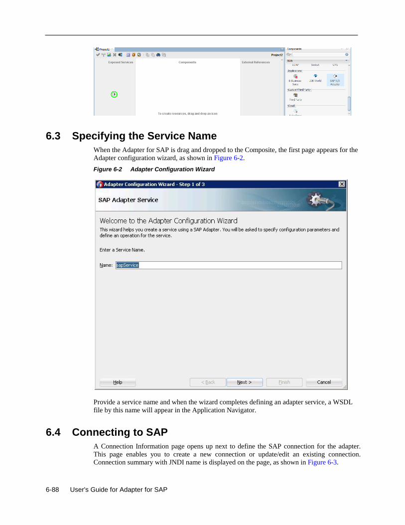
6-88 User's Guide for Adapter for SAP
6.3 Specifying the Service Name
When the Adapter for SAP is drag and dropped to the Composite, the first page appears for the
Adapter configuration wizard, as shown in Figure 6-2.
Figure 6-2 Adapter Configuration Wizard
Provide a service name and when the wizard completes defining an adapter service, a WSDL
file by this name will appear in the Application Navigator.
6.4 Connecting to SAP
A Connection Information page opens up next to define the SAP connection for the adapter.
This page enables you to create a new connection or update/edit an existing connection. Connection summary with JNDI name is displayed on the page, as shown in Figure 6-3.
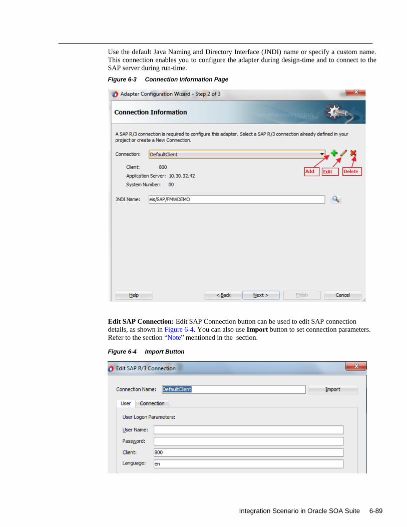
Integration Scenario in Oracle SOA Suite 6-89
Use the default Java Naming and Directory Interface (JNDI) name or specify a custom name.
This connection enables you to configure the adapter during design-time and to connect to the
SAP server during run-time.
Figure 6-3 Connection Information Page
Edit SAP Connection: Edit SAP Connection button can be used to edit SAP connection
details, as shown in Figure 6-4. You can also use Import button to set connection parameters.
Refer to the section “Note” mentioned in the section.
Figure 6-4 Import Button
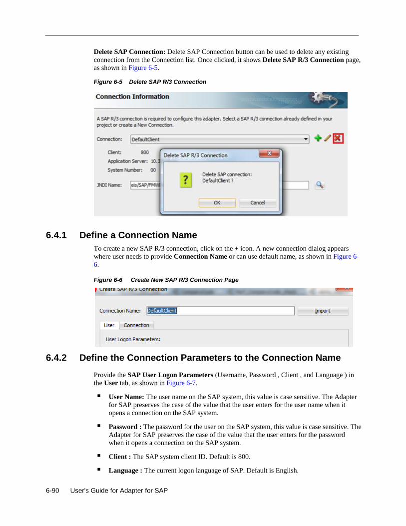
6-90 User's Guide for Adapter for SAP
Delete SAP Connection: Delete SAP Connection button can be used to delete any existing
connection from the Connection list. Once clicked, it shows Delete SAP R/3 Connection page,
as shown in Figure 6-5.
Figure 6-5 Delete SAP R/3 Connection
6.4.1 Define a Connection Name
To create a new SAP R/3 connection, click on the + icon. A new connection dialog appears
where user needs to provide Connection Name or can use default name, as shown in Figure 6-
6.
Figure 6-6 Create New SAP R/3 Connection Page
6.4.2 Define the Connection Parameters to the Connection Name
Provide the SAP User Logon Parameters (Username, Password , Client , and Language ) in
the User tab, as shown in Figure 6-7.
User Name: The user name on the SAP system, this value is case sensitive. The Adapter
for SAP preserves the case of the value that the user enters for the user name when it
opens a connection on the SAP system.
Password : The password for the user on the SAP system, this value is case sensitive. The
Adapter for SAP preserves the case of the value that the user enters for the password
when it opens a connection on the SAP system.
Client : The SAP system client ID. Default is 800.
Language : The current logon language of SAP. Default is English.
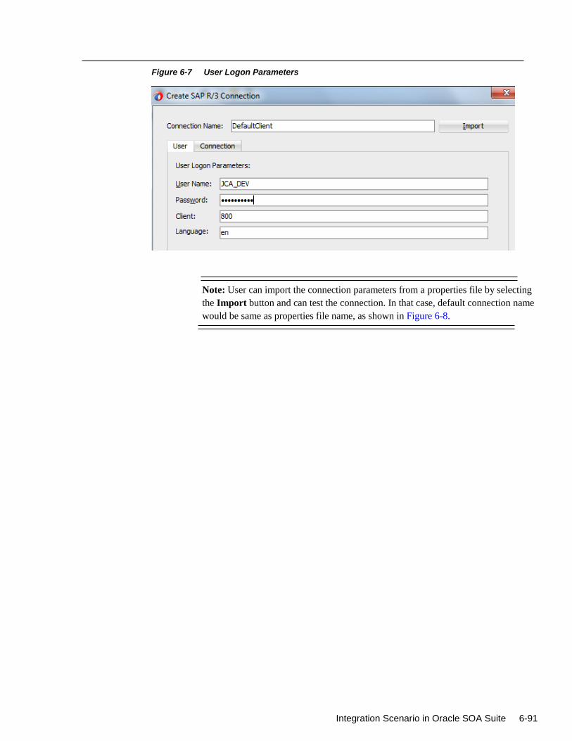
Integration Scenario in Oracle SOA Suite 6-91
Figure 6-7 User Logon Parameters
Note: User can import the connection parameters from a properties file by selecting
the Import button and can test the connection. In that case, default connection name
would be same as properties file name, as shown in Figure 6-8.
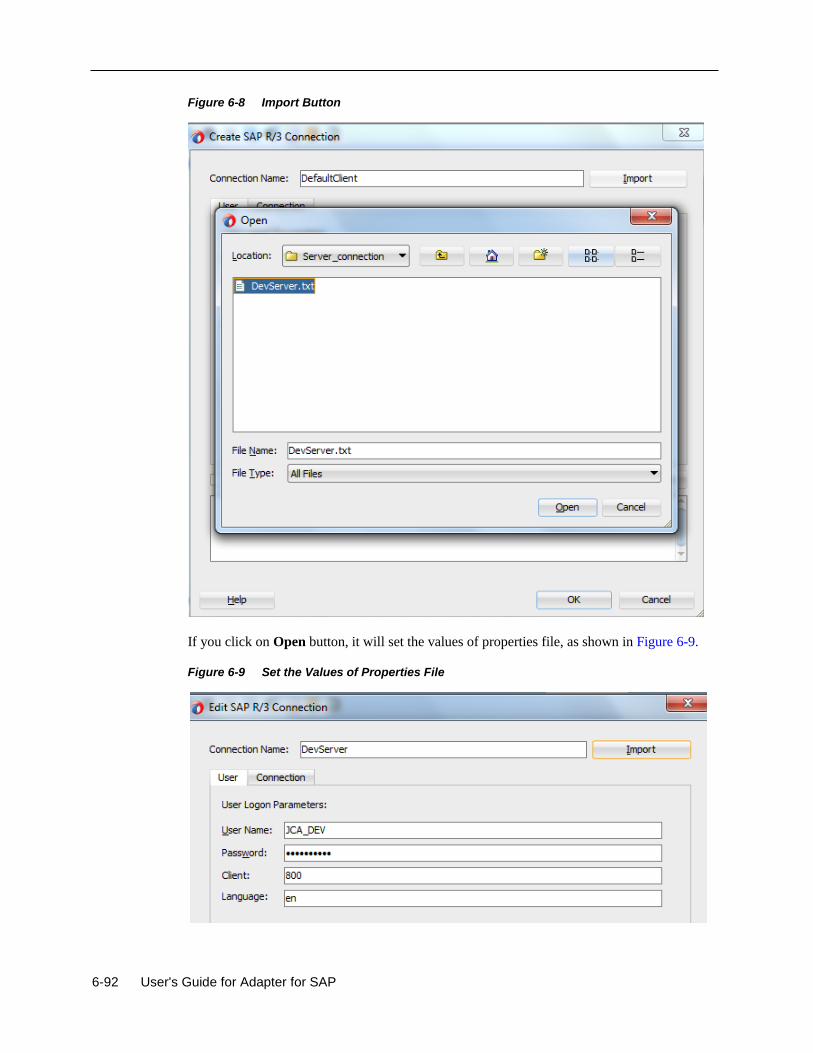
6-92 User's Guide for Adapter for SAP
Figure 6-8 Import Button
If you click on Open button, it will set the values of properties file, as shown in Figure 6-9.
Figure 6-9 Set the Values of Properties File
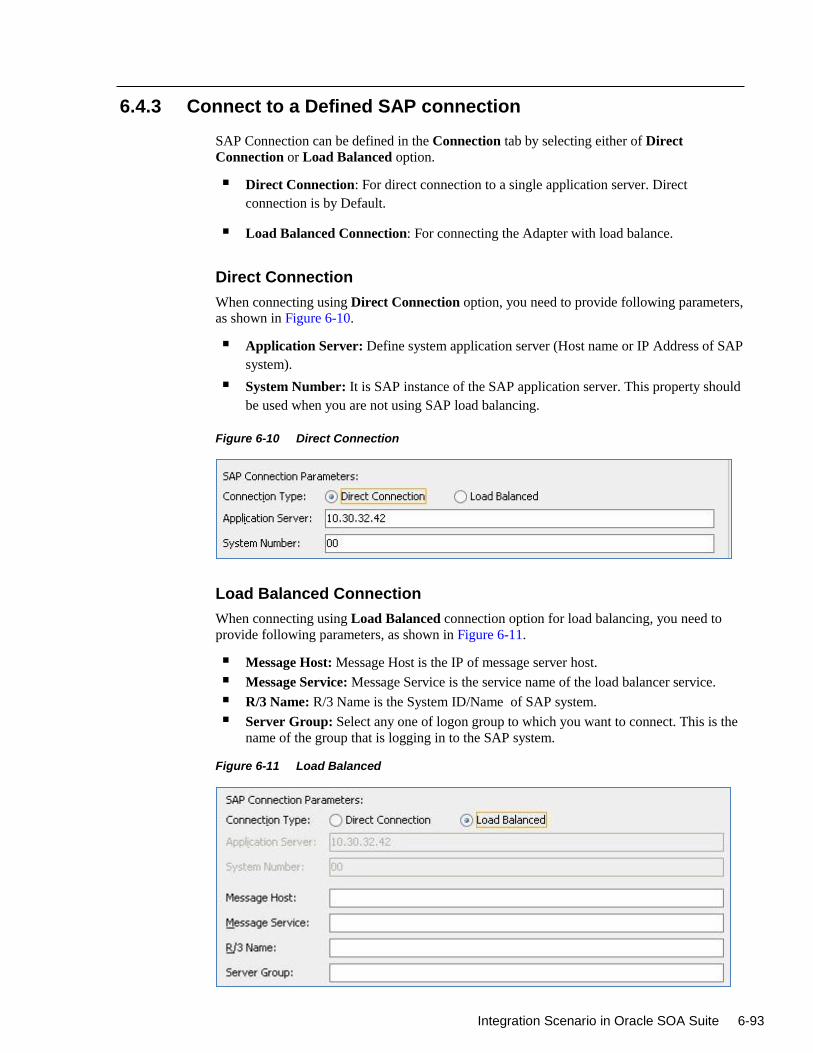
Integration Scenario in Oracle SOA Suite 6-93
6.4.3 Connect to a Defined SAP connection
SAP Connection can be defined in the Connection tab by selecting either of Direct
Connection or Load Balanced option.
Direct Connection: For direct connection to a single application server. Direct
connection is by Default.
Load Balanced Connection: For connecting the Adapter with load balance.
Direct Connection
When connecting using Direct Connection option, you need to provide following parameters,
as shown in Figure 6-10.
Application Server: Define system application server (Host name or IP Address of SAP
system).
System Number: It is SAP instance of the SAP application server. This property should
be used when you are not using SAP load balancing.
Figure 6-10 Direct Connection
Load Balanced Connection
When connecting using Load Balanced connection option for load balancing, you need to
provide following parameters, as shown in Figure 6-11.
Message Host: Message Host is the IP of message server host.
Message Service: Message Service is the service name of the load balancer service.
R/3 Name: R/3 Name is the System ID/Name of SAP system.
Server Group: Select any one of logon group to which you want to connect. This is the
name of the group that is logging in to the SAP system.
Figure 6-11 Load Balanced
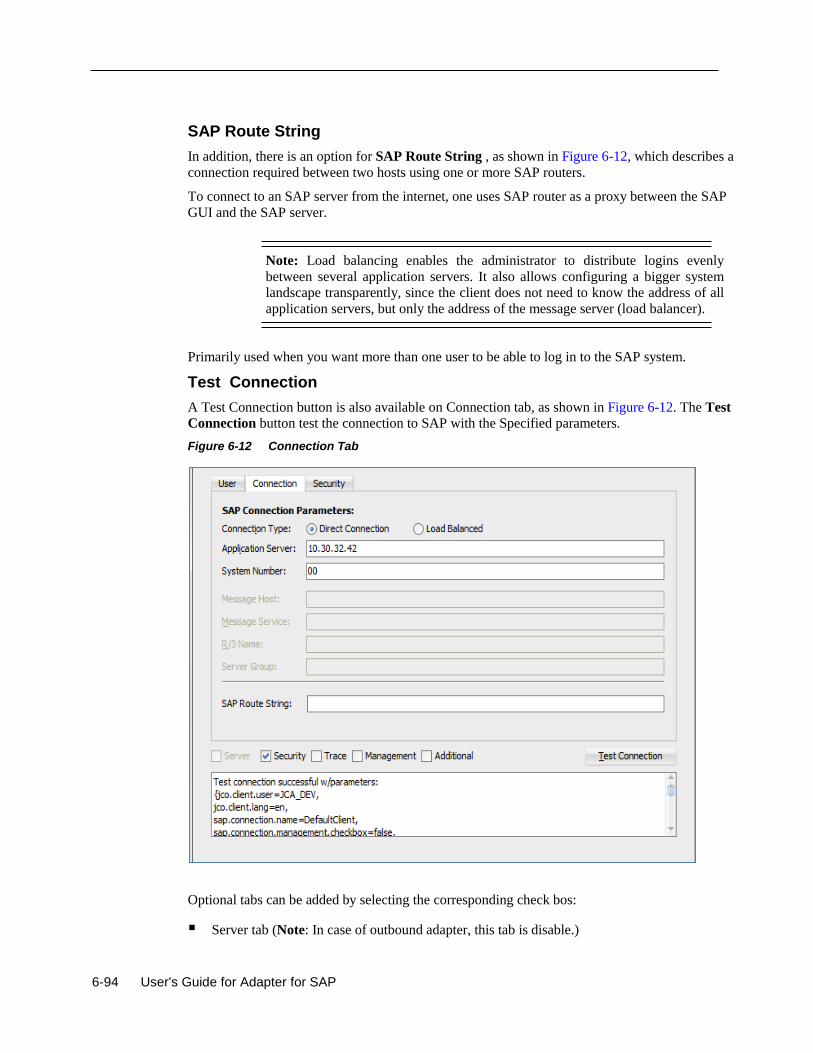
6-94 User's Guide for Adapter for SAP
SAP Route String
In addition, there is an option for SAP Route String , as shown in Figure 6-12, which describes a
connection required between two hosts using one or more SAP routers.
To connect to an SAP server from the internet, one uses SAP router as a proxy between the SAP
GUI and the SAP server.
Note: Load balancing enables the administrator to distribute logins evenly
between several application servers. It also allows configuring a bigger system
landscape transparently, since the client does not need to know the address of all
application servers, but only the address of the message server (load balancer).
Primarily used when you want more than one user to be able to log in to the SAP system.
Test Connection
A Test Connection button is also available on Connection tab, as shown in Figure 6-12. The Test
Connection button test the connection to SAP with the Specified parameters.
Figure 6-12 Connection Tab
Optional tabs can be added by selecting the corresponding check bos:
Server tab (Note: In case of outbound adapter, this tab is disable.)
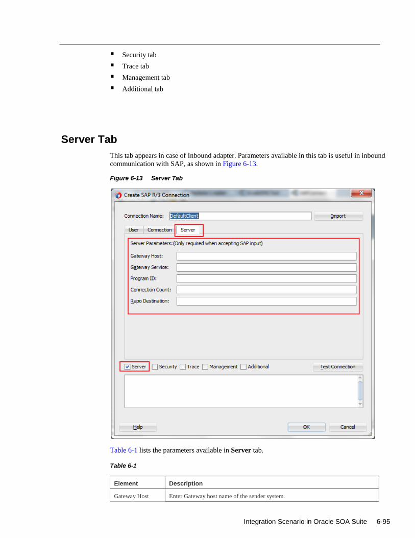
Integration Scenario in Oracle SOA Suite 6-95
Security tab
Trace tab
Management tab
Additional tab
Server Tab
This tab appears in case of Inbound adapter. Parameters available in this tab is useful in inbound
communication with SAP, as shown in Figure 6-13.
Figure 6-13 Server Tab
Table 6-1 lists the parameters available in Server tab.
Table 6-1
Element Description
Gateway Host Enter Gateway host name of the sender system.
6-96 User's Guide for Adapter for SAP
Gateway Service Gateway service of the sender system. This can be the numeric description of the
service port in the sender system or the alphanumeric equivalent (e.g., sapgwXX,
where XX is the system number of the sender system).
Program ID Program ID of the registered server program in SAP. The selected program ID must
uniquely describe the RFC sender channel in the configured gateway (Application
Server (Gateway) and Application Server Service (Gateway) parameters).
Connection Count Number of initial connections required between sender system and adapter.
Repo Destination The repository used by the server to lookup the definitions of an incoming function
call.
Note: The server tab is not supported in the current release.This will be
implemented for future releases.
Trace Tab
Trace Parameters (Optional)
To change the logging level of SAP JCo using following parameters, specify trace level based
on JCo level or individual level like RFC Trace Level, CPIC Trace Level or Server Trace
Level, as shown in Figure 6-14.
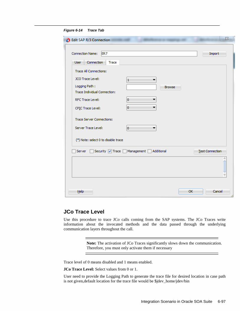
Integration Scenario in Oracle SOA Suite 6-97
Figure 6-14 Trace Tab
JCo Trace Level
Use this procedure to trace JCo calls coming from the SAP systems. The JCo Traces write
information about the invocated methods and the data passed through the underlying
communication layers throughout the call.
Note: The activation of JCo Traces significantly slows down the communication.
Therefore, you must only activate them if necessary
Trace level of 0 means disabled and 1 means enabled.
JCo Trace Level: Select values from 0 or 1.
User need to provide the Logging Path to generate the trace file for desired location in case path
is not given,default location for the trace file would be $jdev_home/jdev/bin
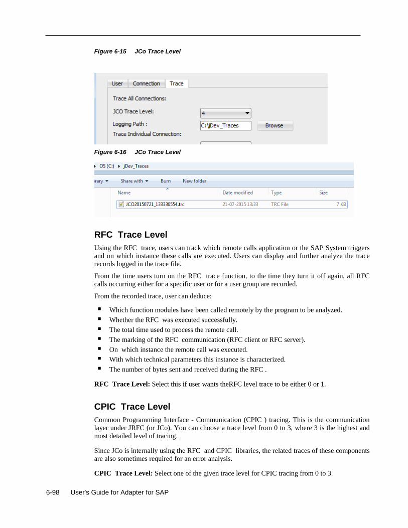
6-98 User's Guide for Adapter for SAP
Figure 6-15 JCo Trace Level
Figure 6-16 JCo Trace Level
RFC Trace Level
Using the RFC trace, users can track which remote calls application or the SAP System triggers
and on which instance these calls are executed. Users can display and further analyze the trace
records logged in the trace file.
From the time users turn on the RFC trace function, to the time they turn it off again, all RFC
calls occurring either for a specific user or for a user group are recorded.
From the recorded trace, user can deduce:
Which function modules have been called remotely by the program to be analyzed.
Whether the RFC was executed successfully.
The total time used to process the remote call.
The marking of the RFC communication (RFC client or RFC server).
On which instance the remote call was executed.
With which technical parameters this instance is characterized.
The number of bytes sent and received during the RFC .
RFC Trace Level: Select this if user wants theRFC level trace to be either 0 or 1.
CPIC Trace Level
Common Programming Interface - Communication (CPIC ) tracing. This is the communication
layer under JRFC (or JCo). You can choose a trace level from 0 to 3, where 3 is the highest and
most detailed level of tracing.
Since JCo is internally using the RFC and CPIC libraries, the related traces of these components
are also sometimes required for an error analysis.
CPIC Trace Level: Select one of the given trace level for CPIC tracing from 0 to 3.
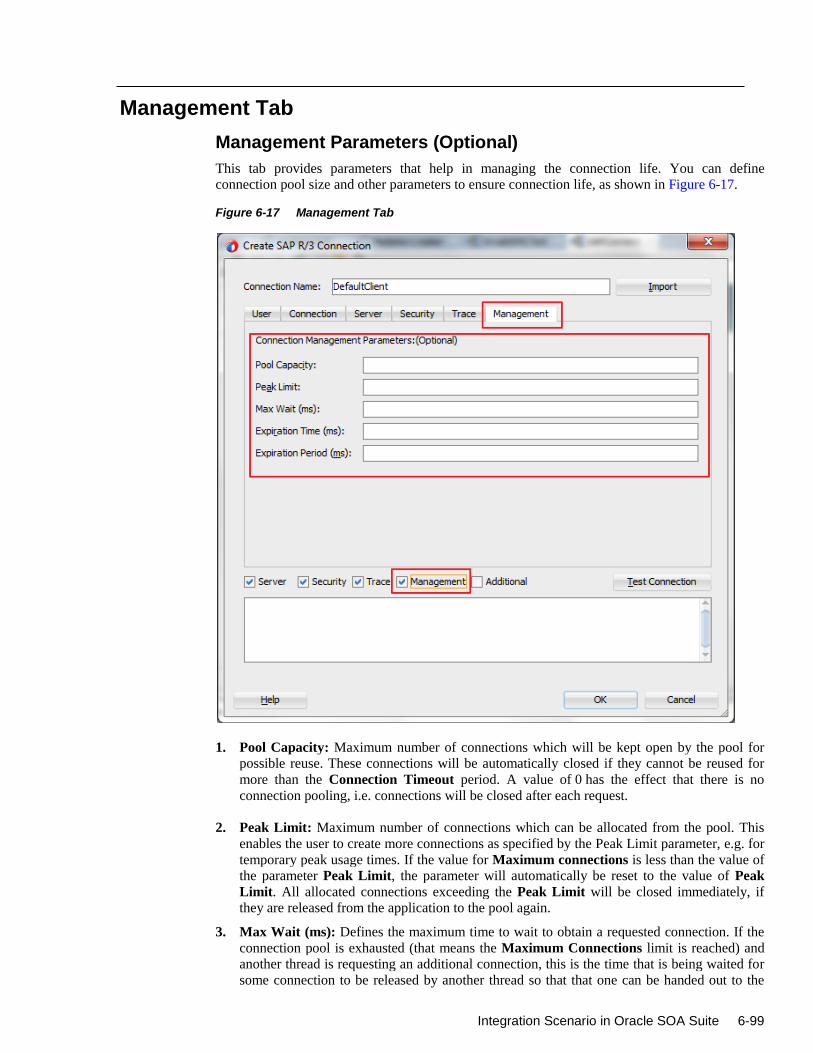
Integration Scenario in Oracle SOA Suite 6-99
Management Tab
Management Parameters (Optional)
This tab provides parameters that help in managing the connection life. You can define
connection pool size and other parameters to ensure connection life, as shown in Figure 6-17.
Figure 6-17 Management Tab
1. Pool Capacity: Maximum number of connections which will be kept open by the pool for
possible reuse. These connections will be automatically closed if they cannot be reused for
more than the Connection Timeout period. A value of 0 has the effect that there is no
connection pooling, i.e. connections will be closed after each request.
2. Peak Limit: Maximum number of connections which can be allocated from the pool. This
enables the user to create more connections as specified by the Peak Limit parameter, e.g. for
temporary peak usage times. If the value for Maximum connections is less than the value of
the parameter Peak Limit, the parameter will automatically be reset to the value of Peak
Limit. All allocated connections exceeding the Peak Limit will be closed immediately, if
they are released from the application to the pool again.
3. Max Wait (ms): Defines the maximum time to wait to obtain a requested connection. If the
connection pool is exhausted (that means the Maximum Connections limit is reached) and
another thread is requesting an additional connection, this is the time that is being waited for
some connection to be released by another thread so that that one can be handed out to the
6-100 User's Guide for Adapter for SAP
waiting thread. If the maximum waiting time is reached, and no connection became available
in the mean time, then a JCO.Exception with the key JCO_ERROR_RESOURCE is thrown.
The default value for the Maximum Waiting Time is 30 seconds (30,000 ms).
4. Expiration Time (ms): Time in ms after which the connections held by the internal pool can
be closed.
5. Expiration Period (ms): Enter expiration period in milliseconds, this is the interval in ms
with which the timeout checker thread checks the connections in the pool for expiration.
Note: The Management tab is not supported in the current release. This will be
implemented for future releases.
Security Tab
SAP Security Parameters
The Adapter for SAP uses the Java Connector (JCo) to communicate with the SAP. You can have
the SNC connection in the case of both inbound and outbound. The JCo needs the information as
mentioned below to be able to use SNC for the connection.
Prerequisite for SNC Communication (Inbound or Outbound)
You have an SNC communication between the client server (Adapter for SAP) and the SAP,
only once the SNC configuration is done on both the partner sides and the required certificates are
exchanged according to the procedure mentioned by SAP.
SNC parameters for Outbound
SNC Parameters required for Outbound Connection to the SAP Server, as shown in Figure 6-18.
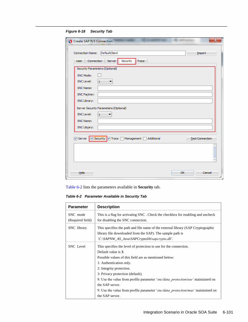
Integration Scenario in Oracle SOA Suite 6-101
Figure 6-18 Security Tab
Table 6-2 lists the parameters available in Security tab.
Table 6-2 Parameter Available in Security Tab
Parameter Description
SNC mode
(Required field)
This is a flag for activating SNC . Check the checkbox for enabling and uncheck
for disabling the SNC connection.
SNC library This specifies the path and file name of the external library (SAP Cryptographic
library file downloaded from the SAP). The sample path is
‘C:\SAPNW_AS_Java\SAPCryptolib\sapcrypto.dll’.
SNC Level This specifies the level of protection to use for the connection.
Default value is 3.
Possible values of this field are as mentioned below:
1: Authentication only.
2: Integrity protection.
3: Privacy protection (default).
8: Use the value from profile parameter ‘snc/data_protection/use’ maintained on
the SAP server.
9: Use the value from profile parameter ‘snc/data_protection/max’ maintained on
the SAP server.
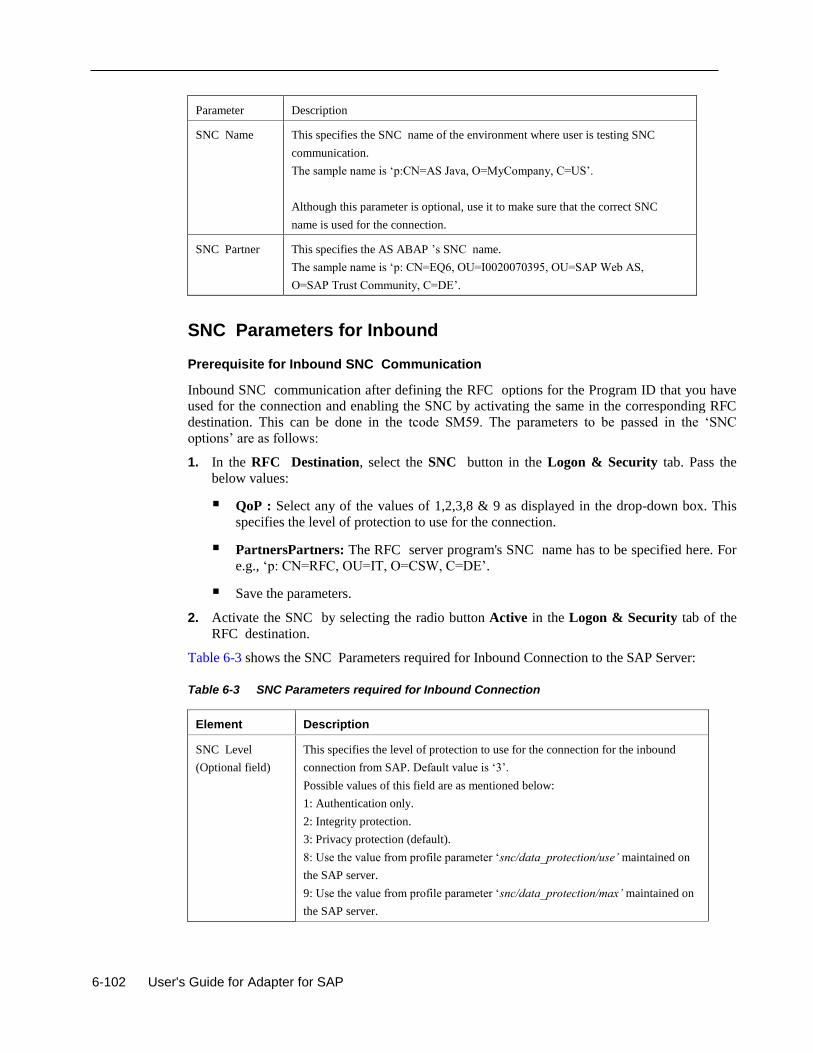
6-102 User's Guide for Adapter for SAP
Parameter Description
SNC Name This specifies the SNC name of the environment where user is testing SNC
communication.
The sample name is ‘p:CN=AS Java, O=MyCompany, C=US’.
Although this parameter is optional, use it to make sure that the correct SNC
name is used for the connection.
SNC Partner This specifies the AS ABAP ’s SNC name.
The sample name is ‘p: CN=EQ6, OU=I0020070395, OU=SAP Web AS,
O=SAP Trust Community, C=DE’.
SNC Parameters for Inbound
Prerequisite for Inbound SNC Communication
Inbound SNC communication after defining the RFC options for the Program ID that you have
used for the connection and enabling the SNC by activating the same in the corresponding RFC
destination. This can be done in the tcode SM59. The parameters to be passed in the ‘SNC
options’ are as follows:
1. In the RFC Destination, select the SNC button in the Logon & Security tab. Pass the
below values:
QoP : Select any of the values of 1,2,3,8 & 9 as displayed in the drop-down box. This
specifies the level of protection to use for the connection.
PartnersPartners: The RFC server program's SNC name has to be specified here. For
e.g., ‘p: CN=RFC, OU=IT, O=CSW, C=DE’.
Save the parameters.
2. Activate the SNC by selecting the radio button Active in the Logon & Security tab of the
RFC destination.
Table 6-3 shows the SNC Parameters required for Inbound Connection to the SAP Server:
Table 6-3 SNC Parameters required for Inbound Connection
Element Description
SNC Level
(Optional field)
This specifies the level of protection to use for the connection for the inbound
connection from SAP. Default value is ‘3’.
Possible values of this field are as mentioned below:
1: Authentication only.
2: Integrity protection.
3: Privacy protection (default).
8: Use the value from profile parameter ‘snc/data_protection/use’ maintained on
the SAP server.
9: Use the value from profile parameter ‘snc/data_protection/max’ maintained on
the SAP server.
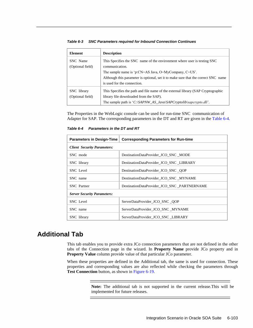
Integration Scenario in Oracle SOA Suite 6-103
Table 6-3 SNC Parameters required for Inbound Connection Continues
Element Description
SNC Name
(Optional field)
This Specifies the SNC name of the environment where user is testing SNC
communication.
The sample name is ‘p:CN=AS Java, O=MyCompany, C=US’.
Although this parameter is optional, set it to make sure that the correct SNC name
is used for the connection.
SNC library
(Optional field)
This Specifies the path and file name of the external library (SAP Cryptographic
library file downloaded from the SAP).
The sample path is ‘C:\SAPNW_AS_Java\SAPCryptolib\sapcrypto.dll’.
The Properties in the WebLogic console can be used for run-time SNC communication of
Adapter for SAP. The corresponding parameters in the DT and RT are given in the Table 6-4.
Table 6-4 Parameters in the DT and RT
Parameters in Design-Time Corresponding Parameters for Run-time
Client Security Parameters:
SNC mode DestinationDataProvider_JCO_SNC _MODE
SNC library DestinationDataProvider_JCO_SNC _LIBRARY
SNC Level DestinationDataProvider_JCO_SNC _QOP
SNC name DestinationDataProvider_JCO_SNC _MYNAME
SNC Partner DestinationDataProvider_JCO_SNC _PARTNERNAME
Server Security Parameters:
SNC Level ServerDataProvider_JCO_SNC _QOP
SNC name ServerDataProvider_JCO_SNC _MYNAME
SNC library ServerDataProvider_JCO_SNC _LIBRARY
Additional Tab
This tab enables you to provide extra JCo connection parameters that are not defined in the other
tabs of the Connection page in the wizard. In Property Name provide JCo property and in
Property Value column provide value of that particular JCo parameter.
When these properties are defined in the Additional tab, the same is used for connection. These
properties and corresponding values are also reflected while checking the parameters through
Test Connection button, as shown in Figure 6-19.
Note: The additional tab is not supported in the current release.This will be
implemented for future releases.
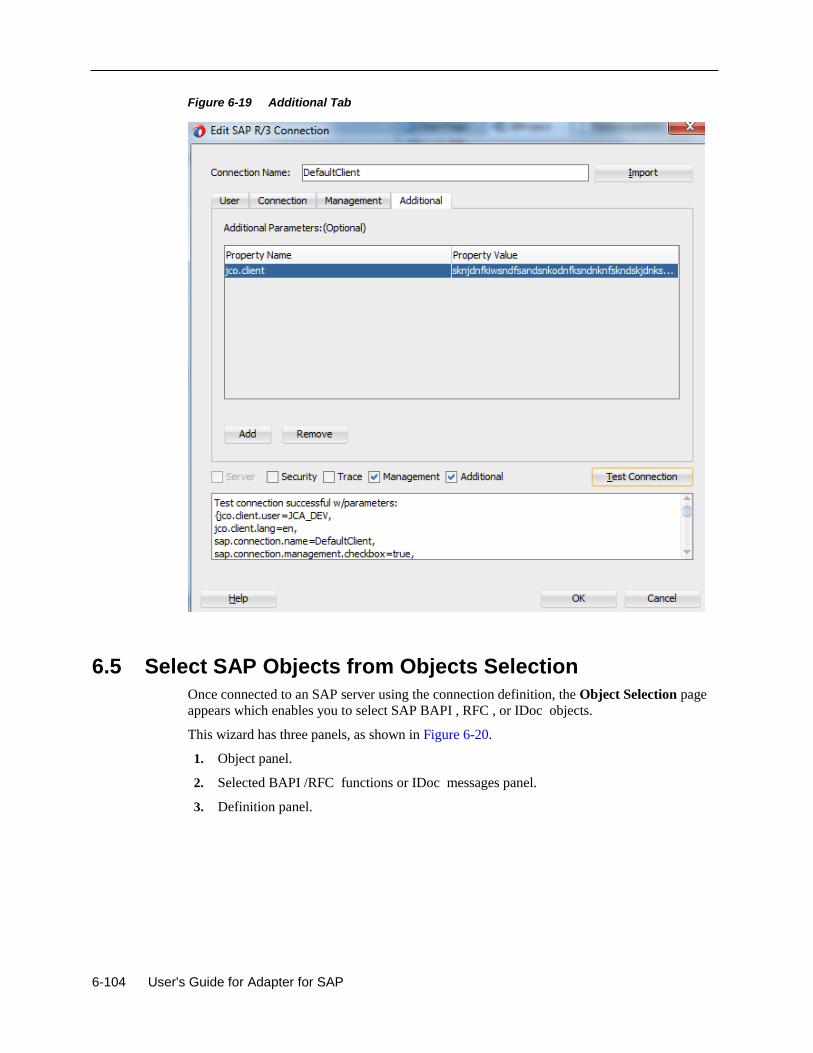
6-104 User's Guide for Adapter for SAP
Figure 6-19 Additional Tab
6.5 Select SAP Objects from Objects Selection
Once connected to an SAP server using the connection definition, the Object Selection page
appears which enables you to select SAP BAPI , RFC , or IDoc objects.
This wizard has three panels, as shown in Figure 6-20.
1. Object panel.
2. Selected BAPI /RFC functions or IDoc messages panel.
3. Definition panel.
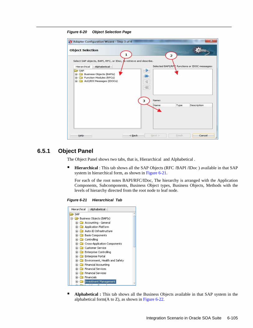
Integration Scenario in Oracle SOA Suite 6-105
Figure 6-20 Object Selection Page
6.5.1 Object Panel
The Object Panel shows two tabs, that is, Hierarchical and Alphabetical .
Hierarchical : This tab shows all the SAP Objects (RFC /BAPI /IDoc ) available in that SAP
system in hierarchical form, as shown in Figure 6-21.
For each of the root notes BAPI/RFC/IDoc, The hierarchy is arranged with the Application
Components, Subcomponents, Business Object types, Business Objects, Methods with the
levels of hierarchy directed from the root node to leaf node.
Figure 6-21 Hierarchical Tab
Alphabetical : This tab shows all the Business Objects available in that SAP system in the
alphabetical form(A to Z), as shown in Figure 6-22.
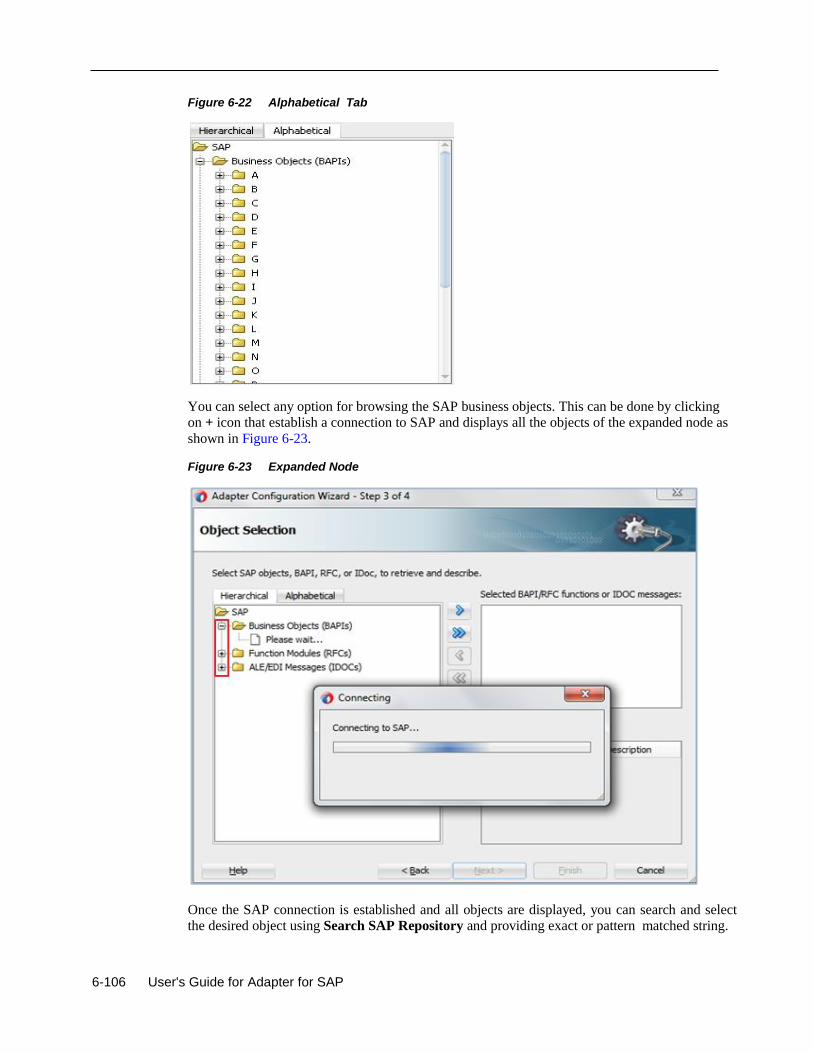
6-106 User's Guide for Adapter for SAP
Figure 6-22 Alphabetical Tab
You can select any option for browsing the SAP business objects. This can be done by clicking
on + icon that establish a connection to SAP and displays all the objects of the expanded node as
shown in Figure 6-23.
Figure 6-23 Expanded Node
Once the SAP connection is established and all objects are displayed, you can search and select the desired object using Search SAP Repository and providing exact or pattern matched string.
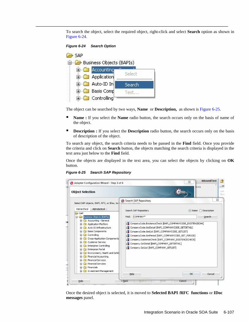
Integration Scenario in Oracle SOA Suite 6-107
To search the object, select the required object, right-click and select Search option as shown in
Figure 6-24.
Figure 6-24 Search Option
The object can be searched by two ways, Name or Description, as shown is Figure 6-25.
Name : If you select the Name radio button, the search occurs only on the basis of name of
the object.
Description : If you select the Description radio button, the search occurs only on the basis
of description of the object.
To search any object, the search criteria needs to be passed in the Find field. Once you provide
the criteria and click on Search button, the objects matching the search criteria is displayed in the
text area just below to the Find field.
Once the objects are displayed in the text area, you can select the objects by clicking on OK
button.
Figure 6-25 Search SAP Repository
Once the desired object is selected, it is moved to Selected BAPI /RFC functions or IDoc
messages panel.
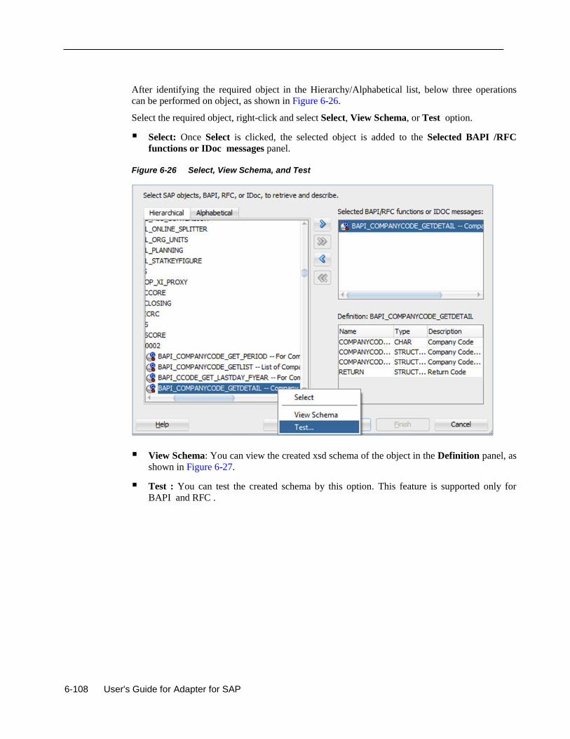
6-108 User's Guide for Adapter for SAP
After identifying the required object in the Hierarchy/Alphabetical list, below three operations
can be performed on object, as shown in Figure 6-26.
Select the required object, right-click and select Select, View Schema, or Test option.
Select: Once Select is clicked, the selected object is added to the Selected BAPI /RFC
functions or IDoc messages panel.
Figure 6-26 Select, View Schema, and Test
View Schema: You can view the created xsd schema of the object in the Definition panel, as
shown in Figure 6-27.
Test : You can test the created schema by this option. This feature is supported only for
BAPI and RFC .
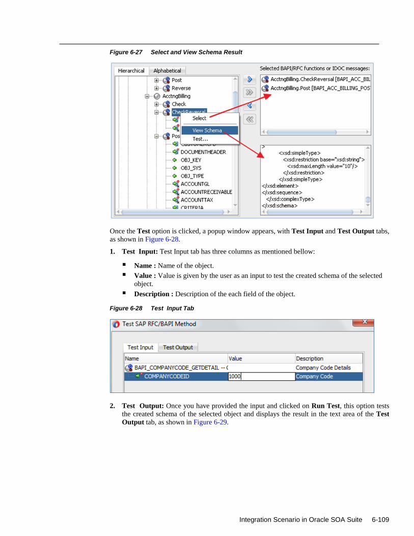
Integration Scenario in Oracle SOA Suite 6-109
Figure 6-27 Select and View Schema Result
Once the Test option is clicked, a popup window appears, with Test Input and Test Output tabs,
as shown in Figure 6-28.
1. Test Input: Test Input tab has three columns as mentioned bellow:
Name : Name of the object.
Value : Value is given by the user as an input to test the created schema of the selected
object.
Description : Description of the each field of the object.
Figure 6-28 Test Input Tab
2. Test Output: Once you have provided the input and clicked on Run Test, this option tests
the created schema of the selected object and displays the result in the text area of the Test
Output tab, as shown in Figure 6-29.
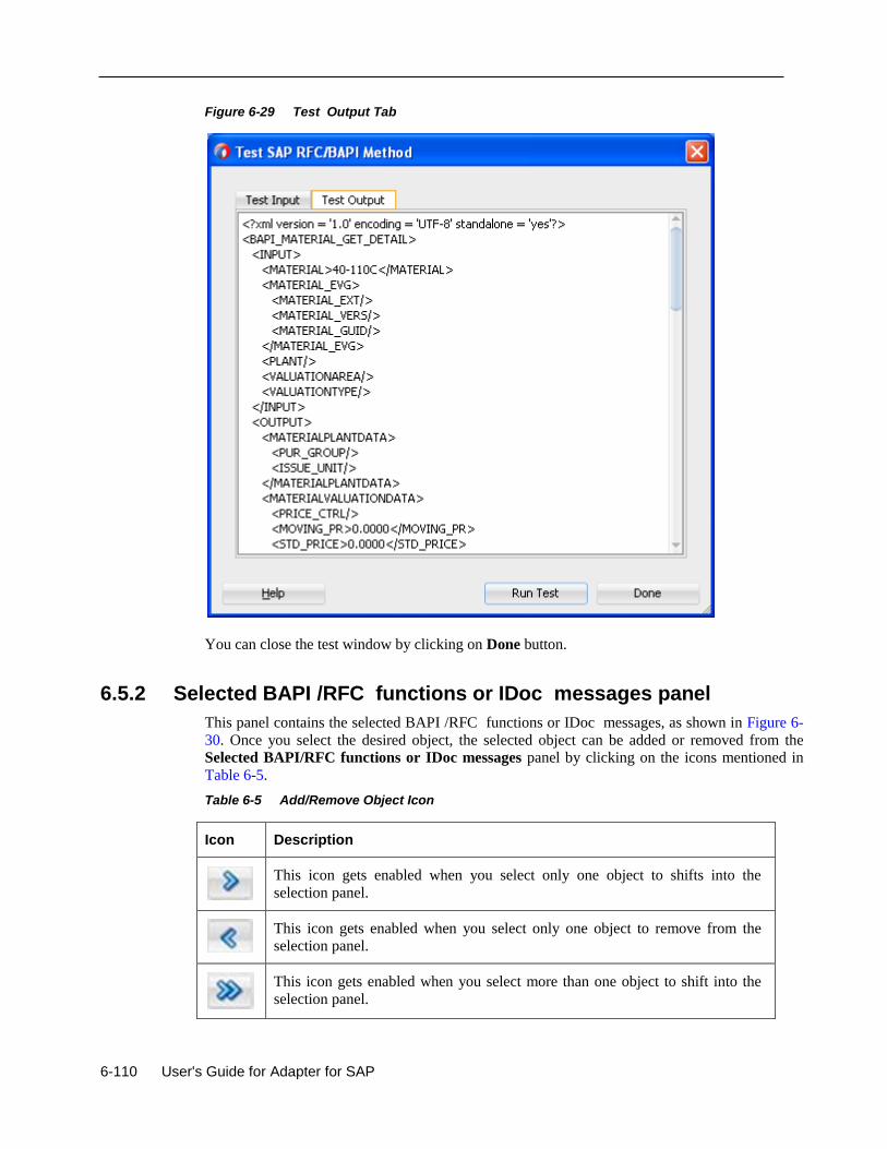
6-110 User's Guide for Adapter for SAP
Figure 6-29 Test Output Tab
You can close the test window by clicking on Done button.
6.5.2 Selected BAPI /RFC functions or IDoc messages panel
This panel contains the selected BAPI /RFC functions or IDoc messages, as shown in Figure 6-
30. Once you select the desired object, the selected object can be added or removed from the
Selected BAPI/RFC functions or IDoc messages panel by clicking on the icons mentioned in
Table 6-5.
Table 6-5 Add/Remove Object Icon
Icon Description
This icon gets enabled when you select only one object to shifts into the
selection panel.
This icon gets enabled when you select only one object to remove from the
selection panel.
This icon gets enabled when you select more than one object to shift into the
selection panel.
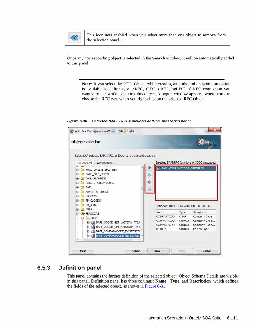
Integration Scenario in Oracle SOA Suite 6-111
This icon gets enabled when you select more than one object to remove from
the selection panel.
Once any corresponding object is selected in the Search window, it will be automatically added
to this panel.
Note: If you select the RFC Object while creating an outbound endpoint, an option
is available to define type (sRFC, tRFC, qRFC, bgRFC) of RFC connection you
wanted to use while executing this object. A popup window appears, where you can
choose the RFC type when you right-click on the selected RFC Object.
Figure 6-30 Selected BAPI /RFC functions or IDoc messages panel
6.5.3 Definition panel
This panel contains the further definition of the selected object. Object Schema Details are visible
in this panel. Definition panel has three columns: Name , Type, and Description which defines
the fields of the selected object, as shown in Figure 6-31.
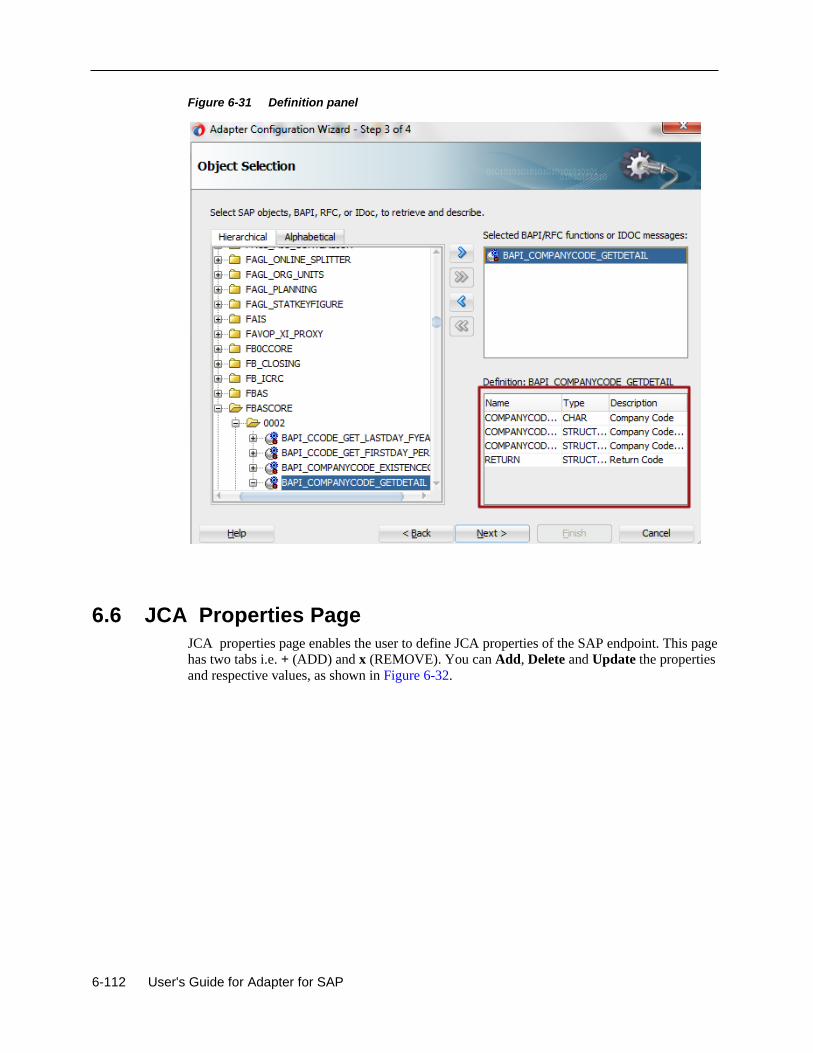
6-112 User's Guide for Adapter for SAP
Figure 6-31 Definition panel
6.6 JCA Properties Page
JCA properties page enables the user to define JCA properties of the SAP endpoint. This page
has two tabs i.e. + (ADD) and x (REMOVE). You can Add, Delete and Update the properties
and respective values, as shown in Figure 6-32.
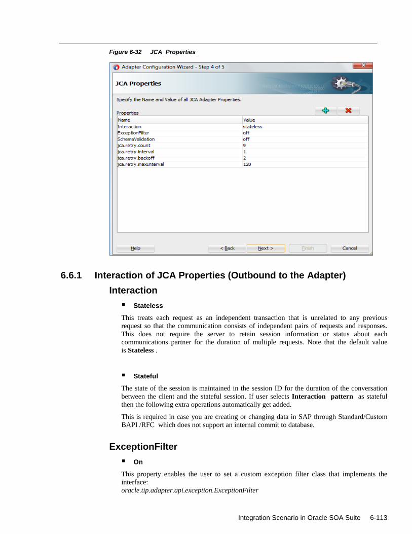
Integration Scenario in Oracle SOA Suite 6-113
Figure 6-32 JCA Properties
6.6.1 Interaction of JCA Properties (Outbound to the Adapter)
Interaction
Stateless
This treats each request as an independent transaction that is unrelated to any previous
request so that the communication consists of independent pairs of requests and responses.
This does not require the server to retain session information or status about each
communications partner for the duration of multiple requests. Note that the default value
is Stateless .
Stateful
The state of the session is maintained in the session ID for the duration of the conversation
between the client and the stateful session. If user selects Interaction pattern as stateful
then the following extra operations automatically get added.
This is required in case you are creating or changing data in SAP through Standard/Custom
BAPI /RFC which does not support an internal commit to database.
ExceptionFilter
On
This property enables the user to set a custom exception filter class that implements the
interface:
oracle.tip.adapter.api.exception.ExceptionFilter
6-114 User's Guide for Adapter for SAP
The exception filter is supported only for outbound processes. This class name is defined in
the .jca file to filter the generated exceptions and categorizes them into the following
categories:
‾ PCRetriableResourceException - A remote fault.
‾ PCResourceException - A binding fault.
This exception can then be handled by the SOA composite fault policy files.
Off
In this case, no exception filter class is added in the .jca file and no exceptions like
PCRetriableResourceException/PCResourceException are thrown in case of remote or
binding faults. Note that the default Value is off .
SchemaValidation
On
SchemaValidation ON is used to validate the Input XML document with the schema in the
WSDL document during run-time. On failure, the XML record is rejected with the error
Invalid Input Xml. This can be configured in a .jca file.
Off
No Validation of Input XML is done with the xsd. Anything wrong in the input XML is
rejected with the JCO exception. Note that the default value is off .
Queue Name
Queue Name needs to be specified to serialize the data that is being sent, like function modules
which depend on each other (such as update and then change) i.e. Queued RFC (QRFC)
connections are used to transport outbound messages to SAP through the queue. This queue needs
to be configured in SAP first, and is given in the Queue name field of the configuration wizard.
Note that the default value is blank. This is applicable for IDOCs.
jca.retry.interval
This property specifies the time interval between each retry.
jca.retry.maxInterval
This property specifies the maximum value of retry interval, i.e. a cap if backoff>1.
jca.retry.count
This property specifies the number of times that user wants the retry to be carried out.
jca.retry.backoff
Integration Scenario in Oracle SOA Suite 6-115
This property specifies the retry interval growth factor (positive integer). The user have to wait
for increasing periods of time between retries 9 attempts with a starting interval of 1 and a back
off of 2 will lead to retries after 1, 2, 4, 8, 16, 32, 64, 128, and 256 (28) seconds.
6.6.2 Activation of JCA Properties (Inbound to the Adapter) ControlCharacter
The Adapter for SAP provides Non-Xml character handling for the data that is coming from SAP
system to the adapter. XML does not support all characters defined in Unicode. For example,
control characters, some of the control character not supported by XML 1.0.
encode
Any character in payload if not supported by XML 1.0, will encode character with its decimal
format.
remove
Any character in payload if not supported by XML 1.0, will remove character.
space
Any character in payload if not supported by XML 1.0, will replaces the character with space.
AutoSYSTAT01
Yes
In this case, Adapter for SAP is able to auto return the sent SYSTAT01 IDoc back to SAP with a
positive response (code 53) upon a successful reception of an IDoc message.
No
In this case, nothing is sent back to SAP by the Adapter upon a successful reception of an IDoc
message. Note that the default value is No.
EncodeIDoc
Flatfile
SAP uses a non-XML text-based format, called the Flatfile IDoc format, for serializing IDoc
messages to file system. In a Flatfile IDoc, all IDoc records including control record and data
record are stored in lines of text separated by a line delimiter.
No
SAP uses the XML format to send IDoc records the field names and complete data.
Note that the default value is No.
programID
The programID specified at the DT level overrides with RT.
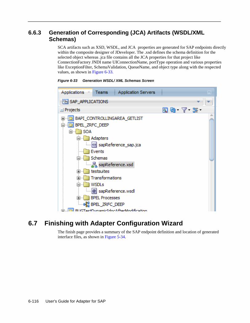
6-116 User's Guide for Adapter for SAP
6.6.3 Generation of Corresponding (JCA) Artifacts (WSDL/XML Schemas)
SCA artifacts such as XSD, WSDL, and JCA properties are generated for SAP endpoints directly
within the composite designer of JDeveloper. The .xsd defines the schema definition for the
selected object whereas .jca file contains all the JCA properties for that project like
ConnectionFactory JNDI name UIConnectionName, portType operation and various properties
like ExceptionFilter, SchemaValidation, QueueName, and object type along with the respected
values, as shown in Figure 6-33.
Figure 6-33 Generation WSDL/ XML Schemas Screen
6.7 Finishing with Adapter Configuration Wizard
The finish page provides a summary of the SAP endpoint definition and location of generated
interface files, as shown in Figure 5-34.
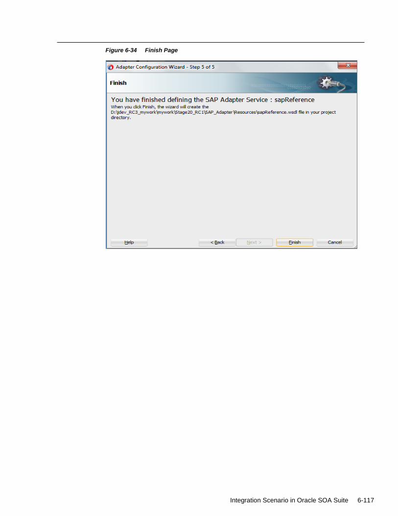
Integration Scenario in Oracle SOA Suite 6-117
Figure 6-34 Finish Page
7-118 User's Guide for Adapter for SAP
7
Configuring the Adapter Run-Time
Parameters on the WebLogic Server
This chapter describes the procedure to configure the Oracle Adapter for SAP on the Oracle
WebLogic Server. This chapter contains the following topics:
Section 7.1, "Adapter Integration with Oracle WebLogic Server"
Prerequisites:
The WebLogic Application server is running.
SAP JCo jars and library is installed in the WebLogic application server.
7.1 Adapter Integration with Oracle WebLogic Server
Oracle Adapter for SAP is deployed within an Oracle WLS container during installation. All
client applications run within the Oracle WLS environment. In a run-time service scenario, an
Enterprise Java Bean, servlet, or Java program client makes the Common Client Interface (CCI)
calls to resource adapters. The adapters process the calls as requests and send them to the EIS.
The EIS response is then sent back to the client.
7.1.1 Configure Run-time Parameters for the Adapter for SAP
1. To configure run-time parameters for the Adapter, navigate to the setting page of the
deployed adapter. This page displays basic information about this resource adapter, as shown
in Figure 7-1.
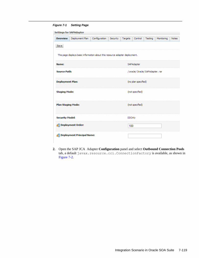
Integration Scenario in Oracle SOA Suite 7-119
Figure 7-1 Setting Page
2. Open the SAP JCA Adapter Configuration panel and select Outbound Connection Pools
tab, a default javax.resource.cci.ConnectionFactory is available, as shown in
Figure 7-2.
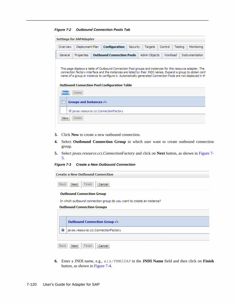
7-120 User's Guide for Adapter for SAP
Figure 7-2 Outbound Connection Pools Tab
3. Click New to create a new outbound connection.
4. Select Outbound Connection Group in which user want to create outbound connection
group.
5. Select javax.resource.cci.ConnectionFactory and click on Next button, as shown in Figure 7-
3.
Figure 7-3 Create a New Outbound Connection
6. Enter a JNDI name, e.g., eis/FMW2SAP in the JNDI Name field and then click on Finish
button, as shown in Figure 7-4.
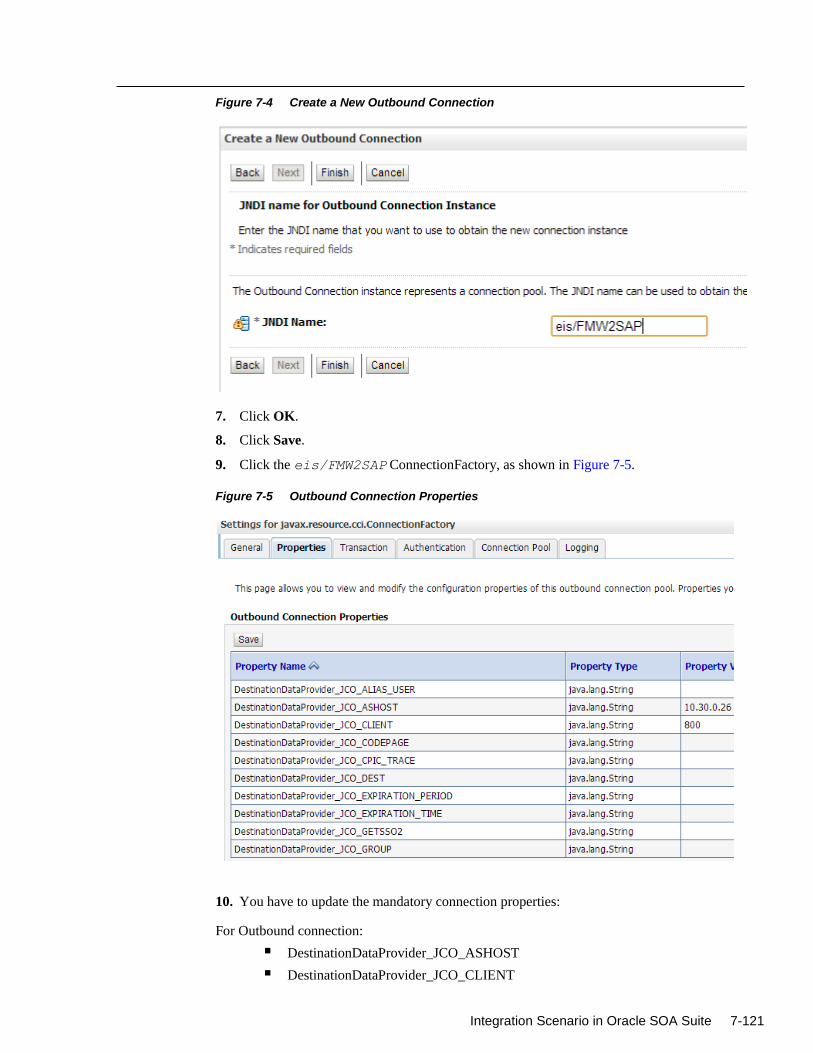
Integration Scenario in Oracle SOA Suite 7-121
Figure 7-4 Create a New Outbound Connection
7. Click OK.
8. Click Save.
9. Click the eis/FMW2SAP ConnectionFactory, as shown in Figure 7-5.
Figure 7-5 Outbound Connection Properties
10. You have to update the mandatory connection properties:
For Outbound connection:
DestinationDataProvider_JCO_ASHOST
DestinationDataProvider_JCO_CLIENT
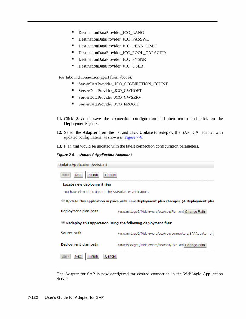
7-122 User's Guide for Adapter for SAP
DestinationDataProvider_JCO_LANG
DestinationDataProvider_JCO_PASSWD
DestinationDataProvider_JCO_PEAK_LIMIT
DestinationDataProvider_JCO_POOL_CAPACITY
DestinationDataProvider_JCO_SYSNR
DestinationDataProvider_JCO_USER
For Inbound connection(apart from above):
ServerDataProvider_JCO_CONNECTION_COUNT
ServerDataProvider_JCO_GWHOST
ServerDataProvider_JCO_GWSERV
ServerDataProvider_JCO_PROGID
11. Click Save to save the connection configuration and then return and click on the
Deployments panel.
12. Select the Adapter from the list and click Update to redeploy the SAP JCA adapter with
updated configuration, as shown in Figure 7-6.
13. Plan.xml would be updated with the latest connection configuration parameters.
Figure 7-6 Updated Application Assistant
The Adapter for SAP is now configured for desired connection in the WebLogic Application Server.
Integration Scenario in Oracle SOA Suite 8-123
8
Integration Scenarios in Oracle SOA Suite
This chapter demonstrates how to create composites to perform Inbound and Outbound
communication with SAP using the Adapter for SAP. The different components used in this
chapter are BPEL, Mediator, OSB, and BPM. You will use different components for
orchestration, transformation and routing, and interact with SAP using the The Adapter for SAP
to create the end-to-end processes.
This chapter contains the following topics:
Section 8.1, "Integration Overview"
Section 8.2, "The Adapter Integration with SOA Service Components"
Section 8.3, "The The Adapter Integration with BPM Service Components"
Section 8.4, "The Adapter Integration with Oracle Service Bus (OSB)"
Section 8.5, "Deploy the Defined Process"
Section 8.6, "Test the Deployed Process"
8.1 Integration Overview
The Oracle Adapter for SAP enables middleware components to interact and exchange data with
the SAP R/3 system. Similar to other WebLogic adapters and applications, the Adapter should be
deployed in WebLogic console under Deployments. SOA/OSB can be successfully deployed to
SOA/OSB server after deployment WSDL is generated in JDeveloper which is used for both
inbound and outbound communication. After deployment to server, the application can be
controlled from EM/Console.
8.2 The Adapter Integration With SOA Service Components
Tool required for the design-time configuration of an Oracle SOA process:
Oracle JDeveloper 12.2.1.
8.2.1 Create a New Application Server Connection
Follow the below steps to create a new Application Server connection in Oracle JDeveloper
12.2.1.
1. Open Oracle JDeveloper 12.2.1.
2. Click Window from the menu bar and select Application Servers to view the Application Server Navigator pane on the JDeveloper IDE, as shown in Figure 8-1.
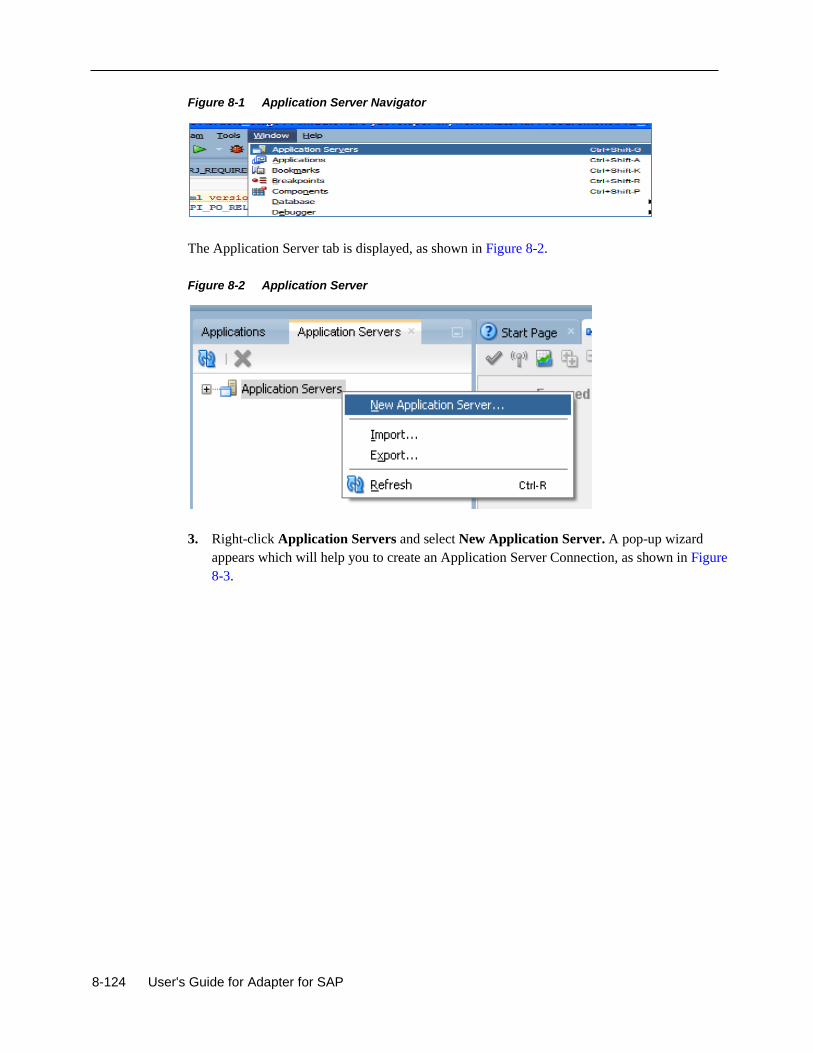
8-124 User's Guide for Adapter for SAP
Figure 8-1 Application Server Navigator
The Application Server tab is displayed, as shown in Figure 8-2.
Figure 8-2 Application Server
3. Right-click Application Servers and select New Application Server. A pop-up wizard
appears which will help you to create an Application Server Connection, as shown in Figure
8-3.
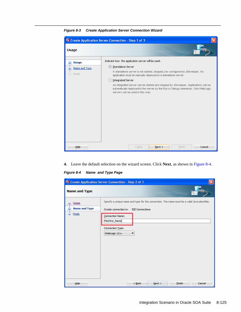
Integration Scenario in Oracle SOA Suite 8-125
Figure 8-3 Create Application Server Connection Wizard
4. Leave the default selection on the wizard screen. Click Next, as shown in Figure 8-4.
Figure 8-4 Name and Type Page
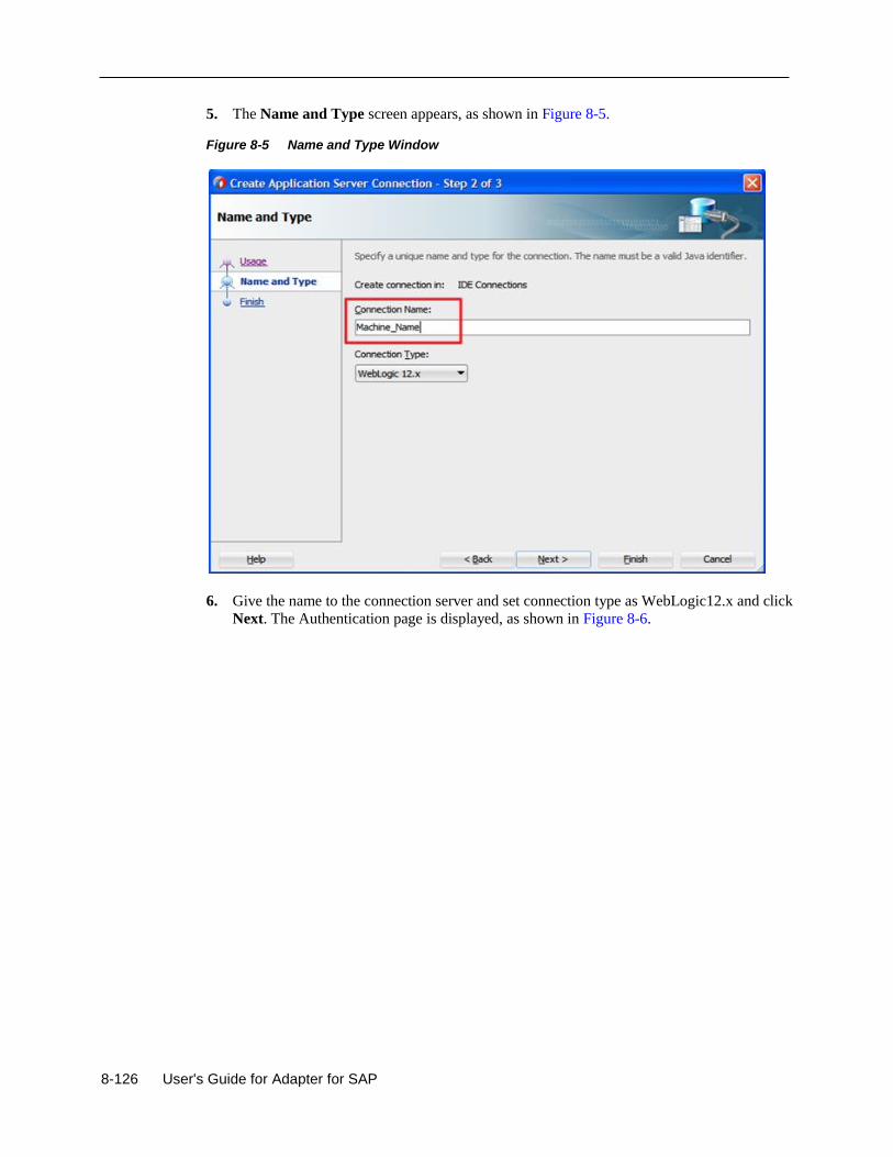
8-126 User's Guide for Adapter for SAP
5. The Name and Type screen appears, as shown in Figure 8-5.
Figure 8-5 Name and Type Window
6. Give the name to the connection server and set connection type as WebLogic12.x and click
Next. The Authentication page is displayed, as shown in Figure 8-6.
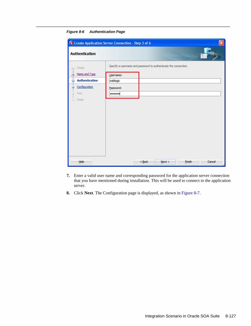
Integration Scenario in Oracle SOA Suite 8-127
Figure 8-6 Authentication Page
7. Enter a valid user name and corresponding password for the application server connection
that you have mentioned during installation. This will be used to connect to the application
server.
8. Click Next. The Configuration page is displayed, as shown in Figure 8-7.

8-128 User's Guide for Adapter for SAP
Figure 8-7 Configuration Page
9. Enter the host name of the machine where Oracle WebLogic server has been installed.
Provide the Port and Domain name as defined during the WebLogic installation and
configuration process.
10. Click Next. The Test page is displayed as shown in Figure 8-8.
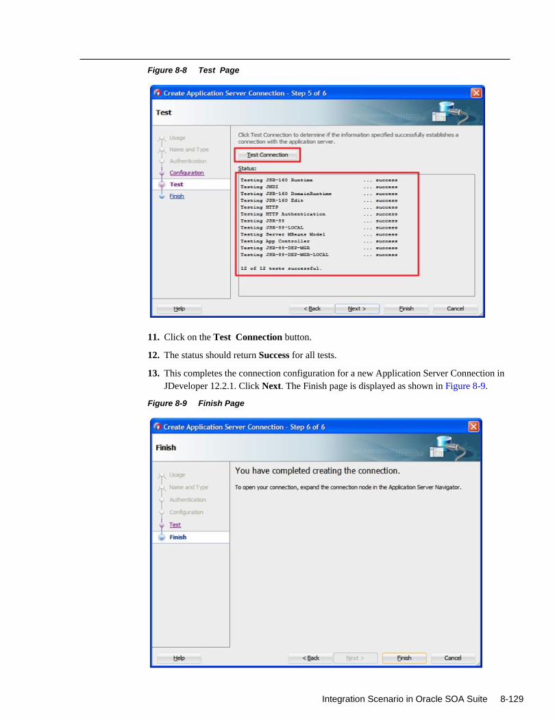
Integration Scenario in Oracle SOA Suite 8-129
Figure 8-8 Test Page
11. Click on the Test Connection button.
12. The status should return Success for all tests.
13. This completes the connection configuration for a new Application Server Connection in
JDeveloper 12.2.1. Click Next. The Finish page is displayed as shown in Figure 8-9.
Figure 8-9 Finish Page
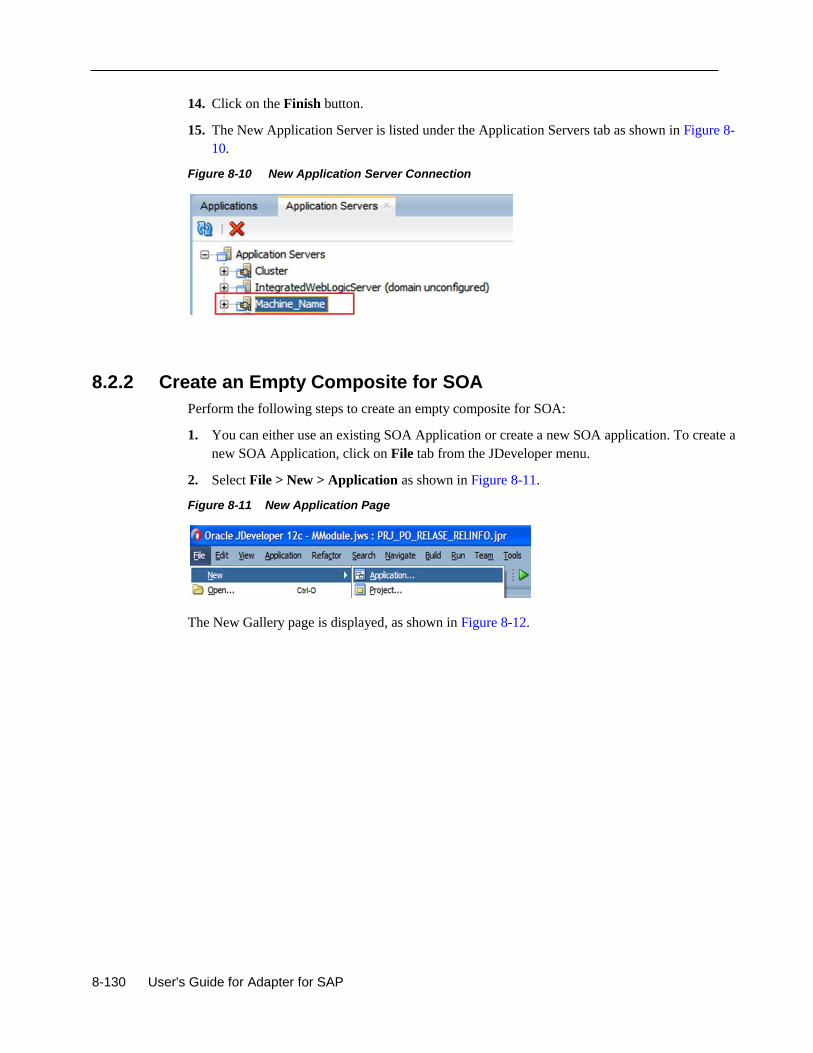
8-130 User's Guide for Adapter for SAP
14. Click on the Finish button.
15. The New Application Server is listed under the Application Servers tab as shown in Figure 8-
10.
Figure 8-10 New Application Server Connection
8.2.2 Create an Empty Composite for SOA
Perform the following steps to create an empty composite for SOA:
1. You can either use an existing SOA Application or create a new SOA application. To create a
new SOA Application, click on File tab from the JDeveloper menu.
2. Select File > New > Application as shown in Figure 8-11.
Figure 8-11 New Application Page
The New Gallery page is displayed, as shown in Figure 8-12.
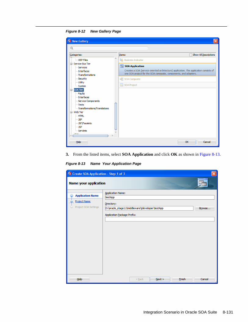
Integration Scenario in Oracle SOA Suite 8-131
Figure 8-12 New Gallery Page
3. From the listed items, select SOA Application and click OK as shown in Figure 8-13.
Figure 8-13 Name Your Application Page
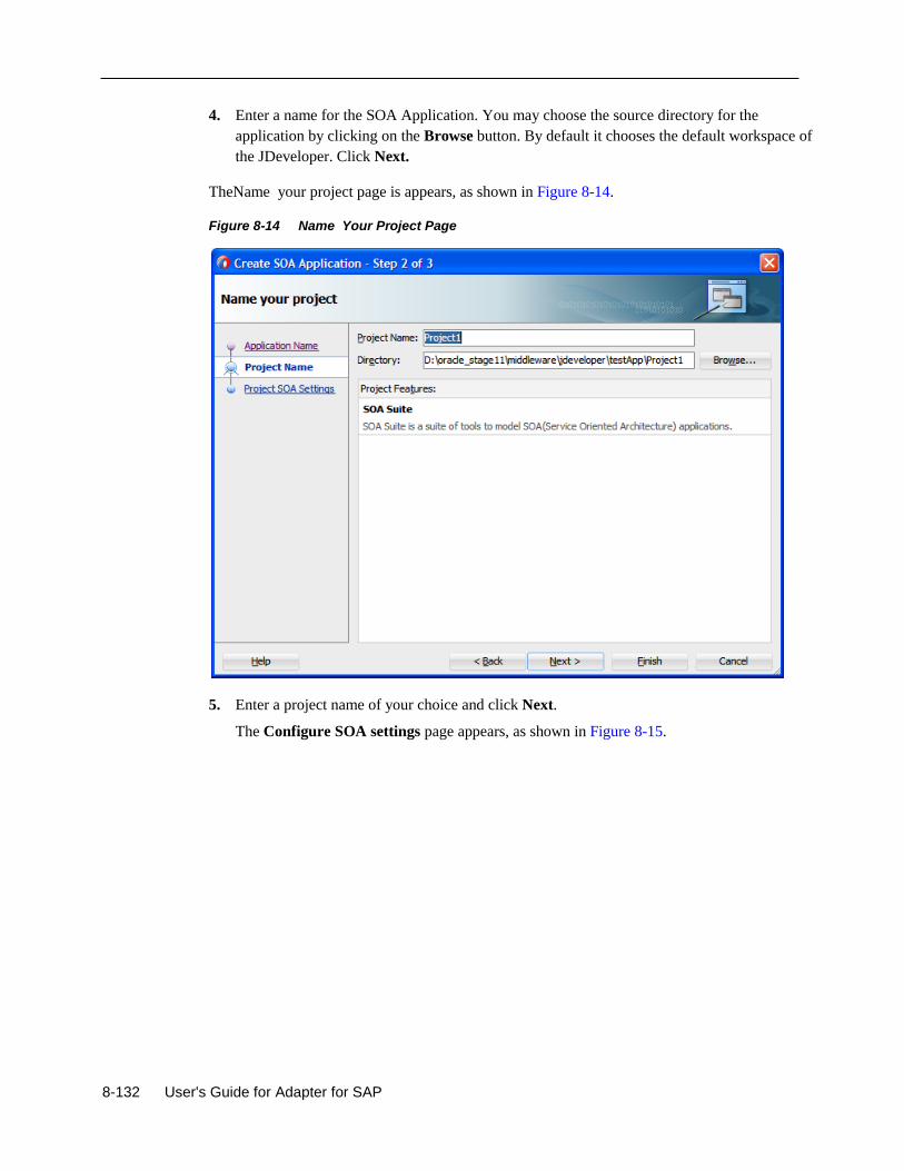
8-132 User's Guide for Adapter for SAP
4. Enter a name for the SOA Application. You may choose the source directory for the
application by clicking on the Browse button. By default it chooses the default workspace of
the JDeveloper. Click Next.
TheName your project page is appears, as shown in Figure 8-14.
Figure 8-14 Name Your Project Page
5. Enter a project name of your choice and click Next.
The Configure SOA settings page appears, as shown in Figure 8-15.
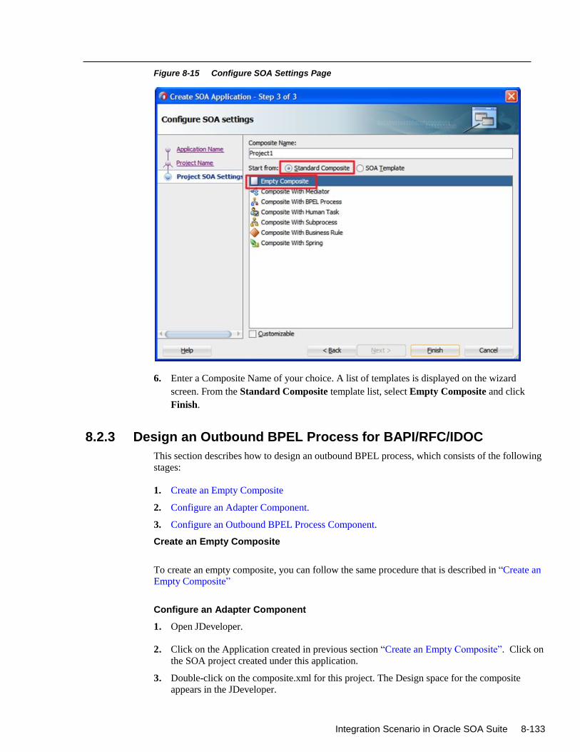
Integration Scenario in Oracle SOA Suite 8-133
Figure 8-15 Configure SOA Settings Page
6. Enter a Composite Name of your choice. A list of templates is displayed on the wizard
screen. From the Standard Composite template list, select Empty Composite and click
Finish.
8.2.3 Design an Outbound BPEL Process for BAPI/RFC/IDOC
This section describes how to design an outbound BPEL process, which consists of the following
stages:
1. Create an Empty Composite
2. Configure an Adapter Component.
3. Configure an Outbound BPEL Process Component.
Create an Empty Composite
To create an empty composite, you can follow the same procedure that is described in “Create an
Empty Composite”
Configure an Adapter Component
1. Open JDeveloper.
2. Click on the Application created in previous section “Create an Empty Composite”. Click on
the SOA project created under this application.
3. Double-click on the composite.xml for this project. The Design space for the composite
appears in the JDeveloper.
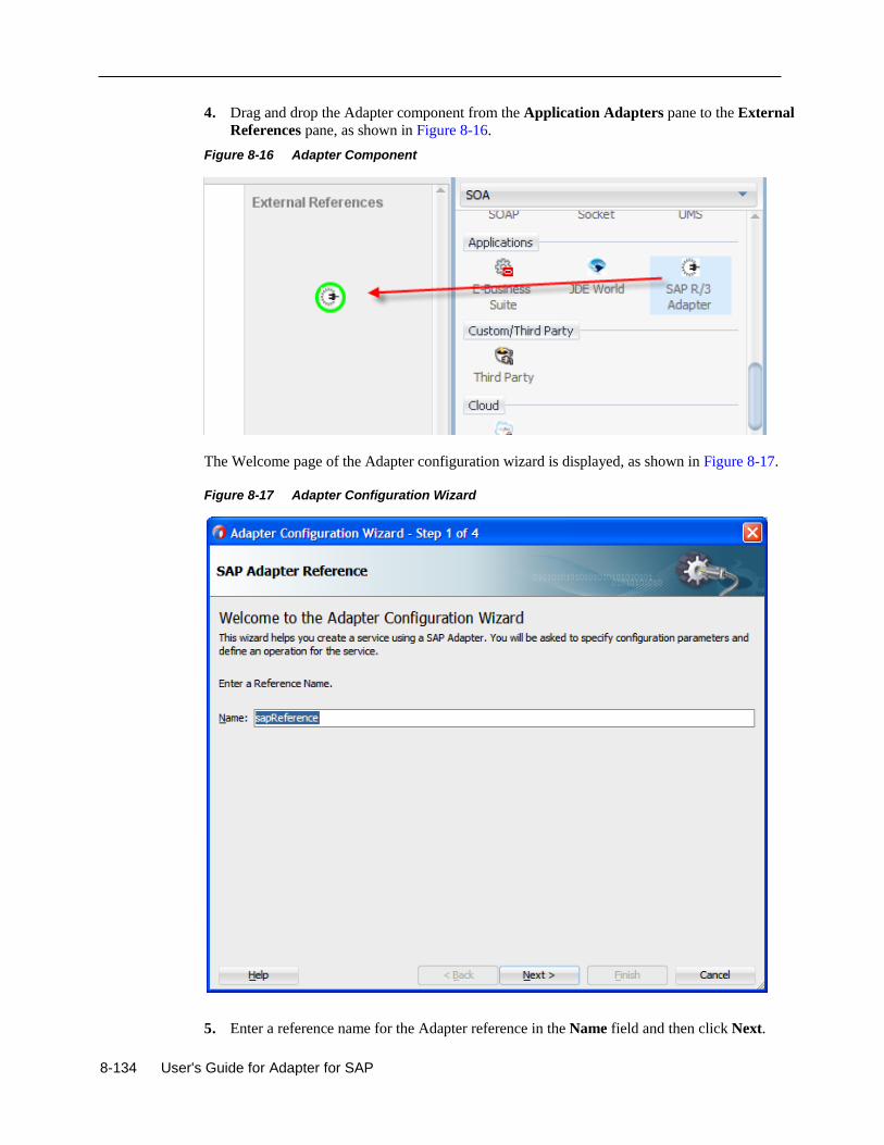
8-134 User's Guide for Adapter for SAP
4. Drag and drop the Adapter component from the Application Adapters pane to the External
References pane, as shown in Figure 8-16.
Figure 8-16 Adapter Component
The Welcome page of the Adapter configuration wizard is displayed, as shown in Figure 8-17.
Figure 8-17 Adapter Configuration Wizard
5. Enter a reference name for the Adapter reference in the Name field and then click Next.
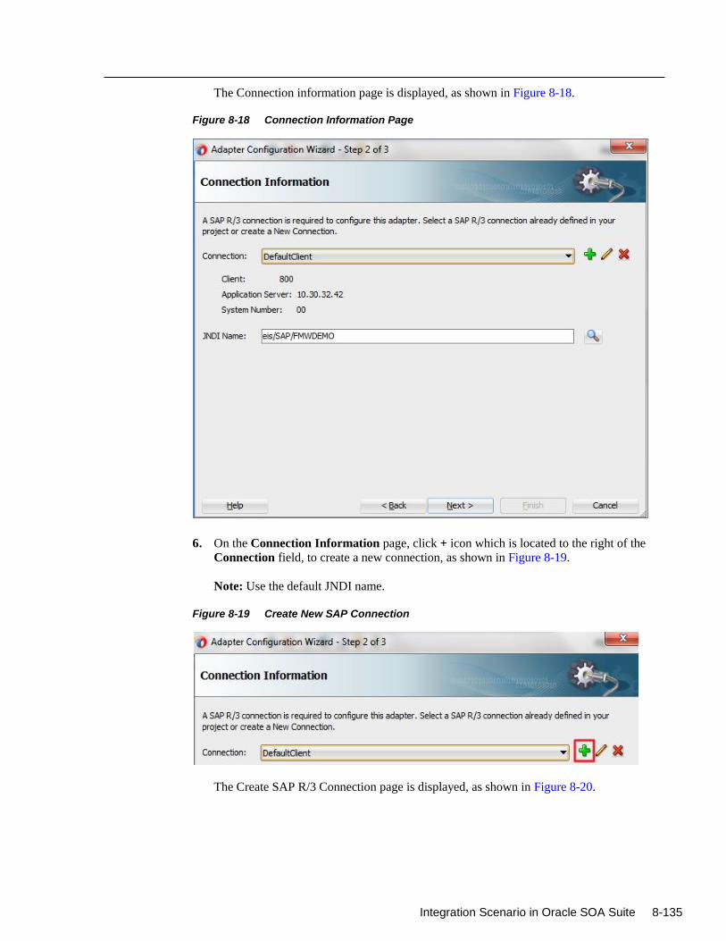
Integration Scenario in Oracle SOA Suite 8-135
The Connection information page is displayed, as shown in Figure 8-18.
Figure 8-18 Connection Information Page
6. On the Connection Information page, click + icon which is located to the right of the
Connection field, to create a new connection, as shown in Figure 8-19.
Note: Use the default JNDI name.
Figure 8-19 Create New SAP Connection
The Create SAP R/3 Connection page is displayed, as shown in Figure 8-20.
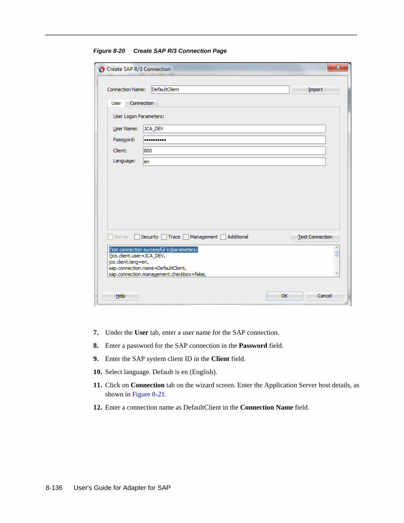
8-136 User's Guide for Adapter for SAP
Figure 8-20 Create SAP R/3 Connection Page
7. Under the User tab, enter a user name for the SAP connection.
8. Enter a password for the SAP connection in the Password field.
9. Enter the SAP system client ID in the Client field.
10. Select language. Default is en (English).
11. Click on Connection tab on the wizard screen. Enter the Application Server host details, as
shown in Figure 8-21.
12. Enter a connection name as DefaultClient in the Connection Name field.
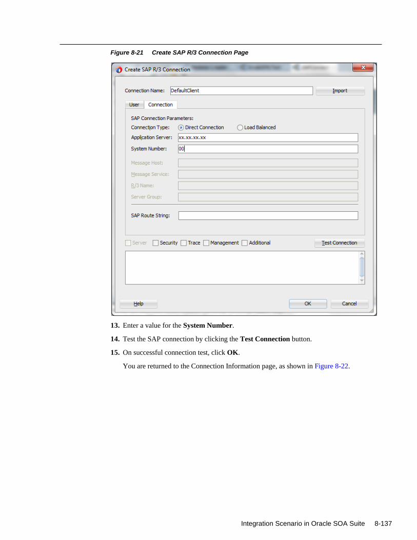
Integration Scenario in Oracle SOA Suite 8-137
Figure 8-21 Create SAP R/3 Connection Page
13. Enter a value for the System Number.
14. Test the SAP connection by clicking the Test Connection button.
15. On successful connection test, click OK.
You are returned to the Connection Information page, as shown in Figure 8-22.
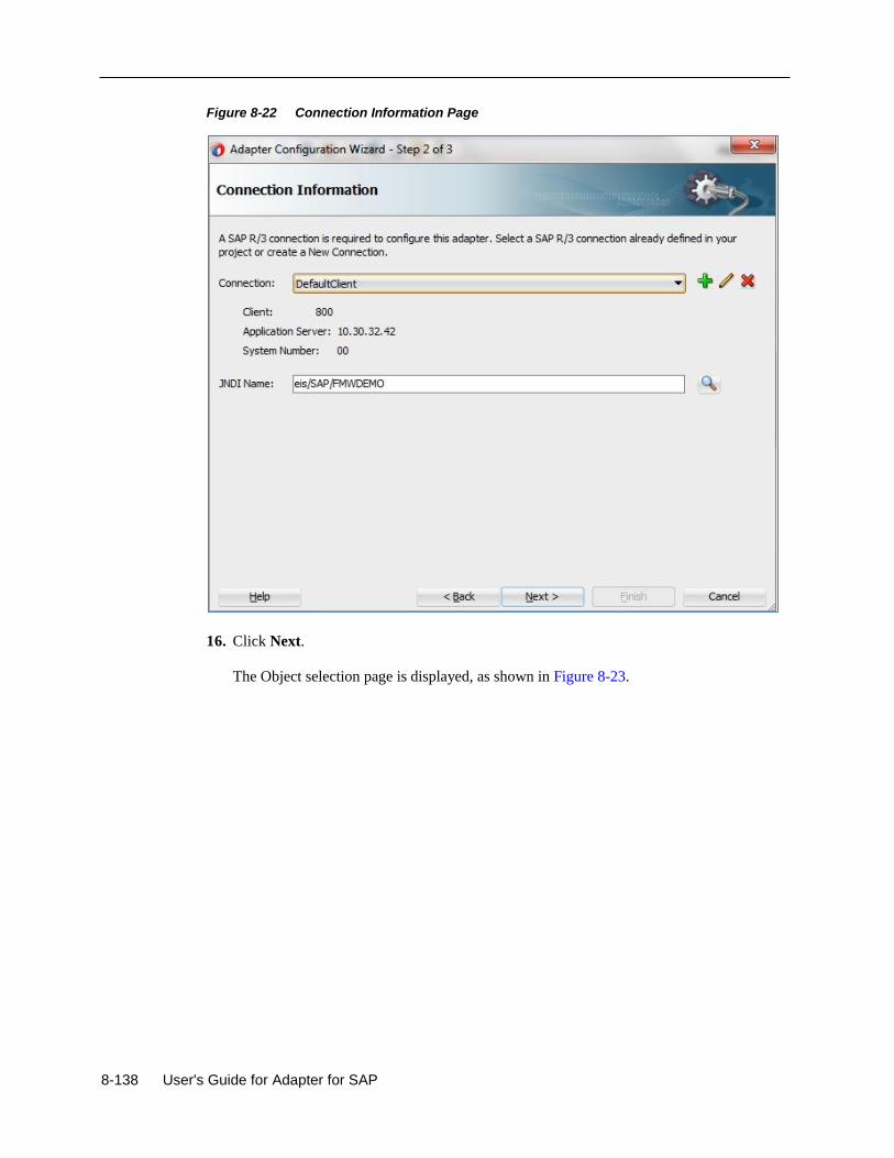
8-138 User's Guide for Adapter for SAP
Figure 8-22 Connection Information Page
16. Click Next.
The Object selection page is displayed, as shown in Figure 8-23.
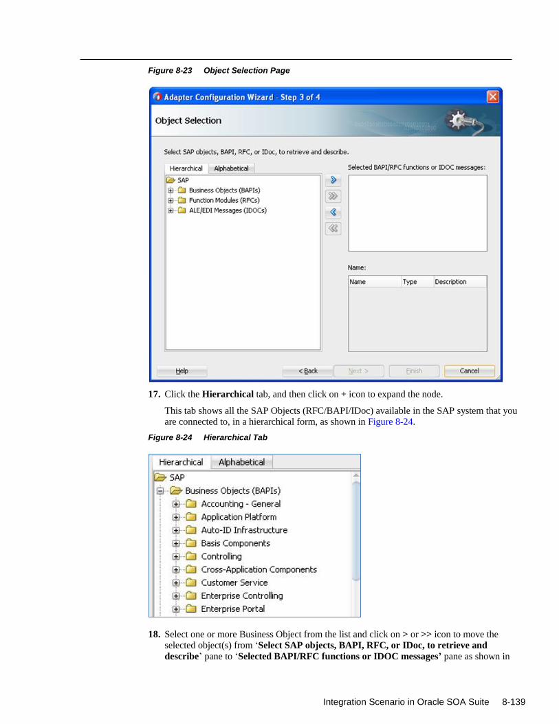
Integration Scenario in Oracle SOA Suite 8-139
Figure 8-23 Object Selection Page
17. Click the Hierarchical tab, and then click on + icon to expand the node.
This tab shows all the SAP Objects (RFC/BAPI/IDoc) available in the SAP system that you
are connected to, in a hierarchical form, as shown in Figure 8-24.
Figure 8-24 Hierarchical Tab
18. Select one or more Business Object from the list and click on > or >> icon to move the
selected object(s) from ‘Select SAP objects, BAPI, RFC, or IDoc, to retrieve and
describe’ pane to ‘Selected BAPI/RFC functions or IDOC messages’ pane as shown in
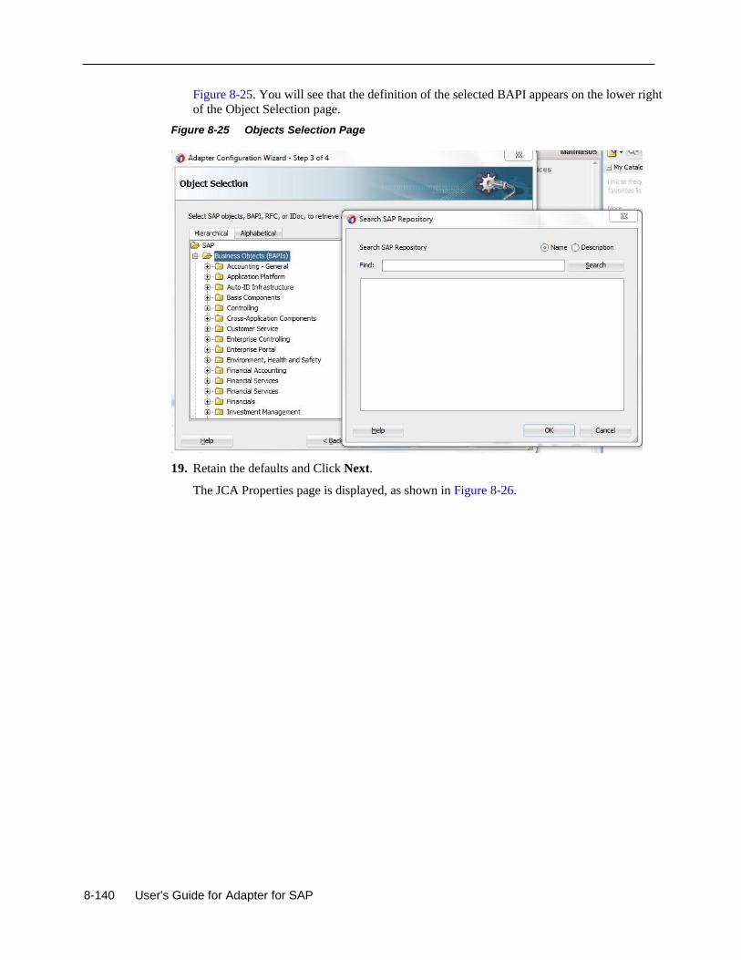
8-140 User's Guide for Adapter for SAP
Figure 8-25. You will see that the definition of the selected BAPI appears on the lower right
of the Object Selection page.
Figure 8-25 Objects Selection Page
19. Retain the defaults and Click Next.
The JCA Properties page is displayed, as shown in Figure 8-26.
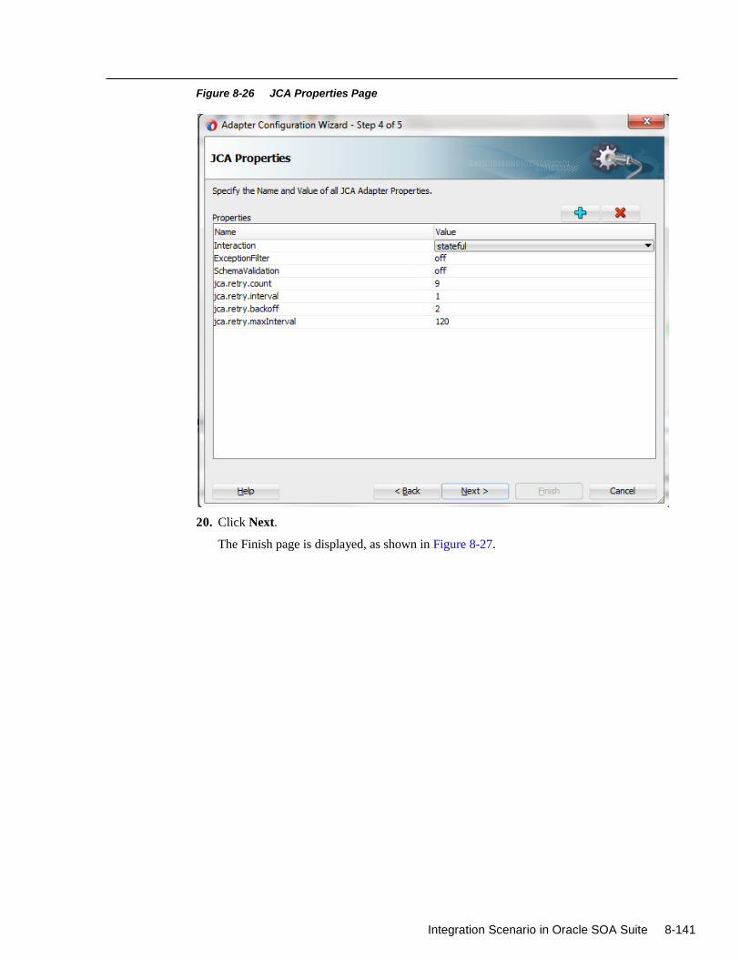
Integration Scenario in Oracle SOA Suite 8-141
Figure 8-26 JCA Properties Page
20. Click Next.
The Finish page is displayed, as shown in Figure 8-27.
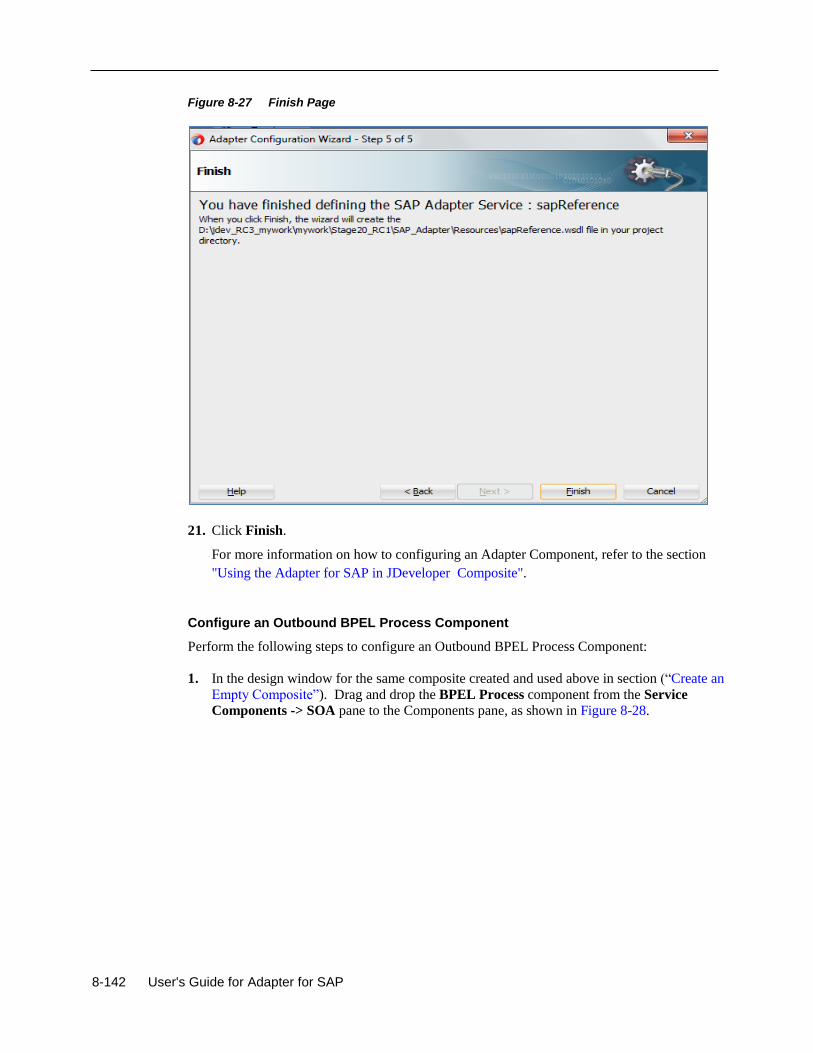
8-142 User's Guide for Adapter for SAP
Figure 8-27 Finish Page
21. Click Finish.
For more information on how to configuring an Adapter Component, refer to the section
"Using the Adapter for SAP in JDeveloper Composite".
Configure an Outbound BPEL Process Component
Perform the following steps to configure an Outbound BPEL Process Component:
1. In the design window for the same composite created and used above in section (“Create an
Empty Composite”). Drag and drop the BPEL Process component from the Service
Components -> SOA pane to the Components pane, as shown in Figure 8-28.
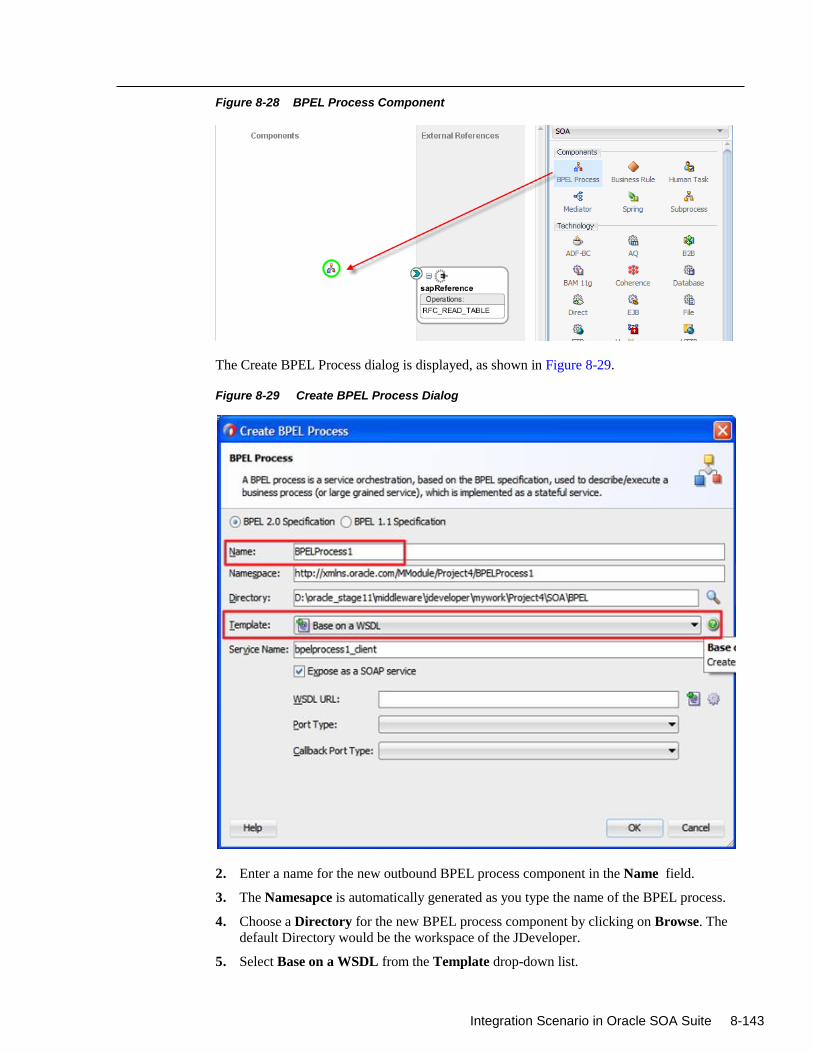
Integration Scenario in Oracle SOA Suite 8-143
Figure 8-28 BPEL Process Component
The Create BPEL Process dialog is displayed, as shown in Figure 8-29.
Figure 8-29 Create BPEL Process Dialog
2. Enter a name for the new outbound BPEL process component in the Name field.
3. The Namesapce is automatically generated as you type the name of the BPEL process.
4. Choose a Directory for the new BPEL process component by clicking on Browse. The
default Directory would be the workspace of the JDeveloper.
5. Select Base on a WSDL from the Template drop-down list.
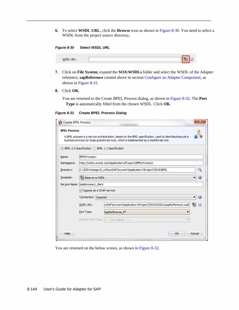
8-144 User's Guide for Adapter for SAP
6. To select WSDL URL, click the Browse icon as shown in Figure 8-30. You need to select a
WSDL from the project source directory,
Figure 8-30 Select WSDL URL
7. Click on File System, expand the SOA\WSDLs folder and select the WSDL of the Adapter
reference, sapReference created above in section Configure an Adapter Component, as
shown in Figure 8-31.
8. Click OK.
You are returned to the Create BPEL Process dialog, as shown in Figure 8-32. The Port
Type is automatically filled from the chosen WSDL. Click OK.
Figure 8-31 Create BPEL Process Dialog
You are returned on the below screen, as shown in Figure 8-32.
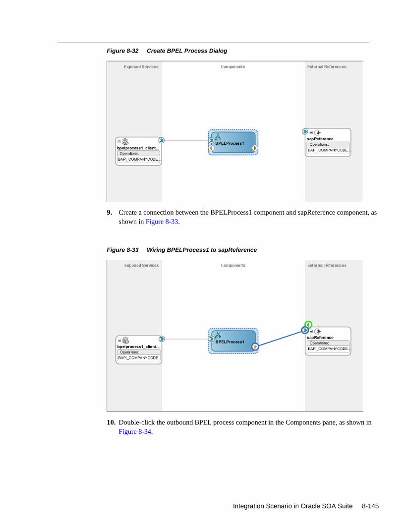
Integration Scenario in Oracle SOA Suite 8-145
Figure 8-32 Create BPEL Process Dialog
9. Create a connection between the BPELProcess1 component and sapReference component, as
shown in Figure 8-33.
Figure 8-33 Wiring BPELProcess1 to sapReference
10. Double-click the outbound BPEL process component in the Components pane, as shown in
Figure 8-34.
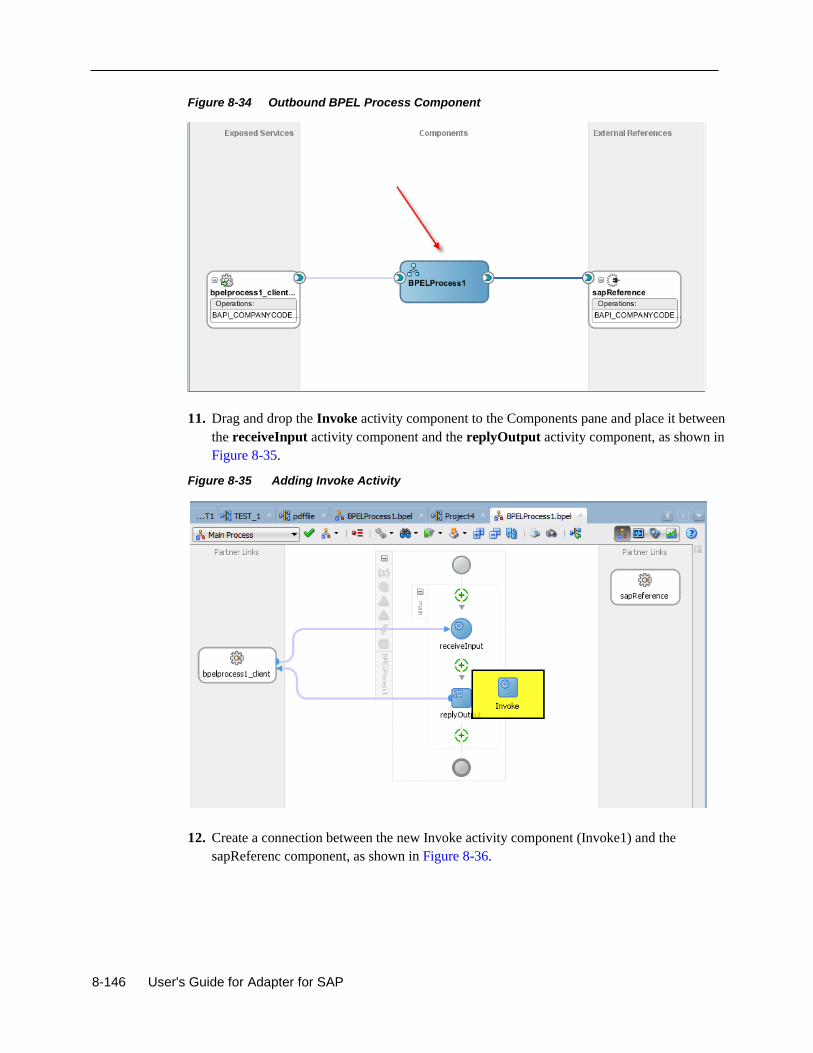
8-146 User's Guide for Adapter for SAP
Figure 8-34 Outbound BPEL Process Component
11. Drag and drop the Invoke activity component to the Components pane and place it between
the receiveInput activity component and the replyOutput activity component, as shown in
Figure 8-35.
Figure 8-35 Adding Invoke Activity
12. Create a connection between the new Invoke activity component (Invoke1) and the
sapReferenc component, as shown in Figure 8-36.
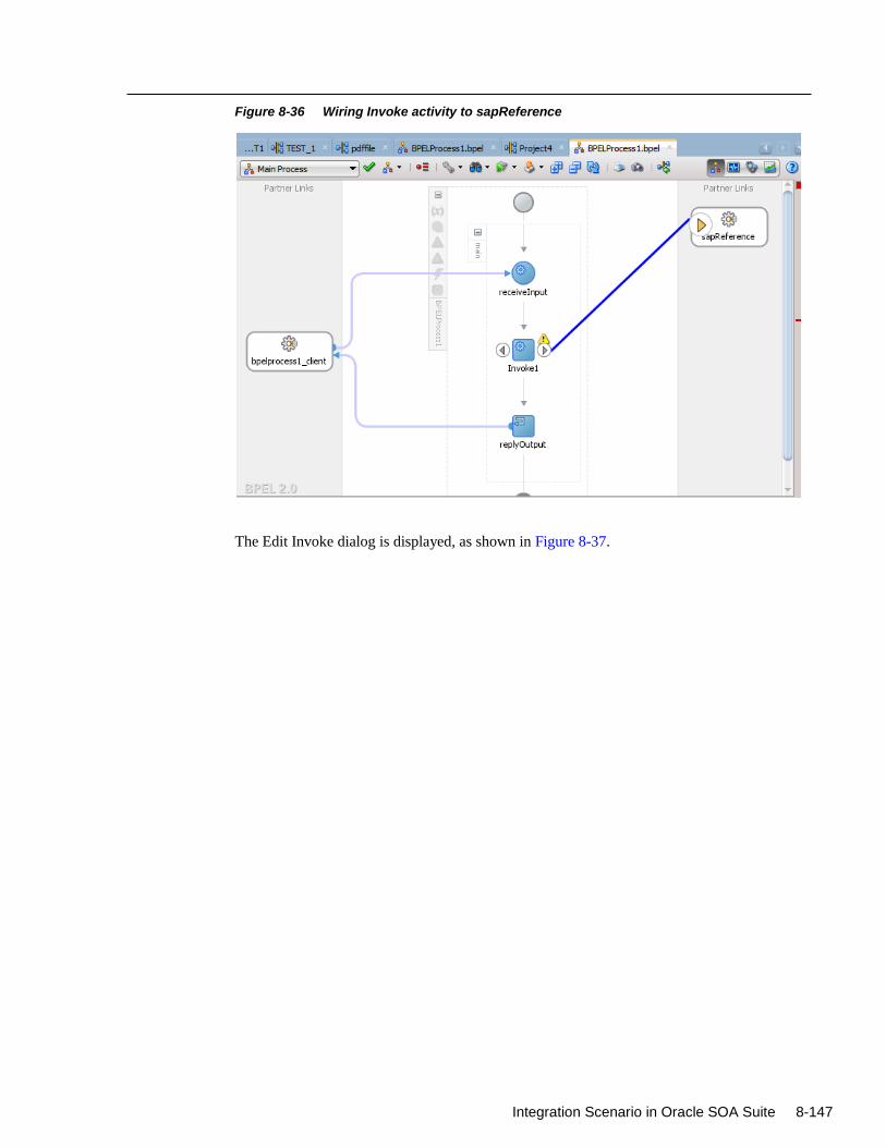
Integration Scenario in Oracle SOA Suite 8-147
Figure 8-36 Wiring Invoke activity to sapReference
The Edit Invoke dialog is displayed, as shown in Figure 8-37.
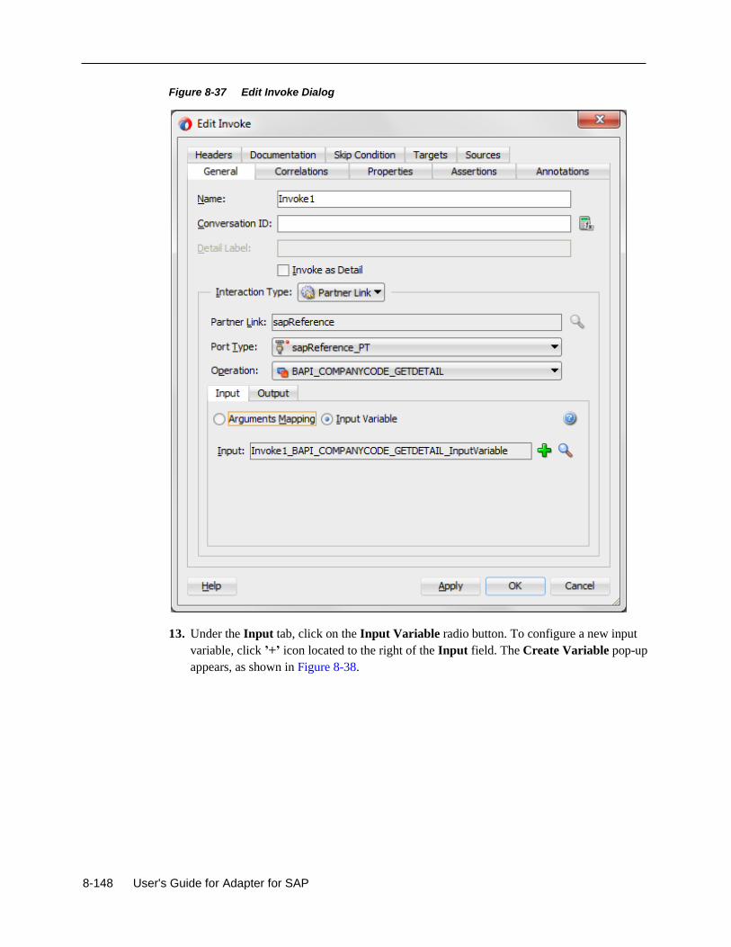
8-148 User's Guide for Adapter for SAP
Figure 8-37 Edit Invoke Dialog
13. Under the Input tab, click on the Input Variable radio button. To configure a new input
variable, click ’+’ icon located to the right of the Input field. The Create Variable pop-up
appears, as shown in Figure 8-38.
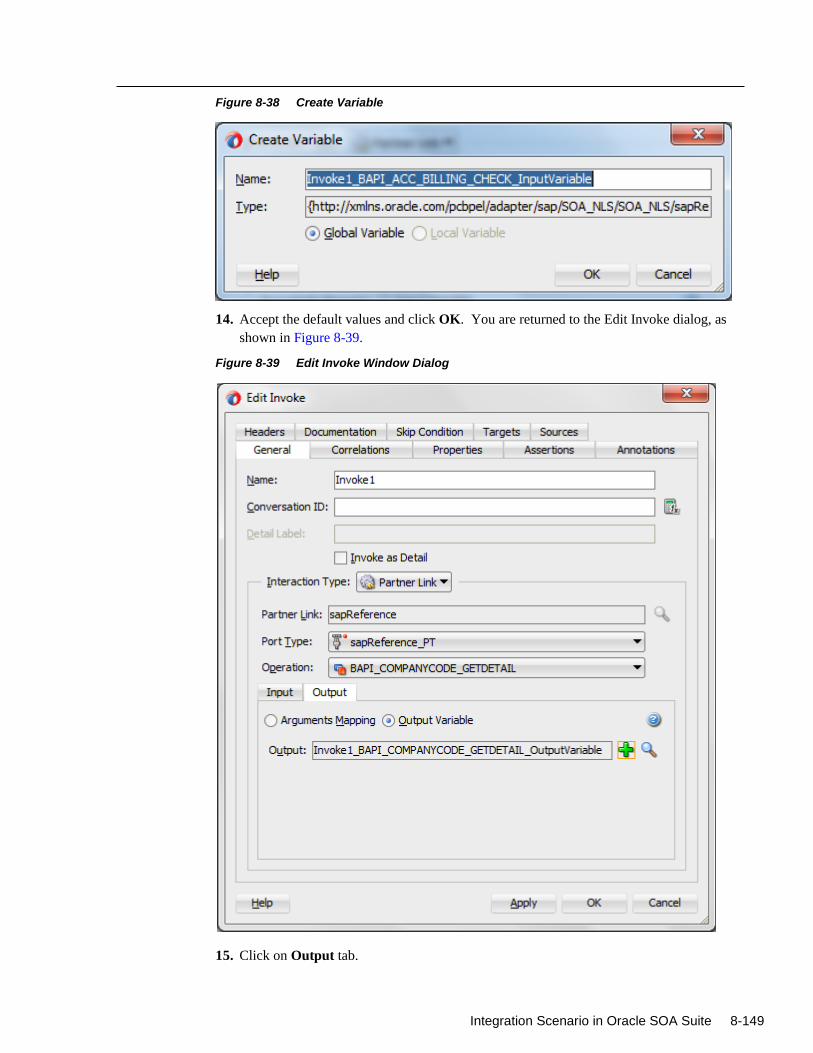
Integration Scenario in Oracle SOA Suite 8-149
Figure 8-38 Create Variable
14. Accept the default values and click OK. You are returned to the Edit Invoke dialog, as
shown in Figure 8-39.
Figure 8-39 Edit Invoke Window Dialog
15. Click on Output tab.
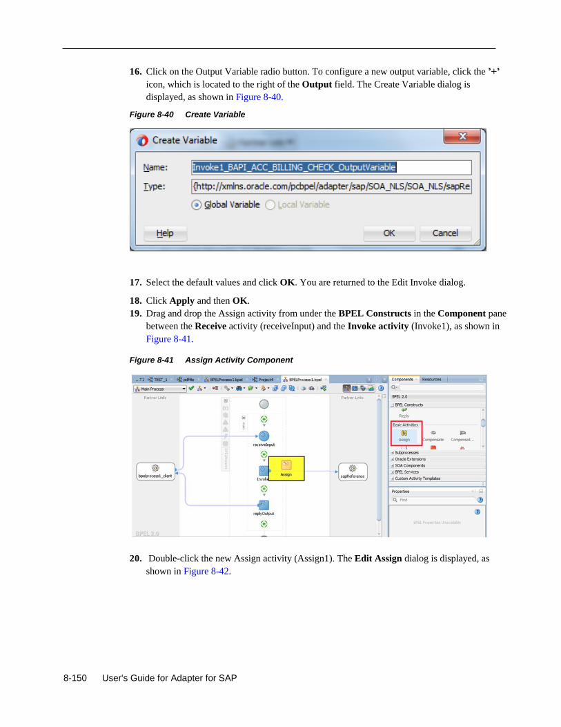
8-150 User's Guide for Adapter for SAP
16. Click on the Output Variable radio button. To configure a new output variable, click the ’+’
icon, which is located to the right of the Output field. The Create Variable dialog is
displayed, as shown in Figure 8-40.
Figure 8-40 Create Variable
17. Select the default values and click OK. You are returned to the Edit Invoke dialog.
18. Click Apply and then OK.
19. Drag and drop the Assign activity from under the BPEL Constructs in the Component pane
between the Receive activity (receiveInput) and the Invoke activity (Invoke1), as shown in
Figure 8-41.
Figure 8-41 Assign Activity Component
20. Double-click the new Assign activity (Assign1). The Edit Assign dialog is displayed, as
shown in Figure 8-42.
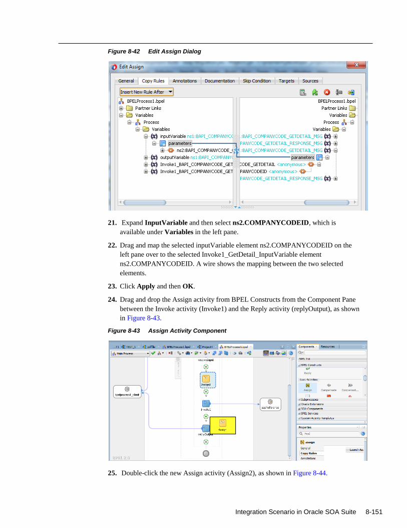
Integration Scenario in Oracle SOA Suite 8-151
Figure 8-42 Edit Assign Dialog
21. Expand InputVariable and then select ns2.COMPANYCODEID, which is
available under Variables in the left pane.
22. Drag and map the selected inputVariable element ns2.COMPANYCODEID on the
left pane over to the selected Invoke1_GetDetail_InputVariable element
ns2.COMPANYCODEID. A wire shows the mapping between the two selected
elements.
23. Click Apply and then OK.
24. Drag and drop the Assign activity from BPEL Constructs from the Component Pane
between the Invoke activity (Invoke1) and the Reply activity (replyOutput), as shown
in Figure 8-43.
Figure 8-43 Assign Activity Component
25. Double-click the new Assign activity (Assign2), as shown in Figure 8-44.
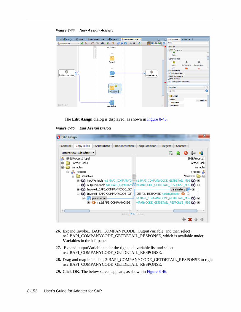
8-152 User's Guide for Adapter for SAP
Figure 8-44 New Assign Activity
The Edit Assign dialog is displayed, as shown in Figure 8-45.
Figure 8-45 Edit Assign Dialog
26. Expand Invoke1_BAPI_COMPANYCODE_OutputVariable, and then select
ns2:BAPI_COMPANYCODE_GETDETAIL_RESPONSE, which is available under
Variables in the left pane.
27. Expand outputVariable under the right side variable list and select
ns2:BAPI_COMPANYCODE_GETDETAIL_RESPONSE.
28. Drag and map left side ns2:BAPI_COMPANYCODE_GETDETAIL_RESPONSE to right
ns2:BAPI_COMPANYCODE_GETDETAIL_RESPONSE.
29. Click OK. The below screen appears, as shown in Figure 8-46.
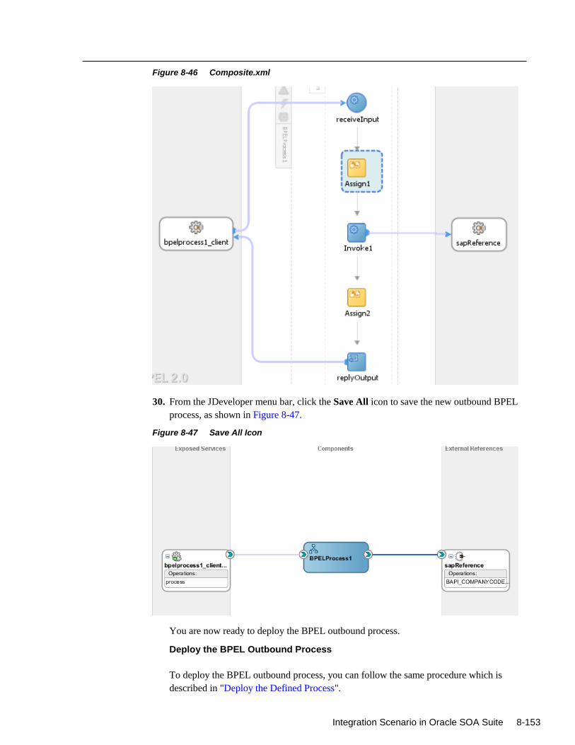
Integration Scenario in Oracle SOA Suite 8-153
Figure 8-46 Composite.xml
30. From the JDeveloper menu bar, click the Save All icon to save the new outbound BPEL
process, as shown in Figure 8-47.
Figure 8-47 Save All Icon
You are now ready to deploy the BPEL outbound process.
Deploy the BPEL Outbound Process
To deploy the BPEL outbound process, you can follow the same procedure which is
described in "Deploy the Defined Process".
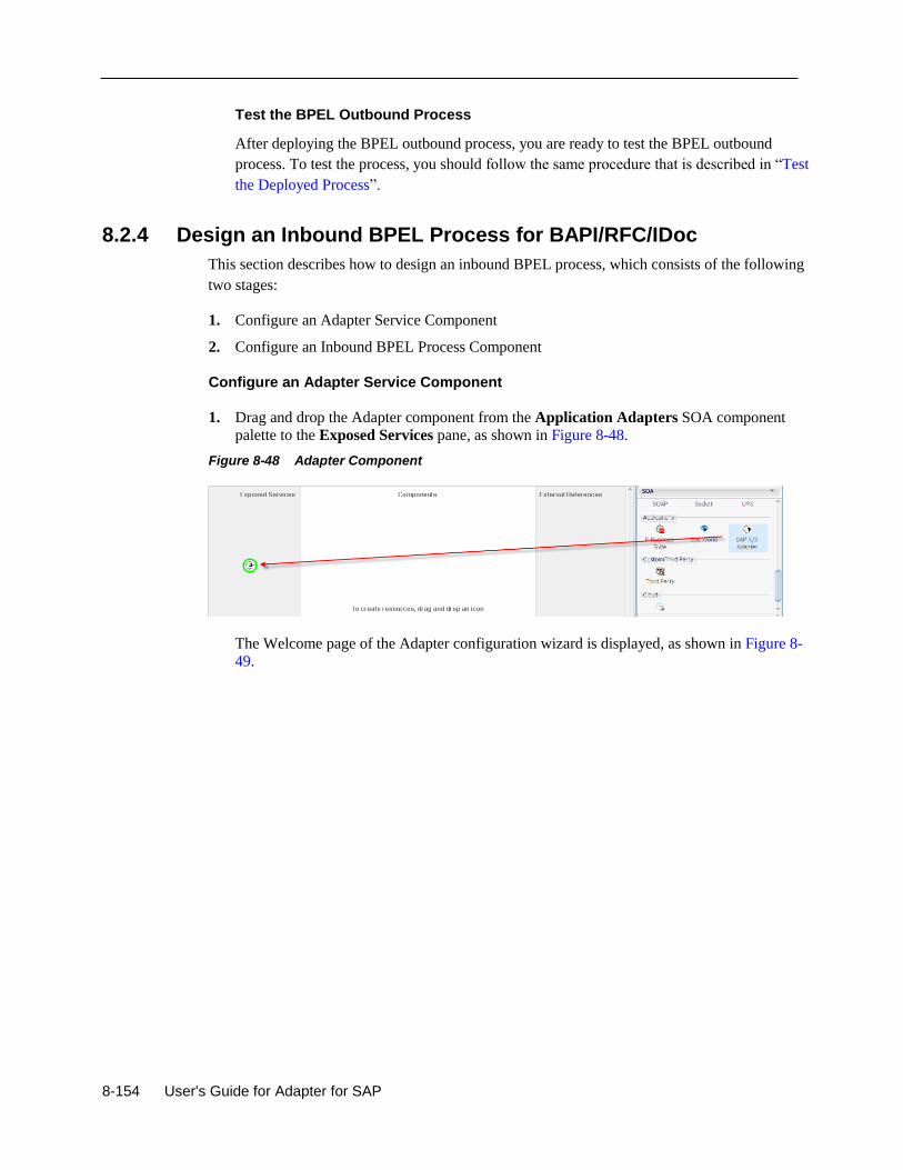
8-154 User's Guide for Adapter for SAP
Test the BPEL Outbound Process
After deploying the BPEL outbound process, you are ready to test the BPEL outbound
process. To test the process, you should follow the same procedure that is described in “Test
the Deployed Process”.
8.2.4 Design an Inbound BPEL Process for BAPI/RFC/IDoc
This section describes how to design an inbound BPEL process, which consists of the following
two stages:
1. Configure an Adapter Service Component
2. Configure an Inbound BPEL Process Component
Configure an Adapter Service Component
1. Drag and drop the Adapter component from the Application Adapters SOA component
palette to the Exposed Services pane, as shown in Figure 8-48.
Figure 8-48 Adapter Component
The Welcome page of the Adapter configuration wizard is displayed, as shown in Figure 8-
49.
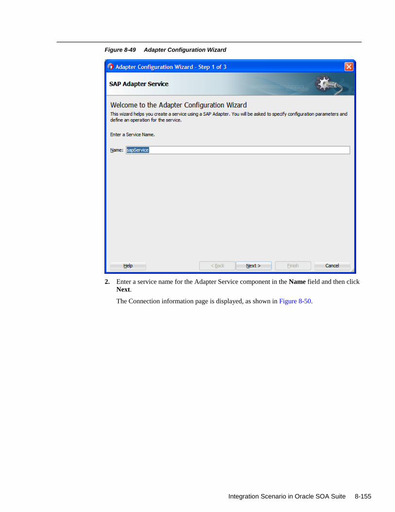
Integration Scenario in Oracle SOA Suite 8-155
Figure 8-49 Adapter Configuration Wizard
2. Enter a service name for the Adapter Service component in the Name field and then click
Next.
The Connection information page is displayed, as shown in Figure 8-50.
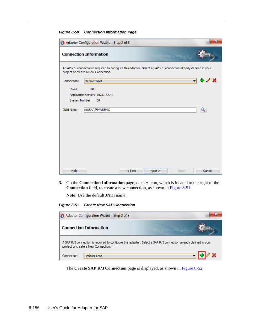
8-156 User's Guide for Adapter for SAP
Figure 8-50 Connection Information Page
3. On the Connection Information page, click + icon, which is located to the right of the
Connection field, to create a new connection, as shown in Figure 8-51.
Note: Use the default JNDI name.
Figure 8-51 Create New SAP Connection
The Create SAP R/3 Connection page is displayed, as shown in Figure 8-52.
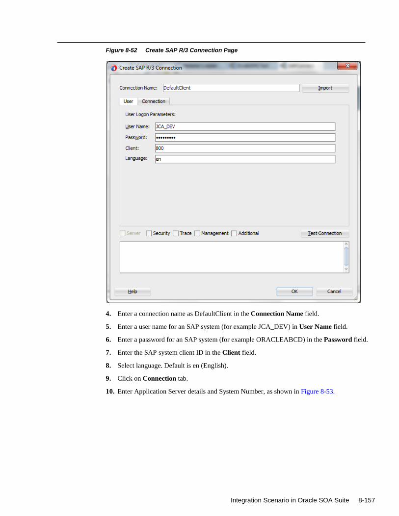
Integration Scenario in Oracle SOA Suite 8-157
Figure 8-52 Create SAP R/3 Connection Page
4. Enter a connection name as DefaultClient in the Connection Name field.
5. Enter a user name for an SAP system (for example JCA_DEV) in User Name field.
6. Enter a password for an SAP system (for example ORACLEABCD) in the Password field.
7. Enter the SAP system client ID in the Client field.
8. Select language. Default is en (English).
9. Click on Connection tab.
10. Enter Application Server details and System Number, as shown in Figure 8-53.
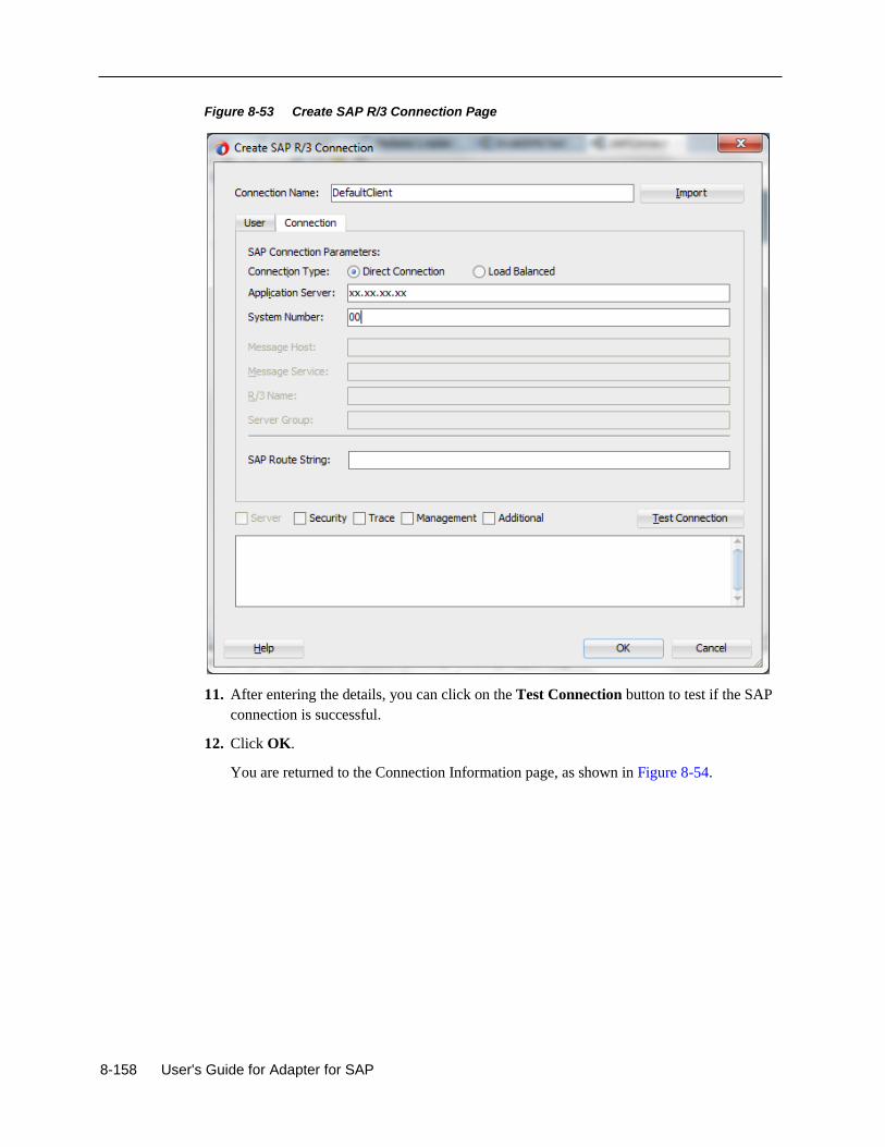
8-158 User's Guide for Adapter for SAP
Figure 8-53 Create SAP R/3 Connection Page
11. After entering the details, you can click on the Test Connection button to test if the SAP
connection is successful.
12. Click OK.
You are returned to the Connection Information page, as shown in Figure 8-54.
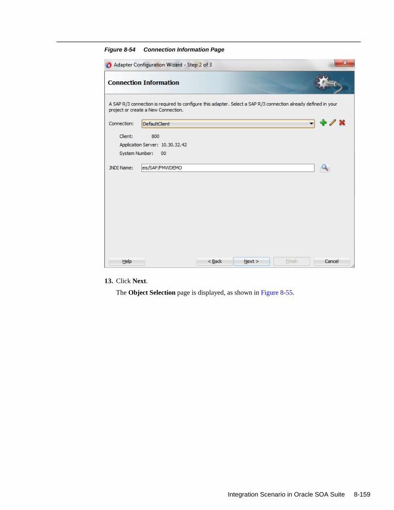
Integration Scenario in Oracle SOA Suite 8-159
Figure 8-54 Connection Information Page
13. Click Next.
The Object Selection page is displayed, as shown in Figure 8-55.
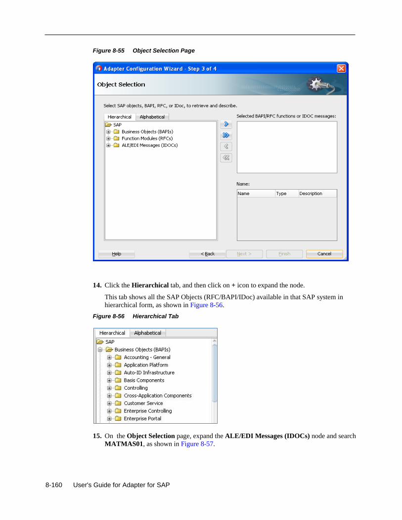
8-160 User's Guide for Adapter for SAP
Figure 8-55 Object Selection Page
14. Click the Hierarchical tab, and then click on + icon to expand the node.
This tab shows all the SAP Objects (RFC/BAPI/IDoc) available in that SAP system in
hierarchical form, as shown in Figure 8-56.
Figure 8-56 Hierarchical Tab
15. On the Object Selection page, expand the ALE/EDI Messages (IDOCs) node and search
MATMAS01, as shown in Figure 8-57.
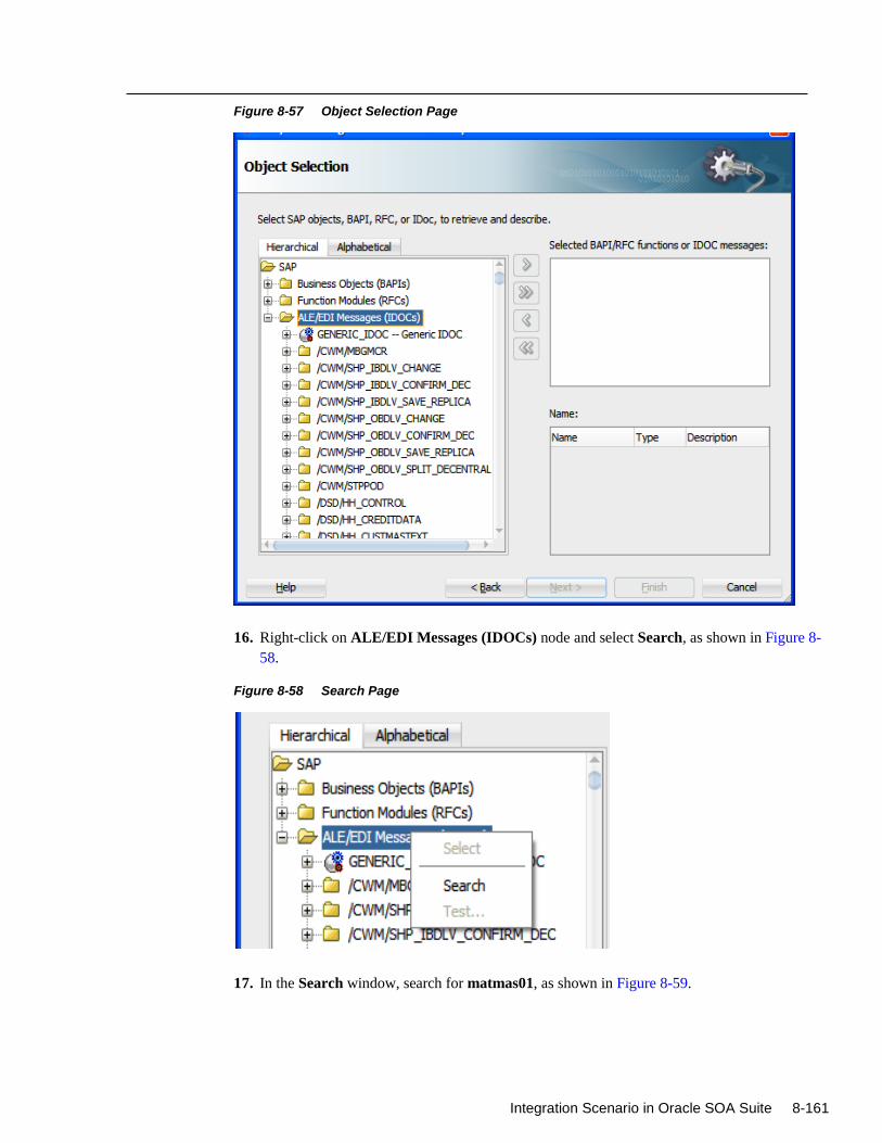
Integration Scenario in Oracle SOA Suite 8-161
Figure 8-57 Object Selection Page
16. Right-click on ALE/EDI Messages (IDOCs) node and select Search, as shown in Figure 8-
58.
Figure 8-58 Search Page
17. In the Search window, search for matmas01, as shown in Figure 8-59.
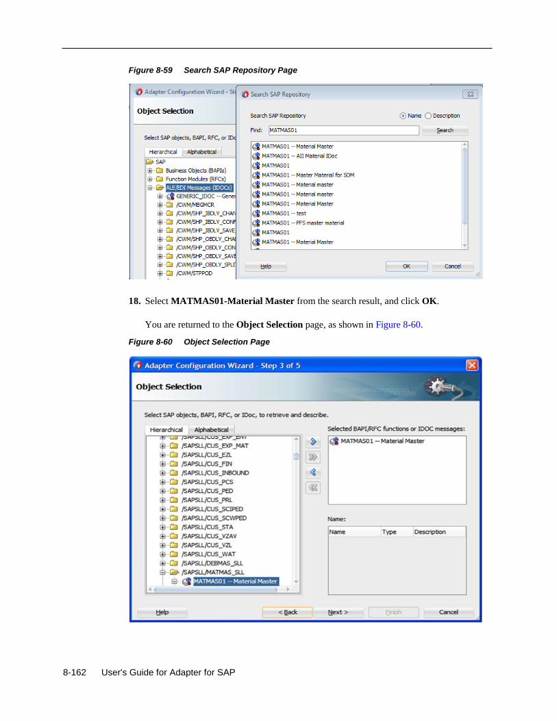
8-162 User's Guide for Adapter for SAP
Figure 8-59 Search SAP Repository Page
18. Select MATMAS01-Material Master from the search result, and click OK.
You are returned to the Object Selection page, as shown in Figure 8-60.
Figure 8-60 Object Selection Page
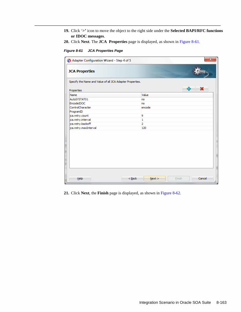
Integration Scenario in Oracle SOA Suite 8-163
19. Click ‘>’ icon to move the object to the right side under the Selected BAPI/RFC functions
or IDOC messages.
20. Click Next. The JCA Properties page is displayed, as shown in Figure 8-61.
Figure 8-61 JCA Properties Page
21. Click Next, the Finish page is displayed, as shown in Figure 8-62.
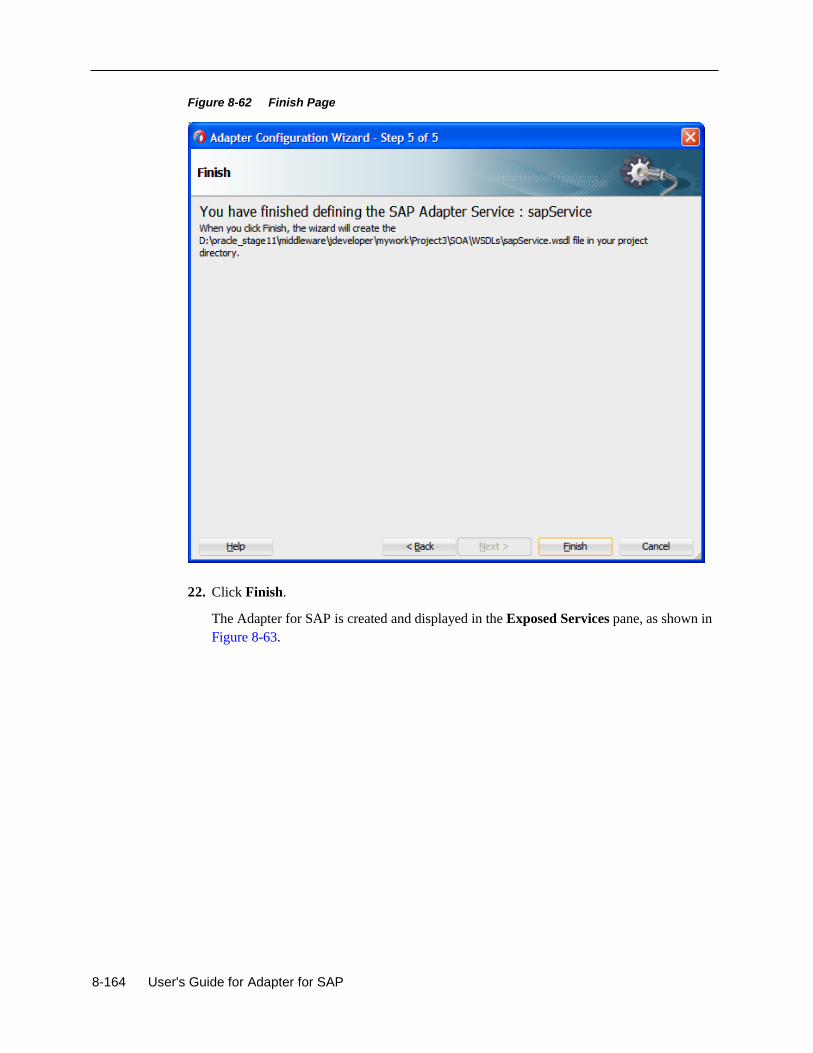
8-164 User's Guide for Adapter for SAP
Figure 8-62 Finish Page
22. Click Finish.
The Adapter for SAP is created and displayed in the Exposed Services pane, as shown in
Figure 8-63.

Integration Scenario in Oracle SOA Suite 8-165
Figure 8-63 Adapter Component
You are now ready to configure an inbound BPEL process component.
Configuring an Inbound BPEL Process Component
Perform the following steps to create an inbound BPEL process component:
1. Create an Empty composite. Refer to section “Create an Empty Composite”
2. Drag and drop the BPEL Process component from the SOA Components palette to the
Components pane in the composite, as shown in Figure 8-64.
Figure 8-64 BPEL Process Component
The Create BPEL Process dialog is displayed, as shown in Figure 8-65.
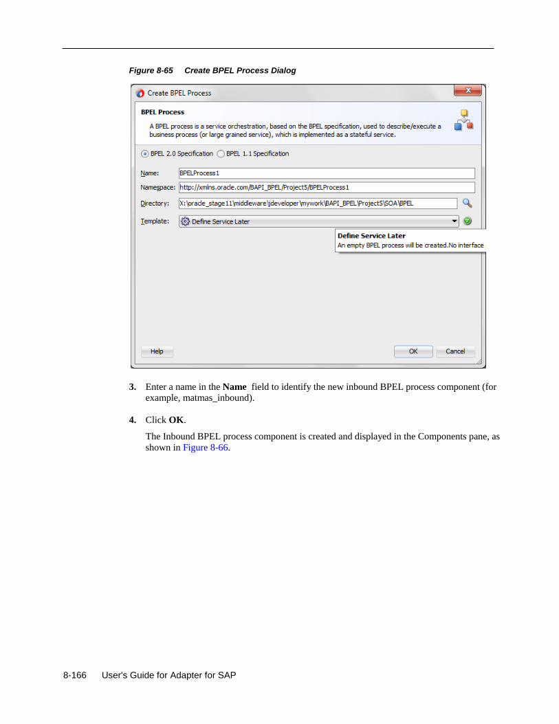
8-166 User's Guide for Adapter for SAP
Figure 8-65 Create BPEL Process Dialog
3. Enter a name in the Name field to identify the new inbound BPEL process component (for
example, matmas_inbound).
4. Click OK.
The Inbound BPEL process component is created and displayed in the Components pane, as
shown in Figure 8-66.
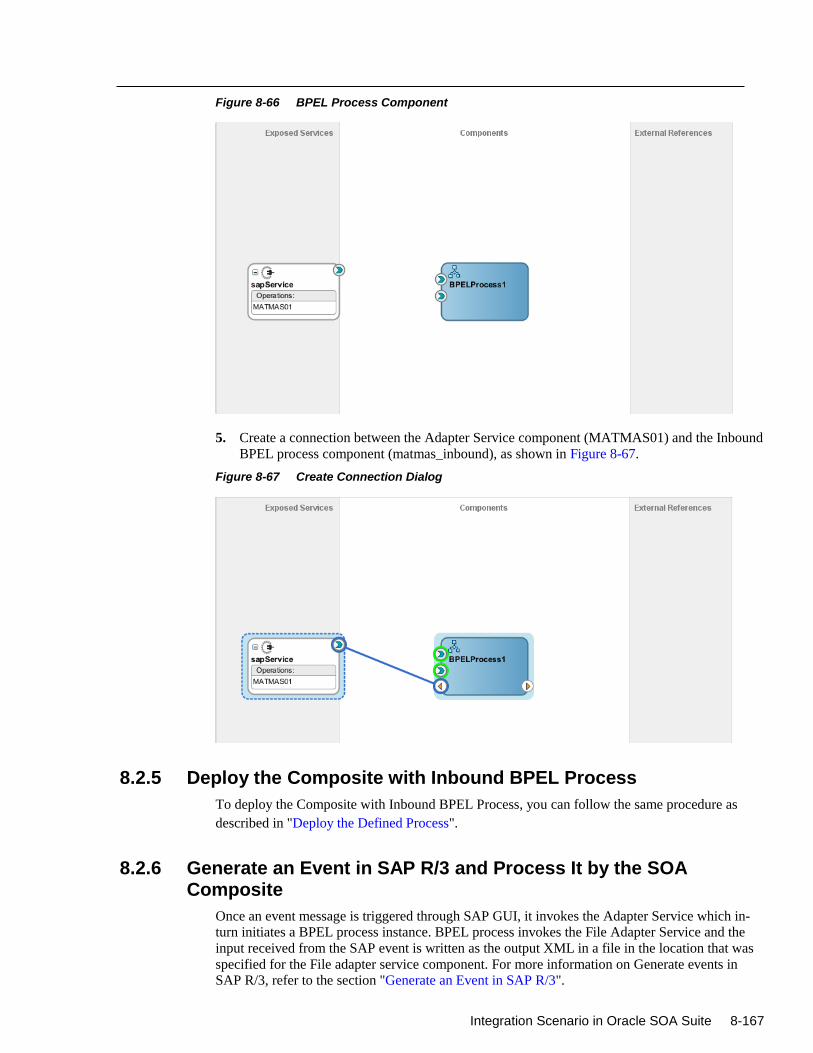
Integration Scenario in Oracle SOA Suite 8-167
Figure 8-66 BPEL Process Component
5. Create a connection between the Adapter Service component (MATMAS01) and the Inbound
BPEL process component (matmas_inbound), as shown in Figure 8-67.
Figure 8-67 Create Connection Dialog
8.2.5 Deploy the Composite with Inbound BPEL Process
To deploy the Composite with Inbound BPEL Process, you can follow the same procedure as
described in "Deploy the Defined Process".
8.2.6 Generate an Event in SAP R/3 and Process It by the SOA Composite
Once an event message is triggered through SAP GUI, it invokes the Adapter Service which in-
turn initiates a BPEL process instance. BPEL process invokes the File Adapter Service and the
input received from the SAP event is written as the output XML in a file in the location that was
specified for the File adapter service component. For more information on Generate events in
SAP R/3, refer to the section "Generate an Event in SAP R/3".
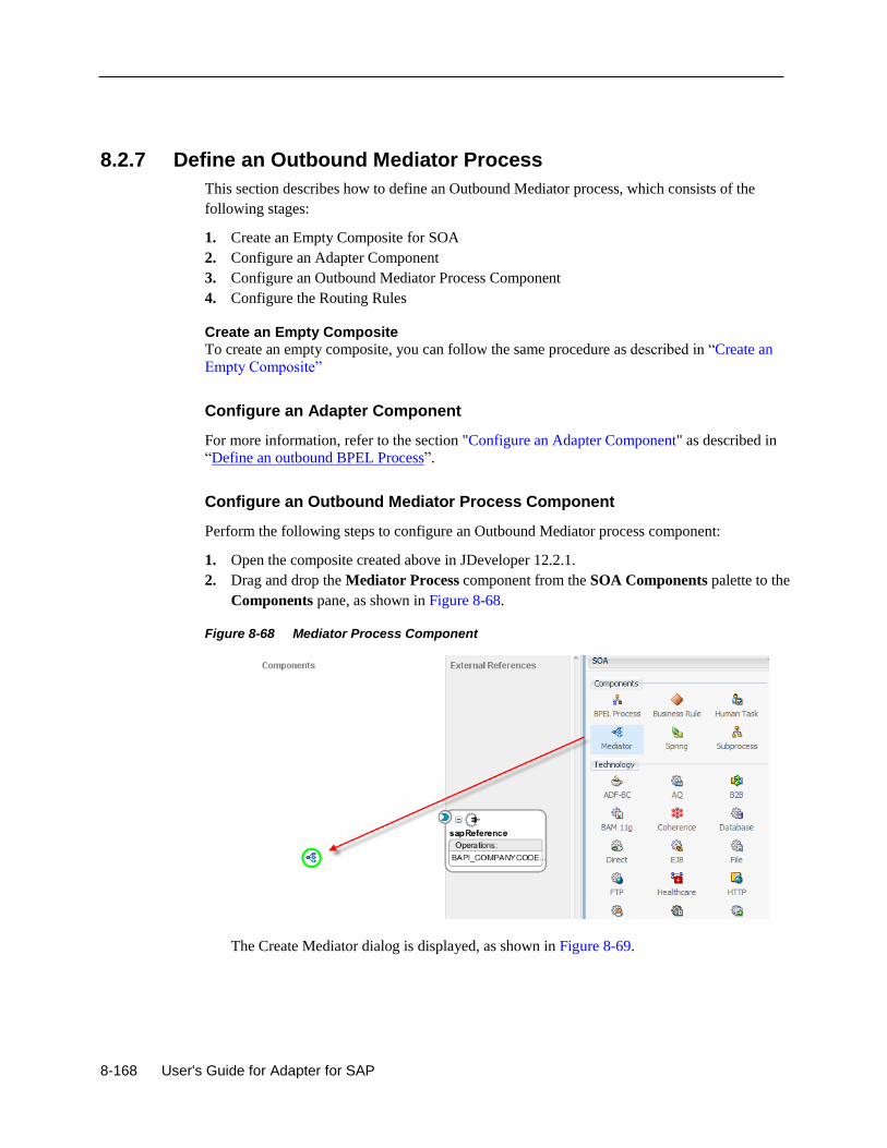
8-168 User's Guide for Adapter for SAP
8.2.7 Define an Outbound Mediator Process
This section describes how to define an Outbound Mediator process, which consists of the
following stages:
1. Create an Empty Composite for SOA
2. Configure an Adapter Component
3. Configure an Outbound Mediator Process Component
4. Configure the Routing Rules
Create an Empty Composite
To create an empty composite, you can follow the same procedure as described in “Create an
Empty Composite”
Configure an Adapter Component
For more information, refer to the section "Configure an Adapter Component" as described in
“Define an outbound BPEL Process”.
Configure an Outbound Mediator Process Component
Perform the following steps to configure an Outbound Mediator process component:
1. Open the composite created above in JDeveloper 12.2.1.
2. Drag and drop the Mediator Process component from the SOA Components palette to the
Components pane, as shown in Figure 8-68.
Figure 8-68 Mediator Process Component
The Create Mediator dialog is displayed, as shown in Figure 8-69.
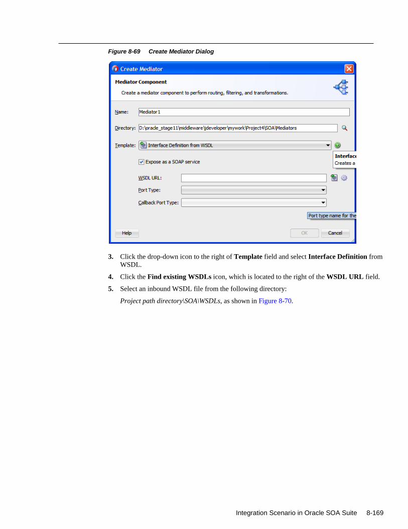
Integration Scenario in Oracle SOA Suite 8-169
Figure 8-69 Create Mediator Dialog
3. Click the drop-down icon to the right of Template field and select Interface Definition from
WSDL.
4. Click the Find existing WSDLs icon, which is located to the right of the WSDL URL field.
5. Select an inbound WSDL file from the following directory:
Project path directory\SOA\WSDLs, as shown in Figure 8-70.
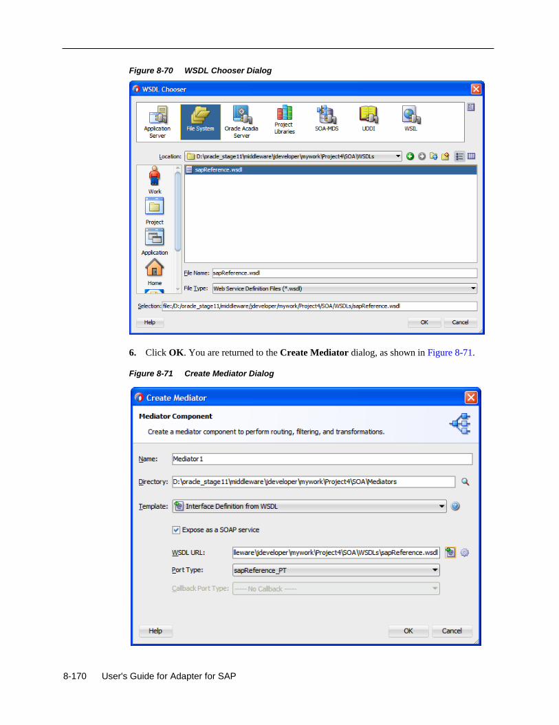
8-170 User's Guide for Adapter for SAP
Figure 8-70 WSDL Chooser Dialog
6. Click OK. You are returned to the Create Mediator dialog, as shown in Figure 8-71.
Figure 8-71 Create Mediator Dialog
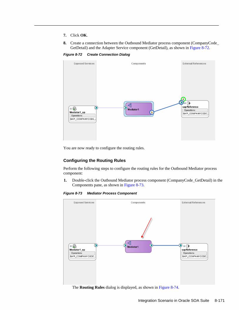
Integration Scenario in Oracle SOA Suite 8-171
7. Click OK.
8. Create a connection between the Outbound Mediator process component (CompanyCode_
GetDetail) and the Adapter Service component (GetDetail), as shown in Figure 8-72.
Figure 8-72 Create Connection Dialog
You are now ready to configure the routing rules.
Configuring the Routing Rules
Perform the following steps to configure the routing rules for the Outbound Mediator process
component:
1. Double-click the Outbound Mediator process component (CompanyCode_GetDetail) in the
Components pane, as shown in Figure 8-73.
Figure 8-73 Mediator Process Component
The Routing Rules dialog is displayed, as shown in Figure 8-74.
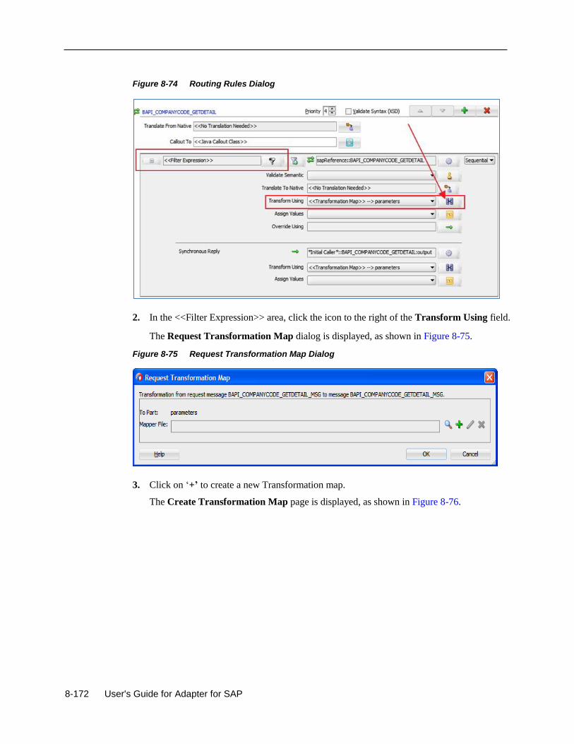
8-172 User's Guide for Adapter for SAP
Figure 8-74 Routing Rules Dialog
2. In the <<Filter Expression>> area, click the icon to the right of the Transform Using field.
The Request Transformation Map dialog is displayed, as shown in Figure 8-75.
Figure 8-75 Request Transformation Map Dialog
3. Click on ‘+’ to create a new Transformation map.
The Create Transformation Map page is displayed, as shown in Figure 8-76.
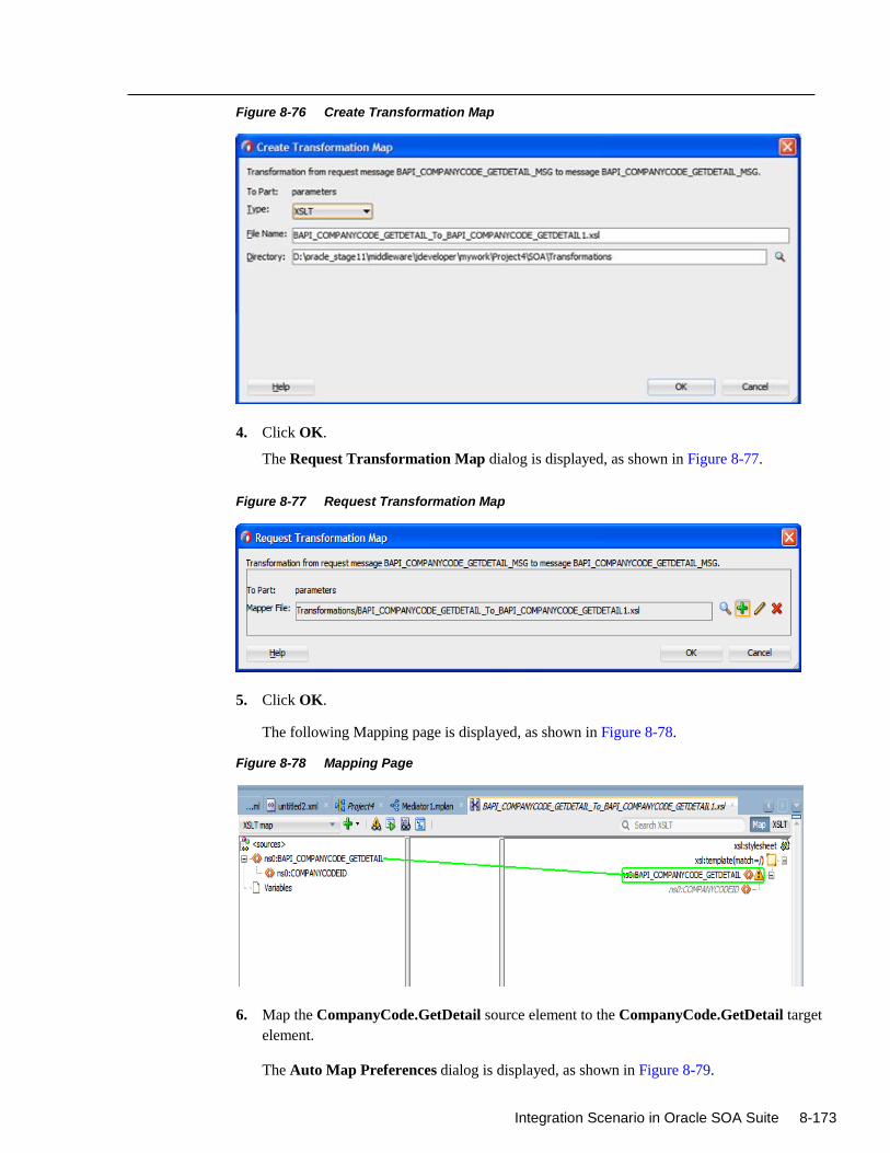
Integration Scenario in Oracle SOA Suite 8-173
Figure 8-76 Create Transformation Map
4. Click OK.
The Request Transformation Map dialog is displayed, as shown in Figure 8-77.
Figure 8-77 Request Transformation Map
5. Click OK.
The following Mapping page is displayed, as shown in Figure 8-78.
Figure 8-78 Mapping Page
6. Map the CompanyCode.GetDetail source element to the CompanyCode.GetDetail target
element.
The Auto Map Preferences dialog is displayed, as shown in Figure 8-79.
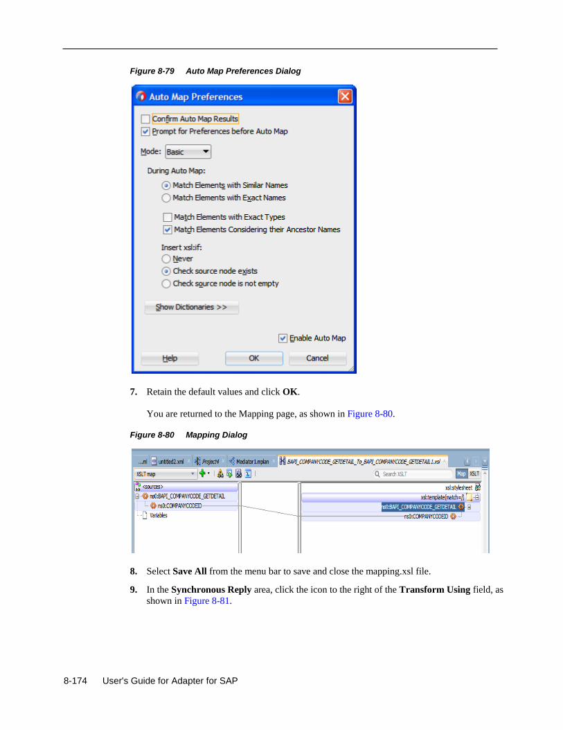
8-174 User's Guide for Adapter for SAP
Figure 8-79 Auto Map Preferences Dialog
7. Retain the default values and click OK.
You are returned to the Mapping page, as shown in Figure 8-80.
Figure 8-80 Mapping Dialog
8. Select Save All from the menu bar to save and close the mapping.xsl file.
9. In the Synchronous Reply area, click the icon to the right of the Transform Using field, as
shown in Figure 8-81.
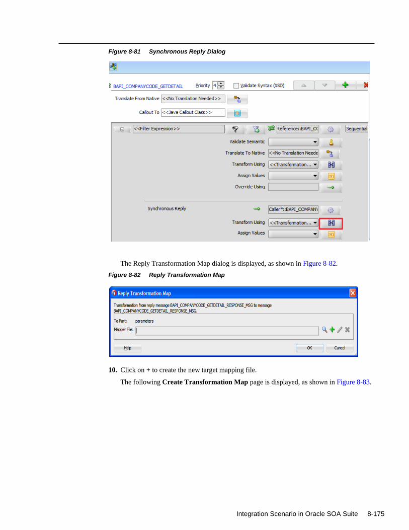
Integration Scenario in Oracle SOA Suite 8-175
Figure 8-81 Synchronous Reply Dialog
The Reply Transformation Map dialog is displayed, as shown in Figure 8-82.
Figure 8-82 Reply Transformation Map
10. Click on + to create the new target mapping file.
The following Create Transformation Map page is displayed, as shown in Figure 8-83.
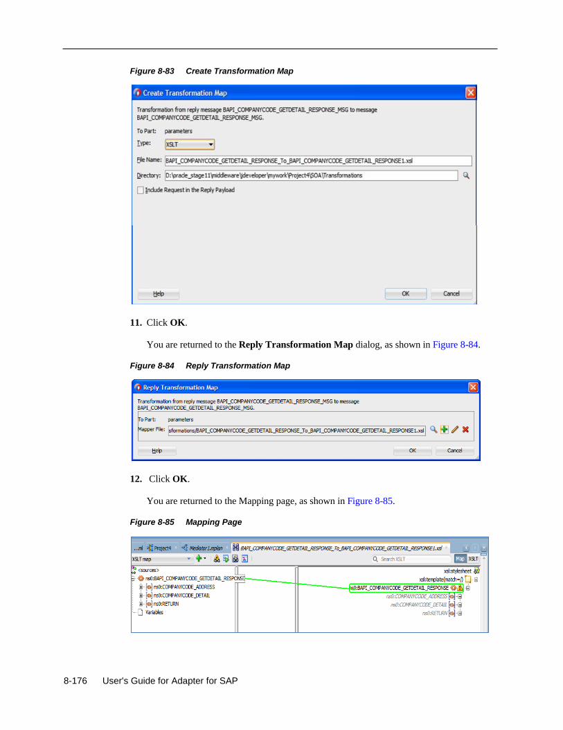
8-176 User's Guide for Adapter for SAP
Figure 8-83 Create Transformation Map
11. Click OK.
You are returned to the Reply Transformation Map dialog, as shown in Figure 8-84.
Figure 8-84 Reply Transformation Map
12. Click OK.
You are returned to the Mapping page, as shown in Figure 8-85.
Figure 8-85 Mapping Page
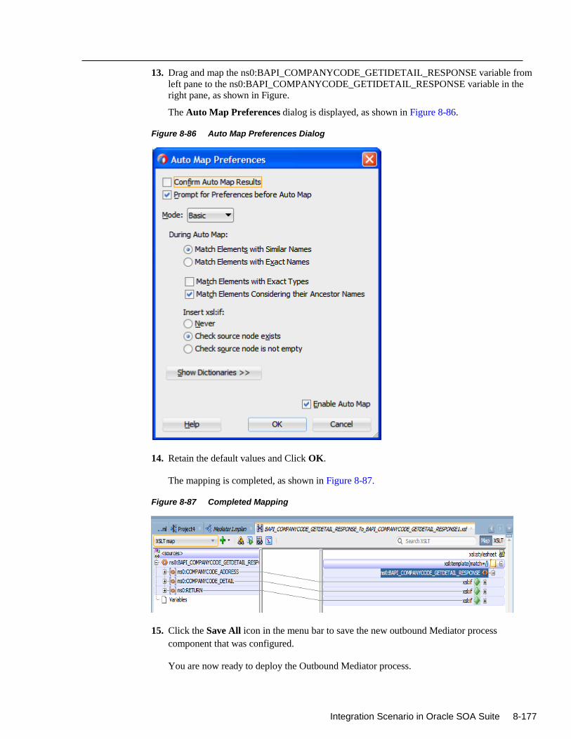
Integration Scenario in Oracle SOA Suite 8-177
13. Drag and map the ns0:BAPI_COMPANYCODE_GETIDETAIL_RESPONSE variable from
left pane to the ns0:BAPI_COMPANYCODE_GETIDETAIL_RESPONSE variable in the
right pane, as shown in Figure.
The Auto Map Preferences dialog is displayed, as shown in Figure 8-86.
Figure 8-86 Auto Map Preferences Dialog
14. Retain the default values and Click OK.
The mapping is completed, as shown in Figure 8-87.
Figure 8-87 Completed Mapping
15. Click the Save All icon in the menu bar to save the new outbound Mediator process
component that was configured.
You are now ready to deploy the Outbound Mediator process.
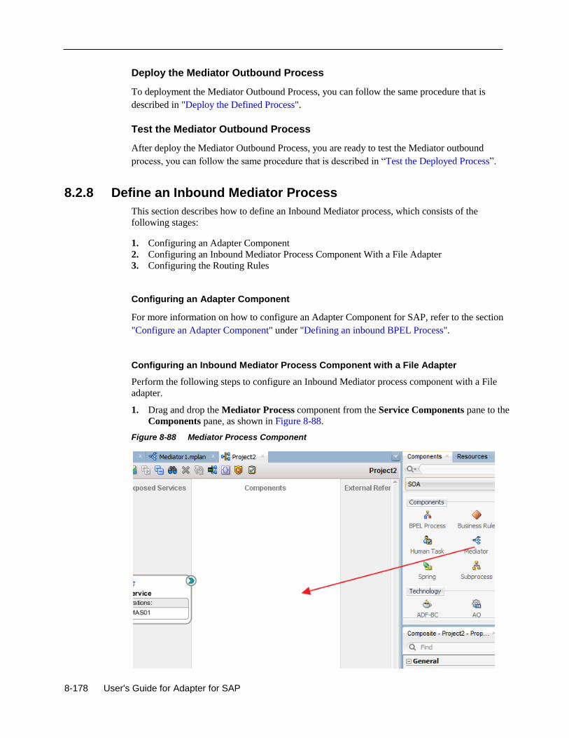
8-178 User's Guide for Adapter for SAP
Deploy the Mediator Outbound Process
To deployment the Mediator Outbound Process, you can follow the same procedure that is
described in "Deploy the Defined Process".
Test the Mediator Outbound Process
After deploy the Mediator Outbound Process, you are ready to test the Mediator outbound
process, you can follow the same procedure that is described in “Test the Deployed Process”.
8.2.8 Define an Inbound Mediator Process
This section describes how to define an Inbound Mediator process, which consists of the
following stages:
1. Configuring an Adapter Component
2. Configuring an Inbound Mediator Process Component With a File Adapter
3. Configuring the Routing Rules
Configuring an Adapter Component
For more information on how to configure an Adapter Component for SAP, refer to the section
"Configure an Adapter Component" under "Defining an inbound BPEL Process".
Configuring an Inbound Mediator Process Component with a File Adapter
Perform the following steps to configure an Inbound Mediator process component with a File
adapter.
1. Drag and drop the Mediator Process component from the Service Components pane to the
Components pane, as shown in Figure 8-88.
Figure 8-88 Mediator Process Component
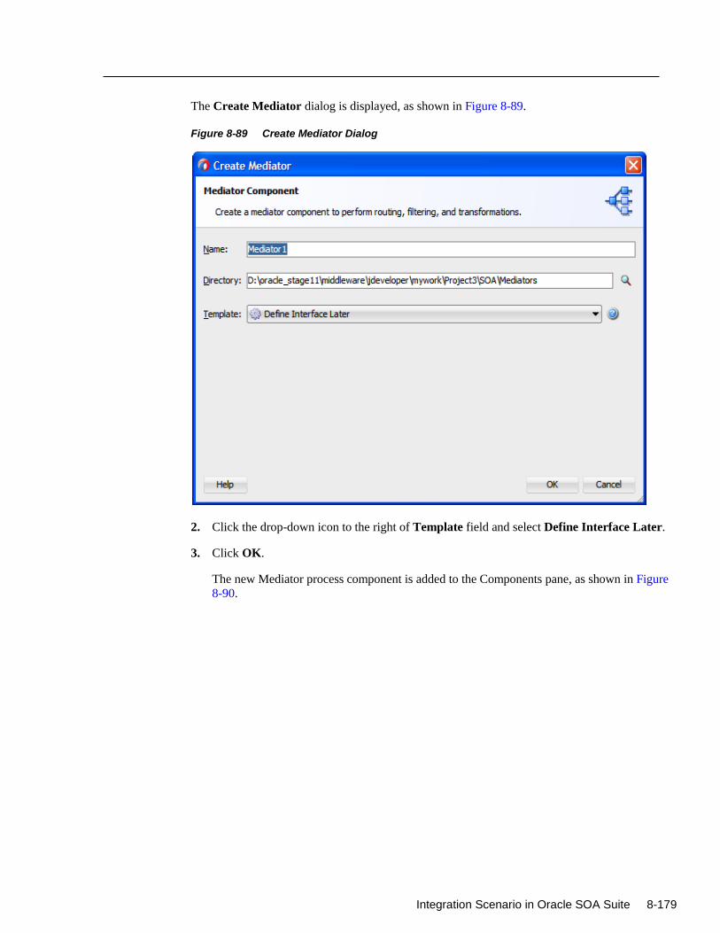
Integration Scenario in Oracle SOA Suite 8-179
The Create Mediator dialog is displayed, as shown in Figure 8-89.
Figure 8-89 Create Mediator Dialog
2. Click the drop-down icon to the right of Template field and select Define Interface Later.
3. Click OK.
The new Mediator process component is added to the Components pane, as shown in Figure
8-90.
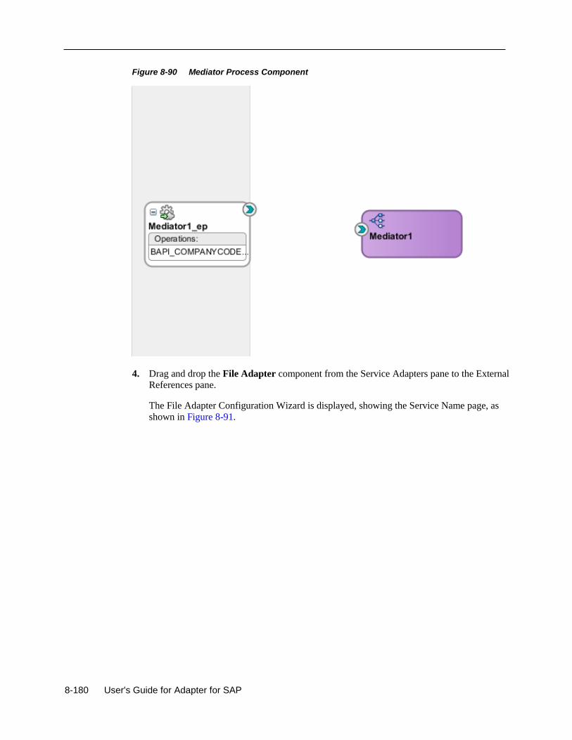
8-180 User's Guide for Adapter for SAP
Figure 8-90 Mediator Process Component
4. Drag and drop the File Adapter component from the Service Adapters pane to the External
References pane.
The File Adapter Configuration Wizard is displayed, showing the Service Name page, as
shown in Figure 8-91.
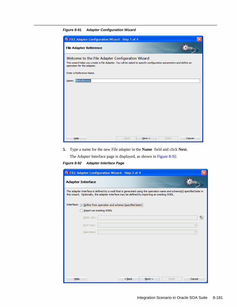
Integration Scenario in Oracle SOA Suite 8-181
Figure 8-91 Adapter Configuration Wizard
5. Type a name for the new File adapter in the Name field and click Next.
The Adapter Interface page is displayed, as shown in Figure 8-92.
Figure 8-92 Adapter Interface Page
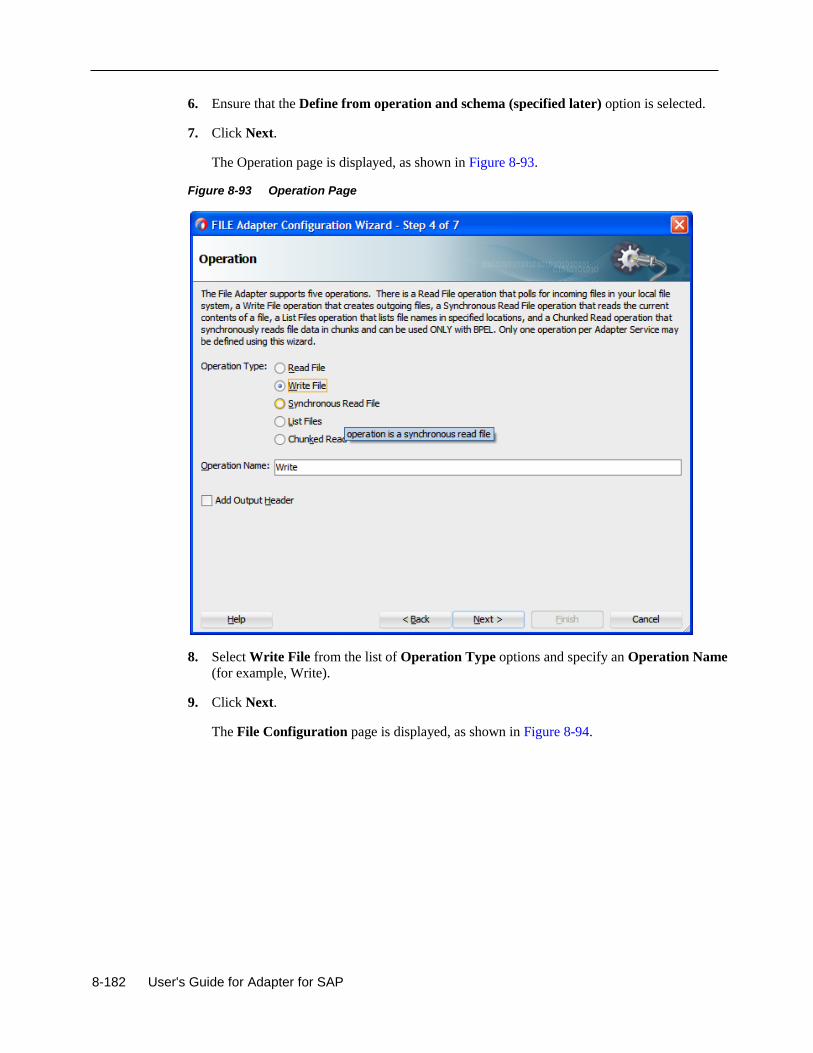
8-182 User's Guide for Adapter for SAP
6. Ensure that the Define from operation and schema (specified later) option is selected.
7. Click Next.
The Operation page is displayed, as shown in Figure 8-93.
Figure 8-93 Operation Page
8. Select Write File from the list of Operation Type options and specify an Operation Name
(for example, Write).
9. Click Next.
The File Configuration page is displayed, as shown in Figure 8-94.
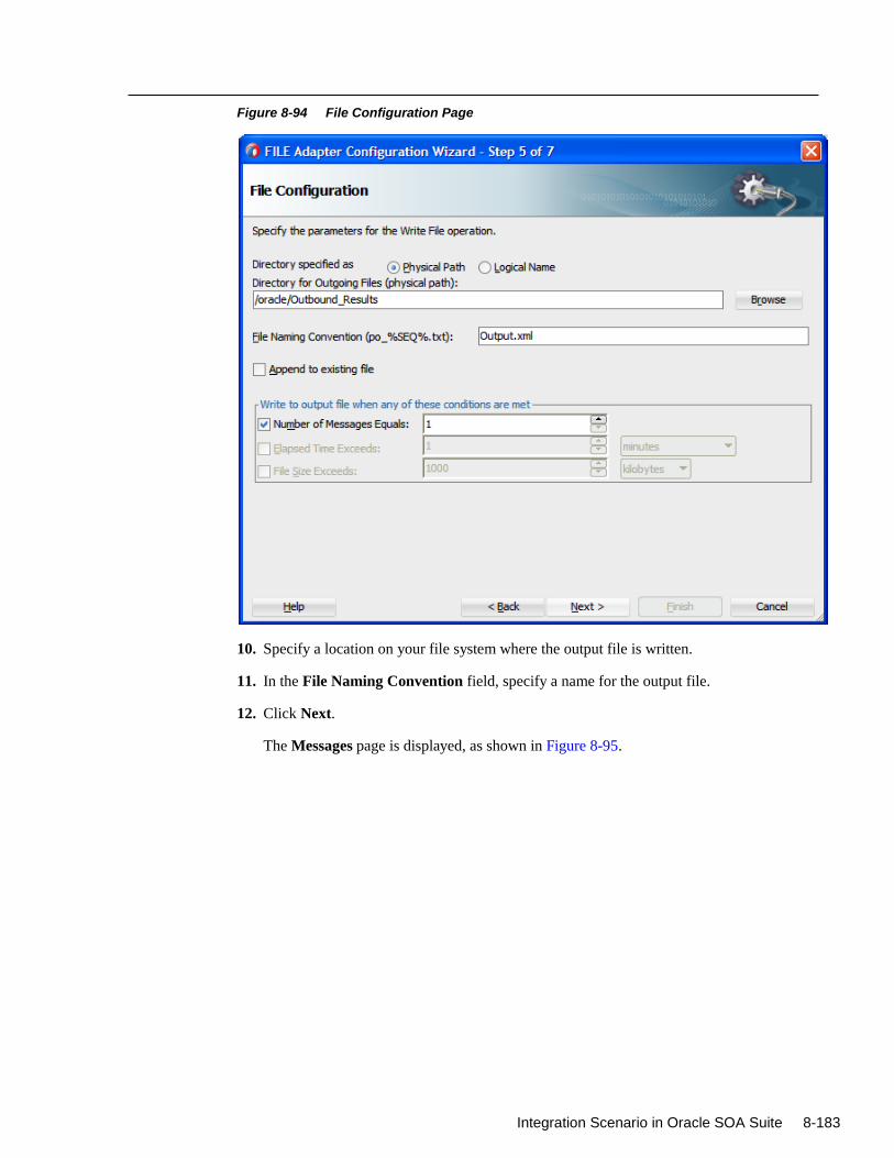
Integration Scenario in Oracle SOA Suite 8-183
Figure 8-94 File Configuration Page
10. Specify a location on your file system where the output file is written.
11. In the File Naming Convention field, specify a name for the output file.
12. Click Next.
The Messages page is displayed, as shown in Figure 8-95.
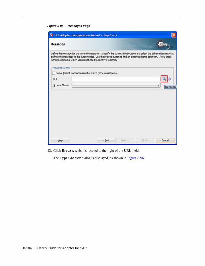
8-184 User's Guide for Adapter for SAP
Figure 8-95 Messages Page
13. Click Browse, which is located to the right of the URL field.
The Type Chooser dialog is displayed, as shown in Figure 8-96.
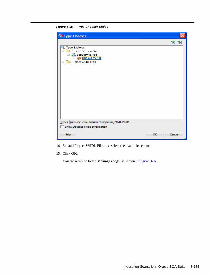
Integration Scenario in Oracle SOA Suite 8-185
Figure 8-96 Type Chooser Dialog
14. Expand Project WSDL Files and select the available schema.
15. Click OK.
You are returned to the Messages page, as shown in Figure 8-97.
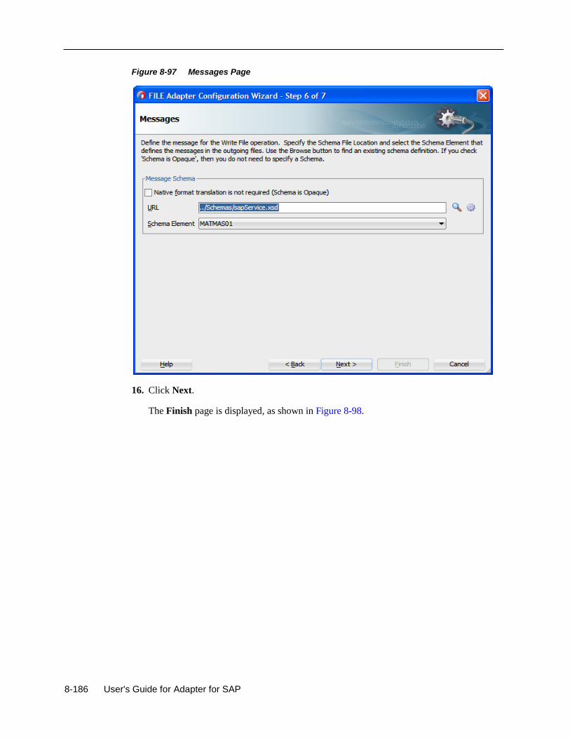
8-186 User's Guide for Adapter for SAP
Figure 8-97 Messages Page
16. Click Next.
The Finish page is displayed, as shown in Figure 8-98.
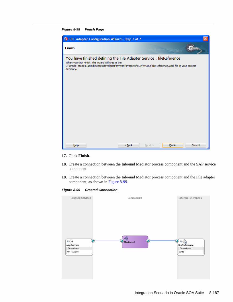
Integration Scenario in Oracle SOA Suite 8-187
Figure 8-98 Finish Page
17. Click Finish.
18. Create a connection between the Inbound Mediator process component and the SAP service
component.
19. Create a connection between the Inbound Mediator process component and the File adapter
component, as shown in Figure 8-99.
Figure 8-99 Created Connection
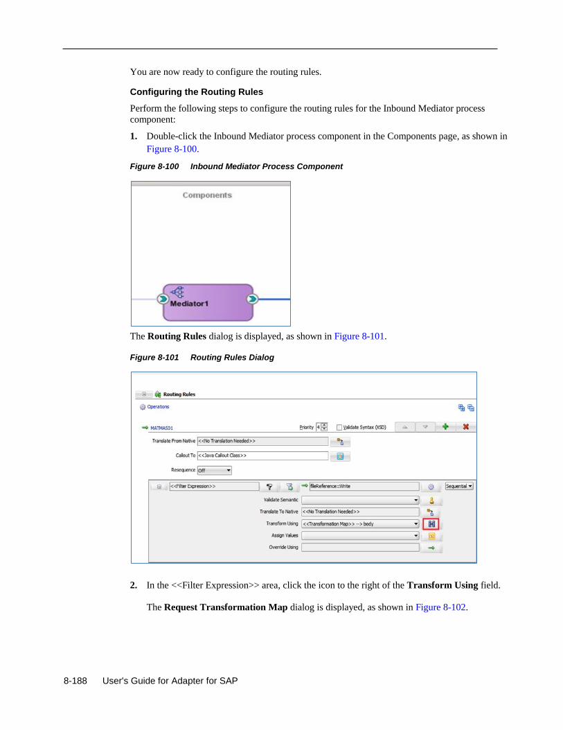
8-188 User's Guide for Adapter for SAP
You are now ready to configure the routing rules.
Configuring the Routing Rules
Perform the following steps to configure the routing rules for the Inbound Mediator process
component:
1. Double-click the Inbound Mediator process component in the Components page, as shown in
Figure 8-100.
Figure 8-100 Inbound Mediator Process Component
The Routing Rules dialog is displayed, as shown in Figure 8-101.
Figure 8-101 Routing Rules Dialog
2. In the <<Filter Expression>> area, click the icon to the right of the Transform Using field.
The Request Transformation Map dialog is displayed, as shown in Figure 8-102.
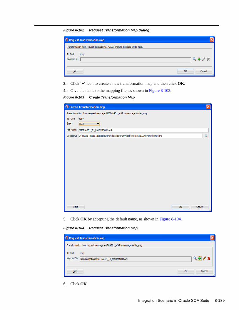
Integration Scenario in Oracle SOA Suite 8-189
Figure 8-102 Request Transformation Map Dialog
3. Click ‘+’ icon to create a new transformation map and then click OK.
4. Give the name to the mapping file, as shown in Figure 8-103.
Figure 8-103 Create Transformation Map
5. Click OK by accepting the default name, as shown in Figure 8-104.
Figure 8-104 Request Transformation Map
6. Click OK.
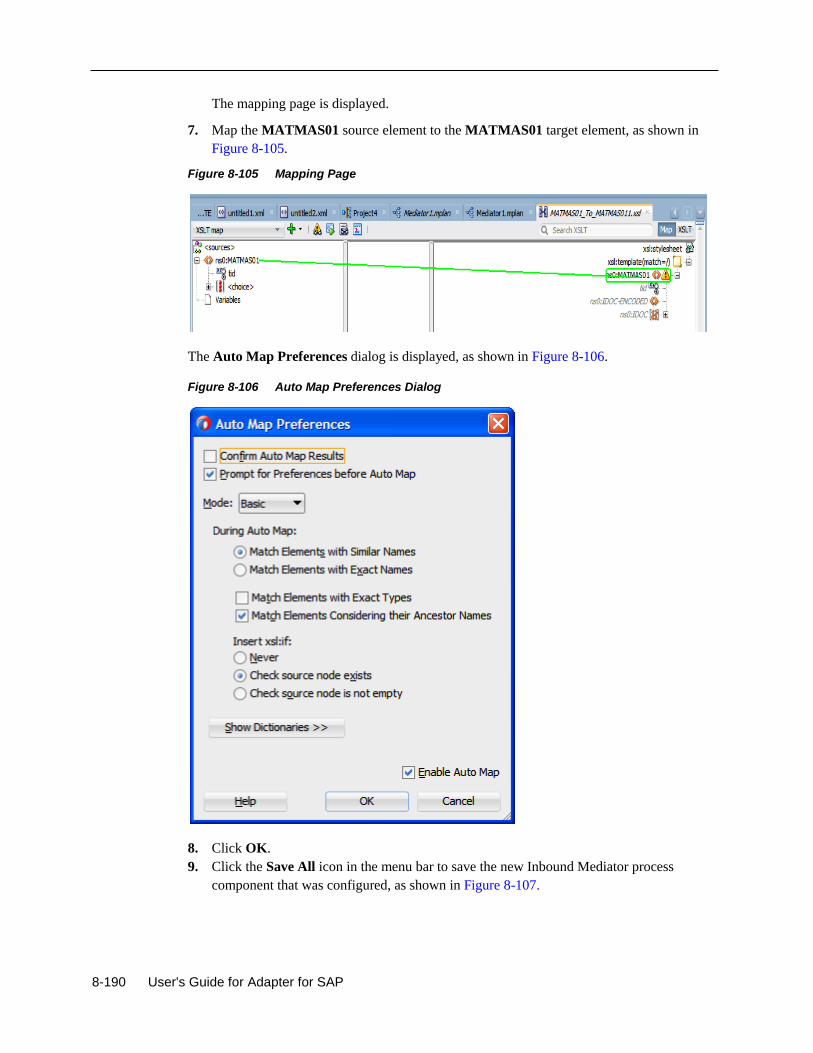
8-190 User's Guide for Adapter for SAP
The mapping page is displayed.
7. Map the MATMAS01 source element to the MATMAS01 target element, as shown in
Figure 8-105.
Figure 8-105 Mapping Page
The Auto Map Preferences dialog is displayed, as shown in Figure 8-106.
Figure 8-106 Auto Map Preferences Dialog
8. Click OK.
9. Click the Save All icon in the menu bar to save the new Inbound Mediator process
component that was configured, as shown in Figure 8-107.
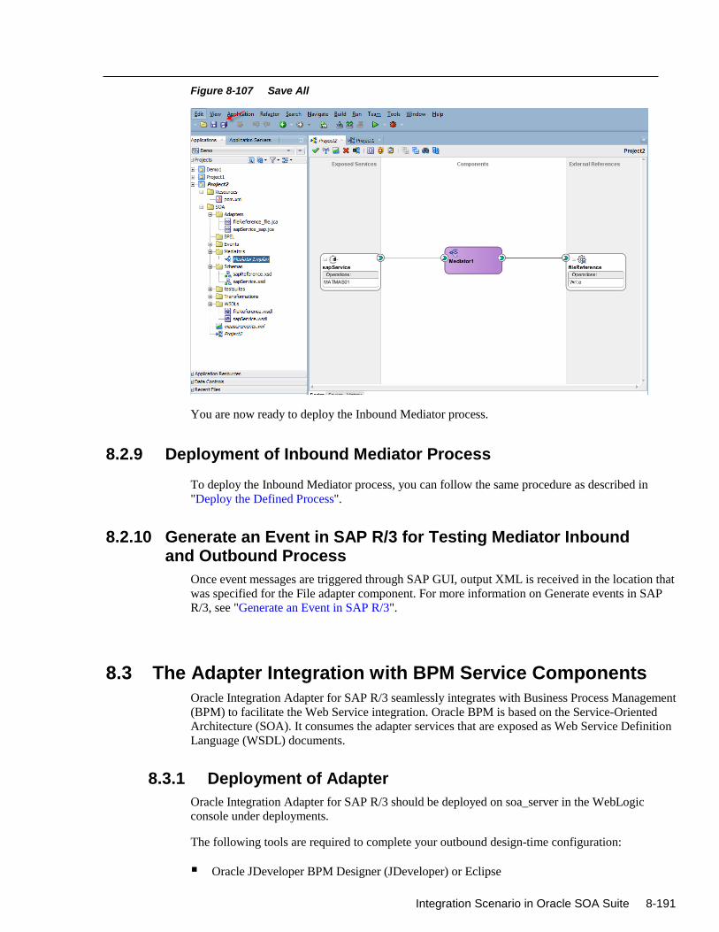
Integration Scenario in Oracle SOA Suite 8-191
Figure 8-107 Save All
You are now ready to deploy the Inbound Mediator process.
8.2.9 Deployment of Inbound Mediator Process
To deploy the Inbound Mediator process, you can follow the same procedure as described in
"Deploy the Defined Process".
8.2.10 Generate an Event in SAP R/3 for Testing Mediator Inbound and Outbound Process
Once event messages are triggered through SAP GUI, output XML is received in the location that
was specified for the File adapter component. For more information on Generate events in SAP
R/3, see "Generate an Event in SAP R/3".
8.3 The Adapter Integration with BPM Service Components
Oracle Integration Adapter for SAP R/3 seamlessly integrates with Business Process Management
(BPM) to facilitate the Web Service integration. Oracle BPM is based on the Service-Oriented
Architecture (SOA). It consumes the adapter services that are exposed as Web Service Definition
Language (WSDL) documents.
8.3.1 Deployment of Adapter
Oracle Integration Adapter for SAP R/3 should be deployed on soa_server in the WebLogic console under deployments.
The following tools are required to complete your outbound design-time configuration:
Oracle JDeveloper BPM Designer (JDeveloper) or Eclipse
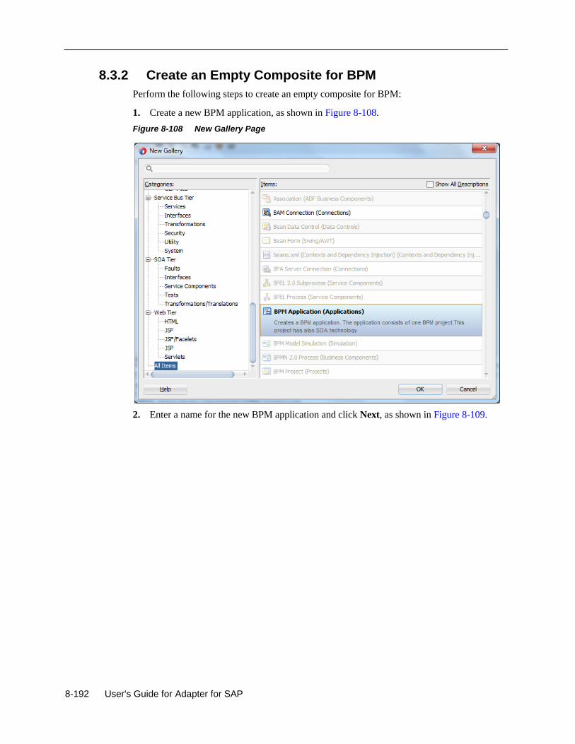
8-192 User's Guide for Adapter for SAP
8.3.2 Create an Empty Composite for BPM
Perform the following steps to create an empty composite for BPM:
1. Create a new BPM application, as shown in Figure 8-108.
Figure 8-108 New Gallery Page
2. Enter a name for the new BPM application and click Next, as shown in Figure 8-109.
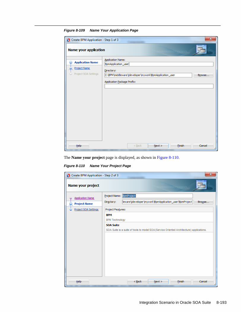
Integration Scenario in Oracle SOA Suite 8-193
Figure 8-109 Name Your Application Page
The Name your project page is displayed, as shown in Figure 8-110.
Figure 8-110 Name Your Project Page
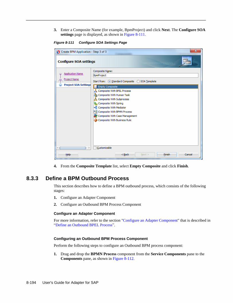
8-194 User's Guide for Adapter for SAP
3. Enter a Composite Name (for example, BpmProject) and click Next. The Configure SOA
settings page is displayed, as shown in Figure 8-111.
Figure 8-111 Configure SOA Settings Page
4. From the Composite Template list, select Empty Composite and click Finish.
8.3.3 Define a BPM Outbound Process
This section describes how to define a BPM outbound process, which consists of the following
stages:
1. Configure an Adapter Component
2. Configure an Outbound BPM Process Component
Configure an Adapter Component
For more information, refer to the section "Configure an Adapter Component" that is described in
“Define an Outbound BPEL Process”.
Configuring an Outbound BPM Process Component
Perform the following steps to configure an Outbound BPM process component:
1. Drag and drop the BPMN Process component from the Service Components pane to the
Components pane, as shown in Figure 8-112.
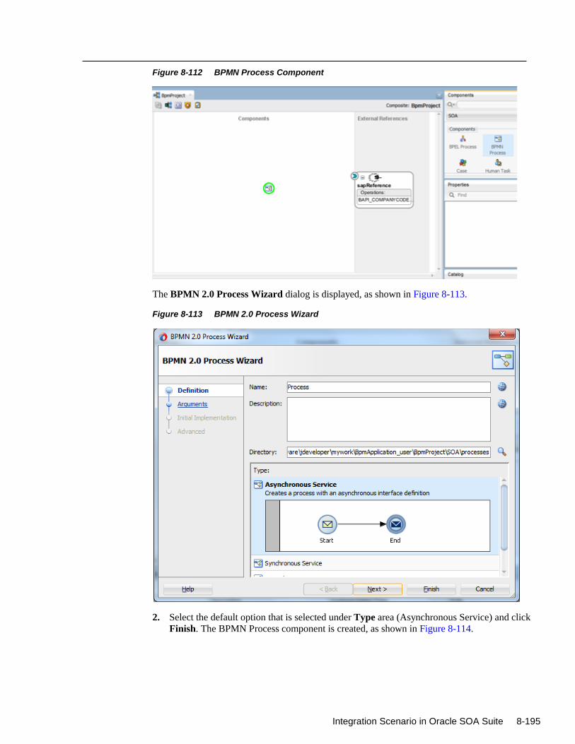
Integration Scenario in Oracle SOA Suite 8-195
Figure 8-112 BPMN Process Component
The BPMN 2.0 Process Wizard dialog is displayed, as shown in Figure 8-113.
Figure 8-113 BPMN 2.0 Process Wizard
2. Select the default option that is selected under Type area (Asynchronous Service) and click
Finish. The BPMN Process component is created, as shown in Figure 8-114.
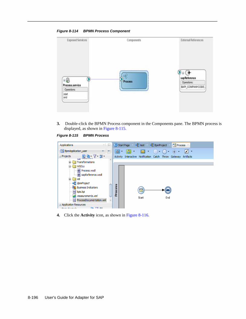
8-196 User's Guide for Adapter for SAP
Figure 8-114 BPMN Process Component
3. Double-click the BPMN Process component in the Components pane. The BPMN process is
displayed, as shown in Figure 8-115.
Figure 8-115 BPMN Process
4. Click the Activity icon, as shown in Figure 8-116.
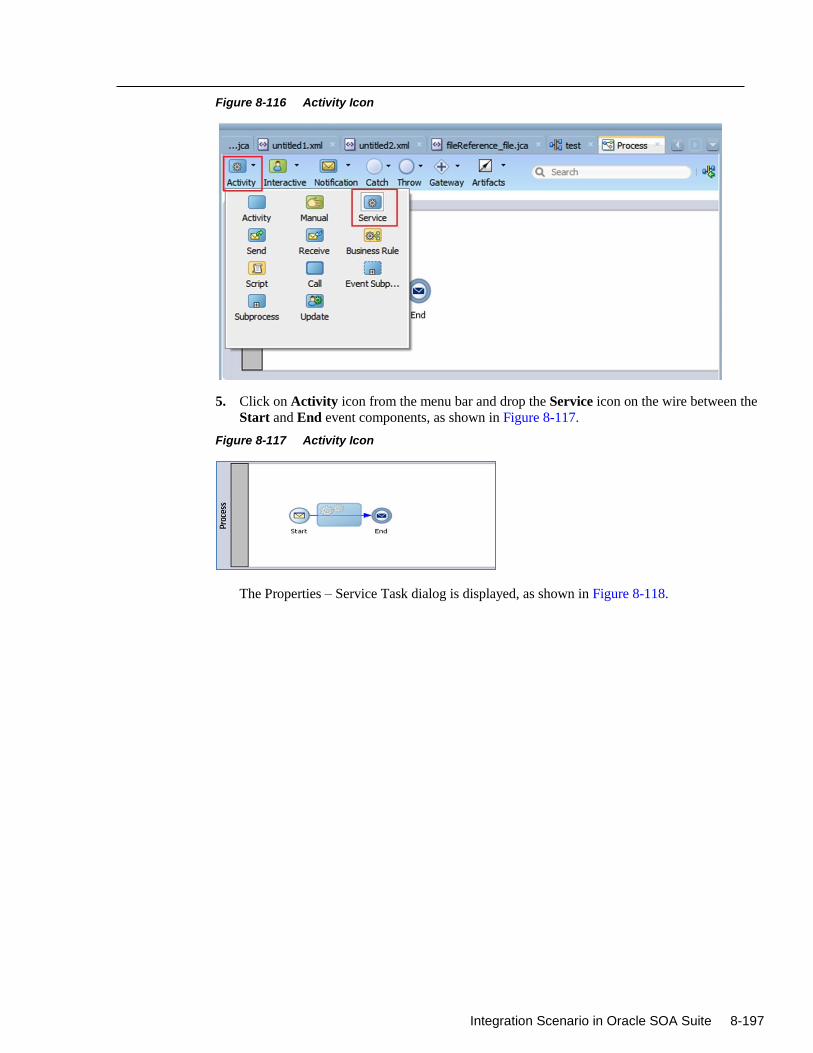
Integration Scenario in Oracle SOA Suite 8-197
Figure 8-116 Activity Icon
5. Click on Activity icon from the menu bar and drop the Service icon on the wire between the
Start and End event components, as shown in Figure 8-117.
Figure 8-117 Activity Icon
The Properties – Service Task dialog is displayed, as shown in Figure 8-118.
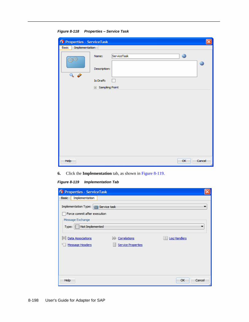
8-198 User's Guide for Adapter for SAP
Figure 8-118 Properties – Service Task
6. Click the Implementation tab, as shown in Figure 8-119.
Figure 8-119 Implementation Tab
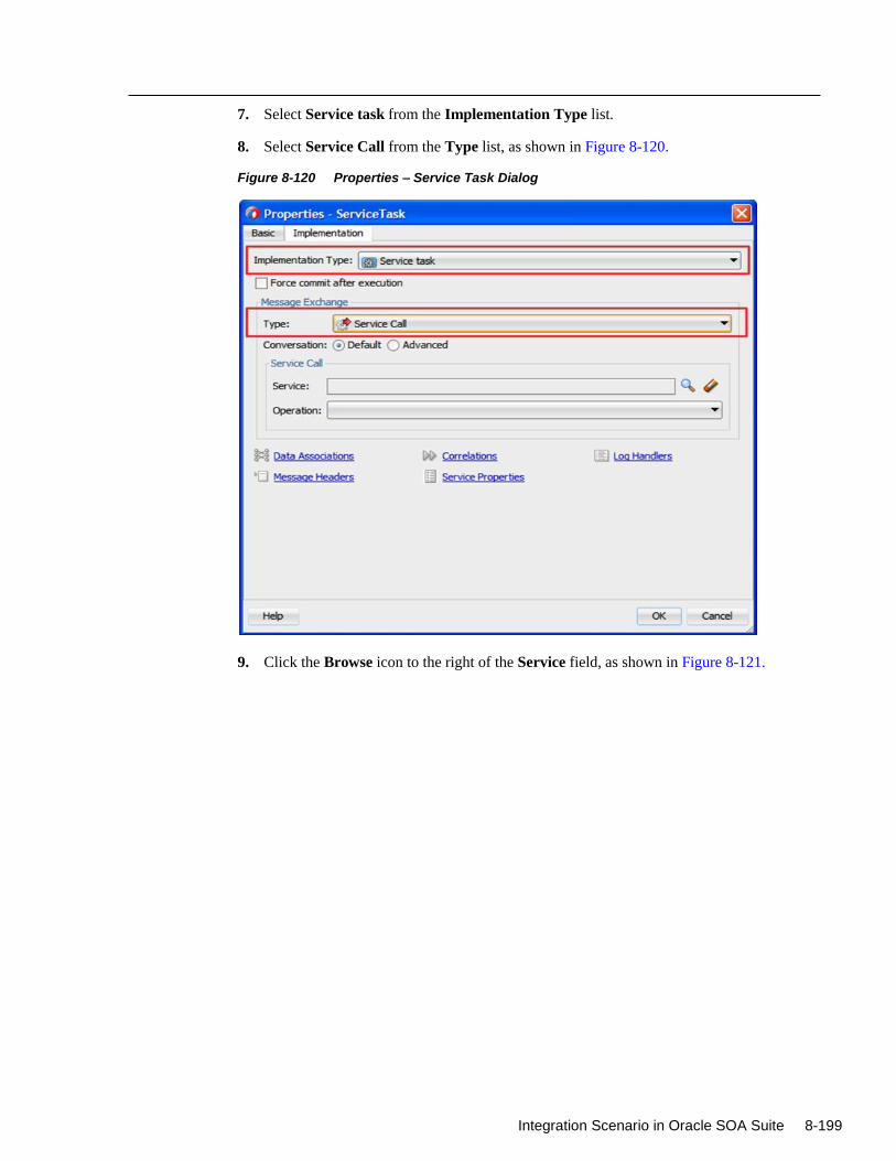
Integration Scenario in Oracle SOA Suite 8-199
7. Select Service task from the Implementation Type list.
8. Select Service Call from the Type list, as shown in Figure 8-120.
Figure 8-120 Properties – Service Task Dialog
9. Click the Browse icon to the right of the Service field, as shown in Figure 8-121.
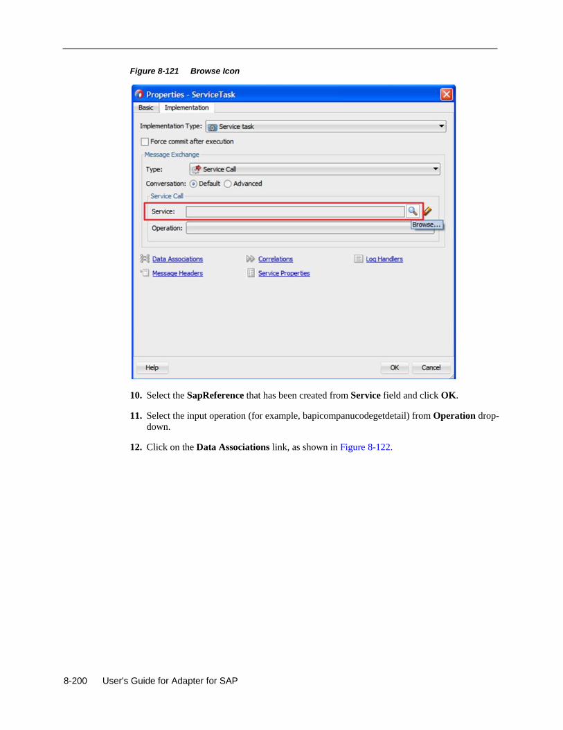
8-200 User's Guide for Adapter for SAP
Figure 8-121 Browse Icon
10. Select the SapReference that has been created from Service field and click OK.
11. Select the input operation (for example, bapicompanucodegetdetail) from Operation drop-
down.
12. Click on the Data Associations link, as shown in Figure 8-122.
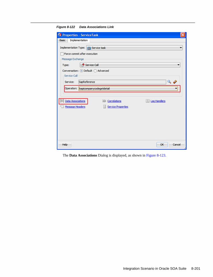
Integration Scenario in Oracle SOA Suite 8-201
Figure 8-122 Data Associations Link
The Data Associations Dialog is displayed, as shown in Figure 8-123.
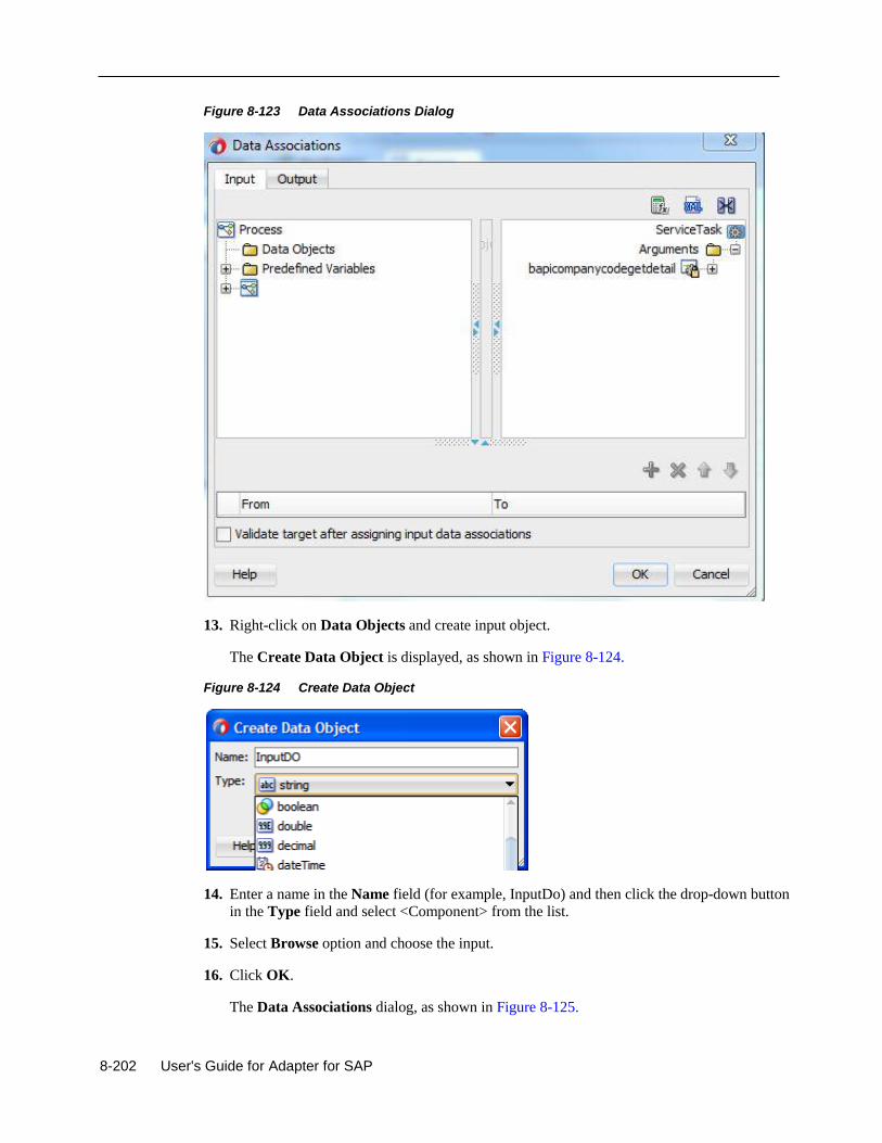
8-202 User's Guide for Adapter for SAP
Figure 8-123 Data Associations Dialog
13. Right-click on Data Objects and create input object.
The Create Data Object is displayed, as shown in Figure 8-124.
Figure 8-124 Create Data Object
14. Enter a name in the Name field (for example, InputDo) and then click the drop-down button
in the Type field and select <Component> from the list.
15. Select Browse option and choose the input.
16. Click OK.
The Data Associations dialog, as shown in Figure 8-125.
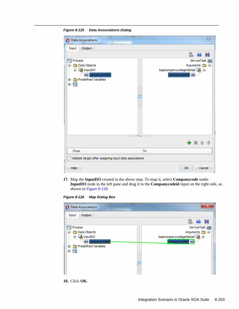
Integration Scenario in Oracle SOA Suite 8-203
Figure 8-125 Data Associations Dialog
17. Map the InputDO created in the above step. To map it, select Companycode under
InputDO node in the left pane and drag it to the Companycodeid input on the right side, as
shown in Figure 8-126.
Figure 8-126 Map Dialog Box
18. Click OK.
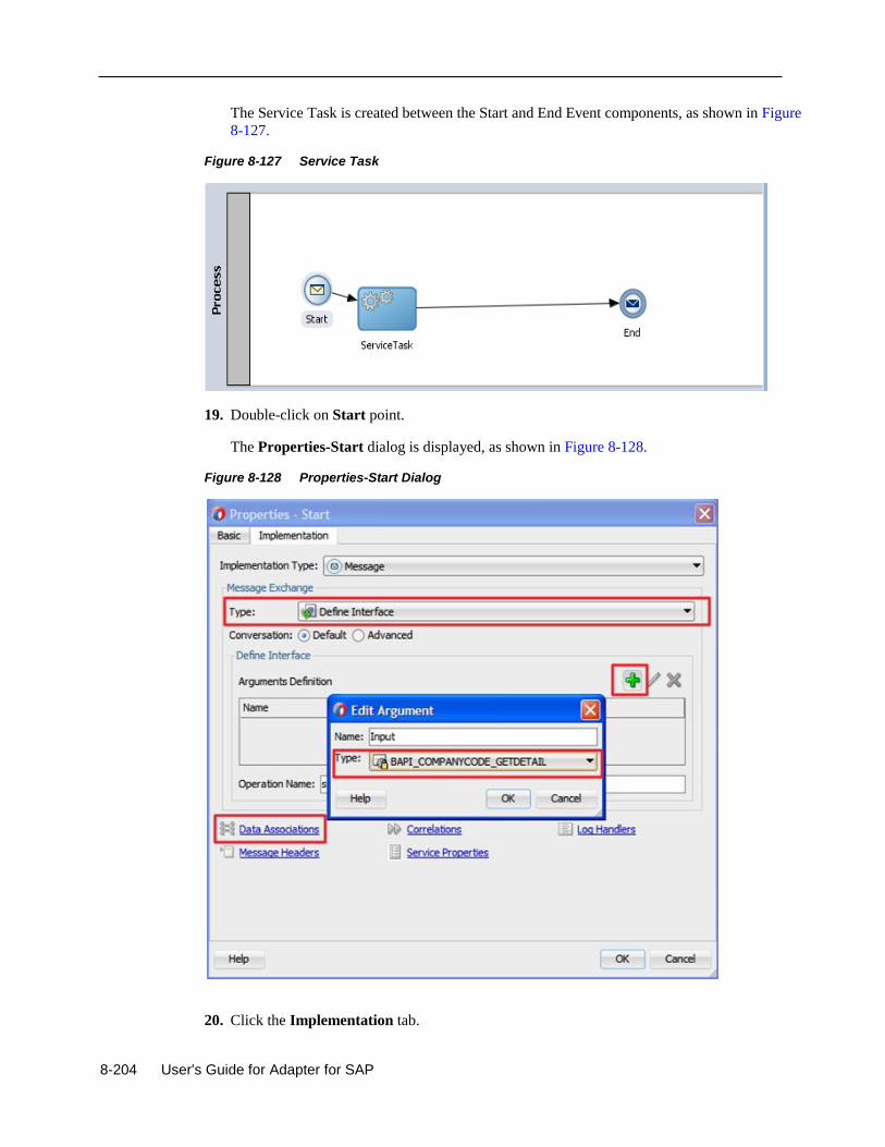
8-204 User's Guide for Adapter for SAP
The Service Task is created between the Start and End Event components, as shown in Figure
8-127.
Figure 8-127 Service Task
19. Double-click on Start point.
The Properties-Start dialog is displayed, as shown in Figure 8-128.
Figure 8-128 Properties-Start Dialog
20. Click the Implementation tab.
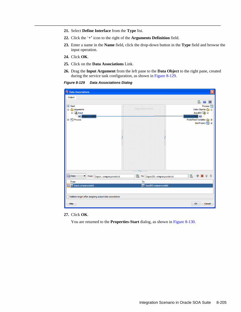
Integration Scenario in Oracle SOA Suite 8-205
21. Select Define Interface from the Type list.
22. Click the ‘+’ icon to the right of the Arguments Definition field.
23. Enter a name in the Name field, click the drop-down button in the Type field and browse the
input operation.
24. Click OK.
25. Click on the Data Associations Link.
26. Drag the Input Argument from the left pane to the Data Object to the right pane, created
during the service task configuration, as shown in Figure 8-129.
Figure 8-129 Data Associations Dialog
27. Click OK.
You are returned to the Properties-Start dialog, as shown in Figure 8-130.
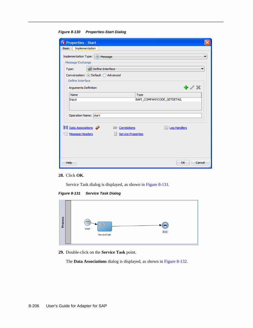
8-206 User's Guide for Adapter for SAP
Figure 8-130 Properties-Start Dialog
28. Click OK.
Service Task dialog is displayed, as shown in Figure 8-131.
Figure 8-131 Service Task Dialog
29. Double-click on the Service Task point.
The Data Associations dialog is displayed, as shown in Figure 8-132.
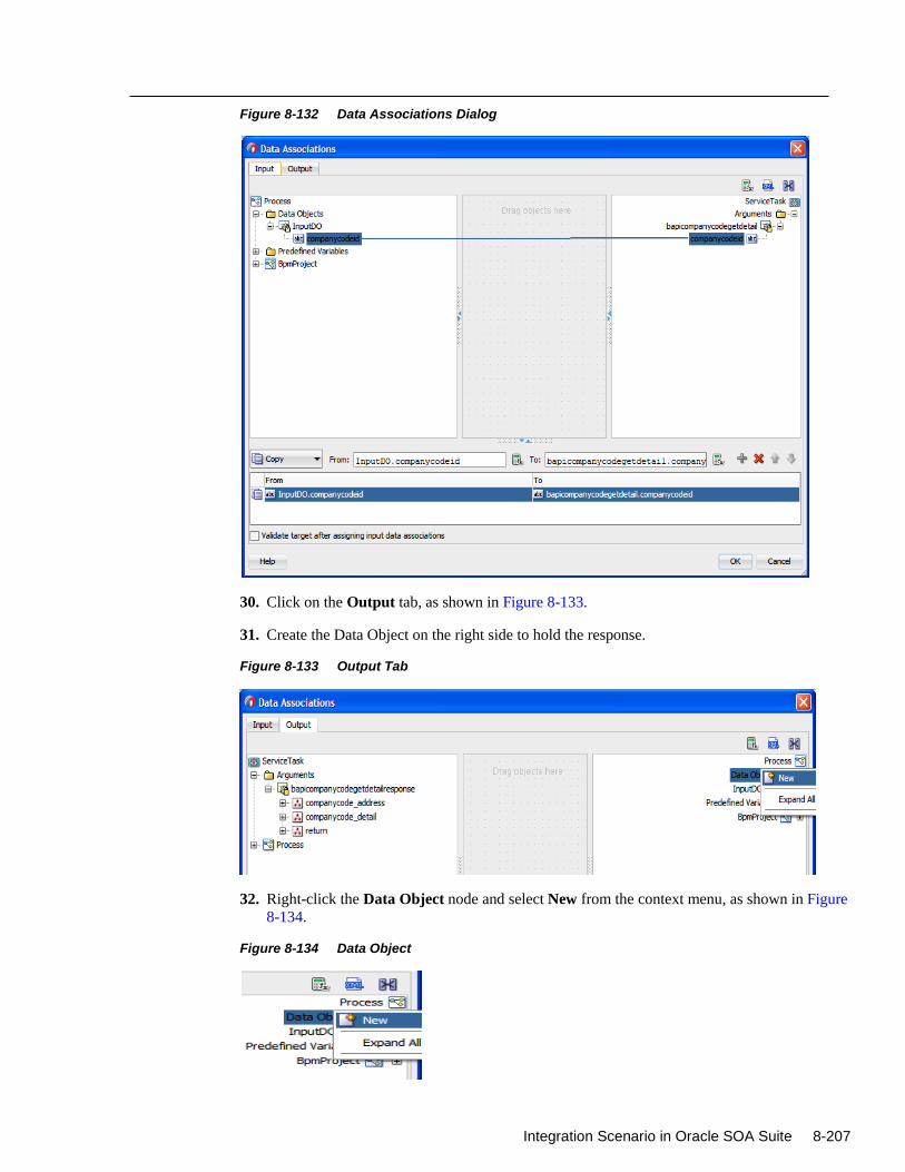
Integration Scenario in Oracle SOA Suite 8-207
Figure 8-132 Data Associations Dialog
30. Click on the Output tab, as shown in Figure 8-133.
31. Create the Data Object on the right side to hold the response.
Figure 8-133 Output Tab
32. Right-click the Data Object node and select New from the context menu, as shown in Figure
8-134.
Figure 8-134 Data Object
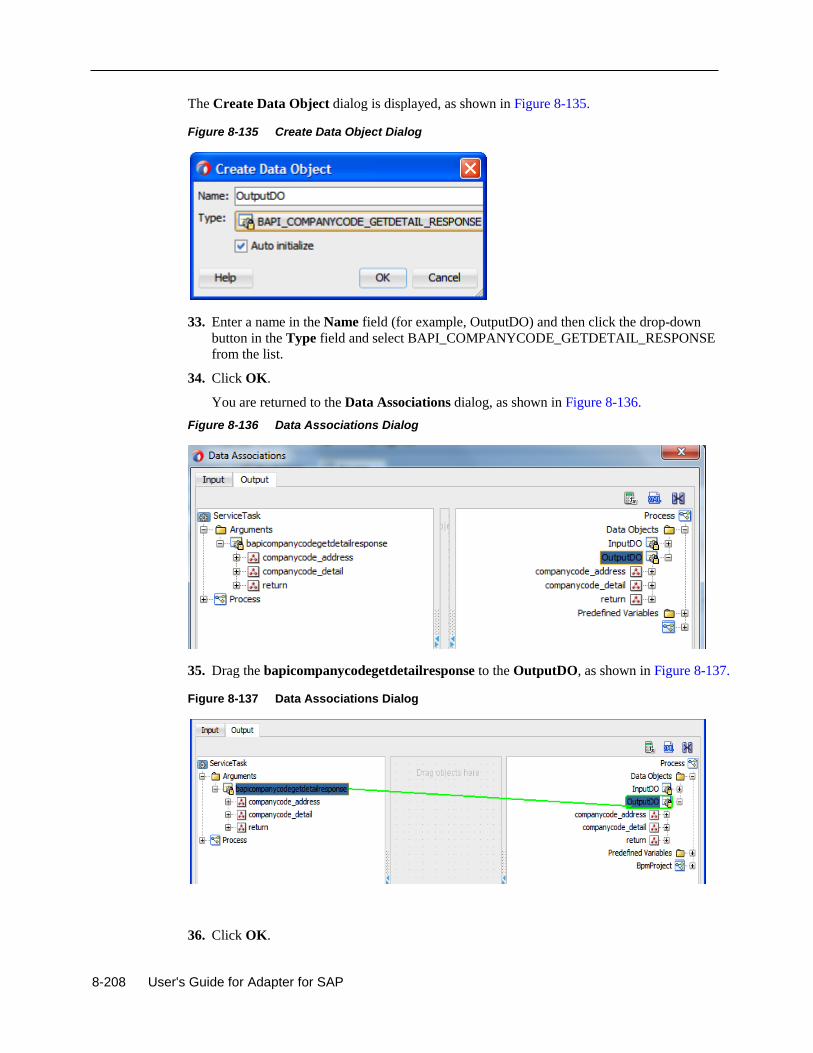
8-208 User's Guide for Adapter for SAP
The Create Data Object dialog is displayed, as shown in Figure 8-135.
Figure 8-135 Create Data Object Dialog
33. Enter a name in the Name field (for example, OutputDO) and then click the drop-down
button in the Type field and select BAPI_COMPANYCODE_GETDETAIL_RESPONSE
from the list.
34. Click OK.
You are returned to the Data Associations dialog, as shown in Figure 8-136.
Figure 8-136 Data Associations Dialog
35. Drag the bapicompanycodegetdetailresponse to the OutputDO, as shown in Figure 8-137.
Figure 8-137 Data Associations Dialog
36. Click OK.
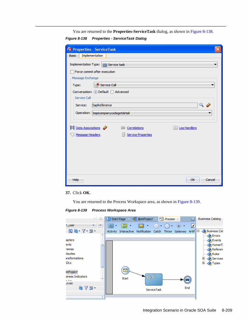
Integration Scenario in Oracle SOA Suite 8-209
You are returned to the Properties-ServiceTask dialog, as shown in Figure 8-138.
Figure 8-138 Properties - ServiceTask Dialog
37. Click OK.
You are returned to the Process Workspace area, as shown in Figure 8-139.
Figure 8-139 Process Workspace Area
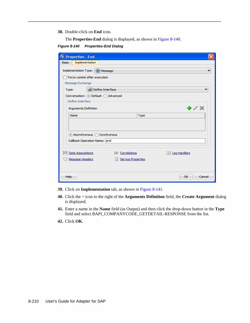
8-210 User's Guide for Adapter for SAP
38. Double-click on End icon.
The Properties-End dialog is displayed, as shown in Figure 8-140.
Figure 8-140 Properties-End Dialog
39. Click on Implementation tab, as shown in Figure 8-141.
40. Click the + icon to the right of the Arguments Definition field, the Create Argument dialog
is displayed.
41. Enter a name in the Name field (as Output) and then click the drop-down button in the Type
field and select BAPI_COMPANYCODE_GETDETAIL-RESPONSE from the list.
42. Click OK.
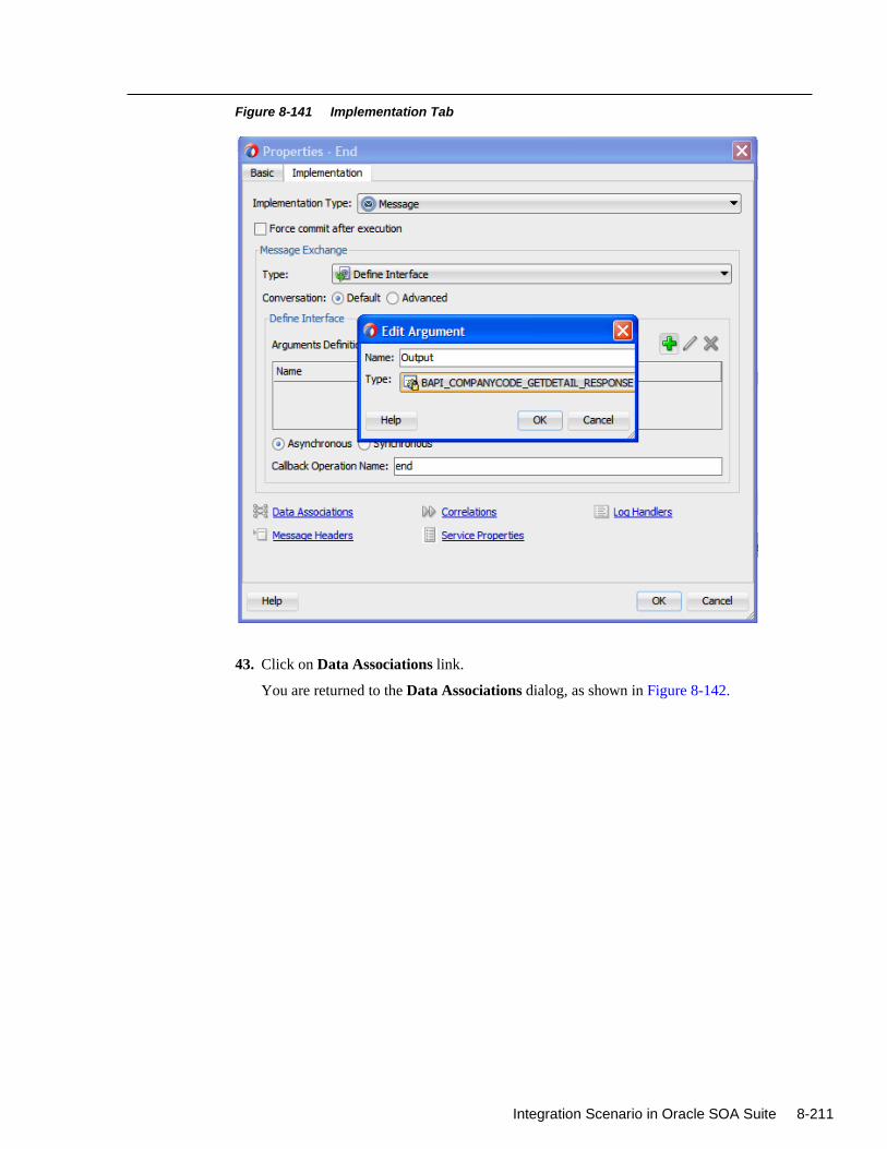
Integration Scenario in Oracle SOA Suite 8-211
Figure 8-141 Implementation Tab
43. Click on Data Associations link.
You are returned to the Data Associations dialog, as shown in Figure 8-142.
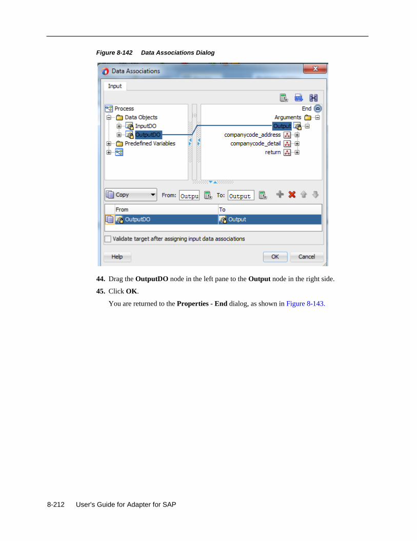
8-212 User's Guide for Adapter for SAP
Figure 8-142 Data Associations Dialog
44. Drag the OutputDO node in the left pane to the Output node in the right side.
45. Click OK.
You are returned to the Properties - End dialog, as shown in Figure 8-143.
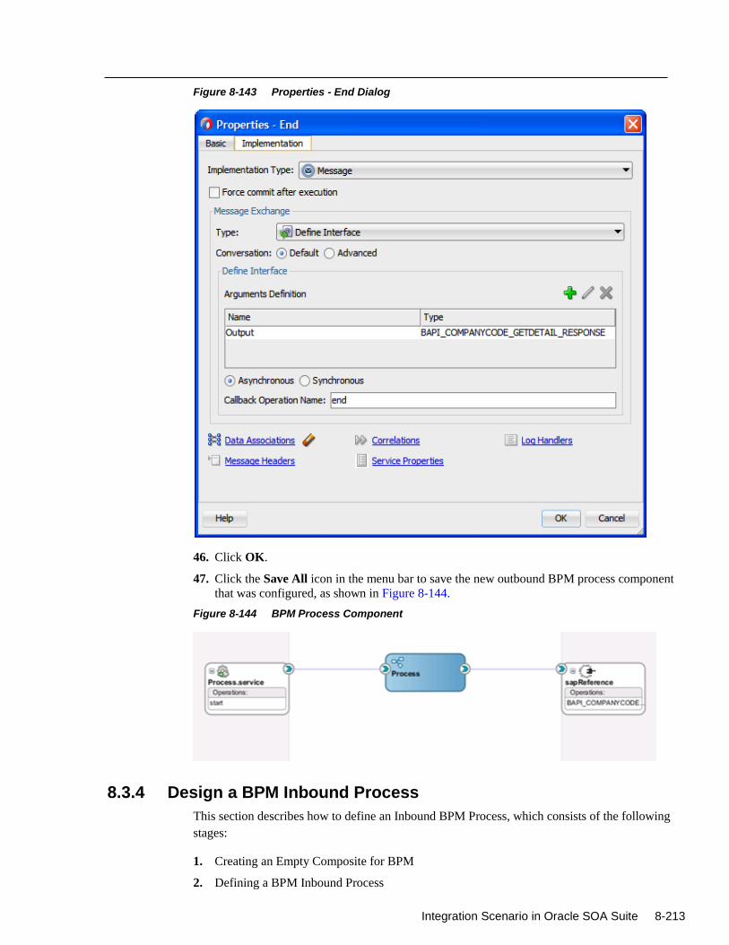
Integration Scenario in Oracle SOA Suite 8-213
Figure 8-143 Properties - End Dialog
46. Click OK.
47. Click the Save All icon in the menu bar to save the new outbound BPM process component
that was configured, as shown in Figure 8-144.
Figure 8-144 BPM Process Component
8.3.4 Design a BPM Inbound Process
This section describes how to define an Inbound BPM Process, which consists of the following
stages:
1. Creating an Empty Composite for BPM
2. Defining a BPM Inbound Process
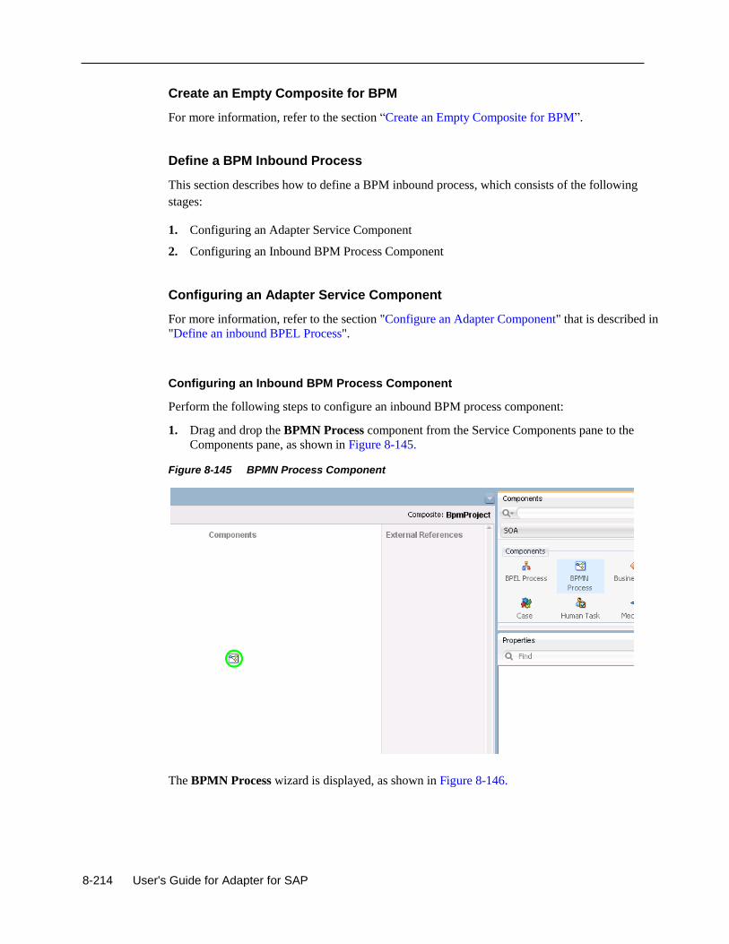
8-214 User's Guide for Adapter for SAP
Create an Empty Composite for BPM
For more information, refer to the section “Create an Empty Composite for BPM”.
Define a BPM Inbound Process
This section describes how to define a BPM inbound process, which consists of the following
stages:
1. Configuring an Adapter Service Component
2. Configuring an Inbound BPM Process Component
Configuring an Adapter Service Component
For more information, refer to the section "Configure an Adapter Component" that is described in
"Define an inbound BPEL Process".
Configuring an Inbound BPM Process Component
Perform the following steps to configure an inbound BPM process component:
1. Drag and drop the BPMN Process component from the Service Components pane to the
Components pane, as shown in Figure 8-145.
Figure 8-145 BPMN Process Component
The BPMN Process wizard is displayed, as shown in Figure 8-146.
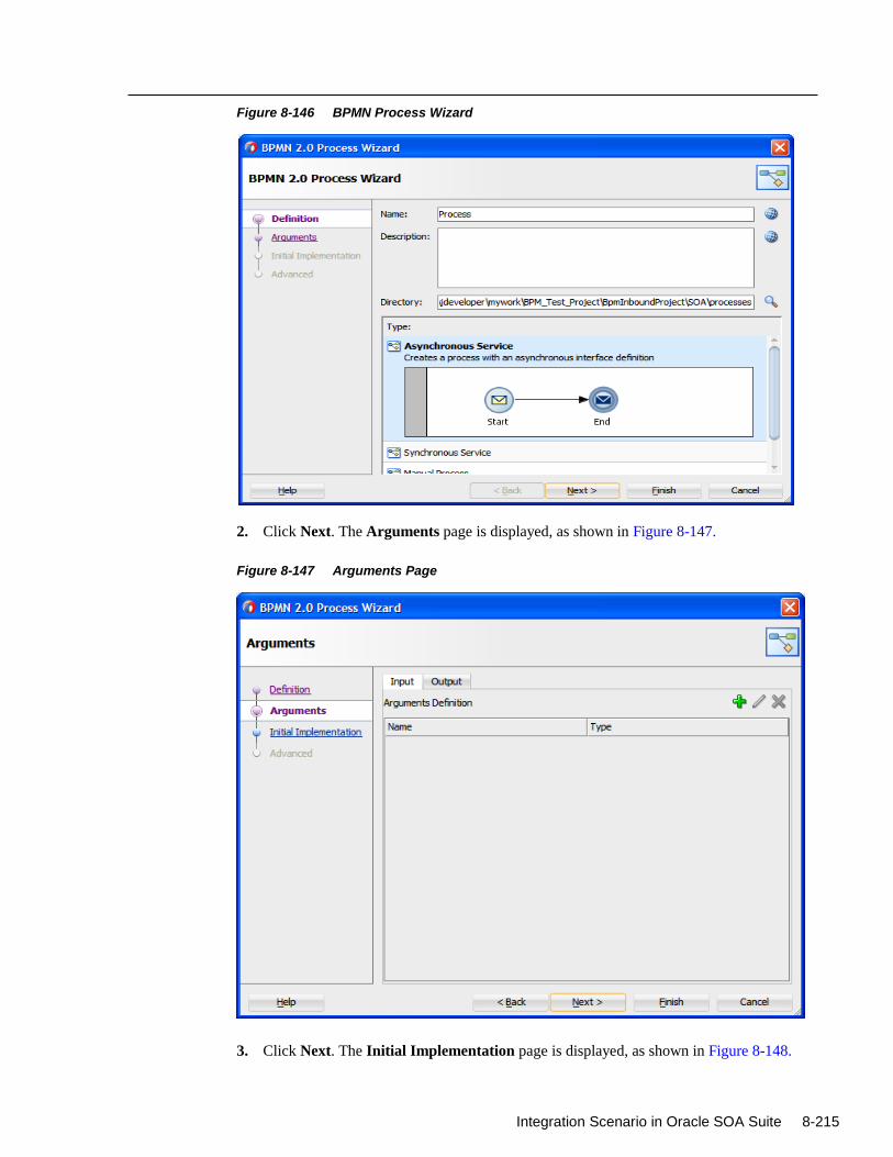
Integration Scenario in Oracle SOA Suite 8-215
Figure 8-146 BPMN Process Wizard
2. Click Next. The Arguments page is displayed, as shown in Figure 8-147.
Figure 8-147 Arguments Page
3. Click Next. The Initial Implementation page is displayed, as shown in Figure 8-148.
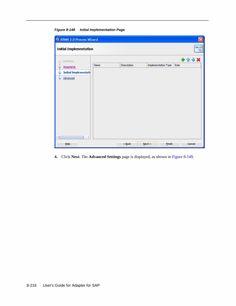
8-216 User's Guide for Adapter for SAP
Figure 8-148 Initial Implementation Page
4. Click Next. The Advanced Settings page is displayed, as shown in Figure 8-149.
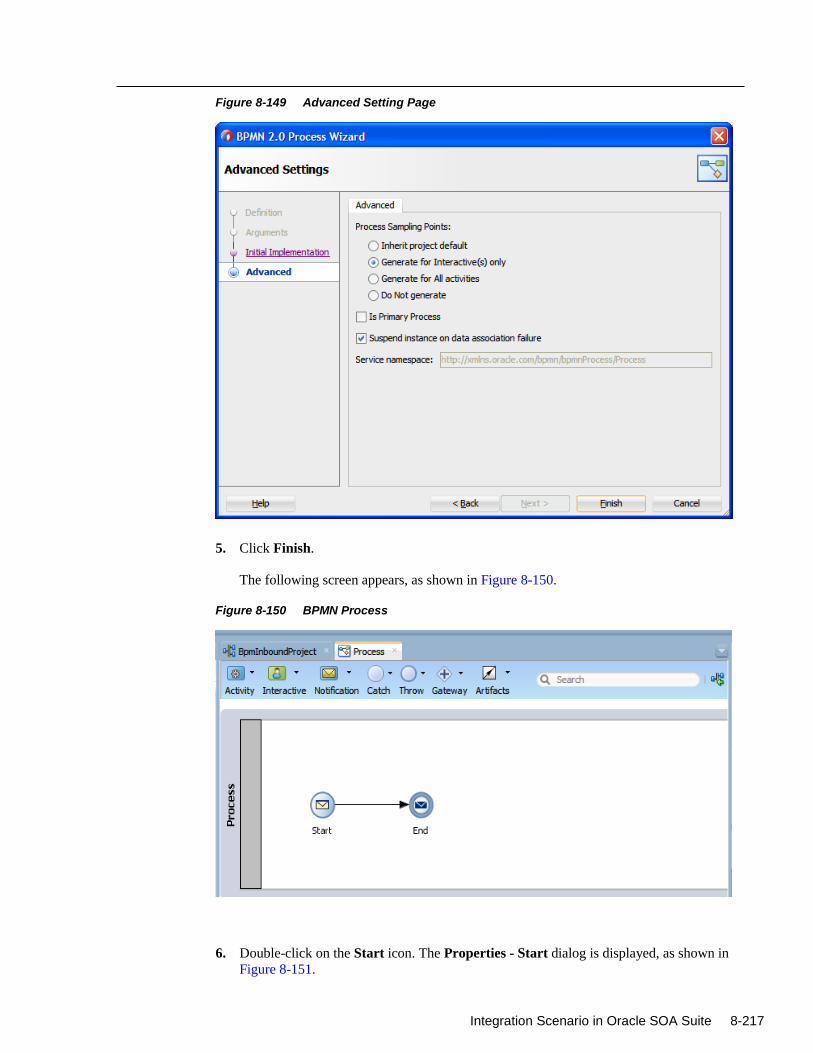
Integration Scenario in Oracle SOA Suite 8-217
Figure 8-149 Advanced Setting Page
5. Click Finish.
The following screen appears, as shown in Figure 8-150.
Figure 8-150 BPMN Process
6. Double-click on the Start icon. The Properties - Start dialog is displayed, as shown in
Figure 8-151.
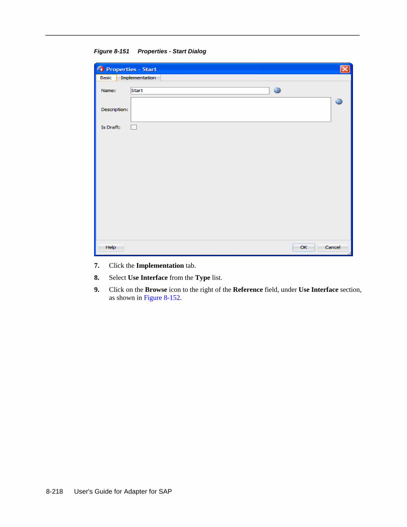
8-218 User's Guide for Adapter for SAP
Figure 8-151 Properties - Start Dialog
7. Click the Implementation tab.
8. Select Use Interface from the Type list.
9. Click on the Browse icon to the right of the Reference field, under Use Interface section,
as shown in Figure 8-152.
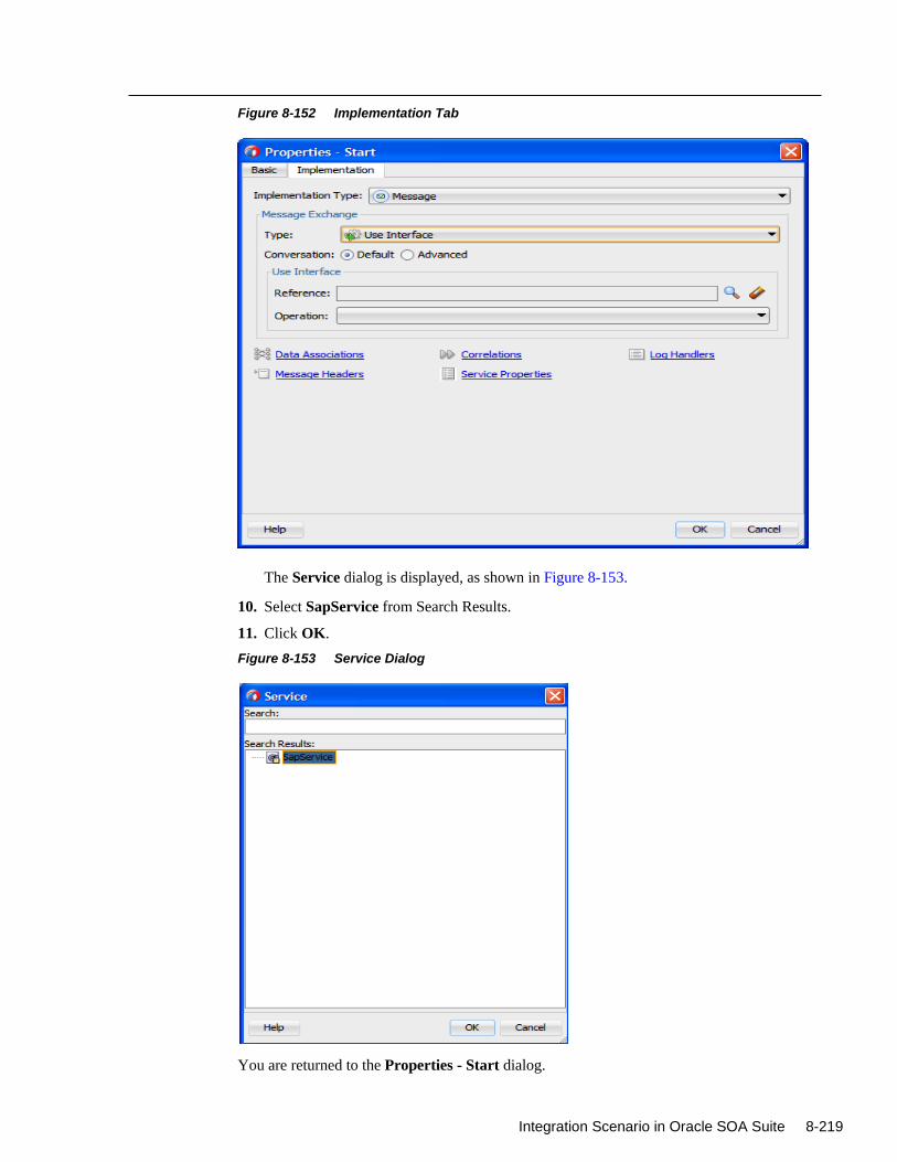
Integration Scenario in Oracle SOA Suite 8-219
Figure 8-152 Implementation Tab
The Service dialog is displayed, as shown in Figure 8-153.
10. Select SapService from Search Results.
11. Click OK.
Figure 8-153 Service Dialog
You are returned to the Properties - Start dialog.
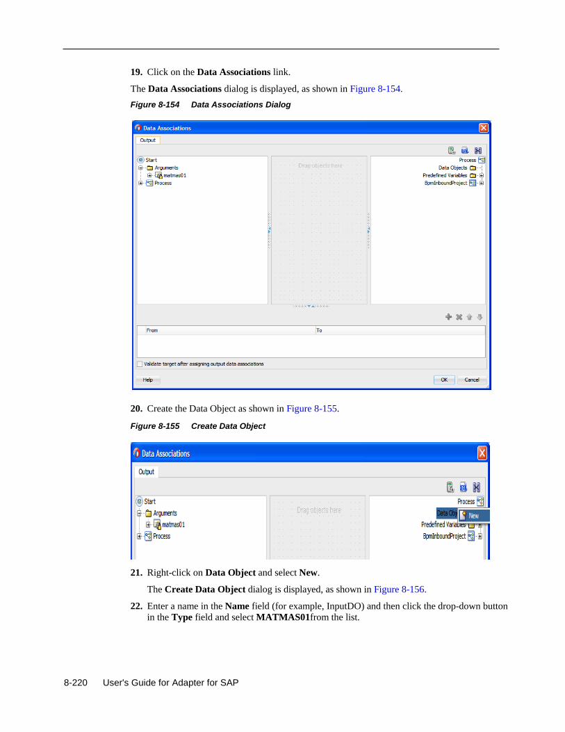
8-220 User's Guide for Adapter for SAP
19. Click on the Data Associations link.
The Data Associations dialog is displayed, as shown in Figure 8-154.
Figure 8-154 Data Associations Dialog
20. Create the Data Object as shown in Figure 8-155.
Figure 8-155 Create Data Object
21. Right-click on Data Object and select New.
The Create Data Object dialog is displayed, as shown in Figure 8-156.
22. Enter a name in the Name field (for example, InputDO) and then click the drop-down button
in the Type field and select MATMAS01from the list.
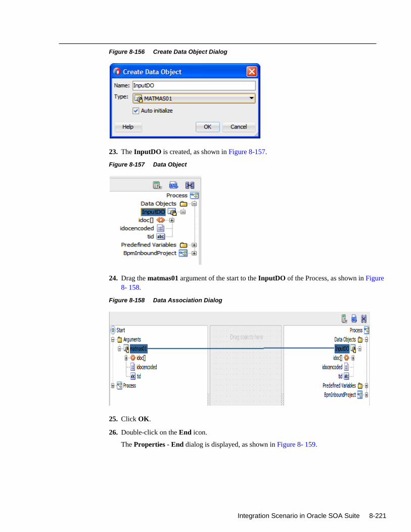
Integration Scenario in Oracle SOA Suite 8-221
Figure 8-156 Create Data Object Dialog
23. The InputDO is created, as shown in Figure 8-157.
Figure 8-157 Data Object
24. Drag the matmas01 argument of the start to the InputDO of the Process, as shown in Figure
8- 158.
Figure 8-158 Data Association Dialog
25. Click OK.
26. Double-click on the End icon.
The Properties - End dialog is displayed, as shown in Figure 8- 159.
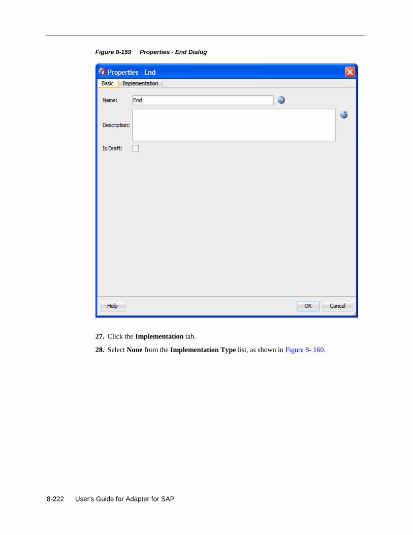
8-222 User's Guide for Adapter for SAP
Figure 8-159 Properties - End Dialog
27. Click the Implementation tab.
28. Select None from the Implementation Type list, as shown in Figure 8- 160.
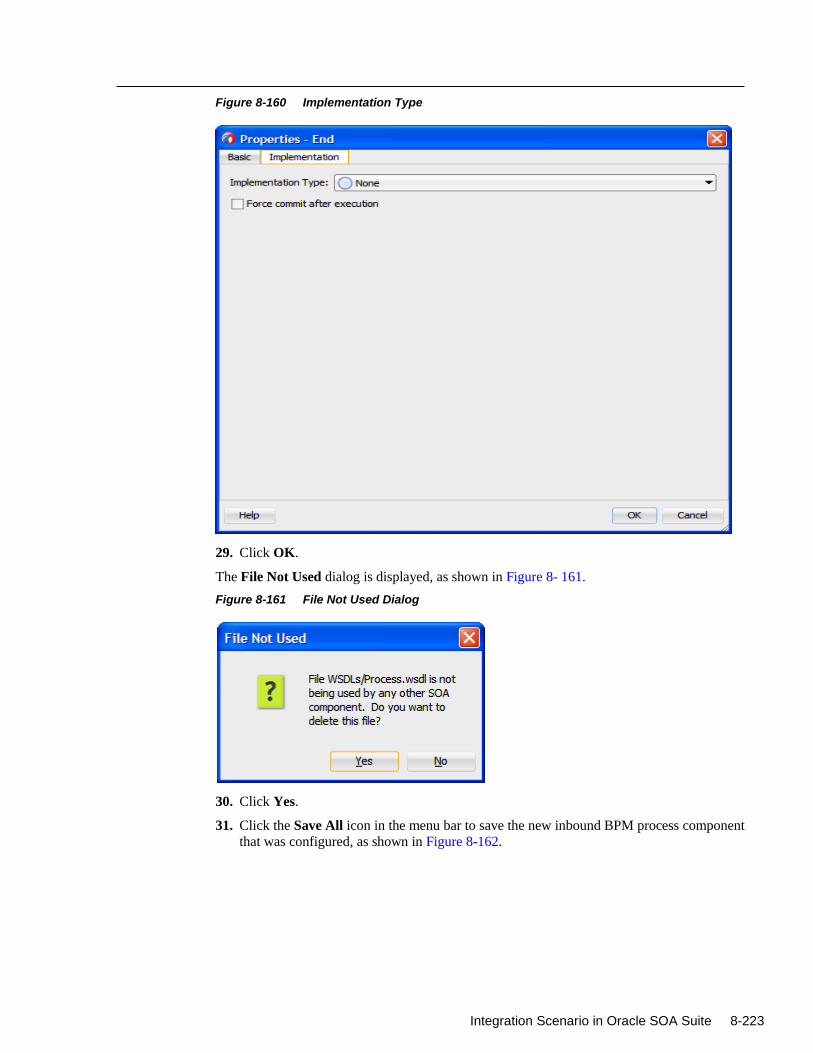
Integration Scenario in Oracle SOA Suite 8-223
Figure 8-160 Implementation Type
29. Click OK.
The File Not Used dialog is displayed, as shown in Figure 8- 161.
Figure 8-161 File Not Used Dialog
30. Click Yes.
31. Click the Save All icon in the menu bar to save the new inbound BPM process component
that was configured, as shown in Figure 8-162.
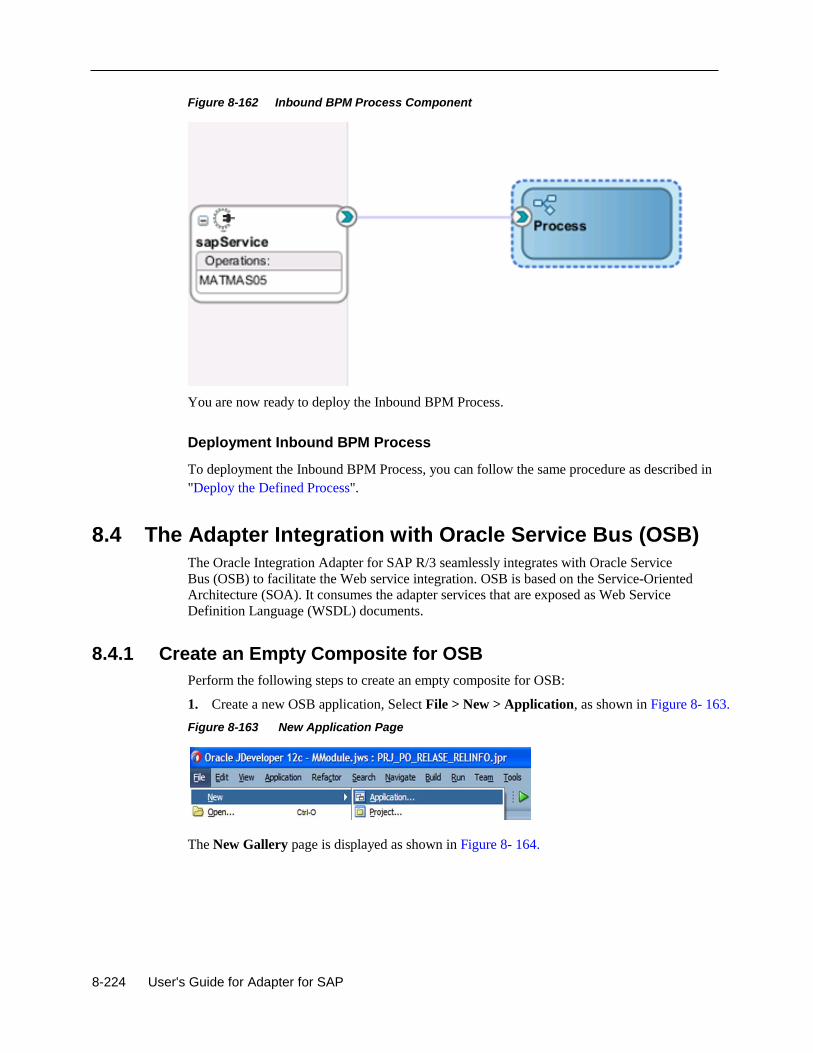
8-224 User's Guide for Adapter for SAP
Figure 8-162 Inbound BPM Process Component
You are now ready to deploy the Inbound BPM Process.
Deployment Inbound BPM Process
To deployment the Inbound BPM Process, you can follow the same procedure as described in
"Deploy the Defined Process".
8.4 The Adapter Integration with Oracle Service Bus (OSB)
The Oracle Integration Adapter for SAP R/3 seamlessly integrates with Oracle Service
Bus (OSB) to facilitate the Web service integration. OSB is based on the Service-Oriented
Architecture (SOA). It consumes the adapter services that are exposed as Web Service
Definition Language (WSDL) documents.
8.4.1 Create an Empty Composite for OSB
Perform the following steps to create an empty composite for OSB:
1. Create a new OSB application, Select File > New > Application, as shown in Figure 8- 163.
Figure 8-163 New Application Page
The New Gallery page is displayed as shown in Figure 8- 164.
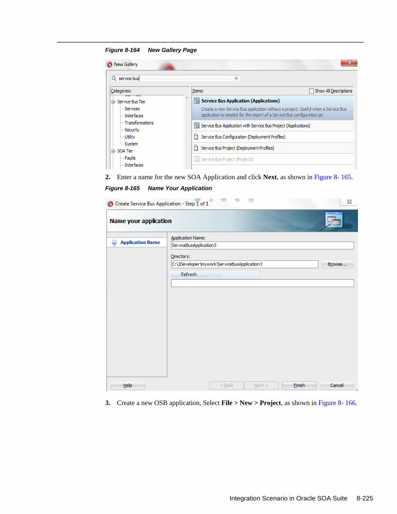
Integration Scenario in Oracle SOA Suite 8-225
Figure 8-164 New Gallery Page
2. Enter a name for the new SOA Application and click Next, as shown in Figure 8- 165.
Figure 8-165 Name Your Application
3. Create a new OSB application, Select File > New > Project, as shown in Figure 8- 166.
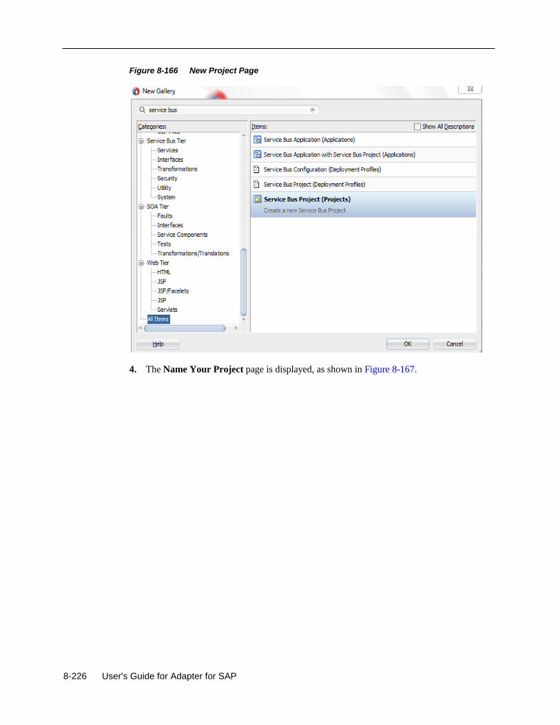
8-226 User's Guide for Adapter for SAP
Figure 8-166 New Project Page
4. The Name Your Project page is displayed, as shown in Figure 8-167.
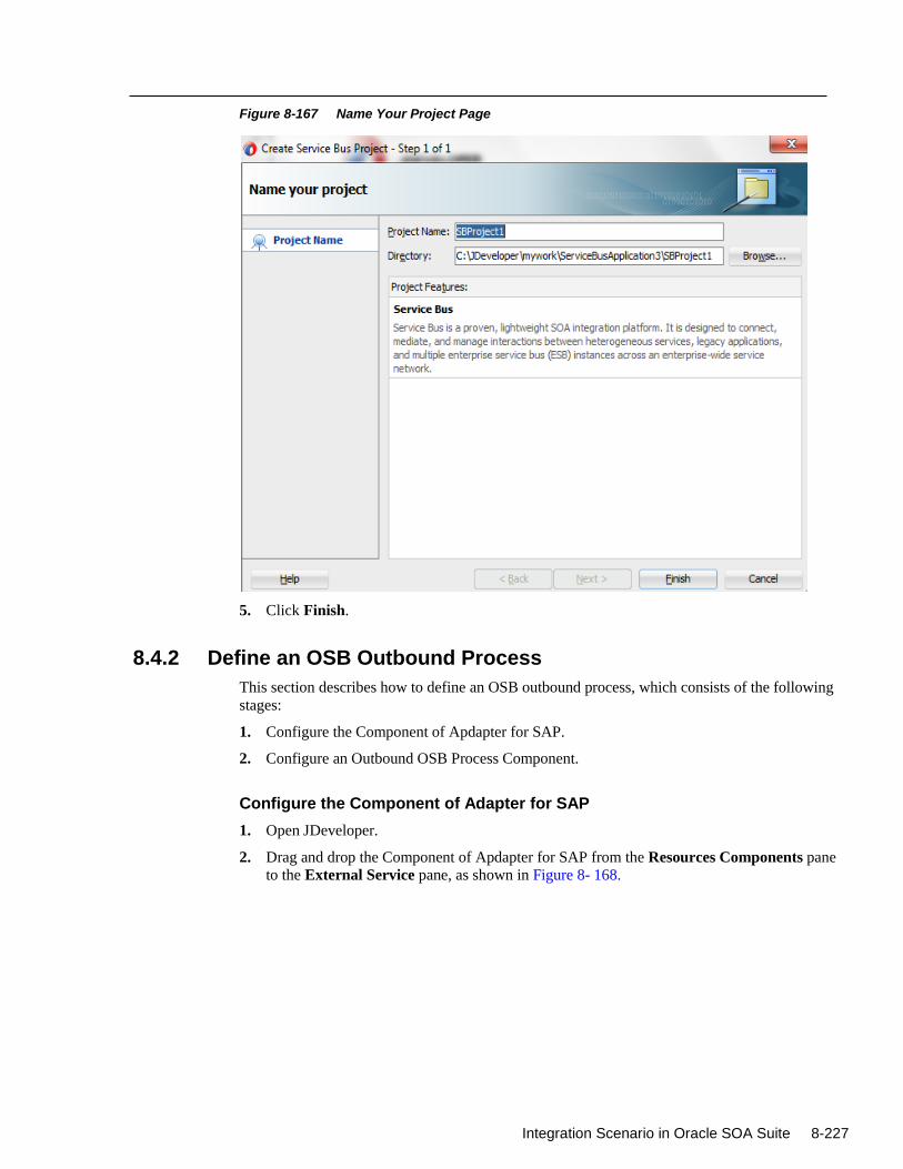
Integration Scenario in Oracle SOA Suite 8-227
Figure 8-167 Name Your Project Page
5. Click Finish.
8.4.2 Define an OSB Outbound Process
This section describes how to define an OSB outbound process, which consists of the following
stages:
1. Configure the Component of Apdapter for SAP.
2. Configure an Outbound OSB Process Component.
Configure the Component of Adapter for SAP
1. Open JDeveloper.
2. Drag and drop the Component of Apdapter for SAP from the Resources Components pane
to the External Service pane, as shown in Figure 8- 168.
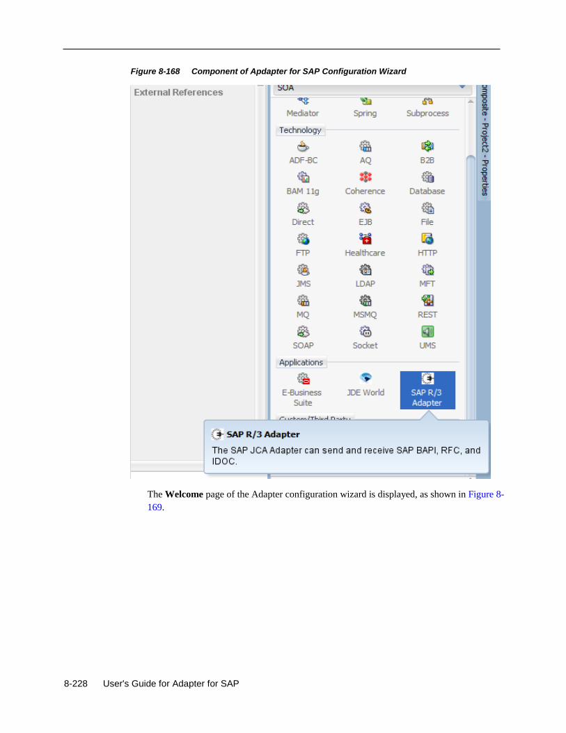
8-228 User's Guide for Adapter for SAP
Figure 8-168 Component of Apdapter for SAP Configuration Wizard
The Welcome page of the Adapter configuration wizard is displayed, as shown in Figure 8-
169.
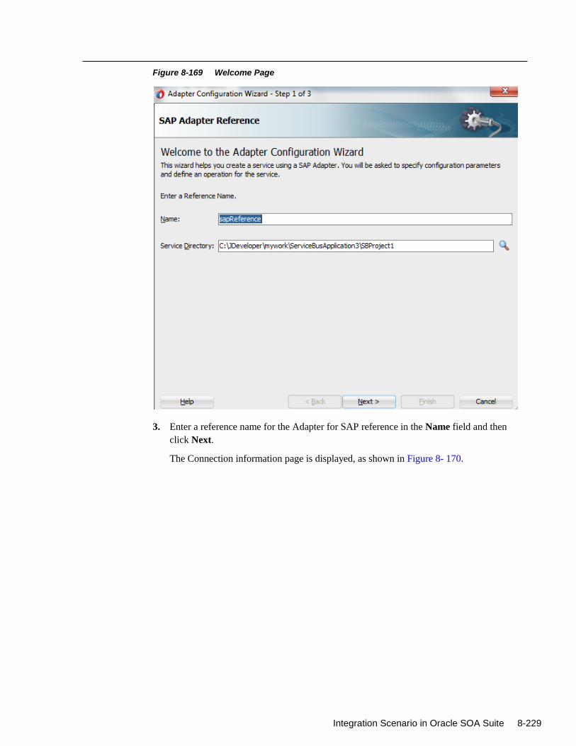
Integration Scenario in Oracle SOA Suite 8-229
Figure 8-169 Welcome Page
3. Enter a reference name for the Adapter for SAP reference in the Name field and then
click Next.
The Connection information page is displayed, as shown in Figure 8- 170.
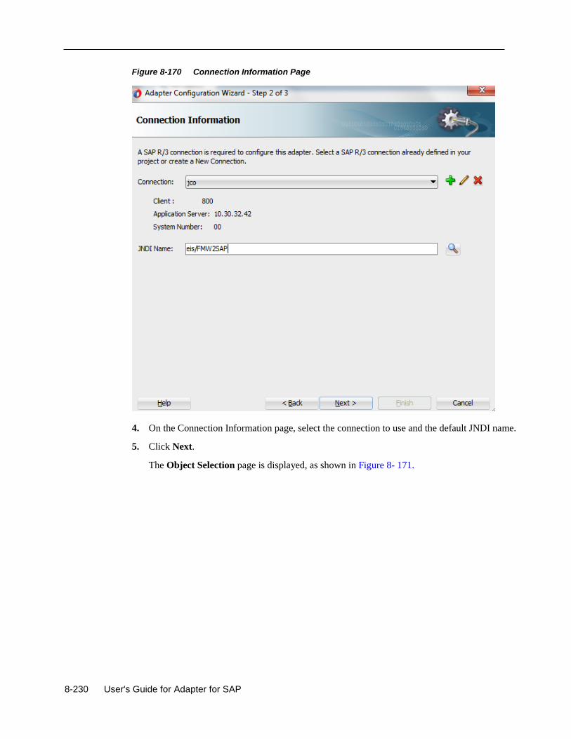
8-230 User's Guide for Adapter for SAP
Figure 8-170 Connection Information Page
4. On the Connection Information page, select the connection to use and the default JNDI name.
5. Click Next.
The Object Selection page is displayed, as shown in Figure 8- 171.
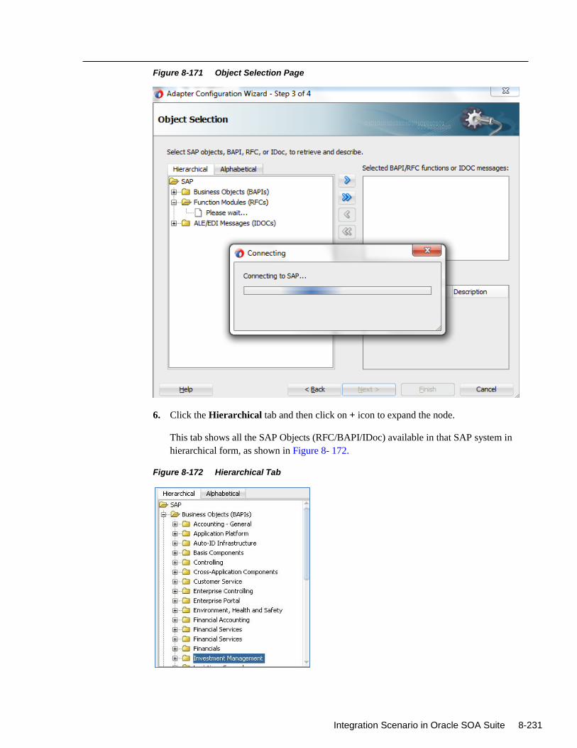
Integration Scenario in Oracle SOA Suite 8-231
Figure 8-171 Object Selection Page
6. Click the Hierarchical tab and then click on + icon to expand the node.
This tab shows all the SAP Objects (RFC/BAPI/IDoc) available in that SAP system in
hierarchical form, as shown in Figure 8- 172.
Figure 8-172 Hierarchical Tab
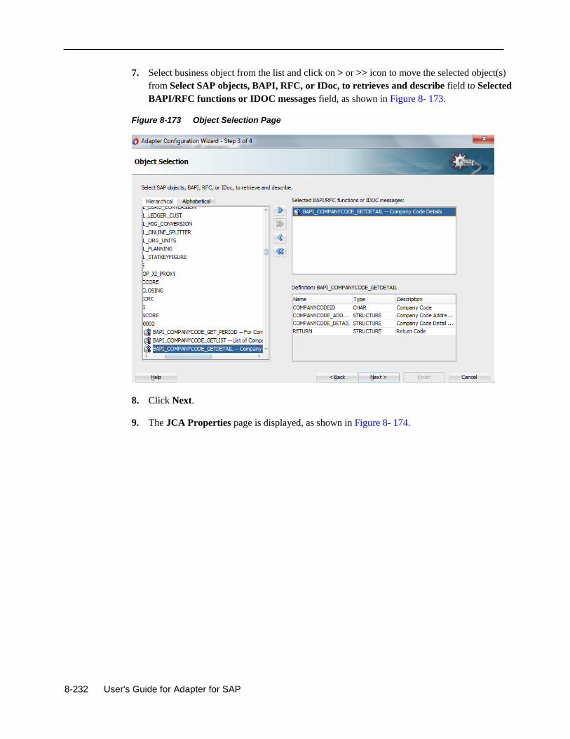
8-232 User's Guide for Adapter for SAP
7. Select business object from the list and click on > or >> icon to move the selected object(s)
from Select SAP objects, BAPI, RFC, or IDoc, to retrieves and describe field to Selected
BAPI/RFC functions or IDOC messages field, as shown in Figure 8- 173.
Figure 8-173 Object Selection Page
8. Click Next.
9. The JCA Properties page is displayed, as shown in Figure 8- 174.
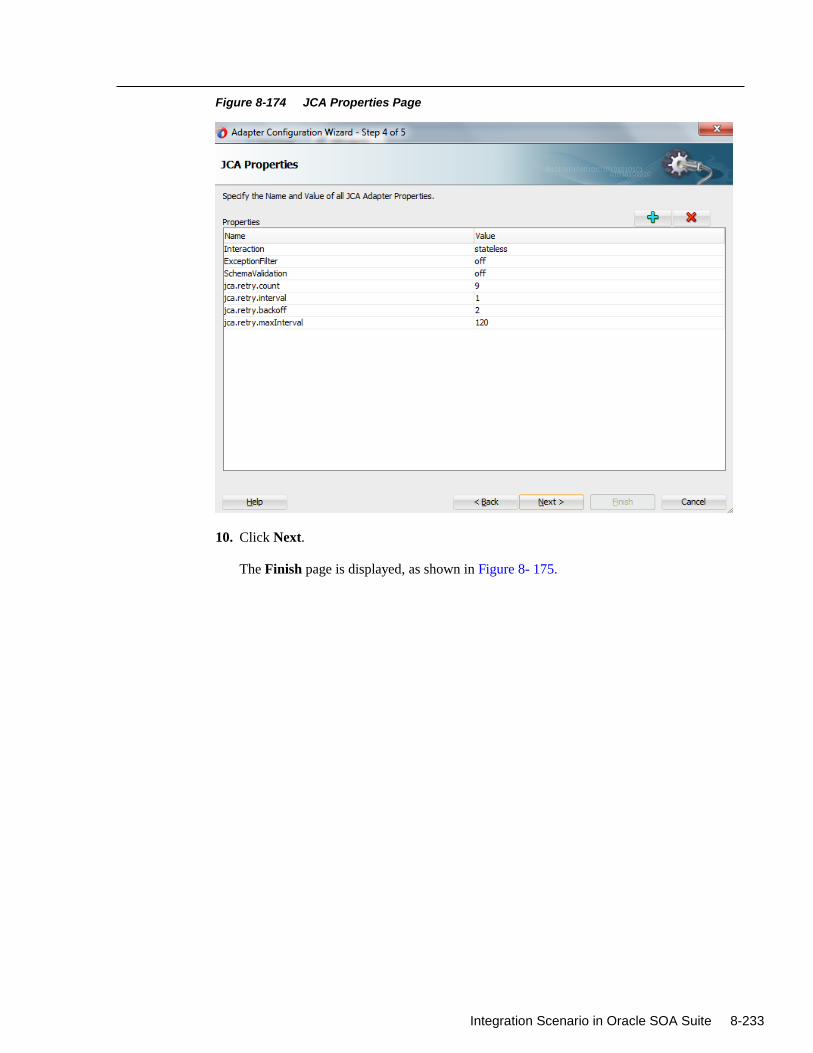
Integration Scenario in Oracle SOA Suite 8-233
Figure 8-174 JCA Properties Page
10. Click Next.
The Finish page is displayed, as shown in Figure 8- 175.
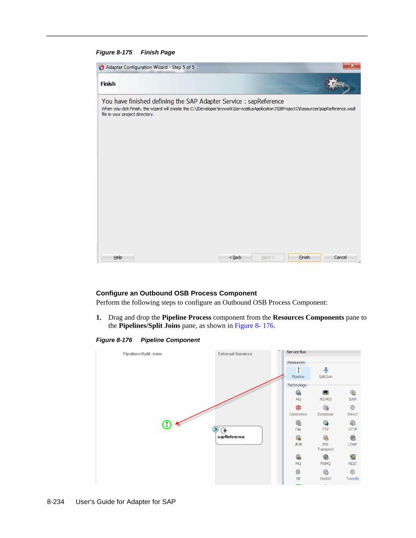
8-234 User's Guide for Adapter for SAP
Figure 8-175 Finish Page
Configure an Outbound OSB Process Component
Perform the following steps to configure an Outbound OSB Process Component:
1. Drag and drop the Pipeline Process component from the Resources Components pane to
the Pipelines/Split Joins pane, as shown in Figure 8- 176.
Figure 8-176 Pipeline Component
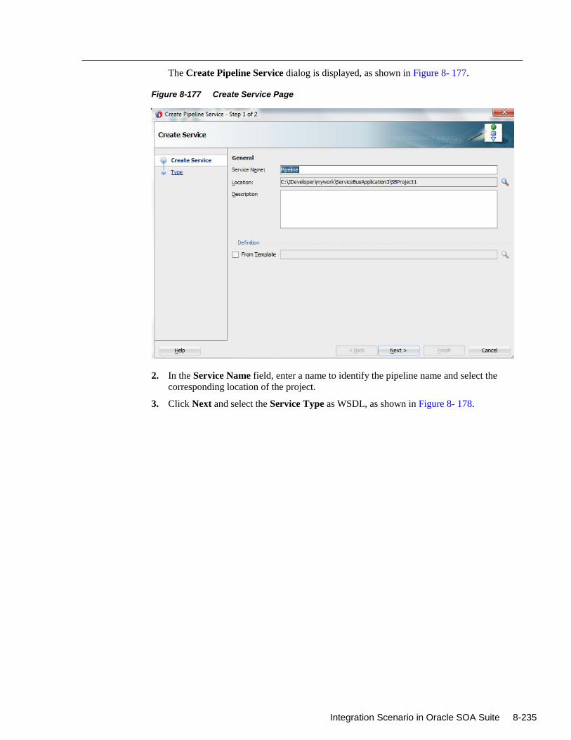
Integration Scenario in Oracle SOA Suite 8-235
The Create Pipeline Service dialog is displayed, as shown in Figure 8- 177.
Figure 8-177 Create Service Page
2. In the Service Name field, enter a name to identify the pipeline name and select the
corresponding location of the project.
3. Click Next and select the Service Type as WSDL, as shown in Figure 8- 178.
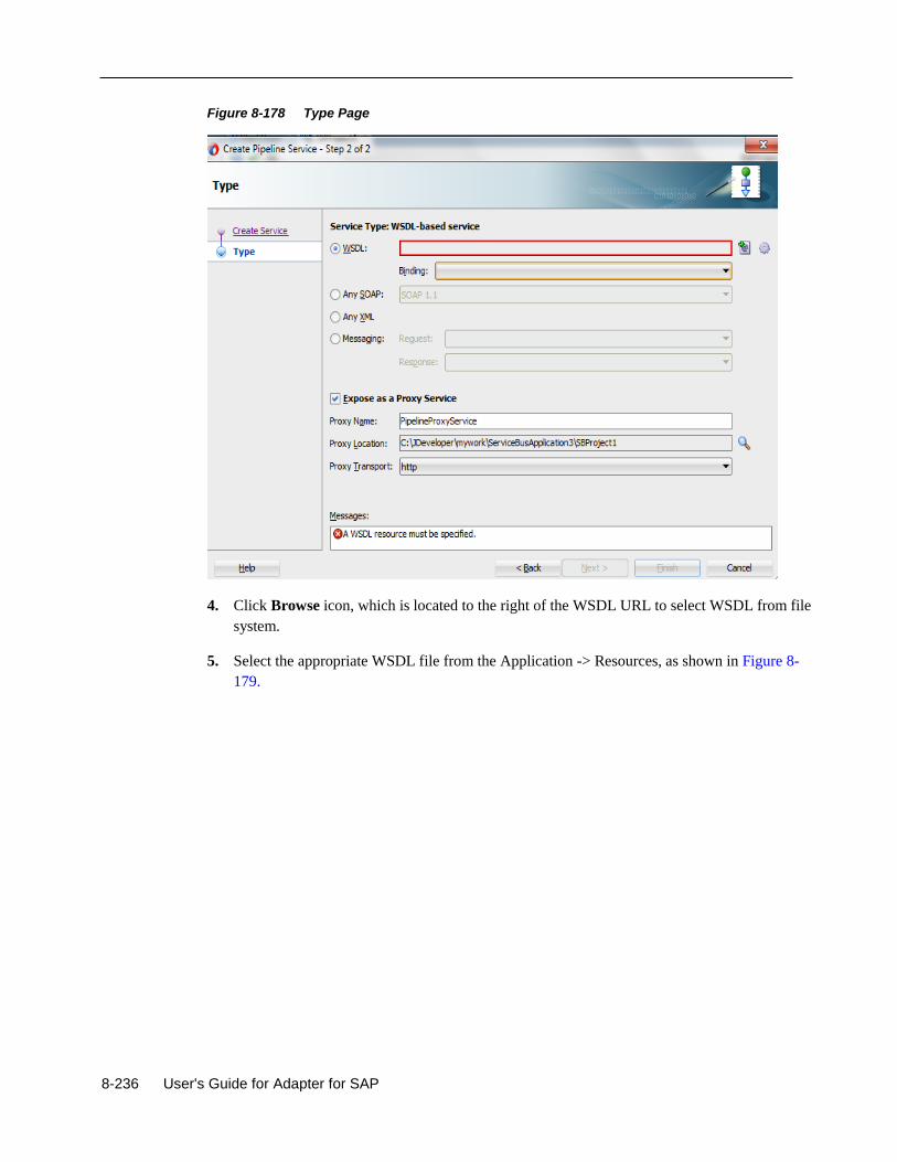
8-236 User's Guide for Adapter for SAP
Figure 8-178 Type Page
4. Click Browse icon, which is located to the right of the WSDL URL to select WSDL from file
system.
5. Select the appropriate WSDL file from the Application -> Resources, as shown in Figure 8-
179.
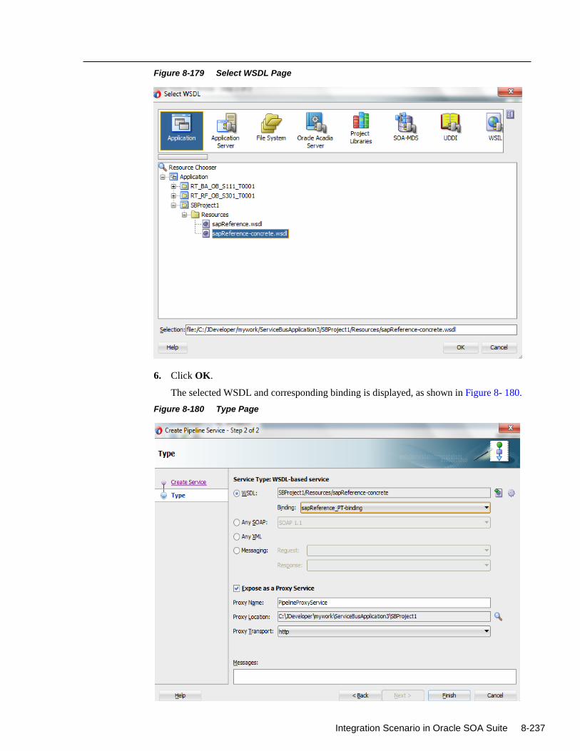
Integration Scenario in Oracle SOA Suite 8-237
Figure 8-179 Select WSDL Page
6. Click OK.
The selected WSDL and corresponding binding is displayed, as shown in Figure 8- 180.
Figure 8-180 Type Page
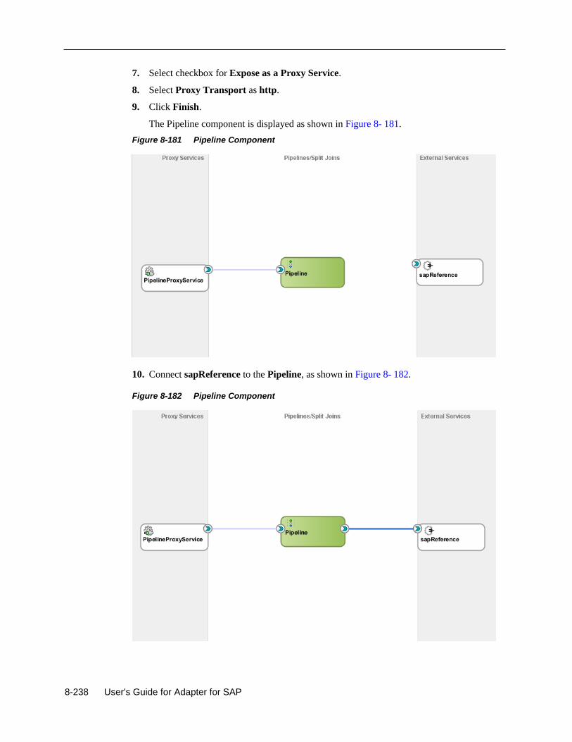
8-238 User's Guide for Adapter for SAP
7. Select checkbox for Expose as a Proxy Service.
8. Select Proxy Transport as http.
9. Click Finish.
The Pipeline component is displayed as shown in Figure 8- 181.
Figure 8-181 Pipeline Component
10. Connect sapReference to the Pipeline, as shown in Figure 8- 182.
Figure 8-182 Pipeline Component
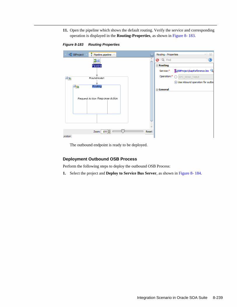
Integration Scenario in Oracle SOA Suite 8-239
11. Open the pipeline which shows the default routing. Verify the service and corresponding
operation is displayed in the Routing-Properties, as shown in Figure 8- 183.
Figure 8-183 Routing Properties
The outbound endpoint is ready to be deployed.
Deployment Outbound OSB Process
Perform the following steps to deploy the outbound OSB Process:
1. Select the project and Deploy to Service Bus Server, as shown in Figure 8- 184.
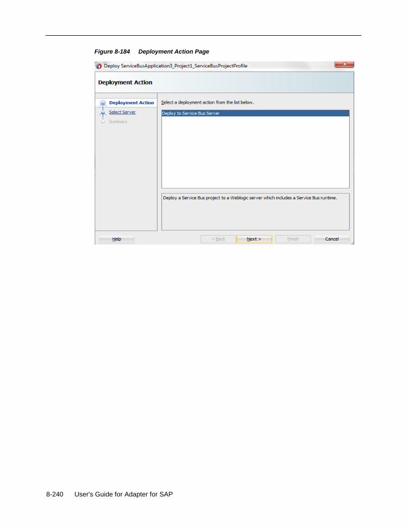
8-240 User's Guide for Adapter for SAP
Figure 8-184 Deployment Action Page
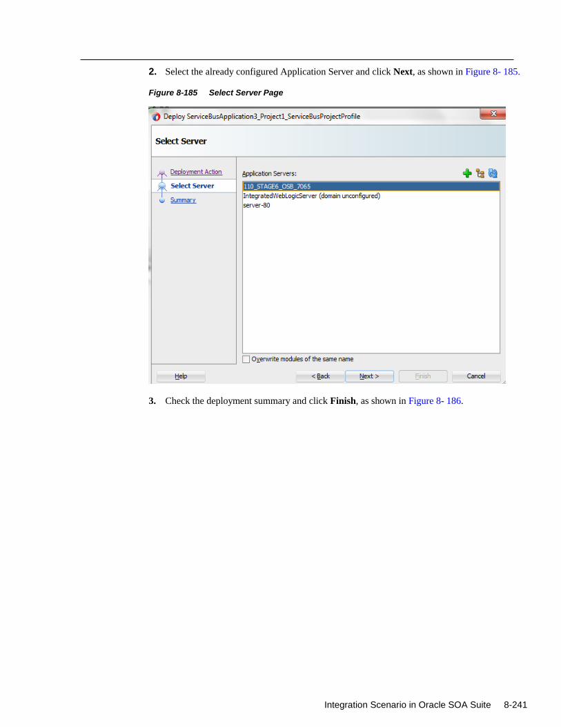
Integration Scenario in Oracle SOA Suite 8-241
2. Select the already configured Application Server and click Next, as shown in Figure 8- 185.
Figure 8-185 Select Server Page
3. Check the deployment summary and click Finish, as shown in Figure 8- 186.
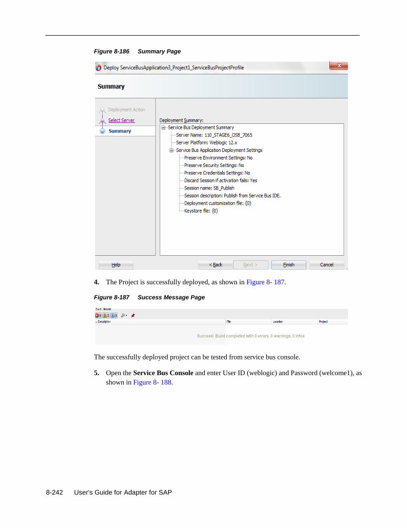
8-242 User's Guide for Adapter for SAP
Figure 8-186 Summary Page
4. The Project is successfully deployed, as shown in Figure 8- 187.
Figure 8-187 Success Message Page
The successfully deployed project can be tested from service bus console.
5. Open the Service Bus Console and enter User ID (weblogic) and Password (welcome1), as
shown in Figure 8- 188.
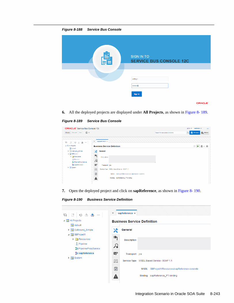
Integration Scenario in Oracle SOA Suite 8-243
Figure 8-188 Service Bus Console
6. All the deployed projects are displayed under All Projects, as shown in Figure 8- 189.
Figure 8-189 Service Bus Console
7. Open the deployed project and click on sapReference, as shown in Figure 8- 190.
Figure 8-190 Business Service Definition
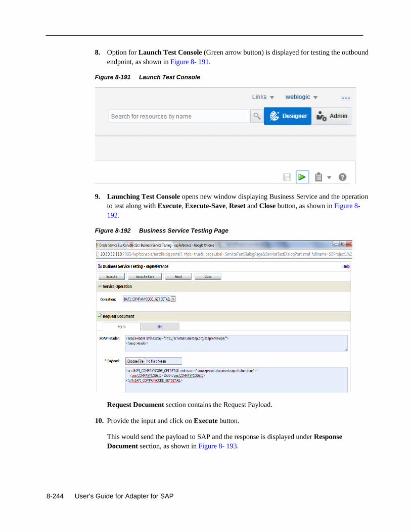
8-244 User's Guide for Adapter for SAP
8. Option for Launch Test Console (Green arrow button) is displayed for testing the outbound
endpoint, as shown in Figure 8- 191.
Figure 8-191 Launch Test Console
9. Launching Test Console opens new window displaying Business Service and the operation
to test along with Execute, Execute-Save, Reset and Close button, as shown in Figure 8-
192.
Figure 8-192 Business Service Testing Page
Request Document section contains the Request Payload.
10. Provide the input and click on Execute button.
This would send the payload to SAP and the response is displayed under Response
Document section, as shown in Figure 8- 193.
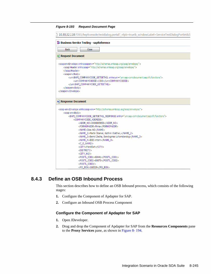
Integration Scenario in Oracle SOA Suite 8-245
Figure 8-193 Request Document Page
8.4.3 Define an OSB Inbound Process
This section describes how to define an OSB Inbound process, which consists of the following
stages:
1. Configure the Component of Apdapter for SAP.
2. Configure an Inbound OSB Process Component
Configure the Component of Apdapter for SAP
1. Open JDeveloper.
2. Drag and drop the Component of Apdapter for SAP from the Resources Components pane
to the Proxy Services pane, as shown in Figure 8- 194.
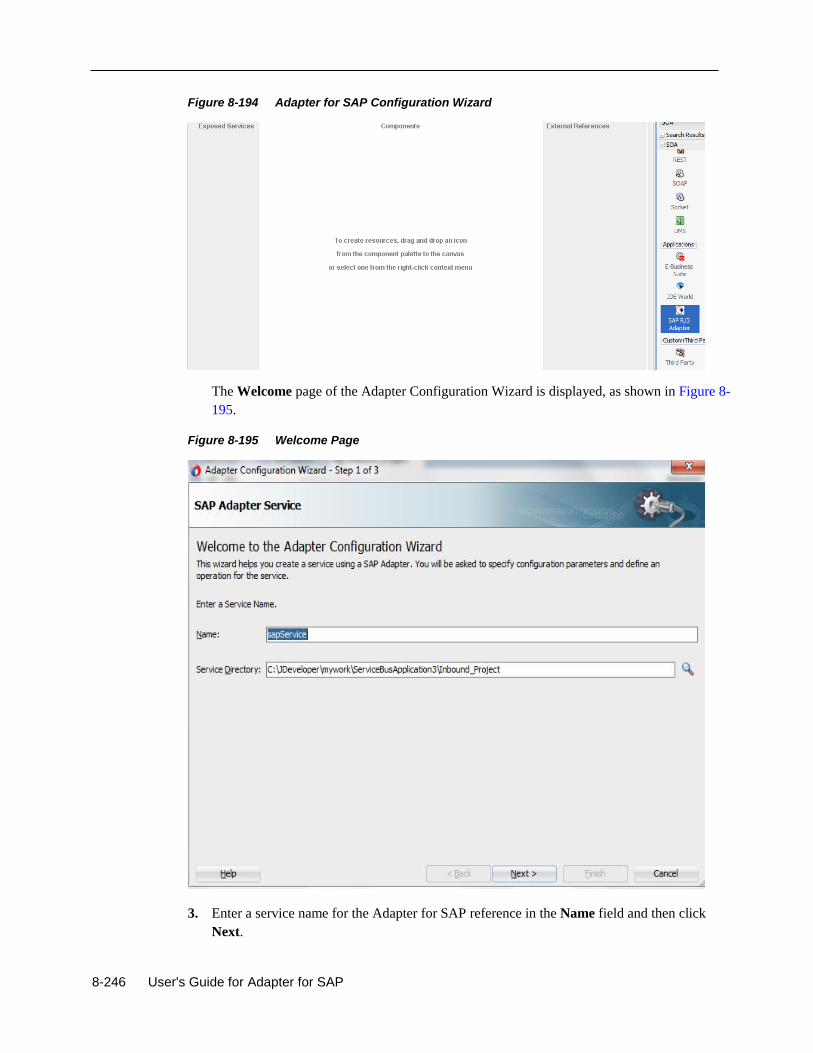
8-246 User's Guide for Adapter for SAP
Figure 8-194 Adapter for SAP Configuration Wizard
The Welcome page of the Adapter Configuration Wizard is displayed, as shown in Figure 8-
195.
Figure 8-195 Welcome Page
3. Enter a service name for the Adapter for SAP reference in the Name field and then click
Next.
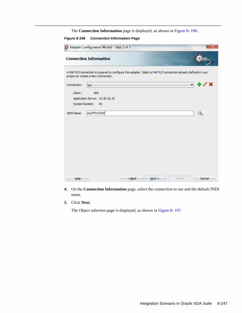
Integration Scenario in Oracle SOA Suite 8-247
The Connection Information page is displayed, as shown in Figure 8- 196.
Figure 8-196 Connection Information Page
4. On the Connection Information page, select the connection to use and the default JNDI
name.
5. Click Next.
The Object selection page is displayed, as shown in Figure 8- 197.
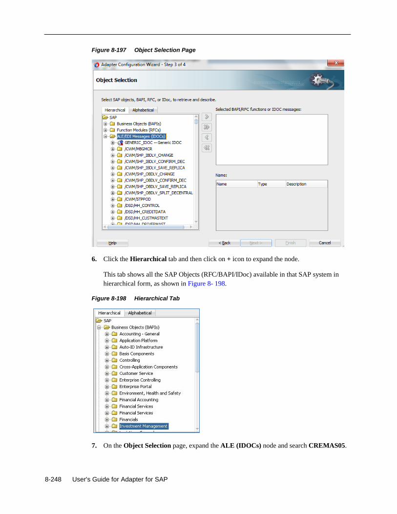
8-248 User's Guide for Adapter for SAP
Figure 8-197 Object Selection Page
6. Click the Hierarchical tab and then click on + icon to expand the node.
This tab shows all the SAP Objects (RFC/BAPI/IDoc) available in that SAP system in
hierarchical form, as shown in Figure 8- 198.
Figure 8-198 Hierarchical Tab
7. On the Object Selection page, expand the ALE (IDOCs) node and search CREMAS05.
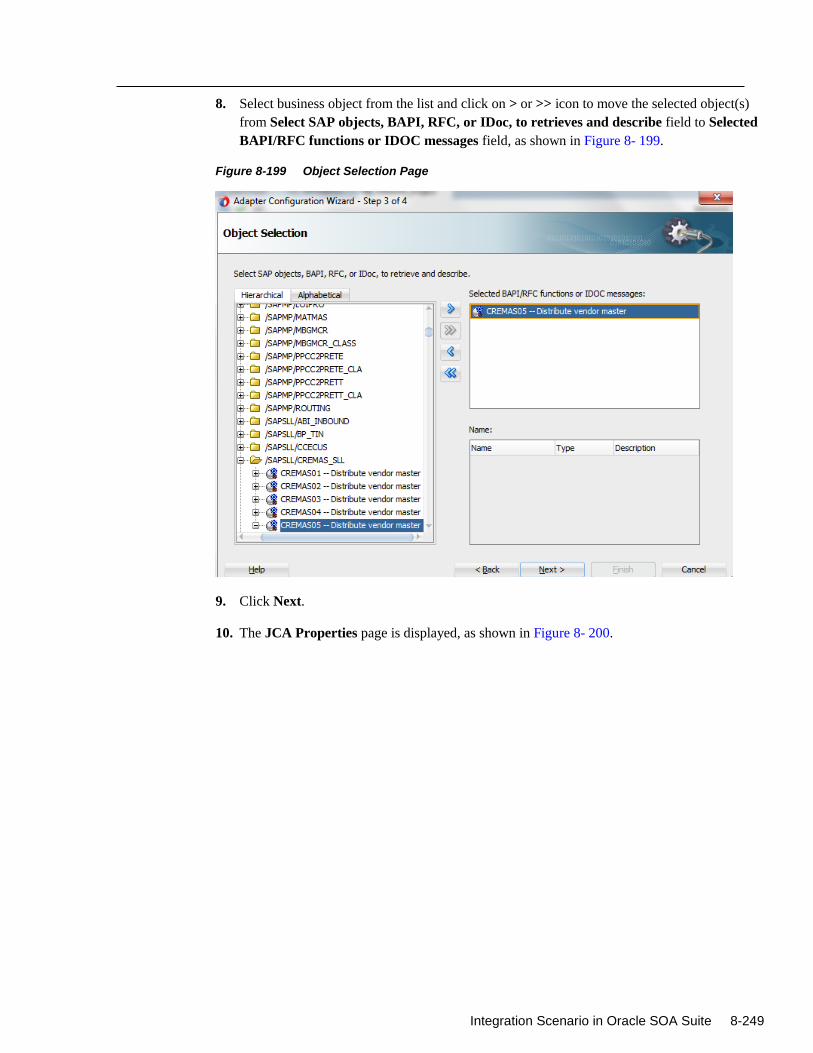
Integration Scenario in Oracle SOA Suite 8-249
8. Select business object from the list and click on > or >> icon to move the selected object(s)
from Select SAP objects, BAPI, RFC, or IDoc, to retrieves and describe field to Selected
BAPI/RFC functions or IDOC messages field, as shown in Figure 8- 199.
Figure 8-199 Object Selection Page
9. Click Next.
10. The JCA Properties page is displayed, as shown in Figure 8- 200.
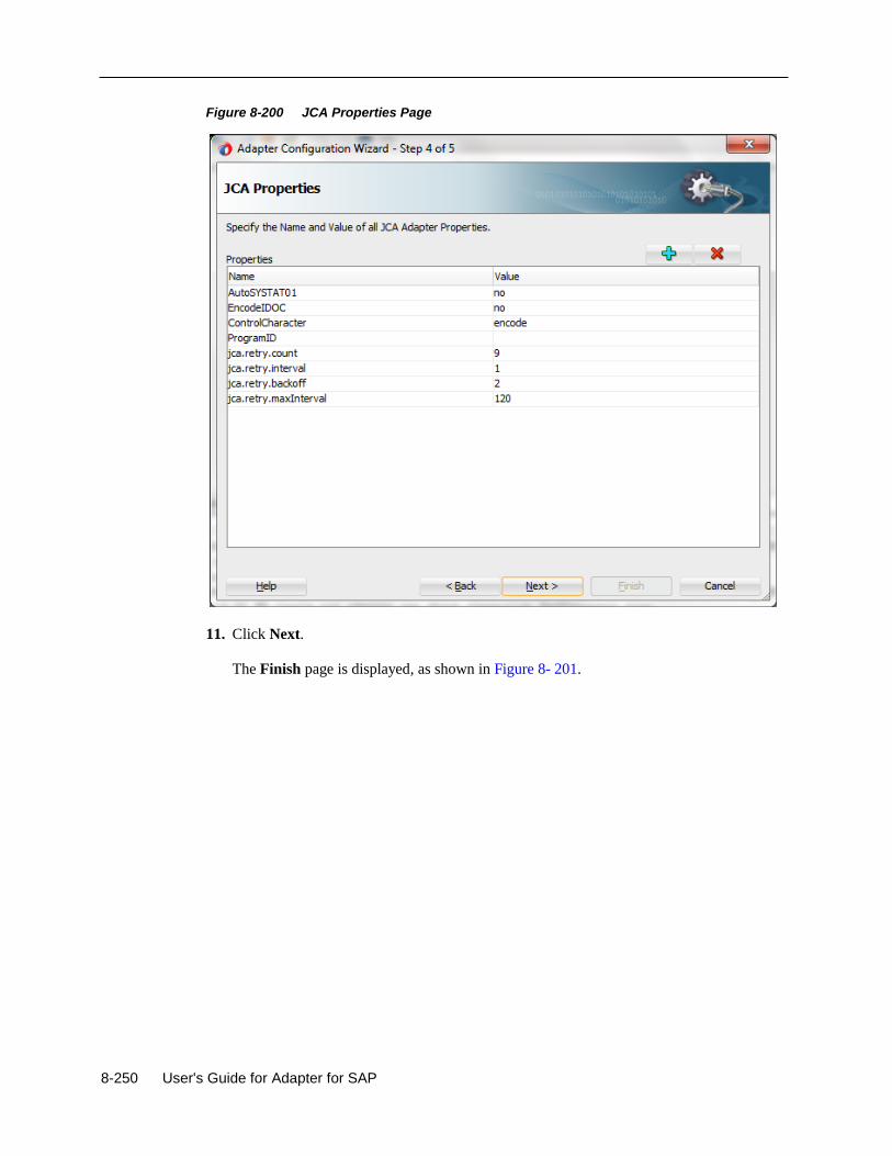
8-250 User's Guide for Adapter for SAP
Figure 8-200 JCA Properties Page
11. Click Next.
The Finish page is displayed, as shown in Figure 8- 201.
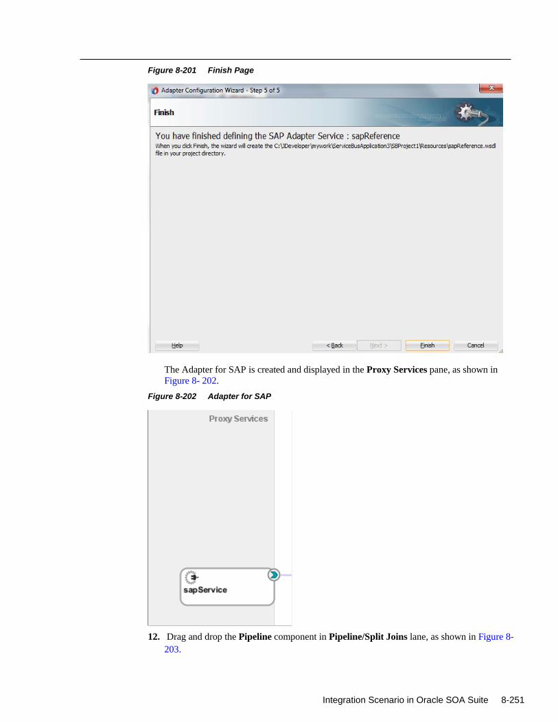
Integration Scenario in Oracle SOA Suite 8-251
Figure 8-201 Finish Page
The Adapter for SAP is created and displayed in the Proxy Services pane, as shown in
Figure 8- 202.
Figure 8-202 Adapter for SAP
12. Drag and drop the Pipeline component in Pipeline/Split Joins lane, as shown in Figure 8-
203.
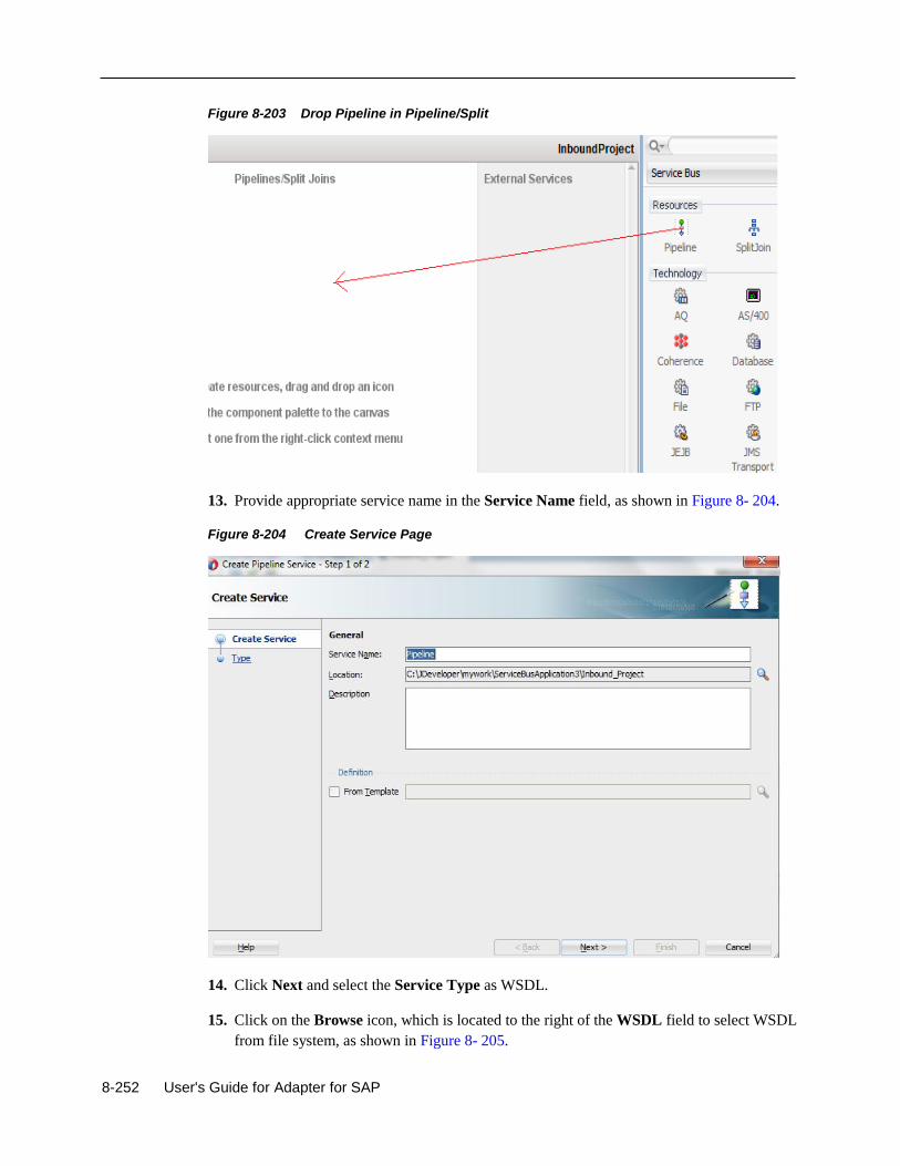
8-252 User's Guide for Adapter for SAP
Figure 8-203 Drop Pipeline in Pipeline/Split
13. Provide appropriate service name in the Service Name field, as shown in Figure 8- 204.
Figure 8-204 Create Service Page
14. Click Next and select the Service Type as WSDL.
15. Click on the Browse icon, which is located to the right of the WSDL field to select WSDL
from file system, as shown in Figure 8- 205.
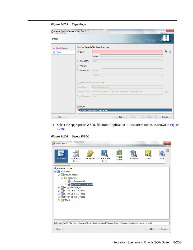
Integration Scenario in Oracle SOA Suite 8-253
Figure 8-205 Type Page
16. Select the appropriate WSDL file from Application -> Resources folder, as shown in Figure
8- 206.
Figure 8-206 Select WSDL
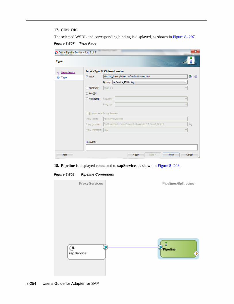
8-254 User's Guide for Adapter for SAP
17. Click OK.
The selected WSDL and corresponding binding is displayed, as shown in Figure 8- 207.
Figure 8-207 Type Page
18. Pipeline is displayed connected to sapService, as shown in Figure 8- 208.
Figure 8-208 Pipeline Component
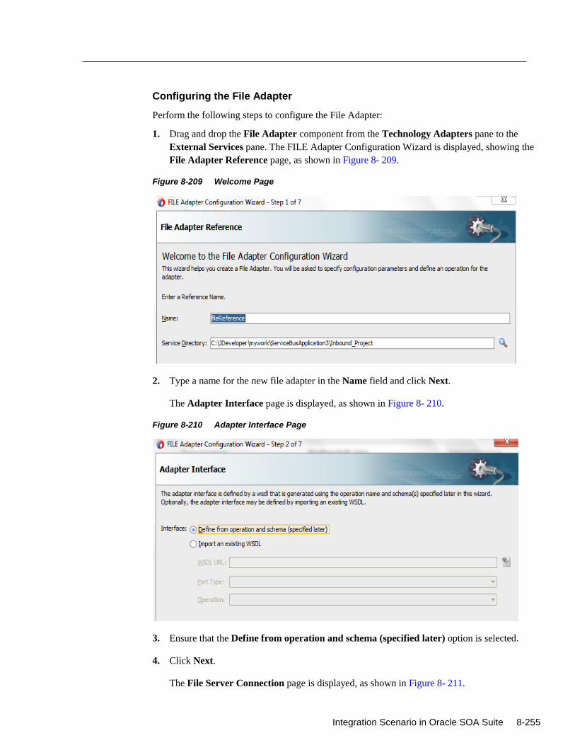
Integration Scenario in Oracle SOA Suite 8-255
Configuring the File Adapter
Perform the following steps to configure the File Adapter:
1. Drag and drop the File Adapter component from the Technology Adapters pane to the
External Services pane. The FILE Adapter Configuration Wizard is displayed, showing the
File Adapter Reference page, as shown in Figure 8- 209.
Figure 8-209 Welcome Page
2. Type a name for the new file adapter in the Name field and click Next.
The Adapter Interface page is displayed, as shown in Figure 8- 210.
Figure 8-210 Adapter Interface Page
3. Ensure that the Define from operation and schema (specified later) option is selected.
4. Click Next.
The File Server Connection page is displayed, as shown in Figure 8- 211.
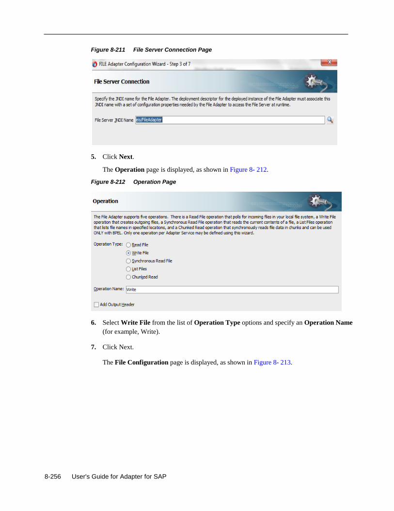
8-256 User's Guide for Adapter for SAP
Figure 8-211 File Server Connection Page
5. Click Next.
The Operation page is displayed, as shown in Figure 8- 212.
Figure 8-212 Operation Page
6. Select Write File from the list of Operation Type options and specify an Operation Name
(for example, Write).
7. Click Next.
The File Configuration page is displayed, as shown in Figure 8- 213.
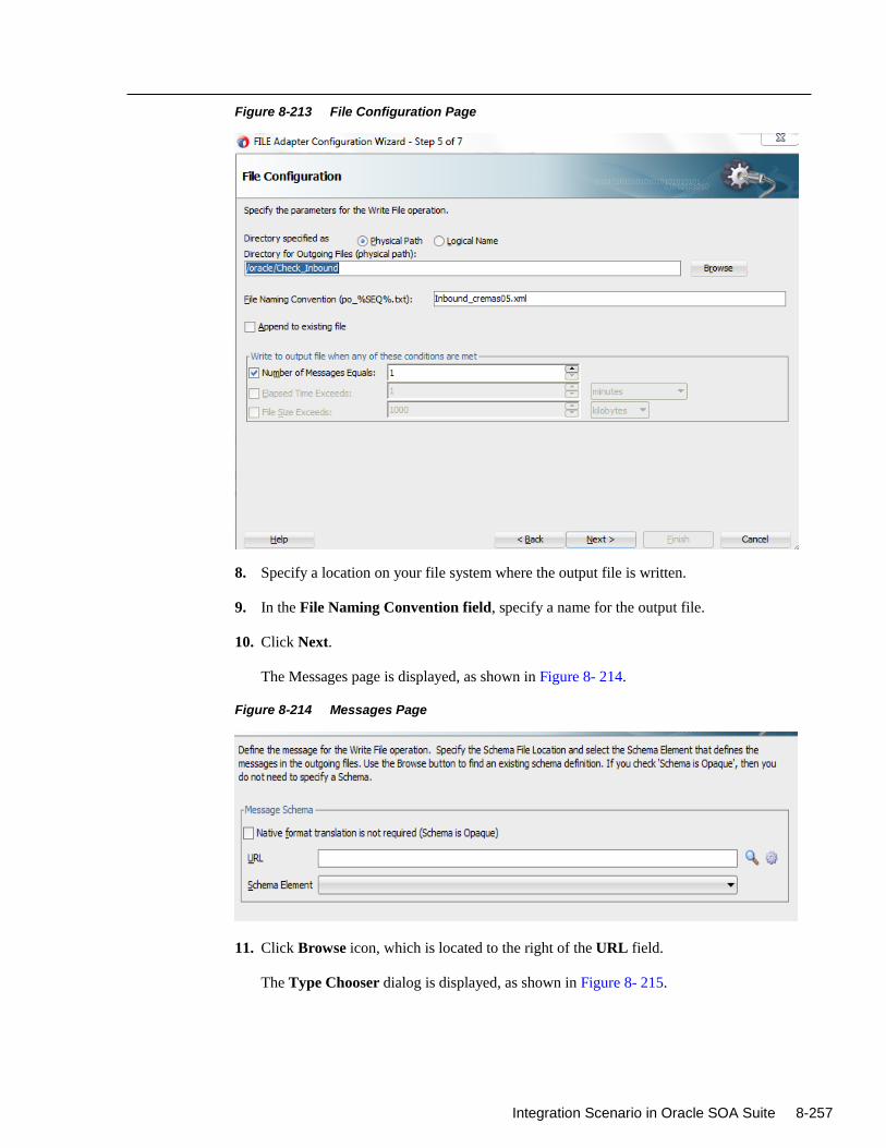
Integration Scenario in Oracle SOA Suite 8-257
Figure 8-213 File Configuration Page
8. Specify a location on your file system where the output file is written.
9. In the File Naming Convention field, specify a name for the output file.
10. Click Next.
The Messages page is displayed, as shown in Figure 8- 214.
Figure 8-214 Messages Page
11. Click Browse icon, which is located to the right of the URL field.
The Type Chooser dialog is displayed, as shown in Figure 8- 215.
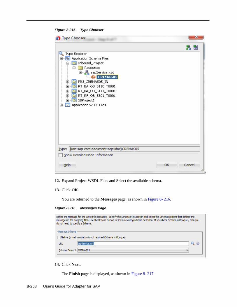
8-258 User's Guide for Adapter for SAP
Figure 8-215 Type Chooser
12. Expand Project WSDL Files and Select the available schema.
13. Click OK.
You are returned to the Messages page, as shown in Figure 8- 216.
Figure 8-216 Messages Page
14. Click Next.
The Finish page is displayed, as shown in Figure 8- 217.
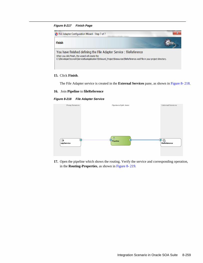
Integration Scenario in Oracle SOA Suite 8-259
Figure 8-217 Finish Page
15. Click Finish.
The File Adapter service is created in the External Services pane, as shown in Figure 8- 218.
16. Join Pipeline to fileReference
Figure 8-218 File Adapter Service
17. Open the pipeline which shows the routing. Verify the service and corresponding operation,
in the Routing-Properties, as shown in Figure 8- 219.
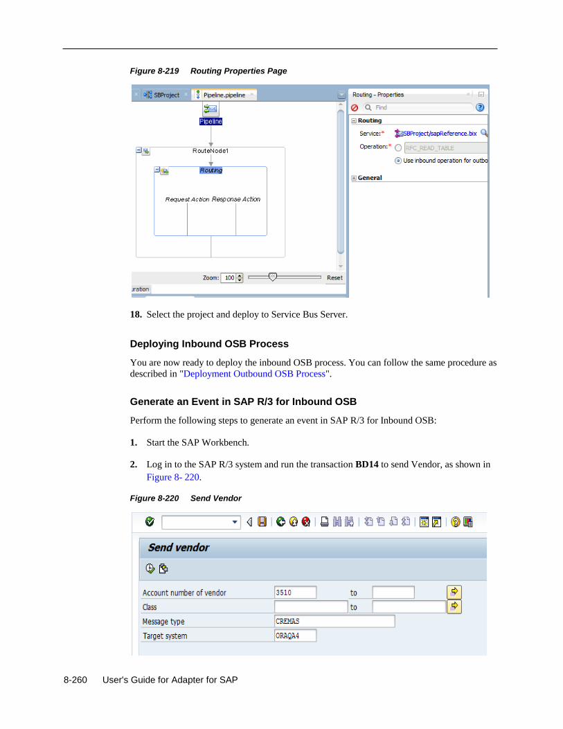
8-260 User's Guide for Adapter for SAP
Figure 8-219 Routing Properties Page
18. Select the project and deploy to Service Bus Server.
Deploying Inbound OSB Process
You are now ready to deploy the inbound OSB process. You can follow the same procedure as
described in "Deployment Outbound OSB Process".
Generate an Event in SAP R/3 for Inbound OSB
Perform the following steps to generate an event in SAP R/3 for Inbound OSB:
1. Start the SAP Workbench.
2. Log in to the SAP R/3 system and run the transaction BD14 to send Vendor, as shown in
Figure 8- 220.
Figure 8-220 Send Vendor
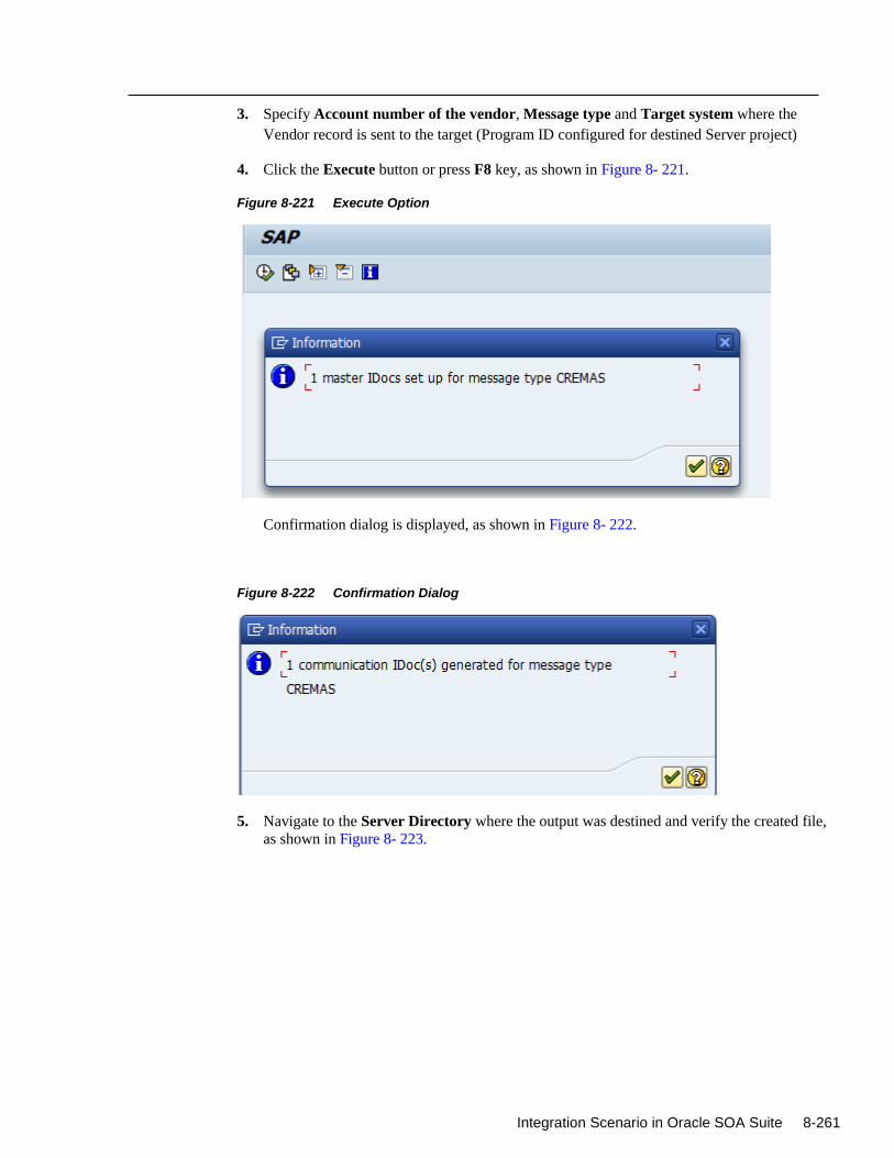
Integration Scenario in Oracle SOA Suite 8-261
3. Specify Account number of the vendor, Message type and Target system where the
Vendor record is sent to the target (Program ID configured for destined Server project)
4. Click the Execute button or press F8 key, as shown in Figure 8- 221.
Figure 8-221 Execute Option
Confirmation dialog is displayed, as shown in Figure 8- 222.
Figure 8-222 Confirmation Dialog
5. Navigate to the Server Directory where the output was destined and verify the created file,
as shown in Figure 8- 223.
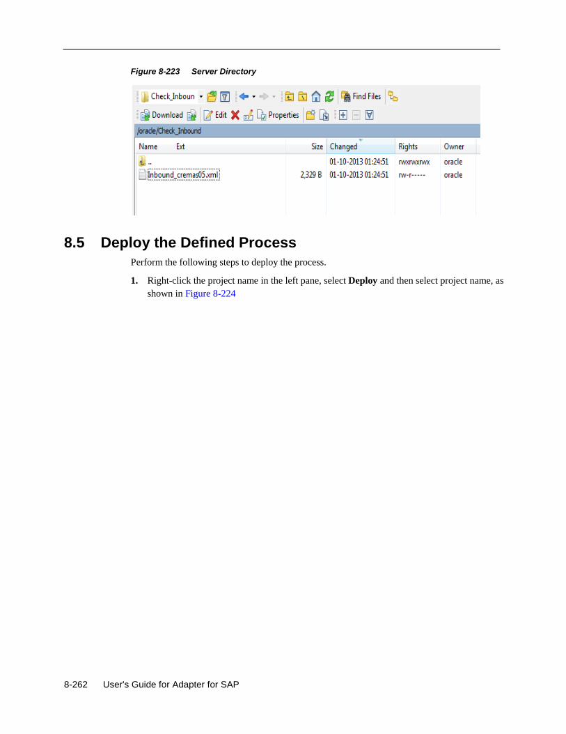
8-262 User's Guide for Adapter for SAP
Figure 8-223 Server Directory
8.5 Deploy the Defined Process
Perform the following steps to deploy the process.
1. Right-click the project name in the left pane, select Deploy and then select project name, as
shown in Figure 8-224
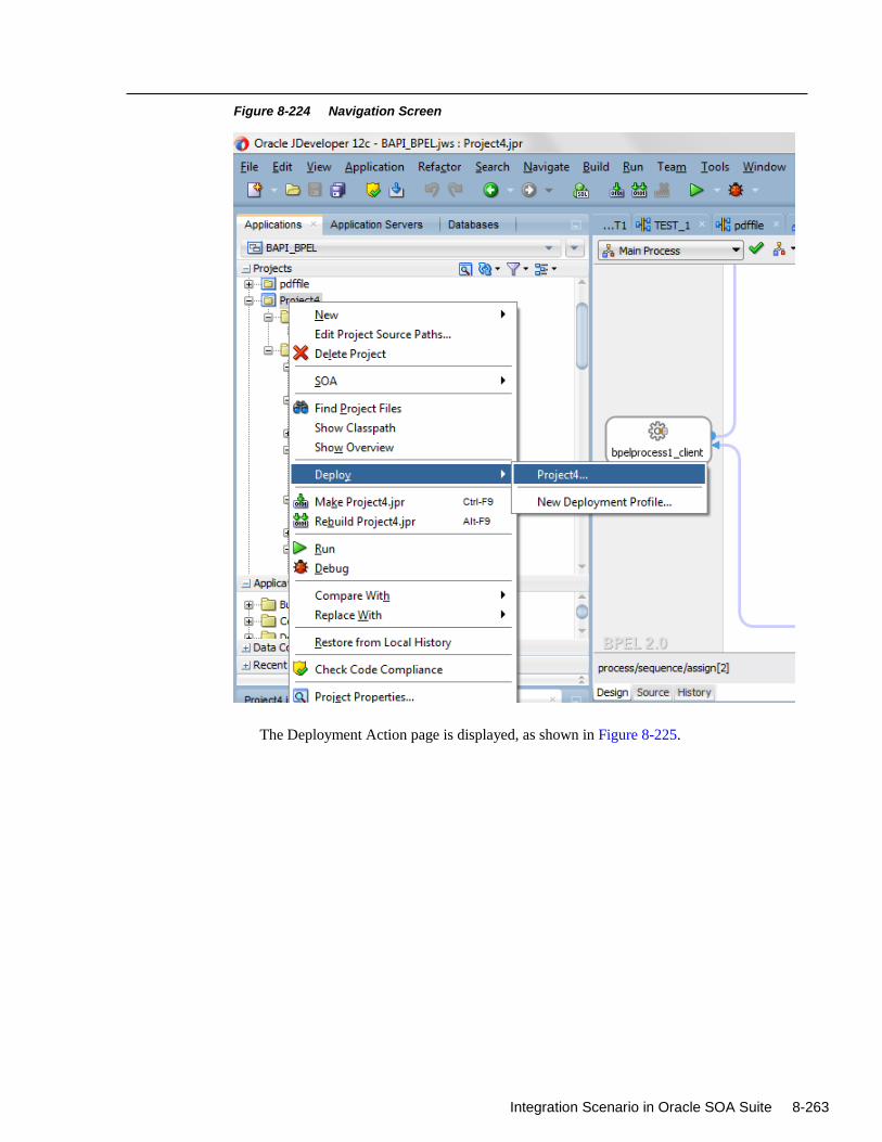
Integration Scenario in Oracle SOA Suite 8-263
Figure 8-224 Navigation Screen
The Deployment Action page is displayed, as shown in Figure 8-225.
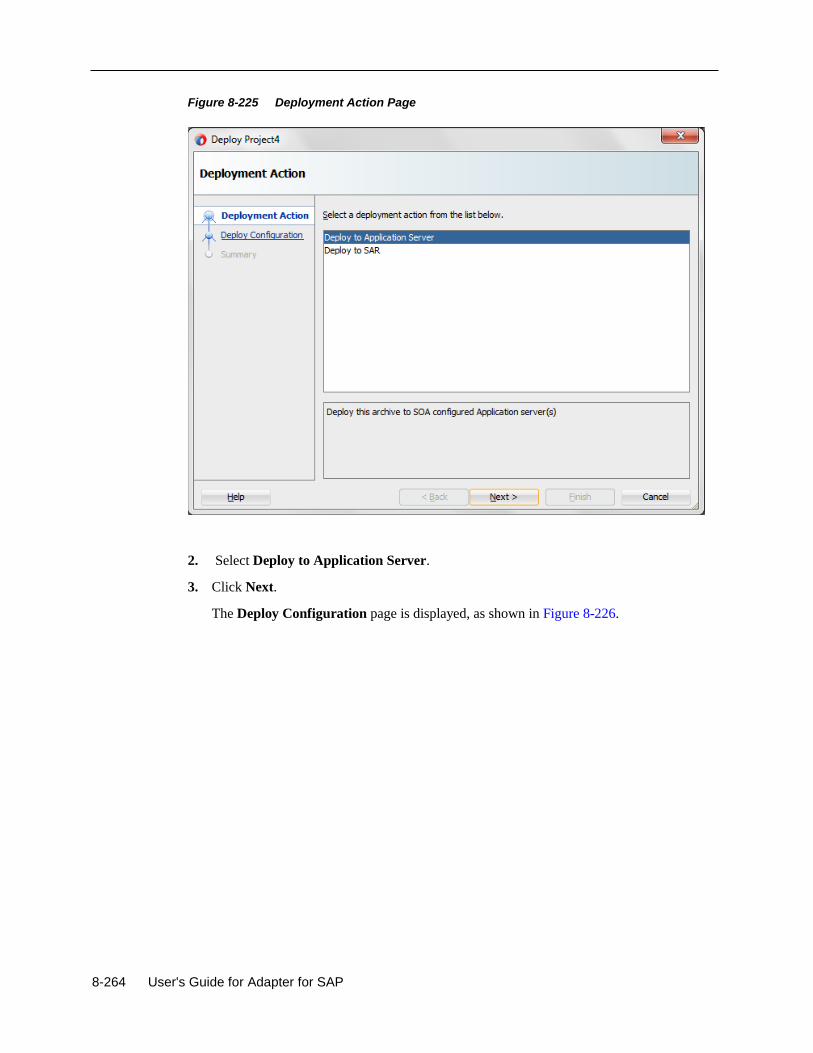
8-264 User's Guide for Adapter for SAP
Figure 8-225 Deployment Action Page
2. Select Deploy to Application Server.
3. Click Next.
The Deploy Configuration page is displayed, as shown in Figure 8-226.
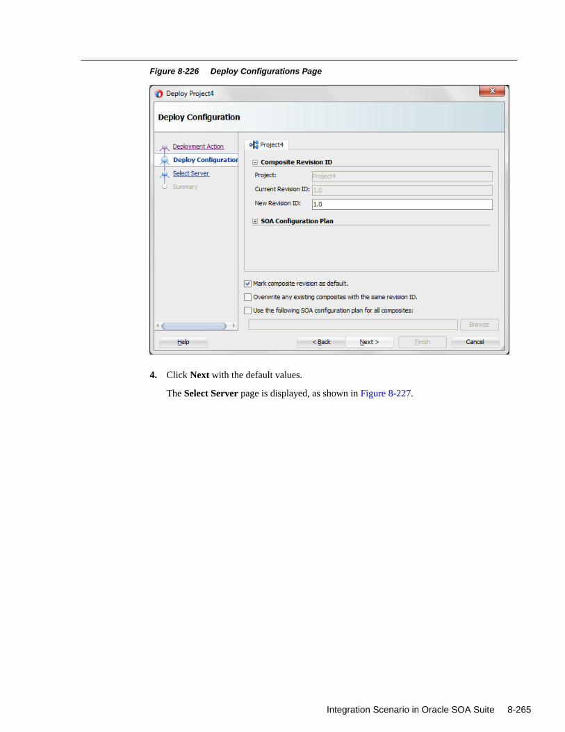
Integration Scenario in Oracle SOA Suite 8-265
Figure 8-226 Deploy Configurations Page
4. Click Next with the default values.
The Select Server page is displayed, as shown in Figure 8-227.
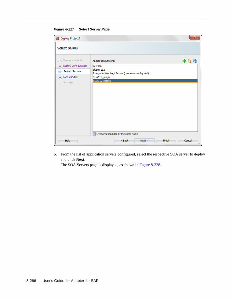
8-266 User's Guide for Adapter for SAP
Figure 8-227 Select Server Page
5. From the list of application servers configured, select the respective SOA server to deploy
and click Next.
The SOA Servers page is displayed, as shown in Figure 8-228.
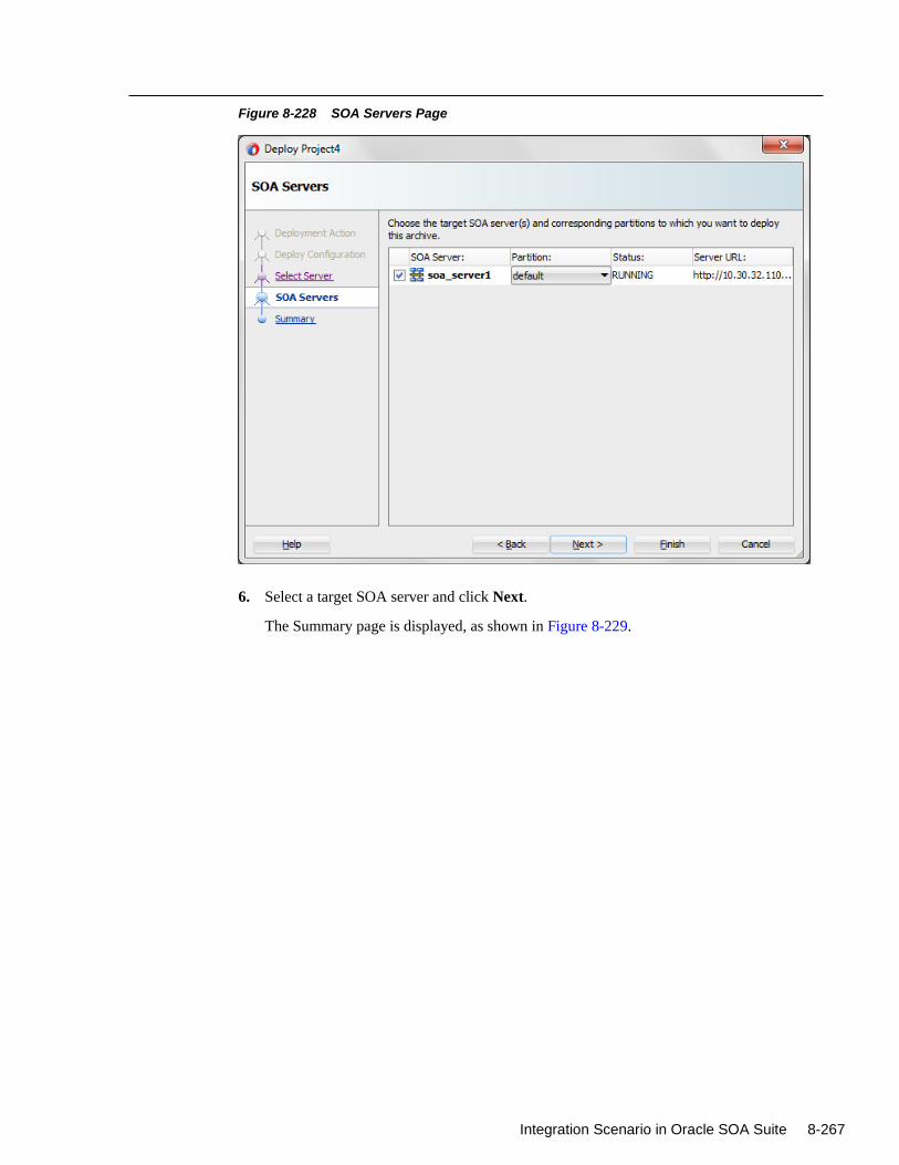
Integration Scenario in Oracle SOA Suite 8-267
Figure 8-228 SOA Servers Page
6. Select a target SOA server and click Next.
The Summary page is displayed, as shown in Figure 8-229.
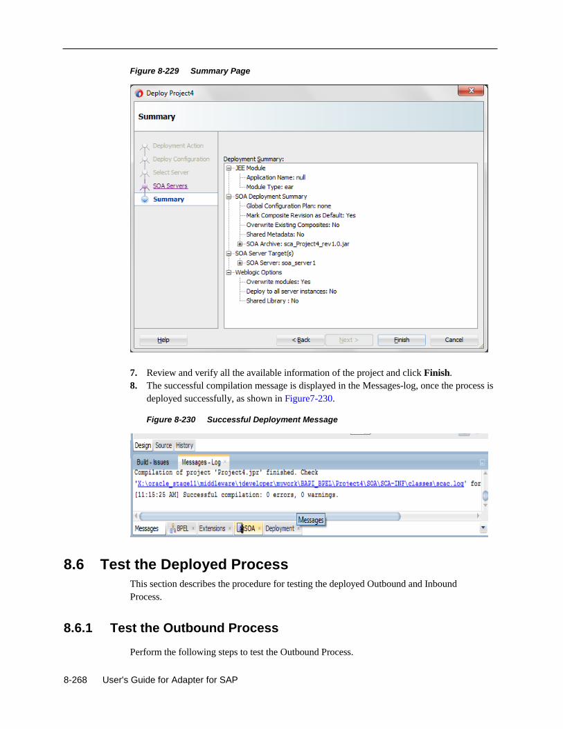
8-268 User's Guide for Adapter for SAP
Figure 8-229 Summary Page
7. Review and verify all the available information of the project and click Finish.
8. The successful compilation message is displayed in the Messages-log, once the process is
deployed successfully, as shown in Figure7-230.
Figure 8-230 Successful Deployment Message
8.6 Test the Deployed Process
This section describes the procedure for testing the deployed Outbound and Inbound
Process.
8.6.1 Test the Outbound Process
Perform the following steps to test the Outbound Process.
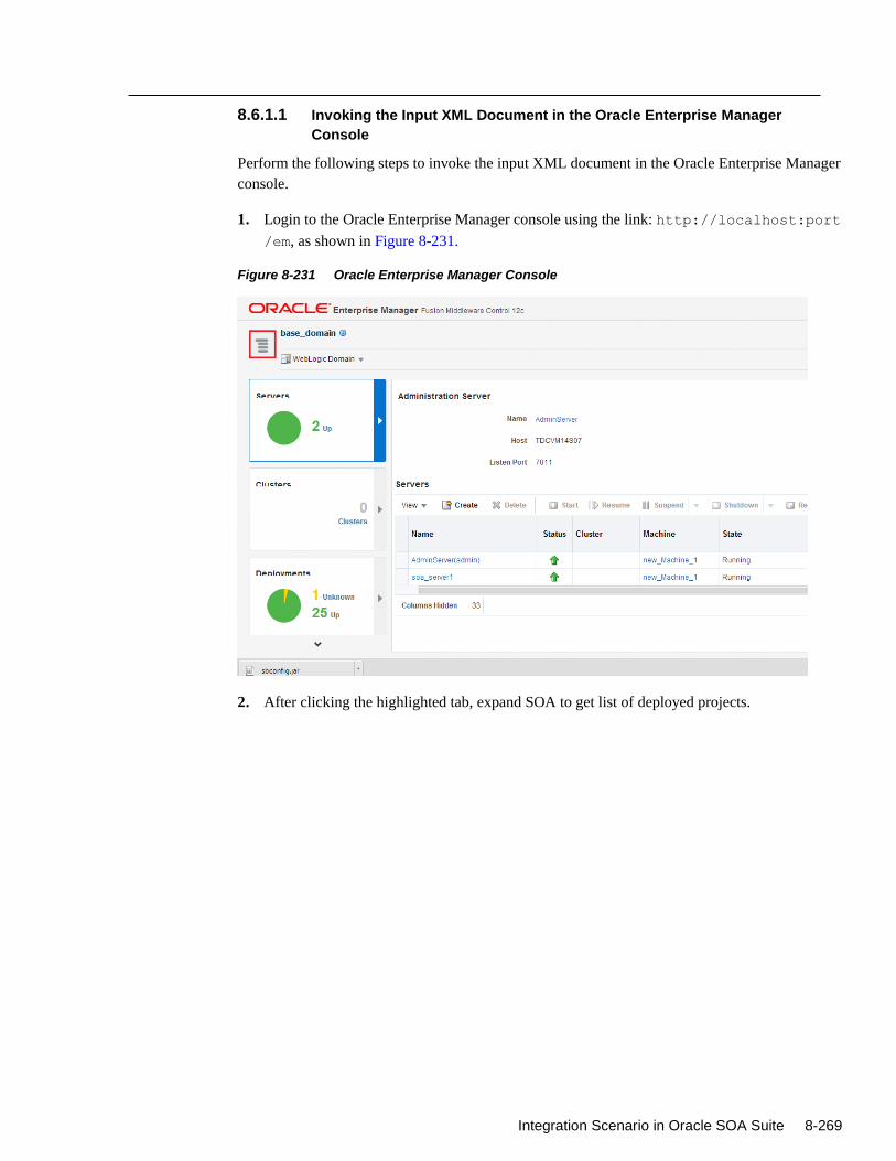
Integration Scenario in Oracle SOA Suite 8-269
8.6.1.1 Invoking the Input XML Document in the Oracle Enterprise Manager
Console
Perform the following steps to invoke the input XML document in the Oracle Enterprise Manager
console.
1. Login to the Oracle Enterprise Manager console using the link: http://localhost:port
/em, as shown in Figure 8-231.
Figure 8-231 Oracle Enterprise Manager Console
2. After clicking the highlighted tab, expand SOA to get list of deployed projects.
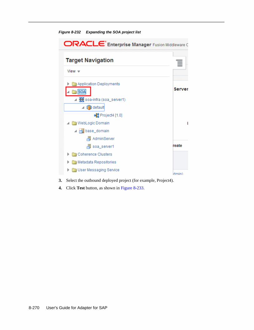
8-270 User's Guide for Adapter for SAP
Figure 8-232 Expanding the SOA project list
3. Select the outbound deployed project (for example, Project4).
4. Click Test button, as shown in Figure 8-233.
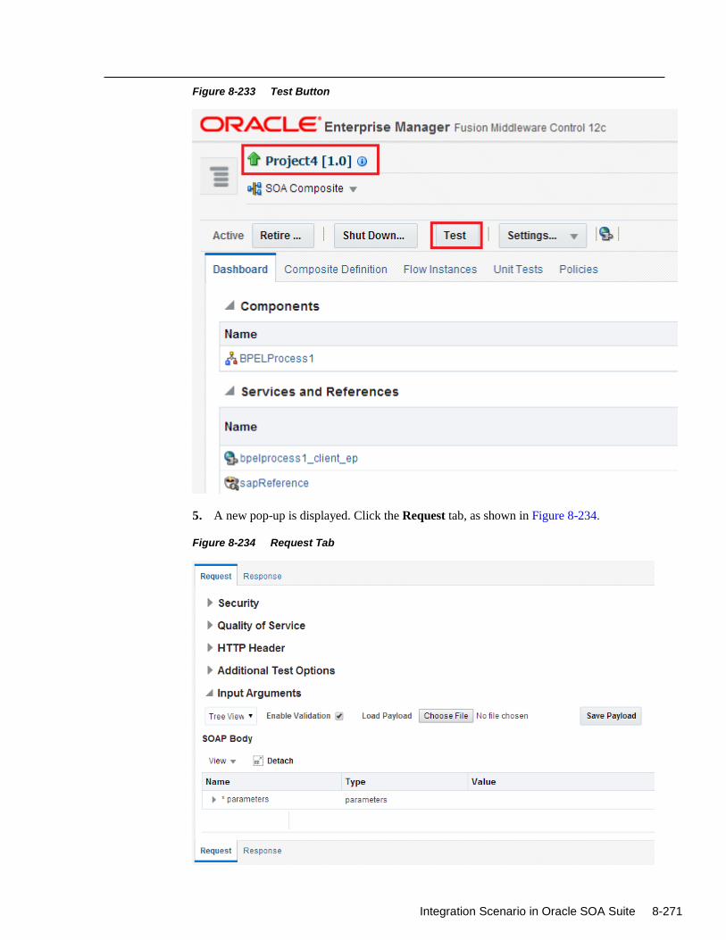
Integration Scenario in Oracle SOA Suite 8-271
Figure 8-233 Test Button
5. A new pop-up is displayed. Click the Request tab, as shown in Figure 8-234.
Figure 8-234 Request Tab
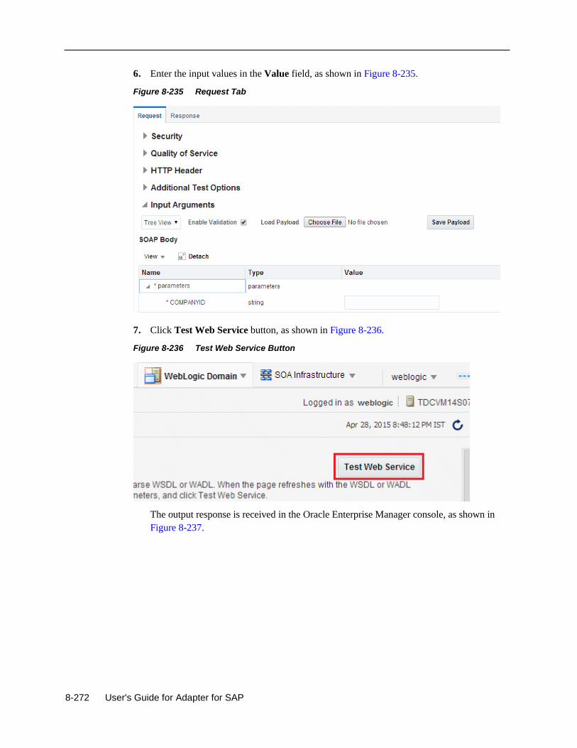
8-272 User's Guide for Adapter for SAP
6. Enter the input values in the Value field, as shown in Figure 8-235.
Figure 8-235 Request Tab
7. Click Test Web Service button, as shown in Figure 8-236.
Figure 8-236 Test Web Service Button
The output response is received in the Oracle Enterprise Manager console, as shown in
Figure 8-237.
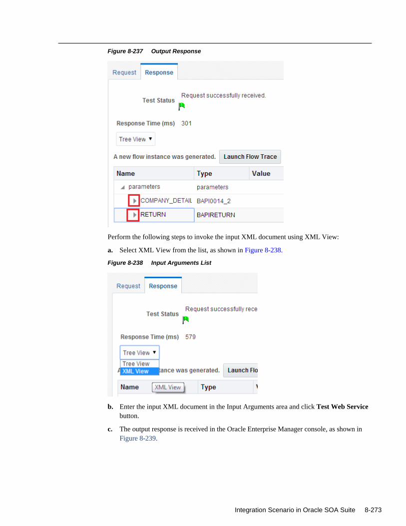
Integration Scenario in Oracle SOA Suite 8-273
Figure 8-237 Output Response
Perform the following steps to invoke the input XML document using XML View:
a. Select XML View from the list, as shown in Figure 8-238.
Figure 8-238 Input Arguments List
b. Enter the input XML document in the Input Arguments area and click Test Web Service
button.
c. The output response is received in the Oracle Enterprise Manager console, as shown in
Figure 8-239.
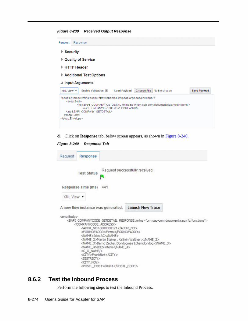
8-274 User's Guide for Adapter for SAP
Figure 8-239 Received Output Response
d. Click on Response tab, below screen appears, as shown in Figure 8-240.
Figure 8-240 Response Tab
8.6.2 Test the Inbound Process
Perform the following steps to test the Inbound Process.
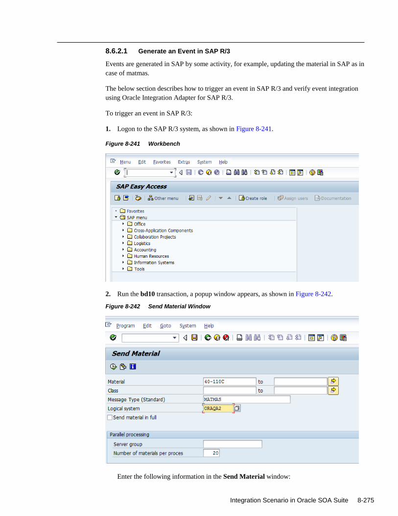
Integration Scenario in Oracle SOA Suite 8-275
8.6.2.1 Generate an Event in SAP R/3
Events are generated in SAP by some activity, for example, updating the material in SAP as in
case of matmas.
The below section describes how to trigger an event in SAP R/3 and verify event integration
using Oracle Integration Adapter for SAP R/3.
To trigger an event in SAP R/3:
1. Logon to the SAP R/3 system, as shown in Figure 8-241.
Figure 8-241 Workbench
2. Run the bd10 transaction, a popup window appears, as shown in Figure 8-242.
Figure 8-242 Send Material Window
Enter the following information in the Send Material window:
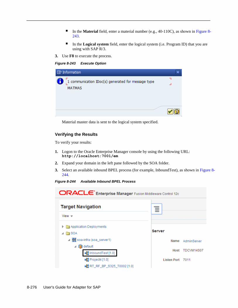
8-276 User's Guide for Adapter for SAP
In the Material field, enter a material number (e.g., 40-110C), as shown in Figure 8-
243.
In the Logical system field, enter the logical system (i.e. Program ID) that you are
using with SAP R/3.
3. Use F8 to execute the process.
Figure 8-243 Execute Option
Material master data is sent to the logical system specified.
Verifying the Results
To verify your results:
1. Logon to the Oracle Enterprise Manager console by using the following URL: http://localhost:7001/em
2. Expand your domain in the left pane followed by the SOA folder.
3. Select an available inbound BPEL process (for example, InboundTest), as shown in Figure 8-
244.
Figure 8-244 Available Inbound BPEL Process
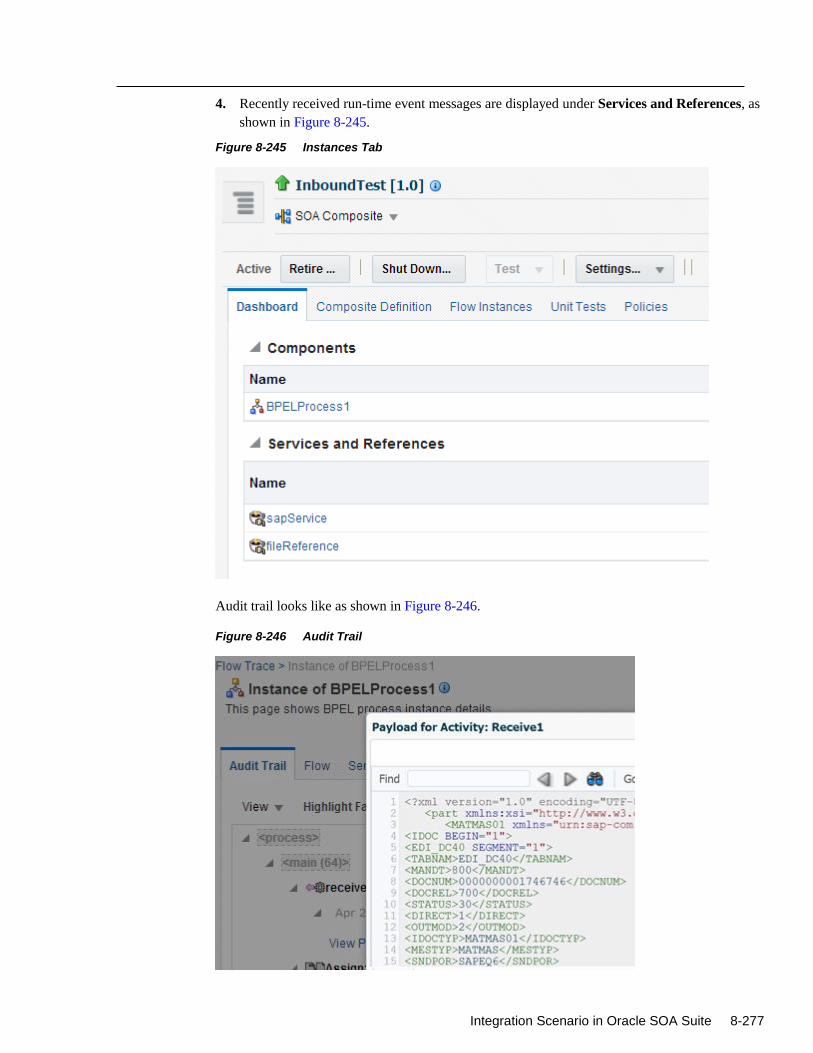
Integration Scenario in Oracle SOA Suite 8-277
4. Recently received run-time event messages are displayed under Services and References, as
shown in Figure 8-245.
Figure 8-245 Instances Tab
Audit trail looks like as shown in Figure 8-246.
Figure 8-246 Audit Trail

8-278 User's Guide for Adapter for SAP
Notes:
Inbound scenario is currently not working in the Integrated weblogic
hybrid domain environment as after receiving the IDoc, it is goes to the
rejection folder.
In this release, generation of Concrete WSDL with multiple objects
(IDoc or, BAPI or RFC) in OSB is currently not working.
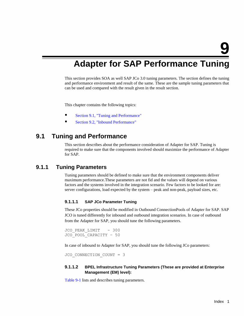
Index 1
9
Adapter for SAP Performance Tuning
This section provides SOA as well SAP JCo 3.0 tuning parameters. The section defines the tuning
and performance environment and result of the same. These are the sample tuning parameters that
can be used and compared with the result given in the result section.
This chapter contains the following topics:
Section 9.1, "Tuning and Performance"
Section 9.2, "Inbound Performance"
9.1 Tuning and Performance
This section describes about the performance consideration of Adapter for SAP. Tuning is
required to make sure that the components involved should maximize the performance of Adapter
for SAP.
9.1.1 Tuning Parameters
Tuning parameters should be defined to make sure that the environment components deliver
maximum performance.These parameters are not fid and the values will depend on various
factors and the systems involved in the integration scenario. Few factors to be looked for are:
server configurations, load expected by the system – peak and non-peak, payload sizes, etc.
9.1.1.1 SAP JCo Parameter Tuning
These JCo properties should be modified in Outbound ConnectionPools of Adapter for SAP. SAP
JCO is tuned differently for inbound and outbound integration scenarios. In case of outbound
from the Adapter for SAP, you should tune the following parameters.
JCO_PEAK_LIMIT - 300
JCO_POOL_CAPACITY – 50
In case of inbound to Adapter for SAP, you should tune the following JCo parameters:
JCO_CONNECTION_COUNT = 3
9.1.1.2 BPEL Infrastructure Tuning Parameters (These are provided at Enterprise
Management (EM) level):
Table 9-1 lists and describes tuning parameters.
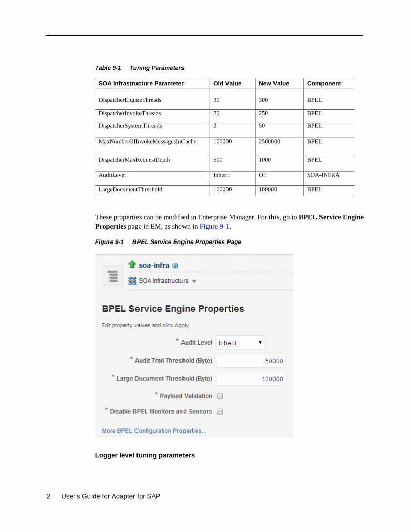
2 User's Guide for Adapter for SAP
Table 9-1 Tuning Parameters
SOA Infrastructure Parameter Old Value New Value Component
DispatcherEngineThreads
30
300
BPEL
DispatcherInvokeThreads 20 250 BPEL
DispatcherSystemThreads 2 50 BPEL
MaxNumberOfInvokeMessagesInCache 100000 2500000 BPEL
DispatcherMaxRequestDepth 600 1000 BPEL
AuditLevel Inherit Off SOA-INFRA
LargeDocumentThreshold 100000 100000 BPEL
These properties can be modified in Enterprise Manager. For this, go to BPEL Service Engine
Properties page in EM, as shown in Figure 9-1.
Figure 9-1 BPEL Service Engine Properties Page
Logger level tuning parameters
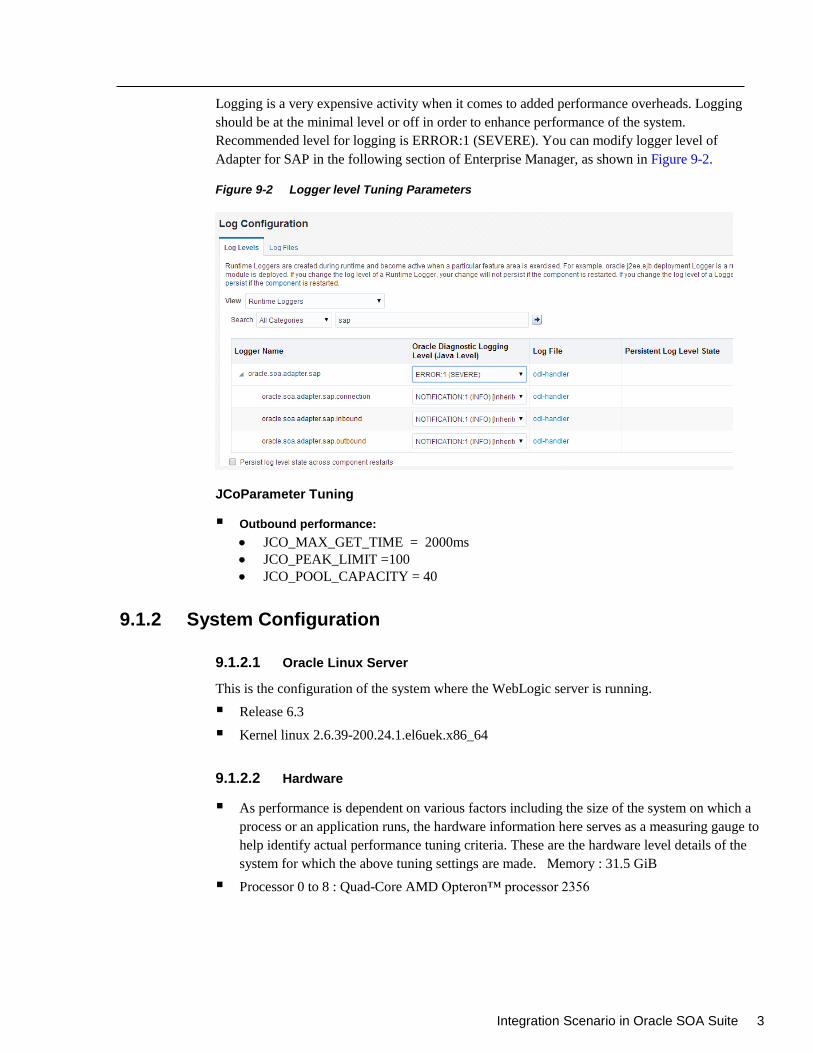
Integration Scenario in Oracle SOA Suite 3
Logging is a very expensive activity when it comes to added performance overheads. Logging
should be at the minimal level or off in order to enhance performance of the system.
Recommended level for logging is ERROR:1 (SEVERE). You can modify logger level of
Adapter for SAP in the following section of Enterprise Manager, as shown in Figure 9-2.
Figure 9-2 Logger level Tuning Parameters
JCoParameter Tuning
Outbound performance:
JCO_MAX_GET_TIME = 2000ms
JCO_PEAK_LIMIT =100
JCO_POOL_CAPACITY = 40
9.1.2 System Configuration
9.1.2.1 Oracle Linux Server
This is the configuration of the system where the WebLogic server is running.
Release 6.3
Kernel linux 2.6.39-200.24.1.el6uek.x86_64
9.1.2.2 Hardware
As performance is dependent on various factors including the size of the system on which a
process or an application runs, the hardware information here serves as a measuring gauge to
help identify actual performance tuning criteria. These are the hardware level details of the
system for which the above tuning settings are made. Memory : 31.5 GiB
Processor 0 to 8 : Quad-Core AMD Opteron™ processor 2356
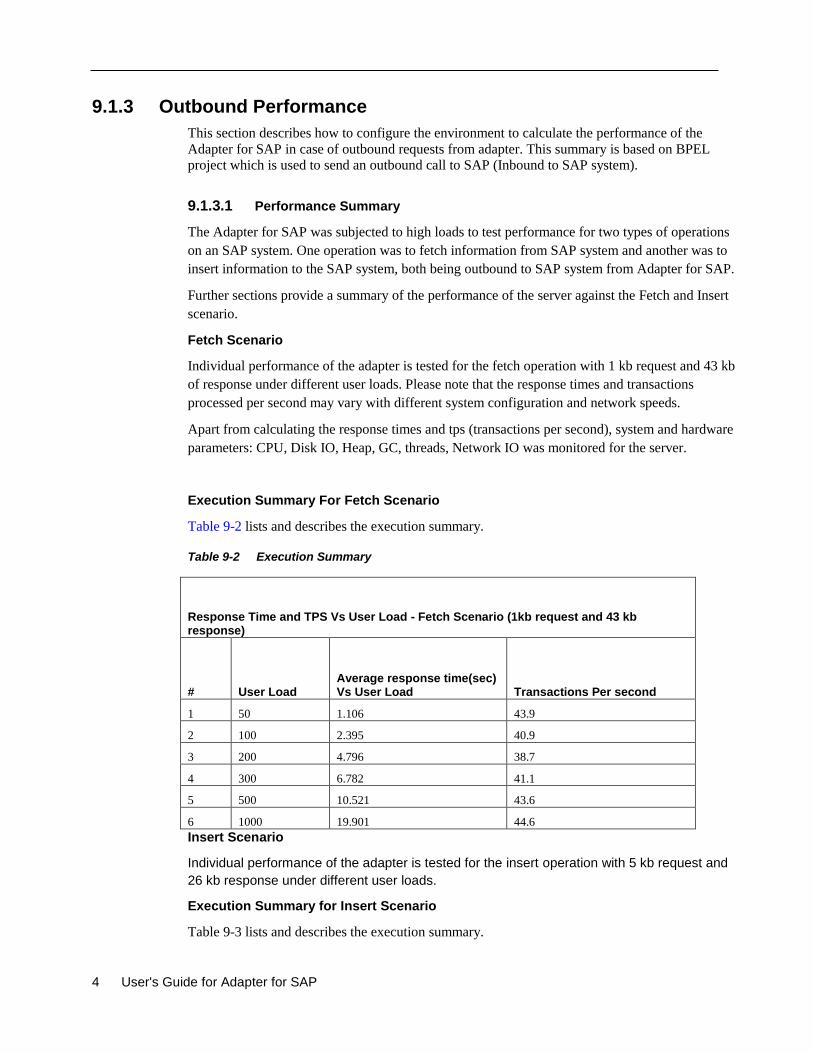
4 User's Guide for Adapter for SAP
9.1.3 Outbound Performance
This section describes how to configure the environment to calculate the performance of the
Adapter for SAP in case of outbound requests from adapter. This summary is based on BPEL
project which is used to send an outbound call to SAP (Inbound to SAP system).
9.1.3.1 Performance Summary
The Adapter for SAP was subjected to high loads to test performance for two types of operations
on an SAP system. One operation was to fetch information from SAP system and another was to
insert information to the SAP system, both being outbound to SAP system from Adapter for SAP.
Further sections provide a summary of the performance of the server against the Fetch and Insert
scenario.
Fetch Scenario
Individual performance of the adapter is tested for the fetch operation with 1 kb request and 43 kb
of response under different user loads. Please note that the response times and transactions
processed per second may vary with different system configuration and network speeds.
Apart from calculating the response times and tps (transactions per second), system and hardware
parameters: CPU, Disk IO, Heap, GC, threads, Network IO was monitored for the server.
Execution Summary For Fetch Scenario
Table 9-2 lists and describes the execution summary.
Table 9-2 Execution Summary
Response Time and TPS Vs User Load - Fetch Scenario (1kb request and 43 kb response)
# User Load Average response time(sec) Vs User Load Transactions Per second
1 50 1.106 43.9
2 100 2.395 40.9
3 200 4.796 38.7
4 300 6.782 41.1
5 500 10.521 43.6
6 1000 19.901 44.6
Insert Scenario
Individual performance of the adapter is tested for the insert operation with 5 kb request and
26 kb response under different user loads.
Execution Summary for Insert Scenario
Table 9-3 lists and describes the execution summary.
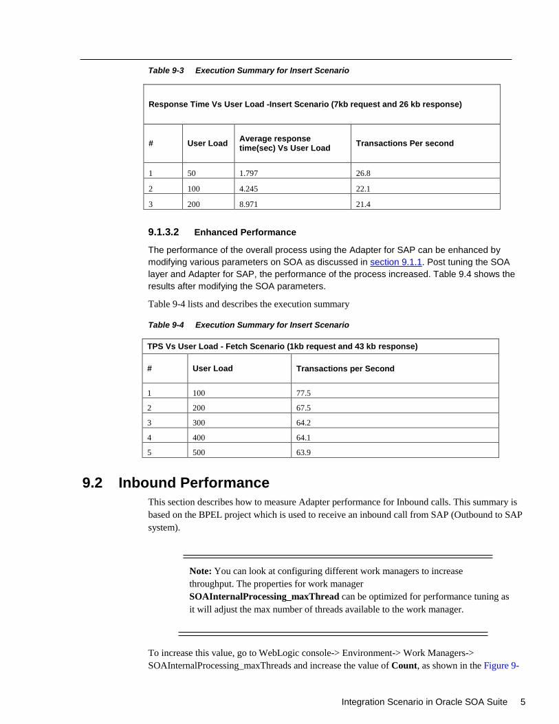
Integration Scenario in Oracle SOA Suite 5
Table 9-3 Execution Summary for Insert Scenario
Response Time Vs User Load -Insert Scenario (7kb request and 26 kb response)
# User Load Average response time(sec) Vs User Load
Transactions Per second
1 50 1.797 26.8
2 100 4.245 22.1
3 200 8.971 21.4
9.1.3.2 Enhanced Performance
The performance of the overall process using the Adapter for SAP can be enhanced by
modifying various parameters on SOA as discussed in section 9.1.1. Post tuning the SOA
layer and Adapter for SAP, the performance of the process increased. Table 9.4 shows the
results after modifying the SOA parameters.
Table 9-4 lists and describes the execution summary
Table 9-4 Execution Summary for Insert Scenario
TPS Vs User Load - Fetch Scenario (1kb request and 43 kb response)
# User Load Transactions per Second
1 100 77.5
2 200 67.5
3 300 64.2
4 400 64.1
5 500 63.9
9.2 Inbound Performance
This section describes how to measure Adapter performance for Inbound calls. This summary is
based on the BPEL project which is used to receive an inbound call from SAP (Outbound to SAP
system).
Note: You can look at configuring different work managers to increase
throughput. The properties for work manager
SOAInternalProcessing_maxThread can be optimized for performance tuning as
it will adjust the max number of threads available to the work manager.
To increase this value, go to WebLogic console-> Environment-> Work Managers->
SOAInternalProcessing_maxThreads and increase the value of Count, as shown in the Figure 9-
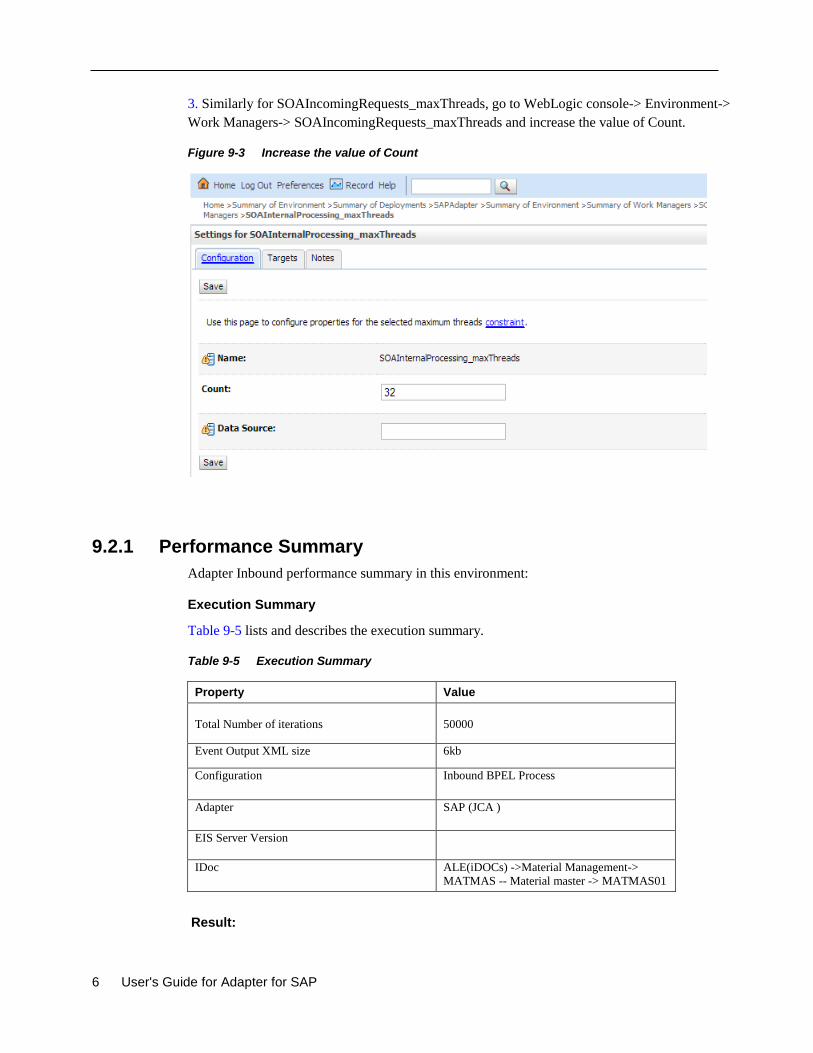
6 User's Guide for Adapter for SAP
3. Similarly for SOAIncomingRequests_maxThreads, go to WebLogic console-> Environment->
Work Managers-> SOAIncomingRequests_maxThreads and increase the value of Count.
Figure 9-3 Increase the value of Count
9.2.1 Performance Summary
Adapter Inbound performance summary in this environment:
Execution Summary
Table 9-5 lists and describes the execution summary.
Table 9-5 Execution Summary
Property Value
Total Number of iterations
50000
Event Output XML size 6kb
Configuration Inbound BPEL Process
Adapter SAP (JCA )
EIS Server Version
IDoc ALE(iDOCs) ->Material Management->
MATMAS -- Material master -> MATMAS01
Result:

Integration Scenario in Oracle SOA Suite 7
Table 9-6 lists and describes the results.
Table 9-6 Results
Name Avg TPS No of Concurrent IDOCs
SAP 25 208
8 User's Guide for Adapter for SAP
10
SOA Reports Integration
This section describes the Reports integration of the Adapter for SAP. Reports are useful in real-
time monitoring of the Adapter for SAP. This feature comes up with Oracle Enterprise Manager.
Using Oracle Enterprise Manager, you can see real-time adapter health report and connection
monitoring, such as closed and open(ed) connections on particular session. You can see health of
any deployed SAP endpoint connection created for that and which messages through this
integration.
This chapter contains the following topics:
Section 10.1, "Adapter Health Report"
10.1 Adapter Health Report
You can check real-time monitoring statistics of SAP Endpoint in Adapter health report.
Perform the following steps to open Adapter health report:
1. Open Enterprise Manager.
2. Go to SOA soa-infra.
3. Select the deployed Adapter project that you want to see.
The Adapter Report tab is displayed as shown in Figure 10-1.
4. Select SAP service / reference.
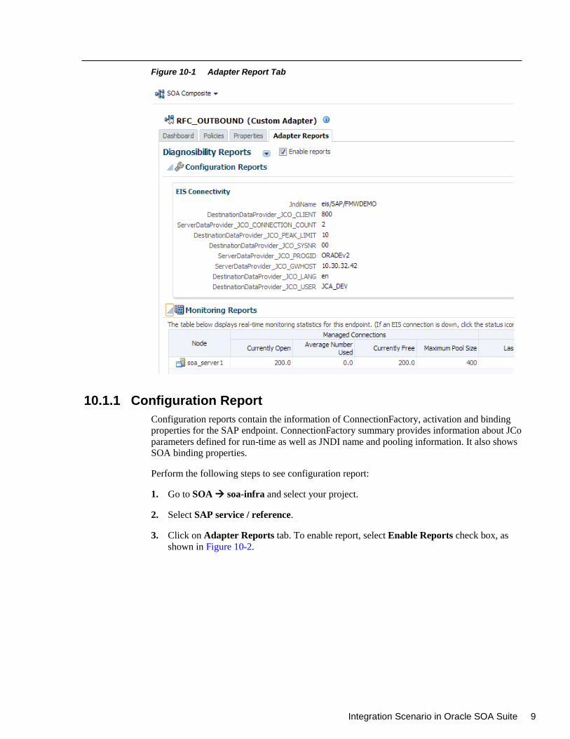
Integration Scenario in Oracle SOA Suite 9
Figure 10-1 Adapter Report Tab
10.1.1 Configuration Report
Configuration reports contain the information of ConnectionFactory, activation and binding
properties for the SAP endpoint. ConnectionFactory summary provides information about JCo
parameters defined for run-time as well as JNDI name and pooling information. It also shows
SOA binding properties.
Perform the following steps to see configuration report:
1. Go to SOA soa-infra and select your project.
2. Select SAP service / reference.
3. Click on Adapter Reports tab. To enable report, select Enable Reports check box, as
shown in Figure 10-2.
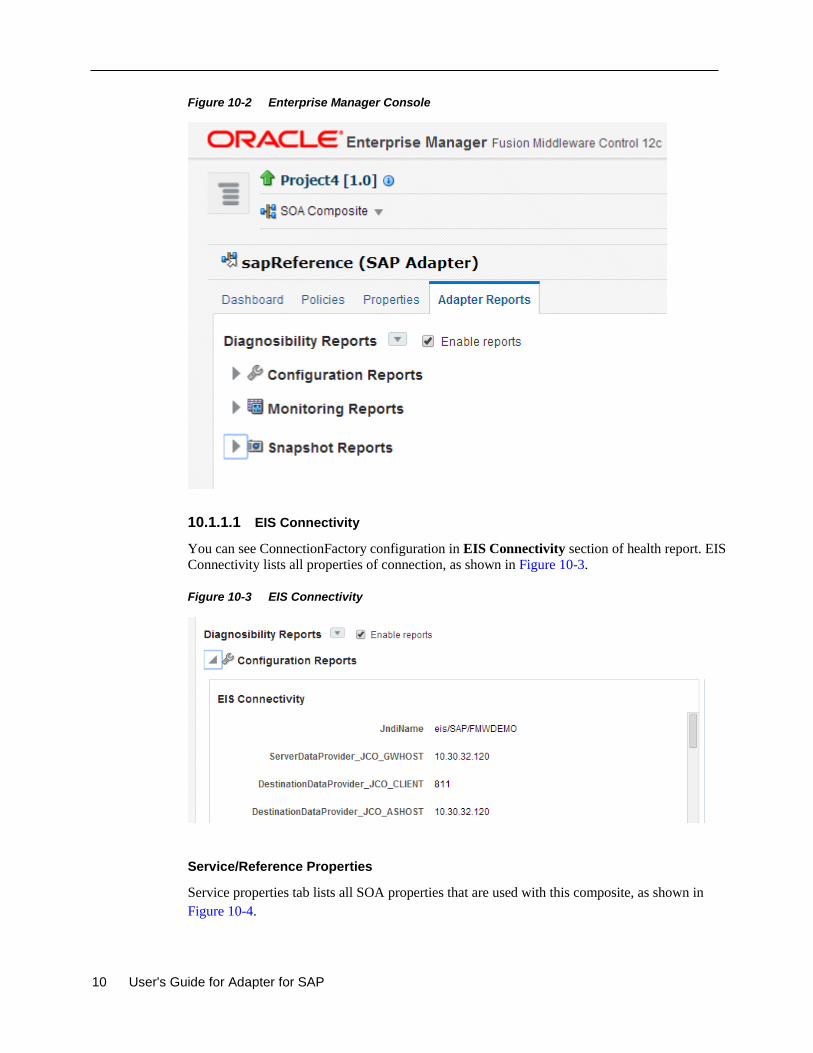
10 User's Guide for Adapter for SAP
Figure 10-2 Enterprise Manager Console
10.1.1.1 EIS Connectivity
You can see ConnectionFactory configuration in EIS Connectivity section of health report. EIS
Connectivity lists all properties of connection, as shown in Figure 10-3.
Figure 10-3 EIS Connectivity
Service/Reference Properties
Service properties tab lists all SOA properties that are used with this composite, as shown in
Figure 10-4.
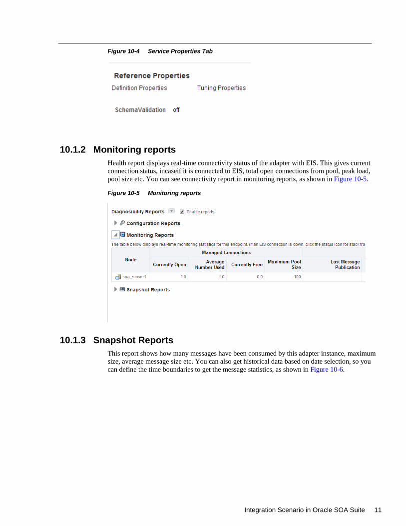
Integration Scenario in Oracle SOA Suite 11
Figure 10-4 Service Properties Tab
10.1.2 Monitoring reports
Health report displays real-time connectivity status of the adapter with EIS. This gives current
connection status, incaseif it is connected to EIS, total open connections from pool, peak load,
pool size etc. You can see connectivity report in monitoring reports, as shown in Figure 10-5.
Figure 10-5 Monitoring reports
10.1.3 Snapshot Reports
This report shows how many messages have been consumed by this adapter instance, maximum
size, average message size etc. You can also get historical data based on date selection, so you
can define the time boundaries to get the message statistics, as shown in Figure 10-6.
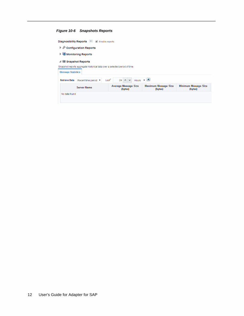
12 User's Guide for Adapter for SAP
Figure 10-6 Snapshots Reports
Integration Scenario in Oracle SOA Suite 13
11
Troubleshooting and Error Messages
The Adapter for SAP enables the configurable logging for debugging connection and other
related issues.
The Adapter for SAP supports the adapter diagnostic framework for reporting and alerting. This
provides run-time adapter diagnostic information as read only reports in EM console. The
framework also provides some alerting functionality.
The Adapter for SAP collects and provides reporting data per service/reference endpoint for each
composite. Endpoint reports capture useful information like EIS connectivity, transaction,
message, fault, downtime statistics etc.
The diagnostic reporting is configurable. There are knobs to turn it off when required. There is a
generic alerting framework for sending normal alerts and rules based alerts. The Adapter for SAP
provides design-time and run-time support to use the alerting framework.
This chapter mentions the possible errors that could occur while using the Adapter for SAP.
These areas of error messages include SAP side error messages, Adapter Design-time issues and
Adapter Run-time issues.
This chapter contains the following topics:
Section 11.1, "Log file Information"
Section 11.2, "Oracle Adapter for SAP Design-time JDeveloper"
Section 11.3, "Oracle Adapter for SAP Run-time"
Section 11.4, "SAP R/3"
11.1 Log file Information
Log file information that can be relevant in troubleshooting can be found in the following
locations based the adapter installation:
For Oracle SOA Suite:
<ORACLE_HOME>\soa\user_projects\domains\${soa_server
domain}\servers\${soa_server name}\logs\soa-server_diagnostic.log
For OSB:
<ORACLE_HOME>\soa\user_projects\domains\${osb_server
domain}\servers\${osb_server name}\logs\osb-server_diagnostic.log
The Oracle Adapter for SAP trace information can be found under the following directory:
For JCO trace at server level:
<ORACLE_HOME>\user_projects\domains\${domain name}\tracename.trc
11.2 Oracle Adapter for SAP Design-Time JDeveloper
Table 11-1 shows the common errors faced while using Adapter for SAP in JDeveloper.
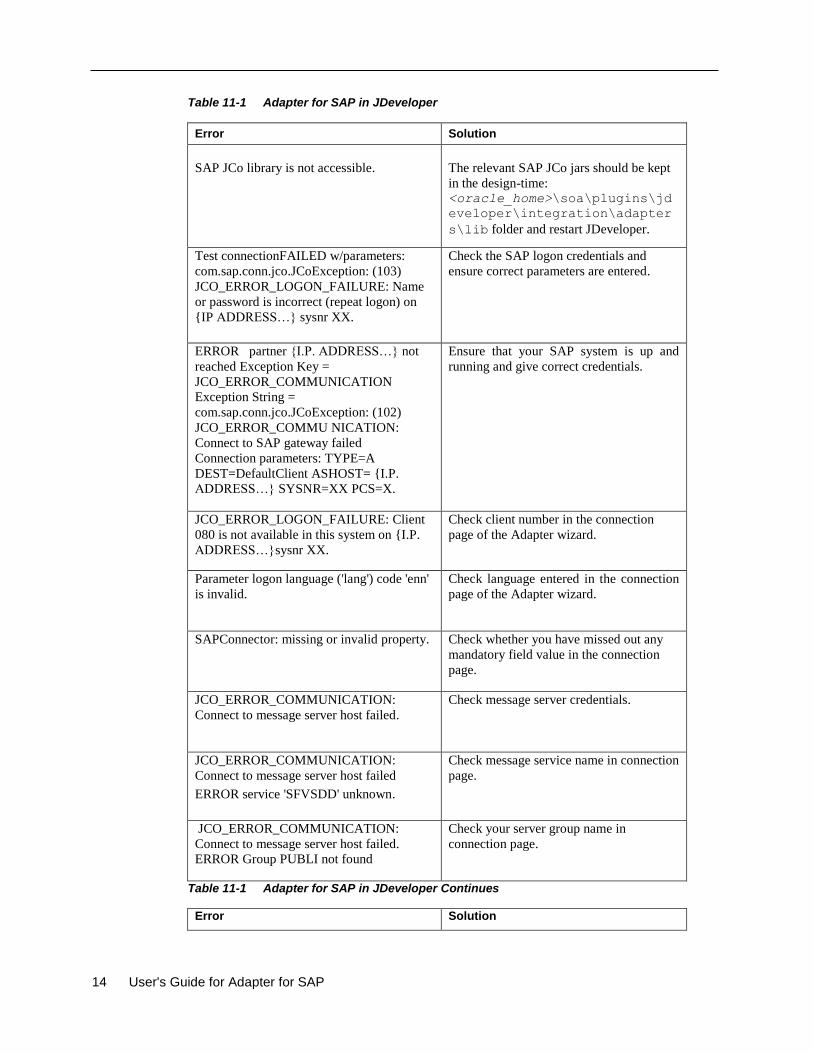
14 User's Guide for Adapter for SAP
Table 11-1 Adapter for SAP in JDeveloper
Error Solution
SAP JCo library is not accessible.
The relevant SAP JCo jars should be kept
in the design-time: <oracle_home>\soa\plugins\jd
eveloper\integration\adapter
s\lib folder and restart JDeveloper.
Test connectionFAILED w/parameters:
com.sap.conn.jco.JCoException: (103)
JCO_ERROR_LOGON_FAILURE: Name
or password is incorrect (repeat logon) on
{IP ADDRESS…} sysnr XX.
Check the SAP logon credentials and
ensure correct parameters are entered.
ERROR partner {I.P. ADDRESS…} not
reached Exception Key =
JCO_ERROR_COMMUNICATION
Exception String =
com.sap.conn.jco.JCoException: (102)
JCO_ERROR_COMMU NICATION:
Connect to SAP gateway failed
Connection parameters: TYPE=A
DEST=DefaultClient ASHOST= {I.P.
ADDRESS…} SYSNR=XX PCS=X.
Ensure that your SAP system is up and
running and give correct credentials.
JCO_ERROR_LOGON_FAILURE: Client
080 is not available in this system on {I.P.
ADDRESS…}sysnr XX.
Check client number in the connection
page of the Adapter wizard.
Parameter logon language ('lang') code 'enn'
is invalid.
Check language entered in the connection
page of the Adapter wizard.
SAPConnector: missing or invalid property. Check whether you have missed out any
mandatory field value in the connection
page.
JCO_ERROR_COMMUNICATION:
Connect to message server host failed.
Check message server credentials.
JCO_ERROR_COMMUNICATION:
Connect to message server host failed
ERROR service 'SFVSDD' unknown.
Check message service name in connection
page.
JCO_ERROR_COMMUNICATION:
Connect to message server host failed.
ERROR Group PUBLI not found
Check your server group name in
connection page.
Table 11-1 Adapter for SAP in JDeveloper Continues
Error Solution
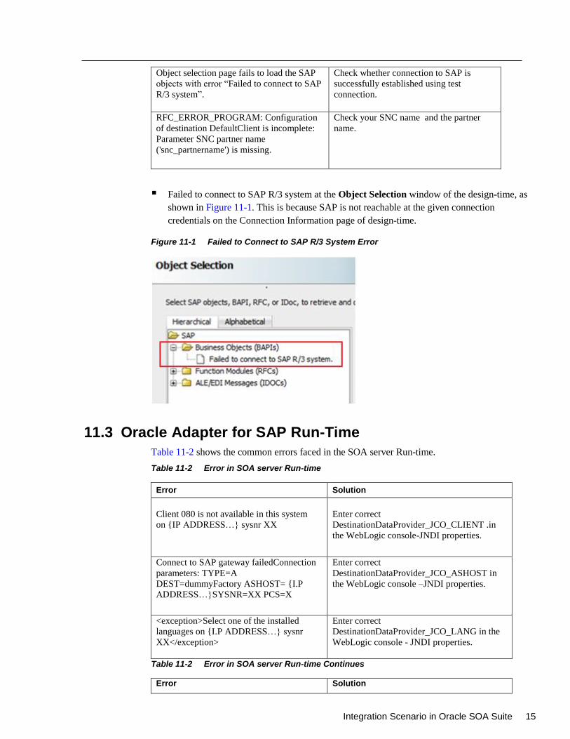
Integration Scenario in Oracle SOA Suite 15
Object selection page fails to load the SAP
objects with error “Failed to connect to SAP
R/3 system”.
Check whether connection to SAP is
successfully established using test
connection.
RFC_ERROR_PROGRAM: Configuration
of destination DefaultClient is incomplete:
Parameter SNC partner name
('snc_partnername') is missing.
Check your SNC name and the partner
name.
Failed to connect to SAP R/3 system at the Object Selection window of the design-time, as
shown in Figure 11-1. This is because SAP is not reachable at the given connection
credentials on the Connection Information page of design-time.
Figure 11-1 Failed to Connect to SAP R/3 System Error
11.3 Oracle Adapter for SAP Run-Time
Table 11-2 shows the common errors faced in the SOA server Run-time.
Table 11-2 Error in SOA server Run-time
Error Solution
Client 080 is not available in this system
on {IP ADDRESS…} sysnr XX
Enter correct
DestinationDataProvider_JCO_CLIENT .in
the WebLogic console-JNDI properties.
Connect to SAP gateway failedConnection
parameters: TYPE=A
DEST=dummyFactory ASHOST= {I.P
ADDRESS…}SYSNR=XX PCS=X
Enter correct
DestinationDataProvider_JCO_ASHOST in
the WebLogic console –JNDI properties.
<exception>Select one of the installed
languages on {I.P ADDRESS…} sysnr
XX</exception>
Enter correct
DestinationDataProvider_JCO_LANG in the
WebLogic console - JNDI properties.
Table 11-2 Error in SOA server Run-time Continues
Error Solution
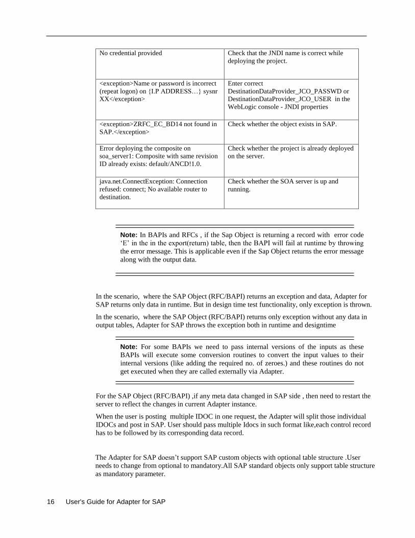
16 User's Guide for Adapter for SAP
No credential provided Check that the JNDI name is correct while
deploying the project.
<exception>Name or password is incorrect
(repeat logon) on {I.P ADDRESS…} sysnr
XX</exception>
Enter correct
DestinationDataProvider_JCO_PASSWD or
DestinationDataProvider_JCO_USER in the
WebLogic console - JNDI properties
<exception>ZRFC_EC_BD14 not found in
SAP.</exception>
Check whether the object exists in SAP.
Error deploying the composite on
soa_server1: Composite with same revision
ID already exists: default/ANCD!1.0.
Check whether the project is already deployed
on the server.
java.net.ConnectException: Connection
refused: connect; No available router to
destination.
Check whether the SOA server is up and
running.
Note: In BAPIs and RFCs , if the Sap Object is returning a record with error code
‘E’ in the in the export(return) table, then the BAPI will fail at runtime by throwing
the error message. This is applicable even if the Sap Object returns the error message
along with the output data.
In the scenario, where the SAP Object (RFC/BAPI) returns an exception and data, Adapter for
SAP returns only data in runtime. But in design time test functionality, only exception is thrown.
In the scenario, where the SAP Object (RFC/BAPI) returns only exception without any data in
output tables, Adapter for SAP throws the exception both in runtime and designtime
Note: For some BAPIs we need to pass internal versions of the inputs as these
BAPIs will execute some conversion routines to convert the input values to their
internal versions (like adding the required no. of zeroes.) and these routines do not
get executed when they are called externally via Adapter.
For the SAP Object (RFC/BAPI) ,if any meta data changed in SAP side , then need to restart the
server to reflect the changes in current Adapter instance.
When the user is posting multiple IDOC in one request, the Adapter will split those individual
IDOCs and post in SAP. User should pass multiple Idocs in such format like,each control record
has to be followed by its corresponding data record.
The Adapter for SAP doesn’t support SAP custom objects with optional table structure .User
needs to change from optional to mandatory.All SAP standard objects only support table structure
as mandatory parameter.
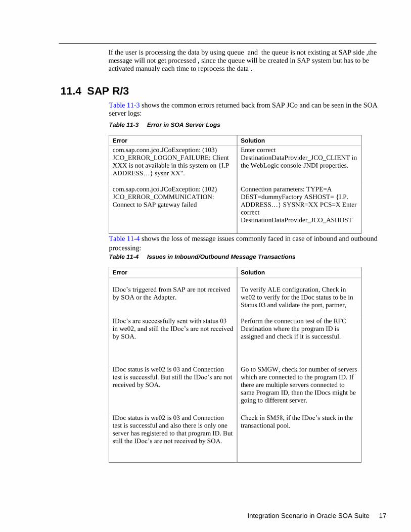
Integration Scenario in Oracle SOA Suite 17
If the user is processing the data by using queue and the queue is not existing at SAP side ,the
message will not get processed , since the queue will be created in SAP system but has to be
activated manualy each time to reprocess the data .
11.4 SAP R/3
Table 11-3 shows the common errors returned back from SAP JCo and can be seen in the SOA
server logs:
Table 11-3 Error in SOA Server Logs
Error Solution
com.sap.conn.jco.JCoException: (103)
JCO_ERROR_LOGON_FAILURE: Client
XXX is not available in this system on {I.P
ADDRESS…} sysnr XX".
Enter correct
DestinationDataProvider_JCO_CLIENT in
the WebLogic console-JNDI properties.
com.sap.conn.jco.JCoException: (102)
JCO_ERROR_COMMUNICATION:
Connect to SAP gateway failed
Connection parameters: TYPE=A
DEST=dummyFactory ASHOST= {I.P.
ADDRESS…} SYSNR=XX PCS=X Enter
correct
DestinationDataProvider_JCO_ASHOST
Table 11-4 shows the loss of message issues commonly faced in case of inbound and outbound
processing:
Table 11-4 Issues in Inbound/Outbound Message Transactions
Error Solution
IDoc’s triggered from SAP are not received
by SOA or the Adapter.
To verify ALE configuration, Check in
we02 to verify for the IDoc status to be in
Status 03 and validate the port, partner,
IDoc’s are successfully sent with status 03
in we02, and still the IDoc’s are not received
by SOA.
Perform the connection test of the RFC
Destination where the program ID is
assigned and check if it is successful.
IDoc status is we02 is 03 and Connection
test is successful. But still the IDoc’s are not
received by SOA.
Go to SMGW, check for number of servers
which are connected to the program ID. If
there are multiple servers connected to
same Program ID, then the IDocs might be
going to different server.
IDoc status is we02 is 03 and Connection
test is successful and also there is only one
server has registered to that program ID. But
still the IDoc’s are not received by SOA.
Check in SM58, if the IDoc’s stuck in the
transactional pool.

18 User's Guide for Adapter for SAP
11.5 Known Issues
1. No Help content appear in Japanese Language for Adapter Design Time screens:
When JDevelper is configured to work with Japanese language, all help content appears in
English instead of Japanese. Awaiting Translation Resource Bundle.
Integration Scenario in Oracle SOA Suite 19
12
Migration Support
The SOA and OSB projects with iWay SAP Endpoints can be migrated over to Oracle Adapter
for SAP using a migration utility within JDeveloper.
This chapter contains the following topics:
Section 12.1, "Migration of SAP Endpoints in SOA Projects"
Section 12.2, "Migration of SAP Endpoints in OSB Projects"
Section 12.3, "Deploying the Adapter Migrated Project”
Section 12.4, “Execution Steps for Deployed Migrated Projects”
Prerquisites:
The iWay projects to be migrated should have WSDL location in the JCA file.
Absence of this will cause incorrect migration.
The iWay project to be migrated should be working on the 12c environment. If the
input project is incorrect, the migrated project will be malformed too.
Note: Although the migration tooling does not report all possible errors in the input
iWay projects but it performs a basic check and reports errors detected in the
migration or deployment process. For e.g., JCA or any other files not migrated with
correct/required value or a WSDL file missing during deployment etc.
12.1 Migration of SAP Endpoints in SOA Projects
The Adapter for SAP must provide tooling to assist the user converting from the OEM version of
iWay SAP Endpoints in SOA composite application to ones based on the Oracle Adapter for
SAP.
Given an existing SOA project with iWay generated SAP endpoints, the migration tooling must
help to the user convert SAP endpoints in the SOA composite. After the conversion, the migrated
project must:
Reuse iWay generated XSD and WSDL files to minimize component interface changes
required within the SOA composite.
Generate a new JCA property file to replace the iWay SAP endpoint in the SOA composite.
Work in the SOA run-time without the iWay adapter.
Steps to migrate iWay Adapter into The Adapter for SAP from JDeveloper:
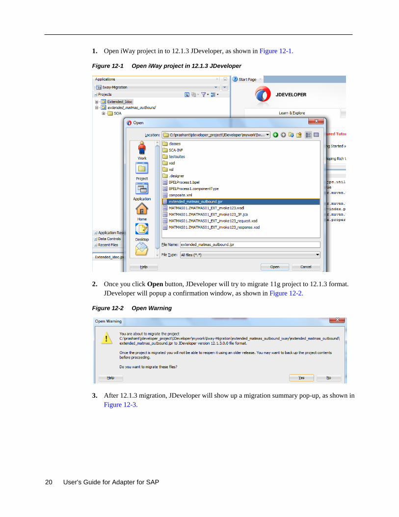
20 User's Guide for Adapter for SAP
1. Open iWay project in to 12.1.3 JDeveloper, as shown in Figure 12-1.
Figure 12-1 Open iWay project in 12.1.3 JDeveloper
2. Once you click Open button, JDeveloper will try to migrate 11g project to 12.1.3 format.
JDeveloper will popup a confirmation window, as shown in Figure 12-2.
Figure 12-2 Open Warning
3. After 12.1.3 migration, JDeveloper will show up a migration summary pop-up, as shown in
Figure 12-3.
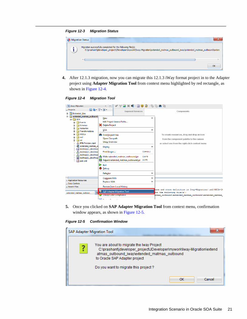
Integration Scenario in Oracle SOA Suite 21
Figure 12-3 Migration Status
4. After 12.1.3 migration, now you can migrate this 12.1.3 iWay format project in to the Adapter
project using Adapter Migration Tool from context menu highlighted by red rectangle, as
shown in Figure 12-4.
Figure 12-4 Migration Tool
5. Once you clicked on SAP Adapter Migration Tool from context menu, confirmation
window appears, as shown in Figure 12-5.
Figure 12-5 Confirmation Window
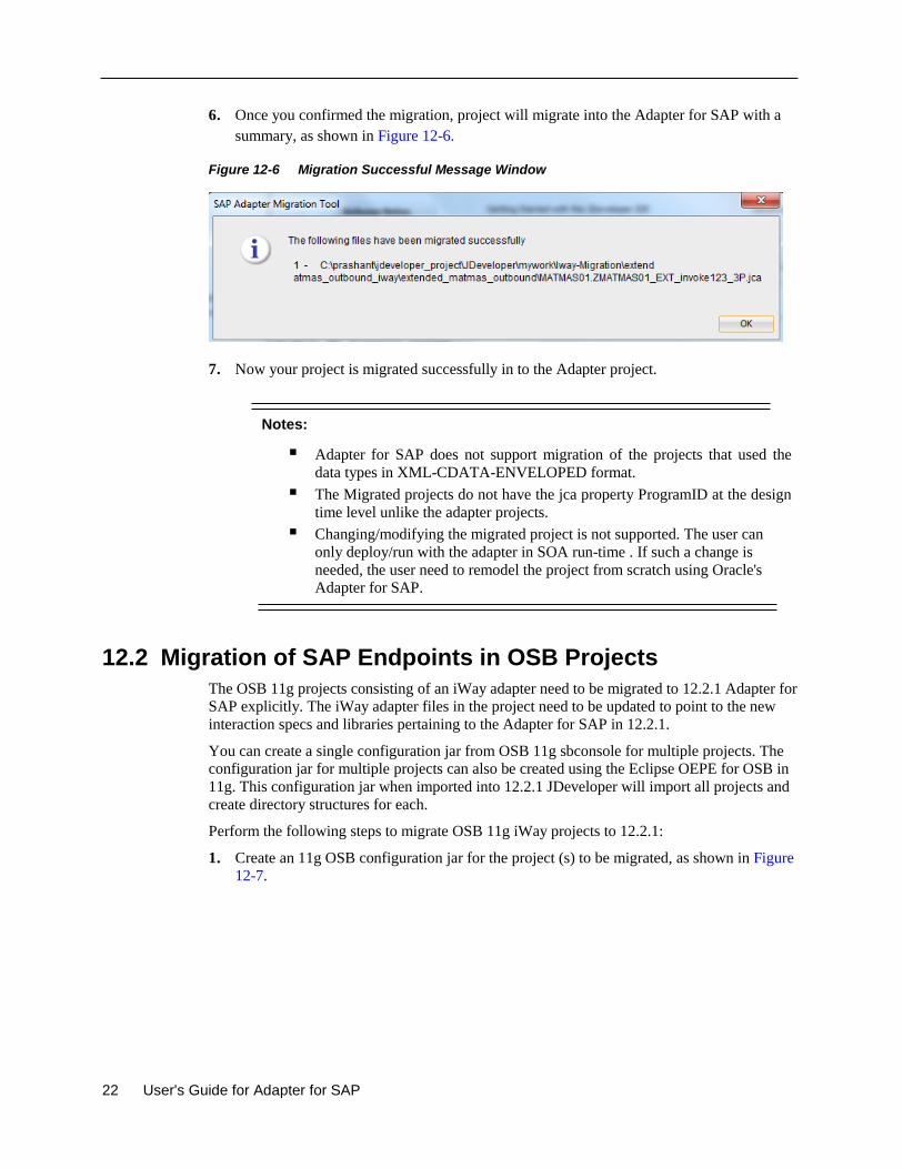
22 User's Guide for Adapter for SAP
6. Once you confirmed the migration, project will migrate into the Adapter for SAP with a
summary, as shown in Figure 12-6.
Figure 12-6 Migration Successful Message Window
7. Now your project is migrated successfully in to the Adapter project.
Notes:
Adapter for SAP does not support migration of the projects that used the
data types in XML-CDATA-ENVELOPED format.
The Migrated projects do not have the jca property ProgramID at the design
time level unlike the adapter projects.
Changing/modifying the migrated project is not supported. The user can
only deploy/run with the adapter in SOA run-time . If such a change is
needed, the user need to remodel the project from scratch using Oracle's
Adapter for SAP.
12.2 Migration of SAP Endpoints in OSB Projects
The OSB 11g projects consisting of an iWay adapter need to be migrated to 12.2.1 Adapter for
SAP explicitly. The iWay adapter files in the project need to be updated to point to the new
interaction specs and libraries pertaining to the Adapter for SAP in 12.2.1.
You can create a single configuration jar from OSB 11g sbconsole for multiple projects. The
configuration jar for multiple projects can also be created using the Eclipse OEPE for OSB in
11g. This configuration jar when imported into 12.2.1 JDeveloper will import all projects and
create directory structures for each.
Perform the following steps to migrate OSB 11g iWay projects to 12.2.1:
1. Create an 11g OSB configuration jar for the project (s) to be migrated, as shown in Figure
12-7.
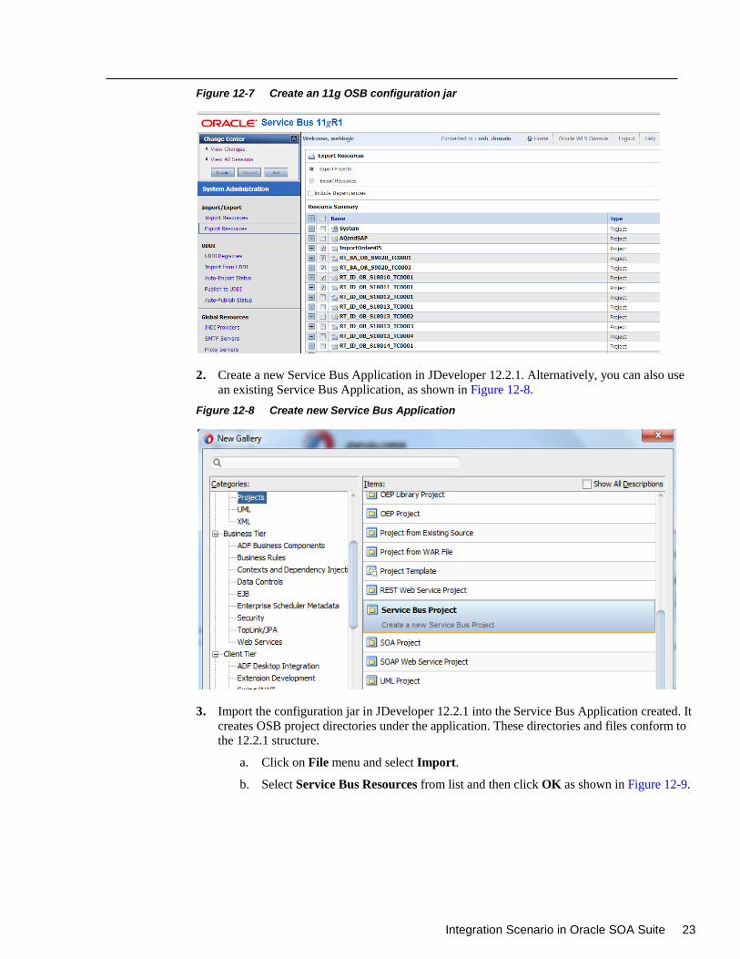
Integration Scenario in Oracle SOA Suite 23
Figure 12-7 Create an 11g OSB configuration jar
2. Create a new Service Bus Application in JDeveloper 12.2.1. Alternatively, you can also use
an existing Service Bus Application, as shown in Figure 12-8.
Figure 12-8 Create new Service Bus Application
3. Import the configuration jar in JDeveloper 12.2.1 into the Service Bus Application created. It
creates OSB project directories under the application. These directories and files conform to
the 12.2.1 structure.
a. Click on File menu and select Import.
b. Select Service Bus Resources from list and then click OK as shown in Figure 12-9.
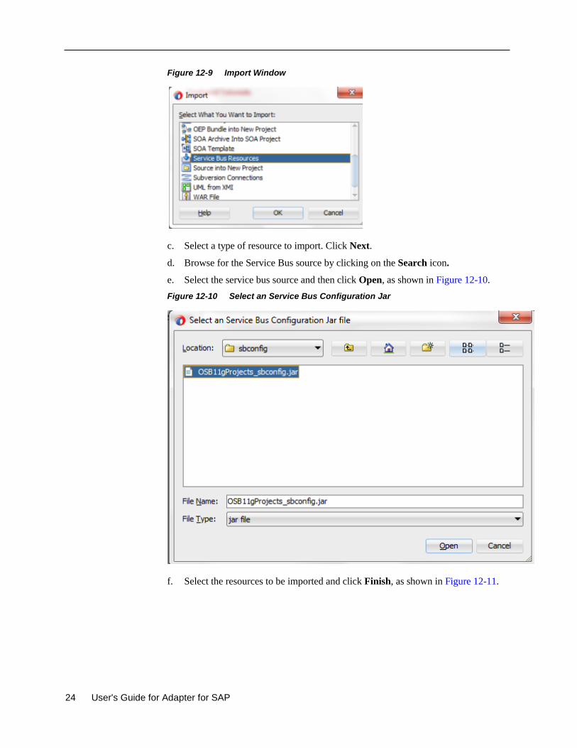
24 User's Guide for Adapter for SAP
Figure 12-9 Import Window
c. Select a type of resource to import. Click Next.
d. Browse for the Service Bus source by clicking on the Search icon.
e. Select the service bus source and then click Open, as shown in Figure 12-10.
Figure 12-10 Select an Service Bus Configuration Jar
f. Select the resources to be imported and click Finish, as shown in Figure 12-11.
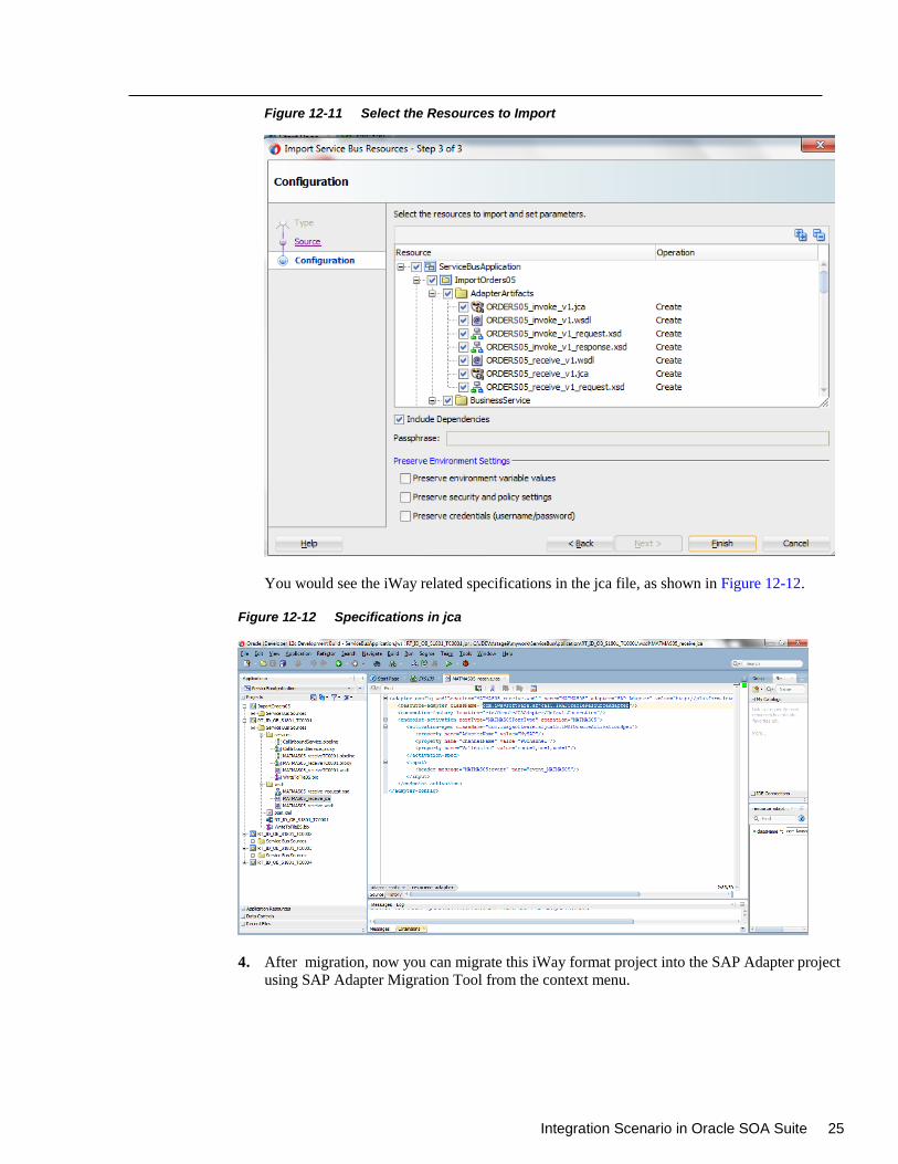
Integration Scenario in Oracle SOA Suite 25
Figure 12-11 Select the Resources to Import
You would see the iWay related specifications in the jca file, as shown in Figure 12-12.
Figure 12-12 Specifications in jca
4. After migration, now you can migrate this iWay format project into the SAP Adapter project
using SAP Adapter Migration Tool from the context menu.
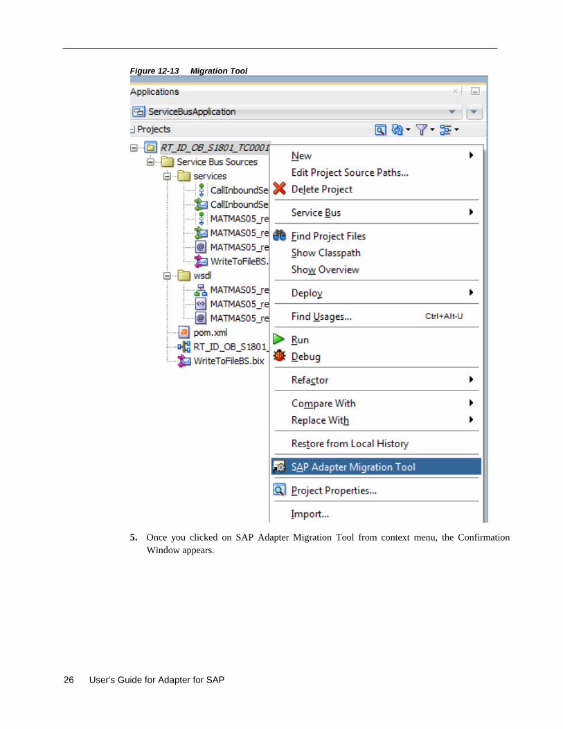
26 User's Guide for Adapter for SAP
Figure 12-13 Migration Tool
5. Once you clicked on SAP Adapter Migration Tool from context menu, the Confirmation
Window appears.
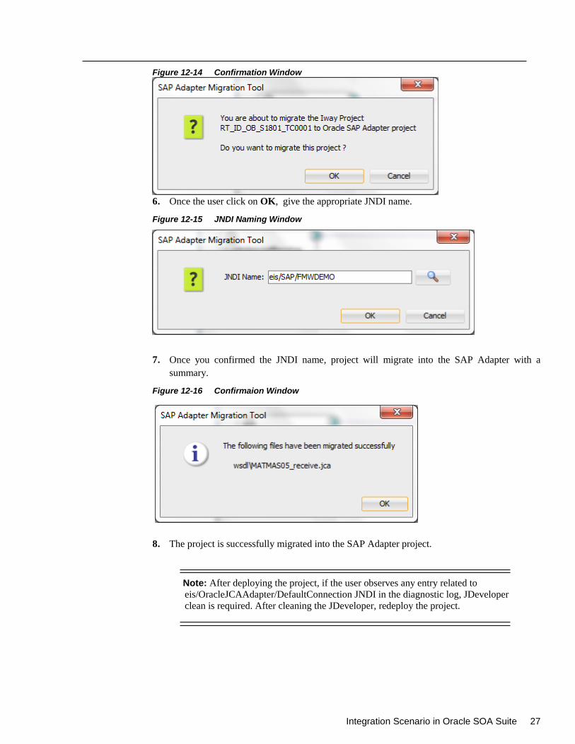
Integration Scenario in Oracle SOA Suite 27
Figure 12-14 Confirmation Window
6. Once the user click on OK, give the appropriate JNDI name.
Figure 12-15 JNDI Naming Window
7. Once you confirmed the JNDI name, project will migrate into the SAP Adapter with a
summary.
Figure 12-16 Confirmaion Window
8. The project is successfully migrated into the SAP Adapter project.
Note: After deploying the project, if the user observes any entry related to
eis/OracleJCAAdapter/DefaultConnection JNDI in the diagnostic log, JDeveloper
clean is required. After cleaning the JDeveloper, redeploy the project.
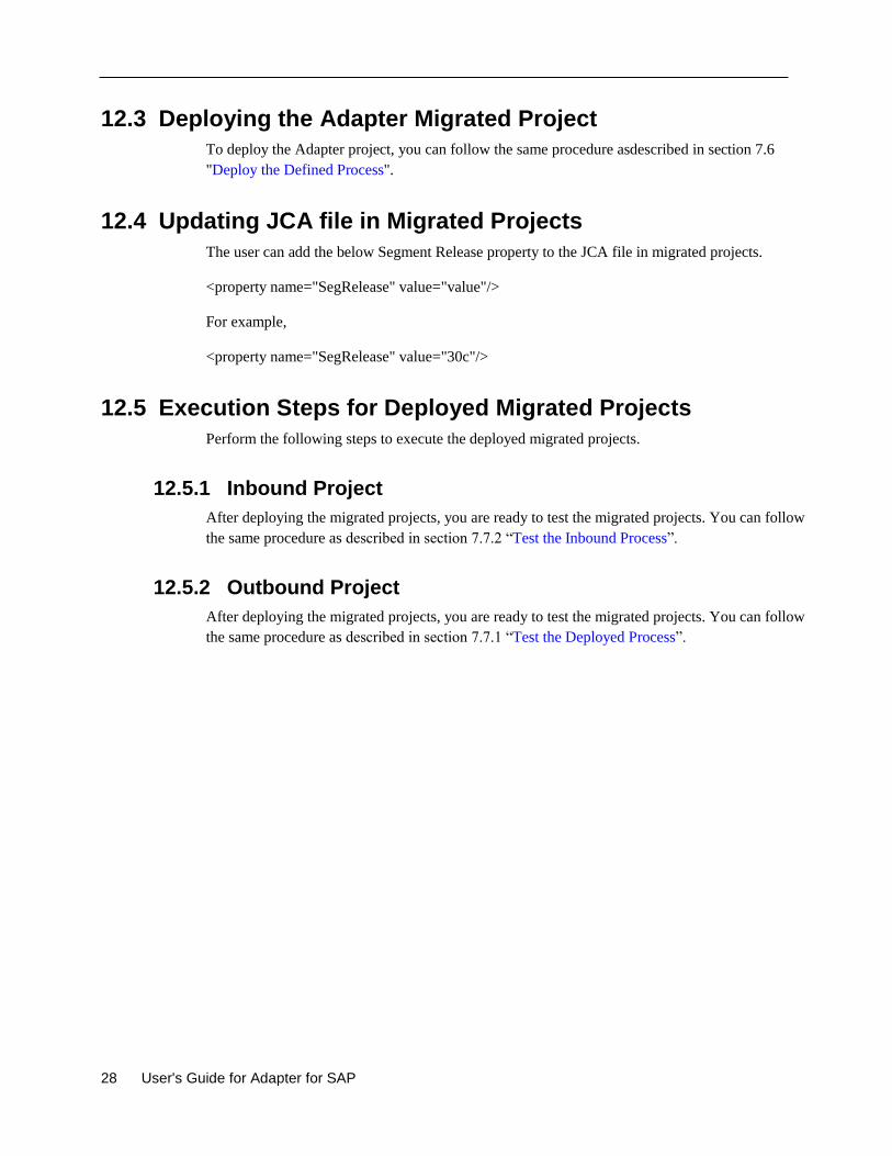
28 User's Guide for Adapter for SAP
12.3 Deploying the Adapter Migrated Project
To deploy the Adapter project, you can follow the same procedure asdescribed in section 7.6
"Deploy the Defined Process".
12.4 Updating JCA file in Migrated Projects
The user can add the below Segment Release property to the JCA file in migrated projects.
<property name="SegRelease" value="value"/>
For example,
<property name="SegRelease" value="30c"/>
12.5 Execution Steps for Deployed Migrated Projects
Perform the following steps to execute the deployed migrated projects.
12.5.1 Inbound Project
After deploying the migrated projects, you are ready to test the migrated projects. You can follow
the same procedure as described in section 7.7.2 “Test the Inbound Process”.
12.5.2 Outbound Project
After deploying the migrated projects, you are ready to test the migrated projects. You can follow
the same procedure as described in section 7.7.1 “Test the Deployed Process”.
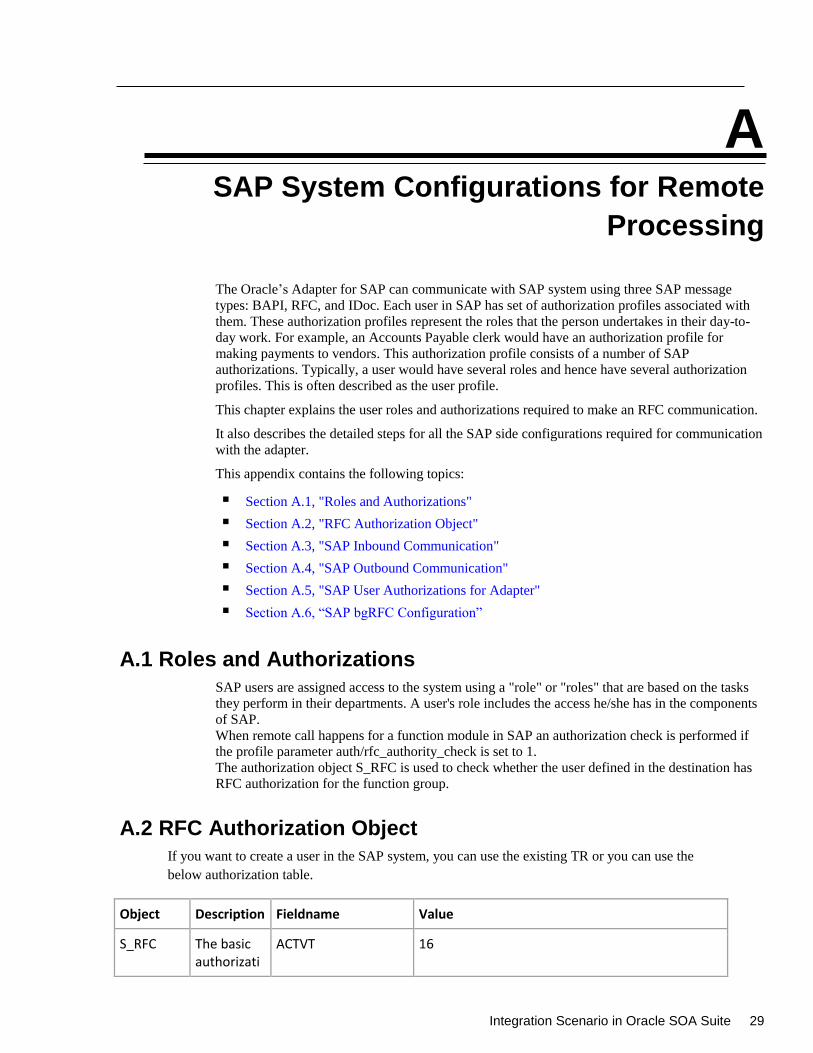
Integration Scenario in Oracle SOA Suite 29
A
SAP System Configurations for Remote
Processing
The Oracle’s Adapter for SAP can communicate with SAP system using three SAP message
types: BAPI, RFC, and IDoc. Each user in SAP has set of authorization profiles associated with
them. These authorization profiles represent the roles that the person undertakes in their day-to-
day work. For example, an Accounts Payable clerk would have an authorization profile for
making payments to vendors. This authorization profile consists of a number of SAP
authorizations. Typically, a user would have several roles and hence have several authorization
profiles. This is often described as the user profile.
This chapter explains the user roles and authorizations required to make an RFC communication.
It also describes the detailed steps for all the SAP side configurations required for communication
with the adapter.
This appendix contains the following topics:
Section A.1, "Roles and Authorizations"
Section A.2, "RFC Authorization Object"
Section A.3, "SAP Inbound Communication"
Section A.4, "SAP Outbound Communication"
Section A.5, "SAP User Authorizations for Adapter"
Section A.6, “SAP bgRFC Configuration”
A.1 Roles and Authorizations
SAP users are assigned access to the system using a "role" or "roles" that are based on the tasks
they perform in their departments. A user's role includes the access he/she has in the components
of SAP.
When remote call happens for a function module in SAP an authorization check is performed if
the profile parameter auth/rfc_authority_check is set to 1.
The authorization object S_RFC is used to check whether the user defined in the destination has
RFC authorization for the function group.
A.2 RFC Authorization Object
If you want to create a user in the SAP system, you can use the existing TR or you can use the
below authorization table.
Object Description Fieldname Value
S_RFC The basic authorizati
ACTVT 16
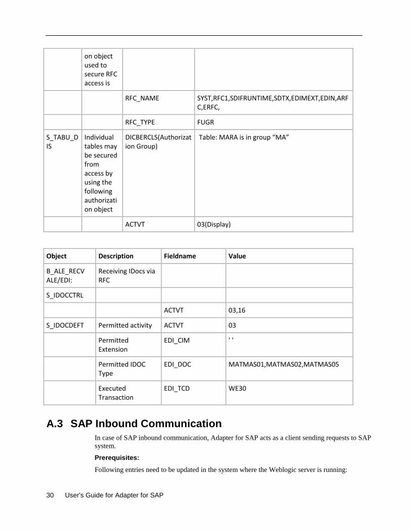
30 User's Guide for Adapter for SAP
on object used to secure RFC access is
RFC_NAME SYST,RFC1,SDIFRUNTIME,SDTX,EDIMEXT,EDIN,ARFC,ERFC,
RFC_TYPE FUGR
S_TABU_DIS
Individual tables may be secured from access by using the following authorization object
DICBERCLS(Authorization Group)
Table: MARA is in group “MA”
ACTVT 03(Display)
Object Description Fieldname Value
B_ALE_RECV ALE/EDI:
Receiving IDocs via RFC
S_IDOCCTRL
ACTVT 03,16
S_IDOCDEFT Permitted activity ACTVT 03
Permitted Extension
EDI_CIM ' '
Permitted IDOC Type
EDI_DOC MATMAS01,MATMAS02,MATMAS05
Executed Transaction
EDI_TCD WE30
A.3 SAP Inbound Communication
In case of SAP inbound communication, Adapter for SAP acts as a client sending requests to SAP
system.
Prerequisites:
Following entries need to be updated in the system where the Weblogic server is running:
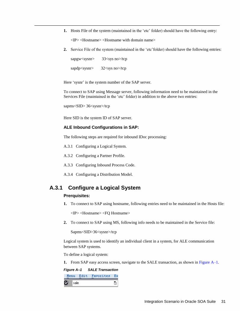
Integration Scenario in Oracle SOA Suite 31
1. Hosts File of the system (maintained in the ‘etc’ folder) should have the following entry:
<IP> <Hostname> <Hostname with domain name>
2. Service File of the system (maintained in the ‘etc’folder) should have the following entries:
sapgw<sysnr> 33<sys no>/tcp
sapdp<sysnr> 32<sys no>/tcp
Here ‘sysnr’ is the system number of the SAP server.
To connect to SAP using Message server, following information need to be maintained in the
Services File (maintained in the ‘etc’ folder) in addition to the above two entries:
sapms<SID> 36<sysnr>/tcp
Here SID is the system ID of SAP server.
ALE Inbound Configurations in SAP:
The following steps are required for inbound IDoc processing:
A.3.1 Configuring a Logical System.
A.3.2 Configuring a Partner Profile.
A.3.3 Configuring Inbound Process Code.
A.3.4 Configuring a Distribution Model.
A.3.1 Configure a Logical System
Prerquisites:
1. To connect to SAP using hostname, following entries need to be maintained in the Hosts file:
<IP> <Hostname> <FQ Hostname>
2. To connect to SAP using MS, following info needs to be maintained in the Service file:
Sapms<SID>36<sysnr>/tcp
Logical system is used to identify an individual client in a system, for ALE communication
between SAP systems.
To define a logical system:
1. From SAP easy access screen, navigate to the SALE transaction, as shown in Figure A–1.
Figure A–1 SALE Transaction
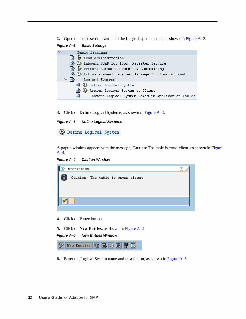
32 User's Guide for Adapter for SAP
2. Open the basic settings and then the Logical systems node, as shown in Figure A–2.
Figure A–2 Basic Settings
3. Click on Define Logical Systems, as shown in Figure A–3.
Figure A–3 Define Logical Systems
A popup window appears with the message, Caution: The table is cross-client, as shown in Figure
A–4.
Figure A–4 Caution Window
4. Click on Enter button.
5. Click on New Entries, as shown in Figure A–5.
Figure A–5 New Entries Window
6. Enter the Logical System name and description, as shown in Figure A–6.
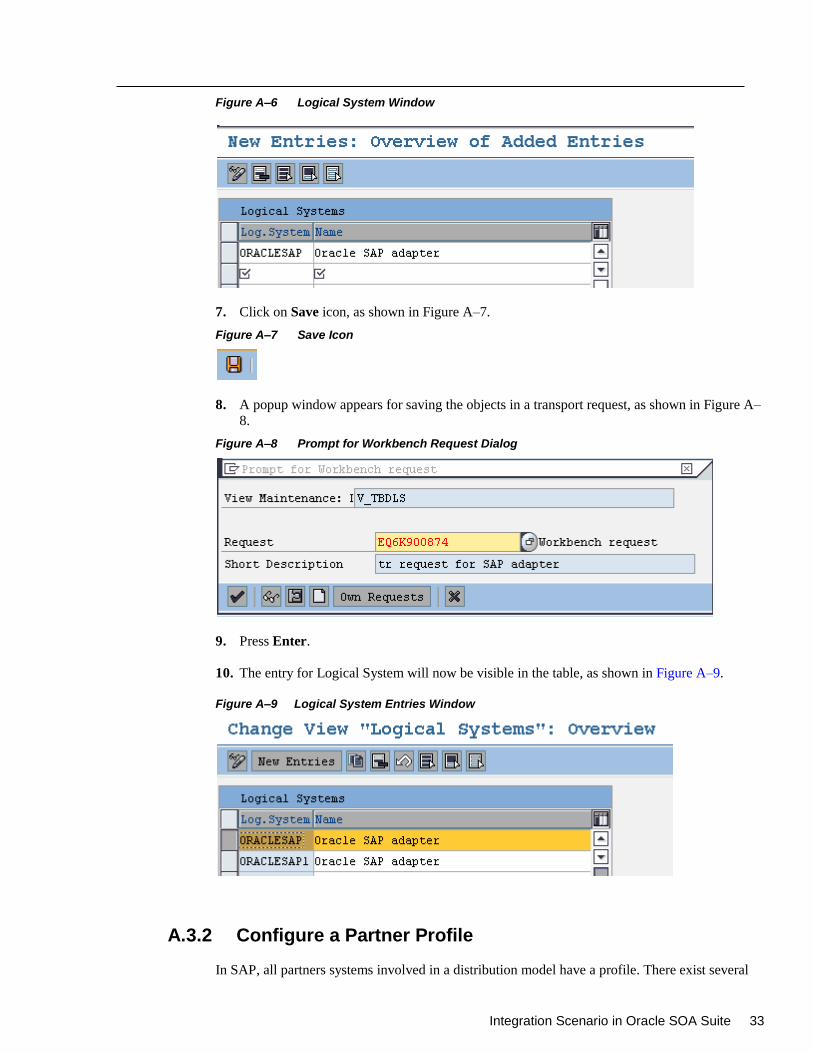
Integration Scenario in Oracle SOA Suite 33
Figure A–6 Logical System Window
7. Click on Save icon, as shown in Figure A–7.
Figure A–7 Save Icon
8. A popup window appears for saving the objects in a transport request, as shown in Figure A–
8.
Figure A–8 Prompt for Workbench Request Dialog
9. Press Enter.
10. The entry for Logical System will now be visible in the table, as shown in Figure A–9.
Figure A–9 Logical System Entries Window
A.3.2 Configure a Partner Profile
In SAP, all partners systems involved in a distribution model have a profile. There exist several
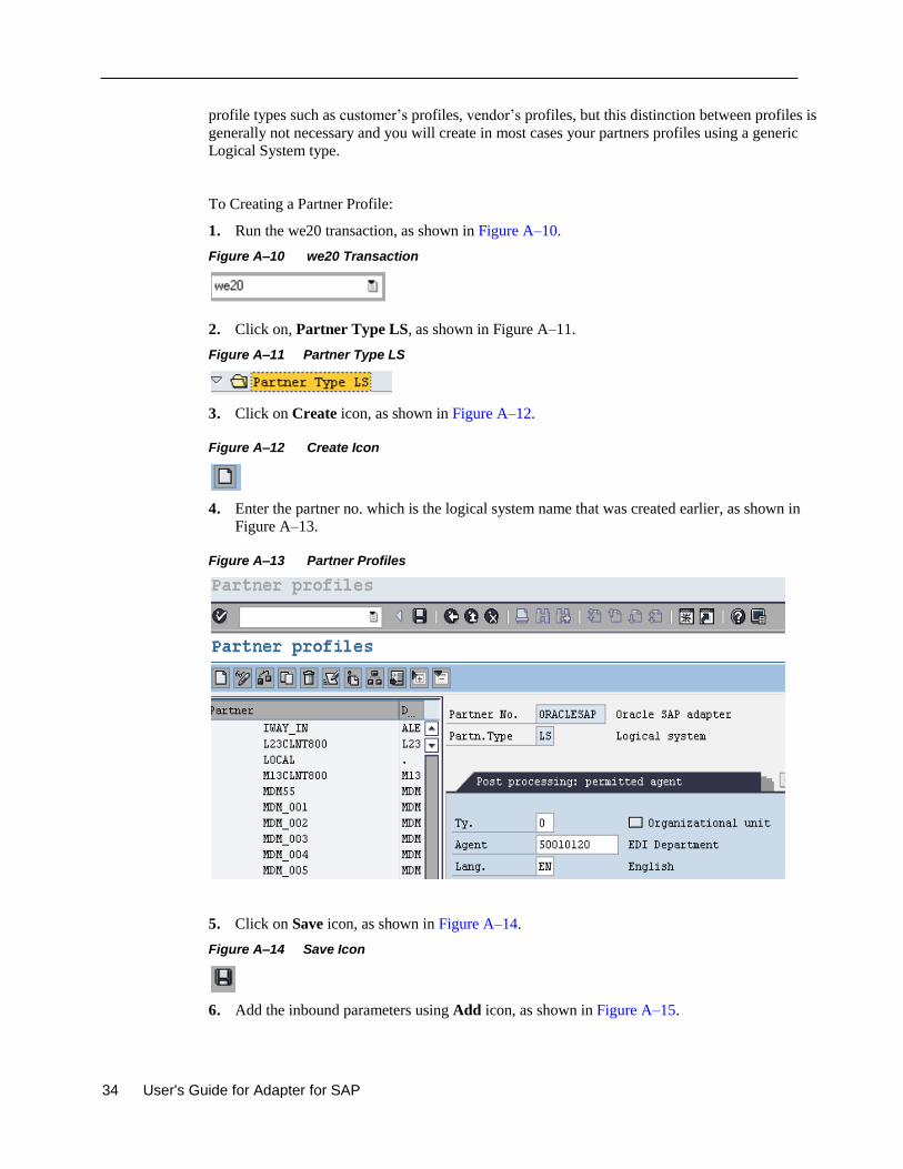
34 User's Guide for Adapter for SAP
profile types such as customer’s profiles, vendor’s profiles, but this distinction between profiles is
generally not necessary and you will create in most cases your partners profiles using a generic
Logical System type.
To Creating a Partner Profile:
1. Run the we20 transaction, as shown in Figure A–10.
Figure A–10 we20 Transaction
2. Click on, Partner Type LS, as shown in Figure A–11.
Figure A–11 Partner Type LS
3. Click on Create icon, as shown in Figure A–12.
Figure A–12 Create Icon
4. Enter the partner no. which is the logical system name that was created earlier, as shown in
Figure A–13.
Figure A–13 Partner Profiles
5. Click on Save icon, as shown in Figure A–14.
Figure A–14 Save Icon
6. Add the inbound parameters using Add icon, as shown in Figure A–15.
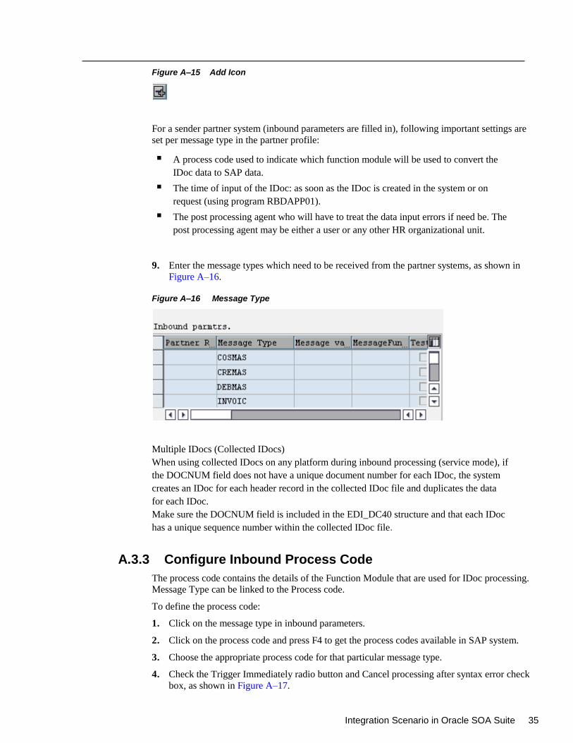
Integration Scenario in Oracle SOA Suite 35
Figure A–15 Add Icon
For a sender partner system (inbound parameters are filled in), following important settings are
set per message type in the partner profile:
A process code used to indicate which function module will be used to convert the
IDoc data to SAP data.
The time of input of the IDoc: as soon as the IDoc is created in the system or on
request (using program RBDAPP01).
The post processing agent who will have to treat the data input errors if need be. The
post processing agent may be either a user or any other HR organizational unit.
9. Enter the message types which need to be received from the partner systems, as shown in
Figure A–16.
Figure A–16 Message Type
Multiple IDocs (Collected IDocs)
When using collected IDocs on any platform during inbound processing (service mode), if
the DOCNUM field does not have a unique document number for each IDoc, the system
creates an IDoc for each header record in the collected IDoc file and duplicates the data
for each IDoc.
Make sure the DOCNUM field is included in the EDI_DC40 structure and that each IDoc
has a unique sequence number within the collected IDoc file.
A.3.3 Configure Inbound Process Code
The process code contains the details of the Function Module that are used for IDoc processing.
Message Type can be linked to the Process code.
To define the process code:
1. Click on the message type in inbound parameters.
2. Click on the process code and press F4 to get the process codes available in SAP system.
3. Choose the appropriate process code for that particular message type.
4. Check the Trigger Immediately radio button and Cancel processing after syntax error check
box, as shown in Figure A–17.
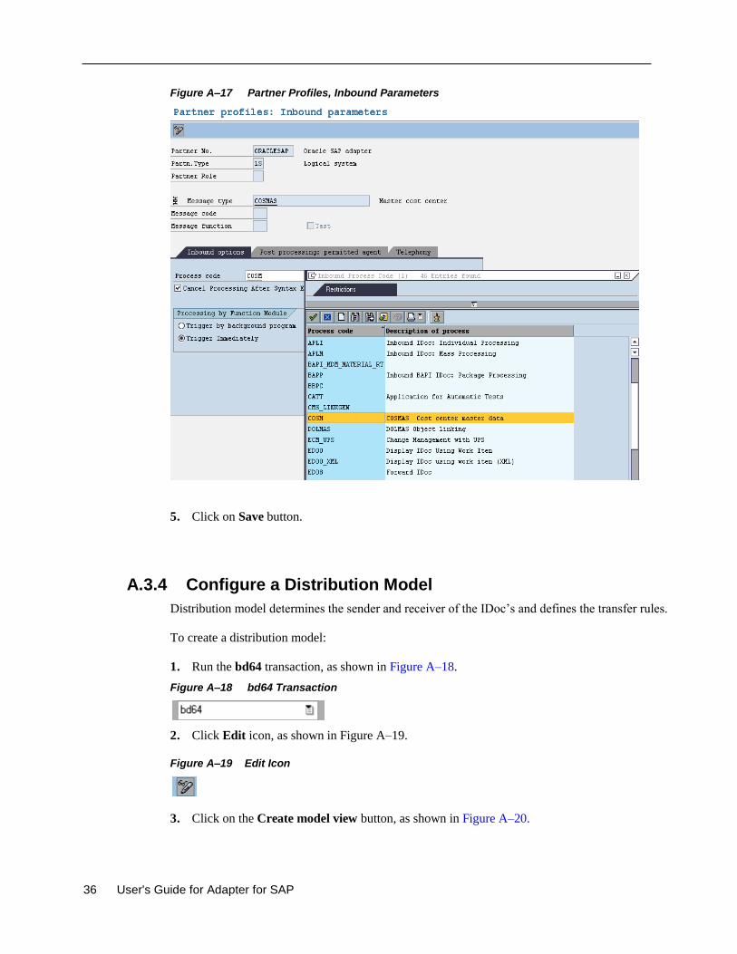
36 User's Guide for Adapter for SAP
Figure A–17 Partner Profiles, Inbound Parameters
5. Click on Save button.
A.3.4 Configure a Distribution Model
Distribution model determines the sender and receiver of the IDoc’s and defines the transfer rules.
To create a distribution model:
1. Run the bd64 transaction, as shown in Figure A–18.
Figure A–18 bd64 Transaction
2. Click Edit icon, as shown in Figure A–19.
Figure A–19 Edit Icon
3. Click on the Create model view button, as shown in Figure A–20.
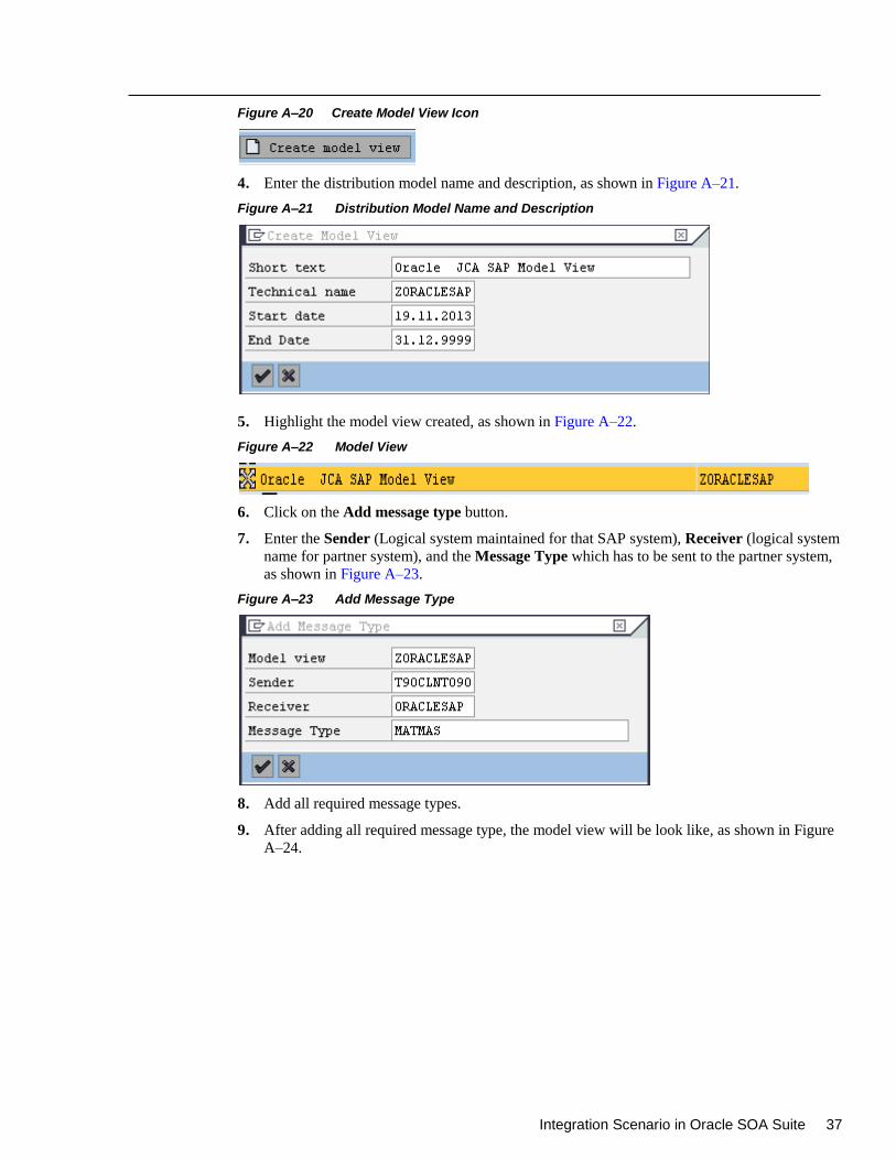
Integration Scenario in Oracle SOA Suite 37
Figure A–20 Create Model View Icon
4. Enter the distribution model name and description, as shown in Figure A–21.
Figure A–21 Distribution Model Name and Description
5. Highlight the model view created, as shown in Figure A–22.
Figure A–22 Model View
6. Click on the Add message type button.
7. Enter the Sender (Logical system maintained for that SAP system), Receiver (logical system
name for partner system), and the Message Type which has to be sent to the partner system,
as shown in Figure A–23.
Figure A–23 Add Message Type
8. Add all required message types.
9. After adding all required message type, the model view will be look like, as shown in Figure
A–24.
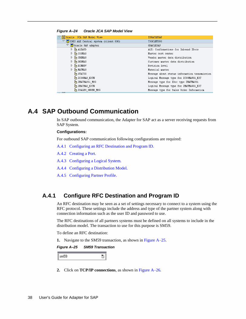
38 User's Guide for Adapter for SAP
Figure A–24 Oracle JCA SAP Model View
A.4 SAP Outbound Communication
In SAP outbound communication, the Adapter for SAP act as a server receiving requests from
SAP System.
Configurations:
For outbound SAP communication following configurations are required:
A.4.1 Configuring an RFC Destination and Program ID.
A.4.2 Creating a Port.
A.4.3 Configuring a Logical System.
A.4.4 Configuring a Distribution Model.
A.4.5 Configuring Partner Profile.
A.4.1 Configure RFC Destination and Program ID
An RFC destination may be seen as a set of settings necessary to connect to a system using the
RFC protocol. These settings include the address and type of the partner system along with
connection information such as the user ID and password to use.
The RFC destinations of all partners systems must be defined on all systems to include in the
distribution model. The transaction to use for this purpose is SM59.
To define an RFC destination:
1. Navigate to the SM59 transaction, as shown in Figure A–25.
Figure A–25 SM59 Transaction
2. Click on TCP/IP connections, as shown in Figure A–26.
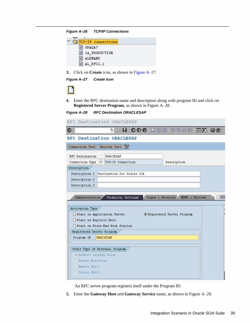
Integration Scenario in Oracle SOA Suite 39
Figure A–26 TCP/IP Connections
3. Click on Create icon, as shown in Figure A–27.
Figure A–27 Create Icon
4. Enter the RFC destination name and description along with program ID and click on
Registered Server Program, as shown in Figure A–28.
Figure A–28 RFC Destination ORACLESAP
An RFC server program registers itself under the Program ID.
5. Enter the Gateway Host and Gateway Service name, as shown in Figure A–29.
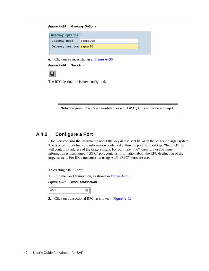
40 User's Guide for Adapter for SAP
Figure A–29 Gateway Options
6. Click on Save, as shown in Figure A–30.
Figure A–30 Save Icon
The RFC destination is now configured.
Note: Program ID is Case Sensitive. For e.g., ORAQA1 is not same as oraqa1.
A.4.2 Configure a Port
IDoc Port contains the information about the way data is sent between the source or target system.
The type of port defines the information contained within the port. For port type “Internet” Port
will contain IP address of the target system. For port type “file”, directory or file name
information is maintained. “tRFC” port contains information about the RFC destination of the
target system. For IDoc transmission using ALE “tRFC” ports are used.
To creating a tRFC port:
1. Run the we21 transaction, as shown in Figure A–31.
Figure A–31 we21 Transaction
2. Click on transactional RFC, as shown in Figure A–32.
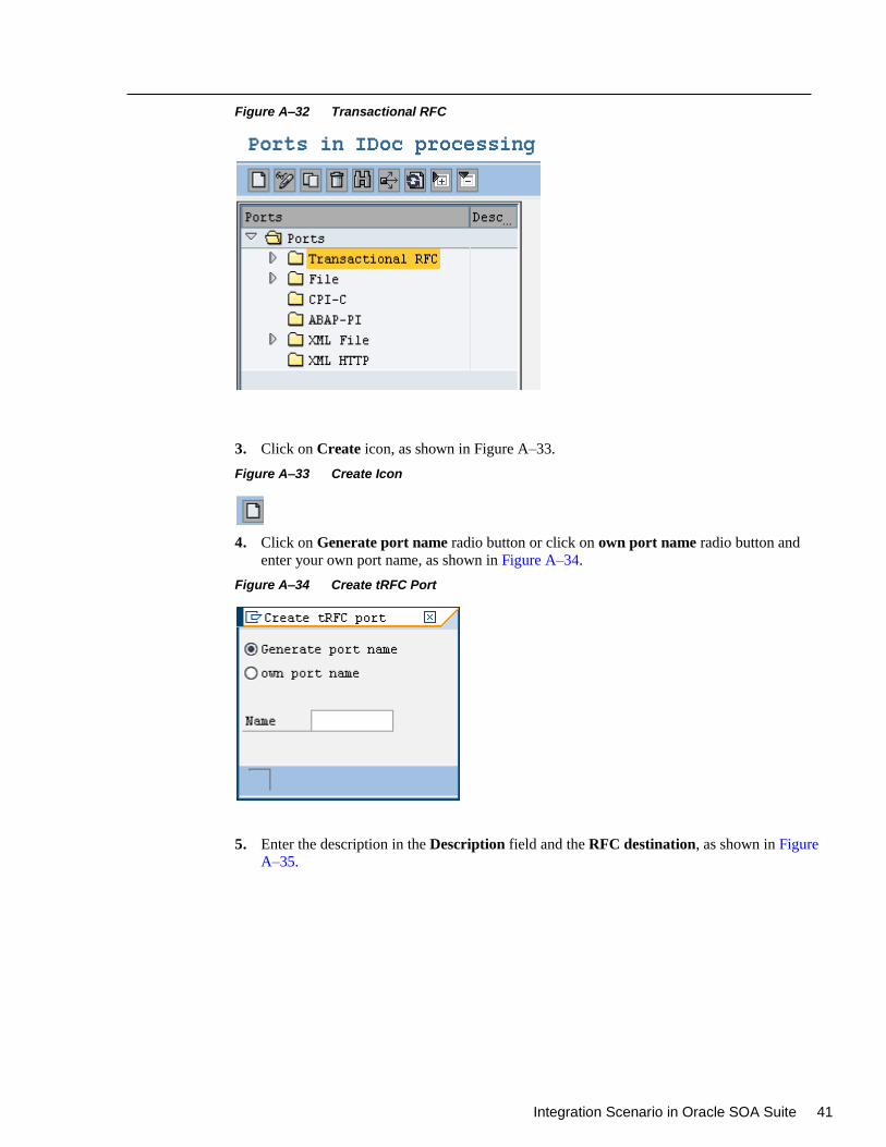
Integration Scenario in Oracle SOA Suite 41
Figure A–32 Transactional RFC
3. Click on Create icon, as shown in Figure A–33.
Figure A–33 Create Icon
4. Click on Generate port name radio button or click on own port name radio button and
enter your own port name, as shown in Figure A–34.
Figure A–34 Create tRFC Port
5. Enter the description in the Description field and the RFC destination, as shown in Figure
A–35.
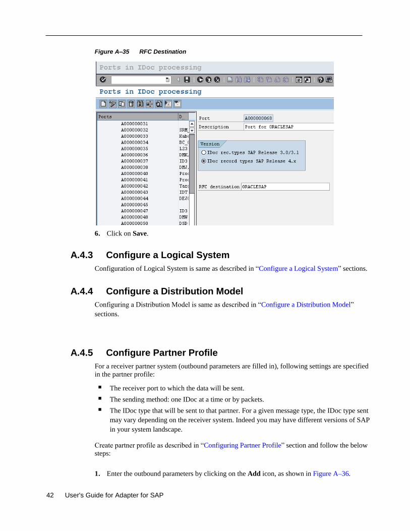
42 User's Guide for Adapter for SAP
Figure A–35 RFC Destination
6. Click on Save.
A.4.3 Configure a Logical System
Configuration of Logical System is same as described in “Configure a Logical System” sections.
A.4.4 Configure a Distribution Model
Configuring a Distribution Model is same as described in “Configure a Distribution Model”
sections.
A.4.5 Configure Partner Profile
For a receiver partner system (outbound parameters are filled in), following settings are specified
in the partner profile:
The receiver port to which the data will be sent.
The sending method: one IDoc at a time or by packets.
The IDoc type that will be sent to that partner. For a given message type, the IDoc type sent
may vary depending on the receiver system. Indeed you may have different versions of SAP
in your system landscape.
Create partner profile as described in “Configuring Partner Profile” section and follow the below
steps:
1. Enter the outbound parameters by clicking on the Add icon, as shown in Figure A–36.
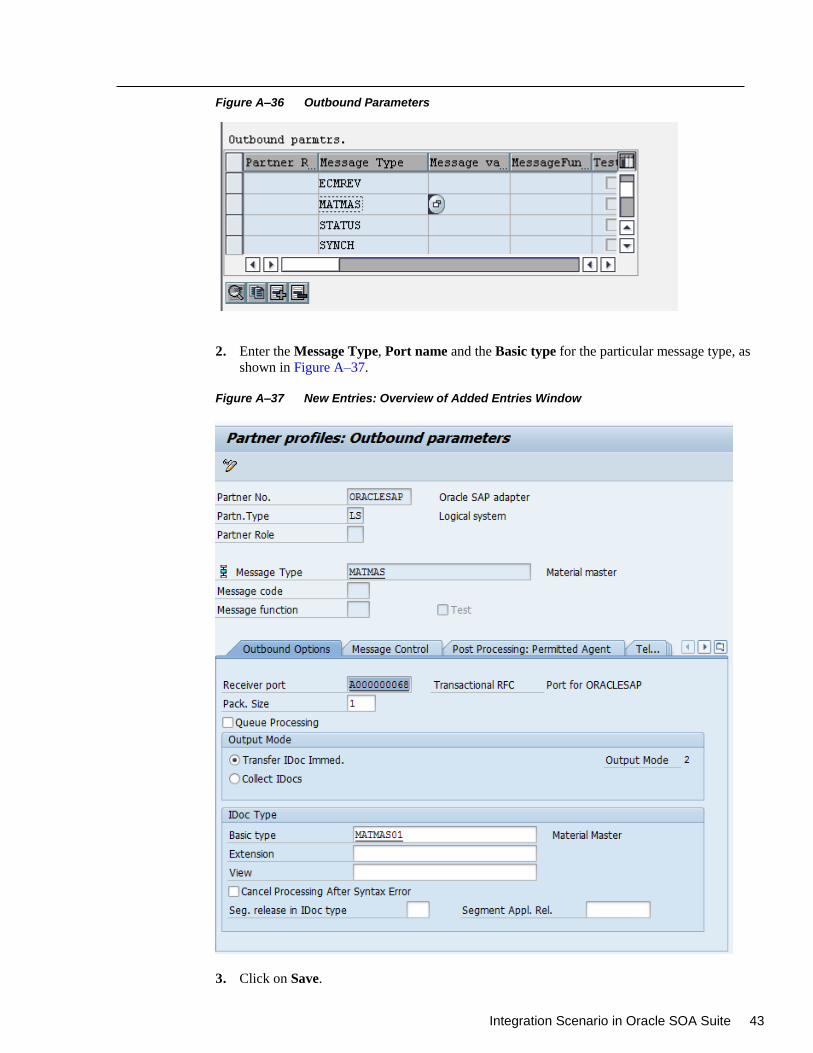
Integration Scenario in Oracle SOA Suite 43
Figure A–36 Outbound Parameters
2. Enter the Message Type, Port name and the Basic type for the particular message type, as
shown in Figure A–37.
Figure A–37 New Entries: Overview of Added Entries Window
3. Click on Save.
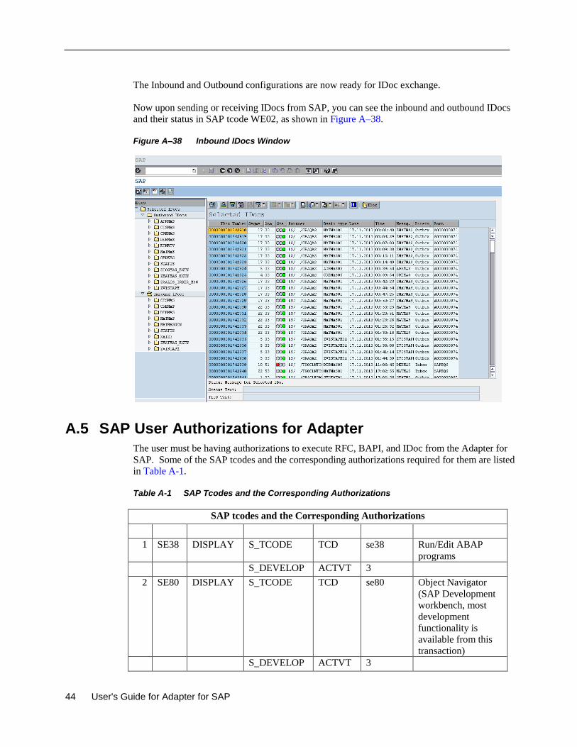
44 User's Guide for Adapter for SAP
The Inbound and Outbound configurations are now ready for IDoc exchange.
Now upon sending or receiving IDocs from SAP, you can see the inbound and outbound IDocs
and their status in SAP tcode WE02, as shown in Figure A–38.
Figure A–38 Inbound IDocs Window
A.5 SAP User Authorizations for Adapter
The user must be having authorizations to execute RFC, BAPI, and IDoc from the Adapter for
SAP. Some of the SAP tcodes and the corresponding authorizations required for them are listed
in Table A-1.
Table A-1 SAP Tcodes and the Corresponding Authorizations
SAP tcodes and the Corresponding Authorizations
1 SE38 DISPLAY S_TCODE TCD se38 Run/Edit ABAP
programs
S_DEVELOP ACTVT 3
2 SE80 DISPLAY S_TCODE TCD se80 Object Navigator
(SAP Development
workbench, most
development
functionality is
available from this
transaction)
S_DEVELOP ACTVT 3
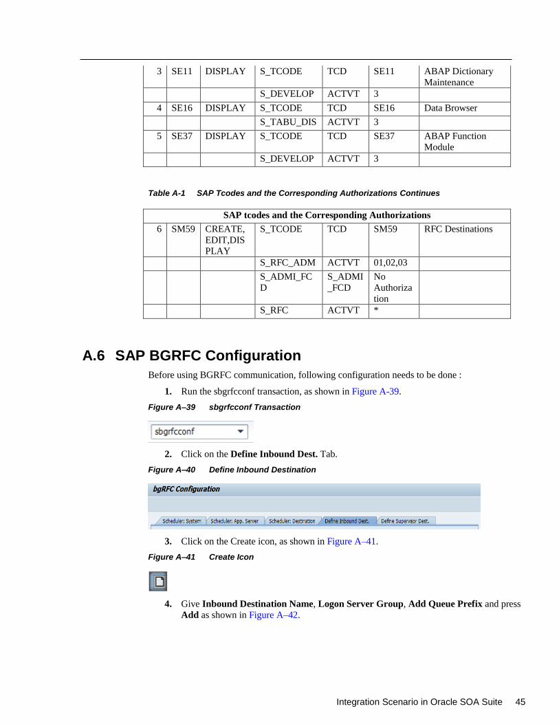
Integration Scenario in Oracle SOA Suite 45
3 SE11 DISPLAY S_TCODE TCD SE11 ABAP Dictionary
Maintenance
S_DEVELOP ACTVT 3
4 SE16 DISPLAY S_TCODE TCD SE16 Data Browser
S_TABU_DIS ACTVT 3
5 SE37 DISPLAY S_TCODE TCD SE37 ABAP Function
Module
S_DEVELOP ACTVT 3
Table A-1 SAP Tcodes and the Corresponding Authorizations Continues
SAP tcodes and the Corresponding Authorizations
6 SM59 CREATE,
EDIT,DIS
PLAY
S_TCODE TCD SM59 RFC Destinations
S_RFC_ADM ACTVT 01,02,03
S_ADMI_FC
D
S_ADMI
_FCD
No
Authoriza
tion
S_RFC ACTVT *
A.6 SAP BGRFC Configuration
Before using BGRFC communication, following configuration needs to be done :
1. Run the sbgrfcconf transaction, as shown in Figure A-39.
Figure A–39 sbgrfcconf Transaction
2. Click on the Define Inbound Dest. Tab.
Figure A–40 Define Inbound Destination
3. Click on the Create icon, as shown in Figure A–41.
Figure A–41 Create Icon
4. Give Inbound Destination Name, Logon Server Group, Add Queue Prefix and press
Add as shown in Figure A–42.
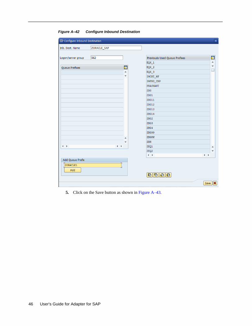
46 User's Guide for Adapter for SAP
Figure A–42 Configure Inbound Destination
5. Click on the Save button as shown in Figure A–43.
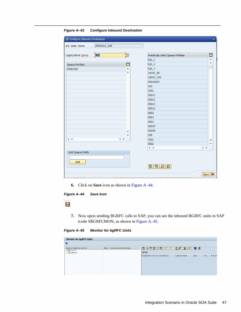
Integration Scenario in Oracle SOA Suite 47
Figure A–43 Configure Inbound Destination
6. Click on Save icon as shown in Figure A–44.
Figure A–44 Save Icon
7. Now upon sending BGRFC calls to SAP, you can see the inbound BGRFC units in SAP
tcode SBGRFCMON, as shown in Figure A–45.
Figure A–45 Monitor for bgRFC Units
48 User's Guide for Adapter for SAP
Glossary
Adapter
Provides universal connectivity by enabling an electronic interface to be accommodated (without loss of function)
to another electronic interface.
Agent
Supports service protocols in listeners and documents. ChannelChannel
Represents configured connections to particular instances of back-end systems. A channel binds one or more event
ports to a particular listener managed by an adapter.
ListenerListener
A component that accepts requests from client applications.
PortPort
Associates a particular business object exposed by the adapter with a particular disposition. A disposition is a URL
that defines the protocol and location of the event data. The port defines the end point of the event consumption.
Integration Scenario in Oracle SOA Suite 49
Index A
Adapter health report, 10-1
AutoSYSTAT, 5-22
B
BAPI, 1-3
C
Configuration report, 10-2
Connection Management, 4-2
Connection pool, 4-2
Connection Pooling, 2-11
Control Character, 5-57
CPIC, 6-11
Credential mapping, 5-34
Custom BAPI, 3-2
Custom IDocs, 3-3
Custom RFC, 3-2
D
Design-time component, 1-2
E
ExceptionFilter, 5-17
Expiration Period, 6-13
Expiration Time, 6-12
Extended IDoc, 3-3
I
IDoc, 1-3, 3-3
J
JCo Traces, 6-10
M
Max Wait, 6-12
O
OSB, 8-94
Outbound Mediator process, 8-41
P
Peak Limit, 6-12
Q
qRFC, 5-1
R
Remote Function Call, 1-3
RFC trace, 6-11
Run-time component, 1-2
S
SAP Connection Parameters, 2-7
SAP JCo, 2-1
SAP RFC authorization object, 1
SAP Route String, 6-7
SchemaValidation, 5-20
SNC parameters, 2-12
Standard IDocs, 3-3
Standard RFC, 3-2
Standardized BAPI, 3-1
stateful, 5-42
stateless, 5-42
T
Test Connection button, 6-7
Trace level, 4-4
Trace parameters, 2-11
tRFC, 5-1
Tuning parameters, 9-1


