Embed Size (px)
Citation preview

68859
Orion-2C, Orion-2D, Orion-3A& MPV-10K
*
Pneumatic Pressure Controllers
Adjustment & Maintenance Manual
*Patent No. 4,698,998
Condec Web Site: www.4condec.comCondec Sales Phone Number: (888) 295-8475

Copyright © 2001 Condec. All rights reserved. Printed in the United States of America. Specifications subject to change without notice.
August 2001
Contents
About This Manual ...................................................................................................................................11.0 Introduction ................................................................................................................................. 12.0 Maintenance................................................................................................................................ 2
2.1 O-ring Repair Kit Data . . . . . . . . . . . . . . . . . . . . . . . . . . . . . . . . . . . . . . . . . . . . . . . . . . . . . . . . . . 22.2 Recommended O-ring materials . . . . . . . . . . . . . . . . . . . . . . . . . . . . . . . . . . . . . . . . . . . . . . . . . . . 22.3 ORION Manifold - Valve Seat Removal . . . . . . . . . . . . . . . . . . . . . . . . . . . . . . . . . . . . . . . . . . . . . . 32.4 ORION Manifold - Vernier Control Disassembly . . . . . . . . . . . . . . . . . . . . . . . . . . . . . . . . . . . . . . . 42.5 ORION Manifold - Vernier Control Reassembly . . . . . . . . . . . . . . . . . . . . . . . . . . . . . . . . . . . . . . . . 42.6 ORION Manifold - Valve Seat Replacement . . . . . . . . . . . . . . . . . . . . . . . . . . . . . . . . . . . . . . . . . . 52.7 MPV-10K Manifold - Valve Seat Removal . . . . . . . . . . . . . . . . . . . . . . . . . . . . . . . . . . . . . . . . . . . . 62.8 MPV-10K Manifold - Valve Seat Replacement . . . . . . . . . . . . . . . . . . . . . . . . . . . . . . . . . . . . . . . . 72.9 ORION Manifold - Valve Adjustment Procedure (Customer Installation). . . . . . . . . . . . . . . . . . . . . . 72.10 MPV-10K Manifold - Valve Adjustment Procedure (Customer Installation). . . . . . . . . . . . . . . . . . . . 82.11 Recommended Mounting Patterns . . . . . . . . . . . . . . . . . . . . . . . . . . . . . . . . . . . . . . . . . . . . . . . . . 92.12 ORION-2C Valve Assembly (55283) Parts List . . . . . . . . . . . . . . . . . . . . . . . . . . . . . . . . . . . . . . . 102.13 ORION-2D Valve Assembly (55286) Parts List . . . . . . . . . . . . . . . . . . . . . . . . . . . . . . . . . . . . . . . 132.14 ORION-3A Valve Assembly (55287) Parts List . . . . . . . . . . . . . . . . . . . . . . . . . . . . . . . . . . . . . . . 162.15 MPV-10K Valve Assembly Parts List. . . . . . . . . . . . . . . . . . . . . . . . . . . . . . . . . . . . . . . . . . . . . . . 19
3.0 Specifications ........................................................................................................................... 22
3.0.1 ORION-2C (PN 55283) . . . . . . . . . . . . . . . . . . . . . . . . . . . . . . . . . . . . . . . . . . . . . . . . . . . . . . . . . . . . 223.0.2 ORION-2D (PN 55286) . . . . . . . . . . . . . . . . . . . . . . . . . . . . . . . . . . . . . . . . . . . . . . . . . . . . . . . . . . . . 223.0.3 ORION-3A (PN 55287) . . . . . . . . . . . . . . . . . . . . . . . . . . . . . . . . . . . . . . . . . . . . . . . . . . . . . . . . . . . . 223.0.4 MPV-10K . . . . . . . . . . . . . . . . . . . . . . . . . . . . . . . . . . . . . . . . . . . . . . . . . . . . . . . . . . . . . . . . . . . . . . 22
Orion/MPV-10K Warranty and Return Policy...................................................................................... 23Orion/MPV-10K Return Material Authorization Form......................................................................... 24

Introduction
1
About This Manual
The ORION/MPV-10K is a pneumatic pressurecontroller with precision vernier. A rugged, compactcontroller manufactured by Condec, designed toprovide ease of operation and installation, by aqualified technician.
Equipped to perform and be maintained on-site, thesecontrollers have proven to substantially reduce thecost, system down-time and man-hours of labornormally associated with these routine servicefunctions.
The patented controller was designed as an allmechanical device that has been factory adjusted andready for on-site installation.
This manual has been written to give the user a simpleand clear explanation of how to operate, andtroubleshoot these controllers.
Before attempting to use either style,Pressure Controller, the followinginstructions must be carefully readand understood by personnel utilizingthe equipment. This is a high-pressuresystem. It is strongly recommendedthat only personnel formally trained inthe use of pneumatic pressureequipment be permitted to operate it.Potentially dangerous conditionscould be produced through negligenthandling or operation of the valve dueto the high pressure used within theunit.
These units are strictly for use with pneumatic pressures.Erroneous readings and potential damage could resultfrom the introduction of hydraulic fluids into the internalvalve body.
Authorized distributors and theiremployees can view or download thismanual from the Condec distributorsite at
www.4condec.com
.
1.0 Introduction
The ORION/MPV-10K represents the latest in technology, offering a combination of features, performance,versatility and reliability not previously available in a pneumatic pressure controller. Some of the moreoutstanding features are listed below:
• Simple Operation: Accompanying operator's manual provides clear, concise instructions for systemoperation.
• ORION-2C, ORION-2D, ORION-3A: To obtain a specific pressure, either the Inlet Pressure valve or theVent (outlet) valve (two outer valves) may be used since both provide precise control. As the pressureapproaches the desired value, the valve being used for control should be slowly rotated clockwise to itsclosed position. With a little experience, pressure values very close to the desired final value may bequickly achieved. To obtain exact final pressure, slowly rotate the Vernier Control (middle) Knob in thedesired direction, clockwise to increase pressure.
• MPV-10K: The pressure valve will begin to open when it is turned counter clockwise approximately 15degrees. Full open position of the valves is achieved with a maximum of 3 1/2 turns from the closedposition. The valve has a fine adjustment sensitivity. Very low torque is required to turn the vernier, so usefingertip adjustment.
• Safe, Clean Operation: All pressure components are made of brass, aluminum or stainless steel andproof-tested to at least 150% of maximum operating pressure.
The heart of the ORION controllers are the two micro-metering valves and the vernier provided for control ofpressure. Overpressure protection must be customer provided, if required, by a fully adjustable pressure regulatorwhich is manually set to limit the system input pressure. The ORION/MPV-10K is designed for compatibilitywith Nitrogen and shop air. Other O-ring materials are available through special ordering or repair kits.
Warning

2
Orion/MPV-10K Adjustment & Maintenance Manual
2.0 Maintenance
This section outlines the mechanical repair procedures for the ORION/MPV-10K pressure source. The repairprocedures cover the major components and subassemblies which are critical to the proper functioning of thecalibrators and that will likely need periodic maintenance over the life of the unit. Only those persons who areformally trained as skilled technicians should attempt to repair these units. All relevant safety precautions shouldbe observed due to the presence of high-pressure cylinders.
2.1 O-ring Repair Kit Data
O-ring repair kits: Nitrile Buna - N (PN 58499)Ethylene - Propylene (PN 58506)Silicone (PN 58509)Neoprene (PN 58515)Fluorocarbon "Viton" (PN 55277)
May be used with: ORION-2C Pneumatic Pressure Controller (PN 55283)ORION-2D Pneumatic Pressure Controller (PN 55286)ORION-3A Pneumatic Pressure Controller (PN 55287)MPV-10K Valve Assemblies - (all Part Numbers)
NOTE:
A small coating of Fluorinated Krytox grease (PN 55593) should be applied to both sides of O-ring prior toinstallation.
2.2 Recommended O-ring materials
NOTE:
Ratings are recommended for use in the Condec products and are meant to be used only as a guide. Based onyour application you may need to do testing. The O-ring material applications listed below are for reference only and arenot to be used in the valves.
Nitrile Buna - N (BN)
The standard for most general applications (petroleum-based lubricants, hydraulic oils, gasoline, fuels, alcohol,LP gases, water, and many other media).
Temperature range: -65 to +300 F
Pressure rating: 0-6000 PSI
Neoprene (C)
For refigeration (freon gases, carbon dioxide gases, chlorine, ozone, sunlight exposure. FDA approved for foodand beverage, odorless, tasteless, non toxic).
Temperature range: -80 to +260 F
Pressure rating: 0-6000 PSI
Ethylene-Propylene (EP)
For hot water, steam, acids, alcohols, alkalis, keytones, phosphate, and brake fluids.
Temperature range: -67 to +302 F
Pressure rating: 0-6000 PSI
Fluorcabon "Viton" (V)
High temperature compatible with wide range of fluids and chemicals. Acids, oils, fuels, solvents and gases.
Temperature range: -65 to +500 F
Pressure rating: 0-10000 PSI

Maintenance
3
Silicone (S)
For high temperature applications. Compatible with air, oxygen, ozone and others.
Temperature range: -85 to +482 F
Pressure rating: 0-3000 PSI
Figure 2-1. Additional ORION-2C O-ring Replacement Parts
2.3 ORION Manifold - Valve Seat Removal
(ORION-2C: Refer to the List of Parts - Table 2-1 on page 10, and Exploded View - Figure 2-6 on page 12)(ORION-2D: Refer to the List of Parts - Table 2-2 on page 13, and Exploded View - Figure 2-8 on page 15)(ORION-3A: Refer to the List of Parts - Table 2-3 on page 16, and Exploded View - Figure 2-10 on page 18)
Tools required: A/R solvent (de-natured alcohol)socket wrench3/4" socketneedle housing socket (PN 65580)isolation valve needle housing socket (PN 68509)hex wrench (.050")hex wrench (.061")needle-nose plierstube fluorinated krytox grease (PN 55593)hand drillNo. 43 drillNo. 4-40 taptap handlesmall hammer
Procedure:
1. Secure the manifold by its center portion, in a bench vise, with the valve knobs pointing upward.2. Using the .061" hex wrench, loosen and remove the knob inserts (4), as well as, the nylon washer (33)
from the pressure and vent valve stems.3. Using the .050" hex wrench, loosen and remove the setscrew (34) and lock nut (2).4. Loosen the 3/4" lock nuts (1) on the
COARSE
(inlet pressure) and
VENT
valve threaded needle housings(10).
5. Using the needle housing socket (65580) and socket wrench, loosen and remove the needle/housingassembly (10,11).
6. To disassemble the
ISOLATION
valve(s), first remove the valve needle (18) by turning the gear (6)clockwise.
7. Loosen and remove the valve housing(s) (19) using the isolation valve housing removal socket (68509),and socket wrench.
8. Remove the valve stem seat(s) (8) and valve needle seat(s) (9) by using the needle-nose pliers.9. Remove the inner and outer O-ring(s) (28, 27) and back-up ring(s) (31, 30) from the valve stem seats and
wash all parts in solvent.10. To remove valve seats (7) from either the
COARSE
(inlet pressure),
VENT
or
ISOLATION
valve(s), tryblowing compressed air through the inlet and outlet fittings. Otherwise, the center holes have to bedrilled and a tap used to extract the seat (steps 11-14).

4
Orion/MPV-10K Adjustment & Maintenance Manual
11. Using the hand drill, with the No. 43 bit, carefully drill out the seat hole, ensuring that the drill does nottouch the hole in the manifold housing directly beneath the seat (7).
12. Blow out any chips from the seat area using compressed air.13. While holding the 4-40 tap perpendicular to the seat, slowly turn until the tap starts to engage the seat.14. When the tap has engaged into the seat, use a small hammer and gently knock upward against the tap
handle to extract the seat. 15. After the seat has been removed, blow any remaining chips from the seat area.
2.4 ORION Manifold - Vernier Control Disassembly
Tools required: A/R solvent (de-natured alcohol)open end wrench (1-1/4")flat blade screwdriversocket wrenchisolation valve needle housing socket (PN 68508)isolation valve needle housing socket (PN 68509)
1. With the manifold housing mounted in a vise, turn the
VERNIER
shaft (14) clockwise until the piston isbottomed.
2. Loosen and remove the end cap (13) using a 1-1/4" wrench. At certain points during removal the end capwill appear to lock up. If this occurs, rotate the shaft clockwise until the end cap is free to turn.
3. Remove the O-ring (29) from the end cap.
ORION-3A: Also remove the backup washer (38) from the end cap.4. Remove the self-sealing screw (36) that acts as the piston key.5. Remove the piston (15) by partially screwing in the threaded end of the
VERNIER
shaft (14) and pulling.6. Remove the O-ring (32) from the piston groove.7. To disassemble the end cap/shaft assembly, mount the end cap in the vise.8. Loosen and remove the locknut (20) using the isolation valve housing socket (PN 68509) and socket
wrench.9. ORION-2C, ORION-2D: Loosen and remove the end bushing (12) using the same socket. Remove the
shaft (14). Remove the mylar bearing washer (41 or 42) from both sides of the shaft flange.
ORION-3A: Loosen and remove the end bushing (12) using the isolation valve housing socket (PN68508) and socket wrench. Remove the shaft (14). Remove the ball bearings (41) from both sides of theshaft flange.
10. Use a small pick or screwdriver to remove the O-ring (27) from the inner groove of the end cap (13).ORION-3A: Also remove backup retainer (39) from inner groove of the end cap (13).
11. Wash all parts in solvent and blow dry with compressed air.
2.5 ORION Manifold - Vernier Control Reassembly
(ORION-2C: Refer to the List of Parts - Table 2-1 on page 10, and Exploded View - Figure 2-6 on page 12)(ORION-2D: Refer to the List of Parts - Table 2-2 on page 13, and Exploded View - Figure 2-8 on page 15)(ORION-3A: Refer to the List of Parts - Table 2-3 on page 16, and Exploded View - Figure 2-10 on page 18)
Tools required: tube fluorinated krytox grease (PN 55593)open end wrench (1-1/4")flat blade screwdriversocket wrenchisolation valve needle housing socket (PN 68508)isolation valve needle housing socket (PN 68509)torque wrench
1. Coat all O-rings and backup washer/retainers with Krytox grease before installing. Make sure that theO-rings and backup rings/washers are installed in the proper order.
2. Install the small O-ring (27) into the end cap inner groove.
ORION-3A: Also install backup retainer (39) in inner groove of the end cap (13).

Maintenance
5
3. ORION-2C, ORION-2D: Add mylar washers (41 or 42) to each side of shaft (14). Apply a small amountof Krytox grease to the shaft threads and install the shaft (14) into the end cap (13).
NOTE:
Part number and quantity will vary. Washers are used to adjust vertical play in shaft (14). Try one washer (41) oneach side to start.
Install the end bushing (12) and tighten until snug using the isolation valve needle housing socket (PN68509) and socket wrench.
ORION-3A: Hold shaft (14) vertically with end that goes through end bushing (12) toward ceiling. Placelight coating of grease on threads of shaft. Place thick coating of grease on top of shaft bearing surface.Allowing grease to hold ball bearings in place. Slide end bushing (12) over top of shaft and down tocontact top of ball bearings. Rotate shaft assembly 180°, placing end bushing towards the floor. Becareful not to displace ball bearings. Place thick coating of grease on shaft and bearing surface. Placesixteen chrome ball bearings (41) on greased surface, allowing grease to hold them in place. Installshaft with bearings into end cap. Install the end bushing and tighten until snug using the isolation valveneedle housing socket (PN 68508) and socket wrench.
4. ORION-2C, ORION-2D: Feel vertical motion of shaft (14). If motion exists, add thicker washer (42) atstep 3, otherwise continue to step 5.
ORION-3A: Tighten so that shaft rotates, but should be firm. Verify no up and down movement. If thereis up and down movement, retighten end bushing.
5. Install the locknut (20) into end cap (13) and using the isolation valve needle housing socket (PN 68509)and torque wrench. Torque to approximately 325 in. lbs. (may not get to torque on all sub-assemblies).
6. Install the O-ring (32) in the piston groove and install the piston (15) into the
VERNIER
cavity. Ensurethat the piston key way is facing the hole into which the self-sealing screw (36) is assembled.
7. Install the self-sealing screw (36) and tighten until snug.8. Install the O-ring (29) on the end cap/shaft assembly, install into manifold and tighten until snug.
ORION-3A: Also install backup washer (38) on the end cap/shaft assembly.
2.6 ORION Manifold - Valve Seat Replacement
(ORION-2C: Refer to the List of Parts - Table 2-1 on page 10, and Exploded View - Figure 2-6 on page 12)(ORION-2D: Refer to the List of Parts - Table 2-2 on page 13, and Exploded View - Figure 2-8 on page 15)(ORION-3A: Refer to the List of Parts - Table 2-3 on page 16, and Exploded View - Figure 2-10 on page 18)
Tools required: A/R solvent (de-natured alcohol)socket wrench3/4" socketfemale socket (PN 65581)needle housing socket (PN 65580)isolation valve needle housing socket (PN 68509)hex wrench (.061")hex wrench (.050")torque wrenchneedle-nose plierstube Fluorinated Krytox grease (PN 55593)No. 43 drill
1. Install a new seat (7) by placing it into the seat well with the needle-nose pliers. Ensure that the seat iscentered within the cavity and gently tap it with a blunt end of a drill bit to install.
2. Install the valve needle seat (9) with the smaller diameter end facing outward.3. Install new O-rings (28, 27) inside and outside of the valve stem seat (8). Coat all O-rings and back-up
rings (30, 31) with fluorinated Krytox grease before installation. Make sure that the rings are installed inthe proper order.
4. Install the valve stem seat (8) by grasping the small diameter end with the needle-nose pliers andpositioning in the valve cavity, then properly seat by gently pushing with the blunt end of a drill bit.
5. For the two outer valves, disassemble the valve needle (11) from its housing (10) and check for any burrsor dirt on the threads which might interfere with smooth operation.

6
Orion/MPV-10K Adjustment & Maintenance Manual
6. Clean both the needle (11) and housing (10) in solvent, dry the parts and apply a small amount offluorinated Krytox grease to the needle threads before reassembly.
7. Assemble the needle into the valve housing and turn it until it stops.8. Reinstall the needle/housing assembly into the valve cavity until finger tight.9. Mount the manifold body (16) in a vise. For the pressure and vent valves (outer) only, torque the
needle/housing assembly to 325 in. lbs. using the needle housing socket (PN 65580) and torque wrench.10. Install the housing lock nuts (1) onto the housing (10) and tighten until snug with the 3/4" socket.11. Using the .050" hex wrench, install and tighten the lock nut (2) and set screw (34).12. Install the knob insert (4) and nylon washer (33) over the needle shaft (11), align the set screws (23) with
the indents and tighten with the .061" hex wrench.13. For the
ISOLATION
or
VACUUM
(inner) valves, install the needle housing (19) and tighten until snugusing the housing installation socket (PN 68509) and torque wrench (there is no specified torque, so usecare when tightening so as not to break the socket nibs).
14. Install the gear (6) over the isolation or vacuum (inner) valve needle (18) shaft, align the set screws (26)with the indents and tighten with the .061" hex wrench.
15. Apply a small amount of fluorinated Krytox grease to the threads of the isolation or vacuum (inner) valveneedle(s) (18) and install into the valve by turning counter-clockwise. Rotate the gear counter-clockwiseuntil the needle just stops at the seat.
2.7 MPV-10K Manifold - Valve Seat Removal
(MPV-10K - refer to the list of parts - Table 2-4 on page 19, and Figure 2-12 on page 21)
Tools required: A/R solvent (de-natured alcohol)socket wrench3/4" socketneedle housing socket (PN 65580)isolation valve needle housing socket (PN 68509)hex wrench (.050")hex wrench (.061")needle-nose plierstube fluorinated krytox grease (PN 55593)hand drillNo. 43 drillNo. 4-40 taptap handle small hammer
1. Secure the manifold in a bench vise by its center portion with the valve knob pointing upward.2. Using the .061" hex wrench, loosen and remove the knob (15) and the nylon washer (14) from the
pressure valve stem (3) or (6).3. Using the .050" hex wrench, loosen and remove the set screw (13) and lock nut (12).4. Loosen the 3/4" lock nut (11) on the pressure valve threaded needle housing (2).5. Using the needle housing socket (PN 65580) and socket wrench, loosen and remove the needle/housing
assembly (2,3) or (2,6).6. Remove the valve stem seat (10) and valve needle seat (5) by using the needle-nose pliers.7. Remove the inner and outer O-rings and back-up rings (7,9) from the valve stem seats and wash all parts
in solvent.8. To remove valve seat (4), blow compressed air through the inlet and outlet fittings. If this is unsuccesful,
the center holes will have to be drilled and a tap used to extract the seat (steps 9 - 12).9. Using the hand drill with No. 43 bit, carefully drill out the seat hole, ensuring that the drill does not touch
the hole in the manifold housing directly beneath the seat (4).10. Blow out any chips from the seat area using compressed air.11. While holding the 4-40 tap perpendicular to the seat, steadily and slowly turn until the tap starts to
engage the seat.

Maintenance
7
12. When the tap has engaged into the seat, use a small hammer and gently knock upward against the taphandle to extract the seat.
13. After the seat has been removed, blow any remaining chips from the seat area.
2.8 MPV-10K Manifold - Valve Seat Replacement
(MPV-10K - refer to the list of parts - Table 2-4 on page 19, and Figure 2-12 on page 21)
Tools required: A/R solvent (de-natured alcohol)socket wrench3/4" socketneedle housing socket (PN 65580)hex wrench (.061")torque wrenchneedle-nose plierstube Fluorinated Krytox grease (PN 55593)No. 43 drill
1. Install a new seat (4) by placing it into the seat with the needle-nose pliers. Ensure that the seat iscentered within the cavity and gently tap it with a blunt end of a drill bit to install.
2. Install the valve needle seat (5) with the smaller diameter end facing outward.3. Install new O-rings inside and outside of the valve stem seat (5). Coat all O-rings and back-up rings
(7,9) with Krytox grease before installation. Make sure that the O-rings and back-up rings are installed inthe proper order.
4. Install the valve stem seat (10) by grasping the small diameter end with the needle-nose pliers andpositioning in the valve cavity, then gently pushing with the blunt end of a drill bit.
5. Disassemble the valve needle (3 or 6) and valve needle housing (2) and check for any burrs or dirt on thethreads which might interfere with smooth operation.
6. Clean both the valve needle (3 or 6) and valve needle housing (2) in solvent, dry the parts and apply asmall amount of Krytox grease to the valve needle threads before re-assembly.
7. Assemble the valve needle (3 or 6) into the valve needle housing (2) and turn until it stops.8. Reinstall the needle/housing assembly into the valve cavity until finger tight.9. Mount the manifold body (1) in a vise. Torque the needle/housing assembly to 325 in. lbs. using the
needle/housing socket (PN 65580).10. Install the housing locknut (11) onto the valve needle housings (2) and tighten until snug with the 3/4"
socket.11. Using the .050" hex wrench, install and tighten the lock nut (12) and set screw (13).12. Install the nylon washer (14) and knob (15) over the valve needle (3 or 6) shaft, align the set screws (16)
with the indents and tighten with the .061" hex wrench.
2.9 ORION Manifold - Valve Adjustment Procedure (Customer Installation)
(ORION-2C Refer to the List of Parts - Table 2-1 on page 10, and Exploded View - Figure 2-6 on page 12)(ORION-2D Refer to the List of Parts - Table 2-2 on page 13, and Exploded View - Figure 2-8 on page 15)(ORION-3A Refer to the List of Parts - Table 2-3 on page 16, and Exploded View - Figure 2-10 on page 18)
NOTE:
The following minimum customer supplied input pressure equipment is required. Input supply pressure with asupply gauge and pressure regulator.
Tools required: hex wrench (.050")hex wrench (.061")
1. Turn the supply pessure regulator off and vent manifold.2. If not already done, remove the ORION input and vent valve (outer) knobs (3) using the .061" hex
wrench. 3. Using a .050" hex wrench, loosen the set screw (34) on each ORION input and vent valve locknut (2)
and turn each locknut clockwise to its stop.

8
Orion/MPV-10K Adjustment & Maintenance Manual
4. Check to see that each knob insert (4) is securely fastened to the ORION input and vent valve shaft (11).If it is loose, re-tighten the set screws (23) with the .061" hex wrench.
5. Close the input valve by turning the knob insert (4) clockwise until you feel the valve needle seat on theO-ring (valve is now in closed position).
6. Rotate gear(s) (small gears with 18 teeth) on isolation valve(s), counter clockwise (gear[s] will rotatetowards valve body) until they stop. Then rotate each gear clockwise 1/2 turn to open isolation valves.
7. Turn the supply pressure regulator to increase the supply pressure to between 80% and 100% ofcustomers line pressure (ORION-2C or ORION-3A: maximum 3000 PSI; ORION-2D: maximum 300PSI).
8. Open the
VENT
valve to atmosphere to release line pressure, then close the
VENT
valve.9. Slowly open the input valve by turning the knob insert (4) counter-clockwise until you notice the input
pressure gauge pressure increase. Then turn the knob insert (4) slightly clockwise until the pressure stopsrising.
10. Mark a radial line at the 12 o’clock position on the knob insert.11. Turn the knob insert (4) clockwise to move the mark to the 6 o’clock position.12. Turn the locknut (2) counter-clockwise until it contacts the bottom of the stop washer. Tighten the set
screw (34) on the locknut with the .050" hex wrench.13. Install the input valve knob (3) on the knob insert (4) and engage its gear (5) with the smaller isolation
valve gear (6). Turn the knob clockwise until the isolation valve is slightly snug.
CAUTION:
do not use excessive torqure when doing this. The seat may be damaged
.
14. Remove the input valve knob (3). Align the set screws (25) with the indentations on the knob insert.Install the knob on the knob insert (4) while engaging the knob gear (5) with the isolation valve gear (6).
15. Tighten the set screws (25) with the .061" hex wrench. The input valve is now adjusted.16. To adjust the
VENT
valve (ouput). Close the input valve by turning the output valve knob clockwise.17. Close the
VENT
valve knob insert (4) clockwise until slightly snug.18. With the supply pressure at customer’s 100% line pressure (ORION-2C or ORION-3A: maximum 3000
PSI; ORION-2D: maximum 300 PSI). Open the
COARSE
valve until the indicated pressure stabilizesand then close the
COARSE
valve.19. Slowly turn the
VENT
valve (ouput) knob insert (4) counter-clockwise until you hear flow from the
VENT
valve, then turn the knob insert (4) slightly clockwise until the pressure stops decreasing.20. Repeat steps 10 - 15 for the
VENT
valve, replacing the term "input valve" with "output valve."
2.10 MPV-10K Manifold - Valve Adjustment Procedure (Customer Installation)
(MPV-10K - Refer to the List of Parts - Table 2-4 on page 19, and Figure 2-12 on page 21)
NOTE:
Customer must supply, as a minimum, input supply pressure with a supply guage and pressure regulator.
Tools required: hex wrench (.050")hex wrench (.061")
1. Turn the supply pressure regulator off.2. If not already done, remove the MPV-10K knob (15) using the .061" hex wrench.3. Using a .050" hex wrench, loosen the set screw (13) on the MPV-10K valve locknut (12) and turn
locknut clockwise until it stops.4. Align the set screws (16) with the indentations on the valve needle (3 or 6). Install the knob using the
.061" hex wrench.5. Turn the supply pressure regulator, to increase the supply pressure to between 80% and 100% of
customer’s line pressure (maximum 10,000 PSI). Let system settle for 5 minutes.
NOTE:Some valves may not be recommended for 10000 PSI, because of O-ring material selection. See Section 2.2 onpage 2.
6. Slowly open the MPV-10K valve by turning the knob (15) counter-clockwise until you notice thepressure of the input pressure guage increase. Then turn the knob slightly clockwise until the pressurestops rising.

Maintenance
9
7. Mark a radial line at the 12 o’clock position on the knob.8. Turn the knob (15) clockwise to move the mark to the 6 o’clock position.9. Turn the locknut (12) counter-clockwise until it contacts the bottom of the stop washer (14).10. Remove the MPV-10K knob (15) using the .061" hex wrench.11. Tighten the set screw (13) on the locknut with the .050" hex wrench.12. Align the set screws (16) with the indentations on the valve needle (3 or 6). Install the knob (15) using
the .061" hex wrench. The output valve is now adjusted.
2.11 Recommended Mounting Patterns
The following figures show recommended mounting patterns.
Figure 2-2. Recommended Hole Pattern for MPV-10K
Figure 2-3. Recommended Hole Pattern for ORION-2C and ORION-2D
Figure 2-4. Recommended Hole Pattern for ORION-3A
.201" Diameter
.593" Diameter
.650"
.48"
.2D
5.80"
1.53"
1.450" 1.450"2.900"
1.350"(2) places
(2) places.213" Diameter
5.80"
1.75"
1.450" 1.450"2.900"
1.350"(2) places
(2) places.213" Diameter

10
Orion/MPV-10K Adjustment & Maintenance Manual
2.12 ORION-2C Valve Assembly (55283) Parts List
The following table lists the component parts of the ORION-2C.
Ref Number PN Description Quantity
1 57482 Nut,Valve Needle Housing 2
2 54401 Locknut 2
3 58079 Knob 2
4 57889 Knob,Insert 2
5 57256 Gear,Spur 40 Teeth 2
6 59233 Gear,Spur 18-tooth 2
7 55896 Valve Seat 4
8 59387 Valve Seat,Stem 4
9 59045 Valve,Needle Seat 4
10 54540 Housing,Valve Needle 2
11 59551 Valve Needle 2
12 57906 Bushing,End 1
13 59378 Cap,End 1
14 59495 Shaft 1
15 59241 Piston 1
16 55714 Body,Dual Valve 1
17 57580 Knob 1
18 55533 Valve Needle 2
19 55159 Housing,Valve Needle 2
20 56784 Locknut 1
21 59845 Plug,Expansion 14
23 59383 Setscrew,6-32NCx1/8 SST 4
24 58342 Screw,Cap Hex Socket Head, #2-56UNC-3A 6
25 59322 Setscrew,6-32NCx1/4 SST 6
26 59326 Setscrew,2-56NCx1/8, alloy steel 4
27 55554 O-ring, Buna N (Nitrile) 70 Durometer Color Black 5
28 55536 O-ring, Buna N (Nitrile) 70 Durometer Color Black 4
29 55573 O-ring, Buna N (Nitrile) 70 Durometer Color Black 1
30 60633 Retainer, Packing Backup 4
31 55570 Washer, Backing .04 Thick 4
32 55577 O-ring, Buna N (Nitrile) 70 Durometer Color Black 1
33 59245 Washer,#8 Screw Size .187, ID x .440 OD x .040 Thick Nylon 2
34 60202 Setscrew, hex 2
35 60837 Screw, MACH Pan Head 2
36 58976 Screw,Self Sealing 1
38 53308 Label 1
41 59878 Spacer .005 thk Mylar 2
42 59880 Spacer .007 thk Mylar 2
Table 2-1. ORION-2C Valve Assembly Parts List

Maintenance
11
Figure 2-5. ORION-2C Valve Assembly (PN 55283) Mounting View

Orion/MPV-10K Adjustment & Maintenance Manual
12
Figure 2-6. ORION-2C, Exploded View
15
32
20
12
42
2
41
OR
14
OR
42
41
2 29
13
27
17
25/2X
25/2X
23/2X
3
4
5
24/3X
33
34
2
1
10
11
8
30
27
31
28
9
7
31
28
9
7
8
30
27
19
6
18
26/2X
38
21/14X
16
36
35/2X
B
A
C
D
1
1
1
1
3
1
1
1
1
3
3
3
1
3
3
3
NOTES:
LIGHTLY COAT THE FOLLOWING WITH LUBRICANT, PN 55593O-RINGS, ITEMS 27, 28, 29 & 32.THREADS ON VALVE NEEDLES, ITEMS 11 & 18.
ITEMS 41 & 42 QUANTITY AND USAGE TO BE SELECTEDDEPENDENT ON FIT, SEE VERNIER CONTROL REASSEMBLYIN MANUAL.
FOR REFERENCE ONLY:O-RING, ITEM 27, .239 IDO-RING, ITEM 28, .042 IDO-RING, ITEM 29, .799 IDO-RING, ITEM 32, .424 ID
1
2
3
THESE COMPONENTS TO BE INSTALLED AT LOCATIONS B & C
THESE COMPONENTS TO BE INSTALLEDAT LOCATIONS A & D

Maintenance
13
2.13 ORION-2D Valve Assembly (55286) Parts List
The following table lists the component parts of the ORION-2D.
Ref Number PN Description Quantity
1 57482 Nut,Valve Needle Housing 2
2 54401 Locknut 2
3 58079 Knob 2
4 57889 Knob,Insert 2
5 57256 Gear,Spur 40 Teeth 1
6 59233 Gear,Spur 18-teeth 1
7 55896 Valve Seat 3
8 59387 Valve Seat,Stem 3
9 59045 Valve,Needle Seat 3
10 54540 Housing, Valve Needle 2
11 59551 Valve Needle 2
12 57906 Bushing,End 1
13 59378 Cap, End 1
14 59495 Shaft 1
15 59241 Piston 1
16 56874 Body, Dual Valve 1
17 57580 Knob 1
18 55533 Valve Needle 1
19 55159 Housing, Valve Needle 1
20 56784 Locknut, 9/16-18UNF-3A, SST 1
21 58927 Screw, hex seal 6
23 59383 Setscrew, 6-32NCx1/8 SST 4
24 58342 Screw, Cap Hex Socket Head, #2-56UNC-3A 3
25 59322 Setscrew, 6-32NCx1/4 SST 6
26 59326 Setscrew, 2-56NCx1/8, alloy steel 2
27 55554 O-ring Buna N (Nitrile) Color Black 4
28 55536 O-ring Buna N (Nitrile) Color Black 3
29 55573 O-ring Buna N (Nitrile) Color Black 1
30 60633 Retainer, Packing Backup 3
31 55570 Washer, Backing 3
32 55577 O-ring Buna N (Nitrile) Color Black 1
33 59245 Washer 2
34 60202 Setscrew, hex 2
35 60837 Screw, MACH Pan Head 2
36 58976 Screw, Self Sealing 1
38 53308 Label 1
39 59738 Fitting, Male Connector 1/8 tube x 1/8 NPT brass 2
40 41944 Male Swivel Elbow 1/8 NPT x 5/32 tube O.D. 2
Table 2-2. ORION-2D Valve Assembly Parts List

14
Orion/MPV-10K Adjustment & Maintenance Manual
Figure 2-7. ORION-2D Valve Assembly (PN 55286) Mounting View
41 59878 Spacer .005 thk Mylar 2
42 59880 Spacer .007 thk Mylar 2
43 57699 Tube Male Connector 5/32 tube O.D. x 1/8 NPT 2
Ref Number PN Description Quantity
Table 2-2. ORION-2D Valve Assembly Parts List (Continued)

Maintenance
15
Figure 2-8. ORION-2D, Exploded View
15
32
20
12
42
2
41
OR
14
OR
42
41
2 29
13
27
17
25/2X
25/2X
23/2X
3
4
5
24/3X
33
34
2
1
10
11
8
30
27
31
31
28
9
7
8
30
27
19
6
18
26/2X
38
21/6X
16
36
35/2X
A
C
1
1
1
1
3
1
1
1
1
3
3
3
1
3
3
3
B
39
7
9
28
43/2X40/2X
4
4
NOTES:
LIGHTLY COAT THE FOLLOWING WITH LUBRICANT (PN 55593):O-RINGS, ITEMS 27, 28, 29 & 32.THREADS ON VALVE NEEDLES, ITEMS 11 & 18.
ITEMS 41 & 42 QUANTITY AND USAGE TO BE SELECTEDDEPENDENT ON FIT, SEE VERNIER CONTROL REASSEMBLYIN MANUAL.
FOR REFERENCE ONLY:O-RING, ITEM 27, .239 IDO-RING, ITEM 28, .042 IDO-RING, ITEM 29, .799 IDO-RING, ITEM 32, .424 ID
1
2
3
THESE COMPONENTS TO BE INSTALLED AT LOCATION“C” ONLY.
4THESE COMPONENTS TO BE INSTALLEDAT LOCATION B
THESE COMPONENTS TO BE INSTALLEDAT LOCATIONS A & C

Orion/MPV-10K Adjustment & Maintenance Manual
16
2.14 ORION-3A Valve Assembly (55287) Parts List
The following table lists the component parts of the ORION-3A.
Ref Number PN Description Quantity
1 57482 Nut,Valve Needle Housing 2
2 54401 Locknut 2
3 58079 Knob 2
4 57889 Knob, Insert 2
5 57256 Gear, Spur 40 Teeth 2
6 59233 Gear, Spur 18 Teeth 2
7 55896 Valve Seat 4
8 59387 Valve Seat, Stem 4
9 59045 Valve, Needle Seat 4
10 54540 Housing, Valve Needle 2
11 59551 Valve Needle 2
12 57600 Bushing, End 1
13 58554 Cap, End 1
14 58699 Shaft 1
15 58597 Piston 1
16 59309 Body, Dual Valve 1
17 57580 Knob 1
18 55533 Valve Needle 2
19 55159 Housing, Valve Needle 2
20 56784 Locknut, 9/16-18UNF-3A, SST 1
21 58464 Setscrew, 12-24NC x 1/4, SST 14
22 58308 Ball, Tungsten carbide 14
23 59383 Setscrew, 6-32NCx1/8 SST 4
24 58342 Screw, Cap Hex Socket Head, #2-56UNC-3A 6
25 59322 Setscrew, 6-32NCx1/4 SST 6
26 59326 Setscrew, 2-56NCx1/8, alloy steel 4
27 55569 O-ring, Fluorocarbon (Viton) color black w/white dot 5
28 55552 O-ring, Fluorocarbon (Viton) color black w/white dot 4
29 58090 O-ring, Fluorocarbon (Viton) color black w/white dot 1
30 60633 Retainer, Packing Backup 4
31 55570 Washer, Backing 4
32 58045 O-ring, Fluorocarbon (Viton) color black w/white dot 1
33 59245 Washer, Nylon 2
34 60202 Setscrew, hex 2
35 60837 Screw, MACH Pan Head #10- 32NFx1/2 Phillips Head 300 Series SST 2
36 54905 Screw, Self Sealing 1
38 57027 Washer, backup 1
39 54448 Retainer, Packing backup 1
Table 2-3. ORION-3A Valve Assembly Parts List

17
Maintenance
Figure 2-9. ORION-3A Valve Assembly (PN 55283) Mounting View
40 55615 O-ring, Fluorocarbon (Viton) color black w/white dot 1
41 58314 Ball, chrome, steel 32
42 59731 Male connector, 1/8 tube x 1/8 NPT, stainless steel 3
Ref Number PN Description Quantity
Table 2-3. ORION-3A Valve Assembly Parts List (Continued)

Orion/MPV-10K Adjustment & Maintenance Manual
18
Figure 2-10. ORION-3A, Exploded View
15
32
20
12
41/16X
14
41/16X
29
13
27
17
25/2X
25/2X
23/2X
3
4
5
24/3X
33
34
2
1
10
11
8
30
27
31
31
28
9
7
8
30
27
19
6
18
26/2X
43
21/14X
16
36
35/2X
B
A
C
D
1
1
1
1
2
1
1
1
1
2
2
2
1
2
2
2
42/3X
7
9
28
3839
40
22/14X
1 2
NOTES:
LIGHTLY COAT THE FOLLOWING WITH LUBRICANT, PN 55593O-RINGS, ITEMS 27, 28, 29, 32 & 40.THREADS ON VALVE NEEDLES, ITEMS 11 & 18.
1
2 FOR REFERENCE ONLY:O-RING, ITEM 27, .239 IDO-RING, ITEM 28, .042 IDO-RING, ITEM 29, .799 IDO-RING, ITEM 32, .424 IDO-RING, ITEM 40, .145 ID
THESE COMPONENTS TO BE INSTALLEDAT LOCATIONS B & C
THESE COMPONENTS TO BE INSTALLEDAT LOCATIONS A & D

Maintenance
19
2.15 MPV-10K Valve Assembly Parts List
The following table lists the component parts of the MPV-10K.
Ref Number PN Description Quantity
1 54193 Valve body 1
2 54540 Housing, valve needle 1
3 59551 Valve needle 1
4 55896 Valve, seat 1
5 59045 Valve, needle seat 1
6 56059 Valve needle 1
7 55570 Washer, backing 1
8 60837 Screw, mach-pan HD 1
9 60633 Retainer, packing 1
10 59387 Valve seat, stem 1
11 57482 Nut, valve needle housing 1
12 54401 Locknut 1
13 60202 Setscrew, hex 1
14 59245 Washer, flat 1
15 58344 Knob 1
16 59322 Setscrew 2
18 55569 O-ring, Fluorocarbon (Viton) color black w/white dot 1
19 55541 O-ring, Ethylene Propylene, color black 1
20 55546 O-ring, Silicone, color rust 1
21 55549 O-ring, Neoprene, color black 1
22 55536 O-ring, Buna-N (Nitrile), color black 1
23 55554 O-ring, Buna-N (Nitrile), color black 1
24 55558 O-ring, Ethylene Propylene, color black 1
25 55562 O-ring, Silicone, color rust 1
26 55565 O-ring, Neoprene, color black 1
27 55552 O-ring, Fluorocarbon (Viton), color black w/white dot 1
Table 2-4. MPV-10K Valve Assembly Parts List

20
Orion/MPV-10K Adjustment & Maintenance Manual
Figure 2-11. MPV-10k Valve Assembly Mounting View
PANEL MOUNTING NUT
.850
1/8 -27
1.35
1.70
.95
.853
1/8-27 NPT
3.80
SETSCREW #6 (2)
1.00
STOP WASHER
LOCKNUT
KNOB

Maintenance
21
Figure 2-12. MPV-10K, Exploded View
18
4
5
19
7
18
9
10
3
2
11
12
13
14
16/2X
15
OR
6
OR
23
24
OR
25
OR
26
OR
20
OR
21
OR
22
OR
27
OR
NOTES:
LIGHTLY COAT O-RINGS ANDTHREADS ON VALVE NEEDLEWITH THE FOLLOWINGLUBRICANT, PART NO. 55593
1
O-RING, .042 ID O-RING, .239 ID
1
1
Orion/MPV-10K Adjustment & Maintenance Manual
22
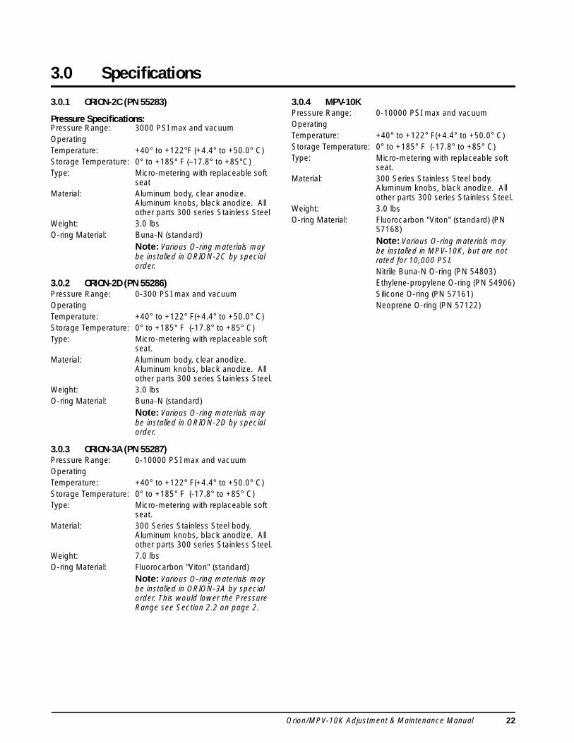
3.0 Specifications
3.0.1 ORION-2C (PN 55283)
Pressure Specifications:
Pressure Range: 3000 PSI max and vacuumOperating Temperature: +40° to +122°F (+4.4° to +50.0° C) Storage Temperature: 0° to +185° F (–17.8° to +85°C)Type: Micro-metering with replaceable soft
seatMaterial: Aluminum body, clear anodize.
Aluminum knobs, black anodize. All other parts 300 series Stainless Steel
Weight: 3.0 lbsO-ring Material: Buna-N (standard)
Note:
Various O-ring materials may be installed in ORION-2C by special order.
3.0.2 ORION-2D (PN 55286)
Pressure Range: 0-300 PSI max and vacuumOperating Temperature: +40° to +122° F(+4.4° to +50.0° C) Storage Temperature: 0° to +185° F (-17.8° to +85° C)Type: Micro-metering with replaceable soft
seat.Material: Aluminum body, clear anodize.
Aluminum knobs, black anodize. All other parts 300 series Stainless Steel.
Weight: 3.0 lbsO-ring Material: Buna-N (standard)
Note: Various O-ring materials may be installed in ORION-2D by special order.
3.0.3 ORION-3A (PN 55287)Pressure Range: 0-10000 PSI max and vacuumOperatingTemperature: +40° to +122° F(+4.4° to +50.0° C) Storage Temperature: 0° to +185° F (-17.8° to +85° C)Type: Micro-metering with replaceable soft
seat.Material: 300 Series Stainless Steel body.
Aluminum knobs, black anodize. All other parts 300 series Stainless Steel.
Weight: 7.0 lbsO-ring Material: Fluorocarbon "Viton" (standard)
Note: Various O-ring materials may be installed in ORION-3A by special order. This would lower the Pressure Range see Section 2.2 on page 2.
3.0.4 MPV-10KPressure Range: 0-10000 PSI max and vacuumOperatingTemperature: +40° to +122° F(+4.4° to +50.0° C) Storage Temperature: 0° to +185° F (-17.8° to +85° C)Type: Micro-metering with replaceable soft
seat.Material: 300 Series Stainless Steel body.
Aluminum knobs, black anodize. All other parts 300 series Stainless Steel.
Weight: 3.0 lbsO-ring Material: Fluorocarbon "Viton" (standard) (PN
57168)Note: Various O-ring materials may be installed in MPV-10K, but are not rated for 10,000 PSI.Nitrile Buna-N O-ring (PN 54803)Ethylene-propylene O-ring (PN 54906)Silicone O-ring (PN 57161)Neoprene O-ring (PN 57122)

23 Specifications
Orion/MPV-10K Warranty and Return PolicyIf possible, please save original packing material which is specifically designed for the unit. Should it benecessary to ship the unit back to the factory, a suitable shipping container must be used along with sufficientpacking material. Do not put a shipping label on the unit as a "suitable shipping container." Some units have beenseverely damaged this way. This is a delicate, precision instrument. Any damage incurred because of poorpackaging procedures will ultimately result in added service charges and longer turn-around times.
Vent unit to the atmosphere before shipping.
When factory service is required, send in only the unit for repair. Retain manual, etc. at your facility. However, ifthere is a problem with a particular part, send in that part with the unit.
If a unit is found to be defective, it may be returned to our repair facility at the following address:CONDEC3 SIMM LANEDOOR D, UNIT 2ANEWTOWN, CT 06470
ATTN: PRESSURE PRODUCTS/REPAIR LAB
Each unit's I.D. plate is stamped with a date code (week/year) prior to shipment. Our warranty is twelve (12)months from that date code and includes repair and/or replacement of the unit at our, Newtown facilities at nocharge. Units subjected to abuse or damaged by external influences, are not covered under warranty.
If the unit is found to be out of warranty, an evaluation charge of not less than fifty (U.S.) dollars ($50.00) will becharged. Please note on any attached paperwork if a repair estimate is required or if there are any other specificinstructions.
Please be explicit as to the nature of the problem and/or its symptoms. Your documentation will save needlesstime and expense. Also, please include a return shipping address (with a street address) and a contact name withfax and telephone numbers. Contact numbers are necessary to provide a job estimate and in case furtherquestions arise at the factory.
Warning

Orion/MPV-10K Adjustment & Maintenance Manual 24
Orion/MPV-10K Return Material Authorization FormThe repair lab is also equipped to do calibrations on our calibrators and pressure standards. Calibrations includea certification and are traceable to N.I.S.T.
CONDEC • 3 SIMM LANE • DOOR D, UNIT 2A • NEWTOWN, CT 06470 ATTN: PRESSURE PRODUCTS/REPAIR LAB
TEL: 888-295-8475 • FAX: 203-364-1556 or 715-234-6967WEB SITE: www.4condec.com
COMPANY NAME:
STREET:
CITY, STATE, ZIP:
TELEPHONE:
FAX:
CONTACT PERSON:
MODEL NUMBER:________________ SERIAL NUMBER: _______________________________
PROBLEM WITH UNIT (PLEASE BE SPECIFIC):
IS THIS A WARRANTY REPAIR? ( ) YES ( ) NO
SHIP TO Address:
COMPANY NAME:
STREET:
CITY, STATE, ZIP:
ATTN:


