Embed Size (px)
Citation preview

Otago Alluvial Fans:
High Hazard Fan
Investigation
June 2011

Otago Regional Council
Private Bag 1954, 70 Stafford St, Dunedin 9054
Phone 03 474 0827 Fax 03 479 0015
Freephone 0800 474 082
Published May 2011
Prepared by Richard Woods, Natural Hazards Analyst, Otago Regional Council

Executive summary
An alluvial fan is an accumulation of river or stream (alluvial) sediments that form a sloping landform,
shaped like an open fan or a segment of a cone. Alluvial fans typically occur near the boundary between
hill slopes and valleys. They owe their origins to changes in the slope of natural-drainage systems; for
example, where a steep gully merges onto a flatter valley floor. The gradient decrease and widening of
the flood path where a gully meets the valley floor encourages the deposition of sediment, which
accumulates over time to form a fan-shaped landform. More than 2000 alluvial-fan areas, equating to
6% of the total land area, have been mapped in Otago.
The principal hazards on alluvial fans are inundation by flood water, debris-flow and debris-flood
deposits, channel migration, deposition and erosion. The unpredictable and variable nature of alluvial-
fan hazards means that they are potentially very hazardous. Despite that, their elevated profile, with
good drainage, makes them attractive places for people to live.
In 2006, the Otago Regional Council (ORC) commissioned a review of the hazards associated with alluvial
fans in Otago. This regional review mapped all alluvial-fan features larger than 0.5km2 in area
throughout the region in a Geographic Information System (GIS) and classified each based on the fan’s
activity status - active or inactive - and the primary depositional process: floodwater dominant, debris
dominant or a composite of both floodwater and debris.
Following completion of the regional review, ORC staff consulted closely with each territorial local
authority (TLA) to identify active alluvial-fan areas that warranted further investigation. This led to
supplementary work on the nature and characteristics of alluvial fans in the 27 identified study areas,
set within a regional perspective of alluvial-fan active processes. Using this dataset, a subset of ‘high-
hazard’ alluvial fans was identified that warranted further specific investigation to determine existing or
potential future vulnerability and consequences of the alluvial-fan hazards.
In consultation with each TLA, ORC staff undertook a review of district-planning zones that intersect
active alluvial-fan areas and have an existing or a greater potential for future development. This
‘screening process’ has determined a subset of eleven specific alluvial fans that intersect existing or
future community areas which also have a high level of hazard exposure. This report summarises the
existing catchment and fan characteristics of each of those eleven alluvial fans and describes the hazard
associated with each.
The fans selected within this investigation do not necessarily represent those fans in Otago with the
highest level of hazard; rather this subset has been selected based on existing and future development
potential.
The report concludes that parts of Queenstown, Wanaka and Roxburgh townships are exposed to
intermittent alluvial-fan hazards. Hazard areas have been defined for particular alluvial fans in these
communities that may be subject to alluvial-fan processes in the future. Elsewhere, communities in the
Makarora Valley have a level of residual exposure to alluvial-fan hazards, should channels migrate
laterally across the fan surface in the future.

1
1. Alluvial fans in the Otago region Alluvial-fan landforms develop where a steep gully emerges from its confines onto a flatter valley floor,
or at locations where sediment accumulates in response to changes in stream gradient and/or width
(Figure 1.1). Primarily formed by intense, heavy rainfall, the overall development of these features is
episodic, often spanning time scales of decades to centuries. Flooding events can be unpredictable and
hazardous on alluvial fans, potentially involving fast-moving sediment-laden floods or slurry-like flows of
debris which can break out from existing streams and forge new, sometimes unexpected paths.
Sediment-laden floods or flows are damaging and destructive, and pose a threat of injury or death to
people. Less serious hazards include floodwater inundation, sediment erosion or build-up, which may
cause damage to land and infrastructure.
Figure 1.1 Diagrammatic representation of an alluvial fan, noting key features (Opus, 2009)
The form and setting of alluvial fans makes them an attractive location for residential development, with
gentle elevated slopes and good drainage. In Otago, fan streams are often ephemeral or inconspicuous,
creating an impression that little or no hazard exists. Throughout the region, residential development
has continued to encroach upon fan areas, with little recognition of the hazard exposure. In response,
ORC contracted a regional-scale hazard assessment of alluvial fans in 2007 (Opus, 2007). Fan areas were
mapped at 1:50,000 scale, identifying and classifying 2197 separate fan areas using a GIS map database.
The investigation found that significant alluvial-fan landforms occupy at least 1970km2, which is 6% of
Otago’s total land area. Fan areas were classified as active or inactive and allocated a primary
depositional process (i.e. floodwater dominant, debris dominant or composite, thereby providing
additional information on potential hazards). Implications for existing communities and future district-
planning objectives were identified through consultation with each TLA and consideration of their
respective district-plan zones. Twenty-seven alluvial-fan areas, many of which were located on the
lateral margins of existing communities, were considered to warrant further investigation. For each

2
area, the entire fan system was mapped, including areas of historical fan activity, upper catchment
stability and channel type, using aerial photography and field investigations. The resulting dataset
provides a comprehensive record of historical fan activity and existing catchment stability to identify
high-hazard areas that coincide with existing, planned or future areas of development.
1.1 Specific high-hazard alluvial fans
Eleven high-hazard alluvial fans were identified from the twenty-seven areas studied in the
supplementary investigation (Barrel et al., 2009). Through consultation with each TLA, the development
potential for each district-planning zone was ranked and matched against the active alluvial-fan areas.
This ‘screening’ process identified areas of existing development or zones with a high potential for
development that intersect active alluvial-fan areas. This process identified ten fans in the Queenstown-
Lakes District, one fan in the Central Otago District and no fans in the Waitaki, Dunedin City and Clutha
districts that warranted further investigation (Table 1).
Table 1 Specific high hazard alluvial-fans identified within the Otago region
District Specific alluvial fans
Queenstown Lakes Pipson Creek (Makarora), Flaxmill Creek (Makarora), Johns Creek (Hawea), Stoney Creek (Wanaka), Waterfall Creek (Wanaka), Walter Peak (Wakatipu), Bob’s Cove (Wakatipu), Brewery Creek (Queenstown), Reavers Lane (Queenstown), Kingston Creek (Kingston)
Central Otago Reservoir Creek (Roxburgh)
To determine the hazards associated with each alluvial fan, the following information was acquired and
collated:
the extent of existing and potential catchment instability that may contribute significant sediment and/or debris supply to the fan surface
the potential for debris-dam formation and identification of existing landforms in the upper catchment that provide evidence for historical damming
vegetation characteristics of the catchment and potential for log-jam dam formation the identification and mapping of palaeo-channels on the fan surface and the potential for these
to be re-occupied through channel avulsion observations of previous debris-flow deposits, their location and potential for future debris flow,
by inspection of existing soil profiles, to determine the general frequency and derivation of events
observations of channel incision down the fan surface, the location of the hydrographic and topographic apices and key inflection points
the potential for aggradation and lateral migration of active channels and the likely risk of avulsion
the potential for significant erosion of existing channels and possible effects.
The holistic environment setting of each alluvial fan is discussed. Catchment and fan characteristics are
described to gain an understanding of the current and potential geomorphic processes that define the
observed and anticipated alluvial fan hazards. The extent of alluvial-fan hazard has been mapped for

3
each specific fan. These areas have been defined by combining active alluvial-fan areas mapped by
Barrel et al. (2009), extending potential hazard areas using stereoscopic aerial photography and ground
verification, and integrating the results of previous site-specific investigations. It is important to note
that these hazard areas represent the full extent of possible unmitigated future alluvial-fan activity.
Alluvial-fan hazards will vary spatially within this boundary, depending on the nature and characteristics
of the storm event and fan surface at that time.
The topographic and hydrographic apices of each fan have been identified on the respective alluvial-fan
maps. The ‘topographic apex’ is the point, commonly where the fan head is located, where the creek or
stream leaves the confines of the valley (Figure 1). This point is static and corresponds with the foothills
of the source catchment. Comparatively, the ‘hydrographic apex’ is the point on the fan surface where
the channel no longer becomes incised into the surface and therefore may migrate or adopt a braided
form. The hydrographic apex is not static and may move within the channel, depending on the nature of
the fan surface, channel and catchment-sediment supply. Often during storm events, the channel may
aggrade and cause the hydrographic apex to move upstream quickly, promoting channel breakout or
avulsion. An example of this phenomenon is shown in Figure 1.2.
Figure 1.2 Pipson Creek in March 2004 (left), looking upstream, and November 2008 (right), looking
downstream. In the left image, the creek has aggraded, so that the channels are migrating laterally outside of the
channels low-flow banks; the hydrographic apex is located upstream and out of sight. In the right image,
excavation and channel contouring has confined the channel to a single-thread channel, far beyond the state
highway; the hydrographic apex is located near the confluence with Makarora River in this image.
1.2 Alluvial-fan formation in Otago in the Queenstown Lakes and Central Otago districts
Many alluvial fans in the Queenstown Lakes District have formed during the recession of the last glacial
period, around 18,000 years ago, as glaciers vacated basins and were replaced by the contemporary
lakes present today. These glaciers buttressed the outlets to many of the tributary catchments in the
adjacent mountain ranges during this period. After the glaciers receded, tributary base levels dropped
considerably, eroding catchments and transporting sediments to the recently vacated basins; these
sediments were deposited in the form of alluvial fans. Since this time, fans have progressively built out
into these basins, and these processes still continue today.
SH 6 Bridge
SH 6 Bridge

4
The rate at which alluvial-fan landforms have developed in Otago is largely dependent on the climatic
and seismic influences of the period. Since the last glaciation, large earthquake events, on plate
boundary’s and local-fault systems, are likely to have influenced the volume of sediment supplied by
source catchments to the alluvial-fan surfaces. In addition, fluctuations in climate between warmer and
cooler periods can affect the frequency and intensity of heavy rainfall events, and the level of sediment
supply to fan surfaces can vary as a result. These conditions mean that alluvial-fan processes, such as
debris-flow and flood events, often occur over timeframes of decades to centuries.
Alluvial fans located in the Lake Wakatipu, Wanaka and Hawea basins have been formed by catchments
eroding into ancient-schist bedrock. These fans have built out onto moraine and river-terrace deposits,
formed immediately following the recession of the glaciers. After the retreat of ice, these lakes were
initially 20-50m higher than today. As their outlets incised into deposits left by the glacier, lowering lake
levels, the surrounding alluvial fans followed suit. These conditions promoted stream incision into fan
deposits, leaving abandoned terraces flanking some of the contemporary alluvial fans.
In the Central Otago District, alluvial fans have formed in response to tectonic uplift of localised
mountain ranges and have maintained levels with the surrounding topography and rivers. As the Clutha
River responded to significant sediment inputs post-glaciation, it has formed many river terraces which
have subsequently been incised. As erosion of tributary catchments has continued, intermittent debris
and flood flows have built alluvial fans out onto these older terraces.
5
2. Pipson Creek, Makarora
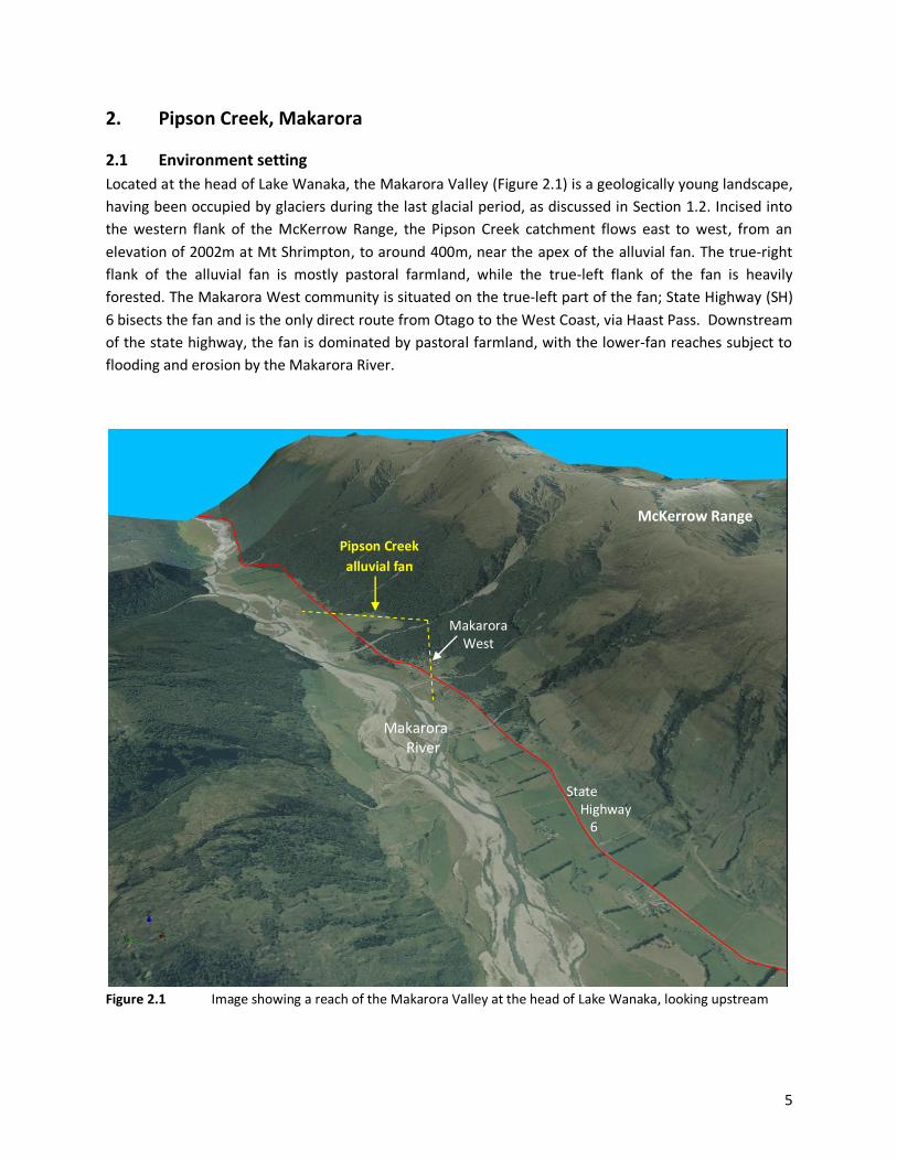
2.1 Environment setting
Located at the head of Lake Wanaka, the Makarora Valley (Figure 2.1) is a geologically young landscape,
having been occupied by glaciers during the last glacial period, as discussed in Section 1.2. Incised into
the western flank of the McKerrow Range, the Pipson Creek catchment flows east to west, from an
elevation of 2002m at Mt Shrimpton, to around 400m, near the apex of the alluvial fan. The true-right
flank of the alluvial fan is mostly pastoral farmland, while the true-left flank of the fan is heavily
forested. The Makarora West community is situated on the true-left part of the fan; State Highway (SH)
6 bisects the fan and is the only direct route from Otago to the West Coast, via Haast Pass. Downstream
of the state highway, the fan is dominated by pastoral farmland, with the lower-fan reaches subject to
flooding and erosion by the Makarora River.
Figure 2.1 Image showing a reach of the Makarora Valley at the head of Lake Wanaka, looking upstream
McKerrow Range
Makarora River
State Highway 6
Makarora West
Pipson Creek
alluvial fan

6
2.2 Catchment characteristics
The Pipson Creek upper catchment (Figure 2.2) is defined by high-altitude, mountainous terrain, with
small bushes and alpine tussocks comprising the dominant vegetation cover. The catchment is
approximately 3.3km2 in size. Slope processes in this part of the catchment are dominated by mass
movement, including creep, slumping and gullying, with many fresh scarps, signifying widespread
instability. Persistent mass movement is dominant on the true-right (northern) slopes of the catchment,
consistent with the dip of the underlying schist bedrock. The true-left (southern) slopes of the
catchment are dominated by creep processes and surficial gullying of exposed bedrock. These slope
conditions, coupled with the erodible nature of the underlying schist and intense, high rainfall of the
area1, provide mechanisms for the direct supply of high-sediment loads to the Pipson Creek channel.
Figure 2.2 The Pipson Creek catchment, noting sediment-source areas and sites of interest; aerial photo
dated March 2006
Field investigations, undertaken by ORC on 7 March 2011, indicate that the scale of upper-catchment
mass-movement activity has increased in recent decades, with the pronounced reactivation of slope
movements or the development of fresh scars. Figure 2.3 shows a large area of recent slope movement
at the location identified as Photo C1 in Figure 2.2. Intense-rainfall events, greater than 20mm/hour, in
February 2011 and December 2010, are likely to have contributed to the reactivation of this slip, as well
1 The mean annual rainfall at Makarora over the period 1967 to 2010 was 2400mm.
Upper catchment Lower catchment

7
as progressive incision of the toe by Pipson Creek. Historic aerial photography (Appendix 1) indicates
that this slip area has been periodically active in the past.
Figure 2.3 also shows Photo C2 (Figure 2.2) of the upper catchment slopes on 7 March 2011. Steep fresh,
gullying of bedrock in the head of the catchment shows that large clasts of material are being actively
supplied to the Pipson Creek channel throughout the upper catchment.
Figure 2.3 Photo C1 (left) and Photo C2 (right), showing recent mass movement in the upper catchment of
Pipson Creek on 7 March 2011
The lower Pipson Creek catchment (Figure 2.2) is typified by steep rock faces, which have a predominant
cover of dense bush. The channel at this location is confined and often incised to bedrock; conditions
that are favourable for the efficient conveyance of debris flow. Two sediment-source areas (Figure 2.4),
described in Opus (2004), contribute significant volumes of sediment and debris to the main channel
during periods of high, intense rainfall. These sediment-source areas have formed as a result of channel
incision by Pipson Creek over-steepening adjacent slopes. Historic aerial photography indicates that
these rock-fall features have formed and developed within the last 50 years. Opus (2004) note that
these locations are the primary source areas which have contributed to debris flows on the fan surface.
Observations in March 2011 indicate that these rock-fall features are still being actively eroded and
continue to provide large volumes of material to Pipson Creek.
Field observations indicate that the majority of the Pipson Creek catchment is dominated by mass-
movement processes. An increased level of instability has been observed in the catchment over the last
50 years, a phenomenon that continues today.

8
Figure 2.4 Pipson Creek lower-catchment primary-source areas. The main source area, as identifed by Opus
(2004), is viewed on the left, while the secondary source area is shown on the right
2.3 Fan characteristics
Pipson Creek has formed a symmetrical semicircular fan, with a stream that aggrades and degrades at
varying rates. The distal portions of the fan are actively eroded by the Makarora River. Debris-flow and
debris-flood deposits dominate the upper parts of the fan, with downstream run-out flood zones
typified by silty-sheet flood deposits. Deposits from larger debris flows extend to the Makarora River
(Barrell et al., 2009).
Figure 2.5 shows the Pipson Creek alluvial fan and key features. Channel incision varies along the length
of the alluvial fan. Near the topographic apex of the fan, where the creek leaves the confines of the
valley, the channel is confined by outcrops of bedrock in places, and is incised by greater than 10m
(Figure 2.6-P1). Erosion of both banks is common in this reach of the creek, as debris flows pass through
efficiently due to the channel’s confinement and steep gradient. The greater the distance from the
source catchment, the less incised the channel becomes, mainly due to a significant reduction in channel
gradient. Much of the Pipson Creek channel, as depicted by Figure 2.5, is less than 2m incised into the
natural-fan surface.

9
As the creek continues downstream, it begins to adopt a slight meander pattern, moving from left to
right. This pattern contributes to the super-elevation of bed levels next to the respective banks of the
channel (Figure 2.6-P2) and can result in avulsion (break-out) of the channel across other parts of the
fan surface (Figure 2.5). In addition, the concave aspect of each meander is subjected to the greatest
velocities from debris and flood flow, which induces erosion of unconsolidated bank materials (Figure
2.6-P3). Observations from March 2011 identified a number of locations where Pipson Creek had
avulsed from its channel onto the adjacent fan surface, as shown in Figure 2.6-P4.
ORC (2007), using dendro-chronological techniques, identified a large palaeo-channel on the southern
margins of the fan surface. The oldest trees in this location were established during the 20th century,
indicating that this channel has been active in recent geological times. The current channel is incised by
greater than 5m below the adjacent level of the head of this palaeo-channel at present (Figure 2.6-P1).
In the lower reaches of the fan, there is little elevation difference (freeboard) between the natural
channel level and the level of the surrounding alluvial-fan surface. As shown in Figure 2.5, the channel
has been considerably modified by in-channel excavation and works downstream of the SH 6 bridge.

10
Figure 2.5 Pipson Creek alluvial fan, noting some key alluvial fan features; aerial photo dated March 2006
White Creek

11
Figure 2.6 Photographs relating to the points of interest identified in Figure 2.5. P1 shows greater than 10m
of channel incision into the alluvial-fan surface near the fan-topographic apex. P2 shows super-elevation of the
true right of the Pipson creek bed, causing avulsion onto the true-left alluvial-fan surface. P3 shows the concave
aspect of a slight channel meander, inducing erosion of the true-right bank. P4 shows deposition on the alluvial-fan
surface as a result of Pipson Creek avulsing from its channel.
2.4 Pipson Creek alluvial-fan hazard
Debris and flood flows have been well documented on the Pipson Creek alluvial fan in recent decades
(Table 2.1). Figure 2.7 shows in-channel aggradation and channel avulsion resulting from large debris
and debris-flood flows.
The alluvial-fan hazards associated with Pipson Creek generally consist of high-velocity-debris and
debris-flood flows, channel avulsion, bank erosion and floodwater ‘sheet-flow’ inundation. Upper parts
of the fan are subject to high-velocity debris flow where the channel is currently confined and steep. As
the fan and channel gradients change downstream, debris-flood deposits are more common, with
considerable channel aggradation occurring during and in the immediate recession of the debris-flow
event. In these reaches and downstream, bank overflow and channel avulsion is common on both the
P1 P2
P3 P4

12
left and right banks, with less than 2m of channel incision (Figure 2.5). Downstream of the SH6 bridge
floodwater inundation in the form of ‘sheet-flow’ is more common, depending on the size of the event.
Rates of catchment erosion have accelerated in recent decades, which has been reflected in large
debris-flow events impacting the fan surface. Due to the scale of catchment instability, it is anticipated
that debris-flow events will continue in this manner into the foreseeable future.
Table 2.1 Total rainfall and maximum intensity measured at the Makarora rainfall gauge and observed
effects on Pipson Creek. The Makarora rainfall gauge is located approximately 2km south of Pipson Creek, at
around 320m above sea level. Older observations sourced from Opus (2004). All events list in this table impacted
and/or covered the SH 6 bridge.
Date Rainfall total Max. rainfall intensity Event
February 2011 129.5mm (22 hours)
21.5mm/hr True-left channel break- out upstream of bridge. Highway inundated.
December 2010 123mm (36 hours)
26.5mm/hr
January 2008 123mm (18 hours)
18mm/hr Highway inundated.
April 2006 59.5mm (18 hours)
13mm/hr Break-out of channel on both banks upstream of bridge. Highway inundated.
March 2004 78.5mm (9 hours)
13.6mm/hr Break-out of channel on both banks upstream of bridge. Highway severely inundated.
February 1998 70.5mm (9 hours)
8.5mm/hr Break-out of channel on both banks upstream of bridge.
December 1995 Gauge relocated Gauge relocated
September 1995 Gauge relocated Gauge relocated Break-out of channel on both banks upstream of bridge.
January 1994 Gauge relocated Gauge relocated
December 1989/ January 1990
Gauge relocated Gauge relocated

13
Figure 2.7 Pipson Creek, following large debris flows in 2004 and 2006. Photo P1 shows significant bank
overflow on the true-right channel upstream of the SH6 bridge. Photo P2 shows large levee embankments formed
on the outside of the channel, which are indicative of high-velocity-debris flows on the upper fan. Photo P3 shows
bank-full conditions upstream of the SH6 bridge, after debris flow in 2006. Photo P4 shows bank-full conditions,
upstream of the SH6 bridge, after debris flow in 2004.
Debris-flow events in Pipson Creek will recur, as has been observed in recent times. Channel
aggradation, erosion, bank overflow and avulsion will occur in varying magnitudes, depending on the
nature and characteristics of the storm event and condition of the catchment. It is likely that bank
overflow and aggradation will occur in those locations where channel incision is less than 2m and
further upstream in very large events. While the fan is heavily forested, woody debris and trees often
exacerbate the possible effects of debris flow and cannot be relied upon as suitable mitigation.
It is noted that a level of risk exists for the Makarora West community from debris flow derived from
Pipson Creek. Should a large sediment input cause the channel to aggrade considerably at the head of
the alluvial fan, there is potential for Pipson Creek to avulse and re-occupy or form new channels in the
direction of the Makarora West community. In addition, flows that avulse from the channel further
down the fan may also re-occupy palaeo-channels towards parts of the community.
P1 (April 2006) P2 (April 2006)
P3 (April 2006) P4 (March 2004)

Historic Aerial Photographs
Pipson Creek, Makarora
16-10-1953
28-11-1998
13-03-2006

14
3. Flaxmill and Oturaki creeks, Makarora
3.1 Environment setting
Located at the head of Lake Wanaka, the Makarora Valley (Figure 3.1) is a geologically young landscape,
having been occupied by glaciers during the last glacial period, as discussed in Section 1.2. Incised into
the western flank of the McKerrow Range, the Flaxmill and Oturaki creek catchments flow east to west
from an elevation of 1944m at Mt Constitution, in the Flaxmill Creek catchment, to around 400m near
the apices of the alluvial fans. The Makarora East community is located on the southern margin of both
alluvial fans next to SH 6. As with Pipson Creek, the state highway bisects both fans and is the only direct
route from Otago to the West Coast, via Haast Pass. The remaining parts of both alluvial fans are
dominated by pastoral farmland.
Figure 3.1 Image showing the lower Makarora Valley at the head of Lake Wanaka
McKerrow Range
Makarora River
State Highway 6
Makarora East
Wilkin River
Flaxmill Creek
alluvial fan
Lake Wanaka
Oturaki Creek
alluvial fan

15
3.2 Catchment characteristics
The Flaxmill and Oturaki creek catchments are shown in Figure 3.2 and have catchment sizes of 3.1 and
0.8km2, respectively. Like Pipson Creek, the upper slopes of both catchments are defined by high-
altitude, mountainous terrain, with small bushes and alpine tussocks being the dominant vegetation
cover. Slope processes in this part of the catchments are dominated by mass movement, including
creep, slumping and gullying, with many fresh scarps, signifying widespread instability. Persistent mass
movement is dominant on the true-right (northern) slopes of the catchment, consistent with the dip of
the underlying schist bedrock. The true-left (southern) slopes of each catchment are dominated by
creep processes and surficial gullying of exposed bedrock. These slope conditions, coupled with the
erodible nature of the underlying schist and intense, high rainfall of the area, provide mechanisms for
the direct supply of high sediment loads to each creek’s channel.
Figure 3.2 The Flaxmill and Oturaki creek catchments; aerial photo dated March 2006
Field investigations, undertaken by ORC on 7 March 2011, indicate that a primary-sediment-source area
in Flaxmill Creek (Figure 3.2) is actively providing sediment to the channel (Figure 3.3). The absence of
vegetation on this slip area, particularly when compared to 2006 aerial photography (Appendix 1),
indicates that it has been active during the period 2006 to 2011. Intense rainfall events, greater than
20mm/hour, in February 2011 and December 2010, have likely contributed to the reactivation of this
slip, as well as progressive incision of the toe by Flaxmill Creek.
P1 View
P2 View
P3 View

16
Figure 3.3 The primary-sediment-source area in the Flaxmill Creek catchment on 7 March 2011, as
annotated in Figure 3.2. Photo P1 shows the fresh face of this slip area, leading up to the head of slide where
instability has been initiated. P2 shows the toe of the primary-source area and shows incision by Flaxmill Creek.
The fresh slip face is observed in Photo 3, indicating the recent removal of material.
Aerial photography from 1953 indicates that instability in the Flaxmill Creek catchment was not as active
at that time. The primary-sediment-source area (Figure 3.2) was largely vegetated and not actively
supplying significant quantities of sediment to the channel. By 1999, this area was very active.
The Oturaki Creek catchment similarly indicates a rather benign level of catchment instability in 1953,
compared to the increased fresh scarps evident in 1999 (Appendix 1).
3.3 Fan characteristics
Flaxmill Creek has formed a symmetrical semicircular fan, with a stream that aggrades and degrades at
varying rates. The distal portions of the fan are actively eroded by the Makarora River. Debris-flow and
debris-flood deposits dominate the upper parts of the fan, with downstream run-out flood zones
typified by silty-sheet flood deposits. Oturaki Creek has also created an alluvial fan that coalesces with
the Flaxmill Creek alluvial fan.
Figure 3.4 shows Flaxmill and Oturaki creeks’ alluvial fans and key features. Channel incision varies along
the length of the Flaxmill Creek alluvial fan. Near the topographic apex of the fan, where the creek
leaves the confines of the valley, the channel is incised by between 3-5m (Figure 3.5). In this reach of the
fan, the channel is subject to rapid aggradation during storm events, as observed in Figure 3.5. Such
aggradation has historically induced avulsion of the channel, spilling debris flows across the true-left
alluvial-fan surface, with large lobate-debris deposits observed in this location. In addition, large palaeo-
channels exist (Figure 3.5), where flow has historically been transferred down the southern part of the
fan surface. The true-right fan surface is elevated above the true left in this location, as mapped in Barrel
et al. (2009).
P1 P2 P3

17
Figure 3.4 Flaxmill and Oturaki creek alluvial fans, noting some key alluvial fan features; aerial photo dated
March 2006
State Highway 6

18
Figure 3.5 Flaxmill Creek alluvial fan just downstream of P1, as shown on Figure 3.4. At this location, metres
of recent channel aggradation (left) have been incised by the active channel. Large debris deposits and palaeo-
channels (right) are located on the true-left surface of the alluvial fan.
Downstream, the Flaxmill Creek alluvial fan is incised into its surface by greater than 3m, until its
hydrographic apex is reached, where the fan becomes less than 3m incised. At this location, channel
avulsion is common, as observed in January 1994 (Figure 3.6). Where the channel has less than 1m
incision, channel aggradation commonly results in avulsion. In the lower reaches, Flaxmill Creek is
confined by informal embankments that are subject to aggradation and erosion; these embankments
are easily breached during large flood events, as observed in January 1994.
Oturaki Creek has a fan area much smaller than Flaxmill. However, it still has the potential to transfer
debris and floodwaters beyond the state highway, as shown in Figure 3.6. Observations in March 2011
indicate that the channel of Oturaki Creek has little to no incision of the fan surface (Figure 3.7).
Channel aggradation at the head of the fan is common, with avulsion of the channel onto the true-left
alluvial-fan surface observed in March 2011. Avulsion along the length of the channel (Figure 3.4) is
likely to continue in the future. The true-left surface of the alluvial fan is dissected by a number of
historic palaeo-channels (Figure 3.4), many of which flow towards the Makarora East township.
Debris deposits
Palaeo-channel

19
Figure 3.6 Flaxmill and Oturaki creeks, following the storm event of January 1994
Figure 3.7 Channel aggradation at the head of the Oturaki Creek alluvial fan (left) and channel avulsion and
sediment deposition down the true left of the fan, March 2011 (right)

20
3.4 Flaxmill Creek alluvial-fan hazard
Debris and flood flows have been well observed on the Flaxmill Creek alluvial fan in recent decades.
Figure 3.6 shows considerable in-channel aggradation and channel avulsion, from debris and debris-
flood flows in January 1994.
The alluvial-fan hazards associated with Flaxmill Creek generally consist of high-velocity-debris and
debris-flood flows, channel avulsion, bank erosion and floodwater ‘sheet-flow’ inundation. Upper parts
of the fan are subject to high-velocity debris flow where the channel is currently confined and steep. As
channel gradients lessen downstream, debris-flood deposits are more common, with considerable
channel aggradation occurring during and in the immediate recession of the debris-flow event. In these
reaches, and downstream, bank overflow and channel avulsion is common on both the left and right
banks, with less than 3m of channel incision (Figure 3.4). Downstream of the SH6 bridge, floodwater
inundation in the form of ‘sheet-flow’ is more common, depending on the size of the event.
Debris-flow and flood events in the Flaxmill Creek catchment are the result of prolonged and/or high-
intensity rainfall events in the upper catchment. Mass-movement processes and slope instability are
widespread in the catchment, with large areas of active landslides contributing high-sediment loads to
the active channel. Due to the scale of catchment instability, it is anticipated that debris-flow events will
continue in this manner into the foreseeable future.
Channel aggradation, erosion, bank overflow and avulsion will occur in varying magnitudes, depending
on the nature and characteristics of the storm event and the condition of the catchment. It is likely that
bank overflow and aggradation will occur in those locations where channel incision is less than 3m, and
further upstream in large events. It is noted that a level of risk exists for the Makarora East community
from debris flow derived from Flaxmill Creek.
3.5 Oturaki Creek alluvial-fan hazard
The Oturaki Creek alluvial fan is superposed onto the greater Flaxmill Creek alluvial fan. The alluvial-fan
hazards associated with this creek are largely aggradational, where recurring debris and debris-flood
flows deposit sediment across the fan surface. Due to very little channel incision, the creek has the
potential to migrate and avulse across the fan surface, as observed in Figure 3.7.
The lateral migration of channels was well observed in January 1994, with large areas of the fan surface
being subjected to flows and subsequent sedimentation (Figure 3.6). In the lower reaches, the fan is
more susceptible to floodwater inundation processes and is likely to reoccupy palaeo-channels on the
southern margins of the fan in the future.

Historic Aerial Photographs
Flaxmill and Oturaki creeks, Makarora
16-10-1953
10-01-1999
13-03-2006

21
4. Johns Creek, Grandview Range
4.1 Environment setting
Located at the southern end of Lake Hawea, the Hawea Basin (Figure 4.1) is a geologically young
landscape, having been occupied by glaciers during the last glacial period, as discussed in Section 1.2.
Incised into the western flank of the Grandview Range, the Johns creek catchment flows east to west,
from an elevation of 1456m at Breast Peak, to around 420m, where the channel leaves the confines of
the valley. Most of the fan surface is dominated by pastoral farmland, with some farm and ancillary
buildings near the head of the fan. On the fan’s lower margins, the creek is bound on both banks by a
small community at Gladstone. Just upstream of the community, Gladstone Road crosses Johns Creek by
way of a ford.
Figure 4.1 Image showing the location of the Johns Creek alluvial fan in the Lake Hawea Basin
Grandview Range
State Highway 6
Lake Hawea township
Johns Creek
alluvial fan
LAKE HAWEA
Grandview Creek
alluvial fan

22
4.2 Catchment characteristics
The Johns Creek catchment is approximately 11km2 in size (Figure 4.2). The catchment is generally
defined by high-altitude, mountainous terrain, with small bushes and alpine tussocks comprising the
dominant vegetation cover. Slope processes in this part of the catchment are dominated by mass
movement, including creep, slumping and gullying, with many fresh scarps, signifying widespread
instability. Slope instability is widespread at the head of the catchment, particularly on northern-facing
slopes, where slopes are mantled with landslide debris, which is being eroded and transported to the
valley floor (Figure 4.3-P1). These slope conditions, coupled with the erodible nature of the underlying
schist, provide conditions for the direct supply of sediment to the active channel.
Figure 4.2 The Johns Creek catchment, noting sites of interest; aerial photo dated April 2005
The valley floor of the Johns Creek catchment is very well incised into basement schist, which is
reflected in the relatively shallow 14% grade of the channel between the head of the fan and location P3
(Figure 4.2). These conditions have allowed the deposition of large amounts of sediment within the
catchment’s active channel, probably on the recession of debris-flow events (Figure 4.3-P4).
Subsequent to their deposition, the contemporary channel has incised into these deposits, reworking
the sediments downstream. The widespread erosion and instability of slopes, coupled with bed and
bank erosion in the Johns Creek catchment, provide large quantities of unconsolidated sediments
conducive to the initiation of debris flows.

23
Figure 4.3 Photographs relating to the points of interest identified in Figure 4.2. P1 shows persistent mass
movement on northern-facing slopes at the head of the Johns Creek catchment. P2 shows the wide valley setting
of the Johns Creek catchment and incised channel into mid-catchment fan deposits. P3 shows chaotic landslide
debris on the catchment’s true right, where these deposits are being actively eroded by the creek. P4 shows a
close-up of incision in the channel mid-catchment.
4.3 Fan characteristics
Johns Creek has formed a semicircular fan that coalesces with the large Grandview Creek fan on its
southern margin. Due to the presence of the Grandview Creek fan, much of the Johns Creek alluvial-fan
activity has been confined to the northern half of the fan, where the contemporary channel is located
today. Sediment-laden flood flows and intermittent-debris flows occur on the fan surface. Sediment is
transported across the fan surface, but is also eroded from the bed and banks of the creek.
Figure 4.4 shows the Johns Creek alluvial fan and key features. Channel incision varies along the length
of the alluvial fan. The true-right bank is incised into the higher fan surface by greater than 5m
downstream of the topographic apex. Just upstream of the topographic apex, in P1, overbank deposition
was observed in a number of locations, where debris flows have reached elevations above the existing
bank height (Figure 4.5-P1). This phenomenon becomes less prevalent as the creek turns northwards
and becomes more incised into the wider fan surface. Downstream of this location, the true-left bank of
the fan becomes less incised, with less than one metre incision between the current channel level and
P1
P4
P3
P2

24
adjacent topography, as observed in P2. The channel in this reach is wide and heavily laden with fresh
sediment and debris, indicating that it is often active. In this reach, a palaeo-channel is situated on the
left bank, where flow can be transferred a considerable distance behind earth embankments to lower
parts of the fan.
At P4, the creek is impounded by an elevated ford, which depending on its formation, may redirect flow
towards adjacent banks. Downstream of the ford, the channel is confined by informal embankments
that consist of unconsolidated sediments excavated from the creek. On the true-left bank, a palaeo-
channel, approximately the same level as the current channel, is present. Elevated above this palaeo-
channel are residential properties some 2-3m higher than this channel (P5). Residential properties are
also present on the true-right bank downstream of the ford (P6).

25
Figure 4.4 Johns Creek alluvial fan, noting some key alluvial fan features; aerial photo dated April 2005

26
Figure 4.5 Photographs relating to the points of interest identified in Figure 4.4
P1 P2
P3 P4
P5 P6

27
4.4 Johns Creek alluvial-fan hazard
While generally confined to the active channel, debris and flood flows are a regular occurrence on the
Johns Creek alluvial fan. Sediment-laden debris-flood flows rework the bed and banks of the channel
that comprise pre-existing alluvial fan deposits. These flows are efficiently transported through the
upper reach of the alluvial fan where the channel is incised by greater than 5m. On lower parts of the
fan, avulsion of the channel is probable on the true-right bank, with the reactivation of palaeo-channels
and lateral migration of flows across the fan surface likely in large events.
Debris flows and flood events in the Johns Creek catchment are the result of prolonged and/or high-
intensity rainfall events in the upper catchment. Mass-movement processes and slope instability is
widespread in the catchment, with large areas of active landslides contributing high-sediment loads to
the active channel. In the lower catchment and on the valley floor, the erosion of old-fan deposits and
the bed and banks provide large amounts of sediment to induce debris-flood flows. Due to the large
volume of sediment available to the active channel, it is anticipated that debris and debris-flood flows
are likely to continue into the foreseeable future in this catchment.
Channel aggradation, erosion, bank overflow and avulsion will occur in varying magnitudes, depending
on the nature and characteristics of the storm event and condition of the catchment. It is likely that
bank overflow and aggradation will occur in those locations where channel incision is less than 2m and
in other locations during very large events. It is noted that a level of risk exists for properties located on
the lower margins of the fan. While avulsion is probable on the left bank, properties are generally
located on an elevated terrace, compared to the right-bank properties, which have very little
distinguishing elevation change from the contemporary channel level.

Historic Aerial Photographs
John’s Creek, Grandview Range
16-10-1953
14-02-1997
6-04-2005

28
5. Stoney Creek, Wanaka
5.1 Environment setting
Located near the southern shores of Lake Wanaka, the Wanaka Basin (Figure 5.1) is a geologically young
landscape, having been occupied by glaciers during the last glacial period, as discussed in Section 1.2.
The Stoney Creek catchment headwaters are incised into the eastern flank of the West Wanaka ranges,
which include Roys Peak and Mount Alpha, and range in altitude from 1160-1320 metres above sea level
(masl). The creek’s outlet flows into Lake Wanaka at an elevation of 288m at the western end of Roys
Bay.
Historically, the Stoney Creek alluvial fan has been used intensively for pastoral farming. An increasing
demand for development and residential properties in the Wanaka district has subjected the fan to
urban encroachment, whereby the lower fan margins have been developed. The often ephemeral state
and benign appearance of the creek does not give a full appreciation of the potential alluvial-fan hazard,
as observed in November 1999 and January 2004.
Figure 5.1 Image showing West Wanaka, including the Stoney Creek catchment and indicative fan area. The
Wanaka CBD is situated in the lower-centre of the image.
Wanaka township CBD
Stoney Creek
alluvial fan
LAKE WANAKA
Stoney Creek
catchment

29
5.2 Catchment characteristics
The Stoney Creek catchment is approximately 1.6km2 in size. The upper catchment of Stoney Creek is
formed in a large landslide, with a headwall that extends into the upper Waterfall Creek catchment.
Large (catchment-scale) and deep (>5m) landslides are extensive on slopes at higher elevations, with
shallow (up to 2m) mass-movement features superposed onto these larger features. The depth of
catchment instability reflects the depth of weathering on these slopes.
The predominant geomorphological processes in the catchment are mechanical weathering, erosion and
mass movement. Mechanical-weathering processes are dominated by freeze-thaw, where the basement
schist and overlying sediments are broken down by congelifraction (the freezing of interstitial water
particles leading to expansion, fracturing and disintegration of particles). Slope deposits - consisting of
schist clasts and gravel fines, derived from the basement schist - are interpreted to be a result of this
freeze-thaw weathering process. Periglacial till or loess deposits have not been formally identified in this
catchment; however, some gravel fines may have been derived from these processes.
These slope deposits are primarily transported downslope by mass-movement and erosion processes,
such as slides, flows, gullying and rilling. In general, mostly fine gravels and silts are provided to the
streams by these processes. However, the steep gradient of the upper catchment watercourses provides
sufficient energy to transport large grain sizes, up to 5m in diameter, during storm events.
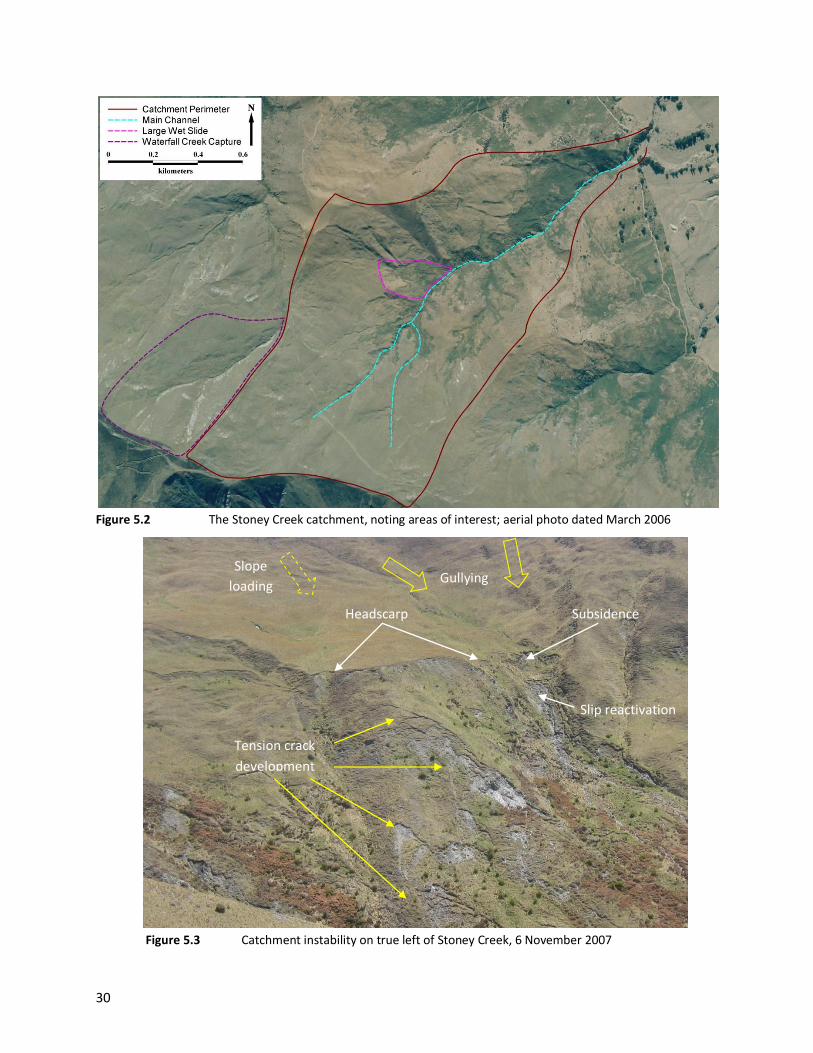
The ‘large wet slide’ (Figure 5.2) on the true-left slopes of the catchment is shown in Figure 5.3.
Following a magnitude 6.7 earthquake, 60km west of Milford Sound on 16 October 2007, parts of this
slide were subject to surficial-debris flow, initiated by a sudden release of water in a pre-existing
headscarp. Observations by ORC in November 2007 identified that this slide area is very active, with high
groundwater levels and many surface channels. In addition, the toe of this slide area is being actively
eroded by Stoney Creek.
On the evening of 30 January 2004, a storm event, concentrated above the Stoney Creek catchment,
caused an upper channel of the Waterfall Creek catchment to aggrade and divert flow across the
catchment divide into the Stoney Creek catchment (Figure 5.4). This phenomenon contributed sediment
and flow to Stoney Creek exacerbating the alluvial-fan hazards downstream. Following this storm event,
ORC undertook earthworks at the catchment divide to train the channel towards Waterfall Creek.
30
Figure 5.2 The Stoney Creek catchment, noting areas of interest; aerial photo dated March 2006
Gullying
Subsidence
Slope
loading
Tension crack
development
Slip reactivation
Headscarp
Figure 5.3 Catchment instability on true left of Stoney Creek, 6 November 2007

31
Figure 5.4 The headwaters of Waterfall Creek, where the creek switches across the catchment divide to
enter the Stoney Creek catchment, taken shortly after the storm event of 30 January 2004
5.3 Fan characteristics
Stoney Creek loses energy where the catchment gradient decreases as it emerges onto the piedmont
terrace at the head of the alluvial fan. The reduction in flow energy, and the loss of flow to groundwater
beyond the valley confines, causes the stream to deposit most of its sediment load on the alluvial-fan
surface. Due to the deposition of this sediment, the Stoney Creek alluvial fan is subject to lateral
migration (avulsion) of channels as a result of channel aggradation or blockage during storm events.
These conditions provide great uncertainty in regard to the location of future flow paths on the fan
surface.
Stoney Creek currently occupies a central position on its alluvial fan (Figure 5.5). The topographic and
hydrographic apex locations are at the head of the alluvial fan. Here, the stream is incised by up to 2m,
but has migrated laterally from its current position in the past, as indicated by the presence of
prominent palaeo-channels to the north and south. Downstream, the channel becomes less incised and
has less than one metre incision for much of its length. Historic palaeo-channels, as a result of channel
avulsion, are common across the fan surface where flood and/or debris flows have eroded new channels
during storm events; a selection of large palaeo-channels is depicted in Figure 5.5.
The ORC has undertaken some hazard-mitigation works as part of the Stoney Creek Flood Protection
Scheme, which has reduced the potential for avulsion and channel aggradation on parts of the Stoney
Waterfall Creek
Stoney Creek

32
Creek alluvial fan. These works have included construction of a debris trap to promote debris detention
to reduce the likelihood of channel aggradation on the lower fan, and channel-shaping works to provide
sufficient capacity for the efficient transfer of design flows. These works and works by others have been
undertaken in the area marked as ‘modified channel’ in Figure 5.5. The works by ORC are to a rural
standard and to the minimum standard expected for an urban area.
5.4 Stoney Creek alluvial-fan hazard
As discussed, the often ephemeral state and benign appearance of Stoney Creek does not give a full
appreciation of its potential alluvial-fan hazard. In November 1999 and January 2004, storm events in
the catchment resulted in debris and flood flows across many parts of the fan surface, with the main
channel being subject to avulsion, aggradation and erosion along its length (Figure 5.6).
The Stoney Creek alluvial-fan hazard area (Figure 5.5) has been derived from the active alluvial-fan areas
mapped by Barrell et al. (2009) and those areas subject to alluvial-fan hazard identified by ORC in 2006.
Barrell et al. (2009) identified areas that have been subject to sedimentation and debris deposition from
past storm events and are still subject to these alluvial-fan processes. The ORC (2006) investigation
identifies those locations that have a level of risk from Stoney Creek alluvial-fan hazards and includes
areas that may not have been subject to easily identifiable sedimentation or debris deposition in the
past. It is noted that the alluvial-fan hazard area depicted to the north merges with the hazard derived
from the adjacent Waterfall Creek catchment.
Depending on the nature and characteristics of each storm event, any part of the hazard area may be
subject to debris or debris-flood flows, channel avulsion, erosion or floodwater inundation. Upper parts
of the fan are slightly more incised than downstream and will convey debris and flood flows more
efficiently. As the fan and channel gradients lessen downstream, debris-flood deposits are more
common with channel aggradation and avulsion more prevalent. These processes occur upstream of the
existing works undertaken by the ORC.
The existing ORC channel works will have no effect on the extent and magnitude of alluvial hazards
observed upstream of their current location (i.e. upstream of Studholme Road). This is also true for
those parts of the fan that are impacted by debris and/or flood flows occurring as a result of channel
avulsion on the upper fan. Future works in this reach of Stoney Creek may reduce the potential for
channel avulsion and the extent of observed channel aggradation downstream.

33
Figure 5.5 The Stoney Creek alluvial fan, noting the identified hazard area and other key features; aerial
photo taken in March 2006

34
Figure 5.6 The effects of debris and flood floods derived from Stoney Creek in January 2004. Top left:
Channel and bank erosion and overbank-debris deposition near the head of the alluvial fan. Top right: Channel
aggradation and debris deposition in the Stoney Creek channel. Bottom left: Channel aggradation near Studholme
Road resulting in channel avulsion and a build-up of sediment against adjacent fencing. Bottom right: Channel and
bank erosion near the Stoney creek outlet at Lake Wanaka

Historic Aerial Photographs
Stoney Creek, Wanaka
27-01-1966
14-02-1997
23-03-2006
35
6. Waterfall Creek, Wanaka
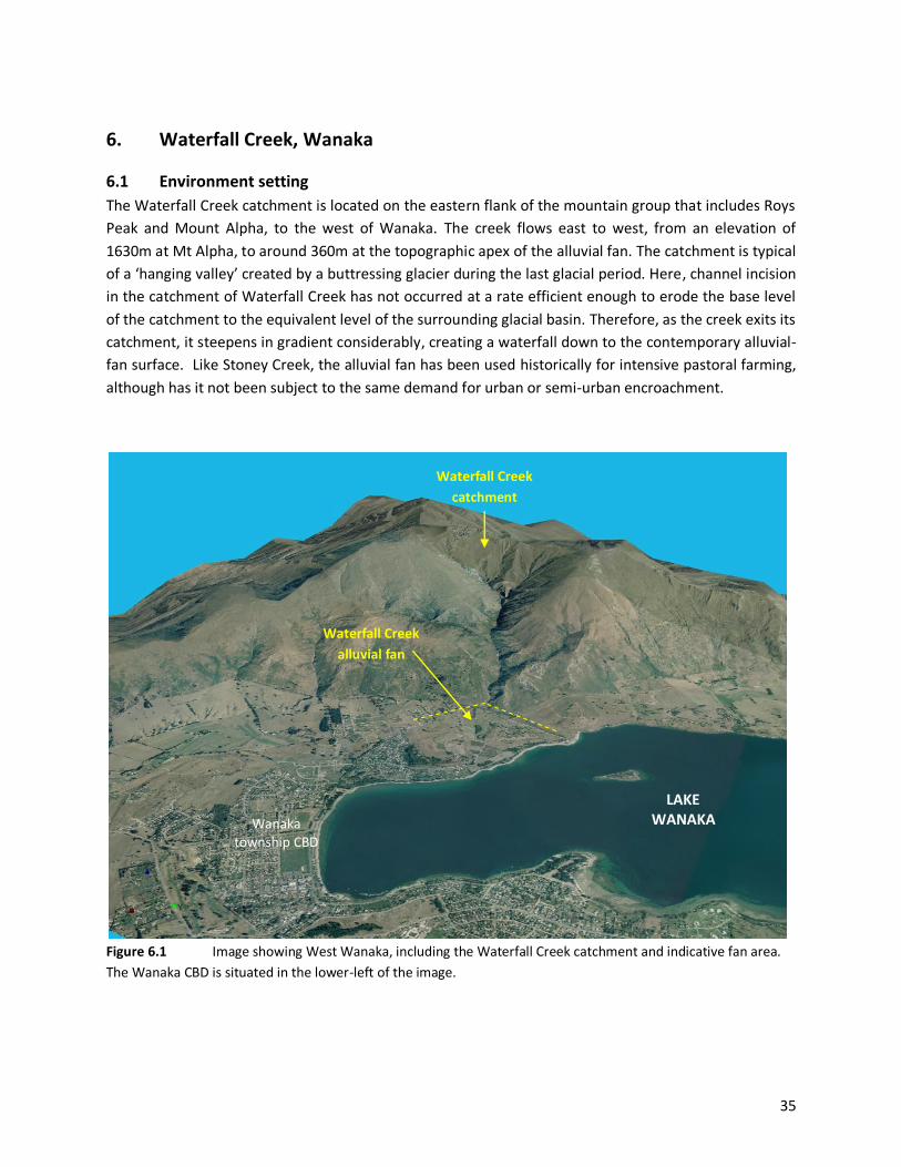
6.1 Environment setting
The Waterfall Creek catchment is located on the eastern flank of the mountain group that includes Roys
Peak and Mount Alpha, to the west of Wanaka. The creek flows east to west, from an elevation of
1630m at Mt Alpha, to around 360m at the topographic apex of the alluvial fan. The catchment is typical
of a ‘hanging valley’ created by a buttressing glacier during the last glacial period. Here, channel incision
in the catchment of Waterfall Creek has not occurred at a rate efficient enough to erode the base level
of the catchment to the equivalent level of the surrounding glacial basin. Therefore, as the creek exits its
catchment, it steepens in gradient considerably, creating a waterfall down to the contemporary alluvial-
fan surface. Like Stoney Creek, the alluvial fan has been used historically for intensive pastoral farming,
although has it not been subject to the same demand for urban or semi-urban encroachment.
Figure 6.1 Image showing West Wanaka, including the Waterfall Creek catchment and indicative fan area.
The Wanaka CBD is situated in the lower-left of the image.
Wanaka township CBD
Waterfall Creek
alluvial fan
LAKE WANAKA
Waterfall Creek
catchment

36
6.2 Catchment characteristics
The upper Waterfall Creek catchment is defined by high mountainous terrain, with small bushes and
alpine tussock being the dominant vegetation cover (Figure 6.2). Slope processes in this area are
dominated by mass movement, with creep, slumping, gullying and fresh scarps, signifying instability
(Figure 6.3). Large-scale mass movement is dominant on east to south-east facing slopes, consistent
with the dip of the underlying schist foliation; while north to north-east facing slopes exhibit undulating
hummocky terrain. These conditions provide mechanisms for the direct transportation of high-sediment
loads to the channel. In-channel slumping on steep gradients and an abundance of freshly formed scarps
are common in this part of the catchment.
The mid-catchment consists of steep slopes, with a more incised single channel, which is joined by
tributaries from both flanks of the valley. Widespread slope instability is present on both sides of the
channel and where slides meet the base of the valley; toe incision by Waterfall Creek is common (Figure
6.3). Slope creep and hummocky terrain is also evident throughout this part of the catchment.
Recent large-scale slope instability and failure is common throughout lower parts of the catchment,
particularly on true-left slopes. The channel in this reach is deeply incised into the valley-floor sediments
and basement schist further downstream. Toe incision of slide features by Waterfall Creek is a common
factor in exacerbating slope instability within these reaches by over-steepening slope material (Figure
6.4).
Two large slides, located just upstream of the alluvial-fan apex, have formed on the dip of the schist
foliation and are actively contributing large amounts of material to the Waterfall Creek channel (Figure
6.4). The size of the slide headwalls have increased in recent decades. Sudden failure of these features
has the potential to block the confined channel, in turn creating a debris dam, which may be prone to
subsequent failure. Should significant lubrication of these failure planes occur during high-intensity
rainfall events, catastrophic failure may occur.
Observations of the catchment channel conditions by the ORC in November 2007 identified old-bed
levels and depositional-bench deposits, indicating that the transportation and deposition of debris flows
have occurred in the past (Figure 6.4). Many of these deposits and features lie well above (1-2m) the
contemporary channel level, indicating that a quiescent phase of debris-flow activity and in-channel
aggradation has occurred in recent times.

37
Figure 6.2 The Waterfall Creek catchment, noting areas of interest; aerial photo dated March 2006
Figure 6.3 Mass-movement processes in the form of slumping and gullying in the upper Waterfall Creek
catchment (left); photograph taken 09 February 2004. Slope failure, induced by toe incision by Waterfall Creek, can
be seen on the right.
Slumping
and gullying
Undulating hummocky
terrain
Slope failure from
toe incision
P1 P2

38
Figure 6.4 Top left: Large schistose slide induced by toe incision, as shown in Figure 6.2. Top right: Two
large slides are evident near the Waterfall Creek alluvial-fan topographic apex. Bottom left: Toe incision of the
slide, shown in P3, is contributing large volumes of sediment to the active Waterfall Creek channel. Bottom right:
Old-bed levels are observed mid-catchment, indicating that debris-flow events have occurred in the catchment in
the past.
6.3 Fan characteristics
Waterfall Creek has formed a semicircular fan that extends from the base of the ranges down to Lake
Wanaka (Figure 6.5), and bisects large outcrops of schist bedrock and moraine deposits. Channel incision
varies along the length of the fan. As the channel exits the confines of the valley, it is incised down to
bedrock and is less than one metre below the surrounding fan surface (Figure 6.6-F1). Downstream, the
creek becomes rapidly incised into the alluvial fan, where the erosive power of the creek has removed
unconsolidated sediments and incised into the fan surface by more than 10m (Figure 6.6-F2). Just
upstream of Wanaka-Mount Aspiring Road, the creek is less incised and prone to lateral migration
across a wider channel width (Figure 6.6-F1). Below the road, the creek meanders between a wider
channel width, incised into old moraine and post-glacial deposits.
ORC (2004) undertook an investigation that used site-specific survey information to map historic palaeo-
channels onto the Waterfall Creek fan surface (Figure 6.5). Three large palaeo-channels were identified
extending south-east towards West Wanaka and north-east towards Lake Wanaka.
Older
headscarp
Toe
incision
Fresh
scarp
P3
Slide
headwalls
P4
Slope failure due to toe
incision
Old-bed level
Current-bed level
1.5m
(approx.)

39
Figure 6.5 Waterfall Creek alluvial fan, noting some key alluvial-fan features; aerial photo taken in March
2006

40
A large debris lobe that extends from the head of the fan to Wanaka-Mount Aspiring Road has been
mapped by Tonkin and Taylor (2007) (Figure 6.6-F4). This study identified large boulders > 8 m3 in size
on the fan surface, with clasts of 5-8 m3 extending beyond the road.
Figure 6.6 Photographs that relate to the points of interest in Figure 6.5. Top: Head of Waterfall Creek fan,
showing less than 1m incision (F1) and becoming much more incised further downstream (F2). Bottom left:
Waterfall Creek, looking upstream from Wanaka-Mount Aspiring Road (F3). Bottom right: Debris lobe on the
Waterfall Creek fan, showing large boulders on the fan surface (F4)
6.4 Waterfall Creek alluvial-fan hazard
Contemporary geomorphic evidence suggests that a quiescent period of debris and debris-flood flows
has been observed on the Waterfall Creek alluvial fan in recent decades. This is reflected in the level of
incision into the fan surface at the current channel location.
On the upper fan, less than one metre incision at the fan apices provides conditions conducive to
causing channel avulsion during periods of high flow. The large sediment quantities available in the
catchment and the size of the catchment indicate that channel aggradation is likely and avulsion
F1
F2

41
probable at this location. Such events are likely to reoccupy historic palaeo-channels and redirect flow
onto other parts of, and possibly beyond, the existing alluvial-fan limits.
Evaluation of slope stability, vegetation dynamics and geomorphic evidence in the Waterfall Creek
catchment suggests that there is potential for a landslide-debris dam to form. This scenario is most likely
to be triggered by a large seismic and/or high-intensity storm event, which may result in complete or
partial slope failures impounding the channel. The effects of a sudden landslide-dam failure in the
catchment would include rapid aggradation on the alluvial fan, particularly in the vicinity of the fan
head, debris and/or debris-flood deposits spreading across the wider fan surface, erosion of the fan
surface and reoccupation of historic palaeo-channels. The slides identified in Figure 6.4-P4 are active,
and if sudden failure and channel impoundment were to occur, their location in the catchment means
that approximately 7.2km2 of catchment may be impounded and subject to subsequent failure.

Historic Aerial Photographs
Waterfall Creek, Wanaka
14-02-1997 27-01-1966
23-03-2006
27-01-1966

42
7. Bob’s Cove, Lake Wakatipu
7.1 Environment setting
Located on the shores of Lake Wakatipu, the Bob’s Cove area is a geologically young landscape, having
been scoured by glaciers during the last glacial period, as discussed in Section 1.2. Bob’s Cove is located
approximately 12km west of Queenstown on the only access road to the Glenorchy township. The
complex of alluvial fans in this area is known as Cove Flat and has historically been dominated by
pastoral farming. Increasing urban development of these flats has occurred in recent decades, with
much of the higher aspects of the alluvial fans being developed into subdivided allotments.
Figure 7.1 Image showing the Bob’s Cove alluvial-fan complex, with respect to the surrounding
environment
Alluvial fans
Glenorchy-Queenstown Road
Bob’s Cove
LAKE
WAKATIPU
43
7.2 Catchment characteristics
The catchments that feed alluvial fans in the Bob’s Cove area are very steep, ranging in grade from 81 to
57%, and have catchment areas of less than 2 km2 (Figure 7.3). They generally peak at elevations around
800 masl and terminate at the fan apices, between 500 to 400 masl.
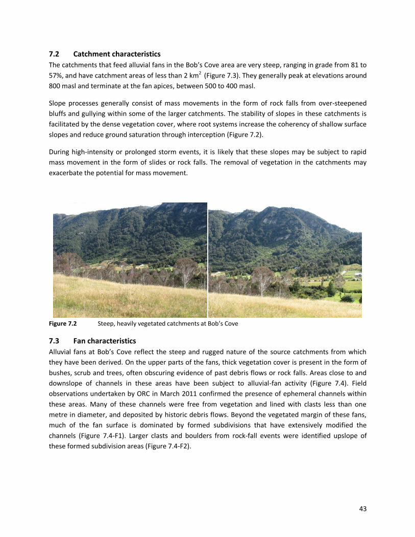
Slope processes generally consist of mass movements in the form of rock falls from over-steepened
bluffs and gullying within some of the larger catchments. The stability of slopes in these catchments is
facilitated by the dense vegetation cover, where root systems increase the coherency of shallow surface
slopes and reduce ground saturation through interception (Figure 7.2).
During high-intensity or prolonged storm events, it is likely that these slopes may be subject to rapid
mass movement in the form of slides or rock falls. The removal of vegetation in the catchments may
exacerbate the potential for mass movement.
Figure 7.2 Steep, heavily vegetated catchments at Bob’s Cove
7.3 Fan characteristics
Alluvial fans at Bob’s Cove reflect the steep and rugged nature of the source catchments from which
they have been derived. On the upper parts of the fans, thick vegetation cover is present in the form of
bushes, scrub and trees, often obscuring evidence of past debris flows or rock falls. Areas close to and
downslope of channels in these areas have been subject to alluvial-fan activity (Figure 7.4). Field
observations undertaken by ORC in March 2011 confirmed the presence of ephemeral channels within
these areas. Many of these channels were free from vegetation and lined with clasts less than one
metre in diameter, and deposited by historic debris flows. Beyond the vegetated margin of these fans,
much of the fan surface is dominated by formed subdivisions that have extensively modified the
channels (Figure 7.4-F1). Larger clasts and boulders from rock-fall events were identified upslope of
these formed subdivision areas (Figure 7.4-F2).

44
Figure 7.3 Bob’s Cove alluvial fans and catchments, noting some key alluvial fan features; aerial photo taken
in February 2006

45
Figure 7.4 Left: Ephemeral channel located within the upper forested area of an alluvial fan at Bob’s Cove;
lateral-debris deposits are evident from historic-debris flow. Centre: Formed subdivision has changed the flow-
path characteristics of the alluvial fans at Bob’s Cove (Figure 7.3-F1). Right: Large clasts are evident on the upslope
parts of alluvial fans at Bob’s Cove (Figure 7.3-F2).
7.4 Bob’s Cove alluvial-fan hazard
As discussed, the channels that flow onto alluvial-fan surfaces at Bob’s Cove are ephemeral and
therefore do not provide a full appreciation of the potential alluvial-fan hazard. Heavily forested
catchments have contributed to the coherency of slopes in these catchments and decreased slope
saturation, resulting in a reduced frequency of mass-movement processes. Debris-flow and rock-fall
events have been infrequent in recent decades.
Depending on the nature and characteristics of each storm event, any part of the hazard area may be
impacted by debris or debris-flood flows or floodwater inundation in the future. It is likely that the fan’s
upper slopes will be impacted by debris-flow and rock-fall events, as these processes have occurred here
in the past, forming the underlying landforms. On the fan’s lower margins, it is more likely that debris-
flood or floodwater sheet-flows will occur. Due to the steep topography, it is likely that mass-movement
processes may become more active should catchment conditions change.

Historic Aerial Photographs - Bob’s Cove, Lake Wakatipu
23-04-1966 12-03-1996
25-02-2006

46
8. Walter Peak, Lake Wakatipu
8.1 Environment setting
Sited opposite Bob’s Cove, the Walter Peak area is similarly a geologically young landscape, having been
scoured by glaciers during the last glacial period, as discussed in Section 1.2. Apart from driving around
the southern end of Lake Wakatipu, the only access to Walter Peak station is by air or on the Earnslaw
charter steamboat. The area is mainly pastoral farmland, with land in the vicinity of Beach Bay and the
wider area having a Rural Visitor Zone within the Queenstown-Lakes District Council Plan. This zoning
means that this location has been targeted by the district council for future development, which has the
potential to include relatively large-scale developments.
Figure 8.1 Image showing the Walter Peak alluvial-fan complex with respect to the surrounding
environment
Walter Peak
Alluvial Fan Complex
LAKE
WAKATIPU
Beach Bay

47
8.2 Catchment characteristics
The catchments that feed alluvial fans in the Walter Peak area are very steep and have catchment areas
of less than 1.5km2 (Figure 8.2). The most eastern catchment peaks at an elevation of 1800 masl at
Walter Peak, with fan apices ranging from around 800 to 500 masl.
Slopes are generally vegetated by small bushes and alpine tussocks and are subject to widespread slope
instability in the form of gullying, slumping and creep, with fresh scarps, signifying instability. Gullying
and the over-steepening of slopes have led to further incision of the surficial-slope deposits, which are
prone to failure and subsequent debris-flow initiation during high-intensity storm events. The active
scarps evident in Figure 8.2 are examples of these processes.
8.3 Fan characteristics
During storm events, debris and debris-flood flows are common on the upper-fan areas. In the fan’s
lower reaches, floodwater inundation and the sedimentation of fine silts and sands is more common as
larger clasts are deposited further up the fan. Channel incision is less than one metre for most of these
fans, and channel aggradation and avulsion is a common occurrence.
Barrell et al. (2009) noted that historic flood and debris flows occurred close to the Walter Peak
homestead buildings at Beach Bay in 1999 and 2002.
8.4 Walter Peak alluvial-fan hazard
The alluvial-fan hazard area has been defined by combining all the active alluvial-fan areas identified by
Barrell et al. (2009). This area is subject to recurrent debris, debris-flood flow and floodwater-inundation
alluvial-fan processes. Persistent avulsion, channel aggradation and erosion are common across all fans
at this location. These very active processes need to be investigated when consideration is given to using
the Rural Visitor Zone in this area in the future.

48
Figure 8.2 Walter Peak alluvial fans and catchments, noting some key alluvial fan features; aerial photo
taken in February 2006

Historic Aerial Photographs
Walter Peak, Lake Wakatipu
27-11-1998 25-02-2006

49
9. Kingston Creek, Kingston
9.1 Environment setting
Located on the southern shores of Lake Wakatipu, the Kingston area is a geologically young landscape,
having been scoured by glaciers during the last glacial period, as discussed in Section 1.2. The Kingston
Creek catchment is located on the western flank of the Hector Mountains at the southern edge of Lake
Wakatipu. The creek flows from an elevation of 1464m at Flat Rock to around 520m at the topographic
apex of the alluvial fan. The alluvial fan is dominated by pastoral-farming activities and is bisected by SH
6 along its lower margins. Downstream of the state highway, the creek flows through the Kingston
township to its confluence with Lake Wakatipu.
Figure 9.1 Image showing the Kingston Creek alluvial fan with respect to the surrounding environment
Kingston Creek
alluvial fan
State Highway 6
Kingston Creek
catchment
KINGSTON LAKE
WAKATIPU

50
9.2 Catchment characteristics
The Kingston Creek catchment is approximately 3.4km2 in size (Figure 9.2). The upper catchment, from
its peak at Flat Rock to around 1100 masl, has a relatively gentle grade of 15% and is dominated by
alpine tussocks. Downstream of this elevation, the creek steepens considerably to a grade of 45% down
to the topographic apex.
Where the catchment steepens, the creek is eroding into post-glacial landslide deposits that flank the
slopes of the Hector Mountains. These deposits were formed following the recession of the buttressing
glaciers during the last glacial period. Subsequent to slope relaxation, mechanical-weathering and mass-
movement processes have contributed to the widespread development of unconsolidated landslide
deposits on these slopes (Figure 9.3-P1). Slope instability is common in this reach of the catchment, with
the greatest volume of sediment being derived from the sediment-source area on the true right of the
creek (Figure 9.3-P2).
Figure 9.2 The Kingston Creek catchment, noting areas of interest; aerial photo dated February 2006

51
Figure 9.3 Left: Large landslide deposits flank the slopes of the Kingston Creek catchment on the channel’s
true left. Right: Kingston Creek, as it descends from the flatter-grade upper catchment; the creek is actively
eroding landslide material in this reach of the catchment.
9.3 Fan characteristics
Kingston Creek has formed a symmetrical semicircular fan that extends from the base of the Hector
Mountains to Lake Wakatipu (Figure 9.4). The dominant debris-flow processes observed at the head of
the alluvial fan are a direct result of the widespread slope instability in the lower catchment (Figure 9.2).
These conditions promote debris-flow processes on the upper fan and debris-flood flows further
downstream. The large boulder field (Figure 9.5-F1), located just downstream of the topographic apex,
has been formed by these debris flows during past events.
Large palaeo-channels are evident across much of the fan surface (Figure 9.5-F2), where Kingston Creek
used to flow. These channels have incised into an older alluvial-fan surface, probably formed in the
years following glaciation when Lake Wakatipu was at higher levels than those observed today. As the
creek flows downstream, it becomes more incised into this deposit, eroding sediment from the bed and
banks during storm events. Sediment from this fan surface contributes to the sedimentation and
channel aggradation observed downstream.
As the creek flows beyond the contemporary extent of this old alluvial-fan deposit, channel incision is
less than one metre (Figure 9.5-F3). From this reach to the state highway, the channel aggrades and
P1 P2

52
migrates laterally, as it is less confined than it is upstream. Sediment and debris is transported or eroded
from upstream and deposited into this reach during storm events.
Downstream of the state highway, the channel is generally incised less than one metre in the vicinity of
the camping ground (Figure 9.5-F4). Further downstream, as it flows between residential areas and
intermittent pastoral land, the creek has varying depths of incision as it has eroded into the surrounding
post-glacial deposits, which consist of moraine, beach ridge and lacustrine.
9.4 Kingston Creek alluvial-fan hazard
The Kingston Creek alluvial fan has historically been subject to recurrent debris-flow events on the upper
fan. Large-scale slope instability and progressive erosion of landslide deposits in the lower catchment
indicate that it is probable debris-flow events will continue into the future. Channel avulsion is likely to
occur in the upper fan reaches, where debris and debris-flood flows will spread laterally. Very large
storm events are likely to convey debris and debris-flood flows as far as, if not beyond, the state
highway.
Continual erosion of old alluvial-fan deposits through bed and bank reworking is likely to continue into
the foreseeable future on the Kingston Creek alluvial fan. These processes will contribute to
sedimentation and channel aggradation further downstream, probably resulting in channel avulsion. In
locations where existing channel incision is less than one metre, it is likely that channel avulsion or
inundation from floodwaters that exceed channel capacity will occur.
Downstream of the state highway, floodwater and sheet-flow inundation may occur where locations
with less than one metre incision (such as the Kingston camping ground) are inundated. In large events,
the channel may change position upstream and no longer follow its current course, causing
sedimentation and/or debris-flood flows on lower parts of the fan.

53
Figure 9.5 Kingston Creek alluvial fan, noting key alluvial fan features; aerial photo dated February 2006

54
Figure 9.5 Photographs that relate to points of interest depicted on Figure 9.4. Top left: The upper Kingston
Creek alluvial fan showing a large clast boulder field at the fan head and recently overturned debris deposits in the
foreground. Top right: Large palaeo-channels traverse the Kingston creek alluvial-fan surface. Bottom left: The
Kingston Creek channel above SH 6 is incised less than one metre for much of its length. Bottom right:
Downstream of the state highway, the creek has almost no incision through the Kingston camping ground.
F1 F2
F3 F4

Historic Aerial Photographs - Kingston Creek, Kingston
16-02-1959 27-11-1998
25-02-2006

55
10. Brewery/Bush Creek, Queenstown Located in the Gorge between Queenstown and the Shotover River valley, the Brewery Creek catchment
(Figure 10.1) is a geologically young landscape, having been occupied by glaciers during the last glacial
period, as discussed in Section 1.2. Incised into the eastern flank of the Bowen Peak mountain group,
the catchment flows west to east from an elevation of 1627m at Bowen Peak to around 380m at the
head of the alluvial fan. The alluvial fan has been modified extensively by urban development, consisting
of residential, industrial and visitor accommodation facilities that form part of Queenstown. The fan is
bisected by Gorge Road on its lower margins, where the channel flows into the Horne Creek flood-
protection detention area.
Figure 10.1 Image showing the Brewery Creek alluvial fan and catchment with respect to the surrounding
environment
Gorge Road
Brewery Creek
catchment
Brewery Creek
alluvial fan
QUEENSTOWN
Reavers Lane
alluvial fan

56
10.1 Catchment characteristics
The Brewery Creek catchment is approximately 8.4km2 in size (Figure 10.2) and is very steep. The upper
catchment is dominated by small bushes and alpine tussocks down to around 1000 masl, where both
sides of the catchment are covered in dense forest. Large rock falls have occurred in the true-left-bank
forested area in the past (Figure 10.3-P1), which is represented by the presence of much younger trees
in the 2006 aerial photography (Appendix 1).
Catchment observations, undertaken by ORC in March 2011, found that Brewery Creek has incised into
basement schist, which reflects the level of the current-channel invert. The true-right bank is bound by
bedrock and is very steep, contributing debris, in the form of large trees, as tributaries erode and
transport material efficiently on very steep grades. The true-left valley-side, next to the creek, is
orientated on the foliation of the basement schist. These slopes are mantled by layers of colluvial
landslide deposits, which are being eroded by the creek, thereby providing large volumes of sediment
and debris to the creek (Figure 10.3-P2).
As slopes are eroded, many of the mature trees next to the creek are being undercut and fall into the
creek due to over-steepening (Figure 10.3-P3). This process contributes large volumes of woody debris
and tree trunks to the active channel, greatly increasing the potential for log-jam dams to form in the
narrow channel (Figure 10.3-P4).
Figure 10.2 The Brewery Creek catchment, noting areas of interest; aerial photo dated February 2006

57
Figure 10.3 Photographs that relate to points of interest depicted in Figure 10.2. Top left: Large rock-fall
boulders strewn across the Brewery Creek’s left bank; this location has been succeeded by younger trees. Top
right: Brewery Creek, looking upstream, colluvial landslide deposits are being eroded on the true left (image right),
and the creek is bound by bedrock on the true right (image left). Bottom left: Large toppled trees lie on slopes next
to the incised Brewery Creek channel. Bottom right: Log-jam dam formed in the Brewery Creek channel
10.2 Fan characteristics
Brewery Creek has formed a semicircular fan that coalesces with the wider Horne Creek flood plain in
the lower valley of the Gorge (Figure 10.4). Near the topographic apex of the fan, the channel flows in a
U-shaped scoured valley, indicative of historic-debris flow (Figure 10.5-004). As the channel leaves the
confines of the valley, it has been extensively modified by excavation into the fan surface, suggesting
that the material used to line the channel has been sourced from the alluvial-fan surface (Figure 10.5-
005/006). Below Gorge Road, the channel flows unconfined across pastoral farmland down to the Horne
Creek detention area (Figure 10.5).
During a debris-flow event, trees on the lateral margins of the flow often have bark and superficial
layers removed from the trunk due to the flow’s erosive power. Figure 10.4 shows a number of locations
where historic-debris-flow heights have been measured from scars on mature trees with respect to the
existing modified-channel invert and respective ground level; examples of these marks are depicted in
figures 10.6 and 10.7.
P1 P2
P3 P4

58
Figure 10.4 Brewery Creek alluvial fan, noting key features; aerial photo dated February 2006

59
Figure 10.5 Top left: The U-shaped valley near the topographic apex of Brewery Creek. Top right: Modified
Brewery Creek channel downstream of the topographic apex. Bottom left: Brewery Creek’s modified channel in
the mid-fan area, with visitor accommodation complex in the background. Bottom right: Brewery Creek’s
unconfined channel below Gorge Road
Figure 10.6 Debris-impact scars on mature trees near Brewery Creek’s topographic apex. Left: Debris mark at
003 (Figure 10.4), showing height with respect to ground level. Centre: Same tree as left image, with figure for
scale. Right: Similar tree just downstream of mark 003
004 005
006
Debris height
Brewery Creek
Debris height
Debris height

60
Figure 10.7 Debris-impact scars on mature trees on the Brewery Creek alluvial fan. Top left: Debris scars on
left-bank trees just upstream of point 005 (Figure 10.4). Top right: Debris scar on true-left treat point 005. Mid-left:
Debris scars on trees at point 006 with figure for scale. Mid-right: Looking across Bowen Street towards trees at
point 008. Lower image: Trees on far side of Bowen Street at 008
Debris height
Debris height
Debris height
Debris height Debris height
Debris heights

61
10.3 Brewery Creek alluvial-fan hazard
The Brewery Creek alluvial fan has been subject to recurrent debris-flow events in the past (figures 10.8,
10.9 and 10.10). The effects of debris and flood flows on the alluvial-fan surface were exacerbated by
the failure of a man-made dam in the catchment in May 1986. In November 1999, large volumes of
debris and sediment inundated a large portion of the fan surface. Debris flows cut access on Gorge Road
and impacted many buildings and residential properties.
The alluvial-fan hazards associated with Brewery Creek generally consist of high-velocity-debris and
debris-flood flows, channel avulsion, bank erosion and floodwater ‘sheet-flow’ inundation. Upper parts
of the fan are subject to high-velocity debris flow where the channel is currently confined and steep. As
the fan and channel gradients change downstream, debris-flood deposits are more common with
considerable channel aggradation, during and in the immediate recession of the debris-flow event.
Large-scale slope instability and continued erosion of landslide material adjacent to the channel in the
catchment is envisaged to continue, based on catchment observations in March 2011 by ORC. It is likely
that future debris-flow events will be exacerbated by the formation of debris dams and log-jam dams
impounding the channel within the catchment. The sudden release of sediment and debris from failure
of these features will result in rapid aggradation of the alluvial-fan surface and avulsion of channels
potentially to any location identified in the hazard area (Figure 10.4).
Depending on the nature and characteristics of each storm event, any part of the hazard area may be
impacted by debris or debris-flood flows or floodwater inundation in the future. It is likely that the fan’s
upper slopes will be impacted by debris flow, as these processes have occurred here in the past, forming
the underlying landforms. The removal of vegetation in the catchment may exacerbate the potential for
mass movement. On the fan’s lower margins, it is more likely that debris-flood or floodwater sheet-
flows will occur. Due to the steep topography, it is likely that mass-movement processes may become
more active should catchment conditions change in the future.
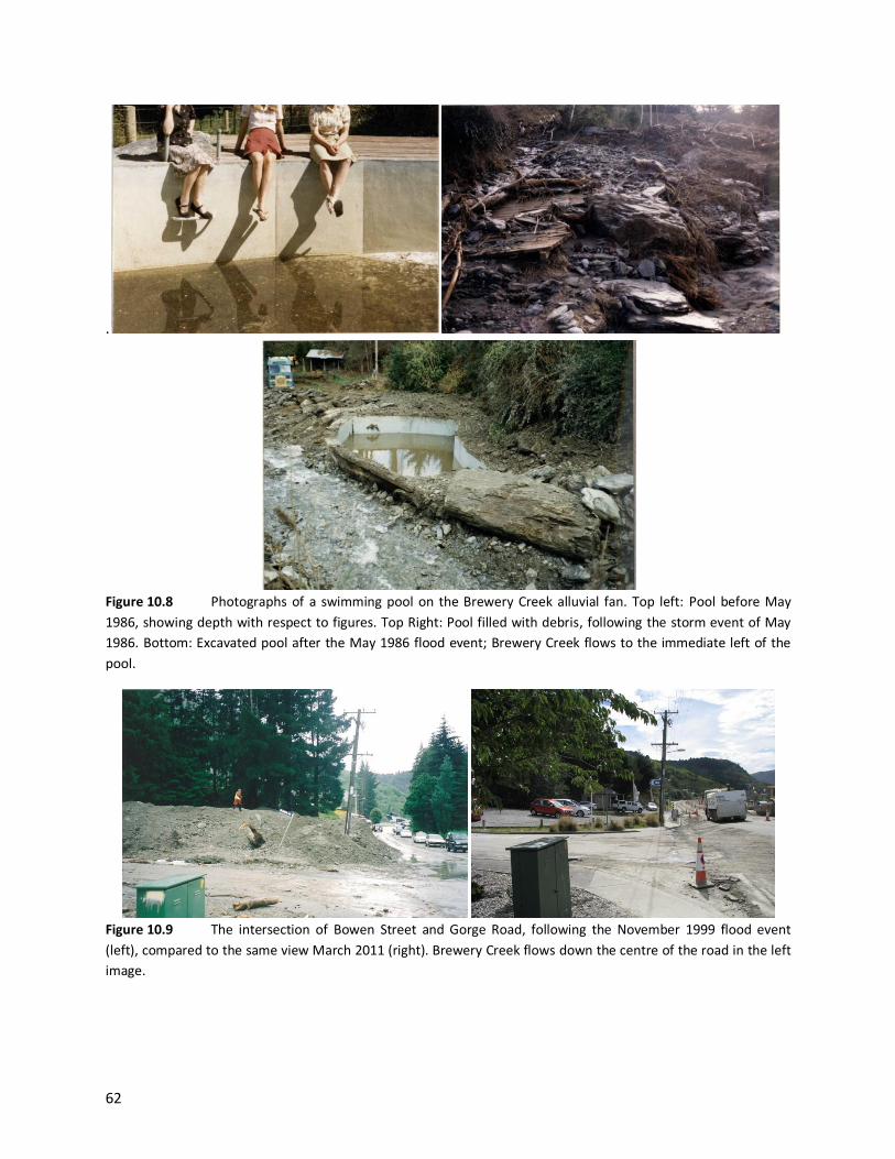
62
.
Figure 10.8 Photographs of a swimming pool on the Brewery Creek alluvial fan. Top left: Pool before May
1986, showing depth with respect to figures. Top Right: Pool filled with debris, following the storm event of May
1986. Bottom: Excavated pool after the May 1986 flood event; Brewery Creek flows to the immediate left of the
pool.
Figure 10.9 The intersection of Bowen Street and Gorge Road, following the November 1999 flood event
(left), compared to the same view March 2011 (right). Brewery Creek flows down the centre of the road in the left
image.

63
Figure 10.10 Brewery Creek, following the November 1999 storm event. Left: Looking north up Gorge Road on
the corner with Bowen Street. Right: Sediment and tree debris carried by Brewery Creek on the downstream side
of Gorge Road, 17 November 1999

Historic Aerial Photographs - Brewery/Bush Creek, Queenstown
06-03-1996 18-05-1959
25-02-2006

64
11. Reavers Lane, Queenstown Like the neighbouring Brewery Creek catchment, the Reavers Lane catchment (Figure 11.1) is a
geologically young landscape, having been occupied by glaciers during the last glacial period, as
discussed in Section 1.2. Incised into the eastern flank of the Bowen Peak mountain group, the
catchment flows west to east from an elevation of around 900 masl to about 380 m at the head of the
alluvial fan. The alluvial fan has been modified extensively by residential urban development, including
visitor accommodation facilities. The creek outflow has been directed into the reticulated stormwater
system at the head of the fan, so no longer has an obvious surface channel.
Figure 11.1 Image showing the Reavers Lane alluvial fan and catchment with respect to the surrounding
environment
11.1 Catchment characteristics
The Reavers Lane catchment is very steep, rugged terrain, with a catchment area of approximately
0.5km2 (Figure 11.2). The catchment is heavily vegetated by dense forest, which facilitates slope stability
where root systems increase the coherency of shallow surface slopes and trees reduce ground
saturation through interception.
QUEENSTOWN
Reavers Lane
catchment
Reavers Lane
alluvial fan Brewery Creek
alluvial fan

65
Slope processes generally consist of mass movements in the form of rock falls from over-steepened
bluffs and gullying near channel margins, although they are not readily identifiable due to forest cover.
Aerial photography from 1966 shows a largely unvegetated catchment exhibiting some of these mass-
movement processes (Appendix 1). During high-intensity or prolonged storm events, it is likely that
these slopes may be subject to rapid mass movement in the form of slides or rock fall. The removal of
vegetation in the catchment may exacerbate the potential for mass movement.
Site observations, undertaken by ORC in March 2011, identified a wide U-shaped lower catchment just
upstream of the fan’s topographic apex. This channel is indicative of having allowed debris and/or
debris- flood flows onto the alluvial-fan surface in the past.
11.2 Fan characteristics
The Reavers Lane alluvial fan reflects the steep and rugged nature of the source catchment from which
it is derived (Figure 11.3). The steep slope of the fan surface from the topographic apex indicates that
the fan has mainly been formed by debris-flow processes in the past. Much of the past evidence of
debris flow has been removed by urban development on the fan surface. Site observations in March
2011 noted large boulders near the head of the alluvial fan, which were believed to have been derived
from the fan surface (Figure 11.4).
The fan has been subject to a quiescent phase of debris-flow activity in recent decades, largely in part to
the succession of dense forestry in the catchment facilitating slope coherency and stability. Alluvial-fan
flood flows are intended to be accommodated for by the existing stormwater drainage system (Figure
11.5).
11.3 Reavers Lane alluvial-fan hazard
As there is no surface channel across the Reavers Lane alluvial-fan surface, the full appreciation of
potential alluvial-fan hazard is not well recognised. At present, a small debris screen and culvert
connected to the reticulated stormwater system is relied upon to accommodate water flows derived
from this catchment (Figure 11.5). Heavily forested catchments have contributed to the coherency of
slopes in these catchments, and decreased slope saturation has resulted in a reduced frequency of
mass-movement processes. Debris-flow and rock-fall events have been infrequent in recent decades.
Depending on the nature and characteristics of each storm event, any part of the hazard area may be
impacted by debris or debris-flood flows or floodwater inundation in the future. It is likely that the fan’s
upper slopes will be impacted by debris-flow and rock-fall events, as these processes have occurred here
in the past, forming the underlying landforms. On the fan’s lower margins, it is more likely that debris-
flood or floodwater sheet-flows will occur. Due to the steep topography, it is likely that mass-movement
processes may become more active should catchment conditions change in the future.

66
Figure 11.2 Reavers Lane alluvial fan and catchment; aerial photo taken February 2006
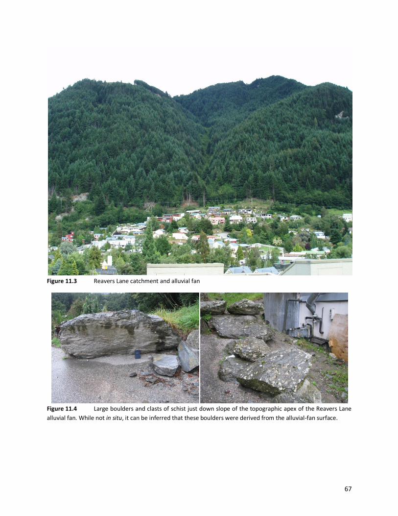
67
Figure 11.3 Reavers Lane catchment and alluvial fan
Figure 11.4 Large boulders and clasts of schist just down slope of the topographic apex of the Reavers Lane
alluvial fan. While not in situ, it can be inferred that these boulders were derived from the alluvial-fan surface.

68
Figure 11.5 Reavers Lane alluvial-fan stormwater screen and culvert entrance (left). Residential properties at
the head of the alluvial fan with respect to location of this structure (right)
Location of culvert
intake and screen

Historic Aerial Photographs - Reavers Lane, Queenstown
18-05-1959 06-03-1996
25-02-2006

69
12. Reservoir Creek, Roxburgh Located on the eastern flanks of the Old Man Range, the Reservoir Creek catchment (Figure 12.1) is a
geologically old landscape, as discussed in Section 1.2. The catchment ranges in elevation from 1023m at
its crest to around 140m at the head of the alluvial fan. Reservoir Creek has built an alluvial fan onto old
river terraces previously deposited by the Clutha River. The fan has been modified extensively by urban
development and is bisected by SH 8 across the mid-fan.
Figure 12.1 Image showing the Reservoir Creek alluvial fan with respect to the surrounding environment
CLUTHA RIVER
Reservoir Creek
catchment
Reservoir Creek
alluvial fan
ROXBURGH State Highway 8

70
12.1 Catchment characteristics
The Reservoir Creek catchment is approximately 10.4km 2 in size (Figure 12.2) and is steep. The upper
catchment is dominated by small bushes and alpine tussocks, with no large areas of forest present.
Catchment observations, undertaken by ORC in March 2011, found that Reservoir Creek is well incised
into basement schist, having been subject to progressive erosion and valley uplift in the past.
Catchment slopes are mantled by large-scale mass-movement features overlain by highly weathered
colluvial deposits that are being actively eroded by the creek (Figure 12.3-P1). The bed of the creek is
comprised of unconsolidated debris deposits sourced from the adjacent slopes, and deposited during
debris-flow events (Figure 12.3). Following the recession of debris-flow events, the channel has incised
into these deposits. For much of its length, the catchment channel is well defined and confined between
the adjacent slopes. These conditions are favourable for the efficient transfer of debris and flood flows
down to the alluvial-fan surface.
Active slope instability in the catchment is generally the direct result of over-saturation during storm
events. Slides and rock falls are common occurrences during high-intensity events, as observed in
October 1978 (Figure 12.4).
Figure 12.2 The Reservoir Creek catchment and surrounding environment; aerial photo dated March 2006

71
Figure 12.3 The Reservoir Creek catchment. Left: Incision into the base of the adjacent slopes contributes
sediment and debris to the channel. Centre: Lower catchment on 17 October 1978, looking downstream; fresh
debris deposits are evident along the length of the channel. Right: The same stretch of lower catchment as centre
image, taken in March 2011, looking upstream. Debris deposits are now vegetated in this reach and have been
subsequently incised by the active channel.
Figure 12.4 Left: Upper catchment debris slide almost impounding the Reservoir Creek channel, 17 October
1978. Right: Channel incision and erosion directly supply debris to the channel, 17 October 1978.
P1
Reservoir
Creek

72
12.2 Fan characteristics
Reservoir Creek has formed a semicircular alluvial fan onto old river terraces, previously deposited by
the Clutha River (Figure 12.5). At the toe of the alluvial fan, the Clutha River actively removes sediment
and debris. Near the topographic apex of the fan, the channel flows in a U-shaped scoured valley,
indicating historic-debris flows have passed through this location. As the channel leaves the confines of
the valley, it has been extensively modified by excavation and the construction of concrete-lined
channels on the fan surface (Figure 12.6). The intention of this structure is to enable the efficient
transfer of debris flows down the fan surface to the Clutha River to prevent flows from spreading into
residential areas.
Channel contouring and the construction of the concrete-lined channel were undertaken by the Otago
Catchment Board (OCB) in 1980 and 1981 (Figure 12.6). In 1983, a storm event in the Reservoir Creek
catchment caused damage to the lined channel, and further improvements were undertaken by the OCB
in 1984. Upstream of the concrete-lined channel, large willows and dense vegetation has grown in the
channel, following the 1984 works (Figure 12.6).
12.3 Reservoir Creek alluvial-fan hazard
The Reservoir Creek alluvial fan has been subject to recurrent debris-flow events in the past (Figure
12.7). In October 1978, debris flows overwhelmed the channel and impacted residential properties on
the fan surface above and below the state highway. In response, authorities excavated the channel and
constructed a concrete-lined channel to convey debris flows efficiently to the lower fan. This structure
was in place by the early 1980s (Figure 12.6).
The alluvial-fan hazards associated with Reservoir Creek generally consist of high-velocity-debris and
debris-flood flows, channel avulsion, bank erosion and floodwater ‘sheet-flow’ inundation. Upper parts
of the fan are subject to high-velocity debris flow where the channel is currently confined and steep. As
the fan and channel gradients change downstream, debris-flood deposits are more common (Figure
12.7), with considerable channel aggradation occurring during and in the immediate recession of the
debris-flow event.
Depending on the nature and characteristics of each storm event, any part of the hazard area may be
impacted by debris or debris-flood flows or floodwater inundation in the future. It is likely that the fans
upper slopes will be impacted by debris flow, as these processes have occurred here in the past, forming
the underlying landforms. On the fan’s lower margins, it is more likely that debris-flood or floodwater
sheet-flows will occur; however, debris flows may impact these areas during high-magnitude events.
Catchment conditions indicate that a large volume of unconsolidated debris is stored in the active
channel margin that may be transported to the fan surface in future events.
It is noted that alluvial fans to the north of the Reservoir Creek catchment, located on the northern
fringe of the Roxburgh urban area, including the Quail Haven subdivision, have not been assessed as
part of this investigation. These catchments are smaller than Reservoir Creek, but still have the potential
to create debris and debris-flood flows and floodwater inundation on the alluvial-fan surfaces. The

73
hazard area defined in Figure 12.5 resembles the active alluvial fan areas mapped by Barrell et al.
(2009).
Figure 12.5 Reservoir Creek alluvial fan noting key features; aerial photo dated March 2006
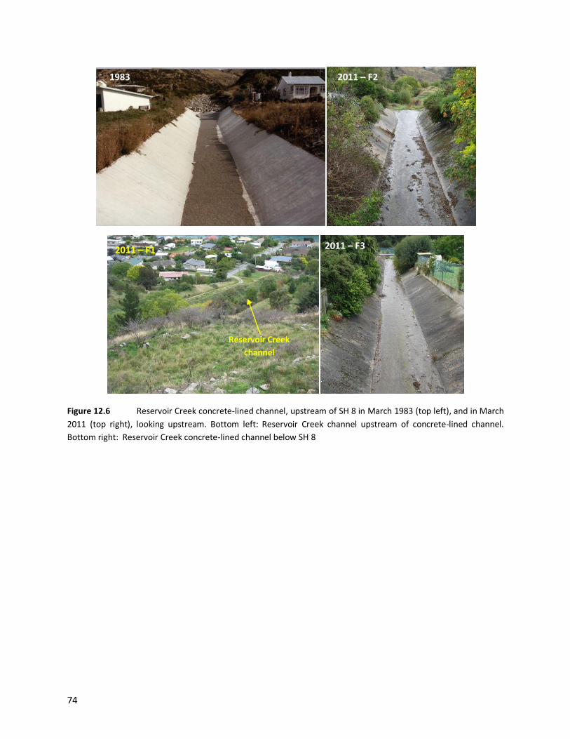
74
Figure 12.6 Reservoir Creek concrete-lined channel, upstream of SH 8 in March 1983 (top left), and in March
2011 (top right), looking upstream. Bottom left: Reservoir Creek channel upstream of concrete-lined channel.
Bottom right: Reservoir Creek concrete-lined channel below SH 8
1983
2011 – F1 2011 – F3
2011 – F2
Reservoir Creek
channel
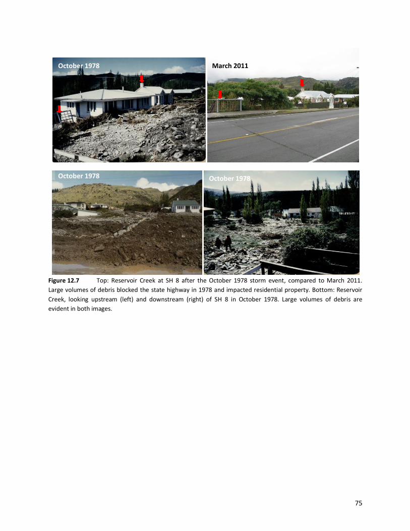
75
Figure 12.7 Top: Reservoir Creek at SH 8 after the October 1978 storm event, compared to March 2011.
Large volumes of debris blocked the state highway in 1978 and impacted residential property. Bottom: Reservoir
Creek, looking upstream (left) and downstream (right) of SH 8 in October 1978. Large volumes of debris are
evident in both images.
October 1978
October 1978 October 1978
March 2011

Historic Aerial Photographs - Reservoir Creek, Roxburgh
13-02-1997
30-03-2006

76
13. Conclusion Eleven specific alluvial fans within the Queenstown Lakes and Central Otago districts have been
assessed. Key features on each alluvial fan and their respective catchments have been identified through
desktop and site-specific investigations. From these datasets, an alluvial-fan hazard area has been
identified for each fan and the probable future hazards discussed.
The report concludes that parts of Queenstown, Wanaka and Roxburgh townships are exposed to
intermittent alluvial-fan hazards. Hazard areas have been defined for particular alluvial fans in these
communities that may be subject to alluvial-fan processes in the future. Elsewhere, communities in the
Makarora Valley have a level of residual exposure to alluvial-fan hazards should channels migrate
laterally across the fan surface in the future.

77
14. Glossary
Aggradation: To raise the grade or level of the river bed, primarily by depositing sediment
accumulations
Alluvial fan: Landforms that develop where a steep gully emerges from its confines onto a flatter valley
floor, or at other sites where sediment accumulates in response to changes in stream gradient and/or
width
Avulsion: The abandonment of a river channel and the establishment of a new channel at a lower
elevation on its floodplain as a result of floodplain/channel aggradation
Braided area: An area where sediments are deposited by numerous streams that may, over time,
meander across the surface. This is generally a wide gently sloping area.
Catchment: The area from which a surface water system derives its water
Debris: Mass of loose unconsolidated material, including silt, sand, gravel, boulders and vegetation
Debris flow: A mass movement (often classified as a type of landslide) involving rapid (5-10m/s, 15-
30km/hr) flow of debris containing coarse-grained, saturated material confined in a steep channel and
running out onto low-gradient fans and valley floors, often resulting from high-intensity rainfall. Because
of their high velocity (speeds faster than a human can run are common), high density (like wet concrete)
and entrained boulders, such flows are highly destructive and dangerous.
Debris flood: A very rapid (up to ~5m/s), surging flow of water, heavily charged with debris (gravel, sand
and silt), in a steep channel. A debris flood is not a landslide, but is a mass-transport phenomenon, with
destructiveness similar to that of water, but less than debris flows. Objects impacted by debris floods
are surrounded or buried by flood debris but are often largely undamaged. This is often the most
common fan-building process on an ‘alluvial fan’. Debris flows and debris floods can occur during the
same flood, with the latter often occurring in the initial and waning stages of an event.
Delta: A fan-shaped alluvial deposit at a river or stream mouth formed by the deposition of successive
layers of sediment
Hydrographic apex: Highest point on a fan at which the stream flow is confined to a single channel
Incised/incision: A stream or channel that has been down-cut or entrenched into a surface
Interstitial: Located or forming in small narrow spaces
Lateral migration: The process whereby channels move sideways across the wider floodplain of the
river

78
Log-jam: A pileup, dam or tangle of logs in a waterway, causing a blockage that impounds flow and
debris
Mass movement: The downhill movement of surface materials under the influence of gravity, often
induced or assisted by increased saturation of the slope
Morphology: The form or structure of the river
Piedmont terrace: A terrace formed or situated at the foot of a valley or mountain range
Post-glacial terrace: A landform created by the deposit of debris and/or floodwater sediments in an
area previously occupied by a valley glacier
Schist: Medium- to coarse-grained metamorphic rock, composed of laminated, often flaky parallel layers
Sheet flow: An overland flow of water taking the form of a thin, continuous film over a relatively smooth
surface and not concentrated in channels
Surficial: Of or relating the surface of an object or landform
Topographic apex: The head or highest point on an alluvial fan

79
15. References Barrell, D.J.A., Cox, S.C., Greene, S., Townsend, D.B., (2009) Otago Alluvial Fans Project: Supplementary
maps and information on fans in selected areas of Otago. GNS Science Consultancy Report 2009/052.
Prepared for Otago Regional Council
Opus International Consultants Ltd (2007) Otago Alluvial Fans Project: Interim Project Report, prepared
for Otago Regional Council
Opus International Consultants Ltd (2009) Otago Alluvial Fans Project, Report # 1205 – Version 2,
prepared for Otago Regional Council
Otago Regional Council (2006) Stoney Creek/Middle Creek Flood Mitigation Works – Progress Report,
prepared for the Queenstown Lakes District Council
Tonkin and Taylor (2007) Waterfall Creek Subdivision – Geotechnical Hazards, prepared for P Highton
(ORC consent application 2007.469)


